-
Contents
-
Table of Contents
-
Troubleshooting
-
Bookmarks
Quick Links
No. IP80-OM00008-D
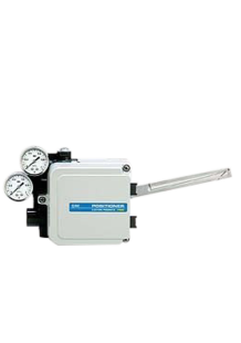
ELECTRO-PNEUMATIC POSITIONER
PRODUCT NAME
IP8000-0∗0-∗-X14
IP8100-0∗0-∗-X14
MODEL/ Series
0
Related Manuals for SMC Networks IP8000-0 Series
Summary of Contents for SMC Networks IP8000-0 Series
-
Page 1
No. IP80-OM00008-D ELECTRO-PNEUMATIC POSITIONER PRODUCT NAME IP8000-0∗0-∗-X14 IP8100-0∗0-∗-X14 MODEL/ Series… -
Page 2
INDEX Safety Instruction 1 Outline 2.Specifications 3.Operation principle 3-1 Type IP8000 3-2 Type IP8100 4.Attaching 4-1 Type IP8000 4-2 Type IP8100 5.Piping and Attaching of Internal Feedback Unit 6.Electrical Wiring 7.Adjustment 7-1 Zero-point adjustment and span adjustment 7-2 Sensitivity adjustment 7-3 Manual switching 8.Maintenance and Check 9.Caution on Handling… -
Page 3: Safety Instructions
Safety Instructions These safety instructions are intended to prevent hazardous situations and/or equipment damage. These instructions indicate the level of potential hazard with the labels of “Caution,” “Warning” or “Danger.” They are all important notes for safety and must be followed in addition to International Standards (ISO/IEC) and other safety regulations.
-
Page 4: Limited Warranty And Disclaimer/Compliance Requirements
Safety Instructions Caution 1.The product is provided for use in manufacturing industries. The product herein described is basically provided for peaceful use in manufacturing industries. If considering using the product in other industries, consult SMC beforehand and exchange specifications or a contract if necessary. If anything is unclear, contact your nearest sales branch.
-
Page 5
1. Outline IP8*00 Series electro-pneumatic positioner controls the motion of actuator by the operation of pilot valve. This pilot valve is activated by signal current from adjustment unit mounted to air cylinder. Specials of “-X14” received the certification of “Intrinsically safe explosion proof conforming with ATEX directive (Ex ib CT5/T6 Gb ) ”… -
Page 6: Operation Principle
3. Operation Principle 3-1 Type IP8000 When the input current increases, armature (13) receives counter-clockwise rotating torque with leaf-spring (11) of torque motor (12) functioning as the support, counter-weight (4) is pushed towards left, the space between nozzle (6) and flapper (5) opens and the nozzle back pressure decreases.
-
Page 7
IP8000(lever type feedback) single action positive operation View Stopper screw Automatic/Manual change-over screw (Do not move) (15) Driven diaphragm (Built-in restrictor) OUT2 OUT1 Sensitivity adjusting screw (Adjusts GAIN) Pilot valve Inlet valve A Inlet valve B Feedback lever Span adjusting lever Exhaust EXH. -
Page 8
3-2 Type IP8100 When the input current increases, armature (14) receives counter-clockwise rotation torque with leaf-spring (12) of torque motor (13) functioning as the support, counter-weight (4) is pushed towards left, the space between nozzle (6) and flapper (5) opens and the nozzle back pressure decreases. -
Page 9
IP8100(Rotary type cam feedback) double actionpositive operation View X Automatic/Manual change-over screw Stopper screw (Do not move) (Built-in restrictor) OUT2 OUT1 Sensitivity adjusting screw (Adjusts GAIN) Pilot valve Inlet valve A Inlet valve B For reverse position,set by turning over the cam and reversing connections of Exhaust outlets OUT1 and OUT2. -
Page 10
4. Attaching Warning (1) Make a space needed for maintenance on the setting area. (2) Care so that finger wouldn’t be pinched during mounting and positioning cam. Cut supply pressure and release compressed air in positioner and actuator in advance. Caution (1) Confirm actuator and positioner are connected properly and tightly. -
Page 11
4-1-2 Connection with external feedback lever Tightening spring (1)Attach to the position that the valve stem and lever Right angle form the right angle when the input signal is Input current 0%(or 100%)position 50%(distribute evenly with 50% input signal set as Input current 50% position the reference). -
Page 12
4-2-2 Connection with feedback shaft Positioner body (1) Attach to the position at which the positioner feedback shaft and the rotary actuator main shaft alsmost Fork pin unit (P368010-23) concentric (range in which the spring pin of feedback shaft edge enters the hole of Fork lever assembly fork lever assembly shaft edge). -
Page 13
5. Piping and Attaching of Internal Feedback Unit… -
Page 15: Electrical Wiring
Caution Prior to piping, flush enough and remove chip, cutting oil and dust in tube so that obstruction wouldn’t intrude into positioner. Confirm specification and working direction of actuator, and mount pipes and internal feedback unit in accordance with table 2 and 3. 6.
-
Page 16
Warning 1. A positioner must be energized only after wiring via a barrier. 2. Use a linear resistance type barrier based on intrinsically safe parameter for the input circuit. 3. If a positioner is used as intrinsic safety type of explosion protected construction for ATEX, connect it only to the intrinsically safety electric circuit with the following maximum value. -
Page 17
7. Adjustment Caution (1) For this positioner, span and zero point adjustment of each actuator is necessary. Adjustment shall be done based on each actuator size. (2) Keep in mind that span and zero point adjustment interfere in each other. (3) Characteristics changes due to change of mounting position, ambient temperature and supply pressure. -
Page 18: Sensitivity Adjustment
7-1 Zero-point adjustment and span adjustment Table 4 Adjustment procedure (1) Set the input current to 0% (4mADC in the standard (1) Set the input current to 0% (4mADC in the standard specification) and turn the zero adjusting knob by hand to set it specification) and turn the zero adjusting knob by hand to set to the actuator starting point.
-
Page 19
7-2 Sensitivity adjustment SUP=0.4MPa near 4mADC Auto/Manual changeover screw (Built-in restrictor) Stopper screw (Do not move) Sensitivity adjust screw Input current mADC Fig.15 Pilot valve Fig16 Input/output-pressure characteristic Fig.16 shows the input current –output pressure characteristics of OUT1 and OUT2 of the pilot valve. -
Page 20: Maintenance And Check
8. Maintenance and Check Warning (1) After installation, repair and disassembling, connect compressed air and perform a proper function test and a leak test. If bleed noise is louder than the initial state or operation is abnormal, stop operation and check if installation is proper or not . And modification of electrical construction is prohibited due to maintaining Explosion-Protected construction function .
-
Page 21: Caution On Handling
9 Caution on Handling Warning Operation ( 1) Do not use this positioner out of the range of its specifications as this can cause failure. (Refer to 1. Specifications.) (2) If the system is supposed to be in danger because of failure of the positioner, prepare the system with a safety circuit to avoid danger.
-
Page 22: Troubleshooting
10. Troubleshooting…
-
Page 25
11. Option 11-1 Pilot valve with output throttle Hunching may occur when the positioner is attached to a small capacity actuator. In such a case, use a pilot valve having a throttle for OUT1 and OUT2. The throttle is removable. (Refer to Figs.17 and 18 for mounting and dismounting the throttle.) Table 5 Throttle types Pilot unit No. -
Page 26
In the case of side attaching, if you use fork lever assembly MX, it is compatible with our IP610 positioner in the attaching size. Also, in the case of backside attaching, if you use fork lever assembly SX, it is compatible with our IP610 positioner in the attaching size. 11-3 External feedback lever ( Type IP8000 ) Levers having different stroke sizes are available for the feedback lever of lever type IP8000. -
Page 27
11-4 Scale plate unit Caution Locate scale plate with care not to make finger pinched between needle and plate. Adjustment of scale plate Perform adjustment of zero span in positioner before installing the positioner to either face of DA or RA with consideration of operating direction. Refer to Fig. 21. Stop positioner at intermediate opening of actuator (where input signal of 50% finishes to enter to the positioner) and adjust the position of needle to meet with 50 % of scale plate. -
Page 28
How to order… -
Page 39
Revision history ’04.06.24 P368010-28,29 P565010-18,19 ’04.11.09 Add the ATEX certificate ’08.07.31 EEx Ex, Addition. Add the “-L,-W ” D ’18.3.7 Change of ”Approval No.” 4-14-1, Sotokanda, Chiyoda-ku, Tokyo 101-0021 JAPAN Tel: + 81 3 5207 8249 Fax: +81 3 5298 5362 http://www.smcworld.com Note: Specifications are subject to change without prior notice and any obligation on the part of the manufacturer.
- Manuals
- Brands
- SMC Networks Manuals
- Valve Positioners
- IP8000-0 Series
Manuals and User Guides for SMC Networks IP8000-0 Series. We have 2 SMC Networks IP8000-0 Series manuals available for free PDF download: Operation Manual, Installation And Maintenance Manual
SMC Networks IP8000-0 Series Operation Manual (39 pages)
ELECTRO-PNEUMATIC POSITIONER
Brand: SMC Networks
|
Category: Valve Positioners
|
Size: 4.18 MB
Table of Contents
-
Safety Instructions
3
-
Limited Warranty and Disclaimer/Compliance Requirements
4
-
Operation Principle
6
-
Electrical Wiring
15
-
Sensitivity Adjustment
18
-
Maintenance and Check
20
-
Caution on Handling
21
-
Operation
21
-
Air Supply
21
-
Troubleshooting
22
Advertisement
SMC Networks IP8000-0 Series Installation And Maintenance Manual (2 pages)
Electropneumatic Positioner
Brand: SMC Networks
|
Category: Valve Positioners
|
Size: 0.4 MB
Advertisement
Related Products
-
SMC Networks IP8000
-
SMC Networks IP8100
-
SMC Networks IP8100-0 Series
-
SMC Networks IP8001 Series
-
SMC Networks IP8101 Series
-
SMC Networks IP Camera Manager
-
SMC Networks IDF3E-20
-
SMC Networks IZS30-780
-
SMC IDFA22E-23-T
-
SMC IDF37E-30-T
SMC Networks Categories
Switch
Network Router
Wireless Router
Adapter
Controller
More SMC Networks Manuals
Specifications:
|
Accompanying Data:
SMC Networks IP8000 Valve Positioners PDF Manual (Updated: Tuesday 6th of December 2022 01:27:24 PM)
Rating: 4.3 (rated by 87 users)
Compatible devices: PS*3**DP series, IP8100-0 1 X83 Series, RE3447 Series, IP8001 Series, SP400, IP8000-0 Series, IP8101 Series, 3767.
Recommended Documentation:
SMC Networks IP8000: Text of Manual
(Ocr-Read Version Summary of Contents, UPD: 06 December 2022)
-
1, CAT.ES60-18 A Electro-Pneumatic Positioner Series IP8000/8100 (Lever type) (Rotary type) EXH.AIR Folk lever joints (Rotary type) Can absorb off-centering. A span adjuster achieves 1/2 split range Opening current transmission (4 to 20mA DC) Can detect remote position. Non-explosion proof rotary type only. Mounting dimensions are same as convention types, ser…
-
2, IP8 000000 MPa MPa OUT2 ELECTORO PNEUMATIC IP8000 POSITIONER MPa MPa OUT2 ELECTORO PNEUMATIC IP8000 POSITIONER MPa SMC MPa SMC How to Order Series IP8000/8100 Electro-Pneumatic Positioner Type 000 100 Lever type feedback Rotary type Pressure gauge 0 1 2 3 None 0.2MPa 0.3MPa 1.0MPa Nil A Note 3) B Note 3) C D E Note 4) F Note 4) G Note 5) H J Note 6) None (Standard) ø0.7 Output restricti…
-
3, S M C M P a S M C M P a SUP OU A M S P A N E L E C T O R O P N E U M A T I C I P 8 0 0 0 P O S I T I O N E R Series IP8000 / 8100 Electro-Pneumatic Positioner Accessory / Option Pilot valve with output restriction (IP8000, 8100 type) In general, mounting on a small-size actuator may cause hunting. For prevention, a pilot valve with a built-in output restriction is avai…
-
4, Series IP8000/8100 Piping IP8000 / Lever type Positive operationReverse operation Double actionSingle action When the input signal is increased, the stem moves as allow mark. When the input signal is increased, the stem moves as allow mark. When the input signal is increased, the stem moves as allow mark. (Reverse valve operation by its positive operation…
-
5, 4 Series IP8000 / 8100 Electro-Pneumatic Positioner Installation IP8000 type (Lever type lever feedback) 2 A connecting fitting or pin to transfer the displacement of valve stem should be mounted at a position so that the feedback lever is at right angles to the valve stem for an input current of 50%. The right figure is the configuration viewed from the f…
-
6, M A E When the input current increases, (11) the plate spring of (12) the torque motor will work as a pivot, (13) armature will receive a counter clockwise torque, (4) the counter weight will be pushed to the left, the clearance between (6) the nozzle and (5) the flapper will increase, and the nozzle back pressure will decrease. Consequently, (7) the exhaust valve of (1) the pilot valve moves…
-
7, M A Series IP8000 / 8100 Electro-Pneumatic Positioner IP8100 / Rotary type Double action positive operation When the input current increases, (12) the plate spring of (13) the torque motor will work as a pivot, (14) armature will receive a counter-clockwise torque, (4) the counter weight will be pushed to the left and the clearance between (6) the nozzle and (5) the flapper will inc…
-
8, Series IP8000/8100 MPa MPa { } { } { } { } 1 E OUT2 ELECTORO PNEUMATIC IP8000 POSITIONER E MPa MPa OUT2 ELECTORO PNEUMATIC IP8000 POSITIONER Dimensions / IP8000 (Lever type) IP8000-0첸0 (No terminal box) 110 38 OUT2.Rc1/4 With plug 35 39 11 38 OUT1.Rc1/4…
-
9, 25% 100% 75% DA 50% 0 % MPa MPa 1 E OUT2 ELECTORO PNEUMATIC IP8100 POSITIONER 25% 100% 75% DA 50% 0% MPa MPa E OUT2 ELECTORO PNEUMATIC IP8100 POSITIONER Series IP8000 / 8100 Electro-Pneumatic Positioner Dimensions / IP8100 (Rotary type) IP8100-0첸0 (No terminal box) 231 198 147 117 Approx.194 35 939 43 23.5 39 11 38 38 110 125 At accessory “H”: (with ext…
-
10, Series IP8000/8100 Safety Instructions Note 1) ISO 4414: Pneumatic fluid power — General rules relating to systems Note 2) JIS B 8370: Pneumatic system axiom Warning Caution : Operator error could result in injury or equipment damage. Warning : Operator error could result in serious injury or loss of life. Danger : In extreme conditions, there is a possible result of serious injury or l…
-
11, Series IP8000/8100 Electro-Pneumatic Positioner Precautions Be sure to read before handling. Operation Maintenance Handling Air Supply Operating Environment Warning Caution Caution Caution Warning Caution 1. Do not operate the positioner outside the specified range as this may cause problems. (Refer to the specifications.) 2. Design the system to include a safety circu…
SMC Networks IP8000: Recommended Instructions
740-0712, ThinkPad Hard Disk Drive, Performa C32, Infotainment Radio Blues, 4 Cylinders, 201740
-
PI miCos GmbH, Freiburger Strasse 30, 79427 Eschbach, Germany Phone +49 7634 5057-0, Fax +49 7634 5057-99, Email [email protected], www.pi.ws MP45E M-605 High-Precision Linear Stage User Manual Version: 1.2.0 Date: 2019-07-02 This document describes the following products: M-605.1DD: Compact precision linear stage, 25 mm travel range, 0.1 μm linear encoder, ActiveDr …
M-605 Series 35
-
SMART POSITIONER PRODUCT MANUAL YT-3300 / 3350 SERIES (PROFIBUS PA & FOUNDATION FIELDBUS) VERSION 1.00 YT-3300 (PA/FF) YT-3350 (PA/FF) Rotork YTC Limited …
YT-3300 Series 67
-
MANUAL NO. 0162068-1CDPart Number: 162068-1CDRevision: 1MH-SERIES SIGMA-5 POSITIONER MANUALMH95, MH185, MH505, MH1605, and MH3105Upon receipt of the product and prior to initial operation, read these instructions thoroughly and retain for future reference.MOTOMAN INSTRUCTIONSMOTOMAN INSTRUCTIONSDX100 INSTRUCTIONSDX100OPERATOR’S MANUALDX100 MAINTENANCE MANUALThe DX100 o …
MH SIGMA-5 Series 101
-
Instruction Manual PPR Series Pneumatic-Pneumatic Positioner 1. Read all safety instructions in this manual carefully before using this product. All work should be done by staff with the necessary training and experience. 2. An air filter regulator should be installed before the positioner. 1. Part Number System PPR ― Feedback Shaft Pressure Gauge (SUP. OUT) Pilo …
PPR Series 2
-
CMC-1001 1 Installation GuideInstallation GuideNon-Metallic Positive PositionerCMC-1001 MountingThe CMC-1001 mounts directly on MCP-1030/1130/ 1040/1140/1160/5140/5160 series actuators.1. At the mounting location, remove one of the screws or bolts that holds the actuator housing together. Do NOT remove more than one actuator screw or bolt.2. Slide the positi …
CMC-1001 2
-
TZID-C QUICK-START Valve Positioner Brief Operating Instructions for TZID-C Commissioning 1. Turn on the air supply to the positioner. Check all tubing and remedy any leaks. 2. Apply the 4…20 mA analog input signal to the positioner, observing + & — polarity. 3. Check for proper mounting: refer to instruction manual if needed. • Open front dust cover fro …
TZIDC 2
-
1062-1-©BÜRKERT 1995 893070 — Ind**/Fév01We reserve the right to make technical changes without noticeINSTRUCTION MANUAL 1062……………………………………………………. 2Advice and service …………………………………………………………………… 81062 …
1062 8
-
D102585X012Type 4000 Valve PositionersContentsIntroduction1. . . . . . . . . . . . . . . . . . . . . . . . . . . . . . Scope of Manual 1. . . . . . . . . . . . . . . . . . . . . . . . . . . . . Description 2. . . . . . . . . . . . . . . . . . . . . . . . . . . . . . . . . . Specifications 2. . . . . . . . . . . . . . . . . . . . . . . . . . . . . . . Installa …
4000 12
Additional Information:
Popular Right Now:
Operating Impressions, Questions and Answers:
- Позиционер пневматический для МИМ SMC IP5000
- Позиционер электро-пневматический для МИМ SMC IP8000 (аналоговый)
- Позиционер электро-пневматический для МИМ SMC IP8001 (цифровой «SMART»)
- Фильтр-регулятор давления воздуха для МИМ SMC серии AW
- Усилитель пневматического сигнала для МИМ SMC EIL100-F02-L
- Клапаны SMC функции открыт/закрыт (пневмораспределители)
- Бесконтактные индуктивные датчики положении (общепромышленные и взрывозащищенные)
- Термочехол для мембранного исполнительного механизма (МИМ)

Для регулирующих и запорно-регулирующих клапанов основными управляющими устройствами являются пневматические (ПП) и электро-пневматические позиционеры (ЭПП). Данные устройства имеют обратную связь со штоком клапана, поэтому превосходят по точности своей работы токовые задатчики и прямое управление пневматическим сигналом.
Укажите необходимую характеристику системы. Цена по запросу!
- Характеристики
- Документация
- Доставка и оплата
-
Характеристики
Характеристики Дополнительное оборудование к МИМ
• Устойчив к ударным и вибрационным нагрузкам
• Высокая точность позиционирования
• Стабильное управление даже малогабаритными исполнительными устройствами
• Возможность установки на различные типы пневмоприводов
• Взрывозащищенное и низкотемпературное взрывозащищенное исполненияМодель IP8000 Тип Линейный тип одностороннего действия двустороннего действия Среда Сжатый воздух, отфильтрованный 5 мкм, содержание масла не более 1 мгм/м3 Входной сигнал (мА DC) 4 ∼ 20 Входное сопротивление (Ом) 235 ± 5 Диапазон рабочих давлений (МПа) 0.14 ∼ 0.7 Рабочий ход 10 ∼ 85 мм (угол поворота) рычага обратной связи 10°C ∼ 30°C) Чувствительность (% от полного диапазона) ≤0.1 ≤0.5 Линейность (% от полного диапазона) ≤±1 ≤±2 Гистерезис (% от полного диапазона) ≤0.75 ≤1 Воспроизводимость ≤0.5% (от полного диапазона) Влияние температуры ≤0.1% (от полного диапазона)/℃ Влияние давления питания ≤0.3% (от полного диапазона) / 0.01 МПа Расход на выходе (норм.л/мин) ≥80 (при давлении питания 0.14 МПа), ≤200 (при давлении питания 0.4 МПа) Потребление сжатого воздуха (норм.л/мин) ≤5 (при давлении питания 0.14 МПа) Диапазон рабочих температур (℃) -20 ∼ 80 (стандартное исполнение и ExibllCT5),
-20 ∼ 60 (ExibllCT6),
-40 ∼ 60, -40 ∼ 80 (низкотемпературные исполнения)Устойчивость к вибрации и ударам Отсутствие резонанса на частотах 5 ∼ 200 Гц Кабельный ввод G 1/2 Степень защиты IP65 Присоединительная резьба Rc(PT) 1/4 Маркировка взрывозащиты Исполнение X14 -ExibllCT6 (ta=60℃), ExibllCT5 (ta=80℃) Исполнение X308 -1ExdbllBT5 Материал корпуса Алюминиевый сплав (покрытие — эпоксидная смола) Вес (кг) 2.4 (с коммутационной коробкой: 2.6 кг) -
Документация
-
Разрешительная документация
-
Разрешительная документация
-
-
Разрешительная документация
-
Доставка и оплата
Способы
доставкиДоставка продукции осуществляется транспортными компаниями Деловые Линии, ПЭК, Желдорэкспедиция, Байкал-Сервис или
собственными автомобилями*:-
I. МАН (до 20 тонн)
-
II. Мерседес (до 20 тонн)
-
III. Хёндай (до 6,5 тонн)
-
IV. Газель (до 1,5 тонн)
* — цену доставки продукции уточняйте при оформлении.
Оплата
заказаЕсли продукция в наличии или срок изготовления 3-5 рабочих дней: предлагаем 100% предоплаты. Если срок изготовления
существенный: предлагаем 50% предоплаты, остальное – по факту готовности продукции к отгрузке. Возможны и иные способы
оплаты. -
наверх


