-
Contents
-
Table of Contents
-
Troubleshooting
-
Bookmarks
Quick Links
No. DIG-31900-OM002-H
SMART POSITIONER (ROTARY TYPE)
PRODUCT NAME
IP8101 Series
MODEL/ Series
Related Manuals for SMC Networks IP8101 Series
Summary of Contents for SMC Networks IP8101 Series
-
Page 1
No. DIG-31900-OM002-H SMART POSITIONER (ROTARY TYPE) PRODUCT NAME IP8101 Series MODEL/ Series… -
Page 2: Table Of Contents
Table of Contents Table of Contents Safety Instructions Introduction Specifications Parameter Settings List Workflow of IP8101 Positioner Setup Operating Principle How to Operation Mounting Example of Mounting on Actuator Connection with Feedback Shaft Fork Lever-Type Fitting Body Cover Unit Piping Double Acting Actuator Single Acting Actuator Piping Layout…
-
Page 3
Mode Change Parameter Functioning in Manual Mode Reflection of Changed Content in Parameter Mode Auto Mode Operation Auto Mode Display Switching Method in Auto Mode Manual Mode Operation Setting Parameters Parameter Code Parameter Code Detail How to Change Values Parameter Setting Procedure Parameter Setting Default Value List Operation Procedure Panel on PCB Cover Improved Controllability… -
Page 4: Safety Instructions
Safety Instructions These safety instructions are intended to prevent hazardous situations and/or equipment damage. These instructions indicate the level of potential hazard with the labels of “Caution,” “Warning” or “Danger.” They are all important notes for safety and must be followed in addition to International Standards (ISO/IEC) , and other safety regulations.
-
Page 5
Safety Instructions Caution 1.The product is provided for use in manufacturing industries. The product herein described is basically provided for peaceful use in manufacturing industries. If considering using the product in other industries, consult SMC beforehand and exchange specifications or a contract if necessary. If anything is unclear, contact your nearest sales branch. -
Page 6: Introduction
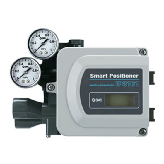
Introduction IP8101 smart positioner is mounted on a pneumatic rotary type actuator to receive a 2-wire 4 to 20mA DC input current from an adjusting meter, to operate a pneumatic pilot valve and to control motion of the pneumatic actuator by electronic control feedback. Also, it has setting parameters which can optionally change the relation between the input current and actuator opening.
-
Page 7
Table 2. Specifications of options Model Item IP8101-0*2-* 52-IP8101-0*4-*-M * Alarm output1, 2 Wiring method 2 wire system Corresponding standard DIN19234/NAMUR Standard Power supply voltage 10~28VDC 5~28VDC * Load current 10~40mADC (Constant Current) ≧2.1mADC Signal status High (Not Active) R=350Ω±10% *… -
Page 8: Parameter Settings List
Parameter Settings List The IP8101 smart positioner operates at settings suitable for various applications by changing * the setting parameters . Table 3 shows the main positioner functions which can be changed. For details of the setting parameters, refer to “■Parameter Code Detail”. Table 3 Setting parameters Description…
-
Page 9: Workflow Of Ip8101 Positioner Setup
Workflow of IP8101 Positioner Setup The workflow of IP8101 smart positioner from setup to initial adjustment is shown below. Follow this flow when performing setups and adjustments of the positioner. Start setup Check Check the specification and ensure the positioner is specifications suitable for the connected actuator and application.
-
Page 10: Operating Principle
Operating Principle When the input current (4 to 20mADC) increases, the current which is applied to the coil of the torque motor (12) through the input, operation and output processing circuits (8) changes, causing the armature (13) to start rotating with the fulcrum of the leaf spring (11). Along with this, a gap is created between nozzle (6) and flapper (5), and nozzle back pressure decreases.
-
Page 11: Mounting
Mounting Warning 1. Confirm the positioner is securely and firmly mounted onto the actuator. 2. Be careful not to get a finger caught when matching mounting positions. Caution 1. Be sure to keep the necessary space available for maintenance work (piping, wiring, adjustment, etc.) in your setup location.
-
Page 12: Connection With Feedback Shaft
■Connection with Feedback Shaft (1) Screw in a fork lever-type fitting to the major shaft of actuator and adjust its height to avoid Positioner body interference with the fork pin unit. (2) Adjust the angle of the fork lever-type fitting Fork pin unit to avoid interference with the positioner body (P368010-23)
-
Page 13: Fork Lever-Type Fitting
■Fork Lever-Type Fitting Since the IP8101 has two means of being mounted, two different kinds of fork lever-type fittings are provided, which are mounted in different ways, depending on the bracket mounting method. Table 4 Description Part no. Fork lever-type fitting M P368010-24 Fork lever-type fitting S P368010-25…
-
Page 14: Piping
Piping Warning Do not touch near the actuator axis when supplying air after piping. Caution 1. Perform sufficient pipe flushing and remove cutting chips, oil and dust from the piping to prevent foreign matter from entering the positioner. 2. When connecting an SMC fitting to an air connection port (SUP, OUT1, OUT2), apply a tightening torque of 12 to 14Nm.
-
Page 15: Piping Layout
■Piping Layout Table 6 No.DIG-31900-OM002…
-
Page 16: Electrical Wiring
Electrical Wiring Warning 1. Be sure to perform electrical wiring with the input current turned off. 2. Be sure to use a ground terminal and perform electrical construction following relevant local regulations. 3. Do not touch around the actuator axis when applying an input current after electrical wiring. 4.
-
Page 17: Electrical Wiring
■Electrical Wiring Input current Terminal No. Power supply Load voltage A Power supply voltage Load Power supply voltage Load Fig. 11 Table 7 Terminal no. Description Electric wire diameter Remarks 2 4 to 20mA DC It corresponds to the 0.14~1.5mm Minimum input current of 3.85mA DC is required for operation.
-
Page 18: Atex Intrinsic Safety Type Of Explosion Protected Construction 17 C
ATEX Intrinsic Safety Type of Explosion Protected Construction Warning 1. A positioner must be energized only after wiring via a barrier. 2. Use a linear resistance type barrier based on intrinsically safe parameter for the input circuit. 3. If a positioner is used as intrinsic safety type of explosion protected construction for ATEX, connect it only to the intrinsically safety electric circuit with the following maximum value.
-
Page 19: Barrier
Hazardous area Non-hazardous area Controller Positioner Input current Barrier Actuator Option output power supply Fig. 12 Cable gland M20×1.5 Input current Analog output Alarm output Grounding M4 screw for internal grounding terminal connection Terminal lug (uses twisted wire of 2.63~6.64mm Fig.
-
Page 20: Description Of Components
Description of Components Fig.14 shows a description of each component. Board cover HART terminal LCD display Input current terminal (Hold down together) Analog output Set button terminal Alarm output UP button terminal Ground terminal Torque motor DOWN button terminal Potentiometer terminal Mode button Fig.
-
Page 21: Initial Adjustment
Initial Adjustment Warning Pay attention to your surroundings when performing the initial adjustment because it causes the positioner to automatically move the actuator. ■Change of Parameters for Initial Operation * , the LCD shows “Not When an input current of 4 to 20mA DC is initially applied after purchasing calibrated”…
-
Page 22: Adjustment Of Fork Lever-Type Fitting Angle
Procedure Select the parameter used in section 2 to 6 by pressing the Down or Up button ( ) and holding down the set button ( ) for + 1sec or longer. Adjust the angle of the fork lever-type fitting connected to the 2.
-
Page 23
4: The positioner standard stroke is a rotational angle of 60 to 100 Actuators with a rotating angle of less than 60 or over 100 are not available. 5: A Description of pressure gauges mounted on the positioner are as shown in Fig. -
Page 24: Simple Balance Current Adjustment
3. Simple balance Adjust the torque motor balance current simply. current adjustment Procedure Press the Down or Up button ) in calibration mode to select zero adjust (0AdJ), and then hold down the set button ( + for 1sec. or longer. The LCD displays go (Go) for confirmation.
-
Page 25: Calibration
4. Calibration Automatically perform zero point / span adjustment and PID * constant Procedure Press the Down or Up button ) in calibration mode to select calibration (CAL), and press and hold down the set button + ) for 1 sec. or longer. The LCD displays go (Go) for confirmation.
-
Page 26
Readjust according to the following procedure if the LCD dose not display good (Good) after the adjustment, which means it has not been performed correctly. * <LCD displays high (HI) or low (Lo) > Procedure When the LCD displays high (HI) or (Lo), rotate balance… -
Page 27: Input Current Calibration
5. Input current calibration Normally, input current dose not need to be calibrated. If input values (S value) have a displacement in auto mode after the above adjustment, input current of 4 to 20mA DC can be calibrated. Procedure Press the Down or Up button ) in calibration mode to select signal-zero (S-O).
-
Page 28: Mode Change On Lcd
Mode Change on LCD ■Mode Change According to Fig. 20, press the mode button ( ), UP button ( ), DOWN button ( ) and set )to change operation mode. + button( ■Parameter Functioning in Manual Mode For the position indication (P value), zero / span setting (parameter code: 400) functions as it is. ■Reflection of Changed Content in Parameter mode The changed content is reflected at the time when the mode moves from parameter to manual, and *…
-
Page 29: Auto Mode Operation
Auto Mode Operation ■Auto Mode Use an auto mode if controlling an actuator by an input current as a smart positioner. ■Display Switching Method at Auto Mode * LCD display can be switched as follows according to Fig. 21 with the auto mode △…
-
Page 30: Setting Parameters
Setting Parameters ■Parameter Code (1) When an input current is entered for the first time, only the parameter mode can be selected. According to “■Initial Adjustment”, calibrate the positioner. (2) After (1), the auto mode is displayed first when an input current is entered. (3) The parameter code is shown in Fig.
-
Page 31: Parameter Code Detail
■Parameter Code Detail (000) Actuator type Displays “rotary (rtry)”. This parameter is fixed when shipped, and cannot be modified. (200) Operation direction “Direct * (dir)” or “Reverse * (rvS)” can be selected. The default when shipped is “direct (dir)”. setting 100% 200=dir 200=rvS…
-
Page 32
The split range can be selected by setting ON or OFF. The default (300) Split range setting when shipped is OFF. If ON is selected, the lower limit (310) (input current range between 0.0 and 80.0%) and the upper limit (320) (input current range between 40.0 to 125.0%) can be set. -
Page 33
(400) Zero point / span setting The zero point / span setting can be selected by setting ON or OFF. The default when shipped is OFF. If ON is selected, the lower limit (410) (stroke range between -20.0 and 60.0%) and the upper limit (420) (stroke range between 40.0 to 120.0%) can be set. -
Page 34
The forced fully-closed / fully-open operation can be selected by (500) Forced fully-close/ setting ON or OFF. The default at shipping is ON. If ON is * fully-open setting selected, the fully-closed setting (510) (input current range between -0.0 and 10.0%) and the fully-open setting (520) (input current range between 90.0 to 100.0%) can be set. -
Page 35
Valve opening characteristic can be selected from the following. (700) Valve opening (700) = Lin Linear characteristics setting (710) = EP25 Equal percentage 1:25 (R=25) Y=(R -0.04)×1/0.96 (720) = EP50 Equal percentage 1:50 (R=50) Y=(R -0.02)×1/0.98 (730) = qo25 Quick opening 25:1 (R=25) Y=(1-R )×1/0.96 (740) = qo50… -
Page 36
* (800) PID constant setting PID constant setting is available . Moreover, PID constant can have simple adjustment with 21 steps. The simply adjusted PID constant will change against the detail setting in the rate shown on * Table 12 . -
Page 37
* Alarm 1 can be selected by setting ON or OFF. The default at (900) Alarm 1 setting shipping is OFF. In addition, an alarm can be selected from the following with ON selected. Lower limit alarm (Lo) (910) = Upper limit alarm (UP) The default value at shipping is the lower limit alarm (Lo). -
Page 38
Alarm output operation Alarm mode 0.5% fixed Upper alarm (UP) Position value Set value for alarm 100% 0.5% fixed Lower alarm (Lo) Position value Set value for alarm Fig. 30 “Proportional output (inC)” or “Reversed output (dEC)” can be * (b00) Analog output setting selected. -
Page 39
The following can be performed: angle adjustment for a fork lever (C00) Calibration (AnGL), balance current adjustment (0AdJ), automatic calibration (CAL), input current adjustment (S-0) & (S-F), confirmation of balance current (bAL), and span adjustment (SPn). (C10) Angle adjustment A mounting angle of a fork lever-type fitting can be adjusted. Referring to the LCD indication, the fully-closed position / fully-open position of an actuator should be adjusted to be between -60 to 60. -
Page 40: How To Change Values
■How to Change Values Flashing Flashing The flashing digit can be changed. One-press on the mode button ( ) can △ button: to increase a value move the flashing digit to the next on the ▽ button: to decrease a value left.
-
Page 41: Parameter Setting Procedure
■Parameter Setting Procedure This parameter is fixed when shipped out of the factory. User can (000) Actuator type not change it. (200) Operation direction Customer can select direct (dir) or reverse (rvs). setting Procedure LCD display Hold down the set button ( +…
-
Page 42
Procedure LCD display <Hereafter, only when (on) is set> For lower limit setting with (310), + hold down set button ( ) for 1sec. or more. After value starts flashing, change value within the range of 0.0 to 80.0%. After changing, hold down mode button ( ) for 1sec. -
Page 43
Possible to select zero point / span mode (on) and non-zero point / (400) Zero point / span setting span mode (oFF), also change the set value during zero point / span mode. Procedure LCD display + Hold down set button ( ) for 1sec. -
Page 44
Mode button Set button ) ≧1s ) ≧1s + ( ( Mode button Set button ) ≧1s ) ≧1s + ( ( Mode button Mode button Set button Set button ) ≧1s ) ≧1s ) ≧1s ) ≧1s + + (… -
Page 45
Procedure LCD display Hold down Down or Up button ). As clause 4 above, change the upper limit with (520) within the range of 90.0 to 100.0%. After changing, hold down mode button ( ) to set the value. Hold down the mode button ( ) for 1sec. -
Page 46
Mode button Set button ) ≧1s ) ≧1s + ( ( Mode button Set button ) ≧1s ) ≧1s + ( ( Dead band setting Fig. 38 (700) Valve opening Valve opening characteristic can be set. The characteristic is plotted by 11 points as specified by user. characteristic setting Procedure LCD display… -
Page 47
Procedure LCD display Hold down Down or Up button ) to set remaining 10 inputs as in clause 4. Hold down the mode button ( ) for 1sec. or longer. Hold down again for 1sec. or longer after interval. Set button )… -
Page 48
Set button Set button ) ≧1s ) ≧1s + + ( ( 0% position setting (%) Mode button Mode button ≧1s ) ≧1s ( ) ( 10% position setting (%) 20% position setting (%) 30% position setting (%) 40% position setting (%) 50% position setting (%) -
Page 49
(800) PID constant setting PID constant setting is possible. Direct direction (Dir) and reverse direction (ruS) are settable individually. Easy adjusting is also possible. For adjustment, see “■Improved controllability”. < (810/820) PID constant of Although PID constant is automatically adjusted during span adjustment, direct direction (Dir) and reverse direction (ruS) are detail setting >… -
Page 50
< (830) Easy adjustment Possible to change PID constant. Setting has to be zero if adjustment of PID constant> is not necessary. Procedure LCD display Hold down set button ( + ) for 1sec. or longer to start parameter change mode. Select easy (EASy) by Down or Up button (… -
Page 51
Mode button Set button ≧1s ≧1s ( ) ( ) + Mode button Set button ≧1s ≧1s ( ) ( ) + P constant I constant D constant Fig. 40-1 Mode button Set button ≧1s ≧1s ( ) ( ) +… -
Page 52
Possible to select set alarm 1 mode (on), non-alarm mode (oFF), and (900) Alarm 1 setting change the set value if alarm 1 mode is selected. Procedure LCD display 1 Hold down the set button ( + 1sec. longer start parameter change mode. -
Page 53
Mode button Set button ≧1s ≧1s ( ) ( ) + Mode button Set button ≧1s ≧1s ( ) ( ) + Mode button Mode button Set button Set button ≧1s ≧1s ≧1s ≧1s ( ) ( ) ( ) (… -
Page 54
Possible to select set alarm 2 mode(on), non-alarm mode(oFF), and (A00) Alarm 2 setting change the set value if alarm 2 mode is selected. Procedure LCD display 1 Hold down the set button ( + 1sec. longer start parameter change mode. 2… -
Page 55
Mode button Set button ≧1s ≧1s ( ) ( ) + Mode button Set button ≧1s ≧1s ( ) ( ) + Mode button Mode button Set button Set button ≧1s ≧1s ≧1s ≧1s ( ) ( ) ( ) (… -
Page 56
Possible to select analog output proportional output (inC) and (b00) Analog output setting reversed output (dEC). Procedure LCD display Hold down the set button ( + 1sec. longer start parameter change mode. Select proportional output (inC) or reversed output (dEC) by Down or ). -
Page 57
<(C40/C50) Input current 4mADC and 20mADC of input current can be calibrated. This is not necessary usually. * calibration > 21: For adjustment procedure, see “5. Input current calibration” of “■Initial Adjustment”. <(C60) Balance current Check the torque motor balance current adjustment condition. If adjustment is good (Good), balance current is correctly *… -
Page 58
* < (C70) Span adjustment > Adjust zero point / span. Unlike automatic calibration of (C30), PID constant automatic setting is not performed. PID set once remains valid. This function is used when only zero-span adjustment is necessary. Procedure LCD display Hold down Down or Up button ) at calibration mode to select span (SPn). -
Page 59
Set button Set button ≧1s ≧1s ( ) ( ) + + Angle I adjustment Mode button Mode button ≧1s ≧1s ( ) ( ) Simple balance current adjustment Span adjustment + PID adjustment Input current Calibration (4mADC) Input current Calibration (20mADC) Balance current… -
Page 60
Mode button Set button ≧1s ≧1s ( ) ( ) + Set button ≧1s ( ) + Normal end *See fig. 44 for details After balance Current adjustment Balance current being evaluated Set button ≧1s ( ) + Balance current readjustment Fig. -
Page 61
Mode button Set button ≧1s ≧1s ( ) ( ) + Readjustment necessary Set button Normal end ≧1s ( ) + Set button ≧1s ( ) + Error Fig. 44-5 Mode button Set button ≧1s ≧1s ( ) ( ) +… -
Page 62
Normal end Button operation Balance current Being adjusted readjustment necessary Hunching occurred Operation failed (Not completed) Set button ≧1s ( ) + Fig. 45 Balance current 2sec. later Button operation readjustment Set button Set button ≧1s ≧1s ( ) ( )… -
Page 63
Automatic PID constant reduction Hunting not Hunting converged converged Button Balance current Set button operation 2sec. later ≧1s readjustment ( ) + Forced escape (Adjustment not completed) Set button Set button Set button ≧1s ≧1s ≧1s ( ) ( ) (… -
Page 64: Parameter Setting Default Value List
■Parameter Setting Default Value List Table 13 shows the parameter default values set at shipment. Please refer the table below when you repeat setting change and want to default the setting. Table13 Parameter Set items Setting Parameter item Details Status Set value 1 Set value 2 assigned…
-
Page 65: Operation Procedure Panel On Pcb Cover
■Operation Procedure Panel on PCB Cover As Fig. 46 shows, on PCB cover, the operation flow from “000 Actuator type” to “C00 Calibration” is described in simplified form for customer’s reference. For details of each parameter setting, see “■Parameter Code Detail” in this operation manual.
-
Page 66: Scale Plate Adjustment
Scale Plate Adjustment Caution (1) Attention should be taken not to have finger caught between the indicator and scale plate during position adjustment of the scale plate. (2) Scale plate edge is sharp. Attention should be taken. (1) After adjusting the positioner zero/span, mount the scale plate to DA surface (Direct operation) or RA (Reversed operation) in correct direction (See Fig.
-
Page 67: Maintenance And Check
Maintenance and Check Warning ① After installation, repair and disassembling, connect compressed air and perform a proper function test and leak test. If bleed noise is louder than the initial state or operation is abnormal, stop operation and check if installation is proper or not. Modification of electrical construction is prohibited due to maintaining Explosion-Protected construction function.
-
Page 68: Caution On Handling
Caution on Handling ■Operation Warning ① If the system is supposed to be in danger because of failure of the positioner, prepare the system with a safety circuit to avoid danger. ② Do not place electrical wiring in hazardous places while energized. Caution ①…
-
Page 69: Handling
■Handling Caution ① Avoid giving impact to the body and torque motor of positioner, and giving excessive force to armature because it leads to failure. Handle with care during transport and operation. ② When the positioner is used in places subject to vibrations, it is recommended that a tie wrap be used to prevent the lead wires from breaking.
-
Page 70: Troubleshooting, Error Code And Check Code
Troubleshooting, Error Code and Check Code ■Troubleshooting If the positioner malfunctions, take countermeasures in accordance with the troubleshooting measures listed in Table 15. Table 15 Reference Error Possible cause Countermeasure page — Input current is disconnected. -Check that wires are connected to No LCD display 15,16 the positioner.
-
Page 71
Error Possible cause Countermeasure Reference page — Input current resolution is faulty. — Check the input current system. Low sensing 5, 15 -Actuator’s sliding resistance is -Reduce the sliding resistance to as large. little as possible. -Operate only the actuator and check the stick-slip movement. -
Page 72: Error Code List
■Error Code List Table 16 shows errors detected while the positioner is being adjusted. When errors are detected during adjustment, adjust the settings again in accordance with the countermeasure. Once an error has been detected, it is possible to reset it to the mode before the detection with the +…
-
Page 73: Check Code List
Error No. Error Possible cause Countermeasure Failed adjustment of The balance current has not been -Adjust the balance adjusting screw balance current adjusted to be good (Good), but to correct the balance current (See 0003 the positioner has been set after Fig.
-
Page 74: How To Order
How to Order For ATEX ATEX Temp. class Construction Intrinsically safe explosion-protected ATEX Category1 (ATEX) + output function + HART communication function T5/T6 For CE marking 52-IP8101-0 3 4- * -* - * IP8101-0 3 *- * -* - * For CE marking Connection Type…
-
Page 75: Drawing
Drawing No.DIG-31900-OM002…
-
Page 76
No.DIG-31900-OM002… -
Page 77
No.DIG-31900-OM002… -
Page 78
No.DIG-31900-OM002… -
Page 79
No.DIG-31900-OM002… -
Page 80
No.DIG-31900-OM002… -
Page 81
No.DIG-31900-OM002… -
Page 82
No.DIG-31900-OM002… -
Page 83
No.DIG-31900-OM002… -
Page 84
No.DIG-31900-OM002… -
Page 85
Revision history A ’05.09.26 Address change B ’06.03.30 Add the “How to Operation” C ’06.11.28 Add the ATEX item D ’07.08.28 Change the temp. range E ’08.07.30 Change the “How to order” by adding the kind of screw F ’09.10.27 Change of “Compressed Air Cleaning Equipment”+ Add the ”Electric wire diameter”…
- Home
- Brands
- SMC Networks
- Valve Positioners
- IP8101 Series
- Operation Manual
Manual for SMC Networks IP8101 Series Valve Positioners (85 pages)
Specifications:
|
SMC Networks IP8101 Series: Read PDF Manual Online
Accompanying Data:
SMC Networks IP8101 Series Valve Positioners PDF Operation Manual (Updated: Monday 5th of December 2022 10:55:46 PM)
Rating: 4.8 (rated by 33 users)
Compatible devices: IP8000-0 Series, 2T456Z, IP8001 Series, BIP ED2-B 03-S75 Series, Chryssafidis P8001 Series, IP8100-0 1 X83 Series, SR-3300, IP8000.
Recommended Documentation:
SMC Networks IP8101 Series: Text of Operation Manual
(Ocr-Read Version Summary of Contents, UPD: 05 December 2022)
-
18, No.DIG-31900-OM002 17 ATEX Intrinsic Safety Type of Explosion Protected Construction 1. A positioner must be energized only after wiring via a barrier. 2. Use a linear resistance type barrier based on intrinsically safe parameter for the input circuit. 3. If a positioner is used as intrinsic safety type of explosion protected construction for …
-
71, No.DIG-31900-OM002 70 Error Possible cause Countermeasure Reference page Low sensing — Input current resolution is faulty. — Check the input current system. 5, 15 -Actuator’s sliding resistance is large. -Reduce the sliding resistance to as little as possible. -Operate only the actuator and check the stick-slip m…
-
48, No.DIG-31900-OM002 47 A or or or or or or or or or or or Mode button ( ) ≧1s Set button + ( ) ≧1s Mode button ( ) ≧1s Set button + ( ) ≧1s 50% position setting (%) 60% position setting (%) 70% position se…
-
65, No.DIG-31900-OM002 64 ■Operation Procedure Panel on PCB Cover As Fig. 46 shows, on PCB cover, the operation flow from “000 Actuator type” to “C00 Calibration” is described in simplified form for customer’s reference. For details of each parameter setting, see “■Parameter Code Detail” in this operation manual. Keep the manual accessible for re…
-
5, No.DIG-31900-OM002 4 Safety Instructions Caution 1.The product is provided for use in manufacturing industries. The product herein described is basically provided for peaceful use in manufacturing industries. If considering using the product in other industries, consult SMC beforehand and exchange specifications or a contract if necessary. If anythin…
-
29, No.DIG-31900-OM002 28 Auto Mode Operation ■Auto Mode Use an auto mode if controlling an actuator by an input current as a smart positioner. ■Display Switching Method at Auto Mode LCD display can be switched as follows according to Fig. 21 with the auto mode * 1 . Manual Mode Operation As it is shown in …
-
38, No.DIG-31900-OM002 37 (b00) Analog output setting * 14 “Proportional output (inC)” or “Reversed output (dEC)” can be selected. When proportional output (inC) is selected, analog output will increase along with the increase of an actuator�…
-
31, No.DIG-31900-OM002 30 ■Parameter Code Detail (000) Actuator type (200) Operation direction setting Displays “rotary (rtry)”. This parameter is fixed when shipped, and cannot be modified. “Direct * 3 (dir)” or “Reverse * 4 (rvS)” can be selected. The default wh…
-
1, No. DIG-31900-OM002-H SMART POSITIONER (ROTARY TYPE) PRODUCT NAME IP8101 Series MODEL/ Series
… -
3, No.DIG-31900-OM002 2 Mode Change 27 Parameter Functioning in Manual Mode 27 Reflection of Changed Content in Parameter Mode 27 Auto Mode Operation 28 Auto Mode 28 Display Switching Method in Auto Mode 28 Manual Mode Operation 28 Setting Parameters 29 Parameter Code 29 Parameter Code Detail 30 How to Change Values 39 Param…
-
26, No.DIG-31900-OM002 25 <Hunting occurs> Procedure LCD 1 If hunching occurs during adjustment, the PID constant is adjusted to automatically eliminate it. 2 After hunting has been eliminated, automatically check the balance current. 3 If the LCD d…
-
14, No.DIG-31900-OM002 13 Piping Do not touch near the actuator axis when supplying air after piping. 1. Perform sufficient pipe flushing and remove cutting chips, oil and dust from the piping to prevent foreign matter from entering the positioner. 2. When connecting an SMC fitting to an air connection port (SUP, OUT1, OUT2), apply a tig…
DOC-381acb87:
SMC Networks IP8101 Series: Recommended Instructions
OM10005, M54-00013 — Optical Desktop Elite, Microline 182, CM4000, 1/2″ IMPACT WRENCH KIT 690163, DTH2450


-
IP80X14-TFJ21GB-BInstallation and Maintenance ManualIP8000/IP8100 0#0 — # — X14 — LElectropneumatic Positioner1 Safety Instructions• This manual contains essential information for the protection of usersand others from possible injury and/or equipment damage.• Read this manual before using the product, to ensure correct handling,and read the manuals of related apparatus before use.• Kee …
IP8000 2
-
KIT INSTALLATION INSTRUCTIONSiemens Industry, Inc. BRACKET KIT PN TGX:16152-1280 15900-796 Rev. 1 June, 2015 SIPART PS2 Mounting Bracket Kit for ASAHI Actuator, Type 14 This publication provides installation instructions to mount a Siemens SIPART PS2 valve positioner on an Asahi type 14 valve actuator and to install the mechanical feedback linkage, typical installation shown in Figur …
SIPART PS2 9
-
Manual ElectronicsCPX analogue I/O modulesI/O modules CPX−2AE−U−I CPX−4AE−I CPX−4AE−T CPX−4AE−TC CPX−4AE−P CPX−2AA−U−ISub−bases CPX−AB−… CPX−M−…CPX TerminalManual526 416en 0906e[746 679] …
CPX Series 308
-
1. Installation DPT-D series actuators are high precision instruments with sub-nanometre resolution and stability. They require careful handling and must not be dropped or subjected to unnecessary torque on installation (see section 3). 1.1 Mounting into a system The DPT-D series of actuators can be mounted by means of an M3 screw requiring 3mm maximum of th …
Queensgate DPT-D Series 2
-
Electro-Pneumatic Positioner YT-1000L Installation manual Installation Safety Warning When installing positioner, please ensure to read and follow safety instruction. All input and supply pressure to valve, actuator, and other related devices must be turned off. Use bypass valve or other equipment to avoid entire system «shut down.» Make sure there is no re …
YT-1000L 3
-
deutsch Betriebsanleitung english User’s guide français Notice d’utilisation italiano Manuale d’uso español Manual de instrucciones 中文 使用说明书 日本語 取扱説明書BIPLD2-T017-04-BP __BIPLD2-T017-04-BP __ -S4 …
BIP LD2-T017-04-BP S4 Series 142
-
Assembly instruction and declaration in accordance with the Machinery Directive 95/16/EC PSD4xx positioning system halstrup-walcher GmbH Stegener Straße 10 79199 Kirchzarten Tel. +49 7661 39 63-0 [email protected] www.halstrup-walcher.com © 30.06.2021, Kö 7100.006394_Assembly instruction_PSD4xx_F_EN PSD4xx positioning system The PSD4xx positioning system is an integrated …
PSD4 Series 6
-
DRAW WIRE SENSORContent:Introduction ….2Technical Data ….3Technical Drawing ….4Installation ….6Accessories ….8Order Code ….8Series SX300Key-Features: — Measurement range up to 15 m — Pressure-sealed up to 300 bar — Output signals: SSI, CANopen, Probus, EtherCAT, Pronet, further on request — Alternative draw wire mechanics for encoder installation — Unpressuris …
SX300 Series 8
-
— ABB MEASUREMENT & ANALYTICS | COMMISSIONING INSTRUCTION TZIDC, TZIDC-110, TZIDC-120 Digital Positioner — ABB Limited Measurement & Analytics Howard Road, St. Neots Cambridgeshire, PE19 8EU UK Tel: +44 (0)870 600 6122 Fax: +44 (0)1480 213 339 Email: [email protected] ABB Automation Products GmbH Measurement & Analytics Schillerstr. 72 32425 Min …
TZIDC 60
-
TROVIS3730-1 Electropneumatic PositionerThis quick guide does not replace the mounting and operating ins-tructions supplied with the positioner. Observe the safety instructions as well as the warning and caution notes specied in the mounting and operating instructions.1 MountingDirect attachment to SAMSON Type3277 ActuatorTravel [mm] Actuator [cm²] Lever …
3730-1 2
Additional Information:
Popular Right Now:
Operating Impressions, Questions and Answers:
-
Contents
-
Table of Contents
-
Troubleshooting
-
Bookmarks
Table of Contents
Table of Contents
Initial Adjustment
1
3
5
5
7
8
9
9
10
10
11
12
12
13
13
14
15
15
15
15
16
17
17
17
17
18
19
19
20
20
20
20
21
23
24
26
27
No.DIG-31900-OM002