-
#1
Yamaha Snowmobile Repair Manual 97 — 02.
Подробное руководство по ремонту и регулировкам снегоходов Yamaha 1997-2002 г.
Модели MM600,MM700,SX600,SX700,VT600,VT700,VX600,VX700
На английском.
283 страницы подробной информации с фото и схемами.
Файл PDF, объем 15 МБ. WINRAR-архив из двух частей.
Скачивать обе части архива (part1,part2) в одну папку,потом распаковать обычным порядком.
Есть еще такое же руководство и каталог запчастей по Yamaha Bravo 250T.
Если кому-то будет нужно — пишите в «личку».
-
7,2 MB
Просмотры: 2.116 -
6,1 MB
Просмотры: 1.632
-
#2
Отсканированные эл.схемы из Yamaha Snowmobile Repair Manual 97 — 02
(Чтобы весь файл не качать,если только схема нужна)  ;)")
Две типовые схемы- с эл. стартером и без эл.стартера.
(См. Стр. 272-275 Repair Manual)
-
826,7 KB
Просмотры: 906
-
#4
gemeny написал(а):
Нет никаких паролей там 
Обе части мануала скачиваете в одну папку, распаковываете WINRARом…
Схемы тоже открываются- только что проверил.
 Loading…
![]()
SNOWMOBILE
OWNER’S MANUAL
SX600H
VT600H
VX600ERH
|
LIT-12628-02-25 |
8DG-28199-14 |

ESU00286
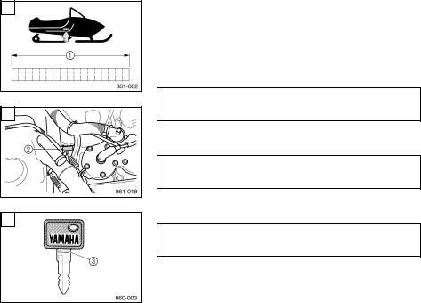
MACHINE IDENTIFICATION
Identification number records
A.FRAME NUMBER:
B.ENGINE NUMBER (PRIMARY ID):
C.KEY NUMBER:
Record the frame number, engine number (Primary ID), and key number in the spaces provided for assistance when ordering spare parts from a Yamaha dealer.
1 The frame number is the seventeen-digit number stamped on the frame of the snowmobile. (See fig. È.)
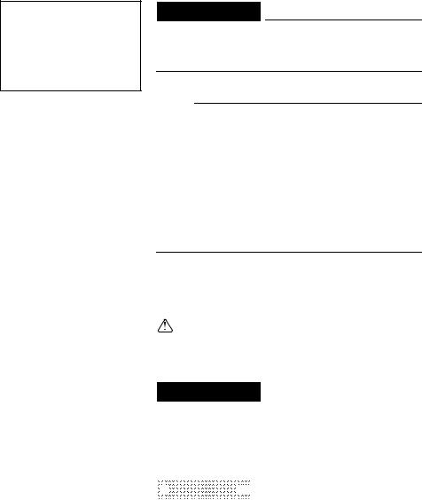
2 The engine number is stamped in the location as shown. (See fig. É.)
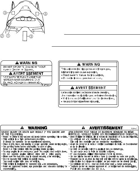
3 Key number (See fig. Ê.)
Also, record and keep the ID numbers in a separate place in case the snowmobile is stolen.

ESU00001
INTRODUCTION
Congratulations! Your choice of a Yamaha snowmobile assures you of the highest quality and dependability. Your Yamaha snowmobile is manufactured by a company well-known for excellence in the field of snowmobiles. The most advanced production equipment and technology have made Yamaha one of the best snowmobile manufacturers. We are confident that this snowmobile will meet the greatest expectations of our customers. This manual is designed to acquaint you with the operation of this snowmobile and minor maintenance required for satisfactory service.
Should major repairs ever be required, you are advised to ask a Yamaha dealer to inspect and repair the snowmobile whenever it is necessary; they have the techniques, tools, and parts to ensure your satisfaction. We hope that the information within this manual will help you enjoy many hours of pleasure with your Yamaha snowmobile.
SX600H
VT600H
VX600ERH
OWNER’S MANUAL
© 2002 by Yamaha Motor Corporation, U.S.A. 1st Edition, March 2002
All rights reserved.
Any reprinting or unauthorized use without the written permission of Yamaha Motor Corporation, U.S.A. is expressly prohibited.
Printed in Japan
P/N LIT-12628-02-25
 WARNING
PLEASE READ AND UNDERSTAND THIS MANUAL COMPLETELY BEFORE OPERATING THE SNOWMOBILE.
NOTE:
●Yamaha continually seeks advancements in product design and quality. Therefore, while this manual contains the most current product information available at the time of printing, there may be minor discrepancies between your snowmobile and this manual. If there is any question concerning this manual, please consult a Yamaha dealer.
●This manual should be considered a permanent part of this snowmobile and should remain with the snowmobile when resold.
Particularly important information is distinguished in this manual by the following notations.
The Safety Alert Symbol means ATTENTION! BECOME ALERT! YOUR SAFETY IS INVOLVED!
 WARNING
Failure to follow WARNING instructions could result in severe injury or death to the snowmobile operator, a bystander, or a person inspecting or repairing the snowmobile.


 CAUTION
 :
:


@
A CAUTION indicates special precautions that must be taken to avoid damage to the snowmobile.
NOTE:
A NOTE provides key information to make procedures easier or clearer.
|
YAMAHA MOTOR |
|
|
CORPORATION, U.S.A. |
|
|
SNOWMOBILE LIMITED |
|
|
WARRANTY ………………………………… |
1-1 |
|
YAMAHA EXTENDED SERVICE |
|
|
(Y.E.S.) ……………………………………….. |
1-4 |
|
LOCATION OF THE |
|
|
IMPORTANT LABELS ………………….. |
2-1 |
|
SAFETY INFORMATION ………………. |
3-1 |
|
DESCRIPTION …………………………….. |
4-1 |
|
CONTROL FUNCTIONS ……………….. |
5-1 |
|
Main switch……………………………….. |
5-1 |
|
Starter lever (choke) …………………… |
5-2 |
|
Throttle lever……………………………… |
5-2 |
|
Throttle override system |
|
|
(T.O.R.S.) …………………………………. |
5-2 |
|
Oil level warning light………………….. |
5-3 |
|
Coolant temperature |
|
|
warning light ……………………………… |
5-4 |
|
Engine stop switch……………………… |
5-6 |
|
Brake lever ……………………………….. |
5-6 |
|
Parking brake lever…………………….. |
5-7 |
|
Shift lever………………………………….. |
5-7 |
|
Headlight beam switch ……………….. |
5-8 |
|
Grip warmer control knob ……………. |
5-8 |
|
Thumb warmer control knob………… |
5-8 |
|
Passenger grip warmer switch …….. |
5-9 |
|
Tripmeter reset knob ………………….. |
5-9 |
|
Shroud latches…………………………… |
5-9 |
|
Drive guard ……………………………… |
5-10 |
|
V-belt holders ………………………….. |
5-10 |
|
Spark plug holders……………………. |
5-10 |
|
Carburetor heating lever……………. |
5-10 |
|
Backrest………………………………….. |
5-11 |
|
Storage compartment ……………….. |
5-11 |
|
PRE-OPERATION CHECKS………….. |
6-1 |
|
Fuel …………………………………………. |
6-1 |
|
Engine oil………………………………….. |
6-2 |
|
Coolant …………………………………….. |
6-2 |
|
Throttle lever …………………………….. |
6-3 |
|
Recoil starter …………………………….. |
6-3 |
|
Throttle override system |
|
|
(T.O.R.S.) …………………………………. |
6-3 |
|
Brake ……………………………………….. |
6-4 |
|
Brake fluid leakage…………………….. |
6-5 |
|
V-belt ……………………………………….. |
6-5 |
|
Drive guard……………………………….. |
6-5 |
|
Drive track ………………………………… |
6-6 |
|
Slide runners …………………………….. |
6-6 |
|
Skis and ski runners …………………… |
6-7 |
|
Steering system…………………………. |
6-7 |
|
Lights……………………………………….. |
6-7 |
|
Battery ……………………………………… |
6-8 |
|
Air filter …………………………………….. |
6-8 |
|
Fittings and fasteners …………………. |
6-9 |
|
Tool kit and recommended |
|
|
equipment…………………………………. |
6-9 |
|
OPERATION ……………………………….. |
7-1 |
|
Starting the engine …………………….. |
7-1 |
|
Emergency engine starting………….. |
7-2 |
|
Break-in ……………………………………. |
7-4 |
|
Riding your snowmobile ……………… |
7-5 |
|
Getting to know your snowmobile … |
7-5 |
|
Learning to ride your snowmobile … |
7-5 |
|
To start out and accelerate………….. |
7-5 |
|
Braking …………………………………….. |
7-5 |
|
Turning …………………………………….. |
7-6 |
|
Riding uphill………………………………. |
7-6 |
|
Riding downhill ………………………….. |
7-7 |
|
Traversing a slope……………………… |
7-7 |
|
Ice or icy surface ……………………….. |
7-7 |
|
Hard-packed snow …………………….. |
7-8 |
|
Operation on surfaces other than |
|
|
snow or ice ……………………………….. |
7-8 |
|
Maximizing drive track life …………… |
7-9 |
|
Driving ……………………………………. |
7-10 |
|
Stopping the engine………………….. |
7-11 |
|
Transporting ……………………………. |
7-12 |
|
PERIODIC MAINTENANCE …………… |
8-1 |
|
Periodic maintenance chart …………. |
8-1 |
|
Tool kit ……………………………………… |
8-4 |
|
Spark plug inspection …………………. |
8-4 |
|
Engine idle speed adjustment ……… |
8-5 |
|
Throttle cable adjustment ……………. |
8-6 |
|
Oil pump cable adjustment ………….. |
8-6 |
|
Carburetor adjustment………………… |
8-7 |
|
High altitude adjustments ……………. |
8-9 |
|
Cooling system ………………………… |
8-10 |
|
V-belt replacement …………………… |
8-12 |
|
Checking the oil level of the drive |
|
|
chain housing ………………………….. |
8-15 |
|
Checking the brake pads…………… |
8-16 |
|
Checking the parking |
|
|
brake pads………………………………. |
8-16 |
|
Checking the brake fluid level…….. |
8-17 |
|
Brake fluid replacement…………….. |
8-18 |
|
Suspension……………………………… |
8-18 |
|
Drive track adjustment………………. |
8-23 |
|
Ski alignment …………………………… |
8-25 |
|
Handlebar adjustment ………………. |
8-26 |
|
Lubrication ………………………………. |
8-28 |
|
Headlight bulb replacement……….. |
8-29 |
|
Headlight beam adjustment……….. |
8-29 |
|
Battery ……………………………………. |
8-30 |
|
Fuse replacement…………………….. |
8-31 |
|
TROUBLESHOOTING ………………….. |
9-1 |
|
STORAGE …………………………………. |
10-1 |
|
SPECIFICATIONS………………………. |
11-1 |
|
Dimensions……………………………… |
11-1 |
|
Engine ……………………………………. |
11-1 |
|
Chassis…………………………………… |
11-1 |
|
Electric……………………………………. |
11-2 |
|
WIRING DIAGRAM …………………….. |
12-1 |

ESU00004
YAMAHA MOTOR CORPORATION, U.S.A.
SNOWMOBILE LIMITED WARRANTY
1-1

1-2

1-3
![]()
ESU00005
YAMAHA EXTENDED SERVICE (Y.E.S.)
1-4
ESU00007
LOCATION OF THE
IMPORTANT LABELS
Please read the following labels carefully before operating this snowmobile.
NOTE:
Maintain or replace safety and instruction labels, as necessary.
|
2 |
3 SX600 |
|||||||||||
1 SX600
2-1

2-2

ESU00009
SAFETY INFORMATION
When you ride your snowmobile, you must know and use the following for your safety. Severe injury or death may result if you ignore any of the following.
Before operating
1.Read the Owner’s Manual and all labels before operating this snowmobile. Become familiar with all of the operating controls and their function. Consult a Yamaha dealer about any control or function you do not understand.
2.This snowmobile was not manufactured for use on public streets, roads, or highways. Such use is prohibited by law, and you could collide with another vehicle.
3.SX600 and VX600ER are designed to carry the OPERATOR ONLY.
Passengers are prohibited. Carrying a passenger can cause loss of control.
4.Do not operate the snowmobile after drinking alcohol or taking drugs. Your ability to operate the snowmobile is reduced by the influence of alcohol or drugs.
5.For safety and proper care of the snowmobile, always perform the pre-operation checks on pages 6-1–6-9 before starting the engine. Check the throttle, brake, and steering for proper operation every time before starting the engine. Make sure that the throttle lever moves freely and it returns to the home position when it is released.
6.Apply the parking brake before starting the engine. Never drive the snowmobile with the parking brake applied. This may overheat the brake disc and reduce
braking ability.
3-1

7.Do not allow anyone to stand behind the snowmobile when starting, inspecting, or adjusting the snowmobile. A broken track, track fittings, or debris thrown by the track could be dangerous to the operator or bystanders.
8.Handle fuel with care; it is HIGHLY FLAMMABLE.
●Never add fuel when the engine is running or hot. Allow the engine to cool for several minutes after running.
●Use an approved fuel container.
●Fill the fuel tank outdoors with extreme care. Never remove the fuel cap indoors. Never fill the fuel tank indoors.
●Never refuel while smoking or in the vicinity of an open flame.
●Make sure that the fuel tank cap is closed securely after refueling. Wipe up any spilled fuel immediately.
9.If you swallow some gasoline, inhale a lot of gasoline vapor, or get some gasoline into your eyes, see your doctor immediately. If any gasoline spills on your skin or clothing, immediately wash your skin with soap and water, and change your clothes.
10.Wear protective clothing. Wear an approved helmet, and a face shield or goggles. Also, wear a good quality snowmobile suit, boots, and a pair of gloves or mittens that will permit use of your thumbs and fingers for operation of the controls.
Operation
1.Do not run the engine indoors, except when starting the engine to transport the snowmobile in or out of the building. Open the outside doors; exhaust fumes are dangerous.
2.Be careful where you ride. There may be obstacles hidden beneath the snow. Stay on established trails to minimize your exposure to hazards. Ride slowly and cautiously when you ride off of established trails. Hitting a rock or stump, or running into wires could cause an accident and injury.
3-2
3.This snowmobile is not designed for use on surfaces other than snow or ice. Use on dirt, sand, grass, rocks, or bare pavement may cause loss of control and may damage the snowmobile.
4.Avoid operating on glare ice, or on snow which has a lot of dirt or sand mixed in. Operation under such conditions will damage or result in rapid wear of ski runners, drive track, slide runners, and drive sprockets.
5.Always ride with other snowmobilers when going on a ride. You may need help if you run out of fuel, have an accident, or damage your snowmobile.
6.Many surfaces such as ice and hard-packed snow require much longer stopping distances. Be alert, plan ahead and begin decelerating early. The best braking method on most surfaces is to release the throttle and apply the brake gently—not suddenly.
Maintenance and storage
1.Do not leave the snowmobile on its left side for an extended period of time. Fuel may leak out from the fuel breather hose.
2.Modifications made to the snowmobile not approved by Yamaha, or the removal of original equipment may render your snowmobile unsafe for use that may cause severe personal injury. Modifications may also make the snowmobile illegal to use.
3.Never store the snowmobile with fuel in the fuel tank inside a building where ignition sources are present such as hot water and space heaters, an open flame, sparks, clothes dryers, and the like. Allow the engine to cool off before storing the snowmobile in an enclosed space.
4.Always refer to the “STORAGE” section if the snowmobile is to be stored for an extended period.
5.Maintain or replace safety and instruction labels, as necessary.
3-3
ESU00012
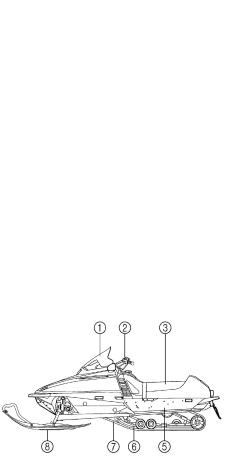
DESCRIPTION |
||
|
SX600 |
1 Windshield |
|
|
2 |
Steering handlebar |
|
|
3 |
Seat |
|
|
4 |
Passenger grip warmer switch (VT600) |
|
|
5 |
Frame |
|
|
6 |
Slide rail suspension |
|
|
7 |
Drive track |
|
|
8 |
Skis |
|
|
VT600 |
VX600ER
4-1
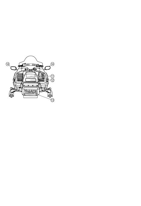
9 Headlight
0 Shroud
A Storage compartment B Tail/brake light
C Snow flap
D Side mirror (VT600 / VX600ER) E Brake lever
F Headlight beam switch G Parking brake lever
H Engine stop switch I Throttle lever
J Shift lever (VT600 / VX600ER) K Starter handle
L Shroud latch M Main switch N Starter lever
O Thumb warmer control knob P Grip warmer control knob Q Tripmeter
R Odometer
S Speedometer
T Tachometer
U Fuel meter
VT600
V Coolant temperature warning light W Oil level warning light
X High beam indicator light Y Tripmeter reset knob
4-2

ESU00013
CONTROL FUNCTIONS
ESU00256
Main switch
The main switch controls the following items.
1 “OFF”
The ignition circuit is switched off.
The key can be removed only in this position.
A2 “ON”
The ignition circuit is switched on. The engine can be started.
NOTE:
The headlight, meter lights, and taillight will come on after the engine starts.
|
B |
For VT600 / VX600ER |
|||
|
3 “START” |
||||
|
The starting circuit is switched on. |
||||
|
The starter motor starts. |
||||
|
CAUTION: |
||||
|
@ |
||||
|
Release the switch immediately after the engine |
||||
|
starts. |
||||
È SX600
É VT600 / VX600ER
5-1
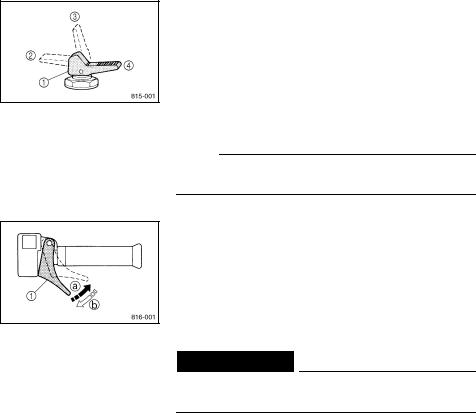
ESU00020
Starter lever (choke)
Use the starter lever (choke) when starting and warming up a cold engine.
1Starter lever (choke)
2When starting a cold engine.
3Warming up
4When the engine is warm.
NOTE:
Refer the “Starting the engine” section for proper operation.
ESU00022
Throttle lever
Once the engine is running cleanly, squeezing a the throttle lever 1 will increase the engine speed and cause engagement of the drive system. Regulate the speed of the snowmobile by varying the throttle position. Because the throttle is spring-loaded, the snowmobile will decelerate, and the engine will return to idle when it is released b.
 WARNING
Check the throttle, brake, and steering for proper operation before starting the engine.
ESU00023
Throttle override system (T.O.R.S.)
If the carburetor or throttle cable should malfunction during operation, the T.O.R.S. will operate when the throttle lever is released.
The T.O.R.S. is designed to interrupt the ignition and keep the engine revolution speed between 2,800 and 3,000 r/min if the carburetor fails to return to idle when the lever is released.
5-2
![]()
 WARNING
●If the T.O.R.S. is activated, make sure that the cause of the malfunction has been corrected and that the engine can be operated without a problem before restarting the engine.
●Be sure to use the specified spark plug and spark plug cap. Otherwise, the T.O.R.S. will not work properly.
|
A |
Idle |
B |
C |
||||
|
or |
Run |
Trouble |
|||||
|
starting |
|||||||
|
Throttle switch |
Off |
On |
Off |
||||
|
Carburetor switch |
On |
Off |
Off |
||||
|
Engine |
Run |
Run |
T.O.R.S. |
||||
|
will operate |
|||||||
È Idle or starting É Run
Ê Trouble
1Carburetor switch
2Throttle switch
3Throttle cable
4Throttle valve a On
b Off
ESU00026
Oil level warning light
If the oil level falls below the lower level, this light comes on.
If the light comes on, add engine oil to the oil tank at the first opportunity.
5-3
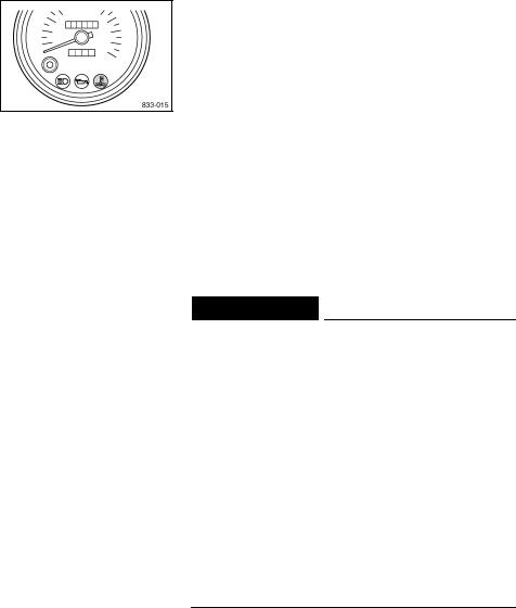
ESU00278
Coolant temperature warning light
This snowmobile is equipped with a self-diagnosis device which is able to detect a malfunctioning sensor, disconnected coupler, broken lead, abnormally high coolant temperature, etc.
The coolant temperature warning light warns the rider of the above problems by flashing or staying on. If necessary, ask a Yamaha dealer for further details. (See page 5-5 for warning light flash patterns.)
After the engine starts, this light flashes three times to check the bulb, and then goes off if there are no problems. (See page 5-5 for warning light flash pattern number 0.)
If it does not flash, have a Yamaha dealer inspect the electrical circuit.
 WARNING
●If the coolant temperature warning light flashes continually or stays on during operation, there may be some problem with the electrical circuit, lead couplers, or engine cooling system. (See page 5-5 for warning light flash pattern numbers 1–7.)
●Stop the engine and allow it to cool off. Then, check that the wire harness couplers are connected properly in the engine compartment and that the coolant level of the coolant reservoir is within the specified range. (See page 6-2.)
●If the coolant temperature warning light remains on after the engine has been started or if it flashes, note the flash pattern, and then have a Yamaha dealer inspect the snowmobile as soon as possible.
5-4
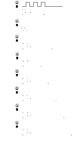
|
No. |
Coolant temperature warning light flash patterns |
||||||||||||||||||||||||||||||||||||||||||||
|
Light bulb check: |
|||||||||||||||||||||||||||||||||||||||||||||
|
0 |
0.5 s |
Light flashes three times, then |
|||||||||||||||||||||||||||||||||||||||||||
|
0.5 s |
3 s |
goes off. |
|||||||||||||||||||||||||||||||||||||||||||
|
· |
· · |
Engine overheat warning: |
|||||||||||||||||||||||||||||||||||||||||||
|
1 |
Light flashes continuously in this |
||||||||||||||||||||||||||||||||||||||||||||
|
0.25 s |
|||||||||||||||||||||||||||||||||||||||||||||
|
pattern. |
|||||||||||||||||||||||||||||||||||||||||||||
|
0.25 s |
|||||||||||||||||||||||||||||||||||||||||||||
|
· |
· |
Light flashes continuously in this |
|||||||||||||||||||||||||||||||||||||||||||
|
· |
|||||||||||||||||||||||||||||||||||||||||||||
|
2 |
pattern. |
||||||||||||||||||||||||||||||||||||||||||||
|
0.75 s |
|||||||||||||||||||||||||||||||||||||||||||||
|
0.25 s |
|||||||||||||||||||||||||||||||||||||||||||||
|
4 s |
|||||||||||||||||||||||||||||||||||||||||||||
|
· |
· |
· |
Light flashes continuously in this |
||||||||||||||||||||||||||||||||||||||||||
|
pattern. |
|||||||||||||||||||||||||||||||||||||||||||||
|
3 |
|||||||||||||||||||||||||||||||||||||||||||||
|
0.75 s |
|||||||||||||||||||||||||||||||||||||||||||||
|
2.5 s |
|||||||||||||||||||||||||||||||||||||||||||||
|
· |
· |
· |
Light flashes continuously in this |
||||||||||||||||||||||||||||||||||||||||||
|
pattern. |
|||||||||||||||||||||||||||||||||||||||||||||
|
4 |
|||||||||||||||||||||||||||||||||||||||||||||
|
0.75 s |
|||||||||||||||||||||||||||||||||||||||||||||
|
0.25 s |
|||||||||||||||||||||||||||||||||||||||||||||
|
3.5 s |
|||||||||||||||||||||||||||||||||||||||||||||
|
Light flashes continuously in this |
|||||||||||||||||||||||||||||||||||||||||||||
|
· · |
· |
||||||||||||||||||||||||||||||||||||||||||||
|
pattern. |
|||||||||||||||||||||||||||||||||||||||||||||
|
5 |
|||||||||||||||||||||||||||||||||||||||||||||
|
0.75 s |
|||||||||||||||||||||||||||||||||||||||||||||
|
0.25 s |
|||||||||||||||||||||||||||||||||||||||||||||
|
4.5 s |
|||||||||||||||||||||||||||||||||||||||||||||
|
Light flashes continuously in this |
|||||||||||||||||||||||||||||||||||||||||||||
|
· |
· · |
||||||||||||||||||||||||||||||||||||||||||||
|
pattern. |
|||||||||||||||||||||||||||||||||||||||||||||
|
6 |
|||||||||||||||||||||||||||||||||||||||||||||
|
0.75 s |
|||||||||||||||||||||||||||||||||||||||||||||
|
0.25 s |
|||||||||||||||||||||||||||||||||||||||||||||
|
5.5 s |
|||||||||||||||||||||||||||||||||||||||||||||
|
Light flashes continuously in this |
|||||||||||||||||||||||||||||||||||||||||||||
|
· |
· · |
||||||||||||||||||||||||||||||||||||||||||||
|
pattern. |
|||||||||||||||||||||||||||||||||||||||||||||
|
7 |
|||||||||||||||||||||||||||||||||||||||||||||
|
0.75 s |
|||||||||||||||||||||||||||||||||||||||||||||
|
0.25 s |
|||||||||||||||||||||||||||||||||||||||||||||
|
6.5 s |
|||||||||||||||||||||||||||||||||||||||||||||
|
: Warning light is on |
: Warning light is off |
s: Second |
5-5
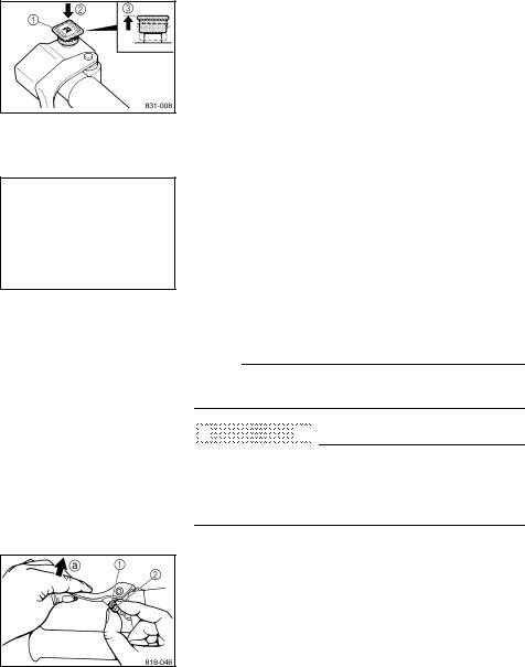
ESU00031
Engine stop switch
The engine stop switch 1 is used to stop the engine in an emergency. Simply push 2 the stop switch to stop the engine. To start the engine, pull 3 the stop switch and proceed with starting the engine. (See page 7-1 for more details.)
During the first few rides, practice using the stop switch so that you can react quickly in an emergency.
ESU00033
Brake lever
The snowmobile is stopped by braking the entire drive system.
Squeeze the brake lever towards the handlebar grip to stop the snowmobile.
1Brake lever
2Brake lever end
3Handlebar end
NOTE:
When the brake lever is operated, the brake light will illuminate.


 CAUTION
 :
:


@
Make sure that the brake lever end does not project out over the handlebar end. This will help prevent brake lever damage when the snowmobile is placed on its side for service.
The brake lever is equipped with a position adjuster. To adjust the brake lever position:
1.Loosen the locknut 1.
2.While lightly pushing the brake lever in direction a, finger tighten the adjusting bolt 2 to set the brake lever to the desired position.
3.Tighten the locknut securely after adjusting the brake lever.
5-6

ESU00035
Parking brake lever
When parking the snowmobile or starting the engine, apply the parking brake by moving the brake lever 1 to the left.
To release the parking brake, move the parking brake lever 1 to the right.
È To apply the parking brake É To release the parking brake
 WARNING
●Always set the parking brake before attempting to start the engine.
●Never run the snowmobile with the parking brake applied. This may overheat the brake disc and reduce braking ability.
ESU00321
Shift lever
For VT600 / VX600ER
The shift lever is used to put the snowmobile into forward or reverse. After coming to a complete stop, push the shift lever down and move it to the desired direction.
1Shift lever
2Push down
3Move to “FWD”
4Move to “REV”
|
Snowmobile movement |
|
|
“FWD” |
Forward |
|
“REV” |
Reverse |


 CAUTION
 :
:


@
Do not shift from “FWD” to “REV” or “REV” to “FWD” while the snowmobile is moving. Otherwise, the drive system could be damaged.
5-7
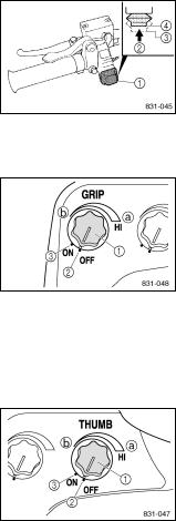
ESU00039
Headlight beam switch
Push the headlight beam switch to change the headlight beam to high or low.
1Headlight beam switch
2Push
3High beam
4Low beam
ESU00279
Grip warmer control knob
The grip warmer control knob controls the electrically heated handlebar grips.
1Grip warmer control knob
2“OFF”
3“ON”
|
Knob position |
Grip warmer temperature |
|
Turn clockwise a |
Higher |
|
Turn counterclockwise b |
Lower |
ESU00280
Thumb warmer control knob
The thumb warmer control knob controls the electrically heated throttle lever.
1Thumb warmer control knob
2“OFF”
3“ON”
|
Knob position |
Thumb warmer temperature |
|
Turn clockwise a |
Higher |
|
Turn counterclockwise b |
Lower |
5-8
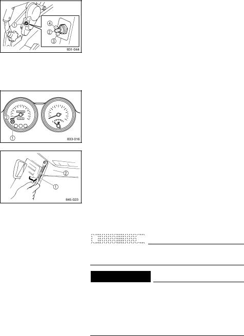
ESU00044
Passenger grip warmer switch
For VT600
The passenger grip warmer switch controls the electrically heated passenger grips.
1 Passenger grip warmer switch
2“OFF”
3“HI” High
4“LO” Low
ESU00046
Tripmeter reset knob
Use the tripmeter reset knob to reset the tripmeter.
1Tripmeter reset knob
2Turn counterclockwise
ESU00048
Shroud latches
To open the shroud, unhook the shroud latches, and then slowly raise the shroud forward until it stops. When closing the shroud, slowly lower it to its home position, and then hook the shroud latches.
1Shroud latch
2Shroud


 CAUTION
 :
:


@
Make sure that all cables and wires are in place when closing the shroud.
 WARNING
●Do not drive the snowmobile with the shroud open, unlatched, or removed.
●Keep your body and clothing away from rotating parts when servicing with the shroud open.
●Do not touch the hot muffler and engine during or immediately after operation.
5-9
ESU00052
Drive guard
The drive guard is designed to cover the V-belt clutch and V-belt in case parts break or come loose.
 WARNING
●Make sure that the drive guard is tightened securely before operating the snowmobile.
●Never run the engine with the V-belt or drive guard removed.
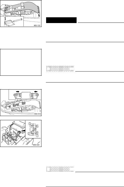
ESU00053
V-belt holders
Keep a spare V-belt for emergency use by placing it into the V-belt holders provided.


 CAUTION
 :
:


@
Make sure that the V-belt is installed securely in the holders.
ESU00056
Spark plug holders
Keep spare spark plugs for emergency use by placing them into the spark plug holders provided.
ESU00057
Carburetor heating lever
The carburetor heating lever controls the flow of coolant through each carburetor body.
Make sure that the lever is in the “ON” position to heat the carburetors while the ambient temperature is below 0 °C (32 °F).
1Carburetor heating lever
2“ON”
3“OFF”


 CAUTION
 :
:


@
When operating the snowmobile above 0 °C (32 °F), move the carburetor heating lever to the “OFF” position, since the carburetors do not need to be heated.
5-10
ESU00067
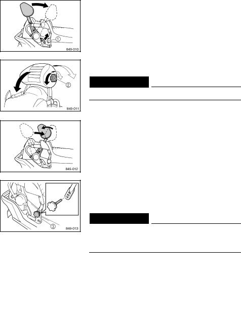
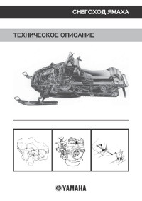
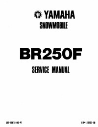
Backrest
For VT600
The backrest is adjustable.
Pull the backrest adjusting lever 1 upward to adjust the backrest position.
Turn the backrest adjusting knob 2 right or left to further adjust the backrest.
 WARNING
Do not sit on the backrest.
When riding without a passenger, the backrest can be adjusted for the rider as shown in the illustration.
To adjust the passenger grip position, remove the passenger grip adjusting knobs 3 on both sides of the seat, and change the position of the passenger grip to any one of the three positions shown.
 WARNING
Make sure that the passenger grip adjusting knobs are tightened securely after adjusting the passenger grip position.
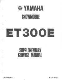
ESU00242
Storage compartment
Open the storage compartment to store the service tools, spare parts, or other small items.
È SX600 / VX600ER É VT600
5-11
Описание конструкции снегохода Yamaha.
- Год издания: —
- Страниц: 65
- Формат: PDF
- Размер: 6,9 Mb
Руководство на английском языке по техническому обслуживанию и ремонту снегохода Yamaha BR250F.
- Год издания: 1981
- Страниц: 191
- Формат: PDF
- Размер: 8,7 Mb

Руководство по эксплуатации и техническому обслуживанию снегоходов Yamaha BR250TG и Yamaha VK540EG.
- Год издания: 2001
- Страниц: 88
- Формат: PDF
- Размер: 8,7 Mb
Дополнение к руководству по техническому обслуживанию и ремонту снегохода Yamaha ET300E.
- Год издания: 1980
- Страниц: 8
- Формат: PDF
- Размер: 790 Kb

Сборник руководств по эксплуатации и техническому обслуживанию снегоходов Yamaha FX Nytro моделей FX10/RFX10 различных модификаций.
- Год издания: 2007-2012
- Страниц: 94/118/122
- Формат: PDF
- Размер: 32,0 Mb
Сборник руководств на английском языке по эксплуатации и техническому обслуживанию снегоходов Yamaha FX Nytro модели FX10 различных модификаций.
- Год издания: 2007-2011
- Страниц: 92/104
- Формат: PDF
- Размер: 18,5 Mb
Руководство на английском языке по техническому обслуживанию и ремонту снегохода Yamaha FX Nytro модели FX10 различных модификаций.
- Год издания: 2007
- Страниц: 410
- Формат: PDF
- Размер: 13,5 Mb

Руководство по эксплуатации и техническому обслуживанию снегоходов Yamaha MM700/VT700/VX700ER.
- Год издания: 2001
- Страниц: 100
- Формат: PDF
- Размер: 9,2 Mb

Сборник руководств на английском языке по эксплуатации и техническому обслуживанию снегоходов Yamaha MM600/MM700/SX600/VT600/VT700/VX600/VX700 различных модификаций.
- Год издания: 1998-2002
- Страниц: —
- Формат: PDF
- Размер: 32,0 Mb

Сборник руководств по эксплуатации и техническому обслуживанию снегоходов Yamaha PZ50/RPZ50 Venture различных модификаций.
- Год издания: 2006/2012
- Страниц: 110/120
- Формат: PDF
- Размер: 11,7 Mb

Сборник руководств на английском языке по эксплуатации и техническому обслуживанию снегоходов Yamaha PZ50 Phazer, Venture различных модификаций.
- Год издания: 2006-2009
- Страниц: 88/92/98/104
- Формат: PDF
- Размер: 21,6 Mb
Сборник руководств на английском языке по техническому обслуживанию и ремонту снегохода Yamaha PZ50 Phazer, Venture различных модификаций.
- Год издания: 2006-2007
- Страниц: 424/114
- Формат: PDF
- Размер: 21,2 Mb

Руководство на английском языке по техническому обслуживанию и ремонту снегоходов Yamaha PZ500C и Yamaha VT500XLC.
- Год издания: 1998
- Страниц: 209
- Формат: PDF
- Размер: 6,0 Mb

Руководство на английском языке по эксплуатации и техническому обслуживанию снегоходов Yamaha PZ 500D/PZ500MLD/VT500XLD.
- Год издания: 1999
- Страниц: 83
- Формат: PDF
- Размер: 2,4 Mb
Сборник руководств по эксплуатации и техническому обслуживанию снегоходов Yamaha RS10/RS90/RSG90/RST90 RS Vecror, RS Venture различных модификаций.
- Год издания: 2004/2011/2012
- Страниц: 100/108/162
- Формат: PDF
- Размер: 31,0 Mb
Сборник руководств на английском языке по эксплуатации и техническому обслуживанию снегоходов Yamaha RS90/RSG90/RST90 RS Vector, RS Venture различных модификаций.
- Год издания: 2004-2011
- Страниц: —
- Формат: PDF
- Размер: 63,5 Mb

Сборник руководств на английском языке по техническому обслуживанию и ремонту снегоходов Yamaha RS90/RSG90/RST90 RS Venture различных модификаций.
- Год издания: 2004/2006/2008
- Страниц: 414/202/299
- Формат: PDF
- Размер: 37,1 Mb

Сборник руководств по эксплуатации и техническому обслуживанию снегоходов Yamaha RX10/RXW10 Apex различных модификаций.
- Год издания: 2001-2012
- Страниц: —
- Формат: PDF
- Размер: 28,6 Mb

Сборник руководств на английском языке по эксплуатации и техническому обслуживанию снегоходов Yamaha RX90/RXW90 Apex различных модификаций.
- Год издания: 2002-2010
- Страниц: —
- Формат: PDF
- Размер: 48,2 Mb

Руководство на английском языке по эксплуатации и техническому обслуживанию снегоходов Yamaha SRX700G.
- Год издания: 2001
- Страниц: 84
- Формат: PDF
- Размер: 6,6 Mb

Сборник руководств по эксплуатации и техническому обслуживанию снегоходов Yamaha SXV60/SXV70/VT60/VT70 различных модификаций.
- Год издания: 2003
- Страниц: 113/127
- Формат: PDF
- Размер: 10,5 Mb

Сборник руководств на английском языке по эксплуатации и техническому обслуживанию снегоходов Yamaha SXV60/SXV70/VT60/VT70 различных модификаций.
- Год издания: 2001-2005
- Страниц: —
- Формат: PDF
- Размер: 48,3 Mb

Сборник руководств по эксплуатации и техническому обслуживанию снегоходов Yamaha VK10/VK10D RS Viking.
- Год издания: 2007/2012
- Страниц: 98/108
- Формат: PDF
- Размер: 15,6 Mb

Сборник руководств на английском языке по эксплуатации и техническому обслуживанию снегоходов Yamaha VK10L и Yamaha VK10X.
- Год издания: 2005/2007
- Страниц: 98/88
- Формат: PDF
- Размер: 7,9 Mb
Дополнение к руководству по техническому обслуживанию и ремонту снегоходов Yamaha VK10L/VK10W.
- Год издания: 2005-2006
- Страниц: 360/103
- Формат: PDF
- Размер: 12,2 Mb

Руководство по эксплуатации и техническому обслуживанию снегоходов Yamaha VK540E/VK540EC.
- Год издания: 2012
- Страниц: 82
- Формат: PDF
- Размер: 3,2 Mb

Сборник руководств на английском языке по эксплуатации и техническому обслуживанию снегоходов Yamaha VK540EG/VK540EK.
- Год издания: 2001/2004
- Страниц: 76
- Формат: PDF
- Размер: 4,8 Mb

Руководство на английском языке по техническому обслуживанию и ремонту снегохода Yamaha VK540EK.
- Год издания: 2000
- Страниц: 211
- Формат: PDF
- Размер: 4,9 Mb

Руководство по эксплуатации и техническому обслуживанию снегохода Yamaha VT500XL.
- Год издания: 2001
- Страниц: 84
- Формат: PDF
- Размер: 8,2 Mb
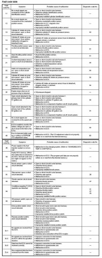
Коды неисправностей Yamaha.
- Год издания: —
- Страниц: 11
- Формат: JPG
- Размер: 1,7 Mb

- Manuals
- Brands
- Yamaha Manuals
- Snowmobiles
- VX500SXBC
- Service manual
-
Contents
-
Table of Contents
-
Bookmarks
Quick Links
SUPPLEMENTARY SERVICE MANUAL
Related Manuals for Yamaha VX500SXBC
Summary of Contents for Yamaha VX500SXBC
-
Page 1
SUPPLEMENTARY SERVICE MANUAL… -
Page 2
OE001 son inspecting or repairing the snowmobile. NOTICE CAUTION: This manual was written by the Yamaha Mo- tor Company primarily for use by Yamaha A CAUTION indicates special precautions dealers and their qualified mechanics. It is that must be taken to avoid damage to the not possible to put an entire mechanic’s… -
Page 3
OE031 ILLUSTRATED SYMBOLS (Refer to the illustration) Illustrated symbols 1 to 9 are designed as thumb tabs to indicate the chapter’s number and content. 1 General information 2 Periodic inspection and adjustment 3 Chassis 4 Power train 5 Engine overhaul 6 Cooling system 7 Carburetion 8 Electrical… -
Page 4: Table Of Contents
CONTENTS GENERAL INFORMATION ….ENGINE ……MACHINE IDENTIFICATION .
-
Page 5: General Information
MACHINE IDENTIFICATION/IMPORTANT INFORMATION INFO 1E001 GENERAL INFORMATION MACHINE IDENTIFICATION FRAME SERIAL NUMBER The frame serial number 1 is located on the right-hand side of the frame (just below the front of the seat). ENGINE SERIAL NUMBER The engine serial number 1 is located on the right-hand side of the crankcase.
-
Page 6: Power Train
Adjust the V-belt position by removing or adding a spacer 2 on each adjusting bolt. For this adjustment, consult a Yamaha deal- er or another qualified mechanic. CAUTION: As the V-belt wears, adjustment may be necessary.
-
Page 7
INSP DRIVE V-BELT 2. Adjust the position of the V-belt by re- moving or adding a spacer 1 on each adjusting bolt 2 . V-belt height adjustment To move V-belt up: Add spacer To move V-belt down: Reduce spacer 3. Tighten: S Adjusting bolt Adjusting bolt: 10 Nm (1.0 mSkg, 7.2 ftSlb) -
Page 8: Brake Pad Inspection
INSP BRAKE PAD INSPECTION/SLID RUNNER INSPECTION BRAKE PAD INSPECTION 1. Apply the brake lever. 2. Inspect: S Brake pad Wear indicator 1 nearly contacts the brake disc ! Replace the brake pads as a set. Wear limit a : 4.7 mm (0.185 in) SLIDE RUNNER INSPECTION 1.
-
Page 9: Tuning
INSP CLUTCH TUNING W White S Silver Blue CLUTCH P Pink R Red O Orange High altitude Y Yellow G Green Specifications Model: VX500SXB 4,500 X 7,000 ft X 3,500 ft 3,000 X 5,000 ft 6,500 X 10,000 ft Elevation Idle speed Approx.
-
Page 10
INSP CLUTCH W white S Silver Blue P Pink R Red O Orange Y Yellow G Green Specifications Model: VX700ER X 3,500 ft 3,000 X 5,000 ft 4,500 X 7,000 ft 6,500 X 10,000 ft Elevation Idle speed Approx. 1,600 r / min Clutch Approx. -
Page 11
INSP CLUTCH 2E331 The clutch may require tuning depending upon the area of operation and desired han- dling characteristics. The clutch can be tuned by changing engagement and shifting speed. Clutch engagement speed is defined as the engine speed where the machine first begins to move from a complete stop. -
Page 12: Gear Selection
INSP GEAR SELECTION GEAR SELECTION The reduction ratio of the driven gear to the drive gear must be set according to the snow conditions. If there are many rough surfaces unfavorable snow conditions, drive/driven gear ratio should be increased. If the surfaces are fairly smooth or better snow conditions exist, decrease the ratio.
-
Page 13
INSP GEAR SELECTION 3 Secondary spring Spring rate Wire Free No. of Parts No. NSmm/ rad Color gauge length Standard coils (kgmm/ rad) (mm) (mm) 90508-500B1 6003 (613) BROWN 90508-536A9 7147 (729) VX500 90508-556A2 8314 (848) GREEN VX700 90508-556A7 9460 (965) SILVER 4 Secondary spring twist angle Seat… -
Page 14
INSP GEAR SELECTION 6 Primary spring Spring rate Wire Outside Free Preload No. of Standard Parts No. N / mm Color gauge diameter length (kg) coils (kg / mm) (mm) (mm) (mm) 90501-481J1 9.8 (1.0) 196.1 (20) S-B-S 5.16 85.4 90501-487G8 14.7 (1.5) 147 (15) -
Page 15: Front Suspension
INSP FRONT SUSPENSION FRONT SUSPENSION Spring preload (700) 1. Adjust: S Turn the adjusting ring 1 to the proper position. Spring adjuster position Softer z ! Harder Preload Standard CAUTION: Be sure that the left and right spring preload is the same. Spring preload (500) 1.
-
Page 16: Rear Suspension
INSP REAR SUSPENSION REAR SUSPENSION Stopper band 1. Adjust: S Stopper band tension CAUTION: Be sure that the left and right length is the same. NOTE: This adjustment affects the handling charac- teristics of the machine. Adjustment steps: S Loosen the locknut 1 . S Turn the adjusting nut 2 in or out to adjust the stopper band tension.
-
Page 17
INSP REAR SUSPENSION Spring preload (500) 1. Adjust: S Turn the spring seat 1 in or out. Spring seat Standard Shorter z ! Longer distance Harder z ! Softer Preload Length Max. Min. (front) 172 mm 182 mm 192 mm (6.77 in) (7.17 in) (7.56 in) Length Max. -
Page 18: Chassis
CHAS CHASSIS SKI (500) 10 Nm (1.0 mSkg, 7.2 ftSlb) 21 Nm (2.1 mSkg, 15 ftSlb) 48 Nm (4.8 mSkg, 35 ftSlb) : ESSO beacon 325 grease or Aeroshell grease #7A Order Job name/Part name Q’ty Remarks Ski removal Remove the parts in the order below. Cotter pin Ski column lower bracket Ski stopper…
-
Page 19: Inspection
CHAS SKI/FRONT SUSPENSION INSPECTION 1. Inspect: S Ski 1 S Ski runner 2 S Ski column lower bracket 3 S Ski handle 4 S Ski stopper 5 Wear/cracks/damage ! Replace. S Mounting bolt 6 S Collar 7 Wear/damage ! Replace. FRONT SUSPENSION This shock absorber contains highly com- pressed nitrogen gas.
-
Page 20: Installation
CHAS FRONT SUSPENSION INSTALLATION 1. Install: S Control rod 1 S Nut 2 S Joint 3 a Set length Left hand Model Set length (mm) angle (_) 460.2 ± 0.5 mm VX500 94 ± 1 (18.11 ± 0.0197 in) Upper 458.7 ±…
-
Page 21: Power Train
POWR SECONDARY SHEAVE ASSEMBLY 1. Install: S Secondary sheave spring 1 S Bolts 2 (along with the shims) Bolt: 10 Nm (1.0 mSkg, 7.2 ftSlb) 2. Install: S Stopper S Sliding sheave Screw (stopper): 6.5 Nm (0.65 mSkg, 4.6 ftSlb) 3.
-
Page 22: Drive Chain Housing
POWR DRIVE CHAIN HOUSING DRIVE CHAIN HOUSING WITHOUT REVERSE MODEL (500) 10 Nm (1.0 mSkg, 7.2 ftSlb) 24 Nm (2.4 mSkg, 17 ftSlb) 48 Nm (4.8 mSkg, 35 ftSlb) 60 Nm (6.0 mSkg, 43 ftSlb) Order Job name/Part name Q’ty Remarks Drive chain housing removal Remove the parts in the order below.
-
Page 23: Installation
POWR DRIVE CHAIN HOUSING INSTALLATION During installation, pay attention to the fol- lowing point: A Make sure that the bearing seals face towards the drive chain, as shown. B Properly install the rubber seal onto the drive chain housing, making sure that these are no gaps.
-
Page 24: Drive Chain Housing And Jackshaft Installation
POWR DRIVE CHAIN HOUSING DRIVE CHAIN HOUSING AND JACKSHAFT INSTALLATION 1. Install: S Drive chain housing S Jackshaft Installation steps: D Install the drive chain housing 1 . D Tighten the bolts 2 . Bolt (drive chain housing): 48 Nm (4.8 mSkg, 35 ftSlb) D Temporarily tighten the nuts 3 .
-
Page 25: With Reverse Model (700)
POWR DRIVE CHAIN HOUSING WITH REVERSE MODEL (700) 10 Nm (1.0 mSkg, 7.2 ftSlb) 24 Nm (2.4 mSkg, 17 ftSlb) 48 Nm (4.8 mSkg, 35 ftSlb) 60 Nm (6.0 mSkg, 43 ftSlb) Order Job name/Part name Q’ty Remarks Drive chain housing removal Remove the parts in the order below.
-
Page 26
POWR DRIVE CHAIN HOUSING Order Job name/Part name Q’ty Remarks Reverse drive gear Spring Chain tensioner Roller Collar Spring Journal Reverse driven gear Washer Forward driven sprocket Collar Counter gear Drive sprocket Drive chain Collar Washer Plate Shaft Drive chain housing For installation, reverse the removal procedure. -
Page 27: Installation
POWR DRIVE CHAIN HOUSING/JACKSHAFT INSTALLATION During installation, pay attention to the fol- lowing point: A Properly install the rubber seal onto the drive chain housing, making sure that these are no gaps. B Make sure that the bearing seals face towards the drive chain, as shown.
-
Page 28: Brake
POWR BRAKE BRAKE 1.5 Nm (0.15 mSkg, 1.1 ftSlb) 6 Nm (0.6 mSkg, 4.3 ftSlb) Order Job name/Part name Q’ty Remarks Brake caliper disassembly Disassembly the parts in the order below. Cap bolt Retaining pin Pad spring Brake pads Shim 1 Shim 2 Bleed screws Oil seals…
-
Page 29: Brake Pad Replacement
POWR BRAKE CAUTION: Disc brake components rarely require disas- sembly. DO NOT: D Disassemble components unless abso- lutely necessary. D Use solvents on internal brake compo- nents. D Use contaminated brake fluid for clean- ing. Use only clean brake fluid. D Allow brake fluid to come in contact with the eyes, otherwise eye injury may occur.
-
Page 30
POWR BRAKE 2. Install: S Brake pads S Pad spring Installation steps: S Connect a suitable hose 1 tightly to the caliper bleed screw 2 . Put the other end of this hose into an open container. S Loosen the caliper bleed screw and push the pistons into the caliper with the finger. -
Page 31: Slide Rail Suspension
POWR SLIDE RAIL SUSPENSION SLIDE RAIL SUSPENSION 71 Nm (7.1 mSkg, 51 ftSlb) Order Job name/Part name Q’ty Remarks Slide rail suspension removal Remove the parts in the order below. Tension adjuster Loosen. Blind caps Bolts Washer Slide rail suspension For installation, reverse the removal procedure.
-
Page 32
POWR SLIDE RAIL SUSPENSION 4 Nm (0.4 mSkg, 2.9 ftSlb) 15 Nm (1.5 mSkg, 11 ftSlb) 30 Nm (3.0 mSkg, 22 ftSlb) 49 Nm (4.9 mSkg, 35 ftSlb) 71 Nm (7.1 mSkg, 50 ftSlb) 24 Nm (2.4 mSkg, 17 ftSlb) Order Job name/Part name Q’ty… -
Page 33
POWR SLIDE RAIL SUSPENSION 24 Nm (2.4 mSkg, 17 ftSlb) 49 Nm (4.9 mSkg, 35 ftSlb) 71 Nm (7.1 mSkg, 50 ftSlb) Order Job name/Part name Q’ty Remarks Suspension wheels Collar Wheel brackets Circlips Suspension wheels Bushings Shaft Rear suspension bracket Spacers Bushings Collar… -
Page 34
POWR SLIDE RAIL SUSPENSION 49 Nm (4.9 mSkg, 35 ftSlb) 71 Nm (7.1 mSkg, 50 ftSlb) Order Job name/Part name Q’ty Remarks Rear shock absorber Bushings Collar Pull rod Collars Bushings Collars (700) Suspension wheels Control rods Bushings Screw Bushings –30–… -
Page 35
POWR SLIDE RAIL SUSPENSION 24 Nm (2.4 mSkg, 17 ftSlb) 71 Nm (7.1 mSkg, 50 ftSlb) 75 Nm (7.5 mSkg, 54 ftSlb) Order Job name/Part name Q’ty Remarks Rear pivot arm Bushings Collar Collar Rear pivot arm bracket Collar Circlips Suspension wheels Wheel bracket Rear axle… -
Page 36: Front Axle And Track
POWR FRONT AXLE AND TRACK FRONT AXLE AND TRACK 27 mm INSTALLATION (1.06 in) Reverse the “REMOVAL” procedure. Note the following points. 1. Install: S Sprocket wheels S Guide wheels 60 mm 132.6 mm 201.4 mm (2.36 in) (5.22 in) (7.93 in) NOTE: 164.1 mm…
-
Page 37: Engine
ENGINE ASSEMBLY ENGINE ENGINE ASSEMBLY 90 Nm (9.0 mSkg, 65 ftSlb) 60 Nm (6.0 mSkg, 43 ftSlb) Order Job name/Part name Q’ty Remarks Engine removal Remove the parts in the order below. Exhaust pipe Carburetor Refer to “CARBURETOR”. Recoil starter Refer to “RECOIL STARTER”.
-
Page 38
ENGINE ASSEMBLY 23 Nm (2.3 mSkg, 17 ftSlb) 60 Nm (6.0 mSkg, 43 ftSlb) 90 Nm (9.0 mSkg, 65 ftSlb) 23 Nm (2.3 mSkg, 17 ftSlb) Order Job name/Part name Q’ty Remarks Engine removal Remove the parts in the order below. Exhaust pipe Carburetor Refer to “CARBURETOR”. -
Page 39: Cylinder Head And Cylinder
CYLINDER HEAD AND CYLINDER CYLINDER HEAD AND CYLINDER INSPECTION 1. Measure: S Piston-to-cylinder clearance Measurement steps: 1st step: S Measure the cylinder bore “C” with a cylinder bore gauge 1 . NOTE: Measure the cylinder bore “C” parallel to, and at right angles to the crankshaft. Then find the average of the measurements.
-
Page 40
CYLINDER HEAD AND CYLINDER 2nd step: S Measure the piston skirt diameter “P” with a micrometer from distance a . a 500: 25 mm (0.98 in) 700: 15 mm (0.59 in) from the piston bottom edge. Piston size P 500: 67.930 X 67.935 mm (2.6745 X 2.6746 in) Standard 700: 70.425 X 70.430 mm… -
Page 41: Heat Exchanger
COOL HEAT EXCHANGER COOLING SYSTEM HEAT EXCHANGER 1. Measure: S Filler cap opening pressure Cap opens at pressure below the speci- fied pressure ! Replace. Cap opening pressure: 95 X 125 kPa (0.95 X 1.25 kg/cm 13.58 X 17.87 psi) Measurement steps: D Attach the cooling system tester (90890-01325, YU-24460-01) to the…
-
Page 42: Carburetion
CARB CARBURETORS CARBURETION CARBURETORS * Intake silencer D First, remove the throttle cable from the cable guide on the steering column. D Adjust the throttle cable free play while the cable is in the cable guide. D After adjusting the throttle cable free play, properly install the upper and lower intake silencer plates and seal.
-
Page 43
CARB CARBURETORS * Intake silencer D First, remove the throttle cable from the cable guide on the steering column. D Adjust the throttle cable free play while the cable is in the cable guide. D After adjusting the throttle cable free play, properly install the upper and lower intake silencer plates and seal. -
Page 44
CARB CARBURETORS Order Job name/Part name Q’ty Remarks Carburetor separation Separation the parts in the order below. Coolant hoses Starter cable holder Collar Spring Screw Loosen Starter rod Spring Starter levers Breather hoses Top covers Gaskets Throttle shaft connecting screws Connecting plate (upper) Connecting plate (lower) For assembly, reverse the separation… -
Page 45: Assembly
CARB CARBURETORS ASSEMBLY 1. Measure: S Float height a Out of specification ! Adjust. Float height: 22.3 ± 2.0 mm (0.878 ± 0.080 in) 13.3 ± 2.0 mm (0.524 ± 0.080 in) Measurement and adjustment steps: S Hold the carburetor in an upside down position.
-
Page 46: Specifications
Maximum torque r/min Starting system Recoil hand starter Electric and recoil hand starter Lubrication system: Separate lubrication (YAMAHA AUTOLUBE) Engine oil: Type YAMALUBE 2-cycle oil Tank capacity 3.0 L (2.6 Imp gt, 3.2 Us gt) Drive chain housing oil: Type Gear oil API “GL-3”…
-
Page 47
SPEC GENERAL SPECIFICATIONS Model VX500SXB VX700ER Carburetor: Type/quantity TM36 TM33 Manufacturer MIKUNI Spark plug: Type BR9ES Manufacturer 0.7 X 0.8 mm (0.028 X 0.031 in) Transmission: Primary reduction system V-Belt 3.8 X 1.0 : 1 Primary reduction ratio Clutch type Automatic centrifugal engagement Secondary reduction system… -
Page 48: Maintenance Specifications
SPEC MAINTENANCE SPECIFICATIONS MAINTENANCE SPECIFICATIONS ENGINE Model VX500SXB VX700ER Cylinder head: 23.3 X 23.9 cm 22.9 X 23.5 cm Volume (with spark plug) <Warp limit> <0.03 mm (0.0012 in)> * Lines indicate straight edge measurement. Cylinder: Material Aluminum alloy with dispersion coating 68.00 X 68.02 mm 70.50 X 70.52 mm…
-
Page 49
SPEC MAINTENANCE SPECIFICATIONS Model VX500SXB VX700ER Crankshaft: 61.95 X 62.00 mm 55.95 X 56.00 mm Crank width “A” (2.439 X 2.440 in) (2.203 X 2.205 in) 179.85 X 180.15 mm 291.75 X 292.30 mm Crank width “B” (7.080 X 7.093 in) (11.486 X 11.508 in) Crankshaft deflection “C”… -
Page 50
SPEC MAINTENANCE SPECIFICATIONS Model VX500SXB VX700ER Carburetor: Type/Quantity TM36/2 pcs. TM33/3 pcs. Manufacturer MIKUNI I.D. mark 8CJ10 8CH10 Main jet (M.J) #151.3 #1 : #145 #2, 3 : #143.8 Main air jet (M.A.J) ø2.5 – Pilot jet (P.J) Jet needle (J.N) 8CFY14-56-2 6DGM5-3 Needle jet (N.J) -
Page 51
SPEC MAINTENANCE SPECIFICATIONS Model VX500SXB VX700ER Thermostat: 50 X 55_C Opening temperature (122_F X 132_F) Valve lift 8 mm/70_C (159_F) –47–… -
Page 52: Power Train
SPEC MAINTENANCE SPECIFICATIONS POWER TRAIN Model VX500SXB VX700ER Transmission: Type V-belt automatic 3.8 X 1.0 : 1 Range of ratio 4,000 ± 200 r/min Engagement r/min 7,800 ± 250 r/min 8,300 ± 250 r/min Shift r/min 267 X 270 mm Sheave center distance “A”…
-
Page 53
SPEC MAINTENANCE SPECIFICATIONS Model VX500SXB VX700ER Rivet: Outer Part number 90261-06034 90261-06015 Material Steel Size 13.9 mm (0.55 in) 10.3 mm (0.40 in) Quantity 3 pcs Hole quantity 3 pcs Inner Part number 90261-06028 90261-06034 Material Aluminum Steel Size 10.3mm (0.40in) 13.9 mm (0.55 in) Quantity 3 pcs… -
Page 54
SPEC MAINTENANCE SPECIFICATIONS Model VX500SXB VX700ER Track: Part number 8AB-47110-10 8CH-47110-00 Width 381 mm (15.0 in) Length 3,072 mm (120.9 in) Pitch 64 mm (2.52 in) Number of links Height “B” 16 mm (0.63 in) 25 X 30 mm Deflection at 10 kg (22 lb) (0.98 X 1.18 in) Slide rail suspension: Front travel… -
Page 55
SPEC MAINTENANCE SPECIFICATIONS Model VX500SXB VX700ER Shock absorber: Damping force Front 3,320N ± 460N/0.3m/s 720 N ± 150N/0.3m/s Extension 1,110N ± 225N/0.3m/s 1,020 N ± 210N/0.3m/s Compression Rear 1,950N ± 264N/0.3m/s 2,206 N ± 657N/0.3m/s Extension 1,380N ± 235N/0.3m/s 726 N ± 216N/0.3m/s Compression Slide runner: Thickness… -
Page 56: Chassis
SPEC MAINTENANCE SPECIFICATIONS CHASSIS Model VX500SXB VX700ER Frame: Frame material Aluminum Seat height 685 mm (26.8 in) 730 mm (28.7 in) Luggage box location Rear side of seat Steering: Lock-to-lock angle (left) 29.6_ (R ski) 34.8_ (L ski) 29.4_ (R ski) 34.7_ (L ski) (right) 34.8_ (R ski) 29.6_ (L ski) 34.7_ (R ski) 29.4_ (L ski)
-
Page 57: Electrical
18_ at 4.500 r/min 24_ at 4.500 r/min Advanced type Electrical type Ignition coil: Model/Manufacturer 8AB-00/YAMAHA 8DG-00/YAMAHA Minimum spark gap 3 mm (0.118 in) or more 0.2 Ω ± 20% at 20_C (68_F) 0.06 Ω ± 20% at 20_C Primary coil resistance (68_F) 4.9 kΩ…
-
Page 58
SPEC MAINTENANCE SPECIFICATIONS Model VX500SXB VX700ER Rectifier/regulator: Model/manufacturer 8CR-00/MATSUSHITA 13.8 X 14.8 V No load regulated voltage 14.0 X 15.0 V Battery: (for electric model) Specific gravity – 1.280 Type – GM18Z-3A Electric starter system: (for electric model) Type – Bendix Starter motor: (for electric model) Model/manufacturer… -
Page 59
SPEC MAINTENANCE SPECIFICATIONS High altitude settings VX500SXB Tempera- – 40_C – 29_C – 18_C – 7_C 15_C ture (– 40_F) (– 20_F) (0_F) (20_F) (40_F) (60_F) Altitude 0 X 100 m MJ#155 MJ#153.8 MJ#152.5 MJ#151.3 MJ#150 (0 X 330 ft) JN-2.0 JN-2.0 JN-2.0… -
Page 60
SPEC MAINTENANCE SPECIFICATIONS High altitude settings VX700ER Tempera- – 40_C – 29_C – 18_C – 7_C 15_C ture (– 40_F) (– 20_F) (0_F) (20_F) (40_F) (60_F) Altitude MJ#1 #148.8 MJ#1 #147.5 MJ#1 #146.3 MJ#1 #145.0 MJ#1 #143.8 MJ#2#3 #147.5 MJ#2#3 #146.3 MJ#2#3 #145.0 MJ#2#3 #143.8 MJ#2#3 #142.5… -
Page 61
SPEC MAINTENANCE SPECIFICATIONS Tightening torque: Tightening torque Parts to be tightened Parts to be tightened Remarks Remarks mSkg ftSlb Crankcase (first) Tighten the bolts in two Crankcase (final) stages. Engine bracket (front) and frame 500 Engine bracket (front) and frame Engine bracket damper (front) Engine bracket and engine Engine bracket upper and lower (rear) -
Page 62
SPEC MAINTENANCE SPECIFICATIONS Tightening torque Parts to be tightened Parts to be tightened Remarks Remarks mSkg ftSlb Sliding frame and slide runner Slide rail suspension mounting bolt Rear pivot arm and bracket Apply LOCTITE Shock absorber and rear pivot arm Rear pivot arm and rod Rear suspension bracket and rod Control rod and sliding frame… -
Page 63
SPEC MAINTENANCE SPECIFICATIONS –59–… -
Page 64: Cable Routing <500
SPEC CABLE ROUTING CABLE ROUTING <500> –60–…
-
Page 65
SPEC CABLE ROUTING CABLE ROUTING <For 500> 1 Oil pump cable 2 Throttle cable 3 Fasten the wire harness. Do not fasten the throttle cable and oil pump cable. 4 Fasten the throttle cable and oil pump cable with a plastic clamp. Route the cable along the side of the handle holder. -
Page 66
SPEC CABLE ROUTING –62–… -
Page 67
SPEC CABLE ROUTING 35 To the conduction 36 Voltage regulator 37 Rectifire regulator 38 Fasten the wire harness with a plastic clamp. 39 Rectifire regulator (ECC model) 40 Brake hose holder 41 Fasten the wire harness with a plastic clamp. 42 To reverse gear 43 Fasten the wire harness, fuel breather hose and oil… -
Page 68
SPEC CABLE ROUTING –64–… -
Page 69
SPEC CABLE ROUTING 1 Wire lead (electrical starter model) 2 Carburetor switch coupler 3 Fasten the throttle cable and oil pump cable with a plastic clamp. 4 Air temperature sensor coupler (ECC model) 5 Coolant hose 6 Starter relay lead 7 Starter relay sub lead (electrical starter model) 8 Fasten the wire harness,… -
Page 70
SPEC CABLE ROUTING –66–… -
Page 71
SPEC CABLE ROUTING 32 Solenoid coupler (ECC model) 33 Ignition coil 34 Carburetor heating lever 35 Coolant hose 36 Speedometer cable 37 Fasten the throttle cable, water temperature sensor lead, carburetor switch lead and solenoid lead with a plastic clamp. 38 Water temperature sensor coupler 39 Under 50 mm (1.97 in) -
Page 72
SPEC CABLE ROUTING –68–… -
Page 73
SPEC CABLE ROUTING 1 Make sure that the oil tank cap and oil breather hose do not touch each other. 2 Route the fuel breather hose along the upper of the main harness. 3 Route the oil breather hose along the upper of the main harness. -
Page 74: Cable Routing <700
SPEC CABLE ROUTING CABLE ROUTING <700> –70–…
-
Page 75
SPEC CABLE ROUTING CABLE ROUTING <For 700> 1 Oil pump cable 2 Throttle cable 3 Do not fasten the throttle cable and oil pump wire with a plastic clamp. 4 Thumb warmer coupler 5 Engine stop switch coupler 6 Holder 7 Grip warmer coupler 8 Brake light switch coupler 9 Head light switch coupler… -
Page 76
SPEC CABLE ROUTING –72–… -
Page 77
SPEC CABLE ROUTING 37 DC back buzzer (reverse model) 38 Voltage regulator 39 Rectifier regulator 40 DC back buzzer coupler 41 Fasten the wire harness with a plastic clamp. 42 Brake hose holder 43 Fasten the wire harness with a plastic clamp. 44 To reverse gear 45 Fasten the wire harness, fuel breather hose and oil… -
Page 78
SPEC CABLE ROUTING –74–… -
Page 79
SPEC CABLE ROUTING 1 Fasten the carburetor switch, water temperature sensor lead, coolant hose, wire lead and battery negative lead with a plastic clamp. 2 Clamp 3 Fasten the ignition coil and starter cable with a plastic clamp. 4 Fasten the wire lead, battery negative lead and coolant hose with a plastic clamp. -
Page 80
SPEC CABLE ROUTING –76–… -
Page 81
SPEC CABLE ROUTING 1 Wire harness 2 50 mm (1.97 in) 3 Make sure that the oil tank cap and oil breather hose do not touch each other. 4 Route the fuel breather hose along the upper of the main harness. -
Page 82
WIRING DIAGRAM VX500SXB CDI magneto Brake light switch Rectifier / regulator Tail / brake light Starter relay / fuse Speedometer assembly Battery Oil level indicator light Starter motor Water temp. indicator light Main switch High beam indicator light Engine stop switch Speedometer light Throttle switch Tachometer assembly… -
Page 83
WIRING DIAGRAM VX700ER CDI magneto Brake light switch Rectifier / regulator Tail / brake light Starter relay / fuse Speedometer assembly Battery Oil level indicator light Starter motor Water temp indicator light Main switch High beam indicator light Engine stop switch Speedometer light Throttle switch Tachometer assembly… -
Page 84
PRINTED IN USA PRINTED ON RECYCLED PAPER…
This manual is also suitable for:
Vx700erc
Yamaha имела 15-летний опыт производства снегоходов, когда выпустила снегоход Vmax в 1983 году. Одиннадцать лет спустя Yamaha заменила двигатель оригинальной модели двигателем объемом 600 или 500 куб. Этот новый дизайн просуществовал до 1999 года, когда двигатель Vmax 600 cc выпускался в трех разных вариантах: стандартный Vmax 600 (VX600), 600 Deluxe (VX600ER) и 600 SX (VX600SXB).
Содержание
- 1
Vmax 600 Engineering - 2
VX600ER и VX600SXB Engineering - 3
коробка передач - 4
Трек/Подвеска - 5
измерения
Vmax 600 Engineering
Стандартный 1999 VX600 имел двухтактный двухцилиндровый двигатель с рабочим диаметром 2,94 x 2,68 дюйма и рабочим объемом 36,5 кубических дюймов. Он также имел жидкостную систему охлаждения, ручной стартер и карбюратор Mikuni TM36 X 2.
VX600ER и VX600SXB Engineering
В отличие от них, VX600ER и VX600SXB были оснащены двухтактным трехцилиндровым двигателем с рабочим диаметром 2,56 x 2,35 дюйма и рабочим объемом 36,2 куб. Дюйма. Оба также имели ручной стартер, жидкостную систему охлаждения и Mikuni TM31 X 3.
коробка передач
Хотя все триммеры Vmax 600 1999 года имели автоматическую центробежную передачу, технические характеристики варьировались между VX600 и VX600ER/SXB. VX600 имел скорость включения 4000 оборотов в минуту (об/мин), скорость переключения 7800 об/мин и коэффициент снижения 39:23. Обрезки ER и SXB также показали скорость зацепления 4000 об/мин, но сместились на 8500 об/мин и имели коэффициент снижения 39:21.
Трек/Подвеска
Все модели VX600, ER и SXB, совместимые во всех комплектациях 1999 года, были оснащены литыми резиновыми гусеницами шириной 15 дюймов и длиной 29,6 дюйма, которые были усилены стержнями из стекловолокна. На всех комплектациях Vmax 99 года также была установлена система подвески на направляющих. Стандартные VX600 и VX600ER были оснащены четырехместной полиэтиленовой звездочкой с девятью зубьями, а VX400SXB – двойной полиэтиленовой звездочкой с девятью зубьями и направляющими.
измерения
Все обрезки Vmax 600 расширены до 108,7 дюймов в длину. VX600 и VX600ER имеют размеры 47,2 дюйма в ширину, а VX600SXB чуть меньше – 46,1 дюйма. VX600 имел высоту 48,4 дюйма, короче, чем VX600ER, на 51,2 дюйма, но выше, чем высота 42,7 дюйма у VX600SXB. При 534 фунтах без топлива VX600ER был самым тяжелым Vmax 600, в то время как Vmax SXB весил 498 фунтов, а стандартный Vmax весил 483. Все имели емкость топливного бака 11,7 галлона и емкость масляного бака 3,2 кварта.
|
Title |
File Size |
Download Links |
|
Yamaha BR250 Bravo Snowmobile Service Manual.pdf |
10.3Mb |
Download |
|
Yamaha BR250 Parts Catalog.rar |
8.3Mb |
Download |
|
Yamaha BR250F Service Manual.pdf |
10.8Mb |
Download |
|
Yamaha BR250TG/VK540EG Owner’s Manual.pdf |
8.7Mb |
Download |
|
Yamaha EC340E Supplementary Service Manual.pdf |
892.9kb |
Download |
|
Yamaha ET300E Supplementary Service Manual.pdf |
790.2kb |
Download |
|
Yamaha ET410 Parts Catalog.rar |
4.1Mb |
Download |
|
Yamaha FX Nytro Owner`s Manual.rar |
18.5Mb |
Download |
|
Yamaha FX Nytro Service Manual.pdf |
13.5Mb |
Download |
|
Yamaha FX/FX10/RFX10 Owner’s Manual.rar |
32Mb |
Download |
|
Yamaha FX10 Parts Catalog.rar |
13.2Mb |
Download |
|
Yamaha MM600/MM700 Parts Catalog.rar |
6.2Mb |
Download |
|
Yamaha MM600/MM700/MX600/VT600/VT700/VX600/VX700 Owner`s Manual.rar |
32Mb |
Download |
|
Yamaha MM700/VT700/VX700ER Owner`s Manual.pdf |
9.2Mb |
Download |
|
Yamaha Phazer Venture Lite PZ50MTA 2011 Supplementary Service Manual.pdf |
6.4Mb |
Download |
|
Yamaha PZ-series Parts Catalog.rar |
30Mb |
Download |
|
Yamaha PZ50 Owner`s Manual.rar |
11.7Mb |
Download |
|
Yamaha PZ50 Phazer, Venture Owner`s Manual.rar |
21.6Mb |
Download |
|
Yamaha PZ50 Service Manual.rar |
21.2Mb |
Download |
|
Yamaha PZ500/VT500 Owner`s Manual.pdf |
2.4Mb |
Download |
|
Yamaha PZ500C/VT500XLC Service Manual.rar |
6Mb |
Download |
|
Yamaha RS10/RS90/RSG90/RST90 Owner`s Manual.rar |
31Mb |
Download |
|
Yamaha RS90 Parts Catalog.rar |
7.6Mb |
Download |
|
Yamaha RS90/RSG90/RST90 RS Vector, RS Venture Owner`s Manual.rar |
63.5Mb |
Download |
|
Yamaha RS90/RSG90/RST90 RS Venture Service Manual.rar |
37.1Mb |
Download |
|
Yamaha RS90L Owner`s Manual.pdf |
5.8Mb |
Download |
|
Yamaha RSG90 Parts Catalog.rar |
3.5Mb |
Download |
|
Yamaha RST90 Parts Catalog.rar |
11.9Mb |
Download |
|
Yamaha RX-1 Service Manual.pdf |
18.8Mb |
Download |
|
Yamaha RX10 Parts Catalog.rar |
28Mb |
Download |
|
Yamaha RX10/RXW10 Owner`s Manual.rar |
28.6Mb |
Download |
|
Yamaha RX10LTGTYL Service Manual.pdf |
32.7Mb |
Download |
|
Yamaha RX90/RXW90 Apex Owner`s Manual.rar |
48.2Mb |
Download |
|
Yamaha RXW10 Parts Catalog.rar |
5.1Mb |
Download |
|
Yamaha SL292C 1971 Service Manual.pdf |
26Mb |
Download |
|
Yamaha Snowmobile Design Description.pdf |
6.9Mb |
Download |
|
Yamaha snowmobile fault codes list.rar |
1.7Mb |
Download |
|
Yamaha SRX700 Parts Catalog.rar |
5.9Mb |
Download |
|
Yamaha SRX700 Service Manual.pdf |
7.4Mb |
Download |
|
Yamaha SX500/600/700 Parts Catalog.rar |
10.7Mb |
Download |
|
Yamaha SXV-VT owner`s manual.rar |
48.3Mb |
Download |
|
Yamaha SXV60/SXV70/VT60/VT70 Owner`s Manual.rar |
48.3Mb |
Download |
|
Yamaha SXV70 Parts Catalog.rar |
14.6Mb |
Download |
|
Yamaha SXV70ERJ Owner’s Manual.pdf |
9.6Mb |
Download |
|
Yamaha VK10/VK10D RS Viking Owner`s Manual.rar |
15.6Mb |
Download |
|
Yamaha VK10/VK540 Parts Catalog.rar |
22.7Mb |
Download |
|
Yamaha VK10L/ Yamaha VK10X Owner`s Manual.rar |
7.9Mb |
Download |
|
Yamaha VK540EG/VK540EK Owner`s Manual.rar |
4.8Mb |
Download |
|
Yamaha VK540EK Service Manual.pdf |
4.9Mb |
Download |
|
Yamaha VT Parts Catalog.rar |
65.9Mb |
Download |
|
Yamaha VT500XL Owner`s Manual.pdf |
8.2Mb |
Download |
|
Yamaha VT700F Service Manual.pdf |
13.1Mb |
Download |
|
Yamaha VX500/600/700 Parts Catalog.rar |
21.2Mb |
Download |
|
Yamaha VX500SXBC Service Manual.pdf |
2.3Mb |
Download |
Yamaha is one of the oldest corporations in the world producing musical instruments, sound equipment, sports equipment, etc.
Yamaha began to produce snowmobiles from the beginning of the 60s of the last century, and already in 1968 the mass production of this equipment began. The company’s products were oriented to the
US and Canada markets.
A feature of Yamaha snowmobiles is that their motor was borrowed from motorcycles, due to this, snowmobiles received additional aggression. Every year, Yamaha increased
production, and by 1983, 500 thousand units of equipment had rolled off its conveyors, and by 1997, the line of one million snowmobiles had been overcome.
Production facilities are located in both Japan and the United States. Yamaha is considered the most successful manufacturer of snowmobiles, if we consider their financial performance. The
Japanese manufacturer worldwide employs more than 40 thousand employees. The domestic market of Japan in the total share of sales occupies only 12%, the remaining 88% is export.
The modern market divides snowmobiles into:
- Utilitarian;
- Tourist;
- Sports;
- Mountain.
Japanese utilitarian Yamaha snowmobiles are very popular in Russia. Especially Yamaha RS Viking Professional and Yamaha VK 540. This is a classic of the genre. If you need a
reliable utilitarian snowmobile, the first thing that comes to mind is, of course, Viking.
The latest VK540 IV has even greater cross-country ability in deep snow, carrying capacity, high-torque and endurance. At the same time, it is economical and highly reliable.
Everything in VK540 IV is aimed at giving you maximum pleasure from overcoming the virgin snow. The heart of the snowmobile is the time-tested 535cc 2-cylinder 2-stroke Yamaha engine, powerful
and tough. It is reliable and easy to maintain, and in combination with a 2-speed transmission expands the capabilities of the snowmobile. Innovatively designed wide skis with an optimized skate
profile provide excellent deep snow maneuverability and handling.
Lightweight and durable, the wide Camoplast Ripsaw Full Block ™ caterpillar is known for its exceptional cross-country ability. A new torsion rear suspension was used, leading drive wheels of the
track with external gearing. Electric heating of the handlebars of the steering wheel and the trigger of «gas», a high windshield were installed. Convenient seatpost and spacious trunk, 2-seater
seat, spacious footrests with non-slip surface. With VK540IV, work has never been so much fun!
Yamaha Japanese snowmobiles are always among the best in the world. In the 2011 lineup, 3 models were presented:
- Snowmobile Yamaha RS Venture TF
- Snowmobile Yamaha RS Venture GT
- Snowmobile Yamaha Venture Multi Purpose
Yamaha sports snowmobiles in 2011 were represented by only three models: FX Nytro R-TX, FX Nytro X-TX and APEX X-TX. All these models are suitable for fast driving along natural
trails and are of the rough trail type. It is important to recall that all of these models are 4-stroke. This is the general policy of Yamaha on environmentally friendly technology. Let us focus
on the new product of 2011 for the Russian market — the Yamaha APEX X-TX model. This is the first snowmobile to feature an EPS electric power steering system that sets new standards for handling
and stability. This model is equipped with a modified four-cylinder engine with an EXUP exhaust system and a fuel injection system. These improvements were made in order to significantly increase
peak power and torque at low and medium ranges of engine speed. A long 144 ”/ 3658mm track, new front suspension geometry, Dual Shock® suspensions and wide skis make it easy to cross any trails.
