
-
Contents
-
Table of Contents
-
Bookmarks
Quick Links
series
®
User Guide
v1.1
For Soundcraft Ui24R
®
Related Manuals for SoundCraft Ui24R
Summary of Contents for SoundCraft Ui24R
-
Page 1
® User Guide v1.1 For Soundcraft Ui24R ®… -
Page 2
Soundcraft is a trading division of Harman International Industries Ltd. Information in this manual is subject to change without notice and does not represent a commitment on the part of the vendor. Soundcraft shall not be liable for any loss or damage whatsoever arising from the use of information or any error contained in this manual. No part of this… -
Page 3: Table Of Contents
Ui24R User Manual CONTENTS CONTENTS 1.0 AN INTRODUCTION TO Ui 5.0: CHANNEL EDIT 1.1: Safety 5.1: DigiTech 1.2: Warranty 5.2: Parametric EQ 1.3: Specifications 5.3: Graphic EQ 5.3.1 AFS — Feedback Elimination 2.0: GETTING STARTED 5.4:1: Gate 2.1: System Overview 2.2: Hardware I/O & Control 5.4.2: Compressor…
-
Page 4
• 32 x 32 USB Audio Interface • Intergrated switch mode IEC connection power supply The Ui24R boasts 22 mic/line inputs, 10 x XLR combo mic/line inputs, 10 x XLR mic inputs, two channels of Hi-Z/instrument inputs, as well as a stereo RCA line input. A 2-channel USB media player is included, along with eight balanced XLR Aux/Matrix outputs, two quarter-inch headphone outputs with level control, plus balanced stereo XLR and quarter-inch main outputs. -
Page 5: Safety
This equipment complies with FCC radiation exposure limits set forth for an uncontrolled environment. End users must follow the specific operating instructions for satisfying RF exposure compliance. This transmitter must not be co-locat- ed or operating in conjunction with any other antenna or transmitter. No modifications Changes or modifications not expressly approved by the party responsible for compliance could void the user’s authority to operate the equipment. The minimum distance required away from the Ui24R mixer and or any antenna is 20cm. Canada Statement This device complies with Industry Canada’s licence-exempt RSSs. Operation is subject to the following two condi- tions: (1) This device may not cause interference; and (2) This device must accept any interference, including interference that may cause undesired operation of the device.
-
Page 6
• Ventilation should not be impeded by covering the ventilation openings with items such as newspapers, table cloths, curtains etc or mounting in enclosures where ari cannot circulate to an appropriate level to keep the Ui24R under 40C or 104F. 1.1: INTRODUCTION > SAFETY… -
Page 7
Ui24R User Manual 1.1: SAFETY INTRODUCTION > SAFETY WARNINGS ADVICE FOR THOSE WHO PUSH THE BOUNDARIES Although your new console will not output any sound until you feed it signals, it has the capability to produce sounds which, when monitored through an amplifier or headphones, can damage hear- ing over time. Please take care when working with your audio — if you are manipulating controls which you don’t understand (which we all do when we are learning), make sure your monitors are turned down. Remember that your ears are the most important tool of your trade, look after them, and they will look after you. -
Page 8: Warranty
Equipment or the defective component should be returned to the Dealer or to Soundcraft and subject to the following conditions the Dealer or Soundcraft will repair or replace the defective components. Any components replaced will become the property of Soundcraft.
-
Page 9: Specifications
Each Band Freq 20Hz to 22kHz Temperature range 5°C — 40°C Q .05 — 15 Humidity 0%-90% Storage Temperature -20°C to 60°C Gain -20dB to +20dB HPF 20Hz to 1kHz (selectable slopes) E & OE.Soundcraft reserves the right to change LPF 22kHz to 1kHz (selectable slopes) specifications and or images in this manual with- out notice. 1.3: SPECIFICATIONS…
-
Page 10: Getting Started
GETTING STARTED — AN INTRODUCTION TO THIS MANUAL Anyone with minimal audio experience should be able to operate the Soundcraft Ui Series consoles without reading too much of this manual, though we do recommend you take the time to go through it.
-
Page 11: System Overview
Ui24R User Manual GETTING STARTED > SYSTEM OVERVIEW This Soundcraft Ui console uses a compact main unit with built-in I/O, processing, and web server. Phones, tablets, and PCs can connect to the web server via Wi-Fi for platform-independant software control.
-
Page 12: Hardware I/O & Control
Ui24R User Manual 2.2: HARDWARE I/O & CONTROL GETTING STARTED > HARDWARE The Ui main unit’s front panel hosts all local audio inputs and outputs plus three master level controls. On one side panel you will find the power connector and power switch; on the other you will find the RESET button, FOOTSWITCH connection, two USB ports, and the Ethernet (wired LAN) connection). PHONES Set level for headphones outputs This controls the overall level of headphone output one. Individual headphone volume control can be achieved through the SETTINGS control page. The headphone source signal defaults to the main stereo signal but switches to the Solo bus when AFL or PFL is selected.
-
Page 13
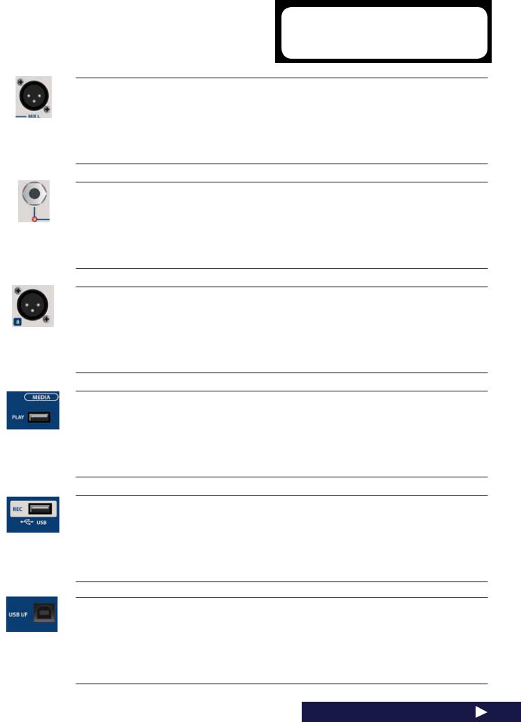
See guide for playback and recording instructions — section 9.0. USB B (DAW Connection) USB Socket for connection directly to PC/Mac The Soundcraft Ui24RR mixer can be used as a 32 x 32 USB Audio Interface with CORE Audio and ASIO drivers. 2.2: Hardware I/O And Control… -
Page 14
Ui24R User Manual 2.2: HARDWARE I/O & CONTROL GETTING STARTED > HARDWARE Power Connector & Switch The Ui mixer has an AC IC connection universal power supply. Use the power switch with the reset button (other side panel) to reset the unit to factory default settings if required. RESET Recessed push switch used to reset the unit. -
Page 15
Ui24R User Manual 2.2: HARDWARE I/O & CONTROL GETTING STARTED > HARDWARE Wi-Fi Indicator Shows Wi-Fi is operating normally The indicator also shows Wi-Fi boot status during power up. It stops its timed flash sequence when booted and available for connections. Then flashes with data activity. If the WiFi LED keeps flashing it can mean the firmware is not loading into the DSP. Make sure latest firm- ware is loaded into the unit and that the DC power connector is properly screwed on. ETHERNET 2… -
Page 16: Input Channel Routing
2.3: INPUT CHANNEL ROUTING Ui24R User Manual GETTING STARTED > INPUT CHANNEL ROUTING The diagram shows the audio signal path through an input channel — from physical input to bus sends (Aux, FX, Mix, and so on). Please note: The entire signal path (except for the hardware pre and output DACs) is clip-free with infinite headroom. It means that internal clipping is not introduced even by driving the EQ/Dyn to the max.
-
Page 17: Getting Connected
Ui24R User Manual GETTING STARTED > GETTING CONNECTED The Soundcraft Ui series uses built-in web server technology to enable computer, tablet, and phone-based in-browser control of all functions — simply connect to the Ui Wi-Fi access point (hotspot) and browse to the appropriate URL. Alternatively, you can connect via an existing Wi-Fi network, or via a wired LAN (Local Area Network) using the Ethernet port on the side of the unit. See Section 10.1 for…
-
Page 18: Software Control
Ui24R User Manual 3.0: SOFTWARE CONTROL SOFTWARE CONTROL The browser-based software control for the Ui Series is available to any device in two versions. The small-screen version is optimised for phone-sized devices; the large-screen version is optimised for tablets and computers. In order to make best use of your Ui mixer, please read this section of software control. There are several navigation and menu access functions that will greatly simplify Ui control.
-
Page 19: 1: Updates & Requirements
10. You can browse to the about page to see the new Firmware version information. USB AUDIO DRIVER The Ui24R requires the use of the Soundcraft SI Impact Audio Driver for multichannel USB playback and recording. It can be downloaded via: http://www.soundcraft.com/en/softwares/soundcraft-multichannel-usb-audio-driver-v3-20 or above…
-
Page 20: 2: Reset The Mixer
Ui24R User Manual 3.0.2: RESET THE MIXER SOFTWARE > RESET THE MIXER There are two levels of reset for the Ui mixer. The first will reset network settings in the event that you are unable to connect. The second (uses a fullreset.txt file on a USB memory stick in conjunction with the reset button. This will fully reset the unit back to its factory firmware and default settings. Networking Reset Reset Networking and Admin password if you have forgotten the admin password or if you are no longer able to connect to the Ui.
-
Page 21: Software Navigation
3.1: SOFTWARE NAVIGATION Ui24R User Manual SOFTWARE > SOFTWARE NAVIGATION There are many navigation / gesture techniques common to both the Tablet and Phone versions of the Ui control software. This section describes the main ones. Section 3.7 summarises all control gestures.
-
Page 22
3.1: SOFTWARE NAVIGATION Ui24R User Manual SOFTWARE > SOFTWARE NAVIGATION Double Tap Channel Strip Double tap anywhere except the fader to access the METERS screen or switch back to the MIX screen from the GAIN screen. Scroll Channel Names Touch/click-hold and slide on channel names to access channel names across the whole mixer, including FX Sends, Aux Sends, and Group Faders. -
Page 23
3.1: SOFTWARE NAVIGATION Ui24R User Manual SOFTWARE > SOFTWARE NAVIGATION Long (held) Tap/Click A long tap/click on certain controls brings up a sub-menu specific to that control. For example, a long hold or click on a channel name gives access to channel presets, renaming, copy/paste settings, sub group assignment, stereo linking, channel reset, and the ASSIGN ME function. Slideout View… -
Page 24: 1: Control / Gesture Summary
3.1.1: CONTROL / GESTURE SUMMARY Ui24R User Manual SOFTWARE > CONTROL SUMMARY:MIX PAGE SHORTCUTS Double Click/Tap on to return Channel Volume to 0db Virtual LCD Display Single click/tap on channel Pan or to temporarily display channel Pan Balance control zone…
-
Page 25
3.1.1: CONTROL / GESTURE SUMMARY Ui24R User Manual SOFTWARE > CONTROL SUMMARY:MIX PAGE SHORTCUTS Double click/tap in AUX MASTER to navigate to AUX SENDS Page channel strip zone (excluding fader cap) Double click/tap on channel fader to channel EDIT mode EQ tab cap to navigate… -
Page 26
3.1.1: CONTROL / GESTURE SUMMARY Ui24R User Manual SOFTWARE > CONTROL SUMMARY:CHANNEL EDIT PAGE PARAMETRIC EQ Double click/tap in vacant space to navigate to MIX page. Drag PEQ frequency balls to adjust dB gain (up and down) and frequency values (left and right) Double click/tap frequency balls to reset selected frequency band to 0dB and default frequency. -
Page 27
3.1.1: CONTROL / GESTURE SUMMARY Ui24R User Manual SOFTWARE > CONTROL SUMMARY:CHANNEL EDIT PAGE GRAPHIC EQ On Master EQ and AUX1-2 you Note, only available on MASTER may also DRAG HPF and LPF Left/Right and AUX/MATRIX 1 and EQ’s to select the desired fre- quency. -
Page 28
3.1.1: CONTROL / GESTURE SUMMARY Ui24R User Manual SOFTWARE > CONTROL SUMMARY:CHANNEL EDIT:AUX SENDS Long click/press-and-hold chan- for ‘set all Pre or Post’ option. nel strip PRE/POST button Double click/tap in channel send to navigate to MIX Page. strip zone (excluding fader cap) Double click/tap on channel label to navigate to selected channel EDIT page DYN tab. -
Page 29
3.1.1: CONTROL / GESTURE SUMMARY Ui24R User Manual SOFTWARE > CONTROL SUMMARY:CHANNEL EDIT:FX SENDS Double click/tap in channel send to navigate to MIX Page. strip zone (excluding fader cap) Double click/tap on channel label. to navigate to selected channel EDIT page DYN tab Long click/press-and-hold on to engage channel pop-up menu. -
Page 30
3.1.1: CONTROL / GESTURE SUMMARY Ui24R User Manual SOFTWARE > CONTROL SUMMARY:CHANNEL EDIT:FX SENDS Double click/tap in channel strip to navigate to MIX Page. zone (excluding fader cap) Double click/tap on channel fader to navigate to channel EDIT mode EQ tab. Double click/tap on channel label… -
Page 31
3.1.1: CONTROL / GESTURE SUMMARY Ui24R User Manual SOFTWARE > CONTROL SUMMARY:SLIDEOUT PANEL SHORTCUTS List selectors in addition to using a ‘load’ button trigger. Item selections available in list boxes can be made by double clicking/tapping on a selection Long click/press-and-hold on to navigate to Sub Group configu- SUB GROUPS ration (METERS page, SUBS tab.) -
Page 32
3.1.1: CONTROL / GESTURE SUMMARY Ui24R User Manual SOFTWARE > CONTROL SUMMARY:CHANNEL EDIT PAGE Digitech Tab: to bring up amp list selector Single click/tap on amp head Digitech Tab: to bring up cab list selector Single click/tap on cabinet DYN Tab: to navigate to MIX page. -
Page 33
3.1.1: CONTROL / GESTURE SUMMARY Ui24R User Manual SOFTWARE > CONTROL SUMMARY:METERS PAGE Single click/tap on any channel to navigate to relevant channel on meter VU zone MIX page. Long click/press-and-hold on for numeric tempo entry. TAP button 3.1.1: CONTROL SUMMARY… -
Page 34
3.1.1: CONTROL / GESTURE SUMMARY Ui24R User Manual SOFTWARE > CONTROL SUMMARY/SHORTCUTS SLO-MO FINE ADJUSTMENT Allows fiune adjustment of param- Hold on fader eters for greater accuracy. SET TO ZERO Double click on any parameter will reset back to zero Double Click JUMP TO METERS/AUX… -
Page 35: Tablet Navigation
3.2: TABLET NAVIGATION Ui24R User Manual SOFTWARE > TABLET / LARGE SCREEN NAVIGATION The MIX Screen is the default for the Ui tablet / large screen software — You can navigate from there to other screens and functions in a variety of ways. The Level 1 Navigation controls take you directly to various primary screens, Level 2 navigation (page tabs) switches layers within the selected screen, and Level 3 navigation controls select individual channels.
-
Page 36: Aux Sends
3.2: TABLET NAVIGATION Ui24R User Manual SOFTWARE > TABLET / LARGE SCREEN NAVIGATION MIX / GAIN Access the MIX and GAIN pages When the button is orange, the MIX page is shown (channel faders) and when the button is Red, the GAIN page is shown (remote gain faders and input stage controls). EDIT Access the EDIT page for the selected channel Resulting page configuration depends on selected channel. For example, the EDIT page for an input chan- nel will have EQ, Dynamics, Aux Sends, and FX Send tabs. Certain Tabs will be preselected if you navigate from certain views.
-
Page 37
3.2: TABLET NAVIGATION Ui24R User Manual SOFTWARE > TABLET / LARGE SCREEN NAVIGATION SNAPSHOT Access the Show and Snapshots pop-up selector Load shows and snapshots directly from this pop-up. SLIDEOUT Access the SLIDEOUT view on the right hand side of the screen Offers fast view and status switching functionality. The Slideout view can be configured as ‘pinned’… -
Page 38: 1: Keyboard Control
3.2.1: KEYBOARD CONTROL Ui24R User Manual SOFTWARE > KEYBOARD CONTROL and shortcuts For users mixing with a device that has a keyboard, please see below a set of easily accessible key com- mands, making it quick and efficient to access the most used features on the mixer. Keys 1 = Meters 2 = Toggle Mix/Gain…
-
Page 39
3.2.1: KEYBOARD CONTROL Ui24R User Manual SOFTWARE > GUI shortcuts Nav bar LCD — long click to jump to SETTINGS->SHOWS Master channel strip LCD — click to toggle view between MIX and METERS page Pan slider — single click to show value in LCD Pan slider — Double click to reset to CENTER Fader cap — Double click fader cap to jumpt to EDIT->GEQ… -
Page 40: Tablet Screens
3.3: TABLET SCREENS Ui24R User Manual SOFTWARE > TABLET SOFTWARE SCREENS The main tablet software screens are accessed from the level 1 Navigation Buttons along the top of the screen area, or via fast-access routes, such as double-tapping on a fader to access the EQ screen (see section 3.1). METERS The Tabs are METERS (for all channels), MUTES (Mute group Assignment), VIEWS (View Group assignment), and SUBS (sub-group assignment). The Meters page features VU meters…
-
Page 41
3.3: TABLET SCREENS Ui24R User Manual SOFTWARE > TABLET SOFTWARE SCREENS EDIT The EDIT page provides access to audio processing such as EQ, DYNAMICS, and FX. The specific audio processing tabs available depend on the selected channel type. For example, the aux outputs and Master Channel include Graphic EQ. -
Page 42
3.3: TABLET SCREENS Ui24R User Manual SOFTWARE > TABLET SOFTWARE SCREENS MEDIA The Ui mixer has a built in media player. This can be used for backing tracks or for background music in between sets. The file playback is streamed directly from a USB stick. Press the MEDIA icon to enter the player page. -
Page 43: Phone Navigation
3.4: PHONE NAVIGATION Ui24R User Manual SOFTWARE > PHONE NAVIGATION The MIX screen is the default for the Ui software — You can navigate from there to other screens and functions in a variety of ways. To access the Menu screen, press the NAV icon in the top right corner of the screen.
-
Page 44: Phone Screens
3.4: PHONE SCREENS Ui24R User Manual SOFTWARE > PHONE SOFTWARE SCREENS From the MENU screen you can access the MIX screen (Return button, top right corner) and nine other primary screens via the large colour-coded buttons. PLAYER The Ui mixer has a built in media player. This can be used for backing tracks or for background music in between sets. The file playback is streamed directly from a USB stick.
-
Page 45
3.5: PHONE SCREENS Ui24R User Manual SOFTWARE > PHONE SOFTWARE SCREENS AUX SENDS AUX SENDS is where the AUX mix is created. The AUX input channel faders determine the signal level sent to that aux bus. Select an aux mix on the right to adjust the mix from all channels. -
Page 46: Mixer Channels
Ui24R User Manual 4.0: MIXER CHANNELS MIXER CHANNELS The Ui mixers has a variety of input and output channel types. You can view all channels in the main MIX screen and drag-scrolling along the virtual console. You can also use the MIX page Slideout panels to select specific channel types and preset views.
-
Page 47: 1: Channel Strip
Ui24R User Manual 4.0:1 CHANNEL STRIP CHANNEL STRIP The Channel Strip has a host of information right at your fingertips. The following is a breakdown of what a user can expect to find. Mute and Solo buttons when acti- vated will either Mute the channel, removing it from the mix or Solo it by removing all other channels. VCA group information is displayed top LH for…
-
Page 48: 2: Ui Side Panel
Ui24R User Manual 4.0:2 Ui SIDE PANEL CHANNEL STRIP The Ui Side panel is a multi-function interface that enables easy access to View and Mute Groups. The expanded format has separate tabs for Banks, Media Player and Functions allowing even greater ac- cessibility.
-
Page 49: Input Gain Page
4.1: INPUT: GAIN PAGE Ui24R User Manual CHANNELS > INPUT: GAIN PAGE The Gain page allows you to control the input stage aspects of a Ui input channel. It is a channel strip-type display with red fader level indicators. TABLET: Click/tap MIX/GAIN button to toggle MIX and GAIN pages.
-
Page 50
4.1: INPUT: GAIN PAGE Ui24R User Manual PHANTOM POWER Phantom Power is required to power certain microphones such as condenser microphones, or other active devices such as an active DI. It is activated per channel. You can get an overview of phan- tom power status in the METERS screen (blue indicator). -
Page 51: Input Mix Page
4.2: INPUT: MIX PAGE Ui24R User Manual CHANNELS > INPUT: MIX PAGE The MIX page is the Ui control software’s default page and allows you to control the routing and panning and fader of a Ui input channel. Please note — the phone software displays panning/balance, solo, and mute status, but for control you should use the EDIT page. Those controls are described in this section.
-
Page 52: Channel Name
4.2: INPUT: MIX PAGE Ui24R User Manual CHANNELS > INPUT: GAIN PAGE MUTE Turn off the audio signal of a channel MUTE is an immediate audio off, rather than having to slide down the fader (and removes the possibility of forgetting its original position). The MUTE button mutes the channel output to the main stereo bus. It can also mute an aux output, depending on the aux’s PRE or POST status (post fader aux will be muted). SOLO Solo this channel The SOLO button is grey when not in use and yellow when operational. Press the SOLO button to only hear the Soloed channel.
-
Page 53: 1: Input Sub Menu
4.2.1: INPUT SUB-MENU Ui24R User Manual CHANNELS > INPUT SUB-MENU (Add VCA after Assign Sub Group on image grab) By long-clicking/tapping on a channel name you can access the channel sub-menu for access to various channel parameters… CHANNEL PRESETS Recall and save whole channel settings — Factory and User preset banks. RENAME Rename the channel. The new name will be shown in the Channel Name fields.
-
Page 54: 2: Vca Groups
4.2.2: VCA GROUPS Ui24R User Manual ASSIGN VCA VCA Groups allow you to control groups of Input Channels from a single VCA Master. For example, you could put the whole drum kit under the control of a single VCA Master, or if you have a multiple mics on a guitar cabi- net you could set the ratios with individual channels and then create a Guitar VCA Master — move the VCA Mas- ter Channel and all Group Member levels will be ‘offset’ from current levels by the VCA Master level. The Ui24R…
-
Page 55: 3: Matrix
4.2.3: MATRIX Ui24R User Manual MATRIX Matrix can best be described as a mixer inside the mixer. In its most simple form, a matrix takes a selec- tion of inputs (usually derived from the group and main output buses) and allows routing of those signals, complete with level control, to a series of outputs. Matrix systems offer the ability to choose from a variety of inputs including external sources, and offer sig- nal processing including EQ, compression, noise gate and delay/reverb.
-
Page 56: 4: Meters
4.2.4: METERS Ui24R User Manual METERS The Meters page displays all active channels meter readings along with indicators for Mute, Solo, Phantom 48v power and Phase Reverse. Users can click on any channel meter and they will be brought to directly to that channel. Alterna- tively, double clicking in an input channel will bring the user back to the Meters page.
-
Page 57: Aux Sends
AUX SENDS is where the aux mixes are created — these can be for monitor outputs, for external FX sends, and more. They have dedicated outputs on the Ui hardware. The aux faders have orange level indicator lines and determine how much of each input channel is contributed to the Aux bus. Ui24R has 8 main Aux busses available.You can view all aux contributions from a single channel by navigating to that channel’s EDIT page and selecting the AUX SENDS screen / tab.
-
Page 58
4.3: AUX SENDS Ui24R User Manual CHANNELS > AUX SENDS M-AUX / COPY MIX Copy the main mix to this aux mix This button copies the fader positions from the MIX page and moves all aux send faders to the same posi- tion on the AUX SENDS page. -
Page 59
4.3: AUX SENDS Ui24R User Manual CHANNELS > AUX POP MENU CHANNEL PRESETS Recall and save whole AUX channel settings — Factory and User preset banks. RENAME Rename the AUX channel. The new name will be shown in the AUX Name fields. COPY / PASTE SETTINGS Copy the AUX channel settings to the pasteboard. A ‘PASTE SETTINGS’ option will appear when you select another AUX channel sub menu. Use that to paste the copied settings to that AUX channel. -
Page 60
4.3: AUX SENDS Ui24R User Manual CHANNELS > AUX SENDS AUX SENDS In Channel edit mode the AUX Sends tab will show the selected Channels sends to all AUX’s creating an alternate Channel based AUX view. 4.3: AUX SENDS… -
Page 61: 1: Aux Master
The Aux Master channel is the output path for Aux busses. In other words, the Aux 1 mix of contribu- tions from all input channels passes through the Aux 1 Master channel before being sent out of the physical Aux 1 output. Ui24R has four Aux busses available, and Ui24R has six. The highest-num- bered aux pairs (3/4 for Ui24R and 5/6 for Ui24R) are available as physical outputs when the HEAD- PHONES OUT option is set to ‘AUX’ in SETTINGS…
-
Page 62: Fx Sends
4.4: FX SENDS Ui24R User Manual CHANNELS > FX SENDS FX SENDS faders effectively determine the amount of effect (delay, reverb, chorus) on each input channel. They work much like aux sends in that a mix of input channel contributions is created on the FX SENDS page — one for each FX processor. After processing, that mix is returned via its own FX Return channel, which works just like an input channel — adjusting the overall level of that processor’s mix in the master…
-
Page 63: Sub Group Master
4.5: SUB GROUP MASTER Ui24R User Manual CHANNELS > SUB GROUP MASTER CHANNEL (4 x Sub Groups) If you want to have control over the drum kit mix, for example, but also want single fader control over the whole kit’s contribution to the mix, you would use a Sub Group. When input channels are allocated to Sub Groups, either via the input channel sub-menu, or via the SUBS screen in the DASHBOARD/METERS page, they are mixed together into a single stereo channel.
-
Page 64: 1: View/Mute Groups
VIEW & MUTE GROUPS There are 6 View and 6 Mute groups available for users on the Ui24R. These can be navigated to via the Ui24R sidebar. Users can name the group, set the group number and elements of the group with this screen.
-
Page 65: Master Channel
4.6: MASTER CHANNEL Ui24R User Manual CHANNELS > MASTER CHANNEL The Master Stereo Channel is the output channel for the main stereo (left & right) mix — determined by the input channel and FX Return channel faders and pan/balance controls. The Master Channel has its own EDIT page tabs, just like other channels (see section 5). The EQ for Ui Output channels (including Aux Masters) is a Graphic EQ (GEQ) rather than a parametric EQ (input channels and sub group masters). The Master Fader (red fader knob) controls the overall output volume of your mixer. The actual level set by the fader is shown in the top display above the fader in dB (decibels). Display & Indicators As well as dB, this display also has 3 useful indicators: CLIP (C) Notifies you of any input gain clipping. When an input channel signal…
-
Page 66: 1: Master Channel Sub-Menu
4.6.1: MASTER SUB-MENU Ui24R User Manual CHANNELS > MASTER CHANNEL > SUB MENU By long-clicking/tapping on a the Master Channel name you can access the Master Channel sub-menu for access to the ‘Set To Zero’ function and the Master Channel Preset Manager. SET TO ZERO DB This is a fast way to set the channel fader level back to zero dB. Click and Hold the MASTER channel name, then touch SET TO ZERO DB.
-
Page 67: Channel Edit
Ui24R User Manual 5.0: CHANNEL EDIT CHANNEL EDIT The EDIT page is the basic access point for channel-based signal processing: EQ, dynamics, and FX and auxiliary sends. The actual processing and options available depend on the channel type. The selected channel strip will be shown on the left of the EDIT screen. In the phone software, the default EDIT page is a via-point for more detailed views and also offers access to basic channel parameters such as pan/balance, phase, phantom power, and more.
-
Page 68: Digitech
Ui24R User Manual 5.1: DIGITECH CHANNEL EDIT > DIGITECH DigiTech input processing and channel view is available to the first two Ui mixer channels, and includes Hi-Z (high input impedance) selection for sources such direct-input guitar pick-ups. The DigiTech processing includes amp modelling: Emulations of guitar amps (with associated param- eters) and cabinets. The DigiTech view also allows single-view editing of selected channel features via the ‘Jack-Plug Buttons’. Note: This is an AMP simulator, it’s not a complete FX chain. AMP SELECT Choose a guitar amp model Clicking or tapping anywhere on the guitar amp graphic will bring up a pop-up menu of available guitar amp models.
-
Page 69: Channel Controls
Ui24R User Manual 5.1: DIGITECH CHANNEL EDIT > DIGITECH DIGITECH ON/OFF Turn DigiTech processing on or off When DigiTech processing is turned off, the channel will revert to its standard input stage. PRESETS Open the PRESETS management pop-up You can save and load settings presets for the DigiTech processing using this pop-up.
-
Page 70: Parametric Eq
Ui24R User Manual 5.2: PARAMETRIC EQ CHANNEL EDIT > PARAMETRIC EQ EQ adjusts the amplitude of an audio signal at particular frequencies. Ui input channels, FX Return channels, and Sub Group master channels have a four-band parametric EQ, plus High Pass Filter (HPF), and a De-Esser controlled from the same screen. The display also incorporates an optional…
-
Page 71
Ui24R User Manual 5.2: PARAMETRIC EQ CHANNEL EDIT > PARAMETRIC EQ RESET Reset the EQ to default values The EQ is set ‘flat’, and frequency and Q values are reset to defaults. BYPASS Bypass the EQ section of channel processing This control bypasses only the parametric EQ. HPF and De-Esser processing is unaffected. -
Page 72
Ui24R User Manual 5.2: PARAMETRIC EQ CHANNEL EDIT > PARAMETRIC EQ HPF/LPF BALL Draggable graphic ‘ball’ for High Pass and Low Pass Filter controls Drag this graphic element to control. Left/Right adjusts Cut-Off frequency. Double-click/tap to reset. Right Hand side of the screen displays selectable slope. HPF/LPF SLOPE CONTROL High pass and low pass filtering is available to Ui24R users and is accessible through the Parametric EQ. -
Page 73
Ui24R User Manual 5.2: PARAMETRIC EQ CHANNEL EDIT > PARAMETRIC EQ EQ Q Fader control of EQ ‘Q’ Q is effectively a measure of how tall and thin the bell shape of the EQ band is — the lower the Q, the wider the bandwidth affected, and vice versa. Fader control of EQ is only available with tablet software. Double- click/tap to reset. -
Page 74: Graphic Eq
Ui24R User Manual 5.3: GRAPHIC EQ CHANNEL EDIT > GRAPHIC EQ Ui Aux Send Master channels and the Stereo Master Channel incorporate Graphic EQ (GEQ) instead of the parametric EQ of the input channels. This includes 31 fixed frequency bands (which can be scrolled across the screen) with adjustable boost/cut. In addition, the GEQ screen gives access to the dbx AFS (Automatic Feedback Suppression) processing. The display also incorporates an optional Real Time Analyser (RTA), which shows a spectral view of the incoming signal. HPF/LPF Master Outputs and Aux/Matrix Out 1/2 HPF and LPF can be dragged to setup crossover points and filters Activate the Real Time Analyser feature The RTA display shows a real-time spectral view of incoming audio. This is sometimes useful for targeting specific characteristics with EQ bands quickly.
-
Page 75
Ui24R User Manual 5.3: GRAPHIC EQ CHANNEL EDIT > GRAPHIC EQ BYPASS Bypass the GEQ processing dbx AFS SETUP Set up and operate the feedback elimination system for this bus. Only available with tablet software. See section 5.3.1 for more detail. -
Page 76: Afs
Ui24R User Manual 5.3.1: AFS CHANNEL EDIT > GRAPHIC EQ > AFS AFS2 is a dbx feedback suppression system that uses 12 intelligent filters to detect and eliminate feedback across the audio spectrum. You can set AFS2 up on the master stereo output and/or Aux bus master channels by navigating to the channel’s Edit screen and selecting the EQ tab. works in two modes. Fixed mode is used for ‘ringing out’ a system before a performance to ensure maximum headroom.
-
Page 77
Ui24R User Manual 5.3.1: AFS CHANNEL EDIT > GRAPHIC EQ > AFS MODE Choose LIVE, FIXED, or LOCK Fixed mode is for pre-performance set-up, Live mode is for use during performance, and LOCK prevents changes to the current filters status. SENSITIVITY Adjust the input level feeding the AFS… -
Page 78: 1: Gate
5.4.1: GATE CHANNEL EDIT > GATE The Ui24R Gate section is accesible via the Edit Tab on the top toolbar. A Gate is a threshold-driven gain reduction process normally used to attenuate a signal when its level falls below the Threshold.
-
Page 79
Ui24R User Manual 5.4.1: GATE CHANNEL EDIT > DYNAMICS DEPTH Adjust the gate Depth RELEASE Adjust the Gate Release This is the speed at which the gate returns to ‘no attenuation’ after the signal level has fallen below the threshold level. GRM — METERING Gain reduction metering There are three meters: Input signal, output signal, and a meter showing the amount of attenuation currently being applied due to the dynamics processing. -
Page 80
Ui24R User Manual 5.4.1: GATE CHANNEL EDIT > DYNAMICS PRESETS Save / load Dynamics presets Brings up a standard preset management pop-up box. 5.4.1: GATE… -
Page 81: 2: Compressor
5.4.2: COMPRESSOR CHANNEL EDIT > COMPRESSOR The Ui24R Compressor section is accesible via the Edit Tab on the top toolbar. A compressor is a threshold driven process used to reduce the dynamic range of a signal by applying gain reduction when the signal level exceeds the threshold and applying ‘make-up gain’ to keep the overall level con-…
-
Page 82
Ui24R User Manual 5.4.2: COMPRESSOR CHANNEL EDIT > COMPRESSOR RELEASE Adjust the Release of the compressor How soon after the signal dips below the threshold the compressor stops. GAIN Adjust the Gain of the compressor Allows you to boost the compressed signal. as compression often attenuates the signal significantly HOLD Adjust the Hold time. -
Page 83: Aux/Fx Sends
Ui24R User Manual 5.5: AUX/FX SENDS CHANNEL EDIT > AUX/FX SENDS The AUX and FX SENDS tabs in the EDIT screen are a convenient way to access all output contributions for a single channel — as opposed to the ‘mix view’ approach of the dedicated AUX SEND and FX SEND pages. The AUX SENDS view/tab for both phone and tablet software versions includes PRE/POST and MUTE buttons for each send.
-
Page 84: Patching
Ui24R User Manual 5.6 PATCHING Patches can be set up for Local inputs, Multitrack USB A and Multi-track USB-DAW Quick reset and Patch 1:1 make setting and resetting patches a one touch solution. LOCAL The Patching screen enables the user to select either the input source 1-20 or L/R Line In for each channel.
-
Page 85
Ui24R User Manual 5.6 PATCHING SOUNDCHECK Soundtcheck is basically another set of patches. It can be used to set up a trial mix via pre-recorded files on USB for example or work on a straight live soundcheck or a mixture of both. Setup is the same as it is for normal patching applications. Once the Soundcheck mode is engaged the selection panel will be green. -
Page 86
Ui24R User Manual 5.6: PATCHING SOUNDCHECK ASSIGN PAGE The Soundcheck Assign page assigns the soundcheck patch for the selected channel. SOUNDCHECK INDICATOR The Soundcheck Indicator is located in the top left corner of the Level 1 LCD Panel. This will appear to indicate when the Ui is in Soundcheck Mode. -
Page 87: Mix Features
Ui24R User Manual 6.1: VIEW & MUTE GROUPS MIX FEATURES > VIEW & MUTE GROUPS In Ui software you can mute channels individually, or in Mute Groups. There are six Mute Groups available to be assigned to any muteable channels. To mute all channels in a Mute Group, simply select the required Mute Group button. View Groups work in much the same way, though these define…
-
Page 88: Moreme
Ui24R User Manual 6.2: MOREME MIX FEATURES > MOREME MOREME allows users to assign their own channels (which may include a vocal mic and an instrument channel for example) and mix the balance of those channels with a single large fader. This is a simple way to mix your own sound against other band members. To view MOREME in the phone software, open the NAV menu and press MOREME, or it can be accessed from the AUX SENDS screen with a double press on the green AUX MASTER fader.
-
Page 89
Ui24R User Manual 6.2: MOREME MIX FEATURES > MOREME “MOREME” Portrait Mode ON/OFF It is now possible to define whether MOREME is displayed automatically in portrait mode on devices offering orientation support. Some users prefer to operate fader view pages (MIX, AUX, FX) in por- trait display orientation so the faders are “long throw”. MOREME Modes: MOREME ON — Portrait mode orientation will automatically display the MOREME page MOREME OFF — Portrait mode orientation will display the regular GUI with extended faders. Some features of the GUI display will be “grayed out” and restricted from view due to the dimension limita-… -
Page 90
7.0: FX EDIT FX EDIT Digital FX are used in all types of audio to help create depth and colour to a mix. The Ui24R has three internal Lexicon FX processors: Reverb, Delay, and Chorus. The Ui24R has an additional processor that can either be an additional reverb or delay. -
Page 91: Reverb
Ui24R User Manual 7.1: REVERB FX EDIT > REVERB Reverberation (or “reverb” for short) is the complex effect created by the way we perceive sound in an enclosed space. Reverb is dependent on many features of that space, including the size, shape and the type of materials that line the walls. Reverb is a natural component of the acoustic experience, and most people feel that something is missing without it.
-
Page 92: Delay
Ui24R User Manual 7.2: DELAY FX EDIT > DELAY Delays repeat a sound a short time after it first occurs. Delay becomes echo when the output is fed back into the input (feedback). This turns a single repeat into a series of repeats, each a little softer than the last. The Ui delay time is set in Milliseconds or in musical values. Press the DIV display to access a drop down box with the available musical note values. Press the TAP TEMPO button repeatedly to tap in the desired delay time. (This is usually done in time with the music.) Press and hold the TAP TEMPO button to manually type in the delay time in BPM. TAP / BPM Delay Tempo A delay time setting that uses a ‘tapped’ tempo as a guide. Tap the ‘TAP TEMPO’ button to set the delay…
-
Page 93: Chorus
Ui24R User Manual 7.3: CHORUS FX EDIT > CHORUS Chorus creates a lush, full sound by combining two or more signals together where one is unaffected and the other signals vary in pitch very slightly over time. Chorus is commonly used to fatten up tracks and to add body to guitars without colouring the original tone.
-
Page 94: Effects Screen
Ui24R User Manual 7.4: FX SCREEN FX EDIT > EFFECTS SCREEN The Effects Screen has four effects patches. The first patch is fixed with a high quality Lexicon reverb but the other three are assignable. Click and Hold on the ef- fect name will bring up a menu for quick selection of Reverb or Delay Click and Hold on the ef-…
-
Page 95: Shows & Snapshots
Ui24R User Manual 8.0: SHOWS & SNAPSHOTS SHOWS & SNAPSHOTS A SHOW is a collection of SNAPSHOTS. A SNAPSHOT is a record of every setting on the console. You can save and recall snapshots and shows via the Ui control software — Phone or Tablet.
-
Page 96
Ui24R User Manual 8.0: SHOWS & SNAPSHOTS SHOWS & SNAPSHOTS The unit ships with the Default Show loaded, and the * Init * snapshot. It is a good idea to create a new Show to work with and use the Default Show is an easy route back to default settings. -
Page 97: Media Player & Recorder
The Record (Ui24R) and Playback features use one or two USB Memory sticks placed in the USB sockets on the Ui hardware. The Ui24R has both play and record sockets on the front panel, the Ui24R has a USB ‘PLAY’ socket. There are two more USB sockets on the side panel of the unit. Press the MEDIA icon to enter the player page, or go via the PLAYER menu button in Phone software.
-
Page 98
2-Track Stereo USB recording is available on the Ui24R. New shuffle button. MTK USB Record Along with 2-Track stereo recording, the Ui24R can also multitrack record up to 22 separate tracks which can then be imported into any DAW software for further processing or mastering. MTK USB Playback Individual multitrack recordings can be played back through the GUI and remixed. -
Page 99
MULTI-TRACK PLAYBACK & RECORDING FROM USB The Ui24R can playback and record multi-track from USB up to 22 tracks. Patches will be set by dou- ble clicking a mixer patch slot which will open up the mixer patch assignment modal. Any changes will be universal. -
Page 100: 2: Usb Playback & Recording
PLAYBACK & RECORDING USB STICK COMPATIBILITY The Ui24R is compatible with most USB sticks for 2 track playback and recording. Multi-track USB Play- back will require a minimum of USB 3.0 with a transfer rate of 25mb/s. SPEED BUFFER INDICATOR The Speed buffer indicator will monitor the transfer rate during USB Playback and Recording.
-
Page 101
Patching of USB-DAW can be done within an individual channels Patching Screen USING THE USB-DAW PROCESSING AS AN INSERT WITHIN THE Ui24R This screen allows the user to adjust the input level when they are using their DAW processing as an insert on an input channel. -
Page 102: Settings
Ui24R User Manual 10.0: SETTINGS SETTINGS The SETTINGS page allows the user to manage basic setup configurations, network parameters (including the password setting for the WiFi access point), GUI preferences, and access permissions on a per-user basis. Phone and tablet software versions display the settings in slightly different forms, but al are accessible on either platform. The sub headings used in this section refer to the Tablet software.
-
Page 103
Ui24R User Manual 10.0: SETTINGS SETTINGS GUI PERFORMANCE FRAME RATE FULL, 1/2, 13, 1/4 Choose the highest frame rate that your device can reproduce for best performance. DISABLE RESCALING ON, OFF Enable/Disable display rescaling. Disable this if your display is struggling with GUI movements.. -
Page 104
Ui24R User Manual 10.0: SETTINGS SETTINGS DISABLE VU INPUT LEVEL OFF,ON Disable/Enable input level VU meters. DISABLE VU PEAK OFF, ON Disable / Enable the peak indicators for VU meters. HIDE COMP/GATE OFF, ON When off, the channel meters include shorter red LED gain reduction metering below the primary meters. -
Page 105
Ui24R User Manual 10.0: SETTINGS SETTINGS PEDAL FUNCTION MUTE FX Enable pedal to mute FX MUTE ALL Enable pedal to mute all channels PLAY Enable pedal to activate USB playback RECORD Enable pedal to activate USB record TAP TEMPO Enable pedal to set delay tempo via tap tempo function… -
Page 106
Ui24R User Manual 10.0: SETTINGS SETTINGS LOCAL USER GUI PRESETS Local client side user settings can now be save/loaded as presets to connected media. This al- lows users to change devices with ease, taking their predefined local user presets with them, without having to set up their GUI every time they change devices! Local client side GUI settings can be found in the SETTINGS—>SETTINGS tab page, under LO- CAL. -
Page 107
Ui24R User Manual 10.0: SETTINGS Solo and headphone levels You can digitally set the output volume for Headphone 1 or 2 as well as the relative SOLO level. 10.0: SETTINGS… -
Page 108
There is also an Administration password change page, and a summary ‘Network State’ page. IMPORTANT: The default administration user name is ‘admin’ and the default administration password is ‘admin’. You will be asked for these when you touch the CONFIG button. You can either use the UI24R as a hotspot or connect to an external Wifi network. LAN is available at anytime unless disabled. You can change the password using the Administrator Password page once you are in the CONFIG area. -
Page 109: 1: Hotspot Settings
Ui24R User Manual 10.1.1: HOTSPOT SETTINGS > NETWORK CONFIG > HOTSPOT The Ui has it’s own hotspot, so it can create it’s own network so other devices can connect to it and ac- cess the software in it’s built-in webserver. Select the Hotspot Configuration menu in Network Config to edit the Hotspot settings. Use the Save/Update button to save Hotspot settings. IMPORTANT: You cannot have both Hotspot and Client WIFI enabled at the same time. Hotspot Enabled / Disabled Enable or disable the UI’s own Hotspot. Please note, if the Hotspot is disabled you will need to connect to the Ui via…
-
Page 110
Ui24R User Manual 10.0.1: HOTSPOT SETTINGS > NETWORK CONFIG > HOTSPOT ENABLE/DISABLE BROADCAST OF THE UI’s HOTSPOT NETWORK SSID There is now an option to enable or disable the broadcasting of the Ui networks hotspot SSID. To enable/disable broadcast of the Ui’s hotspot SSID: — Go to the SETTINGS—>NETWORK tab page… -
Page 111: 2: Wi-Fi Settings
Ui24R User Manual 10.1.2: WI-FI SETTINGS > NETWORK CONFIG > WI-FI The Ui can connect to an existing Wi-Fi network / Hotspot, and you can access the control software via the unit’s IP number (shown in Settings > Network). Select the Wi-Fi Configuration menu in Network Config to edit the Wi-Fi settings. Use the Save/Update button to save Wi-Fi settings.
-
Page 112: 3: Lan Settings
Ui24R User Manual 10.1.3: LAN SETTINGS > NETWORK CONFIG > LAN The Ui can connect to an existing wired LAN (Local Area Network) by connection the Ethernet port on the side of the unit. This is the fastest, most secure method of connection to the Ui. Select the LAN Configuration menu in Network Config to edit the LAN settings. Use the Save/Update button to save LAN settings.
-
Page 113
Ui24R User Manual MASTER PASSWORD HARD LOCK (ADMIN/PASS) ACCESS LIMITATIONS A master password protection access limitation feature has been designed to allow a user logged in with a master password the ability to define a wide range of mixer access limitations for other connected users (without knowledge of the password. ie not logged in). Enabling MASTER PASSWORD PROTECTION: — Go to SETTINGS—>ACCESS tab page — Select the ENABLE button — Set a master password of your choice to enable MASTER PASSWORD PROTECTION Note: Enabling MASTER PASSWORD PROTECTION will automatically log a user in. -
Page 114
Ui24R User Manual APPENDIX 01: NO SOUND? NO SOUND? A TROUBLESHOOTING GUIDE A Troubleshooting Guide. One of the most common problems experienced with mixing consoles is finding that an input isn’t appearing at an output. There are many possible reasons for this, but the best way to troubleshoot it is to go through the expected signal path and workout where the ‘break’ is… It is also important that you double checking all routing, assignments, and Solo / Mute Group status. -
Page 115
Ui24R User Manual APPENDIX 01: NO SOUND? NO SOUND? A TROUBLESHOOTING GUIDE Is the Gate shut? It is possible for an incorrectly set Gate process to stop all signal. This happens most often when the threshold is set too high and the signal never gets loud enough to ‘open’ the Gate. You can easily check this by bypassing active Gates in the dynamics (DYN) tab of the channel EDIT page. -
Page 116
Ui24R User Manual APPENDIX 02: SYSTEM FAQ SYSTEM FAQ The Ui is not just an audio mixer — it is a WiFi hotspot and a web server, and it runs sophisticated control software for phone and tablet-type devices. The following FAQ addresses any issues you might have with this ‘system’ aspect of Ui operation. -
Page 117
Ui24R User Manual APPENDIX 02: SYSTEM FAQ SYSTEM FAQ A (Windows 8, 8.1, RT): This is obviously most useful on tablets, not on desktop PCs where you don’t want to see the Start screen. Navigate to the website you want to pin, pull up the app bar by right-clicking or swiping up from the bottom of your screen and tap the star icon. Tap the pin icon, enter a name for the shortcut, and click Pin to Start. -
Page 118
Ui24R User Manual APPENDIX 02: SYSTEM FAQ SYSTEM FAQ 7) The Ui mixer will perform a firmware update The GUI will present a message stating whether the update has been successful or not. 9) You must power cycle the unit and reconnect their client device. 10) You can now browse to the about page to see the new firmware version information. Q: How do I attenuate the media player input? It is really hot signal? You can use adjust the Compressor Gain control down -24dB to compensate for the incredibly hot signal that many audio files are mastered at. This adjustment will act like a PAD and allow you additional range on…
 -
Page 119
SYSTEM FAQ-HDMI HDMI connection issues: The Ui24R requires that HDMI connected components be able to recognize and communicate with each other. This is referred to as the “HDMI handshake”. If the “handshake” doesn’t work, the HDCP encryption that is imbedded in the HDMI signal is not being recognized properly by one, or more, of the connected components. -
Page 120
APPENDIX 02: SYSTEM FAQ SYSTEM FAQ-Touch screen Touch connection issues: The Ui24R requires that the touch screen information be passed via a USB cable to one of the USB A con- nections. Each screen has it’s own USB ID number called VID and PID, in some instances even the same model may have a different VID and PID depending on which country it was purchased from. -
Page 121
In such situations it is recommended to use a more powerful external router with larger antennas or use an Ethernet connection directly to the Ui24R. Using a Wifi scanner application you should determine which channels are free in your area and set the Ui24R to use one of these channels. You should also have a direct line of sight to the Wifi Antenna of the Ui24R or router you are using. DOM 18 error If you are getting the following error message when connecting to the Ui mixer’s hotspot via ipad: 498 Securityerror DOM exception 18. An attempt was made to break thru security policy of user agent. It’s…
 The GUI will present a message stating whether the update has been successful or not. 9) You must power cycle the unit and reconnect their client device. 10) You can now browse to the about page to see the new firmware version information. Q: How do I attenuate the media player input? It is really hot signal? You can use adjust the Compressor Gain control down -24dB to compensate for the incredibly hot signal that many audio files are mastered at. This adjustment will act like a PAD and allow you additional range on…
 Посмотреть инструкция для Soundcraft Ui24R бесплатно. Руководство относится к категории DJ-система, 62 человек(а) дали ему среднюю оценку 8.8. Руководство доступно на следующих языках: английский. У вас есть вопрос о Soundcraft Ui24R или вам нужна помощь? Задайте свой вопрос здесь
Не можете найти ответ на свой вопрос в руководстве? Вы можете найти ответ на свой вопрос ниже, в разделе часто задаваемых вопросов о Soundcraft Ui24R.
Когда звук считается слишком громким?
Инструкция Soundcraft Ui24R доступно в русский?
Не нашли свой вопрос? Задайте свой вопрос здесь
Смотреть руководство для Soundcraft Ui24R ниже. Все руководства на ManualsCat.com могут просматриваться абсолютно бесплатно. Нажав кнопку «Выбор языка» вы можете изменить язык руководства, которое хотите просмотреть.

MANUALSCAT | RU
Вопросы и ответы
У вас есть вопрос о Soundcraft Ui24R, но вы не можете найти ответ в пользовательском руководстве? Возможно, пользователи ManualsCat.com смогут помочь вам и ответят на ваш вопрос. Заполните форму ниже — и ваш вопрос будет отображаться под руководством для Soundcraft Ui24R. Пожалуйста, убедитесь, что вы опишите свои трудности с Soundcraft Ui24R как можно более детально. Чем более детальным является ваш вопрос, тем более высоки шансы, что другой пользователь быстро ответит на него. Вам будет автоматически отправлено электронное письмо, чтобы проинформировать вас, когда кто-то из пользователей ответит на ваш вопрос.
как подключить фантомное питание на канал?
Тимур2021-12-04
Задать вопрос о Soundcraft Ui24R
- Бренд:
- Soundcraft
- Продукт:
- DJ-система
- Модель/название:
- Ui24R
- Тип файла:
- Доступные языки:
- английский
Сопутствующие товары Soundcraft Ui24R
Ui24R User Manual
INFORMATION
IMPORTANT
Please read this manual carefully before using your mixer
for the first time.
This equipment complies with the EMC directive 2004/30/EU and LVD 2014/35/EU
This product is approved to safety standards:
EN 60950-1:2006 + A11:2009 + A1:2010 + A12:2011 + A2:2013
And EMC standards
EN55032:2012+AC:2013
EN55103-2:2009
EN61000-3-3: 2013
EN61000-3-2: 2014
Warning: Any modification or changes made to this device, unless explicitly approved by Harman, will
invalidate the authorisation of this device. Operation of an unauthorised device is prohibited under Section
302 of the Communications act of 1934, as amended, and Subpart 1 of Part 2 of Chapter 47 of the Code of
Federal Regulations.
NOTE: This equipment has been tested and found to comply with the limits for a Class B digital device, pursuant to
Part 15 of the FCC Rules. These limits are designed to provide reasonable protection against harmful interference in
a residential installation. This equipment generates, uses and can radiate radio frequency energy and, if not installed
and used in accordance with the instructions, may cause harmful interference to radio communications. However,
there is no guarantee that interference will not occur in a particular installation. If this equipment does cause harmful
interference to radio or television reception, which can be determined by turning the equipment off and on, the user is
encouraged to try to correct the interference by one or more of the following measures:
* Reorient or relocate the receiving antenna
* Increase the separation between the equipment and the receiver
* Connect the equipment into an outlet on a circuit different from that to which the receiver is connected.
* Consult the dealer or an experienced radio/TV technician for help.
For further details contact:
Harman Professional Inc, 8500 Balboa Blvd. Northridge,CA 91329 USA
email: soundcraft@harman.com
© Harman International Industries Ltd. 2017 All rights reserved
Parts of the design of this product may be protected by worldwide patents.
Part No. 5076585 USA, 5076586 EU, 5085429 AU
Rev 1.0
E&OE January 2017
Soundcraft is a trading division of Harman International Industries Ltd. Information in this manual is subject to change
without notice and does not represent a commitment on the part of the vendor. Soundcraft shall not be liable for any
loss or damage whatsoever arising from the use of information or any error contained in this manual. No part of this
manual may be reproduced, stored in a retrieval system, or transmitted, in any form or by any means, electronic,
electrical, mechanical, optical, chemical, including photocopying and recording, for any purpose without the express
written permission of Soundcraft.
Harman International Industries Limited
8500 Balboa Blvd. Northridge,CA 91329 USA
http://www.soundcraft.com
INFORMATION
INFORMATION
 Loading…
![]()
 ®
®  series
User Guide v1.0
For Soundcraft Ui24R
®
|
Ui24R User Manual |
INFORMATION |
INFORMATION
IMPORTANT
Please read this manual carefully before using your mixer for the first time.
This equipment complies with the EMC directive 2004/30/EU and LVD 2014/35/EU
This product is approved to safety standards:
EN 60950-1:2006 + A11:2009 + A1:2010 + A12:2011 + A2:2013
And EMC standards
EN55032:2012+AC:2013
EN55103-2:2009
EN61000-3-3: 2013
EN61000-3-2: 2014
Warning: Any modification or changes made to this device, unless explicitly approved by Harman, will invalidate the authorisation of this device. Operation of an unauthorised device is prohibited under Section 302 of the Communications act of 1934, as amended, and Subpart 1 of Part 2 of Chapter 47 of the Code of Federal Regulations.
NOTE: This equipment has been tested and found to comply with the limits for a Class A digital device, pursuant to Part 15 of the FCC Rules. These limits are designed to provide reasonable protection against harmful interference in a residential installation. This equipment generates, uses and can radiate radio frequency energy and, if not installed and used in accordance with the instructions, may cause harmful interference to radio communications. However, there is no guarantee that interference will not occur in a particular installation. If this equipment does cause harmful interference to radio or television reception, which can be determined by turning the equipment off and on, the user is encouraged to try to correct the interference by one or more of the following measures:
*Reorient or relocate the receiving antenna
*Increase the separation between the equipment and the receiver
*Connect the equipment into an outlet on a circuit different from that to which the receiver is connected.
*Consult the dealer or an experienced radio/TV technician for help.
For further details contact:
Harman Professional Inc, 8500 Balboa Blvd. Northridge,CA 91329 USA email: soundcraft@harman.com
© Harman International Industries Ltd. 2017 All rights reserved
Parts of the design of this product may be protected by worldwide patents. Part No. 5076585 USA, 5076586 EU, 5085429 AU
Rev 1.0
E&OE January 2017
Soundcraft is a trading division of Harman International Industries Ltd. Information in this manual is subject to change without notice and does not represent a commitment on the part of the vendor. Soundcraft shall not be liable for any loss or damage whatsoever arising from the use of information or any error contained in this manual. No part of this manual may be reproduced, stored in a retrieval system, or transmitted, in any form or by any means, electronic, electrical, mechanical, optical, chemical, including photocopying and recording, for any purpose without the express written permission of Soundcraft.
|
Harman International Industries Limited |
|||
|
8500 Balboa Blvd. Northridge,CA 91329 USA |
|||
|
INFORMATION |
|||
|
http://www.soundcraft.com |
|||

Ui24R User Manual
CONTENTS
1.0 AN INTRODUCTION TO Ui
1.1: Safety
1.2: Warranty
1.3: Specifications
2.0: GETTING STARTED
2.1: System Overview
2.2: Hardware I/O & Control
2.3: Input Channel Routing
2.4: Getting Connected
3.0: SOFTWARE CONTROL
3.0.1: Updates & Requirements
3.0.2: Reset The Mixer
3.1: Software Navigation
3.1.1: Control / Gesture Summary
3.2: Tablet Navigation
3.2.1: Keyboard Control
3.3: Tablet Screens
3.4: Phone Navigation
3.5: Phone Screens
4.0: MIXER CHANNELS
4.0.1: Channel Strip
4.0.2: Ui Side Panel
4.1: Input Gain Page
4.2: Input Mix Page
4.2.1: Input Sub Menu
4.2.2: VCA Groups
4.2.3: Matrix
4.2.4: Meters
4.3: Aux Sends
4.3.1: Aux Master
4.4: FX Sends
4.5: Sub Group Master
4.5.1: View/Mute Groups
4.6: Master Channel
4.6.1: Master Channel Sub-Menu
CONTENTS
5.0: CHANNEL EDIT
5.1: DigiTech
5.2: Parametric EQ
5.3: Graphic EQ
5.3.1 AFS2 — Feedback Elimination
5.4:1: Gate
5.4.2: Compressor
5.5: Aux / FX Sends
5.6: Patching
6.0: MIX FEATURES
6.1: View & Mute Groups
6.2: MOREME
7.0: LEXICON FX EDIT
7.1: Reverb
7.2: Delay
7.3: Chorus
7.4: Effects Screen
8.0: SHOWS & SNAPSHOTS
9.0: MEDIA PLAYER & RECORDER
9.0.1: Multitrack Playback & Recording
9.0.2: USB Playback & Recording
10.0: SETTINGS
10.1: Network Configuration
10.1.1: Hotspot Settings
10.1.2: Wi-Fi Settings
10.1.3: LAN Settings
10.1.4: Access control
APPENDIX 01: Troubleshooting: No Sound?
APPENDIX 02: Troubleshooting: System FAQ
For clarity, this manual uses section references rather than page numbers. In some instances, one section reference may extend to several pages.
CONTENTS
|
Ui24R User Manual |
1.0: INTRODUCTION |
INTRODUCTION TO Ui
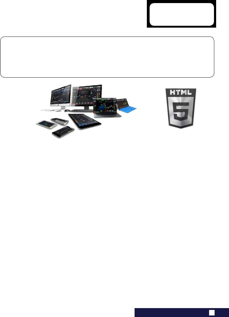
The Ui Series mixers feature cross-platform compatibility with iOS, Android, Windows, Mac OS, and Linux devices, and can use up to 10 control devices simultaneously. In addition, the Ui24R features built-in HARMAN signal processing from dbx, DigiTech and Lexicon, including dbx AFS2, DigiTech Amp Modeling, and more. The Ui24R features fully recallable and remote-controlled mic pre-amps and phantom power designed by Studer.
MAIN FEATURES
•Tablet/PC/SmartphoneControlledDigitalMixer
•IntegratedDualAntenna2.4Gand5GWi-FiandLANconnection
•Cross-platformcompatibilitywithiOS,Android,Windows,MacOS,andLinuxdevices
•Useupto10controldevices(tablets,phones,PCs)simultaneously
•LegendaryHarmanSignalProcessingfromdbx®,Digitech®,andLexicon®
•Fullyrecallableandremote-controlledmicpreamps
•4-bandParametricEQ,High-PassFilte,Low-PassFilerr,Compressor,De-esserandNoiseGateoninputchannels
•31-bandGraphicEQ,NoiseGateandCompressoronalloutputs(MasterL/RandAUX1/2featureLPFancdHPFfilters)
•Real-TimeFrequencyAnalyser(RTA)oninputsandoutputs
•4dedicatedLexicon®FXeffectsprocessors:Reverbs,Delays,Chorus
•4xSubgroups,6xVCA’s,MuteGroups,ViewGroups,andMOREMEmixercontrols
•Show/Snapshotrecallwithchannelsafesandsecuritylockout
•2-channelUSBaudioplaybackandrecordingand22multi-trackUSBrecording
•32x32USBAudioInterface
•IntergratedswitchmodeIECconnectionpowersupply
The Ui24R boasts 22 mic/line inputs, 10 x XLR combo mic/line inputs, 10 x XLR mic inputs, two channels of Hi-Z/instrument inputs, as well as a stereo RCA line input. A 2-channel USB media player is included, along with eight balanced XLR Aux/Matrix outputs, two quarter-inch headphone outputs with level control, plus balanced stereo XLR and quarter-inch main outputs. Two-channel USB audio playback is compatible with MP3, WAV and AIFF formats. It also includes a 22 multi-track recorder/player, 32 x 32 low latency audio interface and direct HDMI display connection output.
1.0: INTRODUCTION TO Ui
|
Ui24R User Manual |
1.1: SAFETY |
INTRODUCTION > SAFETY
SAFETY NOTICES
For your own safety and to avoid invalidation of the warranty please read this section carefully.
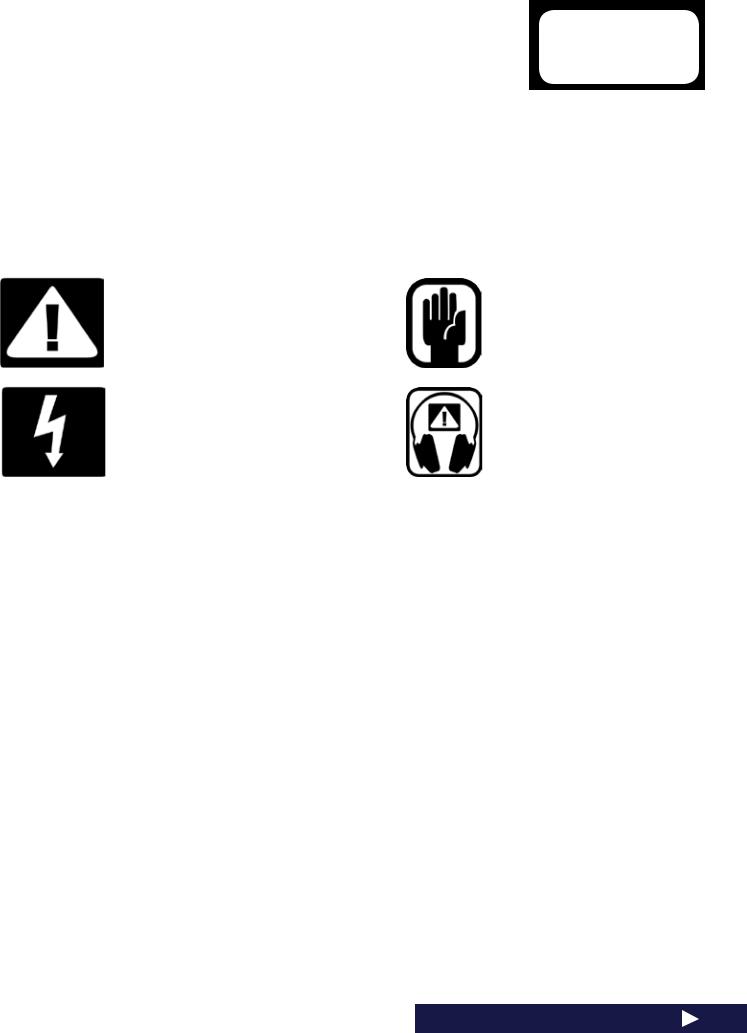
Important Symbols
Cautions
Alerts the user to the presence of important operating and maintenance (servicing) instructions in the literature accompanying the appliance.
Warnings
Alerts the user to the presence of uninsulated
‘dangerous voltage’ within the product’s enclosure that may be of sufficient magnitude to constitute a risk of electric shock to persons.
The internal power supply unit contains no user serviceable parts. Refer all servicing to a qualified service engineer, through the appropriate Soundcraft dealer.
Radio frequency exposure
This equipment complies with FCC radiation exposure limits set forth for an uncontrolled environment. End users must follow the specific operating instructions for satisfying RF exposure compliance. This transmitter must not be co-locat- ed or operating in conjunction with any other antenna or transmitter. No modifications Changes or modifications not expressly approved by the party responsible for compliance could void the user’s authority to operate the equipment.
The minimum distance required away from the Ui24R mixer and or any antenna is 20cm.
Canada Statement
This device complies with Industry Canada’s licence-exempt RSSs. Operation is subject to the following two conditions:
(1)This device may not cause interference; and
(2)This device must accept any interference, including interference that may cause undesired operation of the device.
Le présent appareil est conforme aux CNR d’Industrie Canada applicables aux appareils radio exempts de licence. L’exploitation est autorisée aux deux conditions suivantes :
(1)l’appareil ne doit pas produire de brouillage;
(2)l’utilisateur de l’appareil doit accepter tout brouillage radioélectrique subi, même si le brouillage est susceptible d’en compromettre le fonctionnement.
This End equipment should be installed and operated with a minimum distance of 20 centimeters between the radiator and your body.
Cet équipement devrait être installé et actionné avec une distance minimum de 20 centimètres entre le radiateur et votre corps.
1.1: INTRODUCTION > SAFETY
|
Ui24R User Manual |
1.1: SAFETY |
INTRODUCTION > SAFETY
WARNINGS
•Read these instructions.
•Keep these instructions.
•Heed all warnings.
•Follow all instructions.
•Clean the apparatus only with a dry cloth.
•Do not install near any heat sources such as radiators, heat resistors, stoves, or other apparatus
(including amplifiers) that produce heat.
•Do not block any ventilation openings. Install in accordance with the manufacturer’s instructions.
•Do not use this apparatus near water.
•Do not defeat the safety purpose of the polarized or grounding type plug. A polarized plug has two blades with one wider than the other. A grounding type plug has two blades and a third grounding prong. The wide blade or the third prong are provided for your safety. When the provided plug does not fit into your outlet, consult an electrician for replacement of the obsolete outlet.
•Protect the power cord from being walked on or pinched particularly at plugs, convenience receptacles and the point where they exit from the apparatus.
•Only use attachments/accessories specified by the manufacturer.
•Unplug this apparatus during lightning storms or when unused for long periods of time.
•Refer all servicing to qualified service personnel. Servicing is required when the apparatus has been damaged in any way such as power-supply cord or plug is damaged, liquid has been spilled or objects have fallen into the apparatus, the apparatus has been exposed to rain or moisture, does not operate normally, or has been dropped.
•Use only with the cart, stand, tripod, bracket, or table specified by the manufacturer, or sold with the apparatus. When the cart is used, use caution when moving the cart/apparatus combination to avoid injury from tip-over.
•No naked flame sources, such as lighted candles or cigarettes etc., should be placed on the apparatus.
•No user serviceable parts. Refer all servicing to a qualified service engineer, through the appropriate Soundcraft dealer.
•The socket-outlet shall be installed near the equipment and shall be easily accessible.
•It is recommended that all maintenance and service on the product should be carried out by Soundcraft or its authorised agents. Soundcraft cannot accept any liability whatsoever for any loss or damage caused by service, maintenance or repair by unauthorised personnel.
•WARNING: To reduce the risk of fire or electric shock, do not expose this apparatus to rain or moisture. Do not expose the apparatus to dripping or splashing and do not place objects filled with liquids, such as vases, on the apparatus. No naked flame sources, such as lighted candles, should be placed on the apparatus.
•Ventilation should not be impeded by covering the ventilation openings with items such as newspapers, table cloths, curtains etc or mounting in enclosures where ari cannot circulate to an appropriate level to keep the Ui24R under 40C or 104F.
1.1: INTRODUCTION > SAFETY
|
Ui24R User Manual |
1.1: SAFETY |
INTRODUCTION > SAFETY
WARNINGS
ADVICE FOR THOSE WHO PUSH THE BOUNDARIES
Although your new console will not output any sound until you feed it signals, it has the capability to produce sounds which, when monitored through an amplifier or headphones, can damage hearing over time.
Please take care when working with your audio — if you are manipulating controls which you don’t understand (which we all do when we are learning), make sure your monitors are turned down. Remember that your ears are the most important tool of your trade, look after them, and they will look after you.
Most importantly — don’t be afraid to experiment to find out how each parameter affects the sound — this will extend your creativity and help.
NOTE: This equipment has been tested and found to comply with the limits for a Class A digital device, pursuant to Part 15 of the FCC Rules. These limits are designed to provide reasonable protection against harmful interference when the equipment is operated in a commercial environment. This equipment generates, uses and can radiate radio frequency energy and, if not installed and used in accordance with the instruction manual, may cause harmful interference to radio communications. Operation of this equipment in a residential
area is likely to cause harmful interference in which case the user will be required to correct the interference at his own expense.
This Class A digital apparatus meets the requirements of the Canadian Interference-Causing Equipment Regulations.
Cet appareil numérique de la Classe A respecte toutes les exigences du Règlement sur le matériel brouilleur du Canada.
NOTE: The packaging, in which your console arrived, forms part of the product and must be retained for future use.
1.1: INTRODUCTION > SAFETY

|
Ui24R User Manual |
1.2: WARRANTY |
INTRODUCTION > SAFETY
WARRANTY
1 Soundcraft is a trading division of Harman International Industries Ltd.
End User means the person who first puts the equipment into regular operation.
Dealer means the person other than Soundcraft (if any) from whom the End User purchased the Equipment, provided such a person is authorised for this purpose by Soundcraft or its accredited Distributor. Equipment means the equipment supplied with this manual.
2 If within the period of twelve months from the date of delivery of the Equipment to the End User it shall prove defective by reason only of faulty materials and/or workmanship to such an extent that the effectiveness and/or usability thereof is materially affected the Equipment or the defective component should be returned to the Dealer or to Soundcraft and subject to the following conditions the Dealer or Soundcraft will repair or replace the defective components. Any components replaced will become the property of Soundcraft.
3 Any Equipment or component returned will be at the risk of the End User whilst in transit (both to and from the Dealer or Soundcraft) and postage must be prepaid.
4 This warranty shall only be available if:
a)The Equipment has been properly installed in accordance with instructions contained in Soundcraft’s manual.
b)The End User has notified Soundcraft or the Dealer within 14 days of the defect appearing; and
c)No persons other than authorised representatives of Soundcraft or the Dealer have effected any replacement of parts maintenance adjustments or repairs to the Equipment; and
d)The End User has used the Equipment only for such purposes as Soundcraft recommends, with only such operating supplies as meet Soundcraft’s specifications and otherwise in all respects in accordance Soundcraft’s recommendations.
5 Defects arising as a result of the following are not covered by this Warranty: faulty or negligent handling, chemi cal or electro-chemical or electrical influences, accidental damage, Acts of God, neglect, deficiency in electrical power, air-conditioning or humidity control.
6.The benefit of this Warranty may not be assigned by the End User.
7.End Users who are consumers should note their rights under this Warranty are in addition to and do not affect any other rights to which they may be entitled against the seller of the Equipment.
1.2: INTRODUCTION > WARRANTY

Ui24R User Manual
INTRODUCTION > SAFETY
SOUNDCRAFT Ui TYPICAL SPECIFICATIONS
•Frequency Response
20Hz-20kHz +/- 0.5 dB
•THD
Mic input (Min gain to bus) @ 1kHz <0.005% Mic input (Max gain to bus) @ 1kHz <0.008%
• Noise
Residual Noise -96dBu
Mic Input E.I.N.22Hz-22kHz unweighted: -128dB EIN
• Input Gain
Mic/Line Gain -6dB to +58dB (Step accuracy depends on size of fader in GUI)
• Gate
Threshold -inf to +6dB Attack 1ms to 400ms Release 5ms to 2000ms Hold 1ms to 2000ms Depth -inf to 0dB
•Compressor
Threshold -90dB +6dB Ratio 1:1 — 50:1 Attack 1ms — 400ms
Release 10ms — 2000ms Makeup Gain -24dB — +48dB
•EQ Channel
4 band parametriq EQ
Each Band Freq 20Hz to 22kHz Q .05 — 15
Gain -20dB to +20dB
HPF 20Hz to 1kHz (selectable slopes) LPF 22kHz to 1kHz (selectable slopes)
1.3: SPECIFICATIONS
• De-esser
Threshold -90dB to 6dB
Ratio infinity to 1:1
Frequency 2kHz to 15kHz
• EQ Outputs
31 band GEQ, 20Hz — 20KHz +-15dB
•Compressor outputs
Threshold -90dB +6dB Ratio 1:1 — 50:1 Attack 1ms — 400ms
Release 10ms — 2000ms Makeup Gain -24dB — +48dB
•dbx® AFS on all outputs
12 parametric EQ’s (6 fixed, 6 floating)
• Latency
All Processing ON for inputs and outputs 3.2ms
•Input and Output Levels
Mic Input +19.5dBu max Line input +19.5dBu max Mix output +20.5dBu max
Headphone outputs 500mW 1 output used
(@120Ω), 380mw both outputs used
•Input and Output Impedances
Mic input 1-2 4.2kΩ input 3-20 6kΩ
Line Input 12kΩ
Hi-Z Input >600kΩ
Balanced Outputs <150Ω
• USB
Max Current 500mA
Max Current available to all ports: 900mA
• Power
Consumption (typical) < 65W
AC input voltage range 88-265VAC auto sensing AC frequency 47-63Hz
• Operating Conditions
Temperature range 5°C — 40°C
Humidity 0%-90%
Storage Temperature -20°C to 60°C
E & OE.Soundcraft reserves the right to change specifications and or images in this manual without notice.
1.3: SPECIFICATIONS

|
Ui24R User Manual |
2.0: GETTING STARTED |
GETTING STARTED — AN INTRODUCTION TO THIS MANUAL
Anyone with minimal audio experience should be able to operate the Soundcraft Ui Series consoles without reading too much of this manual, though we do recommend you take the time to go through it.
An excellent place to start would be the feature list on the introductory page (section 1.0), the Wi-Fi and software set-up guide (3.1), and the software control guides for phone (3.2) and tablet (3.3) software.
To get started with Ui control, go to the ‘Getting Connected’ section: 2.4
If you’re reading the PDF version of the manual, you can use the thumbnail view and links from the Contents page to navigate quickly.
For clarity, this manual uses section references rather than page numbers. In some instances, one section reference may extend to several pages.
2.0: INTRODUCTION TO THIS MANUAL
![]()
|
Ui24R User Manual |
2.1: SYSTEM OVERVIEW |
GETTING STARTED > SYSTEM OVERVIEW
This Soundcraft Ui console uses a compact main unit with built-in I/O, processing, and web server. Phones, tablets, and PCs can connect to the web server via Wi-Fi for platform-independant software control.
NOTE: When mouting the Ui24R in any kind of enclosure make sure you have sufficient space above, bellow and on bothsides of the Ui24R for passive cooling of the device. In exterme environments a fan may need to be added to your enclosure!
2.1: SYSTEM OVERVIEW
|
Ui24R User Manual |
2.2: HARDWARE I/O & CONTROL |
GETTING STARTED > HARDWARE
The Ui main unit’s front panel hosts all local audio inputs and outputs plus three master level controls. On one side panel you will find the power connector and power switch; on the other you will find the RESET button, FOOTSWITCH connection, two USB ports, and the Ethernet (wired LAN) connection).
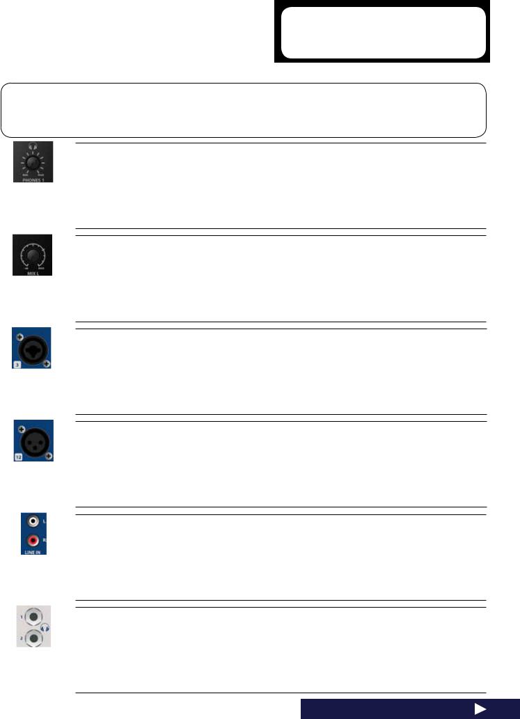
PHONES
Set level for headphones outputs
This controls the overall level of headphone output one. Individual headphone volume control can be achieved through the SETTINGS control page. The headphone source signal defaults to the main stereo signal but switches to the Solo bus when AFL or PFL is selected.
MIX L / MIX R
Set levels for MIX L and Mix R outputs
The Mix output is the Ui’s main left/right stereo output and appears on both the XLR and Jack Mix L/R outputs.
COMBO INPUT
Connection for 1/4” TRS/TS Jack (Line) or XLR (Mic level)
The input number corresponds to channel number in the Ui control software.
XLR Input
Mic XLR Input
The input number corresponds to channel number in the Ui control software.
LINE IN
Line level RCA inputs
The RCA inputs feed the Line In L and Line In R channels in the UI mixer.
HEADPHONES OUT
Headphone sockets
These are not independent, meaning each output receives the same signal. The headphone outputs receive the same audio signal as the main outputs unless a channel Solo is active note the volumes can be independently controlled in the SETTINGS page as well as the SOLO level.
2.2: Hardware I/O And Control
|
Ui24R User Manual |
2.2: HARDWARE I/O & CONTROL |
GETTING STARTED > HARDWARE
MIX L/R OUTPUT — XLR
Master Channel XLR outputs
The Master Channel XLR and jack outputs are parallel connections (identical).
MIX L/R OUTPUT — JACK
Master Channel Jack outputs
The Master Channel XLR and jack outputs are parallel connections (identical).
AUX/MATRIX OUTPUTS
Physical outputs for the Aux/Matrix outputs
The Ui24R has 8 x Aux/Matrix outputs. Aux/Matrix outputs are assigned in software.
2 TRK MEDIA — PLAY
USB Socket for USB Flash Drive with audio playback files
2 track Audio files must be saved to the USB stick as either MP3, AAC, .WAV, .OGG, .AIFF, or .FLAC files.
See section 9.0.
This USB socket can also be used for Show File and Snaphot import/export, and software updates. There are two additional USB sockets on the side of the unit.
MEDIA — REC plus Multi-track Play and Record
USB Socket for USB Flash Drive — for multi-track play and record audio
The Soundcraft Ui24RR mixer will record the Master Channel stereo output as a stereo file or multitrack recording onto the storage device. See guide for playback and recording instructions — section 9.0.
USB B (DAW Connection)
USB Socket for connection directly to PC/Mac
The Soundcraft Ui24RR mixer can be used as a 32 x 32 USB Audio Interface with CORE Audio and ASIO drivers.
2.2: Hardware I/O And Control
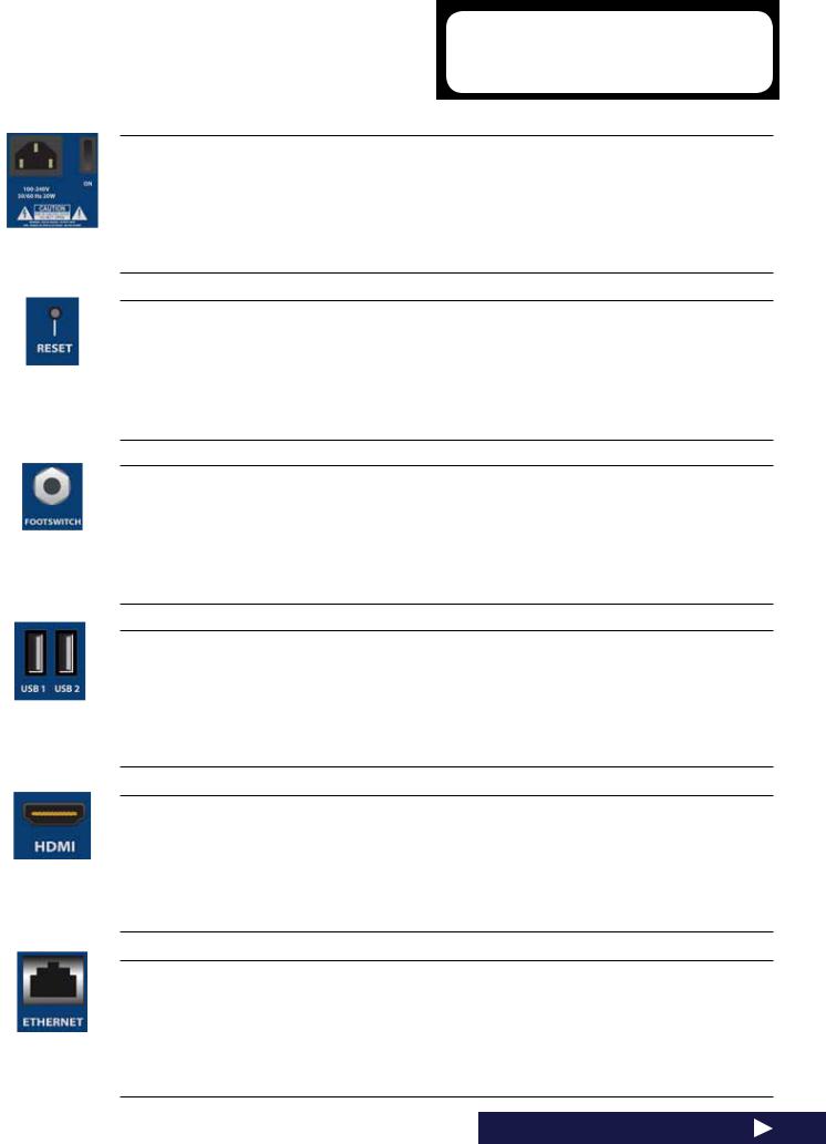
|
Ui24R User Manual |
2.2: HARDWARE I/O & CONTROL |
GETTING STARTED > HARDWARE
PWR
Power Connector & Switch
The Ui mixer has an AC IC connection universal power supply. Use the power switch with the reset button
(other side panel) to reset the unit to factory default settings if required.
RESET
Recessed push switch used to reset the unit.
To reset Network settings ONLY, switch the unit on while holding down the reset button for at least ten seconds. For a full system reset, see section 3.0.2.
FOOTSWITCH
Footswtich connector used to toggle selected configurations.
Use a footswitch with a quarter-inch jack connection. The unit will auto-detect the connector type, though the footswitch itself must be a non-latching type. The SETTINGS page has a variety of functions that can be assigned.
Side USB Connectors 1 & 2
May be used for Connecting Keyboard, Mouse and Touchscreen
There are USB connections on the front panel of the unit for audio recording and playback.
HDMI Connector
Supports HDMI Video standard
Complete Mixer Web Interface is displayed on HDMI screen. Please note if using DVI and VGA adaptors they must be active. Performance will depend on other concurrent functions which are being used in the mixer. (eg. while recording to USB MTK stick you may see a slow down in screen update)
ETHERNET
Standard RJ45-wired connector for use with wired Ethernet.
A wired Ethernet conenction to the Ui is the most secure. See section 10.1 for more details on network settings and configurations. By default the IP address is 10.10.2.1.
2.2: Hardware I/O And Control
|
Ui24R User Manual |
2.2: HARDWARE I/O & CONTROL |
GETTING STARTED > HARDWARE
Wi-Fi Indicator
Shows Wi-Fi is operating normally
The indicator also shows Wi-Fi boot status during power up. It stops its timed flash sequence when booted and available for connections. Then flashes with data activity.
If the WiFi LED keeps flashing it can mean the firmware is not loading into the DSP. Make sure latest firmware is loaded into the unit and that the DC power connector is properly screwed on.
ETHERNET 2
Future Expansion Port
Wi-Fi Antenna
Necessary for wireless network connection — Hotspot or WiFi
Make sure the Antenna(s) are firmly screwed into their sockets and normally orientated vertically. For more information on wireless network settings, see section 10.1. The Ui24RR ships with 2 WiFi antenna’s for better wifi performance. The second antenna is on the right side of the Ui24R.
2.2: Hardware I/O And Control
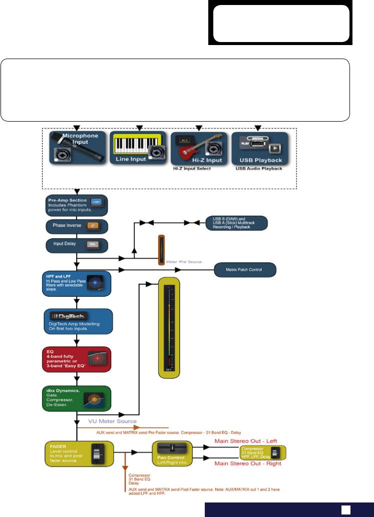
|
Ui24R User Manual |
2.3: INPUT CHANNEL ROUTING |
GETTING STARTED > INPUT CHANNEL ROUTING
The diagram shows the audio signal path through an input channel — from physical input to bus sends
(Aux, FX, Mix, and so on).
Please note: The entire signal path (except for the hardware pre and output DACs) is clip-free with infinite headroom. It means that internal clipping is not introduced even by driving the EQ/Dyn to the max.
Sufficiently reducing the level on the Master Channel strip will get rid of any clipping on the output.
2.3: INPUT CHANNEL ROUTING
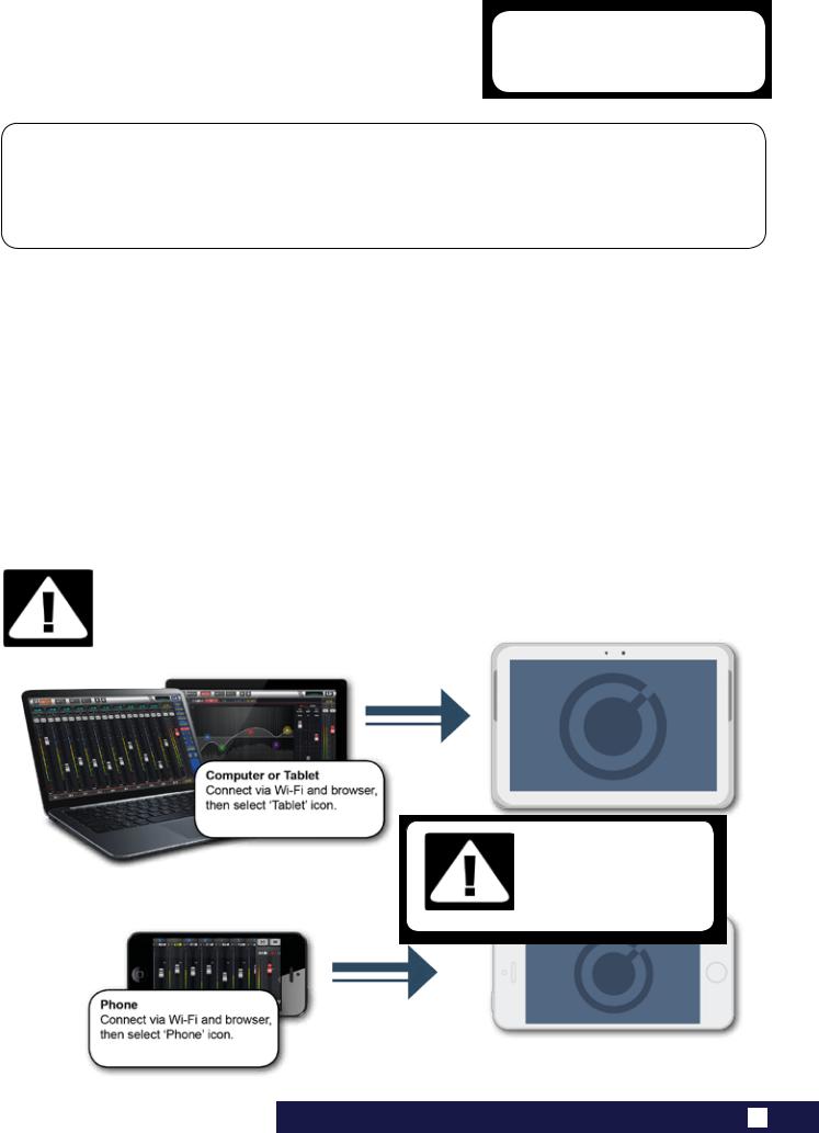
|
Ui24R User Manual |
2.4: GETTING CONNECTED |
GETTING STARTED > GETTING CONNECTED
The Soundcraft Ui series uses built-in web server technology to enable computer, tablet, and phone-based in-browser control of all functions — simply connect to the Ui Wi-Fi access point (hotspot) and browse to the appropriate URL. Alternatively, you can connect via an existing Wi-Fi network, or via a wired LAN (Local Area Network) using the Ethernet port on the side of the unit. See Section 10.1 for details on network configuration.
Connecting To Ui Hotspot with computer, tablet, or phone.
1)Ensure the Wi-Fi antenna is attached to the unit, connect the external power supply, and turn on the power to your mixer. You will see an LED light up inside the Wi-Fi logo on your Ui hardware; this will flash until booted successfully.
2)Navigate to Wi-Fi set-up on your device and connect to the “Soundcraft Ui24” access point. If this is the first time you have connected, the default password will be ‘scuiwlan’. (by default it will not have a password, please assign one that you can remember)
3)Launch your device’s browser, and enter the URL ui.io. For Android users, you must use Android browser 4.4 or later, or other modern browsers like Chrome to use the Ui web app. In some cases where certain protection software is running on a system you may need to enter the ip address 10.10.1.1
4)You should see the device selection screen showing icons for large screen (tab icon) and small screen
IMPORTANT!
The first time you connect, it is important to set up a new password for Wi-Fi access. Press the Settings icon, then choose the first tab: ‘NETWORK’ to access the password field.
DEFAULT HOTSPOT PASSWORD:
scuiwlan
2.4: GETTING CONNECTED — SOFTWARE CONTROL
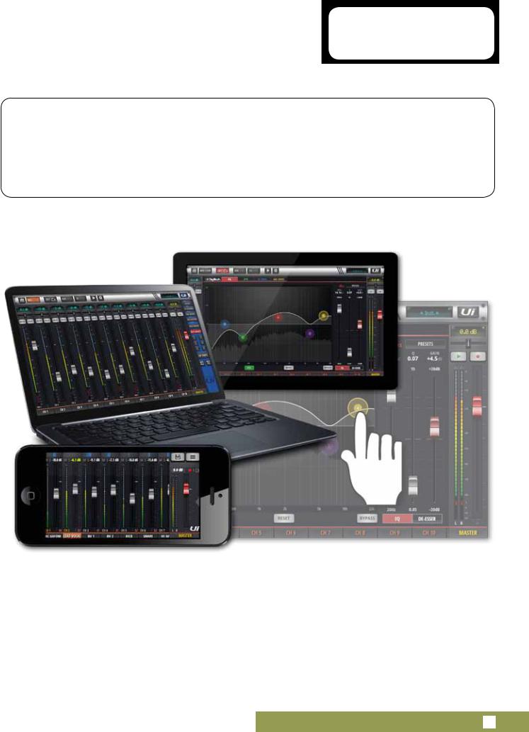
|
Ui24R User Manual |
3.0: SOFTWARE CONTROL |
SOFTWARE CONTROL
The browser-based software control for the Ui Series is available to any device in two versions.
The small-screen version is optimised for phone-sized devices; the large-screen version is optimised for tablets and computers.
In order to make best use of your Ui mixer, please read this section of software control. There are several navigation and menu access functions that will greatly simplify Ui control.
3.0: SOFTWARE CONTROL
|
Ui24R User Manual |
3.0.1: UPDATES & REQUIREMENTS |
SOFTWARE UPDATES & REQUIREMENTS
The browser-based software control for the Ui Series actually runs from a virtual web server in the main Ui unit itself and is compatible with any modern browser software running on your control device. For Android users, you must use Android browser 4.4 or later, or another modern browser like Chrome to use the Ui web app.
Up to 10 control devices can be used simultaneously.(Depending on available bandwidth)
Software Updates
Regular software updates are posted on the Soundcraft website and are available from the product page. In the Tablet software you can check your current Ui software version by navigating to the SETTINGS page and selecting the ABOUT tab. In the Phone software you can check your current Ui software version by navigating to the SETTINGS page and selecting the HELP tab.
To update the Ui software:
1.Download the Ui update file from the website and leave in .zip format.
2.Copy the .zip file to a USB media device suitable for connection to a Ui mixer’s USB port. Note: The file can reside in any directory. Any USB port on the mixer is also acceptable.
3.Ensure your client device is connected to the Ui mixer GUI
4.Connect the USB media
5.The GUI display will display that the USB device has been mounted. After the stick has been read (maybe 10 more seconds) the update will be recognised.
6.The GUI will ask if you would like to update. Choose OK.
7.The mixer will perform the update
8.The GUI will present a message stating whether the update has been successful or not.
9.You must power-cycle the unit and reconnect a client device.
10.You can browse to the about page to see the new Firmware version information.
USB AUDIO DRIVER
The Ui24R requires the use of the Soundcraft SI Impact Audio Driver for multichannel USB playback and recording.
It can be downloaded via: http://www.soundcraft.com/en/softwares/soundcraft-multichannel-usb-audio-driver-v3-20 or above
IMPORTANT!
Note that if you have any type of zip file (other than the update file) in any directory on the
USB key already, the software update will not work. Note Mac OS by default unzips downloaded files which will render the firmware update incompatible.
3.0.1: SOFTWARE UPDATES & REQUIREMENTS

|
Ui24R User Manual |
3.0.2: RESET THE MIXER |
SOFTWARE > RESET THE MIXER
There are two levels of reset for the Ui mixer. The first will reset network settings in the event that you are unable to connect. The second (uses a fullreset.txt file on a USB memory stick in conjunction with the reset button. This will fully reset the unit back to its factory firmware and default settings.
Networking Reset
Reset Networking and Admin password if you have forgotten the admin password or if you are no longer able to connect to the Ui.
Use a paper clip (or similar) to hold down the recessed reset button (side panel) down for approximately 10 seconds while you power on the unit. This will initialise the Ui’s networking and admin password to the default state.
Full Reset
This method removes all updates you may have performed on the mixer and returns the unit to its default factory shipping firmware and state. All settings, snapshots, users, profiles and shows will be lost.
Please ensure you have saved/backed up any shows before resetting your Ui.
1)Create a test file named fullreset.txt (no contents necessary) and copy to a USB stick
2)Insert the USB stick into one of the Ui’s USB ports.
3)Use a slim, long object to hold the reset button down for approximately 10 seconds while you power on the unit.
4)The Ui will recognise the fullreset.txt file on the USB stick and perform a full factory reset.
5)You must power cycle the unit and reconnect the client device. Power off for at least 10-15 seconds before powering back on.
Note: A flick of the power off/on will almost always fail to boot properly, and can get stuck (with continuous flashing blue Wi-Fi LED). Make sure to power off, wait 10-15 seconds, then power on. The blue Wi-Fi LED will pulse/flash for around 10-15 seconds then remain on.
3.0.2: RESET THE MIXER
![]()
|
Ui24R User Manual |
3.1: SOFTWARE NAVIGATION |
SOFTWARE > SOFTWARE NAVIGATION
There are many navigation / gesture techniques common to both the Tablet and Phone versions of the Ui control software. This section describes the main ones. Section 3.7 summarises all control gestures. Please Note: The screen shots shown are from the phone version of the software, except where the two differ significantly in content.
Scroll Mixer
Touch /Click and slide on the mixer screen to scroll along to whole available mixer — including FX Send, Aux Send and Group masters.
Fader / Channel Name
Select a channel by touching or clicking on a fader or channel name.
The selected channel will remain active (keep focus) regardless of function screen until a new channel is selected.
Double Tap Fader
Access the channel EQ from MIX Screen. Double tap or double click.
3.1: SOFTWARE NAVIGATION
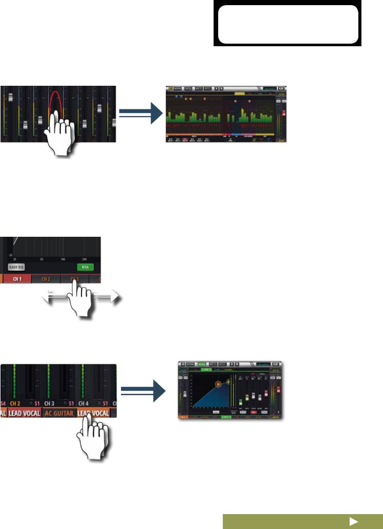
|
Ui24R User Manual |
3.1: SOFTWARE NAVIGATION |
SOFTWARE > SOFTWARE NAVIGATION
Double Tap Channel Strip
Double tap anywhere except the fader to access the METERS screen or switch back to the MIX screen from the GAIN screen.
Scroll Channel Names
Touch/click-hold and slide on channel names to access channel names across the whole mixer, including FX Sends, Aux Sends, and Group Faders.
Double Tap Channel Name
Phone: Access the Dashboard screen for that channel — access to
EQ, dynamics, Aux and FX Sends, and more.
Tablet: Access EDIT Page > Dynamics tab.
3.1: SOFTWARE NAVIGATION
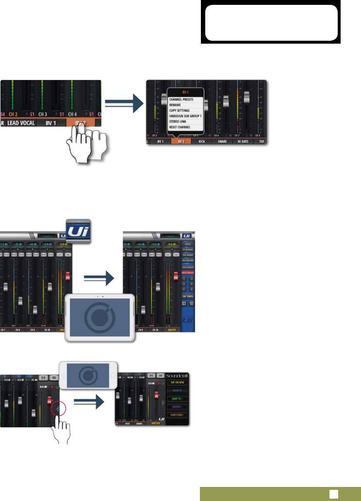
|
Ui24R User Manual |
3.1: SOFTWARE NAVIGATION |
SOFTWARE > SOFTWARE NAVIGATION
Long (held) Tap/Click
A long tap/click on certain controls brings up a sub-menu specific to that control. For example, a long hold or click on a channel name gives access to channel presets, renaming, copy/paste settings, sub group assignment, stereo linking, channel reset, and the ASSIGN ME function.
Slideout View
Touch the Slideout Arrow to the right of the MIX screen to access the Slideout View panel.
For the tablet software Slideout panel, click/touch the Ui button in the top right corner of the screen. The tablet Slideout offers fast mixer navigation to common channel groups, MUTE and VIEW group access, the TAP TEMPO button, plus MUTE ALL and MUTE FX functions.
On the phone software this gives fast access to the TAP TEMPO and MUTE FX buttons, plus JUMP TO (mixer navigation), GROUPS (Mute & View Groups), and FUNCTIONS (fast functions such as playback and record) options.
You can pin the Slideout View in place via the SETTINGS Screen.
3.1: SOFTWARE NAVIGATION
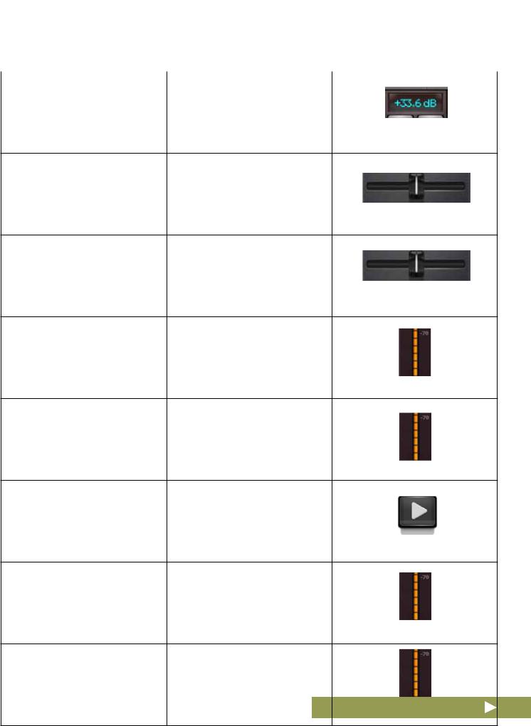
|
Ui24R User Manual |
3.1.1: CONTROL / GESTURE SUMMARY |
|||
|
SOFTWARE > CONTROL SUMMARY:MIX PAGE SHORTCUTS |
||||
|
Double Click/Tap on |
to return Channel Volume to 0db |
|||
|
Virtual LCD Display |
|
Single click/tap on channel Pan or |
to temporarily display channel Pan |
|
Balance control zone |
or Balance value in relative virtual |
|
channel LCD display |
|
Double click/tap on channel Pan |
to centre channel Pan or Balance. |
|
or Balance control |
Double click/tap in INPUT channel to navigate to METERS Page strip zone (excluding fader cap)
|
Double click/tap in LINE INPUT |
to navigate to METERS Page |
|
channel strip zone (excluding fader |
|
|
cap) |
|
Double click/tap in PLAYER chan- |
to navigate to PLAYER/MEDIA |
|
nel strip zone (excluding fader cap) |
Page. |
Double click/tap in FX RETURN to navigate to FX SENDS Page channel strip zone (excluding fader
cap)
Double click/tap in SUG GROUP to navigate to METERS Page channel strip zone (excluding fader
cap)
3.1.1: CONTROL SUMMARY
Ui24R User Manual 3.1.1: CONTROL / GESTURE SUMMARY
SOFTWARE > CONTROL SUMMARY:MIX PAGE SHORTCUTS
Double click/tap in AUX MASTER to navigate to AUX SENDS Page channel strip zone (excluding fader
cap)
Double click/tap on channel fader to channel EDIT mode EQ tab cap to navigate
|
Double click/tap on channel label |
to navigate to selected channel |
|
(channel types: INPUT, LINE IN, |
EDIT page DYN tab. |
|
PLAYER, SUB GROUP, AUX) |
|
Double click/tap on channel label |
to navigate o selected channel |
|
(channel type: FX RETURN) |
EDIT page FX tab (Global FX pa- |
|
rameters) |
|
Long click/press and hold on |
to engage channel pop-up menu. |
|
channel label |
|
Single click/tap on top level navi- |
to engage shows/snapshot pop-up |
|
gation panel virtual LCD display. |
list short-cut activator |
|
Long click/press-and-hold on top |
to navigate to SETTINGS page |
|
level navigation panel virtual LCD |
SHOWS tab |
|
display |
|
Single click/tap on MASTER |
to navigate to METERS Page |
|
channel virtual LCD display |
3.1.1: CONTROL SUMMARY
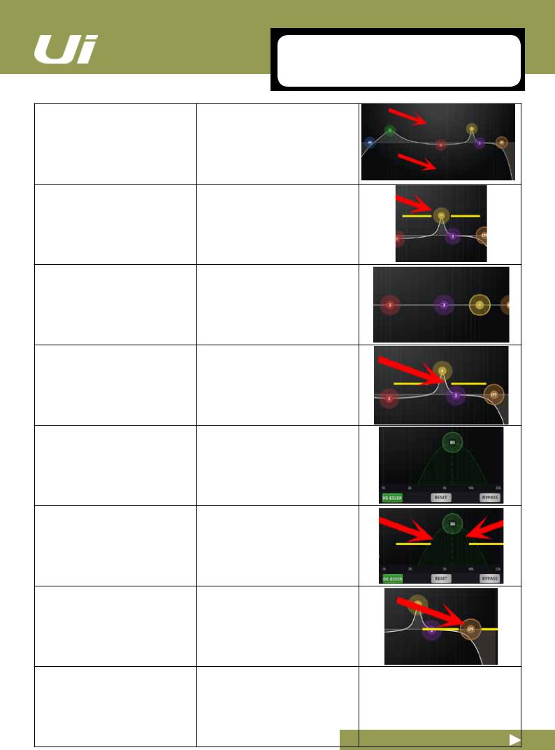
Ui24R User Manual 3.1.1: CONTROL / GESTURE SUMMARY
SOFTWARE > CONTROL SUMMARY:CHANNEL EDIT PAGE PARAMETRIC EQ
Double click/tap in vacant space to navigate to MIX page.
|
Drag PEQ frequency balls |
to adjust dB gain (up and down) |
|
and frequency values (left and |
|
|
right) |
|
Double click/tap frequency balls |
to reset selected frequency band to |
|
0dB and default frequency. |
|
Pinch-gesture or mousewheel/ |
to adjust Q value |
|
trackpad scroll on selected fre- |
|
|
quency ball |
|
Drag DE-ESSER frequency ball |
to adjust frequency and dB thresh- |
|
old values. |
|
Pinch-gesture or mousewheel/ |
to adjust ratio value. |
|
trackpad scroll on DE-ESSER |
|
|
frequency ball |
|
Drag LPF/HPF frequency ball |
to adjust LC/HPF frequency value. |
|
Note: The slope of the curve can |
|
|
also be adjusted by selecting the |
|
|
desired curve from the right panel |
|
|
menu. |
3.1.1: CONTROL SUMMARY
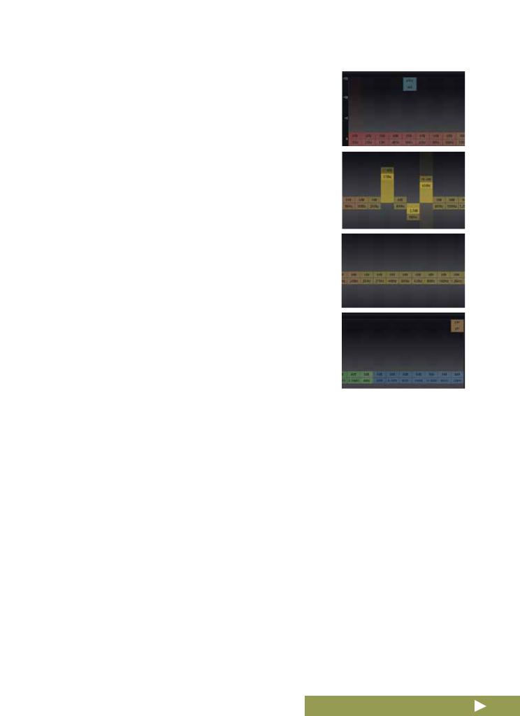
|
Ui24R User Manual |
3.1.1: CONTROL / GESTURE SUMMARY |
|||||
|
SOFTWARE > CONTROL SUMMARY:CHANNEL |
||||||
|
EDIT PAGE GRAPHIC EQ |
||||||
|
On Master EQ and AUX1-2 you |
Note, only available on MASTER |
|||||
|
may also DRAG HPF and LPF |
Left/Right and AUX/MATRIX 1 and |
|||||
|
EQ’s to select the desired fre- |
2. |
|||||
|
quency. |
||||||
|
GEQ frequency |
to adjust dB gain of selected fre- |
|||||
|
quency. |
||||||
|
Double click/tap GEQ frequency |
to reset selected frequency to 0dB. |
|||||
|
Drag GEQ to see the rest of the |
Top Left hand corner you will see a |
|||||
|
frequencies (size depends on |
representation of all 31 bands |
|||||
|
screen size being used) |
||||||
3.1.1: CONTROL SUMMARY
|
Ui24R User Manual |
3.1.1: CONTROL / GESTURE SUMMARY |
|||||
|
SOFTWARE > CONTROL SUMMARY:CHANNEL |
||||||
|
EDIT:AUX SENDS |
||||||
|
Long click/press-and-hold chan- |
for ‘set all Pre or Post’ option. |
|||||
|
nel strip PRE/POST button |
||||||
|
Double click/tap in channel send |
to navigate to MIX Page. |
|||||
|
strip zone (excluding fader cap) |
||||||
|
Double click/tap on channel label |
to navigate to selected channel |
|||||
|
EDIT page DYN tab. |
||||||
|
Long click/press-and-hold on |
to engage channel pop-up menu |
|||||
|
channel label |
||||||
|
Double click/tap in channel LCD |
to ‘Return To Zero Level’ |
|||||
3.1.1: CONTROL SUMMARY
Ui24R User Manual 3.1.1: CONTROL / GESTURE SUMMARY
SOFTWARE > CONTROL SUMMARY:CHANNEL EDIT:FX SENDS
Double click/tap in channel send to navigate to MIX Page. strip zone (excluding fader cap)
Double click/tap on channel label. to navigate to selected channel
EDIT page DYN tab
|
Long click/press-and-hold on |
to engage channel pop-up menu. |
|
channel label |
|
Double click/tap in channel LCD |
to ‘Return To Zero Level’ |
3.1.1: CONTROL SUMMARY
|
Ui24R User Manual |
3.1.1: CONTROL / GESTURE SUMMARY |
|||||
|
SOFTWARE > CONTROL SUMMARY:CHANNEL |
||||||
|
EDIT:FX SENDS |
||||||
|
Double click/tap in channel strip |
to navigate to MIX Page. |
|||||
|
zone (excluding fader cap) |
||||||
|
Double click/tap on channel fader |
to navigate to channel EDIT mode |
|||||
|
cap |
EQ tab. |
|||||
|
Double click/tap on channel label |
to navigate to selected channel |
|||||
|
EDIT page DYN tab |
||||||
|
Long click/press-and-hold on |
to engage channel pop-up menu. |
|||||
|
channel label |
||||||
3.1.1: CONTROL SUMMARY
![]()
|
Ui24R User Manual |
3.1.1: CONTROL / GESTURE SUMMARY |
|||||
|
SOFTWARE > CONTROL SUMMARY:SLIDEOUT |
||||||
|
PANEL SHORTCUTS |
||||||
|
List selectors |
in addition to using a ‘load’ button |
|||||
|
Item selections available in list |
trigger. |
|||||
|
boxes can be made by double |
||||||
|
clicking/tapping on a selection |
||||||
|
Long click/press-and-hold on |
to navigate to Sub Group configu- |
|||||
|
SUB GROUPS |
ration (METERS page, SUBS tab.) |
|||||
|
Long click/press-and-hold on |
to navigate to Views configuration |
|||||
|
VIEW GROUPS |
(METERS page, VIEWS tab) |
|||||
|
Long click/press-and-hold on |
to navigate to Mute Groups con- |
|||||
|
MUTE GROUPS |
figuration (METERS page, MUTES |
|||||
|
tab). |
||||||
|
Long click/press-and-hold on |
for numeric tempo entry. |
|||||
|
TAP TEMPO |
||||||
At anytime you may click on the HOME button to get back to the main mixer. It is recommeded for easy use to select the BIGGER SLIDOUT panel from the settings menu and PIN it to the mixer so it is available at any time.
3.1.1: CONTROL SUMMARY

|
Ui24R User Manual |
3.1.1: CONTROL / GESTURE SUMMARY |
||||
|
SOFTWARE > CONTROL SUMMARY:CHANNEL |
|||||
|
EDIT PAGE |
|||||
|
Digitech Tab: |
to bring up amp list selector |
||||
|
Single click/tap on amp head |
|
Digitech Tab: |
to bring up cab list selector |
|
Single click/tap on cabinet |
|
DYN Tab: |
to navigate to MIX page. |
|
Double click/tap in vacant space |
|
DYN Tab: |
to adjust dynamics threshold value |
|
Drag threshold ball. |
|
DYN Tab: |
to adjust dynamics ratio value |
|
Drag ratio ball |
|
FX Tab: |
to navigate to MIX page |
|
Double click/tap in vacant space. |
|
FX Tab: |
for Preset Manager |
|
Single click/tap in virtual FX rack |
|
AUX Tab: |
to navigate to MIX page. |
|
Double click/tap in vacant space |
3.1.1: CONTROL SUMMARY

|
Ui24R User Manual |
3.1.1: CONTROL / GESTURE SUMMARY |
SOFTWARE > CONTROL SUMMARY:METERS PAGE
Single click/tap on any channel meter VU zone
to navigate to relevant channel on MIX page.
|
Long click/press-and-hold on |
for numeric tempo entry. |
|
TAP button |
3.1.1: CONTROL SUMMARY

|
Ui24R User Manual |
3.1.1: CONTROL / GESTURE SUMMARY |
||||||
|
SOFTWARE > CONTROL SUMMARY/SHORTCUTS |
|||||||
|
SLO-MO FINE ADJUSTMENT |
Allows fiune adjustment of param- |
||||||
|
Hold on fader |
eters for greater accuracy. |
||||||
|
SET TO ZERO |
Double click on any parameter will |
||||||
|
Double Click |
reset back to zero |
||||||
|
JUMP TO METERS/AUX |
Double click on any channel will |
||||||
|
Double Click |
open up same channel in Meters/ |
||||||
|
Aux pages |
|||||||
|
JUMP TO EQ/DYN |
Double Click etc. |
||||||
|
Double Click |
|||||||
|
CHANGE FX |
Will bring up pop menu for quick |
||||||
|
Press and Hold |
change of effects |
||||||
|
DOTTED TABS |
Any tab with dot in right corner will- |
||||||
|
Press and Hold |
have a shortcut function that can be |
||||||
|
activated via pressing and holding. |
|||||||
3.1.1: CONTROL SUMMARY

|
Ui24R User Manual |
3.2: TABLET NAVIGATION |
SOFTWARE > TABLET / LARGE SCREEN NAVIGATION
The MIX Screen is the default for the Ui tablet / large screen software — You can navigate from there to other screens and functions in a variety of ways. The Level 1 Navigation controls take you directly to various primary screens, Level 2 navigation (page tabs) switches layers within the selected screen, and
Level 3 navigation controls select individual channels.
METERS
Access the METERS page
Tabs on this page are METERS, (meters & status), MUTES, VIEWS,, VCA’s and SUBS (Sub Groups). The default meters page shows status for phantom power, phase, mute, and solo, plus bargraph metering for level, gain reduction (dynamics). You can activate mute groups, use Tap Tempo, and CLEAR SOLO, MUTE
ALL, AND MUTE FX directly from this page.
3.2: TABLET NAVIGATION

|
Ui24R User Manual |
3.2: TABLET NAVIGATION |
SOFTWARE > TABLET / LARGE SCREEN NAVIGATION
MIX / GAIN
Access the MIX and GAIN pages
When the button is orange, the MIX page is shown (channel faders) and when the button is Red, the GAIN page is shown (remote gain faders and input stage controls).
EDIT
Access the EDIT page for the selected channel
Resulting page configuration depends on selected channel. For example, the EDIT page for an input channel will have EQ, Dynamics, Aux Sends, and FX Send tabs. Certain Tabs will be preselected if you navigate from certain views. For example, selecting EDIT from the FX Sends main page will preselect the FX Sends tab in for the
highlighted channel.
AUX SENDS
Access the AUX SENDS page
Shows a fader based view of all aux send levels for the selected aux bus. Also shows the Aux Master channel on right hand side. Selecting EDIT from the AUX SENDS page will preselect the AUX SENDS tab for the selected input channel.
FX SENDS
Access the FX SENDS page
Shows a fader based view of all FX send levels for the selected FX Send Bus. Also shows FX Return channel on right hand side. Selecting EDIT from the FX SENDS page will preselect the FX Send tab for the selected input channel.
MEDIA
Access the MEDIA page
Playback and record controls, plus playlist and track selections. Also shows Playback L and Playback R channels on left hand side.
SETTINGS
Access the SETTING page
System and mixer settings and configurations.
3.2: TABLET NAVIGATION

|
Ui24R User Manual |
3.2: TABLET NAVIGATION |
SOFTWARE > TABLET / LARGE SCREEN NAVIGATION
SNAPSHOT
Access the Show and Snapshots pop-up selector
Load shows and snapshots directly from this pop-up.
SLIDEOUT
Access the SLIDEOUT view on the right hand side of the screen
Offers fast view and status switching functionality. The Slideout view can be configured as ‘pinned’ (permanent) in the SETTINGS page for Mix and Aux/FX Sends pages independently.
3.2: TABLET NAVIGATION