-
Contents
-
Table of Contents
-
Troubleshooting
-
Bookmarks
Quick Links
3.568.5275.400
Electropneumatic Smart Positioner
IM-P343-37
CH Issue 3
Printed in Italy
SP400
5. Installation
7. Gyorsbeállítási folyamat
8. Programozási
folyamatábra
9. Programozás és
beüzemelés
11. Default values and
program settings
12. Glossary of
display data
IM-P343-37
CH Issue 3
1
© Copyright 2011
Related Manuals for Spirax Sarco SP400
Summary of Contents for Spirax Sarco SP400
-
Page 1
3.568.5275.400 IM-P343-37 CH Issue 3 SP400 Electropneumatic Smart Positioner Installation and Maintenance Instructions 1. Index 2. Safety information 3. Technical information 4. Options 5. Installation 6. Electrical connections 7. Gyorsbeállítási folyamat 8. Programozási folyamatábra 9. Programozás és beüzemelés 10. Maintenance 11. -
Page 2
Programmable functions 4. Options Pressure gauge block Mounting the SP400 positioner — General informaton Sequence for mounting an SP400 positioner to 5. Installation a linear actuator Sequence for mounting an SP400 positioner to a rotary actuator Air supply and connections… -
Page 3
IP65 (see BS EN 60534-1 1998). 2.2 Electrical safety requirements The SP400 is a class III product which must only be powered from Safe Extra Low Voltage (SELV) sources whether by virtue of a 4 — 20 mA control signal or from a separate power supply. -
Page 4
3. Technical information 3.1 Description The SP400 smart valve positioner is loop powered from a 4 — 20 mA input signal to provide accurate adaptive positional control of pneumatic actuated linear and quarter turn valves. Precise control is maintained through valve position feedback that automatically varies the pneumatic output pressure to overcome the effects of stem friction and flow forces to maintain desired valve position. -
Page 5
No. Features indicates all is OK ! Indicates a delay in positioning, this disappears when the position is reached Indicates that the value displayed is a percentage Indicates that the value displayed is the input current measured in mA Indicates that the value displayed is a time measured in seconds Indicates that you’re accessing the main programming menus… -
Page 6
3.3 Materials Part Material Finish Case and cover Die cast aluminium Anti-corrosive paint to RAL5010 Magnet bracket Die cast aluminium 3.4 Programmable functions Autostroke Automatic commissioning routine Valve type 2-port or 3-port Selectable 0 to 100% or 100% to 0% % travel depending on valve / actuator configuration Control action… -
Page 7
4. Options 4.1 Pressure gauge block An optional pressure gauge block (Figure 3) can be fitted onto the SP400 positioner which includes two pressure gauges indicating air supply pressure and output air signal pressure to the actuator. The pressure gauge block can be retrospectively fitted using 2 off M5 socket head screws. -
Page 8
VDI / VDE 3845 compliant mounting kit for rotary actuators. 5.1.2 The SP400 has an enclosure rating of IP65 and should be installed in a location that will not exceed its ambient temperature limits of -10°C minimum and +80°C maximum. -
Page 9
5.2 Sequence for mounting an SP400 positioner to a linear actuator Fig. 4 Pillar mounting kit for a linear actuator 5.2.1 Loosely attach the magnet bracket (2) to the valve / actuator connector (refer to Figures 4 and 5). Be sure it is positioned horizontally (as shown in Figure 5). -
Page 10
PN1000 Fig. 7 Bracket markings 5.2.3 If you’re not using a Spirax Sarco actuator, slide the bracket till the distance ‘A’ between the center of the magnet and the inner side of the mounting plate is 25 mm (Figure 8). -
Page 11
Fig. 9 Pillar actuator assembly Mounting plate Assembled Yoke actuator Fig.10 Yoke actuator assembly 5.2.5 Locate the protection plate onto the back of the SP400 positioner housing and fix in place (Figures 11 and 12). Protection plate Assembled Fig. 11 Fig. -
Page 12
5.2.6 5.2.7 Attach the positioner mounting plate to the Adjust the vertical position of the SP400 positioner as shown in Figures 26 and 27. positioner and mounting plate assembly, by sliding it up or down on the pillar style actuators,… -
Page 13
5.3 Sequence for mounting an SP400 positioner to a rotary actuator 5.3.1 Assembly for fitting an SP400 on to a ¼ turn valve. Fig. 17 Mounting kit IM-P343-37 CH Issue 3… -
Page 14
Fig. 19 Fig. 18 Fig. 20 IM-P343-37 CH Issue 3… -
Page 15
Fig. 21 Assembled Fig. 22 IM-P343-37 CH Issue 3… -
Page 16
5.3.2 Adjust the magnet orientation as illustrated in Figures 23 and 24 and tighten the bolt to fix the magnet into position. There should be a distance of between 5 and 14 mm between the magnet and the positioner. Refer to Figure 23 for actuator with clockwise rotation. Refer to Figure 24 for actuator with anti-clockwise rotation. -
Page 17
/ regulator is fitted in the mains air supply to the positioner. The filter / regulator should have a coalescing filter such as a Spirax Sarco type MPC2, or suitable compressed air pipework is used. -
Page 18
Systems: Installation design and practice or local equivalent. 6.2 Wiring diagrams 6.2.1 Terminal block MENU MANUAL AUTOS AUTOMATIC TUNE AUTOSTROKE keep pressed SP400 Fig. 26 Pole Description Not used 4-20 mA current signal input Mainboard Not used Not used Not used… -
Page 19
6.2.2 Single loop applications The SP400 is loop powered using the 4 — 20 mA input signal source providing a minimum signal of 3.6 mA can be maintained. Minimum current 3.6 mA Maximum current 30 mA Maximum voltage drop < 7 V… -
Page 20
7. Gyors beállítási funkció 2-utú szelep Akövetkező leírás a 2 utú szelepeknél használható melyhez pneumatikus működtetőt szereltek direct működésú és a vezérlőjele 4-20 mA kivétel ha egyébb különleges beállítást igényel. Megjegyzés:: A PN5000 és PN6100 sotrozathoz egyéb beállítások is szükségesek. (lásd a 9.5.2). -
Page 21
(with travel setting (TRAVL) 0 — 100%, refer to Figures 14 and 15) Proceed as above up to Section 7.1.8. 7.2.1 On completion of a successful autostroke press and hold the key for 3 seconds to access the SP400 MENU. 7.2.2 key three times to access SET. Press the 7.2.3 Press the key once to advance to VALVE TYPE. -
Page 22
8. Programozási folyamatábra Beállítás Software SP400 verzió (Ver X.XX ) MENÜ Kézi működtetés RETRN PSWRD (MCTL ) parancstól MANOP % Úthosz Autostroke aktiválása (TRAVL AUTOS (AUTOS ) 0-100% / 100-0% ) Megjegyzés: A TUNE, SET, és RUN parancsok csak a sikeres AUTOSTROKE lefútatása… -
Page 23
3 sec enter Enter Auto vissza Tarolt adatok torlese (RESET) Tarolt adatok visszaallitasa (RETRN) atmeneti adatok tarolasa (RTAIN) C-CAL DBAND VALVE SPLIT RANGE CTRLA AUTO mA INPUT OPERATION (% TRAVEL) SP400 MENU-be) IM-P343-37 CH Issue 3… -
Page 24
Gyors beállítás Programozási megjegyzések A szabályzó szelephez ilesztett poziciónáló beállítást igényel. A minimálisműködtető jel 3.6 mA, amely a poziciónáló működéséhez szükséges. A programozáshoz a SP400-as menűjébe kell belépni és futatni a az AUTOSROKE funkciót mielőtt az automata állásba lehetne kapcsolni. -
Page 25
9.2.1 VER -.— szoftver verzió Programozási megjegyzések A szofver verzió kijelzéséhez az enter gombot kell megnyomni Az enter gomb megnyomásával visszatér a menűbe. Automatikusan is visszatér 10 másodperc mulva a SP400-as menűbe. Nyomd és tarsd az enter gombot lenyomva a PSWRD menűhőz. IM-P343-37… -
Page 26
Resetting to default values (refer to Section 9 for default values) should be used if it is intended to use the positioner on a different control valve. If the SP400 positioner has been moved on its mounting or is to be fitted on a different control valve it will be necessary to undertake a new autostroke (AUTOS). -
Page 27
9.3 MANOP 3 second enter Manual operation C-CAL MANOP (MCTL) Fig. 31 Programming notes Press and hold the key for 3 seconds to enter manual control mode (MCTL). The display will count the 3 seconds. Press the key to enter the current calibration mode (C-CAL). Press the key to return to MANOP. -
Page 28
12 mA 100% 20 mA 20 mA In this way a perfect match is achieved between the setpoint of the PLC and the setpoint of the of the SP400 (i.e. the input current read by the SP400). IM-P343-37 CH Issue 3… -
Page 29
AUTOS — automatic autostroke commissioning % Travel 3 second (TRAVL Autostroke activate enter AUTOS 0-100% / (AUTOS) 100-0%) Fig. 32 Programming notes AUTOS provides access to: 1. Autostroke commissioning (AUTOS). 2. % travel display (TRAVL). AUTOS Autostroke provides an automatic commissioning routine which will take approximately 1 to 3 minutes to complete. -
Page 30
9.4.1 TRAVL — % travel display Programming notes Press the key to access TRAVL. Provides selection of valve travel display with option of 0 — 100% or 100 — 0%. Default is 0 — 100%. Use the keys to toggle selection. key to return to AUTOS. -
Page 31
Display = 0% Display = 100% Fig. 35 2-port valve normally open — TRAVL setting = 100% to 0% Display = 100% Display = 0% Fig. 36 2-port valve normally closed — TRAVL setting = 100% to 0% IM-P343-37 CH Issue 3… -
Page 32
100% 100% TRAVEL setting = 0 to 100% TRAVEL setting = 0 to 100% DISPLAY = 0% DISPLAY = 100% TRAVL setting = 100 to 0% TRAVL setting = 100 to 0% DISPLAY = 100% DISPLAY = 0% Fig. 37 3-port valve and spring extend actuator 100% 100% TRAVEL setting = 0 to 100%… -
Page 33
SET — setting of valve functions SPLIT DBAND VALVE CTRLA RANGE Fig. 39 Programming notes Provides access to basic valve set up functions. Press the key to scroll round all SET functions. Functions include: — Valve type (2-port or 3-port) (VALVE) — Control action (direct or reverse) -
Page 34
9.5.1 VALVE — valve type Programming notes 2-port On 2-port valves when the setpoint is 100%, the positioner will open to 95% of the stroke and display 100%, to prevent the back of the plug hitting the bonnet. Tight shut-off is set to 1% on ‘vent’ operation. 3-port On 3-port valves tight shut-off is set to 1% on ‘vent’ and ‘fill’ operations to ensure shut-off on both seats. -
Page 35
9.5.2 CTRLA — direct or reverse control action Programming notes Provides selection of direct (dIRCT) (4 — 20 mA) or reversed (REV) (20 — 4 mA) valve positioning control action. Press the keys to select desired action. Default action is dIRCT. Press the key to accept the displayed action and advance to deadband (DBAND). -
Page 36
Fig. 42 CTRL Control Action dIRCT or REV setting guidance Installed orientation At-rest position Control action 100% dIRCT 4 mA 20 mA 100% 100% 4 mA 20 mA 100% dIRCT 4 mA 20 mA 100% 100% (TRAVL) 0 — 100% 4 mA 20 mA 4 mA… -
Page 37
9.5.3 dbANd — deadband setting (positional sensitivity) Programming notes Dead-band provides adjustment of the valve positioning sensitivity relative to the input signal and is expressed as a % of the input signal span. Default value based on a 4 — 20 mA input signal span is 0.5%. To alter the displayed value press the keys. -
Page 38
The valve will move to a position as dictated by the input control signal. To alter or check SET or TUNE values it is necessary to return to the SP400 MENU. Press key for 3 seconds to return to the SP400 MENU. The display will count the and hold the 3 seconds.The positioner will vent the actuator and the valve will travel to its fail safe position. -
Page 39
At any time during automatic operation the mA input signal can be displayed by pressing the key. To return to the SP400 MENU press and hold the key for 3 seconds. Commissioning notes During normal operation the % valve travel will be continually displayed. A indicates that the valve is performing satisfactorily. -
Page 40
To change the filter proceed as follows: Ensure that the air supply to the positioner is isolated. Unscrew the filter plug (1) from the SP400 housing using a 5 mm hex. head socket key (refer to Figure 65). The replacement filter plug can now be fitted: Fit the ‘O’ ring (4) and filter (3) onto the filter plug (1) (refer to Figure 49). -
Page 41
11. Default values and program settings Default Programmed Main menu Sub-menu Setting options value value 2-PORT Valve type (2-PORT) 3-PORT (VALVE) Control action Direct (dIRCT) (dIRCT) (CTRLA) Reverse (REV) Deadband 0.5%, 1.5%, 0.5% (dBAND) 3.0%, 5.0% (range 4-20 mA) Split range LOW (range 4-13 mA) (SPLIT) HIGH (range 11-20 mA) -
Page 42
12. Glossary of display data 12.1 Main menu display functions Display Description SET UP Indicates that the SP400 positioner fitted to the valve has not been programmed or commissioned. Indicates that you have now entered the SP400 main menu. Provides access to: SP400 • View the version of the embedded software. -
Page 43
12.2 Sub-menu display functions Display Description VER x.xx Indicates the version of software embedded within the SP400 positioner. PSWRD Permits the upgrade from SP400 to SP500. RETRN Enables previously stored function values to be recalled. RTAIN Enables temporary changes made to function values to be retained. -
Page 44
IM-P343-37 CH Issue 3…
3.1 Description
The SP400 smart valve positioner is loop powered from a 4 — 20 mA input signal to provide
accurate adaptive positional control of pneumatic actuated linear and quarter turn valves.
Precise control is maintained through valve position feedback that automatically varies the
pneumatic output pressure to overcome the effects of stem friction and flow forces to maintain
desired valve position. Indication of valve position is provided through a continuous digital
display of % travel. Valve position feedback is retrieved by means of a non contact technology
based on Hall effect. The pneumatics are based on piezovalve technology — Therefore, high
resolution, high reliability, vibration insensitivity and extremely low air consumption is
guaranteed at steady state.
The SP400 includes many smart functions that can be fully programmed through menu driven
software using an integral keypad and LCD alphanumeric data. The absence of mechanical
linkages between valve stem and positioner, drastically simplifies the mounting procedure
and reduces the time required. Moreover the software has been designed to simplify
operations as much as possible: commissioning requires just assembling the SP400 to the
valve and pressing one button. The SP400 is supplied with a NAMUR standard mounting kit
for attachment to yoke or pillar mounted actuators. For quarter turn valves, a mounting kit
compliant to VDI / VDE 3845 is supplied.
4
12
11
Fig. 1
No. Part
1.
LCD display
2.
Main menu functions with LCD flag indication
3.
Signal pressure to actuator
4.
Gland connection for wiring M20
5.
Terminal block
6.
Increase value or toggle value key
7.
Decrease value or toggle value key
8.
Enter key
9.
Supply pressure to positioner
10.
Optional pressure gauge block with gauges
11.
Spare M20 gland connection for wiring a 4-20 mA retransmission or software switches
12.
External earth
13.
Internal earth
4
1
13
5
6
2
7
8
IM-P343-37 CH Issue 3
3
10
9
- Home
- Brands
- Spirax Sarco
- Valve Positioners
- SP400
- Installation And Maintenance Instructions Manual
Manual for Spirax Sarco SP400 Valve Positioners (44 pages)
Specifications:
|
Spirax Sarco SP400: Read PDF Manual Online
Accompanying Data:
Spirax Sarco SP400 Valve Positioners PDF Installation And Maintenance Instructions Manual (Updated: Tuesday 22nd of November 2022 10:34:43 PM)
Rating: 4.5 (rated by 65 users)
Compatible devices: SP2, SP7-10, EP500, BPS 34, IF302, EP5 Series, SP500, SP200.
Recommended Documentation:
Spirax Sarco SP400: Text of Installation And Maintenance Instructions Manual
(Ocr-Read Version Summary of Contents, UPD: 22 November 2022)
-
4, IM-P343-37 CTLS Issue 4 4 start of text under grey section header box start of text continuing from previous page TRANSLATION RUN OVER SP400 Electropneumatic Smart Positioner 8. Programming flow chart 34 9. Programming and commissioning 36 9.1 SET-UP NOW 9.2 SP400 MENU 37 9.3 MANOP 39 9.4 AUTOS — automatic autostroke commissioning 41 9.5 SET — setting of valve functions 45 9.6 RUN…
-
6, IM-P343-37 CTLS Issue 4 6 start of text under grey section header box start of text continuing from previous page TRANSLATION RUN OVER SP400 Electropneumatic Smart Positioner 3.1 Description The SP400 smart valve positioner is loop powered from a 4 — 20 mA input signal to provide accurate adaptive positional control of pneumatic actuated linear and quarter turn valves. Precise control i…
-
2, IM-P343-37 CTLS Issue 4 2 start of text under grey section header box start of text continuing from previous page TRANSLATION RUN OVER SP400 Electropneumatic Smart Positioner
… -
19, IM-P343-37 CTLS Issue 4 19 SP400 Electropneumatic Smart Positioner 5.3.2 Adjust the magnet orientation as illustrated in Figures 23 and 24 and tighten the bolt to fix the magnet into position. There should be a distance of between 5 and 14 mm between the magnet and the positioner. Refer to Figure 23 for actuator with clockwise rotation. Refer to Figure 24 for actuat…
-
43, IM-P343-37 CTLS Issue 4 43 SP400 Electropneumatic Smart Positioner 12.2 Sub-menu display functions Display Description VER x.xx Indicates the version of software embedded within the SP400 positioner. PSWRD Permits the upgrade from SP400 to SP500. RETRN Enables previously stored function values to be recalled. RTAIN Enables temporary changes made to function values…
-
36, IM-P343-37 CTLS Issue 4 36 start of text under grey section header box start of text continuing from previous page TRANSLATION RUN OVER SP400 Electropneumatic Smart Positioner 9.5.1 VALVE — valve type • Programming notes 2-port On 2-port valves when the setpoint is 100%, the positioner will open to 95% of the stroke and display 100%, to prevent the back of the …
-
15, IM-P343-37 CTLS Issue 4 15 SP400 Electropneumatic Smart Positioner 5.2.6 Attach the positioner mounting plate to the positioner as shown in Figures 13 and 14. 5.2.7 Adjust the vertical position of the SP400 positioner and mounting plate assembly, by sliding it up or down on the pillar style actuators, ensuring that the positioner is roughly centred on the actu…
-
20, IM-P343-37 CTLS Issue 4 20 start of text under grey section header box start of text continuing from previous page TRANSLATION RUN OVER SP400 Electropneumatic Smart Positioner Fig.25 ¼» NPT air supply (supply) ¼» NPT air signal to actuator (output 1) 5.4 Air supply and connections WARNING: Supply air pressure must not exceed the maximum allowable air pressur…
-
14, IM-P343-37 CTLS Issue 4 14 start of text under grey section header box start of text continuing from previous page TRANSLATION RUN OVER SP400 Electropneumatic Smart Positioner 5.2.4 Loosely attach the positioner mounting plate to the actuator as shown in the following pictures: for the pillar actuator (Figure 9), and for the yoke actuator (Figure 10). 5.2.5 Locate the protection plate onto the…
-
38, IM-P343-37 CTLS Issue 4 38 start of text under grey section header box start of text continuing from previous page TRANSLATION RUN OVER SP400 Electropneumatic Smart Positioner 9.5.3 dbANd — deadband setting (positional sensitivity) • Programming notes Dead-band provides adjustment of the valve positioning sensitivity relative to the input signal and is expressed as a % …
-
28, IM-P343-37 CTLS Issue 4 28 start of text under grey section header box start of text continuing from previous page TRANSLATION RUN OVER SP400 Electropneumatic Smart Positioner 9.2.2 PSWRD menu This menu allows the user to upgrade an SP400 to an SP500 smart positioner. Contact our offices for further details. 9.2.3 RETRN — RTAIN — RESET • Programming notes Provi…
-
13, IM-P343-37 CTLS Issue 4 13 SP400 Electropneumatic Smart Positioner 5.2.2 Slide the bracket (2) to the left or to the right (Figure 6) till the correct position is achieved. If you’re using a Spirax Sarco actuator the correct position is impressed on the magnet bracket (Figure 7). 5.2.3 If you’re not using a Spirax Sarco actuator, slide the bracket till the distance &…
-
27, IM-P343-37 CTLS Issue 4 27 SP400 Electropneumatic Smart Positioner Fig. 30 9.2 SP400 MENU • Programming notes You are now in SP400 MENU. SP400 functions include: 1. Visualisation of the embedded software version (VER—). 2. Positional setting (CALIB). 3. Resetting of programmed values to default settings (RESET). 4. To retain settings in the temporary memor…
-
31, IM-P343-37 CTLS Issue 4 31 SP400 Electropneumatic Smart Positioner 9.4 AUTOS — automatic autostroke commissioning AUTOS % Travel (TRAVL 0-100%/ 100-0%) Autostroke activate (AUTOS) 3 second enter Fig. 32 • Programming notes AUTOS provides access to: 1. Autostroke commissioning (AUTOS). 2. % travel display (TRAVL). AUTOS Autostroke provides an automatic commissioning …
DOC-a86106b7:
Spirax Sarco SP400: Recommended Instructions
KUIS185, MVP200, VP4024C, 454RF — CDX CD Changer, NV-HD620 Series


-
Instruction Manual for the HPP-5 High Pressure Positioner Table of Contents Section Page Introduction 2 Description 2 Scope of Manual 2 Technical Assistance 2 Applications …
HPP-5 19
-
IM-P343-44 CTLS Issue 51EP500 Standard Electropneumatic Positioner1. Safety information2. Technical information3. Installation4. Commissioning5. Maintenance6. Spare parts7. Fault finding8. Approvals3.568.5275.305EP500Standard Electropneumatic PositionerInstallation and Maintenance InstructionsIM-P343-44CTLS Issue 5© Copyright 2021Printed in Italy …
EP500 28
-
SAP 100029 en Operating Manual Original Operating Manual 1 Edition 03/15 Subject to modifications Fork Positioner T 163SN / T 163N T 163SN Fork positioner with fork carrier for ISO 2330 forks with sideshift and mechanical synchronism T 163N Fork positioner with fork carrier for ISO 2330 forks without sideshift and mechanical synchronism …
T 163SN 21
-
Series 3730Electropneumatic PositionerType 3730-6with HART®communication and pressure sensorsMounting andOperating InstructionsEB 8384-6 EN (1300-1623)Firmware version 1.01Edition February 2012Fig. 1 · Type 3730-6 …
3730-6 124
-
Data Sheet T 8394 ENAssociated Information Sheet T 8350Edition June 2014Fig.3: Type 3725, attachment to rotary actuators according to VDI/VDE3845Fig.2: Type 3725, attachment to Type 3372 ActuatorFig.1: Type 3725, direct attachment to Type3277 ActuatorThe positioner ensures a predetermined assignment of the valve (controlled variable x) to the input si …
3725-000 4
-
SM-900.4401 AA Type Actuator PositionersService Information The user of these devices must conform to all applicable electrical, mechanical, piping and other codes in the installation, operation or repair of these devices. INSTALLATION! Do not attempt to install, operate or repair these devices without proper training in the technique of working on pneumatic or hydraul …
AB-1 10
-
POSITIONERS POSIMATIC 1E SAFETY INSTRUCTIONS FOR USE AND MAINTENANCE MACHINE No W000315254 EDITION : EN Instructions for use REF: 8695 6634 REVISION : Q DATE : 04-2019 Original instructions …
POSIMATIC 1E 22
-
IM-P343-29 CH Issue 5 1SP200 Electropneumatic Smart PositionerInstallation and Maintenance InstructionsIM-P343-29CH Issue 53439650/51. Index2. Safety information3. Technical information4. Options5. Installation6. Electrical connections7. Quick start procedure8. Programming flow chart9. Programming and commissioning10. Maintenance11. Default …
SP200 64
-
SIPARTElectropneumatic positionersSIPART PS2 (6DR5…)Compact Operating Instructions6DR5… with and without HART, with PROFIBUS PA, with FOUNDATION Fieldbus09/2019A5E03436620-AEIntroduction1Safety instructions2Installing/mounting3Connecting4Commissioning5Service and maintenance6Technical data7Certificates and supportAAccessory part sealing plug / thread adapterB …
SIPART PS2 6DR5 series 88
-
1067POSITIONER TYPE 1067E-1-TABLE OF CONTENTS1 INTRODUCTION …………………………………………………………………………………………………. E-21.1 Unpacking and inspecting …………………………………………………………………………………….. E-21.2 General notes on use and safety ……………………………… …
1067 50
Additional Information:
Popular Right Now:
Operating Impressions, Questions and Answers:
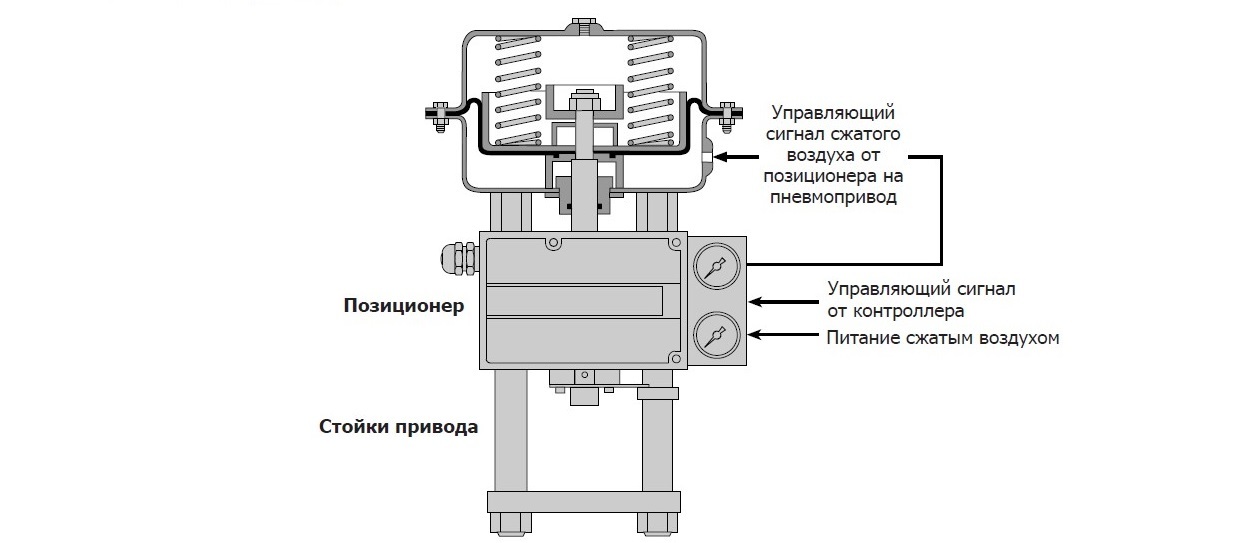
В ранее вышедшей статье мы подробно рассказали об особенностях клапанов серии Spira-TrolTM и рассмотрели варианты их применения в различных процессах. Но, как известно, сам клапан это всего лишь часть устройства для регулирования потока среды, которое также включает в себя исполнительный механизм, например, пневматический привод, который, в свою очередь, может быть оснащен позиционером.
Позиционер – это дополнительное устройство, которое обычно монтируют на стойках пневмопривода и которое имеет бесконтактную или механическую связь со штоком привода/клапана для получения обратной связи о его положении. Электропневматический позиционер преобразует электрический сигнал в пневматический сигнал сжатого воздуха, который направляется в пневмопривод для перемещения штока клапана в требуемое положение.
Часто задают вопрос: «В каком случае следует использовать позиционер?»
Рассматривать необходимость использования позиционера нужно в следующих обстоятельствах:
1. Когда требуется точное позиционирование штока клапана.
2. Когда нужно ускорить отклик клапана на изменение управляющего сигнала, что обеспечивается более высоким давлением воздуха управляющего сигнала, поступающего с позиционера на пневмопривод.
3. Для возможности работы клапана на более высоком перепаде давления на клапане (позиционер действует в качестве усилителя сигнала).
4. В случаях, когда трение в уплотнении штока клапана приводит к слишком сильному запаздыванию в реакции на изменение управляющего сигнала.
5. Для обеспечения линейности отклика при использовании нелинейного привода.
6. В случаях, когда изменения перепада давления в клапане могут приводить к изменению положения плунжера клапана.
Для систем регулирования большинство процессов с такими средами, как пар и вода, обычно используют либо электрические, либо пневматические привода. Пневматические более востребованные в технологических процессах благодаря быстродействию (по сравнению с электрическими) и возможности занимать безопасное положение при потере питания или управляющего сигнала под действием пружин.
Темой данной статьи будут являться электропневматические позиционеры, которые являются неотъемлемой частью системы регулирования. Мы опишем производимые нашей компанией позиционеры, их технические характеристики и отличительные особенности.
На сегодняшний день наша компания производит три различных электропневматических позиционера (нажмите на картинку, чтобы узнать больше о каждом продукте):
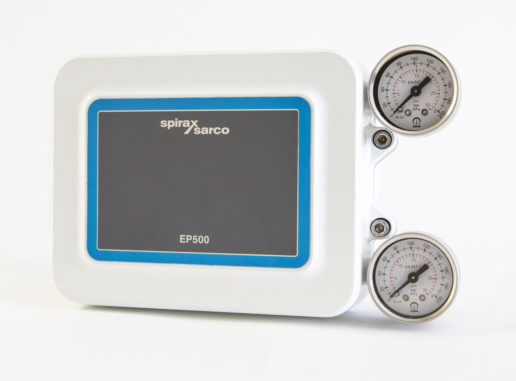
Модель ЕР500 – это по сути обновленная версия позиционера ЕР5, который имеет достаточно простую и надежную конструкцию. Данный тип электропневматического позиционера зарекомендовал себя как надежное и высокоточное устройство, которое востребовано на рынке.
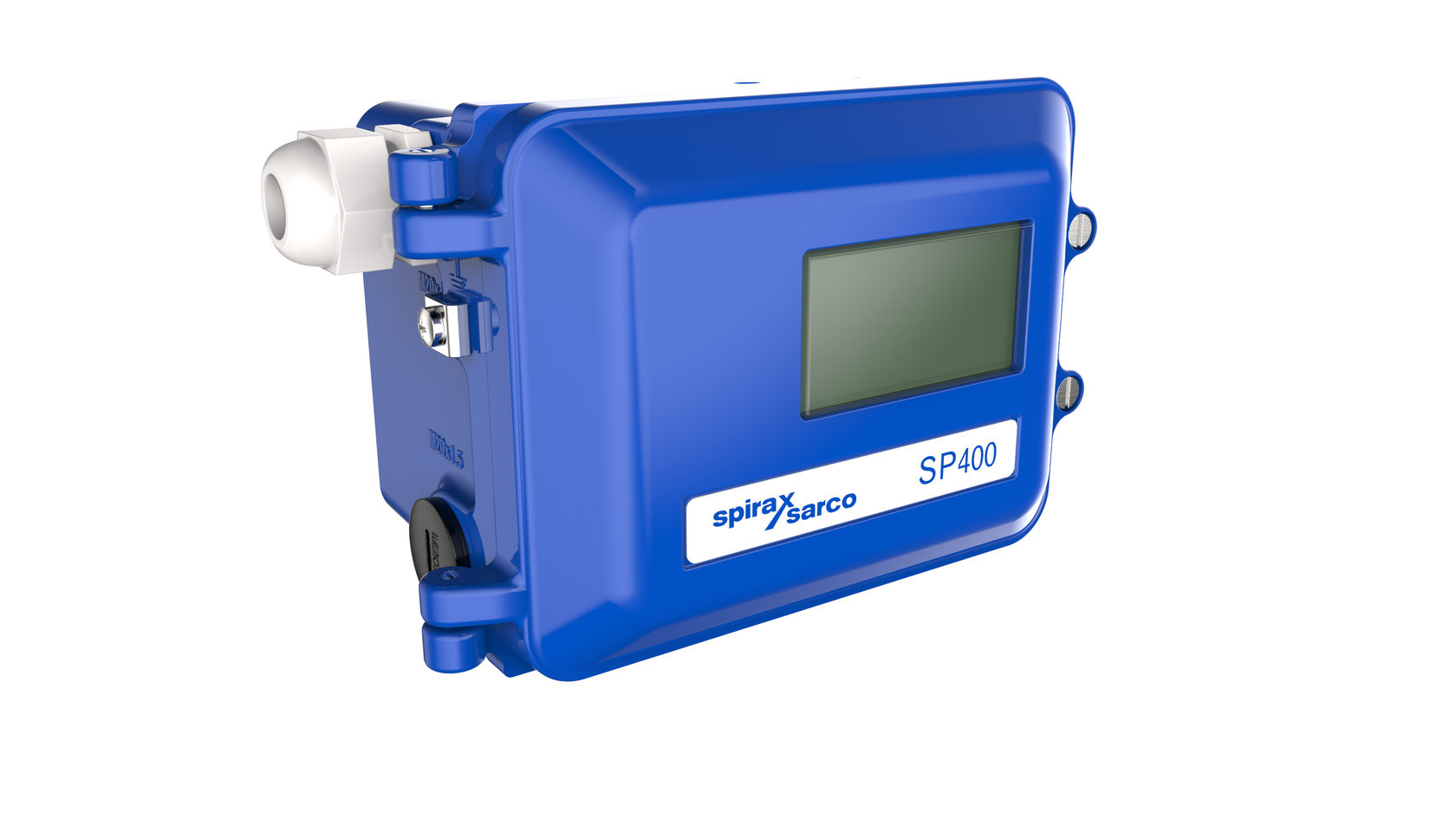
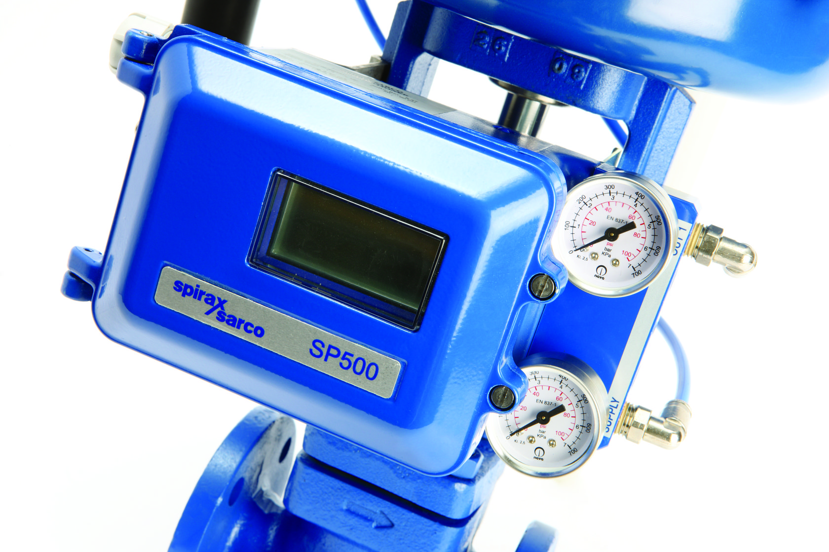
Более подробно хотелось бы остановиться на типе SP400/500. Эта серия была специально разработана с учетом требований и пожеланий наших заказчиков.
Отличительными особенностями данной серии являются:
- простая и быстрая функция авто-настройки (запускается нажатием одной кнопки, длительность процедуры 1,5-2 минуты)
- для обеспечения контакта со штоком клапана используется бесконтактный датчик Холла, что позволяет обеспечит более точную обратную связь по положению клапана, исключает ошибки и выход из строя из-за нарушения механической связи;
- программируемые функции и встроенная клавиатура (для корректировки параметров не требует подключения сторонних устройств);
- электрические соединения с низким сопротивлением. Позиционер не требует внешних источников питания, достаточно питания от управляющего сигнала;
- цифровой контроль расхода сжатого воздуха – благодаря данному решению позиционер практически не потребляет воздух в стационарных режимах.
Таким образом позиционеры имеют очень низкую стоимость эксплуатации. Учитывая постоянно растущие цены на энергоносители значение потребления сжатого воздуха становится важнее с каждым годом.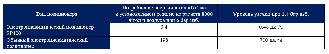
- расширенное меню программируемых функций для более точного управления клапаном
- возможность установки (опционально) платы ретрансляции сигнала о фактическом положении клапана
- доступна версия с HART протоколом
Дополнительную информацию по электропневматических позиционерах производства Spirax Sarco вы можете найти на нашем сайте или позвонить по телефону 8 800 551-00-25.
+7 (495) 215-16-67
8 (800) 333-16-67
с 9:00-19:00 — ежедневно (МСК)
Заказать звонок
×
Обратный звонок
Представьтесь
Номер вашего телефона
Ваш вопрос
я даю согласие Shopozz на обработку персональных данных
в соответствии с Федеральным законом от 27.07.2006 года №152-ФЗ «О персональных данных», на условиях и для целей, определенных Политикой конфиденциальности.
×
Доставка товаров с аукциона eBay и интернет-магазинов США в
Россию (Москва, Санкт-Петербург, Новосибирск, Екатеринбург,
Казань, Нижний Новгород, Челябинск, Красноярск, Самара, Уфа,
Ростов-на-Дону, Омск, Краснодар, Воронеж, Волгоград, Пермь и
другие города).
© Shopozz — сервис покупок за рубежом