Руководство на английском языке по техническому обслуживанию и ремонту + схемы электрооборудования автомобиля SsangYong Actyon второго поколения.
- Автор: —
- Издательство: SsangYong
- Год издания: 2012
- Страниц: —
- Формат: PDF
- Размер: 95,2 Mb
Сборник руководств на английском языке по техническому обслуживанию и ремонту + схемы электрооборудования автомобиля SsangYong Actyon первого поколения.
- Автор: —
- Издательство: SsangYong
- Год издания: 2006-2010
- Страниц: —
- Формат: PDF
- Размер: 1,3 Gb

Руководство по эксплуатации и техническому обслуживанию автомобилей SsangYong Actyon с 2013 года выпуска.
- Автор: —
- Издательство: Automechanic
- Год издания: —
- Страниц: 361
- Формат: —
- Размер: —
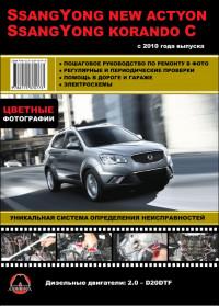
Руководство по техническому обслуживанию и ремонту автомобилей SsangYong New Actyon и SsangYong Korando C с 2010 года выпуска с дизельным двигателем объемом 2,0 л.
- Автор: —
- Издательство: Монолит
- Год издания: —
- Страниц: 347
- Формат: PDF
- Размер: 273,2 Mb

Руководство по техническому обслуживанию и ремонту автомобилей SsangYong New Actyon и SsangYong Korando C с 2010 года выпуска с дизельным двигателем объемом 2,0 л.
- Автор: —
- Издательство: Монолит
- Год издания: —
- Страниц: 356
- Формат: —
- Размер: —

Руководство по техническому обслуживанию и ремонту автомобилей SsangYong New Actyon и SsangYong Korando C с 2010 года выпуска с дизельным двигателем объемом 2,0 л.
- Автор: —
- Издательство: Монолит
- Год издания: —
- Страниц: 376
- Формат: —
- Размер: —
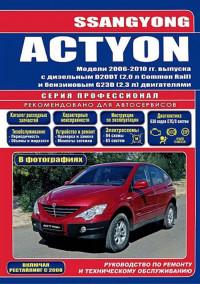
Руководство по техническому обслуживанию и ремонту + каталог расходных запчастей автомобиля SsangYong Actyon 2006-2010 годов выпуска с бензиновыми и дизельными двигателями.
- Автор: —
- Издательство: Легион-Автодата
- Год издания: 2015
- Страниц: 424
- Формат: —
- Размер: —
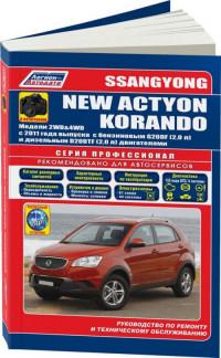
Руководство по техническому обслуживанию и ремонту + каталог расходных запчастей автомобилей SsangYong Actyon и SsangYong Korando с 2011 года выпуска с бензиновыми и дизельными двигателями.
- Автор: —
- Издательство: Легион-Автодата
- Год издания: 2015
- Страниц: 491
- Формат: —
- Размер: —
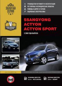
Руководство по техническому обслуживанию и ремонту автомобилей SsangYong Actyon и SsangYong Actyon Sports с 2006 года выпуска с бензиновыми и дизельными двигателями.
- Автор: —
- Издательство: Монолит
- Год издания: —
- Страниц: 352
- Формат: —
- Размер: —
Сборник руководств по эксплуатации и техническому обслуживанию автомобиля SsangYong Actyon второго поколения.
- Автор: —
- Издательство: SsangYong
- Год издания: —
- Страниц: —
- Формат: PDF
- Размер: 26,1 Mb
Сборник руководств по эксплуатации и техническому обслуживанию автомобиля SsangYong Actyon первого поколения.
- Автор: —
- Издательство: SsangYong
- Год издания: —
- Страниц: 304/347
- Формат: PDF
- Размер: 19,9 Mb


Руководство по эксплуатации SsangYong Actyon

Руководство по эксплуатации SsangYong Kyron

Руководство по эксплуатации SsangYong New Rexton

Руководство по эксплуатации SsangYong Actyon Sports Q

Руководство по эксплуатации SsangYong Rexton

Руководство по эксплуатации SsangYong Actyon Sports/Actyon
Ремонт и сервис SsangYong
Как выполнить ремонт Сан Енг, если дилеров в Москве не осталось? Конечно, можно довериться местному гаражному умельцу. Но лучше обратиться к специалистам.
ААРОН АВТО имеет опыт в ремонте и обслуживании корейских внедорожников Саньенг с 2011 года.

Если кто-то сталкивался с установкой светодиодных ламп с эффективным кулерным радиатором в штатные противотуманные фары, напишите, пожалуйста, хватает ли места для их установки с правой стороны, там где расположен бак с омывающей жидкостью. Фото приветствуются, вдруг, кто-то просто решит заменить штатные лампы накаливания и «залезет» туда.
Да, в итоге я его и не нашёл), конкретного ответа никто не дал. Обошёлся лампами для указателей поворота со встроенной «обманкой» (производство: Южная Корея, вдруг, кому-то будет интересно). В итоге долгих, дорогих и «болезненных» доработок всех источников света в автомобиле, могу сказать следующее. Серьёзные проблемы были только с подбором ламп передних/задних указателей поворота, подключением светодиодных ламп ближнего/дальнего света фар (потребовалось менять реле и добавлять дорогие «обманки», с дешёвыми лампы корректно не работали).
Доброго времени суток, кто может мне помочь? Решил заменить лампы в задних указателях поворота с накаливания на светодиодные. Пересмотрел все схемы и фото — не могу найти реле «аварийки» или указателей поворота. При включении указателей поворота, вроде, звук доносится из-под торпедо. Автомобиль 2015-ого года выпуска.

У наших машин нет реле поворота.

Так там же корандо? Что все одинаково?

На Актионе 2014 головной свет:
дальний H1/60Wt
ближний H7/55Wt
В схемах написано вроде как бы для нью актион, но указана 1 лампа Н4.

Большое спасибо! Очень помог!

Спасибо, очень даже получилось «посмотреть». Черно-белые схемы, но есть что искал, ПТФ, электронное реле, вставка в другом месте fe11. Найти бы ещё перевод с англ. этого сокровища.

Ссылка не работает. У меня есть цветное руководство, рус. за 1200р. на более старые модификации. Оно обозначено Корандо С. Когда ничего нет, тоже полезное руководство. Теперь есть и Ваша рекомендация.
Это Корандо С дизель, у меня есть такое же руководство на бензин.
У меня дизель 2013 г.в.
Ну тогда, как говориться «Учите Шурочка английский!»
Как-то давно, помнится скачивал сее на русском, если найду, то скину.

Они переехали на другой домен
Leodav
Ссылка не работает. У меня есть цветное руководство, рус. за 1200р. на более старые модификации. Оно обозначено Корандо С. Когда ничего нет, тоже полезное руководство. Теперь есть и Ваша рекомендация.
Я по этой книжке ставил ПТФ и доводчик стекол. Вроде все соответствует

Электросхемы С210 немного отличаются от схем Вашего авто на фото С200. На монтажных блоках у порогов вместо 5-6 разъёмов, у С210 — 2шт.
- Manuals
- Brands
- SSANGYONG Manuals
- Automobile
- Actyon 2012.12
- Manual
-
Contents
-
Table of Contents
-
Troubleshooting
-
Bookmarks
Quick Links
0-3
0000-00
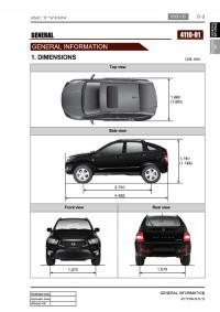
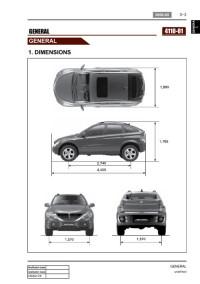
1. DIMENSIONS
Unit: mm
Top view
Side view
Front view
Rear view
Related Manuals for SSANGYONG Actyon 2012.12
Summary of Contents for SSANGYONG Actyon 2012.12
-
Page 1
0000-00 1. DIMENSIONS Unit: mm Top view Side view Front view Rear view… -
Page 2: Specifications
2. SPECIFICATIONS…
-
Page 3
0000-00… -
Page 4: Vehicle Identification
3. VEHICLE IDENTIFICATION Engine Number (G23D) Chassis Number The engine number is stamped on the The chassis number is stamped on the upper rear left-hand side of the cylinder frame behind the front right tire. block. Engine Number (D20DTR) Vin Label Certification Label The engine number is stamped The certification label is located on…
-
Page 5: Maintenance Interval
0000-00 4. MAINTENANCE INTERVAL 1) Diesel Engine — EU…
-
Page 7
0000-00… -
Page 8
0-10 2) Diesel Engine — GENERAL… -
Page 9
0-11 0000-00… -
Page 10
0-12… -
Page 11: Gasoline Engine
0-13 0000-00 3) Gasoline Engine…
-
Page 12
0-14… -
Page 13
0-15 0000-00… -
Page 14: Recommended Fluids And Lubricants
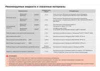
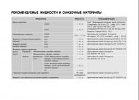
0-16 5. RECOMMENDED FLUIDS AND LUBRICANTS Use only Ssangyong recommended fluids and lubricants. Do not mix any different types or brands of oils or fluids. This may cause damages. Keep the specified levels when adding or replacing the fluids.
-
Page 15: Jack-Up Points
0-17 0000-00 6. JACK-UP POINTS…
-
Page 16: Pin Arrangement Of Diagnostic Connector
0-18 7. PIN ARRANGEMENT OF DIAGNOSTIC CONNECTOR It is installed under the instrument panel and consists of 16 pins 1) Functions of Terminal Pin no. 1 Pin no. 2 Pin no. 3 STICS «C1» Pin no. 4 Ground Signal ground Pin no.
-
Page 17: Electric Components And Layout
0-19 0000-00 8. ELECTRIC COMPONENTS AND LAYOUT 1) Wiring Harness Arrangement…
-
Page 18: Components Locator
0-20 2) Components Locator…
-
Page 19: Standard Bolts Specifications
0-21 0000-00 9. STANDARD BOLTS SPECIFICATIONS…
-
Page 20
0-22 Metric bolt strength is embossed on the head of each bolt. The strength of bolt can be classified as 4T, 7T, 8.8T, 10.9T, 11T and 12.9T in general. Observe standard tightening torque during bolt tightening works and can adjust torque to be proper within 15 % if necessary. -
Page 21
0000-00 1. GLOSSARY… -
Page 23
0000-00… -
Page 25
0000-00… -
Page 27
0000-00… -
Page 28
0-10… -
Page 29: Engine Layout
01-3 0000-00 1. ENGINE LAYOUT Front view Rear view Right view Left view…
-
Page 30
01-4 2. MAJOR COMPONENTS ▶ Front view Vacuum pump Camshaft position sensor Oil filter assembly Power steering pump pulley Oil pressure switch Water pump pulley Idler pulley No. 2 Alternator pulley Auto tensioner Idler pulley No. 1 A/C compressor pulley Isolation damper ▶… -
Page 31
01-5 0000-00 ▶ Right view Front exhaust gas temperature sensor Oil dipstick tube & gauge assembly E-VGT actuator E-VGT turbocharger Coolant screw plug Oil drain plug ▶ Left view Thermostat assembly Variable swirl valve assembly E-EGR valve E-EGR solenoid valve Oil cooler assembly EGR cooler Electronic throttle body… -
Page 32: Engine Compartment Layout
Always turn the engine off and allow it to cool before starting the maintenance. Regularly check the engine oil level and add Ssangyong genuine engine oil if necessary. Clean the dipstick with clean cloth so that any foreign materials cannot get into the engine.
-
Page 33: Service Interval
General Change every 45,000 km (Draining water from fuel filter: whenever replacing the engine oil) 2) Specification and Capacity Specification Quality class: Ssangyong genuine engine oil (Approved by MB Engine oil Sheet 229.51, SAE 5W/30) Capacity approx. 6.0 litter Specification…
-
Page 34: Caution When Servicing The Engine
01-8 4. CAUTION WHEN SERVICING THE ENGINE 1) Cleaness Engine has a lot of precisely machined (grinding, polishing, lapping) surfaces. Thus, there should be great cautions for cleaness when servicing the engine components. Apply the engine oil on the sliding surfaces when assemblying the components.
-
Page 35: Lubrication System
01-9 0000-00 (3) Cautions before service Scalding hot coolant and steam could be blown out under pressure, which could cause serious injury. Never remove the coolant reservoir cap when the engine and radiator are hot. (4) Lubrication system Prolonged exposure to the engine oil make cause a skin cancer or an irritation. Used engine cotains the hazardous material that may cause the skin cancer.
-
Page 36
01-10 5. STANDARD BOLTS SPECIFICATIONS Metric bolt strength is embossed on the head of each bolt. The strength of bolt can be classified as 4T, 7T, 8.8T, 10.9T, 11T and 12.9T in general. Observe standard tightening torque during bolt tightening works and can adjust torque to be proper within 15 % if necessary. -
Page 37: Tightening Torque
01-11 0000-00 6. TIGHTENING TORQUE Note (total Tightening Numbers of Name Size tightening torque (Nm) fastener torque) M12×82 55±5Nm, Main bearing cap Not-reusable 180˚ M9×52 40±5Nm, Connecting rod cap 50 ~80Nm 90˚+10˚ M6×20 10±1Nm Crankshaft rear seal M8×35 25±2.5Nm Oil pump M10×22 45±5Nm, Drive plate…
-
Page 38
01-12 Note (total Numbers of Tightening Name Size tightening fastener torque (Nm) torque) M6×12 10±1Nm Hot water inlet pipe M6×12 10±1Nm Hot water inlet pipe M10×90 (LO) 25±2.5Nm Alternator 알터네이터 M10×90 (하) 25±2.5Nm M10×116 (HI) 46±4.6Nm M10×116 (상) 46±4.6Nm M8×85 Air conditioner 25~2.5Nm 에어컨… -
Page 39
01-13 0000-00 Note (total Tightening Numbers of Name Size tightening torque (Nm) fastener torque) 45±4.5Nm Idler pulley/tensioner pulley 20±2Nm Glow plug M8×25 10±1Nm Vacuum pump M6×40 10±1Nm Timing gear case cover M6×45 10±1Nm M6×50 10±1Nm M6×35 10±1Nm Cylinder head cover M6×16 10±1Nm Oil dipstick gauge cover… -
Page 40: Coding And Initialization
01-14 7. CODING AND INITIALIZATION 1) Engine Variant Coding Unit Selection Description Remarks PTC auxilary heater For PTC auxilary heater equipped vehicle, select «YES». Glow plug Relay (K-line) Select «AQGS». AQGS (CAN) AQGS (CAN) Transmission 6-speed M/T Select the appropriate system. Select 5-speed A/T (DC 5 AT) Select…
-
Page 41: Specification
02-3 0000-00 1. SPECIFICATION Unit Description Specification Remark Cylinder head Height 131.9 to 132.1 mm Flatness below 0.1 mm Valve protrusion Intake valve 0.6 to 1.0 mm Exhaust valve 0.6 to 1.0 mm Flatness on manifold Intake manifold 0.08 mm side Exhaust manifold 0.08 mm…
-
Page 42
02-4 2. TIGHTENING TORQUE Bolt Remark Specified torque Component Size Quantity (Total torque) (Nm) M12×82 55±5Nm, Main bearing cap Not re-usable 180˚ M9×52 40±5Nm, Connecting rod cap 50 to 80 Nm 90˚+10˚ M6×20 10 ± 1 Nm Rear cover M8×35SOC 25 ±… -
Page 43
02-5 0000-00 Specified torque Bolt Remark Component Size (Nm) Quantity (Total torque) M6×16 10±1Nm Hot water inlet pipe M10×90 25±2.5Nm Alternator M10×116 46±4.6Nm M8×25 A/C bracket 7.8~11.8Nm M6×25 10±1Nm A/C sub bracket M8×35 25±2.5Nm Intake manifold M8×110 25±2.5Nm M8×40 25±2.5Nm Oil filter module M8×20 25±2.5Nm… -
Page 44
02-6 Bolt Remark Specified torque Component Size Quantity (Total torque) (Nm) 20±2Nm Glow plug M8×25 10±1Nm Vacuum pump M12×55 85±8.5Nm Timing gear case cover M6×25 10±1Nm M6×45 10±1Nm M6×50 10±1Nm M6×35 10±1Nm Cylinder head cover M6×16 10±1Nm Oil gauge tube 25±2.5Nm Oil filter cap M8×35SOC… -
Page 45
02-7 0000-00 3. CHECK AND INSPECTION 1) Cylinder (1) Compression pressure test ▶ Specified value 16.5 : 1 Compression ratio at normal operating temperature (80˚C) Test condition Standard 32 bar Compression pressure 18 bar Minimum Differential limit between cylinders Maximum 3 bar The compression pressure test is to check the conditions of internal components (piston, piston ring, intake and exhaust vale, cylinder head gasket). -
Page 46
02-8 Crank the engine for approx. 10 seconds by using the start motor. Record the test result and measure the compression pressure of other cylinders with same manner. If the measured value is out of specified value, perform the cylinder pressure leakage test. -
Page 47
02-9 0000-00 (3) Piston protrusion check Position the piston at TDC and measure the piston protrusion from crank case mating surface. Specified value 0.475 to 0.745 mm Measure it at both ends of crankshaft. -
Page 48
02-10 2) Cylinder Head (1) Cylinder head mating surface check ▶ Specified value Total height «A» 131.9 to 132.1 mm Minimum height after machining 131.9 mm Longitudinal direction 0.1 / 150 Flatness Transverse direction 0.15 below 0.1 mm Parallel deviation of cylinder head Rmax 7 Peak-to valley of surface Rz 6.3… -
Page 49
02-11 0000-00 4. GUIDELINES ON ENGINE SERVICE To prevent personal injuries and vehicle damages that can be caused by mistakes during engine and unit inspection/repair and to secure optimum engine performance and safety after service works, basic cautions and service work guidelines that can be easily forgotten during engine service works are described in. -
Page 50
02-12 ▶ Fuel and lubrication system Do not allow the fluid and engine oil to make contact with the body paintwork and hoses. If work on the fluid system such as fuel and oil, working area should be well ventilated and smoking should be prohibited. -
Page 51
02-13 0000-00 1. BELT LAYOUT It is single drive type and uses FEAD (Front End Accessories Drive) design to make a compact layout. ▶ Components D20DTR Engine HPS (Hydraulic Power Steering) Crankshaft pulley (DDU) Auto tensioner Tensioner pulley Vacuum pump A/C compressor pulley Alternator pulley Water pump pulley… -
Page 52
02-14 1) Crankshaft Pulley (Isolation Damper) (1) Overview The strut type tensioner automatically adjusts the belt tension to provide the reliability and durability for the system. And, the belt tension is decreased to minimize the friction loss and improve the belt operating noise. -
Page 53
02-15 0000-00 (3) Features Rubber damper: Decrease crankshaft torsion Improve belt NHV: Reduce unbalance speed to crankshaft due to irregular combustion Minimize noise: Anti-vibration from crankshaft and belt Post bonded type rubber damper: Improve durability of rubber damper… -
Page 54: Belt Tensioner
02-16 2) Belt Tensioner (1) Overview The torque deviation from crankshaft affects the components in belt drive system and the belt movement. The auto tensioner system is to adjust this deviation automatically. In D20DTR engine, one of the mechanical tensioner, pivot damped tensioner is used to keep the damping force, system reliability and durability.
-
Page 55: Vacuum Pump
02-17 0000-00 2. VACUUM PUMP Vacuum pump generates the vacuum pressure and supplies it to EGR cooler bypass solenoid. This pump is single vane type and displacement is 210 cc/rev. The lubrication oil is supplied through the hole in hollow shaft. ▶…
-
Page 56: Operation
02-18 1) Location 2) Operation The vacuum pump is engaged to the exhaust camshaft. Connection between vacuum pump and exhaust camshaft Oil supply and driving Vacuum pump Exhaust camshaft…
-
Page 57: Engine Mounting
02-19 0000-00 3. ENGINE MOUNTING D20DTR engine uses 3-point mounting type that supports the engine and transmission simultaneously. ▶ Components Front mounting insulator (Right side) Front mounting insulator (Left side) Location Insulator Location Insulator Rear mounting insulator…
-
Page 58
02-20 1) Functions Appearance Type and function Front mounting insulator (Right side) Type: Rubber mounting Function: Supports the torque reaction Front mounting insulator (Left side) Type: Rubber mounting Function: Supports the torque reaction Rear mounting insulato Type: Rubber mounting Function: Supports the powertrain rod… -
Page 59: Intake Manifold
02-21 0000-00 4. INTAKE/EXHAUST MANIFOLD 1) Intake Manifold Intake manifold is installed on the cylinder head with 8 bolts. The variable swirl valve is introduced to improve the EGR gas mixture and turbulence in combustion chamber and to decrease the exhaust gas. ▶…
-
Page 60: Cylinder Head Cover
02-22 5. CYLINDER HEAD COVER AND OIL SEPARATOR 1) Cylinder Head Cover The cylinder head cover is made by high strength plastic to reduce the weight. The multi twist type oil separator improves the oil consumption. ▶ Components Front view Cylinder head cover Rear view…
-
Page 61: Oil Separator
02-23 0000-00 2) Oil Separator (1) Overview Oil separator separates the particle in blow-by gas to minimize the engine oil consumption and reduces the inflow oil from intake system into the combustion chamber. The separated oil returns to oil pan through cylinder head.
-
Page 62: Cylinder Head
02-24 6. CYLINDER HEAD Cylinder head contains cam position sensor, vacuum pump, intake manifold, exhaust manifold and valve assembly. Vacuum pump and the high pressure (HP) pump are driven by Camshaft and valves are install in vertical direction. This enables the compact layout in cylinder head assembly. ▶…
-
Page 63
02-25 0000-00 1) Cylinder Head (1) Overview The cylinder is made by gravity casting and the water jacket is integrated type. The cylinder oil passage is drilled and sealed by cap. The Camshaft bearing cap is also made by casting and installed on the cylinder head. (2) Features Location of Expansion Plugs Front… -
Page 64
02-26 ▶ Closed flow type water jacket (improving cooling performance) 2) Camshaft (1) Overview Hollow type camshaft contains cam, octagon cam, HP pump gear and intake/exhaust gears. Camshaft operates the intake/exhaust valves, vacuum pump and HP pump, and transfers the engine oil to vacuum pump through the internal oil passage. -
Page 65
02-27 0000-00 3) Valve Assembly (Installed in Cylinder Head) (1) Features Automatic valve clearance adjuster by hydraulic pressure (Maintenance Free) — Hydraulic lash Optimized adjustment of valve clearance reduces the valve noise. Roller type finger follower reduces the friction loss. Vertical installation. -
Page 66
02-28 4) Cylinder Head Gasket (1) Features Sealing the cylinder gas pressure — Peak pressure: 190 bar Minimizing the distortion of engine structure (cylinder head, block): profile stopper, backland stopper Material: MLS (Multi Layer Steel), Gasket (3 layers) Thickness of gasket: 3 types (1.2 /1.3 /1.4 mm) Thickness marking Ex: 1.3t (2) Thickness of cylinder head gasket… -
Page 67: Chain Drive
02-29 0000-00 7. CHAIN AND GEAR DRIVE SYSTEM D20DTR engine uses single stage chain drive system. Timing chain drives the exhaust side and gear drive the intake side. Timing chain is single bush type. Upper chain drives HP pump connected to intake Camshaft by driving exhaust cam shift sprocke, and lower chain drives oil pump to lubricate the engine.
-
Page 68
02-30 2) Timing Chain and Gear (1) Timing chain Simple layout: optimized timing, enhanced Single stage layout: minimized chain load Chain upper bush — Single bush type (112 EA) Chain lower bush — Single bush type (60 EA) (2) Tensioner Tensioner adjusts the chain tension to keep it tight during engine running. -
Page 69: Guide Rail
02-31 0000-00 (3) Mechanical Tensioner Assembly Operating principle — Use only spring tension Tensioner type — Compensation and impact absorbing Static and dynamic force — Spring (4) Guide rail The guide rail is used for optimizing the movement of chain drive system. And it also prevents the chain from contacting each other when the chain is loose, and reduces the chain wear.
-
Page 70
02-32 (5) Timing gear case cover Timing gear case cover (TGCC) Timing gear case cover Oil seal Screw plug… -
Page 71
02-33 0000-00 ▶ Features Major function: Protecting the chain drive system, minor function: Shielding the chain noise. Install crankshaft front seal and screw plug on the timing gear case cover. Location of chain tensioner screw plug A671 997 01 46 Crankshaft front seal Do not touch the inner lip of crankshaft front seal. -
Page 72: Oil Pan
02-34 8. OIL PAN The oil pan in D20DTR engine improves the NVH. Especially, the oil draining is much easier than before. ▶ Components Oil pan sassembly…
-
Page 73
02-35 0000-00 9. DUAL MASS FLYWHEEL (DMF) & DRIVE PLATE 1) Overview Flywheel is installed on crankshaft. When starting the engine, this functions as follows: Reducing the irregular speed of crankshaft due to unbalanced combustion -> Improving the power train NVH, Improving the driving performance Reducing the clutch noise by using ball bearing… -
Page 74: Operation
02-36 3) Operation Compensating the irregular operation of engine: The secondary flywheel operates almost evenly so does not cause gear noises The mass of the primary flywheel is less than conventional flywheel so the engine irregularity increases more (less pulsation absorbing effect). Transaxle protection function: Reduces the torsional vibration to powertrain (transaxle) by reducing the irregularity of engine.
-
Page 75: Drive Plate
02-37 0000-00 4) Features Reduced vibration noise from the powertrain by blocking the torsional vibrations Enhanced vehicle silence and riding comforts: reduced engine torque fluctuation Reduced shifting shocks Smooth acceleration and deceleration 5) Advantages Improved torque response by using 3-stage type spring: Strengthens the torque response in all ranges (low, medium, and high speed) by applying respective spring constant at each range.
-
Page 76
02-38 10. PISTON/CRANKSHAFT/CYLINDER BLOCK The crankshaft and the cylinder block convert the compression pressure to the rotating energy. ▶ Components Cylinder block Piston Connecting rod Crankshaft… -
Page 77
02-39 0000-00 1) Piston (1) Overview Piston assembly contains piston, #1 ring, #2 ring, oil ring, piston pin and snap ring. The expansion energy from engine is transferred to the crankshaft through connecting rod to convert the linear movement to rotating energy. (2) Layout Material: B2+ #2 ring… -
Page 78: Assembling The Piston
02-40 (3) Functions Piston transfers the combustion energy from engine to connecting rod. Especially in the direct injection engine such as D20DTF, it provides the combustion space and largely effects to the engine performance and exhaust gas. ▶ Piston ring #1 ring (Top ring) : Prevents the high pressurized combustion gas from leaking into crank chamber, and prevents the engine oil getting into combustion chamber.
-
Page 79
02-41 0000-00 Selecting piston oversize Top of piston Top of cylinder block Piston Cylinder bore Engine Part NO Marking NO. 671 030 06 17 671 037 07 01 671 037 08 01 D20DTF 671 037 09 01 671 037 10 01 671 037 11 01… -
Page 80: Connecting Rod
02-42 2) Connecting Rod (1) Overview Connecting rod converts the reciprocating movement of piston to the rotating movement of crankshaft. The big end is connected to connecting rod bearing and the crank pin journal, and the small end is connected to the piston pin. (2) Components Piston pin bush Connecting rod…
-
Page 81
02-43 0000-00 (3) Selection of crankshaft pin journal bearing The connecting rod bearing contains 3 sets of 3 grades in upper and lower sections. Three sets in the table below have nearly same oil clearance (0.015~0.063 mm) of bearing. Identification: Coloe mark on bearing side surface Upper bearing Lower bearing Journal… -
Page 82
02-44 3) Crankshaft (1) Overview Crankshaft is installed on the cylinder block. (2) Arrangement Upper thrust bearing Crankshaft main bearing upper Crankshaft main bearing upper Crank pin journal Main journal Lower thrust bearing Crankshaft main bearing lower Crankshaft main bearing lower… -
Page 83
02-45 0000-00 (3) Selection of crankshaft main bearing Mating surface of crankshaft sprocket Bottom of cylinder block Selection of lower main bearing Selection of upper main bearing Selection of bearing according to pin punch & Mark Color Thickness of main color bearing (mm) Mark… -
Page 84: Cylinder Block
02-46 4) Cylinder Block (1) Overview The major dimensions in D20DTR are similar to D20DTR engine. It has two mounting bosses for knock sensor and meets the requirements for EURO5 regulation. (2) Layout Right side Right side Expansion plug Screw plug…
-
Page 85
02-47 0000-00 Left side Expansion plug (3) Features For simple manufacturing, the crankcase blow- by gas passage and the oil return hole are made by casting on the cylinder block. -
Page 86
02-48 The bottom side of water jacket is desgined as sine wave to strengthen the structure of crankcase. The main flow of coolant starts from outlet port of water pump and goes along the longitudinal direction of engine. The coolant passage from cylinder head to inlet port of water pump is integrated in cylinder head. Water jacket core The engine oil from oil pump is supplied to the main oil gallery through oil channel, oil filter module and cross bore in cylinder block without using external pipes. -
Page 87
03-3 2210-01 1. SPECIFICATION Description Specification Fuel Diesel Type Fuel heater + priming pump + water separator integrated type Filter type Changeable filter element type Change interval every 40,000 km every 45,000 km Fuel filter Water separation every 20,000 km interval every 15,000 km Water accumulating capacity… -
Page 88: Maintenance And Inspection
03-4 2. MAINTENANCE AND INSPECTION 1) Maintenance Procedures for DI Engine Fuel System Always keep the workshop and lift clean (especially, from dust). Always keep the tools clean (from oil or foreign materials). Wear a clean vinyl apron to prevent the fuzz, dust and foreign materials from getting into fuel system. Wash your hands and do not wear working gloves.
-
Page 89
03-5 2210-01 Follow the job procedures. If you find a defective component, replace it with new one. Once disconnected, the fuel pipes between HP pump and fuel rail and between fuel rail and each injector should be replaced with new ones. The pipes should be tightened tospecified tightening torques during installation. -
Page 90: Hydraulic System
03-6 2) Diagnostic Test for Engine Fuel System (1) Overview If a DTC is displayed on the diagnostic device, check the low pressure- and high pressure fuel systems before removing the components. To run the system properly, the electric system must be intact but for the DI engine, the fuel pressure should be measured also when there is a malfunction even after the diagnostic test with a diagnostic device.
-
Page 91
03-7 2210-01 (3) Excessive backleak of injector ▶ Excessive injector backleak Occurs when the injector control valve is not sealed due to the entry of the foreign materials. ▶ Example: Entry of foreign materials Burned out and worn HP pump Mechanical damage inside the injector… -
Page 92
03-8 (4) Loss of pump pressure/flow ▶ Loss of HP pump pressure/flow Faulty fuel supply line, or damaged or worn pump causes the lack of flow pressure and flow volume ▶ Example: Air in fuel supply line Excessive load on fuel supply line (←400 mBar) Burned out and mechanical worn pump High temperature of fuel supply (>… -
Page 93
03-9 2210-01 3) DI Engine Fuel System Pressure Test (1) Test device (Tool kit) Device for high pressure Device for low pressure (2) Pre-check Check-tighten fuel supply line Check fuel level in fuel tank Check air in fuel supply line (bubble in fuel supply line or fuel) Check fuel supply line for leaks (low pressure and high pressure) Check that specified fuel is used Check fuel filter for contamination… -
Page 94
03-10 (3) DI Engine Fuel System Check Procedure If several DTCs are output simultaneously, check the electric wiring for open or short circuit. Check the low pressure fuel system and fuel filter and confirm that there are no abnormalities. Carry out the high pressure fuel system check. -
Page 95
03-11 2210-01 (4) Fuel System Check Procedure… -
Page 96
03-12 (5) High Pressure System Pressure Test ▶ Fuel rail pressure test Disconnect the fuel rail pressure sensor connector and then IMV connector. Connect the pressure tester to the fuel rail pressure sensor connector. Crank the engine 2 times for 5 seconds. Read the highest pressure value displayed on the tester display. -
Page 97
03-13 2210-01 ▶ How To Use Pressure Tester Press the «TEST» button on the tester to check if the message «TEST?» is displayed. If the button is pressed again at 4 seconds after starting engine cranking, the highest pressure is displayed on the tester. The fuel rail pressure value can be checked using a diagnostic device. -
Page 98
03-14 (6) Low Pressure System Pressure Test ▶ Inspection procedure All wirings/connectors and fuel lines should be connected and the engine should work properly. Prepare a special tool for low pressure test and clean it thoroughly to prevent foreign materials from entering. Disconnect the key connector for fuel filter connection, and connect both connectors to the fuel filter and hose. -
Page 99
03-15 2210-01 ▶ Static test for backleak of injector Disconnect the injector return hose and cover the openings with caps shaped screw (included in the special tool). Connect the hose of the container for measuring backleak to the return nipple of the injector. -
Page 100
03-16 ▶ Dynamic test for backleak of injector Warm up the engine so that the engine coolant temperature be over 80℃ and star the engine again. Disconnect the injector return hose and cover the openings with caps shaped screw (included in the special tool).. Connect the hose of the container for measuring backleak to the return nipple of the injector. -
Page 101
03-17 2210-01 ▶ HP pump pressure test Prepare a special tool for high pressure test and clean it thoroughly to prevent foreign materials from entering. Disconnect the high pressure fuel supply pipe on the HP pump and install the close rail in the tool kit. -
Page 102: Cautions For Di Engine
03-18 3. CAUTIONS FOR DI ENGINE 1) Cautions for DI Engine This chapter describes the cautions for DI engine equipped vehicle. This includes the water separation from engine, warning lights, symptoms when engine malfunctioning, causes and actions. DI Engine Comparatively conventional diesel engines, DI engine controls the fuel injection and timing electrically, delivers high power and reduces less emission..
-
Page 103
03-19 2210-01 2) Cleanness (1) Cleanness of DI engine fuel system ▶ Cleanness of DI engine fuel system and service procedures The fuel system for DI engine consists of transfer (low pressure) line and high pressure line. Its highest pressure reaches over 1,800 bar. Some components in injector and HP pump are machined at the micrometer 100 μm of preciseness. -
Page 104: Water In Fuel
03-20 (2) Di engine and its expected problems and remedies can be caused by water in fuel ▶ System supplement against paraffin separation In case of Diesel fuel, paraffin, one of the elements, can be separated from fuel during winter and then can stick on the fuel filter blocking fuel flow and causing difficult starting finally.
-
Page 105: Fuel Flow Diagram
03-21 2210-01 1. OVERVIEW The components in fuel system supply the fuel and generate the high pressure to inject the fuel to each injector. They are controlled by the engine ECU. The common rail fuel injection system consists of fuel tank, fuel line, low pressure line which supplies low pressure fuel to the low pressure pump (including high pressure pump), common rail which distributes and accumulates the high pressurized fuel from the fuel pump, high pressure line which connected to the injector, and the engine control unit (ECU) which calculates the accelerator pedal position and…
-
Page 106
03-22 2. SYSTEM LAYOUT AND OPERATION 1) Layout For sensor and actuator control logic, refer to Chapter «Engine Control». Engine ECU (D20DTR) Fuel tank Engine control by various signals Fuel metering by sender HFM sensor Measuring intake air mass and temperature Camshaft position sensor Crankshaft position sensor… -
Page 107
03-23 2210-01 High pressure pump Accelerator pedal position sensor Plunger type HP pump (1,800 bar) Vane type LP pump (6 bar) Generating high pressurized fuel and supplying it according to engine rpm, Detecting driver’s intention required volume, required pressure for speed up/down Fuel filter assembly Supplying clean fuel/fuel heating/water separation by… -
Page 108
03-24 2) Fuel System Flow Diagram The fuel from the fuel tank is supplied to the fuel heater of fuel filter/priming pump and then low pressure generated by the low pressure pump (built into HP pump) is transmitted to the HP pump. The fuel pressure at the HP pump is controlled by the IMV valve, and the maximum allowed pressure is 1,800 bar. -
Page 109
03-25 2210-01 3) Input/Output devices Refer to Chapter «Engine Control». -
Page 110
03-26 The engine ECU calculates the accelerator pedal based on the input signals from various sensors, and controls the overall operation of the vehicle. The ECU receives the signals from various sensor through data line, and performs effective air-fuel ratio control based on these signals. -
Page 111: Specification
04-3 1719-00 1. SPECIFICATION Unit Description Specification Air cleaner element Filter type Dry, filter element Initial resistance Max. 300 mmAq Service interval EU; Clean or change every 20,000 km GEN: Clean or change every 15,000 km -30 ~ 100˚C Air cleaner assembly Operating temperature Intercooler Core material…
-
Page 112
04-4 2. INSPECTION 1) Troubleshooting ▶ When Abnormal Noises are Heard from the Engine Room For the vehicle equipped with DI engine, if a learning noise occurs in each range or other noises occur, the major cause of it is a faulty turbocharger assembly. But an interference issue, poor tightness or loose in the intake and exhaust system also can cause those noises. -
Page 113: Troubleshooting Sequence
04-5 1719-00 3) Troubleshooting Sequence The basic checks for intake system are as follows: ▶ Basic Checks for Intake System Make sure to replace or clean the air cleaner element periodically. Otherwise, engine will be derated or work abnormally because of low intake air volume.
-
Page 114
04-6 1. OVERVIEW The intake system for D20DTR engine is equipped with a throttle body which includes a flap. This flap is controlled by an electrical signal to cut off the intake air entering to the engine when the ignition switch is turned off. -
Page 115
04-7 1719-00 1719-02 Swirl control valve Operating variably in accordance with the engine load and rpm.* For more information, refer to Chapter «Engine Control». 1719-01 Intake manifold Passage for variable swirl valve and for intake air 1719-16 Electric throttle body * For more information, refer to Chapter «Engine Control». -
Page 116
04-8 3. INPUT/OUTPUT OF INTAKE SYSTEM For more information, refer to Chapter » Engine Control». -
Page 117: Operating Process
04-9 1719-00 4. OPERATING PROCESS ▶ Work Flow…
-
Page 118
04-10 1) Types of swirl Swirl: One cylinder has two intake air ports, one is set horizontally and the other one is set vertically. Swirl is the horizontal air flows in cylinder due to the horizontal intake air ports. Tumble: Tumble is the vertical air flows in cylinder due to the vertical intake air port Squish: Squish is the air flows due to the piston head. -
Page 119
04-11 1719-00 Engine speed Swirl valve Amount of Load Remarks swirl Low speed, Increased EGR ratio, better air-fuel below 3,000 rpm Closed Heavy Low load mixture (reduce exhaust gas) High speed, Increase charge efficiency, higher over 3,000 rpm Open Light High load engine power The variable swirl valve actuator operates when… -
Page 120: Troubleshooting
05-3 1729-01 1. TROUBLESHOOTING 1) Work Flow…
-
Page 121
05-4 2. CAUTIONS Do not park the vehicle on flammable materials, such as grass, leaves and carpet. Do not touch the catalyst or the exhaust gas ignition system when the engine is running. If a misfire occurs in the combustion chamber or the emission of pollutant exceeds the specified level, the catalyst can be damaged. -
Page 122
05-5 1729-01 1. OVERVIEW This system purifies the exhaust gas generated by the combustion in the engine to reduce the pollutants and noise during that arise during combustion. 2. LAYOUT Exhaust manifold assembly Exhaust front pipe assembly CDPF assembly For more information, refer to Chapter «Engine Control». -
Page 123
05-6 3. OPERATING PROCESS 1) Exhaust Gas Flow 2) Input & Output Devices… -
Page 124: Specification
06-3 1914-01 1. SPECIFICATION Unit Description Specification Max. expansion coefficient Max. turbine speed 226,000rpm Turbocharger Max. temperature of turbine housing 790 ℃ Weight 6.5kg E-VGT actuator Operation duty cycle 250Hz…
-
Page 125
06-4 2. INSPECTION 1) Cautions During Driving The following lists cautions to take during test drive and on the turbocharger vehicle, which must be considered during the operation. It’s important not to drastically increase the engine rpm starting the engine. It could make rotation at excessive speed even before the journal bearing is lubricated and when the turbocharger rotates in poor oil supply condition, it could cause damage of bearing seizure within few seconds. -
Page 126
06-5 1914-01 2) Inspection of Turbocharger When problem occurs with the turbocharger, it could cause engine power decline, excessive discharge of exhaust gas, outbreak of abnormal noise and excessive consumption of oil. On-board Inspection Check the bolts and nuts foe looseness or missing Check the intake and exhaust manifold for looseness or damage Check the oil supply pipe and drain pipe for damages Check the housing for crack and deterioration… -
Page 127
06-6 3) Inspection of Turbine Thoroughly check the followings. Must absolutely not operate the turbocharger with the compressor outlet and inlet opened as it could damage the turbocharger or be hazardous during inspection. Interference: In case where is trace of interference or smallest damage on the compressor wheel means, most of times, that abrasion has occurred on the journal bearing. -
Page 128
06-7 1914-01 4) Possible Causes of Defect The following tries to understand the defects that can occur with vehicle installed with the turbocharger and to manage the reasons of such defects. In case where oil pan/oil pipe has been contaminated, oil filter is defected and where adhesive of gaskets has been contaminated into the oil line. -
Page 129
06-8 Oil Pump Defect: Rapid over-loaded driving after replacing oil filter and oil and clogging of oil line. -
Page 130
06-9 1914-01 Turbine Side: Inflow of foreign materials from engine Compressor Side: such as air filter, muffler and nut… -
Page 131
06-10 Defects caused by reasons other than that of the turbocharger. -
Page 132
06-11 1914-01 3. TROUBLESHOOTING The followings are cautions to take in handling defects of turbocharger, which must be fully aware of. 1) Cautions After stopping the engine, check whether the bolts on pipe connecting section are loose as well as the connecting condition of vacuum port and modulator, which is connected to the actuator. -
Page 133
06-12 2) Work Flow for Troubleshooting… -
Page 134
06-13 1914-01… -
Page 135
06-14… -
Page 136
06-15 1914-01… -
Page 137
06-16… -
Page 138
06-17 1914-01 1. SYSTEM DESCRIPTION OF E-VGT (Electric-Variable Geometry Turbine) 1) Overview The E-VGT turbocharger has one shaft where at each ends are installed with two turbines having different angles to connect one end of housing to the intake manifold and the other end to the exhaust manifold. -
Page 139
06-18 2) Features (1) Performance (for EURO V) Enhanced emmission control: By temperature control with CDPF system Target temperature and airflow control (2) E-VGT Actuator (Electric-Actuator) Optimizes the exhaust gas flow rate by controlling the vanes inside the turbine housing with the E- Actuator. -
Page 140
06-19 1914-01 For detailed information about the control logic, refer 2. COMPONENTS to Chapter “Engine Control”. E-VGT turbocharger Engine ECU (D20DTR) Accelerator pedal position sensor Atmospheric pressure, RPM signal Transfers driver’s will to Improves engine power E-VGT duty control accelerate to ECU T-MAP sensor HFM sensor Coolant temperature… -
Page 141: Input/Output Devices
06-20 3. INPUT/OUTPUT DEVICES…
-
Page 142: Operating Principles
06-21 1914-01 4. OPERATING PRINCIPLES The E-VGT is designed to get more improved engine power in all ranges by controlling the turbine as follows: 1) How it Works at Low Speed Normal turbocharger cannot get the turbo effect because the amount of exhaust gas is not enough and the flow speed is slow in a low speed zone, but VGT allows the flow passage of exhaust to narrow, resulting in increasing the flow speed of exhaust gas and running the turbine quickly and powerfully.
-
Page 143
06-22 2) How it Works at High Speed In a high speed zone, the amount of exhaust gas increases and it is accompanied with a great force. Therefore, if the inner diameter of venturi is more widened, the turbine in the turbocharger by the releasing force of abundant exhaust gas can deliver a more increased energy to the compressor. -
Page 144: Specification
07-3 1543-00 1. SPECIFICATION Unit Specification Oil pump Lubrication system Gear pump, forced circulation Unit Specification Type Inscribed gear Oil pump Lubrication system Gear pump, forced circulation Capacity 63 L at 4,000 rpm Type Inscribed gear 5.8 bar ± 0.3 bar Relief pressure Capacity 63 L at 4,000 rpm…
-
Page 145: Maintenance
Recheck the oil level after 5 minutes. Regularly check the engine oil level and add Ssangyong genuine engine oil if necessary. Clean the dipstick with clean cloth so that any foreign materials cannot get into the engine.
-
Page 146: System Description
07-5 1543-00 1. SYSTEM DESCRIPTION 1) Overview The lubrication system supplies oil to each lubrication section to prevent friction and wear and to remove heat from the friction part. As the engine runs, frictional heat is generated on each lubrication section. If this condition persists, the bearing can be burned and stuck.
-
Page 147
07-6 2. FUNCTIONS OF LUBRICATION 1) Lubrication It creates a viscous barrier between moving parts that reduces friction, which means less heat and longer life for those parts. As a lubricant, oil must maintain a protective film to prevent metal-to-metal contact. -
Page 148
08-3 1520-00 1. SPECIFICATION Unit Description Specification Cooling system Type Water cooling, forced circulation Coolant Capacity approx. 8.5 L Radiator Core size 555W x 582.4H x 27T (over 326,250mm2) Flow type Cross flow Min. cooling capacity over 68,000 kcal/h Antifreeze Type SYC1025 (Long life coolant) Mixing ratio… -
Page 149
08-4 2. INSPECTION Problem Possible Cause Action Coolant level is — Leak from the radiator — Change the radiator too low — Leak from the coolant auxiliary tank — Change the coolant auxiliary tank — Leak from the heater core — Change the heater — Leak from the coolant hose — Reconnect the hose or replace… -
Page 150: Coolant Level Check
08-5 1520-00 1) Coolant Level Check Park the vehicle on level ground and apply the parking brake. Stop the engine and wait until it is cooled down. The coolant level should be between the MAX and MIN mark on the coolant reservoir. Check the coolant level.
-
Page 151
08-6 2) Leak Test Release the pressure in the system by loosening the pressure cap of the coolant reservoir slightly. Then, remove the pressure cap completely. Never open the cap until the coolant temperature becomes under 90℃ to prevent any burn. Add the coolant so that the coolant level is between MAX and MIN mark on the coolant auxiliary tank. -
Page 152
08-7 1520-00 3. CAUTIONS If 100% of anti-freeze is added, the water pump vane can be damaged and thermal conductivity can be decreased resulting in poor circulation in the cooling system which leads to overheated engine. Use of non-recommended coolant could cause damage to the cooling system and overheating of the engine. -
Page 153
08-8 1. SYSTEM DESCRIPTION 1) Overview Coolant reservoir Long life coolant is used. Water pump Sealing Oil filter module Water pump Impeller vane The water pump is driven by the engine drive belt and supplies the coolant to each area of the engine. Thermostat When the engine coolant reaches 90℃, the thermostat… -
Page 154
08-9 1520-00 Coolant temperature sensor Measures the coolant temperature and sends the result to the engine ECU. Electric fan Circulates the fresh air forcibly to exchange heat with the radiator core fin. Radiator Releases heat through fins and cools down the hot coolant as the coolant passes through the tube of the radiator core. -
Page 155
09-3 1451-01 1. SPECIFICATION Unit Description Specification Crankshaft pulley : Alternator pulley 1 : 2.94 Normal output (idling/2200 rpm) 70/120 A Alternator Regulator voltage 14.6 V Length 12.5 mm Brush Wear limit 7 mm Type Battery Capacity 90 AH… -
Page 156: Alternator Output Test
09-4 2. INSPECTION 1) Alternator Output Test Item How to check DTC set value / Action Disconnect the cable connected to the B Pass: If the measured current is 45 terminal on the alternator. Connect one end A or higher. of the ammeter to the B terminal and the Fail: If the measured current is less other end to the cable connected to the B…
-
Page 157
09-5 1451-01 2) Troubleshooting for Alternator Item Cause Action Defective alternator voltage regulator Replace the alternator Overcharged battery Defective voltage detection wiring Repair or replace Loose alternator drive belt Adjust the belt tension or replace Poor connection of related circuit or open Retighten the loose connection or circuit repair open circuit… -
Page 158: Checking Battery
09-6 3) Checking Battery…
-
Page 159
09-7 1451-01 (1) Checking ▶ Using battery tester PASS (11.0 V or more): Explain to the customer that the battery is reusable. Need to be charged (9.0 to 11.0 V): Charge the battery with a charger and reinstall it. Explain it to the customer. -
Page 160
09-8 (3) Starting with jumper cable If the battery is weak or terminated, the battery from another vehicle can be used with jumper cables to start the engine. ▶ Connecting order The positive (+) terminal of the discharged battery The positive (+) terminal of the booster battery The negative (-) terminal of the booster battery Connect one end of the other jumper cable to the body of the discharged vehicle, such as the engine block or a front towing hook. -
Page 161
09-9 1451-01 (4) Maintenance If the charge warning lamp ( ) on the instrument cluster comes on while driving, there is a malfunction in the charge system including the battery. Therefore, carrying out the system check is needed. Make sure that the battery cables are firmly connected. If the terminals are corroded, clean them with a wire brush or sandpapers. -
Page 162
09-10 1. SYSTEM DESCRIPTION 1) Overview The charge system is designed to supply electrical energy to the vehicle while driving, and supplies a constant direct current voltage by converting mechanical rotational movement to electrical energy. The voltage regulator on the back of the alternator controls the generated voltage in all rotating ranges and adjusts the system voltage according to the electric load and ambient temperature change. -
Page 163: Operating Process
09-11 1451-01 2. OPERATING PROCESS 1) Charging Flow…
-
Page 164: Output Characteristics
09-12 2) Charging The alternator uses a new regulator which has three diodes. It consists of the delta stator, rectifier bridge, slip ring and brush. ▶ Charging time according to vehicle conditions and environment Specification: Charging a fully depleted high- capacity battery takes twice or more as long as charging a fully depleted battery for small vehicles.
-
Page 165: Circuit Diagram
09-13 1451-01 3. CIRCUIT DIAGRAM…
-
Page 166
10-3 1413-00 1. SPECIFICATION Description Specification Glow plug Rated voltage 12 V 1100°C Maximum temperature 1080 ~ 1100°C Operating temperature Glow plug control unit EMS operating voltage 6 ~ 16 V -40°C ~ 110°C Operating temperature Dark current Max. 1 mA… -
Page 167
10-4 1. OVERVIEW The pre-heating system for D20DTR engine has the glow plug to the cylinder head (combustion chamber), and improves the cold start performance and reduces the emission level. The pre-heating resistor (air heater) is used to heat the intake air. This enables the diesel fuel to be ignited in low temperature condition. -
Page 168: System Operation
10-5 1413-00 2. SYSTEM OPERATION 1) Input/Output Diagram of Glow Plug Control Unit 2) System Diagram…
-
Page 169
10-6 3) Circuit Diagram… -
Page 170
10-7 1413-00 4) Operation Glow plug is installed in the cylinder head. It enhances the cold starting performance and reduces the exhaust gas during cold starting. (1) Operation Duty control area: Between 5 and 100% Frequency: 20 Hz Duty ratio = (RMS voltage)² (Battery voltage)²… -
Page 171
10-8 ▶ During cranking: Step 2 and step 3 Step 2: If the ECU receives the cranking signal after pre-heating (step 1), the GCU supplies the voltage of 6.8 V for 1 sec to raise the temperature to 1,100℃. Step 3: The GCU supplies the voltage of 5.1 V to keep the temperature at 1,000°C. Under fixed temperature: The AQGS unit supplies power for 30 seconds (Step 1 + Step 3) if no cranking signal is received after the step 1. -
Page 172
11-3 1461-01 1. SPECIFICATION Description Specification Capacity 12 V, 2.2 kW Engagement Meshed type Rotating direction Clockwise Pinion gear manufacturing Cooled forging Solenoid operating voltage Max. 8 V Weight 2.5 kg Bracket manufacturing Aluminum die casting… -
Page 173: Troubleshooting
11-4 2. TROUBLESHOOTING Possible Cause Problem Action Low battery voltage Charge or replace Loose, corroded or damaged battery cable Repair or replace Engine will not crank Faulty starter or open circuit Faulty ignition switch or blown fuse Repair or replace Poor engine ground Repair Low battery voltage…
-
Page 174
11-5 1461-01 1. SYSTEM DESCRIPTION The starter (start motor) starts the engine with rotational power by converting the electric energy to the mechanical energy. When the engine is cranking, the pinion gear meshes with the ring gear. If the ring gear overruns, the pinion gear clutch overruns to protect the pinion gear. -
Page 175
11-6 2) Circuit Diagram… -
Page 176: Cruise Control Switch
12-3 8510-23 1. CRUISE CONTROL SWITCH The cruise control is an automatic speed control system that maintains a desired driving speed without using the accelerator pedal. The vehicle speed must be greater than 36 km/h to engage the cruise control. This feature is especially useful for motorway driving.
-
Page 177
12-4 1) Traffic Conditions for Using Cruise Control Use the cruise control system only when the traffic is not jammed, driving on motorways or highways where there is no sudden change in the driving condition due to traffic lights, pedestrian, etc. Improper use of the cruise control could be dangerous. -
Page 178: Setting A Desired Speed
12-5 8510-23 2. HOW TO OPERATE CRUISE CONTROL SWITCH 1) Setting a Desired Speed To operate the cruise control, accelerate to the desired speed, which must be more than 36 km/h (23 MPH) and less than 150 km/h (90 MPH). When the desired speed is reached, push up the ACCEL switch of the cruise control lever or push down the DECEL switch for 1 second per one switching and then release the accelerator pedal slowly.
-
Page 179
12-6 2) Accelerating with the Cruise Control System (1) While the cruise control system is running Push up the ACCEL switch of the cruise control lever and hold it until the desired speed is reached without an accelerator pedal intervention. When the desired speed is reached, release the lever. -
Page 180
12-7 8510-23 3) Decelerating with the Cruise Control System (1) While the cruise control system is running Push down the DECEL switch of the cruise control lever and hold it until the desired speed is reached without a brake pedal intervention. But the cruise control system cannot maintain the cruise function at less than 34 km/h. -
Page 181
12-8 4) Recovery of Set Speed (RESUME) Even if the cruise control is cancelled, the previous set cruise speed can be recovered by pushing (Type A) or pulling (Type B) toward the cruise control lever when the current vehicle speed is over 36 km/h without an acceleration intervention. -
Page 182
12-9 8510-23 5) Normal Cancellation of the Cruise Control The cruise control system will be canceled when one or more items of the following conditions are applied; When the brake pedal is depressed. When the cruising speed is downed less than 38 km/h. When the OFF switch is operated by pulling the cruise control lever (Type A) or by pushing the ON- OFF switch of the cruise control lever (Type B). -
Page 183
But if the cruise control system isn’t recovered, you should contact a Ssangyong Dealer for diagnosis of the cruise control system. Abnormal changes of the gear selector lever can damage the yyengine. Do not move the gear shift lever to Neutral while driving at the set speed. -
Page 184
13-3 1793-00 1. SPECIFICATION Item Specification EGR response time 50 ms Motor Driven by DC motor E-EGR valve Valve EGR gas flow rate 120 kg/h Cooling capacity 8.3 kW or more Cooling fin type Wavy fin E-EGR cooler Cooler type U-shaped Vacuum E-EGR bypass valve… -
Page 185
13-4 1. SYSTEM DESCRIPTION 1) Overview The EGR (Electric-Exhaust Gas Recirculation) valve reduces the NOx emission level by recirculating some of the exhaust gas to the intake system. To meet Euro-V regulation, the capacity and response rate of E-EGR valve in D20DTR engine have been greatly improved. -
Page 186
13-5 1793-00 2) Location and Components HFM sensor E-EGR cooler and bypass valve EGR cooler EGR bypass Used as a main map value to control the EGR. See the section «Engine control» for E-EGR The coolant temperature, engine rpm, engine valve control logic. -
Page 187: Operating Process
13-6 2. OPERATING PROCESS 1) Schematic Diagram…
-
Page 188: Input/Output Devices
13-7 1793-00 2) Input/Output Devices…
-
Page 189: Control Logic
13-8 3) Control Logic The EGR system controls the EGR amount based on the map values shown below: ※ Main map value: Intake air volume ※ Auxiliary map value: Compensation by the coolant temperature Compensation by the atmospheric pressure: Altitude compensation Compensation by the boost pressure deviation (the difference between the requested value and the measured value of boost pressure) Compensation by the engine load: During sudden acceleration…
-
Page 191
14-3 2412-02 1. SPECIFICATION Emission Regulation Euro-V 154.06㎠ Front Area 158 X 124 X 78L Size 158 X 124 X 254L Shell SUS430J1L X 1.5t CDPF Canister End Cone SUS430J1L X 2.0t (Single) Catalyst Capacity 5.1L CDPF Material of Filter… -
Page 192
14-4 2. CAUTIONS ▶ Standard pattern of soot accumulation (1) Abnormal Soot Accumulation (2) Normal Soot Combustion ▶ Cautions to protect the catalyst filter Use the designated fuel only. Observe the recommended service intervals of engine oil. Check the engine oil level frequently and add if necessary. Do not idle the vehicle unnecessarily. -
Page 193
14-5 2412-02 (3) Warning Lamp Related to CDPF ▶ CDPF regeneration process (warning lamp NOT illuminated) The CDPF system enters the regeneration mode when the driving distance becomes approx. 600 to 1,200 km (may differ by the driving condition and driving style). Then, the engine ECU performs the CDPF regeneration operation. -
Page 194
14-6 Excessive overload of CDPF (warning lamp illuminated) If the vehicle is driven at a speed of 5 to 10 km/h for an extended period of time, the soot accumulated in the CDPF cannot be burned as the CDPF cannot reach the regeneration temperature. -
Page 195
14-7 2412-02 1. OVERVIEW The DOC (Diesel Oxidation Catalyst) generates CO2 and H2O which are harmless through the oxidation process of CO and HC. And the DPF (Diesel Particulate Filter) collects PM (Particle Matter) and is regenerated to reduce the quantity of particulates, HC and CO. But there is a limitation in reducing the emission of exhaust gas for each system, so the CDPF which combines these two system is applied. -
Page 196
14-8 2. COMPONENT Front temperature CDPF Rear temperature sensor DOC+DPF sensor Measures the temperature Protects the turbocharger. of fuel combustion. Differential pressure Engine ECU Throttle sensor DCM 3.7 valve Calculates the amount of PM collected by reading the pressure difference between before and after the CDPF. -
Page 197
14-9 2412-02 3. INPUT/OUTPUT DEVICES Front temperature sensor: This sensor is installed at the inlet of DOC and detects whether the DOC can burn (oxidize) the post-injected fuel or not. Rear temperature sensor: This sensor is installed at the inlet of DPF and monitors that the temperature of the exhaust gas is kept at 600℃. -
Page 198
14-10 4. POST-INJECTION AND AIR MASS CONTROL A DPS (Differential Pressure Sensor) measures the pressure difference between before and after the CDPF and detects whether the soot is collected in the CDPF or not. If PM is collected in the CDPF (In this case the pressure difference between before and after the CDPF exceeds the specified value. -
Page 199
14-11 2412-02 Front temperature sensor Rear temperature sensor HFM sensor Intake air mass Engine ECU (D20DTR) Measures the temperature of exhaust gas. Measure the outlet temperature of DOC. This sensor is located at the rear This sensor is located at the side of exhaust manifold and rear side of DOC and monitors the temperature of… -
Page 200
14-12 5. OPERATING PROCESS [Configuration and principle of operation] Collecting PM Oxidation (DOC) → Regeneration The exhaust gas passed through the When the exhaust gas enters The engine ECU detects the exhaust manifold into the CDPF assembly, its amount of PM collected by the enters into the CDPF CO, HC and PM are reduced information from the… -
Page 201
14-13 2412-02 1) Oxidation of DOC The DOC oxidizes HC and CO of the exhaust gas in the two-way catalytic converter at 180℃ or more, and performs best at the temperature between 400 and 500℃. The front EGT sensor detects whether the DOC can burn (oxidize) the post-injected fuel or not, and sends the signal to the ECU to maintain the DOC operating temperature between 300 and 500℃. -
Page 202
14-14 2) Collecting PM of DPF There is a filter installed in the DPF and the PM filtered by this filter is burned (regeneration) when the temperature of exhaust gas is increased due to post-injection. The filter has a honeycomb-like structure to capture the particulate matter and the inlet and outlet of each channel are closed alternatively. -
Page 203
14-15 2412-02 3) PM Regeneration of DPF The differential pressure sensor installed in the DPF measures the pressure values of inlet and outlet of CDPF. And the amount of the PM collected in the filter is calculated based on the exhaust temperature, intake air mass flow, booster pressure, etc. -
Page 204
14-16 4) Fuel Injection During CDPF Regeneration… -
Page 205: Electric Circuit Diagram
14-17 2412-02 6. ELECTRIC CIRCUIT DIAGRAM…
-
Page 206
15-3 0000-00 1. ENGINE DATA LIST Data Unit Value ℃ 0.436 V (130℃) to 4.896 V (-40℃) Coolant temperature ℃ -40 to 130℃ (varies by ambient air Intake air temperature temperature or engine mode) 750 ± 20 Idle speed Engine load 18~25% Mass air flow kg/h… -
Page 207: Major Components
15-4 1. MAJOR COMPONENTS Rear EGT sensor Front EGT sensor Glow plug Oxygen sensor Injector (C3I) Differential pressure HFM (air mass/ Camshaft position Variable swirl valve sensor temperature) sensor actuator…
-
Page 208
15-5 0000-00 Coolant temperature Fuel temperature EGR valve Fuel rail pressure sensor sensor sensor E-EGR bypass valve E-VGT actuator GCU (Preglow control Water sensor unit) T-MAP sensor Knock sensor Electric throttle body D20DTR ECU (2 ea) -
Page 209
15-6 2. SYSTEM OPERATION 1) Input/Output of ECU (1) ECU Block diagram… -
Page 210
15-7 0000-00 (2) Components for ECU Input -Auto cruise switch — Rear right wheel speed (without ABS) — Refrigerant pressure sensor — Clutch pedal signal — Blower switch signal — Brake pedal signal Crankshaft Accelerator pedal Throttle position Knock sensor position sensor sensor sensor… -
Page 211
15-8 (3) Components for ECU Output E-EGR valve A/C compressor Injector Throttle position sensor E-EGR cooler Variable swirl E-VGT actuator IMV valve bypass valve valve PTC heater Cooling fan — Glow plug unit — Instrument cluster — ABS & ESP unit — TCU — GCU — Self diagnosis… -
Page 212: Control Function
15-9 0000-00 2) ECU Control (1) Function a. ECU Function ECU receives and analyzes signals from various sensors and then modifies those signals into permissible voltage levels and analyzes to control respective actuators. ECU microprocessor calculates injection period and injection timing proper for engine piston speed and crankshaft angle based on input data and stored specific map to control the engine power and emission gas.
-
Page 213: Fuel Injection Control
15-10 (2) Fuel injection control a. Multi injection Fuel injection process consists of 3 steps: Main Injection, Pilot Injection, Post Injection Injection Function Main Produces engine power Pilot 1 Reduces PM by injecting before After PM control main injection. Reduces NOx and noise by Reduces PM by enabling fuel Pilot 2 Post 1…
-
Page 214: Pilot Injection
15-11 0000-00 b. Pilot Injection Injection before main injection. Consists of 1st and 2nd pilot injection, and Pre-injection Inject a small amount of fuel before main injection to make the combustion smooth. Also, called as preliminary injection or ignition injection. This helps to reduce Nox, engine noise and vibration, and to stabilize the idling.
-
Page 215
15-12 c. Main Injection The power of the vehicle is determined by the main fuel injection volume. Main injection calculates the fuel volume based on pilot injection. The calculation uses the value for accelerator pedal position, engine rpm, coolant temperature, intake air temperature, boost pressure, boost temperature and atmospheric pressure etc. -
Page 216: Fuel Pressure Control
15-13 0000-00 (3) Fuel Pressure Control ▶ Fuel Pressure Fuel pressure is controlled by IMV opening according to the calculated value by ECU. ▶ Pressure in the fuel rail is determined according to engine speed and load on the engine. When engine speed and load are high The degree of turbulence is very great and the fuel can be injected at very high pressure in order to optimize combustion.
-
Page 217
15-14 (4) Injection Timing Control ▶ Injection timing is determined by the conditions below. Coolant temperature Hot engine — Retarded to reduce Nox Cold engine — Advanced to optimize the combustion Atmospheric pressure Advanced according to the altitude Warming up Advanced during warming up in cold engine Rail pressure Retarded to prevent knocking when the rail pressure is high… -
Page 218: Fuel Control
15-15 0000-00 A fourth correction is made according to the pressure error. This correction is used to reduce the injection timing advance when the pressure in the rail is higher than the pressure demand. A fifth correction is made according to the rate of EGR. This correction is used to correct the injection timing advance as a function of the rate of exhaust gas recirculation.
-
Page 219
15-16 B. Driver Demand The driver demand is the translation of the pedal position into the fuel demand. It is calculated as a function of the pedal position and of the engine speed. The driver demand is filtered in order to limit the hesitations caused by rapid changes of the pedal position. -
Page 220: Flow Limitation
15-17 0000-00 C. Idle Speed Controller The idle speed controller consists of 2 principal modules: The first module determines the required idle speed according to: * The operating conditions of the engine (coolant temperature, gear engaged) * Any activation of the electrical consumers (power steering, air conditioning, others) * The battery voltage * The presence of any faults liable to interface with the rail pressure control or the injection control.
-
Page 221
15-18 F. Pilot Flow Control The pilot flow represents the amount of fuel injected into the cylinder during the pilot injection. This amount is determined according to the engine speed and the total flow. A first correction is made according to the air and water temperature. This correction allows the pilot flow to be adapted to the operating temperature of the engine. -
Page 222
15-19 0000-00 (6) MDP Learning Control MDP (Minimum Drive Pulse ) refers to the minimum power supply pulse for injection which the injector can perform. It is possible to control the fuel volume for each injector accurately through correct learning for the MDP value. The basic process of MDP learning is that the pulse slightly higher than MDP is supplied and then (b) the vibration generated from the cylinder is… -
Page 223
15-20 C. Learning Conditions Idle MDP learning Drive MDP learning over 60℃ over 60℃ Coolant temperature Vehicle speed Idling over 50km/h (over 5 seconds) Engine rpm 2,000 to 2,500 rpm 0 < Fuel temperature < 80℃ Fuel temperature Learning 2 times for each cylinder (every 5 2 times for each cylinder seconds) (every 5 seconds) -
Page 224
15-21 0000-00 (7) Knocking Control A. Resetting the pilot injection The knocking control is used to reset the pilot injection flow in closed loop for each injector. This method allows the correction of any injector deviations over a period of time. The principle of use of the knocking control is based on the detection of the combustion noises. -
Page 225
15-22 This is done periodically under certain operating conditions. When the resetting is finished, the new minimum pulse value replaces the value obtained during the previous resetting. The first MDP value is provided by the C3I. Each resetting then allows the closed loop of the MDP to be updated according to the deviation of the injector. -
Page 226
15-23 0000-00 (8) Swirl control A. Overview ▶ Variable swirl valve The strong swirl caused by intake air is important element for anti-locking function in diesel engine. The swirl control valve partially closes the intake port to generate the swirl according to the engine conditions. When the engine load is in low or medium range, the swirl could not be generated because the air flow is slow. -
Page 227
15-24 B. Input/Output for variable swirl valve… -
Page 228
15-25 0000-00 C. Types of swirl Swirl: One cylinder has two intake air ports, one is set horizontally and the other one is set vertically. Swirl is the horizontal air flows in cylinder due to the horizontal intake air ports. Tumble: Tumble is the vertical air flows in cylinder due to the vertical intake air port Tumble: Tumble is the vertical air flows in cylinder due to the vertical… -
Page 229
15-26 Engine speed Swirl valve Amount of Load Remarks swirl Low speed, below 3,000 rpm Increased EGR ratio, better air-fuel Closed Heavy Low load mixture (reduce exhaust gas) High speed, over 3,000 rpm Increase charge efficiency, higher Open Light High load engine power The variable swirl valve actuator operates when turning the ignition switch ON/OFF position to… -
Page 230: Egr Control
15-27 0000-00 (9) EGR control A. Overview The EGR (Electric-Exhaust Gas Recirculation) valve reduces the NOx emission level by recirculating some of the exhaust gas to the intake system. To meet Euro-V regulation, the capacity and response rate of E-EGR valve in D20DTR engine have been greatly improved.
-
Page 231
15-28 C. Input/Output of E-EGR system… -
Page 232
15-29 0000-00 D. Bypass control for EGR cooler ▶ Cooler temperature When the coolant temperature is below 70℃, the exhaust gas is bypassed the EGR cooler. ▶ Exhaust gas temperature When the exhaust gas temperature is below 300℃, the exhaust gas is bypassed the EGR cooler. Otherwise, PM could be increased due to too low exhaust gas temperature. -
Page 233
15-30 F. Features As EGR ratio goes up, smoke volume will be As EGR temperature goes up, the higher. But, this lowers the combustion concentration of NOx will be higher. Thus, it is chamber temperature and accordingly the necessary to cool down the exhaust gas. concentration of NOx is decreased. -
Page 234
15-31 0000-00 (10) E-VGT control A. Overview E-VGT (Electric-Variable Geometry Turbine) turbocharger system in D20DTF engine uses the venturi effect that controls the flow rate of exhaust gas by adjusting the passage in turbine housing. The newly adopted DC motor actuator (E-actuator) controls the E-VGT system more precisely and faster. To get the high operating power from turbine, the ECU reduces the exhaust gas passage In low speed range and increases it in high speed range. -
Page 235
15-32 C. Input/Output for E-VGT system… -
Page 236
15-33 0000-00 D. E-VGT system control Turbocharger system operates the E-VGT actuator according to the signals for engine epm, accelerator pedal position, atmospheric pressure, T-MAP, coolant temperature and intake air temperature. Turbocharger actuator is performed PWM control by ECU. In general, the boost pressure feedbacks the turbocharger operation and the boost temperature is used for calculating the precise density. -
Page 237
15-34 (11) Wide band oxygen sensor control A. Overview For diesel engine, combustion is not performed at the optimum (theoretically correct) air-fuel ratio and the oxygen concentration is thin in most cases. So the wide-band oxygen sensor is used for this kind of engine, and this sensor is a little different from the one that used for gasoline engine. -
Page 238
15-35 0000-00 C. Input/Output for oxygen sensor… -
Page 239
15-36 D. Oxygen sensor control The wide band oxygen sensor uses ZnO2. It produces the voltage by movement of oxygen ions when there is oxygen concentration difference between exhaust gas and atmosphere. If a certain voltage is applied to the sensor, the movement of oxygen ions occurs regardless of the oxygen density. -
Page 240: Cooling Fan Control
15-37 0000-00 (12) Cooling fan control A. Overview of cooling fan and A/C compressor The cooling system maintains the engine temperature at an efficient level during all engine operating conditions. The water pump draws the coolant from the radiator. The coolant then circulates through water jackets in the engine block, the intake manifold, and the cylinder head.
-
Page 241
15-38 C. Input/Output for cooling fan and A/C compressor… -
Page 242
15-39 0000-00 D. Cooling fan and A/C compressor control ▶ Conditions for cooling fan The cooling fan module controls the cooling fan relay, high speed relay and low speed relay. The cooling fan is controlled by the series and parallel circuits. Coolant temperature Refrigerant pressure A/C switch… -
Page 243
15-40 (13) PTC heater control A. Overview The supplementary electrical heater is installed in DI engine equipped vehicle as a basic equipment. The PTC system is operated according to two temperature values measured at the coolant temperature sensor and HFM sensor. This device is mounted in the heater air outlet and increase the temperature of air to the passenger compartment. -
Page 244
15-41 0000-00 C. Operation process The ceramic PTC has a feature that the resistance goes up very high at a certain temperature. There are three circuits in PTC heater. Only one circuit is connected when PTC1 relay is ON, and two circuits are connected when PTC2 relay is ON. -
Page 245: Control Conditions
15-42 D. Control conditions Operation Operating condition PTC Heater — Coolant temperature < 15℃ PTC HI ON (PTC2) — Coolant temperature 15℃ ≤ 65℃, intake air temperature ≤ -10℃ — Coolant temperature 15℃ < 65 to 60℃, intake air PTC LO ON temperature <-10℃…
-
Page 246
15-43 0000-00 (14) Immobilizer control A. Overview The Immobilizer System provides an additional theft deterrent to the vehicle in which it is installed and prevents it from being started by unauthorized persons. The transponder integrated in the key and the engine control unit have the same code. -
Page 247
15-44 ▶ Key approval process When turning the ignition switch to ON position, the power is supplied to BCM and ECU. ECU communicate with the immobilizer key to check if it is valid crypto code. If it is valid, ECU start to control the engine when turning the ignition switch to START position. -
Page 248
15-45 0000-00 (15) CDPF control A. Overview As the solution for environmental regulations and PM Particle Material) of diesel engine, the low emission vehicle is getting popular. This vehicle is equipped with an extra filter to collect the soot and burn it again so that the amount of PM in the exhaust gas passed through the DOC (Diesel Oxidation Catalyst) is reduced. -
Page 249
15-46 C. Input/Output for CDPF control… -
Page 250
15-47 0000-00 D. Operation process When the differential pressure sensor detects the pressure difference between the front and the rear side of CDPF, the sensor sends signal indicating the soot is accumulated and the post injection is performed to raise the temperature of exhaust gas. The amount of fuel injected is determined according to the temperature of exhaust gas detected by the rear temperature sensor. -
Page 251
15-48 E. Cautions Use only specified Engine Oil (approved by MB Sheet 229.51) for CDPF. ▶ Use only specified engine oil (Low Ash Oil) The vehicle equipped with CDPF should use specific engine oil to improve the engine performance and fuel economy, and ensure the service life of CDPF. ▶… -
Page 252
15-49 0000-00 3) Input/Output for CAN communication… -
Page 253: Description And Operation
01-3 1113-01 1. DESCRIPTION AND OPERATION 1) Cleanliness and Care An automobile engine is a combination of many machined, honed, polished and lapped surfaces with tolerances that are measured in the ten-thousanths of an inch. When any internal engine parts are serviced, care and cleanliness are important. A liberal coating of enigne oil should be applied to friction areas during assembly, to protect and lubricate the surfaces on initial operation.
-
Page 254: On-Engine Service
01-4 2) On-engine Service Disconnect the negative battery cable before removing or installing any electrical unit, or when a tool or equipment could easily come in contact with exposed electrical terminals. Disconnecting this cable will help prevent personal injury and damage to the vehicle. The ignition must also be in LOCK unless otherwise noted.
-
Page 255
01-5 1113-01 2. G23D ENGINE ASSEMBLY Front View Rear View… -
Page 256
01-6 LH Side View RH Side View… -
Page 257
01-7 1113-01 3. G23D ENGINE STRUCTURE Front View Side View… -
Page 258
01-8 ▶ Front View FUNCTION FUNCTION HFM Sensor Intake Manifold Intake Air Duct Cylinder Head Cylinder Head Cover Exhaust Manifold Ignition Coi Dipstick Guide Tube and Gauge Spark Plug Connector Connecting Rod Fuel Distributor Crankshaft Injector Engine Mounting Bracket Exhaust Camshaft Starter Intake Camshaft Crankcase… -
Page 259: Diagnostic Information And Procedure
01-9 1113-01 4. DIAGNOSTIC INFORMATION AND PROCEDURE 1) Oil Leak Diagnosis Most fluid oil leaks are easily located and repaired by visually finding the leak and replacing or repairing the necessary parts. On some occasions a fluid leak may be difficult to locate or repair. The following procedures may help you in locating and repairing most leaks.
-
Page 260
01-10 ▶ Black Light and Dye Method A dye and light kit is available for finding leaks, Refer to the manufacturer’s directions when using the kit. Pour the specified amount of dye into the engine oil fill tube. Operate the vehicle normal operating conditions as directed in the kit. Direct the light toward the suspected area. -
Page 261: Compression Pressure Test
01-11 1113-01 2) Compression Pressure Test ▶ Standard Service Data A9912 0012B (001 589 76 21 00) Compression Pressure Tester ▶ Measuring Procedure Warm the engine up to normal operating temperature. Remove the spark plugs using the spark plug wrench. Place the diagram sheet to compression pressure tester A9912 0012B (001 589 76 21 00).
-
Page 262: Cylinder Pressure Leakagetest
01-12 3) Cylinder Pressure LeakageTest ▶ Permissible Pressure Leakage Max. 25 % At Whole Engine Max. 10 % At Valve and Cylinder Head Gasket Max. 20 % At Piston and Piston Ring ▶ Cylinder Number OT (TDC) 1, 4 UT (BDC 180 °) 2, 3 ▶…
-
Page 263
01-13 1113-01 ▶ Leakage Test Warm the engine up to normal operating temperature. Disconnect the negative battery cable. Remove the spark plugs. Check the coolant level by opening the coolant reservoir cap and replenish if insufficient. Open the engine oil filler cap. Connect the tester to air pressure line and adjust the scale of tester. -
Page 264: General Diagnosis
01-14 5. GENERAL DIAGNOSIS…
-
Page 265
01-15 1113-01 ▶ General Diagnosis (Cont’d) -
Page 266
01-16 ▶ General Diagnosis (Cont’d) -
Page 267
01-17 1113-01 ▶ General Diagnosis (Cont’d) -
Page 268
01-18 ▶ General Diagnosis (Cont’d) -
Page 269: Engine Specifications
01-19 1113-01 6. SPECIFICATIONS 1) Engine Specifications MSE : Engine Control Module 3.53D : 4 Cylinder Version…
-
Page 270
01-20 2) Fastener Tightening Specifications… -
Page 271
01-21 1113-01 ▶ Fastener Tightening Specifications (Cont’d) -
Page 272: Performance Curve
01-22 2) Performance Curve…
-
Page 274: Fuel System Specification
02-3 2211-06 1. FUEL SYSTEM SPECIFICATION ▶ Use Only Unleaded Fuel Rated at 89 Octane or Higher Fuel quality and additives contained in fuel have a significant effect on power output, drivability, and life of the engine. Fuel with too low an octane number can cause engine knock. Caution: Use of fuel with an octane number lower than 89 may damage engine and exhaust system.
-
Page 275
02-4 ▶ Temperature VS Resistance… -
Page 276: Fuel System
02-5 2211-06 1. FUEL SYSTEM The function of the fuel metering system is to deliver the correct amount of fuel to the engine under all operating conditions. The fuel is delivered to the engine by the individual fuel injectors mounted into the intake manifold near each cylinder.
-
Page 277: Starting Mode
02-6 1) Starting Mode When the ignition is turned ON, the ECM turns the fuel pump relay on for 1 second. The fuel pump then builds fuel pressure. The ECM also checks the Engine Coolant Temperature (ECT) sensor and the Throttle Position (TP) sensor and determines the proper air/fuel ratio for starting the engine.
-
Page 278: Battery Voltage Correction Mode
02-7 2211-06 7) Battery Voltage Correction Mode When battery voltage is low, the ECM can compensate for a weak spark delivered by the ignition module by using the following methods: Increasing the fuel injector pulse width. Increasing the idle speed rpm. Increasing the ignition dwell time.
-
Page 279
03-3 1713-08 1. SPECIFICATIONS (1) Fastener Tightening Specifications… -
Page 280: Specification
04-3 2420-01 1. SPECIFICATION (1) Fastener Tightening Specifications…
-
Page 281: Description And Operation
04-4 1. DESCRIPTION AND OPERATION 1) Exhaust System When you are inspecting or replacing exhaust system components, make sure there is adequate clearance from all points on the underbody to avoid possible overheating of the floor panel and possible damage to the passenger compartment insulation and trim materials.
-
Page 282
04-5 2420-01 ▶ Catalytic Converter and Temperature Catalytic converter has the normal function of purification at a range of the temperature. Because it has a weak point of decreasing of the purification rate in the condition of continuous high temperature, it should keep the temperature range of 400 to 500°C for normal condition. -
Page 283
04-6 ▶ Method for Reduction of NOx NOx is generated a great deal in case that combustion temperature and excess air factor are high. EGR valve can decrease NOx (30 to 35% decrease) by making temperature of combustion chamber fall by means of exhaust gas re-circulation. -
Page 284: Oil Circulation
05-3 1531-24 1. OIL CIRCULATION 1 Oil Strainer 16 Oil Supply (To Chain Tensioner) 2 Oil Pump 17 Camshaft 3 Oil Pan 18 Cam Bearing 4 Oil Non-Return Valve 19 Valve 5 Oil Filter 20 Oil Gallery (Supply Oil to Intake Tappet) 6 Oil Filter Bypass Valve 21 Oil Gallery (Supply Oil to Exhaust Tappet) 22 Ball (φ…
-
Page 285: General Specifications
06-3 2110-01 1. GENERAL SPECIFICATIONS…
-
Page 286: Fastener Tightening Specifications
06-4 2. FASTENER TIGHTENING SPECIFICATIONS…
-
Page 287: Component Locator
06-5 2110-01 1. COMPONENT LOCATOR 1. Reserver Tank 9. Radiator 2. Deaeration Tube 10. Lower Radiator Insulator 3. Inlet Hose 11. Plate 6. Clamp 12. Clip 7. Clamp 13. Upper Radiator Insulator 8. Bolt (M6, 2 piece) 14. Bracket 15. PWM Electric Fan…
-
Page 288: General Description
06-6 2. DESCRIPTION AND OPERATION 1) General Description The cooling system maintains the engine temperature at an efficient level during all engine operating conditions. When the engine is cold, the cooling system cools the engine slowly or not at all. This slow cooling of the engine allows the engine to warm up quickly.
-
Page 289: Water Pump
06-7 2112-01 4) Water Pump The belt-driven centrifugal water pump consists of an impeller, a drive shaft, and a belt pulley. The impeller is supported by a completely sealed bearing. The water pump is serviced as an assembly and, therefore, cannot be disassembled. 5) Thermostat A wax pellet-type thermostat controls the flow of the engine coolant through the engine cooling system.
-
Page 290: Engine Coolant Temperature Sensor
06-8 The cooling fans are mounted behind the radiator in the engine compartment. The electric cooling fans increase the flow of air across the radiator fins and across the condenser on air conditioned (A/C)- equipped vehicles. This helps to speed cooling when the vehicle is at idle or moving at low speeds. All models have two fans.
-
Page 291: Mounting Location
06-9 2110-01 3. PWM (PULSE WIDTH MODULATION) ELECTRIC FAN OPERATION 1) Function The PWM (Pulse Width Modulation) high capacity electric fan is installed instead of electric condenser fan to enhance the durability and controllability and reduce noise. 2) Mounting Location Fan shroud PWM unit Electric fan…
-
Page 292
06-10 3) PWM Electric Fan (1) Advantages and Disadvantages of the PWM Electric Fan ▶ Advantages Enhanced A/C performance: at low speed, at idling, driving in city Reduction of vibration/noise: fan activated by PWM only when necessary Reduction of engine consuming power (V/Fan driving force) by 4 Hp — Cost saving ▶… -
Page 293
06-11 2112-01 5) Shutting-off Condition of the A/C Compressor ▶ Coolant temperature When coolant temperature is below 20°C or over 115°C, engine speed is below 650 rpm or over 4500 rpm for 4 seconds after engine starting, abrupt acceleration and A/C refrigerant pressure sensor detecting the followings A/C compressor is turned off when the refrigerant pressure is below 2.0 kg/cm2 and then is turned on when the refrigerant pressure is over 2.4 kg/cm2. -
Page 294
07-3 1452-01 1. DIAGNOSTIC INFORMATION AND PROCEDURE 1) Ignition System… -
Page 295
07-4 2) Ignition System (Cont’d) -
Page 296: Reserve Capacity
07-5 1452-01 1. DESCRIPTION AND OPERATION 1) Battey The sealed battery is standard on all cars. There are no vent plugs in the cover. The battery is completely sealed, except for two small vent holes in the sides. These vent holes allow the small amount of gas produced in the battery to escape. The battery has the following advantages over conventional batteries: ·…
-
Page 297: Cold Cranking Amperage
07-6 (2) Cold Cranking Amperage The cold cranking amperage test is expressed at a battery temperature of -18°C(0°F). The current rating is the minimum amperage, which must be maintained by the battery for 30 seconds at the specified temperature, while meeting a minimum voltage requirement of 7.2 volts. This rating is a measure of cold cranking capacity.
-
Page 298: Charging A Completely Discharged Battery (Off The Vehicle)
07-7 1452-01 4) Charging a Completely Discharged Battery (Off the Vehicle) Unless this procedure is properly followed, a perfectly good battery may be needlessly replaced. The following procedure should be used to recharge a completely discharged battery: Measure the voltage at the battery terminals with an accurate voltmeter. If the reading is below 10 volts, the charge current will be very low, and it could take some time before the battery accepts the current in excess of a few milliamperes.
-
Page 299: Jump-Starting Procedure
07-8 5) Jump Starting Procedure Position the vehicle with the charged battery so that the jumper cables will reach from the charged battery to the battery that requires charging. Turn off the ignition, all the lights, and all the electrical loads in both vehicles. Leave the hazard flasher on if jump starting where there may be other traffic and any other lights needed for the work area.
-
Page 300: Charging System
07-9 1452-01 6) Alternator Alternators are equipped with internal regulators. Unlike three-wire generators, the alternator may be used with only two connections: battery positive and an «D+» terminal to the charge indicator lamp. As with other charging systems, the charge indicator lamp lights when the ignition switch is turned to RUN, and goes out when the engine is running.
-
Page 301: Starting System
07-10 9) Starting System The engine electrical system includes the battery, the ignition, the starter, the generator, and all the related wiring. Diagnostic tables will aid in troubleshooting system faults. When a fault is traced to a particular component, refer to that component section of the service manual. The starting system circuit consists of the battery, the starter motor, the ignition switch, and all the related electrical wiring.
-
Page 302
08-3 8510-23 1. CRUISE CONTROL SWITCH The cruise control is an automatic speed control system that maintains a desired driving speed without using the accelerator pedal. The vehicle speed must be greater than 36 km/h to engage the cruise control. This feature is especially useful for motorway driving. -
Page 303
08-4 1) Traffic Conditions for Using Cruise Control Use the cruise control system only when the traffic is not jammed, driving on motorways or highways where there is no sudden change in the driving condition due to traffic lights, pedestrian, etc. Improper use of the cruise control could be dangerous. -
Page 304
08-5 8510-23 2. HOW TO OPERATE CRUISE CONTROL SWITCH 1) Setting a Desired Speed To operate the cruise control, accelerate to the desired speed, which must be more than 36 km/h (23 MPH) and less than 150 km/h (90 MPH). When the desired speed is reached, push up the ACCEL switch of the cruise control lever or push down the DECEL switch for 1 second per one switching and then release the accelerator pedal slowly. -
Page 305
08-6 2) Accelerating with the Cruise Control System (1) While the cruise control system is running Push up the ACCEL switch of the cruise control lever and hold it until the desired speed is reached without an accelerator pedal intervention. When the desired speed is reached, release the lever. -
Page 306
08-7 8510-23 3) Decelerating with the Cruise Control System (1) While the cruise control system is running Push down the DECEL switch of the cruise control lever and hold it until the desired speed is reached without a brake pedal intervention. But the cruise control system cannot maintain the cruise function at less than 34 km/h. -
Page 307
08-8 4) Recovery of Set Speed (RESUME) Even if the cruise control is cancelled, the previous set cruise speed can be recovered by pushing (Type A) or pulling (Type B) toward the cruise control lever when the current vehicle speed is over 36 km/h without an acceleration intervention. -
Page 308
08-9 8510-23 5) Normal Cancellation of the Cruise Control The cruise control system will be canceled when one or more items of the following conditions are applied; When the brake pedal is depressed. When the cruising speed is downed less than 38 km/h. When the OFF switch is operated by pulling the cruise control lever (Type A) or by pushing the ON- OFF switch of the cruise control lever (Type B). -
Page 309
But if the cruise control system isn’t recovered, you should contact a Ssangyong Dealer for diagnosis of the cruise control system. Abnormal changes of the gear selector lever can damage the yyengine. Do not move the gear shift lever to Neutral while driving at the set speed. -
Page 310: Engine Data Display Table
09-3 1521-01 1. ENGINE DATA DISPLAY TABLE…
-
Page 311
09-4 1) TEMPERATURE VS RESISTANCE 2. FASTENER TIGHTENING SPECIFICATIONS… -
Page 312: Locations Of Interior Units And Sensors
01-2 1. LOCATIONS OF INTERIOR UNITS AND SENSORS…
-
Page 313
01-3 0000-00… -
Page 314: Location And Compartment Of Interior Switches
01-4 2. LOCATION AND COMPARTMENT OF INTERIOR SWITCHES…
-
Page 315
01-5 0000-00… -
Page 316: Switches, Units And Sensors In Engine Compartment
01-6 3. SWITCHES, UNITS AND SENSORS IN ENGINE COMPARTMENT Receiver drier and horn Ambient temperature IWE vacuum solenoid valve sensor (4WD) (on battery tray)
-
Page 317
01-7 0000-00 ESP pressure sensor / primary, secondary ESP(ABS) HECU Theft deterrent horn Fuse and relay box (under the battery) -
Page 318
01-8 4. ELECTRIC COMPONENTS AND LAYOUT 1) Wiring Harness Arrangement… -
Page 319
01-9 0000-00 2) Components Locator… -
Page 320: Diagnostic Connector
01-10 5. DIAGNOSTIC CONNECTOR 1) Pin Arrangement of Diagnostic Connector It is installed under the instrument panel and consists of 16 pins. The REKES key coding should be performed with Scan-100. 2) Functions of Terminal Pin no. 1 Pin no. 2 Pin no.
-
Page 321
02-3 8410-00 1. CAUTIONS WHEN WORKING ON ELECTRICAL UNITS Disconnect the negative cable from the battery in advance when working on electrical units. Make sure to turn «OFF» the ignition switch and other lamp switches before disconnecting or connecting the negative battery cable. -
Page 322
02-4 Make sure a connector is connected securely. Loose connection results in malfunction. When disconnecting a connector equipped with a lock, press it down to the direction in the below figure. When checking voltage or continuity of the connector terminal with a circuit tester, connect the tester probe to the terminal at the harness side. -
Page 323: General Information
02-5 8410-00 2. GENERAL INFORMATION The ICM (Integrated Control Module) box installed to the new Actyon model is integrated with some relays of previous model and is installed to the back of the STICKS. As the ICM box is newly installed, the following relays are integrated into the ICM box. — Door lock relay (previously installed to STICKS bracket) — Windshield de-icer relay (previously installed next to floor on the driver side) — Turn signal lamp relay (previously installed to passenger side fuse &…
-
Page 324: In Engine Compartment
02-6 1. OVERVIEW The ICM (Integrated Control Module) mounted to the back of the STICS is integrated with the door lock relay, windshield de-icer relay and turn signal lamp relay. There are four fuse & relay units. 2. FUSE & RELAY MOUNTING LOCATION (1) In engine compartment Fuse &…
-
Page 325
03-3 8710-01 1. OVERVIEW RKSTICS (REKES + STICS (Super Time & Integrated Control System)), is almost the same as that of ACTYON in terms of its function and role. Due to the removal of tailgate opening switch and rear wiper and washer system, the circuit layout is slightly changed, compared to ACTYON. -
Page 326: Specifications
03-4 2. SPECIFICATIONS 1) Electrical Performance ▶ Electrical Performance ▶ Characteristics of Radio Wave Transmitting frequency: 447.800 ± 0.0125 MHz Channel width: below 12.5 KHz Frequency bandwidth: below 8.5 KHz Modulation method: FSK (Frequency Shift Keying) Receiving distance: Approx. 10 ~ 15 m (In case there are not obstacles around the system)
-
Page 327
03-5 8710-01 ▶ Rated Load… -
Page 328
03-6 ▶ Input Signals… -
Page 329
03-7 8710-01 ▶ Chattering of Input Signals Vehicle speed input: The vehicle speed is the average value of 4 pulses among 6 pulse inputs regardless of the input for 1.0 second after IGI 1 ON. The time indicated in each function does not include the vehicle speed calculating time. -
Page 330
03-8 1. OVERVIEW RKSTICS (REKES + STICS (Super Time & Integrated Control System)), is almost the same as that of ACTYON in terms of its function and role. Due to the removal of tailgate opening switch and rear wiper and washer system, the circuit layout is slightly changed, compared to ACTYON. -
Page 331: Functions And Specifications
03-9 8710-01 2. FUNCTIONS AND SPECIFICATIONS 1) Wiper and Washer Operations Front Automatic Wiping Speed Control Switch The interval of wiper swings can be adjusted by twisting the control knob upward or downward when the windshield wiper switch is in the AUTO position. Fast: Fast interval Slow: Slow interval Front wiper operation…
-
Page 332: Rear Wiper Operation
03-10 Front Auto Washer and Wiper Switch When pressing the auto washer switch with the wiper switch «OFF», the washer fluid is sprayed on the windshield and the wiper sweeps off 4 times, after then the washer fluid is sprayed and the wiper sweeps off 3 times again. Rear Washer and Wiper The rear washer and the wiper operate only while holding the switch.
-
Page 333
03-11 8710-01 2) Wiper MIST and Front Washer Coupled Wiper The wiper relay is turned on at 0.3 seconds after from the time when the washer switch is turned on for 0.1 to 0.59 seconds (T2) with the ignition switch «ON». If the wiper parking terminal gets off, the wiper relay is turned off. -
Page 334
03-12 When the washer switch is turned on for more than 0.6 seconds during the wiper operation by INT switch, the operation in step (2) is performed. When it is turned on for a certain period of time (0.1 to 0.59 seconds), the operation in step (1) is performed. -
Page 335
03-13 8710-01 3) Rear Washer Motor Control When the rear washer switch is turned on with the ignition switch «ON», the rear washer motor relay output gets ON from the time when the rear washer switch is turned on. It gets OFF when the rear washer switch is turned off. -
Page 336
03-14 4) Auto Washer and Wiper Switch (AFW) When the auto washer switch is turned on with the ignition switch «ON» and the INT switch «OFF», the washer motor output gets ON for 1 second. If the system recognizes the output signal, the wiper relay output gets ON during 4 cycles and the washer motor output gets ON for 1 second. -
Page 337
03-15 8710-01 The auto washer switch output is overridden during the washer coupled wiper operation. The auto washer switch input is overridden during the auto washer coupled wiper operation. The auto washer switch input is overridden during the rain sensor coupled wiper or vehicle speed sensitive INT wiper operation. -
Page 338
03-16 5) Rain Sensor Coupled Wiper and Auto Light Control If equipped with RKSTICS rain sensor, it has following operation system. ▶ System layout… -
Page 339
03-17 8710-01 6) INT Switch Auto Position Reminder (Power-Up Reminder Wiper) When turning off and on the auto INT switch, the system drives the wiper motor through LOW relay regardless of communication with rain sensor. The wiper relay (LOW) is turned on and the wiper motor runs one cycle when changing the wiper switch to «AUTO»… -
Page 340
03-18 7) Washer Coupled Wiper in Rain Sensing Mode The washer coupled wiper is operated when receiving the washer switch input with the ignition switch «ON» and the auto INT switch «ON» in the rain sensing mode. At this moment, the communication with the rain sensor is overridden. -
Page 341
03-19 8710-01 Rain Sensing Sensitivity Control The wiper LOW relay is turned on and the wiper motor runs one cycle when the volume sensitivity is increased (while the ignition key is in the «ON» position, the wiper switch is in the «ON» position, and the wiper motor is in «Parked»…
 -
Page 342
03-20 9) When the Wiper Parking Signal is abnormal The wiper system continuously outputs the wiper parking signal when the wiper parking terminal is grounded (while the ignition key is in «ON» position and the wiper switch is in «ON» position). * The wiper motor runs only when the rain sensor requires the wiper operation. -
Page 343
03-21 8710-01 10) Defective Rain Sensor The wiper relay (LOW) is turned on and the wiper motor runs one cycle when the volume sensitivity is changed to 2 from 3 during receiving the malfunction signal from the rain sensor (while the ignition key is in «ON»… -
Page 344
03-22 (1) Trouble shooting The wiper does not operate one cycle when turning the multifunction wiper Symptom 1. switch to the «AUTO» from the «OFF» position or starting the engine while the wiper switch is in the «AUTO» position. When starting the engine with the multifunction wiper switch in the «AUTO» position, the wiper operates one cycle to remind a driver that the wiper switch is in the «AUTO»… -
Page 345
03-23 8710-01 The wiper does not operate at high speed even in heavy rain. Symptom 5. Check if the wiper operates at high speed when grounding pin 1 and pin 2. The wiper responses are too fast or slow. Symptom 6. Check whether the variable resistance knob on the wiper switch is set in «FAST»… -
Page 346: Auto Light Control
03-24 11) Auto Light Control The tail lamps and headlamps can be controlled by the communication with the rain sensor only when the auto light switch is in «AUTO» position with the ignition switch «ON». Rain detected headlamp: If it rains heavy which requires the highest INT speed, the headlamps are turned on automatically.
-
Page 347
03-25 8710-01 12) Speed Sensitive INT (Intermittent) Wiper For RKSTICS without the rain sensor, perform the following operation: ▶ Controls the wiper intermittent operation by the values from the vehicle speed and the volume. Calculates and converts the Intermittent interval automatically by using the INT VOLUME when the ignition switch is in the «ON»… -
Page 348
03-26 Pause time of vehicle speed sensitive INT wiper ▶ Speed sensitive INT (intermittent) wiper The wiper relay continues to output for remaining «ON» time even when the INT switch is turned off. IGN 2 switch «ON», INT switch «OFF»: Resume the intermittent time when turning «ON» IGN 2 switch «OFF», INT switch «ON»: Resume the intermittent time when turning «ON»… -
Page 349
03-27 8710-01 13) Ignition Key Reminder Warning (The ignition key reminder warning has priority over the «TAILLAMP ON WARNING».) The chime buzzer sounds continuously when opening the driver’s door while the ignition key is in ignition switch. When removing the ignition key or closing the driver’s door during chime buzzer operation, the buzzer stops. -
Page 350
03-28 ▶Ignition Key Reminder The system outputs «UNLOCK» signal for 5 seconds after the driver’s door is opened and the door lock switch is changed to «LOCK» (while the ignition key is in ignition switch). The system outputs «UNLOCK» signal for 5 seconds (T2) when the door lock switch is changed to «LOCK»… -
Page 351
03-29 8710-01 14) All Door Lock Prevention Function when a Door is Open All doors, except the tailgate and hood, output «UNLOCK» signal for 5 seconds when the «LOCK» signal is inputted (while the ignition key is removed and one of any doors is open). When the door is closed during the UNLOCK output, the UNLOCK output stops immediately. -
Page 352
03-30 15) Tail Lamp Left on Warning The chime buzzer sounds with the interval of 0.8 second when opening the driver’s door while the tail lamp is turned on and the ignition key is removed. The chime/buzzer output stops when turning off the tail lamp and closing the driver’s door. The system outputs «UNLOCK»… -
Page 353: Door Ajar Warning
03-31 8710-01 16) Door Ajar Warning The warning light in instrument panel comes on when opening any of doors including tailgate while the vehicle speed is below 10 km/h. The warning light goes off when closing the door under step 1. The warning light blinks when the vehicle speed is over 10 km/h while the warning light is turned on.
-
Page 354: Seat Belt Warning
03-32 17) Seat Belt Warning The seat belt warning light comes on and the chime buzzer sounds for 6 seconds when turning the ignition key to «ON» from «OFF». If the seat belt is fastened before turning the ignition key to the the «ON» position, the warning light in the instrument panel blinks, however, the chime buzzer does not sound.
-
Page 355
03-33 8710-01 18) Parking Brake Warning The parking brake warning light comes on for approx. 4 seconds when turning the ignition key from the «OFF» to the «ON» position regardless of the vehicle speed and the parking brake switch position. After this 4 seconds, the warning lamp comes on, goes off or blinks according to the vehicle speed and the parking brake switch position. -
Page 356
03-34 19) Front/Center Room Lamp Control The overhead console lamp (front room lamp) and the center room lamp come on when opening the door while the center room lamp switch is at the coupled operating position and the key reminder switch is «OFF». -
Page 357
03-35 8710-01 Front Room Lamp: 12V / 8W — 2EA Center Room Lamp: 12V / 8W — 1EA Driver’s seat Tailgate Center Room Lamp (Lamp : ON) Center Room Lamp (Door coupled operation) Front room lamp (driver’s or passenger’s) is Center Room Lamp turned on and off when pressing the switch (1 or If the switch is at the door coupled position, the… -
Page 358
03-36 20) Ignition Key Hole Illumination The ignition key hole illumination comes on when opening the driver’s door or passenger’s door while the ignition key is removed. The ignition key hole illumination stays on for 10 seconds when closing the door after step 1. The output stops when the ignition key is turned to the «ON»… -
Page 359
03-37 8710-01 21) Tail Lamp Auto Cut (Battery Saver) The tail lamp is turned on or off according to the operations of the tail lamp switch. The tail lamp relay is turned off (auto cut) when opening and closing the driver’s door after removing the ignition key without turning off the tail lamp. -
Page 360
03-38 23) Rear Defogger Timer The rear defogger output is «ON» when turning «ON» the rear defogger switch while the IGN 2 switch is «ON» (with engine running). The output is «OFF» when turning «ON» the rear defogger switch again during output. The output is «ON»… -
Page 361
03-39 8710-01 24) Door Lock/Unlock Control by Door Lock Switch The door lock system outputs «LOCK» signal for 0.5 seconds when positioning the driver’s or passenger’s door lock switch to the lock position. The door lock system outputs «UNLOCK» signal for 0.5 seconds when positioning the driver’s or passenger’s door lock switch to the unlock position. -
Page 362
03-40 25) Tailgate Open Control When pressing and holding the tailgate open switch for more than 0.6 seconds while LOCK switches in all doors are in UNLOCK position and the vehicle speed is 0 Km/h, STICS operates the tailgate relay for 0.5 seconds to unlock the tailgate. If any LOCK switch is switched to LOCK position or vehicle speed exceeds 3 Km/h while operating the tailgate open relay, the output of the tailgate relay gets OFF. -
Page 363
03-41 8710-01 26) Door Lock/Unlock Control by Door Lock Switch The door lock system outputs «LOCK/UNLOCK» signal for 0.5 seconds when operating the central door lock switch. (However, if the door lock switch (front doors) is at LOCK position, the system outputs UNLOCK signal, and vice versa.) The «LOCK»… -
Page 364
03-42 27) Door LOCK/UNLOCK by Remote Control Key The door lock relay output is «ON» for 0.5 seconds when receiving the remote control lock signal. The door unlock relay output is «ON» for 0.5 seconds when receiving the remote control unlock signal. -
Page 365: Auto Door Lock
03-43 8710-01 28) Auto Door Lock The door lock system outputs «LOCK» when the vehicle speed maintains over 50 km/h. However, it doesn’t output «LOCK» when all doors are locked or failed. If any of doors is unlocked after outputting «LOCK» in step 1, outputs «LOCK» up to 5 times (except step 1) at the interval of one second.
-
Page 366
03-44 29) Auto Door Unlock (Crash Unlock) The air bag collision signal input cannot be accepted within 7 seconds after turning the ignition key to «ON» position. After this period, the door lock system outputs «UNLOCK» for all doors for 5 seconds from 0.4 seconds after receiving the air bag collision signal. -
Page 367: Time Lag Power Window Control
03-45 8710-01 30) Time Lag Power Window Control The power window relay output is «ON» when turning on the ignition switch. The power window relay output is «ON» for 30 seconds when turning off the ignition switch. The power window relay output is «OFF» when opening the driver’s door or the passenger’s door. The power window relay is turned «OFF»…
-
Page 368
03-46 32) Description of Theft Deterrent Function Armed mode activation requirements The «LOCK» output is «ON» when the «LOCK» signal is received from transmitter while the ignition key is removed and all doors are closed. The armed mode is activated when the door lock switch is locked (hazard warning flasher blink twice). -
Page 369
03-47 8710-01 Armed mode cancellation requirements 1) Receiving UNLOCK signal from the remote control key or starting the engine. Warning operation requirements 1) When opening the door in armed mode 2) When unlocking the door lock switch in armed mode by other than the remote control key 3) When closing and then opening the door after completion of warning (27 seconds) Warning operation 1) The theft deterrent horn and hazard warning flasher output is «ON»… -
Page 370
03-48 8. Operations when removing and installing the battery If the system is in armed mode while installing a battery, the horn sounds and the emergency warning lamp blinks (Same operations with warning in armed mode). RELOCK Operation It the door is not opened or the ignition key is not inserted into the key cylinder within 30 seconds after unlocking the door with remote control key, the system outputs «LOCK»… -
Page 371: Remote Door Lock
03-49 8710-01 34) Remote Door Lock All doors are locked when briefly pressing the door LOCK switch on remote control key (less than 0.5 seconds). The system outputs LOCK signal immediately after receiving the door lock message from the remote control key.
-
Page 372: Door Unlock
03-50 35) Door Unlock The door unlock operates when pressing the door switch on the remote control key for longer than 0.5 seconds. The door unlock relay is «ON» for 0.5 seconds when receiving the door unlock message from the remote control key.
-
Page 373: Circuit Diagram
03-51 8710-01 3. CIRCUIT DIAGRAM 1) Power/Ground, Chime Bell, Buzzer Warning Lamp (Brake, Seat Belt, DR Open)
-
Page 374
03-52 2) Central Door Lock Circuit… -
Page 375
03-53 8710-01 3) Tail Lamp, Hazard, Power Window… -
Page 376
03-54 4) Defogger… -
Page 377
03-55 8710-01 5) Panic, Auto Light / Rain Sensing, Room Lamp… -
Page 378
03-56 6) FRT Wiper/Washer/ RR Washer… -
Page 379
03-57 8710-01 7) Mirror Fold’g/Unfold’g, Fold SW… -
Page 380
04-3 7010-06 1. OVERVIEW 1) What is the Immobilizer System? The immobilizer system prevents the vehicle theft by allowing only the authorized key to start the engine. The transponder inside the key communicates with the immobilizer installed in the key box, and the system permits the engine to start after confirming the encrypted coding from the engine ECU. -
Page 381: System Diagram
04-4 2) System Diagram The certification for the immobilizer is performed when turning the ignition switch to the «ON» position after the CAN communication between the ECU and immobilizer is established.
-
Page 382
04-5 7010-06 2. BASIC FUNCTIONS OF IMMOBILIZER KEY (REKES FUNCTION) ▶ Door Unlock and Panic Function Briefly press (below 0.5 sec): Door unlock and theft deterrent LED flasher mode is deactivated Briefly press: blink once Press and hold (over 2 sec): Panic function Press and hold: blink twice 1. -
Page 383: Other Functions In System
04-6 3. OTHER FUNCTIONS IN SYSTEM 1) Immobilizer Function The immobilizer system prevents the vehicle theft by allowing only the authorized key to start the engine. The transponder inside the key communicates with the immobilizer installed in the key box, and the system permits the engine to start after confirming the encrypted coding from the engine ECU.
-
Page 384: Engine Control Unit (Ecu)
04-7 7010-06 ▶ Immobilizer and Warning Lamp This indicator comes on when the ignition key is communicating with the engine control unit (during engine starting) and goes out after starting the engine. Lamp ON: in communication Blinking twice for one second: immobilizer system failure Blinking once for two seconds: ①…
-
Page 385: Rekes Operation Logic
04-8 4. REKES OPERATION LOGIC 1) Remote Door Lock When briefly pressing the door lock switch on the remote control key for less than 0.5 seconds, all doors are locked. The system outputs the «LOCK» signal immediately after receiving the door lock message from the remote control key.
-
Page 386
04-9 7010-06 2) Door Unlock When pressing and holding the door unlock switch on the remote control key for more than 0.5 seconds, all doors are unlocked. When receiving the DOOR UNLOCK message from the remote control key, the door unlock relay is turned on for 0.5 seconds. -
Page 387: Circuit Diagram
04-10 5. CIRCUIT DIAGRAM…
-
Page 388: Specifications
05-3 8210-01 1. SPECIFICATIONS Item Specification Rated voltage DC 12V Operating voltage DC 9 V ~ 16 V Checking voltage DC 13.5 V -30℃ ~ +80℃ Operating temperature -40℃ ~ +85℃ Storage temperature Illumination color Dial White Pointer Gear position display in A/T P, R, N, D, 1, 2, 3, 4, 5 and 6 (Left hand of LCD display)
-
Page 389: Descriptions Of Indicator Display
05-4 1. DESCRIPTIONS OF INDICATOR DISPLAY It sends and receives information to/from each unit through CAN communication line. The LCD display and separate ESP ON/OFF indicator are newly added. Tachometer Engine hood open warning light ESP indicator/warning light Battery charge warning light Immobilizer indicator Water separator warning light Glow indicator…
-
Page 390
05-5 8210-01 ▶ System Layout Front view Rear view A. Main connector (white) B. Sub connector (gray) NO.1 NO.10 NO.1 NO.10 NO.11 NO.20 NO.11 NO.20… -
Page 391
05-6 ▶ Connector Pin Arrangement The connector pin sections illustrated below are viewed from the front of the instrument cluster. The arrangement of the pins is the same for both the main connector and the sub connector. Main connector — 20-pin (white) Sub connector — 20-pin (gray) 1. -
Page 392
05-7 8210-01 ▶ Indicators on Instrument Cluster Bulb Symbol Item Power Turning ON condition Type Multifunction Turn signal lamp-L When activating switch switch Multifunction Turn signal lamp-R When activating switch switch 4WD HIGH IGN ON/ CAN signal input indicator Winter mode IGN ON/ CAN signal input indicator Front fog lamp… -
Page 393
05-8 Bulb Symbol Item Power Turning ON condition Type Engine check IGN ON/ CAN signal input warning lamp 4WD LOW IGN ON/ CAN signal input indicator ESP indicator/ IGN ON/ CAN signal input warning light (ESP & buzzer activated) IGN ON/ CAN signal input ESP OFF indicator Brake warning light IGN ON, CAN signal input… -
Page 394
05-9 8210-01 Bulb Symbol Item Power Turning ON condition Type Engine oil pressure Signal input warning lamp Water separator IGN ON/ CAN signal input warning light (DSL only) Engine coolant IGN ON/ CAN signal input overheat warning light Engine hood open Switch ground warning lamp EBD warning light… -
Page 395
05-10 2. CONFIGURATION 1) RPM Gauge The tachometer indicates engine speed in revolutions per minute. Multiply 1,000 to the current number, then it will be the current number of engine revolutions. Under the normal engine operating temperature, the proper idling speed is 700 ~ 800 rpm. The red zone (danger rpm range) starts from 4,500 rpm. -
Page 396
05-11 8210-01 2) Speedometer Gauge The speedometer indicates the vehicle speed by calculating the signals from the rear left and rear right wheel speed sensors through ABS or ESP unit. (For the vehicle without ABS or ESP, the signals are received from the EMS) If the speedometer gauge vibrates, stops at a certain range or makes an abnormal noise, there could be defectives in speedometer. -
Page 397
05-12 The allowable tolerance increases when the tires are worn or the tire pressure is out of specified range. -
Page 398: Fuel Level Gauge
05-13 8210-01 3) Fuel Level Gauge The fuel level gauge displays the resistance value of the float on the fuel sender in the fuel tank through a pointer. Note that this vehicle doesn’t have a service hole for checking the fuel sender connector in the fuel tank.
-
Page 399
05-14 4) Coolant Temperature Gauge The coolant temperature gauge displays the coolant temperature with a pointer. The angle of pointer that changes by coolant temperature is as shown below. Measurement of coolant temperature sensor resistance Measure the resistance between the terminal and the ground with an ohmmeter and replace if the resistance is out of specified range. -
Page 400
05-15 8210-01 5) Description for LCD Display LCD display ▶ Mode Description Change Mode LCD Display Description Order TRIP A The maximum distance value that can be displayed is 999.9 km with increments of 0.1 km. The trip meter is reset to 0.0 km when the value reaches above 999.9 km. -
Page 401
05-16 Change Mode LCD Display Description Order Instant fuel The fuel range is calculated based on the distance consumption driven and fuel consumed every 2 seconds. If the vehicle speed is below 10 km/h or the engine rpm is 200 rpm or less, the instant fuel economy is not displayed. -
Page 402
05-17 8210-01 ▶ Shifting Mode TRIP/reset switch… -
Page 403
05-18 ▶ Brightness of LCD display when turning ON/OFF tail lamp Tail lamp OFF Tail lamp ON Sequen Level Display brightness Brightness Display brightness Brightness ratio ratio ILL1 ILL2 (LCD: 12%) ILL3 (LCD: 19%) ILL4 (LCD: 26%) ILL5 (LCD: 33%) ILL6 100% (LCD: 40%) -
Page 405: Warning Lights And Indicators
05-20 3. WARNING LIGHTS AND INDICATORS Seat belt warning lamp Brake warning light Door ajar warning light The seat belt warning light comes on and This warning light comes on the seat belt warning chime sounds for 6 and warning buzzer sounds This light comes on seconds when the ignition switch is when the parking brake is…
-
Page 406
05-21 8210-01 ABS Warning Light Low Fuel Level 4WD Indicator Warnig Light This warning light comes on 4WD HIGH Indicator This warning light when the ignition switch is turned The lamp blinks momentarily during to «ON» position and should go comes on when the the change of driving mode. -
Page 407
05-22 (1) Operation of HDC Indicator Controller This table describes the coming-on and blinking mode of HDC indicator according to the HDC switch operation (ON/OFF). The HDC indicator on the instrument panel has two modes; green (function lamp) and red (warning lamp). The HDC switch is a push & self return type switch ? When you press it once, it starts to operate and when you press it again, it stops the operation. -
Page 408: Esp Warning Lamp
05-23 8210-01 (2) ESP Warning Lamp ▶ ESP Warning Lamp Blinking in Control ESP warning lamp blinks when ESP control is activated. If the activation reaches a certain limitation, a beep sounds to warn the driver. The ESP warning lamp goes off when ESP function is deactivated. Even when the ESP is operated for a very short period of time, the ESP warning lamp blinks minimum of 4 times every 500 milliseconds.
-
Page 409
05-24 ▶ Resuming the ESP System by Using the ESP OFF Switch The ESP system will be resumed and the ESP warning lamp at the instrument panel goes off when the ESP switch at the center switch panel is pushed (for over approximately 150 ms) while the ESP system is not operating. -
Page 410
05-25 8210-01 ▶ ESP OFF Switch Monitoring When the ESP unit recognizes that the ESP OFF switch is pushed for over 10 seconds, the ESP unit determines it as a ESP OFF switch malfunction. When the ESP OFF switch is pushed, the ESP system is resumed after 10 seconds. -
Page 411
05-26 ▶ ESP Warning Lamp Operation Depending on System Conditions The table shows ESP warning lamp operations when the ESP system is defective or ESP (including TCS function) is working. -
Page 412
05-27 8210-01 4. SELF-DIAGNOSIS CHECK ▶ How to enter self-diagnosis mode Turn the ignition ON with the TRIP switch pressed. Press and hold the TRIP switch for 5 to 10 sec. with the ignition ON. Press and hold the TRIP switch for less than 10 sec. and then cycle the switch between ON and OFF 5 times within 3 sec. -
Page 413
05-28 5. BUZZER OUTPUT SPEC Buzzer Priority Remark beside ON time OFF time RPAS buzzer 75ms 650ms 650ms delay and then output 75ms sound Over speed 500ms 200ms warning ESP buzzer 100ms 100ms output Temp buzzer 500ms 500ms output Fuel filter 500ms 500ms WKS_KL= In &… -
Page 414: Circuit Diagram
05-29 8210-01 6. CIRCUIT DIAGRAM 1) Gauge (Speed, RPM, Fuel, Temp), Warning Lamp (Fuel, Fuel Filter, ABS, Brake, 4WD)
-
Page 415
05-30 2) Warning Lamp (BATT Charge, Oil, Hood, Door, ENG Check, Air Bag, Seat Belt), Turn Signal, Fog Lamp, Hazard… -
Page 416: Specifications
The surface of lamps can get foggy when raining or washing the vehicle. This is normal and is a result of the temperature difference between inner and outer surface of lamp cover. However, if water gets into the lamp, have the system checked at Ssangyong Authorized Service Center.
-
Page 417: Switch Arrangement
07-3 8510-31 1. SWITCH ARRANGEMENT Outside Rearview Mirror Folding Switch To fold the outside rearview mirrors, press the switch. To unfold the mirrors, press it again. Rear Fog Lamp Switch The rear fog lamp comes on when the rear fog lamp is turned on only while the front fog lamp is ON.
-
Page 418
07-4 HDC Switch When this button is pressed once, HDC is ready for use. The green HDC indicator comes on the instrument panel. When the button is pressed again, HDC is deactivated and the indicator goes off. (Refer to ABS/ESP section.) Heated Tailgate Glass and Outside Rearview Mirror Glass Switch Press this switch to turn on the tailgate and outside… -
Page 419
07-5 8510-31 Sun roof switch Main room lamp switch Front room lamp spot switch 4WD Control Switch Driver’s Heated Seat Switch Passenger’s Heated Seat Switch Head Lamp Leveling Switch Audio Remote Control Switch MUTER POWER ▲ MODER ▲ SEEK ▼ SEEK Bluetooth ▼… -
Page 420
08-3 7810-01 & 1. SYSTEM LAYOUT AND FUNCTION The wiper and washer system are controlled by STICS according to driver’s wiper switch operation. And the detection of rain drops by rain sensor is transmitted to STICS as the signal for wiper system control. The characteristics of the wiper and washer system including basic functions of manual wiper are as follows. -
Page 421
08-4 3) Rear Washer Fluid Supply System There is no separate washer fluid reservoir for the rear washer system in this vehicle. The rear washer system uses the front washer fluid reservoir. Because of this, the washer hose is supposed to be long between front reservoir tank and rear washer nozzle. -
Page 422
08-5 7810-01 4) Fluidic Washer Nozzle Fluidic Washer Nozzle is applied to the front washer spray system in this vehicle. The inside of nozzle is designed to utilize the fluidic movement. This is a shape of the inside of nozzle. It is designed to change the spraying direction continuously according to the spraying time (fan-shape). -
Page 423
08-6 2. CONFIGURATION (INCLUDING RAIN SENSOR) Multifunction wiper and washer switch Rain sensor unit Integrated into the auto light sensor. Auto washer switch Detects and sends amount of rain Pressing the switch makes washer fluid to be drops to STICS sprayed for 2 sec. -
Page 424
08-7 7810-01 Rear Washer Hose Mounting Rear washer hose Rear washer hose mounting There is no separate washer fluid reservoir for the rear washer system in this vehicle. The rear washer system uses the front washer fluid reservoir. Because of this, the washer hose is supposed to be long between front reservoir tank and rear washer nozzle. -
Page 425: Wiper & Washer Related Function And Specification
08-8 3. WIPER & WASHER RELATED FUNCTION AND SPECIFICATION 1) Wiper and Washer Fluid Switch Operation…
-
Page 426
08-9 7810-01 2) STICS Control Logic Related to Wiper and Washer (1) Wiper MIST and Front Washer Coupled Wiper The wiper relay is turned on 0.3 seconds after turning «ON» the washer switch for 0.1 ~ 0.59 seconds with the ignition key «ON», and it is turned off when the parking terminal is turned off. The wiper relay is turned on 0.3 seconds after turning «ON»… -
Page 427
08-10 When the washer switch is ON for more than 0.6 seconds during the wiper operation by the INT switch, the operation in step (2) is performed. When it is ON for a certain period of time (0.1 to 0.59 seconds), the operation in step (1) is performed. -
Page 428
08-11 7810-01 The auto washer switch output is overridden during the washer coupled wiper operation. The auto washer switch input is overridden during the auto washer coupled wiper operation. The auto washer switch input is overridden during the rain sensor coupled wiper or vehicle speed sensitive INT wiper operation. -
Page 429
08-12 4. WIPER AND WASHER SYSTEM RELATED CIRCUIT DIAGRAM… -
Page 430: System Layout And Overview
09-3 8610-09 1. SYSTEM LAYOUT AND OVERVIEW The rain sensing wiper unit in this vehicle doesn’t control the wiper directly. The rain sensing unit detects the amount of rain drops and sends the operating signal to STICS, and STICS drives the wiper directly. Rain Sensor Unit Multifunction Wiper Switch: (Auto Light Sensor Integrated Type)
-
Page 431
09-4 Emitter lens which located at bottom emits the infrared rays and the lens guides the infrared rays to target point. Auto light sensor (Vertical) Auto light sensor (Horizon) Enlarged auto light sensor section ▶ STICS The rain sensing unit detects the amount of rain drops and sends the operating signal to STICS, and STICS drives the wiper directly. -
Page 432
09-5 8610-09 2. RAIN SENSING OPERATION The rain sensor is installed on the specific heat treated windshield that has minimum 13% of transmittance rate with specified intensity of radiation. It is installed on the glass with a adhesive of Sorepa. It communicates with STICS and makes the wipers to operate automatically under the rain sensing mode (multifunction switch wiper: AUTO mode). -
Page 433: Rain Sensor Related Circuit
09-6 3. RAIN SENSOR RELATED CIRCUIT The rain sensor has one connector with 4 pins and each pin has following function as shown in the circuit diagram. However, in this vehicle, the terminal No. 1 and No. 2 are for communications between STICS and the rain sensor;…
-
Page 434: Functions And Specifications Of Rain Sensing Wiper
09-7 8610-09 4. FUNCTIONS AND SPECIFICATIONS OF RAIN SENSING WIPER 1) Power-up Reminder Wiper When turning off and on the INT auto switch, the system drives the wiper motor for one cycle through LOW relay regardless of communication with rain sensor. The wiper relay (LOW) is turned on and the wiper motor runs one cycle when changing the INT auto switch to «ON»…
-
Page 435
09-8 2) Washer Coupled Wiper in the Rain Sensing Mode The washer coupled wiper is operated when receiving the washer switch input with the ignition switch «ON» and the auto INT switch «ON» in rain sensing mode. At this moment, the communication with the rain sensor is overridden. -
Page 436
09-9 8610-09 3) Rain Sensing Sensitivity Control The wiper relay (LOW) is turned on and the wiper motor runs one cycle when the volume sensitivity is increased (ex: from 0 to 1) (while the ignition key is in «ON» position, the wiper switch is in «AUTO» position, and the wiper motor is in «Parked»… -
Page 437
09-10 5) Wiper Operation When the Wiper Parking Terminal Is Grounded The wiper system continuously outputs the parking signal of current sensitivity when the parking terminal is grounded (while the ignition key is in «ON» position and the INT switch is in «ON» position). ※… -
Page 438
09-11 8610-09 6) Defective Rain Sensor The wiper relay (LOW) is turned on and the wiper motor runs one cycle when the wiper sensitivity is changed to 2 from 3 during receiving the malfunction signal from the rain sensor (while the ignition key is in ‘ON’ position and the INT switch is in «ON»… -
Page 439: Operation Mode Of Rain Sensing Wiper System
09-12 5. OPERATION MODE OF RAIN SENSING WIPER SYSTEM Rain detected headlamp: If it rains heavy which requires the highest INT speed, the headlamps are turned on automatically. Night detected wiping: When the auto light control turns on the headlamps and the rain sensor detects the rain, the wiper sensitivity is automatically increased by one level.
-
Page 440: Component Specifications
10-3 8790-03 1. COMPONENT SPECIFICATIONS The parking aid system emits the supersonic wave signals from the sensors on the rear bumper with a specific interval and detects the reflected signals from obstacles while the gear selector lever is in «R» position.
-
Page 441: Cautions On Parking Aid System
10-4 2. CAUTIONS ON PARKING AID SYSTEM Note that the display does not show everything in the rear area. Always check nobody, especially animals and children, is behind the vehicle when parking or reversing. If you can not properly check the vehicle behind, get out of the vehicle and then visually check it. The parking aid system is just a supplemental device to help your parking operation.
-
Page 442
10-5 8790-03 ▶ The parking aid system will not work or improperly work under following cases 1. Certain obstacles that sensors can not detect Wires, ropes, chains. Cotton, sponge, clothes, snow that absorb ultrasonic waves. Obstacles lower than the bumper (ex. drain ditch or mud puddle) 2. -
Page 443: System Overview
10-6 1. SYSTEM OVERVIEW The parking aid device is integrated in the rear bumper and it uses three Piezoelectric elements to measure vertical and horizontal distance to obstacles. When placing the gear selector lever to «R» position, the designated unit (PAS unit in the rear right quarter panel) activates the parking aid sensors to measure the distance to obstacles.
-
Page 444
10-7 8790-03 Left/Right/Center Sensor Location Side Sensor Center Sensor PAS Sensor Parking Aid Unit The PAS unit is installed in the rear right section of the rear quarter panel. -
Page 445: Alarm Interval
10-8 2. ALARM INTERVAL Alarm interval and display changes according to the distance as below: While reversing, if obstacles are within stage 1, the warning beep sounds with long intervals. If within stage 2, the warning beep sounds with short intervals and if within stage 3, the warning beep sounds continuously.
-
Page 446: Troubleshooting Of Sensor
10-9 8790-03 3. TROUBLESHOOTING OF SENSOR When the power is applied (gear selector lever is in «R» position), the sensor will be diagnosed once. If found any failure due to open circuit to sensor or communication error, warning buzzer sounds for 3 seconds and the data on failed sensor transmits to the instrument panel to light up the corresponding LED.
-
Page 447: Circuit Diagram
10-10 4. CIRCUIT DIAGRAM…
-
Page 448: Specifications
01-3 3650-01 1. SPECIFICATIONS Item W5A330(300) W5A580(2WD)/W5A400(4WD) W5A580(400) Input torque 330Nm 450Nm Diameter( Torque converter) 270mm 270mm Lockup function Gear ratios 3.951 3.595 2.423 2.186 1.486 1.405 1.000 1.000 0.833 0.831 Reverse: 3.167/1.926 3.147/1.93 S mode / W mode Driving type 2WD(4WD) Fluid specification Shell ATF 134…
-
Page 449
01-4 Item W5A580(2WD)/W5A400(4WD) 5.0 ± 0.2Ω M/P, S/P solenoid Resistance valve(23℃) Operating distance 0.6mm Operating current 0 ~ 1A 2.5 ± 0.2Ω Lockup solenoid Resistance valve(25℃) Operating distance 0.2mm Operating current 1.5 ~ 2.0A Operating range 3rd to 5th gears RPM sensor Resistance HALL type… -
Page 450: Tightening Torque
01-5 3650-01 2. TIGHTENING TORQUE Description Tightening Torque (Nm) Remark Oil drain plug (oil pan) Hexagon, 5 mm Oil filler pipe (upper) 8 ~ 10 Oil filler pipe (lower) 8 ~ 10 Oil cooler pipe 30 ~ 38 Oil pan T 30 Torque converter housing/oil pump Transmission rear mounting bracket…
-
Page 451
01-6 1. OVERVIEW DC A/T Assembly Number DC A/T Assembly Number (With T/Converter) (With T/Converter) A/T Serial Number Base model AT type DC A/T Variant Number A/T Serial Number ▶DC 5-Speed Automatic Transmission DCAG 5-speed automatic transmission is an electronically controlled 5-speed transmission with a lockup clutch in the torque converter. -
Page 452
01-7 3650-01 ▶Characteristics… -
Page 453: Power Flow
01-8 2. POWER FLOW 1) Power Flow ▶Sectional View B1 C1 C2 B3 C3 B2 ▶Shifting elements 1) Selector program switch: «S» mode 2) Selector program switch: «W» mode 3) Overrun…
-
Page 454
01-9 3650-01 ▶1st Gear (3.932) Torque converter lockup clutch 3rd gear ratio Center planetary gear set Engine speed Mounting elements Impeller Transmission, input shaft Rear planetary gear set Turbine wheel 1st gear ratio Stator Front planetary gear set 2nd gear ratio Input shaft: Clockwise rotation Front sun gear: Locked by F1 and B1, Planetary gear carrier: Rotation with reduced speed Rear ring gear: Counterclockwise rotation… -
Page 455
01-10 ▶2nd Gear (2.408) Torque converter lockup clutch 2nd gear ratio Center planetary gear set Engine speed Mounting elements Impeller Transmission, input shaft Rear planetary gear set Turbine wheel 1st gear ratio Stator Front planetary gear set Input shaft: Clockwise rotation Sun gear and planetary gear carrier: Clockwise rotation by C1 activation Rear ring gear: Clockwise rotation Rear sun gear: Locked by F2 and B2, Planetary gear carrier: Rotation with reduced speed… -
Page 456
01-11 3650-01 ▶3rd Gear (1.486) Torque converter lockup clutch Mounting elements Impeller Engine speed Rear planetary gear set Turbine wheel Transmission, input shaft Stator Front planetary gear set 1st gear ratio Center planetary gear set Input shaft: Clockwise rotation Front ring gear: Clockwise rotation Center ring gear: Clockwise rotation by clutch 2 activation (direct connection) Center sun gear: Locked by B2, Planetary gear carrier: Clockwise rotation with reduced speed Output shaft: Clockwise rotation… -
Page 457
01-12 ▶4th Gear (1.000) Torque converter lockup clutch Stator Turbine wheel Engine speed Center planetary gear set Front planetary gear set Planetary gear set Impeller Input shaft: Clockwise rotation Front ring gear: Clockwise rotation Center ring gear and rear planetary gear carrier: Clockwise rotation Front sun gear and planetary gear carrier: Clockwise rotation (direct connection) Rear ring gear: Clockwise rotation Rear sun gear: Rotation by ring gear and planetary gear carrier (direct connection) -
Page 458
01-13 3650-01 ▶5th Gear (0.830) Torque converter lockup clutch 2nd gear ratio Center planetary gear set Engine speed 3rd gear ratio Impeller Transmission, input shaft Mounting elements Turbine wheel 1st gear ratio Rear planetary gear set Front planetary gear set Stator Input shaft: Clockwise rotation Front sun gear: Locked, Planetary gear carrier: Rotation with reduced speed… -
Page 459
01-14 ▶Reverse 1st Gear (3.167, «S» Mode) Torque converter lockup clutch Mounting elements Center planetary gear set Engine speed Mounting elements Impeller Transmission, input shaft Rear planetary gear set Turbine wheel 1st gear ratio Stator Front planetary gear set 2nd gear ratio Input shaft: Clockwise rotation Front ring gear: Clockwise rotation Front sun gear: Locked by one-way clutch F1… -
Page 460
01-15 3650-01 ▶Reverse 2nd Gear (1.926, «W» Mode) Torque converter lockup clutch 2nd gear ratio Center planetary gear set Engine speed Mounting elements Impeller Transmission, input shaft Rear planetary gear set Turbine wheel 1st gear ratio Stator Front planetary gear set Input shaft: Clockwise rotation Front ring gear: Clockwise rotation Front planetary gear carrier: Clockwise rotation by clutch C1 activation (direct connection) -
Page 461: Circuit Diagram
01-16 3. CIRCUIT DIAGRAM ▶ Start motor, TGS lever, CAN line…
-
Page 462
01-17 3650-01 ▶Solenoid, Oil temperature sensor, Speed sensor (N2, N3) -
Page 463
02-3 3680-01 1. GENERAL INFORMATION DSI M78 Automatic Transmission is based on the transmission in the vehicle with D20DT engine for EURO III or EURO IV. Differences: changed some components (torque converter and torque converter housing, some pinion gears, sun gear), increased torsional damping force. ▶… -
Page 464
02-4 ▶ ▶ Tip switch on steering wheel Gear position display on instrument cluster Driving gear can be adjusted by operating the tip switch after moving the gear select lever in This indicator shows the current position of the “M” position. gear. -
Page 465: Features And Specifications
02-5 3680-01 2. FEATURES AND SPECIFICATIONS 1) Specifications Description DSI M78 (6-speed) Remarks 3.53:1 Gear ratio 2.14:1 1.48:1 1.16:1 0.87:1 0.68:1 Reverse 3.09:1 Transmission Fluid Fuchs ATF 3292 fluid Capacity Approx. 9.5 L Change interval Check the fluid at every Under the severe driving 10,000 km or 1 year, and conditions, change the fluid at…
-
Page 466
02-6 2) Appearance ▶ 4WD Automatic Transmission Torque converter Oil cooler return Oil cooler outlet Inhibiter switch Connector plug Adapter housing Transfer case… -
Page 467
02-7 3680-01 ▶ 2WD Automatic Transmission Torque converter Oil cooler return Oil cooler outlet Inhibiter switch Connector plug Flange for propeller shaft Flange for propeller shaft… -
Page 468: Sectional Diagram
02-8 3) Sectional Diagram Fluid pump Clutch pack Single planetary Double planetary gear-set gear-set Torque converter Valve body Fluid pump Clutch pack Single planetary Double planetary gear-set gear-set Torque converter Valve body…
-
Page 469: Tightening Torque
02-9 3680-01 3. TIGHTENING TORQUE Description Size x Numbers Tightening torque Transfer case housing M12 x 32 54 ~ 68 Etension housing M12 x 32 54 ~ 68 Oil pan M6 x 16 4 ~ 6 Valve body to transmission housing M6 x 26 8 ~ 13 Valve body to transmission housing…
-
Page 470: Shift Pattern Diagram
02-10 4. SHIFT PATTERN DIAGRAM…
-
Page 471
02-11 3680-01 1. OVERVIEW The six speed automatic (M78) transmission is available in two variants: four wheel drive and two wheel drive. The transmission has the following features: Six Forward Speeds One reverse gear A torque converter with an integral converter lock-up clutch Electronic shift and pressure controls A single planetary gear-set A double planetary gear-set… -
Page 472
02-12 2. FEATURES 1) Features ▶ Early Downshifts with Hard Braking and Skip Shifts When heavy braking is detected, the transmission downshifts early and skips gears to provide increased engine braking to provide gear selection for tip-in. ▶ Gear Hold on Uphill/Downhill If the accelerator pedal is released when travelling uphill, upshifts are prevented to reduce busyness on grades. -
Page 473: Cooling System
02-13 3680-01 2) Cooling System The transmission cooling system ensures rapid warm-up and constant operating temperature resulting in reduced fuel consumption and refined shift quality. It also includes a cooler by-pass within the hydraulic system to allow sufficient cooling and lubrication to the transmission drivetrain in the event of a blockage in the transmission cooler.
-
Page 474: Mode Descriptions
02-14 3. MODE DESCRIPTIONS 1) Functions Shift Lock Release Button Hole when Locked in the «P» Position (1) If you cannot move the gear select lever from the «P» position, try to move the lever while pushing down here with a sharp object such as a ballpoint pen. For your safety, turn off the engine and depress the brake pedal before the attempt.
-
Page 475
02-15 3680-01 2) Mode “M” (Manual Shift Mode) This allows the driver to define the highest possible gear by selecting «+» or «-» on the gear selector when the lever is in the «M» position. When the lever is first moved to the manual «M» position the transmission will select the lowest possible gear. -
Page 476: Limp Home Mode
02-16 4. LIMP HOME MODE ▶ In case of transmission malfunction If a serious fault occurs in the automatic transmission, the TCU enters the limp home mode to secure safe driving and protect the automatic transmission. As power is no longer supplied to the solenoid, the current basic function (P, R, N, D) is maintained and the 4th gear can be maintained only by the operation of the hydraulic system without electrical operation.
-
Page 477: Electronic Control System
02-17 3680-01 5. ELECTRONIC CONTROL SYSTEM 1) Overview The transmission control unit (TCU) and its input/output networks control the operations of transmission: Shift timing Line pressure Clutch pressure (shift feel) Torque converter clutch In addition, the TCU receives input signals from certain transmission-related sensors and switches. The TCU also uses these signals when determining transmission operating strategy.
-
Page 478
02-18 (2) CAN Input/Output TCU receives and sends the data among the units through P-CAN communication. ▶ CAN Input/Output Data between Engine ECU and TCU… -
Page 479
02-19 3680-01 ▶ CAN Input/Output Data between ABS/ESP and TCU ▶ CAN Input/Output Data between TCCU and TCU ▶ CAN Input/Output Data between ICM and TCU… -
Page 480
02-20 3) Transmission Control Monitoring System TCU monitors all input and output signals to identify possible failures. If a fault is detected, TCU activates the safety mode to keep the driver’s safety and the life span of transmission. ▶ Monitoring the Supply Voltage If the battery voltage is too high or too low, the TCU sets the DTC. -
Page 481
02-21 3680-01 ▶ Pressure Modulation To provide a higher level of shift comfort and durability, the hydraulic pressure in the shift related friction elements of the transmission must be matched accurately to the input torque to transmission. This hydraulic pressure is composed of a hydraulically pre-set basic pressure and a control pressure which is set by one of the variable bleed solenoids. -
Page 482
02-22 ▶ Winter Mode (W) When the Winter mode is selected, the second gear is engaged to start off the vehicle easily to prevent wheel spin on slippery surfaces and WINTER mode indicator comes ON. The first gear is not available in this mode. -
Page 483: Power Flow
02-23 3680-01 6. POWER FLOW Power flows in gears: Power flow — 1st gear (M) Power flow — 1st gear (D) Power flow — 2nd gear (D) Power flow — 2nd gear (D) ? lockup (D) Power flow — 3rd gear (D) Power flow — 4th gear (D) — 4th gear (D) in Limp home mode Power flow — 5th gear (D) Power flow — 6th gear (D)
-
Page 484
02-24 ▶ Hydraulic Circuit Diagram… -
Page 485
02-25 3680-01 1) Power Flow — Manual (M Position) ▶ Power Flow Diagram ▶ Functioning elements C2 applied, FSG (Forward Sun Gear) driven Manual 1st gear is not engaged even when B2 applied to hold Rear Planet Carrier moving the manual valve to a certain position. stationary This gear state is obtained electronically by Provides engine breake effect… -
Page 486
02-26 ▶ 1st Gear (M) (3.53:1) -
Page 487
02-27 3680-01 2) Power Flow — 1st Gear (D) ▶ Power Flow Diagram ▶ Functioning elements C2 applied, FSG (Forward Sun Gear) driven 1-2 OWC (One-Way Clutch) operated to hold Rear Planet Carrier stationary ▶ Control S1 ON, S2 OFF S1 ON, C1 shift valve moved to the left end, C1 clutch not engaged C2 shift valve open (S2 OFF), C2 clutch engaged by drive oil Drive oil (for C2 clutch engagement) is regulated by VBS S6… -
Page 488
02-28 ▶ 1st Gear (D) (3.53:1) -
Page 489
02-29 3680-01 3) Power Flow — 2nd Gear (D) ▶ Power Flow Diagram ▶ Functioning elements C2 applied, FSG (Forward Sun Gear) driven B1 applied to hold Rear Planet Carrier stationary ▶ Control S1 ON, S4 ON, S2 OFF S1 ON, C1 shift valve moved to the left end, C1 clutch not engaged C2 shift valve open (S2 OFF), C2 clutch engaged by drive oil Drive oil (for C2 clutch engagement) is regulated by VBS S6 S4 ON, B1 shift valve moved to the left end, B1 band operated… -
Page 490
02-30 ▶ 2nd Gear (D) (2.14:1) -
Page 491
02-31 3680-01 4) Power Flow — 2nd Gear (D) Lock-Up ▶ Power Flow Diagram ▶ Connecting Components Gear Engaged element ratio Lock-up clutch 2.14 Gear ON / OFF solenoids Variable pressure sol. valve-VBS ratio S5(A) S6(A) S7(A) S8(A) S9(A) S10(A) 2.14… -
Page 492
02-32 ▶ 2nd Gear (D) Lock-Up… -
Page 493
02-33 3680-01 5) Power Flow — 3rd Gear (D) ▶ Power Flow Diagram ▶ Functioning elements C2 applied, FSG (Forward Sun Gear) driven C3 clutch cannot be engaged if S7 is OFF C3 applied, Rear Planet Carrier driven and the oil pressure is not supplied to C3 Rear Planet Gear Set is locked and its regulator valve. -
Page 494
02-34 ▶ 3rd Gear (D) (1.48:1) -
Page 495
02-35 3680-01 6) Power Flow — 4th Gear (D) & 4th Gear (D) in Limp Home Mode ▶ Power Flow Diagram ▶ Functioning elements C2 applied, FSG (Forward Sun Gear) driven 4th gear is used as Limp Home Mode. C1 applied, Rear Planet Carrier driven ▶… -
Page 496
02-36 ▶ 4th gear (D) & 4th gear (D) in Limp home mode (1.16:1) -
Page 497
02-37 3680-01 7) Power Flow — 5th Gear (D) ▶ Power Flow Diagram ▶ Functioning elements C1 applied, Rear Planet Carrier driven C3 applied, RSG (Rear Sun Gera) driven ▶ Control S1 OFF, S2 and S3 ON S2 ON, C2 shift valve moved to the left end, C2 clutch not engaged C1 shift valve open (S1 OFF), C1 clutch engaged by drive oil S3 and S7 ON, C3 shift valve moved to the left end, C3 clutch engaged ▶… -
Page 498
02-38 ▶ 5th gear (D) (0.87:1) -
Page 499
02-39 3680-01 Power flow — 6th gear (D) ▶ Power Flow Diagram ▶ Functioning elements C1 applied, Rear Planet Carrier driven B1 applied, RSG (Rear Sun Gera) locked ▶ Control S1 OFF, S2 and S4 ON S3 ON, C2 shift valve moved to the left end, C2 clutch not engaged C1 shift valve open (S1 OFF), C1 clutch engaged by drive oil S4 ON, B1 shift valve moved to the left end, B1 Band engaged ▶… -
Page 500
02-40 ▶ 6th gear (D) (0.68:1) -
Page 501
02-41 3680-01 9) Power flow — Reverse (R) ▶ Power Flow Diagram ▶ Functioning elements C3 applied, RSG (Rear Sun Gera) locked B2 applied, Rear Planet Carrier locked ▶ Control S1, S2 and S3 ON Line pressure applied to B2 Band directly through manual valve S3 ON, Pressure to C3 increased or regulated S1 and S2 ON, C1 not engaged in any case ▶… -
Page 502
02-42 ▶ Reverse gear (R) (3.09:1) -
Page 503
02-43 3680-01 10) Power Flow — Reverse (R) Limp Home Mode ▶ Power Flow Diagram ▶ Connecting Components Gear Engaged element ratio Lock-up clutch 3.09 Gear ON / OFF solenoids Variable pressure sol. valve-VBS ratio S5(A) S6(A) S7(A) S8(A) S9(A) S10(A) 3.09… -
Page 504
02-44 ▶ Reverse (R) Limp Home Mode… -
Page 505
02-45 3680-01 11) Power flow — Park (P) ▶ Power Flow Diagram ▶ Connecting Components Gear Engaged element ratio Lock-up clutch Gear ON / OFF solenoids Variable pressure sol. valve-VBS ratio S5(A) S6(A) S7(A) S8(A) S9(A) S10(A) -
Page 506
02-46 ▶ Park… -
Page 507
02-47 3680-01 12) Neutral (N) ▶ Power Flow Diagram ▶ Connecting Components Gear Engaged element ratio Lock-up clutch Gear ON / OFF solenoids Variable pressure sol. valve-VBS ratio S5(A) S6(A) S7(A) S8(A) S9(A) S10(A) -
Page 508
02-48 ▶ Neutral… -
Page 509: Overview And Characteristics Of Manual Transmission
03-3 3170-01 1. OVERVIEW AND CHARACTERISTICS OF MANUAL TRANSMISSION 1) System Components Inside Front View (1) Features All gears use the helical type and high strength materials. The helical type gear prevents the axial gear missing and provides less noise. The semi-remote control type gear shift mechanism is used to prevent incorrect shifting.
-
Page 510
03-4 2. SPECIFICATIONS AND TIGHTENING TORQUE OF MANUAL TRANSMISSION 1) Specifications… -
Page 511
03-5 3170-01 2) Tightening Torque… -
Page 512: Manual Transmission System
03-6 1. MANUAL TRANSMISSION SYSTEM 1) Neutral Switch 0.5 mm 0.5 mm N (Neutral) Switch Outside N Switch Inside N Switch…
-
Page 513
03-7 3170-01 2) Function of N Switch (1) Aids a smooth start of the vehicle by raising the RPM during the gear shifting when the engine is cold. When the vehicle is trying to start from the stopped state (vehicle speed below 3 km/h), the N switch determines the shifting timing by using the clutch switch and the N switch. -
Page 514
03-8 (2) Detects the position of the shifting lever for the HDC operation among ABS/ESP functions. The HDC function operates only if the M/T shift lever is in forward or reverse position. Please refer to the ABS/ESP section for the specific information related to the HDC. ▶… -
Page 516: Specification
04-3 3170-01 1. SPECIFICATION Description Specification Gear ratio 4.489 : 1 2.337 : 1 1.350 : 1 1.000 : 1 0.784 : 1 0.679 : 1 Reverse 4.253 : 1 Synchronizer T: Triple-cone ring type T: Triple-cone T: Triple-cone S: Single-cone D: Double-cone S: Single-cone Reverse…
-
Page 517: Special Service Tools
04-4 2. SPECIAL SERVICE TOOLS Part No. & Name Appearance Description Install the main shaft 1st gear sleeve Part No.: SSM00203- Install the drive pinion assembly front ball bearing Name: Install the main shaft double angular ball Main shaft 1st sleeve bearing installer Install the main shaft reverse sleeve and…
-
Page 518
04-5 3170-01 Part No. & Name Appearance Description Install the counter shaft front roller bearing Part No.: SSM00203- Name: Counter shaft bearing installer Support the counter shaft when removing the roller Part No.: T88310011A-9 bearing with a puller Name: Bearing support Special service tool Supplier: Tool &… -
Page 519
04-6 3. TIGHTENING TORQUE Tightening torque Part name Numbers Adhesive (Nm) 1. Seal bolt (rolling plunger and guide spring) 53.9~67.6 Loctite 2. Guide bolt 14.7~21.5 Loctite 3. Pocket ball bearing bolt 29.4~41.1 Loctite 4. Reverse shift fork retainer bolt 53.9~67.6 Loctite 5. -
Page 520
04-7 3170-01 ▶ 3163161-00 Housing Case — Transmission Breather — Air Retainer — Bearing Pulg — Seal (53.9 ~ 67.6 Nm) Bolt — Seal (19.6 ~ 24.5 Nm) Cylinder assembly — Concentric slave Seal — Oil Plunger — Rolling Bushing Boot Spacer Guide — Oil… -
Page 521
04-8 ▶ 3162-00 Main shaft… -
Page 522
04-9 3170-01 Ring — Snap Ring assembly — Triple cone Ring — Snap Gear assembly — 1st speed Bearing — Ball Sleeve — 1st gear Pinion assembly — Main drive Bearing — Double angular ball Bearing — Needle roller Ring — Snap Ring — Synchronizer Gear — Main shaft 5th Ring — Snap… -
Page 523
04-10 ▶ 33163-00 Counter shaft Ring — Snap Hub — Synchronizer Bearing — Roller Sleeeve — Synchronizer Gear — Counter shaft Ring — Synchronizer Gear — Counter shaft cluster Sleeve — Speed gear Bearing — Roller Bearing — Needle roller Sleeve ?- Speed gear Gear assembly — 6th speed Bearing — Needle roller… -
Page 524
04-11 3170-01 ▶ 3164-00 Adapter assembly Plate — Intermediate Bolt — Seal (19.6 ~ 26.4 Nm) Guide — Oil Shaft — Reverse idler gear Bolt (7.8 ~ 9.8 Nm) Bearing — Needle roller Pin — Dowel Gear — Reverse idler Retainer — Bearing Spacer — Reverse Magnet… -
Page 525
04-12 ▶ 3165-00 Rail and shift fork Shaft assembly — Control Lug _ Reverse shaft Ring — Retainer Fork — Reverse shaft Bearing — Retainer ball Rail — Shaft 5th & 6th Pin — Spring Fork — Shaft 5th & 6th Rail sub assembly — Shaft 1st &… -
Page 526
04-13 3170-01 ▶ 3166-00 Extension housing Lever assembly — Semi remote Bolt — Flange (42.1 ~ 53.9 Nm) Lever — Shift Seal — Oil Boot — Rubber Seal — Oil Ring — Retainer Pin — Dowel O-ring Switch — Neutral (29.4 ~ 34.3 Nm) Bearing Gasket Shim… -
Page 527
04-14 1. OVERVIEW 6-speed M/T Front view Sectional view 1) Characteristics of Transmission Forward and Reverse gears are helical gear. The clutch is operated by concentric slave cylinder (CSC). To prevent the improper gear shift, semi-remote control system has been introduced. To prevent the gears from engaging improperly, the synchronizer mechanisms and independent interlock systems are installed on 1/2 gears, 3/4 gears, 5/6 gears and reverse gear. -
Page 528: Gear Ratio
04-15 3170-01 2) Sectional Diagram Transmission housing Intermediate plate Extension housing Counter shaft Main shaft Main drive gear 3) Gear Ratio Teeth Gear Final gear ratio Input Output 4.489 2.337 1.350 1.000 0.784 0.679 4.253 Idle: 25…
-
Page 529: Power Flow
04-16 2. POWER FLOW 1st speed 2nd speed…
-
Page 530
04-17 3170-01 3rd speed 4th speed… -
Page 531
04-18 5th speed 6th speed… -
Page 532
04-19 3170-01 Reverse gear… -
Page 533: Shifting Mechanism
04-20 3. SHIFTING MECHANISM High-Force mechanism for reverse gear shift Control shaft Neutral switch Backup lamp switch Lug arrangement Control finger 1st/2nd 3rd/4th 5th/6th…
-
Page 534
05-3 3722-01 1. INTRODUCTION The TGS lever prevents inappropriate or unexpected shifting of gears to increase safety. It also helps the driver safely select a needed gear. The solenoid of the TGS lever has the factory-installed “P” Lock function which allows the driver to shift gears from the ¡°P¡± position only when the brake pedal is depressed. -
Page 535
05-4 2. FUNCTIONS OF THE SELECTOR LEVER 1) Selector Lever’s Positions (1) P: Parking The engine can start. The parking pole stops the driving wheels from rolling. To move the lever from “P” to another position, the brake pedal must be depressed (Parking Lock System). -
Page 536
05-5 3722-01 (6) 6: 6 gears (only available in the “M” position) The 6th gear state will display on the instrument cluster. 6-5, 6-4 automatic kick-down shifts are available. 6th gear has engine braking available. (7) 5: 5 gears (only available in the “M” position) The 5th gear state will display on the instrument cluster. -
Page 537: Transmission Mode
05-6 2) Transmission Mode (1) Activating the Manual Mode (M Mode) To prevent any wrong shifting down or up in the “D” position, the manual mode can be activated only in the “M” position. When both tip switches on the steering wheel and the knob send out shifting up or down signals in the M mode to the controller of the selector lever, the controller only accepts the first signal and ignores the second signal.
-
Page 538: Mode Switch
05-7 3722-01 3. MODE SWITCH 1) Function and Usage The mode switch is installed next to the Selector Lever as shown in the picture. It has the Standard (S) and Winter (W) modes. · The S mode is for driving under normal conditions and uses the 1st gear to start off.
-
Page 539: Electric Circuit
05-8 2) Electric Circuit…
-
Page 540: Function Description
05-9 3722-01 4. PARKING LOCK SYSTEM 1) Function Description The parking lock system is built in the selector lever unit as shown in the figure. The wiring to detect the brake switch is connected to the selector lever unit so that the system detects the brake switch operation signal for allowing shift from the “P”…
-
Page 541
05-10 3) Shift Lock Solenoid Function… -
Page 542
05-11 3722-01 4) Shift Lock Solenoid Function Unless the ignition switch is turned to “ON” and the brake pedal is pressed, the Selector Lever Unit does not activate the P Locking solenoid and the Selector Lever (1) stays locked. In this situation, the lock lever (4) is engaged to the P Lock position and the Locking Lever Tap (3) holds the Lock Lever (2). -
Page 543
05-12 5) Shift Lock Release in P Positions Although the brake pedal is depressed, if you cannot shift out of “P” with the ignition switch in ON, please apply the following instruction: Apply the parking brake firmly and turn the ignition off. -
Page 544: Clutch Specifications
06-3 3010-01 1. CLUTCH SPECIFICATIONS 2. TIGHTENING TORQUE…
-
Page 545: Function And Overview
06-4 1. FUNCTION AND OVERVIEW 1) SAT (Self Adjusting Technology) Clutch System (1) Function SAT is new clutch system which adjusts the Internal Components of Clutch Cover clutch freeplay according to the wear of clutch disc. (2) Operation description Diaphragm spring rotates the adjusting equipment as clutch disc is wearing and so, pressure plate is pushed to clutch disc side at the amount of wear.
-
Page 546
06-5 3010-01 2) Overview ▶ Driving Elements The driving elements consist of two flat surfaces machined to a smooth finish. One of these is the rear face of the engine flywheel and the other is the clutch pressure plate. The clutch pressure plate is fitted into a clutch steel cover, which is bolted to the flywheel. -
Page 547
06-6 3) Functions Components of Clutch Assembly Adapter/Pipe Assembly Clutch Assembly Concentric Slave Cylinder… -
Page 548
06-7 3010-01 Cross Sectional View of Clutch Assembly Transmission housing Bolt Clutch disc assembly Washer Clutch disc cover assembly Bolt… -
Page 549: Specification
07-3 3310-00 1. SPECIFICATION Description Specification Structure Universal joint with yoke arm and spider Number of spiders Front Part time T/C Rear Three Runout Max. 0.3mm Unbalance Max. 18 g.cm / 4,500 rpm Dimension of front 552.3*Φ63.5 (Compressed) propeller shaft (Length x 603.8*Φ63.5 (Compressed) Dia.) (mm) 1136.0*Φ63.5…
-
Page 550
07-4 1. OVERVIEW The propeller shaft transfers the power through the transmission and transfer case to the front/rear axle differential carrier (final reduction gear). It is manufactured by a thin rounded steel pipe to have the strong resisting force against the torsion and bending. -
Page 551: Front View
08-3 4120-01 1. SPECIFICATIONS OF AXLE 1) Front View 2) Rear View 3) Specifications Description Specification Axle shaft type Semi-floating type Axle housing type Build-up type Differential Type Conventional Gear type Hypoid Final gear ratio DSL Eng + A/T, M/T DSL Eng + A/T, M/T 3.54 / 4.27 GSL Eng + A/T, M/T…
-
Page 552
08-4 4) Specifications of Front and Rear Axle The specification below is for front and rear axles equipped in Actyon, including gear ratio and specific specifications. For details, refer to each section. Location Front axle Rear axle Specification Gear ratio 4.55R (5MT) 3.54R (5AT) 4.55R (5MT) -
Page 553
08-5 4120-01 1. OVERVIEW OF AXLE 1) Front Axle 2) Rear Axle… -
Page 554
09-3 4116-01 1. OVERVIEW By using the planetary gear sets, two-gears shift type part time transfer case achieves direct connection when selecting 4WD «HIGH» and 2.48 of reduction gear ratio when selecting 4WD «LOW». The silent chain in transfer case transfers the output power to front wheels. The simple operation of switches on instrument panel allows to shift between «2H»… -
Page 555
09-4 1. STRUCTURE Front axle Front locking hub system (IWE) Power steering assembly Front propeller shaft MB5th / DSI6th gear automatic transmission Part time transfer case TCCU Rear propeller shaft Rear axle… -
Page 556: Components Location
09-5 3240-01 1) Components Location Magnet clutch power supply connector (for 1 pin) Transfer case main connector Shift motor connector Rear propeller shaft Transfer case assembly T/C motor Oil drain plug (Tightening torque: 19 ~ 30 Nm) Damper Front propeller shaft Oil filler plug (Tightening torque: 19 ~ 30 Nm)
-
Page 557
09-6 2. SYSTEM LAYOUT AND OPERATION 1) System Layout… -
Page 558: Locking Hub System
09-7 4116-01 3. LOCKING HUB SYSTEM The transfer case and the TCCU differ from previous models only in the speed sensor related parts. However, the operaing process of the vacuum locking hub operation system works oppositely from previous models and its components also have changed. The vacuum locking hub that is applied to Kyron uses the IWE (Integrated Wheel End) system, and in this system, the vacuum is generated only within the hub actuator.
-
Page 559
09-8 1) Vacuum System Related to 4WD In 4WD mode, the TCCU blocks the transferring of Vacuum operation during 2WD vacuum pressure from mode vacuum pump to locking During 2WD mode, the vacuum hub by supplying the pressure from vacuum pump is power to solenoid valve. -
Page 560
09-9 4116-01 4. POWER FLOW 1) Components of Power Flow Part time transfer case Transfer case Engine Rear (2WD) Rear wheel side Front (4WD) Front wheel side… -
Page 561
09-10 2) Flow Layout… -
Page 562
09-11 3240-01 3) 2H Mode (Rear Wheel Drive) (1) Layout ↓… -
Page 563
09-12 4) 4H Mode (4 Wheel Drive — High speed) (1) Layout ↓… -
Page 564
09-13 0000-00 4) 4L Mode (4 Wheel Drive — Low speed) (1) Layout… -
Page 565: Wheel Alignment
10-3 4411-01 1. SPECIFICATIONS OF SUSPENSION Description Specification Suspension type Front Double wishbone Rear 5-Link Spring type Coil spring Shock absorber type Cylindrical double tube (gas type) Stabilizer type Torsion bar 86.5 ± 5 mm Height «H» (When tightening upper arm/lower arm/shock absorber yoke nut) 2.
-
Page 566
11-3 4850-01 1. SPECIFICATION Unit Description Specification Front brake Type Ventilated disc Ø294 mm Outer diameter of disc Ø43.0 x 2 mm Inner diameter of caliper cylinder Thickness of disc 28 mm (wear limit: 25.4 mm) Area of brake pad Above 60 cm2 Pad wear indicator Mechanical type… -
Page 567: System Overview
11-4 2. SYSTEM OVERVIEW 1) Terms and Definition CBS: Conventional Brake System ABS: Anti-Lock Brake System EBD: Electronic brake-Force Distribution ESP: Electronic Stability Program ABD: Automatic Braking Differential ASR: Acceleration Slip Regulation AYC: Active Yaw Control (Understeer and Oversteer Control) HBA: Hydraulic Brake Assistant ARP: Active Rollover Protection HSA: Hill Start Assistant…
-
Page 568: Parts Arrangement
11-5 4850-01 3) Parts Arrangement Vehicle with Vehicle with ESP Part name Vehicle with ABS/EBD HECU Front wheel speed sensor Applied Applied Rear wheel speed sensor ABS warning lamp EBD indicator Longitudinal G sensor 2WD: N/A, 4WD: Applied Not applied Not applied Sensor cluster (Yaw rate sensor,…
-
Page 569
11-6 5) Indicators and Warning Lamps for ABS/ESP Indicator/Warning Lamp Lamp Description EBD warning lamp ON when EBD function is failed ABS warning lamp ON when ABS function is failed ESP indicator Blinking when ESP function is operating ESP OFF indicator ON when the ESP OFF switch is pressed ESP warning lamp ON when ESP function is failed… -
Page 570: Troubleshooting
11-7 4850-01 3. TROUBLESHOOTING Problem Possible Cause Action Noise or vehicle Incorrectly mounted back plate or caliper Repair vibration when applied Loosened bolt of back plate or caliper Retighten Uneven wear of brake disc Replace Brake pad contamination Clean or replace Sticking brake pad on contact surface Replace Wear or hardening of brake pad…
-
Page 571
11-8 Problem Possible Cause Action Increased pedal stroke Air in brake line Bleed air Oil leak Repair Worn brake pad Replace Excessive clearance between push rod and master Adjust cylinder Worn or damaged piston seal Replace Brake dragging Parking brake is not fully released Release Incorrect adjustment of parking brake Adjust… -
Page 572
11-9 4850-01 Problem Cause Action Burning smell around Too frequent braking in high driving speed Reduce the use of tire foot brake/use engine brake Used only foot brake during downhill driving properly Driving with foot on brake pedal Get off the foot from pedal Foreign materials such as dirt or sand in brake system Replace: caliper,… -
Page 573
11-10 ▶ BRAKE OPERATION AND NOISE This section describes the noise phenomena occurred possibly in the brake system operation. Distinguish between the information given below and the actual problems and then, inspect the vehicle and take appropriate measures. Noise symptoms and Causes Symptom 1. -
Page 574: Air Bleeding
11-11 4850-01 4. AIR BLEEDING Never reuse the used brake fluid. Use only specifies brake fluid (DOT 4). Add brake fluid between MAX and MIN lines on the reservoir (0.7 to 0.8 liters). Be careful not to splash the brake fluid on painted area or body. Make sure that any foreign material does not get into brake line.
-
Page 575
11-12 Air bleed screw at rear brake Air bleed screw at rear brake Air bleed screw at front brake Air bleed screw at front brake Repeat the air bleeding procedures until clear Air bleeding completed brake fluid comes out of air bleed screw. Air in brake fluid Deteriorated… -
Page 576: Brake System Check
11-13 4850-01 5. BRAKE SYSTEM CHECK ▶ Maximum Stroke of Brake Pedal Check the brake pedal with below procedures: Start the engine. Pump the brake pedal around 3 times. Depress the brake pedal with approx. 30 kg and measure the distance (A) between the upper surface of pedal pad and the lower dash panel.
-
Page 577
11-14 ▶ Pedal Height Check the pedal height with below procedures: Push rod Start the engine and measure the length (A) Stop lamp between floor mat and pedal. switch If the measured value is out of the specified value, adjust the length. Specified value (B) 155mm Adjust the pedal height with below procedures:… -
Page 578
11-15 4850-01 ▶ Pedal Free Play Check the pedal free play with below procedures: Stop the engine. Depress the brake pedal several times to discharge the vacuum pressure of the brake booster. Depress the brake pedal until you feel the resistance, and measure the movement (A). -
Page 579
11-16 ▶ Brake Booster Let the engine run for 1 to 2 minutes and stop it. If the brake pedal stroke is shortened as pumping the brake pedal, the system is normal. If not, the system is defective. Depress the brake pedal several times with engine off. -
Page 580
11-17 4850-01 ▶ Brake Fluid 1. Color Ligh gold (New oil) → Brown → Black 2. Service Interval/Type Change: every 2 years, Type: DOT4 The water in the brake fluid has an adverse effect to the brake system. If the fluid contains around 3% of water, the boiling point of the brake fluid goes down by 25%. -
Page 581
11-18 ▶ Front Brake Pad Thickness Measure the pad thickness and replace it if it is below the wear limit. New pad Wear limit 10.5 mm 2 mm Wera limit point Disc Thickness Measure the disc thickness at over four points. -
Page 582
11-19 4850-01 Clean the dissembled components and visually check the followings: Damage and tear on boot Uneven wear and oil contamination Damage, crack and wear on cylinder body (A) and guide pin (B) Wear, rust and damage on the cylinder and piston Scratch and bending on disc plate… -
Page 583
11-20 ▶ Rear Brake Pad Thickness Remove the front tire. 2. Measure the pad thickness and replace it if it is below the wear limit. New pad Wear limit 10 mm Disc thickness Measure the disc thickness at over four points. -
Page 584
11-21 4850-01 ▶ Parking Brake Check the brake force with below procedures: Count the number of the clicks (notches) when pulling up the parking brake with 19 kg of force. Specified notches If the clicks are over or below the specified value, adjust the clicks to the specified value with the parking brake adjusting nut. -
Page 585
11-22 6. COMPONENTS ▶ Brake Pedal, Master Cylinder and Booster Brake master cylinder assembly Nut — Brake pedal Brake booster assembly Stop lamp switch Brake master cylinder Stopper Nut (12.8~16.7 Nm) Clevis pin Booster mounting seal Snap pin O-ring Bolt — Brake pedal assembly Brake pedal assembly (17.6~21.6 Nm) Brake pedal… -
Page 586
11-23 4850-01 ▶ Brake Pipe Master cylinder primary tube assembly Brake tube mounting clip Master cylinder secondary tube assembly Brake tube mounting holder Front tube assembly Brake tube 2-way connector Front tube assembly Screw 2-way connector tube assembly Rear hose 2-way connector Front brake hose assembly 3-way connector hose tube assembly Front brake hose mounting holder… -
Page 587
11-24 ▶ Front/Rear Brake Assembly Rear brake caliper assembly Front brake caliper assembly Rear brake pad Front brake pad Washer Washer Bolt (52.9~63.7 Nm) Front caliper mounting bolt Rear brake disc (25.5~30.4 Nm) Rear disc brake dust shield Caliper clip set Bolt Rear drum brake assembly Parking brake shoe… -
Page 588
11-25 4850-01 ▶ Parking Brake Parking brake lever assembly Equalizer Nut (9.8~12.7 Nm) Front brake mounting bracket Bolt Parking brake rear cable assembly Parking brake rear cable assembly Bolt (9.8~12.7 Nm) Parking brake cable retaining ring… -
Page 589
11-26 1. OVERVIEW Even though a driver cuts off the power, while driving, the vehicle continues to move due to the law of inertia. Therefore, a braking device is needed to stop the vehicle. The brake system normally uses the frictional discs that converts the kinetic energy to the thermal energy by frictional operation. -
Page 590
11-27 0000-00 ▶ Braking distance & stopping distance Stopping distance = free running distance + braking distance What is stopping distance? A certain distance (free running distance + braking distance) is needed from the moment an obstacle appears ahead until you bring your vehicle to a complete stop. This is called as stopping distance. What is braking distance? Tire slip occurs until the vehicle stops completely when the the brake is applied. -
Page 591: System Layout
11-28 2. SYSTEM LAYOUT Master Cylinder and Booster HECU Brake Pedal Front Brake Assembly Front Wheel Speed Sensor (4WD)
-
Page 592
11-29 4850-01 ABS/EBD Indicators Parking Brake Lever Rear Brake Assembly Parking Brake Rear Wheel Speed Sensor (4WD) -
Page 593: Parking Brake
11-30 3. PARKING BRAKE ▶ Front Disc Brake Brake caliper Brake pad Air breather Brake disc Drive shaft Brake hub Lower arm ball joint Upper arm connection 2-way piston Brake caliper Tie rod end connection Knuckle Backing plate Lower arm connection…
-
Page 594
11-31 4850-01 ▶ Rear Disc Brake Air breather Brake caliper Brake pad Brake disc Brake hub Rear shock absorber Brake hose Brake caliper one-way piston Air breather Backing plate… -
Page 595: Hydraulic Circuit
11-32 4. HYDRAULIC CIRCUIT with ABS Brake booster Front disc brake and caliper Brake fluid reservoir and master cylinder Rear disc brake and caliper HECU (Hydraulic & Electric Control Unit) 3-way connector (ESP ONLY)
-
Page 596
11-33 4850-01 5. CIRCUIT DIAGRAM OF STOP LAMP… -
Page 597: System General
12-3 4892-01 1. SYSTEM GENERAL 1)Front Disc Brake Front Disc For the front brake system, the ventilated disc type is applied regardless of the ABS/ESP Ventilated disc type system installation. Two cylinders are installed in each caliper. Piston Piston Front Ventilated Disc and Caliper (2 internal Cylinders) 2) Rear Disc Brake For the rear brake system, it differ between…
-
Page 598: Sectional Drawing
12-4 2. SECTIONAL DRAWING 1) Front Disc Brake 2) Rear Disc Brake…
-
Page 599
12-5 4892-01 3) Non-ABS Equipped Vehicle — With One Wheel Speed Sensor The wheel speed sensor is installed on the rear right wheel regardless of the ABS/ESP installation. This sensor is to signal the vehicle speed to the engine ECU, TCCU, transmission and instrument panel. There is no separate unit to process the wheel speed sensor signal. -
Page 600: Specifications
12-6 3. SPECIFICATIONS Description Item NON-ABS ABS/ESP Brake pedal Brake master cylinder Brake booster Front brake Rear brake Parking brake Brake fluid…
-
Page 601: Brake Operation And Noise
12-7 4892-01 4. BRAKE OPERATION AND NOISE This section describes the noise phenomena occured possibly in the brake system operation. Distinguish between the information given below and the actual problems and then, inspect the vehicle and take appropriate measures. 1) Noise Phenomena and Causes Phenomenon 1.
-
Page 602: Esp System Related Precautions
12-8 5. ESP SYSTEM RELATED PRECAUTIONS The HDC system is intended for use only on off-roads with a slope level exceeding 10%. Thus, do not use it on public road. Too frequent use of HDC system may weaken the durability of the ESP HECU and related systems. Driver must turn the HDC switch to OFF position when driving on public and level roads.
-
Page 603
12-9 4892-01 1. OVERVIEW OF ESP(ELECTRONIC STABILITY PROGRAM) SYSTEM The ESP system consists of basic ABS functions, the vehicle position control depending on the driving conditions and the road conditions, the HBA (Hydraulic Brake Assist System) that improves the braking power in an emergency, and the ARP (Active Rollover Protection) that obstructs the physical tendency to rollover during sharp turns and prevents the vehicle rollover by quickly and firmly controlling the engine output and the brake. -
Page 604
12-10 2. COMPONENTS OF ESP ESP OFF Switch HDC Switch ESP is deactivated by pressing the switch HDC is activated by pressing the switch (ESP warning lamp comes on) (Green HDC indicator comes on) ESP is activated by pressing the switch again HDC is deactivated by pressing the switch again (ESP warning lamp goes off) (Green HDC indicator goes off) -
Page 605
12-11 4892-01 Receives the signals from wheel speed sensor, HECU steering wheel angle sensor, sensor cluster and pressure sensor and perform the vehicle stability control function. Rear Wheel Speed Sensor (LH/RH) Wheel Speed Sensor(FOR 4WD) -
Page 606: Principle Of Esp
12-12 3. PRINCIPLE OF ESP 1) Understeer & Oversteer Control situations, and stabilizes the vehicle by wheel-individual braking and engine control intervention with no need for actuating the brake. This system is developed to help the driver avoid the danger of losing the control of the vehicle stability due to under-steering or over-steering during cornering.
-
Page 607
12-13 4892-01 Over steering (2) Over steering Oversteering is when the steering wheel is steered to a certain angle during driving and the rear tires slip outward losing traction. When compared with under steering vehicles, the controlling of the vehicle is difficult during cornering and the vehicle can spin due to rear wheel moment when the rear tires lose traction and the vehicle speed increases. -
Page 608: Esp Control
12-14 (3) ESP Controls During Under Steering The ESP system recognizes the directional angle with the steering wheel angle sensor and senses the slipping route that occurs reversely against the vehicle cornering direction during understeering with the yaw rate sensor and the lateral sensor. Then the ESP system applies the brake at the rear inner wheel to compensate the yaw moment value.
-
Page 609
12-15 4892-01 The following figure shows the operating range according to driving conditions. Operating range Turning Turning… -
Page 610
12-16 3) Vehicle Control During Cornering The figure below shows the vehicle controls by ESP system under various situations such as when the brake pedal is pressed (or not pressed) during cornering and when the ABS is operating or when just the conventional brake is operating during braking. -
Page 611
12-17 4892-01 4. PRINCIPLE OF BAS(BRAKE ASSIST SYSTEM) BAS (Brake Assist System) system helps in an emergency braking situation when the driver applies the brake fast, but not with sufficient pressure, which leads to dangerously long braking distance. ECU recognizes the attempt at full braking and transmits the signal calling for full brake pressure from the hydraulic booster. -
Page 612
12-18 The brake pressure value and the changed value of the pressure sensor are the conditions in which the BAS system operates. There are 2 pressure sensors under the master cylinder. When the ESP ECU system determines that emergency braking is present, the pump operates, the brake fluid in the master cylinder is sent to the pump and the braking pressure is delivered to the wheels via the inlet valves. -
Page 613
12-19 4892-01 5. PRINCIPLE ARP(ACTIVE ROLL-OVER PROTECTION) The ARP (Active Roll-over Protection) system is a safety assistant device that minimizes, by controlling brakes and the engine, the physical tendency of the vehicle rollover during sharp lane changes or U- turns. For the system, software is added to the existing ESP system and no additional device or switch is needed. -
Page 614
12-20 During the ARP operation, vehicle safety (rollover prevention) takes the first priority and thus, stronger engine control is in effect. Consequently, the vehicle speed decreases rapidly, so the driver must take caution for the vehicle may drift away from the lane. The ARP function is activated when the vehicle is subject to turning over due to sharp cornering even when the ESP function is turned off (however, the ARP function is also deactivated when the ESP function is not operatable due to system malfunction). -
Page 615
12-21 4892-01 6. PRINCIPLE OF HDC(HILL DESCENT CONTROL) 1) System Overview The HDC system is an automatic descent control device that allows the vehicle to automatically decelerate to about 7 km/h by 0.1G, on steep roads (slope level exceeding 10%) through a separately installed switch operation. -
Page 616
12-22 2) HDC (Hill Descent Control) System Operating Conditions 1. When HDC switch is turned ON 2. Gearshift lever position (Forward/Reverse) Manual transmission: operates in the 1st gear or reverse gear position (does not operate in neutral position). Automatic transmission: operates in any position except for P (parking) or N (neutral) positions. The vehicles with manual transmission do not have a separate device or switch that detects the 1st gear. -
Page 617
12-23 4892-01 5. Vehicle position control function in ESP and HBA function are not in operation: The HDC is the device to improve the engine brake effect during downhill driving on a steep hill. If the ESP function is in operation, HDC operation is overridden. 6. -
Page 618
12-24 3) HDC (Hill Descent Control) System Non-Operation Conditions When HDC switch is turned OFF Gearshift lever has passed neutral (N) position. Vehicle with manual transmission: Sensing at the neutral switch Vehicle with automatic transmission: Sensing at the selector lever unit When the vehicle speed is out of the specified values (under 7 km/h). -
Page 619
12-25 4892-01 4) Input/Output Signals for HDC Operation The HDC controller operates its function in the HECU inside the ESP unit and receives the following signals to perform the hill descent control function. -
Page 620
12-26 5) Operation of HDC Indicator Controller This table describes the coming-on and blinking mode of HDC indicator according to the HDC switch operation (ON/OFF) and operation conditions. The HDC indicator on the instrument panel has two modes; green (function lamp) and red (warning lamp). -
Page 621
12-27 4892-01 6) Cautions When Using HDC System Customers must first acquaint themselves with the HDC operation related information, e.g. operation conditions and non-operation conditions, because they may feel unfamiliar with its function and operation process. The noise during the HDC operation is very different from that during the ABS/ESP operation. This noise may be irritating and accompany some vibration, because, on steep hills, it attempts to control the physical properties of the vehicle weight with the braking power. -
Page 622
12-28 7) Components and Locations There are no major changes in the ESP system of ACTYON comparing to the conventional ESP system. However, the HDC switch and the HDC indicator has been added to the system as the HDC system has been applied. -
Page 623
12-29 4892-01 (1) Comparison with ABS System ESP OFF Switch ABS, ESP, HDC Indicator Steering Wheel Sensor Cluster (Yaw Rate + Lateral Sensor + HDC Switch Angle Sensor Longitudinal Sensor) -
Page 624
12-30 7. INPUT AND OUTPUT DIAGRAM OF ESP SYSTEM ▶ Input/Output of ESP System… -
Page 625
12-31 4892-01 8. HYDRAULIC CIRCUIT DIAGRAM OF ESP SYSTEM… -
Page 626
12-32 If the vehicle is equipped with ABS, the braking force at each wheel will be controlled with 3-channel 4- sensor method. Also, if the vehicle is equipped with ESP, 4 wheels will be controlled independently with 4-channel method. (When controlling ABS system only, it will be operated with 3-channel method.) When compared to the vehicle equipped with ABS only, the internal hydraulic circuit has a normally-open separation valve and a shuttle valve in primary circuit and in secondary circuit. -
Page 627: Hydraulic Pressure For Each Esp Operating Range
12-33 4892-01 HYDRAULIC PRESSURE FOR EACH ESP OPERATING RANGE ESP Hydraulic unit in idling and normal braking position In this position, the separation valve and the inlet valve are open (normal open), the electrically operated shuttle valve and the outlet valve are closed. When the brake is applied under these conditions, the brake fluid will be sent to each wheel via the separation valve and inlet valve.
-
Page 628
12-34 ESP unit circuit (when the pressure is maintained) The Inlet valve and outlet valve will be closed to maintain the pressure in the hydraulic circuit applied at the wheels. By closing the valves, the hydraulic pressure at the wheels will not be lost or supplied any more. During ESP operation, the separation valve closes and only the shuttle valve at the pump opens. -
Page 629
12-35 4892-01 10. HYDRAULIC CIRCUIT OF BAS (BRAKE ASSIST SYSTEM) The above figure shows one front and one rear wheel and the same hydraulic circuit forms as in the ESP operation. When HECU recognizes that it is an emergency and it is required for hard braking, depending on the pressure value of the brake pressure sensor and pressure changes caused by the pressure sensor timing, it operates the pump immediately to apply the brake pressure at the wheels. -
Page 630
12-36 11. COMPONENTS OF ABS SYSTEM The following figure shows the basic system components of the ABS. This system consists of HECU (valve body and ECU integrated type), front wheel speed sensor and rear wheel speed sensor. HECU (Valve Body and ABS warning lamp ECU Integrated Type) EBD warning lamp… -
Page 631
12-37 4892-01 1) Input and Output Diagram Of ABS System… -
Page 632: Hydraulic Circuit Of Abs
12-38 2) Hydraulic Circuit Of ABS The vehicle equipped only with the ABS controls the wheel’s braking force using 3-channel 4-sensor method. The front wheels that are the primary circuit of the brake system is composed of two wheel speed sensors and two channel valves system with two inlet valves and two outlet valves.
-
Page 633: Abs Circuit In Each Operation Range
12-39 4892-01 3) ABS Circuit in Each Operation Range Hydraulic Pressure Circuit when ABS is Not Operating The hydraulic pressure in the master cylinder increases through the vacuum booster and it is delivered to the wheel via the normal open inlet valve. At this moment, the normally- closed outlet valve is closed.
-
Page 634
12-40 Pressure Increases in the Circuit when ABS is Operating As the wheel speed increases, the inlet valve opens and the wheel’s pressure increases due to the master cylinder pressure. The oil in the low pressure chamber circulates to the wheel by the pump (no pressure increase in wheel). -
Page 635: Specifications
13-3 4610-01 1. OVERVIEW When a driver turns the steering wheel, the front wheels are steered and the vehicle moves to the desired direction. However, there is a certain limitation to increase the steering efficiency only with the mechanical methods. A steering system using hydraulic pressure has been introduced to decrease the driver’s steering effort while using the normal gear ratio.
-
Page 636
13-4 1. SYSTEM LAYOUT… -
Page 637
13-5 4610-01… -
Page 638
13-6 2. COMPONENTS… -
Page 639
13-7 4610-01… -
Page 640
14-3 4170-09 1. SPECIFICATIONS Description Specification Tire 16 inch 225/75R 16 18 inch 255/60R 18 Tire inflation pressure Temporary tire Full Size : 32psi,2.21bar 175/90R 16 Temporary : 60psi,4.13bar Tire inflation pressure Full Size : 32psi,2.21bar Temporary : 60psi,4.13bar Wheel 16 inch 6.5J x 16 18 inch… -
Page 641: Trouble Diagnosis
14-4 2. TROUBLE DIAGNOSIS Problem Possible Cause Action Uneven tire wear Incorrect tire pressure Adjust Unbalanced wheel Adjust Improper location change of tire Change tire location in specified interval Incorrect toe adjustmen Adjust Incorrect wheel bearing preload adjustment Adjust Malfunction of brake syste Adjust Tire squeal, vibration Too low tire pressure…
-
Page 642: Appearance Check
14-5 4170-09 3. INSPECTION 1) Appearance Check Symptom Possible Cause Wear at tread edge Insufficient tire inflation pressure or overload Outside Inside Wear at tread center Excessive tire inflation pressure Inside Outside Excessive wear in the outer side of the tread than in the inner side Excessive camber or deflection of knuckle arm…
-
Page 643
14-6 Symptom Possible Cause Blade type wear from outer side toward inner side of the tread Excessive toe-in, Deflection of knuckle arm, Difference in tie rod length Outside Inside between left and right sides Blade type wear from inner side toward outer side of the tread Excessive toe-in, Deflection of knuckle arm,… -
Page 644
14-7 4170-09 2) Typical Inspection Tread Inspect the tread condition on the tire surface and various damages resulting from the foreign materials, crack, stone or nail etc. If there is any damage in the tire, repair or replace it. Wear limit Measure the depth of the tire tread. -
Page 645
14-8 Tire inflation pressure Tire inflation pressure Specified value 32 psi, 2.21 bar Check the tire inflation pressure by Proper Proper Over inspecting the tread width. inflation inflation inflation Maintaining the specified tire ressure is essential for comfortable riding, driving safety, and long tire life. -
Page 646
14-9 4170-09 Wheel balance Check the wheel balance when the wheel is unbalanced or the tire is repaired. The total weight of the wheel weight should not exceed 150 g. Ensure that the balance weight installed is not projected over 3mm from the wheel surface. -
Page 647
14-10 4. COMPONENTS Alloy wheel Alloy wheel Steel wheel Cap assembly — wheel Cap assembly — wheel Nut (120 ~ 140 Nm) Tire… -
Page 648
14-11 4170-09 1. OVERVIEW A radial tire uses a cord angle of 90 degrees. That is, the cord material runs in a radial or direct line from one bead to the other across the tread. In addition, a radial tire has a belt overwrap under the tread surface to provide greater structural stability. -
Page 649
14-12 ▶ Location OVM Tools Jack Jack connection Spare tire… -
Page 650
14-13 4170-09 ▶ Structure of Tire Tread This thick layer of rubber provides the interface between the tire and the road. Wear-resistant rubber is used to protect the carcass and belt against fractures and impacts and to deliver a long driving life. Shoulder Located between the tread and sidewall, the shoulder rubber is the thickest so that the design must allow for the easy diffusion of heat generated within the tire while driving. -
Page 651
14-14 ▶ Tire Unit Indication Aspect ratio (%) = Nominal section height (H) / Nominal section width (W) X 100 ▶ Tire Inflation Pressure (32 psi, 2.21 bar) Proper inflation Excessive inflation pressure Low inflation pressure pressure Tread width Tread width Tread width The contact area between the The contact area between the… -
Page 652
14-15 4170-09 2. ABNORMAL TIRE SYMPTOM ▶ Standing Wave 32psi, 2.21bar Specified tire inflation pressure During driving, the rotating tire repeats deformation and restoring movement in is tread. This happens when the tire pressure is low in high speed driving. However, when the wheel rotating speed is fast, the tire is deformed even before it is restored to its original shape and the trembling wave appears on the tread portion. -
Page 653
14-16 ▶ Hydro Planing When the vehicle is driven on a road surface covered with water at high speed, tires do not contact with the road surface but rotate floating on a thin film of water. It causes brake failure, lower traction force and losing the steering performance. To prevent this, increase the tire inflation pressure, use tires with leaf shape tread which is not worn. -
Page 654: Wheel Balance
14-17 4170-09 3. WHEEL BALANCE If weight is not equally distributed around the wheel, unbalance centrifugal force by the wheel rotation produces vibration. As the centrifugal force is produced proportional to the square of the rotating speed, the wheel weight should be balanced even at high speed. There are two types of the tire and wheel balancing: static and dynamic.
-
Page 655: System Layout And Components
01-2 1. SYSTEM LAYOUT AND COMPONENTS Type Air Conditioner Controller Compressor FATC FATCFATC Manual air Manual air conditioner conditioner Sun Sensor — Instrument Panel Upper Left It changes sun load coming through front windshield into current to input to FATC controller. This sensor is installed at the front bottom of Ambient Temperature Sensor engine compartment.
-
Page 656
01-3 6810-01 Air Conditioner Module Assembly — Inside of Instrument Panel Coolant temperature sensor Air source door Heater Unit Side actuator Air mix door actuator Air conditioner filter Mode door actuator Power transistor Thermo AMP Air conditioner controller Main wiring Blower Unit Side connector Condenser… -
Page 657: Ventilation System
01-4 2. VENTILATION SYSTEM 1) Locations of Vents 2) Air Duct…
-
Page 658
01-5 6810-01 3) Air Duct Layout Mode door actuator Coolant temperature Air mix door sensor actuator Air source door actuator Main wiring connector Blower motor Thermo Power A/C unit and active incar transistor Front Air Conditioner Module Wiring Layout Coolant temperature detection sensor Mode door actuator Air source door actuator Power transistor… -
Page 659
01-6 3. AIR CONDITIONER MODULE AND SENSORS 1) Locations Coolant Temperature Air Source Door Air Conditioner Filter Sensor Actuator Air mix door actuator Mode Door Actuator Thermo AMP Power Transistor/ Blower A/C Controller Active Incar Motor Unit Sensor Power transistor Active incar sensor Blower motor… -
Page 660
01-7 6810-01 2) Components… -
Page 661
01-8 3) PTC Heater Layout (1) PTC Heater Assembly Layout… -
Page 662: System Diagram
01-9 6810-01 4. SYSTEM DIAGRAM This figure shows the input and output system between FACT A/C components and A/C controller. 1) Air Conditioner Compressor Control by Engine ECU In case of conventional vehicle models, the system turns ON/OFF the compressor switch according to refrigerant pressure, ambient temperature and condenser temperature to protect air conditioner circuits.
-
Page 664
02-3 8810-03 1. OVERVIEW (INCLUDING CURTAIN AIR BAGS) Front air bag inflation Curtain air bag inflation The air bag systems for this vehicle are not much different from the previous air bag system installed in other vehicles. The curtain air bags are installed at the bottom of the roof trim instead of the side air bag and they enhance the passenger’s safety. -
Page 665: Locations And Related Components
02-4 1. LOCATIONS AND RELATED COMPONENTS 1) LH DAB: Driver Air Bag Air Bag Warning Lamp (Cluster) Curtain air bag Gas guide Inflator Air bag cable Driver side STICS Curtain air bag collision G sensor BPT: Belt Pretensioner 40 ms after receiving the air bag deployment signal at the vehicle speed 3 km/h or higher, it sends out the door UNLOCK signal for 5 seconds.
-
Page 666
02-5 8810-03 2) RH PAB: Passenger Air Bag LH/RH Inflator Connector Gas guide Curtain air bag Gas guide Inflator Air bag cable Passenger side Air Bag Unit (SDM) Curtain air bag collision G sensor BPT: Belt Pretensioner The collision G sensor is installed inside this. And it sends out signals to deploy the front air bags (driver’s and passenger’s air bags) and (or) the driver’s and passenger’s seat belt retensioners. -
Page 667: Air Bag System Operation Process
02-6 2. AIR BAG SYSTEM OPERATION PROCESS The overall air bag operation process and its functions and roles are broadly explained in this block diagram. This diagram summarizes and highlights the functions adopted by Ssangyoung Motors. 1) Air Bag System Block Diagram (Functions and Roles Included)
-
Page 668
02-7 8810-03… -
Page 669: Air Bag Module And Related Components
02-8 3. AIR BAG MODULE AND RELATED COMPONENTS This section describes the air bag module installed in ACTYON. The module consists of the inflator, the cushion, and the mounting cover. 1) DAB (Driver Air Bag) The driver’s air bag is installed inside the steering wheel. If the acceleration sensor (inside the air bag unit) is activated by the deceleration from vehicle collision, the detonation is fired by the electrical signal of the air bag unit.
-
Page 670
02-9 8810-03 2) PAB (Passenger Air Bag) The passenger’s air bag is installed inside the instrument panel above the glove box. Its operation process is the same as the driver’s one. The driver’s air bag, the passenger’s air bag, and the seat belt pretensioners on both seats are made to operate together. -
Page 671
02-10 3) CAB (Curtain Air Bag) The curtain air bags are installed on both sides of the roof side rails (inside the headlinings). Each curtain air bag is also composed of the air bag cushion and the inflator that has the detonator, explosives, and the gas generator. -
Page 672
02-11 8810-03 (1) Components… -
Page 673
02-12 4) Driver and Passenger BPT (Belt Pre-Tensioner) The belt pretensioner is installed at the lower side of the B-pillar and operates simutaneously when the front air bags deploy. When a collision occurs or when brakes are applied, a seat belt with a pretensioner detects the stopping action and tightens the belt before the wearer is propelled forward. -
Page 674
02-13 8810-03 (1) Components Belt Pretensioner Pretensioner reel assembly Reel bracket Upper stay D-ring Bending tongue Tongue stopper Lower anchor D-bolt Washer Fiber washer Rivet ID label Plastic washer Steel washer D-bolt Label D-bolt Spacer Bush Lower anchor cover… -
Page 675
02-14 5) Air Bag Unit Air bag unit is installed under the AV head unit in center fascia panel. The sensor that detects collision is integrated into the air bag unit. Air Bag Unit Connector… -
Page 676: Curtain Air Bag Sensor
02-15 8810-03 6) Curtain Air Bag Sensor The curtain air bag sensor is installed inside each B-pillar of the driver’s and passenger’s seats (that is, around the pretensioner reel). The body panel has guiding holes to ensure its correct installation. But incorrect tightening torque may break the sensor or make it insecure.
-
Page 677
02-16 7) Air Bag System Deployment (Firing Loop) According to the collision deceleration rate that each collision G sensor reads, the air bag unit sends out about 2~4 or higher Amp current. This current generates some heat, which fires the detonator in the inflator. -
Page 678: Air Bag Deployment Signal Output (Crash Out)
02-17 8810-03
Air Bag Deployment Signal Output (Crash Out) When the air bag deploys, the signal is sent to STICS to perform the basic security operation which is the automatic door unlock function that release the automatic door lock mode. (1) Automatic Door Unlock (Crash unlock: unlock when colliding) When the ignition key is the ON position, the air bag signal is not accepted for the first 7 seconds. -
Page 679: Air Bag Warning Lamp Operational Conditions
02-18 9) Air Bag Warning Lamp Operational Conditions The air bag warning lamp on the instrument panel has a few operational conditions. The following are the conditions: (1) When Turning the Ignition Switch to ON Position The air bag unit performs a turn-on test when the ignition is turned on. The air bag unit flashes the air bag warning lamp six times at 1Hz interval.
-
Page 680: Electrical Wiring Diagram
02-19 8810-03 10) Electrical Wiring Diagram…
-
Page 681: Composition Of Seat
03-3 7410-01 1. COMPOSITION OF SEAT 1) Front Seat (1) Driver Seat Reclining Motor Lumbar Support Lever Seat cushion (rear area) up/ down bar Sliding rail Sliding rail Seat cushion (front area) up/ down bar Seat Cushion (Rear Area) Seat Cushion (Front Area) Sliding motor Up/Down Motor Up/Down Motor…
-
Page 682: Passenger Seat
03-4 (2) Passenger Seat Reclining Motor Sliding rail Sliding rail Power Seat Switch Reclining Switch Sliding lever (No seat height control function) Sliding motor…
-
Page 683
03-5 7410-01 2. FUNCTIONS OF SEAT 1) Switches and Functions of Driver Seat Seat Sliding Adjustment When sliding the switch forward or rearward, the seat slides forward or rearward by the sliding motor. * Driver and passenger seats Seat Cushion Height Adjustment When moving the center of the switch up or down, the whole seat cushion moves up or down. -
Page 684: Rear Seat
03-6 2) Rear Seat Headrest Height Adjustment To raise the headrest, pull it up without pressing the release button. To lower the headrest, press the release button (1) on top of seatback and push the headrest down. Seatback Reclining Adjustment Full Flatting the Seat Seatback Seatback…
-
Page 685
03-7 7410-01 3. COMPONENTS OF SEAT BELT 3 Point Type seat belt: Driver, Passenger seat, Rear side and Rear Center 2 Point Type seat belt: Rear Center Pretensioner: Installed at front seats. The seat belt pretensiner rewinds the seat belt immediately to protect occupant’s head and chest when a frontal collision occurs. -
Page 686
03-8 4. CIRCUIT DIAGRAM 1) Power Seat — Driver… -
Page 687: Power Seat — Passenger
03-9 7410-01 2) Power Seat — Passenger…
-
Page 688: Components And Locations
04-3 7340-01 1. COMPONENTS AND LOCATIONS Sunroof Switch Sunroof Motor Sunroof Control Unit (SCU) Sunroof Assembly Front Drain Hose Rear Drain Hose…
-
Page 689: Operation And Function
04-4 2. OPERATION AND FUNCTION When driving the vehicle with the window or sunroof open at a certain position, you may feel some pressure upon your ears or hear some noises similar to those from a helicopter (wind buffeting effect). This happens because of an influx in air through the window or sunroof and its resonance effect.
-
Page 690: Anti-Trap Function
04-5 7340-01 3) Anti-trap Function To prevent any body parts from being trapped by the sliding sunroof, an Anti-Trap function automatically opens the sunroof when an object is trapped. However, if the Anti-Trap function operates 3 times consecutively, the function switches to the manual operation and the sunroof goes back to the original position.
-
Page 691
04-6 6) Circuit Diagram of Sunroof… -
Page 692
05-2 1. LOCATIONS Instrument Panel Assembly Instrument Panel Sun Visor Glove Box and Instrument Instrument Lower Panel (Driver Side) Lower Panel (Passenger Side) A Pillar B Pillar C Pillar/D Pillar and Rear Quarter Panel Center Console Assembly C Pillar D Pillar Quarter Panel… -
Page 693
05-3 7610-01 Door Trim (Front Door) Rear Door Trim Headlining Assembly Interior Room Lamp Sun Visor A Pillar Front Room Lamp Roof Wiring B Pillar Rear Washer Hose… -
Page 694
06-3 7870-00 1. COMPOSITION OF BODY EXTERIOR Hood Assembly Front Fender Assembly Front Door Assembly Front Bumper Assembly… -
Page 695
06-4 Rear Door Assembly Tailgate Assembly Side sill garnish Rear Bumper Assembly… -
Page 696
07-3 4110-01 1. DIMENSIONS Unit: mm Top view Side view Front view Rear view… -
Page 697
07-4 2. JACK-UP POINTS… -
Page 698: Design Changes For Improving Nvh Performance
07-5 4110-01 3. DESIGN CHANGES FOR IMPROVING NVH PERFORMANCE 1) Dual Type Dash Panel and Engine Tunnel with Foaming Pad Blocks the noise from engine and transmission and improves the reinforcement of vehicle body. Dash panel Deadening sheet Dash reinforcement Added an additional member to the bottom of dash panel to minimize the possibility of engine retreat when collision.
-
Page 699
07-6 2) Improved Reinforcement and NVH According to the Introducing of Front Floor and Rear Floor 3) Applied the Door Outer Panel Door impact beam reinforcement to reinforce the door impact beam Door impact beam to protect the passengers in case of side collision… -
Page 700
07-7 4110-01 4) Applied BPR (Body Panel Reinforcement) Sealer to the Body Panel BPR sealer is sprayed by robot and is designed to reinforce the body panel and reduce the noise. -
Page 701
07-8 5) Applied the Asphalt to the Body Panel (Improved Anti-Vibration)
 Rain Sensing Sensitivity Control The wiper LOW relay is turned on and the wiper motor runs one cycle when the volume sensitivity is increased (while the ignition key is in the «ON» position, the wiper switch is in the «ON» position, and the wiper motor is in «Parked»…
 58 посетителей на сайте. Из них:
Список пользователей
giorgi
Был(a) в сети 12 минут назад
ram6434
Был(a) в сети 18 минут назад
novros
Был(a) в сети 1 час назад
ekam
Был(a) в сети 2 часа назад
kto
Был(a) в сети 2 часа назад
гоша
Был(a) в сети 3 часа назад
KKtus
Был(a) в сети 3 часа назад
vcvcvc
Был(a) в сети 3 часа назад
Krava82
Был(a) в сети 5 часов назад
foksxXx
Был(a) в сети 5 часов назад
pycckob
Был(a) в сети 5 часов назад
bayan83
Был(a) в сети 5 часов назад
yurcim
Был(a) в сети 5 часов назад
alex68
Был(a) в сети 6 часов назад
Aidar85
Был(a) в сети 6 часов назад
VLRy00
Был(a) в сети 6 часов назад
feca
Был(a) в сети 6 часов назад
urasik
Был(a) в сети 7 часов назад
xdudekx
Был(a) в сети 7 часов назад
fargo68
Был(a) в сети 7 часов назад
smat
Был(a) в сети 7 часов назад
Ketus
Был(a) в сети 9 часов назад
zmeyvik
Был(a) в сети 9 часов назад
Magua
Был(a) в сети 9 часов назад
Kot2023
Был(a) в сети 10 часов назад
KTC
Был(a) в сети 10 часов назад
bondzyo
Был(a) в сети 10 часов назад
bes699
Был(a) в сети 11 часов назад
sktem
Был(a) в сети 14 часов назад
mob-3
Был(a) в сети 16 часов назад
Ricos
Был(a) в сети 17 часов назад
Lestar
Был(a) в сети 17 часов назад
Aslanbi
Был(a) в сети 18 часов назад
Уважаемые читатели. Все книги, размещённые в разделе Библиотека, найдены нами в интернете либо сканированы самостоятельно. Некоторые сканы присланы трудолюбивым и благодарными читателями. Основу Библиотеки составляет историческая и техническая литература середины ХХ века. Мы не можем отследить по каждой из книг то, насколько она попадает под защиту закона Об авторском праве и смежных правах. Поэтому не выкладываем литературу относительно недавних годов выпуска, которую ещё можно встретить в магазинах. Наша Библиотека – это именно библиотека, в ней собраны редкие экземпляры, к которым мы относимся (простите уж) не как к предмету чужого бизнеса, а как информационному достоянию человечества. Что, конечно, не исключает нашей готовности немедленно удалить конкретные книги из общего доступа, если на то поступит сколько-нибудь обоснованное требование со стороны владельца тех самых авторских прав. Мы сделаем это безропотно и немедленно, только скажите.

Руководство по эксплуатации SsangYong New Actyon 2013
2013
Скачано: 947
We have 35 Ssangyong
Actyon manuals
covering a total of 18 years of production.
In the table below you can see 0
Actyon Workshop Manuals,0
Actyon Owners Manuals and 10 Miscellaneous
Ssangyong Actyon downloads.
Our most popular manual is the
SsangYong Actyon 2008 Service Repair Manual PDF
.
This (like all of our manuals) is available to download for free in PDF format.
How to download a Ssangyong Actyon
Repair Manual (for any year)
These Actyon manuals have been provided by our users,
so we can’t guarantee completeness. We’ve checked the years that the manuals cover
and we have Ssangyong Actyon repair manuals
for the following years; 1999, 2000, 2005, 2006, 2008, 2010, 2011, 2012, 2013, 2014, 2015, 2015, 2016 and 2017.
Go through the 35 different PDF’s that are displayed below,
for example this one. You’ll then be shown the first 10 pages of this specific
document, you can then scroll down and click ‘show full PDF’. Then you can click
download you’ve got a totally free car manual, forever!
What topics does the Ssangyong Actyon
Service/Repair Manual cover?
In total, that’s over 19331 pages of content dedicated to your
Ssangyong Actyon. Here’s a non exhaustive list
of what’s covered;
- Ssangyong Actyon service manual for roadside repairs
- Ssangyong Actyon owners manual covering weekly checks
- Ssangyong Actyon workshop manual covering Lubricants, fluids and tyre pressures
- Ssangyong Actyon service PDF’s covering routine maintenance and servicing
- Detailed Ssangyong Actyon Engine and Associated Service Systems (for Repairs and Overhaul) (PDF)
- Ssangyong Actyon Transmission data Service Manual PDF
- Ssangyong Actyon Brakes and suspension PDF
- Ssangyong Actyon Wiring Diagrams
Looking for a Free Ssangyong Actyon Haynes /
Ssangyong Actyon Chilton Manuals?
We get a lot of people coming to the site looking to get themselves a free
Ssangyong Actyon Haynes
manual. There are two things you need to know; firstly it’s illegal, and secondly —
there are much better ways of servicing and understanding your
Ssangyong Actyon engine than
the Haynes manual. That’s essentially what we’re here for — to give you an
alternative to the Haynes and Chilton, online and totally for free.
Show more
Show less
Руководство по эксплуатации и ремонту Ссан Йонг Нью Актион / Корандо С
 Серия: Золотая серия
Формат: А4
Кол-во стр.: 376
Автор: Коллектив авторов
Тип двигателя: G20DF
Объем двигателя: 2.0
Мощность: 149 л.с.
В руководстве по ремонту Ssang Yong New Actyon / Korando C приведена информация по диагностике неполадок и последующие операции по ремонту и регулировке элементов систем мотора, включая системы зажигания, впрыска топлива и запуска двигателя, а также других систем и узлов авто. В инструкции по техобслуживанию и эксплуатации даны советы о том как грамотно проводить регулярное техобслуживание машины своими силами, а также полезные указания и рекомендации о том, как его провести полное ТО с минимальной для себя финансовой нагрузкой.
|
|
|
|
|


Присоединяйтесь к нам в TELEGRAM:►https://t.me/newactyon_ru
Страница 1 из 1
- Вы не можете создать новую тему
(Отметить этот форум прочитанным)Документация
|
Клубные фото
|


 15 марта 2022 16:05


![P080612_12.56[01].JPG](http://www.newactyon.ru/uploads/1334659541/tn_gallery_954_465_250457.jpg "P080612_12.56[01].JPG")
Показывать
сортировать
от
Сроки:
Запомнить параметры
Страница 1 из 1
- Вы не можете создать новую тему
Обозначения
- Открытая тема (есть новые ответы)
- Открытая тема (нет новых ответов)
- Горячая тема (есть новые ответы)
- Горячая тема (нет новых ответов)
- Опрос (есть новые голоса)
- Опрос (нет новых голосов)
- Закрытая тема
- Тема перемещена


