Сборник руководств на английском языке по техническому обслуживанию и ремонту + схемы электрооборудования автомобиля SsangYong Korando 1996-2006 годов выпуска.
- Автор: —
- Издательство: SsangYong
- Год издания: —
- Страниц: —
- Формат: PDF
- Размер: 321,6 Mb
Сборник руководств на английском языке по техническому обслуживанию и ремонту + схемы электрооборудования автомобиля SsangYong Korando с 2010 года выпуска.
- Автор: —
- Издательство: SsangYong
- Год издания: 2010-2013
- Страниц: —
- Формат: PDF
- Размер: 570,0 Mb
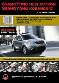
Руководство по техническому обслуживанию и ремонту автомобилей SsangYong New Actyon и SsangYong Korando C с 2010 года выпуска с дизельным двигателем объемом 2,0 л.
- Автор: —
- Издательство: Монолит
- Год издания: —
- Страниц: 347
- Формат: PDF
- Размер: 273,2 Mb

Руководство по техническому обслуживанию и ремонту автомобилей SsangYong New Actyon и SsangYong Korando C с 2010 года выпуска с дизельным двигателем объемом 2,0 л.
- Автор: —
- Издательство: Монолит
- Год издания: —
- Страниц: 352
- Формат: —
- Размер: —

Руководство по техническому обслуживанию и ремонту автомобилей SsangYong New Actyon и SsangYong Korando C с 2010 года выпуска с дизельным двигателем объемом 2,0 л.
- Автор: —
- Издательство: Монолит
- Год издания: —
- Страниц: 376
- Формат: —
- Размер: —

Руководство по техническому обслуживанию и ремонту + каталог расходных запчастей автомобилей SsangYong Actyon и SsangYong Korando с 2011 года выпуска с бензиновыми и дизельными двигателями.
- Автор: —
- Издательство: Легион-Автодата
- Год издания: 2015
- Страниц: 491
- Формат: —
- Размер: —
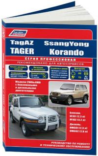
Руководство по эксплуатации, техническому обслуживанию и ремонту + каталог расходных запчастей автомобилей SsangYong Korando и Tagaz Tager с бензиновыми и дизельными двигателями.
- Автор: —
- Издательство: Легион-Автодата
- Год издания: —
- Страниц: 402
- Формат: —
- Размер: —

Руководство по эксплуатации и ремонту автомобилей SsangYong Korando с 1996 и Tagaz Tager с 2008 года выпуска с бензиновыми и дизельными двигателями.
- Автор: —
- Издательство: Монолит
- Год издания: —
- Страниц: 402
- Формат: —
- Размер: —

-
Contents
-
Table of Contents
-
Bookmarks
Quick Links
FOREWORD
This manual has been prepared to acquaint you with the operation and maintenance of
your new KORANDO and to provide important safety information. We urge you to read
it carefully and follow the recommendations to help assure the most enjoyable, safe,
and trouble-free operation of your vehicle.
When it comes to service, remember that your SSANGYONG dealer knows your ve-
hicle best and is interested in your complete satisfaction.
We would like to take this opportunity to thank you for choosing KORANDO and assure
you of our continuing interest in your motoring pleasure and satisfaction.
This manual should be considered as a permanent part of your vehicle, and must re-
main with the vehicle at the time of resale.
PYUNGTAEK, KOREA
Summary of Contents for SSANGYONG Korando
Эта краткая инструкция разработана Новосибирским Гуру автомобилей SY Korando и Musso Алексеем (MaxAlex Service). Как он сам ее прокомментировал: Данная инструкция составлена в виде авторитарных утверждений, не терпящих обсуждения. Типа «Суй в ж…у помидоры — некогда объяснять»
Вводная
Это не гоночная машина. Максимальная скорость 100 км/час
Это ЗАДНЕПРИВОДНАЯ машина. На полном приводе ездить нельзя. ДА! Нельзя! И особенно в гололед.
Расход солярки по паспорту 10 литров на 100 км. В реальности может доходить до 15 литров. Обусловлено некачественным топливом, городскими условиями и пробками.
Двигатель
О да! Это легенда… Мерседес OM601(2.3л четыре горшка) OM602(2,9л пять горшков) всеядные дизельные моторы с рядным ТНВД BOSCH.
Ресурс мотора 250 — 750 тыс. км. Может доходить до 1500 тыс. км. — все зависит от обслуживания.
Моторы лучше турбированые, т.к. без турбины машина с этим мотором больше похожа на мотоблок для окучивания овощей, чем на автомобиль.
Турбины боятся не надо — ее ресурс 200 — 250 тыс км. Грубая проверка турбины на живучесть производится просто: снимаем впускной патрубок, который идет от воздушного фильтра на турбину. Нежно (как клитор любимой женщины) берем двумя палацами вал турбины и покачиваем. Радиальный люфт вала допустим. Но если присутствует осевой люфт, то пора копить деньги на новую турбину.
Двигатель. Масло
Периодичность смены масла: раз в 5 тыс.км. Масло применять только с допуском MB229.3
Летом 10w40, зимой 5w40.
Объем масла 8 и 9 литров для моторов 2.3 и 2,9 соответственно.
Вместе с маслом рекомендую менять топливные и воздушные фильтра. Цена не большая, зато мотор дольше будет здоровым.
Двигатель. Топливная система
Это то, за что эти двигатели получили статус легендарных. Всеядные… У меня был случай, когда человек ездил неделю на чистом бензине.
В общем пофиг где и на какой заправке заправляться. Этот мотор сожрет все, а вас все равно обманут. Разница лишь в расходе и в тяговитости мотора на данном топливе. Не факт, что если сегодня на заправке вам залили хорошее топливо, то завтра оно будет таким же.
Раз в 50 тыс.км. Требуется замена распылителей. Естественно меняются теплоотводные шайбы под распылителями и шланги обратки. Рекомендую иметь в машине хотя бы 0,5 метров шланга обратки. Бывает эти шланги лопаются в самый неподходящий момент. Шланги обратки весьма специфические, у них внутренний диаметр 3,2 мм. Наша промышленность выпускает шланги начиная с 4 мм. Так что обмануть судьбу не удастся — покупайте дорогие оригинальные шланги.
Если у вас в дороге лопнул шланг обратки — не надо отчаиваться. Корейцы обо всем позаботились. Т.к. мы с вами заглушили клапан ЕГР (см. ниже), то в нашем распоряжении 1,5 метра шикарного вакуумного шланга. Этот шланг идет от стакана масляного фильтра по трубке кондиционера на правый борт капота — отрезаем и пользуемся! Как временное решение (на пару недель) — вполне работоспособно.
Раз в 150 тыс.км. Требуется замена форсунок в сборе.
Фильтр грубой очистки. В схеме питания оригинального мотора Мерседес установлен фильтр грубой очиски топлива. К сожалению на SY такой фильтр зачастую отсутствует, хотя тоже присутствует на картинках. Данную несправедливость нужно испрпвить. Поэтому идем в ближайший магазин и покупаем десяток топливных фильтров грубой очистки для дизеля. Типа BIG GB-612. В отличии от «жигулевского» фильтра, в дизельном фильтре вместо бумажного или поролонового фильтрующего элемента установлена нейлоновая или металлическая сеточка.
Фильтр врезаем в топливный шланг, который идет от металлической трубки топливной магистрали на топливоподкачивающий насос. Топливоподкачивающий насос установлен сбоку на ТНВД. ТНВД установлен с левой стороны двигателя.
Что нам дает фильтр грубой очистки:
Во первых мы визуально можем контролировать степень загрязнения топлива.
Во вторых фильтр отсеивает крупные частички грязи, что продляет жизнь топливоподкачивающему насосу и основному фильтру.
В третьих грубый фильтр хоть немного, но задерживает воду, которая находится в топливе.
В четвертых зимой смерзшийся парафин в первую очередь скапливается в фильтре грубой очистки, а не в основном фильтре.
Выводы из третьего и четвертого утверждения очень пригодятся нам зимой. Т.к. мы купили ни один, а десяток фильтров, то в том случае, когда парафин, либо вода забьет фильтр грубой очистки мы его легко и просто поменяем. Тем самым основной фильтр будет более-менее свободным от воды и замершего парафина. Менять основной фильтр на трассе в сорокаградусный мороз — это то еще удовольствие.
Рекомендую два раза в год (осенью и весной) делать промывку топливной системы специальной жидкостью Wynns Diesel System Purge.
Дополнительные фильтры типа «Сепар» — не нужны:
И подобные им смысла не имеют, а подчас еще и вредны. Посмотрите на нас топливоподкачивающий насос. Да, да, вот этот маленький смешной малыш, который прикреплен сбоку на ТНВД и есть топливоподкачивабщий насос. И уверяю вас, с подачей нужного количества топлива для работы мотора он справляется на «ура». В общем качает он топливо со скоростью примерно литр в минуту. Установив дополнительное сопротивление на пути потока топлива, мы рискуем обеспечить топливное голодание двигателя на больших оборотах и в добавок подсос воздуха в топливную магистраль.
Если проанализируем, то поймем, что «сепар» от слова «сепаратор». А это значит, что топливо в таком фильтре отделяется от вредных примесей благодаря центробежным силам. А что бы создать такие центробежные силу, нужно обеспечить высокубю скорость прокачки. Может быть это и возможно на машинах типа Камаз или огромных тракторах Катерпилер, но для нашего насосика это недостижимо. Поэтому не будем тратить лишние 10 тыс. руб. на эту бессмысленную вещь.
Двигатель. Система охлаждения
Антифриз применять ТОЛЬКО с допуском MB325.0. Данный антифриз может быть либо темно-зеленого, либо желтого цвета. Если в машине залита жидкость другого цвета — срочно под замену. Применение «неродного» антифриза приводит к тому, что через 6 месяцев «сжирает» головку и это требует снятия, шлифовки и вообще денег.
Антифризы между собой НЕ СМЕШИВАЮТСЯ! Вообще! Масла еще можно смешать. Нампример в мотор для экстренной доливки можно долить любое моторное масло, в коробку-автомат — масло уровня Декстрон 2. В мосты все, что угодно уровня GL-5. Антифризы смешивать нельзя. Если у вас появилась срочная потребность в антифризе, то возите с собой тот антифриз, который у вас залит сейчас. Либо просто добавьте дистиллированной воды — так будет намного лучше. Если в магазине продавец вам говорит: «У вас же зеленый антифриз, вот возьмите этот — он тоже зеленый», то плюньте ему в глаза, насрите на прилавок и уходите из этого магазина!
Антифриз меняется вместе с термостатом раз в два года.
1. Сливаем старый антифриз,
2. Меняем термостат (помпу по желанию).
3. наливаем дисцилилованую воду,
4. Прогреваем мотор, что бы термостат открылся.
5. Охлаждаем мотор хотя бв до 50 градусов.
6. Сливаем воду
7. Наливаем новый антифриз.
В среднем, лучшие низкотемпературные характеристики получаются при соотношении 60% антифриза и 40% воды. Чистый антифриз, как это ни странно, замерзает при минус 10 градусах.
Заодно при смене антифриза, имеет смысл отдельно промыть салонную печку. Помпа от газели, две пачки антинакипина на 5 литров воды вам в помощь.
Термостат «родной» из Кореи стоит на 80 градусов. Рекомендую ставить на 85 градусов — зимой теплее, да и на оригинальных немецких моторах стоят именно на 85 градусов.
Помпа, как правило, накрывается на пробеге от 140 до 160 тысяч км. Поэтому если ты только купил машину — имеет смысл помпу поменять.
Двигатель. Навесное оборудование.
Раз в 50 тыс.км. Нужно менять ремень, натяжной ролик, обводной ролик, паразитный ролик, коромысло натяжителя и амортизатор. В общем все под замену.
И мне пофигу, что вам там сказал сосед, мастер с сервиса и прочие клоуны. Есть кадры, которые меняют только ремень, а есть «умные» кадры, которые меняют ремень и еще аж и обводной ролик. Только итог одинаков в обоих случаях — обрыв ремня, поломанное коромысло натяжителя, развалившийся ролик натяжителя. И все это происходит в самый неподходящий для вас момент.
Если на генераторе установлен обычный шкив, а не обгонная муфта, то НУЖНО установить на генератор обгонную муфту. Это намного продляет жизнь ремня и роликов. Хотя есть генераторы с разными резьбами. На какой-то можно накрутить муфту, а какие то имеют бОльший диаметр резьбы.
В любом случае, возите ВСЕГДА с собой запасной ремень, оба ролика и коромысло натяжителя. Хотя бы старые.
Двигатель. Первоочередной Легкий и Нужный Тюнинг.
Самое первое, что надо сделать, купив машину, это заглушить клапан EGR. Клапан находится с правой стороны мотора и представляет собой «грибок», прикрученный двумя болтами (под шестигранник) к впускному тракту. Нужно открутить эти болты, отодвинуть клапан. Вытащить прокладку и по внешней форме прокладки вырезать такой бутерброд: тонкий паронит, жестянка от пивной банки и снова тонкий паронит. «Бутерброд» установить вместо старой прокладки.
Для чего служит клапан ЕГР? На определенных оборотах двигателя клапан открывается и получается что часть выхлопных газов идет во впускной коллектор. Типа для дожига не сгоревшего топлива, что повышает экологию. Все это хорошо на нормальном топливе, однако в нашем типа «топливе» содержание сажи зашкаливает все мыслимые пределы. Эта сажа, смешиваясь с парами масла из сапуна двигателя (да и турбина тоже немного гонит масло) поступают в камеры сгорания. Вся эта гадость откладывается на впускном тракте, впускных клапанах. Следствием этого является зауженное сечение впускного тракта и обширный нагар на клапанах. Нагар задирает маслосъемные колпачки, мешает клапанам плотно прилегать к седлам, что в итоге приводит к низкой компрессии. Более того, впускной тракт построен таким образом, что бОльшая часть абразивной сажи попадает во второй цилиндр. Отсюда задир стенок цилиндра и более низкая компрессия.
Второе, чем надо заняться, это выбить к чертям собачьим катализатор
Может быть катализатор штука хорошая, но тогда, когда он новый. Тем более, как писалось выше, из выхлопной трубы у нас летит сажи в неограниченных количествах (Да здравствует Газпром!). В общем были случаи, что проехав всего лишь 50 км на некачественном топливе, катализатор забивался наглухо. Двигателю просто не было сил преодолевать сопротивление забитого катализатора. Отсюда нестабильная работа и отсутствие тяги. Вспомним еще и турбину, которая крутится в зависимости от скорости и объемов выхлопных газов: нет скорости, нет давления наддува.
В общем снимаем катализатор, берем в руки зубило и лом и выбиваем из него всю дрянь.
Третий акт Марлезонского балета по тюнингу: (а вернее по доведения машины до нормального состояния).
Раз мы выбили катализатор, заглушили ЕГР и заменили распылители, то имеет смысл промыть топливную систему с помощью Wynns Diesel System Purge и продуть впускной тракт препаратом Wynns EGR3.
Двигатель. Глубокий Тюнинг.
Есть всего лишь один относительно дешевый способ добиться прироста мощности и приемистости мотора:
Установить более мощную турбину и добавить соответственно цикловую подачу топлива. Для мотора 2.3 литра идеально подходить турбина от мотора 2.9 литра. Причем что на Муссо, что на Корандо хорошо встает турбина от Муссо, а еще лучше от Муссо-Спорт Евро3).
Второй способ связан с заменой ГБЦ на другую, с бОльшим проходным сечением клапанов, установкой распредвала с другими фазами газораспределения, заменой плунжеров ТНВД на плунжера бОльшего диаметра и т.д. и т.п.
Для примера: в Корее продается набор турбина большей производительности и ГБЦ, которая сможет переварить подачу такого давления воздуха от этой турбины. Прирост мощности примерно 15 — 25 л.с. Цена этого удовольствия в Корее примерно 2,5 тысячи долларов. Цена хорошего мотора 2,9ТД в полной комплектации в Корее 900 долларов.
Двигатель. Зимняя эксплуатация
Правила простые:
1. Осенью в бак добавляйте удалитель влаги из бака.
2. Начиная с октября добавляйте перед заправкой антигель в бак. Рекомендую Ravenol или Wynns. Они в отличии от других, сами по себе не замерзают.
3. Так же зимой имеет смысл добавлять 0,5 литра двухтактного масла на бак. Зимой солярка «сухая», а масло позволяет мягче работать топливной системе.
4. Больше НИЧЕГО не надо добавлять в бак. Все это плохо кончается.
5. Раз в два года необходимо менять свечи накаливания. Использовать только свечи BERU.
6. Очень часто (почти всегда) обгорает силовой провод, который идет на реле свечей. На Муссо этот провод идет от коробочки на АКБ до реле, а на Корандо провод идет от блока предохранителей тоже на реле накала свечей. Т.е. провод внешне выглядит целым, но его сопротивление очень велико и не позволяет как положено нагреться свечам — происходят потери тока. В итоге до минус 20 градусов заводимся нормально, а если температукра падает ниже, то все — приплыли. Решение простое: параллельно родному проводу прокладываем провод примерно на 6кв.мм.
7. Раз уж зашла речь про провода, то перед зимой нужно сделать следующее.: Разобрать клеммы АКБ, зачистить все контакты, смазать медной смазкой ( нет медной, тогда графитовой). Так же зачистить и смазать минусовой контакт на двигателе — он подключается к левой лапе-опоре мотора. Зачистить и смазать плюсовой провод, который идет непосредственно на стартер.
8. Если вашему аккумулятору три года или больше — выкиньте его в помойку. И купите новую батарейку. Да, я вас слышу — вы прошлую зиму отлично ездили, и сейчас хорошо заводитесь. В февральские морозы вернемся к этому спору, если вы еще будете готовы поспорить.
9. На Корандо ставится АКБ максимальной емкости 75 А*ч, на Муссо возможно воткнуть АКБ на 90 А*ч, и то, если разогнуть молотком и пассатижами площадку для установки. Законы физики никто не отменял — нельзя в батарейку размером с «Крону» засунуть атомную электростанцию. Отсюда вывод: если на этикетке АКБ вашего Корандо красуется надпись 85 — 90 А*ч, то поменяйте батарейку. Особенно грешат завышением реальной емкости… блин… да все производители! В общем покупайте либо Варту, либо Баннер.
Коробка Автомат
Как правило (начиная с 1997 года) установлена коробка BTRa M74 . Ресурс коробки 180 — 220 тыс .км.
99% проблем с этой коробкой — это проблемы с потенциометром. Поэтому меняем потенциометр и еще дополнительно возим с собой запасной. Потенциометр установлен на ТНВД.
И один процент связан с датчиком скорости. Установлен на раздатке рядом с фланцем заднего кардана.
Масло в коробку заливается только специальное: Castrol TQ95, Ravenol ATF BTR 95LE. В крайнем случае Liqui Moly Top Tec ATF 1100. Отличие Ravenol ATF BTR 95LE от Castrol TQ95 в том, что первое синтетическое, а значит имеет более низкую точку замерзания. Castrol TQ95 — рекомендуемое корейцами масло, однако является минеральным и в наших зимних условиях непригодно. Да и цена Castrol TQ95 примерно на 30% больше, чем Ravrnol ATF BTR 95LE.
Масло менять каждые 30 тыс.км. Хотя в мануале написано, что замена каждые 60 тыс, но они явно не знали про российский условия эксплуатации.
Емкость коробки 8,5 литров. Для замены требуется примерно 9 литров. Для смены масла обязательно требуется снятие поддона, очистка магнита (заодно и проконтролируете степень износа), замена масляного фильтра и прокладки поддона.
Уровень масла проверяется на теплой коробке, но на заглушенном двигателе. Пробка коробки на «16». Откручивать ТОЛЬКО головкой, иначе можно легко сорвать грани.
Масло меняется в два приема:
1. Снимаем поддон, сливаем масло, сменяем фильтр и прокладку.
2. Очищаем основной магнит от стружки и дополнительно прикрепляем на поддон еще один магнит. Мы используем сверхмощные магниты от сломанных компьютерных жестких дисков. Чем больше стружки (от естественного износа фрикционов) задержится на магнитах, тем здоровей будет наша коробка.
3. Наливаем масло.
4. Катаемся примерно 10 км. Это для того, что бы заместить масло в гидротрансформаторе и промыть коробку.
5. Сливаем масло уже из трубки охлаждения. Трубка находится на основном радиаторе с правой стороны.
6. Доливаем масло до уровня.
Как правило замена масла на «аппарате» приводит к большому расходу масла и преждевременной кончине гидроблока.
Если коробка не сразу едет назад, а только после добавления газа, то вариантов два:
1. Неправильно установлен потенциометр. На холостом ходу должно быть 0,5 Вольт. Если напряжение больше 1,0 Вольта, то коробка «дуреет».
2. Коробка требует ремонта. И никакие замены масла и танцы с бубнами здесь уже не помогут.
Если коробка «встала» на третьей скорости (аварийный режим), то не надо впадать в панику. Как правило это обрыв одного или нескольких проводков в косе управления. Нужно внимательно осмотреть все разъемы, подозрительные разобрать и пропаять. Бывает окисляется массовый провод самого блока управления коробкой.
Коробка Механика
Не понимаю, как в 21 веке, когда еще в прошлом веке люди слетали на Луну, а сейчас собираются колонизировать Марс, есть некоторые индивидуумы, которые готовы ездить на «палке».
В общем в этих коробках все просто:
1. Масло примерно 3,5 литра. Рекомендую Castrol TransMax-Z.
2. Обычно протыкается вилка сцепления. Поэтому следим и своевременно меняем. Пр мерно на 100 тыс.км.
Обычно заменить только одну вилку сцепления без снятия коробки не получается. А раз коробку все равно снимать, то уж тогда меняйте вилку, диск сцепления, выжимной подшипник и маленький подшипник, который стоит в коленчатом валу. Почему то про подшипник, который стоит в коленчатом валу все забывают. А ведьт именно на него опирается первичный вал коробки. И подшипник совсем недорогой.
Передний привод
Тесно связан с раздаткой.
Повторюсь: у нас ЗАДНЕПРИВОДНАЯ машина. И те, кто ездит зимой на полном приводе, идут туда, куда укажет им вежливый ГОГА (форумчанин из Новосибирска goga64).
Те, кто ставит механические хабы, имеют право на жизнь, но важно их отключать. Т.е. вам придется перед каждым препятствием выходить из машины, включать хабы, а после преодаления препятствия снова выходить и выключать.
У нас же, как правило, люди включают хабы осенью, а отключают весной. Типа мы ща кнопкой из салона раздатку подключим. Тоже идите по направлению, которое укажет ГОГА.
Те, кто меняют местами в хабах пружинку и шестерню, и тем самым залочивают хабы навсегда, тоже можете строится в затылок с людьми из первого абзаца.
Потом опишу все прелести подробно (что делать, как пользоватся и чем это грозит).
Раздатка
Для приведения переднего привода в движение используется цепь.
Масло примерно 1,5 литра. Менять каждые 25 тыс.км. Рекомендую Castrol TransMax-Z.
Включение 4WD рекомендую производить на скорости не более 10км/час и заранее перед преодолением препятствия.
Включение (и выключение тоже) пониженной передачи 4WD Low — производится на стоящем автомобиле в положении селектора АКПП «нейтраль».
Раздатка настолько проста и до безобразия надежна, что и писать то нечего. Однако бывают проблемы с не включением переднего привода (повышенная и пониженная передачи):
1. Как правило обламываются провода в разъемах. Поэтому проверить, разобрать и пропаять.
2. Второй по распространенностью проблемой является износ позистора в моторчике, который переключает режимы раздатки. Способ решения: Разобрать, почистить, собрать. Если не помогло, то менять моторчик.
3. Не включение пониженной передачи бывает из-за того, что захандрил датчик скорости (не тот, который для коробки и спидометра, а второй). Стоит он так дорого (3800 руб), что проще его заменить простым резистором (5 руб).
Подвеска
Изначально подвеска на наших машинах очень дохлая. Ну потому, что машины лет семь ездили в Корее, а потом и мы их эксплуатируем в хвост и в гриву.
В общем безопасно ездить на такой подвеске нельзя: машина валится в поворотах, «козлит» на кочках и прочие неприятности.
Подвеска. Малый Тюнинг
Что надо сделать (все и сразу):
1. Заменить верхние шаровые опоры. (Верхние шаровые ходят 100 тыс, нижние 200 тыс.)
2. Заменить сайлентблоки верхних рычагов.
3. Заменить стойки стабилизаторов (яйца).
4. Заменить сайлентблоки стабилизаторов
5. Амортизаторы Tokico перед E3708, зад E3496
6. Пружины для Муссо и Корандо KYB RD5081. Для Муссо-Спорт KYB RD5082. (Всех секретов не расскажу все равно).
7. Торсионы рекомендую заменить на усиленные от версий SY с бензиновым мотором 3,2 литра.
Верхние шаровые переставить под рычаг.
Написать про кастор… — будет дололнено
Мосты
Ну здесь все просто.
1. Масло в мостах менять каждые 25 тыс.км. Рекомендую 75w90 уровня GL5. В задний мост 1,9 литра, в передний мост 1,3 литра.
Ступичные подшипники заднего моста ходят примерно 200 тыс.км. При условии смазки каждые 20 тыс км. Во время смазки желательно заменить внутренние сальники моста.
Ступичные подшипники передних колес ходят 100 тыс.км. При условии смазки каждые 20 тыс км. Для смазки требуется заменить сальники ступичных подшипников.
Тормозная система
Если машина оборудована системой TCS, то рекомендую внимательно следить за задними тормозными колодками и своевременно менять их. Понять есть такая система или нет, достаточно просто: надо заглянуть под мост. Если с рамы на мост идут два тормозных шланга, то у вас система TCS. Если один шланг, то у вас стоит простая ABS.
Если сзади обычные барабанные диски, то они почти вечные. Даже не стоит заморачиваться об их замене.
Допустимый износ передних тормозных дисков — 22мм. И если вы думаете, что их можно проточить и продолжать ездить дальше, то идите туда же, куда пошли те, кто постоянно ездит на переднем приводе.
Тормозная система. Периодичность обслуживания.
Тормозные шланги и тормозную жидкость нужно менять раз в два года. Тормозную жидкость использовать уровня DOT-4 (хотя официальный учебник рекомендует DOT-3). Использовать тормозную жидкость желательно фирм Castrol, Bosch, Ravenol, Mannol. Количество тормозной жидкости в системе 1,2 литра.
Отдельно хочу заострить внимание на тормозных шлангах. Бывает что ни грыж, ни подтеков на шлангах вообще не видно. Однако в самый ответственный момент шланги просто мгновенно рвутся. Поэтому меняем раз в два года и все! Это чья то спасенная жизнь.
Тормозная система. Тюнинг.
Передние суппорта и тормозные диски имеет смысл заменить на двухпоршневые суппорта и диски от Рекстона. Эффективность торможения повышается в полтора раза, а это чья то спасенная жизнь.
Колеса.
Ежу понятно, что все четыре колеса должны быть одного размера, одного рисунка и одного производителя.
Зимой использовать только колеса с шипами. Т.к. эту двухтонную дуру остановить очень трудно.
Родные диски имеют вылет 10 — 18 мм. Больше, чем нулевой вылет использовать нельзя, т. к. ухудшается руление автомобилем, широко расставленные колеса забрызгивают грязью кузов, а самое страшное, что очень сильно возрастает нагрузка на ступичные подшипники.
Максимальный размер колес, который можно поставить на машину без особых извражений и «лифтов» (см выше) для Корандо — 31 дюйм, для Муссо 30 дюймов.
Салон
В наших условиях меняйте салонные фильтры каждые 2 тысячи км. Да, они относительно дорогие, но это того стоит. В противном случае вы забьете грязью и пылью радиатор кондиционера и в итоге снизите эффективность работы всей системы отопления зимой.
Те, кто на зиму вообще выкидывают салонные фильтра — идут лесом. Даже объяснять не хочу почему.
Источник: korandovod.ru

- Manuals
- Brands
- SSANGYONG Manuals
- Automobile
- Korando 2013
- Manual
-
Contents
-
Table of Contents
-
Troubleshooting
-
Bookmarks
Quick Links
Related Manuals for SSANGYONG Korando 2013
Summary of Contents for SSANGYONG Korando 2013
-
Page 149
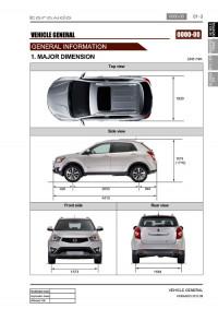
01-3 0000-00 1. MAJOR DIMENSION Unit: mm Top view Side view Front side Rear view… -
Page 150: Vehicle Identification
01-4 2. VEHICLE IDENTIFICATION 1) The engine number (671 950 0 2 5000001) is 2) The chassis number stamped on the lower area of cylinder block in (KPTA0B1SSAP012345) is stamped on the right exhaust manifold side. side in the engine compartment (passenger side).
-
Page 151
01-5 0000-00 ▶ VIN number ▶ Engine number… -
Page 152
01-6 3. SPECIFICATION * ( ) Optional… -
Page 153
01-7 0000-00 * ( ) Optional… -
Page 154
01-8 * ( ) Optional… -
Page 155
01-9 0000-00 4. RECOMMENDED FLUIDS AND LUBRICANTS Use only Ssangyong recommended fluids and lubricants. Do not mix any different types or brands of oils or fluids. This may cause damages. Keep the specified levels when adding or replacing the fluids. -
Page 156
01-10 5. SCHEDULED MAINTENANCE SERVICES 1) Diesel Engine(EU) -
Page 157
01-11 0000-00… -
Page 158
01-12… -
Page 159
01-13 0000-00 2) Diesel Engine(General) -
Page 160
01-14… -
Page 161
01-15 0000-00… -
Page 162
01-16 3) Gasoline Engine… -
Page 163
01-17 0000-00… -
Page 164
01-18… -
Page 168
01-3 0000-00 1. LAYOUT Front view Rear view Right side view Left side view… -
Page 169
01-4 2. MAJOR COMPONENTS ▶ Front View Vacuum pump Oil filter assembly Camshaft position sensor Power steering pump pulley Oil pressure switch Water pump pulley Alternator pulley Idler pulley No. 1 A/C compressor pulley Auto tensioner Idler pulley No. 2 Isolation damper ▶… -
Page 170
01-5 0000-00 ▶ Right side View Wide band oxygen sensor Pre-CDPF pressure port Front exhaust gas temperature sensor Rear exhaust gas temperature sensor CDPF assembly Post-CDPF pressure port Oil drain plug E-VGT turbocharger ▶ Left side View Thermostat assembly Knock sensor 1 connector Oil cooler assembly Variable swirl valve assembly E-EGR valve… -
Page 171
01-6 1. GUIDELINES FOR SERVICE WORKS 1) For Safety To perform the service works easily ans safely, the service technicians must keep the proper working procedures and rules. This manual provides the useful instructions to the service technicians so that they can perform the servive works with standard working process, skills, tips in time. -
Page 172
To improve the efficiency of service work, use only recommended and specified tools. Use only Ssangyong genuine spare parts. Never reuse the cotter pin, gasket, O-ring, oil seal, lock washer and self-locking nut. Replace them with new ones. If reused, normal functions cannot be maintained. -
Page 173
(7) Coolant Check the coolant level in the coolant reservoir, coolant conditions (contamination, foreign material), and hoses for damage and leak. Replace or add the Ssangyong genuine coolant, if needed. (8) Engine drive belt Check all drive belts on the engine for wear, crack and looseness. Retighten or replace the belt, if… -
Page 174
01-9 0000-00 5) Guidelines on Engine Service To prevent the personal injuries and vehicle damages that can be caused by mistakes during service and to provide the optimized performance and safety after service works, the service technicials must keep the basic cautions and service guidelines below. These could be easily forgotten during service works. -
Page 175
01-10 (4) Fuel and lubrication system When working with the fuel or oil systems in enclosed area, always keep the working area well- ventilated and never allow anybody to smoke. Gaskets and seals on the fuel and oil systems should be replaced with new ones. All bolts and nuts should be tightened as specified. -
Page 176
01-11 0000-00 2. JACK-UP POINTS ▶ Stand jack-up points and installation status (front side) Jack-up points and setup (front side) Supporting Jack-up points for Jack-up points for 2-post lift 2-post lift Jack-up points and setup (rear side) Supporting… -
Page 177
01-12 3. STANDARD BOLTS SPECIFICATIONS Metric bolt strength is embossed on the head of each bolt. The strength of bolt can be classified as 4T, 7T, 8.8T, 10.9T, 11T and 12.9T in general. Observe standard tightening torque during bolt tightening works and can adjust torque to be proper within 15 % if necessary. -
Page 178
01-13 0000-00 4. CODING 1) Engine Variant Coding Description Selection Coding Additional heater PTC auxiliary heater is the standard equipment in this vehicle. Select «YES». Gear box 5-speed M/T M/T : 6-speed M/T A/T : 6-speed A/T (DSI 6AT) 6-speed M/T 5-speed A/T (DC 5 AT) 7-speed A/T (DC 7 AT) 6-speed A/T (DC 6 AT) -
Page 179
01-14 2) Chassis Variant Coding Description Selection Coding Domestic/Export EU export Select the appropriate system General export EPB application Select the appropriate system Shift lever type Not defined A/T : DURA lever M/T : M/T DC lever DURA lever Electric power Select the appropriate system steering(EPS) Transfer case… -
Page 180
01-15 0000-00 Description Selection Coding TPMS application Select the appropriate system Transmission type Select the appropriate system DC AT DSI AT Vehicle code STAVIC Select : KORANDO (platform) REXTON KORANDO KYRON ACTYON SPORT Not defined ECU coding status ECU not coded Select : ECU coded ECU coded Signal not valid… -
Page 181
02-3 0000-00 1. SPECIFICATION Unit Description Specification Remark Cylinder head Height 131.9 to 132.1mm Flatness below 0.1mm Flatness on Intake manifold 0.1/150mm manifold side Exhaust manifold 0.15mm Mass balance Backlash 0.05 to 0.15mm shaft (MBU) Connecting rod End play 0.05 to 0.31mm Camshaft Axial end play Intake… -
Page 182
02-4 2. MAJOR CHANGES ▶ Oil pressure switch 0000-00 Oil pressure switch — Newly added oil pressure switch (B) instead of oil level switch (A) -
Page 183
02-5 0000-00 ▶ Engine Mount 1900-00 Mounting Assembly RH 2/4WD 1900-00 Front Mounting Assembly 1900-00 Rear Mounting Assembly — Changed appearance of right-hand mounting assembly and its rubber for enhanced NVH performance — Changed appearance and material of front/rear mounting assemblies’ rubbers for enhanced NVH performance * The mounting appearance has been changed, but work procedure is same as the old one. -
Page 184
02-6 3. TIGHTENING TORQUE Tightening torque Remark Component Size Quantity (Nm) (Total torque) 55 ± 5Nm, M12×82 Main bearing cap Not re-usable 180˚ 40 ± 5Nm, M9×52 Connecting rod cap 50~80Nm 90˚ ± 10˚ Crankshaft rear cover M6×20 10 ± 1Nm M8×35 25 ±… -
Page 185
02-7 0000-00 Remark Tightening torque Component Size Quantity (Total torque) (Nm) M6×12 10 ± 1Nm Hot water inlet pipe M10×90 25 ± 2.5Nm Lower Alternator M10×116 46 ± 4.6Nm Upper M8×85 25 ± 2.5Nm A/C compressor M6×25 10 ± 1Nm A/C bracket M8×35 25 ±… -
Page 186
02-8 Remark Tightening torque Component Size Quantity (Total torque) (Nm) Idle pulley/Tensioner 45 ± 4.5Nm pulley 20 ± 2Nm Glow plug 볼트 비고 품명 규격 규정토오크(Nm) M6×25 10 ± 1Nm 수량 (총 토오크) Vacuum pump M6×40 10 ± 1Nm Timing gear case cover M6×45 10 ±… -
Page 187
02-9 0000-00… -
Page 188
02-10… -
Page 189
02-11 0000-00… -
Page 190
02-12… -
Page 191
02-13 0000-00 4. CHECK AND INSPECTION 1) Cylinder (1) Compression pressure test ▶ Specified value Compression ratio 16.5 : 1 at normal operating temperature (80˚C) Test condition Standard 32 bar Compression pressure 18 bar Minimum Maximum 3 bar Differential limit between cylinders The compression pressure test is to check the conditions of internal components (piston, piston ring, intake and exhaust vale, cylinder head gasket). -
Page 192
02-14 (3) Piston protrusion check Measure how the piston is protruded from the upper side of the cylinder block. Specified value 0.475 to 0.745mm Measure it at both end positions in the axial direction of the crankshaft. -
Page 193
02-15 0000-00 2) Cylinder Head (1) Cylinder head mating surface check ▶ Specified value 131.9 to 132.1 mm Total height «A» Minimum height after machining 131.9mm 0.1 / 150 Longitudinal direction Flatness Transverse direction 0.15 below 0.1 mm Parallel deviation of cylinder head Rmax7 Peak-to valley of surface Rz6.3… -
Page 194
02-16 5. GUIDELINES ON ENGINE SERVICE To prevent personal injuries and vehicle damages that can be caused by mistakes during engine and unit inspection/repair and to secure optimum engine performance and safety after service works, basic cautions and service work guidelines that can be easily forgotten during engine service works are described in. -
Page 195
02-17 0000-00 ▶ Fuel and lubrication system Do not allow the fluid and engine oil to make contact with the body paintwork and hoses. If work on the fluid system such as fuel and oil, working area should be well ventilated and smoking should be prohibited. -
Page 196
02-18 1. BELT SYSTEM The belt system is a single belt drive system which uses single belt and has components on the oil filter housing as FEAD (Front End Accessories Drive) type. ▶ Components with HPS (hydraulic power steering) with EPS (electric power steering) Crankshaft pulley (DDU) Auto tensioner Tensioner pulley… -
Page 197: Vacuum Pump
02-19 0000-00 2. VACUUM PUMP Vacuum pump generates the vacuum pressure and supplies it to EGR cooler bypass solenoid. This pump is single vane type and displacement is 210 cc/rev. The lubrication oil is supplied through the hole in hollow shaft. ▶…
-
Page 198
02-20 3. ENGINE MOUNTINGS D20DTF engine mounting is 4-point mounting type and supports the engine and transaxle. Front and rear mountings are rubber type and support the torque reaction. Left and right mountings support the power train rods and torque reaction. Additionally, right mounting is hydraulic type and supports the engine vibration. -
Page 199
02-21 0000-00 4. INTAKE/EXHAUST SYSTEM 1) Intake Manifold Intake manifold is installed on the cylinder head with 8 bolts. The variable swirl valve is introduced to improve the EGR gas mixture and turbulence in combustion chamber and to decrease the exhaust gas. ▶… -
Page 200
02-22 5. CYLINDER HEAD COVER AND OIL SEPARATOR The cylinder head cover is made by high strength plastic to reduce the weight. The multi twist type oil separator improves the oil consumption. ▶ Components PCV valve Oil separator… -
Page 201: Cylinder Head
02-23 0000-00 6. CYLINDER HEAD Cylinder head contains cam position sensor, vacuum pump, intake manifold, exhaust manifold and valve assembly. Vacuum pump and the high pressure (HP) pump are driven by Camshaft and valves are install in vertical direction. This enables the compact layout in cylinder head assembly.
-
Page 202
02-24 ▶ Components Finger follower & HLA Intake/exhaust Camshafts Camshaft sprocket Cylinder head Camshaft position sensor HP pump drive gear Vacuum pump drive Cylinder head gasket… -
Page 203
02-25 0000-00 7. CHAIN AND GEAR DRIVE SYSTEM D20DTF engine uses single stage chain drive system. Timing chain drives the exhaust side and gear drive the intake side. Timing chain is single bush type. Upper chain drives HP pump connected to intake Camshaft by driving exhaust cam shift sprocke, and lower chain drives oil pump to lubricate the engine. -
Page 204
02-26 ▶ Components Intake/exhaust Camshaft assembly Exhaust HP pump drive gear Connected to Camshaft vacuum pump Intake Camshaft… -
Page 205
02-27 0000-00 Timing gear cover case (TGCC) TGCC Oil seal Screw plug… -
Page 206
02-28 Mass Balance Unit (MBU) Crankshaft MBU drive gear Fuel HP pump HP pump drive gear HP pump gear… -
Page 207: Oil Pan
02-29 0000-00 8. OIL PAN The oil pan in D20DTF engine improves the noise and vibration. Especially, the oil drainage is very easier than before. And, A/C compressor bracket and the oil dipstick tube are mounted on the oil pan. ▶…
-
Page 208
02-30 9. MASS BALANCE SHAFT UNIT (MBU) The balance shaft in MBU (Mass Balance shaft Unit) improves the NVH performance by decreasing the unbalanced force. ▶ Components MBU drive gear Mass balance shaft unit Mass balance shaft unit… -
Page 209
02-31 0000-00 10. FLYWHEEL AND DRIVE PLATE 1) DMF (Dual Mass Flywheel) The dual mass flywheel, or DMF, eliminates excessive transmission gear rattle, reduces gear change/shift effort, and increases fuel economy. There is a friction ring located between the inner and outer flywheel that allows the inner and outer flywheel to slip. -
Page 210
02-32 11. PISTON/CRANKSHAFT/CYLINDER BLOCK This vehicle is FF driving type and the engine is installed in lateral direction. The crankshaft and the cylinder block convert the compression pressure to the rotating energy. ▶ Components Cylinder block Piston Connecting rod Crankshaft… -
Page 211
03-3 0000-00 1. SPECIFICATION Description Specification Fuel Diesel Fuel heater + priming pump + water separator Type integrated type Filter type Changeable filter element type Fuel filter every 40,000 km Change interval every 45,000 km Water accumulating capacity 200 cc Heater capacity 250W 13.5V Injector… -
Page 212
03-4 2. MAJOR CHANGES ▶ Filter Part SGN NO. Sub Sender Filter — Suction port introduced replacing sub sender pre-filter… -
Page 213
03-5 0000-00 3. MAINTENANCE AND INSPECTION 1) Maintenance Procedures for DI Engine Fuel System Always keep the workshop and lift clean (especially, from dust). Always keep the tools clean (from oil or foreign materials). Wear a clean vinyl apron to prevent the fuzz, dust and foreign materials from getting into fuel system. Wash your hands and do not wear working gloves. -
Page 214
03-6 Follow the job procedures. If you find a defective component, replace it with new one. Once disconnected, the fuel pipes between HP pump and fuel rail and between fuel rail and each injector should be replaced with new ones. The pipes should be tightened tospecified tightening torques during installation. -
Page 215
03-7 0000-00 Check the installed components again and connect the negative battery cable. Start the engine and check the operating status. With Scan Tool, check if there are current faults and erase the history faults. -
Page 216
03-8 2) Diagnostic Test for Engine Fuel System (1) Overview If a DTC is displayed on the diagnostic device, check the low pressure- and high pressure fuel systems before removing the components. To run the system properly, the electric system must be intact but for the DI engine, the fuel pressure should be measured also when there is a malfunction even after the diagnostic test with a diagnostic device. -
Page 217
03-9 0000-00 (3) Excessive backleak of injector ▶ Excessive injector backleak Occurs when the injector control valve is not sealed due to the entry of the foreign materials. ▶ Example: Entry of foreign materials Burned out and worn HP pump Mechanical damage inside the injector… -
Page 218
03-10 (4) Loss of pump pressure/flow ▶ Loss of HP pump pressure/flow Faulty fuel supply line, or damaged or worn pump causes the lack of flow pressure and flow volume ▶ Example: Air in fuel supply line Excessive load on fuel supply line (←400 mBar) Burned out and mechanical worn pump High temperature of fuel supply (>… -
Page 219
03-11 0000-00 3) Pressure Test for Fuel System in DI Engine (1) Test device (Tool kit) Tool kit for high pressure line Tool kit for low pressure line (2) Pre-inspection Connections in fuel supply line Fuel level in fuel tank Air in fuel supply line (air bubbles in fuel supply line or fuel) Fuel leaks from fuel supply line (low/high pressure line) Used the specified… -
Page 220
03-12 (3) DTC Check If several DTCs are output simultaneously, check the electric wiring for open or short circuit. Check the low pressure fuel system and fuel filter and confirm that there are no abnormalities. Carry out the high pressure fuel system check. -
Page 221
03-13 0000-00 (4) Fuel System Check Procedure… -
Page 222
03-14 (5) High Pressure System Pressure Test ▶ Fuel rail pressure test Disconnect the fuel rail pressure sensor connector and then IMV connector. Connect the pressure tester to the fuel rail pressure sensor connector. Crank the engine 2 times for 5 seconds. Read the highest pressure value displayed on the tester display. -
Page 223
03-15 0000-00 ▶ How To Use Pressure Tester Press the «TEST» button on the tester to check if the message «TEST?» is displayed. If the button is pressed again at 4 seconds after starting engine cranking, the highest pressure is displayed on the tester. The fuel rail pressure value can be checked using a diagnostic device. -
Page 224
03-16 (6) Low Pressure System Pressure Test ▶ Inspection procedure All wirings/connectors and fuel lines should be connected and the engine should work properly. Prepare a special tool for low pressure test and clean it thoroughly to prevent foreign materials from entering. Disconnect the key connector for fuel filter connection, and connect both connectors to the fuel filter and hose. -
Page 225
03-17 0000-00 ▶ Static test for backleak of injector Disconnect the injector return hose and cover the openings with caps shaped screw (included in the special tool). Connect the hose of the container for measuring backleak to the return nipple of the injector. -
Page 226
03-18 ▶ Dynamic test for backleak of injector Warm up the engine so that the engine coolant temperature be over 80℃ and star the engine again. Disconnect the injector return hose and cover the openings with caps shaped screw (included in the special tool). Connect the hose of the container for measuring backleak to the return nipple of the injector. -
Page 227
03-19 0000-00 ▶ Pressure leak test in fuel system with scan tool When the dynamic test for injector backleak is performed, this test should be done together with it. However, you can check the pressure leak from the fuel system only with this test. To do this test, the coolant temperature should be over 60˚C. -
Page 228
03-20 ▶ HP pump pressure test Prepare a special tool for high pressure test and clean it thoroughly to prevent foreign materials from entering. Disconnect the high pressure fuel supply pipe on the HP pump and install the close rail in the tool kit. -
Page 229
03-21 0000-00 4. CAUTIONS FOR DI ENGINE 1) Cautions for DI Engine This chapter describes the cautions for DI engine equipped vehicle. This includes the water separation from engine, warning lights, symptoms when engine malfunctioning, causes and actions. DI Engine Comparatively conventional diesel engines, DI engine controls the fuel injection and timing electrically, delivers high power and reduces less emission. -
Page 230
03-22 2) Cleanness (1) Cleanness of DI engine fuel system ▶ Cleanness of DI engine fuel system and service procedures The fuel system for DI engine consists of transfer (low pressure) line and high pressure line. Its highest pressure reaches over 1,600 bar. Some components in injector and HP pump are machined at the micrometer 100 μm of preciseness. -
Page 231: Water In Fuel
03-23 0000-00 (2) Di engine and its expected problems and remedies can be caused by water in fuel ▶ System supplement against paraffin separation In case of Diesel fuel, paraffin, one of the elements, can be separated from fuel during winter and then can stick on the fuel filter blocking fuel flow and causing difficult starting finally.
-
Page 232
03-24 1. OVERVIEW The components in the fuel system supply fuel and generate high pressure to inject fuel to each injector. They are controlled by the engine ECU. The common rail fuel injection system consists of fuel tank, fuel line, low pressure line which supplies low pressure fuel to the low pressure pump (includes high pressure pump), high pressure line which connected to the injector and the engine control unit (ECU) which calculates the accelerator pedal position and controls the overall performance of vehicle based on the input signals from various sensors. -
Page 234
03-26 2. SYSTEM LAYOUT AND OPERATION 1) Layout For sensor and actuator control logic, refer to Chapter «ENGINE CONTROL». Fuel supply line Fuel tank Fuel return line Fuel metering by dual sender. Supply the fuel in main fuel tank and sub fuel tank through fuel inlet tube Injector (C3I) Pre-injection, main injection, after-injection by… -
Page 235
03-27 0000-00 High pressure pump Accelerator pedal Fuel filter assembly position sensor Plunger type HP pump (1,800 bar) Vane type transfer pump (6bar) Supply clean fuel/fuel heating/water separation by Generates the high pressurized fuel Detects driver’s intention for priming pump and supply it. -
Page 236
03-28 2) Fuel System Flow Diagram The fuel from the fuel tank is supplied to the fuel heater of fuel filter/priming pump and then low pressure generated by the low pressure pump (built into HP pump) is transmitted to the HP pump. The fuel pressure at the HP pump is controlled by the IMV valve, and the maximum allowed pressure is 1,800 bar. -
Page 237
03-29 0000-00 3) Input/Output devices… -
Page 238
03-30 The engine ECU calculates the accelerator pedal based on the input signals from various sensors, and controls the overall operation of the vehicle. The ECU receives the signals from various sensor through data line, and performs effective air-fuel ratio control based on these signals. -
Page 239
03-31 0000-00 4) Flow Diagram of Fuel Supply System… -
Page 240
03-32 5) Circuit Diagram… -
Page 241
04-3 0000-00 1. SPECIFICATION Component Item Specification Filter type Dry, filter element 0.208 m² Filter area EU: Change every 20,000 km (But, shorten the Air cleaner element service interval under severe conditions) Service interval GEN: Change every 15,000 km (But, shorten the service interval under severe conditions) Weight 1.13 kg… -
Page 242
04-4 2. INSPECTION 1) Troubleshooting ▶ When Abnormal Noises are Heard from the Engine Room For the vehicle equipped with DI engine, if a learning noise occurs in each range or other noises occur, the major cause of it is a faulty turbocharger assembly. But an interference issue, poor tightness or loose in the intake and exhaust system also can cause those noises. -
Page 243
04-5 0000-00 3) Troubleshooting Sequence The basic checks for intake system are as follows: ▶ Basic Checks for Intake System Make sure to replace or clean the air cleaner element periodically. Otherwise, engine will be derated or work abnormally because of low intake air volume. -
Page 244
04-6 1. OVERVIEW The intake system for D20DTF engine is equipped with an electric throttle body which includes a flap. This flap is controlled by an electrical signal to cut off the intake air entering to the engine when the ignition switch is turned off. -
Page 245
04-7 0000-00 2313-15 HFM (Hot Film Air-Mass) sensor HFM sensor, version 6 * For more information, refer to Chapter «Engine Control». 2313-01 Air cleaner assembly and resonator… -
Page 246
04-8 3. INPUT/OUTPUT OF INTAKE SYSTEM… -
Page 247
04-9 0000-00 4. OPERATING PROCESS ▶ Work Flow… -
Page 248
04-10 1) Types of swirl Swirl: One cylinder has two intake air ports, one is set horizontally and the other one is set vertically. Swirl is the horizontal air flows in cylinder due to the horizontal intake air ports. Tumble: Tumble is the vertical air flows in cylinder due to the vertical intake air port Squish: Squish is the air flows due to the piston head. -
Page 249
04-11 0000-00 Load Engine speed Swirl Amount of Remarks valve swirl Low speed, Increased EGR ratio, better air-fuel below 3,000 rpm Closed Heavy Low load mixture (reduce exhaust gas) High speed, Increase charge efficiency, higher over 3,000 rpm Open Light High load engine power The variable swirl valve actuator operates when… -
Page 250
04-12 5. CIRCUIT DIAGRAM… -
Page 251
05-3 0000-00 1. TROUBLESHOOTING 1) Work Flow… -
Page 252
05-4 2. CAUTIONS Do not park the vehicle on flammable materials, such as grass, leaves and carpet. Do not touch the catalyst or the exhaust gas ignition system when the engine is running. If a misfire occurs in the combustion chamber or the emission of pollutant exceeds the specified level, the catalyst can be damaged. -
Page 253
05-5 0000-00 1. OVERVIEW This system purifies the exhaust gas generated by the combustion in the engine to reduce the pollutants and noise during that arise during combustion. 2. COMPONENT Exhaust manifold CDPF assembly Fore details about the CDPF assembly, refer to Chapter «CDPF System». -
Page 254
05-6 3. OPERATING PROCESS 1) Exhaust Gas Flow 2) Input & Output Devices… -
Page 255
06-3 0000-00 1. SPECIFICATION Component Item Specification Max. expansion coefficient Max. turbine speed 215,000 rpm Turbocharger 800 ℃ Max. temperature of turbine housing Weight 7.2 kg E-Actuator Operation duty cycle 300 Hz… -
Page 256
06-4 2. INSPECTION 1) Cautions During Driving The following lists cautions to take during test drive and on the turbocharger vehicle, which must be considered during the operation. It’s important not to drastically increase the engine rpm starting the engine. It could make rotation at excessive speed even before the journal bearing is lubricated and when the turbocharger rotates in poor oil supply condition, it could cause damage of bearing seizure within few seconds. -
Page 257
06-5 0000-00 2) Inspection of Turbocharger When problem occurs with the turbocharger, it could cause engine power decline, excessive discharge of exhaust gas, outbreak of abnormal noise and excessive consumption of oil. On-board Inspection Check the bolts and nuts foe looseness or missing Check the intake and exhaust manifold for looseness or damage Check the oil supply pipe and drain pipe for damages Check the housing for crack and deterioration… -
Page 258
06-6 3) Inspection of Turbine Thoroughly check the followings. Must absolutely not operate the turbocharger with the compressor outlet and inlet opened as it could damage the turbocharger or be hazardous during inspection. Interference: In case where is trace of interference or smallest damage on the compressor wheel means, most of times, that abrasion has occurred on the journal bearing. -
Page 259
06-7 0000-00 4) Possible Causes of Defect The following tries to understand the defects that can occur with vehicle installed with the turbocharger and to manage the reasons of such defects. In case where oil pan/oil pipe has been contaminated, oil filter is defected and where adhesive of gaskets has been contaminated into the oil line. -
Page 260
06-8 Oil Pump Defect: Rapid over-loaded driving after replacing oil filter and oil and clogging of oil line. -
Page 261
06-9 0000-00 Turbine Side: Inflow of foreign materials from engine Compressor Side: such as air filter, muffler and nut… -
Page 262
06-10 Defects caused by reasons other than that of the turbocharger. -
Page 263
06-11 0000-00 3. TROUBLESHOOTING The followings are cautions to take in handling defects of turbocharger, which must be fully aware of. 1) Cautions After stopping the engine, check whether the bolts on pipe connecting section are loose as well as the connecting condition of vacuum port and modulator, which is connected to the actuator. -
Page 264
06-12 2) Work Flow for Troubleshooting… -
Page 265
06-13 0000-00… -
Page 266
06-14… -
Page 267
06-15 0000-00… -
Page 268
06-16… -
Page 269
06-17 0000-00 1. SYSTEM DESCRIPTION OF E-VGT (Electric-Variable Geometry Turbine) A turbocharger is a centrifugal compressor powered by a high speed turbine that is driven by an engine’s exhaust gases. Its benefit lies with the compressor increasing the mass of air entering the engine (forced induction), thereby resulting in greater performance (for either, or both, power and efficiency). -
Page 270
06-18 1) Features (1) Performance (for EURO V) Enhanced emission control: By temperature control with CDPF system Target temperature and airflow control (2) E-Actuator (Electric-Actuator, Rotary type) Optimizes the exhaust gas flow rate by controlling the vanes inside the turbine housing with the E- Actuator. -
Page 271
06-19 0000-00 2. COMPONENTS For more information about control logic, refer to Chapter «Engine Control». E-VGT turbocharger Engine ECU (D20DTF) Accelerator pedal position sensor Atmospheric pressure, RPM signal Transfers accelerating demand to ECU Improves engine power E-VGT duty control T-MAP sensor HFM sensor Coolant temperature sensor Operates the VGT according to… -
Page 272
06-20 3. INPUT/OUTPUT DEVICES… -
Page 273: Operating Principles
06-21 0000-00 4. OPERATING PRINCIPLES The E-VGT is designed to get more improved engine power in all ranges by controlling the turbine as follows: 1) How it Works at Low Speed Normal turbocharger cannot get the turbo effect because the amount of exhaust gas is not enough and the flow speed is slow in a low speed zone, but VGT allows the flow passage of exhaust to narrow, resulting in increasing the flow speed of exhaust gas and running the turbine quickly and powerfully.
-
Page 274
06-22 2) How it Works at High Speed In a high speed zone, the amount of exhaust gas increases and it is accompanied with a great force. Therefore, if the inner diameter of venturi is more widened, the turbine in the turbocharger by the releasing force of abundant exhaust gas can deliver a more increased energy to the compressor. -
Page 275
Type Fulle flow/Paper element Engine oil Specified oil Quality class: Ssangyong genuine engine oil (Total Quartz INEO ECS 5W 30, SK ZIC SY 5W 30 or oil Approved by MB 229. 51) SAE 5W30 Capacity Min.: 4.5 L / Max.: 6.0 L… -
Page 276
07-4 2. MAJOR CHANGES ▶ Oil pressure switch 0000-00 Oil pressure switch — Newly added oil pressure switch (B) instead of oil level switch (A) -
Page 277
Recheck the oil level after 5 minutes. Regularly check the engine oil level and add Ssangyong genuine engine oil if necessary. Clean the dipstick with clean cloth so that any foreign materials cannot get into the engine. -
Page 278
07-6 1. SYSTEM DESCRIPTION 1) Overview The lubrication system supplies oil to each lubrication section to prevent friction and wear and to remove heat from the friction part. As the engine runs, frictional heat is generated on each lubrication section. If this condition persists, the bearing can be burned and stuck. -
Page 279
07-7 0000-00 3) Oil Filter Module The oil filter module consists of lubrication system, cooling system and some mechanical devices as below. System Components Supplementary devices Power steering pump (HPS), Alternator, A/C compressor Belt drive Belt tensioner, Idle pulley Cooling Water pump, Thermostat, Cooler housing and Pipes Lubrication Oil filter, Oil cooler (except coolant pipes) -
Page 280
07-8 2. OPERATING PROCESS 1) Operation Flow… -
Page 281
07-9 0000-00 3. LUBRICATION 1)Anti-friction The oil makes a thin film on the surface of sliding components to reduce the wear due to friction. 2)Cooling The friction makes the heat on the components. The oil absorbs the heat and radiates it or cools it down. 3) Sealing The piston ring on the piston seals the cylinder. -
Page 282
08-3 0000-00 1. SPECIFICATION Description Specification Cooling system Type Water cooling, forced circulation Coolant Capacity Approx. 8.5 liter 740W X 380H X 27t (over 281,200㎣) Core size Radiator Flow type Cross flow Min. cooling capacity over 68,000kcal/h Type Long life coolant (SYC 1025) Antifreeze Mixing ratio 50 : 50… -
Page 283
08-4 2. INSPECTION Possible Cause Action Coolant level — Leak from the radiator — Replace the radiator is too low — Leak from the auxiliary reservoir — Replace the auxiliary reservoir — Leak from the heater core — Replace the heater — Leak from the coolant hose connections — Reconnect the hose or replace — Damaged coolant hose… -
Page 284
08-5 0000-00 1) Coolant Level Check Park the vehicle on level ground and apply the parking brake. Stop the engine and wait until it is cooled down. The coolant level should be between the MAX and MIN mark on the coolant reservoir. Check the coolant level. -
Page 285
08-6 2) Leak Test Release the pressure in the system by loosening the pressure cap of the coolant reservoir slightly. Then, remove the pressure cap completely. Never open the cap until the coolant temperature becomes under 90℃ to prevent any burn. Add the coolant so that the coolant level is between MAX and MIN mark on the coolant auxiliary tank. -
Page 286
08-7 0000-00 3. CAUTIONS If 100% of anti-freeze is added, the water pump vane can be damaged and thermal conductivity can be decreased resulting in poor circulation in the cooling system which leads to overheated engine. Use of non-recommended coolant could cause damage to the cooling system and overheating of the engine. -
Page 287
08-8 1. SYSTEM DESCRIPTION 1) Overview Coolant reservoir Long life coolant is used. Water pump Sealing Oil filter module Water pump pulley Impeller vane The water pump is driven by the engine drive belt and supplies the coolant to each area of the engine. Thermostat When the engine coolant reaches 90℃, the thermostat… -
Page 288
08-9 0000-00 Coolant temperature sensor Measures the coolant temperature and sends the result to the engine ECU. Electric fan Circulates the fresh air forcibly to exchange heat with the radiator core fin. Radiator Releases heat through fins and cools down the hot coolant as the coolant passes through the tube of the radiator core. -
Page 289
08-10 3) System Layout… -
Page 290
08-11 0000-00… -
Page 291
09-3 0000-00 1. SPECIFICATION Specification Alternator Crankshaft pulley : Alternator Pulley 1 : 2.94 Normal output (idling/2200 rpm) 70/120 A 70/140A ← Regulator voltage 14.6 V ← Brush Length 12.5 mm ← Wear limit 7 mm ← Battery Type ← Capacity 90AH… -
Page 292
09-4 2. INSPECTION 1) Alternator Output Test Item How to check DTC set value / Action Disconnect the cable connected to the B Pass: If the measured current is 45 A terminal on the alternator. Connect one end or higher. of the ammeter to the B terminal and the Fail: If the measured current is less other end to the cable connected to the B… -
Page 293
09-5 0000-00 2) Troubleshooting for Alternator Item Cause Action Overcharged battery Defective alternator voltage regulator Replace defective alternator detection wiring Repair or replace Discharged battery Loose alternator drive belt Adjust the belt tension or replace Poor connection of related circuit or Retighten the loose connection or open circuit repair open circuit… -
Page 294
09-6 3) Checking Battery… -
Page 295
09-7 0000-00 (1) Checking ▶ Using battery tester PASS (11.0 V or more): Explain to the customer that the battery is reusable. Need to be charged (9.0 to 11.0 V): Charge the battery with a charger and reinstall it. Explain it to the customer. -
Page 296
09-8 (3) Starting with jumper cable If the battery is weak or terminated, the battery from another vehicle can be used with jumper cables to start the engine. ▶ Connecting order The positive (+) terminal of the discharged battery The positive (+) terminal of the booster battery The negative (-) terminal of the booster battery Connect one end of the other jumper cable to the body of the discharged vehicle, such as the engine block or a front towing hook. -
Page 297
09-9 0000-00 (4) Maintenance If the charge warning lamp ( ) on the instrument cluster comes on while driving, there is a malfunction in the charge system including the battery. Therefore, carrying out the system check is needed. Make sure that the battery cables are firmly connected. If the terminals are corroded, clean them with a wire brush or sandpapers. -
Page 298
09-10 1. SYSTEM DESCRIPTION 1) Overview The charge system is designed to supply electrical energy to the vehicle while driving, and supplies a constant direct current voltage by converting mechanical rotational movement to electrical energy. The voltage regulator on the back of the alternator controls the generated voltage in all rotating ranges and adjusts the system voltage according to the electric load and ambient temperature change. -
Page 299
09-11 0000-00 3) Charging The alternator uses a new regulator which has three diodes. It consists of the delta stator, rectifier bridge, slip ring and brush. ▶ Charging time according to vehicle conditions and environment Specification: Charging a fully depleted high- capacity battery takes twice or more as long as charging a fully depleted battery for small vehicles. -
Page 300
09-12 2. CHARGING OPERATION 1) With Smart Key System… -
Page 301
09-13 0000-00 2) Without SMART Key System… -
Page 302
09-14 3. CIRCUIT DIAGRAM… -
Page 303
09-15 0000-00… -
Page 304
10-3 1413-00 1. SPECIFICATION Description Specification Glow plug Rated voltage 4.4 V 1100°C Maximum temperature 1080 to 1100°C Operating temperature Glow plug control unit EMS operating voltage 6 to 16 V -40°C to 110°C Operating temperature Dark current Max. 1 mA… -
Page 305
10-4 2. TIGHTENING TORQUE Glow plug GCU (Glow plug Control Unit) Name Tightening torque 15 ± 1.5 Nm Glow plug 10 ± 1.0 Nm Glow plug control unit bolt… -
Page 306
10-5 1413-00 1. OVERVIEW The pre-heating system for D20DTF engine has the glow plug to the cylinder head (combustion chamber), and improves the cold start performance and reduces the emission level. The pre-heating resistor (air heater) is used to heat the intake air. This enables the diesel fuel to be ignited in low temperature condition. -
Page 307
10-6 2. SYSTEM OPERATION 1) Input/Output Diagram of Glow Plug Control Unit 2) System Diagram… -
Page 309
10-8 3) Circuit Diagram… -
Page 310
10-9 1413-00… -
Page 311
10-10 4) System Operation Glow plug is installed in the cylinder head. It enhances the cold starting performance and reduces the exhaust gas during cold starting. ECU receives the various signals such as engine rpm, coolant temperature and vehicle speed through CAN communication lines. -
Page 312
10-11 1413-00 (3) Operating Steps ▶ Pre-Glow: Step 1 If normal communication with the ECU is established 2 seconds after the power is supplied to the IGN terminal from the battery, the GCU supplies the battery power to raise the temperature of the glow plug to 1000℃… -
Page 313
10-12 ▶ During cranking: Step 2 and step 3 Step 2: If the ECU receives the cranking signal after pre-heating (step 1), the GCU supplies the voltage of 6.8 V for 1 sec to raise the temperature to 1,100℃. Step 3: The GCU supplies the voltage of 5.1 V to keep the temperature at 1,000°C. Under fixed temperature: The AQGS unit supplies power for 30 seconds (Step 1 + Step 3) if no cranking signal is received after the step 1. -
Page 314
10-13 1413-00 ▶ Normal operating mode This shows the components of preheating system in the pre-heating and the post-heating steps. -
Page 315
10-14 ▶ When there is no engine cranking signal after turning the ignition key ON… -
Page 316
11-3 1461-00 1. SPECIFICATION Capacity 12V 2.3kW Engagement Meshed type Rotating direction Clockwise Pinion gear manufacturing Cooled forging Solenoid operating voltage Max. 8 V Weight 2.5 kg Bracket manufacturing Aluminum die casting… -
Page 317
11-4 2. TROUBLESHOOTING Possible Cause Problem Action Low battery voltage Charge or replace Loose, corroded or damaged battery cable Repair or replace Engine will not crank Faulty starter or open circuit Faulty ignition switch or blown fuse Repair or replace Poor engine ground Repair Low battery voltage… -
Page 318
11-5 1461-00 1. SYSTEM DESCRIPTION The starter (start motor) starts the engine with rotational power by converting the electric energy to the mechanical energy. When the engine is cranking, the pinion gear meshes with the ring gear. If the ring gear overruns, the pinion gear clutch overruns to protect the pinion gear. -
Page 319
11-6 2. OPERATING PROCESS 1) System Layout (1) Engine start SKM performs the authentication process for the SMART key and sends the engine start request to EMS if there is a normally coded SMART key when pressing the Engine Start/Stop button with the brake pedal depressed and gear shift lever in “P”… -
Page 320
11-7 1461-00 (2) With SMART key system… -
Page 321
11-8 (3) Without SMART key system… -
Page 323
11-10 2) Circuit Diagram (1) With SMART key system… -
Page 324
11-11 1461-00… -
Page 325
11-12 (2) Without SMART key system… -
Page 326
11-13 1461-00… -
Page 327
12-3 8530-00 1. OVERVIEW 1) System Description Auto cruise operated ECO cruise operated The cruise control is an automatic speed control system that maintains a desired driving speed without using the accelerator pedal. The cruise control switch is under the right side of steering wheel and ‘ECO”… -
Page 328
12-4 2) Traffic Conditions for Using Cruise Control Use the cruise control system only when the traffic is not jammed, driving on motorways or highways where there is no sudden change in the driving condition due to traffic lights, pedestrian, etc. Improper use of the cruise control could be dangerous. -
Page 329
12-5 8530-00 2. CONFIGURATION 1) Circuit Diagram The engine ECU detects the operating conditions of cruise control system, and monitors the braking performance, vehicle speed, road conditions and ESP system operation. If the engine ECU determines that there are not any problem to drive in cruise control mode, the vehicle can be operated by cruise switch signals (decelerating, accelerating, cruising). -
Page 330
12-6 2) Components Test voltage(VCC 5V) FUNCTION KEY VOLUE REMARK MAIN 0.15 ~ 0.55V DECEL 0.7 ~ 1.1V ACCEL 1.6 ~ 2.0V RESUME 2.52 ~ 2.92V 4.22 ~ 4.82V… -
Page 331
12-7 8530-00 3. OPERATION 1) Setting a Desired Speed To operate the cruise control, accelerate to the desired speed, which must be more than 38 km/h (24 MPH) and less than 150 km/h (90 MPH). In the vehicle equipped with manual transaxle, the gear shift lever should be in 3rd (GSL: 2nd) or higher gear position. -
Page 332
12-8 2) Accelerating with the Cruise Control System (1) While the cruise control system is running Push up the ACCEL switch of the cruise control lever and hold it until the desired speed is reached without an accelerator pedal intervention. When the desired speed is reached, release the lever. -
Page 333
12-9 8530-00 3) Decelerating with the Cruise Control System (1) While the cruise control system is running Push down the DECEL switch of the cruise control lever and hold it until the desired speed is reached without a brake pedal intervention. But the cruise control system cannot maintain the cruise function at less than 38 km/h. -
Page 334
12-10 4) Recovery of Set Speed (RESUME) Even if the cruise control is cancelled, the previous set cruise speed can be recovered by pulling up the cruise control lever when the current vehicle speed is over 38 km/h without an acceleration intervention. But if you turn off the ignition switch, the memorized set speed is cleared and you cannot recover the previous set speed. -
Page 335
12-11 8530-00 5) ECO Cruise Control ECO cruise is ready and ECO cruise indicator on the instrument cluster comes on when pushing down the cruise control lever. To activate the ECO cruise mode, push down the cruise control lever again. To cancel the ECO cruise mode while in operation, push down the cruise control lever again. -
Page 336
12-12 6) Normal Cancellation of the Cruise Control The cruise control system will be canceled when one or more items of the following conditions are applied; When the brake pedal is depressed. When the cruising speed is decreased less than 38 km/h. When pushing the ON-OFF switch of the cruise control lever. -
Page 337
But if the cruise control system isn’t recovered, you should contact a Ssangyong Dealer for diagnosis of the cruise control system. Abnormal changes of the gear selector lever can damage the yyengine. Do not move the gear shift lever to Neutral while driving at the set speed. -
Page 338
13-3 1793-01 1. SPECIFICATION Item E-EGR valve Motor EGR response time 50 mS Driven by DC motor Valve EGR gas flow rate 120 Kg/h Position sensor Sensing type Hall sensor 5V ± 10% Supply voltage Signal range 5% ~ 95% <15mA Max. -
Page 339
13-4 1. SYSTEM DESCRIPTION 1) Overview The EGR (Electric-Exhaust Gas Recirculation) valve reduces the NOx emission level by recirculating some of the exhaust gas to the intake system. To meet Euro-V regulation, the capacity and response rate of E-EGR valve in D20DTF engine have been greatly improved. -
Page 340
13-5 1793-01 2) Location and Components E-EGR cooler and bypass valve HFM sensor EGR cooler EGR bypass Used as a main map value to control the EGR. The cooler lowers the high temperature of the The coolant temperature, engine rpm, engine exhaust gas and the bypass valve directly load, intake air temperature (HFM: decreased at 60˚C or more), atmospheric pressure… -
Page 341
13-6 2. OPERATING PROCESS 1) Schematic Diagram… -
Page 342
13-7 1793-01 2) Input/Output Devices 3) Control Logic The EGR system controls the EGR amount based on the map values shown below: ※ Main map value: Intake air volume ※ Auxiliary map value: Compensation by the coolant temperature Compensation by the atmospheric pressure: Altitude compensation Compensation by the boost pressure deviation (the difference between the requested value and the measured value of boost pressure) Compensation by the engine load: During sudden acceleration… -
Page 343
14-3 1114-00 1. SPECIFICATION Emission Regulation Euro-V Front Area 182.41cm 124 X 158 X 78L Size 124 X 158 X 194L Shell SUS430J1L X 1.5t CDPF Canister End Cone SUS430J1L X 2.0t (Single) Catalyst Capacity 4.2L CDPF Material of Filter AT (Aluminum-Titanium Alloy) -
Page 344
14-4 2. CAUTIONS ▶ Standard pattern of soot accumulation (1) Abnormal Soot Accumulation (2) Normal Soot Combustion ▶ Cautions to protect the catalyst filter Use the designated fuel only. Observe the recommended service intervals of engine oil. Check the engine oil level frequently and add if necessary. Do not idle the vehicle unnecessarily. -
Page 345
14-5 1114-00 (3) Warning Lamp Related to CDPF ▶ CDPF regeneration process (warning lamp NOT illuminated) The CDPF system enters the regeneration mode when the driving distance becomes approx. 600 to 1,200 km (may differ by the driving condition and driving style). Then, the engine ECU performs the CDPF regeneration operation. -
Page 346
14-6 ▶ Excessive overload of CDPF (warning lamp illuminated) If the vehicle is driven at a speed of 5 to 10 km/h for an extended period of time, the soot accumulated in the CDPF cannot be burned as the CDPF cannot reach the regeneration temperature. -
Page 347
14-7 1114-00 1. OVERVIEW The DOC (Diesel Oxidation Catalyst) generates CO2 and H2O which are harmless through the oxidation process of CO and HC. And the DPF (Diesel Particulate Filter) collects PM (Particle Matter) and is regenerated to reduce the quantity of particulates, HC and CO. But there is a limitation in reducing the emission of exhaust gas for each system, so the CDPF which combines these two system is applied. -
Page 348
14-8 2. COMPONENT Rear temperature CDPF Oxygen Front temperature sensor (DOC + DPF) sensor sensor Measures the Protects the temperature of fuel turbocharger. combustion. Engine ECU (D20DTF) Differential pressure sensor Electric throttle body Calculates the amount of PM collected by reading the pressure Regulates the rate of air difference between before and intake. -
Page 349
14-9 1114-00 3. INPUT/OUTPUT DEVICES Front temperature sensor: This sensor is installed at the inlet of DOC and detects whether the DOC can burn (oxidize) the post-injected fuel or not. Rear temperature sensor: This sensor is installed at the inlet of DPF and monitors that the temperature of the exhaust gas is kept at 600℃. -
Page 350
14-10 4. POST-INJECTION AND AIR MASS CONTROL A DPS (Differential Pressure Sensor) measures the pressure difference between before and after the CDPF and detects whether the soot is collected in the CDPF or not. If PM is collected in the CDPF (In this case the pressure difference between before and after the CDPF exceeds the specified value. -
Page 351
14-11 1114-00 Front EGT sensor Rear EGT sensor HFM sensor Intake air volume ECU (DCM 3.7) Measures the temperature of Measures the temperature of DOC. DPF. The DOC performs the redox The DPF burns the soot with reaction at between 300 and hot exhaust gases 500℃… -
Page 352
14-12 5. OPERATING PROCESS [Configuration and principle of operation] Collecting PM Oxidation (DOC) → Regeneration The exhaust gas When the exhaust gas enters The engine ECU detects the into the CDPF assembly, its amount of PM collected by the passed through the CO, HC and PM are reduced information from the exhaust manifold… -
Page 353
14-13 1114-00 6. OPERATING TEMPERATURE… -
Page 354
14-14 7. ELECTRIC CIRCUIT DIAGRAM… -
Page 355
14-15 1114-00 8. CAUTIONS 1) Designated Engine Oil for CDPF (Low Ash Oil) Need to use the designated engine oil for CDPF The smoke from the vehicle may generate the particle material in the ambient air. CDPF is the device to reduce the smoke by collecting and recycling it. To ensure the performance of CDPF, the designated engine oil should be used. -
Page 356
14-16 9. DESCRIPTION ON CDPF REGENERATION Sensor item Data Unit Description Driven distance from last Driven distance from last generation up to CDPF regeneration CDPF regeneration history Display regeneration history (distance/time) (distance/time) Index stored until now in figure, Index ([0] ~ [4]) Driven distance between The regeneration distance/time is stored up CDPF regenerations[0]… -
Page 357
14-17 1114-00 Sensor item Data Unit Unit Times of CDPF regeneration The ECU calculates the soot mass from start (soot mass from engine) engine in consideration of the engine RPM, based on the ECU base MAP. The ECU regenerates the CDPF automatically when it determines that the accumulated soot is about 36 g or greater. -
Page 358
15-3 0000-00 1. ENGINE DATA LIST Data Unit Value ℃ 0.436 V (130℃) to 4.896 V (-40℃) Coolant temperature ℃ -40 to 130℃ (varies by ambient air Intake air temperature temperature or engine mode) 780 ± 20 Idle speed 750 ± 20 Engine load 18~25% Mass air flow… -
Page 359
15-4 1. MAJOR COMPONENT Rear exhaust gas temp. Front exhaust gas temp. Injector (C3I) Oxygen sensor sensor sensor Camshaft position sensor Oil pressure switch Glow plug Variable swirl valve Knock sensor (2) Electronic throttle T-MAP sensor body (Temp.+Pres.) -
Page 360
15-5 0000-00 GCU (Glow plug Differential pres. Fuel temp. sensor D20DTF ECU control unit) sensor Coolant temp. sensor HFM (air mass/temperature) E-EGR Fuel rail pres. sensor E-EGR valve bypass valve… -
Page 361
15-6 2. SYSTEM OPERATION 1) Input/Output of ECU (1) ECU Block diagram… -
Page 362
15-7 0000-00 (2) Components for ECU Input Crankshaft posi. Accel. pedal Throttle HFM sensor Knock sensor sensor posi. sensor posi.sensor Exhaust gas T-MAP sensor temp. sensor Oxygen Differential sensor pressure sensor E-EGR valve Camshaft posi. Coolant temp. posi. sensor sensor sensor Fuel rail pres.sensor… -
Page 363
15-8 (3) Components for ECU Input Start motor Injector Variable swirl Throttle posi. compressor valve sensor E-EGR valve E-EGR cooler E-VGT bypass valve actuator PTC heater Cooling fan Engine room relay box — Glow plug unit — ABS & ESP unit — BCM — E-coupling unit — EPS… -
Page 364
15-9 0000-00 2) ECU Control (1) Function a. ECU Function ECU receives and analyzes signals from various sensors and then modifies those signals into permissible voltage levels and analyzes to control respective actuators. ECU microprocessor calculates injection period and injection timing proper for engine piston speed and crankshaft angle based on input data and stored specific map to control the engine power and emission gas. -
Page 365
15-10 (2) Fuel Control a. Fuel Pressure Control Elements Pressure control consists of 2 principles. Determines rail pressure according to engine operating conditions. Controls IMV to make the rail pressure to reach to the required value. Pressure in the fuel rail is determined according to engine speed and load on the engine. When engine speed and load are high The degree of turbulence is very great and the fuel can be injected at very high pressure in order to optimize combustion. -
Page 366
15-11 0000-00 c. Fuel Injection Control Injection control is used in order to determine the characteristics of the pulse which is sent to the injectors. Injection control consists as below. Injection timing Injection volume Translating fuel injection timing and injection volume into values which can be interpreted by the injector driver. -
Page 367
15-12 ▶ Pilot injection timing control The pilot injection timing is determined as a function of the engine speed and of the total flow. The elements are: A first correction is made according to the air and coolant temperatures. This correction allows the pilot injection timing to be adapted to the operating temperature of the engine. -
Page 368
15-13 0000-00 2. Driver Demand The driver demand is the translation of the pedal position into the fuel demand. It is calculated as a function of the pedal position and of the engine speed. The driver demand is filtered in order to limit the hesitations caused by rapid changes of the pedal position. -
Page 369
15-14 3. Idle Speed Controller The idle speed controller consists of 2 principal modules: The first module determines the required idle speed according to: * The operating conditions of the engine (coolant temperature, gear engaged) * Any activation of the electrical consumers (power steering, air conditioning, others) * The battery voltage * The presence of any faults liable to interface with the rail pressure control or the injection control. -
Page 370
15-15 0000-00 5. Pilot Flow Control The pilot flow represents the amount of fuel injected into the cylinder during the pilot injection. This amount is determined according to the engine speed and the total flow. A first correction is made according to the air and water temperature. This correction allows the pilot flow to be adapted to the operating temperature of the engine. -
Page 371
15-16 e. MDP Learning Control MDP (Minimum Drive Pulse ) refers to the minimum power supply pulse for injection which the injector can perform. It is possible to control the fuel volume for each injector accurately through correct learning for the MDP value. The basic process of MDP learning is that the pulse slightly higher than MDP is supplied and then (b) the vibration generated from the cylinder is… -
Page 372
15-17 0000-00 (3) Accelerometer Control a. Resetting the pilot injection The accelerometer is used to reset the pilot injection flow in closed loop for each injector. This method allows the correction of any injector deviations over a period of time. The principle of use of the accelerometer is based on the detection of the combustion noises. -
Page 373
15-18 This is done periodically under certain operating conditions. When the resetting is finished, the new minimum pulse value replaces the value obtained during the previous resetting. The first MDP value is provided by the C3I. Each resetting then allows the closed loop of the MDP to be updated according to the deviation of the injector. -
Page 374
15-19 0000-00 (4) Swirl control a. Overview Variable swirl valve The strong swirl caused by intake air is important element for anti-locking function in diesel engine. The swirl control valve partially closes the intake port to generate the swirl according to the engine conditions. When the engine load is in low or medium range, the swirl could not be generated because the air flow is slow. -
Page 375
15-20 b. Input/Output for variable swirl valve… -
Page 376
15-21 0000-00 c. Types of swirl Swirl: One cylinder has two intake air ports, one is set horizontally and the other one is set vertically. Swirl is the horizontal air flows in cylinder due to the horizontal intake air ports. Tumble: Tumble is the vertical air flows in cylinder due to the vertical intake air port Squish: Squish is the air flows due to the piston head. -
Page 377
15-22 Load Engine speed Swirl Amount of Remarks valve swirl Low speed, Increased EGR ratio, better air-fuel below 3,000 rpm Closed Heavy Low load mixture (reduce exhaust gas) High speed, Increase charge efficiency, higher over 3,000 rpm Open Light High load engine power The variable swirl valve actuator operates when turning the ignition switch ON/OFF position to… -
Page 378
15-23 0000-00 f. Relationship between swirl and fuel injection pressure The injector for DI engine uses the multi hole design. For this vehicle, there are 8 holes in injector. If the swirl is too strong, the injection angles might be overlapped and may cause the increased PM and insufficient engine power. -
Page 379
15-24 (5) EGR control a. Overview The EGR (Electric-Exhaust Gas Recirculation) valve reduces the NOx emission level by recirculating some of the exhaust gas to the intake system. The major difference with the previous EURO 4 type, is that the DC motor with improved response rate according to the EURO 5 regulation. -
Page 380
15-25 0000-00 c. Input/Output of E-EGR system… -
Page 381
15-26 d. Bypass control for EGR cooler 1. Cooler temperature When the coolant temperature is below 70℃, the exhaust gas is bypassed the EGR cooler. 2. Exhaust gas temperature When the exhaust gas temperature is below 300℃, the exhaust gas is bypassed the EGR cooler. Otherwise, PM could be increased due to too low exhaust gas temperature. -
Page 382
15-27 0000-00 f. Features As EGR ratio goes up, smoke volume will be As EGR temperature goes up, the higher. But, this lowers the combustion chamber concentration of NOx will be higher. Thus, it is temperature and accordingly the concentration of necessary to cool down the exhaust gas. -
Page 383
15-28 (6) E-VGT control a. Overview E-VGT (Electric-Variable Geometry Turbine) turbocharger system in D20DTF engine uses the venturi effect that controls the flow rate of exhaust gas by adjusting the passage in turbine housing. The newly adopted DC motor actuator (E-actuator) controls the E-VGT system more precisely and faster. To get the high operating power from turbine, the ECU reduces the exhaust gas passage In low speed range and increases it in high speed range. -
Page 384
15-29 0000-00 c. Input/Output for E-VGT system… -
Page 385
15-30 d. E-VGT system control Turbocharger system operates the E-VGT actuator according to the signals for engine epm, accelerator pedal position, atmospheric pressure, T-MAP, coolant temperature and intake air temperature. Turbocharger actuator is performed PWM control by ECU. In general, the boost pressure feedbacks the turbocharger operation and the boost temperature is used for calculating the precise density. -
Page 386
15-31 0000-00 (7) Wide band oxygen sensor a. Overview For diesel engine, combustion is not performed at the optimum (theoretically correct) air-fuel ratio and the oxygen concentration is thin in most cases. So the wide-band oxygen sensor is used for this kind of engine, and this sensor is a little different from the one that used for gasoline engine. -
Page 387
15-32 c. Input/Output for oxygen sensor… -
Page 388
15-33 0000-00 d. Oxygen sensor control The wide band oxygen sensor uses ZnO2. It produces the voltage by movement of oxygen ions when there is oxygen concentration difference between exhaust gas and atmosphere. If a certain voltage is applied to the sensor, the movement of oxygen ions occurs regardless of the oxygen density. -
Page 389
15-34 (8) Cooling fan control a. Overview of cooling fan and A/C compressor The cooling system maintains the engine temperature at an efficient level during all engine operating conditions. The water pump draws the coolant from the radiator. The coolant then circulates through water jackets in the engine block, the intake manifold, and the cylinder head. -
Page 390
15-35 0000-00 c. Input/Output for cooling fan and A/C compressor… -
Page 391
15-36 d. Cooling fan and A/C compressor control ▶ Conditions for cooling fan The cooling fan module controls the cooling fan relay, high speed relay and low speed relay. The cooling fan is controlled by the series and parallel circuits. Coolant temperature Refrigerant pressure A/C switch… -
Page 392
15-37 0000-00 (9) PTC heater control a. Overview The supplementary electrical heater is installed in DI engine equipped vehicle as a basic equipment. The PTC system is operated according to two temperature values measured at the coolant temperature sensor and HFM sensor. This device is mounted in the heater air outlet and increase the temperature of air to the passenger compartment. -
Page 393
15-38 c. Operation process The ceramic PTC has a feature that the resistance goes up very high at a certain temperature. There are three circuits in PTC heater. Only one circuit is connected when PTC1 relay is ON, and two circuits are connected when PTC2 relay is ON. -
Page 394
15-39 0000-00 d. Control conditions Operation Operating condition PTC Heater — Coolant temperature < 15℃ PTC HI ON (PTC2) — Coolant temperature 15℃ ≤ 65℃, intake air temperature ≤ -10℃ — Coolant temperature 15℃ < 65 to 60℃, intake air PTC LO ON temperature <-10℃… -
Page 395
15-40 (10) Immobilizer control a. Overview The Immobilizer System provides an additional theft deterrent to the vehicle in which it is installed and prevents it from being started by unauthorized persons. The transponder integrated in the key and the engine control unit have the same code. When the ignition key with the integrated transponder is turned to the ON position, the ECU (Engine Control Unit) checks the crypto code of the key and, if correct, allows the vehicle to start the engine. -
Page 396
15-41 0000-00 ▶ Key approval process When turning the ignition switch to ON position, the power is supplied to BCM and ECU. ECU communicate with the immobilizer key to check if it is valid crypto code. If it is valid, ECU start to control the engine when turning the ignition switch to START position. -
Page 397
15-42 c. Components for immobilizer with Smart key system ▶ Components (For antenna, refer to Chapter “SKM”) Smart key Meter slot cluster Smart key Start motor D20DTF… -
Page 398
15-43 0000-00 ▶ Key approval process in Smart key system equipped vehicle The key approval consists of two processes; immobilizer key approval and Smart key approval. Immobilizer key approval: When inserting the Smart key into Smart key slot, the power is supplied to the key slot. -
Page 399
15-44 (11) CDPF control a. Overview As the solution for environmental regulations and PM Particle Material) of diesel engine, the low emission vehicle is getting popular. This vehicle is equipped with an extra filter to collect the soot and burn it again so that the amount of PM in the exhaust gas passed through the DOC (Diesel Oxidation Catalyst) is reduced. -
Page 400
15-45 0000-00 c. Input/Output for CDPF control… -
Page 401
15-46 d. Operation process When the differential pressure sensor detects the pressure difference between the front and the rear side of CDPF, the sensor sends signal indicating the soot is accumulated and the post injection is performed to raise the temperature of exhaust gas. The amount of fuel injected is determined according to the temperature of exhaust gas detected by the rear temperature sensor. -
Page 402
15-47 0000-00 e. Cautions Use only specified Engine Oil (approved by MB Sheet 229.51) for CDPF. 1. Use only specified engine oil (Low Ash Oil) The vehicle equipped with CDPF should use specific engine oil to improve the engine performance and fuel economy, and ensure the service life of CDPF. -
Page 403
15-48 3) Input/Output for CAN communication (1) Configuration of CAN (P-CAN/B-CAN) Abbreviation Function Glow Control Unit Electronic Power Steering Unit Body Control Module Smart Key Module TPMS Tire Pressure Monitering System CAN Topology communicate with system units. There are two types (P-CAN and B-CAN) of communication according to the communication speed. -
Page 404
15-49 0000-00 (2) CAN communication flow chart Splice pack Wiring harness Location S101 W/H Floor(LH) Glow Control Unit S102 W/H Floor(RH) Inside RH Fender S202 Main wiring Backside Cluster(LH Cowl Cross Member) S204 Main wiring Backside Cluster(Upper ICM Relay Box) S205 W/H Main Backside Audio(CTR Cowl Cross Member) -
Page 405
15-50 (3) Input/Output for CAN communication… -
Page 406
01-3 0000-00 1. LAYOUT Front view Rear view Right side view Left side view… -
Page 407
01-4 2. MAJOR COMPONENTS ▶ Front View Cylinder head cover Cylinder head front cover Engine mounting bracket Timing gear case cover EPS idler pulley Alternator Water pump pulley Hydraulic tensioner assembly A/C compressor Crankshaft pulley Oil pan assembly ▶ Rear View Camshaft position sensor Breather nipple Coolant temperature sensor… -
Page 408
01-5 0000-00 ▶ Right side view Rear oxygen sensor connector Front oxygen sensor connector Heat protector Exhaust manifold Front oxygen sensor WCC complete Crankshaft pulley Rear oxygen sensor Coolant outlet port Oil pan drain plug ▶ Left side view Injector assembly Fuel rail Purge control solenoid valve T-MAP sensor… -
Page 409
01-6 1. GUIDELINES FOR SERVICE WORKS 1) For Safety To perform the service works easily ans safely, the service technicians must keep the proper working procedures and rules. This manual provides the useful instructions to the service technicians so that they can perform the servive works with standard working process, skills, tips in time. -
Page 410
To improve the efficiency of service work, use only recommended and specified tools. Use only Ssangyong genuine spare parts. Never reuse the cotter pin, gasket, O-ring, oil seal, lock washer and self-locking nut. Replace them with new ones. If reused, normal functions cannot be maintained. -
Page 411
(7) Coolant Check the coolant level in the coolant reservoir, coolant conditions (contamination, foreign material), and hoses for damage and leak. Replace or add the Ssangyong genuine coolant, if needed. (8) Engine drive belt Check all drive belts on the engine for wear, crack and looseness. Retighten or replace the belt, if… -
Page 412
01-9 0000-00 5) Guidelines on Engine Service To prevent the personal injuries and vehicle damages that can be caused by mistakes during service and to provide the optimized performance and safety after service works, the service technicials must keep the basic cautions and service guidelines below. These could be easily forgotten during service works. -
Page 413
01-10 2. JACK-UP POINTS ▶ Stand jack-up points and installation status (front side) Jack-up points and setup (front side) Supporting Jack-up points Jack-up points for 2-post lift for 2-post lift Jack-up points and setup (rear side) Supporting… -
Page 414
01-11 0000-00 3. STANDARD BOLTS SPECIFICATIONS Metric bolt strength is embossed on the head of each bolt. The strength of bolt can be classified as 4T, 7T, 8.8T, 10.9T, 11T and 12.9T in general. Observe standard tightening torque during bolt tightening works and can adjust torque to be proper within 15 % if necessary. -
Page 415
01-12 4. CODING 1) Variant Coding Description Selection Coding Unleaded/leaded Unleaded Select the appropriate system Leaded Cruise control No system Select the appropriate system Cruise control Undefined Vehicle speed Max 180kph Selec : 190kph 190kph 200kph 210kph Description Selection Coding Tire size MIL — not illuminate 215/65R 16… -
Page 416
01-13 0000-00 Description Selection Coding Transfer case 2WD : 2WD 4WD : AWD P/T 4WD Not equipped Select the appropriate system Equipped Select lever BTRA lever M/T : M/T lever A/T : DURA lever DC lever DURA lever M/T lever Not equipped Select : Not equipped Equipped… -
Page 417
01-14 Description Selection Coding Immobilizer & Key Non — IMMO Select the appropriate system BCM(IMMO) Vehicle variant Not defined Select : Yes message Vehicle Chairman Select : KORANDO C W200 REXTON Musso Kyron KORANDO C KORANDO (old) Actyon Sport Vehicle code, M/T : M/T transmission A/T : NAGI/HPT… -
Page 418
01-15 0000-00 Description Selection Coding Not equipped Select : Not equipped 2 Corner EAS 4 Corner EAS Domestic/Export Domestic Select the appropriate system General export EU export… -
Page 419
01-16 2) Parameter Coding Parameter Range Remark Fuel characteristic 1 ~ 6 Idle RPM(P) -50 ~ 127 Idle RPM(D) -50 ~ 127 CO correction -6.945 ~ 6.8907 Pedal progress coding 1 ~ 3 Idle RPM(P) — cold condition -50 ~ 127 Idle RPM(D) — cold condition -50 ~ 127… -
Page 420
02-3 1116-01 1. SPECIFICATION Unit Description Specification Height 142.5 mm Weight 15.6 kg Flatness Below 0.05 mm Cylinder head Spark plug offset 2.5 mm Thickness of cylinder head gasket (when compressed) 0.7 mm Intake 0.1~0.35 mm Axial end play Exhaust 0.1~0.35mm Intake valve open BTDC 35/-10… -
Page 421
02-4 2. TIGHTENING TORQUE Name Size Quantity Tightening torque 70 ± 7 Nm Heater core screw bolt 25 ± 2.5 Nm Ladder frame bolt M8 X 1.25 X 20 10 ± 1.0 Nm TGCC M6 X 1.0 X 25 Name Size Quantity Tightening torque… -
Page 422
02-5 1116-01 Name Size Quantity Tightening torque 25 ± 2.5 Nm Intake manifold lower bracket bolt M8 X 1.25 X 16 40 ± 5 Nm Exhaust manifold nut 10 ± 1 Nm Heat protector bolt M6 X 1.0 X 25 10 ±… -
Page 423
02-6 3. GUIDELINES ON ENGINE SERVICE G20DF engine is for FF (Front Engine Front Drive) type vehicle. Therefore, there are some deferent maintenance and repair works compared to the engine for FR (Front Engine Rear Drive) type vehicle. For safe and correct works, you must observe the working procedures and instructions in this manual. And, use the designated tools as follow: : Power train mounting stand / Engine hanger / Engine stand / Heavy duty engine jack. -
Page 424
02-7 1116-01 ▶ Engine and accessories Engine has a lot of precise components. The specified tightening torque and correct procedures should be kept during service works. And, the working area is always clean and well prepared. When disassembling the engine, related parts (bolts, gaskets, etc.) should be stored as a set. Carefully read the disassembly and reassembly procedures in this manual before starting the works. -
Page 425
02-8 ▶ Fuel and engine oil system The engine oil and fuel damages the painted surfaces and rubber material of the vehicle. Disconnect the negative cable from the battery before servicing the fuel system, and prepare the service plug grip. When working with the fuel or oil systems in enclosed area, always keep the working area well- ventilated and never allow anybody to smoke. -
Page 426
02-9 1337-04 1) Drive Belt ▶ Overview There are two types of belt system; EPS (Electric Power Steering) and HPS (Hydraulic Power Steering). In the vehicle with ESP, instead of power steering pulley, the idle pulley is installed on the engine. The belt system is a single belt drive system which uses single V-belt with 6 grooves. -
Page 427
02-10 2) Hydraulic Tensioner Assembly ▶ Overview The hydraulic tensioner maintains the belt tension to minimize the slip and vibration and provides long life span of the belt. Hydraulic tensioner consists of hydraulic tension spring, hydraulic damper, lever arm and tension pulley. To transfer the tension to the belt from the hydraulic tensioner in small working space in G20DF engine, the belt system uses the longer lever arm. -
Page 428
02-11 1337-04 3) Crankshaft Pulley (CRS) ▶ Overview The strut type tensioner automatically adjusts the belt tension to provide the reliability and durability for the system. And, the belt tension is decreased to minimize the friction loss and improve the belt operating noise. -
Page 429
02-12 ▶ Location Front mounting assembly Right mounting assembly Location: Front side of transaxle housing and Location: Engine block side and body side front side of sub frame member Location Front mounting Location Right mounting Left mounting assembly Rear mounting assembly Location: Upper side of transaxle housing and Location: Rear side of transaxle housing and front body side member… -
Page 430
02-13 1990-01 ▶ Function Appearance Type and function Front mounting: Bracket + Insulator Type: Rubber type mounting Function: support torque reaction Rear mounting: Bracket + Insulator Type: Rubber type mounting Function: support torque reaction Left mounting: Bracket + Insulator Type: Rubber type mounting Function: — support power train rod — support torque reaction Rear mounting: Bracket + Insulator and D-damper Type: Hydraulic type mounting Function:… -
Page 431
02-14 1) Cylinder Head ▶ Overview The cylinder head assembly is located on the cylinder block. This contains the combustion chamber, intake and exhaust ports, valve running housing, and oil gallery. And, this also contains the water jacket to dissipate the heat from the combustion chamber ▶… -
Page 432
02-15 1211-01 ▶ Closed-roof water jacket (improving coolimg efficiency) Intake side Exhaust side ▶ Cylinder head oil gallery… -
Page 433
02-16 ▶ Components Exhaust camshaft Finger follower & HLA Intake camshaft CVVT Camshaft position Intake camshaft gear sensor… -
Page 434
02-17 1211-01 2) Cylinder Head Cover ▶ Overview The cylinder head cover protects the valve system. It contains the breathing system with PCV valve for recirculation of blow-by gas. The blow-by gas is induced into the intake manifold through the breather nipple and PCV Valve. -
Page 435
02-18 3) Camshaft Assembly ▶ Overview The camshaft is hollow type, and contains the cam, octagon cam, OCV gallery, cam position rotor. The camshaft operates the intake and exhaust valves. ▶ Location Exhaust camshaft Intake camshaft Timing marks Align the timing marks (A) on the camshaft flange and camshaft cap when installing the intake/exhaust camshaft. -
Page 436
02-19 1211-01 4) Intake/Exhaust Valve Assembly (Installed on Cylinder Head) (1) Features Automatic adustment of valve clearance by hydraulic pressure system (Maintenance Free)_Hydraulic lash Decreased valve operating noise Decreased friction loss by introducing the roller type finger follower Valave installation angle: 17° Decreased running amount by compact design (increased valve following movement in high speed and improved fuel economy by decreased friction loss) (2) Layout and components… -
Page 437
02-20 5) Cylinder Head Gasket ▶ Overview The cylinder head gasket is installed between cylinder block and cylinder head to seal the combustion gas from the combustion chamber, engine oil and coolant. ▶ Location Cylinder head gasket 3 Layer MLS Gasket Thickness : 0.7 mm (Compressed) PFP: Max. -
Page 438
02-21 1311-01 ▶ Overview The drive chain is single chain drive system with simple design and variable performance, and it utilizes the hydraulic tensioner to reduce the wave impact generated by the chain. The silent chain provides the silence during the operation. To improve NVH, the shoulder bolt has been introduced. ▶… -
Page 439
02-22 1) Timing Gear Case Cover ▶ Features Major function: Protecting the chain drive system, minor function: Shielding the chain noise Timing gear case cover prevents the oil from leaking. The crankshaft front seal and the engine mounting bracket are installed on the timing gear case cover. -
Page 440
02-23 1311-01 2) Hydraulic Auto Tensioner In G20DF engine, the hydraulic auto tensioner is used to keep the tension for chain drive system of engine. The auto tensioner is operated by the spring in tensioner and the hydraulic pressure. Layout and Location Hydraulic chain tensioner Oil gallery… -
Page 441
02-24 3) Oil Pump Chain Tensioner Layout and Location Oil pump chain tensioner Operated by spring in tensioner Tensioner type: Compensating and absorbing the impact Static and dynamic force: spring… -
Page 442
02-25 1311-01 4) Timing Chain and Gear ▶ Timing chain A. Timing chain Teeth: 146 ea B. Oil pump chain Teeth: 58 ea Simple layout provides the optimized timing. Decreased chain vibration and noise Single stage layout: minimized chain load… -
Page 443
02-26 5) Chain Rails The chain rails are used for optimizing the movement of chain drive system. And they also prevent the chain from contacting each other when the chain is loose, and reduces the chain wear. The chain rail is normally made of PA (Polyamide nylon), and PA66 and PA46 are used for the chain rails in G20DF engine. -
Page 444
02-27 1130-13 1) Overview Dual mass flywheel (DMF) Drive plate — Manual transaxle — Automatic transaxle Dual mass flywheel reduces the unbalanced The drive plate initially drives the powertrain rotation of crankshaft in manual transaxle system by using the power from the start motor equipped vehicle. -
Page 445
02-28 2) Operation of DMF Compensating the irregular operation of engine: The secondary flywheel operates almost evenly so does not cause gear noises The mass of the primary flywheel is less than conventional flywheel so the engine irregularity increases more (less pulsation absorbing effect). Transaxle protection function: Reduces the torsional vibration to powertrain (transaxle) by reducing the irregularity of engine. -
Page 446
02-29 1130-13 3) Features of DMF Reduced vibration noise from the powertrain by blocking the torsional vibrations Enhanced vehicle silence and riding comforts: reduced engine torque fluctuation Reduced shifting shocks Smooth acceleration and deceleration 4) Advantages of DMF Improved torque response by using 2-stage type spring: Strengthens the torque response in all ranges (low, medium, and high speed) by applying respective spring constant at each range. -
Page 447
02-30 ▶ Overview Piston assembly contains piston, #1 ring, #2 ring, oil ring, piston pin and snap ring. The expansion energy from engine is transferred to the crankshaft through connecting rod to convert the linear movement to rotating energy. ▶ Layout and Components Bottom Components… -
Page 448
02-31 1130-33 ▶ Functions Piston transfers the combustion energy from engine to connecting rod. A. Piston ring #1 ring (Top ring) : Prevents the high pressurized combustion gas from leaking into crank chamber, and prevents the engine oil getting into combustion chamber. #2 ring: Scrapes the engine oil on the cylinder bore, and prevents the leaked combustion gas from #1 ring from leaking into the crank chamber. -
Page 449
02-32 ▶ Assembling the piston Install the piston rings with the «X» mark on the ring facing upwards. Position the end gap of #1 ring at 180˚ away from the end gap of #2 ring. Position the end gap of oil ring at 180˚ away from the end gap of coil spring, and position the end gap of oil ring at 90˚… -
Page 450
02-33 1130-25 ▶ Overview Connecting rod converts the reciprocating movement of piston to the rotating movement of crankshaft. The big end is connected to connecting rod bearing and the crank pin journal, and the small end is connected to the piston pin. ▶… -
Page 451
02-34 ▶ Selection of connecting rod bearing Select the bearing shell combination according to the table below: Conrod_UPR Conrod_LWR Clearance Grade Grade Blue 0.005 ~ 0.050 Yellow Yellow 0.005 ~ 0.050 Blue 0.005 ~ 0.050… -
Page 452
02-35 1130-01 ▶ Overview Crankshaft is installed on the cylinder block. The crankshaft converts the reciprocative movement of piston to the rotatinal movement. ▶ Layout and Components Crankshaft… -
Page 453
02-36 ▶ Selection of crankshaft main bearing Bottom of cylinder block Crankshaft sprocket installing surface Engine name Main journal bearing 핀 펀치 마크별 베어링 선택 Diameter of Diameter of crankshaft Mark Color crankshaft main main journal in cylinder Color punch journal (mm) block (mm) mark… -
Page 454
02-37 1128-01 ▶ Overview The cylinder block is made of special cast iron, and contains the major components such as cylinder head, crankshaft and piston assembly. There are oil and coolant galleries to lubricate and cool the engine. ▶ Components Front view Plug screw (water jacket plug) (70Nm) Expansion plug (intake: 4) -
Page 455
02-38 ▶ Coolant and oil flows Coolant Cylinder head Coolant pipe Cylinder block water jacket Thermostat Coolant pump Engine oil Supply line to cylinder head Supply line to PCJ Main bearing Oil filter assembly Oil pump… -
Page 456
04-3 1740-01 1. SPECIFICATION Unit Description Specification Filter type Dry, filter element 0.225 m² Filtering area Air cleaner element Clean every 7,500 km Service interval Change every 15,000 km Weight 1.45 kg Air cleaner assembly 25℃ Operating temperature Capacity Shorten the service interval under severe conditions such as driving on a dusty road or offroad. -
Page 457
04-4 2. LAYOUT Intake Manifold Assy Bolt Bolt Electric Throttle Body T-MAP sensor Bolt Bolt Acoustic Cover Intake Manifold Brkt… -
Page 458
04-5 0000-00 Air Cleaner Assy Snorkel Assy Element Assy Water Portector Air Cleaner MTG NO.2 Resonator Assy Insulator Collar RR Fascia MTG Screw Rivet Spring Clamp Bolt Resonance Duct Resonance O-Ring Screw Air Cleaner MTG NO.1 Air Cleaner to Engine Hose Assy Air Cleaner MTG Bolt… -
Page 459
04-6 1. OVERVIEW To improve the engine performance, the VIS system has been introduced in the intake manifold. It provides the “Long Runner” in low speed and the “Short Runner” in high speed. And, to reduce the internal pulsation in the intake manifold, the Runner # 1 and #2 are located in symmetry position with Runner #3 and #4. -
Page 460
04-7 0000-00 PCV valve Blow-by hose Purge control solenoid valve Electronic throttle body Air cleaner element… -
Page 461
04-8 3. OPERATING PROCESS When Long Runner is operating When Short Runner is operating Intake air flows… -
Page 462
04-9 1740-01 4. INPUT/OUTPUT DEVICES… -
Page 463
04-10 5. CIRCUIT DIAGRAM… -
Page 464
03-3 2221-01 1. SPECIFICATION Unit Specification Fuel Unleaded gasoline Fuel system Fuel injection MPI (Muilt Point Injecter) type Fuel supply Returnless Fuel System Capacity 57 L Fuel tank Material Plastic Fuel sender Dual sender type Fuel filter Service interval Change every 100,000 km Fuel pump Pressure 3.8 bar… -
Page 465
03-4 2. SYSTEM LAYOUT Fuel tank assy Suction tube assy Fuel tank strap assy Harness wiring assy Heat shield assy Fuel pump plate cover Sub sender assy O-ring Main fuel pump assy clamp Fuel filler assy Fuel filler cap assy Feed tube assy Screw Return tube assy… -
Page 466
03-5 2221-01 Fuel Filter Assy Bolt Fuel Return Pipe Fuel Supply pipe Fuel Vapor Pipe Assy Canister Compl Fuel line Holder Fuel line Holder… -
Page 467
03-6 1. OVERVIEW The fuel system is a returnless type that the fuel pressure regulator is mounted inside the fuel tank. The engine ECU controls the fuel injection in each injector electronically. According to the engine loads, the engine ECU draws or cuts off the evaporated gas in canister into the combustion chamber. -
Page 469
03-8 2. COMPONENTS Canister Fuel filter Fuel filter Fuel tank assembly Fuel pump and fuel sender assembly Canister Fuel neck hose Primary fuel sender Fuel tank assembly… -
Page 470
03-9 2221-01 Engine ECU Engine compartment Secondary fuel sender Injector Fuel rail Purge control solenoid valve… -
Page 471
03-10 3. SCHEMATIC DIAGRAM OF FUEL FLOWS… -
Page 472
03-11 2221-01 4. INPUT/OUTPUT DEVICES The engine ECU calculates the accelerator pedal based on the input signals from various sensors, and controls the overall operation of the vehicle. The ECU receives the signals from various sensor through data line, and performs effective airfuel ratio control based on these signals. -
Page 473
05-3 1745-01 1. TROUBLESHOOTING… -
Page 474
05-4 2. LAYOUT Exhaust Manifold Assy Exhaust Manifold Gasket Hex Flange Nut Heat Protector Assy Hex Bolt (M6 X 1 X 25) Heat Protector Assy Hex Bolt (M8 X 1.25 X 16) -
Page 475
05-5 1745-01 WCC Compl Hanger Exhaust FRT Pipe Assy Hanger UCC Compl Hanger Muffler Complete ?RR Exhaust FRT Heat Protector CTR Muffler Heat Protector Bolt RR Muffler Heat Protector Gasket Ring Clamp Gasket CTR Muffler Complete… -
Page 476
05-6 3. CAUTIONS Do not park the vehicle on flammable materials, such as grass, leaves and carpet. Do not touch the catalyst or the exhaust gas ignition system when the engine is running. If a misfire occurs in the combustion chamber or the emission of pollutant exceeds the specified level, the catalyst can be damaged. -
Page 477
05-7 1745-01 1. OVERVIEW This system purifies the exhaust gas generated by the combustion in the engine to reduce the pollutants and noise during that arise during combustion. Harmful materials produced in the combustion process is treated and reduced in the exhaust system. Harmful materials discharged from the crankcase and fuel tank is drawn into the intake system again to reduce discharge amount of harmful materials. -
Page 478
05-8 2. COMPONENTS Engine ECU Engine CHECK lamp Exhaust manifold PCV valve Blow-by hose… -
Page 479
05-9 2414-00 Exhaust No.1 Exhaust No.2 Exhaust No.3 (main muffler) Front oxygen sensor Rear oxygen sensor… -
Page 480
05-10 3. WORK FLOW IN EXHAUST SYSTEM… -
Page 481
05-11 1745-01 4. INPUT/OUTPUT DEVICES… -
Page 482
06-3 1443-01 1. SPECIFICATION Description Specification 3 ~ 7 kΩ Internal resistance Center electrode Iridium alloy Spark plug Ground electrode Platinum alloy Electrode clearance 1.1 mm Change interval 160,000 km 7 ± 0.5A Primary operating current Generated voltage Max. 400 V / 5~20 kV (primary/secondary) Ignition coil Ignition type… -
Page 483
06-4 2. LAYOUT Ignition Coil Bolt Spark Plug… -
Page 484
06-5 1443-01 1. OVERVIEW The ignition system is to supply high voltage generated from the ignition coil to the spark plug. The G20DF engine is equipped with the independent type direct ignition system that the ignition coil is installed in each cylinder. The basic ignition timing in each cylinder is determined by the signals from camshaft position sensor and crankshaft position sensor. -
Page 485
06-6 2. COMPONENTS Ignition coil Spark plug Injector Knock sensor Camshaft position sensor… -
Page 486
06-7 1443-01 Crankshaft position sensor Engine ECU Coolant temperature sensor T-MAP sensor Electric throttle valve Accelerator pedal position sensor… -
Page 487
06-8 3. INPUT/OUTPUT DEVICES… -
Page 489
06-10 4. CIRCUIT DIAGRAM… -
Page 490
06-11 1443-01… -
Page 491
Gear pump, forced circulation Oil pump Type Internal gear Oil filter Type Full flow/Paper element Quality class: Ssangyong genuine engine oil (Approved by MB 229.51 SAE 5W30) Engine oil Capacity 4.5 L Oil injection nozzle Type Flange and bolt type The engine oil filter element should be changed at the same time with the engine oil. -
Page 492
Recheck the oil level after 5 minutes. Regularly check the engine oil level and add Ssangyong genuine engine oil if necessary. Clean the dipstick with clean cloth so that any foreign materials cannot get into the engine. -
Page 493
07-5 1535-01 3. LAYOUT Oil Pump Assy Bolt Seal Ring Oil Dipstick Tube Assy Oil Pan Oil Dipstick Gauge Assy Bolt O-Ring Drain Plug Bolt Bolt O-Ring Oil Pump Chain Sealant Oil Pump Chain Tensioner Assy Dust Cover… -
Page 494
07-6 Oil Filter Assy O-Ring Oil Filter Cover Oil Filter Bypass Valve Assy Oil Filter Element Kit Oil Filter Housing Gasket Drain Plug Bolt Oil pressure switch… -
Page 495
07-7 1535-01 1. OVERVIEW The lubrication system supplies oil to each lubrication section to prevent friction and wear and to remove heat from the friction part. As the engine runs, frictional heat is generated on each lubrication section. If this condition persists, the bearing can be burned and stuck. In other words, it creates an oil film on each sliding surface to convert solid friction to liquid friction in order to minimize wear and prevent temperature increasing on the friction part. -
Page 496
07-8 3. OPERATING PROCESS 1) Operation Flow CVVT Cam journal Chain bearing tensioner Main oil gallery in cylinder block Oil jet Oil pressure Main journal bearing switch Oil pump Oil filter assembly Oil supply… -
Page 497
08-3 2112-01 1. SPECIFICATION Description Specification Cooling system Type Water cooling, forced circulation Coolant Capacity Approx. 8.0 ~ 8.5 L Core size 740W X 378.9H X 27T Radiator Flow type Cross flow Type SYC 1025 (LLC) Antifreeze Mixing ratio 50:50 (water:antifreeze) Type Electric Cooling fan module… -
Page 498
08-4 2. INSPECTION Problem Possible Cause Action Leak from the radiator Change the radiator Leak from the coolant auxiliary tank Change the coolant auxiliary tank Leak from the heater core Change the heater Leak from the coolant hose connections Reconnect the hose or replace the Damaged coolant hose clamp Change the hose… -
Page 499
08-5 2112-01 Problem Possible Cause Action Thermostat is stuck open Change the thermostat Coolant Improper operation of cooling fan Replace the cooling fan or repair the temperature is related circuit too low Defective temperature sensor or faulty Replace the sensor or repair the wiring related wiring… -
Page 500
08-6 1) Coolant Level Check Park the vehicle on level ground and apply the parking brake. Stop the engine and wait until it is cooled down. The coolant level should be between the MAX and MIN mark on the coolant reservoir. If the coolant level is below the “MIN”… -
Page 501
08-7 2112-01 2) Leak Test Release the pressure in the system by loosening the pressure cap of the coolant reservoir slightly. Then, remove the pressure cap completely. Never open the cap until the coolant temperature becomes under 90℃ to prevent any burn. Add the coolant so that the coolant level is between MAX and MIN mark on the coolant auxiliary tank. -
Page 502
08-8 3. CAUTIONS If 100% of anti-freeze is added, the water pump vane can be damaged and thermal conductivity can be decreased resulting in poor circulation in the cooling system which leads to overheated engine. Use of non-recommended coolant could cause damage to the cooling system and overheating of the engine. -
Page 503
08-9 2112-01 4. LAYOUT Water Pump Assy Coolant Pipe Assy Bolt Bolt Water Pump Pulley Bypass Hose Bolt Clamp Thermostat Assy Deaeration Pipe Assy Bolt Bolt Coolant Outlet Port Assy Bolt Deaeration Hose Bolt Clamp… -
Page 504
08-10 Cooling Radiator Assy Insulator Module MTG LWR Fan & Shroud Assy Module MTG UPR Brkt Assy Cover-Radiator Screw Seal Side Protector-Eroom Hot Air Screw Screw Fastener… -
Page 505
08-11 2112-01 Hose-Rad Inlet WDT_Clamp_M24 Hose-Rad Outlet WDT_Clamp_M30 Hose-Make Up Clip_Closed_CT_M25 Hose Assy-Deaeration Rad Bolt-Tapping Hose Assy-Deaeration Rsvr Clamp_Spring_M14 Hose Assy-Deaeration Eng Screw Clip-Deaeration Tube mtg Tank Assy-Reservoir WDT_Spring_Clamp_M45 Cap-Reservoir Tank WDT_Spring_Clamp_M50… -
Page 506
08-12 1. OVERVIEW The coolant system is to keep the engine temperature stable. 2. COMPONENTS Coolant reservoir Water pump The water pump is driven by the engine drive belt and supplies the coolant to each area of the engine. Thermostat When the engine coolant reaches 90℃, the thermostat starts to open (fully open at… -
Page 507
08-13 2112-01 Coolant outlet port Coolant temperature sensor Measures the coolant temperature and sends the result to the engine ECU. Radiator PWM fan Radiates the heat through fins and cools Circulates the fresh air forcibly to exchange down the hot coolant as the coolant heat with the radiator core fin. -
Page 508
08-14 3. COOLANT FLOW DIAGRAM Water pump Bypass Heater return Thermostat… -
Page 509
08-15 2112-01 Coolant outlet port Coolant outlet port to radiator to water pump (bypass) to cabin heater to coolant reservoir Coolant temperature sensor mountinh boss from cylinder head Gasket… -
Page 510
09-3 1452-01 1. SPECIFICATION Unit Description Specification Type Crankshaft pulley : Alternator pulley 1 : 2.66 Normal output ← 70/140A Alternator (idle/2200rpm) ← Regulator voltage ← Length 12.5mm Brush ← Wear limit 7.0mm ← Type Battery ← Capacity 90AH… -
Page 511
09-4 2. LAYOUT 1) Alternator Alternator assembly Bolt… -
Page 512
09-5 1452-01 2) Battery Battery assembly Clamp — Battery Bolt Cab — Earth Cable assembly — Cable positive Box assembly — Battery sub Cable assembly — Battery ground Fuse — MID 80A Bolt — Earth Clamp — Battery cable Cap — Terminal Grommet — Ring terminal Connector — Battery Grommet — Ring terminal… -
Page 513
09-6 3. INSPECTION 1) Alternator ▶ Output Test Item How to check DTC set value / Action Disconnect the cable connected to the B Pass: If the measured current terminal on the alternator. Connect one is 45 A or higher. end of the ammeter to the B terminal and Fail: If the measured current is the other end to the cable connected to… -
Page 514
09-7 1452-01 ▶ Troubleshooting Item Cause Action Defective alternator voltage regulator Replace Overcharged battery Defective voltage detection wiring Repair or replace Loose alternator drive belt just the belt tension or replace Poor connection of related circuit or open Retighten the loose circuit connection or repair Discharged battery… -
Page 515
09-8 2) Battery ▶ Inspection… -
Page 516
09-9 1452-01 ▶ Using battery tester PASS (11.0 V or more): Explain to the customer that the battery is reusable. Need to be charged (9.0 to 11.0 V): Charge the battery with a charger and reinstall it. Explain it to the customer. -
Page 517
09-10 ▶ Jump start If the battery is weak or terminated, the battery from another vehicle can be used with jumper cables to start the engine. ▶ Connecting order The positive (+) terminal of the discharged battery The positive (+) terminal of the booster battery The negative (-) terminal of the booster battery Connect one end of the other jumper cable to the body of the discharged vehicle, such as the engine block or a front towing hook. -
Page 518
09-11 1452-01 ▶ Maintenance If the charge warning lamp ( ) on the instrument cluster comes on while driving, there is a malfunction in the charge system including the battery. Therefore, carrying out the system check is needed. Make sure that the battery cables are firmly connected. If the terminals are corroded, clean them with a wire brush or sandpapers. -
Page 519
09-12 1. OVERVIEW The charge system is designed to supply electrical energy to the vehicle while driving, and supplies a constant direct current voltage by converting mechanical rotational movement to electrical energy. The voltage regulator on the back of the alternator controls the generated voltage in all rotating ranges and adjusts the system voltage according to the electric load and ambient temperature change. -
Page 520
09-13 1452-01 2. CHARGING OPERATION 1) Vehicle without Smart key system… -
Page 521
09-14 2) Circuit Diagram… -
Page 522
09-15 1452-01… -
Page 523
11-3 1462-01 1. SPECIFICATION Unit Description Specification Capacity 12V 1.4kw Engagement Meshed type Start motor Rotating direction Clockwise Solenoid operating voltage Max. 8V Weight 2.5kg… -
Page 524
11-4 2. LAYOUT Starter Bolt… -
Page 525
11-5 1462-01 3. TROUBLESHOOTING Problem Possible Cause Action Low battery voltage Charge or replace Loose, corroded or damaged battery cable Repair or replace Engine will not Faulty starter or open circuit crank Faulty ignition switch or blown fuse Repair or replace Poor engine ground Repair Low battery voltage… -
Page 526
11-6 1. OVERVIEW The starter (start motor) starts the engine with rotational power by converting the electric energy to the mechanical energy. When the engine is cranking, the pinion gear meshes with the ring gear. If the ring gear overruns, the pinion gear clutch overruns to protect the pinion gear. -
Page 527
11-7 1462-01 2. OPERATING PROCESS… -
Page 528
11-8 3. CIRCUIT DIAGRAM… -
Page 529
11-9 1462-01… -
Page 530
12-3 8530-00 1. OVERVIEW 1) System Description Auto cruise ECO cruise operated operated The cruise control is an automatic speed control system that maintains a desired driving speed without using the accelerator pedal. The cruise control switch is under the right side of steering wheel and ‘ECO”… -
Page 531
12-4 2) Traffic Conditions for Using Cruise Control Use the cruise control system only when the traffic is not jammed, driving on motorways or highways where there is no sudden change in the driving condition due to traffic lights, pedestrian, etc. Improper use of the cruise control could be dangerous. -
Page 532
12-5 8530-00 2. CONFIGURATION 1) Circuit Diagram The engine ECU detects the operating conditions of cruise control system, and monitors the braking performance, vehicle speed, road conditions and ESP system operation. If the engine ECU determines that there are not any problem to drive in cruise control mode, the vehicle can be operated by cruise switch signals (decelerating, accelerating, cruising). -
Page 533
12-6 2) Components Test voltage(VCC 5V) FUNCTION KEY VOLUE REMARK MAIN 0.15 ~ 0.55V DES/RES 0.7 ~ 1.1V ACC/SET 1.6 ~ 2.0V CANCEL 2.52 ~ 2.92V 4.22 ~ 4.82V… -
Page 534
12-7 8530-00 3. OPERATION 1) Setting a Desired Speed To operate the cruise control, accelerate to the desired speed, which must be more than 38 km/h (24 MPH) and less than 150 km/h (90 MPH). In the vehicle equipped with manual transaxle, the gear shift lever should be in 3rd (GSL: 2nd) or higher gear position. -
Page 535
12-8 2) Accelerating with the Cruise Control System (1) While the cruise control system is running Push up the ACCEL switch of the cruise control lever and hold it until the desired speed is reached without an accelerator pedal intervention. When the desired speed is reached, release the lever. -
Page 536
12-9 8530-00 3) Decelerating with the Cruise Control System (1) While the cruise control system is running Push down the DECEL switch of the cruise control lever and hold it until the desired speed is reached without a brake pedal intervention. But the cruise control system cannot maintain the cruise function at less than 38 km/h. -
Page 537
12-10 4) Recovery of Set Speed (RESUME) To cancel the cruise control function, pull the cruise switch toward you. The resume position should only be used if the driver is fully aware of this speed and wishes to resume this particular speed. -
Page 538
12-11 8530-00 5) ECO Cruise Control ECO cruise is ready and ECO cruise indicator on the instrument cluster comes on when pushing down the cruise control lever. To activate the ECO cruise mode, push down the cruise control lever again. To cancel the ECO cruise mode while in operation, push down the cruise control lever again. -
Page 539
12-12 6) Normal Cancellation of the Cruise Control The cruise control system will be canceled when one or more items of the following conditions are applied; When the brake pedal is depressed. When the cruising speed is decreased less than 38 km/h. When pushing the ON-OFF switch of the cruise control lever. -
Page 540
But if the cruise control system isn’t recovered, you should contact a Ssangyong Dealer for diagnosis of the cruise control system. Abnormal changes of the gear selector lever can damage the yyengine. Do not move the gear shift lever to Neutral while driving at the set speed. -
Page 541
15-3 1490-00 1. ENGINE DATA LIST Data Unit Value ℃ 0.436V (130℃) ~4.896V (-40℃) Coolant temperature -40~130℃ Intake air temperature ℃ (varies according to ambient air temperature or engine mode) 700±50(P/N), 600±(D) Idle speed Engine load 18~25% Mass air flow kg/h 16~25kg/h °TA… -
Page 542
15-4 1. MAJOR COMPONENTS Rear oxygen Ignition coil MCC complete sensor Spark plug OCV (Oil Control Valve) Oil pressure PVC valve Injector Knock sensor switch… -
Page 543
15-5 0000-00 Camshaft position Coolant Temp Front oxygen G20DF engine sensor sensor sensor Purge control solenoid valve Crankshaft position sensor Electronic throttle Magnetic trigger VIS solenoid valve T-MAP sensor body ring… -
Page 544
15-6 2. SYSTEM OPERATION 1) Input/Output of ECU… -
Page 545
15-7 0000-00 2) Components for ECU Input Rear oxygen Coolant temperature Camshaft position Crankshaft position sensor sensor sensor sensor Front oxygen sensor G20DF Engine ECU Electronic throttle body Knock sensor T-MAP sensor Refrigerant pressure sensor Clutch pedal signal Blower switch signal Brake pedal signal ABS &… -
Page 546
15-8 3) Components for ECU Output OCV (Oil Control Valve) Start motor A/C compressor Injector VIS solenoid valve G20DF Engine ECU Ignition coil Purge control solenoid Cooling fan valve module ABS & ESP unit E-coupling unit Instrument cluster Diagnostic tool… -
Page 547
15-9 1490-00 3. ECU CONTROL 1) Functions ECU receives and analyzes signals from various sensors and then modifies those signals into permissible voltage levels and analyzes to control respective actuators. ECU microprocessor calculates injection period and injection timing proper for engine piston speed and crankshaft angle based on input data and stored specific map to control the engine power and emission gas. -
Page 548
15-10 3) Injection Volume Control (1) Overview To keep the best engine conditions and to reduce the emission gas, ECU determines the injection volume and timing. (2) Components ▶ Input Components Accelerator pedal Front oxygen Coolant temperature Crankshaft position position sensor sensor sensor sensor… -
Page 549
15-11 0000-00 (3) Input/Output for Injection Volume Control… -
Page 550
15-12 (4) Basic Injection Volume Map… -
Page 551
15-13 0000-00 4) Ignition System Control (1) Overview G20DF engine is equipped with the single ignition system. Each spark plug is operated independently by the ECU and one ignition coil and spark plug are provided for each cylinder. (2) Components ▶… -
Page 552
15-14 (3) Input/Output for Ignition System… -
Page 553
15-15 0000-00 (4) Features Determines the ignition timing according to input signal The ECU always analyzes the following elements when determining the ignition timing. Crankshaft position sensor Camshaft position sensor Coolant temperature sensor Intake air temperature/air mass Warm-up of catalytic converter The ignition timing is retarded for about 20 seconds to operate the catalytic converter according to the operating temperature under the following conditions: The coolant temperature is 15°C ~ 40°C at starting. -
Page 554
15-16 5) Warm-Up of Catalytic Converter (1) Components ▶ Input Components Coolant temperature Crankshaft position T-MAP sensor sensor sensor ▶ Output Components… -
Page 555
15-17 0000-00 (2) Warm-up Control Function ▶ Idle speed control The idle speed is controlled according to the fuel/air mixture when the engine load is changed, the power steering wheel is turned to its end, the selector lever is in the «D» position and the A/C compressor is in operation. -
Page 556
15-18 6) Cooling Fan Control (1) Overview of Cooling Fan and A/C Compressor The cooling system maintains the engine temperature at an efficient level during all engine operating conditions. The water pump draws the coolant from the radiator. The coolant then circulates through water jackets in the engine block, the intake manifold, and the cylinder head. -
Page 557
15-19 0000-00 (3) Input/Output for Cooling Fan and A/C Compressor… -
Page 558
15-20 (4) Cooling Fan and A/C Compressor Control ▶ Conditions for cooling fan The cooling fan module controls the cooling fan relay, high speed relay and low speed relay. The cooling fan is controlled by the series and parallel circuits Cooling Refrigerant Coolant temperature… -
Page 559
15-21 0000-00 7) Immobilizer Control (1) Overview The Immobilizer System provides an additional theft deterrent to the vehicle in which it is installed and prevents it from being started by unauthorized persons. The transponder integrated in the key and the engine control unit have the same code. -
Page 560
15-22 ▶ Key approval process When turning the ignition switch to ON position, the power is supplied to BCM and ECU. ECU communicate with the immobilizer key to check if it is valid crypto code. If it is valid, ECU start to control the engine when turning the ignition switch to START position. -
Page 561
15-23 0000-00 CAN Configuration (P-CAN/B-CAN) (1) CAN Configuration (P-CAN/B-CAN) Name Function Electronic Control Unit Transmission Control Unit Electronic Power Steering Unit Body Control Moudule Smart Key Moudule CAN system communicates with the system units in vehicle. It consists of P-CAN and B-CAN according to the communication speed.
 -
Page 562
15-24 (2) Wiring Connection of CAN Communication Splice pack Wiring Location Under fuse & relay box in engine S101 Floor wiring (LH) compartment S102 Floor wiring (RH) Inside of right fender Behind instrument cluster (cowl cross S201 Main wiring member) Behind instrument cluster (cowl cross S202 Main wiring… -
Page 563
15-25 0000-00 (3) Input/Output for CAN communication… -
Page 564
01-3 0000-00 1. SPECIFICATIONS 1) Dimensions Unit: mm Top view Side view Front side Rear view… -
Page 565
01-4 2) Identifications 1) The engine number (671 950 0 2 5000001) is 2) The chassis number stamped on the lower area of cylinder block in (KPTA0B1SSAP012345) is stamped on the right exhaust manifold side. side in the engine compartment (passenger side). -
Page 566
01-5 0000-00 ▶ VIN NO. ▶ Engine NO. -
Page 567
01-6 2. SPECIFICATION * ( ) option… -
Page 568
01-7 0000-00… -
Page 569
01-8 3. RECOMMENDED FLUIDS AND LUBRICANTS Use only Ssangyong genuine fluids. Use of non-recommended products could cause damage to the unit Keep the specified capacity and service interval. -
Page 570
01-9 0000-00 4. SCHEDULED MAINTENANCE SERVICES… -
Page 571
01-10… -
Page 572
01-11 0000-00… -
Page 574
02-3 0000-00 1. SPECIFICATIONS System Unit Description Specification Filtering type Dry, filter element 0.208m² Filtering area EU: Change every 20,000 km (But, shorten the service interval under severe Air cleaner element conditions) Service interval GEN: Clean every 7,500 km, change every 15,000 km (But, shorten the service interval Intake under severe conditions) -
Page 576
02-5 0000-00 1. MAJOR COMPONENTS (D20DTF(Low CO2)) CDPF Turbocharger T-MAP sensor Intercooler assembly Air cleaner assembly… -
Page 577
02-6 2. COOLANT FLOWS IN COOLING SYSTEM… -
Page 578
02-7 0000-00… -
Page 579
02-8 3. LAYOUT OF INTAKE SYSTEM 1) Overview The intake system for D20DTF(Low CO2) engine is equipped with a throttle body which includes a flap. This flap is controlled by an electrical signal to cut off the intake air entering to the engine when the ignition switch is turned off. -
Page 580
02-9 0000-00 HFM (Hot Film Air-Mass Sensor) HFM sensor, version 6 Refer to Chapter “Engine Control”. Air cleaner assembly Intercooler assembly Its volume is increased and air flowing Its volume is increased and cooling efficiency is efficiency is improved. improved. -
Page 581
03-3 0000-00 1. SPECIFICATIONS Unit Description Specification 140A (25℃, 6500rpm) Alternator Rated output 76A/1800rpm, 140A/6500rpm, 25℃, 13.5V Battery Capacity 90Ah(20hr) Reserve capacity 180 minutes Starting current (when 710A engine cooed) Weight 23kg Resolving power (Electronic Battery Operating voltage 7~18V Sensor) -40~105℃… -
Page 582
03-4 2. COMPARISON Description Item D20DTF D20DTF (Low CO2) Applied engine D20DTF Battery capacity 12V 90Ah Alternator capacity Delphi 120A Delphi 140A Changed the diameter of belt pulley (Front view) ) Alternator Changed the regulator and control logic (Rear view) Monitoring the battery conditions (voltage, None current, temperature and SOC) -
Page 583: Basic Inspection
03-5 0000-00 3. BASIC INSPECTION 1) Battery Terminal Make sure the terminal connections are securely tightened. If the terminals are corroded, clean them or replace the battery. * Cleaning Remove the corrosion or dirt with a wire brush or sand paper, and then wash out with lukewarm soapy water.
-
Page 584
03-6 ▶ Measuring at (-) wiring Measure the voltage between battery wiring and body ground. Specified value below 0.3V If the voltage is out of the specified value, check the wiring mounting bolt for corrosion and looseness. If there is a poor contact due to corrosion or paint, wipe out the contact area and retighten it. -
Page 585
03-7 0000-00 ▶ Measuring the voltage drop between lines Measure the voltage drop between alternator B+ and battery B+. below 0.3V Specified value If the value is out of the specified value, check the terminal and clamp for looseness. ▶ Checking the charge warning lamp Turn off all electric devices and put the ignition switch “ON”… -
Page 586
03-8 4. INSPECTION — CHARGING CURRENT Perform the basic inspection. ▶ Setting up the testers ▶ Preparation Set up the ammeter and voltmeter as shown in the figure. Make sure to set up the tester while keeping its polarity. -
Page 587
03-9 0000-00 ▶ Inspection Start the engine and turns on the headlamp, blower and heated wire at their full load. Then, measure the maximum output current (MSM measurement value) when racing the engine to 2,700 rpm. 60% of rated current (limit) Specified value The output current may not reach the limit value due to various parameters (high temperature or electric load etc.). -
Page 588
03-10 5. INSPECTION — REGULATING VOLTAGE Perform the basic inspection. ▶ Setting up the testers ▶ Preparation Set up the ammeter and voltmeter as shown in the figure. Make sure to set up the tester while keeping its polarity. ▶ Inspection Turn the ignition ON and measure the voltage on the voltmeter. -
Page 589
03-11 0000-00 6. INSPECTION — DARK CURRENT Perform the basic inspection. 1) When Using Multi-tester ▶ Setting up the tester ▶ Preparation Disconnect the negative cable from the battery. Set up the ammeter as shown in the figure above. Connect the “+” probe to ground wiring and “-“probe to “-“terminal of battery. ▶… -
Page 590
03-12 2) When Using MSM ▶ Setting up the tester ▶ Preparation Disconnect the negative cable from the battery. Set up the ammeter and MSM as shown in the figure above. Make sure to set up the tester while keeping its polarity. -
Page 591
03-13 0000-00 7. INSPECTION — BATTERY Perform the basic inspection (all electric devices OFF). Battery tester 1) Voltage Check (without load) Connect one measuring clamp to “+” terminal of battery first, then connect the other one to “-“terminal. (Disconnect the clamps in the reverse order). -
Page 592
03-14 2) Voltage Check (with load) Push the load switch to ON (to arrow direction) direction for less than 5 seconds. To identify the battery capacity with the voltage drop (V) value, discharge the fixed load capacity (120A) for a certain period (5 seconds). -
Page 593
03-15 0000-00 8. DTC SETTING CONDITIONS ▶ Charge warning lamp ON condition Turn the ignition ON (Engine stopped) Open or short circuit of L terminal wiring, open or short internal circuit of alternator (fixed control of 13.8V) Open or short circuit of F terminal wiring, no feedback output signal… -
Page 594
03-16 1. LAYOUT D20DTF(Low CO2) D20DTF Meter cluster (charge Battery sensor (EBS) warning lamp) Alternator (ALT) -
Page 595
03-17 0000-00 2. OPERATING PROCESS ▶ System diagram ▶ Operation EEM monitors the electric loads and battery conditions and controls the voltage to improve the fuel economy and battery charging efficiency. EBS on “-“ terminal of battery sends the battery information (voltage, current, temperature and SOC) to engine ECU with LIN communication. -
Page 596
03-18 ▶ Basic control logic according to the driving conditions Engine ECU determines the engine loads according to the fuel injection volume and engine speed. It charges the battery by increasing the generating voltage during deceleration. To improve the fuel economy by reducing the alternator load during acceleration, engine ECU decreases the generating voltage and consumes the battery voltage. -
Page 597
03-19 0000-00 3. CAN COMMUNICATION (Charge Warning Lamp) ▶ Overview Meter cluster (charge warning lamp) The meter cluster receives the charge warning lamp ON signal from ECU through CAN line. Charge warning lamp ON conditions Pre-warning When DTC related EEM set Open or short circuit in alternator ▶… -
Page 598
03-20 4. CIRCUIT DIAGRAM… -
Page 599
01-3 0000-00 1. EXTERIOR LAMP SYSTEM LAYOUT Front view Side repeater lamp Puddle lamp Headlamp (Low beam) Turn signal lamp Tail lamp, DRL (EU)* Front fog light Headlamp (High beam) Rear view High-mounted stop lamp Stop lamp Tail lamp Turn signal lamp Back-up lamp Stop lamp, Rear fog light (EU) -
Page 600
01-4 Headlamp Headlamp (Low beam) Headlamp (High beam) Tail lamp, Turn signal DRL (EU)* lamp Front fog light Puddle lamp Side repeater… -
Page 601
01-5 0000-00 Rear combination lamp Stop lamp Tail lamp Turn signal Stop lamp, lamp Rear fog light (EU) Back-up lamp License plate lamp High mounted stop lamp Vehicle with spoiler Vehicle without spoiler… -
Page 602
01-6 2. INTERIOR LAMP SYSTEM LAYOUT Glove box lamp Front room lamp Sun visor lamp… -
Page 603
01-7 0000-00 Center room lamp Luggage lamp Door courtesy lamp… -
Page 604
01-8 3. SWITCH SYSTEM LAYOUT Steering wheel remote Start/stop switch Passenger door switch control switch Cruise control switch Multifunction switch Lower main panel switch Drive door main switch Hazard warning switch FATC switch & Outside rearview mirror bezel assembly switch… -
Page 605
01-9 0000-00 Front seat heating and ventilation switch Overhead console switch With heating and ventilation With heating switch switch Center room lamp switch Luggage lamp switch Tailgate switch Driver power seat switch Rear door switch (RH) Rear door switch (LH) -
Page 606
01-10 4. SCHEMATIC DIAGRAM FOR WIRING AND ELECTRICAL DEVICES 1) Wiring Harness Arrangement… -
Page 607
01-11 0000-00 2) Electrical Devices Mounting Locations… -
Page 608
01-12 3) Connector, Ground And Splice Pack ▶ Connector… -
Page 609
01-13 0000-00 ▶ Ground ▶ Splice pack… -
Page 610
01-14 5. CAN COMMUNICATION CONFIGURATION The CAN topology is linked with CAN communication system, which consists of P-CAN and B-CAN. The instrument cluster and BCM (Body Control Module) communicate through both P-CAN and B-CAN at the same time, and the SKM (SMART Key Module) communicates with the instrument cluster and BCM through B-CAN. -
Page 611
01-15 0000-00 2) CAN Communication Wiring Diagram Splice pack Wiring Location S101 W/H Floor (LH) Glow Control Unit S102 W/H Floor (RH) Inside RH Fender S202 W/H Main Backside Cluster (LH Cowl Cross Member) S204 W/H Main Backside Cluster (Under ICM Relay Box) S205 W/H Main Backside Audio (CTR Cowl Cross Member) -
Page 613
02-3 8410-00 1. CAUTIONS WHEN WORKING ON ELECTRICAL UNITS Disconnect the negative cable from the battery in advance when working on electrical units. Make sure to turn «OFF» the ignition switch and other lamp switches before disconnecting or connecting the negative battery cable. (Otherwise, semiconductor parts can be damaged.) Do not drop or appy excessive impact to… -
Page 614
02-4 Make sure a connector is connected securely. Loose connection results in malfunction. When disconnecting a connector equipped with a lock, press it down to the direction in the below figure. When checking voltage or continuity of the connector terminal with a circuit tester, connect the tester probe to the terminal at the harness side. -
Page 615
02-5 8410-00 2. CHECKING CABLES AND WIRES Check for loose connection or rust. Check terminals and wires for corrosion due to electrolyte leakage. Check terminals and wires for open circuit. Check the wire insulation and coat for damage, cracks or deterioration. Check if the conductive parts of the terminals do not contact with vehicle body or other metal parts. -
Page 616
02-6 3. MAJOR CHANGES ▶ Changes for engine compartment fuse box 8410-02 Engine compartment fuse box — Changed layout Name Changes made ALT terminal and fuse (150A) Newly adopted A/C compressor relay Changed to PCB type Headlamp high beam Changed to PCB type Rear glass/heated mirror relay Changed to PCB type Cooling fan high-speed relay… -
Page 617
02-7 8410-00 8410-02 Changed connector position — Change position of connectors A, B and D 8410-02 Changed connector D — Connector D changed (32 pin → 40 pin) 8410-02 Interior fuse box — Interior fuse box label changed… -
Page 618
02-8 1. OVERVIEW The fuse and relay boxes in this vehicle are mounted on the engine compartment, left side of the instrument panel and rear of the instrument cluster (3 off in total). The capacities and its names for each fuse and relay are marked on the each fuse and relay box cover. -
Page 619
03-3 8710-01 1. SPECIFICATIONS Item Conditions Description Rated voltage 13.5 V Operating voltage 9.0 V to 16.0 V Should be operated normally within (CAN communication: 7.0 V to 18.0 V) this range. -30℃ ~ +80℃ Operating Should be operated normally within temperature this range. -
Page 620
03-4 2. INPUT SIGNALS Input signal Logic IGN1 ON = Battery voltage (IGN ON or START) IGN2 ON = Battery voltage (IGN ON) Alternator ON = Battery voltage (engine running) Key reminder switch IN = Battery voltage (key inserted) Driver door LOCK detecting switch LOCK = GND, UNLOCK = OPEN Driver door UNLOCK detecting switch LOCK = OPEN, UNLOCK = GND… -
Page 621
03-5 8710-01 Input signal Logic 0 Ω to 51 KΩ Intermittent wiper speed control switch Wiper motor parking signal Stop = GND, Rotation = VCC (5 V) AUTO washer switch ON = IGN, OFF = OPEN Windshield washer switch ON = IGN, OFF = OPEN Rear washer switch ON = IGN, OFF = OPEN AUTO light switch… -
Page 622
03-6 3. MAJOR FUNCTIONS w/o SKM w/ SKM Item Function WIPER CONTROL Wiper MIST and washer coupled wiper AUTO washer coupled wiper operation Rain sensor coupled wiper (LIN) Speed sensitive intermittent wiper Wiper LO/HI control Ignition key warning Ignition key reminder warning lamp Ignition key reminder External buzzer control… -
Page 623
03-7 8710-01 w/ SKM Item Function Ignition key remote Transmitter function control function Remote control door LOCK Remote control door UNLOCK Remote control panic Remote control escort AUTO door LOCK after 30 seconds Door Door LOCK/UNLOCK control by door knob switch LOCK/UNLOCK Door LOCK/UNLOCK control by center door LOCK control… -
Page 624
03-8 w/ SKM Item Function System power sleep System power sleep mode control mode Flasher unit control Left turn signal lamp control Right turn signal lamp control Hazard warning lamp control AUTO hazard warning lamp control Emergency hazard warning flasher control Fog lamp control Fog lamp control Immobilizer function… -
Page 625
03-9 8710-01 4. WITH SKM VS. WITHOUT SKM BCM (BODY CONTROL MODULE) BCM (Body Control Module) inputs/outputs data from various switches, sensors, and other modules through the hard wire and CAN communication, and controls the body and electronic system of the vehicle. -
Page 626
03-10 5. MAJOR CHANGES Outside rear view mirror folding/unfolding AUTO folding/unfolding setting AUTO folding/unfolding setting Pressing the manual folding switch for 3 The manual folding switch is not pressed. seconds or more sets the AUTO folding/unfolding and operates the external AUTO folding/unfolding unsetting buzzer once. -
Page 627
03-11 8710-01 REKES key Folding key type The design of REKES key has been changed. -
Page 628
03-12 1. OVERVIEW BCM (Body Control Module) is a module that inputs/outputs data from various switches, sensors, and other modules through the hard wire and CAN communication, and controls the body, electronic system, and chassis of the vehicle. 2. SYSTEM CONFIGURATION 1) Vehicles With SKM ICM box Smart key… -
Page 629
03-13 8710-01 2) Without SKM ICM box Immobilizer Internal buzzer (chime) REKES key Internal buzzer (chime) Warning horn Mounting location Component… -
Page 630
03-14 3. INPUTS AND OUTPUTS… -
Page 631
03-15 8710-01 4. WIPER CONTROL The wiper system operates the wiper and washer using the signals from the multi-function switch, and receives rain sensing signal from the rain sensor unit. ▶ Windshield wiper and washer switch function Type B 1. MIST When the wiper switch is pulled up and released, the wiper cycles once and then Type A… -
Page 632
03-16 ▶ Windshield wiper MIST operation Operation 1. The ignition is turned ON. The MIST switch is turned ON for 0.1 seconds or more. The wiper LO/HI relay is activated 0.1 seconds (T1) after the MIST switch is turned ON. The wiper LO relay is deactivated when the MIST switch is turned OFF and the wiper motor parking signal is input. -
Page 633
03-17 8710-01 Operating process — IGN ON… -
Page 634
03-18 ▶ Windshield washer switch coupled windshield wiper operation Operation 1. (washer switch pressed for 0.1 to 0.59 seconds) The ignition is turned ON. When the windshield washer switch is turned ON for 0.6 seconds or more (T2), the windshield washer motor is activated. -
Page 635
03-19 8710-01 ▶ Windshield washer switch coupled windshield wiper operation (during intermittent windshield wiper) Operation 1. (windshield washer switch pressed for 0.1 to 0.59 seconds) The ignition is turned ON with the wiper AUTO switch ON. The windshield wiper LO relay is activated 0.5 seconds (T1) after the windshield washer switch is turned ON for less than 0.6 seconds (T2). -
Page 636
03-20 Operating process — IGN ON and wiper AUTO switch in ON position Priority of operation: Windshield washer switch → Wiper AUTO switch… -
Page 637
03-21 8710-01 ▶ Rear washer motor control Operation 1. The ignition is turned ON. The rear washer motor is activated when the rear washer switch is turned ON. The rear washer motor is deactivated when the rear washer switch is turned OFF. Priority of operation: Windshield washer switch >… -
Page 638
03-22 ▶ AUTO washer switch coupled wiper operation Operation 1. The wiper AUTO switch is in the OFF position with IGN ON When the AUTO washer switch is turned ON for 0.1 seconds or more (T1), the windshield washer motor is activated for 2 seconds (T2). The windshield wiper LO relay is operated 4 times (T5) 0.5 seconds (T4) after the windshield washer motor has been activated. -
Page 639
03-23 8710-01… -
Page 640
03-24 Operating process — IGN ON and wiper AUTO switch in OFF position… -
Page 641
03-25 8710-01 ▶ BCM and rain sensor system diagram Operating process Data recognition time The LIN communication is established when the ignition is turned ON, regardless of the wiper and light switch operation. Then the function for the LIN data is carried out with the wiper AUTO switch or AUTO light switch in the AUTO position. -
Page 642
03-26 ▶ Power-up reminder wiper Operation 1. The wiper AUTO switch is in the ON position. The ignition is turned ON, and then OFF, and then ON again. The windshield wiper LO relay is not operated. Operation 2. The position of the wiper AUTO switch is changed to the ON from the OFF position with IGN ON. The wiper motor rotates once (T1) initially when the windshield wiper LO relay is activated, regardless of the rain sensor communication. -
Page 643
03-27 8710-01… -
Page 644
03-28 Operating process — IGN ON… -
Page 645
03-29 8710-01 ▶ Washer switch input during rain sensor coupled operation Basic conditions Intermittent operation with IGN ON and wiper AUTO switch in ON position Operation 1. — The rain sensor coupled data is not continuous wiper operation. The windshield washer switch is in the ON position. The communication with the rain sensor is ignored. -
Page 646
03-30 Operating process — Intermittent operation with IGN ON and wiper AUTO switch in ON position… -
Page 647
03-31 8710-01 ▶ Wiper speed control IGN ON/Wiper AUTO switch ON/Wiper motor in parking position Basic conditions Operation 1. — Increasing the speed level (ex: speed level 0 → level 1) The amount of rain is detected by the rain sensor. The windshield wiper LO relay is operated once (T1). -
Page 648
03-32 Operating process — IGN ON/Wiper AUTO switch ON/Wiper motor in parking position… -
Page 649
03-33 8710-01 ▶ Abnormal wiper parking signal stop (GND) Operation 1. (When the wiper motor parking signal stopped at GND) The wiper system sends the corresponding signal of current status with IGN ON and wiper AUTO switch ON. (The wiper motor is operated only when the request signal from the rain sensor is received.) ▶… -
Page 650
03-34 Operating process — IGN ON/Wiper AUTO switch ON/Wiper motor in parking position… -
Page 651
03-35 8710-01 ▶ Rain sensor malfunction (rain sensor external malfunction) IGN ON and wiper AUTO switch in ON position Basic conditions Operation 1. («rain sensor installed improperly» signal received from the rain sensor) The wiper AUTO switch speed level is adjusted (speed level 3 → level 2) The wiper LO relay is operated once (T1). -
Page 652
03-36 ▶ Rain sensor malfunction (no rain sensor signal) Basic conditions IGN ON and AUTO switch ON Operation 1. («no signal detected» signal received from the rain sensor) The AUTO switch speed level is adjusted (ex: speed level 4 → level 3) The wiper LO relay is operated once (T1). -
Page 653
03-37 8710-01 Operating process — IGN ON/Wiper AUTO switch ON… -
Page 654
03-38 ▶ Speed sensitive AUTO wiper The speed sensitive AUTO wiper is operated as follows for the vehicles without rain sensor or the vehicles without rain sensor coupled wiper operation because of faulty rain sensor. Intermittent wiper operation by the values from vehicle speed and speed level of the wiper speed control. -
Page 655
03-39 8710-01 ▶ Wiper troubleshooting Symptom 1. The wiper does not cycle one time when turning the multi-function wiper switch from OFF to AUTO position or when starting the engine with the multi- function wiper switch in AUTO position. When starting the engine with the multi-function wiper switch in AUTO position, the wiper always cycles one time to remind the driver of system in AUTO mode. -
Page 656
03-40 ▶ Wiper LO/HI control Operation 1. When front or rear washer signal is input during the wiper LO/HI operation, the front or rear washer motor is activated. The AUTO washer input is overridden during wiper LO/HI operation. When the signal from the wiper LO/HI switch is received, the wiper LO/HI relay is turned ON/OFF. (The wiper LO relay is always activated when the HI relay is activated.) If the ignition turned OFF while the wiper is operated, the wiper stops operating when the wiper motor parking signal is input. -
Page 657
03-41 8710-01… -
Page 658
03-42 5. IGNITION KEY REMINDER ▶ Internal buzzer (chime) operation for ignition key reminder Operation 1. When the driver door is opened with the ignition key inserted, the internal buzzer (chime) is operated for 10 seconds at intervals of 0.02 sec. ON/1.38 sec. OFF. Operation 2. -
Page 659
03-43 8710-01 Operating process Mounting location for internal buzzer (chime) Internal buzzer (chime) The internal buzzer (chime) is fitted inside the BCM. -
Page 660
03-44 ▶ Ignition key reminder operation Operation 1. The door LOCK switch is in LOCK position after the driver door is opened with the ignition key inserted. The UNLOCK signal is output for 0.5 seconds (T2) immediately after the LOCK signal output. Operation 2. -
Page 661
03-45 8710-01 The door LOCK/UNLOCK relay is installed inside the actuator. -
Page 662
03-46 ▶ All doors LOCK prevention function Operation 1. When the LOCK signal is input with the doors (driver/passenger/rear) open and the ignition key removed or IGN ON). The UNLOCK signal is output for 0.5 seconds (T1) immediately after the LOCK signal output. Except tailgate and hood Operation 2. -
Page 663
03-47 8710-01 The door LOCK/UNLOCK relay is installed inside the actuator. -
Page 664
03-48 6. TAIL LAMP CONTROL ▶ Tail lamp ON warning Operation 1. The driver door is opened with the tail lamp ON and ACC or IGN OFF (ignition key removed). The internal buzzer (chime) sounds for 10 seconds (T2) at intervals of 1.4 seconds (T1). Operation 2. -
Page 665
03-49 8710-01 Operating process — IGN OFF (ignition key removed) -
Page 666
03-50 ▶ Tail lamp AUTO switching off Operation 1. The tail lamp relay is turned ON or OFF according to the ON/OFF operation of the tail lamp switch. Operation 2. When the ignition is turned OFF or the ignition key is turned to the ACC ON position (ignition key removed) with the tail lamp switch ON. -
Page 667
03-51 8710-01 Operating process — IGN OFF (ignition key removed) -
Page 668
03-52 7. DOOR AJAR WARNING LAMP CONTROL ▶ Door ajar warning lamp Operation 1. When the door ajar signal is input while the vehicle is driven at 10 km/h or less (V2). The door ajar warning lamp comes on. The door ajar warning lamp goes out when the open door is closed under the condition stated above. -
Page 669
03-53 8710-01 Operating process — IGN ON… -
Page 670
03-54 8. SEAT BELT CONTROL ▶ Seat belt internal buzzer (chime) and warning lamp Operation 1. The ignition is turned ON from OFF with the driver and passenger seat belts unbuckled. The internal buzzer (chime) sounds and the warning lamp comes on for 6 seconds (T2). (internal buzzer controlled by BCM, warning lamp controlled by instrument cluster) Operation 2. -
Page 671
03-55 8710-01… -
Page 672
03-56 ▶ Seat belt reminder operation ▶ ▶ Only EU If the driver and passenger seat belts are not The seat belt reminder is operated when the fastened with the ignition switch ON, engine vehicle is driven at 25 km/h or more with IGN running, vehicle speed above 10 km/h and ON and alternator in High status (engine any passenger occupied, the seat belt… -
Page 673
03-57 8710-01 Operating process — IGN ON… -
Page 674
03-58 9. SUNROOF WARNING LAMP CONTROL Operation 1. The driver door is opened with the sunroof open and IGN OFF and ACC ON (ignition key removed). The internal buzzer (chime) sounds for 10 seconds (T1). Operation 2. The driver door and sunroof is closed while the internal buzzer (chime) is activated. The internal buzzer (chime) is deactivated. -
Page 675
03-59 8710-01 Operating process — IGN OFF (ignition key removed) -
Page 676
03-60 10. KEY HOLE LAMP CONTROL Operation 1. Door is opened with IGN OFF. The key hole lamp comes on. The key hole lamp comes on for 10 seconds (T1) when the door is closed. Operation 2. The ignition is turned ON with the key hole lamp ON. The key hole lamp goes out. -
Page 677
03-61 8710-01 Operating process… -
Page 678
03-62 11. DEFOGGER (HEATED WIRE) TIMER CONTROL ▶ Front defogger (heated wire) timer control Operation 1. The front defogger (heated wire) switch is turned ON. The front defogger (heated wire) is activated for 12 minutes (T1). Operation 2. Turning on the front defogger (heated wire) switch again when the defogger is activated turns off the fog lamp output. -
Page 679
03-63 8710-01 Operating process — Engine running (Alternator: High) -
Page 680
03-64 Front defogger (heated wire) switch… -
Page 681
03-65 8710-01 ▶ Rear defogger (heated wire) timer control Operation 1. The rear defogger (heated wire) switch is turned ON. The rear defogger (heated wire) is activated for 12 minutes (T1). Operation 2. Turning on the rear defogger (heated wire) switch again when the defogger is activated turns off the fog lamp output. -
Page 682
03-66 Operating process — Engine running (Alternator: High) -
Page 683
03-67 8710-01 Rear defogger (heated wire) switch… -
Page 684
03-68 12. ROOM LAMP CONTROL When the room lamp switch is in the door coupled position and the driver/passenger/rear door is opened, the room lamp comes on. The room lamp goes out automatically after 10 minutes of illumination when the ignition is turned OFF (ignition key is removed) and a door is open. -
Page 685
03-69 8710-01 Operating process — Door coupled front room lamp switch in ON position… -
Page 686
03-70 ▶ Room lamp cut off control Operation 1. The lamp is turned off when entering sleep mode or in alarming status. Operation 2. (preventing battery discharge) When the ignition is turned OFF (ignition key removed) with the room lamp switch ON, the room lamp comes on for 10 minutes and then goes out automatically. -
Page 687
03-71 8710-01 13. REMOTE KEYLESS ENTRY SYSTEM (REKES) ▶ REKES key (Transmitter) When the user operates the switch of the REKES key, the vehicle control message formatted by the remote controller CPU is sent to the main part via radio transmission. The CPU of the main part controls the vehicle and the main part controls the vehicle operations. -
Page 688
03-72 14. CENTRAL DOOR LOCKING SYSTEM CONTROL For BCM with SKM, sleep mode is deactivated by receiving the status signals from the driver door knob switch, passenger door knob switch, rear LH/RH door knob switch, and central door LOCK/UNLOCK switch through the wiring. If all doors are unlocked 5 times within 1 minute after door LOCK signal output, because of faulty door knob switch and door open switch, the doors are forced to lock and not allowed to unlock. -
Page 689
03-73 8710-01 The door LOCK/UNLOCK relay is installed inside the actuator. Operating process… -
Page 690
03-74 ▶ Door LOCK/UNLOCK control by central door LOCK switch Operation 1. The central door LOCK switch is turned ON. The door LOCK/UNLOCK relay is activated for 0.5 seconds (T1, T2). Operation 2. The central door switch signal is ignored in the theft deterrent mode. When one of the door LOCK detection switches* is in LOCK position with the ignition turned OFF, all doors are unlocked automatically. -
Page 691
03-75 8710-01 The door LOCK/UNLOCK relay is installed inside the actuator. Operating process… -
Page 692
03-76 ▶ Door LOCK/UNLOCK by REKES key Operation 1. When the REKES LOCK switch is pressed less than 0.5 seconds (T1), the door LOCK relay is activated for 0.5 seconds (T2). All of following conditions are met within 0.2 seconds (T4) after the chattering time (T3): All doors closed Hood closed Tailgate closed… -
Page 693
03-77 8710-01 The door LOCK/UNLOCK relay is installed inside the actuator. -
Page 694
03-78 ▶ Door LOCK/UNLOCK control by smart key Operation 1. The SKM receives LOCK signal through B-CAN with IGN OFF or ACC ON. The BCM outputs LOCK relay signal for 0.5 seconds (T2). The turn signal lamp is turned ON for 0.5 seconds and then turned OFF for 0.5 seconds, and this operation is repeated 2 times. -
Page 695
03-79 8710-01 Operating process (for vehicles with SKM) -
Page 696
03-80 ▶ Door LOCK/UNLOCK control by door handle switch Operation 1. (when driver door locked) The ignition is turned ON or OFF, or the ACC is turned ON. When the door handle switch is operated, the door LOCK/UNLOCK signal is sent to the BCM through B-CAN. -
Page 697
03-81 8710-01 The door LOCK/UNLOCK relay is installed inside the actuator. -
Page 698
03-82 ▶ AUTO door LOCK control Operation 1. REKES LOCK The vehicle is driven at 30 km/h or more. The door LOCK relay is activated for 0.5 seconds (T2). The door LOCK relay is not activated when all doors (except tailgate) are locked or door malfunction signal is input. -
Page 699
03-83 8710-01 The door LOCK/UNLOCK relay is installed inside the actuator. Operating process (for vehicles without SKM) -
Page 700
03-84 ▶ AUTO UNLOCK upon receiving air bag deployment signal Operation 1. Air bag deployment signal is not input for initial 7 seconds (T4) after IGN ON Operation 2. When air bag deployment signal (OFF→ON) is input 7 seconds (T4) after IGN ON Signal from unlock relay is output for 5 seconds (T3) after 40 ms (T2) When turning IGN OFF during 5 seconds (T3) of unlock relay signal output Signal from unlock relay is input for the rest of the time… -
Page 701
03-85 8710-01 The UNLOCK by the air bag deployment signal takes priority over the LOCK/UNLOCK control from other functions. The LOCK/UNLOCK requests from other functions during or after the UNLOCK output by the air bag signal are ignored. However, the LOCK control is carried out when the ignition switch is turned to the «OFF»… -
Page 702
03-86 15. PANIC ALARM CONTROL ▶ REKES key panic alarm (for vehicles without SKM) Operation 1. The REKES key panic signal is received. The hazard warning lamp and warning horn are activated for 30 seconds (T1) at intervals of 0.5 sec. ON/0.5 sec. -
Page 703
03-87 8710-01 Operating process… -
Page 704
03-88 ▶ Smart key panic alarm (for vehicles with SKM) Operation 1. The ignition is turned ON or OFF, or the ACC is turned ON. The smart key panic signal is received. The hazard warning lamp and siren are activated for 30 seconds (T1) at intervals of 0.5 sec. ON/0.5 sec. -
Page 705
03-89 8710-01 Operating process… -
Page 706
03-90 16. TAILGATE OPEN CONTROL ▶ Tailgate open control (for vehicles without SKM) Operation 1. The ignition is turned OFF or ON, or ACC is turned ON with the driver door unlocked. When the tailgate open switch is pressed for more than 0.1 seconds (T1), the tailgate open relay is activated for 1 second. -
Page 707
03-91 8710-01 Operating process — When the driver door is unlocked with the power OFF, ACC ON, or IGN ON. -
Page 708
03-92 ▶ Tailgate open control (for vehicles with SKM) Operation 1. The ignition is turned OFF or ON, or ACC is turned ON with the driver door unlocked. When the tailgate open switch is pressed for more than 0.1 seconds (T1), the tailgate open relay is activated for 1 second. -
Page 709
03-93 8710-01 Operating process — in theft deterrent mode… -
Page 710
03-94 17. THEFT DETTERENT FUNCTION ▶ Theft deterrent mode entering by REKES key (for vehicles without SKM) Operation 1. All doors (including hood and tailgate) are closed with the ignition key removed. REKES LOCK signal is received. The door LOCK relay is activated. All doors (including hood and tailgate) are locked The system enters the theft deterrent mode after operating the hazard warning lamp twice. -
Page 711
03-95 8710-01 The door LOCK/UNLOCK relay is installed inside the actuator. -
Page 712
03-96 Operating process — IGN OFF/ACC ON — All doors (including hood and tailgate) closed… -
Page 713
03-97 8710-01 ▶ Theft deterrent mode deactivation conditions (for vehicles without SKM) The REKES UNLOCK signal is input with IGN ON. When the REKES UNLOCK signal is input in the theft deterrent mode or with the theft deterrent mode deactivated, the hazard warning lamp is operated once and the theft deterrent mode is deactivated (without warning horn output). -
Page 714
03-98 ▶ Theft deterrent mode entering by smart key (for vehicles with SKM) Operation 1. The ignition is turned OFF or ACC is turned ON with all doors (including hood and tailgate) closed. The door LOCK signal is received through B-CAN. The door LOCK relay is activated. -
Page 715
03-99 8710-01 The door LOCK/UNLOCK relay is installed inside the actuator. -
Page 716
03-100 Operating process — IGN OFF/ACC ON — All doors (including hood and tailgate) closed ▶ Theft deterrent mode deactivation conditions (for vehicles with SKM) When UNLOCK signal by the smart key with IGN OFF or by the door handle switch with the door locked is received, the door UNLOCK signal is output and the theft deterrent mode is deactivated after the hazard warning lamp (once) and external buzzer (SKM buzzer) (twice) operations. -
Page 717
03-101 8710-01 ▶ Theft deterrent mode (for vehicles with SKM) The BCM monitors the following conditions continuously in theft deterrent mode. Battery power Front/rear door open Tailgate open 4 doors LOCK/UNLOCK Hood open ▶ Theft deterrent alarm activation (for vehicles with SKM) Any door including hood and tailgate is opened in theft deterrent mode. -
Page 718
03-102 ▶ Theft deterrent alarm deactivation (for vehicles with/without SKM) Operation 1. The system is in theft deterrent mode. The conditions for theft deterrent alarm are met. The hazard warning lamp flashes and the warning horn is activated. Operation 2. The theft deterrent alarm is activated. -
Page 719
03-103 8710-01 Operating process — Theft deterrent alarm activated… -
Page 720
03-104 18. POWER WINDOW RELAY CONTROL ▶ Time lag power window control Operation 1. The ignition is turned ON. The power window relay is activated. The ignition is turned OFF. The power window relay is turned ON for 30 seconds (T1). Operation 2. -
Page 721
03-105 8710-01 Operating process — The ignition is turned OFF. 19. SLEEP MODE If the state of the LOCK switches of driver/passenger/rear doors and tailgate is not changed for 6 seconds with the all doors including tailgate closed and IGN OFF (ignition key removed), even if the state is not LOCK, the system enters the sleep mode to power down. -
Page 722
03-106 20. FLASHER FUNCTION ▶ LH/RH turn signal lamp control Operation 1. The LH/RH turn signal lamp switch is turned ON with IGN ON. The LH/RH turn signal lamp flashes 75 times per minute (T1), and the internal buzzer sounds at intervals of 0.4 sec. -
Page 723
03-107 8710-01… -
Page 724
03-108 ▶ Hazard warning lamp switch control Operation 1. The hazard warning lamp switch is turned ON with IGN ON or OFF. The hazard warning lamp flashes 75 times per minute (T1), and the internal buzzer sounds at intervals of 0.4 sec. ON/0.4 sec. OFF. The hazard warning lamp and internal buzzer are deactivated when the hazard warning lamp switch is turned OFF. -
Page 725
03-109 8710-01… -
Page 726
03-110 ▶ AUTO hazard warning flasher control Operation 1. The hazard warning lamp comes on 3 times (T3) when the AUTO hazard warning lamp switch is pressed for less than 0.6 seconds (T1). Operation 2. The hazard warning lamp comes on 10 times (T4) when the AUTO hazard warning lamp switch is pressed for 0.6 seconds or more (T2). -
Page 727
03-111 8710-01… -
Page 728
03-112 ▶ Emergency hazard warning lamp control (coupled with ABS) The BCM activates emergency hazard warning lamp operation when receiving emergency braking signal from the ESP/ABS. Priority of operation (Manual operation of hazard warning lamp > Emergency stop signal > Emergency AUTO hazard warning lamp >… -
Page 729
03-113 8710-01… -
Page 730
03-114 Operating process The BCM activates emergency hazard warning lamp operation when receiving emergency braking flasher ON signal from the ESP/ABS. When the emergency stop signal is input through the P-CAN, the hazard warning lamp flashes with the frequency of 4 Hz and the internal buzzer sounds at 1.25 Hz. P-CAN signal during operation: Emergency Stop=EBL_INFO=0*0=Hazard Warning Lamp unrequested… -
Page 731
03-115 8710-01 ▶ Rear fog lamp control (only EU) Operation 1. When pressing the rear fog lamp switch with IGN2 ON (headlamp ON condition), The rear fog lamps are turned on. When pressing the rear fog lamp switch again during the operation, The rear fog lamps are turned off. -
Page 732
03-116 21. OUTSIDE REAR VIEW MIRROR FOLDING/UNFOLDING ▶ Folding/unfolding control Operation 1. The folding switch is turned ON. The folding relay is activated for 16 seconds (T1). Operation 2. The folding switch is turned OFF. The unfolding relay is activated for 16 seconds (T1). Operation 3. -
Page 733
03-117 8710-01 22. APPROACH (PUDDLE) LAMP ▶ Approach lamp control (for vehicles without SKM) Operation 1. (Puddle lamp ON conditions) The lamp is illuminated for 30 seconds when the REKES key UNLOCK signal is received in theft deterrent mode. The lamp is illuminated when the driver door is opened after the ignition is turned OFF. Operation 2. -
Page 734
03-118 23. BUZZER CONTROL ▶ Priority of BCM buzzer control External buzzer Internal buzzer (chime) Warning horn (SKM buzzer) Internal buzzer (chime) -
Page 735: Immobilizer System
03-119 8710-01 24. IMMOBILIZER SYSTEM 1) System Description The BCM without SKM communicates with the transponder in the REKES key and immobilizer unit in the key box through wireless communication. The immobilizer unit and BCM check the encrypted codes received through hard wire communication to start the engine. Stays on: Communication failure between immobilizer and EMS (ECU) Flashes: Immobilizer coding failure (once per second) 2) System Diagram…
-
Page 736
03-120 3) Immobilizer Ignition Key Verification When turning the ignition key to the ON position, the power is supplied to the immobilizer unit and EMS (ECU). The ECU communicates with the immobilizer unit to verify the key and transponder. If it is valid, the ECU starts to control the engine or immobilizer indicator (illumination or flashing) when the ignition key is turned to the START position. -
Page 737
03-121 8710-01 4) REKES Key Configuration Main cover Key plate Battery (CR2032) Spring Remote controller PCB Transponder Battery cover Side cover ▶ Battery replacement Remove the battery cover with a flat-bladed screwdriver to replace the battery. ▶ Transponder replacement Remove the battery cover to remove the battery. Remove the key plate after removing the rubber cover and screws. -
Page 738
03-122 5) Cautions for immobilizer When deleting the old code of the transponder registering an extra ignition key, please attend on the site and observe the process personally. In any cases, the immobilizer system cannot be removed from the vehicle. If you attempt to remove it and damage the system, starting will be impossible. -
Page 739
04-3 8712-03 1. SPECIFICATIONS ▶ Smart key module Component Item Specifications Rated voltage 12.0 V 9.0 V to 16.0 V Operating voltage (CAN: 6.0 V to 18.0 V) SKM unit -30℃ to 80℃ Operation temperature (Electric) Max. operating humidity Dark current 5.5 mA Voltage drop 1.0 V or less… -
Page 740
04-4 ▶ LF (Low Frequency) antenna Component Item Specifications 134.2 ± 1.5 kHz Frequency Smart key antenna Current consumption Max. 1.2 A Operating temperature -30℃ to 80℃ range Rated voltage 5.0 V Voltage range 6.0 V to 16.0 V Door handle switch Rated current 5 to 20 mA Operating temperature… -
Page 742
04-6 1. OVERVIEW The SKM (Smart Key Module) system is equipped to only the vehicles with smart key and is to prevent theft and enhance the driver experience. When the driver presses a door handle switch carrying a smart key, this system checks the smart key information and driver door status and locks/unlocks the doors (passive function). -
Page 743
04-7 8712-03 ESCL Interior (center) antenna Mounting Mounting location Component Component location Interior (rear) antenna The ESCL (Electric Steering Column Lock) is a device which locks the Mounting location Component steering handle with an electrical signal. LF transmission for valid smart key searching inside vehicle (passive start and KEY IN/OUT) Door handle switch &… -
Page 744
04-8 3. INPUT/OUTPUT DIAGRAM… -
Page 745
04-9 8712-03 4. PASSIVE ENTRY MANAGEMENT Searching for a smart key signal from the outside the vehicle is prioritized in the theft deterrent mode when the passive entry signal is input. Searching for a smart key signal from the inside is prioritized when the theft deterrent mode is deactivated. -
Page 746
04-10 (2) Passive start actuation area Starting the engine by pressing the START/STOP switch with the gear selector lever in «P» or «N» position and the brake pedal depressed (START/STOP switch LED: green) after the driver has entered the vehicle carrying a smart key. Interior (center) antenna Interior (rear) antenna Passive start actuation area: Vehicle interior… -
Page 747
04-11 8712-03 (3) Passive LOCK The passive LOCK (door LOCK) is activated by the door handle switch with a valid smart key present within the passive entry actuation area. ▶ Passive LOCK and verification by door handle switch The ignition is turned OFF or ACC is turned ON. All doors are closed and the driver door is unlocked. -
Page 748
04-12 (4) Passive UNLOCK The passive UNLOCK (door UNLOCK) is activated by the door handle switch with a valid smart key present within the passive entry actuation area. ▶ Passive UNLOCK and verification by door handle switch The driver door is locked and the system in the theft deterrent mode. The door handle switch on the driver or passenger door is pressed briefly. -
Page 749
04-13 8712-03 (5) Passive tailgate open The tailgate open control is activated by the tailgate open switch with a valid smart key present within the passive entry actuation area. ▶ Passive tailgate open by tailgate open switch The driver door is locked and the system in the theft deterrent mode. The tailgate open switch signal is received. -
Page 750
04-14 (6) Puddle (approach) lamp control The SKM sends the AUTO approach (puddle) lamp ON signal and UNLOCK signal to the BCM through the B-CAN with AUTO approach (puddle) lamp ON, smart key UNLOCK and Passive entry UNLOCK. ▶ Operating conditions The SKM starts to search a smart key 30 seconds after the vehicle has entered the theft deterrent mode. -
Page 751
04-15 8712-03 5. REKES CONTROL FUNCTION ▶ REKES LOCK operation The REKES LOCK signal is sent when the LOCK button on the smart key is pressed briefly (0.1 sec. to 1.5 sec.). The SKM receives the REKES LOCK signal and sends the REKES LOCK request signal to the BCM through B-CAN. -
Page 752
04-16 ▶ REKES panic The ignition is turned OFF, ON, or ACC is turned ON. The panic signal is sent when the panic button on the smart key is pressed 1 second or more. The SKM receives the panic signal and sends the panic request signal to the BCM through B-CAN. The BCM controls the panic alarm and hazard warning lamp. -
Page 753
04-17 8712-03 6. SMART KEY FUNCTION LIMITATION (SILENT) /DEACTIVATION ▶ Silent smart key Limits the passive UNLOCK function when searching for the smart key which activated the REKES LOCK inside the vehicle (including external/internal antenna overlapping area), to prevent the break-in. Silent activation conditions Silent: The passive UNLOCK is unavailable when — All doors closed (B-CAN) -
Page 754
04-18 ▶ Smart key deactivation This function prevents the operation by the smart key inside the vehicle even if the driver breaks in the vehicle in the theft deterrent mode. In theft deterrent mode, the smart key(s) inside the vehicle is deactivated to prevent theft. Deactivation conditions FOB deactivation: The smart key inside the — All doors closed (B-CAN) -
Page 755
04-19 8712-03 7. SMART KEY VERIFICATION TIME CONTROL The smart key verification time control consists of pre-verification timer and immobilizer verification timer, and no verification process is required for 30 seconds after the each verification process has been completed. Pre-verification timer: Time for performing start & power mode function that controls the vehicle power. -
Page 756
04-20 Component Pre-verification timer Immobilizer verification timer 30 seconds has been passed after 30 seconds has been passed after the pre-verification timer the immobilizer verification timer Door handle switch ON IGN1 OFF Deactivation IGN ON No smart key is found inside the conditions Theft deterrent mode vehicle with all doors closed after any… -
Page 757
04-21 8712-03 ▶ Power control and engine start diagram… -
Page 758
04-22 ▶ Engine starting When the START/STOP button is pressed with the brake pedal applied and gear selector lever in P or N position, the SKM performs the immobilizer verification and sends the engine START request signal to the EMS if a normal coded smart key is found. When the .engine start request signal from the START/STOP switch is received, the SKM sends the start request signal through the P-CAN and the vehicle power status signal to the BCM through the B- CAN. -
Page 759
04-23 8712-03 Condition for starting request transmission ACC ON: Gear selector lever (P/N), Brake switch ON, START/STOP switch signal IGN ON: Vehicle in stationary, Gear selector lever (P/N), Brake switch ON, START/STOP switch ON Condition for canceling starting request At engine starting completed ▶… -
Page 760
04-24 9. ESCL CONTROL ESCL lock/unlock is not performed at ESCL virgin mode. The SKM does not carry out the ESCL LOCK control if the engine is running with IGN ON or the vehicle speed is 3 km/h or higher. All the ESCL functions including START/STOP switch is disabled during anti-scanning flag bit set. -
Page 761
04-25 8712-03 3) ESCL Retry Control ESCL operation is not possible if Bolt is “Failure”. When the UNLOCK retry occurs after ESCL LOCK command, the ESCL LOCK is performed. The UNLOCK retry is possible up to 2 times automatically. If the UNLOCK retry occurs 3 times in succession, the ESCL NOT LOCKED warning is triggered. -
Page 762
04-26 10. START/STOP SWITCH CONTROL 1) Power Status ▶ Ignition status indicator on START switch Status Turning-ON conditions IGN OFF, IGN ON & engine ON Engine can be started by START/STOP switch operation/Engine is cranking Green (IGN OFF & brake switch ON, ACC ON & brake switch ON, IGN ON & brake switch ON) Amber ACC ON… -
Page 763
04-27 8712-03 11. SKM WARNING CONTROL (1) Smart Key Not Detected Warning ▶ With ACC ON Any door except the driver door is opened and then closed. The SKM starts to identify a smart key by using the interior antenna after confirming that all the doors are closed through CAN communication with the BCM. -
Page 764
04-28 (2) Smart Key Detected Warning (Smart Key Found Inside Vehicle) ▶ Smart key deactivation warning The ignition is turned OFF or ACC is turned ON. A verified smart key found in the vehicle with all doors (including tailgate) closed. The REKES LOCK or passive LOCK signal is input with a valid smart key from the outside the vehicle. -
Page 765
04-29 8712-03 (3) Smart key verification fail warning When the verification is requested for ignition status change or engine starting and no verified smart key is in the vehicle, the SKM sends the «smart key verification status» signal, which indicates that the verification has failed, for up to 10 sec. -
Page 766
04-30 Ignition status change (OFF → ACC) / (OFF → IGN)/(ACC → IGN) / (IGN → engine ON) If above conditions are met again, the SKM re-verifies the transponder and sends the verification status for another 10 sec. When the ignition status is changed by a smart key verification while the transponder verification is processed, the SKM sends the signal for [transponder verification fail], and sends the smart key verification status for 10 sec. -
Page 767
04-31 8712-03 ▶ ESCL JAM Warning Deactivation The ESCL JAM FAILURE warning will be deactivated as soon as the signal “ESCL UNIT STATUS OK” is received by the ESCL restart when the ESCL UNLOCK (or LOCK) activation conditions are met again by pressing the START/STOP switch to change the ignition status within 10 seconds or after 10 seconds triggering the warning. -
Page 768
04-32 (10) Brake not working alert The SKM sends the brake not working alert signal for 10 sec. every time the ignition status is changed after the 1st cycle (OFF-ACC-IGN-ACC-OFF) while the brake is not operated. ▶ Warning deactivation conditions when the brake pedal is depressed, the system is reset and alert deactivation signal is sent. -
Page 769
04-33 8712-03 12. SKM IMMOBILIZER SYSTEM 1) System Description The immobilizer system prevents the vehicle theft by allowing only the authorized key to start the engine. The transponder inside the key communicates with the SKM (immobilizer slot) and EMS (ECU) through P-CAN communication, and the system permits the engine to start after confirming the encrypted coding. -
Page 770
04-34 3) Operating Process Key verification can be divided into two types, immobilizer key verification and smart key verification. The immobilizer verification is applied for the SKM system, and verifies the transponder built in the smart key. When the smart key is inserted into the slot, the verification is carried out, overriding the RF signal from the smart key. -
Page 771
05-3 8010-01 1. SPECIFICATION Pin No. Specification Rated voltage DC 12.0 V Operating voltage DC 9 V ~ 16 V CAN operating DC 7 V ~ 18 V voltage Inspection voltage DC 13.5 V Operating -30℃ ~ +80℃ temperature -40℃ ~ +85℃ Storage temperature IGN OFF: 1 mA, 12 V Measurement condition (at 25℃): 60 seconds after that ignition is… -
Page 772
05-4 2. MAJOR CHANGES 1) TPMS/Global Warning Lamp Added Status Standard type Supervision type TPMS/global warning lamp added TPMS warning lamp Global warning Comes on when there is a Comes on when the tire malfunction in TPMS. pressure is not normal. TPMS/Global warning lamp added TPMS/Global warning lamp added Warning… -
Page 773
05-5 8010-01 2) TPMS Mode (1) Supervision type LCD instrument cluster display It monitors the tire and warns the driver if there is any abnormality. The driver can see the current tire pressure by pressing the TRIP switch. Status Message Operating condition Pressure of the tire displayed as “—”… -
Page 774
05-6 (2) Standard type LCD instrument cluster display The standard type instrument cluster shows only tire pressure and “—”. 3) GSI(Gear Shift Indication) Status Standard type Supervision type Display gear stage for manual transmission Informs appropriate shift time for manual transmission : This means that you should shift up to 3rd gear. -
Page 775
05-7 8010-01 4) ESCL Status Supervision type LCD display The ESCL (Electric Steering Column Lock) is a device to lock the steering handle using an electric signal, not a mechanical type and shows the messages above if the relevant systems are faulty. 5) LCD display Status LCD display… -
Page 776
05-8 6) TPMS/Global Warning Lamp Added Status Standard type Supervision type ECO indicator Diesel Gasoline Warming up indicator Diesel Gasoline… -
Page 777
05-9 8010-01 1. OVERVIEW There are two types in the instrument cluster used for KORANDO C: SVC (super vision) and STD (standard). While the SVC type has three LCD screens — <DOT LCD>, <GAGE SEG LCD> and <ODO SEG LCD>, the STD type has one LCD screen. 2. -
Page 778
05-10 ▶ Engine RPM gauge Speedometer… -
Page 779
05-11 8010-01 3. DESCRIPTION OF WARNING LAMPS & INDICATORS 1) SVC… -
Page 780
05-12 2) STD… -
Page 781
05-13 8010-01 3) Details of Warning Lamps and Indicators ▶ Headlamp high beam indicator Indicator (blue) This lamp comes on when the headlamp high beam is operated. ▶ Front fog lamp indicator Indicator (green) This indicator comes on when the fog lamp switch is operated after the tail lamps comes on. -
Page 782
05-14 ▶ Low fuel level warning lamp Warning lamp This lamp comes on if the fuel level is approx. 10 ℓ or below. (amber) However, the fuel level may change slight depending on vehicle condition, inclination of the road, etc. Also, it blinks if there is a short or open circuit between the fuel level sensor and cluster. -
Page 783
05-15 8010-01 ▶ Indicator (amber) This indicator comes on when the ESP system is faulty. ▶ ESP OFF indicator Indicator (amber) This indicator comes on when pressing the ESP OFF switch. ▶ Engine check warning lamp Indicator (amber) This lamp comes on if any sensor or device related to the engine control is defective. -
Page 784
05-16 ▶ Brake warning lamp (brake fluid) Indicator This lamp comes on when the parking brake is applied or the brake fluid (red) is insufficient. If this lamp doesn’t go off after the parking brake is released, check the brake fluid level first and then fluid leakage. ▶… -
Page 785
05-17 8010-01 ▶ Hazard indicator Indicator (red) This indicator comes on when the hazard warning flashers are switched on. (applies to STD class) ▶ ECO indicator Indicator (green) This indicator comes on when the ECO cruise system is activated. This indicator goes off when the brake pedal is depressed. (ECO deactivated) ▶… -
Page 786
05-18 ▶ Passenger seat belt reminder Indicator (red) This indicator comes on when the ignition switch is turned to the «ON» position and goes off when the passenger’s seat belt is fastened. ▶ Left turn signal indicator Indicator (green) The left turn signal indicator blinks if the light switch is pushed down to the left, and both turn signal indicators blink if the hazard warning flasher switch is pressed. -
Page 787
05-19 8010-01 ▶ Steering wheel heating indicator Indicator (amber) This indicator comes on when the steering wheel heating switch is operated with the ignition switch turned on and the engine running. (applies to SVC class) ▶ TPMS WARNING LIGHT Indicator (amber) This warning light comes on when the ignition switch is turned to “ON”… -
Page 788
05-20 4. OPERATING PROCESS 1) SVC 2) STD… -
Page 789
05-21 8010-01 3) Display Sequence ▶ Display sequence for STD main LCD & SVC DOT LCD… -
Page 790
05-22 Operating time of Function Trip switch Below 1 second Mode change (ODO → TRIP A → TRIP B → DTE → AFC → IFC → ILLUMINATION (60 to 980 ms) → TPMS(FRONT WHEEL) → TPMS(REAR WHEEL) → OUT TEMP) Mode change (TRIP A →… -
Page 791
05-23 8010-01 4) Illumination & Brightness (1) Operations for Power Supply ▶ Operations for power supply in SVC When the ignition switch is turned to ON position, the message «WELCOME» is displayed for 2 seconds on the DOT LCD and the seat belt reminder comes on for 4 seconds. However, if a signal with higher priority is received, the seat belt reminder comes on only for 2 seconds to display it. -
Page 792
05-24 When the ignition is switched off, the message «GOOD-BYE» is displayed for 2 seconds and disappears. The other LCDs go off as soon as the ignition is switched off. The dial and pointer dim down for 2 seconds and go off at the same time when the DOT LCD goes off. -
Page 793
05-25 8010-01 ▶ Operations for power supply in STD The operation input before the LCD backlight is illuminated, right after the ignition is turned OFF or ON, is ignored. The LCD backlight and other lamps are illuminated 0.4 ±0.1 second after the ignition ON is detected. -
Page 794
05-26 (2) Illumination Level ▶ Brightness in SVC 작동전원 ODO, gauge LCD, dial pointer DOT LCD Illumination Operating power level Night Night OFF (however, level 6 for initial Initial Level 6 Level 6 operation with B+ & IGN1 ON) time B+(B-CAN Wake UP) After… -
Page 795
05-27 8010-01 5) System Analysis (1) SVC ▶ Symbols in SVC… -
Page 796
05-28 ▶ Symbols in SVC (via CAN) -
Page 797
05-29 8010-01 The pre-warning is performed for 4 seconds after turning the ignition switch to ON position. BCM checks that the warning lamps (ABS, ESP, ESP OFF, 4WD CHECK, 4WD LOCK) are matched with CAN signals. The pre-warning is performed by the variant code. The pre-warning of the MICOM control warning is performed 400 ms after turning the ignition switch to ON position. -
Page 798
05-30 (2) STD ▶ Symbols in STD… -
Page 799
05-31 8010-01 The pre-warning is performed for 4 seconds after turning the ignition switch to ON position. BCM checks that the warning lamps (ABS, ESP, ESP OFF, 4WD CHECK, 4WD LOCK) are matched with CAN signals. The pre-warning is performed by the variant code. The pre-warning of the MICOM control warning is performed 400 ms after turning the ignition switch to ON position. -
Page 800
05-32 ▶ Symbols in STD (via CAN) -
Page 801
05-33 8010-01… -
Page 802
05-34 6) Odometer (ODO) and Trip Meter (TRIP) The total driving distance (0 to 999,999 km or 0 to 999,999 miles) and the trip distance (0.0 to 999.9 km or 0.0 to 9,999.9 miles) are calculated by using the value of pulse per 1 km which is programmed in the EEPROM. -
Page 803
05-35 8010-01 ▶ STD Class Odometer Display & Data Storage Function Signal Remark Input data Speed signal Display type 6 digits LCD Display range 0~999999 km(mile) Hold Resolution 1 km (mile) Maximum Odo If the signal indicating value actual vehicle speed above 300 km/h is received, the data is not accumulated. -
Page 804
05-36 7) Display Mode (1) DTE (Distance To Empty) Mode The DTE (distance to empty) function is an estimation on how much further the vehicle can be driven with the fuel remaining in the tank, based on the previous driving pattern (fuel economy). ▶… -
Page 805
05-37 8010-01 (2) Average Fuel Consumption Mode The LCD display indicates average fuel consumption calculated based on total driving distance and total fuel consumption since B+ power supply or data reset. Function Signal Remark Display type 3 digits LCD Display range 0.0 km ~ 99.9 km (0 miles~99.9 miles) Resolution 0.1 km (mile) -
Page 806
05-38 (3) Instant Fuel Consumption Mode The LCD display indicates the instant fuel consumption (for 2 seconds) calculated based on driving distance and fuel consumption for last 2 seconds. Function Signal Remark Display type 3 digits LCD Display range 0.0 ~ 99.9 (MPG, ℓ/100 km, km/ℓ) Resolution 0.1 km (mile) -
Page 807
05-39 8010-01 (4) Illumination Mode ▶ TRIP/RESET switch Press for less than 1 second: change to next mode Press for more than 1 second: : Enter into illumination level mode → Level changes by 1 step up and down when pressing the switch for more than 1 second on consecutively illumination mode (e.g. -
Page 808
05-40 ▶ Supervision type Pressing the TRIP switch at the illumination brightness mode changes the screen to the tire pressure display mode. If the tire pressure is normal, “Tire Pressure OK” is displayed. If the tire pressure is abnormal, the tire in question blinks then comes on depending on how the abnormality is severe on the display screen. -
Page 809
05-41 8010-01 (6) Ambient Air Temperature Mode The ambient air temperature is calculated and displayed. This is displayed on both STD and SVC class, regardless of FATC type (automatic or manual). For SVC class, the driver set only the unit between ℃ and ℉ on the DOT LCD, the ambient temperature is displayed on the SEG LCD. -
Page 810
05-42 Buzzer ▶ Specifications Function Signal Part name PKM17EPP-2002-B0 (MURATA, Piezoelectric Sound Components) Permitted input voltage 25 VP-P or less -20˚C to +70˚C Operating temperature -30˚C to +80˚C Storage temperature Sound pressure level 70 dB/min (3 Vp-p, 2 kHz, square wave, 10 cm) 19.0 nF ±30% (120 Hz) Capacitance ▶… -
Page 811
05-43 8010-01 9) PAS (Parking Aid System) (1) Sensor Operating Process The ultrasonic sensors transmit ultrasonic waves and receive the reflected waves from an obstacle to detect it in the following order: L → C → R. (2) Self Diagnosis Mode ▶… -
Page 812
05-44 ▶ Buzzer interval when measuring distance Exception/error handling Timeout processing time for buzzer interval after measuring distance/self diagnosis: 600 ms — If timeout is reached, the PAS returns to undetected condition. Process while re-inputting After timeout, the process is performed normally if the signal required for display is received from beginning to end. -
Page 813
05-45 8010-01 ▶ DOT LCD message display Message Pin No. Operating condition Pin No. Message Operating condition Ambient temperature: TRIP switch indicates air temperature outside control Reset: Press and hold the Trip switch Trip A for more than 1 second Reset: Press and hold the Trip switch Trip B for more than 1 second… -
Page 814
05-46 Message Pin No. Pin No. Message Operating condition Operating condition Domestic Export This message comes on the LCD display, if the smart key is not in the vehicle when the door is open and closed in the ignition ON or ACC mode. This message comes on the LCD display for approx. -
Page 815
05-47 8010-01 Pin No. Message Operating condition Pin No. Message Operating condition Domestic Export LCD display shows this message for 10 seconds when the ignition switch or Smart key system is defective. Smart key warning This message comes on for approx. 10 seconds if the low smart key battery is detected when the ignition switch is pressed or the engine is started. -
Page 816
ESP check faulty. This message comes on when the ABS system is ABS check faulty. LCD display shows this message when the engine oil Engine oil level level is low. Have the system checked at Ssangyong check Authorized Service Center. -
Page 817
05-49 8010-01 Pin No. Message Operating condition Pin No. Message Operating condition Domestic Export This message helps the driver to predict the driving direction since the tire alignment is displayed on the instrument cluster. The images on the left show that the tires are aligned to the left. -
Page 818
05-50 5. SELF DIAGNOSIS PROCESS 1) Self Diagnosis Process Mode… -
Page 819
05-51 8010-01 2) What Is Shown On Instrument Cluster ▶ Supervision type ▶ Standard type (1) Self diagnosis for gauge Speedometer/tachometer (RPM): Oscillates between lower mark and upper mark repeatedly. (2) Self diagnosis for warning lamp and indicator lamp All the warning lamps and indicator lamps come on by MICOM control (CAN communication) and they blink if faulty. -
Page 820
06-3 8510-00 1. SPECIFICATIONS ▶ Multifunction switch Unit Specification Rated voltage DC 12 V Light switch ON: 1 A (relay load) High beam: 0.3 A (relay load) Dimmer & passing Low beam: 0.3 A (relay load) switch Passing: 0.3 A (relay load) Multifunction turn light Turn signal lamp… -
Page 821
06-4 ▶ Lower main switch Item Specification 4WD LOCK switch DC 12V — 0.1A Lower main switch ESP OFF switch DC 12V — 0.1A Steering wheel heating switch DC 12V — 0.1A ▶ Center fascia switch Item Specification Hazard warning flasher switch DC 12V — 0.1A (max. -
Page 822
06-5 8510-00 ▶ Audio remote control switch Item Resistance Output voltage 0 Ω ± 5% VOL — 0 to 0.3 V 3.3 KΩ ± 5% VOL + 0.4 to 1.0 V 6 KΩ ± 5% MODE 1.1 to 1.4 V 9.9 KΩ… -
Page 823
06-6 2. MAJOR CHANGES ▶ Center fascia switch Center fascia switch Rear glass/outside Windshield rearview mirror heating switch Windshield Hazard warning flasher heating switch heating switch switch TRIP reset switch TRIP reset switch Rear glass/outside rearview mirror Digital clock Hazard warning lamp switch heating switch — Center fascia switch design and layout changed — Digital clock switch deleted… -
Page 824
06-7 8510-00 ▶ Seat heating and ventilation unit & switch application ▶ Front seat heating & ventilation switch (2-level of driver seat heating and ventilation, 2-level of passenger seat heating) Driver seat ventilation switch (2nd step → 1st step → OFF) Driver seat heating switch Passenger seat heating switch (2nd step →… -
Page 825
06-8 1. OVERVIEW This helps to enable the driver to drive the vehicle safely and comfortably by operating the switch for the driving situation. 1) Mounting Locations Door panel switch (driver) Door panel switch (passenger) Door panel switch (rear) IP panel switch Steering wheel switch Front console switch Trunk switch… -
Page 827
06-10 ▶ Switch layout Steering wheel remote Start/stop switch Passenger door switch control switch Cruise control switch Multifunction switch Lower main panel switch Center fascia switch Drive door main switch Heater and A/C control switch (auto) & outside mirror switch… -
Page 828
06-11 8510-00 Front seat heating and ventilation switch Overhead console switch With heating and ventilation With heating switch switch Center room lamp switch Luggage lamp switch Tailgate switch Driver power seat Rear door switch and Rear door switch and switch heating switch (RH) heating switch (LH) -
Page 829
06-12 2. SWITCH CLUSTER ON DOOR TRIM 1) Driver Door Switches (1) Power window main switch It is mounted to the door trim and can open or close the 4 windows. It has the switches which can lock or unlock all the doors and windows. The window main switch has the auto open and close function (only for driver), anti-trap system and driver window safety function. -
Page 830
06-13 8510-00 Driver door window switch The driver’s door window switch has Auto down/Auto up function. The window can be controlled within 30 seconds by activating the power window relay even after turning off the ignition switch. However, if any of front doors is opened or the Lock switch on the remote control key is pressed (theft deterrent mode is activated) during the delaying period, the delaying time is immediately canceled (power window relay is deactivated). -
Page 831
06-14 ▶ Time lag power window control When turning the ignition switch to ON position, the power window relay is turned ON. The power window relay keeps ON for 30 seconds even when stopping the engine. However, the power window relay is turned OFF when opening a front door. When locking the door (activation of theft deterrent mode), the power window relay is immediately turned OFF. -
Page 832
06-15 8510-00 ▶ Function of door lock/unlock switch There are 5 actuators in door lock/unlock system (including tailgate). All of them can control the corresponding door lock and unlock separately. But, the driver door lock switch can control all door locks. -
Page 833
06-16 ▶ Door lock/unlock control by door LOCK switch When moving the driver or passenger door lock (knob) switch to LOCK from UNLOCK position, BCM sends the LOCK signal for 0.5 seconds. When moving the driver or passenger door lock (knob) switch to UNLOCK from LOCK position, BCM sends the UNLOCK signal for 0.5 seconds. -
Page 834
06-17 8510-00 ▶ Door lock/unlock control by central door lock switch When pressing the central door lock/unlock switch, BCM sends the LOCK or UNLOCK signal according to the previous condition of driver door lock switch for 0.5 seconds. The central door dock switch is not available when the system is in theft deterrent mode. When turning the ignition off, all doors are automatically unlocked if any of the door lock (knob) switches is in LOCK position. -
Page 835
06-18 2) Outside Mirror Switch (1) Overview It is mounted to the door trim and can be adjusted to up, down, left or right so that the driver can obtain a clear view of the rear of the vehicle depending on the driver’s physical condition. The driver can fold the outside rearview mirror when passing by the narrow road or parking the vehicle. -
Page 836
06-19 8510-00 ▶ Folding/unfolding control When you turn the folding switch to the «ON» position, the folding relay is activated for 16 seconds. When you turn the folding switch to the «OFF» position, the unfolding relay is activated for 16 seconds. -
Page 837
06-20 3) Power Window Sub Switch (Passenger) It is mounted to the door trim and can open or close only the window at the door. Power window sub switch (passenger) Power window sub switch (passenger) The window is operated only when the switch is operated. -
Page 838
06-21 8510-00 3. INTEGRATED INSTRUMENT PANEL SWITCH 1) Overview It is mounted to the instrument panel and combined with the cooler; which provides cooling and dehumidification by repeating the cycles of compression -> condensation -> expansion -> evaporation, and heater; which controls the heating systemically in the course of circulating the coolant heated by the engine heat to the heater. -
Page 839
06-22 ▶ Description Automatic Temperature AUTO switch Fan speed dial A/C switch control dial When pressing this Turn the dial to the When the switch is To set the switch, «AUTO» is shown left or right to adjust pressed, the indicator temperature, turn the on the display and the the fan speed in 8… -
Page 840
06-23 8510-00 Manual Fan speed dial MAX A/C switch Defroster & foot mode switch Turn the dial to the left This is designed for increasing driver or right to adjust the fan comfort. When the switch is pressed, the If the switch is pressed, the indicator comes on while the speed in 7 steps. -
Page 841
06-24 2) Center Fascia Switch This helps the driver to drive the vehicle comfortably by operating the switch for the driving situation. It consists of the windshield heating switch, TRIP/RESET switch, rear glass/outside rearview mirror heating switch and hazard warning flasher switch. Center fascia switch Windshield heating switch TRIP/RESET switch… -
Page 842
06-25 8510-00 ▶ Description Windshield heating switch TRIP/RESET switch Press this switch to operate the windshield Whenever pressing this button, the information is heating system for 12 minutes. Press the displayed in the following order: Odometer, Trip switch again to stop the system. The A, Trip B, Distance to empty, Average fuel heated glass will operate for about 6 economy, Instant fuel economy, Illumination level,… -
Page 843
06-26 (1) Rear glass/outside mirror heating switch ▶ Overview The rear glass/outside mirror heating is operated by BCM. The heating operates for about 12 minutes when the switch is pressed with the engine started. Press the switch again to stop the operation. The output is «ON»… -
Page 844
06-27 8510-00 (2) Windshield heating switch The windshield glass/outside mirror heating is operated by BCM. The heating operates for about 12 minutes when the switch is pressed with the engine started. Press the switch again to stop the operation. The output is «ON» only for 6 minutes when turning on the rear defogger switch within 10 minutes after completion of output for 12 minutes. -
Page 845
06-28 (3) Trip switch Whenever pressing this button, the information is displayed in the following order: Odometer, Trip A, Trip B, Distance to empty, Average fuel consumption, Instant fuel consumption, Illumination level, Ambient air temperature (for STD); Trip A, Trip B, Distance to empty, Average fuel consumption, Instant fuel consumption, Illumination level, Ambient air temperature (for SVC). -
Page 846
06-29 8510-00 (4) Hazard warning flasher switch ▶ Operation process When the driver presses the switch, all the turn signal lamps flash regardless of the ignition switch status. Pressing the switch again turns off the turn signal lamps. The turn signal lamp does not operate while the hazard warning flasher operates. -
Page 847
06-30 3) Lower Main Panel Switch This helps the driver to drive the vehicle comfortably by operating the switch for the driving situation. Lower main panel switch 4WD LOCK switch Rear fog lamp switch (EU ONLY) ESP OFF switch HLLD (Headlamp Leveling Device) Steering wheel heating switch… -
Page 848
06-31 8510-00 4WD LOCK switch 4WD LOCK switch Rear fog lamp switch (EU ONLY) This switch is of push lock type, which This switch is of push lock type, which This switch is of push return type, enables to increase/decrease the enables to increase/decrease the torque to the rear wheels in AWD torque to the rear wheels in AWD… -
Page 849
06-32 (1) 4WD LOCK switch ▶ How to operate 4WD LOCK switch When the switch is pressed, 4WD LOCK mode is activated (4WD LOCK indicator lamp comes on). If you press the switch again, the system enters 4WD AUTO mode (indicator lamp goes off). 4WD LOCK switch ▶… -
Page 850
06-33 8510-00 (2) ESP OFF switch ▶ Overview The ESP OFF switch is located to the driver’s lower panel. When the driver press the ESP OFF switch, the ESP OFF indicator lamp comes on in the instrument cluster and the ESP becomes disabled. However, the ABS still works as it should. -
Page 851
06-34 ▶ ESP warning lamp module The ESP warning lamp shows self-diagnosis result of ESP function and whether there is a fault. The ESP warning lamp comes on when: Initialization mode after IGN ON, ESP disabled due to failure, during ESP operation (blink), under diagnostic mode, indicator lamp ON in instrument cluster, impossible to communicate with CAN module. -
Page 852
06-35 8510-00 (3) Operation process ▶ Steering wheel heating switch The steering wheel heating switch is mounted to the lower main panel. In that, signal voltage from the steering wheel heating controller, which is installed in the steering wheel, is grounded. This is used as an operation signal for the steering wheel heating system. -
Page 853
06-36 4) Power Seat Switch Assembly (1) Power seat switch (Driver side) Power seat switch Power seat switch Seat sliding Seatback reclining Seat height adjustment Seat sliding Seatback reclining Seat height adjustment… -
Page 854: Steering Wheel Switch
06-37 8510-00 4. STEERING WHEEL SWITCH 1) Audio Remote Control Switch Audio remote control switch (RH) Audio remote control switch (LH) MUTE & MODE switch SEEK UP/DOWN switch Volume UP/DOWN switch Handsfree switch Tip switch (D-) Tip switch (D+)
-
Page 855
06-38 SEEK UP/DOWN switch MUTE & MODE switch To eliminate the sound (MUTE), briefly CD mode press this switch. To change the audio Select next/previous track and mode (Radio-CD-USB-AUX-Radio), press FF/REW and hold this switch. Radio mode Change frequency UP or DOWN Press and hold to auto search Volume UP/DOWN switch Handsfree switch… -
Page 856
06-39 8510-00 2) Multifunction Switch The multifunction switch contains the auto washer and wiper switch, front fog lamp switch and auto hazard warning flasher switch. For the vehicle with air bag, since the contact coil is fitted to the upper part of the multifunction switch and ESP steering wheel angle sensor is fitted to upper part of the contact coil, pay attention to when removing and fitting or checking the wiring. -
Page 857
06-40 ▶ Light switch Headlamps ON Headlamp, side-marker, tail, license plate, fog, and instrument cluster lamps come Tail lamp ON Side-marker, tail, license plate, fog, and instrument cluster lamps come on. Automatic light ON Head- and tail lamps automatically turn on or off based upon the intensity of the sunlight Lights OFF analyzed by the automatic light… -
Page 858
06-41 8510-00 ▶ Wiper switch Auto washer switch If pressing the switch when the wiper switch turns to the «OFF» position, MIST washer fluid is sprayed once and If you move the wiper switch to “MIST” wiper operates 4 times. position and release it, the windshield After a while, washer fluid is sprayed wipers operate one wiping cycle. -
Page 859
06-42 Type B Windshield Washer Operation In the “OFF” position, pull the lever toward you to spray washer fluid on the windshield and to operate the wipers 1~3 cycles. Pull the lever briefly (for less than 0.6 seconds): One wiping cycle with washer spray Pull and hold the lever for more than 0.6 seconds: Three wiping cycles… -
Page 860
06-43 8510-00 3) Cruise Control Switch The cruise control is an automatic speed control system that maintains a desired driving speed without using the accelerator pedal. The cruise control switch is fitted to the bottom right section of the steering wheel. -
Page 861
06-44 4) Horn Switch Two horns are installed in the radiator grille at the bottom of both sides (one on each side). There is another horn installed at the bottom of the battery tray side in the engine compartment for theft alarm. Operating the horn switch on the steering wheel applies the power to the horn relay to operate both horns (Dual horn). -
Page 862
06-45 8510-00 5. SEAT HEATING AND VENTILATION SWITCH Front seat heating & ventilation switch (2-level of driver seat heating and ventilation, 2-level of passenger seat heating) Front seat & rear seat heating (Driver and passenger seats: LO↔HI, rear seats: ON↔OFF) ▶… -
Page 863
06-46 2) Front Seat & Rear Seat Heating Switch Overview (Driver and Passenger Seats: LO↔HI, Rear Seats: ON↔OFF) The front seat heating switch can be operated to Front seat heating switch (Driver: LO↔HI, Passenger: LO↔HI) the desired temperature (LO/HI) by pressing the front seat heating switch. -
Page 864
06-47 8510-00 6. OVERHEAD CONSOLE SWITCH The front room lamp is controlled by the BCM. The front room lamp comes on when opening the driver or passenger door. (door coupled operation switch ON) When closing the driver or passenger door, the front room lamp comes on for 2 seconds and then dims down for 3 seconds. -
Page 865
06-48 Door coupled operation switch Front room lamp switch The front room lamp and center room The driver/passenger room lamps turns on lamp come on when opening a door with when pressing in these switches. this switch pressed in. Sunroof switch ▶… -
Page 866
06-49 8510-00 ▶ Door coupled room lamp operation and dimming control When opening any of doors while the room lamp switch in overhead console is pressed in («Door» coupled position), the front and center room lamps come on. If the key is removed and door stays open, the room lamps automatically goes off after 10 minutes. -
Page 867
06-50 ▶ Sunroof warning control When removing the ignition key with the sunroof open (without SKM) or when opening the driver door with IGN OFF or ACC and sunroof open (with SKM), the indoor buzzer sounds for 10 seconds with the interval of 0.02s ON/1.58s OFF. -
Page 868
06-51 8510-00 7. TAILGATE SWITCH Tailgate open switch… -
Page 869
06-52 ▶ Tailgate open Without SKM When pressing the tailgate switch for more than 0.1 second with driver door unlocked and vehicle speed below 3 (±0.1) km/h, the tailgate open relay is turned ON for about 1 second, with power OFF, ACC ON or IGN ON. However, it is turned ON when the vehicle speed is below 3 (±0.1) km/h, with IGN ON. -
Page 870
07-3 8310-00 1. LAMP SPECIFICATIONS 1) Exterior Lamps Description Numbers Specification Headlamp High beam H1-55W Low beam H7-55W Turn signal lamp P21W Position lamp Front fog light H16-19W Rear fog light Side repeater Rear combination lamp Tail lamp Turn signal lamp PY21W Back-up lamp W16W… -
Page 871
07-4 2. AUTOMATIC LIGHT SENSOR SPECIFICATIONS Pin No. Specification Operating voltage 9 V to 16 V Load Max. 200 mA (relay load) -30℃ to 85℃ Operating temperature -40℃ to ±120℃ Storage temperature Mounting location Top center of inner side of windshield glass ▶… -
Page 872
07-5 8310-00 3. MAJOR CHANGES ▶ Front side Headlamp Headlamp Turn signal lamp Headlamp (high/low beam) (low beam) Headlamp (high beam) Tail lamp, Tail lamp Turn signal lamp DRL (EU)* — Headlamp design and its function changed (2 lamp system → 4 lamp system) — Headlamp (high/low beam) dualized and tail lamp changed to LED type Fog lamp — Fog lamp design changed… -
Page 873
07-6 ▶ Rear side Rear combination lamp Stop lamp Stop/tail lamp Tail lamp Turn signal Turn signal lamp lamp Backup lamp Stop lamp, Rear fog Rear fog light (EU) Backup lamp light — Rear combination lamp design and its function changed — Tail lamp (stop lamp) changed to LED type… -
Page 874
07-7 8310-00 ▶ Indoor Front door courtesy lamp — Door courtesy lamp design changed due to modified front door trim… -
Page 875
07-8 1. EXTERIOR LAMP 1) Overview Exterior lamps can be divided into front, rear and side lamps as follows. Front lamp: headlamp and fog lamp Rear lamp: combination lamp, license lamp, high mounted stop lamp and reflex reflector lamp Side lamp: outside turn signal lamp and puddle (approach) lamp 2) Layout ▶… -
Page 876
07-9 8310-00 ▶ Rear side High mounted stop lamp Vehicle with spoiler Vehicle without spoiler Rear combination lamp Stop lamp Tail lamp Stop lamp, Turn signal Rear fog lamp light (EU) Backup lamp License plate lamp Reflex reflector lamp… -
Page 877
07-10 3) Operating Process (1) Headlamp (high/low beam) operation process The headlamp is usually operated by the multifunction switch or by the REKES or smart key through the BCM. The BCM controls the headlamp and tail lamp according to the signal from the AUTO light sensor through LIN communication when the multifunction switch is in «AUTO»… -
Page 878
07-11 8310-00 (2) Tail lamp ▶ Front Tail lamp ▶ Rear Tail lamp The tail lamp is operated by the BCM when the BCM receives a signal from the multifunction switch. ▶ Tail lamp warning The buzzer sounds for 10 seconds with the interval of 0.02 s ON and 1.38 s OFF when opening the driver door with the key removed (without SKM)/with IGN OFF or ACC (with SKM) and tail lamp ON. -
Page 879
07-12 (3) Auto light (LIN) Auto light switch Automatic light sensor unit The auto light sensor unit is installed to the back side of the ECM mirror located upper center of the windshield, and detects the illuminance change. The BCM communicates with the auto light sensor when the ignition is turned on, and turns on or off the tail lamp and headlamp automatically according to the signals from the sensor when the multifunction switch is set to AUTO light. -
Page 880
07-13 8310-00 ▶ Control by BCM The rain sensor & AUTO light module communicates with BCM with IGN ON. When the AUTO light switch is in the AUTO position, the BCM controls the tail lamp and headlamp according to the LIN communication data. -
Page 881
07-14 (4) License lamp operation process When the corresponding lamp comes on and goes off by operating the tail lamp, AUTO light, high beam and low beam on the multifunction switch, the license lamp also does. -
Page 883
07-16 ▶ Headlamp… -
Page 884
07-17 8310-00… -
Page 885
07-18 ▶ Headlamp(W/ VSM) -
Page 886
07-19 8310-00… -
Page 887
07-20 ▶ Tail lamp circuit diagram… -
Page 888
07-21 8310-00… -
Page 889
07-22 (5) Fog lamp The fog lamp is operated by the fog lamp switch only when the headlamp (tail lamp) is operating. The front and rear fog lamps go off when turning the ignition switch or headlamp (tail lamp) switch to the «OFF»… -
Page 890
07-23 8310-00 ▶ Fog lamp circuit diagram… -
Page 891
07-24 (6) Turn signal lamp / Side repeater lamp ▶ Front Turn signal lamp ▶ Rear Turn signal lamp The turn signal lamp is operated by the BCM when the BCM receives a signal from the multifunction switch. The BCM cycles the turn signal lamp and buzzer (ON/OFF) 75 times per minute. The turn signal lamps are operational only when IGN1 is ON. -
Page 892
07-25 8310-00 (7) Side repeater lamp Side repeater lamp The side repeater lamp is operated by the BCM when the BCM receives a signal from the multifunction switch. The BCM cycles the side repeater lamp and buzzer (ON/OFF) 75 times per minute. The side repeater lamp operates only when IGN1 is ON. -
Page 893
07-26 ▶ Turn signal lamp circuit diagram… -
Page 894
07-27 8310-00… -
Page 895
07-28 (8) Stop lamp operation process Depressing the brake pedal lights on the stop lamps by a signal from the stop lamp switch fitted to the brake pedal and releasing the brake pedal turns off it. High mounted stop lamp Rear combination stop lamp (9) Backup lamp operation process When shifting the TGS lever into the «R»… -
Page 897
07-30 ▶ Stop lamp circuit diagram… -
Page 898
07-31 8310-00… -
Page 899
07-32 ▶ Stop lamp (W/ VSM) circuit diagram… -
Page 900
07-33 8310-00… -
Page 901
07-34 ▶ Backup lamp circuit diagram… -
Page 902
07-35 8310-00 (10) Puddle (approach) lamp Approach (puddle) lamp ▶ Lamp control for models without SKM Approach lamp ON When receiving the UNLOCK signal in the theft deterrent mode, the approach lamps come ON for 30 seconds. When turning the ignition switch to OFF from ON position and opening the driver door, the approach lamps come ON. -
Page 903: Interior Lamps
07-36 2. INTERIOR LAMPS 1) Layout Glove box lamp Front room lamp Sun visor lamp…
-
Page 904
07-37 8310-00 Center room lamp Luggage lamp Door courtesy lamp… -
Page 905
07-38 2) Operation (1) Front room lamp/Center room lamp Front room lamp Center room lamp Press switch to turn on center room lamp and Door coupled operation switch: Comes on press again to turn off it. when opening door and goes off when closing It comes on when opening the door with door with switch pressed coupled operation switch in the front room lamp… -
Page 906
07-39 8310-00 (2) Luggage lamp The luggage lamp is turned on when the tailgate is opened Luggage lamp with the switch operated. This lamp is not controlled by the BCM, unlike the front/center room lamp. ▶ Luggage lamp control by coupled operation switch when opening/closing tailgate The luggage lamp comes on when the tailgate is open. -
Page 907
07-40 (5) Courtesy lamp The door courtesy lamp comes on when the driver’s door Courtesy lamp or passenger’s door is opened. -
Page 909
07-42 ▶ Room lamp circuit diagram… -
Page 910
07-43 8310-00… -
Page 911
08-3 7810-00 1. WIPER CONTROL ▶ Wiper mist & washer coupled wiper ▶ Auto washer coupled wiper ▶ Rain sensor coupled wiper operation (LIN) ▶ Speed sensitive intermittent wiper ▶ Wiper low/high control 2. CAUTIONS ON RAIN SENSOR When the wiper switch is in the AUTO position, the wiper will operate for 1 cycle if the initial engine start is made. -
Page 912
08-4 1. WIPER AND WASHER SYSTEM 1) AUTO Washer Coupled Wiper Function Operating part for rear wiper/washer AUTO washer switch (press) If you press the AUTO washer switch briefly with the ignition key ON and INT-AUTO switch «OFF», the washer motor is operated for about 2 seconds to spray washer fluid once after the switch is turned ON and the wiper relay is turned ON for 4 cycles. -
Page 913
08-5 7810-00 3) Fluidic Washer Nozzle This vehicle has the fluidic washer nozzle, which is designed to use fluid movement occurring in the washer fluid spraying process. Washer nozzle When installing the washer nozzle, make sure that the mounting surface is clean and free of dirt or debris, since the water may come into the engine compartment in accordance with a seamless contact condition between the mounting surface of the nozzle and the curved surface of the engine hood. -
Page 914
08-6 2. RAIN SENSING SYSTEM In the rain sensing wiper operation system, the rain sensing unit only sends the information about the amount of rain drops to the BCM, and it does not operate the wiper directly. The wiper and washer are controlled by the BCM according to the driver’s choice. -
Page 915
08-7 7810-00 ▶ The rain sensor detects the amount of rain drops and sends the operating request signal to the BCM, which drives the wiper directly. At this moment, the BCM also sends the information on whether the wiper is in operation mode or whether the multifunction wiper switch is in AUTO position to the rain sensor. -
Page 916
08-8 3. SYSTEM LAYOUT (INCLUDING RAIN SENSOR) Wiper and washer switch Rain sensor unit Wiper Front wiper Rear wiper Rear washer hose and nozzle For vehicles with For vehicles without rear rear spoiler spoiler… -
Page 917
08-9 7810-00 Front nozzle assembly Washer fluid reservoir assembly Reservoir tank Washer motor Washer motor… -
Page 918
08-10 4. WIPER AND WASHER OPERATION 1) Windshield Wiper Control Function Front auto washer switch MIST When you press this switch with the front wiper switch in “OFF” position, If you move the wiper switch to “MIST” washer fluid will be sprayed and the position and release it, the windshield wipers wiper will automatically operate 4 times. -
Page 919
08-11 7810-00 (1) Wiper mist When the multifunction switch is pushed to the MIST position for 0.1 sec. or more with the IGN1 ON, the wiper relay is turned on after 0.1 sec. has passed. When the wiper returns to the park position, the wiper relay is turned off. -
Page 920
08-12 (2) Wiper LO/HI control The wiper LOW relay is turned on when the multifunction wiper switch is at the LO position. The wiper HIGH relay is turned on when the wiper switch is at the HI position. When the wiper switch is at the HI position, both the LOW relay (constant operation) and HIGH relay are operated. -
Page 921
08-13 7810-00 2) Windshield Washer Control Function (1) Windshield washer coupled wiper Wiper and Washer Coupled Operation Pull the switch briefly (for less than 0.6 sec.) : One wiping cycle Pull and hold the switch for more than 0.6 sec. : Three wiping cycles with washer fluid spray … -
Page 922
08-14 When holding the front washer switch at ON position for 0.1 to 0.59 seconds during the wiper operation by the intermittent/automatic wiper switch, the wiper will operate only once. When holding the washer switch for more than 0.6 seconds, the wiper relay is activated 0.5 seconds after. The wiper stops after three more wipes since that the washer switch is turned to «OFF»… -
Page 923
08-15 7810-00 (2) AUTO washer coupled wiper Auto washer switch If pressing the switch when the wiper switch turns to the «OFF» position, washer fluid is sprayed once and wiper operates 4 times. After a while, washer fluid is sprayed once more and the wiper operates 3 times. -
Page 924
08-16 3) Rear Wiper Control Function Type B Windshield Washer Operation In the “OFF” position, pull the lever toward you to spray washer fluid on the windshield and to operate the wipers 1~3 cycles. Pull the lever briefly (for less than 0.6 seconds): One wiping cycle with washer spray Pull and hold the lever for more than… -
Page 925
08-17 7810-00 4) Rear Washer Control Function When the switch is fully turned, washer fluid will be sprayed onto the rear window glass and the wiper will also operate. When the switch is released, it will return to the “OFF” position and turn off the wiper and washer. -
Page 926
08-18 5) Rain Sensor Coupled Wiper Control Function AUTO operation and sensitivity control AUTO: Wiper operates automatically by rain sensor FAST <—-> Auto delay/auto speed control A position that can control sensitivity against rains on the windshield and transmits wiping demand signal accordingly. -
Page 927
08-19 7810-00 (1) Rain sensor coupled wiper operation (LIN) ▶ System layout… -
Page 928
08-20 (2) Power-up reminder wiper If the intermittent/automatic wiper switch is in «ON» position, the wiper motor does not operate even when turning the ignition switch to ON from OFF position. When the INT/AUTO wiper switch is turned on from off with the ignition switch ON, the wiper is operated at low speed for the 1st cycle regardless of the rain sensor signals. -
Page 929
08-21 7810-00 (3) Washer coupled wiper operation during rain sensor coupled operation When the washer switch signal is received during intermittent operation coupled with rain sensor with IGN ON and intermittent/automatic washer switch operation, the wipers operate in washer coupled mode regardless of the communication with the rain sensor. -
Page 930
08-22 (4) Sensitivity control (instant wiping) When the wiping speed control switch is turned to «FAST» with IGN2 ON, intermittent/automatic wiper switch in «ON» position and wiper motor stop (parking position), the wiper motor operates one cycle at low speed. (only when the rain sensor detects raindrops) If the wiping speed control switch is changed more than 2 stages within 2 seconds, the wiper motor operates only one cycle. -
Page 931
08-23 7810-00 (5) For abnormal wiper parking signal The wiper system sends continuously the signal for current status when the wiper parking terminal is shorted to ground with IGN2 ON and intermittent wiper switch in «ON» position. * The wiper motor is operated only when there is a request from the rain sensor. When the parking terminal is shorted to power with IGN2 ON and intermittent wiper switch in «ON»… -
Page 932
08-24 (6) For faulty rain sensor When the wiper speed control switch is turned to step 2 from step 3 the wiper motor cycles one time at low speed, provided that the BCM receives a faulty sensor signal from the rain sensor unit with IGN ON and the INT/AUTO switch ON. -
Page 933
08-25 7810-00 (7) Speed sensitive intermittent wiper For the vehicles without rain sensor, the BCM operates the wiper as follows: When turning the ignition switch to ON from OFF position with the intermittent wiper switch in «ON» position, the wipers do not operate. When turning the wiper switch to ON from OFF position after turning the ignition switch to ON position, the wipers operate one cycle. -
Page 934
08-26 ▶ Speed sensitive intermittent wiper interval… -
Page 935
09-3 8790-00 1. SPECIFICATION Pin No. Specification Pin No. Specification Insulating resistance No heat & fire due to current Rated voltage DC 12.0 V leak Operating voltage DC 9.0 V ~ 16.0 V Unit: 100 mA or less Max. permissible current Operating -30℃… -
Page 936
09-4 1. OVERVIEW When the gear selector lever is shifted into “R», the parking aid system is activated and three sensors in the rear bumper detect the distance to any obstacle. The PAS detects the returning signals reflected to the obstacles at regular intervals when the vehicle is parked to indicate the display and alarm for the distance between the obstacles by phase so as to allow the driver easy parking by securing safe distance. -
Page 937
09-5 8790-00 2. CONFIGURATION Installation of PAS sensor Parking aid unit PAS sensor… -
Page 938
09-6 3. OPERATING PROCESS When PAS receives «R» signal, it starts to detect the obstacles behind vehicle after self diagnosis. If the system detects the obstacle, the buzzer sounds according to the distance. If there is no obstacle, starts to detect the obstacles after self diagnosis again. 1) Block Diagram… -
Page 939
09-7 8790-00 2) Rear PAS Sensor While reversing, if obstacles are within stage 1, the warning beep sounds with long intervals. If within stage 2, the warning beep sounds with short intervals and if within stage 3, the warning beep sounds continuously. -
Page 940
09-8 ▶ Circuit diagram of ECU ▶ Internal circuit diagram of sensors… -
Page 941
09-9 8790-00 ▶ Sensor operating sequence The ultrasonic sensors transmit ultrasonic waves and receive the reflected waves from an obstacle to detect it in the following order: L → C → R. -
Page 942
09-10 4. OUTPUT SPECIFICATIONS FOR SENSOR SELF- DIAGNOSIS BUZZER SOUND ▶ Buzzer interval during self diagnosis Self diagnosis is performed once when the ignition is switched on (gear shift lever in «R» position). If the system is defective (Fail) due to open sensor or communication problem, the information for the failed sensor is displayed as buzzer sound. -
Page 943
11-3 8910-05 1. SPECIFICATION Unit Item Specification Voltage DC 14.4 V 4 Ω Speaker impedance Audio Max. power 45 watts x 4 ch Weight 2,244 g Size 310.4 mm (W) x 275.7 mm (H) x 209 mm (D) FM: 87.5 MHz ~ 108.0 MHz Frequency AM: 531 kHz ~ 1,602 kHz FM: 18 dBu… -
Page 944
11-4 Unit Item Specification Operating current Max. 150 mA Operating voltage DC 10.5 V to 16 V Operating temperature Micro pole Audio -30℃ ~ +60℃ antenna specification Storage temperature -40℃ ~ +80℃ 75 Ω (FM) I/O impedance… -
Page 945
This mark indicates potentially hazardous situation which, if not observed, may result in serious injury and material damage. Ssangyong is not liable for any personal injury and material damage, caused by violation of traffic regulations or neglect of observing actual traffic and driving situations. -
Page 946
11-6 3. MAJOR CHANGES ▶ Audio head unit Audio head unit — Audio head unit design changed LCD resolution — LCD display resolution increased LCD display digital clock Digital clock — LCD display digital clock adopted (center fascia switch → audio LCD display) -
Page 947
11-7 8910-05 ▶ USB & AUX jack USB & AUX jack — USB & AUX jack switch arrangement changed — USB insertion (reverse direction → normal direction) — iPod support function added to USB terminal ▶ USB cable USB cable length changed due to new instrument panel ▶… -
Page 948
11-8 ▶ Front tweeter speaker Front tweeter speaker — Design changed ▶ Front door speaker Front door speaker — Design changed… -
Page 949
11-9 8910-05 ▶ Rear door speaker Rear door speaker — Design changed… -
Page 950
11-10 1. OVERVIEW The audio head unit is fitted with the Bluetooth handsfree for convenience. It has a micro pole antenna and its own integrated amplifier to improve the radio frequency reception rate and to provide the high- quality sound. The iPod function also has been added to the USB terminal. 2. -
Page 951
11-11 8910-05 Bluetooth (hands-free) microphone Audio head unit Audio remote USB/AUX jack assembly control switch Rear door speaker Micro pole antenna… -
Page 952
11-12 3. OPERATION PROCESS Audio remote control switch Bluetooth (hands-free) USB/AUX jack assembly microphone It sends the transmission tone Outputs the signal when signal to the head unit and outputs Sends USB signal, AUX power, mode, volume the receiving tone and navigation (stereo) and iPod output up/down, handsfree, seek guidance sound to the driver’s door… -
Page 953
11-13 8910-05 Door speaker FL Tweeter speaker FL Door speaker RL Door speaker FR Tweeter speaker FR Door speaker RR… -
Page 954
11-14 4. SWITCH OPERATION AND FUNCTION 1) Audio Head Unit Name Description Display window Displays operation status and various information [BAND/AS] button Briefly press: Switching between AM and FM radio Press and hold: Registering and storing station with good reception automatically Briefly press: Scanning receivable stations or displaying [SCAN/INF] button other information of music currently playing… -
Page 955
11-15 8910-05 Name Description Disc slot Insert or eject a disc to play CD button Select CD/MP3 disc play function Disc eject button Eject a disc Station memory button Radio mode [1~6] Briefly press: Select a stored station directly Press and hold: Store the listening broadcasting frequency MP3/CD mode Press [3FLDR▼] / [6FLDR▲] button to move other folder Power/mute button with… -
Page 956
11-16 2) Display Window Radio CD/MP3 Radio station band: FM1/FM2/AM Disc insertion display FM stereo reception display Play mode display EQ: POP/ROCK/COUNTRY/VOICE/JAZZ/ RDM (Random): Play folder in random CLASSIC orderRPT (Repeat): Play folder Receiving broadcasting frequency repeatedly INT (Intro): Play folder intro Digital clock Current folder name Specified station number: P1~P6… -
Page 957
11-17 8910-05 5. SETTINGS ▶ Tone setup Set the Bass/Middle/Treble, Balance and EQ (sound effect) for the sound of the output speaker. When pressing the SET button, «Setup List» is displayed. — «Setup List» screen is displayed only for 5 seconds. Turn the [TUNE] dial to select a desired «Tone Setup»… -
Page 958
11-18 6. CURRENT TIME/DATE SETTING ▶ Turn the power off and set the displayed current time and date. When pressing the SET button, «Setup List» is displayed. — «Setup List» screen is displayed only for 5 seconds. Turn the [TUNE] dial to select a desired «Time & Date» and press the [ENTER] button. — Press the [1BACK◀] button in order to go back to the previous screen. -
Page 959: Radio Settings
11-19 8910-05 7. RADIO SETTINGS ▶ Listening radio station Press the [BAND] button repeatedly to select the desired broadcasting band. — Select one of FM1, FM2 or AM. — Broadcasting is received from the broadcasting frequency which has been listening previously. ▷…
-
Page 960
11-20 8. MP3 [WMA]/CD PLAYER ▶ To change play mode Press the [2RPT] button repeatedly to select the repeat mode. RPT: Repeat all the songs in the current folder in order (applies only to MP3/WMA disc) — RPT: Repeat the playing song consecutively — OFF: Deactivates repeat mode Press the [4INT] button repeatedly to select the intro play mode. -
Page 961
— If the searched device selection item is displayed, carry out selecting/connecting «SSANGYONG». — If the device search fails for 60 seconds, «NO device paired» is displayed. If this is the case, carry out steps 1~2 above again. -
Page 962
11-22 ▶ Answering an incoming call When the call is incoming, the bell rings and «CALL IN» and sender’s telephone number are displayed. To make a call, press the [Call] button. — «BT TEL» is displayed during a call and you can converse through the microphone and speaker connected to this system. -
Page 963
11-23 8910-05 10. EXTERNAL DEVICE (USB/AUX & I-POD) ▶ To playback USB/iPod Press and hold the power button to turn the audio off. Insert the linking cable of the USB or iPod in which MP3/WMA file to play is stored to the USB terminal. -
Page 964
11-24 Cautions for using USB memory/iPod Ensure that the connection or disconnection between the audio system and the USB memory/iPod is carried out only when the engine is switched off. If the engine is switched on or off while the USB memory is connected or disconnected, the USB memory may be damaged or not operate normally. -
Page 965
01-3 0000-00 1. MAJOR CHANGES ▶ Wheel assembly changed Wheel Assembly 16-inch Silver 17-inch Silver 18-inch Hyper silver PN: 41730-34000 PN: 41730-34100 PN: 41730-34220 16-inch Silver 17-inch Silver 18-inch Diamond cutting PN: 41730-34200 PN: 41730-34300 PN: 41730-34400 — 16, 17 and 18-inch wheel assembly design changed (For 17-inch: existing 18-inch design used) (For 18-inch: Hyper silver type →… -
Page 966
01-4 ▶ Newly added TPMS (Tire Pressure Monitoring System) DOT LCD display window (supervision type) Displays current tire pressure and abnormality. TPMS related warning lamp TPMS warning lamp Global warning lamp — TPMS warning lamp: Comes on if an error occurs in any component related to the TPMS regardless of tire inflation pressure. -
Page 967
01-5 0000-00 Wheel module The wheel modules are mounted to each wheel rim and hole. They transmit the signal of the pressure and temperature in tire, rotating direction and wheel module ID code, etc. using the radio frequency to the TPMS ECU. TPMS ECU The TPMS ECU is located to the rear bumper rail under the vehicle. -
Page 968
01-6 2. MOUNTING LOCATIONS (CHASSIS) HECU (Hydraulic & Electronic Control Unit) HECU for ABS HECU for EPS Moto Moto ECU (Electronic ECU (Electronic HU (Hydraulic Unit) (Hydraulic Unit) Control Unit) Control Unit) The HECU (Hydraulic & Electronic Control Unit) determines the slip conditions of vehicle wheels by calculating each wheel’s speed and the increment/decrement of speed based on the information detected by the sensors, and controls the pumping and boosting/reducing/keeping pressure by operating the valve and motor of HECU. -
Page 969
01-7 0000-00 Sensor cluster TGS Lever assembly The TGS communicates with TCU (Transmission Control Unit), ECU, ESP HECU and instrument cluster to let the driver select the desired transmission gear and to maintain the desired driving condition. Also, the tip switch is installed on the The sensor cluster is linked to lever knob and the steering wheel the sensors on the unit board… -
Page 970
01-8 3. CHASSIS COMPONENT LAYOUT 1) 4WD Vehicle With Automatic Transmission A/T assembly Inhibitor switch Inhibitor switch Torque converter Oil pan Torque converter Oil pan Automatic transmission is available as 4WD- and 2WD-type, and provides 6 speeds for forward travel and 1 reverse travel. -
Page 971
01-9 0000-00 2) 2WD Vehicle With Manual Transmission The 2WD vehicle with manual transmission is a front wheel drive type vehicle that doesn’t have PTU, propeller shaft, E-coupling and rear axle which are applied to 4WD vehicle. Its under structure is very simple. -
Page 972
01-10 4. SUB FRAME AND STEERING GEAR BOX LAYOUT Front sub frame with HPS type steering gear box assembly Rear side HPS type steering gear box assembly Front sub frame Front side assembly The front sub frame consists of 4 body bush mountings and 2 transmission bush mountings which reduce the vibration from the powertrain and road, and also control the torque. -
Page 973
01-11 0000-00 Rear sub frame assembly for 4WD Rear side Body mounting Body mounting Axle mounting Body mounting Body mounting Front side The rear sub frame for 4WD vehicle consists of 4 body (bush) mountings and 2 axle (direct) mountings which reduce the vibration from the powertrain and road, and also control the torque. -
Page 974
01-12 5. FRONT SUSPENSION COMPONENT LAYOUT Front suspension supports the vehicle weight and absorber the vibration from tires. And, in this type of suspension, the steering linkage tie rod is mounted on the knuckle. The Macpherson Strut suspension is an independent suspension which has a spring on the strut with a built-in shock absorber. The lower arm is installed on sub frame and large strut damper is installed on the knuckle to support the tire. -
Page 975
01-13 0000-00 Front coil spring assembly Coil spring Shock absorber assembly The coil spring is made by winding solid steel rod to form the coil shape. Its energy absorption rate per weight is higher than that of the leaf spring and it allows to absorb small vibration properly resulted in keeping the ride comforts. -
Page 976
01-14 6. REAR SUSPENSION COMPONENT LAYOUT Multi-link type suspension is the independent suspension. It provides good ride comfort and drivability by reducing the coil spring weight. Also, it increases the space for passenger compartment by lowering the floor. This type of suspension consists of multiple links such as trailing arm, upper arm, lower arm and track rod. -
Page 977
01-15 0000-00 Stabilizer bar assembly Stabilizer bar Bushing Clamp Link The stabilizer bar assembly is not activated if the left/right wheels move up/down simultaneously, but if both wheels move up/down differently it is activated with frame to minimize the tilting of the body. Coil spring Coil spring is installed between the coil spring link and body… -
Page 978
01-16 7. BRAKE SYSTEM AND ESP SYSTEM LAYOUT A. Indicators on instrument cluster ESP indicator Parking brake ABS warning lamp warning light B. Master cylinder assembly Description for master cylinder in this chapter is based on ABS/ESP equipped vehicle. For CBS, there is an extra pressure valve mounted to the master cylinder. -
Page 979
01-17 0000-00 G. Brake pedal F. Parking brake 4WD and 2WD 2WD Rear side Front side The wheel speed sensor for 4WD has the same structure and mounting location with the one for 2WD vehicle. But the rear side wheel speed sensor for 2WD vehicle has different sensor appearance and mounting status because the knuckle shape is different from the 4WD vehicle. -
Page 980
01-18 8. STEERING SYSTEM LAYOUT 1) HPS (Hydraulic Power Steering) The hydraulic pump is a vane The oil reservoir sends the oil to There is a shock absorber which type pump and consists of the the power steering pump and is folded in the axial direction flow control valve and pressure receives the oil from the power… -
Page 981
01-19 0000-00 2) EPS (Electric Power Steering) Colum shaft assembly Fuse Column shaft The ECU controls the electric The vehicle with EPS has power steering system EPS fuse (80A) mounted to BLAC motor depending on the driving the positive (+) terminal of the conditions, based on the battery, and this fuse supplies signals from the torque and… -
Page 982
01-20 1. GUIDELINES FOR SERVICE WORKS 1) For Safety To perform the service works easily ans safely, the service technicians must keep the proper working procedures and rules. This manual provides the useful instructions to the service technicians so that they can perform the servive works with standard working process, skills, tips in time. -
Page 983
To improve the efficiency of service work, use only recommended and specified tools. Use only Ssangyong genuine spare parts. Never reuse the cotter pin, gasket, O-ring, oil seal, lock washer and self-locking nut. Replace them with new ones. If reused, normal functions cannot be maintained. -
Page 984
(7) Coolant Check the coolant level in the coolant reservoir, coolant conditions (contamination, foreign material), and hoses for damage and leak. Replace or add the Ssangyong genuine coolant, if needed. (8) Engine drive belt Check all drive belts on the engine for wear, crack and looseness. Retighten or replace the belt, if… -
Page 985
01-23 0000-00 2. JACK-UP POINTS ▶ Stand jack-up points and installation status (front side) Stand jack-up points and installation status (front side) Installation status Jack-up points for Jack-up points for 2-post lift 2-post lift Stand jack-up points and installation status (rear side) Installation status… -
Page 986
01-24 3. STANDARD BOLTS SPECIFICATIONS Metric bolt strength is embossed on the head of each bolt. The strength of bolt can be classified as 4T, 7T, 8.8T, 10.9T, 11T and 12.9T in general. Observe standard tightening torque during bolt tightening works and can adjust torque to be proper within 15 % if necessary. -
Page 987
02-3 3680-01 1. GENERAL INFORMATION ▶ Automatic transaxle (M11) Inhibitor switch The Model 11 six speed automatic transaxle is available in two variants: four wheel drive and two wheel drive. Six forward speeds One reverse gear A toruqe converter with an integral converter lock-up clutch with slip control capabilities Oil pan Electronic shift and pressure controls… -
Page 988
02-4 ▶ ▶ Tip switches on steering wheel Meter cluster The shiftable gear can be adjusted by pressing the This indicator shows the current position of «UP (D+)» or «DOWN(D-)» switch when the gear the gear. selector lever is in “M” position. Shift down Shift up ▶… -
Page 989
02-5 3680-01 2. SPECIFICATIONS 1) Specifications Descriptions Specification Gear ratio 1st gear 4.156 2nd gear 2.375 3rd gear 1.522 4th gear 1.144 5th gear 0.859 6th gear 0.676 Reverse gear 3.178 Type Fuchs TITAN ATF 3292 Capacity approx. 7.5 L Change interval EU: Inspect every 20,000 km or 12 months (But, change every 60,000 km under severe condition) -
Page 990
02-6 2) Sectional Diagram Clutch pack Single planetary gear-set Oil pump Double planetary gear-set Torque converter Input shaft Intermediate shaft Differential assembly… -
Page 991
02-7 3680-01 3. TIGHTENING TORQUE Size x Tightening torque Descriptions Numbers (Nm) Engine side mounting bolt 17 mm X 4 85.0 to 100 Oil pan and engine side mounting 14 mm X 4 56.0 to 62.0 Automatic transaxle bolt Oil filler plug 16 mm 25.0 to 30.0 Oil drain plug… -
Page 992
02-8 1. OVERVIEW Engine power reaches the transaxle via a torque converter with integral converter lock-up clutch. The six forward gears and one reverse gear are obtained from a single planetary set, followed by a double planetary set. This type of gear-set arrangement is commonly known as Lepelletier type gear-set. The Model M11 6 speed automatic transaxle is electronically controlled. -
Page 993
02-9 3680-01 2. FEATURES 1) Advantages ▶ Early Downshift with Hard Braking and Skip Shifts When heavy braking is detected, the transaxle downshifts early and skips gears to provide increased engine braking to provide gear selection for tip-in. ▶ Gear Hold going Uphill/Downhill If the accelerator pedal is released when traveling uphill, upshifts are prevented to reduce busyness on grades. -
Page 994
02-10 2) Transaxle Cooling The transaxle cooling system ensures rapid warm-up and constant operating temperature resulting in reduced fuel consumption and refined shift quality. It also includes a cooler by-pass within the hydraulic system to allow sufficient lubrication to the transaxle drivetrain in the event of a blockage in the transaxle cooler. -
Page 995
02-11 3680-01 3. MODES AND FUNCTIONS 1) Mode Switch ▶ W: Winter mode (pressed «OUT») To select the winter mode, press the mode switch. The winter mode indicator (W) in the instrument cluster comes on. To return to standard mode, press the switch again. The indicator goes out. -
Page 996
02-12 ▶ 1st Gear State STD type The 1st gear state will display on the instrument cluster. Unlike the normal 1st gear, engine braking will be available in this manual 1st state. ▶ 2nd Gear State The 2nd gear state will display on the instrument cluster. -
Page 997
02-13 3680-01 4. LIMP HOME MODE ▶ When the transaxle is defective In the event of a system fault, the TCU also provides for failure mode effect control (FMEC) to maintain maximum functional operation of the transaxle. In the event of a total loss of control or electrical power, the basic transaxle functions (Park, Reverse, Neutral and Drive) are retained. -
Page 998
02-14 5. TRANSAXLE ELECTRONIC CONTROL SYSTEM 1) General Information The transmission control unit (TCU) and its input/output network control the following transmission operations: Shift timing Line pressure Clutch pressure (shift feel) Torque converter clutch also uses these signals when determining transaxle operating strategy. Using all of these input signals, the TCU can determine when the time and conditions are right for a shift, or when to apply or release the torque converter clutch. -
Page 999
02-15 3680-01 This information is used by the TCU to decide which shift pattern to select and for shift energy management. Electro-hydraulic solenoid valves and variable bleed solenoids control the transaxle gear changes. Six variable bleed solenoids and four on/off solenoids are used to direct transaxle fluid flow to control the fluid pressure within the three clutches and two bands. -
Page 1000
02-16 3) Shift Map Selection The driver can manually select between normal (S) and winter modes (W) via the mode switch. Depending on the transaxle temperature, uphill and downhill grades and altitude, shift maps will be selected by the TCU to suit the driving conditions. The following maps are available. ▶… -
Page 1001
02-17 3680-01 6. CAN NETWORK ▶ Schematic Diagram of Network Communication The TCU sends signals to be used by other vehicle systems via the CAN bus, such as: Selector lever position Selected gear state Manual mode activation Output torque Transaxle fluid temperature Engine torque reduction requests… -
Page 1002
02-18 7. POWER TRANSFER Power transfer modes are as follow: Manual: 1st gear (position M) Drive: 1st gear Drive: 2nd gear Drive: 3rd gear Drive: 4th gear — limp home mode Drive: 5th gear Drive: 6th gear 1) Gear Selection and Engagement Element Engagement element (clutch/band) Gear Gear ratio… -
Page 1003
02-19 3680-01 2) Power Flowing Sequence Torque converter Input shaft Front planetary gear This is a fluid clutch. Transfers the power Generates the gear Transfers the power from from torque converter ratio and transfers the engine to transaxle and to front planetary power. -
Page 1004
02-20 3) Power Flow ▶ Front planetary gear Front sun gear (FSG) Planetary hear pinion (PP) Ring gear (Internal) ▶ Intermediate gear ▶ Rear planetary gear Drive gear Forward sun gear (FSG) Driven gear Reverse sun gear (RSG) ▶ Differential gear Short pinion (SPP) Long oinion (LPP) Pinion… -
Page 1006
02-22 3) Hydraulic Circuit Diagram… -
Page 1007
02-23 3680-01… -
Page 1008
02-24 4) Power Transfer in Each Gear (1) Manual (position M) — 4.156 : 1 ▶ Power flow (2) Drive 1st Gear (1st Auto) — 4.156 : 1 ▶ Power flow… -
Page 1009
02-25 3680-01 (3) Drive 2nd (2nd Auto) — 2.375 : 1 ▶ Power flow (4) Drive 3rd (3rd Auto) — 1.522 : 1 ▶ Power flow… -
Page 1010
02-26 (5) Drive 4th (4th Auto) — 1.144 : 1 ▶ Power flow (6) Drive 5th (5th Auto) — 0.859 : 1 ▶ Power flow… -
Page 1011
02-27 3680-01 (7) Drive 6th (6th Auto) — 0.676 : 1 ▶ Power flow (8) Reverse — 3.178 : 1 ▶ Power flow… -
Page 1012
02-28 (9) Neutral / Park ▶ Power flow… -
Page 1013
03-3 3660-01 1. ABBREVIATION Abbreviation Name Diagnostic trouble code Transmission control unit Automatic transmission fluid Damper clutch PCSV Pressure control solenoid valve Under drive Over drive Low reverse Line pressure Solenoid Variable force solenoid PG-A Input speed sensor PG-B Output speed sensor… -
Page 1014
03-4 2. GENERAL INFORMATION ▶ Automatic transaxle (6F24) Inhibitor switch The Model 6F24 six speed automatic transaxle is available in two variants: four wheel drive and two wheel drive. Six forward speeds One reverse gear A toruqe converter with an integral converter lock- up clutch with slip control capabilities Torque converter Oil pan… -
Page 1015
03-5 3660-01 ▶ ▶ Tip switches on steering wheel Meter cluster The shiftable gear can be adjusted by pressing the This indicator shows the current position of «UP (D+)» or «DOWN(D-)» switch when the gear the gear. selector lever is in “M” position. Shift down Shift up ▶… -
Page 1016
03-6 3. SPECIFICATIONS 1) Specifications Descriptions Specification Gear ratio 1st gear 4.212 2nd gear 2.637 3rd gear 1.800 4th gear 1.386 5th gear 1.000 6th gear 0.772 Reverse gear 3.385 Shift pattern Variable Shift range 4 Range (P-R-N-D) + Manual mode Shift range valve VFS : 6EA Planetary gear… -
Page 1017
03-7 3660-01 4. COMPONENTS One-way clutch Torque converter (with slip lockup) HPT 6A/T (6F24) Harness Oil pump Valve body Side gear Driven gear… -
Page 1018
03-8 5. TIGHTENING TORQUE Size x Tightening torque Descriptions Numbers (Nm) TGS lever TGS lever 12 mm X 4 17.6 ~ 21.6Nm Nut (manual control lever) 13 mm X 1 14.0 ~ 20.0Nm TGS cable Nut (floor) 12 mm X 1 17.6 ~ 21.6Nm Nut (dash panel) 12 mm X 2… -
Page 1019
03-9 3660-01 Size x Tightening torque Descriptions Numbers (Nm) Automatic Bolt (oil lubrication pipe) 10 mm X 1 9.8 ~ 11.7Nm transaxle Bolt (oil pump) 12 mm X 7 20.0 ~ 26.0Nm Bolt (parking rod guide) 10 mm X 2 9.8 ~ 11.7Nm Bolt (U/D brake retainer) T40 X 6… -
Page 1020
03-10 6. SPECIAL SERVICE TOLLS Part number Name Tool How to use 00104-001(UD) Remover & Installer — U/D brake return sprin 00104-002(OD) Remover& Installer — O/D clutch return spring 00104-003(LR) Remover& (use with 00104-001) Installer — L/R brake return spring * Special service tool Supplier: Tool &… -
Page 1021
03-11 3660-01 1. OVERVIEW The Model 6F24 6 speed automatic transaxle is electronically controlled. The control system is comprised of the following components: External transaxle control unit (TCU) Input and output speed sensors Six variable force solenoids(VFS) and two on/off solenoids Torque converter ATF temperature sensor TCU controls the oil pressure for various internal clutches and brakes to select the gear. -
Page 1022
03-12 2. FEATURES 1) Advantages ▶ Early Downshift with Hard Braking and Skip Shifts When heavy braking is detected, the transaxle downshifts early and skips gears to provide increased engine braking to provide gear selection for tip-in. ▶ Gear Hold going Uphill/Downhill If the accelerator pedal is released when traveling uphill, upshifts are prevented to reduce busyness on grades. -
Page 1023
03-13 3660-01 2) Transaxle Cooling The transaxle cooling system ensures rapid warm-up and constant operating temperature resulting in reduced fuel consumption and refined shift quality. It also includes a cooler by-pass within the hydraulic system to allow sufficient lubrication to the transaxle drivetrain in the event of a blockage in the transaxle cooler. -
Page 1024
03-14 3. MODES AND FUNCTIONS This allows the driver to define the highest possible gear by selecting “+” or “-” on the gear selector when the lever is in the “M” position. When the lever is first moved to the manual “M”… -
Page 1025
03-15 3660-01 ▶ 1st Gear State STD type The 1st gear state will display on the instrument cluster. Unlike the normal 1st gear, engine braking will be available in this manual 1st state. ▶ 2nd Gear State The 2nd gear state will display on the instrument cluster. -
Page 1026
03-16 4. LIMP HOME MODE ▶ When the transaxle is defective In the event of a system fault, the TCU also provides for failure mode effect control (FMEC) to maintain maximum functional operation of the transaxle. (There are 3 FMEC modes, mechanical limp-home mode, electrical limp-home mode, limp-home mode C.) In the event of a total loss of control or electrical power, the basic transaxle functions (Park, Reverse, Neutral and Drive) are retained. -
Page 1027
03-17 3660-01 5. TRANSAXLE ELECTRONIC CONTROL SYSTEM 1) General Information The transmission control unit (TCU) and its input/output network control the following transmission operations: Shift timing Line pressure Clutch pressure (shift feel) Torque converter clutch also uses these signals when determining transaxle operating strategy. Using all of these input signals, the TCU can determine when the time and conditions are right for a shift, or when to apply or release the torque converter clutch. -
Page 1028
03-18 6. CAN NETWORK ▶ Schematic Diagram of Network Communication The TCU sends signals to be used by other vehicle systems via the CAN bus, such as: Selector lever position Selected gear state Manual mode activation Transaxle fluid temperature Engine torque reduction requests… -
Page 1029
03-19 3660-01 7. POWER TRANSFER Power transfer modes are as follow: Manual: 1st gear (position M) Drive: 1st gear Drive: 2nd gear Drive: 3rd gear Drive: 4th gear — limp home mode Drive: 5th gear Drive: 6th gear 1) Overview Name Component OVER DRIVE CLUTCH… -
Page 1030
03-20 2) Operation in Each Gear Position (1) Neutral/Park Lower & reverse brake (LR/B) operated → Overdrive (O/D) hub locked → Middle & rear (MID & REAR) P/C locked Input shaft rotated → Rear sun gear rotated → Rear inner pinion reverse rotated → Rear outer pinion rotated →… -
Page 1031
03-21 3660-01 (2) Reverse (3.385) Middle planetary gear locked, middle sun gear rotated When the sun gear rotates with the planetary gear locked in middle planetary gear set, the annulus gear (front planetary gear) rotates in reverse direction with decreased speed and the power flows through the front planetary gear. -
Page 1032
03-22 (3) 1st Drive Gear (4.212) Front sun gear and middle & rear planetary gears locked, and rear sun gear always rotated When the rear sun gear rotates, the rear planetary gear set reduces the speed at first, and then the reduced power is transferred to rear &… -
Page 1033
03-23 3660-01 (4) 2nd Drive Gear (2.637) Front sun gear and middle sun gear locked, rear sun gear always rotated When the sun gear rotates, the power is transferred to the rear & front annulus gears, and then the reaction power from the front planetary gear and middle annulus gear locked with sun gear is transferred to middle &… -
Page 1034
03-24 (5) 3rd Drive Gear (1.800) Front sun gear locked, middle & rear sun gear rotated When the middle sun gear and rear sun gear rotate, the power is transferred to the rear & front annulus gears, and then the reaction power from the front planetary gear and middle annulus gear locked with sun gear is transferred to middle &… -
Page 1035
03-25 3660-01 (6) 4th Drive Gear (1.386) Front sun gear locked, rear planetary gear and rear sun gear rotated When the overdrive clutch (OD/C) operates, the carrier is engaged with sun gear in rear planetary gear set and the power with 1:1 ratio flows to the front planetary gear locked with sun gear after passing through the rear &… -
Page 1036
03-26 (7) 5th Drive Gear (1.000) Middle & rear planetary gears, middle sun gear and rear sun gear rotated The rotating ratio of 1;1 is transferred to middle annulus gear (front planetary gear) because the middle planetary gear and sun gear in middle planetary gear set rotate simultaneously. At this moment, the rear planetary gear set rotates in 1:1 ratio (same in 4th gear). -
Page 1037
03-27 3660-01 (8) 6th Drive Gear (0.722) Middle planetary gear rotated, middle sun gear locked When the sun gear is locked in middle planetary gear set and the planetary gear rotates, the middle annulus gear increases the speed and the power is transferred to front planetary gear. The rear planetary gear set rotates in 1;1 ratio (same in 4th &… -
Page 1038
04-3 3190-01 1. SPECIFICATION Specification Item Remark D20DTF + D20DTF G20DF DG20DD Low CO₂ Model name WM6F1 Overall length 370 mm Distance between shafts 205 mm / 70 mm Weight (except transmission fluid) 62 kgf (2WD) / 63 kgf (4WD) Gear ratio 3.538 3.385… -
Page 1039
04-4 Item Specification Remark Transmission Transmission fluid SAE 75W / 85, API GL-4 fluid Capacity 1.65 L Replacement interval Replacement Inspect and replenish every 60000 km interval (or 3 years) Normal driving condition: Fill for Life (Severe driving condition: Change every 120000 km) Inspect and replenish every 60000 km (or 4 years) -
Page 1040
04-5 3190-01 2. TIGHTENING TORQUE Part name Tightening torque Remark 1. Drive gear mounting bolt of differential carrier 166.6 to 176.4 Nm 10 EA 2. Reverse shaft mounting bolt 74.5 to 89.2 Nm 3. Transmission case mounting bolt 19.6 to 26.5 Nm 22 EA 4. -
Page 1041
04-6 1. OVERVIEW This vehicle is equipped with WM6F1 M/T (Manual Transmission). This transmission is integrated with an axle and designed to maximize the driving performance by optimizing the gear ratio according to the engine torque. WM6F1 M/T assembly Front view Rear view… -
Page 1042
04-7 3190-01 1) Characteristics of WM6F1 M/T Both Forward and Reverse gears use the helical gear and are made of high-strength material. Drives the clutch with a concentric slave cylinder mounting bolt. Shifting the transmission gears is performed through the remote control cable. A pull type clutch is used for Reverse gear shifting. -
Page 1043
04-8 2) Internal Configuration… -
Page 1044
04-9 3190-01 3) Schematic Diagram 4) Gear Ratio Speed gear Final gear Number of Number of Total gear Item Gear ratio Gear ratio teeth teeth ratio Input Output Input Output 3.538 16.059 1.909 8.664 4.538 1.179 5.349 0.814 3.694 0.737 2.898 0.628 2.47… -
Page 1045: Power Flows
04-10 2. POWER FLOWS Sectional view of WM6F1 M/T 1st speed gear 2nd speed gear 3rd speed gear…
-
Page 1046
04-11 3190-01 4th speed gear 5th speed gear 6th speed gear Reverse gear… -
Page 1047
04-12 3. SHIFTING MECHANISM Shift lever Selector lever Control shaft 5th/6th speed gear shift lug Reverse gear shift fork 5th/6th speed gear shift fork 5th/6th speed gear & Reverse shift rail 1st/2nd speed gear shift fork 3rd/4th speed gear shift lug 3rd/4th speed gear shift fork 1st/2nd, 3rd/4th speed gear shift rail… -
Page 1048
05-3 0000-00 1. SPECIFICATION Description Specification Operating type Hydraulic type Clutch cover Type Diaphragm spring strap Adjusting type SATIC (Self Adjusting Technology with Integrated Cassette) type Clutch pedal Type Suspended type 135 ± 3 mm Max. operating travel 7.1 ± 3 mm Pedal free play (Longitudinal) Pedal free play (Transverse) 3 mm… -
Page 1049
05-4 2. TIGHTENING TORQUE Tightening torque Description Amount Upper (17 mm) 85.0 to 100 Nm 54.0 Nm + 20° Front (14 mm) Clutch housing bolt Rear (14 mm) 51.3 to 56.7 Nm Lower (14 mm) 56.0 to 62.0 Nm Pressure plate assembly bolt (Hexagon 6 mm) 21.0 to 27.0 Nm Concentric slave cylinder bolt (Hexagon 5 mm) 10 to 16 Nm… -
Page 1050
05-5 0000-00 1. OVERVIEW The hydraulic clutch transmits the force required to operate the clutch pedal to the concentric slave cylinder fitted to the clutch housing as a hydraulic pressure. (The hydraulic pressure is transmitted in the following order: Clutch pedal — Clutch master cylinder — Clutch pipe — Clutch damper — Clutch pipe and hose — Concentric slave cylinder — Pressure plate — Flywheel.) If a driver depress the clutch pedal, the hydraulic pressure is generated in the master cylinder. -
Page 1051
05-6 2. SATIC (SELF ADJUSTING TECHNOLOGY WITH INTEGRATED CASSETTE) 1) System Description ▶ Function On the conventional clutch, the pedal force tends to increase in proportion to the degree of disc run-out. However, the SATIC clutch has the adjusting function which activates the cassette system inserted to the clutch cover to maintain a constant pedal force and clearance when the disc runs out. -
Page 1052
05-7 0000-00 2) Overview ▶ Driving elements The driving elements consist of two flat surfaces machined to a smooth finish. One of these is the rear face of the engine flywheel and the other is the clutch pressure plate. The clutch pressure plate is fitted into a clutch steel cover, which is bolted to the flywheel. -
Page 1053
05-8 3) Layout Clutch disc Clutch cover assembly Clutch setting jig Dual mass flywheel (DMF) Concentric slave cylinder… -
Page 1054
05-9 0000-00 3. DUAL MASS FLYWHEEL (DMF) The dual mass flywheel (DMF) is of having a mass divided into two halves. While one mass is connected to the engine crankshaft, which is affected by the mass moment of inertia of the engine, the other mass is affected by one of the transmission. The divided dual masses are connected to the coil spring and damping system internally. -
Page 1055
06-3 3310-02 1. SPECIFICATION Description Specification Structure 2-piece type with CV joint, spider, and rubber coupling Weight below 12.0 kg Joint type CV joint, spider, rubber coupling Spider Numbers one (installed on center bearing side) Ø24 mm External diameter Ø62.5 mm Overall size 1,069 x Ø60 mm Dimension… -
Page 1056
06-4 1. OVERVIEW The propeller shaft is a thin steel pipe which transfers the power from the transmission to the E-coupling, and has high resistance to torsion and bending. The propeller shaft has the universal joint (cross axle) mounted on the center of the shaft and splines for the slip joint on the E-coupling side to accommodate the height and length changes which occur as the shaft rotates at high speed. -
Page 1057
06-5 3310-02 2. COMPONENT End cap Plain washer VL joint assembly AL washer Washer Center bearing assembly Bolt Ball bearing Circlip Dust shield Clamp (big) Intermediate shaft Boot Fork yoke Clamp (small) Rubber coupling Stub shaft Alignment support Bending absorber Bolt Paper damper Washer… -
Page 1058
07-3 4110-01 1. SPECIFICATION Component Item Specifications Front drive Joint type Inside: Tripod joint shaft Outside: Ball joint 2WD, Inside: 23° Max. allowed angle Outside: 46° To compensate the bending Installation of equivalent angle length shaft Rear drive Joint type Inside: Cross groove joint shaft Outside: Ball joint… -
Page 1059
07-4 1. COMPONENT For AWD vehicle For 2WD vehicle Front drive shaft (LH) E-coupling — 4WD Front drive shaft (RH) Rear differential carrier — 4WD Intermediate shaft Rear drive shaft (LH) — 4WD Power transfer unit(PTU) — 4WD Rear drive shaft (RH) — 4WD Propeller shaft — 4WD… -
Page 1060
07-5 4110-01 2. TORQUE STEER Torque steer is a condition in which a vehicle pulls to either side because of an inequality of traction between the left and right driving wheels when a large torque is applied to the front wheel of a FWD or 4WD. -
Page 1061: Rear Axle
07-6 3. REAR AXLE The rear axle installed in this car is a removable axle, called IRDA (Independent Rear Differential Axle). The rear differential carrier is installed directly on the sub frame, and there is an independent suspension that allows each wheel on the same axle to move vertically and independently of each other with the universal joint and the slip joint.
-
Page 1062
08-3 0000-00 1. SPECIFICATION System Description Specification Front Suspension type Macperson strut type suspension Spring type Coil spring Stabilizer type Torsion bar type Shock absorber Type Cylindrical reciprocation type Max. length (extended) 564 mm Min. length 372 mm (compressed) Min. length Inner diameter (A) Upper: 84.0 mm (compressed) -
Page 1063
08-4 1) Wheel Alignment System Description Specification 76.8 ± 5 mm Front Ground clearance (A) Trim height : wheel 433 mm center ↔ Wheel house -0.5 ± 0.5˚ Camber (maintenance free) 4.8 ± 0.5˚ Caster (maintenance free) 0.0 ± 0.1˚ Total toe-in (adjust by tie rod) 12.85˚… -
Page 1064
08-5 0000-00 2. TIGHTENING TORQUE ▶ Front suspension assembly… -
Page 1065
08-6 ▶ Rear suspension assembly… -
Page 1066
08-7 0000-00 1. OVERVIEW The suspension is the device to connect the axle and vehicle. It absorbs the vibrations and impacts from road surface, which enhances the comforts, driving force, braking force and drivability. Underview of vehicle with 2WD, 6M/T Underview of vehicle with 4WD, 6A/T Front suspension Front suspension… -
Page 1067
08-8 1) Front Suspension (Macperson Strut Type) Front suspension supports the vehicle weight and absorber the vibration from tires. And, in this type of suspension, the steering linkage tie rod is mounted on the knuckle. Macperson strut type suspension Macperson strut type suspension is the independent suspension which has the spring on the strut integrated with shock absorber. -
Page 1068
08-9 0000-00 2) Rear Suspension (Multi-link Type) Multi-link type suspension is the independent suspension. It provides good ride comfort and drivability by reducing the coil spring weight. Also, it increases the space for passenger compartment by lowering the floor. This type of suspension consists of multiple links such as trailing arm, upper arm, lower arm and track rod. -
Page 1069
09-3 0000-00 1. SPECIFICATION Unit Description Specification Gear ratio 2.929 (Power Transfer Unit) Numbers of helical gear 22/39 Numbers of hypoid gear 23/38 IDEMITSU LW 80W/90 ≒ 0.58 L Oil capacity -40 to 150°C Operating temperature E-coupling Maximum torque 1,000 Nm -40 to 120°C Operating temperature Numbers of main clutch… -
Page 1070
09-4 1. OVERVIEW The AWD system in this vehicle is the electronic 4WD system and controls the traction to rear wheels according to the driving conditions. 1) Driving Mode (1) AUTO mode (Normal driving mode) Normally the vehicle is in 2WD mode. Automatically change to this mode when the vehicle needs higher traction. -
Page 1071
09-5 0000-00 2. SYSTEM LAYOUT E-coupling control unit PTU assembly E-coupling (located on the floor under driver seat) 1) Components (1) PTU (Power Transfer Unit) The power transfer unit in the front wheel drive model changes the angle of engine torque to 90° and transfer it to E-coupling to distribute the torque to rear wheels. -
Page 1072
10-3 4850-00 1. SYSTEM OVERVIEW 1) Terms and Definition CBS: Conventional Brake System ABS: Anti-Lock Brake System EBD: Electronic brake-Force Distribution ESP: Electronic Stability Program ABD: Automatic Braking Differential ASR: Acceleration Slip Regulation AYC: Active Yaw Control (Understeer and Oversteer Control) HBA: Hydraulic Brake Assistant ARP: Active Rollover Protection HSA: Hill Start Assistant… -
Page 1073
10-4 3) Parts Arrangement Vehicle with Vehicle with Part name Vehicle with ABS/EBD HECU Front wheel speed sensor Applied Applied Rear wheel speed sensor ABS warning lamp EBD indicator Longitudinal G sensor 2WD: N/A, 4WD: Applied Not applied Not applied Sensor cluster (Yaw rate sensor, lateral/longitudinal G sensor) -
Page 1074
10-5 4850-00 4) Component A. Meter cluster-ABS, EBD, ESP B. Master cylinder and C. HECU indicator/warning lamp booster ABS warning lamp Parking brake warning lamp ESP indicator D. Front brake assembly Caliper Disc E. Rear brake assembly Caliper Disc F. Front/rear wheel speed sensor G. -
Page 1075
10-6 2. SPECIFICATION (DSL ONLY) Unit Description Specification Front brake Type Ventilated disc Ø298 mm Outer diameter of disc Ø43.0 x 2 mm Inner diameter of caliper cylinder Thickness of disc 26 mm (wear limit: 24 mm) Thickness of brake pad 10.5 mm (wear limit: 2 mm) Pad wear indicator Mechanical type… -
Page 1076
10-7 4850-00 1. OVERVIEW Even though a driver cuts off the power, while driving, the vehicle continues to move due to the law of inertia. Therefore, a braking device is needed to stop the vehicle. The brake system normally uses the frictional discs that converts the kinetic energy to the thermal energy by frictional operation. -
Page 1077
10-8 2. SECTIONAL DIAGRAM ▶ Front disc brake Brake pad Wheel disc Brake caliper Brake hose Brake hub Drive shaft Brake disc Knuckle Brake hose bracket mounting bolt (12 mm): Shock absorber 9.8 ~ 12.8Nm Brake disc Air breather screw: 8.8 ~ Back plate 10.8Nm Brake hose bolt… -
Page 1078
10-9 4850-00 ▶ Rear disc brake Wheel disc Caliper Brake hub Knuckle Brake hose Brake disc Brake disc 1) Tightening torque Fastener Tightening torque Remark Brake pad guide bolt 25.5 ~ 30.4Nm 14 mm x 2EA Brake caliper mounting bolt 52.9 ~ 63.7Nm 17 mm x 2EA Brake hose bolt… -
Page 1079
10-10 3. SYSTEM LAYOUT ▶ Hydraulic line Brake booster HECU (Hydraulic & Electric Control Unit) Brake reservoir and master cylinder Rear disc brake and caliper Front disc brake and caliper… -
Page 1081
10-12 4. CIRCUIT DIAGRAM OF STOP LAMP… -
Page 1082
10-13 4850-00… -
Page 1083
11-3 4890-00 1. SPECIFICATION Specification Unit Description Clock frequency 32 MHz 50 MHz HECU Memory 128 KB 512 KB Switch Orifice Orifice Wheel speed ABS / ESP sensor — 40°C to 150°C — 40°C to 150°C Operating temperature — 40°C to 115°C — 40°C to 115°C Operating frequency 1 to 2,500 Hz… -
Page 1084
11-4 ▶ Circuit diagram of wheel speed sensor ABS / ESP… -
Page 1085
11-5 4890-00 1. SYSTEM OVERVIEW 1) What is ABS? When braking suddenly or braking on slippery roads, the vehicle keeps moving forward but the wheels are locking and not rotating. If these happen, the vehicle may lose stability or rotate resulting in an accident. -
Page 1086
11-6 2. COMPONENT 1. ABS hydraulic device and control unit 2. ABS warning lamp Located under the power steering fluid reservoir and contains the pressure sensor. EBD warning lamp (ABS warning lamp + Brake warning lamp) 4. Wheel speed sensor 4. -
Page 1087
11-7 4890-00 ▶ HECU ECU (Electronic Control Unit) ECU calculates the wheel speed, acceleration and deceleration with the information from wheel speed sensor, and determines the wheel slip to control the valve and motor. HU (Hydraulic Unit) The hydraulic circuit contains the primary circuit and secondary circuit for ABS operation. -
Page 1088
11-8 ▶ G-sensor (only for 4WD) G-sensor For the vehicle with the ABS, a speed difference between the wheels is not noticeable as all the wheels are slipping during abrupt braking. Therefore, the vehicle needs the speed information from other sensors other than the wheel speed sensor. -
Page 1089
11-9 4890-00 3. ABS CONTROL LOGIC The principal ABS control logic is the determination of the reference speed by choosing one wheel meeting a certain condition, while sensing the speed information from 4 wheel speed sensors when the vehicle is being driven. For example, when the comparison of the reference speed with front right wheel speed shows a slip, the control signal is determined according to whether it’s deceleration or acceleration. -
Page 1090
11-10 4. WARNING LAMPS ABS warning lamp Brake warning lamp (EBD warning lamp: ABS warning lamp + Brake warning lamp) 1) ABS Warning Lamp ABS warning lamp module indicates the self diagnosis and malfunction. ABS warning lamp ON: When turning the ignition switch to ON position, ABS warning lamp comes on for 3 seconds for self- diagnosis and goes off if the system is OK (initialization mode). -
Page 1091
11-11 4890-00 2) EBD (Electronic Brake-force Distribution) Warning Lamp (Brake Warning Lamp) EBD warning lamp when the system performs the self diagnosis and when it detects the malfunction of EBD system. However, the brake warning lamp comes on regardless of EBD when the parking brake is applied. -
Page 1092
11-12 5. SYSTEM OPERATION 1) Block Diagram of ABS HECU… -
Page 1093
11-13 4890-00 2) Basic Theory of ABS Function To give you a better understanding of the tasks and functions of ABS, we will first look at the physics principles. (1) Stopping distance The stopping distance depends on the vehicle weight and initial speed when braking starts. This also applies for vehicle with ABS, where ABS always tries to set an optimum brake force on each wheel. -
Page 1094
11-14 ▶ Slip The brake slip is the difference between the vehicle speed and the wheel circumference speed. If the wheel locks, the slip is greatest, that is 100 %. If the wheel is running freely and un-braked, the slip is the lowest, equal to 0 %. -
Page 1095
11-15 4890-00 ▶ KAMM circle Before we go into the Kamm circle, you should know that a tire offers a maximum of 100 % transmissibility. It is all the same for the tire whether we require 100 % in the direction of braking or in the direction of the acting lateral force, e.g. -
Page 1096
11-16 3) Basic ABS Control ▶ Operation of ABS control unit Applications of the ABS control unit The signals produced by the wheel sensors are evaluated in the electronic control unit. From the information received, the control unit must first compute the following variables: Wheel speed Reference speed… -
Page 1097
11-17 4890-00 4) ABS Control Pattern The ABS control is performed by comparing the reference speed with each wheel speed. Firstly, it is determined whether the vehicle is in the deceleration or acceleration state using the wheel speed change ratio. Then, a signal is transmitted to the valve. Finally, the brake pressure is adjusted via the signal. -
Page 1098
11-18 5) EBD (Electronic Brake Force Distribution) System ▶ System description As an add-on logic to the ABS base algorithm, EBD works in a range in which the intervention thresholds for ABS control are not reached yet. EBD ensures that the rear wheels are sensitively monitored for slip with respect to the front axle. If slip is detected, the inlet valves for the rear wheels are switched to pressure hold to prevent a further increase in pressure at the rear-wheel breaks, thus electronically reproducing a pressure-reduction function at the rear-wheel brakes. -
Page 1099
11-19 4890-00 6. HYDRAULIC CIRCUIT OF ABS 1) Normal Brake Operation (ABS is not working) Mode If the driver depress the brake pedal so that the ABS does not operate, the hydraulic pressure in the master cylinder increases through the vacuum booster and it is delivered to the wheel via the normal open inlet valve. -
Page 1100
11-20 2) DUMP (ABS is working) Mode Even when the hydraulic pressure on each circuit is constant, the wheel can be locked as the wheel speed decreases. This is when the ABS HECU detects the wheel speed and the vehicle speed and gives the optimized braking without locking the wheels. -
Page 1101
11-21 4890-00 3) HOLD (ABS is working) Mode As hydraulic pressure on each wheel increases, the wheel tends to lock. In order to prevent the wheel from locking, the hydraulic valve modulator operates the inlet valve control solenoid to stop increasing the hydraulic pressure by closing the inlet valve. -
Page 1102
11-22 4) RISE (ABS is working) Mode As the wheel speed increases, the inlet valve opens and the wheel’s pressure increases due to the master cylinder pressure. In addition, the pump circulates the oil in the low pressure chamber to the wheel. -
Page 1103
11-23 4890-00 7. CIRCUIT DIAGRAM… -
Page 1104
12-3 0000-00 1. SPECIFICATION Description Unit HECU Clock frequency: 32 MHz Clock frequency: 50 MHz Memory: 128 KB Memory: 512 KB Switch orifice Switch orifice Wheel speed sensor Active type Active type Steering wheel angle None Max. detection angle speed: 1500 °/Sec sensor Operating voltage: 9 to 12 V… -
Page 1105
12-4 2) Specification of Steering Wheel Angle Sensor Description Specification Operating voltage 9 to 16 V Maximum output current 10 mA ±100°/Sec Maximum detection angle speed -30 to 75 ℃ Operating temperature Supplying voltage 9 to 16 V (battery voltage) Output voltage (HI) approx. -
Page 1106
12-5 0000-00 1. OVERVIEW The ESP (Electronic Stability Program) has been developed to help a driver avoid danger of losing control of the vehicle stability due to understeer or oversteer during cornering. The yaw rate sensor, lateral sensor and longitudinal sensor in the sensor cluster and the steering wheel angle sensor under the steering column detect the vehicle conditions when the inner or outer wheels are spinning during oversteer, understeer or cornering. -
Page 1107
12-6 2. COMPONENTS 1. HECU assembly 2. Steering wheel angle 3. ESP OFF switch sensor Located under the power Located on column shaft with Located on the left side of steering fluid reservoir and contact coil. instrument panel. contains the pressure sensor. 5. -
Page 1108
12-7 0000-00 3. PRECAUTIONS The warning lamp flashes and warning beep sounds when the ESP is operating When the ESP operates during vehicle movement, the ESP warning lamp on the instrument panel flashes and beep comes on every 0.1 second. The ESP system is only a supplementary device for comfortable driving. -
Page 1109
12-8 4. WARNING LAMPS ABS warning lamp Brake warning lamp ESP OFF indicator ESP warning lamp/indicator EBD warning lamp 1) ABS ABS warning lamp module indicates the self-diagnosis and malfunction. ABS warning lamp ON: Warning Lamp When turning the ignition switch to ON position, ABS warning lamp comes on for 3 seconds for self- diagnosis and goes off if the system is OK (initialization mode). -
Page 1110
12-9 0000-00 2) EBD (Electronic Brake-force Distribution) Warning Lamp (Brake Warning Lamp) EBD warning lamp when the system perform the self diagnosis and when it detects the malfunction of EBD system. However, the brake warning lamp comes on regardless of EBD when the parking brake is applied. -
Page 1111
12-10 5. SYSTEM DESCRIPTION 1) Block Diagram of ESP HECU… -
Page 1112
12-11 0000-00 2) Operation of ESP System The ESP (Electronic Stability Program) has been developed to help a driver avoid danger of losing control of the vehicle stability due to understeer or oversteer during cornering. The yaw rate sensor, lateral sensor and longitudinal sensor in the sensor cluster and the steering wheel angle sensor under the steering column detect the vehicle conditions when the inner or outer wheels are spinning during oversteer, understeer or cornering. -
Page 1113
12-12 ▶ ESP controls during understeer The ESP system recognizes the directional angle with the steering wheel angle sensor and senses the slipping route that occurs reversely against the vehicle cornering direction during understeer with the yaw rate sensor and lateral sensor. Then, the ESP system applies the braking force to the rear inner wheel to compensate the yaw moment value. -
Page 1114
12-13 0000-00 3) Vehicle Control During Cornering The figure below shows the vehicle controls by the ESP system under various situations such as when the brake pedal is depressed or not depressed during cornering, when the ABS is operating and when braking without the ABS. -
Page 1115
12-14 4) HBA (Hydraulic Brake Assist System) (1) Purpose HBA (Hydraulic Brake Assist) system helps in an emergency braking situation when the driver applies the brake fast, but not with sufficient pressure, which leads to dangerously long braking distance. ECU recognizes the attempt at full braking and transmits the signal calling for full brake pressure from the hydraulic booster. -
Page 1116
12-15 0000-00 5) ARP (Active Roll-Over Protection) The ARP (Active Roll-over Protection) system is a safety assistant device that minimizes, by controlling brakes and the engine, the physical tendency of the vehicle rollover during sharp lane changes or U- turns. For the system, software is added to the existing ESP system and no additional device or switch is needed. -
Page 1117
12-16 6) HSA (Hill Start Assist) The HSA (Hill Start Assist) prevents the vehicle from rolling backward by supplying the hydraulic pressure to the wheels by the HECU after the brake pedal is released when starting off on uphill. -
Page 1118
12-17 0000-00 7) Emergency Hazard Flasher Control (Coupled with ABS) (1) System layout (2) Emergency stop signal function When ABS system is operating (or sudden braking), the hazard warning flashers will blink for 10 seconds to inform the emergency situation to the vehicles behind. (3) Operating process When receiving the emergency stop signal through PCAN communication it blinks with the interval of 4 Hz and when receiving the emergency stop OFF signal through PCAN communication it blinks with the… -
Page 1119
12-18 The BCM flashes the emergency auto hazard flasher with interval of 1.25 times/sec.: The emergency hazard flasher does not operate if the vehicle speed is over 50 km/h when the emergency stop signal is received. The emergency hazard flasher operates if the vehicle speed is 50 km/h or lower when the emergency stop signal is received. -
Page 1120
12-19 0000-00 6. HYDRAULIC CIRCUIT OF ESP MCP: Master Cylinder Primary MSP: Master Cylinder Secondary ESV: Electric Shuttle Valve NO: Normal Open NC: Normal Close LPA: Low Pressure Accumulator… -
Page 1121
12-20 ▶ Circuit description When compared to the vehicle equipped with ABS/EBD only, the internal hydraulic circuit has a normally-open separation valve and a shuttle valve in primary circuit and in secondary circuit. When the vehicle brakes are not applied during engine running or when applying the non-ABS operating brakes, the normally-open separation valve and the inlet valve are open, whereas the normally-closed shuttle valve and the outlet valve are closed. -
Page 1122
12-21 0000-00 1) Idling and Normal Braking Condition In this position, the separation valve and the inlet valve are open (normal open), the electrically operated shuttle valve and the outlet valve are closed. When the brake is applied under these conditions, the brake fluid will be sent to each wheel via the separation valve and inlet valve. -
Page 1123
12-22 2) DUMP (ESP is working) Mode The pressure decreases just before the wheel speed drops and the wheels are locked. The inlet valve closes and the outlet valve opens as in the ABS HECU and the oil is gathered at the low pressure chamber while no additional oil is being supplied. -
Page 1124
12-23 0000-00 3) HOLD (ESP is working) Mode The Inlet valve and outlet valve will be closed to maintain the pressure in the hydraulic circuit applied at the wheels. By closing the valves, the hydraulic pressure at the wheels will not be lost or supplied any more. -
Page 1125
12-24 4) RISE (ESP is working) Mode The shuttle valve and inlet valve will be open and the separation valve and outlet valve will be closed. Then, the pump is operated. When ESP operates while the ABS is operating, the pressure will be increased continuously until just before the corresponding wheel gets locked. -
Page 1126
12-25 0000-00 5) Hydraulic Circuit of HBA The above figure shows one front and one rear wheel and the same hydraulic circuit forms as in the ESP operation. When HECU recognizes that it is an emergency and it is required for hard braking, depending on the pressure value of the brake pressure sensor and pressure changes caused by the pressure sensor timing, it operates the pump immediately to apply the brake pressure at the wheels. -
Page 1127
12-26 7. CIRCUIT DIAGRAM ▶ Wheel speed sensor, Stop lamp switch, Self diagnostic connector, Warning lamp (ABS/ESP) -
Page 1128
12-27 0000-00… -
Page 1129
13-3 0000-00 1. SPECIFICATION (HPS) Component Item Specification Steering wheel Type 3-spoke Φ 380 mm Outside diameter Number of revolutions 3.09 rotations Heated wire Simple ON/OFF Gear box Type Rack and pinion Gear ratio 46.94 ± 72.5 mm Rack stroke 38.62°… -
Page 1130
13-4 2. TIGHTENING TORQUE Item Tightening torque Remark 1. Power steering reservoir mounting bolt 8.8 to 13.7 Nm 12 mm x 2 EA 25 ± 2.5 Nm 2. Power steering Upper mounting bolt/nut 13 mm x 1 EA pump 25 ± 2.5 Nm Lower mounting bolt 12 mm x 2 EA 3. -
Page 1131
13-5 0000-00 3. DIFFERENCES BETWEEN HPS AND EPS HPS (Hydraulic Power Steering) EPS (Electric Power Steering) Crankshaft pulley (DDU) Auto tensioner Tensioner pulley Vacuum pump A/C compressor pulley Alternator pulley Water pump pulley No.1 idle pulley No.2 idle pulley Power steering pump… -
Page 1132
13-6 1. SYSTEM DESCRIPTION The power steering has been designed to make the wheel move more easily than in a manual steering system. The hydraulic power assists the process utilizing hydraulic fluid. The fluid increases pressure in the power steering pump and aids the movement of the steering mechanism. The power steering system consists of pump, oil reservoir, rack and gear box. -
Page 1133
13-7 0000-00 2. SYSTEM LAYOUT The steering pump is driven by the engine power through a belt. This pump circulates the power steering oil from the reservoir -> steering pump -> oil supply pipe -> steering gear box -> oil return pipe -> reservoir to perform steering operations. -
Page 1134
14-3 4610-00 1. SPECIFICATION Unit Description Specification System operation Operating type Motor driven power steering system — 40°C to 80°C Operating temperature Rated voltage 12 V Rated current 85 A Operating voltage Network 8 to 16 V C-EPS ECU 8 to 16 V Full Performance 10 to 16 V Type… -
Page 1135
14-4 2. TIGHTENING TORQUE… -
Page 1136
14-5 4610-00 3. DIFFERENCES BETWEEN HPS AND EPS HPS (Hydraulic Power Steering) EPS (Electric Power Steering) Crankshaft pulley (DDU) Auto tensioner Tensioner pulley Vacuum pump A/C compressor pulley Alternator pulley Water pump pulley No.1 idle pulley No.2 idle pulley Power steering pump… -
Page 1137
14-6 1. OVERVIEW The electric power steering, EPS, does not have any belt-driven steering pump constantly running, so it is lightweight and the motor consumes energy only when the steering wheel is turned by the driver, and this leads to improvement in fuel efficiency. Also, the elimination of a belt-driven pump and its accessories greatly simplifies manufacturing and maintenance. -
Page 1138
14-7 4610-00 2. OPERATION Output torque = 1) Steering force (manual torque) + 2) Assist torque When the driver turns the steering wheel, a torque is generated and the torque sensor and the steering angle sensor in the EPS system detect the rotation of the steering column to run the electric motor. At this time, the worm gear connected to the motor drives the helical gear mounted to the steering column to generate the assist torque for the steering column. -
Page 1139
15-3 4170-00 1. SPECIFICATION Description Specification Remark 16 inch 215 / 65R 16 Standard Tire 17 inch 225 / 60R 17 Optional 18 inch 225 / 55R 18 Optional Tire inflation pressure 32psi 16 inch 6.5 J X 16 Standard Wheel 17 inch 6.5 J X 17… -
Page 1140
15-4 2. MAJOR CHANGES ▶ Wheel assembly changed Wheel Assembly 16-inch Silver 17-inch Silver 18-inch Hyper silver PN: 41730-34000 PN: 41730-34100 PN: 41730-34220 16-inch Silver 17-inch Silver 18-inch Diamond cutting PN: 41730-34200 PN: 41730-34300 PN: 41730-34400 — 16, 17 and 18-inch wheel assembly design changed (For 17-inch: existing 18-inch design used) (For 18-inch: Hyper silver type →… -
Page 1141
15-5 4170-00 ▶ Repair kit changed Repair kit Repair kit casing design changed (open cover type → integrated type) ▶ Newly added TPMS (Tire Pressure Monitoring System) Wheel module The wheel modules are mounted to each wheel rim and hole. They transmit the signal of the pressure and temperature in tire, rotating direction and wheel module ID code, etc. -
Page 1142
15-6 1. OVERVIEW A radial tire uses a cord angle of 90 degrees. That is, the cord material runs in a radial or direct line from one bead to the other across the tread. In addition, a radial tire has a belt overwrap under the tread surface to provide greater structural stability. -
Page 1143
15-7 4170-00 2) Tire Unit Indication Aspect ratio (%) = Nominal section height (H) / Nominal section width (W) X 100 3) Tire Inflation Pressure (32 psi) Proper inflation pressure Excessive inflation pressure Low inflation pressure Tread width Tread width Tread width The contact area between the The contact area between the… -
Page 1144
15-8 2. ABNORMAL TIRE SYMPTOM 1) Standing Wave 32psi Specified tire inflation pressure During driving, the rotating tire repeats deformation and restoring movement in is tread. This happens when the tire pressure is low in high speed driving. However, when the wheel rotating speed is fast, the tire is deformed even before it is restored to its original shape and the trembling wave appears on the tread portion. -
Page 1145
15-9 4170-00 2) Hydro Planing When the vehicle is driven on a road surface covered with water at high speed, tires do not contact with the road surface but rotate floating on a thin film of water. It causes brake failure, lower traction force and losing the steering performance. To prevent this, increase the tire inflation pressure, use tires with leaf shape tread which is not worn. -
Page 1146: Wheel Balance
15-10 3. WHEEL BALANCE If weight is not equally distributed around the wheel, unbalance centrifugal force by the wheel rotation produces vibration. As the centrifugal force is produced proportional to the square of the rotating speed, the wheel weight should be balanced even at high speed. There are two types of the tire and wheel balancing: static and dynamic.
-
Page 1147
16-3 4012-00 1. SPECIFICATION Unit Construction Front sub Body mounting: frame 4-points bush Transaxle mounting: 2-points bush Weight: 22.37 kg BRKT-ENG MTG RR BRKT-ENG MTG FRT Rear sub Body mounting: frame 4-points bush (4WD) Axle mounting: 4-points bush Weight: 16.61 kg Rear sub Body mounting: frame… -
Page 1148
16-4 2. TIGHTENING TORQUE ▶ Front sub frame — based on 4WD 1. Transaxle mounting (Front) Bolt (17 mm) / 68.6 to 88.2 Nm Nut (17 mm) 2. Front mounting (LH & RH) 88.2 to 107.8 Nm Bolt (17 mm) 3. -
Page 1149
16-5 4012-00 ▶ Rear sub frame — based on 4WD 5. Front mounting (LH & RH) 88.2 to 107.8 Nm Bolt (17 mm) 6. Rear mounting (LH & RH) Bolt (17 mm) 88.2 to 107.8 Nm 7. Rear axle mounting 8. -
Page 1150
16-6 1) Sectional Diagram and Bolts for Front Sub Frame Installation Sectional diagram 1. Front 2. Rear Mounting bracket Mounting bolt 3. Transaxle mounting (Front) For manual transaxle For automatic transaxle (diesel) Mounting nut 29.4 to 39.2 Nm 4. Transaxle mounting (Rear) 9.4 to 39.2 Nm Bolt… -
Page 1151
16-7 4012-00 2) Sectional Diagram and Bolts for Rear Sub Frame Installation Sectional structure 1. Front 2. Rear 3. Rear axle — Front (4WD) 4. Rear axle — rear (4WD) -
Page 1152
16-8 The front sub frame consists of 4 body bush mountings(A) and 2 engine bush mountings(B) which reduce the vibration from the powertrain and road, and also control the torque. And the two engine bush mountings consist of an engine mounting which supports the engine powertrain and a transmission mounting. -
Page 1153
16-9 4015-01 The rear sub frame system consists of body bush mountings and direct mountings which reduce the vibration transmitted from the powertrain and road to the vehicle body. For 4WD, it consists of 4 body mountings (bush mountings) and 2 axle mountings (bush mountings) and for 2WD, it consists of 4 body mountings (direct mountings). -
Page 1154
15-3 4190-00 1. SPECIFICATIONS Unit Item Specification Remarks Voltage range 9 ~ 16 V Active mode 50 mA Coast mode 30 mA TPMS ECU Sleep mode 100 uA Bit rate 500 Kbps Modulation type Amplitude modulation (AM) Frequency 433.92 Mhz 0 ~ 6.375 bar Pressure measuring 1 bar = about 14.5 psi… -
Page 1155
15-4 2. SPECIAL TOOL FOR TPMS SYSTEM The following torque wrench and connecting adapter should be prepared when installing the TPMS wheel module. When fitting the wheel module, tighten the mounting bolt to the specified tightening torque (1.4 Nm) to prevent the wheel module from being damaged due to excessive tightening. Torque wrench (0.1~5.0 Nm) E-socket T-10 Tire valve changer… -
Page 1156
15-5 4190-00 3. CAUTIONS The tire pressure values displayed on the instrument cluster are sent from the wheel modules after the vehicle is driven for a period of time. Therefore, they are not displayed at initial start (more than 20 minutes have elapsed after ignition off). It can be displayed after 10 minutes of driving at speed of 20 km/h or higher. -
Page 1157
15-6 If the vehicle is equipped with the TPMS, all wheels are equipped with the wheel modules. In this case, the wheel module may be interfered with the wheel rim depending on the mounting surface type of the rim. Therefore, always use the SYMC genuine wheel and wheel module for the vehicle. Mounted view Clean the wheel mounting surface and inner side of the wheel thoroughly when replacing the tires. -
Page 1159
15-8 1. OVERVIEW The TPMS is used to reduce the accident rate, enhance driving stability and avoid an unnecessary fuel consumption and tire wear by monitoring the tire pressure and temperature to inform the driver of tire pressure information and its status through the instrument cluster. The wheel module fitted in the tire transmits the internal data for the tire to the TPMS ECU periodically through the wireless transmission. -
Page 1160
15-9 4190-00 Wheel module The wheel modules are mounted to each wheel rim and hole. TPMS ECU The TPMS ECU is mounted to the rear bumper beam. -
Page 1161
15-10 3. TPMS ECU I/O DIAGRAM… -
Page 1162
15-11 4190-00 4. TPMS PRESSURE VALUE DISPLAYING PROCESS The TPMS ECU receives the tire pressure value from the wheel module through the wireless transmission once every about 30 seconds and displays the pressure value on the instrument cluster through CAN line. Under normal circumstances, it transmits the tire pressure value and temperature value together with its ID (Identification) once every about 30 seconds to reduce the load on the wheel module’s battery. -
Page 1163: Low Tire Pressure Warning
15-12 5. LOW TIRE PRESSURE WARNING If the tire pressure is less than 13% of the proper value calculated by the TPMS ECU depending on the ambient temperature for more than 8 minutes, the 1st low tire pressure warning is given. And, if the tire pressure is less than 20% for more than 4 minutes, the 2nd warning is given.
-
Page 1164
15-13 4190-00 ▶ At room temperature of 0°C ▶ At room temperature of 40°C… -
Page 1165
15-14 6. DISPLAY AND WARNING LAMPS RELATED TO TPMS Supervision type Display on cluster TPMS warning lamp This lamp comes on when the engine is initially started or the ignition switch is pressed ON (for about 4.0 seconds). Then, it goes off if the system is normal. -
Page 1166
15-15 4190-00 Standard type Display on cluster TPMS warning lamp This lamp comes on when the engine is initially started or the ignition switch is pressed ON (for about 4.0 seconds). Then, it goes off if the system is normal. It comes on if an error occurs in any component related to the TPMS regardless of tire inflation pressure. -
Page 1167
15-16 1) DOT LCD Display Related to TPMS ▶ Supervision type Status DOT LCD display Condition & illumination method The specified tire pressure is based on a cold tire with the vehicle unloaded (no Correct tire pressure occupant); 32 psi at 20℃. Corresponding status lamp blinks with reverse shading at interval of 0.4 seconds if Excessive tire pressure…
 CAN Configuration (P-CAN/B-CAN) (1) CAN Configuration (P-CAN/B-CAN) Name Function Electronic Control Unit Transmission Control Unit Electronic Power Steering Unit Body Control Moudule Smart Key Moudule CAN system communicates with the system units in vehicle. It consists of P-CAN and B-CAN according to the communication speed.
We have 19 Ssangyong
Korando manuals
covering a total of 63 years of production.
In the table below you can see 0
Korando Workshop Manuals,0
Korando Owners Manuals and 9 Miscellaneous
Ssangyong Korando downloads.
Our most popular manual is the
SsangYong Korando C C200 2010.10 Service Manual & Wiring Diagram
.
This (like all of our manuals) is available to download for free in PDF format.
How to download a Ssangyong Korando
Repair Manual (for any year)
These Korando manuals have been provided by our users,
so we can’t guarantee completeness. We’ve checked the years that the manuals cover
and we have Ssangyong Korando repair manuals
for the following years; 1954, 2002, 2004, 2010, 2011, 2012, 2013 and 2017.
Go through the 19 different PDF’s that are displayed below,
for example this one. You’ll then be shown the first 10 pages of this specific
document, you can then scroll down and click ‘show full PDF’. Then you can click
download you’ve got a totally free car manual, forever!
What topics does the Ssangyong Korando
Service/Repair Manual cover?
In total, that’s over 8001 pages of content dedicated to your
Ssangyong Korando. Here’s a non exhaustive list
of what’s covered;
- Ssangyong Korando service manual for roadside repairs
- Ssangyong Korando owners manual covering weekly checks
- Ssangyong Korando workshop manual covering Lubricants, fluids and tyre pressures
- Ssangyong Korando service PDF’s covering routine maintenance and servicing
- Detailed Ssangyong Korando Engine and Associated Service Systems (for Repairs and Overhaul) (PDF)
- Ssangyong Korando Transmission data Service Manual PDF
- Ssangyong Korando Brakes and suspension PDF
- Ssangyong Korando Wiring Diagrams
Looking for a Free Ssangyong Korando Haynes /
Ssangyong Korando Chilton Manuals?
We get a lot of people coming to the site looking to get themselves a free
Ssangyong Korando Haynes
manual. There are two things you need to know; firstly it’s illegal, and secondly —
there are much better ways of servicing and understanding your
Ssangyong Korando engine than
the Haynes manual. That’s essentially what we’re here for — to give you an
alternative to the Haynes and Chilton, online and totally for free.
Show more
Show less