-
Contents
-
Table of Contents
-
Bookmarks
Quick Links
ST 500 «PIRANHA»
MULTIFUNCTIONAL DETECTION DEVICE
USER MANUAL
ST Group , Ltd.
St. Petersburg, Russia
+7 (812) 412-33-21
info @sm ersh.pr o
www. spymarket.com
Related Manuals for ST Group PIRANHA ST 500

Summary of Contents for ST Group PIRANHA ST 500
-
Page 1
ST 500 «PIRANHA» MULTIFUNCTIONAL DETECTION DEVICE USER MANUAL ST Group , Ltd. St. Petersburg, Russia +7 (812) 412-33-21 info @sm ersh.pr o www. spymarket.com… -
Page 2: Table Of Contents
ST 500 «Piranha» Operation Manual: General Information CONTENTS GENERAL INFORMATION………………………………………………………………………………………..… Purpose and Capabilities………………………………………………………………….…………………………………… Specification………….………………………………………………………………………………………………………….…… Description of Specification Items.………………………………………………………………………………………. Power Supply………………………………………………………………………………………………………………………… Technical Specifications………………………………………………………………………………………………………… INTERFACE OPTIONS……………………………………………………………………………………… …………. Turning the Device On/Off……………………………………………………………………………………………………. Main Menu…………………………………………………………………………………………………….….…………………… Status Bar……………………………………………………………………………………………………..……………………… SETTINGS Service Mode……………………………………………………………………………………..………………. 2.4.1 Setting the Date……………………………………………………………………………………………………………………. 2.4.2 Setting the Time……………………………………………………………………………………………………………….………
-
Page 3
ST 500 «Piranha» Operation Manual: General Information LOW FREQUENCY AMPLIFIER Channel (LFA) …………………………………………………….…… ELECTRONIC SWITCH CONTROL Mode …………………………………………………………………………….… ELECTRONIC SWITCH SETTINGS Mode………………………………………………………………………………. Setting the Gain…………………………………………………………………………………………….……………………… Setting the Bias Voltage………………………………………………………………………………………………………. AUTOMATED Mode………………………………………………………………………………………………………………… OSCILLOSCOPE……………………………………………………………………………………………….……………………. SPECTRUM ANALYZER…………………………………………………………………………………….……………………. ST 500 SOFTWARE ………………………………………………………………………………………………………….. Purpose…………………………………………………………………………………………………………………………………. Functionality…………………………………………………………………………………………………………………………. PC Requirements………………………………………………………………….………………………………………………. -
Page 4: General Information
ST 500 «Piranha» Operation Manual: General Information 1. GENERAL INFORMATION This user manual describes the composition and operation of the multifunctional detection device ST 500 «PIRANHA». The information contained in this manual is cross-referenced with hyperlinks. 1.1. PURPOSE AND CAPABILITIES The multifunctional detection device ST 500 «PIRANHA»…
-
Page 5: Specification
ST 500 «Piranha» Operation Manual: General Information 1.2. SPECIFICATION Main Unit……………………………………………………………………………………………………… …………… 1 pcs. Adapter for connecting the main unit to electric mains……………………. …………………… 1 pcs. Cable for connecting the main unit to telephone line sockets…. …………………………… 1 pcs. Cable for connecting the main unit to low current sockets…………………………… ……… 1 pcs.
-
Page 6: Description Of Specification Items
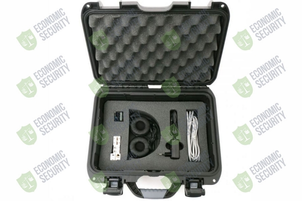
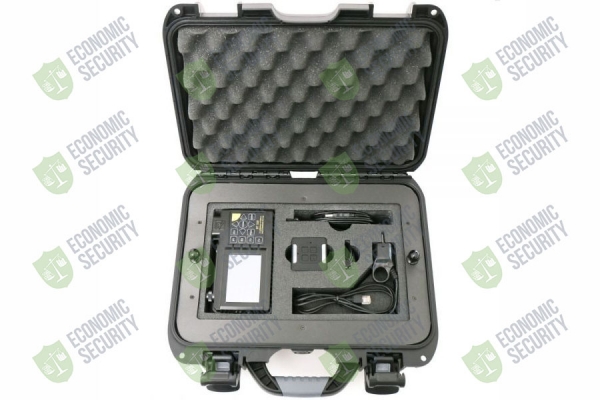
ST 500 «Piranha» Operation Manual: General Information For transportation and storage of the device, the NANUK 915 shock- and moisture-proof plastic case is used. All the items in the bundle are housed in the two panels within the case. Upper case panel Lower case panel In the placement scheme above, the numbers assigned to items in the ST 500 bundle are the same as in 1.2.1.
-
Page 7
ST 500 «Piranha» Operation Manual: General Information The appearance of the main unit is shown in fig.2. Fig.2 Number in fig.2 Marking on the device Element description Display Keyboard F1-F4 Hotkeys Cancellation (return) key FUNC Key to enable additional functions ENTER Confirmation key MODE… -
Page 8
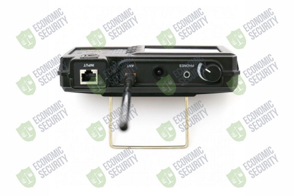
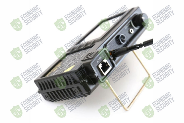
ST 500 «Piranha» Operation Manual: General Information Number in fig.2 Marking on the device Element description Sensor of the IR DETECTOR Antenna socket of the SELECTIVE HF DETECTOR Electronic switch input INPUT Prop Info shield with serial number Inbuilt speaker Charger connected indicator Charger socket Mini-USB for PC connection… -
Page 9: Power Supply
ST 500 «Piranha» Operation Manual: General Information 1.3.7. TEST SOUND SOURCE Purpose of the test sound source (fig.1, emission of a sound signal (whose correlation with the reception on ST 500 means that there is an active eavesdropping device nearby making unencoded transmissions) …
-
Page 10: Technical Specifications
ST 500 «Piranha» Operation Manual: General Information 1.5. TECHNICAL SPECIFICATIONS Selective HF Detector: operative frequency range, MHz 20-6000 passband, MHz 1 or 20 impedance, Ohm rate of scanning, GHz/sec bandpass flatness, dB ±6 minimum detection level, dB dynamic range, dB IR Detector: spectral range, 0.75…1.1…
-
Page 11: Interface Options
The Device is turned on/off with the pwer switch and volume control button (fig. 2, 3). When turned on, the display will show a screen (fig.3) with the ST Group Ltd. logo, name of the Device, and firmware version number. Fig.3 Press any key to go to the main menu of device.
-
Page 12: Status Bar
ST 500 «Piranha» Operation Manual: Interface Options 2.3. STATUS BAR In the upper part of the Device’s screen is a status bar shown in fig.5 Fig.5 In fig.5: active channel electric mains sign pair of wires connected battery charge sign current time (hh:mm) 2.4.
-
Page 13: Setting The Date
ST 500 «Piranha» Operation Manual: Interface Options 2.4.1. SETTING THE DATE In order to set the date, use the keys to select «DATE» in the menu and press «ENTER». The following screen (fig.7) will appear. Fig.7 The date format is «DD/MM/ YYYY».
-
Page 14: Selective Hf Detector Channel
ST 500 «Piranha» Operation Manual: Selective HF Detector Channel 3. «SELECTIVE HF DETECTOR» CHANNEL The «SELECTIVE HF DETECTOR» channel is intended for the detection of analog and digital wireless (utilizing GSM, LTE, Bluetooth, or WiFi) eavesdropping devices operating in the frequency range 20 MHz — 6 GHz.
-
Page 15
ST 500 «Piranha» Operation Manual: Selective HF Detector Channel Fig.9 In fig.9: active channel screen cursor frequency value at the current cursor position dynamic bar indicating signal level at the selected frequency peak signal value over all cycles at the selected frequency (maroon) pulse signals detected in the last measurement cycle (green) continuous signals detected in the last measurement cycle (red) lower bound of the set frequency range viewing band… -
Page 16: Differential Mode
ST 500 «Piranha» Operation Manual: Selective HF Detector Channel Fig.10 IM PO RT A NT ! Until the gain setting is completed, other modes and functions are not available, except for switching to the Main Menu of the device (by pressing «MODE»). 3.2.
-
Page 17: Fixed Frequency Analysis Function
ST 500 «Piranha» Operation Manual: Selective HF Detector Channel In fig.11: active channel DIFFERENTIAL mode highlighted as currently active constant differential signal registered during the last scanning cycle (lilac) pulse differential signal registered during the last scanning cycle (yellow) peak signal level at the given frequency over all cycles (maroon) Functionality: …
-
Page 18: Set «0» Function
ST 500 «Piranha» Operation Manual: Selective HF Detector Channel In fig.12: active detection channel signal level at the selected frequency (at cursor position) «SET «0» active selected passband (1 MHz or 20 MHz) OSCILLOSCOPE active Functionality: tuning to the frequency of the detected signal …
-
Page 19: Oscilloscope Function
ST 500 «Piranha» Operation Manual: Selective HF Detector Channel 3.2.3. OSCILLOSCOPE To activate the OSCILLOSCOPE, after switching on the «FIXED FREQUENCY ANALYSIS» function, press the «F3». The «OSC» field will become lighter. The screen will look as shown in fig.13 below. Fig.13 In fig.13: active detection channel…
-
Page 20: Automated Mode
ST 500 «Piranha» Operation Manual: Selective HF Detector Channel 3.3. AUTOMATED MODE The AUTOMATED mode is used to register signals whose amplitudes exceed the adaptive detection threshold. It is activated from the DIFFERENTIAL or «PANORAMA» mode by pressing «F2». Search for signals is performed within set frequency limits, based on the data obtained in the DIFFERENTIAL mode (if the AUTOMATED mode has been activated from the DIFFERENTIAL mode).
-
Page 21: Frequency Tuning Function
ST 500 «Piranha» Operation Manual: Selective HF Detector Channel Functionality: sorting the detected signals (by frequency or by level) quick tuning to the detected signal by selecting it in the table fine frequency tuning passband selection (1 MHz or 20 MHz) …
-
Page 22: Oscilloscope Function
ST 500 «Piranha» Operation Manual: Selective HF Detector Channel 3.3.2. OSCILLOSCOPE To analyze the demodulated signal with the oscilloscope use the keys to select the corresponding table row and press «F3». Functionality and controls described in 3.2.3. To turn off the OSCILLOSCOPE, press «F3» or «ESC». 3.4.
-
Page 23: Base Stations Monitoring Function
ST 500 «Piranha» Operation Manual: Selective HF Detector Channel Controls: Action table row selection ENTER turning on «ANALYZING DETECTED SIGNALS» function turning on «BASE STATIONS MONITORING» function turning on «USER LIST» function activating gain adjustment returning to «PANORAMA» or DIFFERENTIAL mode (to the previous mode) MODE switching to the main menu of device F1, FUNC…
-
Page 24: User List Function
ST 500 «Piranha» Operation Manual: Selective HF Detector Channel 3.4.3. «USER LIST» FUNCTION This function allows detecting the activity of radio transmitters in pre-set frequency ranges, and analyze the detected signals. The screen will look as shown in fig.18. Fig.18 In fig.18: active channel active option (highlighted)
-
Page 25
ST 500 «Piranha» Operation Manual: Selective HF Detector Channel Fig.19 In fig.19: active channel white frame of the active window (OSCILLOSCOPE or SPECTRUM ANALYZER) OSCILLOSCOPE window digital communications standard division value of the oscilloscope time axis SPECTRUM ANALYZER window frequency value at SPECTRUM ANALYZER marker position lower bound of range spectrum SPECTRUM ANALYZER marker… -
Page 26
ST 500 «Piranha» Operation Manual: Selective HF Detector Channel OSCILLOSCOPE and SPECTRUM ANALYZER controls Action MODE switching to the main menu of device switching to the previous mode ENTER turning on/off SET «0» function horizontal zoom (OSCILLOSCOPE) cursor positioning (SPECTRUM ANALYZER) switching between OSCILLOSCOPE and SPECTRUM ANALYZER F1 — F4, disabled… -
Page 27: Infrared Detector Channel
ST 500 «Piranha» Operation Manual: Infrared Detector Channel 4. «INFRARED DETECTOR» CHANNEL («IR DETECTOR») The «IR DETECTOR» channel is intended for the detection of eavesdropping devices that utilize the infrared range for transmissions. The infrared detector sensor is located on the upper surface of the Device (fig.2, Analysis of the detected signals is carried out using: …
-
Page 28: Differential Mode
ST 500 «Piranha» Operation Manual: Infrared Detector Channel 4.1. DIFFERENTIAL MODE The DIFFERENTIAL mode helps locate the source of a detected IR signal. Upon activation, the detected signal level will be set as «0» and the signal level bar will be showing the difference in excess of it.
-
Page 29: Connecting St 500 To Wire Lines
ST 500 «Piranha» Operation Manual: Connecting to Cabling 5. CONNECTING ST 500 TO CABLING For connecting the Device to the tested circuits, various cables and adapters are supplied with ST 500. They are shown yellow in the figs. 22-27 below. 5.1.
-
Page 30: Connecting To Telephone Lines
ST 500 «Piranha» Operation Manual: Connecting to Cabling CONNECTING TO A LAN CABLE EQUIPPED WITH AN RJ45 SOCKET When testing a LAN line without parallel connection of any end user devices, the Device is connected to the computer socket with a patch cord (fig.1, 4).
-
Page 31: Connecting To Low Current Multi-Core Cables Without Connectors
ST 500 «Piranha» Operation Manual: Connecting to Cabling CONNECTING TO A TELEPHONE LINE EQUIPPED WITH AN RJ11 SOCKET While testing telephone lines, if there is no necessity in a parallel connection of end user devices, a cable fitted with an RJ11 socket is cable-connected to the main unit (fig.1, 3).
-
Page 32: Wired Receiver Channel (Wr)
ST 500 «Piranha» Operation Manual: Wired Receiver Channel 6. THE «WIRED RECEIVER» CHANNEL The «WIRED RECEIVER» channel is intended for the detection of signals from eavesdropping devices transmitting over electric mains and low current lines in the frequency range 0.1–180 MHz. The detected signals are analyzed with the aid of …
-
Page 33: Electric Mains Testing
ST 500 «Piranha» Operation Manual: Wired Receiver Channel Fig.29 ELECTRIC MAINS TESTING FUNCTIONAL SCHEME OF THE «WIRED RECEIVER» CHANNEL (ELECTRIC MAINS TESTING) 6.3. «PANORAMA» MODE (ELECTRIC MAINS TESTING) When «MAINS» is chosen from the menu (fig.28), «PANORAMA» mode turns on, and all the signal activity in the circuit within the selected frequency band is displayed on the screen (fig.30).
-
Page 34
ST 500 «Piranha» Operation Manual: Wired Receiver Channel Fig.30 In fig.30: active detection channel electric mains selected signal level at the selected frequency frequency value at cursor position screen cursor pulse signals detected in the last measurement cycle (red) steady signals detected in the last measurement cycle (green) peak signal level at the given frequency over all cycles (maroon) lower zoom limit position of the selected band, as against maximum… -
Page 35: Differential Mode
ST 500 «Piranha» Operation Manual: Wired Receiver Channel Action activating the DIFFERENTIAL mode activating/deactivating the attenuator (20 dB) ENTER turning on «FIXED-FREQUENCY ANALYSIS» function ESC, MODE switching to the main menu of device F1, FUNC disabled 6.4. DIFFERENTIAL MODE The DIFFERENTIAL mode is used to reduce the influence of external interference on the information signals, and evaluate changes in the activity within a band upon connecting new technical appliances to the circuit.
-
Page 36: Fixed-Frequency Analysis Function
ST 500 «Piranha» Operation Manual: Wired Receiver Channel Controls Action adjusting the band limits (zoom) cursor positioning activating the AUTOMATED mode deactivating the DIFFERENTIAL mode activating/deactivating the attenuator (20 dB) ENTER activating «FIXED-FREQUENCY ANALYSIS» function ESC, MODE switching to the main menu of device F1, FUNC disabled 6.4.1.
-
Page 37: Oscilloscope Function
ST 500 «Piranha» Operation Manual: Wired Receiver Channel Functionality: activating/deactivating the attenuator (20 dB) AM/FM demodulation toggling researching signals with the OSCILLOSCOPE frequency tuning Controls: Action cursor positioning (frequency tuning) toggling AM/FM demodulation turning on OSCILLOSCOPE activating/deactivating the attenuator (20 dB) ENTER, ESC turning on «FIXED-FREQUENCY ANALYSIS»…
-
Page 38: Automated Mode
ST 500 «Piranha» Operation Manual: Wired Receiver Channel Functionality: determining the time parameters of the demodulated signal setting the division value of the time axis listening to a demodulated (AM/FM) signal activating/deactivating the attenuator (20 dB) Controls: Action setting the division value of the horizontal sweep…
-
Page 39: Frequency Tuning Function
ST 500 «Piranha» Operation Manual: Wired Receiver Channel Functionality: sorting of the detected signals (by frequency or by level) quick tuning to the detected signal by selecting it in the table frequency tuning activating/deactivating the attenuator (20 dB) …
-
Page 40: Low Current Circuit Testing
ST 500 «Piranha» Operation Manual: Wired Receiver Channel Controls: Action setting the division value of the horizontal sweep 100µS/200µS/500µS/1mS/2mS/5mS/10mS toggling AM/FM demodulation F3, ESC turning off OSCILLOSCOPE on/off attenuator (20 dB) MODE switching to the main menu of device To turn off the OSCILLOSCOPE, press «F3» or «ESC». LOW CURRENT CIRCUIT TESTING Low current circuits typically utilize multiwire cables.
-
Page 41
ST 500 «Piranha» Operation Manual: Wired Receiver Channel Fig.36 In fig.36: active channel pair of wires connected pairs of wires direct voltage on wire pairs alternating voltage on wire pairs current table row Functionality: selecting a paired combination of wires … -
Page 42: Electronic Switch Settings Mode
ST 500 «Piranha» Operation Manual: Wired Receiver Channel 6.7. «ELECTRONIC SWITCH SETTINGS» MODE This mode is intended for setting up the electronic switch before testing low current multiwire cables. The setting-up procedure consists in choosing the pin numbers in the 8-pin socket of the electronic switch, to be connected to the cores of the cable under inspection.
-
Page 43: Panorama Mode (Low Current Circuit Testing)
ST 500 «Piranha» Operation Manual: Wired Receiver Channel Controls: Action navigation ENTER connecting/disconnecting the selected pin activating/deactivating the standard 8P8C scheme activating/deactivating the standard 6P6C scheme activating/deactivating the standard 6P4C scheme activating/deactivating the standard 6P2C scheme ESC, FUNC exiting the mode (to the previous screen) , MODE disabled To finish the electronic switch setup and switch to «ELECTRONIC SWITCH CONTROL»…
-
Page 44
ST 500 «Piranha» Operation Manual: Wired Receiver Channel Fig.39 In fig.39: pair of wires connected key for returning to the previous screen The «Switch» key is used to activate to the «ELECTRONIC SWITCH CONTROL» mode (fig.36) for connecting and analyzing another pair of wires. Controls Action band setting (zoom) -
Page 45: Low Frequency Amplifier Channel (Lfa)
ST 500 «Piranha» Operation Manual: Low Frequency Amplifier Channel 7. «LOW FREQUENCY AMPLIFIER» CHANNEL The «LOW FREQUENCY AMPLIFIER» channel is intended for the detection of low-frequency signals from eavesdropping devices in low current circuits. An oscillogram, spectrogram and acoustic information are used to analyze the detected signals.
-
Page 46
ST 500 «Piranha» Operation Manual: Low Frequency Amplifier Channel Fig.40 In fig.40: active channel pair of wires connected gain selected bias voltage selected wire pairs measured values of direct voltage measured values of alternating voltage The measured values of direct and alternating voltage are shown for the pair of wires that is currently selected in the table (fig.41). -
Page 47: Electronic Switch Settings Mode
ST 500 «Piranha» Operation Manual: Low Frequency Amplifier Channel Controls: Action table row selection (connecting pairs of wires) F1, ENTER turning on OSCILLOSCOPE gain setting on/off bias voltage setting on/off activating the AUTOMATED mode ESC, MODE switching to the main menu of device FUNC activating «ELECTRONIC SWITCH SETTINGS»…
-
Page 48: Setting The Bias Voltage
ST 500 «Piranha» Operation Manual: Low Frequency Amplifier Channel The screen view when setting the gain value is shown in fig.43. Fig.43 The selected gain value remains unchanged until next adjustment or «LOW FREQUENCY AMPLIFIER» channel deactivation (return to main menu of device). 7.4.
-
Page 49: Automated Mode
ST 500 «Piranha» Operation Manual: Low Frequency Amplifier Channel Im p or t an t! While setting the bias voltage, other functions will be inaccessible. The bias voltage, once set, will remain unchanged until deactivation of the «LOW FREQUENCY AMPLIFIER» channel (switching to the main menu of device). If the voltage on the pair connected to the ST 500 is beyond ±3 V, the application of bias voltage to these wires is disabled.
-
Page 50: Spectrum Analyzer
ST 500 «Piranha» Operation Manual: Low Frequency Amplifier Channel Fig.46 In fig.46: active channel data representation form connected pair of wires set division value of the time axis (mcs or ms) measured value of signal magnitude vertical zoom oscillogram Upon activation of the OSCILLOSCOPE, the gain value and bias voltage, set in the «ELECTRONIC SWITCH CONTROL»…
-
Page 51
ST 500 «Piranha» Operation Manual: Low Frequency Amplifier Channel Fig.47 In fig.47: active channel data representation form frequency value at cursor position connected pair of wires SPECTRUM ANALYZER Controls Action cursor positioning F1, ESC switching to «ELECTRONIC SWITCH CONTROL» mode activating/deactivating Gain Setting activating/deactivating Bias Voltage Setting activating OSCILLOSCOPE… -
Page 52: St 500 Software
ST 500 «Piranha» Operation Manual: Software 8. SOFTWARE 8.1. PURPOSE 1. Preparation and loading into ST 500 of a priori information for analyzing the received signals using «SELECTIVE DETECTOR» channel AUTOMATED «WIRELESS COMMUNICATION» modes: adjustment of «THREAT» and «NON-THREAT» frequency bands, …
-
Page 53: Graphical Interface
ST 500 «Piranha» Operation Manual: Software 8.5. GRAPHICAL INTERFACE The PC screen with running ST 500 software is shown in fig.48. Fig.48 In fig.48: 1 — software name 2 — application window control (minimize, maximize, close) 3 — mode tabs 4 — language setting (русский/English) 5 — software mode tabs 6 — data field and controls in the active mode…
-
Page 54: Ranges Highlighting Mode
ST 500 «Piranha» Operation Manual: Software 8.6.1. «RANGES HIGHLIGHTING» MODE This mode is intended for defining the limits of bands in which the presence of «THREAT» or «NON-THREAT» signals is likely. «THREAT» bands: operating frequency bands of digital mobile communications devices …
-
Page 55
ST 500 «Piranha» Operation Manual: Software In fig.49: list of highlighted ranges: sequence number, initial (lower) and ending (upper). The line of the adjustable range is highlighted in blue activity checkbox. If not ticked: signals found in this range will be classified as «UNKNOWN»… -
Page 56: Mobile Bands Mode
ST 500 «Piranha» Operation Manual: Software comment (fig.49,
 on/off activity checkbox (fig.49, 2) 3. Click «Apply Changes» to save the changes made, or «Cancel» to exit without saving changes Restrictions for band editing or addition 1. Frequency ranges cannot border on, or overlap with, one another. If this restriction is not met, the following warning prompt will appear, «Initial Frequency is in a different range # xx (xxx — xxx)»…
 -
Page 57
ST 500 «Piranha» Operation Manual: Software Fig.50 In fig.50: — list of frequency bands of mobile devices: sequence number, initial (lower) and ending (upper) frequencies, range designation. The line of the adjustable range is highlighted in blue — activity checkbox. If not ticked: no search for signals in this range — control of data exchange with ST 500 (reads and writes data relating only to the «Mobile bands»… -
Page 58
ST 500 «Piranha» Operation Manual: Software Changing parameters 1. To edit a band in the list, select the corresponding table row, which will be highlighted blue. 2. Edit parameters: initial (lower) and/or ending (upper)band frequency (fig.50, 4,5) name or comment on the band (fig.50, 6) … -
Page 59: Base Bands Mode
8.6.5. «FIRMWARE UPDATE» MODE The current firmware version is shown on the screen when the device is turned on (fig.51). Fig.51 Get information and download the latest version of the firmware can be on the ST Group Ltd official site: http://spymarket.com/tp When «Firmware update”…
-
Page 60
3 – browsing button 4 – update start button 5 – update progress bar To update the firmware 1. Download to PC from ST Group Ltd official site http://spymarket.com/tp file ST500_vx_xx.bin (‘x_xx’ is version number) 2. Start ST 500 software. -
Page 61: Use Guidelines
ST 500 «Piranha» Operation Manual: Use Guidelines 9. USE GUIDELINES 9.1. GUIDELINES FOR USE OF «SELECTIVE HF DETECTOR» CHANNEL The «SELECTIVE HF DETECTOR» channel is intended for detection, identification and localization of radio transmitting, «active» eavesdropping devices in the range of 20 — 6000 MHz. Three option of searching for eavesdropping devices: …
-
Page 62: Search In The Panorama Mode And Differential Mode
ST 500 «Piranha» Operation Manual: Use Guidelines Signs of «THREAT» signal: at the frequency of the detected signal, the test sound is heard through the headphones, the test sound is not heard in the headphones, but the oscilloscope picture of the demodulated signal changes with the test sound, …
-
Page 63: Search In The Wireless Communication Mode
ST 500 «Piranha» Operation Manual: Use Guidelines 9.1.3. SEARCH IN THE «WIRELESS COMMUNICATION» MODE In the «WIRELESS COMMUNICATION» mode, the frequency bands that meet a specific digital communication standard and are used by eavesdropping devices are monitored. When searching for eavesdropping devices, three functions are used: 1.
-
Page 64: Localization Of The Source Of Detected Signal
ST 500 «Piranha» Operation Manual: Use Guidelines 6. Monitor signal presence, watching the level bars in the table. 7. If radio traffic is detected in any band, it is necessary to investigate the observed signals. To do this, set the cursor to the desired band and activate the «ANALYSIS OF DETECTED SIGNALS»…
-
Page 65: Guidelines For Use Of Infrared Detector Channel
ST 500 «Piranha» Operation Manual: Use Guidelines When localizing a GSM signal source in an energetic way, difficulties may arise. The signal level in different places of the room will be approximately the same, and it is difficult to determine where the signal level is at its maximum.
-
Page 66: Guidelines For Use Of The Wired Receiver Channel
ST 500 «Piranha» Operation Manual: Use Guidelines 9.3. GUIDELINES FOR USE OF THE «WIRED RECEIVER» CHANNEL The WIRED RECEIVER channel is intended for the detection of wired high-frequency transmitters in electric mains and low current circuits. The range of information transmission via electric mains, as a rule, does not exceed 500 meters within one or several buildings, which are powered from one low-voltage bus of a transformer substation.
-
Page 67
ST 500 «Piranha» Operation Manual: Use Guidelines When an electric mains circuit is being tested, the electronic switch automatically engages the pair of wires «1-2», which corresponds to the wiring scheme of the adaptor’s plug. In the status bar the symbol (electric mains mode) is shown. -
Page 68: Low Current Circuit Testing
ST 500 «Piranha» Operation Manual: Use Guidelines If «THREAT» signals were not detected, check the changes in the differential spectrum when the consumers are connected. It is required to receive a differential panorama of the powered line, and then in turn connect consumers.
-
Page 69: Guidelines For Use Of Low Frequency Amplifier Channel
ST 500 «Piranha» Operation Manual: Use Guidelines When a four-wire telephone line cable is connected, the switch contacts with numbers 3, 4, 5, 6 will be used. Wire combinations 3-4, 3-5, 3-6, 4-5, 4-6, 5-6 should be checked. It is necessary to take into account that the transmitter can be powered normally (from the involved «4-5″…
-
Page 70: Search For Active Microphones In An Analog Telephone Line
ST 500 «Piranha» Operation Manual: Use Guidelines 9.4.1. SEARCH FOR ACTIVE MICROPHONES IN AN ANALOG TELEPHONE LINE The initial state: 1. The tested telephone line consists of 4 wires. 2. The cable is equipped with a 6P4C plug. 3. The consumer device is an analog telephone. 4.
-
Page 71: Activation Of Electret Microphones In An Analog Telephone Line
ST 500 «Piranha» Operation Manual: Use Guidelines Case 4 There is no voltage. The test sound An electret microphone is connected, Pair 3-6 cannot be heard in the audio output. with «phantom» power supply from the telephone line and signal transmission The voltage DC 26 V.
-
Page 72: Localization With St 500 And Non-Linear Junction Detector
ST 500 «Piranha» Operation Manual: Use Guidelines Actions with the test sound source: 1. Turn on the test sound source. 2. Decrease the sound volume. 3. Carry the test sound source slowly around the room. ST 500 operator procedure: 1. Activate «LFA» or «WR» (in whichever the transmission channel has been detected). 2.
-
Page 73: Supplement #1. Functions Of The Controls
ST 500 «Piranha» Operation Manual: Supplement #1 — Functions of the Controls 10. SUPPLEMENT #1. FUNCTIONS OF THE CONTROLS. 10.1. BASIC SETTINGS MAIN MENU (CHANNEL SELECTION) enable SELECTIVE HF DETECTOR channel enable IR DETECTOR channel enable WIRED RECEIVER channel enable LOW FREQUENCY AMPLIFIER channel navigate ENTER confirmation of action…
-
Page 74: Selective Hf Detector
ST 500 «Piranha» Operation Manual: Supplement #1 — Functions of the Controls 10.2. SELECTIVE HF DETECTOR GAIN ADJUSTMENT increase gain decrease gain deactivate Gain adjustment ENTER MODE go to main menu of device FUNC disabled F1-F3 «PANORAMA» (DIFFERENTIAL) mode «PANORAMA» (DIFFERENTIAL) mode ESC or go to main menu of device MODE…
-
Page 75
ST 500 «Piranha» Operation Manual: Supplement #1 — Functions of the Controls «PANORAMA» MODE. FIXED-FREQUENCY ANALYSIS, OSCILLOSCOPE MODE go to main menu of device ESC F3 turn off OSCILLOSCOPE time-axis zoom select passband (1 or 20 MHz) activate Gain Setting ENTER disabled FUNC… -
Page 76
ST 500 «Piranha» Operation Manual: Supplement #1 — Functions of the Controls «WIRELESS COMMUNICATION» MODE «MOBILE DEVICES MONITORING» function MODE go to main menu of device go to «PANORAMA» navigate ENTER turn on «ANALYZING DETECTED SIGNALS» turn on «BASE STATION MONITORING» turn on «USER LIST»… -
Page 77: Ir Detector
ST 500 «Piranha» Operation Manual: Supplement #1 — Functions of the Controls 10.3. IR DETECTOR MODE go to main menu of device ENTER activate /deactivate DIFFERENTIAL mode time-axis zoom F1-F4 FUNC disabled 10.4. WIRED RECEIVER ELECTRIC MAINS TESTING «PANORAMA» (DIFFERENTIAL mode) ESC or go to main menu of device MODE…
-
Page 78
ST 500 «Piranha» Operation Manual: Supplement #1 — Functions of the Controls OSCILLOSCOPE (when activated from the «PANORAMA» mode) MODE go to main menu of device F3 ESC turn off OSCILLOSCOPE toggle modulation (FM/AM) activate/deactivate Attenuator time-axis zoom FUNC disabled AUTOMATED mode MODE go to main menu of device… -
Page 79
ST 500 «Piranha» Operation Manual: Supplement #1 — Functions of the Controls LOW CURRENT CIRCUIT TESTING «ELECTRONIC SWITCH CONTROL» mode MODE go to main menu of device navigate ENTER activate «PANORAMA» mode FUNC activate «ELECTRONIC SWITCH SETTINGS» mode F1-F4 disabled «ELECTRONIC SWITCH SETTINGS»… -
Page 80
ST 500 «Piranha» Operation Manual: Supplement #1 — Functions of the Controls «PANORAMA» (DIFFERENTIAL mode). «FIXED-FREQUENCY ANALYSIS» function MODE go to main menu of device turn off «FIXED-FREQUENCY ANALYSIS» ENTER function toggle modulation (FM/AM) turn on OSCILLOSCOPE turn on/off Attenuator cursor positioning (frequency tuning) FUNC disabled… -
Page 81: Low Frequency Amplifier
ST 500 «Piranha» Operation Manual: Supplement #1 — Functions of the Controls «FREQUENCY TUNING» function MODE go to main menu of device ENTER turn off «FREQUENCY TUNING» function adjust frequency toggle modulation (FM/AM) turn on OSCILLOSCOPE turn on/off Attenuator FUNC disabled OSCILLOSCOPE (when activated from the AUTOMATED mode) MODE…
-
Page 82
ST 500 «Piranha» Operation Manual: Supplement #1 — Functions of the Controls GAIN SETTING MODE go to the main menu of device deactivate GAIN SETTING activate Setting the Bias Voltage Gain + Gain — ENTER set minimum gain (x1) FUNC disabled F1 F4 BIAS VOLTAGE CONTROL… -
Page 83: Supplement #2. Typical Settings Of The Electronic Switch
ST 500 «Piranha» Operation Manual: Supplement #2 — Typical Electronic Switch Settings 11. SUPPLEMENT #2. TYPICAL SETTINGS OF THE ELECTRONIC SWITCH. 8C8P connecting («F1») Computer 8-wire line equipped RJ45 connector 6P6C connecting («F2») 6-wire telephone line, equipped with connector RJ25 or RJ12 6P4C connecting («F3») 4-wire telephone line (equipped with connectors RJ11)
-
Page 84
ST 500 «Piranha» Operation Manual: Supplement #2 — Typical Electronic Switch Settings 6P2C connecting («F4») 2-wire telephone line (equipped with RJ25 or RJ11) Manual setup of the electronic switch ( and «ENTER») Settings for an arbitrary 4-wire line, not equipped with a connector (connection through RJ45 adapter) -
Page 85: Supplement #3. Reference Information
ST 500 «Piranha» Operation Manual: Supplement #3 — Reference Information 12. SUPPLEMENT #3. REFERENCE INFORMATION. 12.1. «TWISTED PAIR» CABLE A twisted pair cable is a type of cable that consists of one or several twisted pairs, i.e., insulated conductor strands twisted together with relatively few windings per length unit and enclosed in an outer plastic casing.
-
Page 86: Wiring Scheme Eia/Tia-568B
ST 500 «Piranha» Operation Manual: Supplement #3 — Reference Information 12.3.1. EIA/TIA-568A WIRING SCHEME connector # Color of wire connector # white and green (TX+) green (TX-) white and orange (RX+) blue white and blue orange (RX-) white and brown brown 12.3.2.
-
Page 87: Wiring Scheme Eia/Tia-568A
ST 500 «Piranha» Operation Manual: Supplement #3 — Reference Information A crossover connection between two computers is also possible as illustrated in the tables below, but such connections are rare. connector # Color of wire connector # scheme 1 white and green (TX+) green (TX-) white and orange (RX+) blue…
-
Page 88
ST 500 «Piranha» Operation Manual: Supplement #3 — Reference Information Line type Purpose User device two-wire analogue municipal telephone line, office PBX analogue line analogue telephone two-wire digital office PBX digital line digital telephone four-wire digital office PBX digital lines digital system telephone four-wire hybrid office PBX hybrid lines…
 on/off activity checkbox (fig.49, 2) 3. Click «Apply Changes» to save the changes made, or «Cancel» to exit without saving changes Restrictions for band editing or addition 1. Frequency ranges cannot border on, or overlap with, one another. If this restriction is not met, the following warning prompt will appear, «Initial Frequency is in a different range # xx (xxx — xxx)»…
 Артикул: 01418
Возможности:
- Поиск и локализация радиопередающих подслушивающих устройств
- Радиомикрофонов, телефонных радиоретрансляторов, радиостетоскопов
- Видеокамер с радиоканалом
- Радиомаяков систем слежения
- Идентификация цифровых протоколов обнаруженных радиосигналов: GSM, CDMA, Bluetooth, LTE, WiFi
- Идентификация сигналов базовых станций и мобильных устройств цифровой связи
- Поиск и локализации активных проводных подслушивающих устройств
- кабельных микрофонов, передающих информацию по штатным и специально проложенным слаботочным проводным линиям
- обнаружение сигналов подслушивающих устройств, передающих информацию по силовым и слаботочным линиям в диапазоне частот от 100 кГц до 180 МГц.
- Активация электретных кабельных микрофонов путем подачи в линию напряжения смещения
- Поиск и локализация подслушивающих устройств, передающих информацию в инфракрасном диапазоне
- Посмотреть и купить можно также в нашем Демонстрационном зале
- Посмотреть видео о приборе — «ST 500 Пиранья»
Интересует это оборудование, но есть вопросы?
Многофункциональный поисковый прибор «ST 500 Пиранья» состоит из четырех каналов обнаружения.
Каналы для обнаружения беспроводных подслушивающих устройств:
- СЕЛЕКТИВНЫЙ ВЧ ДЕТЕКТОР предназначен для обнаружения аналоговых и цифровых (использующих стандарты GSM, LTE, Bluetooth, WiFi) радиопередающих подслушивающих устройств в диапазоне частот 20 — 6000 МГц.
- ИК ДЕТЕКТОР предназначен для обнаружения ИК передатчиков (подслушивающих устройств, использующих для передачи информации инфракрасный диапазон частот).
Каналы для обнаружения проводных подслушивающих устройств:
- ПРОВОДНОЙ ПРИЕМНИК предназначен для обнаружения высокочастотных сигналов подслушивающих устройств, передающих информацию по силовым и слаботочным проводным линиям в диапазоне частот 100 кГц – 180 МГц.
- УСИЛИТЕЛЬ НИЗКОЙ ЧАСТОТЫ предназначен для обнаружения НЧ сигналов подслушивающих устройств.
В Детектор Системс вы можете приборести поисковый прибор «ST 500 Пиранья» по цене производителя.
| Характеристика | Значение |
| Селективный ВЧ детектор: | — |
| рабочий диапазон частот, МГц | 20-6000 |
| полоса пропускания, МГц | 1, 20 |
| входное сопротивление, Ом | 50 |
| скорость сканирования, ГГц/сек | 18 |
| неравномерность АЧХ, дБ | ±6 |
| минимальный уровень обнаруживаемого сигнала, дБ | -70 |
| динамический диапазон, дБ | 50 |
| габариты основного блока (длина, ширина, высота), мм | 165 х 100 х 40 |
| масса основного блока, кг | 0,47 |
| габариты упаковки (длина, ширина, высота), мм | 390 х 310 х 170 |
| габариты упаковки (длина, ширина, высота), мм | 390 х 310 х 170 |
| масса комплекта в упаковке, кг | 4 |
*
Производитель сохраняет за собой право изменять технические характеристики, комплектацию и внешний вид товара без предварительного оповещения дилера.
Просьба, уточнять технические характеристики и комплектацию у продавца перед покупкой.
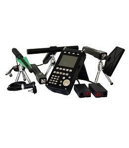
| Наименование | Количество |
| Главный блок | 1 шт. |
| Адаптер для подключения главного блока к силовым линиям | 1 шт. |
| Кабель для подключения главного блока к розеткам телефонных линий | 1 шт. |
| Кабель для подключения главного блока к розеткам локальная вычислительная сети (ЛВС) | 1 шт. |
| Кабель для подключения главного блока к USB портам ПК | 1 шт. |
| Антенна телескопическая | 1 шт. |
| Зарядное устройство | 1 шт. |
| Наушники | 1 шт. |
| Flash-накопитель | 1 шт. |
| Соединительная муфта (RJ11) | 1 шт. |
| Соединительная муфта (RJ45) | 1 шт. |
| Разветвитель 1х2 (RJ11) | 1 шт. |
| Разветвитель 1х2 (RJ45) | 1 шт. |
| Адаптер для подключения многопроводного кабеля + отвертка | 1 шт. |
| Кейс для переноски и хранения | 1 шт. |
| Паспорт | 1 шт. |
*
Производитель сохраняет за собой право изменять технические характеристики, комплектацию и внешний вид товара без предварительного оповещения дилера.
Просьба, уточнять технические характеристики и комплектацию у продавца перед покупкой.
Отзывы на ST 500 ПИРАНЬЯ (Артикул — 01418)
Кроме Пираньи, рынок не может предложить ничего похожего по количеству каналов, диапазонам и видам прослушки, поэтому приобрел именно это прибор. Что могу сказать, о выборе не пожалел. Работал по всем каналам обнаружения и проводных, и беспроводных прослушек. Эффективно, довольно быстро.
Мощный и функциональные прибор, который стоит своих денег. Полностью довольны прибором.
Достойный внимания 4-х канальный обнаружитель. Покупали по совету безопасников. В работе хорош. Рекомендую.
Спасибо!
Ваш отзыв будет опубликован после проверки модератором.
ПРИБОР «ST 500 ПИРАНЬЯ» МОЖНО КУПИТЬ В КОМПЛЕКТЕ СО СКИДКОЙ
К ЭТОЙ ПОКУПКЕ РЕКОМЕНДУЕМ посмотреть ТОВАРЫ

ОПТИК-2
Эффективный обнаружитель скрытых, замаскированных в интерьере видеокамер, с максимальным функционалом
ХИТ продаж
ST 131 ПИРАНЬЯ II
Новый многофункциональный поисковый комплекс для обнаружения широкого спектра прослушивающих устройств
Мы предоставляем несколько вариантов оплаты. Вы можете заплатить по безналу как юридическое лицо, картой или одним из множества способов, которые предоставляет агрегатор платежей.
Быстрая доставка товара по Вашему адресу
в любой город РФ.
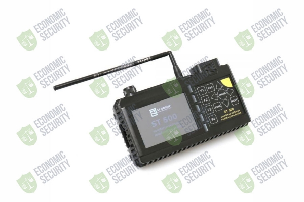
Многофункциональный поисковый прибор ST 500 «ПИРАНЬЯ» предназначен для поиска идентификации и локализации подслушивающих устройств.
Описание:
Функционально прибор состоит из четырех каналов обнаружения.
Каналы для обнаружения беспроводных подслушивающих устройств:
- СЕЛЕКТИВНЫЙ ВЧ ДЕТЕКТОР предназначен для обнаружения аналоговых и цифровых (использующих стандарты GSM, LTE, Bluetooth, WiFi) радиопередающих подслушивающих устройств в диапазоне частот 20 — 6000 МГц.
- ИК ДЕТЕКТОР предназначен для обнаружения ИК передатчиков (подслушивающих устройств, использующих для передачи информации инфракрасный диапазон частот).
Каналы для обнаружения проводных подслушивающих устройств:
- ПРОВОДНОЙ ПРИЕМНИК предназначен для обнаружения высокочастотных сигналов подслушивающих устройств, передающих информацию по силовым и слаботочным проводным линиям в диапазоне частот 100 кГц – 180 МГц.
- УСИЛИТЕЛЬ НИЗКОЙ ЧАСТОТЫ предназначен для обнаружения НЧ сигналов подслушивающих устройств.
Более подробно об устройстве и функциональных возможностях ST 500 «Пиранья»:
Руководство по эксплуатации ST 500 «ПИРАНЬЯ»
Более подробно об отличиях многофункциональных приборов ST 031M и ST 500:
FAQ — ЧАВО
| Селективный ВЧ детектор: | |
|
рабочий диапазон частот, МГц |
20-6000 |
|
полоса пропускания, МГц |
1, 20 |
| входное сопротивление, Ом | 50 |
| скорость сканирования, ГГц/сек | 18 |
| неравномерность АЧХ, дБ | ±6 |
| минимальный уровень обнаруживаемого сигнала, дБ | -70 |
| динамический диапазон, дБ | 50 |
| ИК детектор: | |
| спектральный диапазон, мкм | 0,75…1,1 |
| полоса детектирования, МГц | 5 |
| угол поля зрения, град | ±20 |
| минимально обнаруживаемая мощность, Вт/Гц½ | 10-13 |
| Проводной приемник: | |
| рабочий диапазон частот, МГц | 0,1-180 |
| время сканирования всего диапазона, сек | 2 |
| минимальный уровень обнаруживаемого сигнала, дБм | -50…-75 |
| динамический диапазон, дБ | 50 |
| входное сопротивление, Ом | 100 |
| демодуляция | АМ, FM |
| полоса пропускания входного фильтра, кГц | 180 |
| максимально допустимое напряжение в линии, В | 250(AC), 60(DC) |
| Усилитель низкой частоты: | |
| диапазон частот, Гц | 20 — 25000 |
| входное сопротивление, кОм | 200 |
| диапазон регулировки усиления, раз | 1,2,5,10,20,50,100 |
| максимальная амплитуда сигнала на входе, В |
±60(DC), ±1(АС) |
| спектральная плотность напряжения шума, нВ/Гц | 3 |
| диапазон установки напряжения смещения, В | +30, -30 |
| Электропитание: | |
| встроенный литий-полимерный аккумулятор с напряжением, В | 3,7 |
| потребляемая мощность, Вт | <1 |
| время непрерывной работы при максимальной потребляемой мощности, час |
>4 |
| время заряда аккумулятора, час | 7 |
| Масса и габариты: | |
| габариты основного блока, мм | 165 х 100 х 40 |
| масса основного блока, кг | 0,47 |
| габариты упаковки (длина, ширина, высота), мм | 390 х 310 х 170 |
| масса комплекта в упаковке, кг | 4 |
Вас может заинтересовать:
ST500 МНОГОФУНКЦИОНАЛЬНЫЙ ПОИСКОВЫЙ ПРИБОР
ST 400 CAYMAN НЕЛИНЕЙНЫЙ ЛОКАТОР
ST 100 ПОИСКОВЫЙ ПРИЕМНИК
ST 401 CAYMAN ПОРТАТИВНЫЙ НЕЛИНЕЙНЫЙ ЛОКАТОР
ST 600 КОМБИНИРОВАННЫЙ ПОИСКОВЫЙ ПРИБОР
ST 301 SPIDER АНАЛИЗАТОР ПРОВОДНЫХ ЛИНИЙ
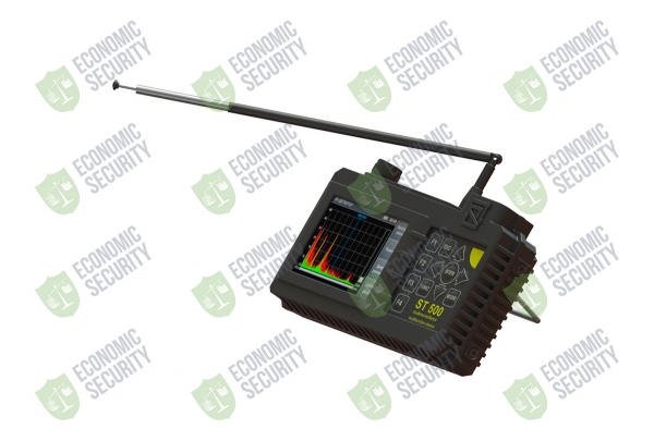
Устройства, предназначенные для прослушки и перехвата данных, компактны. Их легко камуфлировать или прятать в деталях интерьера. Поэтому поиск является сложной задачей, для выполнения которой необходимо специальное оборудование и время. Упростить ее помогают поисковые детекторы. ST 500 обнаруживает средства перехвата информации по акустическому, виброакустическому, инфракрасному каналу и проводным линиям.
Сфера применения ST 500
Большинство специальных технических средств узко специализированы. Каждое решает одну из задач: проводит радио-мониторинг, пеленгует источник излучения, анализирует силовые и телефонные линии. Сканер ST 500 совмещает в себе функции нескольких устройств, что автоматизирует процесс поиска. Применяется для оценки качества установленной защиты от технического шпионажа. Работает в разных режимах. Они переключаются автоматически при подключении соответствующего преобразователя: антенны, датчика или адаптера.

Оборудование решает следующие задачи:
- Определяет местоположение радио-микрофонов, радио-стетоскопов, телефонных ретрансляторов, спрятанных видеокамер с радиоканалом, устройств ретрансляции изображений с мониторов, маяков.
- Вычисляет приборы, передающие информацию по стандартам «Bluetooth», «EDGE», «3G», «Wi-Fi», «GSM», «CDMA», «LTE», «GPRS» и других протоколов радиопередачи.
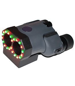
- Обнаруживает технические средства, которые работают с излучением в инфракрасном диапазоне.
- Помогает выявить устройства, использующие для передачи данных проводные линии, в том числе пожарную и охранную сигнализацию, сети переменного тока, абонентские телефоны.
- Находит источники электромагнитных полей: трансформаторы усилителей частоты звука, электродвигатели, которые используются в диктофонах.
ST 500 выявляет возможные места возникновения виброакустических путей утечки и помогает оценить результативность звукоизоляции.
Функциональные возможности и преимущества оборудования
ST 500 – комбинированный прибор, который может работать в режимах анализатора спектра, ИК детектора и осциллографа. Функциональность достигается за счет сочетания широкодиапазонного перестраиваемого по частоте приемника, блока распознавания закладок, блока акустической локации в одном устройстве. Детектор сравнивает естественный акустический фон помещения с принятыми сигналами и автоматически обрабатывает данные. Диапазон высокочастотного анализа расширен до 6000 МГц, что дает возможность улавливать передачу радиоустройств новых моделей. Порог частоты детектора устанавливается в зависимости от целей и условий работ.
Детектор работает в нескольких режимах:
- высокочастотного детектора;
- анализатора проводных линий;
- инфракрасных излучений;
- НЧ магнитных полей;
- виброокустического преобразователя;
- акустического приемника.
Каждый из режимов предназначен для обнаружения устройств определенного вида. Результат выдается в виде динамических тональных щелчков. Информация отображается на дисплее; акустический контроль осуществляется через наушники или динамики. Когда устройство уверенно принимает сигнал с известными параметрами, под цифровой шкалой появляется надпись. На фоне естественных помех принимается и детектируется интенсивный радиосигнал. На дисплее отображаются его текущие значения и изменчивость. В режиме анализа низких частот и акустического преобразователя сигналы отбираются на основе анализа осциллограммы.
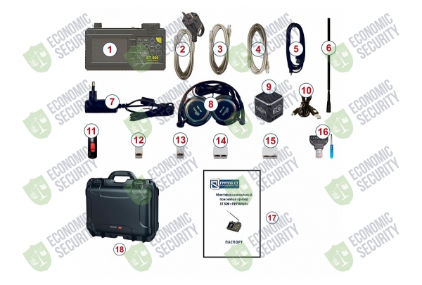
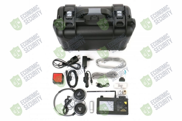
1.Основной блок
2. Адаптер для подключения
основного блока к силовым линиям
3. Кабель для подключения
основного блока к розеткам телефонных
линий
4. Кабель для подключения
основного блока к розеткам ЛВС
5. Кабель для подключения
основного блока к USB порту ПК
6. Телескопическая антенна
Зарядное устройство
7. Наушники
8. Источник контрольного звука
9. Кабель для зарядки
источника контрольного звука
10. USB накопитель (флэш-карта)
11. Соединительная муфта (RJ11)
12. Соединительная муфта (RJ45)
13. Разветвитель 1х2 (RJ11)
14. Разветвитель 1х2 (RJ45)
15. Адаптер для подключения
многопроводного кабеля (с отверткой)
16. Паспорт
17. Кейс
Часть процессов автоматизирована. Например, проверка многопроводных линий проводится автоматически благодаря встроенному коммутатору. Он работает как с обесточенными, так и с находящимися под напряжением сетями. Прибор ST 500 можно подключать к ПК. Специально разработанное программное обеспечение повышает поисковый потенциал: позволяет вводить дополнительные настройки, сохранять или загружать данные объектов, анализировать обнаруженные сигналы. Прибор удобен в управлении и использовании. Работает от батарей, так что нет привязки к внешнему источнику питания. Результативность детектора проверена сотрудниками Economic Security в полевых условиях.
Многофункциональный поисковый прибор ST 500 «ПИРАНЬЯ» предназначен для поиска идентификации и локализации подслушивающих устройств.
Функционально прибор состоит из четырех каналов обнаружения.
Каналы для обнаружения беспроводных подслушивающих устройств:
- СЕЛЕКТИВНЫЙ ВЧ ДЕТЕКТОР предназначен для обнаружения аналоговых и цифровых (использующих стандарты GSM, LTE, Bluetooth, WiFi) радиопередающих подслушивающих устройств в диапазоне частот 20 — 6000 МГц.
- ИК ДЕТЕКТОР предназначен для обнаружения ИК передатчиков (подслушивающих устройств, использующих для передачи информации инфракрасный диапазон частот).
Каналы для обнаружения проводных подслушивающих устройств:
- ПРОВОДНОЙ ПРИЕМНИК предназначен для обнаружения высокочастотных сигналов подслушивающих устройств, передающих информацию по силовым и слаботочным проводным линиям в диапазоне частот 100 кГц – 180 МГц.
- УСИЛИТЕЛЬ НИЗКОЙ ЧАСТОТЫ предназначен для обнаружения НЧ сигналов подслушивающих устройств.
Покупая Многофункциональный поисковый прибор ST 500 Пиранья
в нашем интернет-магазине, вы можете рассчитывать на бесплатную доставку по Москве.
Функционально прибор состоит из четырех каналов обнаружения.
Каналы для обнаружения беспроводных подслушивающих устройств:
- Селективный ВЧ детектор предназначен для обнаружения аналоговых и цифровых (использующих стандарты GSM, LTE, Bluetooth, WiFi) радиопередающих подслушивающих устройств в диапазоне частот 20 — 6000 МГц.
- ИК детектор предназначен для обнаружения ИК передатчиков (подслушивающих устройств, использующих для передачи информации инфракрасный диапазон частот).
Каналы для обнаружения проводных подслушивающих устройств:
- Проводной приёмник предназначен для обнаружения высокочастотных сигналов подслушивающих устройств, передающих информацию по силовым и слаботочным проводным линиям в диапазоне частот 100 кГц – 180 МГц.
- Усилитель низкой частоты предназначен для обнаружения НЧ сигналов подслушивающих устройств.
Основные отличия ST 500 от ST 031M:
- Расширен частотный диапазон селективного ВЧ детектора (20 – 6000 МГц), что позволило отказаться от использования широкополосного СВЧ детектора.
- Для поиска ИК передатчиков в конструкцию прибора добавлен ИК детектор.
- Для автоматизации проверки многопроводных слаботочных линий используется встроенный электронный коммутатор.
- Расширен частотный диапазон сканирующего проводного приёмника (0,1 – 180 МГц).
- Встроенный источник напряжения смещения позволяет отказаться от использования внешнего источника питания.
- В связи с началом производства комбинированного поискового прибора ST 600 низкочастотный (магнитный) датчик в комплект поставки ST500 не входит.
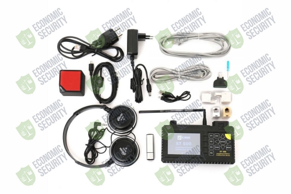
Комплектация:
- Основной блок
- Адаптер для подключения основного блока к силовым линиям
- Кабель для подключения основного блока к розеткам телефонных линий
- Кабель для подключения основного блока к розеткам ЛВС
- Кабель для подключения основного блока к USB порту ПК
- Телескопическая антенна
- Зарядное устройство
- Наушники
- USB накопитель (флэш-карта)
- Соединительная муфта (RJ11)
- Соединительная муфта (RJ45)
- Разветвитель 1х2 (RJ11)
- Разветвитель 1х2 (RJ45)
- Адаптер для подключения многопроводного кабеля (с отверткой)
- Паспорт
- Ударопрочный кейс
Порядковый номер элемента соответствует номеру элемента на картинке
