- Manuals
- Brands
- Atmel Manuals
- Motherboard
- AVR STK500
- User manual
-
Contents
-
Table of Contents
-
Troubleshooting
-
Bookmarks
Quick Links
www.DataSheet4U.com
STK500
…………………………………………………………………..
User Guide
DataSheet4U.com
DataSheet4U.com
4
DataSheet
U
.com
Related Manuals for Atmel AVR STK500
Summary of Contents for Atmel AVR STK500
-
Page 1
www.DataSheet4U.com STK500 …………….User Guide DataSheet4U.com DataSheet4U.com DataSheet .com… -
Page 2: Table Of Contents
www.DataSheet4U.com Table of Contents Section 1 Introduction ………………. 1-1 Starter Kit Features ……………….1-1 Device Support ………………1-2 Section 2 Getting Started………………2-1 Unpacking the System …………….2-1 System Requirements…………….2-1 Quick Start ………………..2-1 2.3.1 Connecting the Hardware…………..2-2 2.3.2 Programming the Target AVR Device ……….2-3 Section 3 Hardware Description …………….
-
Page 3
www.DataSheet4U.com Table of Contents 3.11.3 Main Power LED…………….3-23 3.11.4 Target Power LED …………….3-23 3.11.5 Status LED ………………3-23 Section 4 Installing AVR Studio …………….4-1 Section 5 Using AVR Studio …………….. 5-1 Windows Software ………………5-1 Starting the Windows Software …………..5-1 5.2.1 Starting STK500 ……………..5-1 STK500 User Interface …………….5-2 5.3.1… -
Page 4: Introduction
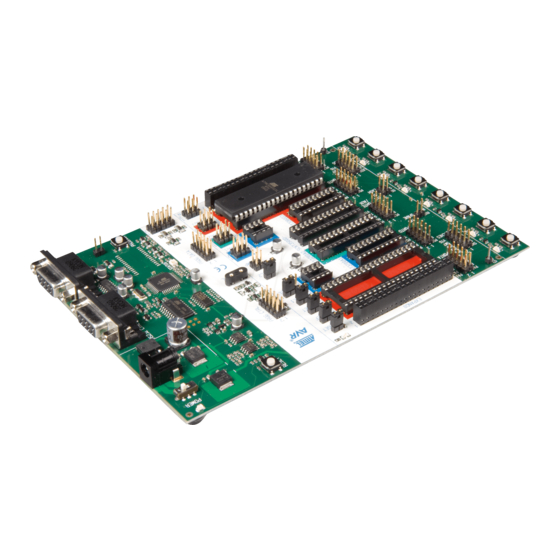
STK500 is a complete starter kit and development system for the AVR Flash microcon- troller from Atmel Corporation. It is designed to give designers a quick start to develop code on the AVR and for prototyping and testing of new designs.
-
Page 5: Device Support
AT90S4434 AT90S8515 AT90S8535 ATmega161 ATmega163 ATtiny11 ATtiny12 ATtiny15 ATtiny28 Support for new AVR devices may be added in new versions of AVR Studio. The latest version of AVR Studio is always available from www.atmel.com. DataSheet4U.com STK500 User Guide DataSheet .com…
-
Page 6: Getting Started
(1 pc) 6-wire cable for in-system programming (4 pcs) 2-wire cable for UART and DataFlash connections 9-pin RS-232 cable DC power cable Atmel CD-ROM with datasheets and software AT90S8515-8PC sample microcontroller DataSheet4U.com System The minimum hardware and software requirements are: ®…
-
Page 7: Connecting The Hardware
www.DataSheet4U.com Getting Started power on and off. The red LED is lit when power is on, and the status LEDs will go from red, via yellow, to green. The green LED indicates that the target V is present. The program now running in the AT90S8515 will respond to pressed switches by toggling the LEDs.
-
Page 8
www.DataSheet4U.com Getting Started Instructions on how to install and use AVR Studio are given in Section 5 on page 5-1. When AVR Studio is started, the program will automatically detect to which COM port the STK500 is connected. 2.3.2 Programming the The STK500 is controlled from AVR Studio, version 3.2 and higher. -
Page 9
www.DataSheet4U.com Getting Started DataSheet4U.com DataSheet4U.com STK500 User Guide DataSheet .com… -
Page 10: Hardware Description
www.DataSheet4U.com Section 3 Hardware Description Figure 3-1. STK500 Components Header for expansion boards Headers Sockets for for I/O ports target AVR Options setting Target reset jumpers push button Switches Power switch Power connector Header for switches Power LED Parallel programming headers RS232 interface header…
-
Page 11: Description Of User Switches
www.DataSheet4U.com Hardware Description Figure 3-2. Implementation of LEDs and LED Headers 150R LED0 LED1 LED2 LED3 LED4 LED5 LED6 LED7 LEDn Note: The AVR can source or sink enough current to drive an LED directly. In the STK500 design, a transistor with two resistors is used to give the same amount of light from the LED, whatever the target voltage (VTG) may be, and to turn off the LEDs when VTG is missing.
-
Page 12: Connection Of Leds And Switches
www.DataSheet4U.com Hardware Description Connection of Figure 3-4. Connection of LEDs and Switches to I/O Port Headers LEDs and Switches Any I/O port of the AVR can be connected to the LEDs and switches using the 10-wire cables. The headers are supplied with VTG (target V ) and GND lines in addition to the DataSheet4U.com signal lines.
-
Page 13
www.DataSheet4U.com Hardware Description The special functions of this port are: PE0 — PE2: Table 3-1. Port E Connection ATmega161 AT90S4414/AT90S8515 PE0/ICP/INT2 PE1/ALE PE2/OC1B OC1B REF: Analog reference voltage. This pin is connected to the AREF pin on devices having a separate analog reference pin. XT1: XTAL 1 pin. -
Page 14: Description Of Dataflash Pins
A DataFlash is a high-density Flash memory with SPI serial interface. A detailed DataFlash Pins datasheet of the DataFlash can be obtained from the Flash memory section of the Atmel CD-ROM or from the Atmel Web site. The DataFlash can be connected to the I/O pins of the microcontroller sockets. The 4-pin header marked “DATAFLASH”…
-
Page 15
www.DataSheet4U.com Hardware Description Figure 3-11. PORTB SPI Pinout (40-pin Parts) (SS)PB4 PB5(MOSI) (MISO)PB6 PB7(SCK) Figure 3-12. PORTB SPI Pinout (28-pin Analog Parts) (SS)PB2 PB3(MOSI) (MISO)PB4 PB5(SCK) Figure 3-13. Connection of I/O Pins to DataFlash for AT90S8515 DataSheet4U.com DataSheet4U.com STK500 User Guide DataSheet .com… -
Page 16: Target Socket Section
www.DataSheet4U.com Hardware Description Figure 3-14. Schematic of DataFlash Connections Voltage AT45D021 converter DataFlash Target Socket The programming module consists of the eight sockets in the white area in the middle of the starter kit. In these sockets the target AVR devices can be inserted for programming Section and used in the application.
-
Page 17: Isp Programming
www.DataSheet4U.com Hardware Description The part inserted in the socket can be programmed in the system from AVR Studio with two different methods: 1. AVR In-System Programming (ISP) running at the parts normal supply voltage. 2. High-voltage programming, where the supply voltage is always 5 volts. Four general nets (VTARGET, RESET, XTAL1 and AREF) can be connected to the socket section.
-
Page 18
www.DataSheet4U.com Hardware Description Table 3-2. AVR Sockets AVR Devices STK500 Socket Color Number Target ISP Header AT90S1200 SCKT3300D3 SPROG3 AT90S2313 AT90S2323 SPROG1. Connect RST on AT90S2343 SCKT3400D1 Blue PORTE to PB5 on PORTB. ATtiny12 ATtiny11 SCKT3400D1 Blue High-voltage programming only ATtiny28 SCKT3500D- None… -
Page 19: High-Voltage Programming
www.DataSheet4U.com Hardware Description 3.7.2 High-voltage For high-voltage programming, a 12V programming voltage is applied to the RESET pin Programming of the AVR device. All AVR devices can be programmed with high-voltage program- ming, and the target device can be programmed while it is mounted in its socket. Two different methods are used for high-voltage programming: 8-pin parts use a serial programming interface, while other parts use a parallel programming interface.
-
Page 20
www.DataSheet4U.com Hardware Description Figure 3-17. Connection for Parallel High-voltage Programming Some of the jumper settings on STK500 must be changed when using high-voltage pro- DataSheet4U.com gramming. Figure 3-18 explains these jumper settings. Figure 3-18. Jumper Settings for High-voltage Programming VTARGET AREF RESET Jumpers… -
Page 21
www.DataSheet4U.com Hardware Description 6. Mount jumper XTAL1 to route the oscillator signal to the device. 7. Mount jumpers VTARGET and RESET. 8. When programming AT90S2333 or AT90S4433, mount both PJUMP jumpers. The 2-wire cables can be used instead of jumpers. 9. -
Page 22: Jumper Settings
www.DataSheet4U.com Hardware Description Figure 3-19. Connection for Serial High-voltage Programming DataSheet4U.com Jumper Settings A master MCU and eight jumpers control the hardware settings of the starter kit. During normal operation these jumpers should be mounted in the default position. To configure the starter kit for advanced use, the jumpers can be removed or set to new positions.
-
Page 23: Target V Cc Settings, Vtarget
www.DataSheet4U.com Hardware Description Table 3-4. Description of Jumpers Jumper Description of Default Setting VTARGET On-board VTARGET supply connected AREF On-board Analog Voltage Reference connected RESET On-board reset system connected XTAL1 On-board clock system connected OSCSEL On-board oscillator selected BSEL2 Unmounted. Used for high-voltage programming of ATmega161 and ATmega163 PJUMP Unmounted.
-
Page 24: Analog Reference Voltage, Aref
www.DataSheet4U.com Hardware Description Figure 3-22. VTARGET Connection VTARGET 10 — 15V 0 — 6V Voltage VTG NET regulator Green LED Jumper Master Note: The green LED will light when there is a voltage available on the VTG NET. It’s impossible to use the debug or programming area of STK500 without VTG. 3.8.2 Analog Reference The analog reference voltage (AREF) can supply the reference voltage to the on-chip…
-
Page 25: Reset Settings, Reset
www.DataSheet4U.com Hardware Description The STK500 master MCU controls the analog reference voltage using the internal PWM. The AVR’s AREF signal is also accessible on the PORTE header; this pin can also be used for external AREF signal. Figure 3-24 shows the internal connection of the AREF signal.
-
Page 26: Clock Settings, Xtal1 And Oscsel
www.DataSheet4U.com Hardware Description The STK500 master MCU controls the RESET signal to the target AVR. The RESET signal is accessible on the PORTE/AUX header; this pin can also be used for external RESET signal. Figure 3-26 shows the internal connection of the RESET signal. Figure 3-26.
-
Page 27
www.DataSheet4U.com Hardware Description When the XTAL1 jumper is mounted, the STK500 internal clock system is used as main clock to the target AVR. The internal clock system can either use a crystal in the on-board crystal socket or a software-generated clock from the master MCU. The fre- quency of the software-generated clock can be set from 0 to 3.68 MHz. -
Page 28: Bsel2 Jumper
www.DataSheet4U.com Hardware Description Figure 3-29. XTAL1 and OSCSEL Connections Oscillator OSCSEL XTAL1 XTAL1 NET Jumper Jumper Voltage converter MASTER Studio PORTE 3.8.5 BSEL2 Jumper The BSEL2 jumper connects the Byte Select 2 signal for high-voltage programming of ATmega161 and ATmega163. The BSEL2 jumper should only be mounted when high- voltage programming ATmega161 or ATmega163.
-
Page 29
www.DataSheet4U.com Hardware Description Figure 3-30. Expansion Headers Expansion header 0 Prog Ctrl Pin 1 Pin 1 Expansion header 1 Prog Data Figure 3-31. Expansion Connector 0 Pinout DataSheet4U.com AUXI0 AUXO0 BSEL2 DataSheet4U.com 3-20 STK500 User Guide DataSheet .com… -
Page 30: Signal Descriptions
www.DataSheet4U.com Hardware Description Figure 3-32. Expansion Connector 1 Pinout AUXI1 AUXO1 DATA7 DATA6 DATA5 DATA4 DATA3 DATA2 DATA1 DATA0 3.9.1 Signal Descriptions The signals AUXI1, AUXI0, AUXO1 and AUXO0 are intended for future use. Do not con- nect these signals to your application. The DATA[7:0] and CT[7:1] signals are also found on the Prog Data and Prog Ctrl con- nectors.
-
Page 31: Miscellaneous
www.DataSheet4U.com Hardware Description Figure 3-33. Prog Ctrl Header Pinout CT1(RDY/BSY) (OE)CT2 CT3(/WR) (BS1)CT4 CT5(XA0) (XA1)CT6 CT7(PAGEL) The Prog Ctrl signals are normally used for the control signals when parallel high- voltage programming an AVR device. Note: All Prog Ctrl signals are based on 5V CMOS logic. No voltage conversion to adapt to VTG is done on these signals.
-
Page 32: Reset Push Button
www.DataSheet4U.com Hardware Description Figure 3-35. Special Functions and Status Indication LEDs RESET push button Target power LED Main power LED Program push button Status LED 3.11.1 RESET Push Button The RESET push button resets the target AVR device when pushed. The master MCU is not controlled by the RESET push button.
-
Page 33
www.DataSheet4U.com Hardware Description DataSheet4U.com DataSheet4U.com 3-24 STK500 User Guide DataSheet .com… -
Page 34: Installing Avr Studio
AVR development. It has an editor, an assembler and a debugger and is front-end for all AVR emulators and the STK500 starter kit. To install AVR Studio, insert the supplied Atmel CD-ROM databook in the computer and navigate to “Products > AVR 8-bit RISC > Software”. Right-click with the mouse on the “AVRstudio.exe”…
-
Page 35
www.DataSheet4U.com Installing AVR Studio DataSheet4U.com DataSheet4U.com STK500 User Guide DataSheet .com… -
Page 36: Using Avr Studio
Section 4 on page 4-1. Once installed, AVR Studio can be started by double- Software clicking on the AVR Studio icon. If default install options are used, the program is located in the Windows “Start menu > Programs > Atmel AVR Tools” folder. 5.2.1 Starting STK500 Pressing the “AVR”…
-
Page 37: Stk500 User Interface
www.DataSheet4U.com Using AVR Studio STK500 User The STK500 user interface includes powerful features for the STK500 development board. The available settings are divided into six groups, each selectable by clicking Interface on the appropriate tab. Since different devices have different features, the available options and selections will depend on which device is selected.
-
Page 38: Fuses» Settings
www.DataSheet4U.com Using AVR Studio 5.3.1.4 EEPROM If the STK500 user interface is opened without a project loaded in AVR Studio, the “Use Current Simulator/Emulator EEPROM Memory” option will be grayed out. When a project is open, this option allows programming of the EEPROM memory content cur- rently present in the EEPROM Memory view.
-
Page 39: Lockbits» Settings
www.DataSheet4U.com Using AVR Studio 5.3.3 “LockBits” Settings Similar to the “Fuses” tab, the “LockBits” tab shows which lock modes are applicable to the selected device. All lock bits are accessible in both ISP and high-voltage program- ming. A lock mode may consist of a combination of setting multiple lock bits. This is handled by the STK500 user interface, and the correct lock bits are programmed auto- matically for the selected lock mode.
-
Page 40: Advanced» Settings
www.DataSheet4U.com Using AVR Studio 5.3.4 “Advanced” The “Advanced” tab is currently divided into two subgroups. Settings 5.3.4.1 Signature Bytes By pressing the “Read Signature” button, the signature bytes are read from the target device. The signature bytes act like an identifier for the part. Please refer to the AVR datasheets to read more about signature bytes.
-
Page 41: Board» Settings
www.DataSheet4U.com Using AVR Studio 5.3.5 “Board” Settings The “Board” tab allows the changing of operating conditions on the STK500 develop- ment board. The following properties can be modified: VTARGET, AREF and oscillator frequency. The interface is very flexible and it is possible to force the operating conditions beyond the recommended specifications for the device.
-
Page 42: Auto» Settings
www.DataSheet4U.com Using AVR Studio Since it is not possible to generate an unlimited number of frequencies, the STK500 user interface will calculate the value closest to the value written to the oscillator text box. The calculated value is then presented in the oscillator text box, overwriting the previously written number.
-
Page 43: History Window
www.DataSheet4U.com Using AVR Studio 5.3.7 History Window The History window is located at the bottom of the STK500 view. In this window the dia- log between AVR Studio and STK500 is shown. For every new command performed, the old dialog is replaced with the new one. Figure 5-8.
-
Page 44
www.DataSheet4U.com Using AVR Studio Read signature bytes. Erase device. If applied with another programming parameter, the device will be erased before any other programming takes place. Program device; Flash (f), EEPROM (e) or both (b). Corresponding input files are required. Read out device;… -
Page 45: Datasheet4U.com
www.DataSheet4U.com Using AVR Studio Syntax for AT90S1200, AT90S2313, AT90S4414, AT90S4433, AT90S2333, AT90S8515, AT90S2323,AT90S2343, AT90S8535, AT90S4434, AT90C8534, ATmega103, Supported ATmega161, ATmega163, ATtiny11, ATtiny12, ATtiny15, ATtiny28 Devices Figure 5-9. Sample Usage Program Flash Erase before program Name of hex file stk500 -dAT90S8515 -iftest.hex Select device number Verify device…
-
Page 46: In-System Programming Of An External Target System
www.DataSheet4U.com Section 6 In-System Programming of an External Target System The STK500 can be used as a programmer to program AVR devices in other applica- tions. There are two different ISP connector pinouts available: a 6-pin and a 10-pin version. Both are supported by STK500. Figure 6-1.
-
Page 47
www.DataSheet4U.com In-System Programming of an External Target System DataSheet4U.com DataSheet4U.com STK500 User Guide DataSheet .com… -
Page 48: Troubleshooting Guide
www.DataSheet4U.com Section 7 Troubleshooting Guide Table 7-1. Troubleshooting Guide Problem Reason Solution The DC power cable is not Connect the DC power cable connected. to the DC jack (page 2-2). Wrong power supply is used. Check that the power supply The red power LED is not on.
-
Page 49
www.DataSheet4U.com Troubleshooting Guide Table 7-1. Troubleshooting Guide (Continued) Problem Reason Solution Serial cable is not connected, Connect serial cable to or power is off. RS232PROG and check power connections. Disable other programs that are using PC COM port. AVR Studio does not detect PC COM port is in use. -
Page 50: Technical Support
Section 8 Technical Support For technical support, please contact avr@atmel.com. When requesting technical sup- port for STK500, please include the following information: Version number of AVR Studio. This can be found in the AVR Studio menu, “Help > About”.
-
Page 51
www.DataSheet4U.com Technical Support DataSheet4U.com DataSheet4U.com STK500 User Guide DataSheet .com… -
Page 52: Example Applications
www.DataSheet4U.com Section 9 Example Applications Using LEDs and Connect PORTB to LEDS and PORTD to SWITCHES. Switches LEDs will operate differently depending on what switch is pressed. Tip: Copy the code from this document into AVR Studio. ;***** STK500 LEDS and SWITCH demonstration .include «8515def.inc»…
-
Page 53
www.DataSheet4U.com Example Applications sbis PIND,0x03 ; If (Port D, pin3 == 0) Temp ; then rotate LEDS one left sbis PIND,0x04 ; If (Port D, pin4 == 0) Temp ; then invert all LEDS sbis PIND,0x05 ; If (Port D, pin5 == 0) Temp ;… -
Page 54: Warranty Statement
DataSheet4U.com Atmel without Atmel’s Returned Material Authorization form. Prior to any return of goods by Buyer pursuant to this Section, Buyer shall afford Atmel the opportunity to inspect such goods at Buyer’s location, and any such goods so inspected shall not be returned to Atmel without its prior written consent.
-
Page 55
No licenses to patents or other intellectual prop- erty of Atmel are granted by the Company in connection with the sale of Atmel products, expressly or by implication. Atmel’s products are not authorized for use as critical components in life suppor t devices or systems.
Как пользоваться?
Наша цель — обеспечить Вам самый быстрый доступ к руководству по эксплуатации устройства Atmel STK500. Пользуясь просмотром онлайн Вы можете быстро просмотреть содержание и перейти на страницу, на которой найдете решение своей проблемы с Atmel STK500.
Для Вашего удобства
Если просмотр руководства Atmel STK500 непосредственно на этой странице для Вас неудобен, Вы можете воспользоваться двумя возможными решениями:
- Полноэкранный просмотр -, Чтобы удобно просматривать инструкцию (без скачивания на компьютер) Вы можете использовать режим полноэкранного просмотра. Чтобы запустить просмотр инструкции Atmel STK500 на полном экране, используйте кнопку Полный экран.
- Скачивание на компьютер — Вы можете также скачать инструкцию Atmel STK500 на свой компьютер и сохранить ее в своем архиве. Если ты все же не хотите занимать место на своем устройстве, Вы всегда можете скачать ее из ManualsBase.
Руководство по эксплуатации Atmel STK500
Печатная версия
Многие предпочитают читать документы не на экране, а в печатной версии. Опция распечатки инструкции также предусмотрена и Вы можете воспользоваться ею нажав на ссылку, находящуюся выше — Печатать инструкцию. Вам не обязательно печатать всю инструкцию Atmel STK500 а только некоторые страницы. Берегите бумагу.
Резюме
Ниже Вы найдете заявки которые находятся на очередных страницах инструкции для Atmel STK500. Если Вы хотите быстро просмотреть содержимое страниц, которые находятся на очередных страницах инструкции, Вы воспользоваться ими.
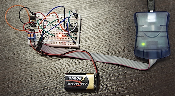
Работа с микроконтроллерами: прошивка программатором и чистый «Си»
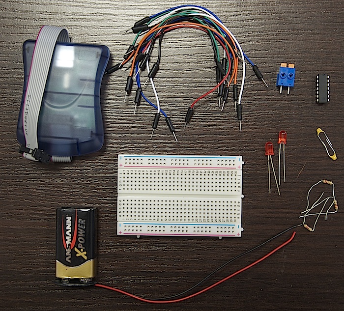
В этой статье я расскажу о том, как программировать микроконтроллеры без использования Arduino. Мы будем использовать программатор AvrISP STK500 для программирования контроллера ATtiny84.
Нам понадобится
Подключаем питание
Arduino мы не используем, поэтому обо всем нам придется думать самостоятельно. И первое, с чем необходимо разобраться — питание. Мы будем использовать преобразователь L7805, обладающей следующими характеристиками:
-
Выходной ток до 1.5 А
-
Выходное напряжение — ровные 5 В
-
Защита от перегрева
-
Защита от короткого замыкания
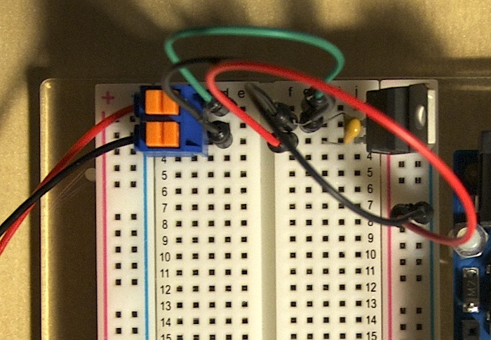
Теперь нам надо узнать схему подключения этого преобразователя. Ее мы найдем на странице 3 даташита.
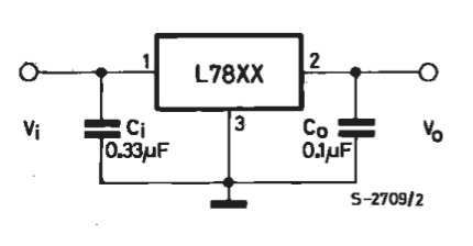
Помимо самого преобразователя, мы видим еще 2 конденсатора — входной Сi и выходной Сo. Входной конденсатор необходим для того, чтобы сгладить пульсации на входе в случае удаленности L7805 от источника. В нашем случае длина соединительных проводов не будет превышать 15 см, поэтому входного конденсатора у нас не будет. Зато будет выходной, поскольку мы хотим «кормить» наш контроллер стабильным питанием.
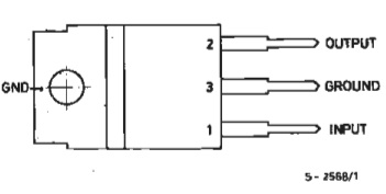
Распиновка
Необходимо знать назначение ножек преобразователя. Это описано на 2-й странице даташита.
Схема
С учетом всего вышеописанного, получается схема для организации питания.
Программатор
В качестве программатора мы использовали AvrISP STK500 от Seeed Studio. Для его работы под Windows и Mac OS необходимы драйверы. Их можно скачать с официального сайта. Пользователям Linux устанавливать ничего не нужно — программатор будет сразу готов к работе.
Подключение к контроллеру
Распиновка разъема программатора такова:

Важно!
Это распиновка разъема программатора, если смотреть на него сверху (отверстиями от себя). Не перепутайте!
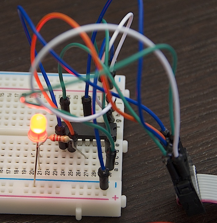
Разъем программатора необходимо подключить к микроконтроллеру. Можно использовать как 10-пиновый разъём, так и 6-пиновый. Без разницы. Соединим проводами соответствующие пины, т.е:
| 10-пиновый ICSP | ATtiny84 | |
|---|---|---|
| Reset | 5 | 4 |
| MOSI | 1 | 7 |
| MISO | 9 | 8 |
| SCK | 7 | 9 |
Прошивка
Напишем код прошивки на чистом «C», которая заставит светодиод мигать. Использование ШИМ-сигналов и считывание аналоговых сигналов на чистом «C» не так тривиальна, и может являться темой отдельной статьи, поэтому остановимся пока на простейшем примере.
- blink.c
-
#include <avr/io.h>
#include <util/delay.h>

int main(void) {
    // номер пина 2 в порту А -- на выход
    DDRA = 1 << 2;

    // основной цикл
    while (1==1) {
        _delay_ms(500);  // задержка 500 мс
        PORTA ^= 1 << 2; // инвертирование значения на выводе
    }

    return 0;
}
После скетчей Arduino, код малопонятен, правда? Ничего, сейчас я объясню, что да как.
В первых двух строчках мы подключаем необходимые библиотеки, чтобы воспользоваться такими штуками, как DDRA, PORTA, _delay_ms.
Что же такое DDRA?
Это регистр микроконтроллера, управляющий направлением работы порта А. Он содержит в себе 8 бит. Если установить какой-то бит в 1, то пин с соответствующим номером станет выходом.
PORTA — тоже регистр, но он содержит в себе данные порта А. Если мы хотим на вывод номер 2 записать логическую единицу, то мы должны поместить 1 в соответсвующий бит регистра.
А _delay_ms — функция задержки.
Исходя из этого можно составить таблицу соответствия:
| Arduino | C | |
|---|---|---|
| Направление | pinMode(led, OUTPUT); |
DDRA = 1 << 2; |
| Значение | digitalWrite(led, HIGH); |
PORTA = 1 << 2; |
| Задержка | delay(1000); |
_delay_ms(50); |
Однако, самым важным различием кода является то, что в программе на С нет разделений функций setup и loop. За все это отвечает функция int main(void). И она выполняется всего 1 раз! А мы хотим, чтобы наш светодиод моргал не один раз, а постоянно. Как раз для этого и используется бесконечный цикл while (1==1).
Поэтому легко сделать вывод, что этот цикл и есть аналог функции loop() в Arduino. А то, что до него — аналог функции setup().
Далее начинается самое интересное. Нам нужно скомпилировать и загрузить прошивку. Однако, в зависимости от вашей операционной системы, методика будет различаться.
Mac OS X
Первым делом необходимо скачать и установить CrossPack for AVR Development. Это даст нам все необходимые инструменты.
CrossPack состоит из двух частей.
-
AVR Libc — a C library for GCC on AVR microcontrollers
-
AVRDUDE — AVR Downloader/Uploader
Первая нам нужна для написания кода и создания файла прошивки, а вторая — для заливки прошивки в контроллер.
Проект создается в три шага.
-
Запустите терминал
-
Перейдите в нем в нужную папку
-
Создайте проект с помощью команды
avr-project
$ mkdir ~/AVR
$ cd AVR
$ avr-project firstProject
Using template: /usr/local/CrossPack-AVR-20130212/etc/templates/TemplateProject
В результате будет создано следующее дерево файлов.
$ tree
.
|-- firmware
|   |-- main.c
|   `-- Makefile
`-- firstProject.xcodeproj

1 directory, 3 files
На данном этапе нас интересует содержимое файла Makefile. В нем содержится информация о том, что вообще мы используем: какой контроллер, программатор. Это все описывается в строках с 20 по 24:
DEVICE     = atmega8
CLOCK      = 8000000
PROGRAMMER = #-c stk500v2 -P avrdoper
OBJECTS    = main.o
FUSES      = -U hfuse:w:0xd9:m -U lfuse:w:0x24:m
Пройдемся по строкам:
-
DEVICEсодержит в себе название контроллера, который мы программируем -
CLOCK— частота работы -
PROGRAMMER— используемый программатор -
OBJECTS— какие объектные файлы будут сгененрированы -
FUSES— конфигурация fuse-битов в микроконтроллере
Это автосгенерированный make-файл, поэтому нам необходимо вручную его подправить. Править будем строку DEVICE у нас же микроконтроллер attiny84 и строку FUSES. А вот с ней все сложнее.
Fuse-биты, или просто «фьюзы» — два (иногда три) особых байта, в которых содержится фундаментальая конфигурация работы контроллера. Очень важно правильно их задать.
Внимание!
Задание неверных fuse-битов может привезти к тому, что микроконтроллер перестанет работать и вернуть его к нормальной жизни может быть либо очень сложно либо невозможно!
Воспользеумся сайтом AVR Fuse Calcuator.
Сначала из выпадающего списка выберем нужный нам контроллер (ATtiny84).

И затем укажем необходимые опции, которые нам нужны. Сейчас для нас важны 2 вещи: сохранение возможности прошивать контроллер через SPI и сохранение его работоспособности без внешнего резонатора, поэтому выбираем соответствующие пункты, а остальные оставляем по умолчанию.
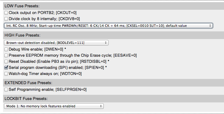
Видим, как поменялись сгенерированные значения.

Внесем изменения в Makefile.
DEVICE     = attiny84
CLOCK      = 8000000
PROGRAMMER = -c stk500v2 -P /dev/tty.usbserial
OBJECTS    = main.o
FUSES      = -U lfuse:w:0xe2:m -U hfuse:w:0xdf:m -U efuse:w:0xff:m
Прошивка
Она происходит в 2 этапа.
Сначала необходимо перейти в папку firmware и выполнить команду make. Если ошибок нет, то результат выполнения команды будет таким:
$ make
avr-gcc -Wall -Os -DF_CPU=8000000 -mmcu=attiny84 -c main.c -o main.o
avr-gcc -Wall -Os -DF_CPU=8000000 -mmcu=attiny84 -o main.elf main.o
rm -f main.hex
avr-objcopy -j .text -j .data -O ihex main.elf main.hex
avr-size --format=avr --mcu=attiny84 main.elf
AVR Memory Usage
----------------
Device: attiny84

Program:     126 bytes (1.5% Full)
(.text + .data + .bootloader)

Data:          0 bytes (0.0% Full)
(.data + .bss + .noinit)
Эта команда сделает из нашего исходника main.c файл, пригодный для заливки в контроллер — main.hex.
Второй этап — как раз заливка прошивки. Делается это с помощью команды make flash. Ее нормальный вывод выглядит следующим образом:
- make-flash-result
-
$ make flash
avrdude -c stk500v2 -P /dev/tty.usbserial -p attiny84 -U flash:w:main.hex:i

avrdude: AVR device initialized and ready to accept instructions

Reading | ################################################## | 100% 0.01s

avrdude: Device signature = 0x1e930c
avrdude: NOTE: FLASH memory has been specified, an erase cycle will be performed
         To disable this feature, specify the -D option.
avrdude: erasing chip
avrdude: reading input file "main.hex"
avrdude: writing flash (126 bytes):

Writing | ################################################## | 100% 0.10s

avrdude: 126 bytes of flash written
avrdude: verifying flash memory against main.hex:
avrdude: load data flash data from input file main.hex:
avrdude: input file main.hex contains 126 bytes
avrdude: reading on-chip flash data:

Reading | ################################################## | 100% 0.08s

avrdude: verifying ...
avrdude: 126 bytes of flash verified

avrdude: safemode: Fuses OK

avrdude done.  Thank you.
Все, прошивка контроллера завершена.
Windows
Здесь все проще.
Первым делом необходимо скачать и уствновить среду разработки для AVR — Atmel AVR Studio 4. А вторым — Atmel AVR Toolchain.
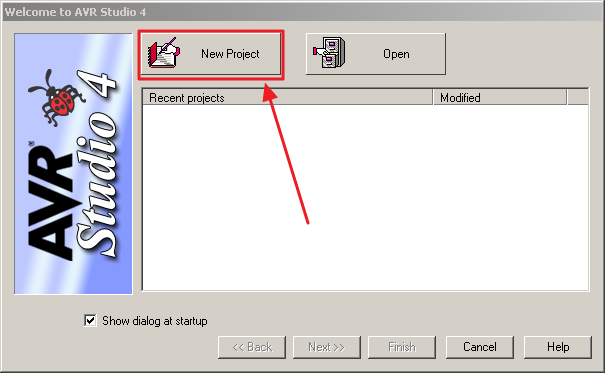
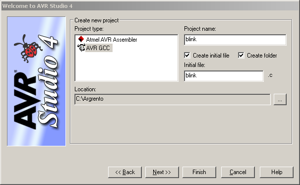
После запуска среды, необходимо создать новый проект.
Затем указать имя, расположение и то, что мы хотим использовать С (GCC).
Третий шаг — настройка отладчика.
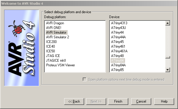
На этом все, проект готов к использованию.
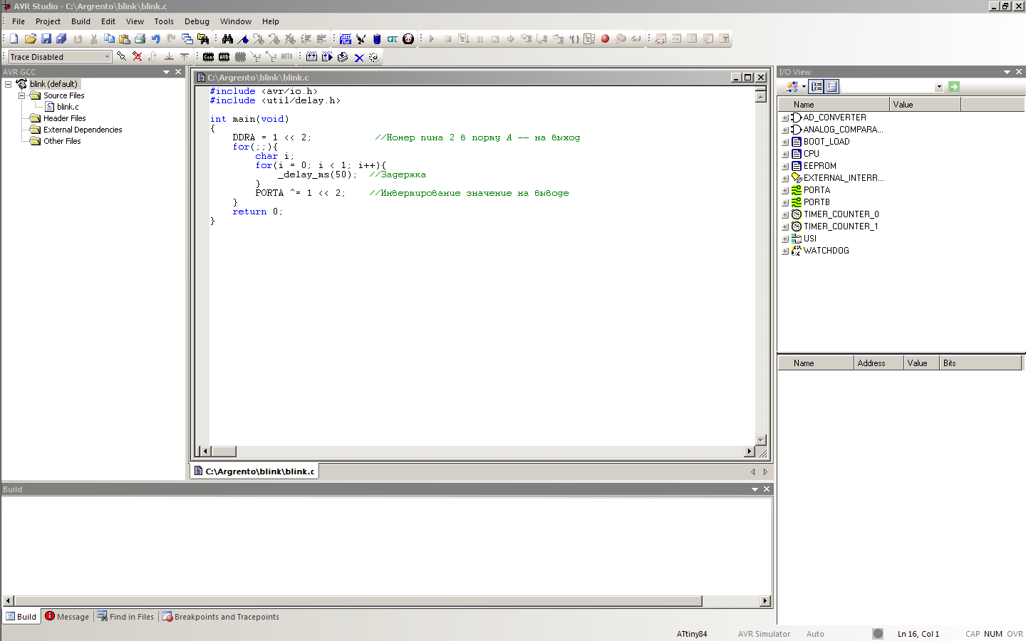
Теперь необходимо написать и сохранить исходник, который мы уже обсудили.
В результате общий вид среды разработки выглядит вот так:
Теперь необходимо подключиться к программатору. Делается это с помощью нажатия на кнопку con.
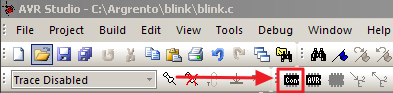
В качестве Platform выбираем STK500, а в Port — Auto. Затем нажимаем Connect.
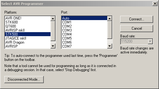
Если все правильно, то в открывшемся окне выбираем вкладку Main и нажимаем в ней на кнопку Read Signature.
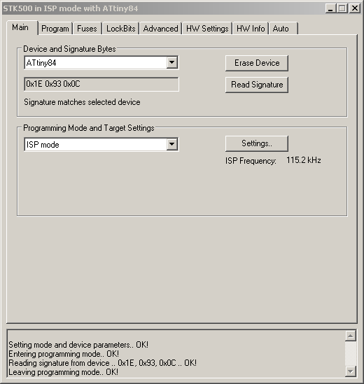
Строка Reading signature from device .. 0x1E, 0x93, 0x0C .. OK! говорит о том, что все хорошо и сигнатура успешно прочиталась. Сигнатура — это своего рода позывной микроконтроллера, которым он сообщает собственную модель.
Это окно нельзя закрывать, иначе соединение с программатором будет потеряно. Просто сверните его.
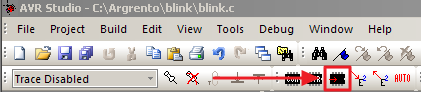
Теперь нажмем Build → Build. Это заставит программу скомпилироваться.
Прошьем контроллер с помощью кнопки Write Flash Memory Using Current Settings — это заставит скомпилированную программу загрузиться в память микроконтроллера.
Заключение
Мы собрали простейшее устройство мигалку, но сделали это на низком уровне. С использованием программатора и «продвинутой» среды разработки, а не Arduino.
Разобравшись в премудростях программирования микроконтроллеров на чистом «Си», вы сможете выжимать из них максимум возможности, затрачивая при этом минимум места и денег.