Друзья, по себе знаю, что часто нужно быстро найти какую-то информацию по нашим машинам, и поиск превращается в гуглёжный ад: начиная сложными вещами о том, какие моменты затяжек того или иного узла и простыми типа заводской спецификации и рекомендаций жидкостей и масел.
Поэтому делюсь тем, что сам нашел и накопил.
Рекомендую сохранить к себе на компьютеры, смартфоны и облака. Бывает очень кстати, когда нужно посмотреть что-то в гараже, где плохой интернет, или вообще когда поломка застала в полях.
__________
Что в меню
1. Оригинальный англоязычный пользовательский мануал. Фактически скан той книжки, что давали в руки покупателю в салоне, наиболее вероятно что в США. Но мануал оригинальный заводской. Напечатан в 2000 году, имеет даже заводской парт-намбер, как запчасть: 99011-65D22-03E Содержит основные схемы, таблицу расположения реле и предохранителей и простую пользовательскую информацию для самых маленьких и тупых: в какую дырку лить бензин, а в какую садиться.
Ссылка на скачивание с моего Яндекс.Диска: disk.yandex.ru/i/ZYoTmzYWn6tnrw
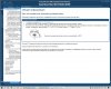
Основные спецификации выкладываю скриншотами.
________
2. Оригинальный англоязычный сервисный мануал. Это та книга(и), которую Suzuki отправляли в сервисы официальных дилеров. Описаны абсолютно все узлы от кузова до проводки и каждого болтика в моторе, их ремонт и обслуживание, всё до мелочей — в каком порядке и как разбирать, как собирать, с каким моментом затягивать, какой специнструмент и какие детали использовать, что можно повтороно ставить, а что одноразовое и т.д. Максимально подробно чтобы любой американский автослесарь Майкл ил Джон разобрался.
Внимание! Структурировано по папкам, логика мне неизвестна. Чтобы найти нужный узел — открывайте подряд и смотрите оглавления. Что-то дублируется.
Либо открывайте с ПК и не меняя расположения файлов открывайте файл TOP.pdf — это интерактивные pdf-ки, по ним можно кликать и переходить к нужному мануалу. Только испанские, немецкие и французские версии я убрал за ненадобностью.

Обложка
Ссылка на скачивание с моего Яндекс.Диска: disk.yandex.ru/d/weOwCcCe1Nkzlw
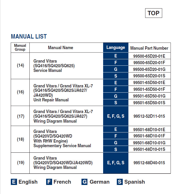
Пример файла-меню
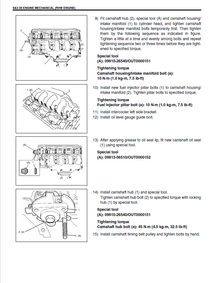
Пример одной из страниц
________
3. Отрывок из русскоязычного мануала по ремонту двигателя H25A. Источник мне неизвестен. Не слишком подробный, но есть основная информация по порядку сборки-разборки, моментам затяжки, зазорам и допустимым значениям, размерам ремонтных деталей и т.д. Есть схемы узлов. Судя по всему, схемы взяты из мануала из п.2. Качество скана — такое себе, но что-то понять можно чтобы не накосячить.
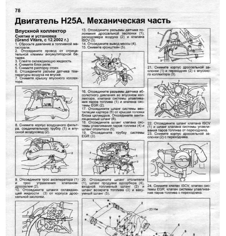
Пример содержимого
Ссылка на скачивание с моего Яндекс.Диска: disk.yandex.ru/i/aeebadx54-EhGw
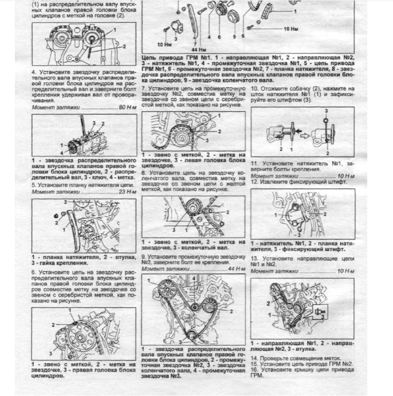
Еще пример страницы
Прошу сохранять себе, пользоваться и не стесняться совать под нос горе-сервисникам, которые с радостью сломают починят вашу машину, взяв с вас деньги, при том что сами её первый раз в жизни видят и понятия не имеют, как тут что чинить, что лить и как сделать нормальный ремонт.
Победим вместе рукожопый ремонт! Спасем наши автомобили!
Добавлено: онлайн-мануал www.manualslib.com/produc…-Vitara-2003-6027410.html
________________
UPD.
Добавляю ссылки на другие мануалы от добрых людей:
1. www2.izook.com/wp-content/tech-library/?C=D;O=D
Предоставил добрый человек sansanych666 за что ему спасибо=)
2. disk.yandex.ru/d/TiXnfIV7vygphQ
Русскоязычное руководство по эксплуатации и ремонту от издательства Легиона (отрывок которого у меня выше), англоязычный сервисный мануал, а также каталог сувенирной продукции Suzuki от 2020 года от доброго человека Brat2WB
3. drive.google.com/drive/fo…8xXrdDj5jhft8mtQG29kET_v-
Оригинальные англоязычные сервисные мануалы по ремонту двигателя, электрики, шасси и кузова. Предоставил добрый человек sansanych666
4. www.kniga-auto.ru/catalog…k/suz-grand_vitara/45011/
Ссылка на приобретение в интернет-магазине бумажной версии руководства по эксплуатации, обслуживанию и ремонту в цветных фотографиях от издательства Мир Автокниг.
Поделился добрый человек Miramaxs
Друзья, всем спасибо! Если есть чем дополнить — кидайте в комментарии, добавлю в пост.
_______
P.S. И не колхозь машину, чини и обслуживай нормально, а?
- Руководства по ремонту
- Руководство по ремонту Сузуки Гранд Витара 1998-2005 г.в.
Руководство по ремонту Suzuki Grand Vitara / Сузуки Гранд Витара
Общая информация об автомобиле.

«Сузуки-Гранд Витара» пришла на смену «Витаре». Кузова – трехдверный и пятидверный, вагонной компоновки. Бензиновые двигатели: Р4, 16-кл., 1,6 л, 69 кВт/94 л.с.; 2,0 л, 94 кВт/128 л.с.; V6, 24-кл.; 2,5 л, 106 кВт/144 л.с. Турбодизель («Мазда»): Р4, 8-кл., 64 кВт/87 л.с. Коробка передач – М5 или А4, привод – полный (подключаемый передний мост).
2000 год. Новый турбодизель («Пежо-Ситроен»): Р4, 8-кл., 80 кВт/109 л.с.
2001 год. Семиместная версия «Сузуки-Гранд Витара XL-7» с бензиновым двигателем V6, 24-кл., 127 кВт/173 л.с. Коробка передач – М5 или А4.
2002 год. Рестайлинг модели: новая панель приборов, климат-контроль, более комфортная подвеска.
2003 год. Рестайлинг XL-7: пятиступенчатый «автомат» с электронным управлением, муфта подключения переднего моста с электроприводом, рама новой конструкции.
Слова «вседорожник» и «внедорожник» звучат почти одинаково, но наполнены разным смыслом. Покупатель в основном ориентируется на имидж, поэтому большинство недорогих «джипов» – «паркетники», весьма неловкие на бездорожье. «Сузуки-Гранд Витара» – одно из редких исключений. Комфортабельный, отвечающий современным требованиям пассивной безопасности вседорожник сохранил наиболее привлекательные черты предшественника, «Сузуки-Витара» – рамную конструкцию, понижающий ряд передач и невысокую цену.
Но в наследство достались и некоторые особенности, не зная которых угробите машину в два счета, даже не съезжая с асфальта. Поэтому выбирать подержанную «Гранд Витару» нужно с пристрастием, а эксплуатировать – с умом. В этом случае 15–20 тыс. долларов за четырех-пятилетний экземпляр станут разумным вложением денег.
↓ Комментарии ↓
1. Общая информация
1.0 Общая информация
1.1 Меры предосторожности
1.2. Диагностика
1.3 Основные меры предосторожности
1.4 Меры предосторожности при работе с катализатором
1.5 Меры предосторожности при обслуживании электрических цепей
1.6. Процедура проверки электрических цепей
1.7 Прерывающееся или слабое соединение
1.8 Меры предосторожности при установке средств мобильной связи
1.9. Идентификационная информация
1.10 Предупреждающие, предостерегающие и информационные наклейки
1.11 Места подъема автомобиля
1.12 исок сокращений, использующихся в данном руководстве
1.13.1. Метрическая информация
1.14 Стандартные моменты затяжек
2. Техническое обслуживание и смазка
2.0 Техническое обслуживание и смазка
2.1. Обслуживание, рекомендованное при жестком режиме езды
2.3 Рекомендуемые жидкости и смазочные материалы
3. Обогреватель, вентиляция и кондиционер
3.0 Обогреватель, вентиляция и кондиционер
3.1 Вентиляция салона
3.2. Диагностика
5. Рулевое управление
5.0 Рулевое управление
5.1 Диагностическая таблица
5.2. Диагностика шин
5.3 Диагностика вибраций
6. Регулировка углов установки колес передней подвески
6.0 Регулировка углов установки колес передней подвески
6.1 Схождение передних колес
6.2 Развал передних колес
6.3 Кастер
6.4 Подготовка к регулировке углов установки колес передней подвески
6.5 Регулировка угла схождения передних колес
6.6 Регулировка угла развала и кастера
6.7 Угол поворота колес
6.8 Боковое скольжение колес (эталон)
7. Система гидроусилителя руля
7.0 Система гидроусилителя руля
7.1. Основное описание
7.2. Диагностика
8. Рулевое колесо и рулевая колонка
8.0 Рулевое колесо и рулевая колонка
8.2. Диагностика
8.3. Обслуживание вне мастерской
8.4 Спецификации момента затяжки
8.5 Специальный инструмент
9. Рулевое колесо и рулевая колонка c подушкой безопасности
9.0 Рулевое колесо и рулевая колонка c подушкой безопасности
9.2 Диагностика
9.3. Обслуживание вне мастерской
9.4 Спецификации момента затяжки
9.5 Специальный инструмент
10. Подвеска
10.0 Подвеска
10.2. Диагностика
10.3. Обслуживание вне мастерской
11. Задняя подвеска
11.0 Задняя подвеска
11.2. Диагностика
11.3. Обслуживание вне мастерской
12. Колеса и шины
12.0 Колеса и шины
12.1. Колеса
12.2. Диагностика
12.4. Обслуживание вне мастерской
13. приводной вал/подшипник вала. Масляный сальник
13.0 приводной вал/подшипник вала. Масляный сальник
13.2. Диагностика
13.3. Обслуживание вне мастерской
13.4 Спецификации момента затяжки
13.5 Необходимый для сервисного обслуживания материал
13.6 Специальный инструмент
14. Карданные валы
14.0 Карданные валы
14.2. Диагностика
14.3 Обслуживание вне мастерской
14.4 Спецификации момента затяжки
14.5 Необходимый материал для сервисного обслуживания
14.6 Специальный инструмент
15. Тормозная система
15.0 Тормозная система
15.2. Диагностика
15.3 Диагностическая таблица
15.4. Проверка и регулировка
15.5 Технические условия — крутящий момент затяжки
15.6 Необходимые материалы для обслуживания
15.7 Специальный инструмент
16. Тормозная магистраль/шланг/главный цилиндр тормоза
16.0 Тормозная магистраль/шланг/главный цилиндр тормоза
16.1. Сборка тормозного усилителя
16.2 Диагностика
16.3 Проверка и регулировка
17. Передние тормоза
17.0 Передние тормоза
17.2 Диагностика
17.3 Проверка и регулировка
17.4. Обслуживание транспортного средства
17.5 Крутящий момент затяжки
17.6 Необходимые материалы
18. Стояночный и задний тормоз
18.0 Стояночный и задний тормоз
18.2. Диагностика
19. Антиблокировочная тормозная система (ABS)
19.0 Антиблокировочная тормозная система (ABS)
19.1. Путь тормозного шланга/магистрали
19.2. Диагностика
20. Двигатели
20.0 Двигатели
20.1. Общее описание
20.2. Текущее обслуживание
20.3. Шток поршня, поршневые кольца, шатуны и цилиндры
20.4 Специальный инструмент
20.5 Необходимые сервисные материалы
20.6 Технические характеристики вращающего момента затяжки
21. Механическая часть двигателя J20
21.0 Механическая часть двигателя J20
21.1 Смазка двигателя
21.2. Текущее обслуживание
21.3. Монтажная арматура двигателя
21.4 Специальный инструмент
21.5 Необходимые сервисные материалы
21.6 Технические характеристики вращающего момента затяжки
22. Охлаждение двигателя
22.0 Охлаждение двигателя
22.1. Компоненты системы охлаждения
22.2 Диагностика
22.3. Техническое обслуживание
22.4. Текущее обслуживание транспортного средства
22.5 Необходимые сервисные материалы
22.6 Технические характеристики вращающего момента затяжки
23. Топливная система
23.0 Топливная система
23.1 Текущее техническое обслуживание транспортного средства
23.2 Топливный насос
23.3 Топливный фильтр
23.4 Топливные провода
23.5 Крышка заливной топливной горловины
23.6 Топливный бак
23.7 Техническая характеристика вращающего момента затяжки
24. Система зажигания
24.0 Система зажигания
24.1. Электропроводка системы
24.2. Диагностика
24.3. Обслуживание транспортного средства
24.4 Спецификация, крутящий момент затяжки
24.5 Специальный инструмент
25. Система зажигания для двигателя J20
25.0 Система зажигания для двигателя J20
25.1. Электропроводка системы
25.2. Диагностика
25.3. Обслуживание транспортного средства
25.4 Спецификация, крутящий момент затяжки
25.5 Специальный инструмент
26. Система запуска
26.0 Система запуска
26.1. Цепь стартера
26.2. Диагностика
26.3 Необходимые материалы
26.4 Специальный инструмент
27. Система электрооборудования
27.0 Система электрооборудования
27.1. Подставка и держатель
27.5. Спецификации
27.6 Моменты затяжки
28. Система выпуска
28.0 Система выпуска
28.1 Компоненты
28.2 Техническое обслуживание
28.3. Работы, производимые на автомобиле
29. Коробки передач
29.0 Коробки передач
29.1 Описание системы
29.2 Диагностика
29.3. Обслуживание вне мастерской
30. Механическая коробка передач (тип 2)
30.0 Механическая коробка передач (тип 2)
30.1 Описание системы
30.2 Диагностика
31. Автоматическая коробка передач (4 A/T)
31.0 Автоматическая коробка передач (4 A/T)
31.1. Функции сцепления/тормоза
31.2. Диагностика автоматической коробки передач
31.3. Меры предосторожности при диагностике неполадок
31.4. Визуальный осмотр
31.5. Обслуживание вне мастерской
31.7. Система блокировки тормозов
31.8. Проверка системы
32. Сцепление
32.0 Сцепление
32.2 Диагностика
32.3. Обслуживание вне мастерской
32.4. Ремонт модуля
33. Передача
33.0 Передача
33.2 Диагностика
33.3. Обслуживание вне мастерской
34. Передний и задний дифференциалы
34.0 Передний и задний дифференциалы
34.1. Система управления полным приводом
35. Задний дифференциал
35.0 Задний дифференциал
35.2 Диагностика
35.3. Обслуживание вне мастерской
35.5 Спецификации момента затяжки
35.6 Необходимый для сервиса материал
36.1. Меры предосторожности при работе
37. Система освещения
37.0 Система освещения
37.1. Автомобили с брезентовым верхом
37.2. Диагностика
37.3. Техническое обслуживание
38. Инструменты/Информация для водителей
38.0 Инструменты/Информация для водителей
38.1 Автомобили с брезентовым верхом
38.2. Знаки и метки
38.3. Диагностика
38.4. Техническое обслуживание
39.1. Общее описание
39.2. Диагностика
39.3. Техническое обслуживание
40. Иммобилайзер
40.0 Иммобилайзер
40.1. Автомобили с брезентовым верхом
40.2 Система бортовой диагностики (с функцией самодиагностики)
41. Электрооборудование
41.0 Электрооборудование
41.1. Общее описание
41.2. Коды диагностики неисправностей

-
-
#1
Кто разжился мануалами — кидайте, кому то может пригодиться.
Сюда весомое не лезет- ссылки на Я-диск
1) Русский общий мануал Suzuki_Grand_Vitara__XL-7__Escudo_1998-2004

2) Английский родной Сервис Мануал на XL-7 с моторами H27 и немного на RhW
XL-7 Service Manual
Машинный перевод с кривыми границами , но суть понять можно имея ориг и это)))) в ворде, ибо имеется возможность подвинуть элементы
Последнее редактирование: 15 Март 2021
-
-
#2
RU / Передний Дифференциал моторным приводем
машинный перевод с правкой разметок
-
5 MB
Просмотры: 55
Последнее редактирование: 15 Март 2021
-
-
#3
Англ GRAND VITARA (SQ416/SQ420/SQ625) Vin
2S2GTA03C00600001 JS3TA03V 34100001 2S2GTA52C00600001 JS3TB03V 34100001 JSAFTA03V00200001 JS3TB52V 34100001 JSAFTA03V30200001 JS3TD62V 34100001 JSAFTB03V00200001 JS3TL52V 34100001 JSAFTB52V00200001 JSAFTD02V00200001 JSAFTD62V00200001 JSAFTD62V34200001 JSAFTL52V00200001 JSAFTL52V34200001
-
16.9 MB
Просмотры: 107
-
-
#4
EN SQ416/SQ420/SQ625
VIN No. JSAFTD82V00100001
-
11.9 MB
Просмотры: 100
-
-
#5
EN :SQ416/SQ420/SQ625
JSAFTA03V00150001 JS3TA03V 14150001 2S2GTA03C00470001 JSAFTA03V10150001 JS3TA52V 14150001 2S2GTA03C10470001 JSAFTA03V14150001 JS3TL52V 14150001 2S2GTA03C16470001 JSAFTA52V00150001 JS3TD62V 14150001 2S3TA03C 16100001 JSAFTA52V10150001 2S3TA52C 16100001 JSAFTA52V14150001 2S2GTA52C00470001 JSAFTL52V00150001 2S2GTA52C10470001 JSAFTL52V10150001 JSAFTL52V14150001 JSAFTD62V00150001 JSAFTD62V10150001 JSAFTD62V14150001
-
12.5 MB
Просмотры: 85 -
10.9 MB
Просмотры: 46
-
-
#6
EN :SQ416/SQ420/SQ625
-
6.1 MB
Просмотры: 80
-
-
#7
EN : SQ416-SQ420-SQ625 — WIRING MANUAL/ Electric
-
4.4 MB
Просмотры: 61
-
-
#8
EN : SQ416-SQ420-SQ625 SERVICE MANUALchassiselectricalbody Body/Warning
-
20.5 MB
Просмотры: 39 -
2.3 MB
Просмотры: 24
-
-
#9
SQ416-SQ420-SQ625 SERVICE MANUAL
-
12.1 MB
Просмотры: 56
-
-
#10
GV, XL_7 до 10.2002
GV, XL_7 после 10.2002}
-
-
#11
Ru программа по SQ416-SQ420-SQ420WD
-
287.7 KB
Просмотры: 53
-
-
#12
Дизель RF SQ416-SQ420-SQ420
-
7.6 MB
Просмотры: 41
-
-
#13
99500-65D20-01E
-
21.5 KB
Просмотры: 27 -
21.3 KB
Просмотры: 15 -
26.6 MB
Просмотры: 41 -
21.5 MB
Просмотры: 37
-
-
#14
99501-65D50-01E
-
40.4 KB
Просмотры: 16 -
12.5 MB
Просмотры: 37
-
-
#15
99501-68D10-01E
EN / _Grand Vitara XL-7 (JA627) Wiring Diagram Manual (99512-52D20-015)
XL7
vin JSAHTX92V___200001~
JS3TX92V__200001~
-
26.5 KB
Просмотры: 23 -
20.6 MB
Просмотры: 105 -
10.3 MB
Просмотры: 81
Последнее редактирование: 17 Март 2021
-
-
#16
у меня пока все. по JA627 интересно мне
Exhaust System — Exhaust Noise From Under Vehicle
Exhaust Pipe Gasket: Customer Interest Exhaust System — Exhaust Noise From Under Vehicle
VITARA
Section Title: Engine TSB No. TS 17 03296
Division: Automotive Category: Technical
SUBJECT EXHAUST SYSTEM NOISE
MODEL(S): GRAND VITARA (SQ625W) AND GRAND VITARA XL-7 (JA627)
YEAR: 1999-2004
CONDITION: Exhaust noise can be heard from under the vehicle.
CAUSE: The exhaust pipe seal ring may have corroded due to exposure to road salt or other winter
weather elements during driving.
CORRECTION: Replace the muffler seal ring part numbers 14183-58B02 or 14183-65D00 with
part number 14183-65D10.
PART(S) INFORMATION:
WARRANTY CLAIM INFORMATION
Service and Repair
Fuel Pressure Release: Service and Repair
FUEL PRESSURE RELIEF PROCEDURE
CAUTION: This work must not be done when engine is hot. If done so, it may cause adverse effect
to catalyst.
After making sure that engine is cold, relief fuel pressure as follows.
1. Place transmission gear shift lever in «Neutral» (shift selector lever to «P» range for A/T vehicle),
set parking brake, and block drive wheels.
2. Remove fuel pump relay (1) from its connector. 3. Remove fuel filler cap to release fuel vapor
pressure in fuel tank and then reinstall it. 4. Start engine and run it till it stops for lack of fuel.
Repeat cranking engine 2 — 3 times of about 3 seconds each time to dissipate fuel pressure in
lines. Fuel connections are now safe for servicing.
5. Upon completion of servicing, install fuel pump relay to relay box.
Page 3836
DIAGNOSIS — CLEARANCE, SIDE MARKER, TAIL AND LICENCE PLATE LIGHTS
Page 1013
Timing Chain Guide: Service and Repair RH (No. 2) Bank 2nd Timing Chain and Chain Tensioner
For further information regarding this component and the system that it is a part of, please refer to
Timing Chain; Service and Repair.
Page 3621
1.
— The male terminal and female terminal are identified by a double enclosure and a single one
respectively.
— The intermediate connector which connects harnesses is shown by both shapes of the male
terminal and the female terminal but the connector to be connected directly to the equipment is
shown by the shape of the connector on the harness side.
— The connectors described are always «harness side connectors» which are viewed from the
direction as shown at the right.
2.
— There are three types of connectors with respect to the way it is connected and each type is
illustrated as shown.
Page 903
Engine Oil: Service and Repair
WARNING:
— New and used engine oil can be hazardous. Be sure to read «WARNING» in General Precaution
and observe what in written there.
— Step 1) — 7) outlined below must be performed with ENGINE NOT RUNNING. For step  , be
, be
sure to have adequate ventilation while engine is running.
Before draining engine oil, check engine for oil leakage. If any evidence of leakage is found, make
sure to correct defective part before proceeding to the following work.
1. Drain engine oil by removing drain plug. 2. After draining oil, wipe drain plug clean. Reinstall
drain plug, and tighten it securely as specified below.
Tightening torque Engine oil drain plug (a): 50 N.m (5.0 kg-m, 36.5 lb-ft)
3. Loosen oil filter by using oil filter wrench (special tool).
Special tool (A) : 09915-47310
NOTE: Before fitting new oil filter, be sure to oil its O-ring Use engine oil for this purpose.
4. Screw new filter on oil filter stand by hand until the filter O-ring contacts the mounting surface.
CAUTION: To tighten oil filter properly, it is important to accurately identify the position at which
filter O-ring first contacts the mounting
Page 1516
E61 (23 — 35), C51-3 (1 — 9)
Diagrams
Page 2937
Air Conditioning Switch: Testing and Inspection Rear A/C Main Switch
REAR A/C MAIN SWITCH
Check rear A/C main switch for each terminal-to-terminal continuity. If check results are not
specified, replace rear A/C main switch.
Page 3603
1.
— The male terminal and female terminal are identified by a double enclosure and a single one
respectively.
— The intermediate connector which connects harnesses is shown by both shapes of the male
terminal and the female terminal but the connector to be connected directly to the equipment is
shown by the shape of the connector on the harness side.
— The connectors described are always «harness side connectors» which are viewed from the
direction as shown at the right.
2.
— There are three types of connectors with respect to the way it is connected and each type is
illustrated as shown.
Rear Defogger Timer Relay
Heated Glass Element Relay: Testing and Inspection Rear Defogger Timer Relay
Rear Defogger Timer Relay
1. Disconnect rear defogger timer relay. 2. Connect (+) wire and (-) wire of 12 V battery to terminal
«A», «B», «C», «D», and «test light» as shown in the figure. 3. Connect (-) wire of 12 V battery to
terminal «E» and check if test light come on. 4. After 10 minutes, if test light go out, it means that
timer relay is operating.
Page 1807
7. If ignition timing is out of specification, loosen flange bolt, adjust timing by turning CMP sensor
(1) while engine is running, and then tighten bolt
(2).
Tightening torque CMP sensor bolt (a) : 15 N.m (1.5 kg-m, 11.0 lb-ft)
8. After tightening bolt (2), recheck that ignition timing is within specification. 9. After checking
and/or adjusting, end fixed spark mode of SUZUKI scan tool.
NOTE: In this state, ignition timing may vary more or less of initial ignition timing but it is nothing
abnormal.
10. With engine idling (closed throttle position and vehicle stopped), check that ignition timing is
about BTDC 12 — 16° (shown in the figure). Also,
check that increasing engine speed advances ignition timing.
If above check results are not satisfactory, check input signals related to this system.
Keyless Entry System — Inoperative Using Transmitter
Keyless Entry Module: Customer Interest Keyless Entry System — Inoperative Using Transmitter
Section Title: General Info. TSB No. TS 02 09112
Division: Automotive Category: General Tech Info
SUBJECT PROGRAMMABLE KEYLESS ENTRY SYSTEM
MODEL(S): ALL
YEAR: 2001 — 2003
CONDITION:
The Keyless Entry System is inoperative when using transmitter(s). Transmitter(s) battery is good.
CAUSE:
The signals between the transmitter and the controller are no longer programmed together
(unsynchronized).
CORRECTION:
2003 models: These vehicles have a programmable controller. Use the applicable Service Manual
to diagnose the concern. Replace only the individual components as necessary. DO NOT install a
set. Then use the programming procedure located in the Vehicle Owner’s Manual.
2001 — 2002 models: Use the applicable Service Manual to diagnose the concern. If diagnostics
determine the transmitters(s) or controller need to be replaced, install a new programmable
Keyless Controller Set. Then use the programming procedure located in the KEYLESS ENTRY
SYSTEM OWNER’S MANUAL SUPPLEMENT packaged in the set.
Without ABS
Brake Bleeding: Service and Repair Without ABS
BLEEDING BRAKE
CAUTION: Brake fluid is extremely damaging to paint. If fluid should accidentally touch painted
surface, immediately wipe fluid from paint and clean painted surface.
NOTE: For vehicle equipped with ABS, make sure that ignition switch turns off.
Be sure to bleed air of brake system according to the following procedure when its oil hydraulic
circuit has been disconnected.
Hydraulic lines of brake system consists of 2 separate lines, one for front wheel brakes and the
other for rear wheel brakes. Air bleeding is necessary at right and left front wheel brakes, left rear
wheel brake and LSPV (if equipped without ABS), i.e. 4 places (3 places for vehicle with ABS) in
all. 1. Fill master cylinder reservoir with brake fluid and keep at least one-half full of fluid during
bleeding operation.
2. Remove bleeder plug cap. (1) Attach a vinyl tube (2) to bleeder plug of wheel cylinder, and insert
the other end into container (3).
Page 3806
It is possible to retrieve the location and shape of each connector from the connector code
indicated in («SYSTEM CIRCUIT DIAGRAM») and the position of each pin from the connector pin
No.
To Retrieve Location of Connector:
Open («SYSTEM CIRCUIT DIAGRAM») to consult the connector code of the questioned connector.
Then, refer to («CONNECTOR LAYOUT DIAGRAM») and look for the same code as the connector
code in question. The place where the code is found is the location of that connector.
To Retrieve Shape or Pin No.:
Open («SYSTEM CIRCUIT DIAGRAM») to consult the connector code and pin No. of the connector
of interest. Then, refer to («LIST OF CONNECTORS») as shown at the right in the figure and look
for the desired connector code where the shape of that connector is shown. This method is
convenient when locating the connector of interest among similar connectors. Also, by using this, it
is possible to find the position of each pin from the connector pin No. provided in («SYSTEM
CIRCUIT DIAGRAM»). It is helpful when retrieving pin position in the connector for checking
continuity between pins.
To know the location, shape or pin position of the connector, cross-refer («SYSTEM CIRCUIT
DIAGRAM»), («CONNECTOR LAYOUT DIAGRAM») and («LIST OF CONNECTORS») as follows:
How to Read Connector Layout Diagram
Page 2982
Repairs and Inspections Required After a Collision: Service and Repair Seat Belt System
SEAT BELT WITH PRETENSIONER
INSPECTION Seat belts and attaching parts can affect the vital components and systems of a
vehicle. Therefore, they should be inspected carefully and replaced with genuine parts only.
Seat belt
— The seat belt webbing or strap should be free from damage.
— Fully extend the seat belt to make sure there are no twists or tears in it.
Anchor bolt
— Inspect all seat belt anchor bolts to verify that they are secure.
— All anchor bolts should be secure and torqued to specification.
INSPECTION
SECOND REAR SEAT BELT
Check second rear seat belt in the same way as when inspecting front seat belt except
pretensioner inspection.
THIRD REAR SEAT BELT
Check third rear seat belt in the same way as when inspecting second rear seat belt.
SEAT BETS WITH ALR
As to seat belts with ALR (other than driver side seat belt), check them as follows in addition to
above check.
— With vehicle at stop, pull seat belt all the way out, let it retract a little and try to pull it. It should not
be pulled out, that is, it should be locked where retracted.
— Let seat belt retract to its original state. Next, pull it half way out, let it retract a little and try to pull
it again. It should be pulled out smoothly, that is it should not be locked at this time.
Page 742
Page 1537
2. Install MAF sensor to air cleaner case. 3. Install air cleaner outlet hose. 4. Connect MAF sensor
coupler securely. 5. Connect negative cable (-) to battery.
Page 2917
Symbols And Marks
Wire Color Symbols
Page 1812
5. Install A/T fluid level gauge and filler tube.
Tightening torque A/T filler tube bolt (a) : 85 N.m (8.5 kg-m, 61.5 lb-ft)
Page 83
— When connecting connectors, also hold connectors and put them together until they lock securely
(a click is heard).
— When installing the wiring harness, fix it with clamps so that no slack is left.
— When installing vehicle parts, be careful so that the wiring harness is not interfered with or caught
by any other part.
— To avoid damage to the harness, protect its part which may contact against a part forming a sharp
angle by winding tape or the like around it.
— When replacing a fuse, make sure to use a fuse of the specified capacity. Use of a fuse with a
larger capacity will cause a damage to the electrical parts and a fire.
Specifications
Tightening Torque Specifications
Page 194
Main Relay (Computer/Fuel System): Testing and Inspection
1. Disconnect negative (-) cable at battery.
2. Remove main relay (1) from its connector.
3. Check resistance between each two terminals as in table.
If check results are as specified, proceed to next operation check. If not, replace.
4. Check that there is continuity between terminals «A» and «B» when battery is connected to
terminals «C» and «D». If malfunction is found, replace.
Page 3915
5. Install steering column hole cover (1). 6. Install steering wheel to steering column.
Page 3433
When necessary to know the location of an electrical part or intermediate connector, it is easily
possible to retrieve it by this diagram.
First consult («SYSTEM CIRCUIT DIAGRAM») or connector table for the connector code of interest.
Second refer to the diagrams and look for the same code. More information on use of the code is
illustrated below.
[A-1]:
Harness symbol and corresponding harness name A: Battery cable B: A/C engine room harness
Rear A/C wire C: Engine harness D: Injector harness E: Main harness Oil pressure switch wire
Console wire G: Instrument panel harness J: Front and rear door wire
Page 2783
A/C Controller Voltage Values Table (Part 2)
Page 549
Spark Plug: Testing and Inspection Inspection
CAUTION: When servicing the iridium/platinum spark plugs (slender center electrode type plugs),
do not touch the center electrode to avoid damage to it. The electrode is not strong enough against
mechanical force as it is slender and its material is not mechanically tough.
Inspect them for electrode wear, carbon deposits and Insulator damage. If any abnormality is
found, replace them with specified new plug.
Spark plug air gap «a»: 1.0 — 1.1 mm (0.039 — 0.043 in.)
Spark plug type: DENSO SK16PR11 NGK *IFR5J11
NOTE: Under -25 °C (-13 °F), it is highly recommended to use the spark plugs with an asterisk (*)
for better engine starting performance.
Page 4016
Installation
Reverse removal procedure to install window regulator noting the following point.
— Tighten bolts and nuts according to the order (a, b, c / 1, 2, 3, 4) shown in the figure.
Page 3755
When necessary to know the location of an electrical part or intermediate connector, it is easily
possible to retrieve it by this diagram.
First consult («SYSTEM CIRCUIT DIAGRAM») or connector table for the connector code of interest.
Second refer to the diagrams and look for the same code. More information on use of the code is
illustrated below.
[A-1]:
Harness symbol and corresponding harness name A: Battery cable B: A/C engine room harness
Rear A/C wire C: Engine harness D: Injector harness E: Main harness Oil pressure switch wire
Console wire G: Instrument panel harness J: Front and rear door wire
Locations
Engine Room Part 1
Exhaust System — Vibration/Rattles/Squeaks
Exhaust Pipe Gasket: Customer Interest Exhaust System — Vibration/Rattles/Squeaks
TSB No. TS06-04 11010 Section Title: Engine
Division: Automotive Category: Technical
SUBJECT: RATTLE/VIBRATION/SQUEAKING NOISE FROM EXHAUST
MODEL: GRAND VITARA (SQ-625), XL-7 (JA-627)
YEAR: 1999-2001
CONDITION: Vehicles may experience conditions where a rattle or squeaking noise can be heard
coming from the # 1 exhaust pipe.
CAUSE: Vibration from the # 1 exhaust pipe heat shield or surface contamination between the # 1
exhaust pipe and its sealing ring.
CORRECTION: Removal of the # 1 exhaust pipe, installation of additional glass fiber packing
between the # 1 exhaust pipe and heat shield, and use updated sealing ring (PN 14183-65D00)
when installing the # 1 exhaust pipe back in the vehicle.
AFFECTED VEHICLES:
This procedure applies only to 1999-2001 Grand Vitara (SQ-625) and 2001 XL-7 (JA-627) models
that fall within the listed VIN range and exhibit either of the above mentioned conditions. In the
event the technician encounters a vehicle that meets this criteria, follow the instructions outlined in
this bulletin, ensuring all steps are completed.
REQUIRED PARTS:
REPAIR PROCEDURE
1. Disconnect the negative battery cable.
Page 3277
10. Take out glass.
Installation
Reverse removal sequence to install door glass. However, be careful of the following points.
— Securely seal door sealing cover (1) with adhesive (2).
Page 1005
Check teeth of sprocket for wear or damage.
RH Bank 2nd Timing Chain
Check timing chain for wear or damage.
Timing Chain Tensioner Adjuster No. 2
^ Check shoe for wear or damage.
^ Check that plunger slides smoothly.
INSTALLATION
1. Check timing mark on crankshaft as shown in the figure. 2. Apply oil to timing chain tensioner
adjuster No. 2.
Page 1288
Page 3069
3. Short (1) the two deployment harness leads together by fully seating one banana plug into the
other.
4. Remove air bag (inflator) module(s) and seat belt pretensioner(s) from vehicle.
WARNING: Always carry live air bag (inflator) module with trim cover away from you.
— When storing a live air bag (inflator) module or when leaving a live air bag (inflator) module
unattended on a bench or other surface, always face the bag and trim cover up and away from the
surface. As the live passenger air bag (inflator) module must be placed with its bag (trim cover)
facing up, place it on the workbench with a slit (1) or use the workbench vise (2) to hold it securely
at its lower mounting bracket (3). This is necessary so that a free space is provided to allow the air
bag to expand in the unlikely event of
Page 772
If measured camshaft journal clearance exceeds limit, measure journal (housing) bore and outside
diameter of camshaft journal. Replace camshaft or cylinder head assembly whichever the
difference from specification is greater. Camshaft journal bore dia. (IN & EX):
Standard: 26.000 — 26.033 mm (1.0236 — 1.0249 inch)
Camshaft journal O.D. (IN & EX):
Standard: 25.934 — 25.955 mm (1.0210 — 1.0218 inch)
Wear of Hydraulic Valve Lash Adjuster
Check adjuster for pitting, scratches, or damage. If any malcondition is found, replace.
Measure cylinder head bore and adjuster outside diameter to determine cylinder head-to-adjuster
clearance. If clearance exceeds limit, replace adjuster or cylinder head. Hydraulic valve lash
adjuster O.D.: Standard: 30.959 — 30.975 mm (1.2188 — 1.2194 inch) Cylinder head bore: Standard:
31.000 — 31.025 mm (1.2205 — 1.2214 inch) Cylinder head to adjuster clearance: Standard: 0.025 0.066 mm (0.0010 — 0.0025 inch) Limit: 0.15 mm (0.0059 inch)
INSTALLATION
Page 3754
It is possible to retrieve the location and shape of each connector from the connector code
indicated in («SYSTEM CIRCUIT DIAGRAM») and the position of each pin from the connector pin
No.
To Retrieve Location of Connector:
Open («SYSTEM CIRCUIT DIAGRAM») to consult the connector code of the questioned connector.
Then, refer to («CONNECTOR LAYOUT DIAGRAM») and look for the same code as the connector
code in question. The place where the code is found is the location of that connector.
To Retrieve Shape or Pin No.:
Open («SYSTEM CIRCUIT DIAGRAM») to consult the connector code and pin No. of the connector
of interest. Then, refer to («LIST OF CONNECTORS») as shown at the right in the figure and look
for the desired connector code where the shape of that connector is shown. This method is
convenient when locating the connector of interest among similar connectors. Also, by using this, it
is possible to find the position of each pin from the connector pin No. provided in («SYSTEM
CIRCUIT DIAGRAM»). It is helpful when retrieving pin position in the connector for checking
continuity between pins.
To know the location, shape or pin position of the connector, cross-refer («SYSTEM CIRCUIT
DIAGRAM»), («CONNECTOR LAYOUT DIAGRAM») and («LIST OF CONNECTORS») as follows:
How to Read Connector Layout Diagram
Page 1023
1. Clean sealing surface on timing chain cover, crankcase, cylinder block and cylinder heads.
Remove oil, old sealant, and dust from sealing surface.
2. Apply sealant «A»: Suzuki Bond 1207F (# 99000-31250) to timing chain cover sealing surface
area as shown in the figure. Ensure proper sealant bead. Do not over apply.
Page 3064
Seat Belt Tensioner: Testing and Inspection
WARNING: Never measure resistance of pretensioner or disassemble it. Otherwise, personal injury
may result.
CAUTION: If seat belt pretensioner (retractor assembly) was dropped from a height of 30 cm (1 ft)
or more, It should be replaced.
Seat belts and attaching parts can affect the vital components and systems of a vehicle. Therefore,
they should be inspected carefully and replaced with genuine parts only.
Retractor assembly
1. Let the seat belt retract fully to confirm its easy retraction.
— The retractor assembly should lock webbing when pulled quickly.
— The retractor assembly should lock webbing even when tilted (approx. 15 °) toward the fore and
aft or right and left directions.
2. Check retractor assembly with seat belt pretensioner appearance visually for following
symptoms and if any one of them is applicable, replace it
with a new one as an assembly. Pretensioner has activated.
— There is a crack in seat belt pretensioner (retractor assembly).
— Wire harness or connector is damage.
— Seat belt pretensioner (retractor assembly) is damaged or a strong impact (e.g., dropping) was
applied to it.
Description and Operation
Shift Interlock Solenoid: Description and Operation
SHIFT LOCK SOLENOID CONTROL
This system consists of shift lock solenoid (2) control system and interlock cable (5) control system.
The shift lock solenoid (2) control system is so designed that the selector lever (1) can not be
shifted from «P» range position unless the ignition switch (6) is turned ON and the brake pedal (4) is
depressed. And the interlock cable (5) control system is so designed that the selector lever (1)
cannot be shifted from «P» range position unless the ignition switch (6) is turned to «ACC» or «ON»
position. Also, the ignition key cannot be pulled out of the key slot unless the selector lever (1) is in
«P» range.
SHIFT LOCK SOLENOID CONTROL OPERATIONS
Page 506
Wiper Switch: Testing and Inspection Rear Wiper and Washer Switch
1. Disconnect negative (-) cable at battery. 2. Disconnect combination switch lead wire coupler. 3.
Use a circuit tester to check the continuity at each switch position. If any continuity is not obtained,
replace switch.
Page 2347
Brake Hose/Line: Locations
Brake Hose/Pipe Routing
Page 2919
Control Module HVAC: Connector Views
Terminal Arrangement Of A/C Controller
Terminal Arrangement Of ECM
Removal and Installation
Throttle Body: Service and Repair Removal and Installation
REMOVAL
1. Disconnect negative (-) cable at battery. 2. Drain cooling system. 3. Remove strut tower bar.
4. Disconnect accelerator cable (1) and or A/T throttle cable (2) from throttle body. 5. Disconnect
water hoses from throttle body.
Page 34
When necessary to know the location of an electrical part or intermediate connector, it is easily
possible to retrieve it by this diagram.
First consult («SYSTEM CIRCUIT DIAGRAM») or connector table for the connector code of interest.
Second refer to the diagrams and look for the same code. More information on use of the code is
illustrated below.
[A-1]:
Harness symbol and corresponding harness name A: Battery cable B: A/C engine room harness
Rear A/C wire C: Engine harness D: Injector harness E: Main harness Oil pressure switch wire
Console wire G: Instrument panel harness J: Front and rear door wire
Page 206
Main Relay (Computer/Fuel System): Testing and Inspection
1. Disconnect negative (-) cable at battery.
2. Remove main relay (1) from its connector.
3. Check resistance between each two terminals as in table.
If check results are as specified, proceed to next operation check. If not, replace.
4. Check that there is continuity between terminals «A» and «B» when battery is connected to
terminals «C» and «D». If malfunction is found, replace.
Page 3537
Cruise Control Servo Cable: Adjustments
CRUISE CABLE PLAY INSPECTION AND ADJUSTMENT
1. Remove actuator cap. 2. With actuator lever (1) returned at original position (2) (Where lever
does not move clockwise any further), check cruise cable for play.
If it is out of specification, adjust it as follows
Cruise Cable play «a» : 1 — 2 mm (0.04 — 0.08 in.)
3. Loosen cable lock nut (3). 4. Adjust cable play to specified value by turning adjusting nut (4). 5.
Tighten lock nut (3) securely after adjustment.
Page 3519
Clutch Switch: Testing and Inspection Clutch Pedal Position Switch Circuit Check
Clutch Pedal Position Switch Circuit Check (Step 1 — 3)
Clutch Pedal Position Switch Circuit Check (Fig. For Step 1)
Specifications
Valve Clearance: Specifications CLEARANCE
CLEARANCE
Hydraulic Lifters Not Adjustable
Page 622
LSPV specification (for fail-safe system function check):
7. Upon completion of fluid pressure test, bleed brake system and perform brake test.
Headlight Switch (In Combination Switch)
Combination Switch: Testing and Inspection Headlight Switch (In Combination Switch)
1. Disconnect negative (-) cable at battery. 2. Disconnect combination switch lead wire couplers. 3.
Use a circuit tester to check the continuity at each switch position. If any continuity is not obtained,
replace switch.
Service and Repair
Camshaft Position Sensor: Service and Repair
CAUTION: Disassembly Is prohibited. If anything faulty is found, replace as an assembly unit.
REMOVAL
1. Disconnect CMP sensor coupler (2). 2. Remove A/T fluid level gauge and filler tube. 3. Remove
CMP sensor (1) by removing bolt (3).
INSTALLATION
NOTE: After Installing CMP sensor, adjust ignition timing. (Refer to «IGNITION TIMING CHECK
AND ADJUSTMENT»).
1. Install a new O-ring (2) with engine oil applied to CMP sensor (1).
Page 1652
Fuel Injector: Testing and Inspection
ON-VEHICLE INSPECTION
1. Using sound scope (1) or such, check operating sound of injector when engine is running or
cranking.
Cycle of operating sound should vary according to engine speed. If no sound or an unusual sound
is heard, check injector circuit (wire or coupler) or injector.
2. Disconnect connector from injector, connect ohmmeter between terminals of injector and check
resistance.
If resistance is out of specification, replace.
Fuel injector resistance: 14.2 — 14.8 ohm (at 20 °C, 68 °F)
3. Connect connector to injector securely.
INSPECTION
WARNING: As fuel is injected in this inspection, perform in a well ventilated area and away from
open flames. Use special care to prevent sparking when connecting and disconnecting test lead to
and from battery.
Engine — Oil Leaks From Left Front of Engine
Front Crankshaft Seal: All Technical Service Bulletins Engine — Oil Leaks From Left Front of Engine
Section Title: Engine TSB No. TS 06 02244R2
Division: Automotive Category: Technical
SUBJECT: OIL LEAKING FROM LEFT FRONT OF ENGINE
MODEL(S): GRAND VITARA (SQ625) / XL-7 (JA627)
YEAR: 1999-2003
AFFECTED VIN(S): ~JS3TX92V-34111669 ~J53TY92V-34103760 ~JS3TD62V-34104519
~JS3TE62V-34101455
CONDITION: Engine oil leaking down left front of engine.
CORRECTION: If the condition appears to be only light (weepage/seepage) it may be due to dirt
accumulating on engine protective coating applied during manufacturing. This condition can be
corrected by cleaning the affected area.
If the condition is oil leaking down left front of engine remove the timing cover according to Section
6 of the applicable SQ 625 / JA 627 Service Manual. Thoroughly clean the sealing surfaces of the
cover block and cylinder head of any oil old sealer and dirt. Replace front crankshaft seal. Reseal;
paying particular attention to the areas noted in this bulletin.
REVISION: Addition of detailed diagram of where Suzuki Bond 1207B and minimum length of
sealer to be applied. See Step 3.
PART(S) INFORMATION:
FRONT TIMING CHAIN COVER RESEAL
1. Clean sealing surface on timing chain cover, crankcase, cylinder block and cylinder heads.
Remove oil, old sealant, and dust from sealing surface.
2. Apply sealant «A»: Suzuki Bond 1207F (# 99000-31250) to timing chain cover sealing surface
area as shown in the figure. Ensure proper sealant bead. Do not over apply.
Testing and Inspection
Air Flow Meter/Sensor: Testing and Inspection
NOTE: Use voltmeter with high-impedance (10 kohm/V minimum) or digital type voltmeter.
1. Connect voltmeter (1) to «B+» terminal of MAF sensor (2) coupler disconnected and ground (3).
2. Turn ignition switch ON and check that voltage is battery voltage. If not, check if wire harness is
open or connection is poor.
3. Turn ignition switch OFF and remove ECM/PCM cover (1) from bracket. 4. Connect MAF sensor
coupler to MAF sensor.
5. Turn ignition switch ON and check voltage at MAF sensor output terminal of ECM/PCM
connector (1).
MAF sensor output voltage Voltage: 1.0 — 1.6 V
6. Start engine and check that voltage is lower than 5 V and it rises as engine speed increases.
(Reference data: 1.7 — 2.0 V at specified idle speed) If check result is not as specified above, cause
may lie in wire harness, coupler connection, MAF sensor or ECM/ PCM.
Service and Repair
Maintenance Required Lamp/Indicator: Service and Repair
The OEM does not provide a Maintenance Required Indicator for this model.
Page 4003
7. Detach rear part of glass run (1) from center sash (2).
Service and Repair
Fuel Pressure Release: Service and Repair
FUEL PRESSURE RELIEF PROCEDURE
CAUTION: This work must not be done when engine is hot. If done so, it may cause adverse effect
to catalyst.
After making sure that engine is cold, relief fuel pressure as follows.
1. Place transmission gear shift lever in «Neutral» (shift selector lever to «P» range for A/T vehicle),
set parking brake, and block drive wheels.
2. Remove fuel pump relay (1) from its connector. 3. Remove fuel filler cap to release fuel vapor
pressure in fuel tank and then reinstall it. 4. Start engine and run it till it stops for lack of fuel.
Repeat cranking engine 2 — 3 times of about 3 seconds each time to dissipate fuel pressure in
lines. Fuel connections are now safe for servicing.
5. Upon completion of servicing, install fuel pump relay to relay box.
Locations
Heater Control Cables
Page 1565
Oxygen Sensor: Service and Repair
HEATED OXYGEN SENSOR (SENSOR 1)
REMOVAL
WARNING: To avoid danger of being burned, do not touch exhaust system when system is hot.
Oxygen sensor removal should be performed when system is cool.
1. Disconnect negative (-) cable from battery.
2. Disconnect coupler of oxygen sensor (s). 3. Remove oxygen sensor (s) from exhaust manifold
(s).
NOTE: Be careful not to expose it to excessive shock.
INSTALLATION
Reverse removal procedure noting the followings.
— Tighten oxygen sensor (s) to specified torque.
Tightening torque Heated oxygen sensor 1(a): 45 N.m (4.5 kg-m, 32.5 lb-ft)
— Connect connector of oxygen sensor (s) and clamp wire harness securely.
— After installing oxygen sensor (s), start engine and check that no exhaust gas leakage exists.
HEATED OXYGEN SENSOR (SENSOR 2)
REMOVAL
WARNING: To avoid danger of being burned, do not touch exhaust system when system is hot.
Oxygen sensor removal should be performed when system is cool.
Procedures
Keyless Entry Transmitter Battery: Procedures
REPLACEMENT BATTERY OF TRANSMITTER
If the transmitter becomes unreliable, replace the battery. As the battery power is consumed, the
operation distance will be shorter.
1. Put the edge of a coin or a flat blade screw driver in the slot (1) of the transmitter and pry it open.
2. Replace the battery (lithium disc-type CR2032 or equivalent) (2) so its «+» terminal faces the «+»
mark of the transmitter.
CAUTION: Use care not to allow grease or dirt to be attached on the printed circuit board and the
battery.
3. Close the transmitter firmly. 4. Make sure the door locks can be operated with the transmitter.
NOTE: To prevent theft, be sure to break the transmitter before discarding it.
— Dispose of the used battery properly according to applicable rules or regulations. Do not dispose
of lithium batteries with ordinary household trash.
Page 1085
Fuel Pressure: Testing and Inspection
1. Relieve fuel pressure in fuel feed line referring to «FUEL PRESSURE RELIEF PROCEDURE».
2. Disconnect fuel feed hose from (3) delivery fuel feed pipe (1).
CAUTION: A small amount of fuel may be released when fuel feed hose is removed. Place
container under the fuel feed hose or fuel feed pipe with a shop cloth so that released fuel is caught
in container or absorbed in cloth. Place that cloth in an approved container.
3. Connect special tools and hose (2) between fuel feed hose and fuel feed pipe as shown in
figure, and clamp hose securely to ensure no leaks occur
during checking.
4. Check that battery voltage is above 11 V. 5. Turn ignition switch ON to operate fuel pump and
after 3 seconds turn it OFF Repeat this 3 or 4 times and then check fuel pressure. 6. Start engine.
7. Measure fuel pressure at idling.
If measure pressure doesn’t satisfy specification, refer to «Diagnostic Flow Table B-3» under
Computers/Testing/Non-Trouble Code Diagnostic Procedures and check each possibly defective
part. Replace if found defective.
Page 3508
— When replacing back door, coat replacement door inside with wax for proper anticorrosive
treatment. Refer to Undercoating / Anti-Corrosion Compound Application Area.
— Apply sealing compound to peripheral of door hem area and reinstall door sealing cover (1).
— When weather-strip is hardened and water leaks have developed, replace it.
Page 127
K: Roof wire L: Floor harness O: Back door wire License light wire High mounted stop light wire Q:
Air bag harness Pretensioner wire R: Fuel wire
[A-2]:
Connector Number (Serial number: 01)
[B]:
This indicates the intermediate connector. Nos. are given to male and female connectors
respectively. When the harness symbol (alphabet) is different, so is the harness name. (For the
details, refer to [A-1] above.)
[C]:
This indicates the connector code. The connector code in the parentheses () has the same
meaning as the above intermediate connector and at the same time, it indicates that there is a
harness continuity in («CONNECTOR LAYOUT DIAGRAM»). That is, it suggests that the harness is
continued or illustration and the continued harness can be identified by the same connector code.
[D]:
This indicates the ground point No. The same No. is used as the ground point. (For the details,
refer to («GROUND POINT»).)
How to Read Ground Point
Ground point means the position where the negative harness among wiring harnesses is grounded.
The diagram in («GROUND POINT») shows such ground points. In («SYSTEM CIRCUIT
DIAGRAM»), there are many ground marks followed by black circles with numerical figures in them
which mean that the end of the harness with such black circle is grounded to some part of the
vehicle.
To locate the ground point (installation position), refer to («GROUND POINT»).
How to Read Power Supply Diagram
Page 1140
Coolant: Testing and Inspection
COOLANT LEVEL CHECK
WARNING: To help avoid danger of being burned: ^
Do not remove reservoir cap while coolant is «boiling» and
^ Do not remove radiator cap while engine and radiator are still hot.
Scalding fluid and steam can be blown out under pressure if either cap is taken off too soon.
To check level, lift hood and look at «see-through» coolant reservoir. It is not necessary to remove
radiator cap to check coolant level. When engine is cool, check coolant level in reservoir. A normal
coolant level should be between «FULL» and «LOW» marks on reservoir. If coolant level is below
«LOW» mark, remove reservoir cap and add proper coolant to reservoir to bring coolant level up to
«FULL» mark. Then, reinstall cap.
NOTE: ^
If recommended quality antifreeze is used, there is no need to add extra inhibitors or additives that
claim to improve system. They may be harmful to proper operation of system.
^ When installing reservoir cap, align arrow marks on reservoir and cap.
Page 2512
Fuses 21 — 32
Page 1116
Spark Plug: Service and Repair
REMOVAL
1. Remove ignition coil cover. 2. Disconnect ignition coil coupler.
3. Remove ignition coil bolt (1), and then pull out ignition coil assembly (2). 4. Remove spark plug
(3).
INSTALLATION
1. Install spark plug (3) and tighten them to specified torque.
Tightening torque Spark plug (a) : 25 N.m (2.5 kg-m, 18.0 lb-ft)
2. Install ignition coil assembly (2) securely. 3. Tighten ignition coil bolt (1), and then connect
ignition coil coupler. 4. Install ignition coil cover.
Page 567
Timing Component Alignment Marks: Locations 2ND Timing Chain
2ND Timing Chain
Timing Component Alignment Marks
^ The marks on sprockets (3) match with marks on cylinder head.
^ Check timing mark on crankshaft as shown in figure.
^ Check timing mark on idler sprocket No.2 (1) as shown in figure.
Locations
Instrument Panel
Page 1472
Fuel Tank Pressure Sensor: Service and Repair
REMOVAL
1. Remove fuel tank from vehicle body according to procedure described in «Engine Fuel» and
remove fuel tank pressure sensor from fuel tank.
INSTALLATION
1. Install fuel tank pressure sensor (1) on fuel tank (2) directing sensor terminals to fuel pump side.
Tightening torque Fuel tank pressure sensor bolt (a): 1.6 N.m (0.16 kg-m, 1.2 lb-ft)
2. Connect connector to tank pressure sensor (1) securely. 3. Install fuel tank to body according to
procedure described.
Page 1226
8. Install new updated muffler seal ring (pn 14183-65D00) as shown in fig 4.
9. Install # 1 exhaust pipe.
10. Install the oxygen sensors HO2S B1 S2 and HO2S B2 S2.
11. Install front propeller shaft to the front differential, ensuring that match marks are used.
Tightening Torque: 5.0 Kg-m (36.5 lb-ft)
12. Connect the negative battery cable.
13. Road test vehicle.
Disclaimer
Drivetrain — Rear Axle/Wheel Bearing Service Update
Wheel Bearing: Technical Service Bulletins Drivetrain — Rear Axle/Wheel Bearing Service Update
XL-7
Section Title: Suspension TSB No. TS 01 10224
Division: Automotive Category: Technical
SUBJECT: SERVICE MANUAL UPDATE ON REAR SUSPENSION AXLE SHAFT AND WHEEL
BEARING SERVICE PROCEDURE
MODEL(S): XL-7 (JA627)
YEAR: 2001-2004
CONDITION: Service Manual update due to parts change.
CAUSE: The circlip (1) and circlip groove (2) in the axle have been discontinued on vehicles and
spare parts produced starting July 2004.
CORRECTION:
LH (No.1) Bank 2nd Timing Chain and Chain Tensioner
Timing Chain Guide: Service and Repair LH (No.1) Bank 2nd Timing Chain and Chain Tensioner
For further information regarding this component and the system that it is a part of, please refer to
Timing Chain; Service and Repair.
Page 3150
When necessary to know the location of an electrical part or intermediate connector, it is easily
possible to retrieve it by this diagram.
First consult («SYSTEM CIRCUIT DIAGRAM») or connector table for the connector code of interest.
Second refer to the diagrams and look for the same code. More information on use of the code is
illustrated below.
[A-1]:
Harness symbol and corresponding harness name A: Battery cable B: A/C engine room harness
Rear A/C wire C: Engine harness D: Injector harness E: Main harness Oil pressure switch wire
Console wire G: Instrument panel harness J: Front and rear door wire
Page 816
Service Precautions
Seat Belt Tensioner: Service Precautions
HANDLING AND STORAGE
LIVE (INACTIVATED) SEAT BELT PRETENSIONER
Special care is necessary when handling and storing a live (inactivated) seat belt pretensioners.
Also, when the seat belt pretensioners activate, gas is generated and the seat belt (1) is retracted
into the retractor assembly (2) quickly.
Note, therefore, that if they activate accidentally the seat belt pretensioners and other object(s)
around them may be thrown through the air.
WARNING: Never attempt to measure the resistance of the seat belt pretensioners. It is very
dangerous as the electric current from the tester may activate pretensioner.
— Never attempt to disassemble the seat belt pretensioners (retractor assembly).
— If any abnormality is found, be sure to replace it with new one as an assembly.
— When an abnormality is noted as existing in the live (inactivated) seat belt pretensioner, be sure
to activate it before discarding it.
— When grease, cleaning agent oil, water, etc., got on the seat belt pretensioners (retractor
assembly), wipe it off immediately with a dry cloth.
— If seat belt pretensioner was dropped from a height of 30 cm (1 ft) or more, it should be replaced
with a new one as an assembly.
Page 2966
Refrigerant Pressure Sensor / Switch: Testing and Inspection
Dual Pressure Switch
1. Check dual pressure switch (1) on liquid pipe for continuity at normal temperature (approx. 25 °C
(77 °F)) when A/C system has a proper charge
of refrigerant and when A/C system (compressor) is under operation. In each of these cases,
switch should show proper continuity.
2. Using a manifold gauge set, check switch for operation at specified pressure as shown, refer to
«PERFORMANCE DIAGNOSIS».
Dual pressure switch specification Switch ON : above «C» and below «D» Switch «OFF»: below «A»
or above «B» «A» : Approx. 200 kPa (2.0 kg/sq.cm) «B» : Approx. 3200 kPa (32 kg/sq.cm) «C» :
Approx. 230 kPa (2.3 kg/sq.cm) «D» : Approx. 2800 kPa (28 kg/sq.cm)
Tightening torque: Dual pressure switch: 10 N.m (1.0 kg-m, 7.5 lb-ft)
Locations
Instrument Panel
Page 1007
7. Check position of camshaft housings.
Embossed marks are provided on each camshaft housing, indicating position and direction for
installation. Install housings as indicated by these marks.
8. After applying oil to housing bolts, tighten them temporarily first. Then tighten them by following
sequence («1» — «17») as shown the figure.
Tighten a little at a time and evenly among bolts and repeat tightening sequence 2 or 3 times
before they are tightened to specified torque below. Tightening torque
Camshaft housing bolt: 12 Nm (1.2 kg-m, 8.5 ft. lbs.)
9. Install timing chain guide No. 3 (1).
Tightening torque
Timing chain guide No. 3 bolt (c): 11 Nm (1.1 kg-m, 7.5 ft. lbs.)
10. Install 1st timing chain. 11. Install LH bank 2nd timing chain. 12. Install timing chain cover. 13.
Install oil pan, front differential housing, P/S system, cooling system, intake manifold with throttle
body and other parts. 14. Refill cooling system with coolant, front differential with gear oil, P/S
system with specified fluid and engine with engine oil. 15. Check wheel alignment. 16. Verify that
there is no fuel leakage, water leakage and oil leakage at each connection.
ABS Warning Lamp
Brake Warning Indicator: Testing and Inspection ABS Warning Lamp
ABS WARNING LAMP CHECK
1. Turn ignition switch ON.
2. Check that ABS warning lamp (1) comes ON for about 2 seconds and then goes off. If any faulty
condition is found, advance to Diagnostic Flow
Table — A, B. C or D.
Page 3431
Look in («GROUND POINT») for the black circle with the same numerical figure as the one
described in («SYSTEM CIRCUIT DIAGRAM»).
NOTE: If there is an electrical part whose ground point is not found in («GROUND POINT»), that
part itself serves as a ground.
How to Read Connector Codes and Pin NOS.
Locations
Rear Duct
Clutch Pedal Position (CPP) Switch Inspection
Clutch Switch: Testing and Inspection Clutch Pedal Position (CPP) Switch Inspection
Check for resistance between terminals under each condition below. If check result is not
satisfactory, replace.
CPP switch resistance When switch shaft is free : Continuity When switch shaft is pushed : No
continuity
Heater Control Lever Assembly
Control Assembly: Service and Repair Heater Control Lever Assembly
REMOVAL
1. Disconnect negative (-) cable at battery. 2. Disable air bag system. Refer to «DISABLING AIR
BAG SYSTEM». 3. Remove heater mode control switch, refer to «HEATER MODE CONTROL
SWITCH». 4. Remove glove box.
5. Disconnect control cables (3) from blower motor unit (2) and heater unit (1).
6. Disconnect blower motor switch (1) connector at coupler. 7. Remove heater control lever
assembly (2).
INSTALLATION
Page 1106
7. If ignition timing is out of specification, loosen flange bolt, adjust timing by turning CMP sensor
(1) while engine is running, and then tighten bolt
(2).
Tightening torque CMP sensor bolt (a) : 15 N.m (1.5 kg-m, 11.0 lb-ft)
8. After tightening bolt (2), recheck that ignition timing is within specification. 9. After checking
and/or adjusting, end fixed spark mode of SUZUKI scan tool.
NOTE: In this state, ignition timing may vary more or less of initial ignition timing but it is nothing
abnormal.
10. With engine idling (closed throttle position and vehicle stopped), check that ignition timing is
about BTDC 12 — 16° (shown in the figure). Also,
check that increasing engine speed advances ignition timing.
If above check results are not satisfactory, check input signals related to this system.
Inspection on Vehicle
Seat Belt: Testing and Inspection Inspection on Vehicle
Seat belts with ALR
As to seat belts with ALR (other than driver side seat belt), check them as follows in addition to
above check.
— With vehicle at stop, pull seat belt all the way out, let it retract a little and try to pull it. It should not
be pulled out, that is, it should be locked where retracted.
— Let seat belt retract to its original state. Next, pull it half way out, let it retract a little and try to pull
it again. It should be pulled out smoothly, that is it should not be locked at this time.
Page 1821
2. Install CMP sensor to camshaft.
Fit the dog of CMP sensor coupling into the slots of camshaft, when installing. The dogs of CMP
sensor coupling are offset. Therefore, if the dogs can not be fitted into the slots, turn the CMP
sensor shaft by 180 degree and try again.
3. Tighten CMP sensor bolt (3).
Tightening torque CMP sensor bolt (a) : 15 N.m (1.5 kg-m, 11.0 lb-ft)
4. Connect CMP sensor coupler (2) to CMP sensor (1).
Page 1047
^ Check timing marks that align each of the them shown in figure.
Page 3926
[C]:
Variations by specifications are identified by codes.
[D]:
This indicates continuity between same symbol.
[E]: Wire color
This indicates the wire color. (Refer to «WIRE COLOR SYMBOLS».)
[F]:
This indicates the variations by the specifications.
[G]:
This indicates that the circuit is continued to the same symbol.
[H]:
This indicates that the shield wire.
[I]: Ground point
This indicates the ground No. (Refer to («GROUND POINT») for the location.)
[J]: Symbol mark
Symbol marks are used for better legibility. For more information, refer to «SYMBOLS AND
MARKS».
[K]: Identical marks
This indicates that the intermediate connector is identical.
[L]:
This indicates variation of circuit depending on specifications.
[M]: Connector code
This indicates the reference code to («CONNECTOR LAYOUT DIAGRAM») or («LIST OF
CONNECTORS») for further information.
[N]: Pin No.
This indicates the pin No. (Refer to («LIST OF CONNECTORS») for the pin position in the
connector.)
Indication of Connectors and How to Read Them
The connectors are indicated as shown below in («SYSTEM CIRCUIT DIAGRAM»). For the shape
and pin arrangement of each connector used, refer to («LIST OF CONNECTORS»). Described
below are how they are indicated and how to read them.
Page 1454
E61 (1 — 22)
Page 3731
The circuit diagram of each system shows the electric circuit from the main fuse, fuse box or the
ignition switch (at the top in the diagram) to the ground (at the bottom) so that the circuit can be
followed easily when performing inspection and service work.
Further information on connector, ground point and fuses is provided by cross-reference of
«SYSTEM CIRCUIT DIAGRAM» and the other systems as described in the preceding indications.
Connector code, ground No. and fuse No. are the reference code for cross-reference.
[A]: Fuse No.
This No. indicates the reference code to power supply diagram. (Refer to («POWER SUPPLY
DIAGRAM») for the continuity of the upper circuit.)
[B]: Connector mark
This indicates that the connector is identical.
Page 1627
Fuel Pressure: Testing and Inspection
1. Relieve fuel pressure in fuel feed line referring to «FUEL PRESSURE RELIEF PROCEDURE».
2. Disconnect fuel feed hose from (3) delivery fuel feed pipe (1).
CAUTION: A small amount of fuel may be released when fuel feed hose is removed. Place
container under the fuel feed hose or fuel feed pipe with a shop cloth so that released fuel is caught
in container or absorbed in cloth. Place that cloth in an approved container.
3. Connect special tools and hose (2) between fuel feed hose and fuel feed pipe as shown in
figure, and clamp hose securely to ensure no leaks occur
during checking.
4. Check that battery voltage is above 11 V. 5. Turn ignition switch ON to operate fuel pump and
after 3 seconds turn it OFF Repeat this 3 or 4 times and then check fuel pressure. 6. Start engine.
7. Measure fuel pressure at idling.
If measure pressure doesn’t satisfy specification, refer to «Diagnostic Flow Table B-3» under
Computers/Testing/Non-Trouble Code Diagnostic Procedures and check each possibly defective
part. Replace if found defective.
Page 2689
Blower Motor: Testing and Inspection Heater Blower Motor
— Check continuity between terminal to terminal as shown in the figure. If check results are
continuity, proceed to next operation check. If not, replace.
— Connect battery to blower motor as shown, then check that the blower motor operates smoothly.
Reference current for blower motor : 18 — 24 A at 12 V
Page 3597
It is possible to retrieve the location and shape of each connector from the connector code
indicated in («SYSTEM CIRCUIT DIAGRAM») and the position of each pin from the connector pin
No.
To Retrieve Location of Connector:
Open («SYSTEM CIRCUIT DIAGRAM») to consult the connector code of the questioned connector.
Then, refer to («CONNECTOR LAYOUT DIAGRAM») and look for the same code as the connector
code in question. The place where the code is found is the location of that connector.
To Retrieve Shape or Pin No.:
Open («SYSTEM CIRCUIT DIAGRAM») to consult the connector code and pin No. of the connector
of interest. Then, refer to («LIST OF CONNECTORS») as shown at the right in the figure and look
for the desired connector code where the shape of that connector is shown. This method is
convenient when locating the connector of interest among similar connectors. Also, by using this, it
is possible to find the position of each pin from the connector pin No. provided in («SYSTEM
CIRCUIT DIAGRAM»). It is helpful when retrieving pin position in the connector for checking
continuity between pins.
To know the location, shape or pin position of the connector, cross-refer («SYSTEM CIRCUIT
DIAGRAM»), («CONNECTOR LAYOUT DIAGRAM») and («LIST OF CONNECTORS») as follows:
How to Read Connector Layout Diagram
Locations
Blower Motor Relay: Locations
Instrument Panel
Keyless Entry — Remote Transmitter Inoperative
Keyless Entry Module: All Technical Service Bulletins Keyless Entry — Remote Transmitter
Inoperative
Section Title: General Info.
TSB No. TS02 12164R
Division: Automotive
Category: General Tech Info
SUBJECT: PROGRAMMABLE KEYLESS ENTRY SYSTEM
MODEL(S): ALL
YEAR: 2001 — 2002
CONDITION: The Keyless Entry System is inoperative when using transmitter(s). Transmitter(s)
battery is good.
CAUSE: The signals between the transmitter and the controller are no longer programmed together
(unsynchronized).
CONDITION: 2001 — 2002 models: Use the applicable Service Manual to diagnose the concern. If
diagnostics determine the transmitters(s) or controller need to be replaced, install a new
programmable Keyless Controller Set. Then use the programming procedure located in the
KEYLESS ENTRY SYSTEM OWNER’S MANUAL SUPPLEMENT
REVISION: 2003 information removed due to confusion in the field. See appropriate Service
Manual 2003 keyless entry system repair procedure.
PART(S) INFORMATION:
Page 1280
C51-2 (5 — 30)
Specifications
Tightening Torque Specifications
Locations
Engine Room Part 2
Page 1923
Fluid Line/Hose: Service and Repair Oil Cooler Hoses
OIL COOLER HOSES
When replacing them, be sure to note the followings. ^
to replace clamps at the same time
^ to insert hose as far as its limit mark
^ to clamp hose securely
Service and Repair
Oil Pick Up/Strainer: Service and Repair
For further information regarding this component and the system that it is a part of, please refer to
Oil Pan, Engine; Service and Repair.
Testing and Inspection
Seat Heater Switch: Testing and Inspection
Front Seat Heater Switch (Driver and Passenger Side) Inspection
1. Confirm that ignition switch is OFF position. 2. Pull out seat heater switch from front center
console box. 3. Disconnect seat heater switch coupler. 4. Check for continuity between terminals at
each switch position as shown below. If check result is not as specified, replace.
Page 2768
Look in («GROUND POINT») for the black circle with the same numerical figure as the one
described in («SYSTEM CIRCUIT DIAGRAM»).
NOTE: If there is an electrical part whose ground point is not found in («GROUND POINT»), that
part itself serves as a ground.
How to Read Connector Codes and Pin NOS.
Page 3735
— When connecting connectors, also hold connectors and put them together until they lock securely
(a click is heard).
— When installing the wiring harness, fix it with clamps so that no slack is left.
— When installing vehicle parts, be careful so that the wiring harness is not interfered with or caught
by any other part.
— To avoid damage to the harness, protect its part which may contact against a part forming a sharp
angle by winding tape or the like around it.
— When replacing a fuse, make sure to use a fuse of the specified capacity. Use of a fuse with a
larger capacity will cause a damage to the electrical parts and a fire.
Page 134
— Always be careful not to handle electrical parts (computer, relay, etc.) in a rough manner or drop
them.
— When performing a work that produces a heat exceeding 80°C in the vicinity of the electrical
parts, remove the heat sensitive electrical part(s) beforehand.
— Use care not to expose connectors and electrical parts to water which will be a cause of a trouble.
— When using a tester for checking continuity or measuring voltage, be sure to insert the tester
probe from the wire harness side.
WARNING: This vehicle is equipped with Supplemental Inflatable Restraint Air Bag System.
Service on or around Air Bag System Components or Wiring must be performed only by an
authorized Suzuki dealer. Please observe all the warnings described in the Air Bag System
Component and Wiring Location View mentioned in FOREWORD before performing service on or
around Air Bag System Components or Wiring. Failure to follow WARNING could result in
unintended air bag deployment or could render the air bag inoperative. Either of these two
conditions may result in severe injury.
Page 915
9. Remove upper oil pan according to the following procedure. Lower upper oil pan until it stops by
way of cross member and oil pump strainer and
keep it at that position temporarily. With wrench inserted between upper oil pan and lower
crankcase, and oil pump strainer mounting bolt removed, remove oil pump strainer (1). Then
remove upper oil pan from temporarily supported position.
CLEAN
^ Inside of oil pan and oil pump strainer screen.
^ Clean sealing surface on upper oil pan, lower oil pan and lower crankcase. Remove oil, old
sealant, and dust from sealing surface.
INSTALLATION
1. Install new O-ring (1) to lower crankcase as shown in the figure 2. Install 2 new O-rings to oil
pump strainer.
Page 4035
— Perform Steps 9) to 10) within 10 min. to ensure sufficient adhesion.
— Be sure to refer to adhesive maker’s instruction for proper handling and drying time.
10. Holding rubber sucker grips (1), place glass onto body by aligning mating marks marked in
Step 3) and press it.
Page 2442
Battery: Service Precautions
HANDLING
When handling battery, following safety precautions should be followed:
— Hydrogen gas is produced by battery. A flame or spark near battery may cause the gas to ignite.
— Battery fluid is highly acidic. Avoid spilling on clothing or other fabric. Any spilled electrolyte
should be flushed with large quantity of water and cleaned immediately.
Page 3718
— Always be careful not to handle electrical parts (computer, relay, etc.) in a rough manner or drop
them.
— When performing a work that produces a heat exceeding 80°C in the vicinity of the electrical
parts, remove the heat sensitive electrical part(s) beforehand.
— Use care not to expose connectors and electrical parts to water which will be a cause of a trouble.
— When using a tester for checking continuity or measuring voltage, be sure to insert the tester
probe from the wire harness side.
WARNING: This vehicle is equipped with Supplemental Inflatable Restraint Air Bag System.
Service on or around Air Bag System Components or Wiring must be performed only by an
authorized Suzuki dealer. Please observe all the warnings described in the Air Bag System
Component and Wiring Location View mentioned in FOREWORD before performing service on or
around Air Bag System Components or Wiring. Failure to follow WARNING could result in
unintended air bag deployment or could render the air bag inoperative. Either of these two
conditions may result in severe injury.
Page 1255
8. Install new updated muffler seal ring (pn 14183-65D00) as shown in fig 4.
9. Install # 1 exhaust pipe.
10. Install the oxygen sensors HO2S B1 S2 and HO2S B2 S2.
11. Install front propeller shaft to the front differential, ensuring that match marks are used.
Tightening Torque: 5.0 Kg-m (36.5 lb-ft)
12. Connect the negative battery cable.
13. Road test vehicle.
Disclaimer
Testing and Inspection
Dimmer Switch: Testing and Inspection
ILLUMINATION CONTROLLER
1. Connect a bulb (test light) to wire as shown in the figure.
2. Make sure that illumination controller knob is turned up to brighten test light and down to darken
it.
Page 3155
1.
— The male terminal and female terminal are identified by a double enclosure and a single one
respectively.
— The intermediate connector which connects harnesses is shown by both shapes of the male
terminal and the female terminal but the connector to be connected directly to the equipment is
shown by the shape of the connector on the harness side.
— The connectors described are always «harness side connectors» which are viewed from the
direction as shown at the right.
2.
— There are three types of connectors with respect to the way it is connected and each type is
illustrated as shown.
Page 2273
CAUTION: Never polish pad lining with sandpaper. If lining is polished with sandpaper, hard
particles of sandpaper will be deposited in lining and may damage disc. When pad lining requires
correction, replace it with a new one.
Front disc brake pad thickness (lining + rim) «a» Standard:
15.0 mm (0.590 inch)
Service limit:
7.0 mm (0.275 inch)
NOTE: When pads are removed, visually inspect caliper for brake fluid leak. Correct leaky point, if
any.
Brake Disc
Before this inspection, brake pads must be removed. Check disc surface for scratches in wearing
parts. Scratches on disc surface noticed at the time of specified inspection or replacement are
normal and disc is not defective unless they are serious. But when there are deep scratches or
scratches all over disc surface, replace it. When only one side is scratched, polish and correct that
side. Front brake disc thickness «a» Standard:
22 mm (0.866 inch)
Service limit:
20 mm (0.787 inch)
Use wheel nuts (1) and suitable plain washers (2) to hold the disc securely against the hub, then
mount a dial gauge (3) as shown in the figure and measure the runout at 25 mm (0.98 inch) from
the outer edge of the disc. Front Brake disc deflection Limit: 0.15 mm (0.006 inch)
NOTE: Check front wheel bearing for looseness before measurement.
Slide Pin Bolt/Cylinder Slide Pin
Locations
Blower Motor Relay: Locations
Instrument Panel
Page 2269
NOTE:
Remove all of the old shims. Install the new set as shown. Apply included grease between the pad
back and the new shim. It is not necessary to replace the disk brake pads during the completion of
this repair. Brake pads are a consumable item and will not be covered by warranty.
Disclaimer
Page 1603
Evaporative Emission Control Canister: Service and Repair
REMOVAL
1. Hoist vehicle.
2. Remove EVAP canister (1) with its bracket (2). 3. Disconnect tank hose, purge hose and refuel
vapor control valve hose from EVAP canister.
For quick joint, disconnect it as follows: a. Remove mud or dust around joint by blowing
compressed air, and push joint fully in arrow direction. b. Disconnect hose joint while joint lock is
unlocked by pushing both sides of joint.
4. Remove EVAP canister bolts. 5. Disconnect air valve hose from EVAP canister.
INSTALLATION
1. Connect air valve hose to EVAP canister. 2. Install EVAP canister (1) to its bracket. 3. Connect
tank hose, purge hose and refuel vapor control valve hose to EVAP canister (1), and clamp then
securely. For quick joint, push joint into
pipe till joint lock clicks.
Page 2008
Clutch Fluid: Testing and Inspection
CLUTCH FLUID INSPECTION
Fluid level should be always between MIN and MAX lines on reservoir. If fluid decreases quickly,
check for leakage, repair leaky point, if any, and add fluid up to MAX level.
NOTE: ^
Brake fluid damages painted surface badly. Should it get on painted surface, remove it immediately
and clean surface thoroughly.
^ Do not use shock absorber fluid or any other fluid which contains mineral oil. Do not use
container which has been used for mineral oil or which is wet from water. Mineral oil will cause
swelling and distortion of rubber parts in hydraulic clutch system and water will mix with brake fluid,
lowering fluid boiling point. Keep all fluid containers capped to prevent contamination.
^ Make sure not to use fluid whose container cap was first opened more than a year ago.
Page 3711
K: Roof wire L: Floor harness O: Back door wire License light wire High mounted stop light wire Q:
Air bag harness Pretensioner wire R: Fuel wire
[A-2]:
Connector Number (Serial number: 01)
[B]:
This indicates the intermediate connector. Nos. are given to male and female connectors
respectively. When the harness symbol (alphabet) is different, so is the harness name. (For the
details, refer to [A-1] above.)
[C]:
This indicates the connector code. The connector code in the parentheses () has the same
meaning as the above intermediate connector and at the same time, it indicates that there is a
harness continuity in («CONNECTOR LAYOUT DIAGRAM»). That is, it suggests that the harness is
continued or illustration and the continued harness can be identified by the same connector code.
[D]:
This indicates the ground point No. The same No. is used as the ground point. (For the details,
refer to («GROUND POINT»).)
How to Read Ground Point
Ground point means the position where the negative harness among wiring harnesses is grounded.
The diagram in («GROUND POINT») shows such ground points. In («SYSTEM CIRCUIT
DIAGRAM»), there are many ground marks followed by black circles with numerical figures in them
which mean that the end of the harness with such black circle is grounded to some part of the
vehicle.
To locate the ground point (installation position), refer to («GROUND POINT»).
How to Read Power Supply Diagram
Page 3160
Wire Color Symbols
The wire color is abbreviated to three or five alphabets each.
There are two kinds of colored wire used in this vehicle. One is single-colored wire and the other is
dual-colored (striped) wire. As the color symbol, the single-colored wire uses three or five
alphabets (i.e. «GRN»); the dual-colored wire uses two color symbols combination (i.e. «GRN/YEL»).
The first symbol represents the base color of the wire («GRN» in the figure) and the second symbol
represents the color of the stripe («YEL» in the figure).
Capacity Specifications
Coolant: Capacity Specifications
Coolant Capacities Engine, Radiator and Heater 8.2 L
Reservoir 0.9 L
Total 9.1 L
Page 2878
Refrigerant Oil: Service and Repair
REPLENISHING COMPRESSOR OIL
CAUTION: Be sure to use HFC-134a (R-134a) compressor oil.
When replacing air conditioning parts with new ones, it is necessary to replenish oil by the amount
supposedly remaining in each part.
WHEN CHANGING GAS ONLY
When it is unavoidable to change gas without replacing any component part for engine removal
and installation or for some other reason, replenish 20 cu.cm (20 cc) oil. When replenishing gas
only, oil replenishment is not necessary.
WHEN REPLACING COMPRESSOR
Compressor oil is sealed in each new compressor by the amount required for air conditioner cycle.
Therefore, when using a new compressor for replacement, drain oil from it by the amount
calculated as follows.
A/C Switch
Air Conditioning Switch: Testing and Inspection A/C Switch
A/C Switch
— Press A/C switch button (2) and check if there is continuity between terminals «D» and «G».
— With battery voltage (+) connected to terminal «K» and (-) to terminal «D», press A/C switch button
(2) and check if indicator lamp (3) lights.
Page 3979
Power Window Switch: Testing and Inspection Power Window Main Switch Inspection
Power Window Main Switch Inspection
Inspect switch continuity between terminals.
Diagram Information and Instructions
Keyless Entry Module: Diagram Information and Instructions
Abbrevations
How to Locate Ground Point
Page 3991
— Adjust equalizer of window regulator so that measurement A and B are equal.
Page 2654
Page 3860
Ambient Light Sensor: Testing and Inspection
1. Turn ignition switch to on position, turn lighting switch to off position. 2. Cover the sensor lens of
Auto-on headlight controller (1) with a hand and check headlights come on after 20 seconds. If
headlights do not come
on, go to step 4).
3. Light the sensor lens of Auto-on headlight controller (1) with a light (2) and check headlights go
out after 20 seconds. If headlights do not go out,
go to step 4). If check result of step 1) to 3) is OK, this system is OK.
4. Disconnect coupler (1) from Auto-on headlights controller with ignition switch «OFF». 5. Check
the voltage between terminals are as follows. If check result is not satisfactory, repair and recheck.
Auto-on headlight system circuit specification (voltage): Terminal G34-6 and G34-1 (Ignition switch
«OFF») : 0 V Terminal G34-6 and G34-1 (Ignition switch ON) : 10 — 14 V
Page 3124
Look in («GROUND POINT») for the black circle with the same numerical figure as the one
described in («SYSTEM CIRCUIT DIAGRAM»).
NOTE: If there is an electrical part whose ground point is not found in («GROUND POINT»), that
part itself serves as a ground.
How to Read Connector Codes and Pin NOS.
Page 1643
Air Flow Meter/Sensor: Service and Repair
REMOVAL
1. Disconnect negative cable (-) at battery and coupler (1) from MAF sensor (3). 2. Remove air
cleaner outlet hose (2) from throttle body and MAF sensor (3).
3. Remove MAF sensor from air cleaner case.
CAUTION: Don’t disassemble MAF sensor.
— Do not expose MAF sensor to any shock.
— Do not blow compressed air by using air gun or the like.
— Do not put linger or any other object into MAF sensor. Malfunction may occur.
INSTALLATION
1. Check MAF sensor seal (1) for deterioration and damage.
Page 2745
5. Disconnect coupler from dual pressure switch (1). 6. Disconnect condenser outlet pipe (3). 7.
Disconnect condenser cooling fan motor coupler (2).
8. Remove condenser (1) with fan.
NOTE: Be careful not to damage fins of condenser and radiator.
9. Remove A/C condenser cooling fan assembly from condenser.
INSTALLATION
Reverse removal sequence to install condenser, noting following point.
1. When replacing condenser, add 20 to 30 cc of refrigerating oil from compressor suction-side. 2.
Evacuate and charge system according to previously described procedure.
Page 2098
Specifications
Tightening Torque Specification
Page 688
Refrigerant Oil: Service and Repair
REPLENISHING COMPRESSOR OIL
CAUTION: Be sure to use HFC-134a (R-134a) compressor oil.
When replacing air conditioning parts with new ones, it is necessary to replenish oil by the amount
supposedly remaining in each part.
WHEN CHANGING GAS ONLY
When it is unavoidable to change gas without replacing any component part for engine removal
and installation or for some other reason, replenish 20 cu.cm (20 cc) oil. When replenishing gas
only, oil replenishment is not necessary.
WHEN REPLACING COMPRESSOR
Compressor oil is sealed in each new compressor by the amount required for air conditioner cycle.
Therefore, when using a new compressor for replacement, drain oil from it by the amount
calculated as follows.
Page 2333
Excessive or uneven wear of pad lining may indicate unsmooth return of the piston, in such a case,
replace rubber seal.
REASSEMBLY
Reassemble front brake in reverse order of disassembly, noting the following points
CAUTION: ^
Wash each part cleanly before installation in the same fluid as the one used in master cylinder
reservoir.
^ Never use other fluid or thinner.
^ Before installing piston and piston seal to cylinder, apply fluid to them.
^ After reassembling brake lines, bleed air from them.
Piston Seal Piston seal is used to seal piston and cylinder and to adjust clearance between pad
and disc. Replace with a new one at every overhaul. Fit piston seal into groove in cylinder taking
care not to twist it.
Piston and Boot
1. Before inserting piston into cylinder, install boot (1) onto piston (2) as shown in the figure.
2. Fit boot as it is in figure into boot groove in cylinder with fingers.
Check to make sure that boot is fitted into boot groove in cylinder completely in its circumference.
3. Insert piston into cylinder by hand and fit boot in boot groove in piston.
Page 1108
7. If ignition timing is out of specification, loosen flange bolt, adjust timing by turning CMP sensor
(1) while engine is running, and then tighten bolt
(2).
Tightening torque CMP sensor bolt (a) : 15 N.m (1.5 kg-m, 11.0 lb-ft)
8. After tightening bolt (2), recheck that ignition timing is within specification. 9. After checking
and/or adjusting, end fixed spark mode of SUZUKI scan tool.
NOTE: In this state, ignition timing may vary more or less of initial ignition timing but it is nothing
abnormal.
10. With engine idling (closed throttle position and vehicle stopped), check that ignition timing is
about BTDC 12 — 16° (shown in the figure). Also,
check that increasing engine speed advances ignition timing.
If above check results are not satisfactory, check input signals related to this system.
Page 845
Piston: Service and Repair
For further information regarding this component and the system that it is a part of, please refer to
Cylinder Block Assembly; Service and Repair.
Keyless Entry System — Inoperative Using Transmitter
Keyless Entry Module: Customer Interest Keyless Entry System — Inoperative Using Transmitter
Section Title: General Info. TSB No. TS 02 09112
Division: Automotive Category: General Tech Info
SUBJECT PROGRAMMABLE KEYLESS ENTRY SYSTEM
MODEL(S): ALL
YEAR: 2001 — 2003
CONDITION:
The Keyless Entry System is inoperative when using transmitter(s). Transmitter(s) battery is good.
CAUSE:
The signals between the transmitter and the controller are no longer programmed together
(unsynchronized).
CORRECTION:
2003 models: These vehicles have a programmable controller. Use the applicable Service Manual
to diagnose the concern. Replace only the individual components as necessary. DO NOT install a
set. Then use the programming procedure located in the Vehicle Owner’s Manual.
2001 — 2002 models: Use the applicable Service Manual to diagnose the concern. If diagnostics
determine the transmitters(s) or controller need to be replaced, install a new programmable
Keyless Controller Set. Then use the programming procedure located in the KEYLESS ENTRY
SYSTEM OWNER’S MANUAL SUPPLEMENT packaged in the set.
Service and Repair
Clutch Release Bearing: Service and Repair
For further information regarding this component and the system that it is a part of, please refer to
Clutch, M/T; Service and Repair.
Testing and Inspection
Fuel Cut Control Unit: Testing and Inspection
FUEL CUT OPERATION
NOTE: Before inspection, check to make sure that gear shift lever is in Neutral position (with APT
model, selector lever in «P» range) and that parking brake lever is pulled all the way up.
1. Warm up engine to normal operating temperature. 2. While listening to sound of injector by using
sound scope (1) or such, increase engine speed to higher than 3,000 r/min. 3. Check to make sure
that sound to indicate operation of injector stops when throttle valve is closed instantly and it is
heard again when engine
speed is reduced to less than about 2,000 r/min.
Page 2914
3.
— Wiring of this vehicle uses joint connectors (J/C) which divide one wire into several different wires
or combine several different wires into one wire.
— The pin numbers for joint connectors are omitted because all the same color wires are connected
with each other inside the joint connectors, the structure of which can be seen by opening the
connector head as shown.
— The joint connectors is illustrated.
Precautions
CAUTIONS IN SERVICING
When performing works related to electric Systems, observe following cautions for the purpose of
protection of electrical parts and prevention of a fire from occurrence.
— When removing the battery from the vehicle or disconnecting the cable from the battery terminals
for inspection or service works on the electric Systems, always confirm first that the ignition switch
and all the other switches have been turned OFF. Otherwise, the semi-conductor part may be
damaged.
— When disconnecting cables from the battery, be sure to disconnect the one from the negative (-)
terminal first and then the other from the positive (+) terminal.
— Reverse the above order when connecting the cables to the battery terminals.
— When disconnecting connectors, never pull the wiring harnesses. Unlock the connector lock first
and then pull them apart by holding connectors themselves.
Engine — Oil Leaks From Left Front of Engine
Timing Cover: All Technical Service Bulletins Engine — Oil Leaks From Left Front of Engine
Section Title: Engine TSB No. TS 06 02244R2
Division: Automotive Category: Technical
SUBJECT: OIL LEAKING FROM LEFT FRONT OF ENGINE
MODEL(S): GRAND VITARA (SQ625) / XL-7 (JA627)
YEAR: 1999-2003
AFFECTED VIN(S): ~JS3TX92V-34111669 ~J53TY92V-34103760 ~JS3TD62V-34104519
~JS3TE62V-34101455
CONDITION: Engine oil leaking down left front of engine.
CORRECTION: If the condition appears to be only light (weepage/seepage) it may be due to dirt
accumulating on engine protective coating applied during manufacturing. This condition can be
corrected by cleaning the affected area.
If the condition is oil leaking down left front of engine remove the timing cover according to Section
6 of the applicable SQ 625 / JA 627 Service Manual. Thoroughly clean the sealing surfaces of the
cover block and cylinder head of any oil old sealer and dirt. Replace front crankshaft seal. Reseal;
paying particular attention to the areas noted in this bulletin.
REVISION: Addition of detailed diagram of where Suzuki Bond 1207B and minimum length of
sealer to be applied. See Step 3.
PART(S) INFORMATION:
FRONT TIMING CHAIN COVER RESEAL
1. Clean sealing surface on timing chain cover, crankcase, cylinder block and cylinder heads.
Remove oil, old sealant, and dust from sealing surface.
2. Apply sealant «A»: Suzuki Bond 1207F (# 99000-31250) to timing chain cover sealing surface
area as shown in the figure. Ensure proper sealant bead. Do not over apply.
Power Window Main Switch
Power Window Switch: Testing and Inspection Power Window Main Switch
Type 1
Page 1830
Spark Plug: Application and ID
NGK Plug Type ……………………………………………………………………………………………………………………
………………………………………………………….. IFR5J11
Denso Plug Type …………………………………………………………………………………………………………………
……………………………………………………….. SK16PR11
Specifications
Idle Speed: Specifications
Idle Speed (A/C Off) 690 +/- 50 Rpm
Idle Speed (A/C On) 750 +/- 50 Rpm
Diagram Information and Instructions
Control Module HVAC: Diagram Information and Instructions
Abbrevations
How to Locate Ground Point
Page 1161
Temperature Sensor (Gauge): Service and Repair
ENGINE COOLANT TEMPERATURE SENSOR
Refer to service and repair.
Page 991
Timing chain tensioner nut (b): 27 Nm (2.7 kg-m, 19.5 ft. lbs.)
6. Install 1st timing chain by aligning match marks on RH silver plate of 1st timing chain and RH
bank 1st timing chain intake camshaft sprocket. 7. Apply oil to bush of idler sprocket No. 2. 8.
Install idler sprocket No. 2 and sprocket shaft.
9. Install idler sprocket No. 2 by aligning match marks on LH silver plate of 1st timing chain.
10. Install crankshaft sprocket by aligning match marks on gold or yellow plate of 1st timing chain
and crankshaft timing sprocket.
To install it, fit a spanner to hexagonal part at the center of RH bank intake camshaft to turn a little.
Page 3283
Installation
Reverse removal sequence to install door window regulator noting the following points.
— Tighten regulator base nuts according to the order (a, b, c) shown in the figure.
— Adjust door window regulator according to the following procedure. a. Loosen 3 nuts, 2 screws
and 2 bolts. b. Raise window fully. c. Tighten 3 regulator rail nuts according to the order (d, e, f)
shown in the figure and 2 center sash bolts A. d. Lower window. e. Tighten 2 screws B to specified
torque. Tighten front screw first, then rear.
Tightening torque Glass attaching screw (front and rear): 2.5 N.m (0.25 kg-m, 1.8 lbf-ft)
Page 1115
Spark Plug: Testing and Inspection Inspection
CAUTION: When servicing the iridium/platinum spark plugs (slender center electrode type plugs),
do not touch the center electrode to avoid damage to it. The electrode is not strong enough against
mechanical force as it is slender and its material is not mechanically tough.
Inspect them for electrode wear, carbon deposits and Insulator damage. If any abnormality is
found, replace them with specified new plug.
Spark plug air gap «a»: 1.0 — 1.1 mm (0.039 — 0.043 in.)
Spark plug type: DENSO SK16PR11 NGK *IFR5J11
NOTE: Under -25 °C (-13 °F), it is highly recommended to use the spark plugs with an asterisk (*)
for better engine starting performance.
Page 75
It is possible to retrieve the location and shape of each connector from the connector code
indicated in («SYSTEM CIRCUIT DIAGRAM») and the position of each pin from the connector pin
No.
To Retrieve Location of Connector:
Open («SYSTEM CIRCUIT DIAGRAM») to consult the connector code of the questioned connector.
Then, refer to («CONNECTOR LAYOUT DIAGRAM») and look for the same code as the connector
code in question. The place where the code is found is the location of that connector.
To Retrieve Shape or Pin No.:
Open («SYSTEM CIRCUIT DIAGRAM») to consult the connector code and pin No. of the connector
of interest. Then, refer to («LIST OF CONNECTORS») as shown at the right in the figure and look
for the desired connector code where the shape of that connector is shown. This method is
convenient when locating the connector of interest among similar connectors. Also, by using this, it
is possible to find the position of each pin from the connector pin No. provided in («SYSTEM
CIRCUIT DIAGRAM»). It is helpful when retrieving pin position in the connector for checking
continuity between pins.
To know the location, shape or pin position of the connector, cross-refer («SYSTEM CIRCUIT
DIAGRAM»), («CONNECTOR LAYOUT DIAGRAM») and («LIST OF CONNECTORS») as follows:
How to Read Connector Layout Diagram
Page 2686
Heater Blower Unit
Specifications
Brake Light Switch: Specifications
Stop Light Switch Lock Nut 7.5 Nm
Page 2356
For Vehicle With ABS
Testing and Inspection
Fuel Cut Control Unit: Testing and Inspection
FUEL CUT OPERATION
NOTE: Before inspection, check to make sure that gear shift lever is in Neutral position (with APT
model, selector lever in «P» range) and that parking brake lever is pulled all the way up.
1. Warm up engine to normal operating temperature. 2. While listening to sound of injector by using
sound scope (1) or such, increase engine speed to higher than 3,000 r/min. 3. Check to make sure
that sound to indicate operation of injector stops when throttle valve is closed instantly and it is
heard again when engine
speed is reduced to less than about 2,000 r/min.
Page 2178
When the select lever (1) is in «P» range, the ignition key position is «ON» and depressing the brake
pedal cause the electric current to flow to the solenoid. As the shift lock solenoid rod (3) (or the lock
plate (3)) is drawn toward the solenoid (4) in this state, it frees the interlock cam (2) (or the detent
pin (2)), which then allows the select lever (1) to be shifted from «F range to any other position.
Even when the select lever (1) is in «P» range, if the ignition key position is «LOCK» or «ACC» or the
brake pedal is not depressed, the electric current does not flow to the solenoid (4).
In this state, the shift lock solenoid rod (3) (or the lock plate (3)) is pushed away from the solenoid
(4) by spring force and it obstructs the interlock cam (2) (or the detent pin (2)) movement. Thus the
select lever button does not work even when pressed and the select ]ever (1) shift is prevented.
Service and Repair
Fuel Pressure Release: Service and Repair
FUEL PRESSURE RELIEF PROCEDURE
CAUTION: This work must not be done when engine is hot. If done so, it may cause adverse effect
to catalyst.
After making sure that engine is cold, relief fuel pressure as follows.
1. Place transmission gear shift lever in «Neutral» (shift selector lever to «P» range for A/T vehicle),
set parking brake, and block drive wheels.
2. Remove fuel pump relay (1) from its connector. 3. Remove fuel filler cap to release fuel vapor
pressure in fuel tank and then reinstall it. 4. Start engine and run it till it stops for lack of fuel.
Repeat cranking engine 2 — 3 times of about 3 seconds each time to dissipate fuel pressure in
lines. Fuel connections are now safe for servicing.
5. Upon completion of servicing, install fuel pump relay to relay box.
Page 140
System Circuit
Locations
Engine Room Part 1
Testing and Inspection
DIAGNOSIS — SPEEDOMETER AND VSS
Testing and Inspection
Transmission Position Switch/Sensor: Testing and Inspection
Transmission Range Switch Circuit Check (Step 1 — 2)
Transmission Range Switch Circuit Check (Fig. For Step 1)
Specifications
Spark Plug: Specifications
Plug Gap 1.0 — 1.1 mm (0.039 — 0.043 in.)
Tightening Torque 25 Nm (18 lb-ft.)
Page 500
Windshield Washer Switch: Testing and Inspection Front Wiper and Washer Switch (In
Combination Switch)
1. Disconnect negative (-) cable at battery. 2. Disconnect combination switch lead wire coupler. 3.
Use a circuit tester to check the continuity at each switch position. If any continuity is not obtained,
replace switch.
Specifications
Compression Check: Specifications
Compression Pressure Standard 14. — 16.0 kg/cm2
Limit 13.0 kg/cm2
Maximum Difference Between Any 2 Cylinders 1.0 kg/cm2
Page 3992
— Secure door sealing cover (1) with adhesive (2).
Locations
Instrument Panel
Stop Lamp Switch (With Pedal Position Switch)
Brake Switch (Cruise Control): Testing and Inspection Stop Lamp Switch (With Pedal Position
Switch)
1. Disconnect negative (-) cable at battery. 2. Disconnect stop lamp switch connector and remove
stop lamp switch from pedal bracket. 3. Check switch (2 contacts) for resistance under each of the
following each conditions.
If check result is not satisfactory, replace stop lamp switch.
Stop lamp switch specification Between terminals «1» and «3» (Contact for stop lamp) FREE (2) :
Continuity, PUSH (1) : No continuity Between terminals «2» and «4» (Contact for brake pedal
position) FREE (2) : No continuity, PUSH (1) : Continuity
4. Install stop lamp switch and adjust its position.
Specifications
Ignition Timing: Specifications
Ignition Timing 5 deg. +/- 1 deg. BTDC
(when it is fixed by SUZUKI scan tool)
Service and Repair
Valve Guide: Service and Repair
For further information regarding this component and the system that it is a part of, please refer to
Cylinder Head Assembly; Service and Repair.
Page 1965
3. With select lever shifted to any position other than «P» range, check that ignition key cannot be
turned between «LOCK» and «ACC» position and
it cannot be removed from ignition switch unless it is at «LOCK» position.
Page 3756
K: Roof wire L: Floor harness O: Back door wire License light wire High mounted stop light wire Q:
Air bag harness Pretensioner wire R: Fuel wire
[A-2]:
Connector Number (Serial number: 01)
[B]:
This indicates the intermediate connector. Nos. are given to male and female connectors
respectively. When the harness symbol (alphabet) is different, so is the harness name. (For the
details, refer to [A-1] above.)
[C]:
This indicates the connector code. The connector code in the parentheses () has the same
meaning as the above intermediate connector and at the same time, it indicates that there is a
harness continuity in («CONNECTOR LAYOUT DIAGRAM»). That is, it suggests that the harness is
continued or illustration and the continued harness can be identified by the same connector code.
[D]:
This indicates the ground point No. The same No. is used as the ground point. (For the details,
refer to («GROUND POINT»).)
How to Read Ground Point
Ground point means the position where the negative harness among wiring harnesses is grounded.
The diagram in («GROUND POINT») shows such ground points. In («SYSTEM CIRCUIT
DIAGRAM»), there are many ground marks followed by black circles with numerical figures in them
which mean that the end of the harness with such black circle is grounded to some part of the
vehicle.
To locate the ground point (installation position), refer to («GROUND POINT»).
How to Read Power Supply Diagram
Page 2271
Brake Pad: Testing and Inspection
BRAKE PAD CHECK
Inspect pad linings periodically according to maintenance schedule whenever wheels are removed
(for tire rotation or other reason). Take a look through hole of caliper and check lining thickness «e»
of inside pad. If one of brake pad is worn to service limit, all linings must be replaced at the same
time. Front brake pad thickness «e»: Standard: 10.0 mm (0.39 inch) Service Limit: 2.0 mm (0.08
inch)
Page 1765
2. Install MAF sensor to air cleaner case. 3. Install air cleaner outlet hose. 4. Connect MAF sensor
coupler securely. 5. Connect negative cable (-) to battery.
Description and Operation
Heated Glass Element Switch: Description and Operation
REAR WINDOW DEFOGGER SWITCH SIGNAL (IF EQUIPPED)
This signal is sent from rear window defogger circuit. ECM (PCM) uses it as one of the factors for
controlling IAC valve and ignition timing.
Service and Repair
Valve Cover: Service and Repair
REMOVAL
1. Remove throttle body and intake manifold. 2. Remove ignition coil covers. 3. Disconnect ignition
coil couplers and remove ignition coils.
4. Remove cylinder head covers.
INSTALLATION
1. Clean sealing surfaces on cylinder heads and covers.
2. Remove oil, old sealant, and dust from sealing surfaces. After cleaning, apply sealant «A» to
cylinder heads sealing surface area as shown in the
figure. «A»: Sealant 99000-31150
Page 2331
NOTE: Make sure that boots are fit into groove securely.
3. Install brake flexible hose as shown in the figure and torque hose mounting bolt (1) to
specification
Tightening torque Flexible house bolt (a): 23 Nm (2.3 kg-m, 17.0 ft. lbs.)
4. Torque wheel nuts to specification.
Tightening torque Wheel nut (a): 100 Nm (10.0 kg-m, 72.5 ft. lbs.)
5. After completing installation, fill reservoir with brake fluid and bleed brake system. Perform brake
test and check each installed part for oil
leakage. Tightening torque Bleeder plug: 8.0 Nm (0.8 kg-m, 6.0 ft. lbs.)
Page 1214
2. Install exhaust manifolds.
^ Always install new bolts with pre-coated adhesive to the locations with * mark.
^ Tighten both manifold nuts and bolts to specified torque. Tightening torque
Exhaust manifold bolt and nut (a): 30 Nm (3.0 kg-m, 21.5 ft. lbs.)
3. Install stabilizer bar if it was removed. 4. Install exhaust manifold stiffeners.
Page 1822
5. Install A/T fluid level gauge and filler tube.
Tightening torque A/T filler tube bolt (a) : 85 N.m (8.5 kg-m, 61.5 lb-ft)
Description and Operation
Shift Interlock Solenoid: Description and Operation
SHIFT LOCK SOLENOID CONTROL
This system consists of shift lock solenoid (2) control system and interlock cable (5) control system.
The shift lock solenoid (2) control system is so designed that the selector lever (1) can not be
shifted from «P» range position unless the ignition switch (6) is turned ON and the brake pedal (4) is
depressed. And the interlock cable (5) control system is so designed that the selector lever (1)
cannot be shifted from «P» range position unless the ignition switch (6) is turned to «ACC» or «ON»
position. Also, the ignition key cannot be pulled out of the key slot unless the selector lever (1) is in
«P» range.
SHIFT LOCK SOLENOID CONTROL OPERATIONS
Page 2550
Engine Room Part 2
Testing and Inspection
Seat Belt Buckle Switch: Testing and Inspection
Seat belts and attaching parts can affect the vital components and systems of a vehicle. Therefore,
they should be inspected carefully and replaced with genuine parts only.
Seat belt switch
Check driver side seat belt strap switch for continuity by using ohmmeter.
Seat belt strap switch specification
Without inserted buckle tongue to buckle catch: Terminal «A» and «B»: Continuity
With inserted buckle tongue to buckle catch: Terminal «A» and «B»: No continuity (Infinity ohm)
Page 181
E61 (1 — 22)
Page 671
Engine Oil: Service and Repair
WARNING:
— New and used engine oil can be hazardous. Be sure to read «WARNING» in General Precaution
and observe what in written there.
— Step 1) — 7) outlined below must be performed with ENGINE NOT RUNNING. For step , be
sure to have adequate ventilation while engine is running.
Before draining engine oil, check engine for oil leakage. If any evidence of leakage is found, make
sure to correct defective part before proceeding to the following work.
1. Drain engine oil by removing drain plug. 2. After draining oil, wipe drain plug clean. Reinstall
drain plug, and tighten it securely as specified below.
Tightening torque Engine oil drain plug (a): 50 N.m (5.0 kg-m, 36.5 lb-ft)
3. Loosen oil filter by using oil filter wrench (special tool).
Special tool (A) : 09915-47310
NOTE: Before fitting new oil filter, be sure to oil its O-ring Use engine oil for this purpose.
4. Screw new filter on oil filter stand by hand until the filter O-ring contacts the mounting surface.
CAUTION: To tighten oil filter properly, it is important to accurately identify the position at which
filter O-ring first contacts the mounting
Page 1901
^ Figure at the left shows shift solenoid valve (2) check. Check TCC solenoid valve also in the
same way.
INSTALLATION
Reverse removal procedure to install solenoid valves and noting the following points. ^
For details of solenoid valve installation, refer to «UNIT REPAIR». Use new gasket and O-ring.
^ Install oil tubes in such order as shown in the figure.
^ For details of oil pan installation, refer to «UNIT REPAIR». Use new oil pan gasket.
^ Tighten universal joint flange bolts & nuts and exhaust pipe bracket bolts to specified torque.
^ Fill A/T fluid and check fluid level.
^ Check for fluid leakage after warming up A/T.
Page 138
A/C Controller Voltage Values Table (Part 1)
Page 1438
2. Install CMP sensor to camshaft.
Fit the dog of CMP sensor coupling into the slots of camshaft, when installing. The dogs of CMP
sensor coupling are offset. Therefore, if the dogs can not be fitted into the slots, turn the CMP
sensor shaft by 180 degree and try again.
3. Tighten CMP sensor bolt (3).
Tightening torque CMP sensor bolt (a) : 15 N.m (1.5 kg-m, 11.0 lb-ft)
4. Connect CMP sensor coupler (2) to CMP sensor (1).
Service and Repair
Rear Door Window Glass: Service and Repair
Rear Door Glass Removal and Installation
Rear Door Glass Components
Removal
1. Remove inside handle bezel (1).
Page 1458
C51-2 (5 — 30)
Page 361
5. Install steering column hole cover (1). 6. Install steering wheel to steering column.
Page 1667
PART(S) INFORMATION:
NOTE:
For Claim Submission information please refer to Campaign Bulletin SC-26
Kit A Installation Instructions
Installation
1) Inspect the radiator core support for an «ER» sticker. If there is an ER» sticker the recall has been
completed, no further action required. If there is
Page 1289
Engine Control Module: Service and Repair
ENGINE CONTROL MODULE (ECM) / POWERTRAIN CONTROL MODULE (PCM)
CAUTION: As ECM (PCM) consists of precision parts, be careful not to expose it to excessive
shock.
REMOVAL
1. Disconnect negative (-) cable from battery. 2. Disable air bag system (if equipped) referring to
«DISABLING THE AIR BAG SYSTEM».
3. Remove ECM (PCM) cover (1) from bracket.
4. Disconnect connectors from ECM (PCM) (1). 5. Remove ECM (PCM) (1) with bracket (2).
INSTALLATION
1. Install ECM (PCM) with bracket to vehicle. 2. Connect connectors to ECM (PCM) securely. 3.
Install ECM (PCM) cover to bracket. 4. Enable air bag system (if equipped) referring to «ENABLING
AIR BAG SYSTEM». 5. Connect negative (-) cable to battery.
Page 904
surface.
5. Tighten the filter 3/4 turn from the point of contact with the mounting surface using an oil filter
wrench.
Tightening torque (For reference) Oil filter (b) : 14 N.m (1.4 kg-m, 10.5 lb-ft)
6. Replenish oil until oil level is brought to FULL level mark on dipstick. (oil pan and oil filter
capacity). The filler inlet is at the top of the cylinder
head cover. Use only engine oil with American Petroleum Institute (API) Certified For Gasoline
Engines «Starburst» symbol. Select the appropriate oil viscosity according to the chart. It is highly
recommended to use SAE 5W-30 oil. However, SAE 10W-30 oil is usable for ambient
temperatures above -18 °C (0 °F).
NOTE: Engine oil capacity is specified. However, note that the amount of oil required when actually
changing oil may somewhat differ from the data in the table depending on various conditions
(temperature, viscosity, etc.)
7. Check oil filter and drain plug for oil leakage.
Page 3193
When necessary to know the location of an electrical part or intermediate connector, it is easily
possible to retrieve it by this diagram.
First consult («SYSTEM CIRCUIT DIAGRAM») or connector table for the connector code of interest.
Second refer to the diagrams and look for the same code. More information on use of the code is
illustrated below.
[A-1]:
Harness symbol and corresponding harness name A: Battery cable B: A/C engine room harness
Rear A/C wire C: Engine harness D: Injector harness E: Main harness Oil pressure switch wire
Console wire G: Instrument panel harness J: Front and rear door wire
Page 902
Engine Oil: Fluid Type Specifications
Engine Oil Type …………………………………………………………………………………………………………………..
……………………………………………………. SAE 10W-30
Page 2980
— SDM —
Check for external damage such as deformation, scratch, crack, peeled paint, etc.
— Check that SDM cannot be installed properly due to a cause in itself. (There is a gap between
SDM and SDM plate, or it cannot be fixed securely.)
— Check that connector or lead wire of SDM has a scorching, melting or damage.
— Check SDM connector and terminals for tightness.
— Check SDM sets a diagnostic trouble code (Refer to «DTC CHECK».) and the diagnostic table
leads to a malfunctioning SDM. See: Air Bag Systems/Testing and Inspection/Reading and
Clearing Diagnostic Trouble Codes/How to Display and Read Diagnostic Trouble Codes
If any faulty condition is found in above checks, replace.
— Air bag wire harness and connections Check for damages, deformities or poor connections.
— Check wire harness clamps for tightness.
If any faulty condition is found, correct or replace.
— Forward sensor Check sensor (1), sensor bracket (2), and front panel (3) for damage bend or rust.
— Check that connector (4) or lead wire (5) of forward sensor has a scorching, melting or damage.
If any faulty condition is found in above checks, replace.
Page 3531
Cruise Control Servo: Testing and Inspection
CRUISE CONTROL ACTUATOR ASSEMBLY (WITH CONTROL MODULE)
Move actuator lever (1) by hand and check its operation as described below.
1. Actuator lever (1) should not turn clockwise. 2. Actuator lever (1) should turn smoothly by about
1/3 rotation counterclockwise and contact internal stopper. 3. When hand is taken off from actuator
lever (1) at the position in 2) above, it should return to its original position (2) by return spring force.
If
actuator lever (1) does not operate as described above, replace it.
Testing and Inspection
Vehicle Speed Sensor/Transducer — Cruise Control: Testing and Inspection
VSS Circuit Check (Step 1)
VSS CIrcuit Check (Fig. For Step 1)
Page 1542
5. Install A/T fluid level gauge and filler tube.
Tightening torque A/T filler tube bolt (a) : 85 N.m (8.5 kg-m, 61.5 lb-ft)
Page 139
A/C Controller Voltage Values Table (Part 2)
Page 3285
Page 2302
Brake Drum: Service and Repair
BRAKE DRUM INSPECTION
Brake Drum
Inspect drum for cleanliness. Check wear of its braking surface by measuring its inside diameter.
Whenever brake drums are removed, they should be thoroughly cleaned and inspected for cracks,
scores, deep grooves.
Brake dram inside diameter «a» Standard: 254 mm (8.66 inch) Service Limit: 256 mm (8.74 inch)
Cracked, Scored, or Grooved Drum A cracked, drum is unsafe for further service and must be
replaced. Do not attempt to weld a cracked drum. Smooth up any slight scores. Heavy or extensive
scoring will cause excessive brake lining wear and it will probably be necessary to resurface drum
braking surface. If brake linings are slightly worn and drum is grooved, drum should be polished
with fine emery cloth but should no be turned.
NOTE: When drum is removed, visually inspect wheel cylinder for brake fluid leakage. Correct
leaky point, if any.
Brake shoe
Where lining is worn out beyond service limit, replace shoe. If one of brake linings is to service
limit, all linings must be replaced at the same time.
Rear brake drum shoe thickness «a» Standard: 7.1 mm (0.28 inch) Service limit: 3.6 mm (0.14 inch)
CAUTION: Never polish lining with sandpaper. If lining is polished with sandpaper, hard particles of
sandpaper will be deposited in lining and may damage drum. When it is required to correct lining,
replace it with a new one.
INSTALLATION
NOTE: See NOTE at the beginning of this section.
Locations
Horn Relay: Locations
Engine Room Part 1
Page 1868
3. Version information is displayed. If you do not have the latest version, you must download the
Pass-Thru Reprogramming Software and install it then download the Database and install it.
ECU Calibration Verification
1. Connect the SDS to the vehicle and attempt reprogram.
2. If the «This ECU is suitable for reprogramming» screen appears, continue the reprogram and the
vehicle will have the latest update. Write the information from «The reprogramming is successful»
screen onto the reprogram label (see step 7) and affix it inside the glove box as indicated in the
corresponding TSB.
3. If an error screen appears A028 ECU already has latest version» appears, the ECU already has
the most current calibration. If there is no glove box label indicating the current calibration, write in
the Pass-Thru version and Database version on the Reprogram Label P/N 99963-01501-224
Engine — Modified Main Bearing Oil Clearance/Selection
Crankshaft Main Bearing: Technical Service Bulletins Engine — Modified Main Bearing Oil
Clearance/Selection
Section Title: Engine
TSB No. TS 14 10285R
Division: Automotive
Category: Technical
SUBJECT: MODIFICATION OF MAIN BEARING OIL CLEARANCE AND THE BEARING
SELECTION PROCEDURE
MODEL(S): VITARA (SQ420/SQ625L), GRAND VITARA (SQ625W) AND XL-7 (JA627)
YEAR: 1999-2005
REVISION: Main bearing oil clearance specification and main bearing selection chart in the Service
Manual has been updated on the H25 and H27 engines. Please also see attached pages 1 thru 4.
CONDITION: Oil clearance of the main bearings has been modified.
CAUSE: N/A
CORRECTION: The crankshaft main bearing oil clearance for the H25 and H27 engines has been
modified as well as the main bearing selection procedure.
Page 673
8. Start engine and run it for 3 minutes. Stop it and wait 5 minutes before checking oil level. Add oil,
as necessary, to bring oil level to FULL level
mark on dipstick.
Page 3827
Power supply diagram shows the circuit from the positive terminal of the battery to each fuse in the
box and where each fuse is connected (each system circuit name). In addition, the electric load
value of each fuse is indicated.
Since every («SYSTEM CIRCUIT DIAGRAM») is drawn from the circuit down the fuse, cross-refer
to («POWER SUPPLY DIAGRAM») for the continuity of the upper circuit referring to fuse No. at
each fuse symbol mark.
How to Read System Circuit Diagram
Specifications
Tightening Torque Specification
Locations
Instrument Panel
Locations
Electronic Brake Control Module: Locations
Engine Room Part 1
Blower Motor Resistor
Blower Motor Resistor: Testing and Inspection Blower Motor Resistor
Blower Motor Resistor
Measure each terminal-to-terminal resistance on resistor. If measured resistance is incorrect,
replace heater blower motor resistor.
Heater blower resister resistance HI-LO : Approx. 2.0 Ohms
HI-M1 : Approx. 1.0 Ohms
HI-M2 : Approx. 0.4 Ohms
Page 1141
Coolant: Service and Repair
ON-VEHICLE SERVICE
WARNING: ^
Check to make sure that engine coolant temperature is cold before removing any part of cooling
system.
^ Also be sure to disconnect negative cable from battery terminal before removing any part.
COOLANT DRAINING
1. Remove radiator cap. 2. Loosen drain plug (1) on radiator to drain coolant. 3. After draining
coolant, be sure to tighten drain plug securely. 4. Fill cooling system.
Page 3985
2. Remove inside lock knob and door inside pull handle case fitting screw. 3. Remove door trim (1).
With inside handle bezel (2) tilted as shown in the figure, turn door trim (1) 90° counterclockwise to
remove it. And disconnect power window switch lead wire at coupler.
Page 1232
2. For 4WD vehicles, before disconnecting the front propeller shaft, put match mark on joint flange
and propeller shaft to facilitate their installation as shown in fig. 1.
3. For 4WD vehicles, disconnect the front propeller shaft from the front differential.
4. Remove the oxygen sensors HO2S B1-S2 and HO2S B2-S2 from exhaust pipe # 1.
5. Remove exhaust pipe # 1.
6. Remove exhaust pipe gaskets and muffler seal ring. Clean and prepare surfaces for installation.
7. Remove the two (2) clamps securing the heat shield halves, install the molded counter measure
insulation (pn 14191-67D00) between the pipe and the upper heat shield as shown in fig. 2, and
install heat shields.
Page 318
Evaporator Temperature Sensor / Switch: Description and Operation
A/C EVAPORATOR THERMISTOR
A thermistor (1) is a temperature sensor to sense the temperature of air discharged from
evaporator. The electrical characteristic is shown in the chart.
When temperature is lower than preset temperature, amplifier makes magnet clutch turn off to
prevent evaporator from frosting.
Locations
Air Filter Element
Testing and Inspection
Ignition Switch: Testing and Inspection
IGNITION (MAIN) SWITCH
1. Disconnect negative (-) cable at battery. 2. Disable air bag system. Refer to DISABLING AIR
BAG SYSTEM». 3. Disconnect main switch lead wire coupler. 4. Check continuity between
terminals. Use circuit tester to check continuity at each switch position. If continuity is not obtained
according to the
table, replace ignition (main) switch.
A/C — Evaporator Core Freezes Up
Evaporator Temperature Sensor / Switch: All Technical Service Bulletins A/C — Evaporator Core
Freezes Up
Section Title: HVAC TSB No. TS 03 03273R
Division: Automotive Category: Technical
SUBJECT: REVISED REPAIR PROCEDURE FOR A/C EVAPORATOR FREEZE-UP DURING
USE
MODEL(S): GRAND VITARA, GRAND VITARA XL-7
YEAR: 1999-2002 GRAND VITARA 2001-2002 GRAND VITARA XL-7
CONDITION:
A/C stops cooling then begins cooling again after several minutes and/or water dripping from
evaporator case on passenger side floor.
CAUSE:
A/C evaporator freeze-up during extended use and/or water dripping onto the carpet from
condensation building on the outside of the evaporator case.
CORRECTION:
Remove A/C evaporator core as outlined in the applicable year and model Service Manual.
Remove thermistor probe and move probe above row 7 and clip in row 9 as shown in the
photographs.
Disclaimer
Page 3882
Hazard Warning Switch: Service and Repair
Hazard Switch
REMOVAL
1. Remove meter cluster (1). 2. Pull hazard switch (2) out of instrument panel. 3. Disconnect
coupler from hazard switch. 4. Remove hazard switch.
INSTALLATION
Reverse removal procedure.
Testing and Inspection
Air Flow Meter/Sensor: Testing and Inspection
NOTE: Use voltmeter with high-impedance (10 kohm/V minimum) or digital type voltmeter.
1. Connect voltmeter (1) to «B+» terminal of MAF sensor (2) coupler disconnected and ground (3).
2. Turn ignition switch ON and check that voltage is battery voltage. If not, check if wire harness is
open or connection is poor.
3. Turn ignition switch OFF and remove ECM/PCM cover (1) from bracket. 4. Connect MAF sensor
coupler to MAF sensor.
5. Turn ignition switch ON and check voltage at MAF sensor output terminal of ECM/PCM
connector (1).
MAF sensor output voltage Voltage: 1.0 — 1.6 V
6. Start engine and check that voltage is lower than 5 V and it rises as engine speed increases.
(Reference data: 1.7 — 2.0 V at specified idle speed) If check result is not as specified above, cause
may lie in wire harness, coupler connection, MAF sensor or ECM/ PCM.
Page 1215
5. Install exhaust No. 1 (1) pipe.
Tighten exhaust No. 1 pipe bolts and nuts to specified torque. Tightening torque
Exhaust No. 1 pipe bolt and nut (b): 50 Nm (5.0 kg-m, 36.5 ft. lbs.)
6. Reverse removal procedure to install front propeller shaft if removed.
When installing propeller shaft, align match mark (1). Use following specification to torque universal
joint flange. Tightening torque
Universal joint flange bolt (c): 55 Nm (5.5 kg-m, 40.0 ft. lbs.)
7. Connect EGR pipe to left (No. 1) bank exhaust manifold (1). 8. Install exhaust manifold covers
(2). 9. Install oil level gauge guide (3) using new O-ring.
10. Install P/S pump assembly (4) if it was removed. Refer to Power Steering Pump; Service and
Repair. 11. Adjust P/S pump drive belt tension.
12. Connect oxygen sensor lead wire couplers. Be sure to clamp its lead wires. 13. Connect
negative (-) cable to battery. Upon completion of installation, start engine and check that no
exhaust gas leakage exists.
Page 2872
Refrigerant Control Solenoid Valve Relay: Testing and Inspection
1 — Blower Relay, 2 — Solenoid Valve Relay
REAR BLOWER MOTOR RELAY AND SOLENOID VALVE RELAY
1. Disconnect negative (-) cable at battery. 2. Remove rear blower motor relay (1) and/or solenoid
valve relay (2) from vehicle. 3. Check that there is no continuity between terminal «c» and «d». If
there is continuity, replace relay. 4. Connect battery positive (+) terminal to terminal «a» of relay. 5.
Connect battery negative (-) terminal «b» of relay. 6. Check continuity between terminal «c» and «d».
If there is no continuity when relay is connected to the battery, replace relay.
Page 2362
Brake Proportioning/Combination Valve: Adjustments
For further information, refer to Service and Repair.
Page 3570
Cruise Control Switch: Testing and Inspection Cruise Main Switch
CRUISE MAIN SWITCH
1. Disconnect negative (-) cable at battery. 2. Disconnect connector from cruise main switch (1). 3.
Remove cruise main switch (1) from instrument panel. 4. Check for resistance between «IG» and
«LOAD» terminals. If check result is not satisfactory, replace.
Cruise main switch specification Switch button released: Infinity Switch button pressed: About 3.9
kOhms
5. Install cruise main switch (1) to instrument panel and connect connector securely.
Service and Repair
Crankshaft Main Bearing Seal: Service and Repair
For further information regarding this component and the system that it is a part of, please refer to
Cylinder Block Assembly; Service and Repair.
Page 2600
2. Connect Yellow connector (1) of contact coil and combination switch assembly, and be sure to
lock connector with lock lever.
a. Connect connector. b. Lock connector with lock lever.
3. Connect Yellow connector (1) of passenger air bag (inflator) module, and be sure to lock
connector with lock lever.
a. Connect connector. b. Lock connector with lock lever.
4. Install glove box. 5. Install «AIR BAG» fuse to «AIR BAG» fuse box. 6. Turn ignition switch to ON
and verify that «AIR BAG» warning lamp flashes 6 times and then turns off. If it does not operate as
described,
perform «AIR BAG DIAGNOSTIC SYSTEM CHECK».
Cooling System — Apparent Water Pump Leaks
Water Pump: Technical Service Bulletins Cooling System — Apparent Water Pump Leaks
GENERAL
Section Title: Engine TSB No. TS 06 03296
Division: Automotive Category: Technical
SUBJECT: WATER PUMP LEAK
MODEL(S): ALL
YEAR: ALL
CONDITION: Signs of coolant leakage at water pump weep hole.
CAUSE: During break in, some coolant will pass through the seal and leave green and white
deposits around and below the weep hole.
CORRECTION: If these deposits of coolant are found around the weep hole do not replace the
water pump.
If these deposits of coolant are found and coolant is visibly leaking from the weep hole enough to
drip on to the ground, replace the water pump.
Disclaimer
Page 2863
Refrigerant: Application and ID
Whether the A/C in the vehicle being serviced uses HFC-1 34a (R-134a) or CFC-12 (R-12) is
indicated on LABEL on the compressor. Also, it can be checked by the shape of the service
(charge) valve.
Page 2884
Refrigerant Pressure Sensor / Switch: Testing and Inspection
Dual Pressure Switch
1. Check dual pressure switch (1) on liquid pipe for continuity at normal temperature (approx. 25 °C
(77 °F)) when A/C system has a proper charge
of refrigerant and when A/C system (compressor) is under operation. In each of these cases,
switch should show proper continuity.
2. Using a manifold gauge set, check switch for operation at specified pressure as shown, refer to
«PERFORMANCE DIAGNOSIS».
Dual pressure switch specification Switch ON : above «C» and below «D» Switch «OFF»: below «A»
or above «B» «A» : Approx. 200 kPa (2.0 kg/sq.cm) «B» : Approx. 3200 kPa (32 kg/sq.cm) «C» :
Approx. 230 kPa (2.3 kg/sq.cm) «D» : Approx. 2800 kPa (28 kg/sq.cm)
Tightening torque: Dual pressure switch: 10 N.m (1.0 kg-m, 7.5 lb-ft)
Page 2186
^ Figure at the left shows shift solenoid valve (2) check. Check TCC solenoid valve also in the
same way.
INSTALLATION
Reverse removal procedure to install solenoid valves and noting the following points. ^
For details of solenoid valve installation, refer to «UNIT REPAIR». Use new gasket and O-ring.
^ Install oil tubes in such order as shown in the figure.
^ For details of oil pan installation, refer to «UNIT REPAIR». Use new oil pan gasket.
^ Tighten universal joint flange bolts & nuts and exhaust pipe bracket bolts to specified torque.
^ Fill A/T fluid and check fluid level.
^ Check for fluid leakage after warming up A/T.
Page 647
When draining from drain plug hole: 2.5 liters (5.28/4.40 US/Imp. pt.) When overhauling: 6.8 liters
(14.37/11.97 US/Imp. pt.)
Page 670
Engine Oil: Fluid Type Specifications
Engine Oil Type …………………………………………………………………………………………………………………..
……………………………………………………. SAE 10W-30
Testing and Inspection
Positive Crankcase Ventilation Valve: Testing and Inspection
PCV SYSTEM
NOTE: Be sure to check that there is no obstruction in PCV valve or its hoses before checking
engine idle speed/IAC duty for obstructed PCV valve or hose hampers its accurate checking.
ON-VEHICLE INSPECTION
1. Disconnect PCV valve (1) from cylinder head cover and plug head cover hole. 2. Run engine at
idle.
3. Place your finger over end of PCV valve (1) to check for vacuum. If there is no vacuum, check
for clogged valve. Replace as necessary.
4. After checking vacuum, stop engine and remove PCV valve (1). Shake valve and listen for the
rattle of check needle inside the valve (1). If valve
does not rattle, replace.
5. After checking, connect PCV valve (1), PCV hose and clamp securely.
Page 1988
Page 3701
Ambient Light Sensor: Description and Operation
AUTO-ON HEADLIGHTS SYSTEM
The auto-on headlights system works as follows. With the ignition switch turned ON, when it
becomes dark the headlights and clearance lights are turned ON and when it becomes light, both
of these lights are turned «OFF».
Page 2703
Blower Motor Relay: Service and Repair
HEATER BLOWER RELAY
REMOVAL
1. Disconnect negative (-) cable at battery. 2. Disable air bag system. Refer to «DISABLING AIR
BAG SYSTEM» 3. Open glove box, then remove screw. 4. Remove glove box. 5. Disconnect relay
coupler.
6. Remove heater blower relay (1) by loosening its fastening screw (2).
INSTALLATION
1. Reverse removal procedure for installation. 2. Enable air bag system. Refer to «ENABLING AIR
BAG SYSTEM».
Page 2289
Brake Rotor/Disc: Specifications
Disc Thickness Standard 22 mm
Service Limit 20 mm
Disc Deflection Service Limit 0.15 mm
Page 2675
Air Door Actuator / Motor: Testing and Inspection
HEATER MODE CONTROL ACTUATOR
Heater mode control actuator specification
1. Connect battery voltage (+) to terminal «b» and (-) to terminal «a». 2. Connect each terminal listed
to terminal «a» (negative (-) terminal of battery) and check if lever rotation angle is as specified in
the figure.
Capacity Specifications
Fluid — A/T: Capacity Specifications
Automatic Transaxle Fluid Capacity
Drain and refill …………………………………………………………………………………………………………………….
…………………………………………………. 2.6 Qts. (2.5L) Overhaul …………………………………………………..
……………………………………………………………………………………………………………………………. 7.1 Qts.
(6.8L)
Page 3133
— When connecting connectors, also hold connectors and put them together until they lock securely
(a click is heard).
— When installing the wiring harness, fix it with clamps so that no slack is left.
— When installing vehicle parts, be careful so that the wiring harness is not interfered with or caught
by any other part.
— To avoid damage to the harness, protect its part which may contact against a part forming a sharp
angle by winding tape or the like around it.
— When replacing a fuse, make sure to use a fuse of the specified capacity. Use of a fuse with a
larger capacity will cause a damage to the electrical parts and a fire.
Page 298
Air Conditioning Switch: Service and Repair Rear A/C Main Switch
REAR A/C MAIN SWITCH
REMOVAL
1. Remove rear console box (1). 2. Remove front console box mounting screws (2) and clips (3). 3.
Disconnect console box wire coupler. 4. Remove rear console box (4). 5. Disconnect rear A/C main
switch connector. 6. Remove A/C main switch (5) from front console box (4).
INSTALLATION
Reverse removal procedure for installation.
Page 3259
Installation
Reverse removal procedure to install back door lock assembly noting the following points.
— Back door / Rear gate latch striker. Adjust back door / rear gate latch striker so that its center
aligns with the center of groove in back door / rear gate latch base. To adjust back door / rear gate
latch and striker with each other, insert proper number of shims (1) below the bottom of striker, as
shown.
Locations
Engine Room Part 1
Service and Repair
Fuel Pressure Release: Service and Repair
FUEL PRESSURE RELIEF PROCEDURE
CAUTION: This work must not be done when engine is hot. If done so, it may cause adverse effect
to catalyst.
After making sure that engine is cold, relief fuel pressure as follows.
1. Place transmission gear shift lever in «Neutral» (shift selector lever to «P» range for A/T vehicle),
set parking brake, and block drive wheels.
2. Remove fuel pump relay (1) from its connector. 3. Remove fuel filler cap to release fuel vapor
pressure in fuel tank and then reinstall it. 4. Start engine and run it till it stops for lack of fuel.
Repeat cranking engine 2 — 3 times of about 3 seconds each time to dissipate fuel pressure in
lines. Fuel connections are now safe for servicing.
5. Upon completion of servicing, install fuel pump relay to relay box.
Service and Repair
Air Filter Element: Service and Repair
AIR CLEANER ELEMENT
This air cleaner element is of dry type. Note that it needs cleaning according to the following
method.
REMOVAL
1. Remove air cleaner upper case. 2. Remove air cleaner element.
INSPECTION Check element for dirt.
CLEAN
Blow off dust by blowing compressed air from air outlet side of element (i.e., the side facing up
when installed in air cleaner case).
INSTALLATION 1. Install element to air cleaner box. 2. Install air cleaner upper case.
Page 268
Brake Switch (Cruise Control): Testing and Inspection Stop Lamp Switch (With Pedal Position
Switch) Circuits Check
Stop Lamp Switch (With Pedal Position Switch) Circuit Check (Step 1 -3)
Stop Lamp Circuit Check (Fig. For Step 1)
Page 817
Page 1746
Idle Speed/Throttle Actuator — Electronic: Service and Repair
REMOVAL
1. Disconnect battery negative cable at battery. 2. Disconnect AC valve connector.
3. Remove IAC valve (1) from throttle body.
INSTALLATION
1. Install new O-ring to throttle body. 2. Install IAC valve to throttle body. 3. Tighten IAC valve
screws to specified torque.
Tightening torque IAC valve screw (a) : 3.5 N.m (0.35 kg-m, 2.5 lb-ft)
4. Connect IAC valve connector securely. 5. Connect negative cable (-) to battery.
Fast Idle Air Valve 1. Disconnect IAC valve coupler with ignition switch OFF 2. Check that with cold
engine started, as cooling water temperature rises, engine idle speed reduces gradually.
If check result is as described above, fast idle air valve is in good condition.
If not, fast idle air valve, air passage or coolant passage is faulty.
Page 2165
Transmission Speed Sensor: Service and Repair
VSS (SPEEDOMETER) DRIVE GEAR AND SENSOR ROTOR (2WD VEHICLE)
REMOVAL
1. Remove extension case from transmission. 2. Remove circlip (7) and then pull off VSS
(speedometer) drive gear (6). 3. Remove steel ball (3), spacer (5) and sensor rotor (4) from output
shaft (1).
INSTALLATION 1. Make sure that key (2) is installed in the groove. 2. Install sensor rotor (4) and
spacer (5) onto output shaft (1). 3. Install steel ball (3) and drive gear (6) onto output shaft (1). 4.
Install new circlip (7) onto output shaft (1) and make sure that circlip (7) fits in groove. 5. Install
extension case to transmission.
Page 709
Fuses 1 — 8
Testing and Inspection
DIAGNOSIS — SEAT BELT WARNING LIGHT
Page 4044
Windshield Washer Switch: Testing and Inspection Front Wiper and Washer Switch (In
Combination Switch)
1. Disconnect negative (-) cable at battery. 2. Disconnect combination switch lead wire coupler. 3.
Use a circuit tester to check the continuity at each switch position. If any continuity is not obtained,
replace switch.
Page 2553
Fuses 21 — 32
Page 410
1. Disconnect negative (-) cable from battery. 2. Disconnect coupler (3) of oxygen sensor(s). 3.
Remove oxygen sensor(s) (2) from exhaust manifold(s) (1).
NOTE: Be careful not to expose it to excessive shock.
INSTALLATION
Reverse removal procedure noting the followings.
— Tighten oxygen sensor(s) to specified torque.
Tightening torque Heated oxygen sensor 2 (a) : 45 N.m (4.5 kg-m, 32.5 lb-ft)
— Connect connector of oxygen sensor(s) and clamp wire harness securely.
— After installing oxygen sensor(s), start engine and check that no exhaust gas leakage exists.
Page 1173
Temperature Gauge: Component Tests and General Diagnostics
ENGINE COOLANT TEMPERATURE METER
1. Disconnect «Y/W» lead wire going to sender gauge installed to thermostat case. 2. Use a bulb
(12 V, 3.4 W) in position to ground wire as shown in the figure. 3. Turn main switch ON. Confirm
that bulb is lighted with meter pointer fluctuating several seconds thereafter.
If meter does not fluctuate, replace.
Testing and Inspection
Compressor Clutch Relay: Testing and Inspection
A/C COMPRESSOR RELAY AND A/C CONDENSER FAN MOTOR RELAY
1. Disconnect negative (-) cable at battery. 2. Remove condenser cooling fan motor relay (2) and/or
compressor relay (1) from vehicle. 3. Check that there is no continuity between terminal «c» and «d».
If there is continuity, replace relay. 4. Connect battery positive (+) terminal to terminal «b» of relay.
Connect battery negative (-) terminal «a» of relay. Check continuity between
terminal «c» and «d». If there is no continuity when relay is connected to the battery, replace relay.
Testing and Inspection
Safing Sensor: Testing and Inspection
CAUTION:
— Never disassemble forward sensor.
— Sensor should be replaced when it was dropped from a height of 90 cm (3 ft) or more.
— Check sensor (1) and its bracket (2) for dents, cracks, deformation or rust.
— Check sensor connector (sensor side and harness side) or lock mechanism for damage or crack.
— Check connector terminals for bent, corrosion or rust.
— Check sensor for resistance.
Sensor resistance : 738 — 905 ohms
Page 1881
3. With select lever shifted to any position other than «P» range, check that ignition key cannot be
turned between «LOCK» and «ACC» position and
it cannot be removed from ignition switch unless it is at «LOCK» position.
Testing and Inspection
Seat Belt Latch: Testing and Inspection
Seat belts and attaching parts can affect the vital components and systems of a vehicle. Therefore,
they should be inspected carefully and replaced with genuine parts only.
Belt latch
— Belt latch should be secure when latched.
— Inspect the seat belt buckle, ensuring that it locks and unlocks easily.
— After buckling the seat belt, tug sharply on the belt, checking that the buckle remains locked.
Page 2363
Brake Proportioning/Combination Valve: Service and Repair
INSPECTION AND ADJUSTMENT
Confirm the following before inspection and adjustment. ^
Fuel tank is filled with fuel fully.
^ Vehicle is equipped with spare tire, tools, jack and jack handle.
^ Vehicle is free from any other load.
With vehicle in above conditions; 1. Place it on level floor.
2. Push up LSPV lever with finger till it stops and measure length of coil spring «L» as it is pulled. 3.
Spring length «e’ should be the value specified.
Spring length (between spring ends) «L»: 125 mm (4.92 inch)
4. If it isn’t, adjust it to specification by changing stay (2) positions as shown in the figure. After
adjustment, tighten bolt (1) to specified torque.
Tightening torque LSPV stay bolt (a): 23 Nm (2.3 kg-m, 17.0 ft. lbs.)
NOTE: Check to make sure that LSPV body and brake pipe joints are free from fluid leakage.
Replace defective parts, if any.
Page 1200
1. When positioning thermostat and O-ring on thermostat case, be sure to position it so that air
bleed valve comes at top (for G16 engine) air bleed
valve comes at match mark and into the recession of thermostat case (for J20 and H25 engines).
2. Install thermostat cap to intake manifold (for G16 engine), water pump (for J20 engine) or
thermostat case (for H25 engine). 3. Install cooling fan and fan shroud and connect radiator inlet
hose to radiator (for H25 engine only). 4. Fill cooling system. 5. Connect negative (-) cable at
battery. 6. After installation, check each part for leakage.
Service and Repair
Turn Signal Switch: Service and Repair
TURN SIGNAL SWITCH (IN COMBINATION SWITCH)
Refer to «CONTACT COIL AND COMBINATION SWITCH.
Page 4059
Windshield Washer Switch: Testing and Inspection Rear Wiper and Washer Switch
1. Disconnect negative (-) cable at battery. 2. Disconnect combination switch lead wire coupler. 3.
Use a circuit tester to check the continuity at each switch position. If any continuity is not obtained,
replace switch.
Testing and Inspection
Rotor: Testing and Inspection
Rotor
— Using ohmmeter, check for continuity between slip rings of rotor. If there is no continuity, replace
rotor.
Standard resistance between slip rings of rotor : 1.6 — 2.0 Ohms at 20 °C (68 °F)
— Using ohmmeter, check that there is no continuity between slip ring and rotor. If there is
continuity, replace rotor.
— Check slip rings for roughness or scoring. If rough or scored, replace rotor. Using a vernier
caliper, measure the slip ring diameter. If the diameter is less than minimum, replace the rotor.
Standard diameter of slip ring : 14.2 — 14.4 mm (0.557 — 0.567 in.)
Minimum diameter of slip ring : 12.8 mm (0.504 in.)
Page 3872
Combination Switch: Testing and Inspection Turn Signal Switch (In Combination Switch)
1. Disconnect negative (-) cable at battery. 2. Disconnect combination switch lead wire. 3. Use a
circuit tester to check the continuity at each switch position. If any continuity is not obtained,
replace switch.
Page 2636
Wheel Bearing: Specifications
Bearing Retainer Nut 50 Nm
Page 2734
2. Using special tool, install new circlip (1) as shown.
Special tool (A) : 09990 — 06107
3. Install clamp portion and ground terminal of lead wire.
4. Install magnet clutch (1).
a. Set magnet clutch squarely over clutch installation boss. b. Place special tool onto clutch
bearing.
Ensure that edge rests only on inner race of bearing.
Special tool (A) : 09991 — 06010
c. Install new circlip.
CAUTION: Be careful not to scratch bearing seal.
5. Adjust clearance between armature plate (1) and magnet clutch (2) by putting shim(s) on
compressor shaft.
Standard clearance between armature plate and magnet clutch «a» : 0.35 — 0.6 mm (0.014 — 0.023
in.)
Page 645
Fluid — A/T: Service and Repair
FLUID LEVEL
Level Check At Normal Operating Temperature 1. Stop vehicle and place it level. 2. Apply parking
brake and place chocks against wheels. 3. With selector at P position, start engine. 4. Warm up
engine till fluid temperature reaches normal operating temperature (70 — 80° C (158 — 176° F)). As a
guide to check fluid temperature,
warm up engine till engine coolant temperature meter indicated around 1 unit above «C» point.
5. Keep engine idling and shift selector slowly to «L» and back to «P» position. 6. With engine idling,
pull out dipstick, wipe it off with a clean cloth and put it back into place.
7. Pull out dipstick again and check fluid level indicated on it. Fluid level should be between FULL
HOT and LOW HOT. If it is below LOW HOT,
add an equivalent of DEXRON III up to FULL HOT. Fluid specification: An equivalent of DEXRON
III
NOTE: ^
DO NOT RACE ENGINE while checking fluid level, even after the engine start.
^ DO NOT OVERFILL. Overfilling can causes foaming and loss of fluid through breather. Then
slippage and transmission failure can result.
^ Bringing the level from LOW HOT to FULL HOT requires 0.3 liters (0.64/0.53 US/Imp. pt).
^ If vehicle was driven under high load such as pulling a trailer, fluid level should be checked about
half an hour after it is stopped.
Level Check At Room Temperature
Testing and Inspection
Door Switch: Testing and Inspection
DRIVER SIDE DOOR SWITCH INSPECTION
Use an ohmmeter to check switch (1) for continuity. If found defective, replace switch.
Driver side door switch specification «OFF» position (door closed): No continuity ON position (door
open): Continuity
Page 409
Oxygen Sensor: Service and Repair
HEATED OXYGEN SENSOR (SENSOR 1)
REMOVAL
WARNING: To avoid danger of being burned, do not touch exhaust system when system is hot.
Oxygen sensor removal should be performed when system is cool.
1. Disconnect negative (-) cable from battery.
2. Disconnect coupler of oxygen sensor (s). 3. Remove oxygen sensor (s) from exhaust manifold
(s).
NOTE: Be careful not to expose it to excessive shock.
INSTALLATION
Reverse removal procedure noting the followings.
— Tighten oxygen sensor (s) to specified torque.
Tightening torque Heated oxygen sensor 1(a): 45 N.m (4.5 kg-m, 32.5 lb-ft)
— Connect connector of oxygen sensor (s) and clamp wire harness securely.
— After installing oxygen sensor (s), start engine and check that no exhaust gas leakage exists.
HEATED OXYGEN SENSOR (SENSOR 2)
REMOVAL
WARNING: To avoid danger of being burned, do not touch exhaust system when system is hot.
Oxygen sensor removal should be performed when system is cool.
Page 2443
Battery: Description and Operation
The battery has 3 major functions in the electrical system.
— It is a source of electrical energy for cranking the engine.
— It acts as a voltage stabilizer for the electrical system.
— It can, for a limited time, provide energy when the electrical load exceeds the output of the
generator.
CARRIER AND HOLD-DOWN
The battery carrier should be in good condition so that it will support the battery securely and keep
it level. Before installing the battery, the battery carrier and hold-down clamp should be clean and
free from corrosion and make certain there are no parts in carrier.
To prevent the battery from shaking in its carrier, the hold-down bolts should be tight enough but
not over-tightened.
ELECTROLYTE FREEZING
The freezing point of electrolyte depends on its specific gravity. Since freezing may ruin a battery, it
should be protected against freezing by keeping it in a fully charged condition. If a battery is frozen
accidentally, it should not be charged until it is warmed.
SULFATION
If the battery is allowed to stand for a long period in discharged condition, the lead sulfate becomes
converted into a hard, crystalline substance, which will not easily turn back to the active material
again during the subsequent recharging. «Sulfation» means the result as well as the process of that
reaction.
Such a battery can be revived by very slow charging and may be restored to usable condition but
its capacity is lower than before.
BUILT-IN INDICATOR
The battery has a built-in temperature compensated indicator in the top of the battery. This
indicator is to be used with the following diagnostic procedure. When checking the indicator, make
sure that the battery has a clean top. A light may be needed in some poorly-lit areas.
Page 3274
6. Remove glass fitting screws (2). Then down door glass (1).
Page 3758
The circuit diagram of each system shows the electric circuit from the main fuse, fuse box or the
ignition switch (at the top in the diagram) to the ground (at the bottom) so that the circuit can be
followed easily when performing inspection and service work.
Further information on connector, ground point and fuses is provided by cross-reference of
«SYSTEM CIRCUIT DIAGRAM» and the other systems as described in the preceding indications.
Connector code, ground No. and fuse No. are the reference code for cross-reference.
[A]: Fuse No.
This No. indicates the reference code to power supply diagram. (Refer to («POWER SUPPLY
DIAGRAM») for the continuity of the upper circuit.)
[B]: Connector mark
This indicates that the connector is identical.
Front Wiper and Washer Switch (In Combination Switch)
Wiper Switch: Testing and Inspection Front Wiper and Washer Switch (In Combination Switch)
1. Disconnect negative (-) cable at battery. 2. Disconnect combination switch lead wire coupler. 3.
Use a circuit tester to check the continuity at each switch position. If any continuity is not obtained,
replace switch.
Service and Repair
Sunroof / Moonroof Windguard: Service and Repair
Sliding Roof Deflector Removal and Installation
Removal
1. Open sliding roof. 2. Disconnect negative (-) cable at battery. 3. Remove screws and disconnect
deflector (1) from deflector link (2).
Installation
Reverse removal procedure to install deflector (1).
Page 81
1.
— The male terminal and female terminal are identified by a double enclosure and a single one
respectively.
— The intermediate connector which connects harnesses is shown by both shapes of the male
terminal and the female terminal but the connector to be connected directly to the equipment is
shown by the shape of the connector on the harness side.
— The connectors described are always «harness side connectors» which are viewed from the
direction as shown at the right.
2.
— There are three types of connectors with respect to the way it is connected and each type is
illustrated as shown.
Page 3152
Power supply diagram shows the circuit from the positive terminal of the battery to each fuse in the
box and where each fuse is connected (each system circuit name). In addition, the electric load
value of each fuse is indicated.
Since every («SYSTEM CIRCUIT DIAGRAM») is drawn from the circuit down the fuse, cross-refer
to («POWER SUPPLY DIAGRAM») for the continuity of the upper circuit referring to fuse No. at
each fuse symbol mark.
How to Read System Circuit Diagram
Page 1112
Spark Plug: Application and ID
NGK Plug Type ……………………………………………………………………………………………………………………
………………………………………………………….. IFR5J11
Denso Plug Type …………………………………………………………………………………………………………………
……………………………………………………….. SK16PR11
Page 3861
Terminal G34-6 and G34-4 : 10 — 14 V Terminal G34-6 and G34-5 : 10 — 14 V
6. If check result of step 5) is OK, replace controller and recheck.
Testing and Inspection
DIAGNOSIS — FUEL METER AND FUEL GAUGE UNIT
Page 3558
Brake Switch (Cruise Control): Testing and Inspection Stop Lamp Switch (With Pedal Position
Switch) Circuits Check
Stop Lamp Switch (With Pedal Position Switch) Circuit Check (Step 1 -3)
Stop Lamp Circuit Check (Fig. For Step 1)
Page 1842
Shift Interlock Solenoid: Testing and Inspection
INSPECTION
1. Check to make sure that select lever cannot be moved to any other range from «P» range
position when ignition switch key is at «ACC» position, at
«LOCK» position (or it is removed from keyhole of ignition switch) or brake pedal is not depressed.
2. Shift select lever to «P» range position, release knob button (1) and check for the following.
^ Ignition key can be turned between «LOCK» and «ACC» positions back and forth and also it can
be removed from ignition switch.
^ With shift lock solenoid rod (2) (or manual release plate (2)) moved in arrow direction and ignition
key turned to «ACC» position, select lever (1) can be shifted from «P» range position to any other
range.
^ With shift lock solenoid rod (2) (or manual release plate (2)) moved in arrow direction and ignition
key turned to «LOCK» position, select lever (1) can not be shifted from «P» range position to any
other range.
^ When ignition switch is turned «ON» and brake pedal , depressed, select lever can be shifted from
«P» range position to any other range.
Page 353
Brake Light Switch: Adjustments
BRAKE LIGHT SWITCH ADJUSTMENT
Adjustment should be made as follows when installing switch (1). Pull up brake pedal toward you
and while holding it there, adjust switch position so that clearance between end of thread and brake
pedal return cushion. Then tighten lock nut to specified torque. Clearance «b» between end of
thread and brake pedal return cushion: 1.5 — 2.0 mm (0.06 — 0.08 inch) Tightening torque Brake
light switch lock nut (a): 7.5 Nm (0.75 kg-m, 5.5 ft. lbs.)
Defogger Switch
Heated Glass Element Switch: Testing and Inspection Defogger Switch
Defogger Switch
Use a circuit tester to check defogger switch for continuity. If switch has no continuity between
terminals, replace.
Testing and Inspection
Refueling Control Valve: Testing and Inspection
1. Check vapor control valve for damage. 2. Put vapor control valve in kerosene and check that
float moves smoothly to contact valve seat.
If found malfunctioning, replace.
Page 1261
Disclaimer
Specifications
Compression Check: Specifications
Compression Pressure Standard 14. — 16.0 kg/cm2
Limit 13.0 kg/cm2
Maximum Difference Between Any 2 Cylinders 1.0 kg/cm2
Page 3182
2001 — 2002 MODELS
All 2001-2002 models with keyless entry Systems have a factory installed non-programmable
controller assembly. This controller is identified by a white connector (see picture shown) and only
supports the original two transmitters provided with the vehicle. When replacing any component of
the system, it requires the replacement of the controller assembly and its transmitters as a set.
A new programmable controller is now available as a set for these 2001 — 2002 vehicles. The
programmable controller is identified by a label stating «PROGRAMMABLE TRANSMITTER» and a
grey connector as shown above.
NOTE:
The new controller can support up to 4 transmitters. Extra transmitters are available (see PARTS
INFORMATION).
On these 2001-2002 models, perform the diagnostics located in the applicable Service Manual and
if it states to replace the controller or transmitter(s), be sure to install the new programmable
Keyless Controller Set. Then program up to four(4) transmitters to the controller using the Owner’s
Manual Supplement instructions which is packed with the controller set.
NOTE:
After programming the transmitters to the controller, be sure to place the Keyless Entry System
Owner’s Manual Supplement in with the Vehicle Owner’s Manual. The customer will then have the
information available to program their transmitters to their controller, if needed.
Disclaimer
Page 2130
Flywheel: Service and Repair
For further information regarding this component and the system that it is a part of, please refer to
Cylinder Block Assembly; Service and Repair.
Page 3730
Power supply diagram shows the circuit from the positive terminal of the battery to each fuse in the
box and where each fuse is connected (each system circuit name). In addition, the electric load
value of each fuse is indicated.
Since every («SYSTEM CIRCUIT DIAGRAM») is drawn from the circuit down the fuse, cross-refer
to («POWER SUPPLY DIAGRAM») for the continuity of the upper circuit referring to fuse No. at
each fuse symbol mark.
How to Read System Circuit Diagram
Page 2412
Locations
Instrument Panel
Page 578
3. If belt is too tight or too loose, adjust it to proper tension by displacing generator position. 4.
Tighten generator adjusting bolt and pivot bolt. 5. Connect negative (-) cable at battery.
FOR J20 ENGINE 1. Inspect belt for cracks, cuts, deformation, wear and cleanliness. If so, replace
belt.
2. Check belt for tension. Belt is in proper tension when it deflects 5 to 7 mm (0.20 — 0.27 inch)
under thumb pressure (about 10 kg or 22 lb.).
Cooling fan belt tension «a» (as deflection/10 kg (22 lbs.))
For J20 engine: 5 — 7 mm (0.20 — 0.27 inch)
NOTE: When replacing belt with a new one, adjust belt tension to 4 — 5 mm (0.16 — 0.20 inch).
Page 1573
Throttle Position Sensor: Service and Repair
REMOVAL
1. Disconnect negative cable (-) at battery. 2. Disconnect coupler from TP sensor. 3. Remove TP
sensor from throttle body.
INSTALLATION
1. Install TP sensor (1) to throttle body (2).
Fit TP sensor (1) to throttle body (2) in such way that its holes are a little away from TP sensor
screw holes as shown in the figure and turn TP sensor (1) clockwise so that those holes align.
Tightening torque TP sensor screw (a): 3.5 N.m (0.35 kg-m, 2.5 lb-ft)
2. Connect coupler to TP sensor (1) securely. 3. Connect battery negative cable (-) to battery.
Page 2297
6. Install parking brake cable (3) to brake back plate (1) and tighten parking brake cable nut to
specified torque.
Tightening torque Parking brake cable nut (a): 11 Nm (11 kg-m, 8.0 ft. lbs.)
7. Install brake shoes. 8. Install brake drum. 9. Refill differential housing with new specified gear oil.
10. Fill reservoir with brake fluid and bleed brake system
11. Install wheel and tighten wheel nuts to specified torque.
Tightening torque Wheel nut (b): 100 Nm (10.0 kg-m, 72.5 ft. lbs.)
12. Upon completion of all jobs, depress brake pedal with about 30 kg (66 lbs.) load 3 to 10 times
so as to obtain proper drum to shoe clearance.
Adjust parking brake cable.
13. Tighten parking brake lever cover screws. 14. Check to ensure that brake drum is free from
dragging and proper braking is obtained. Then remove vehicle from hoist and perform brake test
(foot brake and parking brake).
15. Check each installed part for oil leakage.
Pressure, Vacuum and Temperature Specifications
Fuel Pressure: Pressure, Vacuum and Temperature Specifications
Operating Pressure (Engine Off) 38.4 — 44.0 psi
Idle Pressure (Engine On) 28.4 — 34.1 psi
Leakdown pressure 28.4 psi
1 minute after pump shuts off
Page 1157
Engine Temperature Sensor: Service and Repair
REMOVAL
1. Disconnect negative cable from battery. 2. Drain cooling system. 3. Disconnect coupler from
ECT sensor (1). 4. Remove ECT sensor from water outlet cap (2).
INSTALLATION
Reverse removal procedure noting the followings.
— Clean mating surfaces of sensor and water outlet cap (1).
— Use new O-ring.
— Tighten ECT sensor to specified torque.
Tightening torque ECT sensor (a): 15 N.m (1.5 kg-m, 11.0 lb-ft)
— Connect coupler to sensor securely.
— Refill cooling system.
Specifications
Tightening Torque Specification
Testing and Inspection
Oil Pressure Sender: Testing and Inspection
OIL PRESSURE SWITCH
Use an ohmmeter to check switch continuity.
Oil pressure switch specification During Engine Running: No continuity (Infinity Ohms) At Engine
Stop : Continuity (0 Ohms)
Specifications
Tires: Specifications
Tire Size P235/60 R16
Page 2413
Vacuum Brake Booster: Description and Operation
BOOSTER ASSEMBLY
The booster is located between the master cylinder and the brake pedal. It is so designed that the
force created when the brake pedal is depressed is mechanically increased combined with the
engine vacuum.
CAUTION: ^
Never disassemble brake booster assembly. If it is found faulty, replace it with new assembly.
^ The torque values specified are for dry, unlubricated fasteners. If any hydraulic component is
removed or brake line disconnected, bleed the brake system.
Keyless Entry — Remote Transmitter Inoperative
Keyless Entry Module: Customer Interest Keyless Entry — Remote Transmitter Inoperative
Section Title: General Info.
TSB No. TS02 12164R
Division: Automotive
Category: General Tech Info
SUBJECT: PROGRAMMABLE KEYLESS ENTRY SYSTEM
MODEL(S): ALL
YEAR: 2001 — 2002
CONDITION: The Keyless Entry System is inoperative when using transmitter(s). Transmitter(s)
battery is good.
CAUSE: The signals between the transmitter and the controller are no longer programmed together
(unsynchronized).
CONDITION: 2001 — 2002 models: Use the applicable Service Manual to diagnose the concern. If
diagnostics determine the transmitters(s) or controller need to be replaced, install a new
programmable Keyless Controller Set. Then use the programming procedure located in the
KEYLESS ENTRY SYSTEM OWNER’S MANUAL SUPPLEMENT
REVISION: 2003 information removed due to confusion in the field. See appropriate Service
Manual 2003 keyless entry system repair procedure.
PART(S) INFORMATION:
Page 1560
Manifold Pressure/Vacuum Sensor: Service and Repair
REMOVAL
1. Disconnect negative cable (-) at battery. 2. Disconnect connector from manifold absolute
pressure sensor. 3. Remove manifold absolute pressure sensor from intake manifold.
INSTALLATION
1. Confirm that vacuum passage on intake manifold is free from clog. 2. Apply engine oil to O-ring
of sensor.
3. Install sensor (1) to intake manifold (2). 4. Connect connector to sensor (1) securely.
Page 1806
Ignition Timing: Adjustments
IGNITION TIMING CHECK AND ADJUSTMENT
NOTE: Before starting engine, place transmission gear shift lever in «Neutral» (shift selector lever to
«P» range for MU model), and set parking brake.
1. Start engine and warm it up to normal operating temperature. 2. Make sure that all of electrical
loads except ignition are switched off. 3. Check to be sure that idle speed is within specification.
4. Connect SUZUKI scan tool to DLC (1) with ignition switch OFF, restart engine and fix ignition
timing by using fixed spark mode of SUZUKI
scan tool.
Special tool A: 09931 — 76011 B: Mass storage cartridge C: 09931 — 76030
5. Set timing light to ignition harness for No.1 cylinder. 6. Using timing light, check that timing
observed from viewpoint is within specification.
Initial ignition timing of viewpoint (when it is fixed by SUZUKI scan tool): 5 ± 1° BTDC
Ignition order: 1-6-5-4-3-2
Special tool A: 09930 — 76420
Locations
Instrument Panel
Page 2112
Specifications
Brake Light Switch: Specifications
Stop Light Switch Lock Nut 7.5 Nm
Page 3237
5. Remove door sealing cover. 6. Remove door outside weather-strip (1).
Lower window all the way down. Then, use a tape-wrapped putty knife (or screwdriver) to pry off
weather-strip.
CAUTION: Use a tape-wrapped putty knife (or screwdriver) to pry off weather-strip. Use of an
unwrapped tool will cause damage to painting.
Specifications
Clutch Fluid: Specifications Clutch Master Cylinder
Clutch Master Cylinder
Clutch Reservoir Fluid : DOT 3 Brake Fluid
Page 1455
E61 (23 — 35), C51-3 (1 — 9)
Page 2404
^ Check equalizer inclined angle. Equalizer inclined angle «a»: Within 15 degrees Tightening torque
Parking brake lever bolt (a): 23 Nm (2.3 kg-m, 17.0 ft. lbs.)
^ After all parts are installed, parking brake lever needs to be adjusted.
^ Check brake drum for dragging and brake system for proper performance.
Page 3906
DIAGNOSIS — CLEARANCE, SIDE MARKER, TAIL AND LICENCE PLATE LIGHTS
Testing and Inspection
Power Door Lock Switch: Testing and Inspection
Power Door Lock Switch Inspection
Inspect continuity at terminals according to the door lock switch action.
Page 2216
Hydraulic Control Assembly — Antilock Brakes: Service and Repair
ABS HYDRAULIC UNIT/CONTROL MODULE ASSEMBLY
CAUTION: Never disassemble ABS hydraulic unit/control module assembly, loosen blind plug or
remove motor. Performing any of these prohibited services will affect original performance of ABS
hydraulic unit/control module assembly.
HYDRAULIC UNIT INSPECTION Check hydraulic unit for fluid leakage If any, repair or replace
REMOVAL 1. Disconnect negative (-) cable at battery.
2. Using special tool, disconnect brake pipes (2) from ABS hydraulic unit/control module assembly
(1) and loosen flare nuts as shown in the figure
Special tool (A): 09950-78220
NOTE: Put bleeder plug cap onto pipe to prevent fluid from spilling. Do not allow brake fluid to get
on painted surfaces.
3. Disconnect ABS hydraulic unit/control module assembly connector (1).
Testing and Inspection
Hazard Warning Switch: Testing and Inspection
Hazard Switch
Use a circuit tester to check the continuity of each switch position. If any continuity is not obtained,
replace switch.
Page 1674
Kit B installation instructions
Installation
1) Inspect the radiator core support for an «ER» sticker. If there is an ER» sticker the recall has been
completed, no further action required. If there is no ER» sticker please continue to the next step.
CAUTION:
The following work must NOT be performed when the engine is hot, as it may cause damage to the
catalytic convertors.
WARNING:
The following work must be performed in a well ventilated non smoking area away from any open
flames or sparks.
Defogger Switch
Heated Glass Element Switch: Testing and Inspection Defogger Switch
Defogger Switch
Use a circuit tester to check defogger switch for continuity. If switch has no continuity between
terminals, replace.
Page 133
— When connecting connectors, also hold connectors and put them together until they lock securely
(a click is heard).
— When installing the wiring harness, fix it with clamps so that no slack is left.
— When installing vehicle parts, be careful so that the wiring harness is not interfered with or caught
by any other part.
— To avoid damage to the harness, protect its part which may contact against a part forming a sharp
angle by winding tape or the like around it.
— When replacing a fuse, make sure to use a fuse of the specified capacity. Use of a fuse with a
larger capacity will cause a damage to the electrical parts and a fire.
Service and Repair
Valve Spring: Service and Repair
For further information regarding this component and the system that it is a part of, please refer to
Cylinder Head Assembly; Service and Repair.
Page 2547
Fuses 10 — 20
Locations
Instrument Panel
Description and Operation
Power Steering Pump: Description and Operation
GENERAL DESCRIPTION
Power steering (P/S) pump specification: The specification of this power steering pump is the same
as the specification of the same section in the service manual mentioned in this manual except for
data of relieved pressure shown below. Relieved pressure: 7850 kPa (78.5 kg/cm2, 1116 psi)
Page 1198
Thermostat: Service and Repair
REMOVAL
1. Drain coolant and tighten drain plug.
2. Remove fan shroud with cooling fan after disconnecting radiator inlet hose from radiator (H25
engine only). 3. Remove thermostat cap (1). 4. Remove thermostat.
INSPECTION
^ Make sure that air bleed valve (1) of thermostat is clean. Should this valve be clogged, engine
would tend to overheat.
^ Check to make sure that valve seat is free from foreign matters, which would prevent valve from
seating tight. Check thermostat seal (2) and O-ring for breakage, deterioration or any other damage
Page 3757
Power supply diagram shows the circuit from the positive terminal of the battery to each fuse in the
box and where each fuse is connected (each system circuit name). In addition, the electric load
value of each fuse is indicated.
Since every («SYSTEM CIRCUIT DIAGRAM») is drawn from the circuit down the fuse, cross-refer
to («POWER SUPPLY DIAGRAM») for the continuity of the upper circuit referring to fuse No. at
each fuse symbol mark.
How to Read System Circuit Diagram
Page 942
19. Install surge tank cover (1). 20. Install air cleaner upper case. 21. Connect coupler to intake air
temp. sensor and MAP sensor.
22. Install strut tower bar (1). 23. Check to ensure that all removed parts are back in place.
Reinstall any necessary parts, which have not been reinstalled. 24. Refill cooling system. 25.
Connect negative cable at battery. 26. Upon completion of installation, verify that there is no fuel
leakage at each connection.
Page 3318
3. Remove sliding roof switch and sliding roof trim (if equipped). 4. Remove sun visor assembly (1)
5. Remove map lamp (2), doom lamp (3) and luggage lamp (4). 6. Remove assistant grips (5). 7.
Disconnect rear washer hose and roof harness. 8. Remove head lining (6).
NOTE:
Page 2009
Clutch Fluid: Service and Repair
REMOVAL
NOTE: Do not allow fluid to get on painted surface.
1. Remove dust and dirt from each joint of hose (2) and pipe (1) to be disconnected and clean
around reservoir cap. 2. Take out fluid with syringe or such. 3. Disconnect fluid pipe (1) from hose
(2).
NOTE: To disconnect pipe (1) from hose (2), separate them by using flare nut wrench (4) and
spanner (3) so as not to kink them.
INSPECTION
Check pipe (1) and hose (2) for dent, kink, crack, dirt and dust. Replace if check result is not
satisfactory.
INSTALLATION
Page 1387
8. After checking fuel pressure, remove fuel pressure gauge (1).
CAUTION: As fuel feed line is still under high fuel pressure, make sure to release fuel pressure
according to following procedures. Place fuel container under joint.
— Cover joint with rag and loosen joint nut slowly to release fuel pressure gradually.
9. Remove fuel pressure gauge, hose and 3-way joint.
10. Connect fuel feed hose and clamp it securely. 11. With engine «OFF» and ignition switch «ON»,
check for fuel leaks.
Abnormal Noise Diagnosis
Evaporator Case: Testing and Inspection Abnormal Noise Diagnosis
Abnormal Noise From Evaporator
There are various types of noise, ranging from those produced in the engine compartment to those
from the passenger compartment, also from rumbling noises to whistling noises.
Diagram Information and Instructions
Backup Lamp: Diagram Information and Instructions
Abbrevations
How to Locate Ground Point
Page 4036
11. Check for water leakage by pouring water over windshield through hose. If leakage is found,
dry windshield and fill leaky point with adhesive. If
water still leaks even after that, remove glass and start installation procedure all over again.
CAUTION: Upon completion of installation, note the following. Do not use high pressure water.
— Do not blow compressed air directly at adhesive applied part when drying.
— Do not use infrared lamp or like for drying.
— Sudden closing of door before adhesive is completely set may cause glass to become loose or to
come off. Therefore, if door is opened or closed before adhesive is completely set, make sure to
open all door glasses and use proper care.
— If molding is not securely in place, hold it down with a tape until adhesive is completely set.
— Each adhesive has its own setting time. Be sure to refer to its maker’s instruction, check setting
time of adhesive to be used and observe precautions to be taken before adhesive is set.
Page 2263
NOTE:
Remove all of the old shims. Install the new set as shown. Apply included grease between the pad
back and the new shim. It is not necessary to replace the disk brake pads during the completion of
this repair. Brake pads are a consumable item and will not be covered by warranty.
Disclaimer
Locations
1 — Blower Relay, 2 — Solenoid Valve Relay
Page 802
Crankshaft Gear/Sprocket: Service and Repair
For further information regarding this component and the system that it is a part of, please refer to
Timing Chain; Service and Repair.
Page 1167
— Move control lever (1) to FRESH position (2), then push lever fully in arrow direction (4) and fix
cable (3) with clamp in position as shown in the figure.
Page 3278
— When weather-strip is hardened, water leak may develop. In such case, replace it with new one.
Front Wiper and Washer Switch (In Combination Switch)
Wiper Switch: Testing and Inspection Front Wiper and Washer Switch (In Combination Switch)
1. Disconnect negative (-) cable at battery. 2. Disconnect combination switch lead wire coupler. 3.
Use a circuit tester to check the continuity at each switch position. If any continuity is not obtained,
replace switch.
Page 1777
Throttle Body: Service and Repair Additional Information
For further information regarding this component and the system that it is a part of, please refer to
Intake Manifold; Service and Repair.
Page 2909
K: Roof wire L: Floor harness O: Back door wire License light wire High mounted stop light wire Q:
Air bag harness Pretensioner wire R: Fuel wire
[A-2]:
Connector Number (Serial number: 01)
[B]:
This indicates the intermediate connector. Nos. are given to male and female connectors
respectively. When the harness symbol (alphabet) is different, so is the harness name. (For the
details, refer to [A-1] above.)
[C]:
This indicates the connector code. The connector code in the parentheses () has the same
meaning as the above intermediate connector and at the same time, it indicates that there is a
harness continuity in («CONNECTOR LAYOUT DIAGRAM»). That is, it suggests that the harness is
continued or illustration and the continued harness can be identified by the same connector code.
[D]:
This indicates the ground point No. The same No. is used as the ground point. (For the details,
refer to («GROUND POINT»).)
How to Read Ground Point
Ground point means the position where the negative harness among wiring harnesses is grounded.
The diagram in («GROUND POINT») shows such ground points. In («SYSTEM CIRCUIT
DIAGRAM»), there are many ground marks followed by black circles with numerical figures in them
which mean that the end of the harness with such black circle is grounded to some part of the
vehicle.
To locate the ground point (installation position), refer to («GROUND POINT»).
How to Read Power Supply Diagram
Page 910
8. Start engine and run it for 3 minutes. Stop it and wait 5 minutes before checking oil level. Add oil,
as necessary, to bring oil level to FULL level
mark on dipstick.
Page 2474
Ignition Switch: Service and Repair
IGNITION (MAIN) SWITCH
REMOVAL
1. Disconnect negative (-) cable at battery. 2. Disable air bag system. Refer to «DISABLING AIR
BAG SYSTEM». 3. Remove steering column assembly. 4. Remove steering lock/ignition (main)
switch from steering column.
INSTALLATION
1. Install steering lock/ignition (main) switch to steering column. 2. Install steering column
assembly. 3. Enable air bag system. Refer to «ENABLING AIR BAG SYSTEM».
NOTE: When installing steering column, special care must be taken for tightening sequence and its
torque.
Service and Repair
Fuel Pressure Release: Service and Repair
FUEL PRESSURE RELIEF PROCEDURE
CAUTION: This work must not be done when engine is hot. If done so, it may cause adverse effect
to catalyst.
After making sure that engine is cold, relief fuel pressure as follows.
1. Place transmission gear shift lever in «Neutral» (shift selector lever to «P» range for A/T vehicle),
set parking brake, and block drive wheels.
2. Remove fuel pump relay (1) from its connector. 3. Remove fuel filler cap to release fuel vapor
pressure in fuel tank and then reinstall it. 4. Start engine and run it till it stops for lack of fuel.
Repeat cranking engine 2 — 3 times of about 3 seconds each time to dissipate fuel pressure in
lines. Fuel connections are now safe for servicing.
5. Upon completion of servicing, install fuel pump relay to relay box.
Page 2731
Compressor Clutch: Testing and Inspection
Check the following items.
— Check no sigh of compressor oil leakage
— Check magnet clutch pulley bearing for noise and grease leakage.
— Check magnet clutch operation as follows: a. Connect battery (1) and ammeter (2) to compressor
(3) as shown. b. Check that steadily locks between armature plate (4) and magnet clutch pulley (5).
c. Check that ammeter (2) indicates specified current.
Specified current of magnet clutch : 4 A MAX at 12 V
If any detects are found, repair or replace magnet clutch assembly.
Locations
Instrument Panel
Page 131
1.
— The male terminal and female terminal are identified by a double enclosure and a single one
respectively.
— The intermediate connector which connects harnesses is shown by both shapes of the male
terminal and the female terminal but the connector to be connected directly to the equipment is
shown by the shape of the connector on the harness side.
— The connectors described are always «harness side connectors» which are viewed from the
direction as shown at the right.
2.
— There are three types of connectors with respect to the way it is connected and each type is
illustrated as shown.
Page 769
6. Remove 1st timing chain. 7. Remove RH bank camshafts. 8. Remove CMP sensor. 9. Loosen
LH bank camshaft housing bolts in such order («1» -«19») as shown in the figure and remove them.
10. Remove the LH bank camshaft housings.
11. Remove the LH bank camshafts.
12. Remove valve lash adjuster.
CAUTION: ^
Never disassemble hydraulic valve lash adjuster.
^ Don’t apply force (1) to body of adjuster, oil in high pressure chamber in adjuster will leak.
NOTE: Immerse removed adjuster in clean engine oil and keep it there till reinstalling it so as to
prevent oil leakage. If it is left in air, place it with its bucket body facing down. Don’t place on its
side or with bucket body facing up.
INSPECTION
Cam Wear
Page 620
Brake Fluid: Testing and Inspection Fluid Pressure Test
FLUID PRESSURE TEST (IF EQUIPPED WITH LSPV)
Test procedure for LSPV assembly is as follows. Before testing, confirm the followings. ^
Fuel tank is filled with fuel fully.
^ Vehicle is equipped with spare tire, tools, jack and jack handle.
(1) Air Bleeder Plug, (2) Weight, (3) Attachment
1. Stop vehicle on level floor and place approximately about 100 kg (220 lbs.) weight on rear
housing so that rear axle weighs 900 kg (1984 lbs.).
Rear axle weight «L»: 900 kg (1984 lbs.)
2. Install special tool to front and rear brake.
NOTE: Special tool(s) should be connected to breather of front (driver’s side brake) and rear
brakes.
Special tool (A): 09956-02310 (B): 09952-46510 (Attachment of thread diameter 8 mm of bleeder
plug) (C): 09952-48320 (Attachment for thread diameter 7 mm of bleeder plug) (D): 55473-82030
(Air bleeder plug as a spare part)
NOTE: ^
For brake with bleeder plug (thread diameter: 10 mm), install special tool (A) (fluid pressure
gauge).
^ For brake with bleeder plug (thread diameter: 8 mm), install special tool (A) (except attachment)
and special tool (B) (attachment).
^ For brake with bleeder plug (thread diameter: 7 mm), install special tool (A) (except attachment)
and special tool (C) (attachment).
3. Depress brake pedal gradually till fluid pressure of front brake becomes as specified below and
check corresponding pressure of rear brake then. It
should be within specification given.
Page 1429
Air Flow Meter/Sensor: Service and Repair
REMOVAL
1. Disconnect negative cable (-) at battery and coupler (1) from MAF sensor (3). 2. Remove air
cleaner outlet hose (2) from throttle body and MAF sensor (3).
3. Remove MAF sensor from air cleaner case.
CAUTION: Don’t disassemble MAF sensor.
— Do not expose MAF sensor to any shock.
— Do not blow compressed air by using air gun or the like.
— Do not put linger or any other object into MAF sensor. Malfunction may occur.
INSTALLATION
1. Check MAF sensor seal (1) for deterioration and damage.
Page 2911
The circuit diagram of each system shows the electric circuit from the main fuse, fuse box or the
ignition switch (at the top in the diagram) to the ground (at the bottom) so that the circuit can be
followed easily when performing inspection and service work.
Further information on connector, ground point and fuses is provided by cross-reference of
«SYSTEM CIRCUIT DIAGRAM» and the other systems as described in the preceding indications.
Connector code, ground No. and fuse No. are the reference code for cross-reference.
[A]: Fuse No.
This No. indicates the reference code to power supply diagram. (Refer to («POWER SUPPLY
DIAGRAM») for the continuity of the upper circuit.)
[B]: Connector mark
This indicates that the connector is identical.
Page 2769
It is possible to retrieve the location and shape of each connector from the connector code
indicated in («SYSTEM CIRCUIT DIAGRAM») and the position of each pin from the connector pin
No.
To Retrieve Location of Connector:
Open («SYSTEM CIRCUIT DIAGRAM») to consult the connector code of the questioned connector.
Then, refer to («CONNECTOR LAYOUT DIAGRAM») and look for the same code as the connector
code in question. The place where the code is found is the location of that connector.
To Retrieve Shape or Pin No.:
Open («SYSTEM CIRCUIT DIAGRAM») to consult the connector code and pin No. of the connector
of interest. Then, refer to («LIST OF CONNECTORS») as shown at the right in the figure and look
for the desired connector code where the shape of that connector is shown. This method is
convenient when locating the connector of interest among similar connectors. Also, by using this, it
is possible to find the position of each pin from the connector pin No. provided in («SYSTEM
CIRCUIT DIAGRAM»). It is helpful when retrieving pin position in the connector for checking
continuity between pins.
To know the location, shape or pin position of the connector, cross-refer («SYSTEM CIRCUIT
DIAGRAM»), («CONNECTOR LAYOUT DIAGRAM») and («LIST OF CONNECTORS») as follows:
How to Read Connector Layout Diagram
Service and Repair
Camshaft Position Sensor: Service and Repair
CAUTION: Disassembly Is prohibited. If anything faulty is found, replace as an assembly unit.
REMOVAL
1. Disconnect CMP sensor coupler (2). 2. Remove A/T fluid level gauge and filler tube. 3. Remove
CMP sensor (1) by removing bolt (3).
INSTALLATION
NOTE: After Installing CMP sensor, adjust ignition timing. (Refer to «IGNITION TIMING CHECK
AND ADJUSTMENT»).
1. Install a new O-ring (2) with engine oil applied to CMP sensor (1).
Page 3739
DIAGNOSIS — BRAKE LIGHTS
Page 1283
E61 (1 — 22)
Page 793
Connecting Rod Bearing: Specifications Dimensions
Dimensions
Rod Bearing Clearance: Standard: Service Limit:
0.045-0.063 mm (0.0018-0.0025 inch) 0.08 mm (0.0031 inch)
Specifications
Tightening Torque Specification
Testing and Inspection
Ignition Switch: Testing and Inspection
IGNITION (MAIN) SWITCH
1. Disconnect negative (-) cable at battery. 2. Disable air bag system. Refer to DISABLING AIR
BAG SYSTEM». 3. Disconnect main switch lead wire coupler. 4. Check continuity between
terminals. Use circuit tester to check continuity at each switch position. If continuity is not obtained
according to the
table, replace ignition (main) switch.
Page 3829
[C]:
Variations by specifications are identified by codes.
[D]:
This indicates continuity between same symbol.
[E]: Wire color
This indicates the wire color. (Refer to «WIRE COLOR SYMBOLS».)
[F]:
This indicates the variations by the specifications.
[G]:
This indicates that the circuit is continued to the same symbol.
[H]:
This indicates that the shield wire.
[I]: Ground point
This indicates the ground No. (Refer to («GROUND POINT») for the location.)
[J]: Symbol mark
Symbol marks are used for better legibility. For more information, refer to «SYMBOLS AND
MARKS».
[K]: Identical marks
This indicates that the intermediate connector is identical.
[L]:
This indicates variation of circuit depending on specifications.
[M]: Connector code
This indicates the reference code to («CONNECTOR LAYOUT DIAGRAM») or («LIST OF
CONNECTORS») for further information.
[N]: Pin No.
This indicates the pin No. (Refer to («LIST OF CONNECTORS») for the pin position in the
connector.)
Indication of Connectors and How to Read Them
The connectors are indicated as shown below in («SYSTEM CIRCUIT DIAGRAM»). For the shape
and pin arrangement of each connector used, refer to («LIST OF CONNECTORS»). Described
below are how they are indicated and how to read them.
Page 518
Fuel Pressure: Capacity Specifications
Injected Fuel Volume 56 — 60 cc/15 sec.
Page 3416
PART(S) INFORMATION:
2003 MODELS
These vehicles have the programmable Keyless Controller Assembly. Use the applicable Service
Manual to diagnose the concern. For component parts refer to 2003 Model Parts Catalog.
NOTE:
Replace only the individual components as necessary. DO NOT install a set.
2001 — 2002 MODELS
All 2001-2002 models with keyless entry systems have a factory installed non-programmable
controller assembly. This controller is identified by a white connector (see picture) and only
supports the original two transmitters provided with the vehicle. When servicing any component of
the system or if transmitters are misplaced it requires the replacement of the controller assembly
and its transmitters as a set.
A new programmable controller is now available as a set for these 2001 — 2002 vehicles. The
programmable controller is identified by a label stating «PROGRAMMABLE TRANSMITTER» and a
grey connector as shown.
NOTE:
The new controller can support up to 4 transmitters. Extra transmitters are available (see PARTS
INFORMATION).
On these 2001-2002 models, perform the diagnostics located in the applicable Service Manual and
if it states to replace the controller or transmitter(s), be sure to install the new programmable
Keyless Controller Set. Then program up to four (4) transmitters to the controller using the Owner’s
Manual Supplement instructions which is packed with the controller set.
NOTE:
After programming the transmitters to the controller; be sure to place the Keyless Entry System
Owner’s Manual Supplement in with the Vehicle Owner’s Manual. The customer will then have the
information available to program their transmitters to their controller, if needed.
Disclaimer
Page 1669
Remove and discard the Fuel Pressure Regulator vacuum hose and install the Vacuum Plug (2) at
the manifold connection. Follow the Fuel Pressure Regulator Removal and Installation procedure in
the appropriate Service Manual under the Engine Fuel section.
WARNING:
Be sure you are wearing safety glasses when removing Fuel Pressure Regulator. Fuel could spray
out under high pressure and cause eye injury.
NOTE:
Use the fuel that drains out of the fuel rail to lube the new Regulator’s 0-ring before inserting the
new Regulator into the fuel rail.
4) Rerouting the Pressure Regulator (1) vacuum hose. Starting at the new Fuel Pressure Regulator
connect the Vacuum Hose (4) to the Regulator (1). Insert the Vacuum Hose (4) into one of the
Vacuum Hose Mounting Clamps (3). Install Vacuum Hose Mounting Clamp (3) with existing bolt in
surge tank as shown in picture. Make sure there is a smooth radius in the hose to prevent a kink at
the Regulator.
Page 3127
K: Roof wire L: Floor harness O: Back door wire License light wire High mounted stop light wire Q:
Air bag harness Pretensioner wire R: Fuel wire
[A-2]:
Connector Number (Serial number: 01)
[B]:
This indicates the intermediate connector. Nos. are given to male and female connectors
respectively. When the harness symbol (alphabet) is different, so is the harness name. (For the
details, refer to [A-1] above.)
[C]:
This indicates the connector code. The connector code in the parentheses () has the same
meaning as the above intermediate connector and at the same time, it indicates that there is a
harness continuity in («CONNECTOR LAYOUT DIAGRAM»). That is, it suggests that the harness is
continued or illustration and the continued harness can be identified by the same connector code.
[D]:
This indicates the ground point No. The same No. is used as the ground point. (For the details,
refer to («GROUND POINT»).)
How to Read Ground Point
Ground point means the position where the negative harness among wiring harnesses is grounded.
The diagram in («GROUND POINT») shows such ground points. In («SYSTEM CIRCUIT
DIAGRAM»), there are many ground marks followed by black circles with numerical figures in them
which mean that the end of the harness with such black circle is grounded to some part of the
vehicle.
To locate the ground point (installation position), refer to («GROUND POINT»).
How to Read Power Supply Diagram
Page 3356
It is possible to retrieve the location and shape of each connector from the connector code
indicated in («SYSTEM CIRCUIT DIAGRAM») and the position of each pin from the connector pin
No.
To Retrieve Location of Connector:
Open («SYSTEM CIRCUIT DIAGRAM») to consult the connector code of the questioned connector.
Then, refer to («CONNECTOR LAYOUT DIAGRAM») and look for the same code as the connector
code in question. The place where the code is found is the location of that connector.
To Retrieve Shape or Pin No.:
Open («SYSTEM CIRCUIT DIAGRAM») to consult the connector code and pin No. of the connector
of interest. Then, refer to («LIST OF CONNECTORS») as shown at the right in the figure and look
for the desired connector code where the shape of that connector is shown. This method is
convenient when locating the connector of interest among similar connectors. Also, by using this, it
is possible to find the position of each pin from the connector pin No. provided in («SYSTEM
CIRCUIT DIAGRAM»). It is helpful when retrieving pin position in the connector for checking
continuity between pins.
To know the location, shape or pin position of the connector, cross-refer («SYSTEM CIRCUIT
DIAGRAM»), («CONNECTOR LAYOUT DIAGRAM») and («LIST OF CONNECTORS») as follows:
How to Read Connector Layout Diagram
Page 1282
Engine Control Module: Testing and Inspection
PCM / ECM Connector
Page 3135
Symbols And Marks
Wire Color Symbols
Page 580
Drive Belt: Service and Repair
REMOVAL
1. Disconnect negative (-) cable at battery. 2. Loosen P/S pump drive belt adjusting bolt and then
remove P/S pump belt.
3. Loosen adjusting (1) bolt and pivot bolt. 4. Slacken belt by displacing generator and then remove
it.
INSTALLATION
1. Install belt to water pump pulley, crankshaft pulley and generator pulley. Install P/S pump drive
belt. 2. Adjust belt tension as specified. 3. Tighten adjusting bolt and pivot bolt. 4. Connect negative
(-) cable at battery.
Page 1446
Engine Control Module: Diagrams
PCM / ECM Connector
Page 771
Check clearance by using gaging plastic. The procedure is as follows. 1. Clean housings and
camshaft journals. 2. Make sure that all valve lash adjusters are removed and install camshaft to
cylinder head. 3. Place a piece of gaging plastic the full width of journal of camshaft (parallel to
camshaft). 4. Install camshaft housing. 5. Tighten camshaft housing bolts in such order ([A]: «1» ->
«17», [B]: «1» -> «19») as shown in the figure a little at a time till they are tightened to
specified torque.
NOTE: Do not rotate camshaft while gaging plastic is installed.
6. Remove housing, and using scale (2) on gaging plastic (1) envelope, measure gaging plastic (1)
width at its widest point.
Camshaft journal clearance:
Standard: 0.045 — 0.099 mm (0.0018 — 0.0039 inch) Limit: 0.12 mm (0.0047 inch)
Page 4005
10. Take out glass.
Installation
Reverse removal sequence to install door glass. However, be careful of the following points.
— Securely seal door sealing cover (1) with adhesive (2).
Page 2253
Excessive or uneven wear of pad lining may indicate unsmooth return of the piston, in such a case,
replace rubber seal.
REASSEMBLY
Reassemble front brake in reverse order of disassembly, noting the following points
CAUTION: ^
Wash each part cleanly before installation in the same fluid as the one used in master cylinder
reservoir.
^ Never use other fluid or thinner.
^ Before installing piston and piston seal to cylinder, apply fluid to them.
^ After reassembling brake lines, bleed air from them.
Piston Seal Piston seal is used to seal piston and cylinder and to adjust clearance between pad
and disc. Replace with a new one at every overhaul. Fit piston seal into groove in cylinder taking
care not to twist it.
Piston and Boot
1. Before inserting piston into cylinder, install boot (1) onto piston (2) as shown in the figure.
2. Fit boot as it is in figure into boot groove in cylinder with fingers.
Check to make sure that boot is fitted into boot groove in cylinder completely in its circumference.
3. Insert piston into cylinder by hand and fit boot in boot groove in piston.
Page 1078
CAUTION: Be sure to use the following bolt for fixing special tool to crank pulley. Bolt size: M6,
P1.25 L = 45 mm Strength: 7T
Tightening torque
Crankshaft pulley bolt (a): 150 Nm (15 kg-m, 108.5 ft. lbs.)
Page 431
2. Install MAF sensor to air cleaner case. 3. Install air cleaner outlet hose. 4. Connect MAF sensor
coupler securely. 5. Connect negative cable (-) to battery.
Testing and Inspection
Transmission Position Switch/Sensor: Testing and Inspection
Transmission Range Switch Circuit Check (Step 1 — 2)
Transmission Range Switch Circuit Check (Fig. For Step 1)
Testing and Inspection
Vehicle Speed Sensor: Testing and Inspection
DIAGNOSIS — SPEEDOMETER AND VSS
ON-VEHICLE INSPECTION
1. Hoist vehicle. 2. Release parking brake lever, set transmission in neutral and transfer in «2H». 3.
Remove ECM (PCM) cover.
4. Connector voltmeter between VSS terminal C51-3-1 of ECM (PCM) connector and body ground.
5. Turn ignition switch ON and turn rear right tire slowly with rear left tire locked.
Voltmeter should indicate deflection between 0 — 1 V and 8 — 14 V a few times while tire (1) is
turned one revolution. If check result is not satisfactory, proceed to flow table of «DTC P0500».
Specifications
Compression Check: Specifications
Compression Pressure Standard 14. — 16.0 kg/cm2
Limit 13.0 kg/cm2
Maximum Difference Between Any 2 Cylinders 1.0 kg/cm2
Page 811
Page 2772
Power supply diagram shows the circuit from the positive terminal of the battery to each fuse in the
box and where each fuse is connected (each system circuit name). In addition, the electric load
value of each fuse is indicated.
Since every («SYSTEM CIRCUIT DIAGRAM») is drawn from the circuit down the fuse, cross-refer
to («POWER SUPPLY DIAGRAM») for the continuity of the upper circuit referring to fuse No. at
each fuse symbol mark.
How to Read System Circuit Diagram
Locations
Floor
Page 2185
Shift Solenoid: Service and Repair
REMOVAL
1. Pull out dipstick and lift up vehicle.
2. With engine cooled, remove drain plug (1) from oil pan and drain A/T fluid. 3. Install drain plug
(1) with gasket.
Tightening torque
A/T fluid drain plug (a): 23 Nm, (2.3 kg-m, 17.0 ft. lbs.)
4. Remove exhaust pipe bracket and disconnect front propeller shaft from front differential (if
equipped). 5. Remove oil pan bolts. 6. Remove oil pan. 7. Remove oil tubes. 8. Remove solenoid
valve No.1 (shift solenoid valve A and B) or solenoid valve No.2 (TCC solenoid valve).
OPERATION CHECK
Whenever shift solenoid valves and TCC (lock-up) solenoid valve are removed from transmission,
verify their valve function physically before they are reinstalled. 1. Apply oiler (1) to solenoid valve
(2) and give compression by hands and then check to be sure that transmission fluid from oiler (1)
does not come
out of holes (4) in solenoid valve (2) when battery (3) voltage is not conducted.
2. Under the same conditions, conduct battery (3) voltage and then make sure that fluid comes out
with vigor.
NOTE: ^
If fluid does not come out with vigor in step 2 inspection, do not re-use that solenoid valve (2).
Page 2179
Shift Interlock Solenoid: Testing and Inspection
INSPECTION
1. Check to make sure that select lever cannot be moved to any other range from «P» range
position when ignition switch key is at «ACC» position, at
«LOCK» position (or it is removed from keyhole of ignition switch) or brake pedal is not depressed.
2. Shift select lever to «P» range position, release knob button (1) and check for the following.
^ Ignition key can be turned between «LOCK» and «ACC» positions back and forth and also it can
be removed from ignition switch.
^ With shift lock solenoid rod (2) (or manual release plate (2)) moved in arrow direction and ignition
key turned to «ACC» position, select lever (1) can be shifted from «P» range position to any other
range.
^ With shift lock solenoid rod (2) (or manual release plate (2)) moved in arrow direction and ignition
key turned to «LOCK» position, select lever (1) can not be shifted from «P» range position to any
other range.
^ When ignition switch is turned «ON» and brake pedal , depressed, select lever can be shifted from
«P» range position to any other range.
Page 3759
[C]:
Variations by specifications are identified by codes.
[D]:
This indicates continuity between same symbol.
[E]: Wire color
This indicates the wire color. (Refer to «WIRE COLOR SYMBOLS».)
[F]:
This indicates the variations by the specifications.
[G]:
This indicates that the circuit is continued to the same symbol.
[H]:
This indicates that the shield wire.
[I]: Ground point
This indicates the ground No. (Refer to («GROUND POINT») for the location.)
[J]: Symbol mark
Symbol marks are used for better legibility. For more information, refer to «SYMBOLS AND
MARKS».
[K]: Identical marks
This indicates that the intermediate connector is identical.
[L]:
This indicates variation of circuit depending on specifications.
[M]: Connector code
This indicates the reference code to («CONNECTOR LAYOUT DIAGRAM») or («LIST OF
CONNECTORS») for further information.
[N]: Pin No.
This indicates the pin No. (Refer to («LIST OF CONNECTORS») for the pin position in the
connector.)
Indication of Connectors and How to Read Them
The connectors are indicated as shown below in («SYSTEM CIRCUIT DIAGRAM»). For the shape
and pin arrangement of each connector used, refer to («LIST OF CONNECTORS»). Described
below are how they are indicated and how to read them.
Service and Repair
Air Filter Element: Service and Repair
AIR CLEANER ELEMENT
This air cleaner element is of dry type. Note that it needs cleaning according to the following
method.
REMOVAL
1. Remove air cleaner upper case. 2. Remove air cleaner element.
INSPECTION Check element for dirt.
CLEAN
Blow off dust by blowing compressed air from air outlet side of element (i.e., the side facing up
when installed in air cleaner case).
INSTALLATION 1. Install element to air cleaner box. 2. Install air cleaner upper case.
Page 3121
Instrument Panel
Page 2348
Brake Hose/Pipe Routing
Page 2242
BRAKE WARNING LIGHT
Page 2773
The circuit diagram of each system shows the electric circuit from the main fuse, fuse box or the
ignition switch (at the top in the diagram) to the ground (at the bottom) so that the circuit can be
followed easily when performing inspection and service work.
Further information on connector, ground point and fuses is provided by cross-reference of
«SYSTEM CIRCUIT DIAGRAM» and the other systems as described in the preceding indications.
Connector code, ground No. and fuse No. are the reference code for cross-reference.
[A]: Fuse No.
This No. indicates the reference code to power supply diagram. (Refer to («POWER SUPPLY
DIAGRAM») for the continuity of the upper circuit.)
[B]: Connector mark
This indicates that the connector is identical.
Service and Repair
Fuel Pressure Release: Service and Repair
FUEL PRESSURE RELIEF PROCEDURE
CAUTION: This work must not be done when engine is hot. If done so, it may cause adverse effect
to catalyst.
After making sure that engine is cold, relief fuel pressure as follows.
1. Place transmission gear shift lever in «Neutral» (shift selector lever to «P» range for A/T vehicle),
set parking brake, and block drive wheels.
2. Remove fuel pump relay (1) from its connector. 3. Remove fuel filler cap to release fuel vapor
pressure in fuel tank and then reinstall it. 4. Start engine and run it till it stops for lack of fuel.
Repeat cranking engine 2 — 3 times of about 3 seconds each time to dissipate fuel pressure in
lines. Fuel connections are now safe for servicing.
5. Upon completion of servicing, install fuel pump relay to relay box.
Specifications
Pressure Plate: Specifications
Clutch Cover Bolts 23 Nm
Tighten cover bolts little by little, evenly, in a diagonal
order.
Page 3905
Wire Color Symbols
The wire color is abbreviated to three or five alphabets each.
There are two kinds of colored wire used in this vehicle. One is single-colored wire and the other is
dual-colored (striped) wire. As the color symbol, the single-colored wire uses three or five
alphabets (i.e. «GRN»); the dual-colored wire uses two color symbols combination (i.e. «GRN/YEL»).
The first symbol represents the base color of the wire («GRN» in the figure) and the second symbol
represents the color of the stripe («YEL» in the figure).
Page 2796
Evaporator Case: Testing and Inspection Rear A/C Unit
REAR A/C UNIT (REAR A/C EVAPORATOR)
Check the following.
— Clog of rear A/C evaporator fins. If any clogs are found, rear A/C evaporator fins should be
washed with water, and should be dried with compressed air.
— Rear A/C evaporator fins for leakage and breakage. If any defects are found, repair or replace
rear A/C evaporator.
Page 3925
The circuit diagram of each system shows the electric circuit from the main fuse, fuse box or the
ignition switch (at the top in the diagram) to the ground (at the bottom) so that the circuit can be
followed easily when performing inspection and service work.
Further information on connector, ground point and fuses is provided by cross-reference of
«SYSTEM CIRCUIT DIAGRAM» and the other systems as described in the preceding indications.
Connector code, ground No. and fuse No. are the reference code for cross-reference.
[A]: Fuse No.
This No. indicates the reference code to power supply diagram. (Refer to («POWER SUPPLY
DIAGRAM») for the continuity of the upper circuit.)
[B]: Connector mark
This indicates that the connector is identical.
Page 3128
Power supply diagram shows the circuit from the positive terminal of the battery to each fuse in the
box and where each fuse is connected (each system circuit name). In addition, the electric load
value of each fuse is indicated.
Since every («SYSTEM CIRCUIT DIAGRAM») is drawn from the circuit down the fuse, cross-refer
to («POWER SUPPLY DIAGRAM») for the continuity of the upper circuit referring to fuse No. at
each fuse symbol mark.
How to Read System Circuit Diagram
Page 1694
Working under the vehicle remove and replace the Fuel Hose (9) and hose clamps at the fuel filter
outlet. Refer to next page for fuel filter inlet hose replacement.
WARNING:
Wear safety glasses when removing fuel tank, road debris on top of fuel tank can fall into eyes and
cause injury.
Remove fuel tank shield. Using a transmission jack secure the fuel tank before removing four
mounting bolts. Lower tank carefully far enough to access the fuel filter inlet hose.
Locations
Engine Room Part 1
Testing and Inspection
Transmission Position Switch/Sensor: Testing and Inspection
Transmission Range Switch Circuit Check (Step 1 — 2)
Transmission Range Switch Circuit Check (Fig. For Step 1)
Page 2725
Reverse removal procedure for installation noting the followings:
— Install filter into cooling unit directing arrow mark (2) on its end face to heater unit.
— Enable air bag system after installation. Refer to «ENABLING AIR BAG SYSTEM».
Engine — Thumping Noise
Drive Belt: Technical Service Bulletins Engine — Thumping Noise
SOURCE: Suzuki Drive Master
TITLE: Thumping Noise From Engine Compartment
APPLIES TO: Grand Vitara XL-7
SERVICE TIP:
Problem:
Customer complains of thumping noise coming from engine compartment after vehicle had just
undergone a repair that involved reinstallation or retensioning of the alternator belt.
Repair:
When the alternator belt is either reinstalled or retensioned on the H25 or H27 engines found in the
Grand Vitara and the XL-7, and the belt is too tight, a thumping noise may result. In fact, when
over-tightened, the sound coming from the engine may be very similar to the sound of a lower-end
engine knock (in the crank or the rod). Check and adjust the tension of the alternator belt.
Page 1456
C51-3 (10 — 26), C51-1 (1 — 12)
Locations
Engine Room Part 2
Page 3990
— When window becomes hard to raise and lower, adjust screws (1) to correct tilted glass as shown
in the figure.
Locations
Engine Room Part 2
Page 1804
Ignition Timing: Testing and Inspection
IGNITION TIMING CHECK AND ADJUSTMENT
NOTE: Before starting engine, place transmission gear shift lever in «Neutral» (shift selector lever to
«P» range for MU model), and set parking brake.
1. Start engine and warm it up to normal operating temperature. 2. Make sure that all of electrical
loads except ignition are switched off. 3. Check to be sure that idle speed is within specification.
4. Connect SUZUKI scan tool to DLC (1) with ignition switch OFF, restart engine and fix ignition
timing by using fixed spark mode of SUZUKI
scan tool.
Special tool A: 09931 — 76011 B: Mass storage cartridge C: 09931 — 76030
5. Set timing light to ignition harness for No.1 cylinder. 6. Using timing light, check that timing
observed from viewpoint is within specification.
Initial ignition timing of viewpoint (when it is fixed by SUZUKI scan tool): 5 ± 1° BTDC
Ignition order: 1-6-5-4-3-2
Special tool A: 09930 — 76420
Page 2310
1. Assemble parts as shown in reverse order of removal.
2. Install shoe hold down springs (6) by pushing them down in place and turning hold down pins
(5). 3. Install adjuster (2) and upper shoe return spring (1). 4. Install adjuster lever, adjuster spring
(4) and strut spring (7). 5. For procedure hereafter, refer to steps 1) to 6) of BRAKE DRUM
INSTALLATION.
See: Brake Drum/Service and Repair
Page 1519
C51-2 (5 — 30)
Page 2843
Heater Control Valve Cable: Testing and Inspection
Heater Control Cables
REMOVAL
1. Remove heater control lever assembly. Refer to «CONTROL ASSEMBLY/ HEATER CONTROL
LEVER ASSEMBLY». 2. Disconnect control cables (2) from control lever assembly (1).
INSTALLATION
Install control cables by reversing removal procedure, noting the following point.
— After installing control cables, be sure that control levers move smoothly and stop at proper
position.
Page 2921
A/C Controller Voltage Values Table (Part 2)
Page 1138
Coolant: Fluid Type Specifications
Material Ethylene Glycol Base Coolant Use Additive To Engine Cooling System For Improving
Cooling
Anti-freeze/Anti-corrosion coolant
Efficiency and For Protection Against Rusting.
Sealant Recommended SUZUKI Product SUZUKI BOND NO.1215 (99000-31110)
Use Water Outlet Pipe Bolt
Thread Lock Recommended SUZUKI Product THREAD LOCK CEMENT SUPER (1333B)
(99000-32020)
USE Engine Lock Heater Mounting Bolt
only type A
Page 2511
Fuses 10 — 20
Page 3243
Page 511
Alignment: Description and Operation
ALIGNMENT SERVICE DATA (WITHOUT LOAD)
Toe-in (Toe-in gauge measurement)»B» — «A»: 1 ± 2 mm (0.04 — 0.08 inch) Camber angle «C»: 0′ ±
1.5° Caster: 2° 30′ ± 1°
Specifications
Compression Check: Specifications
Compression Pressure Standard 14. — 16.0 kg/cm2
Limit 13.0 kg/cm2
Maximum Difference Between Any 2 Cylinders 1.0 kg/cm2
Page 696
9. Replenish fluid into reservoir up to specified level.
10. Check brake pedal for «sponginess». If found spongy, repeat entire procedure of bleeding.
Page 281
Cruise Control Switch: Testing and Inspection Cruise Main/Coast/Set/ Resume/Accel/Cancel
Circuit Check
Cruise Main Switch, Coast/Set, Resume/Accel and Cancel Switch Circuits Check (Step 1 — 3)
Cruise Main Switch, Coast/Set, Resume/Accel and Cancel Switch Circuits (Fig. For Step 1)
Page 2828
Evaporator Temperature Sensor / Switch: Description and Operation
A/C EVAPORATOR THERMISTOR
A thermistor (1) is a temperature sensor to sense the temperature of air discharged from
evaporator. The electrical characteristic is shown in the chart.
When temperature is lower than preset temperature, amplifier makes magnet clutch turn off to
prevent evaporator from frosting.
Specifications
Wheel Fastener: Specifications
Wheel Fastener Tighten to: 100 Nm (10.0 kg-m, 72.5 ft. lbs.)
Sequence: Installation
Cooling System — Vitara/XL7/Grand Vitara, Coolant Usage
Coolant: Technical Service Bulletins Cooling System — Vitara/XL7/Grand Vitara, Coolant Usage
VITARA
Section Title: General Info TSB No. TS04 04145R
Division: Automotive Category: Technical
SUBJECT: CORRECT COOLANT USAGE
MODEL(S): VITARA (SQ420/SQ625L), GRAND VITARA (SQ625W) AND XL-7 (JA627)
YEAR: 1999There are three (3) basic types of coolant available in the market today. Ethylene Glycol base
Silicate type coolant, Ethylene Glycol base Phosphate type coolant, and Ethylene Glycol base
Organic Acid type coolant. The color of the coolant is only a dye added by the coolant
manufacturer and does not indicate coolant type or ingredients. The only way to properly identify
the type of coolant is to READ THE LABEL.
For the Vitara, Grand Vitara and XL-7, the proper coolant is the Ethylene Glycol base Phosphate
type coolant. The proper vehicle coolant system mix is 50/50 coolant to water*
*It is strongly recommended that either distilled water is used to mix with concentrated coolant or a
«pre-mixed» coolant is used. This is especially important in areas where the tap water has a high
concentration of dissolved minerals (Hard Water). An extremely high amount of dissolved minerals
may cause the Silicates or Phosphates to drop out of suspension and cause cooling system
malfunction (i.e. rapid seal wear, block corrosion, passage way and/or radiator blockage).
WARNING:
DO NOT MIX DIFFERENT TYPES OF COOLANTS. MIXING DIFFERENT COOLANTS MAY
RESULT IN ACCELERATED SEAL WEAR AND/OR THE POSSIBILITY OF SEVERE
OVERHEATING AND EXTENSIVE ENGINE/AUTOMATIC TRANSMISSION DAMAGE.
Disclaimer
Page 565
^ Check each aligned timing marks as shown in figure.
Page 3744
Brake Light Switch: Description and Operation
BRAKE WARNING LIGHT
The red «BRAKE» warning light will be illuminated when a low brake fluid level in the master
cylinder is sensed, the parking brake switch is closed (parking brake engaged), the ignition switch
is in «ON» and the engine is not running. The EBCM is not connected to the red «BRAKE» warning
light, and cannot illuminate this lamp.
Keyless Entry — Remote Transmitter Inoperative
Keyless Entry Module: All Technical Service Bulletins Keyless Entry — Remote Transmitter
Inoperative
Section Title: General Info.
TSB No. TS02 12164R
Division: Automotive
Category: General Tech Info
SUBJECT: PROGRAMMABLE KEYLESS ENTRY SYSTEM
MODEL(S): ALL
YEAR: 2001 — 2002
CONDITION: The Keyless Entry System is inoperative when using transmitter(s). Transmitter(s)
battery is good.
CAUSE: The signals between the transmitter and the controller are no longer programmed together
(unsynchronized).
CONDITION: 2001 — 2002 models: Use the applicable Service Manual to diagnose the concern. If
diagnostics determine the transmitters(s) or controller need to be replaced, install a new
programmable Keyless Controller Set. Then use the programming procedure located in the
KEYLESS ENTRY SYSTEM OWNER’S MANUAL SUPPLEMENT
REVISION: 2003 information removed due to confusion in the field. See appropriate Service
Manual 2003 keyless entry system repair procedure.
PART(S) INFORMATION:
Page 1654
5. Put graduated cylinder under injector as far apart as possible. 6. Disconnect fuel pump relay. 7.
To operate fuel pump and apply fuel pressure to injector, using wire harness (2) as thick as the one
used for fuel pump circuit, connect two
terminals of relay connector (1) as shown in the figure.
8. Apply battery (4) voltage to injector for 15 seconds and measure injected fuel volume with
graduated cylinder. Test each injector two or three
times. If not within specification, replace injector.
Injected fuel volume: 56 — 60 cc/15 sec. (1.89/1.97 — 2.02/2.11 US/imp. oz/15 sec.)
9. Check fuel leakage from injector (1) nozzle. Do not operate injector for this check (but fuel pump
should be at work). If fuel leaks more than
following specifications, replace.
Fuel leakage: Less than 1 drop/min.
Testing and Inspection
Parking Brake Warning Switch: Testing and Inspection
PARKING BRAKE SWITCH
Use an ohmmeter to check switch (1) for continuity. If found defective, replace switch.
Parking brake switch specification: «OFF» position (parking brake lever released) : No continuity
ON position (parking brake lever pulled up) : Continuity
Page 1700
6) Leak check and apply «ER» sticker.
Pressurize the fuel system. This can be done by turning the ignition key on for three seconds and
off for three seconds several times. Check for leaks. Then start the engine to purge any remaining
air in the fuel system. Be sure to write the dealer number on the blue ER» sticker and affix to
radiator core support as shown. Recall complete.
Disclaimer
Locations
Fuse: Locations
Engine Room Part 1
Page 1071
Timing Cover: Diagrams
TIMING CHAIN COVER REPLACEMENT W/ RELATED COMPONENTS
Part 1 of 2
Part 2 of 2
Page 3764
Symbols And Marks
Wire Color Symbols
Page 1612
1. Check resistance between following terminals of EGR valve (1) in each pair.
If found faulty, replace EGR valve assembly.
2. Remove carbon from EGR valve gas passage.
NOTE: Do not use any sharp-edged tool to remove carbon. Be careful not to damage or bend EGR
valve, valve seat and rod.
3. Inspect valve (2), valve seat (3) and rod for fault, cracks bend or other damage.
If found faulty, replace EGR valve (1) assembly.
Page 3713
The circuit diagram of each system shows the electric circuit from the main fuse, fuse box or the
ignition switch (at the top in the diagram) to the ground (at the bottom) so that the circuit can be
followed easily when performing inspection and service work.
Further information on connector, ground point and fuses is provided by cross-reference of
«SYSTEM CIRCUIT DIAGRAM» and the other systems as described in the preceding indications.
Connector code, ground No. and fuse No. are the reference code for cross-reference.
[A]: Fuse No.
This No. indicates the reference code to power supply diagram. (Refer to («POWER SUPPLY
DIAGRAM») for the continuity of the upper circuit.)
[B]: Connector mark
This indicates that the connector is identical.
Expansion Valve
Expansion Valve: Service and Repair Expansion Valve
Expansion valve
REMOVAL
1. Recover refrigerant by using recovery and recycling equipment. Be sure to follow the instruction
manual for the equipment. The amount of
compressor oil removed must be measured and the same amount added to the system.
2. Remove front grill.
3. Disconnect suction pipe (1) and liquid pipe (2) from evaporator (Cooling unit).
CAUTION: As soon as above hose and pipe are disconnected, cap opened fittings so that moisture
and dust may not enter cooling unit.
4. Disconnect suction pipe, and liquid pipe from suction hose (1) and condenser outlet pipe (2). 5.
Remove pipe clamp (3) then remove suction pipe and liquid pipe.
6. Remove expansion valve (1).
INSTALLATION
1. Reverse removal sequence to install expansion valve. 2. Evacuate and charge system. Refer to
«EVACUATING» and «CHARGING»..
Page 1546
Engine Temperature Sensor: Testing and Inspection
Immerse temperature sensing part of ECT sensor in water and measure resistance between
sensor terminals while heating water gradually.
If measured resistance doesn’t shown such characteristic as shown in the figure, replace ECT
sensor.
Page 2499
Electronic Noise Suppressor: Testing and Inspection
INSPECTION
Using ohmmeter, check to be sure that capacitor (condenser) in noise suppressor is not
conductive.
If check result is not satisfactory, replace noise suppressor.
Service and Repair
Front Door Window Glass: Service and Repair
Front Door Glass Removal and Installation
Front Door Glass Components
Removal
1. Remove inside handle bezel (1).
Page 2369
Hydraulic Control Assembly — Antilock Brakes: Testing and Inspection
PRECAUTIONS
When connector are connected to ABS hydraulic unit control module assembly, do not disconnect
connectors of sensors and turn ignition switch ON. Then DTC will be set in ABS control module.
ABS HYDRAULIC UNIT OPERATION CHECK (USING SUZUKI SCAN TOOL)
1. Connect SUZUKI scan tool to Data Link Connector (DLC) (1) with ignition switch OFF.
Special tool (A): 09931-76011 (SUZUKI scan tool) (B): Mass storage cartridge (C): 09931-76030
(16/14 pin DLC cable)
2. Turn ignition switch to ON position and check actuator operation using «HYDRAULIC CONTROL
TEST» under «miscellaneous test» («MISC.
TEST») mode of SUZUKI scan tool.
ABS HYDRAULIC UNIT OPERATION CHECK (NOT USING SUZUKI SCAN TOOL)
1. Check that basic brake system other than ABS is in good condition.
2. Check that battery voltage is 11 V or higher. 3. With «ABS» warning lamp, check that no
abnormality is detected in ABS. 4. Lift up vehicle. 5. Set transmission to neutral and release
parking brake. 6. Turn each wheel gradually by hand to check if brake dragging occurs. If it does,
correct.
7. With diag. switch terminal (2) of diagnosis connector (1) connected to ground by using service
wire (4), turn ignition switch to ON position and
check that «ABS» warning lamp indicates normal DTC (DTC 12).
Page 462
Ignition Switch: Service and Repair
IGNITION (MAIN) SWITCH
REMOVAL
1. Disconnect negative (-) cable at battery. 2. Disable air bag system. Refer to «DISABLING AIR
BAG SYSTEM». 3. Remove steering column assembly. 4. Remove steering lock/ignition (main)
switch from steering column.
INSTALLATION
1. Install steering lock/ignition (main) switch to steering column. 2. Install steering column
assembly. 3. Enable air bag system. Refer to «ENABLING AIR BAG SYSTEM».
NOTE: When installing steering column, special care must be taken for tightening sequence and its
torque.
Keyless Entry — Remote Transmitter Inoperative
Keyless Entry Module: All Technical Service Bulletins Keyless Entry — Remote Transmitter
Inoperative
Section Title: General Info.
TSB No. TS02 12164R
Division: Automotive
Category: General Tech Info
SUBJECT: PROGRAMMABLE KEYLESS ENTRY SYSTEM
MODEL(S): ALL
YEAR: 2001 — 2002
CONDITION: The Keyless Entry System is inoperative when using transmitter(s). Transmitter(s)
battery is good.
CAUSE: The signals between the transmitter and the controller are no longer programmed together
(unsynchronized).
CONDITION: 2001 — 2002 models: Use the applicable Service Manual to diagnose the concern. If
diagnostics determine the transmitters(s) or controller need to be replaced, install a new
programmable Keyless Controller Set. Then use the programming procedure located in the
KEYLESS ENTRY SYSTEM OWNER’S MANUAL SUPPLEMENT
REVISION: 2003 information removed due to confusion in the field. See appropriate Service
Manual 2003 keyless entry system repair procedure.
PART(S) INFORMATION:
Page 3335
2001 — 2002 MODELS
All 2001-2002 models with keyless entry Systems have a factory installed non-programmable
controller assembly. This controller is identified by a white connector (see picture shown) and only
supports the original two transmitters provided with the vehicle. When replacing any component of
the system, it requires the replacement of the controller assembly and its transmitters as a set.
A new programmable controller is now available as a set for these 2001 — 2002 vehicles. The
programmable controller is identified by a label stating «PROGRAMMABLE TRANSMITTER» and a
grey connector as shown above.
NOTE:
The new controller can support up to 4 transmitters. Extra transmitters are available (see PARTS
INFORMATION).
On these 2001-2002 models, perform the diagnostics located in the applicable Service Manual and
if it states to replace the controller or transmitter(s), be sure to install the new programmable
Keyless Controller Set. Then program up to four(4) transmitters to the controller using the Owner’s
Manual Supplement instructions which is packed with the controller set.
NOTE:
After programming the transmitters to the controller, be sure to place the Keyless Entry System
Owner’s Manual Supplement in with the Vehicle Owner’s Manual. The customer will then have the
information available to program their transmitters to their controller, if needed.
Disclaimer
Page 2786
VOLTAGE CHECK
1. Remove A/C controller (1) from vehicle referring to «A/C CONTROLLER». 2. Remove ECM (2)
from vehicle. 3. Connect A/C controller couplers to A/C controller and connect ECM couplers to
ECM. 4. Check each terminal voltage with couplers connected by referring to «A/C CONTROLLER
VOLTAGE VALUES TABLE».
NOTE: For «Fig. A», «Fig. B», «Fig. C» in the figure, refer to «A/C CONTROLLER VOLTAGE
VALUES TABLE».
System Circuit
Terminal Arrangement Of A/C Controller
Terminal Arrangement Of ECM
Page 2760
1. Install in reverse order of removal procedure, adjustment the following items.
— Move control lever (1) to FRESH position (2).
— Push heater lever fully in arrow direction and fix cable with clamp in position as shown in the
figure.
— Push blower lever fully in arrow direction and fix cable with clamp in position as shown in the
figure.
NOTE: After installing control cables, be sure that control levers move smoothly and stop at proper
position.
2. Enable air bag system. Refer to «ENABLING AIR BAG SYSTEM».
Page 2113
Universal Joint: Service Precautions
NOTE: ^
All propeller shaft fasteners are an important attaching part in that it could affect the performance of
vital parts and systems, and / or could result in major repair expense. They must be replaced with
one of the same part number or with an equivalent part if replacement becomes necessary. Do not
use a replacement part of lesser quality or substitute design. Torque values must be used as
specified during reassembly to assure proper retention of this part.
^ Never attempt to heat, quench or straighten any propeller shaft part. Replace it with a new part,
or damage to the part may result.
Page 2323
BLEEDING
NOTE: The automated bleed procedure may be terminated by pressing the EXIT button on the
SUZUKI scan tool.
1. Turn ignition switch to ON position. 2. Make sure that all bleeder plugs are closed. If use
pressure bleeding tool, install it and set its pressure at 2.4 kg/cm2 (35 psi).
3. Select «Auto Bleed» under «Misc. Tests» on SUZUKI scan tool and press «ENTER». 4. The first
part of automated bleed procedure will cycle pump motor and front release valves for 1 minute (i).
Service and Repair
Front Door Panel: Service and Repair
Front Door Trim Panel Removal and Installation
1. Remove inside handle bezel (1).
2. Remove inside lock knob and door inside pull handle case fitting screw. 3. Remove door trim (1).
With inside handle bezel (2) tilted as shown in the figure, turn door trim (1) 90° counterclockwise to
remove it. And disconnect power window switch lead wire at coupler.
A/C Switch
Air Conditioning Switch: Service and Repair A/C Switch
A/C SWITCH
REMOVAL
1. Disconnect negative (-) cable at battery. 2. If equipped with air bag system, disable air bag
system. Refer to «DISABLING AIR BAG SYSTEM». 3. Remove mode control switch (Refer to
«MODE CONTROL SWITCH»).
INSTALLATION
1. Install in reverse order of removal procedure. 2. If equipped with air bag system, enable air bag
system. Refer to «ENABLING AIR BAG SYSTEM».
Specifications
Idle Speed: Specifications
Idle Speed (A/C Off) 690 +/- 50 Rpm
Idle Speed (A/C On) 750 +/- 50 Rpm
Page 3130
[C]:
Variations by specifications are identified by codes.
[D]:
This indicates continuity between same symbol.
[E]: Wire color
This indicates the wire color. (Refer to «WIRE COLOR SYMBOLS».)
[F]:
This indicates the variations by the specifications.
[G]:
This indicates that the circuit is continued to the same symbol.
[H]:
This indicates that the shield wire.
[I]: Ground point
This indicates the ground No. (Refer to («GROUND POINT») for the location.)
[J]: Symbol mark
Symbol marks are used for better legibility. For more information, refer to «SYMBOLS AND
MARKS».
[K]: Identical marks
This indicates that the intermediate connector is identical.
[L]:
This indicates variation of circuit depending on specifications.
[M]: Connector code
This indicates the reference code to («CONNECTOR LAYOUT DIAGRAM») or («LIST OF
CONNECTORS») for further information.
[N]: Pin No.
This indicates the pin No. (Refer to («LIST OF CONNECTORS») for the pin position in the
connector.)
Indication of Connectors and How to Read Them
The connectors are indicated as shown below in («SYSTEM CIRCUIT DIAGRAM»). For the shape
and pin arrangement of each connector used, refer to («LIST OF CONNECTORS»). Described
below are how they are indicated and how to read them.
Page 2682
Air Duct: Service and Repair Air Conditioning
REAR A/C No.1 AND No.2 DUCT
REAR A/C No.1 DUCT
REMOVAL
1. Remove rear A/C unit referring to «REAR A/C UNIT». 2. Remove rear A/C No.1 duct (1).
INSTALLATION
Reverse removal procedure to install rear A/C No.1 duct (1).
REAR A/C No.2 DUCT
CAUTION: Never remove rear A/C No.2 duct (2) from head lining. Performing this prohibited
service will break head lining.
Page 82
3.
— Wiring of this vehicle uses joint connectors (J/C) which divide one wire into several different wires
or combine several different wires into one wire.
— The pin numbers for joint connectors are omitted because all the same color wires are connected
with each other inside the joint connectors, the structure of which can be seen by opening the
connector head as shown.
— The joint connectors is illustrated.
Precautions
CAUTIONS IN SERVICING
When performing works related to electric Systems, observe following cautions for the purpose of
protection of electrical parts and prevention of a fire from occurrence.
— When removing the battery from the vehicle or disconnecting the cable from the battery terminals
for inspection or service works on the electric Systems, always confirm first that the ignition switch
and all the other switches have been turned OFF. Otherwise, the semi-conductor part may be
damaged.
— When disconnecting cables from the battery, be sure to disconnect the one from the negative (-)
terminal first and then the other from the positive (+) terminal.
— Reverse the above order when connecting the cables to the battery terminals.
— When disconnecting connectors, never pull the wiring harnesses. Unlock the connector lock first
and then pull them apart by holding connectors themselves.
Symptom Related Diagnostic Procedures
DIAGNOSIS — ENGINE COOLANT TEMP. (ECT) METER AND SENSOR
Page 2309
6. Remove parking brake shoe lever (2) from brake shoe (3).
INSPECTION
Parking Shoe Lever
Inspect brake shoe lever for free movement against brake shoe web. If defective, correct or
replace.
Strut, Adjuster
Check thread or ratchet of strut and adjuster for wear, sticking and corrosion.
Springs
Inspect for damage or weakening. Inspect each part with arrow for rust. If found defective, replace.
Brake Shoe Refer to Brake Drum Inspection.
INSTALLATION
Page 3458
4. Install head lining.
Page 2353
Brake Hose/Line: Service Precautions
BRAKES PIPE/HOSE/MASTER CYLINDER
WARNING: For vehicles equipped with Supplement Restraint (Air Bag) System: ^
Service on and around the air bag system components or wiring must be performed only by an
authorized SUZUKI dealer. Please observe all WARNINGS and SERVICE PRECAUTIONS before
performing service on or around the air bag system components or wiring. Failure to follow
WARNINGS could result in unintentional activation of the system or could render the system
inoperative. Either of these two conditions may result in severe injury.
^ Technical service work must be started at least 90 seconds after the ignition switch is turned to
the «LOCK» position and the negative cable is disconnected from the battery. Otherwise, the
system may be activated by reserve energy in the Sensing and Diagnostic Module (SBM).
NOTE: All brake fasteners are important attaching parts in that they could affect the performance of
vital parts and systems, and/or could result in major repair expense. They must be replaced with
one of same part number or with an equivalent part if replacement becomes necessary. Do not use
a replacement part of lesser quality or substitute design. Torque values must be used as specified
during reassembly to assure proper retention of all parts. There is to be no welding as it may result
in extensive damage and weakening of the metal.
Page 885
POWER STEERING PUMP AND/OR A/C COMPRESSOR DRIVE BELTS (IF EQUIPPED)
INSPECTION
1. Disconnect negative (-) cable at battery. 2. Inspect belt for cracks, cuts, deformation, wear and
cleanliness. If any defect exists, replace.
Check belt for tension.
If belt tension is out of above specification, adjust it.
Power steering pump and/or A/C compressor drive belt tension «b» : 4 — 7 mm (0.16 — 0.28 in.)
deflection under 100 N (10 kg, 22 lb) pressure
3. Connect negative (-) cable to battery.
Page 90
Power Door Lock Control Module: Testing and Inspection
Power Door Lock Controller (Without Keyless Entry System) Inspection
1. Disconnect power door lock controller coupler. 2. Connect (+) wire and (-) wire of 12 V battery
(1) to terminal «A», «E» and «F» as shown in figure. 3. Disconnect cord from terminal «E» and
connect it to terminal «G». 4. Repeat Steps 2) and 3) several times and if relay operation is heard
every time, it means that controller (2) is operating.
Page 3019
Air Bag Control Module: Service Precautions
HANDLING AND STORAGE
SDM
WARNING: Never power up air bag system when SDM is not rigidly attached to the vehicle.
Otherwise, personal injury may result.
CAUTION: After detecting one time of such collision as to meet deployment conditions, the SDM
must not be used. Refer to «AIR BAG DIAGNOSTIC SYSTEM CHECK» when checking the SDM.
— Never attempt disassembly of SDM. When storing SDM, select a place where neither high
temperature nor high humidity is anticipated and oil, water and dust are kept off.
— If SDM has been dropped, replace it with a new one.
— If installation part of SDM was damaged, repair that part completely before reinstallation.
— All SDM and mounting bracket fasteners must be carefully torqued and the arrow must be pointed
toward the front of the vehicle to ensure proper operation of the air bag system.
Page 386
5. Install A/T fluid level gauge and filler tube.
Tightening torque A/T filler tube bolt (a) : 85 N.m (8.5 kg-m, 61.5 lb-ft)
Symptom Related Diagnostic Procedures
DIAGNOSIS — ENGINE COOLANT TEMP. (ECT) METER AND SENSOR
Page 2208
Engine Room Part 2
Page 2290
Brake Rotor/Disc: Service and Repair
REMOVAL
1. Hoist vehicle and remove wheel.
2. Remove caliper assembly (2) by loosening carrier bolts (1) (2 pcs).
CAUTION: During removal, be careful not to damage brake flexible hose and not to depress brake
pedal.
3. Remove disc by using 8 mm bolts (1) (2 pcs).
INSPECTION
Refer to Brake Pad; Testing and Inspection; Procedures.
INSTALLATION
NOTE: ^
All brake fasteners are important attaching parts in that they could affect the performance of vital
parts and systems, and/or could result in major repair expense. They must be replaced with one of
same part number or with an equivalent part if replacement becomes necessary. Do not use a
replacement part of lesser quality or substitute design. Torque values must be used as specified
during reassembly to assure proper retention a, all parts. There is to be no welding as it may result
in extensive damage and weakening of the metal.
1. Install disc to wheel hub. 2. Install caliper assembly to steering knuckle.
3. Torque caliper carrier bolts to specification.
Tightening torque Caliper carrier bolt (a): 85 Nm (8.5 kg-m, 61.5 ft. lbs.)
Keyless Entry — Remote Transmitter Inoperative
Keyless Entry Module: Customer Interest Keyless Entry — Remote Transmitter Inoperative
Section Title: General Info.
TSB No. TS02 12164R
Division: Automotive
Category: General Tech Info
SUBJECT: PROGRAMMABLE KEYLESS ENTRY SYSTEM
MODEL(S): ALL
YEAR: 2001 — 2002
CONDITION: The Keyless Entry System is inoperative when using transmitter(s). Transmitter(s)
battery is good.
CAUSE: The signals between the transmitter and the controller are no longer programmed together
(unsynchronized).
CONDITION: 2001 — 2002 models: Use the applicable Service Manual to diagnose the concern. If
diagnostics determine the transmitters(s) or controller need to be replaced, install a new
programmable Keyless Controller Set. Then use the programming procedure located in the
KEYLESS ENTRY SYSTEM OWNER’S MANUAL SUPPLEMENT
REVISION: 2003 information removed due to confusion in the field. See appropriate Service
Manual 2003 keyless entry system repair procedure.
PART(S) INFORMATION:
Specifications
Crankshaft: Specifications
Crankshaft Thrust Play Standard 0.11 — 0.31 mm
Limit 0.38 mm
Thickness Of Crankshaft Thrust Bearing Standard 2.500 mm
Oversize 2.563 mm
0.125 mm (0.0049 inch)
Page 3733
1.
— The male terminal and female terminal are identified by a double enclosure and a single one
respectively.
— The intermediate connector which connects harnesses is shown by both shapes of the male
terminal and the female terminal but the connector to be connected directly to the equipment is
shown by the shape of the connector on the harness side.
— The connectors described are always «harness side connectors» which are viewed from the
direction as shown at the right.
2.
— There are three types of connectors with respect to the way it is connected and each type is
illustrated as shown.
Page 2604
Steering Shaft: Testing and Inspection
For further information regarding this component and the system that it is a part of, please refer to
Steering Column; Testing and Inspection; Procedures.
Locations
Instrument Panel
Testing and Inspection
Air Flow Meter/Sensor: Testing and Inspection
NOTE: Use voltmeter with high-impedance (10 kohm/V minimum) or digital type voltmeter.
1. Connect voltmeter (1) to «B+» terminal of MAF sensor (2) coupler disconnected and ground (3).
2. Turn ignition switch ON and check that voltage is battery voltage. If not, check if wire harness is
open or connection is poor.
3. Turn ignition switch OFF and remove ECM/PCM cover (1) from bracket. 4. Connect MAF sensor
coupler to MAF sensor.
5. Turn ignition switch ON and check voltage at MAF sensor output terminal of ECM/PCM
connector (1).
MAF sensor output voltage Voltage: 1.0 — 1.6 V
6. Start engine and check that voltage is lower than 5 V and it rises as engine speed increases.
(Reference data: 1.7 — 2.0 V at specified idle speed) If check result is not as specified above, cause
may lie in wire harness, coupler connection, MAF sensor or ECM/ PCM.
Page 38
[C]:
Variations by specifications are identified by codes.
[D]:
This indicates continuity between same symbol.
[E]: Wire color
This indicates the wire color. (Refer to «WIRE COLOR SYMBOLS».)
[F]:
This indicates the variations by the specifications.
[G]:
This indicates that the circuit is continued to the same symbol.
[H]:
This indicates that the shield wire.
[I]: Ground point
This indicates the ground No. (Refer to («GROUND POINT») for the location.)
[J]: Symbol mark
Symbol marks are used for better legibility. For more information, refer to «SYMBOLS AND
MARKS».
[K]: Identical marks
This indicates that the intermediate connector is identical.
[L]:
This indicates variation of circuit depending on specifications.
[M]: Connector code
This indicates the reference code to («CONNECTOR LAYOUT DIAGRAM») or («LIST OF
CONNECTORS») for further information.
[N]: Pin No.
This indicates the pin No. (Refer to («LIST OF CONNECTORS») for the pin position in the
connector.)
Indication of Connectors and How to Read Them
The connectors are indicated as shown below in («SYSTEM CIRCUIT DIAGRAM»). For the shape
and pin arrangement of each connector used, refer to («LIST OF CONNECTORS»). Described
below are how they are indicated and how to read them.
Page 988
Check teeth of sprocket for wear or damage.
RH Bank 1st Timing Chain Intake Camshaft Sprocket
Check teeth of sprocket for wear or damage.
Idler Sprocket No. 1
Check teeth of sprocket for wear or damage.
Idler Sprocket No. 2
Check teeth of sprocket for wear or damage.
1st Timing Chain
Check timing chain for wear or damage.
Page 2931
Refrigerant Control Solenoid Valve Relay: Testing and Inspection
1 — Blower Relay, 2 — Solenoid Valve Relay
REAR BLOWER MOTOR RELAY AND SOLENOID VALVE RELAY
1. Disconnect negative (-) cable at battery. 2. Remove rear blower motor relay (1) and/or solenoid
valve relay (2) from vehicle. 3. Check that there is no continuity between terminal «c» and «d». If
there is continuity, replace relay. 4. Connect battery positive (+) terminal to terminal «a» of relay. 5.
Connect battery negative (-) terminal «b» of relay. 6. Check continuity between terminal «c» and «d».
If there is no continuity when relay is connected to the battery, replace relay.
Page 3563
Clutch Switch: Testing and Inspection Clutch Pedal Position Switch Circuit Check
Clutch Pedal Position Switch Circuit Check (Step 1 — 3)
Clutch Pedal Position Switch Circuit Check (Fig. For Step 1)
Page 304
Blower Motor Switch: Testing and Inspection Rear Blower Motor Switch
REAR BLOWER MOTOR SWITCH
— Check rear blower motor switch for each terminal-to-terminal continuity. If check results are not
specified, replace rear blower motor switch.
— Check rear blower motor switch bulb come ON when connect battery positive (+) cable to terminal
«c» and battery negative (-) cable to terminal «f». If A/C blower fan switch bulb does not come ON,
replace it.
Page 2908
When necessary to know the location of an electrical part or intermediate connector, it is easily
possible to retrieve it by this diagram.
First consult («SYSTEM CIRCUIT DIAGRAM») or connector table for the connector code of interest.
Second refer to the diagrams and look for the same code. More information on use of the code is
illustrated below.
[A-1]:
Harness symbol and corresponding harness name A: Battery cable B: A/C engine room harness
Rear A/C wire C: Engine harness D: Injector harness E: Main harness Oil pressure switch wire
Console wire G: Instrument panel harness J: Front and rear door wire
Testing and Inspection
OIL PRESSURE LIGHT
Page 809
Page 998
^ Check that latch and tooth surface are free from damage and latch functions properly.
INSTALLATION
1. Check timing mark on crankshaft as shown in the figure.
2. Check timing mark on idler sprocket No. 2 as shown in the figure.
Page 1975
3. Disconnect connector for illumination lamp, shift lock solenoid and overdrive OFF switch. 4.
Disconnect interlock cable from interlock cam of selector assembly. 5. Remove selector assembly
mounting bolts. 6. Disconnect select cable from lever of selector assembly.
INSTALLATION
NOTE: New selector assembly of type-1 is supplied with held interlock cam at interlock cable
connecting position with pin (1). Remove this pin (1) after connecting interlock cable to interlock
cam and tightening cable nut.
Reverse removal procedure to install noting the followings, ^
Connect interlock cable end to cam referring to steps 2 to 8 of «Interlock Cable Installation».
^ Upon completion of installation, confirm that brake (key) interlock system operates properly.
INSPECTION
Check select lever for smooth and clear-cut movement and position indicator for correct indication.
For operation of select lever, refer to the figure.
ABS Warning Lamp
Brake Warning Indicator: Testing and Inspection ABS Warning Lamp
ABS WARNING LAMP CHECK
1. Turn ignition switch ON.
2. Check that ABS warning lamp (1) comes ON for about 2 seconds and then goes off. If any faulty
condition is found, advance to Diagnostic Flow
Table — A, B. C or D.
Page 1953
Transmission Speed Sensor: Service and Repair
VSS (SPEEDOMETER) DRIVE GEAR AND SENSOR ROTOR (2WD VEHICLE)
REMOVAL
1. Remove extension case from transmission. 2. Remove circlip (7) and then pull off VSS
(speedometer) drive gear (6). 3. Remove steel ball (3), spacer (5) and sensor rotor (4) from output
shaft (1).
INSTALLATION 1. Make sure that key (2) is installed in the groove. 2. Install sensor rotor (4) and
spacer (5) onto output shaft (1). 3. Install steel ball (3) and drive gear (6) onto output shaft (1). 4.
Install new circlip (7) onto output shaft (1) and make sure that circlip (7) fits in groove. 5. Install
extension case to transmission.
Page 3543
Cruise Control Switch: Testing and Inspection Cruise Main Switch
CRUISE MAIN SWITCH
1. Disconnect negative (-) cable at battery. 2. Disconnect connector from cruise main switch (1). 3.
Remove cruise main switch (1) from instrument panel. 4. Check for resistance between «IG» and
«LOAD» terminals. If check result is not satisfactory, replace.
Cruise main switch specification Switch button released: Infinity Switch button pressed: About 3.9
kOhms
5. Install cruise main switch (1) to instrument panel and connect connector securely.
Page 136
Wire Color Symbols
The wire color is abbreviated to three or five alphabets each.
There are two kinds of colored wire used in this vehicle. One is single-colored wire and the other is
dual-colored (striped) wire. As the color symbol, the single-colored wire uses three or five
alphabets (i.e. «GRN»); the dual-colored wire uses two color symbols combination (i.e. «GRN/YEL»).
The first symbol represents the base color of the wire («GRN» in the figure) and the second symbol
represents the color of the stripe («YEL» in the figure).
Page 2785
Control Module HVAC: Testing and Inspection
INSPECTION OF A/C CONTROLLER AND ITS CIRCUITS
CAUTION: A/C controller and ECM cannot be checked by itself. It is strictly prohibited to connect
voltmeter or ohmmeter to A/C controller and ECM with couplers disconnected from it.
A/C Controller
A/C Controller (1) and its circuits can be checked at A/C controller wiring couplers by measuring
voltage.
Fig.A, Fig. B, Fig. C
Testing and Inspection
Evaporative Canister Filter: Testing and Inspection
EVAP CANISTER AIR SUCTION FILTER
Check air suction filter for damage, contamination of mud or water.
If any damage or faulty condition is found, replace.
CAUTION: Never blow compressed air into filter will break.
Page 1084
Fuel Pressure: Capacity Specifications
Injected Fuel Volume 56 — 60 cc/15 sec.
Page 3913
Combination Switch: Service and Repair
CONTACT COIL AND COMBINATION SWITCH ASSEMBLY
CAUTION: Do not turn contact coil (on combination switch) more than allowable number of turns
(about two and a half turns from the center position clockwise or counterclockwise respectively), or
coil will break.
REMOVAL 1. Remove steering wheel from steering column.
2. Remove steering column hole cover (1).
3. Remove steering column cover screws (1) (3 pieces). 4. Separate upper cover (2) and lower
cover (3), then remove them. 5. Disconnect all connectors for contact coil and combination switch
assembly.
6. Remove contact coil and combination switch assembly (1) from steering column.
INSPECTION
Electrical — Multiple Systems Intermittently Inoperative
Grounding Point: All Technical Service Bulletins Electrical — Multiple Systems Intermittently
Inoperative
Section Title: Body Elect. TSB No. TS 03 08092
Division: Automotive Category: XL-7
SUBJECT: INTERMITTENT ELECTRICAL GROUND ON UNITS WITH SUZUKI
MODEL(S): XL-7 VEHICLES WITH FOG/DRIVING LIGHTS
YEAR: 2001
CONDITION:
Customer may experience intermittent or abnormal operation of A/C System 4X4 System right Turn
Signal Shift Lock Relay and Horn.
CAUSE:
Poor or intermittent ground at common ground point # 8 / # 14 located to the left of the right front
headlight behind the radiator support. Condition is caused by insufficient torque on the ground bolt
or ground bolt is stripped out.
CORRECTION:
If bolt is not stripped clean area and re-torque to specification. If bolt is stripped drill out (if
necessary) tap and install a slightly larger bolt with new flat and lock washers.
NOTE:
The torque for the ground bolt should be 5.5 Nm (0.55 Kg-m, 4.0 lb-ft)
Disclaimer
Page 3835
Wire Color Symbols
The wire color is abbreviated to three or five alphabets each.
There are two kinds of colored wire used in this vehicle. One is single-colored wire and the other is
dual-colored (striped) wire. As the color symbol, the single-colored wire uses three or five
alphabets (i.e. «GRN»); the dual-colored wire uses two color symbols combination (i.e. «GRN/YEL»).
The first symbol represents the base color of the wire («GRN» in the figure) and the second symbol
represents the color of the stripe («YEL» in the figure).
Page 3825
When necessary to know the location of an electrical part or intermediate connector, it is easily
possible to retrieve it by this diagram.
First consult («SYSTEM CIRCUIT DIAGRAM») or connector table for the connector code of interest.
Second refer to the diagrams and look for the same code. More information on use of the code is
illustrated below.
[A-1]:
Harness symbol and corresponding harness name A: Battery cable B: A/C engine room harness
Rear A/C wire C: Engine harness D: Injector harness E: Main harness Oil pressure switch wire
Console wire G: Instrument panel harness J: Front and rear door wire
Page 838
^ Install engine block heater in the direction as shown in the figure.
^ Apply thread lock cement to block heater bolt (1). «A»: Thread Lock 99000-32020
^ Tighten engine block heater bolt to specified torque. Tightening torque
Engine block heater bolt (a): 7 Nm (0.7 kg-m, 5.5 ft. lbs.)
^ Use new exhaust manifold gasket.
^ Tighten exhaust manifold bolts and nuts to specified torque.
^ Refill cooling system.
^ Finally, start engine and check for engine coolant leaks and exhaust gas leakage.
Page 807
Page 1139
Coolant: Description and Operation
COOLANT
The coolant recovery system is standard. The coolant in the radiator expands with heat, and the
overflow is collected in the reservoir. When the system cools down, the coolant is drawn back into
the radiator. The cooling system has been filled at the factory with a quality coolant that is a 50/50
mixture of water and ethylene glycol antifreeze. This 50/50 mixture coolant solution provides
freezing protection to -36°C (-33°F). ^
Maintain cooling system freeze protection at -36°C (-33°F) to ensure protection against corrosion
and loss of coolant from boiling. This should be done even if freezing temperatures are not
expected.
^ Add ethylene glycol base coolant when coolant has to be added because of coolant loss or to
provide added protection against freezing at temperature lower than -36°C (-33°F).
Anti-Freeze Proportioning Chart
Coolant Capacity
NOTE: ^
Alcohol or methanol base coolant or plain water alone should not be used in cooling system at any
time as damage to cooling system could occur.
^ Even in a market where no freezing temperature is anticipated, mixture of 70% water and 30%
ethylene glycol antifreeze (Antifreeze/Anticorrosion coolant) should be used for the purpose of
corrosion protection and lubrication.
^ «Hard water», if used, will foul up the cooling circuit by scale formation. Tap water available from
city water supply is the best available water, in a practical sense, for the cooling system. Distilled
water is ideal but is a luxury in most cases.
Rear Defogger Timer Relay
Heated Glass Element Relay: Testing and Inspection Rear Defogger Timer Relay
Rear Defogger Timer Relay
1. Disconnect rear defogger timer relay. 2. Connect (+) wire and (-) wire of 12 V battery to terminal
«A», «B», «C», «D», and «test light» as shown in the figure. 3. Connect (-) wire of 12 V battery to
terminal «E» and check if test light come on. 4. After 10 minutes, if test light go out, it means that
timer relay is operating.
Page 2010
Reverse removal sequence noting the following points. ^
Tighten clutch fluid pipe flare nuts (3) to specified torque. Tightening torque
Clutch fluid pipe flare nut (a) 16 Nm (1.6 kg-m, 11.5 ft. lbs.)
^ For air bleeding of master cylinder alone, it must be removed from vehicle. (For procedures of
removal and installation of master cylinder assembly and air bleeding, refer to «CLUTCH MASTER
CYLINDER».)
^ Do not allow fluid to get on painted surface.
^ Do not allow pipe (1) and hose (2) to contact hard against vehicle or other parts.
^ Install each clamp securely.
^ Install E-ring (4) securely as shown in the figure.
^ After installation, check clutch pedal free travel and bleed air from system.
^ Check fluid leakage.
^ Add fluid close to MAX level of reservoir.
Locations
1 — Blower Relay, 2 — Solenoid Valve Relay
Specifications
Vacuum Brake Booster: Specifications
Booster Nut 13 Nm
Service and Repair
Quarter Window Glass: Service and Repair
Quarter Window Removal and Installation
Refer to «Windshield Removal and Installation» procedures are basically the same. However, note
the followings.
— Before applying primer to glass edge, install molding according to installing position shown in the
figure.
— Observe the following precautions when applying adhesive along glass edge. Adhesive should be applied evenly especially in height.
— Be careful not to damage primer.
— Press glass against body quickly after adhesive is applied.
Adhesive amount specification (quarter window) Height «a»: 12 mm (0.47 in.) Width «b»: 8 mm (0.31
in.) Width «c»: 16 mm (0.63 in.) for glass front, rear and upper section. Width «c»: 14 mm (0.55 in.)
for glass bottom section. Position «d»: 177 mm (6.97 in.) for left side glass front section. Position
«d»: 75 mm (2.95 in.) for right side glass front section. Position «d»: 29 mm (1.15 in.) for glass rear
section. Position «d»: 39 mm (1.54 in.) for glass upper section. Position «d»: 22 mm (0.87 in.) for
glass bottom section.
Specifications
Spark Plug: Specifications
Plug Gap 1.0 — 1.1 mm (0.039 — 0.043 in.)
Tightening Torque 25 Nm (18 lb-ft.)
Page 1987
Locations
Engine Room Part 2
Page 2777
— When connecting connectors, also hold connectors and put them together until they lock securely
(a click is heard).
— When installing the wiring harness, fix it with clamps so that no slack is left.
— When installing vehicle parts, be careful so that the wiring harness is not interfered with or caught
by any other part.
— To avoid damage to the harness, protect its part which may contact against a part forming a sharp
angle by winding tape or the like around it.
— When replacing a fuse, make sure to use a fuse of the specified capacity. Use of a fuse with a
larger capacity will cause a damage to the electrical parts and a fire.
Page 2067
4. There should be a depth of ten millimeters between the support and the edge of the differential.
5. Install the oil seal as described in the service manual.
Disclaimer
Page 4045
Windshield Washer Switch: Testing and Inspection Rear Wiper and Washer Switch
1. Disconnect negative (-) cable at battery. 2. Disconnect combination switch lead wire coupler. 3.
Use a circuit tester to check the continuity at each switch position. If any continuity is not obtained,
replace switch.
Page 3447
Power Door Lock Control Module: Testing and Inspection
Power Door Lock Controller (Without Keyless Entry System) Inspection
1. Disconnect power door lock controller coupler. 2. Connect (+) wire and (-) wire of 12 V battery
(1) to terminal «A», «E» and «F» as shown in figure. 3. Disconnect cord from terminal «E» and
connect it to terminal «G». 4. Repeat Steps 2) and 3) several times and if relay operation is heard
every time, it means that controller (2) is operating.
Page 215
Air Bag Control Module: Service and Repair
SDM
WARNING: During service procedures, be very careful when handling a Sensing and Diagnostic
Module (SDM). Be sure to read «Service Precautions». before starting to work and observe every
precaution during work. Neglecting them may result in personal injury or inactivation of the air bag
system when necessary.
REMOVAL
1. Disconnect negative (-) cable at battery. 2. Disable air bag system.
3. Remove rear and front center console box (1) by removing screw and clips. 4. Remove center
garnish panel (2). 5. Remove ashtray (3) and tuner assembly, clock assembly (5), tuner pocket,
radio hole cover (4), etc.
6. Disconnect SDM connector (1) from SDM (2). 7. Remove SDM (2) from vehicle.
INSTALLATION
1. Check that none of following faulty conditions exists.
— Bend, scratch, deformity in vehicle body mounted on SDM
— Foreign matter or rust on mating surface of vehicle body mounted on SDM
Capacity Specifications
Fluid — A/T: Capacity Specifications
Automatic Transaxle Fluid Capacity
Drain and refill …………………………………………………………………………………………………………………….
…………………………………………………. 2.6 Qts. (2.5L) Overhaul …………………………………………………..
……………………………………………………………………………………………………………………………. 7.1 Qts.
(6.8L)
Page 3043
Tightening Torque Specification
Page 1714
Fuel Pressure: Testing and Inspection
1. Relieve fuel pressure in fuel feed line referring to «FUEL PRESSURE RELIEF PROCEDURE».
2. Disconnect fuel feed hose from (3) delivery fuel feed pipe (1).
CAUTION: A small amount of fuel may be released when fuel feed hose is removed. Place
container under the fuel feed hose or fuel feed pipe with a shop cloth so that released fuel is caught
in container or absorbed in cloth. Place that cloth in an approved container.
3. Connect special tools and hose (2) between fuel feed hose and fuel feed pipe as shown in
figure, and clamp hose securely to ensure no leaks occur
during checking.
4. Check that battery voltage is above 11 V. 5. Turn ignition switch ON to operate fuel pump and
after 3 seconds turn it OFF Repeat this 3 or 4 times and then check fuel pressure. 6. Start engine.
7. Measure fuel pressure at idling.
If measure pressure doesn’t satisfy specification, refer to «Diagnostic Flow Table B-3» under
Computers/Testing/Non-Trouble Code Diagnostic Procedures and check each possibly defective
part. Replace if found defective.
Page 4034
7. Using new brush, apply sufficient amount of primer for glass along glass surface to be adhered
to body.
NOTE: Be sure to refer to maker’s instruction for proper handling and drying time.
— Do not apply primer on outside of ceramic coated surface.
— Do not touch primer coated surface.
Area applied primer for windshield Width «b»: 18 — 19 mm (0.71 — 0.75 in.) Width «c»: 16 — 17 mm
(0.63 — 0.67 in.) Width «d»: 24 mm (0.94 in.) Width «e»: 27 mm (1.06 in.)
8. Apply primer for molding (1) along molding surface all around as shown in the figure. 9. Apply
adhesive (2) referring to the figure.
NOTE: Start from bottom side of glass (3).
— Be careful not to damage primer.
— Height of adhesive (2) applied to lower side should be higher than that of other 3 sides.
Adhesive amount specification for windshield (upper, right and left sides) Width «e»: Approx. 11 mm
(0.43 in.) Height «f»: Approx. 17 mm (0.67 in.) Height «g»: Approx. 25 mm (0.98 in.) Distance «h»:
Approx. 16 mm (0.63 in.)
— Press glass (3) against body quickly after adhesive (2) is applied.
— Use of rubber sucker grip is helpful to hold and carry glass (3) after adhesive (2) is applied.
Page 773
1. Before installing valve lash adjuster to cylinder head, fill oil passage of cylinder head with engine
oil according to the following procedure.
Pour engine oil through oil holes and check that oil comes out from oil holes in sliding part of valve
lash adjuster. Perform this check on both intake and exhaust sides.
2. Valve lash adjuster to cylinder head. Apply engine oil around valve lash adjuster and then install
it to cylinder head.
3. Check timing mark on crankshaft as shown in the figure. 4. Install RH bank camshafts.
5. Install LH bank camshafts.
Apply oil to sliding surface of each camshaft and camshaft journal then install them by aligning
match marks on cylinder head and LH bank camshafts as shown in the figure.
Testing and Inspection
Door Lock Cylinder Switch: Testing and Inspection
Key Cylinder Switch Inspection
Inspect continuity at terminals according to the key action.
Page 79
The circuit diagram of each system shows the electric circuit from the main fuse, fuse box or the
ignition switch (at the top in the diagram) to the ground (at the bottom) so that the circuit can be
followed easily when performing inspection and service work.
Further information on connector, ground point and fuses is provided by cross-reference of
«SYSTEM CIRCUIT DIAGRAM» and the other systems as described in the preceding indications.
Connector code, ground No. and fuse No. are the reference code for cross-reference.
[A]: Fuse No.
This No. indicates the reference code to power supply diagram. (Refer to («POWER SUPPLY
DIAGRAM») for the continuity of the upper circuit.)
[B]: Connector mark
This indicates that the connector is identical.
Capacity Specifications
Refrigerant Oil: Capacity Specifications
Evaporator 25 cc (0.9 oz.)
Rear Evaporator (Dual) 25 cc (0.9 oz.)
Condenser 15 cc (0.5 oz.)
Receiver/dryer 20 cc (0.7 oz.)
Hoses (ea.) 10 cc (0.3 oz.)
Pipes (ea.) 10 cc (0.3 oz.)
New Compressor 140 cc (4.7 oz.)
Page 768
Camshaft: Service and Repair
Camshaft and Valve Lash Adjuster
REMOVAL
1. Disconnect negative (-) cable at battery. 2. Drain engine oil. 3. Drain coolant. 4. Remove timing
chain cover. 5. Remove LH bank 2nd timing chain.
Page 3833
— Always be careful not to handle electrical parts (computer, relay, etc.) in a rough manner or drop
them.
— When performing a work that produces a heat exceeding 80°C in the vicinity of the electrical
parts, remove the heat sensitive electrical part(s) beforehand.
— Use care not to expose connectors and electrical parts to water which will be a cause of a trouble.
— When using a tester for checking continuity or measuring voltage, be sure to insert the tester
probe from the wire harness side.
WARNING: This vehicle is equipped with Supplemental Inflatable Restraint Air Bag System.
Service on or around Air Bag System Components or Wiring must be performed only by an
authorized Suzuki dealer. Please observe all the warnings described in the Air Bag System
Component and Wiring Location View mentioned in FOREWORD before performing service on or
around Air Bag System Components or Wiring. Failure to follow WARNING could result in
unintended air bag deployment or could render the air bag inoperative. Either of these two
conditions may result in severe injury.
Page 3187
PART(S) INFORMATION:
2003 MODELS
These vehicles have the programmable Keyless Controller Assembly. Use the applicable Service
Manual to diagnose the concern. For component parts refer to 2003 Model Parts Catalog.
NOTE:
Replace only the individual components as necessary. DO NOT install a set.
2001 — 2002 MODELS
All 2001-2002 models with keyless entry systems have a factory installed non-programmable
controller assembly. This controller is identified by a white connector (see picture) and only
supports the original two transmitters provided with the vehicle. When servicing any component of
the system or if transmitters are misplaced it requires the replacement of the controller assembly
and its transmitters as a set.
A new programmable controller is now available as a set for these 2001 — 2002 vehicles. The
programmable controller is identified by a label stating «PROGRAMMABLE TRANSMITTER» and a
grey connector as shown.
NOTE:
The new controller can support up to 4 transmitters. Extra transmitters are available (see PARTS
INFORMATION).
On these 2001-2002 models, perform the diagnostics located in the applicable Service Manual and
if it states to replace the controller or transmitter(s), be sure to install the new programmable
Keyless Controller Set. Then program up to four (4) transmitters to the controller using the Owner’s
Manual Supplement instructions which is packed with the controller set.
NOTE:
After programming the transmitters to the controller; be sure to place the Keyless Entry System
Owner’s Manual Supplement in with the Vehicle Owner’s Manual. The customer will then have the
information available to program their transmitters to their controller, if needed.
Disclaimer
Page 3361
[C]:
Variations by specifications are identified by codes.
[D]:
This indicates continuity between same symbol.
[E]: Wire color
This indicates the wire color. (Refer to «WIRE COLOR SYMBOLS».)
[F]:
This indicates the variations by the specifications.
[G]:
This indicates that the circuit is continued to the same symbol.
[H]:
This indicates that the shield wire.
[I]: Ground point
This indicates the ground No. (Refer to («GROUND POINT») for the location.)
[J]: Symbol mark
Symbol marks are used for better legibility. For more information, refer to «SYMBOLS AND
MARKS».
[K]: Identical marks
This indicates that the intermediate connector is identical.
[L]:
This indicates variation of circuit depending on specifications.
[M]: Connector code
This indicates the reference code to («CONNECTOR LAYOUT DIAGRAM») or («LIST OF
CONNECTORS») for further information.
[N]: Pin No.
This indicates the pin No. (Refer to («LIST OF CONNECTORS») for the pin position in the
connector.)
Indication of Connectors and How to Read Them
The connectors are indicated as shown below in («SYSTEM CIRCUIT DIAGRAM»). For the shape
and pin arrangement of each connector used, refer to («LIST OF CONNECTORS»). Described
below are how they are indicated and how to read them.
Cruise Main Switch Indicator Lamp Circuit Check
Cruise Control Indicator Lamp: Testing and Inspection Cruise Main Switch Indicator Lamp Circuit
Check
Cruise Main Switch Indicator Lamp Circuit Check (Step 1 — 3)
Cruise Main Switch Indicator Lamp Circuit Check (Fig. For Step 2)
Page 3201
— Always be careful not to handle electrical parts (computer, relay, etc.) in a rough manner or drop
them.
— When performing a work that produces a heat exceeding 80°C in the vicinity of the electrical
parts, remove the heat sensitive electrical part(s) beforehand.
— Use care not to expose connectors and electrical parts to water which will be a cause of a trouble.
— When using a tester for checking continuity or measuring voltage, be sure to insert the tester
probe from the wire harness side.
WARNING: This vehicle is equipped with Supplemental Inflatable Restraint Air Bag System.
Service on or around Air Bag System Components or Wiring must be performed only by an
authorized Suzuki dealer. Please observe all the warnings described in the Air Bag System
Component and Wiring Location View mentioned in FOREWORD before performing service on or
around Air Bag System Components or Wiring. Failure to follow WARNING could result in
unintended air bag deployment or could render the air bag inoperative. Either of these two
conditions may result in severe injury.
Page 3927
1.
— The male terminal and female terminal are identified by a double enclosure and a single one
respectively.
— The intermediate connector which connects harnesses is shown by both shapes of the male
terminal and the female terminal but the connector to be connected directly to the equipment is
shown by the shape of the connector on the harness side.
— The connectors described are always «harness side connectors» which are viewed from the
direction as shown at the right.
2.
— There are three types of connectors with respect to the way it is connected and each type is
illustrated as shown.
Locations
Instrument Panel
Testing and Inspection
Transmission Position Switch/Sensor: Testing and Inspection
Transmission Range Switch Circuit Check (Step 1 — 2)
Transmission Range Switch Circuit Check (Fig. For Step 1)
Page 2102
Wheel Bearing: Specifications
Bearing Retainer Nut 50 Nm
Page 3070
accidental deployment.
Failure to follow procedures may result in personal injury.
WARNING: For handing and storage of a live seat belt pretensioner, select a place where the ambient
temperature below 65 °C (150 °F), without high humidity and away from electric noise.
— Never carry the seat belt pretensioner by the wire or connector of the pretensioner.
— When placing a live seat belt pretensioner on the workbench or other surface, be sure not to lay it
with its exhaust hole provided side facing down. It is also prohibited to put something on its face
with an exhaust hole or to put a seat belt pretensioner on top of another.
Otherwise, personal injury may result.
5. Set air bag (inflator) module or seat belt pretensioner as follows.
[In case of driver air bag (inflator) module] a. Clear a space on the ground about 185 (6 ft) (3) in
diameter where the driver air bag (inflator) module (1) is to be deployed. A paved, outdoor
location where there is no activity is preferred. If an outdoor location is not available, a space on
the shop floor where there is no activity and sufficient ventilation is recommended. Ensure no loose
or flammable objects are within the deployment area.
b. Place the driver air bag (inflator) module (1), with its vinyl trim cover facing up (2), on the ground
in the space just cleared.
Page 3223
— Move door latch striker sideways to adjust door surface flush with body surface, as shown. In
order to correctly obtain door latch striker position in the fore-and-aft direction, increase or
decrease number of shims inserted between body and striker to adjust it.
NOTE: Apply oil or grease to striker joints periodically.
Front door latch striker position «a»: 10.9 — 12.9 mm (0.43 — 0.51 in.) «b»: 3.4 — 5.4 mm (0.13 — 0.21
in.)
Page 1689
PART(S) INFORMATION:
NOTE:
For Claim Submission information please refer to Campaign Bulletin SC-26
Kit A Installation Instructions
Installation
1) Inspect the radiator core support for an «ER» sticker. If there is an ER» sticker the recall has been
completed, no further action required. If there is
Page 2119
3. Tapping yoke with a hammer, completely remove bearing race. 4. Take out bearing race on the
other side in the same way as in (2) and (3).
5. Push out bearing race on flange yoke side as described in 1 and 2, and then, holding bearing
race in a vise (1), tap flange yoke and take out race.
(Refer to the figure.) Remove bearing race on the opposite side in the same way.
NOTE: ^
Take care not to lose rollers in spider bearing race when removing it.
^ Fit removed bearings temporarily in spider so that they can be reinstalled in their original
positions.
INSPECTION
Inspect propeller shaft and flange yoke for damage, and propeller shaft for runout. If damage is
found or shaft runout exceeds its limit, replace. Propeller shaft runout limit 0.8 mm (0.031 inch)
ASSEMBLY
NOTE: ^
Make sure that rollers inside spider bearing race are all in place.
^ Make sure to apply grease to spider bearing race.
Page 3258
4. Remove back door / rear gate sealing cover. 5. Remove back door / rear gate lock control rod
(1).
Unlock back door / rear gate lock rod pin retainer and disconnect control rod.
6. Disconnect back door lock motor lead wire. 7. Remove lock assembly.
Page 2270
Brake Pad: Specifications
Pad Thickness (Lining plus pad rim) Standard 15.0 mm
Service Limit 7.0 mm
Page 3823
Look in («GROUND POINT») for the black circle with the same numerical figure as the one
described in («SYSTEM CIRCUIT DIAGRAM»).
NOTE: If there is an electrical part whose ground point is not found in («GROUND POINT»), that
part itself serves as a ground.
How to Read Connector Codes and Pin NOS.
Specifications
Flex Plate: Specifications Flex Plate
Flex Plate
Flex Plate: 78Nm. (56.5ft-lbs.)
Page 2591
b) Next, open gauge valve fully and increase engine speed to about 1500 r/min (rpm). Then turn
steering wheel to the left or right fully and take
reading of relief pressure. When it is higher than specified values, possible cause is malfunction of
relief valve. When it is lower than specified values, possible cause is failure in steering gear box.
Replace gear box. Relief pressure (when gauge valve is opened): 7650 — 8350 kPa (76.5 — 83.5
kg/cm2, 1088 — 1187 psi)
CAUTION: Be sure not to hold steering wheel at fully turned position for longer than 10 seconds.
Specifications
Valve Clearance: Specifications CLEARANCE
CLEARANCE
Hydraulic Lifters Not Adjustable
Page 990
3. Check timing mark on RH bank intake camshaft as shown in the figure.
4. Install RH bank 1st timing chain intake camshaft sprocket noting the following points.
^ The sprocket should be set in such way that its RH mark can be seen.
^ Camshaft should be held stationary by using a spanner at its hexagonal parts as shown in the
figure. Tightening torque
RH bank 1st timing chain intake camshaft sprocket bolt (a): 80 Nm (8.0 kg-m, 57.5 ft. lbs.)
5. Install timing chain tensioner as shown in the figure.
Tightening torque
Sealant Application Area
Timing Cover: Service and Repair Sealant Application Area
CONDITION: Oil leaking from timing chain cover.
Page 1452
Page 3636
2. Connect Yellow connector (1) of contact coil and combination switch assembly, and be sure to
lock connector with lock lever.
a. Connect connector. b. Lock connector with lock lever.
3. Connect Yellow connector (1) of passenger air bag (inflator) module, and be sure to lock
connector with lock lever.
a. Connect connector. b. Lock connector with lock lever.
4. Install glove box. 5. Install «AIR BAG» fuse to «AIR BAG» fuse box. 6. Turn ignition switch to ON
and verify that «AIR BAG» warning lamp flashes 6 times and then turns off. If it does not operate as
described,
perform «AIR BAG DIAGNOSTIC SYSTEM CHECK».
Page 3438
1.
— The male terminal and female terminal are identified by a double enclosure and a single one
respectively.
— The intermediate connector which connects harnesses is shown by both shapes of the male
terminal and the female terminal but the connector to be connected directly to the equipment is
shown by the shape of the connector on the harness side.
— The connectors described are always «harness side connectors» which are viewed from the
direction as shown at the right.
2.
— There are three types of connectors with respect to the way it is connected and each type is
illustrated as shown.
Locations
Engine Room Part 2
Ignition Spark Check
Spark Plug: Testing and Inspection Ignition Spark Check
WARNING: Without disconnection of injector coupler, combustible gas may come out from spark
plug holes during this test and may get ignited in engine room.
1. Remove surge tank cover. 2. Disconnect injector coupler (1). 3. Remove spark plug and check it
for condition and type, referring to «SPARK PLUG». 4. If OK, connect ignition coil coupler to ignition
coil assembly and connect spark plug to ignition coil assembly. Ground spark plug. 5. Crank engine
and check if each spark plug sparks. If no spark is emitted, inspect the related parts as described
under «DIAGNOSIS». 6. After checking, install spark plug, referring to «SPARK PLUG». 7. Connect
injector coupler (1). 8. Install surge tank cover.
Testing and Inspection
Evaporative Canister Filter: Testing and Inspection
EVAP CANISTER AIR SUCTION FILTER
Check air suction filter for damage, contamination of mud or water.
If any damage or faulty condition is found, replace.
CAUTION: Never blow compressed air into filter will break.
Page 2229
9. Replenish fluid into reservoir up to specified level.
10. Check brake pedal for «sponginess». If found spongy, repeat entire procedure of bleeding.
Keyless Entry — Remote Transmitter Inoperative
Keyless Entry Module: Customer Interest Keyless Entry — Remote Transmitter Inoperative
Section Title: General Info.
TSB No. TS02 12164R
Division: Automotive
Category: General Tech Info
SUBJECT: PROGRAMMABLE KEYLESS ENTRY SYSTEM
MODEL(S): ALL
YEAR: 2001 — 2002
CONDITION: The Keyless Entry System is inoperative when using transmitter(s). Transmitter(s)
battery is good.
CAUSE: The signals between the transmitter and the controller are no longer programmed together
(unsynchronized).
CONDITION: 2001 — 2002 models: Use the applicable Service Manual to diagnose the concern. If
diagnostics determine the transmitters(s) or controller need to be replaced, install a new
programmable Keyless Controller Set. Then use the programming procedure located in the
KEYLESS ENTRY SYSTEM OWNER’S MANUAL SUPPLEMENT
REVISION: 2003 information removed due to confusion in the field. See appropriate Service
Manual 2003 keyless entry system repair procedure.
PART(S) INFORMATION:
Locations
Floor
Page 110
Blower Motor Relay: Testing and Inspection Rear Blower Motor Relay
1 — Blower Relay, 2 — Solenoid Valve Relay
REAR BLOWER MOTOR RELAY AND SOLENOID VALVE RELAY
1. Disconnect negative (-) cable at battery. 2. Remove rear blower motor relay (1) and/or solenoid
valve relay (2) from vehicle. 3. Check that there is no continuity between terminal «c» and «d». If
there is continuity, replace relay. 4. Connect battery positive (+) terminal to terminal «a» of relay. 5.
Connect battery negative (-) terminal «b» of relay. 6. Check continuity between terminal «c» and «d».
If there is no continuity when relay is connected to the battery, replace relay.
Page 2231
BLEEDING
NOTE: The automated bleed procedure may be terminated by pressing the EXIT button on the
SUZUKI scan tool.
1. Turn ignition switch to ON position. 2. Make sure that all bleeder plugs are closed. If use
pressure bleeding tool, install it and set its pressure at 2.4 kg/cm2 (35 psi).
3. Select «Auto Bleed» under «Misc. Tests» on SUZUKI scan tool and press «ENTER». 4. The first
part of automated bleed procedure will cycle pump motor and front release valves for 1 minute (i).
Page 32
Look in («GROUND POINT») for the black circle with the same numerical figure as the one
described in («SYSTEM CIRCUIT DIAGRAM»).
NOTE: If there is an electrical part whose ground point is not found in («GROUND POINT»), that
part itself serves as a ground.
How to Read Connector Codes and Pin NOS.
Capacity Specifications
Engine Oil: Capacity Specifications
Oil Capacity w/ Filter …………………………………………………………………………………………………………….
………………………………………………. 5.5L (5.8 quarts)
Page 2212
Ignition Spark Check
Spark Plug: Testing and Inspection Ignition Spark Check
WARNING: Without disconnection of injector coupler, combustible gas may come out from spark
plug holes during this test and may get ignited in engine room.
1. Remove surge tank cover. 2. Disconnect injector coupler (1). 3. Remove spark plug and check it
for condition and type, referring to «SPARK PLUG». 4. If OK, connect ignition coil coupler to ignition
coil assembly and connect spark plug to ignition coil assembly. Ground spark plug. 5. Crank engine
and check if each spark plug sparks. If no spark is emitted, inspect the related parts as described
under «DIAGNOSIS». 6. After checking, install spark plug, referring to «SPARK PLUG». 7. Connect
injector coupler (1). 8. Install surge tank cover.
Page 2676
Air Door Actuator / Motor: Service and Repair
HEATER MODE CONTROL ACTUATOR
REMOVAL
1. Disconnect negative (-) cable at battery. 2. Disable air bag system. Refer to «DISABLING AIR
BAG SYSTEM». 3. Remove column hole cover.
4. Disconnect heater mode control actuator coupler (1). 5. Disconnect heater mode control actuator
rod (2) from heater unit. 6. Remove heater mode control actuator from heater unit by removing its
mounting screw (3).
INSTALLATION
1. Install in reverse order of removal procedure. 2. Enable air bag system. Refer to «ENABLING
AIR BAG SYSTEM».
Page 3601
The circuit diagram of each system shows the electric circuit from the main fuse, fuse box or the
ignition switch (at the top in the diagram) to the ground (at the bottom) so that the circuit can be
followed easily when performing inspection and service work.
Further information on connector, ground point and fuses is provided by cross-reference of
«SYSTEM CIRCUIT DIAGRAM» and the other systems as described in the preceding indications.
Connector code, ground No. and fuse No. are the reference code for cross-reference.
[A]: Fuse No.
This No. indicates the reference code to power supply diagram. (Refer to («POWER SUPPLY
DIAGRAM») for the continuity of the upper circuit.)
[B]: Connector mark
This indicates that the connector is identical.
Locations
Instrument Panel
Page 1409
7. If ignition timing is out of specification, loosen flange bolt, adjust timing by turning CMP sensor
(1) while engine is running, and then tighten bolt
(2).
Tightening torque CMP sensor bolt (a) : 15 N.m (1.5 kg-m, 11.0 lb-ft)
8. After tightening bolt (2), recheck that ignition timing is within specification. 9. After checking
and/or adjusting, end fixed spark mode of SUZUKI scan tool.
NOTE: In this state, ignition timing may vary more or less of initial ignition timing but it is nothing
abnormal.
10. With engine idling (closed throttle position and vehicle stopped), check that ignition timing is
about BTDC 12 — 16° (shown in the figure). Also,
check that increasing engine speed advances ignition timing.
If above check results are not satisfactory, check input signals related to this system.
Page 2920
A/C Controller Voltage Values Table (Part 1)
Page 697
Brake Bleeding: Service and Repair With ABS
AIR BLEEDING
The following automated air bleed procedure is required when the one of the following occur. ^
Traditional bleeding at the wheel cylinders does not achieve the desired pedal height or feel. ABS
actuator assembly replacement.
^ Extreme fluid loss occurred.
^ Air ingestion is suspected.
AUTOMATED AIR BLEEDING
This procedure uses a SUZUKI scan tool to cycle the system valves and runs the pump motor in
order to purge any air from the secondary circuits. These secondary circuits are normally closed
off, and are only opened during system initialization at vehicle start up and during ABS operation.
The automated bleed procedure opens these secondary circuits and allows any air trapped inside
the BPMV to flow out toward the wheel cylinders where it can be purged out of the system.
PRELIMINARY SETUP
1. Inspect battery for state of charge. If it is not in good condition, recharge battery and/or repair
charging system as necessary. 2. Inspect visual damage and leaks, repair as necessary.
3. Connect SUZUKI scan tool (1) to DLC (2) and turn ignition switch to ON position. Repair any
DTCs prior to starting automated bleeding.
Special tool (A): 09931-76011 (B): Mass storage cartridge (C): 09931-76030 (D): 09932-66530
4. Turn ignition switch to LOCK position. 5. Connect pressure bleeding tool as per manufacturer’s
instructions, if available.
NOTE: Pressure bleeding tool is used throughout bleeding procedure to apply pressure to brake
lines. If not available, apply pressure by depressing brake pedal only in the steps applying pressure
is necessary.
6. Raise and suitable support vehicle. 7. Remove all four wheels.
8. Remove bleeder plug cap (1).
Attach a vinyl tube (see-through tube) (2) to bleeder plug of wheel cylinder, and insert the other end
into container (3).
9. Pressurize the bleeding tool (if available) to 2.4 kg/cm2 (35 psi).
Adjustments
Clutch Pedal Assembly: Adjustments
CLUTCH PEDAL HEIGHT INSPECTION
Adjust clutch pedal (1) height by loosening clevis lock nut (2) and turning push rod (3) as shown in
the figure. Clutch pedal height specification :
Clutch pedal height is normal if clutch pedal is about 20 mm (0.79 inch) higher than brake pedal.
After adjusting, tighten lock nut (2) to specified torque. Tightening torque
Clevis lock nut (a): 10 Nm (1.0 kg-m, 7.5 ft. lbs.)
CLUTCH PEDAL FREE TRAVEL INSPECTION
Depress clutch pedal (1), stop the moment clutch resistance is felt and measure distance (clutch
pedal free travel). Free travel should be within the following specification. Clutch pedal free travel
«a» 15 — 25 mm (0.6 — 1.1 inch)
Page 1849
^ Figure at the left shows shift solenoid valve (2) check. Check TCC solenoid valve also in the
same way.
INSTALLATION
Reverse removal procedure to install solenoid valves and noting the following points. ^
For details of solenoid valve installation, refer to «UNIT REPAIR». Use new gasket and O-ring.
^ Install oil tubes in such order as shown in the figure.
^ For details of oil pan installation, refer to «UNIT REPAIR». Use new oil pan gasket.
^ Tighten universal joint flange bolts & nuts and exhaust pipe bracket bolts to specified torque.
^ Fill A/T fluid and check fluid level.
^ Check for fluid leakage after warming up A/T.
Page 3148
Look in («GROUND POINT») for the black circle with the same numerical figure as the one
described in («SYSTEM CIRCUIT DIAGRAM»).
NOTE: If there is an electrical part whose ground point is not found in («GROUND POINT»), that
part itself serves as a ground.
How to Read Connector Codes and Pin NOS.
Service and Repair
Rear Door Panel: Service and Repair
Rear Door Trim Panel Removal and Installation
1. Remove inside handle bezel (1).
2. Remove inside lock knob and door inside pull handle case fitting screw. 3. Remove door trim (1)
with inside weather-strip. With inside handle bezel (2) tilted as shown in the figure, turn door trim
(1) 90° counterclockwise
to remove it. And disconnect power window switch lead wire.
Reverse removal procedure to install Door Trim Panel.
Page 563
^ Install 1st timing chain by aligning match marks (2) on RH silver plate (1) of 1st timing chain and
RH (No.2) bank 1st timing chain intake camshaft sprocket (3).
^ Install idler sprocket No.2 by aligning match marks (2) on LH silver plate (1) of 1st timing chain.
Page 774
6. Install LH bank camshaft housing pins as shown in the figure. 7. Apply sealant «A» to LH bank
exhaust camshaft housing No. 5 sealing surface area as shown in the figure.
«A»: Sealant 99000-31150
8. Check position of LH bank camshaft housings.
Embossed marks are provided on each camshaft housing, indicating position and direction for
installation. Install housings as indicated by these marks.
9. After applying oil to housing bolts, tighten them temporarily first. Then tighten them by following
sequence («1» — «19») as shown in the figure.
Tighten a little at a time and evenly among bolts and repeat tightening sequence 2 or 3 times
before they are tightened to specified torque below. Tightening torque
Camshaft housing bolt 12 Nm (1.2 kg-m, 8.5 ft. lbs.)
10. Install 1st timing chain. 11. Install LH bank 2nd timing chain. 12. Install timing chain cover. 13.
Install oil pan, front differential housing, P/S system, cooling system, intake manifold with throttle
body and other parts. 14. Install CMP sensor. 15. Refill cooling system with coolant, front
differential with gear oil, P/S system with specified fluid and engine with engine oil. 16. Check
wheel alignment.
Front Wheel Speed Sensor
Wheel Speed Sensor: Service and Repair Front Wheel Speed Sensor
REMOVAL AND INSTALLATION
Remove front sensor rotor.
INSPECTION
^ Check rotor serration (teeth) for being missing, damaged or deformed.
^ Check sensor rotor (1) for being deformed (warped).
^ Check that no foreign material is attached.
If any faulty is found, repair or replace.
INSTALLATION
Install front sensor rotor.
Page 1450
C51-1 (13 — 28), C51-2 (1 — 4)
Page 41
— When connecting connectors, also hold connectors and put them together until they lock securely
(a click is heard).
— When installing the wiring harness, fix it with clamps so that no slack is left.
— When installing vehicle parts, be careful so that the wiring harness is not interfered with or caught
by any other part.
— To avoid damage to the harness, protect its part which may contact against a part forming a sharp
angle by winding tape or the like around it.
— When replacing a fuse, make sure to use a fuse of the specified capacity. Use of a fuse with a
larger capacity will cause a damage to the electrical parts and a fire.
Page 743
Page 3753
Look in («GROUND POINT») for the black circle with the same numerical figure as the one
described in («SYSTEM CIRCUIT DIAGRAM»).
NOTE: If there is an electrical part whose ground point is not found in («GROUND POINT»), that
part itself serves as a ground.
How to Read Connector Codes and Pin NOS.
Page 78
Power supply diagram shows the circuit from the positive terminal of the battery to each fuse in the
box and where each fuse is connected (each system circuit name). In addition, the electric load
value of each fuse is indicated.
Since every («SYSTEM CIRCUIT DIAGRAM») is drawn from the circuit down the fuse, cross-refer
to («POWER SUPPLY DIAGRAM») for the continuity of the upper circuit referring to fuse No. at
each fuse symbol mark.
How to Read System Circuit Diagram
Page 1999
Transmission Speed Sensor: Service and Repair
VSS (SPEEDOMETER) DRIVE GEAR AND SENSOR ROTOR (2WD VEHICLE)
REMOVAL
1. Remove extension case from transmission. 2. Remove circlip (7) and then pull off VSS
(speedometer) drive gear (6). 3. Remove steel ball (3), spacer (5) and sensor rotor (4) from output
shaft (1).
INSTALLATION 1. Make sure that key (2) is installed in the groove. 2. Install sensor rotor (4) and
spacer (5) onto output shaft (1). 3. Install steel ball (3) and drive gear (6) onto output shaft (1). 4.
Install new circlip (7) onto output shaft (1) and make sure that circlip (7) fits in groove. 5. Install
extension case to transmission.
Testing and Inspection
Lifter / Lash Adjuster: Testing and Inspection
VALVE LASH ADJUSTER NOISE DIAGNOSIS
In case of the followings, valve lash adjuster noise may be caused by air trapped into valve lash
adjusters. ^
Vehicle is left for 24 hours or more.
^ Engine oil is changed.
^ Hydraulic lash adjuster is replaced or reinstalled.
^ Engine is overhauled.
If noise from valve lash adjusters is suspected, perform the following checks. 1. Check engine oil
for the following:
^ Oil level in oil pan — If oil level is low, add oil up to Full level hole on oil level gauge.
^ Oil quality — If oil is discolored, or deteriorated, change it. For particular oil to be used.
^ Oil leaks — If leak is found, repair it.
^ Oil pressure — If defective pressure is found, repair it.
2. Run engine for about half an hour at about 2,000 to 3,000 r/min., and then air will be purge and
tapping sound will cease. 3. Should tapping sound not cease, it is possible that hydraulic valve lash
adjuster is defective. Replace it if defective. If defective adjuster can’t be
located by hearing among 16 of them, check as follows. a. Stop engine and remove cylinder head
cover. b. Push adjuster downward by hand (with less than 20 kg or 44 lbs. force) when cam crest is
not on adjuster to be check if clearance exists
between cam and adjuster. If it does, adjuster is defective and needs replacement. If it does,
adjuster is defective and needs replacement.
Testing and Inspection
Throttle Position Sensor: Testing and Inspection
1. Disconnect negative cable (-) at battery and coupler from TP sensor (4). 2. Using ohmmeter,
check resistance between terminals under each condition given in table.
If check result is not satisfactory, replace TP sensor.
3. Connect TP sensor coupler securely. 4. Connect negative cable to battery.
Page 1655
Fuel Injector: Service and Repair
REMOVAL
1. Relieve fuel pressure in fuel feed line referring to «FUEL PRESSURE RELIEF PROCEDURE». 2.
Remove throttle body intake collector, refer to «THROTTLE BODY».
3. Disconnect fuel feed hose (1) and fuel return hose (2). 4. Disconnect vacuum hose (4) and fuel
return hose from fuel pressure regulator (5). 5. Remove fuel feed pipe (8) and fuel connect pipe (7)
from delivery pipes (6) (right and left).
CAUTION: A small amount of fuel may be released when it is from delivery pipe. Place a shop
cloth under delivery pipe so that released fuel is absorbed in it.
6. Disconnect connector (3) from each injector.
7. Remove delivery pipes (1) (right and left) from intake manifold. 8. Remove fuel injector(s).
INSTALLATION
Specifications
Hydraulic Control Assembly — Antilock Brakes: Specifications
ABS Actuator Bracket Bolt 10 Nm
ABS Hydraulic Unit Bolt 9 Nm
ABS Hydraulic Unit Bracket Bolt 10 Nm
Page 1351
Throttle Position Sensor: Service and Repair
REMOVAL
1. Disconnect negative cable (-) at battery. 2. Disconnect coupler from TP sensor. 3. Remove TP
sensor from throttle body.
INSTALLATION
1. Install TP sensor (1) to throttle body (2).
Fit TP sensor (1) to throttle body (2) in such way that its holes are a little away from TP sensor
screw holes as shown in the figure and turn TP sensor (1) clockwise so that those holes align.
Tightening torque TP sensor screw (a): 3.5 N.m (0.35 kg-m, 2.5 lb-ft)
2. Connect coupler to TP sensor (1) securely. 3. Connect battery negative cable (-) to battery.
Locations
Instrument Panel
Page 2536
Floor
Page 4032
4. Clean contact surfaces of old adhesive, paint or bare metal thoroughly.
If surfaces of paint or bare metal come out, apply primer (2) for body with caution not to apply
primer to surface of adhesive remaining on body.
NOTE: Be sure to refer to primer maker’s instruction for proper handling and drying time.
— Do not touch body and old adhesive surfaces where glass is to be adhered.
Idle Air Control Valve (IAC Valve)
Idle Speed/Throttle Actuator — Electronic: Testing and Inspection Idle Air Control Valve (IAC Valve)
INSPECTION
1. Disconnect connector from IAC valve. 2. Check each coil of IAC valve for resistance. If
resistances is out of specification, replace. 3. Remove air cleaner outlet hose and remove IAC
valve from throttle body. 4. Connect connector to IAC valve.
5. Check that plunger (1) of IAC valve moves once and then stops as soon as ignition switch (2) is
turned OFF after cranking engine for 2 sec.
If plunger (1) of IAC valve does not operate at all, check wire harnesses for open and short. If wire
harnesses are in good condition, replace IAC valve and recheck.
NOTE: This check should be performed by two people, one person operates ignition switch while
the other checks plunger operation.
Page 3564
Clutch Switch: Service and Repair
CLUTCH PEDAL POSITION (CPP) SWITCH
REMOVAL
1. Disconnect CPP switch connector with ignition switch «OFF». 2. Remove CPP switch from pedal
bracket.
INSTALLATION
1. Install CPP switch to pedal bracket. 2. With clutch pedal released, adjust switch position so that
clearance between end of thread and clutch pedal bracket is within specification.
Clearance «a» between end of thread and clutch pedal bracket: 1.5 — 2.0 mm (0.06 — 0.08 in)
3. Tighten lock nut to specified torque.
Tightening torque
Front Washer Operation
Windshield Washer Switch: Testing and Inspection Front Washer Operation
Washer Linked Operation
1. Disconnect negative (-) cable at battery. 2. Disconnect combination switch lead wire coupler. 3.
Make sure that front wiper switch is at «OFF» position. 4. Connect battery positive terminal to
terminal «B3» and battery negative terminal to terminal «E». 5. Connect voltmeter positive lead to
terminal «+1″ and negative lead to terminal E». 6. Push washer switch check that voltage changes
as shown in the figure.
Page 3624
— Always be careful not to handle electrical parts (computer, relay, etc.) in a rough manner or drop
them.
— When performing a work that produces a heat exceeding 80°C in the vicinity of the electrical
parts, remove the heat sensitive electrical part(s) beforehand.
— Use care not to expose connectors and electrical parts to water which will be a cause of a trouble.
— When using a tester for checking continuity or measuring voltage, be sure to insert the tester
probe from the wire harness side.
WARNING: This vehicle is equipped with Supplemental Inflatable Restraint Air Bag System.
Service on or around Air Bag System Components or Wiring must be performed only by an
authorized Suzuki dealer. Please observe all the warnings described in the Air Bag System
Component and Wiring Location View mentioned in FOREWORD before performing service on or
around Air Bag System Components or Wiring. Failure to follow WARNING could result in
unintended air bag deployment or could render the air bag inoperative. Either of these two
conditions may result in severe injury.
Locations
Instrument Panel
Page 1049
Page 141
Control Module HVAC: Testing and Inspection
INSPECTION OF A/C CONTROLLER AND ITS CIRCUITS
CAUTION: A/C controller and ECM cannot be checked by itself. It is strictly prohibited to connect
voltmeter or ohmmeter to A/C controller and ECM with couplers disconnected from it.
A/C Controller
A/C Controller (1) and its circuits can be checked at A/C controller wiring couplers by measuring
voltage.
Fig.A, Fig. B, Fig. C
Page 3134
— Always be careful not to handle electrical parts (computer, relay, etc.) in a rough manner or drop
them.
— When performing a work that produces a heat exceeding 80°C in the vicinity of the electrical
parts, remove the heat sensitive electrical part(s) beforehand.
— Use care not to expose connectors and electrical parts to water which will be a cause of a trouble.
— When using a tester for checking continuity or measuring voltage, be sure to insert the tester
probe from the wire harness side.
WARNING: This vehicle is equipped with Supplemental Inflatable Restraint Air Bag System.
Service on or around Air Bag System Components or Wiring must be performed only by an
authorized Suzuki dealer. Please observe all the warnings described in the Air Bag System
Component and Wiring Location View mentioned in FOREWORD before performing service on or
around Air Bag System Components or Wiring. Failure to follow WARNING could result in
unintended air bag deployment or could render the air bag inoperative. Either of these two
conditions may result in severe injury.
Page 629
Reverse removal sequence noting the following points. ^
Tighten clutch fluid pipe flare nuts (3) to specified torque. Tightening torque
Clutch fluid pipe flare nut (a) 16 Nm (1.6 kg-m, 11.5 ft. lbs.)
^ For air bleeding of master cylinder alone, it must be removed from vehicle. (For procedures of
removal and installation of master cylinder assembly and air bleeding, refer to «CLUTCH MASTER
CYLINDER».)
^ Do not allow fluid to get on painted surface.
^ Do not allow pipe (1) and hose (2) to contact hard against vehicle or other parts.
^ Install each clamp securely.
^ Install E-ring (4) securely as shown in the figure.
^ After installation, check clutch pedal free travel and bleed air from system.
^ Check fluid leakage.
^ Add fluid close to MAX level of reservoir.
Testing and Inspection
Temperature Sensor (Gauge): Testing and Inspection
ENGINE COOLANT TEMPERATURE SENSOR
ECT Sensor Specification
Warm up sender gauge. Thus make sure its resistance is decreased with increase of its
temperature.
Page 1894
Shift Interlock Solenoid: Testing and Inspection
INSPECTION
1. Check to make sure that select lever cannot be moved to any other range from «P» range
position when ignition switch key is at «ACC» position, at
«LOCK» position (or it is removed from keyhole of ignition switch) or brake pedal is not depressed.
2. Shift select lever to «P» range position, release knob button (1) and check for the following.
^ Ignition key can be turned between «LOCK» and «ACC» positions back and forth and also it can
be removed from ignition switch.
^ With shift lock solenoid rod (2) (or manual release plate (2)) moved in arrow direction and ignition
key turned to «ACC» position, select lever (1) can be shifted from «P» range position to any other
range.
^ With shift lock solenoid rod (2) (or manual release plate (2)) moved in arrow direction and ignition
key turned to «LOCK» position, select lever (1) can not be shifted from «P» range position to any
other range.
^ When ignition switch is turned «ON» and brake pedal , depressed, select lever can be shifted from
«P» range position to any other range.
Specifications
Ignition Timing: Specifications
Ignition Timing 5 deg. +/- 1 deg. BTDC
(when it is fixed by SUZUKI scan tool)
Page 1188
Temperature Sensor (Gauge): Service and Repair
ENGINE COOLANT TEMPERATURE SENSOR
Refer to service and repair.
Cooling Unit (A/C Evaporator)
Evaporator Case: Service and Repair Cooling Unit (A/C Evaporator)
Removal and Installation
COOLING UNIT (A/C EVAPORATOR)
REMOVAL
1. Disconnect negative (-) cable at battery. 2. Disable air bag system. Refer to «DISABLING AIR
BAG SYSTEM». 3. Recover refrigerant by using recovery and recycling equipment. Be sure to
follow the instruction manual for the equipment.
The amount of compressor oil removed must be measured and the same amount added to the
system.
4. For G16 and J20 engine models, disconnect suction pipe (1), and liquid pipe (2) from evaporator
(cooling unit).
CAUTION: As soon as above hose and pipe are disconnected, cap opened fittings so that moisture
and dust may not enter cooling unit.
5. Remove blower motor unit. 6. Disconnect thermistor wire coupler. 7. Remove cooling unit
(evaporator).
INSTALLATION
1. Reverse removal and disassembly sequence to install cooling unit, noting the following points.
— Install uniformly the evaporator packing to dash panel hole for expansion valve.
— Adjust fresh air control cable, refer to «HEATER CONTROL LEVER ASSEMBLY».
2. Enable air bag system. Refer to «ENABLING AIR BAG SYSTEM». 3. Evacuate and charge
system. Refer to «RECOVERY» and «EVACUATING».
NOTE: When the thermistor removed, it should be reinstalled in original position. If cooling unit or
evaporator is replaced, pour 25 cc of refrigerating oil to compressor suction-side.
Disassembly and Reassembly
COOLING UNIT (A/C EVAPORATOR)
DISASSEMBLY
Page 3469
3. Remove sliding roof glass by removing bolts (TORX(R) T25) (1).
Without ABS
Parking Brake Lever: Specifications
Parking Brake Lever Bolt 23 Nm
Testing and Inspection
DIAGNOSIS — CLEARANCE, SIDE MARKER, TAIL AND LICENCE PLATE LIGHTS
Page 1212
Exhaust Manifold: Service and Repair
EXHAUST MANIFOLD
WARNING: To avoid danger of being burned, do not service exhaust system while it is still hot.
Service should be performed after system has cooled off.
REMOVAL 1. Disconnect negative (-) cable at battery. 2. Remove air cleaner upper case and
intake air hose if right side exhaust manifold is removed.
3. Detach couplers from their bracket and disconnect oxygen sensor lead wires at couplers.
4. Disconnect EGR pipe from right (No. 2.) bank exhaust manifold if right side exhaust manifold is
removed. 5. Remove oil level gauge guide (3) if left side exhaust manifold is removed. 6. Detach
P/S pump assembly as following, if left side exhaust manifold is removed.
a. Loosen P/S pump drive belt by loosening tensioner bolt. b. Remove P/S pump mounting bolts. c.
Detach P/S pump assembly with its hoses from cylinder block.
7. Remove exhaust manifold covers (2) from exhaust manifolds (1).
Page 1882
Shift Interlock Solenoid: Service and Repair
INSPECTION
Shift lock can be manually released by following procedure. 1. Remove access hole cover (1) by
unfastening screw (2). 2. Turn ignition key to «ACC» position and move shift lock solenoid rod (or
manual release plate) toward rear side of vehicle by using screw driver
or the like.
3. In this state, select lever (3) can be moved to any range or position.
Page 3188
Instrument Panel
Capacity Specifications
Fluid — Transfer Case: Capacity Specifications
Transfer Case Fluid Capacity ………………………………………………………………………………………………..
………………………………………………………. 1.7L (3.6 pt)
System Diagnosis
Exhaust Gas Recirculation: Testing and Inspection
EGR SYSTEM INSPECTION (USING SUZUKI SCAN TOOL)
1. Connect SUZUKI scan tool to data link connector (DLC) (1) with ignition switch OFF
Special tool A: 09931 — 76011 B: Mass storage cartridge C: 09931 — 76030
NOTE: For operation procedure of cartridge, refer to its cartridge operator’s manual.
2. Start engine and warm up it to normal operating temperature.
3. With engine idling (without depressing accelerator pedal), open EGR valve by using «MISC.
TEST» mode.
In this state, according as EGR valve opening increases engine idle speed drops. If not, possible
cause is clogged EGR gas passage, stuck or faulty EGR valve.
INSPECTION
Page 644
Fluid — A/T: Fluid Type Specifications
Automatic Transmission Fluid Type
……………………………………………………………………………………………………………………………… Dexron
III or equivalent
Page 1776
Throttle Body: Service and Repair Cleaning
CAUTION:
— Do not blow compressed air through bypass air passage with IAC valve installed to throttle body.
This will cause IAC valve to malfunction.
— TP sensor, idle air control valve or other components containing rubber must not be places in a
solvent or cleaner bath. A chemical reaction will cause these parts to swell, harden or get distorted.
Clean throttle body bore and bypass air passages (1) by blowing compressed air.
Door Mirror Heater Switch Inspection
Power Mirror Switch: Testing and Inspection Door Mirror Heater Switch Inspection
Door Mirror Heater Switch Inspection
1. Remove mirror heater switch from instrument panel. 2. Check for continuity between terminals at
each switch position as shown. If check result is not as specified, replace switch.
Page 2236
Brake Pedal Assy: Adjustments
BRAKE PEDAL FREE HEIGHT CHECK
Remove foot rest and displace carpet and dash silencer(s) so as to measure brake pedal free
height between pedal face and asphalt sheet installed on dash panel. If the measurement is not
within the specification, check the position of booster push rod clevis and/or stop light switch. The
free height varies depending on installation position of booster push rod clevis and stop light switch
Brake pedal free height «a» from asphalt sheet: 208 — 218 mm (8.19 — 8.58 inch)
Page 3589
Brake Warning Indicator: Testing and Inspection Brake Fluid Level Switch
BRAKE FLUID LEVEL SWITCH
Use an ohmmeter to check switch for continuity. If found defective, replace switch (reservoir).
Brake fluid level switch specification
OFF position (float up) : No continuity ON position (float down) : Continuity
Page 2702
Blower Motor Relay: Testing and Inspection Rear Blower Motor Relay
1 — Blower Relay, 2 — Solenoid Valve Relay
REAR BLOWER MOTOR RELAY AND SOLENOID VALVE RELAY
1. Disconnect negative (-) cable at battery. 2. Remove rear blower motor relay (1) and/or solenoid
valve relay (2) from vehicle. 3. Check that there is no continuity between terminal «c» and «d». If
there is continuity, replace relay. 4. Connect battery positive (+) terminal to terminal «a» of relay. 5.
Connect battery negative (-) terminal «b» of relay. 6. Check continuity between terminal «c» and «d».
If there is no continuity when relay is connected to the battery, replace relay.
Page 352
Brake Light Switch: Description and Operation
BRAKE WARNING LIGHT
The red «BRAKE» warning light will be illuminated when a low brake fluid level in the master
cylinder is sensed, the parking brake switch is closed (parking brake engaged), the ignition switch
is in «ON» and the engine is not running. The EBCM is not connected to the red «BRAKE» warning
light, and cannot illuminate this lamp.
Page 3115
2001 — 2002 MODELS
All 2001-2002 models with keyless entry Systems have a factory installed non-programmable
controller assembly. This controller is identified by a white connector (see picture shown) and only
supports the original two transmitters provided with the vehicle. When replacing any component of
the system, it requires the replacement of the controller assembly and its transmitters as a set.
A new programmable controller is now available as a set for these 2001 — 2002 vehicles. The
programmable controller is identified by a label stating «PROGRAMMABLE TRANSMITTER» and a
grey connector as shown above.
NOTE:
The new controller can support up to 4 transmitters. Extra transmitters are available (see PARTS
INFORMATION).
On these 2001-2002 models, perform the diagnostics located in the applicable Service Manual and
if it states to replace the controller or transmitter(s), be sure to install the new programmable
Keyless Controller Set. Then program up to four(4) transmitters to the controller using the Owner’s
Manual Supplement instructions which is packed with the controller set.
NOTE:
After programming the transmitters to the controller, be sure to place the Keyless Entry System
Owner’s Manual Supplement in with the Vehicle Owner’s Manual. The customer will then have the
information available to program their transmitters to their controller, if needed.
Disclaimer
A/C Switch
Air Conditioning Switch: Testing and Inspection A/C Switch
A/C Switch
— Press A/C switch button (2) and check if there is continuity between terminals «D» and «G».
— With battery voltage (+) connected to terminal «K» and (-) to terminal «D», press A/C switch button
(2) and check if indicator lamp (3) lights.
Service and Repair
Camshaft Position Sensor: Service and Repair
CAUTION: Disassembly Is prohibited. If anything faulty is found, replace as an assembly unit.
REMOVAL
1. Disconnect CMP sensor coupler (2). 2. Remove A/T fluid level gauge and filler tube. 3. Remove
CMP sensor (1) by removing bolt (3).
INSTALLATION
NOTE: After Installing CMP sensor, adjust ignition timing. (Refer to «IGNITION TIMING CHECK
AND ADJUSTMENT»).
1. Install a new O-ring (2) with engine oil applied to CMP sensor (1).
Page 39
1.
— The male terminal and female terminal are identified by a double enclosure and a single one
respectively.
— The intermediate connector which connects harnesses is shown by both shapes of the male
terminal and the female terminal but the connector to be connected directly to the equipment is
shown by the shape of the connector on the harness side.
— The connectors described are always «harness side connectors» which are viewed from the
direction as shown at the right.
2.
— There are three types of connectors with respect to the way it is connected and each type is
illustrated as shown.
Page 604
8. Start engine and run it for 3 minutes. Stop it and wait 5 minutes before checking oil level. Add oil,
as necessary, to bring oil level to FULL level
mark on dipstick.
Page 3307
Installation
Reverse removal sequence to install front floor carpet noting the following point.
— Tighten seat belt anchor bolts as specified torque referring to Front Seat Belt with Pretensioner
Construction.
Page 2632
Cooling System — Vitara/XL7/Grand Vitara, Coolant Usage
Coolant: Technical Service Bulletins Cooling System — Vitara/XL7/Grand Vitara, Coolant Usage
VITARA
Section Title: General Info TSB No. TS04 04145R
Division: Automotive Category: Technical
SUBJECT: CORRECT COOLANT USAGE
MODEL(S): VITARA (SQ420/SQ625L), GRAND VITARA (SQ625W) AND XL-7 (JA627)
YEAR: 1999There are three (3) basic types of coolant available in the market today. Ethylene Glycol base
Silicate type coolant, Ethylene Glycol base Phosphate type coolant, and Ethylene Glycol base
Organic Acid type coolant. The color of the coolant is only a dye added by the coolant
manufacturer and does not indicate coolant type or ingredients. The only way to properly identify
the type of coolant is to READ THE LABEL.
For the Vitara, Grand Vitara and XL-7, the proper coolant is the Ethylene Glycol base Phosphate
type coolant. The proper vehicle coolant system mix is 50/50 coolant to water*
*It is strongly recommended that either distilled water is used to mix with concentrated coolant or a
«pre-mixed» coolant is used. This is especially important in areas where the tap water has a high
concentration of dissolved minerals (Hard Water). An extremely high amount of dissolved minerals
may cause the Silicates or Phosphates to drop out of suspension and cause cooling system
malfunction (i.e. rapid seal wear, block corrosion, passage way and/or radiator blockage).
WARNING:
DO NOT MIX DIFFERENT TYPES OF COOLANTS. MIXING DIFFERENT COOLANTS MAY
RESULT IN ACCELERATED SEAL WEAR AND/OR THE POSSIBILITY OF SEVERE
OVERHEATING AND EXTENSIVE ENGINE/AUTOMATIC TRANSMISSION DAMAGE.
Disclaimer
Rear Defogger Timer Relay
Heated Glass Element Relay: Testing and Inspection Rear Defogger Timer Relay
Rear Defogger Timer Relay
1. Disconnect rear defogger timer relay. 2. Connect (+) wire and (-) wire of 12 V battery to terminal
«A», «B», «C», «D», and «test light» as shown in the figure. 3. Connect (-) wire of 12 V battery to
terminal «E» and check if test light come on. 4. After 10 minutes, if test light go out, it means that
timer relay is operating.
Page 3714
[C]:
Variations by specifications are identified by codes.
[D]:
This indicates continuity between same symbol.
[E]: Wire color
This indicates the wire color. (Refer to «WIRE COLOR SYMBOLS».)
[F]:
This indicates the variations by the specifications.
[G]:
This indicates that the circuit is continued to the same symbol.
[H]:
This indicates that the shield wire.
[I]: Ground point
This indicates the ground No. (Refer to («GROUND POINT») for the location.)
[J]: Symbol mark
Symbol marks are used for better legibility. For more information, refer to «SYMBOLS AND
MARKS».
[K]: Identical marks
This indicates that the intermediate connector is identical.
[L]:
This indicates variation of circuit depending on specifications.
[M]: Connector code
This indicates the reference code to («CONNECTOR LAYOUT DIAGRAM») or («LIST OF
CONNECTORS») for further information.
[N]: Pin No.
This indicates the pin No. (Refer to («LIST OF CONNECTORS») for the pin position in the
connector.)
Indication of Connectors and How to Read Them
The connectors are indicated as shown below in («SYSTEM CIRCUIT DIAGRAM»). For the shape
and pin arrangement of each connector used, refer to («LIST OF CONNECTORS»). Described
below are how they are indicated and how to read them.
Locations
1 — Blower Relay, 2 — Solenoid Valve Relay
Page 2303
For the details, refer to the same item of the same section in the service manual mentioned in the
FOREWORD of this manual noting the following. ^
Before installing brake drum, check outer diameter of brake shoes (3). If it is not within value as
specified below, adjust it to specification by turning adjuster (2). Rear brake shoe outer diameter
«a»: 253.3 — 253.7 mm (9.972 — 9.988 inch)
LH (No.1) Bank 2nd Timing Chain and Chain Tensioner
Timing Chain Tensioner: Service and Repair LH (No.1) Bank 2nd Timing Chain and Chain
Tensioner
For further information regarding this component and the system that it is a part of, please refer to
Timing Chain; Service and Repair.
Page 3191
Look in («GROUND POINT») for the black circle with the same numerical figure as the one
described in («SYSTEM CIRCUIT DIAGRAM»).
NOTE: If there is an electrical part whose ground point is not found in («GROUND POINT»), that
part itself serves as a ground.
How to Read Connector Codes and Pin NOS.
Page 1375
5. Install A/T fluid level gauge and filler tube.
Tightening torque A/T filler tube bolt (a) : 85 N.m (8.5 kg-m, 61.5 lb-ft)
Page 3732
[C]:
Variations by specifications are identified by codes.
[D]:
This indicates continuity between same symbol.
[E]: Wire color
This indicates the wire color. (Refer to «WIRE COLOR SYMBOLS».)
[F]:
This indicates the variations by the specifications.
[G]:
This indicates that the circuit is continued to the same symbol.
[H]:
This indicates that the shield wire.
[I]: Ground point
This indicates the ground No. (Refer to («GROUND POINT») for the location.)
[J]: Symbol mark
Symbol marks are used for better legibility. For more information, refer to «SYMBOLS AND
MARKS».
[K]: Identical marks
This indicates that the intermediate connector is identical.
[L]:
This indicates variation of circuit depending on specifications.
[M]: Connector code
This indicates the reference code to («CONNECTOR LAYOUT DIAGRAM») or («LIST OF
CONNECTORS») for further information.
[N]: Pin No.
This indicates the pin No. (Refer to («LIST OF CONNECTORS») for the pin position in the
connector.)
Indication of Connectors and How to Read Them
The connectors are indicated as shown below in («SYSTEM CIRCUIT DIAGRAM»). For the shape
and pin arrangement of each connector used, refer to («LIST OF CONNECTORS»). Described
below are how they are indicated and how to read them.
Testing and Inspection
Windshield Washer Pump: Testing and Inspection
FRONT WIPER AND WASHER
Washer Pump
1. Connect battery (+) and (-) terminals to pump (+) and (-) terminals respectively to check pumping
rate. 2. Check for both front and rear washer pump.
Washer pump pumping rate Front and Rear: more than 1.0 I/min (2.1 US pt./min, 1.76 Imp pt./min).
Page 646
The fluid level check at room temperature (20 — 30° C (68 — 86° F)) performed after repair or fluid
change before test driving is just preparation for level check of normal operating temperature. The
checking procedure itself is the same as that described previously. If the fluid level is between
FULL COLD and LOW COLD, proceed to test drive. And when the fluid temperature has reached
the normal operating temperature, check fluid level again and adjust it as necessary.
FLUID CHANGE
1. Lift up vehicle.
2. With engine is cool, remove drain plug (1) from oil pan and drain A/T fluid. 3. Install drain plug
(1).
Tightening torque A/T fluid drain plug (a): 23 Nm (2.3 kg-m, 17.0 ft. lbs.)
4. Lower vehicle and fill proper amount of an equivalent of DEXRON III.
5. Check fluid level.
Fluid specification: An equivalent of DEXRON III Fluid capacity
Page 2432
Wheel Speed Sensor: Service and Repair Rear Wheel Speed Sensor
REAR SENSOR ROTOR (RETAINER RING)
REMOVAL 1. Remove rear axle shaft assembly.
2. In order to remove sensor rotor (retainer ring) (2) from shaft (1), grind with a grinder one part «A»
of the sensor rotor (retainer ring) as shown till it
becomes thin.
CAUTION: ^
Cover vinyl sheet (3) or the like over wheel bearing so that fine grains from grinding will not enter
there.
^ Be careful not to go so far as to grind the retainer ring.
3. Break with a chisel (1) the thin ground sensor rotor (retainer ring) (2), and it can be removed.
INSTALLATION
1. Press-fit sensor rotor (retainer ring) (1) as shown in the figure. 2. Install rear axle shaft assembly.
Page 660
Fluid — Differential: Service and Repair
REAR DIFFERENTIAL GEAR OIL CHANGE
NOTE: ^
Hypoid gear oil must be used for differential.
^ It is highly recommended to use SAE 80W-90 viscosity.
1. Before oil change or inspection, be sure to stop engine and lift up vehicle horizontally. 2. Check
oil level and existence of leakage. If leakage is found, correct its cause.
3. Drain old oil and pour proper amount of gear oil as specified (roughly up to level hole).
4. Torque drain plug (3) and level/filler plugs (2)to specification.
«A»: Sealant 99000-31110 Tightening torque Differential oil level/filler plug (a): 50 Nm (5.0 kg-m,
36.5 ft. lbs.) Differential oil drain plug (b): 28 Nm (2.8 kg-m, 20.5 ft. lbs.) Hypoid gear oil: API GL-5,
SAE 75W-85, 80W-90 or 90 Oil capacity: 2.5 liters (5.3/4.4 US/Imp. pt.)
Drivetrain — Front Differential Seal Leaks
Seals and Gaskets: All Technical Service Bulletins Drivetrain — Front Differential Seal Leaks
VITARA
Section Title: Driveline/Axle TSB No. TS 06 05227
Division: Automotive Category: Technical
SUBJECT: FRONT DIFFERENTIAL OIL SEAL REPLACEMENT
MODEL(S): VITARA (5Q420 & 5Q625L), GRAND VITARA (5Q625W), GRAND VITARA XL-7
2001~2003 ONLY (JA627)
YEAR: 1999-2005
CONDITION: There is now a countermeasure part available to address premature seal failure on
the front differential at the right axle.
CAUSE: Axle shaft movement.
CORRECTION: When replacing the right side front differential oil seal be sure to install the new
additional support ring behind the oil seal. See below for parts information and instructions.
PART(S) INFORMATION:
WARRANTY CLAIM INFORMATION:
Page 480
Transmission Speed Sensor: Service and Repair
VSS (SPEEDOMETER) DRIVE GEAR AND SENSOR ROTOR (2WD VEHICLE)
REMOVAL
1. Remove extension case from transmission. 2. Remove circlip (7) and then pull off VSS
(speedometer) drive gear (6). 3. Remove steel ball (3), spacer (5) and sensor rotor (4) from output
shaft (1).
INSTALLATION 1. Make sure that key (2) is installed in the groove. 2. Install sensor rotor (4) and
spacer (5) onto output shaft (1). 3. Install steel ball (3) and drive gear (6) onto output shaft (1). 4.
Install new circlip (7) onto output shaft (1) and make sure that circlip (7) fits in groove. 5. Install
extension case to transmission.
Page 2610
4. Insert pinion shaft into lower shaft assembly lower joint (2) with slit (1) of lower joint, marks (4) on
pinion shaft (5) and gear case (6) aligned.
And then install lower shaft assembly lower joint bolt (3) to lower shaft assembly lower joint (2).
Tighten it to specified torque. Tightening torque Lower shaft assembly lower joint bolt (a): 25 Nm
(2.5 kg-m, 18.0 ft. lbs.)
5. Install steering shaft joint (2) to steering upper shaft (1).
NOTE: Be sure that front wheels and steering wheel are in straight-ahead position.
6. Install shaft joint bolt (upper shaft assembly side) (2) to shaft joint (1). Tighten shaft joint bolt
(upper shaft assembly side) (2) to specified torque
first and then shaft joint bolt (lower shaft assembly side) (3) to specified torque. Tightening torque
Steering shaft joint bolt (b): 25 Nm (2.5 kg-m, 18.0 ft. lbs.)
Diagrams
Rear Blower Motor Switch
Page 1045
Page 3867
Brake Light Switch: Adjustments
BRAKE LIGHT SWITCH ADJUSTMENT
Adjustment should be made as follows when installing switch (1). Pull up brake pedal toward you
and while holding it there, adjust switch position so that clearance between end of thread and brake
pedal return cushion. Then tighten lock nut to specified torque. Clearance «b» between end of
thread and brake pedal return cushion: 1.5 — 2.0 mm (0.06 — 0.08 inch) Tightening torque Brake
light switch lock nut (a): 7.5 Nm (0.75 kg-m, 5.5 ft. lbs.)
Diagram Information and Instructions
Keyless Entry Module: Diagram Information and Instructions
Abbrevations
How to Locate Ground Point
Service and Repair
Camshaft Position Sensor: Service and Repair
CAUTION: Disassembly Is prohibited. If anything faulty is found, replace as an assembly unit.
REMOVAL
1. Disconnect CMP sensor coupler (2). 2. Remove A/T fluid level gauge and filler tube. 3. Remove
CMP sensor (1) by removing bolt (3).
INSTALLATION
NOTE: After Installing CMP sensor, adjust ignition timing. (Refer to «IGNITION TIMING CHECK
AND ADJUSTMENT»).
1. Install a new O-ring (2) with engine oil applied to CMP sensor (1).
Page 1460
Engine Control Module: Service and Repair
ENGINE CONTROL MODULE (ECM) / POWERTRAIN CONTROL MODULE (PCM)
CAUTION: As ECM (PCM) consists of precision parts, be careful not to expose it to excessive
shock.
REMOVAL
1. Disconnect negative (-) cable from battery. 2. Disable air bag system (if equipped) referring to
«DISABLING THE AIR BAG SYSTEM».
3. Remove ECM (PCM) cover (1) from bracket.
4. Disconnect connectors from ECM (PCM) (1). 5. Remove ECM (PCM) (1) with bracket (2).
INSTALLATION
1. Install ECM (PCM) with bracket to vehicle. 2. Connect connectors to ECM (PCM) securely. 3.
Install ECM (PCM) cover to bracket. 4. Enable air bag system (if equipped) referring to «ENABLING
AIR BAG SYSTEM». 5. Connect negative (-) cable to battery.
Specifications
Wheel Speed Sensor: Specifications
Wheel Speed Sensor Bolt Front 23 Nm
Rear 21 Nm
Page 3972
Power Window Switch: Testing and Inspection Sub Switch
Power Window Sub Switch Inspection
Inspect switch continuity between terminal.
Recall 03V512000: Accelerator Cable Replacement
Throttle Cable/Linkage: Recalls Recall 03V512000: Accelerator Cable Replacement
DEFECT: On certain sport utility vehicles, the accelerator cable cap that is attached to the vehicle
firewall can crack due to extended exposure to forces from the accelerator cable and insufficient
long-term durability of the plastic casing cap. If the casing cap becomes cracked, movement of the
inner accelerator cable through the cap can cause the inner accelerator cable to become frayed. If
the inner accelerator cable becomes frayed, it can stick during vehicle operation, which could result
in a crash.
REMEDY: Dealers will replace the accelerator cable, which includes the plastic casing cap. The
manufacturer has reported that owner notification began on January 5, 2004. Owners may contact
Suzuki at 1-800-934-0934.
Page 2853
Hose/Line HVAC: Service and Repair
REFRIGERANT PIPES AND HOSES
REMOVAL
CAUTION: As soon as the above hose or pipe is disconnected, cap its opened fitting to prevent
moisture and dust from entering.
1. Recover refrigerant by using recovery and recycling equipment. Be sure to follow the instruction
manual for the equipment.
The amount of compressor oil removed must be measured and the same amount must be added to
the system when reinstalling.
2. Replace defective hose or pipe.
NOTE: Remove EVAP canister and fuel tank cover, if necessary
INSTALLATION
Reverse removal procedure to install refrigerant line noting the following instruction.
— Evacuate and charge system. Refer to «EVACUATING» and «CHARGING».
Page 186
Service and Repair
Coolant Line/Hose: Service and Repair
REMOVAL
1. Disconnect negative (-) cable at battery. 2. Drain coolant.
3. Remove radiator inlet, outlet hoses (1, 2) and radiator outlet pipe (3). 4. Remove throttle body
and intake manifold.
5. Disconnect ECT sensor (4) coupler. 6. Disconnect heater inlet hose (5) from water outlet cap (3).
7. Remove water outlet cap (3) from cylinder heads. 8. Remove water outlet pipe (2) from
thermostat case (1). 9. Remove thermostat case (1) from cylinder block.
INSTALLATION
Page 3619
The circuit diagram of each system shows the electric circuit from the main fuse, fuse box or the
ignition switch (at the top in the diagram) to the ground (at the bottom) so that the circuit can be
followed easily when performing inspection and service work.
Further information on connector, ground point and fuses is provided by cross-reference of
«SYSTEM CIRCUIT DIAGRAM» and the other systems as described in the preceding indications.
Connector code, ground No. and fuse No. are the reference code for cross-reference.
[A]: Fuse No.
This No. indicates the reference code to power supply diagram. (Refer to («POWER SUPPLY
DIAGRAM») for the continuity of the upper circuit.)
[B]: Connector mark
This indicates that the connector is identical.
Heater Mode Control Switch
Control Assembly: Testing and Inspection Heater Mode Control Switch
Mode control switch specification:
— Check if continuity exists between each pair of terminals listed when mode control button is
pressed.
— With battery voltage (+) connected to terminal «I» and (-) to terminal «F», press each mode control
button and check if indicator lamp (3) lights.
— With battery voltage (+) connected to terminal «A» and (-) to terminal «H», check if illumination
lamp lights.
Page 2648
Wheels: Description and Operation
WHEELS
Standard equipment wheels are following steel wheels.
Wheel specification: 16×7 JJ
Specifications
Piston Ring: Specifications Service Specifications
Service Specifications
Ring Groove Clearance Top 0.03 — 0.07 mm
2nd 0.02 — 0.06 mm
Piston Ring End Gap Top Ring Standard 0.20 — 0.35 mm
Limit 0.7 mm
2nd Ring Standard 0.35 — 0.50 mm
Limit 0.7 mm
Oil Ring Standard 0.20 — 0.70 mm
Limit 1.8 mm
Page 3422
2001 — 2002 MODELS
All 2001-2002 models with keyless entry Systems have a factory installed non-programmable
controller assembly. This controller is identified by a white connector (see picture shown) and only
supports the original two transmitters provided with the vehicle. When replacing any component of
the system, it requires the replacement of the controller assembly and its transmitters as a set.
A new programmable controller is now available as a set for these 2001 — 2002 vehicles. The
programmable controller is identified by a label stating «PROGRAMMABLE TRANSMITTER» and a
grey connector as shown above.
NOTE:
The new controller can support up to 4 transmitters. Extra transmitters are available (see PARTS
INFORMATION).
On these 2001-2002 models, perform the diagnostics located in the applicable Service Manual and
if it states to replace the controller or transmitter(s), be sure to install the new programmable
Keyless Controller Set. Then program up to four(4) transmitters to the controller using the Owner’s
Manual Supplement instructions which is packed with the controller set.
NOTE:
After programming the transmitters to the controller, be sure to place the Keyless Entry System
Owner’s Manual Supplement in with the Vehicle Owner’s Manual. The customer will then have the
information available to program their transmitters to their controller, if needed.
Disclaimer
Page 184
C51-1 (13 — 28), C51-2 (1 — 4)
Testing and Inspection
Starter Drive/Bendix: Testing and Inspection
Pinion and Over-Running Clutch
— Inspect pinion for wear, damage or other abnormal conditions. Check that clutch locks up when
turned in direction of drive and rotates smoothly in reverse direction. Replace if necessary.
— Inspect spline teeth for wear or damage. Replace if necessary. Inspect pinion for smooth
movement.
Symptom Related Diagnostic Procedures
Condenser HVAC: Symptom Related Diagnostic Procedures
Abnormal Noise From Condenser
There are various types of noise, ranging from those produced in the engine compartment to those
from the passenger compartment, also from rumbling noises to whistling noises.
Testing and Inspection
Fuel Gauge Sender: Testing and Inspection
FUEL LEVEL SENSOR (SENDER GAUGE)
Remove fuel pump assembly.
Use an ohmmeter to confirm that resistance of sender gauge unit changes with change of float
position.
If measured value is out of specification, replace fuel sender gauge.
Fuel level sensor specification
Page 3928
3.
— Wiring of this vehicle uses joint connectors (J/C) which divide one wire into several different wires
or combine several different wires into one wire.
— The pin numbers for joint connectors are omitted because all the same color wires are connected
with each other inside the joint connectors, the structure of which can be seen by opening the
connector head as shown.
— The joint connectors is illustrated.
Precautions
CAUTIONS IN SERVICING
When performing works related to electric Systems, observe following cautions for the purpose of
protection of electrical parts and prevention of a fire from occurrence.
— When removing the battery from the vehicle or disconnecting the cable from the battery terminals
for inspection or service works on the electric Systems, always confirm first that the ignition switch
and all the other switches have been turned OFF. Otherwise, the semi-conductor part may be
damaged.
— When disconnecting cables from the battery, be sure to disconnect the one from the negative (-)
terminal first and then the other from the positive (+) terminal.
— Reverse the above order when connecting the cables to the battery terminals.
— When disconnecting connectors, never pull the wiring harnesses. Unlock the connector lock first
and then pull them apart by holding connectors themselves.
Service and Repair
Air Filter Element: Service and Repair
AIR CLEANER ELEMENT
This air cleaner element is of dry type. Note that it needs cleaning according to the following
method.
REMOVAL
1. Remove air cleaner upper case. 2. Remove air cleaner element.
INSPECTION Check element for dirt.
CLEAN
Blow off dust by blowing compressed air from air outlet side of element (i.e., the side facing up
when installed in air cleaner case).
INSTALLATION 1. Install element to air cleaner box. 2. Install air cleaner upper case.
Page 3238
7. Remove glass attaching screws (1).
Page 520
8. After checking fuel pressure, remove fuel pressure gauge (1).
CAUTION: As fuel feed line is still under high fuel pressure, make sure to release fuel pressure
according to following procedures. Place fuel container under joint.
— Cover joint with rag and loosen joint nut slowly to release fuel pressure gradually.
9. Remove fuel pressure gauge, hose and 3-way joint.
10. Connect fuel feed hose and clamp it securely. 11. With engine «OFF» and ignition switch «ON»,
check for fuel leaks.
Page 1626
Fuel Pressure: Capacity Specifications
Injected Fuel Volume 56 — 60 cc/15 sec.
Page 17
PART(S) INFORMATION:
2003 MODELS
These vehicles have the programmable Keyless Controller Assembly. Use the applicable Service
Manual to diagnose the concern. For component parts refer to 2003 Model Parts Catalog.
NOTE:
Replace only the individual components as necessary. DO NOT install a set.
2001 — 2002 MODELS
All 2001-2002 models with keyless entry systems have a factory installed non-programmable
controller assembly. This controller is identified by a white connector (see picture) and only
supports the original two transmitters provided with the vehicle. When servicing any component of
the system or if transmitters are misplaced it requires the replacement of the controller assembly
and its transmitters as a set.
A new programmable controller is now available as a set for these 2001 — 2002 vehicles. The
programmable controller is identified by a label stating «PROGRAMMABLE TRANSMITTER» and a
grey connector as shown.
NOTE:
The new controller can support up to 4 transmitters. Extra transmitters are available (see PARTS
INFORMATION).
On these 2001-2002 models, perform the diagnostics located in the applicable Service Manual and
if it states to replace the controller or transmitter(s), be sure to install the new programmable
Keyless Controller Set. Then program up to four (4) transmitters to the controller using the Owner’s
Manual Supplement instructions which is packed with the controller set.
NOTE:
After programming the transmitters to the controller; be sure to place the Keyless Entry System
Owner’s Manual Supplement in with the Vehicle Owner’s Manual. The customer will then have the
information available to program their transmitters to their controller, if needed.
Disclaimer
Page 2126
Flex Plate: Service and Repair
For further information regarding this component and the system that it is a part of, please refer to
Cylinder Block Assembly; Service and Repair.
Page 1628
8. After checking fuel pressure, remove fuel pressure gauge (1).
CAUTION: As fuel feed line is still under high fuel pressure, make sure to release fuel pressure
according to following procedures. Place fuel container under joint.
— Cover joint with rag and loosen joint nut slowly to release fuel pressure gradually.
9. Remove fuel pressure gauge, hose and 3-way joint.
10. Connect fuel feed hose and clamp it securely. 11. With engine «OFF» and ignition switch «ON»,
check for fuel leaks.
Front Wheel Speed Sensor
Wheel Speed Sensor: Service and Repair Front Wheel Speed Sensor
REMOVAL AND INSTALLATION
Remove front sensor rotor.
INSPECTION
^ Check rotor serration (teeth) for being missing, damaged or deformed.
^ Check sensor rotor (1) for being deformed (warped).
^ Check that no foreign material is attached.
If any faulty is found, repair or replace.
INSTALLATION
Install front sensor rotor.
Specifications
Firing Order: Specifications
Firing Order 1-6-5-4-3-2
Page 568
^ Check timing marks that align each of the them shown in figure.
Page 1774
6. Remove surge tank cover.
Remove intake air pipe (1) and surge tank pipe (2).
7. Disconnect connectors of TP sensor and IAC valve. 8. Disconnect ground wire at connector. 9.
Remove clamp bracket (1) and harness clamps from intake collector.
10. Disconnect connectors of EVAP canister purge valve (1), MAP sensor and EGR valve (5). 11.
Disconnect PCV valve (6) from cylinder head with hose connected, breather hose (3) from cylinder
head and EVAP canister purge valve hose (2). 12. Detach EGR pipe (4) from intake air collector.
13. Remove throttle body (3) and intake collector (2) from intake manifold (1). 14. Disconnect
hoses of PCV from throttle body. 15. Remove throttle body from intake collector.
NOTE: TP sensor (4), or other components containing rubber must not be placed in a solvent or cleaner
bath. A chemical reaction will cause these parts to swell, harden or get distorted.
— Don’t put drills or wires into passages for cleaning. It causes damages in passages.
INSTALLATION
Cooling System — Apparent Water Pump Leaks
Water Pump: Technical Service Bulletins Cooling System — Apparent Water Pump Leaks
GENERAL
Section Title: Engine TSB No. TS 06 03296
Division: Automotive Category: Technical
SUBJECT: WATER PUMP LEAK
MODEL(S): ALL
YEAR: ALL
CONDITION: Signs of coolant leakage at water pump weep hole.
CAUSE: During break in, some coolant will pass through the seal and leave green and white
deposits around and below the weep hole.
CORRECTION: If these deposits of coolant are found around the weep hole do not replace the
water pump.
If these deposits of coolant are found and coolant is visibly leaking from the weep hole enough to
drip on to the ground, replace the water pump.
Disclaimer
Page 182
E61 (23 — 35), C51-3 (1 — 9)
Description and Operation
Heated Glass Element Switch: Description and Operation
REAR WINDOW DEFOGGER SWITCH SIGNAL (IF EQUIPPED)
This signal is sent from rear window defogger circuit. ECM (PCM) uses it as one of the factors for
controlling IAC valve and ignition timing.
Page 1238
Muffler: Service and Repair
MUFFLER
CAUTION: As exhaust pipe has three way catalytic converter in it, it should not be exposed to any
impulse. Be careful not to drop it or hit it against something.
Using the following specified torques, tighten bolts and nut ((a), (b), (c)).
Tightening torque
Exhaust pipe bolt (a): 50 Nm (5.0 kg-m, 36.5 ft. lbs.) Exhaust pipe nut (to exhaust manifold) (a): 50
Nm (5.0 kg-m, 36.5 ft. lbs.) Heated oxygen sensor (b): 45 Nm (4.5 kg-m, 32.5 ft. lbs.) Exhaust pipe
nut (c): 60 Nm (6.0 kg-m, 43.5 ft. lbs.)
A/C Switch
Air Conditioning Switch: Service and Repair A/C Switch
A/C SWITCH
REMOVAL
1. Disconnect negative (-) cable at battery. 2. If equipped with air bag system, disable air bag
system. Refer to «DISABLING AIR BAG SYSTEM». 3. Remove mode control switch (Refer to
«MODE CONTROL SWITCH»).
INSTALLATION
1. Install in reverse order of removal procedure. 2. If equipped with air bag system, enable air bag
system. Refer to «ENABLING AIR BAG SYSTEM».
Page 2656
Disclaimer
Testing and Inspection
Rectifier Diode / Bridge: Testing and Inspection
Rectifier
— Positive Rectifier a. Using an ohmmeter, connect one tester probe to the «B» terminal (1) and the
other to each rectifier terminal (2). b. Reverse the polarity of the tester probes and repeat step a). c.
Check that one shows continuity and the other shows no continuity. If there is continuity, replace
the rectifier.
— Negative Rectifier a. Using an ohmmeter, connect one tester probe to each negative terminal (1)
and the other to each rectifier terminal (2). b. Reverse the polarity of the tester probes and repeat
step a). c. Check that one shows continuity and the other shows no continuity. If there is continuity,
replace the rectifier.
Page 1333
Intake Air Temperature Sensor: Service and Repair
REMOVAL
1. Disconnect negative cable (-) at battery. 2. Disconnect IAT sensor coupler. 3. Remove IAT
sensor from air cleaner case.
INSTALLATION
1. Clean mating surface of sensor and seal (2) on air cleaner case. 2. Install IAT sensor (1) into
seal. 3. Connect connector to IAT sensor securely.
Page 1041
^ Install RH (No.2) bank 1st timing chain intake camshaft sprocket (1) noting the following points. ^
The sprocket should be set in such way that its timing marks (4) can be seen.
^ Camshaft (2) should be held stationary by using a spanner at its hexagonal parts (3) as shown in
figure.
^ Install timing chain tensioner (1) as shown in figure. Tightening torque Timing chain tensioner nut
b: 25 Nm (2.5 kg-m, 18.0 ft. lbs.)
Page 360
Check contact coil and combination switch wire harness for any signs of scorching, melting or other
damage. If it is damaged, replace.
INSTALLATION 1. Check to make sure that vehicle’s front tires are set at straight-ahead position
and then ignition switch is at «LOCK» position.
2. Install contact coil and combination switch assembly to steering column.
NOTE: New contact coil and combination switch assembly is supplied with contact coil set and held
at its center position with a lock pin and seal. Remove this lock pin after installing contact coil and
combination switch assembly to steering column.
3. Connect all connectors that have been removed in removal.
4. Install steering column upper and lower cover (3, 4), and then tighten steering column cover
screws (1, 2).
CAUTION: When installing lower cover and upper cover (3, 4), be careful so that contact coil and
combination switch lead wire is not caught between covers.
Page 359
Combination Switch: Service and Repair
CONTACT COIL AND COMBINATION SWITCH ASSEMBLY
CAUTION: Do not turn contact coil (on combination switch) more than allowable number of turns
(about two and a half turns from the center position clockwise or counterclockwise respectively), or
coil will break.
REMOVAL 1. Remove steering wheel from steering column.
2. Remove steering column hole cover (1).
3. Remove steering column cover screws (1) (3 pieces). 4. Separate upper cover (2) and lower
cover (3), then remove them. 5. Disconnect all connectors for contact coil and combination switch
assembly.
6. Remove contact coil and combination switch assembly (1) from steering column.
INSPECTION
Specifications
Steering Shaft: Specifications
Steering Shaft Nut 33 Nm
Steering Shaf tJoint Bolt 25 Nm
Steering Lower Shaft Assembly Lower Joint Bolt 25 Nm
Steering Upper Shaft Mounting Bolt 23 Nm
Steering Upper Shaft Upper Joint Nut 23 Nm
Specifications
Brake Shoe: Specifications
Brake Lining Thickness Standard 6.5 mm
Service Limit 3.0 mm
Page 84
— Always be careful not to handle electrical parts (computer, relay, etc.) in a rough manner or drop
them.
— When performing a work that produces a heat exceeding 80°C in the vicinity of the electrical
parts, remove the heat sensitive electrical part(s) beforehand.
— Use care not to expose connectors and electrical parts to water which will be a cause of a trouble.
— When using a tester for checking continuity or measuring voltage, be sure to insert the tester
probe from the wire harness side.
WARNING: This vehicle is equipped with Supplemental Inflatable Restraint Air Bag System.
Service on or around Air Bag System Components or Wiring must be performed only by an
authorized Suzuki dealer. Please observe all the warnings described in the Air Bag System
Component and Wiring Location View mentioned in FOREWORD before performing service on or
around Air Bag System Components or Wiring. Failure to follow WARNING could result in
unintended air bag deployment or could render the air bag inoperative. Either of these two
conditions may result in severe injury.
Testing and Inspection
Fuel Cut Control Unit: Testing and Inspection
FUEL CUT OPERATION
NOTE: Before inspection, check to make sure that gear shift lever is in Neutral position (with APT
model, selector lever in «P» range) and that parking brake lever is pulled all the way up.
1. Warm up engine to normal operating temperature. 2. While listening to sound of injector by using
sound scope (1) or such, increase engine speed to higher than 3,000 r/min. 3. Check to make sure
that sound to indicate operation of injector stops when throttle valve is closed instantly and it is
heard again when engine
speed is reduced to less than about 2,000 r/min.
Page 1439
5. Install A/T fluid level gauge and filler tube.
Tightening torque A/T filler tube bolt (a) : 85 N.m (8.5 kg-m, 61.5 lb-ft)
Service and Repair
Air Bag(s) Arming and Disarming: Service and Repair
DISABLING AIR BAG SYSTEM
1. Turn steering wheel so that vehicle’s wheels (front tires) and pointing straight ahead. 2. Turn
ignition switch to «LOCK» position and remove key. 3. Remove «AIR BAG» fuse from «AIR BAG»
fuse box (1).
4. Disconnect Yellow connector (2) of contact coil and combination switch assembly.
a. Release locking of lock lever. b. After unlocked, disconnect to connector.
5. Pull out glove box while pushing its stopper from both right and left sides and disconnect Yellow
connector (1) of passenger air bag (inflator)
module. a. Release locking of lock lever. b. After unlocked, disconnect to connector.
NOTE: With «AIR BAG» fuse removed and ignition switch ON, «AIR BAG» warning lamp will be ON.
This is normal operation and does not indicate an air bag system malfunction.
ENABLING AIR BAG SYSTEM
1. Turn ignition switch to «LOCK» and remove key.
Page 1920
Table 2: PARTS SUPPLY DATA
CAUTION:
Using early and late part numbers together will result in automatic transmission fluid leakage.
Disclaimer
Load Test
Battery: Testing and Inspection Load Test
1. Connect tester (voltmeter and ammeter) (1) and battery load tester (2) across battery (3)
terminals. 2. Apply proper face charge. Refer to L.T. (Load Test) described on battery caution label.
For example, if it is 190 apply 190 ampere load. 3. Remove the load and wait 15 seconds to let
battery recover. 4. Apply same load as in step 2). Read voltage after 15 seconds. 5. Read voltage
after 15 seconds, then remove the load. 6. Check the reading value by using the table.
If the voltage does not drop below the minimum, battery is good. If the voltage does drop below the
minimum, replace the battery.
Battery Load Test Voltage
NOTE: Temperature of battery will affect minimum voltage required to pass load test. See the
above table and estimate the temperature battery has been exposed to for the last several hours.
Page 1989
Page 2848
Heater Core Case: Service and Repair
Heater Unit
REMOVAL
WARNING: Failure to follow the following procedure and WARNING may cause air bag
deployment, personal injury, damage to parts, or air bag being unable to deploy.
— Never rest a steering column assembly on steering wheel with air bag (inflator) module face down
and column vertical.
— When handling the air bag (inflator) modules (driver and passenger), be careful not to drop it or
apply an impact to it. If an excessive impact was applied (e.g., dropped from a height of 91.4 cm (3
feet) or more, never attempt disassembly or repair but replace it with a new one.
— When grease, cleaning agent. Oil, water, etc. has got onto air bag (inflator) modules (driver and
passenger), wipe off immediately with a dry cloth.
1. Disconnect negative (-) cable at battery. 2. Disable air bag system. Refer to «DISABLING AIR
BAG SYSTEM».
3. Drain engine coolant and disconnect heater hoses (1) from heater unit. 4. Recover refrigerant by
using recovery and recycling equipment (if equipped with air conditioning). Be sure to follow the
instruction manual for the
equipment. The amount of compressor oil removed must be measured and the same amount
added to the system.
5. Remove instrument panel, refer to «INSTRUMENT PANEL». 6. Remove cooling unit (If equipped
with air conditioning). Refer to «EVAPORATOR (COOLING UNIT)».
7. Disconnect rear duct (4) from heater unit. 8. Disconnect heater mode control actuator lead wire
(1) at couplers. 9. Remove A/C controller (2) (if equipped).
10. Remove SDM (3).
Cruise Control Module and Circuit Inspection
Cruise Control Module: Testing and Inspection Cruise Control Module and Circuit Inspection
CAUTION: Cruise control module can not be checked by itself. It is strictly prohibited to connect
voltmeter or ohmmeter to cruise control module with coupler disconnected from it.
VOLTAGE CHECK
Check for input or output voltage of control module (voltage between each circuit and body ground)
with cruise control module connector connected.
RESISTANCE CHECK
Page 659
Fluid — Differential: Service Precautions
PRECAUTION FOR MAINTENANCE SERVICE
— When having driven through water, check immediately if water has entered (if so, oil is cloudy).
Water mixed oil must be changed at once.
— Whenever vehicle is hoisted for any other service work than oil change, also be sure to check for
oil leakage and status of breather hoses.
Specifications
Wheel Cylinder: Specifications
Brake Bleeder Plug 7.5 Nm
Wheel Cylinder Bolt 13.5 Nm
Page 965
3. Apply sealant «B»: Suzuki Bond 1 207B (# 99104-31140) to the mating surfaces of the cylinder
heads and cylinder block as shown.
4. Use a plastic scraper as a jig to force the sealer into the air gap formed by the cylinder head,
block and head gasket as shown in call-out «A» below. There are four areas «B» where this must be
performed.
NOTE:
Failure to perform this step will result in oil leaks that will migrate down the front side of the engine
block. This may appear and be misdiagnosed as a crankshaft oil seal leak.
Page 1035
Timing Chain Tensioner: Service and Repair RH (No.2) Bank 2nd Timing Chain and Chain
Tensioner
For further information regarding this component and the system that it is a part of, please refer to
Timing Chain; Service and Repair.
Testing and Inspection
Ignition Switch: Testing and Inspection
IGNITION (MAIN) SWITCH
1. Disconnect negative (-) cable at battery. 2. Disable air bag system. Refer to DISABLING AIR
BAG SYSTEM». 3. Disconnect main switch lead wire coupler. 4. Check continuity between
terminals. Use circuit tester to check continuity at each switch position. If continuity is not obtained
according to the
table, replace ignition (main) switch.
Capacity Specifications
Fluid — Differential: Capacity Specifications
Rear Differential Oil Capacity ………………………………………………………………………………………………..
……………………………………………………………….. 2.2L
Page 2074
4. There should be a depth of ten millimeters between the support and the edge of the differential.
5. Install the oil seal as described in the service manual.
Disclaimer
Page 3365
— Always be careful not to handle electrical parts (computer, relay, etc.) in a rough manner or drop
them.
— When performing a work that produces a heat exceeding 80°C in the vicinity of the electrical
parts, remove the heat sensitive electrical part(s) beforehand.
— Use care not to expose connectors and electrical parts to water which will be a cause of a trouble.
— When using a tester for checking continuity or measuring voltage, be sure to insert the tester
probe from the wire harness side.
WARNING: This vehicle is equipped with Supplemental Inflatable Restraint Air Bag System.
Service on or around Air Bag System Components or Wiring must be performed only by an
authorized Suzuki dealer. Please observe all the warnings described in the Air Bag System
Component and Wiring Location View mentioned in FOREWORD before performing service on or
around Air Bag System Components or Wiring. Failure to follow WARNING could result in
unintended air bag deployment or could render the air bag inoperative. Either of these two
conditions may result in severe injury.
Page 4028
Windshield: Service and Repair
Windshield Removal and Installation
Removal
1. Clean both inside and outside of glass and around it. 2. Remove wiper arms and garnish. 3.
Using tape, cover body surface around glass to prevent any damage. 4. Remove rear view mirror,
sunvisor, and front pillar trims (right and left). 5. If necessary, remove instrument panel. 6. If
necessary, remove head lining. 7. Remove (or cut) windshield molding all around until windshield
edge comes out. 8. Drill hole with eyeleteer (1) through adhesive and let piano string through it.
9. Cut adhesive all around windshield (2) with piano string (1). When using tool (windshield knife)
(3) to cut adhesive, be careful not to cause
damage to windshield (2). Use wire to cut adhesive along lower part of windshield.
NOTE: Use piano string (1) as close to glass as possible so as to prevent damage to body and
instrument panel.
Page 3470
Installation
For installation, reverse removal procedure, noting the following points.
1. Tighten glass fixing bolts temporarily. 2. Position sliding roof glass by closing sliding roof glass
completely. 3. Tighten glass fixing bolts.
Page 914
Oil Pan: Service and Repair
REMOVAL
1. Remove oil level gauge guide. 2. Raise vehicle and remove both front wheels. 3. Remove rack
and pinion assembly.
4. Remove front differential housing (1) with differential (2) from chassis if equipped.
5. Drain engine oil by removing drain plug (3). 6. Remove lower oil pan (2) from upper oil pan (1).
7. Remove oil strainer bracket. 8. Detach radiator outlet pipe from upper oil pan.
Page 1564
Oxygen Sensor: Testing and Inspection
HEATED OXYGEN SENSOR (SENSOR 1) / (SENSOR 2)
INSPECTION
Inspect HO2S-1 and its circuit referring to «DTC P0131/P0132 or P0151/0152 Diag. Flow Table» in
Computers/Testing/Trouble Code Diagnostic Procedures. If malfunction is found, replace.
HEATER INSPECTION
1. Disconnect HO2S-1 or -2 coupler. 2. Using ohmmeter, measure resistance between terminals
«VB» and «GND» of HO2S coupler (1).
If found faulty, replace HO2S.
NOTE: Temperature of HO2S affects resistance value largely. Make sure that HO2S heater is at
correct temperature.
Resistance of HO2S heater: 11.7- 14.3 ohm (at 20°C (68°F)) for HO2S-2 5.0 — 6.4 ohm (at 20°C
(68°F)) for HO2S-1
3. Connect HO2S coupler securely.
Testing and Inspection
Oil Pressure Sender: Testing and Inspection
OIL PRESSURE SWITCH
Use an ohmmeter to check switch continuity.
Oil pressure switch specification During Engine Running: No continuity (Infinity Ohms) At Engine
Stop : Continuity (0 Ohms)
Page 3352
Instrument Panel
Page 4064
Wiper Motor: Testing and Inspection Rear Window Wiper and Washer
— Testing wiper motor As shown in the figure, use a 12 V battery to connect its (+) and (-) terminals
to terminal «D» and Black lead wire respectively. Then motor should rotate at 35 to 45 rpm.
— Testing automatic stop action a. First, connect battery (+) terminal to terminal «D» and battery (-)
terminal to black lead wire and let the motor turn. b. Then disconnect terminal «D» from battery and
let the motor stop. c. Next connect terminal «D» and terminal «A» with a jumper wire and connect
terminal «B» to battery (+) terminal. Observe the wiper motor
turns once again, then stops at a given position.
d. Repeat these steps several times, and inspect if the motor stops at the given position every time.
Testing and Inspection
Parking Brake Warning Switch: Testing and Inspection
PARKING BRAKE SWITCH
Use an ohmmeter to check switch (1) for continuity. If found defective, replace switch.
Parking brake switch specification: «OFF» position (parking brake lever released) : No continuity
ON position (parking brake lever pulled up) : Continuity
Service Precautions
Air Bag Harness: Service Precautions
AIR BAG WIRE HARNESS AND CONNECTOR
Air bag wire harness (1) can be identified easily as it is covered with a yellow protection tube. Be
very careful when handling it.
— When an open in air bag wire harness (1), damaged wire harness, connector or terminal is found,
replace wire harness, connectors and terminals as an assembly.
— When installing it, be careful so that the air bag wire harness (1) is not caught or does not
interfere with other parts.
— Make sure all air bag system grounding points (2) are clean and grounds are securely fastened
for optimum metal-to- metal contact. Poor grounding can cause intermittent problems that are
difficult to diagnose.
Charging Procedure
Battery: Service and Repair Charging Procedure
BATTERY CHARGING
NORMAL PROCEDURES
When it is necessary to charge battery, following safety precautions must be taken.
1. DO NOT CHARGE battery if indicator is clear or light yellow. Replace battery. 2. Disconnect
negative (-) cable from battery. 3. Connect the battery charger cables to the positive (+) and
negative (-) battery terminals. 4. Charge the battery. 5. If battery feels as hot as 52 °C (125 °F) or
hotter, or if violent gassing or spewing of electrolyte through vent holes occurs, discontinue
charging or
reduce charging rate.
NOTE: Temperature of battery itself will affect charging rate, and most charging equipment will not
charge at a constant rate. For example, if charging starts as 30 amperes and drops off to 10
amperes after 1 hour, average current for that hour is 20 amperes and actual boost charge is 20
ampere-hours. Battery can be fast charged or slow charged with ordinary charges. Either method
will restore battery to full charge.
6. Charge battery until indicator turns green dot.
NOTE: Tipping or shaking battery may be necessary to make indicator turn green dot.
7. After charging, Test the battery. (Refer to «BATTERY TEST».)
CHARGING PROCEDURE A VERY FLAT OR COMPLETELY DISCHARGED BATTERY
The following procedure should be used to recharge a very flat or completely discharged battery.
1. Measure voltage at battery terminals with an accurate voltmeter.
If below 10 volts, then charge current will be very low and it could take some time before it accepts
a current in excess of a few milliamperes. Such low current may not be detectable on ammeters
available in the field.
2. Set battery charger on high setting. 3. Some chargers feature polarity protection circuitry which
prevents charging unless charger leads are connected to battery terminals correctly. A
completely discharged battery may not have enough voltage to activate this circuitry, even though
leads are connected properly, making it appear that battery will not accept charging current.
Therefore, follow the specific charger manufacturer’s instruction telling how to bypass or override
circuitry so that charger will turn on and charge low-voltage battery.
4. Battery chargers vary in the amount of voltage and current they provide. Time required for
battery to accept measurable charger current at various
voltages may be as follows. If charge current is still not measurable at the end of charging time
below, replace the battery. If charge current is measurable during charging time below, battery is
considered to be good and charging should be completed in normal manner.
Battery charging time 16.0 V or more: Up to 4 hours 14.0 — 15.9 V: Up to 8 hours 13.9 V or less: Up
to 16 hours
5. It is important to remember that a completely discharged battery must be recharged for a
sufficient number of ampere hours (AH) to restore it to a
usable state. As a general rule of thumb, use nominal AH plus extra about 30% as number of
ampere-hours of charge, which will usually bring green dot into view. If battery is 45 AH, required
AH for complete recharge will be 45 x 1.3 = 58.5. Therefore, following low ampere long hour
charge will be recommended. 3 ampere charge x 20 hours… 60 AH or
— 5 ampere charge x 12 hours… 60 AH, etc.
6. It is recommended that any battery recharged by this procedure should be «LOAD TESTED» to
verify serviceability.
Page 658
Fluid — Differential: Fluid Type Specifications
Differential Oil Type ……………………………………………………………………………………………………………..
…………………………………….. Hypoid GL-5, 80W-90
Page 3504
— Back door / rear gate rubber cushion. Move rubber cushion (1) installed at the left side of back
door / rear gate to align it with its guide.
Testing and Inspection
Sunroof / Moonroof Switch: Testing and Inspection
Sliding Roof Switch Inspection
Check switch for continuity between terminals as shown.
Slide switch (1)
Tilt switch (2)
Page 179
Page 710
Fuses 10 — 20
Page 275
CPP switch lock nut (a): 7.5 N.m (0.75 kg-m, 5.5 lb-ft)
4. Connect connector to CPP switch securely.
Page 996
7. Remove timing chain tensioner adjuster No. 3 (1). To remove it, slacken LH bank 2nd timing
chain by turning intake camshaft (2)
counterclockwise a little while pushing back pad.
8. Remove LH bank intake and exhaust camshaft sprocket bolts.
To remove it, fit a spanner to hexagonal part (3) at the center of camshaft to hold it stationary.
9. Remove LH bank exhaust camshaft sprocket (1).
CAUTION: Removing sprocket (1) from camshaft (2) may cause cam to turn, resulting in damage
to valve and piston. To prevent this, when removing sprocket, hold camshaft stationary by using a
spanner at its hexagonal part.
10. Remove LH bank intake camshaft sprocket. 11. Remove LH bank 2nd timing chain.
INSPECTION
Page 1805
7. If ignition timing is out of specification, loosen flange bolt, adjust timing by turning CMP sensor
(1) while engine is running, and then tighten bolt
(2).
Tightening torque CMP sensor bolt (a) : 15 N.m (1.5 kg-m, 11.0 lb-ft)
8. After tightening bolt (2), recheck that ignition timing is within specification. 9. After checking
and/or adjusting, end fixed spark mode of SUZUKI scan tool.
NOTE: In this state, ignition timing may vary more or less of initial ignition timing but it is nothing
abnormal.
10. With engine idling (closed throttle position and vehicle stopped), check that ignition timing is
about BTDC 12 — 16° (shown in the figure). Also,
check that increasing engine speed advances ignition timing.
If above check results are not satisfactory, check input signals related to this system.
Page 3716
3.
— Wiring of this vehicle uses joint connectors (J/C) which divide one wire into several different wires
or combine several different wires into one wire.
— The pin numbers for joint connectors are omitted because all the same color wires are connected
with each other inside the joint connectors, the structure of which can be seen by opening the
connector head as shown.
— The joint connectors is illustrated.
Precautions
CAUTIONS IN SERVICING
When performing works related to electric Systems, observe following cautions for the purpose of
protection of electrical parts and prevention of a fire from occurrence.
— When removing the battery from the vehicle or disconnecting the cable from the battery terminals
for inspection or service works on the electric Systems, always confirm first that the ignition switch
and all the other switches have been turned OFF. Otherwise, the semi-conductor part may be
damaged.
— When disconnecting cables from the battery, be sure to disconnect the one from the negative (-)
terminal first and then the other from the positive (+) terminal.
— Reverse the above order when connecting the cables to the battery terminals.
— When disconnecting connectors, never pull the wiring harnesses. Unlock the connector lock first
and then pull them apart by holding connectors themselves.
Page 2275
2. Install caliper and torque caliper (slide) pin bolts (1) to specification
Tightening torque Caliper pin bolt (a): 50 Nm (5.0 kg-m, 36.5 ft. lbs.) Caliper pin bolt (b): 85 Nm
(8.5 kg-m, 61.5 ft. lbs.)
NOTE: Make sure that boots are fit into groove securely.
3. Torque wheel nuts to specification.
Tightening torque Wheel nut (a): 100 Nm (10.0 kg-m, 72.5 ft. lbs.)
4. Upon completion of installation, perform brake test.
Service and Repair
Tailgate Window Glass: Service and Repair
Back Door Glass Removal and Installation
Refer to Windshield Removal and Installation. Procedures and cautions are basically the same.
However, note the following.
— Before applying primer to glass edge, install molding according to installing position shown in the
figure.
— Observe the following precautions when applying adhesive along glass edge. Adhesive should be applied evenly especially in height.
— Be careful not to damage primer.
— Press glass against body quickly after adhesive is applied.
Adhesive amount specification (back door glass) Height «b»: 15 mm (0.59 in.) Width «c»: 8 mm
(0.31 in.) Width «d»: 16 mm (0.63 in.) Clearance «e»: 1 mm (0.04 in.)
Page 3765
Wire Color Symbols
The wire color is abbreviated to three or five alphabets each.
There are two kinds of colored wire used in this vehicle. One is single-colored wire and the other is
dual-colored (striped) wire. As the color symbol, the single-colored wire uses three or five
alphabets (i.e. «GRN»); the dual-colored wire uses two color symbols combination (i.e. «GRN/YEL»).
The first symbol represents the base color of the wire («GRN» in the figure) and the second symbol
represents the color of the stripe («YEL» in the figure).
Page 2724
4. Remove filter cover (1).
5. Pull out filter element (1). Pull out upper filter first then the lower one.
CLEAN
Blow off duct by compressed air from air outlet side of the filter element.
INSTALLATION
Page 712
Fuse: Application and ID
Engine Room Part 1
Testing and Inspection
Throttle Position Sensor: Testing and Inspection
1. Disconnect negative cable (-) at battery and coupler from TP sensor (4). 2. Using ohmmeter,
check resistance between terminals under each condition given in table.
If check result is not satisfactory, replace TP sensor.
3. Connect TP sensor coupler securely. 4. Connect negative cable to battery.
Testing and Inspection
Door Lock Cylinder Switch: Testing and Inspection
Key Cylinder Switch Inspection
Inspect continuity at terminals according to the key action.
Page 2657
Wheel Bearing: Specifications
Bearing Retainer Nut 50 Nm
A/T — Torque Converter Bolt Replacement/Torque
Torque Converter: Technical Service Bulletins A/T — Torque Converter Bolt Replacement/Torque
Section Title: Transmission
TSB No. TS 01 12200
Division: Automotive
Category: Technical
SUBJECT: REPLACING AND TIGHTENING TORQUE CONVERTER BOLTS DURING
TRANSMISSION REPLACEMENT
MODEL(S): ALL
YEAR: 1986-2010
CONDITION:
Abnormal operation and damage to new and remanufactured automatic transmissions, resulting
from improper installation of the torque converter bolts.
CAUSE:
Incorrect tightening of correct bolts, and/or the installation of incorrect bolt(s) which secure the drive
plate to the torque converter, damaging the torque converter clutch, resulting in clutch material
contaminating the transmission assembly.
CORRECTION:
Please take care to reuse the same correct bolts that were removed from the torque converter, or
replace them with correct new parts. Always follow the service manual procedure and specification
for proper tightening torque.
PARTS INFORMATION
For vehicles that use two different torque converter bolts, please refer to this illustration and
instruction to determine the proper installation sequence.
> Always install and tighten torque converter mounting bolt Type 1 first. There is no specific
position on the flex plate or torque converter, it simply needs to be tightened first to allow the
centering feature («A») to be effective. After tightening torque converter mounting bolt Type 1, install
and tighten the Type 2 torque converter mounting bolts. Never tighten Type 2 bolts first if a Type 1
bolt is used.
Page 3831
3.
— Wiring of this vehicle uses joint connectors (J/C) which divide one wire into several different wires
or combine several different wires into one wire.
— The pin numbers for joint connectors are omitted because all the same color wires are connected
with each other inside the joint connectors, the structure of which can be seen by opening the
connector head as shown.
— The joint connectors is illustrated.
Precautions
CAUTIONS IN SERVICING
When performing works related to electric Systems, observe following cautions for the purpose of
protection of electrical parts and prevention of a fire from occurrence.
— When removing the battery from the vehicle or disconnecting the cable from the battery terminals
for inspection or service works on the electric Systems, always confirm first that the ignition switch
and all the other switches have been turned OFF. Otherwise, the semi-conductor part may be
damaged.
— When disconnecting cables from the battery, be sure to disconnect the one from the negative (-)
terminal first and then the other from the positive (+) terminal.
— Reverse the above order when connecting the cables to the battery terminals.
— When disconnecting connectors, never pull the wiring harnesses. Unlock the connector lock first
and then pull them apart by holding connectors themselves.
Page 1031
3. Apply sealant «B»: Suzuki Bond 1207B (# 99104-31140) to the mating surfaces of the cylinder
heads and cylinder block as shown. Use a plastic scraper as a jig to force the sealer into the air
gap formed by the cylinder head, block and head gasket as shown in call-out «A» below. There are
four areas «B» where this must be performed.
NOTE:
Failure to perform this step will result in oil weepage/seepage that will migrate down the front side
of the engine block. This may appear and be misdiagnosed as a crankshaft oil seal leak.
Disclaimer
Page 4010
— When replacing back door, coat replacement door inside with wax for proper anticorrosive
treatment. Refer to Undercoating / Anti-Corrosion Compound Application Area.
— Apply sealing compound to peripheral of door hem area and reinstall door sealing cover (1).
— When weather-strip is hardened and water leaks have developed, replace it.
Recall — Potential Fuel Leak/Fire Hazard
Fuel Pressure Regulator: All Technical Service Bulletins Recall — Potential Fuel Leak/Fire Hazard
VITARA
Section Title: Engine TSB No. TS 13 09164
Division: Automotive Category: Technical
SUBJECT: SAFETY RECALL CAMPAIGN: ER, FUEL PRESSURE REGULATOR REPLACEMENT
AND VACUUM LINE REROUTING
MODEL(S): V-6 VITARA, GRAND VITARA AND XL-7
YEAR: ALL 1999-2003 GRAND VITARA AND XL-7
Page 2016
«A»: Grease 99000-25010
6. Fill reservoir with specified brake fluid and check fluid leakage.
7. After installation, bleed air from system. 8. Check clutch pedal free travel.
Testing and Inspection
Vehicle Speed Sensor: Testing and Inspection
DIAGNOSIS — SPEEDOMETER AND VSS
ON-VEHICLE INSPECTION
1. Hoist vehicle. 2. Release parking brake lever, set transmission in neutral and transfer in «2H». 3.
Remove ECM (PCM) cover.
4. Connector voltmeter between VSS terminal C51-3-1 of ECM (PCM) connector and body ground.
5. Turn ignition switch ON and turn rear right tire slowly with rear left tire locked.
Voltmeter should indicate deflection between 0 — 1 V and 8 — 14 V a few times while tire (1) is
turned one revolution. If check result is not satisfactory, proceed to flow table of «DTC P0500».
Locations
Floor
Page 3993
Symptom Related Diagnostic Procedures
DIAGNOSIS — ENGINE COOLANT TEMP. (ECT) METER AND SENSOR
Service and Repair
Planetary Gears: Service and Repair
For further information regarding this component and the system that it is a part of, please refer to
Automatic Transmission/Transaxle; Service and Repair.
Page 1048
Specifications
Intake Manifold: Specifications
Intake Manifold Bolt and Nut 23 Nm
Capacity Specifications
Refrigerant: Capacity Specifications
R-134a Capacity (Dual) 28.8 oz (1.8 lbs)
R-134a Capacity (Single) 19.8 oz. (1.2 lbs)
Recall 04V427000: Fuel Pressure Regulator Replacement
Fuel Supply Line: All Technical Service Bulletins Recall 04V427000: Fuel Pressure Regulator
Replacement
Make / Models : Model/Build Years: Suzuki / Grand Vitara 1999-2003 Suzuki / Grand Vitara XL-7
2001-2004 Suzuki / Vitara 2004 MANUFACTURER: American Suzuki Motor Corp. NHTSA
CAMPAIGN ID Number : 04V427000 Recall Date : AUG 26, 2004
COMPONENT: Fuel System, Gasoline
Potential Number Of Units Affected : 172093
SUMMARY: On certain passenger vehicles, under ambient temperatures below -25 degrees
Celsius, moisture can freeze in the fuel pressure regulator. As a result, fuel system pressure may
increase at the time of engine start up, causing fuel loss at the fuel pipe/fuel hose connection.
CONSEQUENCE: Fuel loss in the presence of an ignition source could result in a fire.
REMEDY: Dealers will replace the fuel pressure regulator, the fuel delivery hose and replace the
hose clamp with an improved clamp. The recall began on September 29, 2004. Owners should
contact Suzuki at 1-800-934-0934.
NOTES: Suzuki Recall NO. 99-ER. Customers Can also contact The National Highway Traffic
Safety Administration’s Auto Safety Hotline at 1-888-DASH-2-DOT (1-888-327-4236).
Exhaust System — Vibration/Rattles/Squeaks
Exhaust Pipe: Customer Interest Exhaust System — Vibration/Rattles/Squeaks
TSB No. TS06-04 11010 Section Title: Engine
Division: Automotive Category: Technical
SUBJECT: RATTLE/VIBRATION/SQUEAKING NOISE FROM EXHAUST
MODEL: GRAND VITARA (SQ-625), XL-7 (JA-627)
YEAR: 1999-2001
CONDITION: Vehicles may experience conditions where a rattle or squeaking noise can be heard
coming from the # 1 exhaust pipe.
CAUSE: Vibration from the # 1 exhaust pipe heat shield or surface contamination between the # 1
exhaust pipe and its sealing ring.
CORRECTION: Removal of the # 1 exhaust pipe, installation of additional glass fiber packing
between the # 1 exhaust pipe and heat shield, and use updated sealing ring (PN 14183-65D00)
when installing the # 1 exhaust pipe back in the vehicle.
AFFECTED VEHICLES:
This procedure applies only to 1999-2001 Grand Vitara (SQ-625) and 2001 XL-7 (JA-627) models
that fall within the listed VIN range and exhibit either of the above mentioned conditions. In the
event the technician encounters a vehicle that meets this criteria, follow the instructions outlined in
this bulletin, ensuring all steps are completed.
REQUIRED PARTS:
REPAIR PROCEDURE
1. Disconnect the negative battery cable.
Page 539
Ignition Timing: Testing and Inspection
IGNITION TIMING CHECK AND ADJUSTMENT
NOTE: Before starting engine, place transmission gear shift lever in «Neutral» (shift selector lever to
«P» range for MU model), and set parking brake.
1. Start engine and warm it up to normal operating temperature. 2. Make sure that all of electrical
loads except ignition are switched off. 3. Check to be sure that idle speed is within specification.
4. Connect SUZUKI scan tool to DLC (1) with ignition switch OFF, restart engine and fix ignition
timing by using fixed spark mode of SUZUKI
scan tool.
Special tool A: 09931 — 76011 B: Mass storage cartridge C: 09931 — 76030
5. Set timing light to ignition harness for No.1 cylinder. 6. Using timing light, check that timing
observed from viewpoint is within specification.
Initial ignition timing of viewpoint (when it is fixed by SUZUKI scan tool): 5 ± 1° BTDC
Ignition order: 1-6-5-4-3-2
Special tool A: 09930 — 76420
Page 2960
Evaporator Temperature Sensor / Switch: Description and Operation
A/C EVAPORATOR THERMISTOR
A thermistor (1) is a temperature sensor to sense the temperature of air discharged from
evaporator. The electrical characteristic is shown in the chart.
When temperature is lower than preset temperature, amplifier makes magnet clutch turn off to
prevent evaporator from frosting.
Page 3195
Power supply diagram shows the circuit from the positive terminal of the battery to each fuse in the
box and where each fuse is connected (each system circuit name). In addition, the electric load
value of each fuse is indicated.
Since every («SYSTEM CIRCUIT DIAGRAM») is drawn from the circuit down the fuse, cross-refer
to («POWER SUPPLY DIAGRAM») for the continuity of the upper circuit referring to fuse No. at
each fuse symbol mark.
How to Read System Circuit Diagram
Page 251
Wheel Speed Sensor: Service and Repair Rear Wheel Speed Sensor
REAR SENSOR ROTOR (RETAINER RING)
REMOVAL 1. Remove rear axle shaft assembly.
2. In order to remove sensor rotor (retainer ring) (2) from shaft (1), grind with a grinder one part «A»
of the sensor rotor (retainer ring) as shown till it
becomes thin.
CAUTION: ^
Cover vinyl sheet (3) or the like over wheel bearing so that fine grains from grinding will not enter
there.
^ Be careful not to go so far as to grind the retainer ring.
3. Break with a chisel (1) the thin ground sensor rotor (retainer ring) (2), and it can be removed.
INSTALLATION
1. Press-fit sensor rotor (retainer ring) (1) as shown in the figure. 2. Install rear axle shaft assembly.
Page 884
Drive Belt: Testing and Inspection
WARNING: All Inspection and replacement are to be performed with ENGINE NOT RUNNING.
WATER PUMP AND GENERATOR DRIVE BELT INSPECTION
1. Disconnect negative (-) cable at battery. 2. Inspect belt for cracks, cuts, deformation, wear and
cleanliness. If any defect exists, replace. Check belt for tension.
Water pump and generator belt tension «a»: 9 — 11 mm (0.35 — 0.43 in.) deflection under 100 N, 10
kg or 22 lb pressure
NOTE: When replacing belt with a new one, adjust belt tension to 7 — 9 mm (0.28 — 0.35 in.)
3. If belt is too tight or too loose, adjust it to specification by adjusting alternator position. 4. Tighten
alternator adjusting bolt and pivot bolts. 5. Connect negative (-) cable to battery.
A/C — Evaporator Core Freezes Up
Evaporator Core: Customer Interest A/C — Evaporator Core Freezes Up
Section Title: HVAC TSB No. TS 03 03273R
Division: Automotive Category: Technical
SUBJECT: REVISED REPAIR PROCEDURE FOR A/C EVAPORATOR FREEZE-UP DURING
USE
MODEL(S): GRAND VITARA, GRAND VITARA XL-7
YEAR: 1999-2002 GRAND VITARA 2001-2002 GRAND VITARA XL-7
CONDITION:
A/C stops cooling then begins cooling again after several minutes and/or water dripping from
evaporator case on passenger side floor.
CAUSE:
A/C evaporator freeze-up during extended use and/or water dripping onto the carpet from
condensation building on the outside of the evaporator case.
CORRECTION:
Remove A/C evaporator core as outlined in the applicable year and model Service Manual.
Remove thermistor probe and move probe above row 7 and clip in row 9 as shown in the
photographs.
Disclaimer
Page 144
A/C Controller Voltage Values Table (Part 2)
Page 3359
Power supply diagram shows the circuit from the positive terminal of the battery to each fuse in the
box and where each fuse is connected (each system circuit name). In addition, the electric load
value of each fuse is indicated.
Since every («SYSTEM CIRCUIT DIAGRAM») is drawn from the circuit down the fuse, cross-refer
to («POWER SUPPLY DIAGRAM») for the continuity of the upper circuit referring to fuse No. at
each fuse symbol mark.
How to Read System Circuit Diagram
Page 35
K: Roof wire L: Floor harness O: Back door wire License light wire High mounted stop light wire Q:
Air bag harness Pretensioner wire R: Fuel wire
[A-2]:
Connector Number (Serial number: 01)
[B]:
This indicates the intermediate connector. Nos. are given to male and female connectors
respectively. When the harness symbol (alphabet) is different, so is the harness name. (For the
details, refer to [A-1] above.)
[C]:
This indicates the connector code. The connector code in the parentheses () has the same
meaning as the above intermediate connector and at the same time, it indicates that there is a
harness continuity in («CONNECTOR LAYOUT DIAGRAM»). That is, it suggests that the harness is
continued or illustration and the continued harness can be identified by the same connector code.
[D]:
This indicates the ground point No. The same No. is used as the ground point. (For the details,
refer to («GROUND POINT»).)
How to Read Ground Point
Ground point means the position where the negative harness among wiring harnesses is grounded.
The diagram in («GROUND POINT») shows such ground points. In («SYSTEM CIRCUIT
DIAGRAM»), there are many ground marks followed by black circles with numerical figures in them
which mean that the end of the harness with such black circle is grounded to some part of the
vehicle.
To locate the ground point (installation position), refer to («GROUND POINT»).
How to Read Power Supply Diagram
Page 2642
Tires: Service Precautions
WHEELS AND TIRES
NOTE: All wheel fasteners are important attaching parts in that they could affect the performance
of vital parts and systems, and/or could result in major repair expense. They must be replaced with
one of the same part number or with an equivalent part if replacement becomes necessary. Do not
use a replacement part of lesser quality or substitute design. Torque values must be used as
specified during reassembly to assure proper retention of all parts. There is to be no welding as it
may result in extensive damage and weakening of the metal.
Page 2368
Hydraulic Control Assembly — Antilock Brakes: Description and Operation
ABS HYDRAULIC UNIT/CONTROL MODULE ASSEMBLY
ABS control module is a component of ABS hydraulic unit control module assembly and has the
following functions.
SELF-DIAGNOSIS FUNCTION
ABS control module diagnoses conditions of the system component parts (whether or not there is
any abnormality) all the time and indicates the results (warning of abnormality occurrence and
DTC) through the ABS warning lamp as described. 1. When ignition switch is turned ON, ABS
warning lamp lights for 2 seconds to check its bulb and circuit.
2. When no abnormality has been detected (the system is in good condition), ABS warning lamp
turns OFF after 2 seconds. 3. When an abnormality in the system is detected, ABS warning lamp
lights and the area where that abnormality lies is stored in the memory of
EEPROM in ABS control module.
4. When Diag. switch terminal (2) of diagnosis connector (1) (monitor connector) is grounded, the
abnormal area is output as DTC. It is indicated by
flashing of ABS warning lamp. (Refer to the table.)
5. Also ABS control module turns ON EBD warning lamp (brake warning lamp) depending on the
trouble that detected by the module and EBD
warning lamp does not indicate DTC as well as ABS warning lamp.
FAIL-SAFE FUNCTION
When an abnormality occurs (an abnormal DTC is detected), ABS control module turns OFF the
fail-safe relay which supplies power to ABS hydraulic unit. Thus, with ABS not operating, brakes
function just like the brake system of the vehicle without ABS.
Testing and Inspection
DIAGNOSIS — CIGARETTE LIGHTER/ACCESSORY SOCKET AND RADIO
Page 2414
Vacuum Brake Booster: Testing and Inspection
BOOSTER OPERATION CHECK
There are two ways to perform this inspection, with and without a tester. Ordinarily, it is possible to
roughly determine its condition without using a tester.
NOTE: For this check, make sure that no air is in hydraulic line.
INSPECTION WITHOUT TESTER
Check Air Tightness 1. Start engine. 2. Stop engine after running for 1 to 2 minutes.
3. Depress brake pedal several times with the same load as in ordinary braking and observe pedal
travel. If pedal goes down deep the first time but its
travel decreases as it is depressed the second and more times, air tightness is obtained.
4. If pedal travel doesn’t change, air tightness isn’t obtained.
NOTE: If defective, inspect vacuum lines and sealing parts, and replace any faulty part. When this
has been done, repeat the entire test.
Check Operation
Brake Fluid Level Check
Brake Fluid: Testing and Inspection Brake Fluid Level Check
BRAKE FLUID LEVEL CHECK
Be sure to use particular brake fluid either as indicated on reservoir cap of that vehicle or
recommended in owner’s manual, which comes along with that vehicle. Use of any other fluid is
strictly prohibited. Fluid level should be between MIN and MAX lines marked on reservoir. When
warning light lights sometimes during driving, replenish fluid to MAX line. When fluid decreases
quickly, inspect brake system for leakage. Correct leaky points and then refill to specified level.
CAUTION: Do not use shock absorber fluid or any other fluid, which contains mineral oil. Do not
use a container, which has been used for mineral oil or a container, which is wet from water.
Mineral oil will cause swelling and distortion of rubber parts in hydraulic brake system and water
mixed into brake fluid will lower fluid boiling point. Keep all fluid containers capped to prevent
contamination.
Page 1044
^ Check each aligned timing marks as shown in figure.
Page 3068
Seat Belt Tensioner: Service and Repair Deployment and Disposal
AIR BAG (INFLATOR) MODULE AND SEAT BELT PRETENSIONER DISPOSAL
WARNING: Failure to follow proper air bag (inflator) module and seat belt pretensioner disposal
procedures can result in air bag deployment and pretensioner activation which may cause personal
injury. Undeployed air bag (inflator) module/inactivated seat belt pretensioner must not be disposed
of through normal refuse channels.
The undeployed air bag (inflator) module and inactivated seat belt pretensioner contain substances
that can cause severe illness or personal injury if the sealed container is damaged during disposal.
Do not dispose of the live (undeployed) air bag (inflator) modules and seat belt pretensioners.
The method employed depends upon the final disposition of the particular vehicle, as noted in
«DEPLOYMENT/ACTIVATION OUTSIDE VEHICLE» and «DEPLOYMENT/ACTIVATION INSIDE
VEHICLE».
Deployment/Activation Outside Vehicle: Follow this procedure when disposing of the air bag
(inflator) module(s) and seat belt pretensioner(s) only (i.e., the vehicle itself will be used again).
Deployment/Activation Inside Vehicle: Follow this procedure when scrapping the entire vehicle
including the air bag (inflator) modules and seat belt pretensioners.
WARNING: Following precautions must be observed for this work. Failure to observe any of them
may result in personal injury.
— The procedure should be followed strictly as described here.
— Be sure to read «SERVICE PRECAUTIONS» beforehand.
— To avoid an accidental deployment, this work should be performed by no more than one person.
— Since the smoke is produced when air bag is deployed and pretensioner is activated, select a well
ventilated area.
— The air bag (inflator) module and seat belt pretensioner will immediately deploy/activate when a
power source is connected to it. Wear safety glasses throughout this entire deployment/activation
and disposal procedure.
— Wear suitable ear protection when deploying air bag activating pretensioner. Also, advise those
who are in the area close to deployment/activation site to wear suitable ear protection.
— Do not deploy/activate two or more air bag system components (air bag (inflator) modules and
seat belt pretensioners) at the same time.
— Never connect deployment harness to any power source before connecting deployment harness
to the air bag (inflator) module and seat belt pretensioner. Deployment harness shall remain
shorted and not be connected to a power source until the air bag is to be deployed and the
pretensioner is to be activated.
DEPLOYMENT/ACTIVATION OUTSIDE VEHICLE
Use this procedure when the vehicle itself is used again (only the air bag (inflator) module(s) and
seat belt pretensioner(s) are disposed).
1. Turn ignition switch to «LOCK», position remove key and put on safety glasses. 2. Check that
there is no open, short or damage in special tool (deployment harness). If any faulty is found, do
not use it and be sure to use new
deployment harness.
Page 1030
1. Clean sealing surface on timing chain cover, crankcase, cylinder block and cylinder heads.
Remove oil, old sealant, and dust from sealing surface.
2. Apply sealant «A»: Suzuki Bond 1207F (# 99000-31250) to timing chain cover sealing surface
area as shown in the figure. Ensure proper sealant bead. Do not over apply.
Heater and Ventilation
Air Duct: Service and Repair Heater and Ventilation
REAR DUCT
Rear Duct
REMOVAL
1. Disconnect negative (-) cable at battery. 2. Remove front and second seats. 3. Remove console
box. 4. Take off carpet till rear duct is totally exposed. 5. Remove rear duct.
INSTALLATION
Reverse removal sequence to install rear duct.
Page 3198
1.
— The male terminal and female terminal are identified by a double enclosure and a single one
respectively.
— The intermediate connector which connects harnesses is shown by both shapes of the male
terminal and the female terminal but the connector to be connected directly to the equipment is
shown by the shape of the connector on the harness side.
— The connectors described are always «harness side connectors» which are viewed from the
direction as shown at the right.
2.
— There are three types of connectors with respect to the way it is connected and each type is
illustrated as shown.
Page 1750
Main Relay (Computer/Fuel System): Testing and Inspection
1. Disconnect negative (-) cable at battery.
2. Remove main relay (1) from its connector.
3. Check resistance between each two terminals as in table.
If check results are as specified, proceed to next operation check. If not, replace.
4. Check that there is continuity between terminals «A» and «B» when battery is connected to
terminals «C» and «D». If malfunction is found, replace.
Page 85
Symbols And Marks
Wire Color Symbols
Page 3538
Cruise Control Servo Cable: Service and Repair
Cruise Cable
REMOVAL
1. Disconnect cruise cable from cruise control arm and accelerator bracket. 2. Remove actuator
cap and disconnect cruise cable from actuator. 3. Release cable from all clamps. 4. Remove cable
from vehicle.
INSTALLATION
Install cruise cable by reversing removal procedure, noting the following points.
— Refer to the figure for proper clamp location and cable routing.
— Adjust cable play to specification referring to «CRUISE CABLE PLAY INSPECTION AND
ADJUSTMENT».
Page 1447
E61 (1 — 22)
Page 1324
Engine Temperature Sensor: Testing and Inspection
Immerse temperature sensing part of ECT sensor in water and measure resistance between
sensor terminals while heating water gradually.
If measured resistance doesn’t shown such characteristic as shown in the figure, replace ECT
sensor.
Page 665
Fluid — Transfer Case: Fluid Type Specifications
Transfer Case Oil Type ………………………………………………………………………………………………………..
…………………………………………………………….. 75W-90
Page 3898
The circuit diagram of each system shows the electric circuit from the main fuse, fuse box or the
ignition switch (at the top in the diagram) to the ground (at the bottom) so that the circuit can be
followed easily when performing inspection and service work.
Further information on connector, ground point and fuses is provided by cross-reference of
«SYSTEM CIRCUIT DIAGRAM» and the other systems as described in the preceding indications.
Connector code, ground No. and fuse No. are the reference code for cross-reference.
[A]: Fuse No.
This No. indicates the reference code to power supply diagram. (Refer to («POWER SUPPLY
DIAGRAM») for the continuity of the upper circuit.)
[B]: Connector mark
This indicates that the connector is identical.
Page 1833
Spark Plug: Testing and Inspection Inspection
CAUTION: When servicing the iridium/platinum spark plugs (slender center electrode type plugs),
do not touch the center electrode to avoid damage to it. The electrode is not strong enough against
mechanical force as it is slender and its material is not mechanically tough.
Inspect them for electrode wear, carbon deposits and Insulator damage. If any abnormality is
found, replace them with specified new plug.
Spark plug air gap «a»: 1.0 — 1.1 mm (0.039 — 0.043 in.)
Spark plug type: DENSO SK16PR11 NGK *IFR5J11
NOTE: Under -25 °C (-13 °F), it is highly recommended to use the spark plugs with an asterisk (*)
for better engine starting performance.
Page 3228
Reverse removal procedure to install Door Trim Panel.
Page 3901
3.
— Wiring of this vehicle uses joint connectors (J/C) which divide one wire into several different wires
or combine several different wires into one wire.
— The pin numbers for joint connectors are omitted because all the same color wires are connected
with each other inside the joint connectors, the structure of which can be seen by opening the
connector head as shown.
— The joint connectors is illustrated.
Precautions
CAUTIONS IN SERVICING
When performing works related to electric Systems, observe following cautions for the purpose of
protection of electrical parts and prevention of a fire from occurrence.
— When removing the battery from the vehicle or disconnecting the cable from the battery terminals
for inspection or service works on the electric Systems, always confirm first that the ignition switch
and all the other switches have been turned OFF. Otherwise, the semi-conductor part may be
damaged.
— When disconnecting cables from the battery, be sure to disconnect the one from the negative (-)
terminal first and then the other from the positive (+) terminal.
— Reverse the above order when connecting the cables to the battery terminals.
— When disconnecting connectors, never pull the wiring harnesses. Unlock the connector lock first
and then pull them apart by holding connectors themselves.
Page 3396
Power Mirror Switch: Testing and Inspection Power Door Mirror Switch
Power Door Mirror Switch Inspection
1. Remove mirror switch from instrument panel. 2. Check continuity at each switch position by
using a circuit tester. If any continuity is not obtained, replace mirror switch.
Testing and Inspection
Fuel Gauge Sender: Testing and Inspection
FUEL LEVEL SENSOR (SENDER GAUGE)
Remove fuel pump assembly.
Use an ohmmeter to confirm that resistance of sender gauge unit changes with change of float
position.
If measured value is out of specification, replace fuel sender gauge.
Fuel level sensor specification
Page 2387
Brake Master Cylinder: Service and Repair Brake Fluid Reservoir
REMOVAL
1. Disconnect reservoir lead wire at coupler.
2. Clean outside of reservoir (1). 3. Take out fluid with syringe or such. 4. Remove reservoir
stopper (3).
5. Remove reservoir (1).
NOTE: Do not allow brake fluid to get on painted surfaces.
INSTALLATION
NOTE: See NOTE at the beginning of this section.
1. When using new grommets, lubricate them with the same fluid as the one to fill reservoir (1) with.
Then press-fit grommets to master cylinder (2).
Grommets must be seated in place.
2. Install reservoir (1) and then insert stopper (3). 3. Connect reservoir lead wire. 4. Fill reservoir (1)
with specified fluid.
Page 1156
Engine Temperature Sensor: Testing and Inspection
Immerse temperature sensing part of ECT sensor in water and measure resistance between
sensor terminals while heating water gradually.
If measured resistance doesn’t shown such characteristic as shown in the figure, replace ECT
sensor.
Page 1308
Main Relay (Computer/Fuel System): Testing and Inspection
1. Disconnect negative (-) cable at battery.
2. Remove main relay (1) from its connector.
3. Check resistance between each two terminals as in table.
If check results are as specified, proceed to next operation check. If not, replace.
4. Check that there is continuity between terminals «A» and «B» when battery is connected to
terminals «C» and «D». If malfunction is found, replace.
Testing and Inspection
Temperature Sensor (Gauge): Testing and Inspection
ENGINE COOLANT TEMPERATURE SENSOR
ECT Sensor Specification
Warm up sender gauge. Thus make sure its resistance is decreased with increase of its
temperature.
Page 1559
MAP sensor output voltage («in voltage 4.5 — 5.5 V, ambient temp. 20 — 30 °C (68 — 86 °F))
Page 164
Engine Room Part 2
Front
Brake Hose/Line: Diagrams Front
FRONT BRAKE HOSE/PIPE REPLACEMENT W/ RELATED COMPONENTS
For Vehicle Without ABS
Service and Repair
Air Bag(s) Arming and Disarming: Service and Repair
DISABLING AIR BAG SYSTEM
1. Turn steering wheel so that vehicle’s wheels (front tires) and pointing straight ahead. 2. Turn
ignition switch to «LOCK» position and remove key. 3. Remove «AIR BAG» fuse from «AIR BAG»
fuse box (1).
4. Disconnect Yellow connector (2) of contact coil and combination switch assembly.
a. Release locking of lock lever. b. After unlocked, disconnect to connector.
5. Pull out glove box while pushing its stopper from both right and left sides and disconnect Yellow
connector (1) of passenger air bag (inflator)
module. a. Release locking of lock lever. b. After unlocked, disconnect to connector.
NOTE: With «AIR BAG» fuse removed and ignition switch ON, «AIR BAG» warning lamp will be ON.
This is normal operation and does not indicate an air bag system malfunction.
ENABLING AIR BAG SYSTEM
1. Turn ignition switch to «LOCK» and remove key.
Page 732
Tires: Description and Operation
TIRES
This vehicle is equipped with following tire.
Tire specification: P235/60 R16
The tires are of tubeless type. The tires are designed to operate satisfactorily with loads up to the
full rated load capacity when inflated to the recommended inflation pressure. Correct tire pressures
and driving habits have an important influence on tire life. Heavy cornering, excessively rapid
acceleration, and unnecessary sharp braking increase tire wear.
Locations
Instrument Panel
Service and Repair
Air Bag(s) Arming and Disarming: Service and Repair
DISABLING AIR BAG SYSTEM
1. Turn steering wheel so that vehicle’s wheels (front tires) and pointing straight ahead. 2. Turn
ignition switch to «LOCK» position and remove key. 3. Remove «AIR BAG» fuse from «AIR BAG»
fuse box (1).
4. Disconnect Yellow connector (2) of contact coil and combination switch assembly.
a. Release locking of lock lever. b. After unlocked, disconnect to connector.
5. Pull out glove box while pushing its stopper from both right and left sides and disconnect Yellow
connector (1) of passenger air bag (inflator)
module. a. Release locking of lock lever. b. After unlocked, disconnect to connector.
NOTE: With «AIR BAG» fuse removed and ignition switch ON, «AIR BAG» warning lamp will be ON.
This is normal operation and does not indicate an air bag system malfunction.
ENABLING AIR BAG SYSTEM
1. Turn ignition switch to «LOCK» and remove key.
Page 579
3. If belt is too tight or too loose, adjust it as follows:
a. Loosen adjusting bolt and pivot bolt. b. Tighten adjusting bolt during keeping fan belt in proper
tension by tightening tension bolt with wrench as shown in the figure. c. Tighten adjusting bolt and
pivot bolt to specified torque.
Tightening torque
Cooling fan pulley adjusting bolt (for J20 engine) (a): 45 Nm (4.5 kg-m, 32.5 ft. lbs.) Cooling fan
pulley pivot bolt (for J20 engine) (a): 45 Nm (4.5 kg-m, 32.5 ft. lbs.)
4. Connect negative (-) cable at battery.
Page 3814
— When connecting connectors, also hold connectors and put them together until they lock securely
(a click is heard).
— When installing the wiring harness, fix it with clamps so that no slack is left.
— When installing vehicle parts, be careful so that the wiring harness is not interfered with or caught
by any other part.
— To avoid damage to the harness, protect its part which may contact against a part forming a sharp
angle by winding tape or the like around it.
— When replacing a fuse, make sure to use a fuse of the specified capacity. Use of a fuse with a
larger capacity will cause a damage to the electrical parts and a fire.
Page 2653
Specifications
Tightening Torque Specification
Page 1995
Transmission Position Switch/Sensor: Adjustments
INSPECTION AND ADJUSTMENT
1. Shift select lever to «N» range. 2. Check that center line on manual valve shaft (2) and «N»
reference line (1) on switch are aligned. If not, loosen switch bolt and align them.
3. Check that engine starts in «N» and «P» ranges but it doesn’t start in «D», «2», «L» or «R» range.
Also, check that back-up lamp lights in «R» range.
If faulty condition cannot be corrected by adjustment, disconnect transmission range switch coupler
and check that continuity exists as shown by moving select lever.
Page 125
It is possible to retrieve the location and shape of each connector from the connector code
indicated in («SYSTEM CIRCUIT DIAGRAM») and the position of each pin from the connector pin
No.
To Retrieve Location of Connector:
Open («SYSTEM CIRCUIT DIAGRAM») to consult the connector code of the questioned connector.
Then, refer to («CONNECTOR LAYOUT DIAGRAM») and look for the same code as the connector
code in question. The place where the code is found is the location of that connector.
To Retrieve Shape or Pin No.:
Open («SYSTEM CIRCUIT DIAGRAM») to consult the connector code and pin No. of the connector
of interest. Then, refer to («LIST OF CONNECTORS») as shown at the right in the figure and look
for the desired connector code where the shape of that connector is shown. This method is
convenient when locating the connector of interest among similar connectors. Also, by using this, it
is possible to find the position of each pin from the connector pin No. provided in («SYSTEM
CIRCUIT DIAGRAM»). It is helpful when retrieving pin position in the connector for checking
continuity between pins.
To know the location, shape or pin position of the connector, cross-refer («SYSTEM CIRCUIT
DIAGRAM»), («CONNECTOR LAYOUT DIAGRAM») and («LIST OF CONNECTORS») as follows:
How to Read Connector Layout Diagram
Page 2241
Brake Warning Indicator: Testing and Inspection Brake Fluid Level Switch
BRAKE FLUID LEVEL SWITCH
Use an ohmmeter to check switch for continuity. If found defective, replace switch (reservoir).
Brake fluid level switch specification
OFF position (float up) : No continuity ON position (float down) : Continuity
Page 1253
2. For 4WD vehicles, before disconnecting the front propeller shaft, put match mark on joint flange
and propeller shaft to facilitate their installation as shown in fig. 1.
3. For 4WD vehicles, disconnect the front propeller shaft from the front differential.
4. Remove the oxygen sensors HO2S B1-S2 and HO2S B2-S2 from exhaust pipe # 1.
5. Remove exhaust pipe # 1.
6. Remove exhaust pipe gaskets and muffler seal ring. Clean and prepare surfaces for installation.
7. Remove the two (2) clamps securing the heat shield halves, install the molded counter measure
insulation (pn 14191-67D00) between the pipe and the upper heat shield as shown in fig. 2, and
install heat shields.
Page 3598
When necessary to know the location of an electrical part or intermediate connector, it is easily
possible to retrieve it by this diagram.
First consult («SYSTEM CIRCUIT DIAGRAM») or connector table for the connector code of interest.
Second refer to the diagrams and look for the same code. More information on use of the code is
illustrated below.
[A-1]:
Harness symbol and corresponding harness name A: Battery cable B: A/C engine room harness
Rear A/C wire C: Engine harness D: Injector harness E: Main harness Oil pressure switch wire
Console wire G: Instrument panel harness J: Front and rear door wire
Page 3552
Cruise Control Module: Testing and Inspection Cruise Control Module Power and Ground Circuits
Check
Cruise Control Module Power And Ground Circuits Check (Step 1)
Cruise Control Module Power And Ground Circuits Check (Fig. For Step 1)
Service and Repair
Oil Filter: Service and Repair
WARNING:
— New and used engine oil can be hazardous. Be sure to read «WARNING» in General Precaution
and observe what in written there.
— Step 1) — 7) outlined below must be performed with ENGINE NOT RUNNING. For step , be
sure to have adequate ventilation while engine is running.
Before draining engine oil, check engine for oil leakage. If any evidence of leakage is found, make
sure to correct defective part before proceeding to the following work.
1. Drain engine oil by removing drain plug. 2. After draining oil, wipe drain plug clean. Reinstall
drain plug, and tighten it securely as specified below.
Tightening torque Engine oil drain plug (a): 50 N.m (5.0 kg-m, 36.5 lb-ft)
3. Loosen oil filter by using oil filter wrench (special tool).
Special tool (A) : 09915-47310
NOTE: Before fitting new oil filter, be sure to oil its O-ring Use engine oil for this purpose.
4. Screw new filter on oil filter stand by hand until the filter O-ring contacts the mounting surface.
CAUTION: To tighten oil filter properly, it is important to accurately identify the position at which
filter O-ring first contacts the mounting
Locations
Instrument Panel
Engine — Oil Leaks From Left Front of Engine
Timing Cover: Customer Interest Engine — Oil Leaks From Left Front of Engine
Section Title: Engine TSB No. TS 06 02244R2
Division: Automotive Category: Technical
SUBJECT: OIL LEAKING FROM LEFT FRONT OF ENGINE
MODEL(S): GRAND VITARA (SQ625) / XL-7 (JA627)
YEAR: 1999-2003
AFFECTED VIN(S): ~JS3TX92V-34111669 ~J53TY92V-34103760 ~JS3TD62V-34104519
~JS3TE62V-34101455
CONDITION: Engine oil leaking down left front of engine.
CORRECTION: If the condition appears to be only light (weepage/seepage) it may be due to dirt
accumulating on engine protective coating applied during manufacturing. This condition can be
corrected by cleaning the affected area.
If the condition is oil leaking down left front of engine remove the timing cover according to Section
6 of the applicable SQ 625 / JA 627 Service Manual. Thoroughly clean the sealing surfaces of the
cover block and cylinder head of any oil old sealer and dirt. Replace front crankshaft seal. Reseal;
paying particular attention to the areas noted in this bulletin.
REVISION: Addition of detailed diagram of where Suzuki Bond 1207B and minimum length of
sealer to be applied. See Step 3.
PART(S) INFORMATION:
FRONT TIMING CHAIN COVER RESEAL
1. Clean sealing surface on timing chain cover, crankcase, cylinder block and cylinder heads.
Remove oil, old sealant, and dust from sealing surface.
2. Apply sealant «A»: Suzuki Bond 1207F (# 99000-31250) to timing chain cover sealing surface
area as shown in the figure. Ensure proper sealant bead. Do not over apply.
Page 3816
Symbols And Marks
Wire Color Symbols
Page 2710
Blower Motor Resistor: Testing and Inspection Rear Blower Motor Resistor
REAR BLOWER MOTOR RESISTOR
Measure each terminal-to-terminal resistance. If measured resistance is incorrect, replace rear
blower motor resistor (1).
Rear blower motor resister resistance Mo-L : Approx. 2.4 Ohms
Mo-ML : Approx. 1.2 Ohms
Mo-MH : Approx. 0.6 Ohms
Page 381
2. Install MAF sensor to air cleaner case. 3. Install air cleaner outlet hose. 4. Connect MAF sensor
coupler securely. 5. Connect negative cable (-) to battery.
Page 3023
Air Bag Control Module: Service and Repair
SDM
WARNING: During service procedures, be very careful when handling a Sensing and Diagnostic
Module (SDM). Be sure to read «Service Precautions». before starting to work and observe every
precaution during work. Neglecting them may result in personal injury or inactivation of the air bag
system when necessary.
REMOVAL
1. Disconnect negative (-) cable at battery. 2. Disable air bag system.
3. Remove rear and front center console box (1) by removing screw and clips. 4. Remove center
garnish panel (2). 5. Remove ashtray (3) and tuner assembly, clock assembly (5), tuner pocket,
radio hole cover (4), etc.
6. Disconnect SDM connector (1) from SDM (2). 7. Remove SDM (2) from vehicle.
INSTALLATION
1. Check that none of following faulty conditions exists.
— Bend, scratch, deformity in vehicle body mounted on SDM
— Foreign matter or rust on mating surface of vehicle body mounted on SDM
Exhaust System — Exhaust Noise From Under Vehicle
Exhaust Pipe Gasket: All Technical Service Bulletins Exhaust System — Exhaust Noise From Under
Vehicle
VITARA
Section Title: Engine TSB No. TS 17 03296
Division: Automotive Category: Technical
SUBJECT EXHAUST SYSTEM NOISE
MODEL(S): GRAND VITARA (SQ625W) AND GRAND VITARA XL-7 (JA627)
YEAR: 1999-2004
CONDITION: Exhaust noise can be heard from under the vehicle.
CAUSE: The exhaust pipe seal ring may have corroded due to exposure to road salt or other winter
weather elements during driving.
CORRECTION: Replace the muffler seal ring part numbers 14183-58B02 or 14183-65D00 with
part number 14183-65D10.
PART(S) INFORMATION:
WARRANTY CLAIM INFORMATION
Locations
Floor
Locations
Floor
Diagram Information and Instructions
Brake Lamp: Diagram Information and Instructions
Abbrevations
How to Locate Ground Point
Page 3728
When necessary to know the location of an electrical part or intermediate connector, it is easily
possible to retrieve it by this diagram.
First consult («SYSTEM CIRCUIT DIAGRAM») or connector table for the connector code of interest.
Second refer to the diagrams and look for the same code. More information on use of the code is
illustrated below.
[A-1]:
Harness symbol and corresponding harness name A: Battery cable B: A/C engine room harness
Rear A/C wire C: Engine harness D: Injector harness E: Main harness Oil pressure switch wire
Console wire G: Instrument panel harness J: Front and rear door wire
Page 2101
Disclaimer
Page 124
Look in («GROUND POINT») for the black circle with the same numerical figure as the one
described in («SYSTEM CIRCUIT DIAGRAM»).
NOTE: If there is an electrical part whose ground point is not found in («GROUND POINT»), that
part itself serves as a ground.
How to Read Connector Codes and Pin NOS.
Page 1577
Transmission Position Switch/Sensor: Adjustments
INSPECTION AND ADJUSTMENT
1. Shift select lever to «N» range. 2. Check that center line on manual valve shaft (2) and «N»
reference line (1) on switch are aligned. If not, loosen switch bolt and align them.
3. Check that engine starts in «N» and «P» ranges but it doesn’t start in «D», «2», «L» or «R» range.
Also, check that back-up lamp lights in «R» range.
If faulty condition cannot be corrected by adjustment, disconnect transmission range switch coupler
and check that continuity exists as shown by moving select lever.
Page 2844
— Move control lever (1) to FRESH position (2), then push lever fully in arrow direction (4) and fix
cable (3) with clamp in position as shown in the figure.
Testing and Inspection
Dimmer Switch: Testing and Inspection
ILLUMINATION CONTROLLER
1. Connect a bulb (test light) to wire as shown in the figure.
2. Make sure that illumination controller knob is turned up to brighten test light and down to darken
it.
Page 690
Replaced Component Oil Requirements
Blower Relay
Blower Motor Relay: Testing and Inspection Blower Relay
HEATER BLOWER RELAY
1. Connect battery positive (+) terminal to terminal (2) of relay. 2. Connect battery negative (-)
terminal to terminal (1) of relay. 3. Check continuity between terminal (3) and (4).
If there is no continuity when relay is connected to the battery, replace relay.
Page 999
3. Install timing chain guide No. 4 (1).
Tightening torque
Timing chain guide No. 4 bolt (a): 11 Nm (1.1 kg-m, 7.5 ft. lbs.)
4. Check that knock-pins of intake and exhaust camshafts are aligned with match marks on
cylinder head as shown in the figure.
5. Install by aligning match marks (2) on yellow plate (1) of LH bank 2nd timing chain and idler
sprocket No. 2.
Page 1896
Shift Interlock Solenoid: Service and Repair
INSPECTION
Shift lock can be manually released by following procedure. 1. Remove access hole cover (1) by
unfastening screw (2). 2. Turn ignition key to «ACC» position and move shift lock solenoid rod (or
manual release plate) toward rear side of vehicle by using screw driver
or the like.
3. In this state, select lever (3) can be moved to any range or position.
Page 3653
2. Connect Yellow connector (1) of contact coil and combination switch assembly, and be sure to
lock connector with lock lever.
a. Connect connector. b. Lock connector with lock lever.
3. Connect Yellow connector (1) of passenger air bag (inflator) module, and be sure to lock
connector with lock lever.
a. Connect connector. b. Lock connector with lock lever.
4. Install glove box. 5. Install «AIR BAG» fuse to «AIR BAG» fuse box. 6. Turn ignition switch to ON
and verify that «AIR BAG» warning lamp flashes 6 times and then turns off. If it does not operate as
described,
perform «AIR BAG DIAGNOSTIC SYSTEM CHECK».
Testing and Inspection
Starter Armature: Testing and Inspection
Armature
Armature Shaft Bush
Inspect bush for wear or damage. Replace if necessary.
Armature
— Inspect commutator for dirt or burn. Correct with sandpaper or lathe, if necessary.
— Check commutator for uneven wear with armature supported on V-blocks. If deflection of dial
gauge pointer exceeds limit, repair or replace.
Commutator out of round Standard : 0.05 mm (0.002 in.) or less
Specifications
Piston: Specifications Service Specifications
Service Specifications
Piston Diameter Standard 83.970 — 83.990 mm
Oversize 0.25 mm 84.220 — 84.240 mm
Oversize 0.50 mm 84.470 — 84.490 mm
Piston Clearance 0.02 — 0.04 mm
Piston Clearance In Small End 0.003 — 0.014 mm
Small End Bore 21.003 — 21.011 mm
Recall — Potential Fuel Leak/Fire Hazard
Fuel Pressure Regulator: Recalls Recall — Potential Fuel Leak/Fire Hazard
VITARA
Section Title: Engine TSB No. TS 13 09164
Division: Automotive Category: Technical
SUBJECT: SAFETY RECALL CAMPAIGN: ER, FUEL PRESSURE REGULATOR REPLACEMENT
AND VACUUM LINE REROUTING
MODEL(S): V-6 VITARA, GRAND VITARA AND XL-7
YEAR: ALL 1999-2003 GRAND VITARA AND XL-7
Service and Repair
Reverse Idler Gear: Service and Repair
For further information regarding this component and the system that it is a part of, please refer to
Manual Transmission/Transaxle; Service and Repair.
Page 2589
Power Steering Pump: Testing and Inspection
CHECK
1. After cleaning joint of high pressure hose and P/S pump thoroughly, disconnect hose from pump
and install special tool (oil pressure gauge,
attachment and hose).
CAUTION: Take care not to cause damage to A/C condenser during service operation, if equipped.
Special tool (A): 09915-77410 (B): 09915-77420
2. Check each connection for fluid leakage and bleed air.
3. With engine idling, turn steering wheel and warm up engine till temperature of fluid in P/S fluid
reservoir rises to 50 — 60°C (122 — 140°F).
Specifications
Crankshaft Gear/Sprocket: Specifications
Crankshaft Pulley Bolt 150 Nm
Page 180
Engine Control Module: Testing and Inspection
PCM / ECM Connector
Service and Repair
Radiator: Service and Repair
REMOVAL
1. Disconnect negative (-) cable at battery.
2. Drain cooling system by loosening drain plug (1) of radiator.
3. When servicing A/T vehicle, place oil pan under radiator (1) and disconnect A/T fluid hoses (2, 3)
from radiator.
4. Loosen cooling fan/clutch nuts (1). 5. Disconnect radiator inlet hose from radiator
Page 4022
Installation
Reverse removal sequence to install door window regulator noting the following points.
— Tighten regulator base nuts according to the order (a, b, c) shown in the figure.
— Adjust door window regulator according to the following procedure. a. Loosen 3 nuts, 2 screws
and 2 bolts. b. Raise window fully. c. Tighten 3 regulator rail nuts according to the order (d, e, f)
shown in the figure and 2 center sash bolts A. d. Lower window. e. Tighten 2 screws B to specified
torque. Tighten front screw first, then rear.
Tightening torque Glass attaching screw (front and rear): 2.5 N.m (0.25 kg-m, 1.8 lbf-ft)
Service and Repair
Clutch Release Fork: Service and Repair
For further information regarding this component and the system that it is a part of, please refer to
Clutch, M/T; Service and Repair.
Page 2438
Ignition Switch: Service and Repair
IGNITION (MAIN) SWITCH
REMOVAL
1. Disconnect negative (-) cable at battery. 2. Disable air bag system. Refer to «DISABLING AIR
BAG SYSTEM». 3. Remove steering column assembly. 4. Remove steering lock/ignition (main)
switch from steering column.
INSTALLATION
1. Install steering lock/ignition (main) switch to steering column. 2. Install steering column
assembly. 3. Enable air bag system. Refer to «ENABLING AIR BAG SYSTEM».
NOTE: When installing steering column, special care must be taken for tightening sequence and its
torque.
Service and Repair
Air Filter Element: Service and Repair
AIR CLEANER ELEMENT
This air cleaner element is of dry type. Note that it needs cleaning according to the following
method.
REMOVAL
1. Remove air cleaner upper case. 2. Remove air cleaner element.
INSPECTION Check element for dirt.
CLEAN
Blow off dust by blowing compressed air from air outlet side of element (i.e., the side facing up
when installed in air cleaner case).
INSTALLATION 1. Install element to air cleaner box. 2. Install air cleaner upper case.
Page 681
Refrigerant: Fluid Type Specifications
HFC-134A R-134A
Page 1843
3. With select lever shifted to any position other than «P» range, check that ignition key cannot be
turned between «LOCK» and «ACC» position and
it cannot be removed from ignition switch unless it is at «LOCK» position.
Page 834
Crankshaft: Service and Repair
For further information regarding this component and the system that it is a part of, please refer to
Cylinder Block Assembly; Service and Repair.
Service and Repair
Pilot Bearing: Service and Repair
For further information regarding this component and the system that it is a part of, please refer to
Clutch, M/T; Service and Repair.
Testing and Inspection
Air Flow Meter/Sensor: Testing and Inspection
NOTE: Use voltmeter with high-impedance (10 kohm/V minimum) or digital type voltmeter.
1. Connect voltmeter (1) to «B+» terminal of MAF sensor (2) coupler disconnected and ground (3).
2. Turn ignition switch ON and check that voltage is battery voltage. If not, check if wire harness is
open or connection is poor.
3. Turn ignition switch OFF and remove ECM/PCM cover (1) from bracket. 4. Connect MAF sensor
coupler to MAF sensor.
5. Turn ignition switch ON and check voltage at MAF sensor output terminal of ECM/PCM
connector (1).
MAF sensor output voltage Voltage: 1.0 — 1.6 V
6. Start engine and check that voltage is lower than 5 V and it rises as engine speed increases.
(Reference data: 1.7 — 2.0 V at specified idle speed) If check result is not as specified above, cause
may lie in wire harness, coupler connection, MAF sensor or ECM/ PCM.
Page 934
Testing and Inspection
Intake Air Temperature Sensor: Testing and Inspection
Immerse temperature sensing part of IAT sensor in water (or ice) and measure resistance between
sensor terminals while heating water gradually.
If measured resistance doesn’t show such characteristic as shown in the figure, replace IAT
sensor.
Page 404
Manifold Pressure/Vacuum Sensor: Service and Repair
REMOVAL
1. Disconnect negative cable (-) at battery. 2. Disconnect connector from manifold absolute
pressure sensor. 3. Remove manifold absolute pressure sensor from intake manifold.
INSTALLATION
1. Confirm that vacuum passage on intake manifold is free from clog. 2. Apply engine oil to O-ring
of sensor.
3. Install sensor (1) to intake manifold (2). 4. Connect connector to sensor (1) securely.
Page 636
Coolant: Fluid Type Specifications
Material Ethylene Glycol Base Coolant Use Additive To Engine Cooling System For Improving
Cooling
Anti-freeze/Anti-corrosion coolant
Efficiency and For Protection Against Rusting.
Sealant Recommended SUZUKI Product SUZUKI BOND NO.1215 (99000-31110)
Use Water Outlet Pipe Bolt
Thread Lock Recommended SUZUKI Product THREAD LOCK CEMENT SUPER (1333B)
(99000-32020)
USE Engine Lock Heater Mounting Bolt
only type A
Page 3029
2. Connect Yellow connector (1) of contact coil and combination switch assembly, and be sure to
lock connector with lock lever.
a. Connect connector. b. Lock connector with lock lever.
3. Connect Yellow connector (1) of passenger air bag (inflator) module, and be sure to lock
connector with lock lever.
a. Connect connector. b. Lock connector with lock lever.
4. Install glove box. 5. Install «AIR BAG» fuse to «AIR BAG» fuse box. 6. Turn ignition switch to ON
and verify that «AIR BAG» warning lamp flashes 6 times and then turns off. If it does not operate as
described,
perform «AIR BAG DIAGNOSTIC SYSTEM CHECK».
Page 1697
2) Relieve the fuel pressure. First remove the fuel filler cap to release fuel vapor pressure in fuel
tank and reinstall it. Then disable the fuel pump and run the engine until it stalls. Crank it again
three time for three seconds each time to purge any remaining fuel pressure.
NOTE:
Remove the fuel pump relay to disable the fuel pump. The fuel pump relay location can be found in
the appropriate Service Manual in the Engine section.
3) Fuel Pressure Regulator (1) replacement.
Remove and discard the Fuel Pressure Regulator vacuum hose and install the Vacuum Plug (2) at
the manifold connection. Follow the Fuel Pressure Regulator Removal and Installation procedure in
the appropriate Service Manual under the Engine Fuel section.
WARNING:
Be sure you are wearing safety glasses when removing Fuel Pressure Regulator. Fuel could spray
out under high pressure and cause eye injury.
Mechanical Specifications
Page 3737
Symbols And Marks
Wire Color Symbols
Page 3743
Instrument Panel
Engine — Connecting Rod Bearing Selection Revision
Connecting Rod Bearing: Technical Service Bulletins Engine — Connecting Rod Bearing Selection
Revision
Section Title: Engine TSB No. TS 02 021003
Division: Automotive Category: Technical
SUBJECT: SERVICE MANUAL UPDATE ON SELECTION METHOD OF THE STANDARD SIZE
CONNECTING ROD BEARING
CONDITION: There have been 5 kinds of standard connecting rod bearings available as spare
parts since April 2001. The service manual update information for the selection method of the
standard size connecting rod bearing is attached to this bulletin.
CAUSE: N/A
CORRECTION: Update your service manuals with the information in this bulletin.
Page 1511
C51-1 (13 — 28), C51-2 (1 — 4)
Specifications
Wheel Cylinder: Specifications
Brake Bleeder Plug 7.5 Nm
Wheel Cylinder Bolt 13.5 Nm
Page 1510
C51-3 (10 — 26), C51-1 (1 — 12)
Diagram Information and Instructions
Keyless Entry Module: Diagram Information and Instructions
Abbrevations
How to Locate Ground Point
Page 2907
It is possible to retrieve the location and shape of each connector from the connector code
indicated in («SYSTEM CIRCUIT DIAGRAM») and the position of each pin from the connector pin
No.
To Retrieve Location of Connector:
Open («SYSTEM CIRCUIT DIAGRAM») to consult the connector code of the questioned connector.
Then, refer to («CONNECTOR LAYOUT DIAGRAM») and look for the same code as the connector
code in question. The place where the code is found is the location of that connector.
To Retrieve Shape or Pin No.:
Open («SYSTEM CIRCUIT DIAGRAM») to consult the connector code and pin No. of the connector
of interest. Then, refer to («LIST OF CONNECTORS») as shown at the right in the figure and look
for the desired connector code where the shape of that connector is shown. This method is
convenient when locating the connector of interest among similar connectors. Also, by using this, it
is possible to find the position of each pin from the connector pin No. provided in («SYSTEM
CIRCUIT DIAGRAM»). It is helpful when retrieving pin position in the connector for checking
continuity between pins.
To know the location, shape or pin position of the connector, cross-refer («SYSTEM CIRCUIT
DIAGRAM»), («CONNECTOR LAYOUT DIAGRAM») and («LIST OF CONNECTORS») as follows:
How to Read Connector Layout Diagram
Testing and Inspection
Door Switch: Testing and Inspection
DRIVER SIDE DOOR SWITCH INSPECTION
Use an ohmmeter to check switch (1) for continuity. If found defective, replace switch.
Driver side door switch specification «OFF» position (door closed): No continuity ON position (door
open): Continuity
Page 3763
— Always be careful not to handle electrical parts (computer, relay, etc.) in a rough manner or drop
them.
— When performing a work that produces a heat exceeding 80°C in the vicinity of the electrical
parts, remove the heat sensitive electrical part(s) beforehand.
— Use care not to expose connectors and electrical parts to water which will be a cause of a trouble.
— When using a tester for checking continuity or measuring voltage, be sure to insert the tester
probe from the wire harness side.
WARNING: This vehicle is equipped with Supplemental Inflatable Restraint Air Bag System.
Service on or around Air Bag System Components or Wiring must be performed only by an
authorized Suzuki dealer. Please observe all the warnings described in the Air Bag System
Component and Wiring Location View mentioned in FOREWORD before performing service on or
around Air Bag System Components or Wiring. Failure to follow WARNING could result in
unintended air bag deployment or could render the air bag inoperative. Either of these two
conditions may result in severe injury.
Page 550
Spark Plug: Service and Repair
REMOVAL
1. Remove ignition coil cover. 2. Disconnect ignition coil coupler.
3. Remove ignition coil bolt (1), and then pull out ignition coil assembly (2). 4. Remove spark plug
(3).
INSTALLATION
1. Install spark plug (3) and tighten them to specified torque.
Tightening torque Spark plug (a) : 25 N.m (2.5 kg-m, 18.0 lb-ft)
2. Install ignition coil assembly (2) securely. 3. Tighten ignition coil bolt (1), and then connect
ignition coil coupler. 4. Install ignition coil cover.
Page 3952
Heated Glass Element Switch: Testing and Inspection Rear Window Defogger Switch Inspection
Rear Window Defogger Switch Inspection
Use a circuit tester to check defogger switch for continuity. If switch has no continuity between
terminals, replace.
Locations
Instrument Panel
Page 716
Fuses 21 — 32
Page 3617
K: Roof wire L: Floor harness O: Back door wire License light wire High mounted stop light wire Q:
Air bag harness Pretensioner wire R: Fuel wire
[A-2]:
Connector Number (Serial number: 01)
[B]:
This indicates the intermediate connector. Nos. are given to male and female connectors
respectively. When the harness symbol (alphabet) is different, so is the harness name. (For the
details, refer to [A-1] above.)
[C]:
This indicates the connector code. The connector code in the parentheses () has the same
meaning as the above intermediate connector and at the same time, it indicates that there is a
harness continuity in («CONNECTOR LAYOUT DIAGRAM»). That is, it suggests that the harness is
continued or illustration and the continued harness can be identified by the same connector code.
[D]:
This indicates the ground point No. The same No. is used as the ground point. (For the details,
refer to («GROUND POINT»).)
How to Read Ground Point
Ground point means the position where the negative harness among wiring harnesses is grounded.
The diagram in («GROUND POINT») shows such ground points. In («SYSTEM CIRCUIT
DIAGRAM»), there are many ground marks followed by black circles with numerical figures in them
which mean that the end of the harness with such black circle is grounded to some part of the
vehicle.
To locate the ground point (installation position), refer to («GROUND POINT»).
How to Read Power Supply Diagram
Page 699
After the cycling has stopped, scan tool will enter «cool down» mode and display a 180 seconds
timer (ii). Automated air bleed will not continue until this timer has expired, and cannot be
overridden.
5. Open bleeder plug (screw) as scan tool instructs (iii). And press «ENTER». 6. Scan tool will then
cycle the respective release valve and pump motor for 60 seconds (iv).
If pressure bleeding tool is not available, repeat depressing brake pedal during this step to keep
applying pressure to brake line and bleed. Fill master cylinder reservoir with brake fluid and keep at
least one-half full of fluid during this operation.
7. Close bleeder plug (screw) as scan tool instructs (v). 8. Repeat steps 5) through 7) for right front
brake, and then left front brake according to instruction of scan tool. 9. Bleed again from each
bleeder plug (screw) independently for approximately 20 seconds in the same way as steps 5), 6)
and 7) according to
instruction of scan tool ((vi), (vii) and (viii)). This step should allow any remaining air to be purged
from brake lines.
10. When automated bleed procedure is completed, scan tool will display the appropriate message
(ix).
Remove pressure bleeding tool from reservoir tank (if installed).
11. After completing bleeding operation, apply fluid pressure to pipe line and check for leakage.
12. Replenish fluid into reservoir up to specified level. 13. Check brake pedal for «sponginess». If
found spongy, repeat entire procedure of bleeding.
Testing and Inspection
Shift Solenoid: Testing and Inspection
SOLENOID VALVES (SHIFT SOLENOID VALVES AND TCC SOLENOID VALVE)
INSPECTION
With PCM couplers disconnected and using service wire as shown in the figure, check each
solenoid valve for clicking sound.
Testing and Inspection
Malfunction Indicator Lamp: Testing and Inspection
1. Turn ON ignition switch (but the engine at stop) and check that MIL (1) lights.
If MIL does not light up, go to «Diagnostic Flow Table A-1» for troubleshooting.
2. Start engine and check that MIL turns OFF 3. If MIL remains ON, and no DTC is stored in ECM
(PCM), go to «Diagnostic Flow Table A-2» under Computers/Testing/Non-Trouble Code
Procedures for troubleshooting.
Page 1296
Main Relay (Computer/Fuel System): Testing and Inspection
1. Disconnect negative (-) cable at battery.
2. Remove main relay (1) from its connector.
3. Check resistance between each two terminals as in table.
If check results are as specified, proceed to next operation check. If not, replace.
4. Check that there is continuity between terminals «A» and «B» when battery is connected to
terminals «C» and «D». If malfunction is found, replace.
Page 187
Engine Control Module: Service and Repair
ENGINE CONTROL MODULE (ECM) / POWERTRAIN CONTROL MODULE (PCM)
CAUTION: As ECM (PCM) consists of precision parts, be careful not to expose it to excessive
shock.
REMOVAL
1. Disconnect negative (-) cable from battery. 2. Disable air bag system (if equipped) referring to
«DISABLING THE AIR BAG SYSTEM».
3. Remove ECM (PCM) cover (1) from bracket.
4. Disconnect connectors from ECM (PCM) (1). 5. Remove ECM (PCM) (1) with bracket (2).
INSTALLATION
1. Install ECM (PCM) with bracket to vehicle. 2. Connect connectors to ECM (PCM) securely. 3.
Install ECM (PCM) cover to bracket. 4. Enable air bag system (if equipped) referring to «ENABLING
AIR BAG SYSTEM». 5. Connect negative (-) cable to battery.
Page 3434
K: Roof wire L: Floor harness O: Back door wire License light wire High mounted stop light wire Q:
Air bag harness Pretensioner wire R: Fuel wire
[A-2]:
Connector Number (Serial number: 01)
[B]:
This indicates the intermediate connector. Nos. are given to male and female connectors
respectively. When the harness symbol (alphabet) is different, so is the harness name. (For the
details, refer to [A-1] above.)
[C]:
This indicates the connector code. The connector code in the parentheses () has the same
meaning as the above intermediate connector and at the same time, it indicates that there is a
harness continuity in («CONNECTOR LAYOUT DIAGRAM»). That is, it suggests that the harness is
continued or illustration and the continued harness can be identified by the same connector code.
[D]:
This indicates the ground point No. The same No. is used as the ground point. (For the details,
refer to («GROUND POINT»).)
How to Read Ground Point
Ground point means the position where the negative harness among wiring harnesses is grounded.
The diagram in («GROUND POINT») shows such ground points. In («SYSTEM CIRCUIT
DIAGRAM»), there are many ground marks followed by black circles with numerical figures in them
which mean that the end of the harness with such black circle is grounded to some part of the
vehicle.
To locate the ground point (installation position), refer to («GROUND POINT»).
How to Read Power Supply Diagram
Page 2719
Blower Motor Switch: Testing and Inspection Rear Blower Motor Switch
REAR BLOWER MOTOR SWITCH
— Check rear blower motor switch for each terminal-to-terminal continuity. If check results are not
specified, replace rear blower motor switch.
— Check rear blower motor switch bulb come ON when connect battery positive (+) cable to terminal
«c» and battery negative (-) cable to terminal «f». If A/C blower fan switch bulb does not come ON,
replace it.
Engine Controls — ECU programming Verification
PROM — Programmable Read Only Memory: Technical Service Bulletins Engine Controls — ECU
programming Verification
GENERAL
Section Title: General Information TSB No. TS05 10056
Division: Automotive Category: Technical
SUBJECT: ELECTRONIC CONTROL UNIT (ECU) REPROGRAMMING VERIFICATION
PROCEDURE USING THE SUZUKI SDS TOOL
MODEL(S): ALL
YEAR: 1996
CONDITION: To verify that the latest Pass-Thru calibration information is programmed into the
on-board ECU if glove box reprogram label is not complete and affixed to the glove box door.
NOTE:
ECU refers to ECMs, TCMs, or PCMs.
CAUSE: N/A
CORRECTION: Follow the verification process outlined below.
Always properly complete the reprogramming label and affix it to the glove box door after verifying
or performing pass-thru reprogramming.
Please refer to the Module reprogramming using «SDS» training course on the website for more
information.
PART(S) INFORMATION:
PC Software and Database Verification Process
Service and Repair
Front Door Window Glass: Service and Repair
Front Door Glass Removal and Installation
Front Door Glass Components
Removal
1. Remove inside handle bezel (1).
Page 1517
C51-3 (10 — 26), C51-1 (1 — 12)
Specifications
Brake Caliper: Specifications
Brake Bleeder Plug 8 Nm
Page 2367
Page 3921
It is possible to retrieve the location and shape of each connector from the connector code
indicated in («SYSTEM CIRCUIT DIAGRAM») and the position of each pin from the connector pin
No.
To Retrieve Location of Connector:
Open («SYSTEM CIRCUIT DIAGRAM») to consult the connector code of the questioned connector.
Then, refer to («CONNECTOR LAYOUT DIAGRAM») and look for the same code as the connector
code in question. The place where the code is found is the location of that connector.
To Retrieve Shape or Pin No.:
Open («SYSTEM CIRCUIT DIAGRAM») to consult the connector code and pin No. of the connector
of interest. Then, refer to («LIST OF CONNECTORS») as shown at the right in the figure and look
for the desired connector code where the shape of that connector is shown. This method is
convenient when locating the connector of interest among similar connectors. Also, by using this, it
is possible to find the position of each pin from the connector pin No. provided in («SYSTEM
CIRCUIT DIAGRAM»). It is helpful when retrieving pin position in the connector for checking
continuity between pins.
To know the location, shape or pin position of the connector, cross-refer («SYSTEM CIRCUIT
DIAGRAM»), («CONNECTOR LAYOUT DIAGRAM») and («LIST OF CONNECTORS») as follows:
How to Read Connector Layout Diagram
Page 542
7. If ignition timing is out of specification, loosen flange bolt, adjust timing by turning CMP sensor
(1) while engine is running, and then tighten bolt
(2).
Tightening torque CMP sensor bolt (a) : 15 N.m (1.5 kg-m, 11.0 lb-ft)
8. After tightening bolt (2), recheck that ignition timing is within specification. 9. After checking
and/or adjusting, end fixed spark mode of SUZUKI scan tool.
NOTE: In this state, ignition timing may vary more or less of initial ignition timing but it is nothing
abnormal.
10. With engine idling (closed throttle position and vehicle stopped), check that ignition timing is
about BTDC 12 — 16° (shown in the figure). Also,
check that increasing engine speed advances ignition timing.
If above check results are not satisfactory, check input signals related to this system.
Locations
Horn Relay: Locations
Engine Room Part 1
Page 145
Control Module HVAC: Service and Repair
A/C CONTROLLER
REMOVAL
1. Disconnect negative (-) cable at battery. 2. Disable air bag system.
Refer to «DISABLING AIR BAG SYSTEM».
3. Open glove box, then remove screw. 4. Remove glove box. 5. Disconnect A/C controller coupler
(2), evaporator thermistor coupler (3). 6. Remove A/C controller (1) from heater unit (4).
INSTALLATION
1. Install in reverse order of removal procedure. 2. Enable air bag system. Refer to «ENABLING
AIR BAG SYSTEM».
Page 3136
Wire Color Symbols
The wire color is abbreviated to three or five alphabets each.
There are two kinds of colored wire used in this vehicle. One is single-colored wire and the other is
dual-colored (striped) wire. As the color symbol, the single-colored wire uses three or five
alphabets (i.e. «GRN»); the dual-colored wire uses two color symbols combination (i.e. «GRN/YEL»).
The first symbol represents the base color of the wire («GRN» in the figure) and the second symbol
represents the color of the stripe («YEL» in the figure).
Page 3809
Power supply diagram shows the circuit from the positive terminal of the battery to each fuse in the
box and where each fuse is connected (each system circuit name). In addition, the electric load
value of each fuse is indicated.
Since every («SYSTEM CIRCUIT DIAGRAM») is drawn from the circuit down the fuse, cross-refer
to («POWER SUPPLY DIAGRAM») for the continuity of the upper circuit referring to fuse No. at
each fuse symbol mark.
How to Read System Circuit Diagram
Testing and Inspection
Superheat Switch: Testing and Inspection
COMPRESSOR THERMAL SWITCH
Use an ohmmeter (2) to check thermal switch (1) for continuity. If there is no continuity, replace it.
Page 1551
Fuel Tank Pressure Sensor: Service and Repair
REMOVAL
1. Remove fuel tank from vehicle body according to procedure described in «Engine Fuel» and
remove fuel tank pressure sensor from fuel tank.
INSTALLATION
1. Install fuel tank pressure sensor (1) on fuel tank (2) directing sensor terminals to fuel pump side.
Tightening torque Fuel tank pressure sensor bolt (a): 1.6 N.m (0.16 kg-m, 1.2 lb-ft)
2. Connect connector to tank pressure sensor (1) securely. 3. Install fuel tank to body according to
procedure described.
Page 395
Fuel Tank Pressure Sensor: Service and Repair
REMOVAL
1. Remove fuel tank from vehicle body according to procedure described in «Engine Fuel» and
remove fuel tank pressure sensor from fuel tank.
INSTALLATION
1. Install fuel tank pressure sensor (1) on fuel tank (2) directing sensor terminals to fuel pump side.
Tightening torque Fuel tank pressure sensor bolt (a): 1.6 N.m (0.16 kg-m, 1.2 lb-ft)
2. Connect connector to tank pressure sensor (1) securely. 3. Install fuel tank to body according to
procedure described.
Page 1150
Fan Clutch: Service and Repair
Cooling Fan and Fan Clutch
REMOVAL
1. Disconnect negative (-) cable at battery.
2. Drain cooling system by loosing drain plug (1) of radiator. 3. Disconnect radiator inlet hose from
radiator. 4. Loosen cooling fan/clutch nuts.
5. Remove P/S oil tank stay bolts (1) from radiator stay (G16 and H25 engines only). 6. Remove
radiator shroud securing clips. 7. Then remove cooling fan/clutch and radiator shroud.
INSPECTION
Inspect fluid coupling for oil leakage. If necessary, replace fan clutch assembly. Do not
disassemble clutch assembly.
Page 3965
Heated Glass Element Switch: Testing and Inspection Rear Window Defogger Switch Inspection
Rear Window Defogger Switch Inspection
Use a circuit tester to check defogger switch for continuity. If switch has no continuity between
terminals, replace.
Page 1490
Manifold Pressure/Vacuum Sensor: Service and Repair
REMOVAL
1. Disconnect negative cable (-) at battery. 2. Disconnect connector from manifold absolute
pressure sensor. 3. Remove manifold absolute pressure sensor from intake manifold.
INSTALLATION
1. Confirm that vacuum passage on intake manifold is free from clog. 2. Apply engine oil to O-ring
of sensor.
3. Install sensor (1) to intake manifold (2). 4. Connect connector to sensor (1) securely.
Page 3176
PART(S) INFORMATION:
2003 MODELS
These vehicles have the programmable Keyless Controller Assembly. Use the applicable Service
Manual to diagnose the concern. For component parts refer to 2003 Model Parts Catalog.
NOTE:
Replace only the individual components as necessary. DO NOT install a set.
2001 — 2002 MODELS
All 2001-2002 models with keyless entry systems have a factory installed non-programmable
controller assembly. This controller is identified by a white connector (see picture) and only
supports the original two transmitters provided with the vehicle. When servicing any component of
the system or if transmitters are misplaced it requires the replacement of the controller assembly
and its transmitters as a set.
A new programmable controller is now available as a set for these 2001 — 2002 vehicles. The
programmable controller is identified by a label stating «PROGRAMMABLE TRANSMITTER» and a
grey connector as shown.
NOTE:
The new controller can support up to 4 transmitters. Extra transmitters are available (see PARTS
INFORMATION).
On these 2001-2002 models, perform the diagnostics located in the applicable Service Manual and
if it states to replace the controller or transmitter(s), be sure to install the new programmable
Keyless Controller Set. Then program up to four (4) transmitters to the controller using the Owner’s
Manual Supplement instructions which is packed with the controller set.
NOTE:
After programming the transmitters to the controller; be sure to place the Keyless Entry System
Owner’s Manual Supplement in with the Vehicle Owner’s Manual. The customer will then have the
information available to program their transmitters to their controller, if needed.
Disclaimer
Page 609
1. Install thermostat case (1) to cylinder block with new O-ring. 2. Install water outlet pipe (2) to
thermostat case (1) with new O-rings. 3. Install water outlet cap (3) to cylinder heads with new
gaskets.
4. Connect heater inlet hose (5) to water outlet cap (3). 5. Connect ECT sensor (4) coupler. 6.
Install throttle body and intake manifold.
7. Install radiator outlet pipe (3) to thermostat case with new O-ring. 8. Install radiator inlet and
outlet hoses (1, 2). 9. Refill cooling system with proper coolant.
Seat Belts — Slow or Incomplete Retraction
Seat Belt: All Technical Service Bulletins Seat Belts — Slow or Incomplete Retraction
Section Title: Restraints TSB No. TS 01 02274
Division: Automotive Category: Technical
SUBJECT: SLOW AND/OR INCOMPLETE RETRACTION OF SEAT BELTS
MODEL(S): VITARA (5Q420), GRAND VITARA (5Q625), AND XL7 (JA627)
YEAR: ALL
CONDITION: Slow and/or incomplete seat belt retraction.
CAUSE: Dirt accumulation on seat belt webbing and guides
CORRECTION: Clean seat belt webbing and guides with mild soap and hot water.
Disclaimer
Page 3738
Wire Color Symbols
The wire color is abbreviated to three or five alphabets each.
There are two kinds of colored wire used in this vehicle. One is single-colored wire and the other is
dual-colored (striped) wire. As the color symbol, the single-colored wire uses three or five
alphabets (i.e. «GRN»); the dual-colored wire uses two color symbols combination (i.e. «GRN/YEL»).
The first symbol represents the base color of the wire («GRN» in the figure) and the second symbol
represents the color of the stripe («YEL» in the figure).
Page 1964
Shift Interlock Solenoid: Testing and Inspection
INSPECTION
1. Check to make sure that select lever cannot be moved to any other range from «P» range
position when ignition switch key is at «ACC» position, at
«LOCK» position (or it is removed from keyhole of ignition switch) or brake pedal is not depressed.
2. Shift select lever to «P» range position, release knob button (1) and check for the following.
^ Ignition key can be turned between «LOCK» and «ACC» positions back and forth and also it can
be removed from ignition switch.
^ With shift lock solenoid rod (2) (or manual release plate (2)) moved in arrow direction and ignition
key turned to «ACC» position, select lever (1) can be shifted from «P» range position to any other
range.
^ With shift lock solenoid rod (2) (or manual release plate (2)) moved in arrow direction and ignition
key turned to «LOCK» position, select lever (1) can not be shifted from «P» range position to any
other range.
^ When ignition switch is turned «ON» and brake pedal , depressed, select lever can be shifted from
«P» range position to any other range.
Page 603
surface.
5. Tighten the filter 3/4 turn from the point of contact with the mounting surface using an oil filter
wrench.
Tightening torque (For reference) Oil filter (b) : 14 N.m (1.4 kg-m, 10.5 lb-ft)
6. Replenish oil until oil level is brought to FULL level mark on dipstick. (oil pan and oil filter
capacity). The filler inlet is at the top of the cylinder
head cover. Use only engine oil with American Petroleum Institute (API) Certified For Gasoline
Engines «Starburst» symbol. Select the appropriate oil viscosity according to the chart. It is highly
recommended to use SAE 5W-30 oil. However, SAE 10W-30 oil is usable for ambient
temperatures above -18 °C (0 °F).
NOTE: Engine oil capacity is specified. However, note that the amount of oil required when actually
changing oil may somewhat differ from the data in the table depending on various conditions
(temperature, viscosity, etc.)
7. Check oil filter and drain plug for oil leakage.
Page 1183
Engine Temperature Sensor: Testing and Inspection
Immerse temperature sensing part of ECT sensor in water and measure resistance between
sensor terminals while heating water gradually.
If measured resistance doesn’t shown such characteristic as shown in the figure, replace ECT
sensor.
Diagram Information and Instructions
License Plate Lamp: Diagram Information and Instructions
Abbrevations
How to Locate Ground Point
Coast/Set, Resume/Accel and Cancel Switches
Cruise Control Switch: Testing and Inspection Coast/Set, Resume/Accel and Cancel Switches
INSPECTION
1. Disable air bag system referring to «DISABLING AIR BAG SYSTEM».
2. Disconnect connector (1) of COAST/SET, RESUME/ACCEL and CANCEL switches. 3. Check
for resistance between «SW» and «GND» terminals of disconnected switch connector (1) under
each condition below.
If check result is not satisfactory, replace combination switch assembly.
COAST/SET, RESUME/ACCEL and CANCEL Switch specification All switches released («OFF») :
Infinity CANCEL switch pressed (ON) : About 0 Ohms COAST/SET switch rotated (ON) : 200 — 240
Ohms RESUME/ACCEL switch rotated (ON) : 820 — 1000 Ohms
Page 1690
no ER» sticker please continue to the next step.
CAUTION:
The following work must NOT be performed when the engine is hot, as it may cause damage to the
catalytic convertors.
WARNING:
The following work must be performed in a well ventilated non smoking area away from any open
flames or sparks.
NOTE:
The vehicle needs to on a hoist before next step due to fuel tank removal later in the procedure.
2) Relieve the fuel pressure. First remove the fuel filler cap to release fuel vapor pressure in fuel
tank and reinstall it. Then disable the fuel pump and run the engine until it stalls. Crank it again
three time for three seconds each time to purge any remaining fuel pressure.
NOTE:
Remove the fuel pump relay to disable the fuel pump. The fuel pump relay location can be found in
the appropriate Service Manual in the Engine section.
3) Fuel Pressure Regulator (1) replacement.
Page 2575
Alignment: Testing and Inspection
REFERENCE INFORMATION
SIDE SLIP For inspecting front wheel side slip with side slip tester
Side slip limit: IN 4 mm/m — OUT 2 mm/m (IN 0.158 inch/3.3 ft. — OUT 0.078 inch/3.3 ft.)
If side slip exceeds above limit, toe-in or front wheel alignment may out not be correct.
Page 2880
Replaced Component Oil Requirements
Removal and Installation
Brake Caliper: Service and Repair Removal and Installation
REMOVAL
1. Hoist vehicle and remove wheel.
2. Remove brake flexible hose mounting bolt from caliper. As this will allow fluid to flow out of hose,
have a container ready beforehand.
3. Remove caliper pin bolts (1). 4. Remove caliper (2).
INSTALLATION
1. Install caliper carrier
2. Torque caliper pin bolts (1) to specifications
Tightening torque Caliper pin bolt (a): 50 Nm (5.0 kg-m, 36.5 ft. lbs.) Caliper pin bolt (b): 85 Nm
(8.5 kg-m, 61.5 ft. lbs.)
Page 1355
Transmission Position Switch/Sensor: Adjustments
INSPECTION AND ADJUSTMENT
1. Shift select lever to «N» range. 2. Check that center line on manual valve shaft (2) and «N»
reference line (1) on switch are aligned. If not, loosen switch bolt and align them.
3. Check that engine starts in «N» and «P» ranges but it doesn’t start in «D», «2», «L» or «R» range.
Also, check that back-up lamp lights in «R» range.
If faulty condition cannot be corrected by adjustment, disconnect transmission range switch coupler
and check that continuity exists as shown by moving select lever.
Page 852
Piston Ring: Service and Repair
For further information regarding this component and the system that it is a part of, please refer to
Cylinder Block Assembly; Service and Repair.
Page 1699
Continuing to your left. Install the last Vacuum Hose Mounting Clamp (7) with the other existing bolt
on the surge tank.
Remove and discard the vacuum plug and clamp at the right rear side of the intake near the MAP
sensor. Connect the Vacuum Adaptor (6) to the Vacuum Hose (4). Connect the Vacuum Hose (5)
to the Adaptor (6) with a Hose Clamp (3). Connect finished hose assembly to the intake and secure
with remaining Hose Clamp (3). See picture.
Page 2361
Brake Proportioning/Combination Valve: Testing and Inspection
For further information, refer to Service and Repair.
Page 1970
Shift Solenoid: Service and Repair
REMOVAL
1. Pull out dipstick and lift up vehicle.
2. With engine cooled, remove drain plug (1) from oil pan and drain A/T fluid. 3. Install drain plug
(1) with gasket.
Tightening torque
A/T fluid drain plug (a): 23 Nm, (2.3 kg-m, 17.0 ft. lbs.)
4. Remove exhaust pipe bracket and disconnect front propeller shaft from front differential (if
equipped). 5. Remove oil pan bolts. 6. Remove oil pan. 7. Remove oil tubes. 8. Remove solenoid
valve No.1 (shift solenoid valve A and B) or solenoid valve No.2 (TCC solenoid valve).
OPERATION CHECK
Whenever shift solenoid valves and TCC (lock-up) solenoid valve are removed from transmission,
verify their valve function physically before they are reinstalled. 1. Apply oiler (1) to solenoid valve
(2) and give compression by hands and then check to be sure that transmission fluid from oiler (1)
does not come
out of holes (4) in solenoid valve (2) when battery (3) voltage is not conducted.
2. Under the same conditions, conduct battery (3) voltage and then make sure that fluid comes out
with vigor.
NOTE: ^
If fluid does not come out with vigor in step 2 inspection, do not re-use that solenoid valve (2).
Front Wheel Speed Sensor
Wheel Speed Sensor: Service and Repair Front Wheel Speed Sensor
REMOVAL AND INSTALLATION
Remove front sensor rotor.
INSPECTION
^ Check rotor serration (teeth) for being missing, damaged or deformed.
^ Check sensor rotor (1) for being deformed (warped).
^ Check that no foreign material is attached.
If any faulty is found, repair or replace.
INSTALLATION
Install front sensor rotor.
Specifications
Brake Caliper: Specifications
Brake Bleeder Plug 8 Nm
Service and Repair
Input Shaft: Service and Repair
For further information regarding this component and the system that it is a part of, please refer to
Manual Transmission/Transaxle; Service and Repair.
Keyless Entry — Remote Transmitter Inoperative
Keyless Entry Module: All Technical Service Bulletins Keyless Entry — Remote Transmitter
Inoperative
Section Title: General Info.
TSB No. TS02 12164R
Division: Automotive
Category: General Tech Info
SUBJECT: PROGRAMMABLE KEYLESS ENTRY SYSTEM
MODEL(S): ALL
YEAR: 2001 — 2002
CONDITION: The Keyless Entry System is inoperative when using transmitter(s). Transmitter(s)
battery is good.
CAUSE: The signals between the transmitter and the controller are no longer programmed together
(unsynchronized).
CONDITION: 2001 — 2002 models: Use the applicable Service Manual to diagnose the concern. If
diagnostics determine the transmitters(s) or controller need to be replaced, install a new
programmable Keyless Controller Set. Then use the programming procedure located in the
KEYLESS ENTRY SYSTEM OWNER’S MANUAL SUPPLEMENT
REVISION: 2003 information removed due to confusion in the field. See appropriate Service
Manual 2003 keyless entry system repair procedure.
PART(S) INFORMATION:
Page 813
Page 1693
5) Fuel line and Fuel Hose Clamp replacement.
There are four fuel hoses and eight hose clamps on the high pressure side of the fuel system which
require replacement. Remove the air cleaner outlet hose and the carbon canister for access to two
of the fuel hoses that will be replaced. The first hose is Fuel Hose (10) which is connected between
Pipe # 1 and Pipe # 2 shown at the right.
The next fuel hose to be replaced is connected from the bottom of fuel pipe # 2 to the fuel feed pipe
at the right frame rail.
Page 2927
Control Module HVAC: Service and Repair
A/C CONTROLLER
REMOVAL
1. Disconnect negative (-) cable at battery. 2. Disable air bag system.
Refer to «DISABLING AIR BAG SYSTEM».
3. Open glove box, then remove screw. 4. Remove glove box. 5. Disconnect A/C controller coupler
(2), evaporator thermistor coupler (3). 6. Remove A/C controller (1) from heater unit (4).
INSTALLATION
1. Install in reverse order of removal procedure. 2. Enable air bag system. Refer to «ENABLING
AIR BAG SYSTEM».
Locations
Diode: Locations
Instrument Panel
Page 2332
Brake Caliper: Service and Repair Disassembly and Reassembly
DISASSEMBLY
Before disassembly, clean all around caliper with brake fluid.
1. Remove anti noise shim (if equipped) and blow compressed air into cylinder through bolt hole
where flexible hose was fitted. With this air
pressure, piston can be pushed out of cylinder.
WARNING: Do not apply too highly compressed air, which will cause piston to jump out of cylinder.
It should be taken out gradually with moderately compressed air. Do not place your fingers in front
of piston when using compressed air.
2. Remove piston seal using a thin blade like a thickness gauge, etc.
CAUTION: Be careful not to damage inside (bore side) of cylinder.
INSPECTION
Cylinder Boot
Check boots for breakage, crack and damage. If defective, replace.
Piston Seal
Page 2835
Expansion Valve: Service and Repair Rear Expansion Valve
REAR EXPANSION VALVE
REMOVAL
1. Remove rear A/C unit referring to «REAR A/C UNIT».
2. Disconnect solenoid valve connector (1). 3. Loosen solenoid valve bracket mounting screws (2).
4. Remove rear liquid pipe and rear suction pipe bolt (1), and then disconnect rear liquid pipe (2)
and rear suction pipe (3) with solenoid valve and its
bracket from rear expansion valve (4).
5. Remove rear expansion valve (4) from rear A/C unit (5).
NOTE: Cap open fitting immediately to keep moisture out of system.
INSTALLATION
Reverse removal procedure to install rear expansion valve.
Testing and Inspection
Parking Brake Warning Switch: Testing and Inspection
PARKING BRAKE SWITCH
Use an ohmmeter to check switch (1) for continuity. If found defective, replace switch.
Parking brake switch specification: «OFF» position (parking brake lever released) : No continuity
ON position (parking brake lever pulled up) : Continuity
Blower Motor Resistor
Blower Motor Resistor: Service and Repair Blower Motor Resistor
Blower Motor Resistor
REMOVAL
1. Disconnect negative (-) cable (2) at battery (1). 2. Disable air bag system. Refer to «DISABLING
AIR BAG SYSTEM».
3. Open glove box (1), then remove screw (2). 4. Remove glove box (1). 5. Disconnect blower
motor resistor lead wire at coupler.
6. Remove heater blower motor resistor (1) by loosening its fastening screw (2).
INSTALLATION
1. Install heater blower motor resistor with screws. 2. Enable air bag system. Refer to «ENABLING
AIR BAG SYSTEM».
Page 792
Affected Service Manuals
Disclaimer
Page 2077
4. There should be a depth of ten millimeters between the support and the edge of the differential.
5. Install the oil seal as described in the service manual.
Disclaimer Technical Service Bulletin # TS06 Date: 070522
Drivetrain — Front Differential Seal Leaks
VITARA
Section Title: Driveline/Axle TSB No. TS 06 05227
Division: Automotive Category: Technical
SUBJECT: FRONT DIFFERENTIAL OIL SEAL REPLACEMENT
MODEL(S): VITARA (5Q420 & 5Q625L), GRAND VITARA (5Q625W), GRAND VITARA XL-7
2001~2003 ONLY (JA627)
YEAR: 1999-2005
CONDITION: There is now a countermeasure part available to address premature seal failure on
the front differential at the right axle.
Page 3844
Hazard Flasher Relay: Testing and Inspection
Hazard Relay
Check that relay clicks continuously when battery and tester are connected as shown in the figure.
Unless a continued click sound is heard, replace relay.
Page 2635
Disclaimer
Testing and Inspection
Throttle Position Sensor: Testing and Inspection
1. Disconnect negative cable (-) at battery and coupler from TP sensor (4). 2. Using ohmmeter,
check resistance between terminals under each condition given in table.
If check result is not satisfactory, replace TP sensor.
3. Connect TP sensor coupler securely. 4. Connect negative cable to battery.
Page 828
Crankshaft Main Bearing: Testing and Inspection
For further information regarding this component and the system that it is a part of, please refer to
Cylinder Block Assembly; Service and Repair.
Page 2018
^ Do not reuse piston assembly and circlip.
Inspect cylinder bore for scoring or corrosion. It is best to replace corroded cylinder. Corrosion can
be identified as pits or excessive roughness.
NOTE: Polishing bore of cylinder with anything abrasive is prohibited, as damage to cylinder bore
may occur.
Rinse cylinder in clean brake fluid. Shake excess rinsing fluid from cylinder. Do not use a cloth to
dry cylinder, as lint from cloth cannot be kept away from cylinder bore surfaces.
ASSEMBLY
NOTE: Before installation, wash each part in specified brake fluid.
1. Apply brake fluid to inside of piston assembly and cylinder body. 2. Install piston assembly into
cylinder.
3. With piston pushed down, install circlip (1) as shown. 4. Install boot.
5. Tighten lock nut to specified torque.
Tightening torque
Clevis lock nut (a): 10 Nm (1.0 kg-m, 7.5 ft. lbs.)
Page 1478
Idle Speed/Throttle Actuator — Electronic: Service and Repair
REMOVAL
1. Disconnect battery negative cable at battery. 2. Disconnect AC valve connector.
3. Remove IAC valve (1) from throttle body.
INSTALLATION
1. Install new O-ring to throttle body. 2. Install IAC valve to throttle body. 3. Tighten IAC valve
screws to specified torque.
Tightening torque IAC valve screw (a) : 3.5 N.m (0.35 kg-m, 2.5 lb-ft)
4. Connect IAC valve connector securely. 5. Connect negative cable (-) to battery.
Fast Idle Air Valve 1. Disconnect IAC valve coupler with ignition switch OFF 2. Check that with cold
engine started, as cooling water temperature rises, engine idle speed reduces gradually.
If check result is as described above, fast idle air valve is in good condition.
If not, fast idle air valve, air passage or coolant passage is faulty.
Page 1657
5. Install fuel connect pipe (1) and tighten union bolts to specified torque with new gaskets (3).
Tightening torque Fuel connect pipe union bolt (b): 30 N.m (3.0 kg-m, 22.0 lb-ft)
6. Install fuel feed pipe (2) and tighten union bolt to specified torque with new gaskets.
Tightening torque Fuel feed pipe union bolt (a): 30 N.m (3.0 kg-m, 22.0 lb-ft)
7. Connect vacuum hose (5) and fuel return hose (4) to fuel pressure regulator.
8. Connect fuel feed hose (1) and fuel return hose (2). 9. Connect connectors of injector wire (3) to
injectors.
10. Install throttle body and intake collector, refer to «THROTTLE BODY». 11. With engine «OFF»
and ignition switch «ON», check for fuel leaks around fuel line connection.
Page 1199
^ Check thermostatic movement of wax pellet as follows: a. Immerse thermostat in water, and heat
water gradually. b. Check that valve starts to open at specific temperature. If valve starts to open at
a temperature substantially below or above specific
temperature, thermostat unit should be replaced with a new one. Such a unit, if reused, will bring
about overcooling or overheating tendency. Temp. at which valve begins to open:
J20 and H25 engines: 82 ± 2°C (179 ± 3.6°F) G16 engine: 88 ± 2°C (190 ± 3.6°F)
Temp. at which valve becomes fully open:
J20 and H25 engines: 95°C (203°F) G16 engine: 100°C (212°F)
Valve lift:
J20 and H25 engines: more than 8 mm at 95°C (203°F) G16 engine: more than 8 mm at 100°C
(212°F)
INSTALLATION
Page 3696
Temperature Sensor (Gauge): Service and Repair
ENGINE COOLANT TEMPERATURE SENSOR
Refer to service and repair.
Page 2416
Vacuum Brake Booster: Service and Repair
CLEARANCE BETWEEN BOOSTER PISTON ROD AND MASTER CYLINDER PISTON CHECK
AND ADJUSTMENT
The length of booster piston rod (1) is adjusted to provide specified clearance «0» between piston
rod (1) end and master cylinder piston (2).
1. Before measuring clearance, push piston rod several times so as to make sure reaction disc is in
place. 2. Keep inside of booster at atmospheric pressure for measurement.
3. Check depth of piston rod, i.e. distance between piston rod and mating surface of
booster-to-master cylinder.
Depth «c» of piston rod for check 15.8 — 16.6 mm (0.623 — 0.653 inch)
Specifications
Hydraulic Control Assembly — Antilock Brakes: Specifications
ABS Actuator Bracket Bolt 10 Nm
ABS Hydraulic Unit Bolt 9 Nm
ABS Hydraulic Unit Bracket Bolt 10 Nm
Page 3894
It is possible to retrieve the location and shape of each connector from the connector code
indicated in («SYSTEM CIRCUIT DIAGRAM») and the position of each pin from the connector pin
No.
To Retrieve Location of Connector:
Open («SYSTEM CIRCUIT DIAGRAM») to consult the connector code of the questioned connector.
Then, refer to («CONNECTOR LAYOUT DIAGRAM») and look for the same code as the connector
code in question. The place where the code is found is the location of that connector.
To Retrieve Shape or Pin No.:
Open («SYSTEM CIRCUIT DIAGRAM») to consult the connector code and pin No. of the connector
of interest. Then, refer to («LIST OF CONNECTORS») as shown at the right in the figure and look
for the desired connector code where the shape of that connector is shown. This method is
convenient when locating the connector of interest among similar connectors. Also, by using this, it
is possible to find the position of each pin from the connector pin No. provided in («SYSTEM
CIRCUIT DIAGRAM»). It is helpful when retrieving pin position in the connector for checking
continuity between pins.
To know the location, shape or pin position of the connector, cross-refer («SYSTEM CIRCUIT
DIAGRAM»), («CONNECTOR LAYOUT DIAGRAM») and («LIST OF CONNECTORS») as follows:
How to Read Connector Layout Diagram
Page 2608
6. Install steering upper shaft upper joint bolt (2) and nut (1). Tighten steering upper shaft upper
joint nut (1) to specified torque.
Tightening torque Steering upper shaft upper joint nut (a): 23 Nm (2.3 kg-m, 17.0 ft. lbs.)
Page 3859
Ambient Light Sensor: Description and Operation
AUTO-ON HEADLIGHTS SYSTEM
The auto-on headlights system works as follows. With the ignition switch turned ON, when it
becomes dark the headlights and clearance lights are turned ON and when it becomes light, both
of these lights are turned «OFF».
Page 494
Power Window Switch: Testing and Inspection Sub Switch
Power Window Sub Switch Inspection
Inspect switch continuity between terminal.
Page 3544
Cruise Control Switch: Testing and Inspection Cruise Main/Coast/Set/ Resume/Accel/Cancel
Circuit Check
Cruise Main Switch, Coast/Set, Resume/Accel and Cancel Switch Circuits Check (Step 1 — 3)
Cruise Main Switch, Coast/Set, Resume/Accel and Cancel Switch Circuits (Fig. For Step 1)
Testing and Inspection
Temperature Sensor (Gauge): Testing and Inspection
ENGINE COOLANT TEMPERATURE SENSOR
ECT Sensor Specification
Warm up sender gauge. Thus make sure its resistance is decreased with increase of its
temperature.
Testing and Inspection
Vehicle Speed Sensor: Testing and Inspection
DIAGNOSIS — SPEEDOMETER AND VSS
ON-VEHICLE INSPECTION
1. Hoist vehicle. 2. Release parking brake lever, set transmission in neutral and transfer in «2H». 3.
Remove ECM (PCM) cover.
4. Connector voltmeter between VSS terminal C51-3-1 of ECM (PCM) connector and body ground.
5. Turn ignition switch ON and turn rear right tire slowly with rear left tire locked.
Voltmeter should indicate deflection between 0 — 1 V and 8 — 14 V a few times while tire (1) is
turned one revolution. If check result is not satisfactory, proceed to flow table of «DTC P0500».
Page 2829
Evaporator Temperature Sensor / Switch: Testing and Inspection
A/C EVAPORATOR THERMISTOR
Evaporator Thermistor Resistance
Check resistance between A/C evaporator thermistor terminals. If check results are as not
specified, replace thermistor.
Page 2789
Control Module HVAC: Service and Repair
A/C CONTROLLER
REMOVAL
1. Disconnect negative (-) cable at battery. 2. Disable air bag system.
Refer to «DISABLING AIR BAG SYSTEM».
3. Open glove box, then remove screw. 4. Remove glove box. 5. Disconnect A/C controller coupler
(2), evaporator thermistor coupler (3). 6. Remove A/C controller (1) from heater unit (4).
INSTALLATION
1. Install in reverse order of removal procedure. 2. Enable air bag system. Refer to «ENABLING
AIR BAG SYSTEM».
Page 1278
C51-3 (10 — 26), C51-1 (1 — 12)
Specifications
Alignment: Specifications
Front Toe-in 1 +/-2 mm (0.04 +/- 0.08 in)
(Toe-in gauge measurement)
Camber 0 min +/- 1.5 deg
Caster 2 deg 30 min +/- 1deg
Steering Angle Inside 35 deg +/- 3 deg
Outside 33 deg +/- 3 deg
Side Slip Limit IN 4 mm/meter — OUT 2 mm/meter (In 0.158 in/3.3 ft — Out 0.078 in/3.3 ft)
Trim Height Right to Left Difference Within: 15 mm (0.6 in.)
Measured from ground level to center of wheel well Same with rear side
Coast/Set, Resume/Accel and Cancel Switches
Cruise Control Switch: Testing and Inspection Coast/Set, Resume/Accel and Cancel Switches
INSPECTION
1. Disable air bag system referring to «DISABLING AIR BAG SYSTEM».
2. Disconnect connector (1) of COAST/SET, RESUME/ACCEL and CANCEL switches. 3. Check
for resistance between «SW» and «GND» terminals of disconnected switch connector (1) under
each condition below.
If check result is not satisfactory, replace combination switch assembly.
COAST/SET, RESUME/ACCEL and CANCEL Switch specification All switches released («OFF») :
Infinity CANCEL switch pressed (ON) : About 0 Ohms COAST/SET switch rotated (ON) : 200 — 240
Ohms RESUME/ACCEL switch rotated (ON) : 820 — 1000 Ohms
Page 3320
— Tighten seat belt anchor bolt as specified torque referring to Front Seat Belt with Pretensioner
Construction.
Page 2549
Fuse: Application and ID
Engine Room Part 1
Page 320
Evaporator Temperature Sensor / Switch: Service and Repair
A/C EVAPORATOR THERMISTOR
REMOVAL
Refer to «COOLING UNIT (EVAPORATOR)».
INSTALLATION
1. Reverse removal sequence to install thermistor. 2. Enable air bag system. Refer to «ENABLING
AIR BAG SYSTEM». 3. Evacuate and charge system. Refer to «EVACUATING» and «CHARGING»..
Keyless Entry — Remote Transmitter Inoperative
Keyless Entry Module: Customer Interest Keyless Entry — Remote Transmitter Inoperative
Section Title: General Info.
TSB No. TS02 12164R
Division: Automotive
Category: General Tech Info
SUBJECT: PROGRAMMABLE KEYLESS ENTRY SYSTEM
MODEL(S): ALL
YEAR: 2001 — 2002
CONDITION: The Keyless Entry System is inoperative when using transmitter(s). Transmitter(s)
battery is good.
CAUSE: The signals between the transmitter and the controller are no longer programmed together
(unsynchronized).
CONDITION: 2001 — 2002 models: Use the applicable Service Manual to diagnose the concern. If
diagnostics determine the transmitters(s) or controller need to be replaced, install a new
programmable Keyless Controller Set. Then use the programming procedure located in the
KEYLESS ENTRY SYSTEM OWNER’S MANUAL SUPPLEMENT
REVISION: 2003 information removed due to confusion in the field. See appropriate Service
Manual 2003 keyless entry system repair procedure.
PART(S) INFORMATION:
Page 1205
Water Pump: Specifications
Water Pump Bolt 27 Nm
Page 3988
7. Remove glass attaching screws (1).
Specifications
Flywheel: Specifications
Flywheel Bolt 70 Nm
Page 2788
A/C Controller Voltage Values Table (Part 2)
Page 280
Cruise Control Switch: Testing and Inspection Cruise Main Switch
CRUISE MAIN SWITCH
1. Disconnect negative (-) cable at battery. 2. Disconnect connector from cruise main switch (1). 3.
Remove cruise main switch (1) from instrument panel. 4. Check for resistance between «IG» and
«LOAD» terminals. If check result is not satisfactory, replace.
Cruise main switch specification Switch button released: Infinity Switch button pressed: About 3.9
kOhms
5. Install cruise main switch (1) to instrument panel and connect connector securely.
Page 2066
1. Completely degrease the inside of the sealing surface.
2. Apply oil resistant RTV sealant to the outer surface of the drive shaft support.
3. Insert the support into the differential with the oil hole at the bottom.
Page 1521
Engine Control Module: Service and Repair
ENGINE CONTROL MODULE (ECM) / POWERTRAIN CONTROL MODULE (PCM)
CAUTION: As ECM (PCM) consists of precision parts, be careful not to expose it to excessive
shock.
REMOVAL
1. Disconnect negative (-) cable from battery. 2. Disable air bag system (if equipped) referring to
«DISABLING THE AIR BAG SYSTEM».
3. Remove ECM (PCM) cover (1) from bracket.
4. Disconnect connectors from ECM (PCM) (1). 5. Remove ECM (PCM) (1) with bracket (2).
INSTALLATION
1. Install ECM (PCM) with bracket to vehicle. 2. Connect connectors to ECM (PCM) securely. 3.
Install ECM (PCM) cover to bracket. 4. Enable air bag system (if equipped) referring to «ENABLING
AIR BAG SYSTEM». 5. Connect negative (-) cable to battery.
Locations
Instrument Panel
Page 889
Drive Belt: Service and Repair
REMOVAL
1. Disconnect negative (-) cable at battery. 2. Loosen P/S pump drive belt adjusting bolt and then
remove P/S pump belt.
3. Loosen adjusting (1) bolt and pivot bolt. 4. Slacken belt by displacing generator and then remove
it.
INSTALLATION
1. Install belt to water pump pulley, crankshaft pulley and generator pulley. Install P/S pump drive
belt. 2. Adjust belt tension as specified. 3. Tighten adjusting bolt and pivot bolt. 4. Connect negative
(-) cable at battery.
Page 1670
Continuing to your left. Install the last Vacuum Hose Mounting Clamp (3) with the other existing bolt
on the surge tank.
Insert Vacuum Tee 3-way (6) and Vacuum Hose (5) into end of Vacuum Hose (4) as shown. Cut
and remove 5cm off of tank pressure control solenoid vacuum hose and connect new Vacuum
Hose (5) with tee assembly to nipple. Then attach remaining vacuum hose from tank pressure
control solenoid to Tee (6).
Page 978
Crankshaft Gear/Sprocket: Service and Repair
For further information regarding this component and the system that it is a part of, please refer to
Timing Chain; Service and Repair.
Testing and Inspection
Compressor Clutch Relay: Testing and Inspection
A/C COMPRESSOR RELAY AND A/C CONDENSER FAN MOTOR RELAY
1. Disconnect negative (-) cable at battery. 2. Remove condenser cooling fan motor relay (2) and/or
compressor relay (1) from vehicle. 3. Check that there is no continuity between terminal «c» and «d».
If there is continuity, replace relay. 4. Connect battery positive (+) terminal to terminal «b» of relay.
Connect battery negative (-) terminal «a» of relay. Check continuity between
terminal «c» and «d». If there is no continuity when relay is connected to the battery, replace relay.
Page 1796
Throttle Position Sensor: Service and Repair
REMOVAL
1. Disconnect negative cable (-) at battery. 2. Disconnect coupler from TP sensor. 3. Remove TP
sensor from throttle body.
INSTALLATION
1. Install TP sensor (1) to throttle body (2).
Fit TP sensor (1) to throttle body (2) in such way that its holes are a little away from TP sensor
screw holes as shown in the figure and turn TP sensor (1) clockwise so that those holes align.
Tightening torque TP sensor screw (a): 3.5 N.m (0.35 kg-m, 2.5 lb-ft)
2. Connect coupler to TP sensor (1) securely. 3. Connect battery negative cable (-) to battery.
Page 524
Idle Speed: Testing and Inspection
IDLE SPEED/IDLE AIR CONTROL (IAC) DUTY INSPECTION
Before idle speed/IAC duty check, make sure of the following.
— Lead wires and hoses of engine/emission control systems are connected securely.
— Accelerator cable is adjusted.
— Ignition timing is within specification.
— All accessories (wipers, heater, lights, A/C, etc.) are out of service.
— Air cleaner has been properly installed and is in good condition.
— ECM (PCM) does not detect any malfunction DTC. After above items are all confirmed, check idle
speed and IAC duty as follows.
NOTE: Before starting engine, place transmission gear shift lever in «Neutral» (shift selector lever to
«P» range for A/T vehicle), and set parking brake and block drive wheels.
USING SUZUKI SCAN TOOL
1. Connect SUZUKI scan tool to DLC with ignition switch OFF
Special tool A: 09931 — 76011 (SUZUKI scan tool) B: Mass storage cartridge C: 16/14 pin DLC
cable
2. Warm up engine to normal operating temperature. 3. Check IAC duty and idle speed by using
«Data List’ mode of SUZUKI scan tool.
Engine idle speed: A/C OFF : 690 ± 50 r/min. A/C ON : 750 ± 50 r/min.
IAC duty at specified idle speed: 5 — 40 % (at A/C OFF)
4. If duty and/or idle speed is out of specifications, check idle air control system referring to «DTC
P0505 IDLE AIR CONTROL SYSTEM
MALFUNCTION».
5. Check that specified engine idle speed is obtained with A/C ON if vehicle is equipped with A/C. If
not, check A/C ON signal circuit and idle air
control system.
Keyless Entry System — Inoperative Using Transmitter
Keyless Entry Module: All Technical Service Bulletins Keyless Entry System — Inoperative Using
Transmitter
Section Title: General Info. TSB No. TS 02 09112
Division: Automotive Category: General Tech Info
SUBJECT PROGRAMMABLE KEYLESS ENTRY SYSTEM
MODEL(S): ALL
YEAR: 2001 — 2003
CONDITION:
The Keyless Entry System is inoperative when using transmitter(s). Transmitter(s) battery is good.
CAUSE:
The signals between the transmitter and the controller are no longer programmed together
(unsynchronized).
CORRECTION:
2003 models: These vehicles have a programmable controller. Use the applicable Service Manual
to diagnose the concern. Replace only the individual components as necessary. DO NOT install a
set. Then use the programming procedure located in the Vehicle Owner’s Manual.
2001 — 2002 models: Use the applicable Service Manual to diagnose the concern. If diagnostics
determine the transmitters(s) or controller need to be replaced, install a new programmable
Keyless Controller Set. Then use the programming procedure located in the KEYLESS ENTRY
SYSTEM OWNER’S MANUAL SUPPLEMENT packaged in the set.
Page 3583
Audible Warning Device: Testing and Inspection
Diagnosis — Light Reminder Warning Buzzer
Diagnosis — Ignition Key Reminder Warning Buzzer
Page 2324
After the cycling has stopped, scan tool will enter «cool down» mode and display a 180 seconds
timer (ii). Automated air bleed will not continue until this timer has expired, and cannot be
overridden.
5. Open bleeder plug (screw) as scan tool instructs (iii). And press «ENTER». 6. Scan tool will then
cycle the respective release valve and pump motor for 60 seconds (iv).
If pressure bleeding tool is not available, repeat depressing brake pedal during this step to keep
applying pressure to brake line and bleed. Fill master cylinder reservoir with brake fluid and keep at
least one-half full of fluid during this operation.
7. Close bleeder plug (screw) as scan tool instructs (v). 8. Repeat steps 5) through 7) for right front
brake, and then left front brake according to instruction of scan tool. 9. Bleed again from each
bleeder plug (screw) independently for approximately 20 seconds in the same way as steps 5), 6)
and 7) according to
instruction of scan tool ((vi), (vii) and (viii)). This step should allow any remaining air to be purged
from brake lines.
10. When automated bleed procedure is completed, scan tool will display the appropriate message
(ix).
Remove pressure bleeding tool from reservoir tank (if installed).
11. After completing bleeding operation, apply fluid pressure to pipe line and check for leakage.
12. Replenish fluid into reservoir up to specified level. 13. Check brake pedal for «sponginess». If
found spongy, repeat entire procedure of bleeding.
Locations
Fuse: Locations
Engine Room Part 1
Page 3197
[C]:
Variations by specifications are identified by codes.
[D]:
This indicates continuity between same symbol.
[E]: Wire color
This indicates the wire color. (Refer to «WIRE COLOR SYMBOLS».)
[F]:
This indicates the variations by the specifications.
[G]:
This indicates that the circuit is continued to the same symbol.
[H]:
This indicates that the shield wire.
[I]: Ground point
This indicates the ground No. (Refer to («GROUND POINT») for the location.)
[J]: Symbol mark
Symbol marks are used for better legibility. For more information, refer to «SYMBOLS AND
MARKS».
[K]: Identical marks
This indicates that the intermediate connector is identical.
[L]:
This indicates variation of circuit depending on specifications.
[M]: Connector code
This indicates the reference code to («CONNECTOR LAYOUT DIAGRAM») or («LIST OF
CONNECTORS») for further information.
[N]: Pin No.
This indicates the pin No. (Refer to («LIST OF CONNECTORS») for the pin position in the
connector.)
Indication of Connectors and How to Read Them
The connectors are indicated as shown below in («SYSTEM CIRCUIT DIAGRAM»). For the shape
and pin arrangement of each connector used, refer to («LIST OF CONNECTORS»). Described
below are how they are indicated and how to read them.
Page 1599
Evaporative Canister Filter: Service and Repair
EVAP CANISTER AIR SUCTION FILTER
REMOVAL
1. Remove air suction bolt (1). 2. Disconnect hose (2) from suction filter (3).
INSTALLATION
1. Connect hoses to air suction filter and clamp them securely. 2. Install air suction filter to vehicle
body.
Locations
Cruise Cable
Engine — Thumping Noise
Drive Belt: Technical Service Bulletins Engine — Thumping Noise
SOURCE: Suzuki Drive Master
TITLE: Thumping Noise From Engine Compartment
APPLIES TO: Grand Vitara XL-7
SERVICE TIP:
Problem:
Customer complains of thumping noise coming from engine compartment after vehicle had just
undergone a repair that involved reinstallation or retensioning of the alternator belt.
Repair:
When the alternator belt is either reinstalled or retensioned on the H25 or H27 engines found in the
Grand Vitara and the XL-7, and the belt is too tight, a thumping noise may result. In fact, when
over-tightened, the sound coming from the engine may be very similar to the sound of a lower-end
engine knock (in the crank or the rod). Check and adjust the tension of the alternator belt.
Locations
Instrument Panel
Page 178
C51-2 (5 — 30)
Page 1001
9. Install timing chain tensioner adjuster No. 3 (1).
Tightening torque
Timing chain tensioner adjuster No. 3 bolt (c): 25 Nm (2.5 kg-m, 18.0 ft. lbs.) Timing chain
tensioner adjuster No. 3 bolt (d): 45 Nm (4.5 kg-m, 32.5 ft. lbs.) Tightening order: «1 » — «2» — «3»
10. Pull out stopper (pin) from set hole.
11. Turn crankshaft 2 rotations clockwise then align timing mark on crankshaft and timing mark on
cylinder block as shown in the figure. Check each
other timing marks that align them shown in the figure.
Page 1792
2. With throttle valve closed, check clearance «c» which should be within the following specification.
If it is out of specification, adjust A/T throttle cable (1) by turning cable adjusting nut (2).
A/T throttle cable installing position specification clearance «c»: 0.8 — 1.5 mm (0.03 — 0.06 in.)
Page 1430
2. Install MAF sensor to air cleaner case. 3. Install air cleaner outlet hose. 4. Connect MAF sensor
coupler securely. 5. Connect negative cable (-) to battery.
Specifications
Firing Order: Specifications
Firing Order 1-6-5-4-3-2
Page 12
2001 — 2002 MODELS
All 2001-2002 models with keyless entry Systems have a factory installed non-programmable
controller assembly. This controller is identified by a white connector (see picture shown) and only
supports the original two transmitters provided with the vehicle. When replacing any component of
the system, it requires the replacement of the controller assembly and its transmitters as a set.
A new programmable controller is now available as a set for these 2001 — 2002 vehicles. The
programmable controller is identified by a label stating «PROGRAMMABLE TRANSMITTER» and a
grey connector as shown above.
NOTE:
The new controller can support up to 4 transmitters. Extra transmitters are available (see PARTS
INFORMATION).
On these 2001-2002 models, perform the diagnostics located in the applicable Service Manual and
if it states to replace the controller or transmitter(s), be sure to install the new programmable
Keyless Controller Set. Then program up to four(4) transmitters to the controller using the Owner’s
Manual Supplement instructions which is packed with the controller set.
NOTE:
After programming the transmitters to the controller, be sure to place the Keyless Entry System
Owner’s Manual Supplement in with the Vehicle Owner’s Manual. The customer will then have the
information available to program their transmitters to their controller, if needed.
Disclaimer
Diagram Information and Instructions
Courtesy Lamp: Diagram Information and Instructions
Abbrevations
How to Locate Ground Point
Page 324
Refrigerant Pressure Sensor / Switch: Testing and Inspection
Dual Pressure Switch
1. Check dual pressure switch (1) on liquid pipe for continuity at normal temperature (approx. 25 °C
(77 °F)) when A/C system has a proper charge
of refrigerant and when A/C system (compressor) is under operation. In each of these cases,
switch should show proper continuity.
2. Using a manifold gauge set, check switch for operation at specified pressure as shown, refer to
«PERFORMANCE DIAGNOSIS».
Dual pressure switch specification Switch ON : above «C» and below «D» Switch «OFF»: below «A»
or above «B» «A» : Approx. 200 kPa (2.0 kg/sq.cm) «B» : Approx. 3200 kPa (32 kg/sq.cm) «C» :
Approx. 230 kPa (2.3 kg/sq.cm) «D» : Approx. 2800 kPa (28 kg/sq.cm)
Tightening torque: Dual pressure switch: 10 N.m (1.0 kg-m, 7.5 lb-ft)
Page 623
Brake Fluid: Service and Repair
FLUSHING BRAKE HYDRAULIC SYSTEM
It is recommended that entire hydraulic system be thoroughly flushed with clean brake fluid
whenever new parts are installed in hydraulic system. Periodical change of brake fluid is also
recommended.
Testing and Inspection
Parking Brake Warning Switch: Testing and Inspection
PARKING BRAKE SWITCH
Use an ohmmeter to check switch (1) for continuity. If found defective, replace switch.
Parking brake switch specification: «OFF» position (parking brake lever released) : No continuity
ON position (parking brake lever pulled up) : Continuity
Page 3808
K: Roof wire L: Floor harness O: Back door wire License light wire High mounted stop light wire Q:
Air bag harness Pretensioner wire R: Fuel wire
[A-2]:
Connector Number (Serial number: 01)
[B]:
This indicates the intermediate connector. Nos. are given to male and female connectors
respectively. When the harness symbol (alphabet) is different, so is the harness name. (For the
details, refer to [A-1] above.)
[C]:
This indicates the connector code. The connector code in the parentheses () has the same
meaning as the above intermediate connector and at the same time, it indicates that there is a
harness continuity in («CONNECTOR LAYOUT DIAGRAM»). That is, it suggests that the harness is
continued or illustration and the continued harness can be identified by the same connector code.
[D]:
This indicates the ground point No. The same No. is used as the ground point. (For the details,
refer to («GROUND POINT»).)
How to Read Ground Point
Ground point means the position where the negative harness among wiring harnesses is grounded.
The diagram in («GROUND POINT») shows such ground points. In («SYSTEM CIRCUIT
DIAGRAM»), there are many ground marks followed by black circles with numerical figures in them
which mean that the end of the harness with such black circle is grounded to some part of the
vehicle.
To locate the ground point (installation position), refer to («GROUND POINT»).
How to Read Power Supply Diagram
Service and Repair
Differential Case: Service and Repair
For further information regarding this component and the system that it is a part of, please refer to
Differential; Service and Repair.
Page 70
PART(S) INFORMATION:
2003 MODELS
These vehicles have the programmable Keyless Controller Assembly. Use the applicable Service
Manual to diagnose the concern. For component parts refer to 2003 Model Parts Catalog.
NOTE:
Replace only the individual components as necessary. DO NOT install a set.
2001 — 2002 MODELS
All 2001-2002 models with keyless entry systems have a factory installed non-programmable
controller assembly. This controller is identified by a white connector (see picture) and only
supports the original two transmitters provided with the vehicle. When servicing any component of
the system or if transmitters are misplaced it requires the replacement of the controller assembly
and its transmitters as a set.
A new programmable controller is now available as a set for these 2001 — 2002 vehicles. The
programmable controller is identified by a label stating «PROGRAMMABLE TRANSMITTER» and a
grey connector as shown.
NOTE:
The new controller can support up to 4 transmitters. Extra transmitters are available (see PARTS
INFORMATION).
On these 2001-2002 models, perform the diagnostics located in the applicable Service Manual and
if it states to replace the controller or transmitter(s), be sure to install the new programmable
Keyless Controller Set. Then program up to four (4) transmitters to the controller using the Owner’s
Manual Supplement instructions which is packed with the controller set.
NOTE:
After programming the transmitters to the controller; be sure to place the Keyless Entry System
Owner’s Manual Supplement in with the Vehicle Owner’s Manual. The customer will then have the
information available to program their transmitters to their controller, if needed.
Disclaimer
Service and Repair
Load Compensator: Service and Repair
REMOVAL
1. Clean around reservoir cap and take out fluid with syringe or such. 2. Hoist vehicle.
3. Disconnect brake pipes (2) from LSPV (1).
4. Remove LSPV assembly (1) with spring (2) from vehicle body. 5. Remove spring (2) from lever
(5).
CAUTION: LSPV assembly (1) must not be disassembled. Replace with new one if defective.
INSTALLATION
CAUTION: LSPV assembly must not be disassembled. Replace with new one if defective.
Install by reversing removal procedure, noting the followings.
Page 2713
Blower Motor Resistor: Service and Repair Rear Blower Motor Resistor
REAR BLOWER MOTOR RESISTOR
REMOVAL
1. Remove rear A/C unit referring to «REAR A/C UNIT». 2. Disconnect rear blower motor resistor
connector (1). 3. Remove rear blower motor resistor (2) from rear A/C unit (3).
INSTALLATION
Reverse removal procedure to install rear blower motor resistor.
Page 380
Air Flow Meter/Sensor: Service and Repair
REMOVAL
1. Disconnect negative cable (-) at battery and coupler (1) from MAF sensor (3). 2. Remove air
cleaner outlet hose (2) from throttle body and MAF sensor (3).
3. Remove MAF sensor from air cleaner case.
CAUTION: Don’t disassemble MAF sensor.
— Do not expose MAF sensor to any shock.
— Do not blow compressed air by using air gun or the like.
— Do not put linger or any other object into MAF sensor. Malfunction may occur.
INSTALLATION
1. Check MAF sensor seal (1) for deterioration and damage.
Exhaust System — Vibration/Rattles/Squeaks
Exhaust Pipe Gasket: All Technical Service Bulletins Exhaust System — Vibration/Rattles/Squeaks
TSB No. TS06-04 11010 Section Title: Engine
Division: Automotive Category: Technical
SUBJECT: RATTLE/VIBRATION/SQUEAKING NOISE FROM EXHAUST
MODEL: GRAND VITARA (SQ-625), XL-7 (JA-627)
YEAR: 1999-2001
CONDITION: Vehicles may experience conditions where a rattle or squeaking noise can be heard
coming from the # 1 exhaust pipe.
CAUSE: Vibration from the # 1 exhaust pipe heat shield or surface contamination between the # 1
exhaust pipe and its sealing ring.
CORRECTION: Removal of the # 1 exhaust pipe, installation of additional glass fiber packing
between the # 1 exhaust pipe and heat shield, and use updated sealing ring (PN 14183-65D00)
when installing the # 1 exhaust pipe back in the vehicle.
AFFECTED VEHICLES:
This procedure applies only to 1999-2001 Grand Vitara (SQ-625) and 2001 XL-7 (JA-627) models
that fall within the listed VIN range and exhibit either of the above mentioned conditions. In the
event the technician encounters a vehicle that meets this criteria, follow the instructions outlined in
this bulletin, ensuring all steps are completed.
REQUIRED PARTS:
REPAIR PROCEDURE
1. Disconnect the negative battery cable.
Page 3200
— When connecting connectors, also hold connectors and put them together until they lock securely
(a click is heard).
— When installing the wiring harness, fix it with clamps so that no slack is left.
— When installing vehicle parts, be careful so that the wiring harness is not interfered with or caught
by any other part.
— To avoid damage to the harness, protect its part which may contact against a part forming a sharp
angle by winding tape or the like around it.
— When replacing a fuse, make sure to use a fuse of the specified capacity. Use of a fuse with a
larger capacity will cause a damage to the electrical parts and a fire.
Keyless Entry — Remote Transmitter Inoperative
Keyless Entry Module: All Technical Service Bulletins Keyless Entry — Remote Transmitter
Inoperative
Section Title: General Info.
TSB No. TS02 12164R
Division: Automotive
Category: General Tech Info
SUBJECT: PROGRAMMABLE KEYLESS ENTRY SYSTEM
MODEL(S): ALL
YEAR: 2001 — 2002
CONDITION: The Keyless Entry System is inoperative when using transmitter(s). Transmitter(s)
battery is good.
CAUSE: The signals between the transmitter and the controller are no longer programmed together
(unsynchronized).
CONDITION: 2001 — 2002 models: Use the applicable Service Manual to diagnose the concern. If
diagnostics determine the transmitters(s) or controller need to be replaced, install a new
programmable Keyless Controller Set. Then use the programming procedure located in the
KEYLESS ENTRY SYSTEM OWNER’S MANUAL SUPPLEMENT
REVISION: 2003 information removed due to confusion in the field. See appropriate Service
Manual 2003 keyless entry system repair procedure.
PART(S) INFORMATION:
Service and Repair
Luggage Rack: Service and Repair
Roof Rail (If Equipped) Removal and Installation
Roof Rail (If Equipped) Components
Removal
1. Remove roof rail front and rear caps as shown in the figure.
Service and Repair
Case: Service and Repair
For further information regarding this component and the system that it is a part of, please refer to
Manual Transmission/Transaxle; Service and Repair.
Page 541
Ignition Timing: Adjustments
IGNITION TIMING CHECK AND ADJUSTMENT
NOTE: Before starting engine, place transmission gear shift lever in «Neutral» (shift selector lever to
«P» range for MU model), and set parking brake.
1. Start engine and warm it up to normal operating temperature. 2. Make sure that all of electrical
loads except ignition are switched off. 3. Check to be sure that idle speed is within specification.
4. Connect SUZUKI scan tool to DLC (1) with ignition switch OFF, restart engine and fix ignition
timing by using fixed spark mode of SUZUKI
scan tool.
Special tool A: 09931 — 76011 B: Mass storage cartridge C: 09931 — 76030
5. Set timing light to ignition harness for No.1 cylinder. 6. Using timing light, check that timing
observed from viewpoint is within specification.
Initial ignition timing of viewpoint (when it is fixed by SUZUKI scan tool): 5 ± 1° BTDC
Ignition order: 1-6-5-4-3-2
Special tool A: 09930 — 76420
Page 3762
— When connecting connectors, also hold connectors and put them together until they lock securely
(a click is heard).
— When installing the wiring harness, fix it with clamps so that no slack is left.
— When installing vehicle parts, be careful so that the wiring harness is not interfered with or caught
by any other part.
— To avoid damage to the harness, protect its part which may contact against a part forming a sharp
angle by winding tape or the like around it.
— When replacing a fuse, make sure to use a fuse of the specified capacity. Use of a fuse with a
larger capacity will cause a damage to the electrical parts and a fire.
Testing and Inspection
OIL PRESSURE LIGHT
Electrical — Multiple Systems Intermittently Inoperative
Grounding Point: All Technical Service Bulletins Electrical — Multiple Systems Intermittently
Inoperative
Section Title: Body Elect. TSB No. TS 03 08092
Division: Automotive Category: XL-7
SUBJECT: INTERMITTENT ELECTRICAL GROUND ON UNITS WITH SUZUKI
MODEL(S): XL-7 VEHICLES WITH FOG/DRIVING LIGHTS
YEAR: 2001
CONDITION:
Customer may experience intermittent or abnormal operation of A/C System 4X4 System right Turn
Signal Shift Lock Relay and Horn.
CAUSE:
Poor or intermittent ground at common ground point # 8 / # 14 located to the left of the right front
headlight behind the radiator support. Condition is caused by insufficient torque on the ground bolt
or ground bolt is stripped out.
CORRECTION:
If bolt is not stripped clean area and re-torque to specification. If bolt is stripped drill out (if
necessary) tap and install a slightly larger bolt with new flat and lock washers.
NOTE:
The torque for the ground bolt should be 5.5 Nm (0.55 Kg-m, 4.0 lb-ft)
Disclaimer
Locations
Electronic Brake Control Module: Locations
Engine Room Part 1
Cruise Control Module and Circuit Inspection
Cruise Control Module: Testing and Inspection Cruise Control Module and Circuit Inspection
CAUTION: Cruise control module can not be checked by itself. It is strictly prohibited to connect
voltmeter or ohmmeter to cruise control module with coupler disconnected from it.
VOLTAGE CHECK
Check for input or output voltage of control module (voltage between each circuit and body ground)
with cruise control module connector connected.
RESISTANCE CHECK
Page 2695
Blower Motor: Service and Repair Rear Blower Motor Assembly
REAR BLOWER MOTOR ASSEMBLY
REMOVAL
1. Remove solenoid valve referring to «SOLENOID VALVE». 2. Disconnect rear blower motor
coupler (1). 3. Remove rear blower motor assembly (2) from rear A/C unit (3).
INSTALLATION
Reverse removal procedure for installation.
Page 3076
1. Turn ignition switch to «LOCK» position, remove key and put on safety glasses. 2. Remove all
loose objects from front seats and instrument panel. 3. [For driver air bag (inflator) module]
Disconnect contact coil connector (1) located near the base of the steering column. [For passenger
air bag (inflator) module] Remove glove box from instrument panel and disconnect passenger air
bag (inflator) module connector (2). [For seat belt pretensioner] Remove both side (driver and
passenger side) front pillar lower trim and disconnect seat belt pretensioner connectors (3).
4. Confirm that each air bag (inflator) module is securely mounted.
Page 1912
Fluid — A/T: Fluid Type Specifications
Automatic Transmission Fluid Type
……………………………………………………………………………………………………………………………… Dexron
III or equivalent
Service and Repair
Air Bag(s) Arming and Disarming: Service and Repair
DISABLING AIR BAG SYSTEM
1. Turn steering wheel so that vehicle’s wheels (front tires) and pointing straight ahead. 2. Turn
ignition switch to «LOCK» position and remove key. 3. Remove «AIR BAG» fuse from «AIR BAG»
fuse box (1).
4. Disconnect Yellow connector (2) of contact coil and combination switch assembly.
a. Release locking of lock lever. b. After unlocked, disconnect to connector.
5. Pull out glove box while pushing its stopper from both right and left sides and disconnect Yellow
connector (1) of passenger air bag (inflator)
module. a. Release locking of lock lever. b. After unlocked, disconnect to connector.
NOTE: With «AIR BAG» fuse removed and ignition switch ON, «AIR BAG» warning lamp will be ON.
This is normal operation and does not indicate an air bag system malfunction.
ENABLING AIR BAG SYSTEM
1. Turn ignition switch to «LOCK» and remove key.
Page 3452
2. Remove nuts. 3. Remove roof rail assembly.
Installation
Reverse removal procedure for installation. Confirm that each roof rail fixing nut is tightened
securely.
Page 1224
2. For 4WD vehicles, before disconnecting the front propeller shaft, put match mark on joint flange
and propeller shaft to facilitate their installation as shown in fig. 1.
3. For 4WD vehicles, disconnect the front propeller shaft from the front differential.
4. Remove the oxygen sensors HO2S B1-S2 and HO2S B2-S2 from exhaust pipe # 1.
5. Remove exhaust pipe # 1.
6. Remove exhaust pipe gaskets and muffler seal ring. Clean and prepare surfaces for installation.
7. Remove the two (2) clamps securing the heat shield halves, install the molded counter measure
insulation (pn 14191-67D00) between the pipe and the upper heat shield as shown in fig. 2, and
install heat shields.
Page 2480
— Ground Test Check commutator and armature core. If there is continuity, armature is grounded
and must be replaced.
— Open Circuit Test Check for continuity between segments. If there is no continuity at any test
point, there is an open circuit and armature must be replaced.
Locations
Instrument Panel
Page 1826
Ignition Switch: Service and Repair
IGNITION (MAIN) SWITCH
REMOVAL
1. Disconnect negative (-) cable at battery. 2. Disable air bag system. Refer to «DISABLING AIR
BAG SYSTEM». 3. Remove steering column assembly. 4. Remove steering lock/ignition (main)
switch from steering column.
INSTALLATION
1. Install steering lock/ignition (main) switch to steering column. 2. Install steering column
assembly. 3. Enable air bag system. Refer to «ENABLING AIR BAG SYSTEM».
NOTE: When installing steering column, special care must be taken for tightening sequence and its
torque.
Testing and Inspection
OIL PRESSURE LIGHT
Locations
Engine Room Part 2
Specifications
Spark Plug: Specifications
Plug Gap 1.0 — 1.1 mm (0.039 — 0.043 in.)
Tightening Torque 25 Nm (18 lb-ft.)
Keyless Entry System — Inoperative Using Transmitter
Keyless Entry Module: All Technical Service Bulletins Keyless Entry System — Inoperative Using
Transmitter
Section Title: General Info. TSB No. TS 02 09112
Division: Automotive Category: General Tech Info
SUBJECT PROGRAMMABLE KEYLESS ENTRY SYSTEM
MODEL(S): ALL
YEAR: 2001 — 2003
CONDITION:
The Keyless Entry System is inoperative when using transmitter(s). Transmitter(s) battery is good.
CAUSE:
The signals between the transmitter and the controller are no longer programmed together
(unsynchronized).
CORRECTION:
2003 models: These vehicles have a programmable controller. Use the applicable Service Manual
to diagnose the concern. Replace only the individual components as necessary. DO NOT install a
set. Then use the programming procedure located in the Vehicle Owner’s Manual.
2001 — 2002 models: Use the applicable Service Manual to diagnose the concern. If diagnostics
determine the transmitters(s) or controller need to be replaced, install a new programmable
Keyless Controller Set. Then use the programming procedure located in the KEYLESS ENTRY
SYSTEM OWNER’S MANUAL SUPPLEMENT packaged in the set.
Service and Repair
Valve: Service and Repair
For further information regarding this component and the system that it is a part of, please refer to
Cylinder Head Assembly; Service and Repair.
Page 672
surface.
5. Tighten the filter 3/4 turn from the point of contact with the mounting surface using an oil filter
wrench.
Tightening torque (For reference) Oil filter (b) : 14 N.m (1.4 kg-m, 10.5 lb-ft)
6. Replenish oil until oil level is brought to FULL level mark on dipstick. (oil pan and oil filter
capacity). The filler inlet is at the top of the cylinder
head cover. Use only engine oil with American Petroleum Institute (API) Certified For Gasoline
Engines «Starburst» symbol. Select the appropriate oil viscosity according to the chart. It is highly
recommended to use SAE 5W-30 oil. However, SAE 10W-30 oil is usable for ambient
temperatures above -18 °C (0 °F).
NOTE: Engine oil capacity is specified. However, note that the amount of oil required when actually
changing oil may somewhat differ from the data in the table depending on various conditions
(temperature, viscosity, etc.)
7. Check oil filter and drain plug for oil leakage.
System Diagnosis
Front Door Window Regulator: Testing and Inspection
Front Door Window Regulator Inspection
1. Check regulator sliding and rotating parts for greasing.
2. Check rollers for wear and damage. 3. Check wire for damage.
Capacity Specifications
Engine Oil: Capacity Specifications
Oil Capacity w/ Filter …………………………………………………………………………………………………………….
………………………………………………. 5.5L (5.8 quarts)
Page 175
E61 (23 — 35), C51-3 (1 — 9)
Locations
Blower Motor Relay: Locations
Instrument Panel
Testing and Inspection
Manifold Pressure/Vacuum Sensor: Testing and Inspection
INSPECTION
1. Check sensor O-ring (1) for damage and deterioration. Replace as necessary.
2. Arrange 3 new 1.5 V batteries (2) in series and connect its positive terminal to «Vin» terminal of
MAP sensor (1) and negative terminal to
«Ground» terminal. Then check voltage between «Vout’ and «Ground». Also, check if voltage
reduces when vacuum is slowly applied up to 400 mmHg by using vacuum pump (3). If check
result is not satisfactory, replace manifold absolute pressure sensor.
CAUTION: As connection to wrong terminal will cause damage to manifold absolute pressure
sensor, make absolutely sure to connect properly as shown in the figure.
Page 1764
Air Flow Meter/Sensor: Service and Repair
REMOVAL
1. Disconnect negative cable (-) at battery and coupler (1) from MAF sensor (3). 2. Remove air
cleaner outlet hose (2) from throttle body and MAF sensor (3).
3. Remove MAF sensor from air cleaner case.
CAUTION: Don’t disassemble MAF sensor.
— Do not expose MAF sensor to any shock.
— Do not blow compressed air by using air gun or the like.
— Do not put linger or any other object into MAF sensor. Malfunction may occur.
INSTALLATION
1. Check MAF sensor seal (1) for deterioration and damage.
Page 1120
Compression Check: Testing and Inspection
COMPRESSION CHECK
Check compression pressure on all 6 cylinders as follows: 1. Warm up engine. 2. Stop engine after
warming up. 3. Remove ignition coil covers and disconnect ignition coil harness couplers.
4. Remove all ignition coils (1) and spark plugs (2). 5. Remove surge tank cover. 6. Disconnect fuel
injector wire harness at connector.
7. Install special tool (Compression gauge) into spark plug hole.
Special tool
(A): 09915-64510 (B): 09915-64530 (C): 09915-67010
8. Disengage clutch (to lighten starting load on engine) for M/T vehicle, and depress accelerator
pedal all the way to make throttle fully open. 9. Crank engine with fully charged battery, and read
the highest pressure on compression gauge.
NOTE: For measuring compression pressure, crank engine at least 250 r/min (rpm) by using fully
charged battery.
Compression pressure Standard: 14.0 — 16.0 kg/cm2 (199.0 — 227.5 psi,1400 — 1600 kPa) Limit:
13.0 kg/cm2 (185.0 psi, 1300 kPa) Max. difference between any 2 cylinders: 1.0 kg/cm2 (14.2 psi,
100 kPa)
10. Carry out steps 7), and 9) on each cylinder to obtain 6 readings.
Page 3736
— Always be careful not to handle electrical parts (computer, relay, etc.) in a rough manner or drop
them.
— When performing a work that produces a heat exceeding 80°C in the vicinity of the electrical
parts, remove the heat sensitive electrical part(s) beforehand.
— Use care not to expose connectors and electrical parts to water which will be a cause of a trouble.
— When using a tester for checking continuity or measuring voltage, be sure to insert the tester
probe from the wire harness side.
WARNING: This vehicle is equipped with Supplemental Inflatable Restraint Air Bag System.
Service on or around Air Bag System Components or Wiring must be performed only by an
authorized Suzuki dealer. Please observe all the warnings described in the Air Bag System
Component and Wiring Location View mentioned in FOREWORD before performing service on or
around Air Bag System Components or Wiring. Failure to follow WARNING could result in
unintended air bag deployment or could render the air bag inoperative. Either of these two
conditions may result in severe injury.
Page 59
PART(S) INFORMATION:
2003 MODELS
These vehicles have the programmable Keyless Controller Assembly. Use the applicable Service
Manual to diagnose the concern. For component parts refer to 2003 Model Parts Catalog.
NOTE:
Replace only the individual components as necessary. DO NOT install a set.
2001 — 2002 MODELS
All 2001-2002 models with keyless entry systems have a factory installed non-programmable
controller assembly. This controller is identified by a white connector (see picture) and only
supports the original two transmitters provided with the vehicle. When servicing any component of
the system or if transmitters are misplaced it requires the replacement of the controller assembly
and its transmitters as a set.
A new programmable controller is now available as a set for these 2001 — 2002 vehicles. The
programmable controller is identified by a label stating «PROGRAMMABLE TRANSMITTER» and a
grey connector as shown.
NOTE:
The new controller can support up to 4 transmitters. Extra transmitters are available (see PARTS
INFORMATION).
On these 2001-2002 models, perform the diagnostics located in the applicable Service Manual and
if it states to replace the controller or transmitter(s), be sure to install the new programmable
Keyless Controller Set. Then program up to four (4) transmitters to the controller using the Owner’s
Manual Supplement instructions which is packed with the controller set.
NOTE:
After programming the transmitters to the controller; be sure to place the Keyless Entry System
Owner’s Manual Supplement in with the Vehicle Owner’s Manual. The customer will then have the
information available to program their transmitters to their controller, if needed.
Disclaimer
Keyless Entry — Remote Transmitter Inoperative
Keyless Entry Module: Customer Interest Keyless Entry — Remote Transmitter Inoperative
Section Title: General Info.
TSB No. TS02 12164R
Division: Automotive
Category: General Tech Info
SUBJECT: PROGRAMMABLE KEYLESS ENTRY SYSTEM
MODEL(S): ALL
YEAR: 2001 — 2002
CONDITION: The Keyless Entry System is inoperative when using transmitter(s). Transmitter(s)
battery is good.
CAUSE: The signals between the transmitter and the controller are no longer programmed together
(unsynchronized).
CONDITION: 2001 — 2002 models: Use the applicable Service Manual to diagnose the concern. If
diagnostics determine the transmitters(s) or controller need to be replaced, install a new
programmable Keyless Controller Set. Then use the programming procedure located in the
KEYLESS ENTRY SYSTEM OWNER’S MANUAL SUPPLEMENT
REVISION: 2003 information removed due to confusion in the field. See appropriate Service
Manual 2003 keyless entry system repair procedure.
PART(S) INFORMATION:
Service and Repair
Coolant Line/Hose: Service and Repair
REMOVAL
1. Disconnect negative (-) cable at battery. 2. Drain coolant.
3. Remove radiator inlet, outlet hoses (1, 2) and radiator outlet pipe (3). 4. Remove throttle body
and intake manifold.
5. Disconnect ECT sensor (4) coupler. 6. Disconnect heater inlet hose (5) from water outlet cap (3).
7. Remove water outlet cap (3) from cylinder heads. 8. Remove water outlet pipe (2) from
thermostat case (1). 9. Remove thermostat case (1) from cylinder block.
INSTALLATION
Page 3432
It is possible to retrieve the location and shape of each connector from the connector code
indicated in («SYSTEM CIRCUIT DIAGRAM») and the position of each pin from the connector pin
No.
To Retrieve Location of Connector:
Open («SYSTEM CIRCUIT DIAGRAM») to consult the connector code of the questioned connector.
Then, refer to («CONNECTOR LAYOUT DIAGRAM») and look for the same code as the connector
code in question. The place where the code is found is the location of that connector.
To Retrieve Shape or Pin No.:
Open («SYSTEM CIRCUIT DIAGRAM») to consult the connector code and pin No. of the connector
of interest. Then, refer to («LIST OF CONNECTORS») as shown at the right in the figure and look
for the desired connector code where the shape of that connector is shown. This method is
convenient when locating the connector of interest among similar connectors. Also, by using this, it
is possible to find the position of each pin from the connector pin No. provided in («SYSTEM
CIRCUIT DIAGRAM»). It is helpful when retrieving pin position in the connector for checking
continuity between pins.
To know the location, shape or pin position of the connector, cross-refer («SYSTEM CIRCUIT
DIAGRAM»), («CONNECTOR LAYOUT DIAGRAM») and («LIST OF CONNECTORS») as follows:
How to Read Connector Layout Diagram
Engine — Oil Leaks From Left Front of Engine
Front Crankshaft Seal: Customer Interest Engine — Oil Leaks From Left Front of Engine
Section Title: Engine TSB No. TS 06 02244R2
Division: Automotive Category: Technical
SUBJECT: OIL LEAKING FROM LEFT FRONT OF ENGINE
MODEL(S): GRAND VITARA (SQ625) / XL-7 (JA627)
YEAR: 1999-2003
AFFECTED VIN(S): ~JS3TX92V-34111669 ~J53TY92V-34103760 ~JS3TD62V-34104519
~JS3TE62V-34101455
CONDITION: Engine oil leaking down left front of engine.
CORRECTION: If the condition appears to be only light (weepage/seepage) it may be due to dirt
accumulating on engine protective coating applied during manufacturing. This condition can be
corrected by cleaning the affected area.
If the condition is oil leaking down left front of engine remove the timing cover according to Section
6 of the applicable SQ 625 / JA 627 Service Manual. Thoroughly clean the sealing surfaces of the
cover block and cylinder head of any oil old sealer and dirt. Replace front crankshaft seal. Reseal;
paying particular attention to the areas noted in this bulletin.
REVISION: Addition of detailed diagram of where Suzuki Bond 1207B and minimum length of
sealer to be applied. See Step 3.
PART(S) INFORMATION:
FRONT TIMING CHAIN COVER RESEAL
1. Clean sealing surface on timing chain cover, crankcase, cylinder block and cylinder heads.
Remove oil, old sealant, and dust from sealing surface.
2. Apply sealant «A»: Suzuki Bond 1207F (# 99000-31250) to timing chain cover sealing surface
area as shown in the figure. Ensure proper sealant bead. Do not over apply.
Locations
Instrument Panel
Page 2733
5. Using special tool, remove circlip.
Special tool (A) : 09900 — 06107
6. Remove magnet clutch lead wire clamp screw, and remove magnet clutch read wire ground
terminal.
7. Remove magnet clutch with puller.
NOTE: Be careful not to damage pulley when tapping magnet clutch.
8. Remove circlip using special tool.
Special tool (A) : 09900 — 06107
9. Remove magnet clutch coil (1).
INSTALLATION
1. Install magnet clutch coil (2).
NOTE: Protrusion on under side of magnet clutch coil (2) must match hole in compressor assembly
(3) to prevent movement and correctly locate lead wire.
Page 3151
K: Roof wire L: Floor harness O: Back door wire License light wire High mounted stop light wire Q:
Air bag harness Pretensioner wire R: Fuel wire
[A-2]:
Connector Number (Serial number: 01)
[B]:
This indicates the intermediate connector. Nos. are given to male and female connectors
respectively. When the harness symbol (alphabet) is different, so is the harness name. (For the
details, refer to [A-1] above.)
[C]:
This indicates the connector code. The connector code in the parentheses () has the same
meaning as the above intermediate connector and at the same time, it indicates that there is a
harness continuity in («CONNECTOR LAYOUT DIAGRAM»). That is, it suggests that the harness is
continued or illustration and the continued harness can be identified by the same connector code.
[D]:
This indicates the ground point No. The same No. is used as the ground point. (For the details,
refer to («GROUND POINT»).)
How to Read Ground Point
Ground point means the position where the negative harness among wiring harnesses is grounded.
The diagram in («GROUND POINT») shows such ground points. In («SYSTEM CIRCUIT
DIAGRAM»), there are many ground marks followed by black circles with numerical figures in them
which mean that the end of the harness with such black circle is grounded to some part of the
vehicle.
To locate the ground point (installation position), refer to («GROUND POINT»).
How to Read Power Supply Diagram
Description and Operation
Fan Clutch: Description and Operation
COOLING FAN CLUTCH
Fluid is enclosed in the cooling fan clutch and at its center front, there is a bimetal whose thermal
reaction and the engine speed control the cooling fan speed.
The relation between the temperature detected by the fan clutch and operation of the fan clutch is
as follows.
While the fan clutch detects a temperature lower than 50°C, it remains OFF and the fan revolution
speed is constant (400 to 900 r/min. (rpm): J20 and H25 engines, 600 to 1,300 r/min. (rpm): G16
engine) regardless of the engine speed. As the temperature reaches 50°C to 70°C, the fan clutch
turns ON gradually and the fan revolution speed increases.
A temperature exceeding 70°C causes the fan clutch to turn ON and the fan revolution speed to
increase in proportion with the engine speed.
Once the engine speed exceeds 4,000 r/min. (rpm), however, the fan revolution speed becomes
constant (2,350 to 2,650 r/min. (rpm): J20 and H25 engines, 2,800 to 3,100 r/min. (rpm): G16
engine).
CAUTION: Do not disassemble fan clutch.
Page 3126
When necessary to know the location of an electrical part or intermediate connector, it is easily
possible to retrieve it by this diagram.
First consult («SYSTEM CIRCUIT DIAGRAM») or connector table for the connector code of interest.
Second refer to the diagrams and look for the same code. More information on use of the code is
illustrated below.
[A-1]:
Harness symbol and corresponding harness name A: Battery cable B: A/C engine room harness
Rear A/C wire C: Engine harness D: Injector harness E: Main harness Oil pressure switch wire
Console wire G: Instrument panel harness J: Front and rear door wire
Description and Operation
Data Link Connector: Description and Operation
DLC (1) is in compliance with SAEJ1962 in its installation position, the shape of connector and pin
assignment.
K line of ISO 9141 is used for SUZUKI scan tool or OBD-II generic scan tool to communicate with
ECM (PCM) and Air bag SDM. SUZUKI serial data line is used for SUZUKI scan tool to
communicate with ABS control module.
Testing and Inspection
Headlamp Switch: Testing and Inspection
HEADLIGHT SWITCH (IN COMBINATION SWITCH)
1. Disconnect negative (-) cable at battery. 2. Disconnect combination switch lead wire couplers. 3.
Use a circuit tester to check the continuity at each switch position. If any continuity is not obtained,
replace switch.
Page 3715
1.
— The male terminal and female terminal are identified by a double enclosure and a single one
respectively.
— The intermediate connector which connects harnesses is shown by both shapes of the male
terminal and the female terminal but the connector to be connected directly to the equipment is
shown by the shape of the connector on the harness side.
— The connectors described are always «harness side connectors» which are viewed from the
direction as shown at the right.
2.
— There are three types of connectors with respect to the way it is connected and each type is
illustrated as shown.
Page 2228
3. Depress brake pedal several times, and then while holding it depressed, loosen bleeder plug
about one-third to one half turn.
4. When fluid pressure in the cylinder is almost depleted, retighten bleeder plug. 5. Repeat this
operation until there are no more air bubbles in hydraulic line.
6. When bubbles stop, depress and hold brake pedal and tighten bleeder plug.
Tightening torque Brake pipe 2-way (or 4-way) joint bolt: 23 Nm (2.3 kg-m, 17.0 ft. lbs.) Brake pipe
flare nut: 16 Nm (1.6 kg-m, 11.5 ft. lbs.) Brake bleeder plug (Front caliper (M8)): 8.0 Nm (0.8 kg-m,
6.0 ft. lbs.) Brake bleeder plug (Front caliper (M10)): 8.5 Nm (0.85 kg-m, 6.5 ft. lbs.) Brake bleeder
plug (Wheel cylinder) (a): 7.5 Nm (0.75 kg-m, 5.5 ft. lbs.) Brake bleeder plug (LSPV, if equipped):
7.5 Nm (0.75 kg-m, 5.5 ft. lbs.)
7. Then attach bleeder plug cap. 8. After completing bleeding operation, apply fluid pressure to
pipe line and check for leakage.
Page 2779
Symbols And Marks
Wire Color Symbols
Application and ID
Paint: Application and ID
Color Identification Plate is located under hood on the left or right side of engine firewall.
Page 345
Ambient Light Sensor: Description and Operation
AUTO-ON HEADLIGHTS SYSTEM
The auto-on headlights system works as follows. With the ignition switch turned ON, when it
becomes dark the headlights and clearance lights are turned ON and when it becomes light, both
of these lights are turned «OFF».
Page 994
19. Install timing chain cover. 20. Install oil pan, front differential housing, P/S system, cooling
system, intake manifold with throttle body and other parts. 21. Refill cooling system with coolant,
front differential with gear oil, P/S system with specified fluid and engine with engine oil. 22. Check
wheel alignment. 23. Verify that there is no fuel leakage, water leakage and oil leakage at each
connection.
Page 174
E61 (1 — 22)
Page 3824
It is possible to retrieve the location and shape of each connector from the connector code
indicated in («SYSTEM CIRCUIT DIAGRAM») and the position of each pin from the connector pin
No.
To Retrieve Location of Connector:
Open («SYSTEM CIRCUIT DIAGRAM») to consult the connector code of the questioned connector.
Then, refer to («CONNECTOR LAYOUT DIAGRAM») and look for the same code as the connector
code in question. The place where the code is found is the location of that connector.
To Retrieve Shape or Pin No.:
Open («SYSTEM CIRCUIT DIAGRAM») to consult the connector code and pin No. of the connector
of interest. Then, refer to («LIST OF CONNECTORS») as shown at the right in the figure and look
for the desired connector code where the shape of that connector is shown. This method is
convenient when locating the connector of interest among similar connectors. Also, by using this, it
is possible to find the position of each pin from the connector pin No. provided in («SYSTEM
CIRCUIT DIAGRAM»). It is helpful when retrieving pin position in the connector for checking
continuity between pins.
To know the location, shape or pin position of the connector, cross-refer («SYSTEM CIRCUIT
DIAGRAM»), («CONNECTOR LAYOUT DIAGRAM») and («LIST OF CONNECTORS») as follows:
How to Read Connector Layout Diagram
Page 3125
It is possible to retrieve the location and shape of each connector from the connector code
indicated in («SYSTEM CIRCUIT DIAGRAM») and the position of each pin from the connector pin
No.
To Retrieve Location of Connector:
Open («SYSTEM CIRCUIT DIAGRAM») to consult the connector code of the questioned connector.
Then, refer to («CONNECTOR LAYOUT DIAGRAM») and look for the same code as the connector
code in question. The place where the code is found is the location of that connector.
To Retrieve Shape or Pin No.:
Open («SYSTEM CIRCUIT DIAGRAM») to consult the connector code and pin No. of the connector
of interest. Then, refer to («LIST OF CONNECTORS») as shown at the right in the figure and look
for the desired connector code where the shape of that connector is shown. This method is
convenient when locating the connector of interest among similar connectors. Also, by using this, it
is possible to find the position of each pin from the connector pin No. provided in («SYSTEM
CIRCUIT DIAGRAM»). It is helpful when retrieving pin position in the connector for checking
continuity between pins.
To know the location, shape or pin position of the connector, cross-refer («SYSTEM CIRCUIT
DIAGRAM»), («CONNECTOR LAYOUT DIAGRAM») and («LIST OF CONNECTORS») as follows:
How to Read Connector Layout Diagram
Page 2223
Wheel Speed Sensor: Service and Repair Rear Wheel Speed Sensor
REAR SENSOR ROTOR (RETAINER RING)
REMOVAL 1. Remove rear axle shaft assembly.
2. In order to remove sensor rotor (retainer ring) (2) from shaft (1), grind with a grinder one part «A»
of the sensor rotor (retainer ring) as shown till it
becomes thin.
CAUTION: ^
Cover vinyl sheet (3) or the like over wheel bearing so that fine grains from grinding will not enter
there.
^ Be careful not to go so far as to grind the retainer ring.
3. Break with a chisel (1) the thin ground sensor rotor (retainer ring) (2), and it can be removed.
INSTALLATION
1. Press-fit sensor rotor (retainer ring) (1) as shown in the figure. 2. Install rear axle shaft assembly.
Diagram Information and Instructions
Control Module HVAC: Diagram Information and Instructions
Abbrevations
How to Locate Ground Point
Capacity Specifications
Refrigerant: Capacity Specifications
R-134a Capacity (Dual) 28.8 oz (1.8 lbs)
R-134a Capacity (Single) 19.8 oz. (1.2 lbs)
Page 1688
CERTAIN 2004 V-6 VITARA, SEE VIN LIST
CONDITION: Fuel leak on high pressure fuel hoses where they connect to the steel lines. This
usually occurs at or near the ambient temperature of -25 degrees Centigrade (-13 degrees
Fahrenheit)
CAUSE: Condensation from inside the intake manifold can be drawn into the pressure regulator
diaphragm and freeze. This frozen moisture will lock the regulator valve shut causing excessive
fuel pressure in the fuel system
CORRECTION: -1999 and 2000 vehicles install ER Kit A P/N 15600-67810 per instructions.
-2001 and later vehicles install ER Kit B P/N 15600-67820 per instructions
Specifications
Tightening Torque Specification
Page 1695
Remove old fuel hose and clamps and replace it with new Fuel Hose (8) and Fuel Hose Clamps (7)
as shown in picture.
NOTE:
Be sure the clear protective cover on Fuel Hose (8) is mounted towards the fuel filter.
Carefully raise the tank back up and secure it with the four bolts. Reinstall fuel tank shield. Bolt
tighten torque 50 Nm (5.0 kg-m, 36.5 lb-ft).
6) Leak check and apply «ER» sticker. Lower the vehicle and pressurize the fuel system. This can
be done by turning the ignition key on for three seconds and off for three seconds several times.
Check for leaks. Then start the engine to purge any remaining air in the fuel system. Be sure to
write the dealer number on the blue ER» sticker and affix to radiator core support as shown. Recall
complete.
Page 2900
Condenser Fan Motor Relay: Testing and Inspection
A/C COMPRESSOR RELAY AND A/C CONDENSER FAN MOTOR RELAY
1. Disconnect negative (-) cable at battery. 2. Remove condenser cooling fan motor relay (2) and/or
compressor relay (1) from vehicle. 3. Check that there is no continuity between terminal «c» and «d».
If there is continuity, replace relay. 4. Connect battery positive (+) terminal to terminal «b» of relay.
Connect battery negative (-) terminal «a» of relay. Check continuity between
terminal «c» and «d». If there is no continuity when relay is connected to the battery, replace relay.
Page 3364
— When connecting connectors, also hold connectors and put them together until they lock securely
(a click is heard).
— When installing the wiring harness, fix it with clamps so that no slack is left.
— When installing vehicle parts, be careful so that the wiring harness is not interfered with or caught
by any other part.
— To avoid damage to the harness, protect its part which may contact against a part forming a sharp
angle by winding tape or the like around it.
— When replacing a fuse, make sure to use a fuse of the specified capacity. Use of a fuse with a
larger capacity will cause a damage to the electrical parts and a fire.
Door Mirror Heater Switch Inspection
Power Mirror Switch: Testing and Inspection Door Mirror Heater Switch Inspection
Door Mirror Heater Switch Inspection
1. Remove mirror heater switch from instrument panel. 2. Check for continuity between terminals at
each switch position as shown. If check result is not as specified, replace switch.
Brakes — Front Brake Squeaking Noise When Braking
Brake Pad: Customer Interest Brakes — Front Brake Squeaking Noise When Braking
GRAND VITARA
Section Title: Brakes TSB No.TS07 07187R
Division: Automotive Category: Technical
SUBJECT: FRONT BRAKE SQUEAKING
MODEL(S): GRAND VITARA (5Q625W), GRAND VITARA XL-7 (JA627)
YEAR: 1999~2005 GRAND VITARA ALL 2001~2004 GRAND VITARA XL-7 SEE AFFECTED
VINS
AFFECTED VIN(S): ~J53TY92V44103256 ~J53TX92V44106615
REVISION: The MY range for the XL-7 is 2001~2004
CONDITION: When braking the front brakes emit a squeaking noise.
CAUSE: The front brake assembly may be amplifying normal operating noise.
CORRECTION: New improved brake pad shims are now available. Follow the service manual
instructions for installation procedures. All XL-7s built after the listed VINS above already have the
updated shims.
PART(S) INFORMATION:
WARRANTY CLAIM INFORMATION:
Page 132
3.
— Wiring of this vehicle uses joint connectors (J/C) which divide one wire into several different wires
or combine several different wires into one wire.
— The pin numbers for joint connectors are omitted because all the same color wires are connected
with each other inside the joint connectors, the structure of which can be seen by opening the
connector head as shown.
— The joint connectors is illustrated.
Precautions
CAUTIONS IN SERVICING
When performing works related to electric Systems, observe following cautions for the purpose of
protection of electrical parts and prevention of a fire from occurrence.
— When removing the battery from the vehicle or disconnecting the cable from the battery terminals
for inspection or service works on the electric Systems, always confirm first that the ignition switch
and all the other switches have been turned OFF. Otherwise, the semi-conductor part may be
damaged.
— When disconnecting cables from the battery, be sure to disconnect the one from the negative (-)
terminal first and then the other from the positive (+) terminal.
— Reverse the above order when connecting the cables to the battery terminals.
— When disconnecting connectors, never pull the wiring harnesses. Unlock the connector lock first
and then pull them apart by holding connectors themselves.
Testing and Inspection
Dimmer Switch: Testing and Inspection
ILLUMINATION CONTROLLER
1. Connect a bulb (test light) to wire as shown in the figure.
2. Make sure that illumination controller knob is turned up to brighten test light and down to darken
it.
Main Bearing Specifications
Crankshaft Main Bearing: Specifications Main Bearing Specifications
The content of this article/image reflects the changes identified in TSB- TS 14 10285R
Main bearing cap bolt …………………………………………………………………………………………………………..
………………………………………….. 60 Nm (43.5 ft. lbs.) Crankshaft runout limit ……………………………….
………………………………………………………………………………………………………………. 0.06 mm (0.0023
inch) Crankshaft thrust play
Standard:
…………………………………………………………………………………………………………………………………………..
0.11 — 0.31 mm (0.0043 — 0.0122 inch) Limit: ……………………………………………………………………………
………………………………………………………………………………………. 0.38 mm (0.0150 inch)
Thickness of crankshaft thrust bearing
Standard: ……………………………………………………………………………………………………………………………
…………………………………… 2.500 mm (0.984 inch) Oversize
…………………………………………………………………………………………………………………………. (0.125 mm
(0.0049 inch): 2.563 mm (0.1009 inch)
Crank journal out-of-round and taper
Limit: ………………………………………………………………………………………………………………………………….
………………………………… 0.01 mm (0.0004 inch)
Main bearing clearance
Standard:
………………………………………………………………………………………………………………………………………
0.021 — 0.039 mm (0.0009 — 0.0015 inch) Limit: ………………………………………………………………………..
………………………………………………………………………………………… 0.055 mm (0.0020 inch)
Page 2376
^ Apply multi-purpose grease «A» to upper and lower joint of coil spring.
^ Torque each bolt (2) and nut (1) to specification as shown respectively in the figure. Tightening
torque LSPV spring nut (a): 23 Nm (2.3 kg-m, 17.0 ft. lbs.) LSPV mounting bolt (a): 23 Nm (2.3
kg-m, 17.0 ft. lbs.) Brake pipe flare nut (b): 16 Nm (1.6 kg-m, 11.5 ft. lbs.) Air bleeding plug for
LSPV (c): 7.5 Nm (0.75 kg-m, 9.0 ft. lbs.)
^ Upon completion of installation, fill reservoir tank with specified fluid and bleed air from brake
system.
NOTE: Make sure to bleed air from LSPV bleeder without failure.
^ After bleeding air, check that LSPV is installed properly, referring to «INSPECTION AND
ADJUSTMENT» of «LSPV ASSEMBLY».
INSPECTION AND ADJUSTMENT
Diagrams
Heater Unit
Service and Repair
Lower Side Moulding / Trim: Service and Repair
Side Moldings (If Equipped) Installation
1. Bonding surfaces should be cleaned thoroughly. 2. Install molding by aligning it to clip holes and
pulling it to the rear so that fender or door will not interfere with it when door is opened.
If adequate adhesive force is not available, use urethane adhesive.
Diagrams
Oil Pan: Diagrams
OIL PAN AND OIL PUMP STRAINER REPLACEMENT W/ RELATED COMPONENTS
Part 1 of 2
Part 2 of 2
Page 1329
Fuel Tank Pressure Sensor: Service and Repair
REMOVAL
1. Remove fuel tank from vehicle body according to procedure described in «Engine Fuel» and
remove fuel tank pressure sensor from fuel tank.
INSTALLATION
1. Install fuel tank pressure sensor (1) on fuel tank (2) directing sensor terminals to fuel pump side.
Tightening torque Fuel tank pressure sensor bolt (a): 1.6 N.m (0.16 kg-m, 1.2 lb-ft)
2. Connect connector to tank pressure sensor (1) securely. 3. Install fuel tank to body according to
procedure described.
Page 1416
Spark Plug: Testing and Inspection Inspection
CAUTION: When servicing the iridium/platinum spark plugs (slender center electrode type plugs),
do not touch the center electrode to avoid damage to it. The electrode is not strong enough against
mechanical force as it is slender and its material is not mechanically tough.
Inspect them for electrode wear, carbon deposits and Insulator damage. If any abnormality is
found, replace them with specified new plug.
Spark plug air gap «a»: 1.0 — 1.1 mm (0.039 — 0.043 in.)
Spark plug type: DENSO SK16PR11 NGK *IFR5J11
NOTE: Under -25 °C (-13 °F), it is highly recommended to use the spark plugs with an asterisk (*)
for better engine starting performance.
Locations
Instrument Panel
Page 3209
Front Bumper Components
Symptom Related Diagnostic Procedures
Front Seat Heater Symptom Diagnosis
Page 1407
7. If ignition timing is out of specification, loosen flange bolt, adjust timing by turning CMP sensor
(1) while engine is running, and then tighten bolt
(2).
Tightening torque CMP sensor bolt (a) : 15 N.m (1.5 kg-m, 11.0 lb-ft)
8. After tightening bolt (2), recheck that ignition timing is within specification. 9. After checking
and/or adjusting, end fixed spark mode of SUZUKI scan tool.
NOTE: In this state, ignition timing may vary more or less of initial ignition timing but it is nothing
abnormal.
10. With engine idling (closed throttle position and vehicle stopped), check that ignition timing is
about BTDC 12 — 16° (shown in the figure). Also,
check that increasing engine speed advances ignition timing.
If above check results are not satisfactory, check input signals related to this system.
Page 2232
After the cycling has stopped, scan tool will enter «cool down» mode and display a 180 seconds
timer (ii). Automated air bleed will not continue until this timer has expired, and cannot be
overridden.
5. Open bleeder plug (screw) as scan tool instructs (iii). And press «ENTER». 6. Scan tool will then
cycle the respective release valve and pump motor for 60 seconds (iv).
If pressure bleeding tool is not available, repeat depressing brake pedal during this step to keep
applying pressure to brake line and bleed. Fill master cylinder reservoir with brake fluid and keep at
least one-half full of fluid during this operation.
7. Close bleeder plug (screw) as scan tool instructs (v). 8. Repeat steps 5) through 7) for right front
brake, and then left front brake according to instruction of scan tool. 9. Bleed again from each
bleeder plug (screw) independently for approximately 20 seconds in the same way as steps 5), 6)
and 7) according to
instruction of scan tool ((vi), (vii) and (viii)). This step should allow any remaining air to be purged
from brake lines.
10. When automated bleed procedure is completed, scan tool will display the appropriate message
(ix).
Remove pressure bleeding tool from reservoir tank (if installed).
11. After completing bleeding operation, apply fluid pressure to pipe line and check for leakage.
12. Replenish fluid into reservoir up to specified level. 13. Check brake pedal for «sponginess». If
found spongy, repeat entire procedure of bleeding.
Page 2913
1.
— The male terminal and female terminal are identified by a double enclosure and a single one
respectively.
— The intermediate connector which connects harnesses is shown by both shapes of the male
terminal and the female terminal but the connector to be connected directly to the equipment is
shown by the shape of the connector on the harness side.
— The connectors described are always «harness side connectors» which are viewed from the
direction as shown at the right.
2.
— There are three types of connectors with respect to the way it is connected and each type is
illustrated as shown.
Testing and Inspection
Brush Holder: Testing and Inspection
Brush Holder
— Check movement of brush in brush holder. If brush movement within brush holder is sluggish,
check brush holder for distortion and sliding faces for contamination. Clean or correct as
necessary.
— Check for continuity across brush positive terminal (1) and grounded brush holder (2). If continuity
exists, brush holder is grounded due to defective insulation and should be replaced.
Page 3903
— Always be careful not to handle electrical parts (computer, relay, etc.) in a rough manner or drop
them.
— When performing a work that produces a heat exceeding 80°C in the vicinity of the electrical
parts, remove the heat sensitive electrical part(s) beforehand.
— Use care not to expose connectors and electrical parts to water which will be a cause of a trouble.
— When using a tester for checking continuity or measuring voltage, be sure to insert the tester
probe from the wire harness side.
WARNING: This vehicle is equipped with Supplemental Inflatable Restraint Air Bag System.
Service on or around Air Bag System Components or Wiring must be performed only by an
authorized Suzuki dealer. Please observe all the warnings described in the Air Bag System
Component and Wiring Location View mentioned in FOREWORD before performing service on or
around Air Bag System Components or Wiring. Failure to follow WARNING could result in
unintended air bag deployment or could render the air bag inoperative. Either of these two
conditions may result in severe injury.
Page 3120
PART(S) INFORMATION:
2003 MODELS
These vehicles have the programmable Keyless Controller Assembly. Use the applicable Service
Manual to diagnose the concern. For component parts refer to 2003 Model Parts Catalog.
NOTE:
Replace only the individual components as necessary. DO NOT install a set.
2001 — 2002 MODELS
All 2001-2002 models with keyless entry systems have a factory installed non-programmable
controller assembly. This controller is identified by a white connector (see picture) and only
supports the original two transmitters provided with the vehicle. When servicing any component of
the system or if transmitters are misplaced it requires the replacement of the controller assembly
and its transmitters as a set.
A new programmable controller is now available as a set for these 2001 — 2002 vehicles. The
programmable controller is identified by a label stating «PROGRAMMABLE TRANSMITTER» and a
grey connector as shown.
NOTE:
The new controller can support up to 4 transmitters. Extra transmitters are available (see PARTS
INFORMATION).
On these 2001-2002 models, perform the diagnostics located in the applicable Service Manual and
if it states to replace the controller or transmitter(s), be sure to install the new programmable
Keyless Controller Set. Then program up to four (4) transmitters to the controller using the Owner’s
Manual Supplement instructions which is packed with the controller set.
NOTE:
After programming the transmitters to the controller; be sure to place the Keyless Entry System
Owner’s Manual Supplement in with the Vehicle Owner’s Manual. The customer will then have the
information available to program their transmitters to their controller, if needed.
Disclaimer
Page 126
When necessary to know the location of an electrical part or intermediate connector, it is easily
possible to retrieve it by this diagram.
First consult («SYSTEM CIRCUIT DIAGRAM») or connector table for the connector code of interest.
Second refer to the diagrams and look for the same code. More information on use of the code is
illustrated below.
[A-1]:
Harness symbol and corresponding harness name A: Battery cable B: A/C engine room harness
Rear A/C wire C: Engine harness D: Injector harness E: Main harness Oil pressure switch wire
Console wire G: Instrument panel harness J: Front and rear door wire
Page 385
2. Install CMP sensor to camshaft.
Fit the dog of CMP sensor coupling into the slots of camshaft, when installing. The dogs of CMP
sensor coupling are offset. Therefore, if the dogs can not be fitted into the slots, turn the CMP
sensor shaft by 180 degree and try again.
3. Tighten CMP sensor bolt (3).
Tightening torque CMP sensor bolt (a) : 15 N.m (1.5 kg-m, 11.0 lb-ft)
4. Connect CMP sensor coupler (2) to CMP sensor (1).
Testing and Inspection
PCV Valve Hose: Testing and Inspection
PCV SYSTEM
NOTE: Be sure to check that there is no obstruction in PCV valve or its hoses before checking
engine idle speed/IAC duty for obstructed PCV valve or hose hampers its accurate checking.
PCV HOSE
Check hoses for connection, leakage, clog, and deterioration. Replace as necessary.
Locations
Instrument Panel
Drivetrain — Differential Bevel Pinion Mounting Distance
Pinion Bearing Spacer: Technical Service Bulletins Drivetrain — Differential Bevel Pinion Mounting
Distance
VITARA
Section Title: Driveline/Axle TSB No. TS 03 07084
Division: Automotive Category: Technical
SUBJECT: BEVEL PINION MOUNTING DISTANCE
MODEL(S): VITARA/GRAND VITARA/XL-7
YEAR: ALL
CONDITION: The bevel pinion mounting distance (1) is no longer written on the bevel pinion gear.
CAUSE: Effective November 2003 the bevel pinion mounting distance (1) on the bevel pinion gear
shaft will not be provided.
CORRECTION: When bevel pinion shim selection is necessary, the table below is required to
determine the «mounting distance» value. Please follow the formula described in the appropriate
Service Manual.
MOUNTING DISTANCE TABLE:
Disclaimer
Component Tests and General Diagnostics
Air Bag Control Module: Component Tests and General Diagnostics
CAUTION:
— Do not connect a tester whatever type it may be.
— Never repair or disassemble SDM.
— If SDM has been dropped, it should be replaced.
— Check SDM and SDM plate for dents, cracks or deformation. Check SDM connector for damage,
cracks or lock mechanism.
— Check SDM terminal for bent, corrosion or rust.
If any faulty condition is found in above checks, replace.
Keyless Entry System — Inoperative Using Transmitter
Keyless Entry Module: Customer Interest Keyless Entry System — Inoperative Using Transmitter
Section Title: General Info. TSB No. TS 02 09112
Division: Automotive Category: General Tech Info
SUBJECT PROGRAMMABLE KEYLESS ENTRY SYSTEM
MODEL(S): ALL
YEAR: 2001 — 2003
CONDITION:
The Keyless Entry System is inoperative when using transmitter(s). Transmitter(s) battery is good.
CAUSE:
The signals between the transmitter and the controller are no longer programmed together
(unsynchronized).
CORRECTION:
2003 models: These vehicles have a programmable controller. Use the applicable Service Manual
to diagnose the concern. Replace only the individual components as necessary. DO NOT install a
set. Then use the programming procedure located in the Vehicle Owner’s Manual.
2001 — 2002 models: Use the applicable Service Manual to diagnose the concern. If diagnostics
determine the transmitters(s) or controller need to be replaced, install a new programmable
Keyless Controller Set. Then use the programming procedure located in the KEYLESS ENTRY
SYSTEM OWNER’S MANUAL SUPPLEMENT packaged in the set.
Page 54
2001 — 2002 MODELS
All 2001-2002 models with keyless entry Systems have a factory installed non-programmable
controller assembly. This controller is identified by a white connector (see picture shown) and only
supports the original two transmitters provided with the vehicle. When replacing any component of
the system, it requires the replacement of the controller assembly and its transmitters as a set.
A new programmable controller is now available as a set for these 2001 — 2002 vehicles. The
programmable controller is identified by a label stating «PROGRAMMABLE TRANSMITTER» and a
grey connector as shown above.
NOTE:
The new controller can support up to 4 transmitters. Extra transmitters are available (see PARTS
INFORMATION).
On these 2001-2002 models, perform the diagnostics located in the applicable Service Manual and
if it states to replace the controller or transmitter(s), be sure to install the new programmable
Keyless Controller Set. Then program up to four(4) transmitters to the controller using the Owner’s
Manual Supplement instructions which is packed with the controller set.
NOTE:
After programming the transmitters to the controller, be sure to place the Keyless Entry System
Owner’s Manual Supplement in with the Vehicle Owner’s Manual. The customer will then have the
information available to program their transmitters to their controller, if needed.
Disclaimer
Page 1064
3. Apply sealant «B»: Suzuki Bond 1 207B (# 99104-31140) to the mating surfaces of the cylinder
heads and cylinder block as shown.
4. Use a plastic scraper as a jig to force the sealer into the air gap formed by the cylinder head,
block and head gasket as shown in call-out «A» below. There are four areas «B» where this must be
performed.
NOTE:
Failure to perform this step will result in oil leaks that will migrate down the front side of the engine
block. This may appear and be misdiagnosed as a crankshaft oil seal leak.
Page 814
Testing and Inspection
Door Switch: Testing and Inspection
DRIVER SIDE DOOR SWITCH INSPECTION
Use an ohmmeter to check switch (1) for continuity. If found defective, replace switch.
Driver side door switch specification «OFF» position (door closed): No continuity ON position (door
open): Continuity
Specifications
Suspension Strut / Shock Absorber: Specifications
Shock Absorber Nut 29 Nm
Shock Absorber Lower Nut 85 Nm
Page 3712
Power supply diagram shows the circuit from the positive terminal of the battery to each fuse in the
box and where each fuse is connected (each system circuit name). In addition, the electric load
value of each fuse is indicated.
Since every («SYSTEM CIRCUIT DIAGRAM») is drawn from the circuit down the fuse, cross-refer
to («POWER SUPPLY DIAGRAM») for the continuity of the upper circuit referring to fuse No. at
each fuse symbol mark.
How to Read System Circuit Diagram
Page 519
Fuel Pressure: Testing and Inspection
1. Relieve fuel pressure in fuel feed line referring to «FUEL PRESSURE RELIEF PROCEDURE».
2. Disconnect fuel feed hose from (3) delivery fuel feed pipe (1).
CAUTION: A small amount of fuel may be released when fuel feed hose is removed. Place
container under the fuel feed hose or fuel feed pipe with a shop cloth so that released fuel is caught
in container or absorbed in cloth. Place that cloth in an approved container.
3. Connect special tools and hose (2) between fuel feed hose and fuel feed pipe as shown in
figure, and clamp hose securely to ensure no leaks occur
during checking.
4. Check that battery voltage is above 11 V. 5. Turn ignition switch ON to operate fuel pump and
after 3 seconds turn it OFF Repeat this 3 or 4 times and then check fuel pressure. 6. Start engine.
7. Measure fuel pressure at idling.
If measure pressure doesn’t satisfy specification, refer to «Diagnostic Flow Table B-3» under
Computers/Testing/Non-Trouble Code Diagnostic Procedures and check each possibly defective
part. Replace if found defective.
Page 487
Heated Glass Element Switch: Testing and Inspection Rear Window Defogger Switch Inspection
Rear Window Defogger Switch Inspection
Use a circuit tester to check defogger switch for continuity. If switch has no continuity between
terminals, replace.
Testing and Inspection
Shift Solenoid: Testing and Inspection
SOLENOID VALVES (SHIFT SOLENOID VALVES AND TCC SOLENOID VALVE)
INSPECTION
With PCM couplers disconnected and using service wire as shown in the figure, check each
solenoid valve for clicking sound.
Page 128
Power supply diagram shows the circuit from the positive terminal of the battery to each fuse in the
box and where each fuse is connected (each system circuit name). In addition, the electric load
value of each fuse is indicated.
Since every («SYSTEM CIRCUIT DIAGRAM») is drawn from the circuit down the fuse, cross-refer
to («POWER SUPPLY DIAGRAM») for the continuity of the upper circuit referring to fuse No. at
each fuse symbol mark.
How to Read System Circuit Diagram
Recall 04V427000: Fuel Pressure Regulator Replacement
Fuel Supply Line: Recalls Recall 04V427000: Fuel Pressure Regulator Replacement
Make / Models : Model/Build Years: Suzuki / Grand Vitara 1999-2003 Suzuki / Grand Vitara XL-7
2001-2004 Suzuki / Vitara 2004 MANUFACTURER: American Suzuki Motor Corp. NHTSA
CAMPAIGN ID Number : 04V427000 Recall Date : AUG 26, 2004
COMPONENT: Fuel System, Gasoline
Potential Number Of Units Affected : 172093
SUMMARY: On certain passenger vehicles, under ambient temperatures below -25 degrees
Celsius, moisture can freeze in the fuel pressure regulator. As a result, fuel system pressure may
increase at the time of engine start up, causing fuel loss at the fuel pipe/fuel hose connection.
CONSEQUENCE: Fuel loss in the presence of an ignition source could result in a fire.
REMEDY: Dealers will replace the fuel pressure regulator, the fuel delivery hose and replace the
hose clamp with an improved clamp. The recall began on September 29, 2004. Owners should
contact Suzuki at 1-800-934-0934.
NOTES: Suzuki Recall NO. 99-ER. Customers Can also contact The National Highway Traffic
Safety Administration’s Auto Safety Hotline at 1-888-DASH-2-DOT (1-888-327-4236).
Page 2647
Wheels: Service Precautions
WHEELS AND TIRES
NOTE: All wheel fasteners are important attaching parts in that they could affect the performance
of vital parts and systems, and/or could result in major repair expense. They must be replaced with
one of the same part number or with an equivalent part if replacement becomes necessary. Do not
use a replacement part of lesser quality or substitute design. Torque values must be used as
specified during reassembly to assure proper retention of all parts. There is to be no welding as it
may result in extensive damage and weakening of the metal.
Page 1677
Continuing to your left. Install the last Vacuum Hose Mounting Clamp (7) with the other existing bolt
on the surge tank.
Remove and discard the vacuum plug and clamp at the right rear side of the intake near the MAP
sensor. Connect the Vacuum Adaptor (6) to the Vacuum Hose (4). Connect the Vacuum Hose (5)
to the Adaptor (6) with a Hose Clamp (3). Connect finished hose assembly to the intake and secure
with remaining Hose Clamp (3). See picture.
Select Cable
Shift Cable: Adjustments Select Cable
SELECT CABLE
Tightening torque
(a): 13 Nm (1.3 kg-m, 9.5 ft. lbs.) (b): 7 Nm (0.7 kg-m, 5.5 ft. lbs.)
ADJUSTMENT
1. Before tightening cable end nut (4, 5), shift select lever to «N». 2. Also shift manual shift lever (2)
to «N».
Page 3401
Paint: Description and Operation
Metal Replacement Parts Finishing
The metal service replacement parts (or assemblies) are coated with electro-deposition primer. For
the proper adhesion of a paint, the following finish process (refinish steps) becomes necessary.
1. Use wax or grease-removing solvent to clean the part. 2. Use a wet or dry sand-paper (No. 400)
to polish the panel lightly. Do not polish it forcibly to produce any scratch. Clean the part again. 3. If
factory-applied primer coating is cut through to the bare metal, apply metal conditioner to the bare
metal exposed to open air. As for method of
use of the metal conditioner, follow directions on the container.
4. Apply primer-surfacer to the part completely dry before starting sand-paper polishing. As for
drying time, follow directions advised on the
primer-surfacer container.
5. Use a wet or dry sand-paper (No. 400) and water to polish the panel lightly. 6. Wash the part
again. 7. Apply color, coating to the part. 8. Different paints demand different drying methods.
Hence, follow directions advised on the pertinent paint container. 9. When lacquer coating
(quick-drying paint coating) is applied, dry coated surface and polish it with compound.
In the case of the melamine or acrylic coating, compound polishing can be omitted after drying.
10. If the case of lacquer coating, wax should not be applied to coated surface until the surface has
dried completely (for approx. two months)
Before replacing exterior parts or assemblies, check paint conditions of all the covered or hidden
interior surfaces. If any rust scale is found at these places, proceed as follows:
1. Use a proper wire brush, adhesive or liquid rust removing agent to remove rust. As for the
method of use, follow directions advised for respective
materials.
2. If necessary, wash parts with detergent, rinse, and dry them. 3. Before installing exterior body
parts, apply anticorrosive compound to all cleaner surfaces of exterior body parts. Also, apply
anticorrosive
compound to inner surfaces of exterior body parts to be installed.
Page 2551
Fuses 1 — 8
Page 1512
C51-2 (5 — 30)
Testing and Inspection
Transmission Position Switch/Sensor: Testing and Inspection
Transmission Range Switch Circuit Check (Step 1 — 2)
Transmission Range Switch Circuit Check (Fig. For Step 1)
A/C — Evaporator Core Freezes Up
Evaporator Temperature Sensor / Switch: Customer Interest A/C — Evaporator Core Freezes Up
Section Title: HVAC TSB No. TS 03 03273R
Division: Automotive Category: Technical
SUBJECT: REVISED REPAIR PROCEDURE FOR A/C EVAPORATOR FREEZE-UP DURING
USE
MODEL(S): GRAND VITARA, GRAND VITARA XL-7
YEAR: 1999-2002 GRAND VITARA 2001-2002 GRAND VITARA XL-7
CONDITION:
A/C stops cooling then begins cooling again after several minutes and/or water dripping from
evaporator case on passenger side floor.
CAUSE:
A/C evaporator freeze-up during extended use and/or water dripping onto the carpet from
condensation building on the outside of the evaporator case.
CORRECTION:
Remove A/C evaporator core as outlined in the applicable year and model Service Manual.
Remove thermistor probe and move probe above row 7 and clip in row 9 as shown in the
photographs.
Disclaimer
Page 1287
C51-2 (5 — 30)
Page 1848
Shift Solenoid: Service and Repair
REMOVAL
1. Pull out dipstick and lift up vehicle.
2. With engine cooled, remove drain plug (1) from oil pan and drain A/T fluid. 3. Install drain plug
(1) with gasket.
Tightening torque
A/T fluid drain plug (a): 23 Nm, (2.3 kg-m, 17.0 ft. lbs.)
4. Remove exhaust pipe bracket and disconnect front propeller shaft from front differential (if
equipped). 5. Remove oil pan bolts. 6. Remove oil pan. 7. Remove oil tubes. 8. Remove solenoid
valve No.1 (shift solenoid valve A and B) or solenoid valve No.2 (TCC solenoid valve).
OPERATION CHECK
Whenever shift solenoid valves and TCC (lock-up) solenoid valve are removed from transmission,
verify their valve function physically before they are reinstalled. 1. Apply oiler (1) to solenoid valve
(2) and give compression by hands and then check to be sure that transmission fluid from oiler (1)
does not come
out of holes (4) in solenoid valve (2) when battery (3) voltage is not conducted.
2. Under the same conditions, conduct battery (3) voltage and then make sure that fluid comes out
with vigor.
NOTE: ^
If fluid does not come out with vigor in step 2 inspection, do not re-use that solenoid valve (2).
Page 1895
3. With select lever shifted to any position other than «P» range, check that ignition key cannot be
turned between «LOCK» and «ACC» position and
it cannot be removed from ignition switch unless it is at «LOCK» position.
Testing and Inspection
Malfunction Indicator Lamp: Testing and Inspection
1. Turn ON ignition switch (but the engine at stop) and check that MIL (1) lights.
If MIL does not light up, go to «Diagnostic Flow Table A-1» for troubleshooting.
2. Start engine and check that MIL turns OFF 3. If MIL remains ON, and no DTC is stored in ECM
(PCM), go to «Diagnostic Flow Table A-2» under Computers/Testing/Non-Trouble Code
Procedures for troubleshooting.
Pressure, Vacuum and Temperature Specifications
Fuel Pressure: Pressure, Vacuum and Temperature Specifications
Operating Pressure (Engine Off) 38.4 — 44.0 psi
Idle Pressure (Engine On) 28.4 — 34.1 psi
Leakdown pressure 28.4 psi
1 minute after pump shuts off
Locations
Instrument Panel
Testing and Inspection
Transmission Position Switch/Sensor: Testing and Inspection
Transmission Range Switch Circuit Check (Step 1 — 2)
Transmission Range Switch Circuit Check (Fig. For Step 1)
Page 569
Page 176
C51-3 (10 — 26), C51-1 (1 — 12)
Keyless Entry System — Inoperative Using Transmitter
Keyless Entry Module: Customer Interest Keyless Entry System — Inoperative Using Transmitter
Section Title: General Info. TSB No. TS 02 09112
Division: Automotive Category: General Tech Info
SUBJECT PROGRAMMABLE KEYLESS ENTRY SYSTEM
MODEL(S): ALL
YEAR: 2001 — 2003
CONDITION:
The Keyless Entry System is inoperative when using transmitter(s). Transmitter(s) battery is good.
CAUSE:
The signals between the transmitter and the controller are no longer programmed together
(unsynchronized).
CORRECTION:
2003 models: These vehicles have a programmable controller. Use the applicable Service Manual
to diagnose the concern. Replace only the individual components as necessary. DO NOT install a
set. Then use the programming procedure located in the Vehicle Owner’s Manual.
2001 — 2002 models: Use the applicable Service Manual to diagnose the concern. If diagnostics
determine the transmitters(s) or controller need to be replaced, install a new programmable
Keyless Controller Set. Then use the programming procedure located in the KEYLESS ENTRY
SYSTEM OWNER’S MANUAL SUPPLEMENT packaged in the set.
Page 2403
Parking Brake Lever: Service and Repair
REMOVAL
1. Disconnect negative (-) cable at battery. 2. Block vehicle wheels and release parking brake
lever. 3. Remove parking brake lever cover. 4. Disconnect lead wire of parking brake switch at
coupler.
5. Remove parking brake cable locking nut (3).
6. Remove parking brake lever bolts (4) and then remove parking brake lever assembly (5) from
equalizer (2). 7. Remove equalizer (2) from parking brake cable (1).
NOTE: Don’t disassemble parking brake lever switch. It must be removed and installed as a
complete switch assembly.
INSTALLATION
Install in reverse order of REMOVAL procedure, noting the following paints.
Testing and Inspection
Vehicle Speed Sensor/Transducer — Cruise Control: Testing and Inspection
VSS Circuit Check (Step 1)
VSS CIrcuit Check (Fig. For Step 1)
Page 2868
Refrigerant Control Solenoid Valve: Service and Repair
SOLENOID VALVE
REMOVAL
1. Remove rear A/C unit referring to «REAR A/C UNIT». 2. Disconnect solenoid valve connector (1).
3. Loosen solenoid valve flared nuts (2). 4. Remove solenoid valve bracket mounting screws (3),
and then remove rear liquid pipe (4) and rear suction pipe (5) from rear expansion valve. 5.
Remove rear liquid pipe (4), rear suction pipe (5) and solenoid valve bracket (6) from solenoid
valve (7).
NOTE: Cap open fitting immediately to keep moisture out of system.
INSTALLATION
Reverse removal procedure to install solenoid valve.
Service and Repair
Seals and Gaskets: Service and Repair
REAR AXLE SHAFT INNER OIL SEAL
INSTALLATION
1. Using special tool drive in oil seal until it contacts oil seal protector in axle housing.
NOTE: Make sure that oil seal is free from inclination as it is installed.
— Refer to the figure so that oil seal is installed in proper direction.
Special tool (A): 09924-74510 (B): 09944-88210 «A»: Grease 99000-25010 «B»: Sealant
99000-31110
2. For procedure hereafter, refer to steps 6) to 11) Axle Shaft, Conventional Fixed/Floating; Service
and Repair.
Stop Lamp Switch (With Pedal Position Switch)
Brake Switch (Cruise Control): Testing and Inspection Stop Lamp Switch (With Pedal Position
Switch)
1. Disconnect negative (-) cable at battery. 2. Disconnect stop lamp switch connector and remove
stop lamp switch from pedal bracket. 3. Check switch (2 contacts) for resistance under each of the
following each conditions.
If check result is not satisfactory, replace stop lamp switch.
Stop lamp switch specification Between terminals «1» and «3» (Contact for stop lamp) FREE (2) :
Continuity, PUSH (1) : No continuity Between terminals «2» and «4» (Contact for brake pedal
position) FREE (2) : No continuity, PUSH (1) : Continuity
4. Install stop lamp switch and adjust its position.
Page 3491
Power Mirror Switch: Testing and Inspection Power Door Mirror Switch
Power Door Mirror Switch Inspection
1. Remove mirror switch from instrument panel. 2. Check continuity at each switch position by
using a circuit tester. If any continuity is not obtained, replace mirror switch.
Testing and Inspection
Stator: Testing and Inspection
Stator
— Using ohmmeter, check all leads for continuity. If there is no continuity, replace stator.
— Using ohmmeter, check that there is no continuity between coil leads and stator core. If there is
continuity, replace stator.
Page 2590
4. Check back pressure by measuring hydraulic pressure with engine idling and hands off steering
wheel.
When back pressure is higher than specified values, check control valve and piping for clogging.
Back pressure: Lower than 1000 kPa (10 kg/cm2, 142 psi)
5. Check relief pressure.
a) Increase engine speed to about 1500 r/min (rpm). Close gauge valve gradually while watching
pressure increase indicated by gauge and take
reading of relief pressure (maximum hydraulic pressure). When it is higher than specified values,
possible cause is malfunction of relief valve. When it is lower than specified values, possible cause
is either failure of P/S pump or settling of relief valve spring. Relief pressure (when gauge valve is
closed) 7650 — 8350 kPa (76.5 — 83.5 kg/cm2, 1088 — 1187 psi)
CAUTION: Be sure not to close gauge valve for longer than 10 seconds.
Service and Repair
Clutch: Service and Repair
For further information regarding this component and the system that it is a part of, please refer to
Automatic Transmission/Transaxle; Service and Repair.
Page 3572
Cruise Control Switch: Service and Repair
COAST/SET, RESUME/ACCEL AND CANCEL SWITCHES
CAUTION: Never disassemble combination switch assembly. Disassembly will spoil its original
functions.
These switches are built in the combination switch assembly.
Page 3435
Power supply diagram shows the circuit from the positive terminal of the battery to each fuse in the
box and where each fuse is connected (each system circuit name). In addition, the electric load
value of each fuse is indicated.
Since every («SYSTEM CIRCUIT DIAGRAM») is drawn from the circuit down the fuse, cross-refer
to («POWER SUPPLY DIAGRAM») for the continuity of the upper circuit referring to fuse No. at
each fuse symbol mark.
How to Read System Circuit Diagram
Testing and Inspection
Oil Pressure Sender: Testing and Inspection
OIL PRESSURE SWITCH
Use an ohmmeter to check switch continuity.
Oil pressure switch specification During Engine Running: No continuity (Infinity Ohms) At Engine
Stop : Continuity (0 Ohms)
Specifications
Engine Oil Pressure: Specifications PRESSURE
PRESSURE
Oil Pressure Specification At 4000 Engine R.P.M. 390 — 470 Kpa. 55.5 — 66.8 P.S.I.
Page 1867
1. To verify the current Pass-Thru Reprogramming software and database are installed in your PC.
Open the Suzuki Pass-Thru Reprogramming Tool as if to reprogram a vehicle. Then left click the
«P» icon on the top left corner of the screen.
2. Select «About Pass-Thru Reprogramming…»
Testing and Inspection
Transmission Position Switch/Sensor: Testing and Inspection
Transmission Range Switch Circuit Check (Step 1 — 2)
Transmission Range Switch Circuit Check (Fig. For Step 1)
Page 3520
Clutch Switch: Service and Repair
CLUTCH PEDAL POSITION (CPP) SWITCH
REMOVAL
1. Disconnect CPP switch connector with ignition switch «OFF». 2. Remove CPP switch from pedal
bracket.
INSTALLATION
1. Install CPP switch to pedal bracket. 2. With clutch pedal released, adjust switch position so that
clearance between end of thread and clutch pedal bracket is within specification.
Clearance «a» between end of thread and clutch pedal bracket: 1.5 — 2.0 mm (0.06 — 0.08 in)
3. Tighten lock nut to specified torque.
Tightening torque
Page 1513
Seat Belts — Slow or Incomplete Retraction
Seat Belt: Customer Interest Seat Belts — Slow or Incomplete Retraction
Section Title: Restraints TSB No. TS 01 02274
Division: Automotive Category: Technical
SUBJECT: SLOW AND/OR INCOMPLETE RETRACTION OF SEAT BELTS
MODEL(S): VITARA (5Q420), GRAND VITARA (5Q625), AND XL7 (JA627)
YEAR: ALL
CONDITION: Slow and/or incomplete seat belt retraction.
CAUSE: Dirt accumulation on seat belt webbing and guides
CORRECTION: Clean seat belt webbing and guides with mild soap and hot water.
Disclaimer
Page 3239
8. Take out door glass.
Installation
Reverse removal procedure to install door glass noting the following points:
— Tighten glass attaching screws (1) to specified torque. Tighten front screw first, then rear screw.
Tightening torque Glass attaching screw (front and rear) (a): 2.5 N.m (0.25 kg-m, 1.8 lbf-ft)
Page 3622
3.
— Wiring of this vehicle uses joint connectors (J/C) which divide one wire into several different wires
or combine several different wires into one wire.
— The pin numbers for joint connectors are omitted because all the same color wires are connected
with each other inside the joint connectors, the structure of which can be seen by opening the
connector head as shown.
— The joint connectors is illustrated.
Precautions
CAUTIONS IN SERVICING
When performing works related to electric Systems, observe following cautions for the purpose of
protection of electrical parts and prevention of a fire from occurrence.
— When removing the battery from the vehicle or disconnecting the cable from the battery terminals
for inspection or service works on the electric Systems, always confirm first that the ignition switch
and all the other switches have been turned OFF. Otherwise, the semi-conductor part may be
damaged.
— When disconnecting cables from the battery, be sure to disconnect the one from the negative (-)
terminal first and then the other from the positive (+) terminal.
— Reverse the above order when connecting the cables to the battery terminals.
— When disconnecting connectors, never pull the wiring harnesses. Unlock the connector lock first
and then pull them apart by holding connectors themselves.
Page 1002
12. Apply oil to timing chains, tensioner adjusters sprockets, and guides. 13. Install timing chain
cover, oil pan, front differential housing, P/S system, cooling system, intake manifold with throttle
body and other parts. 14. Refill cooling system, P/S system, front differential and engine with each
oil/fluid. 15. Check wheel alignment. 16. Verify that there is no fuel leakage, water leakage and oil
leakage at each connection.
Page 1981
NOTE: ^
Make sure that nut (4) and cable joint (3) have clearance under above conditions.
^ If select cable (1) has been moved, push it in arrow C direction as shown in figure at the left till it
stops and then confirm that select lever is in «N» position.
3. Turn nut (3) by hand till it contacts manual select cable joint (2). Then tighten nut (4) with
wrench. 4. After select cable (1) was installed, check for the following.
^ Push vehicle with select lever shifted to «P».
^ Vehicle should not move.
^ Vehicle can not be driven in «N».
^ Vehicle can be driven in «D», «2», and «L».
^ Vehicle can be backed in «R».
Page 3298
2. Attach new pad (2) cutting appropriately size temporarily and adjust height with a knife (3) so
that fender becomes flush with side body (1).
3. Install front fender.
NOTE: If paint on fender bolt is peeled off, be sure to apply paint again.
4. Install front fender lining. 5. Connect connector of side turn signal (or side marker) lamp. 6.
Install front bumper.
Page 1213
8. Hoist vehicle.
9. For 4WD vehicle, before disconnecting front propeller shaft, put match mark (1) on joint flange
and propeller shaft to facilitate their installation as
shown in the figure.
10. For 4WD vehicle, disconnect propeller shaft from front differential.
11. Remove exhaust No. 1 pipe (1).
12. Remove exhaust manifold stiffeners (1). 13. Remove stabilizer bar mounting bolt and pull down
stabilizer bar if right side exhaust manifold is removed. 14. Remove exhaust manifolds and their
gaskets from cylinder heads.
INSTALLATION 1. Install new manifold gaskets to cylinder heads and No. 1 pipe gasket to exhaust
No. 1 pipe.
Page 2296
Backing Plate: Service and Repair
INSTALLATION
1. Install brake back plate (3) to rear axle shaft (1).
2. Apply sealant «A» to joint seam of rear axle housing (1) and brake back plate.
«A»: Sealant 99000-31110
NOTE: Make sure to remove old sealant before applying it anew.
3. Install rear axle shaft to rear axle housing.
4. Tighten brake back plate nuts to specified torque.
Tightening torque Brake back plate nut (a): 50 Nm (5.0 kg-m, 36.5 ft. lbs.)
5. Install wheel cylinder, and tighten wheel cylinder bolts and brake pipe flare nut (or nuts) to
specified torque.
Tightening torque Wheel cylinder bolt: 13.5 Nm (1.35 kg-m, 10.0 ft. lbs.) Brake pipe flare nut: 16
Nm (1.6 kg-m, 12.0 ft. lbs.)
Specifications
Tightening Torque Specifications
Engine — Thumping Noise
Drive Belt Tensioner: Technical Service Bulletins Engine — Thumping Noise
SOURCE: Suzuki Drive Master
TITLE: Thumping Noise From Engine Compartment
APPLIES TO: Grand Vitara XL-7
SERVICE TIP:
Problem:
Customer complains of thumping noise coming from engine compartment after vehicle had just
undergone a repair that involved reinstallation or retensioning of the alternator belt.
Repair:
When the alternator belt is either reinstalled or retensioned on the H25 or H27 engines found in the
Grand Vitara and the XL-7, and the belt is too tight, a thumping noise may result. In fact, when
over-tightened, the sound coming from the engine may be very similar to the sound of a lower-end
engine knock (in the crank or the rod). Check and adjust the tension of the alternator belt.
Page 2090
3. Press-fit wheel bearing (1) and new retainer ring (2) as shown in the figure
NOTE: Use care not to cause any damage to outside of retainer ring.
— Refer to the figure so that wheel bearing is installed in proper direction.
4. Apply grease «A» to axle shaft inner oil seal lip as shown in the figure.
«A»: Grease 99000-25010
5. Install rear axle shaft to rear axle housing and tighten bearing retainer nuts to specified torque
NOTE: When installing rear axle shaft, be careful not to cause damage to oil seal lip in axle
housing.
Tightening torque Bearing retainer nut (a): 50 Nm (5.0 kg-m, 36.5 ft. lbs.)
6. Tighten wheel speed sensor bolt to specified torque (if equipped with ABS).
Tightening torque Wheel speed sensor bolt (b): 21 Nm (2.1 kg-m, 15.5 ft. lbs.)
7. Refill rear axle housing with new specified gear oil. 8. Install brake drum.
Page 1406
Ignition Timing: Testing and Inspection
IGNITION TIMING CHECK AND ADJUSTMENT
NOTE: Before starting engine, place transmission gear shift lever in «Neutral» (shift selector lever to
«P» range for MU model), and set parking brake.
1. Start engine and warm it up to normal operating temperature. 2. Make sure that all of electrical
loads except ignition are switched off. 3. Check to be sure that idle speed is within specification.
4. Connect SUZUKI scan tool to DLC (1) with ignition switch OFF, restart engine and fix ignition
timing by using fixed spark mode of SUZUKI
scan tool.
Special tool A: 09931 — 76011 B: Mass storage cartridge C: 09931 — 76030
5. Set timing light to ignition harness for No.1 cylinder. 6. Using timing light, check that timing
observed from viewpoint is within specification.
Initial ignition timing of viewpoint (when it is fixed by SUZUKI scan tool): 5 ± 1° BTDC
Ignition order: 1-6-5-4-3-2
Special tool A: 09930 — 76420
Page 3468
Sunroof / Moonroof Panel: Service and Repair
Sliding Roof Glass Removal and Installation
Sliding Roof Components
Removal
1. Open sunshade (1) fully and tilt up sliding roof. 2. Disconnect negative (-) cable at battery.
Keyless Entry System — Inoperative Using Transmitter
Keyless Entry Module: Customer Interest Keyless Entry System — Inoperative Using Transmitter
Section Title: General Info. TSB No. TS 02 09112
Division: Automotive Category: General Tech Info
SUBJECT PROGRAMMABLE KEYLESS ENTRY SYSTEM
MODEL(S): ALL
YEAR: 2001 — 2003
CONDITION:
The Keyless Entry System is inoperative when using transmitter(s). Transmitter(s) battery is good.
CAUSE:
The signals between the transmitter and the controller are no longer programmed together
(unsynchronized).
CORRECTION:
2003 models: These vehicles have a programmable controller. Use the applicable Service Manual
to diagnose the concern. Replace only the individual components as necessary. DO NOT install a
set. Then use the programming procedure located in the Vehicle Owner’s Manual.
2001 — 2002 models: Use the applicable Service Manual to diagnose the concern. If diagnostics
determine the transmitters(s) or controller need to be replaced, install a new programmable
Keyless Controller Set. Then use the programming procedure located in the KEYLESS ENTRY
SYSTEM OWNER’S MANUAL SUPPLEMENT packaged in the set.
Defogger Switch
Heated Glass Element Switch: Testing and Inspection Defogger Switch
Defogger Switch
Use a circuit tester to check defogger switch for continuity. If switch has no continuity between
terminals, replace.
Page 440
2. Install CMP sensor to camshaft.
Fit the dog of CMP sensor coupling into the slots of camshaft, when installing. The dogs of CMP
sensor coupling are offset. Therefore, if the dogs can not be fitted into the slots, turn the CMP
sensor shaft by 180 degree and try again.
3. Tighten CMP sensor bolt (3).
Tightening torque CMP sensor bolt (a) : 15 N.m (1.5 kg-m, 11.0 lb-ft)
4. Connect CMP sensor coupler (2) to CMP sensor (1).
Specifications
Firing Order: Specifications
Firing Order 1-6-5-4-3-2
Testing and Inspection
Seat Heater Switch: Testing and Inspection
Front Seat Heater Switch (Driver and Passenger Side) Inspection
1. Confirm that ignition switch is OFF position. 2. Pull out seat heater switch from front center
console box. 3. Disconnect seat heater switch coupler. 4. Check for continuity between terminals at
each switch position as shown below. If check result is not as specified, replace.
Page 940
4. Install IAC valve, EGR valve (1), EVAP canister purge valve (2), manifold absolute pressure
(MAP) sensor and each hoses to intake collector and
throttle body if removed. Use new gasket, when installing IAC valve and EGR valve.
5. Install throttle body and intake collector assembly to intake manifold with new intake collector
gaskets.
6. Connect hoses of heater, EVAP canister, fuel feed and fuel return.
7. Install EGR pipe with new gaskets. 8. Connect hoses of EVAP canister purge valve and heater.
9. Connect hoses of PCV, breather and water.
10. Connect couplers of manifold absolute pressure (MAP) sensor, EVAP canister purge valve and
EGR valve. Fix wire harness with clamps.
Page 1547
Engine Temperature Sensor: Service and Repair
REMOVAL
1. Disconnect negative cable from battery. 2. Drain cooling system. 3. Disconnect coupler from
ECT sensor (1). 4. Remove ECT sensor from water outlet cap (2).
INSTALLATION
Reverse removal procedure noting the followings.
— Clean mating surfaces of sensor and water outlet cap (1).
— Use new O-ring.
— Tighten ECT sensor to specified torque.
Tightening torque ECT sensor (a): 15 N.m (1.5 kg-m, 11.0 lb-ft)
— Connect coupler to sensor securely.
— Refill cooling system.
Page 3373
Keyless Entry Transmitter Battery: Removal and Replacement
Replacement Transmitter Battery
If the transmitter becomes unreliable, replace the battery. As the battery power is consumed, the
operation distance will be shorter.
1. Put the edge of a coin or a flat blade screw driver in the slot (1) of the transmitter and pry it open.
2. Replace the battery (lithium disc-type CR2032 or equivalent) (2) so its «+» terminal faces the «+»
mark of the transmitter.
CAUTION: Use care not to allow grease or dirt to be attached on the printed circuit board and the
battery.
3. Close the transmitter firmly 4. Make sure the door locks can be operated with the transmitter.
NOTE: To prevent theft, be sure to break the transmitter before discarding it.
— Dispose of the used battery properly according to applicable rules or regulations. Do not dispose
of lithium batteries with ordinary household trash.
Page 453
Safing Sensor: Service and Repair
FORWARD SENSOR
WARNING: During service procedures, be very careful when handling a sensor.
— Never strike or jar a sensor.
— Under some circumstances, it could cause improper operation of the air bag system. A sensor
and mounting bracket bolts must be carefully torqued to assure proper operation.
REMOVAL
1. Disconnect negative cable at battery. 2. Disable air bag system. 3. Remove front grill referring to
«FRONT BUMPER».
4. Disconnect forward sensor connector sliding connector outer (1) as shown.
5. Remove forward sensor bolts (1), and forward sensor (2) from front panel (3).
INSTALLATION
CAUTION: Proper operation of forward sensor requires sensor be rigidly attached to vehicle
structure and that the arrow on sensor bracket be pointing toward the front of the vehicle.
Page 262
Temperature Sensor (Gauge): Service and Repair
ENGINE COOLANT TEMPERATURE SENSOR
Refer to service and repair.
Testing and Inspection
Transmission Position Switch/Sensor: Testing and Inspection
Transmission Range Switch Circuit Check (Step 1 — 2)
Transmission Range Switch Circuit Check (Fig. For Step 1)
Locations
Instrument Panel
Page 3157
— When connecting connectors, also hold connectors and put them together until they lock securely
(a click is heard).
— When installing the wiring harness, fix it with clamps so that no slack is left.
— When installing vehicle parts, be careful so that the wiring harness is not interfered with or caught
by any other part.
— To avoid damage to the harness, protect its part which may contact against a part forming a sharp
angle by winding tape or the like around it.
— When replacing a fuse, make sure to use a fuse of the specified capacity. Use of a fuse with a
larger capacity will cause a damage to the electrical parts and a fire.
Page 2607
2. Install steering upper shaft assembly to dash panel. Tighten steering upper shaft mounting bolts
(1) to specified torque.
Tightening torque Steering upper shaft mounting bolts (a): 23 Nm (2.3 kg-m, 17.0 ft. lbs.)
3. Install steering shaft joint (1) to steering upper shaft (2) by matching it to marks (3) made before
removal.
4. Install shaft joint bolt (upper shaft assembly side) (2) to steering shaft joint (1). Tighten shaft joint
bolt (upper shaft assembly side) (2) to specified
torque first and then shaft joint bolt (lower shaft assembly side) (3) to specified torque. Tightening
torque Steering shaft joint bolt (c): 25 Nm (2.5 kg-m, 18.0 ft. lbs.)
5. Align cutting point «A» of steering column assembly (1) with bolt hole «B» of steering upper shaft
upper joint as shown in the figure. Then connect
steering upper shaft upper joint.
Page 2784
System Circuit
Page 1566
1. Disconnect negative (-) cable from battery. 2. Disconnect coupler (3) of oxygen sensor(s). 3.
Remove oxygen sensor(s) (2) from exhaust manifold(s) (1).
NOTE: Be careful not to expose it to excessive shock.
INSTALLATION
Reverse removal procedure noting the followings.
— Tighten oxygen sensor(s) to specified torque.
Tightening torque Heated oxygen sensor 2 (a) : 45 N.m (4.5 kg-m, 32.5 lb-ft)
— Connect connector of oxygen sensor(s) and clamp wire harness securely.
— After installing oxygen sensor(s), start engine and check that no exhaust gas leakage exists.
Testing and Inspection
Malfunction Indicator Lamp: Testing and Inspection
1. Turn ON ignition switch (but the engine at stop) and check that MIL (1) lights.
If MIL does not light up, go to «Diagnostic Flow Table A-1» for troubleshooting.
2. Start engine and check that MIL turns OFF 3. If MIL remains ON, and no DTC is stored in ECM
(PCM), go to «Diagnostic Flow Table A-2» under Computers/Testing/Non-Trouble Code
Procedures for troubleshooting.
Testing and Inspection
Sunroof / Moonroof Motor: Testing and Inspection
Sliding Roof Motor Inspection
1. Remove head lining. Remove sliding roof motor assembly (1). 2. Connect known-good sliding
roof switch (2) to sliding roof motor assembly. 3. Connect 12 V battery positive terminal to terminal
«A» of motor assembly (1) and battery negative terminal to terminal «B» of motor assembly (1). 4.
Check that the sliding roof motor (1) runs according to the movement of the sliding roof switch (2).
5. If motor does not operate as above, replace sliding roof motor assembly (1).
Page 3721
DIAGNOSIS — BACK-UP LIGHTS
Diagrams
Page 1043
^ Install crankshaft sprocket by aligning match marks (2) on yellow plate (1) of 1st timing chain and
crankshaft timing sprocket.
Page 2402
Parking Brake Lever: Specifications
Parking Lever Assembly Mounting Bolt 23 Nm
Page 589
Cabin Air Filter: Service and Repair
AIR FILTER ELEMENT (IF EQUIPPED)
REMOVAL
Air Filter Element
1. Disconnect negative (-) cable at battery. 2. For vehicle with air bag system, disable air bag
system. Refer to «DISABLING AIR BAG SYSTEM».
3. Pull down glove box (1).
Page 3760
1.
— The male terminal and female terminal are identified by a double enclosure and a single one
respectively.
— The intermediate connector which connects harnesses is shown by both shapes of the male
terminal and the female terminal but the connector to be connected directly to the equipment is
shown by the shape of the connector on the harness side.
— The connectors described are always «harness side connectors» which are viewed from the
direction as shown at the right.
2.
— There are three types of connectors with respect to the way it is connected and each type is
illustrated as shown.
Pressure, Vacuum and Temperature Specifications
Fuel Pressure: Pressure, Vacuum and Temperature Specifications
Operating Pressure (Engine Off) 38.4 — 44.0 psi
Idle Pressure (Engine On) 28.4 — 34.1 psi
Leakdown pressure 28.4 psi
1 minute after pump shuts off
Page 3900
1.
— The male terminal and female terminal are identified by a double enclosure and a single one
respectively.
— The intermediate connector which connects harnesses is shown by both shapes of the male
terminal and the female terminal but the connector to be connected directly to the equipment is
shown by the shape of the connector on the harness side.
— The connectors described are always «harness side connectors» which are viewed from the
direction as shown at the right.
2.
— There are three types of connectors with respect to the way it is connected and each type is
illustrated as shown.
Page 2307
Brake Shoe: Testing and Inspection
BRAKE SHOE CHECK
Inspection should be carried out on following points after brake pedal travel «c» (pedal to asphalt
sheet clearance) check, even when it is more than 115 mm (4.53 inch).
See: Brake Pedal Assy
Amount of brake shoe wear can be checked as follows. 1. Hoist vehicle. 2. Remove rubber plug
from brake back plate. 3. Through hole of back plate, visually check for thickness of brake shoe
lining. If lining thickness «f» is found less than below specified wear limit,
replace with new brake shoes. Rear brake shoe thickness «f»: Service Limit: 1.0 mm (0.04 inch)
Page 3989
8. Take out door glass.
Installation
Reverse removal procedure to install door glass noting the following points:
— Tighten glass attaching screws (1) to specified torque. Tighten front screw first, then rear screw.
Tightening torque Glass attaching screw (front and rear) (a): 2.5 N.m (0.25 kg-m, 1.8 lbf-ft)
Page 3600
Power supply diagram shows the circuit from the positive terminal of the battery to each fuse in the
box and where each fuse is connected (each system circuit name). In addition, the electric load
value of each fuse is indicated.
Since every («SYSTEM CIRCUIT DIAGRAM») is drawn from the circuit down the fuse, cross-refer
to («POWER SUPPLY DIAGRAM») for the continuity of the upper circuit referring to fuse No. at
each fuse symbol mark.
How to Read System Circuit Diagram
Page 42
— Always be careful not to handle electrical parts (computer, relay, etc.) in a rough manner or drop
them.
— When performing a work that produces a heat exceeding 80°C in the vicinity of the electrical
parts, remove the heat sensitive electrical part(s) beforehand.
— Use care not to expose connectors and electrical parts to water which will be a cause of a trouble.
— When using a tester for checking continuity or measuring voltage, be sure to insert the tester
probe from the wire harness side.
WARNING: This vehicle is equipped with Supplemental Inflatable Restraint Air Bag System.
Service on or around Air Bag System Components or Wiring must be performed only by an
authorized Suzuki dealer. Please observe all the warnings described in the Air Bag System
Component and Wiring Location View mentioned in FOREWORD before performing service on or
around Air Bag System Components or Wiring. Failure to follow WARNING could result in
unintended air bag deployment or could render the air bag inoperative. Either of these two
conditions may result in severe injury.
Service and Repair
Front Door Latch: Service and Repair
Front Door Lock Assembly Removal and Installation
Front Door Lock Components
Removal
1. Raise window all the way up. 2. Remove door trim and door sealing cover. 3. Remove door
opening control rods (2). Unlock door lock rod pin retainer (1) and disconnect control rod (2). 4.
Remove door lock control rod (3).
Page 2118
Universal Joint: Service and Repair
REMOVAL
1. Hoist vehicle. 2. Drain transfer oil only when servicing front propeller shaft.
3. Before removing propeller shaft, give match marks (1) on joint flange and propeller shaft as
shown in the figure. 4. Remove propeller shaft.
DISASSEMBLY
1. Using special tool, remove 2 circlips.
Special tool (A): 09900-06108
2. Using special tool, push spider bearing race out 3 — 4 mm (0.12 — 0.16 inch) from shaft yoke race.
NOTE: Before pushing it out, apply penetrate lubricant between bearing race and yoke race.
Special tool (B): 09926-48010 Spider bearing race installing position (length «a») 3 — 4 mm (0.12 0.16 inch)
Page 3987
5. Remove door sealing cover. 6. Remove door outside weather-strip (1).
Lower window all the way down. Then, use a tape-wrapped putty knife (or screwdriver) to pry off
weather-strip.
CAUTION: Use a tape-wrapped putty knife (or screwdriver) to pry off weather-strip. Use of an
unwrapped tool will cause damage to painting.
Specifications
Tightening Torque Specification
Page 3545
Cruise Control Switch: Service and Repair
COAST/SET, RESUME/ACCEL AND CANCEL SWITCHES
CAUTION: Never disassemble combination switch assembly. Disassembly will spoil its original
functions.
These switches are built in the combination switch assembly.
Page 3476
Seat Heater: Component Tests and General Diagnostics
Front Seat Heater Wire Inspection
1. Confirm that seat heater switch is OFF position. 2. Disconnect two couplers of seat heater under
the seat cushion. (If seat under tray is equipped, pull out coupler between tray and seat cushion.)
3. Check for continuity between terminals as shown below. If not continuity, replace faulty seat
heater.
Seat heater circuit in seat back Between A and B Seat heater circuit in seat cushion Between C
and D Between D and F Between E and G
Page 1374
2. Install CMP sensor to camshaft.
Fit the dog of CMP sensor coupling into the slots of camshaft, when installing. The dogs of CMP
sensor coupling are offset. Therefore, if the dogs can not be fitted into the slots, turn the CMP
sensor shaft by 180 degree and try again.
3. Tighten CMP sensor bolt (3).
Tightening torque CMP sensor bolt (a) : 15 N.m (1.5 kg-m, 11.0 lb-ft)
4. Connect CMP sensor coupler (2) to CMP sensor (1).
Page 2495
Floor
Page 2799
1. Remove air filter (2) from evaporator assembly (3) by removing filter cover (1) (if equipped).
2. Remove screws (1) (For G16 and J20 engine models [A]) or clamps (2) (For H25 engine model
[B]) to separate evaporator upper and lower cases
from each other.
3. Remove upper case (1) and remove evaporator (2) from lower case (3). 4. Remove the following
components from evaporator.
— Expansion valve (5)
— A/C thermistor (evaporator temperature sensor) (4)
ASSEMBLY
1. Reverse removal and disassembly sequence to install cooling unit, noting the following points.
— Install uniformly the evaporator packing to dash panel hole for expansion valve.
— Adjust fresh air control cable, refer to «HEATER CONTROL LEVER ASSEMBLY».
2. Enable air bag system. Refer to «ENABLING AIR BAG SYSTEM». 3. Evacuate and charge
system. Refer to «RECOVERY» and «EVACUATING»..
NOTE: When the thermistor removed, it should be reinstalled in original position. If cooling unit or
evaporator is replaced, pour 25 cc of refrigerating oil to compressor suction-side.
Page 3443
Wire Color Symbols
The wire color is abbreviated to three or five alphabets each.
There are two kinds of colored wire used in this vehicle. One is single-colored wire and the other is
dual-colored (striped) wire. As the color symbol, the single-colored wire uses three or five
alphabets (i.e. «GRN»); the dual-colored wire uses two color symbols combination (i.e. «GRN/YEL»).
The first symbol represents the base color of the wire («GRN» in the figure) and the second symbol
represents the color of the stripe («YEL» in the figure).
Drivetrain — Rear Axle/Wheel Bearing Service Update
Wheel Bearing: Technical Service Bulletins Drivetrain — Rear Axle/Wheel Bearing Service Update
XL-7
Section Title: Suspension TSB No. TS 01 10224
Division: Automotive Category: Technical
SUBJECT: SERVICE MANUAL UPDATE ON REAR SUSPENSION AXLE SHAFT AND WHEEL
BEARING SERVICE PROCEDURE
MODEL(S): XL-7 (JA627)
YEAR: 2001-2004
CONDITION: Service Manual update due to parts change.
CAUSE: The circlip (1) and circlip groove (2) in the axle have been discontinued on vehicles and
spare parts produced starting July 2004.
CORRECTION:
Locations
Diode: Locations
Instrument Panel
Page 2448
Battery: Testing and Inspection Indicator Check
Check the state of indicator.
— Green Dot Proceed to load test.
— Dark Charge battery as outlined under «CHARGING PROCEDURES» and proceed to load test.
— Clear or Light Yellow The battery must be replaced.
Page 282
Cruise Control Switch: Service and Repair
COAST/SET, RESUME/ACCEL AND CANCEL SWITCHES
CAUTION: Never disassemble combination switch assembly. Disassembly will spoil its original
functions.
These switches are built in the combination switch assembly.
Diagrams
Rear Blower Motor Switch
Page 3620
[C]:
Variations by specifications are identified by codes.
[D]:
This indicates continuity between same symbol.
[E]: Wire color
This indicates the wire color. (Refer to «WIRE COLOR SYMBOLS».)
[F]:
This indicates the variations by the specifications.
[G]:
This indicates that the circuit is continued to the same symbol.
[H]:
This indicates that the shield wire.
[I]: Ground point
This indicates the ground No. (Refer to («GROUND POINT») for the location.)
[J]: Symbol mark
Symbol marks are used for better legibility. For more information, refer to «SYMBOLS AND
MARKS».
[K]: Identical marks
This indicates that the intermediate connector is identical.
[L]:
This indicates variation of circuit depending on specifications.
[M]: Connector code
This indicates the reference code to («CONNECTOR LAYOUT DIAGRAM») or («LIST OF
CONNECTORS») for further information.
[N]: Pin No.
This indicates the pin No. (Refer to («LIST OF CONNECTORS») for the pin position in the
connector.)
Indication of Connectors and How to Read Them
The connectors are indicated as shown below in («SYSTEM CIRCUIT DIAGRAM»). For the shape
and pin arrangement of each connector used, refer to («LIST OF CONNECTORS»). Described
below are how they are indicated and how to read them.
Page 4006
— When weather-strip is hardened, water leak may develop. In such case, replace it with new one.
Page 1613
Exhaust Gas Recirculation: Service and Repair
REMOVAL
1. Disconnect negative (-) cable at battery. 2. Disconnect EGR valve coupler. 3. Remove wire
harness bracket from intake collector. 4. Remove EGR valve (5) and gasket from intake collector.
INSTALLATION
Reverse removal procedure noting the followings.
— Clean mating surface of valve and intake manifold.
— Use new gasket.
Page 3088
Safing Sensor: Service and Repair
FORWARD SENSOR
WARNING: During service procedures, be very careful when handling a sensor.
— Never strike or jar a sensor.
— Under some circumstances, it could cause improper operation of the air bag system. A sensor
and mounting bracket bolts must be carefully torqued to assure proper operation.
REMOVAL
1. Disconnect negative cable at battery. 2. Disable air bag system. 3. Remove front grill referring to
«FRONT BUMPER».
4. Disconnect forward sensor connector sliding connector outer (1) as shown.
5. Remove forward sensor bolts (1), and forward sensor (2) from front panel (3).
INSTALLATION
CAUTION: Proper operation of forward sensor requires sensor be rigidly attached to vehicle
structure and that the arrow on sensor bracket be pointing toward the front of the vehicle.
Page 4033
5. Install new molding (1) to glass (2). 6. Clean glass surface to be adhered to body with clean
cloth. If cleaning solvent is used, let it dry for more than 10 minutes.
Cleaning area for windshield (distance from the edge of glass or molding) «a»: 30 — 50 mm (1.18 1.97 in.)
Page 2073
1. Completely degrease the inside of the sealing surface.
2. Apply oil resistant RTV sealant to the outer surface of the drive shaft support.
3. Insert the support into the differential with the oil hole at the bottom.
Page 129
The circuit diagram of each system shows the electric circuit from the main fuse, fuse box or the
ignition switch (at the top in the diagram) to the ground (at the bottom) so that the circuit can be
followed easily when performing inspection and service work.
Further information on connector, ground point and fuses is provided by cross-reference of
«SYSTEM CIRCUIT DIAGRAM» and the other systems as described in the preceding indications.
Connector code, ground No. and fuse No. are the reference code for cross-reference.
[A]: Fuse No.
This No. indicates the reference code to power supply diagram. (Refer to («POWER SUPPLY
DIAGRAM») for the continuity of the upper circuit.)
[B]: Connector mark
This indicates that the connector is identical.
Page 1518
C51-1 (13 — 28), C51-2 (1 — 4)
Page 2377
Confirm the following before inspection and adjustment. ^
Fuel tank is filled with fuel fully.
^ Vehicle is equipped with spare tire, tools, jack and jack handle. ^
Vehicle is free from any other load.
With vehicle in above conditions; 1. Place it on level floor. 2. Push up LSPV lever with finger till it
stops and measure length of coil spring «L» as it is pulled. 3. Spring length «L» should be the value
specified.
Spring length (between spring ends) «L»: 103 mm (4.06 inch)
4. If it isn’t, adjust it to specification by changing stay (2) positions as shown in the figure. After
adjustment, tighten bolt (1) to specified torque.
Tightening torque LSPV stay bolt (a): 23 Nm (2.3 kg-m, 17.0 ft. lbs.)
NOTE: Check to make sure that LSPV body and brake pipe joints are free from fluid leakage.
Replace defective parts, if any.
Page 2782
A/C Controller Voltage Values Table (Part 1)
Page 3272
2. Remove inside lock knob and door inside pull handle case fitting screw. 3. Remove door trim (1)
with inside weather-strip. With inside handle bezel (2) tilted as shown in the figure, turn door trim
(1) 90° counterclockwise
to remove it. And disconnect power window switch lead wire.
Page 2761
Control Assembly: Service and Repair Heater Mode Control Switch
REMOVAL
1. Disconnect negative (-) cable at battery. 2. Disable air bag system. Refer to «DISABLING AIR
BAG SYSTEM». 3. Pull off heater control lever knobs.
4. Remove meter cluster hood (1) by removing its mounting screws (2).
5. Remove ashtray, center garnish (1) and instrument glove box compartment.
6. Remove heater mode control switch (2) with heater control panel (3) from heater control lever
assembly (1). 7. Remove heater control panel from mode control switch.
INSTALLATION
1. Install in reverse order of removal procedure. 2. Enable air bag system. Refer to «ENABLING
AIR BAG SYSTEM».
Page 2915
— When connecting connectors, also hold connectors and put them together until they lock securely
(a click is heard).
— When installing the wiring harness, fix it with clamps so that no slack is left.
— When installing vehicle parts, be careful so that the wiring harness is not interfered with or caught
by any other part.
— To avoid damage to the harness, protect its part which may contact against a part forming a sharp
angle by winding tape or the like around it.
— When replacing a fuse, make sure to use a fuse of the specified capacity. Use of a fuse with a
larger capacity will cause a damage to the electrical parts and a fire.
Page 992
CAUTION: Do not turn camshaft more than necessary. If turned excessively, valve and piston may
get damaged.
11. Apply oil to bearing of idler sprocket No. 1.
12. Install idler sprocket No. 1.
Tightening torque
Idler sprocket No. 1 bolt (c): 45 Nm (4.5 kg-m, 32.5 ft. lbs.)
13. With latch of tensioner adjuster No. 1 returned and plunger pushed back into body, insert
stopper into latch and body. After inserting it, check to
make sure that plunger will not come out.
14. Install timing chain tensioner adjuster No. 1 (1).
Tightening torque
Timing chain tensioner adjuster No. 1 bolt (d): 11 Nm (1.1 kg-m, 7.5 ft. lbs.)
15. Pull out stopper (3) from adjuster No. 1 (1).
Page 4058
Windshield Washer Switch: Testing and Inspection Front Wiper and Washer Switch (In
Combination Switch)
1. Disconnect negative (-) cable at battery. 2. Disconnect combination switch lead wire coupler. 3.
Use a circuit tester to check the continuity at each switch position. If any continuity is not obtained,
replace switch.
Page 3282
Rear Door Window Regulator: Service and Repair
Rear Door Window Regulator Removal and Installation
Rear Door Glass Components
Removal
1. Remove door glass. 2. Disconnect power window motor lead wire at coupler and clamp. 3.
Remove door window regulator attaching nuts (6 pcs) (1), and take out regulator through hole (2)
as shown in the figure.
Testing and Inspection
Transmission Speed Sensor: Testing and Inspection
A/T OUTPUT SPEED SENSOR INSPECTION
Check A/T output speed sensor (1) for resistance between terminals of sensor or PCM coupler. A/T
output speed sensor resistance: 387 — 473° (at 20°C (68°F))
Page 3074
Verify that the driver air bag (inflator) module is resting with its vinyl trim cover facing up. [In case of
passenger air bag (inflator) module] Verify that the passenger air bag (inflator) module is firmly and
properly secured in passenger air bag (inflator) module deployment fixture (special tool). [In case of
seat belt pretensioner] Verify that the seat belt pretensioner, is placed as shown in the figure on the
ground in the space just cleared.
10. Connect (2) the air bag (inflator) module or seat belt pretensioner to the deployment harness
connector and lock connector with lock lever. 11. Notify all people in the immediate area that you
intend to deploy/activate the air bag (inflator) module or seat belt pretensioner.
NOTE: When the air bag deploys and the pretensioner activates, the rapid gas expansion will create a
substantial report. Wear suitable ear protection. Notify all people in the immediate area that you
intend to deploy the air bag (inflator) module or activate the seat belt pretensioner and suitable ear
protection should be worn.
— When the driver air bag deploys and the pretensioner activates, driver air bag (inflator) module
and pretensioner (retractor assembly) may jump about 30 cm (1 ft) vertically. This is a normal
reaction of them to the force of the rapid gas expansion inside the air bag and pretensioner.
— After the air bag (inflator) module has been deployed, the surface of the air bag may contain a
powdery residue. This powder consists primarily of cornstarch (used to lubricate the bag as it
inflates) and by-products of the chemical reaction.
WARNING: After deployment/activation, the metal surfaces of the air bag (inflator) module and the seat belt
pretensioner will be very hot. Do not touch the metal areas of them for about 30 minutes after
deployment/activation.
— Do not place the deployed air bag (inflator) module and the activated seat belt pretensioner near
any flammable objects.
— Do not apply water, oil, etc. to deployed air bag (inflator) module and activated seat belt
pretensioner.
— If the deployed air bag (inflator) module and the activated seat belt pretensioner must be moved
before it is cool, wear gloves and handle it by using nonmetal material such as the air bag, webbing
and vinyl trim. Failure to follow procedures may result in fire or personal injury.
12. Separate (1) the two banana plugs on the deployment harness. 13. Connect the deployment
harness to the power source (12 V vehicle battery) (2) to immediately deploy/activate the air bag or
seat belt pretensioner. 14. Disconnect the deployment harness from power source (12 V vehicle
battery) (2) and short (3) the two deployment harness leads together by fully
Page 3851
Engine Room Part 2
Page 695
3. Depress brake pedal several times, and then while holding it depressed, loosen bleeder plug
about one-third to one half turn.
4. When fluid pressure in the cylinder is almost depleted, retighten bleeder plug. 5. Repeat this
operation until there are no more air bubbles in hydraulic line.
6. When bubbles stop, depress and hold brake pedal and tighten bleeder plug.
Tightening torque Brake pipe 2-way (or 4-way) joint bolt: 23 Nm (2.3 kg-m, 17.0 ft. lbs.) Brake pipe
flare nut: 16 Nm (1.6 kg-m, 11.5 ft. lbs.) Brake bleeder plug (Front caliper (M8)): 8.0 Nm (0.8 kg-m,
6.0 ft. lbs.) Brake bleeder plug (Front caliper (M10)): 8.5 Nm (0.85 kg-m, 6.5 ft. lbs.) Brake bleeder
plug (Wheel cylinder) (a): 7.5 Nm (0.75 kg-m, 5.5 ft. lbs.) Brake bleeder plug (LSPV, if equipped):
7.5 Nm (0.75 kg-m, 5.5 ft. lbs.)
7. Then attach bleeder plug cap. 8. After completing bleeding operation, apply fluid pressure to
pipe line and check for leakage.
Page 639
Coolant: Service and Repair
ON-VEHICLE SERVICE
WARNING: ^
Check to make sure that engine coolant temperature is cold before removing any part of cooling
system.
^ Also be sure to disconnect negative cable from battery terminal before removing any part.
COOLANT DRAINING
1. Remove radiator cap. 2. Loosen drain plug (1) on radiator to drain coolant. 3. After draining
coolant, be sure to tighten drain plug securely. 4. Fill cooling system.
Page 3355
Look in («GROUND POINT») for the black circle with the same numerical figure as the one
described in («SYSTEM CIRCUIT DIAGRAM»).
NOTE: If there is an electrical part whose ground point is not found in («GROUND POINT»), that
part itself serves as a ground.
How to Read Connector Codes and Pin NOS.
Page 2251
NOTE: Make sure that boots are fit into groove securely.
3. Install brake flexible hose as shown in the figure and torque hose mounting bolt (1) to
specification
Tightening torque Flexible house bolt (a): 23 Nm (2.3 kg-m, 17.0 ft. lbs.)
4. Torque wheel nuts to specification.
Tightening torque Wheel nut (a): 100 Nm (10.0 kg-m, 72.5 ft. lbs.)
5. After completing installation, fill reservoir with brake fluid and bleed brake system. Perform brake
test and check each installed part for oil
leakage. Tightening torque Bleeder plug: 8.0 Nm (0.8 kg-m, 6.0 ft. lbs.)
Page 1555
Intake Air Temperature Sensor: Service and Repair
REMOVAL
1. Disconnect negative cable (-) at battery. 2. Disconnect IAT sensor coupler. 3. Remove IAT
sensor from air cleaner case.
INSTALLATION
1. Clean mating surface of sensor and seal (2) on air cleaner case. 2. Install IAT sensor (1) into
seal. 3. Connect connector to IAT sensor securely.
Page 1342
Oxygen Sensor: Testing and Inspection
HEATED OXYGEN SENSOR (SENSOR 1) / (SENSOR 2)
INSPECTION
Inspect HO2S-1 and its circuit referring to «DTC P0131/P0132 or P0151/0152 Diag. Flow Table» in
Computers/Testing/Trouble Code Diagnostic Procedures. If malfunction is found, replace.
HEATER INSPECTION
1. Disconnect HO2S-1 or -2 coupler. 2. Using ohmmeter, measure resistance between terminals
«VB» and «GND» of HO2S coupler (1).
If found faulty, replace HO2S.
NOTE: Temperature of HO2S affects resistance value largely. Make sure that HO2S heater is at
correct temperature.
Resistance of HO2S heater: 11.7- 14.3 ohm (at 20°C (68°F)) for HO2S-2 5.0 — 6.4 ohm (at 20°C
(68°F)) for HO2S-1
3. Connect HO2S coupler securely.
Page 1266
2. For 4WD vehicles, before disconnecting the front propeller shaft, put match mark on joint flange
and propeller shaft to facilitate their installation as shown in fig. 1.
3. For 4WD vehicles, disconnect the front propeller shaft from the front differential.
4. Remove the oxygen sensors HO2S B1-S2 and HO2S B2-S2 from exhaust pipe # 1.
5. Remove exhaust pipe # 1.
6. Remove exhaust pipe gaskets and muffler seal ring. Clean and prepare surfaces for installation.
7. Remove the two (2) clamps securing the heat shield halves, install the molded counter measure
insulation (pn 14191-67D00) between the pipe and the upper heat shield as shown in fig. 2, and
install heat shields.
Testing and Inspection
Throttle Position Sensor: Testing and Inspection
1. Disconnect negative cable (-) at battery and coupler from TP sensor (4). 2. Using ohmmeter,
check resistance between terminals under each condition given in table.
If check result is not satisfactory, replace TP sensor.
3. Connect TP sensor coupler securely. 4. Connect negative cable to battery.
Page 214
Air Bag Control Module: Pinout Values and Diagnostic Parameters
Terminal Arrangement Of SDM (Viewed From Harness Side)
Connector «Q01» (SDM Connector)
Page 1379
Ignition Switch: Service and Repair
IGNITION (MAIN) SWITCH
REMOVAL
1. Disconnect negative (-) cable at battery. 2. Disable air bag system. Refer to «DISABLING AIR
BAG SYSTEM». 3. Remove steering column assembly. 4. Remove steering lock/ignition (main)
switch from steering column.
INSTALLATION
1. Install steering lock/ignition (main) switch to steering column. 2. Install steering column
assembly. 3. Enable air bag system. Refer to «ENABLING AIR BAG SYSTEM».
NOTE: When installing steering column, special care must be taken for tightening sequence and its
torque.
Service and Repair
Tailgate Latch: Service and Repair
Back Door / Rear Gate Lock Assembly Removal and Installation
Removal
1. Remove inside handle bezel (1) (if equipped).
2. Remove inside lock knob. 3. Remove door trim (1).
With inside handle bezel tilted as shown in figure, turn door trim 90° counterclockwise to remove it.
Page 4000
2. Remove inside lock knob and door inside pull handle case fitting screw. 3. Remove door trim (1)
with inside weather-strip. With inside handle bezel (2) tilted as shown in the figure, turn door trim
(1) 90° counterclockwise
to remove it. And disconnect power window switch lead wire.
Page 3805
Look in («GROUND POINT») for the black circle with the same numerical figure as the one
described in («SYSTEM CIRCUIT DIAGRAM»).
NOTE: If there is an electrical part whose ground point is not found in («GROUND POINT»), that
part itself serves as a ground.
How to Read Connector Codes and Pin NOS.
Specifications
Fuel Injector: Specifications
Injector Resistance 14.2 — 14.8 Ohms at 20 deg. C (68 deg. F)
Page 2780
Wire Color Symbols
The wire color is abbreviated to three or five alphabets each.
There are two kinds of colored wire used in this vehicle. One is single-colored wire and the other is
dual-colored (striped) wire. As the color symbol, the single-colored wire uses three or five
alphabets (i.e. «GRN»); the dual-colored wire uses two color symbols combination (i.e. «GRN/YEL»).
The first symbol represents the base color of the wire («GRN» in the figure) and the second symbol
represents the color of the stripe («YEL» in the figure).
Page 653
Fluid — M/T: Service and Repair
GEAR OIL INSPECTION AND CHANGE
1. Before changing or inspecting oil, be sure to stop engine and lift vehicle horizontally. 2. With
vehicle lifted up, check oil level and leakage. If leakage exists, correct or repair it.
3. Drain old oil and fill new specified oil as shown by specified amount (roughly up to level hole).
Gear Oil Specification
Oil grade: API GL-4 Viscosity: SAE 75W-85, 75W-90 or 80W-90
Oil Capacity:
Transmission: 2.6 liters (5.5/4.6 US/imp. pt) Transfer: 1.7 liters (3.6/3.0 US/imp. pt)
NOTE: ^
It is highly recommended to use SAE 75W-90 gear oil.
^ Whenever vehicle is hoisted for any other service work than oil change, also be sure to check for
oil leakage and status of breather hoses.
^ If water or rust is mixed in drained oil, be sure to check breather hose and boot of transmission
and transfer.
4. Torque drain plug (1) and level/filler plug (2) as specified after applying sealant to thread of plug.
CAUTION: Transmission oil must not be poured through gear shift control lever part.
«A»: Sealant 99000-31110 Tightening torque
Oil drain plug and level/filer plug (on transmission case) (a): 38 Nm (3.8 kg-m, 27.5 ft. lbs.) Oil drain
plug and level/filer plug (on transfer case) (b): 23 Nm (2.3 kg-m, 17.0 ft. lbs.)
Specifications
Tightening Torque Specification
Page 4037
— Refrain from driving till adhesive is completely set so as to ensure proper and sufficient adhesion.
Page 3931
Symbols And Marks
Wire Color Symbols
Page 2114
Universal Joint: Description and Operation
GENERAL DESCRIPTION
Two universal non-constant velocity joints, which are called cardan joints are provided on front
propeller shaft and one universal non-constant velocity joint, two universal constant velocity joints
and a rubber mounting center support are provided on rear propeller shaft. On the front end of rear
propeller shaft, cardan joint same as that of front propeller shaft is provided. On the rear end of rear
propeller shaft, ball fixed type constant velocity joint (BJ) is provided. On the middle of rear
propeller shaft, double offset type constant velocity joint (DOJ) is provided just behind the center
support. Most universal joints require no maintenance. They are lubricated for life and can not be
lubricated on the vehicle. If a universal joint becomes noisy or worn, it must be replaced. The
propeller shaft is a balanced unit. Handle it carefully so that balance can be maintained.
Page 2918
Wire Color Symbols
The wire color is abbreviated to three or five alphabets each.
There are two kinds of colored wire used in this vehicle. One is single-colored wire and the other is
dual-colored (striped) wire. As the color symbol, the single-colored wire uses three or five
alphabets (i.e. «GRN»); the dual-colored wire uses two color symbols combination (i.e. «GRN/YEL»).
The first symbol represents the base color of the wire («GRN» in the figure) and the second symbol
represents the color of the stripe («YEL» in the figure).
Page 698
BLEEDING
NOTE: The automated bleed procedure may be terminated by pressing the EXIT button on the
SUZUKI scan tool.
1. Turn ignition switch to ON position. 2. Make sure that all bleeder plugs are closed. If use
pressure bleeding tool, install it and set its pressure at 2.4 kg/cm2 (35 psi).
3. Select «Auto Bleed» under «Misc. Tests» on SUZUKI scan tool and press «ENTER». 4. The first
part of automated bleed procedure will cycle pump motor and front release valves for 1 minute (i).
Page 3584
Audible Warning Device: Service and Repair
BUZZER UNIT
REMOVAL
1. Remove combination meter. Refer to «COMBINATION METER». 2. Remove buzzer unit (2) from
combination meter (1).
INSTALLATION
Reverse removal procedure for installation.
Page 1514
Engine Control Module: Testing and Inspection
PCM / ECM Connector
Specifications
Tightening Torque Specifications
Testing and Inspection
Brake Pedal Assy: Testing and Inspection
EXCESSIVE PEDAL TRAVEL CHECK
1. Remove foot rest and displace carpet and dash silencer(s). 2. Start engine. 3. Depress brake
pedal a few times.
4. With brake pedal depressed with approximately 30 kg (66 lbs.) load, measure pedal to asphalt
sheet clearance «c».
If clearance «c» is less than specification, the most possible cause is either rear brake shoes are
worn out beyond limit or air is in lines. Should clearance «c» remain less than specification even
after replacement of brake shoes and bleeding of system, other possible but infrequent cause is
malfunction of rear brake shoe adjusters or booster push rod length out of adjustment. Clearance
«c» between brake pedal (with depressed) and asphalt sheet: over 115 mm (4.53 inch)
BRAKE PEDAL PLAY CHECK
Pedal play should be within specification. If out of specification, check brake light switch for proper
installation position and adjust if necessary. Also check pedal shaft bolt and master cylinder pin
installation for looseness and replace if defective. Brake pedal play «d»: 1 — 8 mm (0.04 — 0.31 inch)
Locations
Instrument Panel
Page 3159
Symbols And Marks
Wire Color Symbols
Page 1076
Bolt size: M8, P1.25 L = 45 mm Strength: 7T
15. Remove crankshaft pulley (1). If it is hard to remove, use special tools (Steering wheel
remover, Bearing puller attachment) as shown in figure. If
bolts of steering wheel remover are too long, replace them with those of suitable length. Special
tool
(B): 09944-36011 (C): 09926-58010
16. Disconnect CKP sensor connector and remove CKP sensor if necessary. 17. Remove timing
chain cover.
CLEAN
Clean sealing surface on timing chain cover, crankcase, cylinder block and cylinder heads.
Remove oil, old sealant, and dust from sealing surface.
INSPECTION
Check oil seal lip for damages or deterioration. Replace as necessary.
NOTE: When installing new oil seal, top it in until its surface is flash with edge of timing chain cover
(1). To install oil seal (2), use special tool (bearing installer).
Special tool
(D): 09913-75510
Page 2867
Refrigerant Control Solenoid Valve: Testing and Inspection
SOLENOID VALVE
1. Connect special tool to solenoid valve (1).
Special tool (A) : 09917 — 47910
2. Check that solenoid valve is closed when vacuum is applied to solenoid valve.
If solenoid valve is opened, replace solenoid valve.
3. Check that solenoid valve (1) is opened when connect battery to solenoid valve as shown is
figure.
NOTE: Solenoid valve terminal is no polarity.
INSTALLATION
Reverse removal procedure to install solenoid valve.
Page 2981
— Seat belt pretensioner Check for dents, cracks, damage or fitness
— Check harness and connector for damage or tightness.
If any faulty condition is found in above checks, replace.
— Seat belts and mounting points Refer to «FRONT SEAT BELT WITH PRETENSIONER».
— «AIR BAG» warning lamp
— After vehicle is completely repaired, perform «AIR BAG DIAGNOSTIC SYSTEM CHECK». See:
Air Bag Systems/Testing and Inspection/Component Tests and General Diagnostics/Diagnostic
Strategies/Air Bag Diagnostic System Check
Oil Cooler Pipes
Fluid Line/Hose: Service and Repair Oil Cooler Pipes
REMOVAL
1. Lift up vehicle.
2. Make sure to wash dirt off from around pipe joints. 3. With engine is cool, loosen oil cooler pipe
union bolts with oil outlet union locked and remove oil cooler pipes (1) from oil outlet unions and
hoses.
NOTE: To avoid fluid leakage, plug open ends of oil outlet unions and hoses right after they are
disconnected.
INSTALLATION
1. Use new union gaskets (2) and connect oil cooler pipes to oil outlet unions. 2. Connect hoses to
pipes and clamp them securely. 3. Tighten union bolts to specified torque with oil outlet union
locked.
Tightening torque
Oil cooler pipe union bolt (a): 35 Nm (3.5 kg-m, 25.5 ft. lbs.)
4. Tighten pipe bolt (3) securely. 5. Check A/T fluid level. 6. Check for fluid leakage after warming
up A/T.
Locations
Floor
Page 118
Condenser Fan Motor Relay: Testing and Inspection
A/C COMPRESSOR RELAY AND A/C CONDENSER FAN MOTOR RELAY
1. Disconnect negative (-) cable at battery. 2. Remove condenser cooling fan motor relay (2) and/or
compressor relay (1) from vehicle. 3. Check that there is no continuity between terminal «c» and «d».
If there is continuity, replace relay. 4. Connect battery positive (+) terminal to terminal «b» of relay.
Connect battery negative (-) terminal «a» of relay. Check continuity between
terminal «c» and «d». If there is no continuity when relay is connected to the battery, replace relay.
Page 3261
Rear Door Latch: Service and Repair Rear Door Lock Assembly Removal and Installation
Rear Door Lock Assembly Removal and Installation
Rear Door Lock Assembly Components
Removal
1. Remove door trim and door sealing cover. 2. Remove door opening control rod (2) and door lock
control rod (1).
Page 936
3. Drain coolant.
WARNING: To help avoid danger of being burned, do not remove drain plug and radiator cap while
engine and radiator are still hot. Scalding fluid and steam can be blown out under pressure if plug
and cap are taken off too soon.
4. Remove strut tower bar (2). 5. Disconnect coupler from intake air temp. sensor, and MAF
sensor. 6. Remove surge tank cover (1).
7. Remove air cleaner upper case, intake air hose, intake air pipe (1) and surge tank pipe (2) as
one component. Do not disassemble them, when
removing and reinstalling.
Page 4024
Locations
Instrument Panel
Page 3609
DIAGNOSIS — CIGARETTE LIGHTER/ACCESSORY SOCKET AND RADIO
Page 2776
3.
— Wiring of this vehicle uses joint connectors (J/C) which divide one wire into several different wires
or combine several different wires into one wire.
— The pin numbers for joint connectors are omitted because all the same color wires are connected
with each other inside the joint connectors, the structure of which can be seen by opening the
connector head as shown.
— The joint connectors is illustrated.
Precautions
CAUTIONS IN SERVICING
When performing works related to electric Systems, observe following cautions for the purpose of
protection of electrical parts and prevention of a fire from occurrence.
— When removing the battery from the vehicle or disconnecting the cable from the battery terminals
for inspection or service works on the electric Systems, always confirm first that the ignition switch
and all the other switches have been turned OFF. Otherwise, the semi-conductor part may be
damaged.
— When disconnecting cables from the battery, be sure to disconnect the one from the negative (-)
terminal first and then the other from the positive (+) terminal.
— Reverse the above order when connecting the cables to the battery terminals.
— When disconnecting connectors, never pull the wiring harnesses. Unlock the connector lock first
and then pull them apart by holding connectors themselves.
Page 2328
Brake Caliper: Description and Operation
DISC BRAKE CALIPER ASSEMBLY
This caliper is mounted to the brake caliper carrier with two caliper pin bolts. Hydraulic force,
created by applying force to the brake pedal, is converted by the caliper to friction. The hydraulic
force acts equally against the piston and the bottom of the caliper bore to move the piston outward
and to move (slide) the caliper inward, resulting in a clamping action on the disc. This clamping
action forces the pads (linings against the disc, creating friction to stop the vehicle.
NOTE: ^
Lubricate parts as specified. Do not use lubricated shop air on brake parts as damage to rubber
components may result. If any component is removed or line disconnected, bleed the brake
system. Replace pads in axle sets only. The torque values specified are for dry, unlubricated
fasteners.
System Diagnosis
Rear Door Window Regulator: Testing and Inspection
Rear Door Window Regulator Inspection
1. Check regulator sliding and rotating parts for greasing.
2. Check rollers for wear and damage. 3. Check wire for damage.
Locations
Instrument Panel
Page 2122
Page 1676
NOTE:
Use the fuel that drains out of the fuel rail to lube the new Regulator’s 0-ring before inserting the
new Regulator into the fuel rail.
4) Rerouting the Pressure Regulator (1) vacuum line. Starting at the new Fuel Pressure Regulator
connect the Vacuum Hose (4) to the Regulator (1). Insert the Vacuum Hose (4) into one of the
Vacuum Hose Mounting Clamps (7). Install Vacuum Hose Mounting Clamp (7) with existing bolt in
surge tank as shown in picture. Make sure there is a smooth radius in the hose to prevent a kink at
the Regulator.
Page 3914
Check contact coil and combination switch wire harness for any signs of scorching, melting or other
damage. If it is damaged, replace.
INSTALLATION 1. Check to make sure that vehicle’s front tires are set at straight-ahead position
and then ignition switch is at «LOCK» position.
2. Install contact coil and combination switch assembly to steering column.
NOTE: New contact coil and combination switch assembly is supplied with contact coil set and held
at its center position with a lock pin and seal. Remove this lock pin after installing contact coil and
combination switch assembly to steering column.
3. Connect all connectors that have been removed in removal.
4. Install steering column upper and lower cover (3, 4), and then tighten steering column cover
screws (1, 2).
CAUTION: When installing lower cover and upper cover (3, 4), be careful so that contact coil and
combination switch lead wire is not caught between covers.
Page 2351
For Vehicle With ABS
Page 2342
LSPV specification (for fail-safe system function check):
7. Upon completion of fluid pressure test, bleed brake system and perform brake test.
Page 111
Blower Motor Relay: Service and Repair
HEATER BLOWER RELAY
REMOVAL
1. Disconnect negative (-) cable at battery. 2. Disable air bag system. Refer to «DISABLING AIR
BAG SYSTEM» 3. Open glove box, then remove screw. 4. Remove glove box. 5. Disconnect relay
coupler.
6. Remove heater blower relay (1) by loosening its fastening screw (2).
INSTALLATION
1. Reverse removal procedure for installation. 2. Enable air bag system. Refer to «ENABLING AIR
BAG SYSTEM».
Page 3366
Symbols And Marks
Wire Color Symbols
Page 747
Wheel Bearing: Service and Repair
For further information regarding this component and the system that it is a part of, please refer to
Axle Shaft, Conventional Fixed/Floating; Service and Repair.
Page 2422
Engine Room Part 2
Page 3363
3.
— Wiring of this vehicle uses joint connectors (J/C) which divide one wire into several different wires
or combine several different wires into one wire.
— The pin numbers for joint connectors are omitted because all the same color wires are connected
with each other inside the joint connectors, the structure of which can be seen by opening the
connector head as shown.
— The joint connectors is illustrated.
Precautions
CAUTIONS IN SERVICING
When performing works related to electric Systems, observe following cautions for the purpose of
protection of electrical parts and prevention of a fire from occurrence.
— When removing the battery from the vehicle or disconnecting the cable from the battery terminals
for inspection or service works on the electric Systems, always confirm first that the ignition switch
and all the other switches have been turned OFF. Otherwise, the semi-conductor part may be
damaged.
— When disconnecting cables from the battery, be sure to disconnect the one from the negative (-)
terminal first and then the other from the positive (+) terminal.
— Reverse the above order when connecting the cables to the battery terminals.
— When disconnecting connectors, never pull the wiring harnesses. Unlock the connector lock first
and then pull them apart by holding connectors themselves.
Page 3248
Installation
Reverse removal procedure to install window regulator noting the following point.
— Tighten bolts and nuts according to the order (a, b, c / 1, 2, 3, 4) shown in the figure.
Page 295
Air Conditioning Switch: Testing and Inspection Rear A/C Main Switch
REAR A/C MAIN SWITCH
Check rear A/C main switch for each terminal-to-terminal continuity. If check results are not
specified, replace rear A/C main switch.
Page 2690
Blower Motor: Testing and Inspection Rear Blower Motor
REAR BLOWER MOTOR ASSEMBLY
1. Check continuity between two terminal as shown.
If check results are no continuity, replace rear blower motor assembly (1).
2. Check operate and current.
a. Fix rear blower motor assembly (1) by using vise. b. Connect battery to rear blower motor
assembly (1) as shown. c. Check that there is smoothly operates and no noise. d. Check that
ammeter indicates specified current.
If measure current is incorrect, replace blower motor assembly.
Rear blower fan motor specified current at 12 V : 16 A maximum
Locations
Horn Relay: Locations
Engine Room Part 1
Component Tests and General Diagnostics
Air Bag Control Module: Component Tests and General Diagnostics
CAUTION:
— Do not connect a tester whatever type it may be.
— Never repair or disassemble SDM.
— If SDM has been dropped, it should be replaced.
— Check SDM and SDM plate for dents, cracks or deformation. Check SDM connector for damage,
cracks or lock mechanism.
— Check SDM terminal for bent, corrosion or rust.
If any faulty condition is found in above checks, replace.
Locations
Electronic Brake Control Module: Locations
Engine Room Part 1
Page 3933
DIAGNOSIS — TURN SIGNAL AND HAZARD WARNING LIGHTS
Page 3616
When necessary to know the location of an electrical part or intermediate connector, it is easily
possible to retrieve it by this diagram.
First consult («SYSTEM CIRCUIT DIAGRAM») or connector table for the connector code of interest.
Second refer to the diagrams and look for the same code. More information on use of the code is
illustrated below.
[A-1]:
Harness symbol and corresponding harness name A: Battery cable B: A/C engine room harness
Rear A/C wire C: Engine harness D: Injector harness E: Main harness Oil pressure switch wire
Console wire G: Instrument panel harness J: Front and rear door wire
Page 1489
MAP sensor output voltage («in voltage 4.5 — 5.5 V, ambient temp. 20 — 30 °C (68 — 86 °F))
Page 731
Tires: Service Precautions
WHEELS AND TIRES
NOTE: All wheel fasteners are important attaching parts in that they could affect the performance
of vital parts and systems, and/or could result in major repair expense. They must be replaced with
one of the same part number or with an equivalent part if replacement becomes necessary. Do not
use a replacement part of lesser quality or substitute design. Torque values must be used as
specified during reassembly to assure proper retention of all parts. There is to be no welding as it
may result in extensive damage and weakening of the metal.
Page 2540
Electronic Noise Suppressor: Testing and Inspection
INSPECTION
Using ohmmeter, check to be sure that capacitor (condenser) in noise suppressor is not
conductive.
If check result is not satisfactory, replace noise suppressor.
Page 3826
K: Roof wire L: Floor harness O: Back door wire License light wire High mounted stop light wire Q:
Air bag harness Pretensioner wire R: Fuel wire
[A-2]:
Connector Number (Serial number: 01)
[B]:
This indicates the intermediate connector. Nos. are given to male and female connectors
respectively. When the harness symbol (alphabet) is different, so is the harness name. (For the
details, refer to [A-1] above.)
[C]:
This indicates the connector code. The connector code in the parentheses () has the same
meaning as the above intermediate connector and at the same time, it indicates that there is a
harness continuity in («CONNECTOR LAYOUT DIAGRAM»). That is, it suggests that the harness is
continued or illustration and the continued harness can be identified by the same connector code.
[D]:
This indicates the ground point No. The same No. is used as the ground point. (For the details,
refer to («GROUND POINT»).)
How to Read Ground Point
Ground point means the position where the negative harness among wiring harnesses is grounded.
The diagram in («GROUND POINT») shows such ground points. In («SYSTEM CIRCUIT
DIAGRAM»), there are many ground marks followed by black circles with numerical figures in them
which mean that the end of the harness with such black circle is grounded to some part of the
vehicle.
To locate the ground point (installation position), refer to («GROUND POINT»).
How to Read Power Supply Diagram
Page 3224
Capacity Specifications
Fluid — M/T: Capacity Specifications
Manual Transmission Capacity ……………………………………………………………………………………………..
………………………………………………………………… 2.4L
Page 886
Drive Belt: Adjustments
COOLING FAN BELT TENSION CHECK AND ADJUSTMENT
WARNING: Disconnect negative cable at battery before checking and adjusting belt tension
FOR G16 AND H25 ENGINES 1. Inspect belt for cracks, cuts, deformation, wear and cleanliness. If
so, replace belt.
2. Check belt for tension. Belt is in proper tension when it deflects 6 to 8 mm (0.24 — 0.32 inch)
under thumb pressure (about 10 kg or 22 lb.).
Cooling fan belt tension «a» (as deflection/10 kg (22 lbs.)) For G16 engine: 6 — 8 mm (0.24 — 0.32
inch)
For H25 engine: 9 — 11 mm (0.35 — 0.43 inch)
NOTE: When replacing belt with a new one, adjust belt tension to 5 — 7 mm (0.20 — 0.27 inch) (G16
engine) or 7 — 9 mm (0.27 — 0.35 inch) (H25 engine).
Page 2372
4. Remove 3 nuts (2) and take out ABS hydraulic unit/control nodule assembly (1) from bracket.
CAUTION: ^
Do not give an impact to hydraulic unit.
^ Use care not to allow dust to enter hydraulic unit.
^ Do not place hydraulic unit on its side or upside down. Handling it in inappropriate way will affect
its original performance.
INSTALLATION Install hydraulic unit by reversing removal procedure, noting the following items.
^ Tighten bolt and nut to specified torque Tightening torque Brake pipe flare nut (a): 16 Nm (1.6
kg-m, 12.0 ft. lbs.) ABS hydraulic unit/control/model assembly nut (b) 21 Nm (2.1 kg-m, 15.5 ft. lbs.)
ABS hydraulic unit bracket bolt (c): 10 Nm (1.0 kg-m, 7.5 ft. lbs.)
^ Bleed air from brake system.
^ Check each installed part for fluid leakage and perform hydraulic unit operation check.
Page 987
12. Remove timing chain tensioner.
13. Remove RH bank 1st timing chain intake camshaft sprocket bolt. To remove it, fit a spanner to
hexagonal part (3) at the center of camshaft (2) to
hold it stationary.
14. Remove RH bank 1st timing chain intake camshaft sprocket (1). 15. Remove 1st timing chain
crankshaft sprocket.
INSPECTION
Timing Chain Guides No. 1 and No. 2
Check shoe for wear or damage.
Timing Chain Tensioner
Check shoe for wear or damage.
1st Timing Chain Crankshaft Sprocket
Power Window Main Switch
Power Window Switch: Testing and Inspection Power Window Main Switch
Type 1
Recall 05V452000: Front Brake Disc Breakage
Brake Rotor/Disc: All Technical Service Bulletins Recall 05V452000: Front Brake Disc Breakage
MAKE/MODELS: MODEL/BUILD YEARS: Suzuki/Grand Vitara 1999-2005 Suzuki/XL-7 2001-2006
MANUFACTURER: American Suzuki Motor Corp. NHTSA CAMPAIGN ID NUMBER: 05V452000
MFG’S REPORT DATE: October 03, 2005
COMPONENT: Service Brakes, Hydraulic: Foundation Components: Disc: Rotor
POTENTIAL NUMBER OF UNITS AFFECTED: 1673
SUMMARY: On certain sport utility vehicles equipped with 16-inch wheels, the front brake discs
may break under severe driving conditions. The breakage can occur in conditions where the
vehicle is driven on a regular basis on extremely steep paved down-slopes while continuously
applying the brakes. CONSEQUENCE: The front brakes may become inoperative and the vehicle
may pull to one side. This could result in a crash without prior warning.
REMEDY: Dealers will replace the front brake discs on these vehicles. The recall is expected to
begin during October 2005. These vehicles are located on St. Thomas Island (Virgin Islands).
Owners should contact Suzuki Del Caribe at 787-622-0600.
NOTES: Suzuki recall No. 99-HQ. Customers can also contact The National Highway Traffic Safety
Administration’s Vehicle Safety Hotline at 1-888-327-4236 (TTY 1-800-424-9153), or go to
http://www.safercar.gov.
Page 2355
Brake Hose/Line: Service and Repair
REMOVAL
1. Raise and suitably support vehicle. Remove tire and wheel.
This operation is not necessary when removing pipes connecting master cylinder and flexible hose.
2. Clean dirt and foreign material from both hose end or pipe end fittings. Remove brake hose or
pipe.
INSTALLATION
1. Reverse removal procedure for brake hose and pipe installation procedure. For installation,
make sure that steering wheel is in straightforward
position and hose has no twist or kink. Check to make sure that hose doesn’t contact any part of
suspension, both in extreme right and extreme left turn conditions. If it does at any point, remove
and correct. Fill and maintain brake fluid level in reservoir. Bleed brake system.
2. Perform brake test and check installed part for fluid leakage.
Tightening torque Brake pipe flare nut (a): 16 Nm (1.6 kg-m, 12.0 ft. lbs.) Brake flexible hose bolt
(brake caliper/2 (4) way joint) (b): 23 Nm (2.3 kg-m, 17.0 ft. lbs.) 2-way (or 4-way) joint mounting
bolt (c): 10 Nm (1.0 kg-m, 7.5 ft. lbs.) Brake hose/pipe bracket bolt (c): 10 Nm (1.0 kg-m, 7.5 ft. lbs.)
ABS actuator bracket bolt (c): 10 Nm (1.0 kg-m, 7.5 ft. lbs.) ABS actuator mounting bolt (d): 9 Nm
(0.9 kg-m, 6.5 ft. lbs.)
NOTE: Insert E-ring till its end surface is flush with or lower than bracket end surface.
For Vehicle Without ABS
Page 3596
Look in («GROUND POINT») for the black circle with the same numerical figure as the one
described in («SYSTEM CIRCUIT DIAGRAM»).
NOTE: If there is an electrical part whose ground point is not found in («GROUND POINT»), that
part itself serves as a ground.
How to Read Connector Codes and Pin NOS.
Specifications
Ball Joint: Specifications
Lower Ball Joint Wear Smooth Rotation
No Ball Stud Damage
No Dust Cover Damage
Tightening Torque 60 Nm (60 kg-m, 43.5 lb-ft)
Page 2100
Please update your Service Manual according to sheets.
AFFECTED SERVICE MANUAL(S):
Page 216
2. Install SDM (2) to vehicle.
CAUTION: Ensure that arrow on the SDM is pointing toward the front of the vehicle.
3. Tighten SDM bolts to specified torque.
Tightening torque SDM bolt (a) : 6 N.m (0.6 kg-m, 4.5 lb ft)
4. Connect SDM connector (1) to SDM (2) securely.
5. Install tuner assembly, clock assembly (5), tuner pocket, radio hole cover (4), etc. and ashtray
(3). 6. Install center garnish panel (2). 7. Install front and rear center console box (1). 8. Connect
negative cable to battery. 9. Enable air bag system.
Testing and Inspection
Fuel Tank Pressure Sensor: Testing and Inspection
1. Check sensor air vent hole and pressure passage for clog. Clean if clogged. 2. Check sensor
O-ring for damage and deterioration. Replace as necessary.
3. Arrange 3 new 1.5 V batteries (2) in series (check that total voltage is 4.5 — 5.0 V) and connect its
positive terminal to «Vin» terminal of tank
pressure sensor (1) and negative terminal to «Ground» terminal. Then check voltage between «Out»
and «Ground».
Also, check if voltage reduces when vacuum is applied up to 6.6 kPa (50 mmHg) by using vacuum
pump (3) and if it increases when positive pressure applied up to 6.6 kPa (50 mmHg) by using
hand pump.
If measured voltage doesn’t shown such characteristic as shown in the figure, replace.
Page 2924
VOLTAGE CHECK
1. Remove A/C controller (1) from vehicle referring to «A/C CONTROLLER». 2. Remove ECM (2)
from vehicle. 3. Connect A/C controller couplers to A/C controller and connect ECM couplers to
ECM. 4. Check each terminal voltage with couplers connected by referring to «A/C CONTROLLER
VOLTAGE VALUES TABLE».
NOTE: For «Fig. A», «Fig. B», «Fig. C» in the figure, refer to «A/C CONTROLLER VOLTAGE
VALUES TABLE».
System Circuit
Terminal Arrangement Of A/C Controller
Terminal Arrangement Of ECM
Page 3384
Power Door Lock Control Module: Testing and Inspection
Power Door Lock Controller (Without Keyless Entry System) Inspection
1. Disconnect power door lock controller coupler. 2. Connect (+) wire and (-) wire of 12 V battery
(1) to terminal «A», «E» and «F» as shown in figure. 3. Disconnect cord from terminal «E» and
connect it to terminal «G». 4. Repeat Steps 2) and 3) several times and if relay operation is heard
every time, it means that controller (2) is operating.
Page 1844
Shift Interlock Solenoid: Service and Repair
INSPECTION
Shift lock can be manually released by following procedure. 1. Remove access hole cover (1) by
unfastening screw (2). 2. Turn ignition key to «ACC» position and move shift lock solenoid rod (or
manual release plate) toward rear side of vehicle by using screw driver
or the like.
3. In this state, select lever (3) can be moved to any range or position.
Page 1541
2. Install CMP sensor to camshaft.
Fit the dog of CMP sensor coupling into the slots of camshaft, when installing. The dogs of CMP
sensor coupling are offset. Therefore, if the dogs can not be fitted into the slots, turn the CMP
sensor shaft by 180 degree and try again.
3. Tighten CMP sensor bolt (3).
Tightening torque CMP sensor bolt (a) : 15 N.m (1.5 kg-m, 11.0 lb-ft)
4. Connect CMP sensor coupler (2) to CMP sensor (1).
Page 3089
1. Check that none of following faulty conditions exists.
— Bend or deformity of sensor bracket (1) and front panel.
— Foreign matter on mating surface of sensor bracket (1) with sensor or excessive rust.
2. Apply thread lock cement to mounting bolts thread. Install forward sensor (1) on front panel (2)
and tighten mounting bolts (3) to specified torque.
«A» : Thread lock cement «1332B» 99000-32100
Tightening torque (a) : 10 N.m (1.0 kg-m, 7.2 lb-ft)
3. Connect forward sensor connector pushing connector inner (1) as shown. 4. Connect negative
cable at battery. 5. Enable air bag system.
Page 2089
Apply grease «A» to oil seal lip (2) of bearing retainer (1) as shown in the figure and install it to axle
shaft.
NOTE: A mount of grease applied to hollow in oil seal should be more than 60% of its vacant
space.
«A»: Grease 99000-25010
1. Aligning serrations between new stud bolt(s) (1) and flange (4), install new stud bolt(s) (1) by
tightening nut (2) as shown in the figure.
2. Install bearing retainer (2) to axle shaft (1).
Page 2230
Brake Bleeding: Service and Repair With ABS
AIR BLEEDING
The following automated air bleed procedure is required when the one of the following occur. ^
Traditional bleeding at the wheel cylinders does not achieve the desired pedal height or feel. ABS
actuator assembly replacement.
^ Extreme fluid loss occurred.
^ Air ingestion is suspected.
AUTOMATED AIR BLEEDING
This procedure uses a SUZUKI scan tool to cycle the system valves and runs the pump motor in
order to purge any air from the secondary circuits. These secondary circuits are normally closed
off, and are only opened during system initialization at vehicle start up and during ABS operation.
The automated bleed procedure opens these secondary circuits and allows any air trapped inside
the BPMV to flow out toward the wheel cylinders where it can be purged out of the system.
PRELIMINARY SETUP
1. Inspect battery for state of charge. If it is not in good condition, recharge battery and/or repair
charging system as necessary. 2. Inspect visual damage and leaks, repair as necessary.
3. Connect SUZUKI scan tool (1) to DLC (2) and turn ignition switch to ON position. Repair any
DTCs prior to starting automated bleeding.
Special tool (A): 09931-76011 (B): Mass storage cartridge (C): 09931-76030 (D): 09932-66530
4. Turn ignition switch to LOCK position. 5. Connect pressure bleeding tool as per manufacturer’s
instructions, if available.
NOTE: Pressure bleeding tool is used throughout bleeding procedure to apply pressure to brake
lines. If not available, apply pressure by depressing brake pedal only in the steps applying pressure
is necessary.
6. Raise and suitable support vehicle. 7. Remove all four wheels.
8. Remove bleeder plug cap (1).
Attach a vinyl tube (see-through tube) (2) to bleeder plug of wheel cylinder, and insert the other end
into container (3).
9. Pressurize the bleeding tool (if available) to 2.4 kg/cm2 (35 psi).
Stop Lamp Switch (With Pedal Position Switch)
Brake Switch (Cruise Control): Testing and Inspection Stop Lamp Switch (With Pedal Position
Switch)
1. Disconnect negative (-) cable at battery. 2. Disconnect stop lamp switch connector and remove
stop lamp switch from pedal bracket. 3. Check switch (2 contacts) for resistance under each of the
following each conditions.
If check result is not satisfactory, replace stop lamp switch.
Stop lamp switch specification Between terminals «1» and «3» (Contact for stop lamp) FREE (2) :
Continuity, PUSH (1) : No continuity Between terminals «2» and «4» (Contact for brake pedal
position) FREE (2) : No continuity, PUSH (1) : Continuity
4. Install stop lamp switch and adjust its position.
Page 1276
E61 (1 — 22)
Page 708
Engine Room Part 2
Page 222
Heated Glass Element Relay: Testing and Inspection Rear Window Defogger Timer Relay (If
Equipped) Inspection
Rear Window Defogger Timer Relay (If Equipped) Inspection
1. Disconnect rear defogger timer relay. 2. Connect (+) wire and (-) wire of 12 V battery to terminal
«A», «B», «C», «D», and «test light (12 V, 3.4W) (1)» as shown in figure. 3. Connect (-) wire of 12 V
battery to terminal «E» and check if test light (1) come on 4. After 10 minutes, if test light go out, it
means that timer relay is operating.
Page 2334
4. To confirm that boot is fitted in its groove in cylinder properly, pull piston out of cylinder a little but
do not take it all out. 5. Insert piston into cylinder by hand.
6. Install anti noise shim, if equipped.
Caliper
Before installing caliper (cylinder body) to carrier, check to ensure that guide pin (pin bolt) inserted
in each caliper carrier hole can be moved smoothly in thrust direction
NOTE: Where temperature gets as low as -30°C in cold weather, use rubber grease whose
viscosity varies very little even at -40°C (-40°F).
Page 2340
Brake Fluid: Testing and Inspection Fluid Pressure Test
FLUID PRESSURE TEST (IF EQUIPPED WITH LSPV)
Test procedure for LSPV assembly is as follows. Before testing, confirm the followings. ^
Fuel tank is filled with fuel fully.
^ Vehicle is equipped with spare tire, tools, jack and jack handle.
(1) Air Bleeder Plug, (2) Weight, (3) Attachment
1. Stop vehicle on level floor and place approximately about 100 kg (220 lbs.) weight on rear
housing so that rear axle weighs 900 kg (1984 lbs.).
Rear axle weight «L»: 900 kg (1984 lbs.)
2. Install special tool to front and rear brake.
NOTE: Special tool(s) should be connected to breather of front (driver’s side brake) and rear
brakes.
Special tool (A): 09956-02310 (B): 09952-46510 (Attachment of thread diameter 8 mm of bleeder
plug) (C): 09952-48320 (Attachment for thread diameter 7 mm of bleeder plug) (D): 55473-82030
(Air bleeder plug as a spare part)
NOTE: ^
For brake with bleeder plug (thread diameter: 10 mm), install special tool (A) (fluid pressure
gauge).
^ For brake with bleeder plug (thread diameter: 8 mm), install special tool (A) (except attachment)
and special tool (B) (attachment).
^ For brake with bleeder plug (thread diameter: 7 mm), install special tool (A) (except attachment)
and special tool (C) (attachment).
3. Depress brake pedal gradually till fluid pressure of front brake becomes as specified below and
check corresponding pressure of rear brake then. It
should be within specification given.
Page 77
K: Roof wire L: Floor harness O: Back door wire License light wire High mounted stop light wire Q:
Air bag harness Pretensioner wire R: Fuel wire
[A-2]:
Connector Number (Serial number: 01)
[B]:
This indicates the intermediate connector. Nos. are given to male and female connectors
respectively. When the harness symbol (alphabet) is different, so is the harness name. (For the
details, refer to [A-1] above.)
[C]:
This indicates the connector code. The connector code in the parentheses () has the same
meaning as the above intermediate connector and at the same time, it indicates that there is a
harness continuity in («CONNECTOR LAYOUT DIAGRAM»). That is, it suggests that the harness is
continued or illustration and the continued harness can be identified by the same connector code.
[D]:
This indicates the ground point No. The same No. is used as the ground point. (For the details,
refer to («GROUND POINT»).)
How to Read Ground Point
Ground point means the position where the negative harness among wiring harnesses is grounded.
The diagram in («GROUND POINT») shows such ground points. In («SYSTEM CIRCUIT
DIAGRAM»), there are many ground marks followed by black circles with numerical figures in them
which mean that the end of the harness with such black circle is grounded to some part of the
vehicle.
To locate the ground point (installation position), refer to («GROUND POINT»).
How to Read Power Supply Diagram
Page 319
Evaporator Temperature Sensor / Switch: Testing and Inspection
A/C EVAPORATOR THERMISTOR
Evaporator Thermistor Resistance
Check resistance between A/C evaporator thermistor terminals. If check results are as not
specified, replace thermistor.
Page 1715
8. After checking fuel pressure, remove fuel pressure gauge (1).
CAUTION: As fuel feed line is still under high fuel pressure, make sure to release fuel pressure
according to following procedures. Place fuel container under joint.
— Cover joint with rag and loosen joint nut slowly to release fuel pressure gradually.
9. Remove fuel pressure gauge, hose and 3-way joint.
10. Connect fuel feed hose and clamp it securely. 11. With engine «OFF» and ignition switch «ON»,
check for fuel leaks.
Service and Repair
Rear Bumper Components
Page 3807
When necessary to know the location of an electrical part or intermediate connector, it is easily
possible to retrieve it by this diagram.
First consult («SYSTEM CIRCUIT DIAGRAM») or connector table for the connector code of interest.
Second refer to the diagrams and look for the same code. More information on use of the code is
illustrated below.
[A-1]:
Harness symbol and corresponding harness name A: Battery cable B: A/C engine room harness
Rear A/C wire C: Engine harness D: Injector harness E: Main harness Oil pressure switch wire
Console wire G: Instrument panel harness J: Front and rear door wire
Page 1070
Timing Cover: Specifications TORQUE
TORQUE
Timing Cover 11 Nm. (7.5 Ft Lbs.)
Testing and Inspection
Superheat Switch: Testing and Inspection
COMPRESSOR THERMAL SWITCH
Use an ohmmeter (2) to check thermal switch (1) for continuity. If there is no continuity, replace it.
Page 2507
Fuses 21 — 32
Page 4015
Front Door Window Regulator: Service and Repair
Front Door Window Regulator Removal and Installation
Front Door Glass Components
Removal
1. Remove door glass. 2. Disconnect power window motor lead wire at coupler and loosen clamp.
3. Loosen regulator mounting bolts (1), nuts (2) and take out regulator through hole (3) as shown in
the figure.
Testing and Inspection
Air Flow Meter/Sensor: Testing and Inspection
NOTE: Use voltmeter with high-impedance (10 kohm/V minimum) or digital type voltmeter.
1. Connect voltmeter (1) to «B+» terminal of MAF sensor (2) coupler disconnected and ground (3).
2. Turn ignition switch ON and check that voltage is battery voltage. If not, check if wire harness is
open or connection is poor.
3. Turn ignition switch OFF and remove ECM/PCM cover (1) from bracket. 4. Connect MAF sensor
coupler to MAF sensor.
5. Turn ignition switch ON and check voltage at MAF sensor output terminal of ECM/PCM
connector (1).
MAF sensor output voltage Voltage: 1.0 — 1.6 V
6. Start engine and check that voltage is lower than 5 V and it rises as engine speed increases.
(Reference data: 1.7 — 2.0 V at specified idle speed) If check result is not as specified above, cause
may lie in wire harness, coupler connection, MAF sensor or ECM/ PCM.
Page 3360
The circuit diagram of each system shows the electric circuit from the main fuse, fuse box or the
ignition switch (at the top in the diagram) to the ground (at the bottom) so that the circuit can be
followed easily when performing inspection and service work.
Further information on connector, ground point and fuses is provided by cross-reference of
«SYSTEM CIRCUIT DIAGRAM» and the other systems as described in the preceding indications.
Connector code, ground No. and fuse No. are the reference code for cross-reference.
[A]: Fuse No.
This No. indicates the reference code to power supply diagram. (Refer to («POWER SUPPLY
DIAGRAM») for the continuity of the upper circuit.)
[B]: Connector mark
This indicates that the connector is identical.
Page 3062
WARNING:
— For handling and storage of a live seat belt pretensioner, select a place where the ambient
temperature below 65 °C (150 °F), without high humidity and away from electric noise.
— Never carry the seat belt pretensioner by the wire or connector of the pretensioner.
— When placing a live seat belt pretensioner on the workbench or other surface, be sure not to lay it
with its exhaust hole (1) provided side facing down. It is also prohibited to put something on its face
with an exhaust hole (1) or to put a seat belt pretensioner on top of another.
Otherwise, personal injury may result.
DEPLOYED AIR BAG (INFLATOR) MODULE AND ACTIVATED SEAT BELT PRETENSIONER
WARNING:
— The air bag (inflator) module and seat belt pretensioner immediately after deployment/activation is
very hot. Wait for at least 30 minutes to cool it off before proceeding the work.
— Do not apply water, oil, etc. to deployed air bag (inflator) module and to activate seat belt
pretensioner.
— After an air bag (inflator) module has been deployed, the surface of the air bag may contain a
powdery residue. This powder consists primarily of cornstarch (used to lubricate the bag as it
inflates) and by-products of the chemical reaction. As with many service procedures, gloves and
safety glasses should be worn.
— Wash your hands with mild soap and water after completing the work.
Refer to the procedure described under «DEPLOYED AIR BAG (INFLATOR) MODULE AND
ACTIVATED SEAT BELT PRETENSIONER DISPOSAL».
DISPOSAL
Do not dispose of the live (undeployed) air bag (inflator) modules and the live (inactivated) seat belt
pretensioners. When disposal is necessary, be sure to deploy/activate the air bag and seat belt
pretensioner according to deployment/activation procedure described in «AIR BAG (INFLATOR)
MODULE AND SEAT BELT PRETENSIONER DISPOSAL».
WARNING: Failure to follow proper air bag (inflator) module and seat belt pretensioner disposal
procedures can result in air bag deployment and pretensioner activation which could cause
personal injury. Undeployed air bag (inflator) module and inactivated seat belt pretensioner must
not be disposed of through normal refuse channels. The undeployed air bag (inflator) module and
inactivated seat belt pretensioner contain substances that can cause severe illness or personal
injury if the sealed container is damaged during disposal.
Page 3073
6. Stretch the deployment harness from the driver or passenger air bag (inflator) module to its full
length 10 m (33 ft)).
7. Place a power source (3) near the shorted end of the deployment harness. Recommended
application: 12 Volts minimum, 2 amps minimum. A
vehicle battery is suggested.
8. Verify that the area around the air bag (inflator) module or seat belt pretensioner is clear of all
people and loose or flammable objects. 9. Verify setting condition of air bag (inflator) module or
pretensioner as follows.
[In case of driver air bag (inflator) module]
Upper
Steering Shaft: Service and Repair Upper
STEERING SHAFT ASSEMBLY
CAUTION: Never turn steering wheel while steering upper shaft assembly is removed. Should it
have been turned and contact coil (on combination switch) have got out of its centered position, it
needs to be centered again. Also, turning steering wheel more than about two and a half turns will
break contact coil.
REMOVAL 1. Turn steering wheel so that vehicle’s front tires are at straight-ahead position. 2. Turn
ignition switch to «LOCK» position and remove key.
3. Make alignment marks (3) on shaft joint (2) and shaft (upper shaft assembly side) (1) for a guide
during reinstallation.
4. After removing bolt (4) on upper shaft assembly (1) side of shaft joint (2) and loosening bolt (5)
on its lower shaft assembly (3) side, move shaft
joint (2) to lower shaft assembly (3) side (in arrow direction in the figure).
5. Remove steering upper shaft upper joint bolt (1) and nut (2) and disconnect steering upper shaft
upper joint removing in arrow direction in the
figure.
6. Remove steering upper shaft mounting bolts (4 pieces). 7. Remove steering upper shaft
assembly from vehicle.
INSPECTION Check steering shaft damage and operation.
INSTALLATION 1. Be sure that front tires and steering wheel are in straight ahead position.
Page 1671
5) Fuel line and Fuel Hose Clamp replacement.
There are four fuel hoses and eight hose clamps on the high pressure side of the fuel system which
require replacement. Remove the air cleaner outlet hose and the carbon canister for access to two
of the fuel hoses that will be replaced. The first hose is Fuel Hose (10) which is connected between
Pipe # 1 and Pipe # 2 shown at the right.
The next fuel hose to be replaced is connected from the bottom of fuel pipe # 2 to the fuel feed pipe
at the right frame rail.
Page 2735
6. Tighten new armature plate nut (1) to specified torque.
Tightening torque Armature plate nut (a) : 18 N.m (1.8 kg-m, 13.0 lb-ft)
Special tool (A) : 09920 — 53740
7. Install compressor to vehicle. Refer to «COMPRESSOR ASSEMBLY».
Page 2199
Transmission Speed Sensor: Service and Repair
VSS (SPEEDOMETER) DRIVE GEAR AND SENSOR ROTOR (2WD VEHICLE)
REMOVAL
1. Remove extension case from transmission. 2. Remove circlip (7) and then pull off VSS
(speedometer) drive gear (6). 3. Remove steel ball (3), spacer (5) and sensor rotor (4) from output
shaft (1).
INSTALLATION 1. Make sure that key (2) is installed in the groove. 2. Install sensor rotor (4) and
spacer (5) onto output shaft (1). 3. Install steel ball (3) and drive gear (6) onto output shaft (1). 4.
Install new circlip (7) onto output shaft (1) and make sure that circlip (7) fits in groove. 5. Install
extension case to transmission.
Pressure, Vacuum and Temperature Specifications
Fuel Pressure: Pressure, Vacuum and Temperature Specifications
Operating Pressure (Engine Off) 38.4 — 44.0 psi
Idle Pressure (Engine On) 28.4 — 34.1 psi
Leakdown pressure 28.4 psi
1 minute after pump shuts off
Specifications
Tires: Specifications
Tire Size P235/60 R16
Page 2143
Fluid — M/T: Service and Repair
GEAR OIL INSPECTION AND CHANGE
1. Before changing or inspecting oil, be sure to stop engine and lift vehicle horizontally. 2. With
vehicle lifted up, check oil level and leakage. If leakage exists, correct or repair it.
3. Drain old oil and fill new specified oil as shown by specified amount (roughly up to level hole).
Gear Oil Specification
Oil grade: API GL-4 Viscosity: SAE 75W-85, 75W-90 or 80W-90
Oil Capacity:
Transmission: 2.6 liters (5.5/4.6 US/imp. pt) Transfer: 1.7 liters (3.6/3.0 US/imp. pt)
NOTE: ^
It is highly recommended to use SAE 75W-90 gear oil.
^ Whenever vehicle is hoisted for any other service work than oil change, also be sure to check for
oil leakage and status of breather hoses.
^ If water or rust is mixed in drained oil, be sure to check breather hose and boot of transmission
and transfer.
4. Torque drain plug (1) and level/filler plug (2) as specified after applying sealant to thread of plug.
CAUTION: Transmission oil must not be poured through gear shift control lever part.
«A»: Sealant 99000-31110 Tightening torque
Oil drain plug and level/filer plug (on transmission case) (a): 38 Nm (3.8 kg-m, 27.5 ft. lbs.) Oil drain
plug and level/filer plug (on transfer case) (b): 23 Nm (2.3 kg-m, 17.0 ft. lbs.)
Page 3932
Wire Color Symbols
The wire color is abbreviated to three or five alphabets each.
There are two kinds of colored wire used in this vehicle. One is single-colored wire and the other is
dual-colored (striped) wire. As the color symbol, the single-colored wire uses three or five
alphabets (i.e. «GRN»); the dual-colored wire uses two color symbols combination (i.e. «GRN/YEL»).
The first symbol represents the base color of the wire («GRN» in the figure) and the second symbol
represents the color of the stripe («YEL» in the figure).
Page 2667
Air Conditioning Switch: Testing and Inspection Rear A/C Main Switch
REAR A/C MAIN SWITCH
Check rear A/C main switch for each terminal-to-terminal continuity. If check results are not
specified, replace rear A/C main switch.
Diagram Information and Instructions
Keyless Entry Module: Diagram Information and Instructions
Abbrevations
How to Locate Ground Point
Page 476
Transmission Position Switch/Sensor: Adjustments
INSPECTION AND ADJUSTMENT
1. Shift select lever to «N» range. 2. Check that center line on manual valve shaft (2) and «N»
reference line (1) on switch are aligned. If not, loosen switch bolt and align them.
3. Check that engine starts in «N» and «P» ranges but it doesn’t start in «D», «2», «L» or «R» range.
Also, check that back-up lamp lights in «R» range.
If faulty condition cannot be corrected by adjustment, disconnect transmission range switch coupler
and check that continuity exists as shown by moving select lever.
Page 2076
1. Completely degrease the inside of the sealing surface.
2. Apply oil resistant RTV sealant to the outer surface of the drive shaft support.
3. Insert the support into the differential with the oil hole at the bottom.
Specifications
Brake Hose/Line: Specifications Brake Bolts
Brake Bolts
Brake Flexible Hose Bolt 23 Nm
Brake Hose/Pipe Bracket Bolt 10 Nm
Locations
Instrument Panel
Page 3536
Cruise Control Servo Cable: Testing and Inspection
CRUISE CABLE PLAY INSPECTION AND ADJUSTMENT
1. Remove actuator cap. 2. With actuator lever (1) returned at original position (2) (Where lever
does not move clockwise any further), check cruise cable for play.
If it is out of specification, adjust it as follows.
Cruise Cable play «a» : 1 — 2 mm (0.04 — 0.08 in.)
3. Loosen cable lock nut (3). 4. Adjust cable play to specified value by turning adjusting nut (4). 5.
Tighten lock nut (3) securely after adjustment.
Diagram Information and Instructions
Control Module HVAC: Diagram Information and Instructions
Abbrevations
How to Locate Ground Point
Page 2505
Fuses 1 — 8
Page 756
Compression Check: Testing and Inspection
COMPRESSION CHECK
Check compression pressure on all 6 cylinders as follows: 1. Warm up engine. 2. Stop engine after
warming up. 3. Remove ignition coil covers and disconnect ignition coil harness couplers.
4. Remove all ignition coils (1) and spark plugs (2). 5. Remove surge tank cover. 6. Disconnect fuel
injector wire harness at connector.
7. Install special tool (Compression gauge) into spark plug hole.
Special tool
(A): 09915-64510 (B): 09915-64530 (C): 09915-67010
8. Disengage clutch (to lighten starting load on engine) for M/T vehicle, and depress accelerator
pedal all the way to make throttle fully open. 9. Crank engine with fully charged battery, and read
the highest pressure on compression gauge.
NOTE: For measuring compression pressure, crank engine at least 250 r/min (rpm) by using fully
charged battery.
Compression pressure Standard: 14.0 — 16.0 kg/cm2 (199.0 — 227.5 psi,1400 — 1600 kPa) Limit:
13.0 kg/cm2 (185.0 psi, 1300 kPa) Max. difference between any 2 cylinders: 1.0 kg/cm2 (14.2 psi,
100 kPa)
10. Carry out steps 7), and 9) on each cylinder to obtain 6 readings.
Page 576
POWER STEERING PUMP AND/OR A/C COMPRESSOR DRIVE BELTS (IF EQUIPPED)
INSPECTION
1. Disconnect negative (-) cable at battery. 2. Inspect belt for cracks, cuts, deformation, wear and
cleanliness. If any defect exists, replace.
Check belt for tension.
If belt tension is out of above specification, adjust it.
Power steering pump and/or A/C compressor drive belt tension «b» : 4 — 7 mm (0.16 — 0.28 in.)
deflection under 100 N (10 kg, 22 lb) pressure
3. Connect negative (-) cable to battery.
Page 1014
Timing Chain Guide: Service and Repair 1st Timing Chain and Chain Tensioner
For further information regarding this component and the system that it is a part of, please refer to
Timing Chain; Service and Repair.
Testing and Inspection
Hazard Warning Switch: Testing and Inspection
Hazard Switch
Use a circuit tester to check the continuity of each switch position. If any continuity is not obtained,
replace switch.
Testing and Inspection
Ignition Coil: Testing and Inspection
IGNITION COIL ASSEMBLY (IGNITER AND IGNITION COIL)
INSPECTION
Check ignition coil assembly for the following:
— Damage
— Deterioration
— Terminal for corrosion
Brake Fluid Level Check
Brake Fluid: Testing and Inspection Brake Fluid Level Check
BRAKE FLUID LEVEL CHECK
Be sure to use particular brake fluid either as indicated on reservoir cap of that vehicle or
recommended in owner’s manual, which comes along with that vehicle. Use of any other fluid is
strictly prohibited. Fluid level should be between MIN and MAX lines marked on reservoir. When
warning light lights sometimes during driving, replenish fluid to MAX line. When fluid decreases
quickly, inspect brake system for leakage. Correct leaky points and then refill to specified level.
CAUTION: Do not use shock absorber fluid or any other fluid, which contains mineral oil. Do not
use a container, which has been used for mineral oil or a container, which is wet from water.
Mineral oil will cause swelling and distortion of rubber parts in hydraulic brake system and water
mixed into brake fluid will lower fluid boiling point. Keep all fluid containers capped to prevent
contamination.
Page 1281
Page 3602
[C]:
Variations by specifications are identified by codes.
[D]:
This indicates continuity between same symbol.
[E]: Wire color
This indicates the wire color. (Refer to «WIRE COLOR SYMBOLS».)
[F]:
This indicates the variations by the specifications.
[G]:
This indicates that the circuit is continued to the same symbol.
[H]:
This indicates that the shield wire.
[I]: Ground point
This indicates the ground No. (Refer to («GROUND POINT») for the location.)
[J]: Symbol mark
Symbol marks are used for better legibility. For more information, refer to «SYMBOLS AND
MARKS».
[K]: Identical marks
This indicates that the intermediate connector is identical.
[L]:
This indicates variation of circuit depending on specifications.
[M]: Connector code
This indicates the reference code to («CONNECTOR LAYOUT DIAGRAM») or («LIST OF
CONNECTORS») for further information.
[N]: Pin No.
This indicates the pin No. (Refer to («LIST OF CONNECTORS») for the pin position in the
connector.)
Indication of Connectors and How to Read Them
The connectors are indicated as shown below in («SYSTEM CIRCUIT DIAGRAM»). For the shape
and pin arrangement of each connector used, refer to («LIST OF CONNECTORS»). Described
below are how they are indicated and how to read them.
Specifications
Brake Master Cylinder: Specifications
Master Cylinder Attaching Nut 13 Nm
Diagrams
Clutch Master Cylinder: Diagrams
DISASSEMBLY PARTS OF CLUTCH MASTER CYLINDER
Headlight Switch (In Combination Switch)
Combination Switch: Testing and Inspection Headlight Switch (In Combination Switch)
1. Disconnect negative (-) cable at battery. 2. Disconnect combination switch lead wire couplers. 3.
Use a circuit tester to check the continuity at each switch position. If any continuity is not obtained,
replace switch.
Page 2508
Fuse: Application and ID
Engine Room Part 1
Page 3608
Wire Color Symbols
The wire color is abbreviated to three or five alphabets each.
There are two kinds of colored wire used in this vehicle. One is single-colored wire and the other is
dual-colored (striped) wire. As the color symbol, the single-colored wire uses three or five
alphabets (i.e. «GRN»); the dual-colored wire uses two color symbols combination (i.e. «GRN/YEL»).
The first symbol represents the base color of the wire («GRN» in the figure) and the second symbol
represents the color of the stripe («YEL» in the figure).
Specifications
Engine Oil Pressure: Specifications PRESSURE
PRESSURE
Oil Pressure Specification At 4000 Engine R.P.M. 390 — 470 Kpa. 55.5 — 66.8 P.S.I.
Page 3071
[In case of passenger air bag (inflator) module] a. Clear a space on the ground about 185 (6 ft) (2)
in diameter where the fixture (special tool) with attached air bag (inflator) module (1) is to be
placed for deployment. A paved outdoor location where there is no activity is preferred. If an
outdoor location is not available, a space on the shop floor where there is no activity and sufficient
ventilation is recommended. Ensure that no loose or flammable objects are within the deployment
area.
b. Place special tool (passenger air bag (inflator) module deployment fixture) on the ground in the
space cleared in step a), if it has not already
been placed there.
c. Fill plastic reservoir in fixture (special tool) with water or sand. This is necessary to provide
sufficient stabilization of the fixture during
deployment.
d. Attach the passenger air bag (inflator) module in the fixture (special tool) using mounting
attachment, hold-down bolts and nuts and M8 bolts
and nuts (1).
CAUTION: Be sure to use the following bolt and nut for fixing passenger air bag (inflator) module to
mounting attachment. Size : M8, Strength : 7T
Securely hand-tighten all fastener prior to deployment.
Page 1254
8. Inspect heat shields to insure that sufficient clearance is maintained at all points shown in fig. 3.
Locations
Instrument Panel
Page 703
2. Connect Yellow connector (1) of contact coil and combination switch assembly, and be sure to
lock connector with lock lever.
a. Connect connector. b. Lock connector with lock lever.
3. Connect Yellow connector (1) of passenger air bag (inflator) module, and be sure to lock
connector with lock lever.
a. Connect connector. b. Lock connector with lock lever.
4. Install glove box. 5. Install «AIR BAG» fuse to «AIR BAG» fuse box. 6. Turn ignition switch to ON
and verify that «AIR BAG» warning lamp flashes 6 times and then turns off. If it does not operate as
described,
perform «AIR BAG DIAGNOSTIC SYSTEM CHECK».
Page 3502
4. Remove back door / rear gate sealing cover. 5. Remove back door / rear gate lock control rod
(1).
Unlock back door / rear gate lock rod pin retainer and disconnect control rod.
6. Disconnect back door lock motor lead wire. 7. Remove lock assembly.
Page 2053
Fluid — Differential: Service and Repair
REAR DIFFERENTIAL GEAR OIL CHANGE
NOTE: ^
Hypoid gear oil must be used for differential.
^ It is highly recommended to use SAE 80W-90 viscosity.
1. Before oil change or inspection, be sure to stop engine and lift up vehicle horizontally. 2. Check
oil level and existence of leakage. If leakage is found, correct its cause.
3. Drain old oil and pour proper amount of gear oil as specified (roughly up to level hole).
4. Torque drain plug (3) and level/filler plugs (2)to specification.
«A»: Sealant 99000-31110 Tightening torque Differential oil level/filler plug (a): 50 Nm (5.0 kg-m,
36.5 ft. lbs.) Differential oil drain plug (b): 28 Nm (2.8 kg-m, 20.5 ft. lbs.) Hypoid gear oil: API GL-5,
SAE 75W-85, 80W-90 or 90 Oil capacity: 2.5 liters (5.3/4.4 US/Imp. pt.)
Testing and Inspection
Hose/Line HVAC: Testing and Inspection
REFRIGERANT PIPES AND HOSES
1. Use a leak tester to check hoses and pipes for any gas leakage. 2. Check each hose or pipe
clamp for tightness. Retighten or replace loose clamp as required, if any.
Specifications
Lateral Stabilizer Rod: Specifications
Lower Rod Bolt and Nut 90 Nm
Upper Rod Bolt and Nut 90 Nm
Lateral Rod Bolt 90 Nm
Description and Operation
Windshield: Description and Operation
Windshield Construction
The front windshield is installed by using a special type of adhesive (that is, one component
urethane adhesive used with primer). For the Windshield replacement, it is important to use an
adhesive which provides sufficient adhesion strength and the follow the proper procedure.
CAUTION:
— For replacement of the glass, use 3 types of primers and 1 type of adhesive made by
YOKOHAMA (one component urethane adhesive to be used with primer in combination). When
using primer and adhesive made by other manufacturers, be sure to refer to handling instructions
supplied with them. Negligence in the following such procedure or misuse of the adhesive in any
way hinders its inherent adhesive property. Therefore, before the work, make sure to read carefully
the instruction and description given by the maker of the adhesive to be used and be sure to follow
the procedure and observe each precaution throughout the work.
— Should coated surface be scratched or otherwise damaged, be sure to repair damaged part, or
corrosion may start from there.
Use an adhesive of above mentioned type which has the following property.
Shearing strength
40 kg/cm2 (569 lb/in2) or more
Adhesive materials and tools required for removal and installation.
— One component urethane adhesive and primers used in combination (For one sheet of
windshield) Adhesive (470 g (15.7 oz.)) Primer for glass (30 g (1.0 oz.)) Primer for body (30 g (1.0
oz.)) Primer for molding (30 g (1.0 oz.))
— Eyeleteer
— Piano string
— Windshield knife
— Brush for primer application (2 pcs)
— Knife
— Rubber sucker grip
— Sealant gun (for filling adhesive)
— Putty spatula (for correcting adhered parts)
Testing and Inspection
Hazard Warning Switch: Testing and Inspection
Hazard Switch
Use a circuit tester to check the continuity of each switch position. If any continuity is not obtained,
replace switch.
Page 1673
Remove old fuel hose and clamps and replace it with new Fuel Hose (8) and Fuel Hose Clamps (7)
as shown in picture.
NOTE:
Be sure the clear protective cover on Fuel Hose (8) is mounted towards the fuel filter.
Carefully raise the tank back up and secure it with the four bolts. Reinstall fuel tank shield. Bolt
tighten torque 50 Nm (5.0 kg-m, 36.5 lb-ft).
6) Leak check and apply «ER» sticker. Lower the vehicle and pressurize the fuel system. This can
be done by turning the ignition key on for three seconds and off for three seconds several times.
Check for leaks. Then start the engine to purge any remaining air in the fuel system. Be sure to
write the dealer number on the blue ER» sticker and affix to radiator core support as shown. Recall
complete.
Page 3785
Hazard Warning Switch: Service and Repair
Hazard Switch
REMOVAL
1. Remove meter cluster (1). 2. Pull hazard switch (2) out of instrument panel. 3. Disconnect
coupler from hazard switch. 4. Remove hazard switch.
INSTALLATION
Reverse removal procedure.
Page 1434
Intake Air Temperature Sensor: Service and Repair
REMOVAL
1. Disconnect negative cable (-) at battery. 2. Disconnect IAT sensor coupler. 3. Remove IAT
sensor from air cleaner case.
INSTALLATION
1. Clean mating surface of sensor and seal (2) on air cleaner case. 2. Install IAT sensor (1) into
seal. 3. Connect connector to IAT sensor securely.
Page 3273
4. Remove door sealing cover. 5. Remove door outer weather-strip (1).
CAUTION: Using a tape-wrapped putty knife (or tape-wrapped screwdriver), pry off weather-strip.
Use of an unwrapped tool will cause damage to painting.
Page 1949
Transmission Position Switch/Sensor: Adjustments
INSPECTION AND ADJUSTMENT
1. Shift select lever to «N» range. 2. Check that center line on manual valve shaft (2) and «N»
reference line (1) on switch are aligned. If not, loosen switch bolt and align them.
3. Check that engine starts in «N» and «P» ranges but it doesn’t start in «D», «2», «L» or «R» range.
Also, check that back-up lamp lights in «R» range.
If faulty condition cannot be corrected by adjustment, disconnect transmission range switch coupler
and check that continuity exists as shown by moving select lever.
Front Wiper and Washer
Wiper Motor: Testing and Inspection Front Wiper and Washer
— As shown in the figure, use a 12 V battery to connect its (+) terminal to terminal «A», and its (-)
terminal to «B (Black)» lead wire. If motor rotates at a low revolution speed of 45 to 55 rpm, it is
proper. For high speed check, connect battery (+) terminal to terminal «B», and its (-) terminal to «B
(Black)» lead wire. If motor rotates at a high revolution speed of 67 to 83 rpm, it is proper.
— Testing automatic stop action.
a. Connect 12 V battery (+) terminal to terminal A» of wiper motor and (-) terminal to Black lead wire
and let the motor turn. b. Disconnect terminal «A» from battery, and let the motor stop. c. Connect
terminal «A» and «D» with a jumper wire, and connect terminal «C» to battery (+) terminal. Observe
the motor turns once again then
stops at a given position.
d. Repeat a) thru c) several times and inspect if the motor stops at the given position every time.
Page 3734
3.
— Wiring of this vehicle uses joint connectors (J/C) which divide one wire into several different wires
or combine several different wires into one wire.
— The pin numbers for joint connectors are omitted because all the same color wires are connected
with each other inside the joint connectors, the structure of which can be seen by opening the
connector head as shown.
— The joint connectors is illustrated.
Precautions
CAUTIONS IN SERVICING
When performing works related to electric Systems, observe following cautions for the purpose of
protection of electrical parts and prevention of a fire from occurrence.
— When removing the battery from the vehicle or disconnecting the cable from the battery terminals
for inspection or service works on the electric Systems, always confirm first that the ignition switch
and all the other switches have been turned OFF. Otherwise, the semi-conductor part may be
damaged.
— When disconnecting cables from the battery, be sure to disconnect the one from the negative (-)
terminal first and then the other from the positive (+) terminal.
— Reverse the above order when connecting the cables to the battery terminals.
— When disconnecting connectors, never pull the wiring harnesses. Unlock the connector lock first
and then pull them apart by holding connectors themselves.
Page 1069
CORRECTION: The sealant application area for Suzuki Bond No. 1207B part no. 99104-31140 has
been increased. Please update affected service manuals.
Locations
Engine Room Part 2
Page 829
Crankshaft Main Bearing: Service and Repair
For further information regarding this component and the system that it is a part of, please refer to
Cylinder Block Assembly; Service and Repair.
Blower Relay
Blower Motor Relay: Testing and Inspection Blower Relay
HEATER BLOWER RELAY
1. Connect battery positive (+) terminal to terminal (2) of relay. 2. Connect battery negative (-)
terminal to terminal (1) of relay. 3. Check continuity between terminal (3) and (4).
If there is no continuity when relay is connected to the battery, replace relay.
Page 3922
When necessary to know the location of an electrical part or intermediate connector, it is easily
possible to retrieve it by this diagram.
First consult («SYSTEM CIRCUIT DIAGRAM») or connector table for the connector code of interest.
Second refer to the diagrams and look for the same code. More information on use of the code is
illustrated below.
[A-1]:
Harness symbol and corresponding harness name A: Battery cable B: A/C engine room harness
Rear A/C wire C: Engine harness D: Injector harness E: Main harness Oil pressure switch wire
Console wire G: Instrument panel harness J: Front and rear door wire
Page 2504
Engine Room Part 2
Page 1678
6) Leak check and apply «ER» sticker.
Pressurize the fuel system. This can be done by turning the ignition key on for three seconds and
off for three seconds several times. Check for leaks. Then start the engine to purge any remaining
air in the fuel system. Be sure to write the dealer number on the blue ER» sticker and affix to
radiator core support as shown. Recall complete.
Disclaimer
Page 3599
K: Roof wire L: Floor harness O: Back door wire License light wire High mounted stop light wire Q:
Air bag harness Pretensioner wire R: Fuel wire
[A-2]:
Connector Number (Serial number: 01)
[B]:
This indicates the intermediate connector. Nos. are given to male and female connectors
respectively. When the harness symbol (alphabet) is different, so is the harness name. (For the
details, refer to [A-1] above.)
[C]:
This indicates the connector code. The connector code in the parentheses () has the same
meaning as the above intermediate connector and at the same time, it indicates that there is a
harness continuity in («CONNECTOR LAYOUT DIAGRAM»). That is, it suggests that the harness is
continued or illustration and the continued harness can be identified by the same connector code.
[D]:
This indicates the ground point No. The same No. is used as the ground point. (For the details,
refer to («GROUND POINT»).)
How to Read Ground Point
Ground point means the position where the negative harness among wiring harnesses is grounded.
The diagram in («GROUND POINT») shows such ground points. In («SYSTEM CIRCUIT
DIAGRAM»), there are many ground marks followed by black circles with numerical figures in them
which mean that the end of the harness with such black circle is grounded to some part of the
vehicle.
To locate the ground point (installation position), refer to («GROUND POINT»).
How to Read Power Supply Diagram
Page 3811
[C]:
Variations by specifications are identified by codes.
[D]:
This indicates continuity between same symbol.
[E]: Wire color
This indicates the wire color. (Refer to «WIRE COLOR SYMBOLS».)
[F]:
This indicates the variations by the specifications.
[G]:
This indicates that the circuit is continued to the same symbol.
[H]:
This indicates that the shield wire.
[I]: Ground point
This indicates the ground No. (Refer to («GROUND POINT») for the location.)
[J]: Symbol mark
Symbol marks are used for better legibility. For more information, refer to «SYMBOLS AND
MARKS».
[K]: Identical marks
This indicates that the intermediate connector is identical.
[L]:
This indicates variation of circuit depending on specifications.
[M]: Connector code
This indicates the reference code to («CONNECTOR LAYOUT DIAGRAM») or («LIST OF
CONNECTORS») for further information.
[N]: Pin No.
This indicates the pin No. (Refer to («LIST OF CONNECTORS») for the pin position in the
connector.)
Indication of Connectors and How to Read Them
The connectors are indicated as shown below in («SYSTEM CIRCUIT DIAGRAM»). For the shape
and pin arrangement of each connector used, refer to («LIST OF CONNECTORS»). Described
below are how they are indicated and how to read them.
Page 711
Fuses 21 — 32
Page 185
C51-2 (5 — 30)
Page 3078
8. Route deployment harness out the vehicle. 9. Verify that the inside of the vehicle and the area
surrounding the vehicle are clear of all people and loose or flammable objects.
10. Stretch the deployment harness to its full length 10 m (33 ft) 11. Place a power source near the
shorted end (3) of the deployment harness. Recommended application: 12 Volts minimum, 2 amps
minimum. A
vehicle battery is suggested.
12. Completely cover windshield area and front door window openings with a drop cloth, blanket to
similar item (2). This reduces the possibility of
injury due to possible fragmentation of the vehicle’s glass or interior.
Testing and Inspection
Parking Brake Warning Switch: Testing and Inspection
PARKING BRAKE SWITCH
Use an ohmmeter to check switch (1) for continuity. If found defective, replace switch.
Parking brake switch specification: «OFF» position (parking brake lever released) : No continuity
ON position (parking brake lever pulled up) : Continuity
Page 974
Camshaft Gear/Sprocket: Service and Repair
For further information regarding this component and the system that it is a part of, please refer to
Timing Components; Timing Chain; Service and Repair.
Page 2925
A/C Controller Voltage Values Table (Part 1)
Back Door / Rear Gate Lock Assembly Removal and
Installation
Rear Door Latch: Service and Repair Back Door / Rear Gate Lock Assembly Removal and
Installation
Back Door / Rear Gate Lock Assembly Removal and Installation
Removal
1. Remove inside handle bezel (1) (if equipped).
2. Remove inside lock knob. 3. Remove door trim (1).
With inside handle bezel tilted as shown in figure, turn door trim 90° counterclockwise to remove it.
Page 613
Hose/Line HVAC: Service and Repair
REFRIGERANT PIPES AND HOSES
REMOVAL
CAUTION: As soon as the above hose or pipe is disconnected, cap its opened fitting to prevent
moisture and dust from entering.
1. Recover refrigerant by using recovery and recycling equipment. Be sure to follow the instruction
manual for the equipment.
The amount of compressor oil removed must be measured and the same amount must be added to
the system when reinstalling.
2. Replace defective hose or pipe.
NOTE: Remove EVAP canister and fuel tank cover, if necessary
INSTALLATION
Reverse removal procedure to install refrigerant line noting the following instruction.
— Evacuate and charge system. Refer to «EVACUATING» and «CHARGING».
Page 3729
K: Roof wire L: Floor harness O: Back door wire License light wire High mounted stop light wire Q:
Air bag harness Pretensioner wire R: Fuel wire
[A-2]:
Connector Number (Serial number: 01)
[B]:
This indicates the intermediate connector. Nos. are given to male and female connectors
respectively. When the harness symbol (alphabet) is different, so is the harness name. (For the
details, refer to [A-1] above.)
[C]:
This indicates the connector code. The connector code in the parentheses () has the same
meaning as the above intermediate connector and at the same time, it indicates that there is a
harness continuity in («CONNECTOR LAYOUT DIAGRAM»). That is, it suggests that the harness is
continued or illustration and the continued harness can be identified by the same connector code.
[D]:
This indicates the ground point No. The same No. is used as the ground point. (For the details,
refer to («GROUND POINT»).)
How to Read Ground Point
Ground point means the position where the negative harness among wiring harnesses is grounded.
The diagram in («GROUND POINT») shows such ground points. In («SYSTEM CIRCUIT
DIAGRAM»), there are many ground marks followed by black circles with numerical figures in them
which mean that the end of the harness with such black circle is grounded to some part of the
vehicle.
To locate the ground point (installation position), refer to («GROUND POINT»).
How to Read Power Supply Diagram
Blower Motor Switch
Blower Motor Switch: Testing and Inspection Blower Motor Switch
Check heater blower motor switch for each terminal-to-terminal continuity. For the detail refer to
«WIRING CIRCUIT».
Page 3893
Look in («GROUND POINT») for the black circle with the same numerical figure as the one
described in («SYSTEM CIRCUIT DIAGRAM»).
NOTE: If there is an electrical part whose ground point is not found in («GROUND POINT»), that
part itself serves as a ground.
How to Read Connector Codes and Pin NOS.
Page 235
Power Mirror Switch: Testing and Inspection Power Door Mirror Switch
Power Door Mirror Switch Inspection
1. Remove mirror switch from instrument panel. 2. Check continuity at each switch position by
using a circuit tester. If any continuity is not obtained, replace mirror switch.
Master Cylinder
Brake Master Cylinder: Service and Repair Master Cylinder
REMOVAL
NOTE: Do not allow brake fluid to get on painted surfaces.
1. Disconnect reservoir lead wire (1) at coupler. 2. Clean around reservoir cap (2) and take out fluid
with syringe or such. 3. Disconnect brake pipes from master cylinder (3) and ABS actuator (4) (if
equipped).
INSPECTION
Inspect distance «A» to be the following.
Distance «A»: 57.4 mm (2.26 inch) or more
If measurement is out of above specification, replace master cylinder assembly.
INSTALLATION
NOTE: See NOTE at the beginning of this section.
1. Install master cylinder to brake booster. 2. Tighten master cylinder attaching nuts to specified
torque.
Tightening torque Master cylinder attaching nut (b): 13 Nm (1.3 kg-m, 9.5 ft. lbs.)
3. Connect hydraulic lines to master cylinder and ABS actuator (if equipped) and tighten flare nuts
to specified torque.
Tightening torque Brake pipe flare nut (c): 16 Nm (1.6 kg-m, 12.0 ft. lbs.)
Page 143
A/C Controller Voltage Values Table (Part 1)
Page 391
Engine Temperature Sensor: Service and Repair
REMOVAL
1. Disconnect negative cable from battery. 2. Drain cooling system. 3. Disconnect coupler from
ECT sensor (1). 4. Remove ECT sensor from water outlet cap (2).
INSTALLATION
Reverse removal procedure noting the followings.
— Clean mating surfaces of sensor and water outlet cap (1).
— Use new O-ring.
— Tighten ECT sensor to specified torque.
Tightening torque ECT sensor (a): 15 N.m (1.5 kg-m, 11.0 lb-ft)
— Connect coupler to sensor securely.
— Refill cooling system.
Page 2341
LSPV specification
4. As done step 3), apply 100 kg/cm2 pressure to front brake and check that rear brake pressure
then is within specification as given.
LSPV specification (applied 100 kg/cm2 pressure to front brake):
5. If rear brake pressure is not within specification, adjust it by changing stay (3) position as follows.
Tightening torque LSPV stay bolt (a): 23 Nm (2.3 kg-m, 17.0 ft. lbs.) ^
If rear brake pressure is higher than specification, move stay to direction «a» and if it is lower, to
direction «b».
^ Repeat steps 4) and 5) until rear brake pressure is within specification.
^ After adjustment, be sure to torque bolt to specification.
6. Disconnect brake pipe (connecting between master cylinder secondary side and 4-way joint)
from master cylinder. Tighten plug (special tool) to
master cylinder. Depress brake pedal. If rear brake pressure is 95 — 100 kg/cm2 when front brake
pressure is 100 kg/cm2, it means that front fail-safe system functions properly. LSPV specification
(for fail-safe system function check): Special tool (A): 09956-02210
Page 1879
When the select lever (1) is in «P» range, the ignition key position is «ON» and depressing the brake
pedal cause the electric current to flow to the solenoid. As the shift lock solenoid rod (3) (or the lock
plate (3)) is drawn toward the solenoid (4) in this state, it frees the interlock cam (2) (or the detent
pin (2)), which then allows the select lever (1) to be shifted from «F range to any other position.
Even when the select lever (1) is in «P» range, if the ignition key position is «LOCK» or «ACC» or the
brake pedal is not depressed, the electric current does not flow to the solenoid (4).
In this state, the shift lock solenoid rod (3) (or the lock plate (3)) is pushed away from the solenoid
(4) by spring force and it obstructs the interlock cam (2) (or the detent pin (2)) movement. Thus the
select lever button does not work even when pressed and the select ]ever (1) shift is prevented.
Service and Repair
Air Bag(s) Arming and Disarming: Service and Repair
DISABLING AIR BAG SYSTEM
1. Turn steering wheel so that vehicle’s wheels (front tires) and pointing straight ahead. 2. Turn
ignition switch to «LOCK» position and remove key. 3. Remove «AIR BAG» fuse from «AIR BAG»
fuse box (1).
4. Disconnect Yellow connector (2) of contact coil and combination switch assembly.
a. Release locking of lock lever. b. After unlocked, disconnect to connector.
5. Pull out glove box while pushing its stopper from both right and left sides and disconnect Yellow
connector (1) of passenger air bag (inflator)
module. a. Release locking of lock lever. b. After unlocked, disconnect to connector.
NOTE: With «AIR BAG» fuse removed and ignition switch ON, «AIR BAG» warning lamp will be ON.
This is normal operation and does not indicate an air bag system malfunction.
ENABLING AIR BAG SYSTEM
1. Turn ignition switch to «LOCK» and remove key.
Page 1130
1. Install new O-rings (3) to water pump (1). 2. Install water pump to cylinder block.
Tightening torque
Water pump bolt (H25 engine) (a): 27 Nm (2.7 kg-m, 19.5 ft. lbs.)
3. Install timing chain cover. 4. Install oil pan, front differential housing, P/S system, cooling system,
intake manifold with throttle body and other parts. 5. Refill cooling system with coolant, front
differential with gear oil, P/S system with specified fluid and engine with engine oil 6. Check wheel
alignment. 7. Verify that there is no fuel leakage, water leakage and oil leakage at each connection.
8. Connect negative (-) cable at battery.
Locations
Instrument Panel
Pressure, Vacuum and Temperature Specifications
Fuel Pressure: Pressure, Vacuum and Temperature Specifications
Operating Pressure (Engine Off) 38.4 — 44.0 psi
Idle Pressure (Engine On) 28.4 — 34.1 psi
Leakdown pressure 28.4 psi
1 minute after pump shuts off
Page 591
Reverse removal procedure for installation noting the followings:
— Install filter into cooling unit directing arrow mark (2) on its end face to heater unit.
— Enable air bag system after installation. Refer to «ENABLING AIR BAG SYSTEM».
Page 2099
Power Window Main Switch
Power Window Switch: Testing and Inspection Power Window Main Switch
Type 1
Page 812
Page 2022
6. Bleed air from system and check clutch pedal free travel.
Page 3532
Cruise Control Servo: Service and Repair
CRUISE CONTROL ACTUATOR ASSEMBLY (WITH CONTROL MODULE)
CAUTION: Never disassemble cruise control actuator assembly. Disassembly will spoil its original
function.
REMOVAL
1. Disconnect negative (-) cable at battery. 2. Disconnect connector from actuator assembly (2)
(with control module). 3. Remove actuator cap (1) from actuator assembly (2). 4. Disconnect cruise
cable (3) from actuator assembly (2). 5. Remove actuator assembly (2) from vehicle.
INSTALLATION
Install actuator assembly by reversing removal procedure, noting the following point.
— Adjust cruise cable play to specification referring to «CRUISE CABLE PLAY INSPECTION AND
ADJUSTMENT».
Testing and Inspection
Fuel Cut Control Unit: Testing and Inspection
FUEL CUT OPERATION
NOTE: Before inspection, check to make sure that gear shift lever is in Neutral position (with APT
model, selector lever in «P» range) and that parking brake lever is pulled all the way up.
1. Warm up engine to normal operating temperature. 2. While listening to sound of injector by using
sound scope (1) or such, increase engine speed to higher than 3,000 r/min. 3. Check to make sure
that sound to indicate operation of injector stops when throttle valve is closed instantly and it is
heard again when engine
speed is reduced to less than about 2,000 r/min.
Keyless Entry — Remote Transmitter Inoperative
Keyless Entry Module: Customer Interest Keyless Entry — Remote Transmitter Inoperative
Section Title: General Info.
TSB No. TS02 12164R
Division: Automotive
Category: General Tech Info
SUBJECT: PROGRAMMABLE KEYLESS ENTRY SYSTEM
MODEL(S): ALL
YEAR: 2001 — 2002
CONDITION: The Keyless Entry System is inoperative when using transmitter(s). Transmitter(s)
battery is good.
CAUSE: The signals between the transmitter and the controller are no longer programmed together
(unsynchronized).
CONDITION: 2001 — 2002 models: Use the applicable Service Manual to diagnose the concern. If
diagnostics determine the transmitters(s) or controller need to be replaced, install a new
programmable Keyless Controller Set. Then use the programming procedure located in the
KEYLESS ENTRY SYSTEM OWNER’S MANUAL SUPPLEMENT
REVISION: 2003 information removed due to confusion in the field. See appropriate Service
Manual 2003 keyless entry system repair procedure.
PART(S) INFORMATION:
Blower Motor Switch
Blower Motor Switch: Testing and Inspection Blower Motor Switch
Check heater blower motor switch for each terminal-to-terminal continuity. For the detail refer to
«WIRING CIRCUIT».
Page 1279
C51-1 (13 — 28), C51-2 (1 — 4)
Page 2800
Evaporator Case: Service and Repair Rear A/C Unit
REAR A/C UNIT (REAR A/C EVAPORATOR)
Rear A/C Unit (Rear A/C Evaporator)
REMOVAL
1. Disconnect negative (-) cable at battery. 2. Recover refrigerant by using recovery and recycling
equipment. Be sure to follow the instruction manual for the equipment.
The amount of compressor oil removed must be measured and the same amount added to the
system.
3. Remove rear luggage mat end garnish (1), rear luggage box (2), rear side sill scuff (3) rear
quarter lower trim (4) and rear quarter upper trim (5).
Cruise Control Module and Circuit Inspection
Cruise Control Module: Testing and Inspection Cruise Control Module and Circuit Inspection
CAUTION: Cruise control module can not be checked by itself. It is strictly prohibited to connect
voltmeter or ohmmeter to cruise control module with coupler disconnected from it.
VOLTAGE CHECK
Check for input or output voltage of control module (voltage between each circuit and body ground)
with cruise control module connector connected.
RESISTANCE CHECK
Ignition Spark Check
Spark Plug: Testing and Inspection Ignition Spark Check
WARNING: Without disconnection of injector coupler, combustible gas may come out from spark
plug holes during this test and may get ignited in engine room.
1. Remove surge tank cover. 2. Disconnect injector coupler (1). 3. Remove spark plug and check it
for condition and type, referring to «SPARK PLUG». 4. If OK, connect ignition coil coupler to ignition
coil assembly and connect spark plug to ignition coil assembly. Ground spark plug. 5. Crank engine
and check if each spark plug sparks. If no spark is emitted, inspect the related parts as described
under «DIAGNOSIS». 6. After checking, install spark plug, referring to «SPARK PLUG». 7. Connect
injector coupler (1). 8. Install surge tank cover.
Page 1267
8. Inspect heat shields to insure that sufficient clearance is maintained at all points shown in fig. 3.
Page 866
3. Install new cylinder head cover gaskets (4) to head covers (1). 4. Install cylinder head covers (1)
to cylinder heads. 5. Using new seal washers (3), tighten nuts (2) to specified torque.
Tightening torque
Cylinder head cover nut (a): 10.5 Nm (1.1 kg-m, 7.5 ft. lbs.)
6. Install ignition coils and connect ignition coil couplers. 7. Install ignition coil covers. 8. Install
throttle body and intake manifold.
Page 493
Power Window Switch: Testing and Inspection Power Window Main Switch Inspection
Power Window Main Switch Inspection
Inspect switch continuity between terminals.
Page 4050
Wiper Switch: Testing and Inspection Rear Wiper and Washer Switch
1. Disconnect negative (-) cable at battery. 2. Disconnect combination switch lead wire coupler. 3.
Use a circuit tester to check the continuity at each switch position. If any continuity is not obtained,
replace switch.
Page 1003
Timing Chain: Service and Repair RH (No.2) Bank 2nd Timing Chain and Chain Tensioner
REMOVAL
Page 2381
Brake Master Cylinder: Service Precautions
BRAKES PIPE/HOSE/MASTER CYLINDER
WARNING: For vehicles equipped with Supplemental Restraint (Air Bag) System ^
Service on and around the air bag system components or wiring must be performed only by an
authorized SUZUKI dealer. Please observe all WARNINGS and «Service Precautions» under
«On-Vehicle Service» in air bag system section before performing service on or around the air bag
system components or wiring. Failure to follow WARNINGS could result in unintentional activation
of the system or could render the system inoperative. Either of these two conditions may result in
severe injury.
^ Technical service work must be started at least 90 seconds after the ignition switch is turned to
the «LOCK» position and the negative cable is disconnected from the battery. Otherwise, the
system may be activated by reserve energy in the Sensing and Diagnostic Module (SDM).
NOTE: ^
For the descriptions (items) not found, refer to the same section of the Service Manual mentioned
in the FOREWORD of this manual.
^ All brake fasteners are important attaching parts in that they could affect the performance of vital
parts and systems, and/or could result in mayor repair expense. They must be replaced with one of
same part number or with an equivalent part if replacement becomes necessary. Do not use a
replacement part of lesser quality or substitute design. Torque values must be used as specified
during reassembly to assure proper retention of all parts. There is to be no welding as it may result
in extensive damage and weakening of the metal.
Page 4023
f. Check that the glass moves up and down smoothly and that the top part of the glass contacts the
glass run evenly.
— Securely seal door sealing cover (1) with adhesive (2).
Page 3439
3.
— Wiring of this vehicle uses joint connectors (J/C) which divide one wire into several different wires
or combine several different wires into one wire.
— The pin numbers for joint connectors are omitted because all the same color wires are connected
with each other inside the joint connectors, the structure of which can be seen by opening the
connector head as shown.
— The joint connectors is illustrated.
Precautions
CAUTIONS IN SERVICING
When performing works related to electric Systems, observe following cautions for the purpose of
protection of electrical parts and prevention of a fire from occurrence.
— When removing the battery from the vehicle or disconnecting the cable from the battery terminals
for inspection or service works on the electric Systems, always confirm first that the ignition switch
and all the other switches have been turned OFF. Otherwise, the semi-conductor part may be
damaged.
— When disconnecting cables from the battery, be sure to disconnect the one from the negative (-)
terminal first and then the other from the positive (+) terminal.
— Reverse the above order when connecting the cables to the battery terminals.
— When disconnecting connectors, never pull the wiring harnesses. Unlock the connector lock first
and then pull them apart by holding connectors themselves.
Diagrams
Rear A/C Unit (Rear A/C Evaporator)
Locations
Instrument Panel
Page 1359
Vehicle Speed Sensor: Service and Repair
Vehicle Speed Sensor
REMOVAL
1. Hoist vehicle. 2. Disconnect coupler from VSS (1). 3. Remove speed sensor.
INSTALLATION
Reverse removal procedure for installation.
Tightening torque (a): 5.5 N.m (0.55 kg-m, 4.0 lb-ft)
Page 2762
Control Assembly: Service and Repair Rear A/C Temperature Controller
REAR A/C EVAPORATOR TEMPERATURE CONTROLLER
REMOVAL
1. Remove rear A/C unit referring to «REAR A/C UNIT». 2. Disconnect rear A/C evaporator
temperature controller connector (1). 3. Remove rear A/C evaporator temperature controller (2)
from rear A/C unit.
INSTALLATION
Reverse removal procedure to install rear A/C evaporator temperature controller noting the
following instruction.
— When the rear A/C evaporator thermistor (temperature sensor) removed, it should be reinstalled
in original position.
Specifications
Camshaft Gear/Sprocket: Specifications Torque
Torque
Camshaft Timing Sprocket Bolt 80 Nm
RH Bank 1st Timing Chain Intake Cam Sprocket Bolt 80 Nm
Crankshaft Pulley Bolt 150 Nm
Page 3048
Seat Belt: Service and Repair
SECOND REAR SEAT BELT
WARNING: Be sure to read «SERVICE PRECAUTIONS» before starting to work and observe every
precaution during work.
REMOVAL
Refer to the figure to remove rear seat belts.
INSTALLATION
Install in reverse order of removal, noting the followings.
— Seat belt anchor bolts should have an unified fine thread (7/16 — 20 UNF). Under no
circumstances should any different sized or metric screw threads be used.
THIRD REAR SEAT BELT
WARNING: Be sure to read «SERVICE PRECAUTIONS» before starting to work and observe every
precaution during work.
Page 2910
Power supply diagram shows the circuit from the positive terminal of the battery to each fuse in the
box and where each fuse is connected (each system circuit name). In addition, the electric load
value of each fuse is indicated.
Since every («SYSTEM CIRCUIT DIAGRAM») is drawn from the circuit down the fuse, cross-refer
to («POWER SUPPLY DIAGRAM») for the continuity of the upper circuit referring to fuse No. at
each fuse symbol mark.
How to Read System Circuit Diagram
Description and Operation
Shift Interlock Solenoid: Description and Operation
SHIFT LOCK SOLENOID CONTROL
This system consists of shift lock solenoid (2) control system and interlock cable (5) control system.
The shift lock solenoid (2) control system is so designed that the selector lever (1) can not be
shifted from «P» range position unless the ignition switch (6) is turned ON and the brake pedal (4) is
depressed. And the interlock cable (5) control system is so designed that the selector lever (1)
cannot be shifted from «P» range position unless the ignition switch (6) is turned to «ACC» or «ON»
position. Also, the ignition key cannot be pulled out of the key slot unless the selector lever (1) is in
«P» range.
SHIFT LOCK SOLENOID CONTROL OPERATIONS
Page 1482
Main Relay (Computer/Fuel System): Testing and Inspection
1. Disconnect negative (-) cable at battery.
2. Remove main relay (1) from its connector.
3. Check resistance between each two terminals as in table.
If check results are as specified, proceed to next operation check. If not, replace.
4. Check that there is continuity between terminals «A» and «B» when battery is connected to
terminals «C» and «D». If malfunction is found, replace.
Page 1166
Heater Control Valve Cable: Testing and Inspection
Heater Control Cables
REMOVAL
1. Remove heater control lever assembly. Refer to «CONTROL ASSEMBLY/ HEATER CONTROL
LEVER ASSEMBLY». 2. Disconnect control cables (2) from control lever assembly (1).
INSTALLATION
Install control cables by reversing removal procedure, noting the following point.
— After installing control cables, be sure that control levers move smoothly and stop at proper
position.
Page 107
Engine Room Part 2
Page 3427
PART(S) INFORMATION:
2003 MODELS
These vehicles have the programmable Keyless Controller Assembly. Use the applicable Service
Manual to diagnose the concern. For component parts refer to 2003 Model Parts Catalog.
NOTE:
Replace only the individual components as necessary. DO NOT install a set.
2001 — 2002 MODELS
All 2001-2002 models with keyless entry systems have a factory installed non-programmable
controller assembly. This controller is identified by a white connector (see picture) and only
supports the original two transmitters provided with the vehicle. When servicing any component of
the system or if transmitters are misplaced it requires the replacement of the controller assembly
and its transmitters as a set.
A new programmable controller is now available as a set for these 2001 — 2002 vehicles. The
programmable controller is identified by a label stating «PROGRAMMABLE TRANSMITTER» and a
grey connector as shown.
NOTE:
The new controller can support up to 4 transmitters. Extra transmitters are available (see PARTS
INFORMATION).
On these 2001-2002 models, perform the diagnostics located in the applicable Service Manual and
if it states to replace the controller or transmitter(s), be sure to install the new programmable
Keyless Controller Set. Then program up to four (4) transmitters to the controller using the Owner’s
Manual Supplement instructions which is packed with the controller set.
NOTE:
After programming the transmitters to the controller; be sure to place the Keyless Entry System
Owner’s Manual Supplement in with the Vehicle Owner’s Manual. The customer will then have the
information available to program their transmitters to their controller, if needed.
Disclaimer
Page 824
Disclaimer
Locations
Engine Room Part 2
Page 202
Fuel Pump Relay: Testing and Inspection
1. Disconnect negative cable at battery.
2. Remove fuel pump relay (2) from connector. 3. Structure of fuel pump relay is the same as that
of main relay.
Check its resistance and operation using the same procedure as that for main relay. If malfunction
is found, replace.
Testing and Inspection
Power Mirror Motor: Testing and Inspection
Power Door Mirror Actuator Inspection
1. Remove garnish from door. 2. Disconnect door mirror coupler. 3. Check that door mirror
operates properly when battery voltage is applied to connector terminals. Connect battery positive
and negative terminal to
the door mirror terminal as shown. If it does not follow the table’s operation, replace door mirror
assembly.
NOTE: When installing door mirror to door, be careful not to pinch harness between door and door
mirror.
Page 2961
Evaporator Temperature Sensor / Switch: Testing and Inspection
A/C EVAPORATOR THERMISTOR
Evaporator Thermistor Resistance
Check resistance between A/C evaporator thermistor terminals. If check results are as not
specified, replace thermistor.
Page 3067
— Seat belt anchor bolts should have an unified fine thread (7/16-20 UNF). Under no circumstances
should any different sized or metric screw threads be used.
— Connect Yellow connector for seat belt pretensioner securely and fit seat belt pretensioner
connector onto front pillar lower panel. a. Connect connector b. Lock connector with lock lever
— Enable air bag system.
Service and Repair
Receiver Dryer: Service and Repair
CONDENSER DRYER (RECEIVER/DRYER)
REMOVAL
1. Remove A/C condenser assembly (1) from vehicle (Refer to «A/C CONDENSER ASSEMBLY»).
2. Remove the cap using a hexagon wrench.
3. Remove the filter (1) from the receiver (2).
4. Remove the dryer (1) using a plier (2).
INSTALLATION
Testing and Inspection
Throttle Position Sensor: Testing and Inspection
1. Disconnect negative cable (-) at battery and coupler from TP sensor (4). 2. Using ohmmeter,
check resistance between terminals under each condition given in table.
If check result is not satisfactory, replace TP sensor.
3. Connect TP sensor coupler securely. 4. Connect negative cable to battery.
Page 3815
— Always be careful not to handle electrical parts (computer, relay, etc.) in a rough manner or drop
them.
— When performing a work that produces a heat exceeding 80°C in the vicinity of the electrical
parts, remove the heat sensitive electrical part(s) beforehand.
— Use care not to expose connectors and electrical parts to water which will be a cause of a trouble.
— When using a tester for checking continuity or measuring voltage, be sure to insert the tester
probe from the wire harness side.
WARNING: This vehicle is equipped with Supplemental Inflatable Restraint Air Bag System.
Service on or around Air Bag System Components or Wiring must be performed only by an
authorized Suzuki dealer. Please observe all the warnings described in the Air Bag System
Component and Wiring Location View mentioned in FOREWORD before performing service on or
around Air Bag System Components or Wiring. Failure to follow WARNING could result in
unintended air bag deployment or could render the air bag inoperative. Either of these two
conditions may result in severe injury.
Page 3440
— When connecting connectors, also hold connectors and put them together until they lock securely
(a click is heard).
— When installing the wiring harness, fix it with clamps so that no slack is left.
— When installing vehicle parts, be careful so that the wiring harness is not interfered with or caught
by any other part.
— To avoid damage to the harness, protect its part which may contact against a part forming a sharp
angle by winding tape or the like around it.
— When replacing a fuse, make sure to use a fuse of the specified capacity. Use of a fuse with a
larger capacity will cause a damage to the electrical parts and a fire.
Page 1959
a. With key release cam (2) set as shown in the figure, connect inner end (1) of interlock cable to
key release cam. (Select lever side)
b. Move key release cam (1) so that it is set at such angle as shown at the left figure and with
special tool inserted in hole A, fix key release cam
(1). Special tool (A): 09925-78210 (6 mm)
c. With key release cam (1) fixed with special tool, install cable outer (2) to bracket and after
making sure that cable outer (2) is pushed in arrow
direction B by leaf spring, tighten mounting nut to specified torque. Remove special tool. Tightening
torque Interlock cable outer mounting nut (a): 13 Nm (1.3 kg-m, 9.5 ft. lbs.)
d. Turn ignition key to «ACC» position and shift select lever to «N» range, and check for the
followings.
i. When select lever is shifted at «P» range with knob button depressed, ignition key can not be
turned from «ACC» to «LOCK» position.
ii. When knob button is released, ignition key can be turned to «LOCK» position. iii. When ignition
key is at «LOCK» position, select lever can not be shifted from «P» to any other range.
e. Install console box. f.
Install steering column cover.
g. Adjust steering column or tighten steering column bolts. h. Install steering column hole cover. i.
If equipped with air bag system, enable air bag system.
Specifications
Valve Clearance: Specifications CLEARANCE
CLEARANCE
Hydraulic Lifters Not Adjustable
Page 3866
Brake Light Switch: Description and Operation
BRAKE WARNING LIGHT
The red «BRAKE» warning light will be illuminated when a low brake fluid level in the master
cylinder is sensed, the parking brake switch is closed (parking brake engaged), the ignition switch
is in «ON» and the engine is not running. The EBCM is not connected to the red «BRAKE» warning
light, and cannot illuminate this lamp.
Page 810
Page 2075
Seals and Gaskets: By Symptom
Technical Service Bulletin # TS06 Date: 070522
Drivetrain — Front Differential Seal Leaks
VITARA
Section Title: Driveline/Axle TSB No. TS 06 05227
Division: Automotive Category: Technical
SUBJECT: FRONT DIFFERENTIAL OIL SEAL REPLACEMENT
MODEL(S): VITARA (5Q420 & 5Q625L), GRAND VITARA (5Q625W), GRAND VITARA XL-7
2001~2003 ONLY (JA627)
YEAR: 1999-2005
CONDITION: There is now a countermeasure part available to address premature seal failure on
the front differential at the right axle.
CAUSE: Axle shaft movement.
CORRECTION: When replacing the right side front differential oil seal be sure to install the new
additional support ring behind the oil seal. See below for parts information and instructions.
PART(S) INFORMATION:
WARRANTY CLAIM INFORMATION:
Testing and Inspection
Shift Solenoid: Testing and Inspection
SOLENOID VALVES (SHIFT SOLENOID VALVES AND TCC SOLENOID VALVE)
INSPECTION
With PCM couplers disconnected and using service wire as shown in the figure, check each
solenoid valve for clicking sound.
Page 3920
Look in («GROUND POINT») for the black circle with the same numerical figure as the one
described in («SYSTEM CIRCUIT DIAGRAM»).
NOTE: If there is an electrical part whose ground point is not found in («GROUND POINT»), that
part itself serves as a ground.
How to Read Connector Codes and Pin NOS.
Page 135
Symbols And Marks
Wire Color Symbols
Removal and Installation
Seat Belt Tensioner: Service and Repair Removal and Installation
FRONT SEAT BELT WITH PRETENSIONER
WARNING:
— Never attempt to disassemble or repair the seat belt pretensioner (retractor assembly). If any
abnormality is found, be sure to replace it with new one as an assembly.
— Be sure to read «SERVICE PRECAUTIONS», before starting to work and observe every
precaution during work. Neglecting them may result in personal injury or unactivation of the seat
belt pretensioner when necessary.
REMOVAL
1. Disconnect negative cable at battery. 2. Disable air bag system. 3. Remove front pillar lower
trim. 4. Disconnect Yellow connector for seat belt pretensioner.
a. Release locking of lock lever. b. After unlocking, disconnect to connector.
5. Remove front seat belts from the vehicle.
INSTALLATION
Install in reverse order of removal, noting the followings.
Page 3946
Heated Glass Element Relay: Testing and Inspection Rear Window Defogger Timer Relay (If
Equipped) Inspection
Rear Window Defogger Timer Relay (If Equipped) Inspection
1. Disconnect rear defogger timer relay. 2. Connect (+) wire and (-) wire of 12 V battery to terminal
«A», «B», «C», «D», and «test light (12 V, 3.4W) (1)» as shown in figure. 3. Connect (-) wire of 12 V
battery to terminal «E» and check if test light (1) come on 4. After 10 minutes, if test light go out, it
means that timer relay is operating.
Page 1314
Air Flow Meter/Sensor: Service and Repair
REMOVAL
1. Disconnect negative cable (-) at battery and coupler (1) from MAF sensor (3). 2. Remove air
cleaner outlet hose (2) from throttle body and MAF sensor (3).
3. Remove MAF sensor from air cleaner case.
CAUTION: Don’t disassemble MAF sensor.
— Do not expose MAF sensor to any shock.
— Do not blow compressed air by using air gun or the like.
— Do not put linger or any other object into MAF sensor. Malfunction may occur.
INSTALLATION
1. Check MAF sensor seal (1) for deterioration and damage.
Page 1759
Main Relay (Computer/Fuel System): Testing and Inspection
1. Disconnect negative (-) cable at battery.
2. Remove main relay (1) from its connector.
3. Check resistance between each two terminals as in table.
If check results are as specified, proceed to next operation check. If not, replace.
4. Check that there is continuity between terminals «A» and «B» when battery is connected to
terminals «C» and «D». If malfunction is found, replace.
Testing and Inspection
Superheat Switch: Testing and Inspection
COMPRESSOR THERMAL SWITCH
Use an ohmmeter (2) to check thermal switch (1) for continuity. If there is no continuity, replace it.
Testing and Inspection
Transmission Speed Sensor: Testing and Inspection
A/T OUTPUT SPEED SENSOR INSPECTION
Check A/T output speed sensor (1) for resistance between terminals of sensor or PCM coupler. A/T
output speed sensor resistance: 387 — 473° (at 20°C (68°F))
Page 3897
Power supply diagram shows the circuit from the positive terminal of the battery to each fuse in the
box and where each fuse is connected (each system circuit name). In addition, the electric load
value of each fuse is indicated.
Since every («SYSTEM CIRCUIT DIAGRAM») is drawn from the circuit down the fuse, cross-refer
to («POWER SUPPLY DIAGRAM») for the continuity of the upper circuit referring to fuse No. at
each fuse symbol mark.
How to Read System Circuit Diagram
Page 4030
Installation
1. Using cleaning solvent, clean windshield edge where windshield glass is to be adhered. (Let it
dry for more than 10 minutes.) 2. Install new glass stoppers (2 pcs) to lower side of windshield and
new fastener (1) to body. When reusing windshield, install new fastener (1) to
windshield.
Page 2637
Wheel Bearing: Service and Repair
For further information regarding this component and the system that it is a part of, please refer to
Axle Shaft, Conventional Fixed/Floating; Service and Repair.
Page 1457
C51-1 (13 — 28), C51-2 (1 — 4)
Page 1915
When draining from drain plug hole: 2.5 liters (5.28/4.40 US/Imp. pt.) When overhauling: 6.8 liters
(14.37/11.97 US/Imp. pt.)
Page 715
Fuses 10 — 20
Page 2893
Blower Motor Relay: Service and Repair
HEATER BLOWER RELAY
REMOVAL
1. Disconnect negative (-) cable at battery. 2. Disable air bag system. Refer to «DISABLING AIR
BAG SYSTEM» 3. Open glove box, then remove screw. 4. Remove glove box. 5. Disconnect relay
coupler.
6. Remove heater blower relay (1) by loosening its fastening screw (2).
INSTALLATION
1. Reverse removal procedure for installation. 2. Enable air bag system. Refer to «ENABLING AIR
BAG SYSTEM».
Page 3912
Combination Switch: Testing and Inspection Turn Signal Switch (In Combination Switch)
1. Disconnect negative (-) cable at battery. 2. Disconnect combination switch lead wire. 3. Use a
circuit tester to check the continuity at each switch position. If any continuity is not obtained,
replace switch.
Page 3623
— When connecting connectors, also hold connectors and put them together until they lock securely
(a click is heard).
— When installing the wiring harness, fix it with clamps so that no slack is left.
— When installing vehicle parts, be careful so that the wiring harness is not interfered with or caught
by any other part.
— To avoid damage to the harness, protect its part which may contact against a part forming a sharp
angle by winding tape or the like around it.
— When replacing a fuse, make sure to use a fuse of the specified capacity. Use of a fuse with a
larger capacity will cause a damage to the electrical parts and a fire.
Recall 04V427000: Fuel Pressure Regulator Replacement
Fuel Pressure Regulator: Recalls Recall 04V427000: Fuel Pressure Regulator Replacement
Make / Models : Model/Build Years: Suzuki / Grand Vitara 1999-2003 Suzuki / Grand Vitara XL-7
2001-2004 Suzuki / Vitara 2004 MANUFACTURER: American Suzuki Motor Corp. NHTSA
CAMPAIGN ID Number : 04V427000 Recall Date : AUG 26, 2004
COMPONENT: Fuel System, Gasoline
Potential Number Of Units Affected : 172093
SUMMARY: On certain passenger vehicles, under ambient temperatures below -25 degrees
Celsius, moisture can freeze in the fuel pressure regulator. As a result, fuel system pressure may
increase at the time of engine start up, causing fuel loss at the fuel pipe/fuel hose connection.
CONSEQUENCE: Fuel loss in the presence of an ignition source could result in a fire.
REMEDY: Dealers will replace the fuel pressure regulator, the fuel delivery hose and replace the
hose clamp with an improved clamp. The recall began on September 29, 2004. Owners should
contact Suzuki at 1-800-934-0934.
NOTES: Suzuki Recall NO. 99-ER. Customers Can also contact The National Highway Traffic
Safety Administration’s Auto Safety Hotline at 1-888-DASH-2-DOT (1-888-327-4236).
Page 2778
— Always be careful not to handle electrical parts (computer, relay, etc.) in a rough manner or drop
them.
— When performing a work that produces a heat exceeding 80°C in the vicinity of the electrical
parts, remove the heat sensitive electrical part(s) beforehand.
— Use care not to expose connectors and electrical parts to water which will be a cause of a trouble.
— When using a tester for checking continuity or measuring voltage, be sure to insert the tester
probe from the wire harness side.
WARNING: This vehicle is equipped with Supplemental Inflatable Restraint Air Bag System.
Service on or around Air Bag System Components or Wiring must be performed only by an
authorized Suzuki dealer. Please observe all the warnings described in the Air Bag System
Component and Wiring Location View mentioned in FOREWORD before performing service on or
around Air Bag System Components or Wiring. Failure to follow WARNING could result in
unintended air bag deployment or could render the air bag inoperative. Either of these two
conditions may result in severe injury.
Page 1036
Timing Chain Tensioner: Service and Repair 1st Timing Chain and Chain Tensioner
For further information regarding this component and the system that it is a part of, please refer to
Timing Chain; Service and Repair.
Page 1320
5. Install A/T fluid level gauge and filler tube.
Tightening torque A/T filler tube bolt (a) : 85 N.m (8.5 kg-m, 61.5 lb-ft)
Page 744
Please update your Service Manual according to sheets.
AFFECTED SERVICE MANUAL(S):
Locations
Instrument Panel
Page 3158
— Always be careful not to handle electrical parts (computer, relay, etc.) in a rough manner or drop
them.
— When performing a work that produces a heat exceeding 80°C in the vicinity of the electrical
parts, remove the heat sensitive electrical part(s) beforehand.
— Use care not to expose connectors and electrical parts to water which will be a cause of a trouble.
— When using a tester for checking continuity or measuring voltage, be sure to insert the tester
probe from the wire harness side.
WARNING: This vehicle is equipped with Supplemental Inflatable Restraint Air Bag System.
Service on or around Air Bag System Components or Wiring must be performed only by an
authorized Suzuki dealer. Please observe all the warnings described in the Air Bag System
Component and Wiring Location View mentioned in FOREWORD before performing service on or
around Air Bag System Components or Wiring. Failure to follow WARNING could result in
unintended air bag deployment or could render the air bag inoperative. Either of these two
conditions may result in severe injury.
Page 2079
2. Apply oil resistant RTV sealant to the outer surface of the drive shaft support.
3. Insert the support into the differential with the oil hole at the bottom.
4. There should be a depth of ten millimeters between the support and the edge of the differential.
Page 3044
Seat Belt: Description and Operation
GENERAL DESCRIPTION
SEAT BELT WITH ELR
The seat belt with Emergency Locking Retractor (ELR) is designed so that it locks immediately (to
prevent the webbing from being pulled out of the retractor any further) when any of the following
items is detected as exceeding each set value; speed at which the webbing is pulled out of the
retractor, acceleration or deceleration of the vehicle speed, and inclination.
SEAT BELT WITH A-ELR
The automatic and emergency locking retractor (A-ELR) works as an Emergency Locking Retractor
(ELR) till its webbing is pulled all the way out and then on as an Automatic Locking Retractor (ALR)
till it is retracted fully.
ALR:
Automatically locks when the webbing is pulled out from the retractor and allowed to retract even a
little.
Then the webbing can not be pulled out any further, unless it is wound all the way back into the
retractor, which releases the lock and allows the webbing to be pulled out.
SEAT BELT WITH PRETENSIONER
The seat belt with ELR and a pretensioner has a pretensioner mechanism which operates in
linkage with the air bag in addition to the above described ELR. The pretensioner takes up the sag
of the seat belt in occurrence of a front collision with an impact larger than a certain set value,
thereby enhancing restraint performance.
Page 1386
Fuel Pressure: Testing and Inspection
1. Relieve fuel pressure in fuel feed line referring to «FUEL PRESSURE RELIEF PROCEDURE».
2. Disconnect fuel feed hose from (3) delivery fuel feed pipe (1).
CAUTION: A small amount of fuel may be released when fuel feed hose is removed. Place
container under the fuel feed hose or fuel feed pipe with a shop cloth so that released fuel is caught
in container or absorbed in cloth. Place that cloth in an approved container.
3. Connect special tools and hose (2) between fuel feed hose and fuel feed pipe as shown in
figure, and clamp hose securely to ensure no leaks occur
during checking.
4. Check that battery voltage is above 11 V. 5. Turn ignition switch ON to operate fuel pump and
after 3 seconds turn it OFF Repeat this 3 or 4 times and then check fuel pressure. 6. Start engine.
7. Measure fuel pressure at idling.
If measure pressure doesn’t satisfy specification, refer to «Diagnostic Flow Table B-3» under
Computers/Testing/Non-Trouble Code Diagnostic Procedures and check each possibly defective
part. Replace if found defective.
Page 399
Intake Air Temperature Sensor: Service and Repair
REMOVAL
1. Disconnect negative cable (-) at battery. 2. Disconnect IAT sensor coupler. 3. Remove IAT
sensor from air cleaner case.
INSTALLATION
1. Clean mating surface of sensor and seal (2) on air cleaner case. 2. Install IAT sensor (1) into
seal. 3. Connect connector to IAT sensor securely.
Page 2252
Brake Caliper: Service and Repair Disassembly and Reassembly
DISASSEMBLY
Before disassembly, clean all around caliper with brake fluid.
1. Remove anti noise shim (if equipped) and blow compressed air into cylinder through bolt hole
where flexible hose was fitted. With this air
pressure, piston can be pushed out of cylinder.
WARNING: Do not apply too highly compressed air, which will cause piston to jump out of cylinder.
It should be taken out gradually with moderately compressed air. Do not place your fingers in front
of piston when using compressed air.
2. Remove piston seal using a thin blade like a thickness gauge, etc.
CAUTION: Be careful not to damage inside (bore side) of cylinder.
INSPECTION
Cylinder Boot
Check boots for breakage, crack and damage. If defective, replace.
Piston Seal
Diagram Information and Instructions
Keyless Entry Module: Diagram Information and Instructions
Abbrevations
How to Locate Ground Point
Electrical — Multiple Systems Intermittently Inoperative
Grounding Point: Customer Interest Electrical — Multiple Systems Intermittently Inoperative
Section Title: Body Elect. TSB No. TS 03 08092
Division: Automotive Category: XL-7
SUBJECT: INTERMITTENT ELECTRICAL GROUND ON UNITS WITH SUZUKI
MODEL(S): XL-7 VEHICLES WITH FOG/DRIVING LIGHTS
YEAR: 2001
CONDITION:
Customer may experience intermittent or abnormal operation of A/C System 4X4 System right Turn
Signal Shift Lock Relay and Horn.
CAUSE:
Poor or intermittent ground at common ground point # 8 / # 14 located to the left of the right front
headlight behind the radiator support. Condition is caused by insufficient torque on the ground bolt
or ground bolt is stripped out.
CORRECTION:
If bolt is not stripped clean area and re-torque to specification. If bolt is stripped drill out (if
necessary) tap and install a slightly larger bolt with new flat and lock washers.
NOTE:
The torque for the ground bolt should be 5.5 Nm (0.55 Kg-m, 4.0 lb-ft)
Disclaimer
Page 1893
When the select lever (1) is in «P» range, the ignition key position is «ON» and depressing the brake
pedal cause the electric current to flow to the solenoid. As the shift lock solenoid rod (3) (or the lock
plate (3)) is drawn toward the solenoid (4) in this state, it frees the interlock cam (2) (or the detent
pin (2)), which then allows the select lever (1) to be shifted from «F range to any other position.
Even when the select lever (1) is in «P» range, if the ignition key position is «LOCK» or «ACC» or the
brake pedal is not depressed, the electric current does not flow to the solenoid (4).
In this state, the shift lock solenoid rod (3) (or the lock plate (3)) is pushed away from the solenoid
(4) by spring force and it obstructs the interlock cam (2) (or the detent pin (2)) movement. Thus the
select lever button does not work even when pressed and the select ]ever (1) shift is prevented.
Page 1520
Page 1740
Fuel Tank Pressure Release Valve: Service and Repair
INSPECTION OF TANK PRESSURE CONTROL VALVE
INSTALLATION
1. Install tank pressure control valve to fuel tank in such direction that vapor flows from its orange
nozzle side (1) towards canister. 2. Connect hoses to tank pressure control valve and clamp them
securely.
Page 3709
It is possible to retrieve the location and shape of each connector from the connector code
indicated in («SYSTEM CIRCUIT DIAGRAM») and the position of each pin from the connector pin
No.
To Retrieve Location of Connector:
Open («SYSTEM CIRCUIT DIAGRAM») to consult the connector code of the questioned connector.
Then, refer to («CONNECTOR LAYOUT DIAGRAM») and look for the same code as the connector
code in question. The place where the code is found is the location of that connector.
To Retrieve Shape or Pin No.:
Open («SYSTEM CIRCUIT DIAGRAM») to consult the connector code and pin No. of the connector
of interest. Then, refer to («LIST OF CONNECTORS») as shown at the right in the figure and look
for the desired connector code where the shape of that connector is shown. This method is
convenient when locating the connector of interest among similar connectors. Also, by using this, it
is possible to find the position of each pin from the connector pin No. provided in («SYSTEM
CIRCUIT DIAGRAM»). It is helpful when retrieving pin position in the connector for checking
continuity between pins.
To know the location, shape or pin position of the connector, cross-refer («SYSTEM CIRCUIT
DIAGRAM»), («CONNECTOR LAYOUT DIAGRAM») and («LIST OF CONNECTORS») as follows:
How to Read Connector Layout Diagram
Page 3766
DIAGNOSIS — INTERIOR LIGHTS
Page 1507
Engine Control Module: Diagrams
PCM / ECM Connector
Page 2658
Wheel Bearing: Service and Repair
For further information regarding this component and the system that it is a part of, please refer to
Axle Shaft, Conventional Fixed/Floating; Service and Repair.
Page 1193
Temperature Gauge: Component Tests and General Diagnostics
ENGINE COOLANT TEMPERATURE METER
1. Disconnect «Y/W» lead wire going to sender gauge installed to thermostat case. 2. Use a bulb
(12 V, 3.4 W) in position to ground wire as shown in the figure. 3. Turn main switch ON. Confirm
that bulb is lighted with meter pointer fluctuating several seconds thereafter.
If meter does not fluctuate, replace.
Service and Repair
Air Filter Element: Service and Repair
AIR CLEANER ELEMENT
This air cleaner element is of dry type. Note that it needs cleaning according to the following
method.
REMOVAL
1. Remove air cleaner upper case. 2. Remove air cleaner element.
INSPECTION Check element for dirt.
CLEAN
Blow off dust by blowing compressed air from air outlet side of element (i.e., the side facing up
when installed in air cleaner case).
INSTALLATION 1. Install element to air cleaner box. 2. Install air cleaner upper case.
Page 3710
When necessary to know the location of an electrical part or intermediate connector, it is easily
possible to retrieve it by this diagram.
First consult («SYSTEM CIRCUIT DIAGRAM») or connector table for the connector code of interest.
Second refer to the diagrams and look for the same code. More information on use of the code is
illustrated below.
[A-1]:
Harness symbol and corresponding harness name A: Battery cable B: A/C engine room harness
Rear A/C wire C: Engine harness D: Injector harness E: Main harness Oil pressure switch wire
Console wire G: Instrument panel harness J: Front and rear door wire
Page 3149
It is possible to retrieve the location and shape of each connector from the connector code
indicated in («SYSTEM CIRCUIT DIAGRAM») and the position of each pin from the connector pin
No.
To Retrieve Location of Connector:
Open («SYSTEM CIRCUIT DIAGRAM») to consult the connector code of the questioned connector.
Then, refer to («CONNECTOR LAYOUT DIAGRAM») and look for the same code as the connector
code in question. The place where the code is found is the location of that connector.
To Retrieve Shape or Pin No.:
Open («SYSTEM CIRCUIT DIAGRAM») to consult the connector code and pin No. of the connector
of interest. Then, refer to («LIST OF CONNECTORS») as shown at the right in the figure and look
for the desired connector code where the shape of that connector is shown. This method is
convenient when locating the connector of interest among similar connectors. Also, by using this, it
is possible to find the position of each pin from the connector pin No. provided in («SYSTEM
CIRCUIT DIAGRAM»). It is helpful when retrieving pin position in the connector for checking
continuity between pins.
To know the location, shape or pin position of the connector, cross-refer («SYSTEM CIRCUIT
DIAGRAM»), («CONNECTOR LAYOUT DIAGRAM») and («LIST OF CONNECTORS») as follows:
How to Read Connector Layout Diagram
Page 4004
8. Remove door center sash (3) (by removing 2 screws (1) with door glass lowered all the way
down). 9. When remove partition glass (2), slide to front to remove it.
Page 3161
DIAGNOSIS — CIGARETTE LIGHTER/ACCESSORY SOCKET AND RADIO
Locations
Instrument Panel
Page 2670
Air Conditioning Switch: Service and Repair Rear A/C Main Switch
REAR A/C MAIN SWITCH
REMOVAL
1. Remove rear console box (1). 2. Remove front console box mounting screws (2) and clips (3). 3.
Disconnect console box wire coupler. 4. Remove rear console box (4). 5. Disconnect rear A/C main
switch connector. 6. Remove A/C main switch (5) from front console box (4).
INSTALLATION
Reverse removal procedure for installation.
Service and Repair
Turn Signal Switch: Service and Repair
TURN SIGNAL SWITCH (IN COMBINATION SWITCH)
Refer to «CONTACT COIL AND COMBINATION SWITCH.
Specifications
Idle Speed: Specifications
Idle Speed (A/C Off) 690 +/- 50 Rpm
Idle Speed (A/C On) 750 +/- 50 Rpm
Page 1990
Page 2940
Air Conditioning Switch: Service and Repair Rear A/C Main Switch
REAR A/C MAIN SWITCH
REMOVAL
1. Remove rear console box (1). 2. Remove front console box mounting screws (2) and clips (3). 3.
Disconnect console box wire coupler. 4. Remove rear console box (4). 5. Disconnect rear A/C main
switch connector. 6. Remove A/C main switch (5) from front console box (4).
INSTALLATION
Reverse removal procedure for installation.
Locations
Fuse: Locations
Engine Room Part 1
Page 1128
Water Pump: Specifications
Water Pump Bolt 27 Nm
Page 764
Camshaft Gear/Sprocket: Service and Repair
For further information regarding this component and the system that it is a part of, please refer to
Timing Components; Timing Chain; Service and Repair.
Page 1713
Fuel Pressure: Capacity Specifications
Injected Fuel Volume 56 — 60 cc/15 sec.
Page 1285
C51-3 (10 — 26), C51-1 (1 — 12)
Page 101
1. Disconnect cruise control module connector from cruise control module with ignition switch
«OFF».
CAUTION: Never touch terminals of cruise control module itself or connect voltmeter or ohmmeter.
2. Check resistance between each pair of terminals of disconnected connectors as shown in the
table.
Locations
Engine Room Part 2
Engine — Rattling Noise From Front of Engine
Timing Chain Tensioner: All Technical Service Bulletins Engine — Rattling Noise From Front of
Engine
Section Title: Engine TSB No. TS 07 03014R2
Division: Automotive Category: Grand Vitara/XL-7
SUBJECT: TIMING CHAIN TENSIONER
MODEL(S): GRAND VITARA/XL-7
YEAR: 1999-CERTAIN 2002
CONDITION: Loud chain rattling noise from right front of engine behind the timing cover. Noise is
usually loudest when engine is started cold.
CAUSE: Number 1 Timing Chain Tensioner not adjusting properly.
CORRECTION: Remove front timing chain cover and replace ONLY the Number 1 Timing Chain
Tensioner (Part Number 12831-85FA7 or latest part number). For removal and installation
procedures for the Number 1 Timing Chain Tensioner, refer to the Engine Mechanical Section of
the applicable Suzuki Service Manual. Reseal front timing chain cover as outlined in TSB 06
02244R2.
REVISION: # 1 tensioner noise normal for first 5 seconds of engine operation. New part #.
NOTE:
^ DO NOT REPLACE TENSIONER # 2 OR # 3.
^ NOISE FROM THE # 1 TENSIONER IS CONSIDERED NORMAL FOR THE FIRST FIVE
SECONDS OF ENGINE OPERATION
AFFECTED VIN(S):
GRAND VITARA XL-7
~JS3TD62V424155323 ~JS3TX92V424116207
~JS3TE62V324152023 ~JS3TY92V224104358
PART(S) INFORMATION:
FRONT TIMING CHAIN COVER RESEAL
Page 1277
E61 (23 — 35), C51-3 (1 — 9)
Page 3242
— Secure door sealing cover (1) with adhesive (2).
Locations
Engine Room Part 2
Page 1451
C51-2 (5 — 30)
Page 441
5. Install A/T fluid level gauge and filler tube.
Tightening torque A/T filler tube bolt (a) : 85 N.m (8.5 kg-m, 61.5 lb-ft)
Page 3514
Brake Switch (Cruise Control): Testing and Inspection Stop Lamp Switch (With Pedal Position
Switch) Circuits Check
Stop Lamp Switch (With Pedal Position Switch) Circuit Check (Step 1 -3)
Stop Lamp Circuit Check (Fig. For Step 1)
Page 1343
Oxygen Sensor: Service and Repair
HEATED OXYGEN SENSOR (SENSOR 1)
REMOVAL
WARNING: To avoid danger of being burned, do not touch exhaust system when system is hot.
Oxygen sensor removal should be performed when system is cool.
1. Disconnect negative (-) cable from battery.
2. Disconnect coupler of oxygen sensor (s). 3. Remove oxygen sensor (s) from exhaust manifold
(s).
NOTE: Be careful not to expose it to excessive shock.
INSTALLATION
Reverse removal procedure noting the followings.
— Tighten oxygen sensor (s) to specified torque.
Tightening torque Heated oxygen sensor 1(a): 45 N.m (4.5 kg-m, 32.5 lb-ft)
— Connect connector of oxygen sensor (s) and clamp wire harness securely.
— After installing oxygen sensor (s), start engine and check that no exhaust gas leakage exists.
HEATED OXYGEN SENSOR (SENSOR 2)
REMOVAL
WARNING: To avoid danger of being burned, do not touch exhaust system when system is hot.
Oxygen sensor removal should be performed when system is cool.
Locations
Instrument Panel
Page 1364
Air Flow Meter/Sensor: Service and Repair
REMOVAL
1. Disconnect negative cable (-) at battery and coupler (1) from MAF sensor (3). 2. Remove air
cleaner outlet hose (2) from throttle body and MAF sensor (3).
3. Remove MAF sensor from air cleaner case.
CAUTION: Don’t disassemble MAF sensor.
— Do not expose MAF sensor to any shock.
— Do not blow compressed air by using air gun or the like.
— Do not put linger or any other object into MAF sensor. Malfunction may occur.
INSTALLATION
1. Check MAF sensor seal (1) for deterioration and damage.
Testing and Inspection
Headlamp Switch: Testing and Inspection
HEADLIGHT SWITCH (IN COMBINATION SWITCH)
1. Disconnect negative (-) cable at battery. 2. Disconnect combination switch lead wire couplers. 3.
Use a circuit tester to check the continuity at each switch position. If any continuity is not obtained,
replace switch.
Page 3022
Air Bag Control Module: Pinout Values and Diagnostic Parameters
Terminal Arrangement Of SDM (Viewed From Harness Side)
Connector «Q01» (SDM Connector)
Page 989
Timing Chain Tensioner Adjuster No. 1
Check that latch and tooth surface are free from damage and latch functions properly.
INSTALLATION
1. Check timing mark on crankshaft as shown in the figure.
2. install 1st timing chain crankshaft sprocket as shown in the figure.
Confirm that tooth for CKP sensor are free from metal particles and damage.
Testing and Inspection
Intake Air Temperature Sensor: Testing and Inspection
Immerse temperature sensing part of IAT sensor in water (or ice) and measure resistance between
sensor terminals while heating water gradually.
If measured resistance doesn’t show such characteristic as shown in the figure, replace IAT
sensor.
Page 1024
3. Apply sealant «B»: Suzuki Bond 1207B (# 99104-31140) to the mating surfaces of the cylinder
heads and cylinder block as shown. Use a plastic scraper as a jig to force the sealer into the air
gap formed by the cylinder head, block and head gasket as shown in call-out «A» below. There are
four areas «B» where this must be performed.
NOTE:
Failure to perform this step will result in oil weepage/seepage that will migrate down the front side
of the engine block. This may appear and be misdiagnosed as a crankshaft oil seal leak.
Disclaimer
Page 1585
Throttle Position Sensor: Service and Repair
REMOVAL
1. Disconnect negative cable (-) at battery. 2. Disconnect coupler from TP sensor. 3. Remove TP
sensor from throttle body.
INSTALLATION
1. Install TP sensor (1) to throttle body (2).
Fit TP sensor (1) to throttle body (2) in such way that its holes are a little away from TP sensor
screw holes as shown in the figure and turn TP sensor (1) clockwise so that those holes align.
Tightening torque TP sensor screw (a): 3.5 N.m (0.35 kg-m, 2.5 lb-ft)
2. Connect coupler to TP sensor (1) securely. 3. Connect battery negative cable (-) to battery.
Specifications
Firing Order: Specifications
Firing Order 1-6-5-4-3-2
Heater Blower Motor
Blower Motor: Service and Repair Heater Blower Motor
REMOVAL
1. Disconnect negative (-) cable at battery. 2. Disable air bag system. Refer to «DISABLING AIR
BAG SYSTEM». 3. Remove ECM with bracket from blower motor unit. 4. Disconnect harness
clamps from dash panel.
5. Loosen 3 nuts (1) fastening blower unit.
6. Disconnect blower motor lead wire at coupler (2). 7. Remove blower motor (3) from blower unit
(1).
INSTALLATION
1. Reverse removal procedure for installation. 2. Enable air bag system. Refer to «ENABLING AIR
BAG SYSTEM».
Description and Operation
Heated Glass Element Switch: Description and Operation
REAR WINDOW DEFOGGER SWITCH SIGNAL (IF EQUIPPED)
This signal is sent from rear window defogger circuit. ECM (PCM) uses it as one of the factors for
controlling IAC valve and ignition timing.
Service and Repair
Maintenance Required Lamp/Indicator: Service and Repair
The OEM does not provide a Maintenance Required Indicator for this model.
Page 1707
— Use new O-ring.
— Apply thin coat of gasoline to O-ring to facilitate installation.
— Tighten fuel pressure regulator (1) bolts to specified torque.
Tightening torque Fuel pressure regulator bolt (a): 10 N.m (1.0 kg-m, 7.5 lb-ft)
— With engine «OFF» and ignition switch «ON», check for fuel leaks around fuel line connection.
Page 2213
Hydraulic Control Assembly — Antilock Brakes: Description and Operation
ABS HYDRAULIC UNIT/CONTROL MODULE ASSEMBLY
ABS control module is a component of ABS hydraulic unit control module assembly and has the
following functions.
SELF-DIAGNOSIS FUNCTION
ABS control module diagnoses conditions of the system component parts (whether or not there is
any abnormality) all the time and indicates the results (warning of abnormality occurrence and
DTC) through the ABS warning lamp as described. 1. When ignition switch is turned ON, ABS
warning lamp lights for 2 seconds to check its bulb and circuit.
2. When no abnormality has been detected (the system is in good condition), ABS warning lamp
turns OFF after 2 seconds. 3. When an abnormality in the system is detected, ABS warning lamp
lights and the area where that abnormality lies is stored in the memory of
EEPROM in ABS control module.
4. When Diag. switch terminal (2) of diagnosis connector (1) (monitor connector) is grounded, the
abnormal area is output as DTC. It is indicated by
flashing of ABS warning lamp. (Refer to the table.)
5. Also ABS control module turns ON EBD warning lamp (brake warning lamp) depending on the
trouble that detected by the module and EBD
warning lamp does not indicate DTC as well as ABS warning lamp.
FAIL-SAFE FUNCTION
When an abnormality occurs (an abnormal DTC is detected), ABS control module turns OFF the
fail-safe relay which supplies power to ABS hydraulic unit. Thus, with ABS not operating, brakes
function just like the brake system of the vehicle without ABS.
Page 3247
Front Door Window Regulator: Service and Repair
Front Door Window Regulator Removal and Installation
Front Door Glass Components
Removal
1. Remove door glass. 2. Disconnect power window motor lead wire at coupler and loosen clamp.
3. Loosen regulator mounting bolts (1), nuts (2) and take out regulator through hole (3) as shown in
the figure.
Removal and Installation
Clutch Master Cylinder: Service and Repair Removal and Installation
REMOVAL
1. Clean around reservoir cap and take out fluid with syringe or such.
2. Remove clip (6) and push rod clevis pin (5). 3. Disconnect fluid pipe (2) from master cylinder
assembly (1).
NOTE: Do not allow fluid to get on painted surfaces.
4. Remove master cylinder attaching nut (3) and bolt (4). 5. Remove master cylinder assembly (1)
and gasket.
INSTALLATION
1. To bleed air from master cylinder assembly (1) itself, tilt it as shown in the figure and add fluid
into it.
NOTE: After bleeding air from master cylinder assembly (1), plug pipe hole in it to prevent fluid
from spilling out of it till pipe is connected.
2. Install master cylinder assembly (1) and new gasket to body, attaching bolt (1), nuts (2) and
push rod clevis pin (3).
NOTE: Do not reuse gasket.
3. Torque mounting bolt (1) and nut (2) to specification. 4. Connect fluid pipe flare nut (4) to
specification.
Tightening torque
Clutch master cylinder mounting bolt and nut (a) 13 Nm (1.3 kg-m, 9.5 ft. lbs.) Clutch fluid pipe flare
nut (b) 16 Nm (1.6 kg-m, 11.5 ft. lbs.)
5. Apply grease to clevis pin (3) and install it.
Page 689
«C» : «A» — «B» «C» : Amount of oil to be drained «A» : Amount of oil sealed in a new compressor «B» :
Amount of oil remaining in removed compressor
NOTE: Compressor assembly supplied from factory is filled up with the following amount of oil.
Amount of oil in new compressor : 140 cu.cm (140 cc)
WHEN REPLACING OTHER PARTS
Page 3346
2001 — 2002 MODELS
All 2001-2002 models with keyless entry Systems have a factory installed non-programmable
controller assembly. This controller is identified by a white connector (see picture shown) and only
supports the original two transmitters provided with the vehicle. When replacing any component of
the system, it requires the replacement of the controller assembly and its transmitters as a set.
A new programmable controller is now available as a set for these 2001 — 2002 vehicles. The
programmable controller is identified by a label stating «PROGRAMMABLE TRANSMITTER» and a
grey connector as shown above.
NOTE:
The new controller can support up to 4 transmitters. Extra transmitters are available (see PARTS
INFORMATION).
On these 2001-2002 models, perform the diagnostics located in the applicable Service Manual and
if it states to replace the controller or transmitter(s), be sure to install the new programmable
Keyless Controller Set. Then program up to four(4) transmitters to the controller using the Owner’s
Manual Supplement instructions which is packed with the controller set.
NOTE:
After programming the transmitters to the controller, be sure to place the Keyless Entry System
Owner’s Manual Supplement in with the Vehicle Owner’s Manual. The customer will then have the
information available to program their transmitters to their controller, if needed.
Disclaimer
Page 1465
Engine Temperature Sensor: Service and Repair
REMOVAL
1. Disconnect negative cable from battery. 2. Drain cooling system. 3. Disconnect coupler from
ECT sensor (1). 4. Remove ECT sensor from water outlet cap (2).
INSTALLATION
Reverse removal procedure noting the followings.
— Clean mating surfaces of sensor and water outlet cap (1).
— Use new O-ring.
— Tighten ECT sensor to specified torque.
Tightening torque ECT sensor (a): 15 N.m (1.5 kg-m, 11.0 lb-ft)
— Connect coupler to sensor securely.
— Refill cooling system.
Page 2117
Universal Joint: Component Tests and General Diagnostics
PROPELLER SHAFT JOINT CHECK
If universal joints are suspected of producing chattering or rattling noise, inspect them for wear.
Check to see if cross spider rattles in yokes or if splines are worn down and replace defective
propeller shaft with new one. Noise coming from universal joint can be easily distinguished from
other noises because rhythm of chattering or raffling is in step with cruising speed. Noise is
pronounced particularly on standing start or in coasting condition (when braking effect of engine is
showing in the drive line).
Locations
Engine Room Part 2
Page 1581
Vehicle Speed Sensor: Service and Repair
Vehicle Speed Sensor
REMOVAL
1. Hoist vehicle. 2. Disconnect coupler from VSS (1). 3. Remove speed sensor.
INSTALLATION
Reverse removal procedure for installation.
Tightening torque (a): 5.5 N.m (0.55 kg-m, 4.0 lb-ft)
System Diagnosis
Front Door Window Regulator: Testing and Inspection
Front Door Window Regulator Inspection
1. Check regulator sliding and rotating parts for greasing.
2. Check rollers for wear and damage. 3. Check wire for damage.
Page 3457
Sunroof / Moonroof Motor: Service and Repair
Sliding Roof Motor Removal and Installation
Removal
1. Remove head lining. 2. Disconnect coupler (3) and remove sliding roof motor assembly (1) by
removing 3 screws (2).
CAUTION: After removing sliding motor assembly, do not move guide and link.
Installation
1. Connect coupler and push the «CLOSE» side of the side switch. 2. Match marks (holes (2)) for
completely closed position of sliding roof motor assembly (1). 3. Install sliding roof motor assembly
(1).
Page 1365
2. Install MAF sensor to air cleaner case. 3. Install air cleaner outlet hose. 4. Connect MAF sensor
coupler securely. 5. Connect negative cable (-) to battery.
Page 1508
E61 (1 — 22)
Page 2444
3 types of indication available under normal operation are as follows.
— Green Dot Battery is sufficiently charged for testing. Dark Battery must be charged before testing.
If there is a cranking complaint, battery should be tested as described in Diagnosis. Charging and
electrical systems should also be checked at this time.
— Clear or Light Yellow This means that fluid level is below the bottom of hydrometer. Its possible
cause is excessive or prolonged charging, a broken case, excessive tipping or normal battery
deterioration. When the battery is found in such condition, it is possible that high charging voltage
is caused by the faulty charging system and therefore, charging and electrical systems need to be
checked. If there is a trouble in cranking and its cause lies in the battery, it should be replaced.
Locations
Engine Room Part 2
Page 1656
1. Replace injector O-ring (1) with new one using care not to damage it. Install grommet (2) to
injector.
2. Check if insulator (1) is scored or damaged. If it is, replace with new one.
Install insulators and cushions (2) to intake manifold.
3. Apply thin coat of fuel to O-rings (1) and then install injectors into delivery pipes (right and left)
and intake manifold. Make sure that injectors
rotate smoothly. If not, probable cause is incorrect installation of O-ring or grommet (2). Replace
O-ring with new one.
4. Tighten delivery pipe bolts (3) and make sure that injectors rotate smoothly.
Page 822
Specifications
Brake Drum: Specifications
Inside Diameter Standard 220 mm
Service Limit 222 mm
Clutch Pedal Position (CPP) Switch Inspection
Clutch Switch: Testing and Inspection Clutch Pedal Position (CPP) Switch Inspection
Check for resistance between terminals under each condition below. If check result is not
satisfactory, replace.
CPP switch resistance When switch shaft is free : Continuity When switch shaft is pushed : No
continuity
Page 1325
Engine Temperature Sensor: Service and Repair
REMOVAL
1. Disconnect negative cable from battery. 2. Drain cooling system. 3. Disconnect coupler from
ECT sensor (1). 4. Remove ECT sensor from water outlet cap (2).
INSTALLATION
Reverse removal procedure noting the followings.
— Clean mating surfaces of sensor and water outlet cap (1).
— Use new O-ring.
— Tighten ECT sensor to specified torque.
Tightening torque ECT sensor (a): 15 N.m (1.5 kg-m, 11.0 lb-ft)
— Connect coupler to sensor securely.
— Refill cooling system.
Page 3276
8. Remove door center sash (3) (by removing 2 screws (1) with door glass lowered all the way
down). 9. When remove partition glass (2), slide to front to remove it.
Page 791
Page 4029
10. Using knife (1), smoothen adhesive (2) remaining on body (3) side so that it is 1 to 2 mm thick
all around.
NOTE: Before using knife (1), clean it with alcohol or the like to remove oil from it.
11. When reusing windshield, remove the adhesive (1) from it, using care not to damage primer
coated surface (2).
Testing and Inspection
Door Switch: Testing and Inspection
DRIVER SIDE DOOR SWITCH INSPECTION
Use an ohmmeter to check switch (1) for continuity. If found defective, replace switch.
Driver side door switch specification «OFF» position (door closed): No continuity ON position (door
open): Continuity
Page 2383
Brake Master Cylinder: Testing and Inspection
MASTER CYLINDER CHECK
Check for a cracked master cylinder casting or brake fluid around the master cylinder. Leaks are
indicated only if there is at least a drop of fluid. A damp condition is not abnormal.
Page 3618
Power supply diagram shows the circuit from the positive terminal of the battery to each fuse in the
box and where each fuse is connected (each system circuit name). In addition, the electric load
value of each fuse is indicated.
Since every («SYSTEM CIRCUIT DIAGRAM») is drawn from the circuit down the fuse, cross-refer
to («POWER SUPPLY DIAGRAM») for the continuity of the upper circuit referring to fuse No. at
each fuse symbol mark.
How to Read System Circuit Diagram
Locations
Instrument Panel
Page 149
Refrigerant Control Solenoid Valve Relay: Testing and Inspection
1 — Blower Relay, 2 — Solenoid Valve Relay
REAR BLOWER MOTOR RELAY AND SOLENOID VALVE RELAY
1. Disconnect negative (-) cable at battery. 2. Remove rear blower motor relay (1) and/or solenoid
valve relay (2) from vehicle. 3. Check that there is no continuity between terminal «c» and «d». If
there is continuity, replace relay. 4. Connect battery positive (+) terminal to terminal «a» of relay. 5.
Connect battery negative (-) terminal «b» of relay. 6. Check continuity between terminal «c» and «d».
If there is no continuity when relay is connected to the battery, replace relay.
Page 2770
When necessary to know the location of an electrical part or intermediate connector, it is easily
possible to retrieve it by this diagram.
First consult («SYSTEM CIRCUIT DIAGRAM») or connector table for the connector code of interest.
Second refer to the diagrams and look for the same code. More information on use of the code is
illustrated below.
[A-1]:
Harness symbol and corresponding harness name A: Battery cable B: A/C engine room harness
Rear A/C wire C: Engine harness D: Injector harness E: Main harness Oil pressure switch wire
Console wire G: Instrument panel harness J: Front and rear door wire
Page 512
Alignment: Testing and Inspection
REFERENCE INFORMATION
SIDE SLIP For inspecting front wheel side slip with side slip tester
Side slip limit: IN 4 mm/m — OUT 2 mm/m (IN 0.158 inch/3.3 ft. — OUT 0.078 inch/3.3 ft.)
If side slip exceeds above limit, toe-in or front wheel alignment may out not be correct.
Service and Repair
Headlamp Bulb: Service and Repair
BULB REPLACEMENT
WARNING: Don’t touch when the bulb is hot.
1. Disconnect negative (-) cable at battery. 2. Disconnect harness from bulb. 3. Remove socket
cover and bulb. 4. Replace bulb and install in reverse removal procedure.
Page 3527
Cruise Control Module: Testing and Inspection Cruise Control Module Power and Ground Circuits
Check
Cruise Control Module Power And Ground Circuits Check (Step 1)
Cruise Control Module Power And Ground Circuits Check (Fig. For Step 1)
Page 2354
Brake Hose/Line: Testing and Inspection
BRAKE HOSE AND PIPE CHECK
The brake hose assembly should be checked for road hazard damage, for cracks and chafing of
the outer cover, for leaks and blisters. A light and mirror may be needed for an adequate
inspection. If any of the above conditions are observed on the brake hose, it is necessary to
replace it. Inspect the pipe for damage, cracks, dents and corrosion. If any defect is found, replace
it.
System Diagnosis
Rear Door Window Regulator: Testing and Inspection
Rear Door Window Regulator Inspection
1. Check regulator sliding and rotating parts for greasing.
2. Check rollers for wear and damage. 3. Check wire for damage.
Service and Repair
Oil Filter: Service and Repair
WARNING:
— New and used engine oil can be hazardous. Be sure to read «WARNING» in General Precaution
and observe what in written there.
— Step 1) — 7) outlined below must be performed with ENGINE NOT RUNNING. For step , be
sure to have adequate ventilation while engine is running.
Before draining engine oil, check engine for oil leakage. If any evidence of leakage is found, make
sure to correct defective part before proceeding to the following work.
1. Drain engine oil by removing drain plug. 2. After draining oil, wipe drain plug clean. Reinstall
drain plug, and tighten it securely as specified below.
Tightening torque Engine oil drain plug (a): 50 N.m (5.0 kg-m, 36.5 lb-ft)
3. Loosen oil filter by using oil filter wrench (special tool).
Special tool (A) : 09915-47310
NOTE: Before fitting new oil filter, be sure to oil its O-ring Use engine oil for this purpose.
4. Screw new filter on oil filter stand by hand until the filter O-ring contacts the mounting surface.
CAUTION: To tighten oil filter properly, it is important to accurately identify the position at which
filter O-ring first contacts the mounting
Page 2388
5. Upon completion of installation, check for fluid leakage.
Page 3075
seating one banana plug into the other.
15. In the unlikely event that the air bag (inflator) module or seat belt pretensioner did not
deploy/activate after following these procedures, proceed
immediately with Steps 20) through 23). If the air bag (inflator) module or the seat belt pretensioner
did deploy/activate, proceed with Steps 16) through 19).
16. Put on a pair of shop gloves to protect your hands from possible irritation and heat when
handling the deployed air bag (inflator) module and the
activated seat belt pretensioner.
17. Disconnect the deployment harness from the air bag (inflator) module and the seat belt
pretensioner as soon after deployment/activation as
possible. This will prevent damage to the deployment harness due to possible contact with the hot
air bag (inflator) module and seat belt pretensioner. The deployment harness are designed to be
reused. They should, however, be inspected for damage after each deployment/activation and
replaced it if necessary.
18. Dispose of the deployed air bag (inflator) module and the activated seat belt pretensioner
through normal refuse channels after it has cooled for at
least 10 minutes and tightly seal the air bag (inflator) module and the seat belt pretensioner in a
strong vinyl bag. (Refer to «DEPLOYED AIR BAG (INFLATOR) MODULE AND ACTIVATED SEAT
BELT PRETENSIONER DISPOSAL» in detail.)
19. Wash your hands with mild soap and water afterward.
NOTE: The remaining steps are to be followed in the unlikely event that the air bag (inflator)
module did not deploy or the seat belt pretensioner did not activate after following these
procedures.
20. Ensure that the deployment harness has been disconnected from the power source and that its
two banana plugs have been shorted together by fully
seating one banana plug into the other.
21. Disconnect the deployment harness from the air bag (inflator) module and the seat belt
pretensioner. 22. Temporarily store air bag (inflator) module or seat belt pretensioner.
[For driver air bag (inflator) module] Temporarily store the air bag (inflator) module with its vinyl trim
cover facing up, away from the surface upon which it rests. Refer to «SERVICE PRECAUTIONS»
for details.
[For seat belt pretensioner] When temporarily strong the seat belt pretensioner, be sure NOT to
face its exhaust hole provided side down. It must face up. Refer to «SERVICE PRECAUTIONS» for
details.
23. Contact your local distributor for further assistance.
DEPLOYMENT/ACTIVATION INSIDE VEHICLE
Use this procedure when scrapping the entire vehicle including the air bag (inflator) modules and
seat belt pretensioners.
CAUTION: When vehicle itself will be used again, deploy/activate the air bag and pretensioner
outside vehicle according to «DEPLOYMENT/ACTIVATION OUTSIDE VEHICLE», for
deploying/activating it inside will cause the instrument panel, glove box and their vicinity to be
deformed. Failure to observe this CAUTION may require unneeded vehicle inspection and repair.
Page 1635
Idle Speed: Testing and Inspection
IDLE SPEED/IDLE AIR CONTROL (IAC) DUTY INSPECTION
Before idle speed/IAC duty check, make sure of the following.
— Lead wires and hoses of engine/emission control systems are connected securely.
— Accelerator cable is adjusted.
— Ignition timing is within specification.
— All accessories (wipers, heater, lights, A/C, etc.) are out of service.
— Air cleaner has been properly installed and is in good condition.
— ECM (PCM) does not detect any malfunction DTC. After above items are all confirmed, check idle
speed and IAC duty as follows.
NOTE: Before starting engine, place transmission gear shift lever in «Neutral» (shift selector lever to
«P» range for A/T vehicle), and set parking brake and block drive wheels.
USING SUZUKI SCAN TOOL
1. Connect SUZUKI scan tool to DLC with ignition switch OFF
Special tool A: 09931 — 76011 (SUZUKI scan tool) B: Mass storage cartridge C: 16/14 pin DLC
cable
2. Warm up engine to normal operating temperature. 3. Check IAC duty and idle speed by using
«Data List’ mode of SUZUKI scan tool.
Engine idle speed: A/C OFF : 690 ± 50 r/min. A/C ON : 750 ± 50 r/min.
IAC duty at specified idle speed: 5 — 40 % (at A/C OFF)
4. If duty and/or idle speed is out of specifications, check idle air control system referring to «DTC
P0505 IDLE AIR CONTROL SYSTEM
MALFUNCTION».
5. Check that specified engine idle speed is obtained with A/C ON if vehicle is equipped with A/C. If
not, check A/C ON signal circuit and idle air
control system.
Without ABS
Brake Bleeding: Service and Repair Without ABS
BLEEDING BRAKE
CAUTION: Brake fluid is extremely damaging to paint. If fluid should accidentally touch painted
surface, immediately wipe fluid from paint and clean painted surface.
NOTE: For vehicle equipped with ABS, make sure that ignition switch turns off.
Be sure to bleed air of brake system according to the following procedure when its oil hydraulic
circuit has been disconnected.
Hydraulic lines of brake system consists of 2 separate lines, one for front wheel brakes and the
other for rear wheel brakes. Air bleeding is necessary at right and left front wheel brakes, left rear
wheel brake and LSPV (if equipped without ABS), i.e. 4 places (3 places for vehicle with ABS) in
all. 1. Fill master cylinder reservoir with brake fluid and keep at least one-half full of fluid during
bleeding operation.
2. Remove bleeder plug cap. (1) Attach a vinyl tube (2) to bleeder plug of wheel cylinder, and insert
the other end into container (3).
Page 3800
Engine Room Part 2
Description and Operation
Shift Interlock Solenoid: Description and Operation
SHIFT LOCK SOLENOID CONTROL
This system consists of shift lock solenoid (2) control system and interlock cable (5) control system.
The shift lock solenoid (2) control system is so designed that the selector lever (1) can not be
shifted from «P» range position unless the ignition switch (6) is turned ON and the brake pedal (4) is
depressed. And the interlock cable (5) control system is so designed that the selector lever (1)
cannot be shifted from «P» range position unless the ignition switch (6) is turned to «ACC» or «ON»
position. Also, the ignition key cannot be pulled out of the key slot unless the selector lever (1) is in
«P» range.
SHIFT LOCK SOLENOID CONTROL OPERATIONS
Page 818
Page 2214
Hydraulic Control Assembly — Antilock Brakes: Testing and Inspection
PRECAUTIONS
When connector are connected to ABS hydraulic unit control module assembly, do not disconnect
connectors of sensors and turn ignition switch ON. Then DTC will be set in ABS control module.
ABS HYDRAULIC UNIT OPERATION CHECK (USING SUZUKI SCAN TOOL)
1. Connect SUZUKI scan tool to Data Link Connector (DLC) (1) with ignition switch OFF.
Special tool (A): 09931-76011 (SUZUKI scan tool) (B): Mass storage cartridge (C): 09931-76030
(16/14 pin DLC cable)
2. Turn ignition switch to ON position and check actuator operation using «HYDRAULIC CONTROL
TEST» under «miscellaneous test» («MISC.
TEST») mode of SUZUKI scan tool.
ABS HYDRAULIC UNIT OPERATION CHECK (NOT USING SUZUKI SCAN TOOL)
1. Check that basic brake system other than ABS is in good condition.
2. Check that battery voltage is 11 V or higher. 3. With «ABS» warning lamp, check that no
abnormality is detected in ABS. 4. Lift up vehicle. 5. Set transmission to neutral and release
parking brake. 6. Turn each wheel gradually by hand to check if brake dragging occurs. If it does,
correct.
7. With diag. switch terminal (2) of diagnosis connector (1) connected to ground by using service
wire (4), turn ignition switch to ON position and
check that «ABS» warning lamp indicates normal DTC (DTC 12).
Page 347
Terminal G34-6 and G34-4 : 10 — 14 V Terminal G34-6 and G34-5 : 10 — 14 V
6. If check result of step 5) is OK, replace controller and recheck.
Page 1086
8. After checking fuel pressure, remove fuel pressure gauge (1).
CAUTION: As fuel feed line is still under high fuel pressure, make sure to release fuel pressure
according to following procedures. Place fuel container under joint.
— Cover joint with rag and loosen joint nut slowly to release fuel pressure gradually.
9. Remove fuel pressure gauge, hose and 3-way joint.
10. Connect fuel feed hose and clamp it securely. 11. With engine «OFF» and ignition switch «ON»,
check for fuel leaks.
Page 2171
Fluid — Transfer Case: Fluid Type Specifications
Transfer Case Oil Type ………………………………………………………………………………………………………..
…………………………………………………………….. 75W-90
Page 74
Look in («GROUND POINT») for the black circle with the same numerical figure as the one
described in («SYSTEM CIRCUIT DIAGRAM»).
NOTE: If there is an electrical part whose ground point is not found in («GROUND POINT»), that
part itself serves as a ground.
How to Read Connector Codes and Pin NOS.
Page 403
MAP sensor output voltage («in voltage 4.5 — 5.5 V, ambient temp. 20 — 30 °C (68 — 86 °F))
Service and Repair
Specifications
Fluid Pan: Specifications Transmission Pan Bolts
Transmission Pan Bolts
Transmission Pan Bolts: 4.5Nm. (3.3ft-lbs)
Page 1528
Main Relay (Computer/Fuel System): Testing and Inspection
1. Disconnect negative (-) cable at battery.
2. Remove main relay (1) from its connector.
3. Check resistance between each two terminals as in table.
If check results are as specified, proceed to next operation check. If not, replace.
4. Check that there is continuity between terminals «A» and «B» when battery is connected to
terminals «C» and «D». If malfunction is found, replace.
Page 3971
Power Window Switch: Testing and Inspection Power Window Main Switch Inspection
Power Window Main Switch Inspection
Inspect switch continuity between terminals.
Page 1515
E61 (1 — 22)
Page 3978
Type 2
Power Window Main Switch
Inspect switch continuity between terminals.
Power Window Sub Switch
Power Window Sub Switch
Inspect switch continuity between terminal.
Testing and Inspection
Dimmer Switch: Testing and Inspection
ILLUMINATION CONTROLLER
1. Connect a bulb (test light) to wire as shown in the figure.
2. Make sure that illumination controller knob is turned up to brighten test light and down to darken
it.
Page 2389
Page 595
Evaporative Canister Filter: Service and Repair
EVAP CANISTER AIR SUCTION FILTER
REMOVAL
1. Remove air suction bolt (1). 2. Disconnect hose (2) from suction filter (3).
INSTALLATION
1. Connect hoses to air suction filter and clamp them securely. 2. Install air suction filter to vehicle
body.
Page 3241
— Adjust equalizer of window regulator so that measurement A and B are equal.
Page 1769
Throttle Position Sensor: Service and Repair
REMOVAL
1. Disconnect negative cable (-) at battery. 2. Disconnect coupler from TP sensor. 3. Remove TP
sensor from throttle body.
INSTALLATION
1. Install TP sensor (1) to throttle body (2).
Fit TP sensor (1) to throttle body (2) in such way that its holes are a little away from TP sensor
screw holes as shown in the figure and turn TP sensor (1) clockwise so that those holes align.
Tightening torque TP sensor screw (a): 3.5 N.m (0.35 kg-m, 2.5 lb-ft)
2. Connect coupler to TP sensor (1) securely. 3. Connect battery negative cable (-) to battery.
Service and Repair
Shift Interlock Cable: Service and Repair
KEY INTERLOCK CABLE
NOTE: Don’t bend interlock cable excessively when removing and installing it, or system will not
operate correctly.
REMOVAL 1. Disconnect negative (-) cable from battery. 2. If equipped with air bag system,
disable air bag system. 3. Remove steering column hole cover. 4. Tilt steering column if steering
column is adjustable.
If no adjustable, loosen steering column bolts.
5. Remove steering column cover. 6. Remove interlock cable clamp screw (2) located at ignition
switch assembly (1). 7. Disconnect interlock cable (3) inner end. (ignition switch side.)
8. With console box removed, take out interlock cable by loosening lock nuts (3).
9. Detach cable end (1) from interlock cam (2) (or key release cam (2)) while pressing claws (5) of
interlock cam boss (4). At this time, be careful not
to cause damage to its claws (5).
INSTALLATION 1. Shift select lever to «N» range and turn ignition key to «ACC» position.
Page 1074
CORRECTION: The sealant application area for Suzuki Bond No. 1207B part no. 99104-31140 has
been increased.
Page 3692
Temperature Gauge: Component Tests and General Diagnostics
ENGINE COOLANT TEMPERATURE METER
1. Disconnect «Y/W» lead wire going to sender gauge installed to thermostat case. 2. Use a bulb
(12 V, 3.4 W) in position to ground wire as shown in the figure. 3. Turn main switch ON. Confirm
that bulb is lighted with meter pointer fluctuating several seconds thereafter.
If meter does not fluctuate, replace.
Page 3319
For without sunroof model: Adhesive is used in head lining. Clear adhesive from head lining and
roof after removing roof lining.
CAUTION: Do not remove rear A/C No.2 duct (1) from head lining (2). If perform this prohibited
service, head lining (2) will be broken.
Installation
Reverse removal procedure to install head lining noting the following instructions.
— Set roof harness (1) and rear washer hose (2) to head lining (3) with adhesive tape as shown.
— For without sunroof model, apply double coated tape (4) to head lining as shown.
Page 2892
Blower Motor Relay: Testing and Inspection Rear Blower Motor Relay
1 — Blower Relay, 2 — Solenoid Valve Relay
REAR BLOWER MOTOR RELAY AND SOLENOID VALVE RELAY
1. Disconnect negative (-) cable at battery. 2. Remove rear blower motor relay (1) and/or solenoid
valve relay (2) from vehicle. 3. Check that there is no continuity between terminal «c» and «d». If
there is continuity, replace relay. 4. Connect battery positive (+) terminal to terminal «a» of relay. 5.
Connect battery negative (-) terminal «b» of relay. 6. Check continuity between terminal «c» and «d».
If there is no continuity when relay is connected to the battery, replace relay.
Specifications
Thermostat: Specifications
Temperature At Which Valve Begins To Open 82 +/- 2 deg C
Temperature At Which Valve Becomes Fully Open 95 deg C
Valve Lift More Than 8 mm at 95 deg C
Testing and Inspection
Door Lock Cylinder Switch: Testing and Inspection
Key Cylinder Switch Inspection
Inspect continuity at terminals according to the key action.
1st Timing Chain and Chain Tensioner
Timing Chain: Service and Repair 1st Timing Chain and Chain Tensioner
REMOVAL
1. Disconnect negative (-) cable at battery. 2. Drain engine oil. 3. Drain coolant. 4. Remove timing
chain cover.
5. For reinstallation of timing chain, align 8 timing marks as shown in the figure by turning
crankshaft. 6. Remove LH bank 2nd timing chain. 7. Remove timing chain guide No. 1. 8. Remove
timing chain guide No. 2. 9. Remove timing chain tensioner adjuster No. 1.
10. Remove idler sprocket No. 1 and 1st timing chain. 11. Remove idler sprocket No. 2 and
sprocket shaft.
Page 86
Wire Color Symbols
The wire color is abbreviated to three or five alphabets each.
There are two kinds of colored wire used in this vehicle. One is single-colored wire and the other is
dual-colored (striped) wire. As the color symbol, the single-colored wire uses three or five
alphabets (i.e. «GRN»); the dual-colored wire uses two color symbols combination (i.e. «GRN/YEL»).
The first symbol represents the base color of the wire («GRN» in the figure) and the second symbol
represents the color of the stripe («YEL» in the figure).
Page 430
Air Flow Meter/Sensor: Service and Repair
REMOVAL
1. Disconnect negative cable (-) at battery and coupler (1) from MAF sensor (3). 2. Remove air
cleaner outlet hose (2) from throttle body and MAF sensor (3).
3. Remove MAF sensor from air cleaner case.
CAUTION: Don’t disassemble MAF sensor.
— Do not expose MAF sensor to any shock.
— Do not blow compressed air by using air gun or the like.
— Do not put linger or any other object into MAF sensor. Malfunction may occur.
INSTALLATION
1. Check MAF sensor seal (1) for deterioration and damage.
Page 2217
4. Remove 3 nuts (2) and take out ABS hydraulic unit/control nodule assembly (1) from bracket.
CAUTION: ^
Do not give an impact to hydraulic unit.
^ Use care not to allow dust to enter hydraulic unit.
^ Do not place hydraulic unit on its side or upside down. Handling it in inappropriate way will affect
its original performance.
INSTALLATION Install hydraulic unit by reversing removal procedure, noting the following items.
^ Tighten bolt and nut to specified torque Tightening torque Brake pipe flare nut (a): 16 Nm (1.6
kg-m, 12.0 ft. lbs.) ABS hydraulic unit/control/model assembly nut (b) 21 Nm (2.1 kg-m, 15.5 ft. lbs.)
ABS hydraulic unit bracket bolt (c): 10 Nm (1.0 kg-m, 7.5 ft. lbs.)
^ Bleed air from brake system.
^ Check each installed part for fluid leakage and perform hydraulic unit operation check.
Specifications
Power Steering Fluid: Specifications Power Steering Fluid
Power Steering Fluid
Recommended P/S Fluid Type DEXRON III or Equivalent
Page 3924
Power supply diagram shows the circuit from the positive terminal of the battery to each fuse in the
box and where each fuse is connected (each system circuit name). In addition, the electric load
value of each fuse is indicated.
Since every («SYSTEM CIRCUIT DIAGRAM») is drawn from the circuit down the fuse, cross-refer
to («POWER SUPPLY DIAGRAM») for the continuity of the upper circuit referring to fuse No. at
each fuse symbol mark.
How to Read System Circuit Diagram
Page 3930
— Always be careful not to handle electrical parts (computer, relay, etc.) in a rough manner or drop
them.
— When performing a work that produces a heat exceeding 80°C in the vicinity of the electrical
parts, remove the heat sensitive electrical part(s) beforehand.
— Use care not to expose connectors and electrical parts to water which will be a cause of a trouble.
— When using a tester for checking continuity or measuring voltage, be sure to insert the tester
probe from the wire harness side.
WARNING: This vehicle is equipped with Supplemental Inflatable Restraint Air Bag System.
Service on or around Air Bag System Components or Wiring must be performed only by an
authorized Suzuki dealer. Please observe all the warnings described in the Air Bag System
Component and Wiring Location View mentioned in FOREWORD before performing service on or
around Air Bag System Components or Wiring. Failure to follow WARNING could result in
unintended air bag deployment or could render the air bag inoperative. Either of these two
conditions may result in severe injury.
Specifications
Backing Plate: Specifications
Brake Back Plate Nut 50 Nm
Testing and Inspection
Door Switch: Testing and Inspection
DRIVER SIDE DOOR SWITCH INSPECTION
Use an ohmmeter to check switch (1) for continuity. If found defective, replace switch.
Driver side door switch specification «OFF» position (door closed): No continuity ON position (door
open): Continuity
Page 997
Timing Chain Guide No. 4 and No. 5
Camshaft Sprocket
Check teeth of sprocket for wear or damage.
Timing Chain
Check timing chain for wear or damage.
Tensioner Adjuster No. 3
^ Check shoe for wear or damage.
Page 3717
— When connecting connectors, also hold connectors and put them together until they lock securely
(a click is heard).
— When installing the wiring harness, fix it with clamps so that no slack is left.
— When installing vehicle parts, be careful so that the wiring harness is not interfered with or caught
by any other part.
— To avoid damage to the harness, protect its part which may contact against a part forming a sharp
angle by winding tape or the like around it.
— When replacing a fuse, make sure to use a fuse of the specified capacity. Use of a fuse with a
larger capacity will cause a damage to the electrical parts and a fire.
Page 3813
3.
— Wiring of this vehicle uses joint connectors (J/C) which divide one wire into several different wires
or combine several different wires into one wire.
— The pin numbers for joint connectors are omitted because all the same color wires are connected
with each other inside the joint connectors, the structure of which can be seen by opening the
connector head as shown.
— The joint connectors is illustrated.
Precautions
CAUTIONS IN SERVICING
When performing works related to electric Systems, observe following cautions for the purpose of
protection of electrical parts and prevention of a fire from occurrence.
— When removing the battery from the vehicle or disconnecting the cable from the battery terminals
for inspection or service works on the electric Systems, always confirm first that the ignition switch
and all the other switches have been turned OFF. Otherwise, the semi-conductor part may be
damaged.
— When disconnecting cables from the battery, be sure to disconnect the one from the negative (-)
terminal first and then the other from the positive (+) terminal.
— Reverse the above order when connecting the cables to the battery terminals.
— When disconnecting connectors, never pull the wiring harnesses. Unlock the connector lock first
and then pull them apart by holding connectors themselves.
Page 2926
A/C Controller Voltage Values Table (Part 2)
Page 1391
Idle Speed: Testing and Inspection
IDLE SPEED/IDLE AIR CONTROL (IAC) DUTY INSPECTION
Before idle speed/IAC duty check, make sure of the following.
— Lead wires and hoses of engine/emission control systems are connected securely.
— Accelerator cable is adjusted.
— Ignition timing is within specification.
— All accessories (wipers, heater, lights, A/C, etc.) are out of service.
— Air cleaner has been properly installed and is in good condition.
— ECM (PCM) does not detect any malfunction DTC. After above items are all confirmed, check idle
speed and IAC duty as follows.
NOTE: Before starting engine, place transmission gear shift lever in «Neutral» (shift selector lever to
«P» range for A/T vehicle), and set parking brake and block drive wheels.
USING SUZUKI SCAN TOOL
1. Connect SUZUKI scan tool to DLC with ignition switch OFF
Special tool A: 09931 — 76011 (SUZUKI scan tool) B: Mass storage cartridge C: 16/14 pin DLC
cable
2. Warm up engine to normal operating temperature. 3. Check IAC duty and idle speed by using
«Data List’ mode of SUZUKI scan tool.
Engine idle speed: A/C OFF : 690 ± 50 r/min. A/C ON : 750 ± 50 r/min.
IAC duty at specified idle speed: 5 — 40 % (at A/C OFF)
4. If duty and/or idle speed is out of specifications, check idle air control system referring to «DTC
P0505 IDLE AIR CONTROL SYSTEM
MALFUNCTION».
5. Check that specified engine idle speed is obtained with A/C ON if vehicle is equipped with A/C. If
not, check A/C ON signal circuit and idle air
control system.
Page 2743
Condenser HVAC: Component Tests and General Diagnostics
CAUTION: Be careful not to damage condenser fins. If condenser fin is bent, straighten it by using
a screwdriver or pair of pliers. If any leakage is found from fitting or tube, repair or replace
condenser.
NOTE: Clogged condenser fins should be washed with water, and should be dried with
compressed air.
Check the following items.
— Condenser tins for blockage
— Condenser fittings for leakage
— Condenser fins for damage
Page 3818
DIAGNOSIS — CLEARANCE, SIDE MARKER, TAIL AND LICENCE PLATE LIGHTS
Page 1880
Shift Interlock Solenoid: Testing and Inspection
INSPECTION
1. Check to make sure that select lever cannot be moved to any other range from «P» range
position when ignition switch key is at «ACC» position, at
«LOCK» position (or it is removed from keyhole of ignition switch) or brake pedal is not depressed.
2. Shift select lever to «P» range position, release knob button (1) and check for the following.
^ Ignition key can be turned between «LOCK» and «ACC» positions back and forth and also it can
be removed from ignition switch.
^ With shift lock solenoid rod (2) (or manual release plate (2)) moved in arrow direction and ignition
key turned to «ACC» position, select lever (1) can be shifted from «P» range position to any other
range.
^ With shift lock solenoid rod (2) (or manual release plate (2)) moved in arrow direction and ignition
key turned to «LOCK» position, select lever (1) can not be shifted from «P» range position to any
other range.
^ When ignition switch is turned «ON» and brake pedal , depressed, select lever can be shifted from
«P» range position to any other range.
Page 959
3. Apply sealant «B»: Suzuki Bond 1 207B (# 99104-31140) to the mating surfaces of the cylinder
heads and cylinder block as shown.
4. Use a plastic scraper as a jig to force the sealer into the air gap formed by the cylinder head,
block and head gasket as shown in call-out «A» below. There are four areas «B» where this must be
performed.
NOTE:
Failure to perform this step will result in oil leaks that will migrate down the front side of the engine
block. This may appear and be misdiagnosed as a crankshaft oil seal leak.
Page 177
C51-1 (13 — 28), C51-2 (1 — 4)
Page 3154
[C]:
Variations by specifications are identified by codes.
[D]:
This indicates continuity between same symbol.
[E]: Wire color
This indicates the wire color. (Refer to «WIRE COLOR SYMBOLS».)
[F]:
This indicates the variations by the specifications.
[G]:
This indicates that the circuit is continued to the same symbol.
[H]:
This indicates that the shield wire.
[I]: Ground point
This indicates the ground No. (Refer to («GROUND POINT») for the location.)
[J]: Symbol mark
Symbol marks are used for better legibility. For more information, refer to «SYMBOLS AND
MARKS».
[K]: Identical marks
This indicates that the intermediate connector is identical.
[L]:
This indicates variation of circuit depending on specifications.
[M]: Connector code
This indicates the reference code to («CONNECTOR LAYOUT DIAGRAM») or («LIST OF
CONNECTORS») for further information.
[N]: Pin No.
This indicates the pin No. (Refer to («LIST OF CONNECTORS») for the pin position in the
connector.)
Indication of Connectors and How to Read Them
The connectors are indicated as shown below in («SYSTEM CIRCUIT DIAGRAM»). For the shape
and pin arrangement of each connector used, refer to («LIST OF CONNECTORS»). Described
below are how they are indicated and how to read them.
A/T — Fluid Pipe Union Bolt & Gasket
Fluid Line/Hose: Technical Service Bulletins A/T — Fluid Pipe Union Bolt & Gasket
VITARA
Section Title: Transmission TSB No. TS 02 04277
Division: Automotive Category: Technical
SUBJECT: SERVICING AND REPLACEMENT OF AUTOMATIC TRANSMISSION FLUID PIPE
UNION BOLT AND GASKET.
MODEL(S): XL-7 GRAND VITARA (JA627), GRAND VITARA (5Q625W & JB627), VITARA (5Q420
& 5Q625L)
YEAR(S): 1999~2006
CONDITION: At the beginning of April 2006 a production modification took place which lead to
eliminating the use of a hexavalent chromium plated union bolt. Due to the change in nominal
length of the replacement bolt the correct gasket is required during servicing. Use of an incorrect
gasket will result in automatic transmission fluid leakage.
CAUSE: An industry-wide change in corrosion protection.
CORRECTION: During servicing of the automatic transmission fluid pipe the correct bolt and
gasket need to be used to ensure a proper seal. For identification and interchange see tables
below.
Table 1: UNION BOLT MODIFICATION
Page 687
Refrigerant Oil: Fluid Type Specifications Refrigerant Oil Type
Refrigerant Oil Type
Oil Type Special Poly Alkaline Glycol (PAG)
Page 3171
2001 — 2002 MODELS
All 2001-2002 models with keyless entry Systems have a factory installed non-programmable
controller assembly. This controller is identified by a white connector (see picture shown) and only
supports the original two transmitters provided with the vehicle. When replacing any component of
the system, it requires the replacement of the controller assembly and its transmitters as a set.
A new programmable controller is now available as a set for these 2001 — 2002 vehicles. The
programmable controller is identified by a label stating «PROGRAMMABLE TRANSMITTER» and a
grey connector as shown above.
NOTE:
The new controller can support up to 4 transmitters. Extra transmitters are available (see PARTS
INFORMATION).
On these 2001-2002 models, perform the diagnostics located in the applicable Service Manual and
if it states to replace the controller or transmitter(s), be sure to install the new programmable
Keyless Controller Set. Then program up to four(4) transmitters to the controller using the Owner’s
Manual Supplement instructions which is packed with the controller set.
NOTE:
After programming the transmitters to the controller, be sure to place the Keyless Entry System
Owner’s Manual Supplement in with the Vehicle Owner’s Manual. The customer will then have the
information available to program their transmitters to their controller, if needed.
Disclaimer
Page 3063
Seat Belt Tensioner: Description and Operation
GENERAL DESCRIPTION
SEAT BELT WITH PRETENSIONER
The seat belt with ELR and a pretensioner has a pretensioner mechanism which operates in
linkage with the air bag in addition to the above described ELR. The pretensioner takes up the sag
of the seat belt in occurrence of a front collision with an impact larger than a certain set value,
thereby enhancing restraint performance.
Page 3072
[In case of seat belt pretensioner] a. Pull out the webbing (2) fully as shown in the figure and cut it
at the root of the pretensioner (retractor assembly) (1) as shown in the figure.
WARNING: As the drum (3) of the retractor assembly (1) turns very quickly as soon as the webbing
(2) is cut, fix the retractor assembly (1) with a vise on the workbench and keep your hands and
fingers away from it when cutting the webbing (2).
b. Clear a space on the ground about 185 cm (6 ft) diameter where the seat belt pretensioner
(retractor assembly) (1) is to be activated. A paved,
outdoor location where there is no activity is preferred. If an outdoor location is not available, a
space on the shop floor where there is no activity and sufficient ventilation is recommended.
Ensure no loose or flammable objects are within the activation area.
c. Place the seat belt pretensioner (retractor assembly) (1) as shown in the figure on the ground in
the space just cleared.
Testing and Inspection
Power Door Lock Actuator: Testing and Inspection
Power Door Lock Actuator Inspection
1. Disconnect power door lock actuator coupler. 2. Connect 12 V battery positive and negative
terminals to the door lock actuator terminals shown below.
If it does not follow the table’s operation, replace the faulty door lock actuator.
Service and Repair
Mainshaft: Service and Repair
For further information regarding this component and the system that it is a part of, please refer to
Manual Transmission/Transaxle; Service and Repair.
Page 3275
7. Detach rear part of glass run (1) from center sash (2).
Page 1315
2. Install MAF sensor to air cleaner case. 3. Install air cleaner outlet hose. 4. Connect MAF sensor
coupler securely. 5. Connect negative cable (-) to battery.
Page 421
Transmission Position Switch/Sensor: Adjustments
INSPECTION AND ADJUSTMENT
1. Shift select lever to «N» range. 2. Check that center line on manual valve shaft (2) and «N»
reference line (1) on switch are aligned. If not, loosen switch bolt and align them.
3. Check that engine starts in «N» and «P» ranges but it doesn’t start in «D», «2», «L» or «R» range.
Also, check that back-up lamp lights in «R» range.
If faulty condition cannot be corrected by adjustment, disconnect transmission range switch coupler
and check that continuity exists as shown by moving select lever.
Diagrams
Rear Blower Motor Switch
Page 2795
Evaporator Case: Testing and Inspection Cooling Unit (A/C Evaporator)
COOLING UNIT (A/C EVAPORATOR)
1. Check evaporator fins for blockage. If found clogged, use compressed air to clean the fins.
CAUTION: Do not use water for cleaning of evaporator.
— Be careful not to damage evaporator fins. If evaporator fin is bent, straighten it by using a
screwdriver or pair of pliers. If any leakage is found from fitting or tube, repair or replace
evaporator.
2. Check inlet and outlet fittings for crack or scratch. Repair them as required.
Page 3077
5. Check that there is no open, short or damage in special tool (deployment harness). If any faulty
condition is found, do not use it and be sure to use
new deployment harness.
6. Short (1) the two deployment harness leads together by fully seating one banana plug into the
other.
WARNING: Deployment harness shall remain shorted and not be connected to a power source
until the air bag is to be and seat belt pretensioner is to be activated.
7. Connect deployment harness connector to air bag (inflator) module (driver or passenger) or seat
belt pretensioner (driver or passenger) and lock
connector with lock lever. a. Connect connector. b. Lock connector with lock lever.
Page 1046
Timing Component Alignment Marks: Locations 2ND Timing Chain
2ND Timing Chain
Timing Component Alignment Marks
^ The marks on sprockets (3) match with marks on cylinder head.
^ Check timing mark on crankshaft as shown in figure.
^ Check timing mark on idler sprocket No.2 (1) as shown in figure.
Page 3745
Brake Light Switch: Adjustments
BRAKE LIGHT SWITCH ADJUSTMENT
Adjustment should be made as follows when installing switch (1). Pull up brake pedal toward you
and while holding it there, adjust switch position so that clearance between end of thread and brake
pedal return cushion. Then tighten lock nut to specified torque. Clearance «b» between end of
thread and brake pedal return cushion: 1.5 — 2.0 mm (0.06 — 0.08 inch) Tightening torque Brake
light switch lock nut (a): 7.5 Nm (0.75 kg-m, 5.5 ft. lbs.)
Air Bag System
Repairs and Inspections Required After a Collision: Service and Repair Air Bag System
REPAIRS AND INSPECTIONS REQUIRED AFTER AN ACCIDENT
CAUTION:
— All air bag system components, including the electrical harness (component mounting points),
must be inspected after an accident. If any components are damaged or bent, they must be
replaced even if air bag system activation did not occur.
— Never use air bag system parts from another vehicle.
— Do not attempt to service the parts below. Service of these parts is by replacement only. Driver/Passenger air bag (inflator) modules, Driver/Passenger seat belt pretensioners
— Forward sensors
— SDM
— Contact coil and combination switch assembly
— Air bag wire harness
— Proper operation of the sensors and air bag system requires that any repairs to the vehicle
structure return it to its original production configuration.
CAUTION: After detecting one time of such collision as to meet deployment conditions, the SDM
must not be used. Refer to «AIR BAG DIAGNOSTIC SYSTEM CHECK» when checking the SDM.
See: Air Bag Systems/Testing and Inspection/Component Tests and General
Diagnostics/Diagnostic Strategies/Air Bag Diagnostic System Check
ACCIDENT WITH DEPLOYMENT/ACTIVATION — COMPONENT REPLACEMENT
Certain air bag system components must be replaced. Those components are:
— Driver and passenger air bag (inflator) modules Replace with new one.
— Driver and Passenger seat belt pretensioners Replace with new one.
— SDM after detecting such collision as to meet deployment conditions Replace with new one.
— Forward sensors Replace with new one.
ACCIDENT WITH OR WITHOUT DEPLOYMENT/ACTIVATION — COMPONENT INSPECTIONS
Certain air bag and restraint system components must be inspected after any crash, whether the
air bag system activated or not.
Those components are:
Page 36
Power supply diagram shows the circuit from the positive terminal of the battery to each fuse in the
box and where each fuse is connected (each system circuit name). In addition, the electric load
value of each fuse is indicated.
Since every («SYSTEM CIRCUIT DIAGRAM») is drawn from the circuit down the fuse, cross-refer
to («POWER SUPPLY DIAGRAM») for the continuity of the upper circuit referring to fuse No. at
each fuse symbol mark.
How to Read System Circuit Diagram
Testing and Inspection
Safing Sensor: Testing and Inspection
CAUTION:
— Never disassemble forward sensor.
— Sensor should be replaced when it was dropped from a height of 90 cm (3 ft) or more.
— Check sensor (1) and its bracket (2) for dents, cracks, deformation or rust.
— Check sensor connector (sensor side and harness side) or lock mechanism for damage or crack.
— Check connector terminals for bent, corrosion or rust.
— Check sensor for resistance.
Sensor resistance : 738 — 905 ohms
Page 65
2001 — 2002 MODELS
All 2001-2002 models with keyless entry Systems have a factory installed non-programmable
controller assembly. This controller is identified by a white connector (see picture shown) and only
supports the original two transmitters provided with the vehicle. When replacing any component of
the system, it requires the replacement of the controller assembly and its transmitters as a set.
A new programmable controller is now available as a set for these 2001 — 2002 vehicles. The
programmable controller is identified by a label stating «PROGRAMMABLE TRANSMITTER» and a
grey connector as shown above.
NOTE:
The new controller can support up to 4 transmitters. Extra transmitters are available (see PARTS
INFORMATION).
On these 2001-2002 models, perform the diagnostics located in the applicable Service Manual and
if it states to replace the controller or transmitter(s), be sure to install the new programmable
Keyless Controller Set. Then program up to four(4) transmitters to the controller using the Owner’s
Manual Supplement instructions which is packed with the controller set.
NOTE:
After programming the transmitters to the controller, be sure to place the Keyless Entry System
Owner’s Manual Supplement in with the Vehicle Owner’s Manual. The customer will then have the
information available to program their transmitters to their controller, if needed.
Disclaimer
Service and Repair
Front Bumper: Service and Repair
Front Bumper Components
NOTE:
— Fasteners are important attaching parts in that they could affect the performance of vital
components and systems, and/or could result in major repair expense. They must be replaced with
one of the same part number or with an equivalent part if replacement becomes necessary. Do not
use a replacement part of lesser quality or substitute design. Torque values must be used as
specified during reassembly to assure proper retention of these parts.
— Before removing front bumper, remove fender lining and disconnect connector of side marker.
Specifications
Tightening Torque Specifications
Page 2879
«C» : «A» — «B» «C» : Amount of oil to be drained «A» : Amount of oil sealed in a new compressor «B» :
Amount of oil remaining in removed compressor
NOTE: Compressor assembly supplied from factory is filled up with the following amount of oil.
Amount of oil in new compressor : 140 cu.cm (140 cc)
WHEN REPLACING OTHER PARTS
Page 2038
Pressure Plate: Service and Repair
For further information regarding this component and the system that it is a part of, please refer to
Clutch, M/T; Service and Repair.
Page 2272
Brake Pad: Service and Repair
REMOVAL
1. Hoist vehicle and remove wheel.
2. Remove caliper pin bolts.
3. Remove E-ring from strut and then remove caliper (1) from caliper carrier.
NOTE: Hang removed caliper with a wire hook (2) or the like so as to prevent brake hose from
bending and twisting excessively or being pulled. Don’t operate brake pedal with pads removed.
4. Remove pads (3).
INSPECTION
Brake Pad
Check pad lining for wear When wear exceeds limit, replace with new one.
Specifications
Tightening Torque Specification
Page 3000
2. Install SDM (2) to vehicle.
CAUTION: Ensure that arrow on the SDM is pointing toward the front of the vehicle.
3. Tighten SDM bolts to specified torque.
Tightening torque SDM bolt (a) : 6 N.m (0.6 kg-m, 4.5 lb ft)
4. Connect SDM connector (1) to SDM (2) securely.
5. Install tuner assembly, clock assembly (5), tuner pocket, radio hole cover (4), etc. and ashtray
(3). 6. Install center garnish panel (2). 7. Install front and rear center console box (1). 8. Connect
negative cable to battery. 9. Enable air bag system.
Symptom Related Diagnostic Procedures
Service and Repair
Fuel Pressure Release: Service and Repair
FUEL PRESSURE RELIEF PROCEDURE
CAUTION: This work must not be done when engine is hot. If done so, it may cause adverse effect
to catalyst.
After making sure that engine is cold, relief fuel pressure as follows.
1. Place transmission gear shift lever in «Neutral» (shift selector lever to «P» range for A/T vehicle),
set parking brake, and block drive wheels.
2. Remove fuel pump relay (1) from its connector. 3. Remove fuel filler cap to release fuel vapor
pressure in fuel tank and then reinstall it. 4. Start engine and run it till it stops for lack of fuel.
Repeat cranking engine 2 — 3 times of about 3 seconds each time to dissipate fuel pressure in
lines. Fuel connections are now safe for servicing.
5. Upon completion of servicing, install fuel pump relay to relay box.
Page 1225
8. Inspect heat shields to insure that sufficient clearance is maintained at all points shown in fig. 3.
Page 2500
Electronic Noise Suppressor: Service and Repair
NOISE SUPPRESSOR
REMOVAL
1. Disconnect coupler of noise suppressor (1). 2. Remove noise suppressor (1) from harness (2).
INSTALLATION
For installation, reverse removal procedure.
Page 417
Throttle Position Sensor: Service and Repair
REMOVAL
1. Disconnect negative cable (-) at battery. 2. Disconnect coupler from TP sensor. 3. Remove TP
sensor from throttle body.
INSTALLATION
1. Install TP sensor (1) to throttle body (2).
Fit TP sensor (1) to throttle body (2) in such way that its holes are a little away from TP sensor
screw holes as shown in the figure and turn TP sensor (1) clockwise so that those holes align.
Tightening torque TP sensor screw (a): 3.5 N.m (0.35 kg-m, 2.5 lb-ft)
2. Connect coupler to TP sensor (1) securely. 3. Connect battery negative cable (-) to battery.
Diagram Information and Instructions
Marker Lamp: Diagram Information and Instructions
Abbrevations
How to Locate Ground Point
Page 1107
Ignition Timing: Adjustments
IGNITION TIMING CHECK AND ADJUSTMENT
NOTE: Before starting engine, place transmission gear shift lever in «Neutral» (shift selector lever to
«P» range for MU model), and set parking brake.
1. Start engine and warm it up to normal operating temperature. 2. Make sure that all of electrical
loads except ignition are switched off. 3. Check to be sure that idle speed is within specification.
4. Connect SUZUKI scan tool to DLC (1) with ignition switch OFF, restart engine and fix ignition
timing by using fixed spark mode of SUZUKI
scan tool.
Special tool A: 09931 — 76011 B: Mass storage cartridge C: 09931 — 76030
5. Set timing light to ignition harness for No.1 cylinder. 6. Using timing light, check that timing
observed from viewpoint is within specification.
Initial ignition timing of viewpoint (when it is fixed by SUZUKI scan tool): 5 ± 1° BTDC
Ignition order: 1-6-5-4-3-2
Special tool A: 09930 — 76420
Page 257
Engine Temperature Sensor: Testing and Inspection
Immerse temperature sensing part of ECT sensor in water and measure resistance between
sensor terminals while heating water gradually.
If measured resistance doesn’t shown such characteristic as shown in the figure, replace ECT
sensor.
Page 3047
Seat Belt: Testing and Inspection Component Inspection
FRONT SEAT BELTWITH PRETENSIONER
INSPECTION Seat belts and attaching parts can affect the vital components and systems of a
vehicle. Therefore, they should be inspected carefully and replaced with genuine parts only.
Seat belt
— The seat belt webbing or strap should be free from damage.
— Fully extend the seat belt to make sure there are no twists or tears in it.
Anchor bolt
— Inspect all seat belt anchor bolts to verify that they are secure.
— All anchor bolts should be secure and torqued to specification.
INSPECTION
SECOND REAR SEAT BELT
Check second rear seat belt in the same way as when inspecting front seat belt except
pretensioner inspection.
THIRD REAR SEAT BELT
Check third rear seat belt in the same way as when inspecting second rear seat belt.
Page 3817
Wire Color Symbols
The wire color is abbreviated to three or five alphabets each.
There are two kinds of colored wire used in this vehicle. One is single-colored wire and the other is
dual-colored (striped) wire. As the color symbol, the single-colored wire uses three or five
alphabets (i.e. «GRN»); the dual-colored wire uses two color symbols combination (i.e. «GRN/YEL»).
The first symbol represents the base color of the wire («GRN» in the figure) and the second symbol
represents the color of the stripe («YEL» in the figure).
Page 1871
1. Open the Suzuki Pass-Thru Reprogramming Tool as if to reprogram a vehicle. Then left click the
«P» icon on the top left corner of the screen.
2. Select «About Pass-Thru Reprogramming…»
3. Version information is displayed. If you do not have version 1.8.0.2, you must download the
Pass-Thru Reprogramming Software and install it then download the Database and install it.
Testing and Inspection
Manifold Pressure/Vacuum Sensor: Testing and Inspection
INSPECTION
1. Check sensor O-ring (1) for damage and deterioration. Replace as necessary.
2. Arrange 3 new 1.5 V batteries (2) in series and connect its positive terminal to «Vin» terminal of
MAP sensor (1) and negative terminal to
«Ground» terminal. Then check voltage between «Vout’ and «Ground». Also, check if voltage
reduces when vacuum is slowly applied up to 400 mmHg by using vacuum pump (3). If check
result is not satisfactory, replace manifold absolute pressure sensor.
CAUTION: As connection to wrong terminal will cause damage to manifold absolute pressure
sensor, make absolutely sure to connect properly as shown in the figure.
Keyless Entry System — Inoperative Using Transmitter
Keyless Entry Module: All Technical Service Bulletins Keyless Entry System — Inoperative Using
Transmitter
Section Title: General Info. TSB No. TS 02 09112
Division: Automotive Category: General Tech Info
SUBJECT PROGRAMMABLE KEYLESS ENTRY SYSTEM
MODEL(S): ALL
YEAR: 2001 — 2003
CONDITION:
The Keyless Entry System is inoperative when using transmitter(s). Transmitter(s) battery is good.
CAUSE:
The signals between the transmitter and the controller are no longer programmed together
(unsynchronized).
CORRECTION:
2003 models: These vehicles have a programmable controller. Use the applicable Service Manual
to diagnose the concern. Replace only the individual components as necessary. DO NOT install a
set. Then use the programming procedure located in the Vehicle Owner’s Manual.
2001 — 2002 models: Use the applicable Service Manual to diagnose the concern. If diagnostics
determine the transmitters(s) or controller need to be replaced, install a new programmable
Keyless Controller Set. Then use the programming procedure located in the KEYLESS ENTRY
SYSTEM OWNER’S MANUAL SUPPLEMENT packaged in the set.
Page 575
Drive Belt: Testing and Inspection
WARNING: All Inspection and replacement are to be performed with ENGINE NOT RUNNING.
WATER PUMP AND GENERATOR DRIVE BELT INSPECTION
1. Disconnect negative (-) cable at battery. 2. Inspect belt for cracks, cuts, deformation, wear and
cleanliness. If any defect exists, replace. Check belt for tension.
Water pump and generator belt tension «a»: 9 — 11 mm (0.35 — 0.43 in.) deflection under 100 N, 10
kg or 22 lb pressure
NOTE: When replacing belt with a new one, adjust belt tension to 7 — 9 mm (0.28 — 0.35 in.)
3. If belt is too tight or too loose, adjust it to specification by adjusting alternator position. 4. Tighten
alternator adjusting bolt and pivot bolts. 5. Connect negative (-) cable to battery.
Page 1090
Idle Speed: Testing and Inspection
IDLE SPEED/IDLE AIR CONTROL (IAC) DUTY INSPECTION
Before idle speed/IAC duty check, make sure of the following.
— Lead wires and hoses of engine/emission control systems are connected securely.
— Accelerator cable is adjusted.
— Ignition timing is within specification.
— All accessories (wipers, heater, lights, A/C, etc.) are out of service.
— Air cleaner has been properly installed and is in good condition.
— ECM (PCM) does not detect any malfunction DTC. After above items are all confirmed, check idle
speed and IAC duty as follows.
NOTE: Before starting engine, place transmission gear shift lever in «Neutral» (shift selector lever to
«P» range for A/T vehicle), and set parking brake and block drive wheels.
USING SUZUKI SCAN TOOL
1. Connect SUZUKI scan tool to DLC with ignition switch OFF
Special tool A: 09931 — 76011 (SUZUKI scan tool) B: Mass storage cartridge C: 16/14 pin DLC
cable
2. Warm up engine to normal operating temperature. 3. Check IAC duty and idle speed by using
«Data List’ mode of SUZUKI scan tool.
Engine idle speed: A/C OFF : 690 ± 50 r/min. A/C ON : 750 ± 50 r/min.
IAC duty at specified idle speed: 5 — 40 % (at A/C OFF)
4. If duty and/or idle speed is out of specifications, check idle air control system referring to «DTC
P0505 IDLE AIR CONTROL SYSTEM
MALFUNCTION».
5. Check that specified engine idle speed is obtained with A/C ON if vehicle is equipped with A/C. If
not, check A/C ON signal circuit and idle air
control system.
Page 1816
Ignition Coil: Service and Repair
IGNITION COIL ASSEMBLY (IGNITER AND IGNITION COIL)
REMOVAL
1. Remove ignition coil cover. 2. Disconnect ignition coil coupler.
3. Remove ignition coil bolt (1), and then pull out ignition coil assembly (2).
INSTALLATION
Install in reverse order of removal.
Page 346
Ambient Light Sensor: Testing and Inspection
1. Turn ignition switch to on position, turn lighting switch to off position. 2. Cover the sensor lens of
Auto-on headlight controller (1) with a hand and check headlights come on after 20 seconds. If
headlights do not come
on, go to step 4).
3. Light the sensor lens of Auto-on headlight controller (1) with a light (2) and check headlights go
out after 20 seconds. If headlights do not go out,
go to step 4). If check result of step 1) to 3) is OK, this system is OK.
4. Disconnect coupler (1) from Auto-on headlights controller with ignition switch «OFF». 5. Check
the voltage between terminals are as follows. If check result is not satisfactory, repair and recheck.
Auto-on headlight system circuit specification (voltage): Terminal G34-6 and G34-1 (Ignition switch
«OFF») : 0 V Terminal G34-6 and G34-1 (Ignition switch ON) : 10 — 14 V
Page 3565
CPP switch lock nut (a): 7.5 N.m (0.75 kg-m, 5.5 lb-ft)
4. Connect connector to CPP switch securely.
Page 1268
8. Install new updated muffler seal ring (pn 14183-65D00) as shown in fig 4.
9. Install # 1 exhaust pipe.
10. Install the oxygen sensors HO2S B1 S2 and HO2S B2 S2.
11. Install front propeller shaft to the front differential, ensuring that match marks are used.
Tightening Torque: 5.0 Kg-m (36.5 lb-ft)
12. Connect the negative battery cable.
13. Road test vehicle.
Disclaimer
Page 183
C51-3 (10 — 26), C51-1 (1 — 12)
Page 3202
Symbols And Marks
Wire Color Symbols
Page 3235
2. Remove inside lock knob and door inside pull handle case fitting screw. 3. Remove door trim (1).
With inside handle bezel (2) tilted as shown in the figure, turn door trim (1) 90° counterclockwise to
remove it. And disconnect power window switch lead wire at coupler.
Page 2979
— Check wire harness and connectors for damage or tightness.
— Check contact coil case for damage.
— If any faulty condition is found in above checks, replace.
— Instrument panel member, reinforcement and knee bolster & panel (1) (driver and passenger) Check for any distortion, bending, cracking or other damage.
— If any faulty condition is found in above checks, replace.
— Passenger air bag (inflator) module Check for dents, cracks, damage or fitness.
— Check trim cover for cracks or deformities.
— Check harness and connector for damage or tightness.
— If any faulty condition is found in above checks, replace.
Testing and Inspection
Seat Heater Switch: Testing and Inspection
Front Seat Heater Switch (Driver and Passenger Side) Inspection
1. Confirm that ignition switch is OFF position. 2. Pull out seat heater switch from front center
console box. 3. Disconnect seat heater switch coupler. 4. Check for continuity between terminals at
each switch position as shown below. If check result is not as specified, replace.
Specifications
Battery
Page 3308
Carpet: Service and Repair Luggage Floor Carpet Removal and Installation
Luggage Floor Carpet Removal and Installation
Floor Carpet Components
Removal
1. Remove luggage floor carpet end garnish (1), rear side sill scuff and rear quarter lower trims (2).
2. Remove luggage hook plate nut (3). 3. Remove luggage floor carpet.
Specifications
Wheels: Specifications
Wheel Nut 100 Nm
Wheel Size 16 x 7 JJ
Page 3607
Symbols And Marks
Wire Color Symbols
Page 1775
1. Clean mating surfaces and install throttle body gasket to intake collector (1) with new gasket (2).
2. Install throttle body to intake collector and tighten bolts. 3. Connect PCV hose. 4. Install throttle
body and intake collector to intake manifold with new intake collector gaskets. 5. Install EGR pipe
with new gaskets. 6. Connect breather hose and EVAP canister purge valve hose and install PCV
valve to cylinder head. 7. Connect connectors of EVAP canister purge valve, MAP sensor and EGR
valve.
Fix wire harness with clamps.
8. Install clamp bracket to intake collector. 9. Connect ground wire connector.
10. Connect connectors of TP sensor, ground and IAC valve. 11. Install surge tank pipe to intake
manifold with new gaskets and intake air pipe to throttle body. Install surge tank cover. 12. Connect
engine coolant hoses to throttle body. 13. Connect accelerator cable and A/T throttle cable (A/T).
14. Install strut tower bar (1) and tighten bolts. 15. Refill cooling system. 16. Connect negative (-)
cable at battery. 17. Adjust accelerator cable and A/T throttle cable, refer to «ACCELERATOR
CABLE ADJUSTMENT» and «A/T THROTTLE CABLE
ADJUSTMENT».
Page 2386
4. Connect reservoir lead wire (1). 5. Fill reservoir with specified brake fluid. 6. After installing,
check brake pedal play and bleed air from system. 7. Perform brake test and check each installed
part for fluid leakage.
Page 1593
Vehicle Speed Sensor: Service and Repair
Vehicle Speed Sensor
REMOVAL
1. Hoist vehicle. 2. Disconnect coupler from VSS (1). 3. Remove speed sensor.
INSTALLATION
Reverse removal procedure for installation.
Tightening torque (a): 5.5 N.m (0.55 kg-m, 4.0 lb-ft)
Page 1464
Engine Temperature Sensor: Testing and Inspection
Immerse temperature sensing part of ECT sensor in water and measure resistance between
sensor terminals while heating water gradually.
If measured resistance doesn’t shown such characteristic as shown in the figure, replace ECT
sensor.
Page 638
Coolant: Testing and Inspection
COOLANT LEVEL CHECK
WARNING: To help avoid danger of being burned: ^
Do not remove reservoir cap while coolant is «boiling» and
^ Do not remove radiator cap while engine and radiator are still hot.
Scalding fluid and steam can be blown out under pressure if either cap is taken off too soon.
To check level, lift hood and look at «see-through» coolant reservoir. It is not necessary to remove
radiator cap to check coolant level. When engine is cool, check coolant level in reservoir. A normal
coolant level should be between «FULL» and «LOW» marks on reservoir. If coolant level is below
«LOW» mark, remove reservoir cap and add proper coolant to reservoir to bring coolant level up to
«FULL» mark. Then, reinstall cap.
NOTE: ^
If recommended quality antifreeze is used, there is no need to add extra inhibitors or additives that
claim to improve system. They may be harmful to proper operation of system.
^ When installing reservoir cap, align arrow marks on reservoir and cap.
Page 2321
9. Replenish fluid into reservoir up to specified level.
10. Check brake pedal for «sponginess». If found spongy, repeat entire procedure of bleeding.
Testing and Inspection
Fuel Tank Pressure Sensor: Testing and Inspection
1. Check sensor air vent hole and pressure passage for clog. Clean if clogged. 2. Check sensor
O-ring for damage and deterioration. Replace as necessary.
3. Arrange 3 new 1.5 V batteries (2) in series (check that total voltage is 4.5 — 5.0 V) and connect its
positive terminal to «Vin» terminal of tank
pressure sensor (1) and negative terminal to «Ground» terminal. Then check voltage between «Out»
and «Ground».
Also, check if voltage reduces when vacuum is applied up to 6.6 kPa (50 mmHg) by using vacuum
pump (3) and if it increases when positive pressure applied up to 6.6 kPa (50 mmHg) by using
hand pump.
If measured voltage doesn’t shown such characteristic as shown in the figure, replace.
Page 2545
Engine Room Part 2
Page 1385
Fuel Pressure: Capacity Specifications
Injected Fuel Volume 56 — 60 cc/15 sec.
Specifications
Harmonic Balancer — Crankshaft Pulley: Specifications
Crankshaft Pulley Bolt 150 Nm
Page 1706
Fuel Pressure Regulator: Service and Repair
REMOVAL
1. Relieve fuel pressure in fuel feed line referring to «FUEL PRESSURE RELIEF PROCEDURE». 2.
Disconnect negative (-) cable from battery.
3. Disconnect vacuum hose (1) from fuel pressure regulator.
4. Remove fuel pressure regulator (1) from fuel delivery pipe (3).
CAUTION: A small amount of fuel may be released when it is from delivery pipe. Place a shop
cloth under delivery pipe so that released fuel is absorbed in it.
5. Disconnect fuel return hose (2) from fuel pressure regulator.
CAUTION: A small amount of fuel may be released when hose is disconnected. Cover hose to be
disconnected with a shop cloth.
INSTALLATION
For installation, reverse removal procedure and note the followings.
Recall 03V512000: Accelerator Cable Replacement
Throttle Cable/Linkage: All Technical Service Bulletins Recall 03V512000: Accelerator Cable
Replacement
DEFECT: On certain sport utility vehicles, the accelerator cable cap that is attached to the vehicle
firewall can crack due to extended exposure to forces from the accelerator cable and insufficient
long-term durability of the plastic casing cap. If the casing cap becomes cracked, movement of the
inner accelerator cable through the cap can cause the inner accelerator cable to become frayed. If
the inner accelerator cable becomes frayed, it can stick during vehicle operation, which could result
in a crash.
REMEDY: Dealers will replace the accelerator cable, which includes the plastic casing cap. The
manufacturer has reported that owner notification began on January 5, 2004. Owners may contact
Suzuki at 1-800-934-0934.
Page 995
Timing Chain: Service and Repair LH (No.1) Bank 2nd Timing Chain and Chain Tensioner
REMOVAL
1. Disconnect negative (-) cable at battery. 2. Drain engine oil. 3. Drain coolant. 4. Remove timing
chain cover.
5. Turn crankshaft to meet the following condition.
^ Key (1) on crankshaft positions as shown in the figure.
^ Arrow mark on idler sprocket No. 2 (2) points the center of crankshaft.
^ The marks on sprockets (3) match with marks on cylinder head.
6. Note that this step must be followed for reinstallation of timing chain.
Page 3604
3.
— Wiring of this vehicle uses joint connectors (J/C) which divide one wire into several different wires
or combine several different wires into one wire.
— The pin numbers for joint connectors are omitted because all the same color wires are connected
with each other inside the joint connectors, the structure of which can be seen by opening the
connector head as shown.
— The joint connectors is illustrated.
Precautions
CAUTIONS IN SERVICING
When performing works related to electric Systems, observe following cautions for the purpose of
protection of electrical parts and prevention of a fire from occurrence.
— When removing the battery from the vehicle or disconnecting the cable from the battery terminals
for inspection or service works on the electric Systems, always confirm first that the ignition switch
and all the other switches have been turned OFF. Otherwise, the semi-conductor part may be
damaged.
— When disconnecting cables from the battery, be sure to disconnect the one from the negative (-)
terminal first and then the other from the positive (+) terminal.
— Reverse the above order when connecting the cables to the battery terminals.
— When disconnecting connectors, never pull the wiring harnesses. Unlock the connector lock first
and then pull them apart by holding connectors themselves.
Page 3958
Heated Glass Element Relay: Testing and Inspection Rear Window Defogger Timer Relay (If
Equipped) Inspection
Rear Window Defogger Timer Relay (If Equipped) Inspection
1. Disconnect rear defogger timer relay. 2. Connect (+) wire and (-) wire of 12 V battery to terminal
«A», «B», «C», «D», and «test light (12 V, 3.4W) (1)» as shown in figure. 3. Connect (-) wire of 12 V
battery to terminal «E» and check if test light (1) come on 4. After 10 minutes, if test light go out, it
means that timer relay is operating.
Page 1129
Water Pump: Service and Repair
REMOVAL
1. Disconnect negative (-) cable at battery. 2. Drain engine oil. 3. Drain coolant. 4. Remove timing
chain cover.
5. Remove water pump assembly (1).
INSPECTION
CAUTION: Do not disassemble water pump. If any repair is required on pump, replace it as
assembly.
^ Rotate water pump by hand to check for smooth operation. If pump does not rotate smoothly or
makes abnormal noise, replace it.
^ Inspect water pump impeller for damage. Replace as necessary.
INSTALLATION
Page 1075
Timing Cover: Service and Repair On Vehicle Service
REMOVAL
1. Disconnect negative cable at battery. 2. Drain engine oil. 3. Drain coolant. 4. Remove throttle
body and intake manifold. 5. Remove cylinder head covers. 6. Remove cooling fan, fan clutch and
water pump pulley. 7. Remove radiator. 8. Remove thermostat cap. 9. Remove P/S pump (A/C
compressor) drive belt.
10. Remove water pump drive belt. 11. Remove P/S pump and P/S pump bracket. 12. Raise
vehicle. 13. Remove oil pan.
14. Remove crankshaft pulley (1) bolt.
To lock crankshaft pulley, use special tool (camshaft pulley holder) as shown in the figure. Special
tool
(A): 09917-68221
CAUTION: Be sure to use the following bolt for fixing special tool to crankshaft pulley.
Page 3236
4. Remove door inside pull handle bracket (1).
Locations
Blower Motor Resistor: Locations
Instrument Panel
Page 501
Windshield Washer Switch: Testing and Inspection Rear Wiper and Washer Switch
1. Disconnect negative (-) cable at battery. 2. Disconnect combination switch lead wire coupler. 3.
Use a circuit tester to check the continuity at each switch position. If any continuity is not obtained,
replace switch.
Specifications
Exhaust Manifold: Specifications
Exhaust Manifold Bolt and Nut 30 Nm
Exhaust No.1 Pipe Bolt and Nut 50 Nm
Page 3260
— Back door / rear gate rubber cushion. Move rubber cushion (1) installed at the left side of back
door / rear gate to align it with its guide.
Locations
Engine Room Part 2
Page 819
Page 3010
Safing Sensor: Service and Repair
FORWARD SENSOR
WARNING: During service procedures, be very careful when handling a sensor.
— Never strike or jar a sensor.
— Under some circumstances, it could cause improper operation of the air bag system. A sensor
and mounting bracket bolts must be carefully torqued to assure proper operation.
REMOVAL
1. Disconnect negative cable at battery. 2. Disable air bag system. 3. Remove front grill referring to
«FRONT BUMPER».
4. Disconnect forward sensor connector sliding connector outer (1) as shown.
5. Remove forward sensor bolts (1), and forward sensor (2) from front panel (3).
INSTALLATION
CAUTION: Proper operation of forward sensor requires sensor be rigidly attached to vehicle
structure and that the arrow on sensor bracket be pointing toward the front of the vehicle.
Drivetrain — Rear Axle/Wheel Bearing Service Update
Wheel Bearing: Technical Service Bulletins Drivetrain — Rear Axle/Wheel Bearing Service Update
XL-7
Section Title: Suspension TSB No. TS 01 10224
Division: Automotive Category: Technical
SUBJECT: SERVICE MANUAL UPDATE ON REAR SUSPENSION AXLE SHAFT AND WHEEL
BEARING SERVICE PROCEDURE
MODEL(S): XL-7 (JA627)
YEAR: 2001-2004
CONDITION: Service Manual update due to parts change.
CAUSE: The circlip (1) and circlip groove (2) in the axle have been discontinued on vehicles and
spare parts produced starting July 2004.
CORRECTION:
Page 3902
— When connecting connectors, also hold connectors and put them together until they lock securely
(a click is heard).
— When installing the wiring harness, fix it with clamps so that no slack is left.
— When installing vehicle parts, be careful so that the wiring harness is not interfered with or caught
by any other part.
— To avoid damage to the harness, protect its part which may contact against a part forming a sharp
angle by winding tape or the like around it.
— When replacing a fuse, make sure to use a fuse of the specified capacity. Use of a fuse with a
larger capacity will cause a damage to the electrical parts and a fire.
Page 2849
11. Remove heater unit.
12. Remove heater core pipe clamps (1) and grommet (2).
13. Pull out heater core (1) from unit (2).
INSTALLATION
1. Install heater unit by reversing removal procedure, noting the following items.
— When installing each part, be careful not to catch any cable or wiring harness.
— When installing steering column assembly, refer to «STEERING COLUMN».
2. Install control cables. (Refer to «HEATER CONTROL CABLES ASSEMBLY».) 3. Fill engine
coolant to radiator. 4. Enable air bag system. Refer to «ENABLING AIR BAG SYSTEM». 5.
Evacuate and charge A/C system. Refer to «EVACUATING SYSTEM» and «PROCEDURE OF
CHARGING».
Page 2693
Blower Motor: Service and Repair Heater Blower Unit
REMOVAL
1. Disconnect negative (-) cable at battery. 2. Disable air bag system. Refer to «DISABLING AIR
BAG SYSTEM». 3. Open glove box, then remove screw. 4. Remove glove box.
5. Remove passenger lower member (1).
6. Remove ECM (1) with bracket (2) from blower motor unit (4).
7. Disconnect blower motor, blower motor relay and resistor lead wires at couplers. 8. Remove
cooling unit (If equipped).
Refer to «EVAPORATOR (COOLING UNIT)».
9. Disconnect fresh air control cable from blower motor case.
Specifications
Wheel Fastener: Specifications
Wheel Fastener Tighten to: 100 Nm (10.0 kg-m, 72.5 ft. lbs.)
Sequence: Installation
Page 2371
Hydraulic Control Assembly — Antilock Brakes: Service and Repair
ABS HYDRAULIC UNIT/CONTROL MODULE ASSEMBLY
CAUTION: Never disassemble ABS hydraulic unit/control module assembly, loosen blind plug or
remove motor. Performing any of these prohibited services will affect original performance of ABS
hydraulic unit/control module assembly.
HYDRAULIC UNIT INSPECTION Check hydraulic unit for fluid leakage If any, repair or replace
REMOVAL 1. Disconnect negative (-) cable at battery.
2. Using special tool, disconnect brake pipes (2) from ABS hydraulic unit/control module assembly
(1) and loosen flare nuts as shown in the figure
Special tool (A): 09950-78220
NOTE: Put bleeder plug cap onto pipe to prevent fluid from spilling. Do not allow brake fluid to get
on painted surfaces.
3. Disconnect ABS hydraulic unit/control module assembly connector (1).
Service and Repair
Valve Body: Service and Repair
For further information regarding this component and the system that it is a part of, please refer to
Automatic Transmission/Transaxle; Service and Repair.
Page 3196
The circuit diagram of each system shows the electric circuit from the main fuse, fuse box or the
ignition switch (at the top in the diagram) to the ground (at the bottom) so that the circuit can be
followed easily when performing inspection and service work.
Further information on connector, ground point and fuses is provided by cross-reference of
«SYSTEM CIRCUIT DIAGRAM» and the other systems as described in the preceding indications.
Connector code, ground No. and fuse No. are the reference code for cross-reference.
[A]: Fuse No.
This No. indicates the reference code to power supply diagram. (Refer to («POWER SUPPLY
DIAGRAM») for the continuity of the upper circuit.)
[B]: Connector mark
This indicates that the connector is identical.
Keyless Entry System — Inoperative Using Transmitter
Keyless Entry Module: All Technical Service Bulletins Keyless Entry System — Inoperative Using
Transmitter
Section Title: General Info. TSB No. TS 02 09112
Division: Automotive Category: General Tech Info
SUBJECT PROGRAMMABLE KEYLESS ENTRY SYSTEM
MODEL(S): ALL
YEAR: 2001 — 2003
CONDITION:
The Keyless Entry System is inoperative when using transmitter(s). Transmitter(s) battery is good.
CAUSE:
The signals between the transmitter and the controller are no longer programmed together
(unsynchronized).
CORRECTION:
2003 models: These vehicles have a programmable controller. Use the applicable Service Manual
to diagnose the concern. Replace only the individual components as necessary. DO NOT install a
set. Then use the programming procedure located in the Vehicle Owner’s Manual.
2001 — 2002 models: Use the applicable Service Manual to diagnose the concern. If diagnostics
determine the transmitters(s) or controller need to be replaced, install a new programmable
Keyless Controller Set. Then use the programming procedure located in the KEYLESS ENTRY
SYSTEM OWNER’S MANUAL SUPPLEMENT packaged in the set.
Abnormal Noise Diagnosis
Blower Motor: Testing and Inspection Abnormal Noise Diagnosis
Abnormal Noise From Blower Motor
There are various types of noise, ranging from those produced in the engine compartment to those
from the passenger compartment, also from rumbling noises to whistling noises.
Page 3314
2. Connect Yellow connector (1) of contact coil and combination switch assembly, and be sure to
lock connector with lock lever.
a. Connect connector. b. Lock connector with lock lever.
3. Connect Yellow connector (1) of passenger air bag (inflator) module, and be sure to lock
connector with lock lever.
a. Connect connector. b. Lock connector with lock lever.
4. Install glove box. 5. Install «AIR BAG» fuse to «AIR BAG» fuse box. 6. Turn ignition switch to ON
and verify that «AIR BAG» warning lamp flashes 6 times and then turns off. If it does not operate as
described,
perform «AIR BAG DIAGNOSTIC SYSTEM CHECK».
Page 984
Page 1417
Spark Plug: Service and Repair
REMOVAL
1. Remove ignition coil cover. 2. Disconnect ignition coil coupler.
3. Remove ignition coil bolt (1), and then pull out ignition coil assembly (2). 4. Remove spark plug
(3).
INSTALLATION
1. Install spark plug (3) and tighten them to specified torque.
Tightening torque Spark plug (a) : 25 N.m (2.5 kg-m, 18.0 lb-ft)
2. Install ignition coil assembly (2) securely. 3. Tighten ignition coil bolt (1), and then connect
ignition coil coupler. 4. Install ignition coil cover.
Locations
Engine Room Part 1
Service and Repair
Control Arm Bushing: Service and Repair
For further information regarding this component and the system that it is a part of, please refer to
Control Arm; Service and Repair.
Locations
Engine Room Part 1
Page 628
Clutch Fluid: Service and Repair
REMOVAL
NOTE: Do not allow fluid to get on painted surface.
1. Remove dust and dirt from each joint of hose (2) and pipe (1) to be disconnected and clean
around reservoir cap. 2. Take out fluid with syringe or such. 3. Disconnect fluid pipe (1) from hose
(2).
NOTE: To disconnect pipe (1) from hose (2), separate them by using flare nut wrench (4) and
spanner (3) so as not to kink them.
INSPECTION
Check pipe (1) and hose (2) for dent, kink, crack, dirt and dust. Replace if check result is not
satisfactory.
INSTALLATION
Locations
Instrument Panel
Page 3437
[C]:
Variations by specifications are identified by codes.
[D]:
This indicates continuity between same symbol.
[E]: Wire color
This indicates the wire color. (Refer to «WIRE COLOR SYMBOLS».)
[F]:
This indicates the variations by the specifications.
[G]:
This indicates that the circuit is continued to the same symbol.
[H]:
This indicates that the shield wire.
[I]: Ground point
This indicates the ground No. (Refer to («GROUND POINT») for the location.)
[J]: Symbol mark
Symbol marks are used for better legibility. For more information, refer to «SYMBOLS AND
MARKS».
[K]: Identical marks
This indicates that the intermediate connector is identical.
[L]:
This indicates variation of circuit depending on specifications.
[M]: Connector code
This indicates the reference code to («CONNECTOR LAYOUT DIAGRAM») or («LIST OF
CONNECTORS») for further information.
[N]: Pin No.
This indicates the pin No. (Refer to («LIST OF CONNECTORS») for the pin position in the
connector.)
Indication of Connectors and How to Read Them
The connectors are indicated as shown below in («SYSTEM CIRCUIT DIAGRAM»). For the shape
and pin arrangement of each connector used, refer to («LIST OF CONNECTORS»). Described
below are how they are indicated and how to read them.
Page 173
Engine Control Module: Diagrams
PCM / ECM Connector
Page 736
Wheels: Service Precautions
WHEELS AND TIRES
NOTE: All wheel fasteners are important attaching parts in that they could affect the performance
of vital parts and systems, and/or could result in major repair expense. They must be replaced with
one of the same part number or with an equivalent part if replacement becomes necessary. Do not
use a replacement part of lesser quality or substitute design. Torque values must be used as
specified during reassembly to assure proper retention of all parts. There is to be no welding as it
may result in extensive damage and weakening of the metal.
Page 1058
3. Apply sealant «B»: Suzuki Bond 1 207B (# 99104-31140) to the mating surfaces of the cylinder
heads and cylinder block as shown.
4. Use a plastic scraper as a jig to force the sealer into the air gap formed by the cylinder head,
block and head gasket as shown in call-out «A» below. There are four areas «B» where this must be
performed.
NOTE:
Failure to perform this step will result in oil leaks that will migrate down the front side of the engine
block. This may appear and be misdiagnosed as a crankshaft oil seal leak.
Removal and Installation
Brake Caliper: Service and Repair Removal and Installation
REMOVAL
1. Hoist vehicle and remove wheel.
2. Remove brake flexible hose mounting bolt from caliper. As this will allow fluid to flow out of hose,
have a container ready beforehand.
3. Remove caliper pin bolts (1). 4. Remove caliper (2).
INSTALLATION
1. Install caliper carrier
2. Torque caliper pin bolts (1) to specifications
Tightening torque Caliper pin bolt (a): 50 Nm (5.0 kg-m, 36.5 ft. lbs.) Caliper pin bolt (b): 85 Nm
(8.5 kg-m, 61.5 ft. lbs.)
Page 3865
Instrument Panel
Page 4001
4. Remove door sealing cover. 5. Remove door outer weather-strip (1).
CAUTION: Using a tape-wrapped putty knife (or tape-wrapped screwdriver), pry off weather-strip.
Use of an unwrapped tool will cause damage to painting.
Page 3781
Hazard Flasher Relay: Testing and Inspection
Hazard Relay
Check that relay clicks continuously when battery and tester are connected as shown in the figure.
Unless a continued click sound is heard, replace relay.
Page 3309
Installation
Reverse removal procedure to install luggage floor carpet.
Locations
Instrument Panel
Page 3929
— When connecting connectors, also hold connectors and put them together until they lock securely
(a click is heard).
— When installing the wiring harness, fix it with clamps so that no slack is left.
— When installing vehicle parts, be careful so that the wiring harness is not interfered with or caught
by any other part.
— To avoid damage to the harness, protect its part which may contact against a part forming a sharp
angle by winding tape or the like around it.
— When replacing a fuse, make sure to use a fuse of the specified capacity. Use of a fuse with a
larger capacity will cause a damage to the electrical parts and a fire.
Brakes — Front Brake Squeaking Noise When Braking
Brake Pad: All Technical Service Bulletins Brakes — Front Brake Squeaking Noise When Braking
GRAND VITARA
Section Title: Brakes TSB No.TS07 07187R
Division: Automotive Category: Technical
SUBJECT: FRONT BRAKE SQUEAKING
MODEL(S): GRAND VITARA (5Q625W), GRAND VITARA XL-7 (JA627)
YEAR: 1999~2005 GRAND VITARA ALL 2001~2004 GRAND VITARA XL-7 SEE AFFECTED
VINS
AFFECTED VIN(S): ~J53TY92V44103256 ~J53TX92V44106615
REVISION: The MY range for the XL-7 is 2001~2004
CONDITION: When braking the front brakes emit a squeaking noise.
CAUSE: The front brake assembly may be amplifying normal operating noise.
CORRECTION: New improved brake pad shims are now available. Follow the service manual
instructions for installation procedures. All XL-7s built after the listed VINS above already have the
updated shims.
PART(S) INFORMATION:
WARRANTY CLAIM INFORMATION:
Page 787
Page 2744
Condenser HVAC: Service and Repair
A/C CONDENSER ASSEMBLY
REMOVAL
1. Disconnect negative (-) cable at battery. 2. Recover refrigerant by using recovery and recycling
equipment. Be sure to follow the instruction manual for the equipment.
The amount of compressor oil removed must be measured and the same amount added to the
system.
3. Remove front bumper assembly and lower stay (1)
4. Disconnect compressor delivery hose (1) from condenser inlet fittings.
CAUTION: As soon as above hose and pipe are disconnected, cap opened fittings so that moisture
and dust do not enter condenser.
Page 2978
— Steering column and shaft joints —
Check for length, damage and bend according to «CHECKING STEERING COLUMN FOR
ACCIDENT DAMAGE». See: Steering and Suspension/Steering/Steering Column/Testing and
Inspection
— Steering column bracket and capsules Check for damage and bent.
— If any faulty condition is found in above checks, replace faulty part.
— Steering wheel and driver air bag (inflator) module Check for damage or air bag (inflator) module fitness.
— Check trim cover (pad surface) for cracks.
— Check wire harness and connector for damage or tightness.
— If any faulty condition is found in above checks, replace faulty part.
— Contact coil and combination switch assembly
Page 562
^ Install RH (No.2) bank 1st timing chain intake camshaft sprocket (1) noting the following points. ^
The sprocket should be set in such way that its timing marks (4) can be seen.
^ Camshaft (2) should be held stationary by using a spanner at its hexagonal parts (3) as shown in
figure.
^ Install timing chain tensioner (1) as shown in figure. Tightening torque Timing chain tensioner nut
b: 25 Nm (2.5 kg-m, 18.0 ft. lbs.)
Page 2912
[C]:
Variations by specifications are identified by codes.
[D]:
This indicates continuity between same symbol.
[E]: Wire color
This indicates the wire color. (Refer to «WIRE COLOR SYMBOLS».)
[F]:
This indicates the variations by the specifications.
[G]:
This indicates that the circuit is continued to the same symbol.
[H]:
This indicates that the shield wire.
[I]: Ground point
This indicates the ground No. (Refer to («GROUND POINT») for the location.)
[J]: Symbol mark
Symbol marks are used for better legibility. For more information, refer to «SYMBOLS AND
MARKS».
[K]: Identical marks
This indicates that the intermediate connector is identical.
[L]:
This indicates variation of circuit depending on specifications.
[M]: Connector code
This indicates the reference code to («CONNECTOR LAYOUT DIAGRAM») or («LIST OF
CONNECTORS») for further information.
[N]: Pin No.
This indicates the pin No. (Refer to («LIST OF CONNECTORS») for the pin position in the
connector.)
Indication of Connectors and How to Read Them
The connectors are indicated as shown below in («SYSTEM CIRCUIT DIAGRAM»). For the shape
and pin arrangement of each connector used, refer to («LIST OF CONNECTORS»). Described
below are how they are indicated and how to read them.
A/C — Evaporator Core Freezes Up
Evaporator Core: All Technical Service Bulletins A/C — Evaporator Core Freezes Up
Section Title: HVAC TSB No. TS 03 03273R
Division: Automotive Category: Technical
SUBJECT: REVISED REPAIR PROCEDURE FOR A/C EVAPORATOR FREEZE-UP DURING
USE
MODEL(S): GRAND VITARA, GRAND VITARA XL-7
YEAR: 1999-2002 GRAND VITARA 2001-2002 GRAND VITARA XL-7
CONDITION:
A/C stops cooling then begins cooling again after several minutes and/or water dripping from
evaporator case on passenger side floor.
CAUSE:
A/C evaporator freeze-up during extended use and/or water dripping onto the carpet from
condensation building on the outside of the evaporator case.
CORRECTION:
Remove A/C evaporator core as outlined in the applicable year and model Service Manual.
Remove thermistor probe and move probe above row 7 and clip in row 9 as shown in the
photographs.
Disclaimer
Page 1887
^ Figure at the left shows shift solenoid valve (2) check. Check TCC solenoid valve also in the
same way.
INSTALLATION
Reverse removal procedure to install solenoid valves and noting the following points. ^
For details of solenoid valve installation, refer to «UNIT REPAIR». Use new gasket and O-ring.
^ Install oil tubes in such order as shown in the figure.
^ For details of oil pan installation, refer to «UNIT REPAIR». Use new oil pan gasket.
^ Tighten universal joint flange bolts & nuts and exhaust pipe bracket bolts to specified torque.
^ Fill A/T fluid and check fluid level.
^ Check for fluid leakage after warming up A/T.
Page 887
3. If belt is too tight or too loose, adjust it to proper tension by displacing generator position. 4.
Tighten generator adjusting bolt and pivot bolt. 5. Connect negative (-) cable at battery.
FOR J20 ENGINE 1. Inspect belt for cracks, cuts, deformation, wear and cleanliness. If so, replace
belt.
2. Check belt for tension. Belt is in proper tension when it deflects 5 to 7 mm (0.20 — 0.27 inch)
under thumb pressure (about 10 kg or 22 lb.).
Cooling fan belt tension «a» (as deflection/10 kg (22 lbs.))
For J20 engine: 5 — 7 mm (0.20 — 0.27 inch)
NOTE: When replacing belt with a new one, adjust belt tension to 4 — 5 mm (0.16 — 0.20 inch).
Page 1477
Idle Speed/Throttle Actuator — Electronic: Testing and Inspection Idle Speed/Idle Air Control (IAC)
Duty Inspection
Before idle speed/IAC duty check, make sure of the following.
— Lead wires and hoses of engine/emission control systems are connected securely.
— Accelerator cable is adjusted.
— Ignition timing is within specification.
— All accessories (wipers, heater, lights, A/C, etc.) are out of service.
— Air cleaner has been properly installed and is in good condition.
— ECM (PCM) does not detect any malfunction DTC. After above items are all confirmed, check idle
speed and IAC duty as follows.
NOTE: Before starting engine, place transmission gear shift lever in «Neutral» (shift selector lever to
«P» range for A/T vehicle), and set parking brake and block drive wheels.
USING SUZUKI SCAN TOOL
1. Connect SUZUKI scan tool to DLC with ignition switch OFF
Special tool A: 09931 — 76011 (SUZUKI scan tool) B: Mass storage cartridge C: 16/14 pin DLC
cable
2. Warm up engine to normal operating temperature. 3. Check IAC duty and idle speed by using
«Data List’ mode of SUZUKI scan tool.
Engine idle speed: A/C OFF : 690 ± 50 r/min. A/C ON : 750 ± 50 r/min.
IAC duty at specified idle speed: 5 — 40 % (at A/C OFF)
4. If duty and/or idle speed is out of specifications, check idle air control system referring to «DTC
P0505 IDLE AIR CONTROL SYSTEM
MALFUNCTION».
5. Check that specified engine idle speed is obtained with A/C ON if vehicle is equipped with A/C. If
not, check A/C ON signal circuit and idle air
control system.
Page 2254
4. To confirm that boot is fitted in its groove in cylinder properly, pull piston out of cylinder a little but
do not take it all out. 5. Insert piston into cylinder by hand.
6. Install anti noise shim, if equipped.
Caliper
Before installing caliper (cylinder body) to carrier, check to ensure that guide pin (pin bolt) inserted
in each caliper carrier hole can be moved smoothly in thrust direction
NOTE: Where temperature gets as low as -30°C in cold weather, use rubber grease whose
viscosity varies very little even at -40°C (-40°F).
Description and Operation
Shift Interlock Solenoid: Description and Operation
SHIFT LOCK SOLENOID CONTROL
This system consists of shift lock solenoid (2) control system and interlock cable (5) control system.
The shift lock solenoid (2) control system is so designed that the selector lever (1) can not be
shifted from «P» range position unless the ignition switch (6) is turned ON and the brake pedal (4) is
depressed. And the interlock cable (5) control system is so designed that the selector lever (1)
cannot be shifted from «P» range position unless the ignition switch (6) is turned to «ACC» or «ON»
position. Also, the ignition key cannot be pulled out of the key slot unless the selector lever (1) is in
«P» range.
SHIFT LOCK SOLENOID CONTROL OPERATIONS
Page 1449
C51-3 (10 — 26), C51-1 (1 — 12)
Page 1286
C51-1 (13 — 28), C51-2 (1 — 4)
Engine — Rattling Noise From Front of Engine
Timing Chain Tensioner: Customer Interest Engine — Rattling Noise From Front of Engine
Section Title: Engine TSB No. TS 07 03014R2
Division: Automotive Category: Grand Vitara/XL-7
SUBJECT: TIMING CHAIN TENSIONER
MODEL(S): GRAND VITARA/XL-7
YEAR: 1999-CERTAIN 2002
CONDITION: Loud chain rattling noise from right front of engine behind the timing cover. Noise is
usually loudest when engine is started cold.
CAUSE: Number 1 Timing Chain Tensioner not adjusting properly.
CORRECTION: Remove front timing chain cover and replace ONLY the Number 1 Timing Chain
Tensioner (Part Number 12831-85FA7 or latest part number). For removal and installation
procedures for the Number 1 Timing Chain Tensioner, refer to the Engine Mechanical Section of
the applicable Suzuki Service Manual. Reseal front timing chain cover as outlined in TSB 06
02244R2.
REVISION: # 1 tensioner noise normal for first 5 seconds of engine operation. New part #.
NOTE:
^ DO NOT REPLACE TENSIONER # 2 OR # 3.
^ NOISE FROM THE # 1 TENSIONER IS CONSIDERED NORMAL FOR THE FIRST FIVE
SECONDS OF ENGINE OPERATION
AFFECTED VIN(S):
GRAND VITARA XL-7
~JS3TD62V424155323 ~JS3TX92V424116207
~JS3TE62V324152023 ~JS3TY92V224104358
PART(S) INFORMATION:
FRONT TIMING CHAIN COVER RESEAL
Page 408
Oxygen Sensor: Testing and Inspection
HEATED OXYGEN SENSOR (SENSOR 1) / (SENSOR 2)
INSPECTION
Inspect HO2S-1 and its circuit referring to «DTC P0131/P0132 or P0151/0152 Diag. Flow Table» in
Computers/Testing/Trouble Code Diagnostic Procedures. If malfunction is found, replace.
HEATER INSPECTION
1. Disconnect HO2S-1 or -2 coupler. 2. Using ohmmeter, measure resistance between terminals
«VB» and «GND» of HO2S coupler (1).
If found faulty, replace HO2S.
NOTE: Temperature of HO2S affects resistance value largely. Make sure that HO2S heater is at
correct temperature.
Resistance of HO2S heater: 11.7- 14.3 ohm (at 20°C (68°F)) for HO2S-2 5.0 — 6.4 ohm (at 20°C
(68°F)) for HO2S-1
3. Connect HO2S coupler securely.
Page 3080
Temporarily store the air bag (inflator) module with its vinyl trim cover facing up, away from the
surface upon which it rests. Refer to «SERVICE PRECAUTIONS» for details.
[For seat belt pretensioner] When temporarily strong the seat belt pretensioner, be sure NOT to
face its exhaust hole provided side down. It must face up. Refer to «SERVICE PRECAUTIONS» for
details.
25. Contact your local distributor for further assistance.
DEPLOYED AIR BAG (INFLATOR) MODULE AND ACTIVATED SEAT BELT PRETENSIONER
DISPOSAL
WARNING: Failure to follow proper air bag (inflator) module and seat belt pretensioner disposal
procedures can result in air bag deployment and pretensioner activation which may cause personal
injury. The undeployed air bag (inflator) module and the inactivated seat belt pretensioner must not
be disposed of through normal refuse channels. The undeployed air bag (inflator) module and the
inactivated seat belt pretensioner contains substances that can cause severe illness or personal
injury if the sealed container is damaged during disposal.
Deployed air bag (inflator) module and the activated seat belt pretensioner can be disposed of
through normal refuse channels just like any other parts. For their disposal, however, following
points should be noted.
— The air bag (inflator) module and the seat belt pretensioner immediately after
deployment/activation is very hot. Wait for 30 minutes to cool it off before handling it.
— Never apply water, oil, etc. to deployed air bag (inflator) module and the activated seat belt
pretensioner to cool it off and be careful so that water, oil etc. does not get on the deployed air bag
(inflator) module and the activated seat belt pretensioner.
— After the air bag (inflator) module has been deployed, the surface of the air bag may contain a
powdery residue. This powder consists primarily of cornstarch (used to lubricate the bag as it
inflates) and by-products of the chemical reaction. As with many service procedures, you should
wear gloves and safety glasses.
— When disposing of the deployed air bag (inflator) module and the activated seat belt pretensioner,
be sure to seal it in a vinyl bag.
— When air bag (inflator) module and seat belt pretensioner have been deployed/activated inside
the vehicle which is going to be scrapped, leave them as installed to the vehicle.
— Be sure to wash your hands with mild soap and water after handling it.
Page 445
Ignition Switch: Service and Repair
IGNITION (MAIN) SWITCH
REMOVAL
1. Disconnect negative (-) cable at battery. 2. Disable air bag system. Refer to «DISABLING AIR
BAG SYSTEM». 3. Remove steering column assembly. 4. Remove steering lock/ignition (main)
switch from steering column.
INSTALLATION
1. Install steering lock/ignition (main) switch to steering column. 2. Install steering column
assembly. 3. Enable air bag system. Refer to «ENABLING AIR BAG SYSTEM».
NOTE: When installing steering column, special care must be taken for tightening sequence and its
torque.
Page 1644
2. Install MAF sensor to air cleaner case. 3. Install air cleaner outlet hose. 4. Connect MAF sensor
coupler securely. 5. Connect negative cable (-) to battery.
Service and Repair
Carrier Bearings: Service and Repair
For further information regarding this component and the system that it is a part of, please refer to
Differential; Service and Repair.
Locations
Instrument Panel
Page 737
Wheels: Description and Operation
WHEELS
Standard equipment wheels are following steel wheels.
Wheel specification: 16×7 JJ
Page 770
Using a micrometer, measure cam height. If measured height is below its limit, replace camshaft.
Intake cam height: Standard: 40.402 — 40.562 mm (1.5906 — 1.5969 inch) Limit: 40.300 mm (1.3581
inch) Exhaust cam height: Standard: 39.428 — 39.588 mm (1.5523 — 1.586 inch) Limit: 39.400 mm
(1.5512 inch)
Camshaft Runout
Set camshaft between two «V» blocks, and measure its runout by using a dial gauge. If measured
runout exceeds below specified limit, replace camshaft. Camshaft runout limit: 0.04 mm (0.002
inch)
Camshaft Journal Wear
Check camshaft journals and camshaft housings for pitting, scratches, wear or damage. If any
malcondition is found, replace camshaft or cylinder head with housing. Never replace cylinder head
without replacing housings.
Page 1870
PROM — Programmable Read Only Memory: Technical Service Bulletins Engine Controls Pass-Through Reprogramming
GENERAL
Section Title: General Info TSB No. TS 04 09086
Division: Automotive Category: Technical
SUBJECT: PASS-THRU REPROGRAMMING SOFTWARE VERSION 1.8.0.2
MODEL(S): ALL
YEAR: 1996~
CONDITION: A new pass-thru reprogramming software version number 1.8.0.2, must be
downloaded and installed prior to downloading and installing the database version 2.006.0728 and
any future database versions, unless notified of a change.
CAUSE: Electronic Control Unit (ECU) damage may occur if the newest database is used with
software version 1.6.0.1.
CORRECTION: Follow the below procedure to check version information in your PC. If you do not
have the latest version p1 ease download and install the software and database from Suzuki
Pitstop.
The new Pass-Thru Reprogramming Software version 1.8.0.2 must be downloaded prior to
downloading the new Database version 2.006.0728. Please check the version currently loaded on
your PC by following the below instruction. If you have the latest Pass-Thru Reprogramming
(1.8.0.2), no action is required. If you do not have the latest version please download the Software
first and install it. Then download the Database and install it.
To check the version of your Pass-Thru Reprogramming Software
Page 627
Clutch Fluid: Testing and Inspection
CLUTCH FLUID INSPECTION
Fluid level should be always between MIN and MAX lines on reservoir. If fluid decreases quickly,
check for leakage, repair leaky point, if any, and add fluid up to MAX level.
NOTE: ^
Brake fluid damages painted surface badly. Should it get on painted surface, remove it immediately
and clean surface thoroughly.
^ Do not use shock absorber fluid or any other fluid which contains mineral oil. Do not use
container which has been used for mineral oil or which is wet from water. Mineral oil will cause
swelling and distortion of rubber parts in hydraulic clutch system and water will mix with brake fluid,
lowering fluid boiling point. Keep all fluid containers capped to prevent contamination.
^ Make sure not to use fluid whose container cap was first opened more than a year ago.
Page 2103
Wheel Bearing: Service and Repair
For further information regarding this component and the system that it is a part of, please refer to
Axle Shaft, Conventional Fixed/Floating; Service and Repair.
Exhaust System — Vibration/Rattles/Squeaks
Exhaust Pipe: All Technical Service Bulletins Exhaust System — Vibration/Rattles/Squeaks
TSB No. TS06-04 11010 Section Title: Engine
Division: Automotive Category: Technical
SUBJECT: RATTLE/VIBRATION/SQUEAKING NOISE FROM EXHAUST
MODEL: GRAND VITARA (SQ-625), XL-7 (JA-627)
YEAR: 1999-2001
CONDITION: Vehicles may experience conditions where a rattle or squeaking noise can be heard
coming from the # 1 exhaust pipe.
CAUSE: Vibration from the # 1 exhaust pipe heat shield or surface contamination between the # 1
exhaust pipe and its sealing ring.
CORRECTION: Removal of the # 1 exhaust pipe, installation of additional glass fiber packing
between the # 1 exhaust pipe and heat shield, and use updated sealing ring (PN 14183-65D00)
when installing the # 1 exhaust pipe back in the vehicle.
AFFECTED VEHICLES:
This procedure applies only to 1999-2001 Grand Vitara (SQ-625) and 2001 XL-7 (JA-627) models
that fall within the listed VIN range and exhibit either of the above mentioned conditions. In the
event the technician encounters a vehicle that meets this criteria, follow the instructions outlined in
this bulletin, ensuring all steps are completed.
REQUIRED PARTS:
REPAIR PROCEDURE
1. Disconnect the negative battery cable.
Testing and Inspection
Evaporative Emission Control Canister: Testing and Inspection
WARNING: DO NOT SUCK nozzles EVAP canister. Fuel vapor Inside EVAP canister is harmful.
1. Check outside of EVAP canister visually.
2. Blow low compressed air into «IN» port (2) and check that air flows through out of other ports
(«PURGE» port (3) and «OUT» port (1)) without
difficulty. If any faulty condition is found in above inspection, replace.
Page 1284
E61 (23 — 35), C51-3 (1 — 9)
Front Wiper and Washer Switch (In Combination Switch)
Wiper Switch: Testing and Inspection Front Wiper and Washer Switch (In Combination Switch)
1. Disconnect negative (-) cable at battery. 2. Disconnect combination switch lead wire coupler. 3.
Use a circuit tester to check the continuity at each switch position. If any continuity is not obtained,
replace switch.
Page 3615
It is possible to retrieve the location and shape of each connector from the connector code
indicated in («SYSTEM CIRCUIT DIAGRAM») and the position of each pin from the connector pin
No.
To Retrieve Location of Connector:
Open («SYSTEM CIRCUIT DIAGRAM») to consult the connector code of the questioned connector.
Then, refer to («CONNECTOR LAYOUT DIAGRAM») and look for the same code as the connector
code in question. The place where the code is found is the location of that connector.
To Retrieve Shape or Pin No.:
Open («SYSTEM CIRCUIT DIAGRAM») to consult the connector code and pin No. of the connector
of interest. Then, refer to («LIST OF CONNECTORS») as shown at the right in the figure and look
for the desired connector code where the shape of that connector is shown. This method is
convenient when locating the connector of interest among similar connectors. Also, by using this, it
is possible to find the position of each pin from the connector pin No. provided in («SYSTEM
CIRCUIT DIAGRAM»). It is helpful when retrieving pin position in the connector for checking
continuity between pins.
To know the location, shape or pin position of the connector, cross-refer («SYSTEM CIRCUIT
DIAGRAM»), («CONNECTOR LAYOUT DIAGRAM») and («LIST OF CONNECTORS») as follows:
How to Read Connector Layout Diagram
Page 3362
1.
— The male terminal and female terminal are identified by a double enclosure and a single one
respectively.
— The intermediate connector which connects harnesses is shown by both shapes of the male
terminal and the female terminal but the connector to be connected directly to the equipment is
shown by the shape of the connector on the harness side.
— The connectors described are always «harness side connectors» which are viewed from the
direction as shown at the right.
2.
— There are three types of connectors with respect to the way it is connected and each type is
illustrated as shown.
Electrical — Multiple Systems Intermittently Inoperative
Grounding Point: Customer Interest Electrical — Multiple Systems Intermittently Inoperative
Section Title: Body Elect. TSB No. TS 03 08092
Division: Automotive Category: XL-7
SUBJECT: INTERMITTENT ELECTRICAL GROUND ON UNITS WITH SUZUKI
MODEL(S): XL-7 VEHICLES WITH FOG/DRIVING LIGHTS
YEAR: 2001
CONDITION:
Customer may experience intermittent or abnormal operation of A/C System 4X4 System right Turn
Signal Shift Lock Relay and Horn.
CAUSE:
Poor or intermittent ground at common ground point # 8 / # 14 located to the left of the right front
headlight behind the radiator support. Condition is caused by insufficient torque on the ground bolt
or ground bolt is stripped out.
CORRECTION:
If bolt is not stripped clean area and re-torque to specification. If bolt is stripped drill out (if
necessary) tap and install a slightly larger bolt with new flat and lock washers.
NOTE:
The torque for the ground bolt should be 5.5 Nm (0.55 Kg-m, 4.0 lb-ft)
Disclaimer
Service and Repair
Piston Pin: Service and Repair
For further information regarding this component and the system that it is a part of, please refer to
Cylinder Block Assembly; Service and Repair.
Headlight Switch (In Combination Switch)
Combination Switch: Testing and Inspection Headlight Switch (In Combination Switch)
1. Disconnect negative (-) cable at battery. 2. Disconnect combination switch lead wire couplers. 3.
Use a circuit tester to check the continuity at each switch position. If any continuity is not obtained,
replace switch.
Page 3153
The circuit diagram of each system shows the electric circuit from the main fuse, fuse box or the
ignition switch (at the top in the diagram) to the ground (at the bottom) so that the circuit can be
followed easily when performing inspection and service work.
Further information on connector, ground point and fuses is provided by cross-reference of
«SYSTEM CIRCUIT DIAGRAM» and the other systems as described in the preceding indications.
Connector code, ground No. and fuse No. are the reference code for cross-reference.
[A]: Fuse No.
This No. indicates the reference code to power supply diagram. (Refer to («POWER SUPPLY
DIAGRAM») for the continuity of the upper circuit.)
[B]: Connector mark
This indicates that the connector is identical.
Page 3874
Check contact coil and combination switch wire harness for any signs of scorching, melting or other
damage. If it is damaged, replace.
INSTALLATION 1. Check to make sure that vehicle’s front tires are set at straight-ahead position
and then ignition switch is at «LOCK» position.
2. Install contact coil and combination switch assembly to steering column.
NOTE: New contact coil and combination switch assembly is supplied with contact coil set and held
at its center position with a lock pin and seal. Remove this lock pin after installing contact coil and
combination switch assembly to steering column.
3. Connect all connectors that have been removed in removal.
4. Install steering column upper and lower cover (3, 4), and then tighten steering column cover
screws (1, 2).
CAUTION: When installing lower cover and upper cover (3, 4), be careful so that contact coil and
combination switch lead wire is not caught between covers.
Testing and Inspection
Transmission Position Switch/Sensor: Testing and Inspection
Transmission Range Switch Circuit Check (Step 1 — 2)
Transmission Range Switch Circuit Check (Fig. For Step 1)
A/C — Evaporator Core Freezes Up
Evaporator Temperature Sensor / Switch: All Technical Service Bulletins A/C — Evaporator Core
Freezes Up
Section Title: HVAC TSB No. TS 03 03273R
Division: Automotive Category: Technical
SUBJECT: REVISED REPAIR PROCEDURE FOR A/C EVAPORATOR FREEZE-UP DURING
USE
MODEL(S): GRAND VITARA, GRAND VITARA XL-7
YEAR: 1999-2002 GRAND VITARA 2001-2002 GRAND VITARA XL-7
CONDITION:
A/C stops cooling then begins cooling again after several minutes and/or water dripping from
evaporator case on passenger side floor.
CAUSE:
A/C evaporator freeze-up during extended use and/or water dripping onto the carpet from
condensation building on the outside of the evaporator case.
CORRECTION:
Remove A/C evaporator core as outlined in the applicable year and model Service Manual.
Remove thermistor probe and move probe above row 7 and clip in row 9 as shown in the
photographs.
Disclaimer
Page 2694
10. Remove fastening nuts (1), remove blower motor unit (2).
INSTALLATION
1. Reverse removal procedure for installation. 2. Connect fresh air control cable, refer to «HEATER
CONTROL CABLES». 3. Enable air bag system. Refer to «ENABLING AIR BAG SYSTEM».
Diagram Information and Instructions
Tail Lamp: Diagram Information and Instructions
Abbrevations
How to Locate Ground Point
Page 1459
Page 2787
A/C Controller Voltage Values Table (Part 1)
Page 1495
Oxygen Sensor: Service and Repair
HEATED OXYGEN SENSOR (SENSOR 1)
REMOVAL
WARNING: To avoid danger of being burned, do not touch exhaust system when system is hot.
Oxygen sensor removal should be performed when system is cool.
1. Disconnect negative (-) cable from battery.
2. Disconnect coupler of oxygen sensor (s). 3. Remove oxygen sensor (s) from exhaust manifold
(s).
NOTE: Be careful not to expose it to excessive shock.
INSTALLATION
Reverse removal procedure noting the followings.
— Tighten oxygen sensor (s) to specified torque.
Tightening torque Heated oxygen sensor 1(a): 45 N.m (4.5 kg-m, 32.5 lb-ft)
— Connect connector of oxygen sensor (s) and clamp wire harness securely.
— After installing oxygen sensor (s), start engine and check that no exhaust gas leakage exists.
HEATED OXYGEN SENSOR (SENSOR 2)
REMOVAL
WARNING: To avoid danger of being burned, do not touch exhaust system when system is hot.
Oxygen sensor removal should be performed when system is cool.
Specifications
Wheel Speed Sensor: Specifications
Wheel Speed Sensor Bolt Front 23 Nm
Rear 21 Nm
Page 909
surface.
5. Tighten the filter 3/4 turn from the point of contact with the mounting surface using an oil filter
wrench.
Tightening torque (For reference) Oil filter (b) : 14 N.m (1.4 kg-m, 10.5 lb-ft)
6. Replenish oil until oil level is brought to FULL level mark on dipstick. (oil pan and oil filter
capacity). The filler inlet is at the top of the cylinder
head cover. Use only engine oil with American Petroleum Institute (API) Certified For Gasoline
Engines «Starburst» symbol. Select the appropriate oil viscosity according to the chart. It is highly
recommended to use SAE 5W-30 oil. However, SAE 10W-30 oil is usable for ambient
temperatures above -18 °C (0 °F).
NOTE: Engine oil capacity is specified. However, note that the amount of oil required when actually
changing oil may somewhat differ from the data in the table depending on various conditions
(temperature, viscosity, etc.)
7. Check oil filter and drain plug for oil leakage.
Page 2781
Control Module HVAC: Connector Views
Terminal Arrangement Of A/C Controller
Terminal Arrangement Of ECM
Page 3590
BRAKE WARNING LIGHT
Page 1991
Torque Converter: Testing and Inspection
STATOR ASSEMBLY FREEWHEELS
If the stator roller clutch becomes ineffective, the stator assembly freewheels at all times in both
directions. With this condition, the vehicle tends to have poor acceleration from a standstill. If poor
acceleration problems are noted, what to be checked first are that the exhaust system is not
blocked, the engine is running properly and the transmission is in 1st gear when starting out.
STATOR ASSEMBLY REMAINS LOCKED UP
If the stator assembly remains locked up at all times, the engine rpm and vehicle speed will tend to
be limited or restricted at high speeds. The vehicle performance when accelerating from a standstill
will be normal. Engine overheating may be noted. Visual examination of the converter may reveal a
blue color from the overheating that will result. Under conditions, if the converter has been removed
from the transmission, the starter roller clutch can be checked by inserting a finger into the splined
inner race of the roller clutch and trying to turn the race in both directions. The inner race should
turn freely clockwise, but be heavy to turn counterclockwise.
NOTE: ^
Converter placed with its flange upright does not fit for this Inspection.
^ For proper checking, position converter with its flange horizontal.
^ Turn stator inner race clockwise as quickly as possible with finger, then turn reversedly at the
same speed and feel difference of inertia.
1. Stator inner race (Should turn freely clockwise only)
DO NOT REPLACE CONVERTER FOR FOLLOWING CONDITIONS:
1. The fluid has an odor, is discolored, and there is no evidence of metal particles. There is no
indication of existence of internal damage, or oil pump
damage. Dump out as much fluid as possible from the converter and replace only the oil pump
screen in the pan.
2. A small amount of wear (sometimes referred to as fretting wear) appears on the hub where the
oil pump drive gear is located. A certain amount of
such wear is normal for both the hub and oil pump gear. Neither the converter nor the oil pump
assembly should be replaced.
Page 43
Symbols And Marks
Wire Color Symbols
Page 1145
1. Install thermostat case (1) to cylinder block with new O-ring. 2. Install water outlet pipe (2) to
thermostat case (1) with new O-rings. 3. Install water outlet cap (3) to cylinder heads with new
gaskets.
4. Connect heater inlet hose (5) to water outlet cap (3). 5. Connect ECT sensor (4) coupler. 6.
Install throttle body and intake manifold.
7. Install radiator outlet pipe (3) to thermostat case with new O-ring. 8. Install radiator inlet and
outlet hoses (1, 2). 9. Refill cooling system with proper coolant.
Service and Repair
Turn Signal Switch: Service and Repair
TURN SIGNAL SWITCH (IN COMBINATION SWITCH)
Refer to «CONTACT COIL AND COMBINATION SWITCH.
Page 823
According to the change in oil clearance, new combinations of the crankshaft main bearings have
been added as described in PART SUPPLY DATA» as shown.
NOTE:
The late crankshaft is usable instead of the early crankshaft if the main bearings are selected
according to the procedure in the pages previously shown.
SERVICE MANUAL UPDATE
Page 3357
When necessary to know the location of an electrical part or intermediate connector, it is easily
possible to retrieve it by this diagram.
First consult («SYSTEM CIRCUIT DIAGRAM») or connector table for the connector code of interest.
Second refer to the diagrams and look for the same code. More information on use of the code is
illustrated below.
[A-1]:
Harness symbol and corresponding harness name A: Battery cable B: A/C engine room harness
Rear A/C wire C: Engine harness D: Injector harness E: Main harness Oil pressure switch wire
Console wire G: Instrument panel harness J: Front and rear door wire
Page 1705
Tightening Torque Specification
Page 2452
Battery: Service and Repair Removal and Installation
Battery
REMOVAL
1. Disconnect negative (-) cable at battery. 2. Disconnect positive (+) cable at battery. 3. Remove
retainer. 4. Remove battery.
INSTALLATION
1. Reverse removal procedure. 2. Torque battery cables to specification.
NOTE: Check to be sure that ground cable has enough clearance to hood panel by terminal.
Tightening torque Body ground bolt (a) : 8.0 N.m (0.8 kg-m, 6.0 lb-ft)
Page 1448
E61 (23 — 35), C51-3 (1 — 9)
Page 2393
Wheel Cylinder: Service and Repair
INSTALLATION
For the details, refer to the same item of the same section in the service manual mentioned in the
FOREWORD of this manual noting the following points.
^ Take off bleeder plug cap from brake pipe and connect pipe (or pipes) to wheel cylinder (1) just
enough to prevent fluid from leaking.
^ Tighten wheel cylinder to brake back plate (1) to specified torque. Tightening torque Wheel
cylinder bolt (for non sealed type) (a): 13.5 Nm (1.35 kg-m, 10.0 ft. lbs.)
Page 2707
Floor
Testing and Inspection
Shift Solenoid: Testing and Inspection
SOLENOID VALVES (SHIFT SOLENOID VALVES AND TCC SOLENOID VALVE)
INSPECTION
With PCM couplers disconnected and using service wire as shown in the figure, check each
solenoid valve for clicking sound.
Page 1691
Remove and discard the Fuel Pressure Regulator vacuum hose and install the Vacuum Plug (2) at
the manifold connection. Follow the Fuel Pressure Regulator Removal and Installation procedure in
the appropriate Service Manual under the Engine Fuel section.
WARNING:
Be sure you are wearing safety glasses when removing Fuel Pressure Regulator. Fuel could spray
out under high pressure and cause eye injury.
NOTE:
Use the fuel that drains out of the fuel rail to lube the new Regulator’s 0-ring before inserting the
new Regulator into the fuel rail.
4) Rerouting the Pressure Regulator (1) vacuum hose. Starting at the new Fuel Pressure Regulator
connect the Vacuum Hose (4) to the Regulator (1). Insert the Vacuum Hose (4) into one of the
Vacuum Hose Mounting Clamps (3). Install Vacuum Hose Mounting Clamp (3) with existing bolt in
surge tank as shown in picture. Make sure there is a smooth radius in the hose to prevent a kink at
the Regulator.
Page 3719
Symbols And Marks
Wire Color Symbols
Page 76
When necessary to know the location of an electrical part or intermediate connector, it is easily
possible to retrieve it by this diagram.
First consult («SYSTEM CIRCUIT DIAGRAM») or connector table for the connector code of interest.
Second refer to the diagrams and look for the same code. More information on use of the code is
illustrated below.
[A-1]:
Harness symbol and corresponding harness name A: Battery cable B: A/C engine room harness
Rear A/C wire C: Engine harness D: Injector harness E: Main harness Oil pressure switch wire
Console wire G: Instrument panel harness J: Front and rear door wire
Page 2916
— Always be careful not to handle electrical parts (computer, relay, etc.) in a rough manner or drop
them.
— When performing a work that produces a heat exceeding 80°C in the vicinity of the electrical
parts, remove the heat sensitive electrical part(s) beforehand.
— Use care not to expose connectors and electrical parts to water which will be a cause of a trouble.
— When using a tester for checking continuity or measuring voltage, be sure to insert the tester
probe from the wire harness side.
WARNING: This vehicle is equipped with Supplemental Inflatable Restraint Air Bag System.
Service on or around Air Bag System Components or Wiring must be performed only by an
authorized Suzuki dealer. Please observe all the warnings described in the Air Bag System
Component and Wiring Location View mentioned in FOREWORD before performing service on or
around Air Bag System Components or Wiring. Failure to follow WARNING could result in
unintended air bag deployment or could render the air bag inoperative. Either of these two
conditions may result in severe injury.
Page 1151
INSTALLATION
Install removed parts in reverse order of removal procedure. After installation, adjust belt tension
for specification and tighten each bolt and nut securely. Tightening torque
Cooling fan/clutch nut (G16 and J20 engines) (a): 11 Nm (1.1 kg-m, 8.0 ft. lbs.) Cooling fan/clutch
nut (H25 engine) (a): 25 Nm (2.5 kg-m, 18.0 ft. lbs.)
^ Refill cooling system with proper coolant.
^ After installation, check each joint for leakage.
Page 2370
8. Turn ignition switch to OFF position. 9. Perform following checks with help of another person.
10. Brake pedal (1) should be depressed.
a) Ignition switch turned to ON position by one person. b) Wheel should be turned by another
person’s hand. At this time, check that:
Operation sound of solenoid is heard and wheel turns only about 0.5 seconds (brake force is
Repressurized). Operation sound of pump motor is heard and pulsation is felt at brake pedal.
11. If all 4-wheels cannot be checked during one ignition cycle (OFF -> ON), repeat Steps and 9)
till all 4 wheels are checked.
If a faulty condition is found in Steps 9) and 10), replace hydraulic unit control module assembly.
Turn ignition switch to OFF position and remove service wire from diagnosis connector.
Page 2078
CAUSE: Axle shaft movement.
CORRECTION: When replacing the right side front differential oil seal be sure to install the new
additional support ring behind the oil seal. See below for parts information and instructions.
PART(S) INFORMATION:
WARRANTY CLAIM INFORMATION:
1. Completely degrease the inside of the sealing surface.
Page 3428
Instrument Panel
Locations
Heater Control Cables
Page 983
Testing and Inspection
Air Flow Meter/Sensor: Testing and Inspection
NOTE: Use voltmeter with high-impedance (10 kohm/V minimum) or digital type voltmeter.
1. Connect voltmeter (1) to «B+» terminal of MAF sensor (2) coupler disconnected and ground (3).
2. Turn ignition switch ON and check that voltage is battery voltage. If not, check if wire harness is
open or connection is poor.
3. Turn ignition switch OFF and remove ECM/PCM cover (1) from bracket. 4. Connect MAF sensor
coupler to MAF sensor.
5. Turn ignition switch ON and check voltage at MAF sensor output terminal of ECM/PCM
connector (1).
MAF sensor output voltage Voltage: 1.0 — 1.6 V
6. Start engine and check that voltage is lower than 5 V and it rises as engine speed increases.
(Reference data: 1.7 — 2.0 V at specified idle speed) If check result is not as specified above, cause
may lie in wire harness, coupler connection, MAF sensor or ECM/ PCM.
Page 815
Page 3441
— Always be careful not to handle electrical parts (computer, relay, etc.) in a rough manner or drop
them.
— When performing a work that produces a heat exceeding 80°C in the vicinity of the electrical
parts, remove the heat sensitive electrical part(s) beforehand.
— Use care not to expose connectors and electrical parts to water which will be a cause of a trouble.
— When using a tester for checking continuity or measuring voltage, be sure to insert the tester
probe from the wire harness side.
WARNING: This vehicle is equipped with Supplemental Inflatable Restraint Air Bag System.
Service on or around Air Bag System Components or Wiring must be performed only by an
authorized Suzuki dealer. Please observe all the warnings described in the Air Bag System
Component and Wiring Location View mentioned in FOREWORD before performing service on or
around Air Bag System Components or Wiring. Failure to follow WARNING could result in
unintended air bag deployment or could render the air bag inoperative. Either of these two
conditions may result in severe injury.
Page 2308
Brake Shoe: Service and Repair
REMOVAL
1. Perform steps 1) to 5) of BRAKE DRUM REMOVAL.
WARNING: Use special care when installing brake shoe return spring. Failure in its proper
installation may allow it to spring back and cause personal injury.
2. Remove shoe hold down springs (6) by turning shoe hold down pins (5). 3. Remove upper shoe
return spring (1), strut springs (7), adjuster (2), adjuster lever (3) and springs (4). 4. Remove brake
shoes and lower shoe return spring (8).
5. Remove brake shoes and disconnect parking brake cable (3) from parking brake shoe lever.
Page 790
Page 1453
Engine Control Module: Testing and Inspection
PCM / ECM Connector
Page 2417
4. If measured depth is out of above specifications, adjust to specifications below by turning
adjusting screw of piston rod.
Special tool (F): 09952-16021
Depth «d» of piston rod for adjustment: 16.3 — 16.6 mm (0.642 — 0.653 inch)
Page 1234
8. Install new updated muffler seal ring (pn 14183-65D00) as shown in fig 4.
9. Install # 1 exhaust pipe.
10. Install the oxygen sensors HO2S B1 S2 and HO2S B2 S2.
11. Install front propeller shaft to the front differential, ensuring that match marks are used.
Tightening Torque: 5.0 Kg-m (36.5 lb-ft)
12. Connect the negative battery cable.
13. Road test vehicle.
Disclaimer
Page 2757
Control Assembly: Testing and Inspection Rear A/C Temperature Controller
REAR A/C EVAPORATOR TEMPERATURE CONTROLLER
1. Connect battery positive (+) cable to terminal «b» and battery negative (-) cable to terminal «c» as
shown. 2. Using ohmmeter, check continuity between terminal «a» and terminal «b» at specified
temperature as shown.
Rear A/C evaporator temperature controller specification: «A» : Approximately 3.5 °C (38.3 °F) «B» :
Approximately 5.0 °C (41 °F)
Page 2771
K: Roof wire L: Floor harness O: Back door wire License light wire High mounted stop light wire Q:
Air bag harness Pretensioner wire R: Fuel wire
[A-2]:
Connector Number (Serial number: 01)
[B]:
This indicates the intermediate connector. Nos. are given to male and female connectors
respectively. When the harness symbol (alphabet) is different, so is the harness name. (For the
details, refer to [A-1] above.)
[C]:
This indicates the connector code. The connector code in the parentheses () has the same
meaning as the above intermediate connector and at the same time, it indicates that there is a
harness continuity in («CONNECTOR LAYOUT DIAGRAM»). That is, it suggests that the harness is
continued or illustration and the continued harness can be identified by the same connector code.
[D]:
This indicates the ground point No. The same No. is used as the ground point. (For the details,
refer to («GROUND POINT»).)
How to Read Ground Point
Ground point means the position where the negative harness among wiring harnesses is grounded.
The diagram in («GROUND POINT») shows such ground points. In («SYSTEM CIRCUIT
DIAGRAM»), there are many ground marks followed by black circles with numerical figures in them
which mean that the end of the harness with such black circle is grounded to some part of the
vehicle.
To locate the ground point (installation position), refer to («GROUND POINT»).
How to Read Power Supply Diagram
Page 3830
1.
— The male terminal and female terminal are identified by a double enclosure and a single one
respectively.
— The intermediate connector which connects harnesses is shown by both shapes of the male
terminal and the female terminal but the connector to be connected directly to the equipment is
shown by the shape of the connector on the harness side.
— The connectors described are always «harness side connectors» which are viewed from the
direction as shown at the right.
2.
— There are three types of connectors with respect to the way it is connected and each type is
illustrated as shown.
Testing and Inspection
Headlamp Switch: Testing and Inspection
HEADLIGHT SWITCH (IN COMBINATION SWITCH)
1. Disconnect negative (-) cable at battery. 2. Disconnect combination switch lead wire couplers. 3.
Use a circuit tester to check the continuity at each switch position. If any continuity is not obtained,
replace switch.
Page 2862
Refrigerant: Fluid Type Specifications
HFC-134A R-134A
Page 833
Crankshaft: Testing and Inspection
For further information regarding this component and the system that it is a part of, please refer to
Cylinder Block Assembly; Service and Repair.
Service and Repair
Air Bag(s) Arming and Disarming: Service and Repair
DISABLING AIR BAG SYSTEM
1. Turn steering wheel so that vehicle’s wheels (front tires) and pointing straight ahead. 2. Turn
ignition switch to «LOCK» position and remove key. 3. Remove «AIR BAG» fuse from «AIR BAG»
fuse box (1).
4. Disconnect Yellow connector (2) of contact coil and combination switch assembly.
a. Release locking of lock lever. b. After unlocked, disconnect to connector.
5. Pull out glove box while pushing its stopper from both right and left sides and disconnect Yellow
connector (1) of passenger air bag (inflator)
module. a. Release locking of lock lever. b. After unlocked, disconnect to connector.
NOTE: With «AIR BAG» fuse removed and ignition switch ON, «AIR BAG» warning lamp will be ON.
This is normal operation and does not indicate an air bag system malfunction.
ENABLING AIR BAG SYSTEM
1. Turn ignition switch to «LOCK» and remove key.
Page 3358
K: Roof wire L: Floor harness O: Back door wire License light wire High mounted stop light wire Q:
Air bag harness Pretensioner wire R: Fuel wire
[A-2]:
Connector Number (Serial number: 01)
[B]:
This indicates the intermediate connector. Nos. are given to male and female connectors
respectively. When the harness symbol (alphabet) is different, so is the harness name. (For the
details, refer to [A-1] above.)
[C]:
This indicates the connector code. The connector code in the parentheses () has the same
meaning as the above intermediate connector and at the same time, it indicates that there is a
harness continuity in («CONNECTOR LAYOUT DIAGRAM»). That is, it suggests that the harness is
continued or illustration and the continued harness can be identified by the same connector code.
[D]:
This indicates the ground point No. The same No. is used as the ground point. (For the details,
refer to («GROUND POINT»).)
How to Read Ground Point
Ground point means the position where the negative harness among wiring harnesses is grounded.
The diagram in («GROUND POINT») shows such ground points. In («SYSTEM CIRCUIT
DIAGRAM»), there are many ground marks followed by black circles with numerical figures in them
which mean that the end of the harness with such black circle is grounded to some part of the
vehicle.
To locate the ground point (installation position), refer to («GROUND POINT»).
How to Read Power Supply Diagram
Service and Repair
Camshaft Position Sensor: Service and Repair
CAUTION: Disassembly Is prohibited. If anything faulty is found, replace as an assembly unit.
REMOVAL
1. Disconnect CMP sensor coupler (2). 2. Remove A/T fluid level gauge and filler tube. 3. Remove
CMP sensor (1) by removing bolt (3).
INSTALLATION
NOTE: After Installing CMP sensor, adjust ignition timing. (Refer to «IGNITION TIMING CHECK
AND ADJUSTMENT»).
1. Install a new O-ring (2) with engine oil applied to CMP sensor (1).
Testing and Inspection
Ignition Switch: Testing and Inspection
IGNITION (MAIN) SWITCH
1. Disconnect negative (-) cable at battery. 2. Disable air bag system. Refer to DISABLING AIR
BAG SYSTEM». 3. Disconnect main switch lead wire coupler. 4. Check continuity between
terminals. Use circuit tester to check continuity at each switch position. If continuity is not obtained
according to the
table, replace ignition (main) switch.
Page 1971
^ Figure at the left shows shift solenoid valve (2) check. Check TCC solenoid valve also in the
same way.
INSTALLATION
Reverse removal procedure to install solenoid valves and noting the following points. ^
For details of solenoid valve installation, refer to «UNIT REPAIR». Use new gasket and O-ring.
^ Install oil tubes in such order as shown in the figure.
^ For details of oil pan installation, refer to «UNIT REPAIR». Use new oil pan gasket.
^ Tighten universal joint flange bolts & nuts and exhaust pipe bracket bolts to specified torque.
^ Fill A/T fluid and check fluid level.
^ Check for fluid leakage after warming up A/T.
Ignition Spark Check
Spark Plug: Testing and Inspection Ignition Spark Check
WARNING: Without disconnection of injector coupler, combustible gas may come out from spark
plug holes during this test and may get ignited in engine room.
1. Remove surge tank cover. 2. Disconnect injector coupler (1). 3. Remove spark plug and check it
for condition and type, referring to «SPARK PLUG». 4. If OK, connect ignition coil coupler to ignition
coil assembly and connect spark plug to ignition coil assembly. Ground spark plug. 5. Crank engine
and check if each spark plug sparks. If no spark is emitted, inspect the related parts as described
under «DIAGNOSIS». 6. After checking, install spark plug, referring to «SPARK PLUG». 7. Connect
injector coupler (1). 8. Install surge tank cover.
Page 1913
Fluid — A/T: Service and Repair
FLUID LEVEL
Level Check At Normal Operating Temperature 1. Stop vehicle and place it level. 2. Apply parking
brake and place chocks against wheels. 3. With selector at P position, start engine. 4. Warm up
engine till fluid temperature reaches normal operating temperature (70 — 80° C (158 — 176° F)). As a
guide to check fluid temperature,
warm up engine till engine coolant temperature meter indicated around 1 unit above «C» point.
5. Keep engine idling and shift selector slowly to «L» and back to «P» position. 6. With engine idling,
pull out dipstick, wipe it off with a clean cloth and put it back into place.
7. Pull out dipstick again and check fluid level indicated on it. Fluid level should be between FULL
HOT and LOW HOT. If it is below LOW HOT,
add an equivalent of DEXRON III up to FULL HOT. Fluid specification: An equivalent of DEXRON
III
NOTE: ^
DO NOT RACE ENGINE while checking fluid level, even after the engine start.
^ DO NOT OVERFILL. Overfilling can causes foaming and loss of fluid through breather. Then
slippage and transmission failure can result.
^ Bringing the level from LOW HOT to FULL HOT requires 0.3 liters (0.64/0.53 US/Imp. pt).
^ If vehicle was driven under high load such as pulling a trailer, fluid level should be checked about
half an hour after it is stopped.
Level Check At Room Temperature
Service Precautions
Steering Wheel: Service Precautions
WARNING: Service on and around the air bag system components or wiring, must be performed only by an
authorized SUZUKI dealer. Please observe all WARNINGS and «Service Precautions» under «On
Vehicle Service» in air bag system section before performing service on or around the air bag
system components or wiring. Failure to follow WARNINGS could result in unintentional activation
of the system or could render the system inoperative. Either of these two conditions may result in
severe injury.
— The procedures in this section must be followed in the order listed to disable the air bag system
temporarily and prevent false diagnostic trouble codes from setting. Failure to follow procedures
could result in possible activation of the air bag system, personal injury or otherwise unneeded air
bag system repairs.
CAUTION: When fasteners are removed, always reinstall them at the same location from which
they were removed. If a fastener needs to be replaced, use the correct part number fastener for
that application. If the correct part number fastener is not available, a fastener of equal size and
strength (or stronger) may be used. Fasteners that are not reused, and those requiring
thread-locking compound, will be called out. The correct torque value must be used when installing
fasteners that require it. If the above procedures are not followed, parts or system damage could
result.
Testing and Inspection
Throttle Position Sensor: Testing and Inspection
1. Disconnect negative cable (-) at battery and coupler from TP sensor (4). 2. Using ohmmeter,
check resistance between terminals under each condition given in table.
If check result is not satisfactory, replace TP sensor.
3. Connect TP sensor coupler securely. 4. Connect negative cable to battery.
Page 2121
Reverse removal procedure to install propeller shaft.
Use the following specification to torque universal joint flange nuts. For rear propeller shaft flange
bolt, apply thread lock cement to thread part of bolts if reused. «A»: Cement 99000-32110
Tightening torque Front propeller shaft flange nuts (a): 50 Nm (5.0 kg-m, 36.5 ft. lbs.) Rear
propeller shaft flange nuts (a): 60 Nm (6.0 kg-m, 43.5 ft. lbs.)
^ When installing propeller shaft, align the match marks. Otherwise, vibration may occur during
driving.
NOTE: If transfer oil was drained for front propeller shaft removal, pour specified gear oil into
transfer case to specified level.
Page 3873
Combination Switch: Service and Repair
CONTACT COIL AND COMBINATION SWITCH ASSEMBLY
CAUTION: Do not turn contact coil (on combination switch) more than allowable number of turns
(about two and a half turns from the center position clockwise or counterclockwise respectively), or
coil will break.
REMOVAL 1. Remove steering wheel from steering column.
2. Remove steering column hole cover (1).
3. Remove steering column cover screws (1) (3 pieces). 4. Separate upper cover (2) and lower
cover (3), then remove them. 5. Disconnect all connectors for contact coil and combination switch
assembly.
6. Remove contact coil and combination switch assembly (1) from steering column.
INSPECTION
Specifications
Valve Clearance: Specifications CLEARANCE
CLEARANCE
Hydraulic Lifters Not Adjustable
Page 3631
Cruise Control Indicator Lamp: Testing and Inspection «Cruise» Indicator Lamp Circuit Check
«CRUISE» Indicator Lamp Circuit Check (Step 1 — 3)
«CRUISE» Indicator Lamp Circuit Check (Fig. For Step 2)
Locations
Floor
Testing and Inspection
Throttle Position Sensor: Testing and Inspection
1. Disconnect negative cable (-) at battery and coupler from TP sensor (4). 2. Using ohmmeter,
check resistance between terminals under each condition given in table.
If check result is not satisfactory, replace TP sensor.
3. Connect TP sensor coupler securely. 4. Connect negative cable to battery.
Testing and Inspection
DIAGNOSIS — SEAT BELT WARNING LIGHT
Page 1413
Spark Plug: Application and ID
NGK Plug Type ……………………………………………………………………………………………………………………
………………………………………………………….. IFR5J11
Denso Plug Type …………………………………………………………………………………………………………………
……………………………………………………….. SK16PR11
Testing and Inspection
Air Flow Meter/Sensor: Testing and Inspection
NOTE: Use voltmeter with high-impedance (10 kohm/V minimum) or digital type voltmeter.
1. Connect voltmeter (1) to «B+» terminal of MAF sensor (2) coupler disconnected and ground (3).
2. Turn ignition switch ON and check that voltage is battery voltage. If not, check if wire harness is
open or connection is poor.
3. Turn ignition switch OFF and remove ECM/PCM cover (1) from bracket. 4. Connect MAF sensor
coupler to MAF sensor.
5. Turn ignition switch ON and check voltage at MAF sensor output terminal of ECM/PCM
connector (1).
MAF sensor output voltage Voltage: 1.0 — 1.6 V
6. Start engine and check that voltage is lower than 5 V and it rises as engine speed increases.
(Reference data: 1.7 — 2.0 V at specified idle speed) If check result is not as specified above, cause
may lie in wire harness, coupler connection, MAF sensor or ECM/ PCM.
Service and Repair
Camshaft Position Sensor: Service and Repair
CAUTION: Disassembly Is prohibited. If anything faulty is found, replace as an assembly unit.
REMOVAL
1. Disconnect CMP sensor coupler (2). 2. Remove A/T fluid level gauge and filler tube. 3. Remove
CMP sensor (1) by removing bolt (3).
INSTALLATION
NOTE: After Installing CMP sensor, adjust ignition timing. (Refer to «IGNITION TIMING CHECK
AND ADJUSTMENT»).
1. Install a new O-ring (2) with engine oil applied to CMP sensor (1).
Component Tests and General Diagnostics
Air Bag Control Module: Component Tests and General Diagnostics
CAUTION:
— Do not connect a tester whatever type it may be.
— Never repair or disassemble SDM.
— If SDM has been dropped, it should be replaced.
— Check SDM and SDM plate for dents, cracks or deformation. Check SDM connector for damage,
cracks or lock mechanism.
— Check SDM terminal for bent, corrosion or rust.
If any faulty condition is found in above checks, replace.
Page 935
Intake Manifold: Service and Repair
REMOVAL
1. Release fuel pressure in fuel feed line.
CAUTION: This work must not be done when engine is hot. If done so, it may cause adverse effect
to catalyst.
2. Disconnect negative (-) cable at battery.
Page 1696
Kit B installation instructions
Installation
1) Inspect the radiator core support for an «ER» sticker. If there is an ER» sticker the recall has been
completed, no further action required. If there is no ER» sticker please continue to the next step.
CAUTION:
The following work must NOT be performed when the engine is hot, as it may cause damage to the
catalytic convertors.
WARNING:
The following work must be performed in a well ventilated non smoking area away from any open
flames or sparks.
Locations
Engine Room Part 1
Page 798
Connecting Rod: Specifications Torque
Torque
Rod Bearing Cap Nut: 45 Nm (32.5 ft-lbs.)
Install bearing cap : Point arrow mark (1) on cap to
crankshaft pully side (2). Tighten cap nuts to
specification.
Page 1966
Shift Interlock Solenoid: Service and Repair
INSPECTION
Shift lock can be manually released by following procedure. 1. Remove access hole cover (1) by
unfastening screw (2). 2. Turn ignition key to «ACC» position and move shift lock solenoid rod (or
manual release plate) toward rear side of vehicle by using screw driver
or the like.
3. In this state, select lever (3) can be moved to any range or position.
Page 820
Please update your service manual according to the specifications and the eight Service Manual
pages shown.
NOTE:
This update will reflect in future printings of the service manuals. If the reprint date on the inside
back cover of the manual is later than the issue date of this bulletin, the manual will have been
corrected.
Page 2732
Compressor Clutch: Service and Repair
MAGNET CLUTCH
Magnet Clutch
REMOVAL
1. Remove compressor from vehicle. Refer to «COMPRESSOR ASSEMBLY».
2. Fix armature plate (1) with special tool and remove armature plate bolt.
Special tool (A) : 09920 — 53740
NOTE: Do not reuse armature plate bolt.
3. Remove armature plate (1). 4. Remove shims from shaft.
Page 1608
Refueling Control Valve: Service and Repair
REMOVAL
1. Remove fuel tank from vehicle body referring to «Engine Fuel».
2. Disconnect hose and remove vapor control valve (1) from fuel tank.
INSTALLATION
1. Clean mating surfaces of vapor control valve and fuel tank.
2. Install new gasket (2), vapor control valve and plate (1) to fuel tank.
CAUTION: At this time, align screw holes in fuel tank gasket and plate accurately, or vapor may
leak.
Tightening torque Vapor control valve screw (a): 1.6 N.m (0.16 kg-m, 1.0 lb-ft)
3. Connect hoses to vapor control valve and clamp them securely. 4. Install fuel tank to vehicle to
body referring to «Engine Fuel».
Page 3986
4. Remove door inside pull handle bracket (1).
Page 3442
Symbols And Marks
Wire Color Symbols
Page 2274
Check slide pin (bolt) for smooth movement as shown in the figure. If it is found faulty, correct or
replace. Apply rubber grease «A» to slide pin (bolt) outer surface. Rubber grease should be the on
whose viscosity is less affected by such low temperature a -40°C (-40°F).
Dust Boot Check boot for breakage, crack and damage. If defective, replace.
INSTALLATION
NOTE: ^
All brake fasteners are important attaching parts in that they could affect the performance of vital
parts and systems, and/or could result in major repair expense. They must be replaced with one of
same part number or with an equivalent part if replacement becomes necessary. Do not use a
replacement part of lesser quality or substitute design. Torque values must be used as specified
during reassembly to assure proper retention a, all parts. There is to be no welding as it may result
in extensive damage and weakening of the metal.
1. Install pad clips and pads
NOTE: Install pad with sensor to body center side of caliper.
Page 2510
Fuses 1 — 8
Page 1494
Oxygen Sensor: Testing and Inspection
HEATED OXYGEN SENSOR (SENSOR 1) / (SENSOR 2)
INSPECTION
Inspect HO2S-1 and its circuit referring to «DTC P0131/P0132 or P0151/0152 Diag. Flow Table» in
Computers/Testing/Trouble Code Diagnostic Procedures. If malfunction is found, replace.
HEATER INSPECTION
1. Disconnect HO2S-1 or -2 coupler. 2. Using ohmmeter, measure resistance between terminals
«VB» and «GND» of HO2S coupler (1).
If found faulty, replace HO2S.
NOTE: Temperature of HO2S affects resistance value largely. Make sure that HO2S heater is at
correct temperature.
Resistance of HO2S heater: 11.7- 14.3 ohm (at 20°C (68°F)) for HO2S-2 5.0 — 6.4 ohm (at 20°C
(68°F)) for HO2S-1
3. Connect HO2S coupler securely.
Testing and Inspection
Door Switch: Testing and Inspection
DRIVER SIDE DOOR SWITCH INSPECTION
Use an ohmmeter to check switch (1) for continuity. If found defective, replace switch.
Driver side door switch specification «OFF» position (door closed): No continuity ON position (door
open): Continuity
Page 938
15. Disconnect couplers from manifold absolute pressure (MAP) sensor, EVAP canister purge
valve, earth terminal and EGR valve. 16. Disconnect PCV hose from cylinder head cover.
Disconnect breather hoses from throttle body or cylinder head cover.
17. Disconnect hoses of EVAP canister purge valve and heater. 18. Remove EGR pipe.
19. Disconnect hoses of heater, EVAP canister, fuel feed and fuel return.
20. Remove throttle body (1) and intake collector (2) from intake manifold (3).
21. Disconnect hoses of PCV valve and EVAP canister purge valve from intake collector. 22.
Remove throttle body (1) from intake collector. 23. Remove IAC valve from throttle body. 24.
Remove EGR valve and EVAP canister purge valve from intake collector.
Testing and Inspection
Vehicle Speed Sensor/Transducer — Cruise Control: Testing and Inspection
VSS Circuit Check (Step 1)
VSS CIrcuit Check (Fig. For Step 1)
Page 2541
Electronic Noise Suppressor: Service and Repair
NOISE SUPPRESSOR
REMOVAL
1. Disconnect coupler of noise suppressor (1). 2. Remove noise suppressor (1) from harness (2).
INSTALLATION
For installation, reverse removal procedure.
Page 3834
Symbols And Marks
Wire Color Symbols
Specifications
Brake Fluid: Specifications
Recommended Fluid DOT 3
Service and Repair
Headliner: Service and Repair
Head Lining Removal and Installation
Removal
1. Remove front side sill scuffs (1), rear side sill scuffs (2), center pillar lower trims (3), center pillar
upper trims (4), front pillar upper trims (5) rear
luggage mat end garnish (6), rear luggage box (7), rear quarter lower trims (8) and rear quarter
upper trims (9).
2. Remove rear A/C No.1 duct (1).
Page 1197
Thermostat: Description and Operation
THERMOSTAT
Temp. at which valve begins to open J20 and H25 engines: 82 ± 2°C (179 ± 3.6°F) G16 engine: 88
± 2°C (190 ± 3.6°F)
Temp. at which valve becomes fully open J20 and H25 engines: 95°C (203°F) G16 engine: 100°C
(212°F)
Valve lift J20 and H25 engines: More than 8 mm at 95°C (203°F) G16 engine: More than 8 mm at
100°C (212°F)
Page 3970
Type 2
Power Window Main Switch
Inspect switch continuity between terminals.
Power Window Sub Switch
Power Window Sub Switch
Inspect switch continuity between terminal.
Page 3011
1. Check that none of following faulty conditions exists.
— Bend or deformity of sensor bracket (1) and front panel.
— Foreign matter on mating surface of sensor bracket (1) with sensor or excessive rust.
2. Apply thread lock cement to mounting bolts thread. Install forward sensor (1) on front panel (2)
and tighten mounting bolts (3) to specified torque.
«A» : Thread lock cement «1332B» 99000-32100
Tightening torque (a) : 10 N.m (1.0 kg-m, 7.2 lb-ft)
3. Connect forward sensor connector pushing connector inner (1) as shown. 4. Connect negative
cable at battery. 5. Enable air bag system.
Testing and Inspection
Intake Air Temperature Sensor: Testing and Inspection
Immerse temperature sensing part of IAT sensor in water (or ice) and measure resistance between
sensor terminals while heating water gradually.
If measured resistance doesn’t show such characteristic as shown in the figure, replace IAT
sensor.
Recall 05V452000: Front Brake Disc Breakage
Brake Rotor/Disc: Recalls Recall 05V452000: Front Brake Disc Breakage
MAKE/MODELS: MODEL/BUILD YEARS: Suzuki/Grand Vitara 1999-2005 Suzuki/XL-7 2001-2006
MANUFACTURER: American Suzuki Motor Corp. NHTSA CAMPAIGN ID NUMBER: 05V452000
MFG’S REPORT DATE: October 03, 2005
COMPONENT: Service Brakes, Hydraulic: Foundation Components: Disc: Rotor
POTENTIAL NUMBER OF UNITS AFFECTED: 1673
SUMMARY: On certain sport utility vehicles equipped with 16-inch wheels, the front brake discs
may break under severe driving conditions. The breakage can occur in conditions where the
vehicle is driven on a regular basis on extremely steep paved down-slopes while continuously
applying the brakes. CONSEQUENCE: The front brakes may become inoperative and the vehicle
may pull to one side. This could result in a crash without prior warning.
REMEDY: Dealers will replace the front brake discs on these vehicles. The recall is expected to
begin during October 2005. These vehicles are located on St. Thomas Island (Virgin Islands).
Owners should contact Suzuki Del Caribe at 787-622-0600.
NOTES: Suzuki recall No. 99-HQ. Customers can also contact The National Highway Traffic Safety
Administration’s Vehicle Safety Hotline at 1-888-327-4236 (TTY 1-800-424-9153), or go to
http://www.safercar.gov.
Page 3812
1.
— The male terminal and female terminal are identified by a double enclosure and a single one
respectively.
— The intermediate connector which connects harnesses is shown by both shapes of the male
terminal and the female terminal but the connector to be connected directly to the equipment is
shown by the shape of the connector on the harness side.
— The connectors described are always «harness side connectors» which are viewed from the
direction as shown at the right.
2.
— There are three types of connectors with respect to the way it is connected and each type is
illustrated as shown.
Page 102
Cruise Control Module: Testing and Inspection Cruise Control Module Power and Ground Circuits
Check
Cruise Control Module Power And Ground Circuits Check (Step 1)
Cruise Control Module Power And Ground Circuits Check (Fig. For Step 1)
Page 2181
Shift Interlock Solenoid: Service and Repair
INSPECTION
Shift lock can be manually released by following procedure. 1. Remove access hole cover (1) by
unfastening screw (2). 2. Turn ignition key to «ACC» position and move shift lock solenoid rod (or
manual release plate) toward rear side of vehicle by using screw driver
or the like.
3. In this state, select lever (3) can be moved to any range or position.
Page 714
Fuses 1 — 8
Page 1982
Shift Cable: Adjustments A/T Throttle Cable
ADJUSTMENT
1. Pull inner cable (3) by force of 2 N (0.2 kg, 0.45 lbs.) or less to be no slack of inner cable with
A/T throttle cable (1) curved as shown in the
figure.
2. Fix stopper (2) to inner cable (3) with clearance «c».
A/T throttle cable adjusting position (clearance «c»): 0.8 — 1.5 mm (0.03 — 0.06 inch)
3. Warm up engine and transmission to normal operating temperature. 4. Make sure that
accelerator cable is adjusted as specified.
5. With throttle valve closed, check clearance «c», which should be within the following
specification, of A/T throttle cable (1). If it is out of
specification, adjust it by turning cable adjusting nut (2). A/T throttle cable adjusting position
(clearance «c»): 0.8 — 1.5 mm (0.03 — 0.06 inch)
6. Tighten lock nut (3) securely.
Page 2320
3. Depress brake pedal several times, and then while holding it depressed, loosen bleeder plug
about one-third to one half turn.
4. When fluid pressure in the cylinder is almost depleted, retighten bleeder plug. 5. Repeat this
operation until there are no more air bubbles in hydraulic line.
6. When bubbles stop, depress and hold brake pedal and tighten bleeder plug.
Tightening torque Brake pipe 2-way (or 4-way) joint bolt: 23 Nm (2.3 kg-m, 17.0 ft. lbs.) Brake pipe
flare nut: 16 Nm (1.6 kg-m, 11.5 ft. lbs.) Brake bleeder plug (Front caliper (M8)): 8.0 Nm (0.8 kg-m,
6.0 ft. lbs.) Brake bleeder plug (Front caliper (M10)): 8.5 Nm (0.85 kg-m, 6.5 ft. lbs.) Brake bleeder
plug (Wheel cylinder) (a): 7.5 Nm (0.75 kg-m, 5.5 ft. lbs.) Brake bleeder plug (LSPV, if equipped):
7.5 Nm (0.75 kg-m, 5.5 ft. lbs.)
7. Then attach bleeder plug cap. 8. After completing bleeding operation, apply fluid pressure to
pipe line and check for leakage.
Page 1000
6. Install sprockets to intake and exhaust camshafts by aligning silver plate of LH bank 2nd timing
chain, match marks on intake sprocket and exhaust
sprocket respectively.
CAUTION: Do not turn camshaft more than necessary. If turned excessively, valve and piston may
get damaged.
7. Install LH bank intake and exhaust camshaft timing sprockets.
To install it, fit a spanner to hexagonal part at the center of camshaft to hold stationary. Tightening
torque
Camshaft timing sprocket bolt (b): 80 Nm (8.0 kg-m, 57.5 ft. lbs.)
8. With latch of tensioner adjuster No. 3 returned and plunger pushed back into body, insert
stopper (pin) into set hole. After inserting it, check to
make sure that plunger will not come out.
Page 1004
1. For reinstallation of timing chain, align 12 timing marks as shown in the figure by turning
crankshaft. 2. Remove LH bank 2nd timing chain. 3. Remove 1st timing chain. 4. Remove timing
chain guide No. 3.
5. Loosen camshaft housing bolts in such order («1» -«17») as shown in the figure and remove
them. 6. Remove camshaft housings. 7. Remove RH bank intake camshaft, RH bank exhaust
camshaft, and RH bank 2nd timing chain as a set. 8. Remove timing chain tensioner adjuster No.
2.
INSPECTION
Timing Chain Guide No. 3
Check shoe for wear or damage.
RH Bank 2nd Timing Chain Sprockets
Testing and Inspection
Manifold Pressure/Vacuum Sensor: Testing and Inspection
INSPECTION
1. Check sensor O-ring (1) for damage and deterioration. Replace as necessary.
2. Arrange 3 new 1.5 V batteries (2) in series and connect its positive terminal to «Vin» terminal of
MAP sensor (1) and negative terminal to
«Ground» terminal. Then check voltage between «Vout’ and «Ground». Also, check if voltage
reduces when vacuum is slowly applied up to 400 mmHg by using vacuum pump (3). If check
result is not satisfactory, replace manifold absolute pressure sensor.
CAUTION: As connection to wrong terminal will cause damage to manifold absolute pressure
sensor, make absolutely sure to connect properly as shown in the figure.
Page 2730
Magnet Clutch
Testing and Inspection
Oil Pressure Sender: Testing and Inspection
OIL PRESSURE SWITCH
Use an ohmmeter to check switch continuity.
Oil pressure switch specification During Engine Running: No continuity (Infinity Ohms) At Engine
Stop : Continuity (0 Ohms)
Service and Repair
Countershaft: Service and Repair
For further information regarding this component and the system that it is a part of, please refer to
Manual Transmission/Transaxle; Service and Repair.
Front Washer Operation
Windshield Washer Switch: Testing and Inspection Front Washer Operation
Washer Linked Operation
1. Disconnect negative (-) cable at battery. 2. Disconnect combination switch lead wire coupler. 3.
Make sure that front wiper switch is at «OFF» position. 4. Connect battery positive terminal to
terminal «B3» and battery negative terminal to terminal «E». 5. Connect voltmeter positive lead to
terminal «+1″ and negative lead to terminal E». 6. Push washer switch check that voltage changes
as shown in the figure.
Page 1811
2. Install CMP sensor to camshaft.
Fit the dog of CMP sensor coupling into the slots of camshaft, when installing. The dogs of CMP
sensor coupling are offset. Therefore, if the dogs can not be fitted into the slots, turn the CMP
sensor shaft by 180 degree and try again.
3. Tighten CMP sensor bolt (3).
Tightening torque CMP sensor bolt (a) : 15 N.m (1.5 kg-m, 11.0 lb-ft)
4. Connect CMP sensor coupler (2) to CMP sensor (1).
Page 2546
Fuses 1 — 8
Page 1177
6. Remove P/S oil tank stay bolts (1) from radiator stay. 7. Remove radiator shroud securing clips.
8. Then remove cooling fan/clutch and radiator shroud.
9. Disconnect water inlet and outlet hose (1, 2) and reservoir tank hose (3) from radiator.
10. Remove radiator (4).
INSPECTION
Check radiator for leakage or damage. Straighten bent fins, if any.
CLEAN
Clean frontal area of radiator cores.
INSTALLATION
Reverse removal procedures, noting the following: ^
Refill cooling system with proper coolant.
^ Adjust cooling fan belt tension to specification.
^ With A/T vehicle, check A/T fluid level.
^ After installation, check each joint for leakage.
Service and Repair
Seals and Gaskets: Service and Repair
REMOVAL AND INSTALLATION
1. Lift vehicle horizontally. 2. Remove rear propeller shaft from extension case. 3. Pry shroud, felt
and oil seal with flat-bladed tool.
4. Be sure to apply grease to oil seal (1) lip. Using special tool and plastic hammer, press-fit new oil
seal (1), felt (2) and shroud (3) up to position
indicated in figure. «A»: Grease 99000-25010 Special tool (A): 09940-53111
5. Install rear propeller shaft.
Page 3571
Cruise Control Switch: Testing and Inspection Cruise Main/Coast/Set/ Resume/Accel/Cancel
Circuit Check
Cruise Main Switch, Coast/Set, Resume/Accel and Cancel Switch Circuits Check (Step 1 — 3)
Cruise Main Switch, Coast/Set, Resume/Accel and Cancel Switch Circuits (Fig. For Step 1)
Page 1207
1. Install new O-rings (3) to water pump (1). 2. Install water pump to cylinder block.
Tightening torque
Water pump bolt (H25 engine) (a): 27 Nm (2.7 kg-m, 19.5 ft. lbs.)
3. Install timing chain cover. 4. Install oil pan, front differential housing, P/S system, cooling system,
intake manifold with throttle body and other parts. 5. Refill cooling system with coolant, front
differential with gear oil, P/S system with specified fluid and engine with engine oil 6. Check wheel
alignment. 7. Verify that there is no fuel leakage, water leakage and oil leakage at each connection.
8. Connect negative (-) cable at battery.
Testing and Inspection
Compressor Clutch Relay: Testing and Inspection
A/C COMPRESSOR RELAY AND A/C CONDENSER FAN MOTOR RELAY
1. Disconnect negative (-) cable at battery. 2. Remove condenser cooling fan motor relay (2) and/or
compressor relay (1) from vehicle. 3. Check that there is no continuity between terminal «c» and «d».
If there is continuity, replace relay. 4. Connect battery positive (+) terminal to terminal «b» of relay.
Connect battery negative (-) terminal «a» of relay. Check continuity between
terminal «c» and «d». If there is no continuity when relay is connected to the battery, replace relay.
Testing and Inspection
Vehicle Speed Sensor: Testing and Inspection
DIAGNOSIS — SPEEDOMETER AND VSS
ON-VEHICLE INSPECTION
1. Hoist vehicle. 2. Release parking brake lever, set transmission in neutral and transfer in «2H». 3.
Remove ECM (PCM) cover.
4. Connector voltmeter between VSS terminal C51-3-1 of ECM (PCM) connector and body ground.
5. Turn ignition switch ON and turn rear right tire slowly with rear left tire locked.
Voltmeter should indicate deflection between 0 — 1 V and 8 — 14 V a few times while tire (1) is
turned one revolution. If check result is not satisfactory, proceed to flow table of «DTC P0500».
Page 775
17. Verify that there is no fuel leakage, water leakage and oil leakage at each connection. 18.
Check ignition timing.
CAUTION: ^
Don’t turn camshafts or start engine (i.e., valves should not be operated for about half an hour after
reinstalling hydraulic valve lash adjusters and camshafts. As it takes time for valves to settle in
place, operating engine within half an hour after their installation may cause interference to occur
between valves themselves or valves and piston.
^ If air is trapped in valve lash adjuster, valve may make tapping sound when engine is operated
after valve lash adjuster is installed. In such a case, run engine for about half an hour at about
2,000 to 3,000 r/min., and then air will be purged and tapping sound will cease. Should tapping
sound not cease, it is possible that valve lash adjuster is defective. Replace it if defective. If
defective adjuster can’t be located by hearing among 24 of them, check as follows. Stop engine and remove cylinder head cover.
— Push adjuster downward by hand (with less than 20 kg or 44 lbs. force) when cam crest is not on
adjuster to be checked and check if clearance exists between cam and adjuster. If it does, adjuster
is defective and needs replacement
Page 1206
Water Pump: Service and Repair
REMOVAL
1. Disconnect negative (-) cable at battery. 2. Drain engine oil. 3. Drain coolant. 4. Remove timing
chain cover.
5. Remove water pump assembly (1).
INSPECTION
CAUTION: Do not disassemble water pump. If any repair is required on pump, replace it as
assembly.
^ Rotate water pump by hand to check for smooth operation. If pump does not rotate smoothly or
makes abnormal noise, replace it.
^ Inspect water pump impeller for damage. Replace as necessary.
INSTALLATION
Page 540
7. If ignition timing is out of specification, loosen flange bolt, adjust timing by turning CMP sensor
(1) while engine is running, and then tighten bolt
(2).
Tightening torque CMP sensor bolt (a) : 15 N.m (1.5 kg-m, 11.0 lb-ft)
8. After tightening bolt (2), recheck that ignition timing is within specification. 9. After checking
and/or adjusting, end fixed spark mode of SUZUKI scan tool.
NOTE: In this state, ignition timing may vary more or less of initial ignition timing but it is nothing
abnormal.
10. With engine idling (closed throttle position and vehicle stopped), check that ignition timing is
about BTDC 12 — 16° (shown in the figure). Also,
check that increasing engine speed advances ignition timing.
If above check results are not satisfactory, check input signals related to this system.
Page 590
4. Remove filter cover (1).
5. Pull out filter element (1). Pull out upper filter first then the lower one.
CLEAN
Blow off duct by compressed air from air outlet side of the filter element.
INSTALLATION
Page 40
3.
— Wiring of this vehicle uses joint connectors (J/C) which divide one wire into several different wires
or combine several different wires into one wire.
— The pin numbers for joint connectors are omitted because all the same color wires are connected
with each other inside the joint connectors, the structure of which can be seen by opening the
connector head as shown.
— The joint connectors is illustrated.
Precautions
CAUTIONS IN SERVICING
When performing works related to electric Systems, observe following cautions for the purpose of
protection of electrical parts and prevention of a fire from occurrence.
— When removing the battery from the vehicle or disconnecting the cable from the battery terminals
for inspection or service works on the electric Systems, always confirm first that the ignition switch
and all the other switches have been turned OFF. Otherwise, the semi-conductor part may be
damaged.
— When disconnecting cables from the battery, be sure to disconnect the one from the negative (-)
terminal first and then the other from the positive (+) terminal.
— Reverse the above order when connecting the cables to the battery terminals.
— When disconnecting connectors, never pull the wiring harnesses. Unlock the connector lock first
and then pull them apart by holding connectors themselves.
Page 2343
Brake Fluid: Service and Repair
FLUSHING BRAKE HYDRAULIC SYSTEM
It is recommended that entire hydraulic system be thoroughly flushed with clean brake fluid
whenever new parts are installed in hydraulic system. Periodical change of brake fluid is also
recommended.
Page 917
7. Apply sealant «A» to lower oil pan sealing surface area as shown in the figure.
«A»: Sealant 99000-31150
8. Install lower oil pan to upper oil pan.
Tightening torque
Oil pan bolt (to upper oil pan) (e): 11 Nm (1.1 kg-m, 8.0 ft. lbs.)
9. Install gasket (1) and drain plug (2) to oil pan.
Tightening torque
Engine oil drain plug (f): 50 Nm (5.0 kg-m, 36.5 ft. lbs.)
10. Attach radiator outlet pipe to upper oil pan. 11. Install front differential housing according to
installation procedure. 12. Install rack and pinion assembly. 13. Refill front differential housing with
gear oil if drained. 14. Install oil level gauge guide with new O-ring. 15. Refill engine with engine oil.
16. Check wheel alignment.
Locations
Instrument Panel
Page 2574
Alignment: Description and Operation
ALIGNMENT SERVICE DATA (WITHOUT LOAD)
Toe-in (Toe-in gauge measurement)»B» — «A»: 1 ± 2 mm (0.04 — 0.08 inch) Camber angle «C»: 0′ ±
1.5° Caster: 2° 30′ ± 1°
Page 3304
PART(S) INFORMATION:
Disclaimer
Page 1791
Throttle Cable/Linkage: Adjustments
ACCELERATOR CABLE ADJUSTMENT
1. Warm up engine to normal operating temperature. And check to make sure that fast idle control
cam is off cam follower lever, if not check fast
idle control system referring to «THROTTLE BODY».
2. With accelerator pedal depressed fully, check clearance between throttle lever and lever stopper
(throttle body) which should be within following
specification.
If measured value is out of specification, adjust accelerator cable (1) to specification with cable
adjusting nut. (2)
Accelerator pedal play «a»: 2 — 7 mm (0.08 — 0.27 in.)
3. With accelerator pedal depressed fully, check clearance between throttle lever (2) and lever
stopper (1) (throttle body) which should be within
following specification.
If measured value is out of specification, adjust it to specification by changing height of pedal
stopper bolt (3).
Clearance «b» between throttle lever and lever stopper (throttle body) (with accelerator pedal
depressed fully): 0.5 — 2.0 mm (0.02 — 0.07 in.)
A/T THROTTLE CABLE ADJUSTMENT (A/T VEHICLE)
1. Make sure that accelerator cable is adjusted as specified.
Service and Repair
Output Shaft: Service and Repair
For further information regarding this component and the system that it is a part of, please refer to
Automatic Transmission/Transaxle; Service and Repair.
Page 554
Compression Check: Testing and Inspection
COMPRESSION CHECK
Check compression pressure on all 6 cylinders as follows: 1. Warm up engine. 2. Stop engine after
warming up. 3. Remove ignition coil covers and disconnect ignition coil harness couplers.
4. Remove all ignition coils (1) and spark plugs (2). 5. Remove surge tank cover. 6. Disconnect fuel
injector wire harness at connector.
7. Install special tool (Compression gauge) into spark plug hole.
Special tool
(A): 09915-64510 (B): 09915-64530 (C): 09915-67010
8. Disengage clutch (to lighten starting load on engine) for M/T vehicle, and depress accelerator
pedal all the way to make throttle fully open. 9. Crank engine with fully charged battery, and read
the highest pressure on compression gauge.
NOTE: For measuring compression pressure, crank engine at least 250 r/min (rpm) by using fully
charged battery.
Compression pressure Standard: 14.0 — 16.0 kg/cm2 (199.0 — 227.5 psi,1400 — 1600 kPa) Limit:
13.0 kg/cm2 (185.0 psi, 1300 kPa) Max. difference between any 2 cylinders: 1.0 kg/cm2 (14.2 psi,
100 kPa)
10. Carry out steps 7), and 9) on each cylinder to obtain 6 readings.
Testing and Inspection
Throttle Position Sensor: Testing and Inspection
1. Disconnect negative cable (-) at battery and coupler from TP sensor (4). 2. Using ohmmeter,
check resistance between terminals under each condition given in table.
If check result is not satisfactory, replace TP sensor.
3. Connect TP sensor coupler securely. 4. Connect negative cable to battery.
Locations
Instrument Panel
Drivetrain — Rear Axle/Wheel Bearing Service Update
Wheel Bearing: Technical Service Bulletins Drivetrain — Rear Axle/Wheel Bearing Service Update
XL-7
Section Title: Suspension TSB No. TS 01 10224
Division: Automotive Category: Technical
SUBJECT: SERVICE MANUAL UPDATE ON REAR SUSPENSION AXLE SHAFT AND WHEEL
BEARING SERVICE PROCEDURE
MODEL(S): XL-7 (JA627)
YEAR: 2001-2004
CONDITION: Service Manual update due to parts change.
CAUSE: The circlip (1) and circlip groove (2) in the axle have been discontinued on vehicles and
spare parts produced starting July 2004.
CORRECTION:
Testing and Inspection
Transmission Speed Sensor: Testing and Inspection
A/T OUTPUT SPEED SENSOR INSPECTION
Check A/T output speed sensor (1) for resistance between terminals of sensor or PCM coupler. A/T
output speed sensor resistance: 387 — 473° (at 20°C (68°F))
Testing and Inspection
Transmission Speed Sensor: Testing and Inspection
A/T OUTPUT SPEED SENSOR INSPECTION
Check A/T output speed sensor (1) for resistance between terminals of sensor or PCM coupler. A/T
output speed sensor resistance: 387 — 473° (at 20°C (68°F))
Testing and Inspection
Power Door Lock Switch: Testing and Inspection
Power Door Lock Switch Inspection
Inspect continuity at terminals according to the door lock switch action.
Page 2548
Fuses 21 — 32
Page 1745
Idle Speed/Throttle Actuator — Electronic: Testing and Inspection Idle Speed/Idle Air Control (IAC)
Duty Inspection
Before idle speed/IAC duty check, make sure of the following.
— Lead wires and hoses of engine/emission control systems are connected securely.
— Accelerator cable is adjusted.
— Ignition timing is within specification.
— All accessories (wipers, heater, lights, A/C, etc.) are out of service.
— Air cleaner has been properly installed and is in good condition.
— ECM (PCM) does not detect any malfunction DTC. After above items are all confirmed, check idle
speed and IAC duty as follows.
NOTE: Before starting engine, place transmission gear shift lever in «Neutral» (shift selector lever to
«P» range for A/T vehicle), and set parking brake and block drive wheels.
USING SUZUKI SCAN TOOL
1. Connect SUZUKI scan tool to DLC with ignition switch OFF
Special tool A: 09931 — 76011 (SUZUKI scan tool) B: Mass storage cartridge C: 16/14 pin DLC
cable
2. Warm up engine to normal operating temperature. 3. Check IAC duty and idle speed by using
«Data List’ mode of SUZUKI scan tool.
Engine idle speed: A/C OFF : 690 ± 50 r/min. A/C ON : 750 ± 50 r/min.
IAC duty at specified idle speed: 5 — 40 % (at A/C OFF)
4. If duty and/or idle speed is out of specifications, check idle air control system referring to «DTC
P0505 IDLE AIR CONTROL SYSTEM
MALFUNCTION».
5. Check that specified engine idle speed is obtained with A/C ON if vehicle is equipped with A/C. If
not, check A/C ON signal circuit and idle air
control system.
Page 425
Vehicle Speed Sensor: Service and Repair
Vehicle Speed Sensor
REMOVAL
1. Hoist vehicle. 2. Disconnect coupler from VSS (1). 3. Remove speed sensor.
INSTALLATION
Reverse removal procedure for installation.
Tightening torque (a): 5.5 N.m (0.55 kg-m, 4.0 lb-ft)
A/C — Evaporator Core Freezes Up
Evaporator Temperature Sensor / Switch: Customer Interest A/C — Evaporator Core Freezes Up
Section Title: HVAC TSB No. TS 03 03273R
Division: Automotive Category: Technical
SUBJECT: REVISED REPAIR PROCEDURE FOR A/C EVAPORATOR FREEZE-UP DURING
USE
MODEL(S): GRAND VITARA, GRAND VITARA XL-7
YEAR: 1999-2002 GRAND VITARA 2001-2002 GRAND VITARA XL-7
CONDITION:
A/C stops cooling then begins cooling again after several minutes and/or water dripping from
evaporator case on passenger side floor.
CAUSE:
A/C evaporator freeze-up during extended use and/or water dripping onto the carpet from
condensation building on the outside of the evaporator case.
CORRECTION:
Remove A/C evaporator core as outlined in the applicable year and model Service Manual.
Remove thermistor probe and move probe above row 7 and clip in row 9 as shown in the
photographs.
Disclaimer
Capacity Specifications
Refrigerant Oil: Capacity Specifications
Evaporator 25 cc (0.9 oz.)
Rear Evaporator (Dual) 25 cc (0.9 oz.)
Condenser 15 cc (0.5 oz.)
Receiver/dryer 20 cc (0.7 oz.)
Hoses (ea.) 10 cc (0.3 oz.)
Pipes (ea.) 10 cc (0.3 oz.)
New Compressor 140 cc (4.7 oz.)
Page 786
Page 1589
Transmission Position Switch/Sensor: Adjustments
INSPECTION AND ADJUSTMENT
1. Shift select lever to «N» range. 2. Check that center line on manual valve shaft (2) and «N»
reference line (1) on switch are aligned. If not, loosen switch bolt and align them.
3. Check that engine starts in «N» and «P» ranges but it doesn’t start in «D», «2», «L» or «R» range.
Also, check that back-up lamp lights in «R» range.
If faulty condition cannot be corrected by adjustment, disconnect transmission range switch coupler
and check that continuity exists as shown by moving select lever.
Page 993
16. Install timing chain guide No. 1 and No. 2.
Tightening torque
Timing chain guide No. 1 and No. 2 bolt (e): 9 Nm (0.9 kg-m, 6.5 ft. lbs.)
17. Check each aligned timing marks as shown in the figure 18. Install LH bank 2nd timing chain.
Page 3726
Look in («GROUND POINT») for the black circle with the same numerical figure as the one
described in («SYSTEM CIRCUIT DIAGRAM»).
NOTE: If there is an electrical part whose ground point is not found in («GROUND POINT»), that
part itself serves as a ground.
How to Read Connector Codes and Pin NOS.
Testing and Inspection
Hose/Line HVAC: Testing and Inspection
REFRIGERANT PIPES AND HOSES
1. Use a leak tester to check hoses and pipes for any gas leakage. 2. Check each hose or pipe
clamp for tightness. Retighten or replace loose clamp as required, if any.
Page 3104
2001 — 2002 MODELS
All 2001-2002 models with keyless entry Systems have a factory installed non-programmable
controller assembly. This controller is identified by a white connector (see picture shown) and only
supports the original two transmitters provided with the vehicle. When replacing any component of
the system, it requires the replacement of the controller assembly and its transmitters as a set.
A new programmable controller is now available as a set for these 2001 — 2002 vehicles. The
programmable controller is identified by a label stating «PROGRAMMABLE TRANSMITTER» and a
grey connector as shown above.
NOTE:
The new controller can support up to 4 transmitters. Extra transmitters are available (see PARTS
INFORMATION).
On these 2001-2002 models, perform the diagnostics located in the applicable Service Manual and
if it states to replace the controller or transmitter(s), be sure to install the new programmable
Keyless Controller Set. Then program up to four(4) transmitters to the controller using the Owner’s
Manual Supplement instructions which is packed with the controller set.
NOTE:
After programming the transmitters to the controller, be sure to place the Keyless Entry System
Owner’s Manual Supplement in with the Vehicle Owner’s Manual. The customer will then have the
information available to program their transmitters to their controller, if needed.
Disclaimer
Page 1869
4. Fill out the Reprogram Label P/N 99963-01501-224 (the part number and version will be
displayed at the «The reprogramming is successful screen). Then affix the label to the back of the
glove box door as pictured.
Disclaimer
Page 454
1. Check that none of following faulty conditions exists.
— Bend or deformity of sensor bracket (1) and front panel.
— Foreign matter on mating surface of sensor bracket (1) with sensor or excessive rust.
2. Apply thread lock cement to mounting bolts thread. Install forward sensor (1) on front panel (2)
and tighten mounting bolts (3) to specified torque.
«A» : Thread lock cement «1332B» 99000-32100
Tightening torque (a) : 10 N.m (1.0 kg-m, 7.2 lb-ft)
3. Connect forward sensor connector pushing connector inner (1) as shown. 4. Connect negative
cable at battery. 5. Enable air bag system.
Page 2962
Evaporator Temperature Sensor / Switch: Service and Repair
A/C EVAPORATOR THERMISTOR
REMOVAL
Refer to «COOLING UNIT (EVAPORATOR)».
INSTALLATION
1. Reverse removal sequence to install thermistor. 2. Enable air bag system. Refer to «ENABLING
AIR BAG SYSTEM». 3. Evacuate and charge system. Refer to «EVACUATING» and «CHARGING»..
Page 566
Specifications
Wheels: Specifications
Wheel Nut 100 Nm
Wheel Size 16 x 7 JJ
Page 1319
2. Install CMP sensor to camshaft.
Fit the dog of CMP sensor coupling into the slots of camshaft, when installing. The dogs of CMP
sensor coupling are offset. Therefore, if the dogs can not be fitted into the slots, turn the CMP
sensor shaft by 180 degree and try again.
3. Tighten CMP sensor bolt (3).
Tightening torque CMP sensor bolt (a) : 15 N.m (1.5 kg-m, 11.0 lb-ft)
4. Connect CMP sensor coupler (2) to CMP sensor (1).
Page 3606
— Always be careful not to handle electrical parts (computer, relay, etc.) in a rough manner or drop
them.
— When performing a work that produces a heat exceeding 80°C in the vicinity of the electrical
parts, remove the heat sensitive electrical part(s) beforehand.
— Use care not to expose connectors and electrical parts to water which will be a cause of a trouble.
— When using a tester for checking continuity or measuring voltage, be sure to insert the tester
probe from the wire harness side.
WARNING: This vehicle is equipped with Supplemental Inflatable Restraint Air Bag System.
Service on or around Air Bag System Components or Wiring must be performed only by an
authorized Suzuki dealer. Please observe all the warnings described in the Air Bag System
Component and Wiring Location View mentioned in FOREWORD before performing service on or
around Air Bag System Components or Wiring. Failure to follow WARNING could result in
unintended air bag deployment or could render the air bag inoperative. Either of these two
conditions may result in severe injury.
Page 2479
Limit : 0.4 mm (0.015 in.)
NOTE: Below specification presupposes that armature is free from bend. Bent armature must be
replaced.
— Inspect commutator for wear. If diameter is below limit, replace armature.
Commutator outside diameter Standard : 29.4 mm (1.16 in.) Limit : 28.8 mm (1.13 in.)
— Inspect commutator for insulator depth. Correct or replace if below limit.
Commutator insulator depth «a» Standard : 0.4 — 0.6 mm (0.015 — 0.023 in.) Limit : 0.2 mm (0.008
in.)
Keyless Entry System — Inoperative Using Transmitter
Keyless Entry Module: All Technical Service Bulletins Keyless Entry System — Inoperative Using
Transmitter
Section Title: General Info. TSB No. TS 02 09112
Division: Automotive Category: General Tech Info
SUBJECT PROGRAMMABLE KEYLESS ENTRY SYSTEM
MODEL(S): ALL
YEAR: 2001 — 2003
CONDITION:
The Keyless Entry System is inoperative when using transmitter(s). Transmitter(s) battery is good.
CAUSE:
The signals between the transmitter and the controller are no longer programmed together
(unsynchronized).
CORRECTION:
2003 models: These vehicles have a programmable controller. Use the applicable Service Manual
to diagnose the concern. Replace only the individual components as necessary. DO NOT install a
set. Then use the programming procedure located in the Vehicle Owner’s Manual.
2001 — 2002 models: Use the applicable Service Manual to diagnose the concern. If diagnostics
determine the transmitters(s) or controller need to be replaced, install a new programmable
Keyless Controller Set. Then use the programming procedure located in the KEYLESS ENTRY
SYSTEM OWNER’S MANUAL SUPPLEMENT packaged in the set.
Page 2017
Clutch Master Cylinder: Service and Repair Disassembly and Assembly
DISASSEMBLY PARTS OF CLUTCH MASTER CYLINDER
1. Reservoir cap 2. Cylinder 3. Piston assembly 4. Push rod 5. Piston stopper 6. Circlip 7. Boot 8.
Lock nut 9. Clevis
DISASSEMBLY
1. Remove boot and then circlip (1) with piston (3) pushed in. 2. Remove push rod (2) and blow
compressed air gradually into hole for pipe connection to remove piston assembly, using care to
prevent it from
jumping out.
INSPECTION
Inspect all disassembled parts for wear or damage and replace parts if necessary.
NOTE: ^
Wash disassembled parts with brake fluid.
Page 3194
K: Roof wire L: Floor harness O: Back door wire License light wire High mounted stop light wire Q:
Air bag harness Pretensioner wire R: Fuel wire
[A-2]:
Connector Number (Serial number: 01)
[B]:
This indicates the intermediate connector. Nos. are given to male and female connectors
respectively. When the harness symbol (alphabet) is different, so is the harness name. (For the
details, refer to [A-1] above.)
[C]:
This indicates the connector code. The connector code in the parentheses () has the same
meaning as the above intermediate connector and at the same time, it indicates that there is a
harness continuity in («CONNECTOR LAYOUT DIAGRAM»). That is, it suggests that the harness is
continued or illustration and the continued harness can be identified by the same connector code.
[D]:
This indicates the ground point No. The same No. is used as the ground point. (For the details,
refer to («GROUND POINT»).)
How to Read Ground Point
Ground point means the position where the negative harness among wiring harnesses is grounded.
The diagram in («GROUND POINT») shows such ground points. In («SYSTEM CIRCUIT
DIAGRAM»), there are many ground marks followed by black circles with numerical figures in them
which mean that the end of the harness with such black circle is grounded to some part of the
vehicle.
To locate the ground point (installation position), refer to («GROUND POINT»).
How to Read Power Supply Diagram
Page 80
[C]:
Variations by specifications are identified by codes.
[D]:
This indicates continuity between same symbol.
[E]: Wire color
This indicates the wire color. (Refer to «WIRE COLOR SYMBOLS».)
[F]:
This indicates the variations by the specifications.
[G]:
This indicates that the circuit is continued to the same symbol.
[H]:
This indicates that the shield wire.
[I]: Ground point
This indicates the ground No. (Refer to («GROUND POINT») for the location.)
[J]: Symbol mark
Symbol marks are used for better legibility. For more information, refer to «SYMBOLS AND
MARKS».
[K]: Identical marks
This indicates that the intermediate connector is identical.
[L]:
This indicates variation of circuit depending on specifications.
[M]: Connector code
This indicates the reference code to («CONNECTOR LAYOUT DIAGRAM») or («LIST OF
CONNECTORS») for further information.
[N]: Pin No.
This indicates the pin No. (Refer to («LIST OF CONNECTORS») for the pin position in the
connector.)
Indication of Connectors and How to Read Them
The connectors are indicated as shown below in («SYSTEM CIRCUIT DIAGRAM»). For the shape
and pin arrangement of each connector used, refer to («LIST OF CONNECTORS»). Described
below are how they are indicated and how to read them.
Page 2051
Fluid — Differential: Fluid Type Specifications
Differential Oil Type ……………………………………………………………………………………………………………..
…………………………………….. Hypoid GL-5, 80W-90
Page 2322
Brake Bleeding: Service and Repair With ABS
AIR BLEEDING
The following automated air bleed procedure is required when the one of the following occur. ^
Traditional bleeding at the wheel cylinders does not achieve the desired pedal height or feel. ABS
actuator assembly replacement.
^ Extreme fluid loss occurred.
^ Air ingestion is suspected.
AUTOMATED AIR BLEEDING
This procedure uses a SUZUKI scan tool to cycle the system valves and runs the pump motor in
order to purge any air from the secondary circuits. These secondary circuits are normally closed
off, and are only opened during system initialization at vehicle start up and during ABS operation.
The automated bleed procedure opens these secondary circuits and allows any air trapped inside
the BPMV to flow out toward the wheel cylinders where it can be purged out of the system.
PRELIMINARY SETUP
1. Inspect battery for state of charge. If it is not in good condition, recharge battery and/or repair
charging system as necessary. 2. Inspect visual damage and leaks, repair as necessary.
3. Connect SUZUKI scan tool (1) to DLC (2) and turn ignition switch to ON position. Repair any
DTCs prior to starting automated bleeding.
Special tool (A): 09931-76011 (B): Mass storage cartridge (C): 09931-76030 (D): 09932-66530
4. Turn ignition switch to LOCK position. 5. Connect pressure bleeding tool as per manufacturer’s
instructions, if available.
NOTE: Pressure bleeding tool is used throughout bleeding procedure to apply pressure to brake
lines. If not available, apply pressure by depressing brake pedal only in the steps applying pressure
is necessary.
6. Raise and suitable support vehicle. 7. Remove all four wheels.
8. Remove bleeder plug cap (1).
Attach a vinyl tube (see-through tube) (2) to bleeder plug of wheel cylinder, and insert the other end
into container (3).
9. Pressurize the bleeding tool (if available) to 2.4 kg/cm2 (35 psi).
Page 2451
Battery: Service and Repair Jump Starting In Case of Emergency
WITH AUXILIARY (BOOSTER) BATTERY
CAUTION: Do not push or tow vehicle to start. Damage to emission system and/or to other parts of
vehicle may result.
Both booster and discharged battery should be treated carefully when using jumper cables. Follow
procedure outlined below, being careful not to cause sparks.
WARNING:
— Departure from these conditions or procedure described below could result in: Serious personal injury (particularly to eyes) or property damage from such causes as battery
explosion, battery acid, or electrical burns.
— Damage to electronic components of either vehicle.
— Never expose battery to open flame or electric spark. Batteries generate gas which is flammable
and explosive.
— Remove rings, watches, and other jewelry. Wear approved eye protection.
— Do not allow battery fluid to contact eyes, skin, fabrics, or painted surface as fluid is a corrosive
acid. Flush any contacted area with water immediately and thoroughly.
— Be careful so that metal tools or jumper cables do not contact positive battery terminal (or metal in
contact with it) and any other metal on vehicle, because a short circuit could occur.
— Batteries should always be kept out of reach of children.
1. Set parking brake and place automatic transmission in PARK (NEUTRAL on manual
transmission). 2. Turn off ignition, turn off lights and all other electrical loads. 3. Check built-in
indicator. If it is clear or light yellow, replace the battery. 4. Attach end of one jumper cable to
positive terminal of booster battery and the other end of the same cable to positive terminal of
discharged
battery (Use 12-volt battery only to jump start engine).
5. Attach one end of the remaining negative cable to negative terminal of booster battery and the
other end to a solid engine ground (such as exhaust
manifold) at least 45 cm (18 in) away from battery of vehicle being started.
WARNING: Do not connect negative cable directly to negative terminal of dead battery.
6. Start engine of vehicle that is providing jump start and turn off electrical accessories. Then start
engine of the vehicle with discharged battery. 7. Reverse connecting procedure exactly when
disconnecting jumper cable. Negative cable must be disconnected from engine that was jump
started
first.
WITH CHARGING EQUIPMENT
CAUTION: When jump starting engine with charging equipment, be sure equipment used is 12-volt
and negative ground. Do not use 24-volt charging equipment. Using such equipment can cause
serious damage to electrical system or electronic parts.
Page 274
Clutch Switch: Service and Repair
CLUTCH PEDAL POSITION (CPP) SWITCH
REMOVAL
1. Disconnect CPP switch connector with ignition switch «OFF». 2. Remove CPP switch from pedal
bracket.
INSTALLATION
1. Install CPP switch to pedal bracket. 2. With clutch pedal released, adjust switch position so that
clearance between end of thread and clutch pedal bracket is within specification.
Clearance «a» between end of thread and clutch pedal bracket: 1.5 — 2.0 mm (0.06 — 0.08 in)
3. Tighten lock nut to specified torque.
Tightening torque
Page 2314
Wheel Cylinder: Service and Repair
INSTALLATION
For the details, refer to the same item of the same section in the service manual mentioned in the
FOREWORD of this manual noting the following points.
^ Take off bleeder plug cap from brake pipe and connect pipe (or pipes) to wheel cylinder (1) just
enough to prevent fluid from leaking.
^ Tighten wheel cylinder to brake back plate (1) to specified torque. Tightening torque Wheel
cylinder bolt (for non sealed type) (a): 13.5 Nm (1.35 kg-m, 10.0 ft. lbs.)
Page 1755
Fuel Pump Relay: Testing and Inspection
1. Disconnect negative cable at battery.
2. Remove fuel pump relay (2) from connector. 3. Structure of fuel pump relay is the same as that
of main relay.
Check its resistance and operation using the same procedure as that for main relay. If malfunction
is found, replace.
Testing and Inspection
Fuel Tank Pressure Sensor: Testing and Inspection
1. Check sensor air vent hole and pressure passage for clog. Clean if clogged. 2. Check sensor
O-ring for damage and deterioration. Replace as necessary.
3. Arrange 3 new 1.5 V batteries (2) in series (check that total voltage is 4.5 — 5.0 V) and connect its
positive terminal to «Vin» terminal of tank
pressure sensor (1) and negative terminal to «Ground» terminal. Then check voltage between «Out»
and «Ground».
Also, check if voltage reduces when vacuum is applied up to 6.6 kPa (50 mmHg) by using vacuum
pump (3) and if it increases when positive pressure applied up to 6.6 kPa (50 mmHg) by using
hand pump.
If measured voltage doesn’t shown such characteristic as shown in the figure, replace.
Service and Repair
Engine Block Heater: Service and Repair
REMOVAL
1. Disconnect negative (-) cable at battery. 2. Drain engine coolant. 3. Remove strut tower bar, if
equipped. 4. Remove right side exhaust manifold.
5. Disconnect engine block heater connector and remove engine block heater (1).
INSPECTION
1. Check continuity between terminal «a» and «c» by using ohmmeter. If there is no continuity,
replace engine block heater. 2. Check that there is no continuity between terminal «a» or «b» and
«c». If there is continuity, replace engine block heater. 3. Check continuity between «c» and block
heater body. If there is no continuity, replace engine block heater.
INSTALLATION
Reverse removal procedure for installation, noting the following:
Page 211
Air Bag Control Module: Service Precautions
HANDLING AND STORAGE
SDM
WARNING: Never power up air bag system when SDM is not rigidly attached to the vehicle.
Otherwise, personal injury may result.
CAUTION: After detecting one time of such collision as to meet deployment conditions, the SDM
must not be used. Refer to «AIR BAG DIAGNOSTIC SYSTEM CHECK» when checking the SDM.
— Never attempt disassembly of SDM. When storing SDM, select a place where neither high
temperature nor high humidity is anticipated and oil, water and dust are kept off.
— If SDM has been dropped, replace it with a new one.
— If installation part of SDM was damaged, repair that part completely before reinstallation.
— All SDM and mounting bracket fasteners must be carefully torqued and the arrow must be pointed
toward the front of the vehicle to ensure proper operation of the air bag system.
Page 2080
5. Install the oil seal as described in the service manual.
Disclaimer
Testing and Inspection
Alternator Brush: Testing and Inspection
Brush and Brush Holder
Check each brush for wear by measuring its length as shown. If brush is found worn down to
service limit, replace brush.
Exposed brush length «a»
Standard : 10.5 mm (0.413 in.)
Limit : 1.5 mm (0.059 in.)
Page 3240
— When window becomes hard to raise and lower, adjust screws (1) to correct tilted glass as shown
in the figure.
Page 3109
PART(S) INFORMATION:
2003 MODELS
These vehicles have the programmable Keyless Controller Assembly. Use the applicable Service
Manual to diagnose the concern. For component parts refer to 2003 Model Parts Catalog.
NOTE:
Replace only the individual components as necessary. DO NOT install a set.
2001 — 2002 MODELS
All 2001-2002 models with keyless entry systems have a factory installed non-programmable
controller assembly. This controller is identified by a white connector (see picture) and only
supports the original two transmitters provided with the vehicle. When servicing any component of
the system or if transmitters are misplaced it requires the replacement of the controller assembly
and its transmitters as a set.
A new programmable controller is now available as a set for these 2001 — 2002 vehicles. The
programmable controller is identified by a label stating «PROGRAMMABLE TRANSMITTER» and a
grey connector as shown.
NOTE:
The new controller can support up to 4 transmitters. Extra transmitters are available (see PARTS
INFORMATION).
On these 2001-2002 models, perform the diagnostics located in the applicable Service Manual and
if it states to replace the controller or transmitter(s), be sure to install the new programmable
Keyless Controller Set. Then program up to four (4) transmitters to the controller using the Owner’s
Manual Supplement instructions which is packed with the controller set.
NOTE:
After programming the transmitters to the controller; be sure to place the Keyless Entry System
Owner’s Manual Supplement in with the Vehicle Owner’s Manual. The customer will then have the
information available to program their transmitters to their controller, if needed.
Disclaimer
Page 157
Hazard Flasher Relay: Testing and Inspection
Hazard Relay
Check that relay clicks continuously when battery and tester are connected as shown in the figure.
Unless a continued click sound is heard, replace relay.
Page 1675
2) Relieve the fuel pressure. First remove the fuel filler cap to release fuel vapor pressure in fuel
tank and reinstall it. Then disable the fuel pump and run the engine until it stalls. Crank it again
three time for three seconds each time to purge any remaining fuel pressure.
NOTE:
Remove the fuel pump relay to disable the fuel pump. The fuel pump relay location can be found in
the appropriate Service Manual in the Engine section.
3) Fuel Pressure Regulator (1) replacement.
Remove and discard the Fuel Pressure Regulator vacuum hose and install the Vacuum Plug (2) at
the manifold connection. Follow the Fuel Pressure Regulator Removal and Installation procedure in
the appropriate Service Manual under the Engine Fuel section.
WARNING:
Be sure you are wearing safety glasses when removing Fuel Pressure Regulator. Fuel could spray
out under high pressure and cause eye injury.
Page 3351
PART(S) INFORMATION:
2003 MODELS
These vehicles have the programmable Keyless Controller Assembly. Use the applicable Service
Manual to diagnose the concern. For component parts refer to 2003 Model Parts Catalog.
NOTE:
Replace only the individual components as necessary. DO NOT install a set.
2001 — 2002 MODELS
All 2001-2002 models with keyless entry systems have a factory installed non-programmable
controller assembly. This controller is identified by a white connector (see picture) and only
supports the original two transmitters provided with the vehicle. When servicing any component of
the system or if transmitters are misplaced it requires the replacement of the controller assembly
and its transmitters as a set.
A new programmable controller is now available as a set for these 2001 — 2002 vehicles. The
programmable controller is identified by a label stating «PROGRAMMABLE TRANSMITTER» and a
grey connector as shown.
NOTE:
The new controller can support up to 4 transmitters. Extra transmitters are available (see PARTS
INFORMATION).
On these 2001-2002 models, perform the diagnostics located in the applicable Service Manual and
if it states to replace the controller or transmitter(s), be sure to install the new programmable
Keyless Controller Set. Then program up to four (4) transmitters to the controller using the Owner’s
Manual Supplement instructions which is packed with the controller set.
NOTE:
After programming the transmitters to the controller; be sure to place the Keyless Entry System
Owner’s Manual Supplement in with the Vehicle Owner’s Manual. The customer will then have the
information available to program their transmitters to their controller, if needed.
Disclaimer
Specifications
Tightening Torque Specification
Specifications
Camshaft Housing: Specifications
After applying oil to housing bolts, tighten them temporarily first. Then tighten them by following
sequence («1» — «19») as shown in the figure. Tighten a little at a time and evenly among bolts and
repeat tightening sequence 2 or 3 times before they are tightened to specified torque below.
Tightening torque
Camshaft housing bolt 12 Nm (1.2 kg-m, 8.5 ft. lbs.)
Page 3605
— When connecting connectors, also hold connectors and put them together until they lock securely
(a click is heard).
— When installing the wiring harness, fix it with clamps so that no slack is left.
— When installing vehicle parts, be careful so that the wiring harness is not interfered with or caught
by any other part.
— To avoid damage to the harness, protect its part which may contact against a part forming a sharp
angle by winding tape or the like around it.
— When replacing a fuse, make sure to use a fuse of the specified capacity. Use of a fuse with a
larger capacity will cause a damage to the electrical parts and a fire.
Page 3156
3.
— Wiring of this vehicle uses joint connectors (J/C) which divide one wire into several different wires
or combine several different wires into one wire.
— The pin numbers for joint connectors are omitted because all the same color wires are connected
with each other inside the joint connectors, the structure of which can be seen by opening the
connector head as shown.
— The joint connectors is illustrated.
Precautions
CAUTIONS IN SERVICING
When performing works related to electric Systems, observe following cautions for the purpose of
protection of electrical parts and prevention of a fire from occurrence.
— When removing the battery from the vehicle or disconnecting the cable from the battery terminals
for inspection or service works on the electric Systems, always confirm first that the ignition switch
and all the other switches have been turned OFF. Otherwise, the semi-conductor part may be
damaged.
— When disconnecting cables from the battery, be sure to disconnect the one from the negative (-)
terminal first and then the other from the positive (+) terminal.
— Reverse the above order when connecting the cables to the battery terminals.
— When disconnecting connectors, never pull the wiring harnesses. Unlock the connector lock first
and then pull them apart by holding connectors themselves.
Page 2447
Battery: Testing and Inspection Visual Inspection
Check for obvious damage, such as cracked or broken case or cover, that could permit loss of
electrolyte. If obvious damage is noted, replace battery. Determine cause of damage and correct
as needed.
Page 1872
Disclaimer
Page 258
Engine Temperature Sensor: Service and Repair
REMOVAL
1. Disconnect negative cable from battery. 2. Drain cooling system. 3. Disconnect coupler from
ECT sensor (1). 4. Remove ECT sensor from water outlet cap (2).
INSTALLATION
Reverse removal procedure noting the followings.
— Clean mating surfaces of sensor and water outlet cap (1).
— Use new O-ring.
— Tighten ECT sensor to specified torque.
Tightening torque ECT sensor (a): 15 N.m (1.5 kg-m, 11.0 lb-ft)
— Connect coupler to sensor securely.
— Refill cooling system.
Page 3503
Installation
Reverse removal procedure to install back door lock assembly noting the following points.
— Back door / Rear gate latch striker. Adjust back door / rear gate latch striker so that its center
aligns with the center of groove in back door / rear gate latch base. To adjust back door / rear gate
latch and striker with each other, insert proper number of shims (1) below the bottom of striker, as
shown.
Service and Repair
Drive/Propeller Shaft: Service and Repair
For further information regarding this component and the system that it is a part of, please refer to
Universal Joint, Drive/Propeller Shaft; Service and Repair.
Service and Repair
Front Fender: Service and Repair
Front Fender Removal and Installation
Front Fender Components
Removal
1. Remove front bumper. 2. Disconnect connector of side turn signal (or side maker) lamp. 3.
Remove front fender lining. 4. Remove front fender.
Installation
1. Remove pad (3) from side body (1) and/or fender (2), using care not to damage painted surface.
Page 1032
Timing Chain Tensioner: Specifications TORQUE
TORQUE
Tightening Torque 11.0 Nm. (7.5 Ft. Lbs.)
Service and Repair
Camshaft Position Sensor: Service and Repair
CAUTION: Disassembly Is prohibited. If anything faulty is found, replace as an assembly unit.
REMOVAL
1. Disconnect CMP sensor coupler (2). 2. Remove A/T fluid level gauge and filler tube. 3. Remove
CMP sensor (1) by removing bolt (3).
INSTALLATION
NOTE: After Installing CMP sensor, adjust ignition timing. (Refer to «IGNITION TIMING CHECK
AND ADJUSTMENT»).
1. Install a new O-ring (2) with engine oil applied to CMP sensor (1).
Page 2830
Evaporator Temperature Sensor / Switch: Service and Repair
A/C EVAPORATOR THERMISTOR
REMOVAL
Refer to «COOLING UNIT (EVAPORATOR)».
INSTALLATION
1. Reverse removal sequence to install thermistor. 2. Enable air bag system. Refer to «ENABLING
AIR BAG SYSTEM». 3. Evacuate and charge system. Refer to «EVACUATING» and «CHARGING»..
Page 2352
Page 3702
Ambient Light Sensor: Testing and Inspection
1. Turn ignition switch to on position, turn lighting switch to off position. 2. Cover the sensor lens of
Auto-on headlight controller (1) with a hand and check headlights come on after 20 seconds. If
headlights do not come
on, go to step 4).
3. Light the sensor lens of Auto-on headlight controller (1) with a light (2) and check headlights go
out after 20 seconds. If headlights do not go out,
go to step 4). If check result of step 1) to 3) is OK, this system is OK.
4. Disconnect coupler (1) from Auto-on headlights controller with ignition switch «OFF». 5. Check
the voltage between terminals are as follows. If check result is not satisfactory, repair and recheck.
Auto-on headlight system circuit specification (voltage): Terminal G34-6 and G34-1 (Ignition switch
«OFF») : 0 V Terminal G34-6 and G34-1 (Ignition switch ON) : 10 — 14 V
Capacity Specifications
Fluid — Differential: Capacity Specifications
Rear Differential Oil Capacity ………………………………………………………………………………………………..
……………………………………………………………….. 2.2L
Page 2655
Please update your Service Manual according to sheets.
AFFECTED SERVICE MANUAL(S):
Locations
Engine Room Part 2
Interior — Floor Mat Installation Guidelines/Precautions
Carpet: Technical Service Bulletins Interior — Floor Mat Installation Guidelines/Precautions
GENERAL INFO
Technical Bulletin
Division: Automotive Section Title: Body, Cab, & Accessories
Category: Technical TSB No. TS 03 07210
SUBJECT: TECHNICIAN/VEHICLE OWNER «BEST PRACTICES»: INSPECTING, REMOVING,
AND INSTALLING FLOOR MATS IN SUZUKI VEHICLES
MODEL(S): ALL
YEAR: ALL
CONDITION: Improper use of a floor mat, allowing it to interfere with the normal operation of the
accelerator, brake, and/or clutch pedals.
CAUSE: The improper installation of the floor mats. Use of mats that do not fit the vehicle properly.
Failing to use the proper anchoring process, holding the mat in the position as designed. Stacking
a floor mat(s) on the existing floor mat.
CORRECTION: Please read and adhere to the steps and precautions in this bulletin to help
minimize the chance that a floor mat may prevent the proper operation of the vehicle.
WARNING
Failure to take the following precautions may result in the driver’s side floor mat interfering with the
pedals and causing a loss of vehicle control or an accident.
^ Make sure that the floor mat grommet(s) is(are) hooked/fastened to the anchors.
^ Never place additional floor mats on top of the existing floor mats.
1. Always remove the floor mat completely if the retaining mechanism or anchor is missing, broken,
or not operating properly for any reason.
^ If the vehicle is equipped with an anchoring system for floor mats, non-Suzuki floor mats, or
Suzuki floor mats that were not designed to work with the fasteners and this vehicle should never
be used.
2. Always inspect the accelerator, brake and clutch pedals for proper operation before starting,
moving, or driving the vehicle when:
^ New floor mats are installed.
^ Existing mats are removed, cleaned, or repositioned for any reason.
3. Replace any floor mats that show signs of wear or conditions that cause the mats to not lay flat
or fit the contours of the floor.
^ When used in some weather conditions or specific footwear, floor mats can show signs of wear
that could obstruct or impair the movement of the driver’s foot/feet.
^ Never use any non-Suzuki floor mats that were not designed to fit the vehicle floor design.
^ Genuine Suzuki Floor Mats should be installed in Suzuki vehicles.
Included is a listing of some of the Floor Mats available as Genuine Suzuki Accessories, available
for purchase at any Suzuki Automotive dealership.
Testing and Inspection
Power Door Lock Switch: Testing and Inspection
Power Door Lock Switch Inspection
Inspect continuity at terminals according to the door lock switch action.
Page 3703
Terminal G34-6 and G34-4 : 10 — 14 V Terminal G34-6 and G34-5 : 10 — 14 V
6. If check result of step 5) is OK, replace controller and recheck.
Service and Repair
Shifter A/T: Service and Repair
MANUAL SELECTOR ASSEMBLY
Tightening torque (a): 18 Nm (1.8 kg-m, 13.5 ft. lbs.)
Tightening torque (a): 18 Nm (1.8 kg-m, 13.5 ft. lbs.)
REMOVAL 1. Disconnect negative cable at battery. 2. Remove console box.
Without ABS
Brake Bleeding: Service and Repair Without ABS
BLEEDING BRAKE
CAUTION: Brake fluid is extremely damaging to paint. If fluid should accidentally touch painted
surface, immediately wipe fluid from paint and clean painted surface.
NOTE: For vehicle equipped with ABS, make sure that ignition switch turns off.
Be sure to bleed air of brake system according to the following procedure when its oil hydraulic
circuit has been disconnected.
Hydraulic lines of brake system consists of 2 separate lines, one for front wheel brakes and the
other for rear wheel brakes. Air bleeding is necessary at right and left front wheel brakes, left rear
wheel brake and LSPV (if equipped without ABS), i.e. 4 places (3 places for vehicle with ABS) in
all. 1. Fill master cylinder reservoir with brake fluid and keep at least one-half full of fluid during
bleeding operation.
2. Remove bleeder plug cap. (1) Attach a vinyl tube (2) to bleeder plug of wheel cylinder, and insert
the other end into container (3).
Page 2987
2. Connect Yellow connector (1) of contact coil and combination switch assembly, and be sure to
lock connector with lock lever.
a. Connect connector. b. Lock connector with lock lever.
3. Connect Yellow connector (1) of passenger air bag (inflator) module, and be sure to lock
connector with lock lever.
a. Connect connector. b. Lock connector with lock lever.
4. Install glove box. 5. Install «AIR BAG» fuse to «AIR BAG» fuse box. 6. Turn ignition switch to ON
and verify that «AIR BAG» warning lamp flashes 6 times and then turns off. If it does not operate as
described,
perform «AIR BAG DIAGNOSTIC SYSTEM CHECK».
Page 3727
It is possible to retrieve the location and shape of each connector from the connector code
indicated in («SYSTEM CIRCUIT DIAGRAM») and the position of each pin from the connector pin
No.
To Retrieve Location of Connector:
Open («SYSTEM CIRCUIT DIAGRAM») to consult the connector code of the questioned connector.
Then, refer to («CONNECTOR LAYOUT DIAGRAM») and look for the same code as the connector
code in question. The place where the code is found is the location of that connector.
To Retrieve Shape or Pin No.:
Open («SYSTEM CIRCUIT DIAGRAM») to consult the connector code and pin No. of the connector
of interest. Then, refer to («LIST OF CONNECTORS») as shown at the right in the figure and look
for the desired connector code where the shape of that connector is shown. This method is
convenient when locating the connector of interest among similar connectors. Also, by using this, it
is possible to find the position of each pin from the connector pin No. provided in («SYSTEM
CIRCUIT DIAGRAM»). It is helpful when retrieving pin position in the connector for checking
continuity between pins.
To know the location, shape or pin position of the connector, cross-refer («SYSTEM CIRCUIT
DIAGRAM»), («CONNECTOR LAYOUT DIAGRAM») and («LIST OF CONNECTORS») as follows:
How to Read Connector Layout Diagram
Page 3521
CPP switch lock nut (a): 7.5 N.m (0.75 kg-m, 5.5 lb-ft)
4. Connect connector to CPP switch securely.
Page 3049
REMOVAL
Refer to the figure to remove rear seat belts.
INSTALLATION
Install in reverse order of removal, noting the followings.
— Seat belt anchor bolts should have an unified fine thread (7/16 — 20 UNF). Under no
circumstances should any different sized or metric screw threads be used.
Page 2248
Brake Caliper: Description and Operation
DISC BRAKE CALIPER ASSEMBLY
This caliper is mounted to the brake caliper carrier with two caliper pin bolts. Hydraulic force,
created by applying force to the brake pedal, is converted by the caliper to friction. The hydraulic
force acts equally against the piston and the bottom of the caliper bore to move the piston outward
and to move (slide) the caliper inward, resulting in a clamping action on the disc. This clamping
action forces the pads (linings against the disc, creating friction to stop the vehicle.
NOTE: ^
Lubricate parts as specified. Do not use lubricated shop air on brake parts as damage to rubber
components may result. If any component is removed or line disconnected, bleed the brake
system. Replace pads in axle sets only. The torque values specified are for dry, unlubricated
fasteners.
Page 2946
Blower Motor Switch: Testing and Inspection Rear Blower Motor Switch
REAR BLOWER MOTOR SWITCH
— Check rear blower motor switch for each terminal-to-terminal continuity. If check results are not
specified, replace rear blower motor switch.
— Check rear blower motor switch bulb come ON when connect battery positive (+) cable to terminal
«c» and battery negative (-) cable to terminal «f». If A/C blower fan switch bulb does not come ON,
replace it.
Specifications
Timing Chain Guide: Specifications TORQUE
TORQUE
No.1 Chain Guides Guide No. 1&2 9Nm (6.5 Ft. Lbs.)
No.2 Chain Guides Guide No. 5&6 11Nm. (7.5 Ft. Lbs.)
RH Head Cams Chain Guide 11 Nm. (7.5 Ft. Lbs.)
Page 1858
Transmission Position Switch/Sensor: Adjustments
INSPECTION AND ADJUSTMENT
1. Shift select lever to «N» range. 2. Check that center line on manual valve shaft (2) and «N»
reference line (1) on switch are aligned. If not, loosen switch bolt and align them.
3. Check that engine starts in «N» and «P» ranges but it doesn’t start in «D», «2», «L» or «R» range.
Also, check that back-up lamp lights in «R» range.
If faulty condition cannot be corrected by adjustment, disconnect transmission range switch coupler
and check that continuity exists as shown by moving select lever.
Page 3340
PART(S) INFORMATION:
2003 MODELS
These vehicles have the programmable Keyless Controller Assembly. Use the applicable Service
Manual to diagnose the concern. For component parts refer to 2003 Model Parts Catalog.
NOTE:
Replace only the individual components as necessary. DO NOT install a set.
2001 — 2002 MODELS
All 2001-2002 models with keyless entry systems have a factory installed non-programmable
controller assembly. This controller is identified by a white connector (see picture) and only
supports the original two transmitters provided with the vehicle. When servicing any component of
the system or if transmitters are misplaced it requires the replacement of the controller assembly
and its transmitters as a set.
A new programmable controller is now available as a set for these 2001 — 2002 vehicles. The
programmable controller is identified by a label stating «PROGRAMMABLE TRANSMITTER» and a
grey connector as shown.
NOTE:
The new controller can support up to 4 transmitters. Extra transmitters are available (see PARTS
INFORMATION).
On these 2001-2002 models, perform the diagnostics located in the applicable Service Manual and
if it states to replace the controller or transmitter(s), be sure to install the new programmable
Keyless Controller Set. Then program up to four (4) transmitters to the controller using the Owner’s
Manual Supplement instructions which is packed with the controller set.
NOTE:
After programming the transmitters to the controller; be sure to place the Keyless Entry System
Owner’s Manual Supplement in with the Vehicle Owner’s Manual. The customer will then have the
information available to program their transmitters to their controller, if needed.
Disclaimer
Page 1963
When the select lever (1) is in «P» range, the ignition key position is «ON» and depressing the brake
pedal cause the electric current to flow to the solenoid. As the shift lock solenoid rod (3) (or the lock
plate (3)) is drawn toward the solenoid (4) in this state, it frees the interlock cam (2) (or the detent
pin (2)), which then allows the select lever (1) to be shifted from «F range to any other position.
Even when the select lever (1) is in «P» range, if the ignition key position is «LOCK» or «ACC» or the
brake pedal is not depressed, the electric current does not flow to the solenoid (4).
In this state, the shift lock solenoid rod (3) (or the lock plate (3)) is pushed away from the solenoid
(4) by spring force and it obstructs the interlock cam (2) (or the detent pin (2)) movement. Thus the
select lever button does not work even when pressed and the select ]ever (1) shift is prevented.
Page 435
Throttle Position Sensor: Service and Repair
REMOVAL
1. Disconnect negative cable (-) at battery. 2. Disconnect coupler from TP sensor. 3. Remove TP
sensor from throttle body.
INSTALLATION
1. Install TP sensor (1) to throttle body (2).
Fit TP sensor (1) to throttle body (2) in such way that its holes are a little away from TP sensor
screw holes as shown in the figure and turn TP sensor (1) clockwise so that those holes align.
Tightening torque TP sensor screw (a): 3.5 N.m (0.35 kg-m, 2.5 lb-ft)
2. Connect coupler to TP sensor (1) securely. 3. Connect battery negative cable (-) to battery.
Page 3526
1. Disconnect cruise control module connector from cruise control module with ignition switch
«OFF».
CAUTION: Never touch terminals of cruise control module itself or connect voltmeter or ohmmeter.
2. Check resistance between each pair of terminals of disconnected connectors as shown in the
table.
Page 3832
— When connecting connectors, also hold connectors and put them together until they lock securely
(a click is heard).
— When installing the wiring harness, fix it with clamps so that no slack is left.
— When installing vehicle parts, be careful so that the wiring harness is not interfered with or caught
by any other part.
— To avoid damage to the harness, protect its part which may contact against a part forming a sharp
angle by winding tape or the like around it.
— When replacing a fuse, make sure to use a fuse of the specified capacity. Use of a fuse with a
larger capacity will cause a damage to the electrical parts and a fire.
Page 2215
8. Turn ignition switch to OFF position. 9. Perform following checks with help of another person.
10. Brake pedal (1) should be depressed.
a) Ignition switch turned to ON position by one person. b) Wheel should be turned by another
person’s hand. At this time, check that:
Operation sound of solenoid is heard and wheel turns only about 0.5 seconds (brake force is
Repressurized). Operation sound of pump motor is heard and pulsation is felt at brake pedal.
11. If all 4-wheels cannot be checked during one ignition cycle (OFF -> ON), repeat Steps and 9)
till all 4 wheels are checked.
If a faulty condition is found in Steps 9) and 10), replace hydraulic unit control module assembly.
Turn ignition switch to OFF position and remove service wire from diagnosis connector.
Description and Operation
Side Air Bag: Description and Operation
GENERAL DESCRIPTION
DRIVER AND FRONT PASSENGER SIDE AIR BAGS
The driver and front passenger side air bags are components of the air bag system. In occurrence
of a front collision with an impact larger than a certain set value, they are activated by the ignition
signal from SDM to supplement protection offered by the driver and front passenger seat belts.
— the driver air bag (inflator) module is deployed from the center of the steering column
— the passenger air bag (inflator) module from the top of the instrument panel in front of the front
passenger seat
For more information, refer to «Air Bag System».
Page 4002
6. Remove glass fitting screws (2). Then down door glass (1).
Page 71
Instrument Panel
Coast/Set, Resume/Accel and Cancel Switches
Cruise Control Switch: Testing and Inspection Coast/Set, Resume/Accel and Cancel Switches
INSPECTION
1. Disable air bag system referring to «DISABLING AIR BAG SYSTEM».
2. Disconnect connector (1) of COAST/SET, RESUME/ACCEL and CANCEL switches. 3. Check
for resistance between «SW» and «GND» terminals of disconnected switch connector (1) under
each condition below.
If check result is not satisfactory, replace combination switch assembly.
COAST/SET, RESUME/ACCEL and CANCEL Switch specification All switches released («OFF») :
Infinity CANCEL switch pressed (ON) : About 0 Ohms COAST/SET switch rotated (ON) : 200 — 240
Ohms RESUME/ACCEL switch rotated (ON) : 820 — 1000 Ohms
Testing and Inspection
Parking Brake Warning Switch: Testing and Inspection
PARKING BRAKE SWITCH
Use an ohmmeter to check switch (1) for continuity. If found defective, replace switch.
Parking brake switch specification: «OFF» position (parking brake lever released) : No continuity
ON position (parking brake lever pulled up) : Continuity
Page 916
3. Apply sealant «A» to upper oil pan (1) sealing surface area as shown in the figure.
«A»: Sealant 99000-31150
4. Place the upper oil pan (1) on the cross member and suspension member (just beneath the
lower crankcase). At this point install oil pump strainer.
Tightening torque
Oil pump strainer bolt (a): 11 Nm (1.1 kg-m, 8.0 ft. lbs.)
5. Install upper oil pan to lower crankcase (1).
Tightening torque
Oil pan bolt (to lower crankcase) (b): 11 Nm (1.1 kg-m, 8.0 ft. lbs.) Oil pan bolt (to lower crankcase)
(c): 27 Nm (2.7 kg-m, 19.5 ft. lbs.)
6. Install bracket (3) to oil pump strainer (2) and upper oil pan (1)..
Tightening torque
Oil pump strainer bolt (d): 11 Nm (1.1 kg-m, 8.0 ft. lbs.)
Testing and Inspection
Air Flow Meter/Sensor: Testing and Inspection
NOTE: Use voltmeter with high-impedance (10 kohm/V minimum) or digital type voltmeter.
1. Connect voltmeter (1) to «B+» terminal of MAF sensor (2) coupler disconnected and ground (3).
2. Turn ignition switch ON and check that voltage is battery voltage. If not, check if wire harness is
open or connection is poor.
3. Turn ignition switch OFF and remove ECM/PCM cover (1) from bracket. 4. Connect MAF sensor
coupler to MAF sensor.
5. Turn ignition switch ON and check voltage at MAF sensor output terminal of ECM/PCM
connector (1).
MAF sensor output voltage Voltage: 1.0 — 1.6 V
6. Start engine and check that voltage is lower than 5 V and it rises as engine speed increases.
(Reference data: 1.7 — 2.0 V at specified idle speed) If check result is not as specified above, cause
may lie in wire harness, coupler connection, MAF sensor or ECM/ PCM.
Page 3896
K: Roof wire L: Floor harness O: Back door wire License light wire High mounted stop light wire Q:
Air bag harness Pretensioner wire R: Fuel wire
[A-2]:
Connector Number (Serial number: 01)
[B]:
This indicates the intermediate connector. Nos. are given to male and female connectors
respectively. When the harness symbol (alphabet) is different, so is the harness name. (For the
details, refer to [A-1] above.)
[C]:
This indicates the connector code. The connector code in the parentheses () has the same
meaning as the above intermediate connector and at the same time, it indicates that there is a
harness continuity in («CONNECTOR LAYOUT DIAGRAM»). That is, it suggests that the harness is
continued or illustration and the continued harness can be identified by the same connector code.
[D]:
This indicates the ground point No. The same No. is used as the ground point. (For the details,
refer to («GROUND POINT»).)
How to Read Ground Point
Ground point means the position where the negative harness among wiring harnesses is grounded.
The diagram in («GROUND POINT») shows such ground points. In («SYSTEM CIRCUIT
DIAGRAM»), there are many ground marks followed by black circles with numerical figures in them
which mean that the end of the harness with such black circle is grounded to some part of the
vehicle.
To locate the ground point (installation position), refer to («GROUND POINT»).
How to Read Power Supply Diagram
1ST Timing Chain
Timing Component Alignment Marks: Locations 1ST Timing Chain
1st Timing Chain
Timing Component Alignment Marks
^ For reinstallation of timing chain, align 8 timing marks as shown in figure by turning crankshaft.
^ Install 1st timing chain crankshaft sprocket (2) to crankshaft as shown in figure.
^ Check timing mark on RH (No.2) bank intake camshaft as shown in figure.
Page 3142
Keyless Entry Transmitter Battery: Removal and Replacement
Replacement Transmitter Battery
If the transmitter becomes unreliable, replace the battery. As the battery power is consumed, the
operation distance will be shorter.
1. Put the edge of a coin or a flat blade screw driver in the slot (1) of the transmitter and pry it open.
2. Replace the battery (lithium disc-type CR2032 or equivalent) (2) so its «+» terminal faces the «+»
mark of the transmitter.
CAUTION: Use care not to allow grease or dirt to be attached on the printed circuit board and the
battery.
3. Close the transmitter firmly 4. Make sure the door locks can be operated with the transmitter.
NOTE: To prevent theft, be sure to break the transmitter before discarding it.
— Dispose of the used battery properly according to applicable rules or regulations. Do not dispose
of lithium batteries with ordinary household trash.
Page 29
Instrument Panel
Specifications
Tightening Torque Specification
Page 564
^ Install crankshaft sprocket by aligning match marks (2) on yellow plate (1) of 1st timing chain and
crankshaft timing sprocket.
Page 273
Clutch Switch: Testing and Inspection Clutch Pedal Position Switch Circuit Check
Clutch Pedal Position Switch Circuit Check (Step 1 — 3)
Clutch Pedal Position Switch Circuit Check (Fig. For Step 1)
Testing and Inspection
Door Lock Cylinder Switch: Testing and Inspection
Key Cylinder Switch Inspection
Inspect continuity at terminals according to the key action.
Page 1006
3. Install timing chain tensioner adjuster No. 2.
Tightening torque
Timing chain tensioner adjuster No. 2 bolt (a): 11 Nm (1.1 kg-m, 7.5 ft. lbs.)
4. Apply oil to sliding surface of each camshafts and camshaft journals.
5. Install RH bank 2nd timing chain by aligning match marks on yellow or silver plates of RH bank
2nd timing chain, RH bank 2nd timing chain
intake camshaft sprocket and RH bank 2nd timing chain exhaust camshaft sprocket as shown in
the figure.
6. Install camshaft housing pins as shown in the figure.
Page 3720
Wire Color Symbols
The wire color is abbreviated to three or five alphabets each.
There are two kinds of colored wire used in this vehicle. One is single-colored wire and the other is
dual-colored (striped) wire. As the color symbol, the single-colored wire uses three or five
alphabets (i.e. «GRN»); the dual-colored wire uses two color symbols combination (i.e. «GRN/YEL»).
The first symbol represents the base color of the wire («GRN» in the figure) and the second symbol
represents the color of the stripe («YEL» in the figure).
Locations
Air Filter Element
Testing and Inspection
Sunroof / Moonroof Switch: Testing and Inspection
Sliding Roof Switch Inspection
Check switch for continuity between terminals as shown.
Slide switch (1)
Tilt switch (2)
Page 130
[C]:
Variations by specifications are identified by codes.
[D]:
This indicates continuity between same symbol.
[E]: Wire color
This indicates the wire color. (Refer to «WIRE COLOR SYMBOLS».)
[F]:
This indicates the variations by the specifications.
[G]:
This indicates that the circuit is continued to the same symbol.
[H]:
This indicates that the shield wire.
[I]: Ground point
This indicates the ground No. (Refer to («GROUND POINT») for the location.)
[J]: Symbol mark
Symbol marks are used for better legibility. For more information, refer to «SYMBOLS AND
MARKS».
[K]: Identical marks
This indicates that the intermediate connector is identical.
[L]:
This indicates variation of circuit depending on specifications.
[M]: Connector code
This indicates the reference code to («CONNECTOR LAYOUT DIAGRAM») or («LIST OF
CONNECTORS») for further information.
[N]: Pin No.
This indicates the pin No. (Refer to («LIST OF CONNECTORS») for the pin position in the
connector.)
Indication of Connectors and How to Read Them
The connectors are indicated as shown below in («SYSTEM CIRCUIT DIAGRAM»). For the shape
and pin arrangement of each connector used, refer to («LIST OF CONNECTORS»). Described
below are how they are indicated and how to read them.
Page 3810
The circuit diagram of each system shows the electric circuit from the main fuse, fuse box or the
ignition switch (at the top in the diagram) to the ground (at the bottom) so that the circuit can be
followed easily when performing inspection and service work.
Further information on connector, ground point and fuses is provided by cross-reference of
«SYSTEM CIRCUIT DIAGRAM» and the other systems as described in the preceding indications.
Connector code, ground No. and fuse No. are the reference code for cross-reference.
[A]: Fuse No.
This No. indicates the reference code to power supply diagram. (Refer to («POWER SUPPLY
DIAGRAM») for the continuity of the upper circuit.)
[B]: Connector mark
This indicates that the connector is identical.
Page 2699
Engine Room Part 2
Locations
Engine Room Part 2
Page 3129
The circuit diagram of each system shows the electric circuit from the main fuse, fuse box or the
ignition switch (at the top in the diagram) to the ground (at the bottom) so that the circuit can be
followed easily when performing inspection and service work.
Further information on connector, ground point and fuses is provided by cross-reference of
«SYSTEM CIRCUIT DIAGRAM» and the other systems as described in the preceding indications.
Connector code, ground No. and fuse No. are the reference code for cross-reference.
[A]: Fuse No.
This No. indicates the reference code to power supply diagram. (Refer to («POWER SUPPLY
DIAGRAM») for the continuity of the upper circuit.)
[B]: Connector mark
This indicates that the connector is identical.
Page 2120
«A» : Grease 99000-25030
CAUTION: In assembly, be sure to use new circlips, spider (1) and bearings (2). Reuse of circlips,
spider (1) and bearings (2) once assembled is prohibited.
1. Insert bearing race (2) into yoke (3), tapping it with a copper hammer (1), until it is flush with
yoke (3) face. When doing this, insert spider (4) into
bearing race (2) to prevent rollers in bearing race (2) from coming out.
2. Insert the other bearing race on the opposite side into yoke, tapping with a hammer until it is
flush with yoke face. 3. Insert bearing races on the flange yoke side in the same way as described
in 1 and 2. 4. Place a metal plate on bearing races when tapping them into avoid damaging yoke.
5. Securely fit 4 circlips to shaft and flange yoke.
NOTE: ^
After assembly, check to ensure that both shaft yoke and flange yoke move smoothly.
^ Make sure that each circlip is fitted in groove securely.
INSTALLATION
Page 1666
CERTAIN 2004 V-6 VITARA, SEE VIN LIST
CONDITION: Fuel leak on high pressure fuel hoses where they connect to the steel lines. This
usually occurs at or near the ambient temperature of -25 degrees Centigrade (-13 degrees
Fahrenheit)
CAUSE: Condensation from inside the intake manifold can be drawn into the pressure regulator
diaphragm and freeze. This frozen moisture will lock the regulator valve shut causing excessive
fuel pressure in the fuel system
CORRECTION: -1999 and 2000 vehicles install ER Kit A P/N 15600-67810 per instructions.
-2001 and later vehicles install ER Kit B P/N 15600-67820 per instructions
Page 2357
Service and Repair
Fluid Pump: Service and Repair
For further information regarding this component and the system that it is a part of, please refer to
Automatic Transmission/Transaxle; Service and Repair.
Specifications
Brake Fluid: Specifications
Recommended Fluid DOT 3
Front Washer Operation
Windshield Washer Switch: Testing and Inspection Front Washer Operation
Washer Linked Operation
1. Disconnect negative (-) cable at battery. 2. Disconnect combination switch lead wire coupler. 3.
Make sure that front wiper switch is at «OFF» position. 4. Connect battery positive terminal to
terminal «B3» and battery negative terminal to terminal «E». 5. Connect voltmeter positive lead to
terminal «+1″ and negative lead to terminal E». 6. Push washer switch check that voltage changes
as shown in the figure.
Service and Repair
Clutch Slave Cylinder: Service and Repair
REMOVAL
NOTE: Do not allow fluid to get on painted surfaces.
1. Clean around reservoir cap and take out fluid with syringe or such.
2. Disconnect fluid hose (2) from operating cylinder (1). 3. Remove operating cylinder attaching
bolts and operating cylinder (1).
INSTALLATION
1. For air bleeding of master cylinder alone, it must be removed from vehicle.
For procedures of removal and installation of master cylinder assembly and air bleeding, refer to
«Clutch Master Cylinder».
2. Apply small amount of grease to rod tip (1).
«A»: Grease 99000-25010
NOTE: Don’t allow any grease to be on boot.
3. Install clutch operating cylinder (1) and torque attaching bolts to specification.
Tightening torque
Clutch operating cylinder mounting bolt (a) 50 Nm (5.0 kg-m, 36.5 ft. lbs.)
4. Connect clutch fluid hose and torque union bolt to specification.
Tightening torque
Clutch hose union bolt (b) 23 Nm (2.3 kg-m, 16.5 ft. lbs.)
5. Fill reservoir with specified brake fluid and check for fluid leakage.
Page 3262
3. Remove lock assembly.
Installation
Reverse removal sequence to install rear door lock, noting points mentioned in Front Door Lock
Assembly Removal and Installation.
Page 827
Crankshaft Main Bearing: Specifications TORQUE
TORQUE
Main Bearing Cap Torque 8mm. Bolts 27 Nm (19.5 ft.lb.)
10 mm. Bolts 60 Nm (43.5 ft.lb.)
Page 637
Coolant: Description and Operation
COOLANT
The coolant recovery system is standard. The coolant in the radiator expands with heat, and the
overflow is collected in the reservoir. When the system cools down, the coolant is drawn back into
the radiator. The cooling system has been filled at the factory with a quality coolant that is a 50/50
mixture of water and ethylene glycol antifreeze. This 50/50 mixture coolant solution provides
freezing protection to -36°C (-33°F). ^
Maintain cooling system freeze protection at -36°C (-33°F) to ensure protection against corrosion
and loss of coolant from boiling. This should be done even if freezing temperatures are not
expected.
^ Add ethylene glycol base coolant when coolant has to be added because of coolant loss or to
provide added protection against freezing at temperature lower than -36°C (-33°F).
Anti-Freeze Proportioning Chart
Coolant Capacity
NOTE: ^
Alcohol or methanol base coolant or plain water alone should not be used in cooling system at any
time as damage to cooling system could occur.
^ Even in a market where no freezing temperature is anticipated, mixture of 70% water and 30%
ethylene glycol antifreeze (Antifreeze/Anticorrosion coolant) should be used for the purpose of
corrosion protection and lubrication.
^ «Hard water», if used, will foul up the cooling circuit by scale formation. Tap water available from
city water supply is the best available water, in a practical sense, for the cooling system. Distilled
water is ideal but is a luxury in most cases.
Specifications
Compressor Clutch: Specifications
Clutch Air Gap 0.4 — 0.6 mm (0.014 — 0.023 in.)
Page 745
Disclaimer
Page 788
Locations
Instrument Panel
Page 1886
Shift Solenoid: Service and Repair
REMOVAL
1. Pull out dipstick and lift up vehicle.
2. With engine cooled, remove drain plug (1) from oil pan and drain A/T fluid. 3. Install drain plug
(1) with gasket.
Tightening torque
A/T fluid drain plug (a): 23 Nm, (2.3 kg-m, 17.0 ft. lbs.)
4. Remove exhaust pipe bracket and disconnect front propeller shaft from front differential (if
equipped). 5. Remove oil pan bolts. 6. Remove oil pan. 7. Remove oil tubes. 8. Remove solenoid
valve No.1 (shift solenoid valve A and B) or solenoid valve No.2 (TCC solenoid valve).
OPERATION CHECK
Whenever shift solenoid valves and TCC (lock-up) solenoid valve are removed from transmission,
verify their valve function physically before they are reinstalled. 1. Apply oiler (1) to solenoid valve
(2) and give compression by hands and then check to be sure that transmission fluid from oiler (1)
does not come
out of holes (4) in solenoid valve (2) when battery (3) voltage is not conducted.
2. Under the same conditions, conduct battery (3) voltage and then make sure that fluid comes out
with vigor.
NOTE: ^
If fluid does not come out with vigor in step 2 inspection, do not re-use that solenoid valve (2).
Page 1077
INSTALLATION
Reverse removal sequence to install timing chain cover noting the following points.
1. Apply sealant «A» to timing chain cover sealing surface area as shown in the figure.
«A»: Sealant 99000-31150
2. Apply engine oil to oil seal lip and water pump O-ring, then install timing chain cover.
Tightening torque
Timing chain cover bolt: 11 Nm (1.1 kg-m, 7.5 ft. lbs.)
3. Apply engine oil to O-ring of CKP sensor (4) and install CKP sensor to timing chain cover.
Tightening torque
CKP sensor bolt (b): 6 Nm (0.6 kg-m, 4.5 ft. lbs.)
4. Install crankshaft pulley (1). To lock crankshaft pulley, use special tool (camshaft pulley holder)
with it at shown in the figure.
Special tool
(A): 09917-68221
Testing and Inspection
Transmission Position Switch/Sensor: Testing and Inspection
Transmission Range Switch Circuit Check (Step 1 — 2)
Transmission Range Switch Circuit Check (Fig. For Step 1)
Page 546
Spark Plug: Application and ID
NGK Plug Type ……………………………………………………………………………………………………………………
………………………………………………………….. IFR5J11
Denso Plug Type …………………………………………………………………………………………………………………
……………………………………………………….. SK16PR11
Page 1672
Working under the vehicle remove and replace the Fuel Hose (9) and hose clamps at the fuel filter
outlet. Refer to next page for fuel filter inlet hose replacement.
WARNING:
Wear safety glasses when removing fuel tank, road debris on top of fuel tank can fall into eyes and
cause injury.
Remove fuel tank shield. Using a transmission jack secure the fuel tank before removing four
mounting bolts. Lower tank carefully far enough to access the fuel filter inlet hose.
Locations
Instrument Panel
Procedures
Keyless Entry Transmitter Battery: Procedures
REPLACEMENT BATTERY OF TRANSMITTER
If the transmitter becomes unreliable, replace the battery. As the battery power is consumed, the
operation distance will be shorter.
1. Put the edge of a coin or a flat blade screw driver in the slot (1) of the transmitter and pry it open.
2. Replace the battery (lithium disc-type CR2032 or equivalent) (2) so its «+» terminal faces the «+»
mark of the transmitter.
CAUTION: Use care not to allow grease or dirt to be attached on the printed circuit board and the
battery.
3. Close the transmitter firmly. 4. Make sure the door locks can be operated with the transmitter.
NOTE: To prevent theft, be sure to break the transmitter before discarding it.
— Dispose of the used battery properly according to applicable rules or regulations. Do not dispose
of lithium batteries with ordinary household trash.
Specifications
Clutch Fluid: Specifications Clutch Master Cylinder
Clutch Master Cylinder
Clutch Reservoir Fluid : DOT 3 Brake Fluid
Page 3411
2001 — 2002 MODELS
All 2001-2002 models with keyless entry Systems have a factory installed non-programmable
controller assembly. This controller is identified by a white connector (see picture shown) and only
supports the original two transmitters provided with the vehicle. When replacing any component of
the system, it requires the replacement of the controller assembly and its transmitters as a set.
A new programmable controller is now available as a set for these 2001 — 2002 vehicles. The
programmable controller is identified by a label stating «PROGRAMMABLE TRANSMITTER» and a
grey connector as shown above.
NOTE:
The new controller can support up to 4 transmitters. Extra transmitters are available (see PARTS
INFORMATION).
On these 2001-2002 models, perform the diagnostics located in the applicable Service Manual and
if it states to replace the controller or transmitter(s), be sure to install the new programmable
Keyless Controller Set. Then program up to four(4) transmitters to the controller using the Owner’s
Manual Supplement instructions which is packed with the controller set.
NOTE:
After programming the transmitters to the controller, be sure to place the Keyless Entry System
Owner’s Manual Supplement in with the Vehicle Owner’s Manual. The customer will then have the
information available to program their transmitters to their controller, if needed.
Disclaimer
Testing and Inspection
Ignition Switch: Testing and Inspection
IGNITION (MAIN) SWITCH
1. Disconnect negative (-) cable at battery. 2. Disable air bag system. Refer to DISABLING AIR
BAG SYSTEM». 3. Disconnect main switch lead wire coupler. 4. Check continuity between
terminals. Use circuit tester to check continuity at each switch position. If continuity is not obtained
according to the
table, replace ignition (main) switch.
Page 1275
Engine Control Module: Diagrams
PCM / ECM Connector
1ST Timing Chain
Timing Component Alignment Marks: Locations 1ST Timing Chain
1st Timing Chain
Timing Component Alignment Marks
^ For reinstallation of timing chain, align 8 timing marks as shown in figure by turning crankshaft.
^ Install 1st timing chain crankshaft sprocket (2) to crankshaft as shown in figure.
^ Check timing mark on RH (No.2) bank intake camshaft as shown in figure.
Specifications
Spark Plug: Specifications
Plug Gap 1.0 — 1.1 mm (0.039 — 0.043 in.)
Tightening Torque 25 Nm (18 lb-ft.)
Page 358
Combination Switch: Testing and Inspection Turn Signal Switch (In Combination Switch)
1. Disconnect negative (-) cable at battery. 2. Disconnect combination switch lead wire. 3. Use a
circuit tester to check the continuity at each switch position. If any continuity is not obtained,
replace switch.
Keyless Entry — Remote Transmitter Inoperative
Keyless Entry Module: All Technical Service Bulletins Keyless Entry — Remote Transmitter
Inoperative
Section Title: General Info.
TSB No. TS02 12164R
Division: Automotive
Category: General Tech Info
SUBJECT: PROGRAMMABLE KEYLESS ENTRY SYSTEM
MODEL(S): ALL
YEAR: 2001 — 2002
CONDITION: The Keyless Entry System is inoperative when using transmitter(s). Transmitter(s)
battery is good.
CAUSE: The signals between the transmitter and the controller are no longer programmed together
(unsynchronized).
CONDITION: 2001 — 2002 models: Use the applicable Service Manual to diagnose the concern. If
diagnostics determine the transmitters(s) or controller need to be replaced, install a new
programmable Keyless Controller Set. Then use the programming procedure located in the
KEYLESS ENTRY SYSTEM OWNER’S MANUAL SUPPLEMENT
REVISION: 2003 information removed due to confusion in the field. See appropriate Service
Manual 2003 keyless entry system repair procedure.
PART(S) INFORMATION:
Testing and Inspection
Intake Air Temperature Sensor: Testing and Inspection
Immerse temperature sensing part of IAT sensor in water (or ice) and measure resistance between
sensor terminals while heating water gradually.
If measured resistance doesn’t show such characteristic as shown in the figure, replace IAT
sensor.
Page 570
Specifications
Alignment: Specifications
Front Toe-in 1 +/-2 mm (0.04 +/- 0.08 in)
(Toe-in gauge measurement)
Camber 0 min +/- 1.5 deg
Caster 2 deg 30 min +/- 1deg
Steering Angle Inside 35 deg +/- 3 deg
Outside 33 deg +/- 3 deg
Side Slip Limit IN 4 mm/meter — OUT 2 mm/meter (In 0.158 in/3.3 ft — Out 0.078 in/3.3 ft)
Trim Height Right to Left Difference Within: 15 mm (0.6 in.)
Measured from ground level to center of wheel well Same with rear side
Page 1105
Ignition Timing: Testing and Inspection
IGNITION TIMING CHECK AND ADJUSTMENT
NOTE: Before starting engine, place transmission gear shift lever in «Neutral» (shift selector lever to
«P» range for MU model), and set parking brake.
1. Start engine and warm it up to normal operating temperature. 2. Make sure that all of electrical
loads except ignition are switched off. 3. Check to be sure that idle speed is within specification.
4. Connect SUZUKI scan tool to DLC (1) with ignition switch OFF, restart engine and fix ignition
timing by using fixed spark mode of SUZUKI
scan tool.
Special tool A: 09931 — 76011 B: Mass storage cartridge C: 09931 — 76030
5. Set timing light to ignition harness for No.1 cylinder. 6. Using timing light, check that timing
observed from viewpoint is within specification.
Initial ignition timing of viewpoint (when it is fixed by SUZUKI scan tool): 5 ± 1° BTDC
Ignition order: 1-6-5-4-3-2
Special tool A: 09930 — 76420
Page 746
Wheel Bearing: Specifications
Bearing Retainer Nut 50 Nm
Diagram Information and Instructions
Turn Signal Lamp: Diagram Information and Instructions
Abbrevations
How to Locate Ground Point
Testing and Inspection
Fuel Tank Pressure Release Valve: Testing and Inspection
INSPECTION OF TANK PRESSURE CONTROL VALVE
1. Air should pass through valve smoothly from black side (3) of tank pressure control valve (1) to
orange side (2) when blown hard. 2. From orange side, even when blown softly, air should come
out of black side. 3. If air doesn’t pass through valve in Step 2) or hard blow is required in Step 3),
replace tank pressure control valve.
WARNING: DO NOT SUCK air through tank pressure control valve. Fuel vapor inside the valve is
harmful.
4. Plug orange nozzle and apply 26 kPa (20 cmHg) vacuum to black nozzle. Check that vacuum is
held at that level (there is no leakage).
If vacuum leaks, replace.
Page 682
Refrigerant: Application and ID
Whether the A/C in the vehicle being serviced uses HFC-1 34a (R-134a) or CFC-12 (R-12) is
indicated on LABEL on the compressor. Also, it can be checked by the shape of the service
(charge) valve.
A/C Switch
Air Conditioning Switch: Testing and Inspection A/C Switch
A/C Switch
— Press A/C switch button (2) and check if there is continuity between terminals «D» and «G».
— With battery voltage (+) connected to terminal «K» and (-) to terminal «D», press A/C switch button
(2) and check if indicator lamp (3) lights.
Clutch Pedal Position (CPP) Switch Inspection
Clutch Switch: Testing and Inspection Clutch Pedal Position (CPP) Switch Inspection
Check for resistance between terminals under each condition below. If check result is not
satisfactory, replace.
CPP switch resistance When switch shaft is free : Continuity When switch shaft is pushed : No
continuity
Page 1338
Manifold Pressure/Vacuum Sensor: Service and Repair
REMOVAL
1. Disconnect negative cable (-) at battery. 2. Disconnect connector from manifold absolute
pressure sensor. 3. Remove manifold absolute pressure sensor from intake manifold.
INSTALLATION
1. Confirm that vacuum passage on intake manifold is free from clog. 2. Apply engine oil to O-ring
of sensor.
3. Install sensor (1) to intake manifold (2). 4. Connect connector to sensor (1) securely.
Page 2301
Brake Drum: Testing and Inspection
For further information, refer to Service and Repair.
Locations
Instrument Panel
Page 785
Service and Repair
Axle Shaft: Service and Repair
REMOVAL
Rear axle shaft length «L» Left side: 700.5 mm (27.6 inch) Right side: 769.5 mm (30.3 inch)
— In order to remove the retainer ring (1) from the shaft (3), grind with a grinder two parts (2) of the
bearing retainer ring as illustrated till it becomes thin.
CAUTION: Be careful not to grind too far not to damage the shaft.
INSTALLATION
Install removed parts in reverse order of removal procedure, noting the following.
Page 1496
1. Disconnect negative (-) cable from battery. 2. Disconnect coupler (3) of oxygen sensor(s). 3.
Remove oxygen sensor(s) (2) from exhaust manifold(s) (1).
NOTE: Be careful not to expose it to excessive shock.
INSTALLATION
Reverse removal procedure noting the followings.
— Tighten oxygen sensor(s) to specified torque.
Tightening torque Heated oxygen sensor 2 (a) : 45 N.m (4.5 kg-m, 32.5 lb-ft)
— Connect connector of oxygen sensor(s) and clamp wire harness securely.
— After installing oxygen sensor(s), start engine and check that no exhaust gas leakage exists.
Page 2889
Engine Room Part 2
Page 2609
Steering Shaft: Service and Repair Lower
STEERING SHAFT ASSEMBLY
CAUTION: Never turn steering wheel while steering lower shaft assembly is removed. Should it
have been turned and contact coil (on combination switch) have got out of its centered position, it
needs to be centered again. Also, turning steering wheel more than about two and a half turns will
break contact coil.
REMOVAL 1. Turn steering wheel so that vehicle’s front tires are at straight-ahead position. 2. Turn
ignition switch to «LOCK» position and remove key.
3. After removing bolt (4) on upper shaft assembly (1) side of shaft joint (2) and loosening bolt (5)
on its lower shaft assembly (3) side, move shaft
joint (2) to lower shaft assembly side (3) (in arrow direction in figure).
4. Remove lower shaft assembly lower joint bolt (2) and then remove lower shaft assembly (1). 5.
Remove shaft joint bolt (lower shaft assembly side) from shaft joint (3) and then remove shaft joint
(3) from lower shaft assembly (1).
INSTALLATION 1. Be sure that front wheels and steering wheel are in straight ahead position.
2. Align flat part «A» of lower shaft assembly (1) with bolt hole «B» of shaft joint as shown in the
figure. Then insert shaft joint (1) into lower shaft
assembly (2).
3. Install shaft joint bolt (lower shaft assembly side) to shaft joint (2). Then tighten it by hand.
Recall 04V427000: Fuel Pressure Regulator Replacement
Fuel Pressure Regulator: All Technical Service Bulletins Recall 04V427000: Fuel Pressure
Regulator Replacement
Make / Models : Model/Build Years: Suzuki / Grand Vitara 1999-2003 Suzuki / Grand Vitara XL-7
2001-2004 Suzuki / Vitara 2004 MANUFACTURER: American Suzuki Motor Corp. NHTSA
CAMPAIGN ID Number : 04V427000 Recall Date : AUG 26, 2004
COMPONENT: Fuel System, Gasoline
Potential Number Of Units Affected : 172093
SUMMARY: On certain passenger vehicles, under ambient temperatures below -25 degrees
Celsius, moisture can freeze in the fuel pressure regulator. As a result, fuel system pressure may
increase at the time of engine start up, causing fuel loss at the fuel pipe/fuel hose connection.
CONSEQUENCE: Fuel loss in the presence of an ignition source could result in a fire.
REMEDY: Dealers will replace the fuel pressure regulator, the fuel delivery hose and replace the
hose clamp with an improved clamp. The recall began on September 29, 2004. Owners should
contact Suzuki at 1-800-934-0934.
NOTES: Suzuki Recall NO. 99-ER. Customers Can also contact The National Highway Traffic
Safety Administration’s Auto Safety Hotline at 1-888-DASH-2-DOT (1-888-327-4236).
Specifications
Idle Speed: Specifications
Idle Speed (A/C Off) 690 +/- 50 Rpm
Idle Speed (A/C On) 750 +/- 50 Rpm
Page 1914
The fluid level check at room temperature (20 — 30° C (68 — 86° F)) performed after repair or fluid
change before test driving is just preparation for level check of normal operating temperature. The
checking procedure itself is the same as that described previously. If the fluid level is between
FULL COLD and LOW COLD, proceed to test drive. And when the fluid temperature has reached
the normal operating temperature, check fluid level again and adjust it as necessary.
FLUID CHANGE
1. Lift up vehicle.
2. With engine is cool, remove drain plug (1) from oil pan and drain A/T fluid. 3. Install drain plug
(1).
Tightening torque A/T fluid drain plug (a): 23 Nm (2.3 kg-m, 17.0 ft. lbs.)
4. Lower vehicle and fill proper amount of an equivalent of DEXRON III.
5. Check fluid level.
Fluid specification: An equivalent of DEXRON III Fluid capacity
Page 2723
Cabin Air Filter: Service and Repair
AIR FILTER ELEMENT (IF EQUIPPED)
REMOVAL
Air Filter Element
1. Disconnect negative (-) cable at battery. 2. For vehicle with air bag system, disable air bag
system. Refer to «DISABLING AIR BAG SYSTEM».
3. Pull down glove box (1).
Service and Repair
Rear Door Window Glass: Service and Repair
Rear Door Glass Removal and Installation
Rear Door Glass Components
Removal
1. Remove inside handle bezel (1).
Page 1344
1. Disconnect negative (-) cable from battery. 2. Disconnect coupler (3) of oxygen sensor(s). 3.
Remove oxygen sensor(s) (2) from exhaust manifold(s) (1).
NOTE: Be careful not to expose it to excessive shock.
INSTALLATION
Reverse removal procedure noting the followings.
— Tighten oxygen sensor(s) to specified torque.
Tightening torque Heated oxygen sensor 2 (a) : 45 N.m (4.5 kg-m, 32.5 lb-ft)
— Connect connector of oxygen sensor(s) and clamp wire harness securely.
— After installing oxygen sensor(s), start engine and check that no exhaust gas leakage exists.
Page 2923
Control Module HVAC: Testing and Inspection
INSPECTION OF A/C CONTROLLER AND ITS CIRCUITS
CAUTION: A/C controller and ECM cannot be checked by itself. It is strictly prohibited to connect
voltmeter or ohmmeter to A/C controller and ECM with couplers disconnected from it.
A/C Controller
A/C Controller (1) and its circuits can be checked at A/C controller wiring couplers by measuring
voltage.
Fig.A, Fig. B, Fig. C
Locations
Instrument Panel
Page 4031
3. To determine installing position of glass (2) to body (3), position glass against body so that
clearance «a» between upper end of glass and body is
about 5 mm (0.197 in.) and clearances between each side end (right and left) of glass and body
are even. Place glass so that lug of fastener is matched with cut in body and fit fastener. Then
mark mating marks (1) on glass (2) and body (3) as shown. Upper clearance can be adjusted by
moving stoppers position.
LH (No.1) Bank 2nd Timing Chain and Chain Tensioner
Page 492
Type 2
Power Window Main Switch
Inspect switch continuity between terminals.
Power Window Sub Switch
Power Window Sub Switch
Inspect switch continuity between terminal.
Page 2643
Tires: Description and Operation
TIRES
This vehicle is equipped with following tire.
Tire specification: P235/60 R16
The tires are of tubeless type. The tires are designed to operate satisfactorily with loads up to the
full rated load capacity when inflated to the recommended inflation pressure. Correct tire pressures
and driving habits have an important influence on tire life. Heavy cornering, excessively rapid
acceleration, and unnecessary sharp braking increase tire wear.
Page 3436
The circuit diagram of each system shows the electric circuit from the main fuse, fuse box or the
ignition switch (at the top in the diagram) to the ground (at the bottom) so that the circuit can be
followed easily when performing inspection and service work.
Further information on connector, ground point and fuses is provided by cross-reference of
«SYSTEM CIRCUIT DIAGRAM» and the other systems as described in the preceding indications.
Connector code, ground No. and fuse No. are the reference code for cross-reference.
[A]: Fuse No.
This No. indicates the reference code to power supply diagram. (Refer to («POWER SUPPLY
DIAGRAM») for the continuity of the upper circuit.)
[B]: Connector mark
This indicates that the connector is identical.
Page 33
It is possible to retrieve the location and shape of each connector from the connector code
indicated in («SYSTEM CIRCUIT DIAGRAM») and the position of each pin from the connector pin
No.
To Retrieve Location of Connector:
Open («SYSTEM CIRCUIT DIAGRAM») to consult the connector code of the questioned connector.
Then, refer to («CONNECTOR LAYOUT DIAGRAM») and look for the same code as the connector
code in question. The place where the code is found is the location of that connector.
To Retrieve Shape or Pin No.:
Open («SYSTEM CIRCUIT DIAGRAM») to consult the connector code and pin No. of the connector
of interest. Then, refer to («LIST OF CONNECTORS») as shown at the right in the figure and look
for the desired connector code where the shape of that connector is shown. This method is
convenient when locating the connector of interest among similar connectors. Also, by using this, it
is possible to find the position of each pin from the connector pin No. provided in («SYSTEM
CIRCUIT DIAGRAM»). It is helpful when retrieving pin position in the connector for checking
continuity between pins.
To know the location, shape or pin position of the connector, cross-refer («SYSTEM CIRCUIT
DIAGRAM»), («CONNECTOR LAYOUT DIAGRAM») and («LIST OF CONNECTORS») as follows:
How to Read Connector Layout Diagram
Page 3192
It is possible to retrieve the location and shape of each connector from the connector code
indicated in («SYSTEM CIRCUIT DIAGRAM») and the position of each pin from the connector pin
No.
To Retrieve Location of Connector:
Open («SYSTEM CIRCUIT DIAGRAM») to consult the connector code of the questioned connector.
Then, refer to («CONNECTOR LAYOUT DIAGRAM») and look for the same code as the connector
code in question. The place where the code is found is the location of that connector.
To Retrieve Shape or Pin No.:
Open («SYSTEM CIRCUIT DIAGRAM») to consult the connector code and pin No. of the connector
of interest. Then, refer to («LIST OF CONNECTORS») as shown at the right in the figure and look
for the desired connector code where the shape of that connector is shown. This method is
convenient when locating the connector of interest among similar connectors. Also, by using this, it
is possible to find the position of each pin from the connector pin No. provided in («SYSTEM
CIRCUIT DIAGRAM»). It is helpful when retrieving pin position in the connector for checking
continuity between pins.
To know the location, shape or pin position of the connector, cross-refer («SYSTEM CIRCUIT
DIAGRAM»), («CONNECTOR LAYOUT DIAGRAM») and («LIST OF CONNECTORS») as follows:
How to Read Connector Layout Diagram
Page 2857
Reverse removal sequence to install condenser dryer, according to instruction manual with supply
parts.
NOTE:
— When replacing condenser dryer, add 40 cc of refrigerating oil the same as compressor oil.
— Do not remove the dryer from the plastic bag until just before inserting it into the receiver.
— Install the condenser dryer (1) with its double-layer portion facing the bottom of the receiver.
— If condenser dryer cap installing is bolt type, tighten specified torque for its bolt.
Tightening torque Cap: 12.5 N.m (1.25 kg-m, 9 lb-ft)
Page 939
25. Remove intake manifold bolts (8 pc.) and nuts (4 pc.). 26. Remove intake manifold.
INSTALLATION
1. Install new intake manifold gaskets (1) to cylinder heads.
2. Install intake manifold (1). Tighten bolts and nuts to specified torque.
Tightening torque
Intake manifold bolt and nut (a): 23 Nm (2.3 kg-m, 16.5 ft. lbs.)
3. Install throttle body (2) to intake collector (1) with new throttle body gasket.
Tighten bolts and nuts to specified torque. Tightening torque
Throttle body bolt and nut (b): 23 Nm (2.3 kg-m, 16.5 ft. lbs.)
Page 3199
3.
— Wiring of this vehicle uses joint connectors (J/C) which divide one wire into several different wires
or combine several different wires into one wire.
— The pin numbers for joint connectors are omitted because all the same color wires are connected
with each other inside the joint connectors, the structure of which can be seen by opening the
connector head as shown.
— The joint connectors is illustrated.
Precautions
CAUTIONS IN SERVICING
When performing works related to electric Systems, observe following cautions for the purpose of
protection of electrical parts and prevention of a fire from occurrence.
— When removing the battery from the vehicle or disconnecting the cable from the battery terminals
for inspection or service works on the electric Systems, always confirm first that the ignition switch
and all the other switches have been turned OFF. Otherwise, the semi-conductor part may be
damaged.
— When disconnecting cables from the battery, be sure to disconnect the one from the negative (-)
terminal first and then the other from the positive (+) terminal.
— Reverse the above order when connecting the cables to the battery terminals.
— When disconnecting connectors, never pull the wiring harnesses. Unlock the connector lock first
and then pull them apart by holding connectors themselves.
Page 3132
3.
— Wiring of this vehicle uses joint connectors (J/C) which divide one wire into several different wires
or combine several different wires into one wire.
— The pin numbers for joint connectors are omitted because all the same color wires are connected
with each other inside the joint connectors, the structure of which can be seen by opening the
connector head as shown.
— The joint connectors is illustrated.
Precautions
CAUTIONS IN SERVICING
When performing works related to electric Systems, observe following cautions for the purpose of
protection of electrical parts and prevention of a fire from occurrence.
— When removing the battery from the vehicle or disconnecting the cable from the battery terminals
for inspection or service works on the electric Systems, always confirm first that the ignition switch
and all the other switches have been turned OFF. Otherwise, the semi-conductor part may be
damaged.
— When disconnecting cables from the battery, be sure to disconnect the one from the negative (-)
terminal first and then the other from the positive (+) terminal.
— Reverse the above order when connecting the cables to the battery terminals.
— When disconnecting connectors, never pull the wiring harnesses. Unlock the connector lock first
and then pull them apart by holding connectors themselves.
Testing and Inspection
Seat Belt Buckle Switch: Testing and Inspection
Seat belts and attaching parts can affect the vital components and systems of a vehicle. Therefore,
they should be inspected carefully and replaced with genuine parts only.
Seat belt switch
Check driver side seat belt strap switch for continuity by using ohmmeter.
Seat belt strap switch specification
Without inserted buckle tongue to buckle catch: Terminal «A» and «B»: Continuity
With inserted buckle tongue to buckle catch: Terminal «A» and «B»: No continuity (Infinity ohm)
Blower Relay
Blower Motor Relay: Testing and Inspection Blower Relay
HEATER BLOWER RELAY
1. Connect battery positive (+) terminal to terminal (2) of relay. 2. Connect battery negative (-)
terminal to terminal (1) of relay. 3. Check continuity between terminal (3) and (4).
If there is no continuity when relay is connected to the battery, replace relay.
Page 937
8. Disconnect accelerator cable (1) and A/T throttle cable (2) (for A/T vehicle) from throttle body. 9.
Disconnect water hoses (3) from throttle body.
10. Disconnect injector wire (1) coupler. 11. Disconnect brake booster hose (2) from intake
manifold.
12. Disconnect couplers of TP sensor (1) and IAC valve (2). 13. Disconnect earth terminal (3) from
intake collector. 14. Remove clamp bracket (4) from intake collector.
Page 2180
3. With select lever shifted to any position other than «P» range, check that ignition key cannot be
turned between «LOCK» and «ACC» position and
it cannot be removed from ignition switch unless it is at «LOCK» position.
Page 2291
4. Torque wheel nuts to specifications.
Tightening torque Wheel nut (a): 100 Nm (10.0 kg-m, 72.5 ft. lbs.)
5. Upon completion of installation, perform brake test.
Page 2506
Fuses 10 — 20
Page 577
Drive Belt: Adjustments
COOLING FAN BELT TENSION CHECK AND ADJUSTMENT
WARNING: Disconnect negative cable at battery before checking and adjusting belt tension
FOR G16 AND H25 ENGINES 1. Inspect belt for cracks, cuts, deformation, wear and cleanliness. If
so, replace belt.
2. Check belt for tension. Belt is in proper tension when it deflects 6 to 8 mm (0.24 — 0.32 inch)
under thumb pressure (about 10 kg or 22 lb.).
Cooling fan belt tension «a» (as deflection/10 kg (22 lbs.)) For G16 engine: 6 — 8 mm (0.24 — 0.32
inch)
For H25 engine: 9 — 11 mm (0.35 — 0.43 inch)
NOTE: When replacing belt with a new one, adjust belt tension to 5 — 7 mm (0.20 — 0.27 inch) (G16
engine) or 7 — 9 mm (0.27 — 0.35 inch) (H25 engine).
Page 2922
System Circuit
Page 1834
Spark Plug: Service and Repair
REMOVAL
1. Remove ignition coil cover. 2. Disconnect ignition coil coupler.
3. Remove ignition coil bolt (1), and then pull out ignition coil assembly (2). 4. Remove spark plug
(3).
INSTALLATION
1. Install spark plug (3) and tighten them to specified torque.
Tightening torque Spark plug (a) : 25 N.m (2.5 kg-m, 18.0 lb-ft)
2. Install ignition coil assembly (2) securely. 3. Tighten ignition coil bolt (1), and then connect
ignition coil coupler. 4. Install ignition coil cover.
Service and Repair
Valve Seat: Service and Repair
For further information regarding this component and the system that it is a part of, please refer to
Cylinder Head Assembly; Service and Repair.
A/C Switch
Air Conditioning Switch: Service and Repair A/C Switch
A/C SWITCH
REMOVAL
1. Disconnect negative (-) cable at battery. 2. If equipped with air bag system, disable air bag
system. Refer to «DISABLING AIR BAG SYSTEM». 3. Remove mode control switch (Refer to
«MODE CONTROL SWITCH»).
INSTALLATION
1. Install in reverse order of removal procedure. 2. If equipped with air bag system, enable air bag
system. Refer to «ENABLING AIR BAG SYSTEM».
Testing and Inspection
Fuel Gauge Sender: Testing and Inspection
FUEL LEVEL SENSOR (SENDER GAUGE)
Remove fuel pump assembly.
Use an ohmmeter to confirm that resistance of sender gauge unit changes with change of float
position.
If measured value is out of specification, replace fuel sender gauge.
Fuel level sensor specification
Page 1421
Compression Check: Testing and Inspection
COMPRESSION CHECK
Check compression pressure on all 6 cylinders as follows: 1. Warm up engine. 2. Stop engine after
warming up. 3. Remove ignition coil covers and disconnect ignition coil harness couplers.
4. Remove all ignition coils (1) and spark plugs (2). 5. Remove surge tank cover. 6. Disconnect fuel
injector wire harness at connector.
7. Install special tool (Compression gauge) into spark plug hole.
Special tool
(A): 09915-64510 (B): 09915-64530 (C): 09915-67010
8. Disengage clutch (to lighten starting load on engine) for M/T vehicle, and depress accelerator
pedal all the way to make throttle fully open. 9. Crank engine with fully charged battery, and read
the highest pressure on compression gauge.
NOTE: For measuring compression pressure, crank engine at least 250 r/min (rpm) by using fully
charged battery.
Compression pressure Standard: 14.0 — 16.0 kg/cm2 (199.0 — 227.5 psi,1400 — 1600 kPa) Limit:
13.0 kg/cm2 (185.0 psi, 1300 kPa) Max. difference between any 2 cylinders: 1.0 kg/cm2 (14.2 psi,
100 kPa)
10. Carry out steps 7), and 9) on each cylinder to obtain 6 readings.
Capacity Specifications
Coolant: Capacity Specifications
Coolant Capacities Engine, Radiator and Heater 8.2 L
Reservoir 0.9 L
Total 9.1 L
Page 3249
— When installing glass, check that the top part of the glass contacts that the glass moves up and
down smoothly.
If the glass is tilted with respect to the glass run, make a fine adjustment with the screws.
Adjustments
Sunroof / Moonroof Panel: Adjustments
Sliding Roof Glass Adjustment
1. Loosen sunroof glass fixing screws (at 4 locations) and move sunroof glass up and down 2 to 3
times. In this way, sunroof glass can be positioned
in both vertical and horizontal directions by elasticity of sliding roof weather strip.
2. Position sunroof glass by such dimensions with respect to roof panel surface as specified.
Sunroof glass position (between glass roof and roof panel) «a»: 0 mm (0.0 in.)
3. After installing all parts and adjusting properly, check sunroof for proper operation (open, close
and up).
Engine — Timing Cover Resealing Revision
Timing Cover: All Technical Service Bulletins Engine — Timing Cover Resealing Revision
Division: Automotive Category: Technical
Section Title: Engine TSB No. TS 12 01074
SUBJECT: SERVICE MANUAL UPDATE FOR RESEALING FRONT TIMING CHAIN COVER.
MODEL(S): VITARA (5Q420), GRAND VITARA (5Q625), & GRAND VITARA XL-7 (JA 627)
YEAR: 1999-2004
CONDITION: Oil leaking from timing chain cover.
Page 2752
Condenser Fan Motor Relay: Testing and Inspection
A/C COMPRESSOR RELAY AND A/C CONDENSER FAN MOTOR RELAY
1. Disconnect negative (-) cable at battery. 2. Remove condenser cooling fan motor relay (2) and/or
compressor relay (1) from vehicle. 3. Check that there is no continuity between terminal «c» and «d».
If there is continuity, replace relay. 4. Connect battery positive (+) terminal to terminal «b» of relay.
Connect battery negative (-) terminal «a» of relay. Check continuity between
terminal «c» and «d». If there is no continuity when relay is connected to the battery, replace relay.
Keyless Entry System — Inoperative Using Transmitter
Keyless Entry Module: All Technical Service Bulletins Keyless Entry System — Inoperative Using
Transmitter
Section Title: General Info. TSB No. TS 02 09112
Division: Automotive Category: General Tech Info
SUBJECT PROGRAMMABLE KEYLESS ENTRY SYSTEM
MODEL(S): ALL
YEAR: 2001 — 2003
CONDITION:
The Keyless Entry System is inoperative when using transmitter(s). Transmitter(s) battery is good.
CAUSE:
The signals between the transmitter and the controller are no longer programmed together
(unsynchronized).
CORRECTION:
2003 models: These vehicles have a programmable controller. Use the applicable Service Manual
to diagnose the concern. Replace only the individual components as necessary. DO NOT install a
set. Then use the programming procedure located in the Vehicle Owner’s Manual.
2001 — 2002 models: Use the applicable Service Manual to diagnose the concern. If diagnostics
determine the transmitters(s) or controller need to be replaced, install a new programmable
Keyless Controller Set. Then use the programming procedure located in the KEYLESS ENTRY
SYSTEM OWNER’S MANUAL SUPPLEMENT packaged in the set.
Page 28
PART(S) INFORMATION:
2003 MODELS
These vehicles have the programmable Keyless Controller Assembly. Use the applicable Service
Manual to diagnose the concern. For component parts refer to 2003 Model Parts Catalog.
NOTE:
Replace only the individual components as necessary. DO NOT install a set.
2001 — 2002 MODELS
All 2001-2002 models with keyless entry systems have a factory installed non-programmable
controller assembly. This controller is identified by a white connector (see picture) and only
supports the original two transmitters provided with the vehicle. When servicing any component of
the system or if transmitters are misplaced it requires the replacement of the controller assembly
and its transmitters as a set.
A new programmable controller is now available as a set for these 2001 — 2002 vehicles. The
programmable controller is identified by a label stating «PROGRAMMABLE TRANSMITTER» and a
grey connector as shown.
NOTE:
The new controller can support up to 4 transmitters. Extra transmitters are available (see PARTS
INFORMATION).
On these 2001-2002 models, perform the diagnostics located in the applicable Service Manual and
if it states to replace the controller or transmitter(s), be sure to install the new programmable
Keyless Controller Set. Then program up to four (4) transmitters to the controller using the Owner’s
Manual Supplement instructions which is packed with the controller set.
NOTE:
After programming the transmitters to the controller; be sure to place the Keyless Entry System
Owner’s Manual Supplement in with the Vehicle Owner’s Manual. The customer will then have the
information available to program their transmitters to their controller, if needed.
Disclaimer
Keyless Entry System — Inoperative Using Transmitter
Keyless Entry Module: Customer Interest Keyless Entry System — Inoperative Using Transmitter
Section Title: General Info. TSB No. TS 02 09112
Division: Automotive Category: General Tech Info
SUBJECT PROGRAMMABLE KEYLESS ENTRY SYSTEM
MODEL(S): ALL
YEAR: 2001 — 2003
CONDITION:
The Keyless Entry System is inoperative when using transmitter(s). Transmitter(s) battery is good.
CAUSE:
The signals between the transmitter and the controller are no longer programmed together
(unsynchronized).
CORRECTION:
2003 models: These vehicles have a programmable controller. Use the applicable Service Manual
to diagnose the concern. Replace only the individual components as necessary. DO NOT install a
set. Then use the programming procedure located in the Vehicle Owner’s Manual.
2001 — 2002 models: Use the applicable Service Manual to diagnose the concern. If diagnostics
determine the transmitters(s) or controller need to be replaced, install a new programmable
Keyless Controller Set. Then use the programming procedure located in the KEYLESS ENTRY
SYSTEM OWNER’S MANUAL SUPPLEMENT packaged in the set.
Page 3131
1.
— The male terminal and female terminal are identified by a double enclosure and a single one
respectively.
— The intermediate connector which connects harnesses is shown by both shapes of the male
terminal and the female terminal but the connector to be connected directly to the equipment is
shown by the shape of the connector on the harness side.
— The connectors described are always «harness side connectors» which are viewed from the
direction as shown at the right.
2.
— There are three types of connectors with respect to the way it is connected and each type is
illustrated as shown.
Diagram Information and Instructions
Radio/Stereo: Diagram Information and Instructions
Abbrevations
How to Locate Ground Point
Specifications
Camshaft Bearing: Specifications
After applying oil to housing bolts, tighten them temporarily first. Then tighten them by following
sequence («1» — «19») as shown in the figure. Tighten a little at a time and evenly among bolts and
repeat tightening sequence 2 or 3 times before they are tightened to specified torque below.
Tightening torque
Camshaft housing bolt 12 Nm (1.2 kg-m, 8.5 ft. lbs.)
Locations
Floor
Page 2906
Look in («GROUND POINT») for the black circle with the same numerical figure as the one
described in («SYSTEM CIRCUIT DIAGRAM»).
NOTE: If there is an electrical part whose ground point is not found in («GROUND POINT»), that
part itself serves as a ground.
How to Read Connector Codes and Pin NOS.
Page 621
LSPV specification
4. As done step 3), apply 100 kg/cm2 pressure to front brake and check that rear brake pressure
then is within specification as given.
LSPV specification (applied 100 kg/cm2 pressure to front brake):
5. If rear brake pressure is not within specification, adjust it by changing stay (3) position as follows.
Tightening torque LSPV stay bolt (a): 23 Nm (2.3 kg-m, 17.0 ft. lbs.) ^
If rear brake pressure is higher than specification, move stay to direction «a» and if it is lower, to
direction «b».
^ Repeat steps 4) and 5) until rear brake pressure is within specification.
^ After adjustment, be sure to torque bolt to specification.
6. Disconnect brake pipe (connecting between master cylinder secondary side and 4-way joint)
from master cylinder. Tighten plug (special tool) to
master cylinder. Depress brake pedal. If rear brake pressure is 95 — 100 kg/cm2 when front brake
pressure is 100 kg/cm2, it means that front fail-safe system functions properly. LSPV specification
(for fail-safe system function check): Special tool (A): 09956-02210
Page 3904
Symbols And Marks
Wire Color Symbols
Specifications
Ignition Timing: Specifications
Ignition Timing 5 deg. +/- 1 deg. BTDC
(when it is fixed by SUZUKI scan tool)
Locations
Engine Room Part 2
Specifications
Camshaft Gear/Sprocket: Specifications Torque
Torque
Camshaft Timing Sprocket Bolt 80 Nm
RH Bank 1st Timing Chain Intake Cam Sprocket Bolt 80 Nm
Crankshaft Pulley Bolt 150 Nm
Locations
Instrument Panel
Testing and Inspection
Sunroof / Moonroof Switch: Testing and Inspection
Sliding Roof Switch Inspection
Check switch for continuity between terminals as shown.
Slide switch (1)
Tilt switch (2)
Page 3591
Brake Warning Indicator: Testing and Inspection EBD Warning Lamp
EBD WARNING LAMP (BRAKE WARNING LAMP) CHECK
NOTE: Perform this check on a level place.
1. Turn ignition switch ON with parking brake applied.
2. Check that EBD warning lamp (brake warning lamp) (1) is turned ON. 3. Release parking brake
with ignition switch ON and check that EBD warning lamp (brake warning lamp) goes off. If it
doesn’t go off, go to
«TABLE-E».
Page 941
11. Install clamp bracket (4) to intake collector. 12. Connect earth terminal (3) to intake collector.
13. Connect couplers of TP sensor (1) and IAC valve (2).
14. Connect brake booster hose (2) to intake manifold. 15. Connect injector wire (1) coupler.
16. Connect water hoses (3) to throttle body. 17. Connect accelerator cable (1) and A/T throttle
cable (2) (for A/T vehicle) to throttle body.
18. Install surge tank pipe (2) to intake manifold with new gaskets and intake air pipe (1) to throttle
body.
Page 3024
2. Install SDM (2) to vehicle.
CAUTION: Ensure that arrow on the SDM is pointing toward the front of the vehicle.
3. Tighten SDM bolts to specified torque.
Tightening torque SDM bolt (a) : 6 N.m (0.6 kg-m, 4.5 lb ft)
4. Connect SDM connector (1) to SDM (2) securely.
5. Install tuner assembly, clock assembly (5), tuner pocket, radio hole cover (4), etc. and ashtray
(3). 6. Install center garnish panel (2). 7. Install front and rear center console box (1). 8. Connect
negative cable to battery. 9. Enable air bag system.
Page 2801
4. Loosen floor suction pipe and floor liquid pipe mounting bolt (1).
5. Remove rear A/C No.2 duct (1). 6. Disconnect rear A/C unit wire couplers (2). 7. Remove rear
A/C unit mounting bolts (3), and then remove rear A/C unit (4).
NOTE: Cap open fitting immediately to keep moisture out of system.
INSTALLATION
Reverse removal procedure to install rear A/C unit noting the following points.
— Evacuate and charge system. Refer to «RECOVERY» and «EVACUATING».
— When the rear A/C evaporator thermistor (temperature sensor) removed, it should be reinstalled
in original position.
— If rear A/C unit or rear A/C evaporator is replaced, pour 25 cu.cm (25 cc) of refrigerating oil to
compressor suction-side.
Testing and Inspection
Temperature Sensor (Gauge): Testing and Inspection
ENGINE COOLANT TEMPERATURE SENSOR
ECT Sensor Specification
Warm up sender gauge. Thus make sure its resistance is decreased with increase of its
temperature.
Page 2877
Refrigerant Oil: Fluid Type Specifications Refrigerant Oil Type
Refrigerant Oil Type
Oil Type Special Poly Alkaline Glycol (PAG)
Page 2633
Testing and Inspection
Safing Sensor: Testing and Inspection
CAUTION:
— Never disassemble forward sensor.
— Sensor should be replaced when it was dropped from a height of 90 cm (3 ft) or more.
— Check sensor (1) and its bracket (2) for dents, cracks, deformation or rust.
— Check sensor connector (sensor side and harness side) or lock mechanism for damage or crack.
— Check connector terminals for bent, corrosion or rust.
— Check sensor for resistance.
Sensor resistance : 738 — 905 ohms
Testing and Inspection
Transmission Speed Sensor: Testing and Inspection
A/T OUTPUT SPEED SENSOR INSPECTION
Check A/T output speed sensor (1) for resistance between terminals of sensor or PCM coupler. A/T
output speed sensor resistance: 387 — 473° (at 20°C (68°F))
Page 3895
When necessary to know the location of an electrical part or intermediate connector, it is easily
possible to retrieve it by this diagram.
First consult («SYSTEM CIRCUIT DIAGRAM») or connector table for the connector code of interest.
Second refer to the diagrams and look for the same code. More information on use of the code is
illustrated below.
[A-1]:
Harness symbol and corresponding harness name A: Battery cable B: A/C engine room harness
Rear A/C wire C: Engine harness D: Injector harness E: Main harness Oil pressure switch wire
Console wire G: Instrument panel harness J: Front and rear door wire
Page 1408
Ignition Timing: Adjustments
IGNITION TIMING CHECK AND ADJUSTMENT
NOTE: Before starting engine, place transmission gear shift lever in «Neutral» (shift selector lever to
«P» range for MU model), and set parking brake.
1. Start engine and warm it up to normal operating temperature. 2. Make sure that all of electrical
loads except ignition are switched off. 3. Check to be sure that idle speed is within specification.
4. Connect SUZUKI scan tool to DLC (1) with ignition switch OFF, restart engine and fix ignition
timing by using fixed spark mode of SUZUKI
scan tool.
Special tool A: 09931 — 76011 B: Mass storage cartridge C: 09931 — 76030
5. Set timing light to ignition harness for No.1 cylinder. 6. Using timing light, check that timing
observed from viewpoint is within specification.
Initial ignition timing of viewpoint (when it is fixed by SUZUKI scan tool): 5 ± 1° BTDC
Ignition order: 1-6-5-4-3-2
Special tool A: 09930 — 76420
Locations
Engine Room Part 2
Page 2382
Brake Master Cylinder: Description and Operation
MASTER CYLINDER ASSEMBLY
The master cylinder has two pistons and three piston cups. Its hydraulic pressure is produced in
the primary («a» in the figure) and secondary («b») chambers. The hydraulic pressure produced in
the primary chamber («a») acts on the rear (for vehicle without ABS, rear) wheel brakes.
Also, the hydraulic pressure produced in the secondary chamber («b») acts on the front (for vehicle
without ABS, front) wheel brakes.
WARNING: Brake master cylinder cannot be disassembled. When anything faulty is found in it, it
must be replaced as an assembly.
CAUTION: Brake master cylinder cannot be disassembled in principle. Should primary piston have
come off from cylinder while dismounting or handling it, wash it in the same specified fluid as that in
reservoir and place it back in cylinder.
Capacity Specifications
Fluid — M/T: Capacity Specifications
Manual Transmission Capacity ……………………………………………………………………………………………..
………………………………………………………………… 2.4L
Page 1536
Air Flow Meter/Sensor: Service and Repair
REMOVAL
1. Disconnect negative cable (-) at battery and coupler (1) from MAF sensor (3). 2. Remove air
cleaner outlet hose (2) from throttle body and MAF sensor (3).
3. Remove MAF sensor from air cleaner case.
CAUTION: Don’t disassemble MAF sensor.
— Do not expose MAF sensor to any shock.
— Do not blow compressed air by using air gun or the like.
— Do not put linger or any other object into MAF sensor. Malfunction may occur.
INSTALLATION
1. Check MAF sensor seal (1) for deterioration and damage.
Idle Air Control Valve (IAC Valve)
Idle Speed/Throttle Actuator — Electronic: Testing and Inspection Idle Air Control Valve (IAC Valve)
INSPECTION
1. Disconnect connector from IAC valve. 2. Check each coil of IAC valve for resistance. If
resistances is out of specification, replace. 3. Remove air cleaner outlet hose and remove IAC
valve from throttle body. 4. Connect connector to IAC valve.
5. Check that plunger (1) of IAC valve moves once and then stops as soon as ignition switch (2) is
turned OFF after cranking engine for 2 sec.
If plunger (1) of IAC valve does not operate at all, check wire harnesses for open and short. If wire
harnesses are in good condition, replace IAC valve and recheck.
NOTE: This check should be performed by two people, one person operates ignition switch while
the other checks plunger operation.
Page 4017
— When installing glass, check that the top part of the glass contacts that the glass moves up and
down smoothly.
If the glass is tilted with respect to the glass run, make a fine adjustment with the screws.
Testing and Inspection
Fuel Gauge Sender: Testing and Inspection
FUEL LEVEL SENSOR (SENDER GAUGE)
Remove fuel pump assembly.
Use an ohmmeter to confirm that resistance of sender gauge unit changes with change of float
position.
If measured value is out of specification, replace fuel sender gauge.
Fuel level sensor specification
Page 23
2001 — 2002 MODELS
All 2001-2002 models with keyless entry Systems have a factory installed non-programmable
controller assembly. This controller is identified by a white connector (see picture shown) and only
supports the original two transmitters provided with the vehicle. When replacing any component of
the system, it requires the replacement of the controller assembly and its transmitters as a set.
A new programmable controller is now available as a set for these 2001 — 2002 vehicles. The
programmable controller is identified by a label stating «PROGRAMMABLE TRANSMITTER» and a
grey connector as shown above.
NOTE:
The new controller can support up to 4 transmitters. Extra transmitters are available (see PARTS
INFORMATION).
On these 2001-2002 models, perform the diagnostics located in the applicable Service Manual and
if it states to replace the controller or transmitter(s), be sure to install the new programmable
Keyless Controller Set. Then program up to four(4) transmitters to the controller using the Owner’s
Manual Supplement instructions which is packed with the controller set.
NOTE:
After programming the transmitters to the controller, be sure to place the Keyless Entry System
Owner’s Manual Supplement in with the Vehicle Owner’s Manual. The customer will then have the
information available to program their transmitters to their controller, if needed.
Disclaimer
Page 3899
[C]:
Variations by specifications are identified by codes.
[D]:
This indicates continuity between same symbol.
[E]: Wire color
This indicates the wire color. (Refer to «WIRE COLOR SYMBOLS».)
[F]:
This indicates the variations by the specifications.
[G]:
This indicates that the circuit is continued to the same symbol.
[H]:
This indicates that the shield wire.
[I]: Ground point
This indicates the ground No. (Refer to («GROUND POINT») for the location.)
[J]: Symbol mark
Symbol marks are used for better legibility. For more information, refer to «SYMBOLS AND
MARKS».
[K]: Identical marks
This indicates that the intermediate connector is identical.
[L]:
This indicates variation of circuit depending on specifications.
[M]: Connector code
This indicates the reference code to («CONNECTOR LAYOUT DIAGRAM») or («LIST OF
CONNECTORS») for further information.
[N]: Pin No.
This indicates the pin No. (Refer to («LIST OF CONNECTORS») for the pin position in the
connector.)
Indication of Connectors and How to Read Them
The connectors are indicated as shown below in («SYSTEM CIRCUIT DIAGRAM»). For the shape
and pin arrangement of each connector used, refer to («LIST OF CONNECTORS»). Described
below are how they are indicated and how to read them.
Blower Motor Switch
Blower Motor Switch: Testing and Inspection Blower Motor Switch
Check heater blower motor switch for each terminal-to-terminal continuity. For the detail refer to
«WIRING CIRCUIT».
Page 2774
[C]:
Variations by specifications are identified by codes.
[D]:
This indicates continuity between same symbol.
[E]: Wire color
This indicates the wire color. (Refer to «WIRE COLOR SYMBOLS».)
[F]:
This indicates the variations by the specifications.
[G]:
This indicates that the circuit is continued to the same symbol.
[H]:
This indicates that the shield wire.
[I]: Ground point
This indicates the ground No. (Refer to («GROUND POINT») for the location.)
[J]: Symbol mark
Symbol marks are used for better legibility. For more information, refer to «SYMBOLS AND
MARKS».
[K]: Identical marks
This indicates that the intermediate connector is identical.
[L]:
This indicates variation of circuit depending on specifications.
[M]: Connector code
This indicates the reference code to («CONNECTOR LAYOUT DIAGRAM») or («LIST OF
CONNECTORS») for further information.
[N]: Pin No.
This indicates the pin No. (Refer to («LIST OF CONNECTORS») for the pin position in the
connector.)
Indication of Connectors and How to Read Them
The connectors are indicated as shown below in («SYSTEM CIRCUIT DIAGRAM»). For the shape
and pin arrangement of each connector used, refer to («LIST OF CONNECTORS»). Described
below are how they are indicated and how to read them.
Service Specifications
Connecting Rod: Specifications Dimensions
Dimensions
Connecting Rod Big-End Side Clearance Standard 0.25 — 0.40 mm
Limit 0.45 mm
Crank Pin Diameter Standard 49.982 — 50.000 mm
0.25 mm Undersize 49.732 — 49.750 mm
Service and Repair
Axle Joint Housing: Service and Repair
REAR AXLE HOUSING
INSTALLATION
— Clean mating surfaces of axle housing (1) and differential carrier and apply sealant «A» to housing
side. «A»: Sealant 99000-31110
— Install differential carrier assembly to axle housing and tighten carrier bolts to specified torque.
Tightening torque Differential carrier bolt (a): 55 Nm (5.5 kg-m, 40.0 ft. lbs.)
— Apply thread lock cement to thread of propeller shaft flange bolt if reused. Install propeller shaft to
joint flange, aligning match marks and torque flange nuts to specification. «A»: Cement
99000-32110 Tightening torque Propeller shaft nut (a): 60 Nm (6.0 kg-m, 43.5 ft. lbs.)
Page 1509
E61 (23 — 35), C51-3 (1 — 9)
Front Floor Carpet Removal and Installation
Carpet: Service and Repair Front Floor Carpet Removal and Installation
Front Floor Carpet Removal and Installation
Floor Carpet Components
Removal
1. Remove front and second seats. 2. Remove third seat cushion. 3. Remove front and second
seat belt lower anchor bolts. 4. Remove dash side trims (1), front side sill scuffs (2), center pillar
inner lower trims (3), rear side sill scuffs (4) and rear quarter lower trims (5).
5. Remove parking brake lever cover, console box and console box front extension. 6. Remove
front floor carpet.
Page 3625
Symbols And Marks
Wire Color Symbols
Page 3203
Wire Color Symbols
The wire color is abbreviated to three or five alphabets each.
There are two kinds of colored wire used in this vehicle. One is single-colored wire and the other is
dual-colored (striped) wire. As the color symbol, the single-colored wire uses three or five
alphabets (i.e. «GRN»); the dual-colored wire uses two color symbols combination (i.e. «GRN/YEL»).
The first symbol represents the base color of the wire («GRN» in the figure) and the second symbol
represents the color of the stripe («YEL» in the figure).
Page 1042
^ Install 1st timing chain by aligning match marks (2) on RH silver plate (1) of 1st timing chain and
RH (No.2) bank 1st timing chain intake camshaft sprocket (3).
^ Install idler sprocket No.2 by aligning match marks (2) on LH silver plate (1) of 1st timing chain.
Specifications
Ignition Timing: Specifications
Ignition Timing 5 deg. +/- 1 deg. BTDC
(when it is fixed by SUZUKI scan tool)
Locations
Instrument Panel
Page 351
Instrument Panel
Page 2998
Air Bag Control Module: Pinout Values and Diagnostic Parameters
Terminal Arrangement Of SDM (Viewed From Harness Side)
Connector «Q01» (SDM Connector)
Page 1841
When the select lever (1) is in «P» range, the ignition key position is «ON» and depressing the brake
pedal cause the electric current to flow to the solenoid. As the shift lock solenoid rod (3) (or the lock
plate (3)) is drawn toward the solenoid (4) in this state, it frees the interlock cam (2) (or the detent
pin (2)), which then allows the select lever (1) to be shifted from «F range to any other position.
Even when the select lever (1) is in «P» range, if the ignition key position is «LOCK» or «ACC» or the
brake pedal is not depressed, the electric current does not flow to the solenoid (4).
In this state, the shift lock solenoid rod (3) (or the lock plate (3)) is pushed away from the solenoid
(4) by spring force and it obstructs the interlock cam (2) (or the detent pin (2)) movement. Thus the
select lever button does not work even when pressed and the select ]ever (1) shift is prevented.
Page 3222
5. Disconnect door lock motor lead wire. 6. Remove lock assembly.
Installation
To install front door lock, reverse removal procedure, noting the following.
— Door latch striker. Move door latch striker up or down so its center aligns with the center of groove
«A» on the door, as shown.
NOTE: Striker should be moved vertically and placed level. Do not adjust door lock.
Tightening torque Door latch striker screw (a): 13 N.m (1.3 kg-m, 9.5 lbf-ft)
Page 808
Page 1698
NOTE:
Use the fuel that drains out of the fuel rail to lube the new Regulator’s 0-ring before inserting the
new Regulator into the fuel rail.
4) Rerouting the Pressure Regulator (1) vacuum line. Starting at the new Fuel Pressure Regulator
connect the Vacuum Hose (4) to the Regulator (1). Insert the Vacuum Hose (4) into one of the
Vacuum Hose Mounting Clamps (7). Install Vacuum Hose Mounting Clamp (7) with existing bolt in
surge tank as shown in picture. Make sure there is a smooth radius in the hose to prevent a kink at
the Regulator.
Page 652
Fluid — M/T: Fluid Type Specifications
Manual Transmission Fluid Type ……………………………………………………………………………………………
…………………………………………………… SAE 75W-90
Diagram Information and Instructions
Cigarette Lighter: Diagram Information and Instructions
Abbrevations
How to Locate Ground Point
Testing and Inspection
Seat Belt Buckle Switch: Testing and Inspection
Seat belts and attaching parts can affect the vital components and systems of a vehicle. Therefore,
they should be inspected carefully and replaced with genuine parts only.
Seat belt switch
Check driver side seat belt strap switch for continuity by using ohmmeter.
Seat belt strap switch specification
Without inserted buckle tongue to buckle catch: Terminal «A» and «B»: Continuity
With inserted buckle tongue to buckle catch: Terminal «A» and «B»: No continuity (Infinity ohm)
Page 821
OIL CLEARANCE SPECIFICATIONS
CRANKSHAFT JOURNALS
The number that indicates the crankshaft journal diameter has been changed from three stamped
numbers («1» through «3») to six stamped numbers («4» through «9») as shown in the figure.
CRANKSHAFT MAIN BEARING
Diagram Information and Instructions
Keyless Entry Module: Diagram Information and Instructions
Abbrevations
How to Locate Ground Point
Page 2052
Fluid — Differential: Service Precautions
PRECAUTION FOR MAINTENANCE SERVICE
— When having driven through water, check immediately if water has entered (if so, oil is cloudy).
Water mixed oil must be changed at once.
— Whenever vehicle is hoisted for any other service work than oil change, also be sure to check for
oil leakage and status of breather hoses.
Page 1653
1. Install injector (1) and fuel pressure regulator (2) to special tool (injector checking tool).
NOTE: Remove grommet from injector, then install injector to special tool and tighten bolts by
hand.
Special tool A: 09912 — 58421
2. Connect special tools (hoses and attachment) to pipes of vehicle.
Special tool B: 09912 — 58431
3. Connect special tool (test lead) to injector.
Special tool C: 09930 — 88521
4. Install suitable vinyl tube onto injector (3) nozzle to prevent fuel from splashing out when
injecting.
Page 1900
Shift Solenoid: Service and Repair
REMOVAL
1. Pull out dipstick and lift up vehicle.
2. With engine cooled, remove drain plug (1) from oil pan and drain A/T fluid. 3. Install drain plug
(1) with gasket.
Tightening torque
A/T fluid drain plug (a): 23 Nm, (2.3 kg-m, 17.0 ft. lbs.)
4. Remove exhaust pipe bracket and disconnect front propeller shaft from front differential (if
equipped). 5. Remove oil pan bolts. 6. Remove oil pan. 7. Remove oil tubes. 8. Remove solenoid
valve No.1 (shift solenoid valve A and B) or solenoid valve No.2 (TCC solenoid valve).
OPERATION CHECK
Whenever shift solenoid valves and TCC (lock-up) solenoid valve are removed from transmission,
verify their valve function physically before they are reinstalled. 1. Apply oiler (1) to solenoid valve
(2) and give compression by hands and then check to be sure that transmission fluid from oiler (1)
does not come
out of holes (4) in solenoid valve (2) when battery (3) voltage is not conducted.
2. Under the same conditions, conduct battery (3) voltage and then make sure that fluid comes out
with vigor.
NOTE: ^
If fluid does not come out with vigor in step 2 inspection, do not re-use that solenoid valve (2).
Specifications
Brake Light Switch: Specifications
Stop Light Switch Lock Nut 7.5 Nm
Specifications
Wheel Speed Sensor: Specifications
Wheel Speed Sensor Bolt Front 23 Nm
Rear 21 Nm
Page 3284
f. Check that the glass moves up and down smoothly and that the top part of the glass contacts the
glass run evenly.
— Securely seal door sealing cover (1) with adhesive (2).
Page 2999
Air Bag Control Module: Service and Repair
SDM
WARNING: During service procedures, be very careful when handling a Sensing and Diagnostic
Module (SDM). Be sure to read «Service Precautions». before starting to work and observe every
precaution during work. Neglecting them may result in personal injury or inactivation of the air bag
system when necessary.
REMOVAL
1. Disconnect negative (-) cable at battery. 2. Disable air bag system.
3. Remove rear and front center console box (1) by removing screw and clips. 4. Remove center
garnish panel (2). 5. Remove ashtray (3) and tuner assembly, clock assembly (5), tuner pocket,
radio hole cover (4), etc.
6. Disconnect SDM connector (1) from SDM (2). 7. Remove SDM (2) from vehicle.
INSTALLATION
1. Check that none of following faulty conditions exists.
— Bend, scratch, deformity in vehicle body mounted on SDM
— Foreign matter or rust on mating surface of vehicle body mounted on SDM
Page 905
8. Start engine and run it for 3 minutes. Stop it and wait 5 minutes before checking oil level. Add oil,
as necessary, to bring oil level to FULL level
mark on dipstick.
Page 3626
Wire Color Symbols
The wire color is abbreviated to three or five alphabets each.
There are two kinds of colored wire used in this vehicle. One is single-colored wire and the other is
dual-colored (striped) wire. As the color symbol, the single-colored wire uses three or five
alphabets (i.e. «GRN»); the dual-colored wire uses two color symbols combination (i.e. «GRN/YEL»).
The first symbol represents the base color of the wire («GRN» in the figure) and the second symbol
represents the color of the stripe («YEL» in the figure).
Specifications
Power Steering Fluid: Specifications Power Steering Fluid
Power Steering Fluid
Recommended P/S Fluid Type DEXRON III or Equivalent
Page 44
Wire Color Symbols
The wire color is abbreviated to three or five alphabets each.
There are two kinds of colored wire used in this vehicle. One is single-colored wire and the other is
dual-colored (striped) wire. As the color symbol, the single-colored wire uses three or five
alphabets (i.e. «GRN»); the dual-colored wire uses two color symbols combination (i.e. «GRN/YEL»).
The first symbol represents the base color of the wire («GRN» in the figure) and the second symbol
represents the color of the stripe («YEL» in the figure).
Page 1369
Throttle Position Sensor: Service and Repair
REMOVAL
1. Disconnect negative cable (-) at battery. 2. Disconnect coupler from TP sensor. 3. Remove TP
sensor from throttle body.
INSTALLATION
1. Install TP sensor (1) to throttle body (2).
Fit TP sensor (1) to throttle body (2) in such way that its holes are a little away from TP sensor
screw holes as shown in the figure and turn TP sensor (1) clockwise so that those holes align.
Tightening torque TP sensor screw (a): 3.5 N.m (0.35 kg-m, 2.5 lb-ft)
2. Connect coupler to TP sensor (1) securely. 3. Connect battery negative cable (-) to battery.
Page 2243
Brake Warning Indicator: Testing and Inspection EBD Warning Lamp
EBD WARNING LAMP (BRAKE WARNING LAMP) CHECK
NOTE: Perform this check on a level place.
1. Turn ignition switch ON with parking brake applied.
2. Check that EBD warning lamp (brake warning lamp) (1) is turned ON. 3. Release parking brake
with ignition switch ON and check that EBD warning lamp (brake warning lamp) goes off. If it
doesn’t go off, go to
«TABLE-E».
Page 1248
Disclaimer
Page 3875
5. Install steering column hole cover (1). 6. Install steering wheel to steering column.
Page 2415
1. With engine stopped, depress brake pedal several times with the same load and make sure that
pedal travel doesn’t change.
2. Start engine while depressing brake pedal. If pedal travel increases a little, operation is
satisfactory. But no change in pedal travel indicates
malfunction.
Check Air Tightness Under Load
1. With engine running, depress brake pedal. Then stop engine while holding brake pedal
depressed.
2. Hold brake pedal depressed for 30 seconds. If pedal height does not change, condition is good.
But it isn’t if pedal rises.
Testing and Inspection
Condenser Fan: Testing and Inspection
A/C CONDENSER FAN ASSEMBLY
— Remove condenser assembly (Refer to «A/C CONDENSER ASSEMBLY»).
— Check continuity between terminal to terminal as shown. If check results are continuity, proceed
to next operation check. If not, replace.
— Connect battery to condenser fan motor as shown, then check that the condenser fan motor
operates smoothly.
Reference current for A/C condenser fan : 8 — 12 A at 12 V
Testing and Inspection
DIAGNOSIS — CIGARETTE LIGHTER/ACCESSORY SOCKET AND RADIO
Page 3367
Wire Color Symbols
The wire color is abbreviated to three or five alphabets each.
There are two kinds of colored wire used in this vehicle. One is single-colored wire and the other is
dual-colored (striped) wire. As the color symbol, the single-colored wire uses three or five
alphabets (i.e. «GRN»); the dual-colored wire uses two color symbols combination (i.e. «GRN/YEL»).
The first symbol represents the base color of the wire («GRN» in the figure) and the second symbol
represents the color of the stripe («YEL» in the figure).
Page 2195
Transmission Position Switch/Sensor: Adjustments
INSPECTION AND ADJUSTMENT
1. Shift select lever to «N» range. 2. Check that center line on manual valve shaft (2) and «N»
reference line (1) on switch are aligned. If not, loosen switch bolt and align them.
3. Check that engine starts in «N» and «P» ranges but it doesn’t start in «D», «2», «L» or «R» range.
Also, check that back-up lamp lights in «R» range.
If faulty condition cannot be corrected by adjustment, disconnect transmission range switch coupler
and check that continuity exists as shown by moving select lever.
Testing and Inspection
Alternator Bearing: Testing and Inspection
Bearing
INSPECTION (FOR 80 A TYPE)
— Check that drive and bearing is not rough or worn.
— Check that end housing bearing is not rough or worn.
Page 1862
Transmission Speed Sensor: Service and Repair
VSS (SPEEDOMETER) DRIVE GEAR AND SENSOR ROTOR (2WD VEHICLE)
REMOVAL
1. Remove extension case from transmission. 2. Remove circlip (7) and then pull off VSS
(speedometer) drive gear (6). 3. Remove steel ball (3), spacer (5) and sensor rotor (4) from output
shaft (1).
INSTALLATION 1. Make sure that key (2) is installed in the groove. 2. Install sensor rotor (4) and
spacer (5) onto output shaft (1). 3. Install steel ball (3) and drive gear (6) onto output shaft (1). 4.
Install new circlip (7) onto output shaft (1) and make sure that circlip (7) fits in groove. 5. Install
extension case to transmission.
Page 1337
MAP sensor output voltage («in voltage 4.5 — 5.5 V, ambient temp. 20 — 30 °C (68 — 86 °F))
Page 3980
Power Window Switch: Testing and Inspection Sub Switch
Power Window Sub Switch Inspection
Inspect switch continuity between terminal.
Page 3828
The circuit diagram of each system shows the electric circuit from the main fuse, fuse box or the
ignition switch (at the top in the diagram) to the ground (at the bottom) so that the circuit can be
followed easily when performing inspection and service work.
Further information on connector, ground point and fuses is provided by cross-reference of
«SYSTEM CIRCUIT DIAGRAM» and the other systems as described in the preceding indications.
Connector code, ground No. and fuse No. are the reference code for cross-reference.
[A]: Fuse No.
This No. indicates the reference code to power supply diagram. (Refer to («POWER SUPPLY
DIAGRAM») for the continuity of the upper circuit.)
[B]: Connector mark
This indicates that the connector is identical.
Page 1719
Fuel Pump Relay: Testing and Inspection
1. Disconnect negative cable at battery.
2. Remove fuel pump relay (2) from connector. 3. Structure of fuel pump relay is the same as that
of main relay.
Check its resistance and operation using the same procedure as that for main relay. If malfunction
is found, replace.
Service and Repair
Extension Housing: Service and Repair
REMOVAL
1. Disconnect negative (-) cable from battery. 2. Lift up vehicle and drain A/T fluid. 3. Remove rear
propeller shaft from extension case. 4. Disconnect vehicle speed sensor connector. 5. Disconnect
A/T output speed sensor connector.
6. Support transmission with a transmission jack (1).
Try not to apply jack against oil pan as much as possible.
7. Remove rear mounting. 8. Remove extension case from transmission.
INSTALLATION
1. Clean mating surfaces of transmission and extension case.
2. Confirm that fluid guide pipe (1) is installed into extension case properly.
3. Install new gasket and extension case (2) to transmission. Tighten bolts (1) to specified torque.
Tightening torque
Extension case bolt (a): 35 Nm (3.5 kg-m, 25.5 ft. lbs.)
4. Install rear mounting and tighten bolts to specified torque. 5. Connect A/T output speed sensor
connector. 6. Connect vehicle speed sensor connector. 7. Install rear propeller shaft. 8. Lower
vehicle. 9. Add A/T fluid and check fluid level.
10. Connect negative (-) cable to battery.
Page 779
Lifter / Lash Adjuster: Service and Repair
For further information regarding this component and the system that it is a part of, please refer to
Camshaft, Engine; Service and Repair.
Page 2995
Air Bag Control Module: Service Precautions
HANDLING AND STORAGE
SDM
WARNING: Never power up air bag system when SDM is not rigidly attached to the vehicle.
Otherwise, personal injury may result.
CAUTION: After detecting one time of such collision as to meet deployment conditions, the SDM
must not be used. Refer to «AIR BAG DIAGNOSTIC SYSTEM CHECK» when checking the SDM.
— Never attempt disassembly of SDM. When storing SDM, select a place where neither high
temperature nor high humidity is anticipated and oil, water and dust are kept off.
— If SDM has been dropped, replace it with a new one.
— If installation part of SDM was damaged, repair that part completely before reinstallation.
— All SDM and mounting bracket fasteners must be carefully torqued and the arrow must be pointed
toward the front of the vehicle to ensure proper operation of the air bag system.
Specifications
Brake Proportioning/Combination Valve: Specifications
Brake Bleeder Plug 7.5 Nm
LSPV Mounting Bolt 23 Nm
LSPV Stay Bolt 20 Nm
LSPV spring Nut 23 Nm
Page 1692
Continuing to your left. Install the last Vacuum Hose Mounting Clamp (3) with the other existing bolt
on the surge tank.
Insert Vacuum Tee 3-way (6) and Vacuum Hose (5) into end of Vacuum Hose (4) as shown. Cut
and remove 5cm off of tank pressure control solenoid vacuum hose and connect new Vacuum
Hose (5) with tee assembly to nipple. Then attach remaining vacuum hose from tank pressure
control solenoid to Tee (6).
Page 2775
1.
— The male terminal and female terminal are identified by a double enclosure and a single one
respectively.
— The intermediate connector which connects harnesses is shown by both shapes of the male
terminal and the female terminal but the connector to be connected directly to the equipment is
shown by the shape of the connector on the harness side.
— The connectors described are always «harness side connectors» which are viewed from the
direction as shown at the right.
2.
— There are three types of connectors with respect to the way it is connected and each type is
illustrated as shown.
Page 2634
Please update your Service Manual according to sheets.
AFFECTED SERVICE MANUAL(S):
A/C — Evaporator Core Freezes Up
Evaporator Temperature Sensor / Switch: All Technical Service Bulletins A/C — Evaporator Core
Freezes Up
Section Title: HVAC TSB No. TS 03 03273R
Division: Automotive Category: Technical
SUBJECT: REVISED REPAIR PROCEDURE FOR A/C EVAPORATOR FREEZE-UP DURING
USE
MODEL(S): GRAND VITARA, GRAND VITARA XL-7
YEAR: 1999-2002 GRAND VITARA 2001-2002 GRAND VITARA XL-7
CONDITION:
A/C stops cooling then begins cooling again after several minutes and/or water dripping from
evaporator case on passenger side floor.
CAUSE:
A/C evaporator freeze-up during extended use and/or water dripping onto the carpet from
condensation building on the outside of the evaporator case.
CORRECTION:
Remove A/C evaporator core as outlined in the applicable year and model Service Manual.
Remove thermistor probe and move probe above row 7 and clip in row 9 as shown in the
photographs.
Disclaimer
Page 142
VOLTAGE CHECK
1. Remove A/C controller (1) from vehicle referring to «A/C CONTROLLER». 2. Remove ECM (2)
from vehicle. 3. Connect A/C controller couplers to A/C controller and connect ECM couplers to
ECM. 4. Check each terminal voltage with couplers connected by referring to «A/C CONTROLLER
VOLTAGE VALUES TABLE».
NOTE: For «Fig. A», «Fig. B», «Fig. C» in the figure, refer to «A/C CONTROLLER VOLTAGE
VALUES TABLE».
System Circuit
Terminal Arrangement Of A/C Controller
Terminal Arrangement Of ECM
Page 2509
Engine Room Part 2
Testing and Inspection
Shift Solenoid: Testing and Inspection
SOLENOID VALVES (SHIFT SOLENOID VALVES AND TCC SOLENOID VALVE)
INSPECTION
With PCM couplers disconnected and using service wire as shown in the figure, check each
solenoid valve for clicking sound.
Testing and Inspection
Transmission Speed Sensor: Testing and Inspection
A/T OUTPUT SPEED SENSOR INSPECTION
Check A/T output speed sensor (1) for resistance between terminals of sensor or PCM coupler. A/T
output speed sensor resistance: 387 — 473° (at 20°C (68°F))
Specifications
Crankshaft Gear/Sprocket: Specifications
Crankshaft Pulley Bolt 150 Nm
Page 137
Control Module HVAC: Connector Views
Terminal Arrangement Of A/C Controller
Terminal Arrangement Of ECM
Testing and Inspection
Ignition Switch: Testing and Inspection
IGNITION (MAIN) SWITCH
1. Disconnect negative (-) cable at battery. 2. Disable air bag system. Refer to DISABLING AIR
BAG SYSTEM». 3. Disconnect main switch lead wire coupler. 4. Check continuity between
terminals. Use circuit tester to check continuity at each switch position. If continuity is not obtained
according to the
table, replace ignition (main) switch.
Page 3551
1. Disconnect cruise control module connector from cruise control module with ignition switch
«OFF».
CAUTION: Never touch terminals of cruise control module itself or connect voltmeter or ohmmeter.
2. Check resistance between each pair of terminals of disconnected connectors as shown in the
table.
Capacity Specifications
Fluid — Transfer Case: Capacity Specifications
Transfer Case Fluid Capacity ………………………………………………………………………………………………..
………………………………………………………. 1.7L (3.6 pt)
Page 1233
8. Inspect heat shields to insure that sufficient clearance is maintained at all points shown in fig. 3.
Testing and Inspection
Fuel Tank Pressure Sensor: Testing and Inspection
1. Check sensor air vent hole and pressure passage for clog. Clean if clogged. 2. Check sensor
O-ring for damage and deterioration. Replace as necessary.
3. Arrange 3 new 1.5 V batteries (2) in series (check that total voltage is 4.5 — 5.0 V) and connect its
positive terminal to «Vin» terminal of tank
pressure sensor (1) and negative terminal to «Ground» terminal. Then check voltage between «Out»
and «Ground».
Also, check if voltage reduces when vacuum is applied up to 6.6 kPa (50 mmHg) by using vacuum
pump (3) and if it increases when positive pressure applied up to 6.6 kPa (50 mmHg) by using
hand pump.
If measured voltage doesn’t shown such characteristic as shown in the figure, replace.
Service and Repair
Air Bag(s) Arming and Disarming: Service and Repair
DISABLING AIR BAG SYSTEM
1. Turn steering wheel so that vehicle’s wheels (front tires) and pointing straight ahead. 2. Turn
ignition switch to «LOCK» position and remove key. 3. Remove «AIR BAG» fuse from «AIR BAG»
fuse box (1).
4. Disconnect Yellow connector (2) of contact coil and combination switch assembly.
a. Release locking of lock lever. b. After unlocked, disconnect to connector.
5. Pull out glove box while pushing its stopper from both right and left sides and disconnect Yellow
connector (1) of passenger air bag (inflator)
module. a. Release locking of lock lever. b. After unlocked, disconnect to connector.
NOTE: With «AIR BAG» fuse removed and ignition switch ON, «AIR BAG» warning lamp will be ON.
This is normal operation and does not indicate an air bag system malfunction.
ENABLING AIR BAG SYSTEM
1. Turn ignition switch to «LOCK» and remove key.
Page 37
The circuit diagram of each system shows the electric circuit from the main fuse, fuse box or the
ignition switch (at the top in the diagram) to the ground (at the bottom) so that the circuit can be
followed easily when performing inspection and service work.
Further information on connector, ground point and fuses is provided by cross-reference of
«SYSTEM CIRCUIT DIAGRAM» and the other systems as described in the preceding indications.
Connector code, ground No. and fuse No. are the reference code for cross-reference.
[A]: Fuse No.
This No. indicates the reference code to power supply diagram. (Refer to («POWER SUPPLY
DIAGRAM») for the continuity of the upper circuit.)
[B]: Connector mark
This indicates that the connector is identical.
Page 1184
Engine Temperature Sensor: Service and Repair
REMOVAL
1. Disconnect negative cable from battery. 2. Drain cooling system. 3. Disconnect coupler from
ECT sensor (1). 4. Remove ECT sensor from water outlet cap (2).
INSTALLATION
Reverse removal procedure noting the followings.
— Clean mating surfaces of sensor and water outlet cap (1).
— Use new O-ring.
— Tighten ECT sensor to specified torque.
Tightening torque ECT sensor (a): 15 N.m (1.5 kg-m, 11.0 lb-ft)
— Connect coupler to sensor securely.
— Refill cooling system.
A/C — Evaporator Core Freezes Up
Evaporator Temperature Sensor / Switch: Customer Interest A/C — Evaporator Core Freezes Up
Section Title: HVAC TSB No. TS 03 03273R
Division: Automotive Category: Technical
SUBJECT: REVISED REPAIR PROCEDURE FOR A/C EVAPORATOR FREEZE-UP DURING
USE
MODEL(S): GRAND VITARA, GRAND VITARA XL-7
YEAR: 1999-2002 GRAND VITARA 2001-2002 GRAND VITARA XL-7
CONDITION:
A/C stops cooling then begins cooling again after several minutes and/or water dripping from
evaporator case on passenger side floor.
CAUSE:
A/C evaporator freeze-up during extended use and/or water dripping onto the carpet from
condensation building on the outside of the evaporator case.
CORRECTION:
Remove A/C evaporator core as outlined in the applicable year and model Service Manual.
Remove thermistor probe and move probe above row 7 and clip in row 9 as shown in the
photographs.
Disclaimer
Page 390
Engine Temperature Sensor: Testing and Inspection
Immerse temperature sensing part of ECT sensor in water and measure resistance between
sensor terminals while heating water gradually.
If measured resistance doesn’t shown such characteristic as shown in the figure, replace ECT
sensor.
Page 95
Engine Room Part 2
Page 1304
Fuel Pump Relay: Testing and Inspection
1. Disconnect negative cable at battery.
2. Remove fuel pump relay (2) from connector. 3. Structure of fuel pump relay is the same as that
of main relay.
Check its resistance and operation using the same procedure as that for main relay. If malfunction
is found, replace.
Page 1958
2. Connect inner end (5) of interlock cable to key interlock lever (4) (Ignition switch side). 3. Install
outer end bracket (3) of interlock cable to ignition switch assembly (1), and tighten screw (2) to
specified torque.
Tightening torque
Interlock cable clamp screw (a): 2.2 Nm (0.22 kg-m, 1.5 ft. lbs.)
4. Pass and connect interlock cable (1) as shown in the figure.
5. For type-1
a. Fix interlock cam (1) by inserting pin (4) with about 4 mm (0. 15 inch) dia. into holes of cam (1)
and lever plate (2). b. Install cable end to interlock cam (1) and stud bolt and after making sure that
cable outer (3) is pushed in arrow direction B by leaf spring,
tighten mounting nut to specified torque. Remove pin (1). Tightening torque Interlock cable outer
mounting nut (a) 13 Nm (1.3 kg-m, 9.5 ft. lbs.)
c. Turn ignition key to «ACC» position and shift select lever to «N» range, and check for the
followings. i.
When select lever is shifted at «P» range with knob button depressed, ignition key can not be turned
from «ACC» to «LOCK» position.
ii. When knob button is released, ignition key can be turned to «LOCK» position. iii. When ignition
key is at «LOCK» position, select lever can not be shifted from «P» to any other range. d. Install
console box. e. Install steering column cover. f.
Adjust steering column or tighten steering column bolts.
g. Install steering column hole cover. h. If equipped with air bag system, enable air bag system.
6. For type-2
Page 3708
Look in («GROUND POINT») for the black circle with the same numerical figure as the one
described in («SYSTEM CIRCUIT DIAGRAM»).
NOTE: If there is an electrical part whose ground point is not found in («GROUND POINT»), that
part itself serves as a ground.
How to Read Connector Codes and Pin NOS.
Page 789
Testing and Inspection
Manifold Pressure/Vacuum Sensor: Testing and Inspection
INSPECTION
1. Check sensor O-ring (1) for damage and deterioration. Replace as necessary.
2. Arrange 3 new 1.5 V batteries (2) in series and connect its positive terminal to «Vin» terminal of
MAP sensor (1) and negative terminal to
«Ground» terminal. Then check voltage between «Vout’ and «Ground». Also, check if voltage
reduces when vacuum is slowly applied up to 400 mmHg by using vacuum pump (3). If check
result is not satisfactory, replace manifold absolute pressure sensor.
CAUTION: As connection to wrong terminal will cause damage to manifold absolute pressure
sensor, make absolutely sure to connect properly as shown in the figure.
Page 2552
Fuses 10 — 20
Page 368
Hazard Warning Switch: Service and Repair
Hazard Switch
REMOVAL
1. Remove meter cluster (1). 2. Pull hazard switch (2) out of instrument panel. 3. Disconnect
coupler from hazard switch. 4. Remove hazard switch.
INSTALLATION
Reverse removal procedure.
Page 4021
Rear Door Window Regulator: Service and Repair
Rear Door Window Regulator Removal and Installation
Rear Door Glass Components
Removal
1. Remove door glass. 2. Disconnect power window motor lead wire at coupler and clamp. 3.
Remove door window regulator attaching nuts (6 pcs) (1), and take out regulator through hole (2)
as shown in the figure.
Diagram Information and Instructions
Clock: Diagram Information and Instructions
Abbrevations
How to Locate Ground Point
Page 3761
3.
— Wiring of this vehicle uses joint connectors (J/C) which divide one wire into several different wires
or combine several different wires into one wire.
— The pin numbers for joint connectors are omitted because all the same color wires are connected
with each other inside the joint connectors, the structure of which can be seen by opening the
connector head as shown.
— The joint connectors is illustrated.
Precautions
CAUTIONS IN SERVICING
When performing works related to electric Systems, observe following cautions for the purpose of
protection of electrical parts and prevention of a fire from occurrence.
— When removing the battery from the vehicle or disconnecting the cable from the battery terminals
for inspection or service works on the electric Systems, always confirm first that the ignition switch
and all the other switches have been turned OFF. Otherwise, the semi-conductor part may be
damaged.
— When disconnecting cables from the battery, be sure to disconnect the one from the negative (-)
terminal first and then the other from the positive (+) terminal.
— Reverse the above order when connecting the cables to the battery terminals.
— When disconnecting connectors, never pull the wiring harnesses. Unlock the connector lock first
and then pull them apart by holding connectors themselves.
Page 3614
Look in («GROUND POINT») for the black circle with the same numerical figure as the one
described in («SYSTEM CIRCUIT DIAGRAM»).
NOTE: If there is an electrical part whose ground point is not found in («GROUND POINT»), that
part itself serves as a ground.
How to Read Connector Codes and Pin NOS.
Page 888
3. If belt is too tight or too loose, adjust it as follows:
a. Loosen adjusting bolt and pivot bolt. b. Tighten adjusting bolt during keeping fan belt in proper
tension by tightening tension bolt with wrench as shown in the figure. c. Tighten adjusting bolt and
pivot bolt to specified torque.
Tightening torque
Cooling fan pulley adjusting bolt (for J20 engine) (a): 45 Nm (4.5 kg-m, 32.5 ft. lbs.) Cooling fan
pulley pivot bolt (for J20 engine) (a): 45 Nm (4.5 kg-m, 32.5 ft. lbs.)
4. Connect negative (-) cable at battery.
Drivetrain — Front Differential Seal Leaks
Seals and Gaskets: Customer Interest Drivetrain — Front Differential Seal Leaks
VITARA
Section Title: Driveline/Axle TSB No. TS 06 05227
Division: Automotive Category: Technical
SUBJECT: FRONT DIFFERENTIAL OIL SEAL REPLACEMENT
MODEL(S): VITARA (5Q420 & 5Q625L), GRAND VITARA (5Q625W), GRAND VITARA XL-7
2001~2003 ONLY (JA627)
YEAR: 1999-2005
CONDITION: There is now a countermeasure part available to address premature seal failure on
the front differential at the right axle.
CAUSE: Axle shaft movement.
CORRECTION: When replacing the right side front differential oil seal be sure to install the new
additional support ring behind the oil seal. See below for parts information and instructions.
PART(S) INFORMATION:
WARRANTY CLAIM INFORMATION:
Page 2161
Transmission Position Switch/Sensor: Adjustments
INSPECTION AND ADJUSTMENT
1. Shift select lever to «N» range. 2. Check that center line on manual valve shaft (2) and «N»
reference line (1) on switch are aligned. If not, loosen switch bolt and align them.
3. Check that engine starts in «N» and «P» ranges but it doesn’t start in «D», «2», «L» or «R» range.
Also, check that back-up lamp lights in «R» range.
If faulty condition cannot be corrected by adjustment, disconnect transmission range switch coupler
and check that continuity exists as shown by moving select lever.
Page 3923
K: Roof wire L: Floor harness O: Back door wire License light wire High mounted stop light wire Q:
Air bag harness Pretensioner wire R: Fuel wire
[A-2]:
Connector Number (Serial number: 01)
[B]:
This indicates the intermediate connector. Nos. are given to male and female connectors
respectively. When the harness symbol (alphabet) is different, so is the harness name. (For the
details, refer to [A-1] above.)
[C]:
This indicates the connector code. The connector code in the parentheses () has the same
meaning as the above intermediate connector and at the same time, it indicates that there is a
harness continuity in («CONNECTOR LAYOUT DIAGRAM»). That is, it suggests that the harness is
continued or illustration and the continued harness can be identified by the same connector code.
[D]:
This indicates the ground point No. The same No. is used as the ground point. (For the details,
refer to («GROUND POINT»).)
How to Read Ground Point
Ground point means the position where the negative harness among wiring harnesses is grounded.
The diagram in («GROUND POINT») shows such ground points. In («SYSTEM CIRCUIT
DIAGRAM»), there are many ground marks followed by black circles with numerical figures in them
which mean that the end of the harness with such black circle is grounded to some part of the
vehicle.
To locate the ground point (installation position), refer to («GROUND POINT»).
How to Read Power Supply Diagram
Page 2142
Fluid — M/T: Fluid Type Specifications
Manual Transmission Fluid Type ……………………………………………………………………………………………
…………………………………………………… SAE 75W-90
Page 1668
no ER» sticker please continue to the next step.
CAUTION:
The following work must NOT be performed when the engine is hot, as it may cause damage to the
catalytic convertors.
WARNING:
The following work must be performed in a well ventilated non smoking area away from any open
flames or sparks.
NOTE:
The vehicle needs to on a hoist before next step due to fuel tank removal later in the procedure.
2) Relieve the fuel pressure. First remove the fuel filler cap to release fuel vapor pressure in fuel
tank and reinstall it. Then disable the fuel pump and run the engine until it stalls. Crank it again
three time for three seconds each time to purge any remaining fuel pressure.
NOTE:
Remove the fuel pump relay to disable the fuel pump. The fuel pump relay location can be found in
the appropriate Service Manual in the Engine section.
3) Fuel Pressure Regulator (1) replacement.
Service and Repair
Camshaft Position Sensor: Service and Repair
CAUTION: Disassembly Is prohibited. If anything faulty is found, replace as an assembly unit.
REMOVAL
1. Disconnect CMP sensor coupler (2). 2. Remove A/T fluid level gauge and filler tube. 3. Remove
CMP sensor (1) by removing bolt (3).
INSTALLATION
NOTE: After Installing CMP sensor, adjust ignition timing. (Refer to «IGNITION TIMING CHECK
AND ADJUSTMENT»).
1. Install a new O-ring (2) with engine oil applied to CMP sensor (1).
Door Mirror Heater Switch Inspection
Power Mirror Switch: Testing and Inspection Door Mirror Heater Switch Inspection
Door Mirror Heater Switch Inspection
1. Remove mirror heater switch from instrument panel. 2. Check for continuity between terminals at
each switch position as shown. If check result is not as specified, replace switch.
Service and Repair
Tailgate Window Glass: Service and Repair
Back Door Glass Removal and Installation
Refer to Windshield Removal and Installation. Procedures and cautions are basically the same.
However, note the following.
— Before applying primer to glass edge, install molding according to installing position shown in the
figure.
— Observe the following precautions when applying adhesive along glass edge. Adhesive should be applied evenly especially in height.
— Be careful not to damage primer.
— Press glass against body quickly after adhesive is applied.
Adhesive amount specification (back door glass) Height «b»: 15 mm (0.59 in.) Width «c»: 8 mm
(0.31 in.) Width «d»: 16 mm (0.63 in.) Clearance «e»: 1 mm (0.04 in.)
Locations
Instrument Panel
Page 713
Engine Room Part 2
Page 3079
13. Notify all people in the immediate area that you intend to deploy the air bag (inflator) module or
activate the seat belt pretensioner.
NOTE: —
When the air bag deploys and the pretensioner activates, the rapid gas expansion will create a
substantial report. Wear suitable ear protection. Notify all people in the immediate area that you
intend to deploy the air bag (inflator) module or to activate the seat belt pretensioner and suitable
ear protection should be worn.
— After the air bag (inflator) module has been deployed, the surface of the air bag may contain a
powdery residue. This powder consists primarily of cornstarch (used to lubricate the bag as it
inflates) and by-products of the chemical reaction.
WARNING: After deployment/activation, the metal surfaces of the air bag (inflator) module and the seat belt
pretensioner will be very hot. Do not touch the metal areas of them for about 30 minutes after
deployment/activation.
— Do not apply water, oil, etc. to deployed air bag (inflator) module and activated seat belt
pretensioner. Failure to follow procedures may result in fire or personal injury.
14. Separate the two banana plugs on the deployment harness. 15. Connect (1) the deployment
harness to the power source (12 V vehicle battery) (2) to immediately deploy/activate the air bag or
the pretensioner. 16. Disconnect the deployment harness from the power source (12 V vehicle
battery) (2) and short (4) the two deployment harness leads together by
fully seating one banana plug into the other.
17. Put on a pair of shop gloves to protect your hands from possible irritation and heat when
handling the deployed air bag (inflator) module and the
activated seat belt pretensioner.
18. Disconnect the deployment harness from the air bag (inflator) module and the seat belt
pretensioner as soon after deployment/activation as
possible. This will prevent damage to the deployment harness due to possible contact with the hot
air bag (inflator) module and seat belt pretensioner. The deployment harness are designed to be
reused. They should, however, be inspected for damage after each deployment/activation and
replaced it if necessary.
19. Carefully remove drop cloth (3) from vehicle and clean off any fragments or discard it entirely.
20. Repeat Steps 2) through 19) to deploy/activate air bag (inflator) modules and seat belt
pretensioners which has not been deployed/activated, if any. 21. In the unlikely event that the air
bag (inflator) module and the seat belt pretensioner proceed immediately with Steps 23) through
25). If the air bag
(inflator) module and the seat belt pretensioner did deploy/activate, proceed with Steps 22).
22. With air bags deployed and pretensioners activated the vehicle may be scrapped in the same
manner as a non-air bag system equipped vehicle. 23. Remove the undeployed air bag (inflator)
module(s) and the inactivated seat belt pretensioner(s) from the vehicle. 24. For air bag (inflator)
module]
Suzuki Grand Vitara (Сузуки Гранд Витара) 1998-2005 г.в.
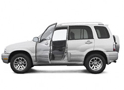
«Сузуки-Гранд Витара» пришла на смену «Витаре». Кузова – трехдверный и пятидверный, вагонной компоновки. Бензиновые двигатели: Р4, 16-кл., 1,6 л, 69 кВт/94 л.с.; 2,0 л, 94 кВт/128 л.с.; V6, 24-кл.; 2,5 л, 106 кВт/144 л.с. Турбодизель («Мазда»): Р4, 8-кл., 64 кВт/87 л.с. Коробка передач – М5 или А4, привод – полный (подключаемый передний мост).
2000 год. Новый турбодизель («Пежо-Ситроен»): Р4, 8-кл., 80 кВт/109 л.с.
2001 год. Семиместная версия «Сузуки-Гранд Витара XL-7» с бензиновым двигателем V6, 24-кл., 127 кВт/173 л.с. Коробка передач – М5 или А4.
2002 год. Рестайлинг модели: новая панель приборов, климат-контроль, более комфортная подвеска.
2003 год. Рестайлинг XL-7: пятиступенчатый «автомат» с электронным управлением, муфта подключения переднего моста с электроприводом, рама новой конструкции.
Слова «вседорожник» и «внедорожник» звучат почти одинаково, но наполнены разным смыслом. Покупатель в основном ориентируется на имидж, поэтому большинство недорогих «джипов» – «паркетники», весьма неловкие на бездорожье. «Сузуки-Гранд Витара» – одно из редких исключений. Комфортабельный, отвечающий современным требованиям пассивной безопасности вседорожник сохранил наиболее привлекательные черты предшественника, «Сузуки-Витара» – рамную конструкцию, понижающий ряд передач и невысокую цену.
Но в наследство достались и некоторые особенности, не зная которых угробите машину в два счета, даже не съезжая с асфальта. Поэтому выбирать подержанную «Гранд Витару» нужно с пристрастием, а эксплуатировать – с умом. В этом случае 15–20 тыс. долларов за четырех-пятилетний экземпляр станут разумным вложением денег.
1. Общая информация
1.0 Общая информация
1.1 Меры предосторожности
1.2. Диагностика
1.3 Основные меры предосторожности
1.4 Меры предосторожности при работе с катализатором
1.5 Меры предосторожности при обслуживании электрических цепей
1.6. Процедура проверки электрических цепей
1.7 Прерывающееся или слабое соединение
1.8 Меры предосторожности при установке средств мобильной связи
1.9. Идентификационная информация
1.10 Предупреждающие, предостерегающие и информационные наклейки
1.11 Места подъем…
2. Техническое обслуживание и смазка
2.0 Техническое обслуживание и смазка
2.1. Обслуживание, рекомендованное при жестком режиме езды
2.3 Рекомендуемые жидкости и смазочные материалы
…
5. Рулевое управление
5.0 Рулевое управление
5.1 Диагностическая таблица
5.2. Диагностика шин
5.3 Диагностика вибраций
…
6. Регулировка углов установки колес передней подвески
6.0 Регулировка углов установки колес передней подвески
6.1 Схождение передних колес
6.2 Развал передних колес
6.3 Кастер
6.4 Подготовка к регулировке углов установки колес передней подвески
6.5 Регулировка угла схождения передних колес
6.6 Регулировка угла развала и кастера
6.7 Угол поворота колес
6.8 Боковое скольжение колес (эталон)
…
8. Рулевое колесо и рулевая колонка
8.0 Рулевое колесо и рулевая колонка
8.2. Диагностика
8.3. Обслуживание вне мастерской
8.4 Спецификации момента затяжки
8.5 Специальный инструмент
…
10. Подвеска
10.0 Подвеска
10.2. Диагностика
10.3. Обслуживание вне мастерской
…
12. Колеса и шины
12.0 Колеса и шины
12.1. Колеса
12.2. Диагностика
12.4. Обслуживание вне мастерской
…
13. приводной вал/подшипник вала. Масляный сальник
13.0 приводной вал/подшипник вала. Масляный сальник
13.2. Диагностика
13.3. Обслуживание вне мастерской
13.4 Спецификации момента затяжки
13.5 Необходимый для сервисного обслуживания материал
13.6 Специальный инструмент
…
14. Карданные валы
14.0 Карданные валы
14.2. Диагностика
14.3 Обслуживание вне мастерской
14.4 Спецификации момента затяжки
14.5 Необходимый материал для сервисного обслуживания
14.6 Специальный инструмент
…
15. Тормозная система
15.0 Тормозная система
15.2. Диагностика
15.3 Диагностическая таблица
15.4. Проверка и регулировка
15.5 Технические условия — крутящий момент затяжки
15.6 Необходимые материалы для обслуживания
15.7 Специальный инструмент
…
17. Передние тормоза
17.0 Передние тормоза
17.2 Диагностика
17.3 Проверка и регулировка
17.4. Обслуживание транспортного средства
17.5 Крутящий момент затяжки
17.6 Необходимые материалы
…
20. Двигатели
20.0 Двигатели
20.1. Общее описание
20.2. Текущее обслуживание
20.3. Шток поршня, поршневые кольца, шатуны и цилиндры
20.4 Специальный инструмент
20.5 Необходимые сервисные материалы
20.6 Технические характеристики вращающего момента затяжки
…
21. Механическая часть двигателя J20
21.0 Механическая часть двигателя J20
21.1 Смазка двигателя
21.2. Текущее обслуживание
21.3. Монтажная арматура двигателя
21.4 Специальный инструмент
21.5 Необходимые сервисные материалы
21.6 Технические характеристики вращающего момента затяжки
…
22. Охлаждение двигателя
22.0 Охлаждение двигателя
22.1. Компоненты системы охлаждения
22.2 Диагностика
22.3. Техническое обслуживание
22.4. Текущее обслуживание транспортного средства
22.5 Необходимые сервисные материалы
22.6 Технические характеристики вращающего момента затяжки
…
23. Топливная система
23.0 Топливная система
23.1 Текущее техническое обслуживание транспортного средства
23.2 Топливный насос
23.3 Топливный фильтр
23.4 Топливные провода
23.5 Крышка заливной топливной горловины
23.6 Топливный бак
23.7 Техническая характеристика вращающего момента затяжки
…
24. Система зажигания
24.0 Система зажигания
24.1. Электропроводка системы
24.2. Диагностика
24.3. Обслуживание транспортного средства
24.4 Спецификация, крутящий момент затяжки
24.5 Специальный инструмент
…
25. Система зажигания для двигателя J20
25.0 Система зажигания для двигателя J20
25.1. Электропроводка системы
25.2. Диагностика
25.3. Обслуживание транспортного средства
25.4 Спецификация, крутящий момент затяжки
25.5 Специальный инструмент
…
26. Система запуска
26.0 Система запуска
26.1. Цепь стартера
26.2. Диагностика
26.3 Необходимые материалы
26.4 Специальный инструмент
…
28. Система выпуска
28.0 Система выпуска
28.1 Компоненты
28.2 Техническое обслуживание
28.3. Работы, производимые на автомобиле
…
29. Коробки передач
29.0 Коробки передач
29.1 Описание системы
29.2 Диагностика
29.3. Обслуживание вне мастерской
…
31. Автоматическая коробка передач (4 A/T)
31.0 Автоматическая коробка передач (4 A/T)
31.1. Функции сцепления/тормоза
31.2. Диагностика автоматической коробки передач
31.3. Меры предосторожности при диагностике неполадок
31.4. Визуальный осмотр
31.5. Обслуживание вне мастерской
31.7. Система блокировки тормозов
31.8. Проверка системы
…
32. Сцепление
32.0 Сцепление
32.2 Диагностика
32.3. Обслуживание вне мастерской
32.4. Ремонт модуля
…
33. Передача
33.0 Передача
33.2 Диагностика
33.3. Обслуживание вне мастерской
…
35. Задний дифференциал
35.0 Задний дифференциал
35.2 Диагностика
35.3. Обслуживание вне мастерской
35.5 Спецификации момента затяжки
35.6 Необходимый для сервиса материал
36.1. Меры предосторожности при работе
…
37. Система освещения
37.0 Система освещения
37.1. Автомобили с брезентовым верхом
37.2. Диагностика
37.3. Техническое обслуживание
…
38. Инструменты/Информация для водителей
38.0 Инструменты/Информация для водителей
38.1 Автомобили с брезентовым верхом
38.2. Знаки и метки
38.3. Диагностика
38.4. Техническое обслуживание
39.1. Общее описание
39.2. Диагностика
39.3. Техническое обслуживание
…
40. Иммобилайзер
40.0 Иммобилайзер
40.1. Автомобили с брезентовым верхом
40.2 Система бортовой диагностики (с функцией самодиагностики)
…