наверное из-за того, что по образованию я инженер…- я так и сужу…
«технари» могут судить по другому…
я вообще инженер-технолог авиационный 
ждём! 
———- Сообщение добавлено в 10:39 ———- Предыдущее сообщение создано в 09:47 ———-
Продолжаем добивать ФАК:
Спасибо ZUR за рассказ про кофр.
ОРИГИНАЛЬНЫЙ кофр SUZUKI King Quad 750 — установка и целесообразность
В свое время я был яростным сторонником мягкого кофра, приобрел очень качественны, оригинальный кофр MOOSE, состоящий из двух частей, сделано на самом деле очень качественно, но поездив в «своей» манере понял, что мне удобней будет пластиковый, и больше по объему , кофр, смотрел разные – некоторые модели ТАМАРАКа, но что то дороговаты, смотрел оригинальный БРП, что тоже не дёшов, но когда уводил его в отчую, не подошел тем, что мал по объему.
И совершенно случайно зайдя на сайт уважаемой фирмы, которую здесь многие знают (подсказка «Максим») я увидел оригинальный SUZUKI- вский кофр, пообшавщись с Максимом, тем более что он его сам на своем 750 эксплуатирует (в дальнейшем он подсказал «апгрейд» крепления, чем я воспользовался) я загорелся желанием и заказал у него, через 2 недели его доставили, и я понял что визуально это то что мне надо. Большой, с двумя крепкими замками, которые можно заблокировать при необходимости шпильками или повесить замочки, с изоляцией краев от воды. Все что было у меня раньще в 3-х емкостях я туда поместил + еще место осталось, снизу я вырезал ванный коврик, цвет конечно гламурный, но на скорость не влияет, сверху накрою паралоном, по эксплуатации отпишусь,
Итак порядок установки на Suzuki King Quad 750 :
1) Снимаем багажник и кладем его на наружнюю нижнюю часть кофра, видем две полосы с отверстиями, намечаем и просверливаем, потом кпо бокам прикладываем штатное крепление (то что маленькое) и тоже наметив просверливаем, потом изнутри обильно наносим силиконовый герметик и вставляем болты с круглой головкой (мебельные НЕПОДОЙДУТ), для перестраховки добавляем крупные шайбы , в качестве гайки советую «контргайку», а в штатных, где увы барашки, к ним к сожалению не смог подобрать гайки, кажется другой «шаг» резьбы, я нанес спец жидкость от раскручивания (забыл как это по-русски), в дальнейшем что нибудь придумаю.
2) Потом дно приведем в порядок и накроем гламурным ковриком, вроде все, далее фото, если вопросы прошу:


———- Сообщение добавлено в 11:26 ———- Предыдущее сообщение создано в 10:39 ———-
СУЗУКИ В ЭКСПЕДИЦИИ
добавлю ещё от себя пару фоток наших походных сузук.
может кому будет интересно размещение канистр и гермомешков. буду признателен если вы добавите что то от себя.
шли на неделю и старались ни в чём себе не отказывать в походных условиях, так что брали много всего.
к своему квадру к заднему бамперу приварили бугель-багажник из профиля квадрат 10*10мм оказалось очень прочно и функционально. гермомешок на 130 литров хоть и был великоват, но лежал очень надёжно и не шевелился.
оптимальным вариантом конечно мешок на 100 литров и чуть меньший размер «багажника».


вниз прямо на шарик, отлично встала пластиковая канистра с водой на 5 литров. там есть за что её хорошенько притянуть и обездвижить. канистра входит естественно при условии что выход с варика переделан шноркелем и штатная пластиковая труба убрана.
по опыту дальнего похода оказалось очень удобно между кофром и спиной водителя на сидушке расположить канистру пластиковую на 15-20 литров с топливом или мешок плотноупакованных мягких вещей. на ровных дорогах можно расслабиться и откинуться как в кресле тем самым разгружая спину водителя.

по бокам кофра очень удобно размещать алюминиевые канистры по 10-15 литров, надо только приделать небольшие съёмные площадки к штатному заднему багажнику. подробных фоток к сожалению нет. надеемся марат-2 выложит. как правило все кофры немного уже квадра особенно если стоят диски с небольшим выносом, так что даже с канистрами маневрировать между деревьев так же просто как и без них.

ещё одну канистру на 5 литров с маслом удаёться легко закрепить в теле квадра над переднем редуктором если у вас конечно вынесен штатный радиатор что в походе является строгой необходимость так как ближайший кёрхер может быть в 50 или более км.
———- Сообщение добавлено в 12:12 ———- Предыдущее сообщение создано в 11:26 ———-
ЗАМЕНА БЕНЗОНАСОСА
Спасибо за отчёт по нему ZUR!!!
Ну что други, потратил я выходные, и слава богу не зря. Сняв бензонасос

) увидев

, высушив влаговпитываюшей тряпочкой бак

вытерев – его снимать Необязательно, бессмысленно, я походил по магазинам- искал сеточку – такой по форме как и ожидалось нет, спросил в Байкленде и у наших уважаемых партнеров, короче отдельно сеточка не поставляется, даже нет такой позиции(блин), поставляется бензонасос в сборе. Прайс 500-650 долларов, причем СШа. Это, да и советы уважаемых соклубников, меня вдохновило на поиски замены, т.е. фирмы БОШ. Когда в 3-4 магазинах мне показывали другое, и я начал закипать, тут до меня, не без намека продавца, доходит – что я то с них требую абсолютный аналог с бензонасоса в сборе!!!. Ну и естественно, вздохнув от радости я выкладываю на прилавок 1640 рублей за БОШский насос


и по 50 рублей за 2-ва варианта сеточек(брать надо :

Ура.1-я часть закончена – еду домой.
Приехав и собравшись духом я начинаю разбирать насос, тот что еще в футляре. Это 2-й по уровню сложность в работе после снятия пластика квадра, связанного надо отдать должное с допприблудами( в дальнейшем я оптимизировал провода для легкости доступа, не дай бог конечно чтоб потребовалось.
Сложность в разборке футляра в том, надо одновременно нажать на 4-е точки , что весьма непросто.,
Потом отсоединить (обращая внимания на полярность при сборке) штекер,


После этого освободить эту хрень

вытянув бензонасос – вынимаем сеточку, обратите внимание, что сетока фиксируется штекером, посему пока вы не вытяните бензонасос – сеточка не освободится.Потом берем и меняем один насос на другой, по идее можно было всунуть жигулевскую сеточку, но
А) хрен его знает может на насос негативно сказались многочисленные попытки запустить с учетом грязной сеточки,
Б) пусть будет лучше в запасе + для дальних поездок потрать те еще 1500-1600 р на доп.насос БОШ.
Чтобы совместить жигулевскую сеточку с футляром надо в этом месте АККУратно подрезать пластик

не бойтесь на свойствах фиксации не скажется.
Вставляем бензонасос, подсоединяем штекера и зашелкиваем 4 – кнопки. Далее бьем себя по лбу и потом этим местом для разбивания орехов об стену: забыли поставить сеточку,не забыв снав заглушку

Опять корячимся и нажимаем, и далеко не пальцами, 4 кнопки, поднимаем насос – вставляем сетоку – защелкиваем.,
Присоединяем эту хрень.
Теперь так должно это выглядить

только поплаво в другую сторону разверните!! (а было так

ВСЕ.
Далее собираем в обратном порядке, незабыв почистить внутренне подсиденьевое пространство и аккуратно расположив там провода.
от себя добавлю что можно поставить любой насос от инжекторных жигулей. всё будет работать.
-
Contents
-
Table of Contents
-
Troubleshooting
-
Bookmarks
Quick Links
This manual contains an introductory description on the SUZUKI LT-A750X/P and procedures for its inspection/
service and overhaul of its main components.
Other information considered as generally known is not included.
Read the GENERAL INFORMATION section to familiarize yourself with the vehicle and its maintenance. Use this
section as well as other sections to use as a guide for proper inspection and service.
This manual will help you know the vehicle better so that you can assure your customers of fast and reliable ser-
vice.
* This manual has been prepared on the basis of the latest specifications at the time of publication. If modifi-
cations have been made since then, differences may exist between the content of this manual and the
actual vehicle.
* Illustrations in this manual are used to show the basic principles of operation and work procedures. They
may not represent the actual vehicle exactly in detail.
* This manual is written for persons who have enough knowledge, skills and tools, including special tools, for
servicing SUZUKI vehicles. If you do not have the proper knowledge and tools, ask your authorized
SUZUKI motorcycle dealer to help you.
WARNING
!
Inexperienced mechanics or mechanics without the proper tools and equipment may not be able to
properly perform the services described in this manual.
Improper repair may result in injury to the mechanic and may render the vehicle unsafe for the rider
and passenger.
© COPYRIGHT SUZUKI MOTOR CORPORATION 2007
FOREWORD
99500-47021-03E
Chapters
Troubleshooting
Summary of Contents for Suzuki kq750
Open the PDF directly: View PDF ![]() .
.
Page Count: 711 [warning: Documents this large are best viewed by clicking the View PDF Link!]
FOREWORD
This manual contains an introductory description on the SUZUKI LT-A750X/P and procedures for its inspection/
service and overhaul of its main components.
Other information considered as generally known is not included.
Read the GENERAL INFORMATION section to familiarize yourself with the vehicle and its maintenance. Use this
section as well as other sections to use as a guide for proper inspection and service.
This manual will help you know the vehicle better so that you can assure your customers of fast and reliable ser-
vice.
© COPYRIGHT SUZUKI MOTOR CORPORATION 2007
* This manual has been prepared on the basis of the latest specifications at the time of publication. If modifi-
cations have been made since then, differences may exist between the content of this manual and the
actual vehicle.
* Illustrations in this manual are used to show the basic principles of operation and work procedures. They
may not represent the actual vehicle exactly in detail.
* This manual is written for persons who have enough knowledge, skills and tools, including special tools, for
servicing SUZUKI vehicles. If you do not have the proper knowledge and tools, ask your authorized
SUZUKI motorcycle dealer to help you.
WARNING
!
Inexperienced mechanics or mechanics without the proper tools and equipment may not be able to
properly perform the services described in this manual.
Improper repair may result in injury to the mechanic and may render the vehicle unsafe for the rider
and passenger.
99500-47021-03E
PartShark.com
877-999-5686
PartShark.com
877-999-5686

00
0
1
2
3
4
5
6
9
Precautions…………..…………………………………………. 00-i
Precautions ……………………….……………….…………. 00-1
General Information ……………….……………….…………. 0-i
General Information …..…………….………………..…… 0A-1
Maintenance and Lubrication ….……………….………. 0B-1
Service Data……………..…………….………………..……0C-1
Engine ………………………….………………..…………….…… 1-i
Precautions ……………………….……………….…………… 1-1
Engine General Information and Diagnosis ………..1A-1
Emission Control Devices ……………………….………. 1B-1
Engine Electrical Devices………….………………..……1C-1
Engine Mechanical………….………………..…………….1D-1
Engine Lubrication System ………….………….………. 1E-1
Engine Cooling System…………………..………………. 1F-1
Fuel System …….…………….………………..…………….1G-1
Ignition System…………….………………..…………….…1H-1
Starting System……………………………………..……….. 1I-1
Charging System…………….………………..……………..1J-1
Exhaust System .…………….………………..……………. 1K-1
Suspension…………………..…………….………………..…… 2-i
Precautions ……………………….……………….…………… 2-1
Suspension General Diagnosis…….………….……….2A-1
Front Suspension ……………………………..……………. 2B-1
Rear Suspension…….……………….………………..……2C-1
Wheels and Tires …………………….…………….……….2D-1
Driveline / Axle ……………..………………..…………….…… 3-i
Precautions ……………………….……………….…………… 3-1
Drive Chain / Drive Train / Drive Shaft ………………. 3A-1
Differential ……….…………….………………..……………. 3B-1
Transfer…..…………….……………….…………….……….3C-1
Propeller Shafts..…………….………………..…………….3D-1
Brake …………..…………….……………….……………..……… 4-i
Precautions ……………………….……………….…………… 4-1
Brake Control System and Diagnosis .………………. 4A-1
Front Brakes….…………….………………..…………….…4B-1
Rear Brakes ………..…………….…………….…………….4C-1
Parking Brake..…………….………………..…………….…4D-1
Transmission / Transaxle …………………..………………. 5-i
Precautions ……………………….……………….…………… 5-1
Automatic Transmission..………….………………..…… 5A-1
Steering………………..……………….…………….……………. 6-i
Precautions ……………………….……………….…………… 6-1
Steering General Diagnosis …………………….………. 6A-1
Steering / Handlebar …….…………….………………….. 6B-1
Body and Accessories………………………………..……… 9-i
Precautions …………….………………………………………. 9-1
Wiring Systems ………….…………………………..………9A-1
Lighting Systems………..…………………………..………9B-1
Combination Meter / Fuel Meter / Horn………………9C-1
Exterior Parts ………….…………………………..…………9D-1
Body Structure ………..…………………………..…………9E-1
TABLE OF CONTENTS
PartShark.com
877-999-5686
PartShark.com
877-999-5686

SUPPLEMENTS
L
LT-A750XK9 (’09 MODEL)
10
LT-A750XPK9 (’09 MODEL)
11
PartShark.com
877-999-5686

Table of Contents 00- i
00
Section 00
CONTENTS
Precautions
Precautions ………………………………….…….00-1
Precautions….…………….…………….………………..… 00-1
Warning / Caution / Note……..……………….………. 00-1
General Precautions ..……….…………………….…… 00-1
Precautions for Electrical Circuit Service ………… 00-2
PartShark.com
877-999-5686
00-1 Precautions:
Precauti ons
Precautions
Precautions
Warning / Caution / Note
B831G20000001
Please read this manual and follow its instructions
carefully. To emphasize special information, the symbol
and the words WARNING, CAUTION and NOTE have
special meanings. Pay special attention to the messages
highlighted by these signal words.
WARNING
!
Indicates a potential hazard that could result
in death or injury.
CAUTION
!
Indicates a potential hazard that could result
in vehicle damage.
NOTE
Indicates special information to make
maintenance easier or instructions clearer.
Please note, however, that the warnings and cautions
contained in this manual cannot possibly cover all
potential hazards relating to the servicing, or lack of
servicing, of the vehicle. In addition to the WARNINGS
and CAUTIONS stated, you must use good judgement
and basic mechanical safety principles. If you are unsure
about how to perform a particular service operation, ask
a more experienced mechanic for advice.
General Precautions
B831G20000002
WARNING
!
• Proper service and repair procedures are
important for the safety of the service
mechanic and the safety and reliability of
the vehicle.
• When 2 or more persons work together,
pay attention to the safety of each other.
• When it is necessary to run the engine
indoors, make sure that exhaust gas is
forced outdoors.
• When working with toxic or flammable
materials, make sure that the area you
work in is well ventilated and that you
follow all of the material manufacturer’s
instructions.
• Never use gasoline as a cleaning solvent.
• To avoid getting burned, do not touch the
engine, engine oil, radiator and exhaust
system until they have cooled.
• After servicing the fuel, oil, water, exhaust
or brake systems, check all lines and
fittings related to the system for leaks.
CAUTION
!
• If parts replacement is necessary, replace
the parts with Suzuki Genuine Parts or
their equivalent.
• When removing parts that are to be reused,
keep them arranged in an orderly manner
so that they may be reinstalled in the
proper order and orientation.
• Be sure to use special tools when
instructed.
• Make sure that all parts used in
reassembly are clean. Lubricate them
when specified.
• Use the specified lubricant, bond, or
sealant.
• When removing the battery, disconnect the
negative (–) cable first and then the
positive (+) cable.
• When reconnecting the battery, connect
the positive (+) cable first and then the
negative (–) cable, and replace the terminal
cover on the positive (+) terminal.
• When performing service to electrical
parts, if the service procedures do not
require use of battery power, disconnect
the negative (–) cable the battery.
• When tightening the cylinder head or case
bolts and nuts, tighten the larger sizes
first. Always tighten the bolts and nuts
diagonally from the inside toward outside
and to the specified tightening torque.
• Whenever you remove oil seals, gaskets,
packing, O-rings, locking washers, self-
locking nuts, cotter pins, circlips and
certain other parts as specified, be sure to
replace them with new ones. Also, before
installing these new parts, be sure to
remove any left over material from the
mating surfaces.
PartShark.com
877-999-5686
Precautions: 00-2
• Never reuse a circlip. When installing a
new circlip, take care not to expand the
end gap larger than required to slip the
circlip over the shaft. After installing a
circlip, always ensure that it is completely
seated in its groove and securely fitted.
• Use a torque wrench to tighten fasteners
to the specified torque. Wipe off grease
and oil if a thread is smeared with them.
• After reassembling, check parts for
tightness and proper operation.
• To protect the environment, do not
unlawfully dispose of used motor oil,
engine coolant and other fluids: batteries,
and tires.
• To protect Earth’s natural resources,
properly dispose of used vehicle and parts.
Precautions for Electrical Circuit Service
B831G20000003
When handling the electrical parts or servicing the FI
systems, observe the following points for the safety of
the systems.
Electrical Parts
Connector / Coupler
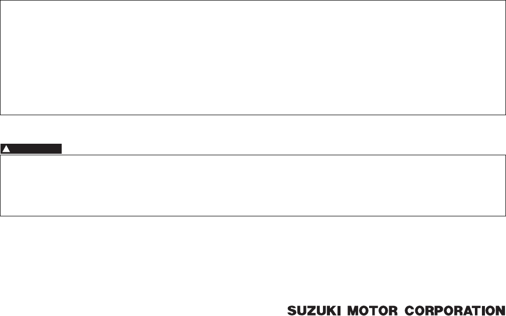
• When connecting a connector, be sure to push it in
until a click is felt.
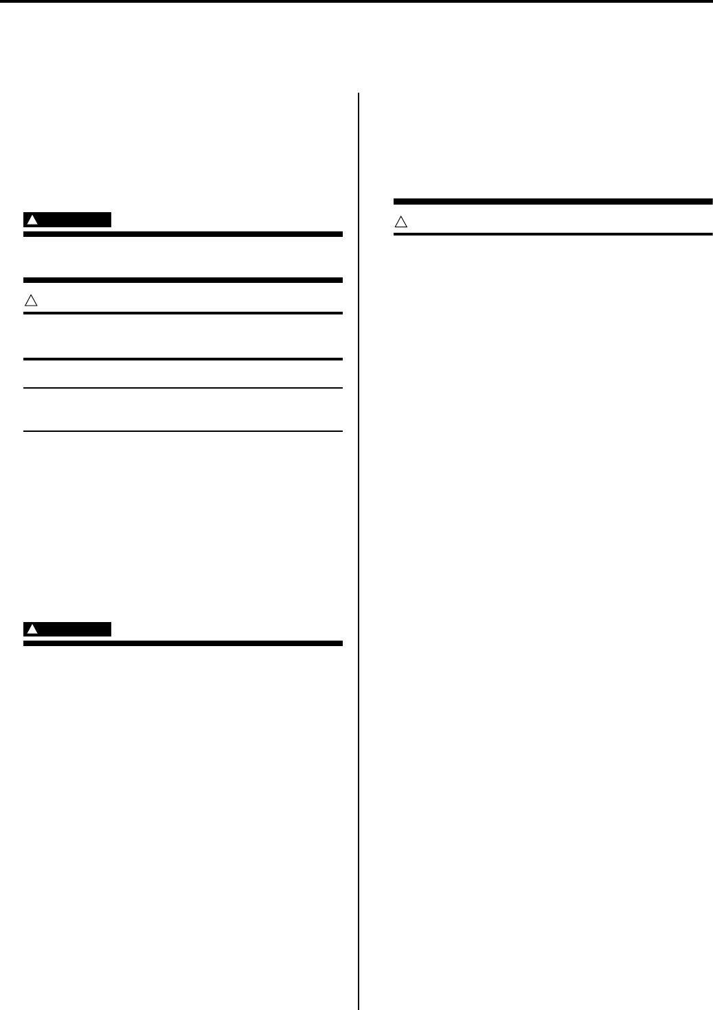
• With a lock type coupler, be sure to release the lock
when disconnecting, and push it in fully to engage the
lock when connecting.
• When disconnecting the coupler, be sure to hold the
coupler body and do not pull the lead wires.
• Inspect each terminal on the connector/coupler for
looseness or bending.
• Push in the coupler straightly. An angled or skewed
insertion may cause the terminal to be deformed,
possibly resulting in poor electrical contact.
• Inspect each terminal for corrosion and
contamination. The terminals must be clean and free
of any foreign material which could impede proper
terminal contact.
• Before refitting the sealed coupler, make sure its seal
rubber is positioned properly. The seal rubber may
possibly come off the position during disconnecting
work and if the coupler is refitted with the seal rubber
improperly positioned, it may result in poor water
sealing.
• Inspect each lead wire circuit for poor connection by
shaking it by hand lightly. If any abnormal condition is
found, repair or replace.
• When taking measurements at electrical connectors
using a tester probe, be sure to insert the probe from
the wire harness side (backside) of the connector/
coupler.
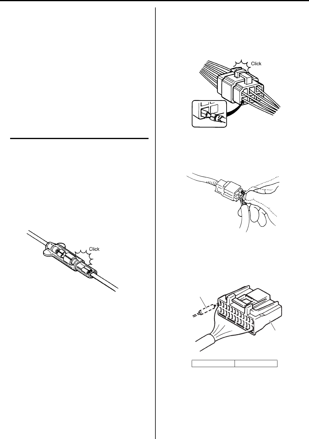
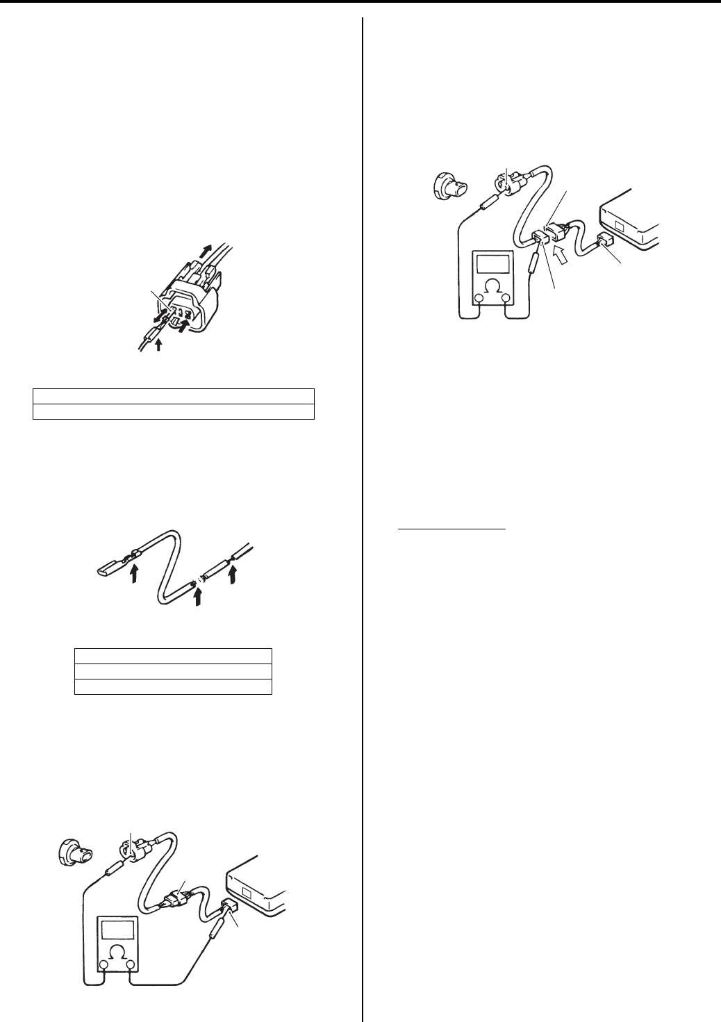
• When connecting meter probe from the terminal side
of the coupler (where connection from harness side
not being possible), use extra care not to force and
cause the male terminal to bend or the female
terminal to open. Connect the probe as shown to
avoid opening of female terminal. Never push in the
probe where male terminal is supposed to fit.
I310G1000001-01
1. Coupler 2. Probe
I310G1000002-01
I310G1000003-02
2
1
I649G1000013-02
PartShark.com
877-999-5686
00-3 Precautions:
• Check the male connector for bend and female
connector for excessive opening. Also check the
coupler for locking (looseness), corrosion, dust, etc.
Clamp
• Clamp the wire harness at such positions as indicated
in “Wiring Harness Routing Diagram in Section 9A
(Page 9A-4)”.
• Bend the clamp properly so that the wire harness is
clamped securely.
• In clamping the wire harness, use care not to allow it
to hang down.
• Do not use wire or any other substitute for the band
type clamp.
Fuse
• When a fuse blows, always investigate the cause to
correct it and then replace the fuse.
• Do not use a fuse of different capacity.
• Do not use wire or any other substitute for the fuse.
Switch
Never apply grease material to switch contact points to
prevent damage.
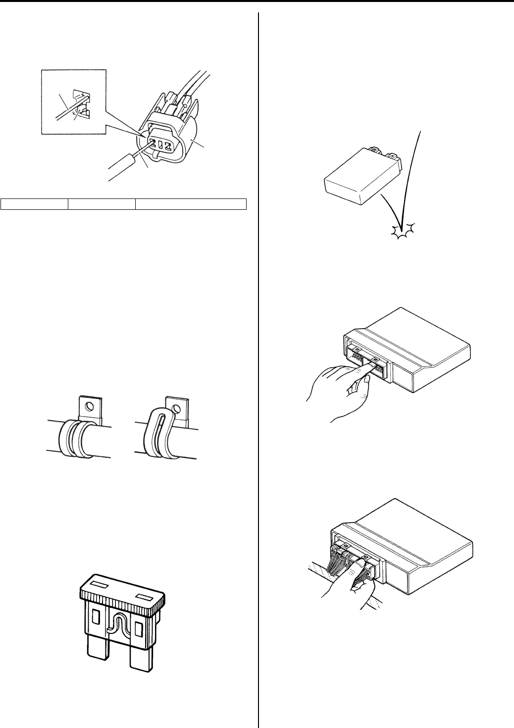
ECM / Various sensors
• Since each component is a high-precision part, great
care should be taken not to apply any severe impacts
during removal and installation.
• Be careful not to touch the electrical terminals of the
electronic parts (ECM, etc.). The static electricity from
your body may damage these.
• When disconnecting and connecting the coupler,
make sure to turn OFF the ignition switch, or
electronic parts may get damaged.
3. Coupler 4. Probe “A”: Where male terminal fits
3
4
4
“A”
I649G1000030-02
CORRECT INCORRECT
I718H1000001-02
I649G1000001-02
I310G1000007-01
I310G1000008-01
I831G1000001-01
PartShark.com
877-999-5686
Precautions: 00-4
Battery
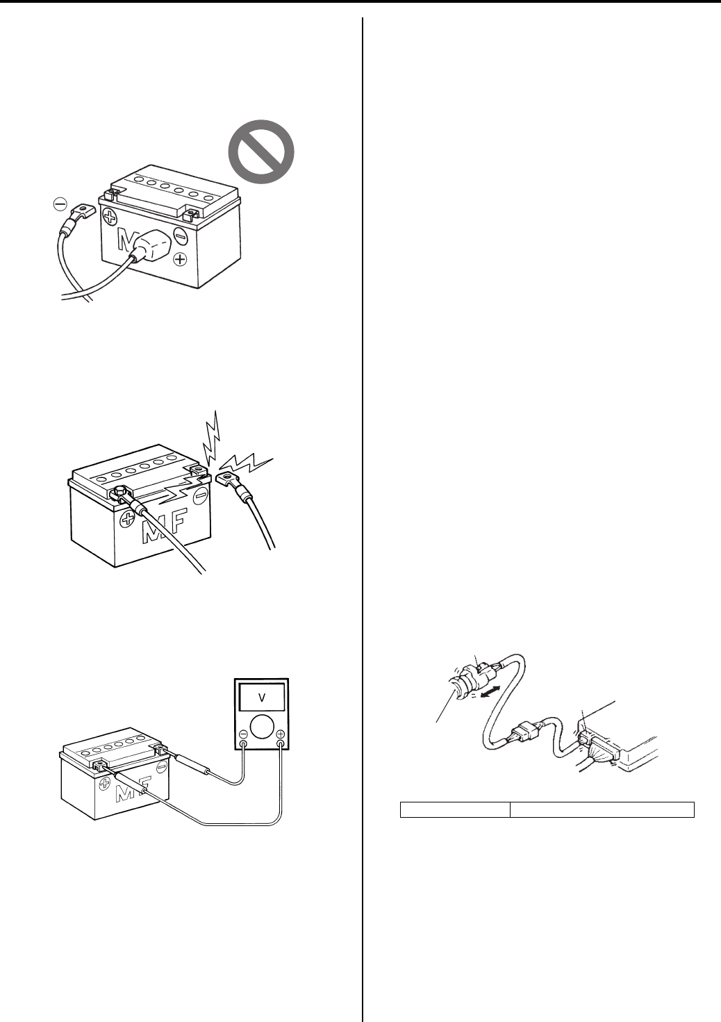
• Battery connection in reverse polarity is strictly
prohibited. Such a wrong connection will damage the
components of the FI systems instantly when reverse
power is applied.
• Removing any battery terminal of a running engine is
strictly prohibited. The moment such removal is made,
damaging counter electromotive force will be applied
to the ECM which may result in serious damage.
• Before measuring voltage at each terminal, check to
make sure that battery voltage is 11 V or higher.
Terminal voltage check with a low battery voltage will
lead to erroneous diagnosis.
• Never connect any tester (voltmeter, ohmmeter, or
whatever) to the electronic unit when its coupler is
disconnected. Otherwise, damage to electronic unit
may result.
• Never connect an ohmmeter to the ECM with its
coupler connected. If attempted, damage to ECM or
sensors may result.
• Be sure to use a specified voltmeter/ohmmeter.
Otherwise, accurate measurements may not be
obtained and personal injury may result.
Electrical Circuit Inspection Procedure
While there are various methods for electrical circuit
inspection, described here is a general method to check
for open and short circuit using an ohmmeter and a
voltmeter.
Open circuit check
Possible causes for the open circuit are as follows. As
the cause can exist in the connector/coupler or terminal,
they need to be checked carefully.
• Loose connection of connector/coupler
• Poor contact of terminal (due to dirt, corrosion or rust,
poor contact tension, entry of foreign object etc.)
• Wire harness being open.
• Poor terminal-to-wire connection.
When checking system circuits including an electronic
control unit such as ECM, etc., it is important to perform
careful check, starting with items which are easier to
check.
1) Disconnect the negative (–) cable from the battery.
2) Check each connector/coupler at both ends of the
circuit being checked for loose connection. Also
check for condition of the coupler lock if equipped.
I718H1000004-01
I310G1000011-01
I310G1000012-02
1. Sensor “A”: Check for loose connection
ECM
“A”
1
“A”
I718H1000005-02
PartShark.com
877-999-5686
00-5 Precautions:
3) Using a test male terminal, check the female
terminals of the circuit being checked for contact
tension.
Check each terminal visually for poor contact
(possibly caused by dirt, corrosion, rust, entry of
foreign object, etc.). At the same time, check to
make sure that each terminal is fully inserted in the
coupler and locked.
If contact tension is not enough, rectify the contact to
increase tension or replace. The terminals must be
clean and free of any foreign material which could
impede proper terminal contact.
4) Using continuity inspect or voltage check procedure
as described below, inspect the wire harness
terminals for open circuit and poor connection.
Locate abnormality, if any.
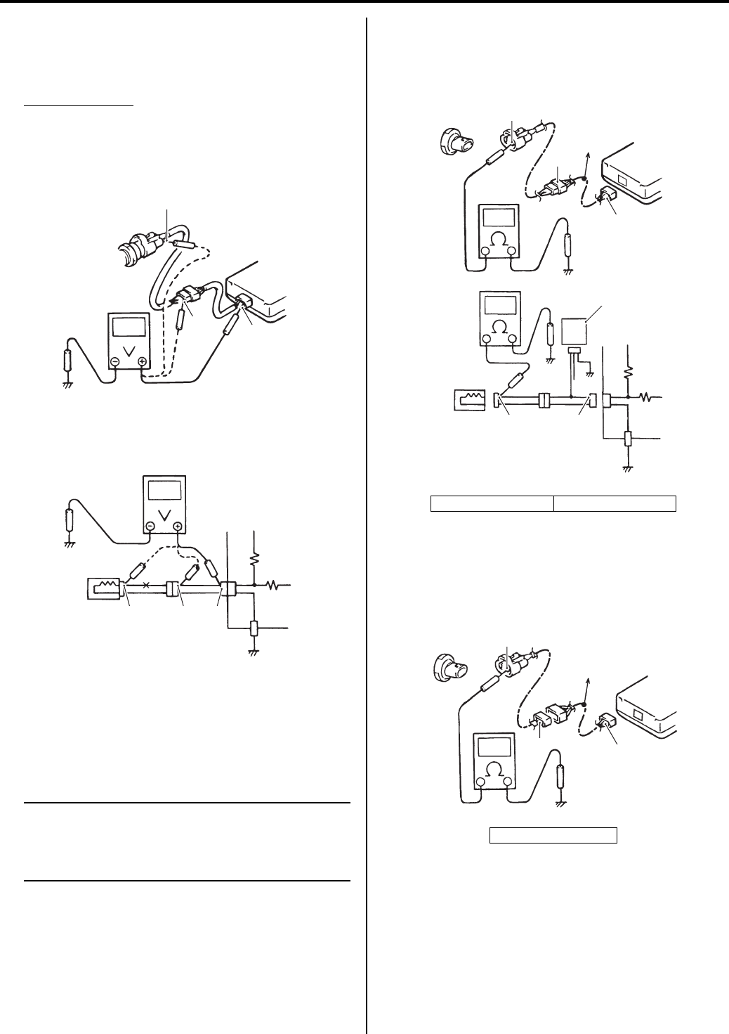
Continuity check
1) Measure resistance across coupler “B” (between “A”
and “C” in figure).
If no continuity is indicated (infinity or over limit), the
circuit is open between terminals “A” and “C”.
2) Disconnect the coupler “B” and measure resistance
between couplers “A” and “B-1”.
If no continuity is indicated, the circuit is open
between couplers “A” and “B-1”. If continuity is
indicated, there is an open circuit between couplers
“B-2” and “C” or an abnormality in coupler “B-2” or
coupler “C”.
Voltage check
If voltage is supplied to the circuit being checked, voltage
check can be used as circuit check.
1) With all connectors/couplers connected and voltage
applied to the circuit being checked, measure
voltage between each terminal and body ground.
2) If measurements were taken as shown in the figure
and results were listed in the following, it means that
the circuit is open between terminals “A” and “B”.
Voltage between
“A” and body ground: Approx. 5 V
“B” and body ground: Approx. 5 V
“C” and body ground: 0 V
“B”: Check contact tension by inserting and removing.
“C”: Check each terminal for bend and proper alignment.
“D”: Looseness of crimping
“E”: Open
“F”: Thin wire (A few strands left)
“C”
“B”
I649G1000027-02
“D”
“E”
“F”
I649G1000028-02
ECM
“A”
“B”
“C”
I705H1000006-02
ECM
“A”
“B” “C”
“B-2”
“B-1”
I705H1000010-02
PartShark.com
877-999-5686
Precautions: 00-6
3) Also, if measured values are as listed following, a
resistance (abnormality) exists which causes the
voltage drop in the circuit between terminals “A” and
“B”.
Voltage between
“A” and body ground: Approx. 5 V
“B” and body ground: Approx. 5 V – 2 V voltage
drop
“C” and body ground: 3 V – 2 V voltage drop
Short circuit check (Wire harness to ground)
1) Disconnect the negative (–) cable from the battery.
2) Disconnect the connectors/couplers at both ends of
the circuit to be checked.
NOTE
If the circuit to be checked branches to other
parts as shown, disconnect all connectors/
couplers of those parts. Otherwise, diagnosis
will be misled.
3) Measure resistance between terminal at one end of
circuit (“A” terminal in figure) and body ground. If
continuity is indicated, there is a short circuit to
ground between terminals “A” and “C”.
4) Disconnect the connector/coupler included in circuit
(coupler “B”) and measure resistance between
terminal “A” and body ground. If continuity is
indicated, the circuit is shorted to the ground
between terminals “A” and “B”.
5V
5V
5V
0V
ECM
“A”
“B” “C”
“A” “B” “C”
I705H1000007-01
“D”: To other parts “E”: Other parts
“D”: To other parts
ECM
5V
“A”
“B”
“C”
“D”
“E”
“A” “C”
I705H1000008-01
ECM
“A”
“B” “C”
“D”
I705H1000009-02
PartShark.com
877-999-5686
00-7 Precautions:
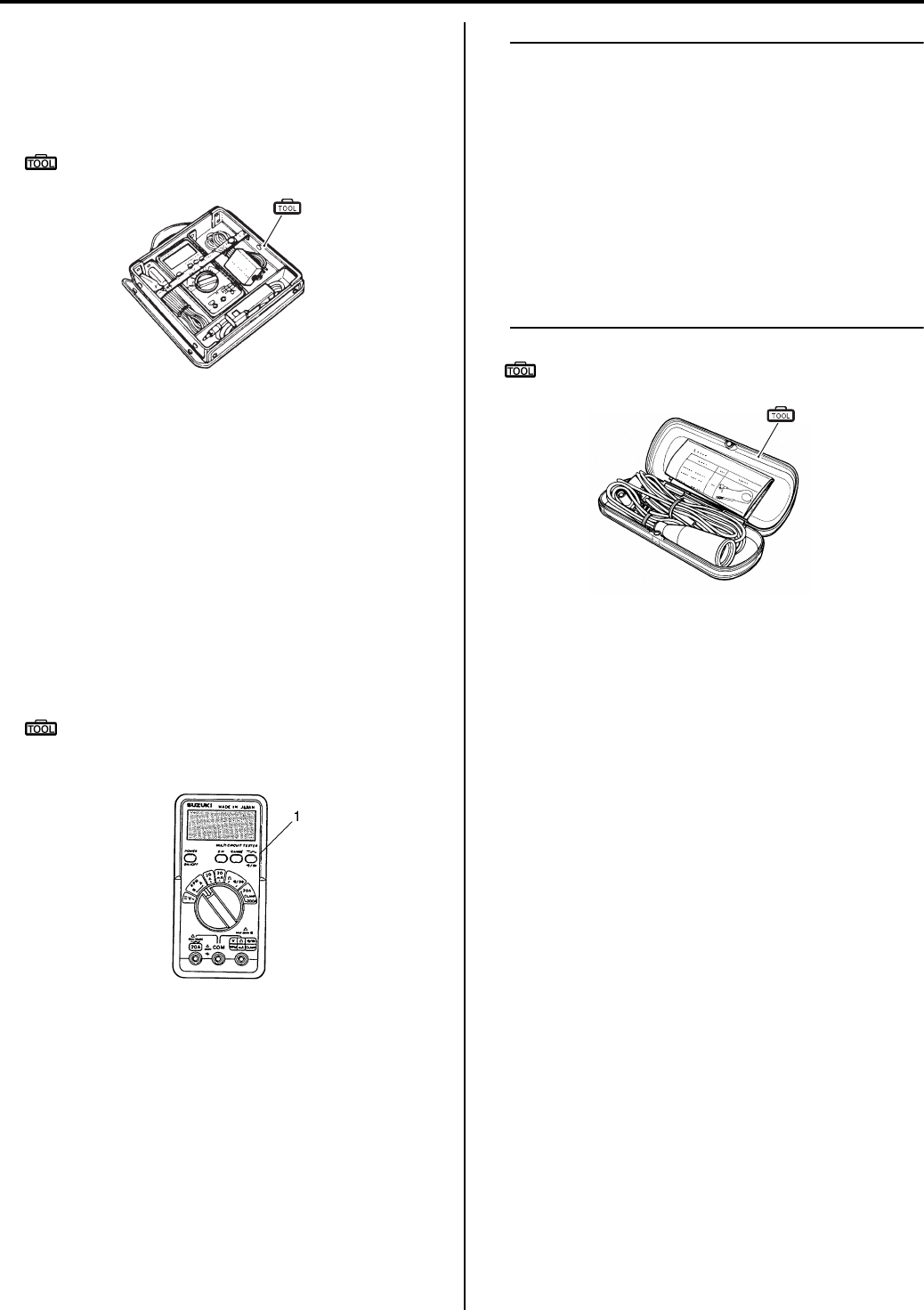
Using The Multi-Circuit Testers
• Use the Suzuki multi-circuit tester set.
• Use well-charged batteries in the tester.
• Be sure to set the tester to the correct testing range.
Special tool
(A): 09900–25008 (Multi-circuit tester set)
Using the testers
• Incorrectly connecting the (+) and (–) probes may
cause the inside of the tester to be burnout.
• If the voltage and current are not known, make
measurements using the highest range.
• When measuring the resistance with the multi-circuit
tester (1), ∞ will be shown as 10.00 MΩ and “1”
flashes in the display.
• Check that no voltage is applied before making the
measurement. If voltage is applied the tester may be
damaged.
• After using the tester, turn the power off.
Special tool
: 09900–25008 (Multi-circuit tester set)
NOTE
• When connecting the multi-circuit tester,
use the needle pointed probe to the back
side of the lead wire coupler and connect
the probes of tester to them.
• Use the needle pointed probe to prevent
the rubber of the water proof coupler from
damage.
• When using the multi-circuit tester, do not
strongly touch the terminal of the ECM
coupler with a needle pointed tester probe
to prevent the terminal damage or terminal
bend.
Special tool
(A): 09900–25009 (Needle pointed probe set)
(A)
I649G1000024-03
I649G1000002-02
(A)
I649G1000025-03
PartShark.com
877-999-5686

Table of Contents 0- i
0
Section 0
CONTENTS
General Information
General Information ……….…………..…….. 0A-1
General Description ………………….………………..…0A-1
Symbols …….……………….……………..…………….…0A-1
Abbreviations ……………………………..…………….… 0A-1
SAE-to-Former SUZUKI Term ………………………. 0A-2
Vehicle Side View ………..………………..……………. 0A-3
Vehicle Identification Number ………….……………. 0A-3
Fuel and Oil Recommendation ………………………0A-3
Engine Coolant Recommendation ……………….… 0A-4
BREAK-IN Procedures……..……………………..…… 0A-4
Country and Area Codes …….…………………..…… 0A-5
Wire Color Symbols ………………………….…………. 0A-5
Warning, Caution and Information Labels
Location ………………………….…………….…………. 0A-6
Component Location ………..…………….…………….0A-7
Electrical Components Location ……………………. 0A-7
Specifications…….…………….…………….…………….0A-9
Specifications (LT-A750X/ZK8)………..……………. 0A-9
Specifications (LT-A750X/ZK9)………..………….. 0A-11
Special Tools and Equipment …………….………..0A-11
Special Tool ………………..………………..………….. 0A-11
Maintenance and Lubrication…………….. 0B-1
Precautions….…………………..……………….………….0B-1
Precautions for Maintenance ……………..…………. 0B-1
General Description ………………….………………..…0B-1
Recommended Fluids and Lubricants…….………. 0B-1
Scheduled Maintenance ……………………….……….0B-1
Periodic Maintenance Schedule Chart……………. 0B-1
Lubrication Points ………..…………………..…………. 0B-2
Repair Instructions .……………….…………………..…0B-3
Air Cleaner Element Inspection and Cleaning ….0B-3
Exhaust Pipe Bolt and Muffler Bolt Inspection …. 0B-4
Valve Clearance Inspection and Adjustment …… 0B-4
Spark Plug Replacement ……………..………………. 0B-9
Spark Plug Inspection and Cleaning………………. 0B-9
Spark Arrester Cleaning…………………………..….0B-10
Fuel Line Inspection ……………….……………….….0B-10
Engine Oil and Filter Replacement ……………….0B-10
Front Differential Gear Oil Inspection…………….0B-12
Front Differential Gear Oil Replacement ………..0B-13
Final Gear Oil Inspection………………………….….0B-14
Final Gear Oil Replacement………………..……….0B-14
Throttle Cable Play Inspection and
Adjustment ……………………….…………….……….0B-15
Throttle Body Inspection ………………….………….0B-15
Cooling System Inspection……………….………….0B-15
Drive V-belt Inspection and Replacement..…….0B-17
Drive Shaft Boots Inspection…………………….….0B-17
Front Brake System Inspection …………………….0B-17
Rear Brake Pedal / Rear Brake (Parking
Brake) Lever Inspection and Adjustment ……..0B-19
Rear Brake Friction Plate Wear Limit
Inspection…….…………….………………..………….0B-20
Tire Inspection…………………….…………….……….0B-21
Steering System Inspection ………………..……….0B-21
Toe Adjustment ………………..……………….……….0B-22
Suspensions Inspection ……………….……………..0B-22
Chassis Bolt and Nut Inspection …………………..0B-23
Compression Pressure Check ………………….….0B-26
Oil Pressure Check …………..……………….……….0B-26
SDS Check……….……………..…………….………….0B-26
Automatic Clutch Inspection….…………….……….0B-26
Specifications………………..….…………….………….0B-27
Tightening Torque Specifications………………….0B-27
Special Tools and Equipment ……………..……….0B-27
Recommended Service Material ……….………….0B-27
Special Tool ……………………….…………….……….0B-27
Service Data ……………………………………… 0C-1
Specifications………………..….…………….……………0C-1
Service Data………………………….…………………....0C-1
Tightening Torque List ………………………………....0C-7
PartShark.com
877-999-5686
0A-1 General Information:
General Info rmation
General Information
General Description
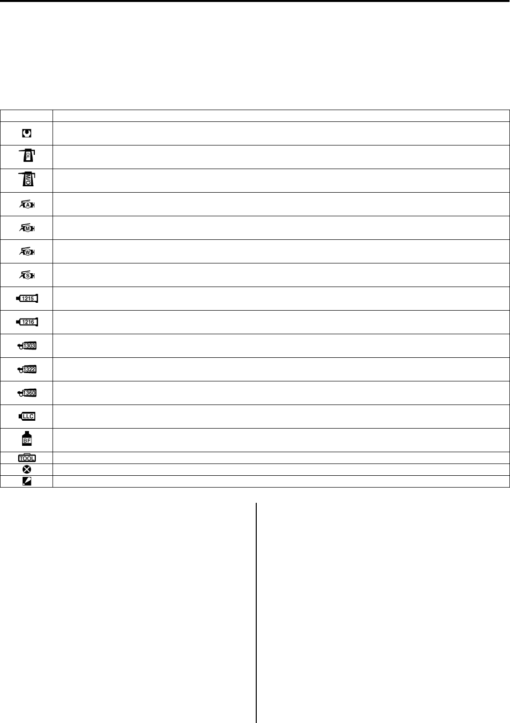
Symbols
B831G20101001
Listed in the table below are the symbols indicating instructions and other information necessary for servicing.
The meaning of each symbol is also included in the table.
Abbreviations
B831G20101002
A:
ABDC: After Bottom Dead Center
AC: Alternating Current
ACL: Air Cleaner, Air Cleaner Box
API: American Petroleum Institute
ATDC: After Top Dead Center
A/F: Air Fuel Mixture
B:
BBDC: Before Bottom Dead Center
BTDC: Before Top Dead Center
B+: Battery Positive Voltage
C:
CKP Sensor: Crankshaft Position Sensor (CKPS)
CKT: Circuit
CO: Carbon Monoxide
CPU: Central Processing Unit
D:
DC: Direct Current
DIFF-LOCK Relay: Differential Lock Relay
DMC: Dealer Mode Coupler
DOHC: Double Over Head Camshaft
DRL: Daytime Running Light
DTC: Diagnostic Trouble Code
E:
ECM: Engine Control Module Engine Control Unit
(ECU) (FI Control Unit)
ECT Sensor: Engine Coolant Temperature Sensor
(ECTS)
Water Temp. Sensor (WTS)
F:
FI: Fuel Injection, Fuel Injector
FP: Fuel pump
FPR: Fuel Pressure Regulator
FP Relay: Fuel Pump Relay
Symbol Definition
Torque control required.
Data beside it indicate specified torque.
Apply oil.
Use engine oil unless otherwise specified.
Apply molybdenum oil solution.
(Mixture of engine oil and SUZUKl MOLY PASTE in a ratio of 1:1).
Apply SUZUKI SUPER GREASE “A” or equivalent.
99000-25010
Apply SUZUKI MOLY PASTE or equivalent.
99000-25140
Apply WATER RESISTANCE GREASE.
99000-25160
Apply SUZUKI SILICONE GREASE or equivalent.
99000-25100
Apply SUZUKI BOND “1215” or equivalent.
99000-31110
Apply SUZUKI BOND “1216B” or equivalent.
99000-31230
Apply THREAD LOCK SUPER “1303” or equivalent.
99000-32030
Apply THREAD LOCK SUPER “1322” or equivalent.
99000-32110
Apply THREAD LOCK SUPER “1360” or equivalent.
99000-32130
Use engine coolant or equivalent.
99000-99032-11X
Apply or use brake fluid.
Use special tool.
Do not reuse.
Note on reassembly.
PartShark.com
877-999-5686

General Information: 0A-2
G:
GEN: Generator
GND: Ground
GP Switch: Gear Position Switch
H:
HC: Hydrocarbons
I:
IAP Sensor: Intake Air Pressure Sensor (IAPS)
IAT Sensor: Intake Air Temperature Sensor (IATS)
IG: Ignition
ISC Valve: Idle Speed Control Valve (ISCV)
J:
JASO: Japanese Automobile Standards Organization
L:
LCD: Liquid Crystal Display
LED: Light Emitting Diode (Malfunction Indicator Lamp)
LH: Left Hand
M:
MAL-CODE: Malfunction Code (Diagnostic Code)
Max: Maximum
MIL: Malfunction Indicator Lamp (LED)
Min: Minimum
N:
NOx: Nitrogen Oxides
O:
OHC: Over Head Camshaft
P:
PCV: Positive Crankcase Ventilation (Crankcase
Breather)
R:
RH: Right Hand
ROM: Read Only Memory
S:
SAE: Society of Automotive Engineers
SDS: Suzuki Diagnosis System
T:
TO Sensor: Tip-over Sensor (TOS)
TP Sensor: Throttle Position Sensor (TPS)
SAE-to-Former SUZUKI Term
B831G20101003
This list shows SAE (Society of Automotive Engineers)
J1930 terms and abbreviations which may be used in
this manual in compliance with SAE recommendations,
as well as their former SUZUKI names.
Ex. SAE term (Abbreviation): Former SUZUKI term
A:
Air Cleaner (ACL): Air Cleaner, Air Cleaner Box
B:
Battery Positive Voltage (B+): Battery Voltage, +B
C:
Crankshaft Position Sensor (CKP Sensor):
Crankshaft Position Sensor (CKPS), Crank Angle
D:
Data Link Connector (DLC): Dealer Mode Coupler
Diagnostic Test Mode (DTM): —
Diagnostic Trouble Code (DTC): Diagnostic Code,
Malfunction Code
E:
Electronic Ignition (EI): —
Engine Control Module (ECM): Engine Control
Module (ECM), Fl Control Unit, Engine Control Unit
(ECU)
Engine Coolant Level (ECL): Coolant Level
Engine Coolant Temperature (ECT): Coolant
Temperature, Engine Coolant Temperature, Water
Temperature
Engine Speed (RPM): Engine Speed (RPM)
F:
Fan Control (FC): —
Fuel Level Sensor: Fuel Level Sensor, Fuel Level
Gauge
Fuel Pump (FP): Fuel Pump (FP)
G:
Generator (GEN): Generator
Ground (GND): Ground (GND, GRD)
I:
Ignition Control Module (ICM): —
Intake Air Temperature (IAT): Intake Air Temperature
(IAT), Air Temperature
Idle Speed Control (ISC): —
Ignition Control (IC): Electronic Spark Advance (ESA)
M:
Malfunction Indicator Lamp (MIL): LED Lamp,
Malfunction Indicator Lamp (MIL)
Manifold Absolute Pressure (MAP): Intake Air
Pressure (IAP), Intake Vacuum
Mass Air Flow (MAF): Air Flow
O:
On-Board Diagnostic (OBD): Self-Diagnosis Function,
Diagnostic
P:
Programmable Read Only Memory (PROM): —
R:
Random Access Memory (RAM): —
Read Only Memory (ROM): ROM
T:
Throttle Body (TB): Throttle Body (TB)
Throttle Body Fuel Injection (TBI): Throttle Body Fuel
Injection (TBI)
Throttle Position Sensor (TP Sensor): TP Sensor
(TPS)
V:
Voltage Regulator (VR): Voltage Regulator
PartShark.com
877-999-5686
0A-3 General Information:
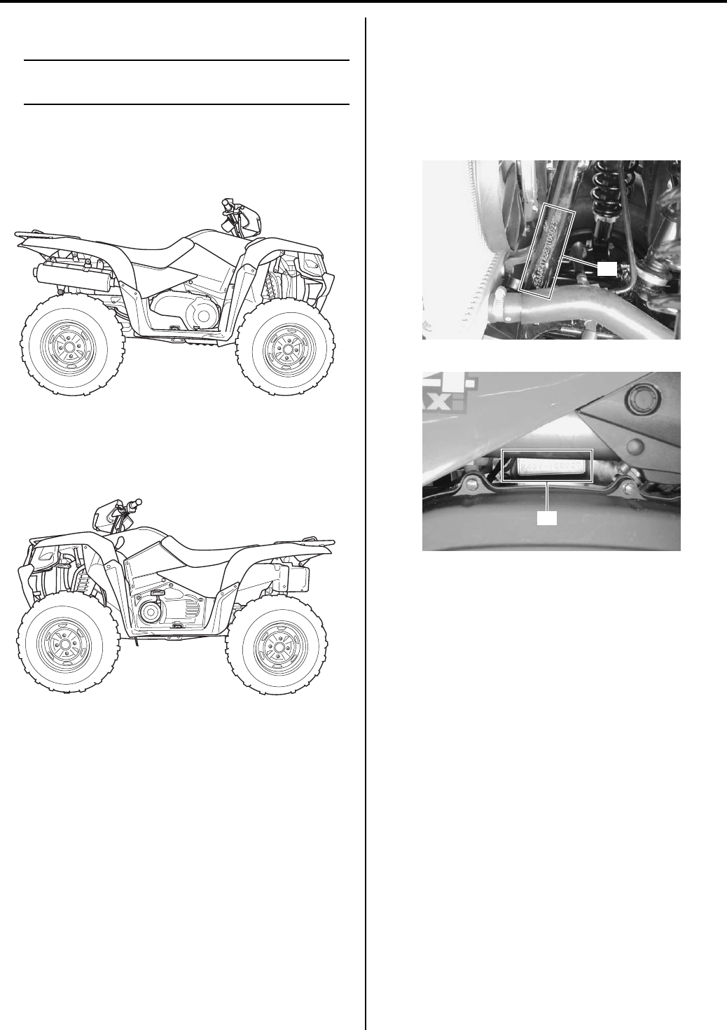
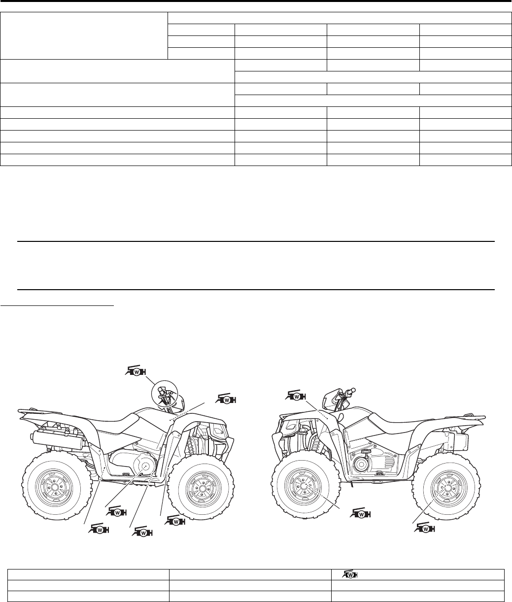
Vehicle Side View
B831G20101004
NOTE
Difference between illustration and actual
vehicle may exist depending on the markets.
SUZUKI LT-A750X (2008-model)
Right Side
Left Side
Vehicle Identification Number
B831G20101005
The frame serial number or V.I.N. (Vehicle Identification
Number) “A” is stamped on the left side of the front frame
pipe. The engine serial number “B” is located on the right
side of the crankcase. These numbers are required
especially for registering the machine and ordering
spare parts.
Fuel and Oil Recommendation
B831G20101006
Fuel (For USA and Canada)
Use only unleaded gasoline of at least 87 pump octane
(R/2 + M/2) or 91 octane or higher rated by the research
method.
Gasoline containing MTBE (Methyl Tertiary Butyl Ether),
less than 10% ethanol, or less than 5% methanol with
appropriate cosolvents and corrosion inhibitor is
permissible.
Fuel (For Other Countries)
Gasoline used should be graded 91 octane (Research
Method) or higher. Unleaded gasoline is recommended.
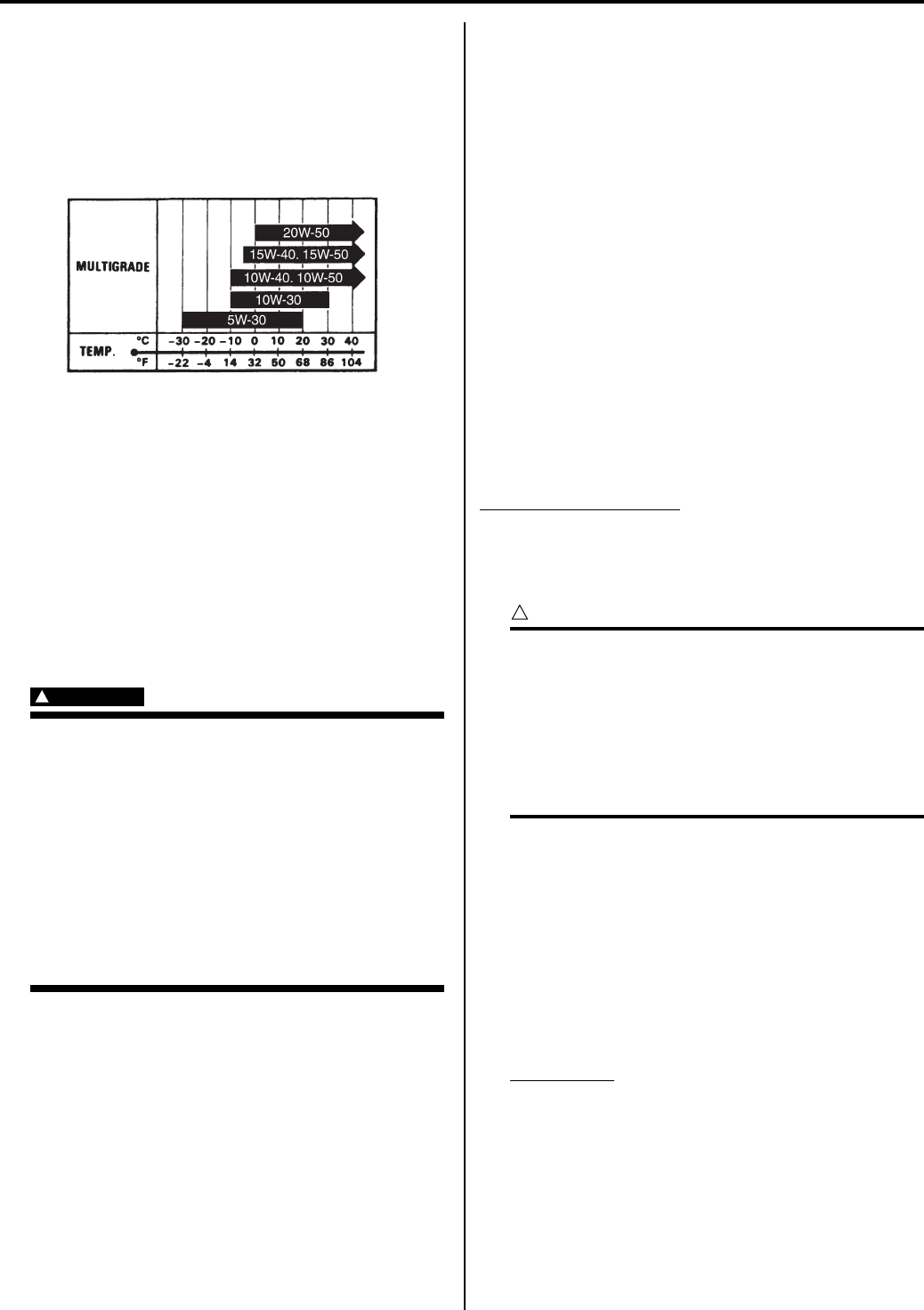
Engine Oil (For USA)
Oil quality is a major contributor to your engine’s
performance and life. Always select good quality engine
oil.
Suzuki recommends the use of SUZUKI
PERFORMANCE 4 MOTOR OIL or an equivalent
engine oil. Use of SF/SG or SH/SJ in API with MA in
JASO.
Suzuki recommends the use of SAE 10W-40 engine oil.
If SAE 10W-40 engine oil is not available, select and
alternative according to the chart.
I831G1010001-01
I831G1010002-01
“A”
I831G1010003-01
“B”
I831G1010004-01
PartShark.com
877-999-5686
General Information: 0A-4
Engine Oil (For Other Countries)
Oil quality is a major contributor to your engine’s
performance and life. Always select good quality engine
oil. Use of SF/SG or SH/SJ in API with MA in JASO.
Suzuki recommends the use of SAE 10W-40 engine oil.
If SAE 10W-40 engine oil is not available, select an
alternative according to the chart.
Front Differential Gear Oil
Use hypoid gear oil that meets the API service
classification GL-5 and is rated SAE #90. Use a hypoid
gear oil with a rating of SAE #80 if the vehicle is
operated where the ambient temperature is below 0 °C
(32 °F).
Rear Drive (Final) Gear Oil
Use mobil fluid 424 or equivalent oil.
Brake Fluid
Specification and classification: DOT 4
WARNING
!
Since the brake system of this vehicle is
filled with a glycol-based brake fluid by the
manufacturer, do not use or mix different
types of fluid such as silicone-based and
petroleum-based fluid for refilling the
system, otherwise serious damage will
result.
Do not use any brake fluid taken from old or
used or unsealed containers.
Never reuse brake fluid left over from a
previous servicing, which has been stored
for a long period.
Engine Coolant Recommendation
B831G20101007
Engine Coolant
Use an anti-freeze/engine coolant compatible with an
aluminum radiator, mixed with distilled water only.
Water for mixing
Use distilled water only. Water other than distilled water
can corrode and clog the aluminum radiator.
Anti-freeze / Engine coolant
The engine coolant perform as a corrosion and rust
inhibitor as well as anti-freeze. Therefore, the engine
coolant should be used at all times even though the
atmospheric temperature in your area does not go down
to freezing point.
Suzuki recommends the use of SUZUKI COOLANT anti-
freeze/engine coolant. If this is not available, use an
equivalent which is compatible with an aluminum
radiator.
Liquid amount of water / Engine coolant
Solution capacity (total)
2 450 ml (2.6/2.2 US/Imp qt)
For engine coolant mixture information, refer to “Engine
Coolant Description in Section 1F (Page 1F-1)”.
CAUTION
!
Mixing of anti-freeze/engine coolant should
be limited to 60%. Mixing beyond it would
reduce its efficiency. If the anti-freeze/engine
coolant mixing ratio is below 50%, rust
inhabiting performance is greatly reduced.
Be sure to mix it above 50% even though the
atmospheric temperature does not go down
to the freezing point.
BREAK-IN Procedures
B831G20101008
During manufacture only the best possible materials are
used and all machined parts are finished to a very high
standard but it is still necessary to allow the moving parts
to “BREAK-IN” before subjecting the engine to maximum
stresses. The future performance and reliability of the
engine depends on the care and restraint exercised
during its early life. The general rules are as follows.
1) Keep to these break-in engine speed limits:
Speed limits
Initial 500 km (300 miles): Less than 1/2 throttle
2) Upon reaching an odometer reading of 500 km (300
miles) you can subject the vehicle to full throttle
operation, for short periods of time.
I831G1010008-01
PartShark.com
877-999-5686

0A-5 General Information:
Country and Area Codes
B931G20101009
The following codes stand for the applicable country(-ies) and area(-s).
Wire Color Symbols
B931G20101010
Model Code Country or Area Effective Frame No.
LT-A750XK8
P-17 Sweden
5SAAR41A 87100001 –
P-24 Australia
P-28 Canada
P-33 U.S.A.
LT-A750XZK8
P-17 Sweden
P-24 Australia
P-28 Canada
P-33 U.S.A.
LT-A750XK9
P-17 Sweden
5SAAR41A 97100001 –
P-24 Australia
P-28 Canada
P-33 U.S.A.
LT-A750XZK9
P-17 Sweden
P-28 Canada
P-33 U.S.A.
Symbol Wire Color Symbol Wire Color
B Black Br/W Brown with White tracer
Bl Blue G/B Green with Black tracer
Br Brown Gr/R Gray with Red tracer
Dg Dark green Gr/W Gray with White tracer
G Green O/G Orange with Green tracer
Gr Gray O/R Orange with Red tracer
O Orange O/W Orange with White tracer
P Pink O/Y Orange with Yellow tracer
R Red O/B Orange with Black tracer
W White O/Bl Orange with Blue tracer
Y Yellow P/W Pink with White tracer
B/Bl Black with Blue tracer R/B Red with Black tracer
B/Br Black with Brown tracer R/G Red with Green tracer
B/G Black with Green tracer W/B White with Black tracer
B/Lg Black with Light green tracer W/Bl White with Blue tracer
B/R Black with Red tracer W/G White with Green tracer
B/W Black with White tracer W/R White with Red tracer
B/Y Black with Yellow tracer W/Y White with Yellow tracer
Bl/B Blue with Black tracer Y/B Yellow with Black tracer
Bl/G Blue with Green tracer Y/Bl Yellow with Blue tracer
Bl/W Blue with White tracer Y/R Yellow with Red tracer
Bl/R Blue with Red tracer Y/G Yellow with Green tracer
Bl/Y Blue with Yellow tracer
PartShark.com
877-999-5686
General Information: 0A-6
Warning, Caution and Information Labels Location
B931G20101011
[A]
5
14 17, 18
11
9
6
3
7
8
10
12, 13
15, 16
4
2
1, 21
23, 24 20
19
I831G1010005-06
1. Certification plate For P-24, 33 13. Max AMP caution label For P-17, 28
2. Information label For P-33 14. Fuel caution label For P-24
3. Gearshift label For P-17, 24, 28, 33 15. Front carrier warning label For P-24, 33
4. Gearshift label For P-28 16. Front carrier warning label For P-17, 28
5. Tire air pressure label For P-17, 24, 28, 33 17. Rear carrier warning label For P-24, 33
6. Tire air pressure label and warning no-
passenger label For P-28 18. Rear carrier warning label For P-17, 28
7. General warning & AGE, 16 label For P-17, 24, 28, 33 19. ICES Canada label For P-28
8. General warning label For P-28 20. Compliance label No.2 For P-28
9. Warning no-passenger label For P-17, 24, 28, 33 21. I.D. plate For P-17
10. AGE, 16 label For P-28 22. Cooling fan label For P-17, 24, 28, 33
11. Manual notice label For P-33 23. Compliance label For P-28
12. Max AMP caution label For P-24, 33 [A]: Left side of frame
PartShark.com
877-999-5686
0A-7 General Information:
Component Location
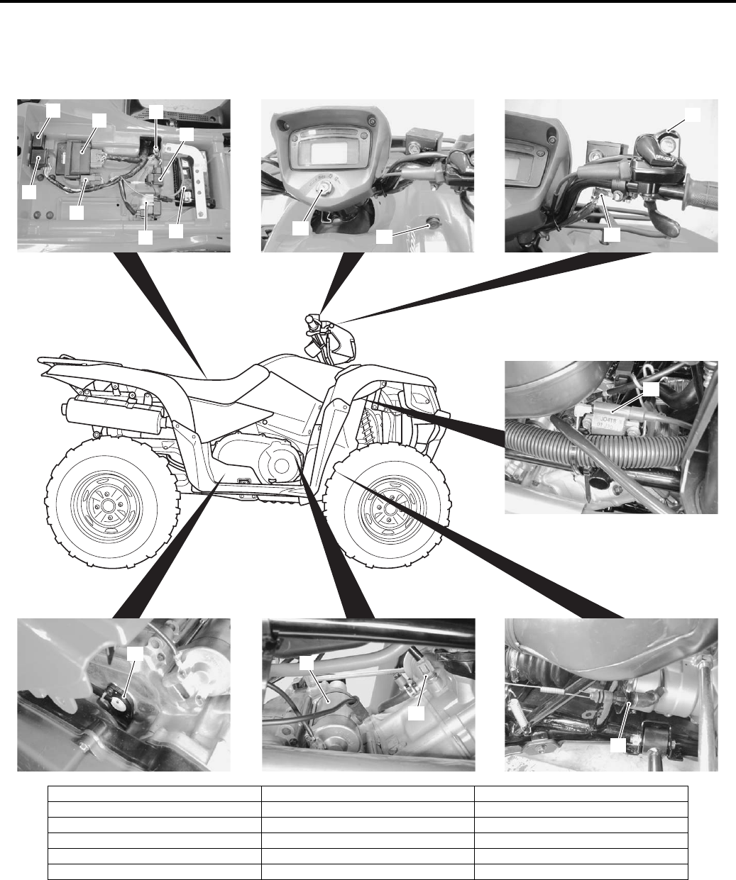
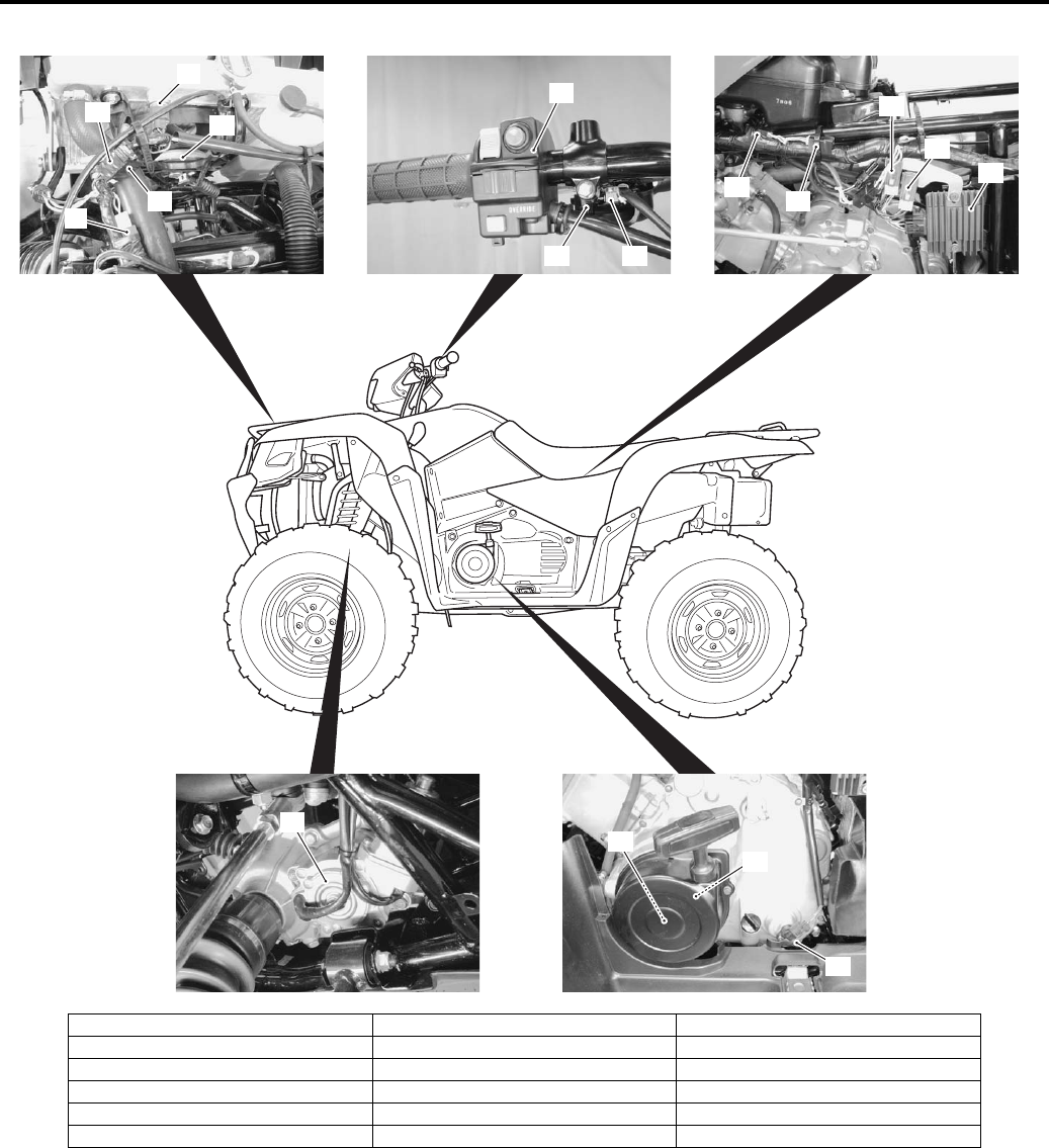
Electrical Components Location
B931G20103001
15
1
2
3
4
5
68
7
13 14 12
11
17 9
10
16
I831G1010006-02
1. Battery 7. 4WD/Diff-lock relay 13. Ignition switch
2. Starter relay/Main fuse 8. Mode selection switch coupler 14. Power source
3. Fuse box 9. Starter motor 15. Ignition coil
4. Neutral relay 10. ECT sensor 16. Rear brake switch
5. Fuel pump relay 11. 4WD/Diff-lock switch 17. Gear position switch
6. ECM 12. Brake lever switch (R)
PartShark.com
877-999-5686
General Information: 0A-8
18
19
20
21
22
25
23
24
26
30
28
27
31
29
33
34
32
I831G1010007-03
18. Cooling fan thermo-switch 24. Parking brake switch 30. High position diode
19. Resister 25. Brake lever switch 31. Low position diode
20. 4WD/Diff-lock actuator diode 26. Regulator/Rectifier 32. Speed sensor
21. Neutral relay diode 27. Parking brake relay 33. CKP sensor
22. Cooling fan 28. Diff-lock relay 34. Generator
23. Handlebar switch 29. Actuator
PartShark.com
877-999-5686

0A-9 General Information:
Specifications
Specifications (LT-A750X/ZK8)
B931G20107001
NOTE
These specifications are subject to change without notice.
Dimensions and dry mass
Engine
Drive train
Item Specification Remark
Overall length 2 115 mm (83.3 in) P-28, 33
2 135 mm (84.1 in) P-17, 24
Overall width 1 210 mm (47.6 in) P-28, 33
1 250 mm (49.2 in) P-17, 24
Overall height 1 245 mm (49.0 in)
Wheelbase 1 280 mm (50.4 in)
Ground clearance 270 mm (10.6 in)
Seat height 880 mm (34.6 in)
Dry mass 273 kg (601 lbs) P-28, 33
275 kg (606 lbs) P-17, 24
Front track 930 mm (36.6 in)
Rear track 940 mm (37.0 in)
Item Specification Remark
Type 4-stroke, liquid-cooled, DOHC
Number of cylinders 1
Bore 104.0 mm (4.094 in)
Stroke 85.0 mm (3.346 in)
Displacement 722 cm3 (44.1 cu.in)
Compression ratio 10.0 : 1
Fuel system Fuel injection
Air cleaner Non-woven fabric element
Starter system Electric and recoil starter
Lubrication system Wet sump
Idle speed 1 300 ± 100 r/min
Item Specification Remark
Clutch Wet shoe, automatic, centrifugal type
Transmission Automatic variable ratio (V-belt)
Transfer 2-speed forward with reverse
Gearshift pattern Transmission Automatic
Transfer L-H-N-R (Hand operated)
Primary reduction ratio (Automatic
drive) Variable change (2.763 – 0.78)
Secondary reduction ratio 2.158 (40/21 x 17/15)
Final reduction ratio (Front & Rear) 3.600 (36/10)
Transfer gear ratio
Low 2.562 (41/16)
High 1.240 (31/25)
Reverse 1.882 (32/17)
Drive system Shaft drive
PartShark.com
877-999-5686

General Information: 0A-10
Chassis
Electrical
Capacities
Item Specification Remark
Front suspension Independent, double wishbone, coil spring, oil damped
Rear suspension Independent, double wishbone, coil spring, oil damped
Front wheel travel 180 mm (7.1 in)
Rear wheel travel 200 mm (7.9 in)
Caster 1.6°
Trail 3.4 mm (0.13 in)
Toe-out 10 mm (0.39 in)
Camber 0.64°
Steering angle 46° (right & left)
Turning radius 3.1 m (10.2 ft)
Front brake Disc brake, twin
Rear brake Sealed oil-bathed multi-disc
Front tire size AT25 x 8-12, tubeless
Rear tire size AT25 x 10-12, tubeless
Item Specification Remark
Ignition type Electronic ignition (CDI)
Ignition timing 7° B.T.D.C. at 1 300 r/min
Spark plug NGK CR6E or DENSO U20ESR-N
Battery 12 V 64.8 kC (18 Ah)/10 HR
Generator Three-phase A.C. generator
Main fuse 30 A
Fuse 10/10/10/10/15/15 A
Headlight 12 V 35/35 W x 2
Auxiliary light 12 V 35/35 W
Brake light/Taillight 12 V 21/5 W
Revercing light 12 V 21 W P-17
Speedometer light LED
Neutral indicator light LED
High beam indicator light LED P-17
Coolant temperature/FI indicator
light LED
Reverse indicator light LED
Diff-lock indicator light LED
Item Specification Remark
Fuel tank 17.5 L (4.6/3.8 US/lmp gal)
Engine oil
Oil change 2 300 ml (2.4/2.0 US/lmp qt)
With filter change 2 500 ml (2.6/2.2 US/lmp qt)
Overhaul 3 000 ml (3.2/2.6 US/lmp qt)
Differential gear oil 500 ml (0.5/0.4 US/lmp qt)
Final gear oil 770 ml (0.7/0.6 US/lmp qt)
Coolant 2 450 ml (2.6/2.2 US/lmp qt)
PartShark.com
877-999-5686
0A-11 General Information:
Specifications (LT-A750X/ZK9)
B931G20107002
NOTE
• These specifications are subject to change without notice.
• Any differences between the LT-A750X/ZK8 (’08-model) and LT-A750X/ZK9 (’09-model) in
specifications are indicated with an asterisk mark (*).
Dimensions and curb mass
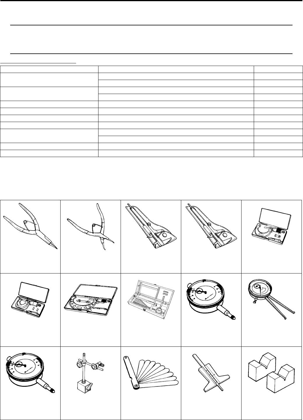
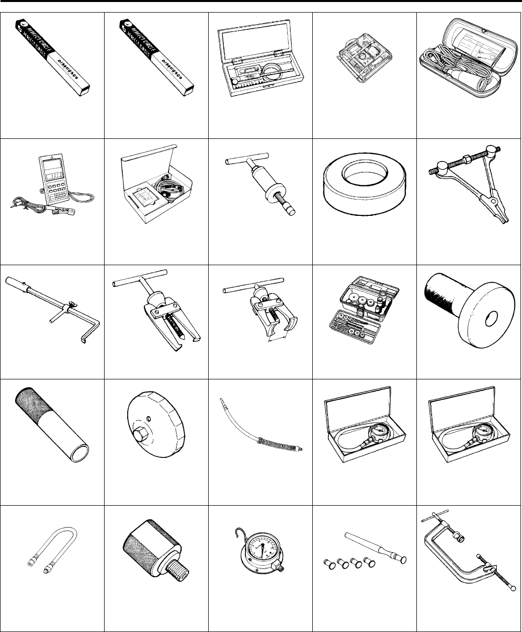
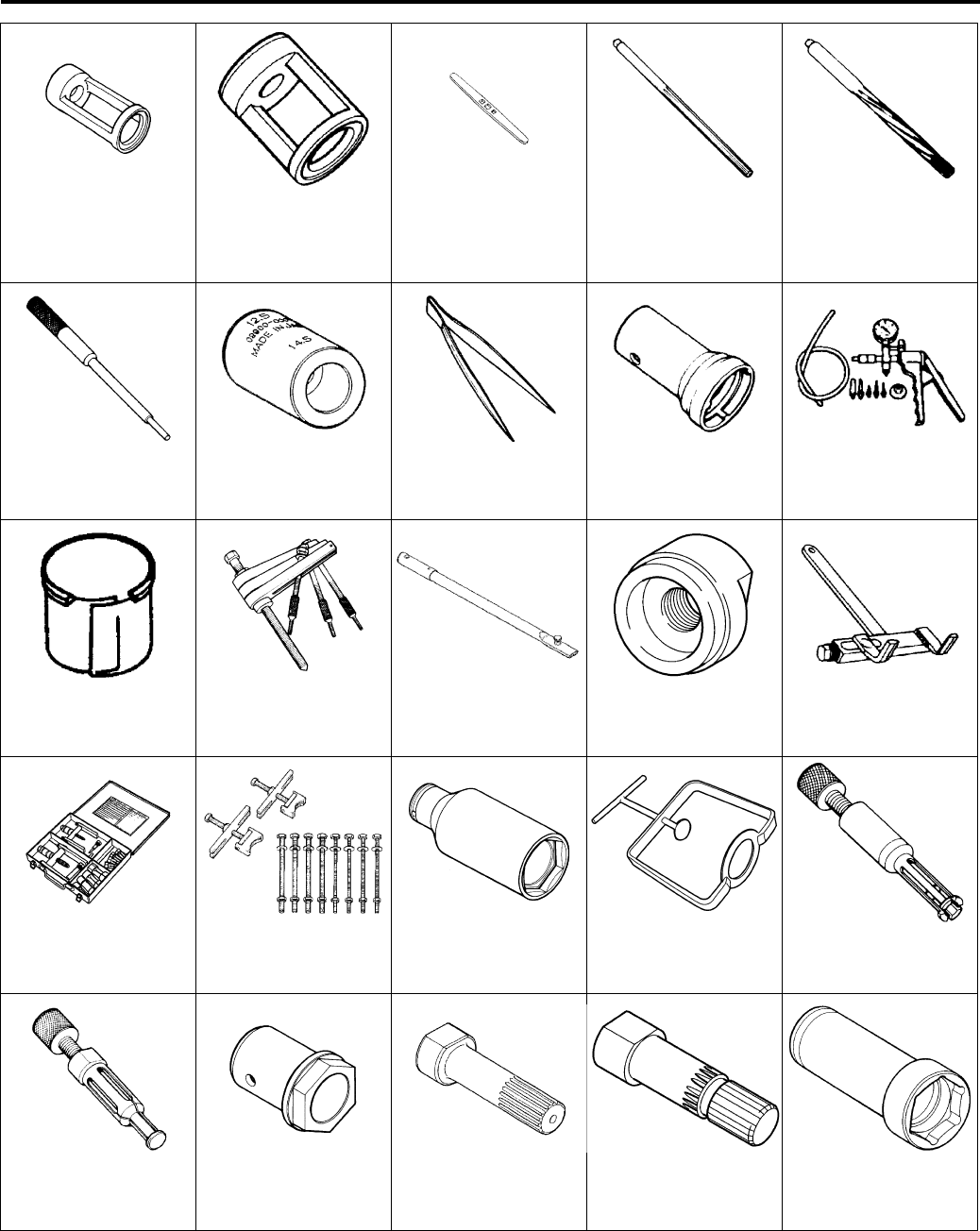
Special Tools and Equipment
Special Tool
B931G20108001
Item Specification Remark
Overall length 2 115 mm (83.3 in) P-28, 33
2 135 mm (84.1 in) P-17, 24
Overall width 1 210 mm (47.6 in) P-28, 33
1 250 mm (49.2 in) P-17, 24
Overall height 1 245 mm (49.0 in)
Wheelbase 1 280 mm (50.4 in)
Ground clearance 270 mm (10.6 in)
Seat height 880 mm (34.6 in)
* Curb mass 302 kg (666 lbs) P-28, 33
304 kg (670 lbs) P-17, 24
Front track 930 mm (36.6 in)
Rear track 940 mm (37.0 in)
09900–06107
Snap ring pliers
09900–06108
Snap ring pliers
09900–20101
Vernier calipers (1/15
mm, 150 mm)
09900–20102
Vernier calipers (1/20
mm, 200 mm)
09900–20202
Micrometer (1/100
mm, 25 – 50 mm)
09900–20205
Micrometer (0 – 25
mm)
09900–20210
Micrometer (100 – 125
mm)
09900–20530
Cylinder gauge set
09900–20602
Dial gauge (1/1000
mm, 1 mm)
09900–20605
Dial calipers (1/100
mm, 10 – 34 mm)
09900–20607
Dial gauge (1/100 mm,
10 mm)
09900–20701
Magnetic stand
09900–20803
Thickness gauge
09900–20805
Tire depth gauge
09900–21304
V-block (100 mm)
PartShark.com
877-999-5686
General Information: 0A-12
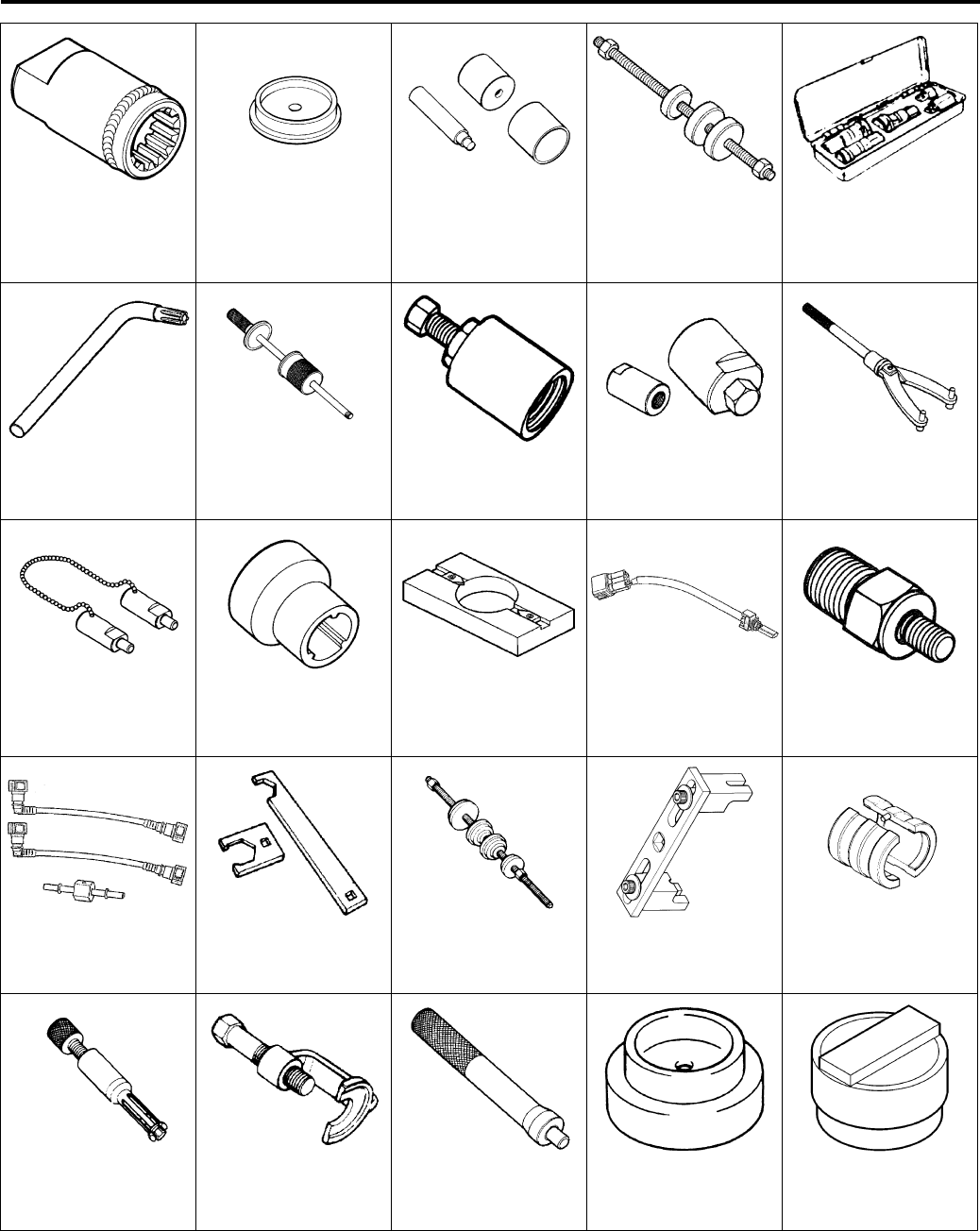
09900–22301
Plastigauge (0.025 –
0.076 mm)
09900–22302
Plastigauge (0.051 –
0.152 mm)
09900–22403
Small bore gauge (18
– 35 mm)
09900–25008
Multi-circuit tester set
09900–25009
Needle pointed probe
set
09900–26006
Engine tachometer
(solar cell type)
09904–41010
SDS set
09910–32812
Crankshaft installer
09910–32860
Attachment
09912–34510
Cylinder
disassembling tool
09913–50121
Oil seal remover
09913–60910
Bearing remover
09913–61510
Bearing puller
09913–70210
Bearing installer set
09913–75520
Bearing installer
09913–84510
Bearing installer
09915–40610
Oil filter wrench
09915–63311
Compression gauge
attachment
09915–64512
Compression gauge
09915–74511
Oil pressure gauge set
09915–74521
Oil pressure gauge
hose
09915–74533
Oil pressure gauge
attachment
09915–77331
Meter (for high
pressure)
09916–10911
Valve lapper set
09916–14510
Valve lifter
PartShark.com
877-999-5686
0A-13 General Information:
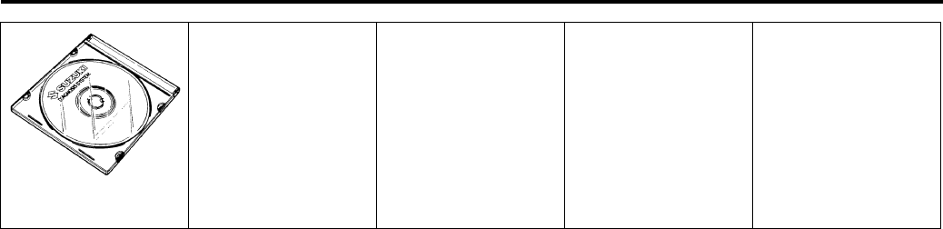
09916–14521
Valve spring
compressor
attachment
09916–14910
Valve spring
compressor
attachment
09916–34542
Reamer handle
09916–34550
Valve guide reamer
(5.5 mm)
09916–34580
Valve guide reamer
(10.8 mm)
09916–44910
Valve guide remover/
installer
09916–57360
Attachment
09916–84511
Tweezers
09917–23711
Ring nut wrench
09917–47011
Vacuum pump gauge
09919–28610
Sleeve protector
09920–13120
Crankcase separating
tool
09920–31020
Extension handle
09920–33540
Clutch shoe remover
09920–53740
Clutch sleeve hub
holder
09921–20240
Bearing remover set
09921–21910
Bearing holder
09922–21410
Long socket (46 mm)
09922–31430
Clutch spring
compressor
09923–73210
Bearing remover
09923–74511
Bearing remover
09924–41830
Bearing retainer
wrench
09924–52420
Secondary bevel gear
holder
09924–52450
Fixed driven face
holder
09924–52460
Socket (52 mm)
PartShark.com
877-999-5686
General Information: 0A-14
09924–52470
Fixed final drive gear
holder
09924–74520
Oil seal installer/
remover
09924–74570
Final drive gear
bearing installer/
remover
09924–84521
Bearing installer set
09930–10121
Spark plug wrench set
09930–11950
Torx wrench
09930–30104
Rotor remover sliding
shaft
09930–30721
Rotor remover
09930–31921
Rotor remover
09930–40113
Rotor holder
09930–40131
Balancer drive
sprocket holder
09930–73140
Starter torque limiter
socket
09930–73170
Starter torque limiter
holder
09930–82720
Mode select switch
09940–40211
Fuel pressure gauge
adapter
09940–40220
Fuel pressure gauge
hose attachment
09940–92430
Rear axel wrench A
09941–34513
Steering race installer
09941–51012
Ring locknut wrench
09941–53610
Front fork installer
hammer
09941–64511
Bearing remover
09942–72410
Tie-rod end remover
09943–88211
Bearing remover/
installer
09944–66010
Bearing installer
09951–15810
Bearing installer
PartShark.com
877-999-5686
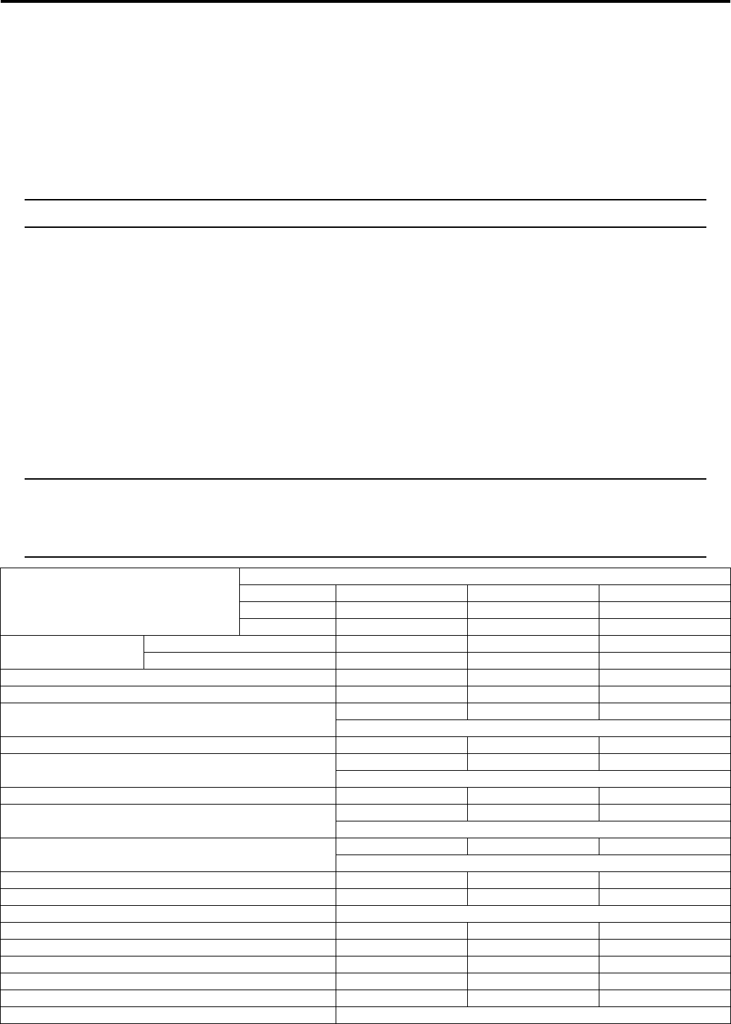
0A-15 General Information:
99565–01010–013
CD-ROM Ver.13
PartShark.com
877-999-5686
Maintenance and Lubrication: 0B-1
General Info rmation
Maintenance and Lubrication
Precautions
Precautions for Maintenance
B931G20200001
The “Periodic Maintenance Schedule Chart” lists the recommended intervals for all the required periodic service work
necessary to keep the vehicle operating at peak performance and economy. Maintenance intervals are expressed in
terms of kilometers, miles and months for your convenience.
NOTE
More frequent servicing may be required on vehicle that are used under severe conditions.
General Description
Recommended Fluids and Lubricants
B931G20201001
Refer to “Fuel and Oil Recommendation in Section 0A (Page 0A-3)” and “Engine Coolant Recommendation in Section
0A (Page 0A-4)”.
Scheduled Maintenance
Periodic Maintenance Schedule Chart
B931G20205001
NOTE
I = Inspect and clean, adjust, replace or lubricate as necessary.
C = Clean.
R = Replace.
T = Tighten.
Item
Interval
km Initial 200 Every 1 000 Every 2 000
miles Initial 100 Every 600 Every 1 200
months Initial 1 Every 3 Every 6
Air cleaner element polyurethane foam element — C C
non-woven fabric element — I I
Exhaust pipe nuts and muffler mounting bolts T T T
Valve clearance I — I
Spark plug —— I
Replace every 6 000 km (4 000 miles).
Spark arrester — — C
Fuel line —I I
Replace every 4 years.
Engine oil and oil filter R — R
Front differential gear oil —— I
Replace every 2 years.
Final gear oil —— I
Replace every year.
Throttle cable play I I I
Throttle body — I I
Engine coolant Replace every 2 years.
Radiator — I I
Radiator hose — — I
Drive belt — I R
Drive shaft boots I I I
Brakes I I I
Rear brake plates Replace every 10 000 km (6 000 miles).
PartShark.com
877-999-5686
0B-2 Maintenance and Lubrication:
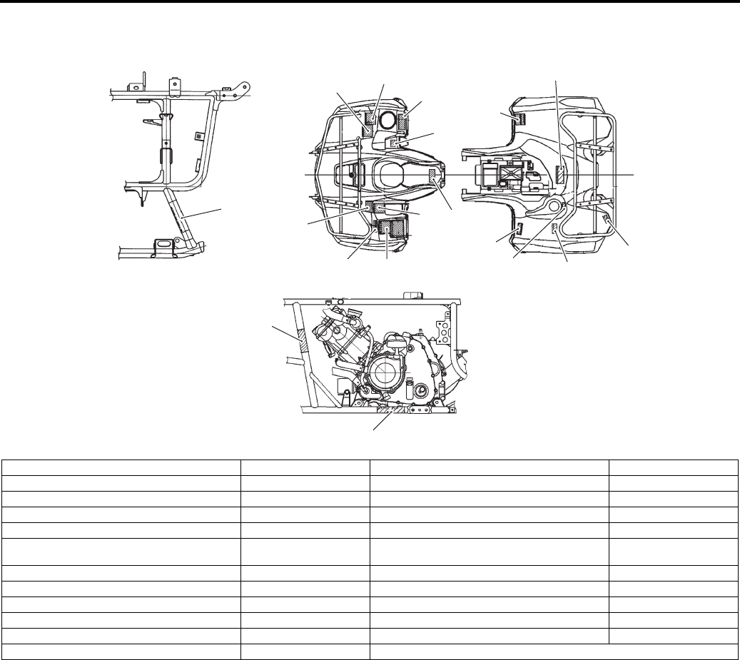
Lubrication Points
B931G20205002
Proper lubrication is important for smooth operation and long life of each working part of the vehicle.
Major lubrication points are indicated as follows.
NOTE
• Before lubricating each part, clean off any rusty spots and wipe off any grease, oil, dirt or grime.
• Lubricate exposed parts which are subject to rust, with a rust preventative spray whenever the
vehicle has been operated under wet or rainy conditions.
Lubricate exposed parts
Every 1 000 km (600 miles, 3 months)
Brake fluid —I I
Replace every 2 years.
Brake hose —— I
Replace every 4 years.
Tires — I I
Steering III
Suspensions — — I
Chassis nuts and bolts T T T
General lubrications — L L
Item
Interval
km Initial 200 Every 1 000 Every 2 000
miles Initial 100 Every 600 Every 1 200
months Initial 1 Every 3 Every 6
1
4
6
4
4
3
1
2
5
5
I831G1020001-03
1. Steering shaft holder 4. Propeller shaft joint spline : Apply water resistance grease.
2. Brake level holder and throttle lever 5. Drive shaft joint spline
3. Brake pedal 6. Drive belt cover bearing (Inner race)
PartShark.com
877-999-5686
Maintenance and Lubrication: 0B-3
Repair Instructions
Air Cleaner Element Inspection and Cleaning
B931G20206001
Inspect and clean element
Every 1 000 km (600 miles, 3 months)
Inspection
1) Remove the air cleaner element. Refer to “Air
Cleaner Element Removal and Installation in Section
1D (Page 1D-5)”.
2) Inspect the air cleaner element for clogging. If it is
clogged with dirt, clean or replace it with a new one.
CAUTION
!
If driving under dusty conditions, inspect or
clean the air cleaner element more frequently.
The surest way to accelerate engine wear is
to operate the engine without the element or
to use a torn element. Make sure that the air
cleaner is in good condition at all times. Life
of the engine depends largely on this
component.
3) After finishing the air cleaner element inspection,
reinstall the removed parts.
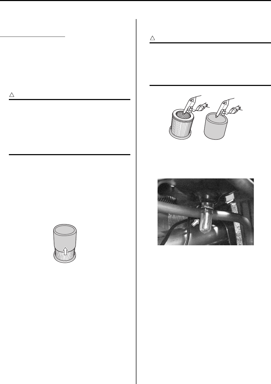
Cleaning
1) Remove the air cleaner element assembly. Refer to
“Air Cleaner Element Removal and Installation in
Section 1D (Page 1D-5)”.
2) Separate the polyurethane from element.
3) Carefully use compressed air to clean the air cleaner
element.
CAUTION
!
Always apply compressed air to the inside of
the air cleaner element. If compressed air is
applied to the outside, dirt will be forced into
the pores of the air cleaner element,
restricting air flow through the air cleaner
element.
4) After cleaning the air cleaner element, reinstall the
removed parts.
5) Drain water from the air cleaner by removing the
drain plug.
6) Reinstall the drain plug.
I831G1020002-01
I831G1020003-01
I831G1020004-01
PartShark.com
877-999-5686
0B-4 Maintenance and Lubrication:
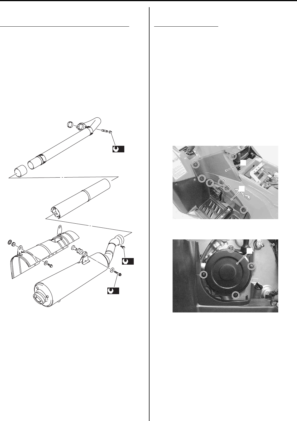
Exhaust Pipe Bolt and Muffler Bolt Inspection
B931G20206002
Tighten exhaust pipe bolts, muffler bolt and nut
Initially at 200 km (100 miles, 1 month) and every 1
000 km (600 miles, 3 months) thereafter
Check the exhaust pipe bolts, muffler bolts and nut to the
specified torque. Refer to “Exhaust Pipe / Muffler
Removal and Installation in Section 1K (Page 1K-2)”.
Tightening torque
Exhaust pipe nut (a): 23 N·m (2.3 kgf-m, 16.5 lbf-ft)
Muffler mounting bolt (b): 23 N·m (2.3 kgf-m, 16.5
lbf-ft)
Muffler connecting bolt (c): 23 N·m (2.3 kgf-m, 16.5
lbf-ft)
Valve Clearance Inspection and Adjustment
B931G20206003
Inspect valve clearance
Initially at 200 km (100 miles, 1 month) and every 2
000 km (1 200 miles, 6 months) thereafter
Inspection
Valve clearance adjustment must be checked and
adjusted, a) at the time of periodic inspection, b) when
the valve mechanism is serviced, and c) when the
camshafts are removed for servicing.
1) Remove the front inner fender (LH & RH). Refer to
“Front Side Exterior Parts Removal and Installation
in Section 9D (Page 9D-6)”.
2) Remove the inlet V-belt cooling duct. Refer to “V-belt
Cooling Duct Removal and Installation in Section 5A
(Page 5A-5)”.
3) Remove the left side cover (1) and engine side cover
(2).
4) Remove the recoil starter (3).
(b)
(c)
(a)
I831G1020005-02
1
2
I831G1020009-02
3
I831G1020010-01
PartShark.com
877-999-5686
Maintenance and Lubrication: 0B-5
5) Drain a small amount of engine coolant and
disconnect the radiator upper hose of thermostat
side. Refer to “Cooling System Inspection (Page 0B-
15)”.
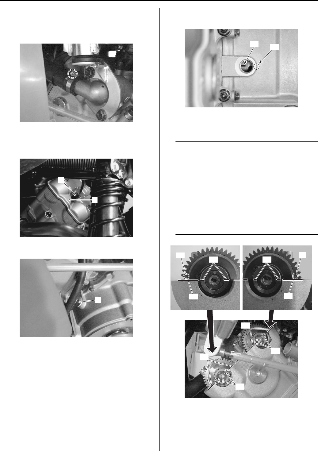
6) Remove the spark plug cap (4) and spark plug (5).
Refer to “Spark Plug Cap and Spark Plug Removal
and Installation in Section 1H (Page 1H-3)”.
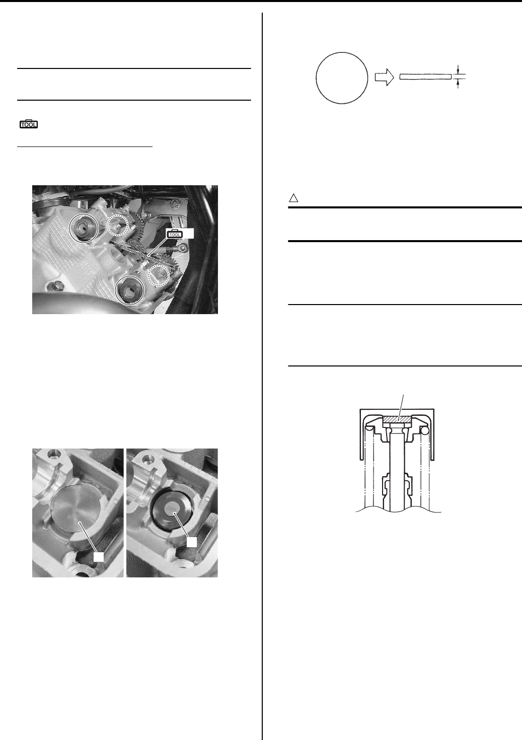
7) Remove the valve timing inspection plug (6).
 Turn the crankshaft to bring the “TDC” line “A” on the
generator rotor to the lug mark “B”.
9) Remove the cylinder head cover. Refer to “Engine
Top Side Disassembly in Section 1D (Page 1D-17)”.
NOTE
• Check the engraved lines “C” on the
camshafts, so it is parallel with the mating
surface “D” on the cylinder head cover.
• The valve clearance should be taken
cylinder is at Top Dead Center (TDC) of
compression stroke.
• The clearance specification is for COLD
state.
• To turn the crankshaft for clearance
checking, be sure to use a wrench, and
rotate in the normal running direction.
I831G1020012-01
5
4
I831G1020085-03
6
I831G1020011-02
“A” “B”
I831G1140086-03
“C”
“C”
“D”
“D”
“C” “C”
EX IN
“D” “D”
I831G1020013-03
PartShark.com
877-999-5686
0B-6 Maintenance and Lubrication:
10) Insert the thickness gauge between the tappet and
the cam. If the clearance is out of specification,
adjust it to the specified range.
NOTE
The valve clearance specification is different
for both intake and exhaust valves.
Special tool
(A): 09900–20803 (Thickness gauge)
Valve clearance (When cold)
IN.: 0.10 – 0.20 mm (0.004 – 0.008 in)
EX.: 0.20 – 0.30 mm (0.008 – 0.012 in)
Adjustment
The clearance is adjusted by replacing the existing
tappet shim with a thicker or thinner shim.
1) Remove the intake or exhaust camshafts. Refer to
“Engine Top Side Disassembly in Section 1D
(Page 1D-17)”.
2) Remove the tappet (1) and shim (2) by fingers or
magnetic hand.
3) Check the figures printed on the shim. These figures
indicate the thickness of the shim, as illustrated.
4) Select a replacement shim that will provide a
clearance within the specified range. For the
purpose of this adjustment, a total of 25 sizes of
tappet shim are available ranging from 2.50 to 3.50
mm in steps of 0.05 mm.
CAUTION
!
Both the right and left valve clearances
should be as closely as possible.
5) Fit the selected shim (2) to the valve stem end, with
numbers toward tappet. Be sure to check shim size
with micrometer to ensure its size.
NOTE
• Be sure to apply engine oil to tappet shim
top and bottom faces.
• When seating the tappet shim, be sure the
figure printed surface faces the tappet.
(A)
I831G1020015-01
1
2
I831G1020016-01
300
3.00 mm
I831G1020091-01
2
I718H1020002-02
PartShark.com
877-999-5686
Maintenance and Lubrication: 0B-7
(INTAKE SIDE)
0.00 – 0.04
0.05 – 0.09
0.10 – 0.20
0.21 – 0.25
0.26 – 0.30
0.31 – 0.35
0.36 – 0.40
0.41 – 0.45
0.46 – 0.50
0.51 – 0.55
0.56 – 0.60
0.61 – 0.65
0.66 – 0.70
0.71 – 0.75
0.76 – 0.80
0.81 – 0.85
0.86 – 0.90
0.91 – 0.95
0.96 – 1.00
1.01 – 1.05
1.06 – 1.10
1.11 – 1.15
1.16 – 1.20
1.21 – 1.25
1.26 – 1.30
1.31 – 1.35
1.36 – 1.40
2.40
2.45
2.50
2.55
2.60
2.65
2.70
2.75
2.80
2.85
2.90
2.95
3.00
3.05
3.10
3.15
3.20
3.25
3.30
3.35
3.40
3.45
3.50
3.50
2.30
2.45
2.50
2.55
2.60
2.65
2.70
2.75
2.80
2.85
2.90
2.95
3.00
3.05
3.10
3.15
3.20
3.25
3.30
3.35
3.40
3.45
3.50
3.50
2.30
2.35
2.50
2.55
2.60
2.65
2.70
2.75
2.80
2.85
2.90
2.95
3.00
3.05
3.10
3.15
3.20
3.25
3.30
3.35
3.40
3.45
3.50
3.50
2.35
2.40
2.55
2.60
2.65
2.70
2.75
2.80
2.85
2.90
2.95
3.00
3.05
3.10
3.15
3.20
3.25
3.30
3.35
3.40
3.45
3.50
3.50
2.40
2.45
2.60
2.65
2.70
2.75
2.80
2.85
2.90
2.95
3.00
3.05
3.10
3.15
3.20
3.25
3.30
3.35
3.40
3.45
3.50
3.50
2.45
2.50
2.65
2.70
2.75
2.80
2.85
2.90
2.95
3.00
3.05
3.10
3.15
3.20
3.25
3.30
3.35
3.40
3.45
3.50
3.50
2.50
2.55
2.70
2.75
2.80
2.85
2.90
2.95
3.00
3.05
3.10
3.15
3.20
3.25
3.30
3.35
3.40
3.45
3.50
3.50
2.55
2.60
2.75
2.80
2.85
2.90
2.95
3.00
3.05
3.10
3.15
3.20
3.25
3.30
3.35
3.40
3.45
3.50
3.50
2.60
2.65
2.80
2.85
2.90
2.95
3.00
3.05
3.10
3.15
3.20
3.25
3.30
3.35
3.40
3.45
3.50
3.50
2.65
2.70
2.85
2.90
2.95
3.00
3.05
3.10
3.15
3.20
3.25
3.30
3.35
3.40
3.45
3.50
3.50
2.70
2.75
2.90
2.95
3.00
3.05
3.10
3.15
3.20
3.25
3.30
3.35
3.40
3.45
3.50
3.50
2.75
2.80
2.95
3.00
3.05
3.10
3.15
3.20
3.25
3.30
3.35
3.40
3.45
3.50
3.50
2.80
2.85
3.00
3.05
3.10
3.15
3.20
3.25
3.30
3.35
3.40
3.45
3.50
3.50
2.85
2.90
3.05
3.10
3.15
3.20
3.25
3.30
3.35
3.40
3.45
3.50
3.50
2.90
2.95
3.10
3.15
3.20
3.25
3.30
3.35
3.40
3.45
3.50
3.50
2.95
3.00
3.15
3.20
3.25
3.30
3.35
3.40
3.45
3.50
3.50
3.00
3.05
3.20
3.25
3.30
3.35
3.40
3.45
3.50
3.50
3.05
3.10
3.25
3.30
3.35
3.40
3.45
3.50
3.50
3.10
3.15
3.30
3.35
3.40
3.45
3.50
3.50
3.15
3.20
3.35
3.40
3.45
3.50
3.50
3.20
3.25
3.40
3.45
3.50
3.50
3.25
3.30
3.45
3.50
3.50
3.30
3.35
3.50
3.50
3.35
3.40
3.50
3.40
3.45
230
2.30
235
2.35
240
2.40
245
2.45
250
2.50
255
2.55
260
2.60
265
2.65
270
2.70
275
2.75
280
2.80
285
2.85
290
2.90
295
2.95
300
3.00
305
3.05
310
3.10
315
3.15
320
3.20
325
3.25
330
3.30
335
3.35
340
3.40
345
3.45
350
3.50
MEASURED
VALVE
CLEARANCE
(mm)
Option
SPECIFIED CLEARANCE/NO ADJUSTMENT REQUIRED
TAPPET SHIM SET (12800-41810)
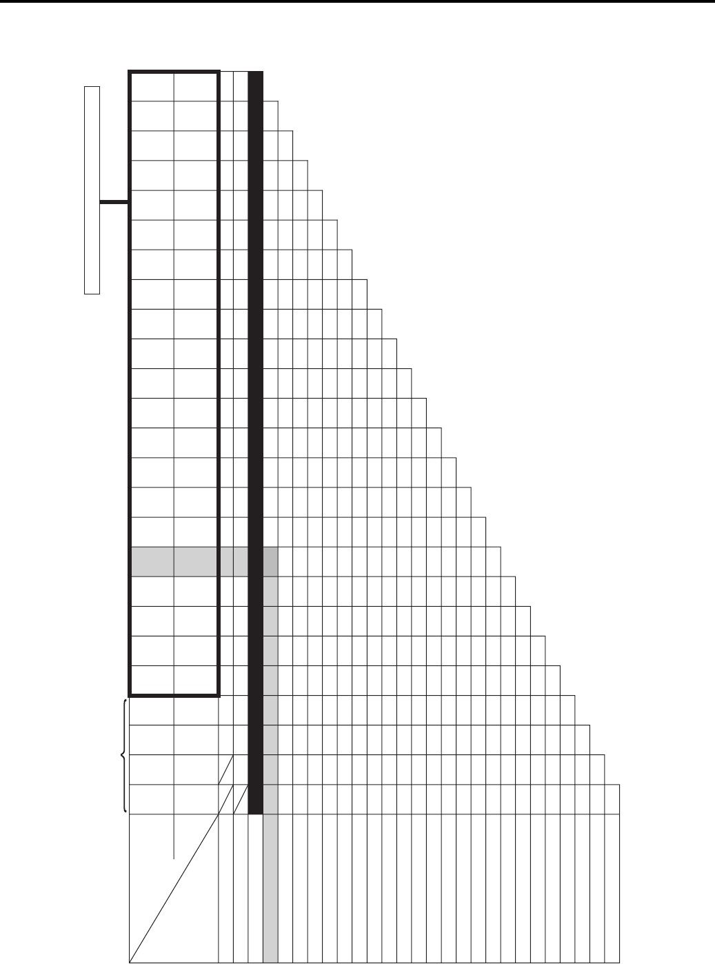
HOW TO USE THIS CHART:
I. Measure valve clearance. “ENGINE IS COLD”
II. Measure present shim size.
III. Match clearance in vertical column with present shim size in horizontal
column.
EXAMPLE
Valve clearance is 0.23 mm
Present shim size 2.70 mm
Shim size to be used 2.80 mm
TAPPET SHIM SELECTION TABLE [INTAKE]
TAPPET SHIM NO. (12892-41C00-XXX)
SUFFIX
NO.
PRESENT
SHIM SIZE
(mm)
I831G1020017-02
PartShark.com
877-999-5686
0B-8 Maintenance and Lubrication:
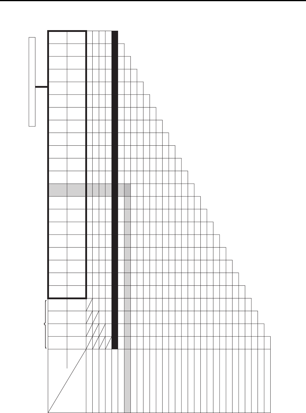
(EXHAUST SIDE)
HOW TO USE THIS CHART:
I. Measure valve clearance. “ENGINE IS COLD”
II. Measure present shim size.
III. Match clearance in vertical column with present shim size in horizontal
column.
EXAMPLE
Valve clearance is 0.38 mm
Present shim size 2.90 mm
Shim size to be used 3.05 mm
0.00 – 0.04
0.05 – 0.09
0.10 – 0.14
0.15 – 0.19
0.20 – 0.30
0.31 – 0.35
0.36 – 0.40
0.41 – 0.45
0.46 – 0.50
0.51 – 0.55
0.56 – 0.60
0.61 – 0.65
0.66 – 0.70
0.71 – 0.75
0.76 – 0.80
0.81 – 0.85
0.86 – 0.90
0.91 – 0.95
0.96 – 1.00
1.01 – 1.05
1.06 – 1.10
1.11 – 1.15
1.16 – 1.20
1.21 – 1.25
1.26 – 1.30
1.31 – 1.35
1.36 – 1.40
1.41 – 1.45
1.46 – 1.50
2.40
2.45
2.50
2.55
2.60
2.65
2.70
2.75
2.80
2.85
2.90
2.95
3.00
3.05
3.10
3.15
3.20
3.25
3.30
3.35
3.40
3.45
3.50
3.50
2.30
2.45
2.50
2.55
2.60
2.65
2.70
2.75
2.80
2.85
2.90
2.95
3.00
3.05
3.10
3.15
3.20
3.25
3.30
3.35
3.40
3.45
3.50
3.50
2.30
2.35
2.50
2.55
2.60
2.65
2.70
2.75
2.80
2.85
2.90
2.95
3.00
3.05
3.10
3.15
3.20
3.25
3.30
3.35
3.40
3.45
3.50
3.50
2.35
2.40
2.55
2.60
2.65
2.70
2.75
2.80
2.85
2.90
2.95
3.00
3.05
3.10
3.15
3.20
3.25
3.30
3.35
3.40
3.45
3.50
3.50
2.30
2.35
2.40
2.45
2.60
2.65
2.70
2.75
2.80
2.85
2.90
2.95
3.00
3.05
3.10
3.15
3.20
3.25
3.30
3.35
3.40
3.45
3.50
3.50
2.35
2.40
2.45
2.50
2.65
2.70
2.75
2.80
2.85
2.90
2.95
3.00
3.05
3.10
3.15
3.20
3.25
3.30
3.35
3.40
3.45
3.50
3.50
2.40
2.45
2.50
2.55
2.70
2.75
2.80
2.85
2.90
2.95
3.00
3.05
3.10
3.15
3.20
3.25
3.30
3.35
3.40
3.45
3.50
3.50
2.45
2.50
2.55
2.60
2.75
2.80
2.85
2.90
2.95
3.00
3.05
3.10
3.15
3.20
3.25
3.30
3.35
3.40
3.45
3.50
3.50
2.50
2.55
2.60
2.65
2.80
2.85
2.90
2.95
3.00
3.05
3.10
3.15
3.20
3.25
3.30
3.35
3.40
3.45
3.50
3.50
2.55
2.60
2.65
2.70
2.85
2.90
2.95
3.00
3.05
3.10
3.15
3.20
3.25
3.30
3.35
3.40
3.45
3.50
3.50
2.60
2.65
2.70
2.75
2.90
2.95
3.00
3.05
3.10
3.15
3.20
3.25
3.30
3.35
3.40
3.45
3.50
3.50
2.65
2.70
2.75
2.80
2.95
3.00
3.05
3.10
3.15
3.20
3.25
3.30
3.35
3.40
3.45
3.50
3.50
2.70
2.75
2.80
2.85
3.00
3.05
3.10
3.15
3.20
3.25
3.30
3.35
3.40
3.45
3.50
3.50
2.75
2.80
2.85
2.90
3.05
3.10
3.15
3.20
3.25
3.30
3.35
3.40
3.45
3.50
3.50
2.80
2.85
2.90
2.95
3.10
3.15
3.20
3.25
3.30
3.35
3.40
3.45
3.50
3.50
2.85
2.90
2.95
3.00
3.15
3.20
3.25
3.30
3.35
3.40
3.45
3.50
3.50
2.90
2.95
3.00
3.05
3.20
3.25
3.30
3.35
3.40
3.45
3.50
3.50
2.95
3.00
3.05
3.10
3.25
3.30
3.35
3.40
3.45
3.50
3.50
3.00
3.05
3.10
3.15
3.30
3.35
3.40
3.45
3.50
3.50
3.05
3.10
3.15
3.20
3.35
3.40
3.45
3.50
3.50
3.10
3.15
3.20
3.25
3.40
3.45
3.50
3.50
3.15
3.20
3.25
3.30
3.45
3.50
3.50
3.20
3.25
3.30
3.35
3.50
3.50
3.25
3.30
3.35
3.40
3.50
3.30
3.35
3.40
3.45
230
2.30
235
2.35
240
2.40
245
2.45
250
2.50
255
2.55
260
2.60
265
2.65
270
2.70
275
2.75
280
2.80
285
2.85
290
2.90
295
2.95
300
3.00
305
3.05
310
3.10
315
3.15
320
3.20
325
3.25
330
3.30
335
3.35
340
3.40
345
3.45
350
3.50
MEASURED
VALVE
CLEARANCE
(mm)
Option
SPECIFIED CLEARANCE/NO ADJUSTMENT REQUIRED
TAPPET SHIM SET (12800-41810)
2.30
TAPPET SHIM SELECTION TABLE [EXHAUST]
TAPPET SHIM NO. (12892-41C00-XXX)
SUFFIX
NO.
PRESENT
SHIM SIZE
(mm)
I831G1020018-02
PartShark.com
877-999-5686
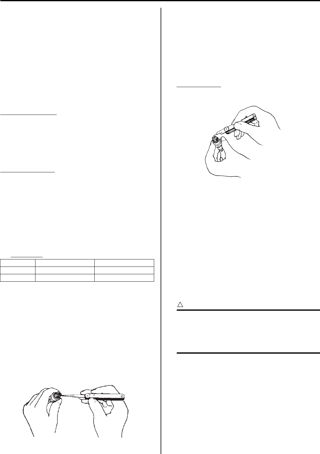
Maintenance and Lubrication: 0B-9
6) Install the camshafts. Refer to “Engine Top Side
Assembly in Section 1D (Page 1D-21)”.
7) Rotate the engine so that the tappet is depressed
fully. This will squeeze out oil trapped between the
shim and the tappet that could cause an incorrect
measurement, then check the clearance again to
confirm that it is within the specified range.
After finishing the tappet clearance adjustment,
reinstall the removed parts. Refer to “Engine Top
Side Assembly in Section 1D (Page 1D-21)”.
Spark Plug Replacement
B931G20206004
Replace spark plug
Every 6 000 km (4 000 miles)
Refer to “Spark Plug Cap and Spark Plug Removal and
Installation in Section 1H (Page 1H-3)”.
Spark Plug Inspection and Cleaning
B931G20206005
Inspect spark plug
Every 2 000 km (1 200 miles, 6 months)
Heat Range
1) Remove the spark plug. Refer to “Spark Plug Cap
and Spark Plug Removal and Installation in Section
1H (Page 1H-3)”.
2) Check spark plug heat range by observing electrode
color.
If it appears white or glazed, replace the spark plug
with colder type one.
Heat range
3) After finishing the spark plug inspection, reinstall the
removed parts.
Carbon Deposits
1) Remove the spark plug. Refer to “Spark Plug Cap
and Spark Plug Removal and Installation in Section
1H (Page 1H-3)”.
2) Check carbon deposits on the spark plug.
If carbon is deposited, remove it using a spark plug
cleaner machine or carefully use a tool with a
pointed end.
3) After finishing the spark plug inspection, reinstall the
removed parts.
Spark Plug Gap
1) Remove the spark plug. Refer to “Spark Plug Cap
and Spark Plug Removal and Installation in Section
1H (Page 1H-3)”.
2) Measure the spark plug gap using a wire gauge.
Adjust the spark plug gap if necessary.
Spark plug gap
0.7 – 0.8 mm (0.028 – 0.030 in)
3) After finishing the spark plug inspection, reinstall the
removed parts.
Electrodes Condition
1) Remove the spark plug. Refer to “Spark Plug Cap
and Spark Plug Removal and Installation in Section
1H (Page 1H-3)”.
2) Check to see the worn or burnt condition of the
electrodes.
If it is extremely worn or burnt, replace the plug. And
also replace the plug if it has a broken insulator, or
damaged thread.
3) After finishing the spark plug inspection, reinstall the
removed parts.
CAUTION
!
Check the thread size and reach when
replacing the spark plug. If the reach is too
short, carbon will be deposited on the screw
portion of the spark plug hole and engine
damage may result.
Standard Cold type
NGK CR6E CR7E
DENSO U20ESR-N U22ESR-N
I649G1020010-02
I831G1020092-01
PartShark.com
877-999-5686

0B-10 Maintenance and Lubrication:
Spark Arrester Cleaning
B931G20206006
Spark arrester cleaning
Every 2 000 km (1 200 miles, 6 months)
1) Remove the muffler end cover (1).
2) Remove the spark arrester (2) from the muffler.
3) Clean the spark arrester (2) with a brush.
4) After finishing the spark arrester cleaning, reinstall
the removed parts.
Fuel Line Inspection
B931G20206007
Inspect fuel line
Every 1 000 km (600 miles, 3 months)
Replace fuel line
Every 4 years
Inspect the fuel line in the following procedures:
1) Remove the left side cover. Refer to “Front Side
Exterior Parts Removal and Installation in Section
9D (Page 9D-6)”.
2) Remove the rear fender. Refer to “Rear Side Exterior
Parts Removal and Installation in Section 9D
(Page 9D-9)”.
3) Remove the fuel tank side cover. Refer to “Fuel Tank
Removal and Installation in Section 1G (Page 1G-
8)”.
4) Inspect the fuel feed hose for damage and fuel
leakage. If any defects are found, the fuel feed hose
must be replaced.
5) After finishing the fuel feed hose inspection or
replacement, reinstall the removed parts.
Engine Oil and Filter Replacement
B931G20206008
Replace engine oil
Initially at 200 km (100 miles, 1 month) and every 2
000 km (1 200 miles, 6 months) thereafter
Replace oil filter
Initially at 200 km (100 miles, 1 month) and every 2
000 km (1 200 miles, 6 months) thereafter
Oil should be changed while the engine is warm. Oil filter
replacement at the above intervals, should be done
together with the engine oil change.
1
I831G1020006-02
2
I831G1020007-03
2
I831G1020008-03
I831G1020019-02
PartShark.com
877-999-5686
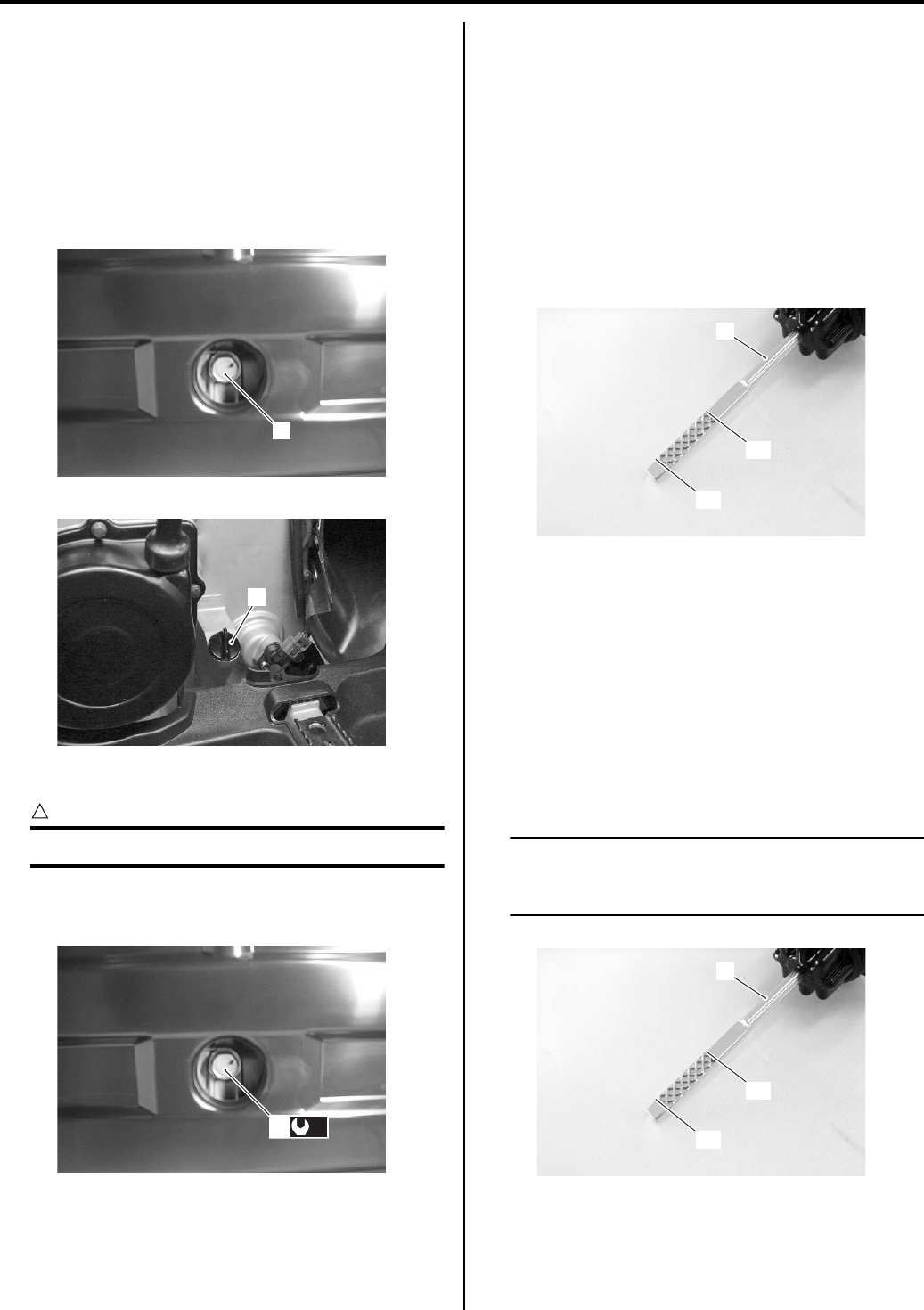
Maintenance and Lubrication: 0B-11
Engine Oil Replacement
1) Place the vehicle on a level ground and set the brake
lock.
2) Remove the engine side cover. Refer to “Front Side
Exterior Parts Removal and Installation in Section
9D (Page 9D-6)”.
3) Place an oil pan below the engine, and drain engine
oil by removing the oil drain plug (1) and filler cap
(2).
4) Tighten the oil drain plug (1) to the specified torque.
CAUTION
!
Replace the gasket washer with a new one.
Tightening torque
Oil drain plug (a): 21 N·m (2.1 kgf-m, 15.0 lbf-ft)
5) Pour new oil through the oil filler. When performing
an oil change (without oil filter replacement), the
engine will hold about 2.3 L (2.4/2.0 US/lmp qt) of oil.
Use of SF/SG or SH/SJ in API with MA in JASO.
6) Start up the engine and allow it to run for several
minutes at idling speed after tightening the oil filler
cap.
7) Turn off the engine and wait about three minutes,
and then check the oil level on the dipstick (3). The
oil level should be between the low level line “A” and
full level line “B”. If the oil level is lower than the low
level line “A”, add oil to the full level line “B”.
Oil Level Inspection
1) Place the vehicle on a level ground and set the brake
lock.
2) Start up the engine and allow it to run for several
minutes at idling speed.
3) Turn off the engine and wait about three minutes,
then check the oil level on the dipstick (1). If the level
is below low level line “A”, add oil to full level line “B”.
If the level is above full level line “B”, drain oil to full
level line “B”.
NOTE
When inspecting the oil level, the oil filler cap
threads are not run in but touching the filler
hole upper edge.
1
I831G1020020-01
2
I831G1020022-01
(a)
1
I831G1020021-01
“A”
“B”
3
I831G1020023-01
“A”
“B”
1
I831G1020024-01
PartShark.com
877-999-5686
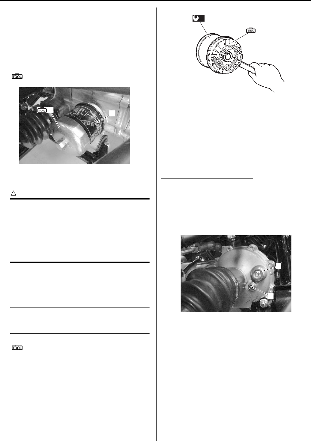
0B-12 Maintenance and Lubrication:
Oil Filter Replacement
1) Drain engine oil as described in the engine oil
replacement procedure.
2) Remove left inner cover. Refer to “Front Side
Exterior Parts Removal and Installation in Section
9D (Page 9D-6)”.
3) Remove the oil filter (1) using the special tool.
Special tool
(A): 09915–40610 (Oil filter wrench)
4) Apply engine oil lightly to the O-ring of new oil filter,
before installation.
CAUTION
!
ONLY USE A GENUINE SUZUKI
MOTORCYCLE OIL FILTER.
Other manufacturer’s oil filters may differ in
thread specifications (thread diameter and
pitch), filtering performance and durability
which may lead to engine damage or oil
leaks. Also, do not use a genuine Suzuki
automobile oil filter on this vehicle.
5) Install a new oil filter. Turn it by hand until you feel
that the oil filter O-ring contacts the oil filter mounting
surface. Then, tighten the oil filter two full turns (or to
specified torque) using the special tool.
NOTE
To properly tighten the oil filter, use the
special tool. Never tighten the oil filter by
hand only.
Special tool
(A): 09915–40610 (Oil filter wrench)
Tightening torque
Oil filter (a): 20 N·m (2.0 kgf-m, 14.5 lbf-ft)
6) Add new engine oil and check the oil level is as
described in the engine oil replacement procedure.
Necessary amount of engine oil
Oil change: 2 300 ml (2.4/2.0 US/lmp qt)
Oil and filter change: 2 500 ml (2.6/2.2 US/lmp qt)
Engine overhaul: 3 000 ml (3.2/2.6 US/lmp qt)
Front Differential Gear Oil Inspection
B931G20206009
Inspect front differential gear oil
Every 2 000 km (1 200 miles, 6 months)
1) Place the vehicle on level ground.
2) Remove the oil level plug (1) and oil filler plug (2),
and inspect the oil level. If the oil level is below the
level hole, add fresh oil until oil flows from the level
hole.
(A) 1
I831G1020025-01
(A)
(a)
1
I718H1020026-01
1
2
I831G1020036-01
PartShark.com
877-999-5686
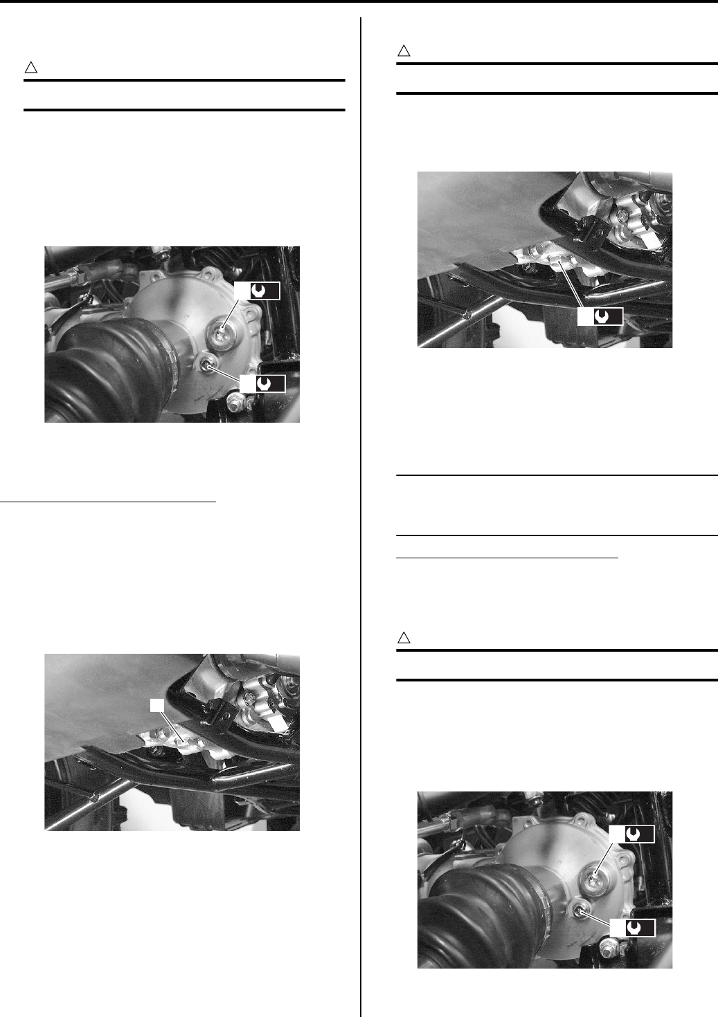
Maintenance and Lubrication: 0B-13
3) Tighten the oil level plug (1) and oil filler plug (2) to
the specified torque.
CAUTION
!
Replace the gasket washers with new ones.
Tightening torque
Front differential gear oil level plug (a): 8.5 N·m (
0.85 kgf-m, 6.0 lbf-ft)
Tightening torque
Front differential gear oil filler plug (b): 35 N·m (
3.5 kgf-m, 25.5 lbf-ft)
Front Differential Gear Oil Replacement
B931G20206010
Replace front differential gear oil
Every 2 years
1) Place the vehicle on level ground.
2) Remove the front under cover. Refer to “Under
Cover Removal and Installation in Section 9D
(Page 9D-12)”.
3) Drain the front differential gear oil by removing the oil
drain plug (1), oil filler plug and oil level plug.
4) Tighten the oil drain plug (1) to the specified torque.
CAUTION
!
Replace the gasket washers with a new one.
Tightening torque
Front differential gear oil drain plug (a): 32 N·m (
3.2 kgf-m, 23.0 lbf-ft)
5) Pour fresh oil through the oil filler hole until it
overflows from the oil level hole. When performing
an oil change, the front differential will hold about
500 ml (0.53 US qt, 0.44 Imp qt) of oil. Use hypoid
gear oil SAE #90, API grade GL-5.
NOTE
Use hypoid gear oil SAE #80, API grade GL-5,
if the vehicle is ridden where the ambient
temperature is below 0 °C (32 °F).
Front differential gear oil capacity
500 ml (0.53 US qt, 0.44 lmp qt)
6) Tighten the oil level plug (2) and oil filler plug (3) to
the specified torque.
CAUTION
!
Replace the gasket washers with new ones.
Tightening torque
Front differential gear oil level plug (b): 8 N·m (
0.8 kgf-m, 5.7 lbf-ft)
Front differential gear oil filler plug (c): 35 N·m (
3.5 kgf-m, 25.5 lbf-ft)
(b)
2
(a)
1
I831G1020037-01
1
I831G1020038-01
(a)
1
I831G1020081-01
(c)
3
(b)
2
I831G1020039-03
PartShark.com
877-999-5686
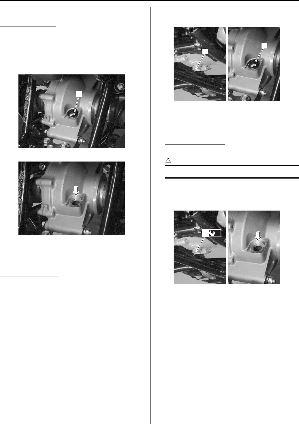
0B-14 Maintenance and Lubrication:
Final Gear Oil Inspection
B931G20206011
Inspect final gear oil
Every 2 000 km (1 200 miles, 6 months)
1) Place the vehicle on a level ground.
2) Remove the filler plug (1), and inspect the oil level. If
the oil level is below, add fresh oil until the oil level
reaches the bottom tip of the thread.
3) Tighten the oil filler plug (1) securely.
Final Gear Oil Replacement
B931G20206012
Replace final gear oil
Every year
1) Place the vehicle on a level ground.
2) Remove the rear under cover. Refer to “Under Cover
Removal and Installation in Section 9D (Page 9D-
12)”.
3) Place an oil pan below the final gear case.
4) Drain oil by removing the oil drain plug (1) and oil
filler plug (2).
5) Tighten the oil drain plug (1) to the specified torque,
and pour fresh oil through the oil filler hole until the
oil level reaches the bottom tip of the thread. Use
Mobil fluid 424 or equivalent oil.
Final gear oil capacity
770 ml (0.81 US qt, 0.68 lmp qt)
CAUTION
!
Replace the gasket with a new one.
Tightening torque
Final gear oil drain plug (a): 23 N·m (2.3 kgf-m,
16.5 lbf-ft)
1
I831G1020040-01
I831G1020041-01
1
2
I831G1020042-02
(a)
1
I831G1020044-02
PartShark.com
877-999-5686
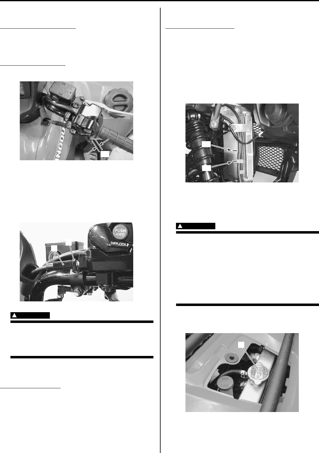
Maintenance and Lubrication: 0B-15
Throttle Cable Play Inspection and Adjustment
B931G20206013
Inspect throttle cable play
Initially at 200 km (100 miles, 1 month) and every 1
000 km (600 miles, 3 months) thereafter
Inspect and adjust the throttle cable play “a” as follows.
Throttle cable play “a”
3.0 – 5.0 mm (0.12 – 0.20 in)
1) Loosen the lock-nut (1) of the throttle cable.
2) Turn the adjuster (2) in or out until the throttle cable
play “a” (at the throttle lever) is between 3 – 5 mm
(0.12 – 0.20 in).
3) Tighten the lock-nut (1) while holding the adjuster
(2).
WARNING
!
After the adjustment is completed, check that
handlebar movement does not raise the
engine idle speed and that the throttle lever
returns smoothly and automatically.
Throttle Body Inspection
B931G20206014
Inspect throttle body
Every 1 000 km (600 miles, 3 months)
Inspect the throttle body periodically for dart or mud. If
any dirt or mud is found, clean it. Refer to “Throttle Body
Removal and Installation in Section 1D (Page 1D-8)”.
Cooling System Inspection
B931G20206015
Replace engine coolant
Every 2 years
Engine Coolant Level Inspection
1) Place the vehicle on a level ground.
2) Check the engine coolant level by observing the full
and lower lines on the engine coolant reservoir tank.
If the level is below the lower line, add engine
coolant to the full line from the engine coolant
reservoir tank filler.
Engine Coolant Change
Refer to “Engine Coolant Description in Section 1F
(Page 1F-1)”.
WARNING
!
Do not open the radiator cap when the engine
is hot, as you may be injured by escaping hot
liquid or vapor. Engine coolant may be
harmful if swallowed or if it comes in contact
with skin or eyes. If engine coolant gets into
the eyes or in contact with the skin, flush
thoroughly with plenty of water. If swallowed,
induce vomiting and call physician
immediately.
1) Remove the radiator cap lid.
2) Remove the radiator cap (1).
“a”
I831G1020026-01
1
2
I831G1020027-01
“F”
“L”
I831G1020028-01
1
I831G1020029-01
PartShark.com
877-999-5686
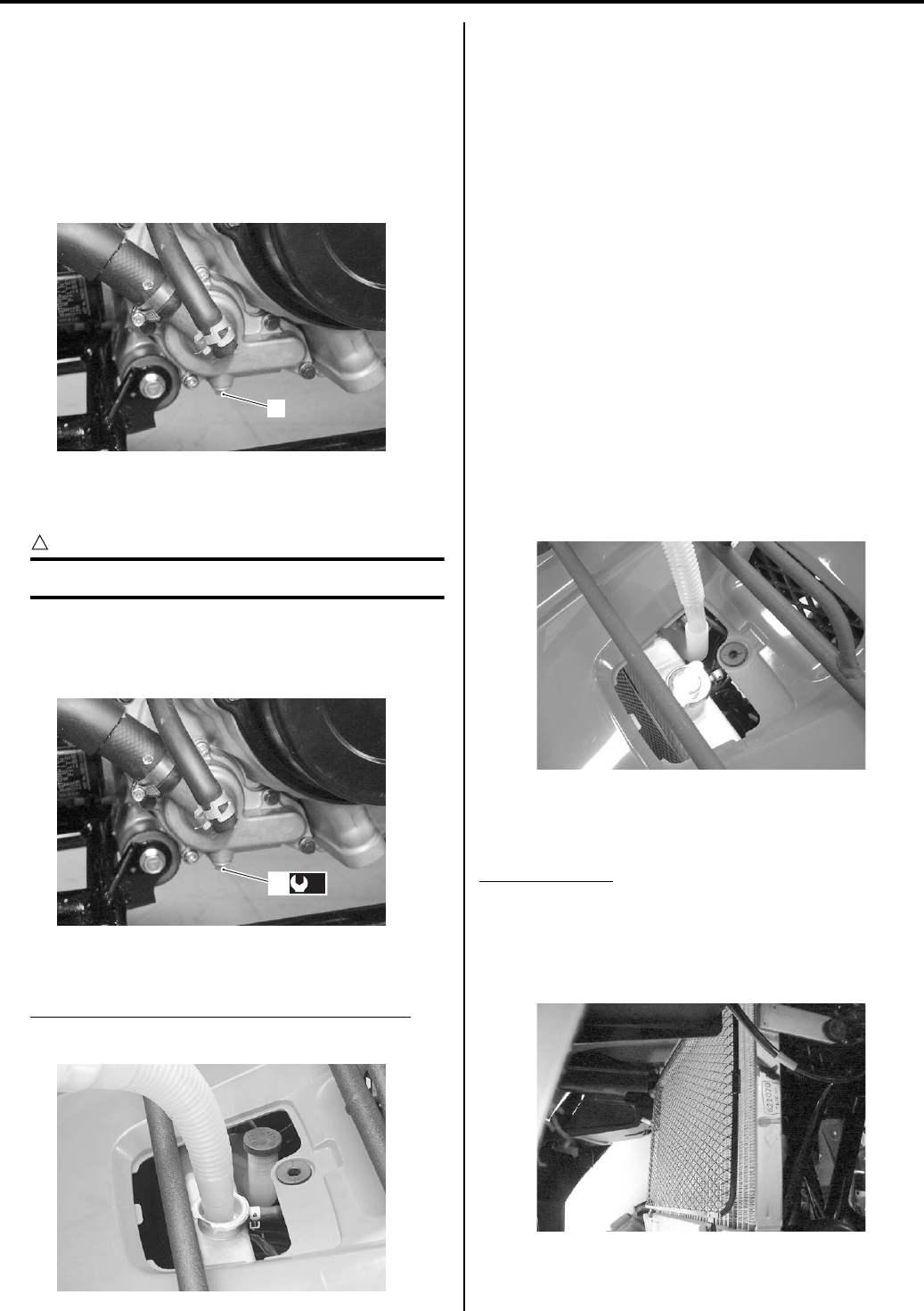
0B-16 Maintenance and Lubrication:
3) Remove the left inner fender. Refer to “Front Side
Exterior Parts Removal and Installation in Section
9D (Page 9D-6)”.
4) Remove the front under cover. Refer to “Under
Cover Removal and Installation in Section 9D
(Page 9D-12)”.
5) Place a pan below the water pump, and then drain
the engine coolant by removing the drain plug (2).
6) Flush the radiator with fresh water if necessary.
7) Tighten the drain plug (4) to the specified torque.
CAUTION
!
Replace the gasket with a new one.
Tightening torque
Engine coolant drain plug (a): 13 N·m (1.3 kgf-
m, 9.5 lbf-ft)
Pour the specified engine coolant up to the radiator
inlet.
Engine coolant capacity (including reservoir)
2 450 ml (2.6/2.2 US/lmp qt)
9) Bleed air from the cooling circuit.
10) After changing engine coolant, reinstall the removed
parts.
Air Bleeding From the Cooling Circuit
1) Place the vehicle on a level ground and set the brake
lock.
2) Pour engine coolant up to the radiator inlet.
3) Slowly swing the vehicle, right and left, to bleed the
air trapped in the cooling circuit.
4) Add engine coolant up to the radiator inlet.
5) Start up the engine and bleed air from the radiator
inlet completely.
6) Add engine coolant up to the radiator inlet.
7) Repeat the 6), 7) procedures until no air bleeds from
the thermostat connector inlet.
Close the radiator cap securely.
9) After warming up and cooling down the engine, add
the specified engine coolant until the level is
between the upper and lower lines on the engine
coolant reservoir tank.
10) Reinstall the removed parts.
Radiator Inspection
Inspect radiator
Every 1 000 km (600 miles, 3 months)
Inspect the radiator for damage and engine coolant
leakage. If any defects are found, replace it with a new
one.
2
I831G1020030-01
(a)
4
I831G1020031-02
I831G1020080-01
I831G1020032-01
I831G1020034-01
PartShark.com
877-999-5686
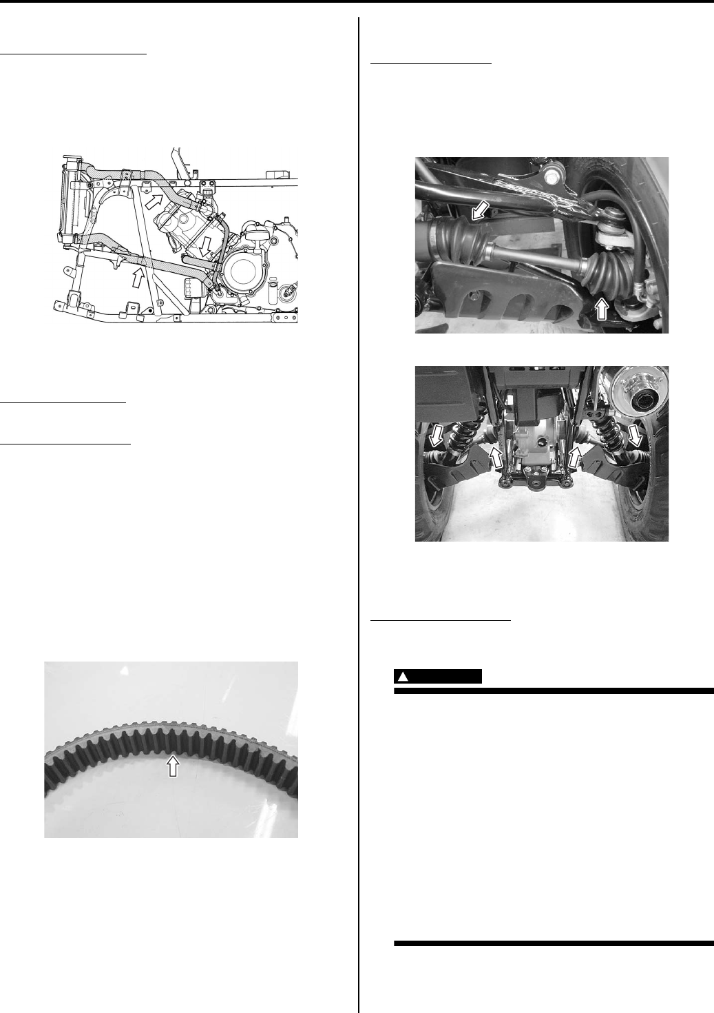
Maintenance and Lubrication: 0B-17
Radiator Hoses Inspection
Inspect radiator hoses
Every 2 000 km (1 200 miles, 6 months)
Inspect the radiator hoses for damage and engine
coolant leakage. If any defects are found, replace them
with new ones.
Drive V-belt Inspection and Replacement
B931G20206016
Inspect drive V-belt
Every 1 000 km (600 miles, 3 months)
Replace drive V-belt
Every 2 000 km (1 200 miles, 6 months)
Inspect the drive V-belt in the following procedures:
1) Remove the drive V-belt. Refer to “V-belt Type
Continuously Variable Automatic Transmission
Removal and Installation in Section 5A (Page 5A-5)”.
2) Inspect the drive V-belt for crack or other damage
and measure the width of belt if necessary. If any
abnormal point are found, replace the drive V-belt
with a new one. Refer to “V-belt Type Continuously
Variable Automatic Transmission Removal and
Installation in Section 5A (Page 5A-5)”.
3) Install the removed parts. Refer to “V-belt Type
Continuously Variable Automatic Transmission
Removal and Installation in Section 5A (Page 5A-5)”.
Drive Shaft Boots Inspection
B931G20206017
Inspect drive shaft
Initially at 200 km (100 miles, 1 month) and every 1
000 km (600 miles, 3 months) thereafter
Inspect the boots for wear or damage. If any defects are
found, replace them with new ones.
Front Brake System Inspection
B931G20206018
Inspect brake system
Initially at 200 km (100 miles, 1 month) and every 1
000 km (600 miles, 3 months) thereafter
WARNING
!
• The brake system of this vehicle is filled
with a glycol-based brake fluid. Do not use
or mix different types of fluid such as
silicone-based and petroleum-based
fluids. Do not use any brake fluid taken
from old, used or unsealed containers.
Never reuse brake fluid left over from the
last servicing or stored for a long period of
time.
• Brake fluid, if it leaks, will interfere with
safe running and immediately discolor
painted surfaces. Check the brake hoses
and hose joints for cracks and oil leakage
before riding.
I831G1020033-01
I831G1020043-01
I831G1020045-02
I831G1020046-01
PartShark.com
877-999-5686
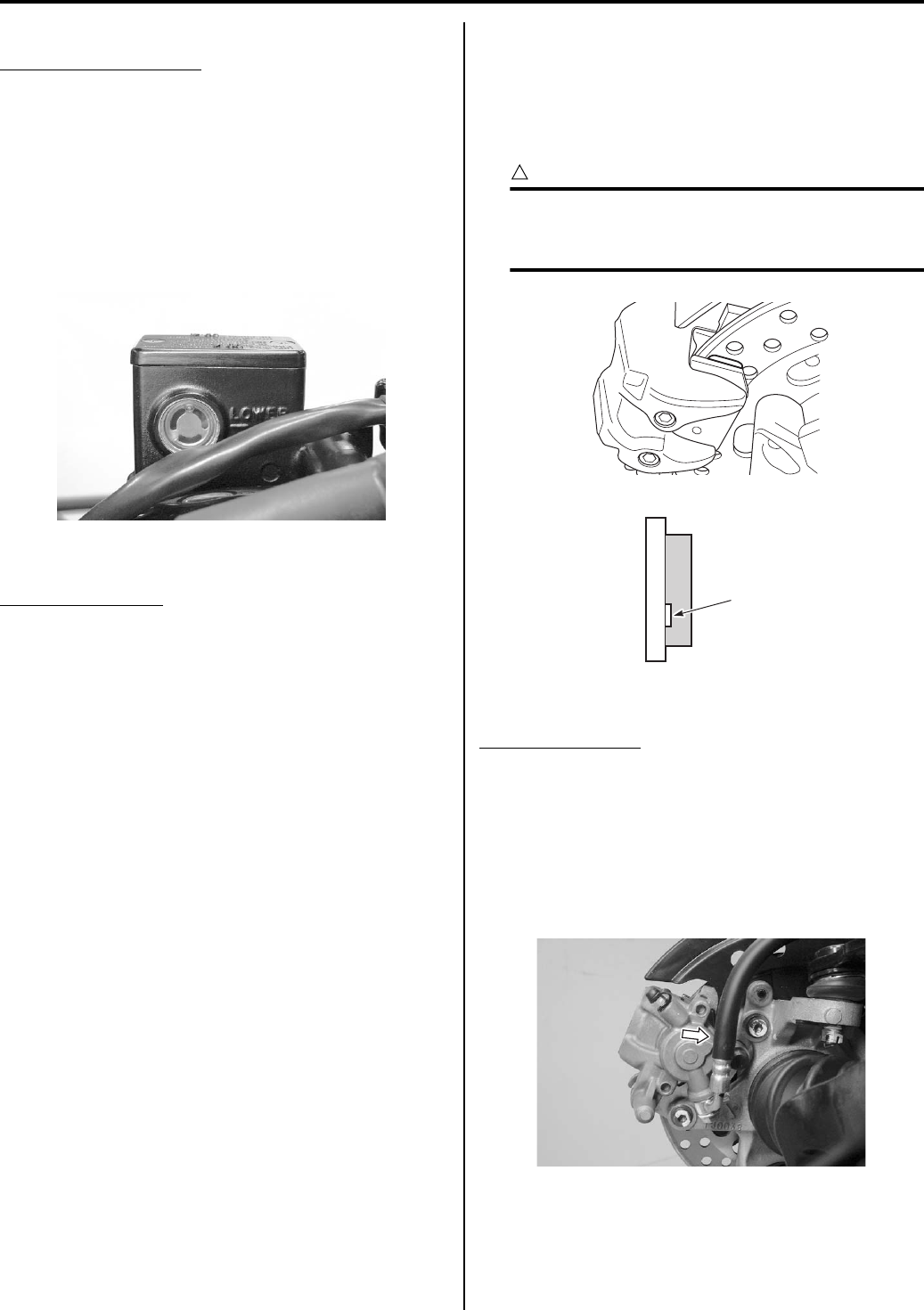
0B-18 Maintenance and Lubrication:
Brake Fluid Level Check
Inspect brake fluid level
Every 1 000 km (600 miles, 3 months)
1) Place the vehicle on a level ground.
2) Check the brake fluid level by observing the lower
limit lines on the brake fluid reservoir. When the
brake fluid level is below the lower limit line,
replenish with brake fluid that meets the following
specification.
BF: Brake fluid (DOT 4)
Brake Fluid Replacement
Replace brake fluid
Every 2 years
Refer to “Brake Fluid Replacement in Section 4A
(Page 4A-6)”.
Air Bleeding from Brake Fluid Circuit
Refer to “Air Bleeding from Front Brake Fluid Circuit in
Section 4A (Page 4A-5)”.
Front Brake Pads Check
The extent of front brake pad wear can be checked by
observing the grooved limit line “A” on the pad. When the
wear exceeds the grooved limit line, replace the pads
with new ones. Refer to “Front Brake Pad Replacement
in Section 4B (Page 4B-2)”.
CAUTION
!
Replace the brake pad as a set, otherwise
braking performance will be adversely
affected.
Front Brake Hose Inspection
Inspect brake hose
Every 2 000 km (1 200 miles, 6 months)
1) Turn the handlebars to left or right.
2) Inspect the brake hoses and hose joints for crack,
damage or brake oil leakage. If any defects are
found, replace the front brake hose with a new one.
Refer to “Front Brake Hose Removal and Installation
in Section 4A (Page 4A-7)”.
I831G1020047-01
I831G1020048-01
“A”
I831G1020082-01
I831G1020035-01
PartShark.com
877-999-5686
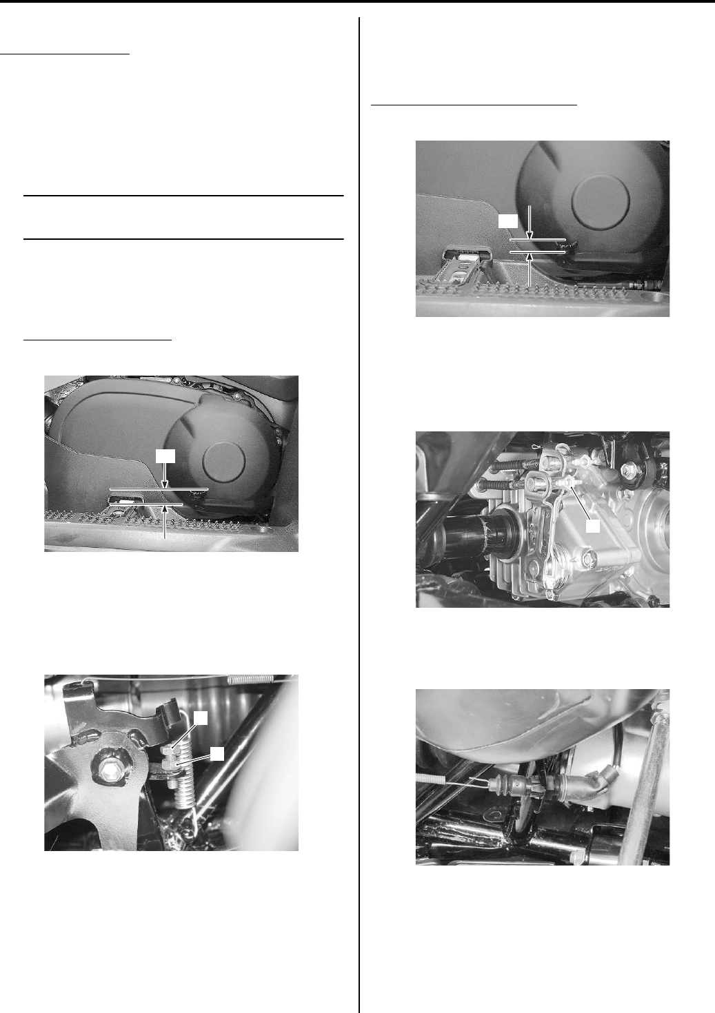
Maintenance and Lubrication: 0B-19
Front Brake Hose Replacement
Replace brake hose
Every 4 years
Refer to “Front Brake Hose Removal and Installation in
Section 4A (Page 4A-7)”.
Rear Brake Pedal / Rear Brake (Parking Brake)
Lever Inspection and Adjustment
B931G20206019
NOTE
Adjust the rear brake by adjusting the brake
pedal first and then adjust the brake lever.
Brake Pedal Height
1) Inspect the brake pedal height “a” between the pedal
top face and footrest. Adjust the brake pedal height if
necessary.
Brake pedal height “a”
12.5 – 22.5 mm (0.5 – 0.9 in)
2) Loosen the lock-nut (1).
3) Turn the adjuster (2) until the brake pedal becomes
12.5 – 22.5 mm (0.5 – 0.9 in) “a” higher from the top
of the footrest.
4) Tighten the lock-nut (1) securely.
Brake Pedal Free Travel
Inspection
Inspect and adjust the rear brake pedal free travel “a” as
follows.
Rear brake pedal free travel “a”
20 – 30 mm (0.8 – 1.2 in)
Adjustment
• Turn the adjuster nut (1) so the rear brake pedal has
20 – 30 mm (0.8 – 1.2 in) free travel at the rear brake
pedal end before pressure is felt.
• Adjust the rear brake light switch so that the brake
light will come on just before pressure is felt when the
brake pedal is depressed.
“a”
I831G1020051-02
1
2
I831G1020052-02
“a”
I831G1020053-02
1
I831G1020054-01
I831G1020090-01
PartShark.com
877-999-5686
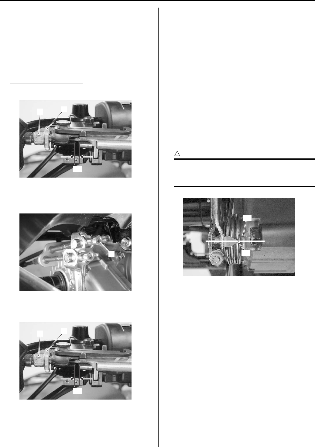
0B-20 Maintenance and Lubrication:
Rear Brake (Parking Brake) Lever Play Adjustment
1) After adjusting the brake pedal, check the rear brake
lever play “a” The brake lever play “a” as measured
at the lever holder should be between 6 – 8 mm (0.2
– 0.3 in) when the lever is lightly pulled in towards
the grip. If adjustment is necessary, slacken the
cable by loosening the lock-nut (1) and screwing the
cable adjuster (2) on the brake lever holder all the
way in.
Rear brake lever play “a”
6 – 8 mm (0.2 – 0.3 in)
2) Turn the adjust nut (3) so the rear brake lever has 6
– 8 mm (0.2 – 0.3 in) play “a” at the rear brake lever
end before pressure is felt.
3) Minor adjustment can be made with the adjuster (2).
4) Tighten the lock-nut (1).
5) After adjusting the play, check that the rear wheels
roll freely without applying the brake, the
transmission in neutral and the rear wheels off the
ground. Readjust the rear brake lever if the rear
wheels could not roll freely.
Rear Brake Friction Plate Wear Limit Inspection
B931G20206020
Replace rear brake friction plate
Every 10 000 km (6 000 miles)
After adjusted rear brake pedal and rear brake lever,
inspect the rear brake friction plate wear limit.
• While fully applying the rear brake, check to see that
the extension line of the index mark “A” is within the
limit “B”. If the extension line is out of the limit “B”,
replace the friction plates with new ones. Refer to
“Rear Brake Disassembly and Assembly in Section
4C (Page 4C-3)”.
CAUTION
!
Replace the friction plate as a set, otherwise
breaking performance will be adversely
affected.
“a”
21
I831G1020093-01
3
I831G1020057-03
“a”
21
I831G1020093-01
“B”
“A”
I831G1020049-02
PartShark.com
877-999-5686
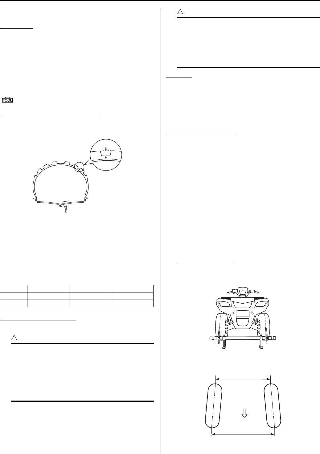
Maintenance and Lubrication: 0B-21
Tire Inspection
B931G20206021
Inspect tire
Every 1 000 km (600 miles, 3 months)
Tire Tread Condition
Operating the vehicle with excessively worn tires will
decrease riding stability and consequently invite a
dangerous situation. It is highly recommended to replace
a tire when the remaining depth of tire tread reaches the
following specification.
Special tool
: 09900–20805 (Tire depth gauge)
Tire tread depth “a” (Service limit)
Front: 4.0 mm (0.16 in)
Rear: 4.0 mm (0.16 in)
Tire Pressure
If the tire pressure is too high or too low, steering will be
adversely affected and tire wear increased. Therefore,
maintain the correct tire pressure for good roadability or
longer tire life will result. Cold inflation tire pressure is as
follows.
Cold inflation tire pressure
Vehicle load capacity limit
172 kg (380 lbs)
CAUTION
!
To minimize the possibility of tire damage
from over-inflation, we strongly
recommended that a manual type air pump
be used rather than a high pressure air
compressor as found in service stations.
When filling air into the tires, never exceed 70
kPa (0.7 kgf/cm2, 10 psi)
CAUTION
!
The standard tire fitted on this vehicle is an
AT25 x 8-12 for the front and a AT25 x 10-
12 for the rear. The use of tires other than
those specified may cause instability. It is
highly recommended to use the specified
tires.
Tire type
DUNLOP
• Front: DUNLOP KT411
• Rear: DUNLOP KT415
Steering System Inspection
B931G20206022
Inspect steering system
Initially at 200 km (100 miles, 1 month) and every 1
000 km (600 miles, 3 months) thereafter
Steering should be adjusted properly for smooth turning
of handlebars and safe running.
1) Place the vehicle on level ground.
2) Make sure the tire pressure for right and left tires in
the same and set to the proper specification.
3) Set the front wheels in the straight position.
4) Place a load of 75 kg (165 lbs) on the seat.
5) Measure the distances (“A” and “B”) between the
front wheels. Subtract the measurement of “A” from
that of “B” to find the toe-out. If the toe-out is not
within specification, adjust the tie-rod to the right or
left until the toe-out is within the specified range.
Toe-out (“B” – “A”)
Standard: 10 ± 4 mm (0.39 ± 0.16 in)
kPa kgf/cm2psi
Front 35 0.35 5.1
Rear 30 0.30 4.4
“a”
I831G1020084-01
I831G1020058-01
FWD
“A”
“B”
I831G1020059-04
PartShark.com
877-999-5686
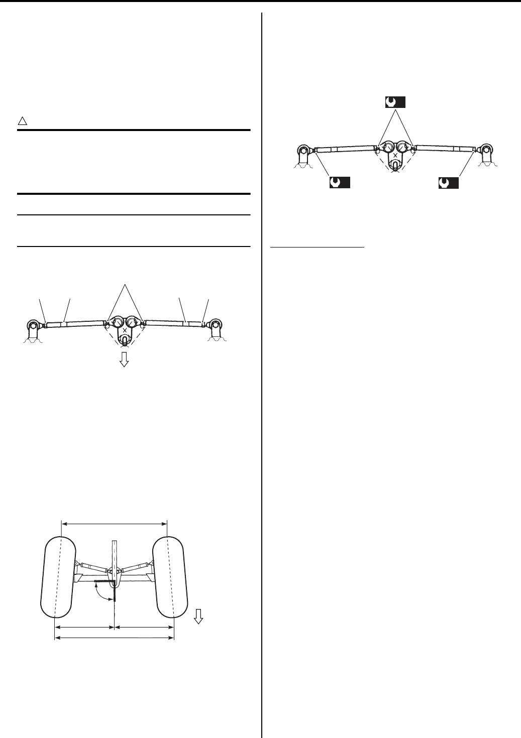
0B-22 Maintenance and Lubrication:
If the toe-out is out of specification, bring it into the
specified range. Refer to “Toe Adjustment (Page 0B-
22)”.
Toe Adjustment
B931G20206023
Adjust the toe-out as follows:
1) Loosen the lock-nuts (1), (2) on each tie-rod.
CAUTION
!
• The lock-nuts (2) have left-hand threads.
• When loosening and tightening the lock-
nuts, hold the tie-rod end with a open end
wrench.
NOTE
Hold the concave part “a” of tie-rod with a
wrench.
2) Temporarily tighten the four lock-nuts.
3) Check that the distances “C” and “D” are equal, as
shown. If the distances are not equal, adjust the tie-
rod to the right or left until the toe-out is within
specification. Check the toe-out again by measuring
distances “A” and “B”.
4) If the toe-out is not within specification, repeat the
adjustment as above until the proper tor-out is
obtained and distances “C” and “D” become equal.
5) After adjustment has been made, tighten the four
lock-nuts to the specified torque.
Tightening torque
Tie-rod lock-nut (a): 45 N·m (4.5 kgf-m, 32.5 lbf-
ft)
Suspensions Inspection
B931G20206024
Inspect suspension
Every 2 000 km (1 200 miles, 6 months)
1) Support the vehicle with a jack and wooden blocks.
2) Remove the front and rear wheels.
3) Inspect the suspension arm and bearing for
scratches, wear, or damage. If any defects are
found, replace them with new ones. Refer to “Front
Shock Absorber Removal and Installation in Section
2B (Page 2B-3)”.
4) Inspect the front and rear shock absorbers for oil
leakage or damage. If any defects are found, replace
them with new ones. Refer to “Front Shock Absorber
Removal and Installation in Section 2B (Page 2B-3)”
and “Rear Shock Absorber Removal and Installation
in Section 2C (Page 2C-3)”.
2
11
“a”
“a”
FWD
I831G1020087-03
“C”
Right angle
(90
°
)
FWD
“A”
“B”
“D”
I831G1020088-04
(a)
(a)
(a)
I831G1020089-01
PartShark.com
877-999-5686
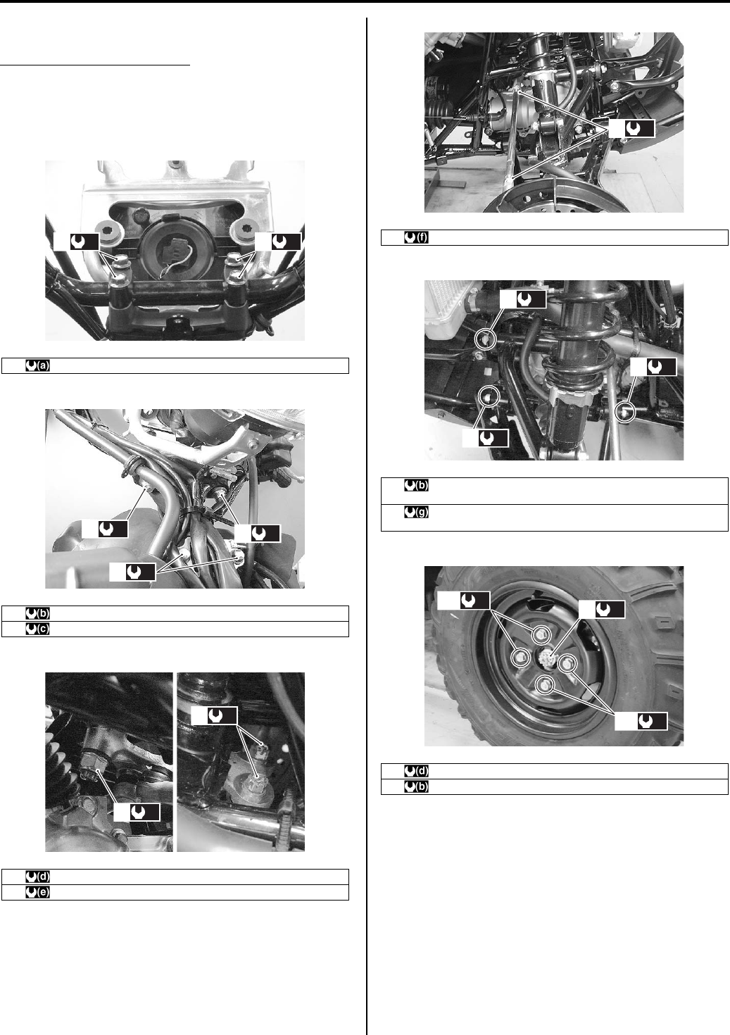
Maintenance and Lubrication: 0B-23
Chassis Bolt and Nut Inspection
B931G20206025
Tighten chassis bolt and nut
Initially at 200 km (100 miles, 1 month) and every 1
000 km (600 miles, 3 months) thereafter
Check that all chassis bolts and nuts are tightened to
their specified torque.
1 Handlebar upper clamp bolt 26 N⋅m (2.6 kgf-m, 19.0 lb-ft)
2 Handlebar holder nut 60 N⋅m (6.0 kgf-m, 43.5 lb-ft)
3 Steering shaft holder bolt 23 N⋅m (2.3 kgf-m, 16.5 lb-ft)
4 Steering shaft lower nut 162 N⋅m (16.2 kgf-m, 117.0 lb-ft)
5 Tie-rod end nut 29 N⋅m (2.9 kgf-m, 21.0 lb-ft)
(a)
1(a)
1
I831G1020062-01
(b)
2(b)
2
(c)
3
I831G1020063-01
(d)
4
(e)
5
I831G1020064-01
6 Tie-rod lock-nut 45 N⋅m (4.5 kgf-m, 32.5 lb-ft)
7 Front suspension arm pivot nut (Upper) 60 N⋅m (6.0 kgf-m, 43.5
lb-ft)
8 Front suspension arm pivot nut (Lower) 65 N⋅m (6.5 kgf-m, 47.0
lb-ft)
9 Front hub nut 110 N⋅m (11.0 kgf-m, 79.5 lb-ft)
10 Front wheel set nut 60 N⋅m (6.0 kgf-m, 43.5 lb-ft)
(f)
6
I831G1020065-01
(b)
7
(g)
8
(g)
8
I831G1020060-02
(b)
10
(b)
10
(d)ޓ
9
I831G1020066-03
PartShark.com
877-999-5686
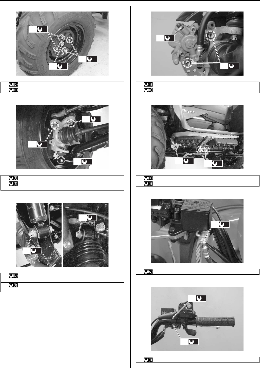
0B-24 Maintenance and Lubrication:
10 Rear wheel set nut 60 N⋅m (6.0 kgf-m, 43.5 lb-ft)
11 Rear hub nut 121 N⋅m (12.1 kgf-m, 87.5 lb-ft)
12 Tie-rod end nut 29 N⋅m (2.9 kgf-m, 21.0 lb-ft)
13 Steering knuckle end nut (Upper and Lower) 29 N⋅m (2.9 kgf-m,
21.0 lb-ft)
14 Front shock absorber mounting nut (Lower) 60 N⋅m (6.0 kgf-m,
43.5 lb-ft)
15 Front shock absorber mounting bolt (Upper) 55 N⋅m (5.5 kgf-m,
40.0 lb-ft)
(b)
10
(b)
10
(d)
11
I831G1020067-04
(f)
13
(f)
12
(f)
13
I831G1020068-04
(b)
14
(i)
15
I831G1020069-04
16 Front brake air bleeder valve 6 N⋅m (0.6 kgf-m, 4.5 lb-ft)
17 Front brake caliper mounting bolt 26 N⋅m (2.6 kgf-m, 19.0 lb-ft)
18 Footrest bar mounting bolt (M8) 26 N⋅m (2.6 kgf-m, 19.0 lb-ft)
19 Footrest bar mounting bolt (M10) 55 N⋅m (5.5 kgf-m, 40.0 lb-ft)
20 Brake hose union bolt 23 N⋅m (2.3 kgf-m, 16.5 lb-ft)
21 Master cylinder mounting bolt 10 N⋅m (1.0 kgf-m, 7.0 lb-ft)
(j)
16
(a)
17
I831G1020070-03
(k)
18 (j)
19
I831G1020071-03
(c)
20
I831G1020072-03
(l)
21
(l)
21
I831G1020073-04
PartShark.com
877-999-5686
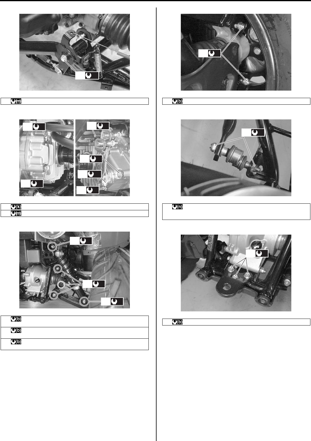
Maintenance and Lubrication: 0B-25
22 Rear brake pedal pivot bolt 11 N⋅m (1.1 kgf-m, 8.0 lb-ft)
23 Rear brake case bolt 26 N⋅m (2.6 kgf-m, 19.0 lb-ft)
24 Rear brake cam lever nut 11 N⋅m (1.1 kgf-m, 8.0 lb-ft)
25 Rear shock absorber mounting nut (Lower) 60 N⋅m (6.0 kgf-m,
43.5 lb-ft)
26 Rear shock absorber mounting nut (Upper) 60 N⋅m (6.0 kgf-m,
43.5 lb-ft)
27 Rear suspension arm pivot nut (Upper and Lower) 60 N⋅m (6.0
kgf-m, 43.5 lb-ft)
(m)
22
I831G1020074-04
(k)
23 (k)
23
(k)
23
(k)
23
(m)
24
(k)
23
I831G1020075-05
(b)
26
(b)
27
(b)
25
I831G1020076-02
28 Rear knuckle nut 60 N⋅m (6.0 kgf-m, 43.5 lb-ft)
29 Rear stabilizer joint nut
[Up to 5SAAR41A497105526: 34 N⋅m (3.4 kgf-m, 24.5 lb-ft)]
[From 5SAAR41A497105527: 60 N⋅m (6.0 kgf-m, 43.5 lb-ft)]
30 Trailer towing mounting bolt 60 N⋅m (6.0 kgf-m, 43.5 lb-ft)
(b)
28
I831G1020077-02
(n)
29
I831G1020078-04
(b)
30
I831G1020079-02
PartShark.com
877-999-5686
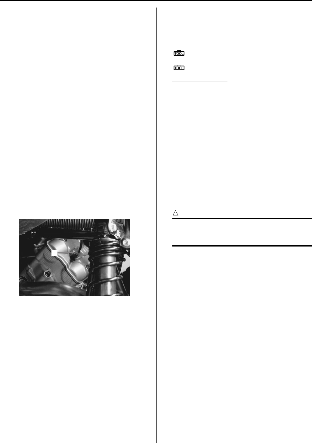
0B-26 Maintenance and Lubrication:
Compression Pressure Check
B931G20206026
Refer to “Compression Pressure Check in Section 1D
(Page 1D-2)”.
Oil Pressure Check
B931G20206027
Refer to “Oil Pressure Check in Section 1E (Page 1E-
2)”.
SDS Check
B931G20206028
Refer to “SDS Check in Section 1A (Page 1A-15)”.
Automatic Clutch Inspection
B931G20206029
This vehicle is equipped with a centrifugal type
automatic clutch.
To insure proper performance and longevity of the clutch
assemblies it is essential that the clutches engage
smoothly and gradually. Before checking the initial
engagement and clutch lock-up two inspection checks
must be performed to thoroughly check the operation of
the drive train.
Initial Engagement Inspection
1) Warm up the engine.
2) Connect the tachometer or the multi circuit tester
onto the spark plug high-tension cord (1).
3) Start the engine.
4) Shift the range lever to the “High” position.
5) Slowly open the throttle and note the engine speed
(r/min) when the vehicle begins to move forward.
Special tool
: 09900–26006 (Engine tachometer (solar
cell type))
: 09900–25008 (Multi-circuit tester set)
Engagement speed
1 500 – 2 000 r/min
6) Disconnect the tachometer and install the frame front
cover.
Clutch “Lock-up” Inspection
Perform this inspection to determine if the clutch is
engaging fully and not slipping.
1) Warn up the engine.
2) Connect a tachometer onto the spark plug high-
tension code.
3) Start the engine.
4) Shift the range lever to the “High” position.
5) Apply the front and rear brakes as firm as possible.
6) Fully open the throttle fully and note the maximum
engine speed sustained during the test cycle.
CAUTION
!
Do not apply full power for more than 5
seconds or damage to the clutch or engine
may occur.
Lock-up r/min
3 500 – 4 000 r/min
If the lock-up speed (r/min) does not coincide with
the standard range, inspect the following items for
any abnormalities.
Refer to “V-belt Type Continuously Variable
Automatic Transmission Removal and Installation in
Section 5A (Page 5A-5)”.
• Clutch shoe
• Clutch wheel
• Movable drive and driven face
1
I831G1020086-01
PartShark.com
877-999-5686
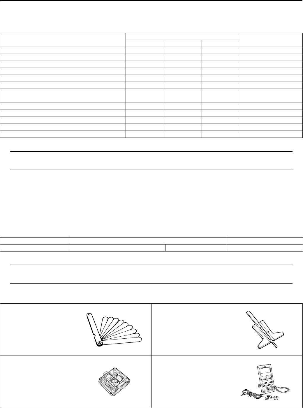
Maintenance and Lubrication: 0B-27
Specifications
Tightening Torque Specifications
B931G20207001
NOTE
The specified tightening torque is also described in the following.
“Chassis Bolt and Nut Inspection (Page 0B-23)”
Reference:
For the tightening torque of fastener not specified in this section, refer to “Tightening Torque List in Section 0C
(Page 0C-7)”.
Special Tools and Equipment
Recommended Service Material
B931G20208001
NOTE
Required service material is also described in the following.
“Lubrication Points (Page 0B-2)”
Special Tool
B931G20208002
Fastening part Tightening torque Note
N⋅mkgf—mlbf—ft
Exhaust pipe nut 23 2.3 16.5 )(Page 0B-4)
Muffler mounting bolt 23 2.3 16.5 )(Page 0B-4)
Muffler connecting bolt 23 2.3 16.5 )(Page 0B-4)
Oil drain plug 21 2.1 15.0 )(Page 0B-11)
Oil filter 20 2.0 14.5 )(Page 0B-12)
Front differential gear oil level plug 8.5 0.85 6.0 )(Page 0B-13)
Front differential gear oil filler plug 35 3.5 25.5
)(Page 0B-13) /
)(Page 0B-13)
Front differential gear oil drain plug 32 3.2 23.0 )(Page 0B-13)
Front differential gear oil level plug 8 0.8 5.7 )(Page 0B-13)
Final gear oil drain plug 23 2.3 16.5 )(Page 0B-14)
Engine coolant drain plug 13 1.3 9.5 )(Page 0B-16)
Tie-rod lock-nut 45 4.5 32.5 )(Page 0B-22)
Material SUZUKI recommended product or Specification Note
Brake fluid DOT 4 — )(Page 0B-18)
09900–20803 09900–20805
Thickness gauge Tire depth gauge
)(Page 0B-6) )(Page 0B-21)
09900–25008 09900–26006
Multi-circuit tester set Engine tachometer (solar
cell type)
)(Page 0B-26) )(Page 0B-26)
PartShark.com
877-999-5686

0B-28 Maintenance and Lubrication:
09915–40610
Oil filter wrench
)(Page 0B-12) /
)(Page 0B-12)
PartShark.com
877-999-5686
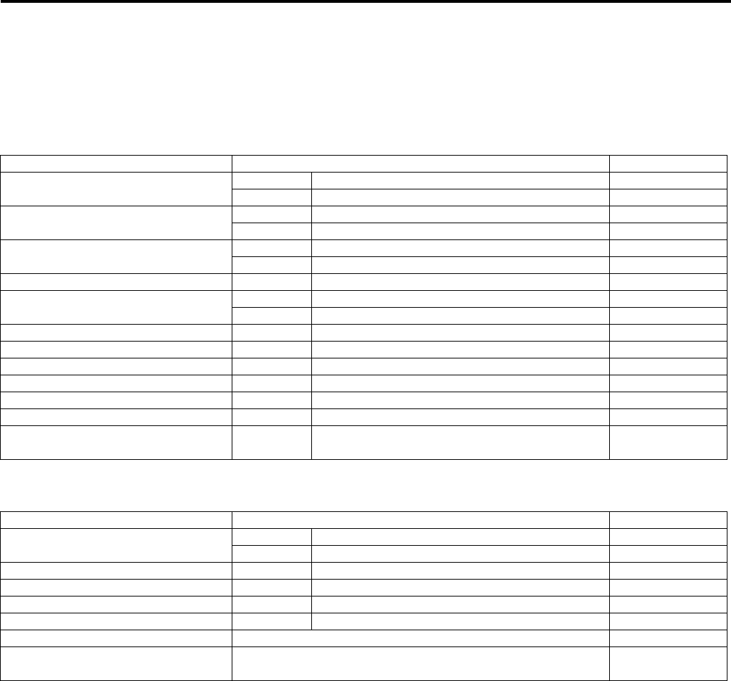
Service Data: 0C-1
General Info rmation
Service Data
Specifications
Service Data
B931G20307001
Valve + Valve Guide
Unit: mm (in)
Camshaft + Cylinder Head
Unit: mm (in)
Item Standard Limit
Valve diam. IN. 36.0 (1.42) —
EX. 33.0 (1.30) —
Tappet clearance (When cold) IN. 0.10 – 0.20 (0.004 – 0.008) —
EX. 0.20 – 0.30 (0.008 – 0.012) —
Valve guide to valve stem clearance IN. 0.010 – 0.037 (0.0004 – 0.0015) —
EX. 0.030 – 0.057 (0.0012 – 0.0022) —
Valve guide I.D. IN. & EX. 5.500 – 5.512 (0.2165 – 0.2170) —
Valve stem O.D. IN. 5.475 – 5.490 (0.2156 – 0.2161) —
EX. 5.455 – 5.470 (0.2148 – 0.2154) —
Valve stem deflection IN. & EX. — 0.35 (0.014)
Valve stem runout IN. & EX. — 0.05 (0.002)
Valve head thickness IN. & EX. — 0.5 (0.02)
Valve seat width IN. & EX. 0.9 – 1.1 (0.035 – 0.043) —
Valve head radial runout IN. & EX. — 0.03 (0.001)
Valve spring free length IN. & EX. — 46.1 (1.81)
Valve spring tension IN. & EX. 182 – 210 N (18.6 – 21.4 kgf, 41.0 – 47.2 lbs)
at length 36.35 mm (1.43 in) —
Item Standard Limit
Cam height IN. 36.330 – 36.380 (1.4303 – 1.4323) 36.030 (1.4185)
EX. 35.300 – 35.350 (1.3898 – 1.3917) 35.000 (1.3780)
Camshaft journal oil clearance IN. & EX. 0.019 – 0.053 (0.0007 – 0.0021) 0.150 (0.0059)
Camshaft journal holder I.D. IN. & EX. 22.012 – 22.025 (0.8666 – 0.8671) —
Camshaft journal O.D. IN. & EX. 21.972 – 21.993 (0.8650 – 0.8659) —
Camshaft runout IN. & EX. — 0.10 (0.004)
Cylinder head distortion — 0.05 (0.002)
Cam drive idle gear/sprocket thrust
clearance 0.15 – 0.27 (0.006 – 0.011) —
PartShark.com
877-999-5686
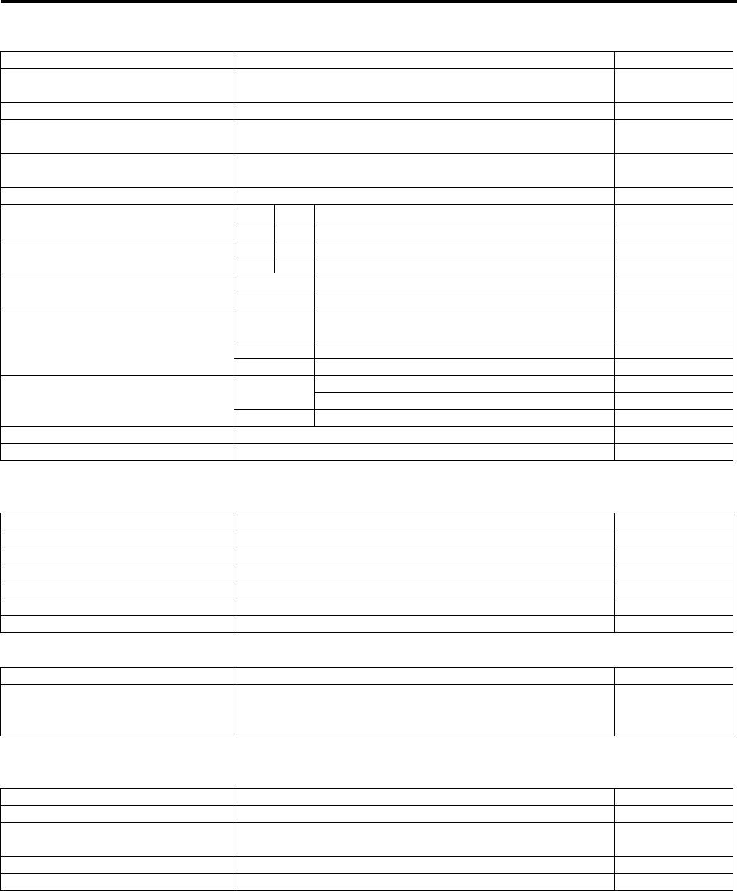
0C-2 Service Data:
Cylinder + Piston + Piston Ring
Unit: mm (in)
Conrod + Crankshaft
Unit: mm (in)
Oil Pump
Clutch
Unit: mm (in)
Item Standard Limit
Compression pressure (Automatic-
decomp. actuated) Approx. 1 000 kPa (10.0 kgf/cm2, 142 psi) —
Piston-to-cylinder clearance 0.030 – 0.040 (0.0012 – 0.0016) 0.120 (0.0047)
Cylinder bore 104.000 – 104.015 (4.0945 – 4.0951) Nicks or
Scratches
Piston diam. 103.965 – 103.980 (4.0931 – 4.0937)
Measure at 15 mm (0.6 in) from the skirt end. 103.880 (4.0898)
Cylinder distortion — 0.05 (0.002)
Piston ring free end gap 1st R Approx. 13.1 (0.52) 10.5 (0.41)
2nd RN Approx. 14.6 (0.57) 11.7 (0.46)
Piston ring end gap 1st R 0.10 – 0.25 (0.004 – 0.010) 0.50 (0.020)
2nd RN 0.10 – 0.25 (0.004 – 0.010) 0.50 (0.020)
Piston ring-to-groove clearance 1st — 0.180 (0.0071)
2nd — 0.150 (0.0059)
Piston ring groove width
1st 0.83 – 0.85 (0.0327 – 0.0335)
1.30 – 1.32 (0.0512 – 0.0520) —
2nd 1.01 – 1.03 (0.0398 – 0.0406) —
Oil 2.01 – 2.03 (0.0791 – 0.0799) —
Piston ring thickness 1st 0.76 – 0.81 (0.0299 – 0.0319) —
1.08 – 1.10 (0.0425 – 0.0433) —
2nd 0.97 – 0.99 (0.0382 – 0.0390) —
Piston pin bore I.D. 23.002 – 23.008 (0.9056 – 0.9058) 23.030 (0.9067)
Piston pin O.D. 22.992 – 23.000 (0.9052 – 0.9055) 22.980 (0.9047)
Item Standard Limit
Conrod small end I.D. 23.006 – 23.014 (0.9057 – 0.9061) 23.040 (0.9071)
Conrod deflection — 3.0 (0.12)
Conrod big end side clearance 0.10 – 0.75 (0.004 – 0.030) 1.0 (0.04)
Conrod big end width 24.95 – 25.00 (0.982 – 0.984) —
Crank web to web width 72.9 – 73.1 (2.87 – 2.88) —
Crankshaft runout — 0.08 (0.003)
Item Standard Limit
Oil pressure (at 60 °C, 140 °F)
140 – 180 kPa
(1.4 – 1.8 kgf/cm2, 20 – 26 psi)
at 3 000 r/min
—
Item Standard Limit
Clutch wheel I.D. 140.0 – 140.2 (5.512 – 5.520) 140.5 (5.53)
Clutch shoe — No groove at any
part
Clutch engagement r/min 1 500 – 2 000 r/min —
Clutch lock-up r/min 3 500 – 4 000 r/min —
PartShark.com
877-999-5686

Service Data: 0C-3
Drive Train
Unit: mm (in) Except ratio
Thermostat + Radiator + Fan + Coolant
Item Standard Limit
Primary reduction ratio (Automatic
drive) Variable change (2.763 – 0.780) —
Secondary reduction ratio 2.158 (40/21 x 17/15) —
Final reduction ratio Front 3.600 (36/10) —
Rear 3.600 (36/10) —
Transfer gear ratio
Low 2.562 (41/16) —
High 1.240 (31/25) —
Reverse 1.882 (32/17) —
Drive V-belt width 34.3 (1.35) 33.3 (1.31)
Movable driven face spring free
length 153.0 (6.02) 145.4 (5.72)
Shift fork to groove
clearance
Low 0.10 – 0.30 (0.0040 – 0.0120) 0.50 (0.020)
High 0.10 – 0.30 (0.0040 – 0.0120) 0.50 (0.020)
Reverse 0.10 – 0.30 (0.0040 – 0.0120) 0.50 (0.020)
Shift fork groove
width
Low 5.50 – 5.60 (0.217 – 0.220) —
High 5.50 – 5.60 (0.217 – 0.220) —
Reverse 5.50 – 5.60 (0.217 – 0.220) —
Shift fork thickness
Low 5.30 – 5.40 (0.209 – 0.213) —
High 5.30 – 5.40 (0.209 – 0.213) —
Reverse 5.30 – 5.40 (0.209 – 0.213) —
Front/Rear output shaft bevel gear
backlash 0.03 – 0.15 (0.001 – 0.006) —
Front drive (differential) gear
backlash 0.05 – 0.10 (0.002 – 0.004) —
Rear drive (final)
gear blacklash
Without gear
cover
specification
0.02 – 0.06 (0.0008 – 0.0024) —
Gear cover
assembled
specification
0.08 – 0.15 (0.0031 – 0.0059) —
Front differential gear oil type Hypoid gear oil SAE #90, API grade GL-5 —
Rear drive gear oil type Mobil 424 or equivalent gear oil —
Front differential gear oil capacity 500 ml (0.53/0.44 US/lmp qt) —
Rear drive gear oil capacity 770 ml (0.81/0.68 US/lmp qt) —
Item Standard Note
Thermostat valve opening
temperature Approx. 82 °C (180 °F) —
Thermostat valve lift 8 mm (0.31 in) and over at 95 °C (203 °F) —
ECT sensor resistance
20 °C
(68 °F) Approx. 2.45 kΩ—
50 °C
(122 °F) Approx. 0.811 kΩ—
80 °C
(176 °F) Approx. 0.318 kΩ—
110 °C
(230 °F) Approx. 0.142 kΩ—
Radiator cap valve opening
pressure 110 – 140 kPa (1.1 – 1.4 kgf/cm2, 15.6 – 19.9 psi) —
Cooling fan thermo-switch operating
temperature
OFF → ON Approx. 93 °C (199 °F) —
ON → OFF Approx. 87 °C (189 °F) —
Engine coolant type Use an antifreeze/coolant compatible with aluminum
radiator, mixed with distilled water only, at the ratio of 50:50. —
Engine coolant Reservoir Approx. 250 ml (0.26/0.22 US/lmp qt) —
Engine Approx. 2 200 ml (2.32/1.94 US/lmp qt) —
PartShark.com
877-999-5686

0C-4 Service Data:
Injector + Fuel Pump + Fuel Pressure Regulator
FI Sensors + Secondary Throttle Valve Actuator
Throttle Body
Item Specification Note
Injector resistance 11 – 13 Ω at 20 °C (68 °F)
Fuel pump discharge amount 55.5 ml (1.88/1.95 US/lmp qt) and more/10 sec.
Fuel pressure regulator operating
set pressure Approx. 294 kPa (2.9 kgf/cm2, 41psi)
Item Specification Note
CKP sensor resistance 150 – 250 Ω
CKP sensor peak voltage 5.0 V and more When cranking
IAP sensor input voltage 4.5 – 5.5 V
IAP sensor output voltage Approx. 2.63 V at idle speed
TP sensor input voltage 4.5 – 5.5 V
TP sensor output voltage Closed Approx. 1.1 V
Opened Approx. 4.3 V
ECT sensor input voltage 4.5 – 5.5 V
ECT sensor output voltage 0.15 – 4.85 V
ECT sensor resistance Approx. 2.45 kΩ at 20 °C (68 °F)
IAT sensor input voltage 4.5 – 5.5 V
IAT sensor output voltage 0.15 – 4.85 V
IAT sensor resistance Approx. 1.60 kΩ at 20 °C (68 °F)
TO sensor resistance 19 – 20 kΩ
TO sensor voltage
Normal 0.4 – 1.4 V
Leaning 3.7 – 4.4 V When leaning
65°
GP switch voltage 0.6 V and more From 1st to Top
Injector voltage Battery voltage
Ignition coil primary peak voltage 80 V and more When cranking
ISC valve resistance Approx. 31 kΩ at 20 °C (68 °F)
Item Specification
Bore size 42 mm
I.D. No. 31G0
Idle r/min 1 300 ± 100 r/min
Fast idle r/min 1 500 – 2 000 r/min (When cold engine)
Throttle cable play 3 – 5 mm (0.12 – 0.20 in)
PartShark.com
877-999-5686

Service Data: 0C-5
Electrical
Unit: mm (in)
Wattage
Unit: W
Item Specification Note
Spark plug Type NGK: CR6E
DENSO: U20ESR-N
Gap 0.7 – 0.8 (0.028 – 0.031)
Spark performance Over 8 (0.3) at 1 atm.
CKP sensor resistance 150 – 250 Ω
CKP sensor peak voltage 5.0 V and more
Ignition coil resistance
Primary 0.1 – 0.6 ΩTerminal –
Ground
Secondary 12 – 19 kΩPlug cap –
Terminal
Ignition coil primary peak voltage 80 V and more When cranking
Generator coil resistance 0.4 – 1.0 Ω
Generator maximum output Approx. 400 W at 5 000 r/min
Generator no-load voltage (When
engine is cold) 75 V (AC) and more at 5 000 r/min
Regulated voltage 13.5 – 15.5 V at 5 000 r/min
Starter motor brush length Standard 12.5 (0.49)
Limit 6.0 (0.24)
Starter torque limiter slip torque Standard 41.2 – 62.8 N⋅m
(4.2 – 6.4 kgf-m, 14.5 – 32.5 lb-ft)
Starter relay resistance 3 – 5 Ω
Battery
Type
designation YTX20CH-BS
Capacity 12 V 64.8 kC (18 Ah)/10 HR
Fuse size
Headlight HI 10 A
LO 10 A
Fuel 10 A
Ignition 15 A
Power source 10 A
Fan 15 A
Main 30 A
Item Specification
P-24, 28, 33 P-17
Headlight HI 35 x 2 ←
LO 35 x 2 ←
Auxiliary headlight 35/35 ←
Brake light/Taillight 21/5 ←
Revercing light — 21
Speedometer light LED ←
High beam indicator light — LED
Neutral indicator light LED ←
FI indicator light/Engine coolant
temp. indicator light LED ←
Reverse indicator light LED ←
Differential lock indicator light LED ←
PartShark.com
877-999-5686
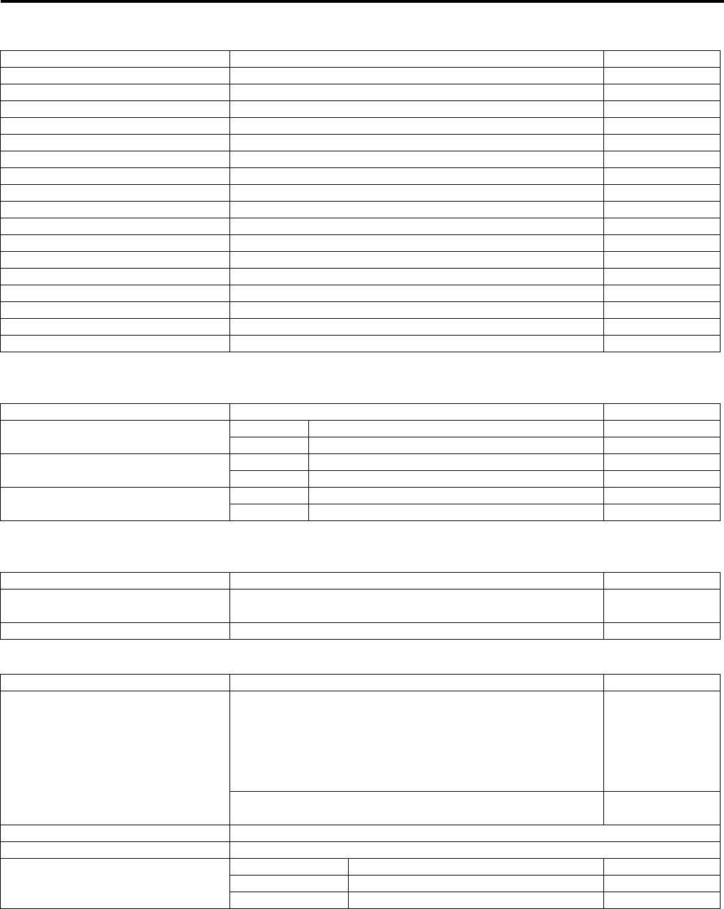
0C-6 Service Data:
Brake + Wheel
Unit: mm (in)
Tire
Unit: mm (in)
Suspension
Unit: mm (in)
Fuel + Oil
Item Standard Limit
Front brake disc thickness — 3.0 (0.12)
Front brake disc runout — 0.30 (0.012)
Front master cylinder bore 14.000 – 14.043 (0.5512 – 0.5529) —
Front master cylinder piston diam. 13.957 – 13.984 (0.5495 – 0.5506) —
Front brake caliper cylinder bore 33.960 – 34.010 (1.3370 – 1.3390) —
Front brake caliper piston diam. 33.878 – 33.928 (1.3338 – 1.3357) —
Rear brake pedal height 12.5 – 22.5 (0.5 – 0.9) —
Rear brake pedal free travel 20 – 30 (0.8 – 1.2) —
Rear brake lever play 6 – 8 (0.2 – 0.3) —
Rear brake outer distance 26.0 – 27.0 (1.02 – 1.06) —
Brake side plate spring free length 21.3 (0.84) 20.2 (0.80)
Brake fluid type DOT 4 —
Steering angle 46° (right & left) —
Turning radius 3.1 m (10.2 ft) —
Toe-out (With 75 kg, 165 lbs) 10 ± 4 mm (0.39 ± 0.16) —
Camber 0.64°—
Caster 1.6°—
Item Standard Limit
Cold inflation tire pressure
(Solo riding)
Front 35 kPa (0.35 kgf/cm2, 5.1 psi) —
Rear 30 kPa (0.30 kgf/cm2, 4.4 psi) —
Tire size Front AT25 x 8-12 , tubeless —
Rear AT25 x 10-12 , tubeless —
Tire tread depth Front — 4.0 (0.16)
Rear — 4.0 (0.16)
Item Standard Limit
Front shock absorber spring
adjustor 2/5 position —
Rear shock absorber spring adjustor 2/5 position —
Item Specification Note
Fuel type
Use only unleaded gasoline of at least 87 pump octane (R/2
+ M/2) or 91 octane or higher rated by the Research
Method. Gasoline containing MTBE (Methyl Tertiary Butyl
Ether), less than 10% ethanol, or less than 5% methanol
with appropriate cosolvents and corrosion inhibitor is
permissible.
P-28, 33
Gasoline used should be graded 91 octane or higher. An
unleaded gasoline type is recommended. Others
Fuel tank capacity 17.5 L (4.6/3.8 US/lmp gal)
Engine oil type SAE 10 W-40, API SF/SG or SH/SJ with JASO MA
Engine oil capacity
Change 2 300 ml (2.4/2.0 US/lmp qt)
Filter change 2 500 ml (2.6/2.2 US/lmp qt)
Overhaul 3 000 ml (3.2/2.6 US/lmp qt)
PartShark.com
877-999-5686

Service Data: 0C-7
Tightening Torque List
B931G20307002
Engine
Item N⋅m kgf-m lb-ft
Spark plug 11 1.1 8.0
Cylinder head cover bolt Initial 10 1.0 7.0
Final 14 1.4 10.5
Cam drive idle gear/sprocket shaft 41 4.1 29.5
Intake pipe bolt 9 0.9 6.5
Cylinder head bolt (M6) 10 1.0 7.0
Cylinder head bolt (L200) Initial 25 2.5 18.0
Final 37 3.7 27.0
Cylinder head bolt (L: 70) 10 1.0 7.0
Cylinder head bolt (L: 100) 10 1.0 7.0
Camshaft journal holder bolt 10 1.0 7.0
Cam chain tension adjuster bolt 10 1.0 7.0
Cam chain tension adjuster cap bolt 7 0.7 5.0
Crankcase bolt (M6) 10 1.0 7.0
Crankcase bolt (M8) 26 2.6 19.0
Valve timing inspection plug 23 2.3 16.5
Clutch shoe nut 150 15.0 108.5
Movable drive face bolt 110 11.0 79.5
Movable driven face bolt 110 11.0 79.5
Movable driven face ring nut 110 11.0 79.5
Clutch outer cover bolt 8 0.8 6.0
Clutch inner cover bolt 9 0.9 6.5
Generator rotor nut 160 11.0 115.5
Generator starter set bolt 11 1.1 8.0
Speed sensor bolt 10 1.0 7.0
Starter clutch bolt 26 2.6 19.0
Exhaust pipe nut 23 2.3 16.5
Muffler connecting bolt 23 2.3 16.5
Muffler mounting bolt 23 2.3 16.5
Engine oil drain plug 21 2.1 15.0
Engine coolant drain plug 13 1.3 9.5
Drive bevel gear nut 100 10.0 72.5
Front output shaft nut 100 10.0 72.5
Engine mounting nut 60 6.0 43.5
Engine mounting damper stopper bolt 23 2.3 16.5
Rear output shaft nut 100 10.0 72.5
Crank balancer drive gear nut 150 15.0 108.5
Crank balancer driven gear bolt 50 5.0 36.0
Starter motor mounting bolt 10 1.0 7.0
Starter motor lead wire connecting nut 6 0.6 4.5
Main oil gallery plug 18 1.8 13.0
Air cleaner box mounting bolt 4.5 0.45 3.0
Stater cup nut 38 3.8 27.5
Oil gallery plug (Cylinder head) 10 1.0 7.0
Water bypass union 12 1.2 8.5
Gear shift lever bolt 10 1.0 7.0
PartShark.com
877-999-5686

0C-8 Service Data:
Drive Train
FI System, Intake Air System and Fuel System
Cooling System
Item N⋅mkgf—mlb—ft
4WD/Diff-lock actuator mounting bolt 22 2.2 16.0
Front drive (Differential) gear case bolt 22 2.2 16.0
Front drive (Differential) gear case mounting nut 50 5.0 36.0
Front drive (Differential) gear oil level plug 8.5 0.85 6.0
Front drive (Differential) gear oil filler plug 35 3.5 25.5
Front drive (Differential) gear oil drain plug 32 3.2 23.0
Front propeller shaft boot clamp screw 1.3 0.13 0.94
Final drive gear nut 100 10.0 72.5
Final drive gear bearing stopper 100 10.0 72.5
Final gear case bolt (M8) 26 2.6 19.0
Final gear case bolt (M10) 55 5.5 40.0
Final gear mounting nut 65 6.5 47.0
Final gear mounting bolt 65 6.5 47.0
Rear propeller shaft boot clamp screw 2 0.2 1.5
Final gear oil drain plug 23 2.3 16.5
Rear propeller shaft coupling nut 100 10.0 72.5
Front output shaft bolt 10 1.0 7.0
Rear output shaft nut 100 10.0 72.5
Rear output shaft drive bevel gear nut 100 10.0 72.5
Rear output shaft driven gear nut 100 10.0 72.5
Front propeller shaft boot clamp screw 1.3 0.13 1.0
Rear propeller shaft boot clamp screw 2 0.2 1.5
Item N⋅mkgf—mlb—ft
CKP sensor mounting bolt 6 0.6 4.5
CKP sensor bracket bolt 6 0.6 4.5
Fuel delivery pipe mounting screw 5 0.5 3.5
Fuel pump retainer 35 3.5 25.5
ECT sensor 18 1.8 13.0
ISC valve mounting screw 2 0.2 1.5
TP sensor mounting screw 2 0.2 1.5
Item N⋅mkgf—mlb—ft
Water pump cover screw 6 0.6 4.5
Water pump mounting bolt 10 1.0 7.0
Cooling fan thermo-switch 17 1.7 12.5
Thermostat cover bolt 23 2.3 16.5
Cooling fan assembly mounting bolt 8.5 0.85 6.0
Water bypass union 12 1.2 8.5
PartShark.com
877-999-5686

Service Data: 0C-9
Chassis
Item N⋅mkgf—mlb—ft
Handlebar clamp bolt 26 2.6 19.0
Handlebar holder nut 60 6.0 43.5
Rear brake lever holder clamp bolt 11 1.1 8.0
Throttle lever case bolt 5 0.5 3.5
Steering shaft holder bolt 23 2.3 16.5
Steering shaft lower nut 162 16.2 117.0
Front suspension arm pivot nut (Upper) 60 6.0 43.5
Front suspension arm pivot nut (Lower) 65 6.5 47.0
Steering knuckle end nut (Upper and Lower) 29 2.9 21.0
Tie-rod end nut 29 2.9 21.0
Tie-rod lock-nut 45 4.5 32.5
Front shock absorber mounting bolt (Upper) 55 5.5 40.0
Front shock absorber mounting nut (Lower) 60 6.0 43.5
Front wheel hub nut 110 11.0 79.5
Rear wheel hub nut 121 12.1 87.5
Wheel set nut (Front and rear) 60 6.0 43.5
Front brake hose union bolt 23 2.3 16.5
Front brake air bleeder valve 6 0.6 4.5
Front brake pad mounting pin 18 1.8 13.0
Front brake caliper mounting bolt 26 2.6 19.0
Caliper holder pin 18 1.8 13.0
Caliper holder slide pin 23 2.3 16.5
Brake pipe flare nut 16 1.6 11.5
Front brake disc mounting bolt 23 2.3 16.5
Brake master cylinder mounting bolt 10 1.0 7.0
Footrest mounting bolt (M8) 26 2.6 19.0
Footrest mounting bolt (M10) 55 5.5 40.0
Rear stabilizer joint nut [Up to 5SAAR41A497105526] 34 3.4 24.5
Rear stabilizer joint nut [From 5SAAR41A497105527] 60 6.0 43.5
Rear shock absorber mounting nut (Upper and Lower) 60 6.0 43.5
Rear suspension arm pivot nut (Upper and Lower) 60 6.0 43.5
Rear knuckle end nut (Upper and Lower) 60 6.0 43.5
Rear brake cam lever nut 11 1.1 8.0
Rear brake case bolt 26 2.6 19.0
Rear brake pedal pivot bolt 11 1.1 8.0
Trailer towing bolt 60 6.0 43.5
Brake lever pivot bolt and nut 6 0.6 4.5
Brake lever pivot bolt lock-nut 6 0.6 4.5
Front propeller shaft boot clamp screw 1.3 0.13 1.0
Rear propeller shaft boot clamp screw 2 0.2 1.5
PartShark.com
877-999-5686
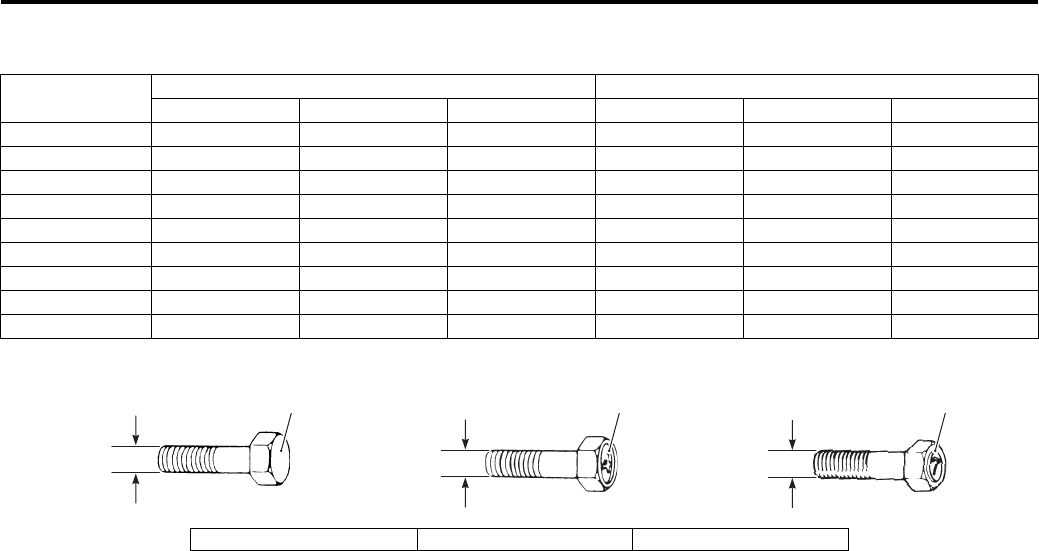
0C-10 Service Data:
Tightening Torque Chart
For other bolts and nuts not listed in the preceding page, refer to this chart:
Bolt Diameter
“a” (mm)
Conventional or “4” marked bolt “7” marked bolt
N⋅mkgf—mlb—ft N⋅mkgf—mlb—ft
4 1.5 0.15 1.0 2.3 0.23 1.5
5 3 0.3 2.0 4.5 0.45 3.0
6 5.5 0.55 4.0 10 1.0 7.0
8 13 1.3 9.5 23 2.3 16.5
10 29 2.9 21.0 50 5.0 36.0
12 45 4.5 32.5 85 8.5 61.5
14 65 6.5 47.0 135 13.5 97.5
16 105 10.5 76.0 210 21.0 152.0
18 160 16.0 115.5 240 24.0 173.5
321
“a” “a” “a”
I649G1030001-04
1. Conventional bolt 2. “4” marked bolt 3. “7” marked bolt
PartShark.com
877-999-5686

0C-11 Service Data:
PartShark.com
877-999-5686

Table of Contents 1- i
1
Section 1
CONTENTS
Engine
Precautions ………………………………….………1-1
Precautions….…………………..……………….…………… 1-1
Precautions for Engine……………..………………..….. 1-1
Engine General Information and
Diagnosis ………….……………………….…….. 1A-1
General Description ………………….………………..…1A-1
Injection Timing Description ………….………………. 1A-1
Schematic and Routing Diagram…………..……….1A-4
FI System Wiring Diagram ………..………………….. 1A-4
Terminal Alignment of ECM Coupler………………. 1A-5
Component Location ………..…………….…………….1A-6
FI System Parts Location….……………….…………. 1A-6
Diagnostic Information and Procedures…………1A-8
Engine Symptom Diagnosis ………….………………. 1A-8
Self-Diagnostic Procedures ………………………… 1A-11
Use of SDS Diagnosis Reset Procedures…..….1A-13
Show Data When Trouble (Displaying Data at
the Time of DTC) …….…………….………………...1A-14
SDS Check …………………….……………….……….. 1A-15
DTC Table………..…………….……………….……….. 1A-19
Fail-Safe Function Table.…….…………….……….. 1A-19
FI System Troubleshooting ….……………….……..1A-20
Malfunction Code and Defective Condition
Table ……………..…………….…………….………….. 1A-22
DTC “C12” (P0335): CKP Sensor Circuit
Malfunction.…………….………………..……………..1A-24
DTC “C13” (P0105-H/L): IAP Sensor Circuit
Malfunction.…………….………………..……………..1A-27
DTC “C14” (P0120-H/L): TP Sensor Circuit
Malfunction.…………….………………..……………..1A-34
DTC “C15” (P0115-H/L): ECT Sensor Circuit
Malfunction.…………….………………..……………..1A-41
DTC “C20” (P1752): Diff-lock Relay Circuit
Malfunction.…………….………………..……………..1A-47
DTC “C21” (P0110-H/L): IAT Sensor Circuit
Malfunction.…………….………………..……………..1A-49
DTC “C23” (P1651-H/L): TO Sensor Circuit
Malfunction.…………….………………..……………..1A-53
DTC “C24” (P0351): Ignition Coil Circuit
Malfunction.…………….………………..……………..1A-59
DTC “C32” (P0201): Fuel Injector Circuit
Malfunction.…………….………………..……………..1A-59
DTC “C40” (P05057): ISC Valve Circuit
Malfunction..…………….……………….……………..1A-62
DTC “C41” (P230-H/L): FP Relay Circuit
Malfunction..…………….……………….……………..1A-67
Specifications…….………….…….…………….……….1A-69
Service Data……..……………..……………….……….1A-69
Special Tools and Equipment ……………..……….1A-70
Special Tool ……………………….…………….……….1A-70
Emission Control Devices .………………… 1B-1
Precautions……..………………..……………….…………1B-1
Precautions for Emission Control Devices ….……1B-1
Repair Instructions ………..……….…………….………1B-1
Crankcase Breather (PCV) Hose Inspection…….1B-1
Crankcase Breather (PCV) Hose Removal
and Installation ……………………….………………….1B-1
Engine Electrical Devices …………..……… 1C-1
Precautions……..………………..……………….…………1C-1
Precautions for Engine Electrical Device …………1C-1
Component Location …..…….………………………….1C-1
Engine Electrical Components Location ………….1C-1
Diagnostic Information and Procedures…………1C-1
Engine Symptom Diagnosis ……….………………....1C-1
Repair Instructions ………..……….…………….………1C-1
ECM Removal and Installation……………………….1C-1
CKP Sensor Inspection …………..……………….……1C-1
CKP Sensor Removal and Installation …………….1C-1
IAP Sensor Inspection…………….……………….……1C-1
IAP Sensor Removal and Installation………………1C-2
TP Sensor Inspection………..……………….…………1C-2
TP Sensor Removal and Installation…….…………1C-2
TP Sensor Adjustment …………………………….……1C-3
IAT Sensor Inspection…………….…………………....1C-3
IAT Sensor Removal and Installation……………...1C-3
ECT Sensor Removal and Installation …………....1C-4
ECT Sensor Inspection …………..……………….……1C-4
TO Sensor Inspection ………………………..…………1C-5
TO Sensor Removal and Installation ………………1C-5
ISC Valve Inspection…..…………….…………….……1C-5
ISC Valve Removal and Installation…..……………1C-5
GP Switch Inspection …………..……………….………1C-6
GP Switch Removal and Installation ………….……1C-6
Specifications…….………….…….…………….…………1C-6
PartShark.com
877-999-5686

1-ii Table of Contents
Service Data…..…………….…………….……………….1C-6
Tightening Torque Specifications…..……………….1C-6
Special Tools and Equipment ………………………..1C-7
Recommended Service Material ………………….…1C-7
Special Tool ………..…………….……………..…………1C-7
Engine Mechanical ……..…………………….. 1D-1
Schematic and Routing Diagram……..…………….1D-1
Throttle Cable Routing Diagram.……………….……1D-1
Diagnostic Information and Procedures…………1D-2
Engine Mechanical Symptom Diagnosis………….1D-2
Compression Pressure Check …………………….…1D-2
Repair Instructions ……………………………………….1D-3
Engine Components Removable with the
Engine in Place ………..……………….…………….…1D-3
Air Cleaner Element Removal and Installation ….1D-5
Air Cleaner Element Inspection and Cleaning ….1D-5
Air Cleaner Box Removal and Installation…..……1D-5
Throttle Cable Removal and Installation ………….1D-6
Throttle Cable Inspection ….………………..…………1D-6
Throttle Cable Play Inspection and
Adjustment ………..…………….……………..…………1D-6
Throttle Body Components .………………..…………1D-7
Throttle Body Construction…..………………..………1D-8
Throttle Body Removal and Installation …..………1D-9
Throttle Body Disassembly and Assembly……..1D-10
Throttle Body Inspection and Cleaning ………….1D-13
Engine Assembly Removal .………………..……….1D-13
Engine Assembly Installation .……………..……….1D-16
Engine Top Side Disassembly ………………….….1D-17
Engine Top Side Assembly …………..……………..1D-21
Valve Clearance Inspection and Adjustment ….1D-27
Camshaft Inspection ..……………….…………….….1D-28
Camshaft Sprocket Inspection …………….……….1D-30
Cam Chain Tension Adjuster Inspection.……….1D-30
Cam Chain Guide Removal and Installation …..1D-30
Cam Chain Guide Inspection .…………………..….1D-30
Cam Chain Tensioner Inspection..…………….….1D-31
Cylinder Head Disassembly and Assembly ……1D-31
Cylinder Head Related Parts Inspection .……….1D-35
Valve Guide Replacement …..………………..…….1D-38
Valve Seat Repair ……………………….……………..1D-40
Cam Drive Idle Gear / Sprocket Thrust
Clearance Inspection and Adjustment …………1D-40
Cylinder Disassembly and Assembly …………….1D-41
Cylinder Inspection.…………….……………..……….1D-41
Piston Ring Removal and Installation ……………1D-42
Piston and Piston Ring Inspection ………………..1D-43
Engine Bottom Side Disassembly .………………..1D-45
Engine Bottom Side Assembly……………………..1D-51
Conrod and Crankshaft Inspection………………..1D-59
Width Between Crankshaft Webs .………………..1D-60
Crankshaft Oil Seal Inspection…………….……….1D-61
Bearing Inspection …..…………….……………….….1D-61
Bearing Removal and Installation …….…………..1D-61
Specifications….……….…………….…………….…….1D-66
Service Data…..…………….…………….……………..1D-66
Tightening Torque Specifications…..……………..1D-68
Special Tools and Equipment ……………..……….1D-69
Recommended Service Material .……………….…1D-69
Special Tool …………………….…………….………….1D-69
Engine Lubrication System ……………….. 1E-1
Precautions..…………………..……………….……………1E-1
Precautions for Engine Oil ………………….…………1E-1
Schematic and Routing Diagram …………….……..1E-1
Engine Lubrication System Chart Diagram ………1E-1
Diagnostic Information and Procedures….……..1E-2
Engine Lubrication Symptom Diagnosis ………….1E-2
Oil Pressure Check ….………………..…………………1E-2
Repair Instructions …………………………….…………1E-3
Engine Oil and Filter Replacement …………………1E-3
Engine Oil Level Inspection……………………………1E-3
Oil Sump Filter Removal and Installation …….…..1E-3
Oil Sump Filter Inspection and Cleaning…..……..1E-4
Oil Jet Removal and Installation………..……………1E-4
Oil Jet Inspection..……………….………………..……..1E-5
Oil Pump Removal and Installation ………………...1E-5
Oil Pump Inspection …………………..…………………1E-7
Specifications..……………….………………….…………1E-7
Service Data……………………….………………..……..1E-7
Tightening Torque Specifications……………………1E-7
Special Tools and Equipment ……………..…………1E-8
Recommended Service Material .…………………...1E-8
Special Tool ……………………….………………..……..1E-8
Engine Cooling System …..…………..……..1F-1
Precautions..…………………..……………….…………… 1F-1
Precautions for Engine Cooling System………….. 1F-1
Precautions for Engine Coolant …………………….. 1F-1
General Description ………..……………….…………… 1F-1
Engine Coolant Description…………………………… 1F-1
Schematic and Routing Diagram …………….…….. 1F-2
Cooling Circuit Diagram ….………….…………….….. 1F-2
Water Hose Routing Diagram ……………..………… 1F-3
Diagnostic Information and Procedures….…….. 1F-4
Engine Cooling Symptom Diagnosis…………….... 1F-4
Repair Instructions ………………………….…………… 1F-4
Cooling Circuit Inspection .……….……………….….. 1F-4
Radiator Cap Inspection…….……………….………… 1F-5
Radiator Inspection and Cleaning ………..………… 1F-5
Cooling Fan Assembly / Radiator Removal
and Installation ………………….………………..…….. 1F-5
Water Hose Removal and Installation …………….. 1F-7
Cooling Fan Inspection …..……………….…………… 1F-7
Radiator Reservoir Tank Removal and
Installation …………….………………..………………... 1F-8
Radiator Reservoir Tank Inspection……………….. 1F-8
Water Hose Inspection……………………….………… 1F-8
ECT Sensor Removal and Installation ….………… 1F-9
ECT Sensor Inspection ……..……………….………… 1F-9
Cooling Fan Thermo-switch Removal and
Installation …………….………………..………………... 1F-9
Cooling Fan Thermo-switch Inspection…………. 1F-10
Thermostat Removal and Installation……………. 1F-11
Thermostat Inspection…….……………….…………. 1F-12
Water Pump Components.……………….…………. 1F-13
Water Pump Removal and Installation ………….. 1F-13
PartShark.com
877-999-5686

Table of Contents 1-iii
Water Pump Disassembly and Assembly ……... 1F-14
Water Pump Related Parts Inspection……….…. 1F-18
Specifications…….…………….…………….………….. 1F-19
Service Data ………….…………….………………..…. 1F-19
Tightening Torque Specifications………..……….. 1F-19
Special Tools and Equipment …………….……….. 1F-20
Recommended Service Material ………………….. 1F-20
Special Tool .…………….…………….……………..…. 1F-20
Fuel System ……………………………….…….. 1G-1
Precautions….…………….…………….………………..…1G-1
Precautions for Fuel System ……..………………..…1G-1
General Description …………….……………….……….1G-2
Fuel System Description ………..…………………..…1G-2
Schematic and Routing Diagram…………..……….1G-3
Fuel Hose Routing Diagram…………….…………….1G-3
Fuel Tank Breather Hose Routing Diagram……..1G-4
Diagnostic Information and Procedures…………1G-5
Fuel System Diagnosis ………….………………..……1G-5
Repair Instructions .……………….…………………..…1G-6
Fuel Pressure Inspection ………….……………..……1G-6
Fuel Pump Inspection ………………………….……….1G-6
Fuel Discharge Amount Inspection …………………1G-7
Fuel Pump Relay Inspection ………………………….1G-7
Fuel Hose Inspection ……………………..…………….1G-8
Fuel Feed Hose Removal and Installation ……….1G-8
Fuel Level Gauge Inspection ……………..………….1G-8
Fuel Level Indicator Inspection …………..………….1G-8
Fuel Tank Removal and Installation…………..……1G-8
Fuel Pump Components …..……………….………….1G-9
Fuel Pump Assembly Removal and
Installation…..………………..…………….…………….1G-9
Fuel Pump Disassembly and Assembly….……..1G-10
Fuel Mesh Filter Inspection and Cleaning………1G-10
Fuel Injector Inspection and Cleaning……………1G-10
Fuel Injector / Fuel Delivery Pipe Removal
and Installation…..……………….………………..….1G-10
Fuel Tank Pressure Control (FTPC) Valve
Removal and Installation…………….……………..1G-12
Fuel Tank Pressure Control (FTPC) Valve
Inspection………………….………………..…………..1G-13
Specifications…….…………….…………….…………..1G-13
Service Data ………….…………….………………..….1G-13
Tightening Torque Specifications………..………..1G-14
Special Tools and Equipment …………….………..1G-14
Special Tool .……………….………………..…………..1G-14
Ignition System….……………………….…….. 1H-1
General Description ………………….………………..…1H-1
Override Switch Description………………………..…1H-1
Schematic and Routing Diagram…………..……….1H-1
Ignition System Diagram ………..………………..……1H-1
Ignition System Components Location ……………1H-1
Diagnostic Information and Procedures…………1H-2
Ignition System Symptom Diagnosis……………….1H-2
No Spark or Poor Spark………………….…………….1H-2
Repair Instructions .……………….…………………..…1H-3
Spark Plug Cap and Spark Plug Removal and
Installation …………….……………….………………....1H-3
Spark Plug Inspection and Cleaning …….…………1H-3
Ignition Coil and Plug Cap Inspection ………..……1H-3
CKP Sensor Inspection …………..……………….……1H-5
CKP Sensor Removal and Installation …………….1H-6
Engine Stop Switch Inspection……………………….1H-6
Ignition Switch Inspection…..……………….…………1H-6
Ignition Switch Removal and Installation…….……1H-7
Override Switch Inspection ……………………………1H-7
Specifications…….………….…….…………….…………1H-8
Service Data………………………….…………………....1H-8
Tightening Torque Specifications……………………1H-8
Special Tools and Equipment ……………..…………1H-8
Special Tool ………………………….……………….……1H-8
Starting System …………….……………..……..1I-1
Schematic and Routing Diagram………………….… 1I-1
Starting System Diagram ……..……………….………. 1I-1
Component Location …..…….…………………….……. 1I-1
Starting System Components Location……………. 1I-1
Diagnostic Information and Procedures…………. 1I-1
Starting System Symptom Diagnosis………………. 1I-1
Starter Motor will not Run……..……………….………. 1I-2
Starter Motor Runs but Does not Crank the
Engine …………………………..…………….……………. 1I-2
Engine Does not Turn Though the Starter
Motor Runs……..………………..……………….………. 1I-2
Repair Instructions ………..……….…………….………. 1I-3
Starter Motor Components……………………….……. 1I-3
Starter Motor Removal and Installation……………. 1I-4
Starter Motor Disassembly and Assembly ……..… 1I-4
Starter Motor Inspection……………………..…………. 1I-5
Starter Relay Removal and Installation……………. 1I-6
Starter Relay Inspection…………….………………….. 1I-7
Neutral Relay Removal and Installation ……..……. 1I-7
Neutral Relay Inspection ……………………………..… 1I-8
Neutral Relay Diode Inspection…..………………..… 1I-8
Parking Brake Relay Removal and Installation ….. 1I-8
Parking Brake Relay Inspection ………..……………. 1I-9
Parking Brake Switch Inspection……….……………. 1I-9
Gear Position Switch Inspection ………….…………. 1I-9
Starter Torque Limiter / Starter Clutch
Removal and Installation…….……………….…….. 1I-10
Starter Driven Gear Bearing Removal and
Installation …………….……………….………………... 1I-12
Starter Related Parts Inspection ……….………….. 1I-12
Starter Button Inspection………………………….….. 1I-13
Recoil Starter Components ………………………….. 1I-14
Recoil Starter Assembly Removal and
Installation …………….……………….………………... 1I-14
Recoil Starter Disassembly and Assembly …….. 1I-15
Recoil Starter Inspection ……………………………... 1I-17
Specifications…….………….…….…………….……….. 1I-18
Service Data……..………………..…………….……….. 1I-18
Tightening Torque Specifications………………….. 1I-18
Special Tools and Equipment ……………..……….. 1I-18
Recommended Service Material ………….……….. 1I-18
Special Tool ………………………….……………….….. 1I-19
PartShark.com
877-999-5686

1-iv Table of Contents
Charging System…………..…………….…….. 1J-1
Schematic and Routing Diagram..……………….… 1J-1
Charging System Diagram …..………………..……… 1J-1
Component Location ………..………………..………… 1J-1
Charging System Components Location…………. 1J-1
Diagnostic Information and Procedures………… 1J-1
Charging System Symptom Diagnosis……………. 1J-1
Battery Runs Down Quickly ………………..………… 1J-2
Repair Instructions ………..………….……………….… 1J-3
Battery Current Leakage Inspection…………..…… 1J-3
Regulated Voltage Inspection ………….……………. 1J-3
Generator Inspection…………..……………..………… 1J-3
Generator Removal and Installation……………..… 1J-4
Regulator / Rectifier Inspection ………..……………. 1J-8
Battery Components ..…………….…………….……… 1J-9
Battery Charging ….…………….……………..………… 1J-9
Battery Removal and Installation …..…………….. 1J-12
Battery Visual Inspection…………………………….. 1J-12
Specifications..……………….……………….…………. 1J-12
Service Data………………….……………….…………. 1J-12
Tightening Torque Specifications…………………. 1J-13
Special Tools and Equipment ……………..………. 1J-13
Recommended Service Material .……………….… 1J-13
Special Tool …………………….…………….…………. 1J-13
Exhaust System………….…………….………. 1K-1
Precautions..…………………..……………….……………1K-1
Precautions for Exhaust System ……….……………1K-1
Repair Instructions ………………………….……………1K-1
Exhaust System Construction ……..………………...1K-1
Exhaust Pipe / Muffler Removal and
Installation …………….………………..………………...1K-2
Exhaust System Inspection…..………………..……..1K-3
Spark Arrester Inspection……………………………...1K-3
Specifications..……………….……………….……………1K-4
Tightening Torque Specifications……………………1K-4
PartShark.com
877-999-5686

Precautions: 1-1
Engine
Precautions
Precautions
Precautions for Engine
B831G21000001
Refer to “General Precautions in Section 00 (Page 00-1)” and “Precautions for Electrical Circuit Service in Section 00
(Page 00-2)”.
PartShark.com
877-999-5686
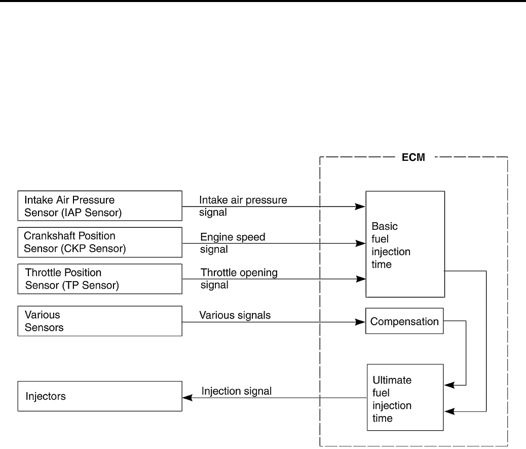
1A-1 Engine General Information and Diagnosis:
Engine
Engine General Information and Diagnosis
General Description
Injection Timing Description
B831G21101001
Injection Time (Injection Volume)
The factors to determine the injection time include the basic fuel injection time, which is calculated on the basis of the
intake air pressure, engine speed and throttle opening angle, and various compensations. These compensations are
determined according to the signals from various sensors that detect the engine and driving conditions.
I718H1110268-03
PartShark.com
877-999-5686
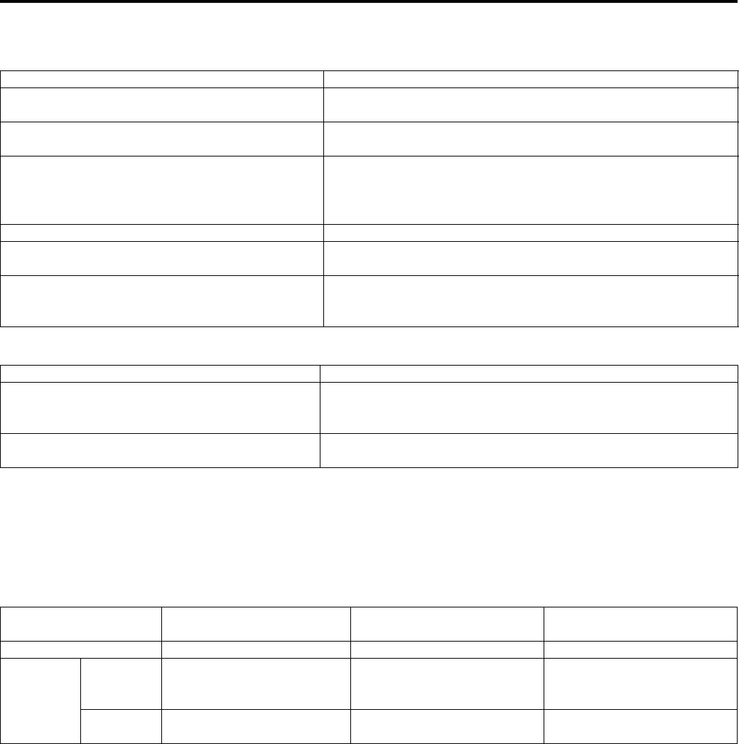
Engine General Information and Diagnosis: 1A-2
Compensation of Injection Time (Volume)
The following different signals are output from the respective sensors for compensation of the fuel injection time
(volume).
Injection Stop Control
Self-Diagnosis Function
The self-diagnosis function is incorporated in the ECM. The function has two modes, “User mode” and “Dealer mode”.
The user can only be notified by the LCD (DISPLAY) panel and LED (FI indicator light). To check the function of the
individual FI system devices, the dealer mode is prepared. In this check, the special tool is necessary to read the code
of the malfunction items.
User Mode
*1
Current letter displayed any one of the clock/hour meter.
*2
When one of the signals is not received by ECM, the fail-safe circuit works and injection is not stopped. In this case,
“FI” and clock/hour meter (*1) are indicated in the LCD panel and vehicle can run.
*3
The injection signal is stopped, when the crankshaft position sensor signal, tip-over sensor signal, ignition signal,
injector signal, fuel pump relay signal or ignition switch signal is not sent to ECM. In this case, “FI” is indicated in the
LCD panel. Vehicle does not run.
“CHEC”:
The LCD panel indications “CHEC” when no communication signal from the ECM is received for 3 seconds.
For Example:
The ignition switch is turned ON, and the engine stop switch is turned OFF. In this case, the speedometer does not
receive any signal form ECM, and the panel indicates “CHEC”.
Signal Descriptions
ENGINE COOLANT TEMPERATURE SENSOR
SIGNAL
When engine coolant temperature is low, injection time (volume)
is increased.
INTAKE AIR TEMPERATURE SENSOR SIGNAL When intake air temperature is low, injection time (volume) is
increased.
BATTERY VOLTAGE SIGNAL
ECM operates on the battery voltage and at the same time, it
monitors the voltage signal for compensation of the fuel injection
time (volume). A longer injection time is needed to adjust injection
volume in the case of low voltage.
ENGINE RPM SIGNAL At high speed, the injection time (volume) is increased.
STARTING SIGNAL When starting engine, additional fuel is injected during cranking
engine.
ACCELERATION SIGNAL/ DECELERATION
SIGNAL
During acceleration, the fuel injection time (volume) is increased
in accordance with the throttle opening speed and engine rpm.
During deceleration, the fuel injection time (volume) is decreased.
Signal Descriptions
TIP-OVER SENSOR SIGNAL (FUEL SHUT-OFF)
When the vehicle tips over, the tip-over sensor sends a signal to
the ECM. Then, this signal cuts OFF current supplied to the fuel
pump, fuel injectors and ignition coils.
OVER-REV. LIMITER SIGNAL The fuel injector stops operation when engine rpm reaches rev.
limit rpm.
Malfunction LCD (display) indication
“A”
FI indicator light indication
“B” Indication mode
“NO” Clock/Hour meter *1 — —
“YES”
Engine can
start
Clock/Hour meter (*1) and
“FI” letters *2 FI indicator light turns ON.
Each 2 sec. Odometer (*1)
and “FI” is indicated
alternately.
Engine can
not start “FI” letters *3 FI indicator light turns ON and
blinks. “FI” is indicated continuously.
PartShark.com
877-999-5686
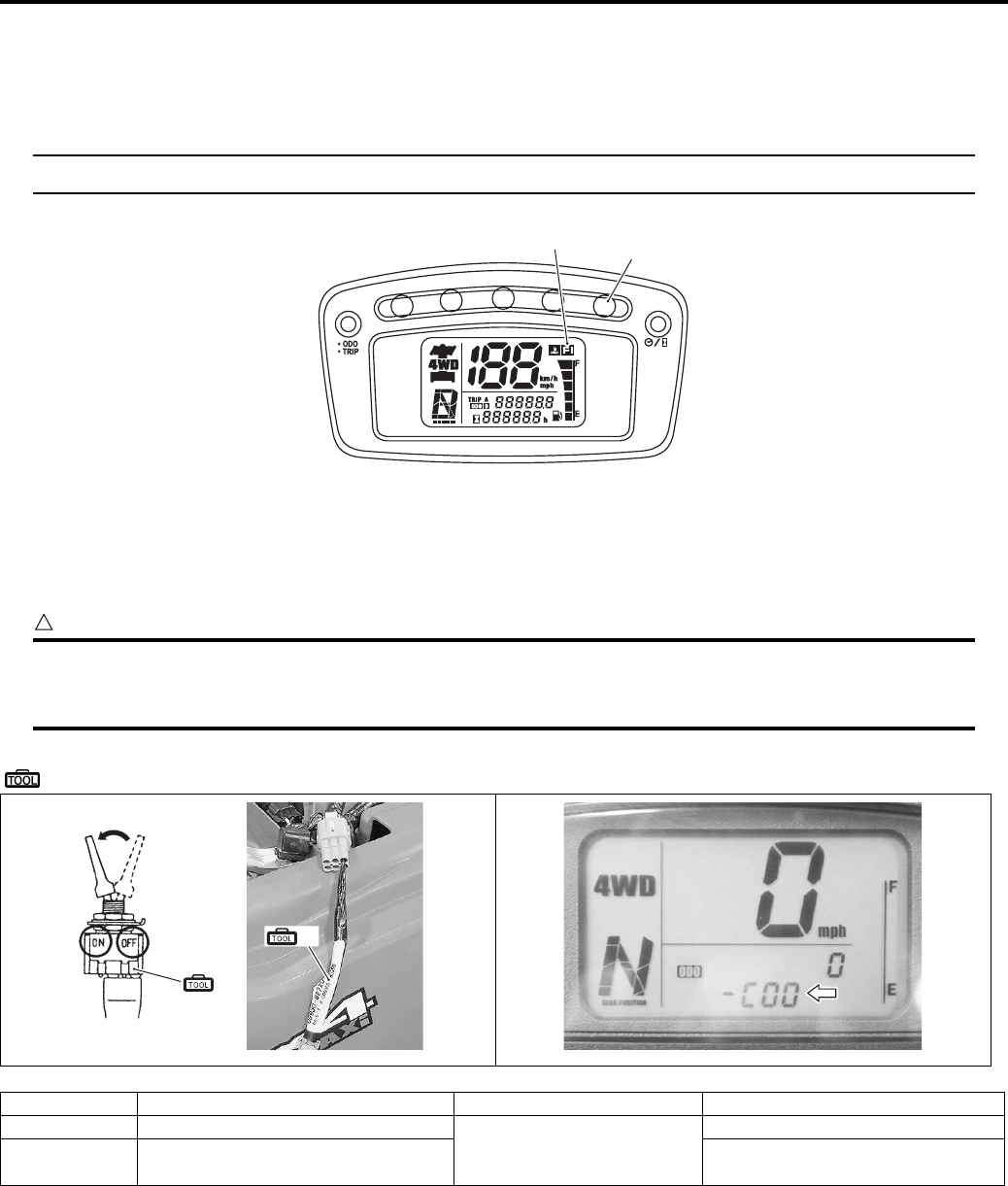
1A-3 Engine General Information and Diagnosis:
If “CHEC” is indicated, the LCD does not indicate the trouble code. It is necessary to check the wiring harness
between ECM and speedometer couplers.
The possible cause of this indication is as follows;
Engine stop switch is in OFF position. Ignition fuse is burnt.
NOTE
The FI light turns ON 2 seconds after the ignition switch turns ON.
Dealer Mode
The defective function is memorized in the computer. Use the special tool’s coupler to connect to the mode select
switch. The memorized malfunction code is displayed on LCD (DISPLAY) panel. Malfunction means that the ECM
does not receive signal from the devices. These affected devices are indicated in the code form.
CAUTION
!
Before checking the malfunction code, do not disconnect the ECM coupler.
If the coupler form the ECM is disconnected, the malfunction code memory is erased and the
malfunction code can not be checked.
Special tool
(A): 09930–82720 (Mode select switch)
Malfunction LCD (display) indication FI light indication Indication mode
“NO” C00
FI indicator light turns OFF.
—
“YES” C** code is indicated from small
numeral to large one. For each 2 sec., code is indicated.
“A” “B”
I831G1110001-03
(A)
(A)
I831G1110014-01 I831G1110015-01
PartShark.com
877-999-5686
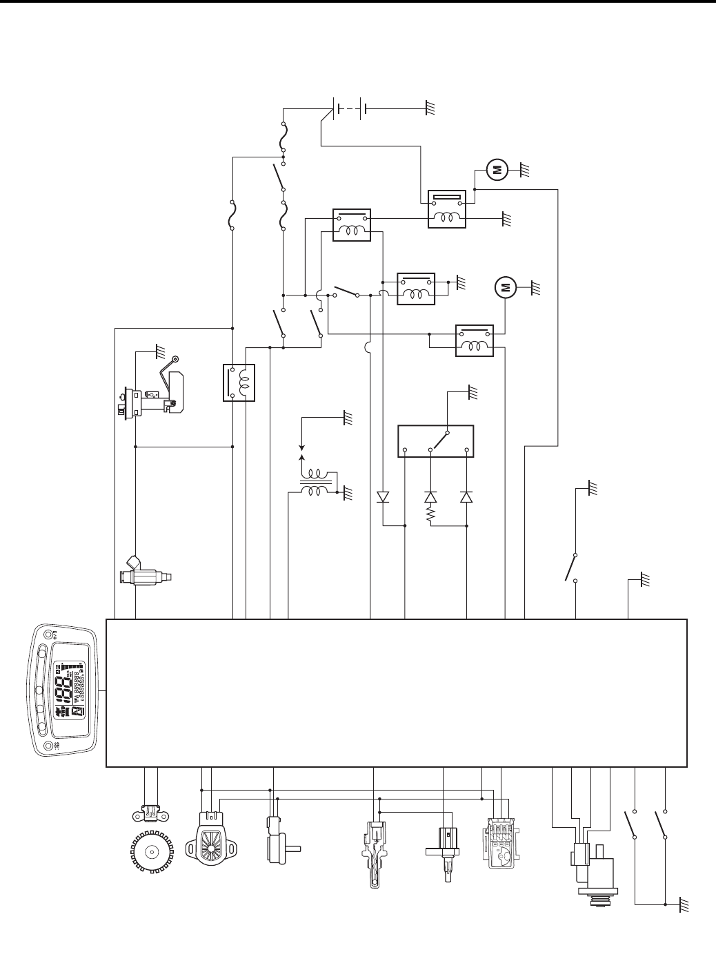
Engine General Information and Diagnosis: 1A-4
Schematic and Routing Diagram
FI System Wiring Diagram
B831G21102001
Crankshaft position sensor
(CKP sensor)
Throttle position sensor
(TP sensor)
Intake air pressure sensor
(IAP sensor)
Engine coolant temperature
sensor
(ECT sensor)
Intake air temperature sensor
(IAT sensor)
Tip-over sensor
(TO sensor)
ISC valve
Diff-lock switch
Diff-lock
relay
Starter
relay
Neutral
relay
Brake
switch (L)
Ignition
switch
Ignition
coil
Fuel injector
Fuel pump relay
Fuel pump
Engine stop
switch
START
button
Starter
motor
Parking
brake
relay
Diff-lock position switch
Override switch
Gear position
switch
N
L
H
30 A15 A
10 A
Speedometer
23
9
18
6
14
13
11
28
24
10
17
34
16
33
29
15
4
2
20
19
3
1
5
26
8
21
12
25
7
1 k
Ω
I831G1110002-04
PartShark.com
877-999-5686
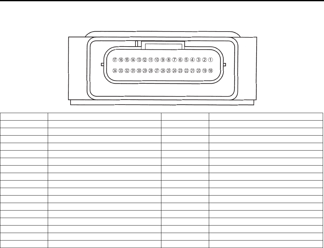
1A-5 Engine General Information and Diagnosis:
Terminal Alignment of ECM Coupler
B831G21102002
I831G1110003-03
TERMINAL NO. CIRCUIT TERMINAL NO. CIRCUIT
1 Ignition coil (IG1) 18 CKP sensor signal (CKP-)
2 Fuel injector (#1) 19 Fuel pump relay (FP relay)
3 Power source (+B) 20 Injector power voltage (VM)
4 Back up power (BATT) 21 Diff-lock relay (DL relay)
5 Brake switch (BRK) 22 Serial data for self-diagnosis (SDL)
6 Power source for sensors (VCC) 23 Serial data for speedometer (TECH)
7 ECM ground (E1) 24 Sensor ground (E2)
8 Forward sensor signal (FOW) 25 Override switch (OVR)
9 CKP sensor signal (CKP+) 26 Neutral switch (NT)
10 TO sensor signal (TO) 27 Test switch (TS)
11 ECT sensor signal (ECT) 28 IAT sensor signal (IAT)
12 Starter relay (STR) 29 Diff-lock switch (DL)
13 IAP sensor signal (IAP) 30 —
14 TP sensor signal (TP) 31 —
15 Diff-lock position sensor signal (DLP) 32 —
16 ISC valve (IS2A) 33 ISC valve (IS2B)
17 ISC valve (IS1A) 34 ISC valve (IS1B)
PartShark.com
877-999-5686
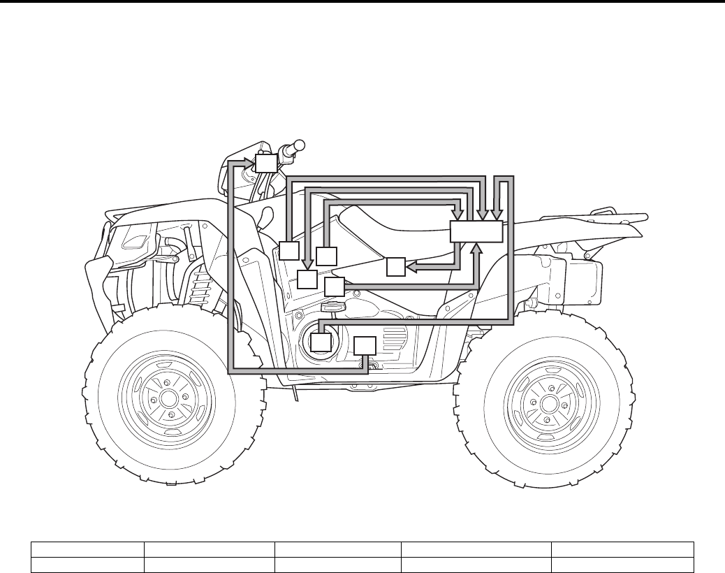
Engine General Information and Diagnosis: 1A-6
Component Location
FI System Parts Location
B831G21103001
“I”
“E”
“B” “C”
“D”
“G”
“H”
“A”
“F”
I831G1110004-02
“A”: ECM “C”: TP sensor “E”: IAT sensor “G”: Speed sensor “I”: Diff-lock relay
“B”: ISC valve “D”: IAP sensor “F”: CKP sensor “H”: Combination meter
PartShark.com
877-999-5686
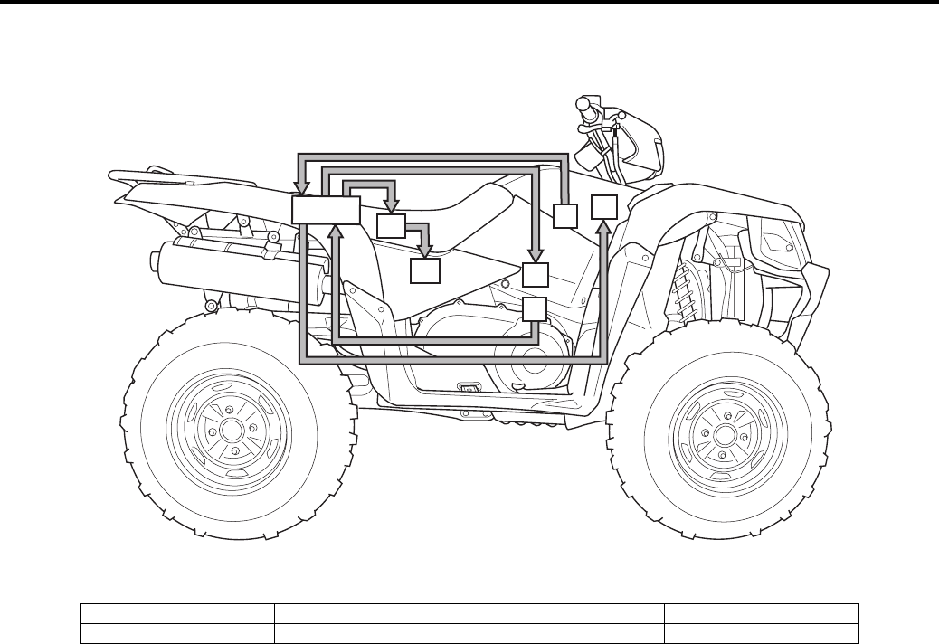
1A-7 Engine General Information and Diagnosis:
“J”
“K”
“N”
“L”
“A”
“M”
“I”
I831G1110005-03
“A”: ECM “J”: TO sensor “L”: Ignition coil “N”: Fuel pump
“I”: ECT sensor “K”: Fuel injector “M”: FP relay
PartShark.com
877-999-5686

Engine General Information and Diagnosis: 1A-8
Diagnostic Information and Procedures
Engine Symptom Diagnosis
B831G21104001
Condition Possible cause Correction / Reference Item
Engine will not start or is
hard to start
(Compression too low)
Valve clearance out of adjustment. Adjust.
Worn valve guides or poor seating of
valves.
Repair or replace.
Mistimed valves. Adjust.
Excessively worn piston rings. Replace.
Worn-down cylinder bore. Replace.
Starter motor cranks too slowly. Refer to “Starting System Diagram in Section
1I (Page 1I-1)”.
Poor seating of spark plug. Retighten.
Engine will not start or is
hard to start (Plugs not
speaking)
Fouled spark plug. Clean.
Wet spark plug. Clean and dry.
Defective ignition coil. Replace.
Open or short in high-tension cord. Replace.
Defective CKP sensor. Replace.
Defective ECM. Replace.
Open-circuited wiring connections. Repair or replace.
Engine will not start or is
hard to start (No fuel
reaching the intake
manifold)
Clogged fuel filter or fuel hose. Clean or replace.
Defective fuel pump. Replace.
Defective fuel pressure regulator. Replace.
Defective fuel injector. Replace.
Defective fuel pump relay. Replace.
Defective ECM. Replace.
Open-circuited wiring connections. Check and repair.
Engine will not start or is
hard to start (Incorrect
fuel/air mixture)
TP sensor out of adjustment. Adjust.
Defective fuel pump. Replace.
Defective fuel pressure regulator. Replace.
Defective TP sensor. Replace.
Defective CKP sensor. Replace.
Defective IAP sensor. Replace.
Defective ECM. Replace.
Defective ECT sensor. Replace.
Defective IAT sensor. Replace.
Engine idles poorly Valve clearance out of adjustment. Adjust.
Poor seating of valves. Replace or repair.
Defective valve guides. Replace.
Worn down camshafts. Replace.
Too wide spark plug gaps. Adjust or replace.
Defective ignition coil. Replace.
Defective CKP sensor. Replace.
Defective ECM. Replace.
Defective ISC valve. Replace.
Engine stalls often
(Incorrect fuel/air mixture)
Defective IAP sensor or circuit. Repair or replace.
Clogged fuel filter. Clean or replace.
Defective fuel pump. Replace.
Defective fuel pressure regulator. Replace.
Damaged or cracked vacuum hose. Replace.
Defective ECT sensor. Replace.
Defective thermostat. Replace.
Defective IAT sensor. Replace.
Engine stalls often (Fuel
injector improperly
operating)
Defective fuel injector. Replace.
No injection signal from ECM. Repair or replace.
Open or short circuited wiring
connection.
Repair or replace.
Defective battery or low battery voltage. Replace or recharge.
PartShark.com
877-999-5686

1A-9 Engine General Information and Diagnosis:
Engine stalls often
(Control circuit or sensor
improperly operating)
Defective ECM. Replace.
Defective fuel pressure regulator. Replace.
Defective TP sensor. Replace.
Defective IAT sensor. Replace.
Defective CKP sensor. Replace.
Defective ECT sensor. Replace.
Defective fuel pump relay. Replace.
Engine stalls often
(Engine parts improperly
operating)
Fouled spark plug. Clean.
Defective CKP sensor or ECM. Replace.
Clogged fuel hose. Clean.
Valve clearance out of adjustment. Adjust.
Engine noisy (Excessive
valve chatter)
Too large valve clearance. Adjust.
Weakened or broken valve springs. Replace.
Worn tappet or cam surface. Replace.
Worn and burnt camshaft journal. Replace.
Engine noisy (Noise
seems to come from
piston)
Worn down pistons or cylinder. Replace.
Combustion chambers fouled with
carbon.
Clean.
Worn piston pin or piston pin bore. Replace.
Worn piston rings or ring grooves. Replace.
Engine noisy (Noise
seems to come from
timing chain)
Stretched chain. Replace.
Worn sprockets. Replace.
Tension adjuster not working. Repair or replace.
Engine noisy (Noise
seems to come from
crankshaft)
Rattling bearings due to wear. Replace.
Worn and burnt journal bearings. Replace.
Engine noisy (Noise
seems to come from
balancer)
Worn and burnt journal bearings. Replace.
Engine noisy (Noise
seems to come from
transmission)
Worn or rubbing gears. Replace.
Worn splines. Replace.
Worn or rubbing primary gears. Replace.
Worn bearings. Replace.
Engine noisy (Noise
seems to come from
water pump)
Worn or damaged impeller shaft. Replace.
Worn or damaged mechanical seal. Replace.
Contact between pump case and
impeller.
Replace.
Engine runs poorly in
high speed range
(Defective engine internal/
electrical parts)
Weakened valve springs. Replace.
Worn camshafts. Replace.
Valve timing out of adjustment. Adjust.
Too narrow spark plug gap. Adjust.
Ignition not advanced sufficiently due to
poorly working timing advance circuit.
Replace ECM.
Defective ignition coil. Replace.
Defective CKP sensor. Replace.
Defective ECM. Replace.
Clogged air cleaner element. Clean.
Clogged fuel hose, resulting in
inadequate fuel supply to injector.
Clean and prime.
Defective fuel pump. Replace.
Defective TP sensor. Replace.
Defective STP sensor/STVA. Replace.
Engine runs poorly in
high speed range
(Defective air flow
system)
Clogged air cleaner element. Clean or replace.
Defective throttle valves. Adjust or replace.
Defective ISC valve. Replace.
Sucking air from throttle body joint. Repair or replace.
Defective ECM. Replace.
Condition Possible cause Correction / Reference Item
PartShark.com
877-999-5686

Engine General Information and Diagnosis: 1A-10
Engine runs poorly in
high speed range
(Defective control circuit
or sensor)
Low fuel pressure. Repair or replace.
Defective TP sensor. Replace.
Defective IAT sensors. Replace.
Defective IAP sensor. Replace.
Defective AP sensor. Replace.
Defective ECM. Replace.
TP sensor out of adjustment. Adjust.
Defective STP sensor/STVA. Replace.
Defective fuel tank pressure control
valve.
Replace.
Engine lacks power
(Defective engine internal/
electrical parts)
Loss of valve clearance. Adjust.
Weakened valve springs. Replace.
Valve timing out of adjustment. Adjust.
Worn piston rings or cylinder. Replace.
Poor seating of valves. Repair.
Fouled spark plug. Clean or replace.
Incorrect spark plugs. Adjust or replace.
Clogged injector. Clean.
TP sensor out of adjustment. Adjust.
Clogged air cleaner element. Clean.
Sucking air from throttle valve. Replace.
Too much engine oil. Drain out excess oil.
Defective fuel pump or ECM. Replace.
Defective CKP sensor and ignition coil. Replace.
Engine lacks power
(Defective control circuit
or sensor)
Low fuel pressure. Repair or replace.
Defective TP sensor. Replace.
Defective IAT sensor. Replace.
Defective CKP sensor. Replace.
Defective IAP sensor. Replace.
Defective AP sensor. Replace.
Defective ECM. Replace.
TP sensor out of adjustment. Adjust.
Defective STP sensor or STVA. Replace.
Defective fuel tank pressure control
valve.
Replace.
Engine overheats
(Defective engine internal
parts)
Heavy carbon deposit on piston crown. Clean.
Not enough oil in the engine. Add oil.
Defective oil pump or clogged oil circuit. Replace or clean.
Use of incorrect engine oil. Change.
Sucking air from intake pipe. Retighten or replace.
Defective cooling system. Refer to “Engine Cooling Symptom Diagnosis
in Section 1F (Page 1F-4)”.
Engine overheats (Lean
fuel/air mixture)
Short-circuited IAP sensor/lead wire. Repair or replace.
Short-circuited IAT sensor/lead wire. Repair or replace.
Sucking air from intake pipe joint. Repair or replace.
Defective fuel injector. Replace.
Defective ECT sensor. Replace.
Engine overheats (The
other factors)
Ignition timing too advanced due to
defective timing advance system (ECT
sensor, CKP sensor and ECM.)
Replace.
Dirty or heavy exhaust
smoke
Worn piston rings or cylinders. Replace.
Too much engine oil in the engine. Check and drain excess oil.
Worn valve guides. Replace.
Scored or scuffed cylinder wall. Replace.
Worn valves stems. Replace.
Defective stem seals. Replace.
Worn oil ring side rails. Replace.
Condition Possible cause Correction / Reference Item
PartShark.com
877-999-5686
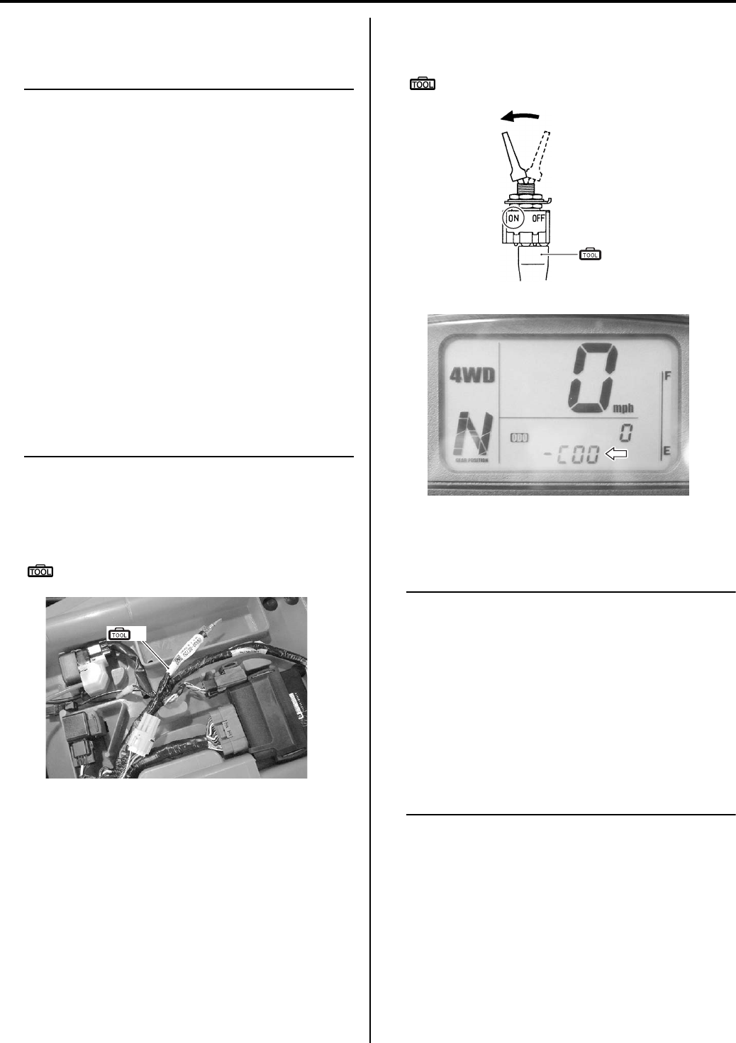
1A-11 Engine General Information and Diagnosis:
Self-Diagnostic Procedures
B831G21104002
Use of Mode Select Switch
NOTE
• Do not disconnect coupler from ECM, the
battery cable from the battery, ECM ground
wire harness from the engine or main fuse
before confirming DTC (Diagnostic Trouble
Code) stored in memory. Such
disconnection will erase memorized
information in ECM memory.
• DTC stored in ECM memory can be
checked by the special tool.
• Before checking DTC, read self-diagnosis
function “User mode and dealer mode”
(Refer to “Self-Diagnostic Procedures
(Page 1A-11)”.) carefully to have good
understanding as to what functions are
available and how to use it.
• Be sure to read “Precautions for Electrical
Circuit Service” (Refer to “Precautions for
Electrical Circuit Service in Section 00
(Page 00-2)”.) before inspection and
observe what is written there.
1) Remove the seat. Refer to “Seat Removal and
Installation in Section 9D (Page 9D-11)”.
2) Connect the special tool to the mode select switch at
the wiring harness.
Special tool
(A): 09930–82720 (Mode select switch)
3) Start the engine or crank the engine for more than 4
seconds.
4) Turn the special tool’s switch ON.
5) Check the DTC to determine the malfunction part.
Refer to “DTC Table (Page 1A-19)”.
Special tool
(A): 09930–82720 (Mode select switch)
6) After repairing the trouble, turn OFF the ignition
switch and turn ON again. If DTC is indicated (C00),
the malfunction is cleared.
NOTE
• Even though DTC (C00) is indicated, the
previous malfunction history DTC still
remains stored in the ECM. Therefore,
erase the history DTC memorized in the
ECM using SDS.
• DTC is memorized in the ECM also when
the wire coupler of any sensor is
disconnected. Therefore, when a wire
coupler has been disconnected at the time
of diagnosis, erase the stored history DTC
using SDS. Refer to “Use of SDS Diagnosis
Reset Procedures (Page 1A-13)”.
7) Turn the ignition switch OFF and disconnect the
special tool from the mode select switch.
Reinstall the seat.
(A)
I831G1110006-01
(A)
I718H1110006-04
I831G1110015-01
PartShark.com
877-999-5686
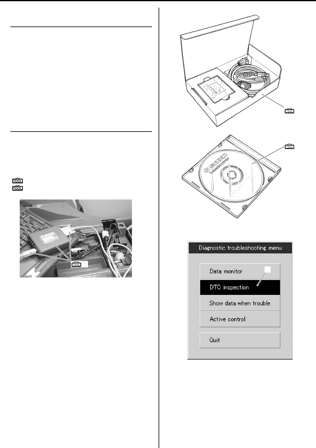
Engine General Information and Diagnosis: 1A-12
Use of SDS
NOTE
• Do not disconnect the coupler from ECM,
the battery cable from the battery, ECM
ground wire harness from the engine or
main fuse before confirming DTC
(Diagnostic Trouble Code) stored in
memory. Such disconnection will erase the
memorized information in ECM memory.
• DTC stored in ECM memory can be
checked by the SDS.
• Be sure to read “Precautions for Electrical
Circuit Service in Section 00 (Page 00-2)”
before inspection and observe what is
written there.
1) Remove the seat. Refer to “Seat Removal and
Installation in Section 9D (Page 9D-11)”.
2) Set up the SDS tools. (Refer to the SDS operation
manual for further details.)
Special tool
(A): 09904–41010 (SDS Set)
(B): 99565–01010–013 (CD-ROM Ver.13)
3) Click the DTC inspection button (1).
(A)
I831G1110008-01
(A)
(B)
I705H1110116-03
1
I705H1110003— 01
PartShark.com
877-999-5686
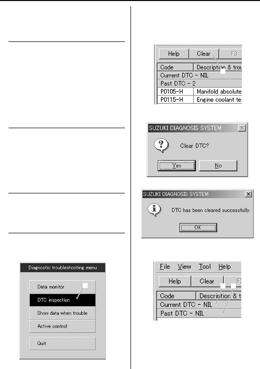
1A-13 Engine General Information and Diagnosis:
4) Start the engine or crank the engine for more than 4
seconds.
5) Check the DTC to determine the malfunction part.
Refer to “DTC Table (Page 1A-19)”.
NOTE
• Read the DTC (Diagnostic Trouble Code)
and show data when trouble (displaying
data at the time of DTC) according to
instructions displayed on SDS.
• Not only SDS is used for detecting
Diagnostic Trouble Codes but also for
reproducing and checking on screen the
failure condition as described by
customers using the trigger. (Refer to
“Show Data When Trouble (Displaying
Data at the Time of DTC) (Page 1A-14)”.)
• How to use trigger. (Refer to the SDS
operation manual for further details.)
6) After repairing the trouble, clear to delete history
code (Past DTC). Refer to “Use of SDS Diagnosis
Reset Procedures (Page 1A-13)”.
7) Close the SDS tool and turn the ignition switch OFF.
Disconnect the SDS tool and install the right frame
cover.
Use of SDS Diagnosis Reset Procedures
B831G21104003
NOTE
The malfunction code is memorized in the
ECM also when the wire coupler of any
sensor is disconnected. Therefore, when a
wire coupler has been disconnected at the
time of diagnosis, erase the stored
malfunction history code using SDS.
1) After repairing the trouble, turn OFF the ignition
switch and turn ON again.
2) Click the DTC inspection button (1).
3) Check the DTC.
4) The previous malfunction history code (Past DTC)
still remains stored in the ECM. Therefore, erase the
history code memorized in the ECM using SDS tool.
5) Click “Clear” (2) to delete history code (Past DTC).
6) Follow the displayed instructions.
7) Check that both “Current DTC” (3) and “Past DTC”
(4) are deleted (NIL).
Close the SDS tool and turn the ignition switch OFF.
9) Disconnect the SDS tool and install the seat.
1
I705H1110003-01
2
I705H1110005-01
I705H1110006-01
I705H1110009-01
34
I705H1110008-01
PartShark.com
877-999-5686
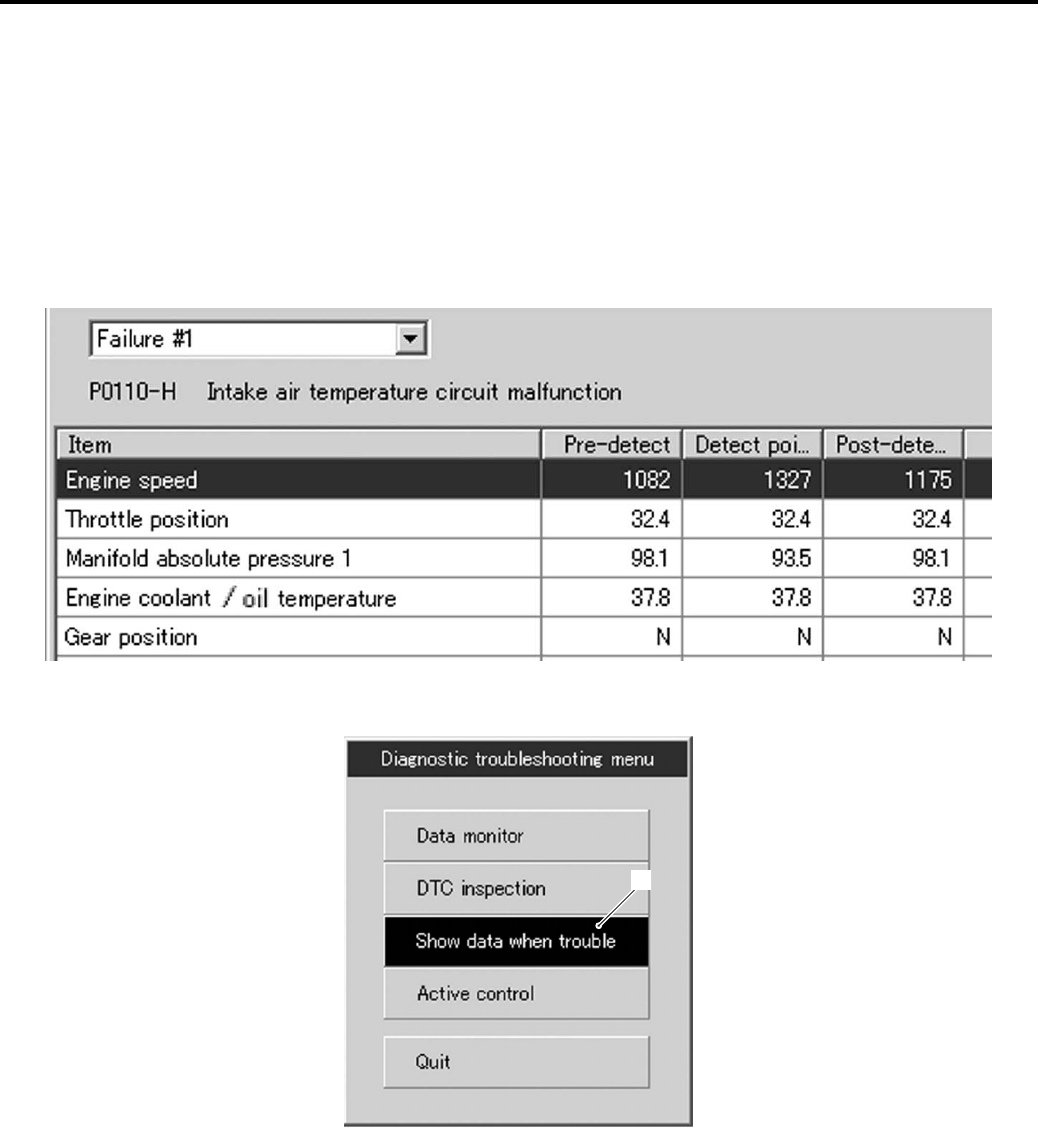
Engine General Information and Diagnosis: 1A-14
Show Data When Trouble (Displaying Data at the Time of DTC)
B831G21104004
Use of SDS
ECM stores the engine and driving conditions (in the form of data as shown in the figure) at the moment of the
detection of a malfunction in its memory. This data is called “Show data when trouble”.
Therefore, it is possible to know engine and driving conditions (e.g., whether the engine was warm or not, where the
motorcycle was running or stopped) when a malfunction was detected by checking the show data when trouble. This
show data when trouble function can record the maximum of two Diagnostic Trouble Codes in the ECM.
Also, ECM has a function to store each show data when trouble for two different malfunctions in the order of
occurrence as the malfunction is detected. Utilizing this function, it is possible to know the order of malfunctions that
have been detected. Its use is helpful when rechecking or diagnosing a trouble.
1) Click “Show data when trouble” (1) to display the data.
I831G1110016-02
1
I718H1110269— 02
PartShark.com
877-999-5686
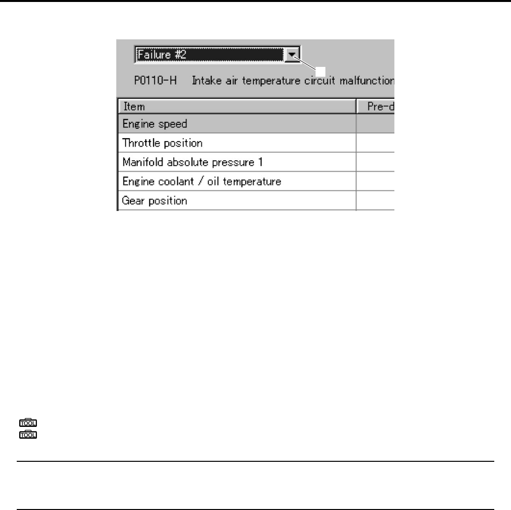
1A-15 Engine General Information and Diagnosis:
2) Click the drop down button (2), either “Failure #1” or “Failure #2” can be selected.
SDS Check
B831G21104005
Using SDS, sample the data at the time of new and periodic vehicle inspections.
After saving the sampled data in the computer, file them by model and by user.
The periodically filed data help improve the accuracy of troubleshooting since they can indicate the condition of vehicle
functions that has changed with time.
For example, when a vehicle is brought in for service but the troubleshooting of a failure is not easy, comparing the
current data value to past filed data value at time of normal condition can allow the specific engine failure to be
determined.
Also, in the case of a customer vehicle which is not periodically brought in for service with no past data value having
been saved, if the data value of a good vehicle condition have been already saved as a master (STD), comparison
between the same models helps to facilitate the troubleshooting.
1) Remove the seat. Refer to “Seat Removal and Installation in Section 9D (Page 9D-11)”.
2) Set up the SDS tool. (Refer to the SDS operation manual for further details.)
Special tool
: 09904–41010 (SDS set)
: 99565–01010–013 (CD-ROM Ver.13)
NOTE
• Before taking the sample of data, check and clear the Past DTC.
• A number of different data under a fixed condition as shown below should be saved or filed as
sample.
2
I831G1110017-01
PartShark.com
877-999-5686
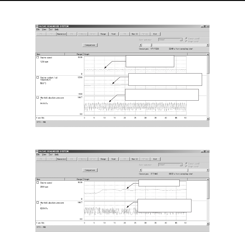
Engine General Information and Diagnosis: 1A-16
Sample
Data sampled from cold starting through warm-up
Data at 3 000 r/min under no load
Check the engine r/min.
1 300 r/min
Check the manifold absolute pressure.
XXX kPa
Check the engine coolant temperature.
XX° C
I831G1110009-03
Check the manifold absolute
pressure XXX kPa.
Approx. 3 000 r/min.
I831G1110010-04
PartShark.com
877-999-5686
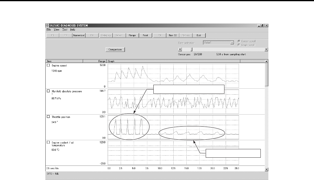
1A-17 Engine General Information and Diagnosis:
Data at the time of racing
Throttle: Quick wide open
Throttle: Slowly open
I831G1110011-01
PartShark.com
877-999-5686
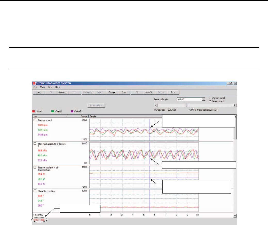
Engine General Information and Diagnosis: 1A-18
Example of Trouble
Three data; value 1 (current data 1), value 2 (past data 2) and value 3 (past data 3); can be made in comparison by
showing them in the graph. Read the change of value by comparing the current data to the past data that have been
saved under the same condition, then you may determine how changes have occurred with the passing of time and
identify what problem is currently occurring.
NOTE
With DTC not output, if the value of engine coolant temperature is found to be lower than the data
saved previously, the possible cause may probably lie in a sensor circuit opened, ground circuit
opened or influence of internal resistance value changes, etc.
No DTC output
Abnormal graph curve of the value 3
Abnormal value of engine coolant
temperature
The engine speed of the value 3 is
higher than the valve 1 and valve 2.
I831G1110012-04
PartShark.com
877-999-5686

1A-19 Engine General Information and Diagnosis:
DTC Table
B831G21104006
In the LCD (DISPLAY) panel, the malfunction code is indicated from small code to large code.
*1
To get the proper signal from the throttle position sensor, the sensor basic position is indicated in the LCD (DISPLAY)
panel. The malfunction code is indicated in three difgits. In front of three digits, a line appears in any of the position,
upper, middle or lower line. If the indication is upper or lower line when engine rpm is 1 300 rpm, slightly turn the
throttle position sensor and bring the line to middle.
In the normal condition, the throttle valve stop screw pushes throttle valves slightly, and indication point is middle line.
Fail-Safe Function Table
B831G21104007
FI system is provided with fail-safe function to allow the engine to start and the motorcycle to run in a minimum
performance necessary even under malfunction condition.
The engine can start and can run even if the above signal is not received from each sensor. But, the engine running
condition is not complete, providing only emergency help (by fail-safe circuit). In this case, it is necessary to bring the
vehicle to the workshop for complete repair.
Code Malfunction Part Remarks
C00 None No defective part
C12 (P0335)
)(Page 1A-24) Crankshaft position sensor (CKP sensor) Pick-up coil signal, signal generator
C13 (P0105-H/L)
)(Page 1A-27) Intake air pressure sensor (IAP sensor)
C14 (P0120-H/L)
)(Page 1A-34) Throttle position sensor (TP sensor) *1
C15 (P0115-H/L)
)(Page 1A-41)
Engine coolant temperature sensor (ECT
sensor)
C20 (P1752)
)(Page 1A-47) Differential lock relay (Diff-lock relay)
C21(P0110-H/L)
)(Page 1A-49) Intake air temperature sensor (IAT sensor)
C23 (P1651-H/L)
)(Page 1A-53) Tip-over sensor (TO sensor)
C24 (P0351)
)(Page 1A-59) Ignition signal (Ignition coil)
C32 (P0201)
)(Page 1A-59) Injector signal (FI)
C40 (P0505)
)(Page 1A-59) Idle speed control valve (ISC valve)
C41 (P0230-H/L)
)(Page 1A-59) Fuel pump control system (FP relay) Fuel pump, Fuel pump relay
Item Fail-Safe Mode Starting Ability Running Ability
IAP sensor Intake air pressure is fixed to 101 kPa (760
mmHg). “YES” “YES”
TP sensor
The throttle opening is fixed to full open
position.
Ignition timing is also fixed.
“YES” “YES”
ECT sensor Engine coolant temperature value is fixed to
80 °C (176 °F). “YES” “YES”
IAT sensor Intake air temperature value is fixed to 40 °C
(104 °F). “YES” “YES”
Diff-lock relay Differential position signal is fixed to neutral
gear. “YES” “YES”
PartShark.com
877-999-5686
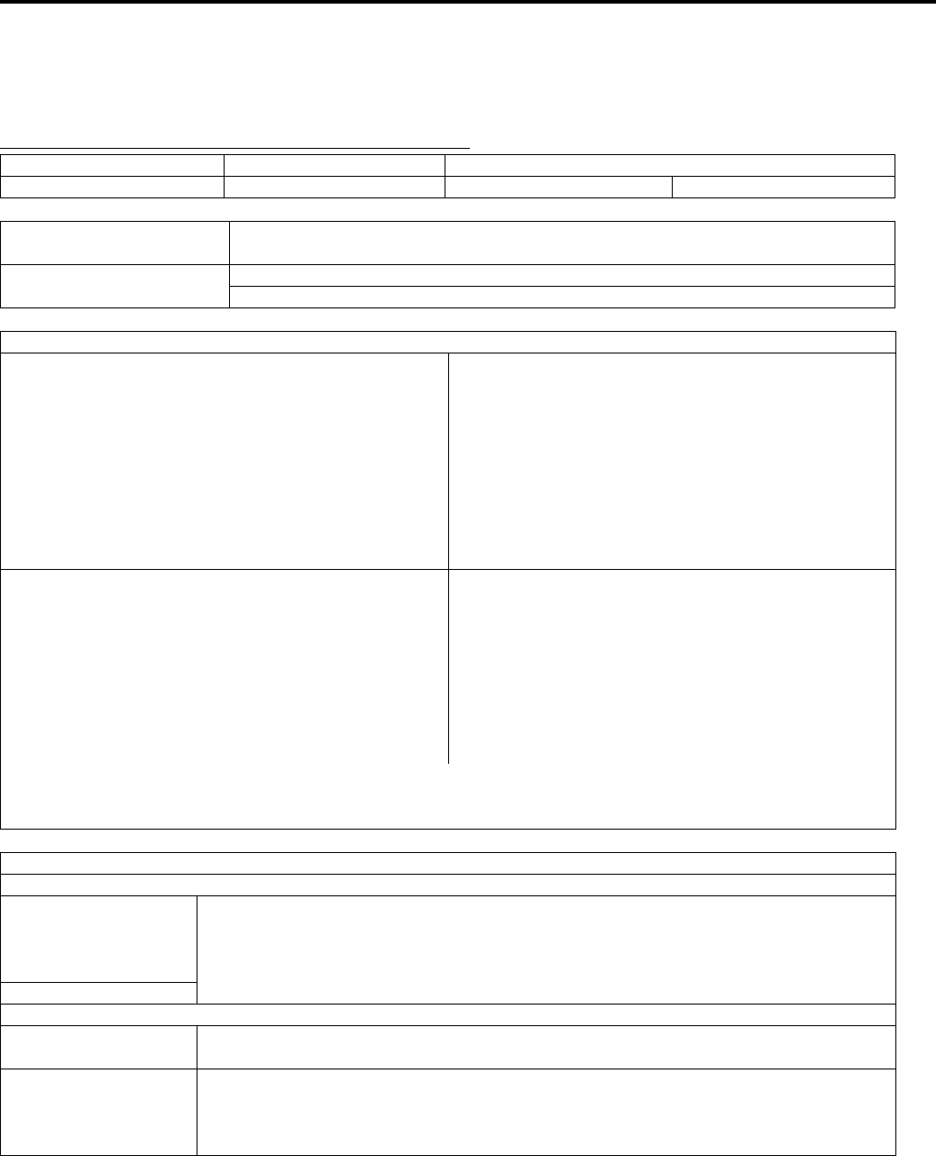
Engine General Information and Diagnosis: 1A-20
FI System Troubleshooting
B831G21104008
Customer Complaint Analysis
Record details of the problem (failure, complaint) and how it occurred as described by the customer. For this purpose,
use of an inspection form such as below will facilitate collecting information required for proper analysis and diagnosis.
EXAMPLE: CUSTOMER PROBLEM INSPECTION FORM
User name: Model: VIN:
Date of issue: Date Reg.: Date of problem: Mileage:
Malfunction indicator
light condition (LED) Always ON / Sometimes ON / Always OFF / Good condition
Malfunction display/code
(LCD)
User mode: No display / Malfunction display ( )
Dealer mode: No code / Malfunction code ( )
PROBLEM SYMPTOMS
Difficult Starting Poor Driveability
No cranking Hesitation on acceleration
No initial combustion Back fire / After fire
No combustion Lack of power
Poor starting at Surging
( cold / warm / always) Abnormal knocking
Other Engine rpm jumps briefly
Other
Poor Idling Engine Stall when
Poor fast Idle Immediately after start
Abnormal idling speed Throttle valve is opened
( High / Low) ( r/min) Throttle valve is closed
Unstable Load is applied
Hunting ( r/min to r/min) Other
Other
OTHERS:
VEHICLE/ENVIRONMENTAL CONDITION WHEN PROBLEM OCCURS
Environmental condition
Weather
Temperature
Frequency
Fair / Cloudy / Rain / Snow / Always / Other
Hot / Warm / Cool / Cold ( °C / °F) / Always
Always / Sometimes (times / day, month) / Only once
Under certain condition
Road Mountainous ( Uphill / Downhill) / Gravel / Other
Vehicle condition
Engine condition Cold / Warming up phase / Warmed up / Always / Other at starting
Immediately after start / Racing without load / Engine speed ( r/min)
Vehicle condition During driving: Constant speed / Accelerating / Decelerating
Right hand corner / Left hand corner
At stop / Vehicle speed when problem occurs ( km/h, mile/h)
Other:
PartShark.com
877-999-5686

1A-21 Engine General Information and Diagnosis:
NOTE
The above form is a standard sample. The form should be modified according to condition and
characteristics of each market.
Visual Inspection
Prior to diagnosis using the mode select switch or SDS, perform the following visual inspections. The reason for visual
inspection is that mechanical failures (such as oil leakage) cannot be displayed on the screen with the use of mode
select switch or SDS.
• Engine oil level and leakage. Refer to “Engine Oil and Filter Replacement in Section 0B (Page 0B-10)”.
• Engine coolant level and leakage. Refer to “Cooling Circuit Inspection in Section 1F (Page 1F-4)”.
• Fuel level and leakage. Refer to “Fuel Line Inspection in Section 0B (Page 0B-10)”.
• Clogged air cleaner element. Refer to “Air Cleaner Element Inspection and Cleaning in Section 0B (Page 0B-3)”.
• Battery condition.
• Throttle cable play. Refer to “Throttle Cable Play Inspection and Adjustment in Section 0B (Page 0B-15)”.
• Vacuum hose looseness, bend and disconnection.
• Broken fuse.
• FI light operation. Refer to “Combination Meter Inspection in Section 9C (Page 9C-4)”.
• Each indicator light operation. Refer to “Combination Meter Inspection in Section 9C (Page 9C-4)”.
• Speedometer operation. Refer to “Speedometer Inspection in Section 9C (Page 9C-6)”.
• Exhaust gas leakage and noise. Refer to “Exhaust System Inspection in Section 1K (Page 1K-3)”.
• Each coupler disconnection.
• Clogged radiator fins. Refer to “Radiator Inspection and Cleaning in Section 1F (Page 1F-5)”.
PartShark.com
877-999-5686

Engine General Information and Diagnosis: 1A-22
Malfunction Code and Defective Condition Table
B831G21104009
Malfunction
Code Detected Item Detected Failure Condition Check For
C00 NO FAULT — —
C12
CKP sensor The signal does not reach ECM for 3 sec. or
more, after receiving the starter signal.
CKP sensor wiring and
mechanical parts.
CKP sensor, lead wire/coupler
connection.
P0335
C13
IAP sensor
The sensor should produce following voltage.
0.5 V ≤ sensor voltage < 4.85 V
In other than the above range, C13 (P0105) is
indicated.
IAP sensor, lead wire/coupler
connection.
P0105
H Sensor voltage is higher than specified value. IAP sensor circuit shorted to
VCC or ground circuit open.
L Sensor voltage is lower than specified value.
IAP sensor circuit open or
shorted to the ground or VCC
circuit open.
C14
TP sensor
The sensor should produce following voltage.
0.2 V ≤ sensor voltage < 4.8 V
In other than the above range, C14 (P0120) is
indicated.
TP sensor, lead wire/coupler
connection.
P0120
H Sensor voltage is higher than specified value. TP sensor circuit shorted to
VCC or ground circuit open.
L Sensor voltage is lower than specified value.
TP sensor circuit open or
shorted to the ground or VCC
circuit open.
C15
ECT sensor
The sensor voltage should be the following.
0.15 V ≤ sensor voltage < 4.85 V
In other than the above range, C15 (P0115) is
indicated.
ECT sensor, lead wire/coupler
connection.
P0115
H Sensor voltage is higher than specified value. ECT sensor circuit open or
ground circuit open.
L Sensor voltage is lower than specified value. ECT sensor circuit shorted to
the ground.
C20
Diff-lock relay
No voltage is applied to 4WD/diff-lock
actuator, although ignition switch is turned ON,
or voltage is applied to 4WD/diff-lock actuator,
although ignition switch is turned OFF.
In this case, the code C20 (P1752) is
indicated.
Diff-lock relay circuit open or
shorted to ground.P1752
C21
IAT sensor
The sensor voltage should be the following.
0.15 V ≤ sensor voltage < 4.85 V
In other than the above range, C21 (P0110) is
indicated.
IAT sensor, lead wire/coupler
connection.
P0110
H Sensor voltage is higher than specified value. IAT sensor circuit open or
ground circuit open.
L Sensor voltage is lower than specified value. IAT sensor circuit shorted to
the ground.
C23
TO sensor
The sensor voltage should be the following for
2 sec. and more, after ignition switch is turned
ON.
0.2 V ≤ sensor voltage < 4.8 V
In other than the above value, C23 (P1651) is
indicated.
TO sensor, lead wire/coupler
connection.
P1651
H Sensor voltage is higher than specified value. TO sensor circuit shorted to
VCC or ground circuit open.
LSensor voltage is lower than specified value.
TO sensor circuit open or
shorted to the ground or VCC
circuit open.
PartShark.com
877-999-5686

1A-23 Engine General Information and Diagnosis:
C24
Ignition signal
CKP sensor (pick-up coil) signal is produced,
but signal from ignition coil is interrupted 8
times or more continuously. In this case, the
code C24 (P0351) is indicated.
Ignition coil, wiring/coupler
connection, power supply from
the battery.
P0351
C32
Fuel injector
CKP sensor (pick-up coil) signal is produced,
but fuel injector signal is interrupted 4 times or
more continuously. In this case, the code C32
(P0201) is indicated.
Fuel injector, wiring/coupler
connection, power supply to
the injector.
P0201
C40
ISC valve The circuit voltage of motor drive is unusual.
ISC valve circuit open or
shorted to the ground.
Power source circuit open.
P0505
C41
Fuel pump relay
No voltage is applied to the fuel pump,
although fuel pump relay is turned ON, or
voltage is applied to fuel pump, although fuel
pump relay is turned OFF.
Fuel pump relay, lead wire/
coupler connection, power
source to the fuel pump relay
and fuel injectors.
P0230
HVoltage is applied to the injector and fuel
pump relay is turned OFF.
Fuel pump relay switch circuit
shorted to power source.
Fuel pump relay (switch side).
LNo voltage is applied to the injector and fuel
pump relay is turned ON.
Fuel pump relay circuit open or
short.
Fuel pump relay (coil side).
Malfunction
Code Detected Item Detected Failure Condition Check For
PartShark.com
877-999-5686
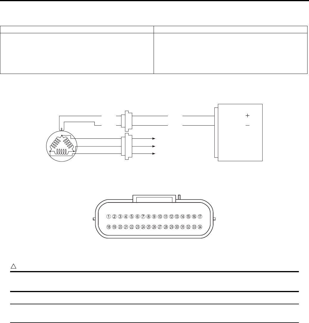
Engine General Information and Diagnosis: 1A-24
DTC “C12” (P0335): CKP Sensor Circuit Malfunction
B831G21104010
Detected Condition and Possible Cause
Wiring Diagram
ECM coupler (Harness side)
Troubleshooting
CAUTION
!
When using the multi-circuit tester, do not strongly touch the terminal of the ECM coupler with a
needle pointed tester probe to prevent the terminal damage or terminal bend.
NOTE
After repairing the trouble, clear the DTC using SDS tool. Refer to “Use of SDS Diagnosis Reset
Procedures (Page 1A-13)”.
Detected Condition Possible Cause
The signal does not reach ECM for 3 sec. or more, after
receiving the starter signal.
• Metal particles or foreign material being stuck on the
CKP sensor and rotor tip.
• CKP sensor circuit open or short.
• CKP sensor malfunction.
• ECM malfunction.
CKP sensor
ECM
To regulator/rectifier
Generator
CKP
CKP
Bl/G
B
Bl
W
9
18
I831G1110018-01
I831G1110019-01
PartShark.com
877-999-5686
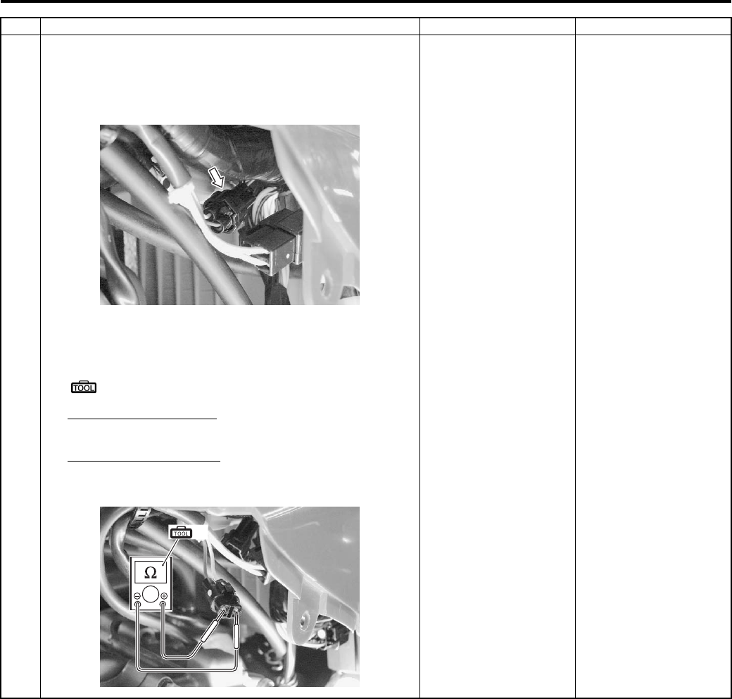
1A-25 Engine General Information and Diagnosis:
Step Action Yes No
1 1) Turn the ignition switch OFF.
2) Check the CKP sensor coupler for loose or poor
contacts.
If OK, then measure the CKP sensor resistance.
3) Disconnect the CKP sensor coupler and measure the
resistance.
Special tool
(A): 09900–25008 (Multi-circuit tester set)
Tester knob indication
Resistance (Ω)
CKP sensor resistance
150 – 250 Ω (Bl – W)
Go to Step 2. Replace the CKP
sensor with a new one.
I831G1110020-02
(A)
I831G1110007-01
PartShark.com
877-999-5686
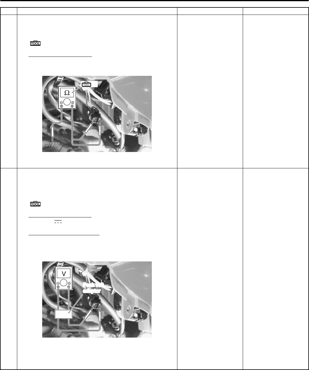
Engine General Information and Diagnosis: 1A-26
1 4) If OK, then check the continuity between each terminal
and ground.
Special tool
(A): 09900–25008 (Multi-circuit tester set)
CKP sensor continuity
∞ Ω (Infinity) (Bl – Ground, W – Ground)
Are the resistance and continuity OK?
Go to Step 2. Replace the CKP
sensor with a new one.
2 1) Crank the engine several seconds with the starter motor,
and measure the CKP sensor peak voltage at the
coupler.
Special tool
(A): 09900–25008 (Multi-circuit tester set)
Tester knob indication
Voltage ( )
CKP sensor peak voltage
5.0 V and more
((+) terminal: Bl – (–) terminal: W)
2) Repeat the above test procedure a few times and
measure the highest peak voltage.
Is the voltage OK?
• Bl or W wire open or
shorted to the
ground, or poor “9” or
“18” connection.
• If wire and
connection are OK,
intermittent trouble or
faulty ECM.
• Recheck each
terminal and wire
harness for open
circuit and poor
connection.
• Replace the ECM
with a known good
one, and inspect it
again. Refer to “ECM
Removal and
Installation in Section
1C (Page 1C-1)”.
• Inspect that metal
particles or foreign
material stuck on the
CKP sensor and rotor
tip.
• If there are no metal
particles and foreign
material, then replace
the CKP sensor with
a new one. Refer to
“CKP Sensor
Removal and
Installation in Section
1C (Page 1C-1)”.
Step Action Yes No
(A)
I831G1110021-01
Peak volt
adaptor
I831G1110022-01
PartShark.com
877-999-5686
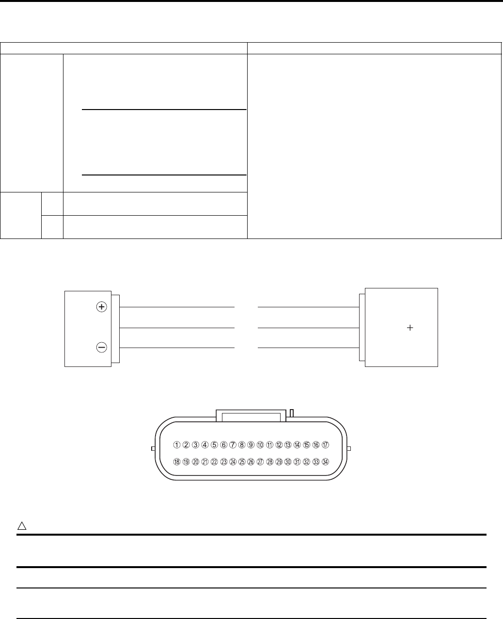
1A-27 Engine General Information and Diagnosis:
DTC “C13” (P0105-H/L): IAP Sensor Circuit Malfunction
B831G21104011
Detected Condition and Possible Cause
Wiring Diagram
ECM coupler (Harness side)
Troubleshooting
CAUTION
!
When using the multi-circuit tester, do not strongly touch the terminal of the ECM coupler with a
needle pointed tester probe to prevent the terminal damage or terminal bend.
NOTE
After repairing the trouble, clear the DTC using SDS tool. Refer to “Use of SDS Diagnosis Reset
Procedures (Page 1A-13)”.
Detected Condition Possible Cause
C13
IAP sensor voltage is not within the
following range.
0.5 V < Sensor voltage ≤ 4.85 V
NOTE
Note that atmospheric pressure
varies depending on weather
conditions as well as altitude.
Take that into consideration
when inspecting voltage.
• Clogged vacuum passage between throttle body and
IAP sensor.
• Air being drawn from vacuum passage between throttle
body and IAP sensor.
• IAP sensor circuit open or shorted to the ground.
• IAP sensor malfunction.
• ECM malfunction.
P0105
HSensor voltage is higher than specified
value.
• IAP sensor circuit is open or shorted to VCC or ground
circuit open.
LSensor voltage is lower than specified
value.
• IAP sensor circuit is shorted to the ground or VCC circuit
open.
IAP sensor ECM
VCC
IAP
E2
R
G/B
B/Br
6
13
24
I831G1110024-01
I831G1110019-01
PartShark.com
877-999-5686
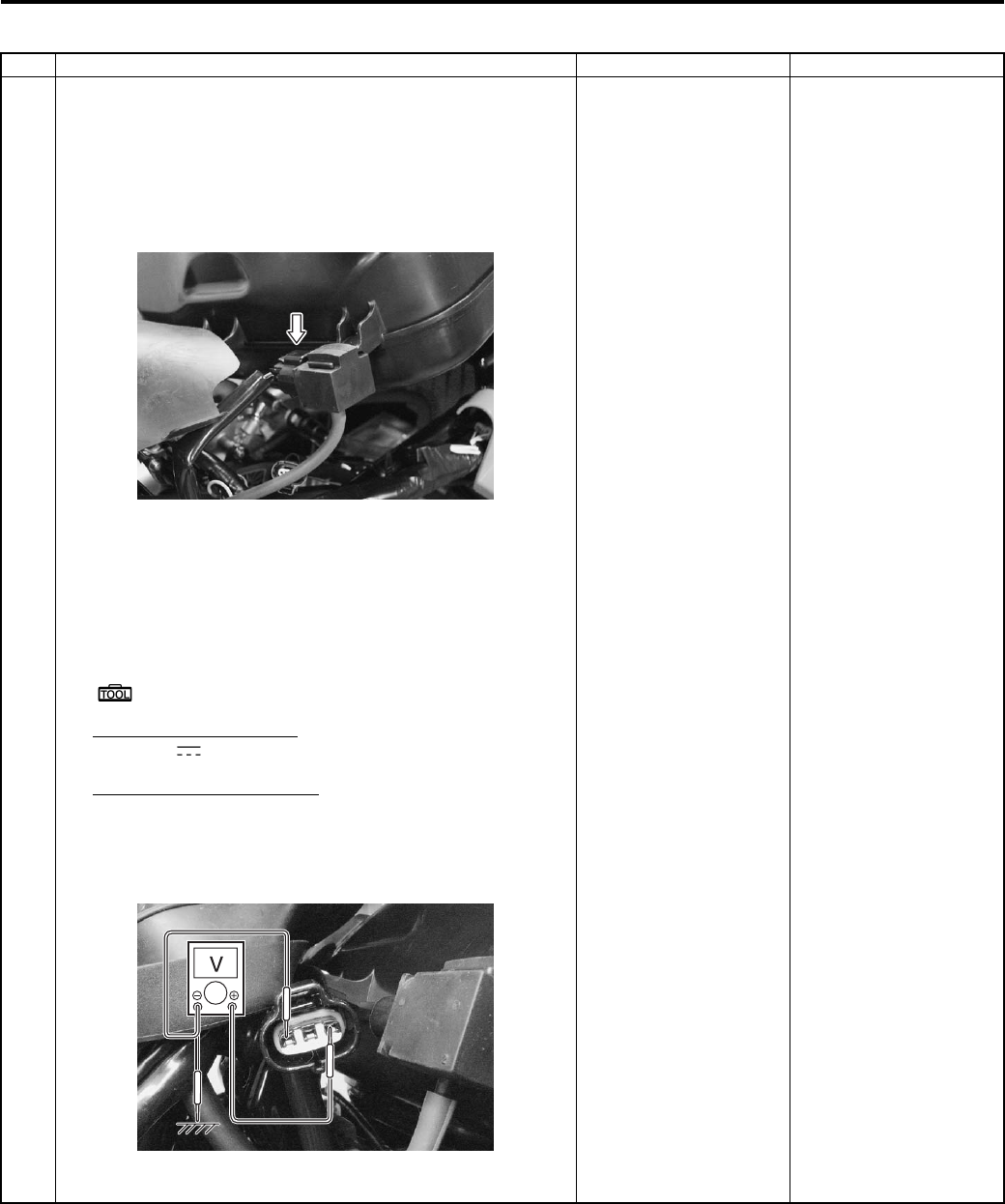
Engine General Information and Diagnosis: 1A-28
C13 (Use of mode select switch)
Step Action Yes No
1 1) Remove the front fender. Refer to “Front Side Exterior
Parts Removal and Installation in Section 9D (Page 9D-
6)”.
2) Turn the ignition switch OFF.
3) Check the IAP sensor coupler for loose or poor contacts.
If OK, then measure the IAP sensor input voltage.
4) Disconnect the IAP sensor coupler.
5) Turn the ignition switch ON.
6) Measure the voltage at the R wire and ground.
If OK, then measure the voltage at the R wire and B/Br
wire.
Special tool
(A): 09900–25008 (Multi-circuit tester set)
Tester knob indication
Voltage ( )
IAP sensor input voltage
4.5 – 5.5 V
((+) terminal: R – (–) terminal: Ground, (+) terminal: R
– (–) terminal: B/Br)
Is the voltage OK?
Go to Step 2. • Loose or poor
contacts on the ECM
coupler.
• Open or short circuit
in the R wire or B/Br
wire.
I831G1110026-01
I831G1110027-01
PartShark.com
877-999-5686
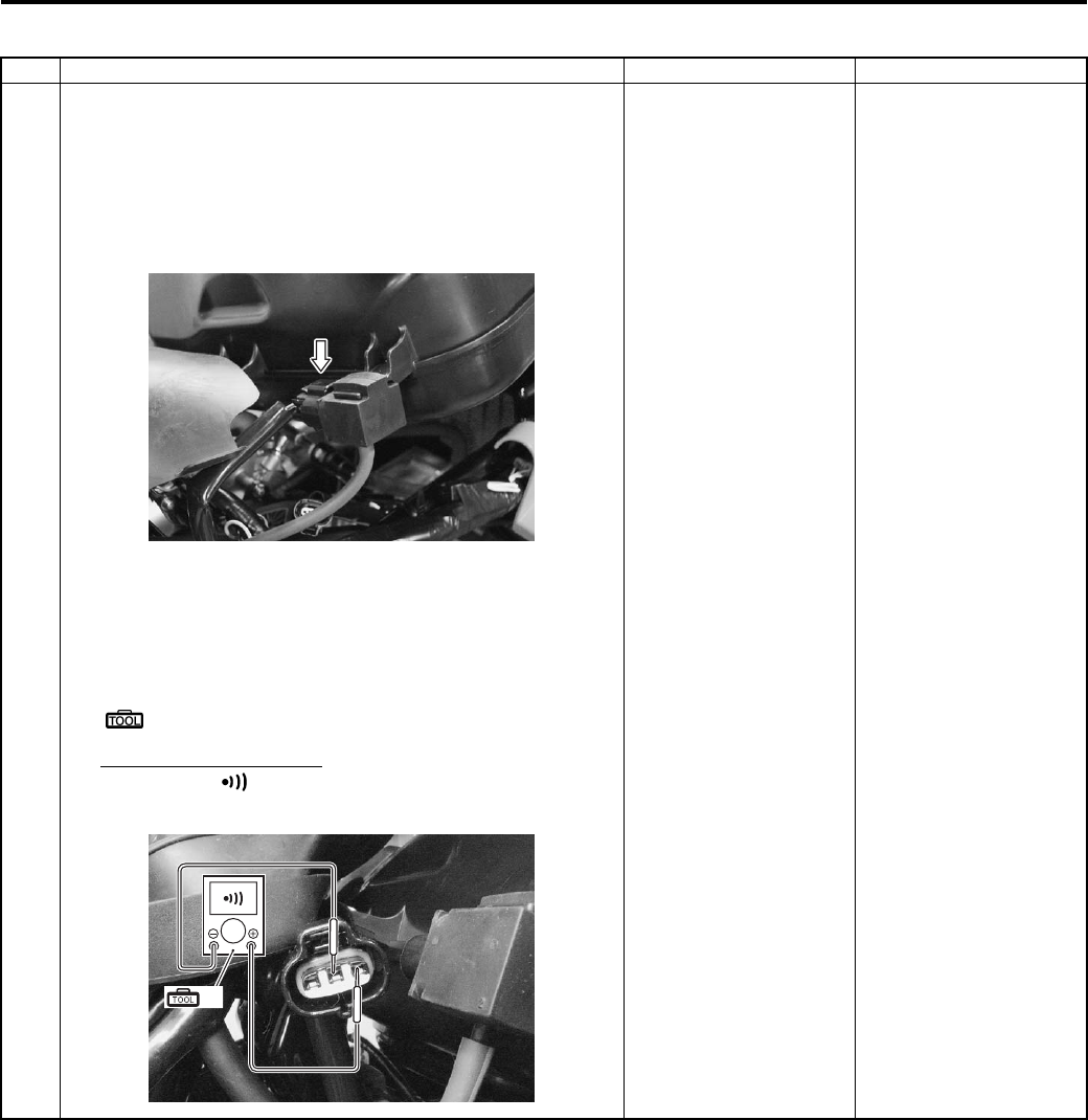
1A-29 Engine General Information and Diagnosis:
P0105-H for IAP sensor (Use of SDS)
Step Action Yes No
1 1) Turn the ignition switch OFF.
2) Remove the front fender. Refer to “Front Side Exterior
Parts Removal and Installation in Section 9D (Page 9D-
6)”.
3) Check the IAP sensor coupler for loose or poor contacts.
If OK, then check the IAP sensor lead wire continuity.
4) Disconnect the IAP sensor coupler.
5) Check the continuity between the R wire and G/B wire.
If the sound is not heard from the tester, the circuit
condition is OK.
Special tool
(A): 09900–25008 (Multi-circuit tester set)
Tester knob indication
Continuity ( )
Go to Step 3. G/B wire shorted to
VCC, or B/Br wire open.
I831G1110026-01
(A)
I831G1110028-02
PartShark.com
877-999-5686
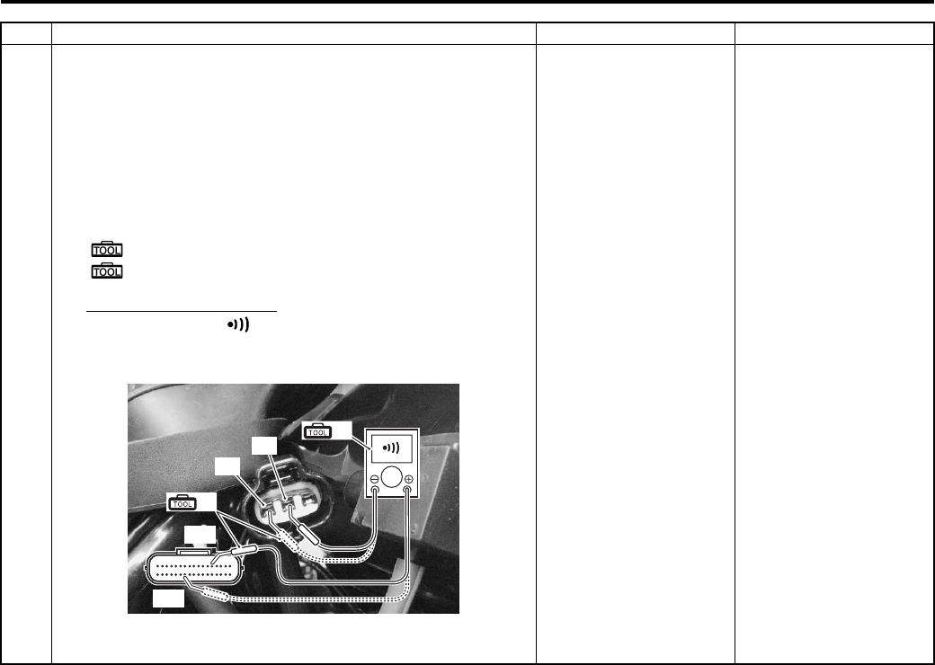
Engine General Information and Diagnosis: 1A-30
Step Action Yes No
1 6) Disconnect the ECM coupler. Refer to “ECM Removal
and Installation in Section 1C (Page 1C-1)”.
7) Insert the needle pointed probes to the lead wire coupler.
Check the continuity between the G/B wire “B” and
terminal “13”.
If OK, then check the continuity between the B/Br wire
“C” and terminal “24”.
Special tool
(A): 09900–25008 (Multi-circuit tester set)
(B): 09900–25009 (Needle pointed probe set)
Tester knob indication
Continuity test ( )
ECM coupler (Harness side)
Is the continuity OK?
Go to Step 3. G/B wire shorted to
VCC, or B/Br wire open.
“13”
“24”
(A)
(B)
“C”
“B”
I831G1110090-03
PartShark.com
877-999-5686
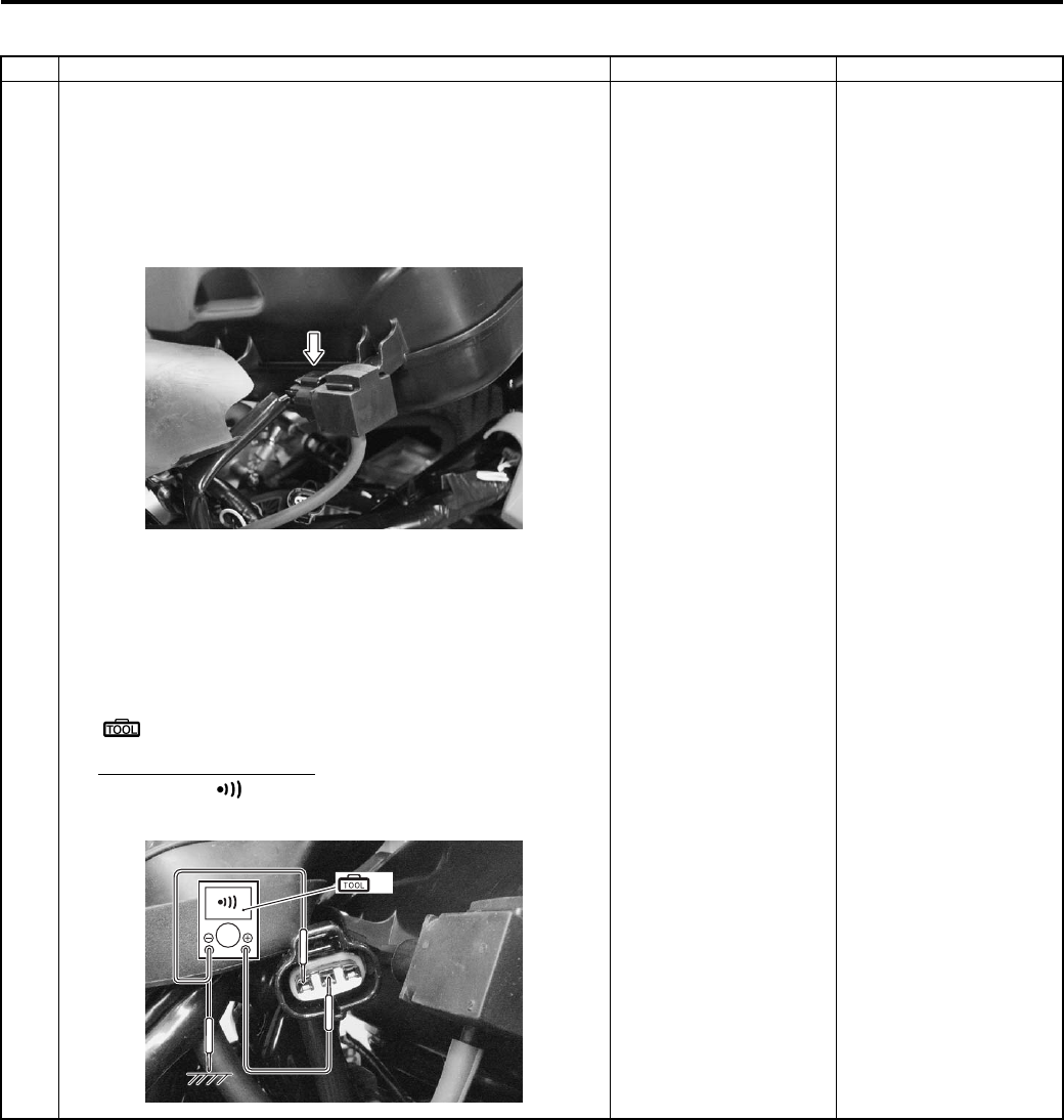
1A-31 Engine General Information and Diagnosis:
P0105-L for IAP sensor (Use of SDS)
Step Action Yes No
1 1) Turn the ignition switch OFF.
2) Remove the front fender. Refer to “Front Side Exterior
Parts Removal and Installation in Section 9D (Page 9D-
6)”.
3) Check the IAP sensor coupler for loose or poor contacts.
If OK, then check the IAP sensor lead wire continuity.
4) Disconnect the IAP sensor coupler.
5) Check the continuity between the G/B wire and ground.
Also, check the continuity between the G/B wire and B/
Br wire. If the sound is not heard from the tester, the
circuit condition is OK.
Special tool
(A): 09900–25008 (Multi-circuit tester set)
Tester knob indication
Continuity ( )
Go to Step 2. R and G/B wire open, G/
B wire shorted to the
ground.
I831G1110026-01
(A)
I831G1110029-01
PartShark.com
877-999-5686
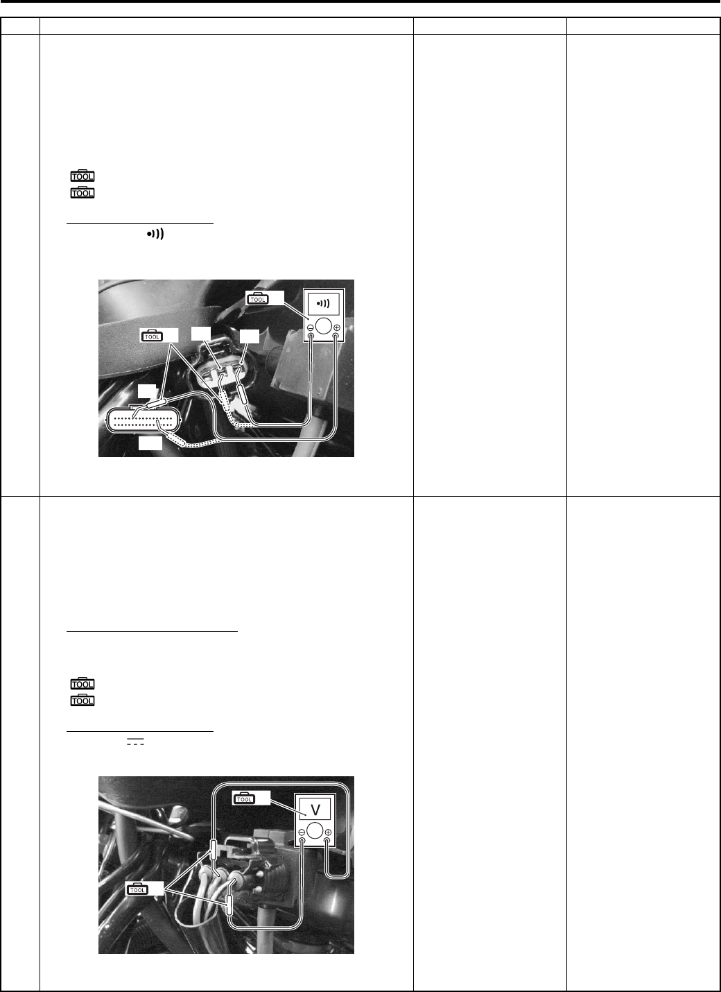
Engine General Information and Diagnosis: 1A-32
1 6) Disconnect the ECM coupler. Refer to “ECM Removal
and Installation in Section 1C (Page 1C-1)”.
7) Insert the needle pointed probes to the lead wire coupler.
Check the continuity between the R wire “A” and
terminal “6”. Also, check the continuity between the G/B
wire “B” and terminal “13”.
Special tool
(A): 09900–25008 (Multi-circuit tester set)
(B): 09900–25009 (Needle pointed probe set)
Tester knob indication
Continuity ( )
ECM coupler (Harness side)
Is the continuity OK?
Go to Step 2. R and G/B wire open, G/
B wire shorted to the
ground.
2 1) Turn the ignition switch OFF.
2) Connect the IAP sensor coupler.
3) Insert the needle pointed probes to the lead wire coupler.
4) Start the engine at idle speed and measure the IAP
sensor output voltage at the wire side coupler between
G/B wire and B/Br wire.
IAP sensor output voltage
Approx. 2.63 V at idle speed
Special tool
(A): 09900–25008 (Multi-circuit tester set)
(B): 09900–25009 (Needle pointed probe set)
Tester knob indication
Voltage ( )
Is the voltage OK?
Go to Step 3. • Check the vacuum
hose for crack or
damage.
• Open or short circuit
in the G/B wire.
• If vacuum hose and
wire is OK, replace
the IAP sensor with a
new one. Refer to
“IAP Sensor Removal
and Installation in
Section 1C
(Page 1C-2)”.
Step Action Yes No
“13”
“6”
(A)
(B) “B” “A”
I831G1110030-03
(B)
(A)
I831G1110031-02
PartShark.com
877-999-5686
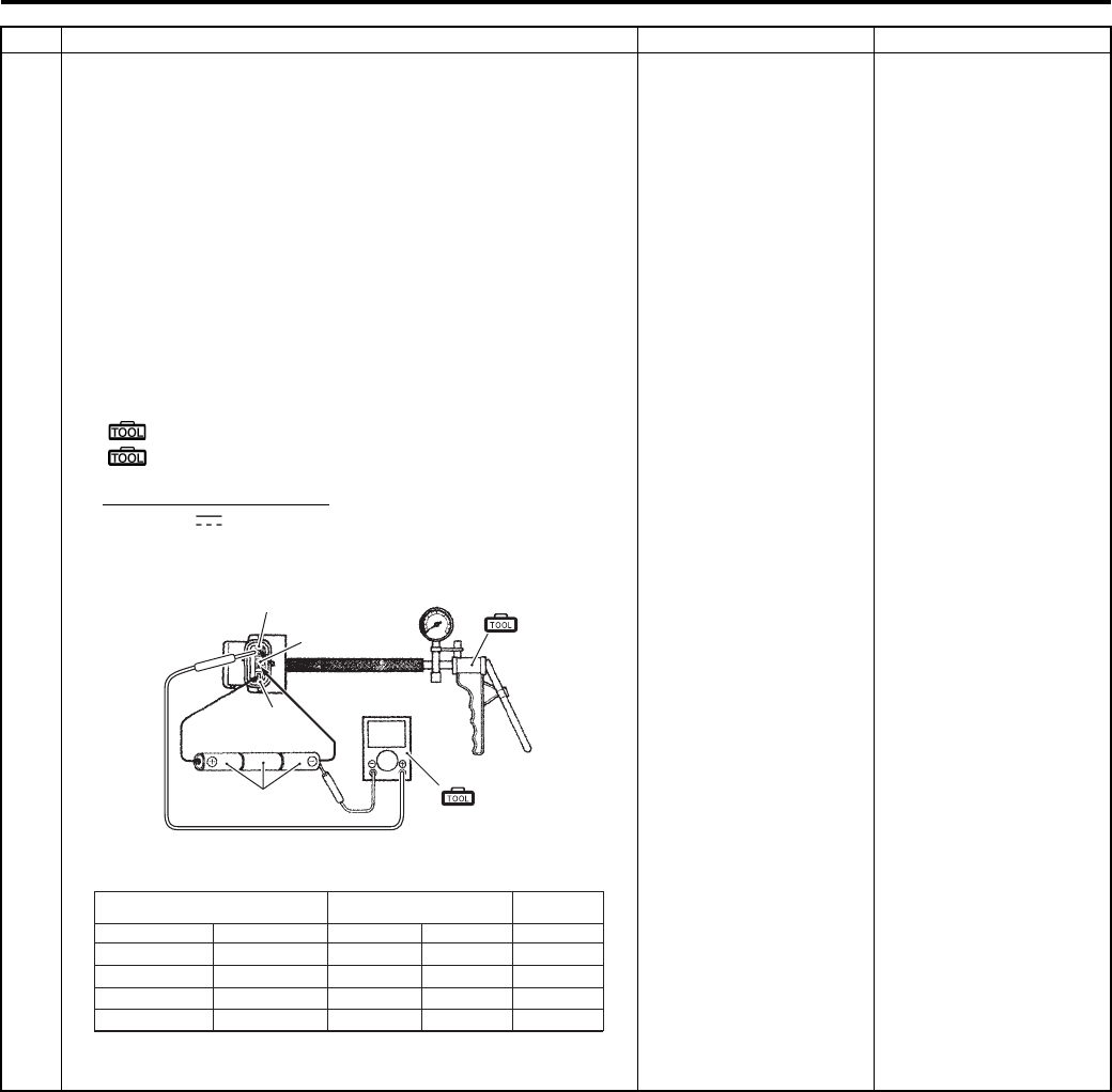
1A-33 Engine General Information and Diagnosis:
3 1) Turn the ignition switch OFF.
2) Remove the IAP sensor. Refer to “IAP Sensor Removal
and Installation in Section 1C (Page 1C-2)”.
3) Connect the vacuum pump gauge to the vacuum port of
the IAP sensor.
Arrange 3 new 1.5 V batteries in series (1) (check that
total voltage is 4.5 – 5.5 V) and connect (–) terminal to
the ground terminal “B” and (+) terminal to the VCC
terminal “A”.
4) Check the voltage between Vout “C” and ground. Also,
check if voltage reduces when vacuum is applied up to
400 mmHg by using vacuum pump gauge.
Special tool
(A): 09917–47011 (Vacuum pump gauge)
(B): 09900–25008 (Multi-circuit tester set)
Tester knob indication
Voltage ( )
Is the voltage OK?
• G/B, R or B/Br wire
open or shorted to
ground, or poor “6”,
“13” or “24”
connection.
• If wire and
connection are OK,
intermittent trouble or
faulty ECM.
• Recheck each
terminal and wire
harness for open
circuit and poor
connection.
• Replace the ECM
with a known good
one, and inspect it
again. Refer to “ECM
Removal and
Installation in Section
1C (Page 1C-1)”.
If check result is not
satisfactory, replace IAP
sensor with a new one.
Refer to “IAT Sensor
Removal and
Installation in Section
1C (Page 1C-3)”.
Step Action Yes No
V
1
“C”
“B”
“A”
(A)
(B)
I831G1110032-01
0 – 2 000
2 001 – 5 000
5 001 – 8 000
8 001 – 10 000
0 – 610
611 – 1 524
1 525 – 2 438
2 439 – 3 048
760 – 707
707 – 634
634 – 567
567 – 526
100 – 94
94 – 85
85 – 76
76 – 70
3.1 – 3.6
2.8 – 3.4
2.6 – 3.1
2.4 – 2.9
ALTITUDE (Reference) ATOMOSPHERIC
PRESSURE
OUTPUT
VOLTAGE
ft m mmHg kPa V
I831G1110033-01
PartShark.com
877-999-5686
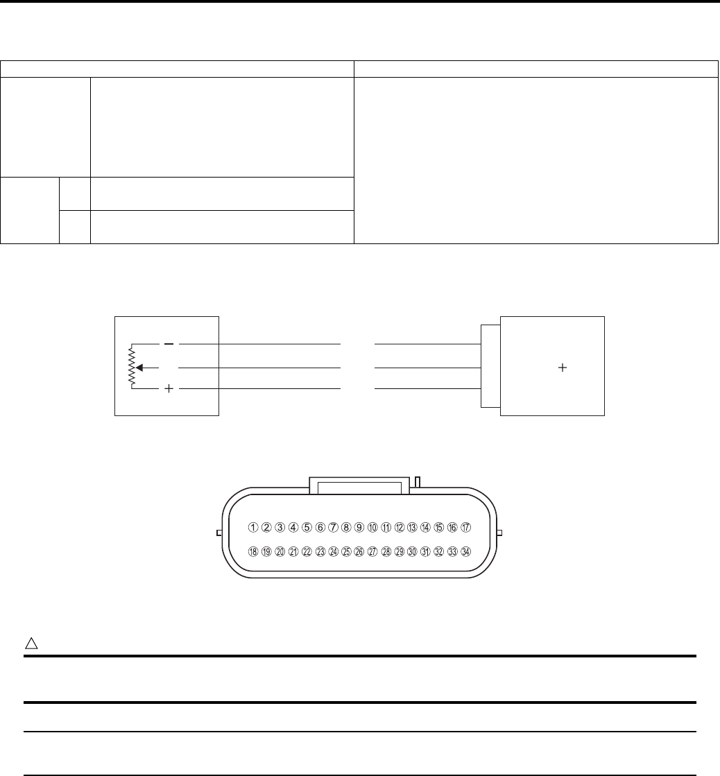
Engine General Information and Diagnosis: 1A-34
DTC “C14” (P0120-H/L): TP Sensor Circuit Malfunction
B831G21104012
Detected Condition and Possible Cause
Wiring Diagram
ECM coupler (Harness side)
Troubleshooting
CAUTION
!
When using the multi-circuit tester, do not strongly touch the terminal of the ECM coupler with a
needle pointed tester probe to prevent the terminal damage or terminal bend.
NOTE
After repairing the trouble, clear the DTC using SDS tool. Refer to “Use of SDS Diagnosis Reset
Procedures (Page 1A-13)”.
Detected Condition Possible Cause
C14
Output voltage is not within the following
range.
Difference between actual throttle opening
and opening calculated by ECM is larger
than specified value.
0.2 V ≤ Sensor voltage < 4.8 V
• TP sensor maladjusted.
• TP sensor circuit open or short.
• TP sensor malfunction.
• ECM malfunction.
P0120
HSensor voltage is higher than specified
value.
• TP sensor circuit is shorted to VCC or ground circuit
open.
LSensor voltage is lower than specified
value.
• TP sensor circuit is open or shorted to the ground or
VCC circuit open.
TP sensor ECM
E2
TP
VCC
YP
B/Br
R
24
14
6
I831G1110025-02
I831G1110019-01
PartShark.com
877-999-5686
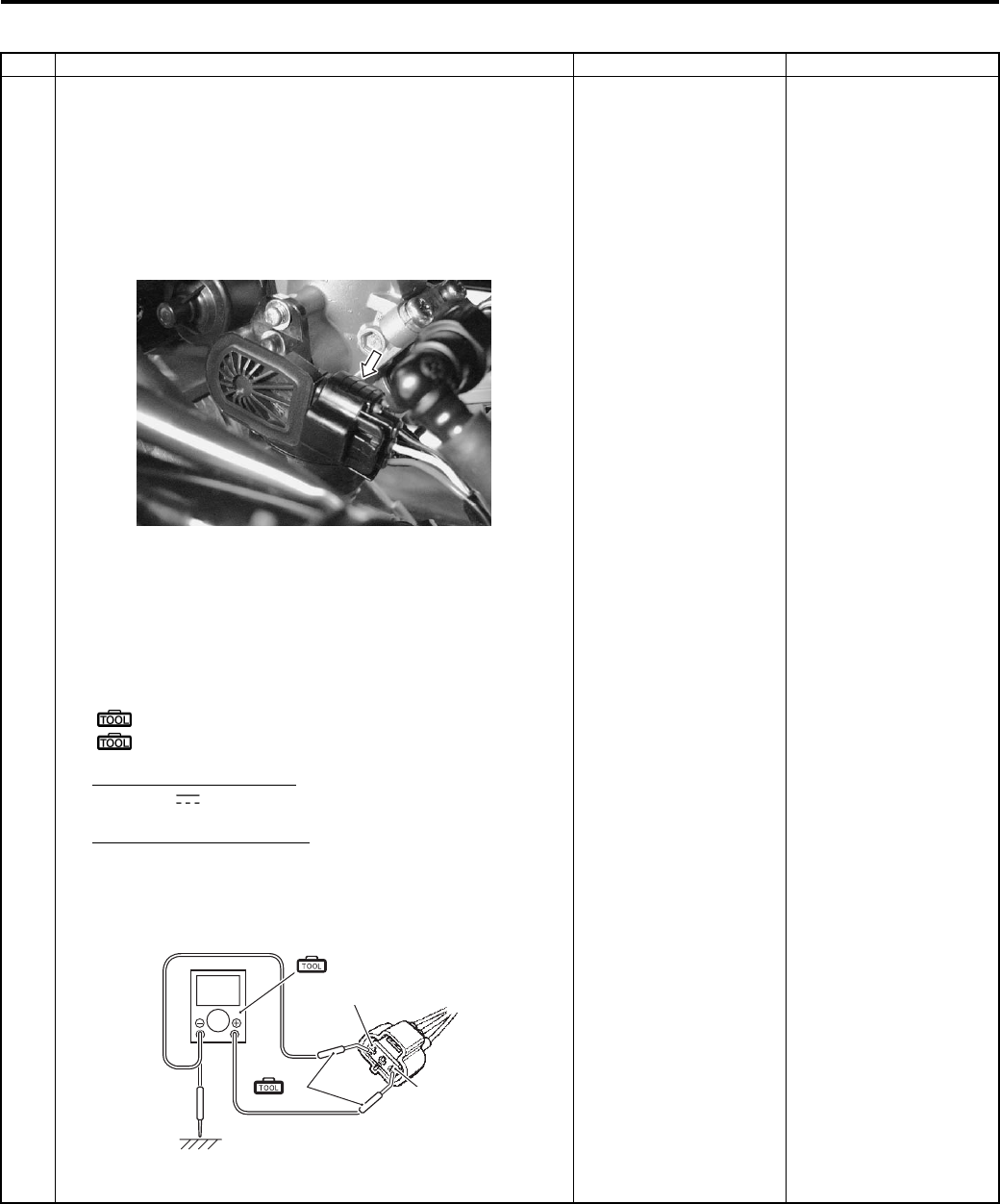
1A-35 Engine General Information and Diagnosis:
C14 (Use of mode select switch)
Step Action Yes No
1 1) Remove the left side cover. Refer to “Front Side Exterior
Parts Removal and Installation in Section 9D (Page 9D-
6)”.
2) Turn the ignition switch OFF.
3) Check the TP sensor coupler for loose or poor contacts.
If OK, then check the TP sensor input voltage.
4) Disconnect the TP sensor coupler.
5) Turn the ignition switch ON.
6) Insert the pointed probes to the lead wire coupler.
7) Measure the input voltage at the R wire “A” and ground.
If OK, then measure the input voltage at the R wire “A”
and B/Br wire “C”.
Special tool
(A): 09900–25008 (Multi-circuit tester set)
(B): 09900–25009 (Needle pointed probe set)
Tester knob indication
Voltage ( )
TP sensor input voltage
4.5 – 5.5 V
((+) terminal: R – (–) terminal: Ground, (+) terminal: R
– (–) terminal: B/Br)
Is the continuity OK?
Go to Step 2. • Loose or poor
contacts on the ECM
coupler.
• Open or short circuit
in the R wire or B/Br
wire.
I831G1110035-01
(B)
V
“A”
“C”
(A)
I831G1110081-01
PartShark.com
877-999-5686
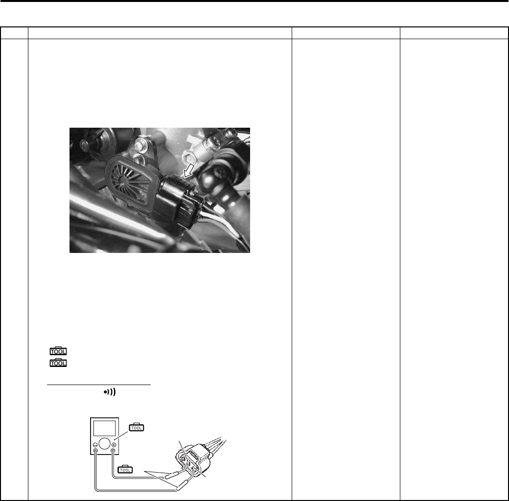
Engine General Information and Diagnosis: 1A-36
P0120-H (Use of SDS)
Step Action Yes No
1 1) Remove the left side cover. Refer to “Front Side Exterior
Parts Removal and Installation in Section 9D (Page 9D-
6)”.
2) Turn the ignition switch OFF.
3) Check the TP sensor coupler for loose or poor contacts.
If OK, then check the TP sensor lead wire continuity.
4) Disconnect the TP sensor coupler.
5) Insert the needle pointed probes to the lead wire coupler.
6) Check the continuity between R wire “A” and Y wire “B”.
If sound is not heard from the tester, the circuit condition
is OK.
Special tool
(A): 09900–25008 (Multi-circuit tester set)
(B): 09900–25009 (Needle pointed probe set)
Tester knob indication
Continuity ( )
Go to Step 2. R wire shorted to VCC
or B/Br wire open.
I831G1110035-01
(A)
(B)
?
“A”
“B”
I831G1110080-02
PartShark.com
877-999-5686
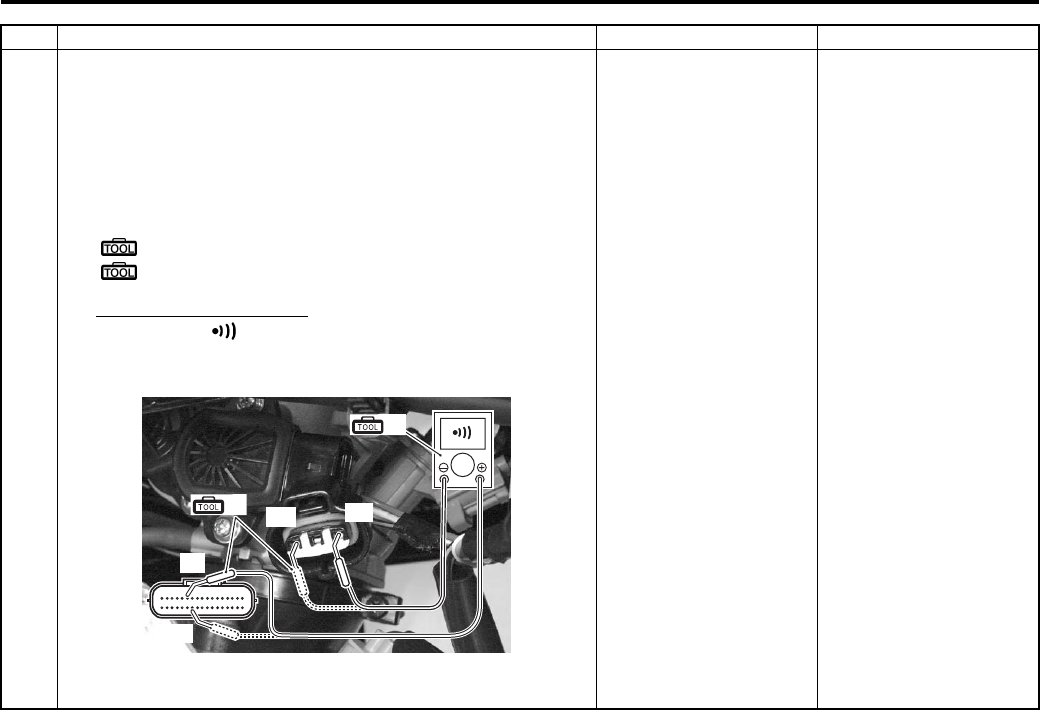
1A-37 Engine General Information and Diagnosis:
Step Action Yes No
1 7) Disconnect the ECM coupler. Refer to “ECM Removal
and Installation in Section 1C (Page 1C-1)”.
Check the continuity between R wire “A” and terminal
“6”.
Also, check the continuity between B/Br wire “C” and
terminal “24”.
Special tool
(A): 09900–25008 (Multi-circuit tester set)
(B): 09900–25009 (Needle pointed probe set)
Tester knob indication
Continuity ( )
ECM coupler (Harness side)
Is the continuity OK?
Go to Step 2. R wire shorted to VCC
or B/Br wire open.
“24”
“6”
(A)
(B) “A”
“C”
I831G1110036-02
PartShark.com
877-999-5686
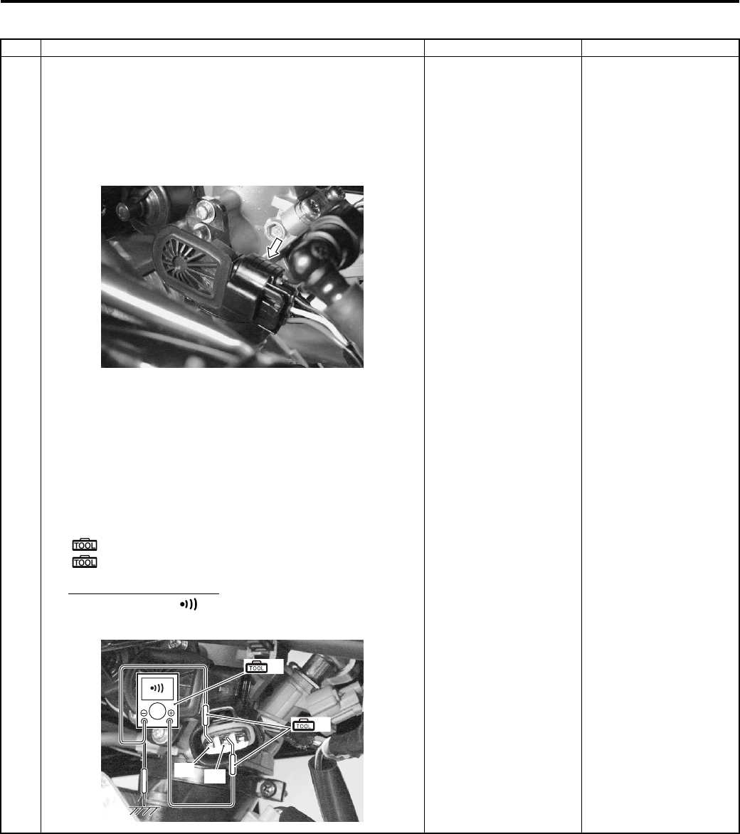
Engine General Information and Diagnosis: 1A-38
P0120-L (Use of SDS)
Step Action Yes No
1 1) Remove the left side cover. Refer to “Front Side Exterior
Parts Removal and Installation in Section 9D (Page 9D-
6)”.
2) Turn the ignition switch OFF.
3) Check the TP sensor coupler for loose or poor contacts.
If OK, then check the TP sensor lead wire continuity.
4) Disconnect the TP sensor coupler.
5) Insert the needle pointed probes to the lead wire coupler.
6) Check the continuity between Y wire “B” and ground.
Also, check the continuity between Y wire “B” and B/Br
wire “C”.
If sound is not heard from the tester, the circuit condition
is OK.
Special tool
(A): 09900–25008 (Multi-circuit tester set)
(B): 09900–25009 (Needle pointed probe set)
Tester knob indication
Continuity test ( )
Go to Step 2. Y or R wire open, or Y
wire shorted to ground.
I831G1110035-01
“C” “B”
(B)
(A)
I831G1110037-02
PartShark.com
877-999-5686
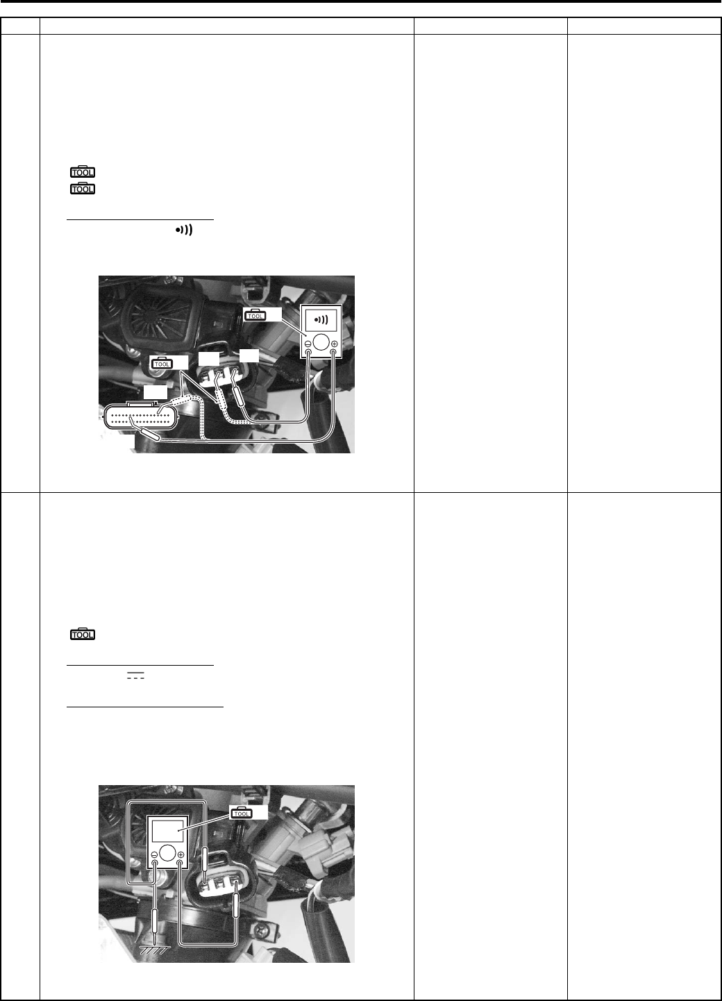
1A-39 Engine General Information and Diagnosis:
Step Action Yes No
1 7) Disconnect the ECM coupler. Refer to “ECM Removal
and Installation in Section 1C (Page 1C-1)”.
Check the continuity between Y wire “B” and terminal
“14”.
Also, check the continuity between R wire “A” and
terminal “6”.
Special tool
(A): 09900–25008 (Multi-circuit tester set)
(B): 09900–25009 (Needle pointed probe set)
Tester knob indication
Continuity test ( )
ECM coupler (Harness side)
Is the continuity OK?
Go to Step 2. Y or R wire open, or Y
wire shorted to ground.
2 1) Correct the ECM coupler.
2) Turn the ignition switch ON.
3) Measure the input voltage between the R wire and
ground.
If OK, the measure the input voltage between the R wire
and B/Br wire.
Special tool
(A): 09900–25008 (Multi-circuit tester set)
Tester knob indication
Voltage ( )
TP sensor input voltage
4.5 – 5.5 V
((+) terminal: R – (–) terminal: Ground, (+) terminal: R
– (–) terminal: B/Br)
In the voltage OK?
Go to Step 3. R and P/B wire open, or
P/B wire shorted to the
ground.
“14”
(A)
(B) “A”
“B”
“6”
I831G1110038-03
(A)
V
I831G1110039-03
PartShark.com
877-999-5686
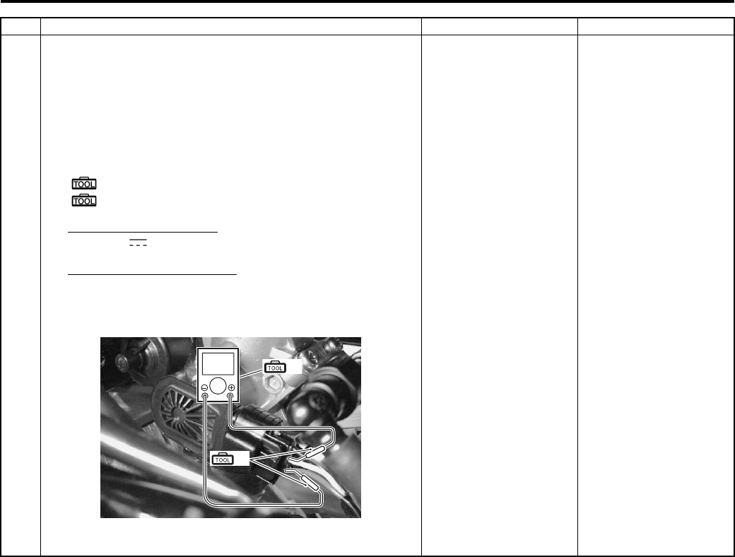
Engine General Information and Diagnosis: 1A-40
3 1) Connect the TP sensor coupler.
2) Insert the needle pointed probes to the lead wire coupler.
3) Turn the ignition switch ON.
4) Measure the TP sensor output voltage at the coupler
(between (+) Y wire and (–) B/Br wire) by opening the
throttle lever.
Special tool
(A): 09900–25008 (Multi-circuit tester set)
(B): 09900–25009 (Needle pointed probe set)
Tester knob indication
Voltage ( )
TP sensor output voltage
Throttle valve is closed: Approx. 1.12 V
Throttle valve is opened: Approx. 4.32 V
Is the voltage OK?
• Y, B/Br or R wire
open or shorted to
ground, or poor “14”,
“24” or “6”
connection.
• If wire and
connection are OK,
intermittent trouble or
faulty ECM.
• Recheck each
terminal and wire
harness for open
circuit and poor
connection.
• Replace the ECM
with a known good
one, and inspect it
again.
If check result is not
satisfactory, replace TP
sensor with a new one.
Refer to “Throttle Body
Disassembly and
Assembly in Section 1D
(Page 1D-10)”.
Step Action Yes No
(A)
V
(B)
I831G1110040-01
PartShark.com
877-999-5686

1A-41 Engine General Information and Diagnosis:
DTC “C15” (P0115-H/L): ECT Sensor Circuit Malfunction
B831G21104013
Detected Condition and Possible Cause
Wiring Diagram
ECM coupler (Harness side)
Troubleshooting
CAUTION
!
When using the multi-circuit tester, do not strongly touch the terminal of the ECM coupler with a
needle pointed tester probe to prevent the terminal damage or terminal bend.
NOTE
After repairing the trouble, clear the DTC using SDS tool. Refer to “Use of SDS Diagnosis Reset
Procedures (Page 1A-13)”.
Detected Condition Possible Cause
C15
Output voltage is not with in the following
range.
0.15 V ≤ Sensor voltage < 4.85 V
• ECT sensor circuit open or short.
• ECT sensor malfunction.
• ECM malfunction.
P0115
HSensor voltage is higher than specified
value.
• ECT sensor circuit is open or ground circuit open.
LSensor voltage is lower than specified
value.
• ECT sensor circuit shorted to the ground.
ECT sensor ECM
B/Bl
B/Br
ECT
E2
11
24
I831G1110041-01
I831G1110019-01
PartShark.com
877-999-5686
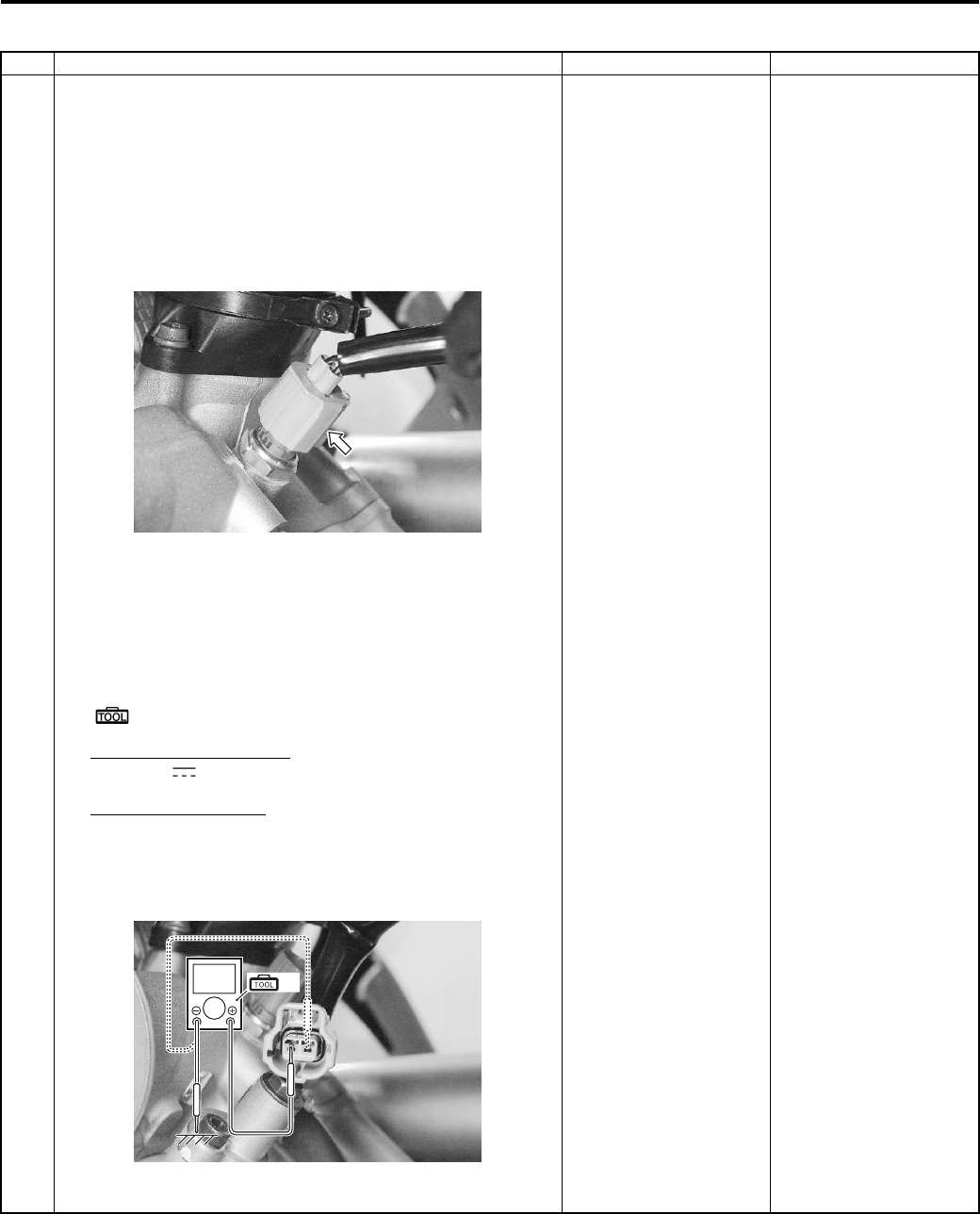
Engine General Information and Diagnosis: 1A-42
C15 (Use of mode select switch)
Step Action Yes No
1 1) Remove the left side cover. Refer to “Front Side Exterior
Parts Removal and Installation in Section 9D (Page 9D-
6)”.
2) Turn the ignition switch OFF.
3) Check the ECT sensor coupler for loose or poor
contacts.
If OK, then measure the ECT sensor voltage at the wire
side coupler.
4) Disconnect the coupler and turn the ignition switch ON.
5) Measure the voltage between the B/Bl wire terminal and
ground.
If OK, then measure the input voltage between B/Bl wire
terminal and B/Br wire terminal.
Special tool
(A): 09900–25008 (Multi-circuit tester set)
Tester knob indication
Voltage ( )
ECT sensor voltage
4.5 – 5.5 V
((+) terminal: B/Bl – (–) terminal: Ground, (+)
terminal: B/Bl – (–) terminal: B/Br)
6)
Is the voltage OK?
Go to Step 2. • Loose or poor
contacts on the ECM
coupler.
• Open or short circuit
in the B/Bl or B/Br
wire.
I831G1110042-01
V(A)
I831G1110043-02
PartShark.com
877-999-5686
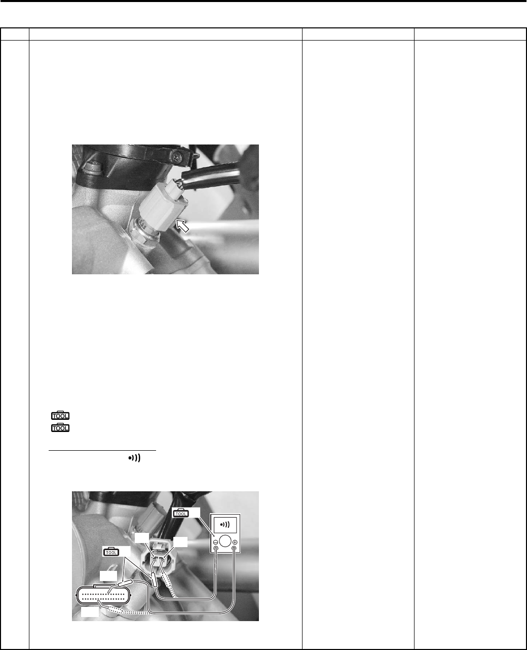
1A-43 Engine General Information and Diagnosis:
P0115-H (Use of SDS)
Step Action Yes No
1 1) Remove the left side cover. Refer to “Front Side Exterior
Parts Removal and Installation in Section 9D (Page 9D-
6)”.
2) Turn the ignition switch OFF.
3) Check the ECT sensor coupler for loose or poor
contacts.
If OK, then check the ECT sensor lead wire continuity.
4) Disconnect the ECT sensor coupler.
5) Disconnect the ECM coupler. Refer to “ECM Removal
and Installation in Section 1C (Page 1C-1)”.
6) Insert the needle pointed probes to lead wire coupler.
7) Check the continuity between B/Bl wire “A” and terminal
“11”.
Also, check the continuity between B/Br wire “B” and
terminal “24”.
Special tool
(A): 09900–25008 (Multi-circuit tester set)
(B): 09900–25009 (Needle pointed probe set)
Tester knob indication
Continuity test ( )
ECM coupler (Harness side)
Is the continuity OK?
Go to Step 2. B/Bl or B/Br wire open.
I831G1110042-01
“24”
“11”
(A)
(B)
“A” “B”
I831G1110044-03
PartShark.com
877-999-5686
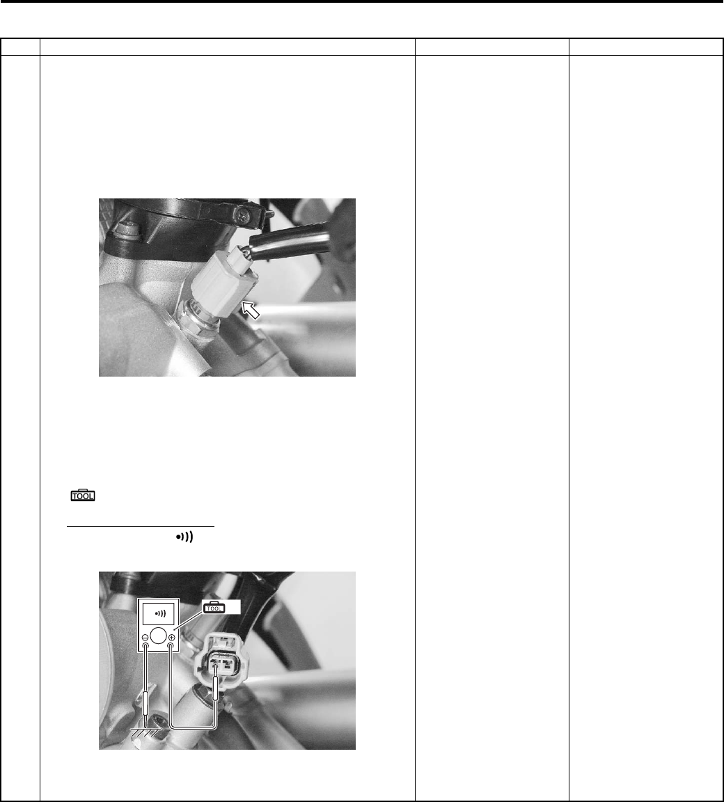
Engine General Information and Diagnosis: 1A-44
P0115-L (Use of SDS)
Step Action Yes No
1 1) Remove the left side cover. Refer to “Front Side Exterior
Parts Removal and Installation in Section 9D (Page 9D-
6)”.
2) Turn the ignition switch OFF.
3) Check the ECT sensor coupler for loose or poor
contacts.
If OK, then check the ECT sensor lead wire continuity.
4) Disconnect the ECT sensor coupler.
5) Check the continuity between B/Bl wire and ground.
If sound is not heard from the tester, the circuit condition
is OK.
Special tool
(A): 09900–25008 (Multi-circuit tester set)
Tester knob indication
Continuity test ( )
6) Connect the ECT sensor coupler.
7) Insert the needle pointed probes to the lead wire coupler.
Go to Step 2. • B/Bl wire shorted to
ground.
• If wire is OK, go to
Step 2.
I831G1110042-01
(A)
I831G1110045-02
PartShark.com
877-999-5686
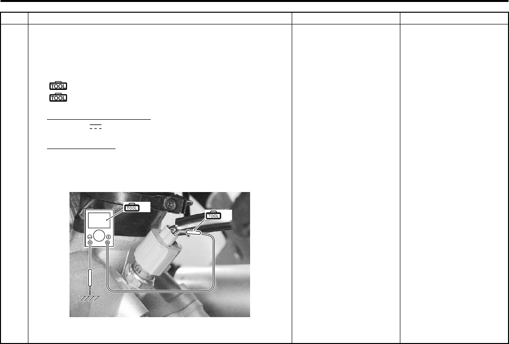
1A-45 Engine General Information and Diagnosis:
Step Action Yes No
1 Turn the ignition switch ON.
9) Measure the output voltage between B/Bl wire and
ground.
Special tool
(A): 09900–25008 (Multi-circuit tester set)
(B): 09900–25009 (Needle pointed probe set)
Tester knob indication
Voltage ( )
Output voltage
0.1 – 4.6 V
((+) terminal: B/Bl – (–) terminal: Ground)
Are the continuity and voltage OK?
Go to Step 2. • B/Bl wire shorted to
ground.
• If wire is OK, go to
Step 2.
(A)
V(B)
I831G1110046-01
PartShark.com
877-999-5686
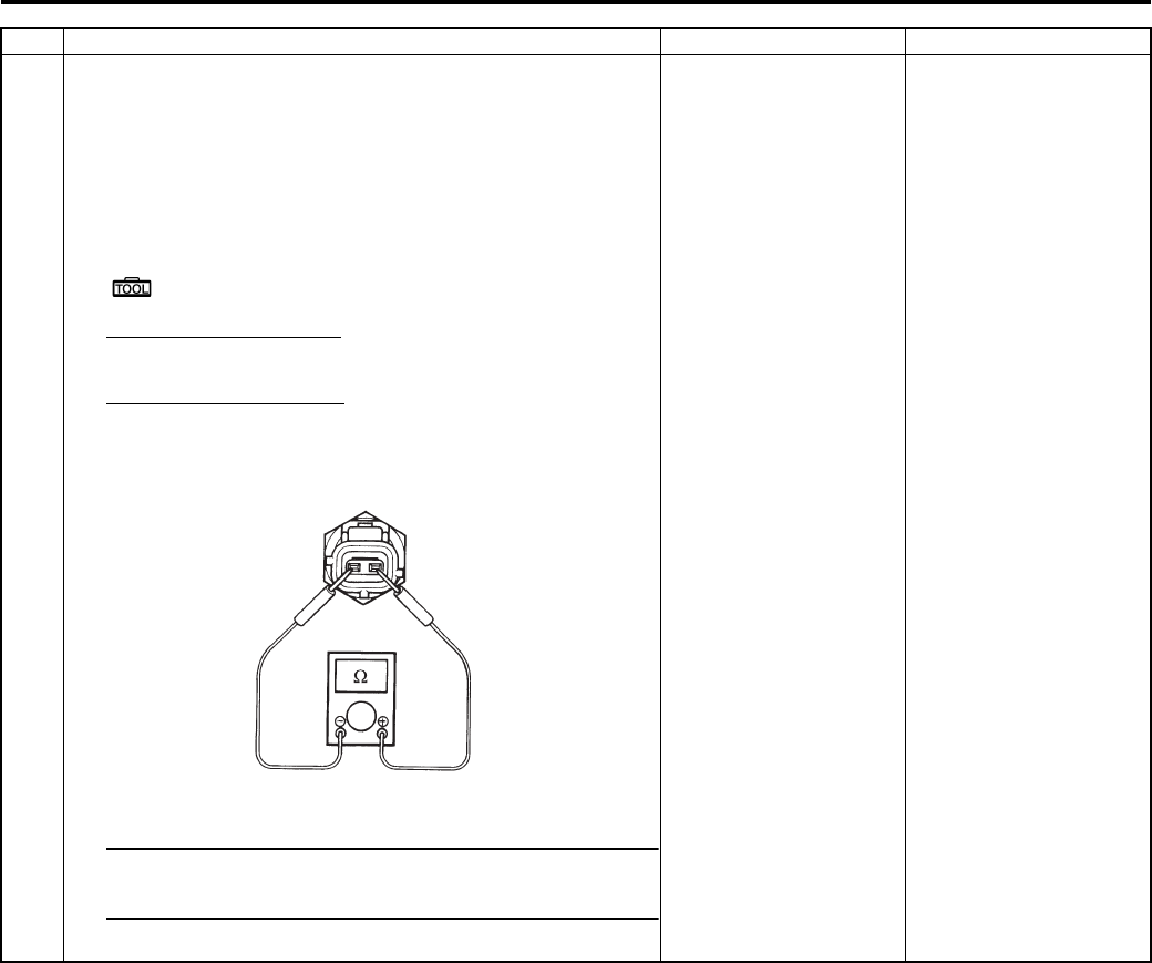
Engine General Information and Diagnosis: 1A-46
2 1) Turn the ignition switch OFF.
2) Connect the ECM coupler.
3) Disconnect the ECT sensor coupler.
4) Measure the ECT sensor resistance. Refer to “ECT
Sensor Inspection in Section 1C (Page 1C-4)” for
details.
Special tool
: 09900–25008 (Multi-circuit tester set)
Tester knob indication
Resistance (Ω)
ECT sensor resistance
Approx 2.45 kΩ at 20 °C (68 °F)
(Terminal – Terminal)
NOTE
Refer to “ECT Sensor Inspection in Section 1C
(Page 1C-4)” for details.
Is the resistance OK?
• B/Br or B/Bl wire
open or shorted to
ground, or poor “24”
or “11” connection.
• If wire and
connection are OK,
intermittent trouble or
faulty ECM.
• Recheck each
terminal and wire
harness for open
circuit and poor
connection.
• Replace the ECM
with a known good
one, and inspect it
again. Refer to “ECM
Removal and
Installation in Section
1C (Page 1C-1)”.
Replace the ECT
sensor with a new one.
Refer to “ECT Sensor
Removal and
Installation in Section
1C (Page 1C-4)”.
Step Action Yes No
I831G1110047-01
PartShark.com
877-999-5686
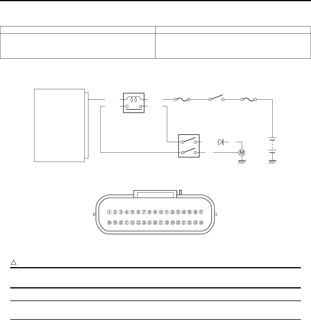
1A-47 Engine General Information and Diagnosis:
DTC “C20” (P1752): Diff-lock Relay Circuit Malfunction
B831G21104014
Detected Condition and Possible Cause
Wiring Diagram
ECM coupler (Harness side)
Troubleshooting
CAUTION
!
When using the multi-circuit tester, do not strongly touch the terminal of the ECM coupler with a
needle pointed tester probe to prevent the terminal damage or terminal bend.
NOTE
After repairing the trouble, clear the DTC using SDS tool. Refer to “Use of SDS Diagnosis Reset
Procedures (Page 1A-13)”.
Detected Condition Possible Cause
No voltage is applied to diff-lock motor, although ignition
switch is turned ON, or voltage is applied to diff-lock
motor, although ignition switch is turned OFF.
• Diff-lock relay circuit open or short.
• Diff-lock relay malfunction.
• ECM malfunction.
ECM
Diff-lock relay
Ignition
switch
Ignition
fuse
Main
fuse
Diff-lock relay
Transfer selecting
switch
Diff-lock
motor
O/Y
B
W/Bl
Br
W
Y/B
B/G
21
I831G1110048-02
I831G1110019-01
PartShark.com
877-999-5686
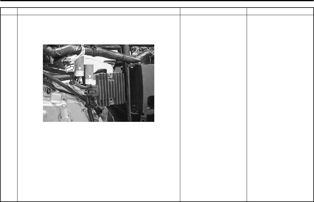
Engine General Information and Diagnosis: 1A-48
Step Action Yes No
1 1) Remove the rear fender. Refer to “Front Side Exterior
Parts Removal and Installation in Section 9D (Page 9D-
6)”.
2) Connect the disconnected couplers and battery.
3) Turn the ignition switch OFF.
4) Check the diff-lock relay coupler for loose or poor
contacts.
If OK, then check the diff-lock relay insulation and
continuity.
Refer to “2WD/4WD/Diff-lock System Inspection in
Section 3B (Page 3B-17)”.
Is the diff-lock relay OK?
• Inspect the 4WD/diff-
lock switch.
• Y/B wire open or
shorted to ground, or
poor “21” connection.
• If wire and
connection are OK,
intermittent trouble or
faulty ECM.
• Recheck each
terminal and wire
harness for open
circuit and poor
connection.
• Replace the ECM
with a known good
one, and inspect it
again.
Replace the diff-lock
relay with a new one.
I831G1110049-01
PartShark.com
877-999-5686
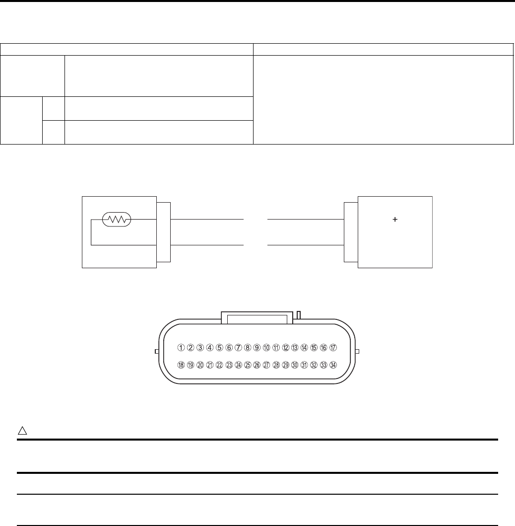
1A-49 Engine General Information and Diagnosis:
DTC “C21” (P0110-H/L): IAT Sensor Circuit Malfunction
B831G21104015
Detected Condition and Possible Cause
Wiring Diagram
ECM coupler (Harness side)
Troubleshooting
CAUTION
!
When using the multi-circuit tester, do not strongly touch the terminal of the ECM coupler with a
needle pointed tester probe to prevent the terminal damage or terminal bend.
NOTE
After repairing the trouble, clear the DTC using SDS tool. Refer to “Use of SDS Diagnosis Reset
Procedures (Page 1A-13)”.
Detected Condition Possible Cause
C21
Output voltage is not with in the following
range.
0.15 V ≤ Sensor voltage < 4.85 V
• IAT sensor circuit open or short.
• IAT sensor malfunction.
• ECM malfunction.
P0110
HSensor voltage is higher than specified
value.
• IAT sensor circuit open or ground circuit open.
LSensor voltage is lower than specified
value.
• IAT sensor circuit shorted to the ground.
IAT sensor ECM
IAT
E2
Dg
B/Br 24
28
I831G1110082-01
I831G1110019-01
PartShark.com
877-999-5686
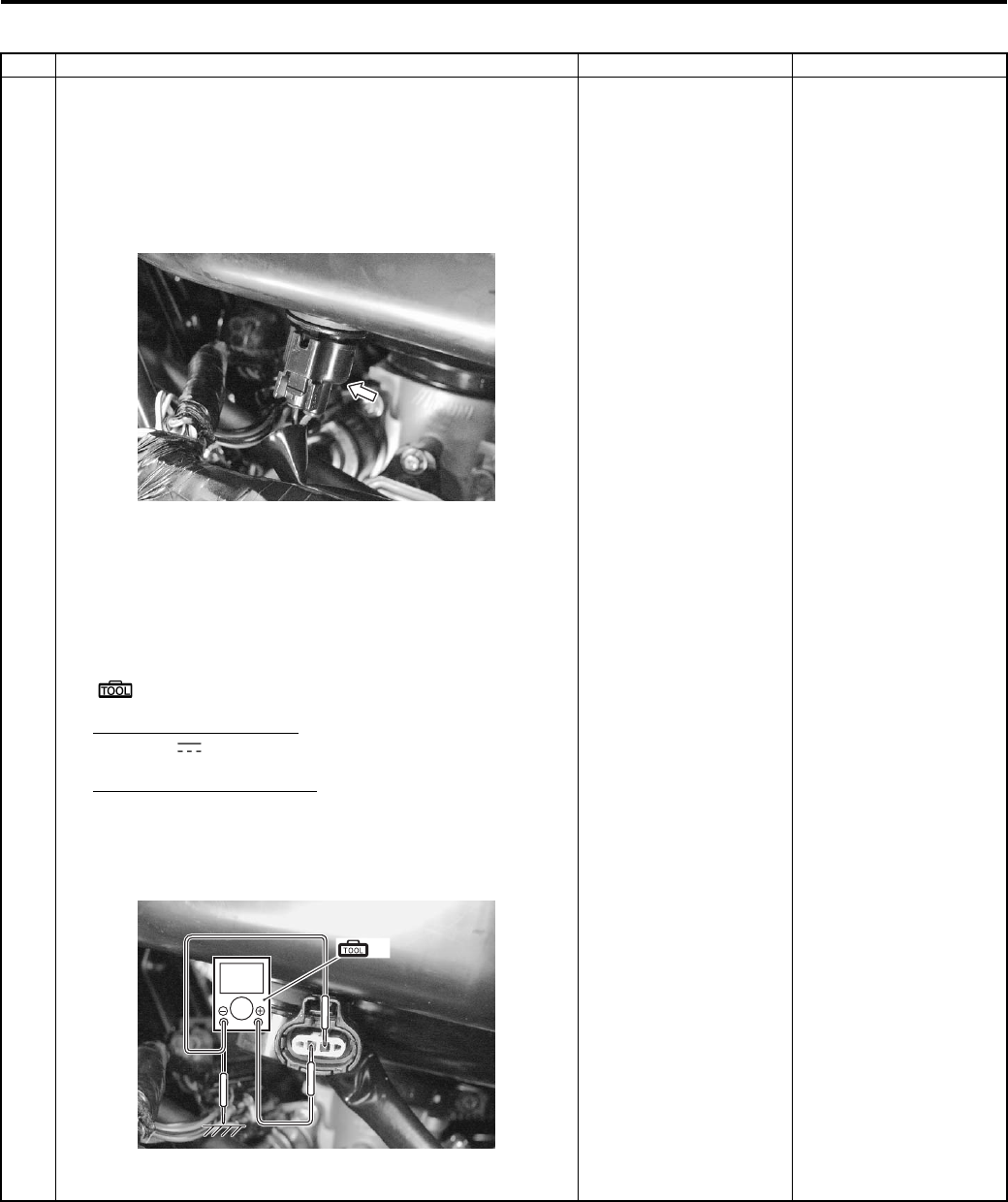
Engine General Information and Diagnosis: 1A-50
C21 (Use of mode select switch)
Step Action Yes No
1 1) Remove the left side cover. Refer to “Front Side Exterior
Parts Removal and Installation in Section 9D (Page 9D-
6)”.
2) Turn the ignition switch OFF.
3) Check the IAT sensor coupler for loose or poor contacts.
If OK, then measure the IAT sensor voltage.
4) Disconnect the coupler and turn the ignition switch ON.
5) Measure the voltage between the Dg wire terminal and
ground.
If OK, then measure the input voltage between Dg wire
terminal and B/Br wire terminal.
Special tool
(A): 09900–25008 (Multi-circuit tester set)
Tester knob indication
Voltage ( )
IAT sensor input voltage
4.5 – 5.5 V
((+) terminal: Dg – (–) terminal: Ground, (+) terminal:
Dg – (–) terminal: B/Br)
Is the voltage OK?
Go to Step 2. • Loose or poor
contacts on the ECM
coupler.
• Open or short circuit
in the Dg wire or B/Br
wire.
I831G1110051-01
(A)
V
I831G1110052-02
PartShark.com
877-999-5686
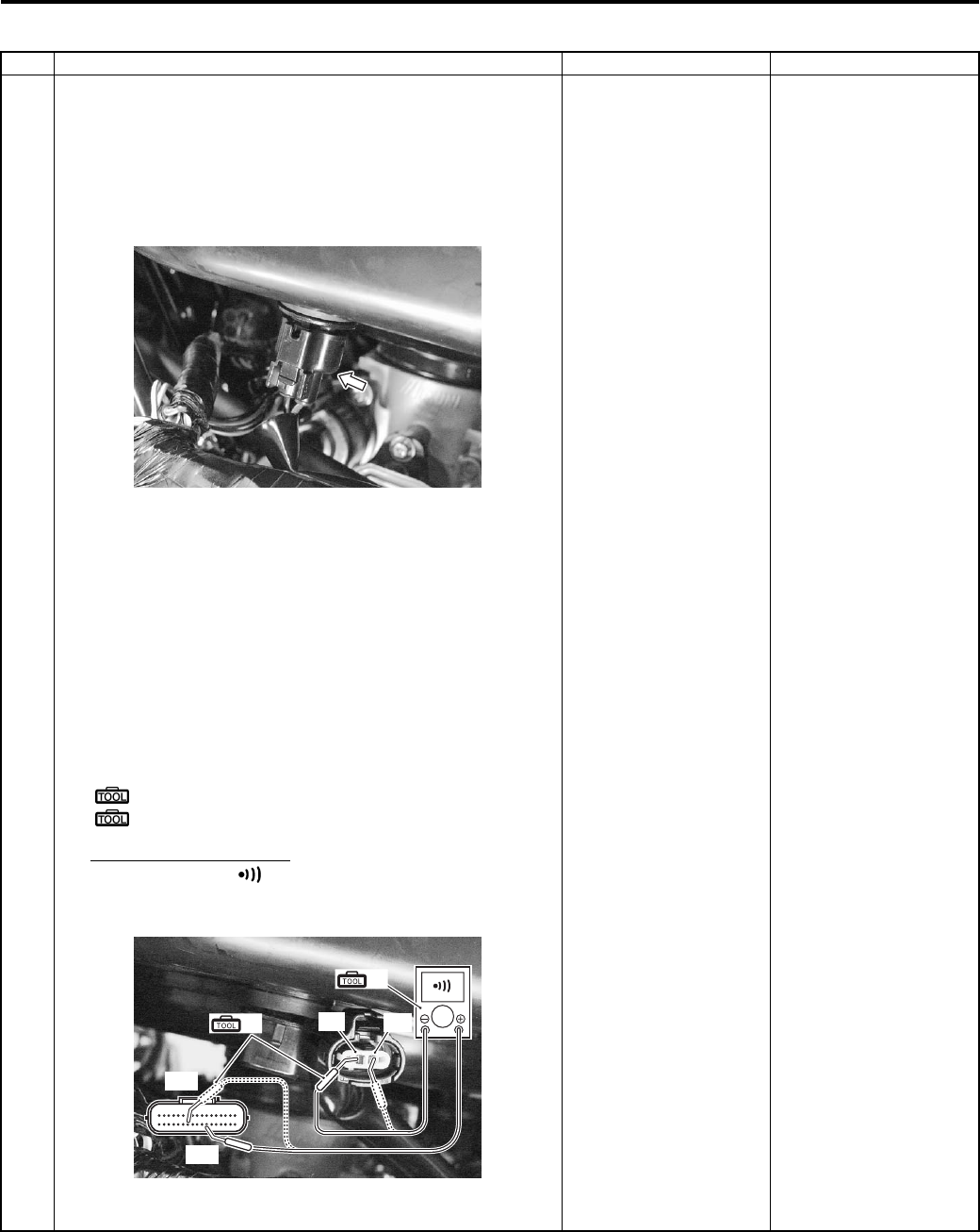
1A-51 Engine General Information and Diagnosis:
P0110-H (Use of SDS)
Step Action Yes No
1 1) Remove the left side cover. Refer to “Front Side Exterior
Parts Removal and Installation in Section 9D (Page 9D-
6)”.
2) Turn the ignition switch OFF.
3) Check the IAT sensor coupler for loose or poor contacts.
If OK, then check the IAT sensor lead wire continuity.
4) Disconnect the IAT sensor coupler.
5) Disconnect the ECM coupler. Refer to “ECM Removal
and Installation in Section 1C (Page 1C-1)”.
Also, check the continuity between B/Br wire “B” and
terminal “24”.
6) Insert the needle pointed probes to the lead wire coupler.
7) Check the continuity between the Dg wire “A” and
terminal “28”.
Also, check the continuity between the B/Br wire “B” and
terminal “24”.
Special tool
(A): 09900–25008 (Multi-circuit tester set)
(B): 09900–25009 (Needle pointed probe set)
Tester knob indication
Continuity test ( )
ECM coupler (Harness side)
Is the continuity OK?
Connect the ECM
coupler and go to step
2.
Dg or B/Br wire open.
I831G1110051-01
“24”
“28”
(A)
(B) “A” “B”
I831G1110050-01
PartShark.com
877-999-5686
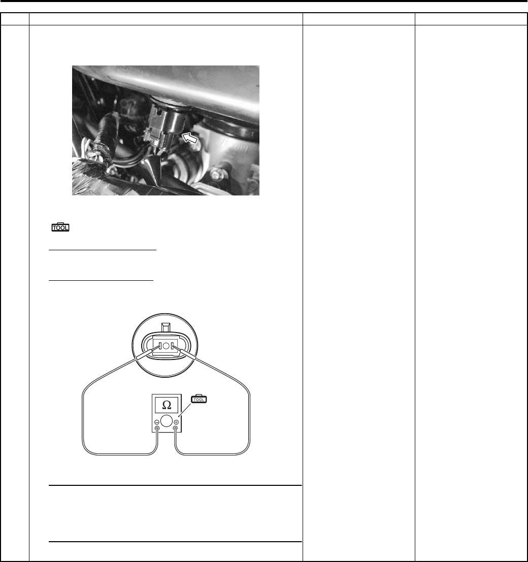
Engine General Information and Diagnosis: 1A-52
2 1) Turn the ignition switch OFF.
2) Measure the IAT sensor resistance.
Special tool
(A): 09900–25008 (Multi-circuit tester set)
Tester knob indication
Resistance (Ω)
IAT sensor resistance
Approx. 1.6 kΩ at 20 °C (68 °F) (Terminal — Terminal)
NOTE
IAT sensor resistance measurement method is
the same way as that of the ECT sensor. Refer to
“ECT Sensor Inspection in Section 1C (Page 1C-
4)”.
Is the resistance OK?
• Dg or B/Br wire open
or shorted to ground,
or poor “28” or “24”
connection.
• If wire and
connection are OK,
intermittent trouble or
faulty ECM.
• Recheck each
terminal and wire
harness for open
circuit and poor
connection.
• Replace the ECM
with a known good
one, and inspect it
again. Refer to “ECM
Removal and
Installation in Section
1C (Page 1C-1)”.
Replace the IAT sensor
with a new one. Refer to
“IAP Sensor Removal
and Installation in
Section 1C (Page 1C-
2)”.
Step Action Yes No
I831G1110051-01
(A)
I831G1110083-03
PartShark.com
877-999-5686
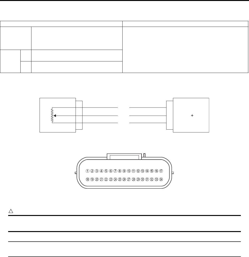
1A-53 Engine General Information and Diagnosis:
DTC “C23” (P1651-H/L): TO Sensor Circuit Malfunction
B831G21104016
Detected Condition and Possible Cause
Wiring Diagram
ECM coupler (Harness side)
Troubleshooting
CAUTION
!
When using the multi-circuit tester, do not strongly touch the terminal of the ECM coupler with a
needle pointed tester probe to prevent the terminal damage or terminal bend.
NOTE
After repairing the trouble, clear the DTC using SDS tool. Refer to “Use of SDS Diagnosis Reset
Procedures (Page 1A-13)”.
Detected Condition Possible Cause
C23
The sensor voltage should be the
following for 2 sec. and more, after ignition
switch is turned ON.
0.2 V ≤ Sensor voltage < 4.8 V
• TO sensor circuit open or short.
• TO sensor malfunction.
• ECM malfunction.
P1651
HSensor voltage is higher than specified
value.
• TO sensor circuit open or shorted to VCC or ground
circuit open.
LSensor voltage is lower than specified
value.
• TO sensor circuit shorted to ground or VCC circuit open.
TO sensor ECM
VCC
TO
E2
R
Br/W
B/Br
6
10
24
I831G1110054-01
I831G1110019-01
PartShark.com
877-999-5686
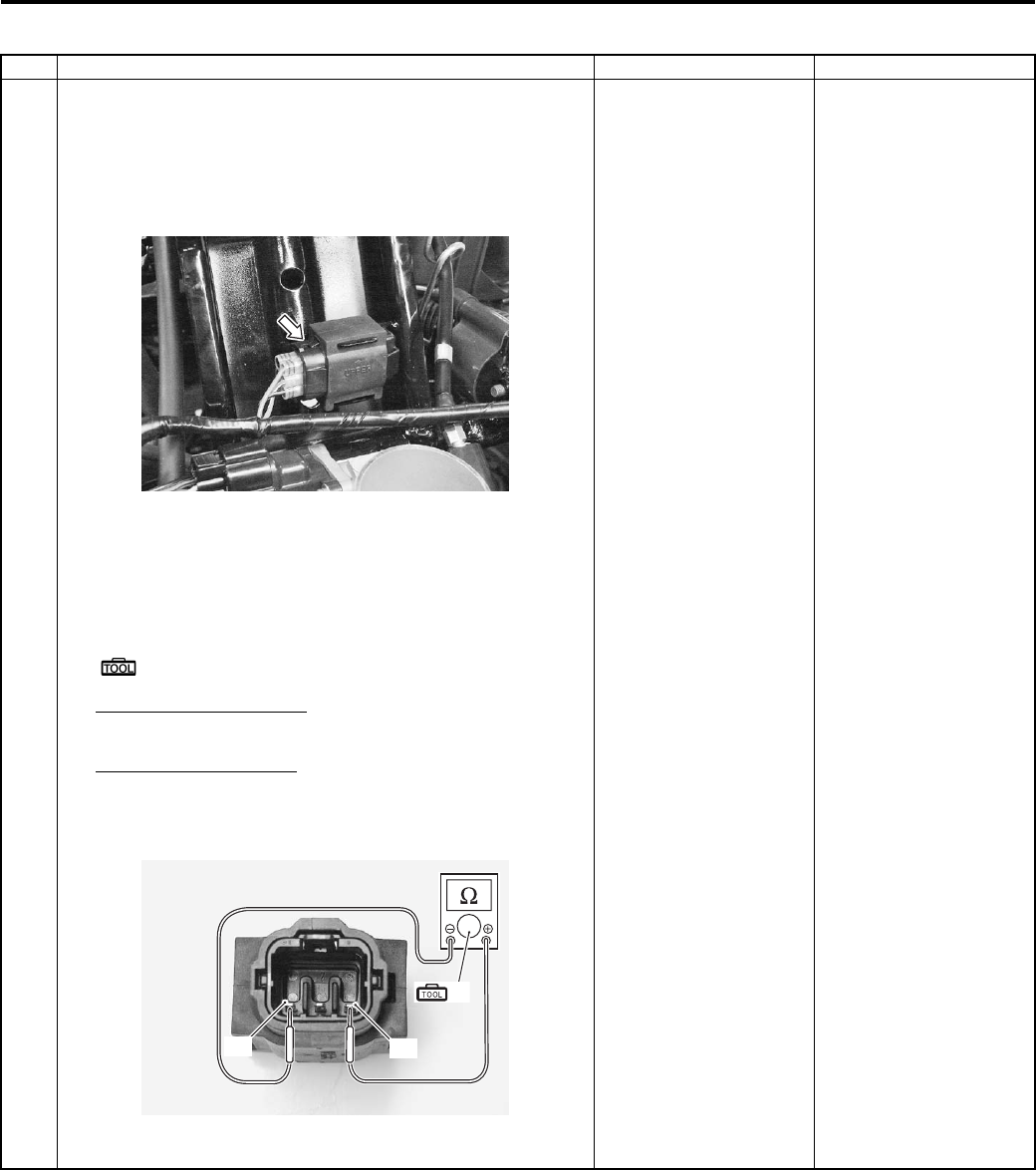
Engine General Information and Diagnosis: 1A-54
C23 (Use of mode select switch)
Step Action Yes No
1 1) Remove the air cleaner box. Refer to “Air Cleaner Box
Removal and Installation in Section 1D (Page 1D-5)”.
2) Turn the ignition switch OFF.
3) Check the TO sensor coupler for loose or poor contacts.
If OK, then measure the TO sensor resistance.
4) Remove the TO sensor.
5) Disconnect the TO sensor coupler.
6) Measure the resistance between terminal “A” and
terminal “B”.
Special tool
(A): 09900–25008 (Multi-circuit tester set)
Tester knob indication
Resistance (Ω)
TO sensor resistance
19.0 – 20.0 kΩ
(Terminal “A” – Terminal “B”)
Is the resistance OK?
Go to Step 2. Replace the TO sensor
with a new one. Refer to
“TO Sensor Removal
and Installation in
Section 1C (Page 1C-
5)”.
I831G1110055-01
“A”
“B”
(A)
I831G1110056-03
PartShark.com
877-999-5686
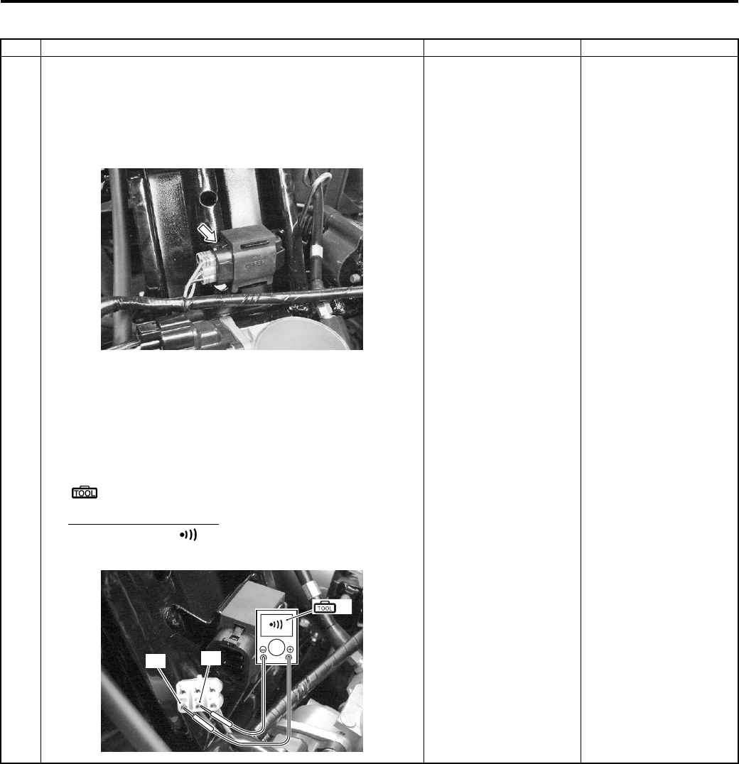
1A-55 Engine General Information and Diagnosis:
P1651-H (Use of SDS)
Step Action Yes No
1 1) Remove the air cleaner box. Refer to “Air Cleaner Box
Removal and Installation in Section 1D (Page 1D-5)”.
2) Turn the ignition switch OFF.
3) Check the TO sensor coupler for loose or poor contacts.
If OK, then check the TO sensor lead wire continuity.
4) Remove the TO sensor.
5) Disconnect the TO sensor coupler.
6) Check the continuity between the R wire “A” and B/Br
wire “B”. If the sound is not heard from the tester, the
circuit condition is OK.
Special tool
(A): 09900–25008 (Multi-circuit tester set)
Tester knob indication
Continuity test ( )
Go to Step 2. Br/W wire shorted to
VCC, or B/Br wire open.
I831G1110055-01
(A)
“A” “B”
I831G1110057-02
PartShark.com
877-999-5686
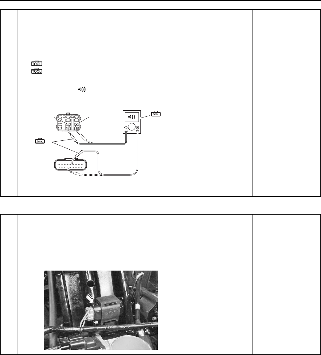
Engine General Information and Diagnosis: 1A-56
P1651-L (Use of SDS)
Step Action Yes No
1 7) Disconnect the ECM coupler.
Check the continuity between Br/W wire “B” and terminal
“10”. Also, check the continuity between B/Br wire “C”
and terminal “24”.
Special tool
(A): 09900–25008 (Multi-circuit tester set)
(B): 09900–25009 (Needle pointed probe set)
Tester knob indication
Continuity test ( )
ECM coupler (Harness side)
Is the continuity OK?
Go to Step 2. Br/W wire shorted to
VCC, or B/Br wire open.
“B” “C”
(A)
(B)
“10”
“24”
I831G1110058-03
Step Action Yes No
1 1) Remove the air cleaner box. Refer to “Air Cleaner Box
Removal and Installation in Section 1D (Page 1D-5)”.
2) Turn the ignition switch OFF.
3) Check the TO sensor coupler for loose or poor contacts.
If OK, then check the TO sensor lead wire continuity.
Go to Step 2. R or B wire open, or Br/
W wire shorted to the
ground.
I831G1110055-01
PartShark.com
877-999-5686
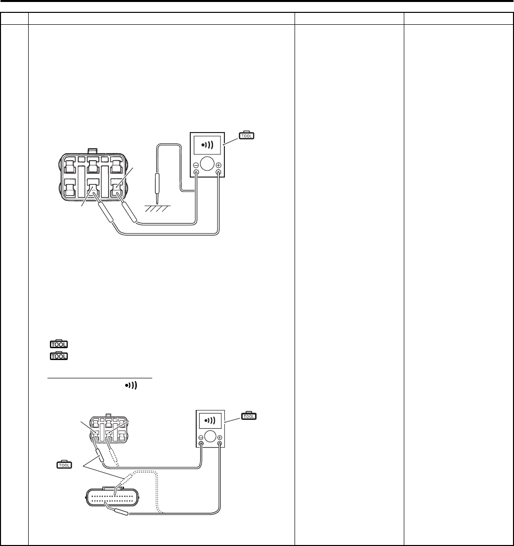
1A-57 Engine General Information and Diagnosis:
Step Action Yes No
1 4) Remove the TO sensor.
5) Disconnect the TO sensor coupler.
6) Insert the needle pointed probes to the lead wire coupler.
7) Check the continuity between Br/W wire “B” and ground.
Also, check the continuity between Br/W wire “B” and B/
Br wire “C”. If sound is not heard from the tester, the
circuit condition is OK.
Disconnect the ECM coupler. Refer to “ECM Removal
and Installation in Section 1C (Page 1C-1)”.
9) Check the continuity between R wire “A” and terminal
“6”.
Also, then check the continuity between Br/W wire “B”
and terminal “10”.
Special tool
(A): 09900–25008 (Multi-circuit tester set)
(B): 09900–25009 (Needle pointed probe set)
Tester knob indication
Continuity test ( )
Is the continuity OK?
Go to Step 2. R or B wire open, or Br/
W wire shorted to the
ground.
(A)
“B”
“C”
I831G1110084-01
“A” “B”
(A)
(B)
“10”
“6”
I831G1110085-02
PartShark.com
877-999-5686
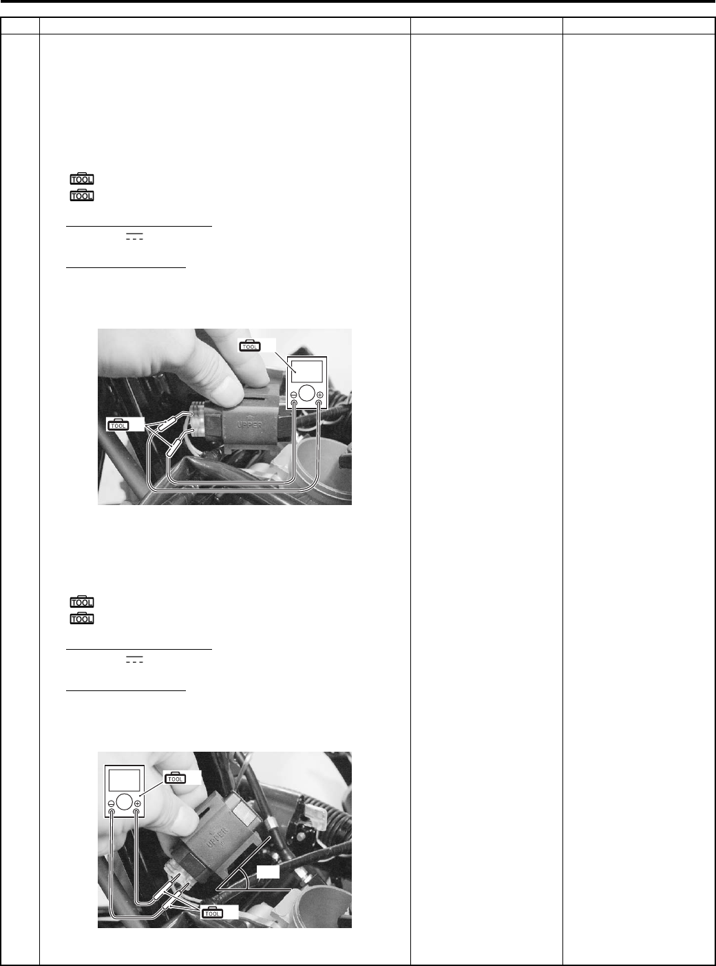
Engine General Information and Diagnosis: 1A-58
2 1) Connect the TO sensor coupler.
2) Insert the needle pointed probes to the lead wire coupler.
3) Turn the ignition switch ON.
4) Measure the voltage at the wire side coupler between
Br/W and B/Br wires.
Also, measure the voltage when learning the vehicle.
Special tool
(A): 09900–25008 (Multi-circuit tester set)
(B): 09900–25009 (Needle pointed probe set)
Tester knob indication
Voltage ( )
TO sensor voltage
0.4 – 1.4 V
((+) terminal: Br/W – (–) terminal: B/Br)
5) Dismount the TO sensor from its bracket and measure
the voltage when it is learned 65° and more, left and
right, from the horizontal level.
Special tool
(A): 09900–25008 (Multi-circuit tester set)
(B): 09900–25009 (Needle pointed probe set)
Tester knob indication
Voltage ( )
TO sensor voltage
3.7 – 4.4 V
((+) terminal: Br/W – (–) terminal: B/Br)
Is the voltage OK?
• R, B/Br or Br/W wire
open or shorted to
ground, or poor “6”,
“24” or “10”
connection.
• If wire and
connection are OK,
intermittent trouble or
faulty ECM.
• Recheck each
terminal and wire
harness for open
circuit and poor
connection.
• Replace the ECM
with a known good
one, and inspect it
again. Refer to “ECM
Removal and
Installation in Section
1C (Page 1C-1)”.
• Loose or poor
contacts on the ECM
coupler.
• Open or short circuit.
• Replace the TO
sensor with a new
one.
Step Action Yes No
V
(A)
(B)
I831G1110059-01
(A)
(B)
V
65°
I831G1110060-01
PartShark.com
877-999-5686
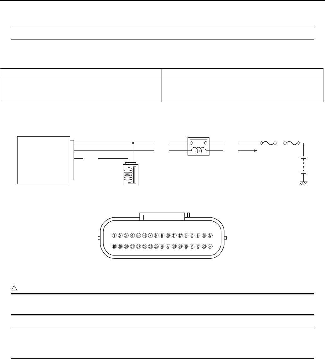
1A-59 Engine General Information and Diagnosis:
DTC “C24” (P0351): Ignition Coil Circuit Malfunction
B831G21104017
NOTE
Refer to “No Spark or Poor Spark in Section 1H (Page 1H-2)” for details.
DTC “C32” (P0201): Fuel Injector Circuit Malfunction
B831G21104018
Detected Condition and Possible Cause
Wiring Diagram
ECM coupler (Harness side)
Troubleshooting
CAUTION
!
When using the multi-circuit tester, do not strongly touch the terminal of the ECM coupler with a
needle pointed tester probe to prevent the terminal damage or terminal bend.
NOTE
• After repairing the trouble, clear the DTC using SDS tool. Refer to “Use of SDS Diagnosis Reset
Procedures (Page 1A-13)”.
• Injector voltage can be detected only for 3 seconds after ignition switch is turned ON.
Detected Condition Possible Cause
CKP signal is produced but fuel injector signal is
interrupted by 4 times or more continuity.
• Injector circuit open or short.
• Injector malfunction.
• ECM malfunction.
ECM
VM
FP
INJ
To engine
stop switch
Fuel
fuse
Main
fuse
Fuel pump relay
Y/R
Y/Bl
R/B
O/W
Fuel injector
Gr/W
20
19
2
I831G1110086-03
I831G1110019-01
PartShark.com
877-999-5686
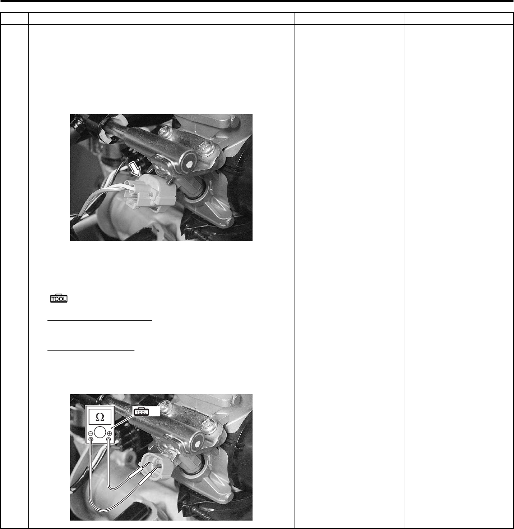
Engine General Information and Diagnosis: 1A-60
Step Action Yes No
1 1) Remove the side cover. Refer to “Front Side Exterior
Parts Removal and Installation in Section 9D (Page 9D-
6)”.
2) Turn the ignition switch OFF.
3) Check the injector coupler for loose or poor contacts.
If OK, then measure the injector resistance.
4) Disconnect the injector coupler and measure the
resistance between terminals.
Special tool
(A): 09900–25008 (Multi-circuit tester set)
Tester knob indication
Resistance (Ω)
Injector resistance
Approx. 11 – 13 Ω at 20 °C (68 °F)
(Terminal – Terminal)
Go to Step 2. Replace the injector
with a new one. Refer to
“Throttle Body
Disassembly and
Assembly in Section 1D
(Page 1D-10)”.
I831G1110087-01
(A)
I831G1110088-01
PartShark.com
877-999-5686
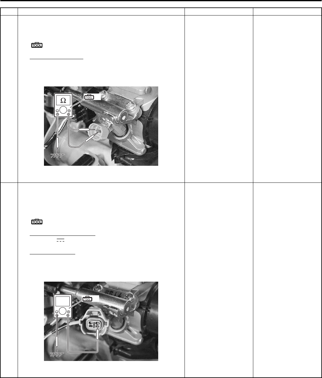
1A-61 Engine General Information and Diagnosis:
1 5) If OK, then check the continuity between each terminal
and ground.
Special tool
(A): 09900–25008 (Multi-circuit tester set)
Injector continuity
∞ Ω (Infinity)
(Terminal – Ground)
Are the resistance and continuity OK?
Go to Step 2. Replace the injector
with a new one. Refer to
“Throttle Body
Disassembly and
Assembly in Section 1D
(Page 1D-10)”.
2 1) Turn the ignition switch ON.
2) Measure the injector voltage between Y/R wire and
ground.
Special tool
(A): 09900–25008 (Multi-circuit tester set)
Tester knob indication
Voltage ( )
Injector voltage
Battery voltage
((+) terminal: Y/R – (–) terminal: Ground)
Is the voltage OK?
• Gr/W or Y/R wire
open or shorted to
ground, or poor “2” or
“20” connection.
• If wire and
connection are OK,
intermittent trouble or
faulty ECM.
• Recheck each
terminal and poor
connection.
• Replace the ECM
with a known good
one, and inspect it
again.
Open circuit in the Y/R
wire.
Step Action Yes No
(A)
I831G1110089-01
(A)
V
I831G1110061-02
PartShark.com
877-999-5686
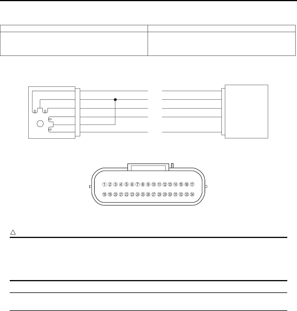
Engine General Information and Diagnosis: 1A-62
DTC “C40” (P05057): ISC Valve Circuit Malfunction
B831G21104019
Detected Condition and Possible Cause
Wiring Diagram
ECM coupler (Harness side)
Troubleshooting
CAUTION
!
• Be careful not to disconnect at lease 3 seconds after ignition switch is turned to OFF.
If the ECM coupler is disconnected within 3 seconds after ignition switch is turned to OFF, there is a
possibility of an usual valve being written in ECM and causing an error of ISC valve operation.
• When using the multi-circuit tester, do not strongly touch the terminal of the ECM coupler with a
needle pointed tester probe to prevent the terminal damage or terminal bend.
NOTE
After repairing the trouble, clear the DTC using SDS tool. Refer to “Use of SDS Diagnosis Reset
Procedures (Page 1A-13)”.
Detected Condition Possible Cause
No voltage is applied to ISC valve motor, although ignition
switch is turned ON, or voltage is applied to ISC valve
motor, although ignition switch is turned OFF.
• ISC valve circuit open or shorted to the ground.
• ISC valve malfunction.
• ECM malfunction.
ISC valve ECM
IS1A
M
BATT
IS1B
B/Lg
R/B
P/W
IS2A
G
IS2B
W/Bl
17
4
34
16
33
I831G1110062-01
I831G1110019-01
PartShark.com
877-999-5686
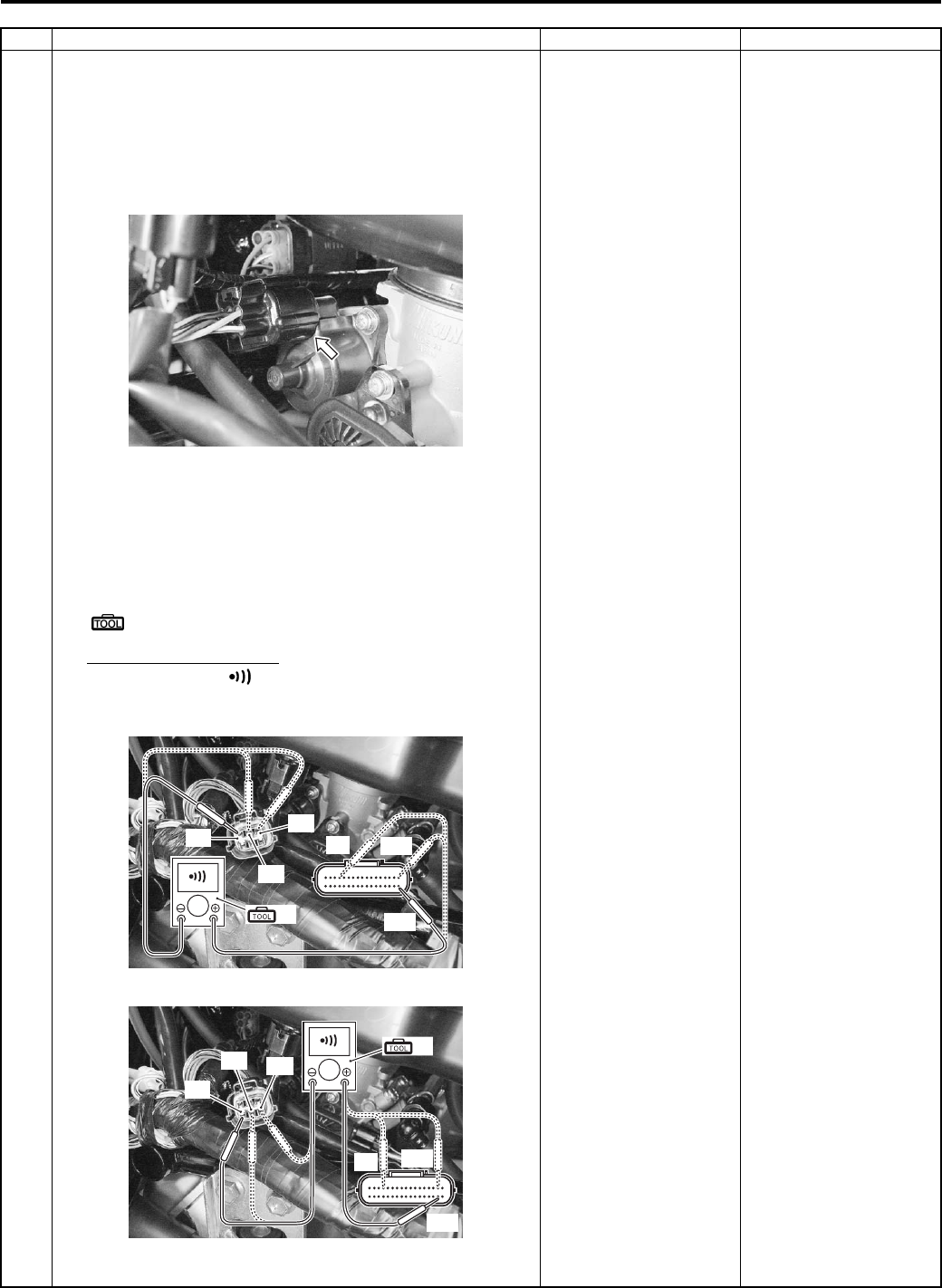
1A-63 Engine General Information and Diagnosis:
Step Action Yes No
1 1) Remove the left side cover. Refer to “Front Side Exterior
Parts Removal and Installation in Section 9D (Page 9D-
6)”.
2) Turn the ignition switch OFF.
3) Check the ISC valve coupler for loose or poor contacts.
If OK, then check the ISC valve lead wire continuity.
4) Disconnect the ISC valve coupler.
5) Check the continuity between terminals “A” and “34”,
terminals “B” and “4”, terminals “C” and “17”, terminals
“D” and “33”, terminals “E” and “4” and terminals “F” and
“16”.
Special tool
(A): 09900–25008 (Multi-circuit tester set)
Tester knob indication
Continuity test ( )
ECM coupler (Harness side)
Is the continuity OK?
Go to Step 2. B/Lg, R/B, P/W, G or W/
Bl wire open.
I831G1110063-01
(A)
“17”
“34”
“A”
“B”
“C”
“4”
I831G1110064-02
(A)
“33”
“16”
“4”
“D”
“E” “F”
I831G1110065-02
PartShark.com
877-999-5686
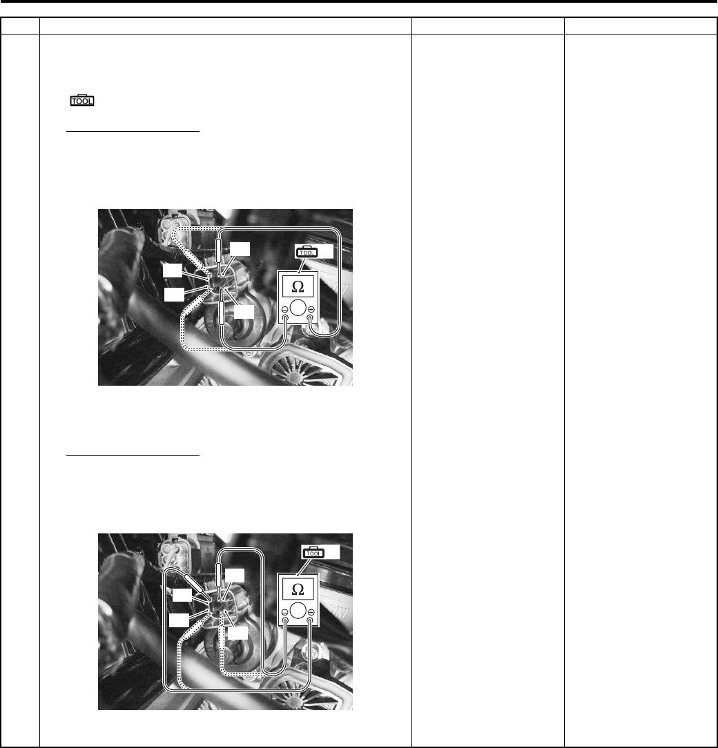
Engine General Information and Diagnosis: 1A-64
2 1) Measure the resistance between terminals “A” and “C”,
terminals “B” and “D”.
Special tool
(A): 09900–25008 (Multi-circuit tester set)
ISC valve resistance
Approx. ∞
(Terminal “A” – Terminal “C”)
(Terminal “B” – Terminal “D”)
2) If OK, then measure the resistance between terminals
“A” and “B”, terminals “C” and “D”.
ISC valve resistance
Approx. 31 kΩ at 20 °C
(Terminal “A” – Terminal “B”)
(Terminal “C” – Terminal “D”)
Is the resistance OK?
If wire is OK,
intermittent trouble or
faulty ECM.
Replace the ISC valve
with a new one.
Step Action Yes No
(A)
“A”
“C”
“B”
“D”
I831G1110066-02
(A)
“A”
“D”
“B”
“C”
I831G1110067-03
PartShark.com
877-999-5686
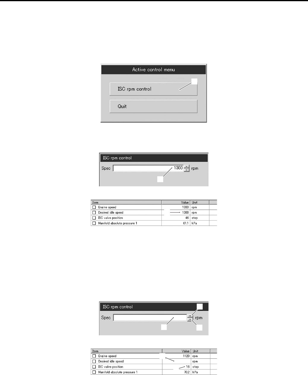
1A-65 Engine General Information and Diagnosis:
ACTIVE CONTROL INSPECTION (ISC RPM CONTROL)
Check 1
1) Set up the SDS tool. (Refer to the SDS operation manual for further details.)
2) Check that the engine is running.
3) Click the “Active control”.
4) Click the “ISC rpm control” (1).
5) Check that the “Spec” (2) is idle speed 1 300 ± 100 rpm.
6) Check that the “Desired idle speed” (3) is within the specified idle rpm.
Check 2
1) Click the button (4) and decrease the “Spec” (2) to 1 100 rpm slowly.
2) Check that the “Desired idle speed” (3) is nearly equal to the “Spec” (2). At the same time, check that the number
of steps (5) in the ISC valve position decreases.
3) Click the button (6) and increase the “Spec” (2) slowly.
4) Check that the “Desired idle speed” (3) is nearly equal to the “Spec” (2). Also, check that the number of steps (5) in
the ISC valve position increases.
1
I831G1110070-02
2
I831G1110068-02
3
I831G1110069-02
24
6
I831G1110071-05
3
5
1100
I831G1110072-02
PartShark.com
877-999-5686
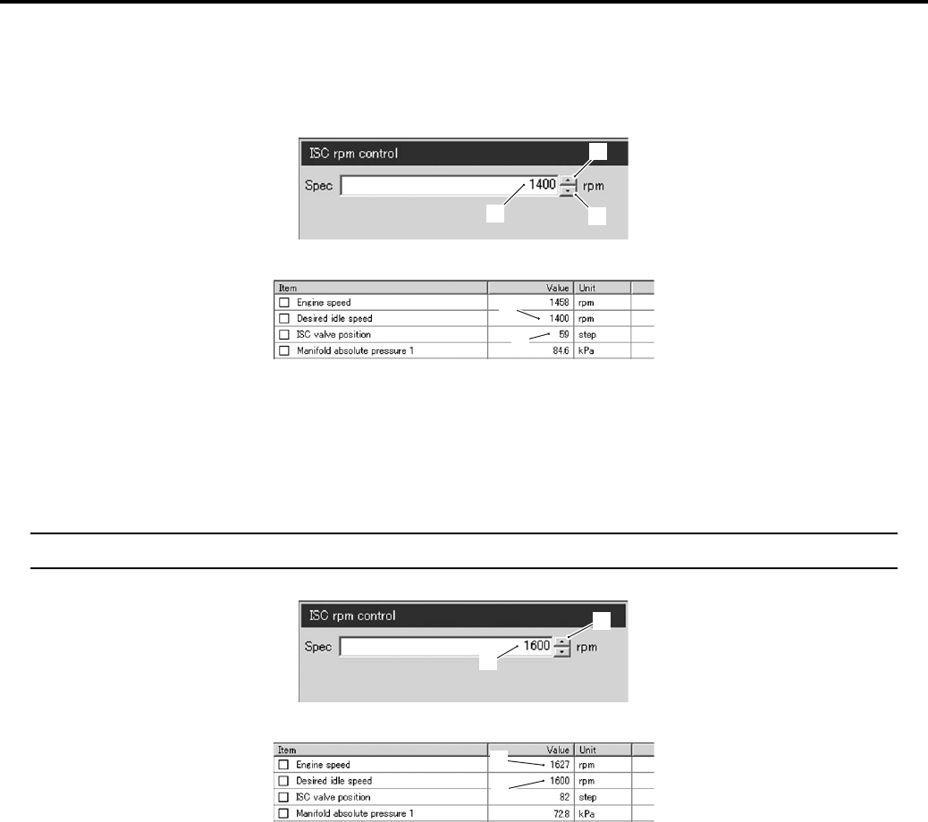
Engine General Information and Diagnosis: 1A-66
Check 3
1) Click the button (6) and increase the “Spec” (2) to 1 400 rpm slowly.
2) Check that the “Desired idle speed” (3) is nearly equal to the “Spec” (2). Also, check that the number of steps (5) in
the ISC valve position increases.
Check 4
1) Click the button (6) and increase the “Spec” (2) to 1 600 rpm.
2) Check that the “Desired idle speed” (3) is approx. 1 600 rpm.
3) Check that the “Engine speed” (7) is close to 1 600 rpm.
NOTE
Be careful not to increase the “Spec” to 1 650 rpm, or the “Engine speed” may reach the upper limit.
If the ISC valve does not function properly, replace the ISC valve or inspect the ISC valve. Refer to “Throttle Body
Disassembly and Assembly in Section 1D (Page 1D-10)”.
2
6
4
I831G1110073-01
3
5
I831G1110074-01
2
6
I831G1110076-01
7
3
I831G1110075-01
PartShark.com
877-999-5686
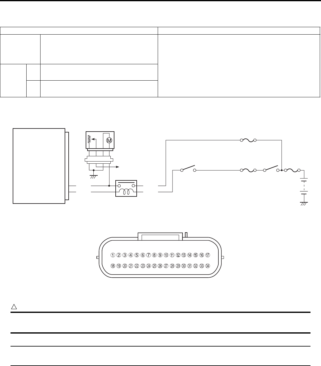
1A-67 Engine General Information and Diagnosis:
DTC “C41” (P230-H/L): FP Relay Circuit Malfunction
B831G21104020
Detected Condition and Possible Cause
Wiring Diagram
ECM coupler (Harness side)
Troubleshooting
CAUTION
!
When using the multi-circuit tester, do not strongly touch the terminal of the ECM coupler with a
needle pointed tester probe to prevent the terminal damage or terminal bend.
NOTE
After repairing the trouble, clear the DTC using SDS tool. Refer to “Use of SDS Diagnosis Reset
Procedures (Page 1A-13)”.
Detected Condition Possible Cause
C41
No voltage is applied to fuel pump
although fuel pump relay is turned ON, or
voltage is applied to fuel pump, although
fuel pump relay is turned OFF.
• Fuel pump relay circuit open or short.
• Fuel pump relay malfunction.
• ECM malfunction.
P0230
HVoltage is applied to fuel pump although
fuel pump relay is turned OFF.
• Fuel pump relay switch circuit shorted to power source.
• Faulty fuel pump relay (switch side).
LNo voltage is applied to fuel pump
although fuel pump relay is turned ON.
• Fuel pump relay coil circuit open or short.
• Faulty fuel pump relay (coil side).
ECM
VM
FP
Engine stop
switch
Ignition
switch
Ignition
fuse
Main
fuse
Fuel
fuse
Fuel pump relay
Fuel pump
To the combination
meter
R/B
O/W
Y/R
Y/Bl
20
19
I831G1110077-04
I831G1110019-01
PartShark.com
877-999-5686
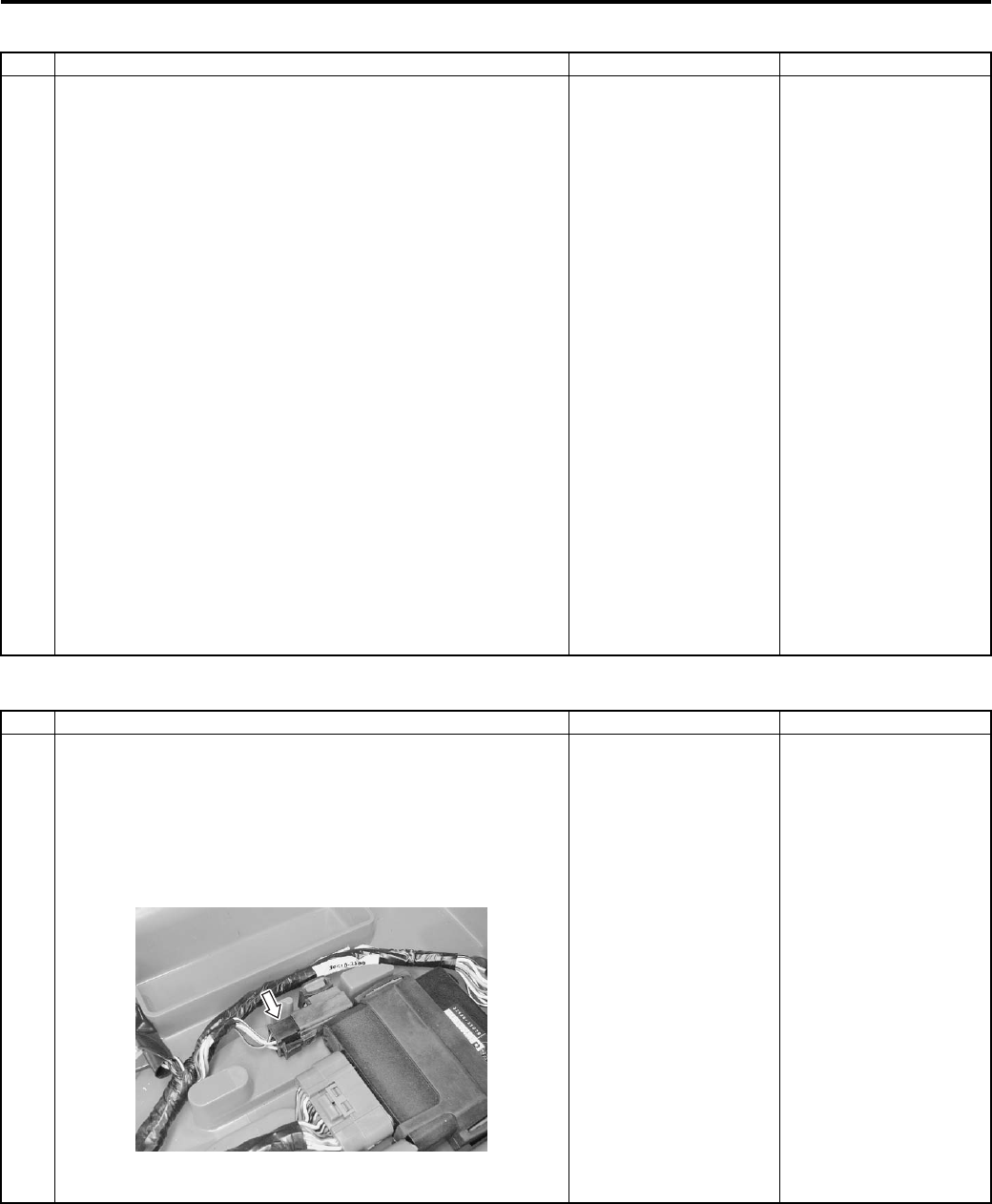
Engine General Information and Diagnosis: 1A-68
C41 (Use of mode select switch)
P0230-H (Use of SDS)
Step Action Yes No
1 1) Remove the seat. Refer to “Front Side Exterior Parts
Removal and Installation in Section 9D (Page 9D-6)”.
2) Turn the ignition switch to OFF.
3) Check the FP relay coupler for loose or poor contacts.
If OK, then check the FP relay. Refer to “Fuel Pump
Relay Inspection in Section 1G (Page 1G-7)”.
Is the FP relay OK?
• Y/Bl or O/W wire
open or shorted to
ground, or poor “19”
connection.
• Y/R or R/B wire open
or shorted to ground,
or poor “20”
connection.
• If wire and
connection are OK,
intermittent trouble or
faulty ECM.
• Recheck each
terminal and wire
harness for open
circuit poor
connection.
• Replace the ECM
with a known good
one, and inspect it
again. Refer to “ECM
Removal and
Installation in Section
1C (Page 1C-1)”.
Replace the FP relay
with a new one.
Step Action Yes No
1 1) Remove the seat. Refer to “Front Side Exterior Parts
Removal and Installation in Section 9D (Page 9D-6)”.
2) Turn the ignition switch to OFF.
3) Check the FP relay coupler for loose or poor contacts.
If OK, then check the FP relay. Refer to “Fuel Pump
Relay Inspection in Section 1G (Page 1G-7)”.
Is the FP relay OK?
• Y/R wire shorted to
power source.
• Y/Bl wire shorted to
ground.
• If wire and
connection are OK,
intermittent trouble or
faulty ECM.
• Recheck each
terminal and wire
harness for open
circuit and poor
connection.
• Replace the ECM
with a known good
one, and inspect it
again.
Replace the FP relay
with a new one.
I831G1110078-01
PartShark.com
877-999-5686
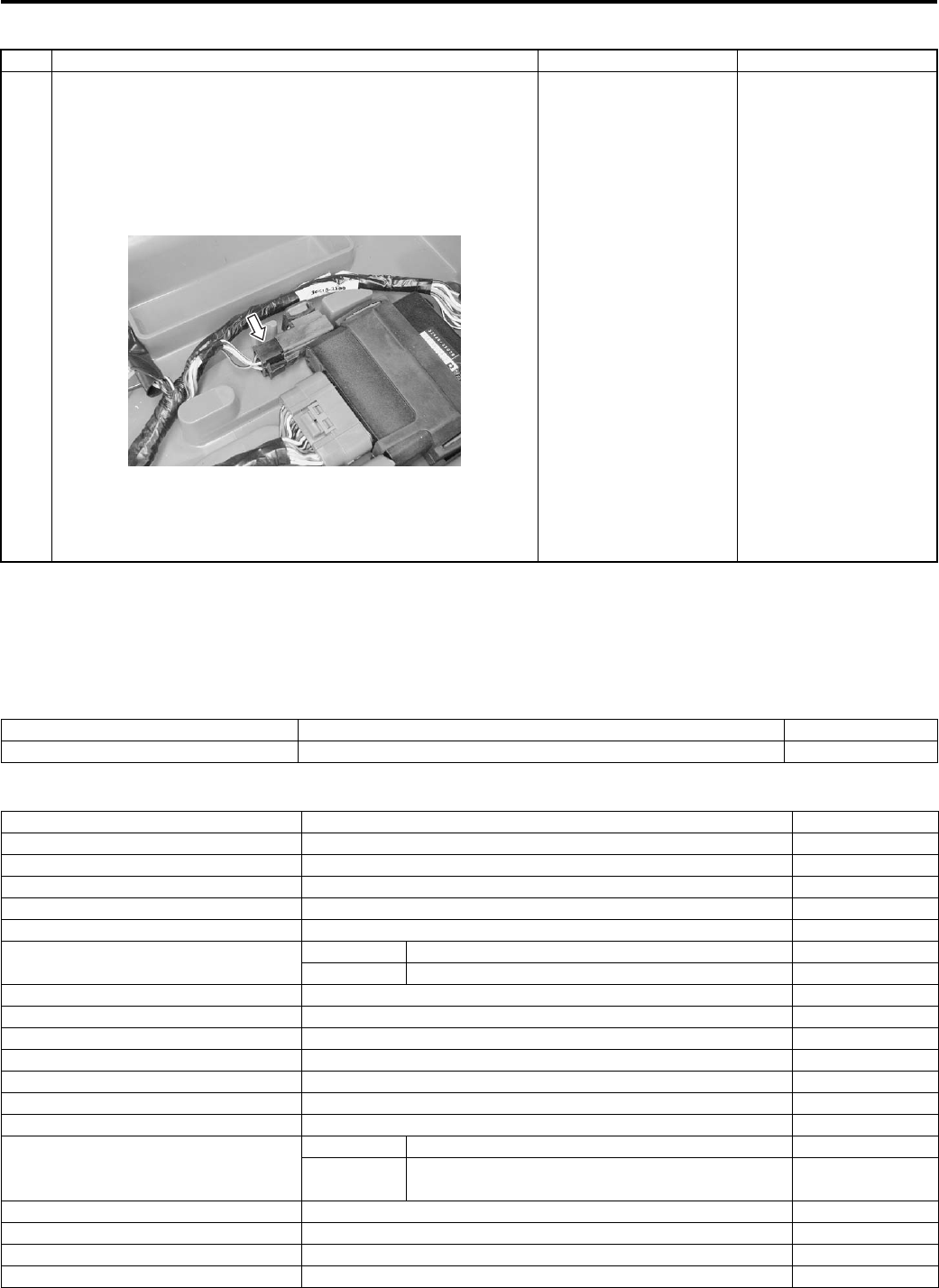
1A-69 Engine General Information and Diagnosis:
P0230-L (Use of SDS)
Specifications
Service Data
B831G21107001
Injector
FI Sensors + Secondary Throttle Valve Actuator
Step Action Yes No
1 1) Turn the ignition switch to OFF.
2) Remove the seat. Refer to “Front Side Exterior Parts
Removal and Installation in Section 9D (Page 9D-6)”.
3) Check the FP relay coupler for loose or poor contacts.
If OK, then check the FP relay. Refer to “Fuel Pump
Relay Inspection in Section 1G (Page 1G-7)”.
Is the FP relay OK?
• Y/Bl wire open or
poor “19” connection.
• O/W wire open or
shorted to ground.
• R/B or Y/R wire open
or shorted to ground
or poor “16”
connection.
• If wire and
connection are OK,
intermittent trouble or
faulty ECM.
• Recheck each
terminal and wire
harness for open
circuit and poor
connection.
• Replace the ECM
with a known good
one, and inspect it
again.
Replace the FP relay
with a new one.
I831G1110078-01
Item Specification Note
Injector resistance 11 – 13 Ω at 20 °C (68 °F) —
Item Specification Note
CKP sensor resistance 150 – 250 Ω
CKP sensor peak voltage 5.0 V and more When cranking
IAP sensor input voltage 4.5 – 5.5 V
IAP sensor output voltage Approx. 2.63 V at idle speed
TP sensor input voltage 4.5 – 5.5 V
TP sensor output voltage Closed Approx. 1.1 V
Opened Approx. 4.3 V
ECT sensor input voltage 4.5 – 5.5 V
ECT sensor output voltage 0.15 – 4.85 V
ECT sensor resistance Approx. 2.45 kΩ at 20 °C (68 °F)
IAT sensor input voltage 4.5 – 5.5 V
IAT sensor output voltage 0.15 – 4.85 V
IAT sensor resistance Approx. 1.60 kΩ at 20 °C (68 °F)
TO sensor resistance 19 – 20 kΩ
TO sensor voltage
Normal 0.4 – 1.4 V
Leaning 3.7 – 4.4 V When leaning
65°
GP switch voltage 0.6 V and more From 1st to Top
Injector voltage Battery voltage
Ignition coil primary peak voltage 80 V and more When cranking
ISC valve resistance Approx. 31 kΩ at 20 °C (68 °F)
PartShark.com
877-999-5686
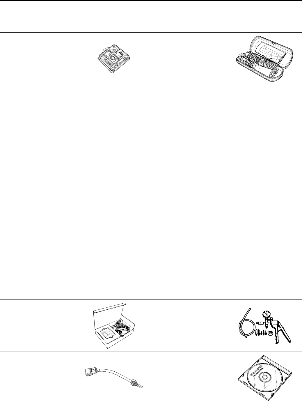
Engine General Information and Diagnosis: 1A-70
Special Tools and Equipment
Special Tool
B831G21108001
09900–25008 09900–25009
Multi-circuit tester set Needle pointed probe set
)(Page 1A-25) /
)(Page 1A-26) /
)(Page 1A-26) /
)(Page 1A-28) /
)(Page 1A-29) /
)(Page 1A-30) /
)(Page 1A-31) /
)(Page 1A-32) /
)(Page 1A-32) /
)(Page 1A-33) /
)(Page 1A-35) /
)(Page 1A-36) /
)(Page 1A-37) /
)(Page 1A-38) /
)(Page 1A-39) /
)(Page 1A-39) /
)(Page 1A-40) /
)(Page 1A-42) /
)(Page 1A-43) /
)(Page 1A-44) /
)(Page 1A-45) /
)(Page 1A-46) /
)(Page 1A-50) /
)(Page 1A-51) /
)(Page 1A-52) /
)(Page 1A-54) /
)(Page 1A-55) /
)(Page 1A-56) /
)(Page 1A-57) /
)(Page 1A-58) /
)(Page 1A-58) /
)(Page 1A-60) /
)(Page 1A-61) /
)(Page 1A-61) /
)(Page 1A-63) /
)(Page 1A-64)
)(Page 1A-30) /
)(Page 1A-32) /
)(Page 1A-32) /
)(Page 1A-35) /
)(Page 1A-36) /
)(Page 1A-37) /
)(Page 1A-38) /
)(Page 1A-39) /
)(Page 1A-40) /
)(Page 1A-43) /
)(Page 1A-45) /
)(Page 1A-51) /
)(Page 1A-56) /
)(Page 1A-57) /
)(Page 1A-58) /
)(Page 1A-58)
09904–41010 09917–47011
SDS set Vacuum pump gauge
)(Page 1A-12) /
)(Page 1A-15)
)(Page 1A-33)
09930–82720 99565–01010–013
Mode select switch CD-ROM Ver.13
)(Page 1A-3) / )(Page 1A-
11) / )(Page 1A-11)
)(Page 1A-12) /
)(Page 1A-15)
PartShark.com
877-999-5686
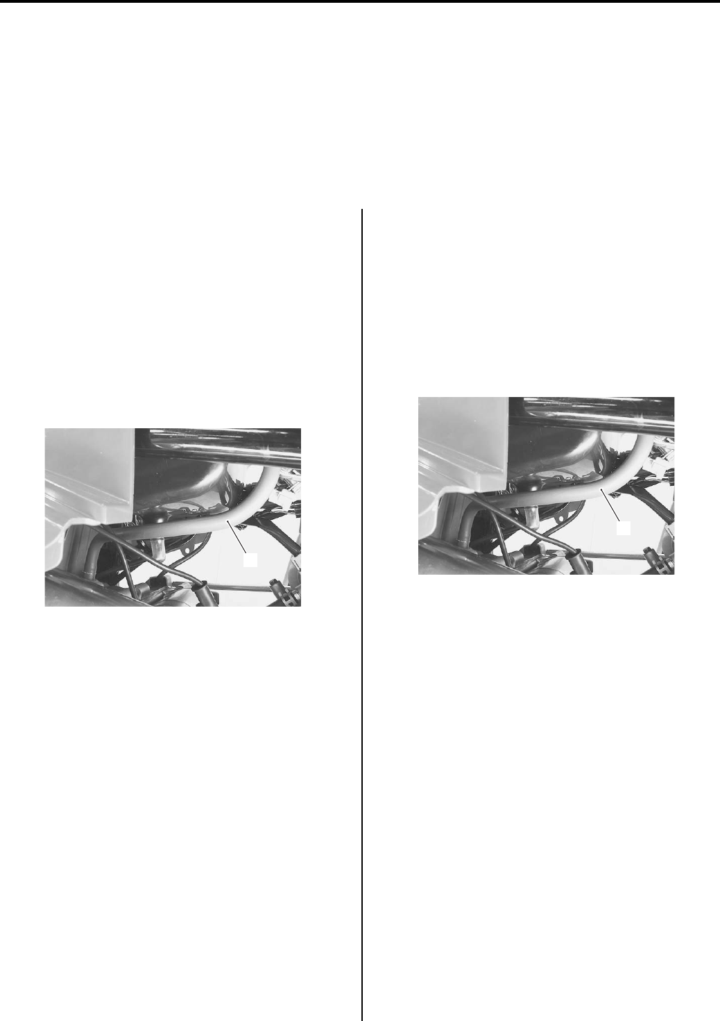
1B-1 Emission Control Devices:
Engine
Emission Control Devices
Precautions
Precautions for Emission Control Devices
B831G21200001
Refer to “General Precautions in Section 00 (Page 00-1)”.
Repair Instructions
Crankcase Breather (PCV) Hose Inspection
B831G21206001
Inspect the PCV hose in the following procedures:
1) Remove the seat. Refer to “Seat Removal and
Installation in Section 9D (Page 9D-11)”.
2) Remove the left side cover. Refer to “Front Side
Exterior Parts Removal and Installation in Section
9D (Page 9D-6)”.
3) Inspect the PCV hose (1) for wear or damage. If it is
worn or damaged, replace the PCV hose with a new
one.
Check that the PCV hose (1) is securely connected.
Crankcase Breather (PCV) Hose Removal and
Installation
B831G21206002
Removal
1) Remove the seat. Refer to “Seat Removal and
Installation in Section 9D (Page 9D-11)”.
2) Remove the left side cover. Refer to “Front Side
Exterior Parts Removal and Installation in Section
9D (Page 9D-6)”.
3) Disconnect the PCV hose (1).
Installation
1) Install the PCV hose as shown in the fuel hose
routing diagram. Refer to “Fuel Hose Routing
Diagram in Section 1G (Page 1G-3)”.
2) Reinstall the removed parts.
1
I831G1120001-01
1
I831G1120001-01
PartShark.com
877-999-5686
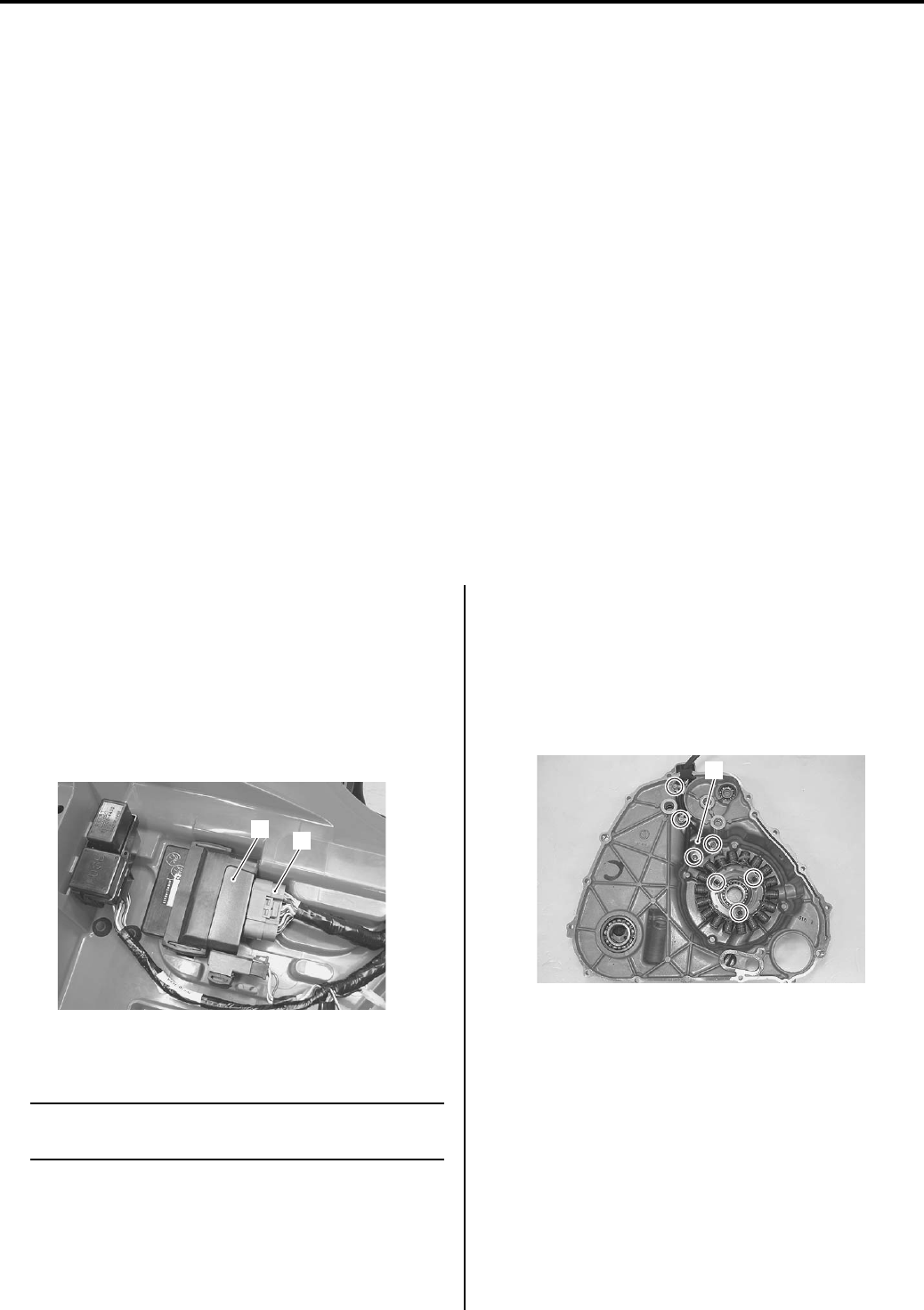
Engine Electrical Devices: 1C-1
Engine
Engine Electrical Devices
Precautions
Precautions for Engine Electrical Device
B831G21300001
Refer to “General Precautions in Section 00 (Page 00-1)” and “Precautions for Electrical Circuit Service in Section 00
(Page 00-2)”.
Component Location
Engine Electrical Components Location
B831G21303001
Refer to “Electrical Components Location in Section 0A (Page 0A-7)”.
Diagnostic Information and Procedures
Engine Symptom Diagnosis
B831G21304001
Refer to “Engine Symptom Diagnosis in Section 1A (Page 1A-8)”.
Repair Instructions
ECM Removal and Installation
B831G21306001
Removal
1) Remove the seat. Refer to “Seat Removal and
Installation in Section 9D (Page 9D-11)”.
2) Remove the battery (–) lead wire.
3) Disconnect the ECM coupler (1) and remove the
ECM (2).
Installation
NOTE
When replacing the ECM, turn the ignition
switch ON and OFF.
Install the ECM in the reverse order of removal.
CKP Sensor Inspection
B831G21306002
Refer to “CKP Sensor Inspection in Section 1H
(Page 1H-5)”.
CKP Sensor Removal and Installation
B831G21306003
Removal
1) Remove the generator cover. Refer to “Generator
Removal and Installation in Section 1J (Page 1J-4)”.
2) Remove the CKP sensor (1) along with generator
starter.
Installation
Install the CKP sensor in the reverse order of removal.
Refer to “Generator Removal and Installation in Section
1J (Page 1J-4)”.
IAP Sensor Inspection
B831G21306004
Refer to “DTC “C13” (P0105-H/L): IAP Sensor Circuit
Malfunction in Section 1A (Page 1A-27)”.
1
2
I831G1130001-02
1
I831G1130002-01
PartShark.com
877-999-5686
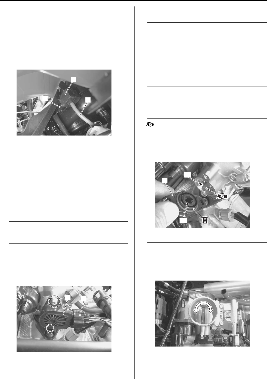
1C-2 Engine Electrical Devices:
IAP Sensor Removal and Installation
B831G21306005
Removal
1) Remove the left inner fender. Refer to “Front Side
Exterior Parts Removal and Installation in Section
9D (Page 9D-6)”.
2) Disconnect the IAP sensor coupler (1) and vacuum
hose (2).
3) Remove the IAP sensor (3).
Installation
Install the IAP sensor in the reverse order of removal.
TP Sensor Inspection
B831G21306006
Refer to “DTC “C14” (P0120-H/L): TP Sensor Circuit
Malfunction in Section 1A (Page 1A-34)”.
TP Sensor Removal and Installation
B831G21306007
Removal
NOTE
Prior to disassembly, mark sensor original
position with a paint or scribe for accurate
reinstallation.
1) Remove the air cleaner box. Refer to “Air Cleaner
Box Removal and Installation in Section 1D
(Page 1D-5)”.
2) Disconnect the TP sensor coupler (1) and remove
the TP sensor (2).
Installation
NOTE
When replacing the TP sensor, turn the
ignition switch ON and OFF.
Install the TP sensor in the reverse order of removal.
Pay attention to the following points:
• Apply a thin coat of engine oil to the O-ring.
• Install the TP sensor (1) and tighten the TP sensor
mounting screw to the specified torque.
NOTE
• Align the throttle shaft end “A” with the
groove “B” of TP sensor.
• Apply grease to the throttle shaft end “A” if
necessary.
: Grease 99000–25010 (SUZUKI SUPER
GREASE A or equivalent)
Tightening torque
TP sensor mounting screw: 2 N·m (0.2 kgf-m, 1.5
lb-ft)
NOTE
Make sure the TP valve open or close
smoothly. If the TP sensor adjustment is
necessary, refer to “TP Sensor Adjustment
(Page 1C-3)”.
12
3
I831G1130003-01
1
2
I831G1130004-01
1
“B”
“A”
I831G1130005-01
I831G1130006-01
PartShark.com
877-999-5686
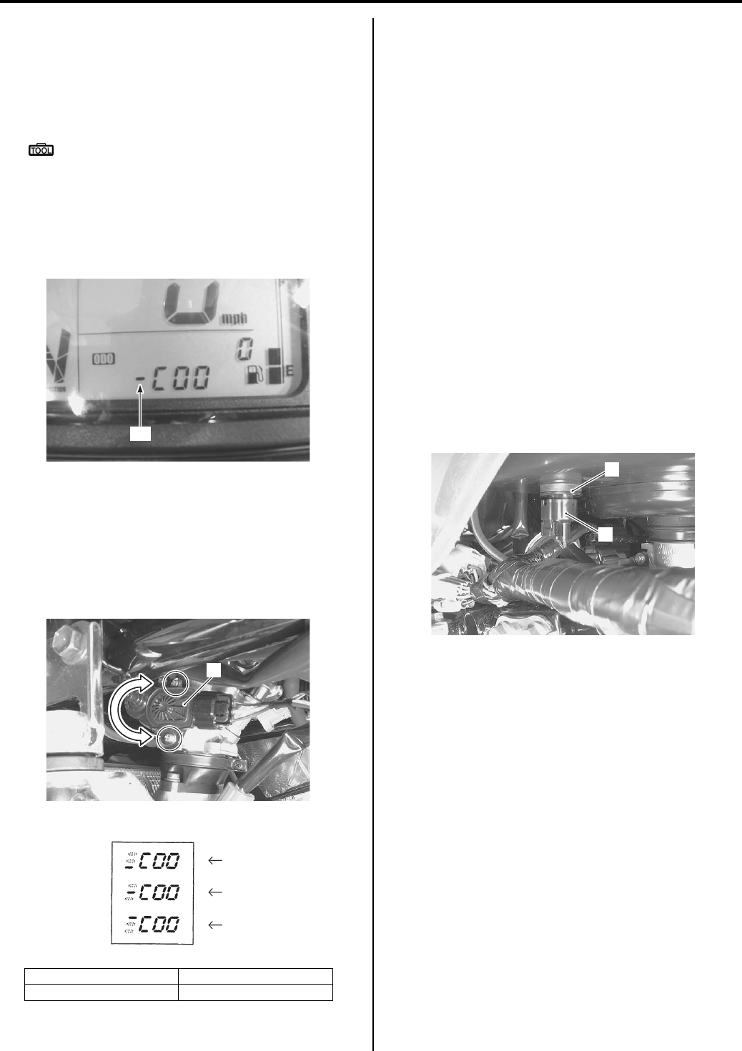
Engine Electrical Devices: 1C-3
TP Sensor Adjustment
B831G21306008
Adjust the TP sensor in the following procedures:
1) Connect the special tool to the mode select switch.
Refer to “Self-Diagnostic Procedures in Section 1A
(Page 1A-11)”.
Special tool
: 09930–82720 (Mode select switch)
2) Warm up the engine and keep it running in idling
speed.
3) Turn the mode select switch ON.
4) Check the position of the bar “A” in the left of C code
displayed on the LCD panel.
5) If the TP sensor adjustment is necessary, remove
the left side cover and loosen the TP sensor
mounting screw. Refer to “Front Side Exterior Parts
Removal and Installation in Section 9D (Page 9D-
6)”.
6) Slide the TP sensor (1) and bring the line to the
middle.
7) Tighten the TP sensor mounting screw.
Tightening torque
TP sensor mounting screw: 2 N·m (0.2 kgf-m,
1.5 lb-ft)
Turn the ignition switch OFF and disconnect the
mode select switch.
9) Reinstall the removed parts.
IAT Sensor Inspection
B831G21306009
Refer to “DTC “C21” (P0110-H/L): IAT Sensor Circuit
Malfunction in Section 1A (Page 1A-49)”.
IAT Sensor Removal and Installation
B831G21306010
Removal
1) Remove the seat. Refer to “Seat Removal and
Installation in Section 9D (Page 9D-11)”.
2) Remove the left side cover. Refer to “Front Side
Exterior Parts Removal and Installation in Section
9D (Page 9D-6)”.
3) Disconnect the coupler (1) and remove the IAT
sensor (2).
Installation
Install the IAT sensor in the reverse order of removal.
“B”: Incorrect position “D”: Incorrect position
“C”: Correct position
“A”
I831G1130007-01
1
I831G1130008-01
“C”
“B”
“D”
I831G1130016-01
1
2
I831G1130009-01
PartShark.com
877-999-5686
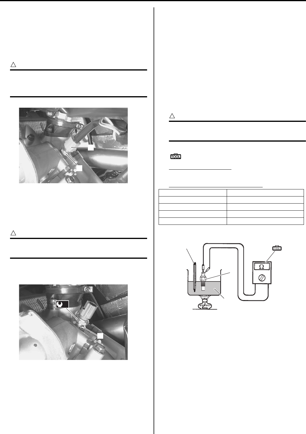
1C-4 Engine Electrical Devices:
ECT Sensor Removal and Installation
B831G21306011
Removal
1) Drain engine coolant. Refer to “Cooling System
Inspection in Section 0B (Page 0B-15)”.
2) Disconnect the coupler (1) and remove the ECT
sensor (2).
CAUTION
!
Take special care when handling the ECT
sensor. It may cause damage if it gets an
excessive impact.
Installation
Install the ECT sensor in the reverse order of removal.
Pay attention to the following points:
• Tighten the ECT sensor to the specified torque.
CAUTION
!
Use the new gasket washer (1) to prevent
engine coolant leakage.
Tightening torque
ECT sensor (a): 18 N·m (1.8 kgf-m, 13.0 lb-ft)
• Pour engine coolant. Refer to “Cooling System
Inspection in Section 0B (Page 0B-15)”.
ECT Sensor Inspection
B831G21306012
Refer to “DTC “C15” (P0115-H/L): ECT Sensor Circuit
Malfunction in Section 1A (Page 1A-41)”.
Inspect the ECT sensor in the following procedures:
1) Remove the ECT sensor. Refer to “ECT Sensor
Removal and Installation (Page 1C-4)”.
2) Connect the ECT sensor (1) to a circuit tester and
place it in the oil (2) contained in a pan, which is
placed on a stove.
3) Heat the oil to raise its temperature slowly and read
the column thermometer (3) and the ohmmeter.
If the ECT sensor ohmic valve does not change in
the proportion indicated, replace it with a new one.
CAUTION
!
Do not contact the ECT sensor and the
column thermometer with a pan.
Special tool
(A): 09900–25008 (Multi-circuit tester set)
Tester knob indication
Resistance (Ω)
Temperature sensor specification
4) Install the ECT sensor. Refer to “ECT Sensor
Removal and Installation (Page 1C-4)”.
1
2
I831G1130010-01
1
(a)
I831G1130011-01
Temperature Standard resistance
20 °C (68 °F) Approx. 2.45 kΩ
50 °C (122 °F) Approx. 0.811 kΩ
80 °C (176 °F) Approx. 0.318 kΩ
110 °C (230 °F) Approx. 0.142 kΩ
(A)
2
1
3
I718H1130014-01
PartShark.com
877-999-5686
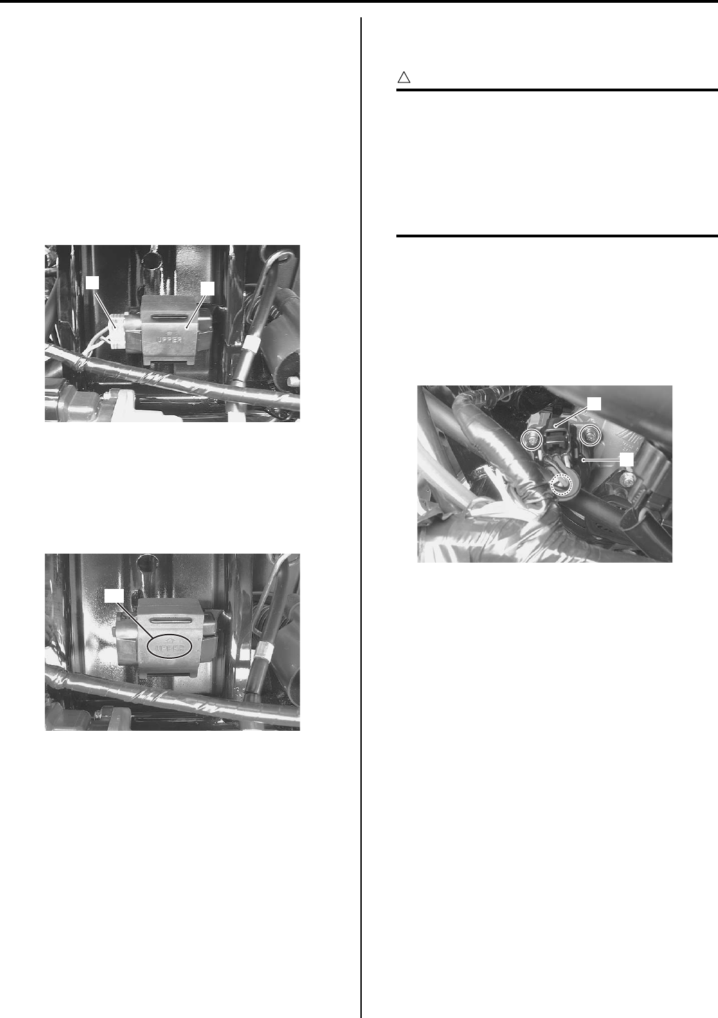
Engine Electrical Devices: 1C-5
TO Sensor Inspection
B831G21306013
Refer to “DTC “C23” (P1651-H/L): TO Sensor Circuit
Malfunction in Section 1A (Page 1A-53)”.
TO Sensor Removal and Installation
B831G21306014
Removal
1) Remove the air cleaner box. Refer to “Air Cleaner
Box Removal and Installation in Section 1D
(Page 1D-5)”.
2) Disconnect the coupler (1) and remove the TO
sensor (2).
Installation
Install the TO sensor in the reverse order of removal.
Pay attention to the following point:
• When installing the TO sensor, bring the “UPPER”
letters and arrow mark “A” upward.
ISC Valve Inspection
B831G21306015
Refer to “DTC “C40” (P05057): ISC Valve Circuit
Malfunction in Section 1A (Page 1A-62)”.
ISC Valve Removal and Installation
B831G21306016
Removal
CAUTION
!
Be careful not to disconnect the ISC valve
coupler at least 3 seconds after ignition
switch is turned to OFF. If the ECM coupler or
ISC valve coupler is disconnected within 3
seconds after ignition switch is turned to
OFF, there is a possibility of an unusual valve
position being written in ECM and causing an
error of ISC valve operation.
1) Remove the seat. Refer to “Seat Removal and
Installation in Section 9D (Page 9D-11)”.
2) Remove the front fender. Refer to “Front Side
Exterior Parts Removal and Installation in Section
9D (Page 9D-6)”.
3) Disconnect the ISC valve coupler (1) and remove the
ISC valve (2).
12
I831G1130012-02
“A”
I831G1130013-01
1
2
I831G1130014-01
PartShark.com
877-999-5686
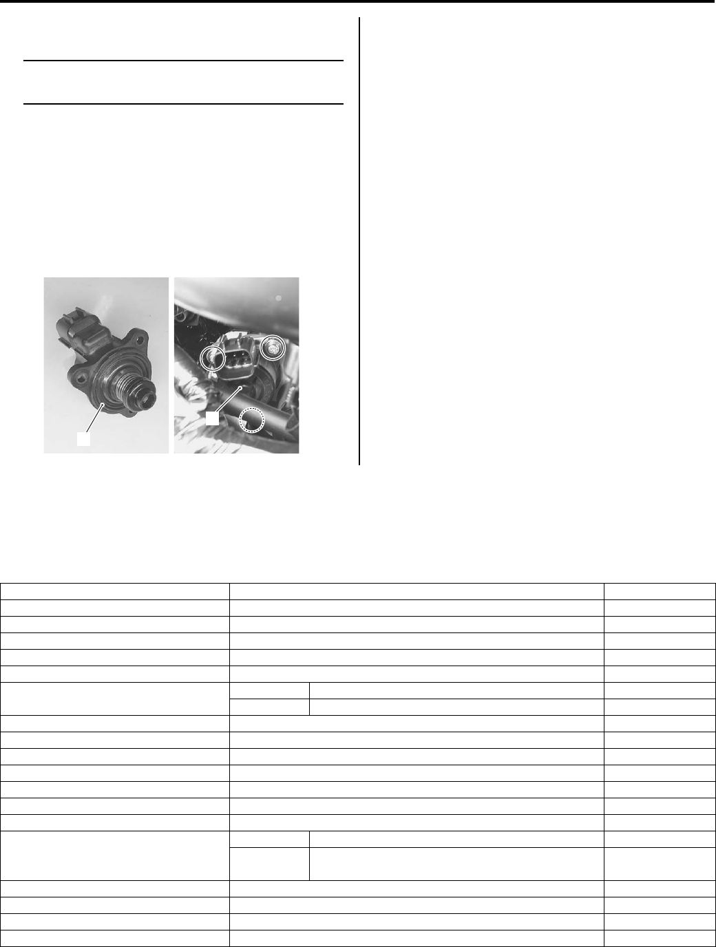
1C-6 Engine Electrical Devices:
Installation
NOTE
When replacing the ISC valve, turn the
ignition switch ON and OFF.
Install the ISC valve in the reverse order of removal.
Pay attention to the following points:
• Install the new O-ring (1).
• Install the ISC valve (2) and tighten the ISC valve
mounting screws to the specified torque.
Tightening torque
ISC valve mounting screw: 2 N·m (0.2 kgf-m, 1.5
lb-ft)
GP Switch Inspection
B831G21306017
Refer to “Gear Position Switch Inspection in Section 1I
(Page 1I-9)”.
GP Switch Removal and Installation
B831G21306018
Refer to “Gear Position (GP) Switch Removal and
Installation in Section 3C (Page 3C-13)”.
Specifications
Service Data
B831G21307001
FI Sensors
2
1
I831G1130015-01
Item Specification Note
CKP sensor resistance 150 – 250 Ω
CKP sensor peak voltage 5.0 V and more When cranking
IAP sensor input voltage 4.5 – 5.5 V
IAP sensor output voltage Approx. 2.63 V at idle speed
TP sensor input voltage 4.5 – 5.5 V
TP sensor output voltage Closed Approx. 1.1 V
Opened Approx. 4.3 V
ECT sensor input voltage 4.5 – 5.5 V
ECT sensor output voltage 0.15 – 4.85 V
ECT sensor resistance Approx. 2.45 kΩ at 20 °C (68 °F)
IAT sensor input voltage 4.5 – 5.5 V
IAT sensor output voltage 0.15 – 4.85 V
IAT sensor resistance Approx. 1.60 kΩ at 20 °C (68 °F)
TO sensor resistance 19 – 20 kΩ
TO sensor voltage
Normal 0.4 – 1.4 V
Leaning 3.7 – 4.4 V When leaning
65°
GP switch voltage 0.6 V and more From 1st to Top
Injector voltage Battery voltage
Ignition coil primary peak voltage 80 V and more When cranking
ISC valve resistance Approx. 31 kΩ at 20 °C (68 °F)
PartShark.com
877-999-5686
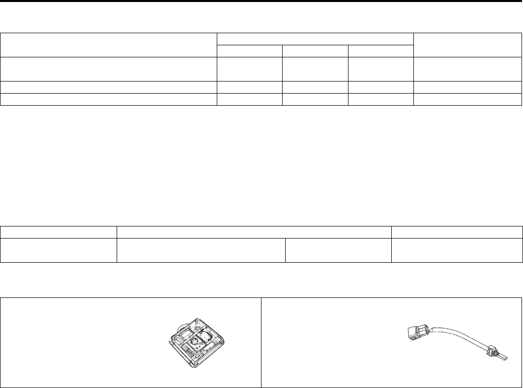
Engine Electrical Devices: 1C-7
Tightening Torque Specifications
B831G21307002
Reference:
For the tightening torque of fastener not specified in this section, refer to “Tightening Torque List in Section 0C
(Page 0C-7)”.
Special Tools and Equipment
Recommended Service Material
B831G21308001
Special Tool
B831G21308002
Fastening part Tightening torque Note
N⋅mkgf—mlb—ft
TP sensor mounting screw 20.2 1.5
)(Page 1C-2) /
)(Page 1C-3)
ECT sensor 18 1.8 13.0 )(Page 1C-4)
ISC valve mounting screw 2 0.2 1.5 )(Page 1C-6)
Material SUZUKI recommended product or Specification Note
Grease SUZUKI SUPER GREASE A or
equivalent
P/No.: 99000–25010 )(Page 1C-2)
09900–25008 09930–82720
Multi-circuit tester set Mode select switch
)(Page 1C-4) )(Page 1C-3)
PartShark.com
877-999-5686
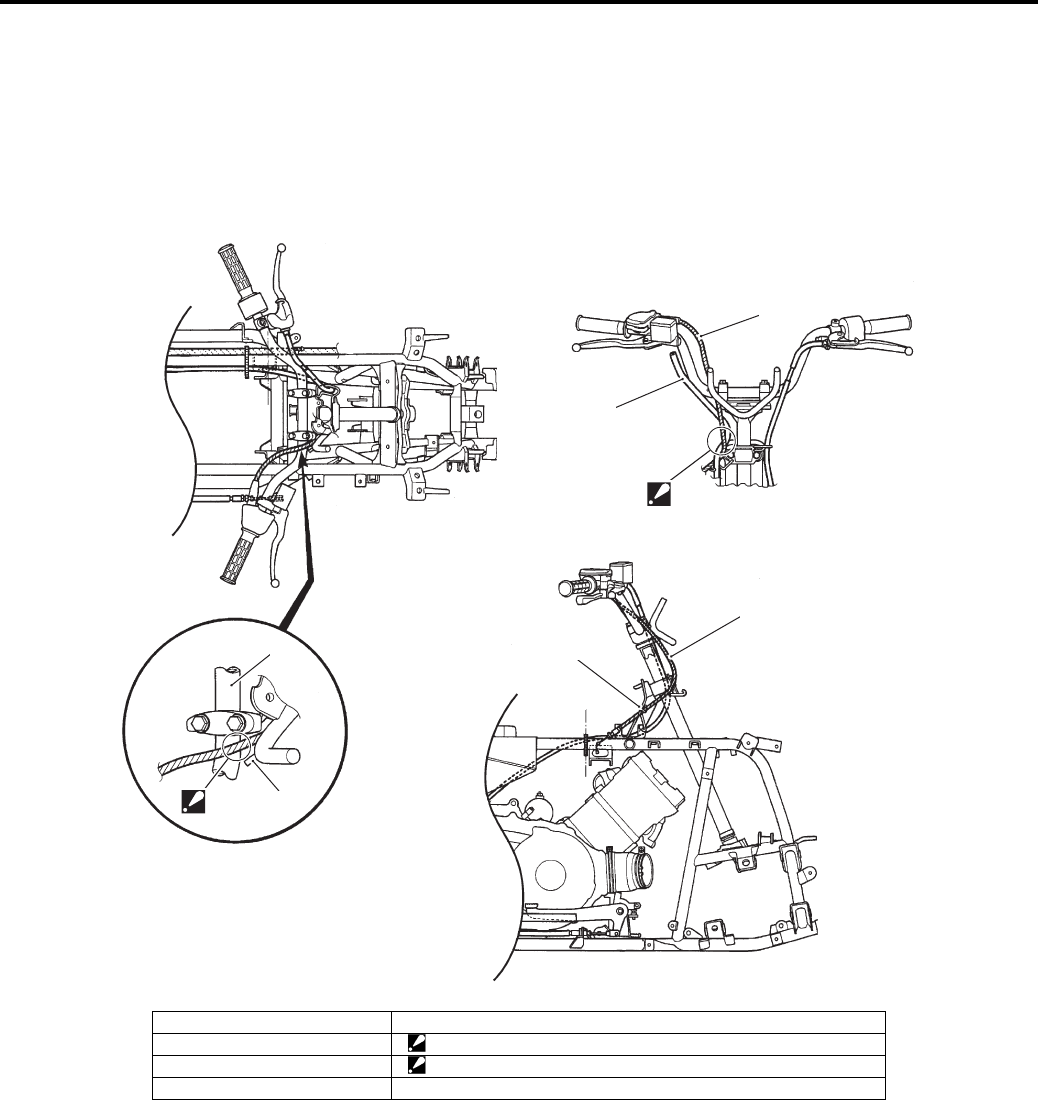
1D-1 Engine Mechanical:
Engine
Engine Mechanical
Schematic and Routing Diagram
Throttle Cable Routing Diagram
B831G21402001
1
1
2
35
4
“A”
“B”
I831G1140002-02
1. Throttle cable 5. Throttle cable guide
2. Brake hose “A”: Pass through the throttle cable inside of pin.
3. Handlebar “B”: Pass through the throttle cable inside of brake hose.
4. Pin
PartShark.com
877-999-5686
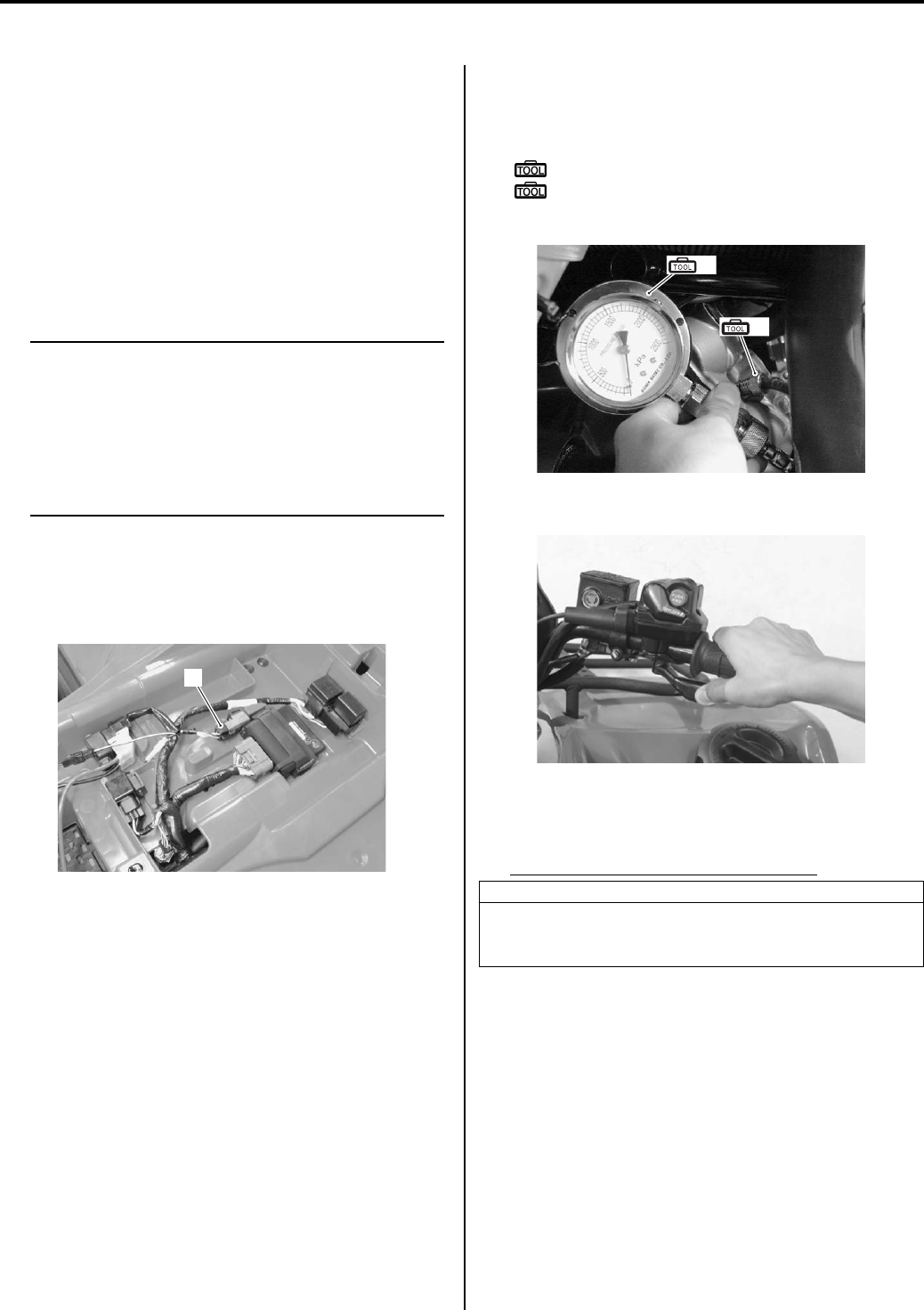
Engine Mechanical: 1D-2
Diagnostic Information and Procedures
Engine Mechanical Symptom Diagnosis
B831G21404001
Refer to “Engine Symptom Diagnosis in Section 1A
(Page 1A-8)”.
Compression Pressure Check
B831G21404002
The compression pressure reading of a cylinder is a
good indicator of its internal condition.
Periodic maintenance records kept at your dealership
should include compression readings for each
maintenance service.
NOTE
• Before checking the engine for
compression pressure, make sure that the
cylinder head nuts are tightened to the
specified torque values and the valves are
properly adjusted.
• Make sure that the battery is in fully—
charged condition.
1) Warm up the engine.
2) Remove the seat. Refer to “Seat Removal and
Installation in Section 9D (Page 9D-11)”.
3) Disconnect the fuel pump relay coupler (1).
4) Remove the spark plug. Refer to “Spark Plug Cap
and Spark Plug Removal and Installation in Section
1H (Page 1H-3)”.
5) Install the compression gauge and adaptor in the
spark plug hole. Make sure that the connection is
tight.
Special tool
(A): 09915–64512 (Compression gauge)
(B): 09915–63311 (Compression gauge
attachment)
6) Keep the throttle grip in the fully-opened position.
7) Press the starter button and crank the engine for a
few seconds. Record the maximum gauge reading
as the cylinder compression.
Compression pressure specification
Low compression pressure can indicate any of
the following conditions:
• Excessively worn cylinder wall
• Worn piston or piston rings
• Piston rings stuck in grooves
• Poor valve seating
• Ruptured or otherwise defective cylinder head
gasket
After checking the compression pressure, reinstall
the removed parts.
1
I831G1140003-01
Standard
Approx. 1 000 kPa
(10.0 kgf/cm2, 142 psi)
(Automatic decompression actuated)
(A)
(B)
I831G1140004-01
I831G1140005-01
PartShark.com
877-999-5686

1D-3 Engine Mechanical:
Repair Instructions
Engine Components Removable with the Engine in Place
B831G21406001
Engine components which can be removed while the engine is installed on the frame are as follows. For the installing
and removing procedures, refer to respective paragraphs describing each component.
Center of Engine
Item Removal Inspection Installation
Starter motor
Refer to “Starter Motor
Removal and Installation in
Section 1I (Page 1I-4)”.
Refer to “Starter Motor
Inspection in Section 1I
(Page 1I-5)”.
Refer to “Starter Motor
Removal and Installation in
Section 1I (Page 1I-4)”.
Air cleaner
Refer to “Air Cleaner
Element Removal and
Installation (Page 1D-5)”.
Refer to “Air Cleaner
Element Inspection and
Cleaning (Page 1D-5)”.
Refer to “Air Cleaner
Element Removal and
Installation (Page 1D-5)”.
Oil filter
Refer to “Engine Oil and
Filter Replacement in
Section 0B (Page 0B-10)”.
—
Refer to “Engine Oil and
Filter Replacement in
Section 0B (Page 0B-10)”.
Exhaust pipe/Muffler
Refer to “Exhaust Pipe /
Muffler Removal and
Installation in Section 1K
(Page 1K-2)”.
Refer to “Exhaust System
Inspection in Section 1K
(Page 1K-3)”.
Refer to “Exhaust Pipe /
Muffler Removal and
Installation in Section 1K
(Page 1K-2)”.
Throttle body
Refer to “Throttle Body
Removal and Installation
(Page 1D-9)”.
Refer to “Throttle Body
Inspection and Cleaning
(Page 1D-13)”.
Refer to “Throttle Body
Removal and Installation
(Page 1D-9)”.
Cylinder head Refer to “Engine Top Side
Disassembly (Page 1D-17)”.
Refer to “Cylinder Head
Related Parts Inspection
(Page 1D-35)”.
Refer to “Engine Top Side
Assembly (Page 1D-21)”.
Cam chain tension
adjuster
Refer to “Engine Top Side
Disassembly (Page 1D-17)”.
Refer to “Cam Chain Tension
Adjuster Inspection
(Page 1D-30)”.
Refer to “Engine Top Side
Assembly (Page 1D-21)”.
Spark plug
Refer to “Spark Plug Cap and
Spark Plug Removal and
Installation in Section 1H
(Page 1H-3)”.
Refer to “Spark Plug
Inspection and Cleaning in
Section 1H (Page 1H-3)”.
Refer to “Spark Plug Cap and
Spark Plug Removal and
Installation in Section 1H
(Page 1H-3)”.
Cylinder head cover
Refer to “Valve Clearance
Inspection and Adjustment in
Section 0B (Page 0B-4)”.
—Refer to “Engine Top Side
Assembly (Page 1D-21)”.
Camshaft Refer to “Engine Top Side
Disassembly (Page 1D-17)”.
Refer to “Camshaft
Inspection (Page 1D-28)”.
Refer to “Engine Top Side
Assembly (Page 1D-21)”.
Valve
Refer to “Cylinder Head
Disassembly and Assembly
(Page 1D-31)”.
Refer to “Cylinder Head
Related Parts Inspection
(Page 1D-35)”.
Refer to “Cylinder Head
Disassembly and Assembly
(Page 1D-31)”.
Cylinder Refer to “Engine Top Side
Disassembly (Page 1D-17)”.
Refer to “Cylinder Inspection
(Page 1D-41)”.
Refer to “Engine Top Side
Assembly (Page 1D-21)”.
Piston Refer to “Engine Top Side
Disassembly (Page 1D-17)”.
Refer to “Piston and Piston
Ring Inspection (Page 1D-
43)”.
Refer to “Engine Top Side
Assembly (Page 1D-21)”.
PartShark.com
877-999-5686

Engine Mechanical: 1D-4
Engine Right Side
Engine Left Side
Item Removal Inspection Installation
Fixed drive face
Refer to “V-belt Type
Continuously Variable
Automatic Transmission
Removal and Installation in
Section 5A (Page 5A-5)”.
Refer to “Movable / Fixed
Drive Face Parts Inspection
in Section 5A (Page 5A-15)”.
Refer to “V-belt Type
Continuously Variable
Automatic Transmission
Removal and Installation in
Section 5A (Page 5A-5)”.
Movable drive face
Refer to “V-belt Type
Continuously Variable
Automatic Transmission
Removal and Installation in
Section 5A (Page 5A-5)”.
Refer to “Movable / Fixed
Drive Face Parts Inspection
in Section 5A (Page 5A-15)”.
Refer to “V-belt Type
Continuously Variable
Automatic Transmission
Removal and Installation in
Section 5A (Page 5A-5)”.
Clutch housing/Clutch shoe
Refer to “Clutch Shoe
Removal and Installation in
Section 5A (Page 5A-16)”.
Refer to “Clutch Parts
Inspection in Section 5A
(Page 5A-20)”.
Refer to “Clutch Shoe
Removal and Installation in
Section 5A (Page 5A-16)”.
Movable driven face
assembly
Refer to “V-belt Type
Continuously Variable
Automatic Transmission
Removal and Installation in
Section 5A (Page 5A-5)”.
Refer to “Movable / Fixed
Driven Face Parts Inspection
in Section 5A (Page 5A-15)”.
Refer to “V-belt Type
Continuously Variable
Automatic Transmission
Removal and Installation in
Section 5A (Page 5A-5)”.
Drive V-belt
Refer to “V-belt Type
Continuously Variable
Automatic Transmission
Removal and Installation in
Section 5A (Page 5A-5)”.
Refer to “Drive V-belt
Inspection in Section 5A
(Page 5A-14)”.
Refer to “V-belt Type
Continuously Variable
Automatic Transmission
Removal and Installation in
Section 5A (Page 5A-5)”.
Gear position switch
Refer to “Gear Position (GP)
Switch Removal and
Installation in Section 3C
(Page 3C-13)”.
Refer to “Gear Position
Switch Inspection in Section
1I (Page 1I-9)”.
Refer to “Gear Position (GP)
Switch Removal and
Installation in Section 3C
(Page 3C-13)”.
Item Removal Inspection Installation
Generator
Refer to “Generator Removal
and Installation in Section 1J
(Page 1J-4)”.
Refer to “Generator
Inspection in Section 1J
(Page 1J-3)”.
Refer to “Generator Removal
and Installation in Section 1J
(Page 1J-4)”.
Starter clutch
Refer to “Starter Torque
Limiter / Starter Clutch
Removal and Installation in
Section 1I (Page 1I-10)”.
Refer to “Starter Related
Parts Inspection in Section 1I
(Page 1I-12)”.
Refer to “Starter Torque
Limiter / Starter Clutch
Removal and Installation in
Section 1I (Page 1I-10)”.
Starter idle gear Refer to “Engine Bottom Side
Disassembly (Page 1D-45)”. —Refer to “Engine Bottom Side
Assembly (Page 1D-51)”.
Starter torque limiter
Refer to “Starter Torque
Limiter / Starter Clutch
Removal and Installation in
Section 1I (Page 1I-10)”.
Refer to “Starter Related
Parts Inspection in Section 1I
(Page 1I-12)”.
Refer to “Starter Torque
Limiter / Starter Clutch
Removal and Installation in
Section 1I (Page 1I-10)”.
Balancer driven gear Refer to “Engine Bottom Side
Disassembly (Page 1D-45)”. —Refer to “Engine Bottom Side
Assembly (Page 1D-51)”.
Oil pump driven gear
Refer to “Oil Pump Removal
and Installation in Section 1E
(Page 1E-5)”.
—
Refer to “Oil Pump Removal
and Installation in Section 1E
(Page 1E-5)”.
Oil pump
Refer to “Oil Pump Removal
and Installation in Section 1E
(Page 1E-5)”.
Refer to “Oil Pump
Inspection in Section 1E
(Page 1E-7)”.
Refer to “Oil Pump Removal
and Installation in Section 1E
(Page 1E-5)”.
CKP sensor
Refer to “Generator Removal
and Installation in Section 1J
(Page 1J-4)”.
Refer to “CKP Sensor
Inspection in Section 1H
(Page 1H-5)”.
Refer to “Generator Removal
and Installation in Section 1J
(Page 1J-4)”.
Water pump
Refer to “Water Pump
Removal and Installation in
Section 1F (Page 1F-13)”.
Refer to “Water Pump
Related Parts Inspection in
Section 1F (Page 1F-18)”.
Refer to “Water Pump
Removal and Installation in
Section 1F (Page 1F-13)”.
PartShark.com
877-999-5686
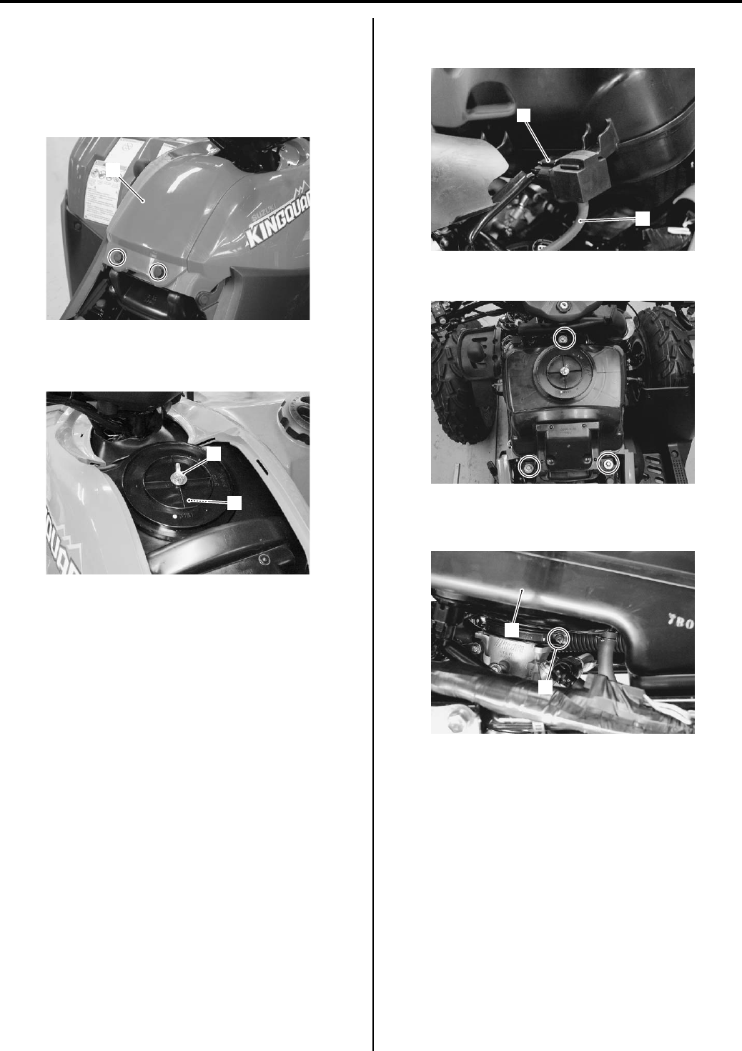
1D-5 Engine Mechanical:
Air Cleaner Element Removal and Installation
B831G21406002
Removal
1) Remove the seat. Refer to “Seat Removal and
Installation in Section 9D (Page 9D-11)”.
2) Remove the air cleaner box cover (1).
3) Remove the air cleaner element bolt (2).
4) Remove the air cleaner element (3).
Installation
Installation in the reverse order of removal.
Air Cleaner Element Inspection and Cleaning
B831G21406003
Refer to “Air Cleaner Element Inspection and Cleaning in
Section 0B (Page 0B-3)”.
Air Cleaner Box Removal and Installation
B831G21406004
Removal
1) Remove the front fender. Refer to “Front Side
Exterior Parts Removal and Installation in Section
9D (Page 9D-6)”.
2) Disconnect the IAP sensor lead wire coupler (1) and
vacuum hose (2).
3) Remove the air cleaner box mounting bolts.
4) Loosen the throttle body clamp screw (3) and
remove the air cleaner box (4).
1
I831G1140007-02
2
3
I831G1140008-01
1
2
I831G1140011-01
I831G1140012-01
3
4
I831G1140013-01
PartShark.com
877-999-5686
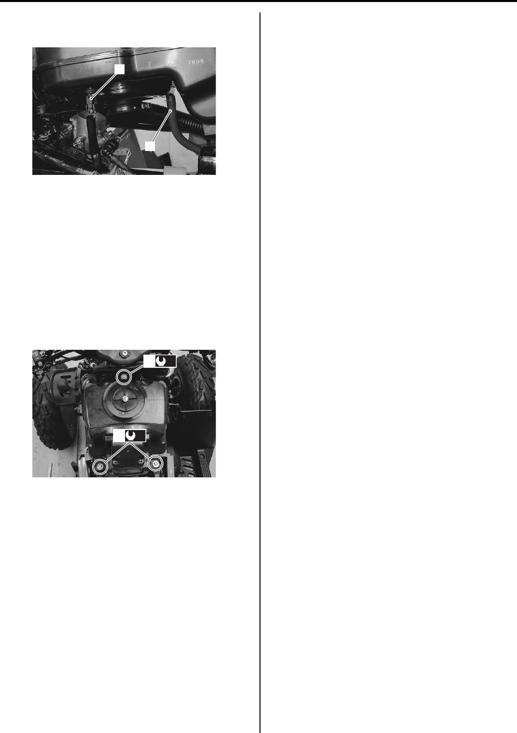
Engine Mechanical: 1D-6
5) Remove the IAT sensor coupler (5) and PCV hose
(6).
Installation
Install the air cleaner box in the reverse order of
removal. Pay attention to the following points:
• Install the air cleaner box (1) and tighten the throttle
body clamp screw. Refer to “Throttle Body
Construction (Page 1D-8)”.
• Tighten the air cleaner box mounting bolts to the
specified torque.
Tightening torque
Air cleaner box mounting bolt (a): 4.5 N·m (0.45
kgf-m, 3.0 lb-ft)
• Install the removed parts.
Throttle Cable Removal and Installation
B831G21406005
Removal
1) Remove the front fender. Refer to “Front Side
Exterior Parts Removal and Installation in Section
9D (Page 9D-6)”.
2) Remove the right handlebar switch box. Refer to
“Handlebars Removal and Installation in Section 6B
(Page 6B-3)”.
3) Remove the throttle cable as shown in the cable
routing diagram. Refer to “Throttle Cable Routing
Diagram (Page 1D-1)”.
Installation
Install the throttle cables in the reverse order of removal.
Pay attention to the following points:
• Install the throttle cable as shown in the cable routing
diagram. Refer to “Throttle Cable Routing Diagram
(Page 1D-1)”.
• Check the throttle cable play and proper operation.
Throttle Cable Inspection
B831G21406006
Check that the throttle lever moves smoothly from full
open to full close. If it does not move smoothly, lubricate
the throttle cable.
Throttle Cable Play Inspection and Adjustment
B831G21406007
Refer to “Throttle Cable Play Inspection and Adjustment
in Section 0B (Page 0B-15)”.
5
6
I831G1140014-01
(a)
1
(a)
1
I831G1140015-02
PartShark.com
877-999-5686
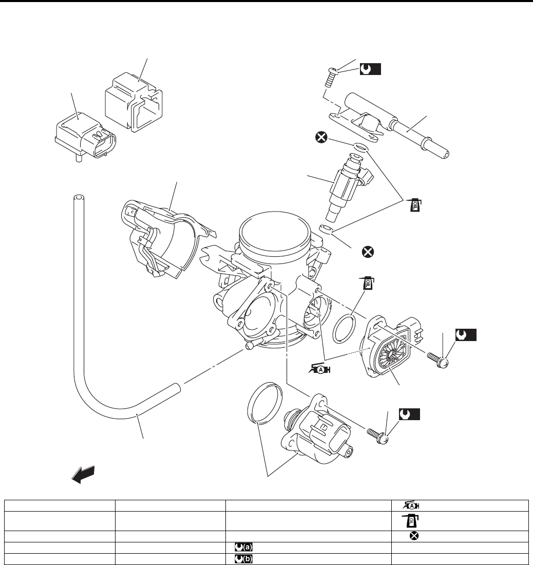
1D-7 Engine Mechanical:
Throttle Body Components
B831G21406008
FWD
1
2
3
6
7
4
(a)
(b)
8
9
13
11
12
10
(a)
5
I831G1140016-05
1. TP sensor 6. Fuel injector 11. TP sensor mounting screw : Apply grease.
2. ISC valve 7. Cushion seal 12. ISC valve mounting screw : Apply engine oil.
3. IAP sensor 8. Vacuum hose 13. Fuel delivery pipe mounting screw : Do not reuse.
4. Fuel delivery pipe 9. Throttle linkage cover : 2 N⋅m (0.2 kgf-m, 1.5 Ib-ft)
5. O-ring 10. IAP sensor cover : 5 N⋅m (0.5 kgf-m, 3.5 Ib-ft)
PartShark.com
877-999-5686
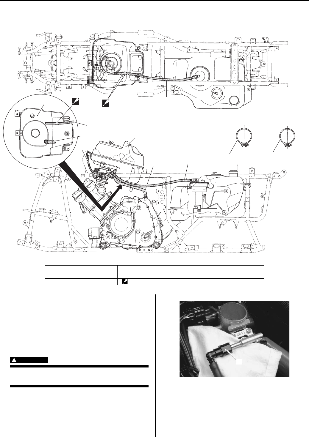
Engine Mechanical: 1D-8
Throttle Body Construction
B831G21406009
Throttle Body Removal and Installation
B831G21406010
Removal
1) Remove the air cleaner box. Refer to “Air Cleaner
Box Removal and Installation (Page 1D-5)”.
2) Place a rug under the fuel feed hose (1) and
disconnect the fuel feed hose (1) from the fuel
delivery pipe.
WARNING
!
Gasoline is highly flammable and explosive.
Keep heat, spark and flame away.
1
12
2
3
55
4
“A”
2
3
FR
LH RH
RR
FR
LH RH
RR
“A”
I831G1140018-01
1. Air cleaner box 4. IAP sensor hose
2. Fuel hose 5. Clamp
3. PCV hose “A”: Pass through the fuel hose between air cleaner guide ribs.
1
I831G1140019-01
PartShark.com
877-999-5686
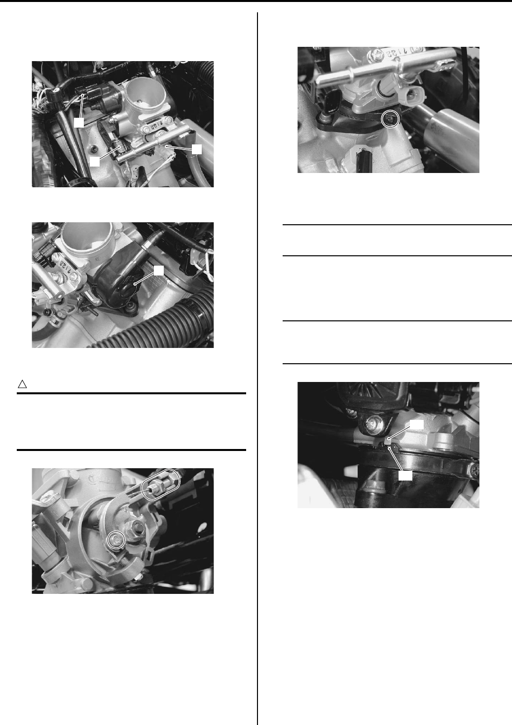
1D-9 Engine Mechanical:
3) Disconnect the fuel injector coupler (2) and TP/IAP/
IAT sensor coupler (3).
4) Disconnect the ISC valve coupler (4).
5) Remove the throttle cable cover (5).
6) Disconnect the throttle cable.
CAUTION
!
After disconnecting the throttle cables, do
not snap the throttle valve from full open to
full close. It may cause damage to the throttle
valve and throttle body.
7) Loosen the throttle body clamp screw and remove
the throttle body assembly.
Installation
NOTE
When replacing the throttle body, turn the
ignition switch ON and OFF.
Install the throttle body in the reverse order of removal.
Pay attention to the following points:
• Install the throttle body.
NOTE
When installing the throttle body, fit the
concave part “A” of the intake pipe onto the
convex part “B” of the throttle body.
2
3
4
I831G1140020-01
5
I831G1140021-01
I831G1140025-02
I831G1140022-01
“A”
“B”
I831G1140026-01
PartShark.com
877-999-5686
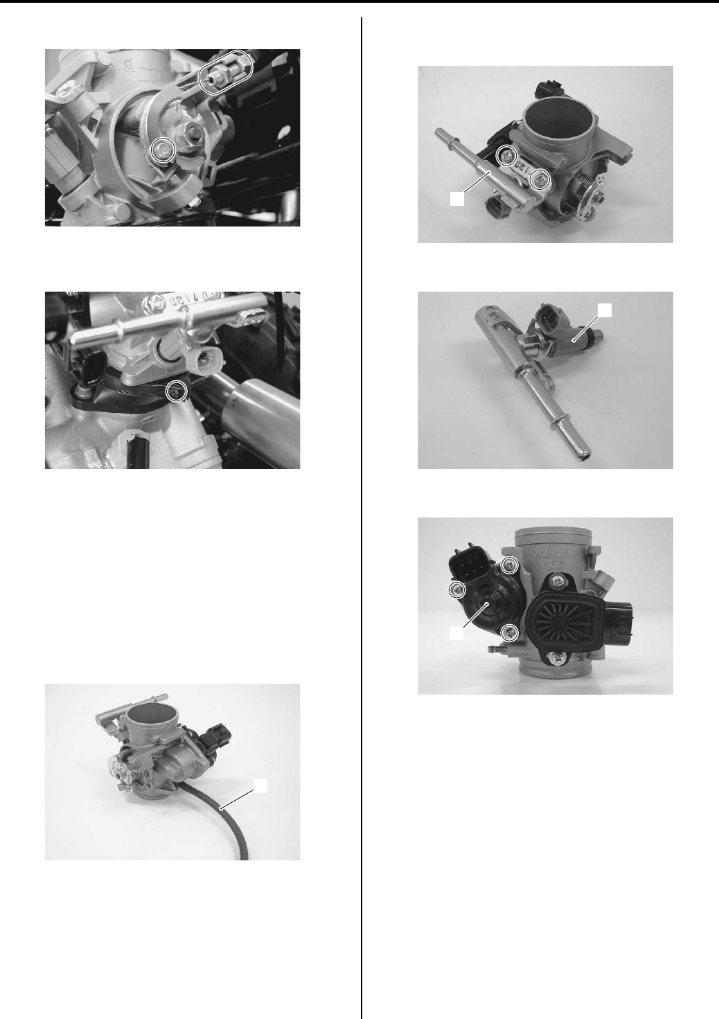
Engine Mechanical: 1D-10
• Connect the throttle cable.
• Tighten the throttle body clamp screws. Refer to
“Throttle Body Construction (Page 1D-8)”.
• After installed throttle cable, adjust the throttle cable
play. Refer to “Throttle Cable Play Inspection and
Adjustment in Section 0B (Page 0B-15)”.
Throttle Body Disassembly and Assembly
B831G21406011
Refer to “Throttle Body Removal and Installation
(Page 1D-9)”.
Disassembly
1) Disconnect the vacuum hose (1).
2) Remove the fuel delivery pipe assembly (2) by
removing its mounting screws.
3) Remove the fuel injector (3).
4) Remove the ISC valve (4).
I831G1140027-01
I831G1140028-01
1
I831G1140030-01
2
I831G1140031-01
3
I831G1140033-01
4
I831G1140034-01
PartShark.com
877-999-5686
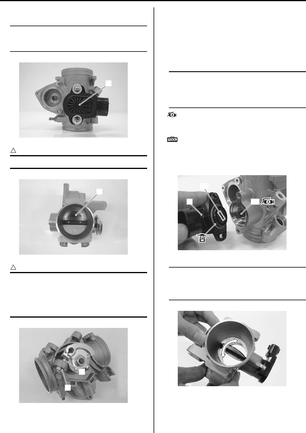
1D-11 Engine Mechanical:
5) Remove the TP sensor (5).
NOTE
Prior to disassembly, mark the TP sensors
original position with a paint or scribe for
accurate reinstallation.
CAUTION
!
Never remove the throttle valve (6).
CAUTION
!
• Do not loosen the lock-nut (7).
• The fast idle screw (8) is factory-adjusted
at the time of delivery and therefore avoid
removing or turning it unless otherwise
necessary.
Assembly
Assembly is the throttle body in the reverse order of
removal. Pay attention to the following points:
• Apply a thin coat of engine oil to the O-ring.
• With the throttle valve fully closed, install the TP
sensor (1) and tighten the TP sensor mounting screw
to the specified torque.
NOTE
• Align the secondary throttle shaft end “A”
with the groove “B” of TP sensor.
• Apply grease to the secondary throttle
shaft end “A” if necessary.
: Grease 99000–25010 (SUZUKI SUPER
GREASE A or equivalent)
Special tool
: 09930–11950 (Torx wrench)
Tightening torque
TP sensor mounting screw: 2 N·m (0.2 kgf-m, 1.5
lb-ft)
NOTE
Make sure the TP valve open or close
smoothly. If the TP sensor adjustment is
necessary, refer to “TP Sensor Adjustment in
Section 1C (Page 1C-3)”.
5
I831G1140035-01
6
I831G1140038-01
7
8
I831G1140039-01
1“A”
“B”
I831G1140040-01
I831G1140042-01
PartShark.com
877-999-5686
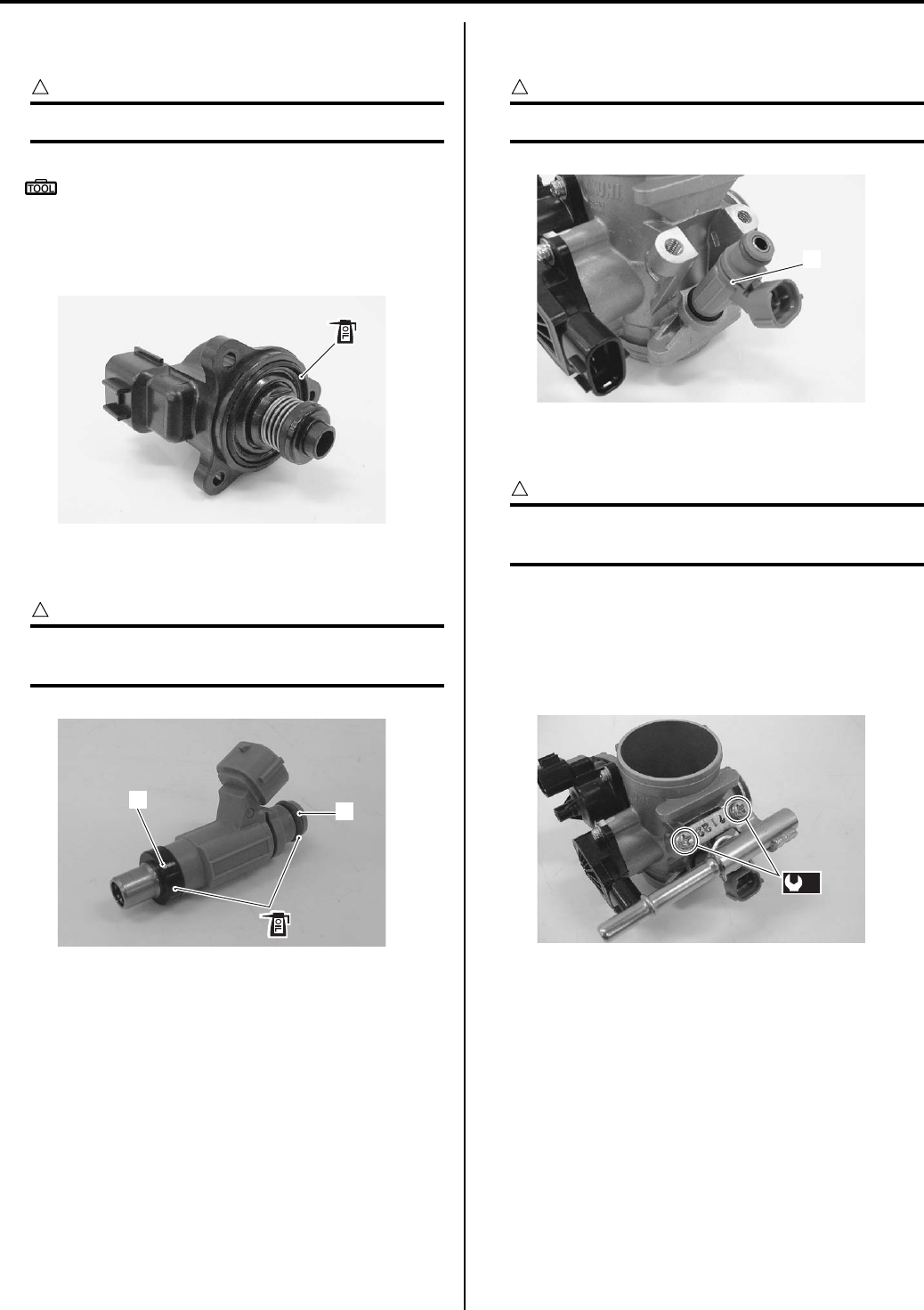
Engine Mechanical: 1D-12
• Apply a thin coat of engine oil to the O-ring and install
the ISC valve assembly.
CAUTION
!
Replace the O-ring with a new one.
Special tool
: 09930–11950 (Torx wrench)
Tightening torque
ISC valve mounting screw (a): 2 N·m (0.2 kgf-m,
1.5 lb-ft)
• Apply a thin coat of engine oil to the new cushion seal
(2) and the O-ring (3).
CAUTION
!
Replace the cushion seal and O-ring with the
new ones.
• Install the fuel injector (4) by pushing it straight to the
throttle body.
CAUTION
!
Never turn the injector while pushing it.
• Install the fuel delivery pipe assembly (5) to the fuel
injector.
CAUTION
!
Never turn the fuel injector while installing
them.
• Tighten the fuel delivery pipe mounting screws to the
specified torque.
Tightening torque
Fuel delivery pipe mounting screw (b): 5 N·m (0.5
kgf-m, 3.5 lb-ft)
I831G1140044-01
23
I831G1140046-01
4
I831G1140047-01
(b)
I831G1140048-01
PartShark.com
877-999-5686
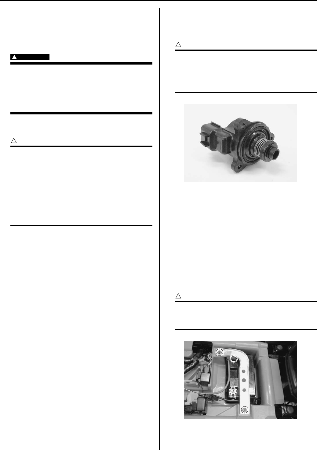
1D-13 Engine Mechanical:
Throttle Body Inspection and Cleaning
B831G21406012
Refer to “Throttle Body Disassembly and Assembly
(Page 1D-10)”.
Cleaning
WARNING
!
Some carburetor cleaning chemicals,
especially dip-type soaking solutions, are
very corrosive and must be handled carefully.
Always follow the chemical manufacturer’s
instructions on proper use, handling and
storage.
• Clean passageways with a spray-type carburetor
cleaner and blow dry with compressed air.
CAUTION
!
Do not use wire to clean passageways. Wire
can damage passageways. If the components
cannot be cleaned with a spray cleaner it may
be necessary to use a dip-type cleaning
solution and allow them to soak. Always
follow the chemical manufacturer’s
instructions for proper use and cleaning of
the throttle body components. Do not apply
carburetor cleaning chemicals to the rubber
and plastic materials.
Inspection
Check following items for any defects or clogging.
Replace the throttle body if necessary.
•O—ring
• Throttle valve
• Vacuum hose
ISC Valve Visual Inspection
Check the ISC valve for carbon deposits or other
damage. If carbon is deposited, remove it with a brush
and clean with a compressed air.
CAUTION
!
Normally, the removed O-ring must be
replaced with a new one. However, this O-
ring is not available for the spare parts. If it is
found to be damaged, replace the ISC valve
assembly with new one.
Engine Assembly Removal
B831G21406013
Before taking the engine out of the frame, wash the
engine using a steam cleaner. Engine removal is
sequentially explained in the following steps:
1) Drain engine oil. Refer to “Engine Oil and Filter
Replacement in Section 0B (Page 0B-10)”.
2) Drain engine coolant. Refer to “Cooling System
Inspection in Section 0B (Page 0B-15)”.
3) Remove the seat. Refer to “Seat Removal and
Installation in Section 9D (Page 9D-11)”.
4) Disconnect the battery lead wires.
CAUTION
!
When disconnecting the battery lead wires,
be sure to disconnect the battery (–) lead
wire first.
I831G1140049-02
I831G1140050-01
PartShark.com
877-999-5686
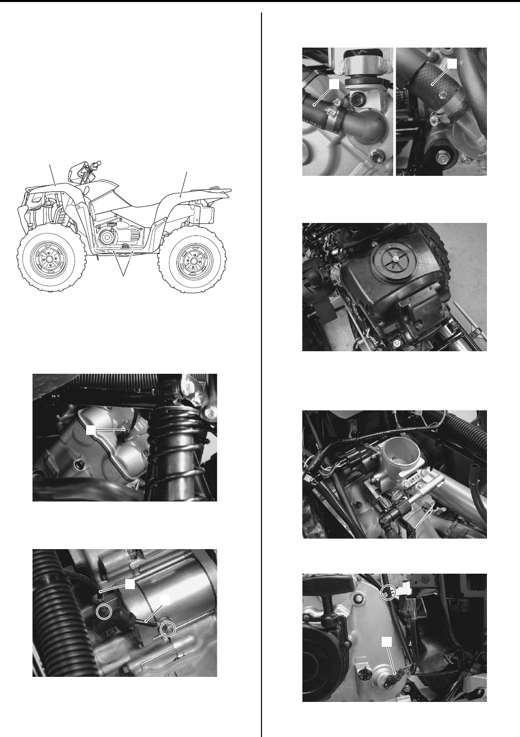
Engine Mechanical: 1D-14
5) Remove the following parts from the vehicle.
• Front fender (1). Refer to “Front Side Exterior
Parts Removal and Installation in Section 9D
(Page 9D-6)”.
• Rear fender (2). Refer to “Rear Side Exterior Parts
Removal and Installation in Section 9D (Page 9D-
9)”.
• Mud guard (Left and Right) (3). Refer to “Rear
Side Exterior Parts Removal and Installation in
Section 9D (Page 9D-9)”.
6) Remove the shift lever assembly. Refer to “Shift
Lever Assembly Removal and Installation in Section
5A (Page 5A-24)”.
7) Disconnect the spark plug cap (4).
Disconnect the starter motor lead wire (5) and
ground lead wire (6).
9) Disconnect the radiator inlet hose (7) and outlet hose
(8).
10) Remove the air cleaner box. Refer to “Air Cleaner
Box Removal and Installation (Page 1D-5)”.
11) Remove the throttle body assembly. Refer to
“Throttle Body Removal and Installation (Page 1D-
9)”.
12) Disconnect the speed sensor coupler (9) and clamp.
12
3
I831G1140052-02
4
I831G1140053-01
5
6
I831G1140054-01
8
7
I831G1140055-02
I831G1140056-01
I831G1140057-01
9
I831G1140058-02
PartShark.com
877-999-5686
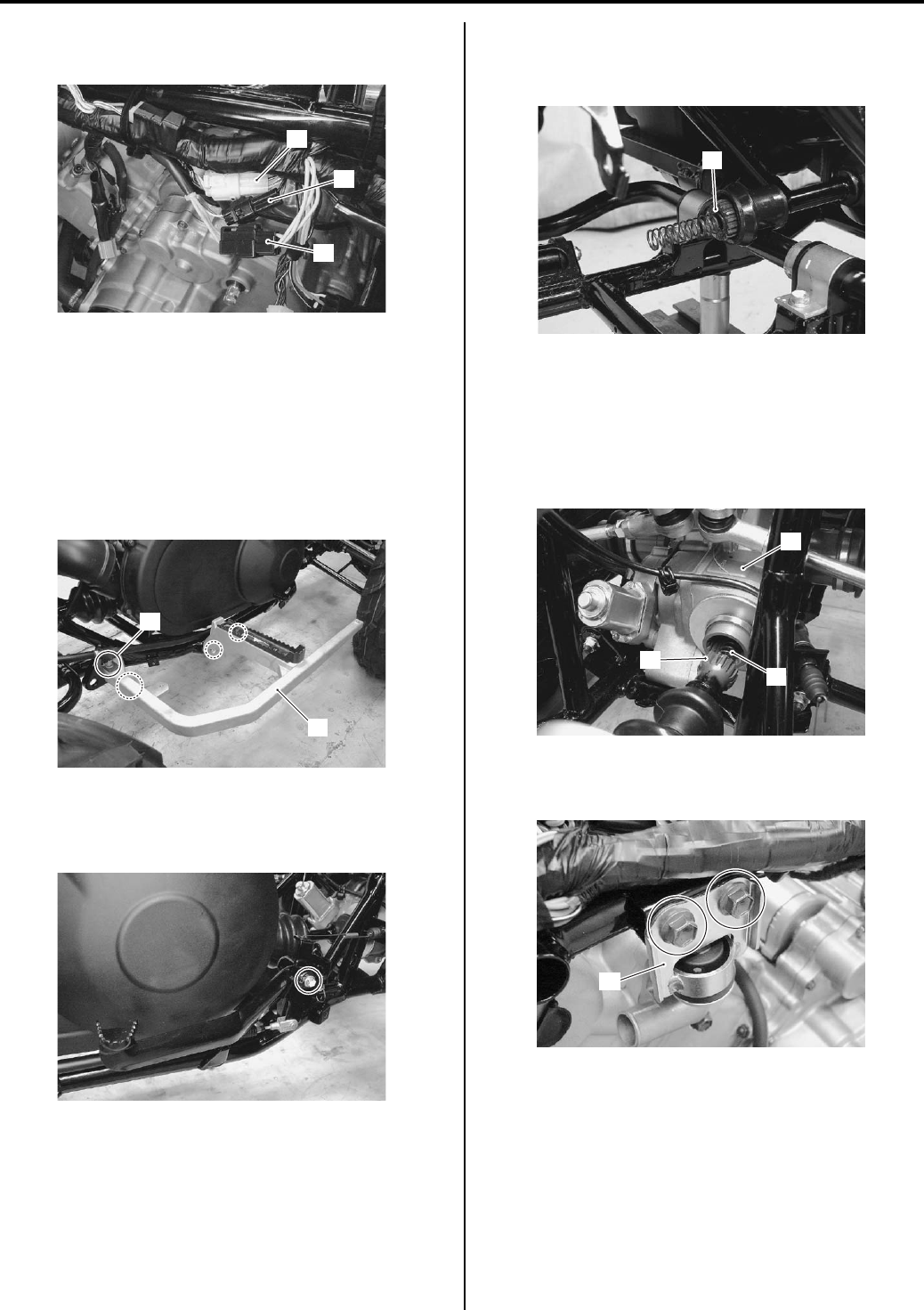
1D-15 Engine Mechanical:
13) Disconnect the generator coupler (10), CKP sensor
coupler (11) and gear position sensor coupler (12).
14) Remove the V-belt cooling ducts. Refer to “V-belt
Cooling Duct Removal and Installation in Section 5A
(Page 5A-5)”.
15) Remove the muffler and exhaust pipes. Refer to
“Exhaust Pipe / Muffler Removal and Installation in
Section 1K (Page 1K-2)”.
16) Remove the rear brake cable clamp bolt (13).
17) Remove the right footrest (14).
18) Remove the rear brake pedal. Refer to “Rear Brake
Pedal Removal and Installation in Section 4A
(Page 4A-14)”.
19) Remove the rear propeller shaft (15). Refer to “Rear
Propeller Shaft Removal and Installation in Section
3D (Page 3D-17)”.
20) Remove the front differential mounting bolts and
slide the front differential assembly (16) forward.
Refer to “Front Drive (Differential) Assembly
Removal and Installation in Section 3B (Page 3B-4)”.
21) Remove the front propeller shaft (17) and spring
(18).
22) Remove the dumper stopper (20) by removing the
mounting bolts.
10
11
12
I831G1140060-02
14
13
I831G1140061-02
I831G1140062-01
15
I831G1140063-03
16
17
18
I831G1140064-02
20
I831G1140065-02
PartShark.com
877-999-5686
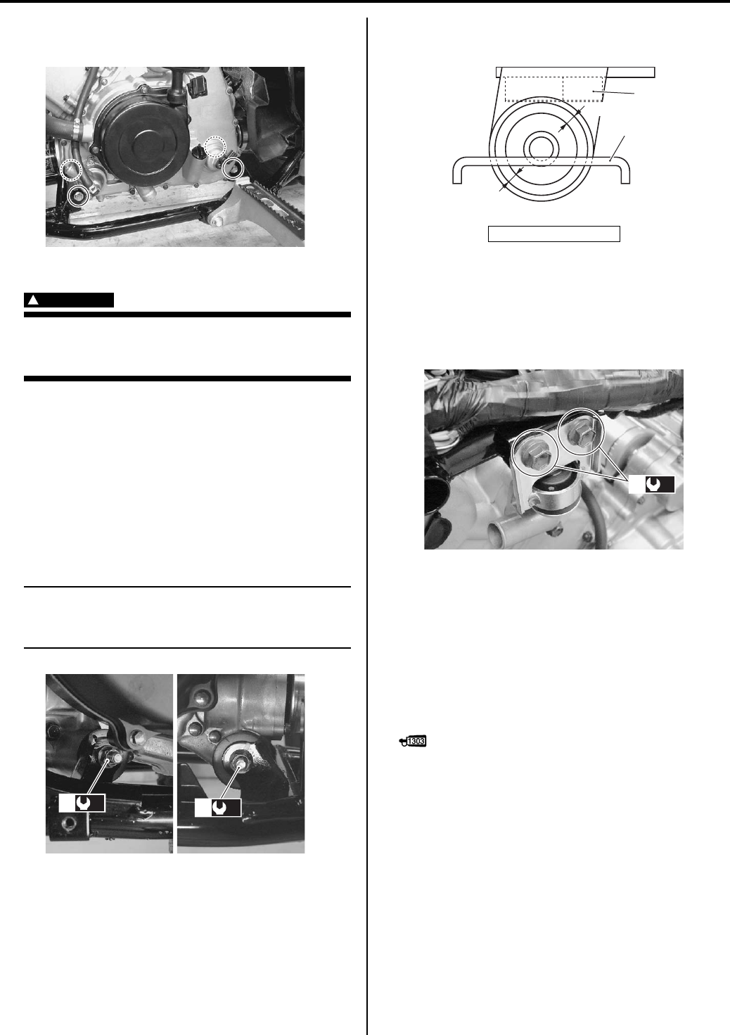
Engine Mechanical: 1D-16
23) Support engine with a jack and remove the engine
mounting bolts and nuts.
24) Remove the engine from the right side.
WARNING
!
Care should be taken not to drop the engine
accidentally when the engine mounting bolts
and nuts are removed.
Engine Assembly Installation
B831G21406014
Reinstall the engine in the reverse order of engine
removal. Pay attention to the following points:
• Tighten the engine mounting nuts (1) to the specified
torque.
Tightening torque
Engine mounting nut (a): 60 N·m (6.0 kgf-m, 43.5
lb-ft)
NOTE
The engine mounting nuts are self-locking.
Once the nuts have been removed, they are
no longer of any use.
• When installing the engine mounting damper stopper
(2), keep that the clearance are equal.
• Tighten the engine mounting damper stopper bolts (3)
to the specified torque.
Tightening torque
Engine mounting damper stopper bolt (b): 23 N·m
(2.3 kgf-m, 16.5 lb-ft)
• Install the front propeller shaft and front differential
assembly. Refer to “Front Drive (Differential)
Assembly Removal and Installation in Section 3B
(Page 3B-4)”.
• Install the rear propeller shaft and rear differential
assembly. Refer to “Final Gear Assembly Removal
and Installation in Section 3B (Page 3B-23)”.
• Apply thread lock to the footrest bolts (4), and tighten
them to the specified torque.
: Thread lock cement 99000–32030
(THREAD LOCK CEMENT SUPER 1303 or
equivalent)
Tightening torque
Footrest mounting bolt (M8) (c): 26 N·m (2.6 kgf-
m, 19.0 lb-ft)
Footrest mounting bolt (M10) (d): 55 N·m (5.5 kgf-
m, 40.0 lb-ft)
I831G1140066-01
(a)
1(a)
1
I831G1140067-03
“a”: Clearance
“a”
“a”
2
2
I831G1140068-03
(b)
3
I831G1140070-05
PartShark.com
877-999-5686
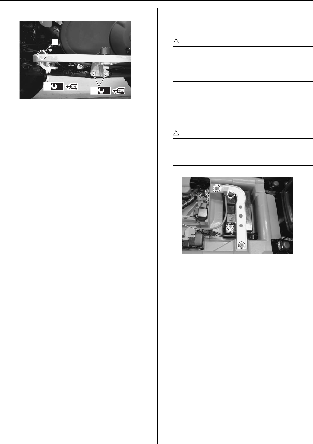
1D-17 Engine Mechanical:
• Install the rear brake cable clamp (5).
• Install the rear brake pedal. Refer to “Rear Brake
Pedal Removal and Installation in Section 4A
(Page 4A-14)”.
• Install the exhaust pipe assembly and muffler. Refer to
“Exhaust Pipe / Muffler Removal and Installation in
Section 1K (Page 1K-2)”.
• Install the shift lever assembly. Refer to “Shift Lever
Assembly Removal and Installation in Section 5A
(Page 5A-24)”.
• Install the throttle body. Refer to “Throttle Body
Removal and Installation (Page 1D-9)”.
• After remounting the engine, route the wiring harness,
cable and hoses properly. Refer to “Wiring Harness
Routing Diagram in Section 9A (Page 9A-4)”, “Throttle
Cable Routing Diagram (Page 1D-1)” and “Water
Hose Routing Diagram in Section 1F (Page 1F-3)”.
• Pour engine coolant and engine oil. Refer to “Cooling
System Inspection in Section 0B (Page 0B-15)” and
“Engine Oil and Filter Replacement in Section 0B
(Page 0B-10)”.
• After finishing the engine installation, check the
following items:
– Throttle cable play
Refer to “Throttle Cable Play Inspection and
Adjustment in Section 0B (Page 0B-15)”.
– Rear brake cable play
Refer to “Rear Brake Pedal / Rear Brake (Parking
Brake) Lever Inspection and Adjustment in Section
0B (Page 0B-19)”.
– Parking Brake cable play
Refer to “Rear Brake Pedal / Rear Brake (Parking
Brake) Lever Inspection and Adjustment in Section
0B (Page 0B-19)”.
– Engine oil and coolant leakage
Refer to “Cooling Circuit Inspection in Section 1F
(Page 1F-4)”.
Engine Top Side Disassembly
B831G21406015
It is unnecessary to remove the engine assembly from
the frame when servicing the engine top side.
CAUTION
!
Identify the position of each removed part.
Organize the parts in their respective groups
(e.g., intake, exhaust) so that they can be
reinstalled in their original positions.
1) Drain engine coolant. Refer to “Cooling System
Inspection in Section 0B (Page 0B-15)”.
2) Remove the seat. Refer to “Seat Removal and
Installation in Section 9D (Page 9D-11)”.
3) Remove the battery.
CAUTION
!
When disconnecting the battery lead wires,
be sure to disconnect the battery (–) lead
wire first.
4) Remove the front fender and left mud guard. Refer to
“Front Side Exterior Parts Removal and Installation
in Section 9D (Page 9D-6)” and “Rear Side Exterior
Parts Removal and Installation in Section 9D
(Page 9D-9)”.
5) Remove the shift lever assembly. Refer to “Shift
Lever Assembly Removal and Installation in Section
5A (Page 5A-24)”.
6) Remove the air cleaner box. Refer to “Air Cleaner
Box Removal and Installation (Page 1D-5)”.
7) Remove the throttle body. Refer to “Throttle Body
Removal and Installation (Page 1D-9)”.
5
(c)
4
(d)
4
I831G1140071-04
I831G1140072-01
PartShark.com
877-999-5686
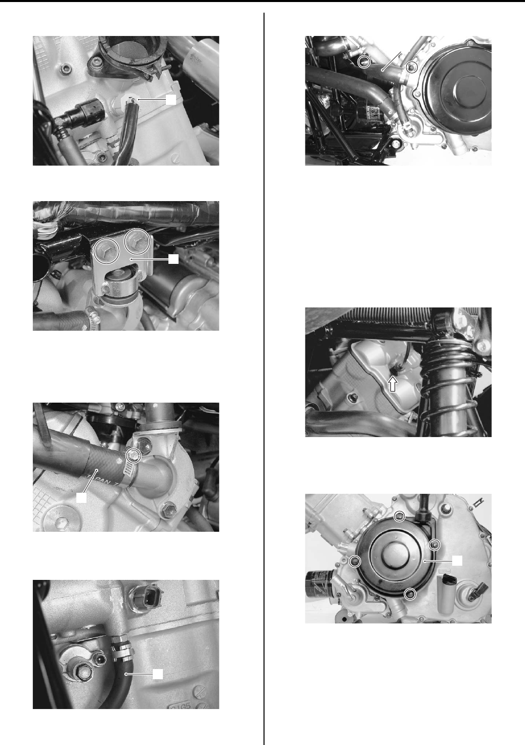
Engine Mechanical: 1D-18
Disconnect the ECT sensor coupler (1).
9) Remove the engine mounting dumper stopper (2).
Water Hose
1) Disconnect the radiator inlet hose (1) of the
thermostat.
2) Disconnect the water bypass hose (2) of the cylinder
head side.
3) Remove the water pump outlet hose (3).
Exhaust Pipe
Remove the exhaust pipe. Refer to “Exhaust Pipe /
Muffler Removal and Installation in Section 1K
(Page 1K-2)”.
Spark Plug Cap / Spark Plug
Remove the spark plug cap and spark plug. Refer to
“Spark Plug Cap and Spark Plug Removal and
Installation in Section 1H (Page 1H-3)”.
Recoil Starter
Remove the recoil starter (1) by removing the bolts.
1
I831G1140073-01
2
I831G1140076-01
1
I831G1140079-01
2
I831G1140080-03
3
I831G1140081-03
I831G1140082-01
1
I831G1140083-01
PartShark.com
877-999-5686
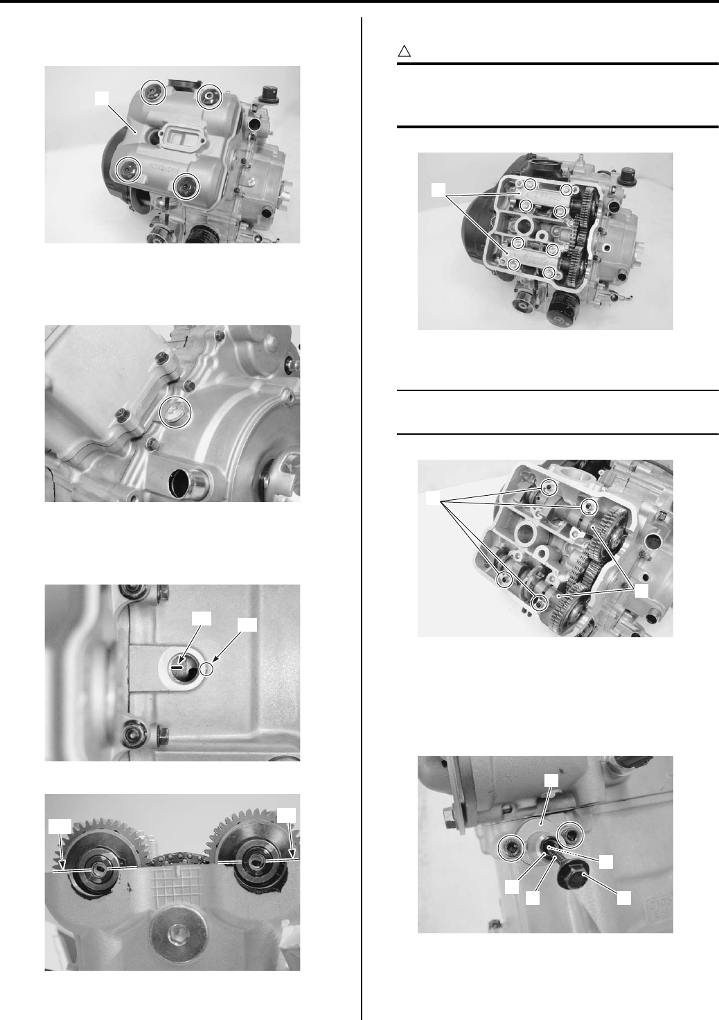
1D-19 Engine Mechanical:
Cylinder Head Cover
Remove the cylinder head cover (1) and its gasket.
Cam Shaft
1) Remove the valve timing inspection plug.
2) Turn the crankshaft and align the match mark “A” on
the crankshaft with the mark “B” of the crankcase.
Also position each of the camshaft as shown.
3) Remove the camshaft journal holders (1).
CAUTION
!
Be sure to loosen the camshaft journal
holder bolts evenly by shifting the wrench
diagonally.
4) Remove the dowel pins (2) and camshafts (3).
NOTE
Be careful not to drop the dowel pins into the
crankcase.
Cam Chain Tension Adjuster
1) Remove the cam chain tension adjuster cap bolt (1).
2) Remove the cam chain tension adjuster (2) with the
spring (3), O-ring (4) and bar (5).
1
I831G1140084-02
I831G1140085-02
“A” “B”
I831G1140086-03
IN
EX
I831G1140087-03
1
I831G1140088-01
2
3
I831G1140089-01
2
3
4
5
1
I831G1140090-02
PartShark.com
877-999-5686
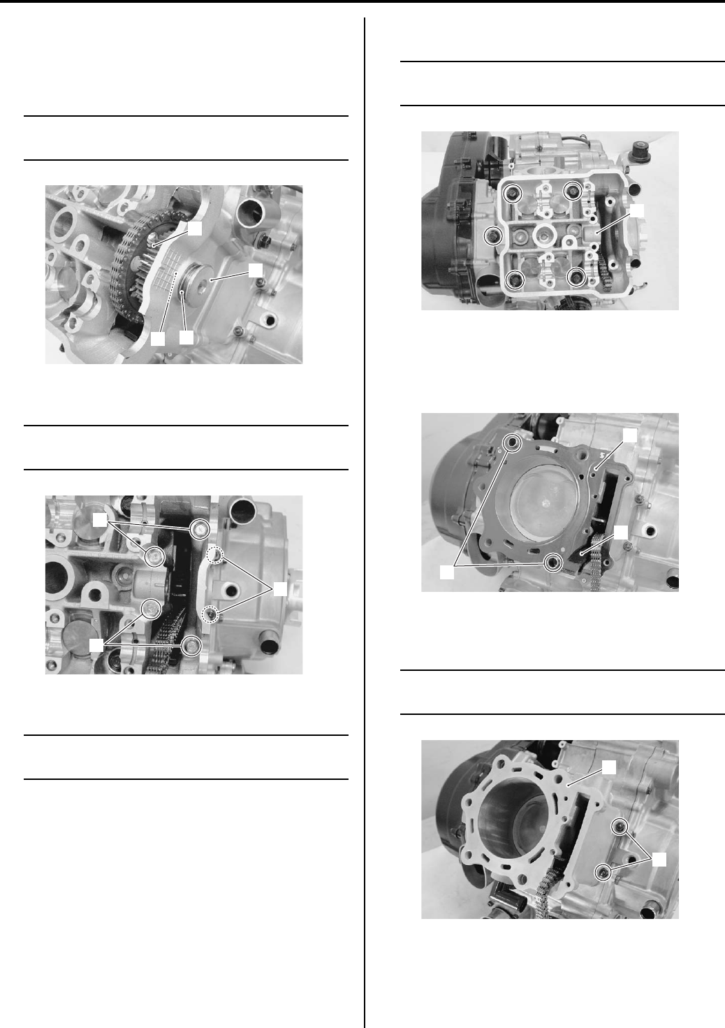
Engine Mechanical: 1D-20
Cylinder Head
1) Remove the cam drive idle gear/sprocket (1) by
removing its shaft (2) with the idle shaft gasket (3)
and cam chain idle shim (4).
NOTE
Be careful not to drop the cam chain idle
shim (4) into the crankcase.
2) Remove the cylinder head bolts (M6) (5).
NOTE
Sightly loosen the cylinder nuts (6) to
facilitate later disassembly.
3) Remove the cylinder head bolts (M10) and washers.
NOTE
When loosening the cylinder head bolts,
loosen each bolt little by little diagonally.
4) Remove the cylinder head (7).
NOTE
If the cylinder head does not come off easily,
lightly tap using a plastic hammer.
Cylinder
1) Remove the dowel pins (1) and gasket (2).
2) Remove the cam chain guide (3).
3) Remove the cylinder (5) by removing the cylinder
nuts (4).
NOTE
If the cylinder does not come off easily,
lightly top using a plastic hammer.
1
2
3
4
I831G1140091-01
5
5
6
I831G1140186-01
7
I831G1140093-01
1
2
3
I831G1140096-01
5
4
I831G1140097-01
PartShark.com
877-999-5686
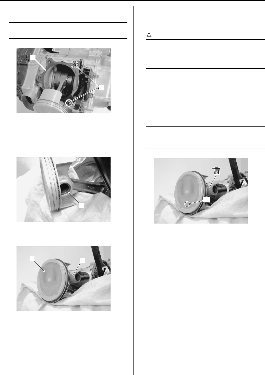
1D-21 Engine Mechanical:
4) Remove the dowel pins (6) and gasket (7).
NOTE
Be careful not to drop the dowel pins (6) into
the crankcase.
Piston
1) Place a clean rag over the cylinder base so as not to
drop the piston pin circlips into the crankcase.
2) Remove the piston pin circlip (1).
3) Draw out the piston pin (2) and remove the piston
(3).
Engine Top Side Assembly
B831G21406016
Assemble the engine top side in the reverse order of
disassembly. Pay attention to the following points:
CAUTION
!
When turning the crankshaft, pull the cam
chain upward, or the chain will be caught
between the crankcase and the cam drive
sprocket.
Piston
• When installing the piston pin, apply a light coat
molybdenum oil solution onto piston pin.
M/O: Molybdenum oil (MOLYBDENUM OIL
SOLUTION)
• Install the piston and piston pin.
NOTE
When installing the piston, the indent “A” on
the piston head must be faced to exhaust
side.
6
7
I831G1140098-01
1
I831G1140103-01
2
3
I831G1140104-01
“A”
I831G1140105-01
PartShark.com
877-999-5686
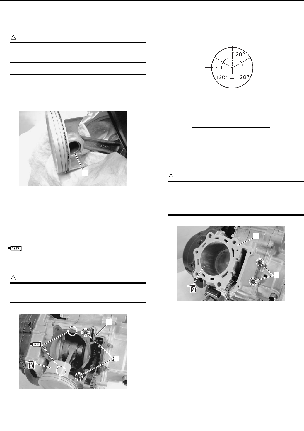
Engine Mechanical: 1D-22
• Place a clean rag over the cylinder base so as not to
drop the piston pin circlip (1) into the crankcase.
• Install the piston pin circlip (1).
CAUTION
!
Use new piston pin circlip (1) to prevent
circlip failure which will occur when it is bent.
NOTE
End gap of the circlip (1) should not be
aligned with the cutaway in the piston pin
bore.
• Apply molybdenum oil solution to the sliding surface
of the piston.
M/O: Molybdenum oil (MOLYBDENUM OIL
SOLUTION)
• Apply bond lightly to the mating surfaces of
crankcases.
: Sealant 99000–31110 (SUZUKI BOND
No.1215 or equivalent)
• Fit the dowel pins (1) and the new gasket (2).
CAUTION
!
Replace the cylinder gasket (2) with a new
one.
• Position the piston ring gaps as shown in the figure.
Before inserting each piston into its cylinder, check
that the gaps are properly positioned.
Cylinder
• Insert the piston into the cylinder (1).
• Temporarily tighten the cylinder base nuts (2).
• Apply engine oil to sliding surface of the cylinder.
CAUTION
!
When installing the cylinder, pull the cam
chain upward, or the chain will be caught
between the crankcase and cam drive
sprocket.
1
I831G1140106-02
1
2
I831G1140108-03
“B”: 2nd ring and lower side rail
“C”: Upper side rail
“D”: 1st ring and spacer
EX
IN
“C”
“B”
“D”
I718H1140051-01
1
2
I831G1140109-02
PartShark.com
877-999-5686
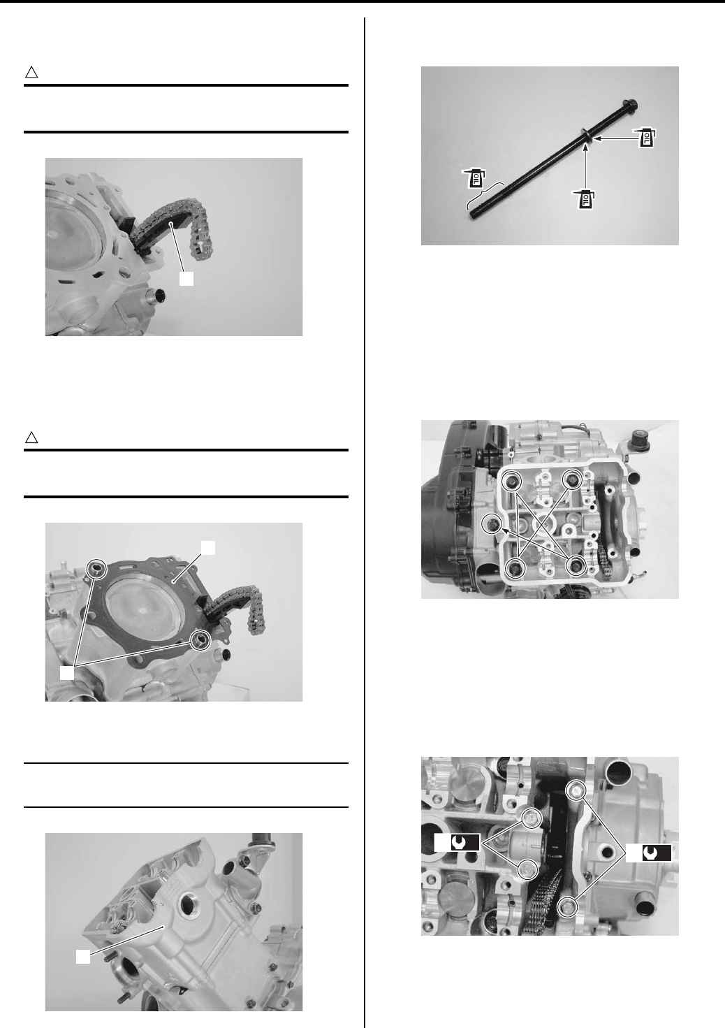
1D-23 Engine Mechanical:
Cam Chain Guide
• Install the cam chain guide (1).
CAUTION
!
Be sure that the cam chain guide (1) is
installed properly.
Cylinder Head
• Fit the dowel pins (1) and new cylinder head gasket
(2).
CAUTION
!
Replace the cylinder head gasket (2) with a
new one.
• Place the cylinder head (3) on the cylinder.
NOTE
When installing the cylinder head (3), keep
the cam chain taut.
• Apply the engine oil to the threads and both sides of
washers.
• Tighten the cylinder head bolts to the specified two-
step torque with a torque wrench sequentially and
diagonally.
Tightening torque
Cylinder head bolt (L: 200) (Initial): 25 N·m (2.5
kgf-m, 18.0 lb-ft)
Cylinder head bolt (L: 200) (Final): 37 N·m (3.7
kgf-m, 27.0 lb-ft)
• After firmly tightening the cylinder head bolts (4),
install the cylinder head bolts.
Tightening torque
Cylinder head bolt (L: 70) (a): 10 N·m (1.0 kgf-m,
7.0 lb-ft)
Cylinder head bolt (L: 100) (b): 10 N·m (1.0 kgf-m,
7.0 lb-ft)
1
I831G1140110-01
1
2
I831G1140111-02
3
I831G1140112-01
I831G1140113-01
I831G1140114-02
(a)
4
(b)
4
I831G1140115-02
PartShark.com
877-999-5686
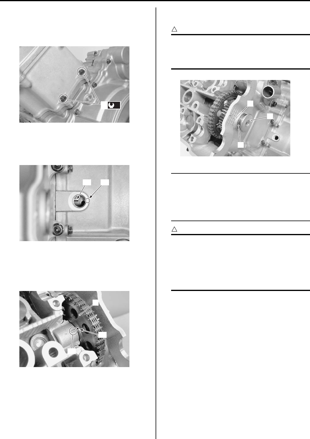
Engine Mechanical: 1D-24
• Tighten the cylinder base nuts (5) to the specified
torque.
Tightening torque
Cylinder base nut (c): 10 N·m (1.0 kgf-m, 7.0 lb-ft)
Cam Drive Idle Gear / Sprocket
• Align the match mark “A” on the generator rotor with
the mark “B” on the crankcase.
• Install the cam drive idle gear/sprocket (1) onto the
cylinder head and cam chain on it. When installing the
cam drive idle gear/sprocket, align the punched mark
“A” on the cam drive gear/sprocket (1) with the
embossed line “B” on the cylinder head.
• Install the cam drive idle gear/sprocket shaft (2),
copper washer (3) and shim (4).
CAUTION
!
When checking the positions, remove the
cam chain slack at the cam chain guide side
by holding the cam drive idle gear/sprocket
by hand.
NOTE
Due to special valve train mechanism,
aligning of the three elements; the punched
mark “C”, embossed line “D” and the gear
tooth root on the cam drive idle gear/
sprocket; can occur once every other
rotation of crankshaft.
CAUTION
!
If the punched mark “C” does not align the
embossed line “D”, turn the crankshaft 360°
(1 turn) to bring the line on the generator
rotor to the index mark on the crankcase
again and reinstall the cam drive idle gear/
sprocket to the correct position as shown in
the figure.
(c)
5
I831G1140116-02
“A” “B”
I831G1140117-02
“A”
“B”
1
I831G1140118-01
2
3
4
I831G1140119-01
PartShark.com
877-999-5686
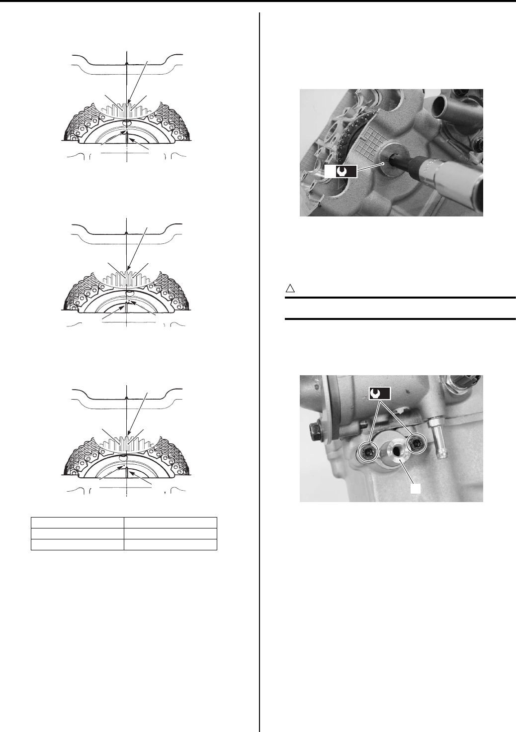
1D-25 Engine Mechanical:
CORRECT
INCORRECT
INCORRECT
• Tighten the cam drive idle gear/sprocket shaft (2) to
the specified torque.
Tightening torque
Cam drive idle gear/sprocket shaft (a): 41 N·m (
4.1 kgf-m, 29.5 lb-ft)
Cam Chain Tension Adjuster
• Install the cam chain tension adjuster (1) and tighten
the its mounting bolts to the specified torque.
CAUTION
!
Use a new gasket to prevent oil leakage.
Tightening torque
Cam chain tension adjuster bolt (a): 10 N·m (1.0
kgf-m, 7.0 lb-ft)
“C”: Punched mark “F”: Root of tooth
“D”: Embossed line “G”: Top of tooth
“E”: White paint
“E” “E”
“F”
“C” “D”
I831G1140120-03
“C”
“D”
“G”
“E”
“E”
I831G1140121-04
“C” “D”
“G”
“E”
“E”
I831G1140122-03
(a)
2
I831G1140328-01
(a)
1
I831G1140123-01
PartShark.com
877-999-5686
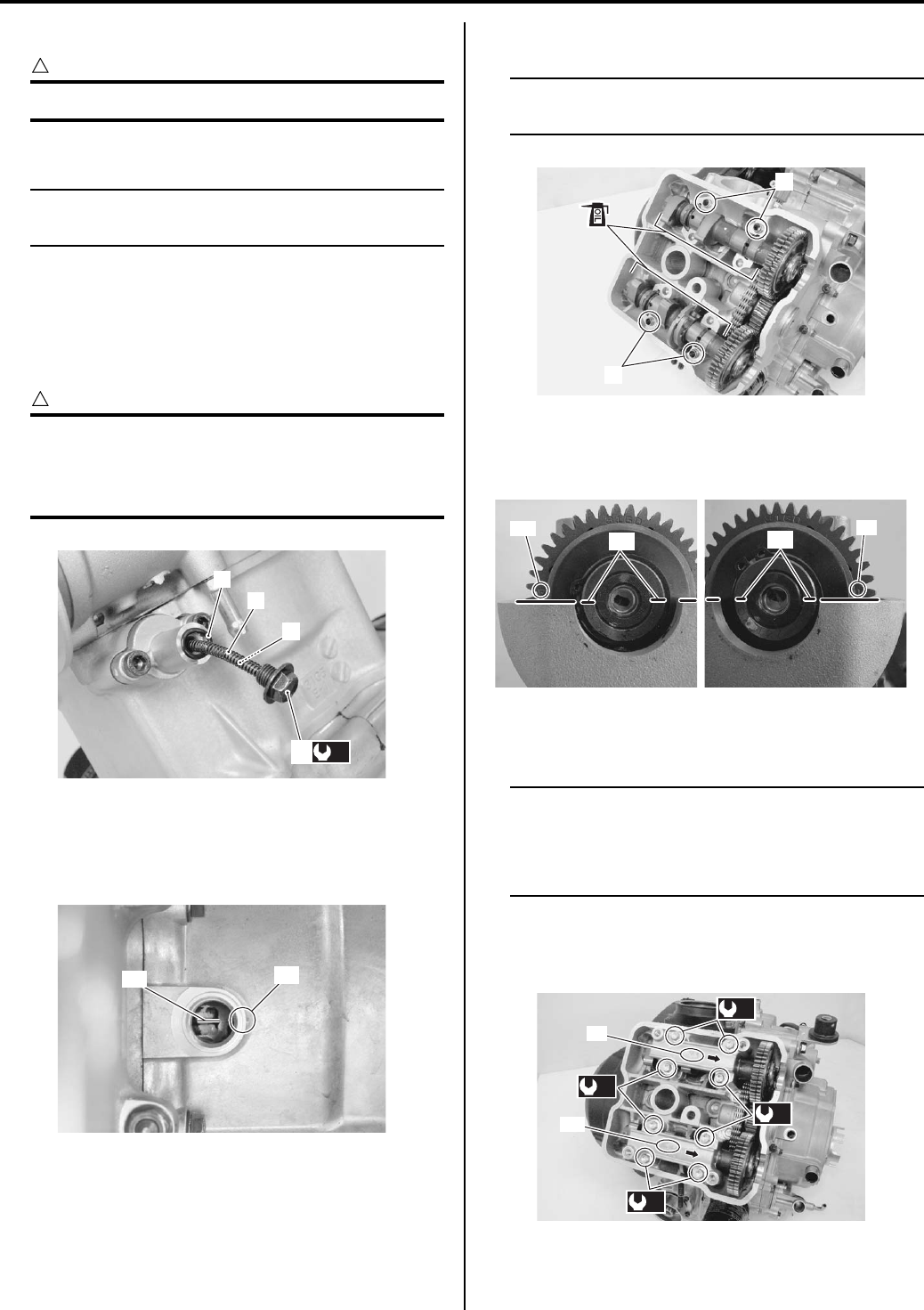
Engine Mechanical: 1D-26
• Install the new O-ring (2), spring (3) and bar (4).
CAUTION
!
Use a new O-ring to prevent oil leakage.
• Install the cam chain tension adjuster cap bolt (5).
NOTE
Click sound is heard when the cam chain
tension adjuster cap bolt is installed.
• Tighten the cam chain tension adjuster cap bolt (5) to
the specified torque.
Tightening torque
Cam chain tension adjuster cap bolt (b): 7 N·m (
0.7 kgf-m, 5.0 lb-ft)
CAUTION
!
After installing the cam chain tension
adjuster, check to be sure that the adjuster
works properly by checking the slack of cam
chain.
Camshaft
• Align the line “A” on the generator rotor with the index
mark “B” on the crankcase.
• Install the dowel pins (1).
• The camshafts are identified by the engraved letters.
• Before replacing the camshafts on cylinder head,
apply engine oil to their journals and cam faces.
• Apply engine oil to the camshaft journal holders.
NOTE
Before installing the camshaft, check that the
tappets are installed correctly.
• Align the engraved mark “C” and “D” on the camshaft
sprockets so it is parallel with the matching surface of
the cylinder head cover.
• Tighten the journal holder bolts to the specified
torque.
NOTE
• Each camshaft journal holder is identified
with an embossed letter.
• The arrow mark of the camshaft journals
camshaft sprocket side.
Tightening torque
Camshaft journal holder bolt (a): 10 N·m (1.0 kgf—
m, 7.0 lb-ft)
2
3
4
(b)
5
I831G1140124-01
“A” “B”
I831G1140125-01
1
1
I831G1140126-01
“C” “D”
EX IN
I831G1140128-05
(a)
(a)
(a)
(a)
EX
IN
I831G1140127-03
PartShark.com
877-999-5686
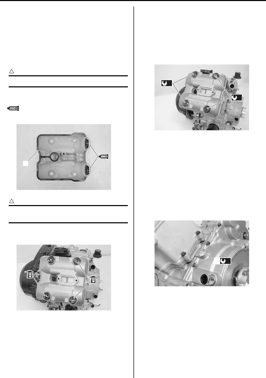
1D-27 Engine Mechanical:
• Be sure to check and adjust the valve clearance.
Refer to “Valve Clearance Inspection and Adjustment
in Section 0B (Page 0B-4)”.
• Before assemble the cylinder head cover, pour a
small amount of engine oil in oil pocket in the cylinder
head.
Cylinder Head Cover
• Install a new gasket (1) to the cylinder head cover.
CAUTION
!
Use a new gasket (1) to prevent oil leakage.
• Apply bond to the cam end caps of the gasket as
shown in the figure.
: Sealant 99000–31230 (SUZUKI BOND
No.1216B or equivalent)
CAUTION
!
Use the gaskets with new ones to prevent oil
leakage.
• Apply engine oil to the both sides of head cover
washers.
• Tighten the head cover bolts to the specified two-step
torque with a torque wrench sequentially and
diagonally.
Tightening torque
Head cover bolt (Initial) (a): 10 N·m (1.0 kgf-m, 7.0
lb-ft)
Head cover bolt (Final) (a): 14 N·m (1.4 kgf-m,
10.0 lb-ft)
Spark plug
• Install the spark plug. Refer to “Spark Plug Cap and
Spark Plug Removal and Installation in Section 1H
(Page 1H-3)”.
Valve Timing Inspection Plug
• Tighten the valve timing inspection plug (1) to the
specified torque.
Tightening torque
Valve timing inspection plug (a): 23 N·m (2.3 kgf-
m, 16.5 lb-ft)
Throttle Body
• Install the throttle body (1). Refer to “Throttle Body
Removal and Installation (Page 1D-9)”.
Valve Clearance Inspection and Adjustment
B831G21406017
Refer to “Valve Clearance Inspection and Adjustment in
Section 0B (Page 0B-4)”.
1
I831G1140129-01
I831G1140130-01
(a)
(a)
I831G1140131-01
(a)
1
I831G1140329-01
PartShark.com
877-999-5686
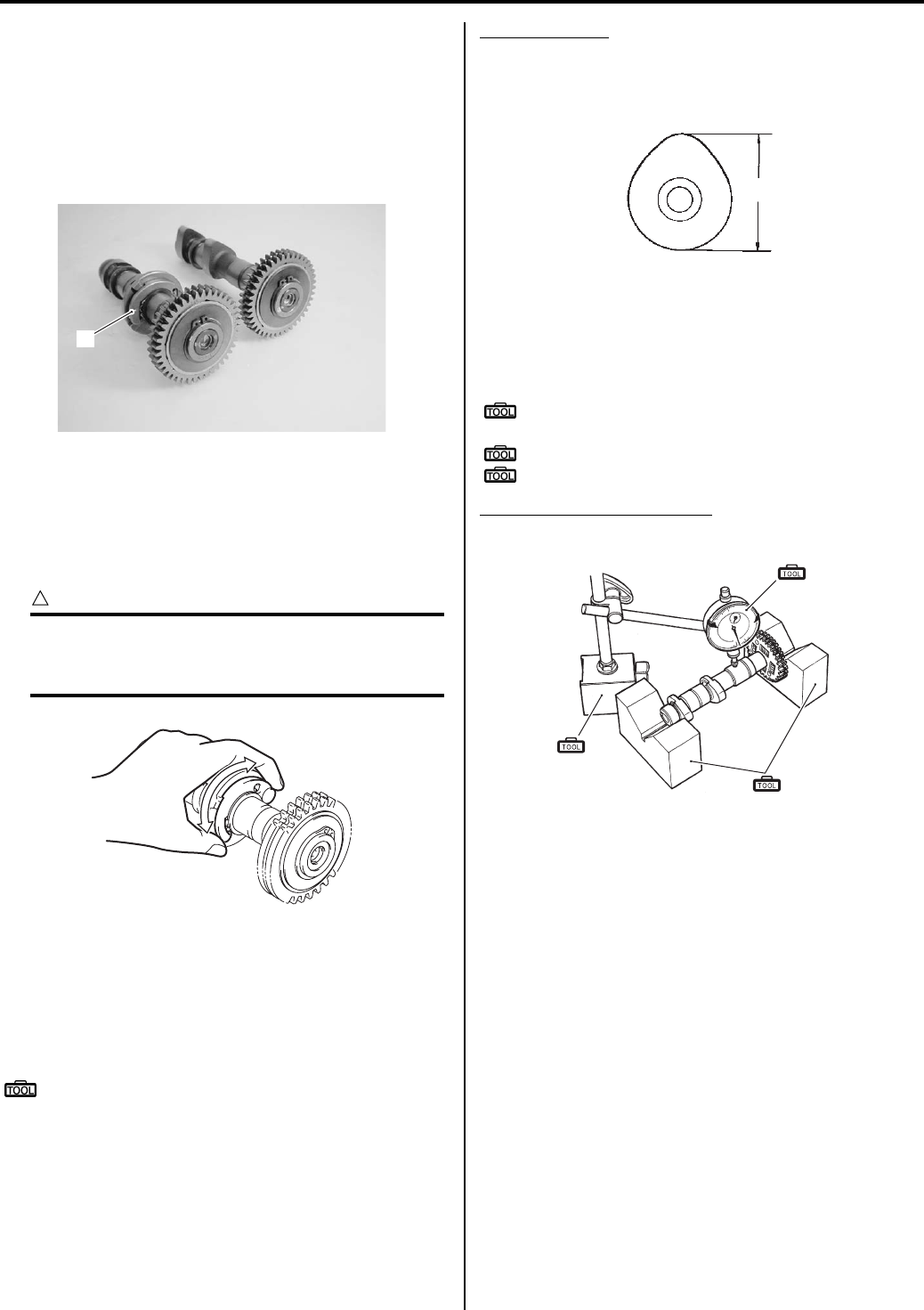
Engine Mechanical: 1D-28
Camshaft Inspection
B831G21406018
Refer to “Engine Top Side Disassembly (Page 1D-17)”.
Refer to “Engine Top Side Assembly (Page 1D-21)”.
Camshaft Identification
The exhaust camshaft has the automatic decompression
(1).
Automatic decompression
Move the automatic decompression weight by hand to
inspect if it is operating smoothly. If it does not operate
smoothly, replace the camshaft/automatic
decompression assembly with a new one.
CAUTION
!
Do not attempt to disassemble the camshaft/
automatic decompression assembly.
It is not serviceable.
Cam Wear
Check the camshaft for wear or damage.
Measure the cam height “a” with a micrometer.
Replace a camshaft if the cams are worn to the service
limit.
Special tool
: 09900–20202 (Micrometer (1/100 mm, 25 – 50
mm))
Cam height “a”
Service limit (IN.): 36.030 mm (1.4185 in)
Service limit (EX.): 35.000 mm (1.3780 in)
Camshaft Runout
Measure the runout using the dial gauge. Replace the
camshaft if the runout exceeds the limit.
Special tool
(A): 09900–20607 (Dial gauge (1/100 mm, 10
mm))
(B): 09900–20701 (Magnetic stand)
(C): 09900–21304 (V-block (100 mm))
Camshaft runout (IN. & EX.)
Service limit: 0.10 mm (0.004 in)
Camshaft Journal Wear
Inspect the camshaft journal wear in the following
procedures:
1) Determine whether or not each journal is worn down
to the limit by measuring the oil clearance with the
camshaft installed in place.
1
I831G1140132-03
I831G1140133-01
“a”
I649G1140199-02
(A)
(B)
(C)
I831G1140134-01
PartShark.com
877-999-5686
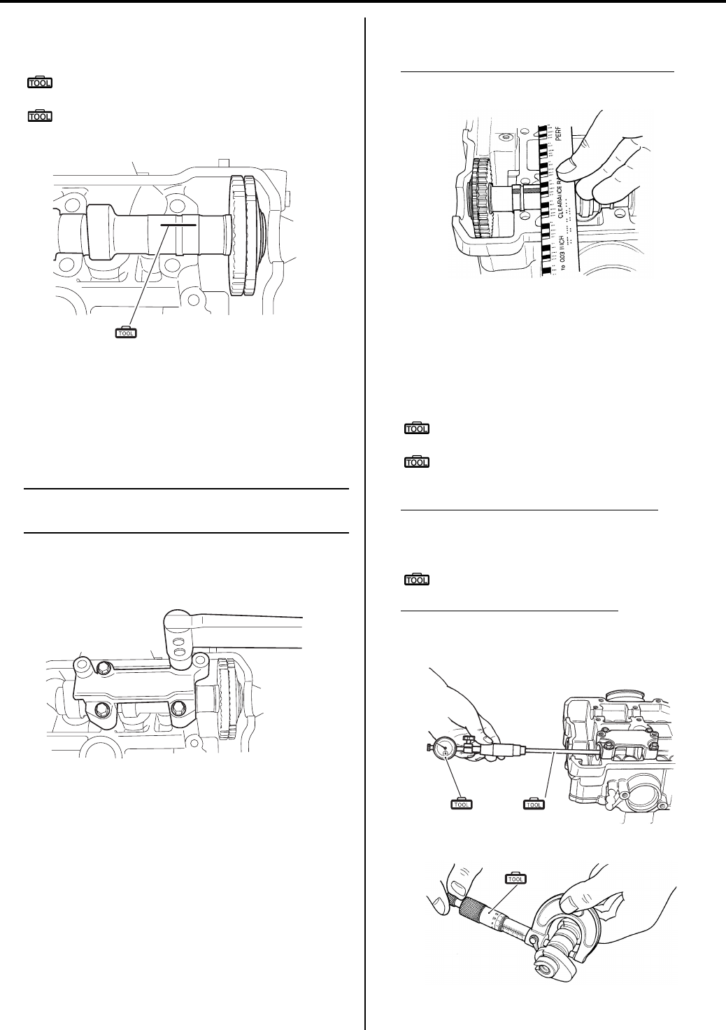
1D-29 Engine Mechanical:
2) Use the plastigauge to read the clearance at the
widest portion, which is specified as follows.
Special tool
(A): 09900–22301 (Plastigauge (0.025 –
0.076 mm))
(B): 09900–22302 (Plastigauge (0.051 –
0.152 mm))
3) Install each camshaft journal holder to its original
position. Refer to “Engine Top Side Assembly
(Page 1D-21)”.
4) Tighten the camshaft journal holder bolts evenly and
diagonally to the specified torque. Refer to “Engine
Top Side Assembly (Page 1D-21)”.
NOTE
Do not rotate the camshafts with the
plastigauge in place.
Tightening torque
Camshaft journal holder bolt: 10 N·m (1.0 kgf-
m, 7.0 lb-ft)
5) Remove the camshaft journal holders and measure
the width of the compressed plastigauge using the
envelope scale.
6) This measurement should be taken at the widest
part of the compressed plastigauge.
Camshaft journal oil clearance (IN. & EX.)
Service limit: 0.150 mm (0.0059 in)
7) If the camshaft journal oil clearance exceeds the
limit, measure the inside diameter of the camshaft
journal holder and the outside diameter of the
camshaft journal. Replace the camshaft or the
cylinder head depending upon which one exceeds
the specification.
Special tool
(C): 09900–20602 (Dial gauge (1/1000 mm, 1
mm))
(D): 09900–22403 (Small bore gauge (18 –
35 mm))
Camshaft journal holder I.D. (IN. & EX.)
Standard: 22.012 – 22.025 mm (0.8666 – 0.8671
in)
Special tool
(E): 09900–20205 (Micrometer (0 – 25 mm))
Camshaft journal O.D. (IN. & EX.)
Standard: 21.972 – 21.993 mm (0.8650 – 0.8659
in)
(A), (B)
I831G1140331-01
I831G1140332-01
I831G1140137-01
(C) (D)
I831G1140138-01
(E)
I831G1140139-01
PartShark.com
877-999-5686
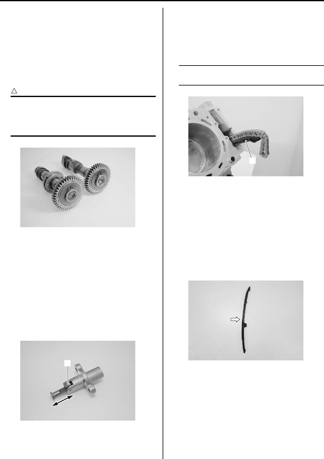
Engine Mechanical: 1D-30
Camshaft Sprocket Inspection
B831G21406019
Inspect the camshaft sprocket in the following
procedures:
1) Remove the intake and exhaust camshafts. Refer to
“Engine Top Side Disassembly (Page 1D-17)”.
2) Inspect the teeth of each camshaft sprocket for wear
or damage.
If they are worn or damaged, replace the camshaft
and cam chain as a set.
CAUTION
!
• Do not disassemble the camshaft
sprocket.
• The camshaft sprocket and cam shaft is
available only as an assembly.
3) Install the camshafts. Refer to “Engine Top Side
Assembly (Page 1D-21)”.
Cam Chain Tension Adjuster Inspection
B831G21406020
The cam chain tension adjuster is maintained at the
proper tension by an automatically adjusted.
1) Remove the cam chain tension adjuster. Refer to
“Engine Top Side Disassembly (Page 1D-17)”.
2) Check that the push rod slides smoothly when
releasing stopper (1). If it does not slide smoothly,
replace the cam chain tension adjuster with a new
one.
3) Install the cam chain tension adjuster. Refer to
“Engine Top Side Assembly (Page 1D-21)”.
Cam Chain Guide Removal and Installation
B831G21406021
Removal
1) Remove the cylinder head. Refer to “Engine Top
Side Disassembly (Page 1D-17)”.
2) Remove the cam chain guide (1).
NOTE
Be careful not to drop the chain into the
crankcase.
Installation
Install the cam chain guide in the reverse order of
removal.
Cam Chain Guide Inspection
B831G21406022
Inspect the cam chain guide in the following procedures:
• Remove the cam chain guides. Refer to “Cam Chain
Guide Removal and Installation (Page 1D-30)”.
• Check the contacting surface of the cam chain guide.
If it is worn or damaged, replace it with a new one.
I831G1140140-01
1
I831G1140141-01
1
I831G1140142-01
I831G1140143-01
PartShark.com
877-999-5686
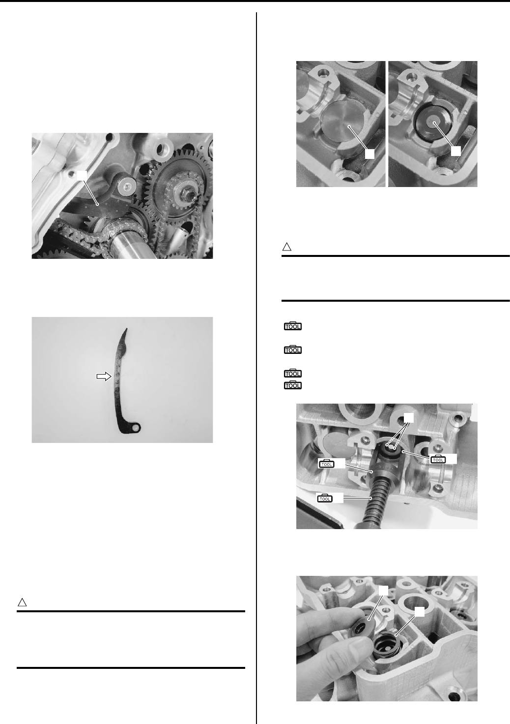
1D-31 Engine Mechanical:
Cam Chain Tensioner Inspection
B831G21406023
Inspect the cam chain tensioner in the following
procedures:
1) Remove the cylinder head. Refer to “Engine Top
Side Disassembly (Page 1D-17)”.
2) Remove the starter driven gear. Refer to “Engine
Bottom Side Disassembly (Page 1D-45)”.
3) Remove the cam chain tensioner (1).
4) Check the contacting surface of the cam chain
tensioner. If it is worn or damaged, replace it with a
new one.
5) Install the cam chain tensioner.
6) Reinstall the starter driven gear. Refer to “Engine
Bottom Side Assembly (Page 1D-51)”.
7) Reinstall the cylinder head cover. Refer to “Engine
Top Side Assembly (Page 1D-21)”.
Reinstall the removed parts.
Cylinder Head Disassembly and Assembly
B831G21406024
Refer to “Engine Top Side Disassembly (Page 1D-17)”.
CAUTION
!
Identify the position of each removed part.
Organize the parts in their respective groups
(i.e., intake, exhaust) so that they can be
installed in their original locations.
Disassembly
1) Remove the tappet (1) and shim (2) by fingers or
magnetic hand.
2) Using the special tools, compress the valve spring
and remove the two cotter halves (3) from the valve
stem.
CAUTION
!
To prevent damage of the tappet sliding
surface with the special tool, use the sleeve
protector.
Special tool
(A): 09916–14510 (Valve spring
compressor)
(B): 09916–14521 (Valve spring compressor
attachment)
: 09916–84511 (Tweezers)
(C): 09919–28610 (Sleeve protector)
3) Remove the valve spring retainer (4) and valve
spring (5).
1
I831G1140144-02
I831G1140145-01
12
I831G1140188-02
3
(A)
(B)
(C)
I831G1140146-02
5
4
I831G1140147-01
PartShark.com
877-999-5686
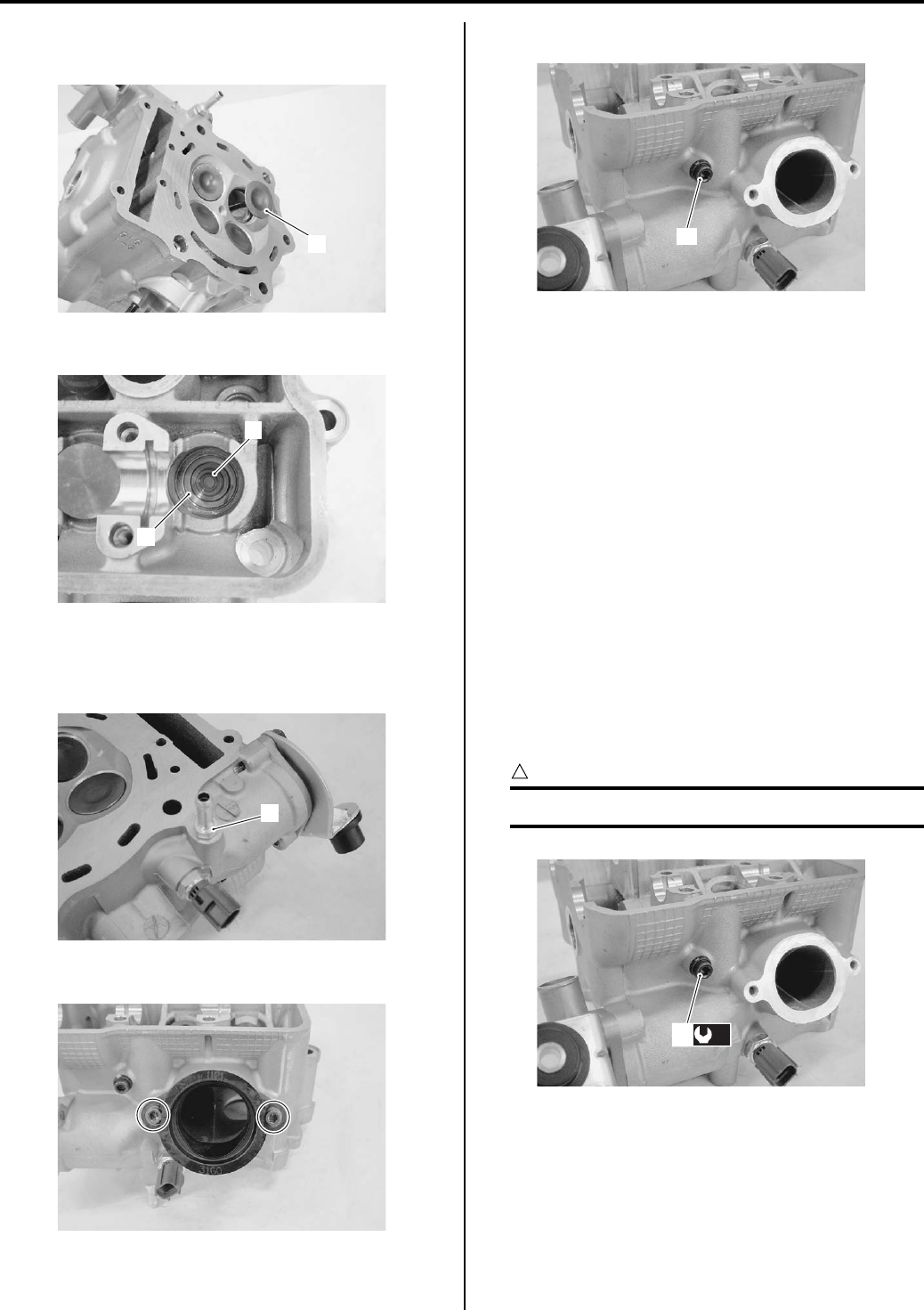
Engine Mechanical: 1D-32
4) Pull out the valve (6) from the combustion chamber
side.
5) Remove the oil seal (7) and spring seat (8).
6) Remove the other valves in the same manner as
described previously.
7) Remove the bypass union (9).
Remove the intake pipe.
9) Remove the oil gallery plug (cylinder head) (10).
10) Remove the ECT sensor. Refer to “ECT Sensor
Removal and Installation in Section 1C (Page 1C-
4)”.
11) Remove the thermostat. Refer to “Thermostat
Removal and Installation in Section 1F (Page 1F-
11)”.
Assembly
Assembly is in the reverse order of disassembly. Pay
attention to the following points:
• Install the thermostat. Refer to “Thermostat Removal
and Installation in Section 1F (Page 1F-11)”.
• Instal the ECT sensor. Refer to “ECT Sensor Removal
and Installation in Section 1C (Page 1C-4)”.
• Tighten the oil gallery plug (1) (cylinder head) to the
specified torque.
Tightening torque
Oil gallery plug (Cylinder head) (a): 10 N·m (1.0
kgf-m, 7.0 lb-ft)
CAUTION
!
Replace the gasket with new ones.
6
I831G1140148-01
7
8
I831G1140149-01
9
I831G1140150-01
I831G1140151-01
10
I831G1140152-01
(a)
1
I831G1140153-02
PartShark.com
877-999-5686
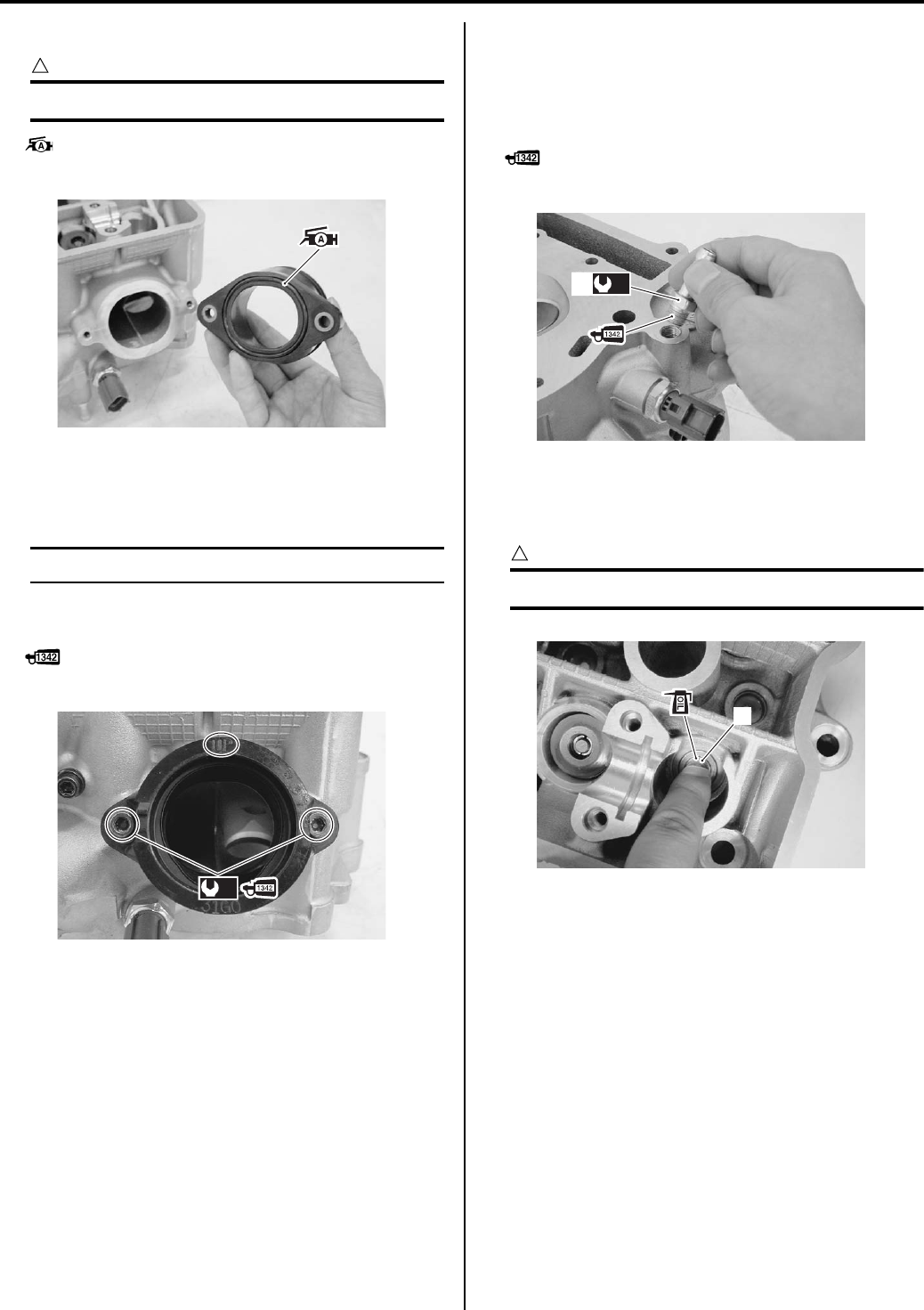
1D-33 Engine Mechanical:
• Apply grease to the O-ring of the intake pipe.
CAUTION
!
Replace the O-ring with new ones.
: Grease 99000–25010 (SUZUKI SUPER
GREASE A or equivalent)
• Apply a small quantity of thread lock to the intake pipe
mounting bolts and tighten them to the specified
torque.
NOTE
Make sure that the “UP” mark faces up.
Tightening torque
Intake pipe bolt (b): 9 N·m (0.9 kgf-m, 6.5 lb-ft)
: Thread lock cement 99000–32050
(THREAD LOCK CEMENT 1342 or equivalent)
• Apply thread lock to the water bypass union (2) and
tighten it to the specified torque.
Tightening torque
Water bypass union (c): 12 N·m (1.2 kgf-m, 8.5 lb-
ft)
: Thread lock cement 99000–32050
(THREAD LOCK CEMENT 1342 or equivalent)
• Install the valve spring seat.
• Apply engine oil to the oil seal (2), and press-fit it into
position.
CAUTION
!
Do not reuse the removed oil seal.
I831G1140156-01
(b)
I831G1140157-02
(c)
2
I831G1140158-04
2
I831G1140159-05
PartShark.com
877-999-5686
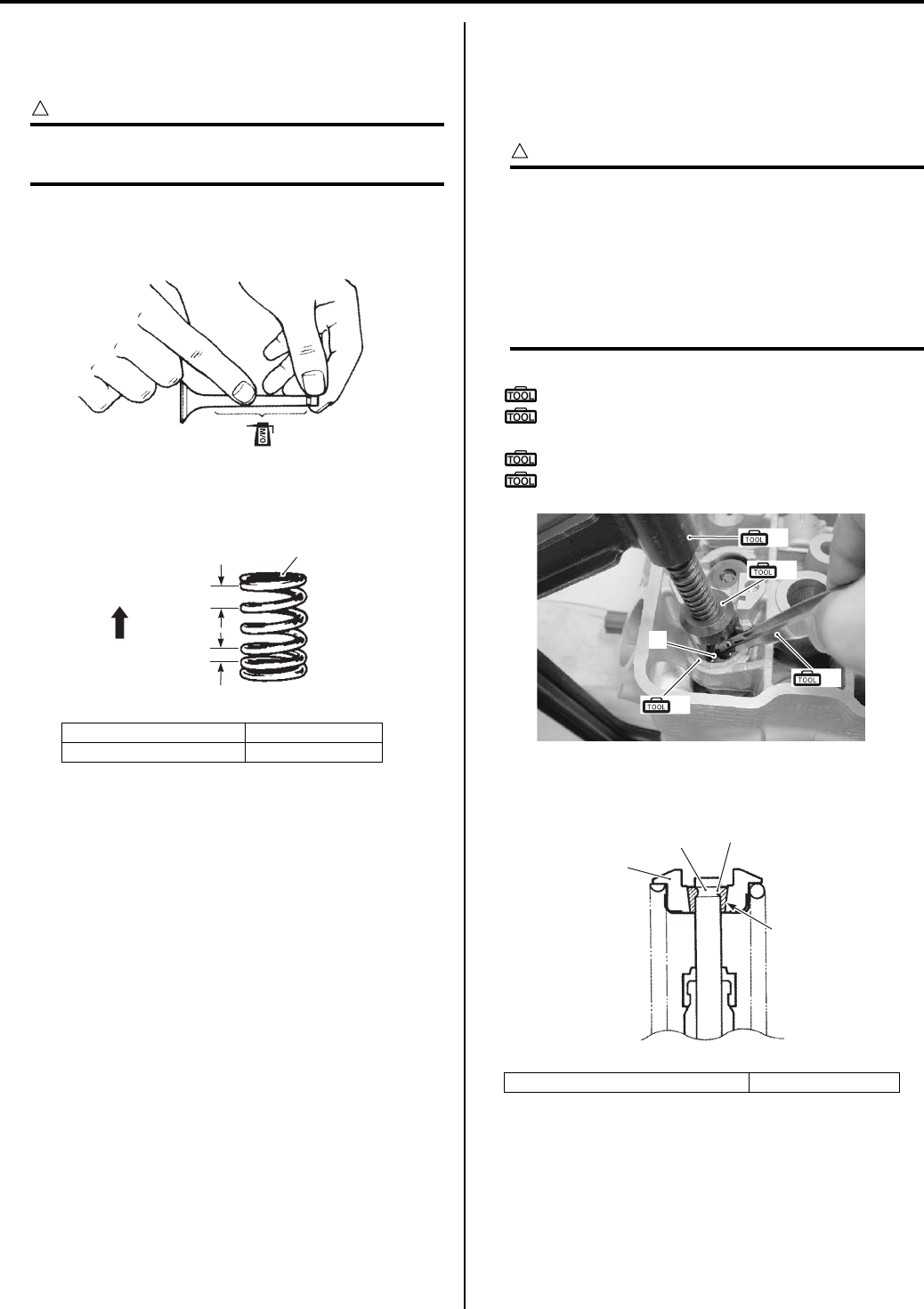
Engine Mechanical: 1D-34
• Insert the valve, with its stem coated with
molybdenum oil all around and along the full stem
length without any break.
CAUTION
!
When inserting the valve, take care not to
damage the lip of the oil seal.
M/O: Molybdenum oil (MOLYBDENUM OIL
SOLUTION)
• Install the valve spring with the small-pitch portion “B”
facing cylinder head.
• Put on the valve spring retainer (3), and using the
special tools, press down the spring, fit the cotter
halves to the stem end, and release the lifter to allow
the cotter halves to wedge in between retainer and
stem.
CAUTION
!
• Be sure to restore each spring and valve to
their original positions.
• Be careful not to damage the valve and
valve stem when handling them.
• To prevent damage of the tappet sliding
surface with the special tool, use the
sleeve protector.
Special tool
(A): 09916–14510 (Valve spring compressor)
(B): 09916–14910 (Valve spring compressor
attachment)
(C): 09916–84511 (Tweezers)
(D): 09919–28610 (Sleeve protector)
• Be sure that the rounded lip “F” of the cotter fits snugly
into the groove “G” in the stem end.
“B”: Small-pitch portion “D”: UPWARD
“C”: Large-pitch portion “E”: Paint
I705H1140165-01
“B”
“D” “C”
“E”
I718H1140004-01
3. Valve spring retainer 4. Cotter
(A)
(B)
(C)
(D)
3
I831G1140160-03
“F”
“G”
4
3
I831G1140161-02
PartShark.com
877-999-5686
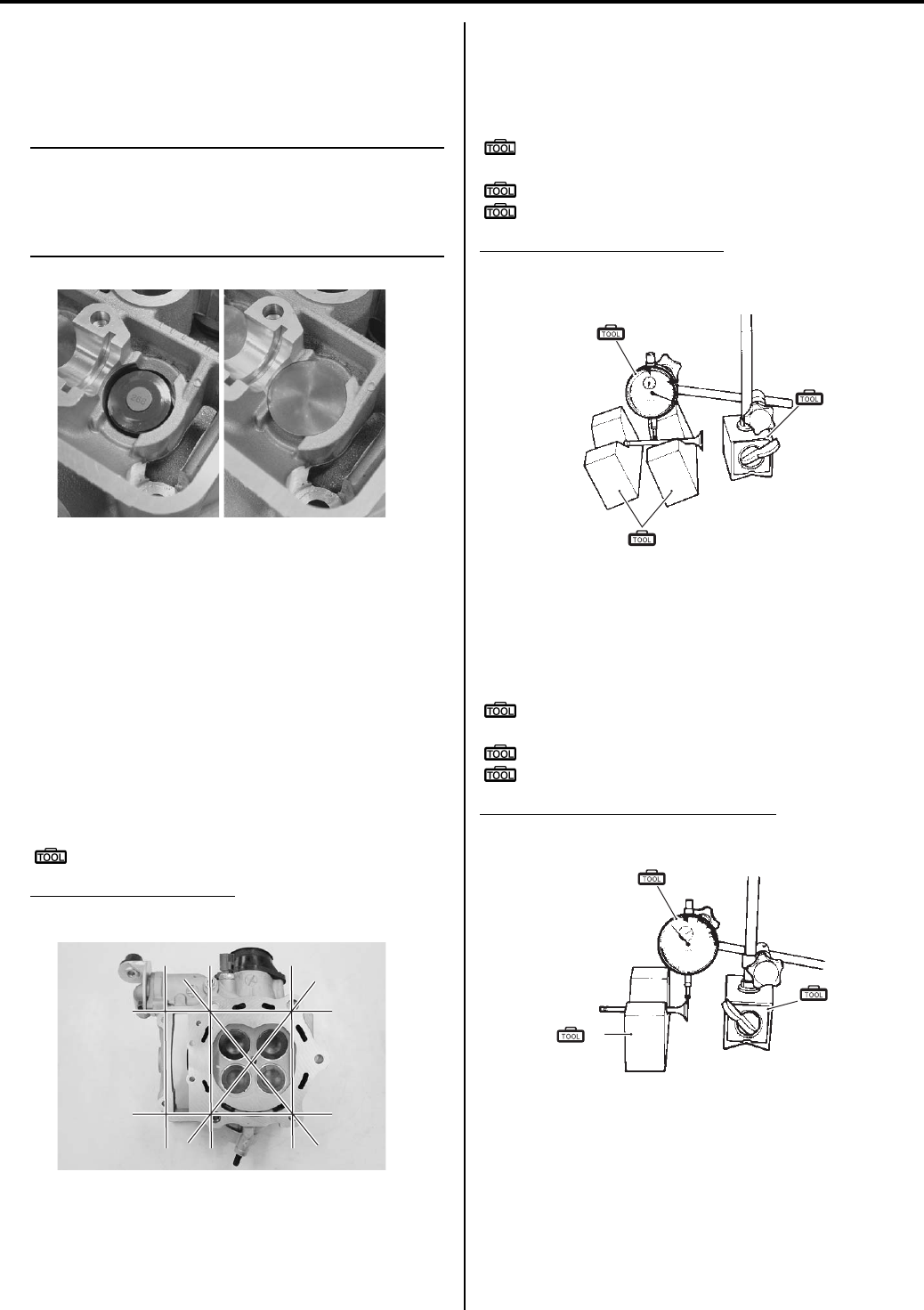
1D-35 Engine Mechanical:
• Install the other valves and springs in the same
manner as described previously.
• Install the tappet shims and the tappets to their
original positions.
NOTE
• Apply engine oil to the stem end, shim and
tappet before fitting them.
• When seating the tappet shim, be sure the
figure printed surface faces the tappet.
Cylinder Head Related Parts Inspection
B831G21406025
Refer to “Cylinder Head Disassembly and Assembly
(Page 1D-31)”.
Cylinder Head Distortion
1) Decarbonize the combustion chambers.
2) Check the gasket surface of the cylinder head for
distortion. Use a straightedge and thickness gauge.
Take clearance readings at several places. If
readings exceed the service limit, replace the
cylinder head.
Special tool
: 09900–20803 (Thickness gauge)
Cylinder head distortion
Service limit: 0.05 mm (0.002 in)
Valve Stem Runout
Support the valve using V-blocks, as shown, and check
its runout using the dial gauge. If the runout exceeds the
service limit, replace the valve.
Special tool
(A): 09900–20607 (Dial gauge (1/100 mm, 10
mm))
(B): 09900–20701 (Magnetic stand)
(C): 09900–21304 (V-block (100 mm))
Valve stem runout (IN. & EX.)
Service limit: 0.05 mm (0.002 in)
Valve Head Radial Runout
Place the dial gauge at a right angle to the valve head
face and measure the valve head radial runout. If it
measures more than the service limit, replace the valve.
Special tool
(A): 09900–20607 (Dial gauge (1/100 mm, 10
mm))
(B): 09900–20701 (Magnetic stand)
(C): 09900–21304 (V-block (100 mm))
Valve head radial runout (IN. & EX.)
Service limit: 0.03 mm (0.001 in)
I831G1140162-01
I831G1140163-01
(A)
(C)
(B)
I649G1140231-03
(A)
(B)
(C)
I649G1140232-03
PartShark.com
877-999-5686
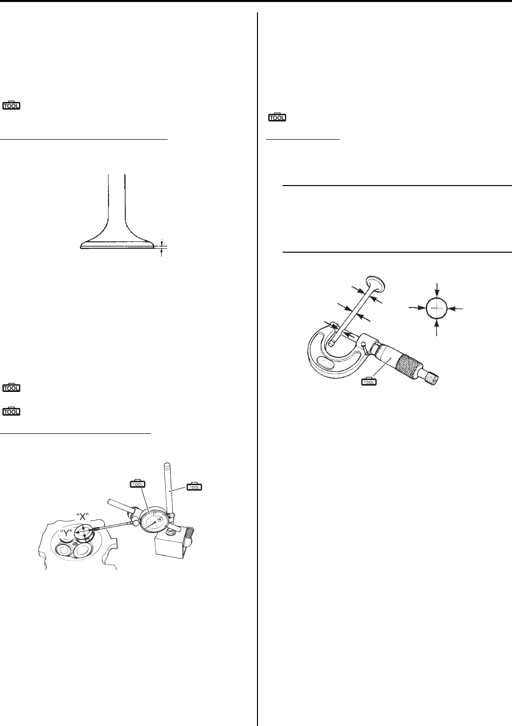
Engine Mechanical: 1D-36
Valve Face Wear
Visually inspect each valve face for wear. Replace any
valve with an abnormally worn face. The thickness of the
valve face decreases as the face wears. Measure the
valve head “a”. If it is out of specification replace the
valve with a new one.
Special tool
: 09900–20101 (Vernier calipers (1/15 mm, 150
mm))
Valve head thickness “a” (IN. & EX.)
Service limit: 0.5 mm (0.02 in)
Valve Stem Deflection
Lift the valve about 10 mm (0.39 in) “a” from the valve
seat. Measure the valve stem deflection in two
directions, “X” and “Y”, perpendicular to each other.
Position the dial gauge as shown. If the deflection
exceeds the service limit, then determine whether the
valve or the guide should be replaced with a new one.
Special tool
(A): 09900–20607 (Dial gauge (1/100 mm, 10
mm))
(B): 09900–20701 (Magnetic stand)
Valve stem deflection (IN. & EX.)
Service limit: 0.35 mm (0.014 in)
Valve Stem Wear
Measure the valve stem O.D. using the micrometer. If it
is out of specification, replace the valve with a new one.
If the valve stem O.D. is within specification but the valve
stem deflection is not, replace the valve guide. After
replacing the valve or valve guide, recheck the
deflection.
Special tool
(A): 09900–20205 (Micrometer (0 – 25 mm))
Valve stem O.D.
Standard (IN.): 5.475 – 5.490 mm (0.2156 – 0.2161 in)
Standard (EX.): 5.455 – 5.470 mm (0.2148 – 0.2154 in)
NOTE
If valve guides have to be removed for
replacement after inspecting related parts,
carry out the steps shown in valve guide
replacement. Refer to “Valve Guide
Replacement (Page 1D-38)”.
“a”
I649G1140233-02
(A) (B)
I831G1140164-02
(A)
I718H1140122-01
PartShark.com
877-999-5686
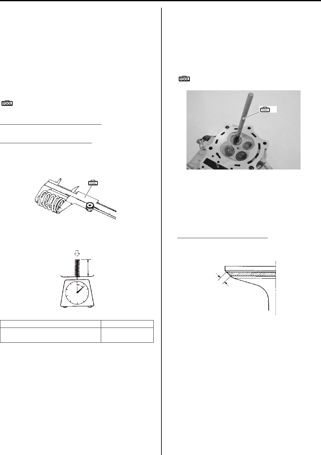
1D-37 Engine Mechanical:
Valve Spring
The force of the coil spring keeps the valve seat tight. A
weakened spring results in reduced engine power output
and often accounts for the chattering noise coming from
the valve mechanism.
Check the valve springs for proper strength by
measuring their free length and also by the force
required to compress them. If the spring length is less
than the service limit or if the force required to compress
the spring does not fall within the specified range,
replace the valve spring.
Special tool
(A): 09900–20101 (Vernier calipers (1/15 mm,
150 mm))
Valve spring free length (IN. & EX.)
Service limit: 46.1 mm (1.81 in)
Valve spring tension (IN. & EX.)
Standard: 182 – 210 N (18.6 – 21.4 kgf, 41.0 – 47.2
Ibs)/36.35 mm (1.43 in)
Valve Seat Width
1) Visually check for valve seat width on each valve
face. If the valve face has worn abnormally, replace
the valve.
2) Coat the valve seat with a red lead (Prussian Blue)
and set the valve in place.
3) Rotate the valve with light pressure.
Special tool
(A): 09916–10911 (Valve lapper set)
4) Check that the transferred red lead (blue) on the
valve face is uniform all around and in center of the
valve face.
If the seat width “a” measured exceeds the standard
value, or seat width is not uniform reface the seat
using the seat cutter. Refer to “Valve Seat Repair
(Page 1D-40)”.
Valve seat width “a” (IN. & EX.)
Standard: 0.9 – 1.1 mm (0.035 – 0.043 in)
Tension “a” Length “b”
182 – 210 N
(18.6 – 21.4 kgf, 41.0 – 47.2 lbs)
36.35 mm
(1.43 in)
(A)
I649G1140237-03
“a”
“b”
I649G1140238-03
(A)
I831G1140165-01
“a”
I649G1140246-02
PartShark.com
877-999-5686
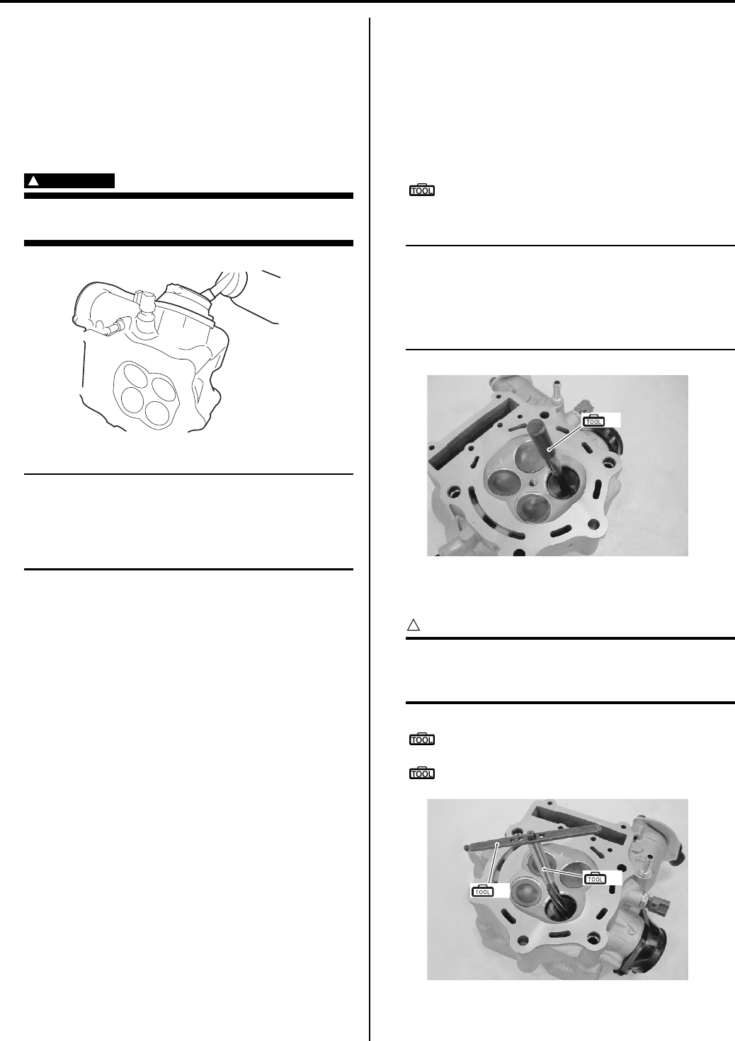
Engine Mechanical: 1D-38
Valve Seat Sealing Condition
1) Clean and assemble the cylinder head and valve
components.
2) Fill the intake and exhaust ports with gasoline to
check for leaks. If any leaks occur, inspect the valve
seat and face for burrs or other things that could
prevent the valve from sealing. Refer to “Valve Seat
Repair (Page 1D-40)”.
WARNING
!
Always use extreme caution when handling
gasoline.
NOTE
After servicing the valve seats, be sure to
check the valve clearance after the cylinder
head has been reinstalled. Refer to “Valve
Clearance Inspection and Adjustment in
Section 0B (Page 0B-4)”.
Valve Guide Replacement
B831G21406026
1) Remove the cylinder head. Refer to “Engine Top
Side Disassembly (Page 1D-17)”.
2) Remove the valves. Refer to “Cylinder Head
Disassembly and Assembly (Page 1D-31)”.
3) Using the valve guide remover, drive the valve guide
out toward the intake or exhaust camshaft side.
Special tool
(A): 09916–44910 (Valve guide remover/
installer)
NOTE
• Discard the removed valve guide sub-
assemblies.
• Only oversized valve guides are available
as replacement parts. (Part No. 11115-
32E70)
4) Refinish the valve guide holes in the cylinder head
using the reamer and handle.
CAUTION
!
When refinishing or removing the reamer
from the valve guide hole, always turn it
clockwise.
Special tool
(B): 09916–34580 (Valve guide reamer (10.8
mm))
(C): 09916–34542 (Reamer handle)
I831G1140334-02
(A)
I831G1140166-01
(B)
(C)
I831G1140167-01
PartShark.com
877-999-5686
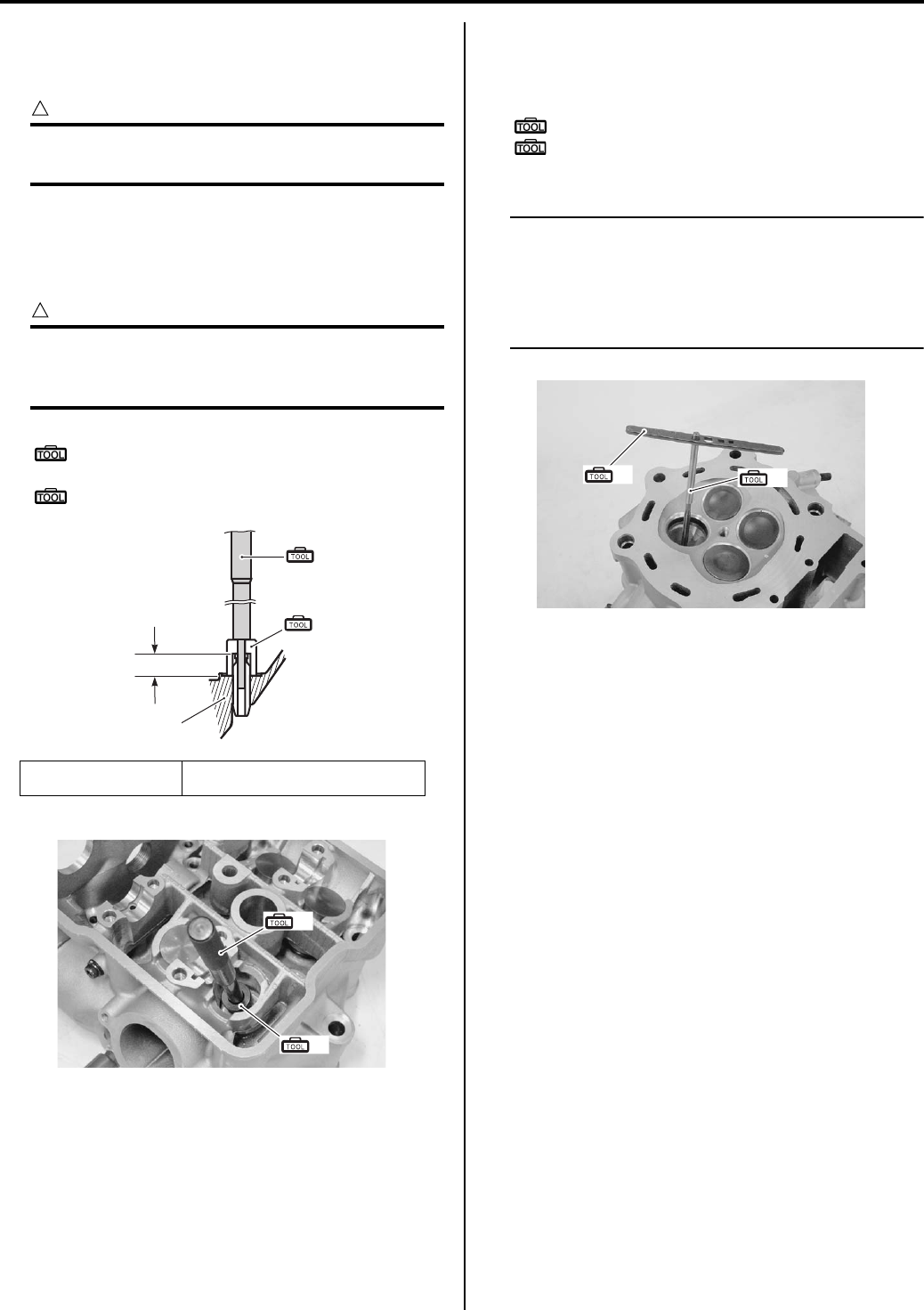
1D-39 Engine Mechanical:
5) Cool down the new valve guides in a freezer for
about one hour and heat the cylinder head to 100 –
150 °C (212 – 302 °F) with a hot plate.
CAUTION
!
Do not use a burner to heat the valve guide
hole to prevent cylinder head distortion.
6) Apply engine oil to each valve guide and valve guide
hole.
7) Drive the guide into the guide hole using the valve
guide installer.
CAUTION
!
Failure to oil the valve guide hole before
driving the new guide into place may result in
a damaged guide or head.
Special tool
(A): 09916–44910 (Valve guide remover/
installer)
(D): 09916–57360 (Attachment)
After installing the valve guides, refinish their guiding
bores using the reamer. Be sure to clean and oil the
guides after reaming.
Special tool
(C): 09916–34542 (Reamer handle)
(E): 09916–34550 (Valve guide reamer (5.5
mm))
NOTE
• Be sure to cool down the cylinder head to
ambient air temperature.
• Insert the reamer from the combustion
chamber and always turn the reamer
handle clockwise.
9) Reassemble the cylinder head. Refer to “Cylinder
Head Disassembly and Assembly (Page 1D-31)”.
10) Install the cylinder head assembly. Refer to “Engine
Top Side Assembly (Page 1D-21)”.
1. Cylinder head “a”: IN.: 14.5 mm (0.57 in)
EX.: 12.5 mm (0.49 in)
“a”
(A)
(D)
1
I718H1140127-01
(A)
(D)
I831G1140168-01
(C) (E)
I831G1140169-01
PartShark.com
877-999-5686
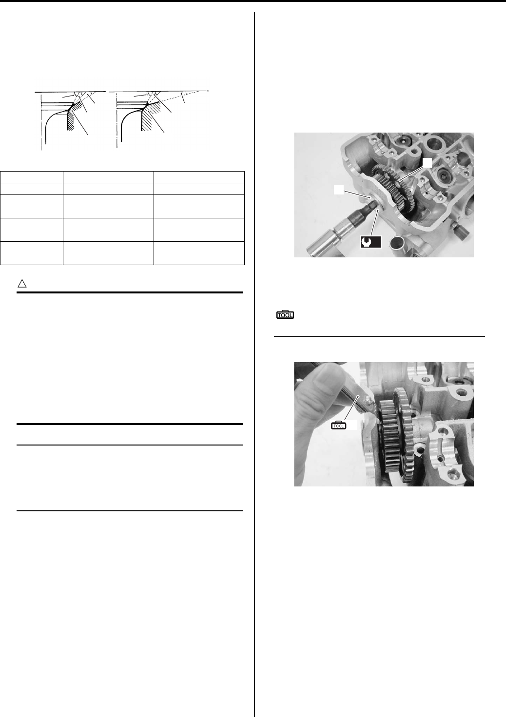
Engine Mechanical: 1D-40
Valve Seat Repair
B831G21406027
The valve seats (1) for both the intake and exhaust
valves are machined to three different angles. The seat
contact surface is cut at 45°.
CAUTION
!
• The valve seat contact area must be
inspected after each cut.
• Do not use lapping compound after the
final cut is made. The finished valve seat
should have a velvety smooth finish but
not a highly polished or shiny finish. This
will provide a soft surface for the final
seating of the valve which will occur
during the first few seconds of engine
operation.
NOTE
After servicing the valve seats, be sure to
check the valve clearance after the cylinder
head has been reinstalled. Refer to “Valve
Clearance Inspection and Adjustment in
Section 0B (Page 0B-4)”.
Cam Drive Idle Gear / Sprocket Thrust
Clearance Inspection and Adjustment
B831G21406028
Inspection
• Install the cam drive idle gear/sprocket (1) and tighten
the shaft (2) to the specified torque.
Tightening torque
Cam drive idle gear/sprocket shaft (a): 41 N·m (
4.1 kgf-m, 29.5 lb-ft)
• Measure the thrust clearance between the idle gear
and shim by using a thickness gauge.
Special tool
(A): 09900–20803 (Thickness gauge)
Cam drive idle gear/sprocket thrust clearance
Standard: 0.15 – 0.27 mm (0.006 – 0.011 in)
Intake Exhaust
Seat angle 30°/45°/60°15°/45°/60°
Seat width 0.9 – 1.1 mm
(0.035 – 0.043 in) ←
Valve
diameter
36 mm
(1.42 in)
33 mm
(1.30 in)
Valve guide
I.D.
5.500 – 5.512 mm
(0.2165 – 0.2170 in) ←
11
60°
30°
45°
15°
45°
60°
IN EX
I831G1140170-02
(a)
1
2
I831G1140171-01
(A)
I831G1140172-01
PartShark.com
877-999-5686
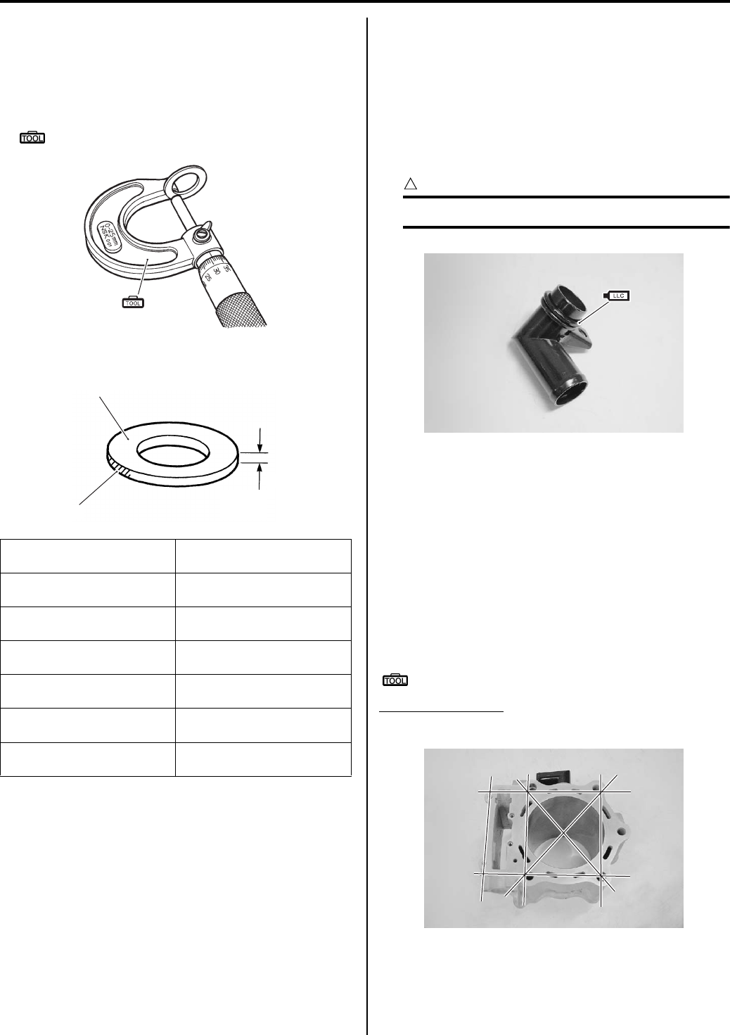
1D-41 Engine Mechanical:
Adjustment
If the thrust clearance is exceed the standard, adjust the
thrust clearance by the following procedures:
• Remove the shim, and measure its thickness with a
micrometer.
Special tool
(A): 09900–20205 (Micrometer (0 – 25 mm))
• Replace the sim with a other size.
• Recheck the thrust clearance.
Cylinder Disassembly and Assembly
B831G21406029
Disassembly
Refer to “Engine Top Side Disassembly (Page 1D-17)”.
Assembly
Assembly is in the reverse order of disassembly. Pay
attention to the following points:
• Apply engine coolant to O-ring of water union.
CAUTION
!
Replace the O-ring with a new one.
• Tighten the water union bolt.
Cylinder Inspection
B831G21406030
Refer to “Engine Top Side Disassembly (Page 1D-17)”.
Refer to “Engine Top Side Assembly (Page 1D-21)”.
Cylinder Distortion
Check the gasket surface of the cylinder for distortion.
Use a straightedge and thickness gauge. Take clearance
readings at several places. If any reading exceeds the
service limit, replace the cylinder.
Special tool
: 09900–20803 (Thickness gauge)
Cylinder distortion
Service limit: 0.05 mm (0.102 in)
Color “A”/Mark “B”
(part No.) Shim thickness “C”
Dark blue
(09181-15182)
1.38 – 1.42
(0.054 – 0.056)
Yellow
(09181-15181)
1.28 – 1.32
(0.050 – 0.052)
Light blue
(09181-15176)
1.18 – 1.22
(0.046 – 0.048)
Light green
(09181-15172)
1.08 – 1.12
(0.043 – 0.044)
Brown
(09181-15166)
0.98 – 1.02
(0.039 – 0.040)
“J” mark
(09181-15164)
0.88 – 0.92
(0.035 – 0.036)
(A)
I831G1140173-01
“C”
“A”
“B”
I831G1140174-01
I831G1140175-01
I831G1140176-01
PartShark.com
877-999-5686
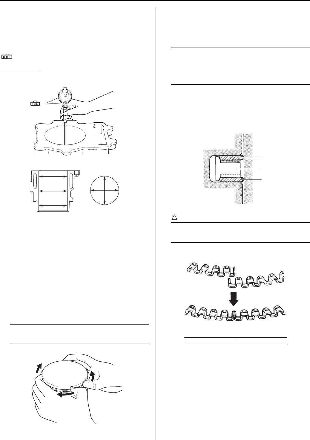
Engine Mechanical: 1D-42
Cylinder Bore
Inspect the cylinder wall for any scratches, nicks or other
damage. If any defects are found, replace the cylinder
with a new one.
Measure the cylinder bore diameter at six places.
Special tool
(A): 09900–20530 (Cylinder gauge set)
Cylinder bore
Standard: 104.000 – 104.015 mm (4.0945 – 4.0951 in)
Piston-to-cylinder Clearance
Refer to “Piston and Piston Ring Inspection (Page 1D-
43)”.
Piston Ring Removal and Installation
B831G21406031
Removal
1) Draw out the piston pin and remove the piston. Refer
to “Engine Top Side Disassembly (Page 1D-17)”.
2) Carefully spread the ring opening with your thumbs
and then push up the opposite side of the 1st ring to
remove it.
NOTE
Do not expand the piston ring excessively
since it is apt to be broken down.
3) Remove the 2nd ring and oil ring in the same
manner.
Installation
NOTE
• When installing the piston ring, be careful
not to damage the piston.
• Do not expand the piston ring excessively
since it is apt to be broken down.
1) Install the piston rings in the order of the oil ring,
second ring and top ring.
a) The first member to go into the oil ring groove is
a spacer (1).
After placing the spacer, fit the two side rails (2).
CAUTION
!
When installing the spacer, be careful so that
the both edges are not overlapped.
(A)
I831G1140177-01
I718H1140141-01
I831G1140178-01
“A”: INCORRECT “B”: CORRECT
1
2
2
I718H1140143-02
A
B
“A”
“B”
I705H1140170-02
PartShark.com
877-999-5686
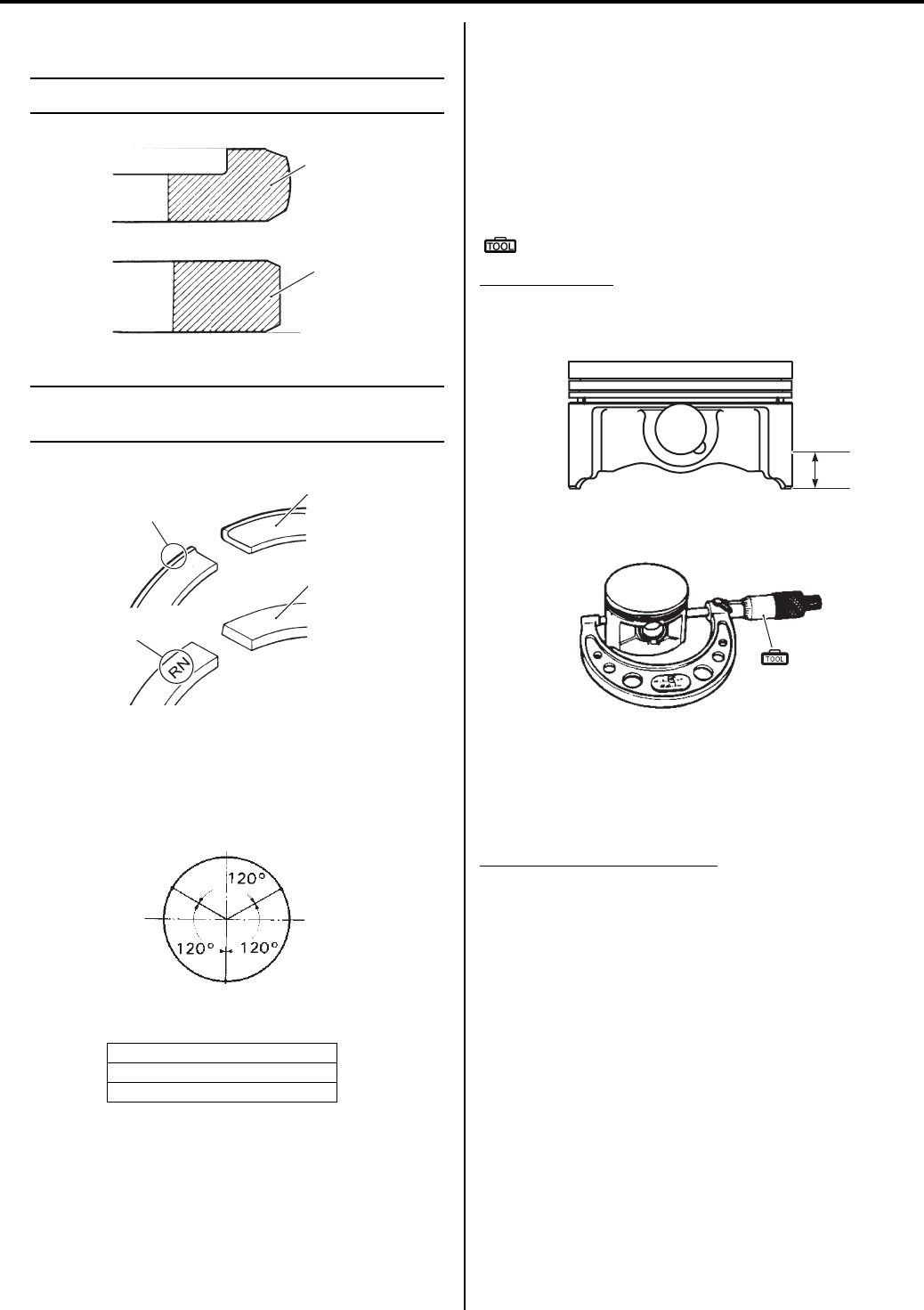
1D-43 Engine Mechanical:
b) Install the 2nd ring (3) and 1st ring (4) to piston.
NOTE
1st ring (4) and 2nd ring (3) differ in shape.
NOTE
Face the side with the edge “C” and stamped
mark “D” upward when assembling.
2) Position the gaps of the three rings and side rails as
shown. Before inserting piston into the cylinder,
check that the gaps are so located.
3) Install the piston and piston pin. Refer to “Engine Top
Side Assembly (Page 1D-21)”.
Piston and Piston Ring Inspection
B831G21406032
Refer to “Piston Ring Removal and Installation
(Page 1D-42)”.
Piston Diameter
Measure the piston diameter using the micrometer at 15
mm (0.6 in) “a” from the skirt end. If the piston diameter
is less than the service limit, replace the piston.
Special tool
(A): 09900–20210 (Micrometer (100 – 125 mm))
Piston diameter
Service limit: 103.880 mm (4.0898 in)
Piston-to-cylinder Clearance
Subtract the piston diameter from the cylinder bore
diameter. If the piston-to-cylinder clearance exceeds the
service limit, replace both the cylinder and the piston.
Piston-to-cylinder clearance
Service limit: 0.120 mm (0.0047 in)
“D”: 2nd ring and lower side rail
“E”: Upper side rail
“F”: 1st ring and spacer
3
4
I831G1140179-02
3
4
“C”
“D”
I831G1140180-01
EX
IN
“D” “E”
“F”
I831G1140181-03
“a”
I831G1140335-02
(A)
I831G1140337-01
PartShark.com
877-999-5686
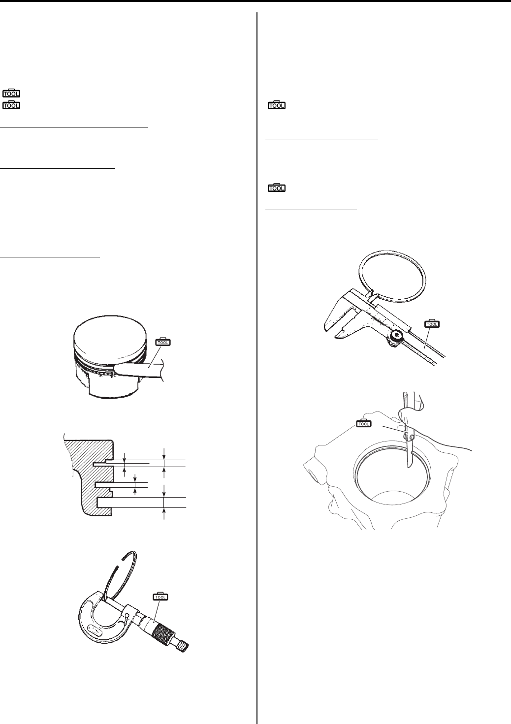
Engine Mechanical: 1D-44
Piston Ring-to-groove Clearance
Measure the side clearances of the 1st and 2nd piston
rings using the thickness gauge. If any of the clearances
exceed the limit, replace both the piston and piston
rings.
Special tool
(A): 09900–20803 (Thickness gauge)
(B): 09900–20205 (Micrometer (0 – 25 mm))
Piston ring-to-groove clearance
Service limit: (1st): 0.180 mm (0.0071 in)
Service limit: (2nd): 0.150 mm (0.0059 in)
Piston ring groove width
“a”: Standard: (1st): 0.83 – 0.85 mm (0.0327 – 0.0335
in)
“b”: Standard: (1st): 1.30 – 1.32 mm (0.0512 – 0.0520
in)
Standard: (2nd): 1.01 – 1.03 mm (0.0398 – 0.0406 in)
Standard: (Oil): 2.01 – 2.03 mm (0.0791 – 0.0799 in)
Piston ring thickness
Standard: (1st):0.76 – 0.81 mm (0.0299 – 0.0319)
Standard: (1st):1.08 – 1.10 mm (0.0425 – 0.0433)
Standard: (2nd): 0.97 – 0.99 mm (0.0382 – 0.0390 in)
Piston Ring Free End Gap and Piston Ring End Gap
Measure the piston ring free end gap using vernier
calipers. Next, fit the piston ring squarely into the
cylinder and measure the piston ring end gap using the
thickness gauge. If any of the measurements exceed the
service limit, replace the piston ring with a new one.
Special tool
(A): 09900–20101 (Vernier calipers (1/15 mm,
150 mm))
Piston ring free end gap
Service limit: (1st): 10.5 mm (0.41 in)
Service limit: (2nd): 11.7 mm (0.46 in)
Special tool
(B): 09900–20803 (Thickness gauge)
Piston ring end gap
Service limit: (1st): 0.50 mm (0.020 in)
Service limit: (2nd): 0.50 mm (0.020 in)
(A)
I831G1140183-03
“a” “b”
I831G1140336-01
(B)
I649G1140264-03
(A)
I649G1140265-03
(B)
I831G1140184-02
PartShark.com
877-999-5686
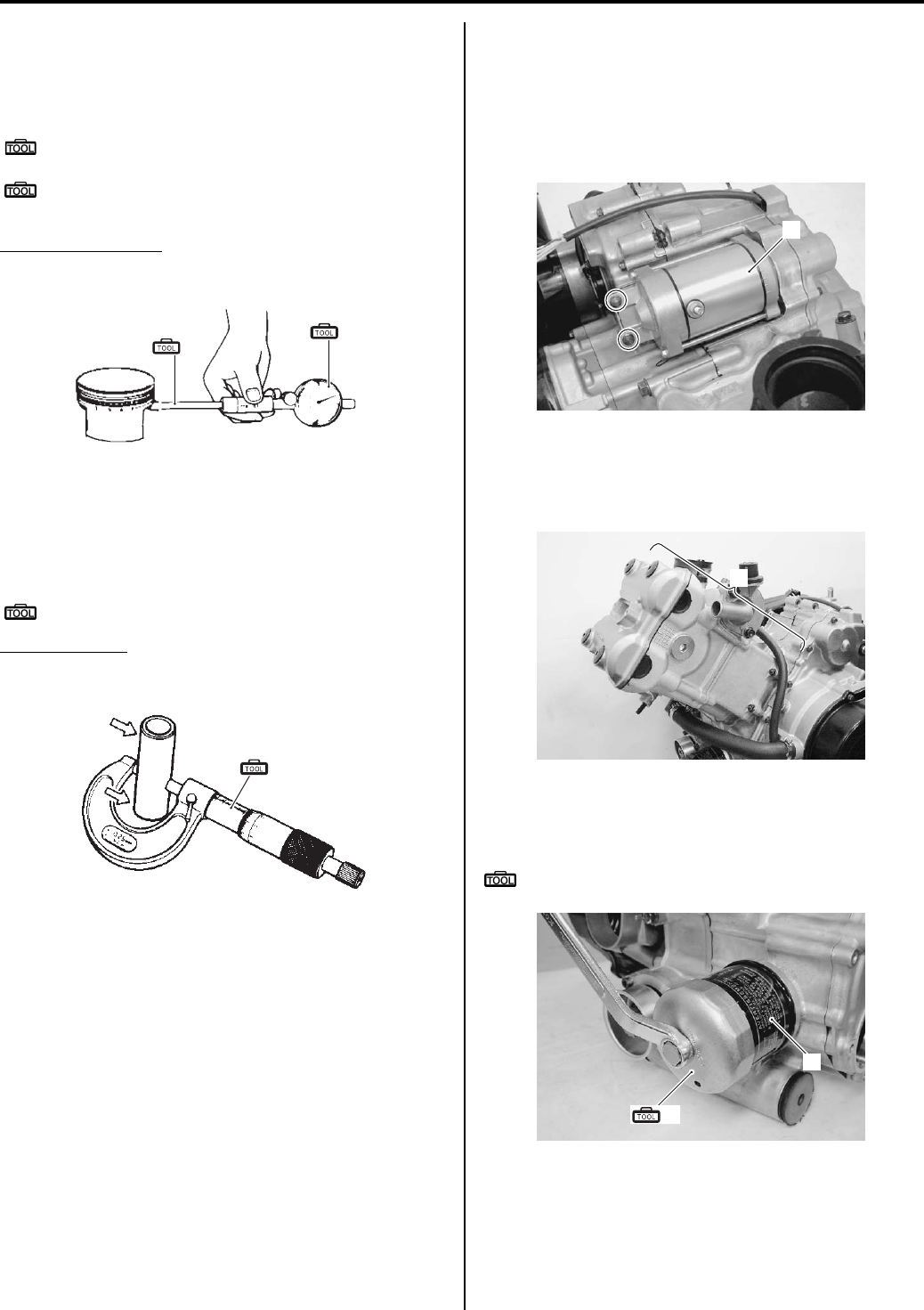
1D-45 Engine Mechanical:
Piston Pin and Pin Bore
Measure the piston pin bore inside diameter using the
small bore gauge. If measurement is out of specification,
replace the piston.
Special tool
(A): 09900–20602 (Dial gauge (1/1000 mm, 1
mm))
(B): 09900–22403 (Small bore gauge (18 – 35
mm))
Piston pin bore I.D.
Service limit: 23.030 mm (0.9067 in)
Measure the piston pin outside diameter at three
positions using the micrometer. If any of the
measurements are out of specification, replace the
piston pin.
Special tool
(C): 09900–20205 (Micrometer (0 – 25 mm))
Piston pin O.D.
Service limit: 22.980 mm (0.9047 in)
Engine Bottom Side Disassembly
B831G21406033
Remove the engine assembly. Refer to “Engine
Assembly Removal (Page 1D-13)”.
Starter Motor
Remove the starter motor (1).
Engine Top Side
Remove the engine top side (1). Refer to “Engine Top
Side Disassembly (Page 1D-17)”.
Oil Filter
Remove the oil filter (1) with the special tool.
Special tool
(A): 09915–40610 (Oil filter wrench)
(A)
(B)
I831G1140185-02
(C)
I649G1140268-03
1
I831G1140189-01
1
I831G1140333-01
(A)
1
I831G1140191-01
PartShark.com
877-999-5686
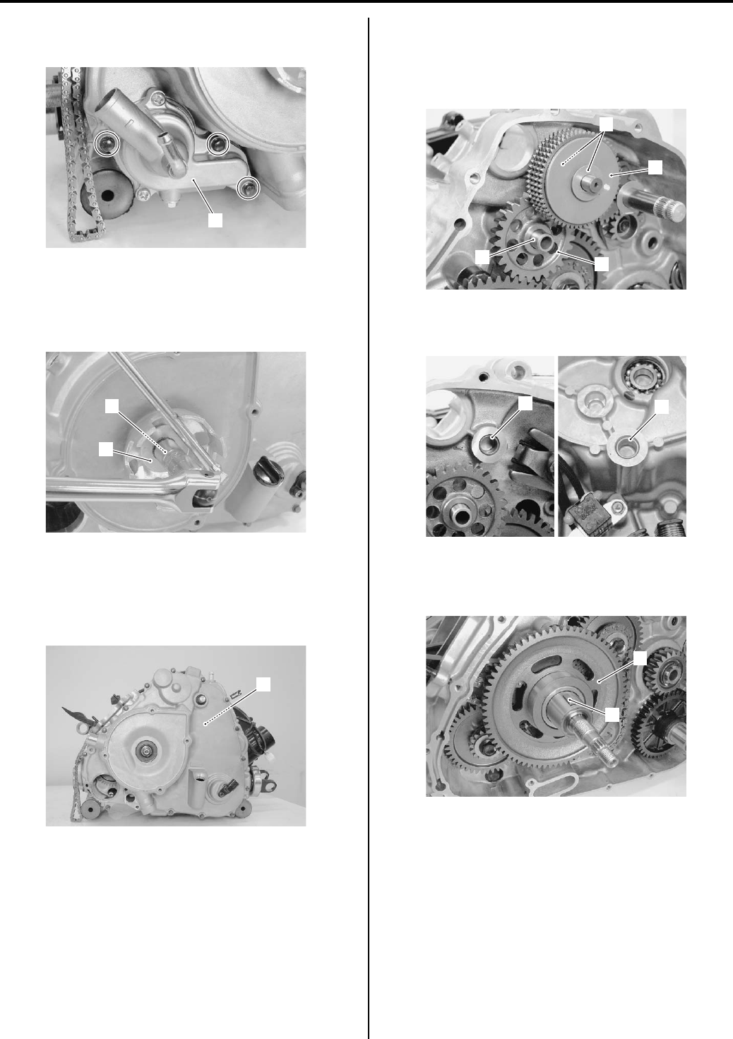
Engine Mechanical: 1D-46
Water Pump
Remove the water pump (1).
Starter Cup
1) Remove the starter cup nut (1) with a suitable bar.
2) Remove the starter cup (2).
Generator
Remove the generator component parts (1). Refer to
“Generator Removal and Installation in Section 1J
(Page 1J-4)”.
Starter Torque Limiter / Starter Idle Gear
1) Remove the starter torque limiter (1) with the
washers (2).
2) Remove the starter idle gear (3) and shaft (4).
3) Remove the bushings (5) from the crankcase and
generator cover.
Starter Driven Gear
Remove the key (1) and starter driven gear (2).
1
I831G1140192-01
1
2
I831G1140193-01
1
I831G1140194-01
1
3
4
2
I831G1140196-02
5
5
I831G1140197-01
1
2
I831G1140195-01
PartShark.com
877-999-5686
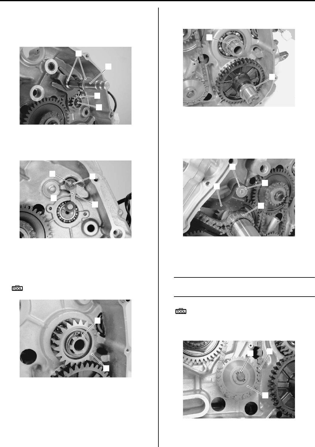
1D-47 Engine Mechanical:
Gear Shift System
1) Remove the washers (1) and gearshift shaft (2).
2) Remove the cam driven gear (3) by removing its bolt
(4).
3) Remove the gear shift cam stopper bolt (5) and gear
shift cam stopper (6), washer (7) and return spring
(8).
Transfer Output Drive Gear
1) Remove the snap ring (1) and transfer output drive
gear (2).
Special tool
: 09900–06107 (Snap ring pliers)
2) Remove the drive gear spacer (3) and output shaft
spacer (4).
Cam Chain / Cam Chain Tensioner
1) Remove the cam chain tensioner bolt (1), cam chain
tensioner (2) and washer (3).
2) Remove the cam chain (4).
Oil Pump
1) Remove the snap ring (1).
NOTE
Do not drop the snap ring (1) into the
crankcase.
Special tool
: 09900–06107 (Snap ring pliers)
2) Remove the oil pump drive chain (2) and oil pump
driven gear (3) from the oil pump.
3
4
2
1
I831G1140198-02
5
6
7
8
I831G1140199-01
1
2
I831G1140203-01
3
4
I831G1140204-01
1
2
4
3
I831G1140205-01
12
3
I831G1140207-01
PartShark.com
877-999-5686
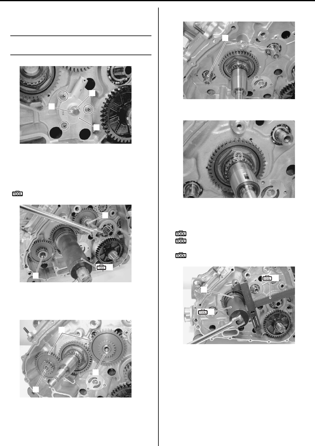
Engine Mechanical: 1D-48
3) Remove the pin (4) and washer (5).
4) Remove the oil pump (6).
NOTE
Do not drop the pin (4) and washer (5) into
the crankcase.
Balancer Shaft Drive / Driven Gear
1) Remove the balancer shaft driven gear bolts (1) by
holding the crankshaft with the special tool.
Special tool
: 09924–52460 (Socket (52 mm))
2) Remove the water pump drive gear (2) and oil pump
drive gear (3).
3) Remove the crank balancer shaft driven gears (4).
4) Remove the keys (5).
5) Unlock the crank balancer drive gear nut.
6) Remove the crank balancer drive gear nut (5) with
the special tools.
Special tool
(A): 09924–52460 (Socket (52 mm))
(B): 09920–53740 (Clutch sleeve hub
holder)
: 09920–31020 (Extension handle)
5
6
4
I831G1140209-01
(A)
1
1
I831G1140210-01
2
3
4
I831G1140211-01
5
I831G1140212-01
I831G1140213-02
(A)
(B)
5
I831G1140214-01
PartShark.com
877-999-5686
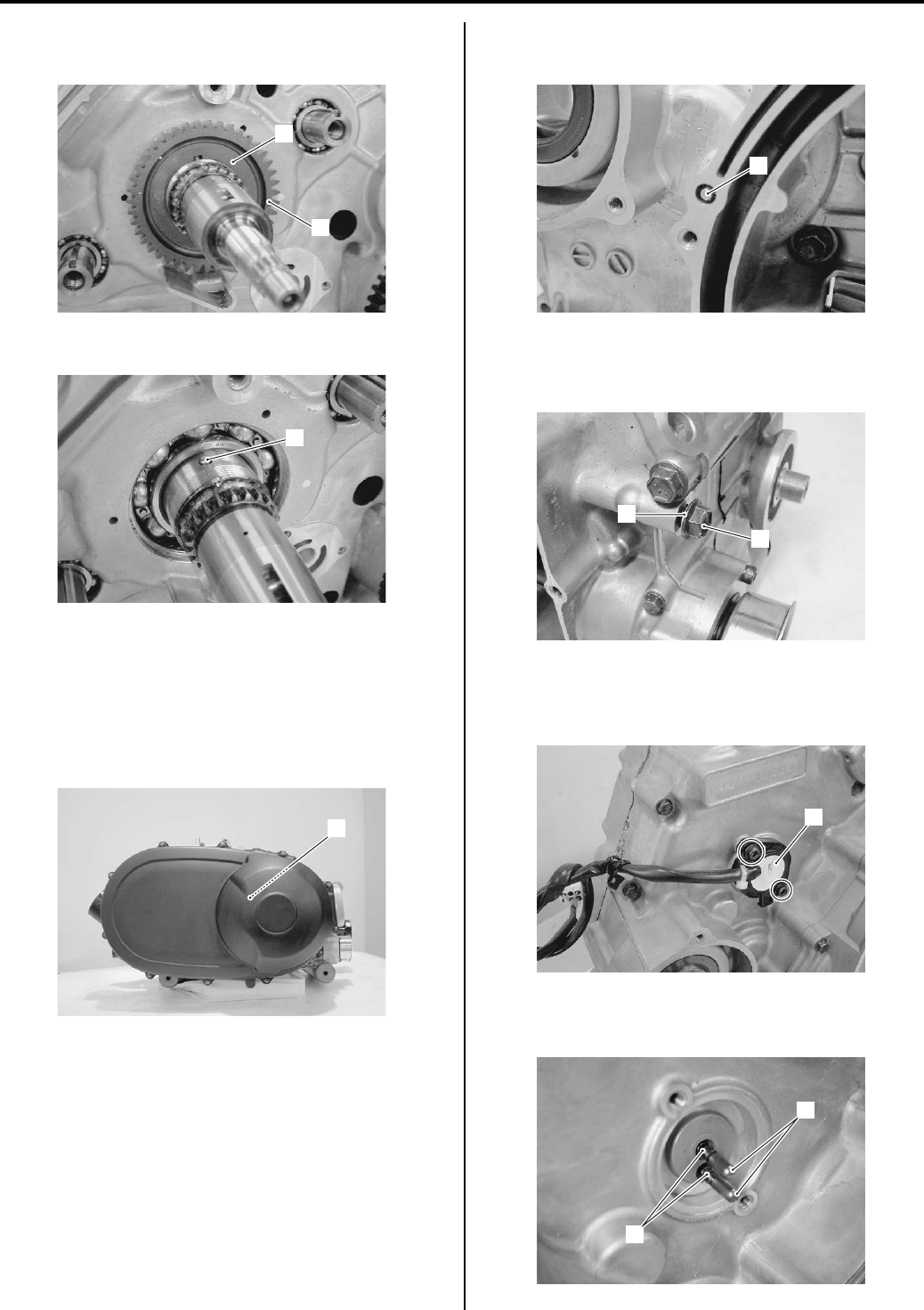
1D-49 Engine Mechanical:
7) Remove the washer (6) and crank balancer drive
gear (7).
Remove the pin (8).
Automatic Transmission
Remove the automatic component parts (1). Refer to “V—
belt Type Continuously Variable Automatic Transmission
Removal and Installation in Section 5A (Page 5A-5)” and
“Clutch Shoe Removal and Installation in Section 5A
(Page 5A-16)”.
Oil Jet
Remove the oil jet (1) from crankcase.
Oil Gallery Plug
Remove the oil gallery plug (1) and gasket (2).
Gear Position Switch
1) Remove the gear position switch (1).
2) Remove the gear position switch contacts (2) and its
springs (3).
6
7
I831G1140215-01
8
I831G1140216-01
1
I831G1140217-01
1
I831G1140218-01
1
2
I831G1140219-01
1
I831G1140220-01
2
3
I831G1140221-01
PartShark.com
877-999-5686
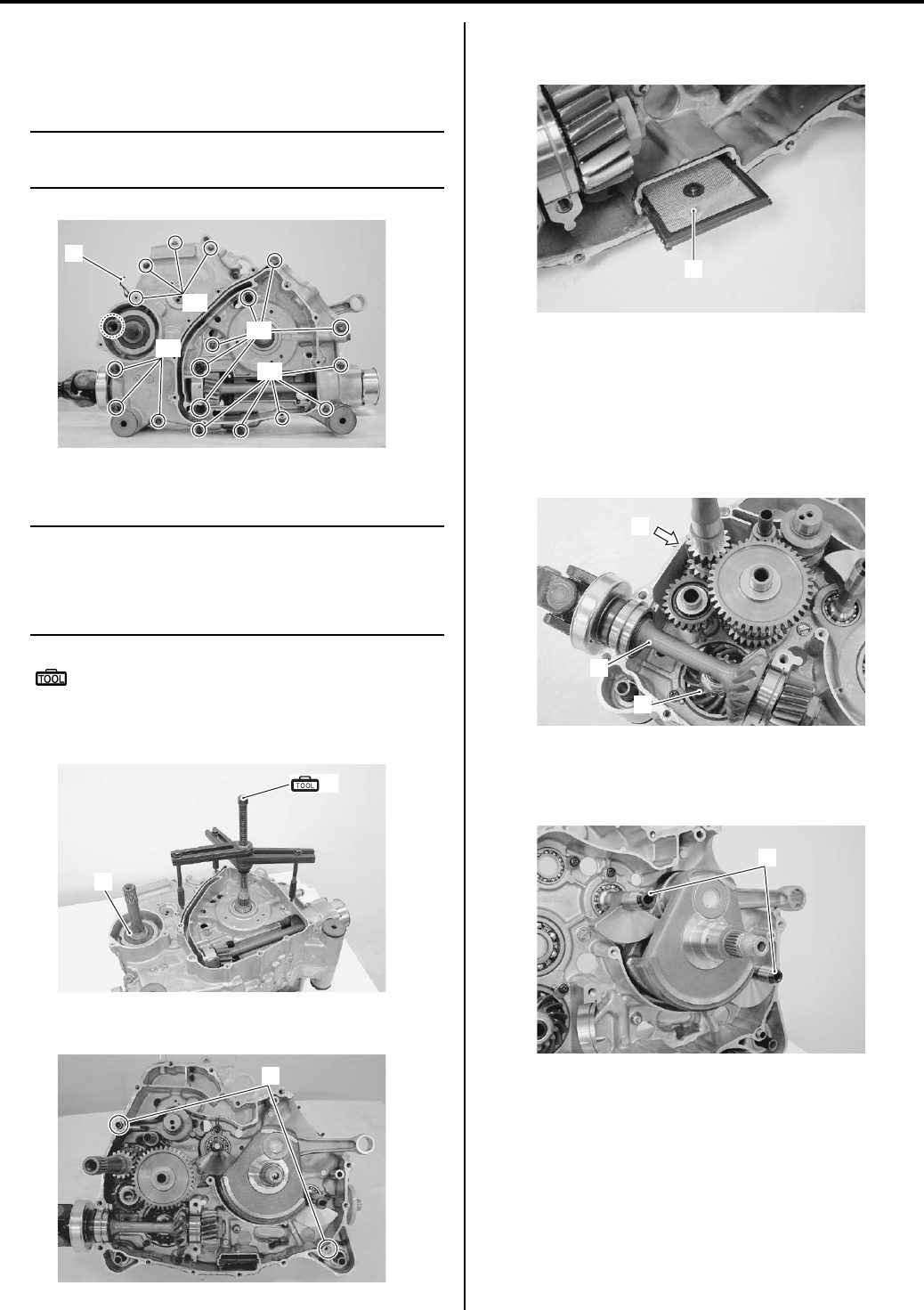
Engine Mechanical: 1D-50
Crankcase
1) Remove the crankcase bolts “A” and clamp (1).
2) Remove the crankcase bolts “B”.
NOTE
Loosen the crankcase bolts diagonally with
the smaller sizes first.
3) Separate the crankcase with the special tool.
NOTE
• The crankcase separator plate is parallel
with the end face of the crankcase.
• The crankshaft must remain in the left
crankcase half.
Special tool
(A): 09920–13120 (Crankcase separating
tool)
4) Remove the collar (2).
5) Remove the dowel pins (3).
Oil Strainer
Remove the oil strainer (1).
Transfer / Rear Output Shaft / Rear Output Shaft
Bevel Gear
Remove the transfer component parts (1), rear output
shaft (2) and rear output shaft bevel gear component
parts (3). Refer to “Transfer Removal and Installation in
Section 3C (Page 3C-3)”.
Crank Balancer
Remove the crank balancer shafts (1).
1
“B”
“A”
“A”
“A”
I831G1140222-02
(A)
2
I831G1140224-01
3
I831G1140225-01
1
I831G1140229-01
3
1
2
I831G1140230-03
1
I831G1140233-01
PartShark.com
877-999-5686
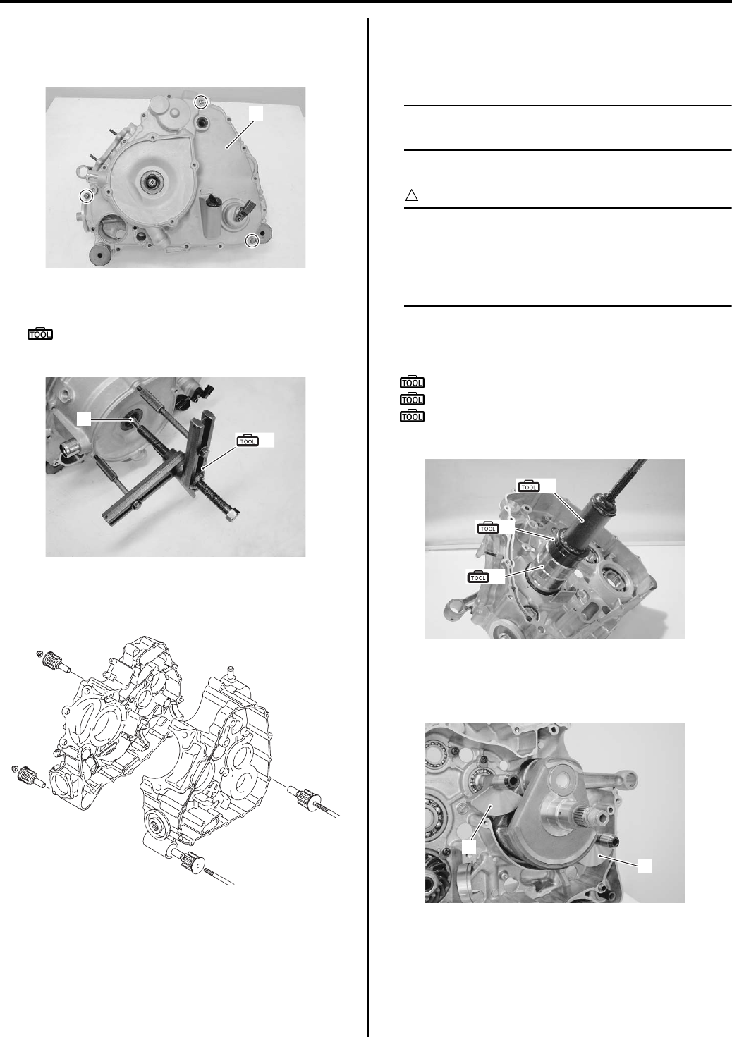
1D-51 Engine Mechanical:
Crankshaft
1) Install the removed generator cover (1) and tighten
the bolts at three places.
2) Remove the crankshaft (2) with the special tool.
Special tool
(A): 09920–13120 (Crankcase separating
tool)
Engine Mount Bushing
Remove the engine mount bushings if necessary.
Engine Bottom Side Assembly
B831G21406034
Assemble the engine bottom side in the reverse order of
disassembly. Pay attention to the following points:
NOTE
Apply engine oil to each running and sliding
part before reassembling.
Crankshaft
CAUTION
!
Never fit the crankshaft into the crankcase by
striking it with a plastic mallet.
Always use the special tool, otherwise the
accuracy of the crankshaft alignment will be
affected.
• Install the crankshaft to left crankcase with the special
tools.
Special tool
(A): 09910–32812 (Crankshaft installer)
(B): 09910–32860 (Attachment)
(C): 09941–53610 (Front fork installer
hammer)
Crank Balancer
• Install the crank balancer shafts (1).
1
I831G1140234-01
2
(A)
I831G1140236-01
I831G1140237-01
(A)
(B)
(C)
I831G1140239-01
1
1
I831G1140241-01
PartShark.com
877-999-5686
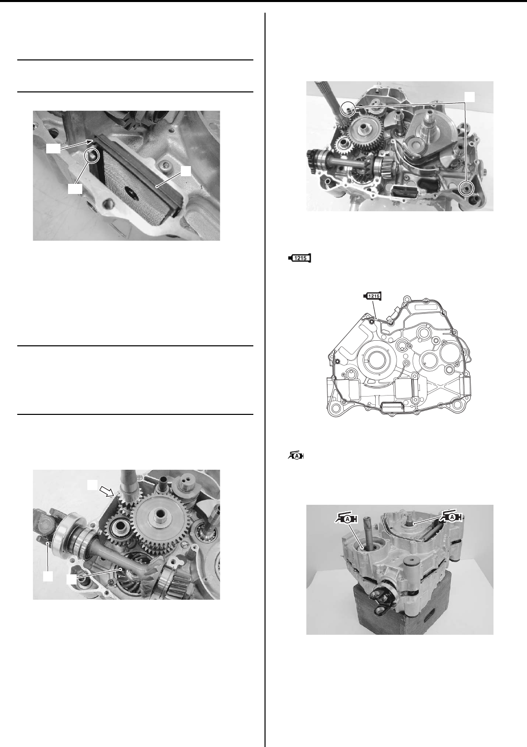
Engine Mechanical: 1D-52
Oil Strainer
• Install the oil strainer (1).
NOTE
Fit the convex part “A” of the oil strainer in
the concave part “B” of the crankcase.
Transfer / Rear Output Shaft / Rear Output Shaft
Bevel Gear
• Install the rear output shaft bevel gear (1) and rear
output shaft (2). Refer to “Transfer Removal and
Installation in Section 3C (Page 3C-3)”.
NOTE
Measure the backlash before installing the
transfer component parts (3). Refer to “Rear
Output Shaft Drive Bevel Gear Shim
Inspection and Adjustment in Section 3D
(Page 3D-11)”.
• Install the transfer component parts (3). Refer to
“Transfer Removal and Installation in Section 3C
(Page 3C-3)”.
Crankcase
• Wipe the crankcase mating surface (both surfaces).
• Insert the dowel pins (1) onto the left crankcase.
• Apply engine oil to the conrod big end and each gear.
• Apply bond to the mating surface of the right
crankcase.
: Sealant 99000–31110 (SUZUKI BOND
No.1215 or equivalent)
• Apply grease to the oil seals.
: Grease 99000–25010 (SUZUKI SUPER
GREASE A or equivalent)
• Assemble the crankcase with in few minutes.
“A”
“B”
1
I831G1140246-01
2
3
1
I831G1140247-02
1
I831G1140248-03
I831G1140252-01
I831G1140250-01
PartShark.com
877-999-5686
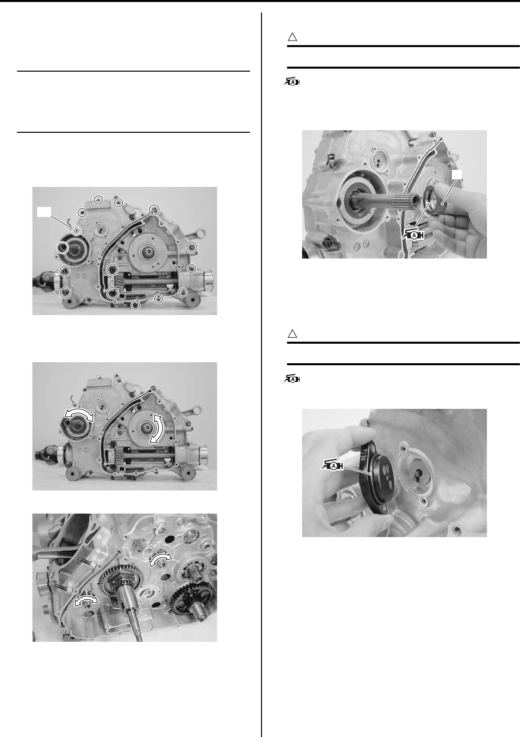
1D-53 Engine Mechanical:
• Tighten the crankcase bolts a little at a time to
equalize the pressure.
• Tighten the crankcase bolts to the specified torque.
NOTE
• Tighten the larger diameter crankcase
bolts first and then smaller ones
diagonally and evenly.
• Fit the cramp to the bolt “A”.
Tightening torque
Crankcase bolt (M6): 10 N·m (1.0 kgf-m, 7.0 lb-ft)
Crankcase bolt (M8): 26 N·m (2.6 kgf-m, 19.0 lb-ft)
• After the crankcase bolts have been tightened, check
if the each shaft rotate smoothly.
• Apply grease to the O-ring.
CAUTION
!
Use the new O-ring to prevent oil leakage.
: Grease 99000–25010 (SUZUKI SUPER
GREASE A or equivalent)
• Install the collar (2).
Gear Position Switch
• Install each gear shift switch contact and spring.
• Apply grease to the O-ring.
CAUTION
!
Replace the O-ring with a new one.
: Grease 99000–25010 (SUZUKI SUPER
GREASE A or equivalent)
“A”
I831G1140253-01
I831G1140255-01
I831G1140256-02
2
I831G1140258-03
I831G1140260-01
PartShark.com
877-999-5686
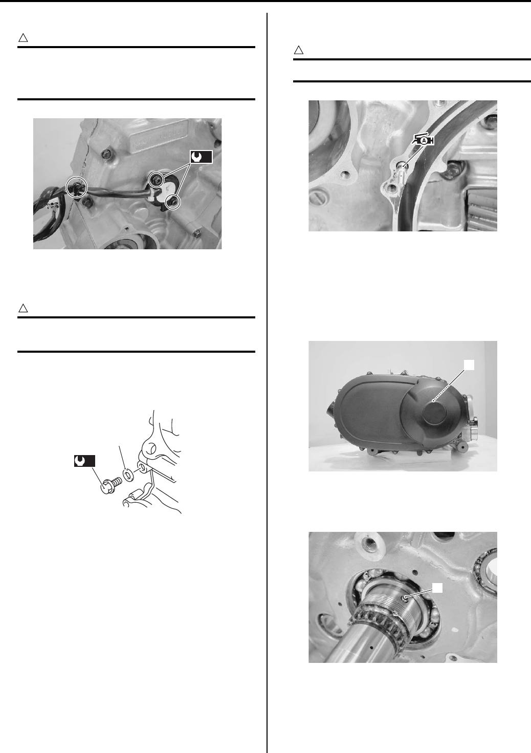
Engine Mechanical: 1D-54
• Tighten the gear position switch mounting bolts.
CAUTION
!
• Be careful not to tighten the bolts too
much.
• Clamp the read wire firmly.
Oil Gallery Plug
Install the oil gallery plug to the specified torque.
CAUTION
!
Use a new gasket (1) to prevent oil pressure
leak.
Tightening torque
Main oil gallery plug (a): 18 N·m (1.8 kgf-m, 13.0 lb-
ft)
Oil Jet
When installing the oil jet, apply grease to the O-ring.
CAUTION
!
Use a new O-ring to prevent oil pressure leak.
Automatic Transmission
• Install the automatic transmission component parts
(1). Refer to “V-belt Type Continuously Variable
Automatic Transmission Removal and Installation in
Section 5A (Page 5A-5)” and “Clutch Shoe Removal
and Installation in Section 5A (Page 5A-16)”.
Crank Balancer Drive / Driven Gear
• Install the pin (1).
(a)
I831G1140261-03
1
(a)
I831G1140339-01
I831G1140262-01
1
I831G1140263-01
1
I831G1140264-02
PartShark.com
877-999-5686
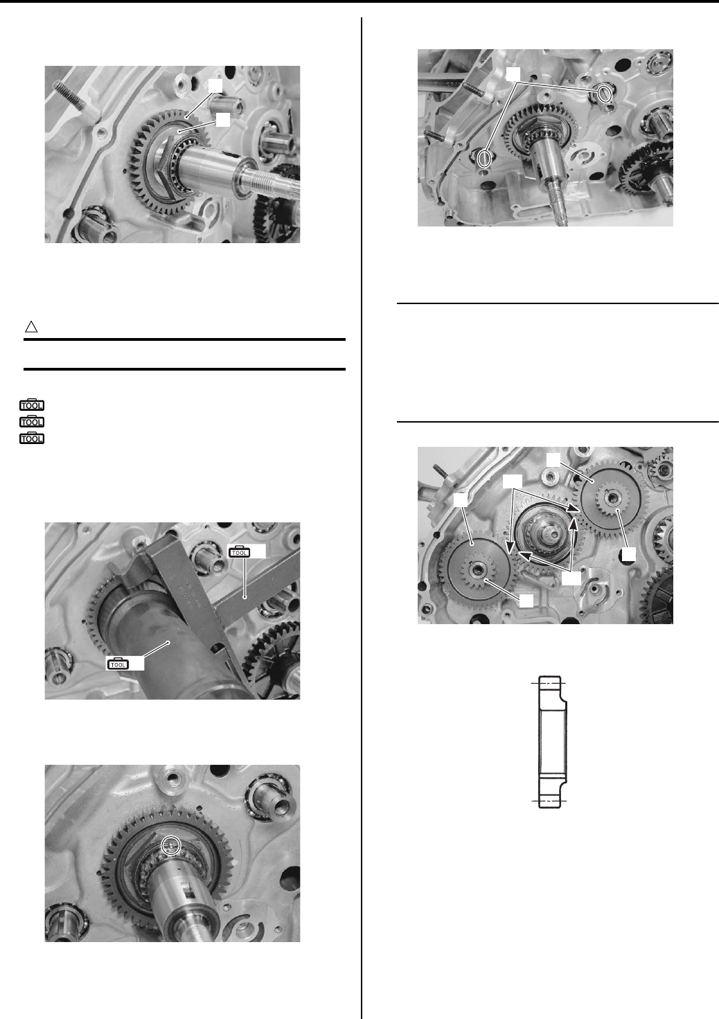
1D-55 Engine Mechanical:
• Install the crank balancer drive gear (2) and washer
(3).
• Hold the crank balancer drive gear with the special
tools and tighten the drive gear nut to the specified
torque with the special tool.
CAUTION
!
Do not reuse the balancer drive gear nut.
Special tool
(A): 09920–53740 (Clutch sleeve hub holder)
(B): 09924–52460 (Socket (52 mm))
: 09920–31020 (Extension handle)
Tightening torque
Crank balancer drive gear nut: 150 N·m (15.0 kgf-
m, 108.5 lb-ft)
• Lock the crank balancer drive gear nut with a center
punch.
• Install the keys (4).
• Install the crank balancer driven gears (5) water pump
drive gear (6) and oil pump drive gear (7).
NOTE
• Align the punch mark “A” of crank
balancer drive gear with the punch marks
“B” of each crank balancer driven gear as
shown.
• Be careful direction of the oil pump drive
gear.
2
3
I831G1140265-02
(A)
(B)
I831G1140266-02
I831G1140267-02
4
I831G1140268-01
5
5
6
7
“A”
“B”
I831G1140269-01
OUTSIDE INSIDE
I831G1140270-02
PartShark.com
877-999-5686
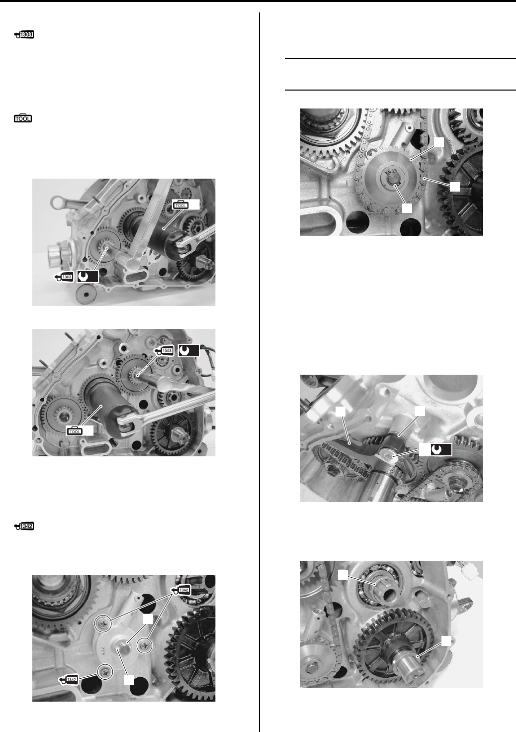
Engine Mechanical: 1D-56
• Apply thread lock to the balancer driven gear bolts.
: Thread lock cement 99000–32030
(THREAD LOCK CEMENT SUPER 1303 or
equivalent)
• Hold the crank balancer drive gear nut with the special
tool and tighten bolts to the specified torque.
Special tool
(A): 09924–52460 (Socket (52 mm))
Tightening torque
Crank balancer driven gear bolt (a): 50 N·m (5.0
kgf-m, 36.0 lb-ft)
Oil Pump
• Apply thread lock to the oil pump mounting bolts and
tighten the bolts.
: Thread lock cement 99000–32050
(THREAD LOCK CEMENT 1342 or equivalent)
• Install the washer (1) and pin (2).
• Install the oil pump drive gear (3) with chain (4).
• Install the snap ring (5).
NOTE
Be careful not to drop the snap ring (5) into
the crankcase.
Cam Chain Tensioner
• Install the cam chain tensioner (1) along with the
washer (2).
• Tighten the cam chain tensioner bolt (3) to the
specified torque.
Tightening torque
Cam chain tensioner bolt (a): 23 N·m (2.3 kgf-m,
16.5 lb-ft)
Transfer Output Drive Gear
• Install the spacer (1) and (2).
(A)
(a)
I831G1140271-02
(A)
(a)
I831G1140272-01
1
2
I831G1140273-01
3
4
5
I831G1140274-01
12
(a)
3
I831G1140275-01
1
2
I831G1140276-01
PartShark.com
877-999-5686
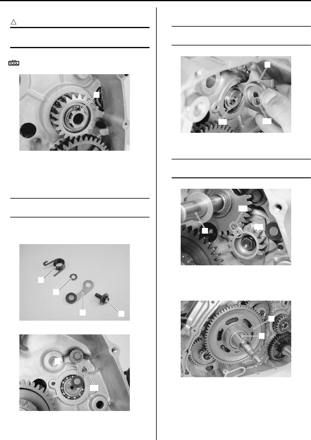
1D-57 Engine Mechanical:
• Install the snap ring (3).
CAUTION
!
The removed snap ring must be replaced
with a new one.
Special tool
: 09900–06107 (Snap ring pliers)
Gearshift System
• Install the gearshift cam stopper (1), bolt (2), washer
(3) and return spring (4).
NOTE
Hook the return spring end “A” to the
stopper (1).
• Check the gearshift cam stopper moves smoothly.
• Locate the gearshift cam in the neutral position.
• Install the gearshift cam stopper plate (5).
NOTE
Align the gearshift cam pin “B” with the
gearshift cam stopper plate hole “C”.
• Install the gearshift shaft (6).
NOTE
Align the punch mark “D” with the concave
mark “E” of gearshift cam of surface.
Starter Driven Gear
• Install the starter driven gear (1) and key (2).
3
I831G1140277-01
12
3
4
I831G1140278-01
1
“A”
I831G1140279-02
5
“C”
“B”
I831G1140280-01
6
“D”
“E”
I831G1140282-01
1
2
I831G1140323-01
PartShark.com
877-999-5686
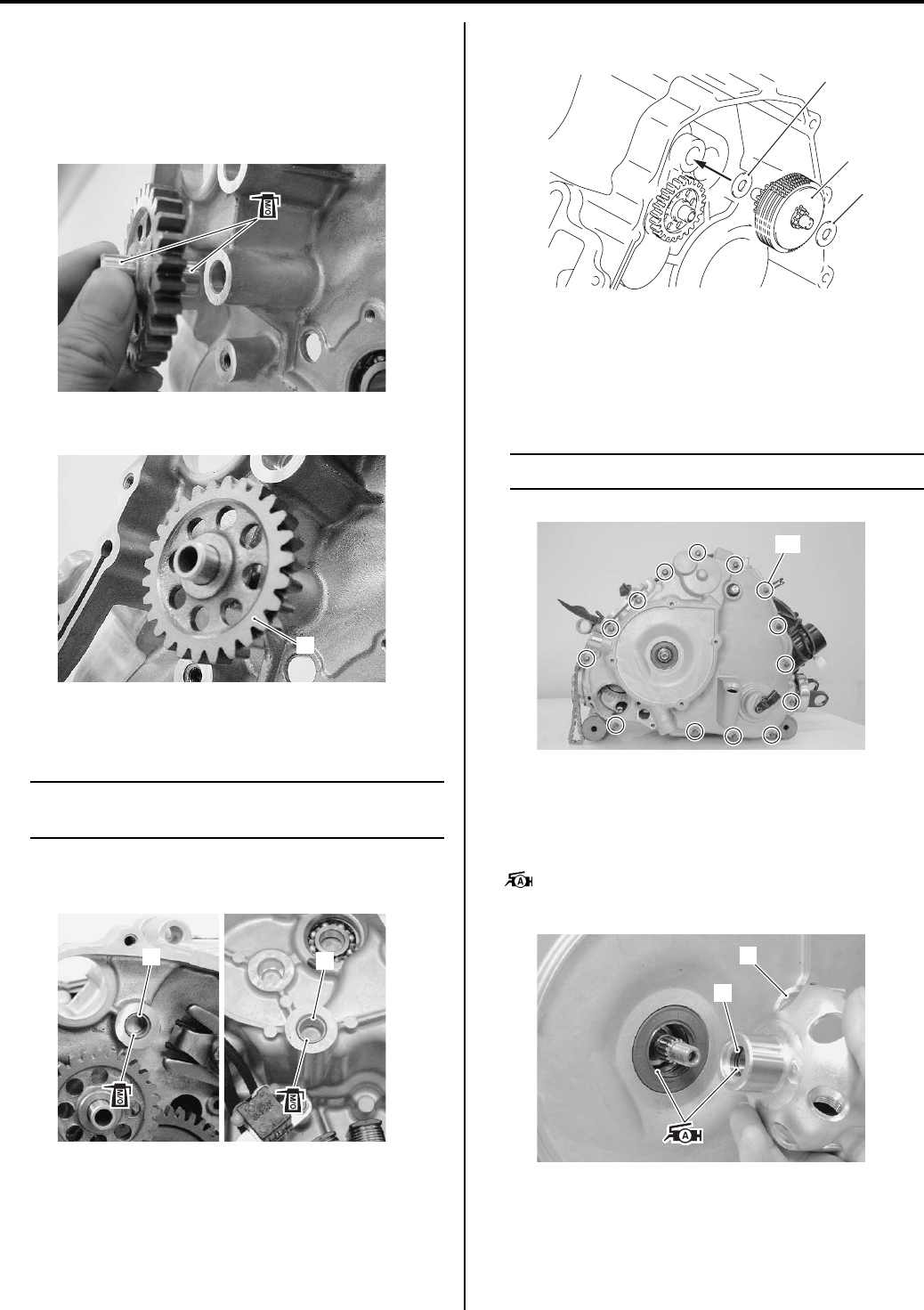
Engine Mechanical: 1D-58
Starter Torque Limiter / Starter Idle Gear
• Apply molybdenum oil solution to the starter idle gear
pin.
M/O: Molybdenum oil (MOLYBDENUM OIL
SOLUTION)
• Install the starter idle gear (1).
• Install the bushings (2) into the crankcase and
generator cover.
NOTE
Apply molybdenum oil solution to the inside
of the bushings.
M/O: Molybdenum oil (MOLYBDENUM OIL
SOLUTION)
• Install the starter torque limiter (3) with washers (4).
Generator
• Install the generator component parts. Refer to
“Generator Removal and Installation in Section 1J
(Page 1J-4)”.
NOTE
Fit the clamp to the bolt “A”.
Starter Cup
• Apply grease to the O-ring and lip of the oil seal.
• Install the starter cup (1).
: Grease 99000–25010 (SUZUKI SUPER
GREASE A or equivalent)
I831G1140283-01
1
I831G1140284-01
22
I831G1140285-01
3
4
4
I831G1140286-02
“A”
I831G1140287-02
1
2
I831G1140288-01
PartShark.com
877-999-5686
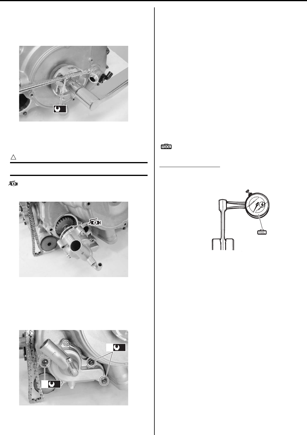
1D-59 Engine Mechanical:
• Tighten the starter cup nut to the specified torque by
holding starter cup with the suitable bar (2).
Tightening torque
Starter cup nut (a): 38 N·m (3.8 kgf-m, 27.5 lb-ft)
Water Pump
• Apply grease to the O-ring.
CAUTION
!
Replace the O-ring with a new one.
: Grease 99000–25010 (SUZUKI SUPER
GREASE A or equivalent)
• Tighten the water pump mounting bolts (1) to the
specified torque.
Tightening torque
Water pump mounting bolt: 10 N·m (1.0 kgf-m, 7.0
lb-ft)
Starter Motor
Install the starter motor. Refer to “Starter Motor Removal
and Installation in Section 1I (Page 1I-4)”.
Engine Top Side
Assemble the engine top side. Refer to “Engine Top Side
Assembly (Page 1D-21)”.
Conrod and Crankshaft Inspection
B831G21406035
Refer to “Engine Bottom Side Disassembly (Page 1D-
45)”.
Conrod Small End I.D.
Measure the conrod small end inside diameter with the
dial calipers.
If conrod small end inside diameter exceeds the service
limit, replace the conrod.
Special tool
(A): 09900–20605 (Dial calipers (1/100 mm, 10 –
34 mm))
Conrod small end I.D.
Service limit: 23.040 mm (0.9071 in)
(a)
I831G1140289-01
I831G1140290-01
(a)
1
(a)
1
I831G1140291-02
(A)
I831G1140292-02
PartShark.com
877-999-5686
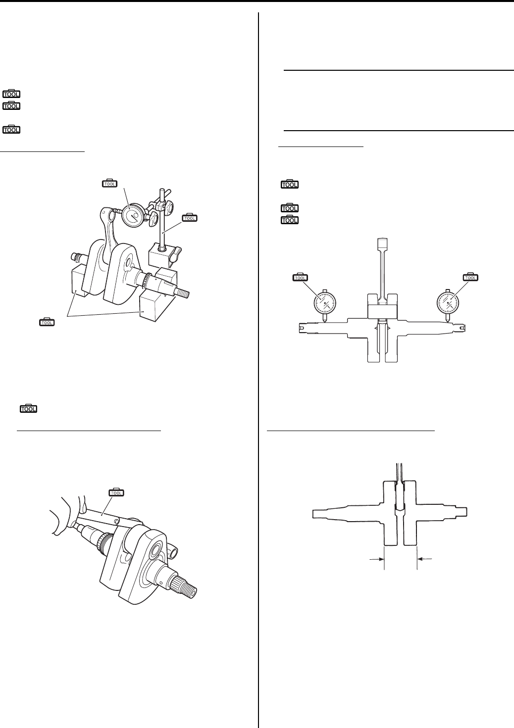
Engine Mechanical: 1D-60
Conrod Deflection
Wear On the big end of the conrod can be estimated by
checking the movement of the small end of the rod. This
method can also check the extent of ware on the parts of
the conrod’s big end.
Special tool
(A): 09900–20701 (Magnetic stand)
(B): 09900–20607 (Dial gauge (1/100 mm, 10
mm))
(C): 09900–21304 (V-block (100 mm))
Conrod deflection
Service Limit: 3.0 mm (0.12 in)
Conrod Big End Side Clearance
1) Check the conrod big end side clearance with the
thickness gauge.
Special tool
(A): 09900–20803 (Thickness gauge)
Conrod big end side clearance
Service limit: 1.0 mm (0.04 in)
2) If the clearance exceeds the limit, replace the
crankshaft assembly and conrod with a new one.
Crankshaft Runout
• Measure the crankshaft runout with V-blocks and dial
gauge.
NOTE
• Place the crankshaft onto the V-blocks so
that it becomes horizontally.
• Measure the runout from the tips of the
crankshaft.
Crankshaft runout
Service limit: 0.08 mm (0.003 in)
Special tool
(A): 09900–20607 (Dial gauge (1/100 mm, 10
mm))
: 09900–20701 (Magnetic stand)
: 09900–21304 (V-block (100 mm))
Width Between Crankshaft Webs
B831G21406036
Measure the width between crankshaft webs “a”.
Width between crankshaft webs “a”
Standard: 72.9 – 73.1 mm (2.87 – 2.88 in)
(A)
(B)
(C)
I831G1140293-01
(A)
I831G1140294-01
(A) (A)
I705H1140241-01
“a”
I705H1140149-04
PartShark.com
877-999-5686
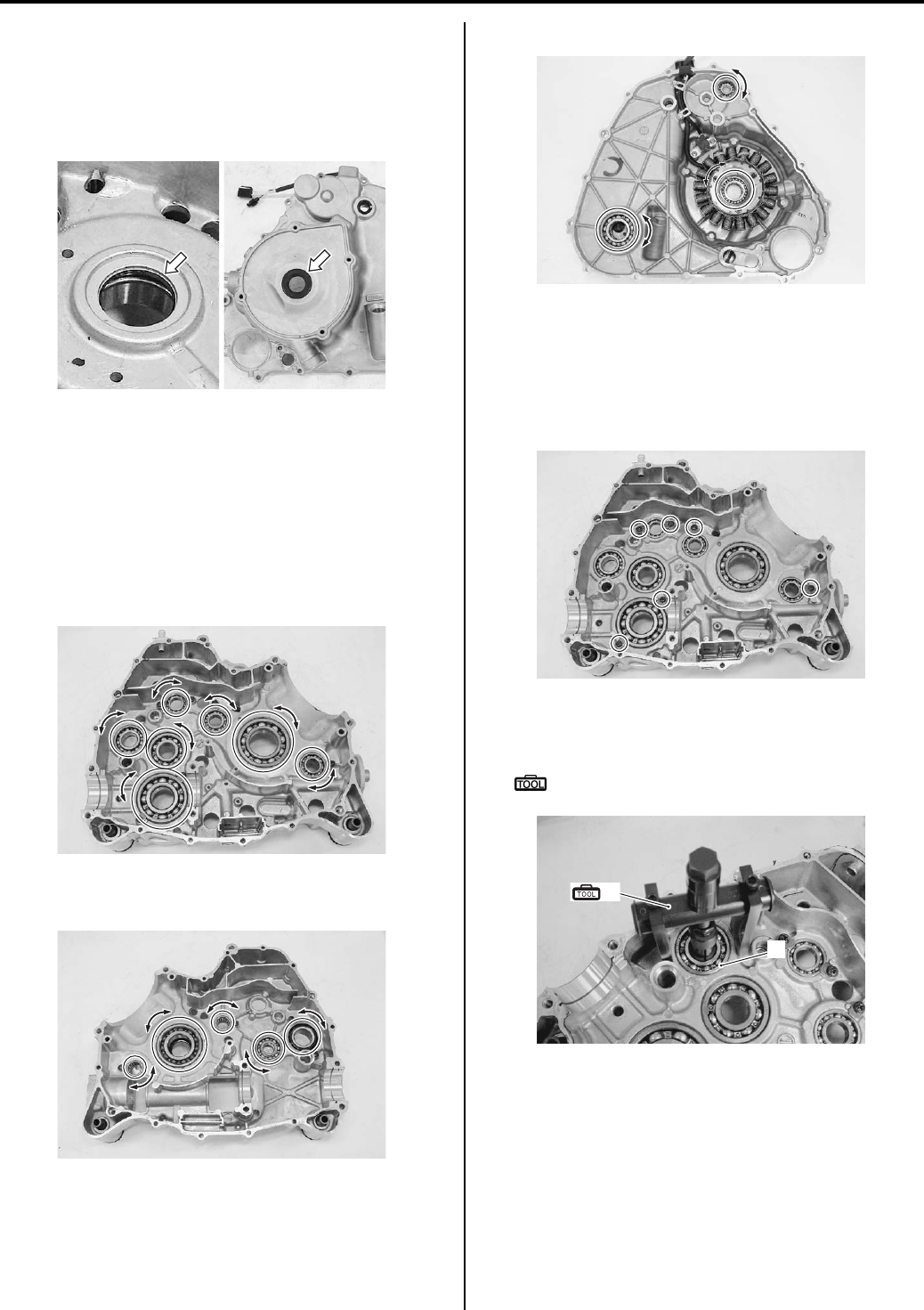
1D-61 Engine Mechanical:
Crankshaft Oil Seal Inspection
B831G21406037
Check the oil seal for damage. If any damage is found,
replace the oil seal with a new one. Refer to “Engine
Bottom Side Disassembly (Page 1D-45)” and “Bearing
Removal and Installation (Page 1D-61)”.
Bearing Inspection
B831G21406038
Refer to “Engine Bottom Side Disassembly (Page 1D-
45)”.
Rotate the bearing inner race by finger to inspect for
abnormal play, noise and smooth rotation while the
bearings are in the crankcase. Replace the bearing if
there is anything unusual.
Left crankcase
Right crankcase
Generator cover
Bearing Removal and Installation
B831G21406039
Removal
Left crankcase
1) Remove the each bearing retainers.
2) Remove the drive shaft bearing (1) with the special
tool.
Special tool
(A): 09921–20240 (Bearing remover set)
I831G1140296-01
I831G1140299-03
I831G1140300-03
I831G1140301-03
I831G1140302-01
1
(A)
I831G1140303-01
PartShark.com
877-999-5686
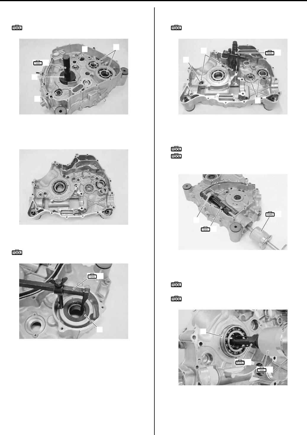
Engine Mechanical: 1D-62
3) Remove the other bearings (2) with the special tool.
Special tool
(B): 09913–70210 (Bearing installer set)
Right crankcase
1) Remove the bearing retainers.
2) Remove the oil seal (1) with the special tool.
Special tool
(A): 09913–50121 (Oil seal remover)
3) Remove the each bearing (2) with the special tool.
Special tool
(B): 09921–20240 (Bearing remover set)
4) Remove the front output shaft bearing (3) with the
special tools.
Special tool
(C): 09923–74511 (Bearing remover)
(D): 09930–30104 (Rotor remover slide
shaft)
5) Remove the crankshaft bearing (4) with the special
tools.
Special tool
(D): 09930–30104 (Rotor remover slide
shaft)
(E): 09941–64511 (Bearing remover)
2
2
22
(B)
I831G1140304-01
I831G1140305-01
(A)
1
I831G1140306-01
2
2
(B)
1
I831G1140307-03
(C)
(D)
3
I831G1140308-01
4
(E)
(D)
I831G1140309-01
PartShark.com
877-999-5686
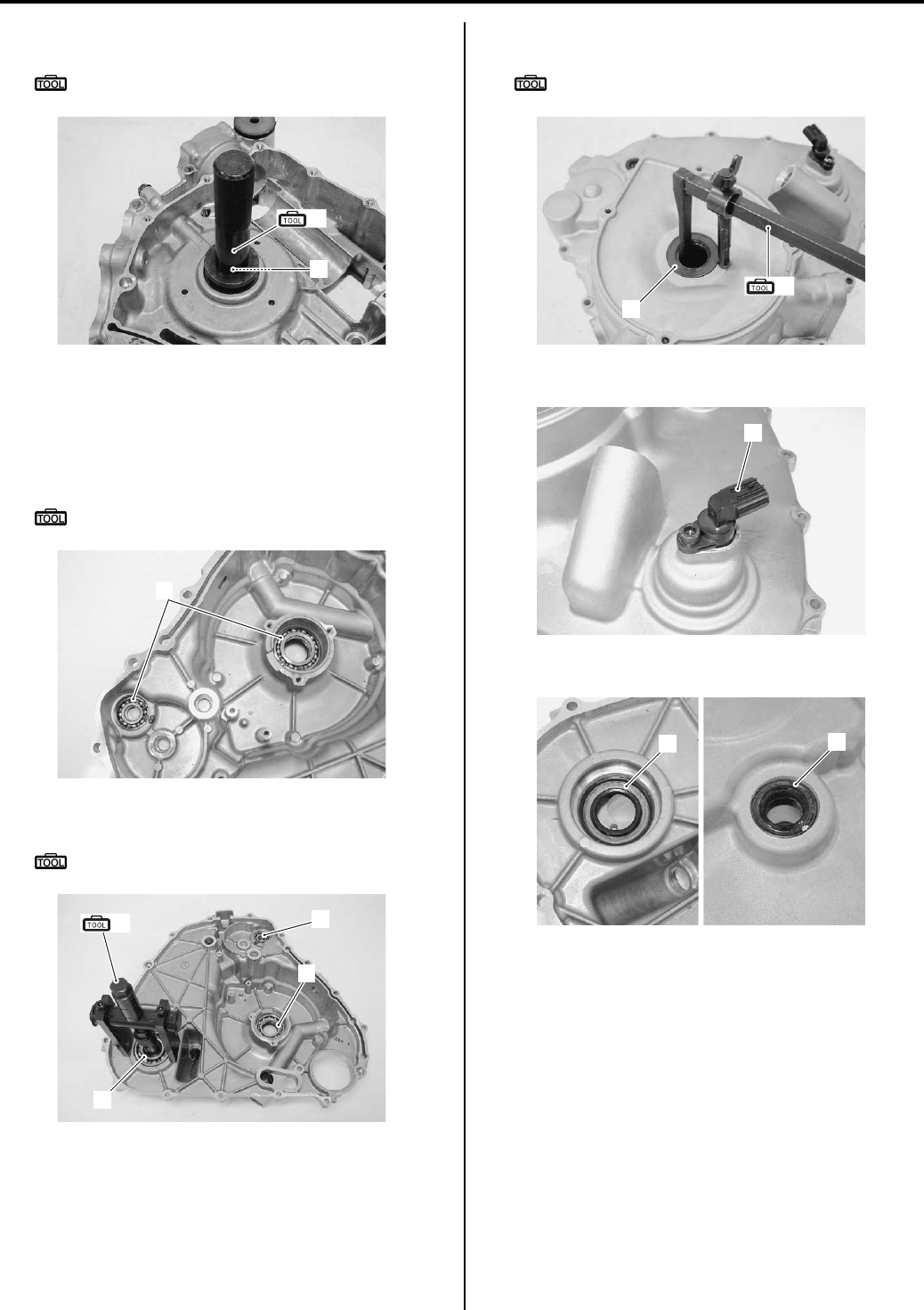
1D-63 Engine Mechanical:
6) Remove the oil seal (5) with the special tool.
Special tool
(F): 09913–70210 (Bearing installer set)
Generator cover
1) Remove the magnet stator. Refer to “Generator
Removal and Installation in Section 1J (Page 1J-4)”.
2) Remove the snap rings (1) with the special tool.
Special tool
: 09900–06108 (Snap ring pliers)
3) Remove the each bearings (2) with the special tool.
Special tool
(A): 09921–20240 (Bearing remover set)
4) Remove the oil seal (3) with the special tool.
Special tool
(B): 09913–50121 (Oil seal remover)
5) Remove the speed sensor (4).
6) Remove the oil seals (5).
(F)
5
I831G1140310-01
1
I831G1140311-01
(A)
2
2
2
I831G1140312-01
3
(B)
I831G1140313-01
4
I831G1140314-01
55
I831G1140315-01
PartShark.com
877-999-5686
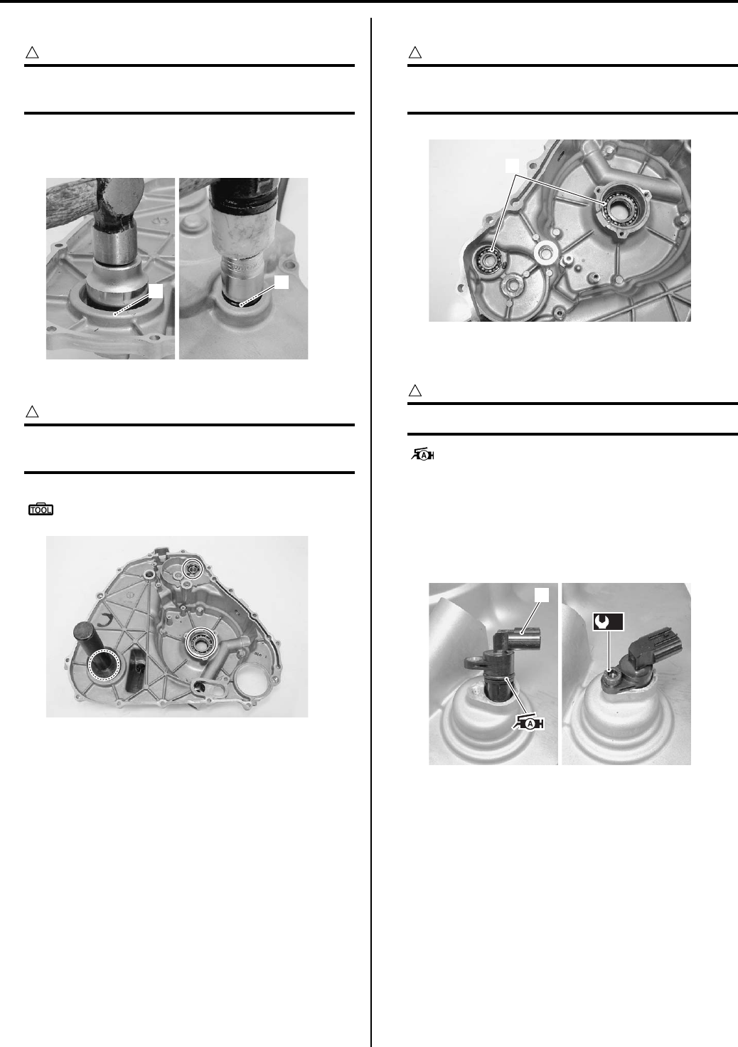
Engine Mechanical: 1D-64
Installation
CAUTION
!
The removed bearings and oil seals must be
replaced with new ones.
Generator cover
1) Install the oil seals (1) with suitable tool.
2) Install the each bearing (2) with a special tool.
CAUTION
!
Use the special tool suitable size for each
bearing to prevent damage.
Special tool
(A): 09913–70210 (Bearing installer set)
3) Install the snap rings (3).
CAUTION
!
The removed snap rings must be replaced
with new ones.
4) Apply grease to O-ring and install the speed sensor
(4).
CAUTION
!
Replace the O-ring with a new one.
: Grease 99000–25010 (SUZUKI SUPER
GREASE A or equivalent)
5) Tighten the bolt to the specified torque.
Tightening torque
Speed sensor bolt (a): 10 N·m (1.0 kgf-m, 7.0 lb-
ft)
6) Install the removed parts. Refer to “Generator
Removal and Installation in Section 1J (Page 1J-4)”.
11
I831G1140316-01
I831G1140317-02
3
I831G1140325-01
4
(a)
I831G1140318-01
PartShark.com
877-999-5686
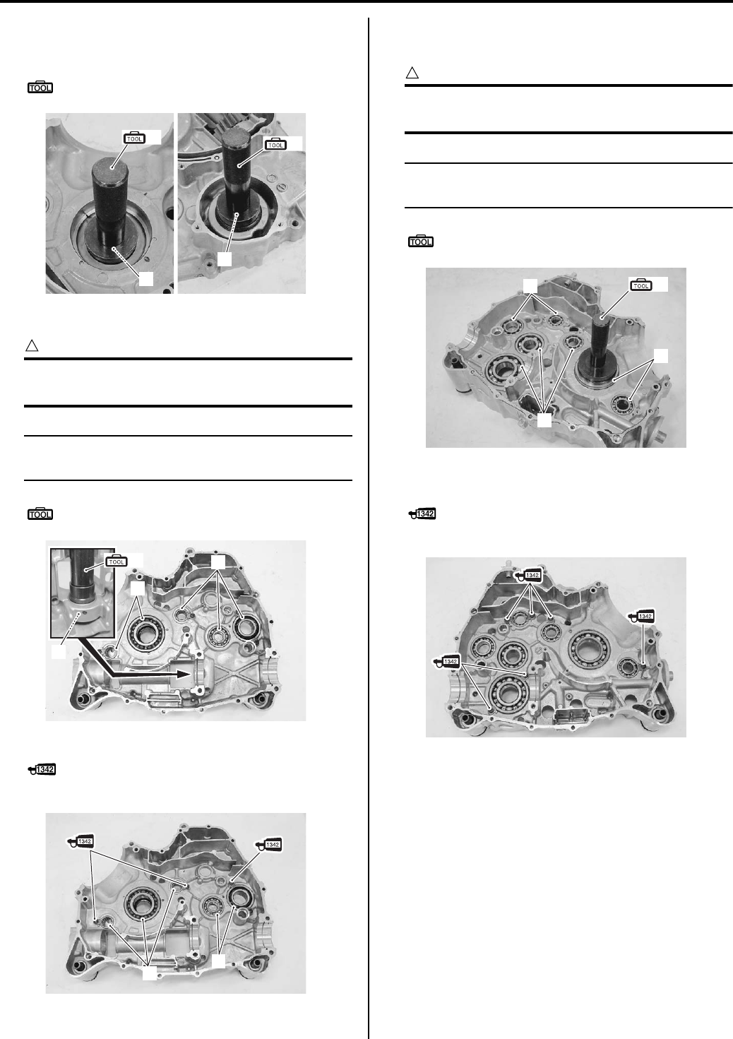
1D-65 Engine Mechanical:
Right crankcase
1) Install the oil seals (1) with the special tool.
Special tool
: 09913–70210 (Bearing installer set)
2) Install the bearings (2) with the special tool.
CAUTION
!
Use the special tool suitable size for each
bearing to prevent damage.
NOTE
The stamped mark side of the bearing faces
inside of crankcase.
Special tool
(A): 09913–70210 (Bearing installer set)
3) Apply thread lock to the screws and tighten them.
: Thread lock cement 99000–32050
(THREAD LOCK CEMENT 1342 or equivalent)
Left crankcase
1) Install the bearings (1) with the special tool.
CAUTION
!
Use the special tool suitable size for each
bearing to prevent damage.
NOTE
The stamped mark side of the bearing faces
inside of crankcase.
Special tool
(A): 09913–70210 (Bearing installer set)
2) Apply thread lock to the screws, and install the
retainers by tightening them.
: Thread lock cement 99000–32050
(THREAD LOCK CEMENT 1342 or equivalent)
(A) (A)
1
1
I831G1140319-02
2
2
(A)
2
I831G1140338-02
2
2
I831G1140320-01
1
1
1
(A)
I831G1140321-01
I831G1140322-01
PartShark.com
877-999-5686
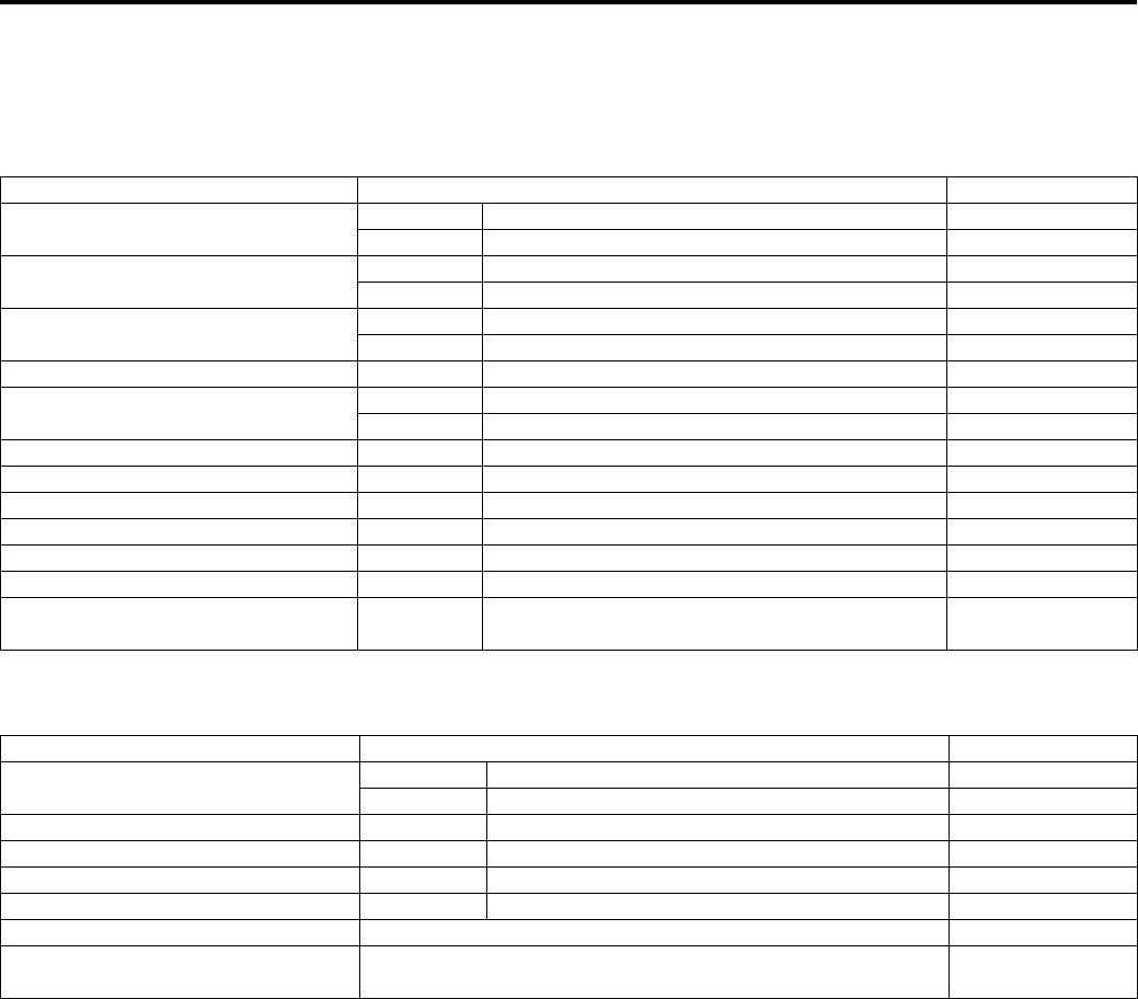
Engine Mechanical: 1D-66
Specifications
Service Data
B831G21407001
Valve + Valve Guide
Unit: mm (in)
Camshaft + Cylinder Head
Unit: mm (in)
Item Standard Limit
Valve diam. IN. 36.0 (1.42) —
EX. 33.0 (1.30) —
Tappet clearance (when cold) IN. 0.10 – 0.20 (0.004 – 0.008) —
EX. 0.20 – 0.30 (0.008 – 0.012) —
Valve guide to valve stem clearance IN. 0.010 – 0.037 (0.0004 – 0.0015) —
EX. 0.030 – 0.057 (0.0012 – 0.0022) —
Valve guide I.D. IN. & EX. 5.500 – 5.512 (0.2165 – 0.2170) —
Valve stem O.D. IN. 5.475 – 5.490 (0.2156 – 0.2161) —
EX. 5.455 – 5.470 (0.2148 – 0.2154) —
Valve stem deflection IN. & EX. — 0.35 (0.014)
Valve stem runout IN. & EX. — 0.05 (0.002)
Valve head thickness IN. & EX. — 0.5 (0.02)
Valve seat width IN. & EX. 0.9 – 1.1 (0.035 – 0.043) —
Valve head radial runout IN. & EX. — 0.03 (0.001)
Valve spring free length IN. & EX. — 46.1 (1.81)
Valve spring tension IN. & EX. 182 – 210 N (18.6 – 21.4 kgf, 41.0 – 47.2 lbs) at
length 36.35 mm (1.43 in) —
Item Standard Limit
Cam height IN. 36.330 – 36.380 (1.4303 – 1.4323) 36.030 (1.4185)
EX. 35.300 – 35.350 (1.3898 – 1.3917) 35.000 (1.3780)
Camshaft journal oil clearance IN. & EX. 0.019 – 0.053 (0.0007 – 0.0021) 0.150 (0.0059)
Camshaft journal holder I.D. IN. & EX. 22.012 – 22.025 (0.8666 – 0.8671) —
Camshaft journal O.D. IN. & EX. 21.972 – 21.993 (0.8650 – 0.8659) —
Camshaft runout IN. & EX. — 0.10 (0.004)
Cylinder head distortion — 0.05 (0.002)
Cam drive idle gear/sprocket thrust
clearance 0.15 – 0.27 (0.006 – 0.011) —
PartShark.com
877-999-5686
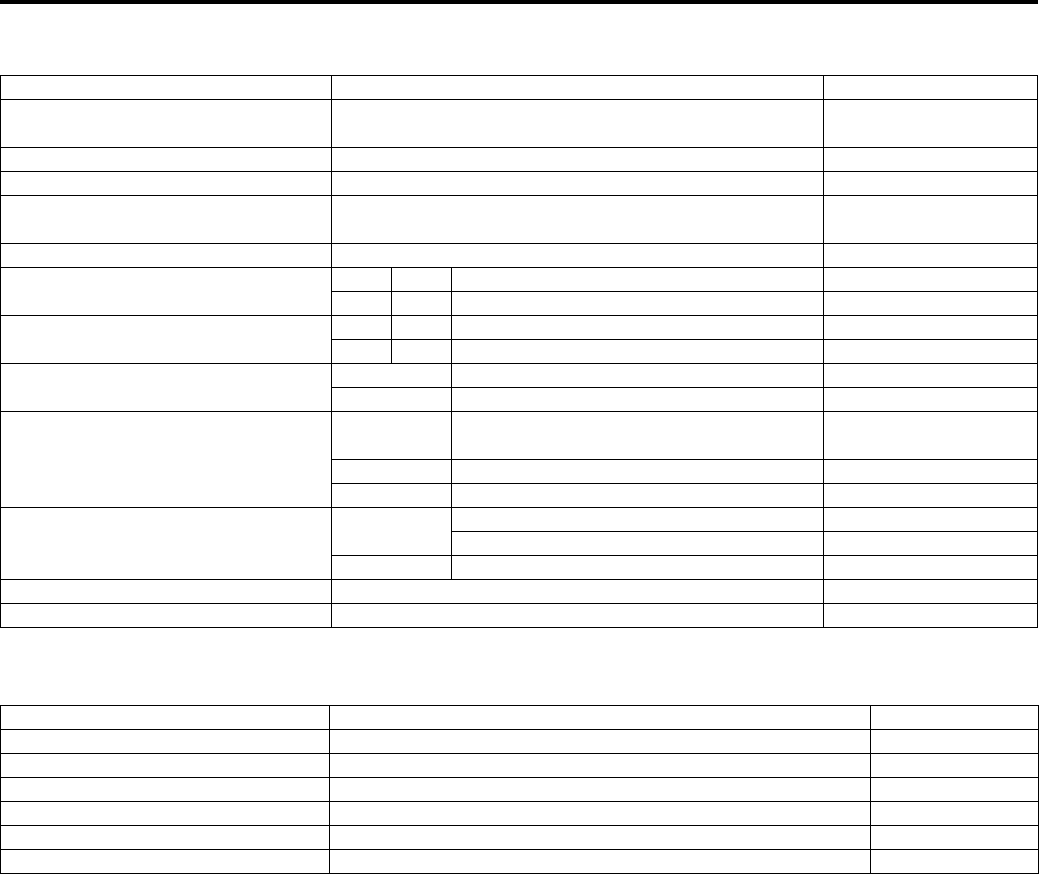
1D-67 Engine Mechanical:
Cylinder + Piston + Piston Ring
Unit: mm (in)
Conrod + Crankshaft
Unit: mm (in)
Item Standard Limit
Compression pressure (Automatic-
decomp. actuated) Approx. 1 000 kPa (10.0 kgf/cm2, 142 psi) —
Piston-to-cylinder clearance 0.030 – 0.040 (0.0012 – 0.0016) 0.120 (0.0047)
Cylinder bore 104.000 – 104.015 (4.0945 – 4.0951) Nicks or Scratches
Piston diam. 103.965 – 103.980 (4.0931 – 4.0937)
Measure at 15 mm (0.6 in) from the skirt end. 103.880 (4.0898)
Cylinder distortion — 0.05 (0.102)
Piston ring free end gap 1st R Approx. 13.1 (0.52) 10.5 (0.41)
2nd RN Approx. 14.6 (0.57) 11.7 (0.46)
Piston ring end gap 1st R 0.10 – 0.25 (0.004 – 0.010) 0.50 (0.020)
2nd RN 0.10 – 0.25 (0.004 – 0.010) 0.50 (0.020)
Piston ring-to-groove clearance 1st — 0.180 (0.0071)
2nd — 0.150 (0.0059)
Piston ring groove width
1st 0.83 – 0.85 (0.0327 – 0.0335)
1.30 – 1.32 (0.0512 – 0.0520) —
2nd 1.01 – 1.03 (0.0398 – 0.0406) —
Oil 2.01 – 2.03 (0.0791 – 0.0799) —
Piston ring thickness 1st 0.76 – 0.81 (0.0299 – 0.0319) —
1.08 – 1.10 (0.0425 – 0.0433) —
2nd 0.97 – 0.99 (0.0382 – 0.0390) —
Piston pin bore I.D. 23.002 – 23.008 (0.9056 – 0.9058) 23.030 (0.9067)
Piston pin O.D. 22.992 – 23.000 (0.9052 – 0.9055) 22.980 (0.9047)
Item Standard Limit
Conrod small end I.D. 23.006 – 23.014 (0.9057 – 0.9061) 23.040 (0.9071)
Conrod deflection — 3.0 (0.12)
Conrod big end side clearance 0.10 – 0.75 (0.004 – 0.030) 1.0 (0.04)
Conrod big end width 24.95 – 25.00 (0.982 – 0.984) —
Crank web to web width 72.9 – 73.1 (2.87 – 2.88) —
Crankshaft runout — 0.08 (0.003)
PartShark.com
877-999-5686

Engine Mechanical: 1D-68
Tightening Torque Specifications
B831G21407002
NOTE
The specified tightening torque is also described in the following.
“Throttle Body Components (Page 1D-7)”
Reference:
For the tightening torque of fastener not specified in this section, refer to “Tightening Torque List in Section 0C
(Page 0C-7)”.
Fastening part Tightening torque Note
N⋅mkgf—mlb—ft
Air cleaner box mounting bolt 4.5 0.45 3.0 )(Page 1D-6)
TP sensor mounting screw 2 0.2 1.5 )(Page 1D-11)
ISC valve mounting screw 2 0.2 1.5 )(Page 1D-12)
Fuel delivery pipe mounting screw 5 0.5 3.5 )(Page 1D-12)
Engine mounting nut 60 6.0 43.5 )(Page 1D-16)
Engine mounting damper stopper bolt 23 2.3 16.5 )(Page 1D-16)
Footrest mounting bolt (M8) 26 2.6 19.0 )(Page 1D-16)
Footrest mounting bolt (M10) 55 5.5 40.0 )(Page 1D-16)
Cylinder head bolt (L: 200) (Initial) 25 2.5 18.0 )(Page 1D-23)
Cylinder head bolt (L: 200) (Final) 37 3.7 27.0 )(Page 1D-23)
Cylinder head bolt (L: 70) 10 1.0 7.0 )(Page 1D-23)
Cylinder head bolt (L: 100) 10 1.0 7.0 )(Page 1D-23)
Cylinder base nut 10 1.0 7.0 )(Page 1D-24)
Cam drive idle gear/sprocket shaft 41 4.1 29.5 )(Page 1D-25) /
)(Page 1D-40)
Cam chain tension adjuster bolt 10 1.0 7.0 )(Page 1D-25)
Cam chain tension adjuster cap bolt 7 0.7 5.0 )(Page 1D-26)
Camshaft journal holder bolt 10 1.0 7.0 )(Page 1D-26) /
)(Page 1D-29)
Head cover bolt (Initial) 10 1.0 7.0 )(Page 1D-27)
Head cover bolt (Final) 14 1.4 10.0 )(Page 1D-27)
Valve timing inspection plug 23 2.3 16.5 )(Page 1D-27)
Oil gallery plug (Cylinder head) 10 1.0 7.0 )(Page 1D-32)
Intake pipe bolt 9 0.9 6.5 )(Page 1D-33)
Water bypass union 12 1.2 8.5 )(Page 1D-33)
Crankcase bolt (M6) 10 1.0 7.0 )(Page 1D-53)
Crankcase bolt (M8) 26 2.6 19.0 )(Page 1D-53)
Main oil gallery plug 18 1.8 13.0 )(Page 1D-54)
Crank balancer drive gear nut 150 15.0 108.5 )(Page 1D-55)
Crank balancer driven gear bolt 50 5.0 36.0 )(Page 1D-56)
Cam chain tensioner bolt 23 2.3 16.5 )(Page 1D-56)
Starter cup nut 38 3.8 27.5 )(Page 1D-59)
Water pump mounting bolt 10 1.0 7.0 )(Page 1D-59)
Speed sensor bolt 10 1.0 7.0 )(Page 1D-64)
PartShark.com
877-999-5686
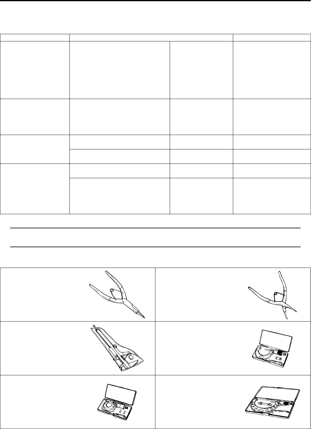
1D-69 Engine Mechanical:
Special Tools and Equipment
Recommended Service Material
B831G21408001
NOTE
Required service material is also described in the following.
“Throttle Body Components (Page 1D-7)”
Special Tool
B831G21408002
Material SUZUKI recommended product or Specification Note
Grease SUZUKI SUPER GREASE A or
equivalent
P/No.: 99000–25010 )(Page 1D-11) /
)(Page 1D-33) /
)(Page 1D-52) /
)(Page 1D-53) /
)(Page 1D-53) /
)(Page 1D-58) /
)(Page 1D-59) /
)(Page 1D-64)
Molybdenum oil MOLYBDENUM OIL SOLUTION — )(Page 1D-21) /
)(Page 1D-22) /
)(Page 1D-34) /
)(Page 1D-58) /
)(Page 1D-58)
Sealant SUZUKI BOND No.1215 or
equivalent
P/No.: 99000–31110 )(Page 1D-22) /
)(Page 1D-52)
SUZUKI BOND No.1216B or
equivalent
P/No.: 99000–31230 )(Page 1D-27)
Thread lock cement THREAD LOCK CEMENT SUPER
1303 or equivalent
P/No.: 99000–32030 )(Page 1D-16) /
)(Page 1D-56)
THREAD LOCK CEMENT 1342 or
equivalent
P/No.: 99000–32050 )(Page 1D-33) /
)(Page 1D-33) /
)(Page 1D-56) /
)(Page 1D-65) /
)(Page 1D-65)
09900–06107 09900–06108
Snap ring pliers Snap ring pliers
)(Page 1D-47) /
)(Page 1D-47) /
)(Page 1D-57)
)(Page 1D-63)
09900–20101 09900–20202
Vernier calipers (1/15 mm,
150 mm)
Micrometer (1/100 mm, 25 –
50 mm)
)(Page 1D-36) /
)(Page 1D-37) /
)(Page 1D-44)
)(Page 1D-28)
09900–20205 09900–20210
Micrometer (0 – 25 mm) Micrometer (100 – 125 mm)
)(Page 1D-29) /
)(Page 1D-36) /
)(Page 1D-41) /
)(Page 1D-44) /
)(Page 1D-45)
)(Page 1D-43)
PartShark.com
877-999-5686
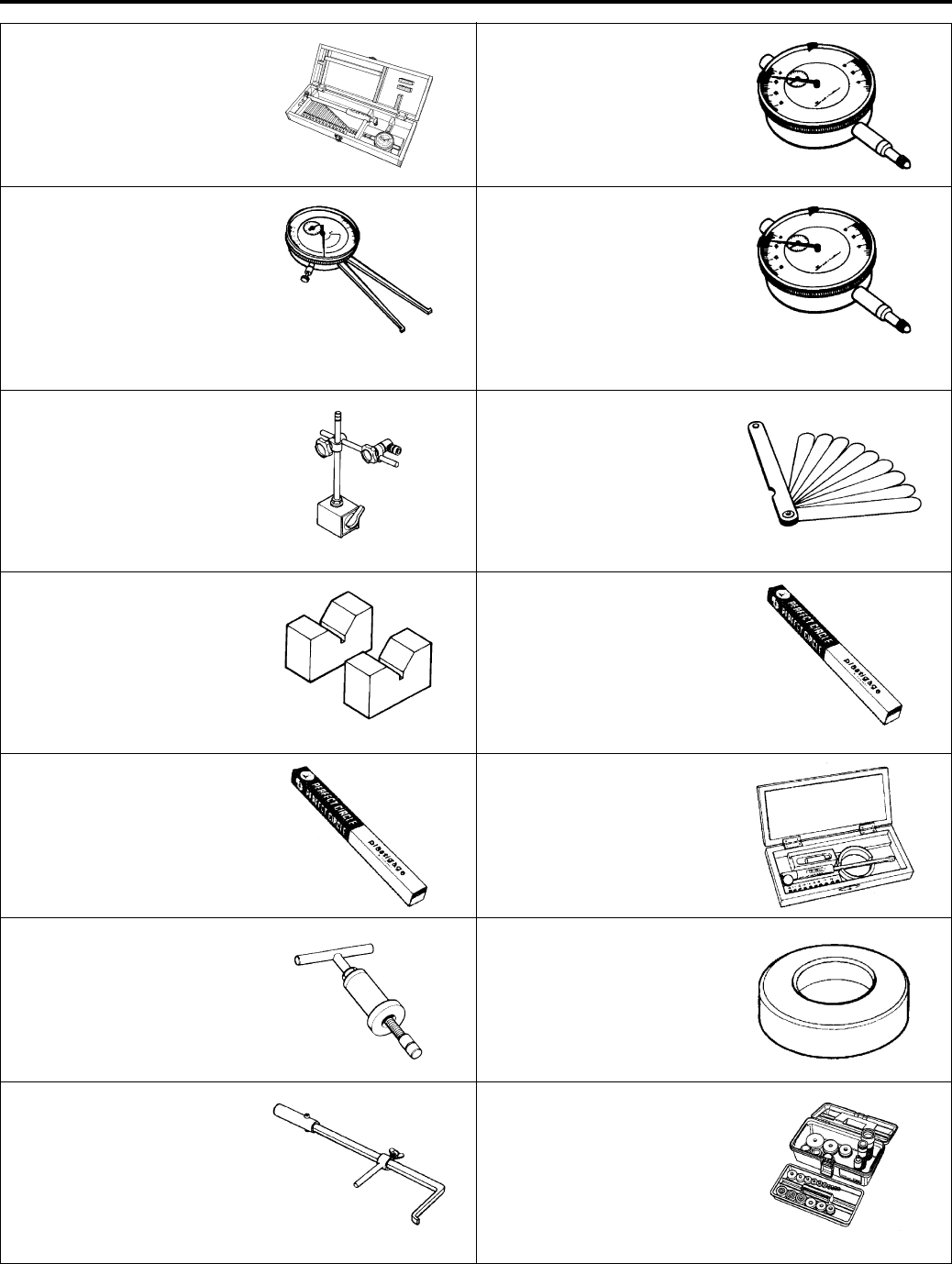
Engine Mechanical: 1D-70
09900–20530 09900–20602
Cylinder gauge set Dial gauge (1/1000 mm, 1
mm)
)(Page 1D-42) )(Page 1D-29) /
)(Page 1D-45)
09900–20605 09900–20607
Dial calipers (1/100 mm, 10
– 34 mm)
Dial gauge (1/100 mm, 10
mm)
)(Page 1D-59) )(Page 1D-28) /
)(Page 1D-35) /
)(Page 1D-35) /
)(Page 1D-36) /
)(Page 1D-60) /
)(Page 1D-60)
09900–20701 09900–20803
Magnetic stand Thickness gauge
)(Page 1D-28) /
)(Page 1D-35) /
)(Page 1D-35) /
)(Page 1D-36) /
)(Page 1D-60) /
)(Page 1D-60)
)(Page 1D-35) /
)(Page 1D-40) /
)(Page 1D-41) /
)(Page 1D-44) /
)(Page 1D-44) /
)(Page 1D-60)
09900–21304 09900–22301
V-block (100 mm) Plastigauge (0.025 – 0.076
mm)
)(Page 1D-28) /
)(Page 1D-35) /
)(Page 1D-35) /
)(Page 1D-60) /
)(Page 1D-60)
)(Page 1D-29)
09900–22302 09900–22403
Plastigauge (0.051 – 0.152
mm)
Small bore gauge (18 – 35
mm)
)(Page 1D-29) )(Page 1D-29) /
)(Page 1D-45)
09910–32812 09910–32860
Crankshaft installer Attachment
)(Page 1D-51) )(Page 1D-51)
09913–50121 09913–70210
Oil seal remover Bearing installer set
)(Page 1D-62) /
)(Page 1D-63)
)(Page 1D-62) /
)(Page 1D-63) /
)(Page 1D-64) /
)(Page 1D-65) /
)(Page 1D-65) /
)(Page 1D-65)
PartShark.com
877-999-5686
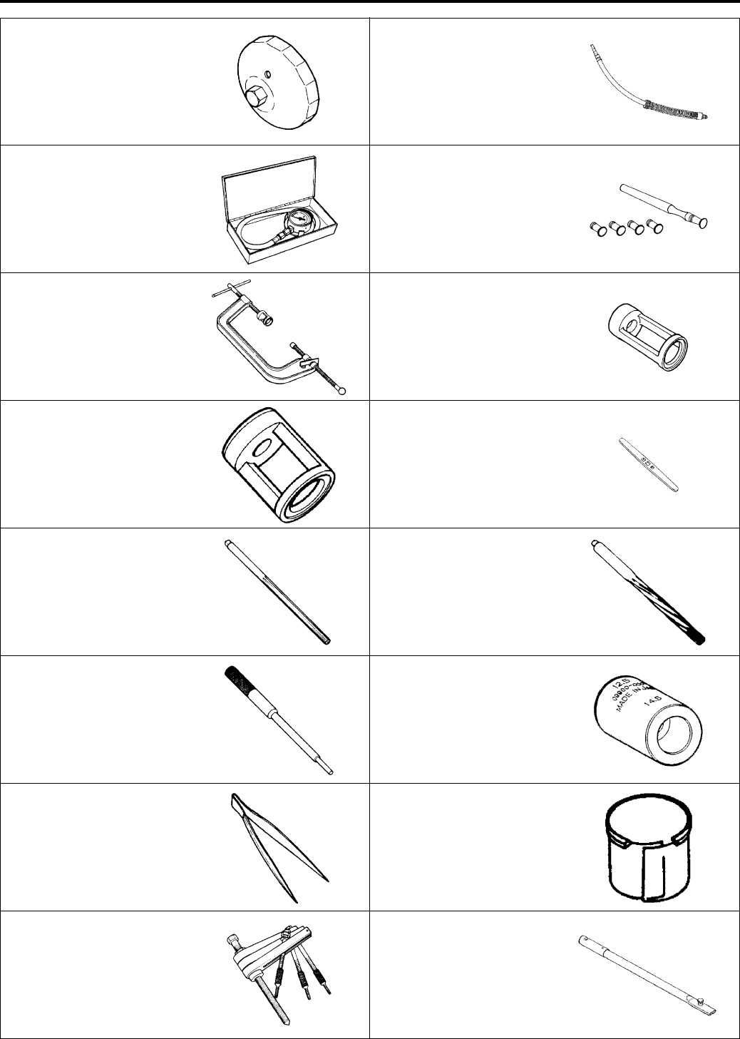
1D-71 Engine Mechanical:
09915–40610 09915–63311
Oil filter wrench Compression gauge
attachment
)(Page 1D-45) )(Page 1D-2)
09915–64512 09916–10911
Compression gauge Valve lapper set
)(Page 1D-2) )(Page 1D-37)
09916–14510 09916–14521
Valve spring compressor Valve spring compressor
attachment
)(Page 1D-31) /
)(Page 1D-34)
)(Page 1D-31)
09916–14910 09916–34542
Valve spring compressor
attachment
Reamer handle
)(Page 1D-34) )(Page 1D-38) /
)(Page 1D-39)
09916–34550 09916–34580
Valve guide reamer (5.5
mm)
Valve guide reamer (10.8
mm)
)(Page 1D-39) )(Page 1D-38)
09916–44910 09916–57360
Valve guide remover/
installer
Attachment
)(Page 1D-38) /
)(Page 1D-39)
)(Page 1D-39)
09916–84511 09919–28610
Valve adjuster driver Sleeve protector
)(Page 1D-31) /
)(Page 1D-34)
)(Page 1D-31) /
)(Page 1D-34)
09920–13120 09920–31020
Crankcase separating tool Extension handle
)(Page 1D-50) /
)(Page 1D-51)
)(Page 1D-48) /
)(Page 1D-55)
PartShark.com
877-999-5686
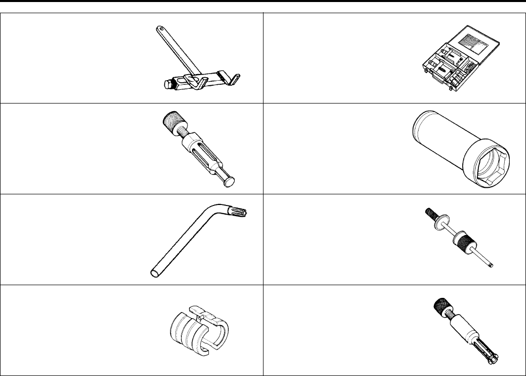
Engine Mechanical: 1D-72
09920–53740 09921–20240
Clutch sleeve hub holder Bearing remover set
)(Page 1D-48) /
)(Page 1D-55)
)(Page 1D-61) /
)(Page 1D-62) /
)(Page 1D-63)
09923–74511 09924–52460
Bearing remover Socket (52 mm)
)(Page 1D-62) )(Page 1D-48) /
)(Page 1D-48) /
)(Page 1D-55) /
)(Page 1D-56)
09930–11950 09930–30104
Torx wrench Rotor remover slide shaft
)(Page 1D-11) /
)(Page 1D-12)
)(Page 1D-62) /
)(Page 1D-62)
09941–53610 09941–64511
Front fork installer hammer Bearing remover
)(Page 1D-51) )(Page 1D-62)
PartShark.com
877-999-5686
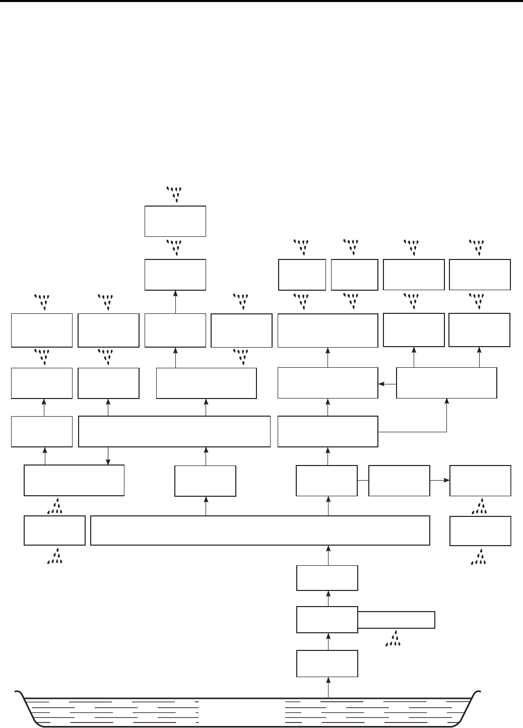
1E-1 Engine Lubrication System:
Engine
Engine Lubrication System
Precautions
Precautions for Engine Oil
B831G21500001
Refer to “Fuel and Oil Recommendation in Section 0A (Page 0A-3)”.
Schematic and Routing Diagram
Engine Lubrication System Chart Diagram
B831G21502001
OIL SUMP
FILTER
OIL PUMP RELIEF VALVE
OIL FILTER
OIL JET DRIVE SHAFT
GEARS
CRANK
CASE (R)
CYLINDER
CAM FACE
& TAPPET
CAMSHAFT
JOURNAL (R)
EX.
CAMSHAFT
CAM FACE
& TAPPET
ONE-WAY
CLUCH
CLUCH SHOE
CONROD
BIG END BEARING
CYLINDER WALL
& PISTON
MAIN GALLERY
OIL PAN
EX. CAMSHAFT
JOURNAL (L)
IN. CAMSHAFT
JOURNAL (L)
CAM FACE
& TAPPET
IN. CAMSHAFT
CAMSHAFT
JOURNAL (R)
CAM FACE
& TAPPET
CAM CHAIN
IDLE GEAR
CAM
CHAIN
ONE-WAY
CLUCH
CAM
CHAIN
STARTER DRIVEN
GEAR BEARING
CRANKSHAFT (L)
CRANKSHAFT
BEARING (R)
CRANKSHAFT (R)
CYLINDER HEAD
I831G1150001-08
PartShark.com
877-999-5686
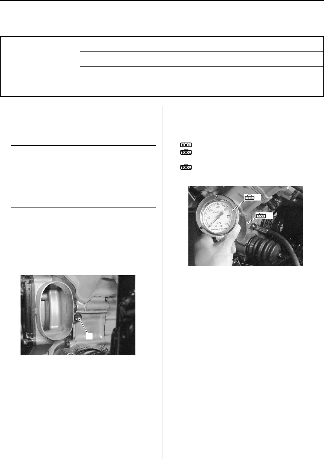
Engine Lubrication System: 1E-2
Diagnostic Information and Procedures
Engine Lubrication Symptom Diagnosis
B831G21504001
Oil Pressure Check
B831G21504002
Check the engine oil pressure periodically. This will give
a good indication of the condition of the moving parts.
NOTE
Before checking the oil pressure, check the
following.
• Oil level (Refer to “Engine Oil and Filter
Replacement in Section 0B (Page 0B-10)”.)
• Oil leaks (If leak is found, repair it.)
• Oil quality (If oil is discolored or
deteriorated, replace it.)
1) Remove the right inner fender. Refer to “Front Side
Exterior Parts Removal and Installation in Section
9D (Page 9D-6)”.
2) Remove the belt cooling intake duct. Refer to “V-belt
Cooling Duct Removal and Installation in Section 5A
(Page 5A-5)”.
3) Remove the main oil gallery plug (1).
4) Install the oil pressure gauge and attachment into
the main oil gallery.
5) Connect the tachometer to the high-tension cord.
Special tool
(A): 09915–74511 (Oil pressure gauge set)
(B): 09915–74533 (Oil pressure gauge
attachment)
: 09900–26006 (Engine tachometer (solar
cell type))
6) Warm up the engine as follows:
Summer: 10 min. at 2 000 r/min
Winter: 20 min. at 2 000 r/min
Condition Possible cause Correction / Reference Item
Engine overheats Insufficient amount of engine oil. Check level and add.
Defective oil pump. Replace.
Clogged oil circuit. Clean.
Incorrect engine oil. Change.
Exhaust smoke is dirty or
thick
Excessive amount of engine oil. Check level and drain.
Engine lacks power Excessive amount of engine oil. Check level and drain.
1
I831G1150002-01
(A)
(B)
I831G1150003-02
PartShark.com
877-999-5686
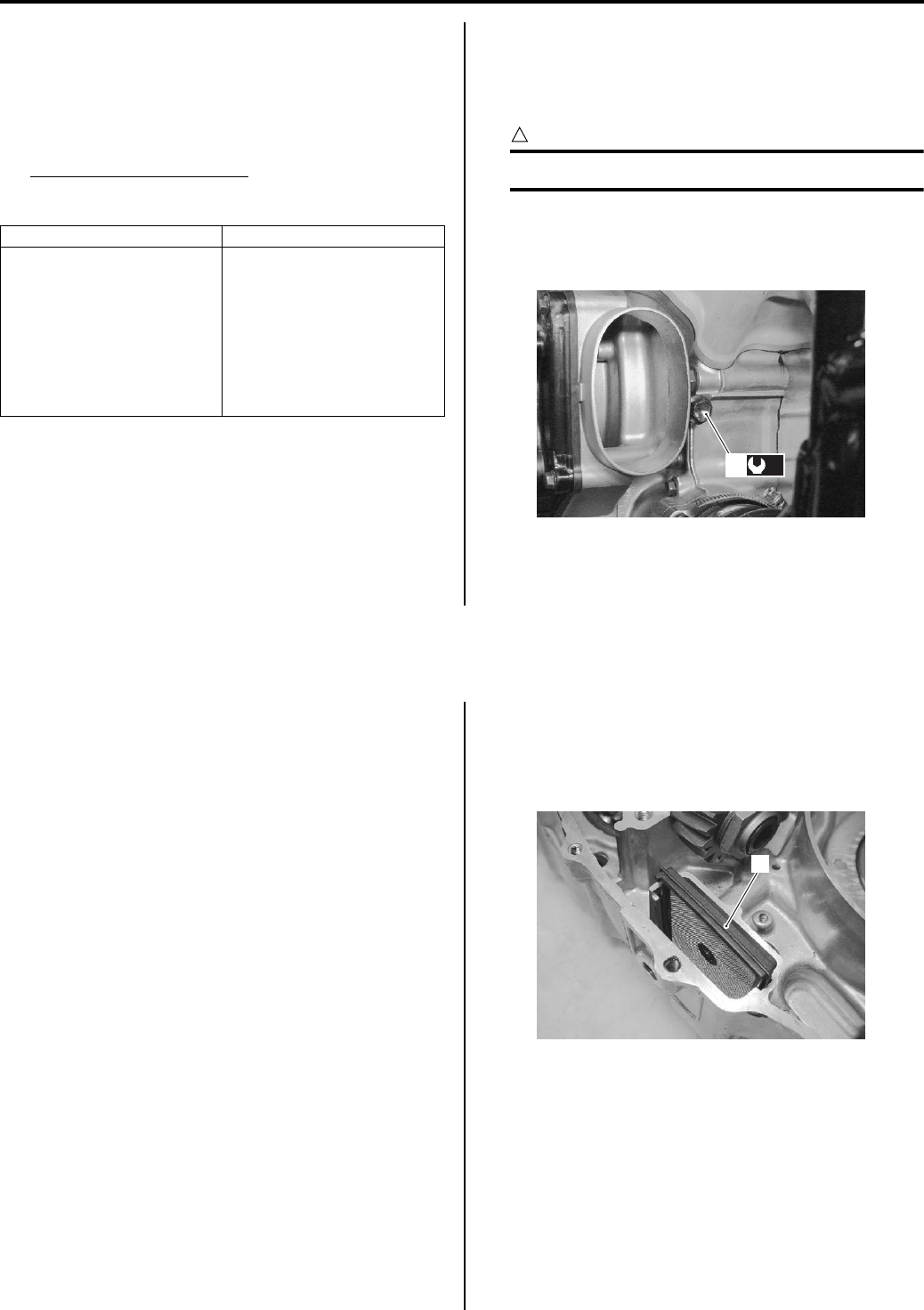
1E-3 Engine Lubrication System:
7) After warm up, increase the engine speed to 3 000 r/
min (Observe the tachometer), and read the oil
pressure gauge.
If the oil pressure is lower or higher than the
specification, the following causes may be
considered.
Oil pressure specification
140 – 180 kPa (1.4 – 1.8 kgf/cm2, 20 – 26 psi) at 3
000 r/min, Oil temp. at 60 °C (140 °F)
Stop the engine and remove the oil pressure gauge
and attachment.
9) Reinstall the main oil gallery plug (1) and tighten it to
the specified torque.
CAUTION
!
Use a new gasket to prevent oil leakage.
Tightening torque
Main oil gallery plug (a): 18 N·m (1.8 kgf-m, 13.0
lb-ft)
10) Check the engine oil level. Refer to “Engine Oil and
Filter Replacement in Section 0B (Page 0B-10)”.
11) Reinstall the removed parts.
Repair Instructions
Engine Oil and Filter Replacement
B831G21506001
Refer to “Engine Oil and Filter Replacement in Section
0B (Page 0B-10)”.
Engine Oil Level Inspection
B831G21506002
Refer to “Engine Oil and Filter Replacement in Section
0B (Page 0B-10)”.
Oil Sump Filter Removal and Installation
B831G21506003
Removal
1) Remove the engine assembly from the frame. Refer
to “Engine Assembly Removal in Section 1D
(Page 1D-13)”.
2) Disassemble the engine top side. Refer to “Engine
Top Side Disassembly in Section 1D (Page 1D-17)”.
3) Separate the left and right crankcase. Refer to
“Engine Bottom Side Disassembly in Section 1D
(Page 1D-45)”.
4) Remove the oil sump filter (1).
High oil pressure Low oil pressure
• Engine oil viscosity is too
high.
• Clogged oil passage.
• Combination of the
above items.
• Clogged oil filter.
• Oil leakage from the oil
passage.
• Damaged O-ring.
• Defective oil pump.
• Combination of the
above items.
(a)
1
I831G1150004-02
1
I831G1150005-01
PartShark.com
877-999-5686
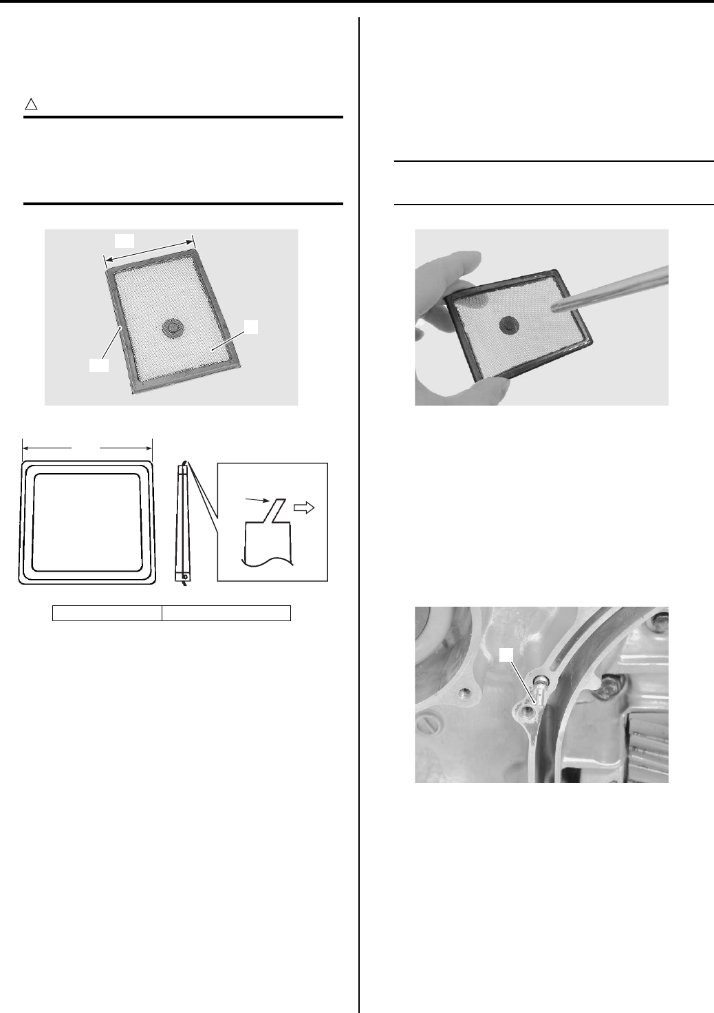
Engine Lubrication System: 1E-4
Installation
Install the oil sump filter in the reverse order of removal.
Pay attention to the following points:
• Install the oil sump filter (1).
CAUTION
!
• The lip “A” of the oil sump filter should be
positioned downward.
• The shorter side “B” of the oil sump filter
should be positioned inside.
Oil Sump Filter Inspection and Cleaning
B831G21506004
Inspect the oil sump filter in the following procedures:
1) Remove the oil sump filter. Refer to “Oil Sump Filter
Removal and Installation (Page 1E-3)”.
2) If the oil sump filter is clogged with sediment or rust,
clean the oil sump filter using compressed air.
NOTE
When the filter is dirtied excessively, replace
the oil sump filter with a new one.
3) Install the oil sump filter. Refer to “Oil Sump Filter
Removal and Installation (Page 1E-3)”.
Oil Jet Removal and Installation
B831G21506005
Removal
1) Remove the clutch shoe housing case and gasket.
Refer to “Clutch Shoe Removal and Installation in
Section 5A (Page 5A-16)”.
2) Remove the oil jet (1).
“A”: Lip “B”: Shorter side
“A”
“B”
1
I831G1150006-02
“A”
“B”
Downside
I705H1150004-01
I831G1150007-01
1
I831G1150008-01
PartShark.com
877-999-5686
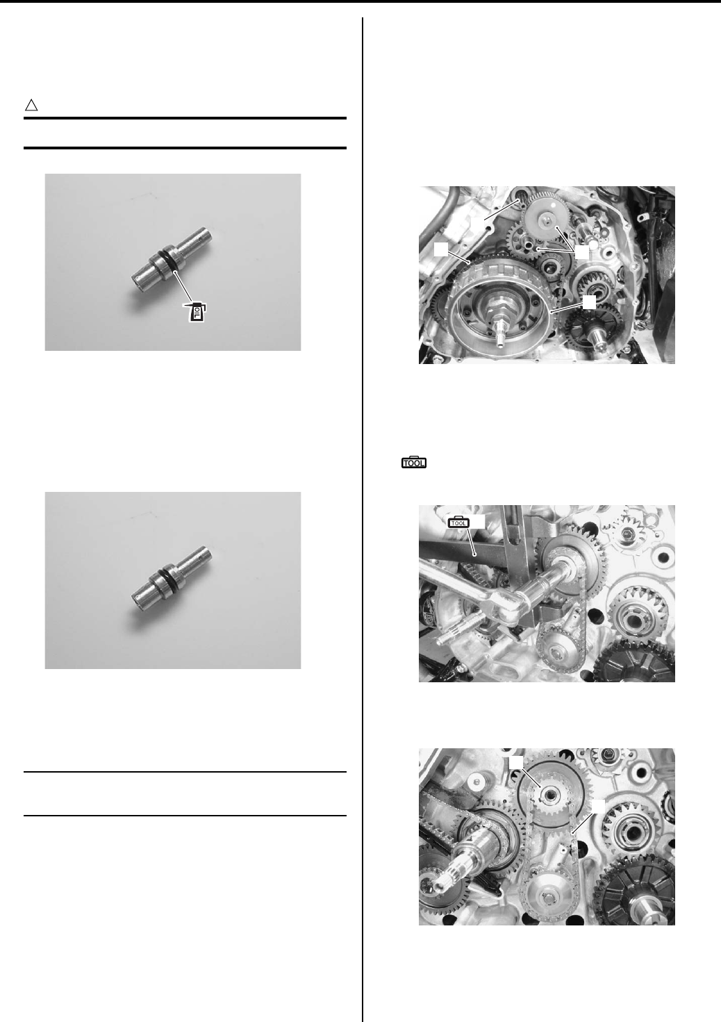
1E-5 Engine Lubrication System:
Installation
Install the oil jet in the reverse order of removal. Pay
attention to the following point:
• Apply engine oil to the O-ring.
CAUTION
!
Use a new O-ring to prevent oil leakage.
Oil Jet Inspection
B831G21506006
Refer to “Oil Jet Removal and Installation (Page 1E-4)”.
Make sure that the oil jet is not clogged. If it is clogged,
clean the oil passage using a wire of the proper size and
compressed air.
Oil Pump Removal and Installation
B831G21506007
Removal
NOTE
Do not drop the each parts into the
crankcase.
1) Drain the engine oil. Refer to “Engine Oil and Filter
Replacement in Section 0B (Page 0B-10)”.
2) Remove the starter motor (1). Refer to “Starter Motor
Removal and Installation in Section 1I (Page 1I-4)”.
3) Remove the starter torque limiter and starter idle
gear (2). Refer to “Starter Torque Limiter / Starter
Clutch Removal and Installation in Section 1I
(Page 1I-10)”.
4) Remove the generator rotor assembly (3) and starter
driven gear (4). Refer to “Generator Removal and
Installation in Section 1J (Page 1J-4)” and “Starter
Torque Limiter / Starter Clutch Removal and
Installation in Section 1I (Page 1I-10)”.
5) Hold the crank balancer driven gear with the special
tool and remove the oil pump drive gear bolt and
washer.
Special tool
(A): 09920–53740 (Clutch sleeve hub
holder)
6) Remove the oil pump drive gear (5) along with the
chain (6).
I831G1150009-03
I831G1150010-02
2
1
3
4
I831G1150011-01
(A)
I831G1150012-01
5
6
I831G1150013-01
PartShark.com
877-999-5686
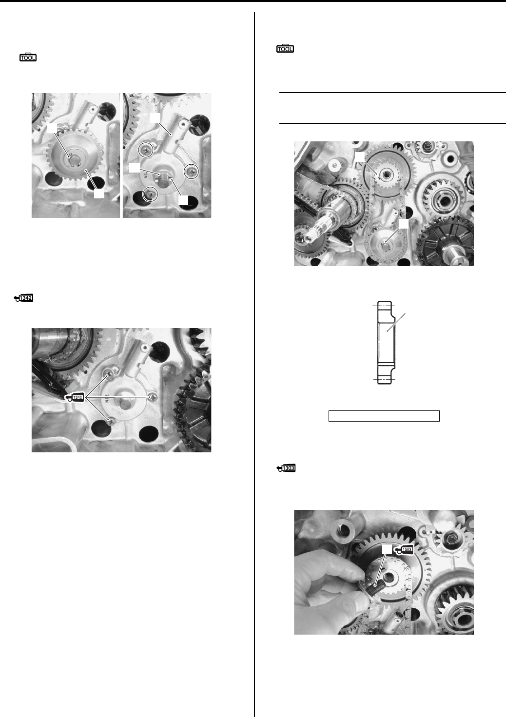
Engine Lubrication System: 1E-6
7) Remove the snap ring (7) and oil pump driven gear
(8).
Special tool
: 09900–06107 (Snap ring pliers)
Remove the pin (9), washer (10) and oil pump (11).
Installation
Install the oil pump in the reverse order of removal. Pay
attention to the following points:
• Apply thread lock to the oil pump bolts.
: Thread lock cement 99000–32050
(THREAD LOCK CEMENT 1342 or equivalent)
• Install the new snap ring (1).
Special tool
: 09900–06107 (Snap ring pliers)
• Install the oil pump drive gear (2) with chain.
NOTE
The flange side of the oil pump drive gear (2)
inside.
• Apply thread lock super to the oil pump drive gear bolt
(3).
: Thread lock cement 99000–32030
(THREAD LOCK CEMENT SUPER 1303 or
equivalent)
7
89
10
11
I831G1150014-01
I831G1150015-02
2. Oil pump drive gear
2
1
I831G1150020-02
2
OUTSIDE INSIDE
I831G1150016-07
3
I831G1150017-02
PartShark.com
877-999-5686
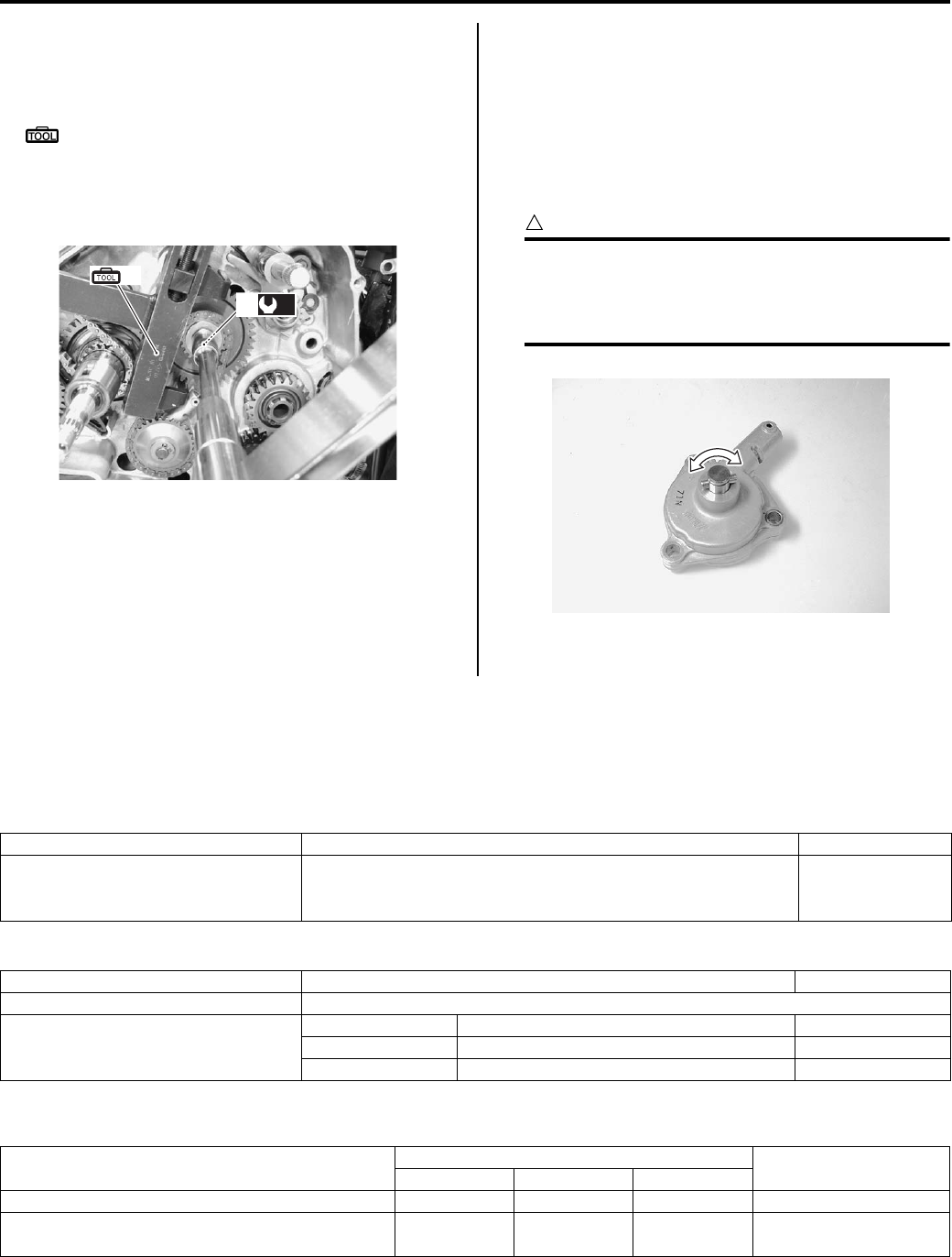
1E-7 Engine Lubrication System:
• Hold the crank balancer driven gear with the special
tool and tighten the oil pump drive gear bolt (3) to the
specified torque.
Special tool
(A): 09920–53740 (Clutch sleeve hub holder)
Tightening torque
Oil pump drive gear/Crank balancer driven gear
bolt (a): 50 N·m (5.0 kgf-m, 36.0 lb-ft)
Oil Pump Inspection
B831G21506008
Inspect the oil pump in the following procedures:
1) Remove the oil pump. Refer to “Oil Pump Removal
and Installation (Page 1E-5)”.
2) Rotate the oil pump by hand and check that it moves
smoothly. If it does not move smoothly, replace the
oil pump assembly.
CAUTION
!
Do not attempt to disassemble the oil pump
assembly.
The oil pump is available only as an
assembly.
3) Install the oil pump. Refer to “Oil Pump Removal and
Installation (Page 1E-5)”.
Specifications
Service Data
B831G21507001
Oil Pump
Oil
Tightening Torque Specifications
B831G21507002
Reference:
For the tightening torque of fastener not specified in this section, refer to “Tightening Torque List in Section 0C
(Page 0C-7)”.
(A)
(a)
3
I831G1150018-03
I831G1150019-01
Item Standard Limit
Oil pressure (at 60 °C, 140 °F)
140 – 180 kPa
(1.4 – 1.8 kgf/cm2, 20 – 26 psi)
at 3 000 r/min
—
Item Specification Note
Engine oil type SAE 10 W-40, API SF/SG or SH/SJ with JASO MA
Engine oil capacity
Change 2 300 ml (2.4/2.0 US/lmp qt)
Filter change 2 500 ml (2.6/2.2 US/lmp qt)
Overhaul 3 000 ml (3.2/2.6 US/lmp qt)
Fastening part Tightening torque Note
N⋅mkgf—mlb—ft
Main oil gallery plug 18 1.8 13.0 )(Page 1E-3)
Oil pump drive gear/Crank balancer driven gear
bolt 50 5.0 36.0 )(Page 1E-7)
PartShark.com
877-999-5686
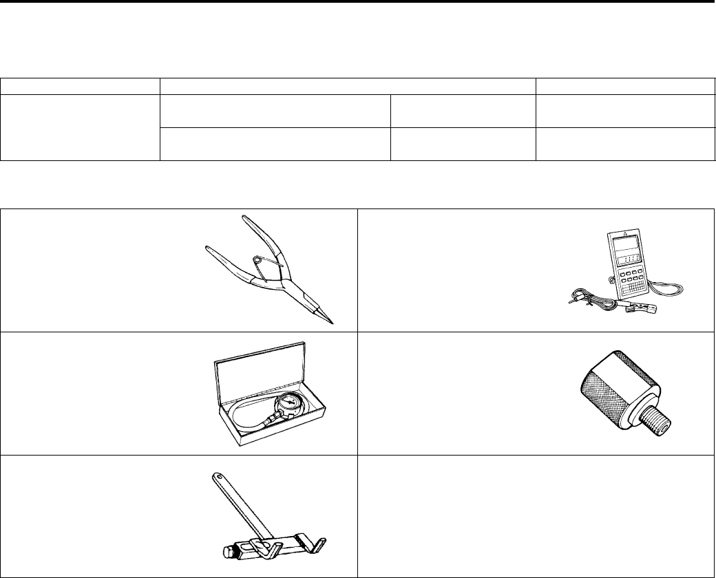
Engine Lubrication System: 1E-8
Special Tools and Equipment
Recommended Service Material
B831G21508001
Special Tool
B831G21508002
Material SUZUKI recommended product or Specification Note
Thread lock cement THREAD LOCK CEMENT SUPER
1303 or equivalent
P/No.: 99000–32030 )(Page 1E-6)
THREAD LOCK CEMENT 1342 or
equivalent
P/No.: 99000–32050 )(Page 1E-6)
09900–06107 09900–26006
Snap ring pliers Engine tachometer (solar
cell type)
)(Page 1E-6) / )(Page 1E-
6)
)(Page 1E-2)
09915–74511 09915–74533
Oil pressure gauge set Oil pressure gauge
attachment
)(Page 1E-2) )(Page 1E-2)
09920–53740
Clutch sleeve hub holder
)(Page 1E-5) / )(Page 1E-
7)
PartShark.com
877-999-5686
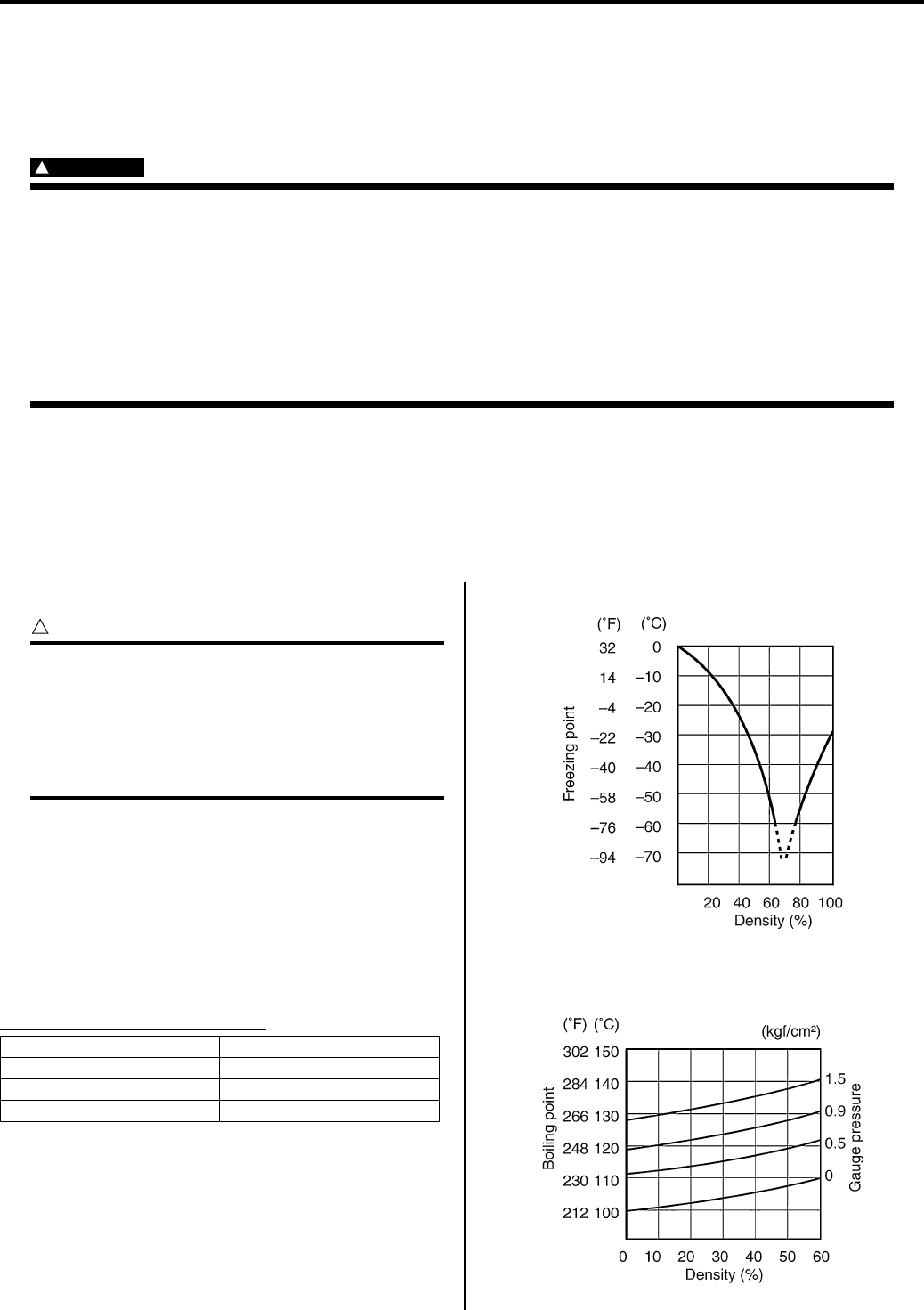
1F-1 Engine Cooling System:
Engine
Engine Cooling System
Precautions
Precautions for Engine Cooling System
B831G21600001
WARNING
!
• You can be injured by boiling fluid or steam if you open the radiator cap when the engine is hot.
After the engine cools, wrap a thick cloth around cap and carefully remove the cap by turning it a
quarter turn to allow pressure to escape and then turn the cap all the way off.
• The engine must be cool before servicing the cooling system.
• Coolant is harmful:
– If it comes in contact with skin or eyes, flush with water.
– If swallowed accidentally, induce vomiting and call physician immediately.
– Keep it away from children.
Precautions for Engine Coolant
B831G21600002
Refer to “Engine Coolant Recommendation in Section 0A (Page 0A-4)”.
General Description
Engine Coolant Description
B831G21601001
CAUTION
!
• Use a high quality ethylene glycol base
anti-freeze, mixed with distilled water. Do
not mix an alcohol base anti-freeze and
different brands of anti-freeze.
• Do not put in more than 60% anti-freeze or
less than 50%. (Refer to Fig. 1 and 2.)
At the time of manufacture, the cooling system is filled
with a 50:50 mixture of distilled water and ethylene
glycol anti-freeze. This 50:50 mixture will provide the
optimum corrosion protection and excellent heat
protection, and will protect the cooling system from
freezing at temperatures above –31 °C (–24 °F).
If the vehicle is to be exposed to temperatures below –
31 °C (–24 °F), this mixing ratio should be increased up
to 55% or 60% according to the figure.
Anti-freeze Proportioning Chart
Fig.1: Engine coolant density-freezing point curve
Fig.2: Engine coolant density-boiling point curve
Anti-freeze density Freezing point
50% –31 °C (–24 °F)
55% –40 °C (–40 °F)
60% –55 °C (–67 °F)
I310G1160001-01
I310G1160002-01
PartShark.com
877-999-5686
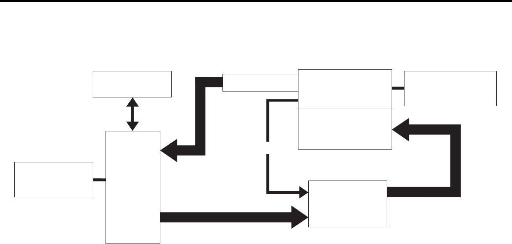
Engine Cooling System: 1F-2
Schematic and Routing Diagram
Cooling Circuit Diagram
B831G21602001
WATER
PUMP
RADIATOR
COOLING
FAN THERMO
SWITCH
ENGINE COOLANT
TEMPERATURE
SWITCH
THERMOSTAT CYLINDER HEAD
CYLINDER
RESERVOIR
TANK
BYPASS
I831G1160001-02
PartShark.com
877-999-5686
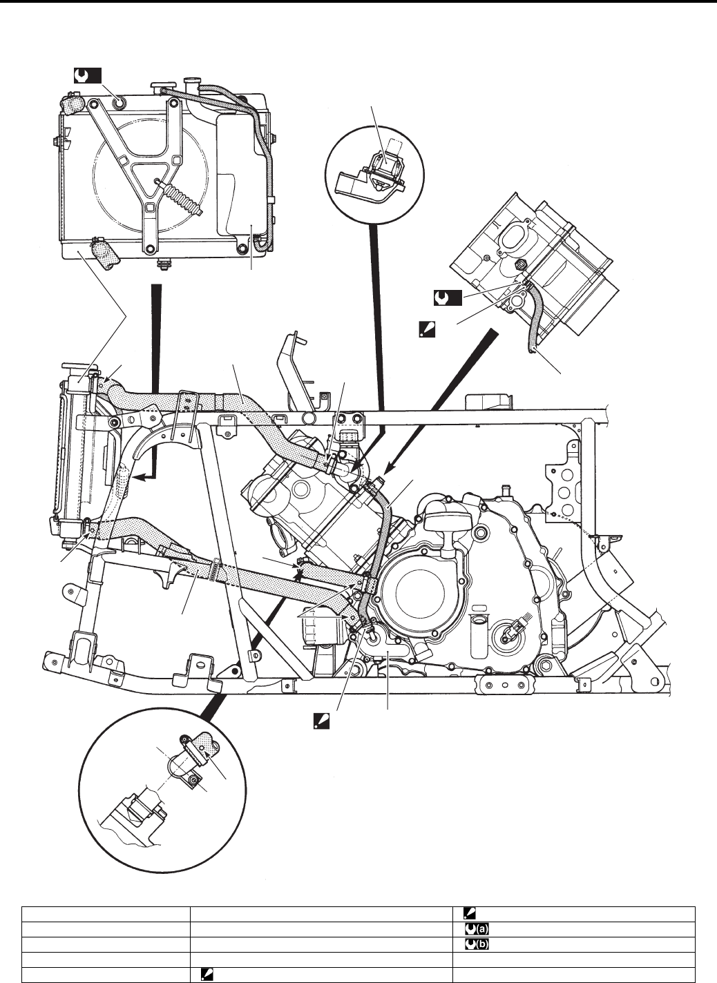
1F-3 Engine Cooling System:
Water Hose Routing Diagram
B831G21602002
1
2
3
4
5
“D”
5
6
7
“C”
“A”
“B”
“B”
“A”
“A”
(a)
(b)
“A”
I831G1160002-05
1. Thermostat 6. Radiator outlet hose “D”: Face the tip of the clip to upper.
2. Radiator 7. Water pump : 17 N⋅m (1.7 kgf-m, 12.5 lb-ft)
3. Reservoir tank “A”: Yellow mark : 12 N⋅m (1.2 kgf-m, 8.5 lb-ft)
4. Radiator inlet hose “B”: White mark
5. Bypass hose “C”: Face the tip of the clip to forward.
PartShark.com
877-999-5686
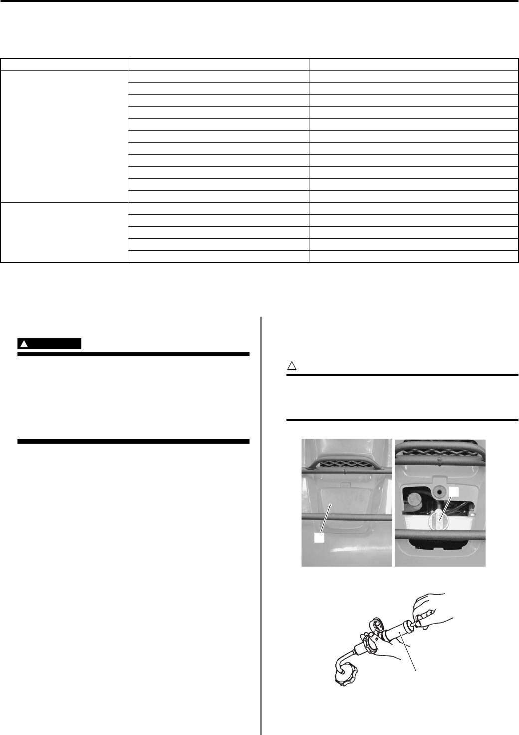
Engine Cooling System: 1F-4
Diagnostic Information and Procedures
Engine Cooling Symptom Diagnosis
B831G21604001
Repair Instructions
Cooling Circuit Inspection
B831G21606001
WARNING
!
• Do not open the radiator cap when the
engine is hot, as you may be injured by
escaping hot liquid or vapor.
• When removing the radiator cap tester, put
a rag on the filler to prevent the engine
coolant from spraying out.
Inspect the cooling circuit in the following procedures:
1) Remove the radiator cap lid (1) and radiator cap (2).
2) Connect the radiator tester (3) to the filler.
3) Pressurize the cooling system with 120 kPa (1.2 kgf/
cm, 17 psi) of pressure, and then check if it holds the
pressure for 10 seconds.
CAUTION
!
Do not exceed the radiator cap release
pressure, or the radiator cap and
subsequently the radiator, can be damaged.
4) After finishing the cooling circuit inspection, reinstall
the removed parts.
Condition Possible cause Correction / Reference Item
Engine overheats Not enough engine coolant. Add engine coolant.
Radiator core clogged with dirt or scale. Clean.
Faulty cooling fan. Repair or replace.
Defective cooling fan thermo-switch. Replace.
Clogged water passage. Clean.
Air trapped in the cooling circuit. Bleed air.
Defective water pump. Replace.
Use of incorrect engine coolant. Replace.
Defective thermostat. Replace.
Defective ECT sensor. Replace.
Defective ECM. Replace.
Engine over cools Defective cooling fan thermo-switch. Replace.
Extremely cold weather. Put on radiator cover.
Defective thermostat. Replace.
Defective ECT sensor. Replace.
Defective ECM. Replace.
1
2
I831G1160003-01
3
I831G1160005-01
PartShark.com
877-999-5686
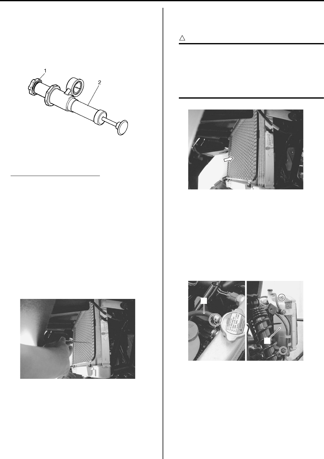
1F-5 Engine Cooling System:
Radiator Cap Inspection
B831G21606002
Inspect the radiator cap in the following procedures:
1) Remove the radiator cap. Refer to “Cooling Circuit
Inspection (Page 1F-4)”.
2) Attach the radiator cap (1) to the radiator tester (2)
as shown in the figure.
3) Slowly apply pressure to the radiator cap.
If the radiator cap does not hold the pressure for at
least 10 seconds, replace it with a new one.
Radiator cap release pressure
110 – 140 kPa (1.1 – 1.4 kgf/cm2, 15.6 – 19.9 psi)
4) After finishing the radiator cap inspection, reinstall
the removed parts.
Radiator Inspection and Cleaning
B831G21606003
Radiator Hose
Refer to “Cooling System Inspection in Section 0B
(Page 0B-15)”.
Radiator
Inspect the radiator for water leaks. If any defects are
found, replace the radiator with a new one.
If the fins are bent or dented, repair them by carefully
straightening them with the blade of a small screwdriver.
Radiator Cleaning
Blow out any foreign matter that is stuck in the radiator
fins using compressed air.
CAUTION
!
• Make sure not to bend the fins when using
compressed air.
• Always apply compressed air from the
engine side of engine. If compressed air is
applied from the front side, dirt will be
forced into the pores of radiator.
Cooling Fan Assembly / Radiator Removal and
Installation
B831G21606004
Removal
1) Remove the front fender. Refer to “Front Side
Exterior Parts Removal and Installation in Section
9D (Page 9D-6)”.
2) Disconnect the hoses (1).
3) Remove the reservoir tank (2).
I718H1160033-01
I831G1160061-01
I831G1160062-01
2
1
I831G1160063-02
PartShark.com
877-999-5686
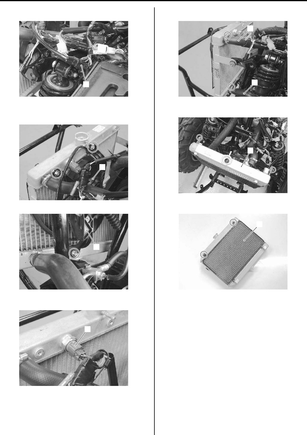
Engine Cooling System: 1F-6
4) Disconnect the cooling fan motor coupler (3).
5) Remove the cooling fan assembly (4) by removing
the bolts.
6) Disconnect the cooling fan thermo-switch (5).
7) Disconnect the inlet hose (6) and outlet hose (7).
Remove the radiator (8) by removing the bolts.
9) Remove the radiator cover (9).
3
I831G1160055-01
4
I831G1160004-01
4
I831G1160007-01
5
I831G1160008-01
6
7
I831G1160009-01
8
I831G1160010-01
9
I831G1160011-02
PartShark.com
877-999-5686
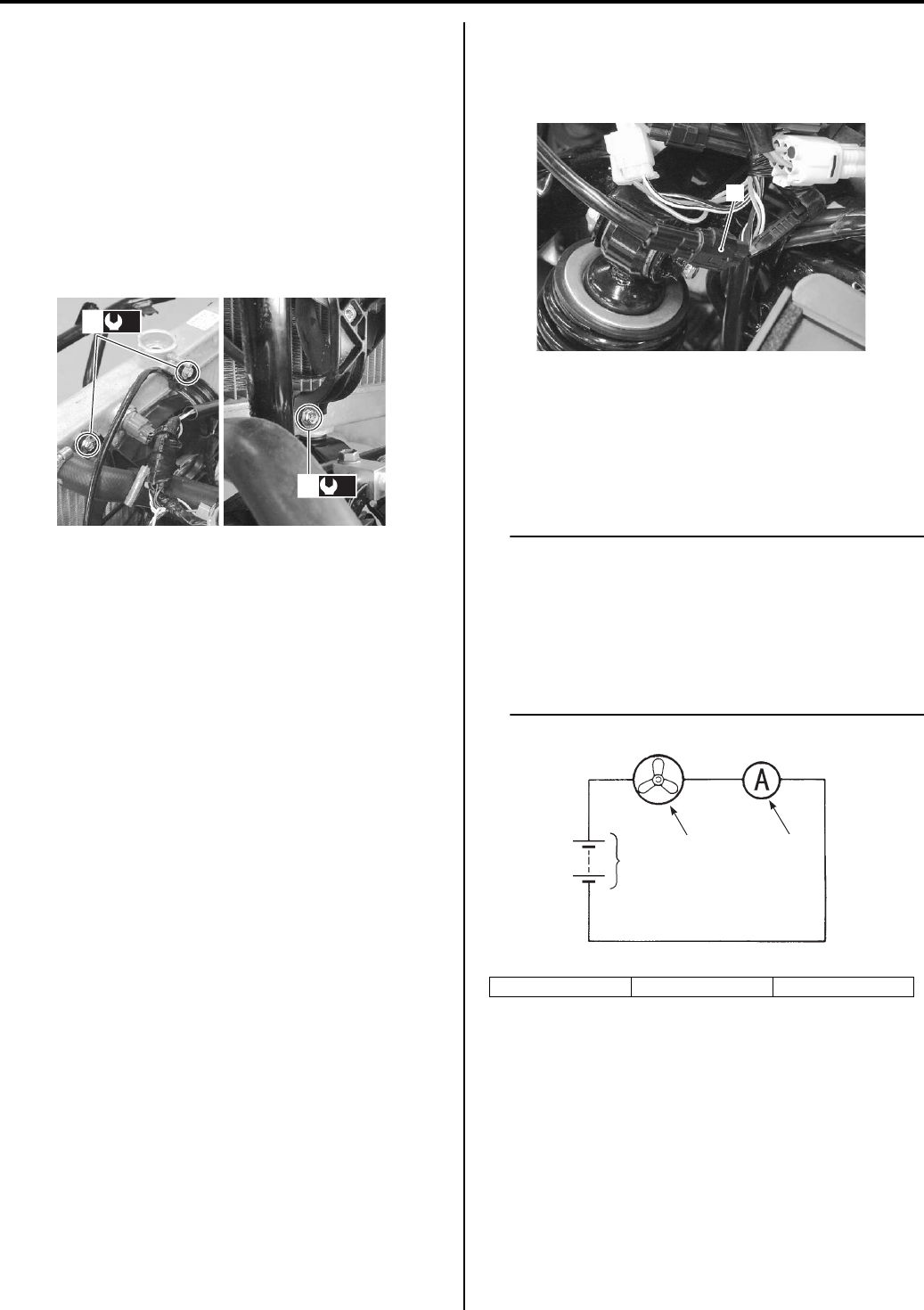
1F-7 Engine Cooling System:
Installation
Install the cooling fan assembly and radiator in the
reverse order of removal. Pay attention to the following
points:
• Connect the radiator hoses securely. Refer to “Water
Hose Routing Diagram (Page 1F-3)”.
• Tighten the cooling fan assembly mounting bolts (1) to
the specified torque.
Tightening torque
Cooling fan assembly mounting bolt (a): 8.5 N·m (
0.85 kgf-m, 6.0 lbf-ft)
• Pour engine coolant. Refer to “Cooling System
Inspection in Section 0B (Page 0B-15)”.
• Bleed air from the cooling circuit. Refer to “Cooling
System Inspection in Section 0B (Page 0B-15)”.
Water Hose Removal and Installation
B931G21606005
Removal
1) Drain engine coolant. Refer to “Cooling System
Inspection in Section 0B (Page 0B-15)”.
2) Remove the front fender. Refer to “Front Side
Exterior Parts Removal and Installation in Section
9D (Page 9D-6)”.
3) Remove the water hose as shown in the water hose
routing diagram. Refer to “Water Hose Routing
Diagram (Page 1F-3)”.
Installation
1) Install the water hose as shown in the water hose
routing diagram. Refer to “Water Hose Routing
Diagram (Page 1F-3)”.
2) Pour engine coolant and bleed air from the cooling
circuit. Refer to “Cooling System Inspection in
Section 0B (Page 0B-15)”.
3) Reinstall the removed parts.
Cooling Fan Inspection
B931G21606006
Inspect the cooling fan in the following procedures:
1) Disconnect the cooling fan motor coupler (1).
2) Test the cooling fan motor for load current with an
ammeter connected as shown in the figure.
If the fan motor does not turn, replace the cooling fan
assembly with a new one. Refer to “Cooling Fan
Assembly / Radiator Removal and Installation
(Page 1F-5)”.
NOTE
• When making this test, it is not necessary
to remove the cooling fan.
• Make sure that the battery has a capacity
enough to supply the motor with 12 V.
• With the motor running at full speed, the
ammeter should indicate an amperage not
higher than 8 A.
3) Connect the cooling fan motor coupler.
(a)
1
(a)
1
I831G1160012-03
2. Fan motor 3. Ammeter 4. Battery
1
I831G1160018-02
23
4
I718H1160048-01
PartShark.com
877-999-5686
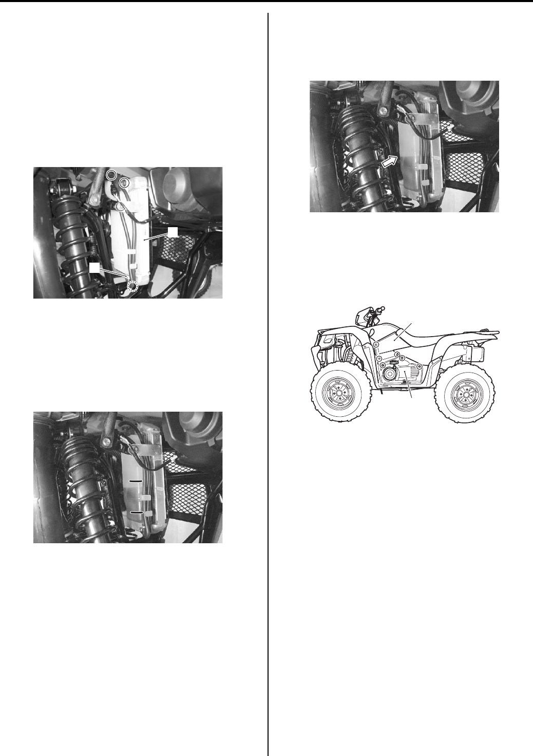
Engine Cooling System: 1F-8
Radiator Reservoir Tank Removal and
Installation
B831G21606007
Removal
1) Remove the right inner fender. Refer to “Front Side
Exterior Parts Removal and Installation in Section
9D (Page 9D-6)”.
2) Remove the reservoir tank mounting bolts.
3) Disconnect the hoses (1) and drain the engine
coolant.
4) Remove the reservoir tank (2).
Installation
Install radiator reservoir tank in the reverse order of
removal. Pay attention to the following points:
• Connect the radiator reservoir tank hoses securely.
Refer to “Water Hose Routing Diagram (Page 1F-3)”.
• Fill the reservoir tank to the upper level.
Radiator Reservoir Tank Inspection
B831G21606008
Inspect the radiator reservoir tank cooling leaks. If any
defects are found, replace the radiator reservoir tank
with a new one.
Water Hose Inspection
B831G21606009
Inspect the water hoses in the following procedures:
1) Remove the left side cover (1) and engine side cover
(2).
2) Check the water hoses for crack, damage or engine
coolant leakage. If any defects are found, replace
the radiator hose with a new one.
2
1
I831G1160019-02
L
F
I831G1160020-04
I831G1160021-01
1
2
I831G1160064-02
PartShark.com
877-999-5686
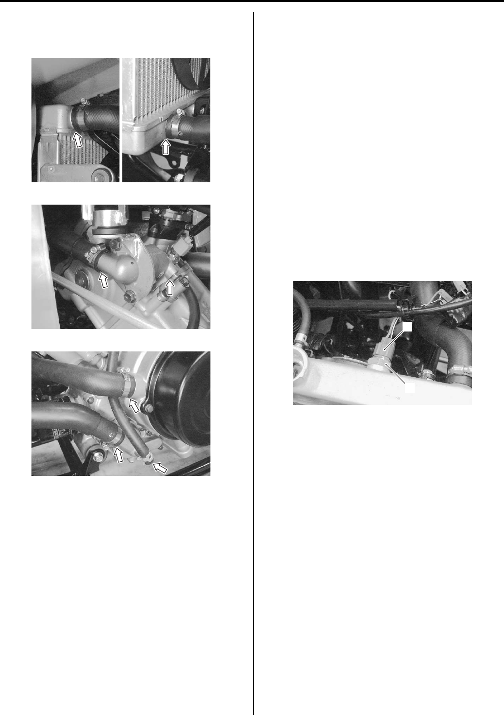
1F-9 Engine Cooling System:
3) Any leakage from the connecting section should be
corrected by proper tightening. Refer to “Water Hose
Routing Diagram (Page 1F-3)”.
4) After finishing the water hose inspection, reinstall the
removed parts.
ECT Sensor Removal and Installation
B831G21606010
Refer to “ECT Sensor Removal and Installation in
Section 1C (Page 1C-4)”.
ECT Sensor Inspection
B831G21606011
Refer to “ECT Sensor Inspection in Section 1C
(Page 1C-4)”.
Cooling Fan Thermo-switch Removal and
Installation
B831G21606012
Removal
1) Remove the front fender. Refer to “Front Side
Exterior Parts Removal and Installation in Section
9D (Page 9D-6)”.
2) Drain engine coolant. Refer to “Cooling System
Inspection in Section 0B (Page 0B-15)”.
3) Disconnect the cooling fan thermo-switch lead wire
coupler (1).
4) Remove the cooling fan thermo-switch (2).
I831G1160022-01
I831G1160023-01
I831G1160024-02
1
2
I831G1160025-02
PartShark.com
877-999-5686
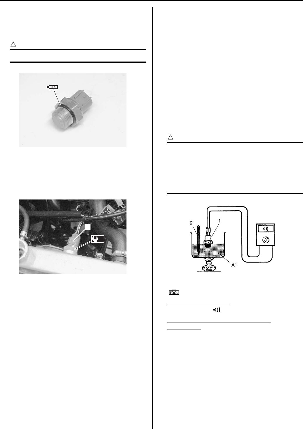
Engine Cooling System: 1F-10
Installation
Install the cooling fan thermo-switch in the reverse order
of removal. Pay attention to the following points:
• Apply engine coolant to the O-ring.
CAUTION
!
Replace the removed O-ring with a new one.
• Tighten the cooling fan thermo-switch to the specified
torque and connect the coupler (1).
Tightening torque
Cooling fan thermo-switch (a): 17 N·m (1.7 kgf-m,
12.5 lb-ft)
• Pour engine coolant. Refer to “Cooling System
Inspection in Section 0B (Page 0B-15)”.
• Bleed air from the cooling circuit. Refer to “Cooling
System Inspection in Section 0B (Page 0B-15)”.
Cooling Fan Thermo-switch Inspection
B831G21606013
Inspect the cooling fan thermo-switch in the following
procedures:
1) Remove the cooling fan thermo-switch. Refer to
“Cooling Fan Thermo-switch Removal and
Installation (Page 1F-9)”.
2) Check the thermo-switch closing or opening
temperatures by testing it at the bench as shown in
the figure.
3) Connect the thermo-switch (1) to a circuit tester and
place it in the water “A” contained in a pan, which is
placed on the stove.
4) Heat the water to raise its temperature slowly and
read the column thermometer (2) when the switch
closes or opens. If any abnormality is found, replace
the cooling fan thermo-switch with a new one.
CAUTION
!
• Take special care when handling the
cooling fan thermo-switch. Do not subject
it to strong blows or allow it to be dropped.
• Do not contact the cooling fan thermo-
switch (1) and the column thermometer (2)
with a pan.
Special tool
: 09900–25008 (Multi-circuit tester set)
Tester knob indication
Continuity test ( )
Cooling fan thermo-switch operating
temperature
Standard (OFF → ON): Approx. 93 °C (199 °F)
Standard (ON → OFF): Approx. 87 °C (189 °F)
5) Reinstall the cooling fan thermo-switch. Refer to
“Cooling Fan Thermo-switch Removal and
Installation (Page 1F-9)”.
I831G1160026-01
1
(a)
I831G1160065-01 I705H1160033-03
PartShark.com
877-999-5686
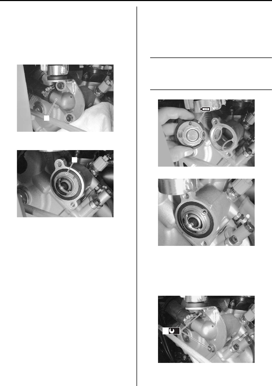
1F-11 Engine Cooling System:
Thermostat Removal and Installation
B831G21606014
Removal
1) Drain a small amount of engine coolant. Refer to
“Cooling System Inspection in Section 0B (Page 0B-
15)”.
2) Place a rag under the thermostat cover (1).
3) Remove the thermostat case (1).
4) Remove the thermostat (2).
Installation
Install the thermostat in the reverse order of removal.
Pay attention to the following points:
• Apply engine coolant to the rubber seal on the
thermostat.
• Install the thermostat.
NOTE
• Align the protrusions on the thermostat
with the groove on the cylinder head.
• The jiggle valve of the thermostat faces
upside.
• Tighten the thermostat cover bolts (1) to the specified
torque.
Tightening torque
Thermostat cover bolt (a): 23 N·m (2.3 kgf-m, 16.5
lb-ft)
1
I831G1160027-01
2
I831G1160028-01
I831G1160029-01
I831G1160030-02
(a)
1
I831G1160031-01
PartShark.com
877-999-5686
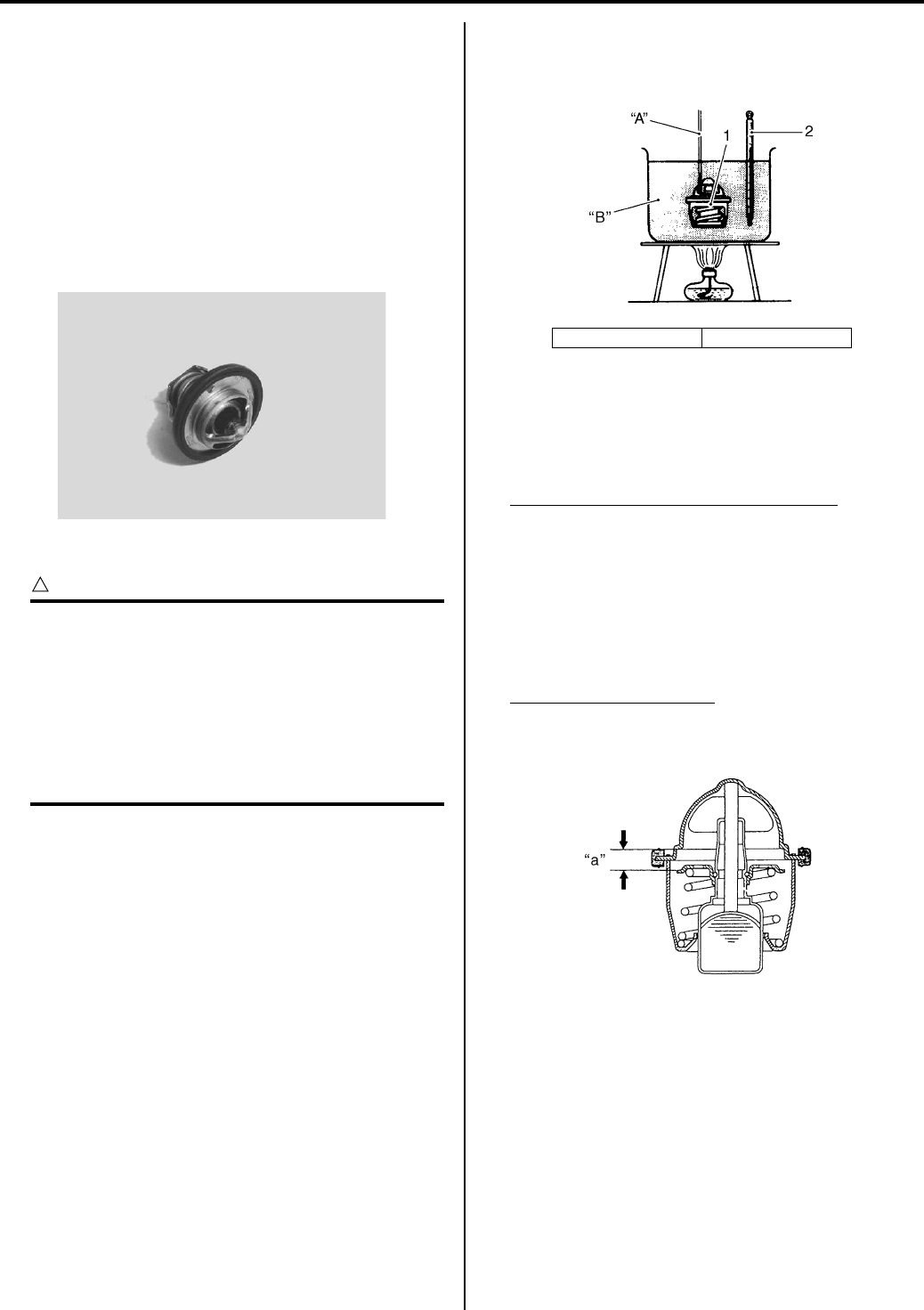
Engine Cooling System: 1F-12
• Pour engine coolant. Refer to “Cooling System
Inspection in Section 0B (Page 0B-15)”.
• Bleed air from the cooling circuit. Refer to “Cooling
System Inspection in Section 0B (Page 0B-15)”.
Thermostat Inspection
B831G21606015
Inspect the thermostat in the following procedures:
1) Remove the thermostat. Refer to “Thermostat
Removal and Installation (Page 1F-11)”.
2) Inspect the thermostat pellet for signs of cracking.
3) Test the thermostat at the bench for control action.
CAUTION
!
• Do not contact the thermostat (1) and the
column thermometer (2) with a pan.
• As the thermostat operating response to
water temperature change is gradual, do
not raise water temperature too quickly.
• The thermostat with its valve open even
slightly under normal temperature must be
replaced.
4) Immerse the thermostat (1) in the water contained in
a beaker and note that the immersed thermostat is in
suspension.
5) Heat the water by placing the beaker on a stove and
observe the rising temperature on a thermometer
(2).
6) Read the thermometer just when opening the
thermostat. If this reading, which is the temperature
level at which the thermostat valve begins to open, is
out of the standard value, replace the thermostat
with a new one.
Thermostat valve opening temperature
Standard: Approx. 82 °C (180 °F)
7) Keep on heating the water to raise its temperature.
Just when the water temperature reaches specified
value, the thermostat valve should have been lifted
by at least 8 mm (0.31 in). A thermostat failing to
satisfy either of the two requirements (start-to-open
temperature and valve lift) must be replaced.
Thermostat valve lift “a”
Standard: 8 mm (0.31 in) and over at 95 °C (203
°F)
9) Install the thermostat. Refer to “Thermostat Removal
and Installation (Page 1F-11)”.
I831G1160032-01
“A”: String “B”: Water
I705H1160030-03
I705H1160031-04
PartShark.com
877-999-5686
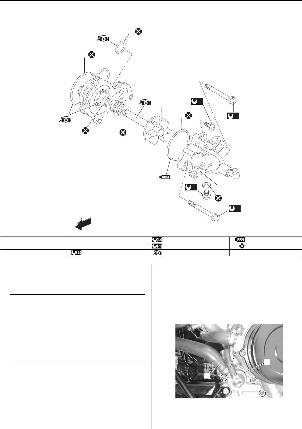
1F-13 Engine Cooling System:
Water Pump Components
B831G21606016
Water Pump Removal and Installation
B831G21606017
Removal
NOTE
Before draining engine oil and engine
coolant, inspect engine oil and coolant
leakage between the water pump and
crankcase. If engine oil is leaking, visually
inspect the oil seal and O-ring. If engine
coolant is leaking, visually inspect the
mechanical seal and seal washer. Refer to
“Water Pump Related Parts Inspection
(Page 1F-18)”.
1) Remove the left inner fender. Refer to “Front Side
Exterior Parts Removal and Installation in Section
9D (Page 9D-6)”.
2) Remove the left mud guard. Refer to “Front Side
Exterior Parts Removal and Installation in Section
9D (Page 9D-6)”.
3) Drain engine oil and coolant. Refer to “Engine Oil
and Filter Replacement in Section 0B (Page 0B-10)”
and “Cooling System Inspection in Section 0B
(Page 0B-15)”.
4) Disconnect the outlet hose (1) and water bypass
hose (2).
5) Remove the water pump assembly (3).
1
2
3
2
2
4
5
FWD
(a)
(c)
(a)
(b)
I831G1160033-05
1. Water pump cover 4. Mechanical seal : 6 N⋅m (0.6 kgf-m, 4.5 lb-ft) : Apply engine coolant.
2. O-ring 5. Oil seal : 13 N⋅m (1.3 kgf-m, 9.5 Ib-ft) : Do not reuse.
3. Impeller : 10 N⋅m (1.0 kgf-n, 7.0 Ib-ft) : Apply grease.
1
2
3
I831G1160034-01
PartShark.com
877-999-5686
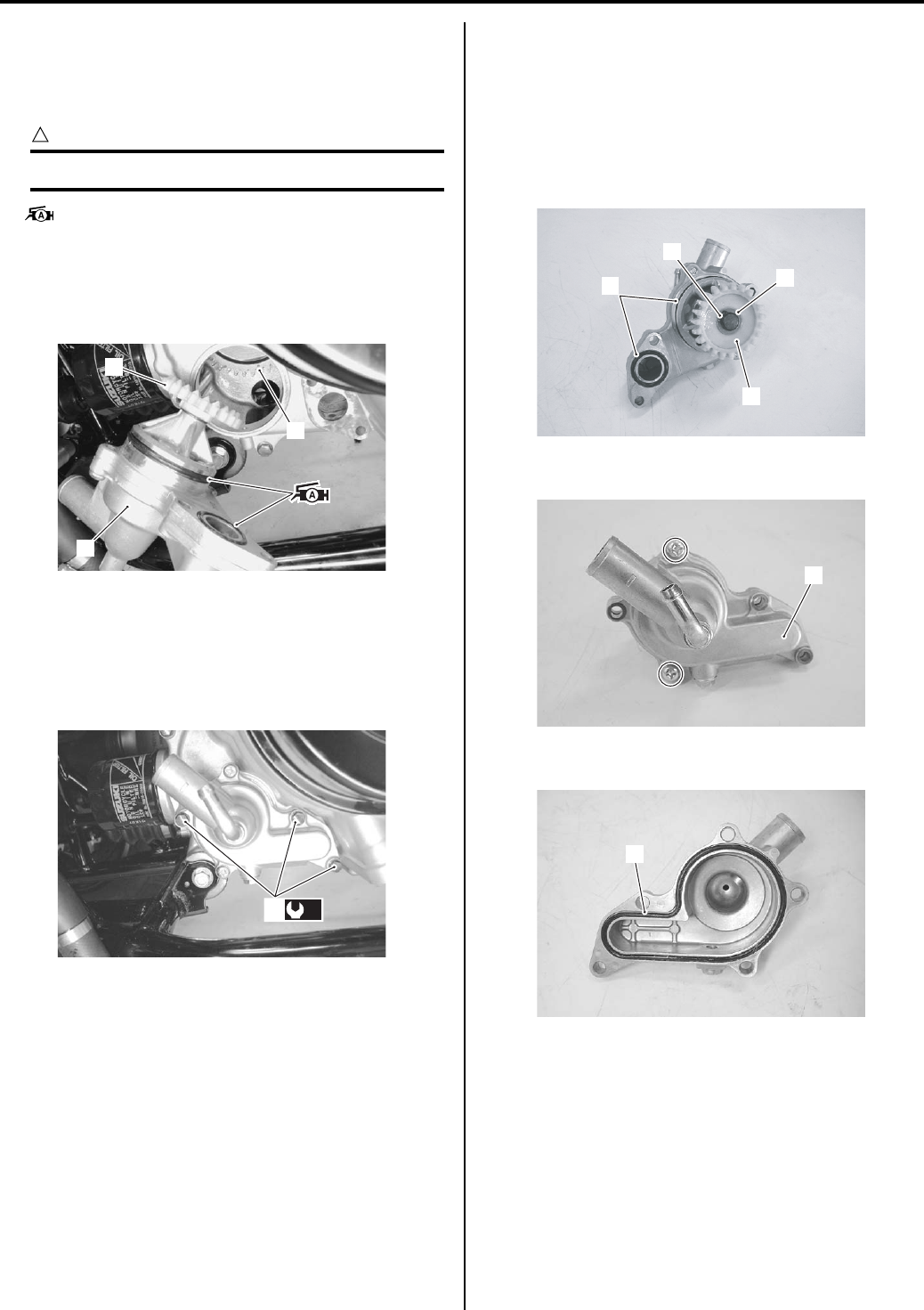
Engine Cooling System: 1F-14
Installation
Install the water pump in the reverse order of removal.
Pay attention to the following points:
• Apply grease to the O-rings.
CAUTION
!
Replace the O-rings with the new ones.
: Grease 99000–25010 (SUZUKI SUPER
GREASE A or equivalent)
• Set the water pump driven gear (1) to the water pump
drive gear (2) and install the water pump assembly
(3).
• Tighten the water pump mounting bolts (4) to the
specified torque.
Tightening torque
Water pump mounting bolt (a): 10 N·m (1.0 kgf-
m, 7.0 lb-ft)
• Connect the water hoses securely. Refer to “Water
Hose Routing Diagram (Page 1F-3)”.
• Pour engine oil and coolant. Refer to “Engine Oil and
Filter Replacement in Section 0B (Page 0B-10)” and
“Cooling System Inspection in Section 0B (Page 0B-
15)”.
• Bleed air from the cooling circuit. Refer to “Front
Differential Gear Oil Inspection in Section 0B
(Page 0B-12)”.
Water Pump Disassembly and Assembly
B831G21606018
Refer to “Water Pump Removal and Installation
(Page 1F-13)”.
Disassembly
1) Remove the O-rings (1), snap ring (2), washer (3)
and water pump driven gear (4).
2) Remove the water pump cover (5).
3) Remove the O-ring (6).
1
2
3
I831G1160035-01
(a)
4
I831G1160036-01
1
2
3
4
I831G1160037-02
5
I831G1160038-01
6
I831G1160039-01
PartShark.com
877-999-5686
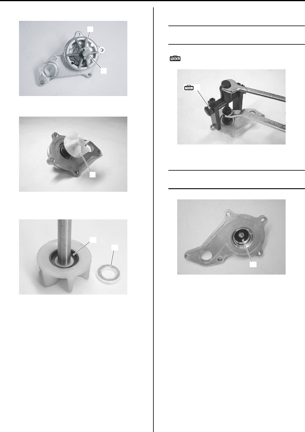
1F-15 Engine Cooling System:
4) Remove the pin (7) and washer (8).
5) Remove the impeller (9).
6) Remove the mechanical seal ring (10) and rubber
seal (11) from the impeller.
7) Remove the mechanical seal with the special tool.
NOTE
If there is no abnormal condition, the
mechanical seal removal is not necessary.
Special tool
(A): 09921–20240 (Bearing remover set)
Remove the oil seal (12).
NOTE
If there is no abnormal condition, the oil seal
removal is not necessary.
7
8
I831G1160040-02
9
I831G1160041-01
11
10
I831G1160042-01
(A)
I831G1160043-01
12
I831G1160044-01
PartShark.com
877-999-5686
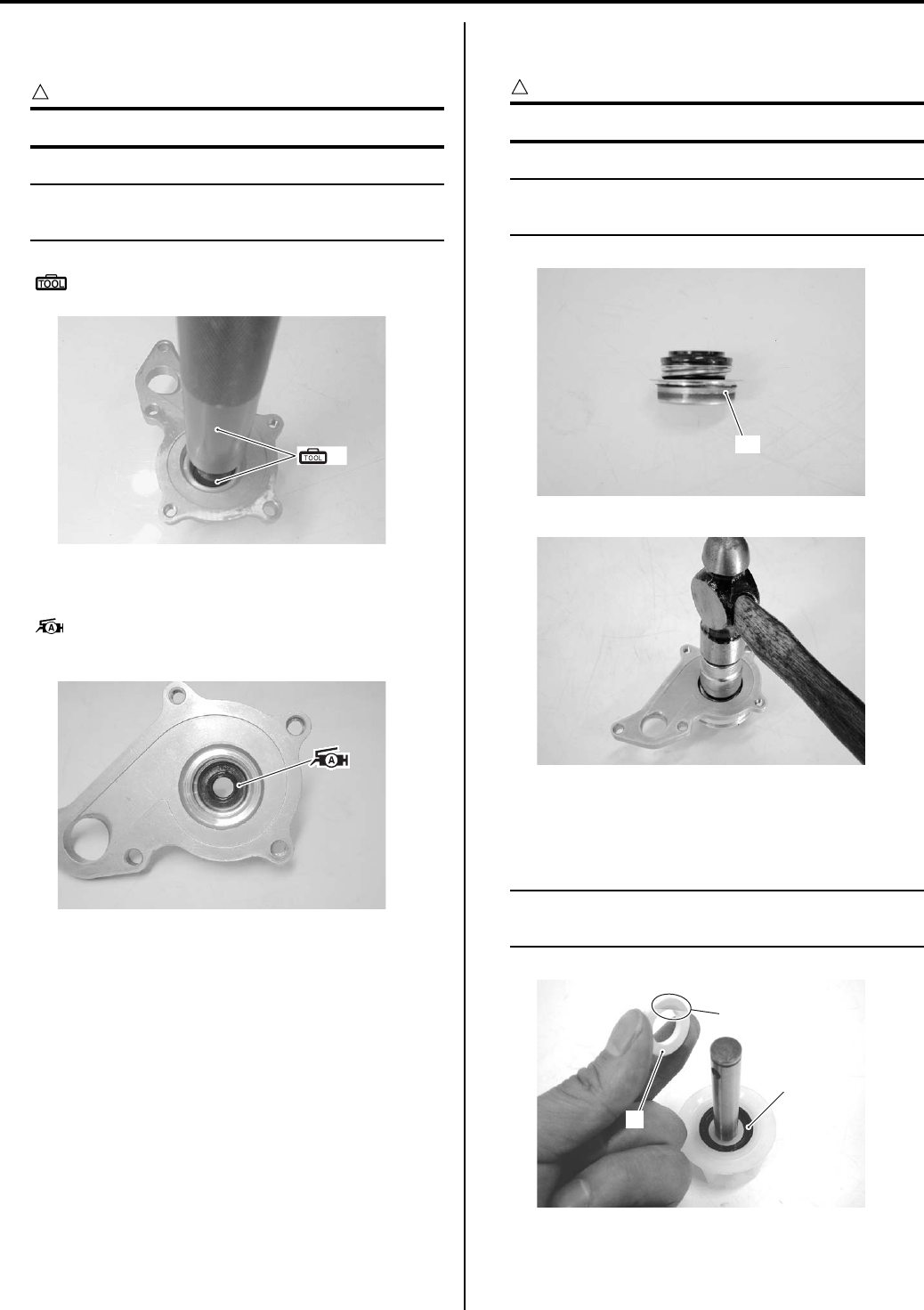
Engine Cooling System: 1F-16
Assembly
1) Install the oil seal with the special tool.
CAUTION
!
Replace the oil seal with a new one.
NOTE
The stamped mark on the oil seal should face
mechanical seal side.
Special tool
(A): 09913–70210 (Bearing installer set)
2) Apply a small quantity of the grease to the oil seal
lip.
: Grease 99000–25010 (SUZUKI SUPER
GREASE A or equivalent)
3) Install a new mechanical seal using a suitable size
socket wrench.
CAUTION
!
Replace the mechanical seal with a new one.
NOTE
On the new mechanical seal, the sealer “A”
has been applied.
4) Install the rubber seal (1) into the impeller.
5) After wiping off the oily or greasy matter from the
mechanical seal ring (2), install it into the impeller.
NOTE
The paint marked side “B” of mechanical seal
ring faces the rubber seal.
(A)
I831G1160045-01
I831G1160046-01
“A”
I831G1160047-01
I831G1160048-01
“B”
2
1
I831G1160049-02
PartShark.com
877-999-5686
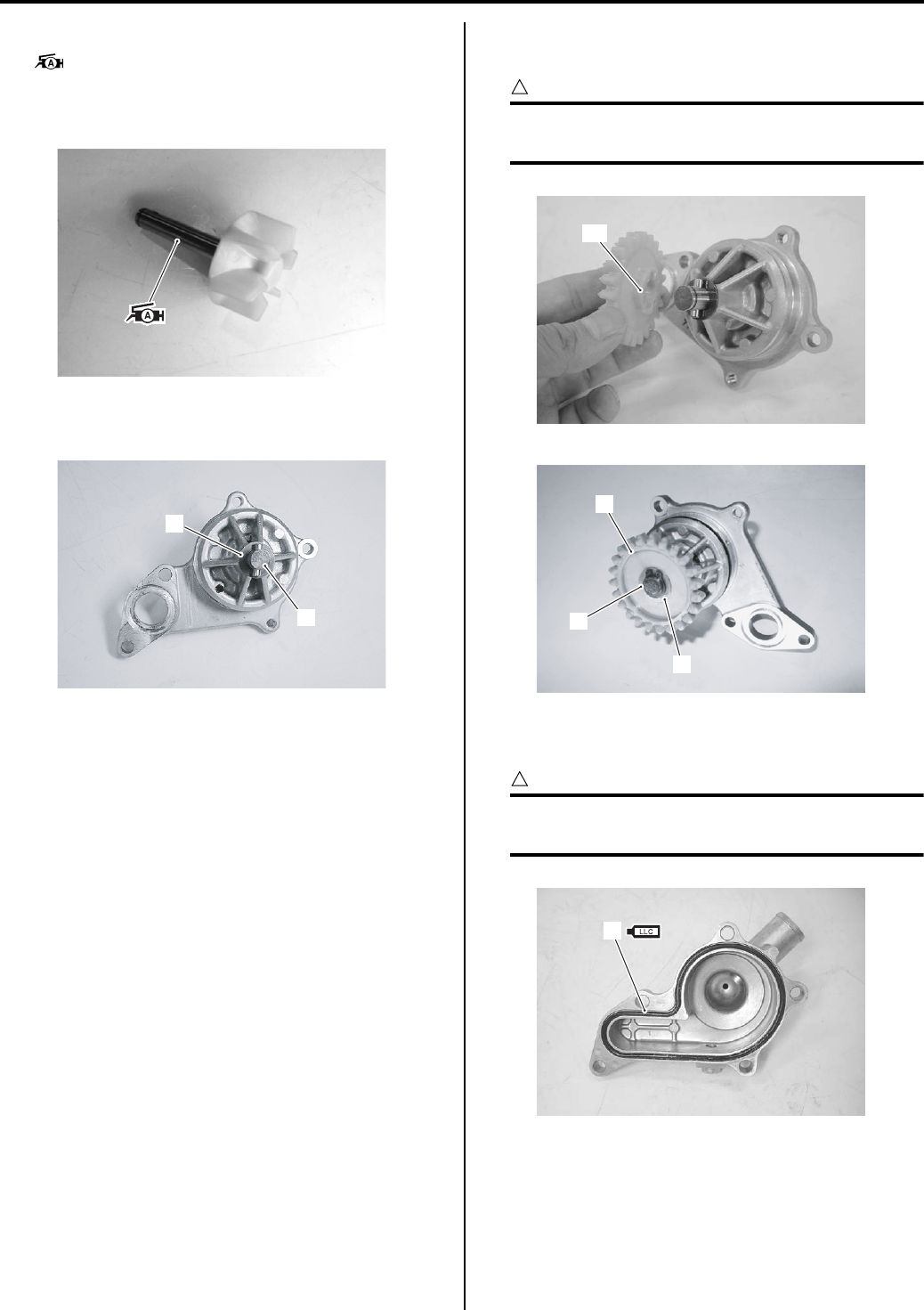
1F-17 Engine Cooling System:
6) Apply grease to the impeller shaft.
: Grease 99000–25010 (SUZUKI SUPER
GREASE A or equivalent)
7) Install the impeller shaft to the water pump body.
Install the washer (3) and pin (4) to the impeller
shaft.
9) Install the water pump driven gear (5), washer (6)
and snap ring (7).
CAUTION
!
The convex part “C” of water pump driven
gear should face the water pump side.
10) Install a new O-ring (8) and apply engine coolant to
it.
CAUTION
!
Use a new O-ring to prevent engine coolant
leakage.
I831G1160051-01
4
3
I831G1160050-02
“C”
I831G1160052-02
6
5
7
I831G1160053-04
8
I831G1160054-02
PartShark.com
877-999-5686
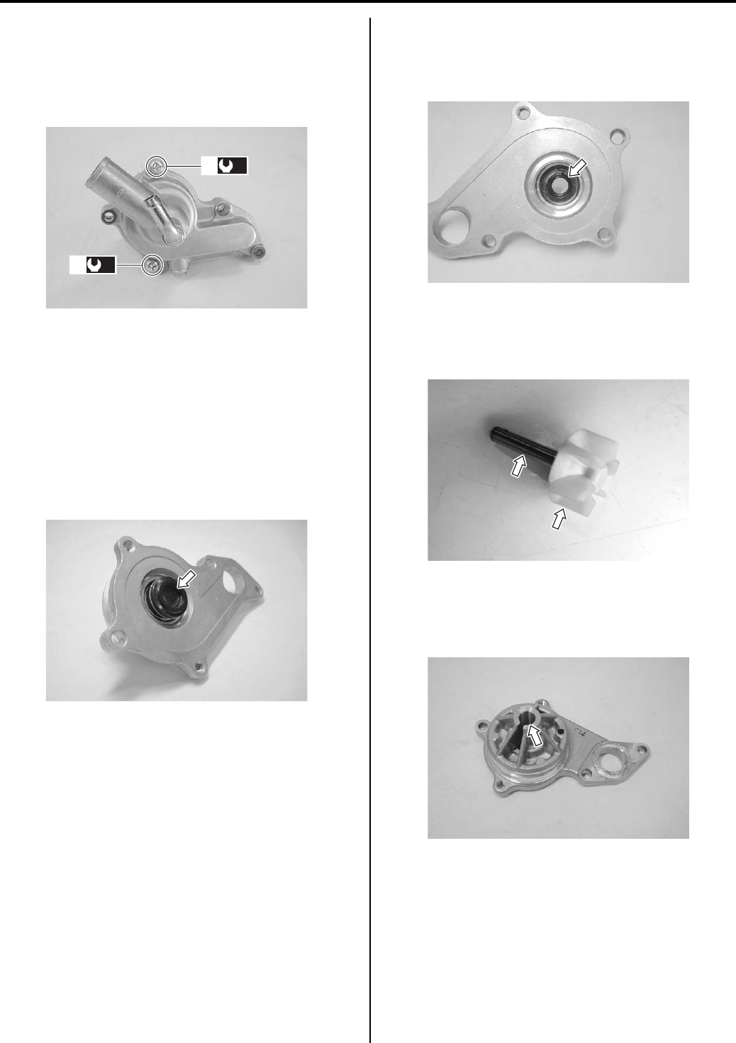
Engine Cooling System: 1F-18
11) Fit the water pump cover and tighten the water pump
cover screws (9) to the specified torque.
Tightening torque
Water pump cover screw (a): 6 N·m (0.6 kgf-m,
4.5 lb-ft)
Water Pump Related Parts Inspection
B831G21606019
Refer to “Water Pump Disassembly and Assembly
(Page 1F-14)”.
Mechanical Seal
Visually inspect the mechanical seal for damage, with
particular attention given to the sealing face.
Replace the mechanical seal that shows indications of
leakage.
Oil Seal
Visually inspect the oil seal for damage, with particular
attention given to the lip.
Replace the oil seal that shows indications of leakage.
Impeller
Visually inspect the impeller and its shaft for damage.
Replace the impeller if necessary.
Impeller Shaft Journal
Visually inspect the journal for damage or scratch.
Replace the water pump body if necessary.
(a)
9
(a)
9
I831G1160056-04
I831G1160057-01
I831G1160058-02
I831G1160059-01
I831G1160060-01
PartShark.com
877-999-5686
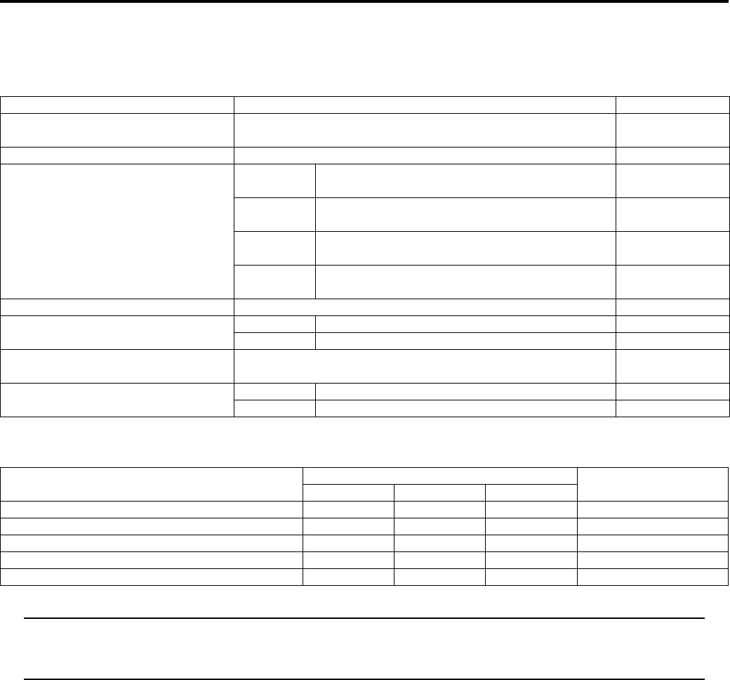
1F-19 Engine Cooling System:
Specifications
Service Data
B831G21607001
Thermostat + Radiator + Fan + Coolant
Tightening Torque Specifications
B831G21607002
NOTE
The specified tightening torque is also described in the following.
“Water Hose Routing Diagram (Page 1F-3)”
“Water Pump Components (Page 1F-13)”
Reference:
For the tightening torque of fastener not specified in this section, refer to “Tightening Torque List in Section 0C
(Page 0C-7)”.
Item Standard Note
Thermostat valve opening
temperature Approx. 82 °C (180 °F) —
Thermostat valve lift 8 mm (0.31 in) and over at 95 °C (203 °F) —
ECT sensor resistance
20 °C
(68 °F) Approx. 2.45 kΩ—
50 °C
(122 °F) Approx. 0.811 kΩ—
80 °C
(176 °F) Approx. 0.318 kΩ—
110 °C
(230 °F) Approx. 0.142 kΩ—
Radiator cap valve opening pressure 110 – 140 kPa (1.1 – 1.4 kgf/cm2, 15.6 – 19.9 psi) —
Cooling fan thermo-switch operating
temperature
OFF → ON Approx. 93 °C (199 °F) —
ON → OFF Approx. 87 °C (189 °F) —
Engine coolant type Use an antifreeze/coolant compatible with aluminum radiator,
mixed with distilled water only, at the ratio of 50:50. —
Engine coolant Reservoir Approx. 250 ml (0.26/0.22 US/lmp qt) —
Engine Approx. 2 200 ml (2.32/1.94 US/lmp qt) —
Fastening part Tightening torque Note
N⋅mkgf—mlb—ft
Cooling fan assembly mounting bolt 8.5 0.85 6.0 )(Page 1F-7)
Cooling fan thermo-switch 17 1.7 12.5 )(Page 1F-10)
Thermostat cover bolt 23 2.3 16.5 )(Page 1F-11)
Water pump mounting bolt 10 1.0 7.0 )(Page 1F-14)
Water pump cover screw 6 0.6 4.5 )(Page 1F-18)
PartShark.com
877-999-5686
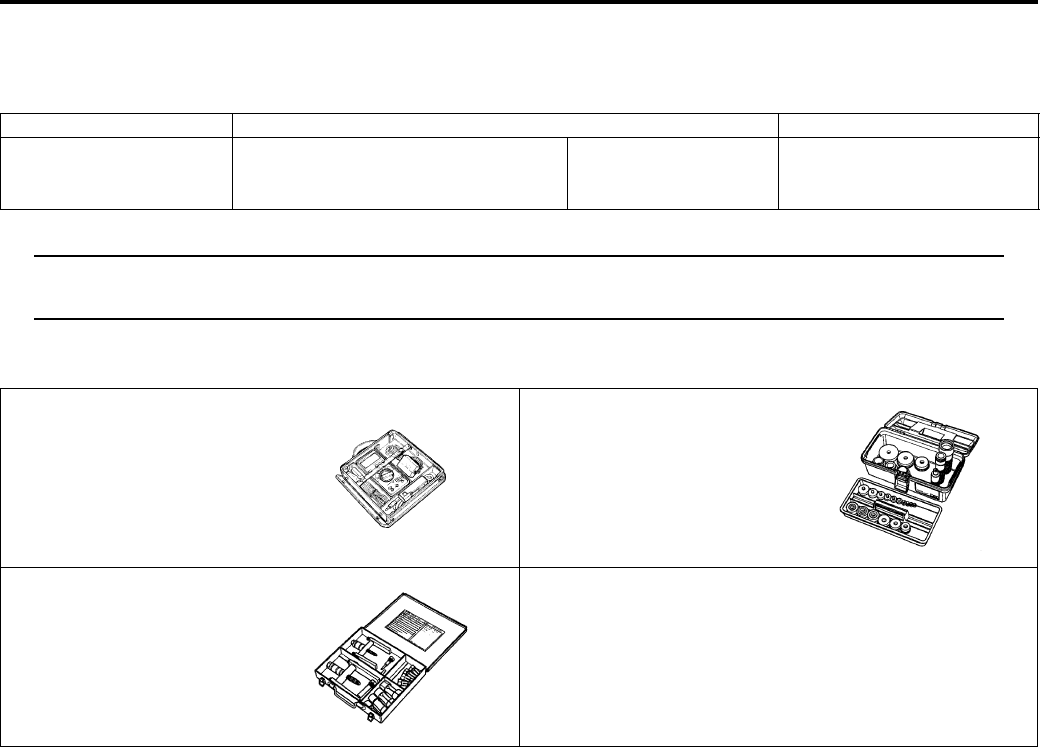
Engine Cooling System: 1F-20
Special Tools and Equipment
Recommended Service Material
B831G21608001
NOTE
Required service material is also described in the following.
“Water Pump Components (Page 1F-13)”
Special Tool
B831G21608002
Material SUZUKI recommended product or Specification Note
Grease SUZUKI SUPER GREASE A or
equivalent
P/No.: 99000–25010 )(Page 1F-14) /
)(Page 1F-16) /
)(Page 1F-17)
09900–25008 09913–70210
Multi-circuit tester set Bearing installer set
)(Page 1F-10) )(Page 1F-16)
09921–20240
Bearing remover set
)(Page 1F-15)
PartShark.com
877-999-5686

1G-1 Fuel System:
Engine
Fuel System
Precautions
Precautions for Fuel System
B831G21700001
WARNING
!
• Keep away from fire or spark.
• During disassembling, use care to minimize spillage of gasoline.
• Spilled gasoline should be wiped off immediately.
• Work in a well-ventilated area.
CAUTION
!
• To prevent the fuel system (fuel tank, fuel hose, etc.) from contamination with foreign particles, blind
all openings.
• After removing the throttle body, tape the cylinder intake section to prevent foreign particles from
entering.
PartShark.com
877-999-5686
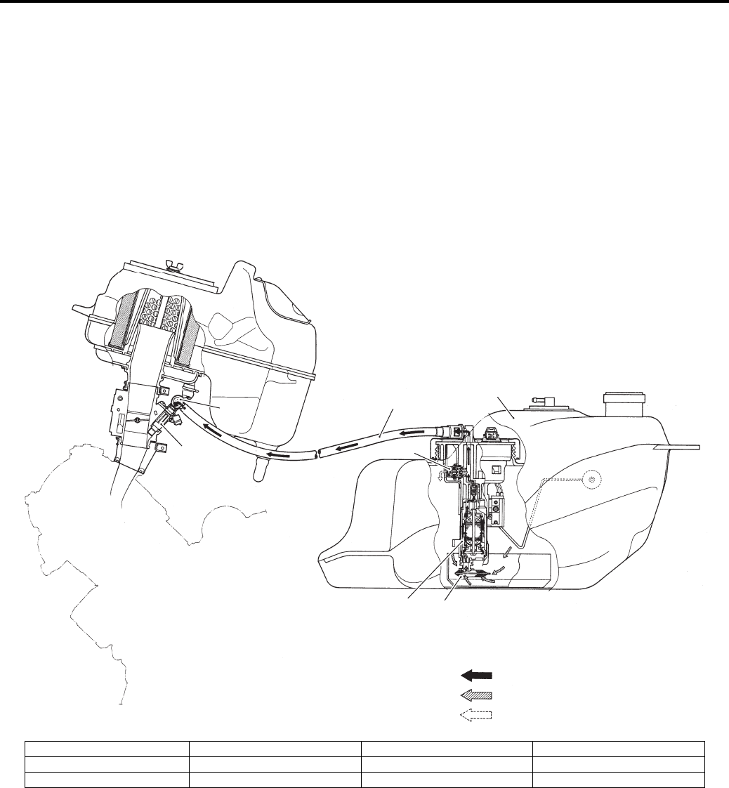
Fuel System: 1G-2
General Description
Fuel System Description
B831G21701001
Fuel System
The fuel delivery system consists of the fuel tank (1), fuel pump (2), fuel mesh filter (3), fuel feed hose (4), fuel delivery
pipe (5) (including fuel injector) and fuel pressure regulator (6). There is no fuel return hose. The fuel in the fuel tank
(1) is pumped up by the fuel pump (2) and pressurized fuel flows into the injector (7) installed in the fuel delivery pipe
(5). Fuel pressure is regulated by the fuel pressure regulator (6). As the fuel pressure applied to the fuel injector (7)
(the fuel pressure in the fuel delivery pipe) is always kept at absolute fuel pressure of 300 kPa (3.0 kgf/cm2, 43 psi), the
fuel is injected into the throttle body in conic dispersion when the injector (7) opens according to the injection signal
from the ECM.
The fuel relieved by the fuel pressure regulator (6) flows back to the fuel tank (1).
1
3
5
6
7
4
2
“C”
“A”
“B”
I831G1170001-01
1. Fuel tank 4. Fuel feed hose 7. Fuel injector “C”: Relieved fuel
2. Fuel pump 5. Fuel delivery pipe “A”: Pressurized fuel
3. Fuel mesh filter 6. Fuel pressure regulator “B”: Before-pressurized fuel
PartShark.com
877-999-5686
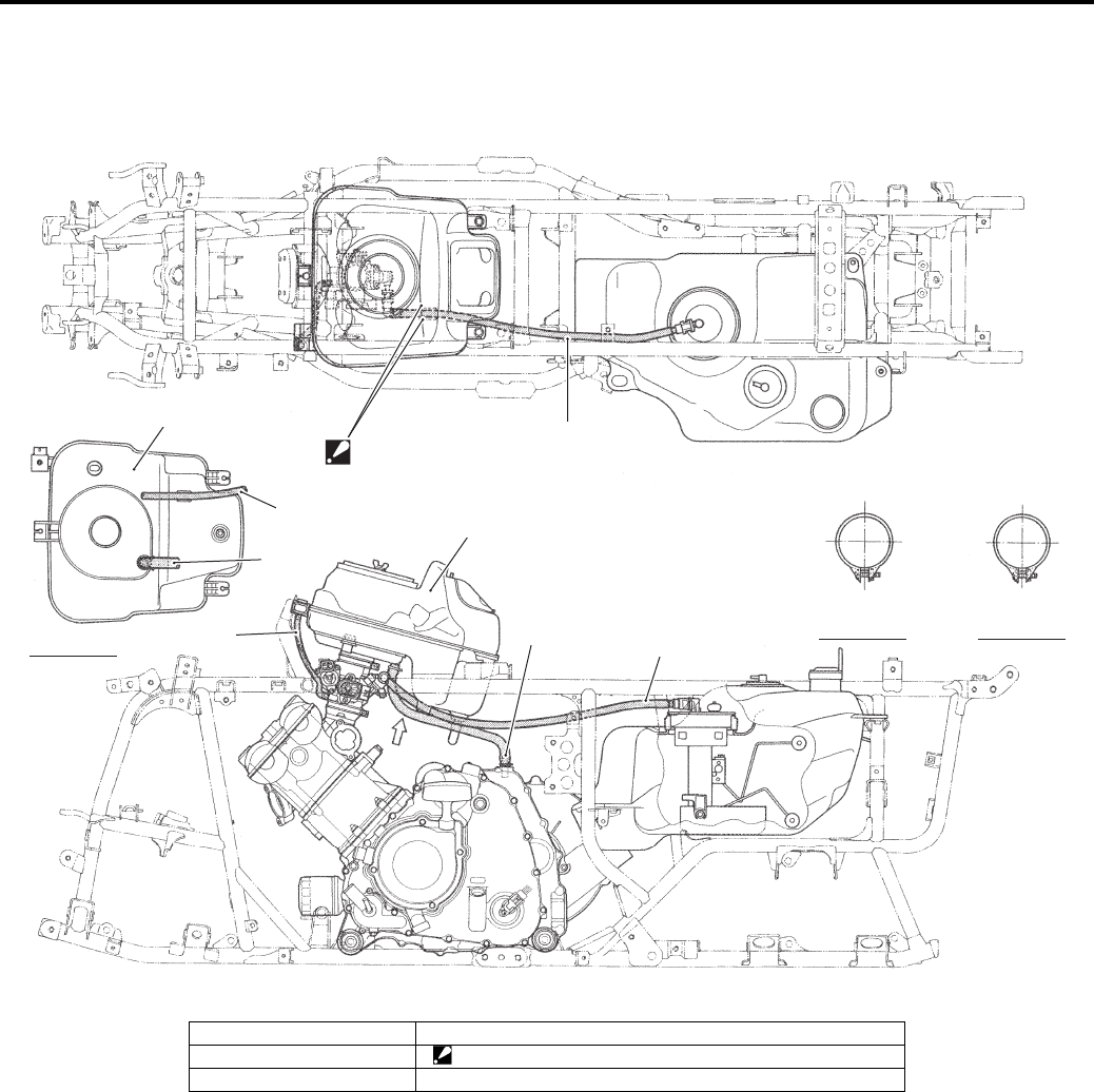
1G-3 Fuel System:
Schematic and Routing Diagram
Fuel Hose Routing Diagram
B831G21702001
A
FR
RR RR
RH RH LH
LH
FR
Intake pipe Outlet tube
1
5
2
2
1
3
43
1
VIEW A
I831G1170002-04
1. Fuel hose 4. IAP sensor hose
2. Air cleaner box 5. Pass the fuel hose between the air cleaner guide.
3. PCV hose
PartShark.com
877-999-5686
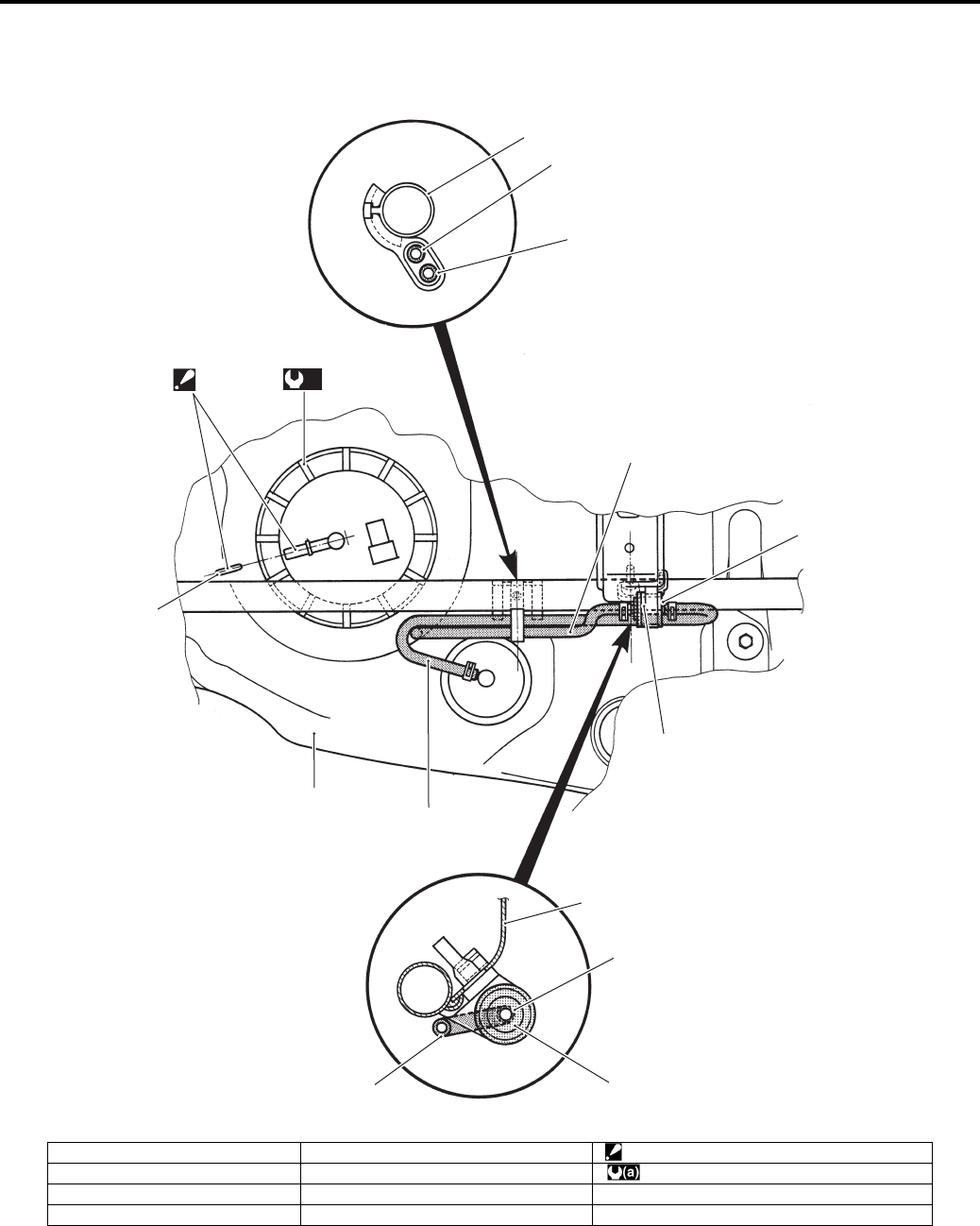
Fuel System: 1G-4
Fuel Tank Breather Hose Routing Diagram
B831G21702002
1
3
2
7
2
3
5
6
4
1
26
8
(a)
“A”
I831G1170003-04
1. Frame 5. Valve (Black) “A”: Align the fuel pump nipple with the mark.
2. Fuel tank breather hose 6. Valve (Orange) : 35 N⋅m (3.5 kgf-m, 25.5 lb-ft)
3. Check valve hose 7. Mark
4. Fuel tank 8. Fuel tank pressure control valve
PartShark.com
877-999-5686

1G-5 Fuel System:
Diagnostic Information and Procedures
Fuel System Diagnosis
B831G21704001
Condition Possible cause Correction / Reference Item
Engine will not start or is
hard to start (No fuel
reaching the intake
manifold)
Clogged fuel filter or fuel hose. Clean or replace.
Defective fuel pump. Replace.
Defective fuel pressure regulator. Replace.
Defective fuel injectors. Replace.
Defective fuel pump relay. Replace.
Defective ECM. Replace.
Open-circuited wiring connections. Check and repair.
Engine will not start or is
hard to start (Incorrect
fuel/air mixture)
Defective fuel pump. Replace.
Defective fuel pressure regulator. Replace.
Defective TP sensor. Replace.
Defective CKP sensor. Replace.
Defective IAP sensor. Replace.
Defective ECM. Replace.
Defective ECT sensor. Replace.
Defective IAT sensors. Replace.
Dirty throttle body. Clean.
Engine stalls often
(Incorrect fuel/air mixture)
Defective IAP sensor or circuit. Repair or replace.
Clogged fuel filter. Clean or replace.
Defective fuel pump. Replace.
Defective fuel pressure regulator. Replace.
Damaged or cracked vacuum hose. Replace.
Defective ECT sensor. Replace.
Defective thermostat. Replace.
Defective IAT sensor. Replace.
Engine stalls often (Fuel
injector improperly
operating)
Defective fuel injectors. Replace.
No injection signal from ECM. Repair or replace.
Open or short circuited wiring
connection.
Repair or replace.
Defective battery or low battery voltage. Replace or recharge.
Engine runs poorly in
high speed range
(Defective control circuit
or sensor)
Low fuel pressure. Repair or replace.
Defective TP sensor. Replace.
Defective IAT sensor. Replace.
Defective IAP sensor. Replace.
Defective ECM. Replace.
Defective CKP sensor. Replace.
Engine lacks power
(Defective control circuit
or sensor)
Low fuel pressure. Repair or replace.
Defective TP sensor. Replace.
Defective IAT sensor. Replace.
Defective CKP sensor. Replace.
Defective IAP sensor. Replace.
Defective ECM. Replace.
PartShark.com
877-999-5686
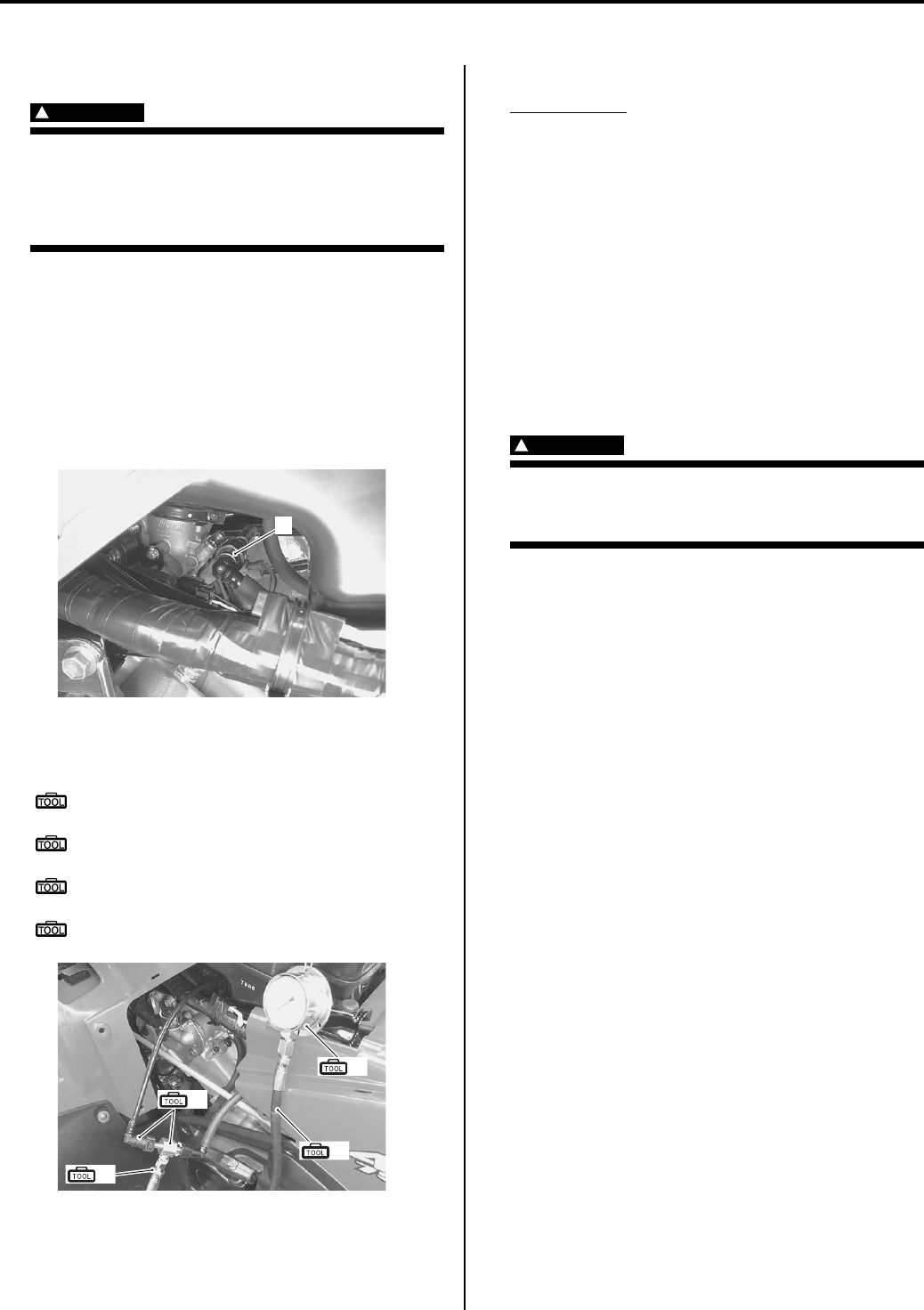
Fuel System: 1G-6
Repair Instructions
Fuel Pressure Inspection
B831G21706001
WARNING
!
• Keep away from fire or spark.
• Spilled gasoline should be wiped off
immediately.
• Work in a well-ventilated area.
Inspect the fuel pressure in the following procedures:
1) Remove the seat. Refer to “Seat Removal and
Installation in Section 9D (Page 9D-11)”.
2) Remove the left side cover. Refer to “Front Side
Exterior Parts Removal and Installation in Section
9D (Page 9D-6)”.
3) Place a rag under the fuel feed hose and disconnect
fuel feed hose (1) from the fuel delivery pipe.
4) Install the special tools between the fuel pump and
fuel delivery pipe.
Special tool
(A): 09940–40211 (Fuel pressure gauge
adapter)
(B): 09940–40220 (Fuel pressure gauge
hose attachment)
(C): 09915–77331 (Meter (for high
pressure))
(D): 09915–74521 (Oil pressure gauge hose)
5) Turn the ignition ON and check for fuel pressure.
Fuel pressure
Approx. 294 kPa (2.9 kgf/cm2, 41 psi)
If the fuel pressure is lower than the specification,
check for the followings:
• Fuel hose leakage
• Clogged fuel filter
• Pressure regulator
• Fuel pump
If the fuel pressure is higher than the specification,
check for the followings:
• Fuel pump
• Pressure regulator
6) Remove the special tools.
WARNING
!
Before removing the special tools, turn the
ignition switch OFF and release the fuel
pressure slowly.
7) Reinstall the removed parts.
Fuel Pump Inspection
B831G21706002
Turn the ignition switch ON and check that the fuel pump
operates for a few seconds.
If the fuel pump motor does not make operating sound,
inspect the fuel pump circuit connections or inspect the
fuel pump relay and TO sensor. Refer to “Fuel Pump
Relay Inspection (Page 1G-7)” and “TO Sensor
Inspection in Section 1C (Page 1C-5)”.
If the fuel pump relay, TO sensor and fuel pump circuit
connections are OK, the fuel pump may be faulty,
replace the fuel pump with a new one. Refer to “Fuel
Pump Assembly Removal and Installation (Page 1G-9)”.
1
I831G1170005-02
(A)
(B)
(C)
(D)
I831G1170007-01
PartShark.com
877-999-5686
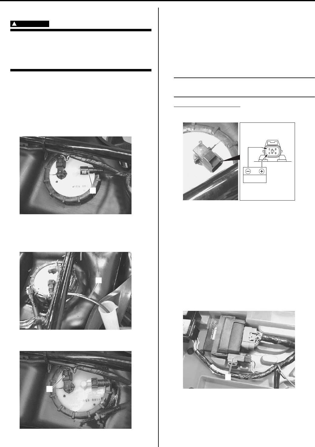
1G-7 Fuel System:
Fuel Discharge Amount Inspection
B831G21706003
WARNING
!
• Keep away from fire or spark.
• Spilled gasoline should be wiped off
immediately.
• Work in a well-ventilated area.
Inspect the fuel discharge amount in the following
procedures:
1) Remove the rear fender. Refer to “Rear Side Exterior
Parts Removal and Installation in Section 9D
(Page 9D-9)”.
2) Place a rag under the fuel feed hose (1) and
disconnect fuel feed hose from the fuel pump.
3) Connect a proper fuel hose (2) to the fuel pump.
4) Place the measuring cylinder and insert the fuel
hose end into the measuring cylinder.
5) Disconnect the fuel pump lead wire coupler (3).
6) Connect a proper lead wire into the fuel pump lead
wire coupler (fuel pump side) and apply 12 V to the
fuel pump (between (+) Y/R wire and (–) B/W wire)
for 10 seconds and measure the amount of fuel
discharged.
If the discharge amount is out of the specification,
the probable cause may be failure of the fuel pump
or clogged fuel filter.
NOTE
The battery must be in fully charged
condition.
Fuel discharge amount
55.5 ml (1.88/1.95 US/lmp oz) and more/10 sec.
7) After finishing the fuel discharge inspection, reinstall
the rear fender. Refer to “Rear Side Exterior Parts
Removal and Installation in Section 9D (Page 9D-
9)”.
Fuel Pump Relay Inspection
B831G21706004
Refer to “Electrical Components Location in Section 0A
(Page 0A-7)”.
Inspect the fuel pump relay in the following procedures:
1) Remove the seat. Refer to “Seat Removal and
Installation in Section 9D (Page 9D-11)”.
2) Remove the fuel pump relay (1).
1
I831G1170008-01
2
I831G1170009-01
3
I831G1170010-01
12V
I831G1170012-02
1
I831G1170013-01
PartShark.com
877-999-5686
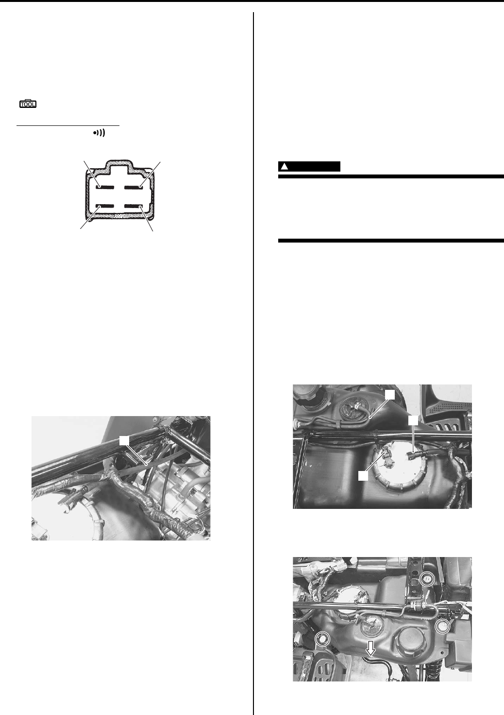
Fuel System: 1G-8
3) First, check for insulation with the tester between
terminals “A” and “B”. Next, check for continuity
between “A” and “B” with 12 V voltage applied,
positive (+) to terminal “C” and negative (–) to
terminal “D”. If continuity does not exist, replace the
relay with a new one.
Special tool
: 09900–25008 (Multi-circuit tester set)
Tester knob indication
Continuity test ( )
Fuel Hose Inspection
B831G21706005
Refer to “Fuel Line Inspection in Section 0B (Page 0B-
10)”.
Fuel Feed Hose Removal and Installation
B831G21706006
Removal
1) Remove the rear fender. Refer to “Rear Side Exterior
Parts Removal and Installation in Section 9D
(Page 9D-9)”.
2) Disconnect the fuel feed hose (1).
Installation
1) Install the fuel feed hose as shown in the fuel hose
routing diagram. Refer to “Fuel Hose Routing
Diagram (Page 1G-3)”.
2) Install the rear fender. Refer to “Rear Side Exterior
Parts Removal and Installation in Section 9D
(Page 9D-9)”.
Fuel Level Gauge Inspection
B831G21706007
Refer to “Fuel Level Gauge Inspection in Section 9C
(Page 9C-6)”.
Fuel Level Indicator Inspection
B831G21706008
Refer to “Fuel Level Indicator Inspection in Section 9C
(Page 9C-5)”.
Fuel Tank Removal and Installation
B831G21706009
Removal
WARNING
!
• Keep away from fire or spark.
• Spilled gasoline should be wiped off
immediately.
• Work in a well-ventilated area.
1) Remove the rear fender. Refer to “Rear Side Exterior
Parts Removal and Installation in Section 9D
(Page 9D-9)”.
2) Remove the fuel tank outer cover. Refer to “Rear
Side Exterior Parts Removal and Installation in
Section 9D (Page 9D-9)”.
3) Place a rag under the fuel feed hose and disconnect
the fuel feed hose (1) from the fuel pump.
4) Disconnect the fuel tank coupler (2) and fuel tank
breather hose (3).
5) Remove the fuel tank mounting bolts.
6) Remove the fuel tank from the left side.
“A”
“B”
“C”
“D”
I718H1170013-01
1
I831G1170014-01
3
2
1
I831G1170015-01
I831G1170016-01
PartShark.com
877-999-5686
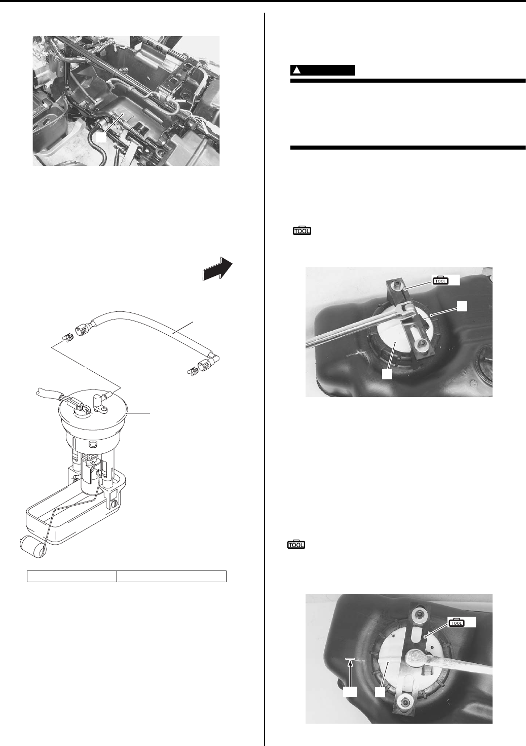
1G-9 Fuel System:
7) Remove the fuel tank lower cover (4).
Installation
Install the fuel tank in the reverse order of removal.
Fuel Pump Components
B831G21706010
Fuel Pump Assembly Removal and Installation
B831G21706011
Removal
WARNING
!
• Spilled gasoline should be wiped off
immediately.
• Keep away from fire or spark.
• Work in a well-ventilated area.
1) Remove the fuel tank. Refer to “Fuel Tank Removal
and Installation (Page 1G-8)”.
2) Remove the fuel pump retainer (1) with the special
tool.
Special tool
: 09941–51012 (Ring locknut wrench)
3) Remove the fuel pump assembly (2).
Installation
Install the fuel pump assembly in the reverse order of
removal.
Pay attention the following points:
• Align the fuel pump nipple (1) with alignment mark “A”
on the fuel tank.
• Tighten the fuel pump retainer with the special tool to
the specified torque.
Special tool
(A): 09941–51012 (Ring locknut wrench)
Tightening torque
Fuel pump retainer: 35 N·m (3.5 kgf-m, 25.5 lb-ft)
1. Fuel pump 2. Fuel feed hose
4
I831G1170017-01
FWD
1
2
I831G1170004-01
1
2
(A)
I831G1170018-01
(A)
1
“A”
I831G1170019-01
PartShark.com
877-999-5686
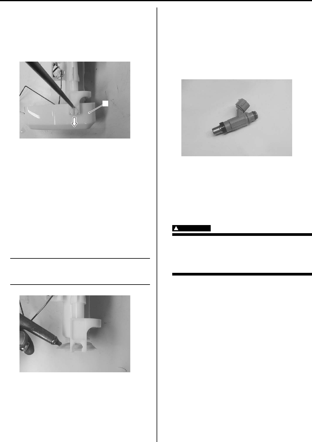
Fuel System: 1G-10
Fuel Pump Disassembly and Assembly
B831G21706012
Refer to “Fuel Pump Assembly Removal and Installation
(Page 1G-9)”.
Disassembly
Remove the fuel cup holder (1) with a (–) screw driver.
Assembly
Assemble the fuel tank pump in the reverse order of the
disassembly.
Fuel Mesh Filter Inspection and Cleaning
B831G21706013
Inspect the fuel mesh filter in the following procedures:
1) Remove the fuel cup holder. Refer to “Fuel Pump
Disassembly and Assembly (Page 1G-10)”.
2) If the fuel mesh filter is clogged with foreign particles,
it hinders smooth gasoline flow resulting in loss of
engine power. Such a filter should be cleaned by
blowing with compressed air.
NOTE
When the fuel mesh filter is dirtied
excessively, replace the fuel mesh filter with
a new one.
3) After finishing the fuel mesh filter inspection, reinstall
the fuel cup holder and fuel pump assembly. Refer to
“Fuel Pump Assembly Removal and Installation
(Page 1G-9)”.
Fuel Injector Inspection and Cleaning
B831G21706014
Inspect the fuel injector in the following procedures:
1) Remove the fuel injector. Refer to “Fuel Injector /
Fuel Delivery Pipe Removal and Installation
(Page 1G-10)”.
2) Check the fuel injector filter for evidence of dirt and
contamination. If present, clean and check for
presence of dirt in the fuel lines and fuel tank.
3) Install the fuel injector. Refer to “Fuel Injector / Fuel
Delivery Pipe Removal and Installation (Page 1G-
10)”.
Fuel Injector / Fuel Delivery Pipe Removal and
Installation
B831G21706015
Removal
WARNING
!
• Spilled gasoline should be wiped off
immediately.
• Keep away from fire or spark.
• Work in a well-ventilated area.
1) Remove the front fender. Refer to “Front Side
Exterior Parts Removal and Installation in Section
9D (Page 9D-6)”.
2) Remove the air cleaner box. Refer to “Air Cleaner
Box Removal and Installation in Section 1D
(Page 1D-5)”.
3) Place a rug under the fuel feed hose (1) and
disconnect the fuel feed hose (1) from the fuel
delivery pipe.
1
I831G1170020-01
I831G1170021-01
I831G1170022-01
PartShark.com
877-999-5686
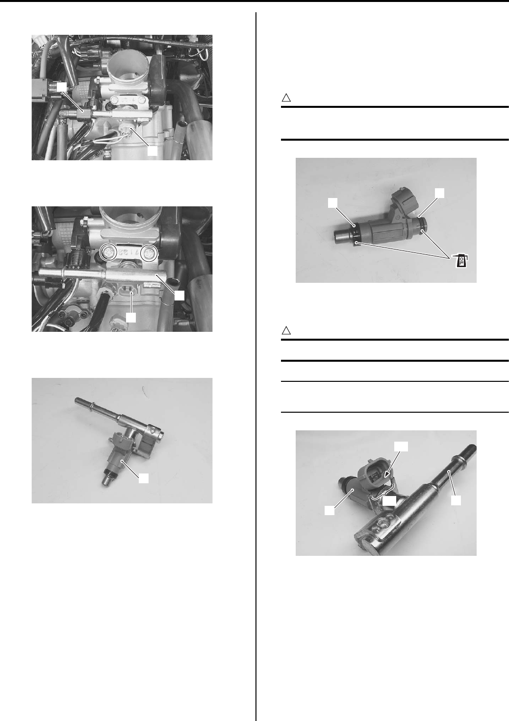
1G-11 Fuel System:
4) Disconnect the injector coupler (2).
5) Remove the fuel delivery pipe (3) with the injector
(4).
6) Remove the fuel injector (4) from the fuel delivery
pipe.
Installation
Install the fuel injector / fuel delivery pipe in the reverse
order of removal.
Pay attention to the following points:
• Apply a thin coat of engine oil to the new cushion seal
(1) and O-ring (2).
CAUTION
!
Replace the cushion seal and O-ring with the
new ones.
• Install the fuel injector (3) by pushing it straight to the
delivery pipe (4).
CAUTION
!
Never turn the injector while pushing it.
NOTE
Align the coupler “A” of injector with boss
“B” of the delivery pipe.
2
1
I831G1170023-01
4
3
I831G1170024-01
4
I831G1170025-02
1
2
I831G1170026-01
“B”
“A”
3
4
I831G1170027-01
PartShark.com
877-999-5686
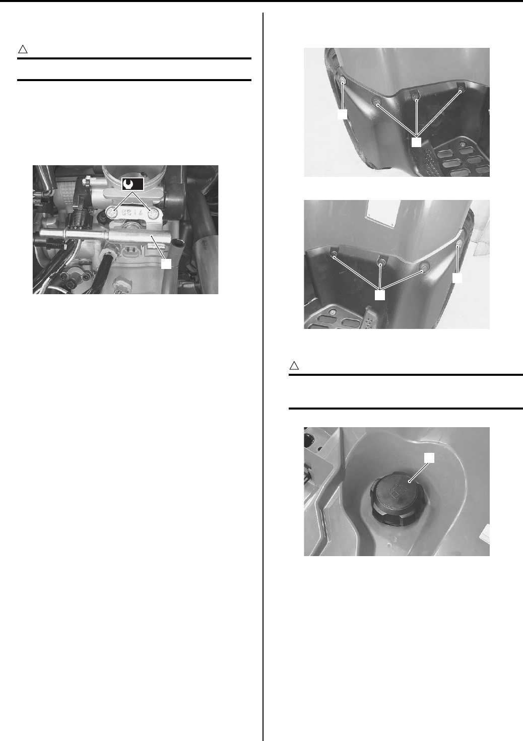
Fuel System: 1G-12
• Install the fuel delivery pipe assembly (5) to the
throttle body assembly.
CAUTION
!
Never turn the fuel injector while installing it.
• Tighten the fuel delivery pipe mounting screws to the
specified torque.
Tightening torque
Fuel delivery pipe mounting screw (a): 5 N·m (0.5
kgf-m, 3.5 lb-ft)
Fuel Tank Pressure Control (FTPC) Valve
Removal and Installation
B831G21706016
Removal
1) Remove the rear carrier. Refer to “Rear Carrier
Removal and Installation in Section 9E (Page 9E-5)”.
2) Remove the seat. Refer to “Seat Removal and
Installation in Section 9D (Page 9D-11)”.
3) Remove the side covers, left and right. Refer to
“Front Side Exterior Parts Removal and Installation
in Section 9D (Page 9D-6)”.
4) Remove the engine side cover. Refer to “Rear Side
Exterior Parts Removal and Installation in Section
9D (Page 9D-9)”.
5) Remove the mad guard mounting fasteners (1) and
screws (2).
6) Remove the fuel tank cap (3).
CAUTION
!
To prevent the fuel tank from contamination
with foreign particles, blind opening.
(a)
5
I831G1170028-01
1
2
I831G1170029-01
1
2
I831G1170030-01
3
I831G1170031-01
PartShark.com
877-999-5686
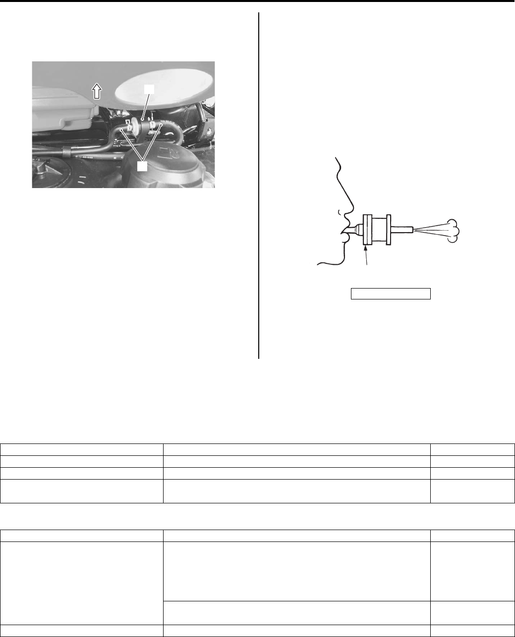
1G-13 Fuel System:
7) Move the rear fender upside.
Disconnect the breather hoses (4) and remove the
FTPC valve (5).
Installation
Install the FTPC valve in the reverse order of removal,
pay attention to the following points.
• Install the FTPC valve as shown in the fuel tank
breather hose routing diagram. Refer to “Fuel Tank
Breather Hose Routing Diagram (Page 1G-4)”.
Fuel Tank Pressure Control (FTPC) Valve
Inspection
B831G21706017
Inspect the FTPC valve in the following procedures:
1) Remove the FTPC valve. Refer to “Fuel Tank
Pressure Control (FTPC) Valve Removal and
Installation (Page 1G-12)”.
2) Check the FTPC valve if air can pass through
smoothly when blown from the orange color side and
not from the other side. If abnormal condition is
found, replace the FTPC valve with a new one.
3) After finishing the FTPC valve inspection, reinstall
the FTPC valve. Refer to “Fuel Tank Pressure
Control (FTPC) Valve Removal and Installation
(Page 1G-12)”.
Specifications
Service Data
B831G21707001
Injector + Fuel Pump + Fuel Pressure Regulator
Fuel
4
5
I831G1170032-01
“A”: Orange
“A”
I705H1170014-02
Item Specification Note
Injector resistance 11 – 13 Ω at 20 °C (68 °F) —
Fuel pump discharge amount 55.5 ml (1.88/1.95 US/lmp oz) and more/10 sec. —
Fuel pressure regulator operating
set pressure Approx. 294 kPa (2.9 kgf/cm2, 41 psi) —
Item Specification Note
Fuel type
Use only unleaded gasoline of at least 87 pump octane (R/2
+ M/2) or 91 octane or higher rated by the Research Method.
Gasoline containing MTBE (Methyl Tertiary Butyl Ether), less
than 10% ethanol, or less than 5% methanol with
appropriate cosolvents and corrosion inhibitor is permissible.
P-28, 33
Gasoline used should be graded 91 octane or higher. An
unleaded gasoline type is recommended. Others
Fuel tank capacity 17.5 L (4.6/3.8 US/lmp gal)
PartShark.com
877-999-5686
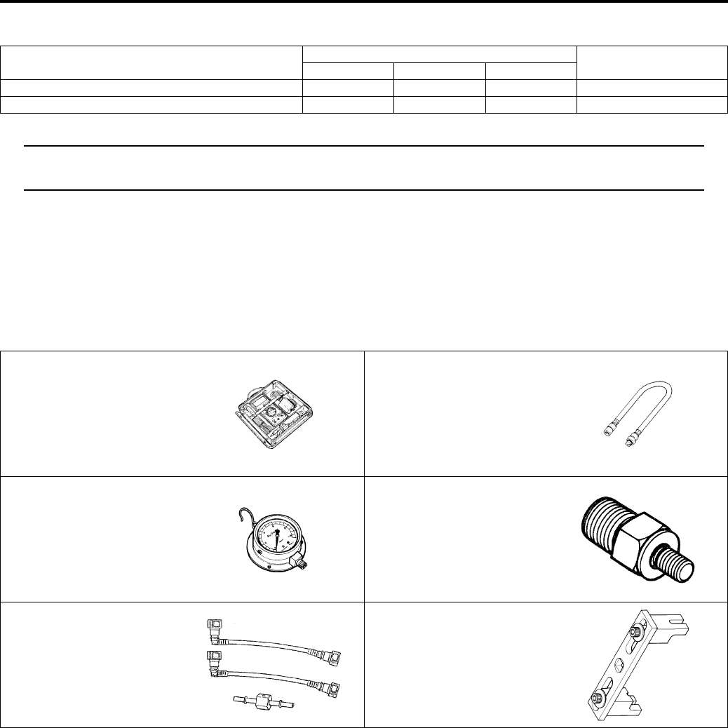
Fuel System: 1G-14
Tightening Torque Specifications
B831G21707002
NOTE
The specified tightening torque is also described in the following.
“Fuel Tank Breather Hose Routing Diagram (Page 1G-4)”
Reference:
For the tightening torque of fastener not specified in this section, refer to “Tightening Torque List in Section 0C
(Page 0C-7)”.
Special Tools and Equipment
Special Tool
B831G21708001
Fastening part Tightening torque Note
N⋅mkgf—mlb—ft
Fuel pump retainer 35 3.5 25.5 )(Page 1G-9)
Fuel delivery pipe mounting screw 5 0.5 3.5 )(Page 1G-12)
09900–25008 09915–74521
Multi-circuit tester set Oil pressure gauge hose
)(Page 1G-8) )(Page 1G-6)
09915–77331 09940–40211
Meter (for high pressure) Fuel pressure gauge
adapter
)(Page 1G-6) )(Page 1G-6)
09940–40220 09941–51012
Fuel pressure gauge hose
attachment
Ring locknut wrench
)(Page 1G-6) )(Page 1G-9) /
)(Page 1G-9)
PartShark.com
877-999-5686
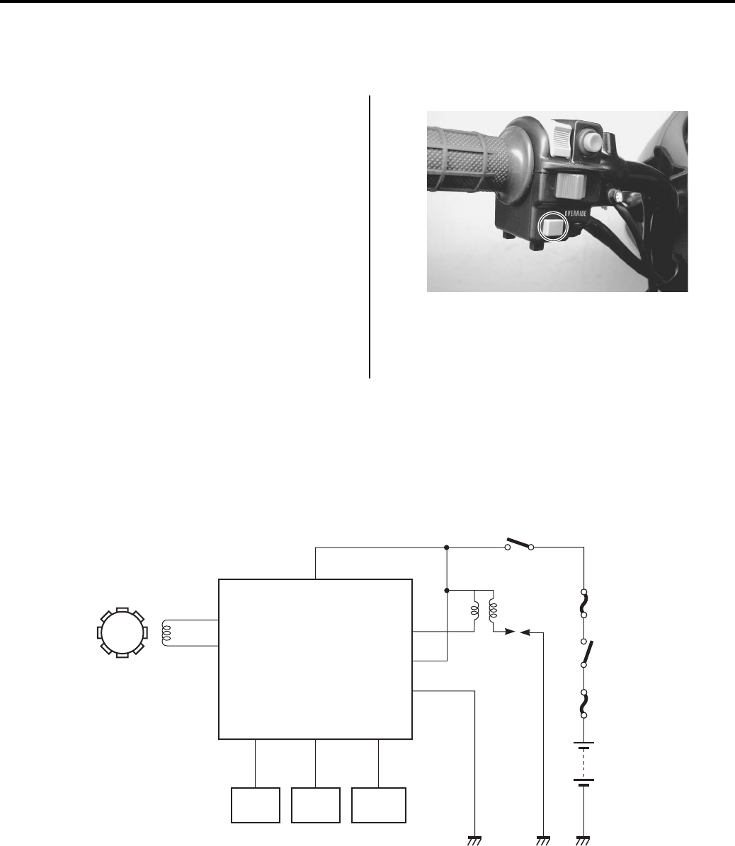
1H-1 Ignition System:
Engine
Ignition System
General Description
Override Switch Description
B831G21801001
The override switch allows the rider to increase the
power available by overriding the normal speed limiter in
forward Differential Lock or Reverse. For example, the
rider may need to use extra power when stuck in the
mud. To override the normal speed limiter the rider must
push the override button and hold it in. When the switch
button is released, engine speed will once again be
limited by the speed limiter.
In forward Differential Lock made, the override mode can
be used for an indefinite period of time simply by holding
the button in continuously.
Operation
1) Set the diff-lock position or “R” (Reverse) position.
2) Operate the override switch while pushing it.
Schematic and Routing Diagram
Ignition System Diagram
B831G21802001
Refer to “Wire Color Symbols in Section 0A (Page 0A-5)”.
Ignition System Components Location
B831G21802002
Refer to “Electrical Components Location in Section 0A (Page 0A-7)”.
I831G1180013-01
CKP
sensor
TP
sensor
ECT
sensor
GP
switch
Engine stop switch
Fuse
Fuse
Ignition
switch
Ignition
coil
Battery
ECM
I831G1180004-04
PartShark.com
877-999-5686
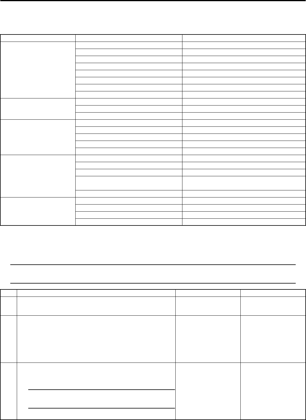
Ignition System: 1H-2
Diagnostic Information and Procedures
Ignition System Symptom Diagnosis
B831G21804001
No Spark or Poor Spark
B831G21804002
Troubleshooting
NOTE
Check that the transfer is in neutral and the engine stop switch is in the “RUN” position. Check that the
fuse is not blown and the battery is fully-charged before diagnosing.
Condition Possible cause Correction / Reference Item
Spark plug not sparking Damaged spark plug. Replace.
Fouled spark plug. Clean or replace.
Wet spark plug. Clean and dry or replace.
Defective ignition coil. Replace.
Defective CKP sensor. Replace.
Defective ECM. Replace.
Open-circuited wiring connections. Repair or replace.
Open or short in high-tension cord. Replace.
Engine stalls easily (No
spark)
Fouled spark plug. Clean or replace.
Defective CKP sensor. Replace.
Defective ECM. Replace.
Spark plug is wet or
quickly becomes fouled
with carbon
Excessively rich air/fuel mixture. Inspect FI system.
Excessively high idling speed. Inspect FI system.
Incorrect gasoline. Change.
Dirty air cleaner element. Clean or replace.
Incorrect spark plug. Change to correct spark plug.
Spark plug quickly
becomes fouled with oil
or carbon
Worn piston rings. Replace.
Worn piston. Replace.
Worn cylinder. Rebore or replace.
Excessive valve-stem to valve-guide
clearance.
Replace.
Worn valve stem oil seals. Replace.
Spark plug electrodes
overheat or burn
Incorrect spark plug. Change to correct spark plug.
Overheated engine. Tune-up.
Loose spark plug. Tighten.
Excessively lean air/fuel mixture. Inspect FI system.
Step Action Yes No
1 Check the ignition system couplers for poor connections.
Is there connection in the ignition system couplers?
Go to step 2. Poor connection of
couplers.
2 Measure the battery voltage between input lead wires (O/W
and B/W) at the ECM with the ignition switch in the “ON”
position.
Is the voltage OK?
Go to Step 3. • Faulty ignition switch.
• Faulty wire harness.
• Broken wire harness
or poor connection of
related circuit
couplers.
3 Measure the ignition coil primary peak voltage. Refer to
“Ignition Coil and Plug Cap Inspection (Page 1H-3)”.
NOTE
This inspection method is applicable only with
the multi-circuit tester and the peak volt adaptor.
Is the peak voltage OK?
Go to step 4. Go to step 5.
PartShark.com
877-999-5686
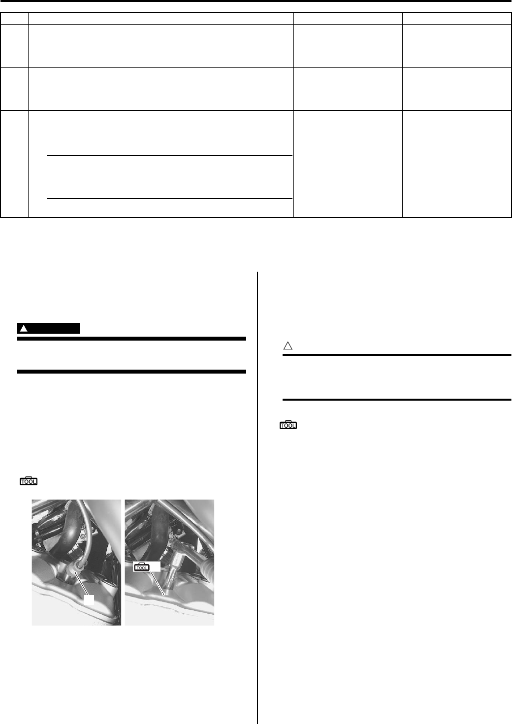
1H-3 Ignition System:
Repair Instructions
Spark Plug Cap and Spark Plug Removal and
Installation
B831G21806001
Removal
WARNING
!
The hot engine can burn you.
Wait until the engine is cool enough to touch.
1) Turn the ignition switch OFF.
2) Remove the right side cover and right inner fender.
Refer to “Front Side Exterior Parts Removal and
Installation in Section 9D (Page 9D-6)”.
3) Disconnect the spark plug cap (1).
4) Remove the spark plug with a spark plug wrench.
Special tool
: 09930–10121 (Spark plug wrench set)
Installation
Install the spark plug in the reverse order of removal.
Pay attention to the following points:
• Screw the spark plug into the cylinder head with
fingers, and then tighten them to the specified torque.
CAUTION
!
Do not cross thread or over tighten the spark
plug, or such an operation will damage the
aluminum threads of the cylinder head.
Special tool
: 09930–10121 (Spark plug wrench set)
Tightening torque
Spark plug: 11 N·m (1.1 kgf-m, 8.0 lb-ft)
Spark Plug Inspection and Cleaning
B831G21806002
Refer to “Spark Plug Inspection and Cleaning in Section
0B (Page 0B-9)”.
Ignition Coil and Plug Cap Inspection
B831G21806003
Refer to “Electrical Components Location in Section 0A
(Page 0A-7)”.
Ignition Coil Primary Peak Voltage
1) Remove the right side cover and right inner fender.
Refer to “Front Side Exterior Parts Removal and
Installation in Section 9D (Page 9D-6)”.
2) Disconnect the spark plug cap. Refer to “Spark Plug
Cap and Spark Plug Removal and Installation
(Page 1H-3)”.
4 Inspect the spark plug. Refer to “Spark Plug Inspection and
Cleaning in Section 0B (Page 0B-9)”.
Is the spark plug OK?
Go to Step 5. Faulty spark plug.
5 Inspect the ignition coil. Refer to “Ignition Coil and Plug Cap
Inspection (Page 1H-3)”.
Is the ignition coil OK?
Go to step 6. Faulty ignition coil.
6 Measure the CKP sensor peak voltage and its resistance.
Refer to “CKP Sensor Inspection (Page 1H-5)”.
NOTE
The CKP sensor peak voltage inspection is
applicable only with the multi-circuit tester and
peak volt adaptor.
Are the peak voltage and resistance OK?
•Faulty ECM.
• Open or short circuit
in wire harness.
• Poor connection of
ignition wire harness.
• Faulty CKP sensor.
• Metal particles or
foreign material being
stuck on the CKP
sensor and rotor tip.
Step Action Yes No
(A)
1
I831G1180001-01
PartShark.com
877-999-5686
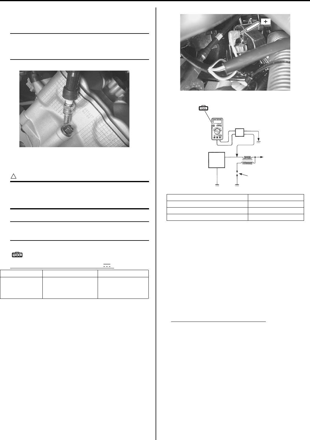
Ignition System: 1H-4
3) Connect the new spark plug to spark plug cap and
ground it to the cylinder head.
NOTE
Be sure that the spark plug is connected
properly and the battery used is in fully-
charged condition.
4) Connect the multi-circuit tester with the peak voltage
adaptor as follows:
CAUTION
!
Before using the multi-circuit tester and peak
voltage adaptor, refer to the appropriate
instruction manual.
NOTE
Do not disconnect the ignition coil lead
wires.
Special tool
: 09900–25008 (Multi-circuit tester set)
Tester knob indication: Voltage ( )
5) Measure the ignition coil primary peak voltage in the
following procedures:
a) Shift the transfer to the neutral, turn the ignition
switch ON.
b) Press the starter button and allow the engine to
crank for a few seconds, and then measure the
ignition coil primary peak voltage.
6) Repeat the b) procedure few times and measure the
highest peak voltage.
If the voltage is lower than standard range, inspect
the ignition coil and the CKP sensor.
Ignition coil primary peak voltage
80 V and more
7) After measuring the ignition coil primary peak
voltage, reinstall the removed parts.
Ignition Coil Resistance
1) Disconnect the spark plug cap. Refer to “Ignition Coil
and Plug Cap Inspection (Page 1H-3)”.
2) Disconnect the ignition coil lead wire.
((+) Probe) ((–) Probe)
Ignition coil W/Bl lead wire
terminal
B/W lead wire
terminal or
Ground
I831G1180005-01
1. ECM “A”: (+) probe
2. Peak voltage adaptor “B”: (–) probe
3. New spark plug “C”: Battery
4. Ignition coil
(ޓ)
I831G1180006-01
1
2
“A”
“B”
“C”
4
3
(A)
I831G1180002-01
PartShark.com
877-999-5686
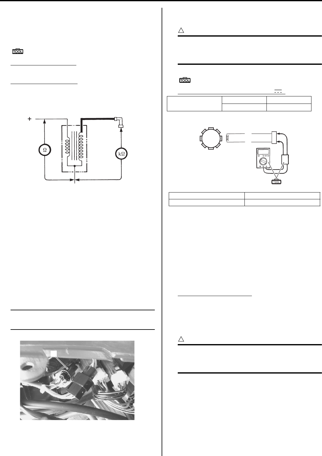
1H-5 Ignition System:
3) Measure the ignition coil resistance in both the
primary and secondary coils. If the resistance is not
within the standard range, replace the ignition coil
with a new one.
Special tool
: 09900–25008 (Multi-circuit tester set)
Tester knob indication
Resistance (Ω)
Ignition coil resistance
Primary: 0.1 – 0.6 Ω ((+) terminal – (–) Ground)
Secondary: 12 – 19 kΩ (Spark plug cap – (–)
terminal)
4) After measuring the ignition coil resistance, reinstall
the removed parts.
CKP Sensor Inspection
B831G21806004
Refer to “Electrical Components Location in Section 0A
(Page 0A-7)”.
CKP Sensor Peak Voltage
1) Remove the left side cover and engine side cover.
Refer to “Front Side Exterior Parts Removal and
Installation in Section 9D (Page 9D-6)”.
2) Disconnect the CKP sensor coupler (1).
NOTE
Be sure that all of the couplers are connected
properly and the battery is fully-charged.
3) Connect the multi-circuit tester with the peak volt
adaptor as follows:
CAUTION
!
Before using the multi-circuit tester and peak
voltage adaptor, refer to the appropriate
instruction manual.
Special tool
(A): 09900–25008 (Multi-circuit tester set)
Tester knob indication: Voltage ( )
4) Measure the CKP sensor peak voltage in the
following procedures:
a) Shift the transfer to the neutral, turn the ignition
switch ON.
b) Press the starter button and allow the engine to
crank for a few seconds, and then measure the
CKP sensor peak voltage.
5) Repeat the b) procedure a few times and measure
the highest CKP sensor peak voltage.
CKP sensor peak voltage
5.0 V and more (Blue – White)
6) If the peak voltage is within the specification, check
the continuity between the CKP sensor coupler and
ECM coupler.
CAUTION
!
Normally, use the needle pointed probe to the
backside of the lead wire coupler to prevent
the terminal bend and terminal alignment.
7) After measuring the CKP sensor peak voltage,
reinstall the removed parts.
(ޓ)
(–)
I831G1180007-01
1
I831G1180008-01
CKP sensor (+) Probe (–) Probe
BI W
2. CKP sensor coupler 4. Peak voltage adaptor
3. CKP sensor
2
3W
BI
(A)
4
I831G1180003-01
PartShark.com
877-999-5686
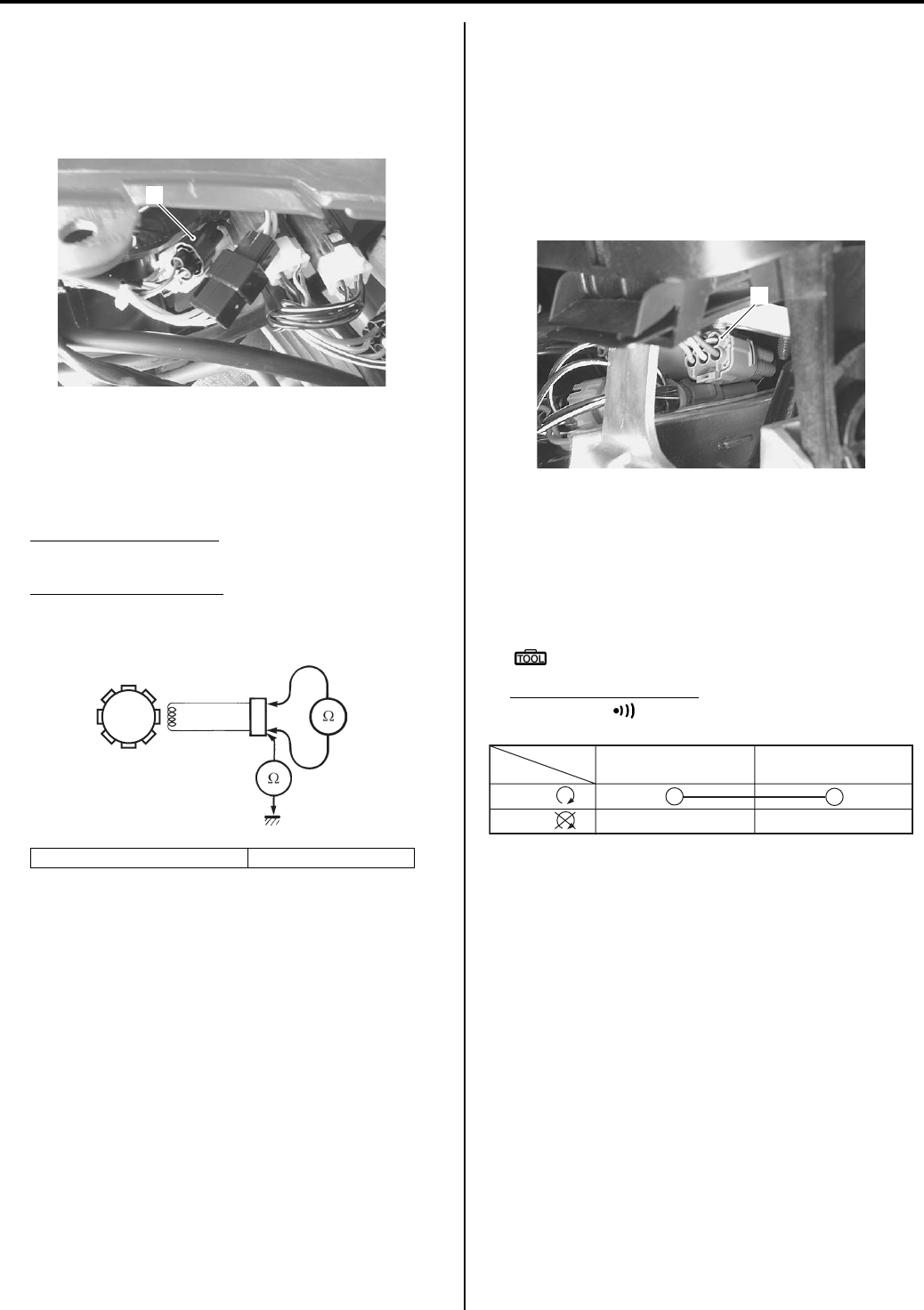
Ignition System: 1H-6
CKP Sensor Resistance
1) Remove the left side cover and engine side cover.
Refer to “Front Side Exterior Parts Removal and
Installation in Section 9D (Page 9D-6)”.
2) Disconnect the CKP sensor coupler (1).
3) Measure the resistance between the lead wires and
ground. If the resistance is not within the standard
range, replace the CKP sensor with a new one.
Refer to “CKP Sensor Removal and Installation
(Page 1H-6)”.
Tester knob indication
Resistance (Ω)
CKP sensor resistance
150 – 250 Ω (Blue – Green)
∞ Ω (Blue – Ground)
4) After measuring the CKP sensor resistance, reinstall
the removed parts.
CKP Sensor Removal and Installation
B831G21806005
Refer to “Generator Removal and Installation in Section
1J (Page 1J-4)”.
Engine Stop Switch Inspection
B831G21806006
Inspect the engine stop switch in the following
procedures:
1) Turn the ignition switch OFF.
2) Remove the left inner fender. Refer to “Front Side
Exterior Parts Removal and Installation in Section
9D (Page 9D-6)”.
3) Disconnect the handlebar switch coupler (1).
4) Inspect the engine stop switch for continuity with a
tester.
If any abnormality is found, replace the handlebar
switch assembly with a new one. Refer to
“Handlebars Removal and Installation in Section 6B
(Page 6B-3)”.
Special tool
: 09900–25008 (Multi-circuit tester set)
Tester knob indication
Continuity ( )
5) After finishing the engine stop switch inspection,
reinstall the removed parts.
Ignition Switch Inspection
B831G21806007
Refer to “Ignition Switch Inspection in Section 9C
(Page 9C-7)”.
2. CKP sensor coupler 3. CKP sensor
1
I831G1180008-01
3
2
I718H1180008-02
1
I831G1180010-01
O O/W
Color
Position
OFF
RUN
()
()
I831G1180009-01
PartShark.com
877-999-5686
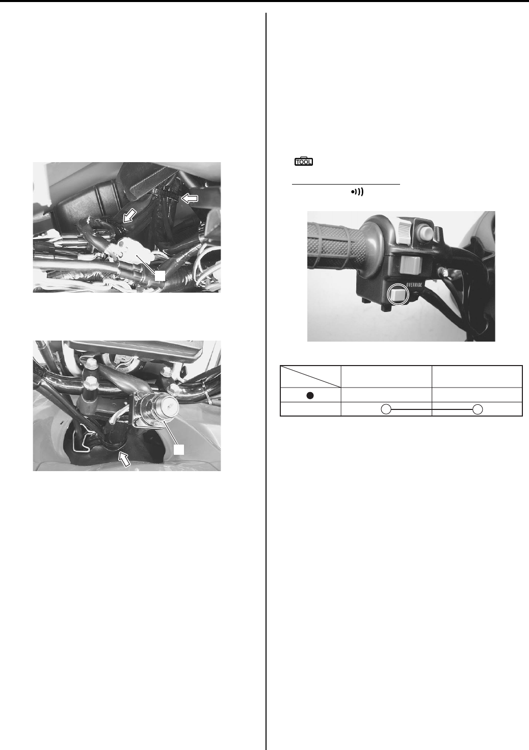
1H-7 Ignition System:
Ignition Switch Removal and Installation
B831G21806008
Removal
1) Remove the left inner fender. Refer to “Front Side
Exterior Parts Removal and Installation in Section
9D (Page 9D-6)”.
2) Remove the combination meter cover. Refer to
“Combination Meter Removal and Installation in
Section 9C (Page 9C-3)”.
3) Disconnect the clamps and ignition switch coupler
(1).
4) Disconnect the clamp and remove the ignition switch
(2).
Installation
Install the ignition switch in the reverse order of removal.
Pay attention to the following point:
• Route the wiring harness properly. Refer to “Wiring
Harness Routing Diagram in Section 9A (Page 9A-4)”.
Override Switch Inspection
B831G21806009
1) Remove the left inner fender. Refer to “Front Side
Exterior Parts Removal and Installation in Section
9D (Page 9D-6)”.
2) Disconnect the override switch read wire coupler.
3) Check the continuity B/W wire and Br wire of the
override switch and pushing the override switch. If
any abnormality is found, replace the left handle
switch assembly with a new one.
Special tool
: 09900–25008 (Multi-circuit tester set)
Tester knob indication
Continuity ( )
1
I831G1180011-02
2
I831G1180012-01
I831G1180013-01
Bl/B
B/W
Color
Position
PUSH
I831G1180014-02
PartShark.com
877-999-5686
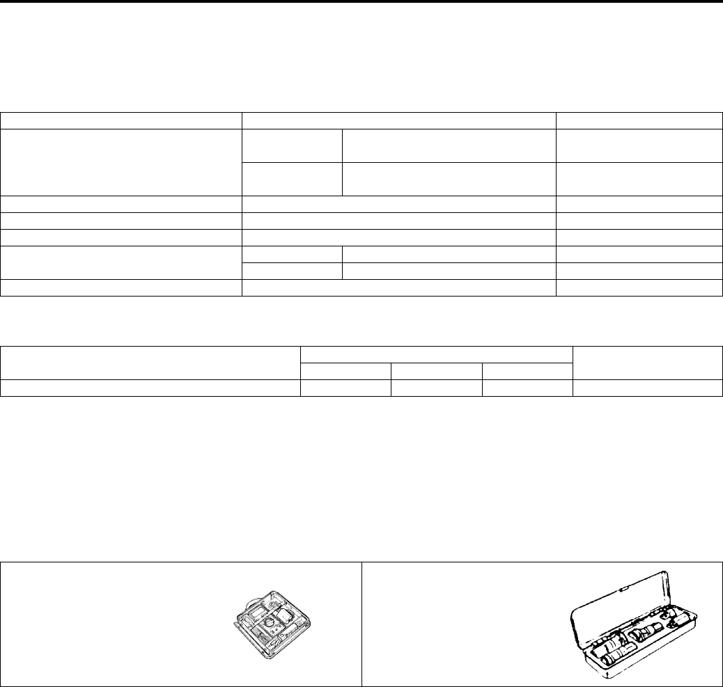
Ignition System: 1H-8
Specifications
Service Data
B831G21807001
Electrical
Unit: mm (in)
Tightening Torque Specifications
B831G21807002
Reference:
For the tightening torque of fastener not specified in this section, refer to “Tightening Torque List in Section 0C
(Page 0C-7)”.
Special Tools and Equipment
Special Tool
B831G21808001
Item Specification Note
Spark plug
Type NGK: CR6E
DENSO: U20ESR-N
Gap 0.7 – 0.8
(0.028 – 0.031)
Spark performance Over 8 (0.3) at 1 atm.
CKP sensor resistance 150 – 250 Ω
CKP sensor peak voltage 5.0 V and more
Ignition coil resistance Primary 0.1 – 0.6 ΩTerminal – Ground
Secondary 12 – 19 kΩPlug cap – Terminal
Ignition coil primary peak voltage 80 V and more When cranking
Fastening part Tightening torque Note
N⋅mkgf—mlb—ft
Spark plug 11 1.1 8.0 )(Page 1H-3)
09900–25008 09930–10121
Multi-circuit tester set Spark plug wrench set
)(Page 1H-4) / )(Page 1H-
5) / )(Page 1H-5) /
)(Page 1H-6) / )(Page 1H-
7)
)(Page 1H-3) / )(Page 1H-
3)
PartShark.com
877-999-5686
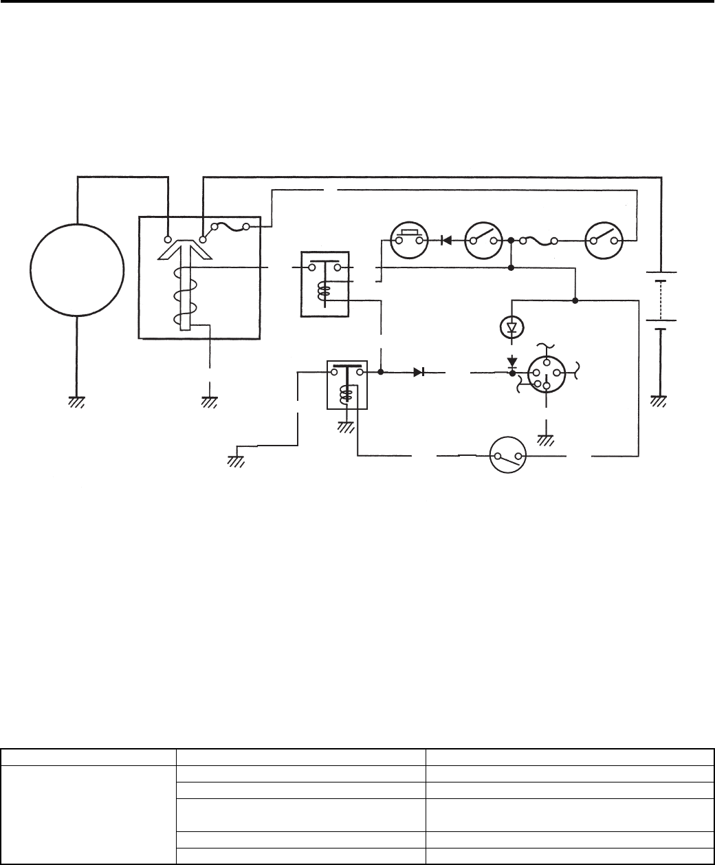
1I-1 Starting System:
Engine
Starting System
Schematic and Routing Diagram
Starting System Diagram
B831G21902001
Refer to “Wire Color Symbols in Section 0A (Page 0A-5)”.
Component Location
Starting System Components Location
B831G21903001
Refer to “Electrical Components Location in Section 0A (Page 0A-7)”.
Diagnostic Information and Procedures
Starting System Symptom Diagnosis
B831G21904001
Starter
motor
Main
fuse
Starter relay
B/W
Y/B
R
Neutral relay
Starter
button
Engine
stop switch Ignition
fuse
Ignition
switch
Parking
brake
relay
Parking
brake
switch
Neutral
indicator
light
Neutral
relay
diode
O/Y
Y/G
Battery
Gear
position
switch
N
Bl/B
B/Bl
B/W
O/YB/R
Bl/B
B/W
I831G1190001-01
Condition Possible cause Correction / Reference Item
Starter button is not
effective
Run down battery. Repair or replace.
Defective switch contacts. Replace.
Brushes not seating properly on starter
motor commutator.
Repair or replace.
Defective starter relay or neutral relay. Replace.
Defective main fuse or ignition fuse. Replace.
PartShark.com
877-999-5686

Starting System: 1I-2
Starter Motor will not Run
B831G21904002
NOTE
Make sure the fuses are not blown and the battery is fully-charged before diagnosing.
Troubleshooting
Starter Motor Runs but Does not Crank the Engine
B831G21904003
The starter motor runs when the transfer is in neutral, but does not run when the transfer is in any position other than
neutral, with the parking lever grasped firmly.
Engine Does not Turn Though the Starter Motor Runs
B831G21904004
• Faulty starter clutch
Step Action Yes No
1 1) Shift the transfer to neutral.
2) Turn on the ignition switch with the engine stop switch in
the “RUN” position and listen for a click from the starter
relay when the starter button is pushed.
Is a click sound heard?
Go to step 2. Go to step 3.
2 Check if the starter motor runs when its terminal is
connected to the battery (+) terminal. (Do not use thin “wire”
because a large amount of current flows.)
Does the starter motor run?
• Faulty starter relay.
• Loose or
disconnected starter
motor lead wire.
• Loose or
disconnected
between starter relay
and battery (+)
terminal.
Faulty starter motor.
3 Measure the starter relay voltage at the starter relay
connectors (between Y/B (+) and B/W (–)) when the starter
button is pushed.
Is the voltage OK?
Go to Step 4. • Faulty ignition switch.
• Faulty engine stop
switch.
• Faulty neutral relay.
• Faulty starter button.
• Poor contact of
connector.
• Open circuit in wire
harness.
4 Check the starter relay. Refer to “Starter Relay Inspection
(Page 1I-7)”.
Is the starter relay OK?
Poor contact of the
starter relay.
Faulty starter relay.
Step Action Yes No
1 Check the parking brake switch. Refer to “Parking Brake
Switch Inspection (Page 1I-9)”.
Is the parking brake switch OK?
Go to Step 2. Faulty parking brake
switch.
2 Check the parking brake relay. Refer to “Parking Brake
Relay Inspection (Page 1I-9)”.
Is the parking brake relay OK?
• Open circuit in wire
harness.
• Poor contact of
connector.
• Faulty parking brake
relay.
PartShark.com
877-999-5686
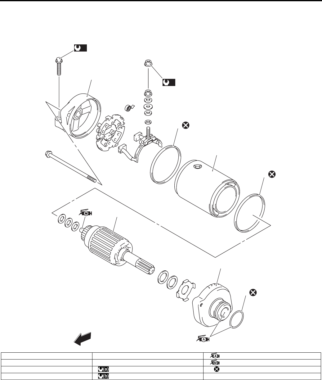
1I-3 Starting System:
Repair Instructions
Starter Motor Components
B831G21906001
4
1
2
3
5
6
4
(a)
FWD
(b)
I831G1190002-04
1. O-ring 5. Starter motor case : Apply grease to sliding surface.
2. Housing end (Inside) 6. Housing end (Outside) : Apply moly paste to sliding surface.
3. Armature : 6 N⋅m (0.6 kgf-m, 4.5 lb-ft) : Do not reuse.
4. O-ring : 10 N⋅m (1.0 kgf-m, 7.0 lb-ft)
PartShark.com
877-999-5686
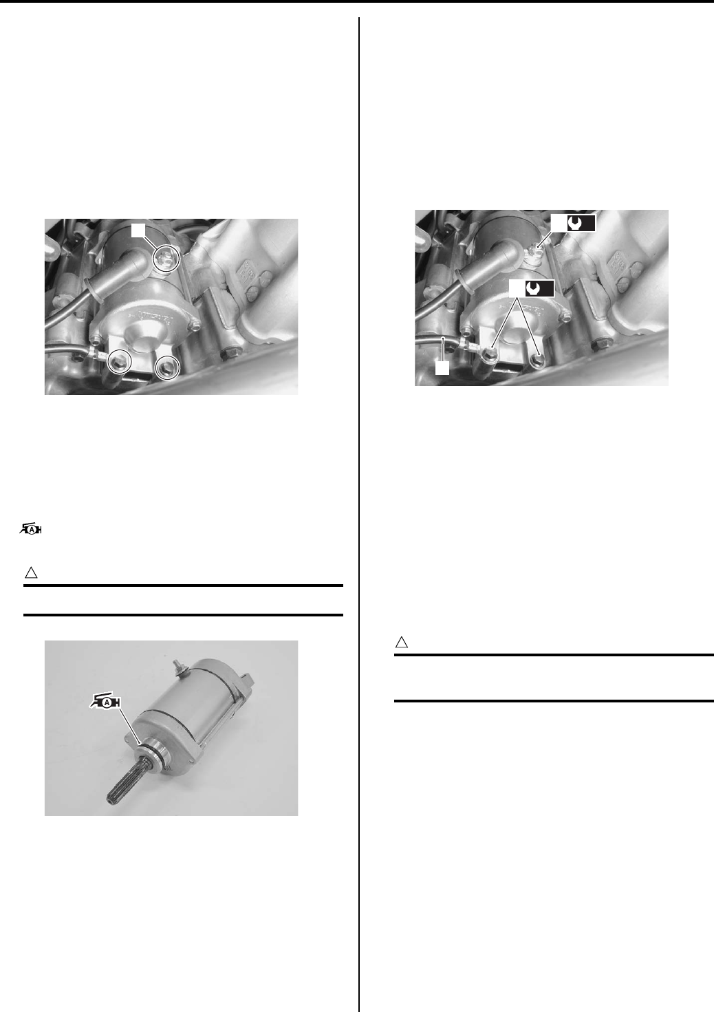
Starting System: 1I-4
Starter Motor Removal and Installation
B831G21906002
Removal
1) Turn the ignition switch OFF and disconnect the
battery (–) lead wire. Refer to “Battery Removal and
Installation in Section 1J (Page 1J-12)”.
2) Remove the right side cover. Refer to“Front Side
Exterior Parts Removal and Installation in Section
9D (Page 9D-6)”.
3) Remove the starter motor lead wire (1).
4) Remove the starter motor.
Installation
Install the starter motor in the reverse order of removal.
Pay attention to the following points:
• Apply grease to the starter motor O-ring.
: Grease 99000–25010 (SUZUKI SUPER
GREASE A or equivalent)
CAUTION
!
Replace the O-ring with a new one.
• Tighten the starter motor mounting bolts (1) with the
battery (–) lead wire (2) and starter motor lead wire
mounting nut (3) to the specified torque. Refer to
“Wiring Harness Routing Diagram in Section 9A
(Page 9A-4)”.
Tightening torque
Starter motor mounting bolt (a): 10 N·m (1.0 kgf-
m, 7.0 lb-ft)
Starter motor lead wire mounting nut (b): 6 N·m (
0.6 kgf-m, 4.5 lb-ft)
Starter Motor Disassembly and Assembly
B831G21906003
Refer to “Starter Motor Removal and Installation
(Page 1I-4)”.
Disassembly
Disassemble the starter motor as shown in the starter
motor components diagram. Refer to “Starter Motor
Components (Page 1I-3)”.
Assembly
Reassemble the starter motor in the reverse order of
removal. Pay attention to the following points:
CAUTION
!
Replace the O-rings with new ones to prevent
oil leakage and moisture.
1
I831G1190003-01
I831G1190004-01
2
(a)
1
(b)
3
I831G1190005-01
PartShark.com
877-999-5686
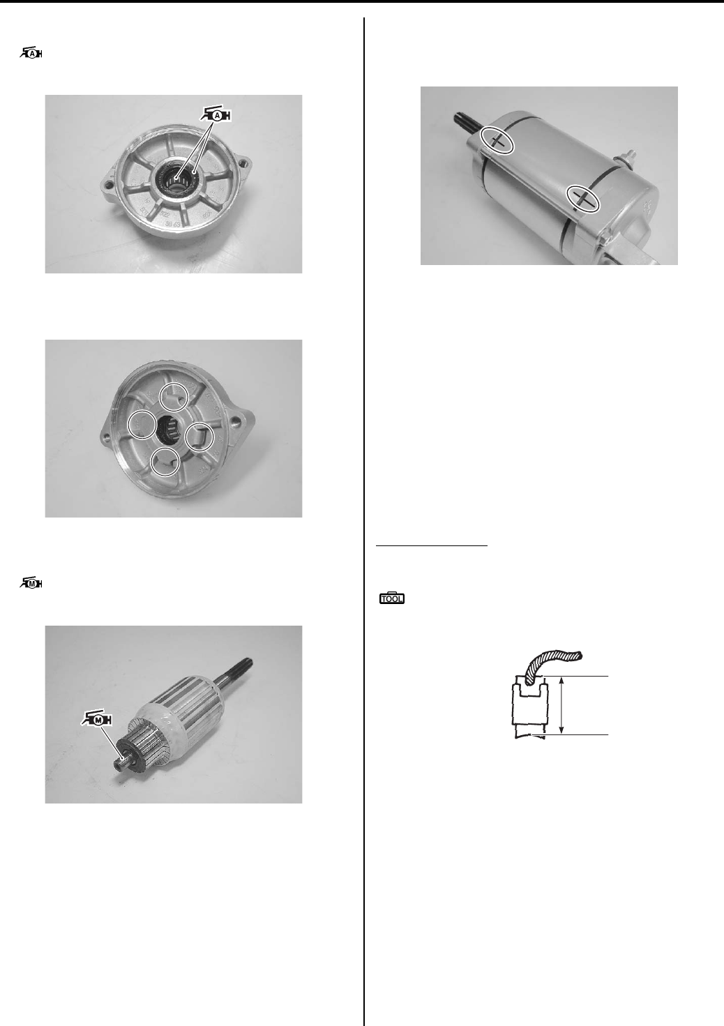
1I-5 Starting System:
• Apply grease to the lip of the oil seal and bearing.
: Grease 99000–25010 (SUZUKI SUPER
GREASE A or equivalent)
• Fit the washer to the housing end correctly as shown
in the figure.
• Apply a small quantity of moly paste to the armature
shaft.
: Moly paste 99000–25140 (SUZUKI Moly
paste or equivalent)
• Align the match mark on the starter motor case with
the match mark on the housing end.
• Tighten the starter motor housing bolts.
Starter Motor Inspection
B831G21906004
Refer to “Starter Motor Disassembly and Assembly
(Page 1I-4)”.
Carbon Brush
Inspect the carbon brushes for abnormal wear, cracks or
smoothness in the brush holder.
If either carbon brush is defective, replace the brush
holder set with a new one.
Measure the length “a” of the carbon brushes using a
vernier calipers. If the measurement is less than the
service limit, replace the housing end assembly with a
new one.
Brush length “a”
Service limit: 6.0 mm (0.24 in)
Special tool
: 09900–20102 (Vernier calipers (1/20 mm, 200
mm))
I831G1190006-02
I831G1190007-01
I831G1190008-01
I831G1190009-01
“a”
I831G1190065-01
PartShark.com
877-999-5686
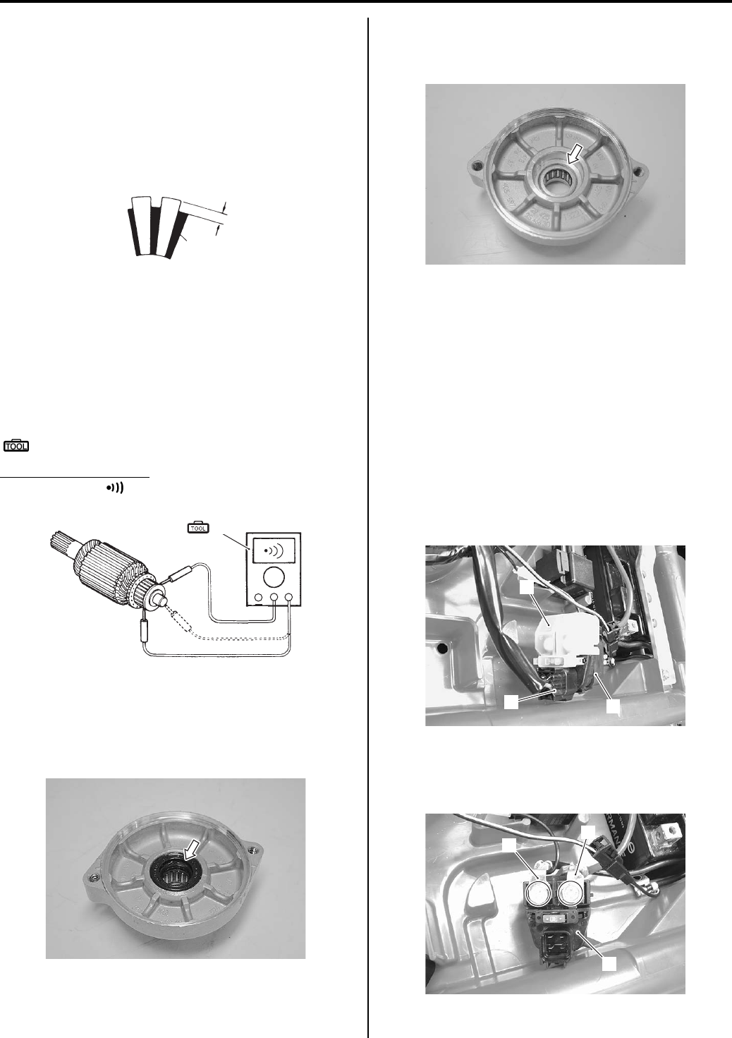
Starting System: 1I-6
Commutator
Inspect the commutator for discoloration, abnormal wear
or undercut “A”.
If the commutator is abnormally worn, replace the
armature.
If the commutator surface is discolored, polish it with
#400 sandpaper and wipe it using a clean, dry cloth.
If there is no undercut, scrape out the insulator (1) with a
saw blade.
Armature Coil
Measure for continuity between each segment. Measure
for continuity between each segment and the armature
shaft.
If there is no continuity between the segments or there is
continuity between the segments and shaft, replace the
armature with a new one.
Special tool
(A): 09900–25008 (Multi-circuit tester set)
Tester knob indication
Continuity set ( )
Oil Seal
Check the seal lip for damage. If any damage is found,
replace the housing end (Inside).
Bearing
Check the bearing of housing end for damage.
If any damage is found, replace the housing end.
Starter Relay Removal and Installation
B831G21906005
Refer to “Electrical Components Location in Section 0A
(Page 0A-7)”.
Removal
1) Turn the ignition switch OFF position.
2) Remove the seat. Refer to “Seat Removal and
Installation in Section 9D (Page 9D-11)”.
3) Disconnect the battery (–) lead wire from the battery.
4) Pull the starter relay (1).
5) Disconnect the starter relay coupler (2) and remove
the starter relay cover (3).
6) Disconnect the starter motor lead wire (4) and
battery (+) lead wire (5).
7) Remove the starter relay (1).
1
“A”
I649G1190016-02
(A)
I649G1190017-03
I831G1190010-01
I831G1190011-01
2
3
1
I831G1190013-01
1
4
5
I831G1190012-01
PartShark.com
877-999-5686
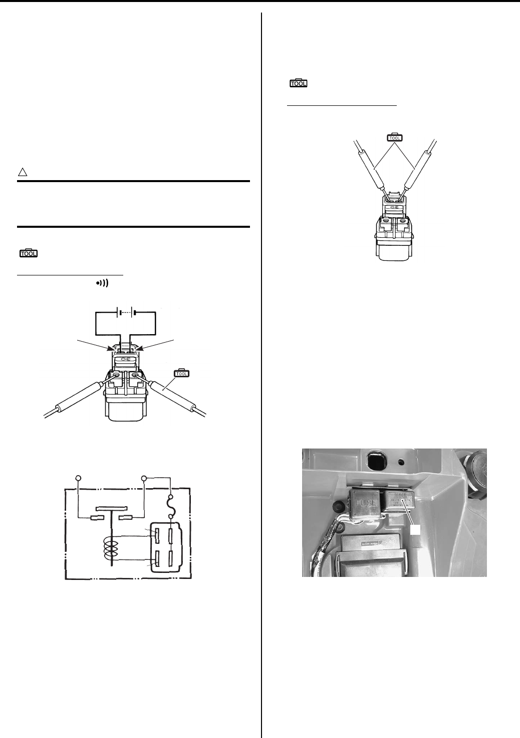
1I-7 Starting System:
Installation
Install the starter relay in the reverse order of removal.
Starter Relay Inspection
B831G21906006
Inspect the starter relay in the following procedures:
1) Remove the starter relay. Refer to “Starter Relay
Removal and Installation (Page 1I-6)”.
2) Apply 12 V to “A” and “B” terminals and check for
continuity between the positive and negative
terminals using the multi-circuit tester. If the starter
relay clicks and continuity is found, the relay is OK.
CAUTION
!
Do not apply battery voltage to the starter
relay for five seconds and more, since the
relay coil may overheat and get damaged.
Special tool
(A): 09900–25008 (Multi-circuit tester set)
Tester knob indication
Continuity test ( )
3) Measure the relay coil resistance between the
terminals using the multi-circuit tester. If the
resistance is not within the specified value, replace
the starter relay with a new one.
Special tool
(A): 09900–25008 (Multi-circuit tester set)
Starter relay resistance
3 – 5 Ω
4) Install the starter relay. Refer to “Starter Relay
Removal and Installation (Page 1I-6)”.
Neutral Relay Removal and Installation
B831G21906007
Refer to “Electrical Components Location in Section 0A
(Page 0A-7)”.
Removal
1) Turn the ignition switch OFF position.
2) Remove the seat. Refer to “Seat Removal and
Installation in Section 9D (Page 9D-11)”.
3) Remove the neutral relay (1).
Installation
Install the neutral relay in the reverse order of removal.
“A” “B”
(A)
I649G1190021-04
“A”
“B”
To batteryTo starter motor
(+)
(–)
I823H1190040-02
(A)
I649G1190023-03
1
I831G1190014-01
PartShark.com
877-999-5686
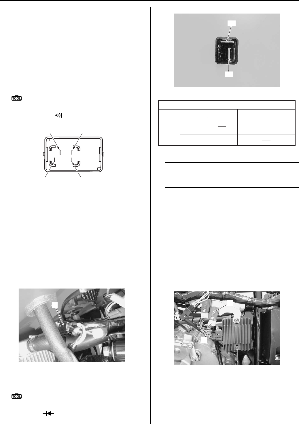
Starting System: 1I-8
Neutral Relay Inspection
B831G21906008
Inspect the neutral relay in the following procedures:
1) Remove the neutral relay. Refer to “Neutral Relay
Removal and Installation (Page 1I-7)”.
2) Check the insulation between “A” and “B” terminals
using the multi-circuit tester.
3) Apply 12 V to terminals “C” and “D” ((+) to “C” and (–
) to “D”) and check the continuity between “A” and
“B”. If there is no continuity, replace the neutral relay
with a new one.
Special tool
: 09900–25008 (Multi-circuit tester set)
Tester knob indication
Continuity test ( )
4) Install the neutral relay. Refer to “Neutral Relay
Removal and Installation (Page 1I-7)”.
Neutral Relay Diode Inspection
B831G21906009
Refer to “Electrical Components Location in Section 0A
(Page 0A-7)”.
Inspect the neutral relay diode in the following
procedures:
1) Remove the left inner fender. Refer to “Front Side
Exterior Parts Removal and Installation in Section
9D (Page 9D-6)”.
2) Disconnect the neutral relay diode (1).
3) Measure the voltage between the “A” and “B”
terminals using the multi-circuit tester.
Special tool
: 09900–25008 (Multi-circuit tester set)
Tester knob indication
Diode test ( )
NOTE
If the multi circuit tester reads 1.4 V and
below when the tester probes are not
connected, replace its battery.
4) Connect the neutral relay diode.
5) Install the left inner fender. Refer to “Front Side
Exterior Parts Removal and Installation in Section
9D (Page 9D-6)”.
Parking Brake Relay Removal and Installation
B831G21906010
Removal
1) Remove the rear fender. Refer to “Rear Side Exterior
Parts Removal and Installation in Section 9D
(Page 9D-9)”.
2) Disconnect the coupler (1) and remove the parking
brake relay (2).
Installation
Install the parking brake relay in the reverse order of
removal.
“C” “D”
“A” “B”
I831G1190016-02
1
I831G1190015-01
“A”
“B”
I831G1190017-01
Probe of tester to:
“A”
“A”“B”
“B”
–0.3 0.6 V
1.4 V and more
(Tester’s battery voltage)
Probe of
tester to:
—
+
I831G1190018-03
1
2
I831G1190019-01
PartShark.com
877-999-5686
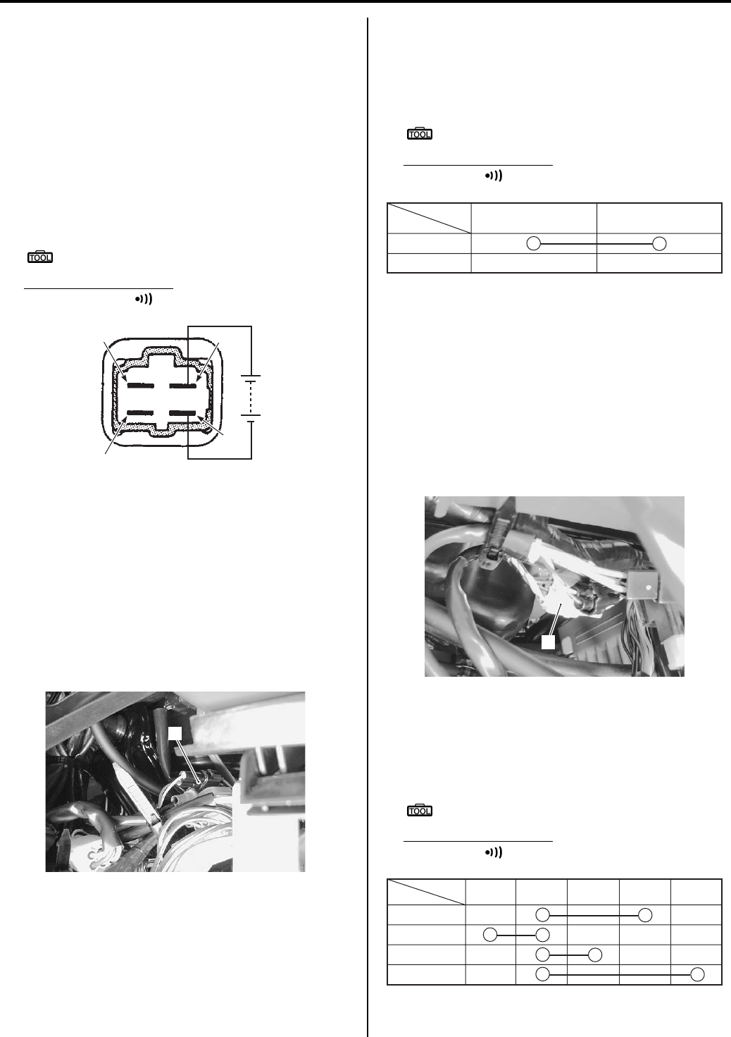
1I-9 Starting System:
Parking Brake Relay Inspection
B831G21906011
Inspect the parking brake relay in the following
procedures:
1) Remove the parking brake relay. Refer to “Parking
Brake Relay Removal and Installation (Page 1I-8)”.
2) Check the insulation between “A” and “B” terminals
using the multi-circuit tester.
3) Apply 12 V to terminals “C” and “D” ((+) to “C” and (–
) to “D”) and check the continuity between “A” and
“B”. If there is no continuity, replace the parking
brake relay with a new one.
Special tool
: 09900–25008 (Multi-circuit tester set)
Tester knob indication
Continuity test ( )
4) Install the parking brake relay in the reverse order of
removal.
Parking Brake Switch Inspection
B831G21906012
Inspect the parking brake switch in the following
procedures:
1) Remove the left inner fender. Refer to “Front Side
Exterior Parts Removal and Installation in Section
9D (Page 9D-6)”.
2) Disconnect the brake switch coupler (1).
3) Inspect the parking brake switch for continuity with a
tester. If any abnormality is found, replace the
parking brake switch with a new one. Refer to
“Handlebars Removal and Installation in Section 6B
(Page 6B-3)”.
Special tool
: 09900–25008 (Multi-circuit tester set)
Tester knob indication
Continuity ( )
4) After finishing the parking brake switch inspection,
reinstall the removed parts.
Gear Position Switch Inspection
B831G21906013
Inspect the gear position switch in the following
procedures:
1) Remove the left side cover and engine side cover.
Refer to “Front Side Exterior Parts Removal and
Installation in Section 9D (Page 9D-6)”.
2) Disconnect the gear position switch coupler (1).
3) Inspect the gear position switch for continuity with a
tester. If any abnormality is found, replace the gear
position switch with a new one. Refer to “Gear
Position (GP) Switch Removal and Installation in
Section 3C (Page 3C-13)”.
Special tool
: 09900–25008 (Multi-circuit tester set)
Tester knob indication
Continuity ( )
“B”
“A” “C”
“D”
I831G1190020-01
1
I831G1190021-01
WBl
Color
Position
ON
OFF
I831G1190022-01
1
I831G1190023-01
Color
H
L
N
R
Position WBlBGR
I831G1190024-02
PartShark.com
877-999-5686
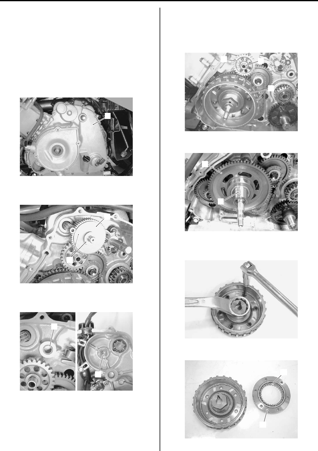
Starting System: 1I-10
4) After finishing the gear position switch inspection,
reinstall the removed parts.
Starter Torque Limiter / Starter Clutch Removal
and Installation
B831G21906014
Removal
1) Drain engine oil. Refer to “Engine Oil and Filter
Replacement in Section 0B (Page 0B-10)”.
2) Remove the generator cover (1). Refer to “Generator
Removal and Installation in Section 1J (Page 1J-4)”.
3) Remove the starter torque limiter (2) with the
washers (3).
4) Remove the bushings (4) from the crankcase and
generator cover.
5) Remove the idle gear shaft (5) and starter idle gear
(6).
6) Remove the generator rotor assembly (7). Refer to
“Generator Removal and Installation in Section 1J
(Page 1J-4)”.
7) Remove the key (8) and starter driven gear (9).
Hold the generator rotor with a 41 mm offset wrench
and remove the starter clutch bolts.
9) Remove the one way clutch (10) from the guide (11).
1
I831G1190025-01
2
3
I831G1190026-02
4
4
I831G1190027-02
5
6
7
I831G1190028-01
8
9
I831G1190030-01
I831G1190031-01
11
10
I831G1190032-01
PartShark.com
877-999-5686
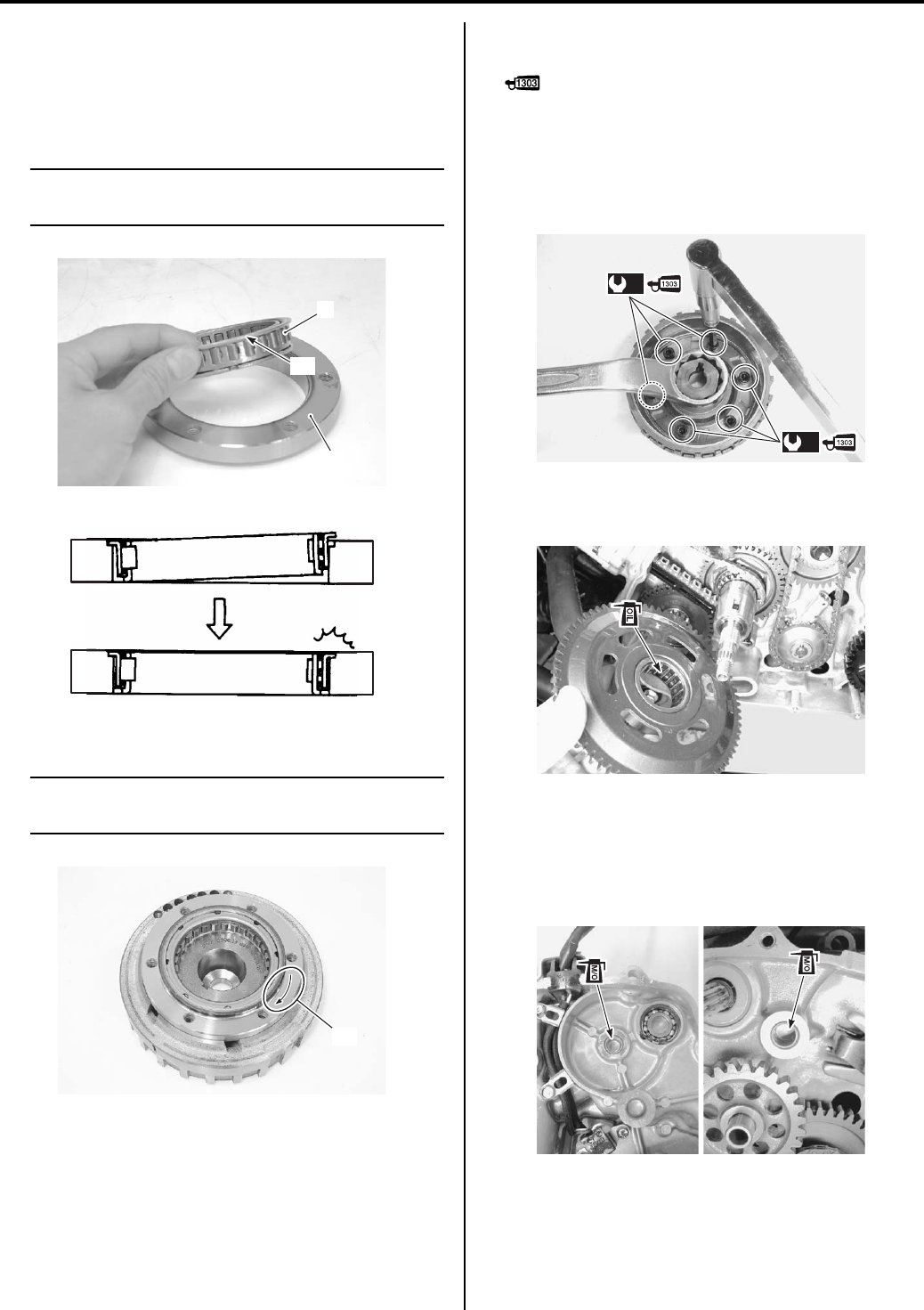
1I-11 Starting System:
Installation
Install the starter clutch in the reverse order of removal.
Pay attention to the following points:
• When inserting the one way clutch (1) into the guide
(2), fit the flange “A” in the step of the guide (2).
NOTE
Be sure to seat the flange “A” of the one way
clutch (1) to the guide (2).
• Install the guide to the generator rotor.
NOTE
The arrow mark “B” must face the generator
rotor side.
• Apply thread lock to the bolts, and then tighten them
to the specified torque.
: Thread lock cement 99000–32030
(THREAD LOCK CEMENT SUPER 1303 or
equivalent)
Tightening torque
Starter clutch bolt (a): 26 N·m (2.6 kgf-m, 19.0 lb-
ft)
• Apply engine oil to the bearing of the starter driven
gear.
• Install the generator rotor assembly onto crankshaft.
Refer to “Generator Removal and Installation in
Section 1J (Page 1J-4)”.
• Apply molybdenum oil solution to the inside of
bushings.
1
2
“A”
I831G1190033-01
I718H1190031-01
“B”
I831G1190034-01
(a)
(a)
I831G1190035-01
I831G1190036-01
I831G1190037-02
PartShark.com
877-999-5686
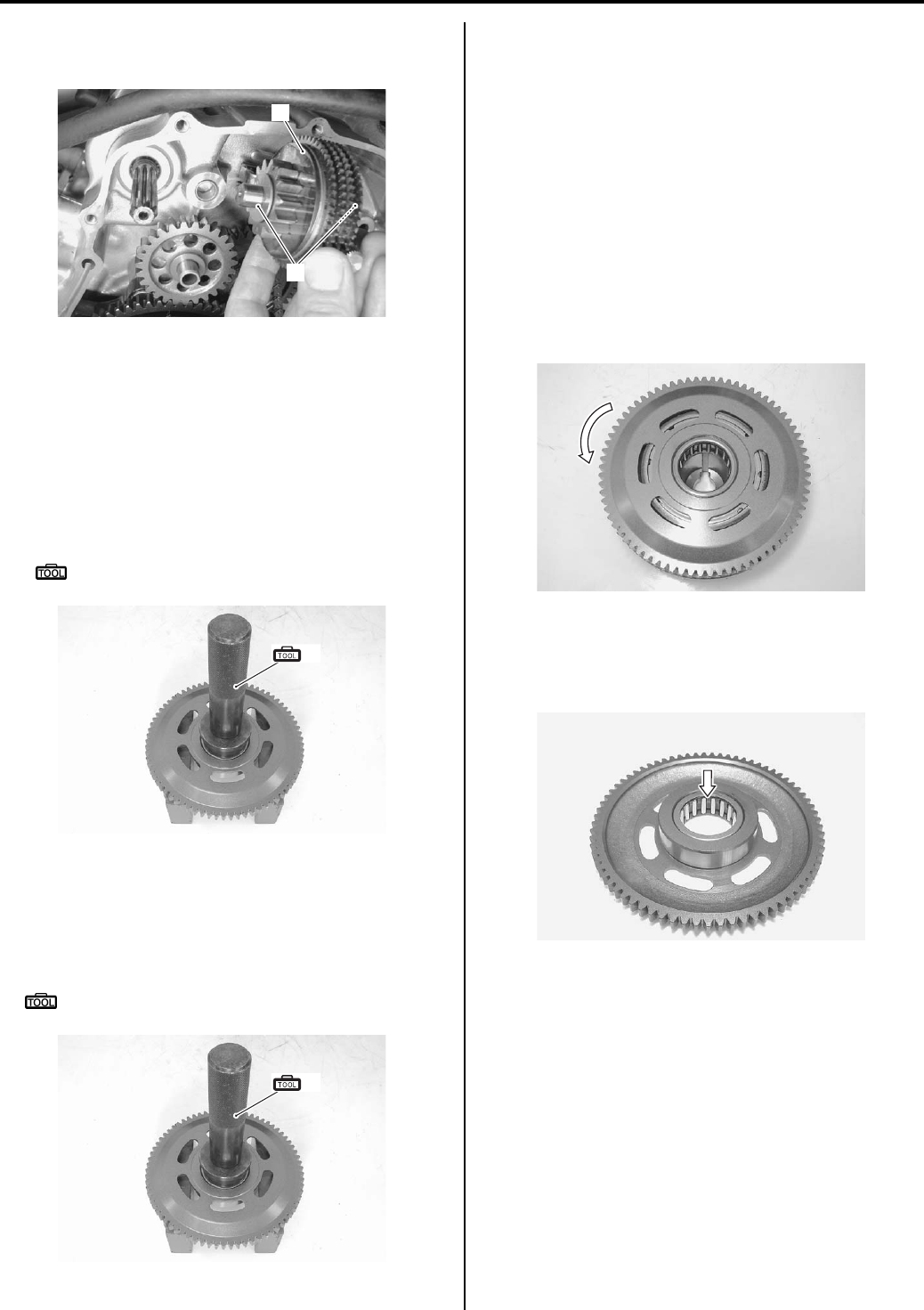
Starting System: 1I-12
• Fit the washers (3) onto the starter torque limiter (4).
• Install the starter torque limiter (4) to the crankcase.
Starter Driven Gear Bearing Removal and
Installation
B831G21906015
Removal
1) Remove the starter driven gear. Refer to “Starter
Torque Limiter / Starter Clutch Removal and
Installation (Page 1I-10)”.
2) Remove the bearing with the special tool.
Special tool
(A): 09913–70210 (Bearing installer set)
Installation
Install the starter driven gear bearing in the reverse order
of removal. Pay attention to following point:
• Install the bearing with the special tool.
Special tool
: 09913–70210 (Bearing installer set)
Starter Related Parts Inspection
B831G21906016
Refer to “Starter Torque Limiter / Starter Clutch Removal
and Installation (Page 1I-10)”.
Starter Clutch
1) Install the starter driven gear onto the starter clutch.
2) Turn the starter driven gear by hand to inspect the
starter clutch for smooth movement. The gear turns
in one direction only. If a large resistance is felt for
rotation, inspect the starter clutch or the starter
clutch contacting surface on the starter driven gear
for wear or damage.
If they are found to be damaged, replace the one
way clutch with a new one.
Starter Driven Gear Bearing
Inspect the starter driven gear bearing for wear or
damage. If necessary, replace it with a new one.
3
4
I831G1190038-01
(A)
I831G1190039-01
(A)
I831G1190039-01
I831G1190041-01
I831G1190042-01
PartShark.com
877-999-5686
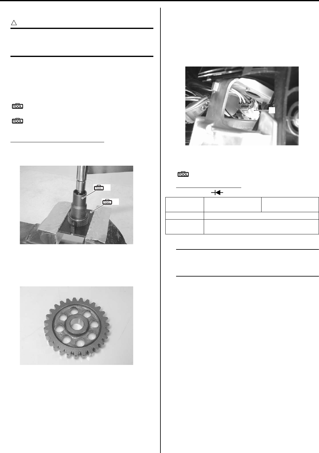
1I-13 Starting System:
Starter Torque Limiter
CAUTION
!
Do not attempt to disassemble the starter
torque limiter. The starter torque limiter is
available only as an assembly.
1) Set the starter torque limiter to the special tools and
vise.
2) Turn the starter torque limiter and check the slip
torque.
Special tool
(A): 09930–73170 (Starter torque limiter
holder)
(B): 09930–73140 (Starter torque limiter
socket)
Starter torque limiter slip torque
Standard: 41.2 – 62.8 N⋅m (4.2 – 6.4 kgf-m, 14.5 –
32.5 lb-ft)
Starter Idle Gear
Inspect the starter idle gear for wear or damage. If any
damage is found, replace it with a new one.
Starter Button Inspection
B831G21906017
Inspect the starter button in the following procedures:
1) Remove the left inner fender. Refer to “Front Side
Exterior Parts Removal and Installation in Section
9D (Page 9D-6)”.
2) Disconnect the handlebar switch coupler (1).
3) Measure the voltage between Y/G and O lead wires.
Special tool
: 09900–25008 (Multi-circuit tester set)
Tester knob indication
Diode test ( )
NOTE
If the tester reads 1.4 V and below when the
tester probes are not connected, replace its
battery.
(A)
(B)
I831G1190043-01
I831G1190044-01
Y/G
((+) probe)
O
((–) probe)
ON 0.4 – 0.6 V
OFF 1.4 V and more
(Tester’s battery voltage)
1
I831G1190045-02
PartShark.com
877-999-5686
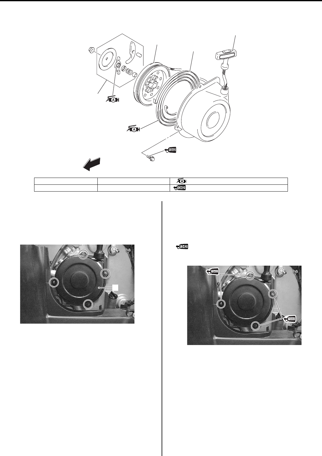
Starting System: 1I-14
Recoil Starter Components
B831G21906018
Recoil Starter Assembly Removal and
Installation
B831G21906019
Removal
• Remove the recoil starter (1).
Installation
Install the recoil starter assembly in the reverse order of
removal. Pay attention to the following point:
• Apply a small quantity of thread lock to the recoil
starter bolts.
: Thread lock cement 99000–32050
(THREAD LOCK CEMENT 1342 or equivalent)
1
2
3
4
FWD
I831G1190046-04
1. Ratchet set 3. Spiral spring : Apply grease.
2. Reel 4. Rope assembly : Apply thread lock to the thread part.
1
I831G1190047-02
I831G1190048-04
PartShark.com
877-999-5686
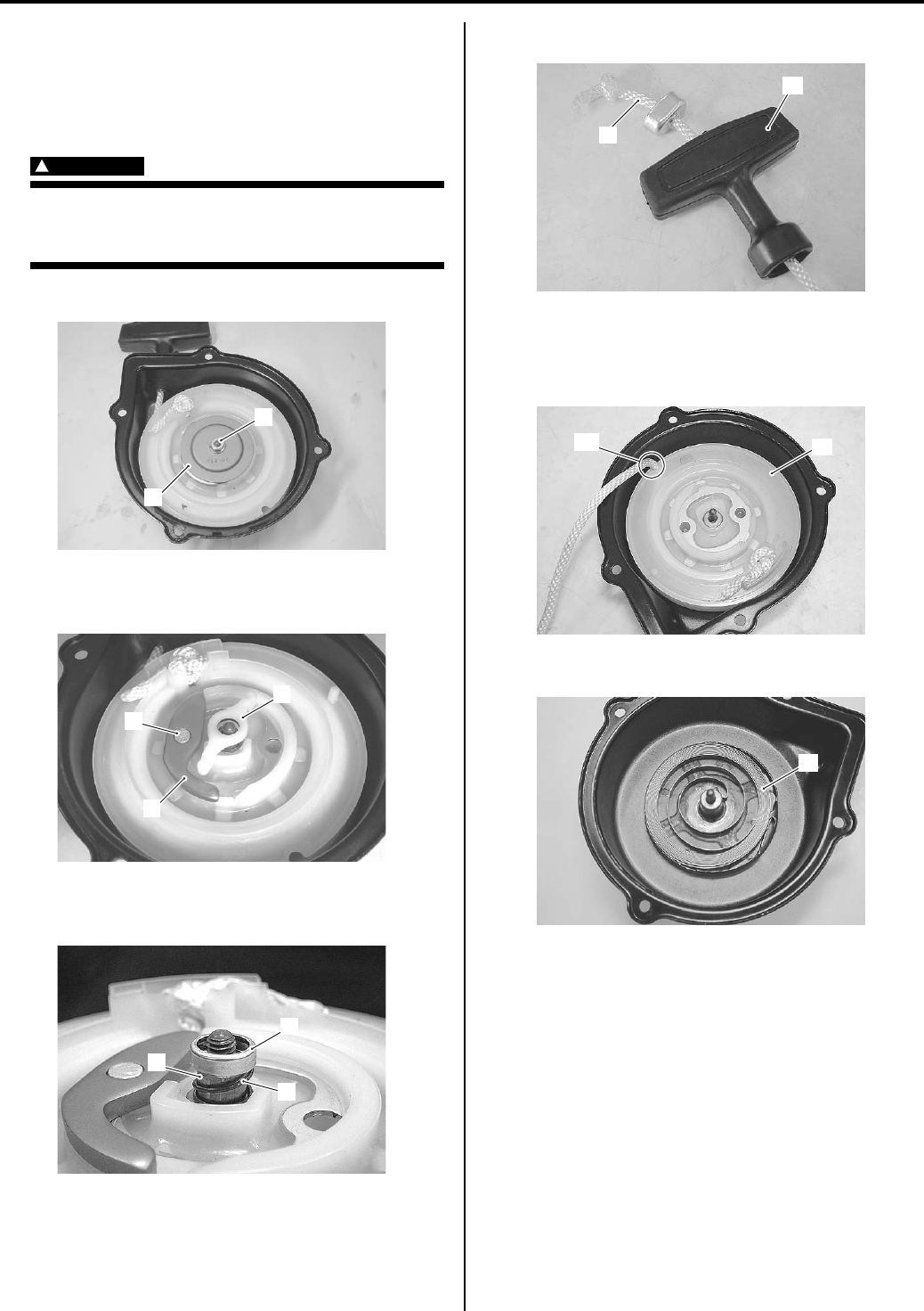
1I-15 Starting System:
Recoil Starter Disassembly and Assembly
B831G21906020
Refer to “Recoil Starter Assembly Removal and
Installation (Page 1I-14)”.
Disassembly
WARNING
!
Wear hand and eye protection when
removing the reel, since the spring may
quickly unwind and cause an injury.
1) Remove the nut (1) and friction plate (2).
2) Remove the ratchet guide (3), ratchet (4) and ratchet
pin (5).
3) Remove the spring cover (6), spring (7) and spacer
(8).
4) Disengage the rope (9) from the handle (10).
5) Hook the rope to groove “A” of the reel (11).
6) Turn the rope on the reel (11) properly.
7) Remove the reel (11).
Remove the spiral spring (12).
1
2
I831G1190049-03
3
5
4
I831G1190050-02
6
7
8
I831G1190051-02
10
9
I831G1190052-02
11
“A”
I831G1190053-02
12
I831G1190054-01
PartShark.com
877-999-5686
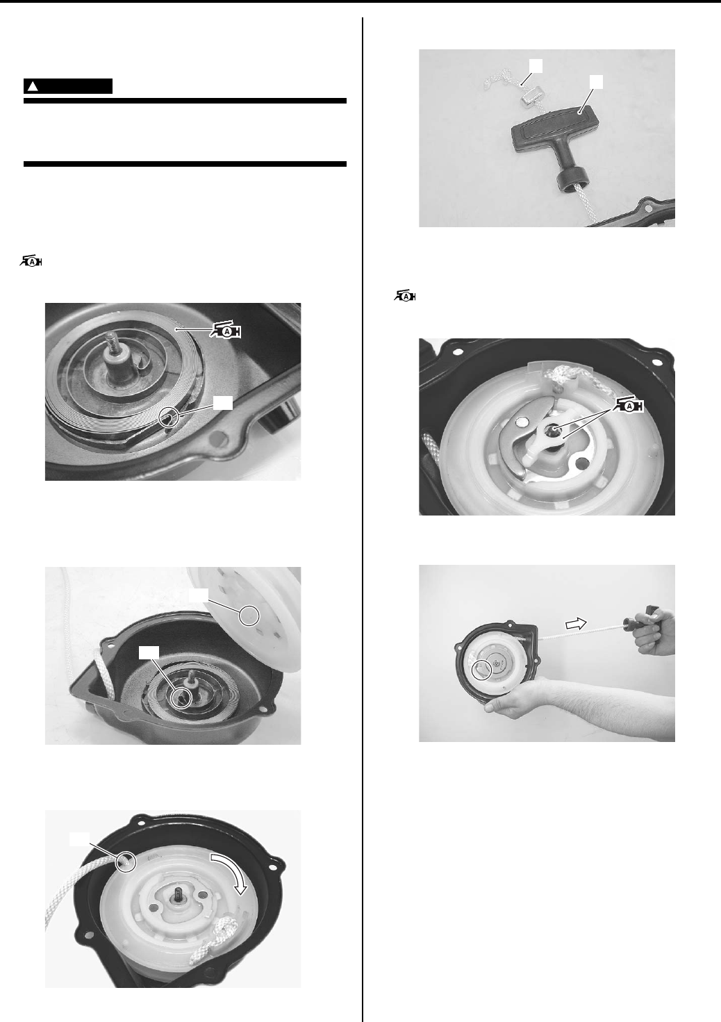
Starting System: 1I-16
Assembly
Assemble the recoil starter in the reverse order of
disassembly. Pay attention to the following points:
WARNING
!
Wear hand and eye protection when
installing the reel, since the spring may
quickly unwind and cause an injury.
• When installing the spiral spring, hook the spiral
spring end “A” with the recoil starter case as shown in
the figure.
• Apply grease to the spiral spring.
: Grease 99000–25010 (SUZUKI SUPER
GREASE A or equivalent)
• Turn the rope on the reel properly.
• After installing the spiral spring, engage the part “B” of
the reel with the spiral spring end “C”.
• Hook the rope onto the hook part “D” of the reel, turn
the reel clockwise five or six times with the rope.
• Connect the handle (1) to the rope (2).
• Install the ratchet related parts.
• Apply grease to the shaft and ratchet guide.
: Grease 99000–25010 (SUZUKI SUPER
GREASE A or equivalent)
• Pull the rope and check that the ratchet is pushed out.
“A”
I831G1190055-01
“C”
“B”
I831G1190056-01
“D”
I831G1190057-01
2
1
I831G1190058-02
I831G1190059-01
I831G1190060-02
PartShark.com
877-999-5686
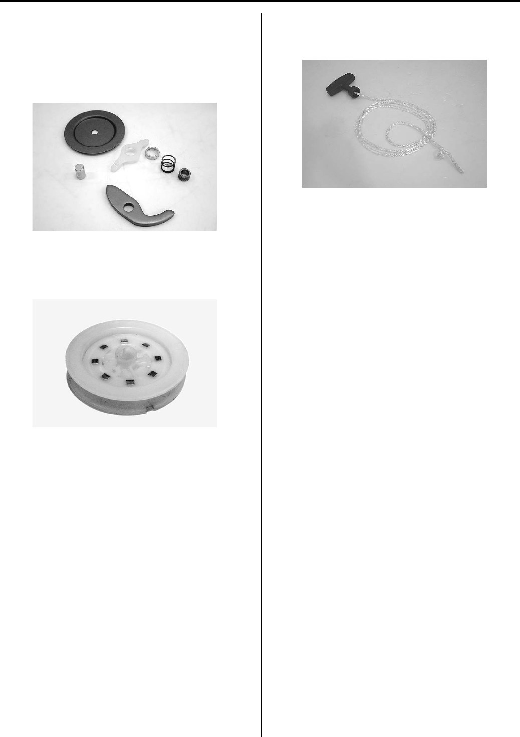
1I-17 Starting System:
Recoil Starter Inspection
B831G21906021
Ratchet Set
Inspect the ratchet set for wear or damage. If any
defects are found, replace the ratchet set with a new
one.
Reel
Inspect the reel for wear or damage. If any defects are
found, replace the reel with a new one.
Rope
Inspect the rope for damage. If any defects are found,
replace the rope with a new one.
I831G1190061-01
I831G1190062-02
I831G1190063-01
PartShark.com
877-999-5686
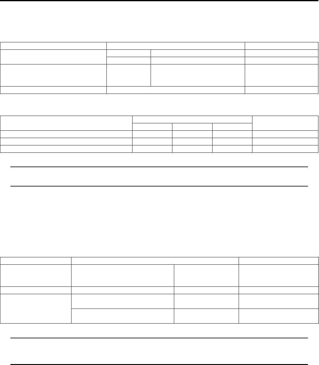
Starting System: 1I-18
Specifications
Service Data
B831G21907001
Unit: mm (in)
Tightening Torque Specifications
B831G21907002
NOTE
The specified tightening torque is also described in the following.
“Starter Motor Components (Page 1I-3)”
Reference:
For the tightening torque of fastener not specified in this section, refer to “Tightening Torque List in Section 0C
(Page 0C-7)”.
Special Tools and Equipment
Recommended Service Material
B831G21908001
NOTE
Required service material is also described in the following.
“Starter Motor Components (Page 1I-3)”
“Recoil Starter Components (Page 1I-14)”
Item Specification Note
Starter motor brush length Standard 12.5 (0.49)
Limit 6.0 (0.24)
Starter torque limiter slip torque Standard 41.2 – 62.8 N⋅m
(4.2 – 6.4 kgf-m, 14.5 – 32.5 lb-ft)
Starter relay resistance 3 – 5 Ω
Fastening part Tightening torque Note
N⋅mkgf—mlb—ft
Starter motor mounting bolt 10 1.0 7.0 )(Page 1I-4)
Starter motor lead wire mounting nut 6 0.6 4.5 )(Page 1I-4)
Starter clutch bolt 26 2.6 19.0 )(Page 1I-11)
Material SUZUKI recommended product or Specification Note
Grease SUZUKI SUPER GREASE A or
equivalent
P/No.: 99000–25010 )(Page 1I-4) / )(Page 1I-5)
/ )(Page 1I-16) /
)(Page 1I-16)
Moly paste SUZUKI Moly paste or equivalent P/No.: 99000–25140 )(Page 1I-5)
Thread lock cement THREAD LOCK CEMENT SUPER
1303 or equivalent
P/No.: 99000–32030 )(Page 1I-11)
THREAD LOCK CEMENT 1342 or
equivalent
P/No.: 99000–32050 )(Page 1I-14)
PartShark.com
877-999-5686
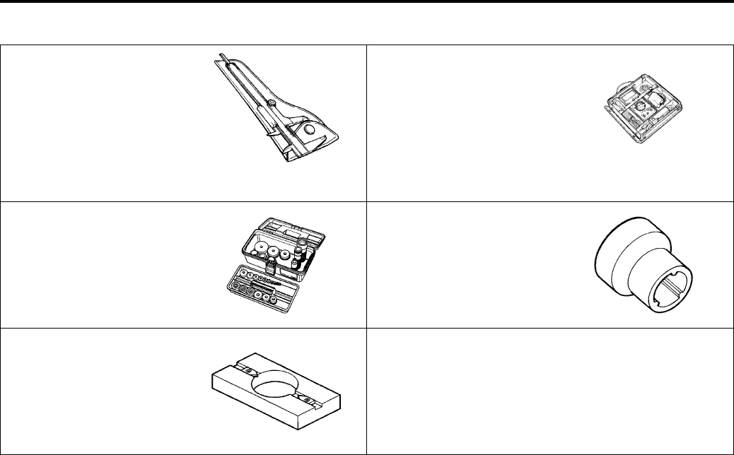
1I-19 Starting System:
Special Tool
B831G21908002
09900–20102 09900–25008
Vernier calipers (1/20 mm,
200 mm)
Multi-circuit tester set
)(Page 1I-5) )(Page 1I-6) / )(Page 1I-7)
/ )(Page 1I-7) / )(Page 1I-
/ )(Page 1I-8) /
)(Page 1I-9) / )(Page 1I-9)
/ )(Page 1I-9) / )(Page 1I-
13)
09913–70210 09930–73140
Bearing installer set Starter torque limiter socket
)(Page 1I-12) / )(Page 1I-
12)
)(Page 1I-13)
09930–73170
Starter torque limiter holder
)(Page 1I-13)
PartShark.com
877-999-5686
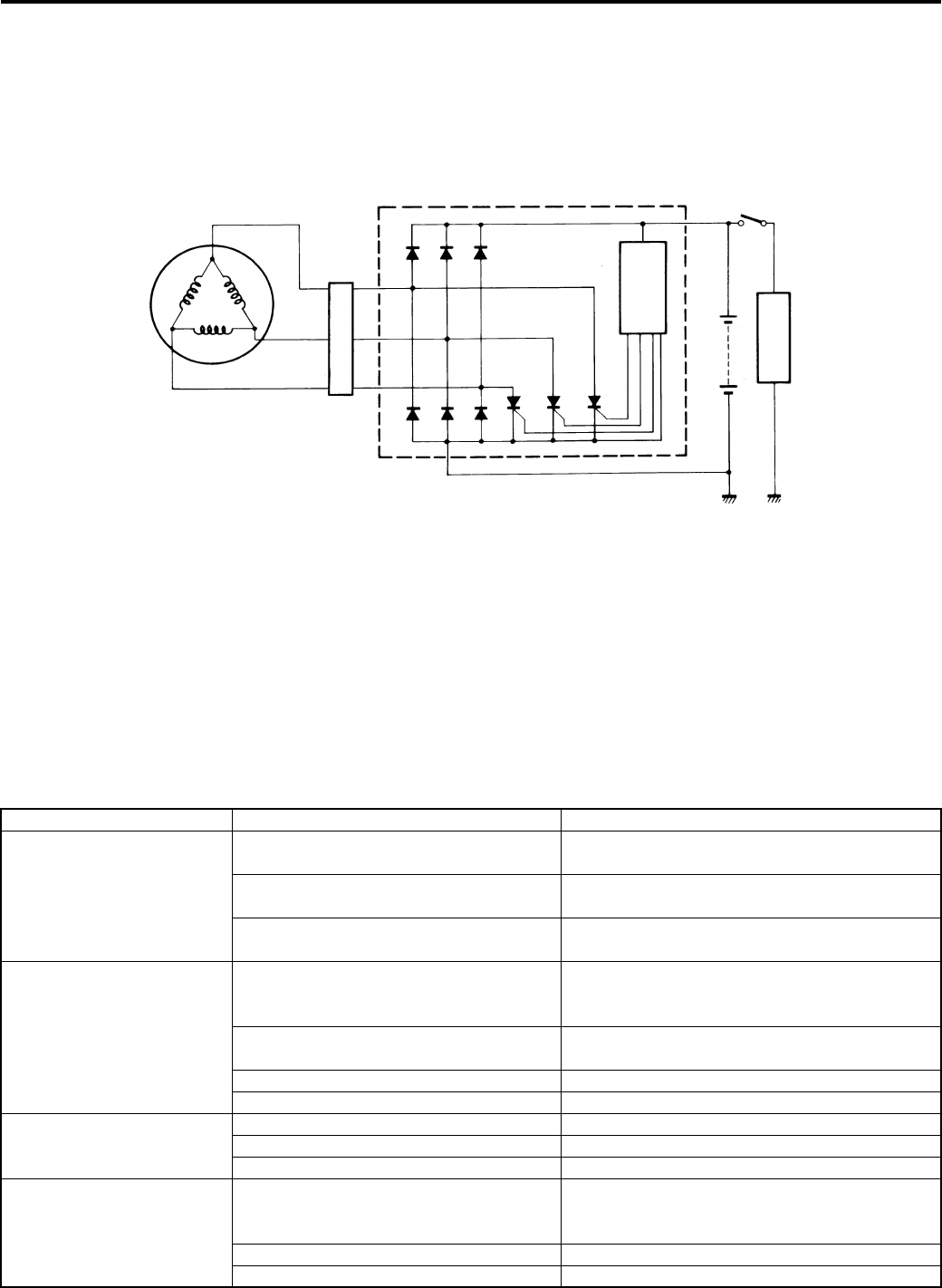
Charging System: 1J-1
Engine
Charging System
Schematic and Routing Diagram
Charging System Diagram
B831G21A02001
Component Location
Charging System Components Location
B831G21A03001
Refer to “Electrical Components Location in Section 0A (Page 0A-7)”.
Diagnostic Information and Procedures
Charging System Symptom Diagnosis
B831G21A04001
SCR
IC
Generator
Regulator/Rectifier Ignition switch
Battery
Load
I718H11A0001-01
Condition Possible cause Correction / Reference Item
Generator does not
charge
Open- or short-circuited lead wires, or
loose lead connections.
Repair, replace or connect properly.
Short-circuited, grounded or open
generator coil.
Replace.
Short-circuited or punctured regulator/
rectifier.
Replace.
Generator does charge,
but charging rate is below
the specification
Lead wires tend to get short- or open-
circuited or loosely connected at
terminals.
Repair or retighten.
Grounded or open-circuited generator
coil.
Replace.
Defective regulator/rectifier. Replace.
Defective cell plates in the battery. Replace the battery.
Generator overcharges Internal short-circuit in the battery. Replace the battery.
Damaged or defective regulator/rectifier. Replace.
Poorly grounded regulator/rectifier. Clean and tighten ground connection.
Unstable charging Lead wire insulation frayed due to
vibration, resulting in intermittent short-
circuiting.
Repair or replace.
Internally short-circuited generator. Replace.
Defective regulator/rectifier. Replace.
PartShark.com
877-999-5686

1J-2 Charging System:
Battery Runs Down Quickly
B831G21A04002
Troubleshooting
Battery overcharges Faulty regulator/rectifier. Replace.
Faulty battery. Replace.
Poor contact of generator lead wire
coupler.
Repair.
Battery runs down quickly Trouble in charging system. Check the generator, regulator/rectifier and
circuit connections and make necessary
adjustments to obtain specified charging
operation.
Cell plates have lost much of their active
materials a result of overcharging.
Replace the battery and correct the charging
system.
Internal short-circuit in the battery. Replace the battery.
Too low battery voltage. Recharge the battery fully.
Too old battery. Replace the battery.
Battery “sulfation” Incorrect charging rate. (When not in
use battery should be checked at least
once a month to avoid sulfation.)
Replace the battery.
The battery was left unused in a cold
climate for too long.
Replace the battery if badly sulfated.
Condition Possible cause Correction / Reference Item
Step Action Yes No
1 Check accessories which use excessive amounts of
electricity.
Are accessories being installed?
Remove accessories. Go to Step 2.
2 Check the battery for current leakage. Refer to “Battery
Current Leakage Inspection (Page 1J-3)”.
Is the battery for current leakage OK?
Go to Step 3. • Short circuit of wire
harness.
• Faulty electrical
equipment.
3 Measure the regulated voltage between the battery
terminals. Refer to “Regulated Voltage Inspection (Page 1J-
3)”.
Is the regulated voltage OK?
• Faulty battery.
• Abnormal driving
condition.
Go to Step 4.
4 Measure the resistance of the generator coil. Refer to
“Generator Inspection (Page 1J-3)”.
Is the resistance of generator coil OK?
Go to Step 5. • Faulty generator coil.
• Disconnected lead
wires.
5 Measure the generator no-load performance. Refer to
“Generator Inspection (Page 1J-3)”.
Is the generator no-load performance OK?
Go to Step 6. Faulty generator.
6 Inspect the regulator/rectifier. Refer to “Regulator / Rectifier
Inspection (Page 1J-8)”.
Is the regulator/rectifier OK?
Go to Step 7. Faulty regulator/rectifier.
7 Inspect wirings.
Is the wirings OK?
Faulty battery. • Short circuit of wire
harness.
• Poor contact of
couplers.
PartShark.com
877-999-5686
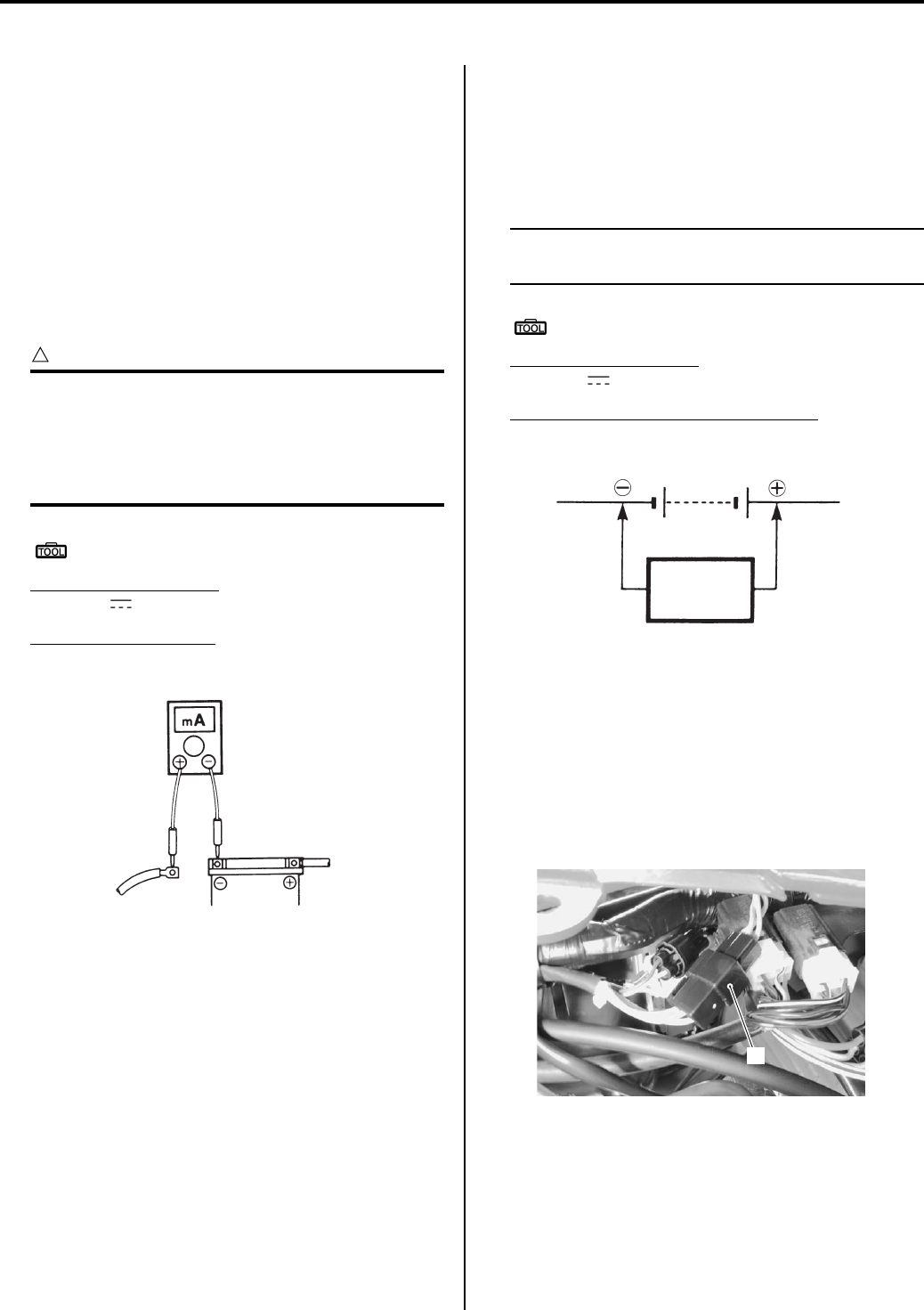
Charging System: 1J-3
Repair Instructions
Battery Current Leakage Inspection
B831G21A06001
Inspect the battery current leakage in the following
procedures:
1) Turn the ignition switch OFF.
2) Remove the seat. Refer to “Seat Removal and
Installation in Section 9D (Page 9D-11)”.
3) Disconnect the (–) battery lead wire.
4) Measure the current between (–) battery terminal
and the (–) battery lead wire using the multi-circuit
tester. If the reading exceeds the specified value,
leakage is evident.
CAUTION
!
• In case of a large current leak, turn the
tester to high range first to avoid tester
damage.
• Do not turn the ignition switch ON when
measuring current.
Special tool
: 09900–25008 (Multi-circuit tester set)
Tester knob indication
Current ( , 20 mA)
Battery current (Leak)
Under 2.6 mA
5) Connect the (–) battery terminal and install the seat.
Regulated Voltage Inspection
B831G21A06002
Inspect the regulated voltage in the following
procedures:
1) Remove the seat. Refer to “Seat Removal and
Installation in Section 9D (Page 9D-11)”.
2) Start the engine and keep it running at 5 000 r/min
with the dimmer switch turned HI position.
3) Measure the DC voltage between the (+) and (–)
battery terminals using the multi-circuit tester. If the
voltage is not within the specified value, inspect the
generator and regulator/rectifier. Refer to “Generator
Inspection (Page 1J-3)” and “Regulator / Rectifier
Inspection (Page 1J-8)”.
NOTE
When making this test, be sure that the
battery is fully charged condition.
Special tool
: 09900–25008 (Multi-circuit tester set)
Tester knob indication
Voltage ( )
Regulated voltage (Charging output)
Standard: 13.5 – 15.0 V at 5 000 r/min
4) Install the seat.
Generator Inspection
B831G21A06003
Generator Coil Resistance
1) Remove the left side cover and engine side cover.
Refer to “Front Side Exterior Parts Removal and
Installation in Section 9D (Page 9D-6)”.
2) Disconnect the generator coupler (1).
I649G11A0002-02
(DCV)
Tester
Battery
I649G11A0003-02
1
I831G11A0001-01
PartShark.com
877-999-5686
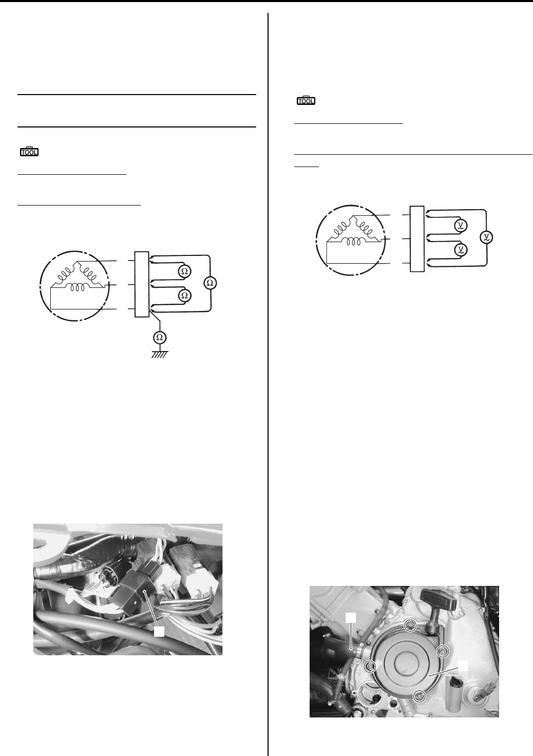
1J-4 Charging System:
3) Measure the resistance between the three lead
wires.
If the resistance is out of specified value, replace the
stator with a new one. Also, check that the generator
core is insulated properly.
NOTE
When making this test, it is not necessary to
remove the generator.
Special tool
: 09900–25008 (Multi-circuit tester set)
Tester knob indication
Resistance (Ω)
Generator coil resistance
0.4 – 1.0 Ω (Y – Y)
∞ Ω (Y – Ground)
4) After finishing the inspection, reinstall the removed
parts.
No-load Performance
1) Remove the side covers, left and right. Refer to
“Front Side Exterior Parts Removal and Installation
in Section 9D (Page 9D-6)”.
2) Connect the tachometer onto the spark plug high-
tension cord.
3) Disconnect the generator coupler (1).
4) Start the engine and keep it running at 5 000 r/min.
5) Using the multi-circuit tester, measure the voltage
between three lead wires.
If the tester reads under the specified value, replace
the generator with a new one.
Special tool
: 09900–25008 (Multi-circuit tester set)
Tester knob indication
Voltage (~)
Generator no-load performance (When engine is
cold)
75 V (AC) and more at 5 000 r/min
Generator Removal and Installation
B831G21A06004
Removal
1) Disconnect the (–) battery lead wire. Refer to
“Battery Removal and Installation (Page 1J-12)”.
2) Drain engine oil. Refer to “Engine Oil and Filter
Replacement in Section 0B (Page 0B-10)”.
3) Remove the left inner fender. Refer to “Front Side
Exterior Parts Removal and Installation in Section
9D (Page 9D-6)”.
4) Remove the left mud guard. Refer to “Rear Side
Exterior Parts Removal and Installation in Section
9D (Page 9D-9)”.
5) Drain engine coolant. Refer to “Cooling System
Inspection in Section 0B (Page 0B-15)”.
6) Remove the water pump assembly. Refer to “Water
Pump Removal and Installation in Section 1F
(Page 1F-13)”.
7) Disconnect the water hose (1) and remove the recoil
starter (2).
Y
Y
Y
I831G11A0002-01
1
I831G11A0001-01
Y
Y
Y
I831G11A0003-01
2
1
I831G11A0004-02
PartShark.com
877-999-5686
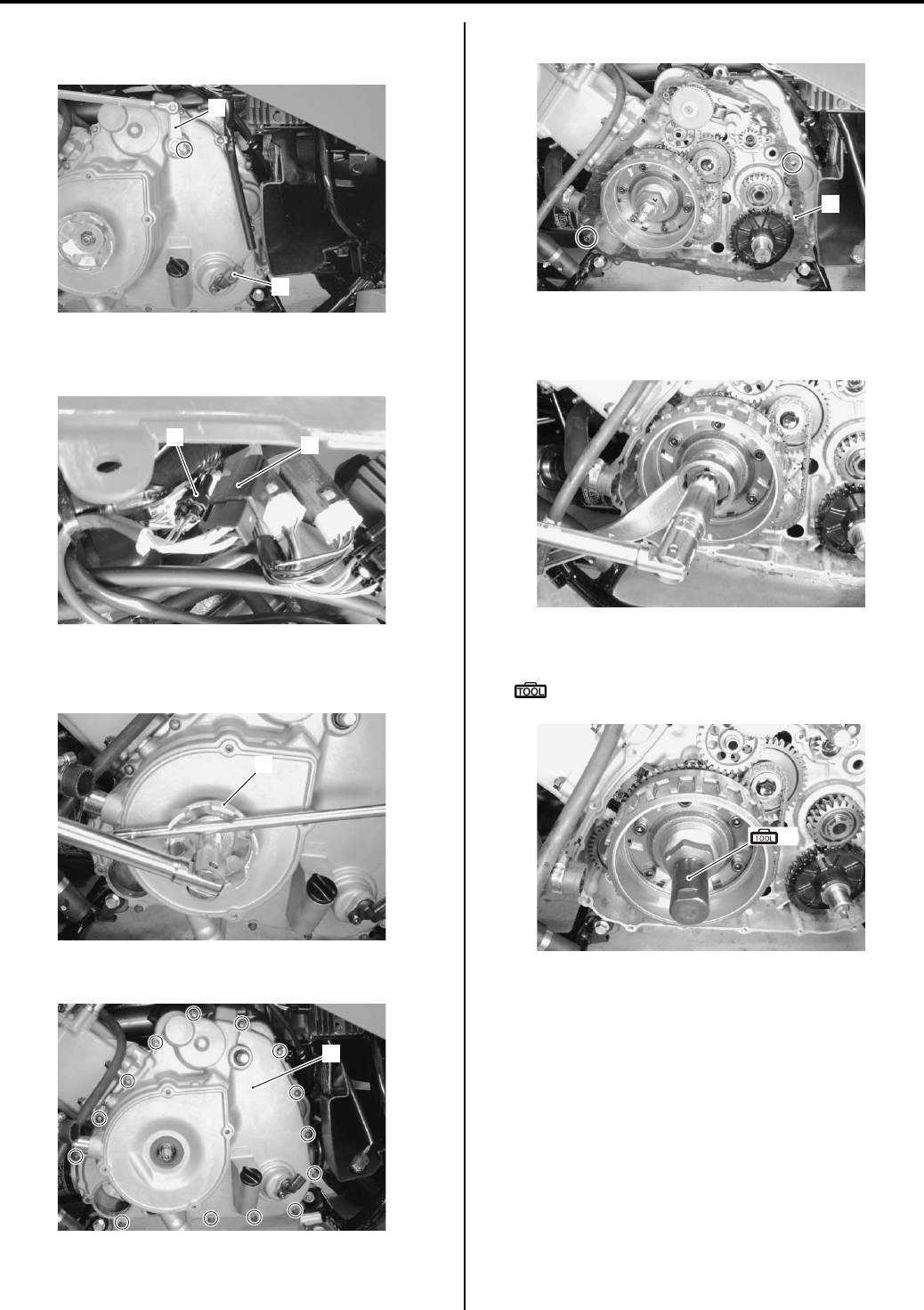
Charging System: 1J-5
Disconnect the gearshift lever arm (3) and speed
sensor coupler (4).
9) Disconnect the CKP sensor coupler (5) and
generator coupler (6).
10) Remove the starter cup nut with a suitable bar.
11) Remove the starter cup (7).
12) Remove the generator cover (8).
13) Remove the gasket (9) and dowel pins.
14) Hold the generator rotor with a 41 mm offset wrench.
15) Remove the generator rotor nut.
16) Install the special tool to the crankshaft end.
Special tool
(A): 09930–31921 (Rotor remover)
3
4
I831G11A0015-01
5
6
I831G11A0006-02
7
I831G11A0005-02
8
I831G11A0008-03
9
I831G11A0009-01
I831G11A0010-01
(A)
I831G11A0011-01
PartShark.com
877-999-5686
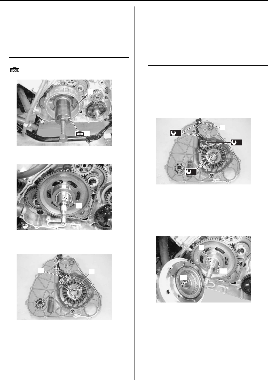
1J-6 Charging System:
17) Remove the generator rotor assembly (10) with the
special tool.
NOTE
Remove the starter clutch if necessary. Refer
to “Starter Torque Limiter / Starter Clutch
Removal and Installation in Section 1I
(Page 1I-10)”.
Special tool
(B): 09930–30721 (Rotor remover)
18) Remove the key (11).
19) Remove the generator stator (12) along with the
CKP sensor (13).
Installation
Install the generator in the reverse order of removal. Pay
attention to the following points:
• Tighten the generator stator set bolts and CKP sensor
mounting bolts to the specified torque.
NOTE
Be sure the grommet (1) is set to the
generator cover.
Tightening torque
Generator stator set bolt (a): 11 N·m (1.1 kgf-m,
8.0 lb-ft)
CKP sensor mounting bolt (b): 6 N·m (0.6 kgf-m,
4.5 lb-ft)
Lead wire clamp bolt (c): 6 N·m (0.6 kgf-m, 4.5 lb-
ft)
• Degrease the tapered portion “A” of generator rotor
assembly and also the crankshaft “B”. Use
nonflammable cleaning solvent to wipe off oily or
greasy matter to make these surfaces completely dry.
• Fit the key (2) in the key slot on the crankshaft.
• Install the generator rotor assembly onto crankshaft.
10
(B)
I831G11A0012-01
11
I831G11A0013-02
12
13
I831G11A0014-02
(a)
(b)
(c)
1
I831G11A0016-03
2
“B”
“A”
I831G11A0017-04
PartShark.com
877-999-5686
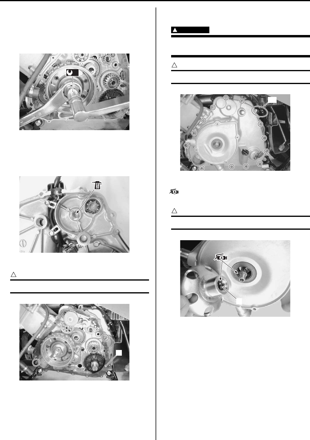
Charging System: 1J-7
• Hold the generator rotor and tighten the generator
rotor nut to the specified torque.
Tightening torque
Generator rotor nut (d): 160 N·m (16.0 kgf-m,
115.5 lb-ft)
• Apply molybdenum oil solution to the inside of the
bush.
M/O: Molybdenum oil (MOLYBDENUM OIL
SOLUTION)
• Install the dowel pins and new gasket (3).
CAUTION
!
Use a new gasket to prevent oil leakage.
• Install the generator cover and tighten the generator
cover bolts.
WARNING
!
Be careful not to pinch the finger between the
generator cover and the crankcase.
CAUTION
!
Fit the clamp to the bolt “C”.
• Apply grease to the O-ring (4) and oil seal lip.
: Grease 99000–25010 (SUZUKI SUPER
GREASE A or equivalent)
CAUTION
!
Replace the O-ring (4) with a new one.
(d)
I831G11A0018-05
I831G11A0019-01
3
I831G11A0020-03
“C”
I831G11A0021-02
4
I831G11A0022-03
PartShark.com
877-999-5686
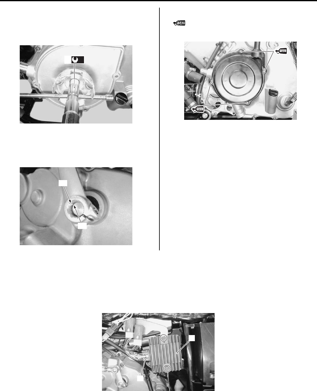
1J-8 Charging System:
• Tighten the starter cup nut (5) to the specified torque.
Tightening torque
Starter cup nut (e): 38 N·m (3.8 kgf-m, 27.5 lb-ft)
• When installing the gearshift lever arm, align the wide
spline teeth “D” with “E”. Refer to “Shift Lever
Disassembly and Assembly in Section 5A (Page 5A-
25)”.
• Apply a small quantity of thread lock to the bolts.
: Thread lock cement 99000–32050
(THREAD LOCK CEMENT 1342 or equivalent)
Regulator / Rectifier Inspection
B831G21A06005
Inspect the regulator/rectifier in the following procedures:
1) Turn the ignition switch OFF.
2) Remove the rear fender. Refer to “Rear Side Exterior Parts Removal and Installation in Section 9D (Page 9D-9)”.
3) Disconnect the regulator/rectifier coupler (1) and remove the regulator/rectifier (2).
(e)
5
I831G11A0023-05
“D”
“E”
I831G11A0024-02
I831G11A0025-02
2
1
I831G11A0026-01
PartShark.com
877-999-5686
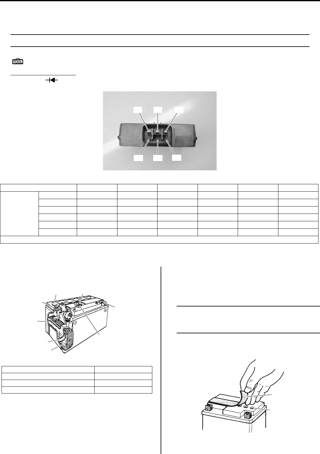
Charging System: 1J-9
4) Measure the voltage between the terminals using the multi-circuit tester as indicated in the following table. If the
voltage is not within the specified value, replace the regulator/rectifier with a new one.
NOTE
If the tester reads 1.4 V and below when the tester probes are not connected, replace its battery.
Special tool
: 09900–25008 (Multi-circuit tester set)
Tester knob indication
Diode test ( )
Unit: V
5) Connect the regulator/rectifier coupler and reinstall the removed parts.
Battery Components
B831G21A06006
Battery Charging
B831G21A06007
Initial Charging
Filling electrolyte
NOTE
When filling electrolyte, the battery must be
removed from the vehicle and must be put on
the level ground.
1) Remove the aluminum tape (1) which seals the
battery filler holes “A”.
“C”“A” “B”
“D” “E” “F”
I831G11A0027-01
“A” “B” “C” “D” “E” “F”
(–) probe of
tester to:
“A” — * 0.4 – 1.2 0.3 – 0.7 0.3 – 0.7 0.3 – 0.7
“B”*—****
“C”**—***
“D” * * 0.3 – 0.7 — * *
“E” * * 0.3 – 0.7 * — *
“F” * * 0.3 – 0.7 * * —
*1.4 V and more (tester’s battery voltage)
1. Anode plates 5. Stopper
2. Separator (Fiberglass plate) 6. Filter
3. Cathode plates 7. Terminal
4. Upper cover breather 8. Safety valve
1
3
2
4
56
7
8
I649G11A0046-03
1
“A”
I649G11A0039-03
PartShark.com
877-999-5686
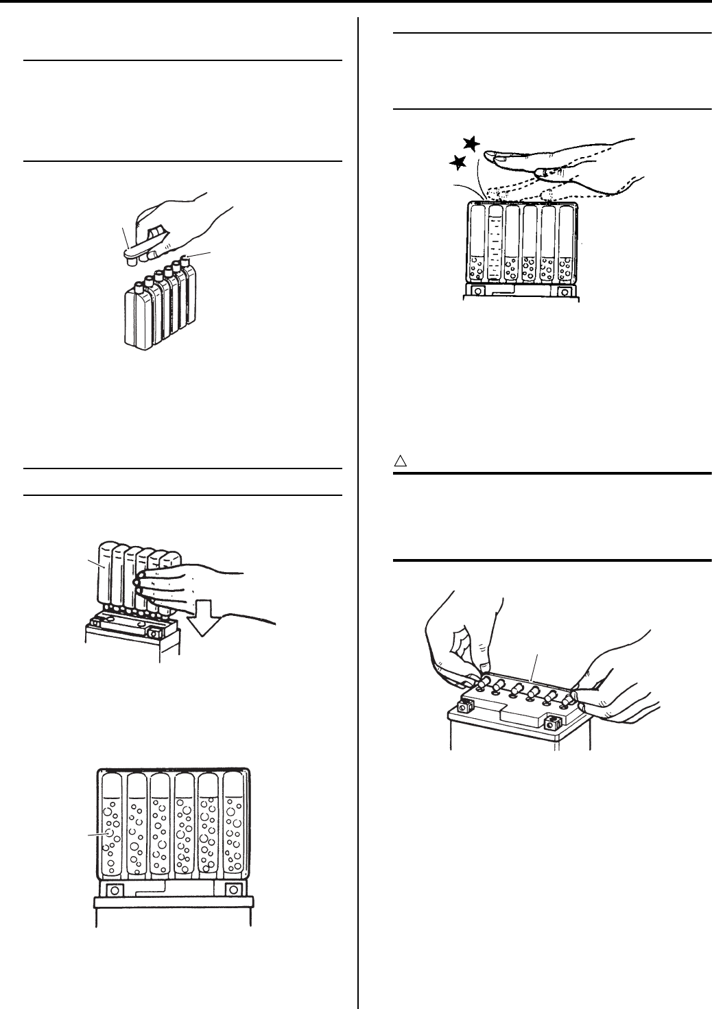
1J-10 Charging System:
2) Remove the caps (2) from the electrolyte container.
NOTE
• Do not remove or pierce the sealed areas
“B” of the electrolyte container.
• After filling the electrolyte completely, use
the removed cap (2) as sealing caps of
battery-filler holes.
3) Insert the nozzles of the electrolyte container (3) into
the electrolyte filler holes of the battery.
4) Hold the electrolyte container firmly so that it does
not fall.
NOTE
Do not allow any of the electrolyte to spill.
5) Make sure that air bubbles (4) rise to the top of each
electrolyte container, and leave in this position for
about more than 20 minutes.
NOTE
If no air bubbles come out from a filler port,
tap the bottom of the electrolyte container
two or three times.
Never remove the container from the battery.
6) After confirming that the electrolyte has entered the
battery completely, remove the electrolyte containers
from the battery.
7) Wait for about 20 minutes.
Insert the caps (2) into the filler holes, pressing in
firmly so that the top of the caps do not protrude
above the upper surface of the battery’s top cover.
CAUTION
!
• Once the caps are installed to the battery,
do not remove the caps.
• Do not tap the caps with a hammer when
installing them.
2
“B”
I649G11A0040-03
3
I649G11A0041-03
4
I649G11A0042-03
I310G11A0024-01
2
I718H11A0027-01
PartShark.com
877-999-5686
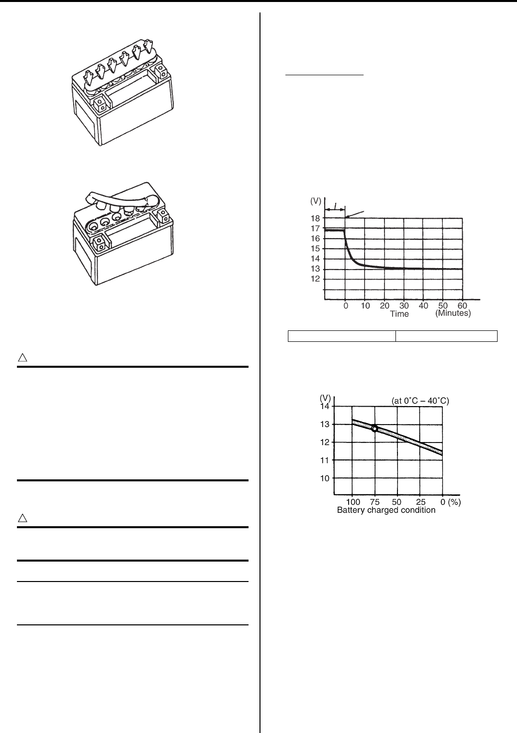
Charging System: 1J-11
Charging
For initial charging, use the charger specially designed
for MF battery.
CAUTION
!
• For charging the battery, make sure to use
the charger specially designed for MF
battery. Otherwise, the battery may be
overcharged resulting in shortened service
life.
• Do not remove the cap during charging.
• Position the battery with the cap facing
upward during charging.
Battery Recharging
CAUTION
!
Do not remove the caps on the battery top
while recharging.
NOTE
When the vehicle is not used for a long
period, check the battery every 1 month to
prevent the battery discharge.
1) Remove the battery from the vehicle. Refer to
“Battery Removal and Installation (Page 1J-12)”.
2) Measure the battery voltage using the multi-circuit
tester.
If the voltage reading is less than the 12 V (DC),
recharge the battery with a battery charger.
Recharging time
1.8 A for 5 to 10 hour
3) After recharging, wait at least 30 minutes and then
measure the battery voltage using the multi-circuit
tester.
If the battery voltage is less than 12.5 V, recharge
the battery again.
If the battery voltage is still less than 12.5 V after
recharging, replace the battery with a new one.
4) Install the battery to the vehicle. Refer to “Battery
Removal and Installation (Page 1J-12)”.
Correct
Incorrect
I649G11A0047-02
“A”: Charging period “B”: Stop charging
“A”
“B”
I649G11A0045-02
I705H11A0029-02
PartShark.com
877-999-5686
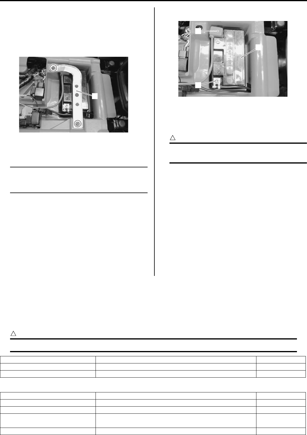
1J-12 Charging System:
Battery Removal and Installation
B831G21A06008
Removal
1) Remove the seat. Refer to “Seat Removal and
Installation in Section 9D (Page 9D-11)”.
2) Remove the battery stay (1).
3) Disconnect the battery (–) lead wire (2).
4) Disconnect the battery (+) lead wire (3).
NOTE
Be sure to disconnect the battery (–) lead
wire (2) first, then disconnect the battery (+)
lead wire (3).
5) Remove the battery (4).
Installation
Install the battery in the reverse order of removal.
Pay attention to following point:
CAUTION
!
Never use anything except the specified
battery.
• Tighten the battery lead wire mounting bolts securely.
Battery Visual Inspection
B831G21A06009
Inspect the battery in the following procedures:
1) Remove the seat. Refer to “Seat Removal and
Installation in Section 9D (Page 9D-11)”.
2) Visually inspect the surface of the battery container.
If any signs of cracking or electrolyte leakage from
the sides of the battery have occurred, replace the
battery with a new one.
If the battery terminals are found to be coated with
rust or an acidic white powdery substance, clean the
battery terminals with sandpaper.
3) Install the seat.
Specifications
Service Data
B831G21A07001
Battery
CAUTION
!
Never use anything except the specified battery.
Generator
1
I831G11A0028-02
3
4
2
I831G11A0029-02
Item Specification Note
Type designation YTX20CH-BS
Capacity 12 V, 64.8 kC (18 Ah)/10 HR
Item Specification Note
Generator coil resistance 0.4 – 1.0 Ω
Generator maximum output Approx. 400 W at 5 000 r/min
Generator no-load voltage
(When engine is cold) 75 V (AC) and more at 5 000 r/min
Regulated voltage 13.5 – 15.5 V at 5 000 r/min
PartShark.com
877-999-5686
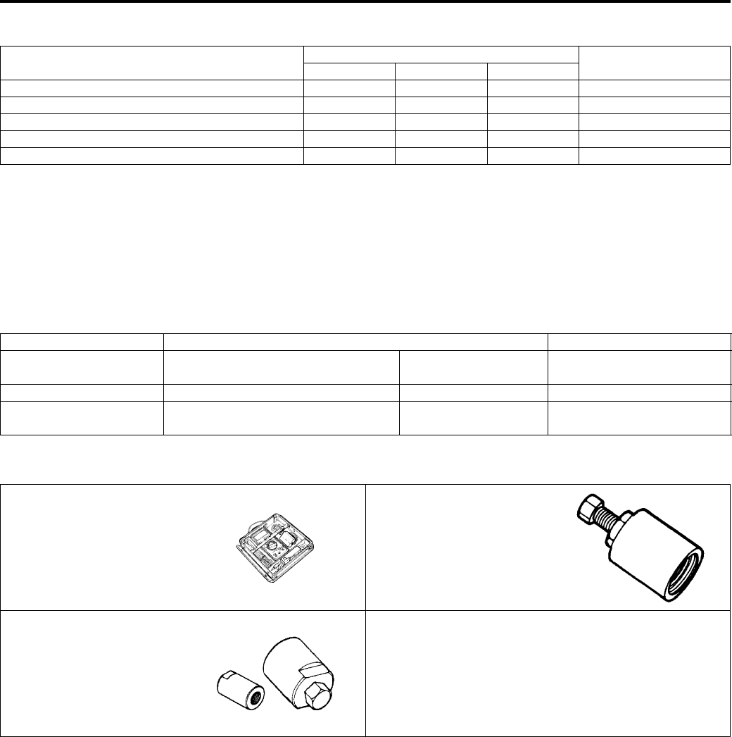
Charging System: 1J-13
Tightening Torque Specifications
B831G21A07002
Reference:
For the tightening torque of fastener not specified in this section, refer to “Tightening Torque List in Section 0C
(Page 0C-7)”.
Special Tools and Equipment
Recommended Service Material
B831G21A08001
Special Tool
B831G21A08002
Fastening part Tightening torque Note
N⋅mkgf—mlb—ft
Generator stator set bolt 11 1.1 8.0 )(Page 1J-6)
CKP sensor mounting bolt 6 0.6 4.5 )(Page 1J-6)
Lead wire clamp bolt 6 0.6 4.5 )(Page 1J-6)
Generator rotor nut 160 16.0 115.5 )(Page 1J-7)
Starter cup nut 38 3.8 27.5 )(Page 1J-8)
Material SUZUKI recommended product or Specification Note
Grease SUZUKI SUPER GREASE A or
equivalent
P/No.: 99000–25010 )(Page 1J-7)
Molybdenum oil MOLYBDENUM OIL SOLUTION — )(Page 1J-7)
Thread lock cement THREAD LOCK CEMENT 1342 or
equivalent
P/No.: 99000–32050 )(Page 1J-8)
09900–25008 09930–30721
Multi-circuit tester set Rotor remover
)(Page 1J-3) / )(Page 1J-
3) / )(Page 1J-4) /
)(Page 1J-4) / )(Page 1J-
9)
)(Page 1J-6)
09930–31921
Rotor remover
)(Page 1J-5)
PartShark.com
877-999-5686
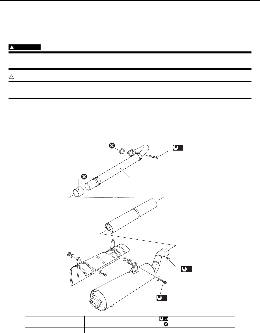
1K-1 Exhaust System:
Engine
Exhaust System
Precautions
Precautions for Exhaust System
B831G21B00001
WARNING
!
To avoid the risk of being burned, do not touch the exhaust system when the system is hot. Any
service on the exhaust system should be performed when the system is cool.
CAUTION
!
Make sure that the exhaust pipe and muffler have enough clearance from the rubber parts and plastic
parts to avoid melting.
Repair Instructions
Exhaust System Construction
B831G21B06001
(a)
4
1
3
2
(a)
5
(a)
6
I831G11B0001-03
1. Exhaust pipe 4. Exhaust pipe nut : 23 N⋅m (2.3 kgf-m, 16.5 lb-ft)
2. Muffler 5. Exhaust pipe mounting bolt : Do not reuse.
3. Connector 6. Muffler connecting bolt
PartShark.com
877-999-5686
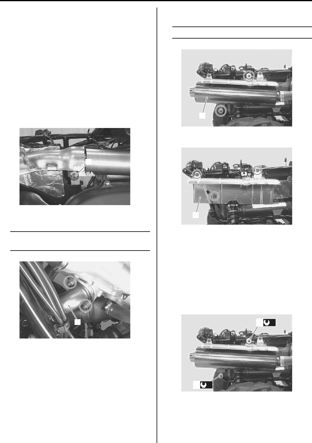
Exhaust System: 1K-2
Exhaust Pipe / Muffler Removal and Installation
B831G21B06002
Removal
1) Remove the inner fenders and side covers, left and
right. Refer to “Front Side Exterior Parts Removal
and Installation in Section 9D (Page 9D-6)”.
2) Remove the rear carrier. Refer to “Rear Carrier
Removal and Installation in Section 9E (Page 9E-5)”.
3) Remove the seat. Refer to “Seat Removal and
Installation in Section 9D (Page 9D-11)”.
4) Remove the engine side cover and rear fender.
Refer to “Rear Side Exterior Parts Removal and
Installation in Section 9D (Page 9D-9)”.
5) Loosen the muffler connecting bolt (1).
6) Remove the exhaust pipe (2).
NOTE
Support the exhaust pipe to prevent it from
falling.
7) Remove the muffler (3).
NOTE
Support the muffler to prevent it from falling.
Remove the muffler cover (4).
Installation
Install the exhaust pipe/muffler in the reverse order of
removal.
Pay attention to the following points:
• Tighten the muffler mounting bolts (1) to the specified
torque.
Tightening torque
Muffler mounting bolt (a): 23 N·m (2.3 kgf-m, 16.5
lb-ft)
1
I831G11B0002-02
2
I831G11B0003-01
3
I831G11B0004-03
4
I831G11B0005-02
(a)
1
(a)
1
I831G11B0006-03
PartShark.com
877-999-5686
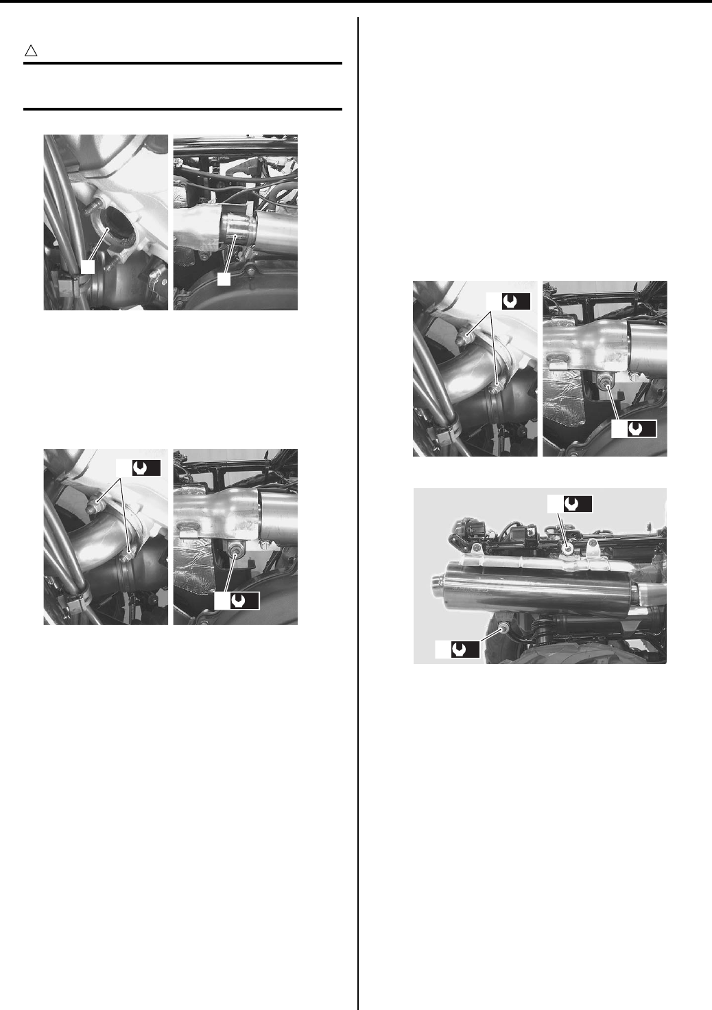
1K-3 Exhaust System:
• Install the exhaust pipe gasket (2) and connector (3).
CAUTION
!
Replace the gasket and connector with new
ones.
• Tighten the exhaust pipe nuts (4) and muffler
connecting mounting bolt (5) to the specified torque.
Tightening torque
Exhaust pipe nut (b): 23 N·m (2.3 kgf-m, 16.5 lb-ft)
Muffler connecting bolt (c): 23 N·m (2.3 kgf-m,
16.5 lb-ft)
Exhaust System Inspection
B831G21B06003
Inspect the exhaust pipe connection and muffler
connection for exhaust gas leakage and mounting
condition. If any defect are found, replace the exhaust
pipe assembly or muffler with a new one.
Check the exhaust pipe nuts (1), muffler connecting bolt
(2) and muffler mounting bolts (3) are tightened to their
specified torque.
Tightening torque
Exhaust pipe nut (a): 23 N·m (2.3 kgf-m, 16.5 lb-ft)
Muffler connecting bolt (b): 23 N·m (2.3 kgf-m, 16.5
lb-ft)
Muffler mounting bolt (c): 23 N·m (2.3 kgf-m, 16.5 lb-
ft)
Spark Arrester Inspection
B831G21B06004
Refer to “Spark Arrester Cleaning in Section 0B
(Page 0B-10)”.
2
3
I831G11B0007-05
(b)
4
(c)
5
I831G11B0008-04
(b)
2
(a)
1
I831G11B0009-03
(c)
3
(c)
3
I831G11B0010-02
PartShark.com
877-999-5686
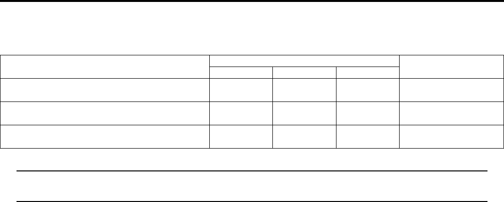
Exhaust System: 1K-4
Specifications
Tightening Torque Specifications
B831G21B07001
NOTE
The specified tightening torque is also described in the following.
“Exhaust System Construction (Page 1K-1)”
Reference:
For the tightening torque of fastener not specified in this section, refer to “Tightening Torque List in Section 0C
(Page 0C-7)”.
Fastening part Tightening torque Note
N⋅mkgf—mlb—ft
Muffler mounting bolt 23 2.3 16.5 )(Page 1K-2) /
)(Page 1K-3)
Exhaust pipe nut 23 2.3 16.5 )(Page 1K-3) /
)(Page 1K-3)
Muffler connecting bolt 23 2.3 16.5 )(Page 1K-3) /
)(Page 1K-3)
PartShark.com
877-999-5686

1K-5 Exhaust System:
PartShark.com
877-999-5686

Table of Contents 2- i
2
Section 2
CONTENTS
Suspension
Precautions ………………………………….………2-1
Precautions….…………………..……………….…………… 2-1
Precautions for Suspension ………………….………… 2-1
Suspension General Diagnosis………….. 2A-1
Diagnostic Information and Procedures…………2A-1
Suspension and Wheel Symptom Diagnosis …… 2A-1
Front Suspension ………..……………..…….. 2B-1
Repair Instructions .……………….…………………..…2B-1
Front Suspension Components ………….…………. 2B-1
Front Suspension Assembly Construction ………. 2B-2
Front Shock Absorber Removal and
Installation……………………….……………….………. 2B-3
Front Suspension Inspection ……………..…………. 2B-3
Front Shock Absorber Inspection…………..………. 2B-3
Spring Pre-load Adjustment ……………….…………. 2B-4
Front Wheel Hub / Steering Knuckle Removal
and Installation…..……………….………………..……2B-4
Front Hub Bearing Inspection ……………….………. 2B-7
Front Hub Bearing Removal and Installation …… 2B-7
Front Suspension Upper / Lower Arm
Removal and Installation…………….………………. 2B-9
Steering Knuckle End Inspection ………………….2B-10
Steering Knuckle End Removal and
Installation……………………….……………….……..2B-11
Front Suspension Arm Related Parts
Inspection………………….………………..………….. 2B-12
Front Suspension Upper Arm Bushing and
Inner Dust Seal Removal and Installation……. 2B-13
Front Suspension Lower Arm Bushing
Removal and Installation…………….…………….. 2B-14
Specifications…….…………….…………….…………..2B-15
Service Data ………….…………….………………..…. 2B-15
Tightening Torque Specifications………..………..2B-15
Special Tools and Equipment …………….………..2B-15
Recommended Service Material ………………….. 2B-15
Special Tool .……………….………………..………….. 2B-16
Rear Suspension ………………………..…….. 2C-1
Repair Instructions ………..……….…………….………2C-1
Rear Suspension Components ………………………2C-1
Rear Suspension Assembly Construction………..2C-2
Rear Shock Absorber Removal and
Installation …………….……………….………………....2C-3
Rear Suspension Inspection ………………………....2C-4
Rear Shock Absorber Inspection ……………………2C-4
Spring Pre-load Adjustment ………….……………….2C-4
Rear Wheel Hub / Suspension Knuckle
Removal and Installation…….……………….………2C-4
Rear Hub Bearing Inspection ………..……………….2C-6
Rear Hub Bearing Removal and Installation …....2C-6
Rear Suspension Arm Upper / Lower
Removal and Installation…….……………….………2C-8
Rear Suspension Arm Related Parts
Inspection……….………………..……………….………2C-9
Rear Suspension Upper Arm Bushing
Removal and Installation….…………….………….2C-11
Rear Suspension Lower Arm Bushing
Removal and Installation….…………….………….2C-12
Rear Suspension Knuckle Bushing Removal
and Installation ……………………….………………..2C-13
Rear Stabilizer Removal and Installation ……….2C-14
Stabilizer Parts Inspection……….…………….…….2C-15
Specifications…….………….…….…………….……….2C-16
Service Data……..……………..……………….……….2C-16
Tightening Torque Specifications………………….2C-16
Special Tools and Equipment ……………..……….2C-16
Recommended Service Material ……….………….2C-16
Special Tool ……………………….…………….……….2C-17
Wheels and Tires ……………………….……… 2D-1
Precautions……..………………..……………….…………2D-1
Precautions for Wheel and Tire..……………….……2D-1
Repair Instructions ………..……….…………….………2D-1
Front and Rear Wheel Components ……………….2D-1
Front / Rear Wheel Removal and Installation …..2D-2
Tire Removal and Installation…..…………………....2D-2
Specifications…….………….…….…………….…………2D-4
Service Data………………………….…………………....2D-4
Tightening Torque Specifications……………………2D-4
PartShark.com
877-999-5686

2-1 Precautions:
Suspension
Precautions
Precautions
Precautions for Suspension
B831G22000001
Refer to “General Precautions in Section 00 (Page 00-1)”.
WARNING
!
All suspensions, bolts and nuts are an important part in that it could affect the performance of vital
parts. They must be tightened to the specified torque periodically and if the suspension effect is lost,
replace it with a new one.
CAUTION
!
Never attempt to heat, quench or straighten any suspension part. Replace it with a new one, or
damage to the part may result.
NOTE
The right and left suspension related parts (shock absorbers, suspension arms and knuckles) are
installed symmetrically and therefore the removal procedure for one side is the same as that for the
other side.
PartShark.com
877-999-5686

Suspension General Diagnosis: 2A-1
Suspension
Suspension General Diagnosis
Diagnostic Information and Procedures
Suspension and Wheel Symptom Diagnosis
B831G22104001
Condition Possible cause Correction / Reference Item
Wobbly front wheel Distorted wheel rim. Replace.
Worn hub bearings. Replace.
Defective or incorrect tire. Replace.
Loose front wheel nut. Tighten.
Worn front suspension bushings. Replace.
Loose front suspension fastener. Tighten.
Front suspension too soft Weak front shock absorber spring. Replace.
Front shock absorber leaks oil. Replace.
Improperly suspension setting. Adjust.
Front suspension too stiff Bent front shock absorber shaft. Replace.
Bent front upper or lower suspension
arm.
Replace.
Improperly suspension setting. Adjust.
Front suspension too
noisy
Loose front suspension fastener. Tighten.
Worn front suspension related bushings. Replace.
Wobbly rear wheel Distorted wheel rim. Replace.
Worn hub bearings. Replace.
Defective or incorrect tire. Replace.
Loose rear wheel nut. Tighten.
Worn rear suspension bushings. Replace.
Loose rear suspension fastener. Tighten.
Rear suspension too soft Weak rear shock absorber spring. Replace.
Rear shock absorber leaks oil. Replace.
Improperly suspension setting. Adjust.
Rear suspension too stiff Bent rear shock absorber shaft. Replace.
Bent rear upper or lower suspension
arm.
Replace.
Improperly suspension setting. Adjust.
Rear suspension too
noisy
Loose rear suspension fastener. Tighten.
Worn rear suspension related bushings. Replace.
PartShark.com
877-999-5686
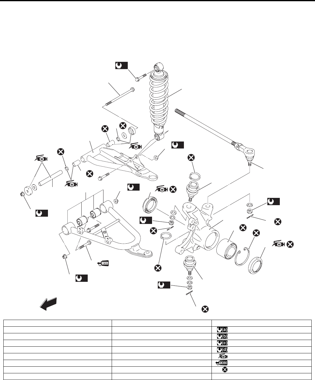
2B-1 Front Suspension:
Suspension
Front Suspension
Repair Instructions
Front Suspension Components
B831G22206001
(a)
1
2
(b)
9
16
13
15
14
18
(d)
13
17
FWD
19
19
19
(b)
3
(d)
(d)
4
7
6
67
8
(c)
11
(c)
11
10
12
5
I831G1220002-08
1. Front shock absorber mounting bolt 10. Suspension arm bolt (Lower) 19. Cotter pin
2. Front shock absorber 11. Suspension arm pivot nut (Lower) : 55 N⋅m (5.5 kgf-m, 40.0 lb-ft)
3. Front shock absorber mounting nut 12. Suspension lower arm set : 60 N⋅m (6.0 kgf-m, 43.5 lb-ft)
4. Suspension arm bolt (Upper) 13. Knuckle end : 65 N⋅m (6.5 kgf-m, 47.0 lb-ft)
5. Suspension upper arm 14. Hub bearing : 29 N⋅m (2.9 kgf-m, 21.0 lb-ft)
6. Bushing 15. Outer dust seal : Apply water resistance grease.
7. Inner dust seal 16. Inner dust seal : Apply thread lock to the thread part.
8. Spacer 17. Tie-rod end : Do not reuse.
9. Suspension arm pivot nut (Upper) 18. Steering knuckle
PartShark.com
877-999-5686
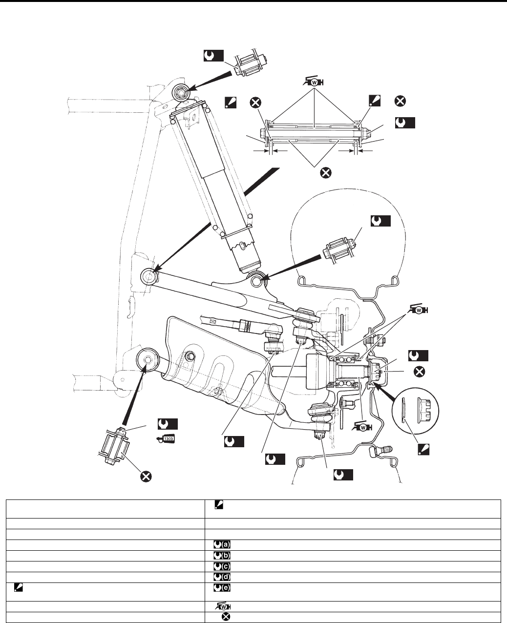
Front Suspension: 2B-2
Front Suspension Assembly Construction
B831G22206002
“a” “a”
10
11
(e)
7
8
(d)
6
(d)
6
(c)
4
(b)
3
(b)
2
(a)
1
12 12
11
9
(d)
5
I831G1220001-06
1. Front shock absorber mounting bolt 11. Inner dust seal
: Align the surface of dust seal with the edge of suspension arm.
2. Front shock absorber mounting nut 12. Outer dust seal
3. Front suspension arm pivot nut (Upper) “a”: Position of the bushing (7.0 mm (0.28 in) from edge of suspension arm)
4. Front suspension arm pivot nut (Lower) : 55 N⋅m (5.5 kgf-m, 40.0 lb-ft)
5. Tie-rod end nut : 60 N⋅m (6.0 kgf-m, 43.5 lb-ft)
6. Steering knuckle end nut (Upper / Lower) : 65 N⋅m (6.5 kgf-m, 47.0 lb-ft)
7. Front wheel hub nut : 29 N⋅m (2.9 kgf-m, 21.0 lb-ft)
8. Washer
: The conical side of washer faces outside.
:110 N⋅m (11.0 kgf-m, 79.5 lb-ft)
9. Cotter pin : Apply water resistance grease.
10. Bushing : Do not reuse.
PartShark.com
877-999-5686
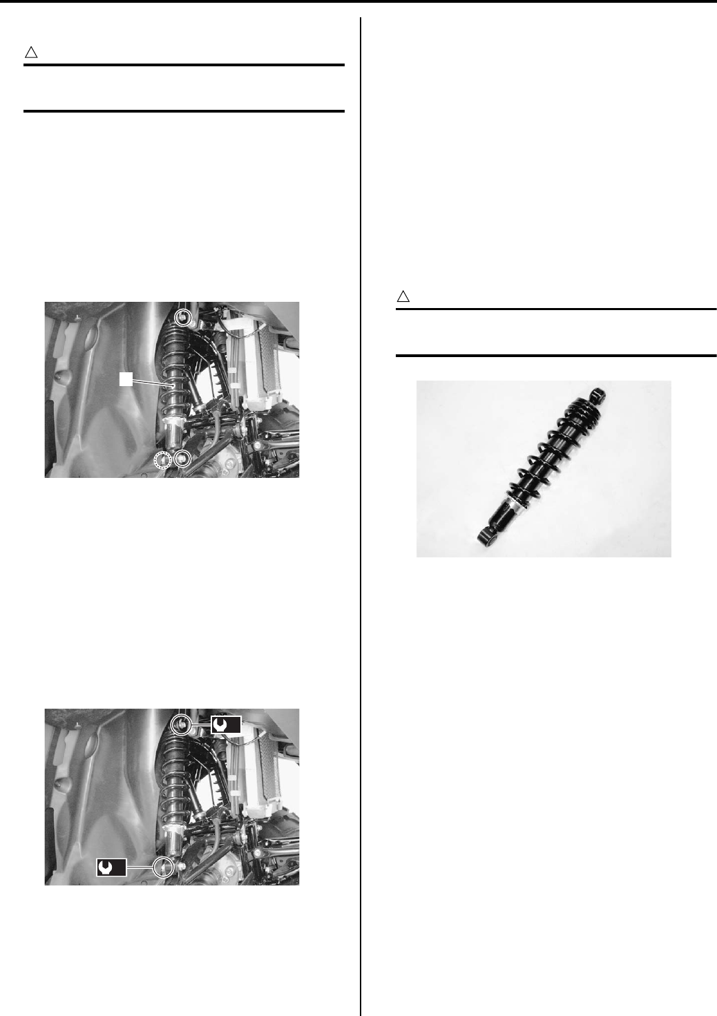
2B-3 Front Suspension:
Front Shock Absorber Removal and Installation
B831G22206003
CAUTION
!
Make sure that the vehicle is supported
securely.
Removal
1) Remove the front wheel. Refer to “Front / Rear
Wheel Removal and Installation in Section 2D
(Page 2D-2)”.
2) Remove the front shock absorber upper mounting
bolt.
3) Remove the front shock absorber lower mounting
nut and bolt.
4) Remove the front shock absorber (1).
Installation
Install the front shock absorber in the reverse order of
removal. Pay attention to the following point:
• Tighten the mounting bolt and nut to the specified
torque.
Tightening torque
Front shock absorber mounting bolt (Upper) (a):
55 N·m (5.5 kgf-m, 40.0 lb-ft)
Front shock absorber mounting nut (Lower) (b):
60 N·m (6.0 kgf-m, 43.5 lb-ft)
Front Suspension Inspection
B831G22206004
Refer to “Suspensions Inspection in Section 0B
(Page 0B-22)”.
Front Shock Absorber Inspection
B831G22206005
Inspect the front shock absorber in the following
procedures:
1) Remove the front shock absorber. Refer to “Front
Shock Absorber Removal and Installation (Page 2B-
3)”.
2) Inspect the front shock absorber for damage and oil
leakage, and absorber bushing for wear or damage.
If any defects are found, replace the front shock
absorber with a new one.
CAUTION
!
Do not attempt to disassemble the front
shock absorber. It is unserviceable.
3) Install the front shock absorber. Refer to “Front
Shock Absorber Removal and Installation (Page 2B-
3)”.
1
I831G1220003-02
(a)
(b)
I831G1220004-02
I831G1220005-01
PartShark.com
877-999-5686
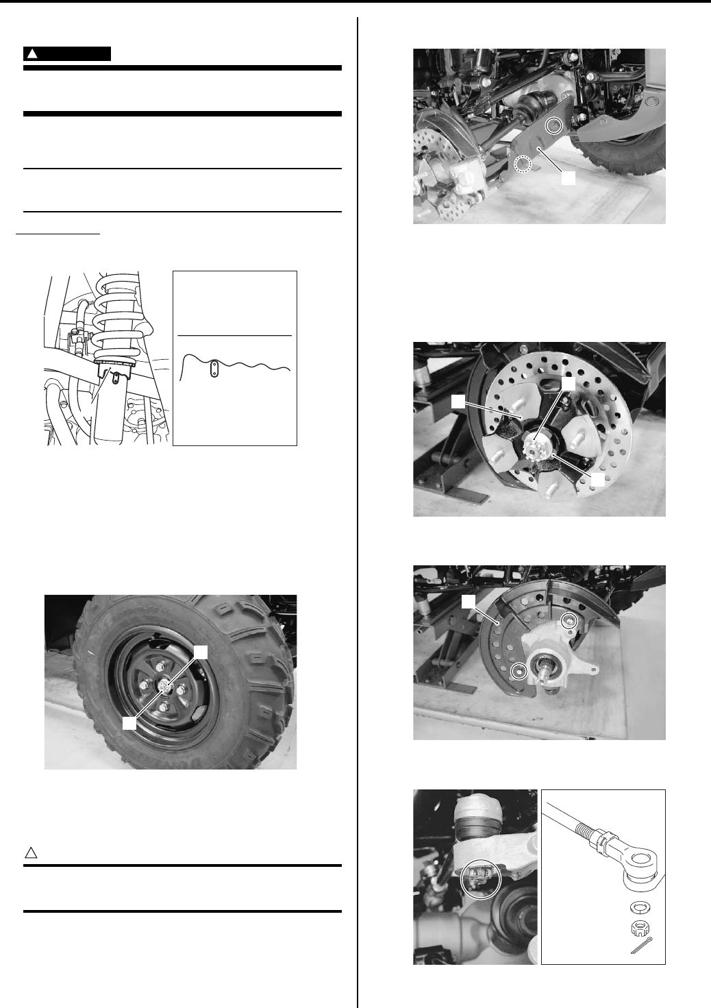
Front Suspension: 2B-4
Spring Pre-load Adjustment
B831G22206006
WARNING
!
Be sure to adjust the spring pre-load on the
both suspensions equally.
• Turn the spring tension ring (1) to the desired position.
NOTE
Position 1 provides the softest spring tension
and position 5 provides the stiffest.
STD position
2nd position
• Install the removed parts.
Front Wheel Hub / Steering Knuckle Removal
and Installation
B831G22206007
Removal
1) Remove the cotter pin (1) and loosen the hub nut (2).
2) Remove the front wheel assembly. Refer to “Front /
Rear Wheel Removal and Installation in Section 2D
(Page 2D-2)”.
CAUTION
!
Make sure that the vehicle is supported
securely.
3) Remove the front drive shaft cover (3).
4) Remove the brake caliper. Refer to “Front Brake
Caliper Removal and Installation in Section 4B
(Page 4B-3)”.
5) Remove the front wheel hub (4) by removing hub nut
(5) and washer (6).
6) Remove the front disc cover (7).
7) Remove the cotter pin, tie-rod end nut and washer.
12345
1
I831G1220058-01
1
2
I831G1220006-01
3
I831G1220007-01
5
6
4
I831G1220008-01
7
I831G1220010-01
I831G1220011-03
PartShark.com
877-999-5686
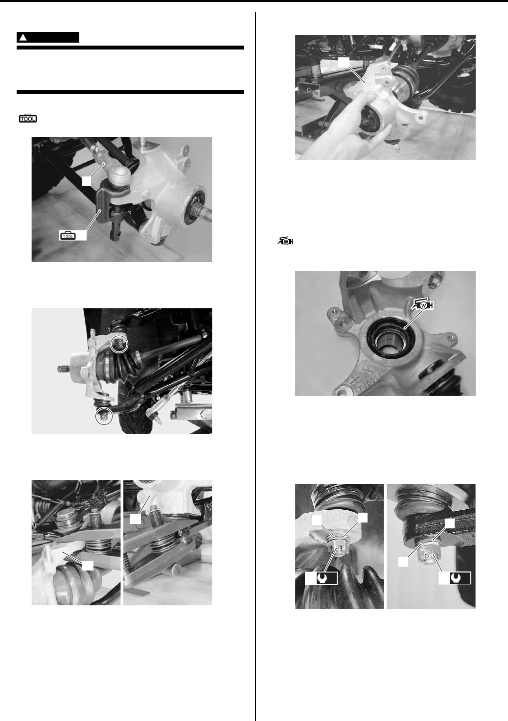
2B-5 Front Suspension:
Disengage the tie-rod end (8) with the special tool.
WARNING
!
When using the tie-rod end remover, keep
clear of the tie-rod end because it may come
loose with some force and could strike you.
Special tool
(A): 09942–72410 (Tie rod end remover)
9) Remove the cotter pins, knuckle end nuts and
washers.
10) Remove the steering knuckle (11) with a
commercially available bearing joint remover.
11) Remove the steering knuckle (11).
Installation
Install the steering knuckle in the reverse order of
removal. Pay attention to the following points:
• Apply grease to the lip of inner dust seal.
: Grease 99000–25160 (Water resistance
grease)
• Install the washer (1) and lock washer (2) and tighten
the knuckle end nuts (3) to the specified torque.
Tightening torque
Steering knuckle end nut (a): 29 N·m (2.9 kgf-m,
21.0 lb-ft)
8
(A)
I831G1220012-02
I831G1220013-02
11
11
I831G1220014-02
11
I831G1220015-02
I831G1220016-01
1
2
1
2
(a)
3(a)
3
I831G1220017-01
PartShark.com
877-999-5686
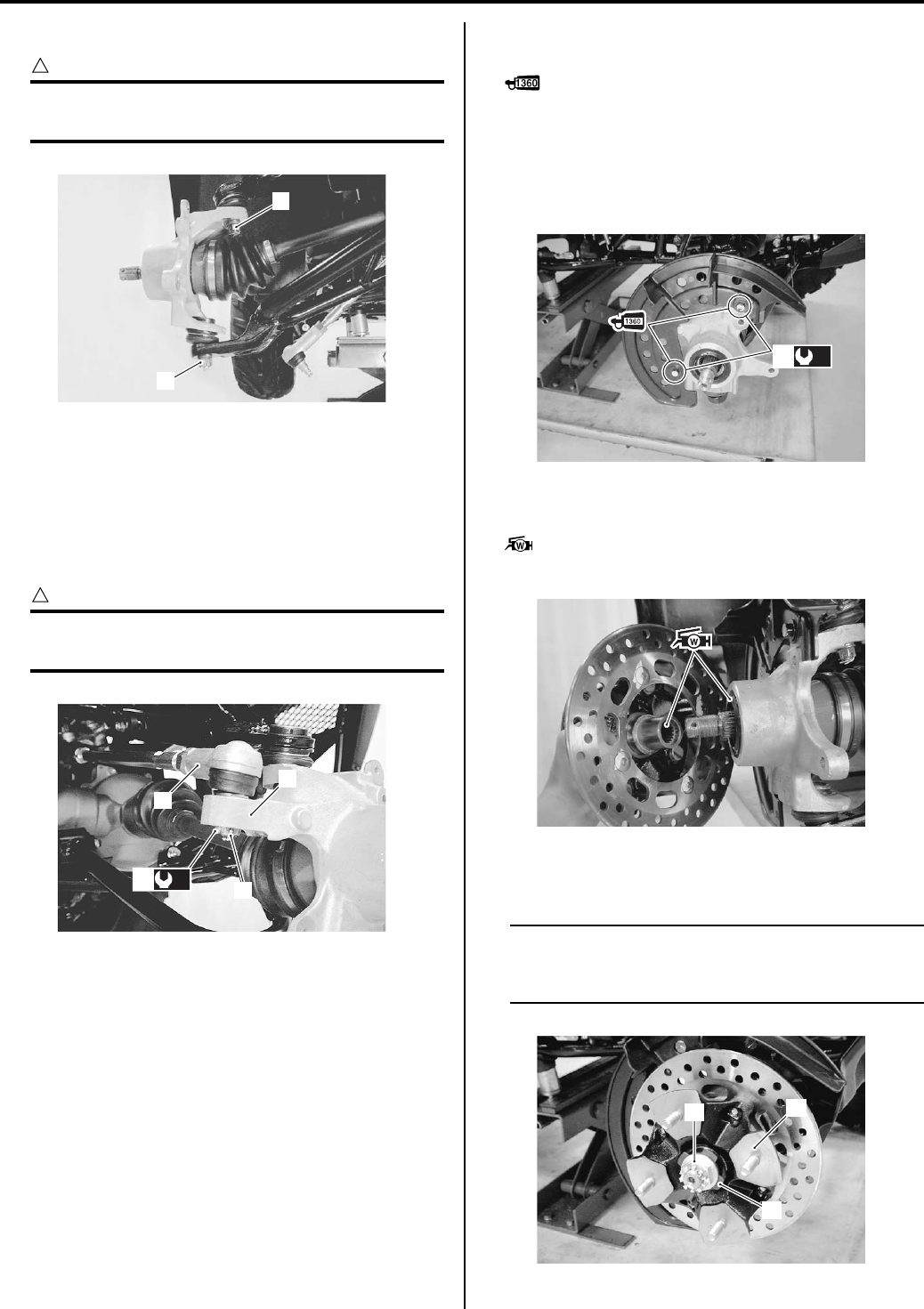
Front Suspension: 2B-6
• Install the cotter pins (4).
CAUTION
!
The removed cotter pins (4) must be replaced
with new ones.
• Connect the tie-rod end (5) to the steering knuckle (6)
and tighten the tie-rod end nut (7) to the specified
torque.
Tightening torque
Tie-rod end nut (b): 29 N·m (2.9 kgf-m, 21.0 lb-ft)
• Install the cotter pin (8).
CAUTION
!
The removed cotter pin (8) must be replaced
with a new one.
• Apply thread lock to the brake disc cover mounting
bolts (9) and tighten them to the specified torque.
: Thread lock cement 99000–32130
(THREAD LOCK CEMENT SUPER 1360 or
equivalent)
Tightening torque
Brake disc cover mounting bolt (c): 10 N·m (1.0
kgf-m, 7.0 lb-ft)
• Apply grease to the wheel hub spline and lip of dust
seal.
: Grease 99000–25160 (Water resistance
grease)
• Install the wheel hub (10), washer (11) and front hub
nut (12).
NOTE
The conical side of washer (11) faces out
side. Refer to “Front Suspension Assembly
Construction (Page 2B-2)”.
4
4
I831G1220018-01
6
8
5
(b)
7
I831G1220019-01
(c)
9
I831G1220020-01
I831G1220021-01
12 10
11
I831G1220022-01
PartShark.com
877-999-5686
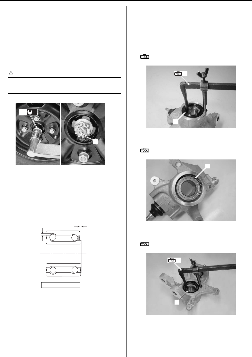
2B-7 Front Suspension:
• Install the brake caliper. Refer to “Front Brake Caliper
Removal and Installation in Section 4B (Page 4B-3)”.
• Install the front wheel assembly. Refer to “Front / Rear
Wheel Removal and Installation in Section 2D
(Page 2D-2)”.
• Tighten the front hub nut (13) to the specified torque.
Tightening torque
Front hub nut (d): 110 N·m (11.0 kgf-m, 79.5 lb-ft)
• Install the cotter pin (14).
CAUTION
!
The removed cotter pin (14) must be replaced
with a new one.
Front Hub Bearing Inspection
B831G22206008
Inspect the inner race play of the front hub bearing by
hand while they are in the steering knuckle.
Rotate the inner races by hand to inspect for abnormal
noise and smooth rotation. If there is anything unusual,
replace the front hub bearing with a new one.
Front Hub Bearing Removal and Installation
B831G22206009
Refer to “Front Wheel Hub / Steering Knuckle Removal
and Installation (Page 2B-4)”.
Removal
1) Remove the outer dust seal (1) with the special tool.
Special tool
(A): 09913–50121 (Oil seal remover)
2) Remove the snap ring (2) with the special tool.
Special tool
: 09900–06108 (Snap ring pliers)
3) Remove the inner dust seal (3) with the special tool.
Special tool
(A): 09913–50121 (Oil seal remover)
“a”: Play
14
(d)
13
I831G1220023-02
“a”
“a”
I831G1220024-02
(A)
1
I831G1220025-03
2
I831G1220026-02
3
(A)
I831G1220027-02
PartShark.com
877-999-5686
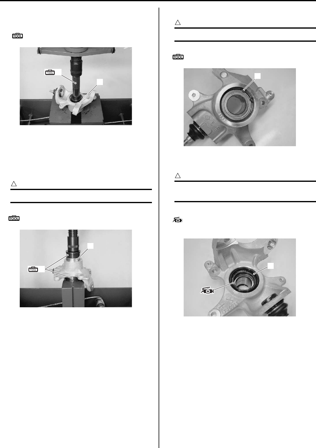
Front Suspension: 2B-8
4) Remove the wheel hub bearing (4), using the
hydraulic press and special tool.
Special tool
(B): 09913–70210 (Bearing installer set)
Installation
Install the wheel hub bearing in the reverse order of
removal. Pay attention to the following points:
• Install the wheel hub bearing (1), using the hydraulic
press and special tool.
CAUTION
!
Never reuse wheel hub bearing (1).
Special tool
(A): 09913–70210 (Bearing installer set)
• Install the snap ring (2) with the special tool.
CAUTION
!
Never reuse snap ring (2).
Special tool
: 09900–06108 (Snap ring pliers)
• Install a new inner dust seal (3) using a suitable size
socket wrench.
CAUTION
!
Replace the inner dust seal (3) with a new
one.
• Apply grease to the lip of inner dust seal.
: Grease 99000–25160 (Water resistance
grease)
(B)
4
I831G1220028-02
1
(A)
I831G1220029-03
2
I831G1220032-02
3
I831G1220030-02
PartShark.com
877-999-5686
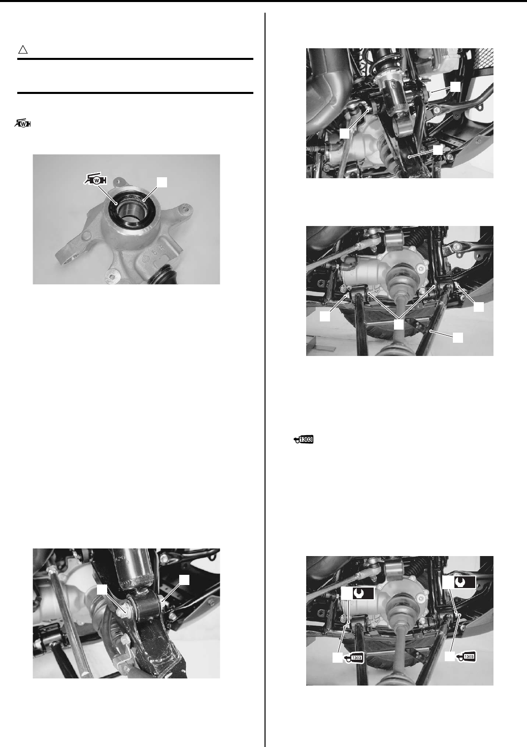
2B-9 Front Suspension:
• Install a new outer dust seal (4) using a suitable size
socket wrench.
CAUTION
!
Replace the outer dust seal (4) with a new
one.
• Apply grease to the lip of outer dust seal (4).
: Grease 99000–25160 (Water resistance
grease)
Front Suspension Upper / Lower Arm Removal
and Installation
B831G22206010
Removal
1) Remove the front wheel assembly. Refer to “Front /
Rear Wheel Removal and Installation in Section 2D
(Page 2D-2)”.
2) Remove the inner fender. Refer to “Front Side
Exterior Parts Removal and Installation in Section
9D (Page 9D-6)”.
3) Disconnect the brake hose. Refer to “Front Brake
Hose Removal and Installation in Section 4A
(Page 4A-7)”.
4) Remove the steering knuckle. Refer to “Front Wheel
Hub / Steering Knuckle Removal and Installation
(Page 2B-4)”.
5) Remove the shock absorber mounting lower bolt (1)
and nut (2).
6) Remove the suspension upper arm (3) by removing
the suspension upper bolt (4) and pivot nut (5).
7) Remove the suspension lower arm (6) by removing
suspension lower bolts (7) and pivot nuts (8).
Installation
1) Apply thread lock to the suspension arm bolts
(lower) (1).
: Thread lock cement 99000–32030
(THREAD LOCK CEMENT SUPER 1303 or
equivalent)
2) Tighten the suspension arm pivot nuts (lower) (2) to
the specified torque.
Tightening torque
Suspension arm pivot nut (Lower) (a): 65 N·m (
6.5 kgf-m, 47.0 lb-ft)
4
I831G1220031-02
1
2
I831G1220033-01
3
5
4
I831G1220034-01
6
7
8
8
I831G1220035-01
1
(a)
2
1
(a)
2
I831G1220036-02
PartShark.com
877-999-5686
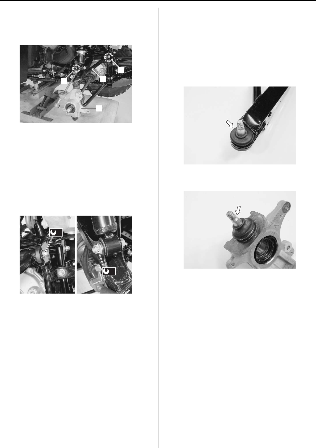
Front Suspension: 2B-10
3) Set the steering knuckle (3) and install the
suspension upper arm (4).
4) Temporarily tighten the suspension arm pivot nut
(upper) (5) and shock absorber mounting nut (6).
5) Tighten the steering knuckle end nut and tie-rod end
nut, and then install the wheel hub. Refer to “Front
Wheel Hub / Steering Knuckle Removal and
Installation (Page 2B-4)”.
6) Tighten the nuts to the specified torque.
Tightening torque
Suspension arm pivot nut (Upper) (b): 60 N·m (
6.0 kgf-m, 43.5 lb-ft)
Shock absorber mounting nut (c): 60 N·m (6.0
kgf-m, 43.5 lb-ft)
7) Install the brake hose. Refer to “Front Brake Hose
Removal and Installation in Section 4A (Page 4A-7)”.
Install the inner fender. Refer to “Front Side Exterior
Parts Removal and Installation in Section 9D
(Page 9D-6)”.
9) Install the front wheel assembly. Refer to “Front /
Rear Wheel Removal and Installation in Section 2D
(Page 2D-2)”.
Steering Knuckle End Inspection
B831G22206011
• Inspect the steering knuckle end for wear or damage.
If any defects are found, replace the front lower
knuckle end with a new one.
• Inspect front lower knuckle end for movement. If there
are any abnormalities, replace the front lower knuckle
end with a new one.
UPPER
LOWER
3
5
64
I831G1220037-02
(c)
(b)
I831G1220038-02
I831G1220039-01
I831G1220040-01
PartShark.com
877-999-5686
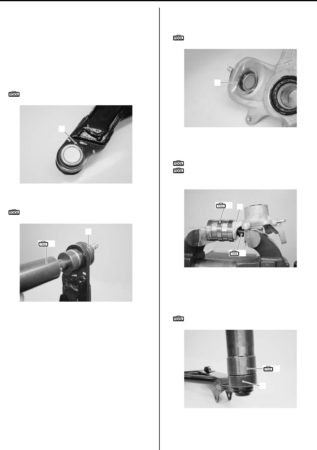
2B-11 Front Suspension:
Steering Knuckle End Removal and Installation
B831G22206012
Refer to “Front Wheel Hub / Steering Knuckle Removal
and Installation (Page 2B-4)” and “Front Suspension
Upper / Lower Arm Removal and Installation (Page 2B-
9)”.
Removal
Upper
• Remove the snap ring (1) with the special tool.
Special tool
: 09900–06107 (Snap ring pliers)
• Remove the knuckle end (2) with the special tool.
Special tool
(A): 09913–70210 (Bearing installer set)
Lower
• Remove the snap ring (1) with the special tool.
Special tool
: 09900–06107 (Snap ring pliers)
• Remove the front lower knuckle end (2) with the
special tools and vise as shown in the figure.
Special tool
(A): 09913–70210 (Bearing installer set)
(B): 09941–53610 (Front fork installer
hammer)
Installation
Upper
• Install the knuckle end (1) with the special tool.
Special tool
(A): 09913–70210 (Bearing installer set)
1
I831G1220041-01
(A)
2
I831G1220042-01
1
I831G1220043-01
(A)
(B) 2
I831G1220044-02
1
(A)
I831G1220045-01
PartShark.com
877-999-5686
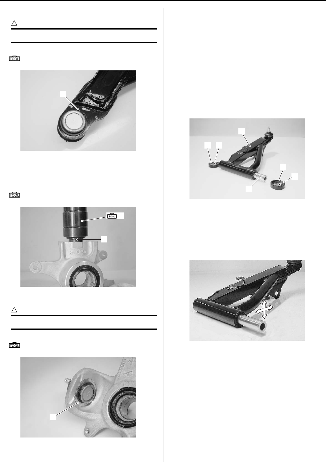
Front Suspension: 2B-12
• Install the snap ring (2) with the special tool.
CAUTION
!
Replace the snap ring (2) with a new one.
Special tool
: 09900–06107 (Snap ring pliers)
Lower
• Install the knuckle end (1) with the special tool.
Special tool
(A): 09913–70210 (Bearing installer set)
• Install the snap ring (2) with the special tool.
CAUTION
!
Replace the snap ring (2) with a new one.
Special tool
: 09900–06107 (Snap ring pliers)
Front Suspension Arm Related Parts Inspection
B831G22206013
Refer to “Front Suspension Upper / Lower Arm Removal
and Installation (Page 2B-9)”.
Upper arm
1) Inspect the following parts for wear or damage. If any
defects are found, replace defective parts with new
ones.
• Upper arm (1)
• Dust seal (2)
• Washer (3)
• Spacer (4)
2) Insert the spacer into bushings.
3) Check the play by moving the spacer up and down. If
excessive play is noted, replace the bushing with a
new one. Refer to “Front Suspension Upper Arm
Bushing and Inner Dust Seal Removal and
Installation (Page 2B-13)”.
2
I831G1220047-01
(A)
1
I831G1220046-01
2
I831G1220048-01
2
2
3
4
3
1
I831G1220049-02
I831G1220050-02
PartShark.com
877-999-5686
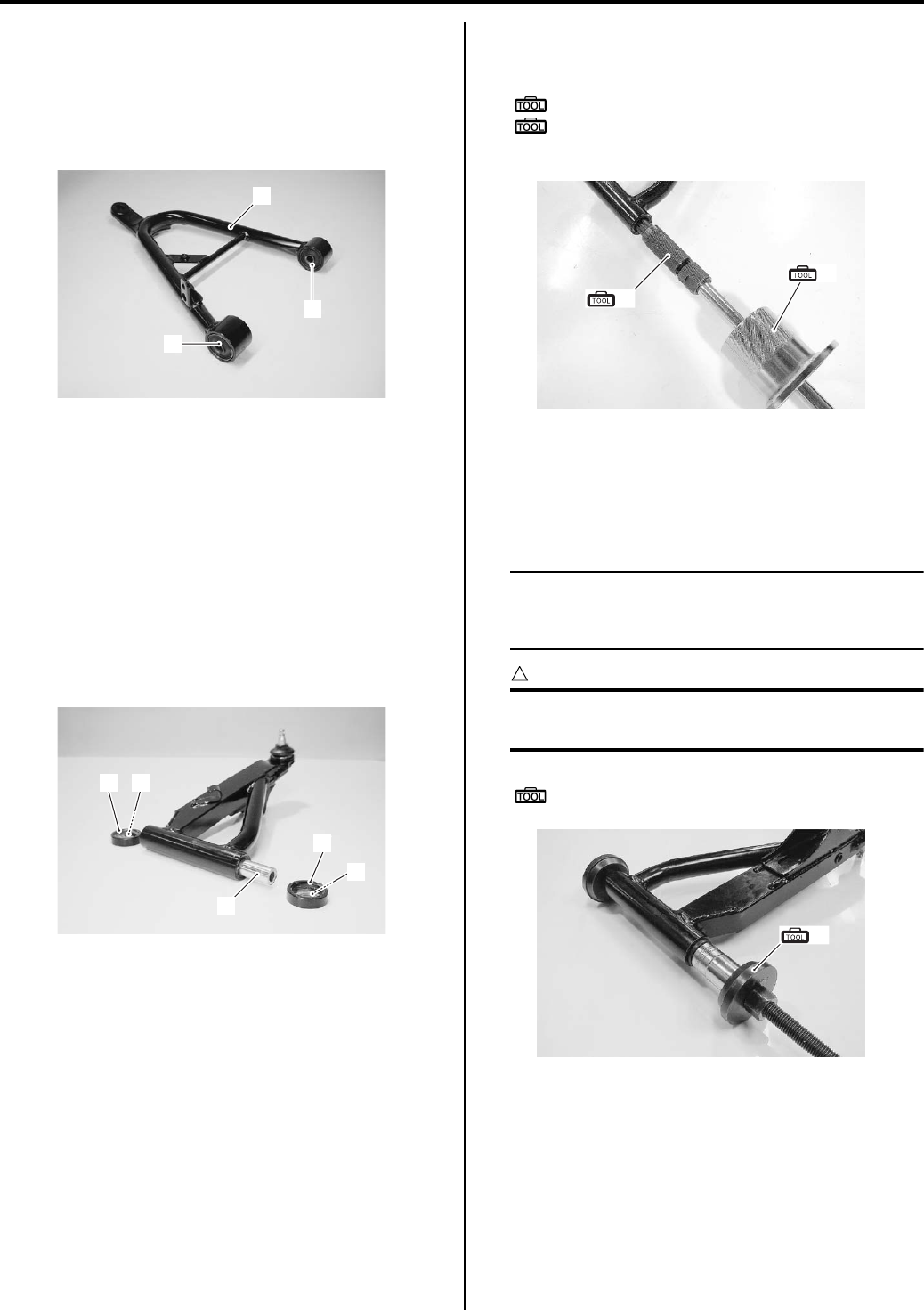
2B-13 Front Suspension:
Lower arm
Inspect the front lower arm (1) and bushings (2) for bend
or damage. If any defects are found, replace the
defective parts with new ones. Refer to “Front
Suspension Lower Arm Bushing Removal and
Installation (Page 2B-14)”.
Front Suspension Upper Arm Bushing and
Inner Dust Seal Removal and Installation
B831G22206014
Refer to “Front Suspension Upper / Lower Arm Removal
and Installation (Page 2B-9)”.
Removal
1) Remove the following parts from the front upper arm.
• Dust seal (1)
•Washer (2)
• Spacer (3)
2) Remove the front upper arm bushings along with
inner dust seals.
Special tool
(A): 09923–73210 (Bearing remover)
(B): 09930–30104 (Rotor remover slide
shaft)
Installation
1) Install the front upper arm bushings and inner dust
seals with the special tool and suitable socket
wrench.
NOTE
Position the bushings and dust seals by
referring to “Front Suspension Assembly
Construction (Page 2B-2)”.
CAUTION
!
The removed bushings and dust seals must
be replaced with new ones.
Special tool
(A): 09941–34513 (Steering race installer)
1
2
2
I831G1220051-01
1
1
2
3
2
I831G1220052-01
(A)
(B)
I831G1220053-01
(A)
I831G1220054-01
PartShark.com
877-999-5686
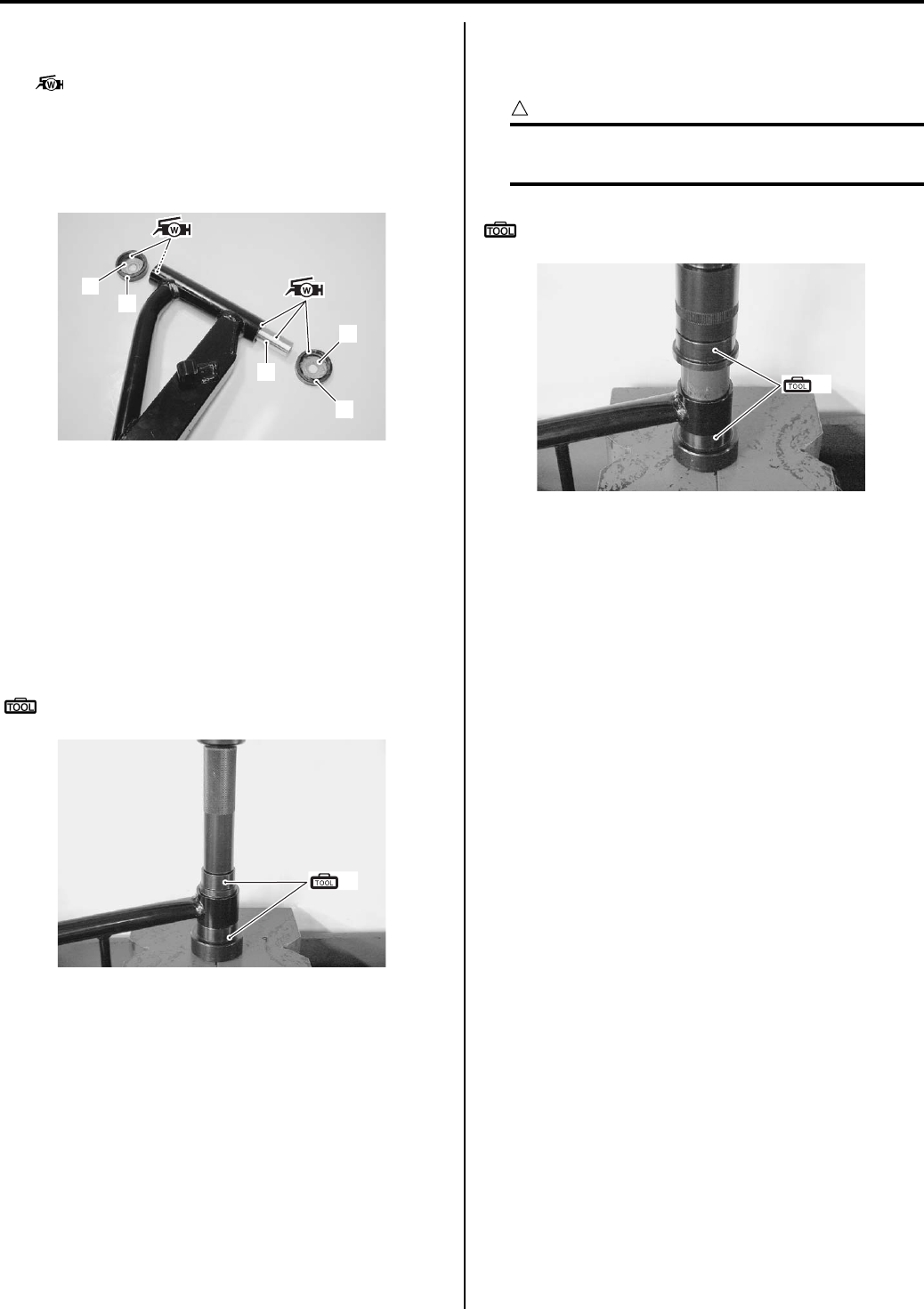
Front Suspension: 2B-14
2) Apply grease to the lip of inner dust seals, spacer (1)
and inside of dust seals (2).
: Grease 99000–25160 (Water resistance
grease)
3) Install the washers (3) to the dust seals (2) and
install the spacer (1) and dust seals (2) to the front
suspension upper arm.
Front Suspension Lower Arm Bushing Removal
and Installation
B831G22206015
Refer to “Front Suspension Upper / Lower Arm Removal
and Installation (Page 2B-9)”.
Removal
Remove the front suspension lower arm bushings with
the special tool and hydraulic press.
Special tool
(A): 09913–70210 (Bearing installer set)
Installation
Install the front suspension lower arm bushings with the
special tool and hydraulic press.
CAUTION
!
The removed bushings must be replaced
with a new one.
Special tool
(A): 09913–70210 (Bearing installer set)
1
2
3
3
2
I831G1220055-01
(A)
I831G1220056-01
(A)
I831G1220057-01
PartShark.com
877-999-5686
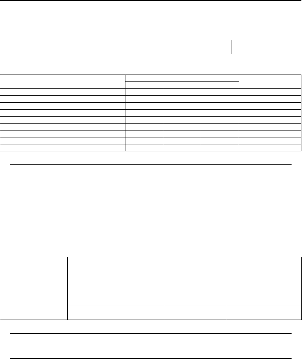
2B-15 Front Suspension:
Specifications
Service Data
B831G22207001
Suspension
Tightening Torque Specifications
B831G22207002
NOTE
The specified tightening torque is also described in the following.
“Front Suspension Components (Page 2B-1)”
“Front Suspension Assembly Construction (Page 2B-2)”
Reference:
For the tightening torque of fastener not specified in this section, refer to “Tightening Torque List in Section 0C
(Page 0C-7)”.
Special Tools and Equipment
Recommended Service Material
B831G22208001
NOTE
Required service material is also described in the following.
“Front Suspension Components (Page 2B-1)”
“Front Suspension Assembly Construction (Page 2B-2)”
Item Standard Limit
Front shock absorber spring adjustor 2/5 position —
Fastening part Tightening torque Note
N⋅mkgf—mlb—ft
Front shock absorber mounting bolt (Upper) 55 5.5 40.0 )(Page 2B-3)
Front shock absorber mounting nut (Lower) 60 6.0 43.5 )(Page 2B-3)
Steering knuckle end nut 29 2.9 21.0 )(Page 2B-5)
Tie-rod end nut 29 2.9 21.0 )(Page 2B-6)
Brake disc cover mounting bolt 10 1.0 7.0 )(Page 2B-6)
Front hub nut 110 11.0 79.5 )(Page 2B-7)
Suspension arm pivot nut (Lower) 65 6.5 47.0 )(Page 2B-9)
Suspension arm pivot nut (Upper) 60 6.0 43.5 )(Page 2B-10)
Shock absorber mounting nut 60 6.0 43.5 )(Page 2B-10)
Material SUZUKI recommended product or Specification Note
Grease Water resistance grease P/No.: 99000–25160 )(Page 2B-5) / )(Page 2B-
6) / )(Page 2B-8) /
)(Page 2B-9) / )(Page 2B-
14)
Thread lock cement THREAD LOCK CEMENT SUPER
1303 or equivalent
P/No.: 99000–32030 )(Page 2B-9)
THREAD LOCK CEMENT SUPER
1360 or equivalent
P/No.: 99000–32130 )(Page 2B-6)
PartShark.com
877-999-5686
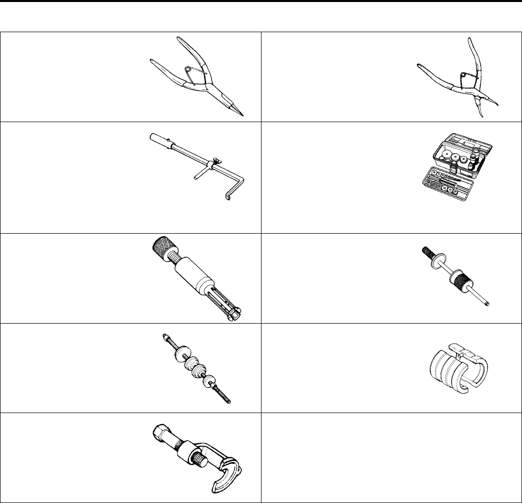
Front Suspension: 2B-16
Special Tool
B831G22208002
09900–06107 09900–06108
Snap ring pliers Snap ring pliers
)(Page 2B-11) /
)(Page 2B-11) /
)(Page 2B-12) /
)(Page 2B-12)
)(Page 2B-7) / )(Page 2B-
09913–50121 09913–70210
Oil seal remover Bearing installer set
)(Page 2B-7) / )(Page 2B-
7)
)(Page 2B-8) / )(Page 2B-
/ )(Page 2B-11) /
)(Page 2B-11) /
)(Page 2B-11) /
)(Page 2B-12) /
)(Page 2B-14) /
)(Page 2B-14)
09923–73210 09930–30104
Bearing remover Rotor remover slide shaft
)(Page 2B-13) )(Page 2B-13)
09941–34513 09941–53610
Steering race installer Front fork installer hammer
)(Page 2B-13) )(Page 2B-11)
09942–72410
Tie rod end remover
)(Page 2B-5)
PartShark.com
877-999-5686
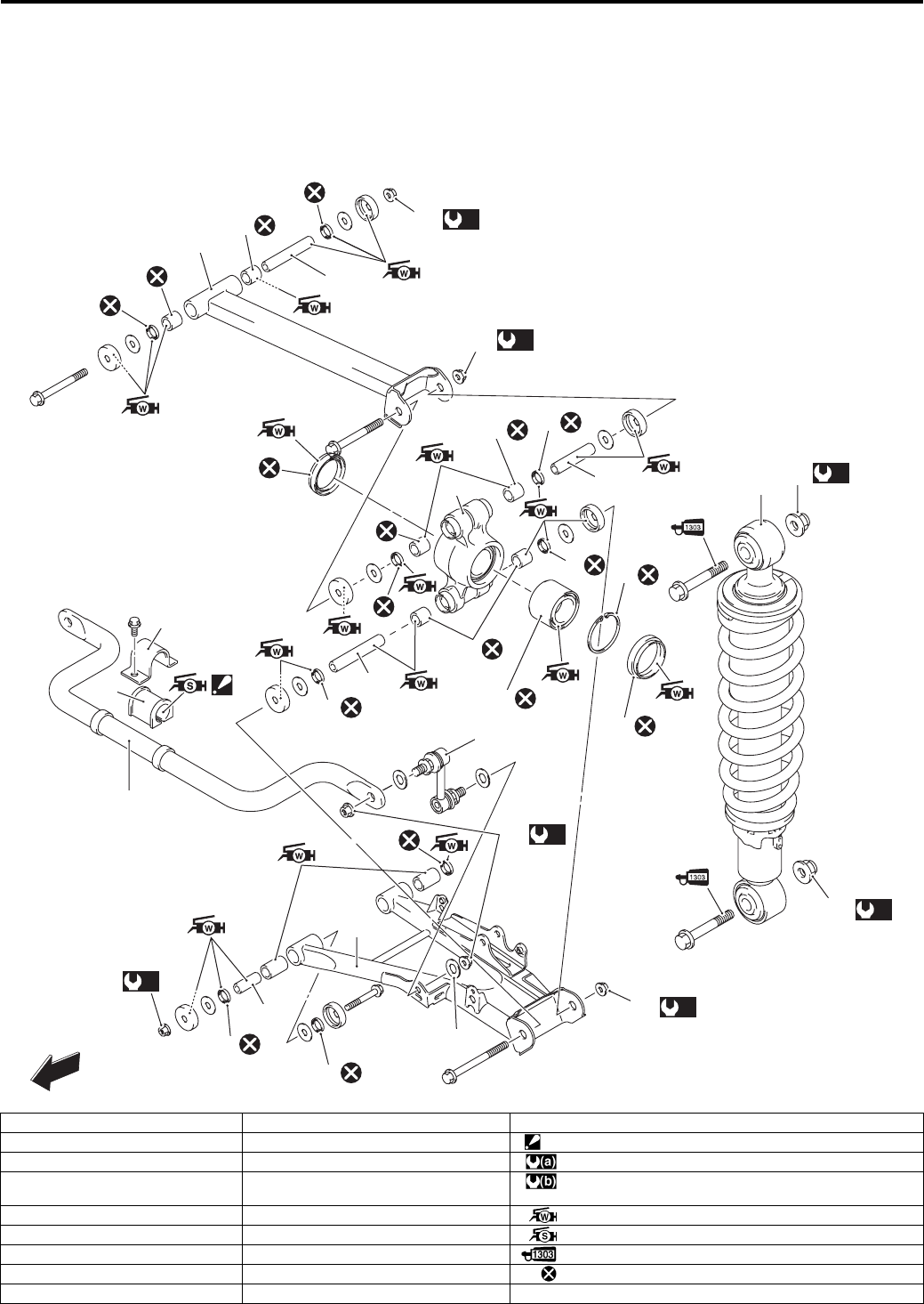
2C-1 Rear Suspension:
Suspension
Rear Suspension
Repair Instructions
Rear Suspension Components
B931G22306001
7
6
8
(a)
16
14
(a)
18
2
4
3
7
(a)
15
1
(a)
16
9
7
(a)
18
(b)
17
(a)
15
12
10
13
11
5
FWD
7
8
9
14
7
8
8
9
8
9
8
8
8
78
“A”
19
I931G1230003-02
1. Rear shock absorber 10. Rear suspension arm (lower) 19. Washer [From 5SAAR41A497105527]
2. Rear stabilizer bar 11. Rear suspension knuckle “A”: Do not apply grease. [From 5SAAR41A197105887]
3. Rear stabilizer bushing 12. Hub bearing : 60 N⋅m (6.0 kgf-m, 43.5 lb-ft)
4. Rear stabilizer bracket 13. Snap ring : Up to 5SAAR41A497105526: 34 N⋅m (3.4 kgf-m, 24.5 lb-ft)
From 5SAAR41A497105527: 60 N⋅m (6.0 kgf-m, 43.5 lb-ft)
5. Rear stabilizer joint 14. Dust seal : Apply water resistance grease.
6. Rear suspension arm (upper) 15. Rear shock absorber mounting nut : Apply silicone grease. [Up to 5SAAR41A197105886]
7. Bushing 16. Rear suspension arm pivot nut : Apply thread lock to thread part.
8. Inner dust seal 17. Rear stabilizer joint nut : Do not reuse.
9. Spacer 18. Rear suspension knuckle nut
PartShark.com
877-999-5686
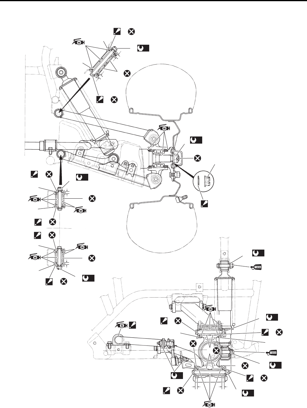
Rear Suspension: 2C-2
Rear Suspension Assembly Construction
B931G22306002
9
9
7
(a)
1
“a”
“a”
8
7
(b)
3
4
3
“a”
“a”
7
8
8
7
7
(c)
12
“a”“a”
9
9
7
7
7
(a)
6
“a” “a” (a)
5
7
9
9
8
(a)
10
(a)
11
(a)
2
9
9
9
9
(a)
2
7
“A”
I931G1230001-04
PartShark.com
877-999-5686
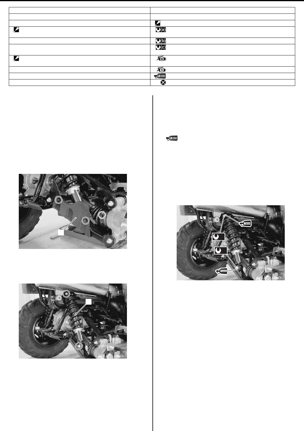
2C-3 Rear Suspension:
Rear Shock Absorber Removal and Installation
B931G22306003
Removal
1) Place the vehicle on level ground and support the
vehicle with a jack.
2) Remove the rear wheel assembly. Refer to “Front /
Rear Wheel Removal and Installation in Section 2D
(Page 2D-2)”.
3) Remove the rear drive shaft cover (1).
4) Remove the shock absorber (2) by removing the
shock absorber upper and lower mounting bolt and
nut.
Installation
Install the rear shock absorber in the reverse order of
removal. Pay attention to the following points:
• Apply thread lock to the rear shock absorber mounting
bolts.
: Thread lock cement 99000–32030
(THREAD LOCK CEMENT SUPER 1303 or
equivalent)
• Tighten the rear shock absorber upper/lower
mounting bolts and nuts.
Tightening torque
Rear shock absorber mounting nut (a): 60 N·m (
6.0 kgf-m, 43.5 lbf-ft)
• Install the rear wheel assembly. Refer to “Front / Rear
Wheel Removal and Installation in Section 2D
(Page 2D-2)”.
1. Rear suspension arm pivot nut (upper) 11. Rear shock absorber mounting nut (lower)
2. Rear suspension arm pivot nut (lower) 12. Stabilizer joint nut
3. Rear wheel hub nut “A”: Do not apply grease. [From 5SAAR41A197105887]
4. Washer
: The conical side of washer faces outside.
:60 N⋅m (6.0 kgf-m, 43.5 lb-ft)
5. Suspension knuckle mounting nut (upper) : 121 N⋅m (12.1 kgf-m, 87.5 lb-ft)
6. Suspension knuckle mounting nut (lower) : Up to 5SAAR41A497105526: 34 N⋅m (3.4 kgf-m, 24.5 lb-ft)
From 5SAAR41A497105527: 60 N⋅m (6.0 kgf-m, 43.5 lb-ft)
7. Inner dust seal
: Align the surface of dust seal with the edge of suspension arm.
: Apply water resistance grease.
8. Bushing : Apply silicone grease. [Up to 5SAAR41A197105886]
9. Outer dust seal : Apply thread lock to the thread part.
10. Rear shock absorber mounting nut (upper) : Do not reuse.
1
I831G1230004-01
2
I831G1230005-01
(a)
(a)
I831G1230062-03
PartShark.com
877-999-5686
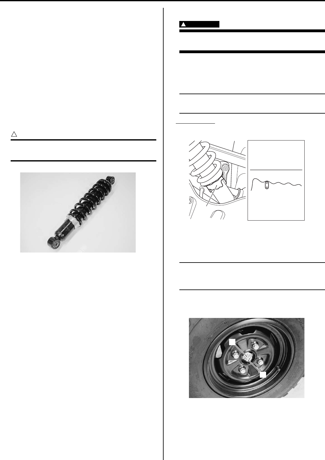
Rear Suspension: 2C-4
Rear Suspension Inspection
B931G22306004
Refer to “Suspensions Inspection in Section 0B
(Page 0B-22)”.
Rear Shock Absorber Inspection
B931G22306005
Inspect the rear shock absorber in the following
procedures:
1) Remove the rear shock absorber. Refer to “Rear
Shock Absorber Removal and Installation (Page 2C-
3)”.
2) Inspect the rear shock absorber for damage and oil
leakage, and absorber bushing for wear or damage.
If any defects are found, replace the rear shock
absorber with a new one.
CAUTION
!
Do not attempt to disassemble the rear shock
absorber. It is unserviceable.
3) Install the rear shock absorber. Refer to “Rear Shock
Absorber Removal and Installation (Page 2C-3)”.
Spring Pre-load Adjustment
B931G22306006
WARNING
!
Be sure to adjust the spring pre-load on the
both suspensions equally.
After installing the rear suspension, adjust the spring
pre-load as follows:
• Turn the spring tension ring (1) to the desired position.
NOTE
Position 1 provides the softest spring tension
and position 5 provides the stiffest.
STD Position
2nd position
Rear Wheel Hub / Suspension Knuckle Removal
and Installation
B931G22306007
NOTE
The right and left suspension parts are
installed procedure for one side is the same
as that for the other side.
Removal
1) Remove the cotter pin (1) and loosen the hub nut (2).
I831G1230006-01
12345
1
I831G1230063-01
1
2
I831G1230007-01
PartShark.com
877-999-5686
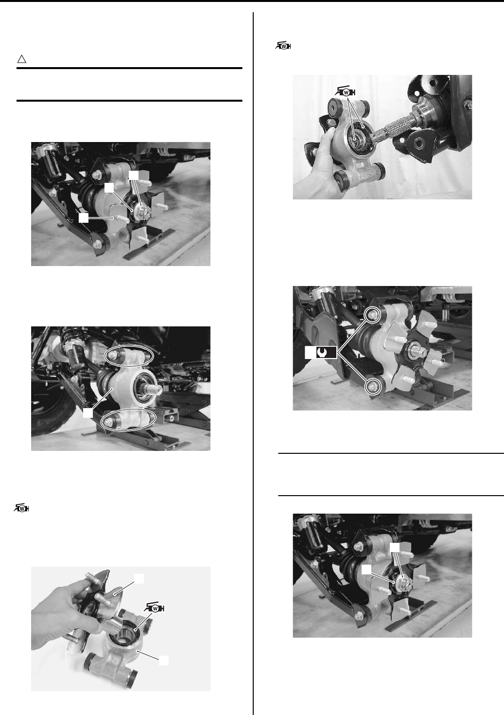
2C-5 Rear Suspension:
2) Remove the rear wheel assembly. Refer to “Front /
Rear Wheel Removal and Installation in Section 2D
(Page 2D-2)”.
CAUTION
!
Make sure that the vehicle is supported
securely.
3) Remove the hub nut (3), washer (4) and rear wheel
hub (5).
4) Remove the suspension knuckle upper and lower
bolts and nuts.
5) Remove the rear suspension knuckle (6).
Installation
• Apply grease to the lip of outer dust seal.
: Grease 99000–25160 (Water resistance
grease or equivalent)
• Install the rear wheel hub (1) to the rear suspension
knuckle (2).
• Apply grease to the lip of outer dust seal and rear
wheel hub spline.
: Grease 99000–25160 (Water resistance
grease or equivalent)
• Tighten the rear knuckle nuts (3) to the specified
torque.
Tightening torque
Rear knuckle end nut (Upper and Lower) (a): 60
N·m (6.0 kgf-m, 43.5 lbf-ft)
• Install the washer (4) and hub nut (5).
NOTE
The conical side of washer (4) faces outside.
Refer to “Rear Suspension Assembly
Construction (Page 2C-2)”.
3
5
4
I831G1230008-01
6
I831G1230009-01
1
2
I831G1230066-01
I831G1230067-01
(a)
3
I831G1230068-01
4
5
I831G1230013-03
PartShark.com
877-999-5686
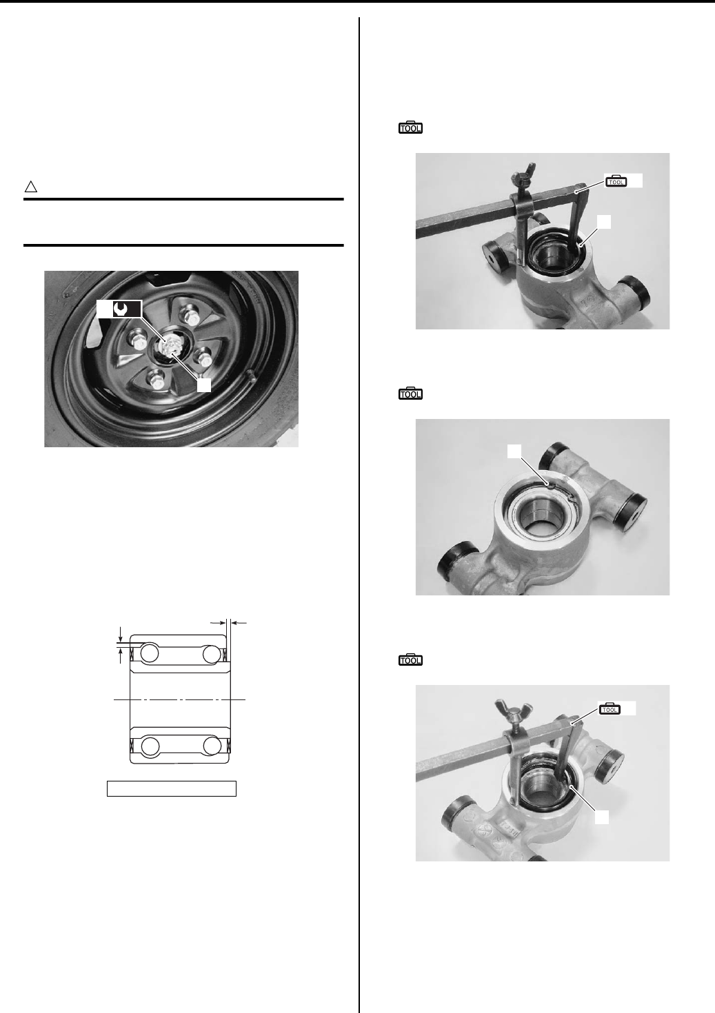
Rear Suspension: 2C-6
• Install the rear wheel assembly. Refer to “Front / Rear
Wheel Removal and Installation in Section 2D
(Page 2D-2)”.
• Tighten the hub nut (5) to the specified torque.
Tightening torque
Rear wheel hub nut (b): 121 N·m (12.1 kgf-m, 87.5
lbf-ft)
• Install the cotter pin (6).
CAUTION
!
The removed cotter pin (6) must be replaced
with a new one.
Rear Hub Bearing Inspection
B931G22306008
Inspect the inner race play of the rear hub bearing by
hand while it is in the rear knuckle.
Rotate the inner race by hand to inspect for abnormal
noise and smooth rotation. If there is anything unusual,
replace the rear hub bearing with a new one.
Rear Hub Bearing Removal and Installation
B931G22306009
Removal
1) Remove the outer dust seal (1) with the special tool.
Special tool
(A): 09913–50121 (Oil seal remover)
2) Remove the snap ring (2) with the special tool.
Special tool
: 09900–06108 (Snap ring pliers)
3) Remove the inner dust seal (3) with the special tool.
Special tool
(A): 09913–50121 (Oil seal remover)
“a”: Play
6
(b)
5
I831G1230014-01
“a”
“a”
I831G1220024-02
1
(A)
I831G1230016-01
2
I831G1230017-01
3
(A)
I831G1230018-01
PartShark.com
877-999-5686
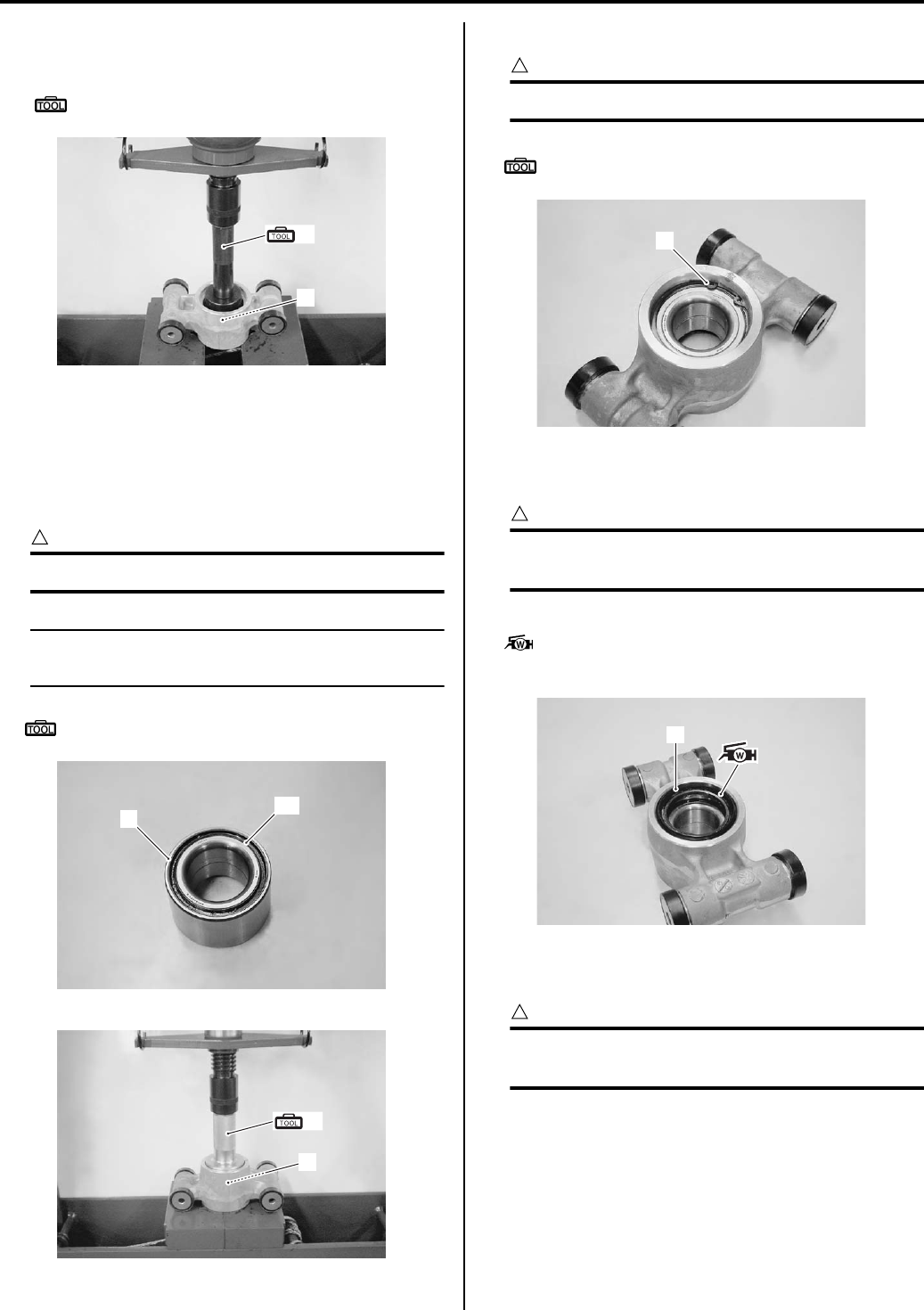
2C-7 Rear Suspension:
4) Remove the hub bearing (4) using the hydraulic
press and special tool.
Special tool
(B): 09913–70210 (Bearing installer set)
Installation
Install the hub bearing in the reverse order of removal.
Pay attention to the following points:
• Install the hub bearing (1) using the hydraulic press
and special tool.
CAUTION
!
Never reuse wheel hub bearing.
NOTE
The sealed side “A” of hub bearing (1) faces
inside.
Special tool
(A): 09913–75520 (Bearing installer)
• Install the snap ring (2) with the special tool.
CAUTION
!
Never reuse snap ring (2).
Special tool
: 09900–06108 (Snap ring pliers)
• Install a new inner dust seal (3) using a suitable size
socket wrench.
CAUTION
!
Replace the inner dust seal (3) with a new
one.
• Apply grease to the lip of inner dust seal (3).
: Grease 99000–25160 (Water resistance
grease or equivalent)
• Install a new outer dust seal (4) using a suitable size
socket wrench.
CAUTION
!
Replace the outer dust seal (4) with a new
one.
(B)
4
I831G1230064-02
1“A”
I831G1230019-01
(A)
1
I831G1230020-01
2
I831G1230021-01
3
I831G1230022-01
PartShark.com
877-999-5686
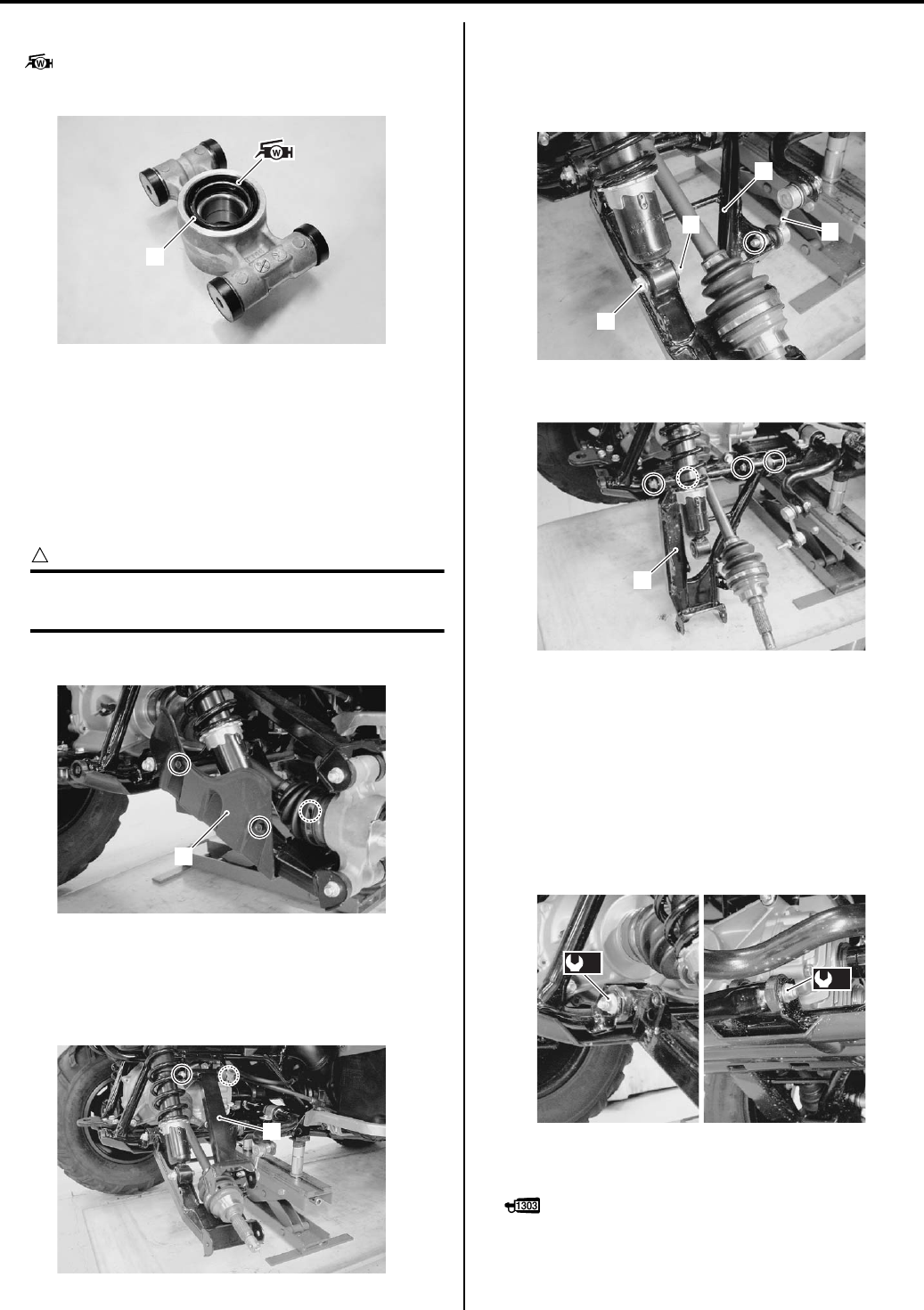
Rear Suspension: 2C-8
• Apply grease to the lip of outer dust seal (4).
: Grease 99000–25160 (Water resistance
grease or equivalent)
Rear Suspension Arm Upper / Lower Removal
and Installation
B931G22306010
Removal
1) Remove the rear wheel assembly. Refer to “Front /
Rear Wheel Removal and Installation in Section 2D
(Page 2D-2)”.
CAUTION
!
Make sure that the vehicle is supported
securely.
2) Remove the rear drive shaft cover (1).
3) Remove the rear suspension knuckle. Refer to “Rear
Wheel Hub / Suspension Knuckle Removal and
Installation (Page 2C-4)”.
4) Remove the rear upper suspension arm (2).
5) Disconnect the stabilizer joint (3) from the rear
suspension lower arm (4).
6) Remove the shock absorber mounting lower bolt (5)
and nut (6).
7) Remove the rear suspension lower arm (4).
Installation
Install the suspension arms in the reverse order of
removal. Pay attention to the following points.
• Tighten the suspension arm pivot nuts to the specified
torque.
Tightening torque
Suspension arm lower pivot nut (a): 60 N·m (6.0
kgf-m, 43.5 lbf-ft)
• Apply thread lock to the shock absorber mounting
bolts.
: Thread lock cement 99000–32030
(THREAD LOCK CEMENT SUPER 1303 or
equivalent)
4
I831G1230023-02
1
I831G1230024-01
2
I831G1230025-01
3
5
6
4
I831G1230026-01
4
I831G1230027-02
(a)
(a)
I831G1230028-01
PartShark.com
877-999-5686
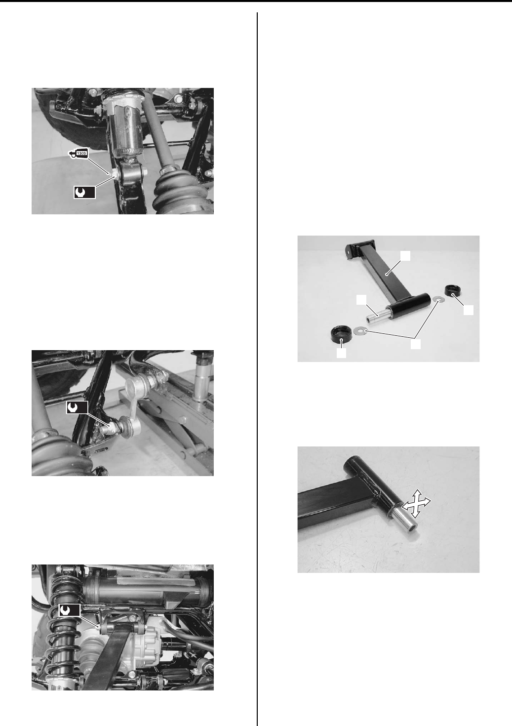
2C-9 Rear Suspension:
• Tighten the shock absorber mounting lower bolt and
nut to the specified torque.
Tightening torque
Rear shock absorber mounting nut (b): 60 N·m (
6.0 kgf-m, 43.5 lbf-ft)
• Connect the stabilizer joint by tightening the joint nut
to the specified torque.
Tightening torque
Rear stabilizer joint nut [Up to
5SAAR41A497105526] (c): 34 N·m (3.4 kgf-m, 24.5
lbf-ft)
Rear stabilizer joint nut [From
5SAAR41A497105527] (c): 60 N·m (6.0 kgf-m, 43.5
lbf-ft)
• Tighten the suspension arm upper bolt and pivot nut
to the specified torque.
Tightening torque
Suspension arm upper pivot nut (d): 60 N·m (6.0
kgf-m, 43.5 lbf-ft)
• Install the rear suspension knuckle arm and wheel
hub. Refer to “Rear Wheel Hub / Suspension Knuckle
Removal and Installation (Page 2C-4)”.
Rear Suspension Arm Related Parts Inspection
B931G22306011
Refer to “Rear Suspension Arm Upper / Lower Removal
and Installation (Page 2C-8)”.
Upper Arm
1) Inspect the following parts for wear or damage. If any
defects are found, replace defective parts with new
ones.
• Suspension upper arm (1)
• Dust seal (2)
• Washer (3)
• Spacer (4)
2) Insert the spacer into bushings.
3) Check the play by moving the spacer up and down. If
excessive play is noted, replace the bushings with a
new one. Refer to “Rear Suspension Upper Arm
Bushing Removal and Installation (Page 2C-11)”.
(b)
I831G1230029-02
(c)
I831G1230030-01
(d)
I831G1230031-01
1
2
2
3
4
I831G1230032-01
I831G1230033-02
PartShark.com
877-999-5686
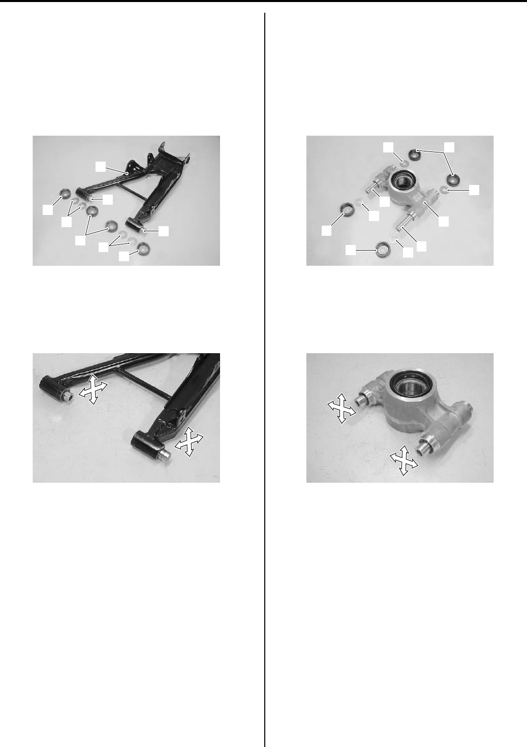
Rear Suspension: 2C-10
Lower Arm
1) Inspect the following parts for wear or damage. If any
defects are found, replace defective parts with new
ones.
• Suspension lower arm (1)
• Dust seal (2)
•Washer (3)
• Spacer (4)
2) Insert the spacer into bushings.
3) Check the play by moving the spacer up and down. If
excessive play is noted, replace the bushings with a
new one. Refer to “Rear Suspension Lower Arm
Bushing Removal and Installation (Page 2C-12)”.
Suspension Knuckle
1) Inspect the following parts for wear or damage. If any
defects are found, replace defective parts with new
ones.
• Suspension knuckle (1)
• Dust seal (2)
• Washer (3)
• Spacer (4)
2) Insert the spacer into bushings.
3) Check the play by moving the spacer up and down. If
excessive play is noted, replace the bushings with a
new one. Refer to “Rear Suspension Upper Arm
Bushing Removal and Installation (Page 2C-11)”.
1
2
2
2
3
4
4
3
I831G1230034-01
I831G1230035-02
3
3
3
3
4
1
4
2
2
2
I831G1230036-02
I831G1230037-02
PartShark.com
877-999-5686
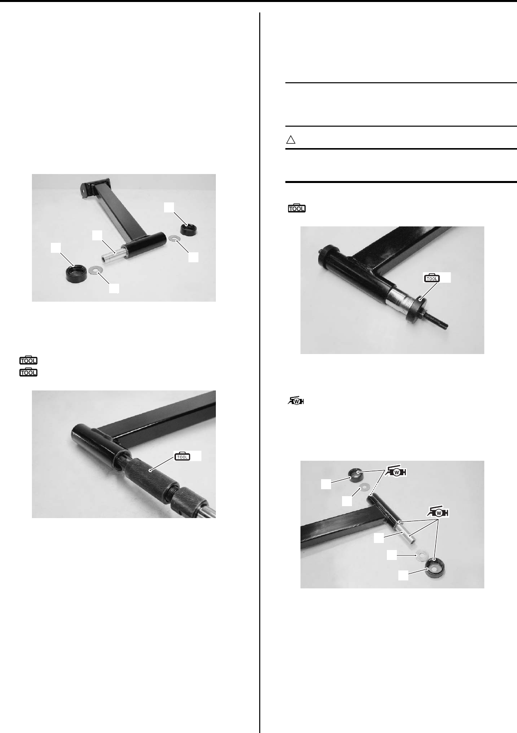
2C-11 Rear Suspension:
Rear Suspension Upper Arm Bushing Removal
and Installation
B931G22306012
Refer to “Rear Suspension Arm Upper / Lower Removal
and Installation (Page 2C-8)”.
Removal
1) Remove the following parts from the rear suspension
upper arm.
• Dust seal (1)
•Washer (2)
• Spacer (3)
2) Remove the rear upper suspension arm bushings
along with inner dust seals with the special tools.
Special tool
(A): 09923–73210 (Bearing remover)
: 09930–30104 (Rotor remover sliding shaft)
Installation
1) Install the rear suspension upper arm bushing and
inner dust seal with the special tool and suitable
socket wrench.
NOTE
Position the bushing and dust seals by
referring to “Rear Suspension Assembly
Construction (Page 2C-2)”.
CAUTION
!
The removed bushings and dust seals must
be replaced with new ones.
Special tool
(A): 09941–34513 (Steering race installer)
2) Apply grease to the lip of inner dust seals, spacer (1)
and inside of dust seals (2).
: Grease 99000–25160 (Water resistance
grease or equivalent)
3) Install the washers (3) and dust seals (2) to the rear
suspension upper arm.
1
1
3
2
2
I831G1230065-01
(A)
I831G1230038-01
(A)
I831G1230039-01
1
2
2
3
3
I831G1230040-01
PartShark.com
877-999-5686
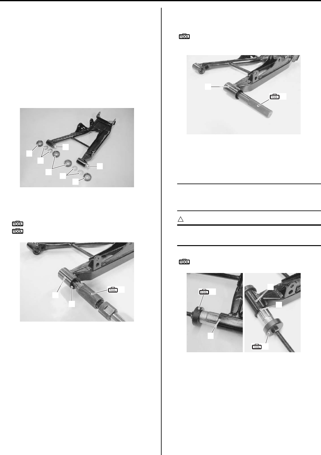
Rear Suspension: 2C-12
Rear Suspension Lower Arm Bushing Removal
and Installation
B931G22306013
Refer to “Rear Suspension Arm Upper / Lower Removal
and Installation (Page 2C-8)”.
Removal
1) Remove the following parts from the rear suspension
lower arm.
• Dust seal (1)
•Washer (2)
• Spacer (3)
2) Remove the rear suspension lower arm bushing (4)
along with inner dust seal (5) with the special tools.
Special tool
(A): 09923–73210 (Bearing remover)
: 09930–30104 (Rotor remover sliding shaft)
3) Remove the another inner dust seal (6) with the
special tool.
Special tool
(B): 09943–88211 (Bearing remover/
installer)
Installation
1) Install the rear lower arm bushings (1) and inner dust
seals (2) with the special tool and suitable socket.
NOTE
Position the bushings and dust seals by
referring to “Rear Suspension Assembly
Construction (Page 2C-2)”.
CAUTION
!
The removed bushings and dust seals must
be replaced with new ones.
Special tool
(A): 09941–34513 (Steering race installer)
3
2
32
3
1
1
I831G1230041-01
(A)
4
5
I831G1230043-03
(B)
6
I831G1230044-03
(A)
2
1
2
(A)
I831G1230045-01
PartShark.com
877-999-5686
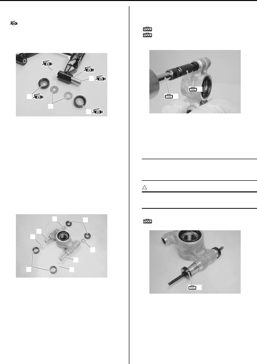
2C-13 Rear Suspension:
2) Apply grease to the lip of inner dust seals, spacer (3)
and inside of dust seals (4).
: Grease 99000–25160 (Water resistance
grease or equivalent)
3) Install the spacer (3), dust seals (4) and washers (5)
to the rear suspension lower arm.
Rear Suspension Knuckle Bushing Removal
and Installation
B931G22306014
Refer to “Rear Wheel Hub / Suspension Knuckle
Removal and Installation (Page 2C-4)”.
Removal
1) Remove the following parts from the suspension
knuckle.
• Dust seal (1)
•Washer (2)
• Spacer (3)
2) Remove the suspension knuckle bushings along
with inner dust seals with the special tools.
Special tool
(A): 09923–73210 (Bearing remover)
(B): 09930–30104 (Rotor remover sliding
shaft)
Installation
1) Install the suspension knuckle bushing and inner
dust seal with the special tool and suitable socket
wrench.
NOTE
Position the bushing s and dust seals by
referring to “Rear Suspension Assembly
Construction (Page 2C-2)”.
CAUTION
!
The removed bushings and dust seals must
be replaced with new ones.
Special tool
(A): 09941–34513 (Steering race installer)
3
5
4
4
I831G1230046-02
1
2
1
2
3
2
2
3
I831G1230047-01
(A)
(B)
I831G1230048-03
(A)
I831G1230049-01
PartShark.com
877-999-5686
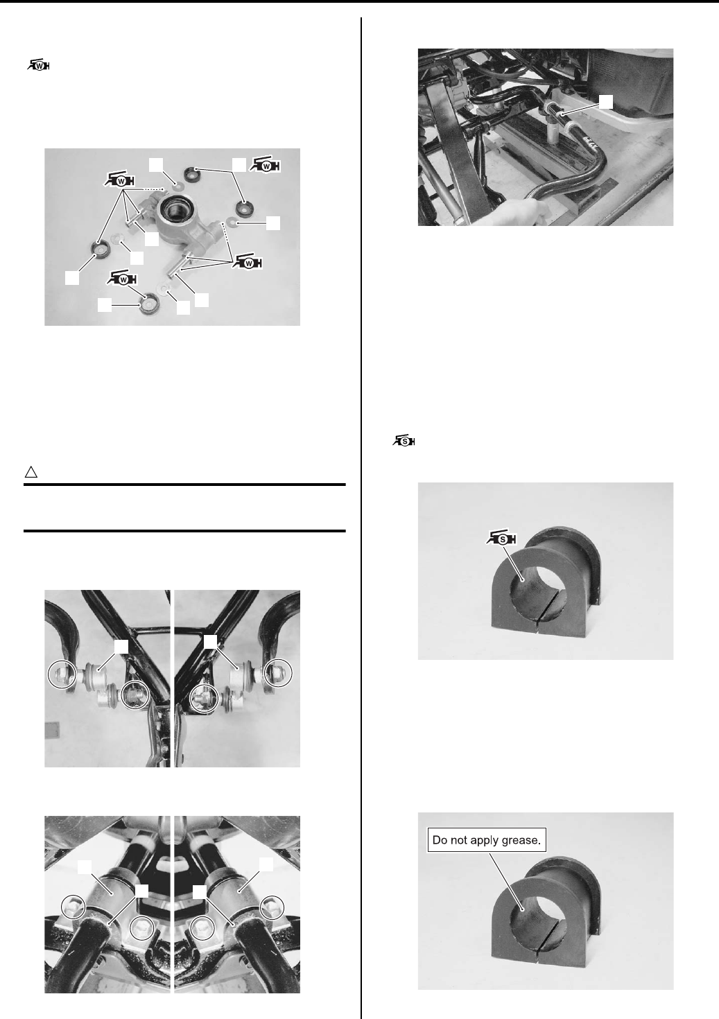
Rear Suspension: 2C-14
2) Apply grease to the lip of the inner dust seals, spacer
(1) and inside of dust seals (2).
: Grease 99000–25160 (Water resistance
grease or equivalent)
3) Install the spacers (1), dust seals (2) and washers
(3) to the rear suspension knuckle.
Rear Stabilizer Removal and Installation
B931G22306015
Removal
1) Remove the rear wheels. Refer to “Front / Rear
Wheel Removal and Installation in Section 2D
(Page 2D-2)”.
CAUTION
!
Make sure that the vehicle is supported
securely.
2) Disconnect the stabilizer joints (1) from the rear
suspension lower arm and stabilizer bar.
3) Remove the stabilizer plates (2) and bushings (3).
4) Remove the stabilizer bar (4).
Installation
Install the stabilizer in the reverse order of removal. Pay
attention to the following points:
Applicable model
Up to 5SAAR41A197105886
Install the stabilizer in the reverse order of removal.
Pay attention to the following points:
• Apply grease to the inside of stabilizer bushing.
: Grease 99000–25100 (SUZUKI SILICONE
GREASE or equivalent)
Applicable model
From 5SAAR41A197105887
Install the stabilizer in the reverse order of removal.
Pay attention to the following points:
• Do not apply grease to the inside of stabilizer bushing.
3
3
3
3
1
1
2
2
2
I831G1230050-01
11
I831G1230055-01
2
3
2
3
I831G1230052-02
4
I831G1230053-01
I831G1230051-03
I931G1230002-02
PartShark.com
877-999-5686
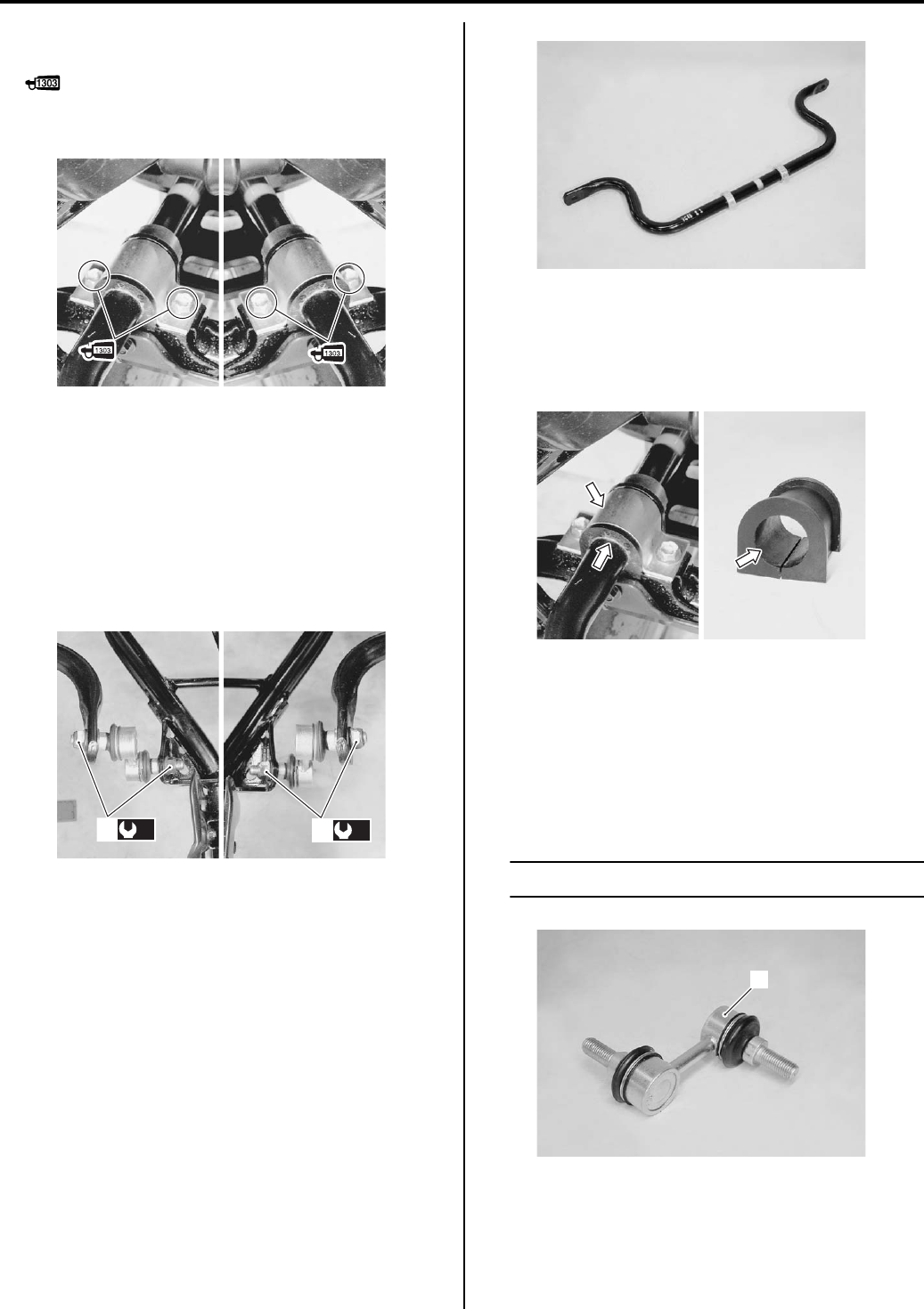
2C-15 Rear Suspension:
• Apply thread lock to the stabilizer plate mounting bolts
and tighten the bolts securely.
: Thread lock cement 99000–32030
(THREAD LOCK CEMENT SUPER 1303 or
equivalent)
• Tighten the stabilizer joint nuts (2) to the specified
torque.
Tightening torque
Rear stabilizer joint nut [Up to
5SAAR41A497105526] (a): 34 N·m (3.4 kgf-m, 24.5
lbf-ft)
Rear stabilizer joint nut [From
5SAAR41A497105527] (a): 60 N·m (6.0 kgf-m, 43.5
lbf-ft)
Stabilizer Parts Inspection
B931G22306016
Refer to “Rear Stabilizer Removal and Installation
(Page 2C-14)”.
Stabilizer Bar
Inspect for damage or deformation. If any defects are
found, replace the stabilizer bar with a new one.
Stabilizer Bushing / Plate
Inspect the bushing and plate for wear or damage. If any
defects are found, replace the bushing and/or plate with
a new one.
Stabilizer Joint
Inspect the stabilizer joint for wear or damage. If any
defects are found, replace the stabilizer joint with a new
one.
Inspect the stabilizer joint smooth movement. If there are
any abnormalities, replace the stabilizer joint with a new
one.
NOTE
Stabilizer joint (1) cannot be disassembled.
I831G1230056-03
(a)
2(a)
2
I831G1230057-01
I831G1230058-01
I831G1230059-01
1
I831G1230060-01
PartShark.com
877-999-5686
Rear Suspension: 2C-16
Specifications
Service Data
B931G22307001
Suspension
Unit: mm (in)
Tightening Torque Specifications
B931G22307002
NOTE
The specified tightening torque is described in the following.
“Rear Suspension Components (Page 2C-1)”
“Rear Suspension Assembly Construction (Page 2C-2)”
Reference:
For the tightening torque of fastener not specified in this section, refer to “Tightening Torque List in Section 0C
(Page 0C-7)”.
Special Tools and Equipment
Recommended Service Material
B931G22308001
NOTE
Required service material is also described in the following.
“Rear Suspension Components (Page 2C-1)”
“Rear Suspension Assembly Construction (Page 2C-2)”
Item Standard Limit
Rear shock absorber spring adjustor 2/5 position —
Fastening part Tightening torque Note
N⋅m kgf-m lbf-ft
Rear shock absorber mounting nut 60 6.0 43.5
)(Page 2C-3) /
)(Page 2C-9)
Rear knuckle end nut (Upper and Lower) 60 6.0 43.5 )(Page 2C-5)
Rear wheel hub nut 121 12.1 87.5 )(Page 2C-6)
Suspension arm lower pivot nut 60 6.0 43.5 )(Page 2C-8)
Rear stabilizer joint nut [Up to
5SAAR41A497105526] 34 3.4 24.5
)(Page 2C-9) /
)(Page 2C-15)
Rear stabilizer joint nut [From
5SAAR41A497105527] 60 6.0 43.5
)(Page 2C-9) /
)(Page 2C-15)
Suspension arm upper pivot nut 60 6.0 43.5 )(Page 2C-9)
Material SUZUKI recommended product or Specification Note
Grease SUZUKI SILICONE GREASE or
equivalent
P/No.: 99000–25100 )(Page 2C-14)
Water resistance grease or
equivalent
P/No.: 99000–25160 )(Page 2C-5) / )(Page 2C-
5) / )(Page 2C-7) /
)(Page 2C-8) / )(Page 2C-
11) / )(Page 2C-13) /
)(Page 2C-14)
Thread lock cement THREAD LOCK CEMENT SUPER
1303 or equivalent
P/No.: 99000–32030 )(Page 2C-3) / )(Page 2C-
/ )(Page 2C-15)
PartShark.com
877-999-5686
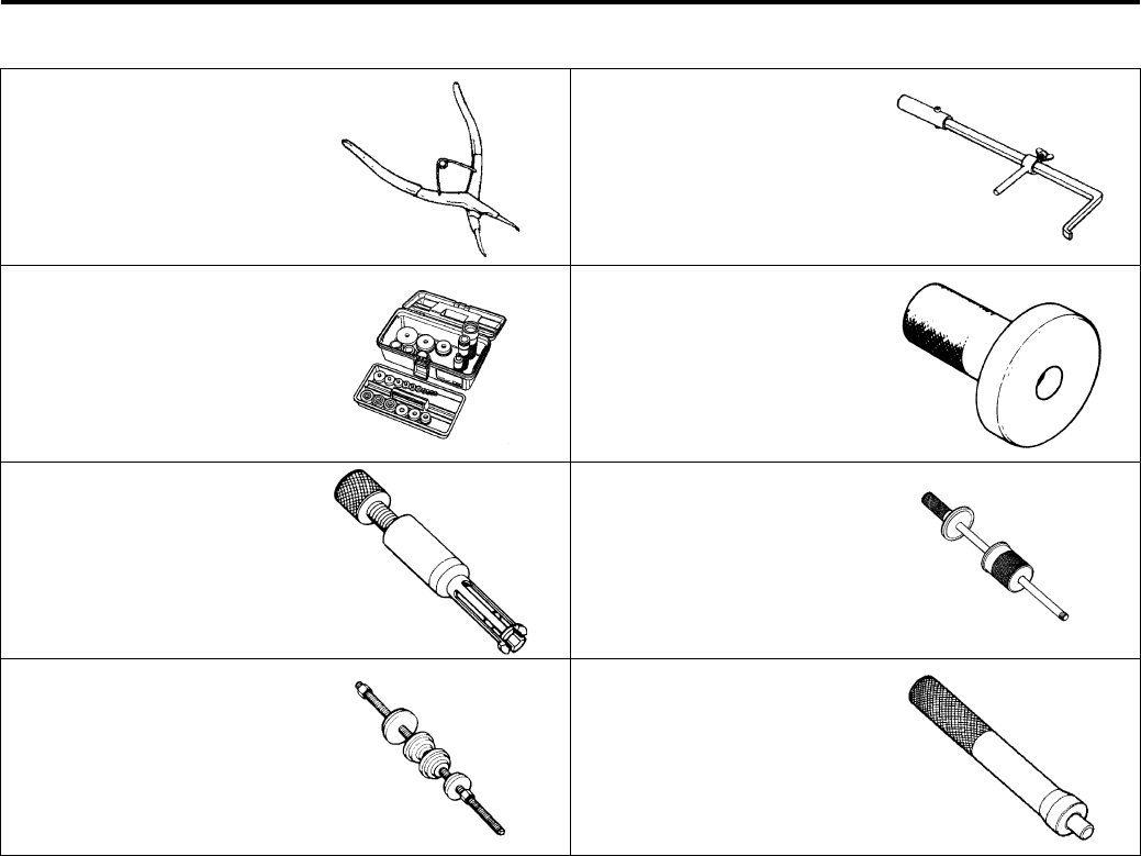
2C-17 Rear Suspension:
Special Tool
B931G22308002
09900–06108 09913–50121
Snap ring pliers Oil seal remover
)(Page 2C-6) / )(Page 2C-
7)
)(Page 2C-6) / )(Page 2C-
6)
09913–70210 09913–75520
Bearing installer set Bearing installer
)(Page 2C-7) )(Page 2C-7)
09923–73210 09930–30104
Bearing remover Rotor remover sliding shaft
)(Page 2C-11) /
)(Page 2C-12) /
)(Page 2C-13)
)(Page 2C-11) /
)(Page 2C-12) /
)(Page 2C-13)
09941–34513 09943–88211
Steering race installer Bearing remover/installer
)(Page 2C-11) /
)(Page 2C-12) /
)(Page 2C-13)
)(Page 2C-12)
PartShark.com
877-999-5686
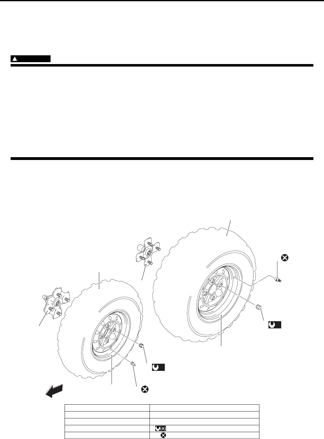
Wheels and Tires: 2D-1
Suspension
Wheels and Tires
Precautions
Precautions for Wheel and Tire
B831G22400001
WARNING
!
• Proper tire pressure and proper tire loading are important factors. Over loading tire can lead to tire
failure and loss of vehicle control.
• Under-inflated tires make smooth cornering difficult, and can result in rapid tire wear.
• Over-inflated tires have a smaller amount of tire in contact with the load, which can contribute to
skidding and loss of control.
• Replace the wheel if find damage such as crack, nick or scratch.
• When tire replacement is necessary, the original equipment type tire should be used.
• Do not mix different types of tires on the same vehicle except in emergencies, because handling
may be seriously affected and may result in loss of control.
• Replacement wheel must be equivalent to the original equivalent wheel.
Repair Instructions
Front and Rear Wheel Components
B831G22406001
1
7
23
(a)
4
(a)
4
6
3
5
8
FWD
I831G1240001-01
1. Front tire 6. Rear wheel
2. Front wheel 7. Front wheel hub
3. Front wheel air valve 8. Rear wheel hub
4. Wheel nut : 60 N⋅m (6.0 kgf-m, 43.5 lb-ft)
5. Rear tire : Do not reuse.
PartShark.com
877-999-5686
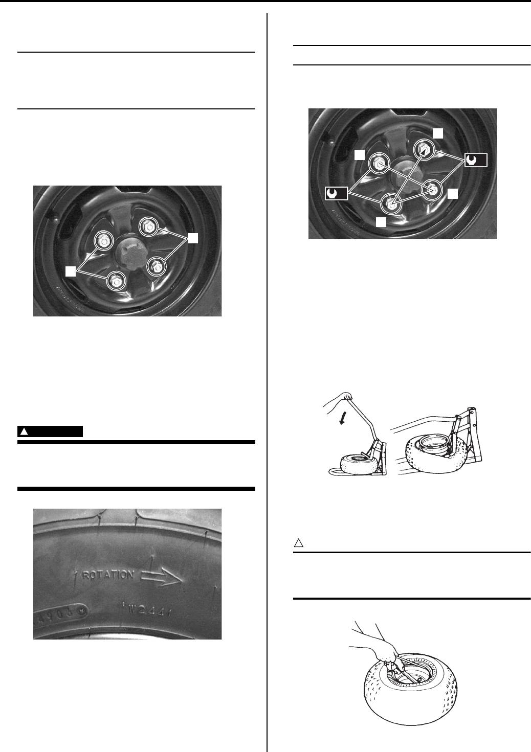
2D-2 Wheels and Tires:
Front / Rear Wheel Removal and Installation
B831G22406002
NOTE
The front and rear wheels are installed
symmetrically and therefore the removal
procedure for one side is the same as that for
the other side.
Removal
1) Place the vehicle on level ground.
2) Support the vehicle with a jack or wooden block.
3) Remove the wheel nuts (1).
4) Remove the wheel.
Installation
Install the wheel in the reverse order of removal. Pay
attention to the following points:
• Install the wheel and tighten the wheel nuts
temporarily.
WARNING
!
The directional arrow on the tire should point
to the wheel rotation, when remounting the
wheel.
• Tighten the wheel nuts to the specified torque.
NOTE
Tighten the wheel nuts diagonally.
Tightening torque
Wheel nut (a): 60 N·m (6.0 kgf-m, 43.5 lb-ft)
Tire Removal and Installation
B831G22406003
1) Remove the wheel from vehicle. Refer to “Front /
Rear Wheel Removal and Installation (Page 2D-2)”.
2) After removing the air valve caps, release the tire
pressure by depressing the valves.
3) Dismount the bead from the rim completely as
shown in the figure.
4) Separate the tire from the rim using a set of tire
levers and rim protectors.
CAUTION
!
When using the tire levers, do not scratch or
hit the sealing portion (hump) of the wheel or
it may cause air-leakage.
1
1
I831G1240002-01
I831G1240003-01
1
2
3
4
(a)
(a)
I831G1240004-01
I831G1240005-01
I831G1240006-01
PartShark.com
877-999-5686
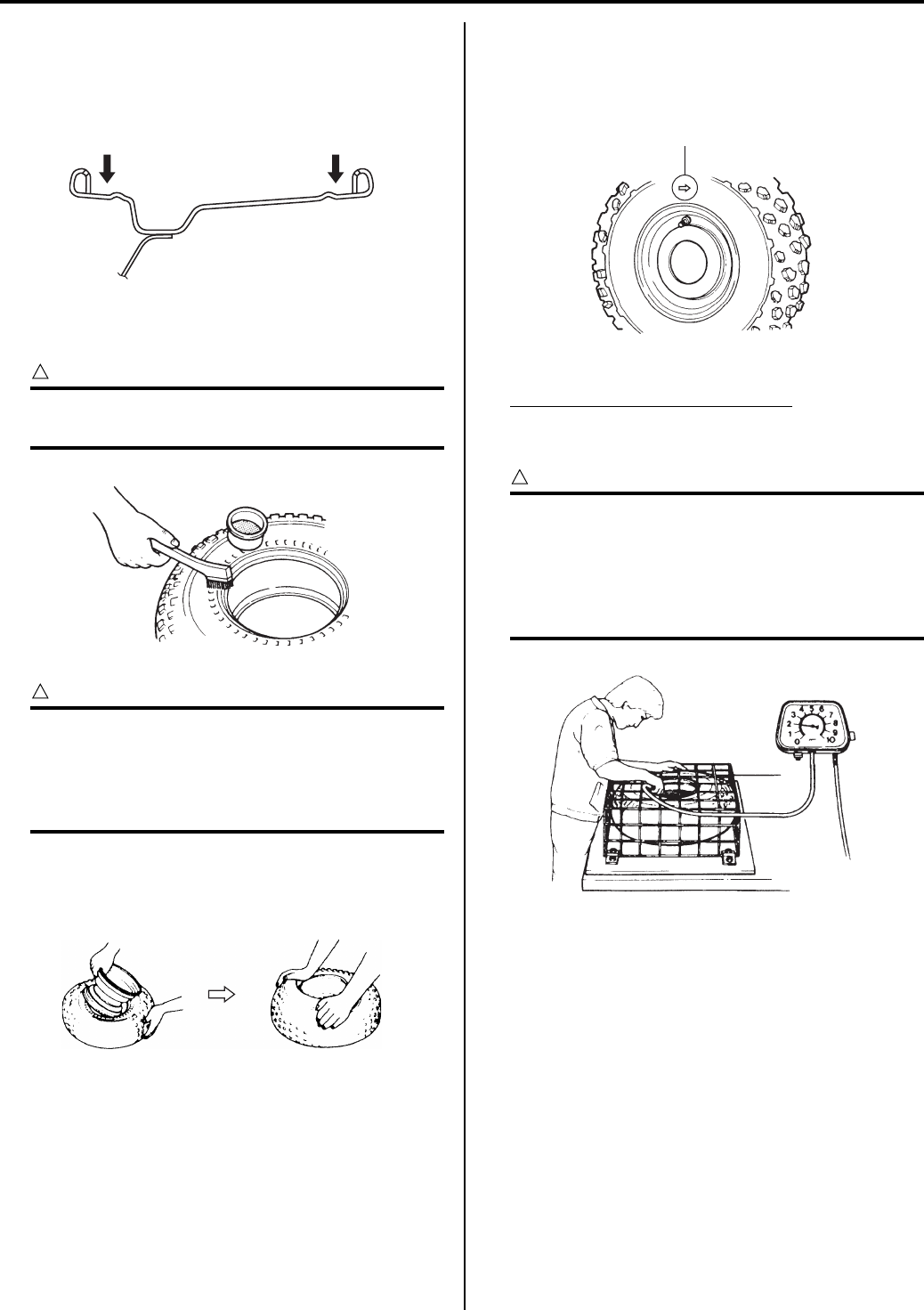
Wheels and Tires: 2D-3
5) After removing the tire, inspect the wheel if
necessary.
Installation
1) Clean up the sealing portion of the rim.
2) Apply tire lubricant to the tire bead and the flange of
the rim.
CAUTION
!
Never apply grease, oil or gasoline to the tire
bead because they will deteriorate the tire.
CAUTION
!
The standard tire fitted on this vehicle is
AT25 x 8-12 for the front and AT25 x 10-
12 for the rear. The use of tires other than
the standard may cause instability. It is highly
recommended to use the specified tire.
3) Mount the tire on the rim by hand as shown in the
figure.
4) When installing each tire, make sure the arrow “A”
on the tire points in the direction of rotation. Also,
make sure the outer side of the wheel rim is facing
outward.
5) Inflate the tire to seat the tire bead.
Maximum tire bead seat pressure
Front: 250 kPa (2.5 kgf/cm2, 36psi)
Rear: 250 kPa (2.5 kgf/cm2, 36 psi)
CAUTION
!
Place the tire under a protective tire cage or
similar protective covering device before
inflating the tire. To minimize the possibility
of tire damage when seating the tire bead,
never exceed the MAXIMUM TIRE BEAD
SEAT PRESSURE rating shown on the tire.
I831G1240007-02
I831G1240008-01
I831G1240009-02
“A”
I831G1240010-01
I831G1240011-02
PartShark.com
877-999-5686
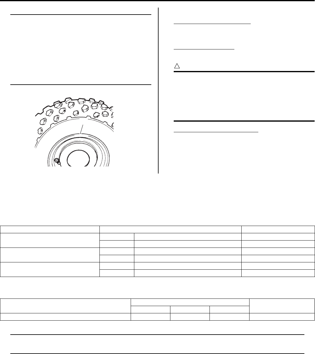
2D-4 Wheels and Tires:
NOTE
Check the “rim line” “B” cast on the tire
sidewalls. It must be equidistant from the
wheel rim all the way around. If the distance
between the rim line and the wheel rim
varies, this indicates that the bead is not
properly seated. If this is so, deflate the tire
completely, and unseat the tire bead on both
sides. Then, coat the bead with clean water,
and re-seat the tire.
6) Adjust the tire pressure to the specified pressure.
Cold inflation tire pressure
Front: 35 kPa (0.35 kgf/cm2, 5.1 psi)
Rear: 30 kPa (0.30 kgf/cm2, 4.4 psi)
Vehicle load capacity
172 kg (380 lbs)
CAUTION
!
Before inflating the tire, check the MAXIMUM
OPERATING PRESSURE rating of the tire.
This is indicated by a “” following the tire
size shown on the sidewall. The number of
“” on the tire indications the maximum
operating pressure.
Maximum operating pressure
: 25 kPa (0.25 kgf/cm2, 3.6 psi)
: 35 kPa (0.35 kgf/cm2, 5.1 psi)
: 45 kPa (0.45 kgf/cm2, 6.5 psi)
Specifications
Service Data
B831G22407001
Tire
Tightening Torque Specifications
B831G22407002
NOTE
The specified tightening torque is also described in the following.
“Front and Rear Wheel Components (Page 2D-1)”
Reference:
For the tightening torque of fastener not specified in this section, refer to “Tightening Torque List in Section 0C
(Page 0C-7)”.
“B”
I831G1240012-02
Item Standard Limit
Cold inflation tire pressure
(Solo riding)
Front 35 kPa (0.35 kgf/cm2, 5.1 psi) —
Rear 30 kPa (0.30 kgf/cm2, 4.4 psi) —
Tire size Front AT25 x 8-12 , tubeless —
Rear AT25 x 10-12 , tubeless —
Tire tread depth Front — 4.0 (0.16)
Rear — 4.0 (0.16)
Fastening part Tightening torque Note
N⋅mkgf—mlb—ft
Wheel nut 60 6.0 43.5 )(Page 2D-2)
PartShark.com
877-999-5686

Table of Contents 3- i
3
Section 3
CONTENTS
Driveline / Axle
Precautions ………………………………….………3-1
Precautions….…………………..……………….…………… 3-1
Precautions for Driveline / Axle ……..………………... 3-1
Drive Chain / Drive Train / Drive Shaft... 3A-1
Diagnostic Information and Procedures…………3A-1
Drive Shaft Symptom Diagnosis ……………………. 3A-1
Repair Instructions .……………….…………………..…3A-1
Front Drive Shaft Components ……………..………. 3A-1
Front Drive Shaft Assembly Removal and
Installation……………………….……………….………. 3A-2
Front Drive Shaft Disassembly and Assembly …. 3A-2
Front Drive Shaft Inspection …..…………….………. 3A-5
Rear Drive Shaft Components ………………………. 3A-6
Rear Drive Shaft Assembly Removal and
Installation……………………….……………….………. 3A-6
Rear Drive Shaft Disassembly and Assembly…..3A-7
Rear Drive Shaft Inspection ………….………………. 3A-7
Special Tools and Equipment …………….………….3A-7
Recommended Service Material ……………………. 3A-7
Special Tool .……………….………………..……………. 3A-7
Differential………………………………….…….. 3B-1
Diagnostic Information and Procedures…………3B-1
Drive Train Symptom Diagnosis………….…………. 3B-1
DTC “C20” (P1752) Diff-lock Relay Circuit
Malfunction.…………….………………..…………….…3B-1
Repair Instructions .……………….…………………..…3B-2
Front Drive (Differential) Components ………….…3B-2
Front Drive (Differential) Construction….…………. 3B-3
Front Drive (Differential) Gear Oil Level
Inspection………………….………………..……………. 3B-4
Front Drive (Differential) Gear Oil
Replacement……..……………….………………..……3B-4
Front Drive (Differential) Assembly Removal
and Installation…..……………….………………..……3B-4
Front Drive (Differential) Assembly
Disassembly and Assembly …………..……………. 3B-5
Front Drive (Differential) Related Parts
Inspection………………….………………..………….. 3B-12
Breather Rubber Case Inspection………….……..3B-14
Front Drive (Differential) Gear Shim
Inspection and Selection…………………………...3B-14
2WD/4WD/Diff-lock System Inspection…………. 3B-17
Rear Drive Breather Hose Routing Diagram….. 3B-20
Final Gear Components …………….………………..3B-21
Final Gear Construction …………….………………..3B-22
Final Gear Oil Level Inspection ..…………………..3B-23
Final Gear Oil Replacement.…………………….….3B-23
Final Gear Assembly Removal and
Installation ………….…………….…………….………. 3B-23
Final Gear Assembly Disassembly and
Assembly…..…………….…………….………………..3B-24
Final Gear Related Parts Inspection ……………..3B-30
Final Gear Shim Inspection and Selection ……..3B-31
Specifications…….………….…….…………….……….3B-34
Service Data……..……………..……………….……….3B-34
Tightening Torque Specifications………………….3B-34
Special Tools and Equipment ……………..……….3B-35
Recommended Service Material ……….………….3B-35
Special Tool ……………………….…………….……….3B-35
Transfer ………….………………………………… 3C-1
Diagnostic Information and Procedures…………3C-1
Transfer Symptom Diagnosis………..……………….3C-1
Repair Instructions ………..……….…………….………3C-2
Transfer Components ………………………..…………3C-2
Transfer Removal and Installation ………………….3C-3
Transfer Construction…….………………..……………3C-6
Counter Shaft / Reverse Idle Gear
Disassembly and Assembly …………………………3C-6
Gearshift Cam Components.………………………….3C-9
Gearshift System Construction …………………….3C-10
Gearshift Cam Disassembly and Assembly ……3C-11
Transfer Gear Bearing Removal and
Installation ………….…………….…………….……….3C-12
Transfer Gear Bearing Inspection .…………….….3C-12
Transfer Related Parts Inspection.…………….….3C-12
Transfer Related Bearing Inspection……………..3C-13
Gear Position (GP) Switch Inspection..………….3C-13
Gear Position (GP) Switch Removal and
Installation ………….…………….…………….……….3C-13
Gearshift Shaft No. 2 / Gearshift Cam Plate
Removal and Installation….…………….………….3C-14
Gearshift Linkage Inspection……………….……….3C-17
Gearshift Shaft Oil Seal Removal and
Installation ………….…………….…………….……….3C-17
Specifications…….………….…….…………….……….3C-18
Service Data……..……………..……………….……….3C-18
Special Tools and Equipment ……………..……….3C-18
PartShark.com
877-999-5686

3-ii Table of Contents
Recommended Service Material …………………..3C-18
Special Tool ………..………………..…………………..3C-18
Propeller Shafts………….…………………….. 3D-1
Repair Instructions ……………………………………….3D-1
Front Output Shaft Components ……………….……3D-1
Front Output Shaft Removal and Installation ……3D-1
Front Output Shaft Disassembly and
Assembly ………….…………….……………..…………3D-2
Front Output Shaft Related Parts Inspection ……3D-5
Rear Output Shaft Components……………..………3D-6
Rear Output Shaft Removal and Installation…….3D-6
Rear Output Shaft Disassembly and
Assembly ………….…………….……………..…………3D-8
Rear Output Shaft Related Parts Inspection .….3D-10
Rear Output Shaft Drive Bevel Gear Shim
Inspection and Adjustment………..…………….…3D-11
Front Propeller Shaft Components….…………….3D-14
Front Propeller Shaft Removal and
Installation ………….…………….…………….……….3D-14
Front Propeller Shaft Related Parts
Inspection.…………….………………..…………….…3D-16
Rear Propeller Shaft Components .……………….3D-17
Rear Propeller Shaft Removal and Installation ..3D-17
Rear Propeller Shaft Related Parts Inspection ..3D-22
Specifications..……………….……………….………….3D-23
Service Data………………….……………….………….3D-23
Tightening Torque Specifications………………….3D-23
Special Tools and Equipment ……………..……….3D-23
Recommended Service Material .……………….…3D-23
Special Tool …………………….…………….………….3D-24
PartShark.com
877-999-5686

Precautions: 3-1
Driveline / Axle
Precautions
Precautions
Precautions for Driveline / Axle
B831G23000001
Refer to “General Precautions in Section 00 (Page 00-1)”.
WARNING
!
Support the vehicle with a jack or wooden block when servicing the drive shafts and drive train.
PartShark.com
877-999-5686
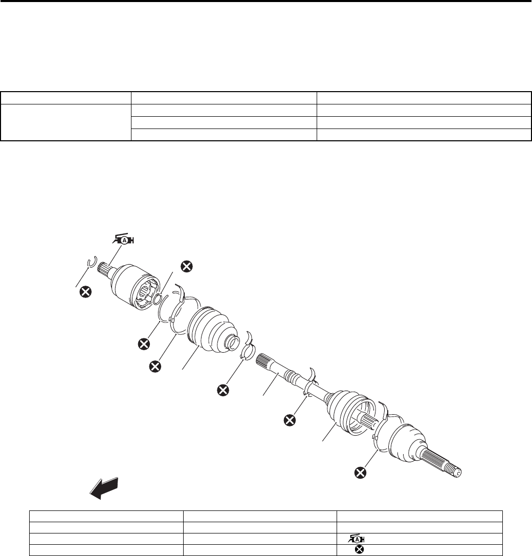
3A-1 Drive Chain / Drive Train / Drive Shaft:
Driveline / Axle
Drive Chain / Drive Train / Drive Shaft
Diagnostic Information and Procedures
Drive Shaft Symptom Diagnosis
B831G23104001
Repair Instructions
Front Drive Shaft Components
B831G23106001
Condition Possible cause Correction / Reference Item
Noisy Drive Shaft Worn drive shaft joints. Replace.
Worn wheel hub bearings. Replace.
Loose wheel nuts. Tighten.
1
2
3
4
5
6
7
9
8
10
FWD
I831G1310001-05
1. Circlip 5. Inner boot 9. Outer boot
2. Snap ring 6. Inner boot band (Small) 10. Outer boot band (Large)
3. Stopper ring 7. Drive shaft : Apply grease.
4. Inner boot band (Large) 8. Outer boot band (Small) : Do not reuse.
PartShark.com
877-999-5686
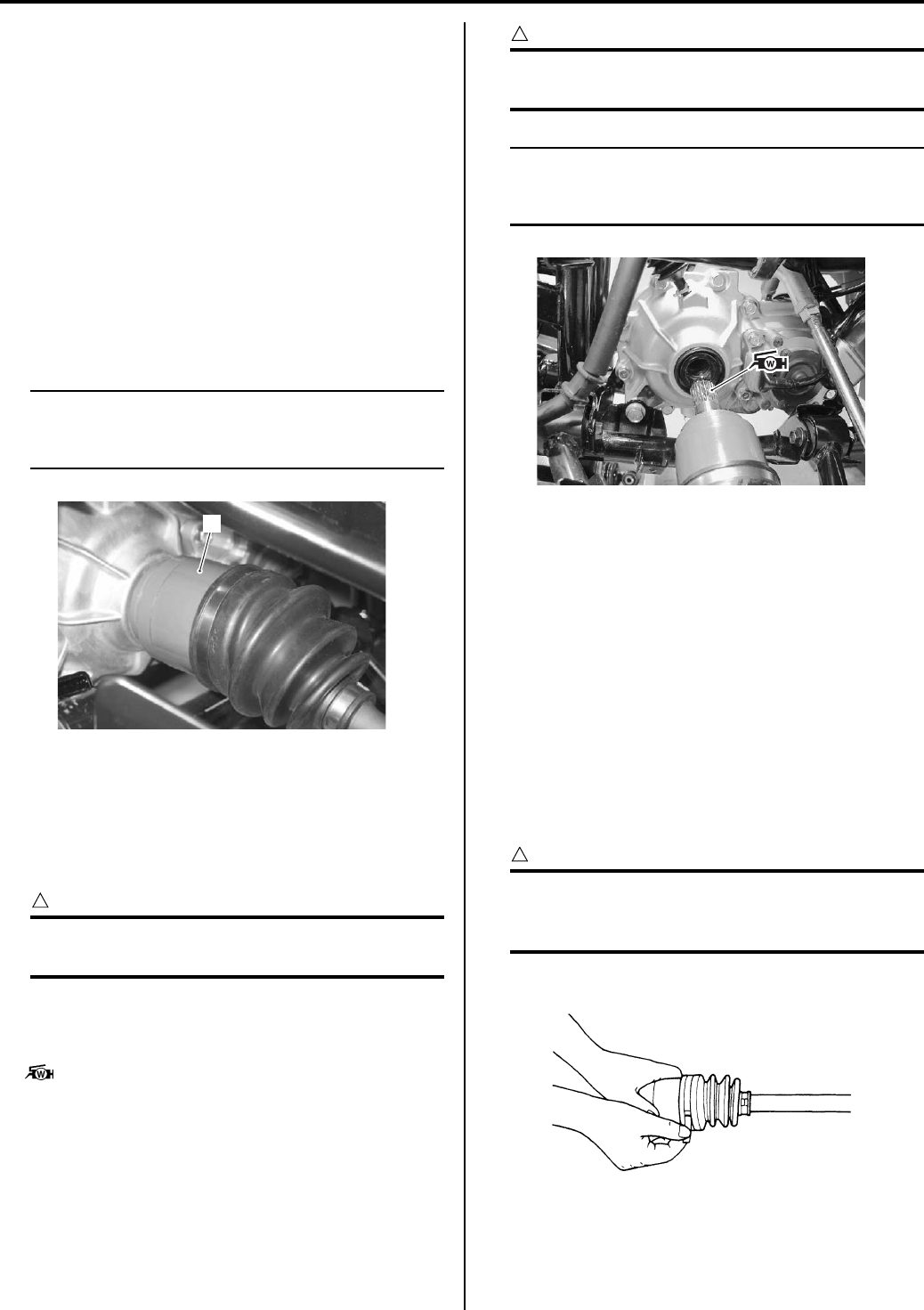
Drive Chain / Drive Train / Drive Shaft: 3A-2
Front Drive Shaft Assembly Removal and
Installation
B831G23106002
Removal
1) Drain the front differential gear oil. Refer to “Front
Differential Gear Oil Inspection in Section 0B
(Page 0B-12)”.
2) Remove the front wheel. Refer to “Front / Rear
Wheel Removal and Installation in Section 2D
(Page 2D-2)”.
3) Remove the steering knuckle. Refer to “Front Wheel
Hub / Steering Knuckle Removal and Installation in
Section 2B (Page 2B-4)”.
4) Hold the inboard joint (1) of the front drive shaft and
tug the drive shaft horizontally.
NOTE
If it is difficult to remove the front drive shaft
from the front differential gear case, use the
suitable tool.
Installation
Install the front drive shaft assembly in the reverse order
of removal. Pay attention to the following points:
• Install a new circlip into the groove of front differential
gear spline.
CAUTION
!
The removed circlip must be replaced with a
new one.
• Apply grease to the spline of the front drive shafts and
install the front drive shafts to the front differential gear
case.
: Grease 99000–25160 (Water resistance
grease)
CAUTION
!
Be careful not to damage the front differential
gear case oil seals.
NOTE
After installing both drive shafts, make sure
the stopper rings are seated properly by
pulling both inboard joints lightly.
• Install the steering knuckle. Refer to “Front Wheel
Hub / Steering Knuckle Removal and Installation in
Section 2B (Page 2B-4)”.
• Install the front wheel. Refer to “Front / Rear Wheel
Removal and Installation in Section 2D (Page 2D-2)”.
• Pour the front differential gear oil. Refer to “Front
Differential Gear Oil Inspection in Section 0B
(Page 0B-12)”.
Front Drive Shaft Disassembly and Assembly
B831G23106003
Refer to “Front Drive Shaft Assembly Removal and
Installation (Page 3A-2)”.
Disassembly
CAUTION
!
Do not disassemble the wheel side joint. If
any damages are found, replace it with a new
one.
1) Remove the boot band of the differential side joint.
1
I831G1310003-01
I831G1310004-02
I831G1310005-01
PartShark.com
877-999-5686
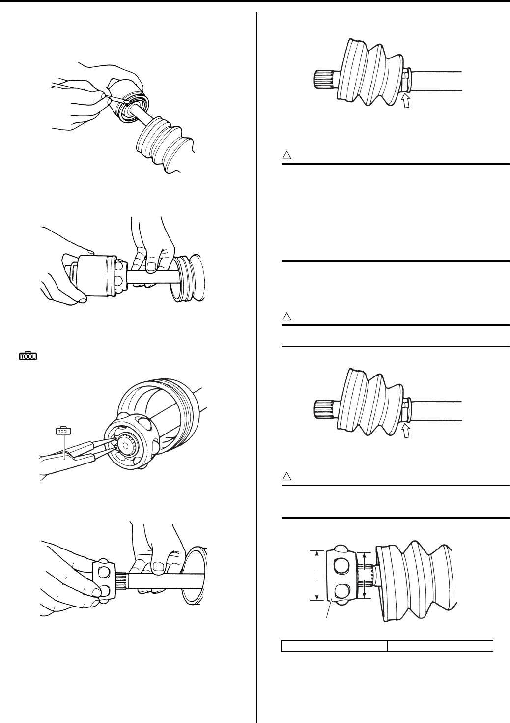
3A-3 Drive Chain / Drive Train / Drive Shaft:
2) Slide the boot toward the center of the front drive
shaft and remove the stopper ring from the outer
race.
3) Remove the outer race from the front drive shaft.
4) Wipe off any grease and remove the snap ring.
Special tool
(A): 09900–06107 (Snap ring pliers)
5) Remove the cage from the front drive shaft.
6) Remove the boot band of the small diameter side.
Assembly
CAUTION
!
• Wash all parts before installation, clean the
inside and outside of the boots with a
cloth.
• Do not wash the boots in any commercially
available degreaser, such as gasoline or
kerosene. Washing in a degreaser causes
deterioration of the boots.
1) Fit a boot on the drive shaft end, fitting the small
diameter side of the boot to the shaft groove, fix its
end with a new boot band.
CAUTION
!
Replace the boot band with a new one.
2) Install the cage (1) on the shaft.
CAUTION
!
Install the cage with the large diameter side
“A” facing the shaft end.
I831G1310006-01
I831G1310007-01
(A)
I831G1310022-01
I831G1310009-01
“A”: Large diameter “B”: Small diameter
I831G1310011-02
I831G1310011-02
1
“A” “B”
I831G1310012-02
PartShark.com
877-999-5686
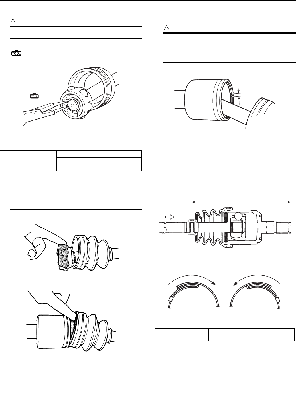
Drive Chain / Drive Train / Drive Shaft: 3A-4
3) Install the new snap ring to the cage.
CAUTION
!
Replace the snap ring with a new one.
Special tool
(A): 09900–06107 (Snap ring pliers)
4) Apply grease to the entire surface of the cage and
the inside of the outer race.
NOTE
The tube of joint grease is included in the
wheel side boot set or wheel side joint
assembly of spare parts.
5) Insert the cage into the outer race and install the new
stopper ring to the groove of the outer race.
CAUTION
!
• Replace the stopper ring with a new one.
• Position the opening of stopper ring “C”
so that it will not be lined up with a ball.
6) After installing the boot on the outer race, insert a
screw driver into the boot on the outer race side and
allow air to enter the boot so that the air pressure in
the boot becomes the same as the atmospheric
pressure at the positions indicated in the figure.
7) Fix the boot on the outer race with a new boot band,
taking care not to distort the boot.
Position
Wheel side Differential side
Grease: Quantity 45 g 85 g
(A)
I831G1310023-01
I831G1310013-01
I831G1310014-01
“D”: Right side “F”: Rotation direction
“E”: Left side “a”: 188 – 198 mm (7.4 – 7.8 in)
“C”
I831G1310015-01
A
“a”
VIEW A
“F”
“D” “E”
“F”
I831G1310016-02
PartShark.com
877-999-5686
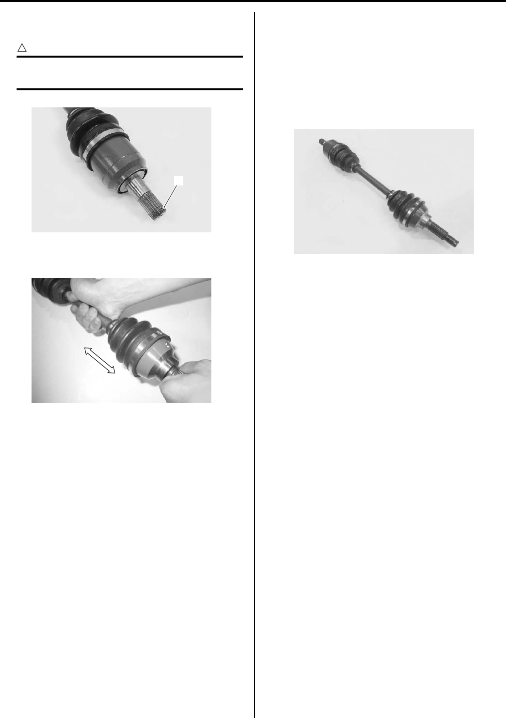
3A-5 Drive Chain / Drive Train / Drive Shaft:
Install the circlip (2) into the groove of front drive
shaft spline.
CAUTION
!
The removed circlip must be replaced with a
new one.
9) Inspect the axle play by using a push-and-pull
motion given to the axle shaft and wheel spindle.
Front Drive Shaft Inspection
B831G23106004
Inspect the front drive shaft in the following procedures:
1) Remove the front drive shaft assembly. Refer to
“Front Drive Shaft Assembly Removal and
Installation (Page 3A-2)”.
2) Inspect the boots, circlip and boot bands for wear or
damage. If any damages are found, replace them
with new ones.
3) Install the front drive shaft assembly. Refer to “Front
Drive Shaft Assembly Removal and Installation
(Page 3A-2)”.
2
I831G1310017-02
I831G1310018-01
I831G1310019-01
PartShark.com
877-999-5686
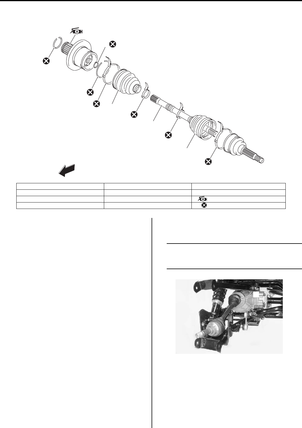
Drive Chain / Drive Train / Drive Shaft: 3A-6
Rear Drive Shaft Components
B831G23106005
Rear Drive Shaft Assembly Removal and
Installation
B831G23106006
Removal
1) Drain the rear final gear oil. Refer to “Final Gear Oil
Inspection in Section 0B (Page 0B-14)”.
2) Remove the rear wheel. Refer to “Front / Rear
Wheel Removal and Installation in Section 2D
(Page 2D-2)”.
3) Remove the rear wheel hub and rear suspension
arm. Refer to “Rear Wheel Hub / Suspension
Knuckle Removal and Installation in Section 2C
(Page 2C-4)”.
4) Hold the in board joint (1) of the rear drive shaft and
tug the drive shaft horizontally.
NOTE
If it is difficult to remove the rear drive shaft
from the rear differential gear case, using the
suitable tool.
FWD
1
2
3
5
6
7
8
9
10
4
I831G1310002-05
1. Circlip 5. Inner boot 9. Outer boot
2. Snap ring 6. Inner boot band (Small) 10. Outer boot band (Large)
3. Stopper ring 7. Drive shaft : Apply grease.
4. Inner boot band (Large) 8. Outer boot band (Small) : Do not reuse.
1
I831G1310020-04
PartShark.com
877-999-5686
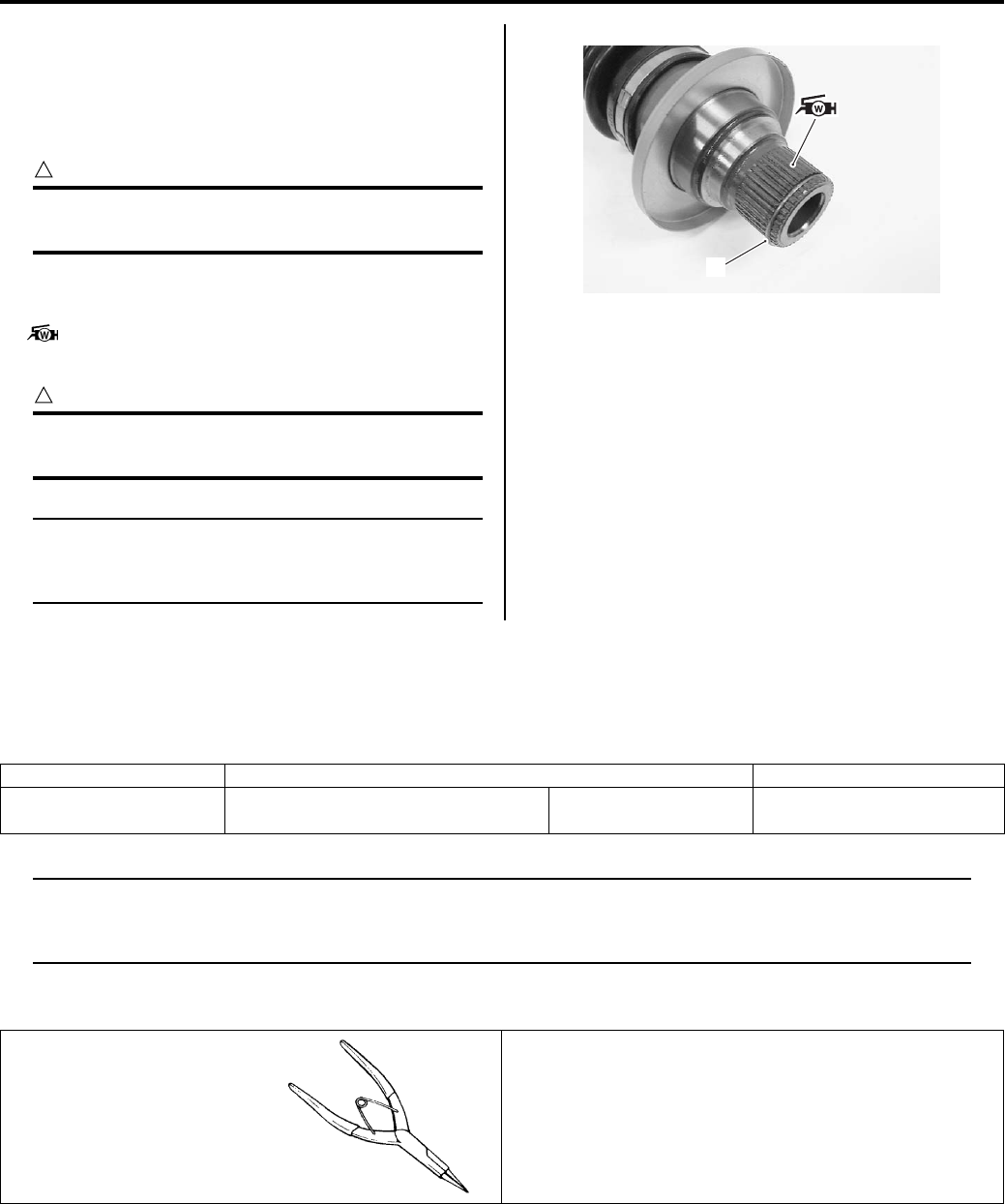
3A-7 Drive Chain / Drive Train / Drive Shaft:
Installation
Install the rear drive shaft in the reverse order of
removal. Pay attention to the following points:
• Install a new circlip (1) into the groove of drive shaft
spline.
CAUTION
!
The removed circlip must be replaced with a
new one.
• Apply grease to the spline of the rear drive shafts and
install the rear drive shafts to the rear final gear case.
: Grease 99000–25160 (Water resistance
grease)
CAUTION
!
Be careful not to damage the front drive case
oil seal.
NOTE
After installing both drive shafts, make sure
the circlips (1) is seated properly by pulling
both inboard joints lightly.
Rear Drive Shaft Disassembly and Assembly
B831G23106007
Refer to “Rear Drive Shaft Assembly Removal and
Installation (Page 3A-6)”.
Rear drive shaft disassembly and assembly as the same
manner of front drive shaft.
Rear Drive Shaft Inspection
B831G23106008
Refer to “Rear Drive Shaft Assembly Removal and
Installation (Page 3A-6)”.
Rear drive shaft inspection as the same manner of front
drive shaft.
Special Tools and Equipment
Recommended Service Material
B831G23108001
NOTE
Required service material is also described in the following.
“Front Drive Shaft Components (Page 3A-1)”
“Rear Drive Shaft Components (Page 3A-6)”
Special Tool
B831G23108002
1
I831G1310021-04
Material SUZUKI recommended product or Specification Note
Grease Water resistance grease P/No.: 99000–25160 )(Page 3A-2) / )(Page 3A-
7)
09900–06107
Snap ring pliers
)(Page 3A-3) / )(Page 3A-
4)
PartShark.com
877-999-5686
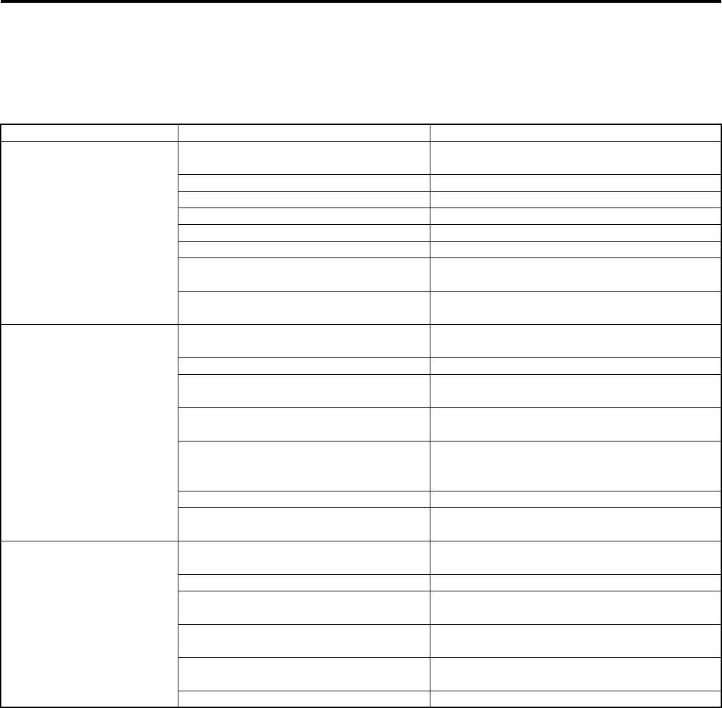
Differential: 3B-1
Driveline / Axle
Differential
Diagnostic Information and Procedures
Drive Train Symptom Diagnosis
B831G23204001
DTC “C20” (P1752) Diff-lock Relay Circuit Malfunction
B831G23204002
Refer to “DTC “C20” (P1752): Diff-lock Relay Circuit Malfunction in Section 1A (Page 1A-47)”.
Condition Possible cause Correction / Reference Item
Engine noisy (Noise
seems to came from front/
rear output shaft bevel
gear, front drive
(differential) bevel gear
and rear drive bevel gear)
Worn or damage drive and driven bevel
gears.
Replace.
Excessive backlash. Adjust.
Improper tooth contact. Adjust.
Damage bearing. Replace.
Worn or rubbing gears. Replace.
Worn output shaft spline. Replace output shaft.
Too large front drive gear thrust
clearance.
Adjust or replace.
Too large rear drive gear thrust
clearance.
Adjust or replace.
Power will not transmit
from the engine to the
front wheel
Broken drive and driven bevel gear
teeth.
Replace.
Worn or broken propeller shaft serration. Replace.
Broken or damaged front drive
(differential) gear or pinion.
Replace.
Improperly operated front differential
shifting motor.
Repair or replace.
Worn or damaged shifting sleeve, shaft
and fork of the 2WD/4WD and diff-lock
shifting.
Replace.
Worn or damaged universal joint. Replace.
Worn or damaged front drive shaft or
universal joint serration.
Replace.
Power will not transmit
from the engine to the
rear wheel
Broken drive and driven bevel gear
teeth.
Replace.
Broken rear output shaft. Replace.
Worn or broken rear drive shaft
serration.
Replace.
Worn or damaged coupling joint
serration.
Replace.
Broken or damaged rear drive and
driven bevel gears.
Replace.
Worn or damaged universal joint. Replace.
PartShark.com
877-999-5686
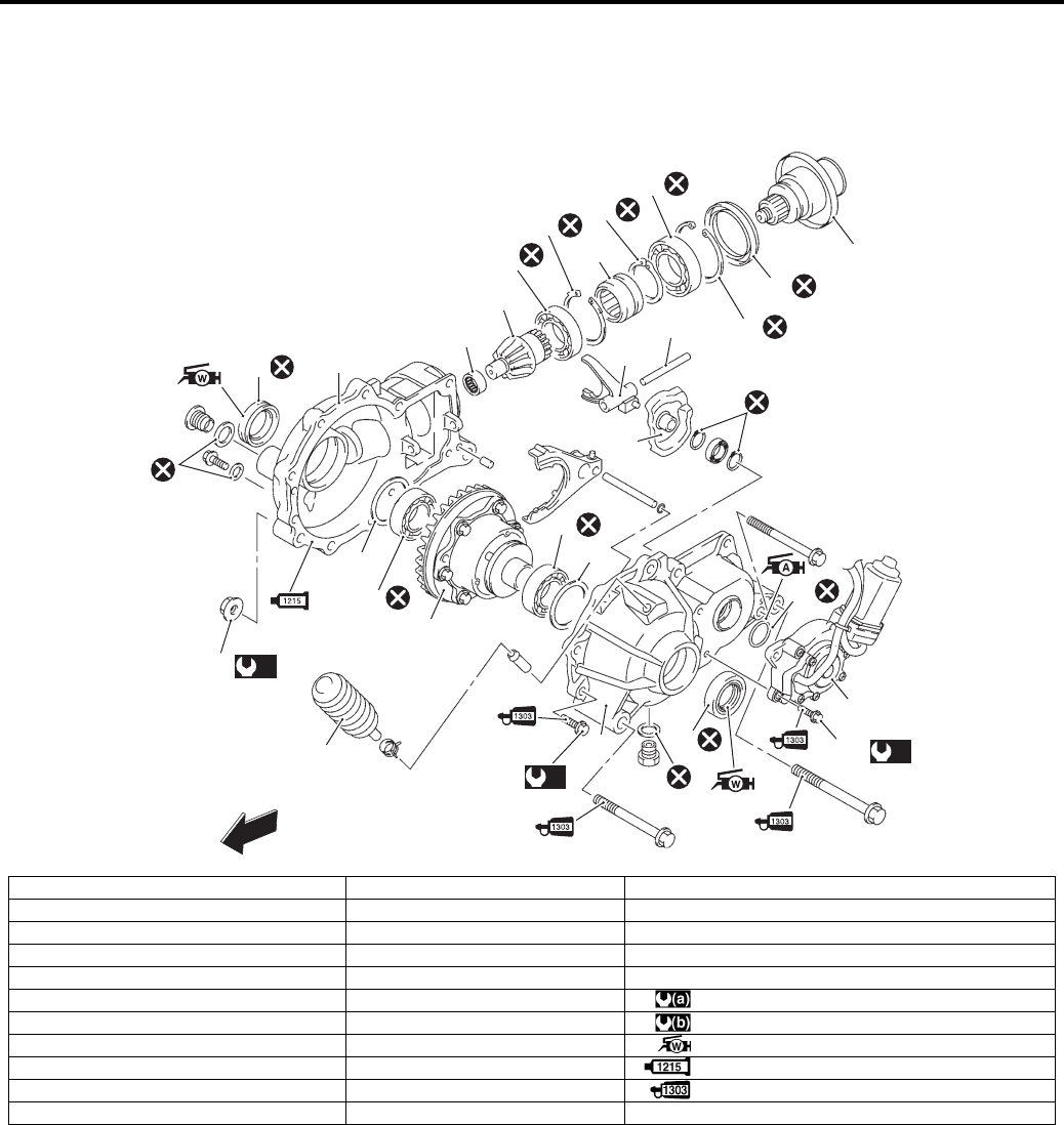
3B-2 Differential:
Repair Instructions
Front Drive (Differential) Components
B831G23206001
1
11
(a)
25
24
3
5
4
6
7
2
(b)
26
11 (b)
27
13
12
8
9
10
20
21
22
23
14
15
16
17
18
19
FWD
I831G1320001-06
1. Front drive (differential) gear case 12. O-ring 23. Input shaft
2. Front drive (differential) gear case cover 13. 4WD/Diff-lock Actuator 24. Breather rubber case
3. Shim (Right side) 14. Bearing 25. Front drive (differential) gear case mounting nut
4. Bearing 15. Drive bevel gear 26. Front drive (differential) gear case cover bolt
5. Front drive (differential) gear case 16. Bearing 27. Actuator mounting bolt
6. Bearing 17. Snap ring : 50 N⋅m (5.0 kgf-m, 36.0 lb-ft)
7. Shim (Left Side) 18. 2WD/4WD shifting sleeve : 22 N⋅m (2.2 kgf-m, 16.0 lb-ft)
8. 2WD/4WD shifting cam 19. Snap ring : Apply water resistance grease.
9. 2WD/4WD shifting fork 20. Bearing : Apply bond.
10. 2WD/4WD shifting fork shaft 21. Snap ring : Apply thread lock to the thread part.
11. Oil seal 22. Oil seal
PartShark.com
877-999-5686
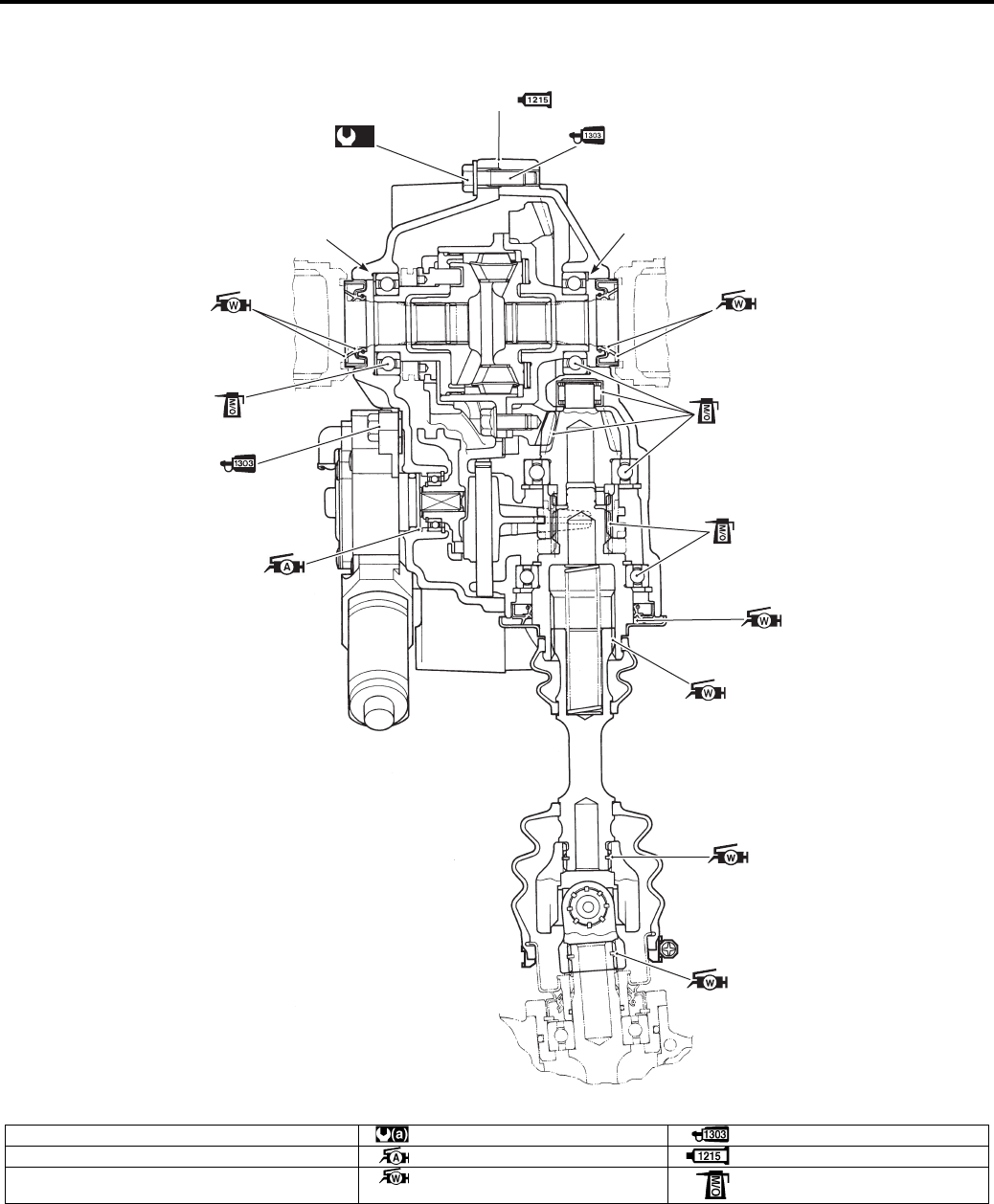
Differential: 3B-3
Front Drive (Differential) Construction
B831G23206002
(a)
2
1
1
“A”
I831G1320002-07
1. Shim : 1.3 N⋅m (0.13 kgf-m, 0.94 lb-ft) : Apply thread lock to the thread part.
2. Front drive (differential) case cover bolt : Apply grease. : Apply bond to matching surface.
“A”: Matching surface : Apply water resistance grease. : Apply molybdenum oil solution.
PartShark.com
877-999-5686
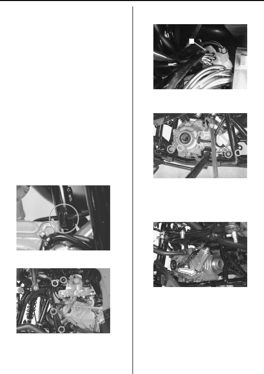
3B-4 Differential:
Front Drive (Differential) Gear Oil Level
Inspection
B831G23206003
Refer to “Front Differential Gear Oil Inspection in Section
0B (Page 0B-12)”.
Front Drive (Differential) Gear Oil Replacement
B831G23206004
Refer to “Front Differential Gear Oil Inspection in Section
0B (Page 0B-12)”.
Front Drive (Differential) Assembly Removal
and Installation
B831G23206005
Removal
1) Remove the front wheels. Refer to “Front / Rear
Wheel Removal and Installation in Section 2D
(Page 2D-2)”.
2) Drain front differential gear oil. Refer to “Front
Differential Gear Oil Inspection in Section 0B
(Page 0B-12)”.
3) Remove the inner fender (left and right). Refer to
“Front Side Exterior Parts Removal and Installation
in Section 9D (Page 9D-6)”.
4) Remove the drive shaft. Refer to “Front Drive Shaft
Assembly Removal and Installation in Section 3A
(Page 3A-2)”.
5) Disconnect the rear brake light switch lead wire.
6) Remove the lead wire clamps.
7) Disconnect the 2WD/4WD/diff-lock actuator lead
wire coupler (1).
Remove the front drive (differential) mounting bolts
and nuts.
9) Remove the front shock absorber. Refer to “Front
Shock Absorber Removal and Installation in Section
2B (Page 2B-3)”.
10) Move the suspension upper arm upward and remove
the front drive (differential) assembly.
I831G1320003-01
I831G1320004-01
1
I831G1320005-02
I831G1320006-02
I831G1320146-01
PartShark.com
877-999-5686
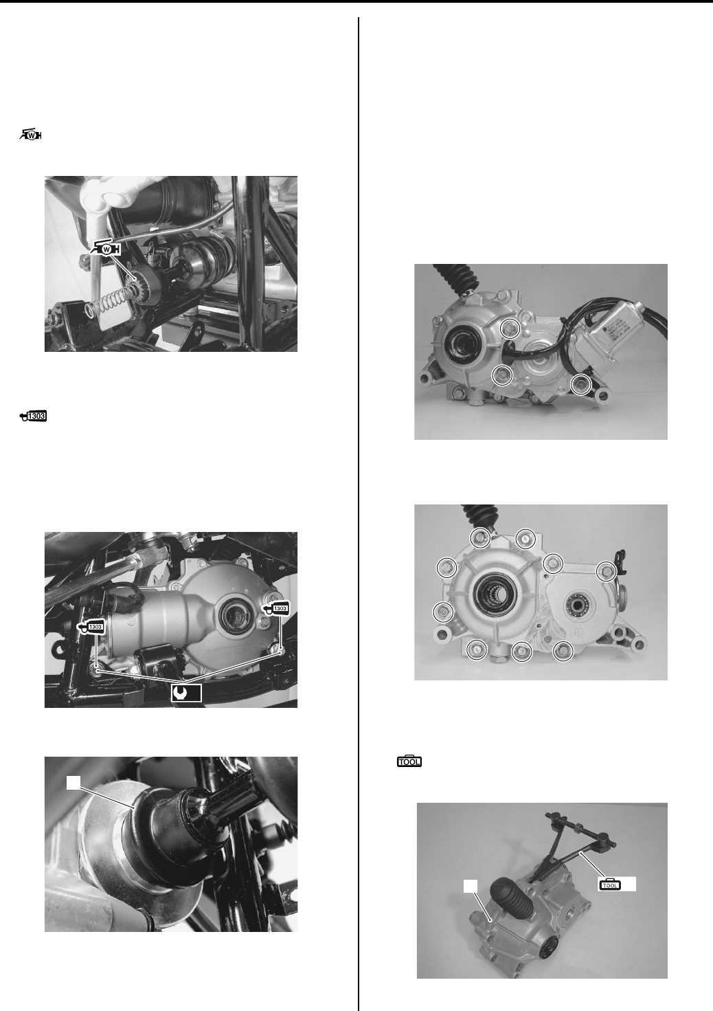
Differential: 3B-5
Installation
Install the front drive (differential) assembly in the
reverse order of removal. Pay attention to the following
points:
• Apply 4.5 gram of grease to spline of the front
propeller shaft.
: Grease 99000–25160 (Water resistance
grease)
• Apply thread lock to the bolts and tighten them to the
specified torque.
: Thread lock cement 99000–32030
(THREAD LOCK CEMENT SUPER 1303 or
equivalent)
Tightening torque
Front drive (differential) mounting nut (a): 50 N·m
(5.0 kgf-m, 36.0 lb-ft)
• Attach the boot (1) to the input shaft.
• After installing the front drive (differential), check the
wiring harness routing and pour the front differential
gear oil. Refer to “Wiring Harness Routing Diagram in
Section 9A (Page 9A-4)” and “Front Differential Gear
Oil Inspection in Section 0B (Page 0B-12)”.
Front Drive (Differential) Assembly
Disassembly and Assembly
B831G23206006
Refer to “Front Drive (Differential) Assembly Removal
and Installation (Page 3B-4)”.
Disassembly
1) Remove the 2WD/4WD/diff-lock actuator assembly.
2) Remove the front drive (differential) case cover bolts
diagonally and evenly.
3) Remove the front drive (differential) case housing
(1).
Special tool
(A): 09912–34510 (Cylinder disassembling
tool)
I831G1320144-01
(a)
I831G1320007-02
1
I831G1320147-01
I831G1320008-01
I831G1320009-01
1(A)
I831G1320010-01
PartShark.com
877-999-5686
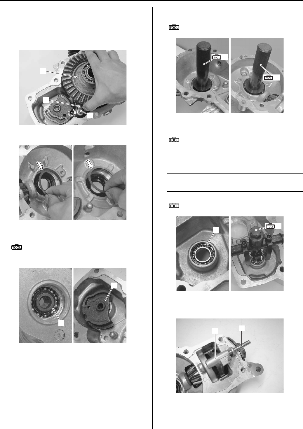
3B-6 Differential:
4) Align the concave part of 2WD/4WD shifting cam
and convex part of diff-lock shift fork.
5) Remove the front drive (differential) gear assembly
(2), diff-lock shifting fork (3) and shifting fork shaft
(4).
6) Remove the shims from the housing and cover.
7) Remove the snap ring (5).
Special tool
: 09900–06108 (Snap ring pliers)
Remove the 2WD/4WD shifting cam (6).
9) Remove the oil seals.
Special tool
(B): 09913–70210 (Bearing installer set)
10) Remove the snap ring (7).
Special tool
: 09900–06108 (Snap ring pliers)
11) Remove the 2WD/4WD shifting cam bearing with the
special tool.
NOTE
If there is no abnormal noise, the bearing
removal is not necessary.
Special tool
(C): 09921–20240 (Bearing remover set)
12) Remove 2WD/4WD gear shifting fork shaft (8) and
4WD/diff-lock shifting fork (9).
2
3
4
I831G1320011-02
I831G1320012-01
5
6
I831G1320013-01
(B)
(B)
I831G1320014-01
7(C)
I831G1320015-02
8
9
I831G1320016-01
PartShark.com
877-999-5686
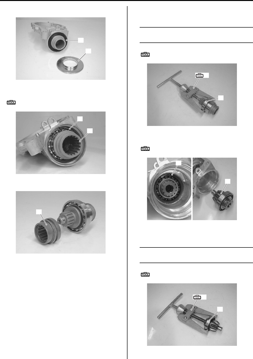
Differential: 3B-7
13) Remove the oil seal cap (10) and oil seal (11).
• Remove the snap ring (12) and input shaft (13).
Special tool
: 09900–06108 (Snap ring pliers)
14) Remove 2WD/4WD shifting sleeve (14).
15) Remove the input shaft bearing (15) with the special
tool.
NOTE
If there is no abnormal noise, the bearing
removal is not necessary.
Special tool
(D): 09913–60910 (Bearing remover)
16) Remove the snap ring (16) and pinion gear (17).
Special tool
: 09900–06108 (Snap ring pliers)
17) Remove the pinion gear bearing with the special
tool.
NOTE
If there is no abnormal noise, the bearing
removal is not necessary.
Special tool
(D): 09913–60910 (Bearing remover)
11
10
I831G1320017-01
12
13
I831G1320018-01
14
I831G1320019-01
(D)
15
I831G1320020-01
16
17
I831G1320021-01
(D)
17
I831G1320022-01
PartShark.com
877-999-5686
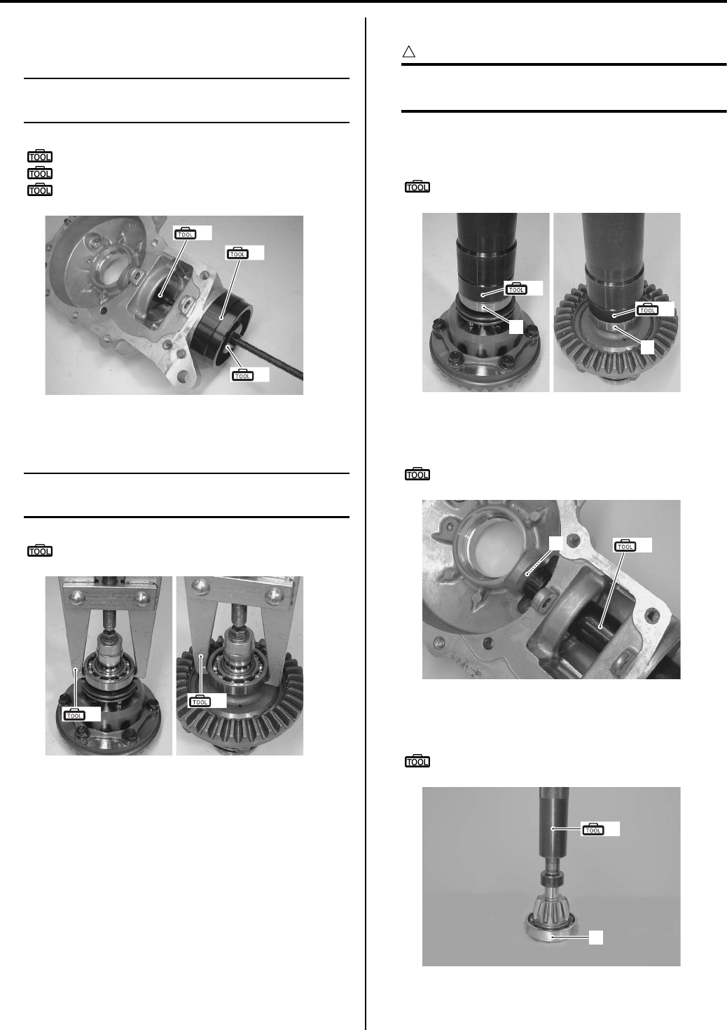
3B-8 Differential:
18) Remove the pinion gear pilot bearing with the special
tools.
NOTE
If there is no abnormal noise, the bearing
removal is not necessary.
Special tool
(E): 09921–20240 (Bearing remover set)
(F): 09944–66010 (Bearing installer)
(G): 09924–84521 (Bearing installer set)
19) Remove the front drive (differential) gear bearing
with the special tool, as shown in the figure.
NOTE
If there is no abnormal noise, the bearing
removal is not necessary.
Special tool
(D): 09913–60910 (Bearing remover)
Assembly
CAUTION
!
The removed oil seals, snap rings and
bearings must be replaced with new ones.
1) Install the bearings (1) to the front drive (differential)
gear assembly with the special tool.
Special tool
(A): 09913–70210 (Bearing installer set)
2) Install the pinion gear pilot bearing (2) into the front
drive (differential) gear case with the special tool.
Special tool
(A): 09913–70210 (Bearing installer set)
3) Install the pinion gear bearing (3) onto the gear shaft
with the special tool.
Special tool
(A): 09913–70210 (Bearing installer set)
(E)
(F)
(G)
I831G1320023-02
(D)
(D)
I831G1320024-01
(A)
(A)
1
1
I831G1320025-01
2(A)
I831G1320026-01
3
(A)
I831G1320027-01
PartShark.com
877-999-5686
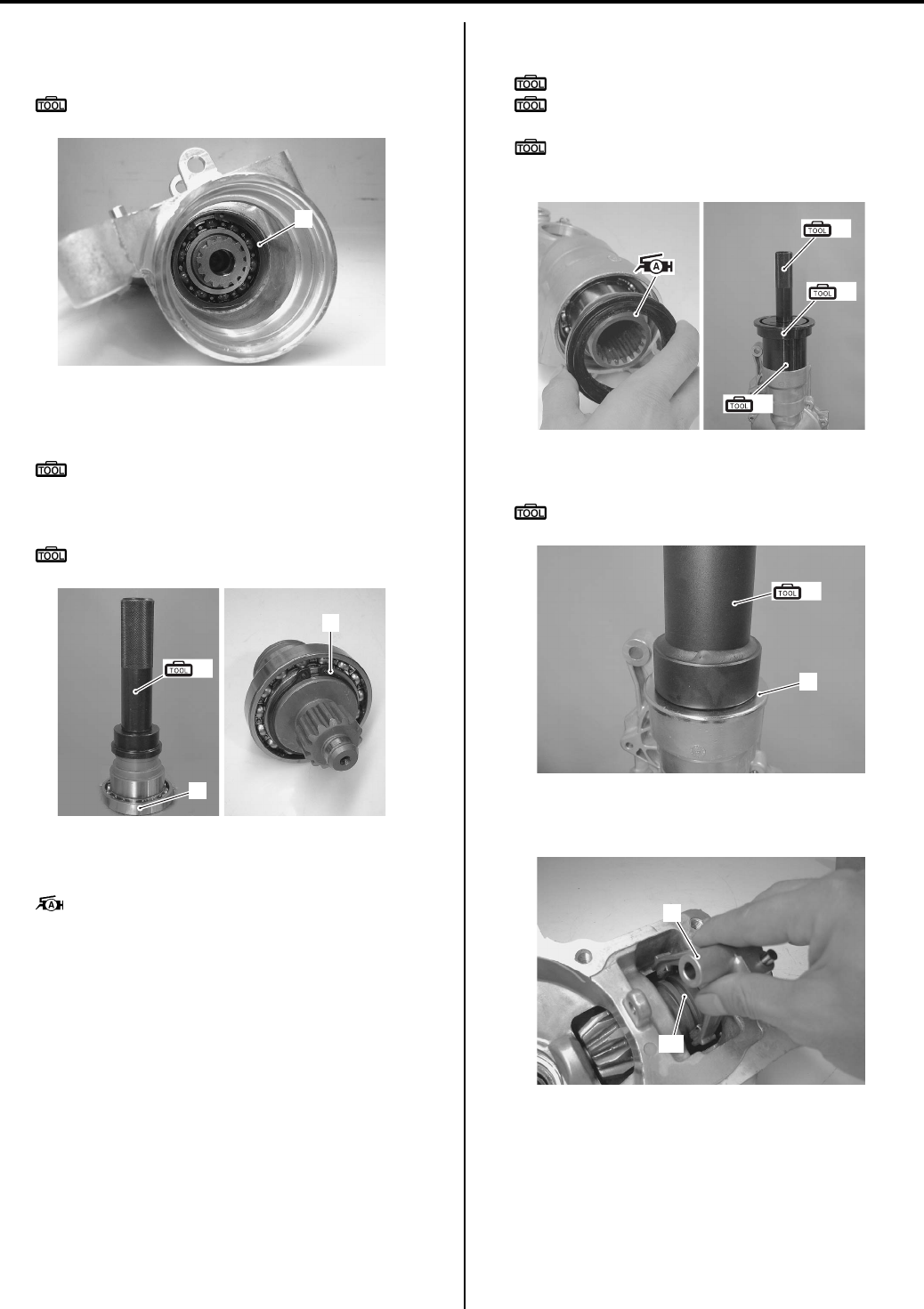
Differential: 3B-9
4) Install the pinion gear into the front drive train
(differential) gear case and fix the snap ring (4).
Special tool
: 09900–06108 (Snap ring pliers)
5) Install the input shaft bearing (5) onto the input shaft
with the special tool.
Special tool
(A): 09913–70210 (Bearing installer set)
6) Install the snap ring (6).
Special tool
: 09900–06108 (Snap ring pliers)
7) Install the input shaft.
Apply a small quantity of grease to the oil seal lip.
: Grease 99000–25010 (SUZUKI SUPER
GREASE A or equivalent)
9) Install the oil seal with the special tool.
Special tool
(A): 09913–70210 (Bearing installer set)
(B): 09924–74520 (Oil seal installer/
remover)
(C): 09924–74570 (Final drive gear bearing
installer/remover)
10) Install the oil seal cap (7) with the special tool.
Special tool
(D): 09922–21410 (Long socket (46 mm))
11) Install the 4WD/diff-lock shifting fork (8), onto the
groove of the 2WD/4WD shifting sleeve “A”.
4
I831G1320028-01
(A)
5
6
I831G1320029-01
(A)
(B)
(C)
I831G1320030-03
(D)
7
I831G1320031-01
8
“A”
I831G1320032-01
PartShark.com
877-999-5686
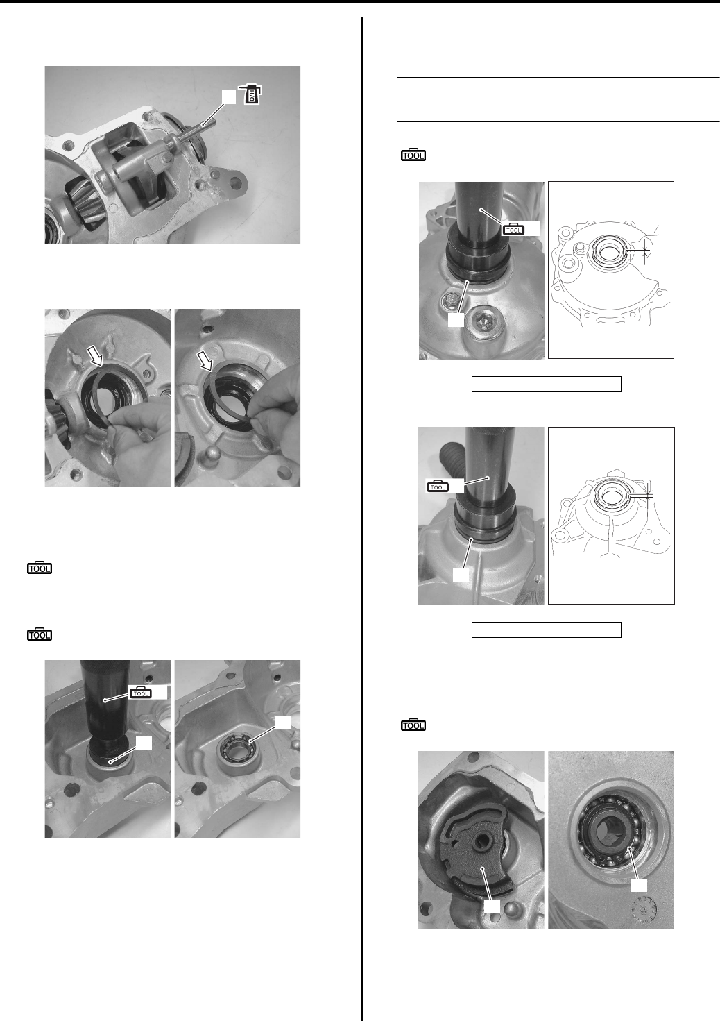
3B-10 Differential:
12) Apply front differential gear oil to the 2WD/4WD
sifting fork shaft (9).
13) Install the left and right side shims into the case
cover and case.
14) Install the 2WD/4WD sifting cam bearing (10) with
special tool.
Special tool
(A): 09913–70210 (Bearing installer set)
15) Install the snap ring (11).
Special tool
: 09900–06108 (Snap ring pliers)
16) Install the oil seals (12) into the front drive
(differential) gear case cover with the special tool.
NOTE
Insert the oil seal until the specified value as
shown in the figure.
Special tool
(A): 09913–70210 (Bearing installer set)
17) Install the 2WD/4WD shifting cam (13).
18) Install the snap ring (14).
Special tool
: 09900–06108 (Snap ring pliers)
9
I831G1320033-02
I831G1320034-01
(A)
10
11
I831G1320035-01
“a”: 4 mm (0.1574 in)
“a”: 4 mm (0.1574 in)
12
(A)
“a”
I831G1320036-02
12
(A)
“a”
I831G1320037-02
13
14
I831G1320038-01
PartShark.com
877-999-5686
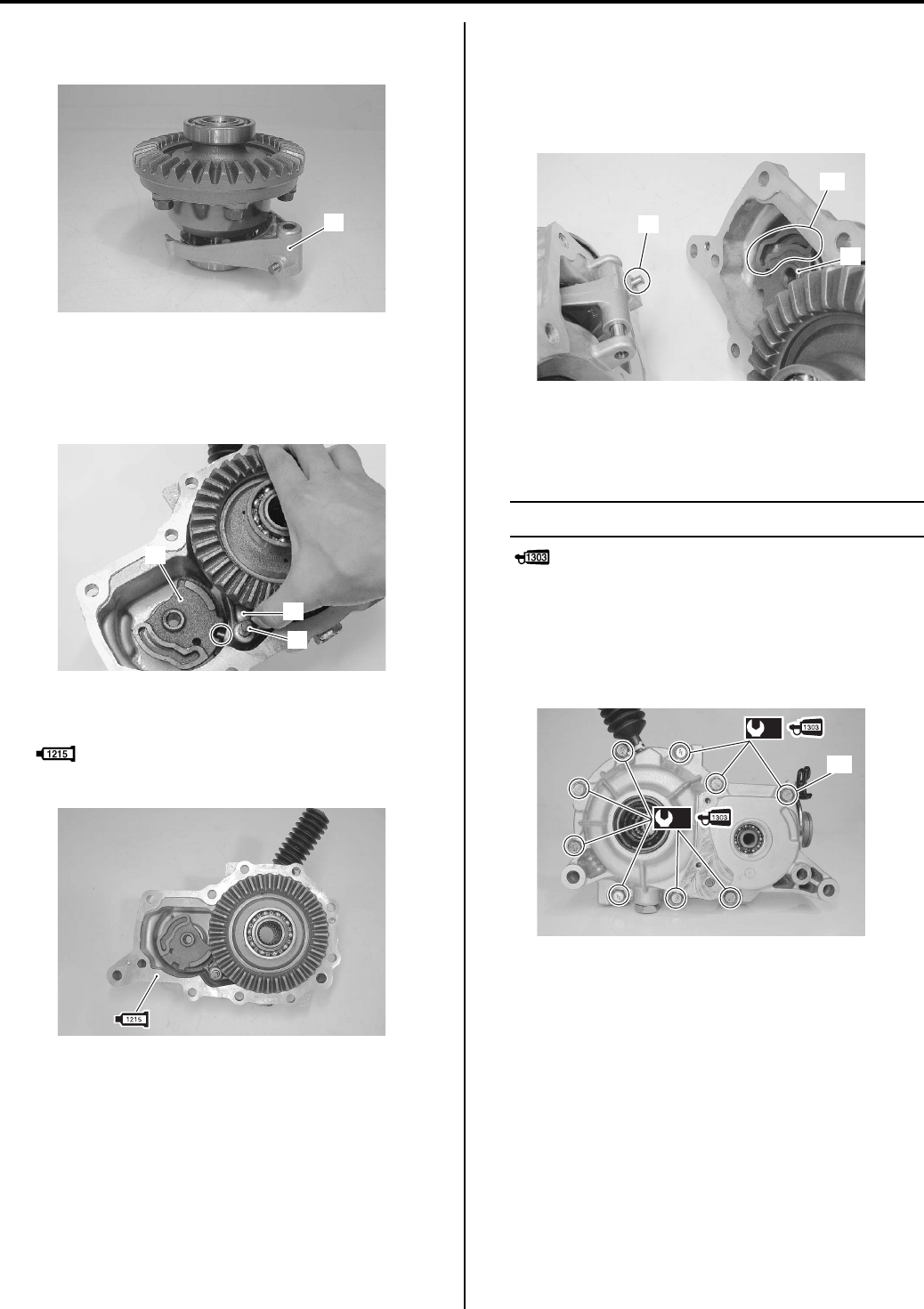
Differential: 3B-11
19) Install the diff-lock shifting fork (15) to the shifting
sleeve.
20) Install the front drive (differential) gear assembly, diff-
lock shifting fork (15) and shifting fork shaft (16).
21) Align the shifting fork pin with the groove of the 2WD/
4WD shifting cam (13).
22) Apply bond to the mating surface of the front drive
(differential) case.
: Sealant 99000–31110 (SUZUKI BOND
No.1215 or equivalent)
23) Turn the 2WD/4WD shifting cam (13) clockwise, and
install 2WD/4WD shifting fork pin to the bottom.
24) Align the 2WD/4WD shifting fork pin (17) with the
groove “C” of the 2WD/4WD shifting cam when
reassembling.
25) Apply a small quantity of thread lock to the front drive
(differential) case cover bolts and tighten then to the
specified torque diagonally.
NOTE
Fit clamp to the bolt “B”.
: Thread lock cement 99000–32030
(THREAD LOCK CEMENT SUPER 1303 or
equivalent)
Tightening torque
Front drive (differential) case cover bolt (a): 22
N·m (2.2 kgf-m, 16.0 lb-ft)
15
I831G1320039-01
13
15
16
I831G1320040-01
I831G1320041-01
17
“C”
13
I831G1320042-02
(a)
(a)
“B”
I831G1320043-02
PartShark.com
877-999-5686
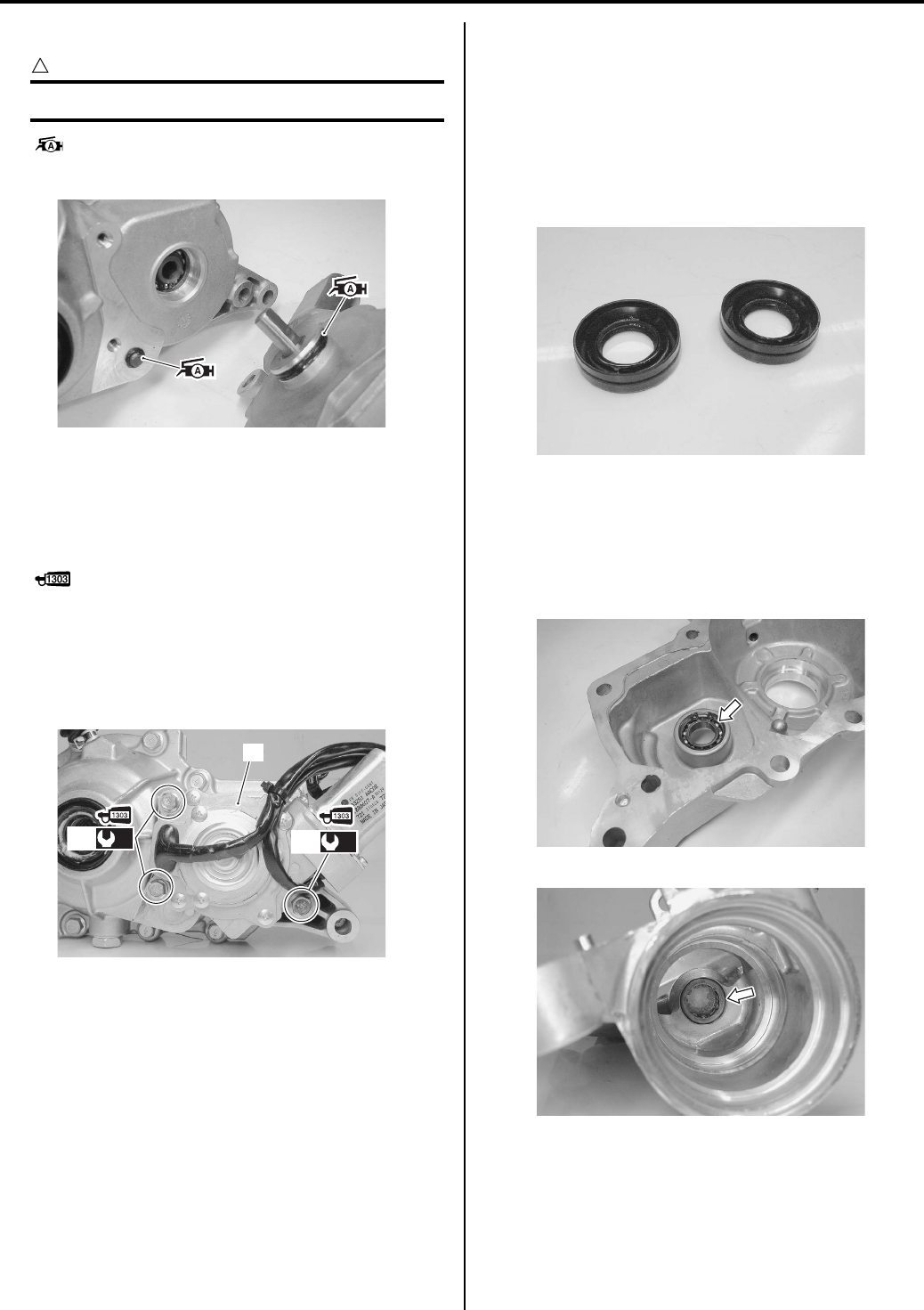
3B-12 Differential:
26) Apply grease to the O-rings.
CAUTION
!
Replace the O-rings with new ones.
: Grease 99000–25010 (SUZUKI SUPER
GREASE A or equivalent)
27) Apply a small quantity of thread lock to the 4WD/diff-
lock actuator mounting bolts (18).
28) Install the 2WD/4WD/diff-lock actuator assembly
(19) and tighten its mounting bolts (18) to the
specified torque.
: Thread lock cement 99000–32030
(THREAD LOCK CEMENT SUPER 1303 or
equivalent)
Tightening torque
4WD/Diff-lock actuator mounting bolt (b): 22
N·m (2.2 kgf-m, 16.0 lb-ft)
29) Check the backlash and tooth contact. Refer to
“Front Drive (Differential) Gear Shim Inspection and
Selection (Page 3B-14)”.
30) Install the Front drive (differential) assembly. Refer to
“Front Drive (Differential) Assembly Removal and
Installation (Page 3B-4)”.
Front Drive (Differential) Related Parts
Inspection
B831G23206007
Refer to “Front Drive (Differential) Assembly
Disassembly and Assembly (Page 3B-5)”.
Front Drive Gear Oil Seals
Inspect the lip of oil seal for wear or damage. If any
defect is found, replace the oil seal with a new one.
2WD/4WD Shifting Cam Bearing and Pinion Gear
Pilot Bearing
Inspect the bearings for abnormal noise and smooth
rotation. Replace the bearing if there is anything
unusual.
I831G1320044-01
19
(b)
18 (b)
18
I831G1320045-01
I831G1320047-01
I831G1320048-01
I831G1320049-01
PartShark.com
877-999-5686
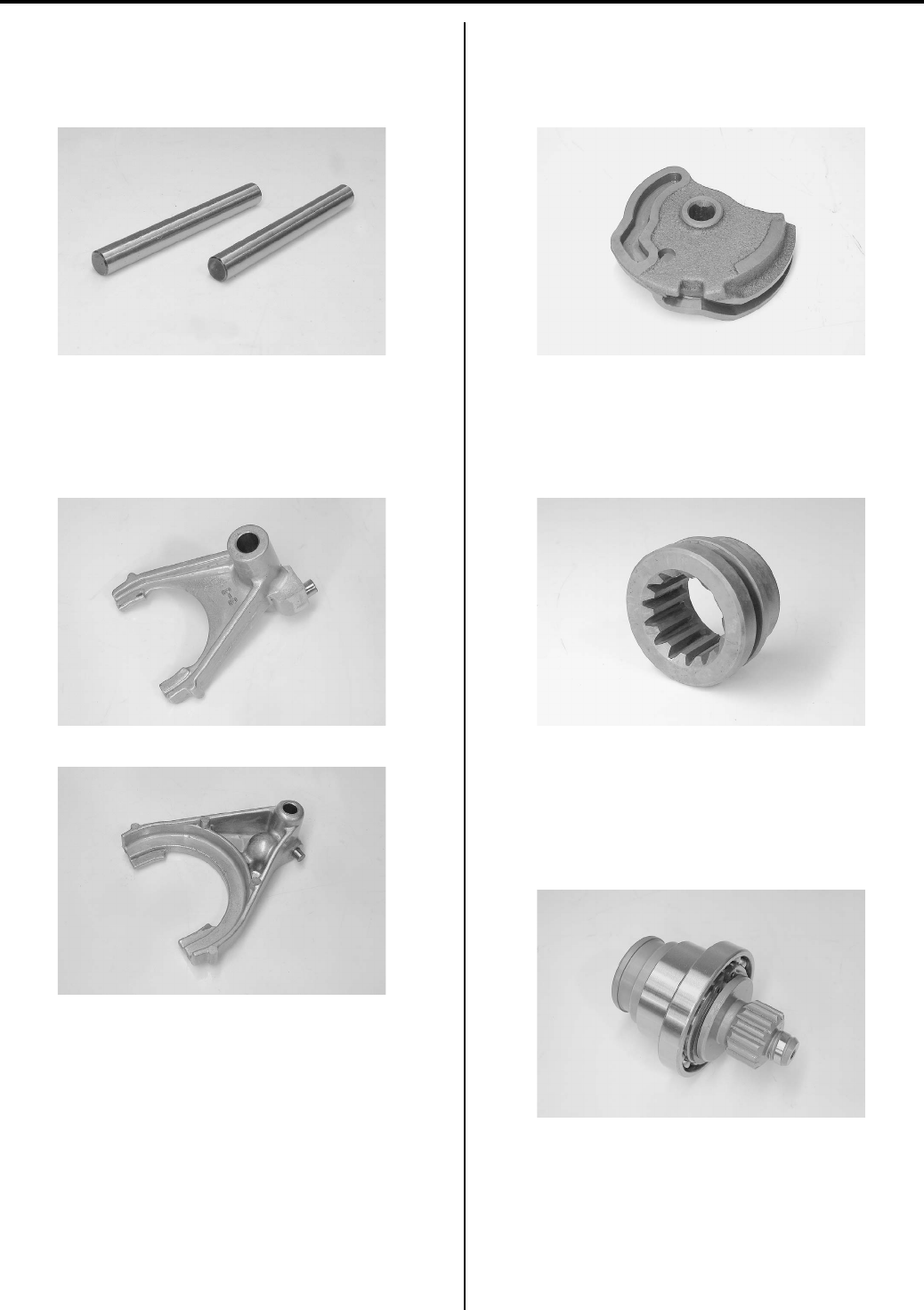
Differential: 3B-13
Diff-lock Shifting Shaft and 2WD/4WD Shifting Shaft
Inspect the 2WD/4WD shifting fork shafts for wear or
damage. If any defects are found, replace the shifting
fork shafts with new ones.
Diff-lock Shifting Fork and 2WD/4WD Shifting Fork
Inspect the shifting forks for wear or damage. If any
defects are found, replace the shifting forks with new
ones.
2WD/4WD Shifting Cam
Inspect the 2WD/4WD shifting cam for wear or damage.
If any defects are found, replace the 2WD/4WD shifting
cam with new ones.
2WD/4WD Shifting Sleeve
Inspect the 2WD/4WD shifting sleeve for wear or
damage. If any defects are found, replace the 2WD/4WD
shifting sleeve with new one.
Input Shaft
Inspect the input shaft for wear or damage.
Inspect the input shaft bearing for abnormal noise and
smooth rotation. If any defects are found, replace
defective parts.
I831G1320050-01
I831G1320051-01
I831G1320052-01
I831G1320143-01
I831G1320054-01
I831G1320055-01
PartShark.com
877-999-5686
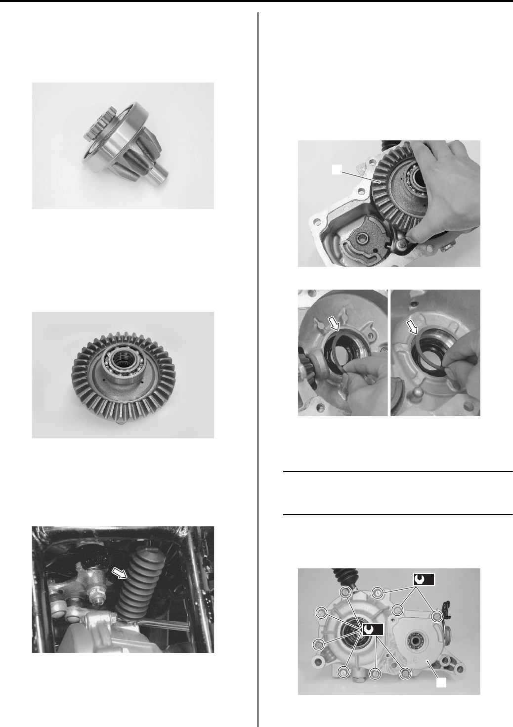
3B-14 Differential:
Pinion Gear
Inspect the pinion gear for wear or damage.
Inspect the pinion gear bearing for abnormal noise and
smooth rotation. If any defects are found, replace
defective parts.
Front Drive (Differential) Gear
Inspect the front drive (differential) gear for stick or
damage.
Inspect the front drive (differential) gear bearing for
abnormal noise and smooth rotation. If any defects are
found, replace defective parts.
Breather Rubber Case Inspection
B831G23206008
Inspect the breathe rubber case for wear or damage. If
any defects are found, replace the breather rubber case
with new one.
Front Drive (Differential) Gear Shim Inspection
and Selection
B831G23206009
Refer to “Front Drive (Differential) Assembly
Disassembly and Assembly (Page 3B-5)”.
Backlash
• Install the pinion gear, input shaft, left and right side
shim(s) and front drive (differential) gear assembly
(1).
• Install the front drive (differential) case (2) and tighten
the bolts to the specified torque diagonally.
NOTE
At this time, it is not necessary to apply a
sealant to the mating surface of the gear
case.
Tightening torque
Front drive (differential) case bolt (a): 22 N·m (2.2
kgf-m, 16.0 lb-ft)
I831G1320056-01
I831G1320057-01
I831G1320058-01
1
I831G1320059-01
I831G1320034-01
(a)
(a)
2
I831G1320060-02
PartShark.com
877-999-5686
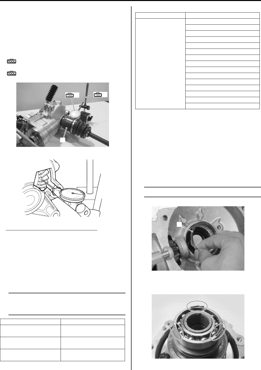
Differential: 3B-15
• Remove the oil filler cap and measure the backlash of
the differential ring gear using the horizontal type dial
gauge and drive shaft (3) as shown in the figure.
• Take backlash readings at three places while turning
the front drive (differential) gear slightly in each
direction and securely holding the pinion gear. Rear
the total backlash on the dial gauge.
Special tool
(A): 09900–20607 (Dial gauge (1/100 mm, 10
mm))
(B): 09900–20701 (Magnetic stand)
Front drive (differential) gear backlash
Standard: 0.05 – 0.10 mm (0.0020 – 0.0040 in)
• Remove the dial gauge and turn the front drive
(differential) gear 120°, then measure the backlash.
Repeat this procedure once more and compare the
difference of the three measurements. If the backlash
should be re-checked until the backlash is within
specification. Check the table at the appropriate shim
thickness.
NOTE
Adjust the backlash by referring to the table
at using the thickness of the removed shims
a guide.
List of shims (for right side)
• If the backlash is too small, replace the right side
shim(s) with a thicker one. If the backlash is too large,
replace the right side shim(s) with a thinner one. If the
right side shim was changed with a 0.10 mm thicker
shim, replace the left side shim with one that is 0.10
mm thinner.
Left Side Shim Selection
• Install the right side shim(s) (1) and front drive
(differential) gear assembly.
NOTE
Do not install the left side shim(s) at this time.
• Put a few pieces of solder (O.D.: 1.2 – 1.5 mm x L: 6
mm) on the bearing outer race, as shown in the figure.
Backlash Shim adjustment
Under 0.05 mm
(0.0020 in) Increase shim thickness
0.05 – 0.10 mm
(0.0020 – 0.0040 in) Correct
Over 0.10 mm
(0.0040 in) Decrease shim thickness
3
(A) (B)
I831G1320061-01
I831G1320062-01
Part No. Shim thickness
27445-38FA0
(Shim set: 15 pcs.)
0.75 mm (0.0295 in)
0.80 mm (0.0315 in)
0.85 mm (0.0335 in)
0.90 mm (0.0354 in)
0.95 mm (0.0374 in)
1.00 mm (0.0394 in)
1.05 mm (0.0413 in)
1.10 mm (0.0433 in)
1.15 mm (0.0453 in)
1.20 mm (0.0472 in)
1.25 mm (0.0492 in)
1.30 mm (0.0512 in)
1.35 mm (0.0531 in)
1.40 mm (0.0551 in)
1.45 mm (0.0571 in)
1
I831G1320064-01
I831G1320065-01
PartShark.com
877-999-5686
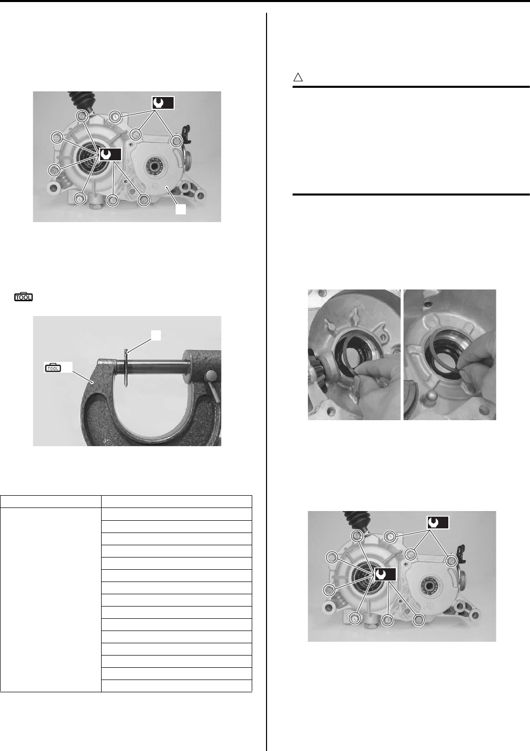
3B-16 Differential:
• Install the front drive (differential) case (2) and tighten
the bolts to the special torque diagonally.
Tightening torque
Front drive (differential) case bolt (a): 22 N·m (2.2
kgf-m, 16.0 lb-ft)
• Remove the front drive (differential) case.
• Measure the thickness of compressed solder (3) with
the micrometer.
Special tool
(A): 09900–20205 (Micrometer (0 – 25 mm))
• Select the proper size of shim(s) from the table,
according the compressed solder thickness.
List of shims (for left side)
• After selecting the proper size of shim(s), check or
adjust the backlash and tooth contact.
Tooth Contact
CAUTION
!
Make sure to check the backlash after the
tooth contact has been adjusted, since it may
have changed. Adjust the tooth contact and
backlash until they are both within
specification. If the correct tooth contact
cannot be maintained when adjusting the
backlash, replace the pinion gear and final
drive (differential) gear as a set.
• Clean and degreas several teeth on the final drive
(differential) gear and pinion gear, and the apply a
coating of machinist’s layout dye or paste to several
teeth of the pinion gear.
• Install the left and right side shims and front drive
(differential) assembly.
• Install the front drive (differential) case and tighten the
bolts to the specified torque diagonally.
Tightening torque
Front drive (differential) case bolt (a): 22 N·m (2.2
kgf-m, 16.0 lb-ft)
Part No. Shim thickness
27445-38FA0
(Shim set: 15 pcs.)
0.75 mm (0.0295 in)
0.80 mm (0.0315 in)
0.85 mm (0.0335 in)
0.90 mm (0.0354 in)
0.95 mm (0.0374 in)
1.00 mm (0.0394 in)
1.05 mm (0.0413 in)
1.10 mm (0.0433 in)
1.15 mm (0.0453 in)
1.20 mm (0.0472 in)
1.25 mm (0.0492 in)
1.30 mm (0.0512 in)
1.35 mm (0.0531 in)
1.40 mm (0.0551 in)
1.45 mm (0.0571 in)
(a)
(a)
2
I831G1320060-02
3
(A)
I831G1320066-01
I831G1320067-01
(a)
(a)
I831G1320068-01
PartShark.com
877-999-5686
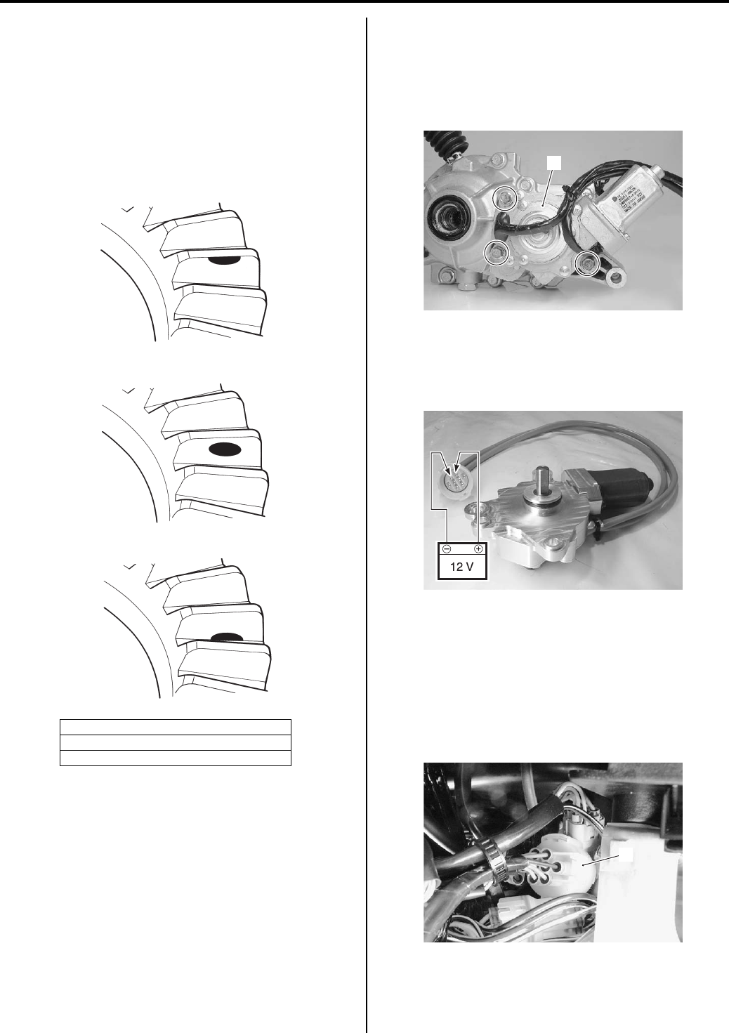
Differential: 3B-17
• Rotate the final drive (differential) gear several turns in
each direction. This will provide a contact pattern on
the coated teeth of final drive (differential) gear.
• Remove the final drive (differential) gear and compare
the coated teeth to the examples shown in [A], [B] and
[C].
• If tooth contact is found to be incorrect (example [A]
and [C]), the shim must be changed and the tooth
contact should be re-check until correct (example [B]).
2WD/4WD/Diff-lock System Inspection
B831G23206010
Actuator
Refer to “Front Drive (Differential) Assembly Removal
and Installation (Page 3B-4)”.
1) Remove the actuator assembly (1).
2) Connect the 12 V battery to the actuator lead wires
(Bl wire and Y wire). If the motor does not run,
replace the diff-lock/transfer actuator assembly with
a new one.
2WD/4WD/Diff-lock Switch
Continuity check
1) Remove the left inner fender. Refer to “Front Side
Exterior Parts Removal and Installation in Section
9D (Page 9D-6)”.
2) Disconnect the 2WD/4WD/diff-lock actuator coupler
(1).
[A]: Incorrect (Contact at tooth top)
[B]: Correct
[C]: Incorrect (Contact at tooth root)
[A]
[B]
[C]
I831G1320046-01
1
I831G1320069-01
I831G1320070-01
1
I831G1320071-01
PartShark.com
877-999-5686
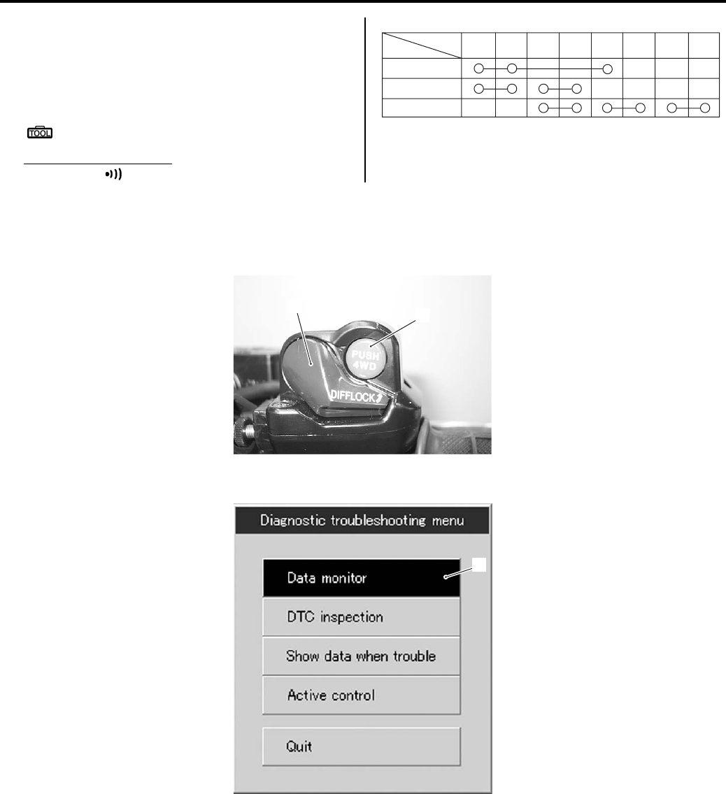
3B-18 Differential:
3) Inspect the 2WD/4WD/diff-lock switch for continuity
with a tester. If any abnormality is found, replace the
left handlebar switch assembly with a new one.
Refer to “Handlebars Removal and Installation in
Section 6B (Page 6B-3)”.
Special tool
: 09900–25008 (Multi-circuit tester set)
Tester knob indication
Continuity ( )
4) After finishing the 4WD/diff-lock inspection, reinstall
the removed parts.
SDS Operation Check
1) Check that the transfer selecting switch (diff-lock position switch (1) and diff-lock switch (2)) is turned OFF.
2) Set up the SDS tool. (Refer to the SDS operation manual for further details.)
3) Click the “Date monitor” button (3).
2WD
4WD
Diff-lock
Color
Position Bl/R O B W/Bl Br B/G B/Y B/W
I831G1320053-01
1
2
I831G1320072-01
3
I831G1320073-02
PartShark.com
877-999-5686
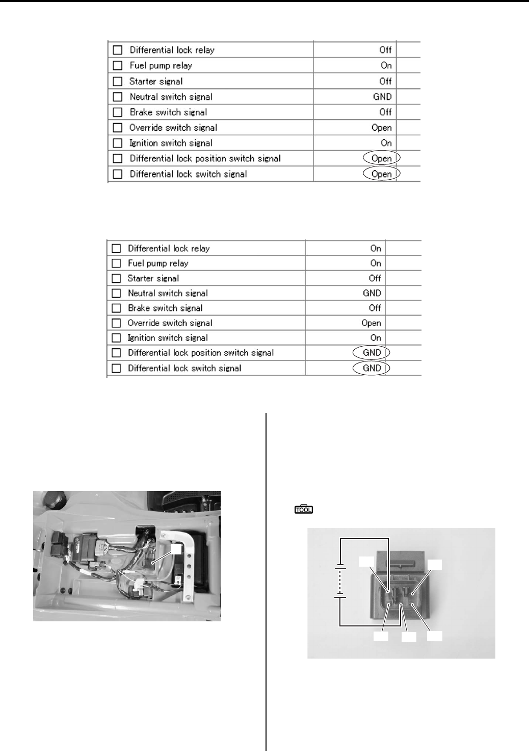
Differential: 3B-19
4) Check that both “Differential lock position switch signal” and “Differential lock switch signal” are “Open”.
5) Turn the transfer selecting switch (diff-lock position switch and diff-lock switch) ON position.
6) Check that both “Differential lock position switch signal” and “Differential lock switch signal” are “GND”.
If the transfer selecting switch dose not function properly, inspect the 4WD/diff-lock switch for continuity check.
Drive Relay
1) Remove the seat. Refer to “Front Side Exterior Parts
Removal and Installation in Section 9D (Page 9D-
6)”.
2) Remove the drive relay (1).
3) Check the continuity between “A” and “D”, between
“D” and “F” terminals with the multi-circuit tester.
Check the insulation between “A” and “E”, between
“E” and “F”. Apply 12 V to the terminals “C” and “E”
((+) to “E” and (–) to “C”), check the insulation
between “D” and “F”.
Special tool
: 09900–25008 (Multi-circuit tester set)
I831G1320074-01
I831G1320075-01
1
I831G1320076-01
“C”
“D”
“E”
“F”
“A”
I831G1320077-03
PartShark.com
877-999-5686
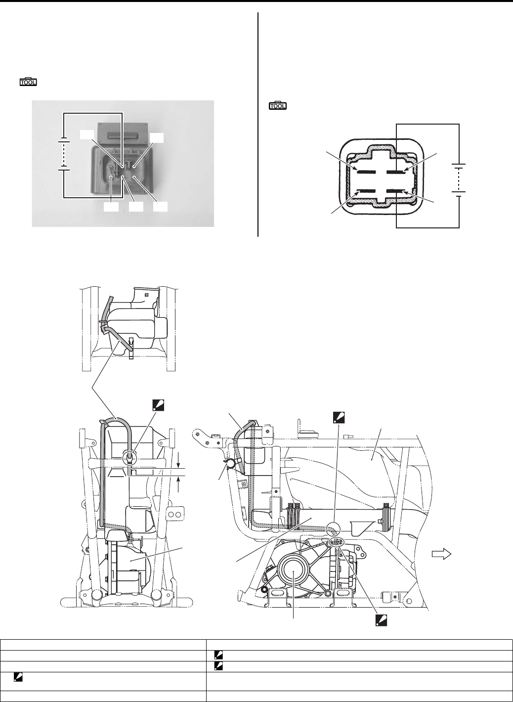
3B-20 Differential:
4) Apply 12 V to the terminal “B” and “E” ((+) to “E” and
(–) to “B”), check the insulation between “A” and “D”.
If any abnormality is found, replace the 4WD/diff-lock
relay with a new one.
Special tool
: 09900–25008 (Multi-circuit tester set)
Diff-lock Relay
Check the insulation between “A” and “B” terminals with
the multi-circuit tester. Then Apply 12 V to the terminal
“C” and “D” ((+) to “C” and (–) to “D”), check the
continuity between “A” and “B”. If there is no continuity,
replace the diff-lock relay with a new one.
Special tool
: 09900–25008 (Multi-circuit tester set)
Rear Drive Breather Hose Routing Diagram
B831G23206011
“D”
“E”
“F”
“A”
“B”
I831G1320078-03
“A”
“B”
“C”
“D”
I831G1320079-02
1
2
2
3
1
5
6
“A”
“B”
“a”
FWD
4
I831G1320145-02
1. Breather hose 6. V-belt cooling duct
2. Rear drive assembly “A”: Press the breather hose between the fuel tank lower cover and belt cooling duct.
3. Clamp “B”: Face the tip of clip to forward.
4. Clamp
: Set the clamp to the concave of belt cooling duct.
“a”: 20 – 30 mm (0.79 – 1.18 in)
5. Fuel tank
PartShark.com
877-999-5686
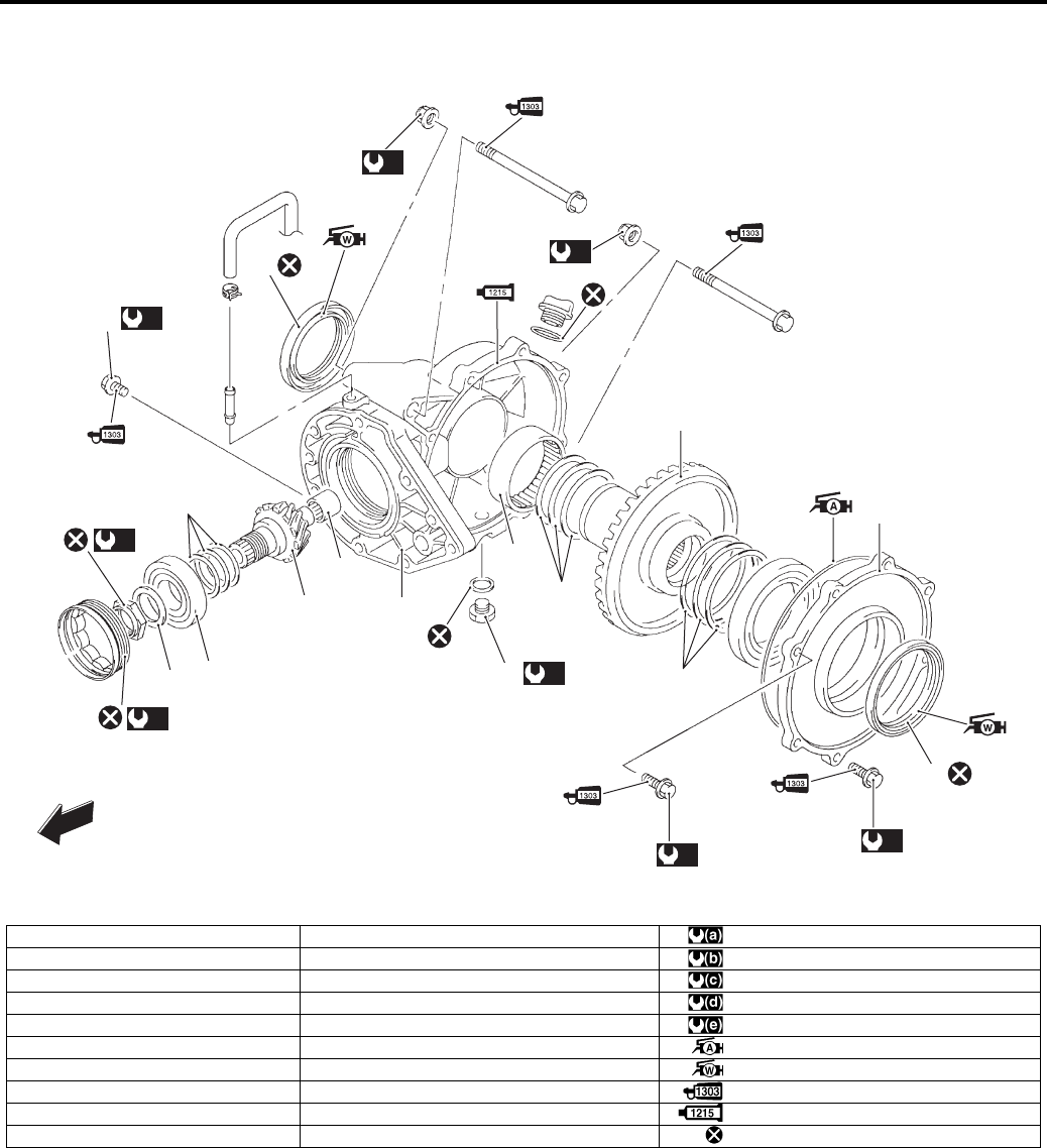
Differential: 3B-21
Final Gear Components
B831G23206012
1
2
3
4
5
6
7
8
910
11
12
13
(a)
14
(a)
15
(b)
16
(c)
17
(d)
17
(d)
18
(d)
19
FWD
20 (e)
I831G1320080-08
1. Final gear case 11. Shim : 100 N⋅m (10.0 kgf-m, 72.0 lb-ft)
2. Final gear case cover 12. Pinion gear : 26 N⋅m (2.6 kgf-m, 19.0 lb-ft)
3. Ring gear 13. Bearing : 55 N⋅m (5.5 kgf-m, 40.0 lb-ft)
4. Shim (Right side) 14. Pinion gear nut : 65 N⋅m (6.5 kgf-m, 47.0 lb-ft)
5. Shim (Left side) 15. Bearing stopper : 23 N⋅m (2.3 kgf-m, 16.5 lb-ft)
6. Bearing 16. Final drive gear case cover bolt (M8) : Apply grease.
7. Oil seal 17. Final drive gear case cover bolt (M10) : Apply water resistance grease.
8. Oil seal 18. Final gear case mounting nut : Apply thread lock to the thread part.
9. Washer 19. Final gear case mounting bolt : Apply bond to matching surface.
10. Bearing 20. Oil drain bolt : Do not reuse.
PartShark.com
877-999-5686
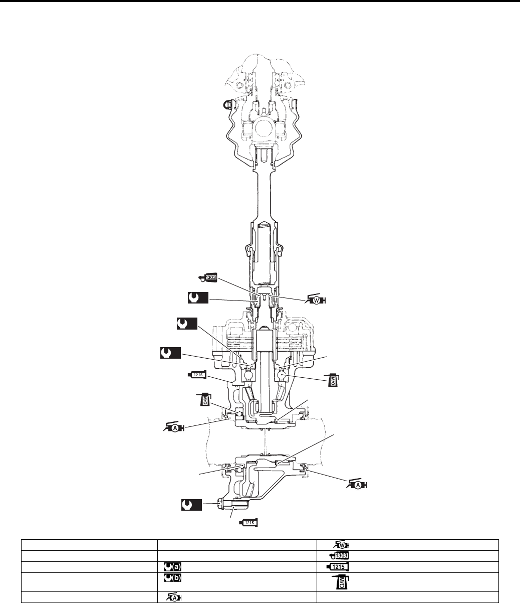
3B-22 Differential:
Final Gear Construction
B831G23206013
1
2
2
3
(b)
4
(b)
5
(b)
6
(a)
“A”
“A”
I831G1320081-04
1. Shim (Left side) 6. Lock-nut : Apply water resistance grease.
2. Shim (Right side) “A”: Matching surface : Apply thread lock to thread part.
3. Pinion gear shim(s) : 26 N⋅m (2.6 kgf-m, 19.0 lb-ft) : Apply bond.
4. Pinion gear nut : 100 N⋅m (10.0 kgf-m, 72.5 lb-ft) : Apply molybdenum oil solution.
5. Final drive bearing stopper : Apply grease.
PartShark.com
877-999-5686
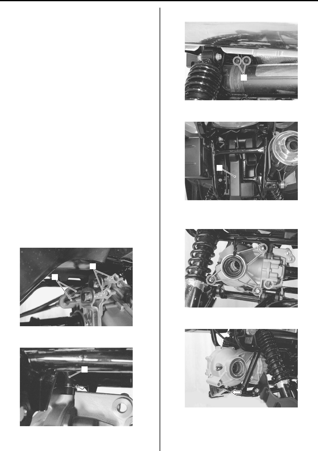
Differential: 3B-23
Final Gear Oil Level Inspection
B831G23206014
Refer to “Final Gear Oil Inspection in Section 0B
(Page 0B-14)”.
Final Gear Oil Replacement.
B831G23206015
Refer to “Final Gear Oil Inspection in Section 0B
(Page 0B-14)”.
Final Gear Assembly Removal and Installation
B831G23206016
Removal
1) Remove the trailer towing. Refer to “Trailer Towing
Removal and Instruction in Section 9E (Page 9E-7)”.
2) Remove the rear under cover. Refer to “Under Cover
Removal and Installation in Section 9D (Page 9D-
12)”.
3) Drain the final gear oil. Refer to “Final Gear Oil
Inspection in Section 0B (Page 0B-14)”.
4) Remove the rear wheel. Refer to “Front / Rear
Wheel Removal and Installation in Section 2D
(Page 2D-2)”.
5) Remove the rear suspension upper arms. Refer to
“Rear Suspension Arm Upper / Lower Removal and
Installation in Section 2C (Page 2C-8)”.
6) Remove the rear drive shaft. Refer to “Rear Drive
Shaft Assembly Removal and Installation in Section
3A (Page 3A-6)”.
7) Remove the rear brake adjust nuts (1) and brake
cables (2).
Disconnect the breather hose (3).
9) Loosen the outlet pipe connecting screws (4).
10) Remove the V-belt outlet cooling duct (5).
11) Remove the final gear assembly mounting bolts and
nuts.
12) Remove the rear final gear assembly for backward.
2
1
I831G1320083-02
3
I831G1320084-03
4
I831G1320085-02
5
I831G1320086-03
I831G1320087-02
I831G1320088-01
PartShark.com
877-999-5686
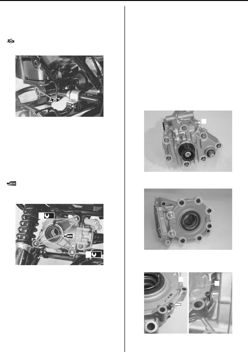
3B-24 Differential:
Installation
Installation the final gear assembly in the reverse order
of removal. Pay attention to the following points:
• Apply 4.5 gram water resistance grease to the spline
of the rear propeller shaft.
: Grease 99000–25160 (Water resistance
grease)
• Install the final gear case assembly to the frame.
• Apply thread lock to the mounting bolts and tighten
the rear final gear case mounting nuts (1) and bolts (2)
to the specified torque.
Tightening torque
Final gear case mounting nut (a): 65 N·m (6.5 kgf-
m, 47.0 lb-ft)
Final gear case mounting bolt (b): 65 N·m (6.5
kgf-m, 47.0 lb-ft)
: Thread lock cement 99000–32030
(THREAD LOCK CEMENT SUPER 1303 or
equivalent)
• Install the rear drive shaft (left and right). Refer to
“Rear Drive Shaft Assembly Removal and Installation
in Section 3A (Page 3A-6)”.
• Install the suspension upper arms. Refer to “Front
Suspension Upper / Lower Arm Removal and
Installation in Section 2B (Page 2B-9)”.
• Install the trailer towing. Refer to “Trailer Towing
Removal and Instruction in Section 9E (Page 9E-7)”.
• Adjust the rear brake pedal free travel. Refer to “Rear
Brake Pedal / Rear Brake (Parking Brake) Lever
Inspection and Adjustment in Section 0B (Page 0B-
19)”.
• Adjust the parking brake lever play. Refer to “Rear
Brake Pedal / Rear Brake (Parking Brake) Lever
Inspection and Adjustment in Section 0B (Page 0B-
19)”.
• Pour the final gear oil. Refer to “Final Gear Oil
Inspection in Section 0B (Page 0B-14)”.
Final Gear Assembly Disassembly and
Assembly
B831G23206017
Refer to “Final Gear Assembly Removal and Installation
(Page 3B-23)”.
Disassembly
1) Remove the rear brake assembly (1). Refer to “Rear
Brake Assembly Removal and Installation in Section
4C (Page 4C-2)”.
2) Remove the final gear cover bolts.
3) Remove the final gear cover (2) from the final gear
case, by using two 5 mm screws.
I831G1320089-01
(a)
1
(b)
2
I831G1320090-06
1
I831G1320092-01
I831G1320093-01
2
2
I831G1320094-02
PartShark.com
877-999-5686
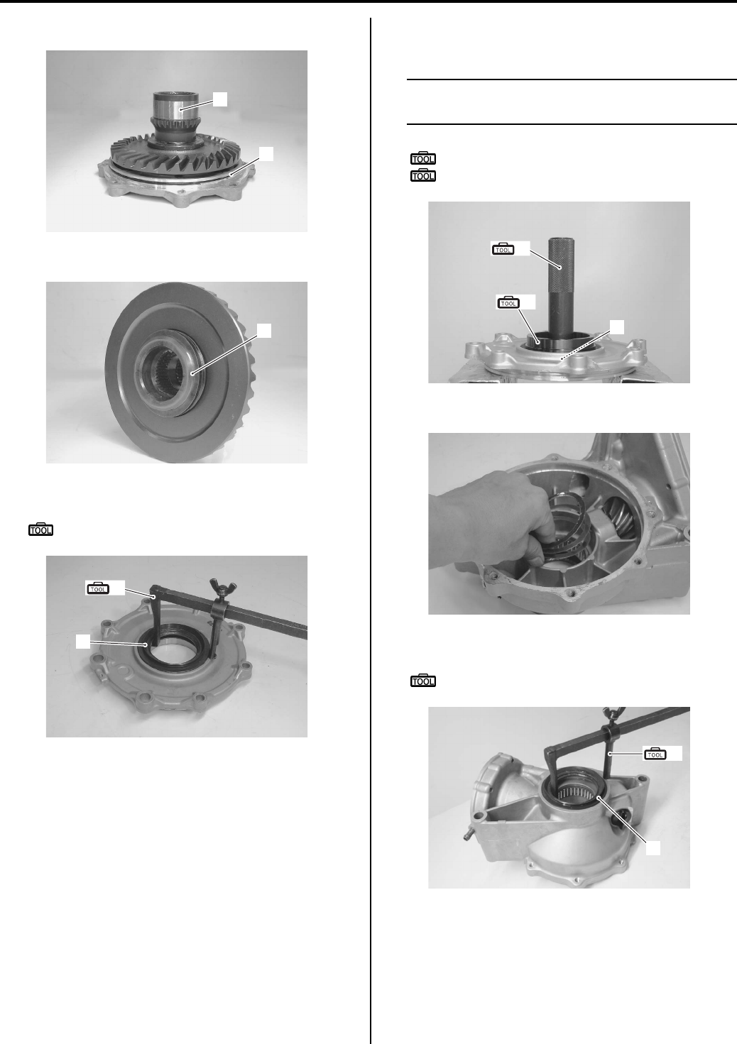
Differential: 3B-25
4) Remove the O-ring (3) and final driven gear (4).
5) Remove the shim(s) (5).
6) Remove the oil seal (6) with the special tool.
Special tool
(A): 09913–50121 (Oil seal remover)
7) Remove the final driven gear bearing (7) with the
special tool.
NOTE
If there is no abnormal condition, the bearing
removal is not necessary.
Special tool
(B): 09913–70210 (Bearing installer set)
(C): 09944–66010 (Bearing installer)
Remove the shim(s).
9) Remove the oil seal (8) with the special tool.
Special tool
(A): 09913–50121 (Oil seal remover)
3
4
I831G1320095-01
5
I831G1320096-02
(A)
6
I831G1320097-01
(B)
(C)
7
I831G1320098-01
I831G1320099-01
(A)
8
I831G1320100-01
PartShark.com
877-999-5686
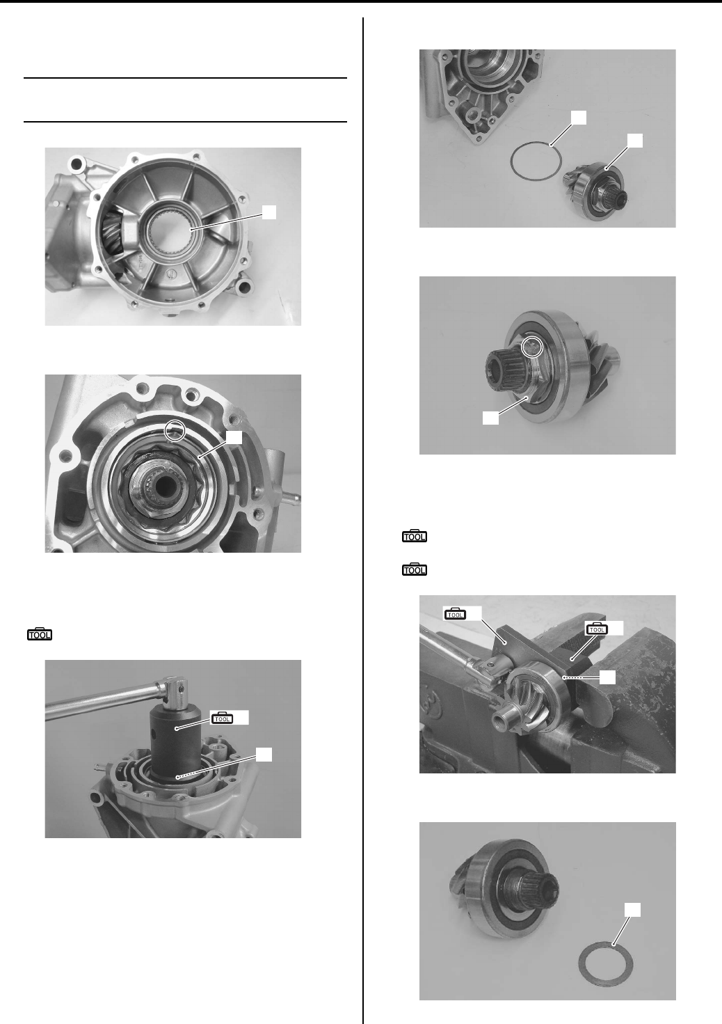
3B-26 Differential:
10) Remove the final driven gear bearing (9) with the
suitable tool.
NOTE
If there is no abnormal condition, the bearing
removal is not necessary.
11) Unlock the final drive stopper (10) with a chisel.
12) Remove the final drive stopper (11) with the special
tool.
Special tool
(D): 09924–41830 (Bearing retainer wrench)
13) Remove the final drive gear (12) and shim(s) (13).
14) Unlock the rear final drive nut (14) with a chisel.
15) Remove the final drive gear nut (14) with the special
tool.
Special tool
(E): 09924–52470 (Fixed final drive gear
holder)
(F): 09940–92430 (Rear axel wrench A)
16) Remove the washer (15).
9
I831G1320101-01
10
I831G1320102-01
(D)
11
I831G1320103-01
12
13
I831G1320104-01
14
I831G1320105-01
(E)
(F)
14
I831G1320106-02
15
I831G1320107-02
PartShark.com
877-999-5686
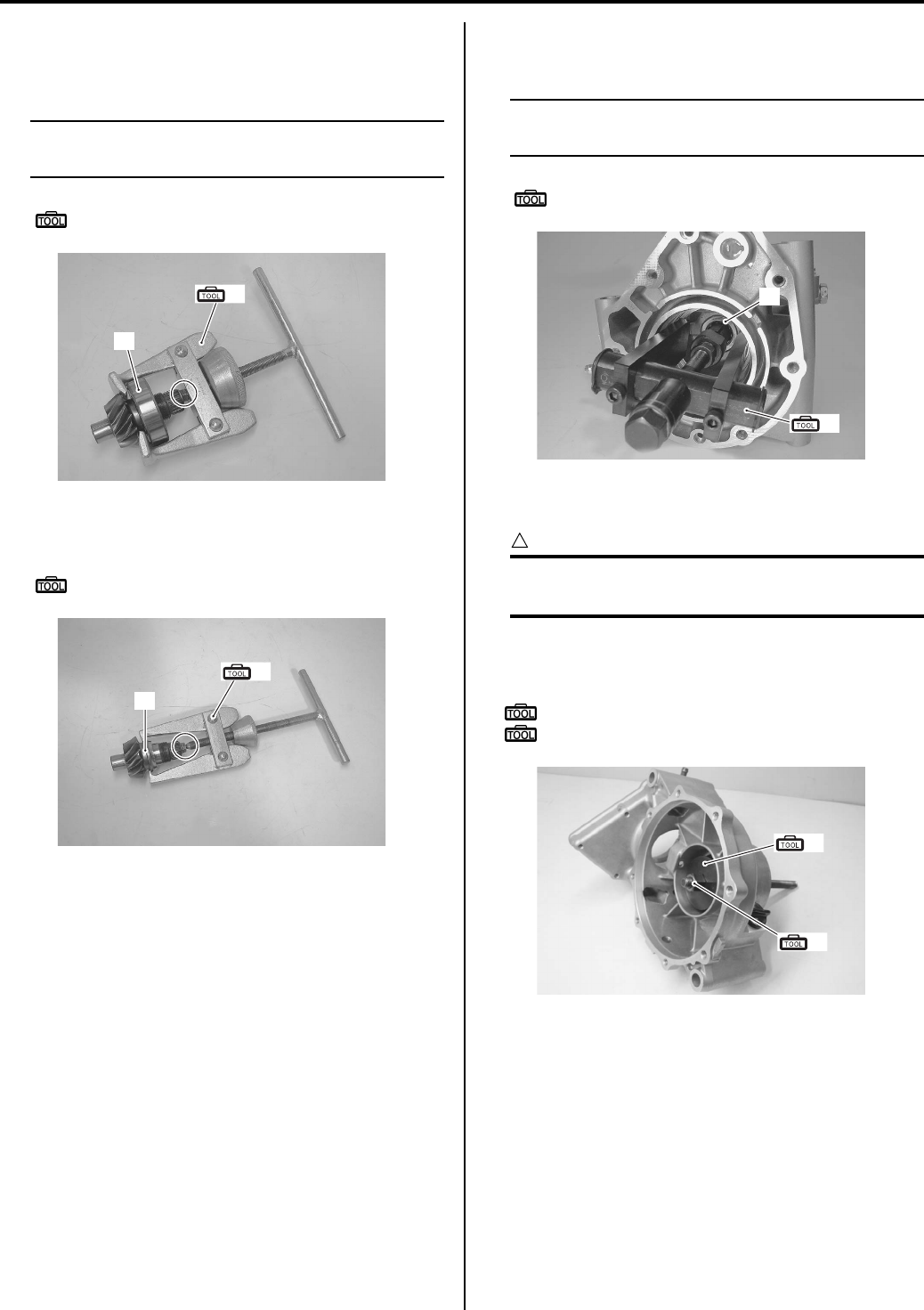
Differential: 3B-27
17) Remove the bearing (16) and the upper inner race
from the pinion gear with the special tool and
suitable tool.
NOTE
If there is no abnormal condition, the bearing
removal is not necessary.
Special tool
(G): 09913–61510 (Bearing puller)
18) Remove the lower inner race (17) with the special
tool.
Special tool
(H): 09913–60910 (Bearing remover)
19) Remove the final drive gear bearing (18) with the
special tool.
NOTE
If there is no abnormal condition, the bearing
removal is not necessary.
Special tool
(I): 09921–20240 (Bearing remover set)
Assembly
CAUTION
!
The removed oil seals, O-rings and bearings
must be replaced with new ones.
• Install the gear case bearing to the gear case with the
special tool.
Special tool
(A): 09913–70210 (Bearing installer set)
(B): 09924–84521 (Bearing installer set)
(G)
16
I831G1320108-01
(H)
17
I831G1320110-01
(I)
18
I831G1320111-01
(A)
(B)
I831G1320112-01
PartShark.com
877-999-5686
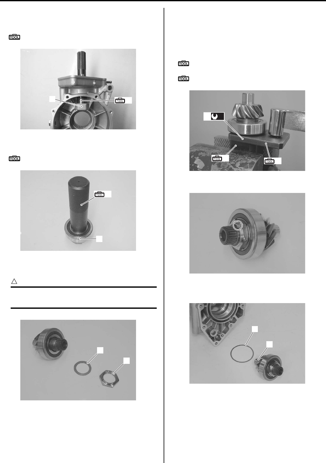
3B-28 Differential:
• Install the final drive gear bearing (1) to the final gear
case with the special tool.
Special tool
(A): 09913–70210 (Bearing installer set)
• Install the final drive bearing (2) with the special tool.
Special tool
(C): 09913–84510 (Bearing installer)
• Install the washer (3) and lock-nut (4) to the final drive
gear.
CAUTION
!
The removed lock-nut (4) must be replaced
with a new one.
• Tighten the lock-nut (4) to the specified torque with
the special tool.
Tightening torque
Final drive lock-nut (a): 100 N·m (10.0 kgf-m, 72.5
lb-ft)
Special tool
(D): 09924–52470 (Fixed final drive gear
holder)
(E): 09940–92430 (Rear axel wrench A)
• Lock the nut with a center punch.
• Install the shim(s) (5) and final drive gear (6) to the
final gear case.
1(A)
I831G1320113-01
(C)
2
I831G1320114-03
3
4
I831G1320115-01
(a)
4
(D) (E)
I831G1320116-02
I831G1320117-01
5
6
I831G1320118-02
PartShark.com
877-999-5686
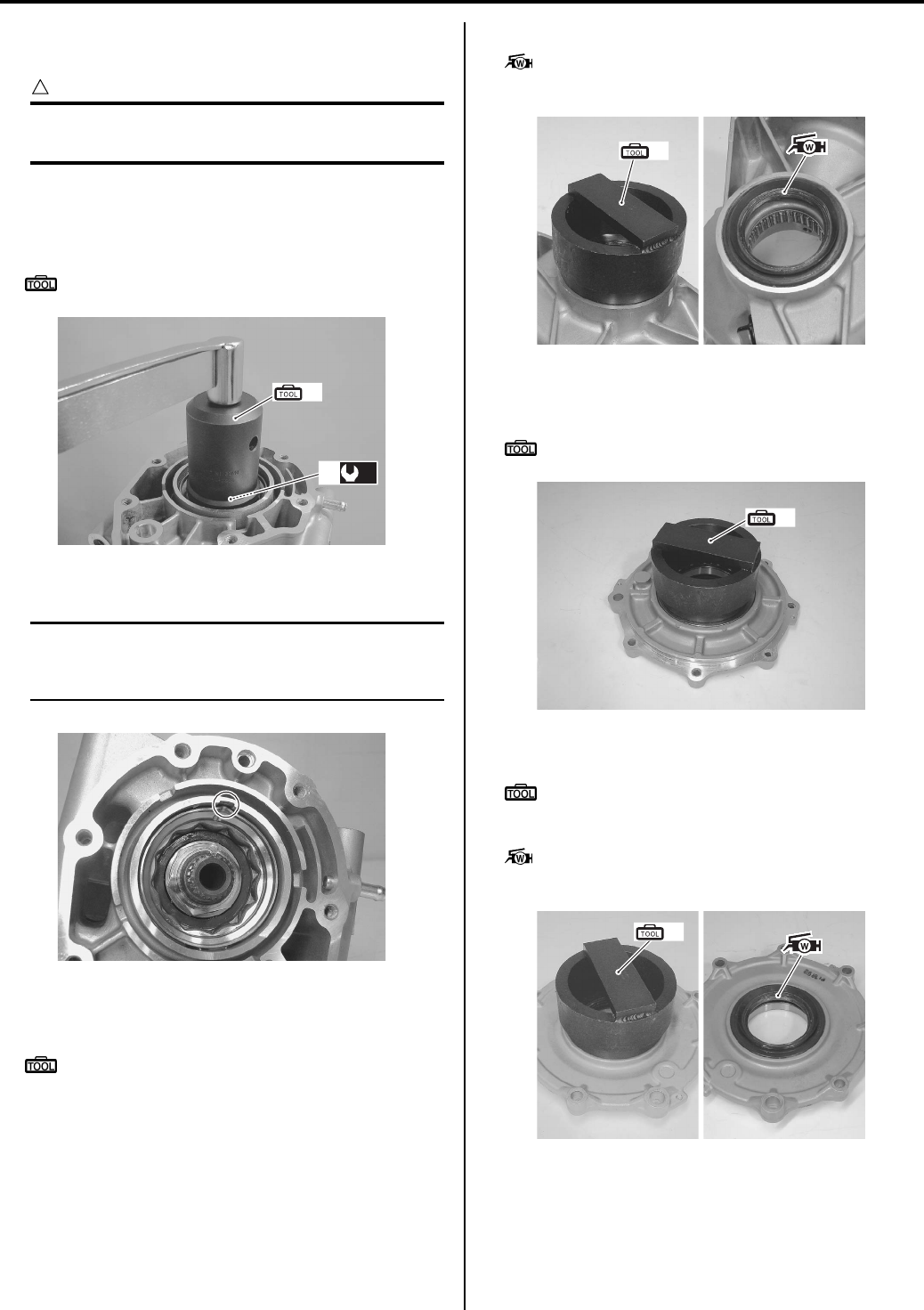
Differential: 3B-29
• Tighten the final drive gear bearing stopper (7) to the
specified torque with the special tool.
CAUTION
!
The removed final drive gear bearing stopper
must be replaced with a new one.
Tightening torque
Final drive gear bearing stopper (b): 100 N·m (
10.0 kgf-m, 72.5 lb-ft)
Special tool
(F): 09924–41830 (Bearing retainer wrench)
• Lock the bearing stopper with a center punch.
NOTE
After the backlash and tooth contact have
been checked or adjusted, stake the collar of
bearing stopper into the notch.
• Install the oil seal to the final gear case with the
special tool.
Special tool
(G): 09951–15810 (Bearing installer)
• Apply a small quantity of grease to the oil seal lip.
: Grease 99000–25160 (Water resistance
grease)
• Install the final driven gear bearing cover with the
special tool.
Special tool
(G): 09951–15810 (Bearing installer)
• Install the oil seal with the special tool.
Special tool
(G): 09951–15810 (Bearing installer)
• Apply a small quantity of grease to the oil seal lip.
: Grease 99000–25160 (Water resistance
grease)
(b)
7
(F)
I831G1320119-02
I831G1320120-01
(G)
I831G1320121-03
(G)
I831G1320122-02
(G)
I831G1320123-03
PartShark.com
877-999-5686
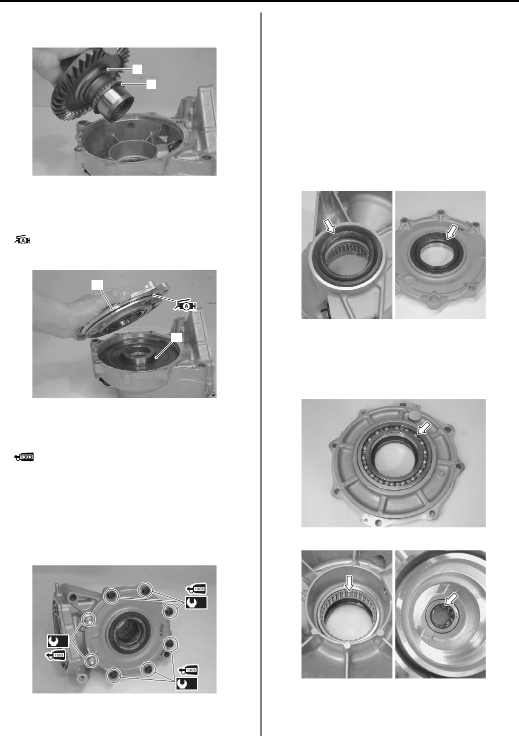
3B-30 Differential:
• Install the final driven gear (8) and shim(s) (9) into the
final gear case.
• Install the shim(s) (10).
• Install the O-ring to the final gear cover (11).
• Apply a small quantity of grease to the O-ring.
: Grease 99000–25010 (SUZUKI SUPER
GREASE A or equivalent)
• Apply a small quantity of thread lock to the final gear
cover tools and tighten them to the specified torque
diagonally.
: Thread lock cement 99000–32030
(THREAD LOCK CEMENT SUPER 1303 or
equivalent)
Tightening torque
Final gear cover bolt (M8) (c): 26 N·m (2.6 kgf-m,
19.0 lb-ft)
Final gear cover bolt (M10) (d): 55 N·m (5.5 kgf-
m, 40.0 lb-ft)
• Check the backlash and tooth contact. Refer to “Final
Gear Shim Inspection and Selection (Page 3B-31)”.
• Install the rear brake assembly. Refer to “Rear Brake
Assembly Removal and Installation in Section 4C
(Page 4C-2)”.
Final Gear Related Parts Inspection
B831G23206018
Refer to “Final Gear Assembly Removal and Installation
(Page 3B-23)”.
Final Driven Gear Oil Seal
Inspect the oil seals lip for damage or wear. If any defect
are found, replace the oil seals with new ones.
Final Driven / Drive Gear Bering
Inspect the bearings for abnormal noise and smooth
rotation. Replace the bearings if there is anything
unusual.
8
9
I831G1320124-01
10
11
I831G1320125-01
(d)
(c)
(c)
I831G1320126-01
I831G1320127-01
I831G1320128-01
I831G1320129-01
PartShark.com
877-999-5686
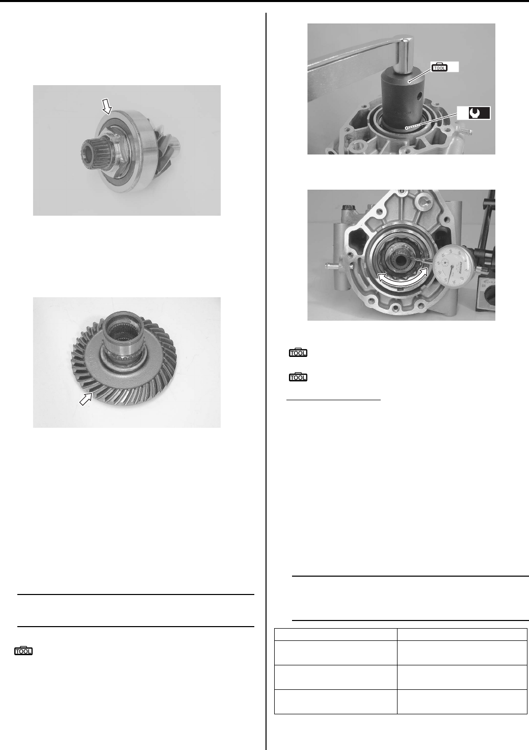
Differential: 3B-31
Final Drive Gear
Inspect the final drive gear for wear or damage.
Inspect the final drive gear bearing for abnormal noise
and smooth rotation. If any defects are found, replace
defective parts.
Final Driven Gear
Inspect the final driven gear for wear or damage. If any
defects are found, replace drive and driven gear as a
set.
Final Gear Shim Inspection and Selection
B831G23206019
Refer to “Final Gear Assembly Removal and Installation
(Page 3B-23)”.
Backlash
• Install the shim(s), final drive gear assembly and new
final drive gear bearing stopper.
• Tighten the final drive gear bearing stopper (1) to the
specified torque with the special tool.
NOTE
As this time, it is not necessary to bend the
bearing stopper collar.
Special tool
(A): 09924–41830 (Bearing retainer wrench)
Tightening torque
Final drive gear bearing stopper (a): 100 N·m (
10.0 kgf-m, 72.5 lb-ft)
• Install the left side shim(s) and final driven gear.
Special tool
: 09900–20607 (Dial gauge (1/100 mm, 10
mm))
: 09900–20701 (Magnetic stand)
Final gear backlash
Standard: 0.02 – 0.06 mm (0.0008 – 0.0024 in)
(without gear cover specification)
Standard: 0.08 – 0.15 mm (0.0031 – 0.0059 in)
(Gear cover assembled specification)
Measure the backlash with the dial gauge, as shown.
Take backlash readings at several places while
turning the gear shift in each direction and securely
holding the final driven gear. If the backlash is not
within specification, the shim must be changed and
the backlash should be re-checked until the backlash
is within specification. Check to the table for the
appropriate shim thickness.
NOTE
Adjust the backlash by referring to the table
at using the thickness of the removed shims
as a guide.
• Check the left side shim selection.
I831G1320130-01
I831G1320131-01
Backlash Shim adjustment
Under 0.02 mm
(0.0008 in) Increase shim thickness
0.02 – 0.06 mm
(0.0008 – 0.0024 in) Correct
Over 0.06 mm
(0.0024 in) Decrease shim thickness
(a)
1
(A)
I831G1320132-01
I831G1320133-01
PartShark.com
877-999-5686
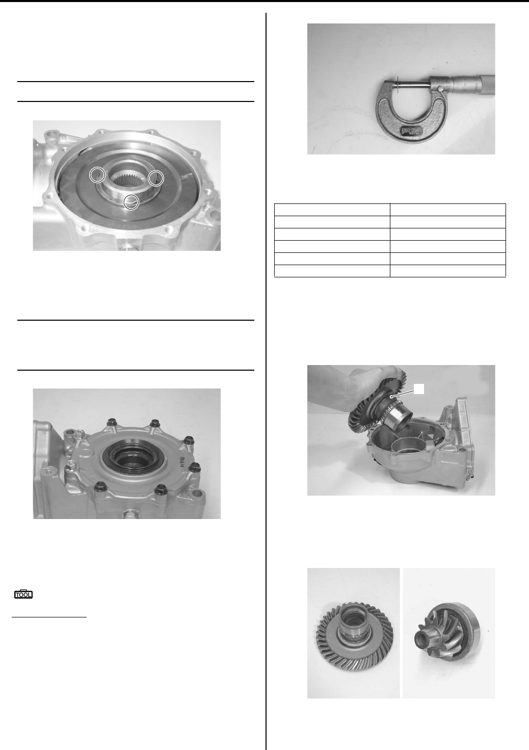
3B-32 Differential:
Left Side Shim Selection
Put a few pieces of solder (O.D.: 1.2 – 1.5 mm x L: 6
mm) on the back side of final driven gear, as shown in
the figure.
NOTE
Do not install the left side shim(s) at this time.
• Install the final gear cover and tighten its bolts to the
specified torque diagonally. Refer to “Final Gear
Assembly Disassembly and Assembly (Page 3B-24)”.
NOTE
• Do not install the new O-ring to the gear
cover.
• Do not apply a thread lock to the bolts.
• Remove the final gear cover.
• Measure the thickness of compressed solder with the
micrometer.
Special tool
: 09900–20205 (Micrometer (0 – 25 mm))
Shim thickness
Compressed solder thickness + 0.10 mm
• Select the proper size of shim(s) from the table,
according as the compressed solder thickness.
LIst of shims (for left side)
After selecting the proper size of shim(s), check or
adjust the backlash and tooth contact.
Tooth Connect
• Remove the final driven gear assembly (1).
• Clean and degreas several teeth on the final drive
gear and final driven gear, and then apply a coating of
machinist’s layout dye or paste to several teeth of the
final drive gear.
I831G1320134-01
I831G1320135-01
Part No. Shim thickness
27326-31G00-030 0.30 mm (0.0118 in)
27326-31G00-035 0.35 mm (0.0138 in)
27326-31G00-040 0.40 mm (0.0157 in)
27326-31G00-050 0.50 mm (0.0197 in)
27326-31G00-060 0.60 mm (0.0236 in)
I831G1320136-01
1
I831G1320137-01
I831G1320138-01
PartShark.com
877-999-5686
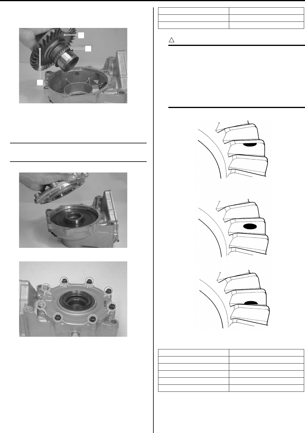
Differential: 3B-33
• Install the left and right side shim(s) (2) and final
driven gear assembly (1).
• Install the final gear cover, and then tighten the bolts
to the specified torque diagonally. Refer to “Final Gear
Assembly Disassembly and Assembly (Page 3B-24)”.
NOTE
At this time, it is not necessary to install the
gear case cover’s O-ring.
• Rotate the final driven gear several turns in each
direction. This will provide connect pattern on the
coated teeth of the gear.
• Remove the final drive gear and compare the coated
teeth to the examples shown in [A], [B] and [C].
If tooth contact is found to be incorrect (examples [A]
and [C]), the shim between the final drive gear bearing
and gear case must be changed and the tooth contact
should be re-checked until the tooth contact is found
to be correct (example [B]).
CAUTION
!
Make sure to check the backlash and shim
thickness after the tooth contact has been
adjusted, since it may have changed. Adjust
the tooth contact and backlash until they are
both within specification. If the correct tooth
contact cannot be maintained when adjusting
the backlash, replace the final drive gear and
final driven gear as a set.
List of shims (for final drive gear)
1
2
2
I831G1320139-01
I831G1320140-01
I831G1320141-01
Tooth contact Shim adjustment
Contact at tooth top [A] Decrease shim thickness
Contact at tooth top [C] Increase shim thickness
Part No. Shim thickness
27445-24A01-030 0.30 mm (0.0118 in)
27445-24A01-035 0.35 mm (0.0138 in)
27445-24A01-040 0.40 mm (0.0157 in)
27445-24A01-050 0.50 mm (0.0197 in)
27445-24A01-060 0.60 mm (0.0236 in)
Incorrect (Contact at tooth top)
Incorrect (Contact at tooth root)
Correct
[A]
[C]
[B]
I831G1320142-02
PartShark.com
877-999-5686
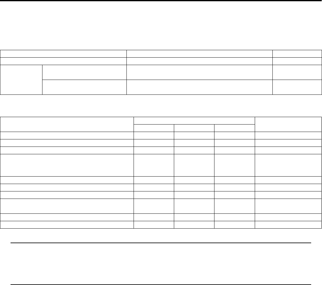
3B-34 Differential:
Specifications
Service Data
B831G23207001
Drive Train
Unit: mm (in)
Tightening Torque Specifications
B831G23207002
NOTE
The specified tightening torque is also described in the following.
“Front Drive (Differential) Components (Page 3B-2)”
“Front Drive (Differential) Construction (Page 3B-3)”
“Final Gear Components (Page 3B-21)”
“Final Gear Construction (Page 3B-22)”
Reference:
For the tightening torque of fastener not specified in this section, refer to “Tightening Torque List in Section 0C
(Page 0C-7)”.
Item Standard Limit
Front drive (differential) gear backlash 0.05 – 0.10 (0.0020 – 0.0040) —
Front gear
backlash
Without gear cover
specification 0.02 – 0.06 (0.0008 – 0.0024) —
Gear cover assembled
specification 0.08 – 0.15 (0.0031 – 0.0059) —
Fastening part Tightening torque Note
N⋅mkgf—mlb—ft
Front drive (differential) mounting nut 50 5.0 36.0 )(Page 3B-5)
Front drive (differential) case cover bolt 22 2.2 16.0 )(Page 3B-11)
4WD/Diff-lock actuator mounting bolt 22 2.2 16.0 )(Page 3B-12)
Front drive (differential) case bolt
22 2.2 16.0
)(Page 3B-14) /
)(Page 3B-16) /
)(Page 3B-16)
Final gear case mounting nut 65 6.5 47.0 )(Page 3B-24)
Final gear case mounting bolt 65 6.5 47.0 )(Page 3B-24)
Final drive lock-nut 100 10.0 72.5 )(Page 3B-28)
Final drive gear bearing stopper 100 10.0 72.5 )(Page 3B-29) /
)(Page 3B-31)
Final gear cover bolt (M 26 2.6 19.0 )(Page 3B-30)
Final gear cover bolt (M10) 55 5.5 40.0 )(Page 3B-30)
PartShark.com
877-999-5686
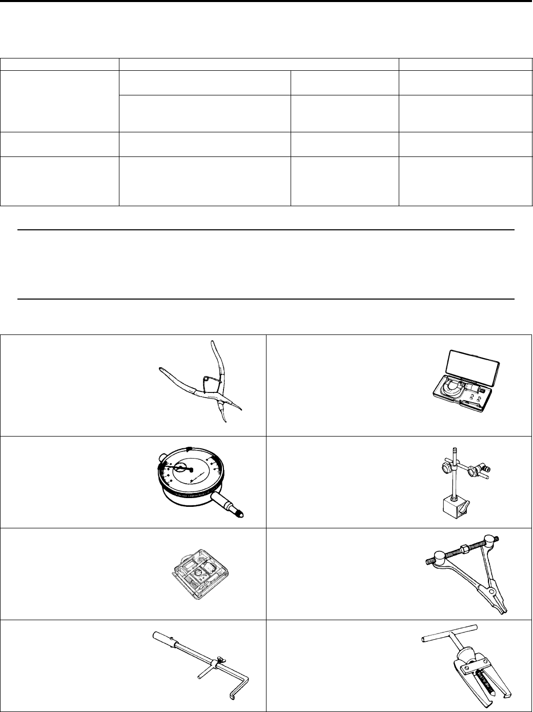
Differential: 3B-35
Special Tools and Equipment
Recommended Service Material
B831G23208001
NOTE
Required service material is also described in the following.
“Front Drive (Differential) Components (Page 3B-2)”
“Front Drive (Differential) Construction (Page 3B-3)”
“Final Gear Components (Page 3B-21)”
“Final Gear Construction (Page 3B-22)”
Special Tool
B831G23208002
Material SUZUKI recommended product or Specification Note
Grease SUZUKI SUPER GREASE A or
equivalent
P/No.: 99000–25010 )(Page 3B-9) / )(Page 3B-
12) / )(Page 3B-30)
Water resistance grease P/No.: 99000–25160 )(Page 3B-5) / )(Page 3B-
24) / )(Page 3B-29) /
)(Page 3B-29)
Sealant SUZUKI BOND No.1215 or
equivalent
P/No.: 99000–31110 )(Page 3B-11)
Thread lock cement THREAD LOCK CEMENT SUPER
1303 or equivalent
P/No.: 99000–32030 )(Page 3B-5) / )(Page 3B-
11) / )(Page 3B-12) /
)(Page 3B-24) /
)(Page 3B-30)
09900–06108 09900–20205
Snap ring pliers Micrometer (0 – 25 mm)
)(Page 3B-6) / )(Page 3B-
6) / )(Page 3B-7) /
)(Page 3B-7) / )(Page 3B-
9) / )(Page 3B-9) /
)(Page 3B-10) /
)(Page 3B-10)
)(Page 3B-16) /
)(Page 3B-32)
09900–20607 09900–20701
Dial gauge (1/100 mm, 10
mm)
Magnetic stand
)(Page 3B-15) /
)(Page 3B-31)
)(Page 3B-15) /
)(Page 3B-31)
09900–25008 09912–34510
Multi-circuit tester set Cylinder disassembling tool
)(Page 3B-18) /
)(Page 3B-19) /
)(Page 3B-20) /
)(Page 3B-20)
)(Page 3B-5)
09913–50121 09913–60910
Oil seal remover Bearing remover
)(Page 3B-25) /
)(Page 3B-25)
)(Page 3B-7) / )(Page 3B-
7) / )(Page 3B-8) /
)(Page 3B-27)
PartShark.com
877-999-5686
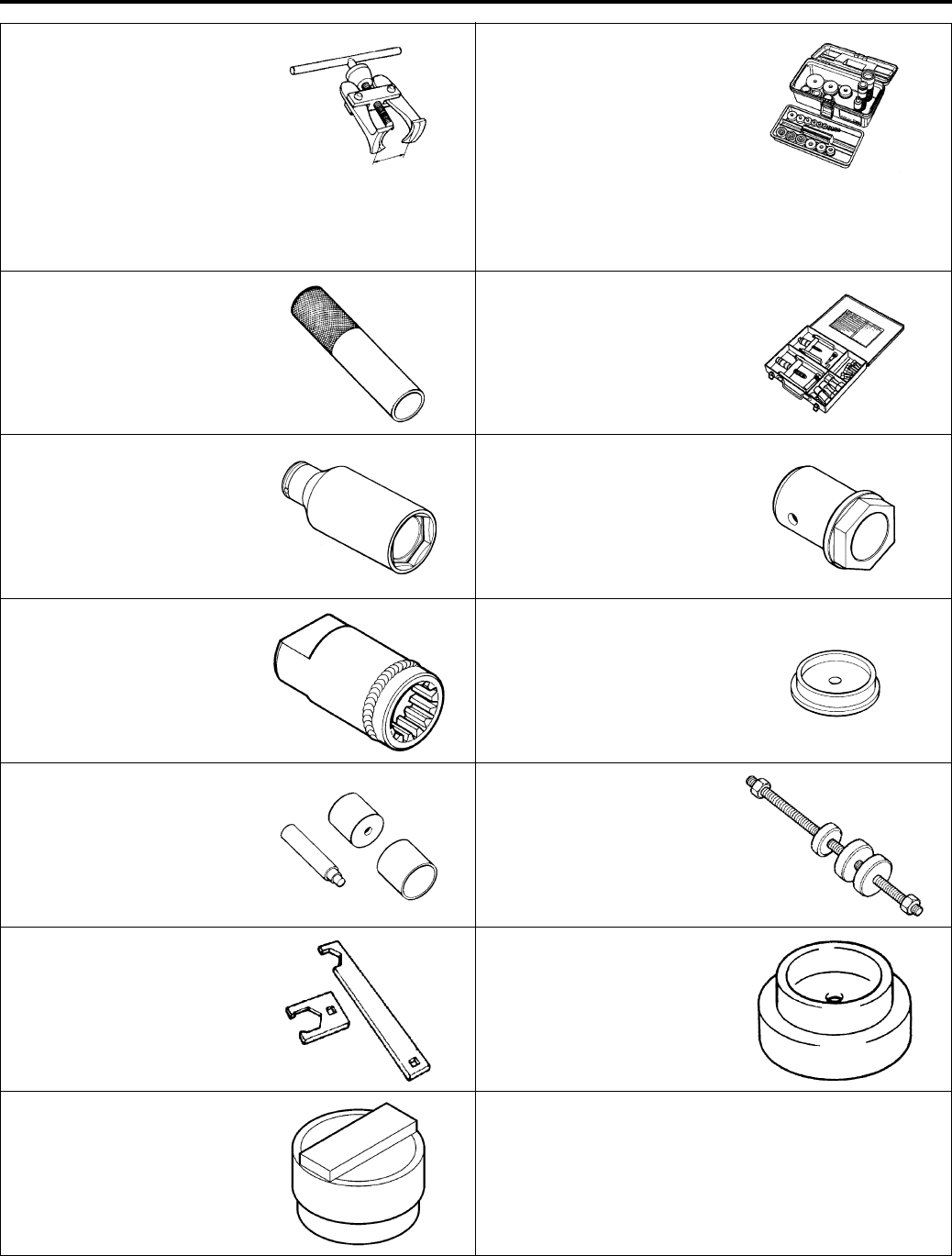
3B-36 Differential:
09913–61510 09913–70210
Bearing puller Bearing installer set
)(Page 3B-27) )(Page 3B-6) / )(Page 3B-
/ )(Page 3B-8) /
)(Page 3B-8) / )(Page 3B-
9) / )(Page 3B-9) /
)(Page 3B-10) /
)(Page 3B-10) /
)(Page 3B-25) /
)(Page 3B-27) /
)(Page 3B-28)
09913–84510 09921–20240
Bearing installer Bearing remover set
)(Page 3B-28) )(Page 3B-6) / )(Page 3B-
/ )(Page 3B-27)
09922–21410 09924–41830
Long socket (46 mm) Bearing retainer wrench
)(Page 3B-9) )(Page 3B-26) /
)(Page 3B-29) /
)(Page 3B-31)
09924–52470 09924–74520
Fixed final drive gear holder Oil seal installer/remover
)(Page 3B-26) /
)(Page 3B-28)
)(Page 3B-9)
09924–74570 09924–84521
Final drive gear bearing
installer/remover
Bearing installer set
)(Page 3B-9) )(Page 3B-8) / )(Page 3B-
27)
09940–92430 09944–66010
Rear axel wrench A Bearing installer
)(Page 3B-26) /
)(Page 3B-28)
)(Page 3B-8) / )(Page 3B-
25)
09951–15810
Bearing installer
)(Page 3B-29) /
)(Page 3B-29) /
)(Page 3B-29)
PartShark.com
877-999-5686
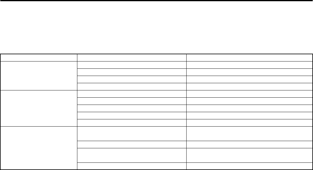
Transfer: 3C-1
Driveline / Axle
Transfer
Diagnostic Information and Procedures
Transfer Symptom Diagnosis
B831G23304001
Condition Possible cause Correction / Reference Item
Engine is noisy (Noise
seems to come from the
transfer)
Worn or rubbing gear. Replace.
Worn transfer input/output shaft. Replace shaft.
Worn bearing. Replace.
Worn splines. Replace.
Transfer will not shift
back
Broken return spring on shift shaft. Replace.
Distorted gearshift forks. Replace.
Worn gearshift shaft. Replace.
Broken gearshift cam. Replace.
Improperly adjusted gearshift cable. Adjust.
Transfer jumps out of
gear
Worn shifting gears on drive shaft or
counter shaft.
Replace.
Distorted or worn gearshift forks. Replace.
Weakened return spring on gearshift
stopper.
Replace.
Worn gearshift stopper cam plate. Replace.
PartShark.com
877-999-5686
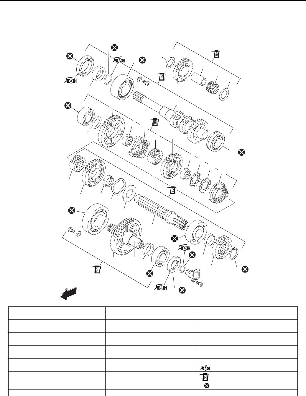
3C-2 Transfer:
Repair Instructions
Transfer Components
B831G23306001
1
1
2
3
5
6
9
10
20
20
12
13
14 15
16 17
14 18
4
21
19
22 23 24
25
26
28
29 30
33
27
FWD
8
7
11
35
32
31
34
I831G1330001-09
1. Washer 14. Driven gear bushing 27. Counter shaft bearing (Left side)
2. Reverse idle gear 15. Select sliding dog 28. Spacer
3. Reverse idle gear shaft 16. Reverse select spacer 29. Drive gear No. 2
4. Reverse idle gear bearing 17. Reverse driven gear 30. Snap ring
5. Oil seal 18. Lock washer 31. Output shaft bearing (Right side)
6. Spacer 19. Lock washer 32. Transfer output drive gear/shaft
7. O-ring 20. High gearshift dog 33. Spacer
8. Drive shaft bearing (Right side) 21. Select spacer 34. Output shaft bearing (Left side)
9. Drive shaft 22. High driven gear 35. Oil seal
10. Drive shaft bearing (Left side) 23. High driven gear bushing : Apply grease.
11. Counter shaft bearing (Right Side) 24. Wave washer : Apply engine oil.
12. Washer 25. Washer : Do not reuse.
13. Low driven gear 26. Counter shaft
PartShark.com
877-999-5686
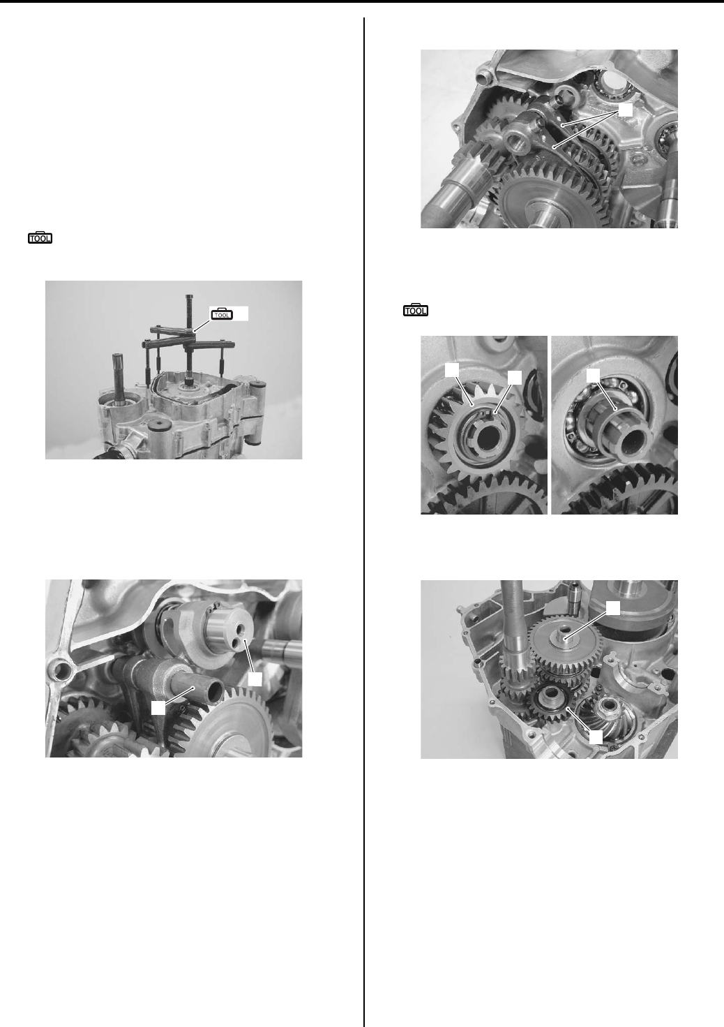
Transfer: 3C-3
Transfer Removal and Installation
B831G23306002
Removal
1) Remove the engine assembly from the frame. Refer
to “Engine Assembly Removal in Section 1D
(Page 1D-13)”.
2) Disassemble the engine top side. Refer to “Engine
Top Side Disassembly in Section 1D (Page 1D-17)”.
3) Separate the crank case with the special tool. Refer
to “Engine Bottom Side Disassembly in Section 1D
(Page 1D-45)”.
Special tool
(A): 09920–13120 (Crankcase separating
tool)
4) Remove the torque limiter and starter idle gear No.
2. Refer to “Starter Torque Limiter / Starter Clutch
Removal and Installation in Section 1I (Page 1I-10)”.
5) Remove the gearshift fork shaft (1) and gearshift
cam (2).
6) Remove the gearshift forks (3).
7) Remove the snap ring (4), drive gear No. 2 (5) and
spacer (6).
Special tool
: 09900–06107 (Snap ring pliers)
Remove the counter shaft assembly (7), reverse idle
gear (8) with shaft.
(A)
I831G1330006-03
1
2
I831G1330007-01
3
I831G1330008-01
546
I831G1330009-01
7
8
I831G1330010-02
PartShark.com
877-999-5686
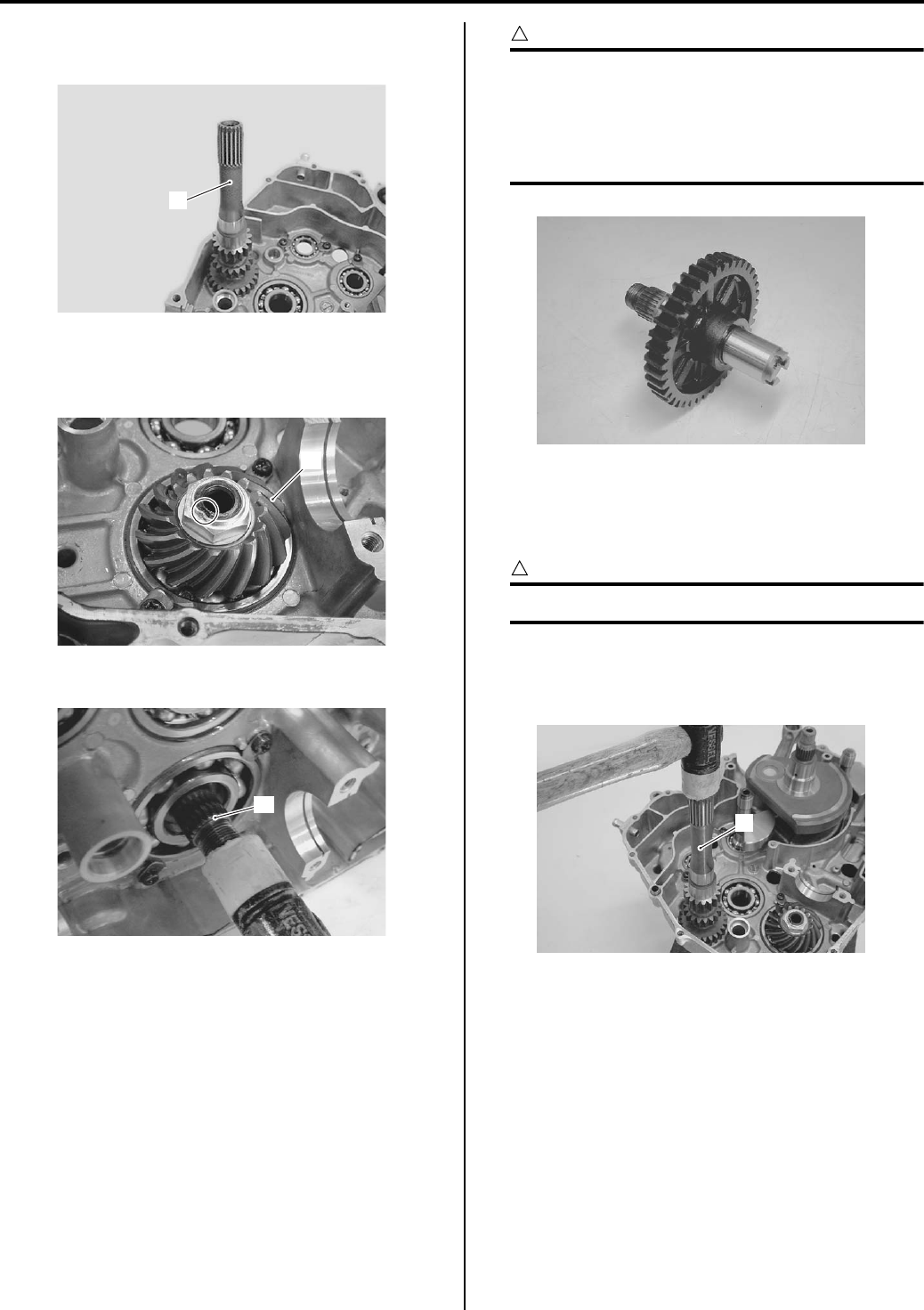
3C-4 Transfer:
9) Remove the drive shaft (9) with a plastic mallet by
installing a suitable washer with the drive face bolt.
10) Remove the drive bevel gear (10). Refer to “Rear
Output Shaft Removal and Installation in Section 3D
(Page 3D-6)”.
11) Remove the output shaft (11) with a plastic mallet.
CAUTION
!
• Do not disassemble the transfer output
shaft.
• The transfer output driven gear and
transfer output shaft is available only as an
assembly.
Installation
Install the transfer in the reverse order of removal. Pay
attention to the following points:
CAUTION
!
Apply engine oil to each gears and shafts.
• Install the bevel gear. Refer to “Rear Output Shaft
Removal and Installation in Section 3D (Page 3D-6)”.
• Install the drive shaft (1) with the plastic mallet.
9
I831G1330011-02
10
I831G1330012-02
11
I831G1330013-01
I831G1330014-01
1
I831G1330015-01
PartShark.com
877-999-5686
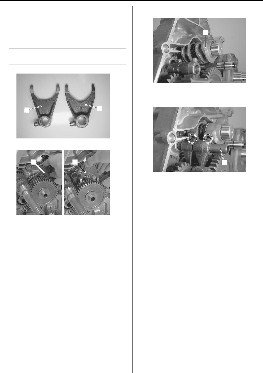
Transfer: 3C-5
• Install the transfer output shaft assembly and reverse
idle gear. Refer to “Transfer Components (Page 3C-
2)”.
• Install the gearshift fork (2) and reverse gearshift fork
(3).
NOTE
Identify the shape of the shift forks and
install them properly.
• Install the gearshift cam (4).
• With engaging each fork and to the cam groove, insert
the fork shaft (5).
• Assemble the engine. Refer to “Engine Bottom Side
Assembly in Section 1D (Page 1D-51)”.
• Remount engine assembly. Refer to “Engine
Assembly Installation in Section 1D (Page 1D-16)”
and “Engine Top Side Assembly in Section 1D
(Page 1D-21)”.
2
3
I831G1330016-01
2
3
I831G1330017-01
4
I831G1330018-01
5
I831G1330019-01
PartShark.com
877-999-5686
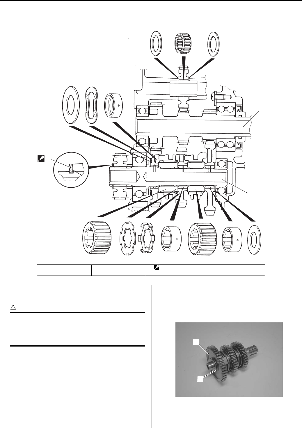
3C-6 Transfer:
Transfer Construction
B831G23306003
Counter Shaft / Reverse Idle Gear Disassembly
and Assembly
B831G23306004
CAUTION
!
Identify the position of each removed part.
Organize the parts in their respective groups
so that they can be reinstalled in their
original position.
Disassembly
Refer to “Transfer Removal and Installation (Page 3C-
3)”.
Counter shaft
1) Remove the counter shaft assembly. Refer to
“Transfer Removal and Installation (Page 3C-3)”.
2) Remove the low driven gear (1) and washer (2).
3
1
2
I831G1330002-03
1. Counter shaft 2. Drive shaft 3. Snap ring
: Assembly snap ring with edge side out.
1
2
I831G1330020-01
PartShark.com
877-999-5686
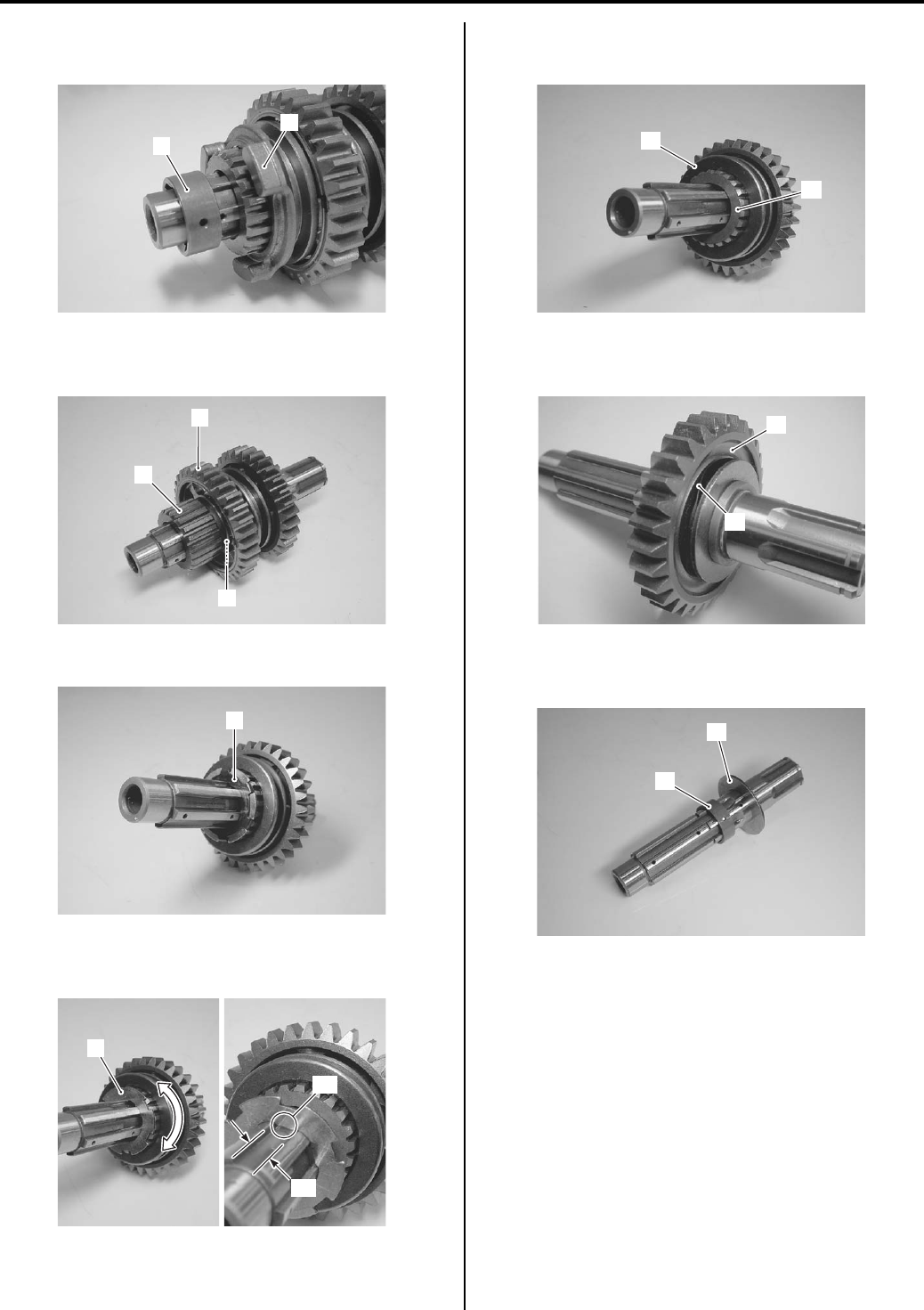
Transfer: 3C-7
3) Remove the low driven gear bushing (3) and select
sliding dog (4).
4) Remove the reverse select spacer (5), reverse gear
(6) and reverse driven gear bushing (7).
5) Remove the lock washer (8).
6) Remove the lock washer (9) by aligning the teeth “A”
of the lock washer with the spline grooves “B”.
7) Remove the high gearshift dog (10) and select
spacer (11).
Remove the high driven gear (12) with the wave
washer (13).
9) Remove the high driven gear bushing (14) and
washer (15).
3
4
I831G1330021-01
5
6
7
I831G1330022-01
8
I831G1330023-01
9
“A”
“B”
I831G1330024-02
10
11
I831G1330025-01
12
13
I831G1330026-01
14
15
I831G1330027-02
PartShark.com
877-999-5686
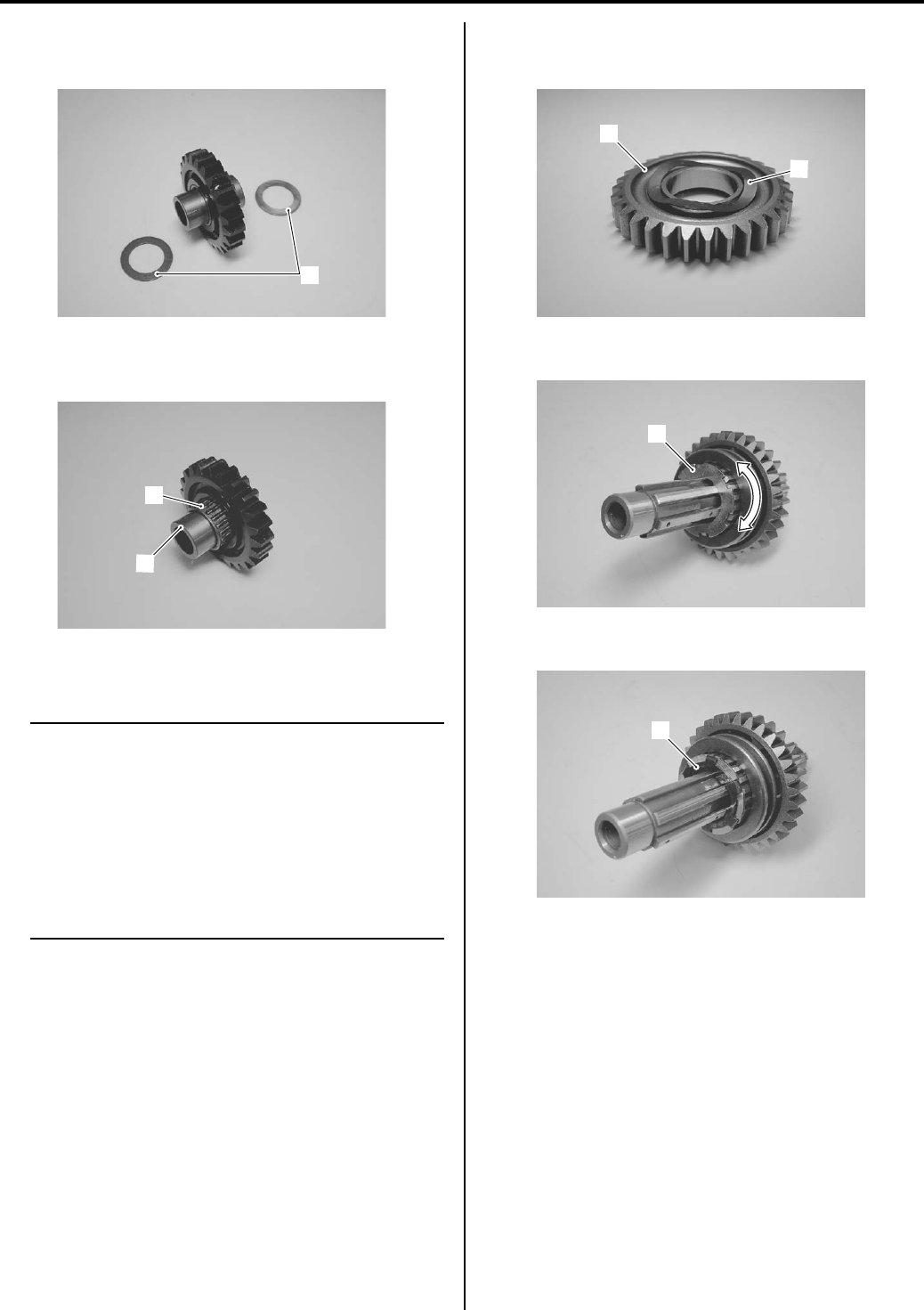
3C-8 Transfer:
Reverse idle gear
1) Remove the washers (1).
2) Remove the reverse idle gear shaft (2) and bering
(3).
Assembly
NOTE
• When reassembling the driven gears,
attention must be given to the locations
and positions of washers. The cross
sectional view shows the correct position
of the snap ring. Refer to “Transfer
Construction (Page 3C-6)”.
• Before installing the gears, coat lightly
engine oil to the counter shaft component
parts.
Assemble the counter shaft and reverse idle gear in the
reverse order of disassembly. Pay attention the following
points:
• Before installing the high driven gear (1), set the wave
washer (2) as shown in the figure.
• Install the lock washer (3).
• Install the lock washer (4).
1
I831G1330028-01
2
3
I831G1330029-01
1
2
I831G1330030-01
3
I831G1330063-01
4
I831G1330064-01
PartShark.com
877-999-5686
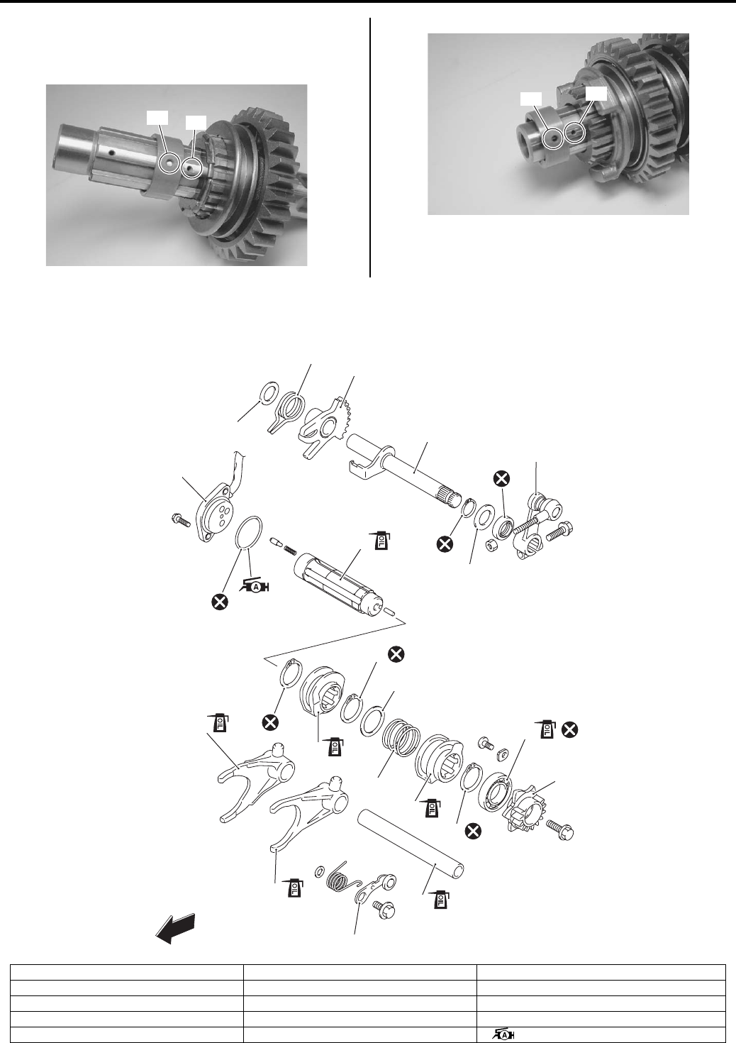
Transfer: 3C-9
• When installing the gear bushing onto the counter
shaft, align the shaft oil hole “C” with the bushing oil
hole “D” as shown in the figure.
Gearshift Cam Components
B831G23306005
“C”
“D”
I831G1330033-05
“D”
“C”
I831G1330034-03
FWD
5
1
7
8
9
10
13
16
17
20
22
21
2
3
11
12
15
4
14
18
18
19
6
I831G1330003-05
1. Gear position switch 10. Snap ring 19. Snap ring
2. O-ring 11. Bearing 20. Gearshift shaft No. 2
3. Gearshift shaft No. 1 12. Gearshift cam stopper plate 21. Shift gear
4. Snap ring 13. Reverse gearshift fork 22. Shift arm return spring
5. Reverse gearshift cam 14. High/Low gearshift fork : Apply grease.
PartShark.com
877-999-5686
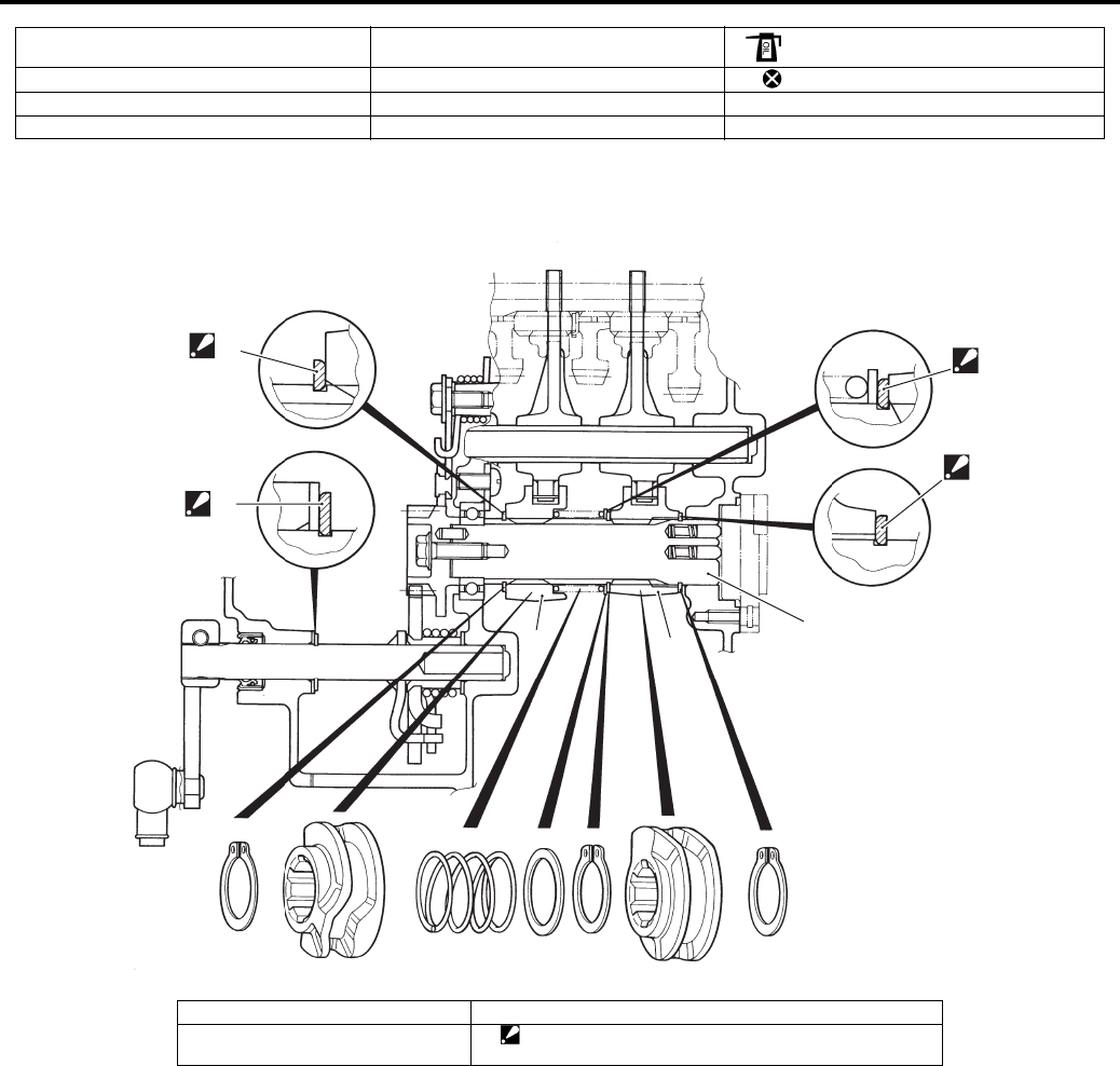
3C-10 Transfer:
Gearshift System Construction
B831G23306006
6. Snap ring 15. Gearshift fork shaft : Apply engine oil.
7. Washer 16. Gearshift cam stopper : Do not reuse.
8. Spring 17. Gearshift arm
9. Gearshift cam 18. Washer
4
4
4
4
1
2
3
I831G1330004-04
1. Gearshift shaft 3. Gearshift cam
2. Reverse gearshift cam 4. Snap ring
: Assemble snap ring with sharp edge side out.
PartShark.com
877-999-5686
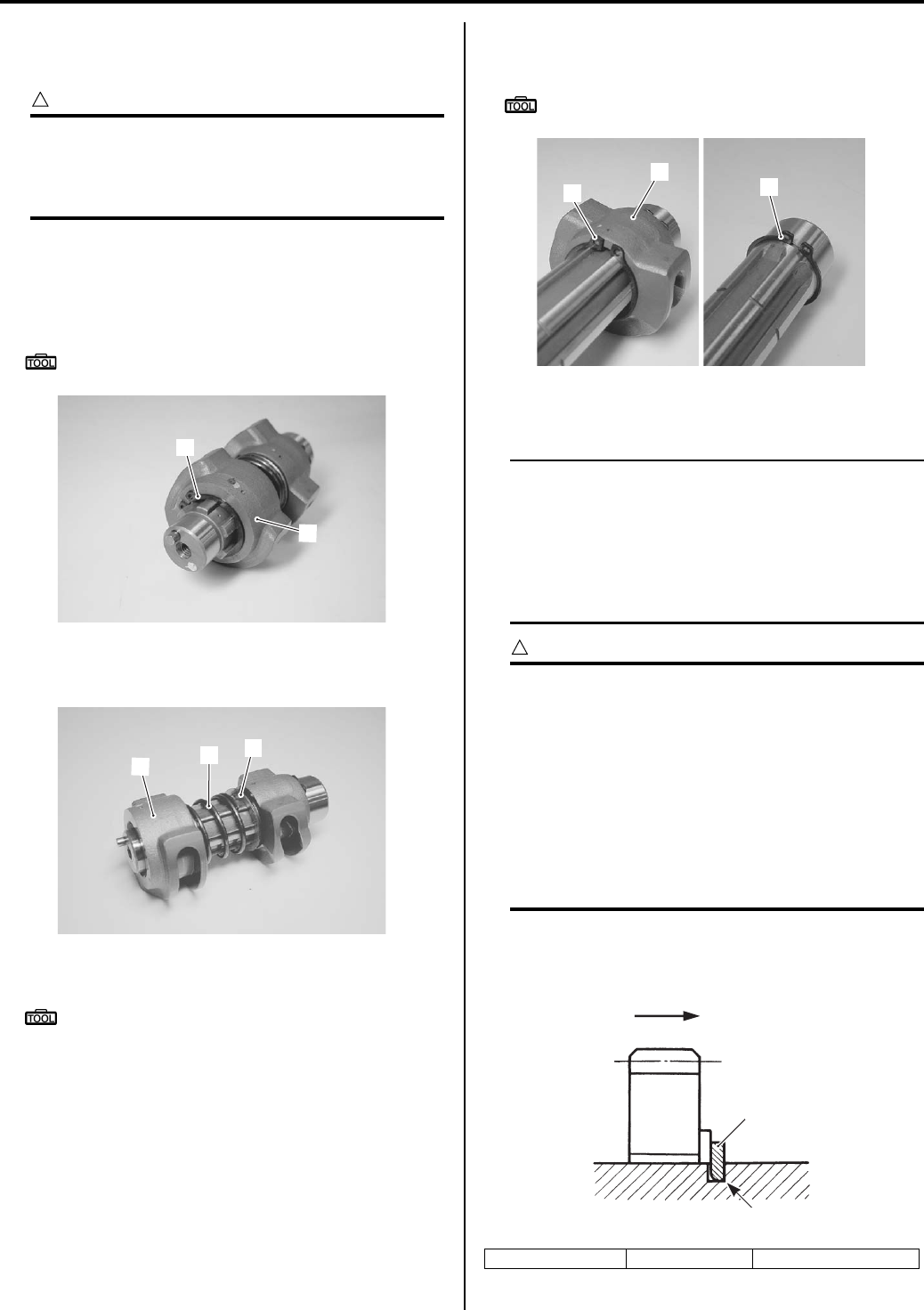
Transfer: 3C-11
Gearshift Cam Disassembly and Assembly
B831G23306007
Disassembly
CAUTION
!
Identify the position of each removed part.
Organize the parts in their respective groups
so that they can be reinstalled in their
original positions.
• Remove the gearshift cam assembly. Refer to
“Transfer Removal and Installation (Page 3C-3)”.
• Remove the snap ring (1) with the special tool by
holding the gearshift cam (2).
Special tool
: 09900–06107 (Snap ring pliers)
• Remove the gearshift cam (2), spring (3) and washer
(4).
• Remove the snap ring (5) with the special tool.
Special tool
: 09900–06107 (Snap ring pliers)
• Remove the reverse gearshift cam (6) and snap ring
(7).
Special tool
: 09900–06107 (Snap ring pliers)
Assembly
NOTE
When reassembling the gearshift cams,
attention must be given to the locations and
positions of washer and snap rings. The
cross sectional view shows the correct
position of the cams, washer and snap rings.
Refer to “Gearshift System Construction
(Page 3C-10)”.
CAUTION
!
• Never reuse a snap rings. After a snap
rings has been removed from a shaft, it
should be discarded and a new snap rings
must be installed.
• When installing a new snap rings, do not
expand the end gap larger than required to
slip the snap rings over the shaft.
• After installing snap rings, make sure that
they are completely seated in their groove
and securely fitted.
• When installing a new snap ring (1), pay attention to
its direction. Fit it to the side where the thrust is as
shown in the figure.
1
2
I831G1330035-01
34
2
I831G1330036-01
1. Snap ring “A”: Thrust “B”: Sharp edge
57
6
I831G1330037-01
“A”
1
“B”
I831G1330039-01
PartShark.com
877-999-5686
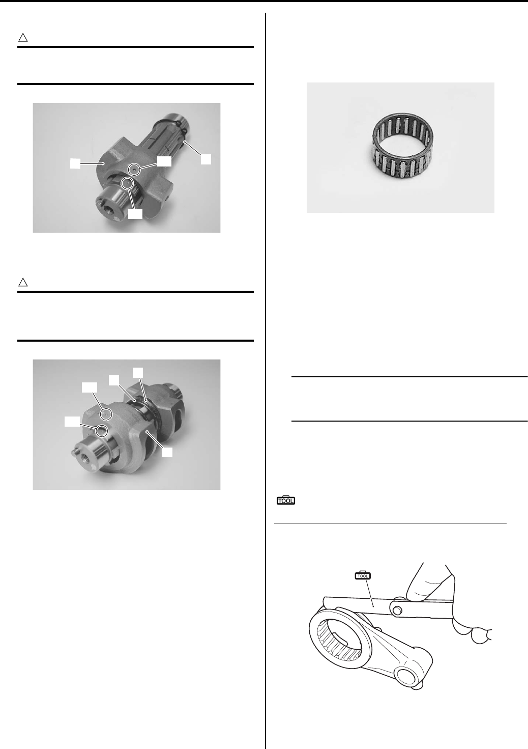
3C-12 Transfer:
• Install the snap ring (1) and gearshift cam (2).
CAUTION
!
• Align the punch mark “A” of the gearshift
cam with the punch mark “B” of the shaft.
• Install the washer (3), spring (4) and reverse shift cam
(5).
CAUTION
!
• Align the punch mark “C” of the reverse
shift cam with the punch mark “D” of the
shaft.
• Install the snap ring.
Transfer Gear Bearing Removal and Installation
B831G23306008
Refer to “Bearing Removal and Installation in Section 1D
(Page 1D-61)”.
Transfer Gear Bearing Inspection
B831G23306009
• Inspect the reverse idle gear shaft bearing for
abnormal noise and smooth rotation. Replace the
bearing if there is anything unusual.
• Inspect the other bearings as shown in the bearing
inspection. Refer to “Bearing Inspection in Section 1D
(Page 1D-61)”.
Transfer Related Parts Inspection
B831G23306010
Refer to “Transfer Removal and Installation (Page 3C-3)”
and “Counter Shaft / Reverse Idle Gear Disassembly
and Assembly (Page 3C-6)”.
Gearshift Fork to Groove Clearance
NOTE
The clearance for each gearshift fork plays
an important role in the smoothness and
positiveness of the shifting action.
Using a thickness gauge, check the gearshift fork
clearance in the groove of its gear.
If the clearance checked is noted to exceed the limit,
replace the fork or its dog, or both.
Special tool
(A): 09900–20803 (Thickness gauge)
Gearshift fork to gearshift fork groove clearance
Standard: 0.10 – 0.30 mm (0.0040 – 0.0120 in)
Service limit: 0.50 mm (0.020 in)
1
2
“A”
“B”
I831G1330038-03
“C”
“D”
3
5
4
I831G1330040-01
I831G1330067-01
(A)
I831G1330066-01
PartShark.com
877-999-5686
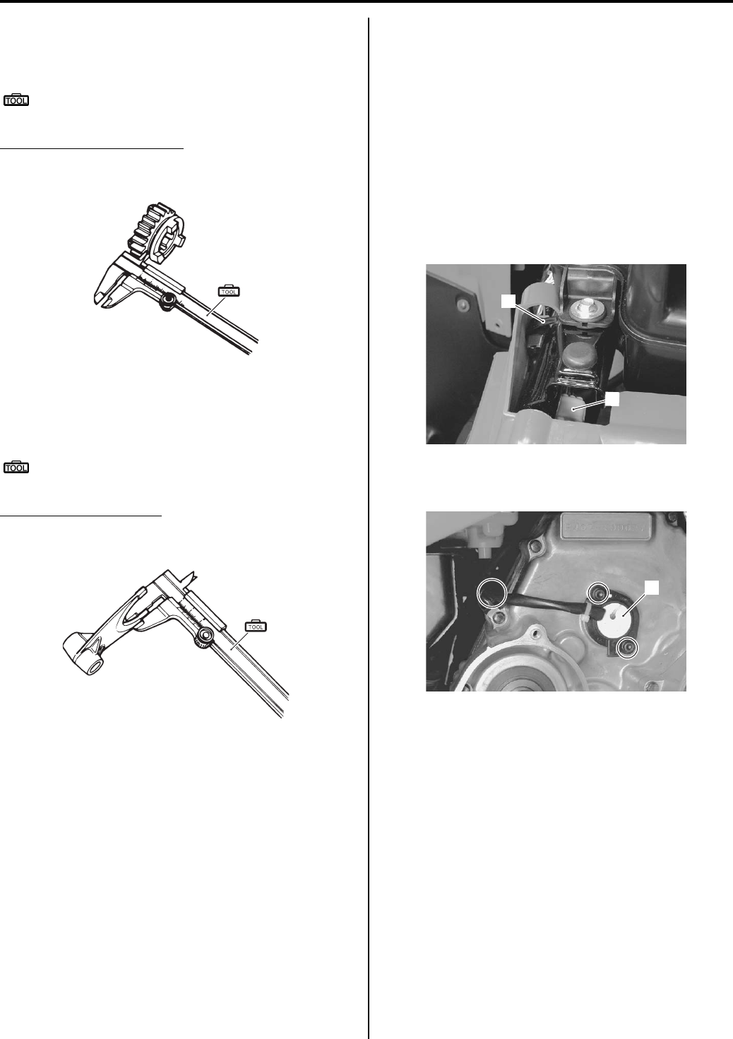
Transfer: 3C-13
Gearshift Fork Groove Width
Measure the gearshift fork groove width using the
vernier calipers.
Special tool
(A): 09900–20102 (Vernier calipers (1/20 mm,
200 mm))
Gearshift fork groove width
Standard (Reverse/Low & High): 5.5 – 5.6 mm (0.217
– 0.220 in)
Gearshift Fork Thickness
Measure the gearshift fork thickness using the vernier
calipers.
Special tool
(A): 09900–20102 (Vernier calipers (1/20 mm,
200 mm))
Gearshift fork thickness
Standard (Reverse/Low & High): 5.3 – 5.4 mm (0.209
– 0.213 in)
Transfer Related Bearing Inspection
B831G23306011
Refer to “Bearing Inspection in Section 1D (Page 1D-
61)”.
Gear Position (GP) Switch Inspection
B831G23306012
Refer to “Gear Position Switch Inspection in Section 1I
(Page 1I-9)”.
Gear Position (GP) Switch Removal and
Installation
B831G23306013
Removal
1) Turn the ignition switch OFF.
2) Remove the left and right side cover. Refer to “Front
Side Exterior Parts Removal and Installation in
Section 9D (Page 9D-6)”.
3) Remove the drive V—belt inner cover. Refer to “Clutch
Shoe Removal and Installation in Section 5A
(Page 5A-16)”.
4) Remove the clamp (1) and disconnect the gear
position switch coupler (2).
5) Disconnect the clamp and remove the gear position
switch (3).
(A)
I649G1520057-03
(A)
I649G1520058-03
1
2
I831G1330044-01
3
I831G1330045-01
PartShark.com
877-999-5686
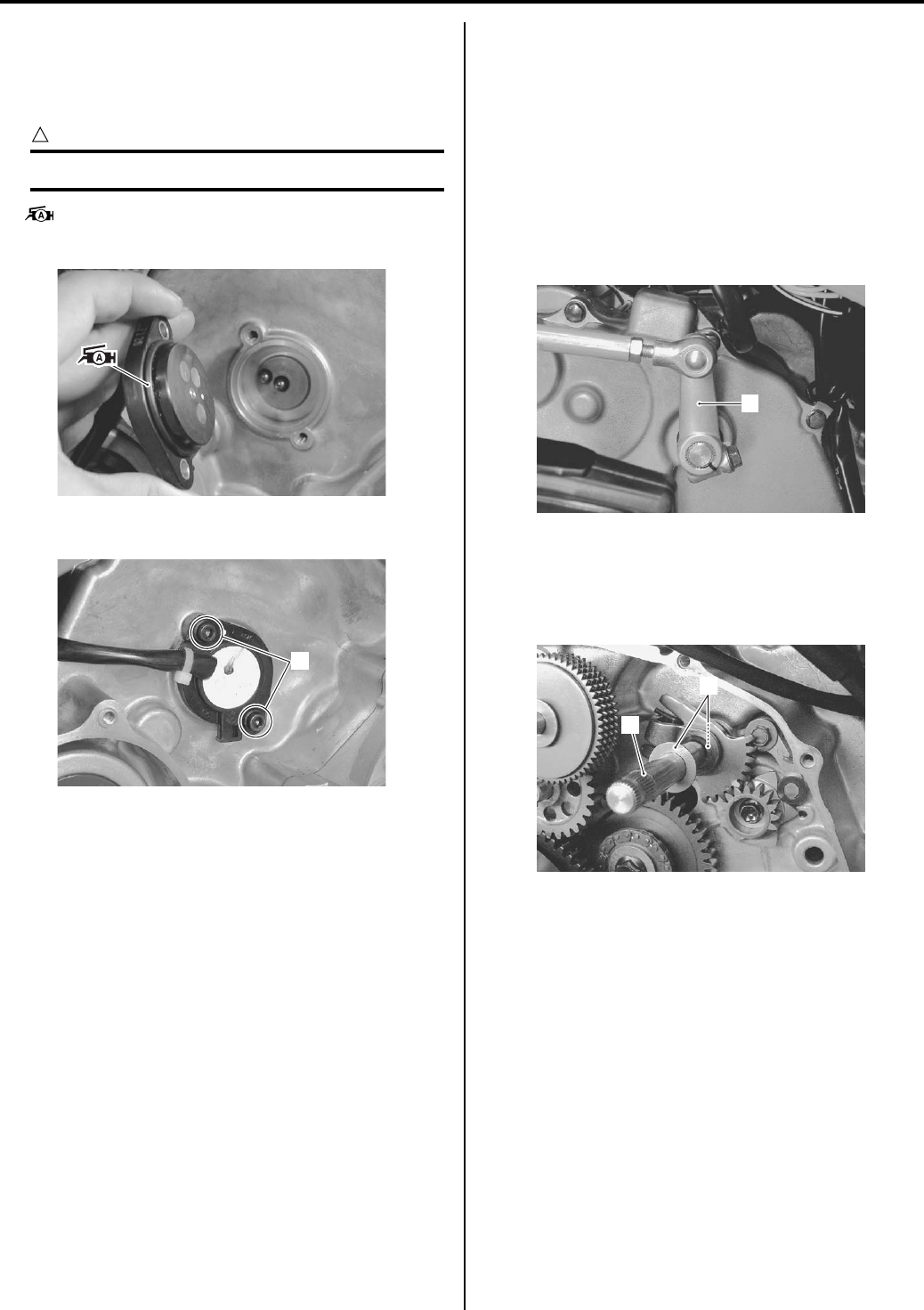
3C-14 Transfer:
Installation
Install the gear position switch in the reverse order of
removal. Pay attention to the following points:
• Apply grease to the O-ring.
CAUTION
!
Replace the O-ring with a new one.
: Grease 99000–25010 (SUZUKI SUPER
GREASE A or equivalent)
• Tighten the gear position switch bolts (1).
• Route the gear position switch lead wire. Refer to
“Wiring Harness Routing Diagram in Section 9A
(Page 9A-4)”.
• Install the V-belt inner cover. Refer to “Clutch Shoe
Removal and Installation in Section 5A (Page 5A-16)”.
• Install the drive V-belt. Refer to “V-belt Type
Continuously Variable Automatic Transmission
Removal and Installation in Section 5A (Page 5A-5)”.
• Install the removed parts.
Gearshift Shaft No. 2 / Gearshift Cam Plate
Removal and Installation
B831G23306014
Removal
Refer to “Shift Lever Assembly Removal and Installation
in Section 5A (Page 5A-24)”.
1) Drain engine oil. Refer to “Engine Oil and Filter
Replacement in Section 0B (Page 0B-10)”.
2) Drain engine coolant. Refer to “Cooling System
Inspection in Section 0B (Page 0B-15)”.
3) Remove the gearshift arm (1).
4) Remove the generator cover. Refer to “Generator
Removal and Installation in Section 1J (Page 1J-4)”.
5) Remove the gearshift shaft assembly (2) and
washers (3).
I831G1330046-01
1
I831G1330047-03
1
I831G1330048-01
3
2
I831G1330049-02
PartShark.com
877-999-5686
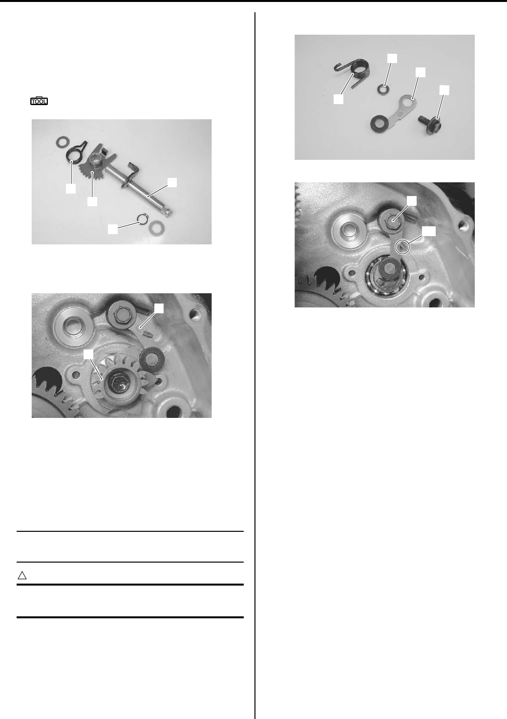
Transfer: 3C-15
6) Remove the following parts from the gearshift shaft
(4).
• Gearshift return spring (5)
• Shift gear (6)
• Snap ring (7)
Special tool
: 09900–06107 (Snap ring pliers)
7) Remove the gearshift cam stopper plate (8).
Remove the gearshift cam stopper (9).
Installation
Install the gearshift shaft and gearshift cam plate in the
reverse order of removal. Pay attention to the following
points:
• Install the gearshift cam stopper (1), bolt (2), washer
(3) and return spring (4).
NOTE
Hook the return spring end “A” to the
gearshift cam stopper.
CAUTION
!
Make sure that the gearshift cam stopper
moves smoothly.
• Tighten the gearshift cam stopper bolt (2) securely.
• Check the gearshift cam stopper moves smoothly.
• Locate the gearshift cam in the neutral position.
7
5
6
4
I831G1330050-03
9
8
I831G1330062-02
1
2
3
4
I831G1330051-01
2
“A”
I831G1330052-02
PartShark.com
877-999-5686
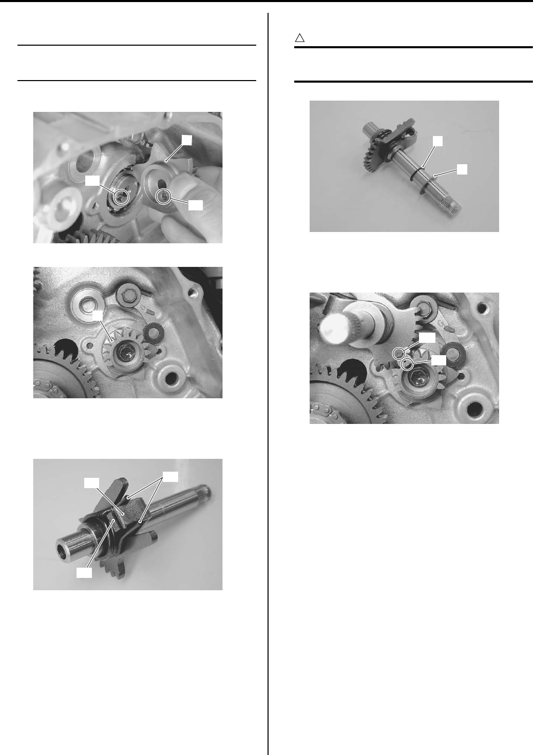
3C-16 Transfer:
• Install the gearshift cam stopper plate (5).
NOTE
• Align the gearshift cam pin “B” with the
gearshift cam stopper plate hole “C”.
• Tighten the gearshift cam stopper plate bolt securely.
• When installing the shift arm return spring, position
the stopper “D” of gearshift shaft No. 2 and stopper
“E” of shift gear between the return spring ends “F”.
• Install the snap ring (6) and washer (7).
CAUTION
!
the removed snap ring (6) must be replaced
with new one.
• Install the gearshift assembly by aligning the punch
mark “G” of shift gear with the match mark “H” of
gearshift cam stopper plate.
• Install the generator cover. Refer to “Generator
Removal and Installation in Section 1J (Page 1J-4)”.
• Pour engine coolant and engine oil. Refer to “Cooling
System Inspection in Section 0B (Page 0B-15)” and
“Engine Oil and Filter Replacement in Section 0B
(Page 0B-10)”.
“B”
“C”
5
I831G1330053-02
5
I831G1330054-02
“F”
“D”
“E”
I831G1330055-01
6
7
I831G1330056-01
“G”
“H”
I831G1330057-03
PartShark.com
877-999-5686
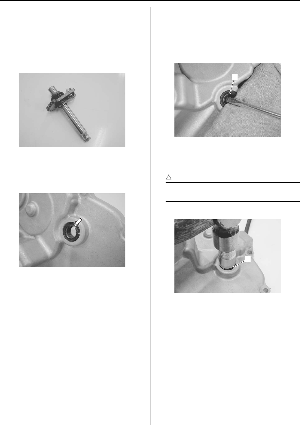
Transfer: 3C-17
Gearshift Linkage Inspection
B831G23306015
Refer to “Gearshift Shaft No. 2 / Gearshift Cam Plate
Removal and Installation (Page 3C-14)”.
Gearshift Shaft
Check the gearshift for bend or wear.
Check the return spring for damage or fatigue.
If any defects are found, replace the defective part(-s).
Gearshift Shaft Oil Seal
Inspect the gearshift shaft oil seal lip for damage or
wear. If any defect are found, replace the oil seal with a
new one.
Gearshift Shaft Oil Seal Removal and
Installation
B831G23306016
Removal
• Remove the generator cover. Refer to “Generator
Removal and Installation in Section 1J (Page 1J-4)”.
• Remove the gearshift shaft oil seal (1).
Installation
Install the oil seal in the reverse order of removal. Pay
attention to the following points:
CAUTION
!
The removed oil seal must be replaced with
new one.
• Install the oil seal (1) with a suitable socket wrench.
• Install the generator cover. Refer to “Generator
Removal and Installation in Section 1J (Page 1J-4)”.
I831G1330058-01
I831G1330059-01
1
I831G1330060-01
1
I831G1330061-01
PartShark.com
877-999-5686
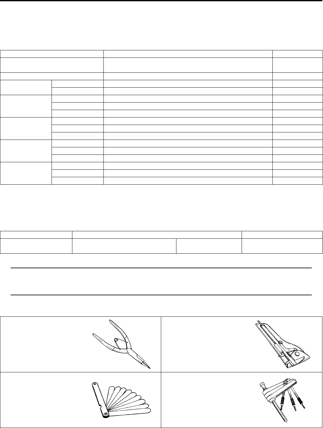
3C-18 Transfer:
Specifications
Service Data
B831G23307001
Drive Train
Unit: mm (in) Except ratio
Special Tools and Equipment
Recommended Service Material
B831G23308001
NOTE
Required service material is also described in the following.
“Transfer Components (Page 3C-2)”
“Gearshift Cam Components (Page 3C-9)”
Special Tool
B831G23308002
Item Standard Limit
Primary reduction ratio (Automatic
drive) Variable change (2.763 – 0.780) —
Secondary reduction ratio 2.158 (40/21 x 17/15) —
Final reduction
ratio
Front 3.600 (36/10) —
Rear 3.600 (36/10) —
Transfer gear
ratio
Low 2.562 (41/16) —
High 1.240 (31/25) —
Reverse 1.882 (32/17) —
Shift fork to
groove clearance
Low 0.10 – 0.30 (0.0040 – 0.0120) 0.50 (0.020)
High 0.10 – 0.30 (0.0040 – 0.0120) 0.50 (0.020)
Reverse 0.10 – 0.30 (0.0040 – 0.0120) 0.50 (0.020)
Shift fork groove
width
Low 5.50 – 5.60 (0.217 – 0.220) —
High 5.50 – 5.60 (0.217 – 0.220) —
Reverse 5.50 – 5.60 (0.217 – 0.220) —
Shift fork
thickness
Low 5.30 – 5.40 (0.209 – 0.213) —
High 5.30 – 5.40 (0.209 – 0.213) —
Reverse 5.30 – 5.40 (0.209 – 0.213) —
Material SUZUKI recommended product or Specification Note
Grease SUZUKI SUPER GREASE A or
equivalent
P/No.: 99000–25010 )(Page 3C-14)
09900–06107 09900–20102
Snap ring pliers Vernier calipers (1/20 mm,
200 mm)
)(Page 3C-3) / )(Page 3C-
11) / )(Page 3C-11) /
)(Page 3C-11) /
)(Page 3C-15)
)(Page 3C-13) /
)(Page 3C-13)
09900–20803 09920–13120
Thickness gauge Crankcase separating tool
)(Page 3C-12) )(Page 3C-3)
PartShark.com
877-999-5686
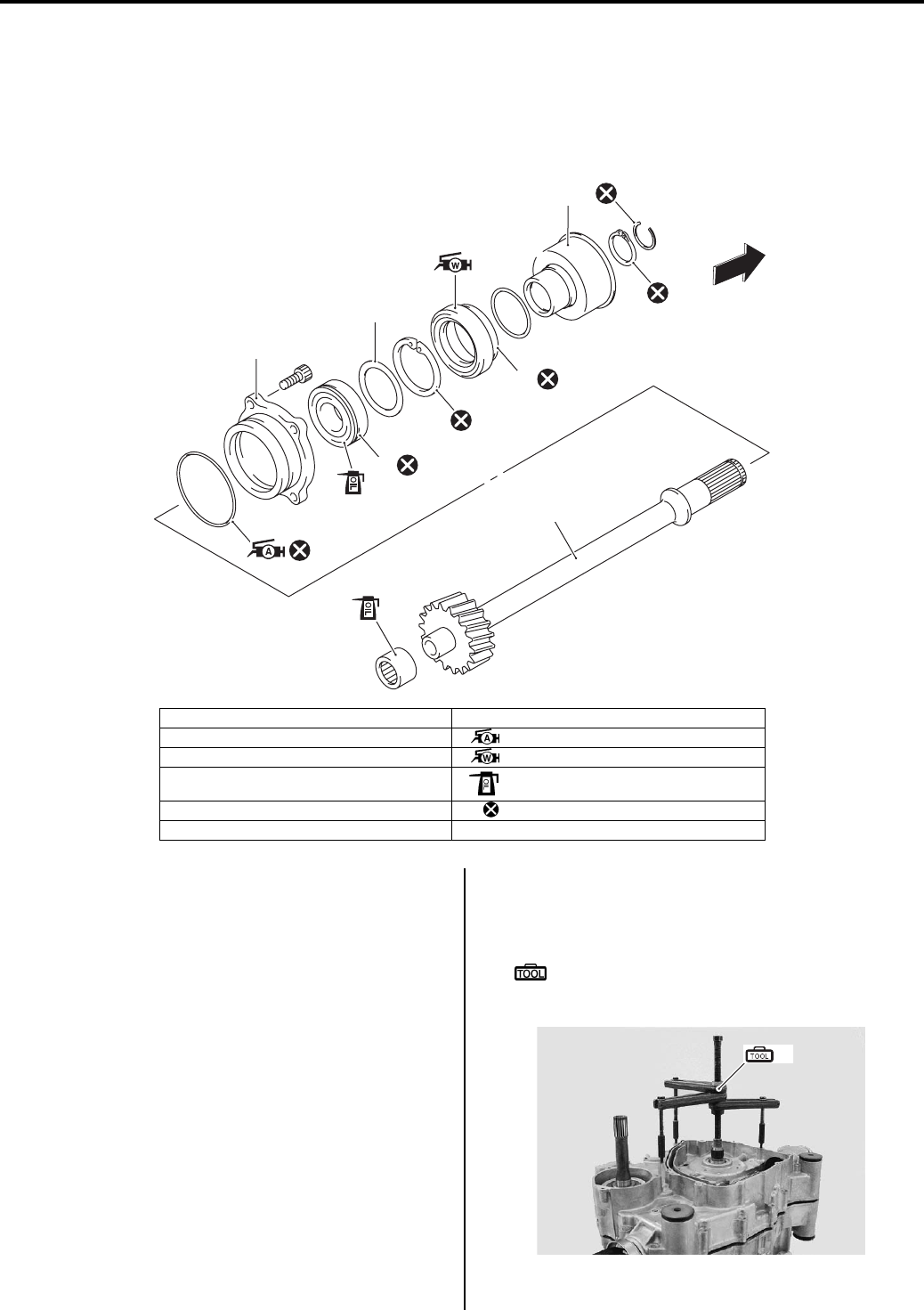
Propeller Shafts: 3D-1
Driveline / Axle
Propeller Shafts
Repair Instructions
Front Output Shaft Components
B831G23406001
Front Output Shaft Removal and Installation
B831G23406002
Removal
1) Remove the engine assembly from the frame. Refer
to “Engine Assembly Removal in Section 1D
(Page 1D-13)”.
2) Disassemble the engine top side. Refer to “Engine
Top Side Disassembly in Section 1D (Page 1D-17)”.
3) Separate the crankcase with the special tool. Refer
to “Engine Bottom Side Disassembly in Section 1D
(Page 1D-45)”.
Special tool
(A): 09920–13120 (Crankcase separating
tool)
1
2
3
5
6
7
4
FWD
I831G1340001-03
1. Front output shaft bearing (Rear) 7. Front drive collar assembly
2. Front output shaft : Apply grease.
3. Front output shaft housing : Apply water resistance grease.
4. Front output shaft bearing (Front) : Apply engine oil.
5. Shim(s) : Do not reuse.
6. Oil seal
(A)
I831G1340002-03
PartShark.com
877-999-5686
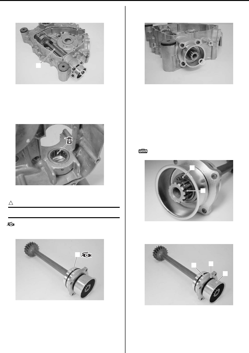
3D-2 Propeller Shafts:
4) Remove the front output shaft (1) from the right
crankcase.
Installation
Install the front output shaft in the reverse order of
removal. Pay attention to the following point:
• Apply engine oil to the front output bearing (rear).
• Apply a small quantity of grease to the O-ring (1).
CAUTION
!
Replace a O-ring (1) with a new one.
: Grease 99000–25010 (SUZUKI SUPER
GREASE A or equivalent)
• Install the front output shaft to the right crankcase.
Tighten the front output shaft bolts.
Front Output Shaft Disassembly and Assembly
B831G23406003
Refer to “Front Output Shaft Removal and Installation
(Page 3D-1)”.
Disassembly
1) Remove the C-ring (1) and snap ring (2).
Special tool
: 09900–06107 (Snap ring pliers)
2) Remove the front drive collar (3), front drive output
shaft housing (4) and O-ring (5).
1
I831G1340003-02
I831G1340097-01
1
I831G1340098-01
I831G1340004-02
1
2
I831G1340005-02
4
5
3
I831G1340006-02
PartShark.com
877-999-5686
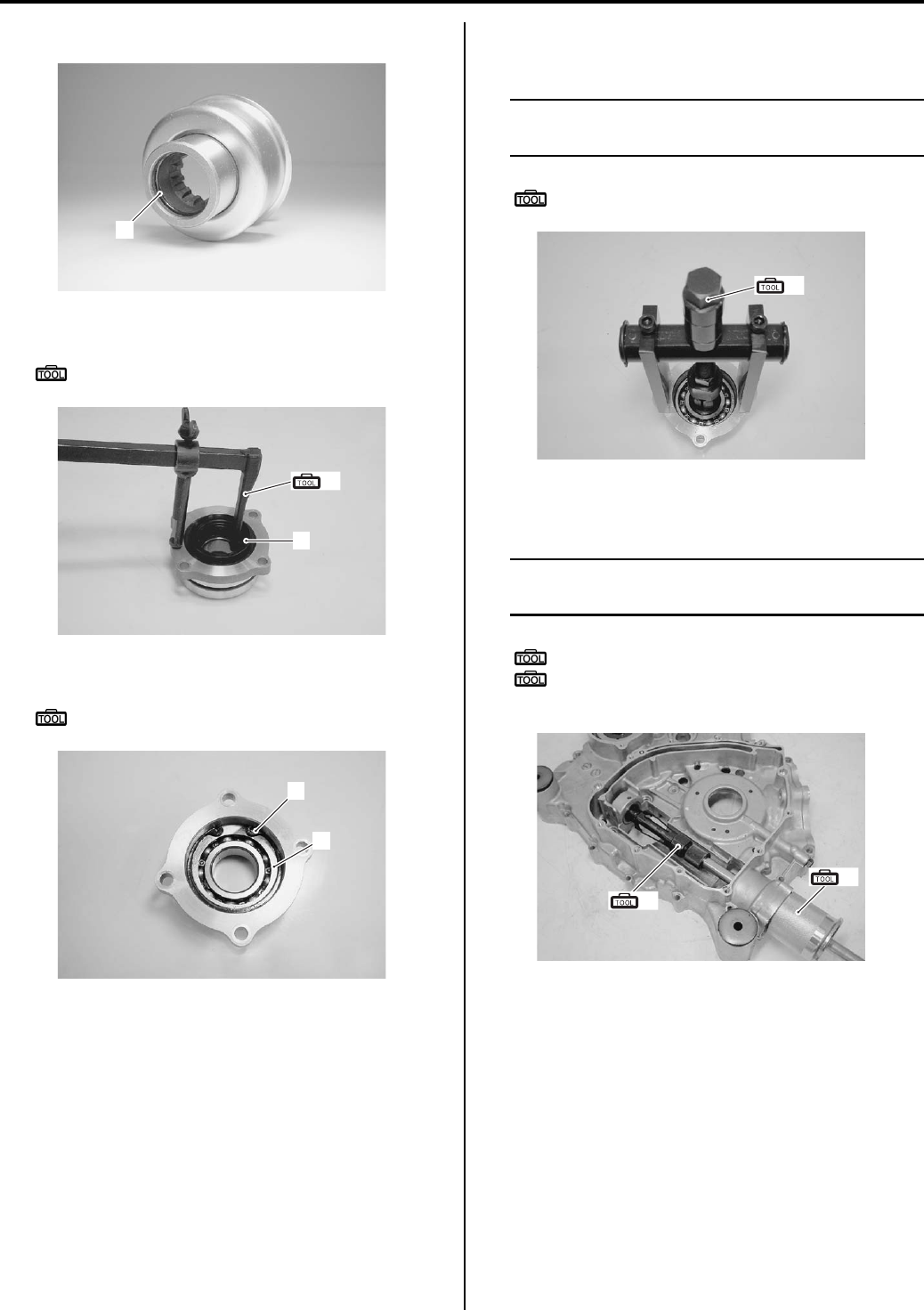
Propeller Shafts: 3D-3
3) Remove the O-ring (6).
4) Remove the oil seal (7) with the special tool.
Special tool
(A): 09913–50121 (Oil seal remover)
5) Remove the snap ring (8) and washer (9).
Special tool
: 09900–06108 (Snap ring pliers)
6) Remove the front output shaft bearing (front) with the
special tool.
NOTE
If there is no abnormal noise, the bearing
removed is not necessary.
Special tool
(B): 09921–20240 (Bearing remover set)
7) Remove the front output shaft bearing (rear) with the
special tool.
NOTE
If there is no abnormal noise, the bearing
removed is not necessary.
Special tool
(C): 09923–74511 (Bearing remover)
(D): 09930–30104 (Rotor remover slide
shaft)
6
I831G1340007-02
(A)
7
I831G1340008-01
8
9
I831G1340009-01
(B)
I831G1340010-01
(C)
(D)
I831G1340011-01
PartShark.com
877-999-5686
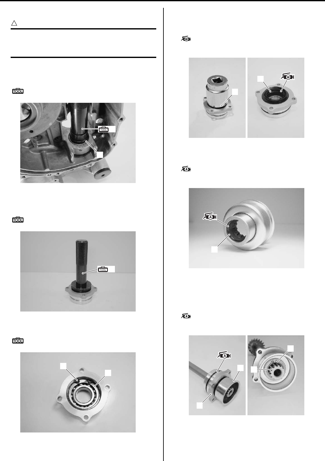
3D-4 Propeller Shafts:
Assembly
CAUTION
!
The removed bearing, snap rings, oil seal, C-
ring and O-rings must be replaced with new
ones.
1) Install the front output shaft bearing (rear) (1) to the
right crankcase with the special tool.
Special tool
(A): 09913–70210 (Bearing installer set)
2) Install the front output shaft bearing (front) to the
front output shaft housing with the special tool.
Special tool
(A): 09913–70210 (Bearing installer set)
3) Install the washer (2) and snap ring (3).
Special tool
: 09900–06108 (Snap ring pliers)
4) Install the oil seal (4) with the suitable socket
wrench.
5) Apply grease to the oil seal lip.
: Grease 99000–25160 (Water resistance
grease)
6) Install the O-ring (5) to the front drive collar.
7) Apply grease to the O-ring (5).
: Grease 99000–25010 (SUZUKI SUPER
GREASE A or equivalent)
Install the output shaft housing (6) and front drive
collar assembly (7) to the front output shaft.
9) Install the snap ring (8), C-ring (9) and O-ring.
10) Apply a small quantity of grease to the O-ring.
: Grease 99000–25010 (SUZUKI SUPER
GREASE A or equivalent)
1
(A)
I831G1340012-01
(A)
I831G1340013-01
2
3
I831G1340014-02
4
4
I831G1340015-04
5
I831G1340016-02
6
79
8
I831G1340017-02
PartShark.com
877-999-5686
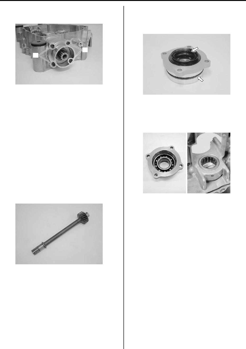
Propeller Shafts: 3D-5
11) Install the front output shaft to the right crankcase.
12) Tighten the front output shaft bolts (10).
13) Assemble the engine. Refer to “Engine Bottom Side
Disassembly in Section 1D (Page 1D-45)” and
“Engine Top Side Assembly in Section 1D (Page 1D-
21)”.
14) Remount the engine assembly. Refer to “Engine
Assembly Installation in Section 1D (Page 1D-16)”.
Front Output Shaft Related Parts Inspection
B831G23406004
Refer to “Front Output Shaft Disassembly and Assembly
(Page 3D-2)”.
Front Output Shaft
Inspect the front output shaft for distortion.
If distortion is found, replace the front output shaft with a
new one.
Inspect the gear of the front output shaft for wear or
damage. If any defects are found, replace the drive and
driven bevel gears as a set.
Oil Seal
Visually inspect the oil seal for damage, with particular
attention given to the lip.
Replace the oil seal that shows indications of leakage.
Front Output Shaft Bearing
Inspect the front output shaft bearings for abnormal
noise and smooth rotation.
Replace the bearings if there is anything unusual.
10
10
I831G1340018-03
I831G1340019-01
I831G1340020-01
I831G1340021-01
PartShark.com
877-999-5686
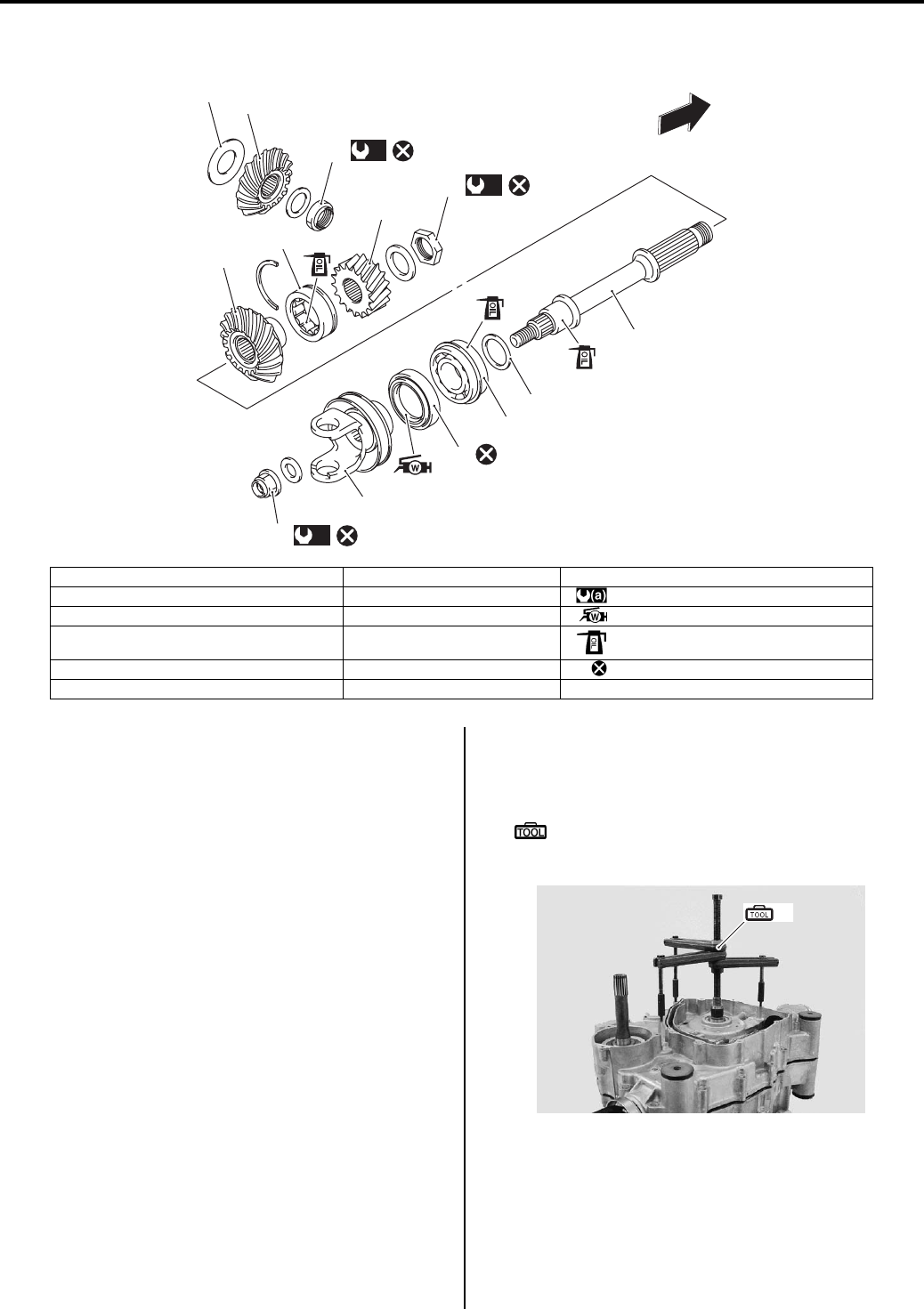
3D-6 Propeller Shafts:
Rear Output Shaft Components
B831G23406005
Rear Output Shaft Removal and Installation
B831G23406006
Removal
1) Remove the engine assembly from the frame. Refer
to “Engine Assembly Removal in Section 1D
(Page 1D-13)”.
2) Disassemble the engine top side. Refer to “Engine
Top Side Disassembly in Section 1D (Page 1D-17)”.
3) Separate the crankcase with the special tool. Refer
to “Engine Bottom Side Disassembly in Section 1D
(Page 1D-45)”.
Special tool
(A): 09920–13120 (Crankcase separating
tool)
1
2
3
4
(a)
11
(a)
10
(a)
12
89
6
FWD
5
7
8
13
I831G1340022-05
1. Rear output shaft drive bevel gear 7. Shim(s) 13. Rear output shaft yoke
2. Shim(s) 8. Bearing : 100 N⋅m (10.0 kgf-m 72.5 lb-ft)
3. Rear output shaft driven bevel gear 9. Oil seal : Apply water resistance grease.
4. Front output shaft drive gear 10. Drive bevel gear nut : Apply engine oil.
5. Bearing 11. Rear output shaft nut : Do not reuse.
6. Rear output shaft 12. Output shaft nut
(A)
I831G1340002-03
PartShark.com
877-999-5686
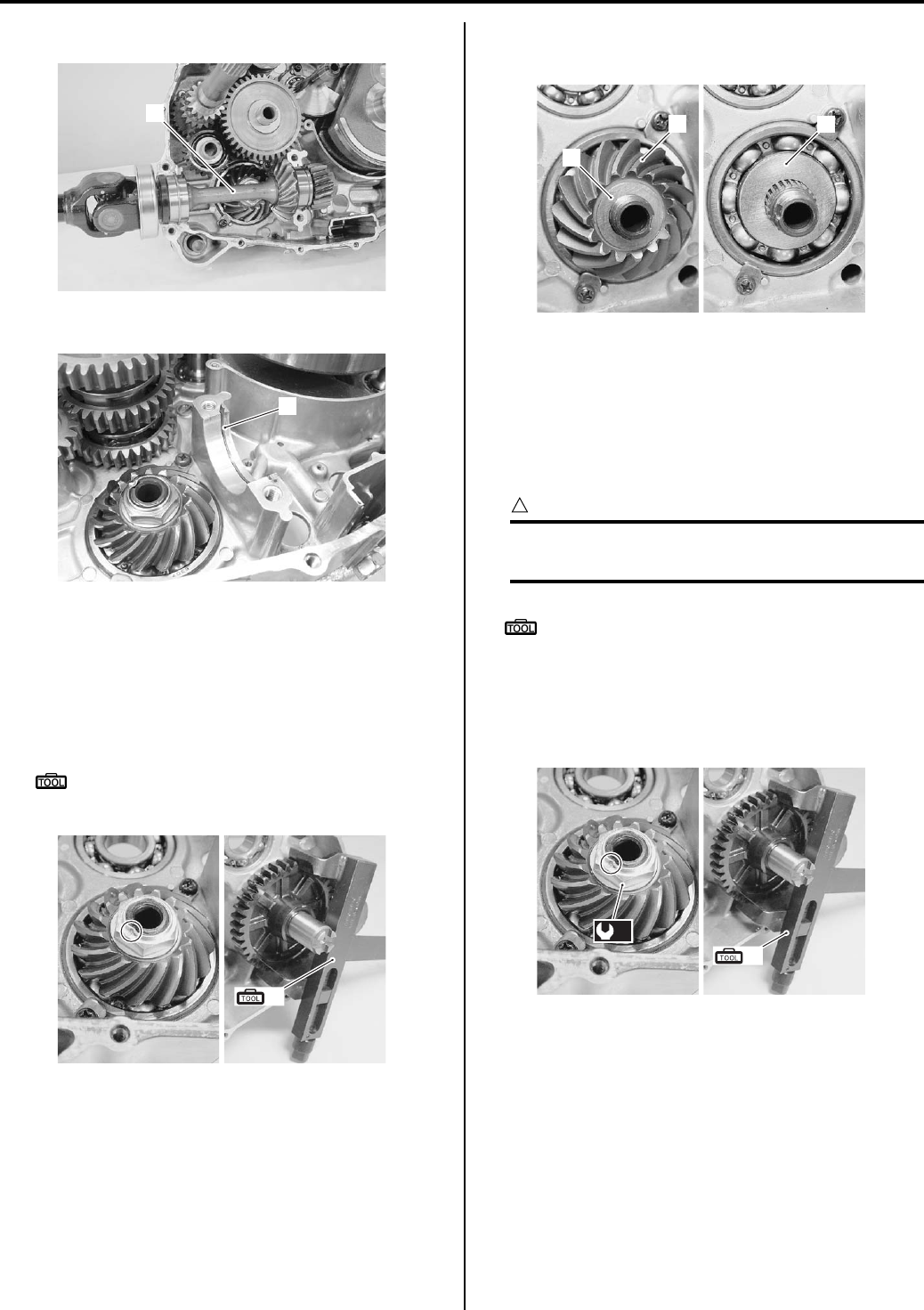
Propeller Shafts: 3D-7
4) Remove the rear output shaft (1).
5) Remove the C-ring (2).
6) Remove the drive shaft, counter shaft assembly and
reverse idle gear. Refer to “Transfer Removal and
Installation in Section 3C (Page 3C-3)”.
7) Unlock the drive bevel gear nut with a chisel.
Hold the transfer output driving gear with the special
tool and remove the drive bevel gear nut.
Special tool
(A): 09920–53740 (Clutch sleeve hub
holder)
9) Remove the washer (3), drive bevel gear (4) and
shim (5).
Installation
Install the rear output shaft in the reverse order of
removal. Pay attention to the following points:
• Hold the transfer output driven gear with the special
tool and tighten the drive bevel gear nut to the
specified torque.
CAUTION
!
The removed drive bevel gear nut must be
replaced with a new one.
Special tool
(A): 09920–53740 (Clutch sleeve hub holder)
Tightening torque
Rear output shaft drive bevel gear nut (a): 100
N·m (10.0 kgf-m, 72.5 lb-ft)
• Lock the drive bevel gear nut with a center punch.
1
I831G1340023-01
2
I831G1340090-01
(A)
I831G1340024-01
3
45
I831G1340026-02
(a)
(A)
I831G1340027-01
PartShark.com
877-999-5686
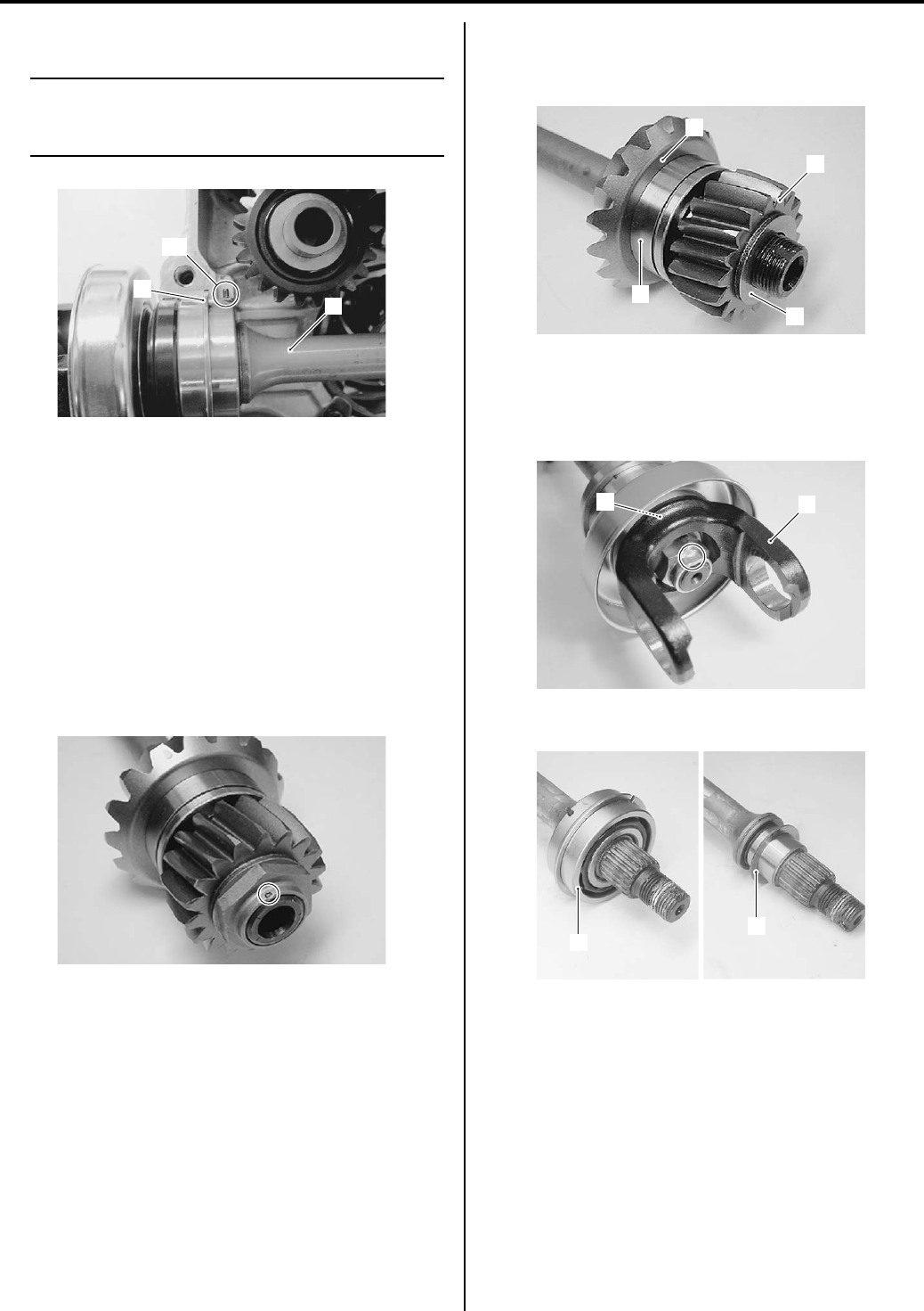
3D-8 Propeller Shafts:
• Install the rear output shaft (1).
NOTE
Be sure to fit the C-ring (2) and bearing
knock-pin “A” on the bearing to the groove of
the crankcase.
• After installed rear output shaft, inspect the backlash
and tooth contact. Refer to “Rear Output Shaft Drive
Bevel Gear Shim Inspection and Adjustment
(Page 3D-11)”.
Rear Output Shaft Disassembly and Assembly
B831G23406007
Refer to “Rear Output Shaft Removal and Installation
(Page 3D-6)”.
Disassembly
1) Using a chisel, unlock the nut. Remove the rear
output shaft nut.
2) Remove the washer (1), rear output shaft driven
gear (2), bearing (3) and rear output shaft driven
bevel gear (4).
3) Remove the rear output shaft yoke (5) and oil seal
(6).
Refer to “Rear Propeller Shaft Removal and
Installation (Page 3D-17)”.
4) Remove the bearing (7) and shim (8).
1
“A”
2
I831G1340028-03
I831G1340031-05
1
3
4
2
I831G1340032-06
5
6
I831G1340029-03
7
8
I831G1340030-03
PartShark.com
877-999-5686
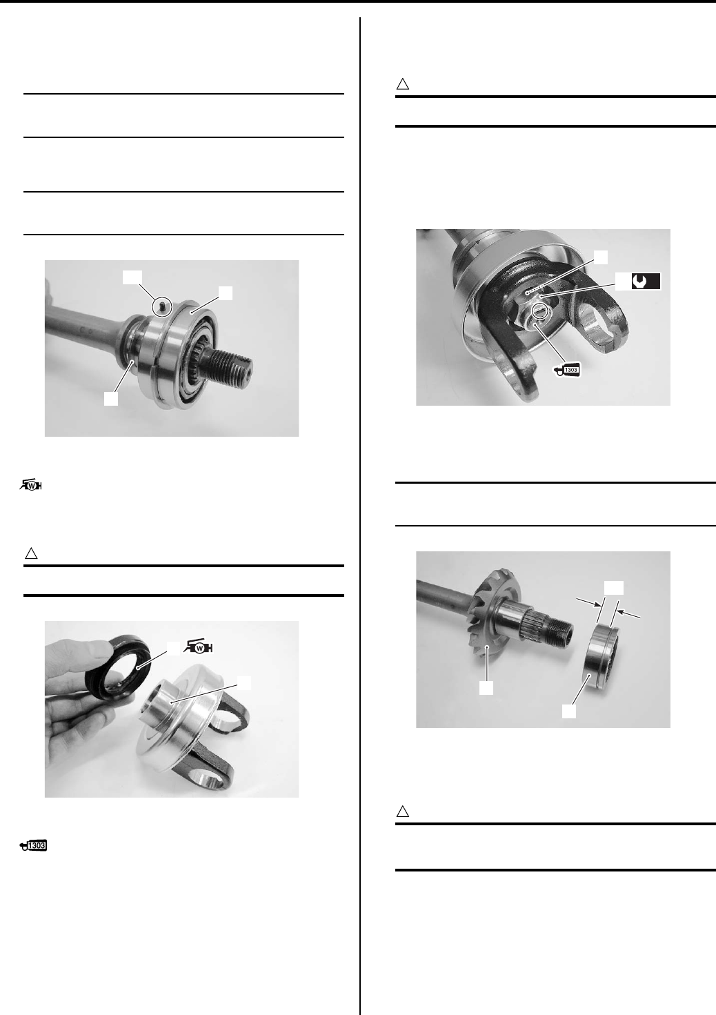
Propeller Shafts: 3D-9
Assembly
Assemble the rear output shaft in the reverse order of
disassembly. Pay attention to the following points:
NOTE
Apply engine oil to each running part before
reassembling.
• Install the shim(s) (1) and bearing (2).
NOTE
The bearing knock-pin “A” should be
positioned inside.
• Apply grease to the oil seal (3).
: Grease 99000–25160 (Water resistance
grease)
• Install the oil seal to the rear output shaft yoke (4).
CAUTION
!
Replace the oil seal (3) with a new one.
• Apply thread lock to the thread part of the output shaft.
: Thread lock cement 99000–32030
(THREAD LOCK CEMENT SUPER 1303 or
equivalent)
• After installed rear output shaft yoke to the rear output
shaft, install the washer (5) and tighten the output
shaft nut (6) to the specified torque.
CAUTION
!
Do not reuse the output shaft nut (6).
Tightening torque
Rear output shaft nut (a): 100 N·m (10.0 kgf-m,
72.5 lb-ft)
• Lock the rear output shaft nut with a center punch.
• Install the rear output shaft driven bevel gear (7) and
bearing (8).
NOTE
The wider side “a” of the bearing should be
positioned bevel gear side.
• With the rear output shaft held immovable with a vise,
tighten the rear output shaft driven gear nut (9) to the
specified torque.
CAUTION
!
The removed nut must be replaced with a
new one.
Tightening torque
Rear output shaft driven gear nut (b): 100 N·m (
10.0 kgf-m, 72.5 lb-ft)
1
2
“A”
I831G1340035-02
3
4
I831G1340101-02
5
(a)
6
I831G1340102-03
7
8
“a”
I831G1340033-02
PartShark.com
877-999-5686
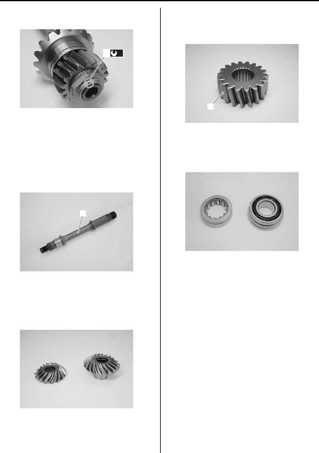
3D-10 Propeller Shafts:
• Lock the rear output shaft driven gear nut (9) with a
center punch.
Rear Output Shaft Related Parts Inspection
B831G23406008
Refer to “Rear Output Shaft Disassembly and Assembly
(Page 3D-8)”.
Rear Output shaft
Inspect the rear output shaft (1) for wear or damage. If
any defects are found, replace the rear output shaft with
a new one.
Rear Output Shaft Bevel Gear
Inspect the drive and driven bevel gear for wear or
damage.
• If any defects are found, replace the drive and driven
bevel gears as a set.
Rear Output Shaft Gear
Inspect the rear output shaft gear for wear or damage. If
any defects are found, replace the rear output shaft gear
with the new one.
Bearing
Inspect the rear output shaft bearing and rear driven
bevel gear bearing for abnormal noise and smooth
rotation.
(b)
9
I831G1340034-03
1
I831G1340036-01
I831G1340037-01
3
I831G1340038-01
I831G1340039-01
PartShark.com
877-999-5686
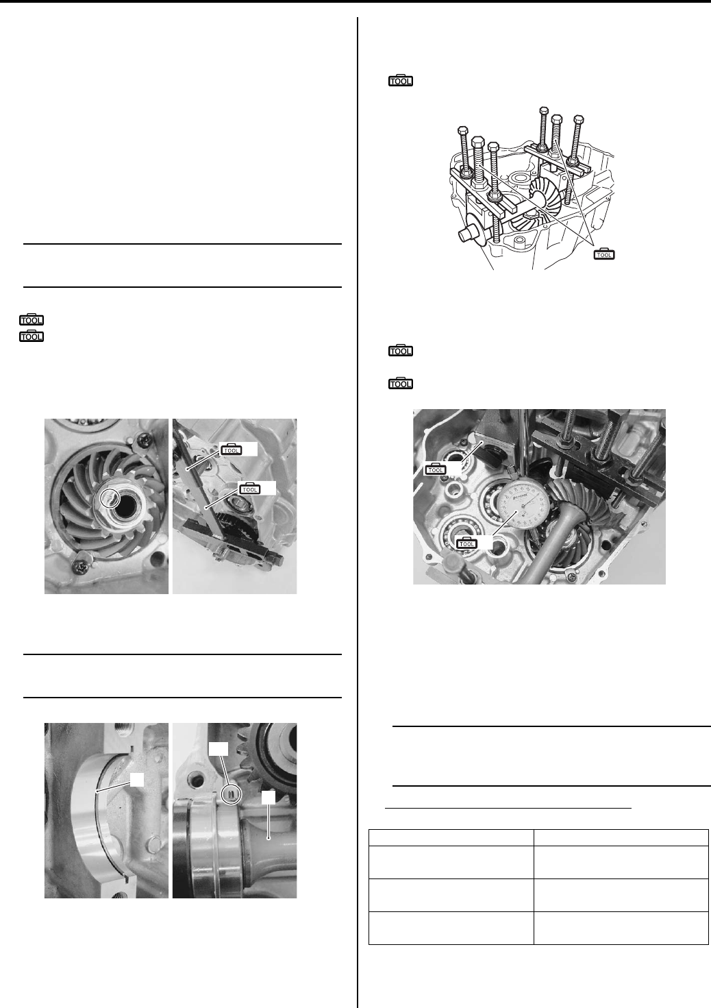
Propeller Shafts: 3D-11
Rear Output Shaft Drive Bevel Gear Shim
Inspection and Adjustment
B831G23406009
Refer to “Rear Output Shaft Removal and Installation
(Page 3D-6)”.
Backlash
• Install the shim, drive bevel gear, washer and new
drive bevel gear nut.
• Hold the transfer output driven gear with the special
tool and tighten the drive bevel gear nut to the
specified torque.
NOTE
At this time, it is not necessary to bend the
drive bevel gear nut collar.
Special tool
(A): 09920–53740 (Clutch sleeve hub holder)
(B): 09920–31020 (Extension handle)
Tightening torque
Rear output shaft drive bevel gear nut: 100 N·m (
10.0 kgf-m, 72.5 lb-ft)
• Install the C-ring (1) and rear output shaft (2).
NOTE
Be sure to fit the bearing knock-pin “A” on
the bearing to the groove of the crankcase.
• Place the rear output shaft on the left crankcase half
and hold bearings with the special tool.
Special tool
(C): 09921–21910 (Bearing holder)
• Set the dial gauge on the drive bevel gear as shown in
the figure.
Special tool
(D): 09900–20607 (Dial gauge (1/100 mm, 10
mm))
(E): 09900–20701 (Magnetic stand)
• Measure the backlash by turning the drive bevel gear
shaft in each direction, reading the total backlash with
the dial gauge. If the backlash is not within
specification, the shim must be changed and backlash
should be re-checked until correct. Check the table at
the appropriate shim thickness.
NOTE
Adjust the backlash by referring to the table
at the using the thickness of the removed
shims as a guide.
Rear output shaft bevel gear backlash
Standard: 0.03 – 0.15 mm (0.0001 – 0.006 in)
(A)
(B)
I831G1340040-01
1
2
“A”
I831G1340041-01
Backlash Shim adjustment
Under 0.03 mm
(0.001 in) Increase shim thickness
0.03 – 0.15 mm
(0.001 – 0.006 in) Correct
Over 0.15 mm
(0.006 in) Decrease shim thickness
(C)
I831G1340099-03
(D)
(E)
I831G1340043-04
PartShark.com
877-999-5686
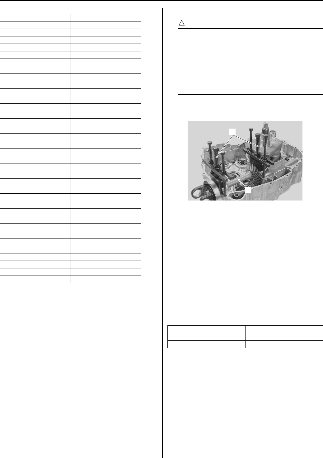
3D-12 Propeller Shafts:
List of shims (for driven bevel gear)
• Check the tooth contact.
Tooth Contact
CAUTION
!
Make sure to check the backlash after the
tooth contact has been adjusted, since it may
have changed. Adjust the tooth contact and
backlash until they are both within
specification. If the correct tooth contact
cannot be maintained when adjusting the
backlash, replace the rear output shaft drive
and driven bevel gears.
• Remove the special tool (1) and rear output shaft (2)
from the left crankcase.
• Clean and degrease several teeth of the drive and
driven bevel gears, and then apply a coating of
machinist’s layout dye or paste to several teeth of the
rear output shaft driven bevel gear.
• Install the rear output shaft.
• Rotate the rear output shaft driven bevel gear several
turns in both directions.
• Remove the output shaft and inspect the coated teeth
of the rear output shaft drive bevel gear. The tooth
contact pattern should be as shown in [A], [B] and [C].
If tooth contact is found to be incorrect (examples [A]
and [C]), the shim thickness between the rear output
shaft drive bevel gear and bearing must be changed
and the tooth contact re-checked until correct
(examples [B]).
Part No. Shim thickness
24945-03G50-055 0.550 mm (0.022 in)
24945-03G50-058 0.575 mm (0.023 in)
24945-03G50-060 0.600 mm (0.024 in)
24945-03G50-063 0.625 mm (0.025 in)
24945-03G50-065 0.650 mm (0.026 in)
24945-03G50-068 0.675 mm (0.027 in)
24945-03G50-070 0.700 mm (0.028 in)
24945-03G50-073 0.725 mm (0.029 in)
24945-03G50-075 0.750 mm (0.030 in)
24945-03G50-078 0.775 mm (0.031 in)
24945-03G50-080 0.800 mm (0.031 in)
24945-03G50-083 0.825 mm (0.032 in)
24945-03G50-085 0.850 mm (0.033 in)
24945-03G50-088 0.875 mm (0.034 in)
24945-03G50-090 0.900 mm (0.035 in)
24945-03G50-093 0.925 mm (0.036 in)
24945-03G50-095 0.950 mm (0.037 in)
24945-03G50-098 0.975 mm (0.038 in)
24945-03G50-100 1.000 mm (0.039 in)
24945-03G50-103 1.025 mm (0.040 in)
24945-03G50-105 1.050 mm (0.041 in)
24945-03G50-108 1.075 mm (0.042 in)
24945-03G50-110 1.100 mm (0.043 in)
24945-03G50-113 1.125 mm (0.044 in)
24945-03G50-115 1.150 mm (0.045 in)
24945-03G50-118 1.175 mm (0.046 in)
24945-03G50-120 1.200 mm (0.047 in)
24945-03G50-123 1.225 mm (0.048 in)
24945-03G50-125 1.250 mm (0.049 in)
24945-03G50-128 1.275 mm (0.050 in)
24945-03G50-130 1.300 mm (0.051 in)
24945-03G50-133 1.330 mm (0.052 in)
24945-03G50-135 1.350 mm (0.053 in)
24945-03G50-138 1.380 mm (0.054 in)
24945-03G50-140 1.400 mm (0.055 in)
Tooth contact Shim adjustment
Contact at tooth top [A] Increase shim thickness
Contact at tooth root [C] Decrease shim thickness
1
2
I831G1340044-02
PartShark.com
877-999-5686
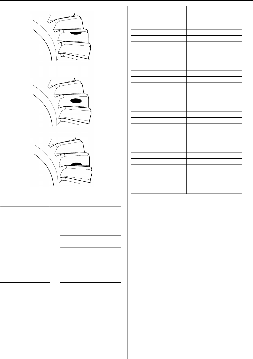
Propeller Shafts: 3D-13
List of shims (for drive bevel gear)
Part No. Shim thickness
24935-19B00-025:
0.25 mm (0.0098 in)
Co
mbi
ned
shi
m
0.25+0.25=0.50 mm
(0.0197 in)
0.25+0.30=0.55 mm
(0.0217 in)
0.30+0.30=0.60 mm
(0.0236 in)
0.30+0.35=0.65 mm
(0.0256 in)
24935-19B00-030:
0.30 mm (0.0118 in)
0.35+0.35=0.70 mm
(0.0276)
0.25+0.25+ 0.25=0.75 mm
(0.0295 in)
24935-19B00-035:
0.35 mm (0.0138 in)
0.25+0.25+0.30=0.80 mm
(0.0315 in)
0.25+0.25+0.35=0.85 mm
(0.0335 in)
Incorrect (Contact at tooth top)
Incorrect (Contact at tooth root)
Correct
[A]
[B]
[C]
I831G1340095-02
Part No. Shim thickness
24935-03G50-055 0.550 mm (0.0217 in)
24935-03G50-058 0.575 mm (0.0226 in)
24935-03G50-060 0.600 mm (0.0236 in)
24935-03G50-063 0.625 mm (0.0246 in)
24935-03G50-065 0.650 mm (0.0256 in)
24935-03G50-068 0.675 mm (0.0266 in)
24935-03G50-070 0.700 mm (0.0276 in)
24935-03G50-073 0.725 mm (0.0285 in)
24935-03G50-075 0.750 mm (0.0295 in)
24935-03G50-078 0.775 mm (0.0305 in)
24935-03G50-080 0.800 mm (0.0315 in)
24935-03G50-083 0.825 mm (0.0325 in)
24935-03G50-085 0.850 mm (0.0335 in)
24935-03G50-088 0.875 mm (0.0344 in)
24935-03G50-090 0.900 mm (0.0354 in)
24935-03G50-093 0.925 mm (0.0364 in)
24935-03G50-095 0.950 mm (0.0374 in)
24935-03G50-098 0.975 mm (0.0384 in)
24935-03G50-100 1.000 mm (0.0394 in)
24935-03G50-103 1.025 mm (0.0404 in)
24935-03G50-105 1.050 mm (0.0413 in)
24935-03G50-108 1.075 mm (0.0423 in)
24935-03G50-110 1.100 mm (0.0433 in)
24935-03G50-113 1.125 mm (0.0443 in)
24935-03G50-115 1.150 mm (0.0453 in)
24935-03G50-118 1.175 mm (0.0463 in)
24935-03G50-120 1.200 mm (0.0472 in)
24935-03G50-123 1.225 mm (0.0482 in)
24935-03G50-125 1.250 mm (0.0492 in)
24935-03G50-128 1.275 mm (0.0502 in)
24935-03G50-130 1.300 mm (0.0512 in)
PartShark.com
877-999-5686
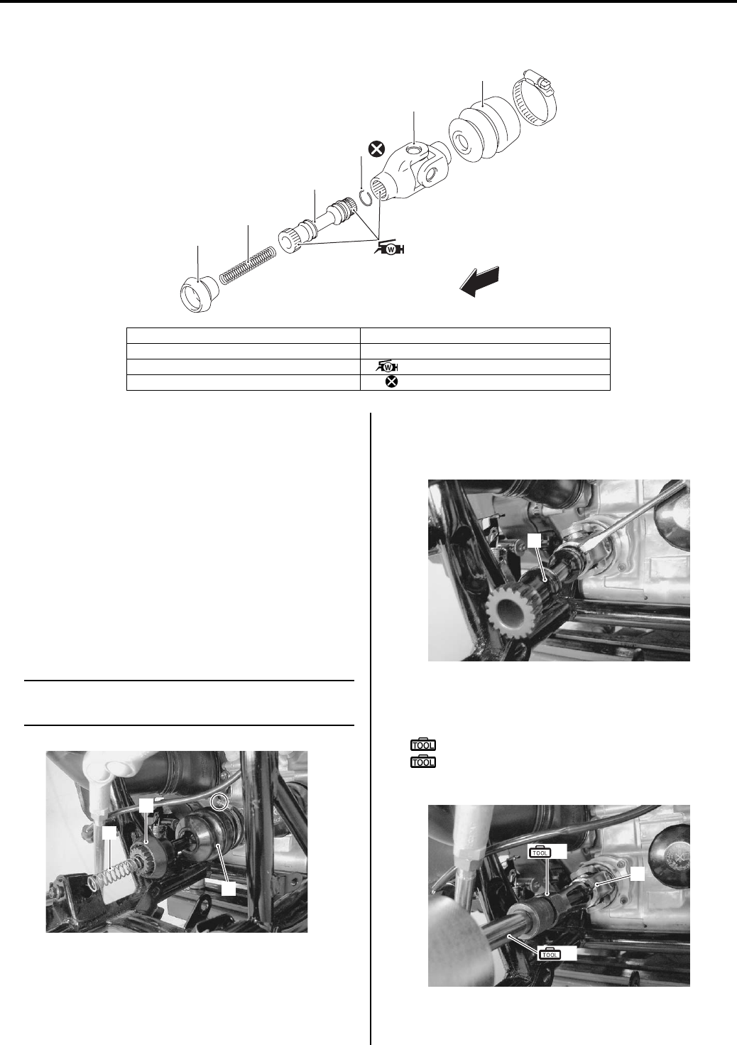
3D-14 Propeller Shafts:
Front Propeller Shaft Components
B831G23406010
Front Propeller Shaft Removal and Installation
B831G23406011
Refer to “Front Propeller Shaft Components (Page 3D-
14)” and “Front Drive (Differential) Construction in
Section 3B (Page 3B-3)”.
Removal
Remove the front drive (differential) assembly.
Refer to “Front Drive (Differential) Assembly Removal
and Installation in Section 3B (Page 3B-4)”.
1) Remove the front propeller shaft spring (1) and front
propeller shaft boot (2).
2) Loosen the boot clamp screw and remove the
universal joint boot (3).
NOTE
Apply oil to the removing direction of the
universal joint boot before removing.
3) Using a (–) screwdriver or the like into a notch of the
universal joint and remove the front propeller shaft
(4).
4) Remove the universal joint (5) from the joint portion
(at the engine side) with special tools.
Special tool
(A): 09923–74511 (Bearing remover)
(B): 09930–30104 (Rotor remover slide
shaft)
FWD
1
2
3
4
5
6
I831G1340045-04
1. Boot 5. Universal joint
2. Front propeller shaft spring 6. Boot
3. Front propeller shaft : Apply water resistance grease.
4. Circlip : Do not reuse.
1
2
3
I831G1340046-01
4
I831G1340047-01
5
(A)
(B)
I831G1340048-01
PartShark.com
877-999-5686
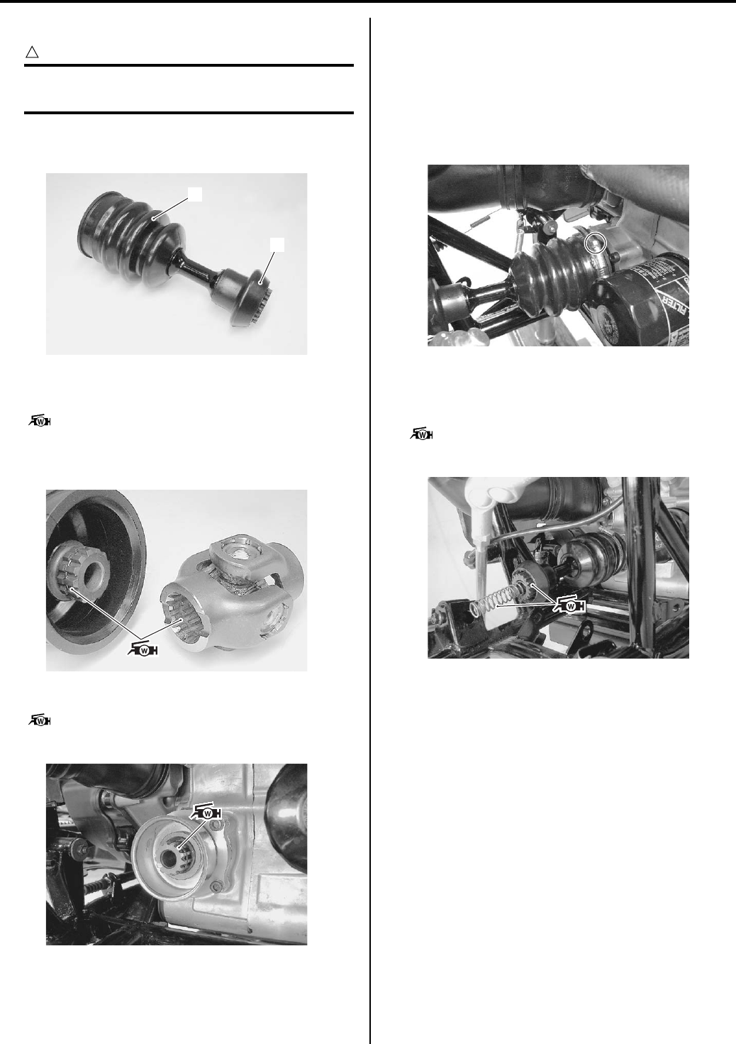
Propeller Shafts: 3D-15
Installation
CAUTION
!
The removed circlips must be replaced with
new ones.
1) Fit the front propeller shaft boot (1) and universal
joint boot (2) to the front propeller shaft groove.
2) Apply grease (approx. 4 grams) to the spline of
universal joint and spline of the front propeller shaft.
: Grease 99000–25160 (Water resistance
grease)
3) Connect the propeller shaft to the universal joint.
4) Apply grease (approx. 4 grams) to the spline.
: Grease 99000–25160 (Water resistance
grease)
5) Connect the universal joint to the joint portion (at the
engine side).
6) Attach the boot to the front drive collar and tighten
the boot clamp screw to the specified torque.
Tightening torque
Front propeller shaft boot clamp screw: 1.3 N·m
(0.13 kgf-m, 1.0 lb-ft)
7) Install the front propeller shaft spring.
Apply grease (approx. 4 grams) to the spline of front
propeller shaft and spring.
: Grease 99000–25160 (Water resistance
grease)
9) Install the front drive (differential) assembly. Refer to
“Front Drive (Differential) Assembly Removal and
Installation in Section 3B (Page 3B-4)”.
2
1
I831G1340049-02
I831G1340050-02
I831G1340051-01
I831G1340100-01
I831G1340052-01
PartShark.com
877-999-5686
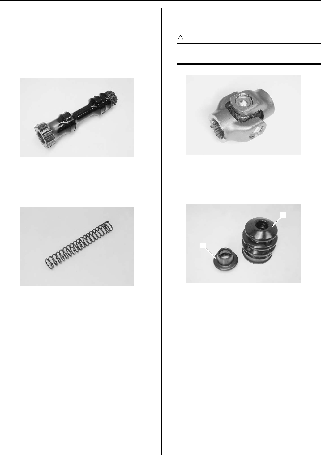
3D-16 Propeller Shafts:
Front Propeller Shaft Related Parts Inspection
B831G23406012
Refer to “Front Propeller Shaft Removal and Installation
(Page 3D-14)”.
Front Propeller Shaft
Inspect the front propeller shaft for wear or damage. If
any defects are found, replace the front propeller shaft
with a new one.
Front Propeller Shaft Spring
Inspect the front propeller shaft spring for damage or
fatigue. If any defects are found, replace the front
propeller shaft spring with a new one.
Universal Joint
Inspect the play by turning the universal joint. If
excessive play is noted, replace it with a new one.
CAUTION
!
Do not attempt to disassemble the universal
joint.
Boots
Inspect the front propeller shaft boot (1) and universal
joint boot (2) for crack or damage. If any defects are
found, replace the boot part with a new one.
I831G1340053-01
I831G1340054-01
I831G1340055-01
1
2
I831G1340056-01
PartShark.com
877-999-5686
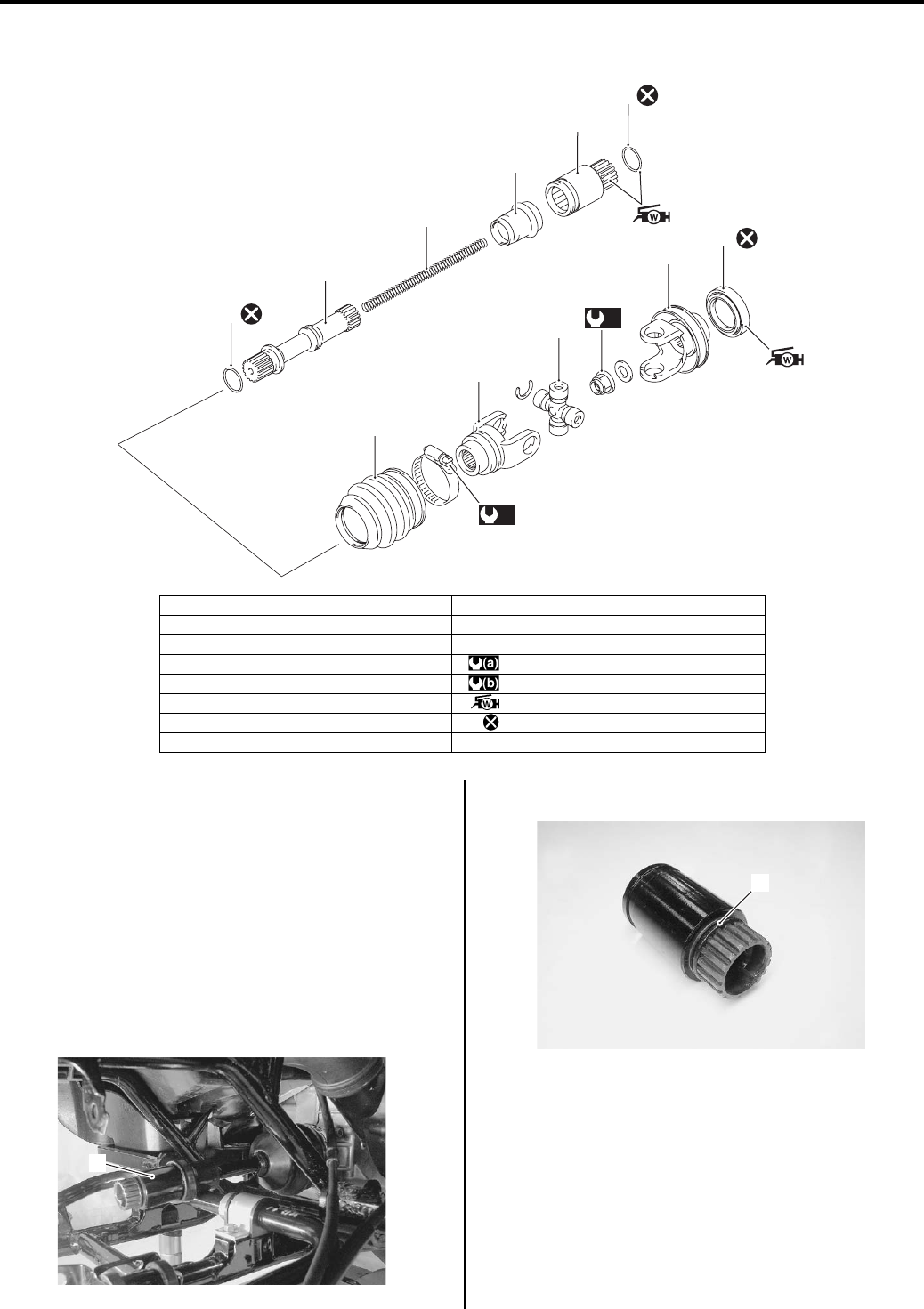
Propeller Shafts: 3D-17
Rear Propeller Shaft Components
B831G23406013
Rear Propeller Shaft Removal and Installation
B831G23406014
Refer to “Rear Propeller Shaft Components (Page 3D-
17)”.
Refer to “Final Gear Construction in Section 3B
(Page 3B-22)”.
Removal
1) Remove the final gear assembly. Refer to “Final
Gear Assembly Removal and Installation in Section
3B (Page 3B-23)”.
2) Remove the rear propeller shaft joint (1).
3) Remove the O-ring (2).
6
5
4
3
2
1
7
8
9
10
11
(a)
(b)
I831G1340057-04
1. O-ring 9. Universal joint set
2. Rear propeller shaft joint 10. Rear output shaft yoke
3. Rear propeller shaft boot 11. Oil seal
4. Rear propeller shaft spring : 100 N⋅m (10.0 kgf-m, 72.5 lb-ft)
5. Rear propeller shaft : 2 N⋅m (0.2 kgf-m, 1.5 lb-ft)
6. O-ring : Apply water resistance grease.
7. Rear propeller shaft boot : Do not reuse.
8. Rear propeller shaft yoke
1
I831G1340059-01
2
I831G1340060-01
PartShark.com
877-999-5686
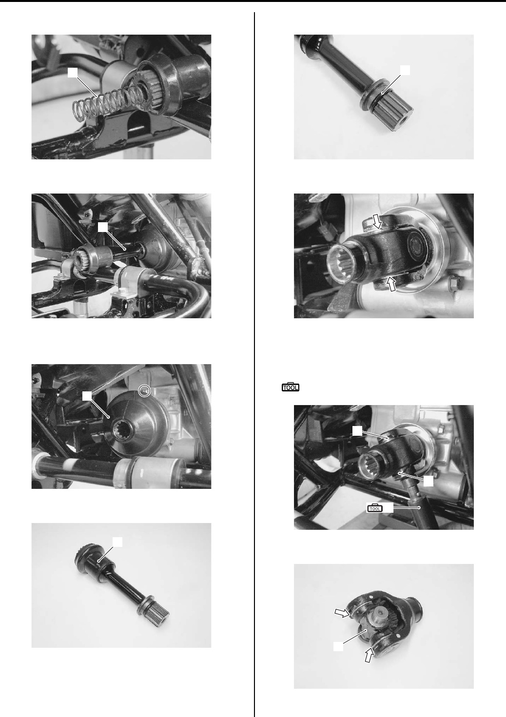
3D-18 Propeller Shafts:
4) Remove the rear propeller shaft spring (3).
5) Draw out the rear propeller shaft (4) horizontally.
6) Loosen the boot clamp screw and remove the rear
propeller shaft boot (5).
7) Remove the rear propeller shaft joint boot (6).
Remove the O-ring (7).
9) Remove the circlips from the universal joint.
10) Remove the bearings (8) by tapping with the special
tool and remove the universal joint and propeller
shaft yoke.
Special tool
(A): 09913–70210 (Bearing installer set)
11) Remove the circlips and joint (9).
3
I831G1340061-01
4
I831G1340062-01
5
I831G1340063-01
6
I831G1340064-01
7
I831G1340065-01
I831G1340066-03
8
8
8
(A)
I831G1340067-03
9
I831G1340068-04
PartShark.com
877-999-5686
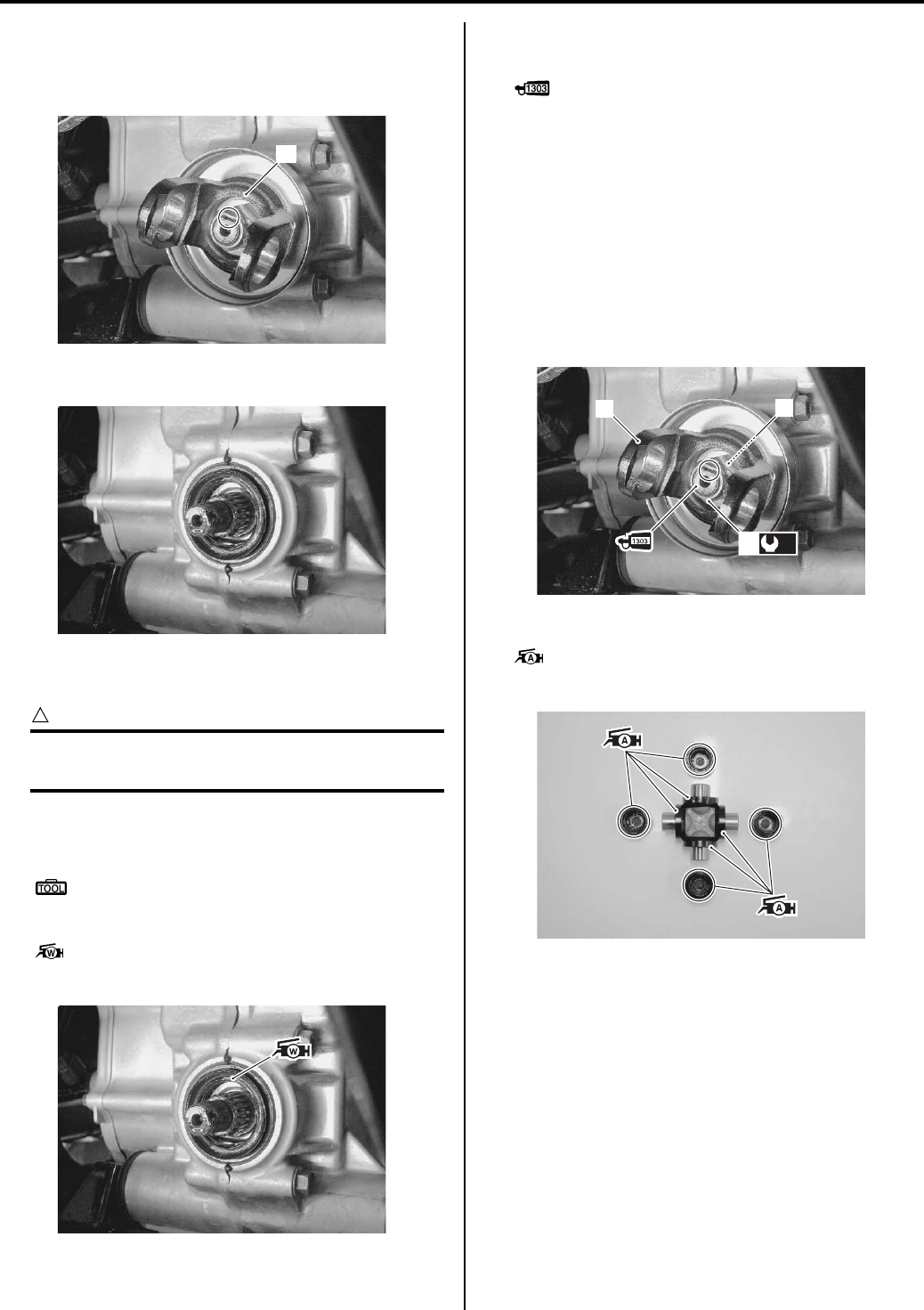
Propeller Shafts: 3D-19
12) Unlock the nut with a chisel.
13) Shift into the reverse gear.
14) Remove the rear output shaft yoke (10).
15) Remove the oil seal.
Installation
CAUTION
!
The removed oil seal, nut, circlips and O-ring
must be replaced with a new ones.
1) Install the oil seal into the final gear case with the
special tool.
Special tool
: 09913–70210 (Bearing installer set)
2) Apply grease to lip of the oil seal.
: Grease 99000–25160 (Water resistance
grease)
3) Shift into the low gear.
4) Apply thread lock to the rear output shaft.
: Thread lock cement 99000–32030
(THREAD LOCK CEMENT SUPER 1303 or
equivalent)
5) Install the rear output shaft yoke (1) and washer (2).
Tighten the rear output shaft nut (3) to the specified
torque.
Tightening torque
Rear output shaft nut (a): 100 N·m (10.0 kgf-m,
72.5 lb-ft)
6) Lock the rear output shaft nut (3) with a center
punch.
7) Apply grease to the bearings and dust seal lip.
: Grease 99000–25010 (SUZUKI SUPER
GREASE A or equivalent)
10
I831G1340069-02
I831G1340070-01
I831G1340071-01
12
(a)
3
I831G1340072-02
I831G1340073-01
PartShark.com
877-999-5686
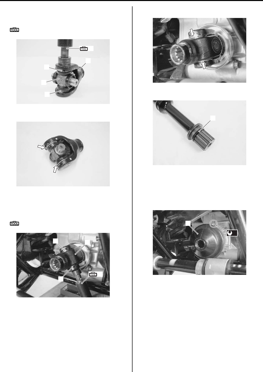
3D-20 Propeller Shafts:
Install the universal joint (4) to the yoke (5) and
bearings (6) with the special tool.
Special tool
(A): 09913–70210 (Bearing installer set)
9) Install the circlips.
10) Install the yoke (5).
11) Install the bearings (6) by tapping with the special
tool.
Special tool
(A): 09913–70210 (Bearing installer set)
12) Install the circlips to the universal joint.
13) Install the O-ring (7) to the rear propeller shaft.
14) Install the rear propeller shaft boot (8) and tighten
the clamp screw to the specified torque.
Tightening torque
Rear propeller shaft boot clamp screw (b): 2
N·m (0.2 kgf-m, 1.5 lb-ft)
(A)
4
6
6
5
I831G1340074-03
I831G1340075-01
6
6
5
(A)
I831G1340076-04
I831G1340077-02
7
I831G1340078-02
(b)
8
I831G1340079-03
PartShark.com
877-999-5686
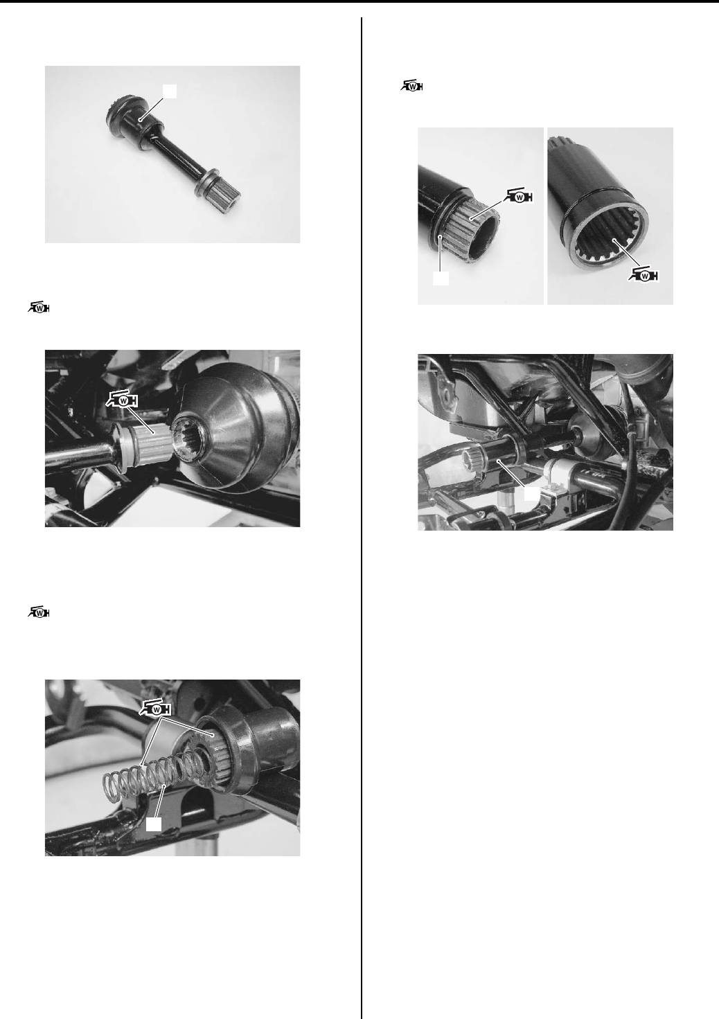
Propeller Shafts: 3D-21
15) Fit the rear propeller shaft joint boot (9) to the rear
propeller shaft groove.
16) Apply resistance grease (approx. 4 grams) to the
splines of the rear propeller shaft.
: Grease 99000–25160 (Water resistance
grease)
17) Install the rear propeller shaft.
18) Apply grease (approx. 4 grams) to the spline of rear
propeller shaft and propeller shaft spring (10).
: Grease 99000–25160 (Water resistance
grease)
19) Install the rear propeller shaft spring (10).
20) Install the O-ring (11) to the rear propeller shaft joint.
21) Apply grease (approx. 4 grams) to the spline of rear
propeller shaft joint.
: Grease 99000–25160 (Water resistance
grease)
22) Install the rear propeller shaft joint (12).
23) Install the final gear assembly. Refer to “Final Gear
Assembly Removal and Installation in Section 3B
(Page 3B-23)”.
9
I831G1340096-02
I831G1340080-01
10
I831G1340081-03
11
I831G1340082-03
12
I831G1340083-04
PartShark.com
877-999-5686
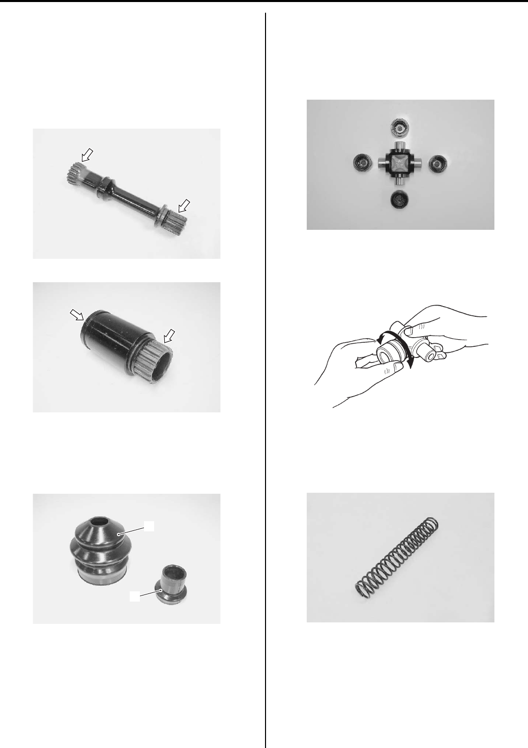
3D-22 Propeller Shafts:
Rear Propeller Shaft Related Parts Inspection
B831G23406015
Refer to “Rear Propeller Shaft Removal and Installation
(Page 3D-17)”.
Rear Propeller Shaft / Rear Propeller Shaft Joint
Inspect the rear propeller shaft and rear propeller shaft
joint for wear or damage. If any defects are found,
replace it with a new one.
Boots
Inspect the rear output joint boot (1) and propeller shaft
joint boot (2) for crack or damage. If any defects are
found, replace the boot with a new one.
Universal Joint
Inspect the universal joint in the following procedures:
1) Inspect the universal joint and outer surface of the
bearing for scuffing, wear or damage. If any defects
are found, replace the bearings and universal joint
as a set.
2) Insert the universal joint to the bearing and check the
play by turning the universal joint, as shown in the
figure. If excessive play is found, replace the
bearings and universal joint as a set.
Rear Propeller Shaft Spring
Inspect the rear propeller shaft spring for wear or
damage. If any defects are found, replace it with a new
one.
I831G1340084-01
I831G1340085-01
1
2
I831G1340086-01
I831G1340087-01
I831G1340094-01
I831G1340089-01
PartShark.com
877-999-5686
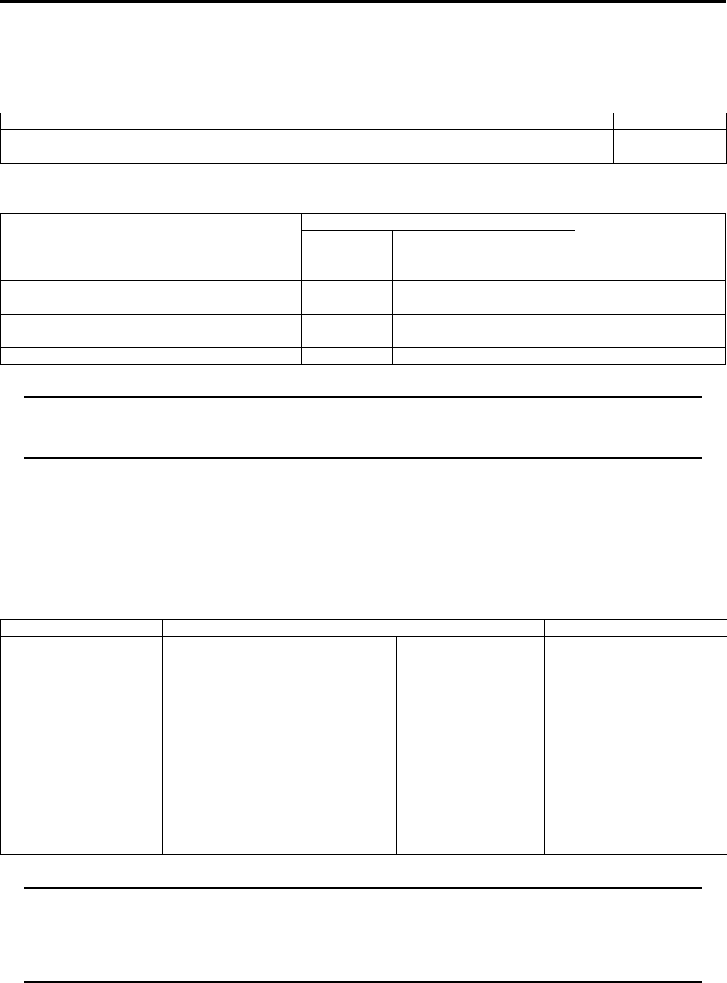
Propeller Shafts: 3D-23
Specifications
Service Data
B831G23407001
Drive Train
Unit: mm (in)
Tightening Torque Specifications
B831G23407002
NOTE
The specified tightening torque is also described in the following.
“Rear Output Shaft Components (Page 3D-6)”
“Rear Propeller Shaft Components (Page 3D-17)”
Reference:
For the tightening torque of fastener not specified in this section, refer to “Tightening Torque List in Section 0C
(Page 0C-7)”.
Special Tools and Equipment
Recommended Service Material
B831G23408001
NOTE
Required service material is also described in the following.
“Front Output Shaft Components (Page 3D-1)”
“Rear Output Shaft Components (Page 3D-6)”
“Front Propeller Shaft Components (Page 3D-14)”
“Rear Propeller Shaft Components (Page 3D-17)”
Item Standard Limit
Front/Rear output shaft bevel gear
backlash 0.03 – 0.15 (0.001 – 0.006) —
Fastening part Tightening torque Note
N⋅mkgf—mlb—ft
Rear output shaft drive bevel gear nut 100 10.0 72.5 )(Page 3D-7) /
)(Page 3D-11)
Rear output shaft nut 100 10.0 72.5 )(Page 3D-9) /
)(Page 3D-19)
Rear output shaft driven gear nut 100 10.0 72.5 )(Page 3D-9)
Front propeller shaft boot clamp screw 1.3 0.13 1.0 )(Page 3D-15)
Rear propeller shaft boot clamp screw 2 0.2 1.5 )(Page 3D-20)
Material SUZUKI recommended product or Specification Note
Grease SUZUKI SUPER GREASE A or
equivalent
P/No.: 99000–25010 )(Page 3D-2) / )(Page 3D-
4) / )(Page 3D-4) /
)(Page 3D-19)
Water resistance grease P/No.: 99000–25160 )(Page 3D-4) / )(Page 3D-
9) / )(Page 3D-15) /
)(Page 3D-15) /
)(Page 3D-15) /
)(Page 3D-19) /
)(Page 3D-21) /
)(Page 3D-21) /
)(Page 3D-21)
Thread lock cement THREAD LOCK CEMENT SUPER
1303 or equivalent
P/No.: 99000–32030 )(Page 3D-9) / )(Page 3D-
19)
PartShark.com
877-999-5686
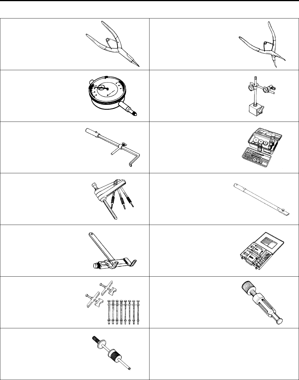
3D-24 Propeller Shafts:
Special Tool
B831G23408002
09900–06107 09900–06108
Snap ring pliers Snap ring pliers
)(Page 3D-2) )(Page 3D-3) / )(Page 3D-
4)
09900–20607 09900–20701
Dial gauge (1/100 mm, 10
mm)
Magnetic stand
)(Page 3D-11) )(Page 3D-11)
09913–50121 09913–70210
Oil seal remover Bearing installer set
)(Page 3D-3) )(Page 3D-4) / )(Page 3D-
4) / )(Page 3D-18) /
)(Page 3D-19) /
)(Page 3D-20) /
)(Page 3D-20)
09920–13120 09920–31020
Crankcase separating tool Extension handle
)(Page 3D-1) / )(Page 3D-
6)
)(Page 3D-11)
09920–53740 09921–20240
Clutch sleeve hub holder Bearing remover set
)(Page 3D-7) / )(Page 3D-
7) / )(Page 3D-11)
)(Page 3D-3)
09921–21910 09923–74511
Bearing holder Bearing remover
)(Page 3D-11) )(Page 3D-3) / )(Page 3D-
14)
09930–30104
Rotor remover slide shaft
)(Page 3D-3) / )(Page 3D-
14)
PartShark.com
877-999-5686

Table of Contents 4- i
4
Section 4
CONTENTS
Brake
Precautions ………………………………….………4-1
Precautions….…………………..……………….…………… 4-1
Precautions for Brake System …..………………..….. 4-1
Brake Fluid Information…………………..……………… 4-1
Brake Control System and Diagnosis … 4A-1
Schematic and Routing Diagram…………..……….4A-1
Front Brake Hose Routing Diagram …….…………. 4A-1
Rear Blake Cable Routing Diagram…………..……4A-2
Diagnostic Information and Procedures…………4A-3
Brake Symptom Diagnosis………..………………..…4A-3
Repair Instructions .……………….…………………..…4A-4
Brake Pedal Height Inspection and
Adjustment ………..…………….…………….…………. 4A-4
Front Brake Light Switch Inspection ………………. 4A-4
Rear Brake Light Switch Inspection …………..……4A-4
Rear Brake Switch Inspection and Adjustment ….4A-4
Parking / Rear Brake Light Switch Inspection….. 4A-5
Parking Brake Lever Switch Inspection…………… 4A-5
Brake Fluid Level Check ……..……………….………. 4A-5
Front Brake Hose Inspection …………..……………. 4A-5
Air Bleeding from Front Brake Fluid Circuit……… 4A-5
Brake Fluid Replacement……………..………………. 4A-6
Front Brake Hose Removal and Installation..……4A-7
Rear Brake Cable Removal and Installation ……. 4A-8
Front Brake Master Cylinder Components………. 4A-9
Front Brake Master Cylinder Assembly
Removal and Installation…………….………………. 4A-9
Front Brake Master Cylinder / Brake Lever
Disassembly and Assembly …………..………….. 4A-11
Front Brake Master Cylinder Parts Inspection ..4A-12
Rear Brake Pedal Construction ……….………….. 4A-13
Rear Brake Pedal Removal and Installation …..4A-14
Specifications…….…………….…………….…………..4A-15
Service Data ………….…………….………………..…. 4A-15
Tightening Torque Specifications………..………..4A-15
Special Tools and Equipment …………….………..4A-16
Recommended Service Material ………………….. 4A-16
Special Tool .……………….………………..………….. 4A-16
Front Brakes ……………..…………….……….. 4B-1
Precautions….…………………..……………….………….4B-1
Precautions for Front Brakes …….………………..…4B-1
Repair Instructions ………..……….…………….………4B-1
Front Brake Components .………………..……………4B-1
Front Brake Pad Inspection…………..……………….4B-2
Front Brake Pad Replacement…………….…………4B-2
Front Brake Caliper Removal and Installation…..4B-3
Front Brake Caliper Disassembly and
Assembly…..…………………..……………….…………4B-4
Front Brake Caliper Parts Inspection ………………4B-6
Front Brake Disc Removal and Installation ………4B-7
Front Brake Disc Inspection …….……………….……4B-8
Specifications…….………….…….…………….…………4B-8
Service Data………………………….…………………....4B-8
Tightening Torque Specifications……………………4B-9
Special Tools and Equipment ……………..…………4B-9
Recommended Service Material ………….…………4B-9
Special Tool ………………………….……………….……4B-9
Rear Brakes……………………………….……… 4C-1
Precautions……..………………..……………….…………4C-1
Precautions for Rear Brake……..……………….……4C-1
Repair Instructions ………..……….…………….………4C-1
Rear Brake Components……………………………....4C-1
Rear Brake Friction Plate Inspection……………....4C-2
Rear Brake Friction Plate Replacement..…………4C-2
Rear Brake Assembly Removal and
Installation …………….……………….………………....4C-2
Rear Brake Disassembly and Assembly ………….4C-3
Rear Brake Parts Inspection ………………………….4C-7
Specifications…….………….…….…………….…………4C-9
Service Data………………………….…………………....4C-9
Tightening Torque Specifications……………………4C-9
Special Tools and Equipment ……………..……….4C-10
Recommended Service Material ……….………….4C-10
Special Tool ……………………….…………….……….4C-10
Parking Brake ……………..…………….……… 4D-1
Schematic and Routing Diagram…………………...4D-1
Parking / Rear Brake Cable Routing Diagram ….4D-1
Repair Instructions ………..……….…………….………4D-3
Parking / Rear Brake Inspection and
Adjustment …………………………….………………....4D-3
Parking / Rear Brake Cable Removal and
Installation …………….……………….………………....4D-3
Parking / Rear Brake Lever Components ………..4D-4
PartShark.com
877-999-5686

4-ii Table of Contents
Parking / Rear Brake Lever Removal and
Installation…………………….………………..…………4D-4
Parking / Rear Brake Light Switch Inspection…..4D-4
Parking / Rear Brake Relay Inspection ……………4D-4
Specifications..……………….……………….……………4D-5
Tightening Torque Specifications……………………4D-5
Special Tools and Equipment ……………..…………4D-5
Recommended Service Material .…………………...4D-5
PartShark.com
877-999-5686

Precautions: 4-1
Brake
Precautions
Precautions
Precautions for Brake System
B831G24000001
Refer to “General Precautions in Section 00 (Page 00-1)”.
Brake Fluid Information
B831G24000002
WARNING
!
• This brake system is filled with an ethylene glycol-based DOT 4 brake fluid. Do not use or mix
different types of fluid, such as silicone-based or petroleum-based.
• Do not use any brake fluid taken from old, used or unsealed containers. Never reuse brake fluid left
over from the last servicing or which has been stored for a long period of time.
• When storing brake fluid, seal the container completely and keep it away from children.
• When replenishing brake fluid, take care not to get dust into the fluid.
• When washing brake components, use new brake fluid. Never use cleaning solvent.
• A contaminated brake disc or brake pad reduces braking performance. Discard contaminated pads
and clean the disc with high quality brake cleaner or neutral detergent.
CAUTION
!
Immediately and completely wipe off any brake fluid contacting any part of the vehicle. The brake fluid
reacts chemically with paint, plastics and rubber materials, etc., and will damage them severely.
PartShark.com
877-999-5686
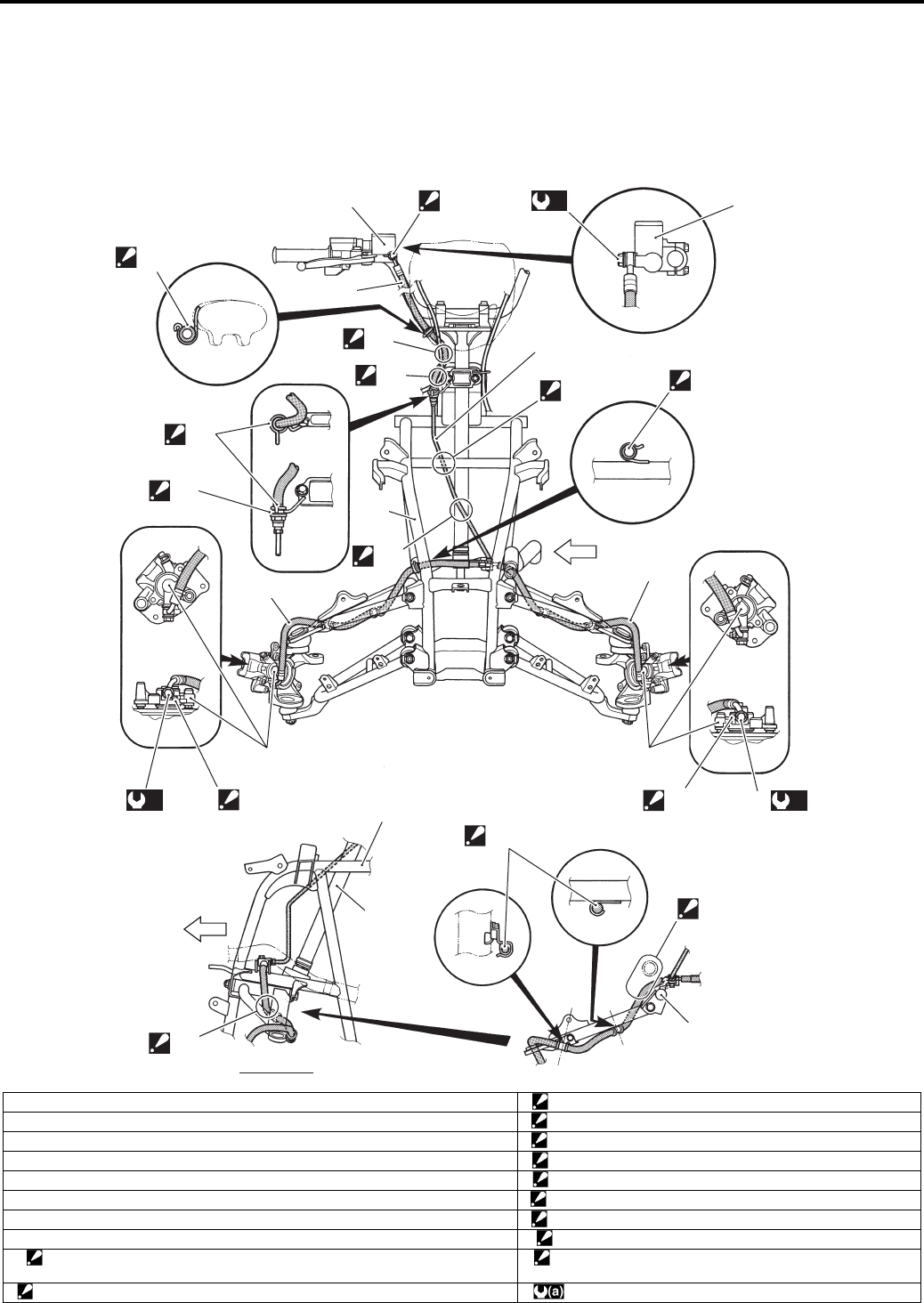
4A-1 Brake Control System and Diagnosis:
Brake
Brake Control System and Diagnosis
Schematic and Routing Diagram
Front Brake Hose Routing Diagram
B831G24102001
11
2
3
5
5
4
6
6
“D”
“A”
“D”
“E”
“F”
“C”
“G”
“D”
“J”
“I”
6
FWD
VIEW A
7
9
9
“H”
“B”
4
A
8(a)
8(a) 8(a)
I831G1410001-09
1. Master cylinder reservoir “B”: Pass the brake hose inside the throttle cable.
2. Front brake hose No. 1 “C”: Pass the brake hose outside the throttle cable.
3. Front brake pipe “D”: Fix the brake hose to the it guide firmly.
4. Front brake hose No. 2 “E”: Face the black mark on the brake hose to forward.
5. Front brake caliper “F”: Tighten flare nut firmly.
6. Frame “G”: Pass the brake pipe front of the steering shaft.
7. Steering shaft “H”: Pass the brake pipe behind the frame bridge.
8. Union bolt “I”: Pass the brake hose inside of the suspension arm.
9. Stopper
: After the brake hose union has contacted the stopper, tighten the union bolt.
“J”: Pass the brake hose under the radiator hose.
“A”: After the brake hose union has contacted the reservoir bottom. : 23 N⋅m (2.3 kgf-m, 16.5 lb-ft)
PartShark.com
877-999-5686
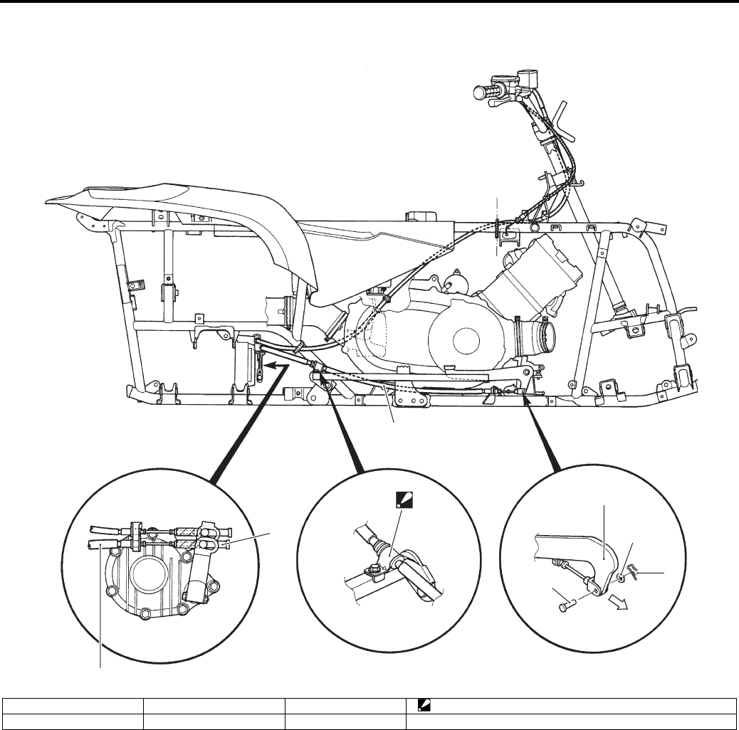
Brake Control System and Diagnosis: 4A-2
Rear Blake Cable Routing Diagram
B831G24102002
1
2
“A”
1
3
5
6
4
Front side
I831G1410035-05
1. Rear brake cable 3. Rear brake pedal 5. Washer “A”: Fix the rear brake cable to the footrest bar with clamp.
2. Adjust nut 4. Pin 6. Cotter pin
PartShark.com
877-999-5686

4A-3 Brake Control System and Diagnosis:
Diagnostic Information and Procedures
Brake Symptom Diagnosis
B831G24104001
Condition Possible cause Correction / Reference Item
Insufficient brake power Leakage of brake fluid from hydraulic
system.
Repair or replace.
Worn pads or friction plate. Replace.
Oil adhesion on friction surface of pads. Clean disc and pads.
Worn disc. Replace.
Air in hydraulic system. Bleed air.
Not enough brake fluid in the reservoir. Replenish.
Defective adjustment of rear brake. Adjust.
Brake squeaking Carbon adhesion on pad surface. Repair surface with sandpaper.
Tilted pad. Correct pad fitting or replace.
Damaged hub bearing. Replace.
Worn pads and disc. Replace.
Foreign material in brake fluid. Replace brake fluid.
Clogged return port of master cylinder. Disassemble and clean master cylinder.
Excessive brake lever
stroke
Air in hydraulic system. Bleed air.
Insufficient brake fluid. Replenish fluid to specified level; bleed air.
Improper quality of brake fluid. Replace with correct fluid.
Leakage of brake fluid Insufficient tightening of connection
joints.
Tighten to specified torque.
Cracked hose. Replace.
Worn piston and/or cup. Replace piston and/or cup.
Worn piston seal and dust seal. Replace piston seal and dust seal.
Brake drags Rusty part. Clean and lubricate.
Insufficient brake lever or brake pedal
pivot lubrication.
Lubricate.
PartShark.com
877-999-5686
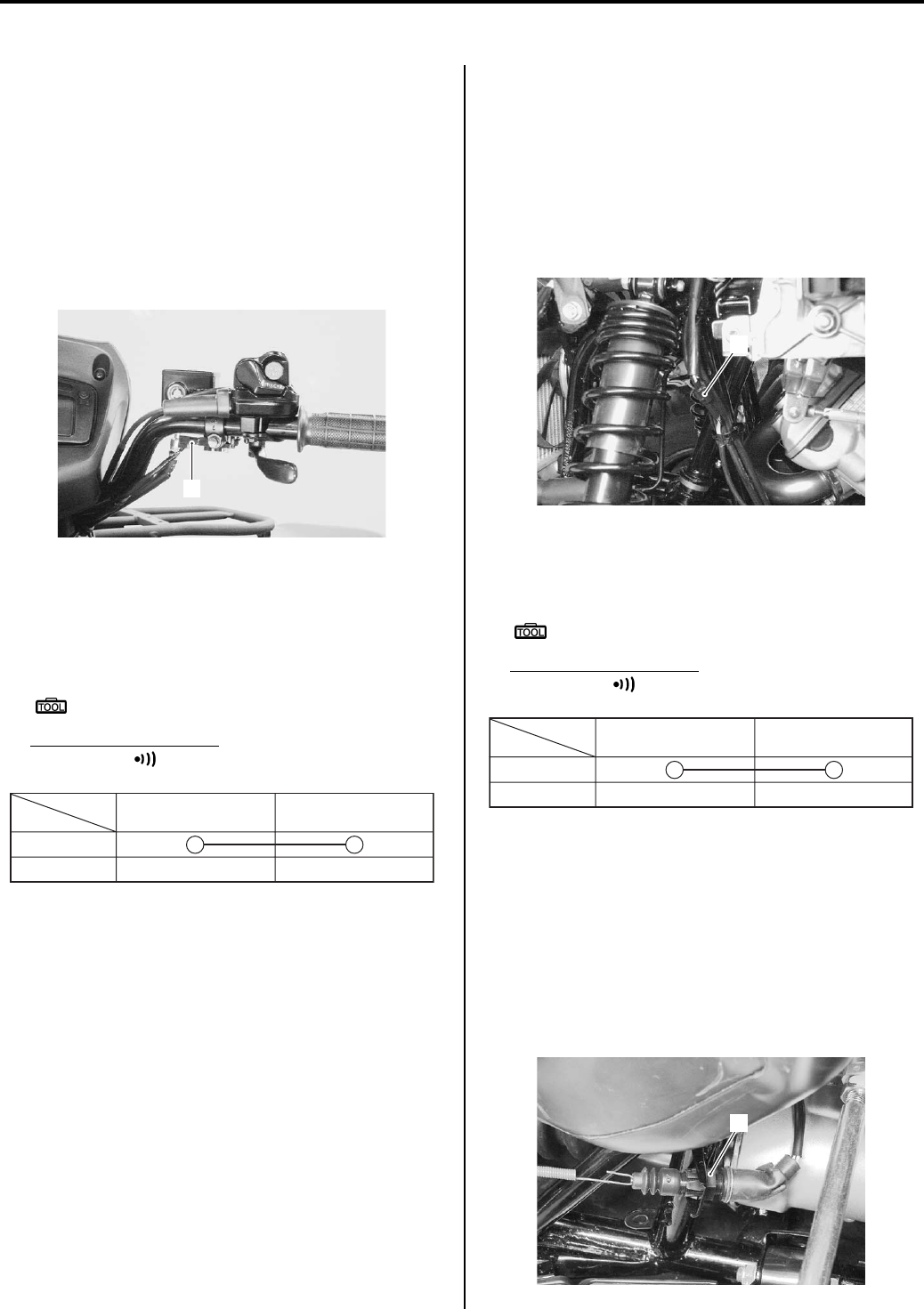
Brake Control System and Diagnosis: 4A-4
Repair Instructions
Brake Pedal Height Inspection and Adjustment
B831G24106001
Refer to “Rear Brake Pedal / Rear Brake (Parking Brake)
Lever Inspection and Adjustment in Section 0B
(Page 0B-19)”.
Front Brake Light Switch Inspection
B831G24106002
Inspect the front brake light switch in the following
procedures:
1) Disconnect the front brake light switch coupler (1).
2) Inspect the switch for continuity with a tester.
If any abnormality is found, replace the front brake
light switch with a new one. Refer to “Front Brake
Master Cylinder / Brake Lever Disassembly and
Assembly (Page 4A-11)”.
Special tool
: 09900–25008 (Multi-circuit tester set)
Tester knob indication
Continuity ( )
3) Connect the front brake light switch coupler.
Rear Brake Light Switch Inspection
B831G24106003
Inspect the rear brake light switch in the following
procedures:
1) Remove the left front inner fender. Refer to “Front
Side Exterior Parts Removal and Installation in
Section 9D (Page 9D-6)”.
2) Disconnect the rear brake light switch lead wire
coupler (1).
3) Inspect the switch for continuity with a tester.
If any abnormality is found, replace the rear brake
light switch with a new one.
Special tool
: 09900–25008 (Multi-circuit tester set)
Tester knob indication
Continuity ( )
4) Connect the rear brake light switch lead wire coupler
(1).
Rear Brake Switch Inspection and Adjustment
B831G24106004
Check the rear brake light switch so that the brake light
will come on just before pressure is felt when the brake
pedal is depressed. If the brake light switch adjustment
is necessary, turn the adjuster nut (1) in or out while
holding the brake pedal.
1
I831G1410002-01
Terminal (B) Terminal (B)
Color
Position
OFF
ON
I831G1410003-02
1
I831G1410034-01
Terminal (O) Terminal (W/B)
Color
Position
OFF
ON
I831G1410032-03
1
I831G1410005-01
PartShark.com
877-999-5686
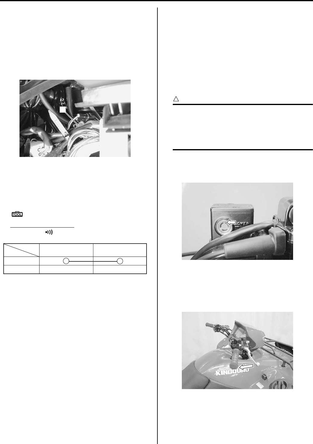
4A-5 Brake Control System and Diagnosis:
Parking / Rear Brake Light Switch Inspection
B831G24106005
Inspect the parking/rear brake light switch in the
following procedures:
1) Remove the left inner fender. Refer to “Front Side
Exterior Parts Removal and Installation in Section
9D (Page 9D-6)”.
2) Disconnect the parking/rear brake light switch lead
wire coupler (1).
3) Inspect the parking/rear brake light switch for
continuity with a tester. If any abnormality is found,
replace the parking/rear brake lever assembly with a
new one. Refer to “Handlebars Removal and
Installation in Section 6B (Page 6B-3)”.
Special tool
: 09900–25008 (Multi-circuit tester set)
Tester knob indication
Continuity ( )
Parking Brake Lever Switch Inspection
B831G24106006
Refer to “Parking Brake Switch Inspection in Section 1I
(Page 1I-9)”.
Brake Fluid Level Check
B831G24106007
Refer to “Front Brake System Inspection in Section 0B
(Page 0B-17)”.
Front Brake Hose Inspection
B831G24106008
Refer to “Front Brake System Inspection in Section 0B
(Page 0B-17)”.
Air Bleeding from Front Brake Fluid Circuit
B831G24106009
Air trapped in the brake fluid circuit acts like a cushion to
absorb a large proportion of the pressure developed by
the master cylinder and thus interferes with the full
braking performance of the brake caliper. The presence
of air is indicated by “sponginess” of the brake lever and
also by lack of braking force. Considering the danger to
which such trapped air exposes the machine and rider, it
is essential that after remounting the brake and restoring
the brake system to the normal condition, the brake fluid
circuit be purged of air in the following manner:
CAUTION
!
• Make sure that the vehicle is supported
securely.
• Handle brake fluid with care: the fluid
reacts chemically with paint, plastic,
rubber materials, etc.
1) Fill the master cylinder reservoir to the top of the
inspection window. Place the reservoir cap to
prevent dirt from entering.
2) Attach a hose to the air bleeder valve, and insert the
free end of the hose into a receptacle.
3) Squeeze and release the brake lever several times
in rapid succession and squeeze the lever fully
without releasing it.
1
I831G1410043-01
BB
Color
Position
ON
OFF
I831G1410044-01
I831G1410009-01
I831G1410010-01
PartShark.com
877-999-5686
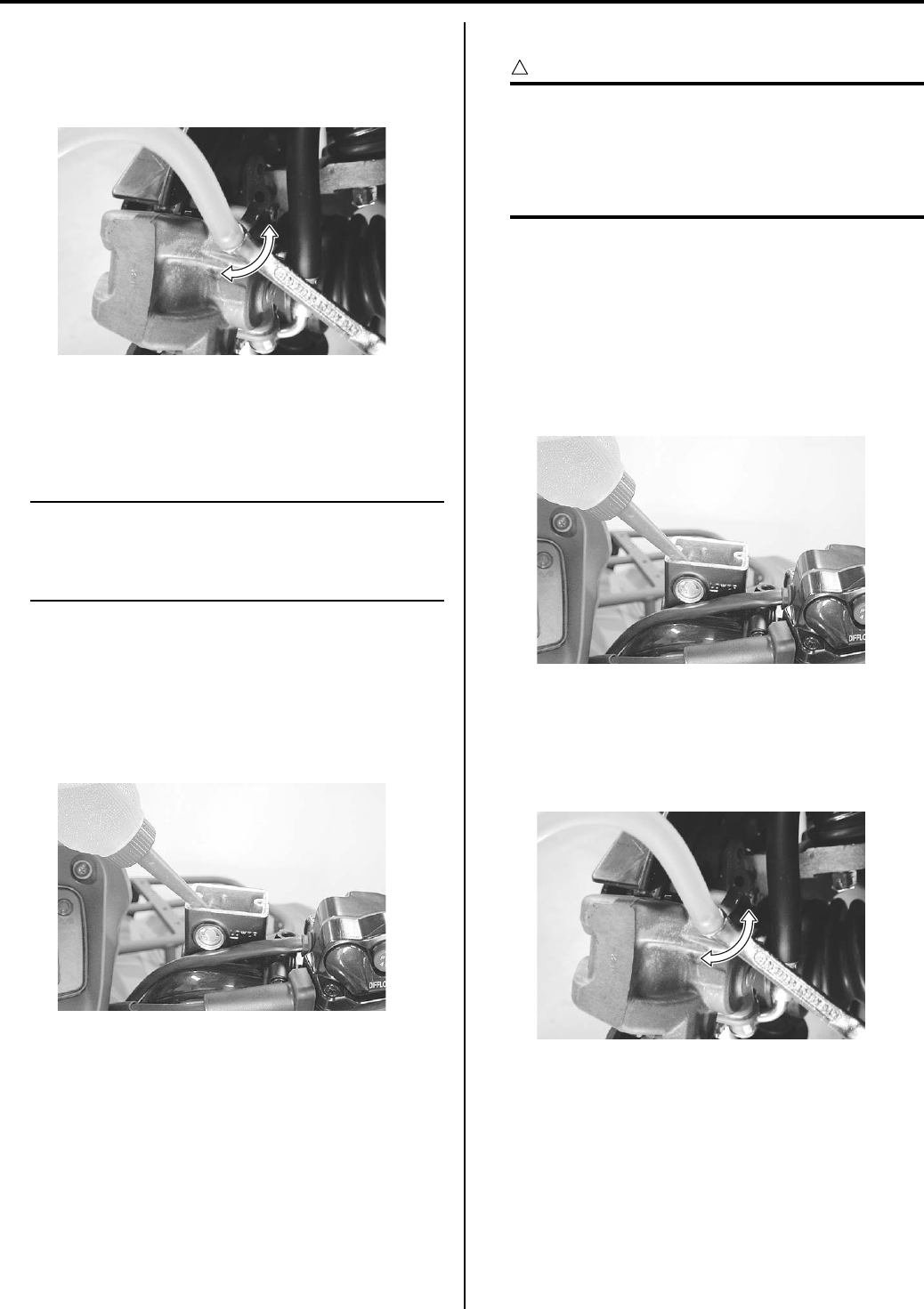
Brake Control System and Diagnosis: 4A-6
4) Loosen the air bleeder valve by turning it a quarter of
a turn so that the brake fluid runs into the receptacle,
this will remove the tension of the brake lever
causing it to touch the handlebar grip.
5) Close the air bleeder valve, pump and squeeze the
lever, and open the valve.
6) Repeat this process until the fluid flowing into the
receptacle no longer contains air bubbles.
NOTE
While bleeding the brake system, replenish
the brake fluid in the reservoir as necessary.
Make sure that there is always some fluid
visible in the reservoir.
7) Close the air bleeder valve and disconnect the hose.
Tightening torque
Front brake air bleeder valve: 6 N·m (0.6 kgf-m,
4.5 lb-ft)
Fill the reservoir with brake fluid to the upper mark of
the reservoir.
9) Install the reservoir cap.
Brake Fluid Replacement
B831G24106010
CAUTION
!
• Make sure that the vehicle is supported
securely.
• Handle brake fluid with care: the fluid
reacts chemically with paint, plastic,
rubber materials, etc.
1) Support the vehicle on a level surface with a jack
and keep the handlebars straight.
2) Remove the front wheels. Refer to “Front / Rear
Wheel Removal and Installation in Section 2D
(Page 2D-2)”.
3) Remove the brake fluid reservoir cap and
diaphragm.
4) Suck up the old brake fluid as much as possible.
5) Fill the reservoir with new brake fluid.
BF: Brake fluid (DOT 4)
6) Connect a clear hose to the air bleeder valve and
insert the other end of the hose into a receptacle.
I831G1410011-01
I831G1410008-01
I831G1410008-01
I831G1410011-01
PartShark.com
877-999-5686
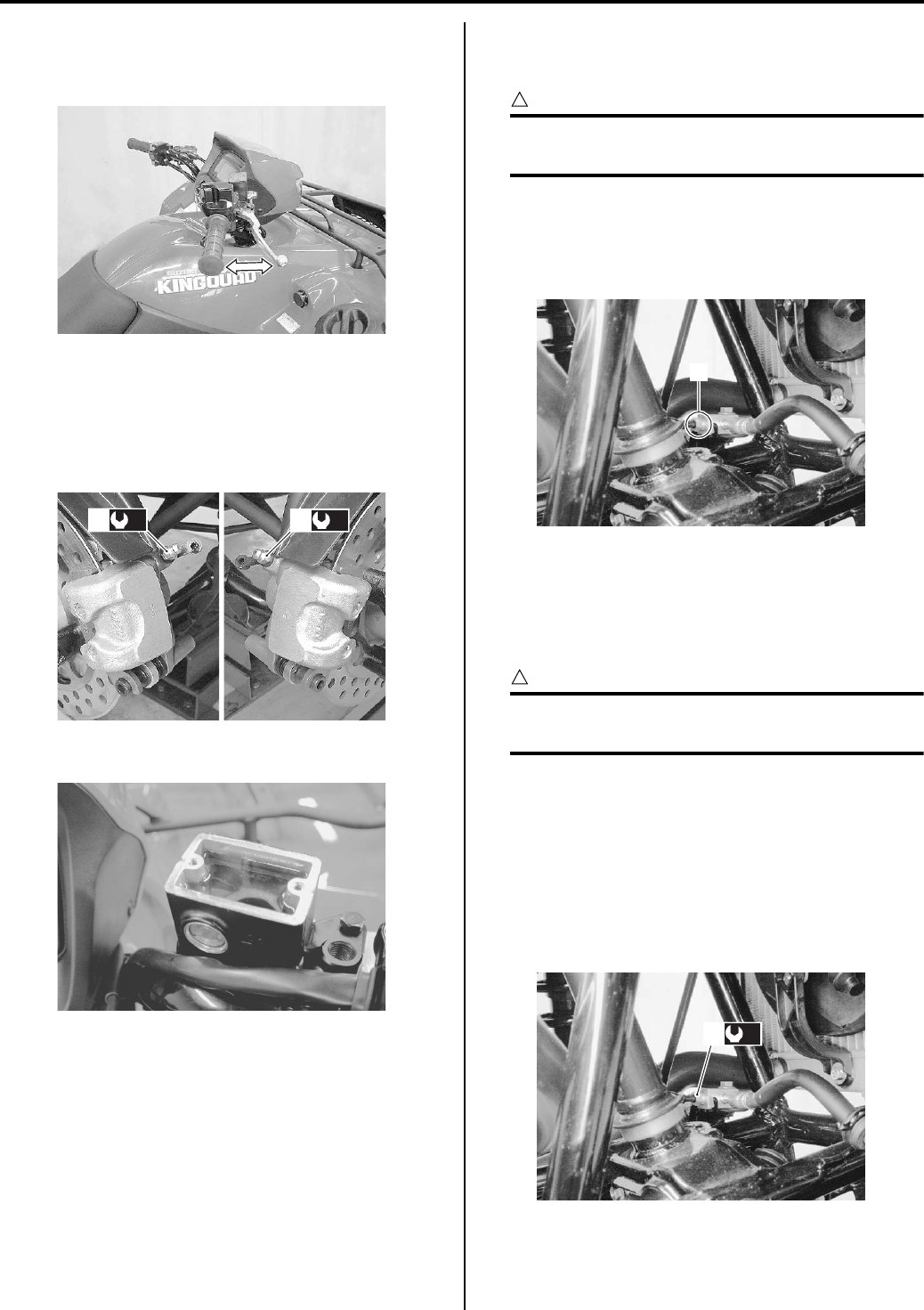
4A-7 Brake Control System and Diagnosis:
7) Loosen the air bleeder valve and pump the brake
lever until the old brake fluid flows out of the brake
system.
Close the air bleeder valve (1) and disconnect the
clear hose.
Tightening torque
Front brake air bleeder valve (a): 6 N·m (0.6 kgf-
m, 4.5 lb-ft)
9) Fill the reservoir with brake fluid.
10) Install the reservoir cap.
11) Install the front wheels. Refer to “Front / Rear Wheel
Removal and Installation in Section 2D (Page 2D-
2)”.
Front Brake Hose Removal and Installation
B831G24106011
Removal
CAUTION
!
Make sure that the vehicle is supported
securely.
1) Drain brake fluid. Refer to “Brake Fluid Replacement
(Page 4A-6)”.
2) Loosen the flare nuts (1) and disconnect the brake
pipe.
3) Remove the front brake hoses as shown in the front
brake hose routing diagram. Refer to “Front Brake
Hose Routing Diagram (Page 4A-1)”.
Installation
CAUTION
!
The seal washers should be replaced with the
new ones to prevent fluid leakage.
1) Install the front brake hose as shown in the front
brake hose routing diagram. Refer to “Front Brake
Hose Routing Diagram (Page 4A-1)”.
2) Tighten the brake flare nut (1) to the specified
torque.
Tightening torque
Brake pipe flare nut (a): 16 N·m (1.6 kgf-m, 11.5
lb-ft)
3) Bleed air from the front brake system. Refer to “Air
Bleeding from Front Brake Fluid Circuit (Page 4A-
5)”.
I831G1410012-01
(a)
1(a)
1
I831G1410013-01
I831G1410036-01
1
I831G1410014-01
(a)
1
I831G1410015-01
PartShark.com
877-999-5686
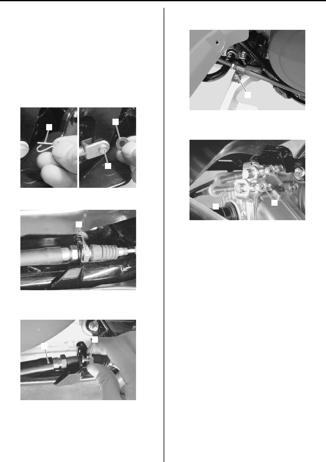
Brake Control System and Diagnosis: 4A-8
Rear Brake Cable Removal and Installation
B831G24106012
Removal
1) Remove the right inner fender. Refer to “Front Side
Exterior Parts Removal and Installation in Section
9D (Page 9D-6)”.
2) Remove the right mud guard. Refer to “Rear Side
Exterior Parts Removal and Installation in Section
9D (Page 9D-9)”.
3) Remove the cotter pin (1), washer (2) and rear brake
cable pin (3).
4) Loosen the rear brake cable holder nut (4).
5) Remove the rear brake holder nut (4) and brake
cable (5).
6) Remove the rear brake cable bolt (7) from the right
footrest.
7) Remove the rear brake cable adjuster nut (7) and
cable (8).
Installation
1) Install the rear brake cable as shown in the rear
brake cable routing diagram. Refer to “Rear Blake
Cable Routing Diagram (Page 4A-2)”.
2) After installed rear brake cable, adjust the adjuster
nut. Refer to “Rear Brake Pedal / Rear Brake
(Parking Brake) Lever Inspection and Adjustment in
Section 0B (Page 0B-19)”.
3) Install the removed parts.
1
2
3
I831G1410016-02
4
I831G1410017-01
4
5
I831G1410033-04
6
I831G1410018-02
87
I831G1410037-03
PartShark.com
877-999-5686
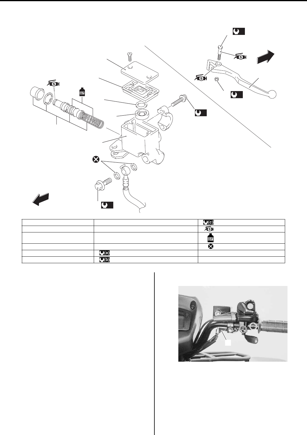
4A-9 Brake Control System and Diagnosis:
Front Brake Master Cylinder Components
B831G24106013
Front Brake Master Cylinder Assembly Removal
and Installation
B831G24106014
Removal
1) Drain brake fluid. Refer to “Brake Fluid Replacement
(Page 4A-6)”.
2) Remove the throttle case assembly. Refer to
“Handlebars Removal and Installation in Section 6B
(Page 6B-3)”.
3) Disconnect the front brake light switch coupler (1).
1
2
3
4
5
6
(a)
7
(b)
(c)
10
(c)
9
FWD
FWD
8
I831G1410019-04
1. Reservoir cap 7. Brake hose union bolt : 6 N⋅m (0.6 kgf-m, 4.5 lb-ft)
2. Diaphragm 8. Brake lever : Apply silicone grease.
3. Plate 9. Brake lever pivot bolt : Apply brake fluid.
4. Separator 10. Brake lever pivot bolt lock-nut : Do not reuse.
5. Master cylinder : 23 N⋅m (2.3 kgf-m, 16.5 lb-ft)
6. Piston/Cup set : 10 N⋅m (1.0 kgf-m, 7.0 lb-ft)
1
I831G1410020-01
PartShark.com
877-999-5686
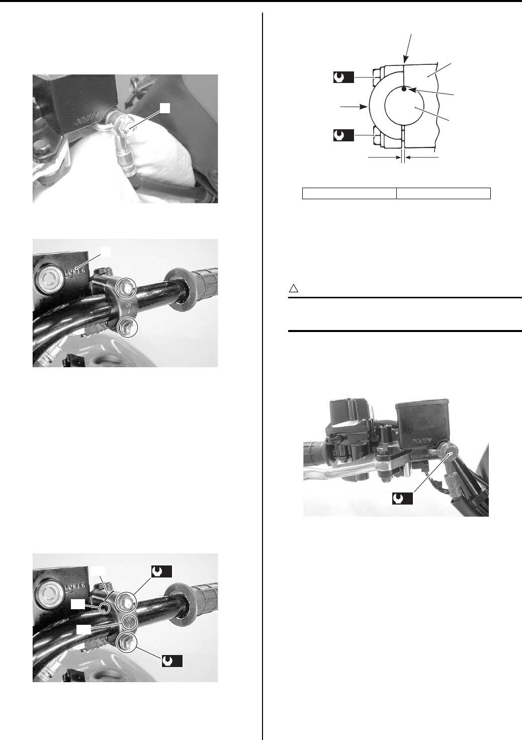
Brake Control System and Diagnosis: 4A-10
4) Place a rag underneath the brake hose union bolt (2)
on the master cylinder to catch any spilt brake fluid.
5) Remove the brake hose union bolt (2) and
disconnect the brake hose.
6) Remove the master cylinder assembly (3).
Installation
Install the front brake master cylinder in the reverse
order of removal. Pay attention to the following points:
• When installing the master cylinder (1) onto the
handlebars (2), align the master cylinder holder’s
mating surface “A” with the punch mark “B” on the
handlebars (2) and tighten the upper holder bolt first.
Refer to “Steering / Handlebars Assembly
Construction in Section 6B (Page 6B-2)”.
Tightening torque
Master cylinder holder bolt (Upper and Lower)
(a): 10 N·m (1.0 kgf-m, 7.0 lb-ft)
• Set the brake hose union as shown in the front brake
hose routing diagram. Refer to “Front Brake Hose
Routing Diagram (Page 4A-1)”.
• After setting the brake hose union to the stopper,
tighten the union bolt (3) to the specified torque.
CAUTION
!
The seal washers should be replaced with the
new ones to prevent fluid leakage.
Tightening torque
Brake hose union bolt (b): 23 N·m (2.3 kgf-m, 16.5
lb-ft)
• Install the throttle case assembly. Refer to
“Handlebars Removal and Installation in Section 6B
(Page 6B-3)”.
• Bleed air from the brake system. Refer to “Air
Bleeding from Front Brake Fluid Circuit (Page 4A-5)”.
2
I831G1410021-01
3
I831G1410022-01
“C”
“B”
“A”
(a)
(a)
I831G1410023-02
“C”: Up mark “a”: Clearance
(a)
(a)
1
2
“a”
“B”
“A”
“C”
I831G1410024-02
(b)
3
I831G1410025-02
PartShark.com
877-999-5686
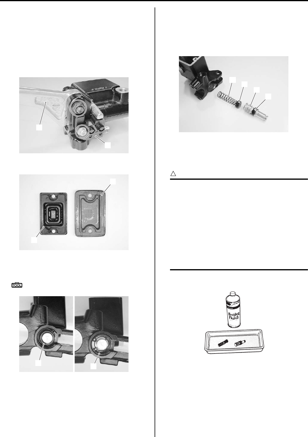
4A-11 Brake Control System and Diagnosis:
Front Brake Master Cylinder / Brake Lever
Disassembly and Assembly
B831G24106015
Refer to “Front Brake Master Cylinder Assembly
Removal and Installation (Page 4A-9)”.
Disassembly
1) Remove the brake lever (1) and brake light switch
(2).
2) Remove the reservoir cap (3) and diaphragm (4).
3) Pull out the dust boot (5) and remove the snap ring
(6) with a special tool.
Special tool
: 09900–06108 (Snap ring pliers)
4) Remove the following parts from the master cylinder.
• Secondary cup (7)
•Piston (8)
• Primary cup (9)
• Spring (10)
Assembly
Assemble the master cylinder in the reverse order of
disassembly. Pay attention to the following points:
CAUTION
!
• Wash the master cylinder components with
new brake fluid before reassembly.
• Do not wipe the brake fluid off after
washing the components.
• When washing the components, use the
specified brake fluid. Never use different
types of fluid or cleaning solvents such as
gasoline, kerosine, etc.
• Apply brake fluid to the master cylinder
bore and all of the master cylinder
component to be inserted into the bore.
BF: Brake fluid (DOT 4)
1
2
I831G1410026-01
3
4
I831G1410027-01
6
5
I831G1410028-01
7
8
9
10
I831G1410029-01
I649G1410024-02
PartShark.com
877-999-5686
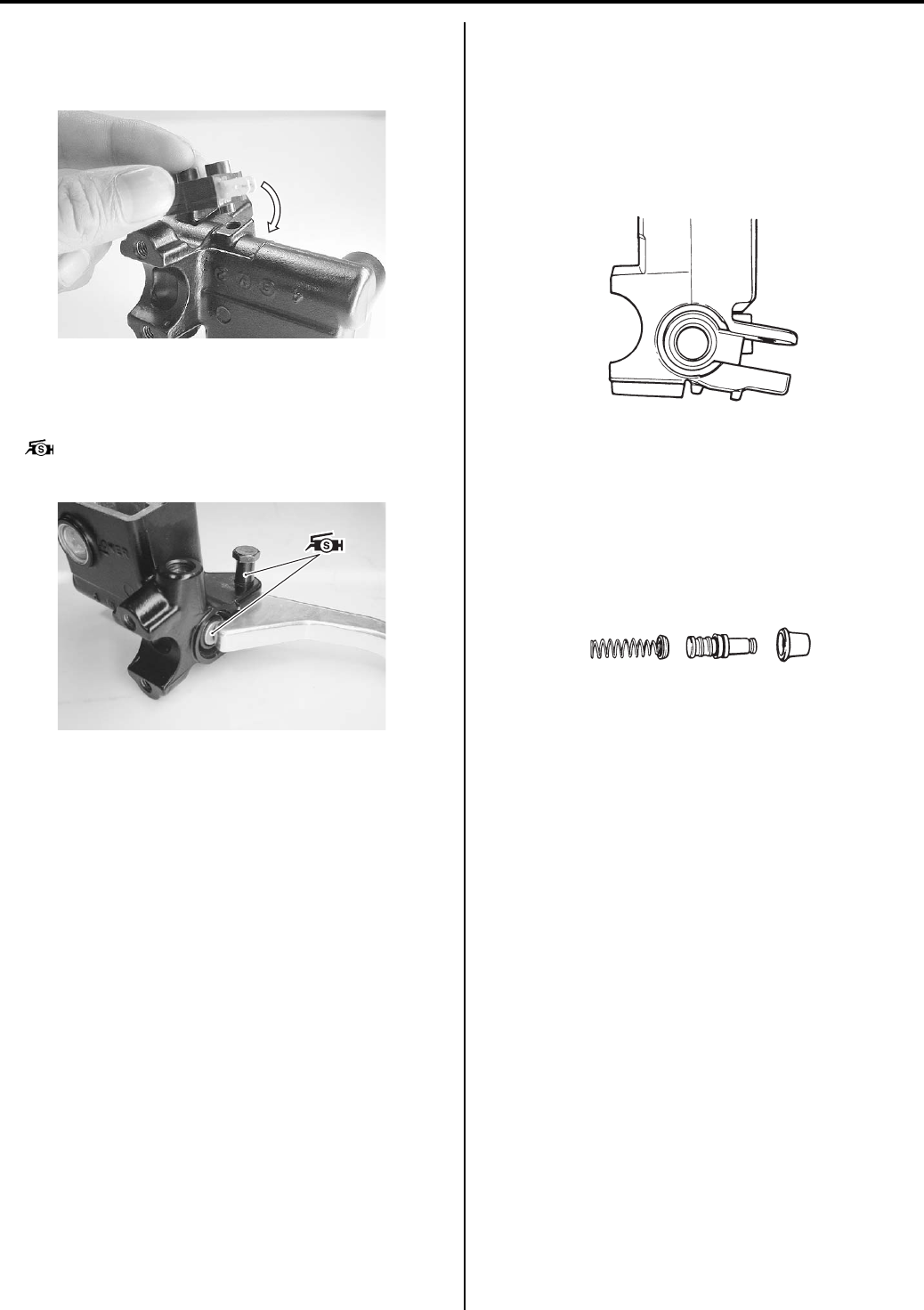
Brake Control System and Diagnosis: 4A-12
• When installing the brake light switch, align the
projection on the switch with the hole in the master
cylinder.
• Apply grease to the brake lever pivot bolt.
• Apply grease to the contact point between piston and
brake lever.
: Grease 99000–25100 (SUZUKI Silicone
Grease or equivalent)
• Tighten the pivot bolt and lock-nut to the specified
torque.
Tightening torque
Brake lever pivot bolt: 6 N·m (0.6 kgf-m, 4.5 lb-ft)
Brake lever pivot bolt lock-nut: 6 N·m (0.6 kgf-m,
4.5 lb-ft)
Front Brake Master Cylinder Parts Inspection
B831G24106016
Refer to “Front Brake Master Cylinder / Brake Lever
Disassembly and Assembly (Page 4A-11)”.
Master Cylinder
Inspect the master cylinder bore for any scratches or
other damage.
Piston
Inspect the piston surface for any scratches or other
damage.
Rubber Parts
Inspect the primary cup, secondary cup and dust boot
for wear or damage.
I831G1410030-01
I831G1410031-01
I649G1410027-02
I649G1410028-02
PartShark.com
877-999-5686
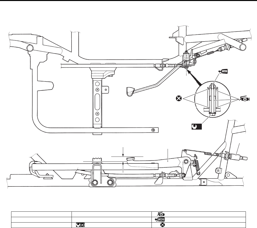
4A-13 Brake Control System and Diagnosis:
Rear Brake Pedal Construction
B831G24106017
“a”
1
2
3
(a)
4
I831G1410038-04
1. Brake pedal 4. Brake pedal pivot bolt : Apply water resistance grease.
2. Brake light switch “a”: 17.5 mm (0.69 in) : Apply thread lock to the thread part.
3. O-ring : 11 N⋅m (1.1 kgf-m, 8.0 lb-ft) : Do not reuse.
PartShark.com
877-999-5686
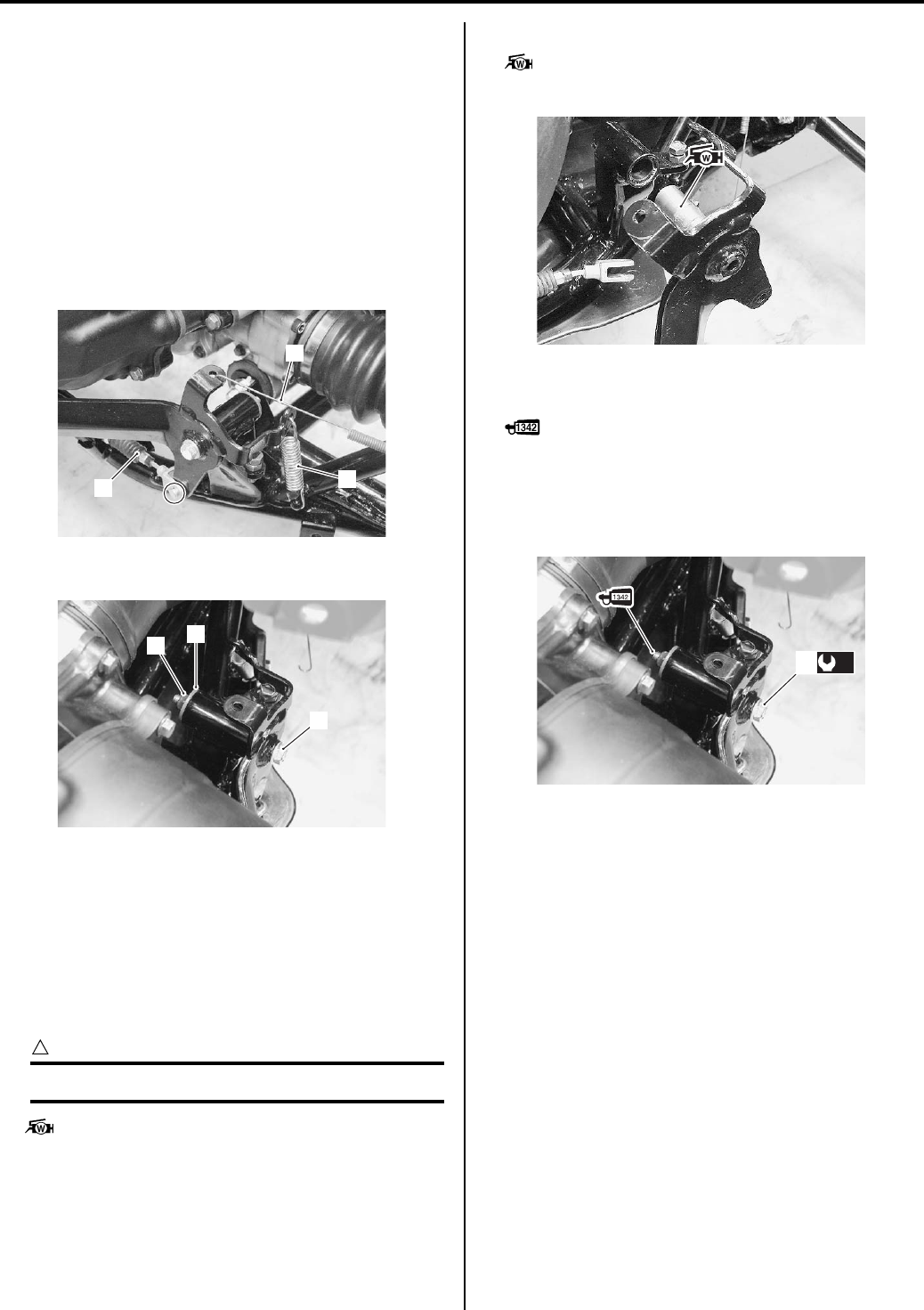
Brake Control System and Diagnosis: 4A-14
Rear Brake Pedal Removal and Installation
B831G24106018
Removal
1) Remove the right inner fender. Refer to “Front Side
Exterior Parts Removal and Installation in Section
9D (Page 9D-6)”.
2) Remove the right mud guard. Refer to “Rear Side
Exterior Parts Removal and Installation in Section
9D (Page 9D-9)”.
3) Remove the spring (1) and (2).
4) Disconnect the rear brake cable (3). Refer to “Rear
Brake Cable Removal and Installation (Page 4A-8)”.
5) Remove the nut (4), washer (5) and bolt (6).
6) Remove the rear brake pedal.
Installation
Install the rear brake pedal in the reverse order of
removal. Pay attention to the following points:
• Apply grease to the O-rings as shown in the rear
brake pedal construction. Refer to “Rear Brake Pedal
Construction (Page 4A-13)”.
CAUTION
!
Replace the O-rings with new ones.
: Grease 99000–25160 (Water resistance
grease)
• Apply grease to the pivot part of brake pedal.
: Grease 99000–25160 (Water resistance
grease)
• Apply thread lock to the bolt (1) and tighten to the
specified torque.
: Thread lock cement 99000–32050
(THREAD LOCK CEMENT 1342 or equivalent)
Tightening torque
Rear brake pedal pivot nut (a): 11 N·m (1.1 kgf-m,
8.0 lb-ft)
• After installed rear brake cable, adjust the adjuster
nut. Refer to “Rear Brake Pedal / Rear Brake (Parking
Brake) Lever Inspection and Adjustment in Section 0B
(Page 0B-19)”.
• Install the removed parts.
1
2
3
I831G1410039-02
45
6
I831G1410040-02
I831G1410041-01
(a)
1
I831G1410042-02
PartShark.com
877-999-5686
4A-15 Brake Control System and Diagnosis:
Specifications
Service Data
B831G24107001
Brake
Unit: mm (in)
Oil
Tightening Torque Specifications
B831G24107002
NOTE
The specified tightening torque is also described in the following.
“Front Brake Hose Routing Diagram (Page 4A-1)”
“Front Brake Master Cylinder Components (Page 4A-9)”
“Rear Brake Pedal Construction (Page 4A-13)”
Reference:
For the tightening torque of fastener not specified in this section, refer to “Tightening Torque List in Section 0C
(Page 0C-7)”.
Item Standard Limit
Rear brake pedal height 12.5 – 22.5 (0.5 – 0.9) —
Front master cylinder bore 14.000 – 14.043 (0.5512 – 0.5529) —
Front master cylinder piston diam. 13.957 – 13.984 (0.5495 – 0.5506) —
Item Specification Note
Brake fluid type DOT 4
Fastening part Tightening torque Note
N⋅mkgf—mlb—ft
Front brake air bleeder valve 60.6 4.5
)(Page 4A-6) /
)(Page 4A-7)
Brake pipe flare nut 16 1.6 11.5 )(Page 4A-7)
Master cylinder holder bolt (Upper and Lower) 10 1.0 7.0 )(Page 4A-10)
Brake hose union bolt 23 2.3 16.5 )(Page 4A-10)
Brake lever pivot bolt 6 0.6 4.5 )(Page 4A-12)
Brake lever pivot bolt lock-nut 6 0.6 4.5 )(Page 4A-12)
Rear brake pedal pivot nut 11 1.1 8.0 )(Page 4A-14)
PartShark.com
877-999-5686
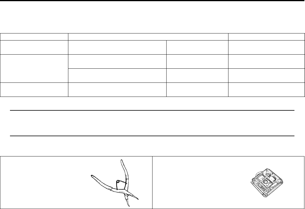
Brake Control System and Diagnosis: 4A-16
Special Tools and Equipment
Recommended Service Material
B831G24108001
NOTE
Required service material is also described in the following.
“Front Brake Master Cylinder Components (Page 4A-9)”
“Rear Brake Pedal Construction (Page 4A-13)”
Special Tool
B831G24108002
Material SUZUKI recommended product or Specification Note
Brake fluid DOT 4 — )(Page 4A-6) / )(Page 4A-
11)
Grease SUZUKI Silicone Grease or
equivalent
P/No.: 99000–25100 )(Page 4A-12)
Water resistance grease P/No.: 99000–25160 )(Page 4A-14) /
)(Page 4A-14)
Thread lock cement THREAD LOCK CEMENT 1342 or
equivalent
P/No.: 99000–32050 )(Page 4A-14)
09900–06108 09900–25008
Snap ring pliers Multi-circuit tester set
)(Page 4A-11) )(Page 4A-4) / )(Page 4A-
4) / )(Page 4A-5)
PartShark.com
877-999-5686
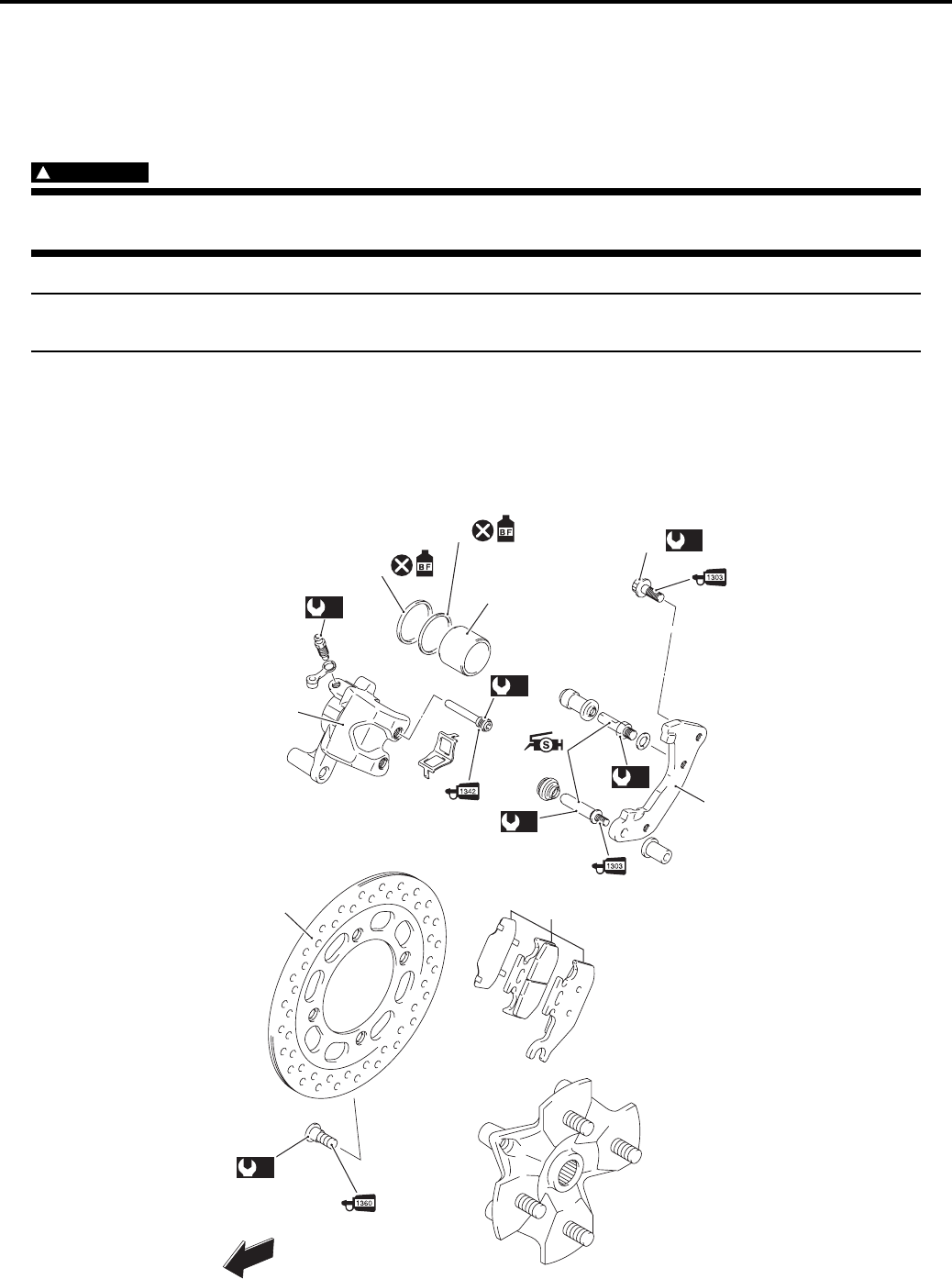
4B-1 Front Brakes:
Brake
Front Brakes
Precautions
Precautions for Front Brakes
B831G24200001
WARNING
!
When servicing the front brake system, place the vehicle on a level ground and support the vehicle
with a jack.
NOTE
The right and left calipers, brake pads and discs are installed symmetrically and therefore the removal
procedure for one side is the same as that for the other side.
Repair Instructions
Front Brake Components
B831G24206001
(b)
(b)
(a)
(c)
(e)
5
2
4
3
FWD
1
6
(d)
7
8
I831G1420001-11
PartShark.com
877-999-5686
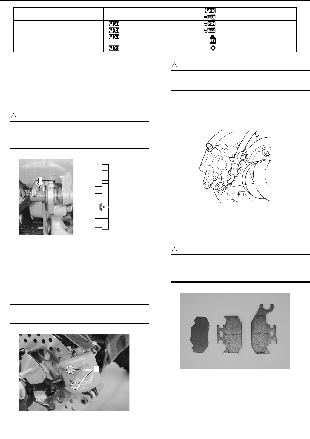
Front Brakes: 4B-2
Front Brake Pad Inspection
B831G24206002
The extent of brake pads wear can be checked by
observing the grooved limit line “A” on the pads. When
the wear exceeds the grooved limit line, replace the
pads with new ones. Refer to “Front Brake Pad
Replacement (Page 4B-2)”.
CAUTION
!
Replace the brake pad as a set, otherwise
braking performance will be adversely
affected.
Front Brake Pad Replacement
B831G24206003
1) Remove the front wheel assembly. Refer to “Front /
Rear Wheel Removal and Installation in Section 2D
(Page 2D-2)”.
2) Remove the pad mounting pins (1).
NOTE
When removing the pads, push the piston all
the way into the brake caliper.
CAUTION
!
Do not operate the brake lever while
dismounting the pads.
3) Remove the front brake caliper by removing the
brake caliper mounting bolts (2). Refer to “Front
Brake Caliper Removal and Installation (Page 4B-
3)”.
4) Remove the brake pads.
5) Clean up the caliper especially around the caliper
piston.
6) Install the new brake pads.
CAUTION
!
Replace the brake pads as a set, otherwise
braking performance will be adversely
affected.
1. Front brake caliper 7. Brake caliper mounting bolt : 23 N⋅m (2.3 kgf-m, 16.5 lb-ft)
2. Piston seal 8. Front brake disk : Apply thread lock to the thread part.
3. Dust seal : 6 N⋅m (0.6 kgf-m, 4.5 lb-ft) : Apply thread lock to the thread part.
4. Piston : 18 N⋅m (1.8 kgf-m, 13.0 lb-ft) : Apply thread lock to the thread part.
5. Brake caliper holder : 23 N⋅m (2.3 kgf-m, 16.5 lb-ft) : Apply brake fluid.
6. Front brake pad set : 26 N⋅m (2.6 kgf-m, 19.0 lb-ft) : Do not reuse.
“A”
I831G1420002-01
1
I831G1420004-02
2
I831G1420031-01
I831G1420005-01
PartShark.com
877-999-5686
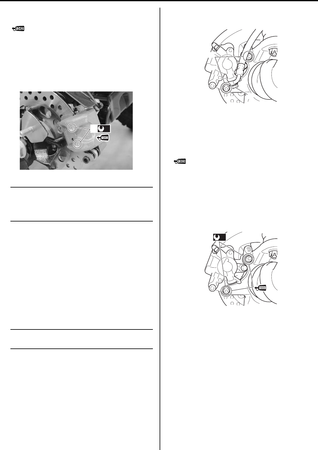
4B-3 Front Brakes:
7) Apply a small quantity of thread lock to the brake pad
mounting pins (2).
: Thread lock cement 99000–32050
(THREAD LOCK CEMENT 1342 or equivalent)
Tighten the front brake pad mounting pins (2) to the
specified torque.
Tightening torque
Front brake pad mounting pin (a): 18 N·m (1.8
kgf-m, 13.0 lb-ft)
NOTE
After replacing the brake pads, pump the
brake lever several times to check for proper
brake operation and then check the brake
fluid level.
9) Install the front wheel assembly.
Front Brake Caliper Removal and Installation
B831G24206004
Removal
1) Remove the front wheel assembly.
2) Drain brake fluid. Refer to “Brake Fluid Replacement
in Section 4A (Page 4A-6)”.
3) Remove the brake hose from the caliper by
removing the union bolt (1) and catch the brake fluid
in a suitable receptacle.
NOTE
Place a rag underneath the union bolt on the
brake caliper to catch any spilt brake fluid.
4) Remove the brake caliper by removing the brake
caliper mounting bolts (2).
Installation
Install the brake caliper in the reverse order of removal.
Pay attention to the following points:
• Apply a small quantity of thread lock to the front brake
caliper mounting bolts (1).
: Thread lock cement 99000–32030
(THREAD LOCK CEMENT SUPER 1303 or
equivalent)
• Tighten the brake caliper mounting bolts (1) to the
specified torque.
Tightening torque
Brake caliper mounting bolt (a): 26 N·m (2.6 kgf—
m, 19.0 lb-ft)
(a)
2
I831G1420006-08
2
1
I831G1420032-01
(a)
1
I831G1420033-01
PartShark.com
877-999-5686
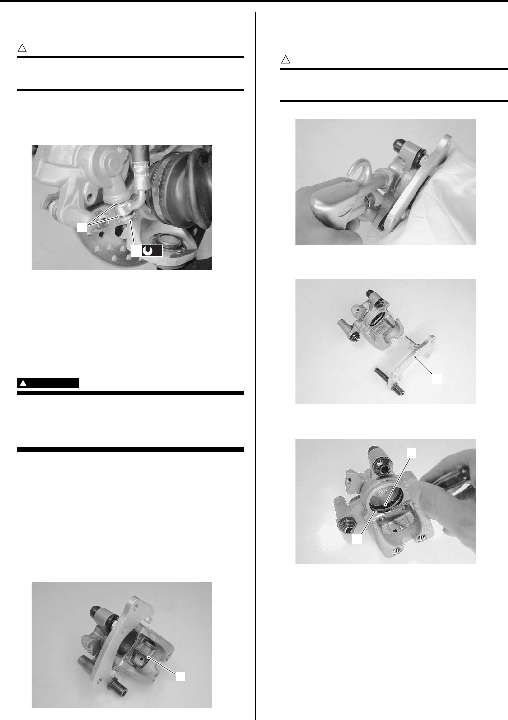
Front Brakes: 4B-4
• After setting the brake hose union to the stopper,
tighten the union bolt (3) to the specified torque.
CAUTION
!
The seal washers (4) should be replaced with
the new ones to prevent fluid leakage.
Tightening torque
Front brake hose union bolt (b): 23 N·m (2.3 kgf-
m, 16.5 lb-ft)
• Bleed air from the brake system after installing the
caliper. Refer to “Air Bleeding from Front Brake Fluid
Circuit in Section 4A (Page 4A-5)”.
• Install the front wheel assembly. Refer to “Front / Rear
Wheel Removal and Installation in Section 2D
(Page 2D-2)”.
• Check the brake fluid leakage and brake operation.
WARNING
!
Brake fluid, if it leaks, will interfere with safe
running and discolor painted surfaces.
Check the brake hose and hose joints for
cracks and fluid leakage.
Front Brake Caliper Disassembly and Assembly
B831G24206005
Refer to “Front Brake Caliper Removal and Installation
(Page 4B-3)”.
Disassembly
1) Remove the brake caliper. Refer to “Front Brake
Caliper Removal and Installation (Page 4B-3)”.
2) Remove the pad spring (1).
3) Place a rag over the brake caliper piston to prevent it
from popping out and then force out the piston using
compressed air.
CAUTION
!
Do not use high pressure air to prevent brake
caliper piston damage.
4) Remove the caliper holder (2) from brake caliper.
5) Remove the piston seal (3) and dust seal (4).
4
(b)
3
I831G1420011-05
1
I831G1420012-03
I831G1420013-02
2
I831G1420014-01
3
4
I831G1420015-02
PartShark.com
877-999-5686
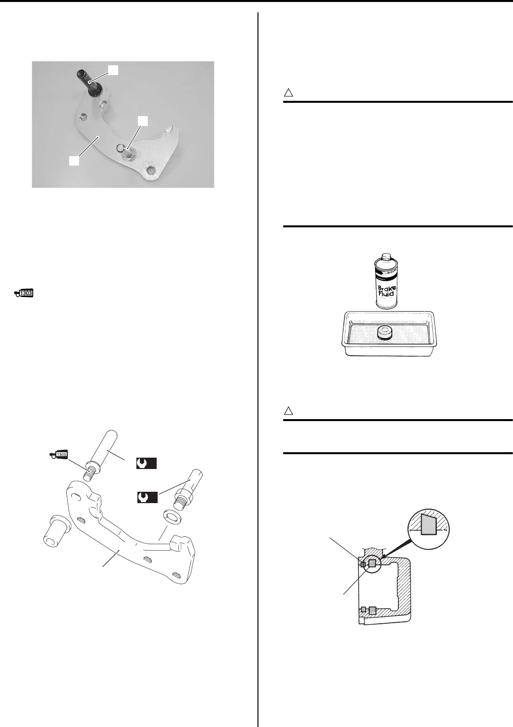
4B-5 Front Brakes:
Brake Caliper Holder
• Remove the caliper holder pin (1) and caliper holder
slide pin (2) from caliper holder (3).
Assembly
Assemble the caliper in the reverse order of
disassembly. Pay attention to the following points:
Brake caliper holder
• Apply thread lock to the caliper holder slide pin (1).
: Thread lock cement 99000–32030
(THREAD LOCK CEMENT SUPER 1303 or
equivalent)
• Tighten the caliper holder slide pin (1) and caliper
holder pin (2) to the holder (3) to the specified torque.
Tightening torque
Caliper holder slide pin (a): 23 N·m (2.3 kgf-m,
16.5 lb-ft)
Caliper holder pin (b): 18 N·m (1.8 kgf-m, 13.0 lb-
ft)
Brake caliper
• Wash the caliper bores and pistons with specified
brake fluid. Particularly wash the dust seal groove and
piston seal groove.
BF: Brake fluid (DOT 4)
CAUTION
!
• Wash the caliper components with fresh
brake fluid before reassembly. Never use
cleaning solvent or gasoline to wash them.
• Do not wipe the brake fluid off after
washing the components.
• When washing the components, use the
specified brake fluid. Never use different
types of fluid or cleaning solvent such as
gasoline, kerosine or the others.
• Apply the brake fluid to piston seal (1) and dust seal
(2).
CAUTION
!
Replace the piston seal (1) and dust seal (2)
with new ones.
BF: Brake fluid (DOT 4)
• Install the piston seal as shown in the figure.
1
2
3
I831G1420016-01
(a)
1
(b)
2
3
I831G1420017-04
I649G1430018-02
1
2
I831G1420018-03
PartShark.com
877-999-5686
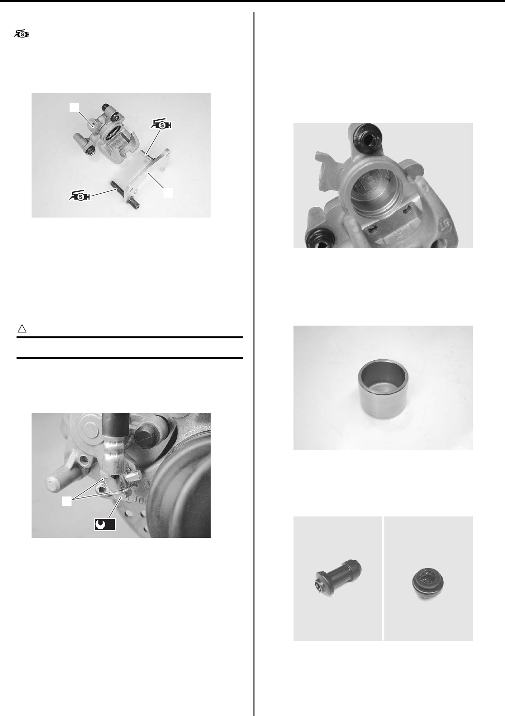
Front Brakes: 4B-6
• Apply silicon grease to the two pins.
: Grease 99000–25100 (SUZUKI SILICONE
GREASE or equivalent)
• Install the brake caliper holder (3) to the brake caliper
(4).
• Install the brake pads. Refer to “Front Brake Pad
Replacement (Page 4B-2)”.
• Install the brake caliper and brake hose. Refer to
“Front Brake Caliper Removal and Installation
(Page 4B-3)” and “Front Brake Hose Routing Diagram
in Section 4A (Page 4A-1)”
• Tighten the union bolt to the specified torque.
CAUTION
!
Replace the gaskets (5) with new ones.
Tightening torque
Front brake hose union bolt (a): 23 N·m (2.3 kgf-
m, 16.5 lb-ft)
Front Brake Caliper Parts Inspection
B831G24206006
Refer to “Front Brake Caliper Disassembly and
Assembly (Page 4B-4)”.
Brake Caliper Cylinder
Inspect the brake caliper cylinder wall for nicks,
scratches or other damage. If any damage is found,
replace the caliper with a new one.
Brake Caliper Piston
Inspect the brake caliper piston surface for any
scratches or other damage. If any damage is found,
replace the piston with a new one.
Boots
Inspect the boots for damage or wear. If any defects are
found, replace them with new ones.
3
4
I831G1420019-01
5
(a)
I831G1420022-01
I831G1420025-01
I831G1420021-01
I831G1420020-03
PartShark.com
877-999-5686
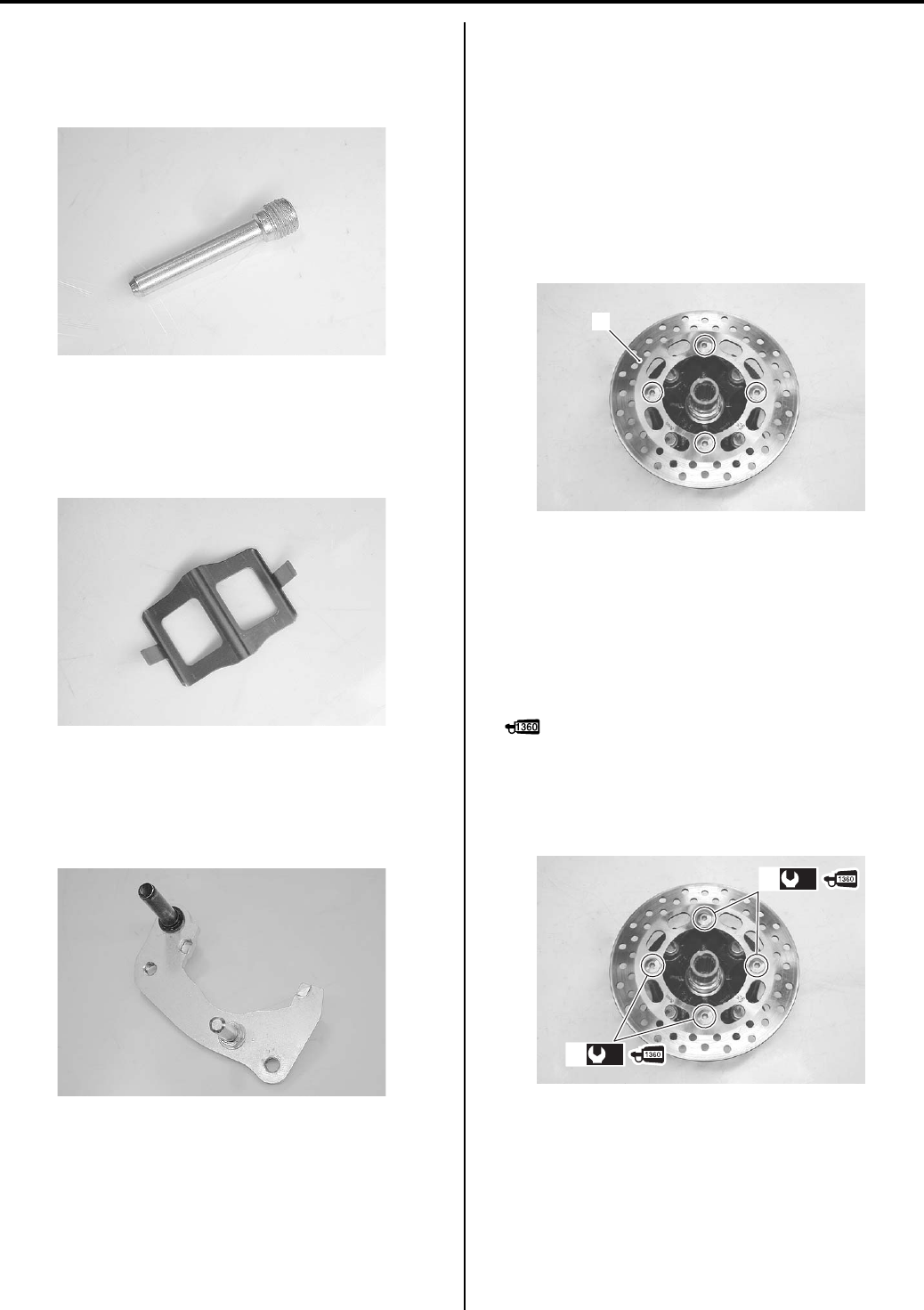
4B-7 Front Brakes:
Brake Pad Mounting Pin
Inspect the brake pad mounting pin for wear or other
damage. If any damage is found, replace the mounting
pin with a new one.
Brake Pad Spring
Inspect the brake pad springs for damage or excessive
bend. If any defects are found, replace them with new
ones.
Brake Caliper Holder
Inspect the brake caliper holder for damage. If any
damage is found, replace the caliper holder with a new
one.
Front Brake Disc Removal and Installation
B831G24206007
Removal
1) Remove the front wheel assembly. Refer to “Front /
Rear Wheel Removal and Installation in Section 2D
(Page 2D-2)”.
2) Remove the front wheel hub. Refer to “Front Wheel
Hub / Steering Knuckle Removal and Installation in
Section 2B (Page 2B-4)”.
3) Remove the brake disc (1) from the front wheel hub.
Installation
Install the front brake disc in the reverse order of
removal. Pay attention to the following points:
• Make sure that the brake discs are clean and free of
any grease.
• Apply thread lock to the brake disc bolts (1) and
tighten them to the specified torque.
: Thread lock cement 99000–32130
(THREAD LOCK CEMENT SUPER 1360 or
equivalent)
Tightening torque
Brake disc bolt (a): 23 N·m (2.3 kgf-m, 16.5 lb-ft)
I831G1420023-01
I831G1420024-01
I831G1420026-01
1
I831G1420027-02
(a)(a)
1
(a)(a)
1
I831G1420028-02
PartShark.com
877-999-5686
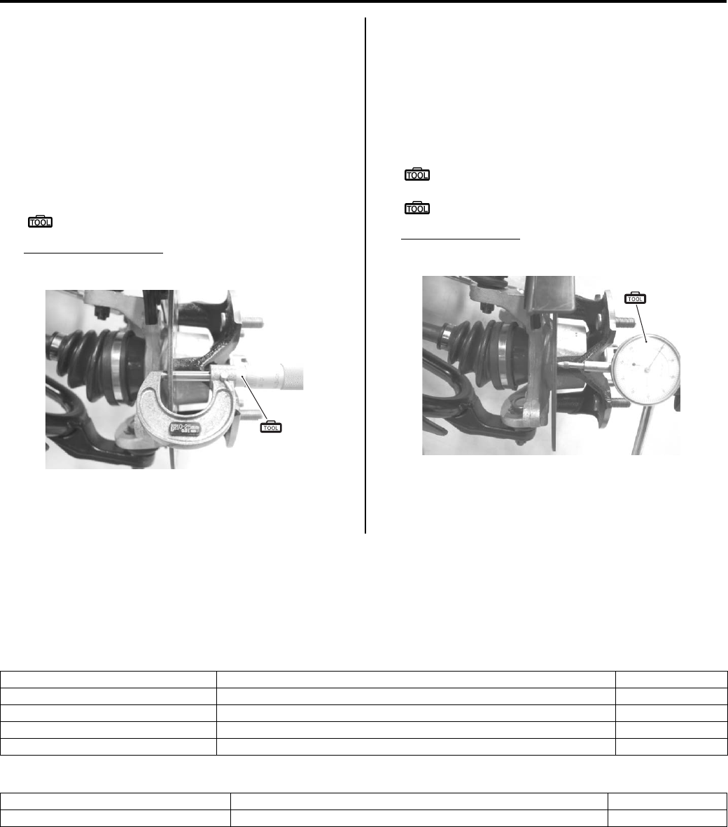
Front Brakes: 4B-8
Front Brake Disc Inspection
B831G24206008
Brake Disc Thickness
1) Dismount the front brake caliper. Refer to “Front
Brake Caliper Removal and Installation (Page 4B-
3)”.
2) Check the brake disc for damage or cracks and
measure the thickness using the micrometer.
3) Replace the brake disc if the thickness is less than
the service limit or if detect is found.
Special tool
(A): 09900–20205 (Micrometer (0 – 25 mm))
Brake disc thickness
Service limit: 3.0 mm (0.12 in)
4) Remount the front brake caliper. Refer to “Front
Brake Caliper Removal and Installation (Page 4B-
3)”.
Brake Disc Runout
1) Dismount the front brake caliper. Refer to “Front
Brake Caliper Removal and Installation (Page 4B-
3)”.
2) Measure the runout using the dial gauge.
Replace the disc if the runout exceeds the service
limit.
Special tool
(A): 09900–20607 (Dial gauge (1/100 mm, 10
mm))
: 09900–20701 (Magnetic stand)
Brake disc runout
Service limit: 0.30 mm (0.012 in)
3) Remount the front brake caliper. Refer to “Front
Brake Caliper Removal and Installation (Page 4B-
3)”.
Specifications
Service Data
B831G24207001
Brake
Unit: mm (in)
Oil
(A)
I831G1420029-02
(A)
I831G1420030-01
Item Standard Limit
Front brake disc thickness — 3.0 (0.12)
Front brake disc runout — 0.30 (0.012)
Front brake caliper cylinder bore 33.960 – 34.010 (1.3370 – 1.3390) —
Front brake caliper piston diam. 33.878 – 33.928 (1.3338 – 1.3357) —
Item Specification Note
Brake fluid type DOT 4
PartShark.com
877-999-5686
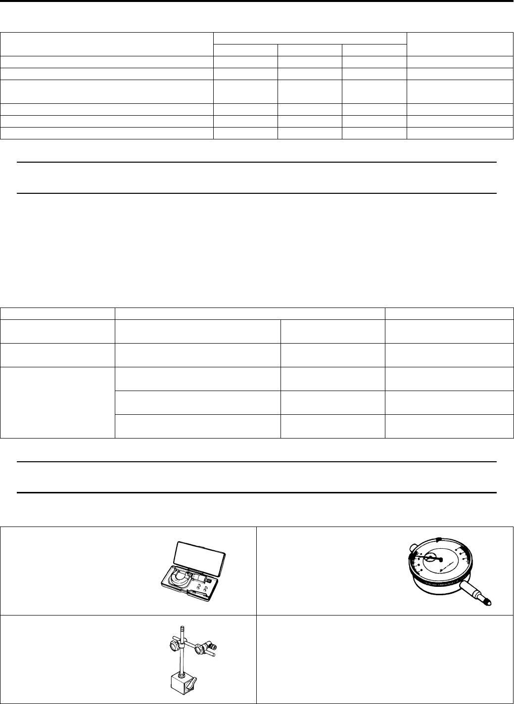
4B-9 Front Brakes:
Tightening Torque Specifications
B831G24207002
NOTE
The specified tightening torque is also described in the following.
“Front Brake Components (Page 4B-1)”
Reference:
For the tightening torque of fastener not specified in this section, refer to “Tightening Torque List in Section 0C
(Page 0C-7)”.
Special Tools and Equipment
Recommended Service Material
B831G24208001
NOTE
Required service material is also described in the following.
“Front Brake Components (Page 4B-1)”
Special Tool
B831G24208002
Fastening part Tightening torque Note
N⋅mkgf—mlb—ft
Front brake pad mounting pin 18 1.8 13.0 )(Page 4B-3)
Brake caliper mounting bolt 26 2.6 19.0 )(Page 4B-3)
Front brake hose union bolt 23 2.3 16.5 )(Page 4B-4) /
)(Page 4B-6)
Caliper holder slide pin 23 2.3 16.5 )(Page 4B-5)
Caliper holder pin 18 1.8 13.0 )(Page 4B-5)
Brake disc bolt 23 2.3 16.5 )(Page 4B-7)
Material SUZUKI recommended product or Specification Note
Brake fluid DOT 4 — )(Page 4B-5) / )(Page 4B-
5)
Grease SUZUKI SILICONE GREASE or
equivalent
P/No.: 99000–25100 )(Page 4B-6)
Thread lock cement THREAD LOCK CEMENT SUPER
1303 or equivalent
P/No.: 99000–32030 )(Page 4B-3) / )(Page 4B-
5)
THREAD LOCK CEMENT 1342 or
equivalent
P/No.: 99000–32050 )(Page 4B-3)
THREAD LOCK CEMENT SUPER
1360 or equivalent
P/No.: 99000–32130 )(Page 4B-7)
09900–20205 09900–20607
Micrometer (0 – 25 mm) Dial gauge (1/100 mm, 10
mm)
)(Page 4B-8) )(Page 4B-8)
09900–20701
Magnetic stand
)(Page 4B-8)
PartShark.com
877-999-5686
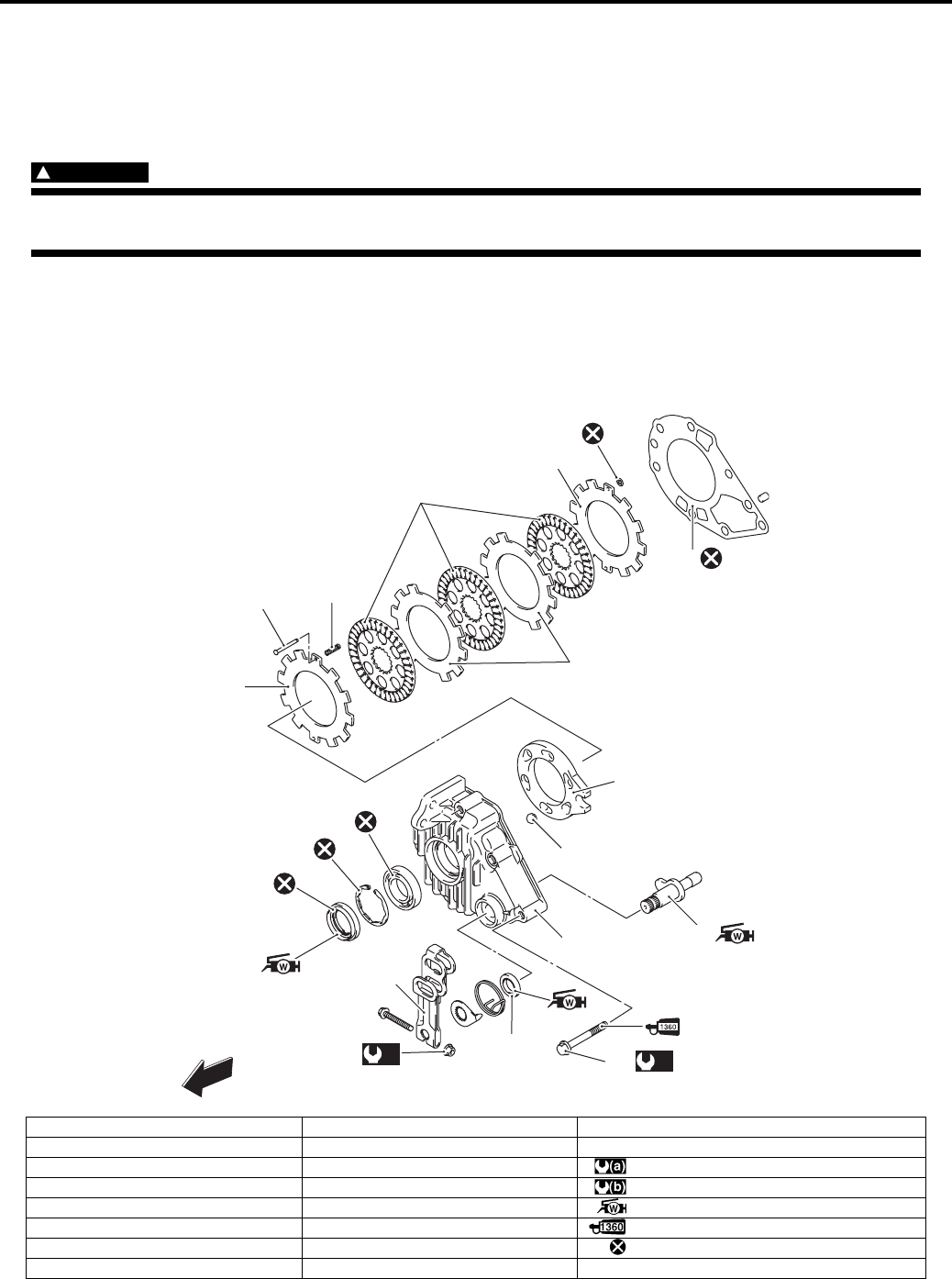
Rear Brakes: 4C-1
Brake
Rear Brakes
Precautions
Precautions for Rear Brake
B831G24300001
WARNING
!
When servicing the rear brake system, place the vehicle on a level ground and support the vehicle with
a jack.
Repair Instructions
Rear Brake Components
B831G24306001
1
2
3
5
4
7
8
9
10
11
12
13
16
(a)
17 (b)
18
15
14
FWD
3
6
I831G1430001-06
1. Friction plate 9. Ball 17. Rear brake cam lever nut
2. Separator plate 10. Rear brake case 18. Rear brake case mounting bolt
3. Side plate 11. Bearing : 11 N⋅m (1.1 kgf-m, 8.0 lb-ft)
4. Side plate pin 12. Snap ring : 26 N⋅m (2.6 kgf-m, 19.0 lb-ft)
5. Side plate spring 13. Oil seal : Apply water resistance grease.
6. Side plate stopper 14. Rear brake cam shaft : Apply thread lock to the thread part.
7. Gasket 15. Oil seal : Do not reuse.
8. Pressure plate 16. Rear brake cam lever
PartShark.com
877-999-5686
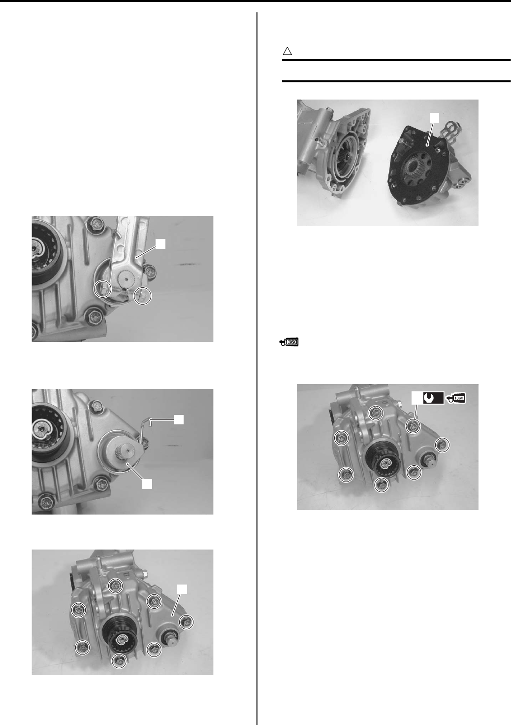
4C-2 Rear Brakes:
Rear Brake Friction Plate Inspection
B831G24306002
Refer to “Rear Brake Friction Plate Wear Limit
Inspection in Section 0B (Page 0B-20)”.
Rear Brake Friction Plate Replacement
B831G24306003
Refer to “Rear Brake Disassembly and Assembly
(Page 4C-3)”.
Rear Brake Assembly Removal and Installation
B831G24306004
Refer to “Final Gear Assembly Removal and Installation
in Section 3B (Page 3B-23)”.
Removal
1) Remove the rear brake cam lever (1).
2) Remove the brake lining indicator (2) and rear brake
cam lever return spring (3).
3) Remove the rear brake case (4).
Installation
• Fit the rear brake case gasket (1).
CAUTION
!
Replace the gasket (1) with a new one.
• Install the rear brake case.
• Apply a small quantity thread lock to the rear brake
case bolts (2).
• Tighten the bolts diagonally to the specified torque.
Tightening torque
Rear brake case bolt (a): 26 N·m (2.6 kgf-m, 19.0
lb-ft)
: Thread lock cement 99000–32130
(THREAD LOCK CEMENT SUPER 1360 or
equivalent)
1
I831G1430003-01
3
2
I831G1430004-01
4
I831G1430005-01
1
I831G1430006-01
(a)
2
I831G1430007-02
PartShark.com
877-999-5686
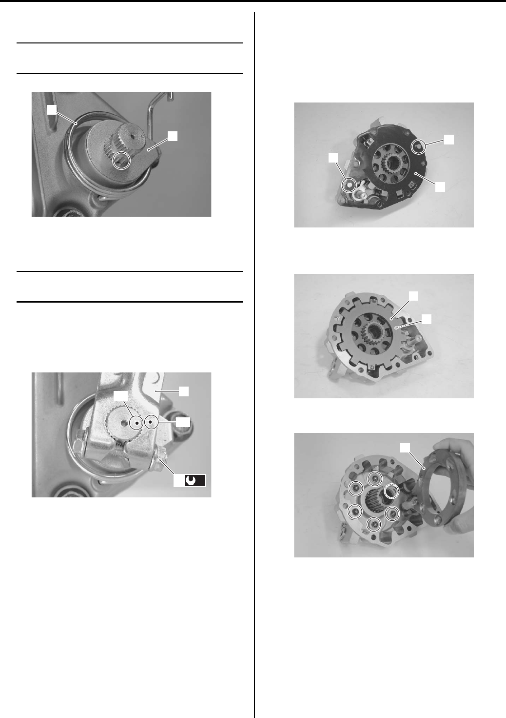
Rear Brakes: 4C-3
• Install the return spring (3) and lining indicator (4).
NOTE
Align the boss of lining indicator (4) with
wide spline on the brake cam shaft.
• Install the rear brake cam lever (5) to the rear brake
cam shaft.
NOTE
When installing the brake cam lever, align the
punched mark “D” with “E”.
• Tighten the cam lever nut (6) to the specified torque.
Tightening torque
Rear brake cam lever nut (b): 11 N·m (1.1 kgf-m,
8.0 lb-ft)
• Install the final gear assembly to the vehicle. Refer to
“Final Gear Assembly Removal and Installation in
Section 3B (Page 3B-23)”.
Rear Brake Disassembly and Assembly
B831G24306005
Refer to “Rear Brake Assembly Removal and Installation
(Page 4C-2)”.
Disassembly
1) Remove the gasket (1) and dowel pins (2).
2) Remove the rear brake steel plates (3) along with
the friction plates (4).
3) Remove the rear brake pressure plate (5) and balls.
3
4
I831G1430008-01
“E”
“D”
5
(b)
6
I831G1430009-02
1
2
2
I831G1430010-02
3
4
I831G1430011-01
5
I831G1430012-01
PartShark.com
877-999-5686
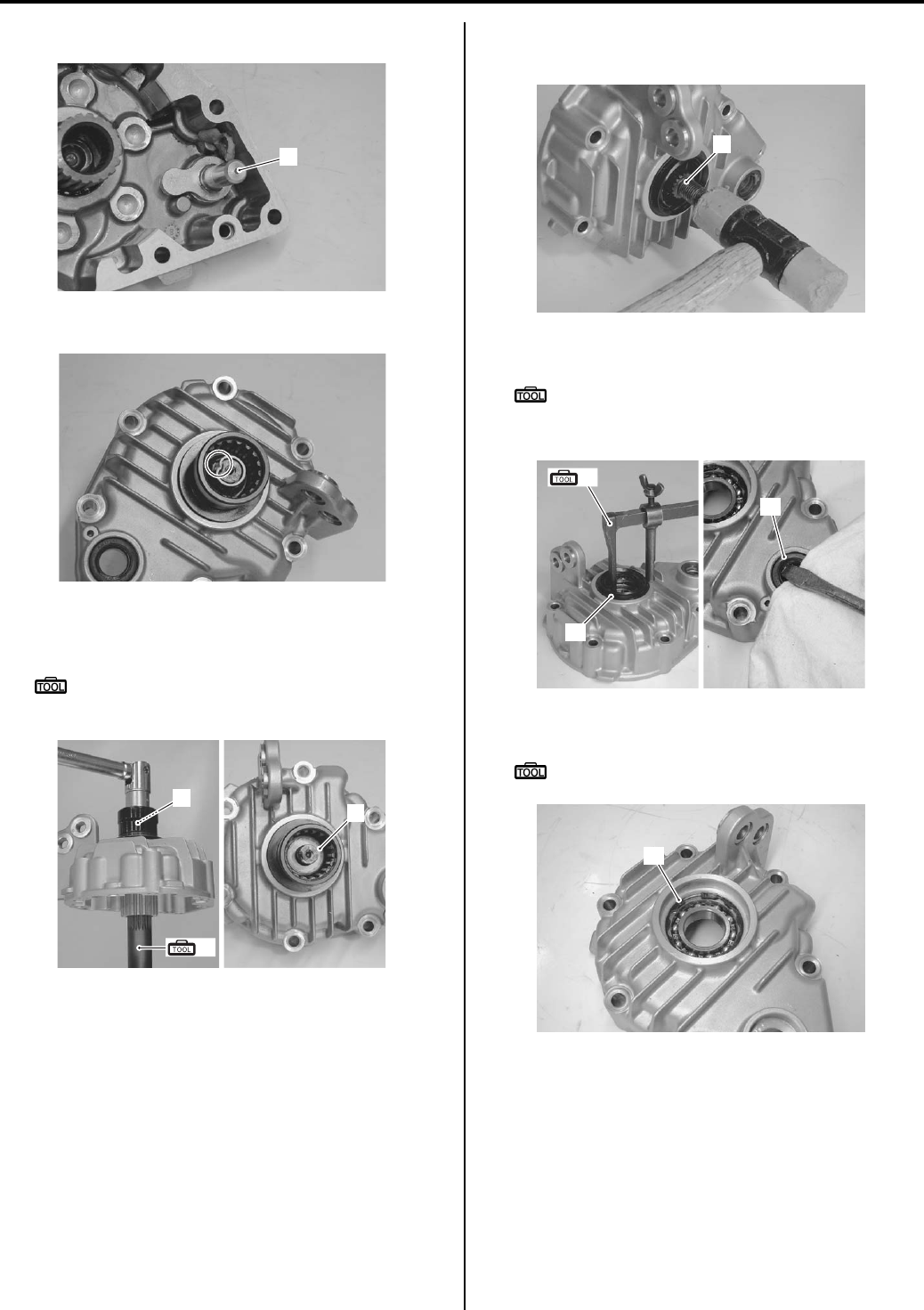
4C-4 Rear Brakes:
4) Remove the rear bake cam shaft (6).
5) Unlock the nut with a chisel.
6) Remove the rear drive gear shaft nut (7) with the
special tool and remove the washer (8).
Special tool
(A): 09924–52420 (Secondary bevel gear
holder)
7) Remove the rear drive gear shaft (9), with plastic
mallet.
Remove the oil seal (10) with the special tool.
Special tool
(B): 09913–50121 (Oil seal remover)
9) Remove the oil seal (11).
10) Remove the snap ring (12) with the special tool.
Special tool
: 09900–06108 (Snap ring pliers)
6
I831G1430013-01
I831G1430014-01
7
8
(A)
I831G1430015-01
9
I831G1430016-01
10
11
(B)
I831G1430017-01
12
I831G1430018-01
PartShark.com
877-999-5686
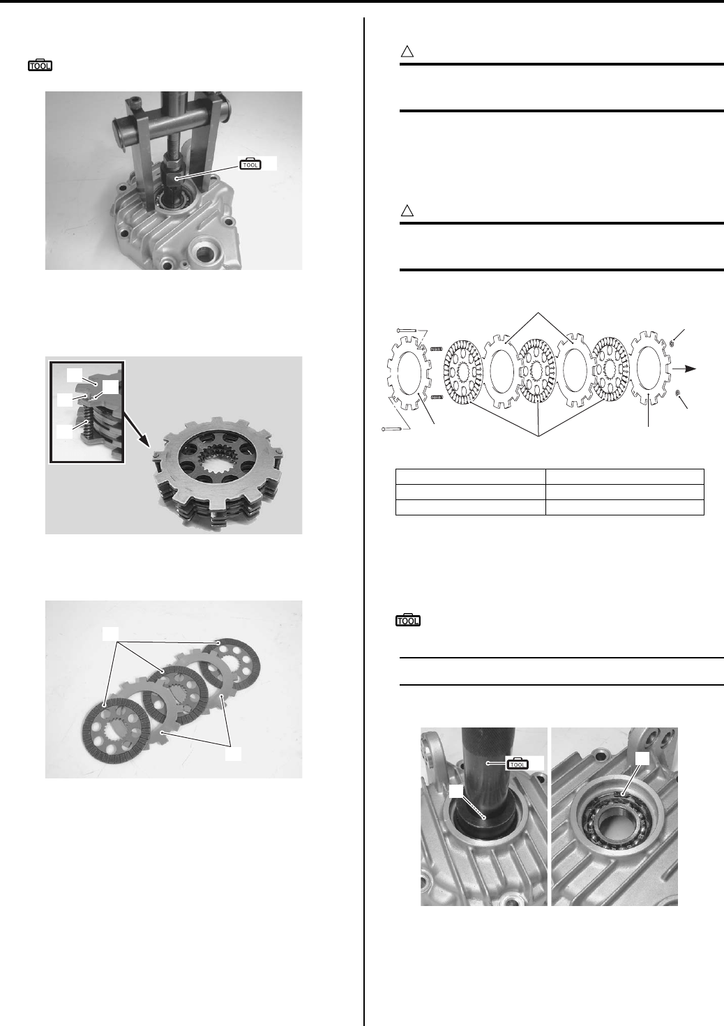
Rear Brakes: 4C-5
11) Remove the bearing with the special tool.
Special tool
(C): 09921–20240 (Bearing remover set)
12) Remove the side plate stopper (13).
13) Remove the side plate (14), pins (15) and springs
(16).
14) Separate the friction plates (17) and separator plates
(18).
Assembly
CAUTION
!
The removed oil seal, bearing and snap ring
must be replaced with new ones.
• Install the rear brake in the reverse order of
disassembly. Pay attention to the following points:
• Assemble the rear brake plates as shown in the
figure.
CAUTION
!
Replace the remove side plate stopper (4)
with a new one.
• Apply final gear oil to the bearing (5) before installing
it.
• Install the bearing with the special tool.
Special tool
(A): 09913–70210 (Bearing installer set)
NOTE
The stamped mark of bearing faces outside.
• Install the snap ring (6).
(C)
I831G1430019-02
13
14
16
15
I831G1430043-03
17
18
I831G1430021-01
1. Separator plate 4. Side plate stopper
2. Friction plate “A”: Direction of out side
3. Side plate
“A”
33
2
1
4
4
I831G1430022-04
(A)
5
6
I831G1430023-03
PartShark.com
877-999-5686
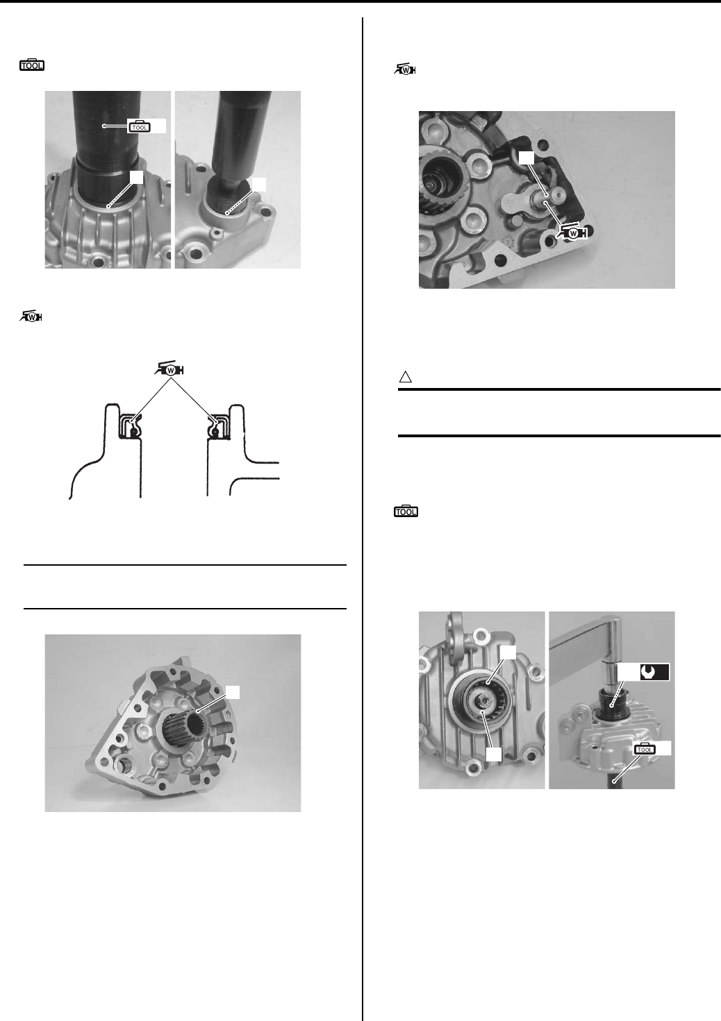
4C-6 Rear Brakes:
• Install the oil seals (7) and (8) with the special tool.
Special tool
(A): 09913–70210 (Bearing installer set)
• Apply grease to the lip of cam shaft oil seal.
: Grease 99000–25160 (Water resistance
grease)
• Install the rear final drive gear shaft (9).
NOTE
If the rear final drive gear shaft not install
easily, lightly tap it using a plastic mallet.
• Install the rear brake cam shaft (10).
• Apply grease to the rear brake cam shaft.
: Grease 99000–25160 (Water resistance
grease)
• Install the rear propeller shaft coupling (11).
• Install the washer (12) and rear drive gear shaft nut
(13).
CAUTION
!
The removed nut (13) must be replaced with a
new one.
• Tighten the rear drive gear shaft nut (13) to the
specified torque with the special tool.
Special tool
(B): 09924–52420 (Secondary bevel gear
holder)
Tightening torque
Rear propeller shaft coupling nut (a): 100 N·m (
10.0 kgf-m, 72.5 lb-ft)
(A)
78
I831G1430024-05
I831G1430025-03
9
I831G1430026-04
10
I831G1430027-05
(B)
11
12
(a)
13
I831G1430028-06
PartShark.com
877-999-5686
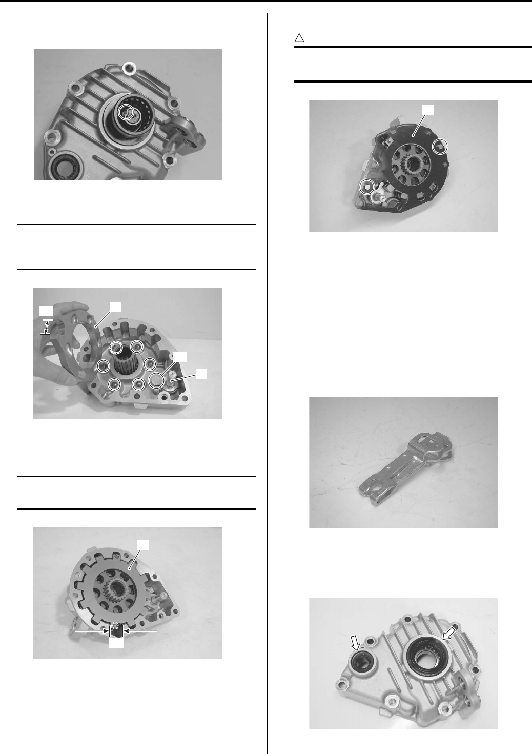
Rear Brakes: 4C-7
• Bend the collar of the nut to the notch on the shaft of
the rear propeller shaft coupling.
• Install the balls and rear brake pressure plate (14).
NOTE
When installing the rear brake pressure plate
(14), align its groove “A” with the cam “B” of
rear brake cam shaft (10).
• Install the rear brake plates (15), aligning the grooves
“C” of the case.
NOTE
Align the side plate pin with groove “C” of
the case as shown in the figure.
• Install the dowel pins and gasket (16).
CAUTION
!
The removed gasket must be replaced with a
new one.
Rear Brake Parts Inspection
B831G24306006
Refer to “Rear Brake Disassembly and Assembly
(Page 4C-3)”.
Rear Brake Cam Lever
Inspect the rear brake cam lever for wear or damage. If
any wear or damage is found, replace it with a new one
Inspect the rear brake cam lever return spring for wear
or damage. If any wear or damage is found, replace it
with a new one.
Oil Seal
Inspect the oil seals for wear or damage. If any wear or
damage is found, replace it with a new one.
I831G1430029-01
“A”
“B”
14
10
I831G1430030-04
15
“C”
I831G1430031-05
16
I831G1430032-03
I831G1430033-01
I831G1430034-01
PartShark.com
877-999-5686
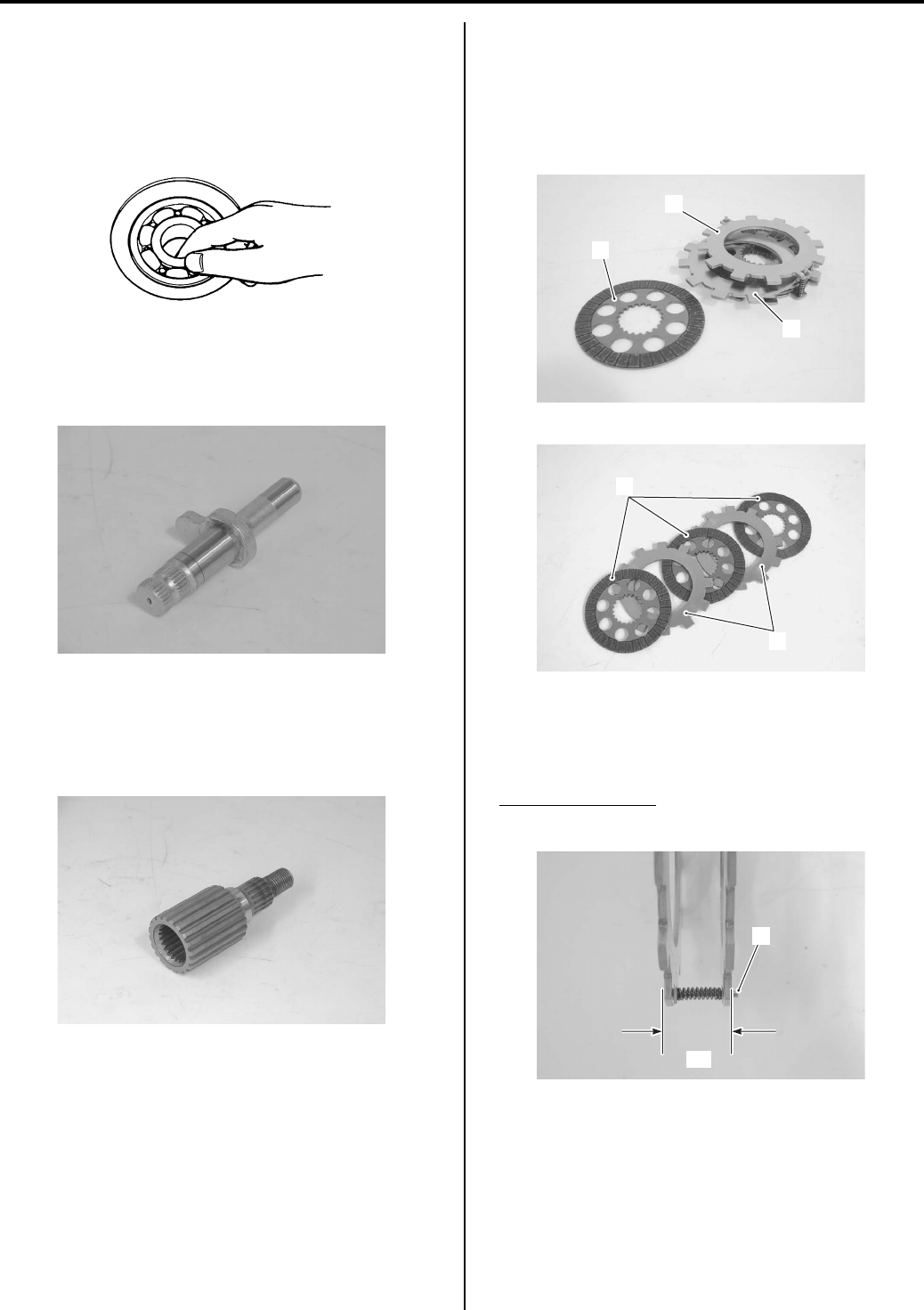
4C-8 Rear Brakes:
Bearing
Inspect the inner race play of the bearing by hand while
it is in the rear brake case.
Turn the inner race by hand to inspect for abnormal
noise or smooth rotation.
• If there is anything unusual, replace it with a new one.
Rear Brake Cam Shaft
Inspect the rear brake cam shaft for wear or damage. If
any wear or damage is found, replace it with a new one.
Rear Drive Gear Shaft
Inspect the rear drive gear shaft for wear or damage. If
any defects are found, replace rear drive gear shaft with
a new one.
Rear Brake Side Plate / Rear Brake Friction Plate /
Steel Plate
• Inspect the rear brake side plates (1), rear brake
friction plates (2) and separator plates (3) for wear or
damage. If any defects are found, replace them as a
set.
• Measure the outer distance “a” between the side
plates as shown in the figure. If the distance “a” is less
than the specification, reassemble the rear brake
plates using the new plate stoppers (4).
Outer distance “a”
Standard: 26.0 – 27.0 mm (1.02 – 1.06 in)
I649G1240015-02
I831G1430036-01
I831G1430037-01
1
3
2
I831G1430038-01
3
2
I831G1430039-01
“a”
4
I831G1430040-04
PartShark.com
877-999-5686
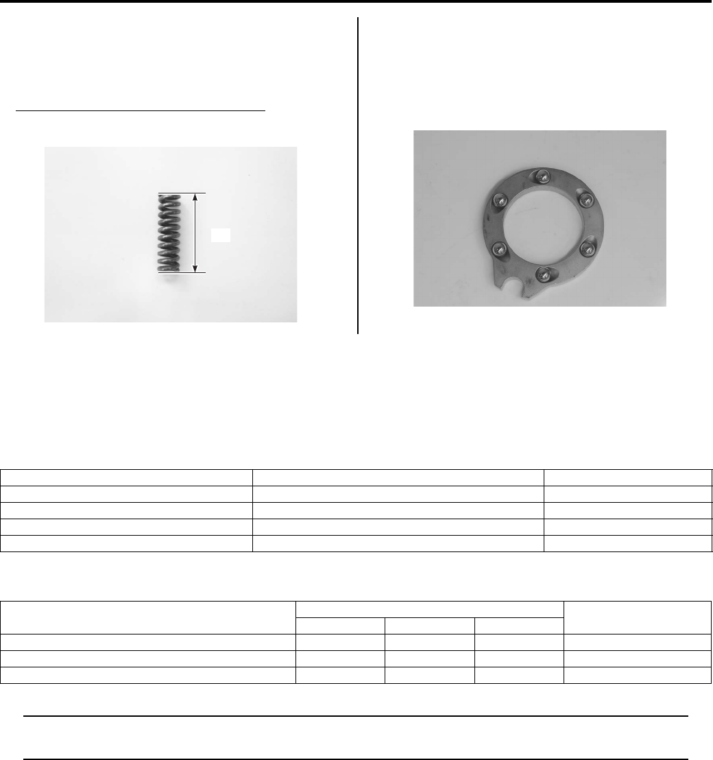
Rear Brakes: 4C-9
Brake Side Plate Spring
• Measure the free length “a”.
• If the free length “a” is shorter than the limit, replace
the spring with a new one.
Brake side plate spring free length “a”
Service limit: 20.2 mm (0.80 in)
Rear Brake Pressure Plate
Inspect the rear brake pressure plate for wear or
damage. If any wear or damage is found, replace it with
a new one.
Inspect the balls for wear or damage. If any wear or
damage is found, replace them with new ones.
Specifications
Service Data
B831G24307001
Brake
Unit: mm (in)
Tightening Torque Specifications
B831G24307002
NOTE
The specified tightening torque is also described in the following.
“Rear Brake Components (Page 4C-1)”
Reference:
For the tightening torque of fastener not specified in this section, refer to “Tightening Torque List in Section 0C
(Page 0C-7)”.
“a”
I831G1430041-02
I831G1430042-01
Item Standard Limit
Rear brake pedal free travel 20 – 30 (0.8 – 1.2) —
Rear brake lever play 6 – 8 (0.2 – 0.3) —
Rear brake outer distance 26.0 – 27.0 (1.02 – 1.06) —
Brake side plate spring free length 21.3 (0.84) 20.2 (0.80)
Fastening part Tightening torque Note
N⋅mkgf—mlb—ft
Rear brake case bolt 26 2.6 19.0 )(Page 4C-2)
Rear brake cam lever nut 11 1.1 8.0 )(Page 4C-3)
Rear propeller shaft coupling nut 100 10.0 72.5 )(Page 4C-6)
PartShark.com
877-999-5686
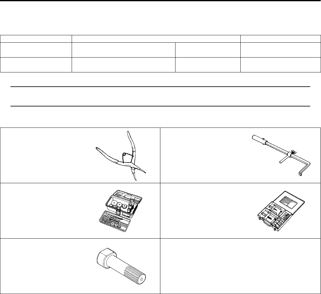
4C-10 Rear Brakes:
Special Tools and Equipment
Recommended Service Material
B831G24308001
NOTE
Required service material is also described in the following.
“Rear Brake Components (Page 4C-1)”
Special Tool
B831G24308002
Material SUZUKI recommended product or Specification Note
Grease Water resistance grease P/No.: 99000–25160 )(Page 4C-6) / )(Page 4C-
6)
Thread lock cement THREAD LOCK CEMENT SUPER
1360 or equivalent
P/No.: 99000–32130 )(Page 4C-2)
09900–06108 09913–50121
Snap ring pliers Oil seal remover
)(Page 4C-4) )(Page 4C-4)
09913–70210 09921–20240
Bearing installer set Bearing remover set
)(Page 4C-5) / )(Page 4C-
6)
)(Page 4C-5)
09924–52420
Secondary bevel gear
holder
)(Page 4C-4) / )(Page 4C-
6)
PartShark.com
877-999-5686
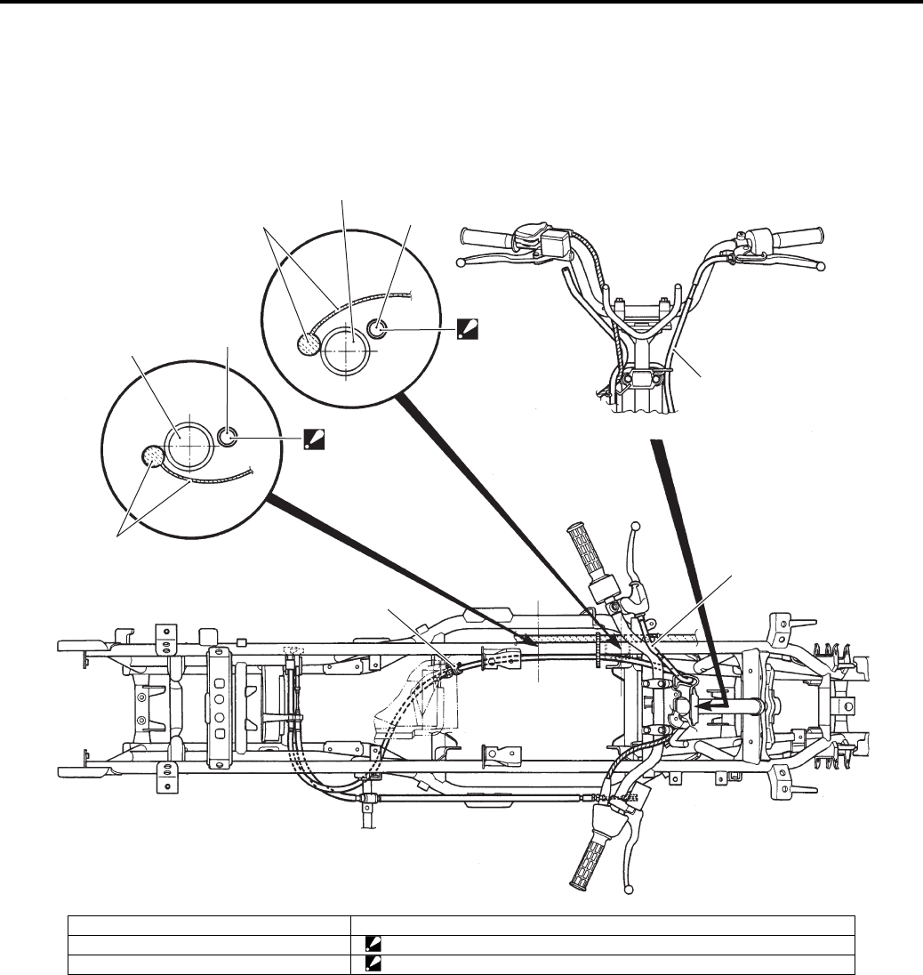
Parking Brake: 4D-1
Brake
Parking Brake
Schematic and Routing Diagram
Parking / Rear Brake Cable Routing Diagram
B831G24402001
1
2
4
3
1
“B”
4
3
“A”
1
1
I831G1440001-02
1. Parking brake cable 4. Wiring harness
2. Parking brake cable guide “A”: Pass the parking brake cable under the wiring harness.
3. Frame “B”: Pass the parking brake cable over the wiring harness.
PartShark.com
877-999-5686
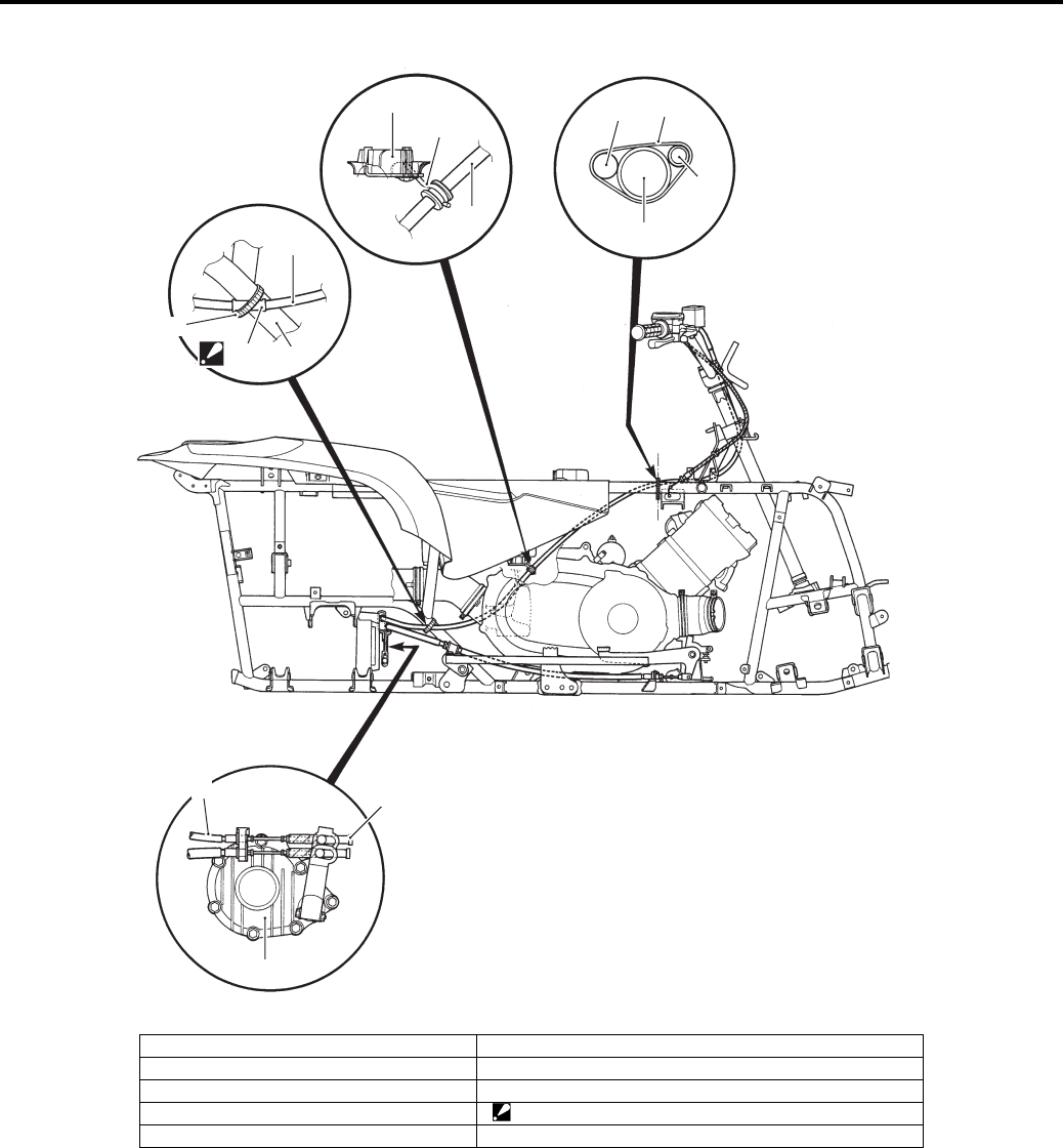
4D-2 Parking Brake:
3
1
5
2
1
4
1
3
7
8
6
“C”
6
1
I831G1440002-03
1. Parking brake cable 6. Clamp
2. Parking brake cable guide 7. Parking brake cable adjust nut
3. Frame 8. Rear brake assembly
4. Wiring harness “C”: Fix the rubber of parking brake cable with clamp.
5. Rear fender
PartShark.com
877-999-5686
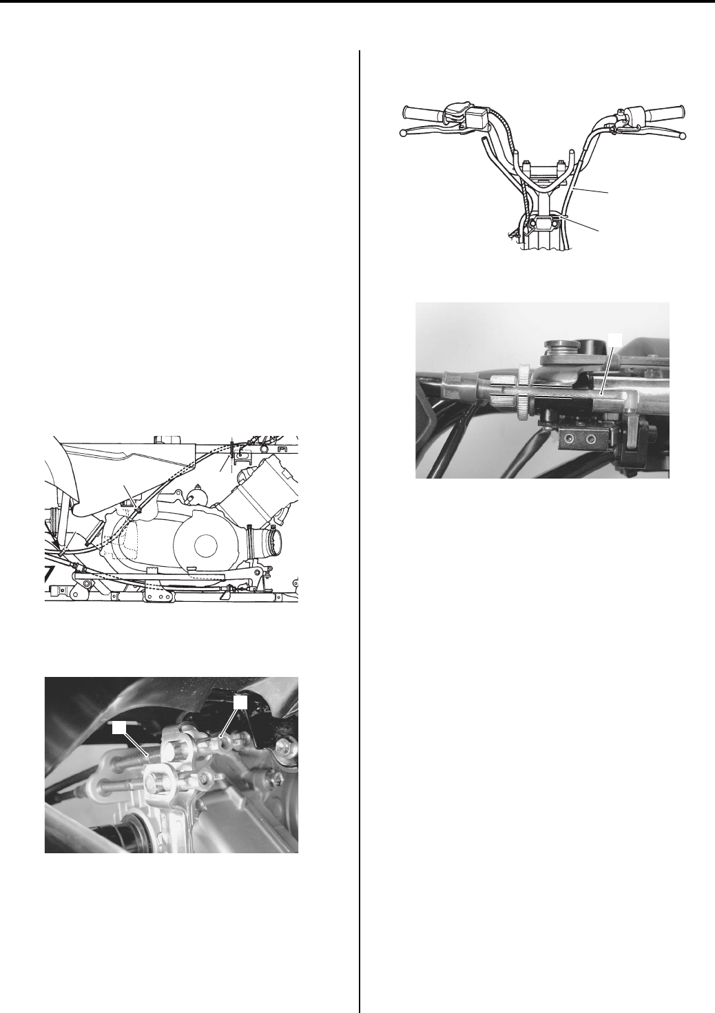
Parking Brake: 4D-3
Repair Instructions
Parking / Rear Brake Inspection and
Adjustment
B831G24406001
Refer to “Rear Brake Pedal / Rear Brake (Parking Brake)
Lever Inspection and Adjustment in Section 0B
(Page 0B-19)”.
Parking / Rear Brake Cable Removal and
Installation
B831G24406002
Removal
1) Remove the seat. Refer to “Seat Removal and
Installation in Section 9D (Page 9D-11)”.
2) Remove the front fender. Refer to “Front Side
Exterior Parts Removal and Installation in Section
9D (Page 9D-6)” and “Front Carrier Removal and
Installation in Section 9E (Page 9E-4)”.
3) Remove the air cleaner box. Refer to “Air Cleaner
Box Removal and Installation in Section 1D
(Page 1D-5)”.
4) Remove the clamps (3) and parking brake cable
from the cable guide (2).
5) Remove the parking brake cable adjuster nut (4) and
parking brake cable (5).
6) Remove the parking brake cable (5) from the cable
guide (6).
7) Disconnect the parking brake cable (5).
Remove the parking brake cable from vehicle.
Installation
1) Install the parking brake cable as shown in the
parking brake cable routing diagram. Refer to
“Parking / Rear Brake Cable Routing Diagram
(Page 4D-1)”.
2) Reinstall the removed parts.
3) After installing the parking brake cable, inspect or
adjust the parking brake cable. Refer to “Rear Brake
Pedal / Rear Brake (Parking Brake) Lever Inspection
and Adjustment in Section 0B (Page 0B-19)”.
3
23
I831G1440003-01
5
4
I831G1440004-01
5
6
I831G1440005-03
5
I831G1440006-02
PartShark.com
877-999-5686
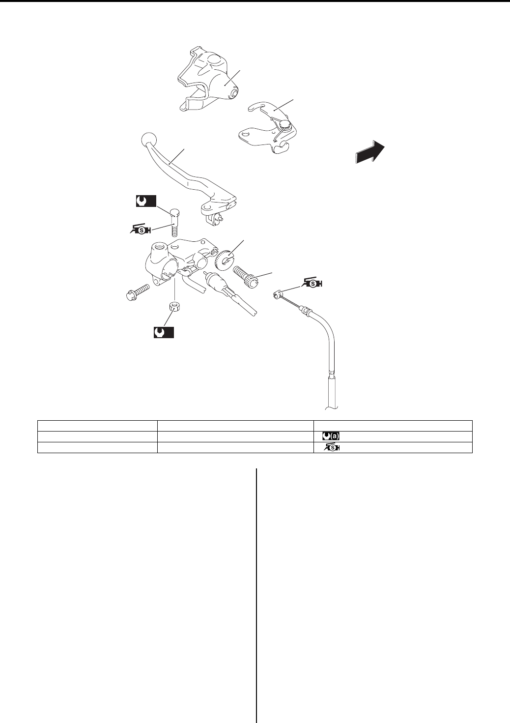
4D-4 Parking Brake:
Parking / Rear Brake Lever Components
B831G24406003
Parking / Rear Brake Lever Removal and
Installation
B831G24406004
Removal
Refer to “Handlebars Removal and Installation in
Section 6B (Page 6B-3)”.
Installation
Refer to “Handlebars Removal and Installation in
Section 6B (Page 6B-3)”.
Parking / Rear Brake Light Switch Inspection
B831G24406005
Refer to “Parking / Rear Brake Light Switch Inspection in
Section 4A (Page 4A-5)”.
Parking / Rear Brake Relay Inspection
B831G24406006
Refer to “Parking Brake Relay Inspection in Section 1I
(Page 1I-9)”.
2
1
3
(a)
4
(a)
5
7
6
FWD
I831G1440007-01
1. Brake lever lock 4. Brake lever pivot bolt 7. Lock-nut
2. Brake lever cover 5. Brake lever pivot nut : 6 N⋅m (0.6 kgf-m, 4.5 lb-ft)
3. Brake lever 6. Adjuster : Apply silicone grease.
PartShark.com
877-999-5686

Parking Brake: 4D-5
Specifications
Tightening Torque Specifications
B831G24407001
NOTE
The specified tightening torque is also described in the following.
“Parking / Rear Brake Lever Components (Page 4D-4)”
Reference:
For the tightening torque of fastener not specified in this section, refer to “Tightening Torque List in Section 0C
(Page 0C-7)”.
Special Tools and Equipment
Recommended Service Material
B831G24408001
NOTE
Required service material is also described in the following.
“Parking / Rear Brake Lever Components (Page 4D-4)”
PartShark.com
877-999-5686

4D-6 Parking Brake:
PartShark.com
877-999-5686

Table of Contents 5- i
5
Section 5
CONTENTS
Transmission / Transaxle
Precautions ………………………………….………5-1
Precautions….…………………..……………….…………… 5-1
Precautions for Transmission / Transaxle……..….. 5-1
Automatic Transmission……………..…….. 5A-1
Schematic and Routing Diagram…………..……….5A-1
Drive Train System ………….……………….…………. 5A-1
Diagnostic Information and Procedures…………5A-2
Automatic Transmission Symptom Diagnosis…..5A-2
Repair Instructions .……………….…………………..…5A-3
Automatic Transmission Components ……………. 5A-3
V-belt Cooling Duct Construction …..………………. 5A-4
V-belt Cooling Duct Removal and Installation….. 5A-5
Clutch Engagement and Lock-up Speed
Inspection………………….………………..……………. 5A-5
V-belt Type Continuously Variable Automatic
Transmission Removal and Installation ………… 5A-5
Movable Drive Face Disassembly and
Assembly ……….…………….…………….……………. 5A-9
Movable Driven Face Disassembly and
Assembly ………….…………….…………….……….. 5A-11
Drive V-belt Inspection ….………………..………….. 5A-14
Movable / Fixed Drive Face Parts Inspection….5A-15
Movable / Fixed Driven Face Parts Inspection ..5A-15
Clutch Shoe Removal and Installation …….…….5A-16
Clutch Housing Case Disassembly and
Assembly…..…………….…………….………………..5A-19
Clutch Parts Inspection ………..……………….…….5A-20
Movable Drive Face Cover Disassembly and
Assembly…..…………….…………….………………..5A-22
Clutch Housing Cover Parts Inspection …..…….5A-23
Shift Lever Assembly Components ……………….5A-23
Gear Shift Knob Removal and Installation ……..5A-24
Shift Lever Assembly Removal and
Installation ………….…………….…………….………. 5A-24
Shift Lever Disassembly and Assembly …………5A-25
Shift Rod Adjustment ………………………………….5A-25
Specifications…….………….…….…………….……….5A-26
Service Data……..……………..……………….……….5A-26
Tightening Torque Specifications………………….5A-27
Special Tools and Equipment ……………..……….5A-27
Recommended Service Material ……….………….5A-27
Special Tool ……………………….…………….……….5A-28
PartShark.com
877-999-5686

5-1 Precautions:
Transmission / Transaxle
Precautions
Precautions
Precautions for Transmission / Transaxle
B831G25000001
Refer to “General Precautions in Section 00 (Page 00-1)”.
PartShark.com
877-999-5686
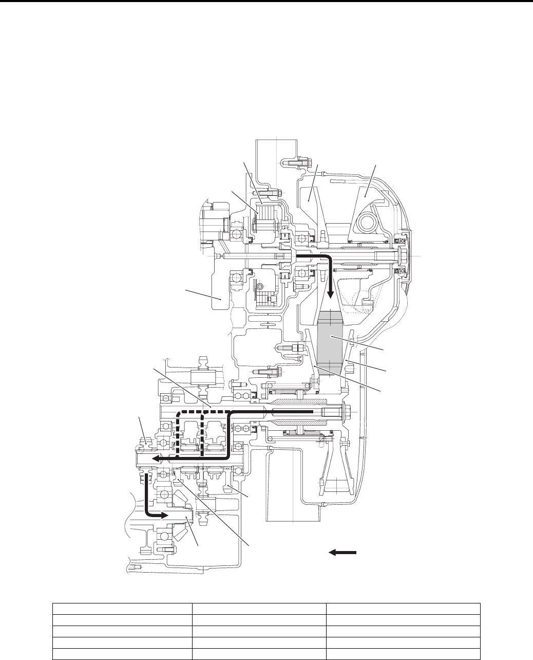
Automatic Transmission: 5A-1
Transmission / Transaxle
Automatic Transmission
Schematic and Routing Diagram
Drive Train System
B831G25102001
1
32
8
9
6
7
12
13 11
10
4
“A”
5
I831G1510001-04
1. Crankshaft 6. Fixed driven face 11. High driven gear
2. Movable drive face 7. Transfer input shaft 12. Transfer output drive gear
3. Fixed drive face 8. Clutch shoe 13. Transfer output driven gear shaft
4. V-belt 9. Clutch housing “A”: Drive train route
5. Movable driven face 10. Low driven gear
PartShark.com
877-999-5686

5A-2 Automatic Transmission:
Diagnostic Information and Procedures
Automatic Transmission Symptom Diagnosis
B831G25104001
Condition Possible cause Correction / Reference Item
Excessive engine noise Gear worn or abnormal contact. Replace.
Spline worn. Replace.
Bearing worn or burned. Replace.
V-belt slipping V-belt slipping. Replace.
Pulley face worn. Replace.
Clutch slipping Clutch shoe worn. Replace.
Centrifugal weight operation failure. Repair or replace.
V—belt worn. Replace.
Clutch dragging Clutch shoe spring fatigued. Replace.
Movable driven face distorted. Replace.
PartShark.com
877-999-5686
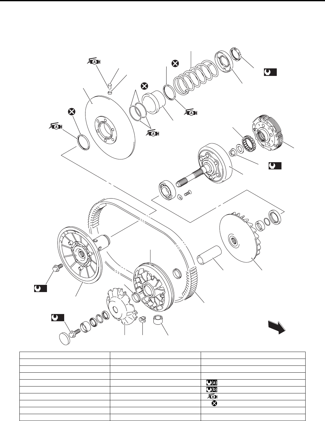
Automatic Transmission: 5A-3
Repair Instructions
Automatic Transmission Components
B831G25106001
16
17
15
18
19
15
20
22
21
(a)
23
(b)
24
(a)
11
10
(a)
1
2 3 5
8
4 9
6
7
FWD
12
14
13
I831G1510002-03
1. Movable drive face bolt 11. Movable driven face bolt 21. Spring
2. Movable drive plate 12. Clutch housing 22. Spring plate
3. Damper 13. One way clutch 23. Movable driven face ring nut
4. Spacer 14. Clutch shoe assembly 24. Clutch shoe nut
5. Roller 15. Oil seal : 110 N⋅m (11.0 kgf-m, 79.5 lb-ft)
6. Oil seal 16. Movable driven face : 150 N⋅m (15.0 kgf-m, 108.5 lb-ft)
7. Movable drive face 17. Pin : Apply grease.
8. Drive V-belt 18. Spacer : Do not reuse.
9. Fixed drive face 19. O-ring
10. Fixed driven face 20. Spring seat
PartShark.com
877-999-5686
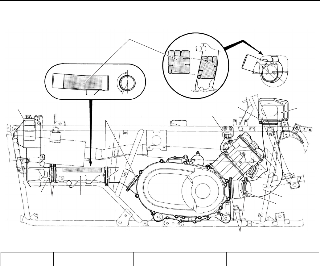
5A-4 Automatic Transmission:
V-belt Cooling Duct Construction
B831G25106002
2
5
3
2
2
9
4
26
7
8
8
1
I831G1510003-06
1. Heat shield 3. Belt cooling inlet duct No. 1 5. Belt cooling inlet duct connector 7. Belt cooling outlet duct No. 2
2. Clamp 4. Belt cooling inlet duct No. 2 6. Belt cooling outlet duct No. 1 8. Belt cooling outlet duct connector
PartShark.com
877-999-5686
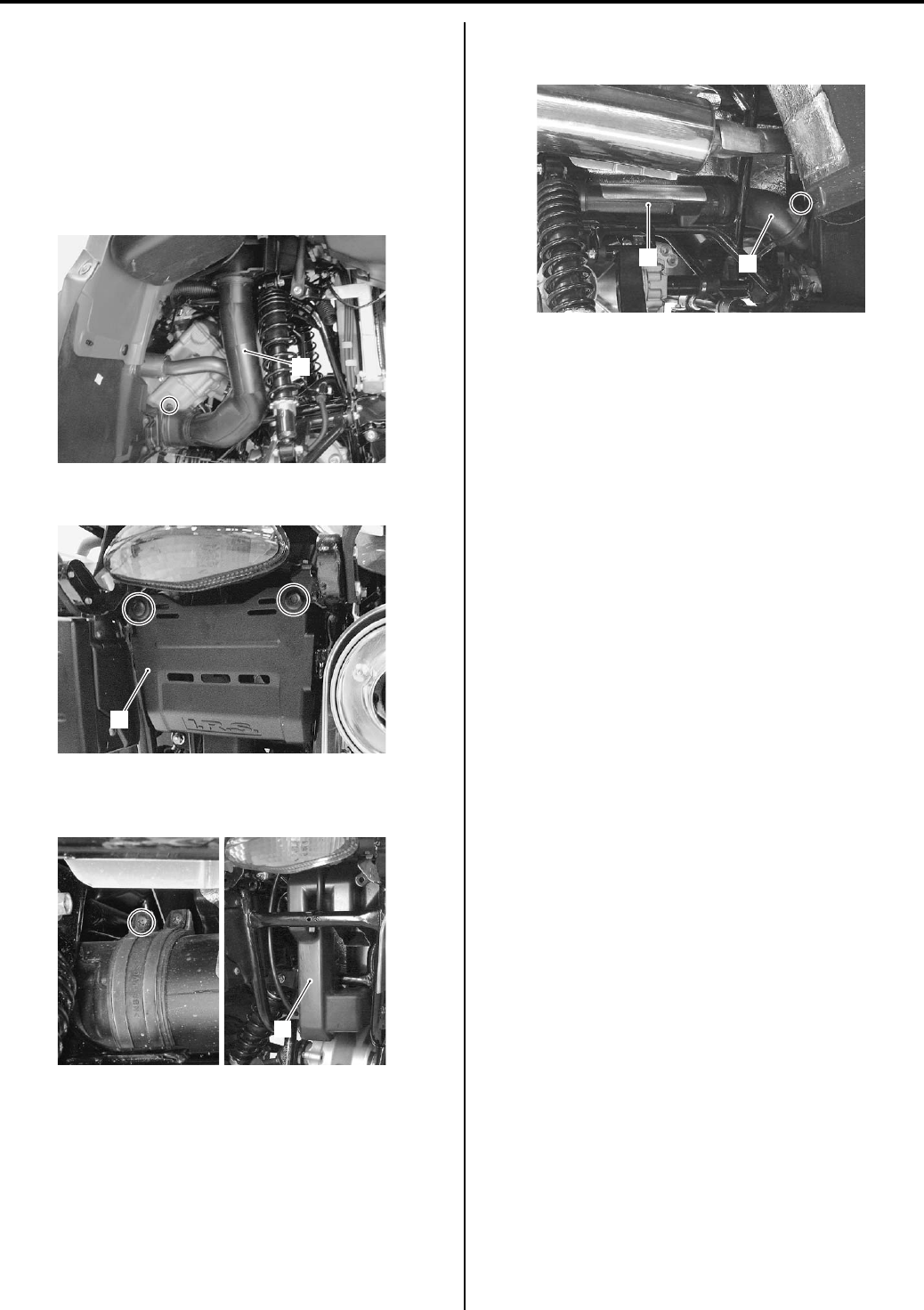
Automatic Transmission: 5A-5
V-belt Cooling Duct Removal and Installation
B831G25106003
Removal
1) Remove the right inner fender. Refer to “Front Side
Exterior Parts Removal and Installation in Section
9D (Page 9D-6)”.
2) Loosen the clamp screw and remove the inlet
cooling duct assembly (1).
3) Remove the rear cover (2).
4) Loosen the clamp and remove the outlet belt cooling
duct No. 2 (3).
5) Remove the outlet belt cooling duct No. 1 (4) along
with outlet belt cooling duct connector (5).
Installation
1) Install the V-belt cooling duct as shown in the V—belt
cooling duct construction. Refer to “V-belt Cooling
Duct Construction (Page 5A-4)”.
2) Install the removed parts.
Clutch Engagement and Lock-up Speed
Inspection
B831G25106004
Refer to “Automatic Clutch Inspection in Section 0B
(Page 0B-26)”.
V-belt Type Continuously Variable Automatic
Transmission Removal and Installation
B831G25106005
Removal
V-belt outer cover
1) Remove the seat. Refer to “Seat Removal and
Installation in Section 9D (Page 9D-11)”.
2) Remove the right cover. Refer to “Front Side Exterior
Parts Removal and Installation in Section 9D
(Page 9D-6)”.
3) Remove the inner fender. Refer to “Front Side
Exterior Parts Removal and Installation in Section
9D (Page 9D-6)”.
4) Removal the footrest. Refer to “Footrest Removal
and Installation in Section 9E (Page 9E-2)”.
5) Remove the brake pedal. Refer to “Rear Brake
Pedal Removal and Installation in Section 4A
(Page 4A-14)”.
1
I831G1510004-01
2
I831G1510005-01
3
I831G1510006-01
45
I831G1510007-03
PartShark.com
877-999-5686
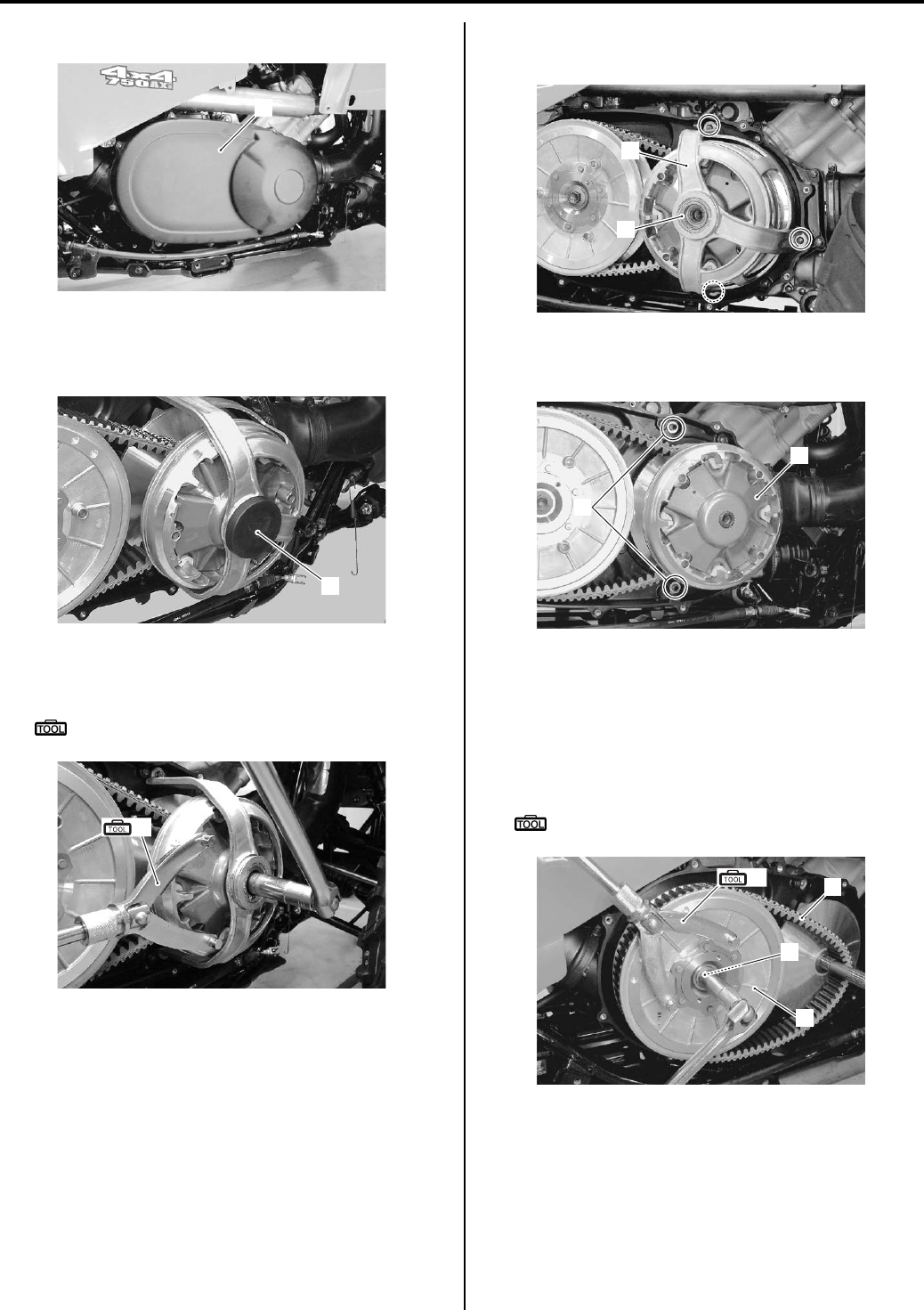
5A-6 Automatic Transmission:
6) Remove the V-belt outer cover (1).
Movable drive face
1) Remove the cap (1).
2) Remove the movable drive face bolt with the special
tool.
Special tool
(A): 09930–40113 (Rotor holder)
3) Remove the movable drive face cover (1) and collar
(2).
4) Remove the dowel pins (3).
5) Remove the movable drive face (4).
Movable driven face
1) Remove the movable driven face bolt (1) with the
special tool.
2) Remove the movable driven face assembly (2) and
drive belt (3).
Special tool
(A): 09930–40113 (Rotor holder)
1
I831G1510008-01
1
I831G1510009-01
(A)
I831G1510010-01
1
2
I831G1510011-01
3
4
I831G1510012-01
(A)
1
2
3
I831G1510013-02
PartShark.com
877-999-5686
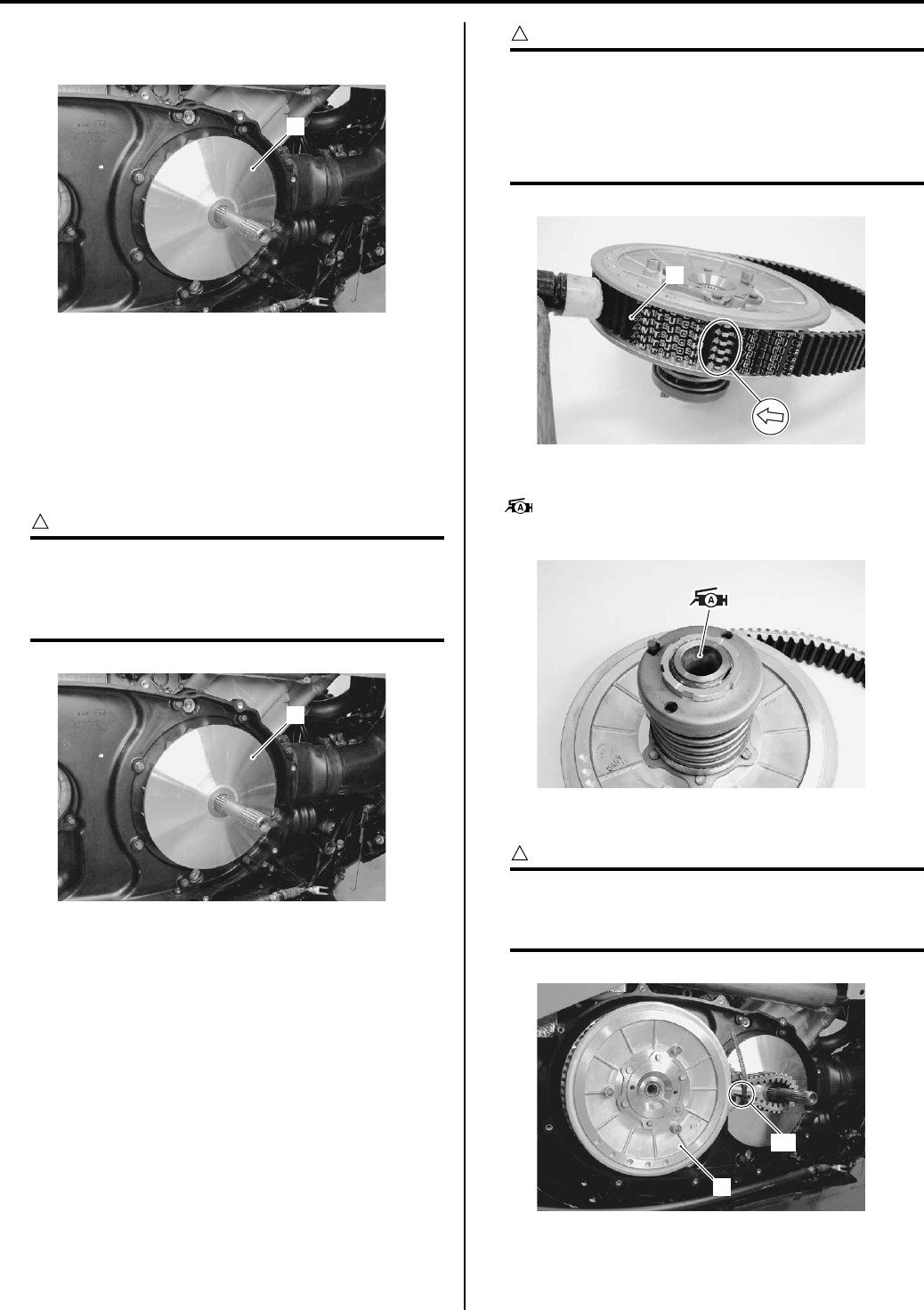
Automatic Transmission: 5A-7
Fixed drive face
Remove the fixed drive face (1).
Installation
Install the automatic transmission component parts in
the reverse order of removal. Pay attention to the
following points:
Fixed drive face
Install the fixed drive face (1).
CAUTION
!
Degrease the fixed drive face. Use
nonflammable cleaning solvent to wipe off
oily or greasy matter and make its surfaces
completely dry.
Movable driven face / drive V-belt
• Install the drive belt (1), as low as possible, between
the movable driven face and fixed driven face by
tapping with a plastic mallet.
CAUTION
!
• The drive belt should be installed so that
the arrows on the drive belt periphery
point in the normal turning direction.
• The drive belt contact surface of the driven
face should be thoroughly cleaned.
• Apply grease in the groove of fixed driven face.
: Grease 99000–25010 (SUZUKI SUPER
GREASE A or equivalent)
• Install the movable driven face assembly (2).
CAUTION
!
Pull the center area “A” of upper and lower
belt lines to be close to each other to prevent
the belt from expanding.
1
I831G1510014-01
1
I831G1510014-01
1
I831G1510015-01
I831G1510016-01
2
“A”
I831G1510017-01
PartShark.com
877-999-5686
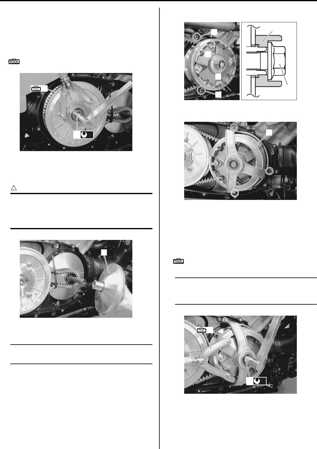
5A-8 Automatic Transmission:
• Tighten the movable driven face bolt (3) to the
specified torque with the special tool.
Tightening torque
Movable driven face bolt (a): 110 N·m (11.0 kgf-
m, 79.5 lb-ft)
Special tool
(A): 09930–40113 (Rotor holder)
Movable Drive Face
• Install the movable drive face assembly (1).
CAUTION
!
Degrease the movable drive face assembly
(1). Use nonflammable cleaning solvent to
wipe off oily or greasy matter and make its
surfaces completely dry.
• Install the collar (2) and movable drive face bolt (3).
NOTE
The deep concave of the collar (2) faces
outside.
• Install the dowel pins (4).
• Install the movable drive face cover (5).
• Tighten the movable drive face bolt (6) to the specified
torque with the special tool.
Tightening torque
Movable drive face bolt (a): 110 N·m (11.0 kgf-m,
79.5 lb-ft)
Special tool
(A): 09930–40113 (Rotor holder)
NOTE
Turn the fixed drive face until the belt is
seated in and driven faces will move together
smoothly without slip.
• Install the cap.
(A)
(a)
3
I831G1510018-01
1
I831G1510019-01
2
3
4
42
3
I831G1510020-02
5
I831G1510021-01
(A)
(a)
6
I831G1510022-01
PartShark.com
877-999-5686
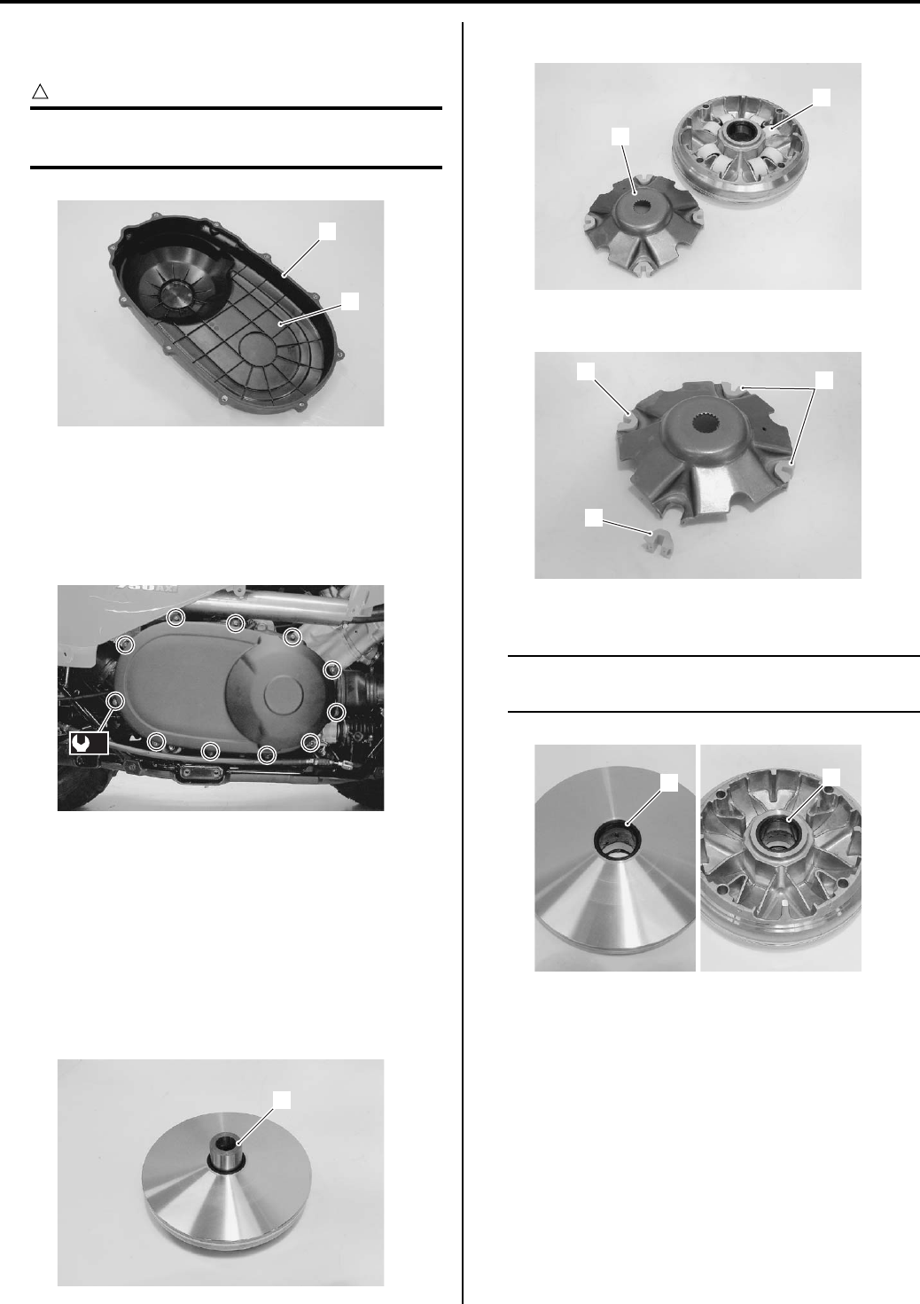
Automatic Transmission: 5A-9
V-belt Outer Cover
• Install the V-belt outer cover (1).
CAUTION
!
If there are wear or damage, replace the
gasket (2) with a new one.
• Tighten the V-belt outer cover bolts to the specified
torque.
Tightening torque
V-belt outer cover bolt (a): 8 N·m (0.8 kgf-m, 6.0
lb-ft)
Movable Drive Face Disassembly and Assembly
B831G25106006
Refer to “Automatic Transmission Components
(Page 5A-3)” and “V-belt Type Continuously Variable
Automatic Transmission Removal and Installation
(Page 5A-5)”.
Disassembly
1) Remove the spacer (1).
2) Remove the movable drive plate (2) and rollers (3).
3) Remove the dampers (4).
4) Remove the oil seals (5) and (6).
NOTE
If there are no abnormal conditions, the oil
seals removal are not necessary.
1
2
I831G1510023-01
(a)
I831G1510111-02
1
I831G1510024-01
2
3
I831G1510025-01
4
4
4
I831G1510026-01
56
I831G1510027-01
PartShark.com
877-999-5686
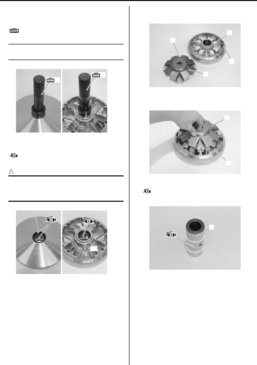
5A-10 Automatic Transmission:
Assembly
1) Install the oil seals with the special tool.
Special tool
(A): 09913–70210 (Bearing installer set)
NOTE
The removed oil seals must be replaced with
new ones.
2) Apply grease to the lip of oil seals and inside grease
groove “A” of the movable drive face.
: Grease 99000–25010 (SUZUKI SUPER
GREASE A or equivalent)
CAUTION
!
• Wipe off any excess grease thoroughly.
• Take care not to apply grease to the
contact surface of the drive belt.
3) Assemble the rollers (1) to the movable drive face
(2).
4) Assemble the four dampers (3) to the movable drive
plate (4).
5) Assemble the movable plate (4) to the movable drive
face (3).
6) Apply grease to the inside groove of the spacer (5).
: Grease 99000–25010 (SUZUKI SUPER
GREASE A or equivalent)
(A)
(A)
I831G1510028-01
“A”
I831G1510029-02
1
2
3
4
I831G1510030-01
3
4
I831G1510031-01
5
I831G1510032-02
PartShark.com
877-999-5686
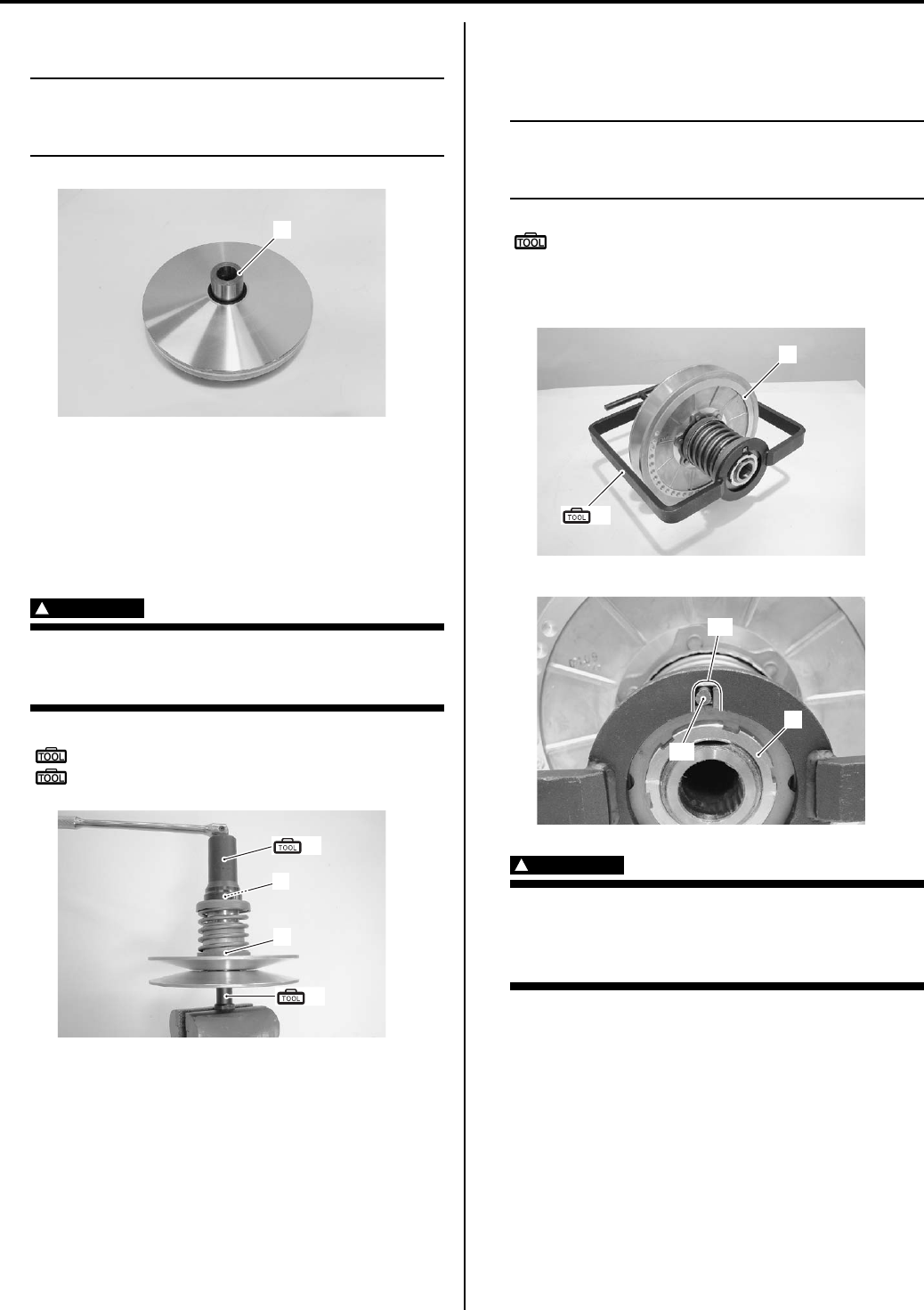
Automatic Transmission: 5A-11
7) Install the spacer (6).
NOTE
When installing the spacer, press down the
movable drive face plate so as not to cause
the rollers to come out of position.
Movable Driven Face Disassembly and
Assembly
B831G25106007
1) Hold the movable driven face assembly (1) with the
special tool and vise, loosen the movable driven face
ring nut (2) with the special tool.
WARNING
!
Do not remove the movable driven face ring
nut before attaching the clutch spring
compressor.
Special tool
(A): 09917–23711 (Ring nut wrench)
(B): 09924–52450 (Fixed driven face holder)
2) Set the special tool to the movable driven face
assembly (1) and compress the movable driven face
assembly by turning in the special tool handle.
NOTE
Make sure to insert the spring end “A” into
the slot “B” of the special tool as shown in
the figure.
Special tool
(c): 09922–31430 (Clutch spring
compressor)
3) Remove the movable driven face ring nut (2).
WARNING
!
Since a high spring force applies to the
movable driven face, care must be used so
as not to cause the movable driven face to
come off abruptly.
6
I831G1510033-01
(A)
(B)
1
2
I831G1510034-01
(C)
1
I831G1510035-01
“A”
“B”
2
I831G1510036-02
PartShark.com
877-999-5686
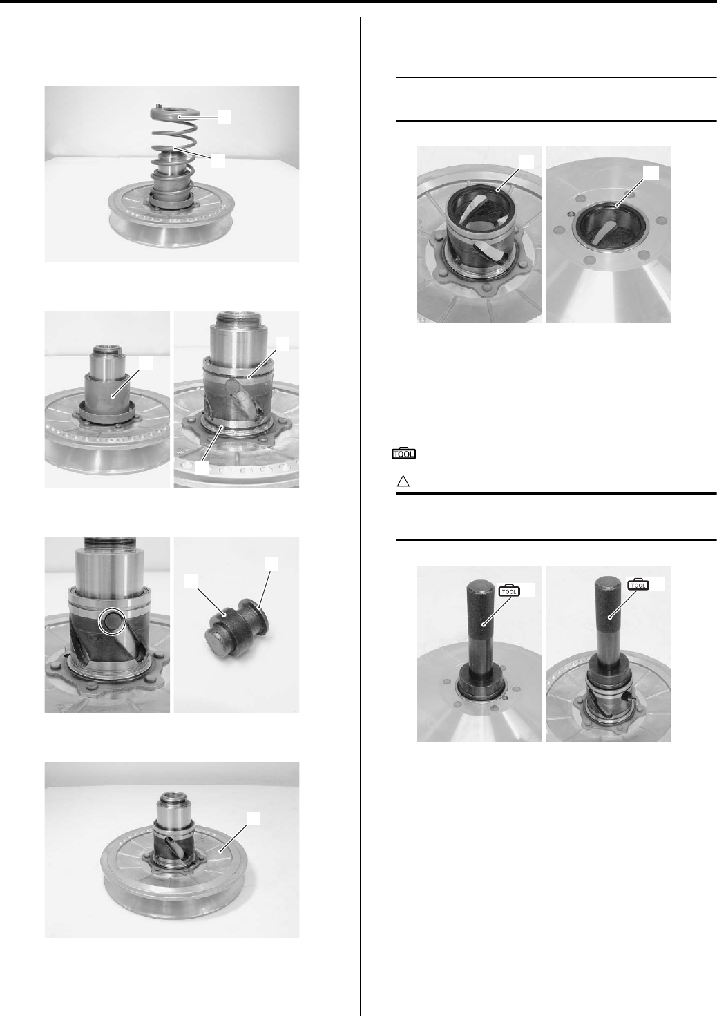
5A-12 Automatic Transmission:
4) Loosen the special tool handle slowly and remove
the special tool.
5) Remove the spring plate (3) and spring (4).
6) Remove the spring seat (5) and O-rings (6).
7) Remove the pins (7) and rollers (8).
Remove the movable driven face (9).
9) Remove the oil seals (10) and (11) from the movable
driven face.
NOTE
If there are no abnormal conditions, the oil
seals removal are not necessary.
Assembly
Assemble the movable driven face in the reverse order
of disassembly. Pay attention to the following points:
• Install the oil seals with the special tool.
Special tool
(A): 09913–70210 (Bearing installer set)
CAUTION
!
The removed oil seals must be replaced with
new ones.
3
4
I831G1510037-01
6
6
5
I831G1510038-01
7
8
I831G1510039-01
9
I831G1510040-01
11
10
I831G1510041-01
(A) (A)
I831G1510042-01
PartShark.com
877-999-5686
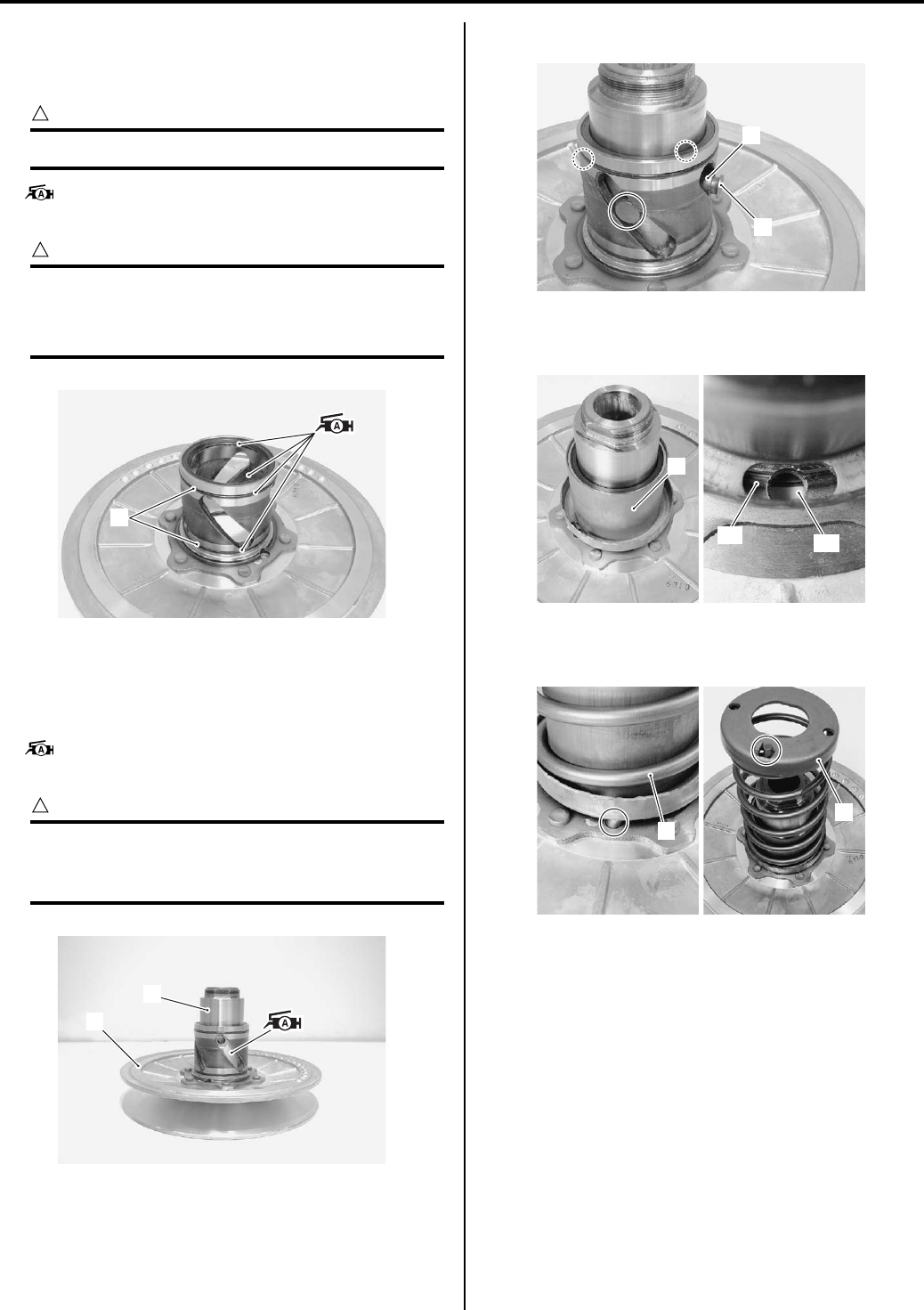
Automatic Transmission: 5A-13
• Install the O-rings (1) to the movable driven face.
• Apply grease to the oil seal lips, O-rings and inside
groove of movable driven face.
CAUTION
!
Replace the O-rings (1) with new ones.
: Grease 99000–25010 (SUZUKI SUPER
GREASE A or equivalent)
CAUTION
!
• Wipe off any excess grease thoroughly.
• Take care not to apply grease to the
contact surface of the drive belt.
• Install the movable driven face (2) to the fixed driven
face (3).
• Apply grease to the pin grooves of the movable driven
face.
: Grease 99000–25010 (SUZUKI SUPER
GREASE A or equivalent)
CAUTION
!
To prevent damaging the oil seal lip from
during installation, slide the lip using a 0.1-
mm steel sheet as a guide.
• Install the rollers (4) and pins (5).
• Install the spring seat (6) aligning the hole “A” with the
hole “B”.
• Install the spring (7) and spring plate (8) by aligning
the spring ends with the holes.
1
I831G1510043-01
2
3
I831G1510116-01
5
4
I831G1510044-02
6
“A” “B”
I831G1510045-01
7
8
I831G1510046-01
PartShark.com
877-999-5686
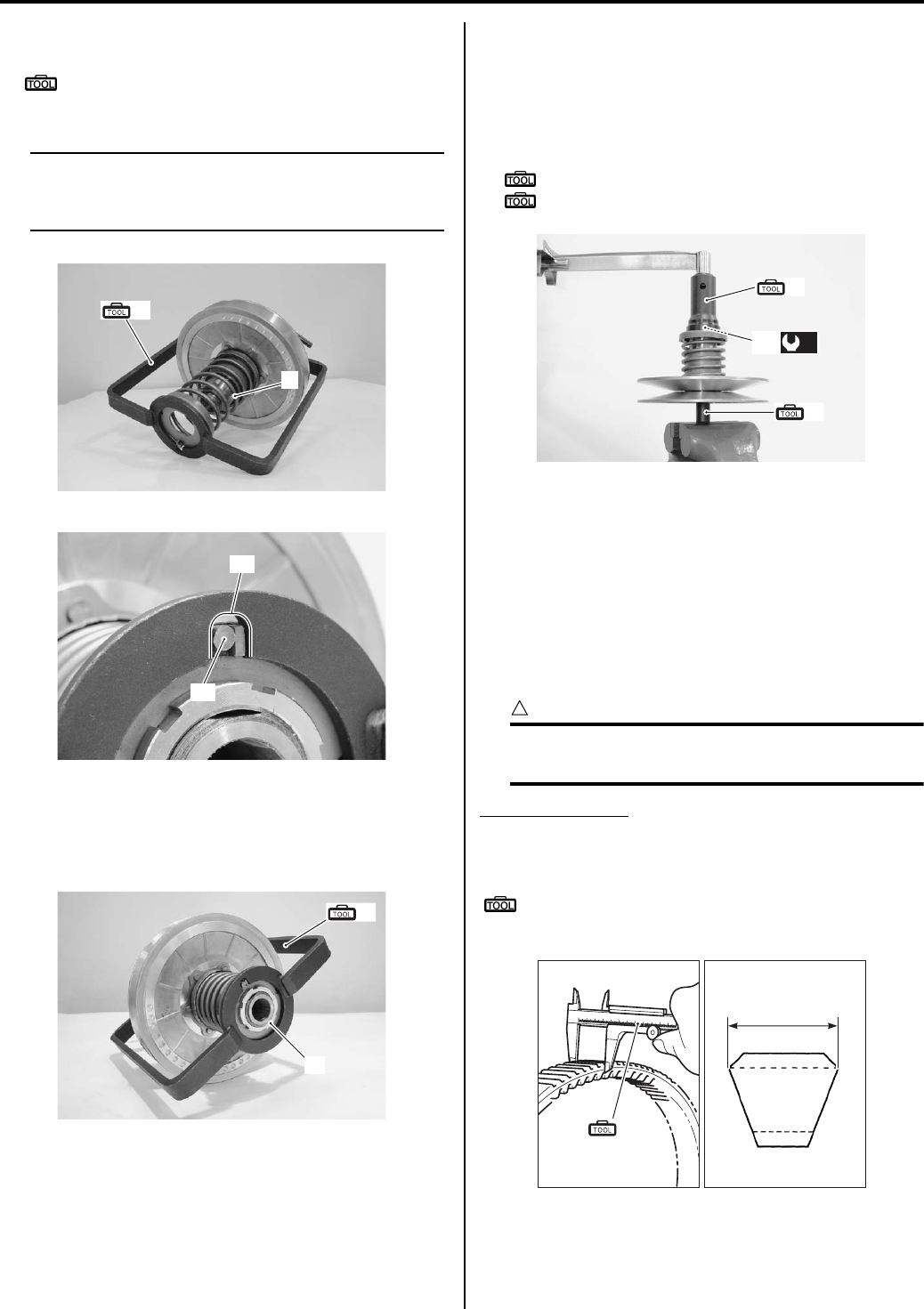
5A-14 Automatic Transmission:
• Compress the spring (7) with the special tool.
Special tool
(B): 09922–31430 (Clutch spring
compressor)
NOTE
Make sure to insert the spring end “A” into
the slot “B” of the special tool as shown in
the figure.
• Tighten the movable driven face ring nut (10)
temporarily.
• Remove the special tool from the movable driven face
assembly.
• Tighten the movable driven face ring nut (10) to the
specified torque with the special tools.
Tightening torque
Movable driven face ring nut (a): 110 N·m (11.0
kgf-m, 79.5 lb-ft)
Special tool
(C): 09917–23711 (Ring nut wrench)
(D): 09924–52450 (Fixed driven face holder)
Drive V-belt Inspection
B831G25106008
Inspect that the drive belt is free from any greasy
substance.
Inspect the contact surface of the drive belt for cracks or
damage and measure the width of the drive belt with the
vernier calipers.
If any defects are found or measurement exceeds the
service limit, replace the drive belt with a new one.
CAUTION
!
If grease or oil is present on the surface of
the drive belt, degrease the belt thoroughly.
Drive V-belt width
Standard: 34.3 (1.35 in)
Service limit: 33.3 mm (1.31 in)
Special tool
(A): 09900–20101 (Vernier calipers (1/15 mm,
150 mm))
(B)
7
I831G1510047-02
“A”
“B”
I831G1510048-01
10
(B)
I831G1510049-01
(C)
(D)
(a)
10
I831G1510050-01
“a”
(A)
I831G1510051-02
PartShark.com
877-999-5686
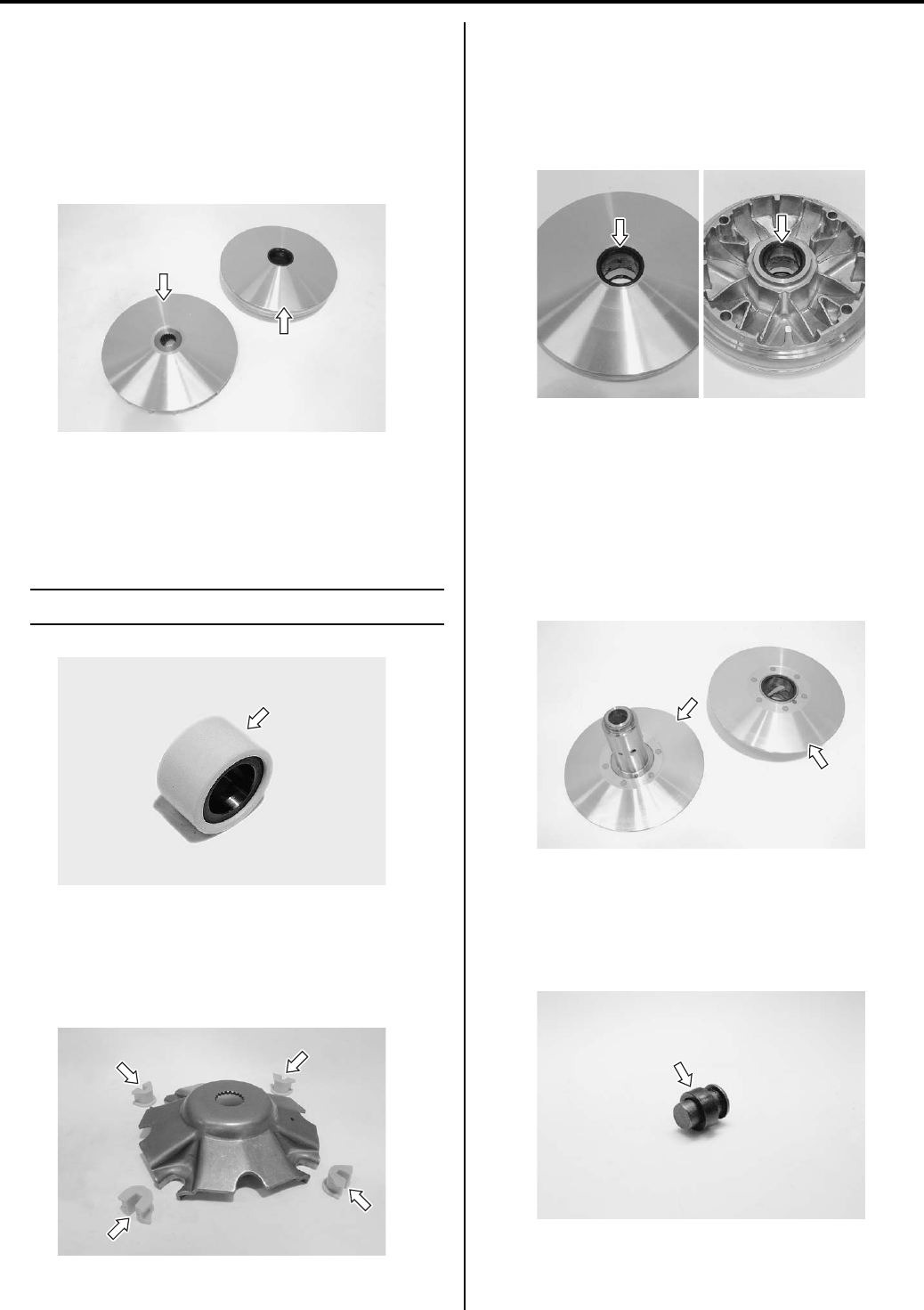
Automatic Transmission: 5A-15
Movable / Fixed Drive Face Parts Inspection
B831G25106009
Movable / Fixed Drive Face
Inspect the drive faces for any abnormal conditions such
as stepped wear or discoloration caused by burning.
If any damages are found, replace the drive faces with
new ones.
Roller
Inspect each roller and their sliding surface for wear or
damage.
If any defects are found, replace the rollers as a set.
NOTE
The rollers must always be changed as a set.
Damper
Inspect the dampers for wear or damage.
If any defects are found, replace the dampers with new
ones.
Oil Seal
Inspect the lip of the oil seal for wear or damage.
If any damages are found, replace the oil seal with a new
one.
Refer to “Movable Driven Face Disassembly and
Assembly (Page 5A-11)”.
Movable / Fixed Driven Face Parts Inspection
B831G25106010
Movable / Fixed Driven Face
Inspect the driven face for any abnormal conditions,
such as stepped wear or discoloration caused by
burning.
If any defects are found, replace them with new ones.
Movable Driven Pin and Spacer
Inspect the movable driven pin and spacer for abnormal
wear or damage. If any defects are found, replace the
pin and spacer with a new one.
I831G1510053-01
I831G1510054-01
I831G1510055-01
I831G1510056-01
I831G1510057-01
I831G1510058-01
PartShark.com
877-999-5686
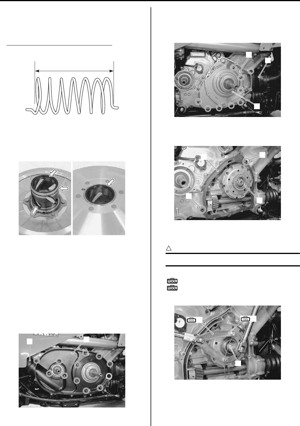
5A-16 Automatic Transmission:
Movable Driven Spring
Measure the spring free length with the vernier calipers.
• If the length is shorter than the service limit, replace
the spring with a new one.
Movable driven face spring free length
Service limit: 145.4 mm (5.72 in)
O-ring and Oil Seal
Inspect the O-rings and oil seals for wear or damage.
If any defects are found, replace the O-rings and oil
seals with new ones.
Clutch Shoe Removal and Installation
B831G25106011
Refer to “V-belt Type Continuously Variable Automatic
Transmission Removal and Installation (Page 5A-5)”.
Removal
1) Drain the engine oil. Refer to “Engine Oil and Filter
Replacement in Section 0B (Page 0B-10)”.
2) Remove the outlet cooling duct connector (1) from
the V-belt inner cover (2).
3) Remove the V-belt inner cover (2).
4) Remove the inlet cooling duct connector (3) from the
clutch housing case (4).
5) Remove the clutch housing case (4) along with the
clutch housing (5).
6) Remove the dowel pins (6) and gasket (7).
7) Remove the one way clutch (8).
Remove the clutch shoe nut (9) with the special
tools.
CAUTION
!
The clutch shoe nut (9) has left-hand threads.
Special tool
(A): 09930–40113 (Rotor holder)
(B): 09930–40131 (Balancer drive sprocket
holder)
I831G1510059-02
I831G1510060-01
12
I831G1510061-01
4
5
3
I831G1510062-02
6
6
7
8
I831G1510063-02
9
(A) (B)
I831G1510064-02
PartShark.com
877-999-5686
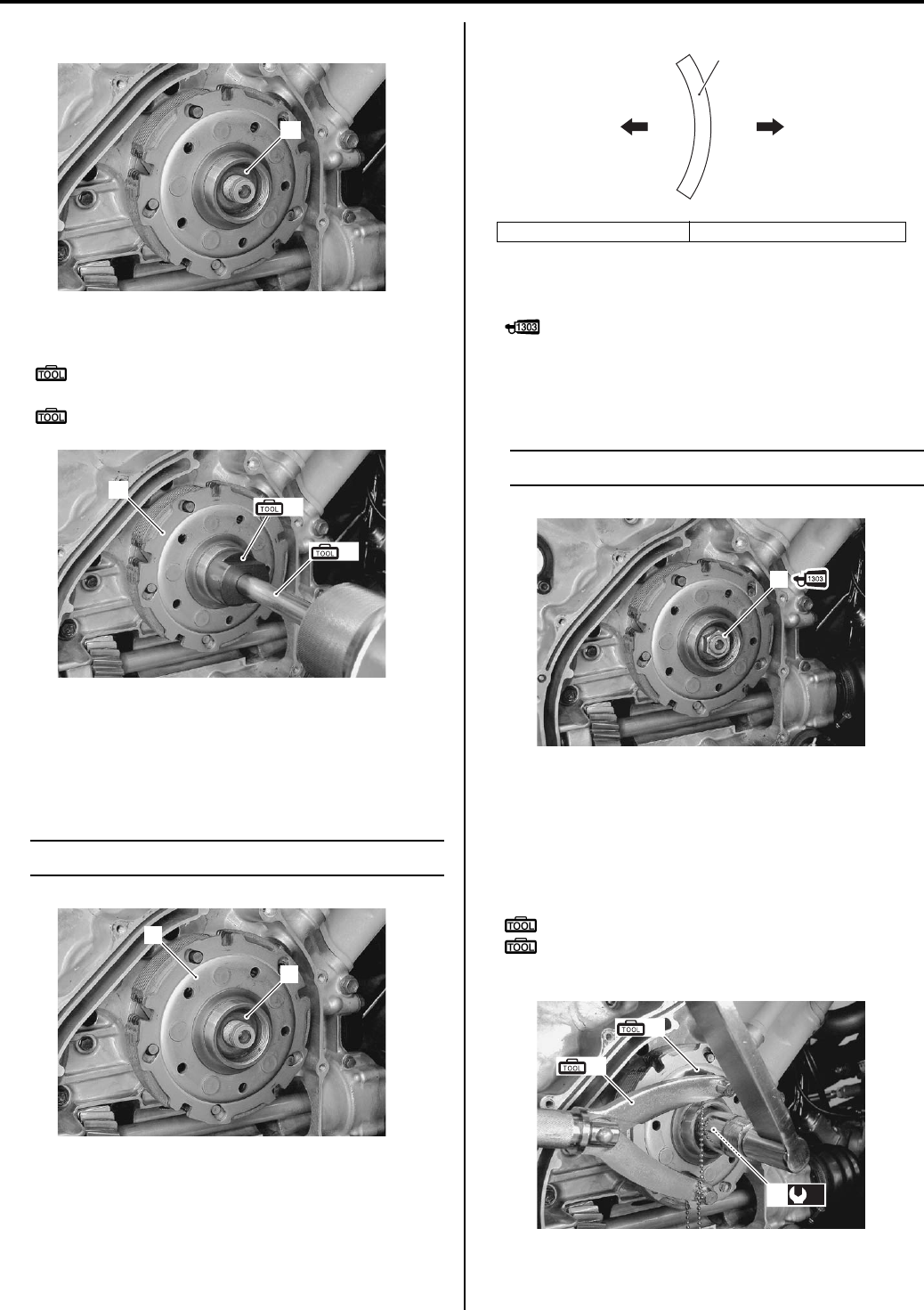
Automatic Transmission: 5A-17
9) Remove the washer (10).
10) Remove the clutch shoe (11) with the special tools.
Special tool
(C): 09930–30104 (Rotor remover slide
shaft)
(D): 09920–33540 (Clutch shoe remover)
Installation
Install the clutch shoe in the reverse order of removal.
Pay attention to the following points:
• Install the clutch shoe (1) and washer (2).
NOTE
Install the washer (2) as shown in the figure.
• Apply a small quantity of thread lock to the clutch
shoe nut (3).
: Thread lock cement 99000–32030
(THREAD LOCK CEMENT SUPER 1303 or
equivalent)
• Install the clutch shoe nut (3).
NOTE
The clutch shoe nut (3) has left-hand threads.
• Tighten the clutch shoe nut (3) to the specified torque
with the special tools.
Tightening torque
Clutch shoe nut (a): 150 N·m (15.0 kgf-m, 108.5
lb-ft)
Special tool
(A): 09930–40113 (Rotor holder)
(B): 09930–40131 (Balancer drive sprocket
holder)
10
I831G1510065-02
11
(C)
(D)
I831G1510066-02
1
2
I831G1510067-01
“a”: Clutch shoe side “b”: Clutch shoe nut side
2
“a” “b”
I831G1510068-01
3
I831G1510069-02
(A)
(B)
(a)
3
I831G1510070-01
PartShark.com
877-999-5686
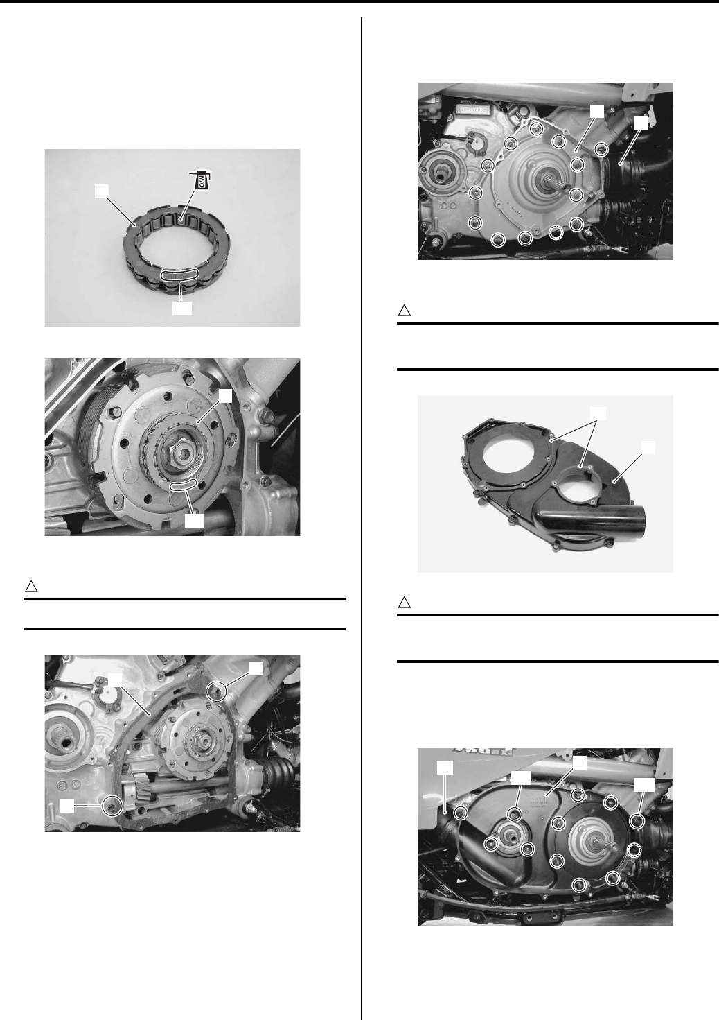
5A-18 Automatic Transmission:
• Apply molybdenum oil solution to the inside of the one
way clutch (4).
M/O: Molybdenum oil (MOLYBDENUM OIL
SOLUTION)
• Install the one way clutch (4) with facing the
“OUTSIDE” mark “A” outside.
• Install the dowel pins (5) and gasket (6).
CAUTION
!
Use a new gasket (6) to prevent oil leakage.
• Install the clutch housing case (7) and inlet belt
cooling duct connector (8) and tighten the bolts
diagonally.
• Install the V-belt inner cover (9).
CAUTION
!
If there are wear or damage, replace the
gaskets (10) with new ones.
CAUTION
!
Tighten the clutch inner cover bolts “A” first
and then other ones diagonally.
Tightening torque
V-belt inner cover bolt: 9 N·m (0.9 kgf-m, 6.5 lb-ft)
• Install the outlet belt cooling duct connector (11).
4
“A”
I831G1510071-02
4
“A”
I831G1510072-02
6
5
5
I831G1510114-02
7
8
I831G1510112-01
9
10
I831G1510113-01
11 9
“A” “A”
I831G1510073-01
PartShark.com
877-999-5686
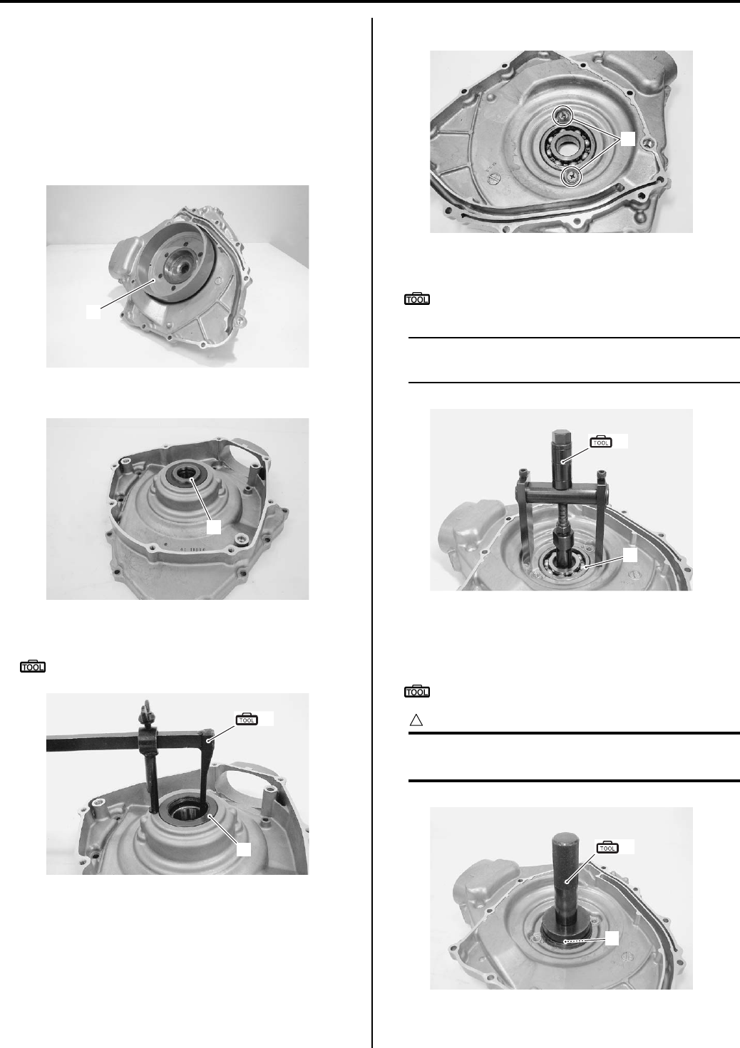
Automatic Transmission: 5A-19
Clutch Housing Case Disassembly and
Assembly
B831G25106012
Refer to “Clutch Shoe Removal and Installation
(Page 5A-16)”.
Disassembly
• Remove the clutch housing (1) from clutch housing
case.
• Remove the collar (2).
• Remove the oil seal (3) with the special tool.
Special tool
(A): 09913–50121 (Oil seal remover)
• Remove the retainers (4).
• Remove the bearing (5) with the special tool.
Special tool
(B): 09921–20240 (Bearing remover set)
NOTE
If there is no abnormal noise, the bearing
removal is not necessary.
Assembly
• Install the bearing (1) with the special tool.
Special tool
(A): 09913–70210 (Bearing installer set)
CAUTION
!
The removed bearing must be replaced with a
new one.
1
I831G1510074-01
2
I831G1510075-01
3
(A)
I831G1510076-01
4
I831G1510077-01
5
(B)
I831G1510078-01
1
(A)
I831G1510079-01
PartShark.com
877-999-5686
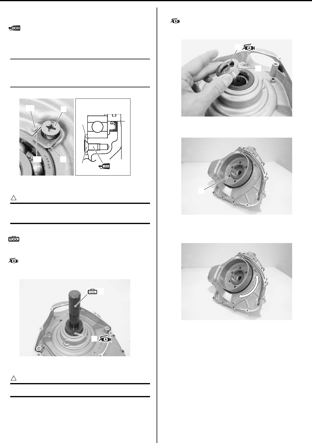
5A-20 Automatic Transmission:
• Apply a small quantity of thread lock to the bearing
retainer screws (2), and tighten them securely.
: Thread lock cement 99000–32030
(THREAD LOCK CEMENT SUPER 1303 or
equivalent)
NOTE
• When installing the bearing retainer (3),
align the convex part “A” of clutch housing
case with the edge “B” of bearing retainer.
• Install the oil seal (4) with the special tool.
CAUTION
!
The removed oil seal (4) must be replaced
with a new one.
Special tool
(A): 09913–70210 (Bearing installer set)
• Apply grease to the rip of the oil seal (4).
: Grease 99000–25010 (SUZUKI SUPER
GREASE A or equivalent)
• Install the collar (5).
CAUTION
!
Replace a O-ring (6) with a new one.
• Apply grease to the O-ring (6).
: Grease 99000–25010 (SUZUKI SUPER
GREASE A or equivalent)
• Install the clutch housing (7).
• After installed the clutch housing, check if the clutch
housing rotates smoothly.
Clutch Parts Inspection
B831G25106013
Refer to “Clutch Housing Case Disassembly and
Assembly (Page 5A-19)”.
2
3
“A”
“B”
3
2
I831G1510080-02
(A)
4
I831G1510081-01
6
5
I831G1510082-01
7
I831G1510083-01
I831G1510052-01
PartShark.com
877-999-5686
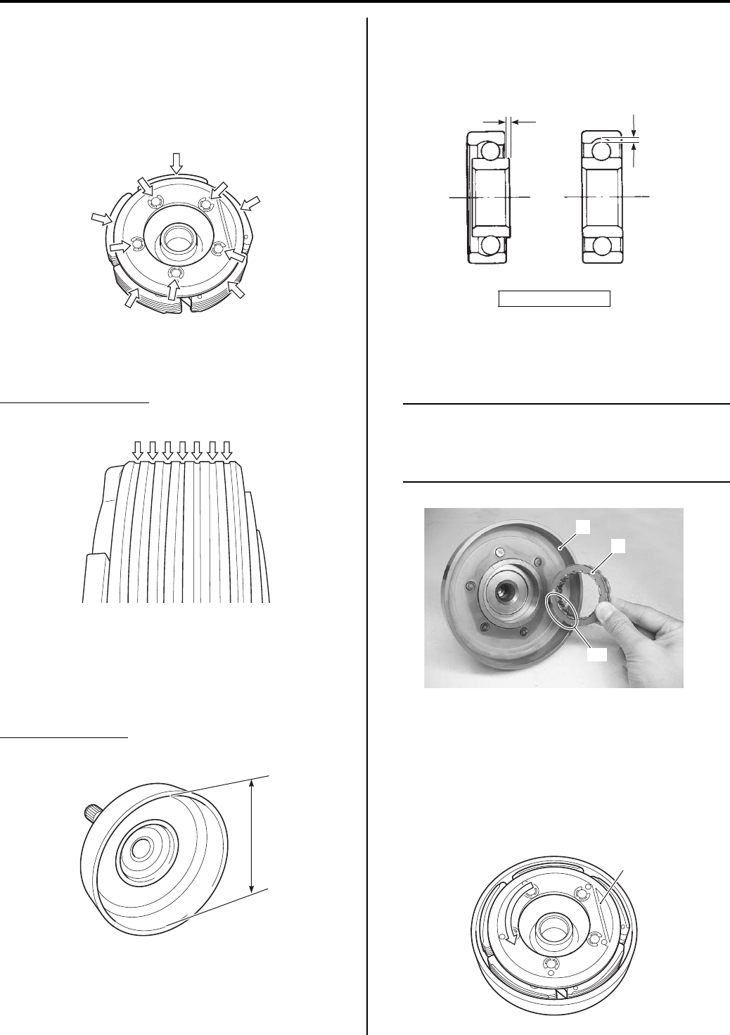
Automatic Transmission: 5A-21
Clutch Shoe
Inspect the boss and centrifugal weight fulcrum sections
for looseness, damage and operation.
Inspect the clutch shoe for damage and fouling with oil
on the surface.
If any defects are found, replace the clutch shoe
assembly with a new one.
Measure the thickness of the clutch shoe at the center
position. If the thickness is less than the service limit,
replace the clutch shoe assembly with a new one.
Clutch shoe thickness
Service limit: No groove at any part
Clutch housing
Inspect the clutch housing for any abnormal surface
damage. Measure the inside diameter of the clutch
housing. If the measurement exceeds the service limit,
replace the clutch housing with a new one.
Clutch housing I.D.
Service limit: 140.5 mm (5.53 in)
Left Clutch Housing Bearing
Rotate the inner race by finger to inspect for abnormal
play, noise and smooth rotation. If there is anything
unusual, replace the bearing with a new one.
One Way Clutch
Install the one way clutch (1) onto the proper direction as
shown.
NOTE
When Installing the one way clutch (1) onto
the clutch housing (2), make sure that the
“OUTSIDE” mark “A” in the one way clutch
faces to the clutch housing.
• Install the clutch shoe (3) onto the clutch housing and
turn the clutch shoe by hand to inspect the one way
clutch for a smooth movement. The clutch shoe turns
one direction only. If a large resistance is felt to
rotation, inspect the one way clutch for damage or one
way clutch contacting surface of the clutch shoe for
wear or damage. If any defects are found, replace
them with new ones.
I831G1510084-01
I831G1510085-01
I831G1510086-01
“a”: play
“a”
“a”
I831G1510087-01
“A”
1
2
I831G1510088-01
3
I831G1510089-01
PartShark.com
877-999-5686
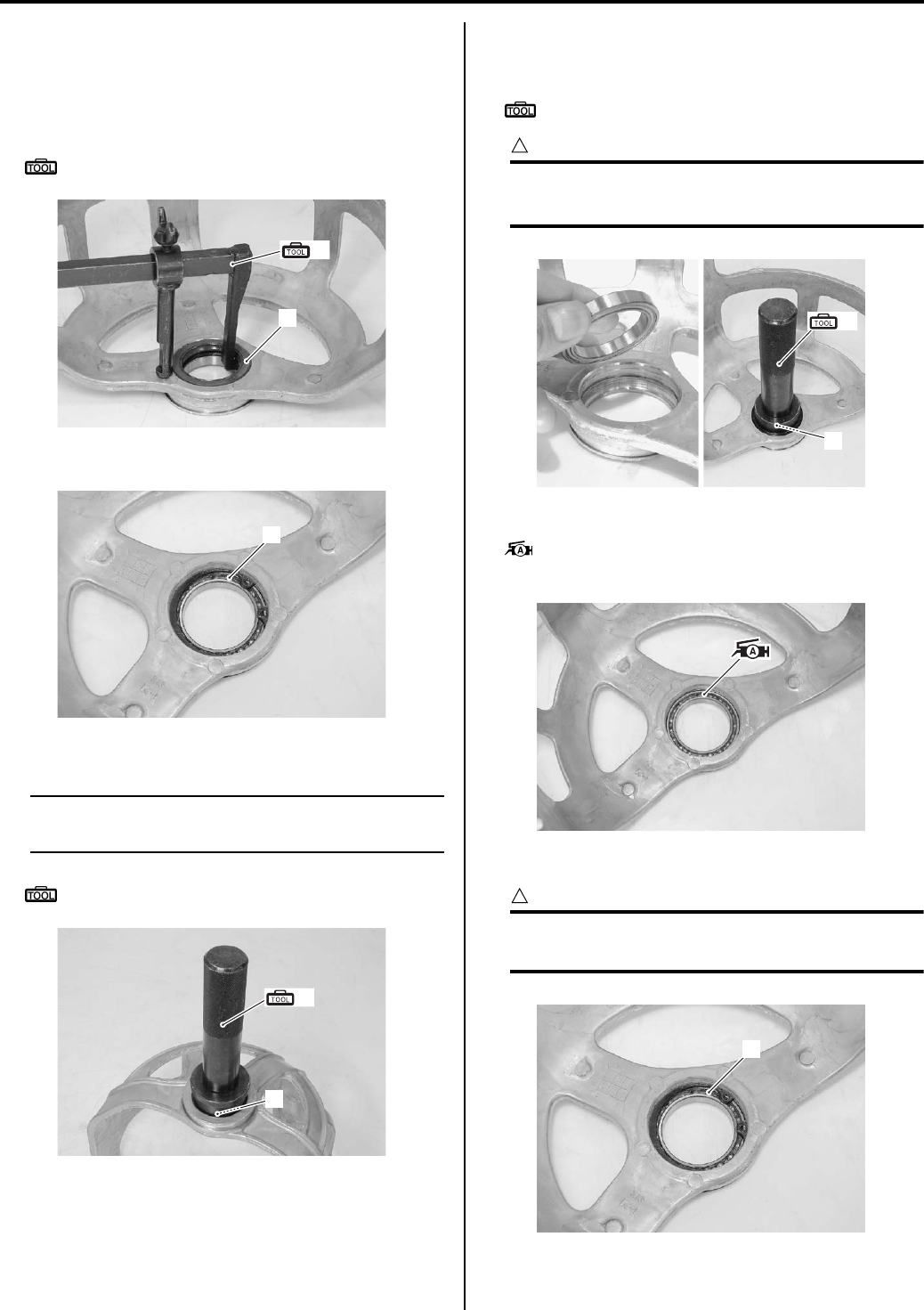
5A-22 Automatic Transmission:
Movable Drive Face Cover Disassembly and
Assembly
B831G25106014
Disassembly
• Remove the oil seal (1) with the special tool.
Special tool
(A): 09913–50121 (Oil seal remover)
• Remove the snap ring (2).
• Remove the bearing (3) with the special tool.
NOTE
If there is no abnormal noise, the bearing
removal is not necessary.
Special tool
(A): 09913–70210 (Bearing installer set)
Assembly
• Press the bearing (1) with the special tool.
Special tool
(A): 09913–70210 (Bearing installer set)
CAUTION
!
• The sealed cover of the bearing must face
outside.
• Apply grease to the bearing.
: Grease 99000–25010 (SUZUKI SUPER
GREASE A or equivalent)
• Install the snap ring (2).
CAUTION
!
The removed snap ring must be replaced
with a new one.
(A)
1
I831G1510090-01
2
I831G1510091-01
(A)
3
I831G1510092-01
(A)
1
I831G1510094-01
I831G1510095-01
2
I831G1510091-01
PartShark.com
877-999-5686
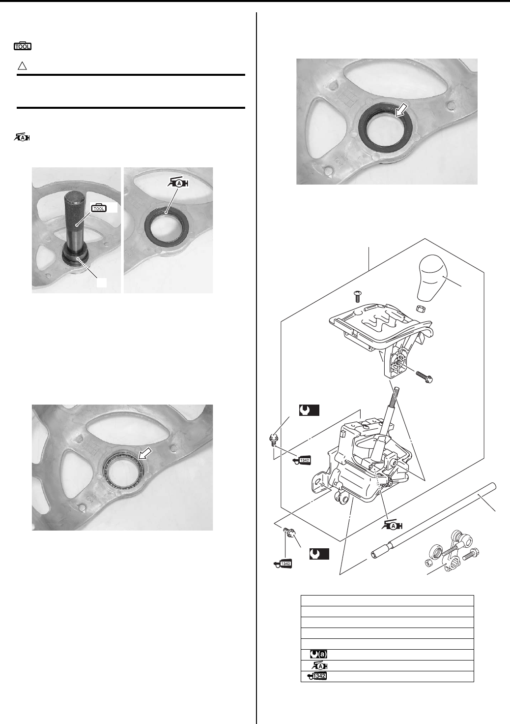
Automatic Transmission: 5A-23
• Install the oil seal (3) with the special tool.
Special tool
(A): 09913–70210 (Bearing installer set)
CAUTION
!
The removed oil seal must be replaced with a
new one.
• Apply grease to the lip of oil seal.
: Grease 99000–25010 (SUZUKI SUPER
GREASE A or equivalent)
Clutch Housing Cover Parts Inspection
B831G25106015
Right Clutch Housing Bearing
Rotate the inner race by finger to inspect for abnormal
play, noise and smooth rotation. If there is anything
unusual, replace the bearing with a new one.
Oil Seal
Inspect the oil seal lip for wear or damage. If any defects
are found, replace the oil seal with a new one.
Shift Lever Assembly Components
B831G25106016
(A)
3
I831G1510100-01
I831G1510099-01
1. Transfer gear shift lever assembly
2. Gear shift knob
3. Rod
4. Gear shift arm
5. Bolt
:10 N⋅m (1.0 kgf-m, 7.0 lb-ft)
: Apply grease.
: Apply thread lock to the thread part.
I831G1510101-01
2
1
3
(a)
5
(a)
5
4
I831G1510102-02
PartShark.com
877-999-5686
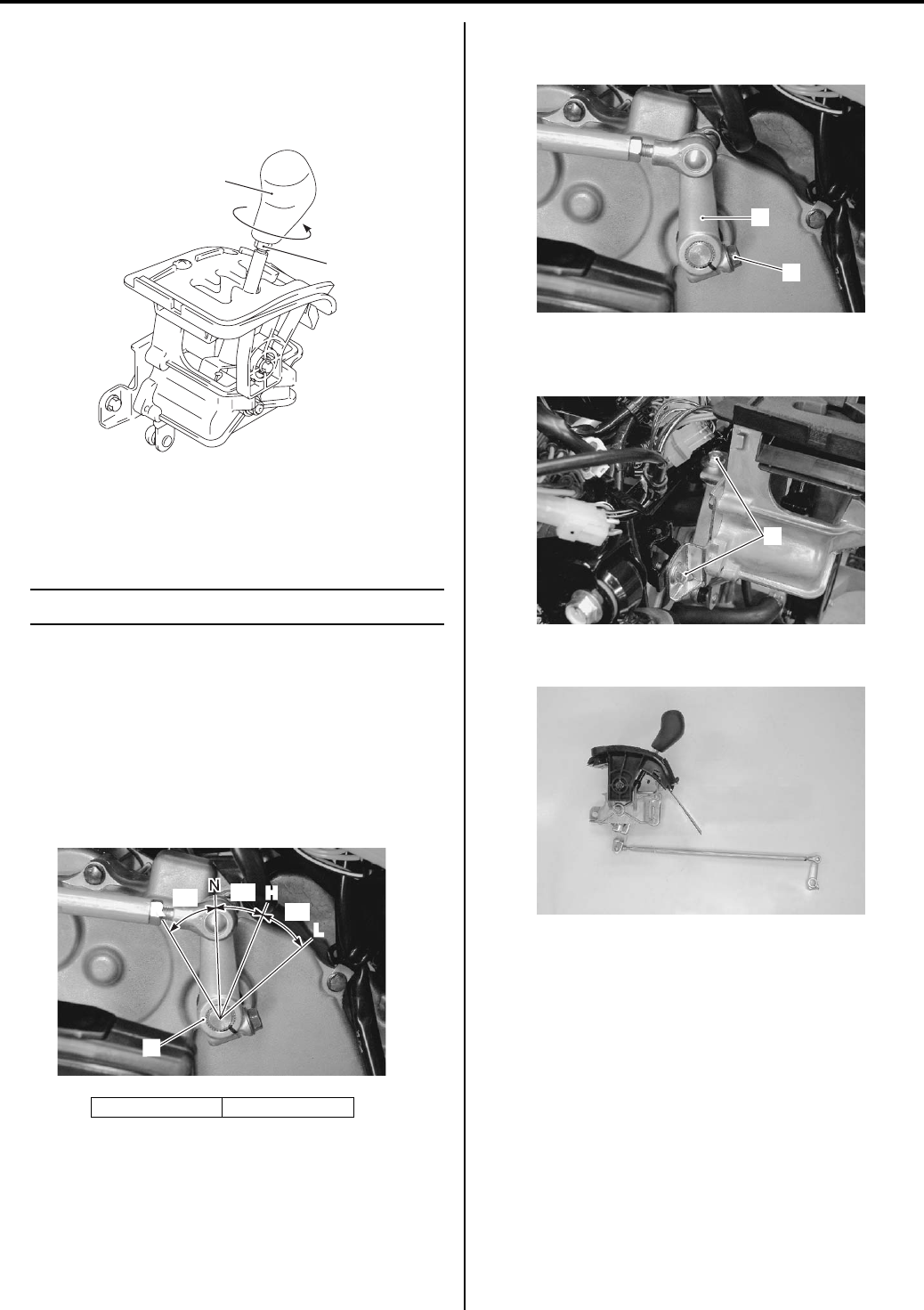
5A-24 Automatic Transmission:
Gear Shift Knob Removal and Installation
B831G25106017
Removal
1) Loosen the lock-nut (1).
2) Remove the gear shift knob (2).
Installation
Install the gear shift knob in the reverse order of
removal.
NOTE
Tighten the lock-nut securely.
Shift Lever Assembly Removal and Installation
B831G25106018
Removal
1) Keep the vehicle on a level ground.
2) Remove the front fender. Refer to “Front Side
Exterior Parts Removal and Installation in Section
9D (Page 9D-6)”.
3) Keep the gear shift arm (1) in the neutral position.
4) Loosen the bolt (2) and remove the gear shift arm
(1).
5) Remove the transfer gear shift lever mounting bolts
(3).
6) Remove the shift lever assembly.
“a”: 30°“b”: 33°
1
2
I831G1510115-01
1
R
L
H
“a”
“b” “b”
I831G1510104-03
2
1
I831G1510105-03
3
I831G1510103-02
I831G1510106-01
PartShark.com
877-999-5686
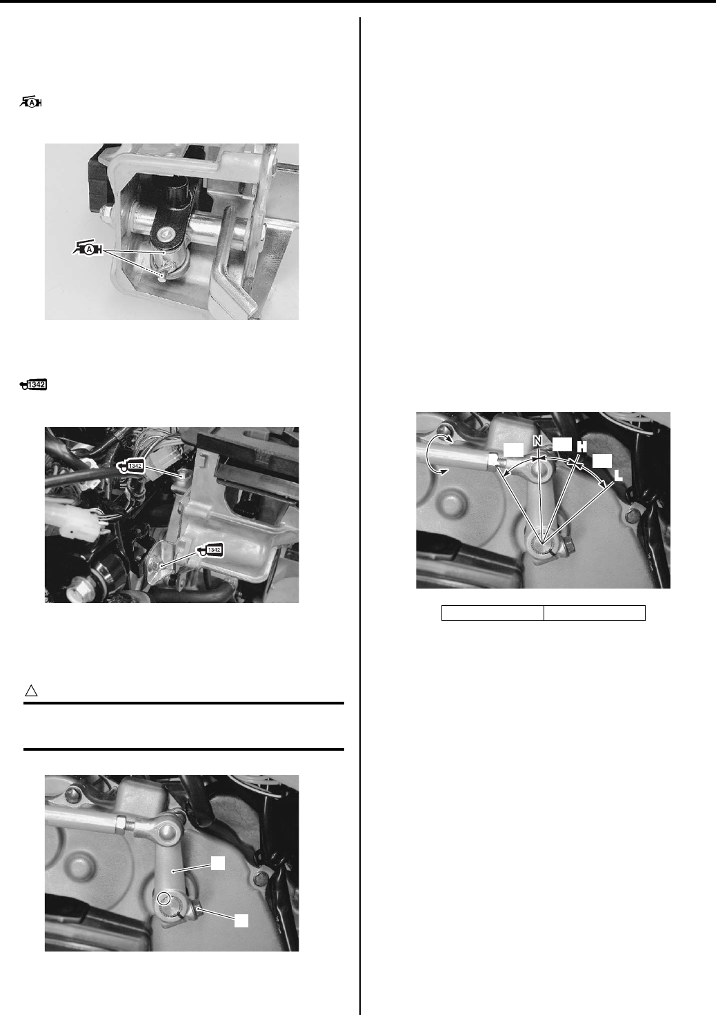
Automatic Transmission: 5A-25
Installation
Install the gear shift lever in the reverse order of
removal. Pay attention to the following points:
• Apply grease to pivot.
: Grease 99000–25010 (SUZUKI SUPER
GREASE A or equivalent)
• Apply thread lock to the shift lever assembly mounting
bolts.
: Thread lock cement 99000–32050
(THREAD LOCK CEMENT 1342 or equivalent)
• Install the gear shift arm (1) to the gear shift shaft in
the correct position.
• Tighten the bolt (2) securely.
CAUTION
!
Make sure the operating angle of the gear
shift arm is accurate.
• Install the removed parts. Refer to “Front Side Exterior
Parts Removal and Installation in Section 9D
(Page 9D-6)”.
Shift Lever Disassembly and Assembly
B831G25106019
1) Removed the shift lever assembly. Refer to “Shift
Lever Assembly Removal and Installation (Page 5A-
24)”.
2) Disassemble the shift lever assembly as shown in
the shift lever components. Refer to “Shift Lever
Assembly Components (Page 5A-23)”.
Assembly
1) Assemble the shift lever as shown in the shift lever
components. Refer to “Shift Lever Assembly
Components (Page 5A-23)”.
2) Install the shift lever assembly. Refer to “Shift Lever
Assembly Components (Page 5A-23)”.
3) After Installing the gear shift lever assembly, adjust
the shift rod. Refer to “Shift Rod Adjustment
(Page 5A-25)”.
Shift Rod Adjustment
B831G25106020
1) Holding the rod (2), loosen the lock-nuts (1).
2) Turning the rod (2), adjust the length of the rod.
3) Tighten the lock-nuts (1).
I831G1510107-03
I831G1510108-02
2
1
I831G1510109-01
“a”: 30°“b”: 33°
R
L
H
“a”
“b”
“b”
I831G1510110-03
PartShark.com
877-999-5686
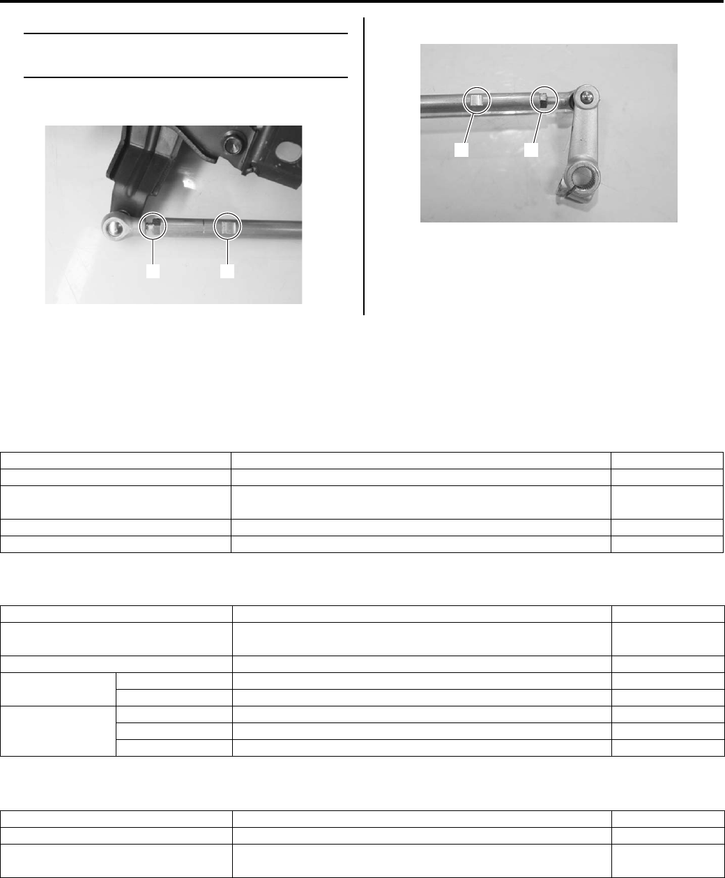
5A-26 Automatic Transmission:
NOTE
Be careful not to separate the rod from the
joint by turning the rod too much.
Shift lever side
Shift arm side
Specifications
Service Data
B831G25107001
Clutch
Unit: mm (in)
Drive Train
Unit: mm (in) Except ratio
Transmission
Unit: mm (in)
1 2
I831G1510117-01
2 1
I831G1510118-01
Item Standard Limit
Clutch wheel I.D. 140.0 – 140.2 (5.512 – 5.520) 140.5 (5.53)
Clutch shoe — No groove at any
part
Clutch engagement r/min 1 500 – 2 000 r/min —
Clutch lock-up r/min 3 500 – 4 000 r/min —
Item Standard Limit
Primary reduction ratio (Automatic
drive) Variable change (2.763 – 0.780) —
Secondary reduction ratio 2.158 (40/21 x 17/15) —
Final reduction
ratio
Front 3.600 (36/10) —
Rear 3.600 (36/10) —
Transfer gear
ratio
Low 2.562 (41/16) —
High 1.240 (31/25) —
Reverse 1.882 (32/17) —
Item Standard Limit
Drive V-belt width 34.3 (1.35) 33.3 (1.31)
Movable driven face spring free
length 153.0 (6.02) 145.4 (5.72)
PartShark.com
877-999-5686
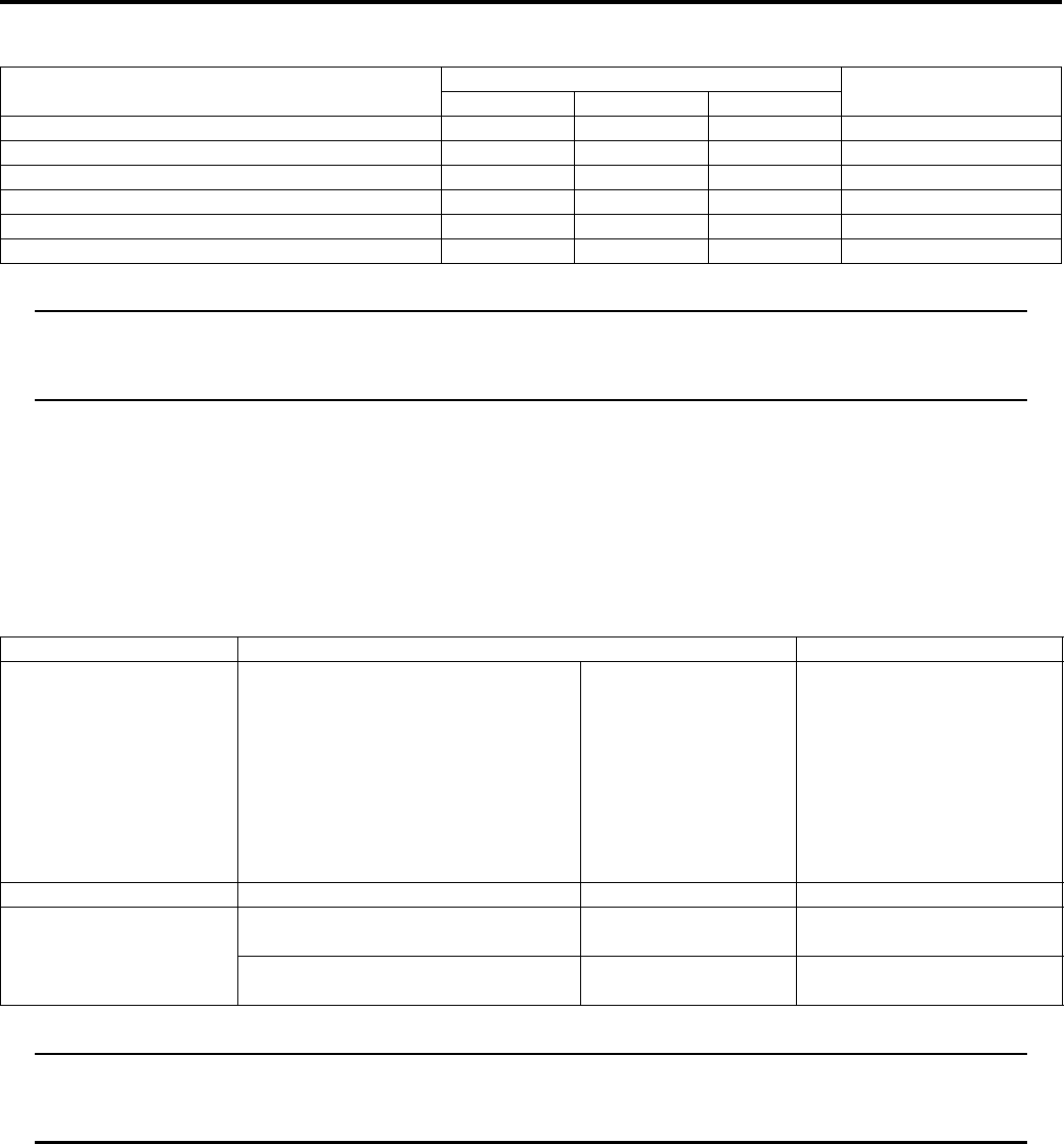
Automatic Transmission: 5A-27
Tightening Torque Specifications
B831G25107002
NOTE
The specified tightening torque is also described in the following.
“Automatic Transmission Components (Page 5A-3)”
“Shift Lever Assembly Components (Page 5A-23)”
Reference:
For the tightening torque of fastener not specified in this section, refer to “Tightening Torque List in Section 0C
(Page 0C-7)”.
Special Tools and Equipment
Recommended Service Material
B831G25108001
NOTE
Required service material is also described in the following.
“Automatic Transmission Components (Page 5A-3)”
“Shift Lever Assembly Components (Page 5A-23)”
Fastening part Tightening torque Note
N⋅mkgf—mlb—ft
Movable driven face bolt 110 11.0 79.5 )(Page 5A-8)
Movable drive face bolt 110 11.0 79.5 )(Page 5A-8)
V-belt outer cover bolt 8 0.8 6.0 )(Page 5A-9)
Movable driven face ring nut 110 11.0 79.5 )(Page 5A-14)
Clutch shoe nut 150 15.0 108.5 )(Page 5A-17)
V—belt inner cover bolt 9 0.9 6.5 )(Page 5A-18)
Material SUZUKI recommended product or Specification Note
Grease SUZUKI SUPER GREASE A or
equivalent
P/No.: 99000–25010 )(Page 5A-7) / )(Page 5A-
10) / )(Page 5A-10) /
)(Page 5A-13) /
)(Page 5A-13) /
)(Page 5A-20) /
)(Page 5A-20) /
)(Page 5A-22) /
)(Page 5A-23) /
)(Page 5A-25)
Molybdenum oil MOLYBDENUM OIL SOLUTION — )(Page 5A-18)
Thread lock cement THREAD LOCK CEMENT SUPER
1303 or equivalent
P/No.: 99000–32030 )(Page 5A-17) /
)(Page 5A-20)
THREAD LOCK CEMENT 1342 or
equivalent
P/No.: 99000–32050 )(Page 5A-25)
PartShark.com
877-999-5686
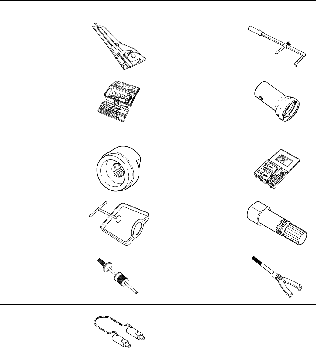
5A-28 Automatic Transmission:
Special Tool
B831G25108002
09900–20101 09913–50121
Vernier calipers (1/15 mm,
150 mm)
Oil seal remover
)(Page 5A-14) )(Page 5A-19) /
)(Page 5A-22)
09913–70210 09917–23711
Bearing installer set Ring nut wrench
)(Page 5A-10) /
)(Page 5A-12) /
)(Page 5A-19) /
)(Page 5A-20) /
)(Page 5A-22) /
)(Page 5A-22) /
)(Page 5A-23)
)(Page 5A-11) /
)(Page 5A-14)
09920–33540 09921–20240
Clutch shoe remover Bearing remover set
)(Page 5A-17) )(Page 5A-19)
09922–31430 09924–52450
Clutch spring compressor Fixed driven face holder
)(Page 5A-11) /
)(Page 5A-14)
)(Page 5A-11) /
)(Page 5A-14)
09930–30104 09930–40113
Rotor remover slide shaft Rotor holder
)(Page 5A-17) )(Page 5A-6) / )(Page 5A-
6) / )(Page 5A-8) /
)(Page 5A-8) / )(Page 5A-
16) / )(Page 5A-17)
09930–40131
Balancer drive sprocket
holder
)(Page 5A-16) /
)(Page 5A-17)
PartShark.com
877-999-5686

Table of Contents 6- i
6
Section 6
CONTENTS
Steering
Precautions ………………………………….………6-1
Precautions….…………………..……………….…………… 6-1
Precautions for Steering ………..…………………..….. 6-1
Steering General Diagnosis……………….. 6A-1
Diagnostic Information and Procedures…………6A-1
Steering Symptom Diagnosis……………..…………. 6A-1
Steering / Handlebar……….…………..…….. 6B-1
Repair Instructions .……………….…………………..…6B-1
Steering / Handlebars Components…………..……6B-1
Steering / Handlebars Assembly Construction …. 6B-2
Handlebars Removal and Installation ……………..6B-3
Handlebars Inspection ………………………….………6B-5
Steering Shaft Removal and Installation ………….6B-6
Tie-rod / Tie-rod End Removal and
Installation …………….……………….………………....6B-9
Steering Parts Inspection ………..……………….….6B-10
Specifications…….………….…….…………….……….6B-11
Service Data……..……………..……………….……….6B-11
Tightening Torque Specifications………………….6B-12
Special Tools and Equipment ……………..……….6B-12
Recommended Service Material ……….………….6B-12
Special Tool ……………………….…………….……….6B-12
PartShark.com
877-999-5686

6-1 Precautions:
Steeri ng
Precautions
Precautions
Precautions for Steering
B831G26000001
Refer to “General Precautions in Section 00 (Page 00-1)”.
PartShark.com
877-999-5686
Steering General Diagnosis: 6A-1
Steeri ng
Steering General Diagnosis
Diagnostic Information and Procedures
Steering Symptom Diagnosis
B831G26104001
Condition Possible cause Correction / Reference Item
Heavy Steering Distorted steering shaft. Replace.
Improper front wheel alignment. Adjust.
Insufficiently lubricated. Lubricate.
Not enough pressure in tires. Adjust.
Worn or incorrect tire or wrong tire
pressure.
Adjust or replace.
Wobbly Handlebars Distorted front steering shaft. Replace.
Crooked tire. Replace.
Worn or incorrect tire or wrong tire
pressure.
Adjust or replace.
Worn bearing/race in steering stem. Replace.
Worn steering shaft holder bushing. Replace.
Worn steering knuckle ends or ball stud. Replace.
Worn front wheel hub bearings. Replace.
PartShark.com
877-999-5686
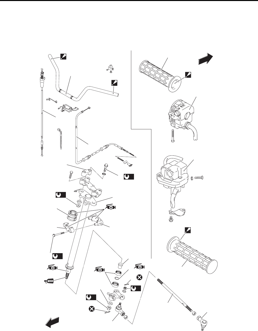
6B-1 Steering / Handlebar:
Steeri ng
Steering / Handlebar
Repair Instructions
Steering / Handlebars Components
B831G26206001
21
21
1
15
16
2
(a)
3
4
(b)
8
12
10
9
FWD
7
(c)
13
11
66
19
FWD
“A”
“A”
“A”
“A”
14
(e)
17
17
18
(d)
5
20
14
I831G1620001-17
PartShark.com
877-999-5686
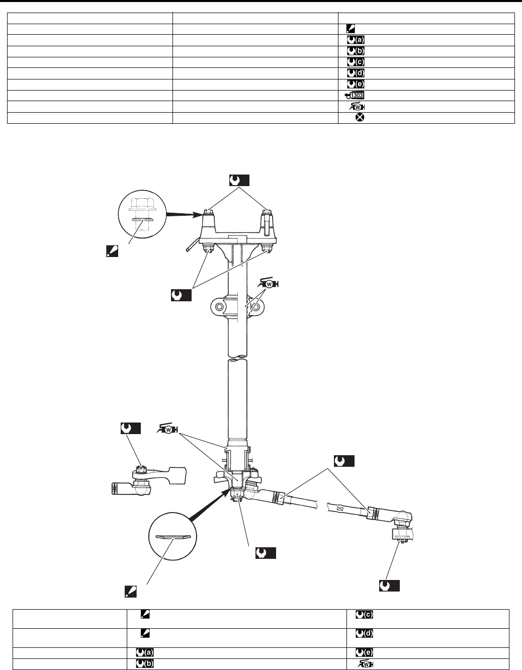
Steering / Handlebar: 6B-2
Steering / Handlebars Assembly Construction
B831G26206002
1. Handlebars 11. O-ring 21. Handle grip
2. Handlebar upper clamp 12. Washer “A”: Apply grip bond.
3. Handlebar clamp bolt 13. Steering shaft lower nut : 26 N⋅m (2.6 kgf-m, 19.0 lb-ft)
4. Steering shaft 14. Cotter pin : 23 N⋅m (2.3 kgf-m, 16.5 lb-ft)
5. Handlebar holder nut 15. Throttle cable : 162 N⋅m (16.2 kgf-m, 117.0 lb-ft)
6. Steering shaft holder 16. Parking brake cable : 60 N⋅m (6.0 kgf-m, 43.5 lb-ft)
7. Steering shaft holder dust seal 17. Tie-rod end : 29 N⋅m (2.9 kgf-m, 21.0 lb-ft)
8. Steering shaft holder bolt 18. Tie-rod : Apply thread lock to the thread part.
9. Steering shaft bushing 19. Throttle case assembly : Apply water resistance grease.
10. Dust seal 20. Handlebar left switch assembly : Do not reuse.
(a)
(b)
1
(c)
2
5
6
(d)
3
(e)
4
(c)
2
I831G1620002-06
1. Handlebar holder nut 5. Washer
: The conical side of washer faces outside.
:29 N⋅m (2.9 kgf-m, 21.0 lb-ft)
2. Tie-rod end nut 6. Washer
: The conical side of washer faces outside.
:162 N⋅m (16.2 kgf-m, 117.0 lb-ft)
3. Steering lower nut : 26 N⋅m (2.6 kgf-m, 19.0 lb-ft) : 45 N⋅m (4.5 kgf-m, 32.5 lb-ft)
4. Tie-rod nut : 60 N⋅m (6.0 kgf-m, 43.5 lb-ft) : Apply water resistance grease.
PartShark.com
877-999-5686
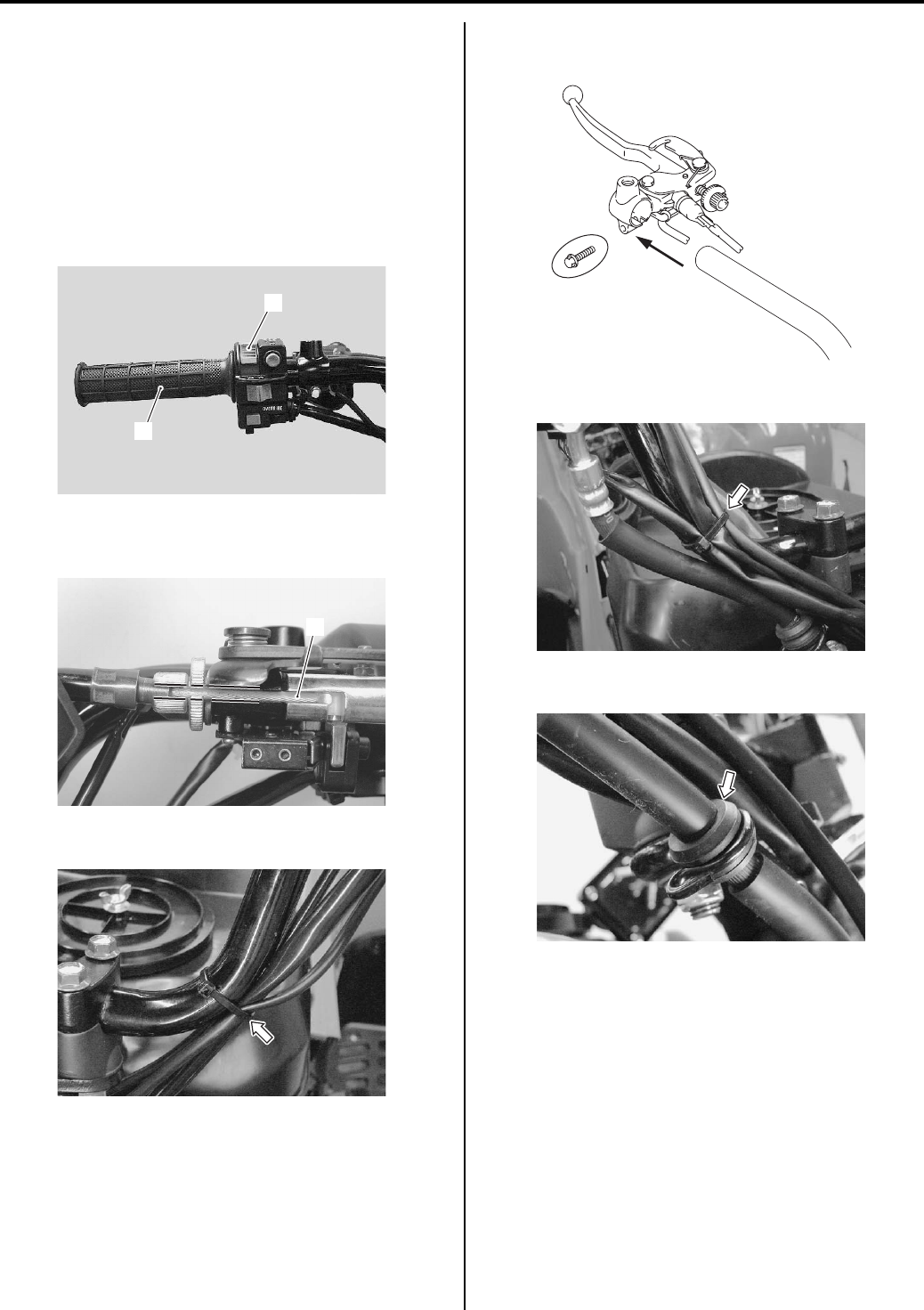
6B-3 Steering / Handlebar:
Handlebars Removal and Installation
B831G26206003
Removal
1) Remove the combination meter. Refer to
“Combination Meter Removal and Installation in
Section 9C (Page 9C-3)”.
2) Remove the following parts from left handlebar.
a) Left grip (1)
b) Left switch box (2)
3) Disconnect the parking brake cable (3) from parking
brake lever.
4) Remove the clamp.
5) Remove the parking brake lever from the handlebar
by removing mounting bolt.
6) Remove the clamp.
7) Disconnect the brake hose from the hose guide.
1
2
I831G1620003-03
3
I831G1620004-02
I831G1620005-02
I831G1620006-05
I831G1620007-02
I831G1620008-02
PartShark.com
877-999-5686
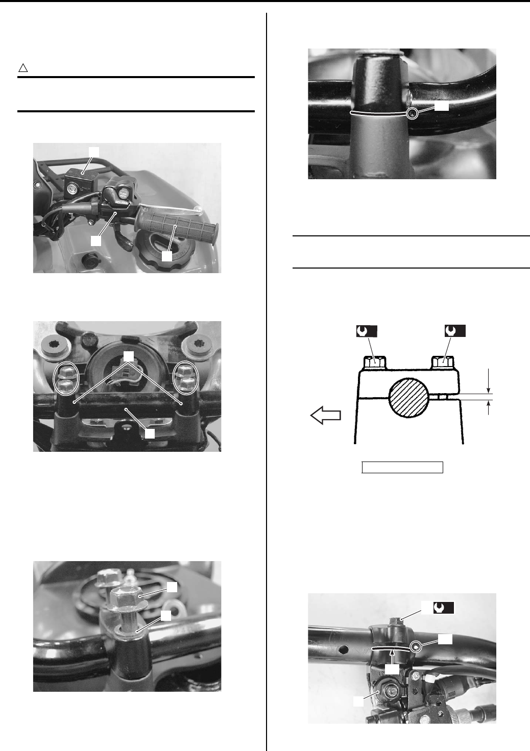
Steering / Handlebar: 6B-4
Remove the following parts from the right handlebar.
a) Right grip (4)
b) Front brake master cylinder/Front brake lever (5)
CAUTION
!
Do not turn the front brake master cylinder
upside down.
c) Throttle lever case (6)
9) Remove the handlebar upper clamps (7) and
handlebars (8).
Installation
Install the handlebars in the reverse order of removal.
Pay attention to the following points:
• Install the washers (1) and bolts (2) as shown in the
steering/handlebars construction. Refer to “Steering /
Handlebars Assembly Construction (Page 6B-2)”.
• Set the handlebars so that its punch mark “A” aligns
with the mating surface of the left handlebar holder.
• Tighten the handlebar holder bolts (3) to the specified
torque.
NOTE
First tighten the handlebar holder bolts (3)
(front ones) to the specified torque.
Tightening torque
Handlebar clamp bolt (a): 26 N·m (2.6 kgf-m, 19.0
lb-ft)
• Align the punch mark “A” on the handlebars with the
mating surface “B” of rear brake lever assembly.
• Tighten the rear brake lever holder clamp bolt (4) to
the specified torque.
Tightening torque
Rear brake lever holder clamp bolt (b): 11 N·m (
1.1 kgf-m, 8.0 lb-ft)
4
5
6
I831G1620009-01
7
8
I831G1620010-01
1
2
I831G1620011-01
“a”: Clearance
“A”
I831G1620012-02
“a”
(a)
3
(a)
FWD
I831G1620013-01
“A”
“B”
(b)
4
3
I831G1620049-01
PartShark.com
877-999-5686
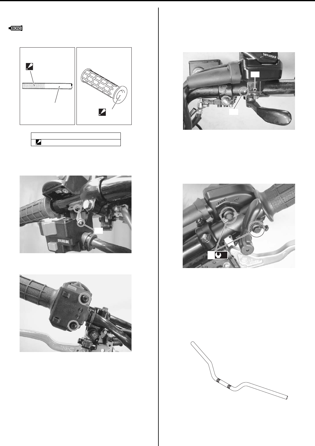
6B-5 Steering / Handlebar:
• Apply adhesive agent to the handlebar right and left
end and right and left grip inner wall.
: Handle grip bond (Handle Grip Bond
(commercially available))
• Insert the projection “D” of the left switch assembly
into the hole of the handlebars.
• Tighten the left handlebar switch screws.
• Install the master cylinder. Refer to “Front Brake
Master Cylinder Assembly Removal and Installation in
Section 4A (Page 4A-9)”.
• Align the punch mark “D” on the handlebars with the
mating surface “E” of the throttle lever case.
• Tighten the throttle lever case bolts (6) to the specified
torque.
Tightening torque
Throttle lever case bolt (c): 5 N·m (0.5 kgf-m, 3.5
lb-ft)
Handlebars Inspection
B831G26206004
Refer to “Handlebars Removal and Installation
(Page 6B-3)”.
Inspect the handlebars for distortion or damage.
If any defects are found, replace the handlebars with a
new one.
5. Handlebar
“C”: Apply handle grip bond.
“C”
“C”
5
I831G1620014-02
“C”
I831G1620015-02
I831G1620016-01
“D”
“E”
I831G1620017-03
(c)
6
I831G1620018-03
I831G1620019-02
PartShark.com
877-999-5686
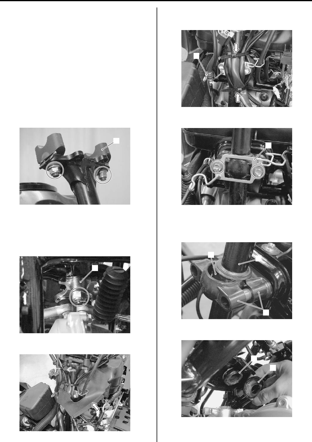
Steering / Handlebar: 6B-6
Steering Shaft Removal and Installation
B831G26206005
Removal
1) Remove the front wheels. Refer to “Front / Rear
Wheel Removal and Installation in Section 2D
(Page 2D-2)”.
2) Remove the front fender. Refer to “Front Side
Exterior Parts Removal and Installation in Section
9D (Page 9D-6)”.
3) Remove the handlebars. Refer to “Handlebars
Removal and Installation (Page 6B-3)”.
4) Remove the auxiliary headlight. Refer to “Auxiliary
Headlight Removal and Installation in Section 9B
(Page 9B-3)”.
5) Remove the handlebar holder (1).
6) Disconnect the tie-rod ends. Refer to “Front Wheel
Hub / Steering Knuckle Removal and Installation in
Section 2B (Page 2B-4)”.
7) Remove the steering lower arm plate (2) by
removing cotter pin, nut and washer.
Remove the center cover.
9) Disconnect the brake hose (3) from the hose guide.
10) Remove the read wire clamps.
11) Remove the steering shaft plate (4).
12) Remove the steering shaft holders (5) and dust seal
(6).
13) Remove the steering shaft (7) from the vehicle.
14) Remove the dust seal (8) and O-ring (9).
1
I831G1620020-01
2
I831G1620021-01
I831G1620023-01
3
I831G1620024-03
4
I831G1620025-03
6
5
7
I831G1620026-03
9
8
I831G1620022-03
PartShark.com
877-999-5686
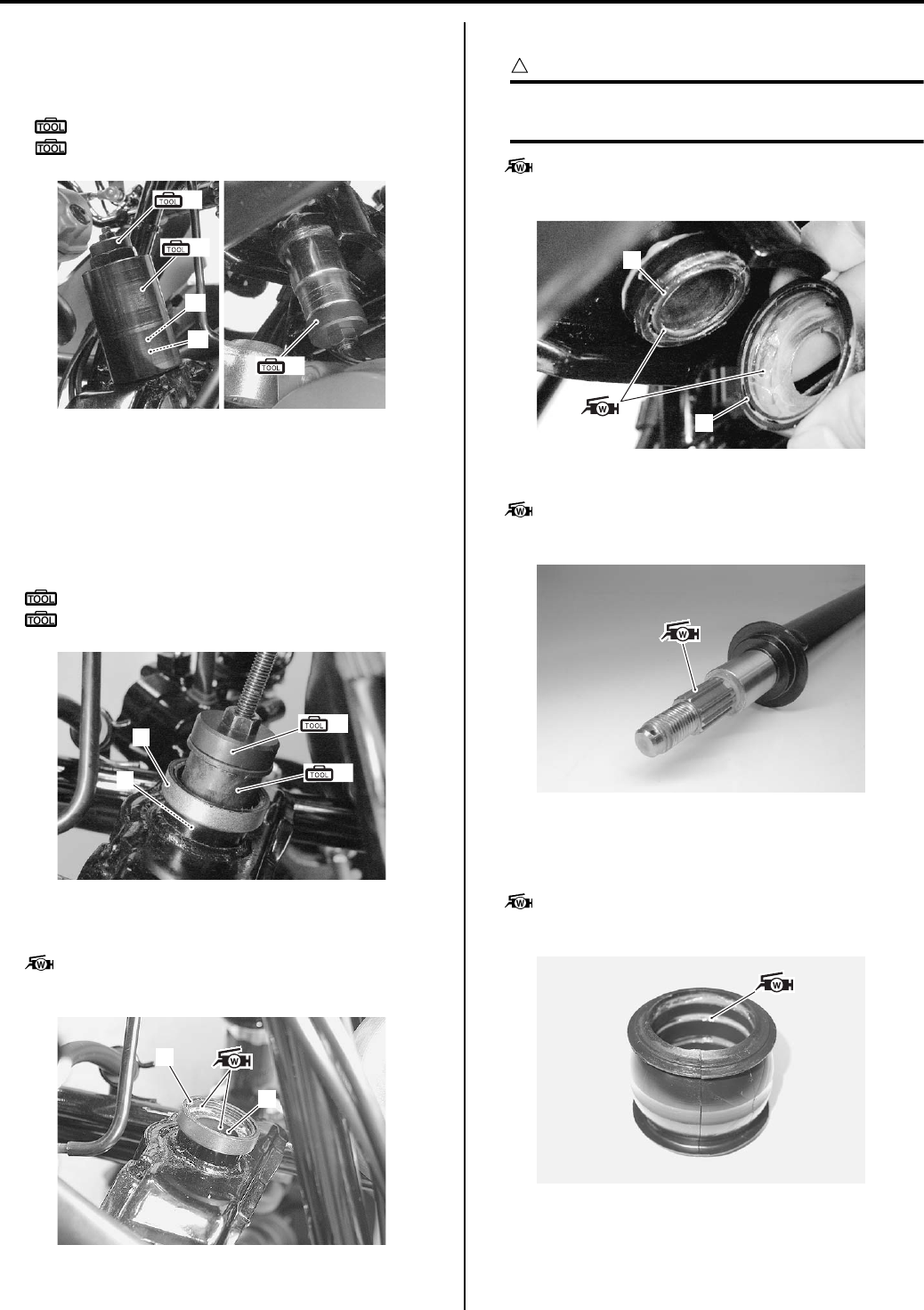
6B-7 Steering / Handlebar:
15) Remove the steering shaft bushing (10) and dust
seal (11) with the special tools and suitable socket
wrench.
Special tool
(A): 09924–84521 (Bearing installer set)
(B): 09930–30721 (Rotor remover)
Installation
Install the steering shaft in the reverse order of removal.
Pay attention to the following points:
• Install the steering shaft lower bushing (1) along with
dust seal (2) with the special tools.
Special tool
(A): 09924–84521 (Bearing installer set)
(B): 09913–70210 (Bearing installer set)
• Apply grease to the steering shaft lower bushing (1)
and dust seal (2).
: Grease 99000–25160 (Water resistance
grease)
• Apply grease to the dust seal (3) and O-ring (4).
CAUTION
!
The removed O-ring must be replaced with a
new one.
: Grease 99000–25160 (Water resistance
grease)
• Apply grease to the spline of steering shaft.
: Grease 99000–25160 (Water resistance
grease)
• Install the steering shaft.
• Apply grease to the steering shaft holder dust seal
before installing.
: Grease 99000–25160 (Water resistance
grease)
(A)
(B)
(A)
11
10
I831G1620027-04
(A)
(B)
1
2
I831G1620048-01
2
1
I831G1620029-02
4
3
I831G1620032-02
I831G1620033-01
I831G1620028-01
PartShark.com
877-999-5686
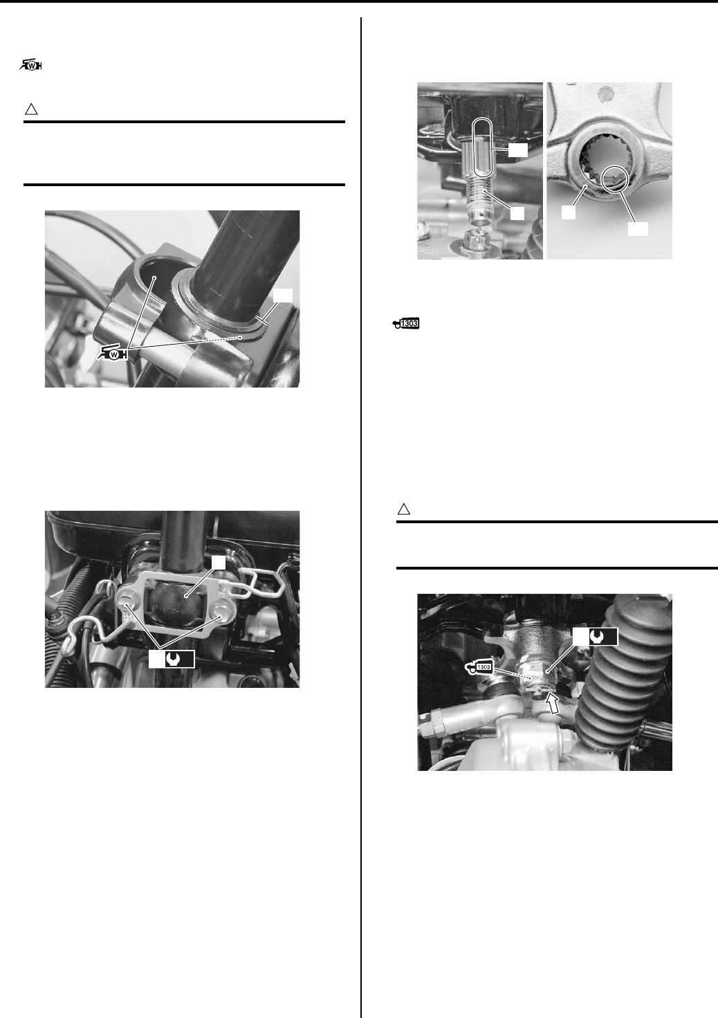
Steering / Handlebar: 6B-8
• Apply grease to the steering shaft holders before
installing the shaft holders.
: Grease 99000–25160 (Water resistance
grease)
CAUTION
!
To prevent the entry of dirt, the dust seal end
“A” must face rearward when installing the
dust seal to steering shaft.
• Install the steering shaft holder (5) and tighten the
mounting bolts (6) to the specified torque.
Tightening torque
Steering shaft holder bolt (a): 23 N·m (2.3 kgf-m,
16.5 lb-ft)
• After installed steering shaft plate, make sure that the
wiring harness, cables and brake hose routing are
properly. Refer to “Wiring Harness Routing Diagram in
Section 9A (Page 9A-4)”.
• When installing the steering arm plate, align the wide
spline “B” of steering shaft (7) with slit “C” of steering
arm plate (8).
• Apply a small quality thread lock to the thread part of
steering shaft.
: Thread lock cement 99000–32030
(THREAD LOCK CEMENT SUPER 1303 or
equivalent)
• Tighten the steering shaft lower nut (9) to the specified
torque.
Tightening torque
Steering shaft lower nut (b): 162 N·m (16.2 kgf-m,
117.0 lb-ft)
• Install the cotter pin.
CAUTION
!
The removed cotter pin must be replaced
with a new one.
“A”
I831G1620030-02
(a)
6
5
I831G1620031-02
“B”
7
“C”
8
I831G1620034-02
(b)
9
I831G1620035-03
PartShark.com
877-999-5686
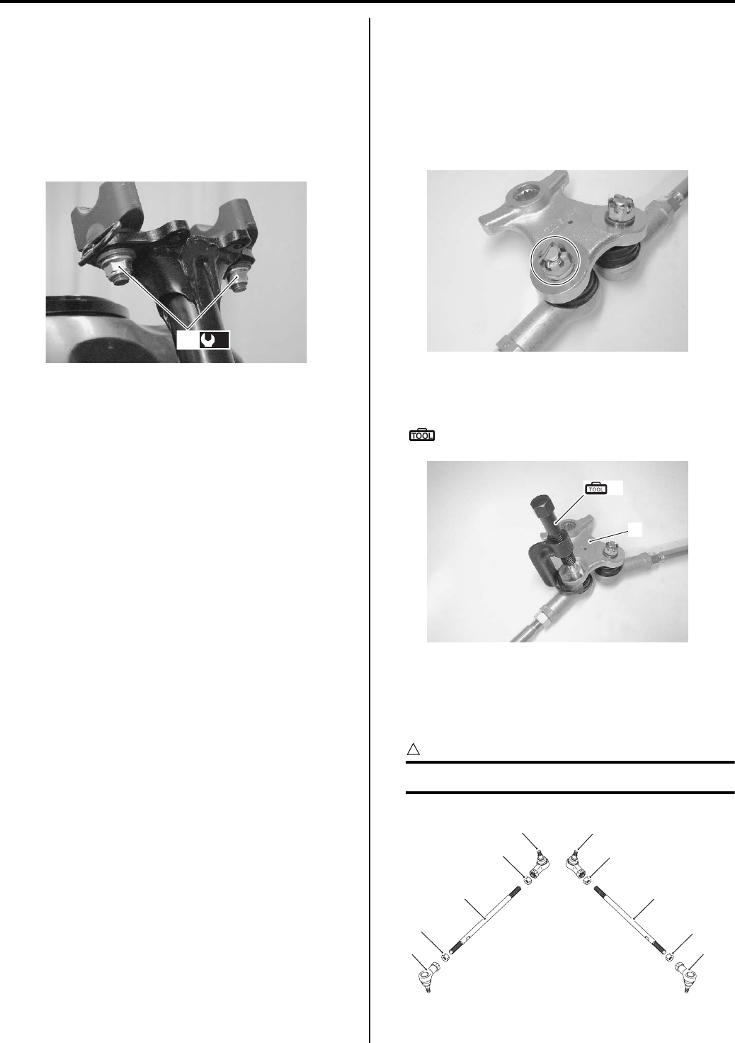
6B-9 Steering / Handlebar:
• Connect the tie-rod ends. Refer to “Front Wheel Hub /
Steering Knuckle Removal and Installation in Section
2B (Page 2B-4)”.
• Tighten the handlebar holder nut (10) to the specified
torque.
Tightening torque
Handlebar holder nut (c): 60 N·m (6.0 kgf-m, 43.5
lb-ft)
• Install the handlebars. Refer to “Handlebars Removal
and Installation (Page 6B-3)”.
• Install the front fender. Refer to “Front Side Exterior
Parts Removal and Installation in Section 9D
(Page 9D-6)”.
• Install the front wheels. Refer to “Front / Rear Wheel
Removal and Installation in Section 2D (Page 2D-2)”.
• After installing these parts, adjust the toe. Refer to
“Toe Adjustment in Section 0B (Page 0B-22)”.
Tie-rod / Tie-rod End Removal and Installation
B831G26206006
Removal
1) Remove the tie-rod end (steering knuckle side).
Refer to “Front Wheel Hub / Steering Knuckle
Removal and Installation in Section 2B (Page 2B-4)”.
2) Remove the cotter pins, tie-rod end nut and spring
washer.
3) Remove the steering arm plate (1) with a special
tool.
Special tool
(A): 09942–72410 (Tie rod end remover)
4) Remove the other tie-rod end in the same manner as
described previously.
5) Separate the tie-rod ends (2), nuts (3), and (4) and
tie-rods (5).
CAUTION
!
The lock-nuts (3) have left-hand threads.
(c)
10
I831G1620036-02
I831G1620037-01
1
(A)
I831G1620038-01
2
2 2
2
3
44
5 5
3
I831G1620039-02
PartShark.com
877-999-5686
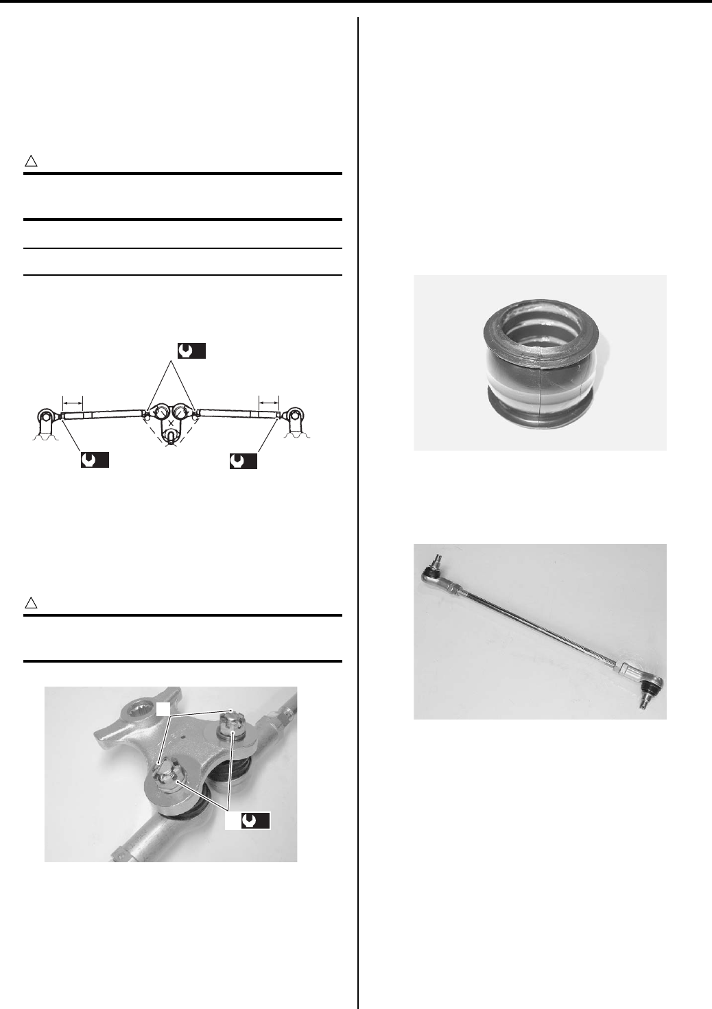
Steering / Handlebar: 6B-10
Installation
Install the tie-rod in the reverse order of removal. Pay
attention to the following points:
• When installing the tie-rods, make sure the short side
“a” of tie-rod come outside.
• Push the tie-rod to tie-rod lock-nut tightening direction.
• Tighten the lock-nuts to the specification.
CAUTION
!
When tightening the lock-nuts, hold the tie—
rod end with a open end wrench.
NOTE
The lock-nuts (1) have left-hand threads.
Tightening torque
Tie-rod lock-nut (a): 45 N·m (4.5 kgf-m, 32.5 lb-ft)
• Install the washers and tighten the rod end nuts (2)
(steering arm plate side) to the specified torque.
Tightening torque
Tie-rod end nut (a): 29 N·m (2.9 kgf-m, 21.0 lb-ft)
• Install the cotter pins (3).
CAUTION
!
The removed cotter pins must be replaced
with new ones.
• Install the tie-rod ends (steering knuckle side). Refer
to “Front Wheel Hub / Steering Knuckle Removal and
Installation in Section 2B (Page 2B-4)”.
• After installed wheels, inspect the toe-out. If the toe-
out is out of specification, bring it into the specified
range. Refer to “Steering System Inspection in
Section 0B (Page 0B-21)” and “Toe Adjustment in
Section 0B (Page 0B-22)”.
Steering Parts Inspection
B831G26206007
Refer to “Steering Shaft Removal and Installation
(Page 6B-6)” and “Tie-rod / Tie-rod End Removal and
Installation (Page 6B-9)”.
Steering Shaft Holder Dust Seal
Inspect the dust seal for wear or damage. If any defects
are found, replace the dust seal with a new one.
Tie-rod
Inspect the tie-rod for distortion or damage. If any
defects are found, replace the tie-rod with a new one.
“a”
“a”
(a)
1
(a) (a)
I831G1620040-03
3
(a)
2
I831G1620041-01
I831G1620042-01
I831G1620043-01
PartShark.com
877-999-5686
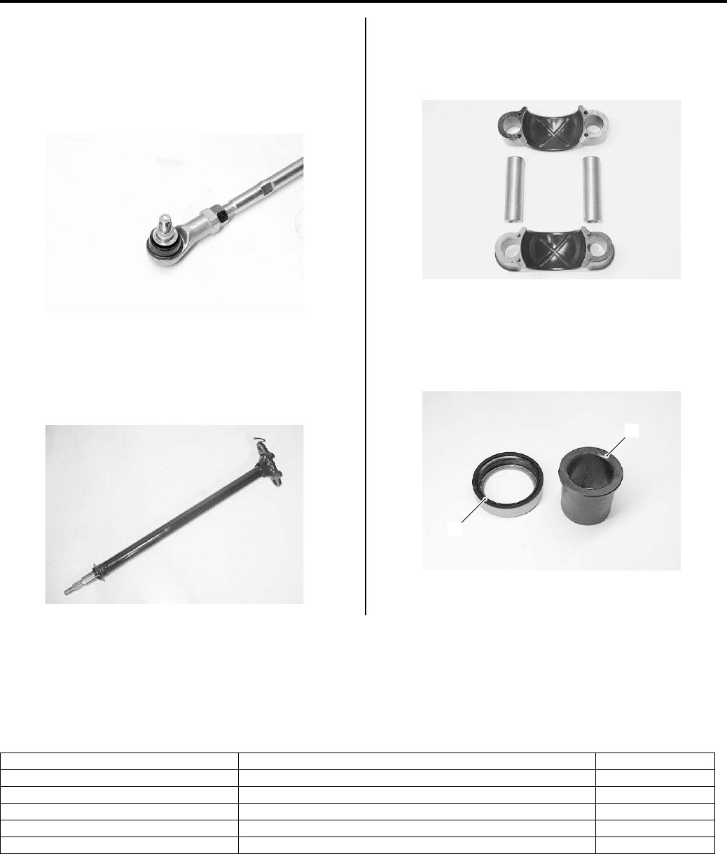
6B-11 Steering / Handlebar:
Tie-rod End
Inspect the tie-rod ends for smooth movement. If there
are any abnormalities, replace the tie-rod ends with new
ones. Inspect the tie-rod end boots for wear or damage.
If any defects are found, replace the tie-rod ends with
new ones.
Steering Shaft
Inspect the steering shaft for distortion or bend. If any
defects are found, replace the steering shaft with a new
one.
Steering Shaft Holder
Inspect the steering shaft holders for wear or damage. If
any defects are found, replace the steering shaft holders
with new ones.
Steering Shaft Bushing and Dust Seal
Inspect the steering shaft bushing (1) and dust seal (2)
for wear or damage. If any defects are found, replace
them with new ones.
Specifications
Service Data
B831G26207001
Wheel
Unit: mm
I831G1620044-01
I831G1620045-01
I831G1620046-01
2
1
I831G1620047-02
Item Standard Limit
Steering angle 46° (right & left) —
Turning radius 3.1 m (10.2 ft) —
Toe-out (with 75 kg, 165 lbs) 10 ± 4 mm (0.39 ± 0.16) —
Camber 0.64°—
Caster 1.6°—
PartShark.com
877-999-5686
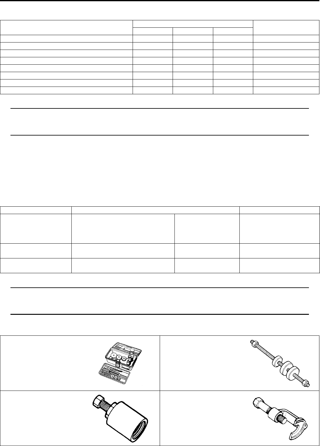
Steering / Handlebar: 6B-12
Tightening Torque Specifications
B831G26207002
NOTE
The specified tightening torque is also described in the following.
“Steering / Handlebars Components (Page 6B-1)”
“Steering / Handlebars Assembly Construction (Page 6B-2)”
Reference:
For the tightening torque of fastener not specified in this section, refer to “Tightening Torque List in Section 0C
(Page 0C-7)”.
Special Tools and Equipment
Recommended Service Material
B831G26208001
NOTE
Required service material is also described in the following.
“Steering / Handlebars Components (Page 6B-1)”
“Steering / Handlebars Assembly Construction (Page 6B-2)”
Special Tool
B831G26208002
Fastening part Tightening torque Note
N⋅mkgf—mlb—ft
Handlebar clamp bolt 26 2.6 19.0 )(Page 6B-4)
Rear brake lever holder clamp bolt 11 1.1 8.0 )(Page 6B-4)
Throttle lever case bolt 5 0.5 3.5 )(Page 6B-5)
Steering shaft holder bolt 23 2.3 16.5 )(Page 6B-8)
Steering shaft lower nut 162 16.2 117.0 )(Page 6B-8)
Handlebar holder nut 60 6.0 43.5 )(Page 6B-9)
Tie-rod lock-nut 45 4.5 32.5 )(Page 6B-10)
Tie-rod end nut 29 2.9 21.0 )(Page 6B-10)
Material SUZUKI recommended product or Specification Note
Grease Water resistance grease P/No.: 99000–25160 )(Page 6B-7) / )(Page 6B-
7) / )(Page 6B-7) /
)(Page 6B-7) / )(Page 6B-
Handle grip bond Handle Grip Bond (commercially
available)
—)(Page 6B-5)
Thread lock cement THREAD LOCK CEMENT SUPER
1303 or equivalent
P/No.: 99000–32030 )(Page 6B-8)
09913–70210 09924–84521
Bearing installer set Bearing installer set
)(Page 6B-7) )(Page 6B-7) / )(Page 6B-
7)
09930–30721 09942–72410
Rotor remover Tie rod end remover
)(Page 6B-7) )(Page 6B-9)
PartShark.com
877-999-5686

6B-13 Steering / Handlebar:
PartShark.com
877-999-5686

Table of Contents 9- i
9
Section 9
CONTENTS
Body and Accessories
Precautions ………………………………….………9-1
Precautions….…………………..……………….…………… 9-1
Precautions for Electrical System ……………..…….. 9-1
Component Location .……………….……………..…….. 9-1
Electrical Components Location ……………………... 9-1
Wiring Systems…………………………..…….. 9A-1
Schematic and Routing Diagram…………..……….9A-1
Wiring Diagram …………………………..…………….… 9A-1
Wiring Harness Routing Diagram………..…………. 9A-4
Specifications…….…………….…………….…………….9A-6
Service Data ………….…………….………………..…… 9A-6
Lighting Systems………………………..…….. 9B-1
Repair Instructions .……………….…………………..…9B-1
Headlight Components ………….………………..…… 9B-1
Headlight Removal and Installation ……….………. 9B-1
Headlight Bulb Replacement ….…………….………. 9B-2
Headlight Beam Adjustment ……..………………..…9B-2
Auxiliary Headlight Components ……………………. 9B-3
Auxiliary Headlight Removal and Installation …… 9B-3
Auxiliary Headlight Bulb Replacement ……….…… 9B-4
Auxiliary Headlight Beam Adjustment…………….. 9B-5
Rear Combination Light components………………9B-5
Rear Combination Light Removal and
Installation……………………….……………….………. 9B-6
Rear Combination Light Bulb Replacement……..9B-6
Reversing Light Bulb Replacement (For P-17) …. 9B-7
Reversing Light Relay Inspection (For P-17) …… 9B-7
Dimmer Switch Inspection……………….……………. 9B-7
Specifications…….…………….…………….…………….9B-8
Service Data ………….…………….………………..…… 9B-8
Special Tools and Equipment …………….………….9B-8
Special Tool .……………….………………..……………. 9B-8
Combination Meter / Fuel Meter / Horn.. 9C-1
General Description ………………….………………..…9C-1
Combination Meter System Description…………..9C-1
Repair Instructions .……………….…………………..…9C-2
Combination Meter Components …..……………….9C-2
Combination Meter Removal and Installation …..9C-3
Combination Meter Disassembly and
Assembly ………….…………….…………….………….9C-3
Combination Meter Inspection ..………………..……9C-4
Engine Coolant Temperature Indicator Light
Inspection……….………………..……………….………9C-4
Engine Coolant Temperature Removal and
Installation …………….……………….………………....9C-4
Fuel Level Indicator Inspection ……………………...9C-5
Fuel Level Gauge Inspection ..…………….…………9C-6
Speedometer Inspection ……………………………....9C-6
Speed Sensor Removal and Installation ………….9C-6
Speed Sensor Inspection …..……………….…………9C-7
Ignition Switch Inspection…..……………….…………9C-7
Ignition Switch Removal and Installation…….……9C-7
Horn Inspection (For P-17, 24)……………………….9C-8
Horn Removal and Installation (For P-17, 24)…..9C-8
Specifications…….………….…….…………….…………9C-8
Service Data………………………….…………………....9C-8
Tightening Torque Specifications……………………9C-8
Special Tools and Equipment ……………..…………9C-9
Recommended Service Material ………….…………9C-9
Special Tool ………………………….……………….……9C-9
Exterior Parts …………….…………….……….. 9D-1
Repair Instructions ………..……….…………….………9D-1
Exterior Parts Construction ……..……………….……9D-1
Rear Fender Heat Shield Construction ……………9D-4
Fuel Tank Lower Cover Heat Shield
Installation …………….……………….………………....9D-5
Fastener Removal and Installation…….……………9D-6
Front Side Exterior Parts Removal and
Installation …………….……………….………………....9D-6
Rear Side Exterior Parts Removal and
Installation …………….……………….………………....9D-9
Seat Removal and Installation ……………………..9D-11
Under Cover Components ……………………….….9D-12
Under Cover Removal and Installation ………….9D-12
Body Structure.………….…………….……….. 9E-1
Repair Instructions ………..……….…………….………9E-1
Body Frame Construction ……………………..………9E-1
Footrest Construction….……………….……………….9E-1
Footrest Removal and Installation.………………....9E-2
Carrier Construction ………….……………….…………9E-3
Front Carrier Removal and Installation ……………9E-4
Rear Carrier Removal and Installation …………….9E-5
Front Grip Bar Construction .……………….…………9E-6
Front Grip Bar Removal and Installation ………….9E-6
PartShark.com
877-999-5686

9-ii Table of Contents
Trailer Towing Construction ……….……………….…9E-7
Trailer Towing Removal and Instruction………….. 9E-7
Specifications….……….…………….…………….………9E-8
Tightening Torque Specifications……………………9E-8
Special Tools and Equipment ……………..…………9E-8
Recommended Service Material .…………………...9E-8
PartShark.com
877-999-5686

Precautions: 9-1
Body and Acc essories
Precautions
Precautions
Precautions for Electrical System
B831G29000001
Refer to “General Precautions in Section 00 (Page 00-1)” and “Precautions for Electrical Circuit Service in Section 00
(Page 00-2)”.
Component Location
Electrical Components Location
B831G29003001
Refer to “Electrical Components Location in Section 0A (Page 0A-7)”.
PartShark.com
877-999-5686

9A-1 Wiring Systems:
Body and Acc essories
Wiring Systems
Schematic and Routing Diagram
Wiring Diagram
B831G29102001
Refer to “Wire Color Symbols in Section 0A (Page 0A-5)”.
PartShark.com
877-999-5686
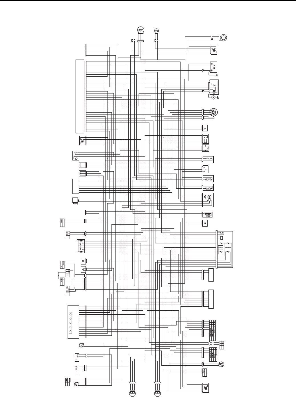
Wiring Systems: 9A-2
For P-17
R
O/Y
Y/B
B/W
Bl/W
O/Y
W/B
B/W
O
Bl/R
Bl
R/G
R
O/Y
R/B
Bl/B
W
W/R
B/Y
O/Y
B/W
W/G
B/G
Y/B
Y/Bl
W/Bl
O/Bl
O
O/W
Y/G
B/W
Br
Br Bl/B
Bl/B
Gr
W/R
W/Y
W/G
B
Y
B/W
O/Y
Bl
Bl/R
O/Y
W/B
O/Y
W/B
O
W/B
OB
B/W
B/W
Y
Y
Y
RR
Y
Y
Y
B/W
B/W
R
Br/W
B/Br
R/B
Bl/B
B/W
Y/Bl
O/W
O/W
R/B
W/B
Gr/W
O/W
R/B
B/R
R
B/W
W/Y
Bl/G
Br/W
B/Bl
B
G/B
Y
R/G
G
B/Lg
B
Y/Bl
Y/R
Y/B
Gr/R
B/G
B/Br
Br
Bl/B
W/R
Dg
B/Y
W/Bl
P/W
O/W
W/R
Gr/R
B/W
Y/R
Y/R
B/W
W/B
B
B
Gr
W
Y
O
O/W
Y/G
B/W
B/W
P
B
B
B/W
B
B/G
B/R
O/R
B/W
B/R
B
Bl
RR
OO
O/Bl
Gr
Bl/W
O/Y
B/R
Bl/R
OO
B
W/Bl
Br
B/G
B/Y
B/W
O
W
Br
Br
R/G
B/W
YY
Bl/B
Bl/R
W/R
W/G
B/W
W/Bl
W
Gr/W
Y/R
B/Lg
R/B
P/W
G
R/B
W/Bl
B/Bl
B/Br
Dg
B/Br
B/Br
G/B
R
R
Y
B/Br
B/R
B/W
B/Bl
B/W
Bl/G
B
B
Y/B
B/W
R
R
B/W
Bl
W
Y
Y
Y
B/Bl
Bl/B
Bl
R
W
G
BB
R
W
Y
Y/Bl
W/Bl
R/B
O/Y
O
O/R
O/B
Y/G
B/Bl
O/Y
Y/B
OOO
W
Br
Gr
G
B
Bl
Y
P
Y/B
O
B/W
Bl/W
O/Y
W/B
B/W
Bl/R
Bl
R/G
R
R/B
Bl/B
W
W/R
B/Y
B/W
W/G
B/G
Y/B
Y/Bl
W/Bl
Y/G
B/W
Gr
W/R
W/Y
W/G
B
B/W
Bl/R
W/B
W/B W/B
B/W
B/W
B/W
R
Br/W
B/Br
R/B
Bl/B
B/W
Y/B
Y/B
BB
Y/Bl
R/B
W/B
Gr/W
R/B
B/R
R
B/W
W/Y
Bl/G
Br/W
B/Bl
B
G/B
Y
R/G
G
B
Y/Bl
Y/R
Y/B
Gr/R
B/G
B/Br
Br
Bl/B
W/R
B/Y
W/Bl
P/W
Bl/R
Gr
B/W
B/W
W/B
Gr
B/W
R
R
B
W/B
W/R
Gr/R
B/W
Y/R
Y/R
B/W
W/B
B
B
Gr
W
Y
Y/G
B/W
B/W
O/G
P
B
O
B
GG
B/W
B
B/G
B/R
B/W
B/R
B
Bl
RR
Gr
Bl/W
B/R
Bl/R
B
W/Bl
Br
B/G
B/Y
B/W
W
Br
Br
R/G
B/W
Bl/B
Bl/R
W/R
W/G
B/W
W/Bl
W
Gr/W
Y/R
R/B
P/W
G
R/B
W/Bl
B/Bl
B/Br
B/Br
B/Br
G/B
R
R
W/Y
W/Y
Gr
Gr
Y
PP
B/Br
B/R
B/W
B/Bl
B/W
Bl/G
B
B
Y/B
B/W
R
R
B/WB/W
B/W
Bl
W
Y
Y
Y
Y
Y
Y
Y
Y
Y
B/Bl
Bl/R
Bl/R
O/Y
RR
O/Y
RR
B/W
B/W
Bl/B
Bl
R
W
G
R
W
Y
Y/Bl
W/Bl
R/B
Y/G
B/Bl
Y/B
W
Br
Gr
G
B
Bl Bl
Bl
Y
P
YO/R
Y
Y
B/W
W
Y
B/W
W
Y
B/W
W
Y
B/W
W
Y
GG
YY
RR
BB
Bl
ON
OFF
ON
OFF
ON3
ON2
ON1
OFF
2WD
4WD
LOCK
L R N B W
ON
OFF HI
LO
RUN
OFF
ON
OFF
ON
OFF
PUSH
PUSH
123
45 6
1
M
DIFF-LOCK
RELAY
COOLING
FAN
THERMO-
SWITCH
COOLING
FAN
MOTOR
BRAKE
LEVER
SWITCH
SET
SECEDE
EMERGENCY
SWITCH
HORN
HORN
BUTTON
IGNITION
SWITCH
PARKING
BRAKE
SWITCH
4WD/DIFF-LOCK
SWITCH
4WD/DIFF-LOCK
ACTUATOR
GEAR
POSITION
SWITCH
FUSE BOX
4WD/
DIFF-LOCK
DIODE INJECTOR ISC VALVE
ECT
SENSOR
IAT
SENSOR
IAP
SENSOR
TP
SENSOR
RESISTOR
PARKING
BRAKE
RELAY
NEUTRAL
RELAY
DIODE CKP
SENSOR
GENERATOR
1. HEAD HI
2. HEAD LO
3. FUEL
4. IGNITION
5. FAN
6. POWER SOURCE
10 A
10 A
10 A
15 A
15 A
10 A
STARTER
MOTOR STARTER
RELAY
1: MAIN (30 A) BATTERY
HEADLIGHT
(L)
HEADLIGHT
(R)
AUXILIARY
HEADLIGHT
: DIFF-LOCK INDICATOR LIGHT
: REVERSE INDICATOR LIGHT
: NEUTRAL INDICATOR LIGHT
: HI-BEAM INDICATOR LIGHT
: ECT/FI INDICATOR LIGHT
L
R
N
B
W
SPEEDOMETER
DIMMER
SWITCH
LOW
POSITION
DIODE
4WD/
DIFF-LOCK
RELAY
BRAKE
LEVER
SWITCH
(L)
REAR
BRAKE
SWITCH
REGULATOR/
RECTIFIER
FUEL
PUMP
FUEL
PUMP
RELAY
BACKUP
LIGHT
RELAY
BACKUP
LIGHT
ECM
REAR
COMBINATION
LIGHT
POWER
SOURCE
IGNITION
COIL
SPEED
SENSOR TO
SENSOR
ENGINE
STOP
SWITCH OVER RIDE
SWITCH
START
BUTTON
GG
BACK BUZZER
PUSH
O/Y
O
O/Y O/G
O
O
O/Y
O/Y
O/Bl
O
O/W
O
O/W
O/Y
O/Y
O/Y O
OB
O/W
B/Lg
Dg
O/W
O/Y
O/Y
O/Y
Dg
B/Lg
O/Y
O
O/R
O/B
O/Y
O/Y
OO
O/Bl
O/R
O/R
O/Y
HIGH
POSITION
DIODE
W
Bl
I831G1910901-10
PartShark.com
877-999-5686
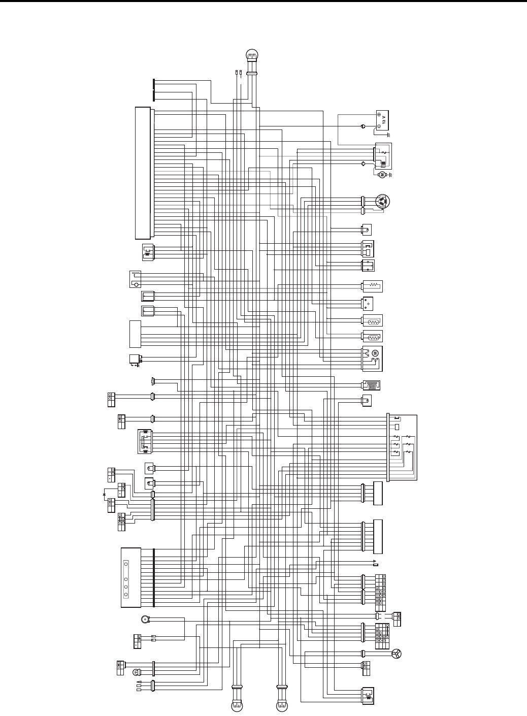
9A-3 Wiring Systems:
For P-24, 28, 33
ON
OFF
ON
OFF
ON3
ON2
ON1
OFF
2WD
4WD
LOCK
L R N W
ON
OFF HI
LO
RUN
OFF
ON
OFF
ON
OFF
PUSH
PUSH
PUSH
123
45 6
1
M
DIFF-LOCK
RELAY
COOLING
FAN
THERMO-
SWITCH
COOLING
FAN
MOTOR
BRAKE
LEVER
SWITCH
HORN
(P-24)
(P-24)
HORN
BUTTON
IGNITION
SWITCH
PARKING
BRAKE
SWITCH
4WD/DIFF-LOCK
SWITCH
4WD/DIFF-LOCK
ACTUATOR
GEAR
POSITION
SWITCH
FUSE BOX
4WD/
DIFF-LOCK
DIODE INJECTOR ISC VALVE
ECT
SENSOR
IAT
SENSOR
IAP
SENSOR
TP
SENSOR
RESISTOR
PARKING
BRAKE
RELAY
NEUTRAL
RELAY
DIODE CKP
SENSOR
GENERATOR
WINCH
(P-28,33)
1. HEAD HI
2. HEAD LO
3. FUEL
4. IGNITION
5. FAN
6. POWER SOURCE
10 A
10 A
10 A
15 A
15 A
10 A
STARTER
MOTOR STARTER
RELAY
1: MAIN (30 A)
BATTERY
HEADLIGHT
(L)
HEADLIGHT
(R)
AUXILIARY
HEADLIGHT
: DIFF-LOCK INDICATOR LIGHT
: REVERSE INDICATOR LIGHT
: NEUTRAL INDICATOR LIGHT
: ECT/FI INDICATOR LIGHT
L
R
N
W
SPEEDOMETER
DIMMER
SWITCH
LOW
POSITON
DIODE
HIGH
POSITION
DIODE
4WD/
DIFF-LOCK
RELAY
BRAKE
LEVER
SWITCH
(L)
REAR
BRAKE
SWITCH
REGULATOR/
RECTIFIER
FUEL
PUMP
FUEL
PUMP
RELAY
ECM
REAR
COMBINATION
LIGHT
POWER
SOURCE
IGNITION
COIL
SPEED
SENSOR TO
SENSOR
ENGINE
STOP
SWITCH OVER RIDE
SWITCH
START
BUTTON
O/Y
O/Y
Y/B
O/B
B
G
O
B
G
B/W
Bl/W
O/Y
O/B O
W/B
B/W
O
Bl/R
Bl
R/G
R
O/Y
R/B
Bl/B
W
W/R
B/Y
O/Y
B/W
W/G
B/G
Y/B
Y/Bl
W/Bl
O/Bl
O/Y
O/W
Y/G
B/W
Br
Gr
W/R
W/Y
W/G
B
B/W
O/Y
Bl
Bl
Bl/R
O/Y
W/B
O/Y
W/B
O
W/B
OB
B/W
B/W
YY
B/W
R
Br/W
B/Br
R/B
Bl/B
B/W
Y/Bl
O/W
R/B
W/B
Gr/W
O/W
R/B
B/R
R
B/W
W/Y
Bl/G
Br/W
B/Bl
B
G/B
Y
R/G
G
B/Lg
B
Y/Bl
Y/R
Y/B
Gr/R
B/G
B/Br
Br
Bl/B
W/R
Dg
B/Y
W/Bl
P/W
O/W
W/R
Gr/R
B/W
Y/R
Y/R
B/W
Y/B
Y/B
BB
W/B
B
B
Gr
W
Y
O
O/W
Y/G
B/W
Bl/B
Bl/B
B/W
P
B
B
G
B/W
B
B/G
B/R
O/R
O/R
B/W
B/R
B
Bl
RR
OO
O/Bl
Gr
Bl/W
O/Y
O/Y
B/R
Bl/R
OO
B
W/Bl
Br
B/G
B/Y
B/W
G
B
O
W
Br
Br
R/G
B/W
Bl/B
Bl/R
W/R
W/G
B/W
W/Bl
W
Gr/W
Y/R
B/Lg
B/Lg
R/B
P/W
G
R/B
W/Bl
B/Bl
B/Br
Dg
B/Br
B/Br
G/B
R
R
Y
B/Br
B/R
B/W
B/Bl
B/W
Bl/G
B
B
Y/B
B/W
R
R
B/W
Bl
W
B/Bl
Bl/B
Bl
R
W
G
BB
R
W
Y
Y/Bl
W/Bl
R/B
O/Y
O
O/R
O/B
Y/G
B/Bl
O/Y
Y/B
OO
W
Br
Gr
G
B
P
Y/B
B
G
B
G
B/W
Bl/W
W/B
B/W
Bl/R
Bl
R/G
R
R/B
Bl/B
W
W/R
B/Y
B/W
W/G
B/G
Y/B
Y/Bl
W/Bl
Y/G
B/W
Br
Gr
W/R
W/Y
W/G
B
B/W
Bl/R
W/B
W/B W/B
B/W
B/W
B/W
RR
R
Br/W
B/Br
R/B
Bl/B
B/W
Y/Bl
R/B
W/B
Gr/W
R/B
B/R
R
B/W
W/Y
Bl/G
Br/W
B/Bl
B
G/B
Y
R/G
G
B
Y/Bl
Y/R
Y/B
Gr/R
B/G
B/Br
Br
Bl/B
W/R
Dg
B/Y
W/Bl
P/W
Gr
B/W
W/B
Gr
B/W
W/B
W/R
Gr/R
B/W
Y/R
Y/R
B/W
W/B
B
B
W
Y
Y/G
Y/G
B/W
B/W
P
B
B
GGG
B/W
GG
B
B/G
B/R
B/W
B/R
B
Bl
RR
Gr
Bl/W
B/R
Bl/R
B
W/Bl
Br
B/G
B/Y
B/W
G
B
W
Br
Br
R/G
B/W
Bl/B
Bl/R
W/R
W/G
B/W
W/Bl
W
Gr/W
Y/R
R/B
P/W
G
R/B
W/Bl
B/Bl
B/Br
Dg
B/Br
B/Br
G/B
R
R
W/Y
W/Y
Gr
Gr
Y
PP
B/Br
B/R
B/W
B/Bl
B/W
Bl/G
B
B
Y/B
B/W
R
R
B/WB/W
B/W
Bl
W
YY
YY
YY
B/Bl
Bl/B
Bl
R
W
G
R
W
Y
Y/Bl
W/Bl
R/B
Y/G
B/Bl
Y/B
W
Br
Gr
G
B
Bl
Bl
YY
Bl
Bl
YY
P
YO/R
OO
O/Bl
O/R Y
Y
B/W
W
Y
B/W
W
Y
B/W
W
Y
B/W
W
YY
YY
YY
YY
YY
YY
O/Y
O
O/Y
O/Y
O/Bl
O/Y
O/W
O
O/W
O/Y
O/Y
O/Y O
OB
O/W
O/W
B/Lg
O/W
O/Y
O/Y
O/B
O/Y
O
O/R
(P-28,33)
Gr
O
Bl/R
W
Bl
I831G1910902-13
PartShark.com
877-999-5686
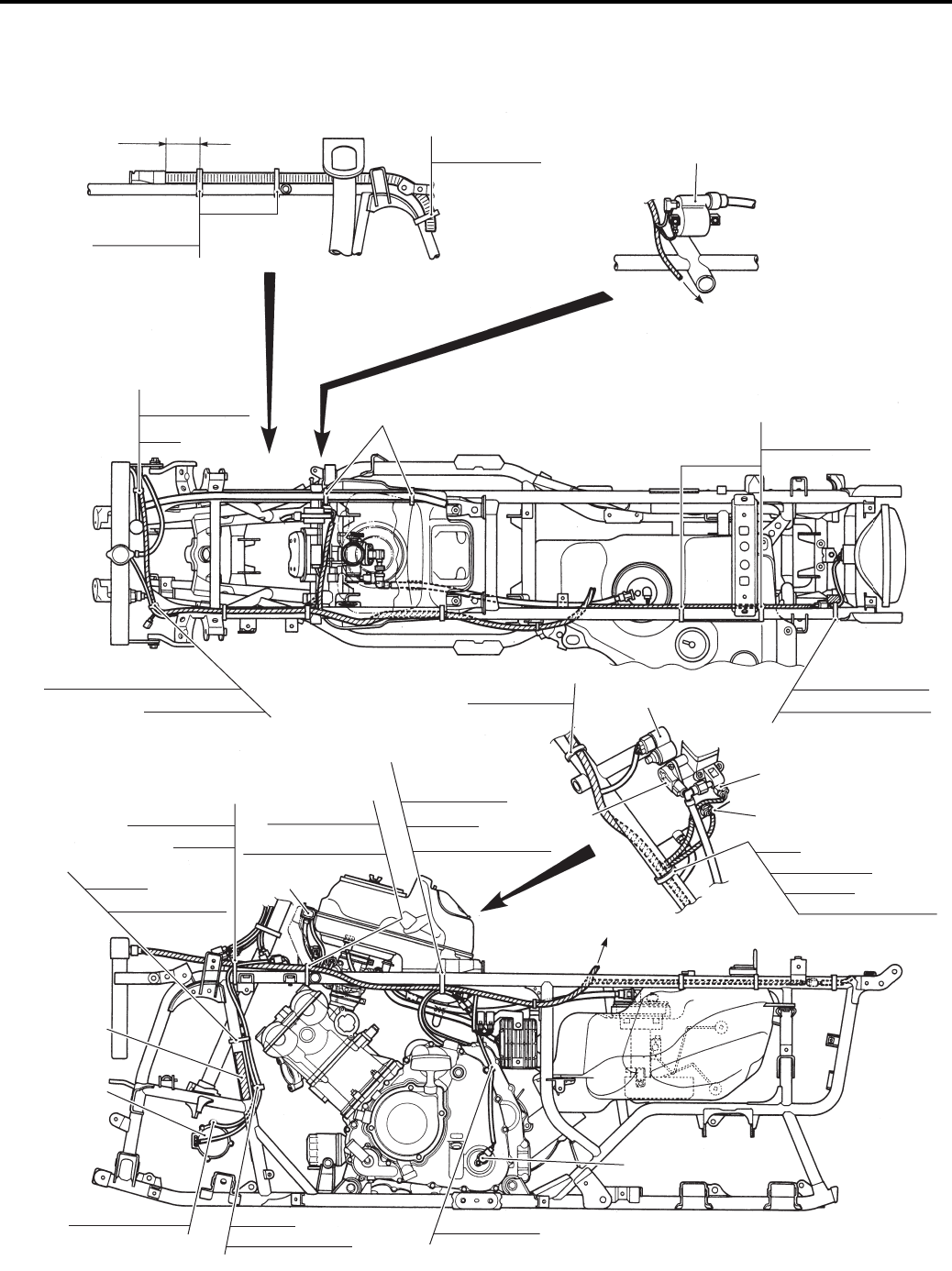
Wiring Systems: 9A-4
Wiring Harness Routing Diagram
B831G29102002
Clamp
Wiring harness
Wiring harness
Wiring harness
60 – 80 mm (2.36 – 3.15 in) Clamp
Wiring harness
Clamp
Clamp
Clamp
Wiring harness
Clamp
Clamp
Brake light/taillight
Back up relay (P-17)
Clamp
Wiring harness
Generator
Gear position switch
Clamp
Speed sensor
Clamp
Actuator
Clamp
Clamp
Clamp
Clamp
Actuator
Foot brake switch
Actuator
Foot brake switch
IAP sensor
IAP sensor
To rear fender top
Speed sensor
Clamp
Wiring harness
TP sensor
Injector coupler
ECT sensor coupler
ISC valve
Ignition coil
To power source
Clamp
Wiring harness
Wiring harness
Wiring harness
Actuator Gear position switch
Generator
Hose
Cooling fan thermo switch
Foot brake switch
Parking brake cable
ICES canada
label (P-28)
I831G1910903-07
PartShark.com
877-999-5686
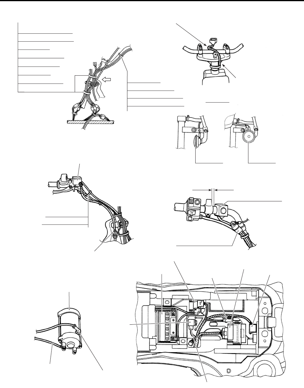
9A-5 Wiring Systems:
Horn button (P-17, 24)
Fix front brake hose
Starter motor
Engine earth
4WD/Diff-lock relay
Set the dealer mode coupler to the rear fender hole.
Starter motor terminal
Battery
ECM
Fuse box
Master cylinder reservoir tank
To combination meter
Set the writing harness as shown.
Pass the writing harness
behind the upper.
Clamp
4WD/Diff-lock switch
Front brake switch
Clamp
Emergency switch (P-17)
Handle switch
Parking brake switch
Horn button (P-17, 24)
Starter relay
Fuel dump relay
Emergency switch (P-17)
10 㧙 15 mm (0.3 㧙 0.6 in)
Horn (P-17) Horn (P-24)
VIEW A
Clamp
Emergency switch (P-17)
4WD/Diff-lock switch
Combination meter
Horn button (P-17, 24)
Front brake switch
Ignition switch
Handle switch
Parking brake switch
A
I831G1910904-09
PartShark.com
877-999-5686
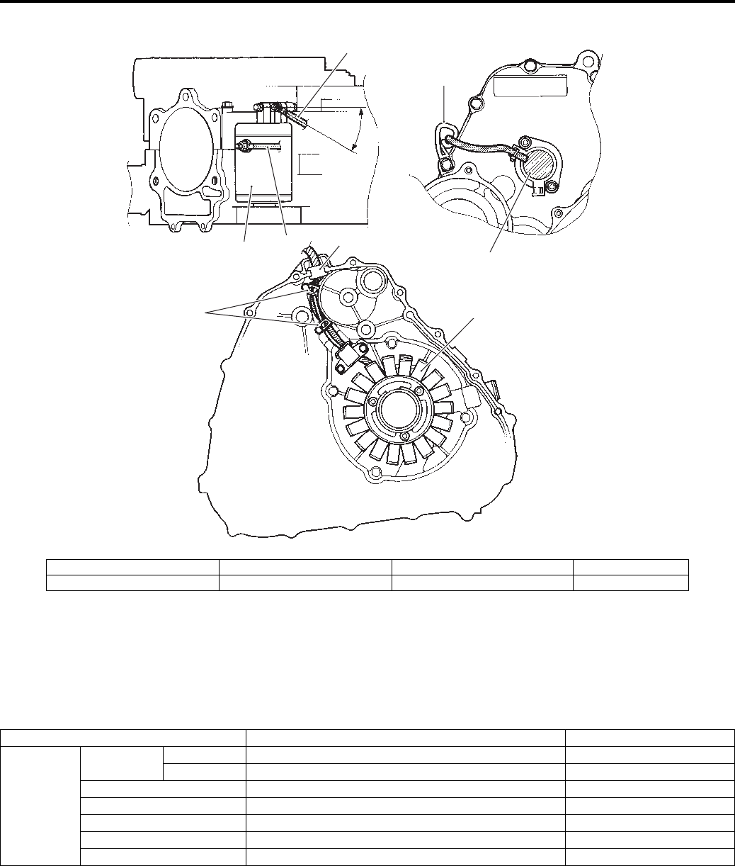
Wiring Systems: 9A-6
Specifications
Service Data
B831G29107001
Electrical
Unit: mm
“a”
15
4
7
7
2
3
6
I831G1910905-05
1. Starter motor 3. Generator stator 5. Starter motor lead wire 7. Clamp
2. Gear position switch 4. Ground wire 6. Grommet “a”: 30°
Item Specification Note
Fuse size
Headlight HI 10 A
LO 10 A
Fuel 10 A
Ignition 15 A
Power source 10 A
Fan 15 A
Main 30 A
PartShark.com
877-999-5686

9B-1 Lighting Systems:
Body and Acc essories
Lighting Systems
Repair Instructions
Headlight Components
B831G29206001
Headlight Removal and Installation
B831G29206002
Removal
1) Remove the front grill upper cover.
Refer to “Front Side Exterior Parts Removal and
Installation in Section 9D (Page 9D-6)”.
2) Disconnect the headlight coupler (1).
3) Remove the headlight assembly (2) by removing
screw (3), fastener (4) and bolts (5).
FWD
1
I831G1920002-03
1. Headlight bulb (12 V 35/35 W)
1
I831G1920003-01
5
4
3
I831G1920004-02
5
2
I831G1920005-03
PartShark.com
877-999-5686
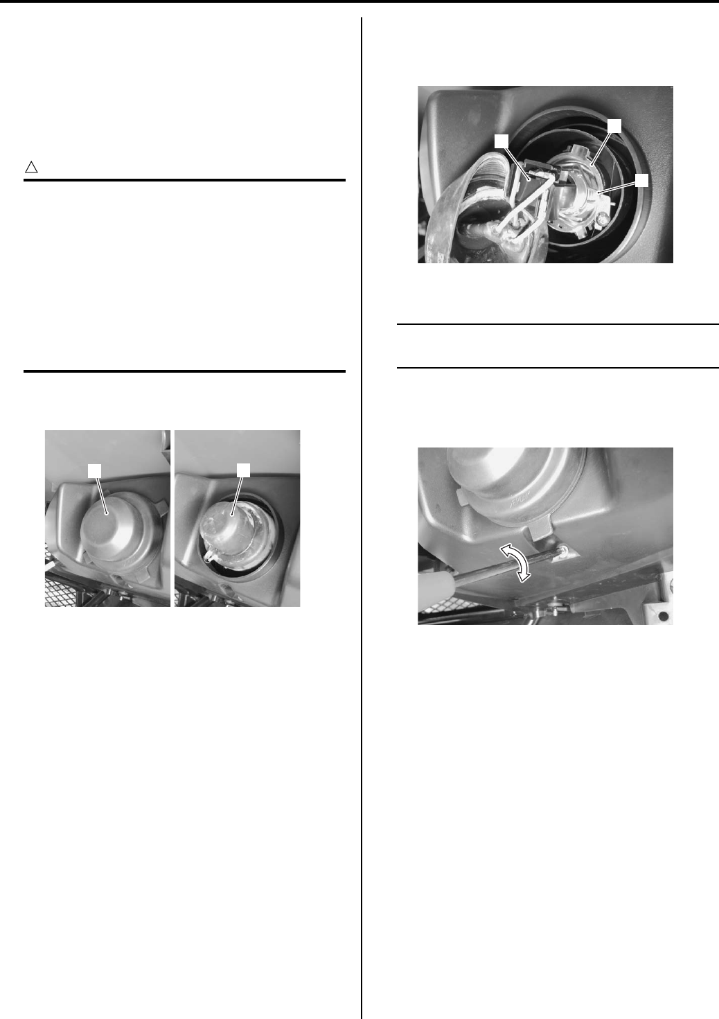
Lighting Systems: 9B-2
Installation
Install the headlight in the reverse order of removal. Pay
attention to the following point:
• After installing, be sure to inspect the headlight beam.
Refer to “Headlight Beam Adjustment (Page 9B-2)”.
Headlight Bulb Replacement
B831G29206003
CAUTION
!
• If you touch the bulb with your bare hands,
clean the bulb with a cloth moistened with
alcohol or soapy water to prevent
premature bulb failure.
• Do not use bulb other than those with
predetermined wattage.
• Remove the bulb when it gets cool, since it
may be heated to an extremely high
temperature when the headlight is turned
ON.
1) Remove the headlight housing cover (1) and bulb
socket rubber cap (2).
2) Disconnect the headlight coupler (3).
3) Replace the headlight bulb (4) by unhooking the bulb
holder spring (5).
4) Reinstall the removed parts.
NOTE
Properly fit the bulb socket rubber cap and
headlight housing cover.
Headlight Beam Adjustment
B831G29206004
Adjust the headlight vertical beam.
2
1
I831G1920006-01
3
5
4
I831G1920007-01
I831G1920008-01
PartShark.com
877-999-5686
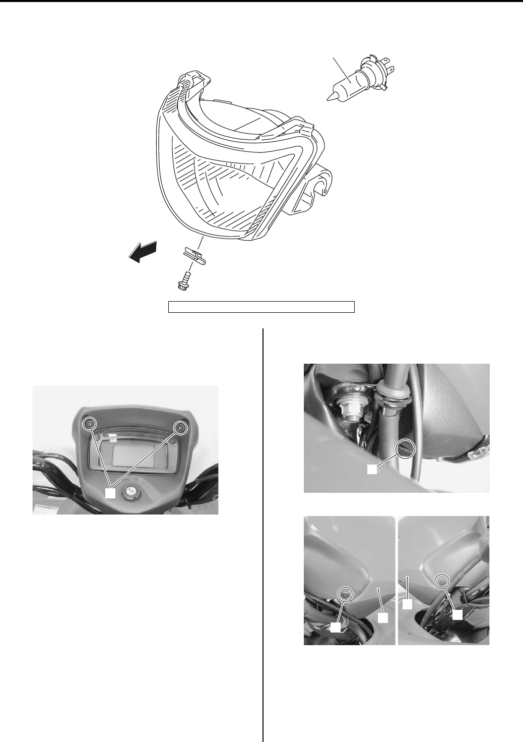
9B-3 Lighting Systems:
Auxiliary Headlight Components
B831G29206005
Auxiliary Headlight Removal and Installation
B831G29206006
Removal
1) Remove the screws (1).
2) Remove the auxiliary headlight cover (2) by
removing the fasteners (3).
FWD
1
I831G1920009-05
1. Auxiliary headlight bulb (12 V 35/35 W)
1
I831G1920010-01
3
I831G1920011-01
3
3
2
2
I831G1920012-01
PartShark.com
877-999-5686
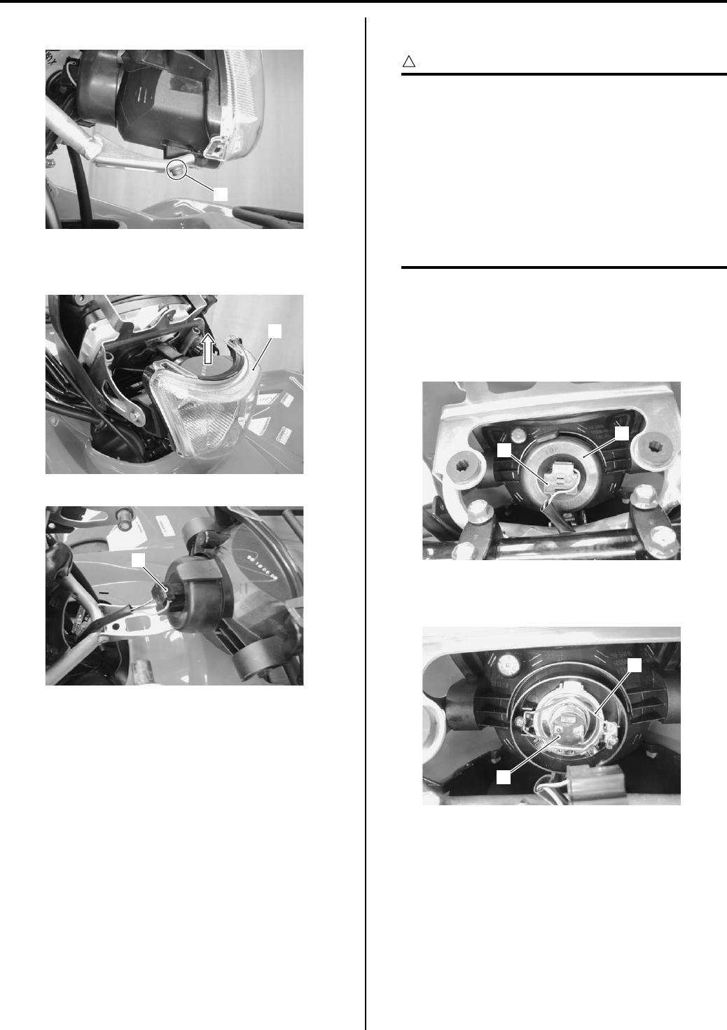
Lighting Systems: 9B-4
3) Remove the auxiliary headlight mounting bolt (4).
4) Disconnect the auxiliary headlight coupler (5) by
removing the auxiliary headlight assembly (6).
Installation
Install the auxiliary headlight in the reverse order of
removal.
Auxiliary Headlight Bulb Replacement
B831G29206007
CAUTION
!
• If you touch the bulb with your bare hands,
clean the bulb with a cloth moistened with
alcohol or soapy water to prevent
premature bulb failure.
• Do not use bulb other than those with
predetermined wattage.
• Remove the bulb when it gets cool, since it
may be heated to an extremely high
temperature when the headlight is turned
ON.
1) Remove the combination meter mounting bolt.
Refer to “Combination Meter Removal and
Installation in Section 9C (Page 9C-3)”.
2) Disconnect the auxiliary headlight coupler (1) and
remove the bulb socket cap (2).
3) Replace the auxiliary headlight bulb (3) by
unhooking the bulb holder spring (4).
4
I831G1920013-01
6
I831G1920014-01
5
I831G1920015-01
2
1
I831G1920016-01
3
4
I831G1920017-01
PartShark.com
877-999-5686
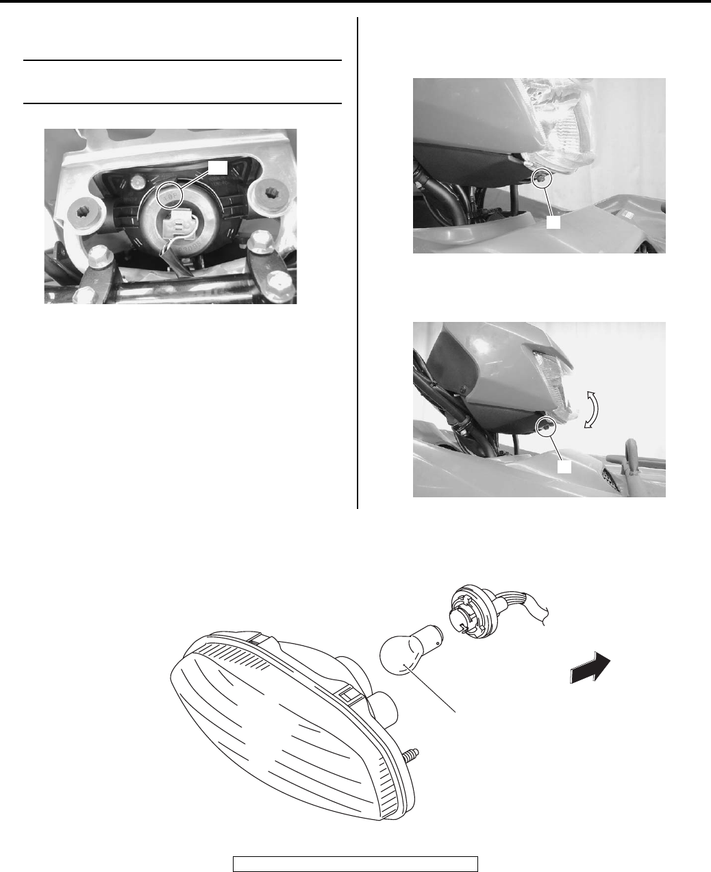
9B-5 Lighting Systems:
4) Properly fit the bulb socket cap (1).
NOTE
Make sure that the “TOP” mark “A” face to
upper side.
5) Reinstall the removed parts.
Auxiliary Headlight Beam Adjustment
B831G29206008
• Loosen the auxiliary headlight mounting bolt (1).
• Adjust the auxiliary headlight beam.
• Tighten the auxiliary headlight mounting bolt (1).
Rear Combination Light components
B831G29206009
“A”
I831G1920018-02
1
I831G1920029-01
1
I831G1920030-01
1
FWD
I831G1920019-04
1. Brake light/Taillight bulb (12 V 21/5 W)
PartShark.com
877-999-5686
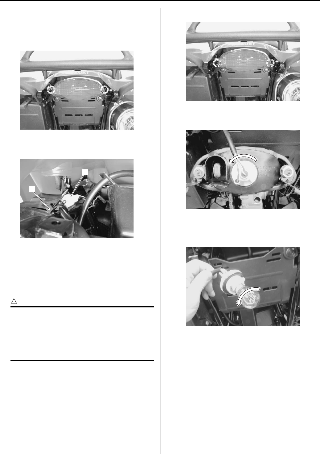
Lighting Systems: 9B-6
Rear Combination Light Removal and
Installation
B831G29206010
Removal
1) Remove the rear combination light mounting bolts.
2) Remove the rear combination light assembly by
disconnecting the clamp (1) and coupler (2).
Installation
Install the rear combination light in the reverse order of
removal.
Rear Combination Light Bulb Replacement
B831G29206011
CAUTION
!
• If you touch the bulb with your bare hands,
clean the bulb with a cloth moistened with
alcohol or soapy water to prevent
premature bulb failure.
• Do not use bulb other than those with
predetermined wattage.
1) Remove the rear combination light.
2) Remove the bulb socket by turning it
counterclockwise.
3) Push in on the bulb, turn it counterclockwise, and
pull it out.
4) Replace the bulb.
5) Reinstall the removed parts.
I831G1920020-01
1
2
I831G1920021-01
I831G1920022-02
I831G1920023-01
I831G1920024-03
PartShark.com
877-999-5686
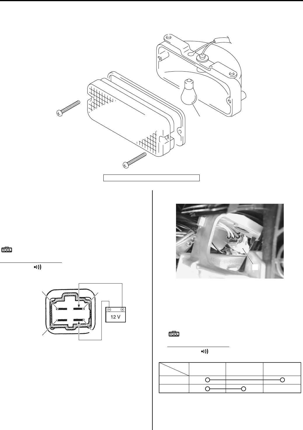
9B-7 Lighting Systems:
Reversing Light Bulb Replacement (For P-17)
B831G29206012
Remove the reversing light bulb (1) as shown in the figure.
Reversing Light Relay Inspection (For P-17)
B831G29206013
First, check the insulation between “A” and “B” terminals
with the multi-circuit tester. Then apply 12 V to terminals
“C” and “D” ((+) to “C” and (–) to “D”) and check the
continuity between “A” and “B”. If there is no continuity,
replace the reversing light relay with a new one.
Special tool
: 09900–25008 (Multi-circuit tester set)
Tester knob indication
Continuity ( )
Dimmer Switch Inspection
B831G29206014
Inspect the dimmer switch in the following procedures:
1) Remove the left inner fender. Refer to “Front Side
Exterior Parts Removal and Installation in Section
9D (Page 9D-6)”.
2) Disconnect the handlebar switch coupler (1).
3) Inspect the dimmer switch for continuity with a tester.
If any abnormality is found, replace the handlebar
switch assembly with a new one.
Refer to “Handlebars Removal and Installation in
Section 6B (Page 6B-3)”.
Special tool
: 09900–25008 (Multi-circuit tester set)
Tester knob indication
Continuity ( )
4) After finishing the dimmer switch inspection, reinstall
the removed parts.
1
I831G1920025-03
1. Reversing light bulb (12 V/21 W)
“A”
“B”
“C”
“D”
I831G1920028-01
1
I831G1920026-01
Position
Color Gr W Y
HI
LO
I831G1920027-01
PartShark.com
877-999-5686
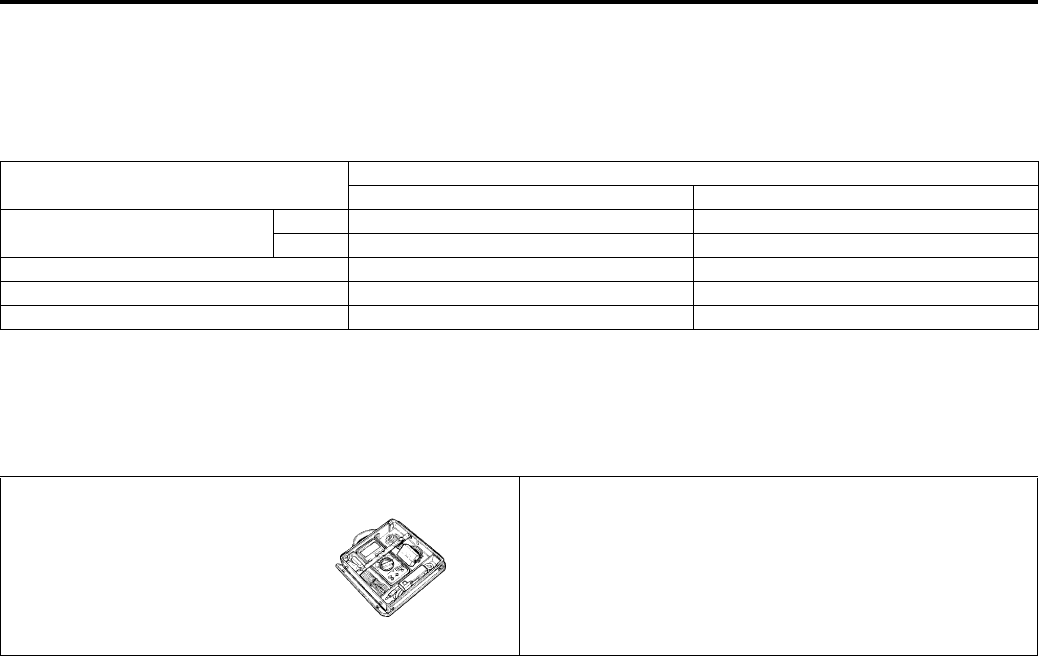
Lighting Systems: 9B-8
Specifications
Service Data
B831G29207001
Wattage
Unit: W
Special Tools and Equipment
Special Tool
B831G29208001
Item Specification
P-24, 28, 33 P-17
Headlight HI 35 x 2 ←
LO 35 x 2 ←
Auxiliary headlight 35/35 ←
Brake light/Taillight 21/5 ←
Revercing light — 21
09900–25008
Multi-circuit tester set
)(Page 9B-7) / )(Page 9B-
7)
PartShark.com
877-999-5686
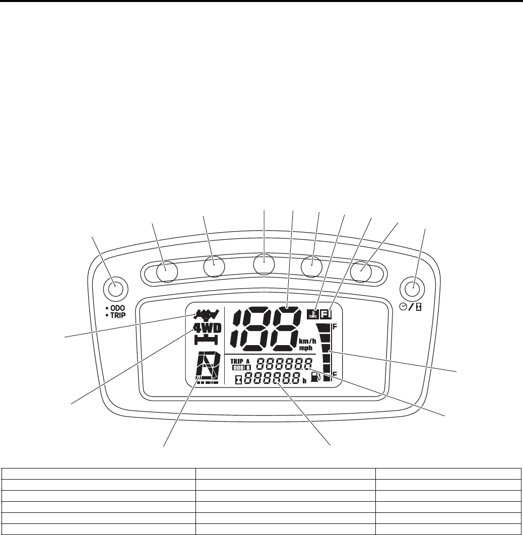
9C-1 Combination Meter / Fuel Meter / Horn:
Body and Acc essories
Combination Meter / Fuel Meter / Horn
General Description
Combination Meter System Description
B831G29301001
This combination meter mainly consists of LCD (Liquid Crystal Display) and LED (Light Emitting Diode).
The LCDs indicate Speed, Odo / Trip A / Trip B, Fuel level, Diff-lock, 4WD, Gear position, Engine coolant temperature,
FI and Clock / Hour / FI (DTC) respectively.
LED (Light Emitting Diode)
LED is used for the illumination light and each indicator light.
LED is maintenance free. LED is less power consuming and more resistant to vibration resistance compared to the
bulb.
1
235
11 12 13 6
8
9
15
4
7
14
10 16
I831G1930001-03
1. Select button (Odo / Trip A / Trip B) 7. Select button (Clock / Hour / FI (DTC)) 13. LCD (FI indicator)
2. LED (Diff-lock indicator light) 8. LCD (Diff-lock indicator) 14. LCD (Fuel level indicator)
3. LED (Reverse indicator light) 9. LCD (4WD indicator) 15. LCD (Odo / Trip A / Trip B)
4. LED (Neutral indicator light) 10. LCD (Gear position indicator) 16. LCD (Clock / Hour / FI (DTC))
5. LED (High-beam indicator light) [For P-17] 11. LCD (Speedometer)
6. LED (Engine coolant temperature / FI indicator light) 12. LCD (Engine coolant temperature indicator)
PartShark.com
877-999-5686
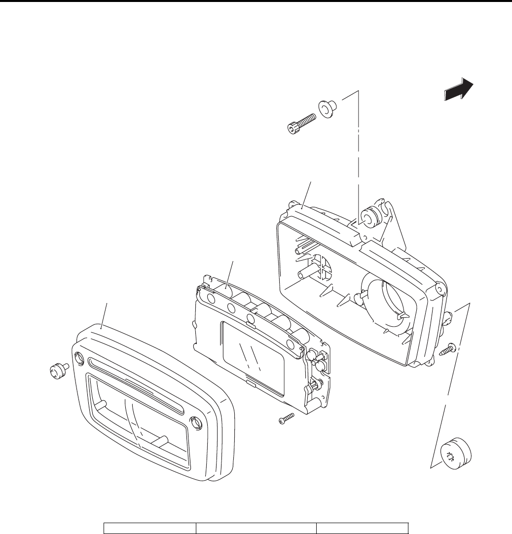
Combination Meter / Fuel Meter / Horn: 9C-2
Repair Instructions
Combination Meter Components
B831G29306001
1
2
3
FWD
I831G1930002-04
1. Upper case 2. Combination meter 3. Lower case
PartShark.com
877-999-5686
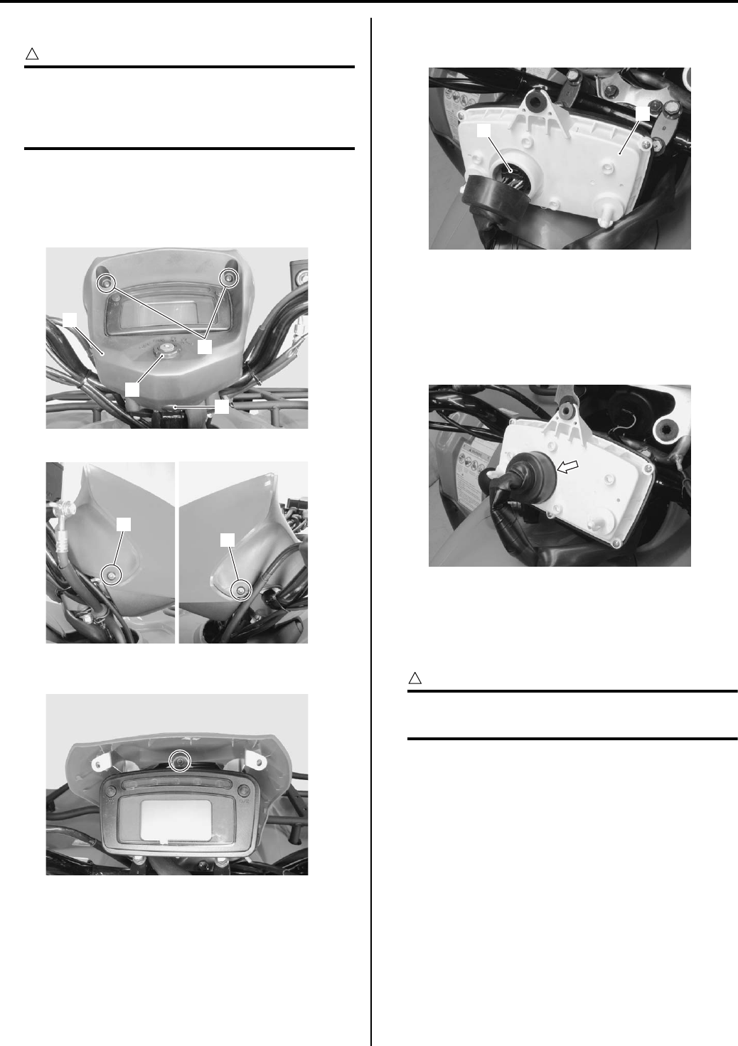
9C-3 Combination Meter / Fuel Meter / Horn:
Combination Meter Removal and Installation
B831G29306002
CAUTION
!
When disconnecting and reconnecting the
combination meter coupler, make sure to
turn OFF the ignition switch, or electronic
parts may get damaged.
Removal
1) Remove the combination meter cover (1) by
removing the screws (2), fasteners (3) and ignition
switch ring nut (4).
2) Remove the combination meter mounting bolt.
3) Disconnect the combination meter coupler (5) and
remove the combination meter assembly (6).
Installation
Install the combination meter in the reverse order of
removal. Pay attention to the following points:
• Make sure that speedometer coupler boot is
positioned properly.
Combination Meter Disassembly and Assembly
B831G29306003
Refer to “Combination Meter Removal and Installation
(Page 9C-3)”.
CAUTION
!
Do not attempt to disassemble the
combination meter unit.
Disassembly
Disassemble the combination meter as shown in the
combination meter components. Refer to “Combination
Meter Components (Page 9C-2)”.
Assembly
Assemble the combination meter as shown in the
combination meter components. Refer to “Combination
Meter Components (Page 9C-2)”.
2
1
4
3
I831G1930004-01
3
3
I831G1930003-01
I831G1930005-01
5
6
I831G1930006-01
I831G1930007-01
PartShark.com
877-999-5686
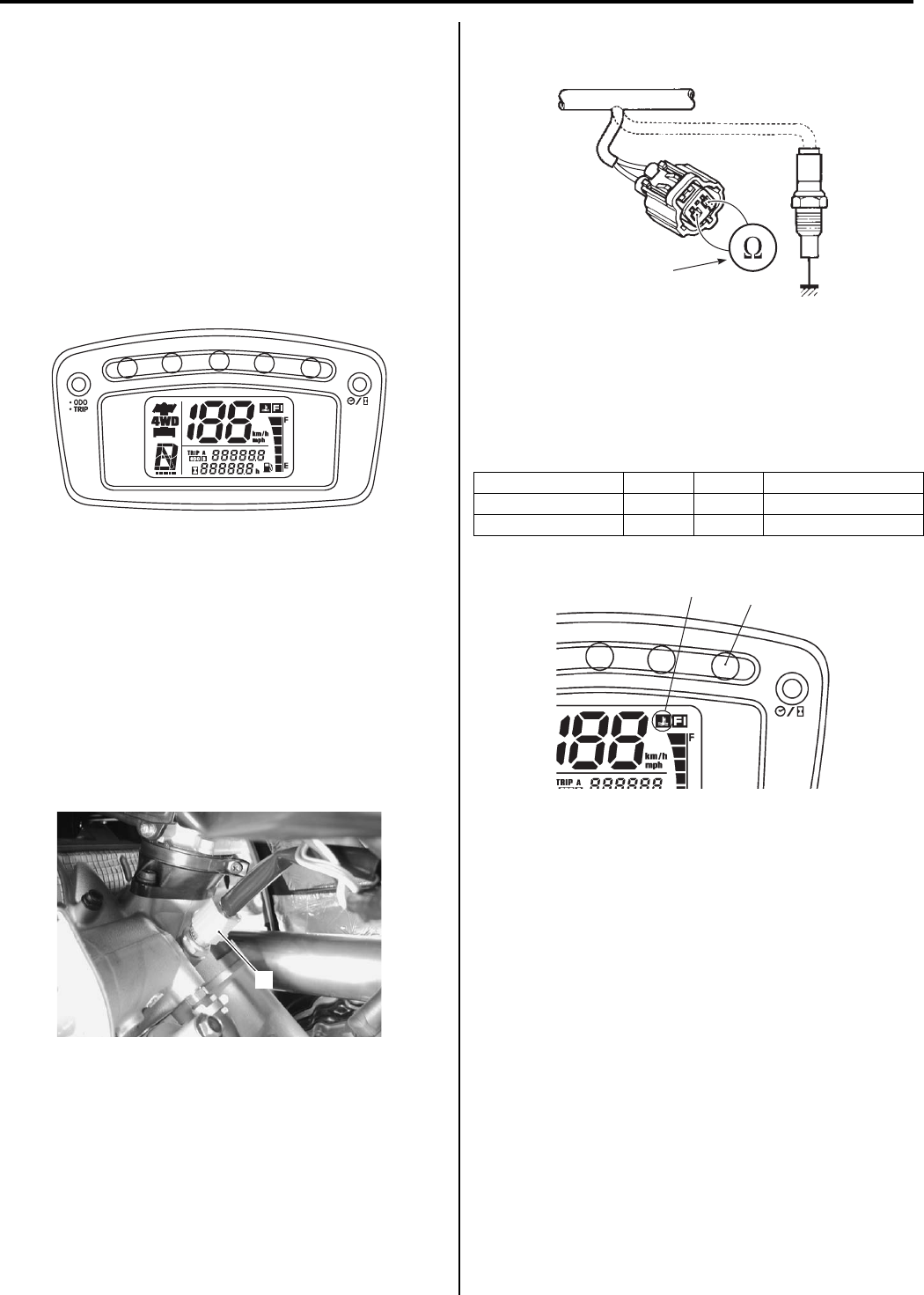
Combination Meter / Fuel Meter / Horn: 9C-4
Combination Meter Inspection
B831G29306004
LED Inspection
Check that the LEDs (Diff-lock indicator light, Reverse
indicator light and FI indicator light / Engine coolant
temperature indicator light) immediately light up for two
seconds when the ignition switch is turned to ON.
Check that other LEDs (Neutral indicator light and High-
beam indicator light (for P-17)) light up/go off by
operating each switch.
If abnormal condition is found, replace the combination
meter unit with a new one after checking its wire
harness/coupler. Refer to “Combination Meter Removal
and Installation (Page 9C-3)”.
Engine Coolant Temperature Indicator Light
Inspection
B831G29306005
Inspect the engine coolant temperature indicator light in
the following procedures:
1) Remove the seat. Refer to “Seat Removal and
Installation in Section 9D (Page 9D-11)”.
2) Remove the left side cover. Refer to “Front Side
Exterior Parts Removal and Installation in Section
9D (Page 9D-6)”.
3) Disconnect the ECT sensor coupler (1).
4) Connect the variable resistor (2) between the
terminals.
5) Turn the ignition switch ON.
6) Check the LCD and LED operations when the
resistance is adjusted to the specified values.
If either one or all indications are abnormal, replace
the combination meter with a new one. Refer to
“Combination Meter Removal and Installation
(Page 9C-3)”.
7) Connect the ECT sensor coupler.
Reinstall the removed parts.
Engine Coolant Temperature Removal and
Installation
B831G29306006
Refer to “ECT Sensor Removal and Installation in
Section 1C (Page 1C-4)”.
I831G1930008-02
1
I831G1930025-01
Resistance LED (3) LCD (4) Water temperature
Approx. 0.14 kΩOFF OFF Approx. 110 °C
0 Ω (Jumper wire) ON ON 120 °C and over
2
I718H1930009-05
3
4
I831G1930026-03
PartShark.com
877-999-5686
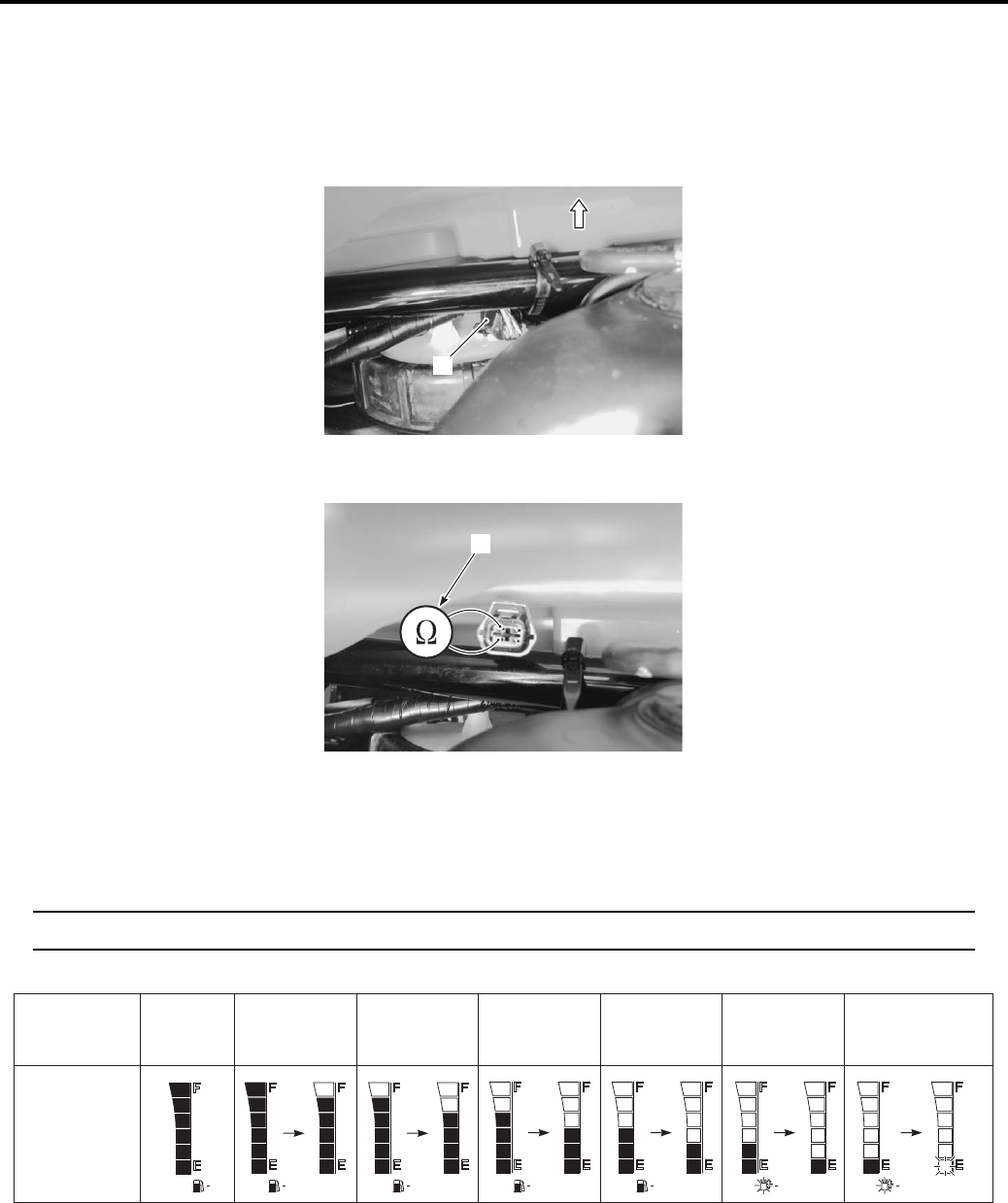
9C-5 Combination Meter / Fuel Meter / Horn:
Fuel Level Indicator Inspection
B831G29306007
Inspect the fuel level indicator in the following procedures:
1) Move the rear fender upside. Refer to “Fuel Tank Pressure Control (FTPC) Valve Removal and Installation in
Section 1G (Page 1G-12)”.
2) Disconnect the fuel level gauge coupler (1).
3) Connect the variable resister (2) between the Y/B and B lead wires from the wire harness.
4) Turn the ignition switch ON.
5) Check the display of fuel level indicator (LCD) as shown in the figure.
If any abnormality is found, replace the combination meter with a new one. Refer to “Combination Meter Removal
and Installation (Page 9C-3)”.
NOTE
It takes approx. 13 seconds that the fuel level indicator indicates the detected fuel level.
6) Connect the fuel level gauge coupler and reinstall the removed parts.
1
I831G1930011-01
2
I831G1930012-02
Resistance
Fuel level
meter
16.5 – 21.5 Ω 23.5 – 30.5 Ω 33 – 41 Ω 53 – 65 Ω 82 – 100 Ω 164 – 208 Ω
Flicker
Flicker Flicker
Less than
16 Ω
ON ON ON ON ON
I831G1930013-04
PartShark.com
877-999-5686
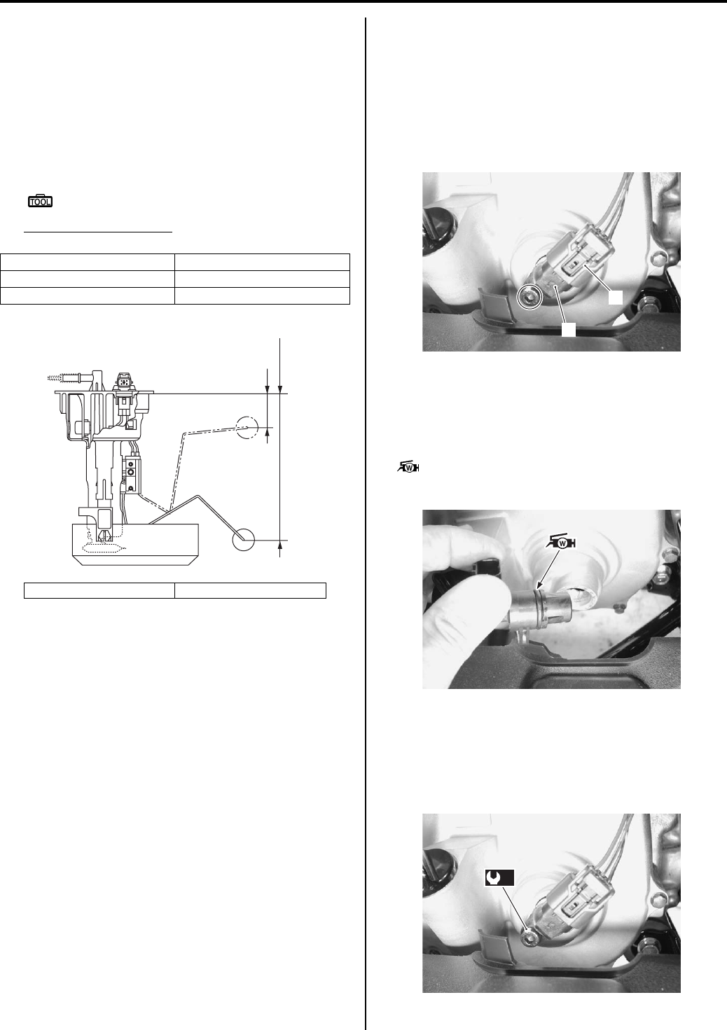
Combination Meter / Fuel Meter / Horn: 9C-6
Fuel Level Gauge Inspection
B831G29306008
Inspect the fuel level gauge in the following procedures:
1) Remove the fuel pump. Refer to “Fuel Pump
Assembly Removal and Installation in Section 1G
(Page 1G-9)”.
2) Measure the resistance at each fuel level gauge in
float position. If the resistance is incorrect, replace
fuel pump with a new one.
Special tool
: 09900–25008 (Multi-circuit tester set)
Tester knob indication
Resistance (Ω)
3) Install the fuel pump. Refer to “Fuel Pump Assembly
Removal and Installation in Section 1G (Page 1G—
9)”.
Speedometer Inspection
B831G29306009
If the speedometer, odometer or trip meter does not
function properly, inspect the speed sensor and the
coupler connections. If the speed sensor and coupler
connections are OK, replace the combination meter unit
with a new one. Refer to “Combination Meter Removal
and Installation (Page 9C-3)”.
Speed Sensor Removal and Installation
B831G29306010
Removal
1) Remove the engine side cover. Refer to “Rear Side
Exterior Parts Removal and Installation in Section
9D (Page 9D-9)”.
2) Disconnect the speed sensor coupler (1).
3) Remove the speed sensor (2).
Installation
Install the speed sensor in the reverse order of removal.
Pay attention to the following points:
• Apply grease to the speed sensor O-ring.
: Grease 99000–25160 (Water resistance
grease)
• Tighten the speed sensor mounting bolt to the
specified torque.
Tightening torque
Speed sensor mounting bolt (a): 10 N·m (1.0 kgf-
m, 7.0 lb-ft)
Float position Resistance
Full “a” 6.4 – 8.4 Ω
Empty “b” 216 – 222 Ω
“a”: 27.7 mm (1.09 in) “b”: 166 mm (6.54 in)
“a”
“b”
I831G1930014-01
1
2
I831G1930015-01
I831G1930016-02
(a)
I831G1930017-03
PartShark.com
877-999-5686
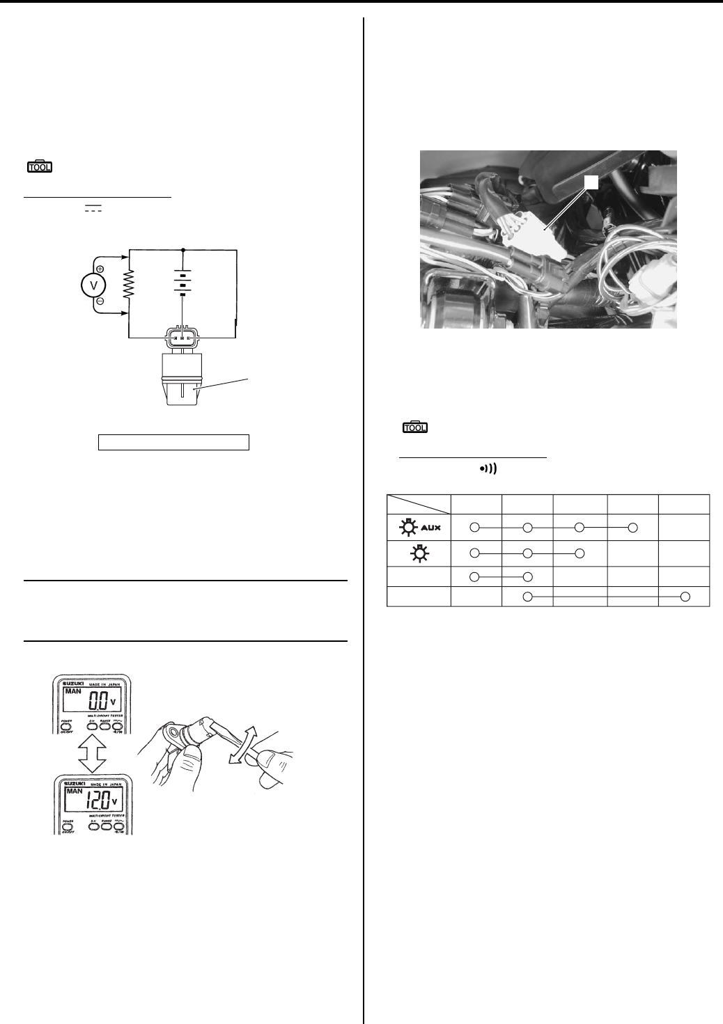
9C-7 Combination Meter / Fuel Meter / Horn:
Speed Sensor Inspection
B831G29306011
Inspect the speed sensor in the following procedures:
1) Remove the speed sensor. Refer to “Speed Sensor
Removal and Installation (Page 9C-6)”.
2) Connect a 12 V battery, 10 kΩ resistor and multi-
circuit tester as shown.
Special tool
: 09900–25008 (Multi-circuit tester set)
Tester knob indication
Voltage ( )
3) Move a screwdriver back and forth across the pick-
up surface of the speed sensor. The voltage
readings should cycle as follows (0 V → 12 V or 12 V
→ 0 V). If the voltage reading does not change,
replace the speed sensor with a new one.
NOTE
While testing, the highest voltage reading
should be the same as the battery voltage (12
V).
Ignition Switch Inspection
B831G29306012
Inspect the ignition switch in the following procedures:
1) Remove the left inner fender. Refer to “Front Side
Exterior Parts Removal and Installation in Section
9D (Page 9D-6)”.
2) Disconnect the ignition switch coupler (1).
3) Inspect the ignition switch for continuity with a tester.
If any abnormality is found, replace the ignition
switch with a new one.
Special tool
: 09900–25008 (Multi-circuit tester set)
Tester knob indication
Continuity ( )
4) After finishing the ignition switch inspection, reinstall
the removed parts.
Ignition Switch Removal and Installation
B831G29306013
Refer to “Ignition Switch Removal and Installation in
Section 1H (Page 1H-7)”.
1. Speed sensor
12 V
10 kΩ
1
I831G1930018-05
I831G1930022-01
1
I831G1930019-02
Color
Position R O Gr P O/R
ON
OFF
I831G1930023-05
PartShark.com
877-999-5686
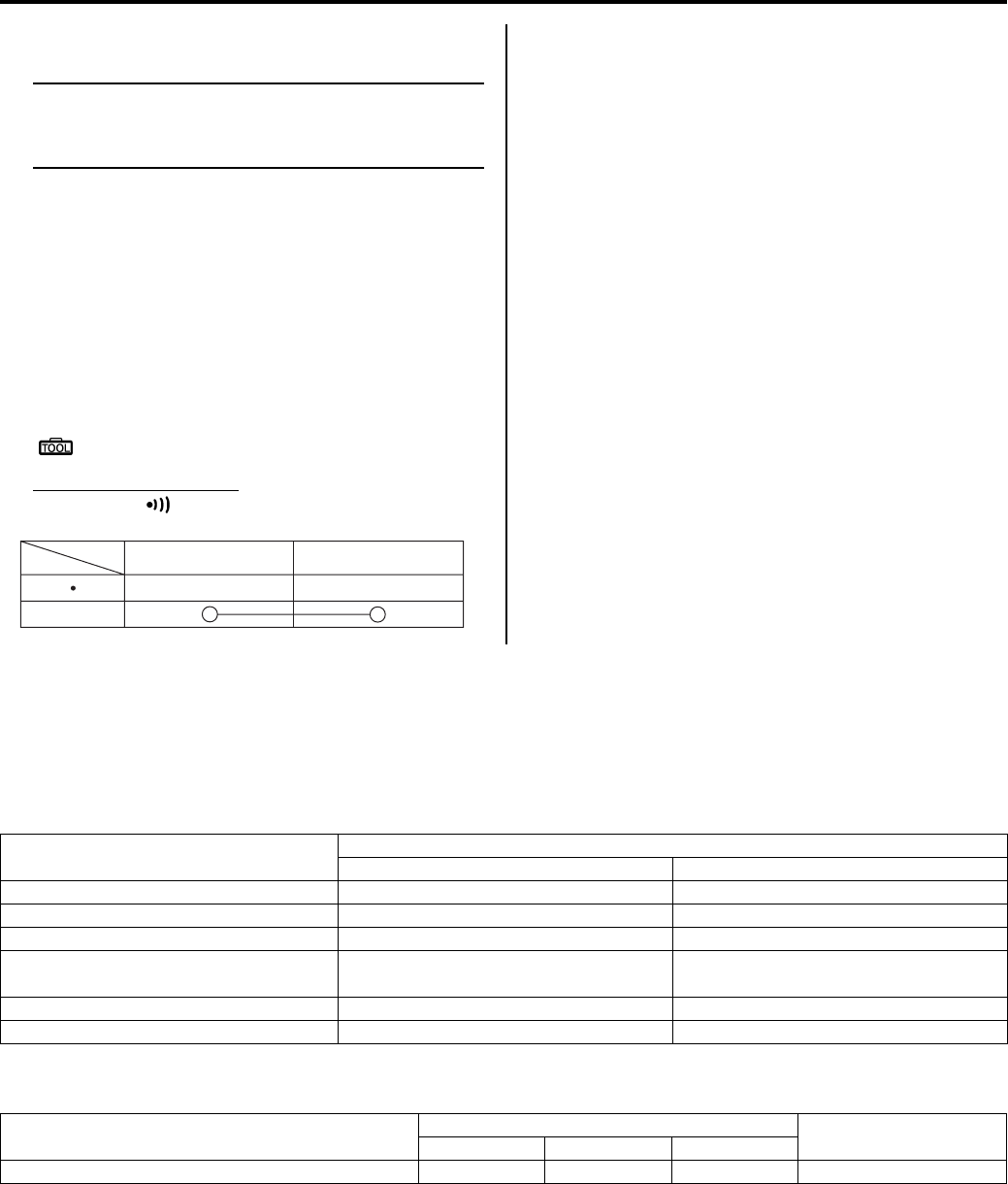
Combination Meter / Fuel Meter / Horn: 9C-8
Horn Inspection (For P-17, 24)
B831G29306014
NOTE
If the horn sound condition is normal, it is not
necessary to inspect the horn button
continuity.
Horn Button Inspection
1) Disconnect the horn couplers as shown in the wiring
harness routing diagram. Refer to “Wiring Harness
Routing Diagram in Section 9A (Page 9A-4)”.
2) Inspect the horn button for continuity with a tester.
If any abnormality is found, replace the horn button
with a new one.
Refer to “Handlebars Removal and Installation in
Section 6B (Page 6B-3)”.
Special tool
: 09900–25008 (Multi-circuit tester set)
Tester knob indication
Continuity ( )
3) Connect the horn couplers.
Horn Inspection
1) Disconnect the horn couplers as shown in the wiring
harness routing diagram. Refer to “Wiring Harness
Routing Diagram in Section 9A (Page 9A-4)”.
2) Connect a 12 V battery to terminal and terminal. If
the sound is not heard from the horn, replace the
horn with a new one.
3) Connect the horn couplers.
Horn Removal and Installation (For P-17, 24)
B831G29306015
Removal
Disconnect the horn couplers and remove the horn by
removing the mounting nut as shown in the wiring
harness routing diagram. Refer to “Wiring Harness
Routing Diagram in Section 9A (Page 9A-4)”.
Installation
Install the horn in the reverse order of removal.
Specifications
Service Data
B831G29307001
Wattage
Unit: W
Tightening Torque Specifications
B831G29307002
Reference:
For the tightening torque of fastener not specified in this section, refer to “Tightening Torque List in Section 0C
(Page 0C-7)”.
Color
Position G B/W
PUSH
I831G1930024-03
Item Specification
P-24, 28, 33 P-17
Speedometer light LED ←
High beam indicator light — LED
Neutral indicator light LED ←
FI indicator light/Engine coolant temp.
indicator light LED ←
Reverse indicator light LED ←
Differential lock indicator light LED ←
Fastening part Tightening torque Note
N⋅mkgf—mlb—ft
Speed sensor mounting bolt 10 1.0 7.0 )(Page 9C-6)
PartShark.com
877-999-5686
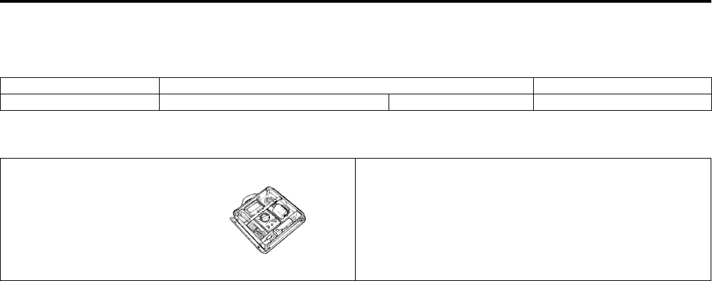
9C-9 Combination Meter / Fuel Meter / Horn:
Special Tools and Equipment
Recommended Service Material
B831G29308001
Special Tool
B831G29308002
Material SUZUKI recommended product or Specification Note
Grease Water resistance grease P/No.: 99000–25160 )(Page 9C-6)
09900–25008
Multi-circuit tester set
)(Page 9C-6) / )(Page 9C-
7) / )(Page 9C-7) /
)(Page 9C-8)
PartShark.com
877-999-5686

Exterior Parts: 9D-1
Body and Acc essories
Exterior Parts
Repair Instructions
Exterior Parts Construction
B831G29406001
PartShark.com
877-999-5686
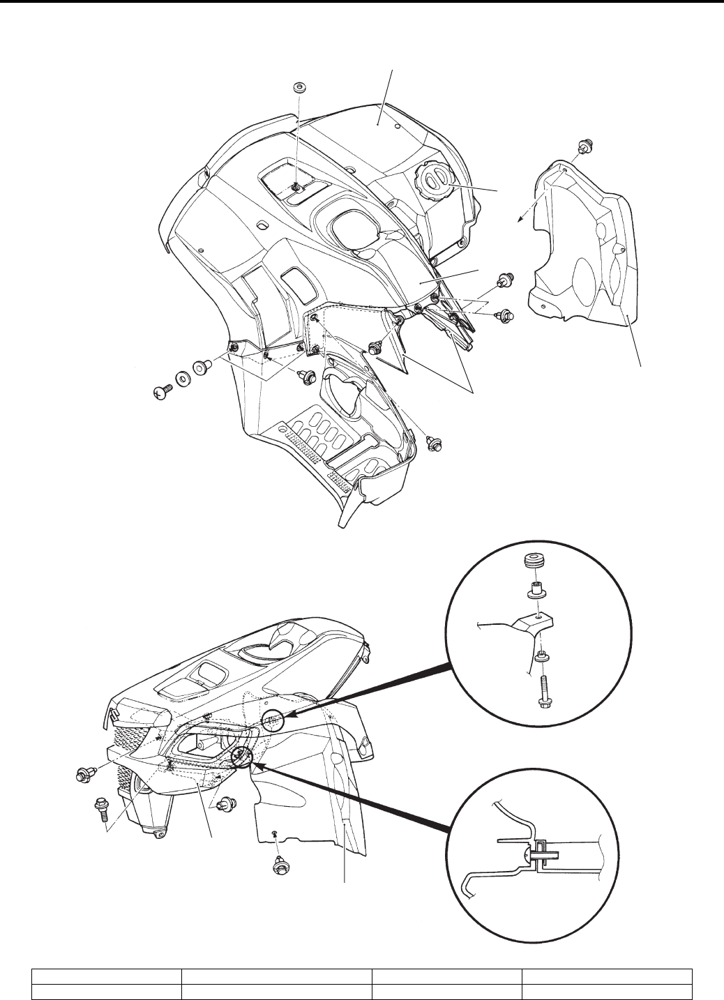
9D-2 Exterior Parts:
Front Side
1
2
3
4
7
5
6
I831G1940001-08
1. Front fender 3. Air cleaner box cover 5. Front grill cover 7. Right inner fender
2. Front box 4. Side cover 6. Left inner fender
PartShark.com
877-999-5686
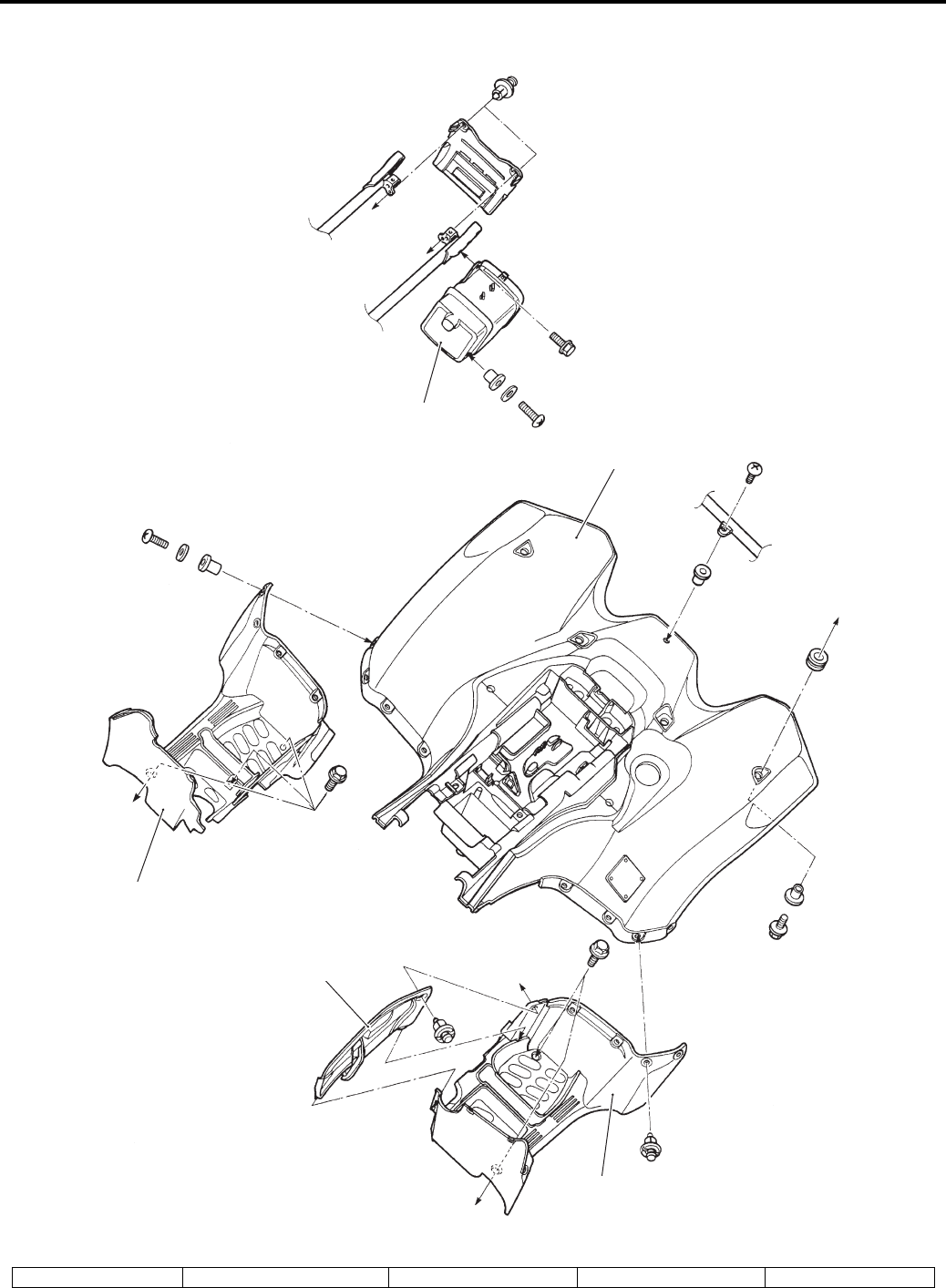
Exterior Parts: 9D-3
Rear Side
1
2
4
5
3
I831G1940002-02
1. Rear fender 2. Right mud guard 3. Left mud guard 4. Engine side cover 5. Rear box
PartShark.com
877-999-5686
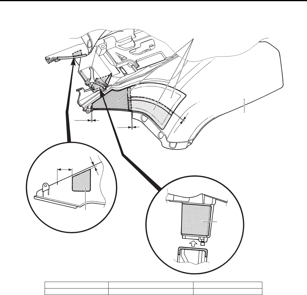
9D-4 Exterior Parts:
Rear Fender Heat Shield Construction
B831G29406002
2
“a”
“b” “a”
1
2
2
“c”
“d”
I831G1940003-07
1. Rear fender “a”: 1 – 3 mm (0.04 – 0.12 in) “c”: 67 mm (2.64 in)
2. Heat shield “b”: 5 mm (0.2 in) “d”: 8 mm (0.3 in)
PartShark.com
877-999-5686
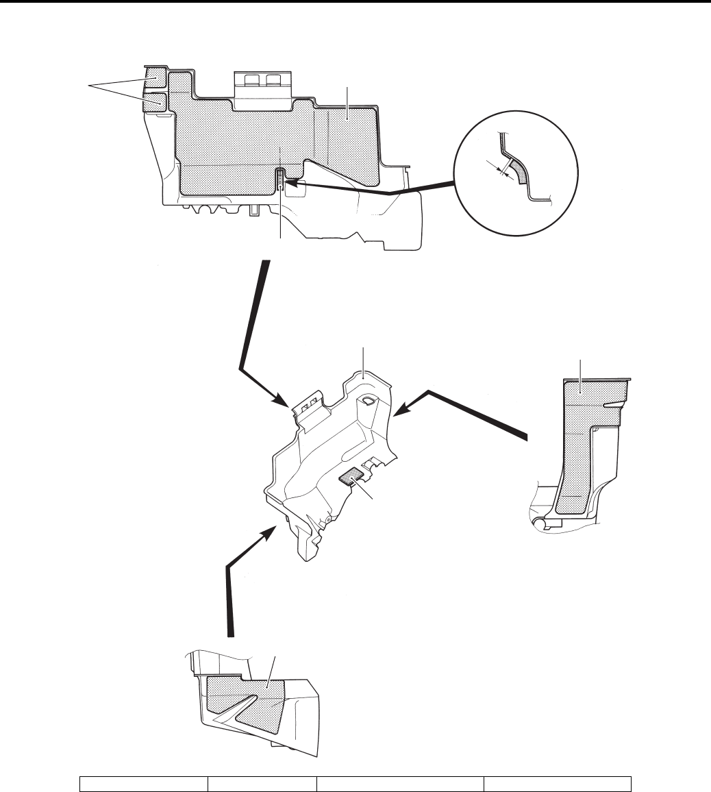
Exterior Parts: 9D-5
Fuel Tank Lower Cover Heat Shield Installation
B831G29406003
1
2
4
“a”
3
2
4
1
I831G1940045-02
1. Heat shield 2. Cushion 3. Fuel tank lower cover “a”: Max. 5 mm (0.2 in)
PartShark.com
877-999-5686
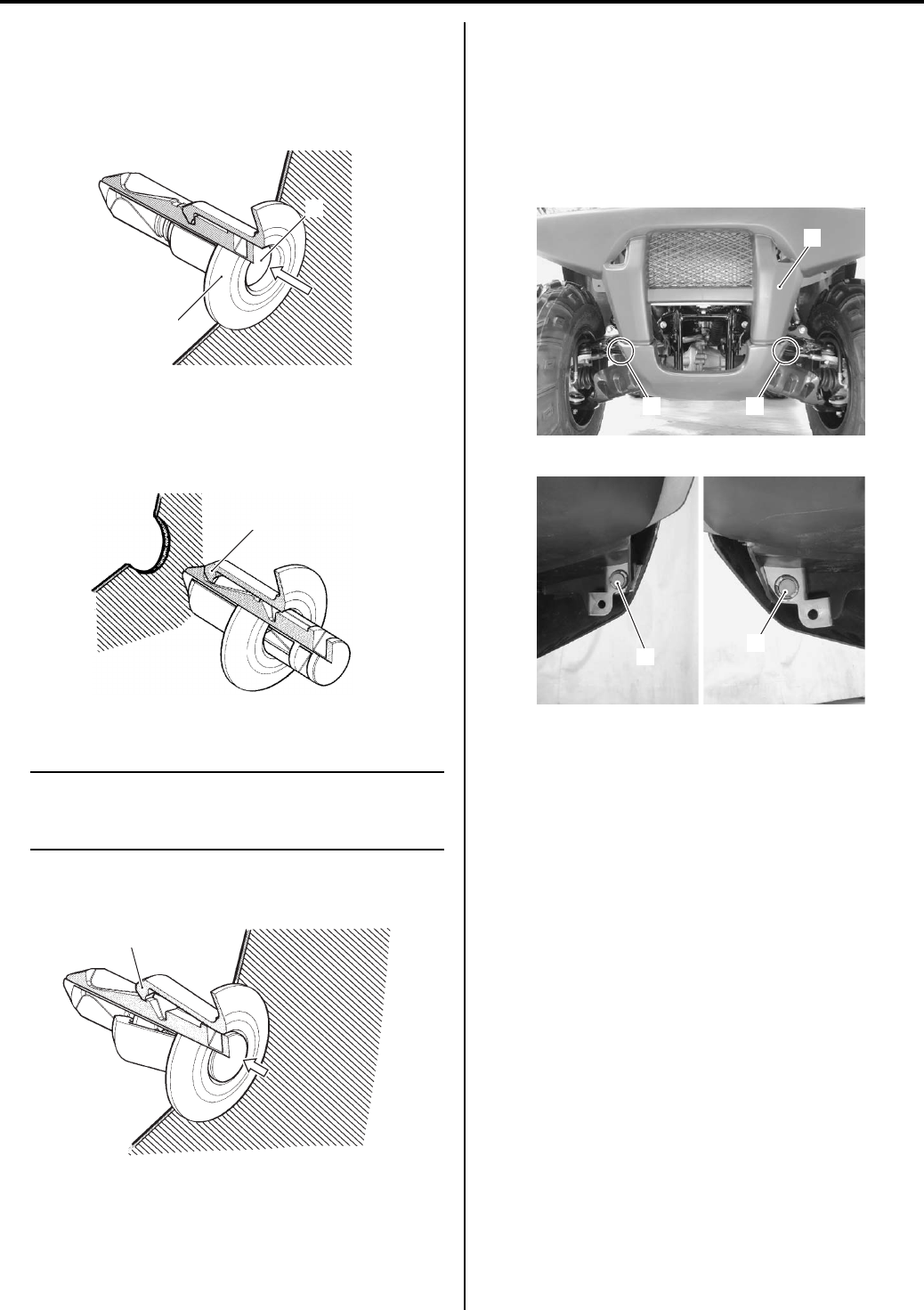
9D-6 Exterior Parts:
Fastener Removal and Installation
B831G29406004
Removal
1) Depress the head of fastener center piece (1).
2) Pull out the fastener (2).
Installation
1) Let the center piece stick out toward the head so that
the pawls “A” closes.
2) Insert the fastener into the installation hole.
NOTE
To prevent the pawl “A” from damage, insert
the fastener all the way into the installation
hole.
3) Push in the head of center piece until it becomes
flush with the fastener outside face.
Front Side Exterior Parts Removal and
Installation
B831G29406005
Front Grill Cover
Removal
Remove the front grill cover (1) by removing the
fasteners (2).
Installation
Install the front grill cover in the reverse order of
removal.
1
2
I649G1940005-02
“A”
I649G1940006-02
“A”
I831G1940046-01
1
22
I831G1940005-01
2
2
I831G1940004-01
PartShark.com
877-999-5686
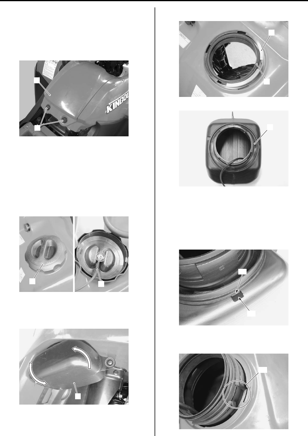
Exterior Parts: 9D-7
Air Cleaner Box Cover
Removal
1) Remove the seat. Refer to “Seat Removal and
Installation (Page 9D-11)”.
2) Remove the air cleaner box cover (1) by removing
the fasteners (2).
Installation
Install the air cleaner box cover in the reverse order of
removal.
Front Box
Removal
1) Remove the front box cap (1).
2) Disconnect the front box cap wire (2).
3) Remove the front box mounting screw.
4) Turn the front box (3) counterclockwise and remove
it.
5) Remove the front box holder (4) and cushions (5).
Installation
Install the front box in the reverse order of removal. Pay
attention to the following points:
• When installing the cushion, fit the convex parts “A” of
the cushion onto the concave parts “B” of the front
box.
• When installing the cushion to the front box, align the
cutout “C” on the front box.
2
1
I831G1940006-01
12
I831G1940007-02
3
I831G1940008-04
5
4
I831G1940009-02
5
I831G1940010-01
“A”
“B”
I831G1940011-01
“C”
I831G1940012-01
PartShark.com
877-999-5686
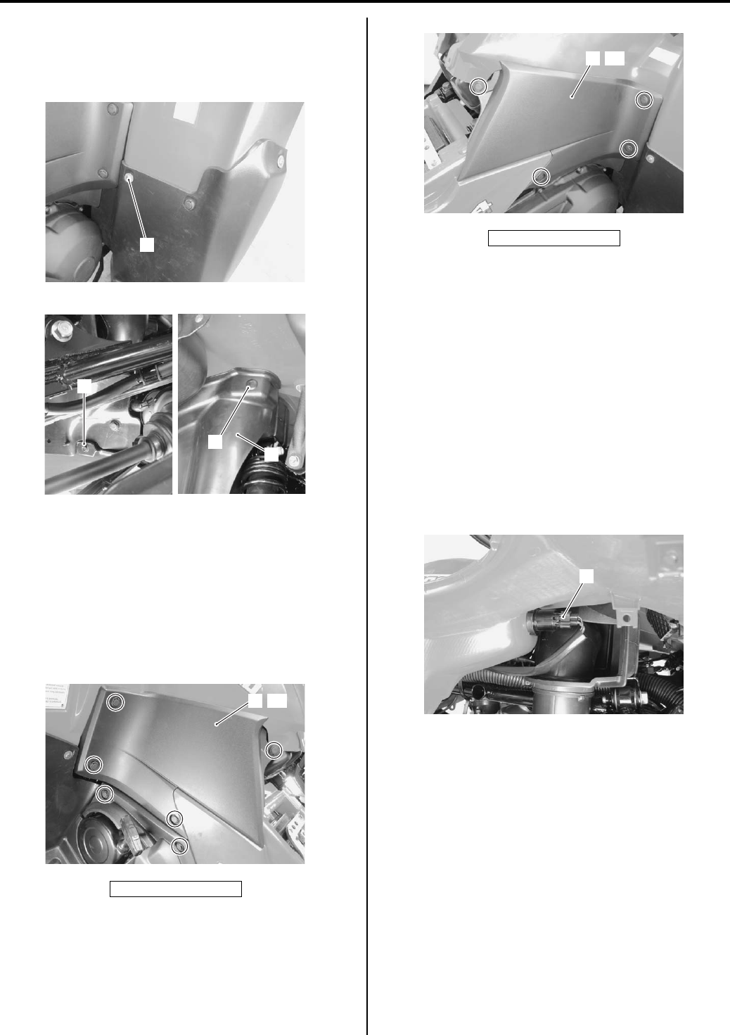
9D-8 Exterior Parts:
Inner Fender
Removal
Remove the inner fenders (1) by removing the screw (2),
bolt (3) and fastener (4), left and right.
Installation
Install the inner fenders in the reverse order of removal.
Side Cover
Removal
1) Remove the seat. Refer to “Seat Removal and
Installation (Page 9D-11)”.
2) Remove the side cover (1), left and right.
Installation
Install the side cover in the reverse order of removal.
Front Fender
Removal
1) Remove the front carrier. Refer to “Front Carrier
Removal and Installation in Section 9E (Page 9E-4)”.
2) Remove the seat. Refer to “Seat Removal and
Installation (Page 9D-11)”.
3) Remove the air cleaner box cover, front box, inner
fenders and side covers. Refer to “Front Side
Exterior Parts Removal and Installation (Page 9D-
6)”.
4) Disconnect the power source socket coupler (1).
“A”: Left side
2
I831G1940013-02
4
3
1
I831G1940014-02
1 “A”
I831G1940015-01
“B”: Right side
1“B”
I831G1940016-01
1
I831G1940017-01
PartShark.com
877-999-5686
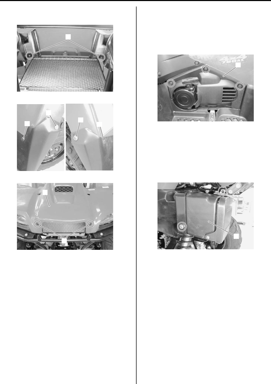
Exterior Parts: 9D-9
5) Remove the front fender (2) by removing the screws
(3) and fasteners (4).
Installation
Install the front fender in the reverse order of removal.
Rear Side Exterior Parts Removal and
Installation
B831G29406006
Engine Side Cover
Removal
Remove the engine side cover (1).
Installation
Install the engine side cover in the reverse order of
removal.
Rear Box
Removal
Remove the rear box (1).
Installation
Install the rear box in the reverse order of removal.
3
I831G1940018-01
4
3
3
4
I831G1940019-01
4
2
I831G1940020-01
1
I831G1940021-01
1
I831G1940022-01
PartShark.com
877-999-5686
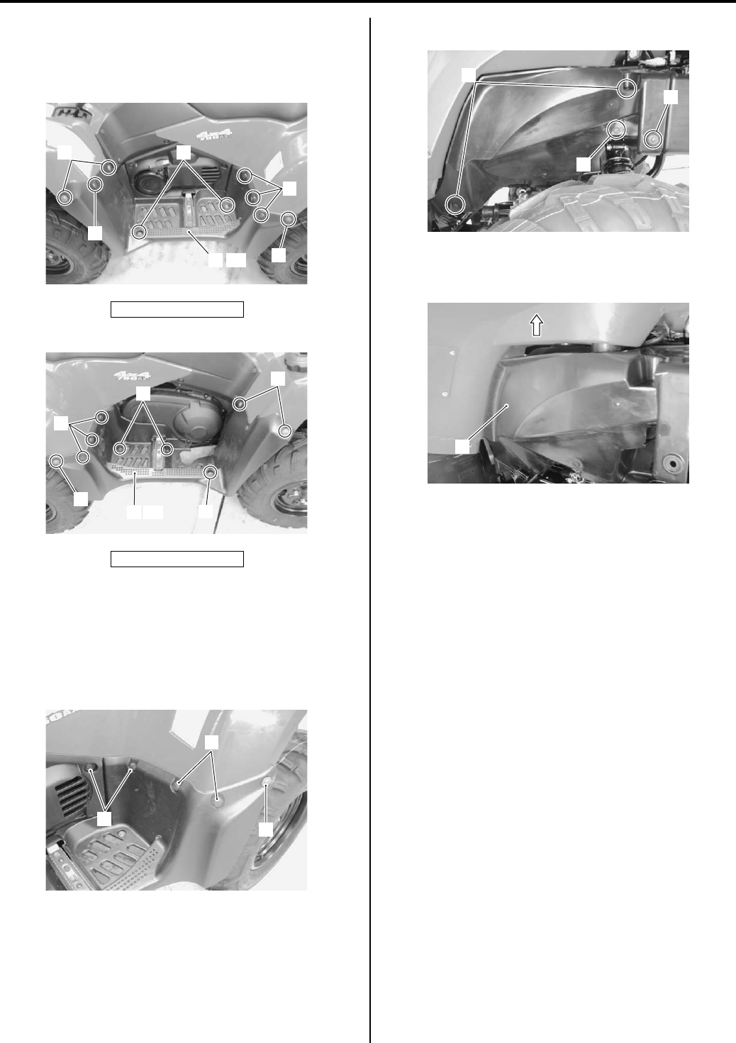
9D-10 Exterior Parts:
Mud Guard
Removal
Remove the mud guards (1) by removing the bolts (2),
screws (3) and fastener (4), left and right.
Installation
Install the mud guard in the reverse order of removal.
Fuel Tank Outer Cover
Removal
1) Remove the fasteners (1) and screw (2).
2) Remove the fasteners (3), bolt (4) and screw (5).
3) Move the rear fender upside.
4) Remove the fuel tank outer cover (6).
Installation
Install the fuel tank outer cover in the reverse order of
removal.
Rear Fender
Removal
1) Remove the rear carrier. Refer to “Rear Carrier
Removal and Installation in Section 9E (Page 9E-5)”.
2) Remove the seat. Refer to “Seat Removal and
Installation (Page 9D-11)”.
3) Remove the side covers, left and right. Refer to
“Front Side Exterior Parts Removal and Installation
(Page 9D-6)”.
4) Remove the engine side cover. Refer to “Rear Side
Exterior Parts Removal and Installation (Page 9D-
9)”.
“A”: Left side
“B”: Right side
2
3
4
“A”
1
4
3
I831G1940023-05
1
2
4
“B”
3
3
2
I831G1940024-02
1
1
2
I831G1940025-01
3
4
5
I831G1940026-01
6
I831G1940027-01
PartShark.com
877-999-5686
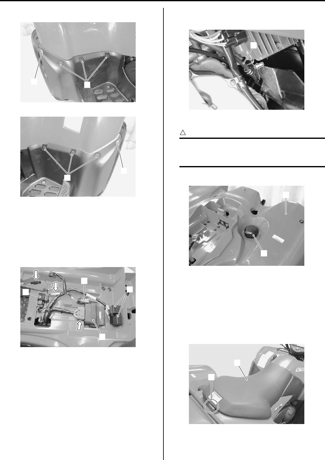
Exterior Parts: 9D-11
5) Remove the fasteners (1) and screws (2).
6) Remove the battery. Refer to “Battery Removal and
Installation in Section 1J (Page 1J-12)”.
7) Remove the starter relay. Refer to “Starter Relay
Removal and Installation in Section 1I (Page 1I-6)”.
Disconnect the couplers and remove the neutral
relay/fuse box (1), ECM (2), fuel pump relay (3) and
4WD/diff-lock relay (4).
9) Remove the parking brake cable (5) from the cable
guide.
10) Remove the fuel tank cap (6).
CAUTION
!
To prevent the fuel tank from contamination
with foreign particles, install the fuel tank
cap, after removing the rear fender.
11) Remove the rear fender (7).
Installation
Install the rear fender in the reverse order of removal.
Seat Removal and Installation
B831G29406007
Removal
Pull the seat lock lever (1) upward, and remove the seat
(2).
Installation
Install the seat in the reverse order of removal.
1
2
I831G1940028-01
1
2
I831G1940029-01
1
3
2
4
I831G1940030-01
5
I831G1940031-01
6
7
I831G1940032-01
1
2
I831G1940033-01
PartShark.com
877-999-5686
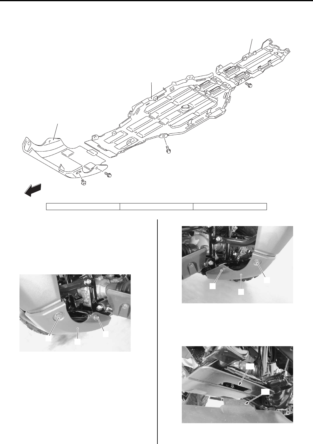
9D-12 Exterior Parts:
Under Cover Components
B831G29406008
Under Cover Removal and Installation
B831G29406009
Front Under Cover
Removal
Remove the front under cover (1) by removing the bolts
(2) and fasteners (3).
Installation
1) Fix the front under cover “B” to the groove “A” of
engine under cover.
2) Install the front under cover.
1
2
3
FWD
I831G1940034-02
1. Front under cover 2. Engine under cover 3. Rear under cover
31
2
I831G1940035-02
3
1
2
I831G1940036-01
“A”
“B”
I831G1940037-02
PartShark.com
877-999-5686
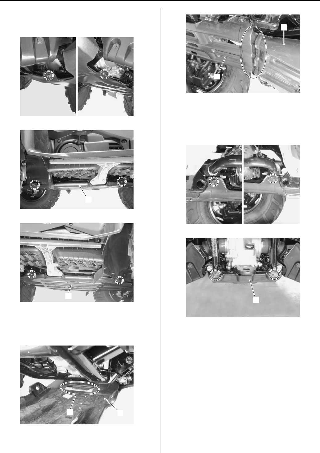
Exterior Parts: 9D-13
Engine Under Cover
Removal
Remove the engine under cover (1).
Installation
1) Fix the engine under cover (1) with the front under
cover (2) and rear under cover (3).
2) Install the engine under cover.
Rear Under Cover
Removal
Remove the rear under cover (1).
Installation
Install the rear under cover in the reverse order of
removal.
I831G1940038-01
1
I831G1940039-01
1
I831G1940040-01
21
I831G1940041-01
1
3
I831G1940042-01
I831G1940043-01
1
I831G1940044-01
PartShark.com
877-999-5686
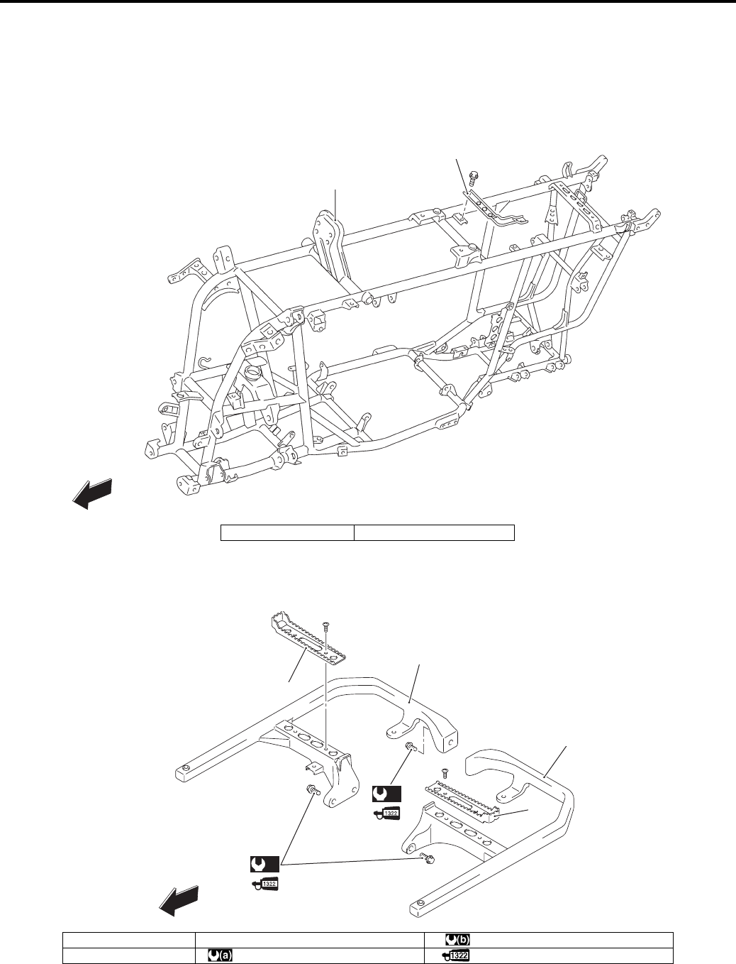
9E-1 Body Structure:
Body and Acc essories
Body Structure
Repair Instructions
Body Frame Construction
B831G29506001
Footrest Construction
B831G29506002
2
1
FWD
I831G1950005-06
1. Frame 2. Battery plate
3
1
2
(b)
3
FWD
(a)
I831G1950001-04
1. Footrest (R) 3. Footrest plate : 55 N⋅m (5.5 kgf-m, 40.0 lb-ft)
2. Footrest (L) : 26 N⋅m (2.6 kgf-m, 19.0 lb-ft) : Apply thread lock to the thread part.
PartShark.com
877-999-5686
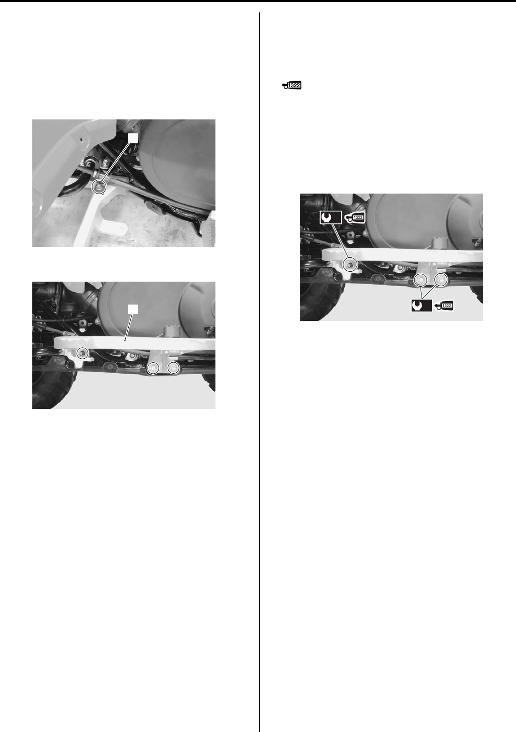
Body Structure: 9E-2
Footrest Removal and Installation
B831G29506003
Removal
1) Remove the mud guard. Refer to “Rear Side Exterior
Parts Removal and Installation in Section 9D
(Page 9D-9)”.
2) Remove the rear brake cable clamp (1) (RH).
3) Remove the footrest (2) (RH & LH).
Installation
Install the footrest in the reverse order of removal. Pay
attention to the following point:
• Apply thread lock to the footrest mounting bolts and
tighten them to the special torque.
: Thread lock cement 99000–32110
(THREAD LOCK CEMENT SUPER 1322 or
equivalent)
Tightening torque
Footrest mounting bolt (M8) (a): 26 N·m (2.6 kgf-
m, 19.0 lb-ft)
Footrest mounting bolt (M10) (b): 55 N·m (5.5 kgf-
m, 40.0 lb-ft)
1
I831G1950002-01
2
I831G1950004-01
(b)
(a)
I831G1950003-01
PartShark.com
877-999-5686
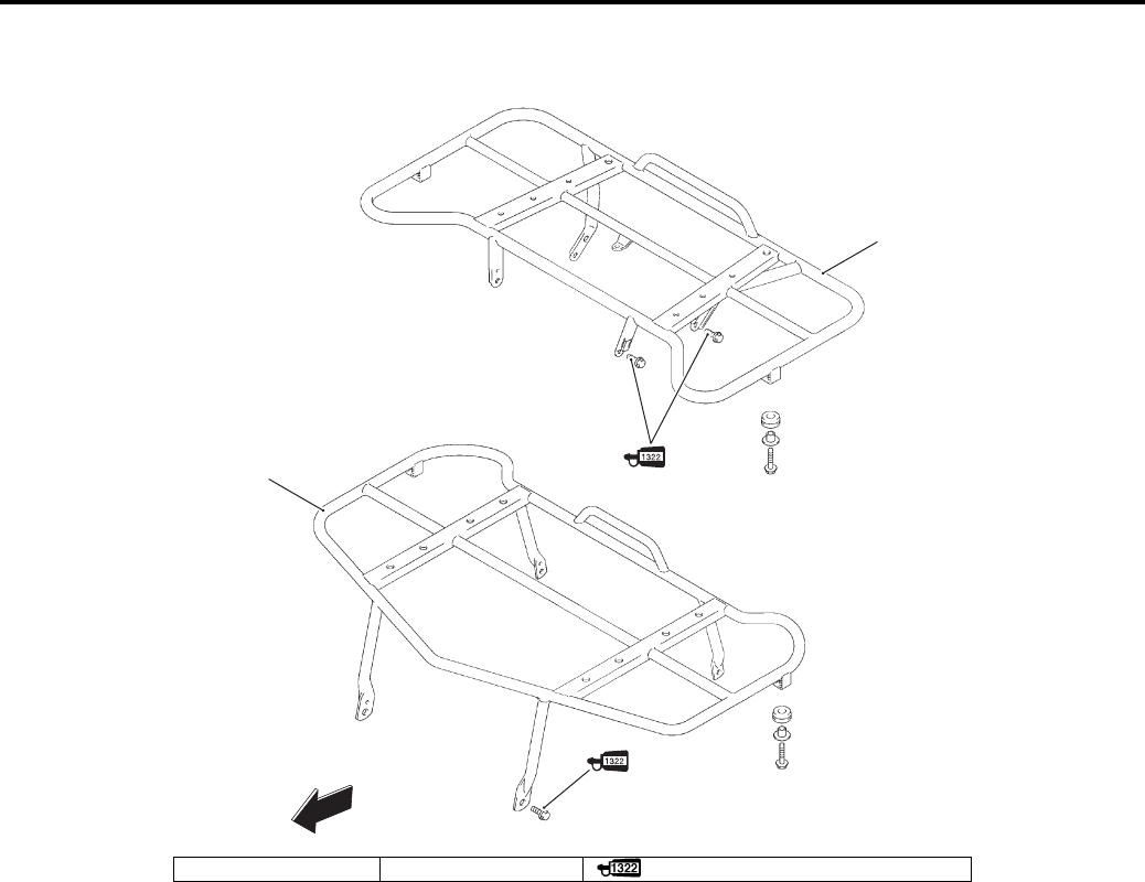
9E-3 Body Structure:
Carrier Construction
B831G29506004
FWD
1
2
I831G1950006-06
1. Front carrier 2. Rear carrier : Apply thread lock to the thread part.
PartShark.com
877-999-5686
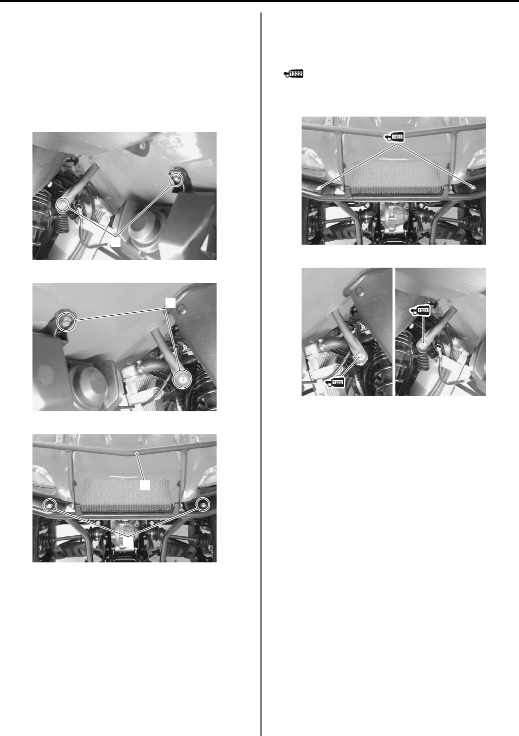
Body Structure: 9E-4
Front Carrier Removal and Installation
B831G29506005
Removal
1) Remove the front grill upper cover. Refer to “Front
Side Exterior Parts Removal and Installation in
Section 9D (Page 9D-6)”.
2) Remove the front carrier (1) by removing the bolts
(2).
Installation
Install the front carrier in the reverse order of removal.
Pay attention to the following point:
• Apply thread lock to the front carrier mounting bolts.
: Thread lock cement 99000–32110
(THREAD LOCK CEMENT SUPER 1322 or
equivalent)
2
I831G1950007-01
2
I831G1950008-02
2
1
I831G1950009-01
I831G1950010-01
I831G1950011-01
PartShark.com
877-999-5686
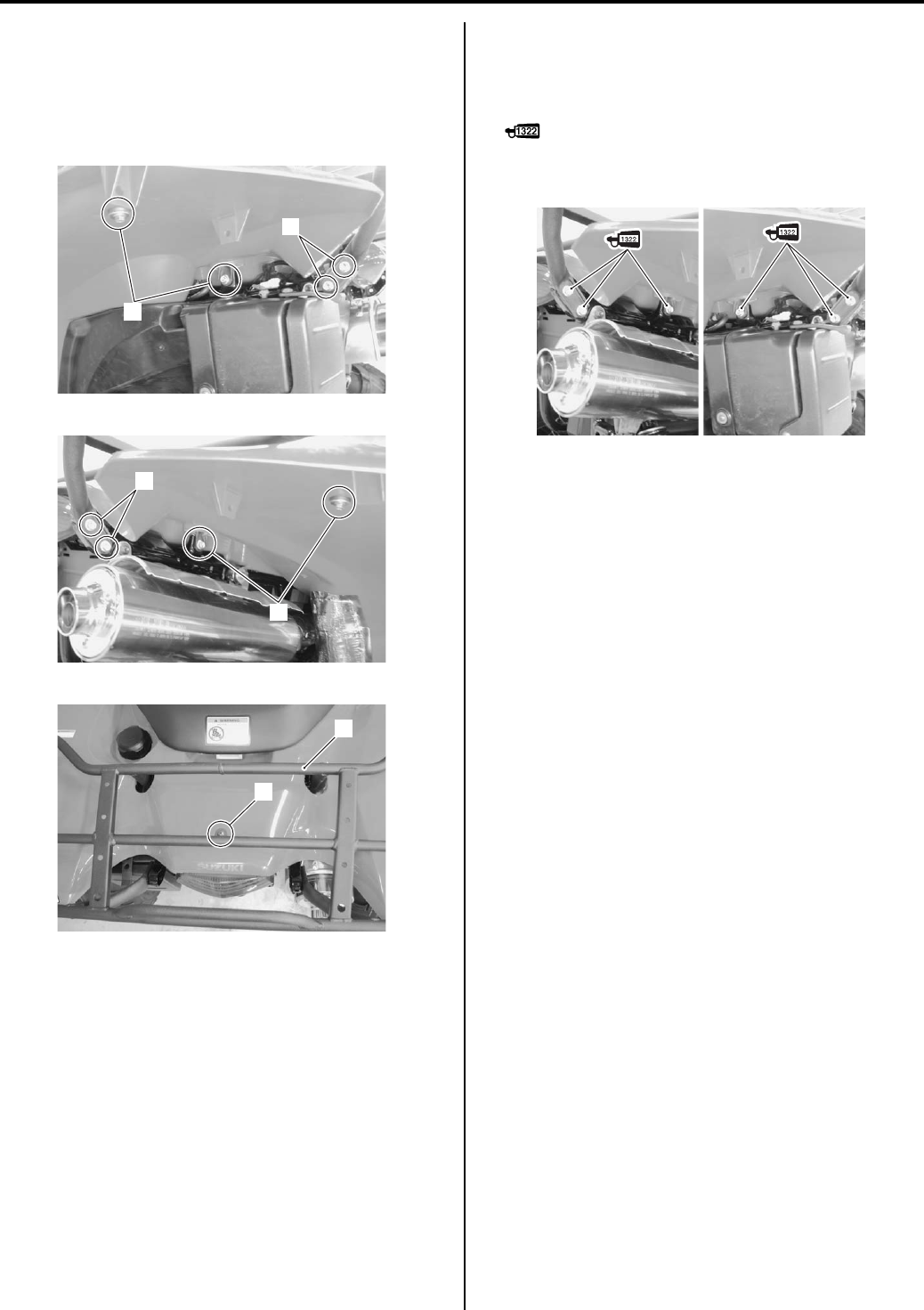
9E-5 Body Structure:
Rear Carrier Removal and Installation
B831G29506006
Removal
1) Remove the rear carrier (1) by removing the bolts (2)
and screw (3).
Installation
Install the rear carrier in the reverse order of removal.
Pay attention to the following point:
• Apply thread lock to the rear carrier mounting bolts.
: Thread lock cement 99000–32110
(THREAD LOCK CEMENT SUPER 1322 or
equivalent)
2
2
I831G1950012-01
2
2
I831G1950013-01
3
1
I831G1950014-01
I831G1950015-01
PartShark.com
877-999-5686
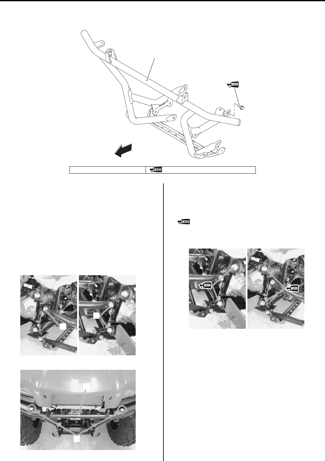
Body Structure: 9E-6
Front Grip Bar Construction
B831G29506007
Front Grip Bar Removal and Installation
B831G29506008
Removal
1) Remove the front carrier. Refer to “Front Carrier
Removal and Installation (Page 9E-4)”.
2) Remove the front cover. Refer to “Front Side Exterior
Parts Removal and Installation in Section 9D
(Page 9D-6)”.
3) Remove the front grip bar (1) by removing the bolt
(2).
Installation
Install the front grip bar in the reverse order of removal.
Pay attention to the following point:
• Apply thread lock to the front grip bar mounting bolts.
: Thread lock cement 99000–32110
(THREAD LOCK CEMENT SUPER 1322 or
equivalent)
FWD
1
I831G1950016-01
1. Front grip bar : Apply thread lock to thread part.
2
2
I831G1950017-01
1
2
I831G1950018-01
I831G1950019-02
PartShark.com
877-999-5686
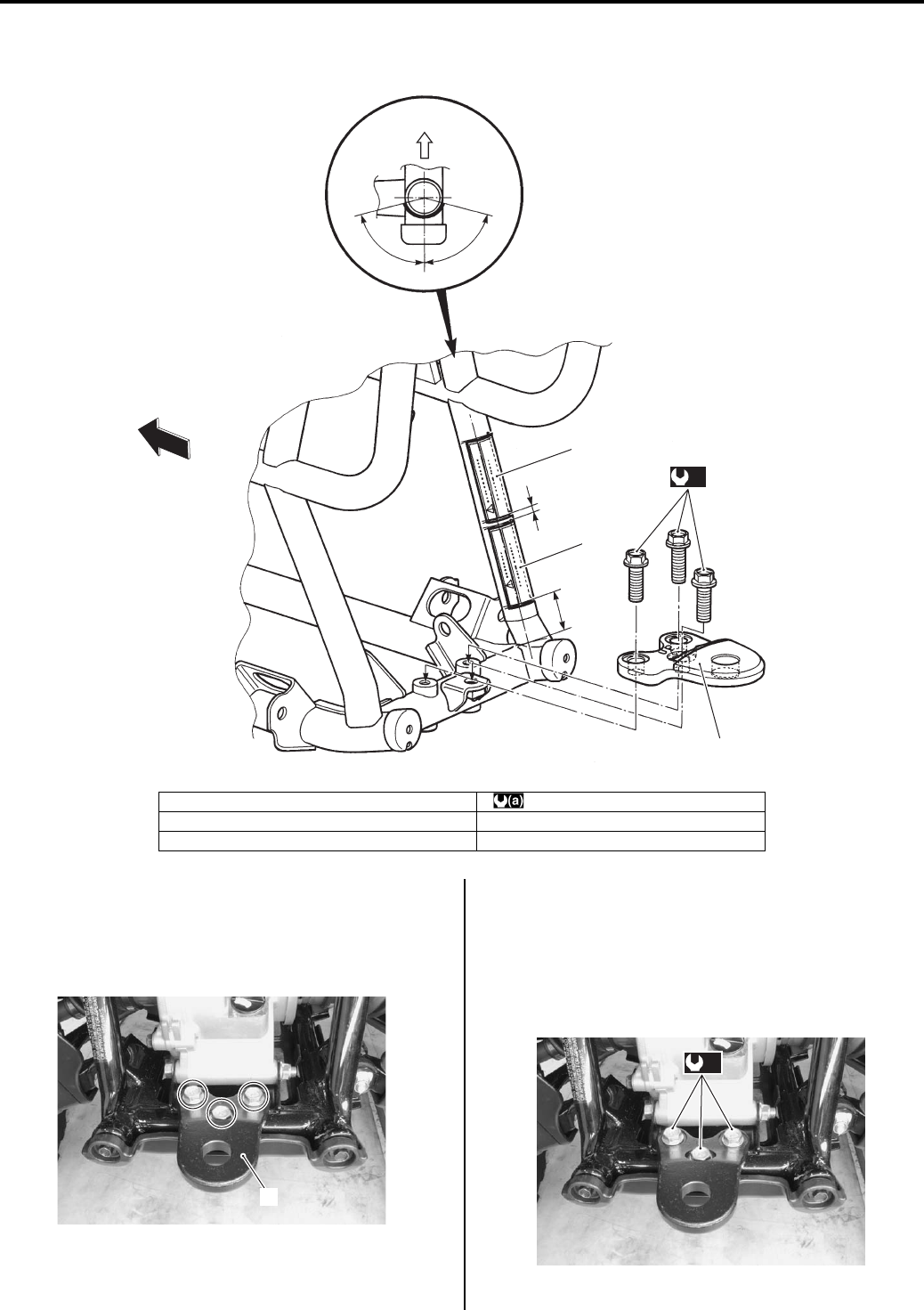
9E-7 Body Structure:
Trailer Towing Construction
B831G29506009
Trailer Towing Removal and Instruction
B831G29506010
Removal
Remove the trailer towing (1).
Installation
Install the trailer towing with the trailer towing mounting
bolts and then tighten them to the specified torque.
Tightening torque
Trailer towing mounting bolt (a): 60 N·m (6.0 kgf-m,
43.5 lb-ft)
FWD
“a”
“b”
1
3
2
FWD
(a)
I831G1950020-04
1. Trailer towing warning label (P-17, 28) : 60 N⋅m (6.0 kgf-m, 43.5 lb-ft)
2. Trailer towing warning label “a“: 5 mm (0.2 in)
3. Trailer towing “b“: 30 mm (1.2 in)
1
I831G1950021-01
(a)
I831G1950022-01
PartShark.com
877-999-5686
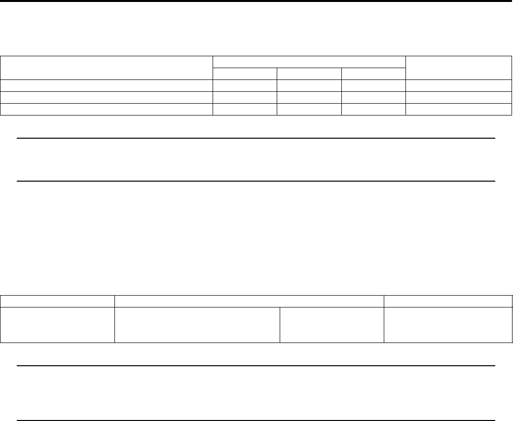
Body Structure: 9E-8
Specifications
Tightening Torque Specifications
B831G29507001
NOTE
The specified tightening torque is also described in the following.
“Footrest Construction (Page 9E-1)”
“Trailer Towing Construction (Page 9E-7)”
Reference:
For the tightening torque of fastener not specified in this section, refer to “Tightening Torque List in Section 0C
(Page 0C-7)”.
Special Tools and Equipment
Recommended Service Material
B831G29508001
NOTE
Required service material is also described in the following.
“Footrest Construction (Page 9E-1)”
“Carrier Construction (Page 9E-3)”
“Front Grip Bar Construction (Page 9E-6)”
Fastening part Tightening torque Note
N⋅mkgf—mlb—ft
Footrest mounting bolt (M8) 26 2.6 19.0 )(Page 9E-2)
Footrest mounting bolt (M10) 55 5.5 40.0 )(Page 9E-2)
Trailer towing mounting bolt 60 6.0 43.5 )(Page 9E-7)
Material SUZUKI recommended product or Specification Note
Thread lock cement THREAD LOCK CEMENT SUPER
1322 or equivalent
P/No.: 99000–32110 )(Page 9E-2) / )(Page 9E-
4) / )(Page 9E-5) /
)(Page 9E-6)
PartShark.com
877-999-5686

#/.4%.43
0!‘ %
30%#)&)#!4)/.3
NOTE:
* Asterisk mark (*) indicates the New K9-model specification.
* The service data is the same as the K8-model.
LT-A750XK9 (‘09-MODEL)
10
LT-A750XK9 (’09-MODEL) 10-1
PartShark.com
877-999-5686

30%#)&)#!4)/.3
$)-%.3)/.3!.$#52″-!33
/VERALLLENGTH MMIN 0
MMIN 0
/VERALLWIDTH MMIN 0
MMIN 0
/VERALLHEIGHT MMIN
7HEELBASE MMIN
‘ROUNDCLEARANCE MMIN
3EATHEIGHT MMIN
#URBMASS KGLBS 0
KGLBS 0
&RONTTRACK MMIN
2EARTRACK MMIN
%.’).%
4YPE STROKELIQUIDCOOLED$/(#
.UMBEROFCYLINDERS
«ORE MMIN
3TROKE MMIN
$ISPLACEMENT CMCUIN
#OMPRESSIONRATIO
&UELSYSTEM &UELINJECTION
!IRCLEANER .ONWOVENFABRICELEMENT
3TARTERSYSTEM %LECTRICANDRECOILSTARTER
,UBRICATIONSYSTEM 7ETSUMP
)DLESPEED ÕRMIN
$2)6%42!).
#LUTCH 7ETSHOEAUTOMATICCENTRIFUGALTYPE
4RANSMISSION !UTOMATICVARIABLERATIO6BELT
4RANSFER SPEEDFORWARDWITHREVERSE
‘EARSHIFTPATTERN 4RANSMISSION !UTOMATIC
4RANSFER ,(.2(ANDOPERATED
0RIMARYREDUCTIONRATIO!UTOMATICDRIVE n6ARIABLECHANGE
3ECONDARYREDUCTIONRATIO
&INALREDUCTIONRATIO&RONT2EAR
4RANSFERGEARRATIO ,OW
(IGH
2EVERSE
$RIVESYSTEM 3HAFTDRIVE
#(!33)3
&RONTSUSPENSION )NDEPENDENTDOUBLEWISHBONECOILSPRINGOILDAMPED
2EARSUSPENSION )NDEPENDENTDOUBLEWISHBONECOILSPRINGOILDAMPED
&RONTWHEELTRAVEL MMIN
2EARWHEELTRAVEL MMIN
#ASTER
4RAIL MMIN
4OEOUT MMIN
#AMBER
3TEERINGANGEL RIGHTLEFT
4URNINGRADIUS MFT
&RONTBRAKE $ISCBRAKETWIN
2EARBRAKE 3EALEDOILBATHEDMULTIDISC
&RONTTIRE !4X°°TUBELESS
2EARTIRE !4X°°TUBELESS
%,%#42)#!,
)GNITIONTYPE %LECTRONICIGNITION#$L
)GNITIONTIMING »4$#ATRMIN
3PARKPLUG .’+#2%OR$%.3/5%32.
«ATTERY 6K#!H(2
‘ENERATOR 4HREEPHASE!#GENERATOR
-AINFUSE !
&USE !
(EADLIGHT 67¾
!58LAMP 67
«RAKELIGHT4AILLIGHT 67
2EVERSEINGLIGHT 67 0
3PEEDOMETERLIGHT ,%$
.EUTRALINDICATORLIGHT ,%$
(IGHBEAMINDICATORLIGHT ,%$ 0
#OOLANTTEMPERATURE&LINDICATORLIGHT ,%$
2EVERSEINDICATORLIGHT ,%$
$IFFLOCKINDICATORLIGHT ,%$
#!0!#)4)%3
&UELTANK ,53LMPGAL
%NGINEOIL OILCHANGE ML53)MPQT
7ITHFILTERCHANGE ML53)MPQT
/VERHAUL ML53)MPQT
$IFFERENTIALGEAROIL ML53)MPOZ
&INALGEAROIL ML53)MPOZ
#OOLANT ,53)MPQT
10-2 LT-A750XK9 (’09-MODEL)
PartShark.com
877-999-5686

LT-A750XPK9 (‘09-MODEL)
11
This chapter describes service data, service specifications and servicing procedures which
differ from those of the LT-A750X/ZK9.
LT-A750XPK9 (’09-MODEL)
PartShark.com
877-999-5686
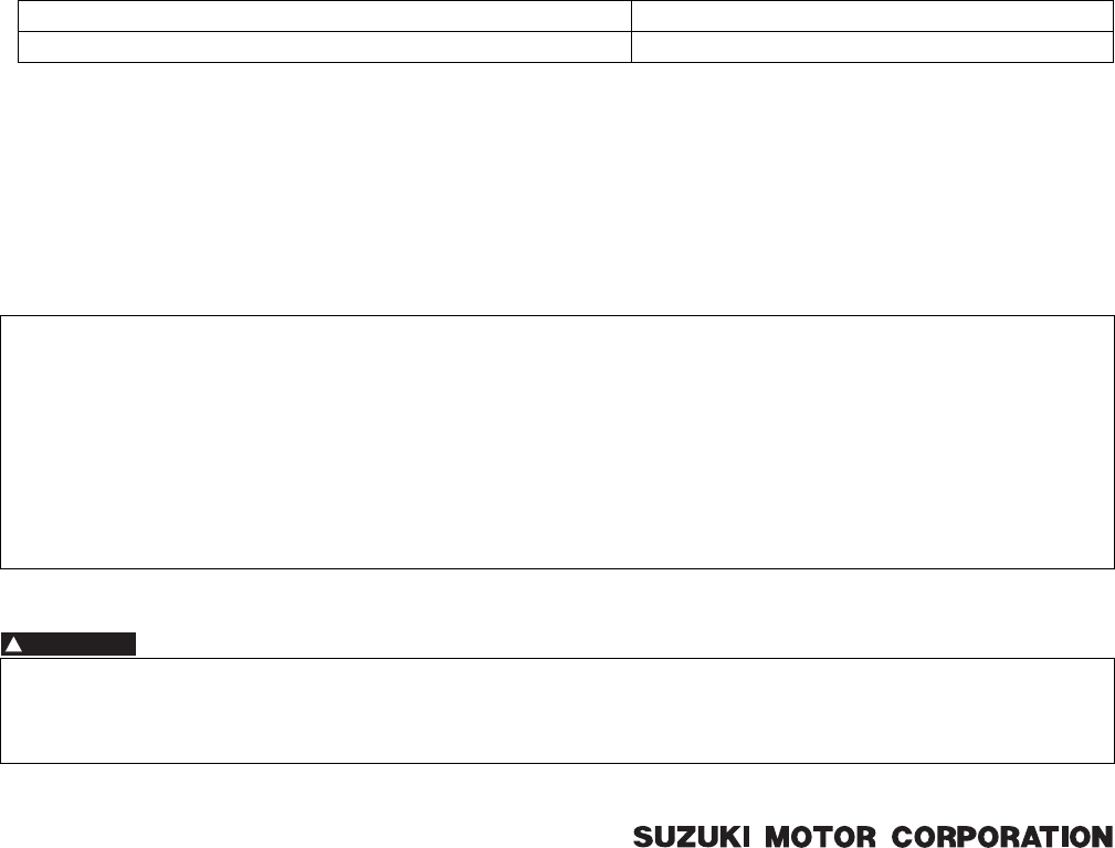
FOREWORD
This SUPPLEMENTARY SERVICE MANUAL is a supplement to SUZUKI LT-A750X/Z SERVICE MANUAL.
It has been prepared exclusively for the following applicable model.
Applicable model:
LT-A750X0:K9
This supplementary service manual describes only service information which differ from that of the main man-
ual. Therefore, whenever servicing the above applicable model, consult this supplement first. And for any sec-
tion, item or description not found in this supplement, refer to the main manual below.
Main Manual:
Other information considered as generally known is not included.
Read the GENERAL INFORMATION section to familiarize yourself with the vehicle and its maintenance. Use
this section as well as other sections to use as a guide for proper inspection and service.
This manual will help you know the vehicle better so that you can assure your customers of fast and reliable ser-
vice.
© COPYRIGHT SUZUKI MOTOR CORPORATION 2009
Manual Name Manual No.
LT-A750X/ZK9 SERVICE MANUAL 99500-47021-03E
* This manual has been prepared on the basis of the latest specifications at the time of publication. If modifi-
cations have been made since then, differences may exist between the content of this manual and the
actual vehicle.
* Illustrations in this manual are used to show the basic principles of operation and work procedures. They
may not represent the actual vehicle exactly in detail.
* This manual is written for persons who have enough knowledge, skills and tools, including special tools, for
servicing SUZUKI vehicles. If you do not have the proper knowledge and tools, ask your authorized
SUZUKI motorcycle dealer to help you.
WARNING
!
Inexperienced mechanics or mechanics without the proper tools and equipment may not be able to
properly perform the services described in this manual.
Improper repair may result in injury to the mechanic and may render the vehicle unsafe for the rider.
PartShark.com
877-999-5686

00
0
1
2
3
4
5
6
9
Precautions…………..…………………………………………. 00-i
Precautions ……………………….……………….…………. 00-1
General Information ……………….……………….…………. 0-i
General Information …..…………….………………..…… 0A-1
Maintenance and Lubrication ….……………….………. 0B-1
Service Data……………..…………….………………..……0C-1
Engine ………………………….………………..…………….…… 1-i
Precautions ……………………….……………….……………. 1-*
Engine General Information and Diagnosis …………1A-*
Emission Control Devices ……………….………….…….1B-*
Engine Electrical Devices………….………………..…… 1C-*
Engine Mechanical………….………………..……………. 1D-*
Engine Lubrication System …….……………….………..1E-*
Engine Cooling System…………………..………………..1F-*
Fuel System …….…………….………………..……………. 1G-*
Ignition System…………….………………..…………….… 1H-*
Starting System……………………………………..……….. 1I-1
Charging System…………….………………..……………..1J-1
Exhaust System .…………….………………..……………..1K-*
Suspension…….……………….……………..……………….…2-*
Precautions ……………………….……………….……………. 2-*
Suspension General Diagnosis…….………….………..2A-*
Front Suspension …………………………..………………..2B-*
Rear Suspension…….……………….………………..…… 2C-*
Wheels and Tires …………………….…………….………. 2D-*
Driveline / Axle ……………..………………..…………….…… 3-i
Precautions ……………………….……………….……………. 3-*
Drive Chain / Drive Train / Drive Shaft ………………. 3A-1
Differential ……….…………….………………..……………..3B-*
Transfer…..…………….……………….…………….………. 3C-*
Propeller Shafts..…………….………………..……………. 3D-*
Brake …………..…………….……………….……………..……… 4-i
Precautions ……………………….……………….……………. 4-*
Brake Control System and Diagnosis .………………. 4A-1
Front Brakes….…………….………………..…………….….4B-*
Rear Brakes ………..…………….…………….……………. 4C-*
Parking Brake..…………….………………..…………….… 4D-*
Transmission / Transaxle ……….……………….…………. 5-*
Precautions ……………………….……………….……………. 5-*
Automatic Transmission..………………………………….5A-*
Steering………………..……………….…………….……………. 6-i
Precautions ……………………….……………….…………… 6-1
Steering General Diagnosis …………………….………. 6A-1
Steering / Handlebar …….…………….………………….. 6B-1
Power Assisted Steering System .…………….……….6C-1
Body and Accessories………………………………..……… 9-i
Precautions …………….…………….……………….…………9-*
Wiring Systems ………….…………………………..………9A-1
Lighting Systems….……………..…………….…………… 9B-*
Combination Meter / Fuel Meter / Horn……………… 9C-*
Exterior Parts …………….…………….……………….…… 9D-*
Body Structure ………..…………………………..…………9E-1
TABLE OF CONTENTS
NOTE
For the screen toned sections with asterisk (*) in the “TABLE OF CONTENTS” below, refer to the same
sections of the service manual mentioned in the “FOREWORD” of this manual.
PartShark.com
877-999-5686
PartShark.com
877-999-5686

Table of Contents 00- i
00
Section 00
CONTENTS
Precautions
Precautions ………………………………………..00-1
Precautions….……………….……………..………………. 00-1
Warning / Caution / Note………..……………………… 00-*
General Precautions …………………………………..…00-*
Precautions for Electrical Circuit Service ………….00-*
Precautions for EPS (LT-A750XP/ZK9) ………….. 00-1
NOTE
For the items with asterisk (*) in the “CONTENTS” below, refer to the same section of the service manual
mentioned in the “FOREWORD” of this manual.
PartShark.com
877-999-5686
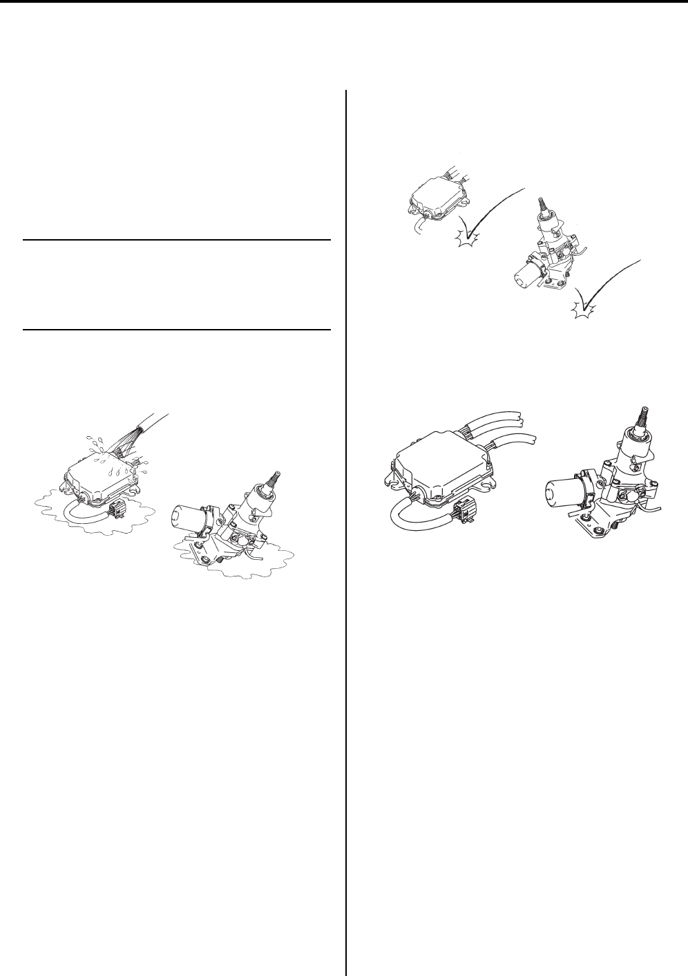
00-1 Precautions:
Precauti ons
Precautions
Precautions
Precautions for EPS (LT-A750XP/ZK9)
B931G40000004
EPS Wiring
• The EPS parts are connected to various lead wires.
The coupler and lead wire connections, as well as the
lead wire and wire harness routings must be done
correctly. Make sure that the proper clamps are used
and positioned correctly.
NOTE
If all of the connections are not properly
connected, the EPS may not operate
correctly. For connector and coupler
precautions. Refer to “Precautions for
Electrical Circuit Service in related manual”.
EPS Control Unit / EPS Body Assembly
• Never allow dust or water to contact the EPS control
unit and EPS body assembly.
• Since each component is a high-precision part, great
care should be taken not to apply any service impacts
during removal and installation.
• The EPS control unit and EPS body assembly cannot
be disassembled. Replace the whole unit with a new
one.
I931H1000004-01
I931H1000003-02
I931H1000005-01
PartShark.com
877-999-5686

Table of Contents 0- i
0
Section 0
CONTENTS
General Information
General Information ………………………….. 0A-1
General Description ………………………..…………….0A-1
Symbols ……….…………….……………..………………..0A-*
Abbreviations ……………………….………………..…….0A-*
SAE-to-Former SUZUKI Term …..………….………..0A-*
Vehicle Side View ……..………………………..………..0A-*
Vehicle Identification Number ……….………………..0A-*
Fuel and Oil Recommendation ……..………….…….0A-*
Engine Coolant Recommendation …………………..0A-*
BREAK-IN Procedures…………………………………..0A-*
Country and Area Codes ……….…………….………..0A-*
Wire Color Symbols ………………………….…………..0A-*
Warning, Caution and Information Labels
Location ………………………….……………….………..0A-*
Abbreviations (LT-A750XP/ZK9)……………………. 0A-1
Vehicle Side View (LT-A750XP/ZK9)……………… 0A-1
Country and Area Codes (LT-A750XP/ZK9)…….0A-1
Warning, Caution and Information Labels
Location (LT-A750XP/ZK9)…………………………. 0A-2
Component Location ………..………….………….…… 0A-*
Electrical Components Location .…………..………..0A-*
Specifications…….……………….…………….………….0A-3
Specifications (LT-A750X/ZK8)……..………….…….0A-*
Specifications (LT-A750X/ZK9)……..………….…….0A-*
Specifications (LT-A750XP/ZK9) …..……………….0A-3
Special Tools and Equipment ……………………….. 0A-*
Special Tools and Equipment ………………………..0A-5
Special Tool …………..…………………………..……….0A-5
Maintenance and Lubrication…………….. 0B-1
Precautions…………..…………………………..…………. 0B-*
Precautions for Maintenance …….………….………..0B-*
General Description ………………………..……………. 0B-*
Recommended Fluids and Lubricants.……………..0B-*
Scheduled Maintenance …………………….…………. 0B-*
Periodic Maintenance Schedule Chart……………..0B-*
Lubrication Points ………..………………..……………..0B-*
Repair Instructions …….…………….………….……….0B-1
Air Cleaner Element Inspection and Cleaning …..0B-*
Exhaust Pipe Bolt and Muffler Bolt Inspection …..0B-*
Valve Clearance Inspection and Adjustment …….0B-*
Spark Plug Replacement ………….……………..…….0B-*
Spark Plug Inspection and Cleaning………….…….0B-*
Spark Arrester Cleaning…………………………..…….0B-*
Fuel Line Inspection ………………………..…………… 0B-*
Engine Oil and Filter Replacement ………………… 0B-*
Front Differential Gear Oil Inspection……………… 0B-*
Front Differential Gear Oil Replacement …………. 0B-*
Final Gear Oil Inspection…………………….………… 0B-*
Final Gear Oil Replacement…….…………….……… 0B-*
Throttle Cable Play Inspection and
Adjustment ……………………….……………….……… 0B-*
Throttle Body Inspection ………………….…………… 0B-*
Cooling System Inspection…………………….……… 0B-*
Drive V-belt Inspection and Replacement……….. 0B-*
Drive Shaft Boots Inspection………………….……… 0B-*
Front Brake System Inspection …..………….……… 0B-*
Rear Brake Pedal / Rear Brake (Parking
Brake) Lever Inspection and Adjustment ………. 0B-*
Rear Brake Friction Plate Wear Limit
Inspection……….……………..……………….………… 0B-*
Tire Inspection……………………….…………….……… 0B-*
Steering System Inspection ……….………….……… 0B-*
Toe Adjustment ………….…………….………….……… 0B-*
Suspensions Inspection ……….…………….………… 0B-*
Chassis Bolt and Nut Inspection …………….……… 0B-*
Compression Pressure Check ………………….…… 0B-*
Oil Pressure Check …….…………….………….……… 0B-*
SDS Check……….………………..…………….………… 0B-*
Automatic Clutch Inspection….…………….………… 0B-*
Air Cleaner Element Inspection and Cleaning
(LT-A750XP/ZK9)………..………………..……………0B-1
Steering System Inspection (LT-A750XP/
ZK9) …………………………………………………………0B-1
Toe Adjustment (LT-A750XP/ZK9) …………………0B-2
Chassis Bolt and Nut Inspection (LT-A750XP/
ZK9) …………………………………………………………0B-3
Specifications………..………………….…………….……0B-4
Tightening Torque Specifications…..……………….0B-4
Special Tools and Equipment ……………………….. 0B-*
Recommended Service Material …………….……… 0B-*
Special Tool ………………………………………..……… 0B-*
Service Data ……………………………………… 0C-1
Specifications………..……………….…………….………0C-1
Service Data……………………….……………….……… 0C-*
Tightening Torque List ………………………….……… 0C-*
Service Data (LT-A750XP/ZK9) …….……………….0C-1
Tightening Torque List (LT-A750XP/ZK9)………..0C-7
NOTE
For the items with asterisk (*) in the “CONTENTS” below, refer to the same section of the service manual
mentioned in the “FOREWORD” of this manual.
PartShark.com
877-999-5686
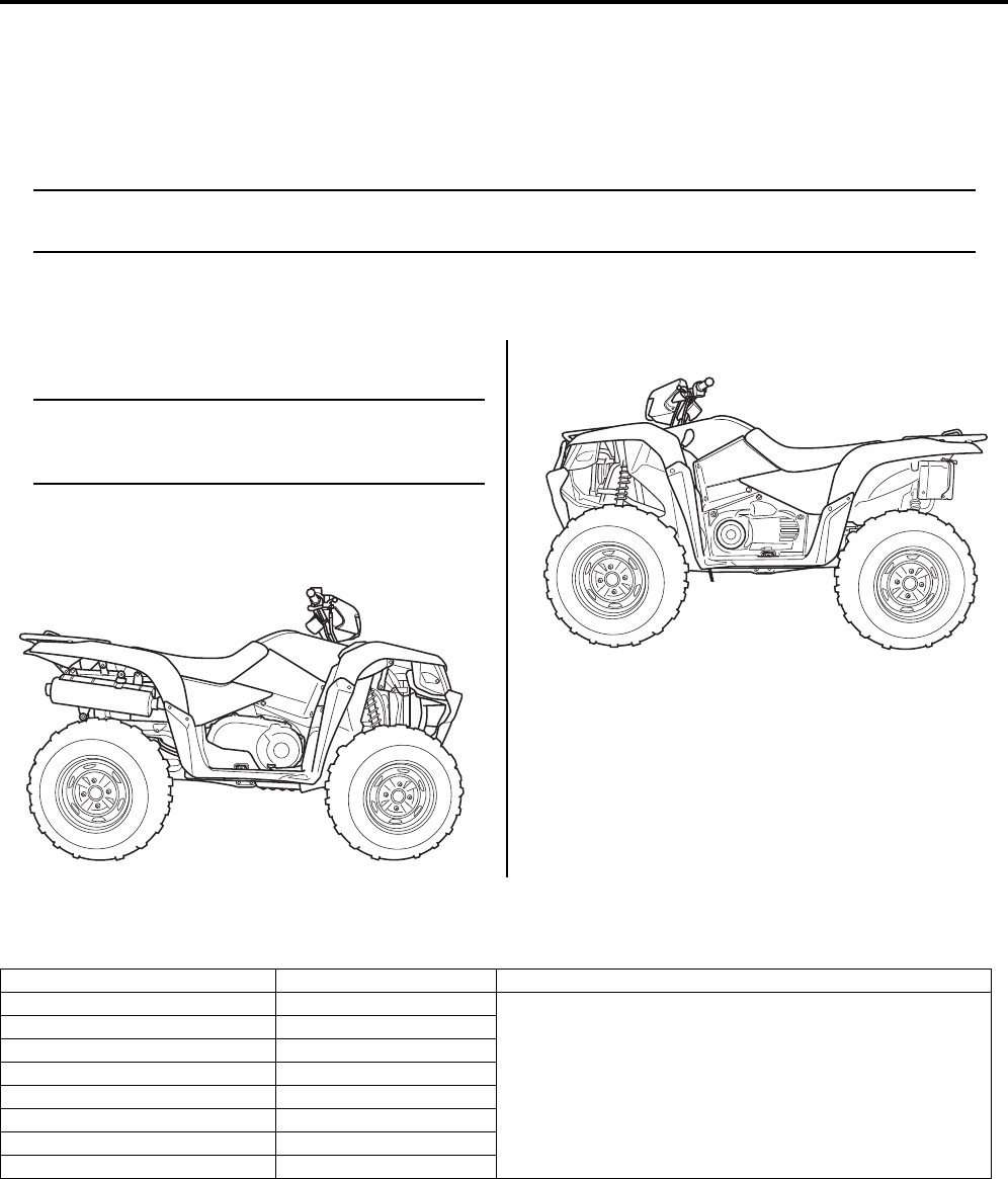
0A-1 General Information:
General In formation
General Information
General Description
Abbreviations (LT-A750XP/ZK9)
B931G40101012
NOTE
Please refer to the LT-A750XK9 (’09-model) service manual for other abbreviations which are not given
in this manual.
E:
EPS: Electronic Power Steering
Vehicle Side View (LT-A750XP/ZK9)
B931G40101013
NOTE
Difference between illustration and actual
motorcycles may exist depending on the
markets.
SUZUKI LT-A750XP (2009-model)
Right Side
Left Side
Country and Area Codes (LT-A750XP/ZK9)
B931G40101014
The following codes stand for the applicable country(-ies) and area(-s).
I931G3010001-01
I931G3010002-01
Code Country or Area Effective Frame No.
LT-A750XPK9 (P-17) Sweden
5SAAR41P97100001 –
LT-A750XPK9 (P-24) Australia
LT-A750XPK9 (P-28) Canada
LT-A750XPK9 (P-33) U.S.A.
LT-A750XPZK9 (P-17) Sweden
LT-A750XPZK9 (P-24) Australia
LT-A750XPZK9 (P-28) Canada
LT-A750XPZK9 (P-33) U.S.A.
PartShark.com
877-999-5686
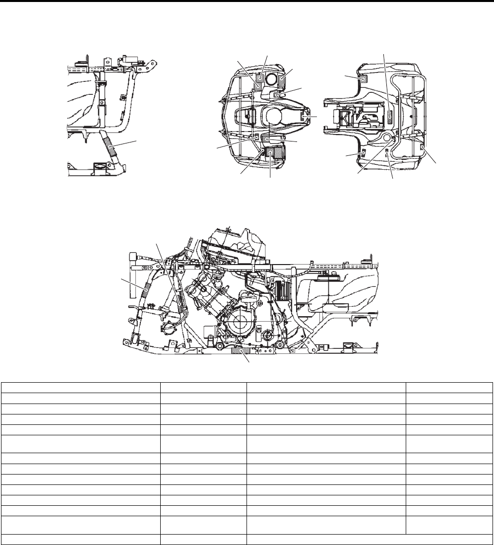
General Information: 0A-2
Warning, Caution and Information Labels Location (LT-A750XP/ZK9)
B931G40101015
5
14 17, 18
11
9
6
3
7
8
10
12, 13
15, 16
4
1, 20, 21
22, 23
24
19
25
2, 26, 27
[A]
I931H1010010-03
1. Certification plate (English) For P-24, 33 15. Front carrier warning label (English) For P-24, 33
2. Information label (English) For P-33 16. Front carrier warning label (English/French) For P-17, 28
3. Gearshift label (English) For P-17, 24, 28, 33 17. Rear carrier warning label (English) For P-24, 33
4. Gearshift label (French) For P-28 18. Rear carrier warning label (English/French) For P-17, 28
5. Tire air pressure label (English) For P-17, 24, 28, 33 19. ICES Canada label (English/French) For P-28
6. Tire air pressure label and warning no-
passenger label (French) For P-28 20. Compliance label (English) For P-28
7. General warning & AGE, 16 label (English) For P-17, 24, 28, 33 21. I.D. plate (English) For P-17
8. General warning label (French) For P-28 22. Cooling fan label (English) For P-24, 33
9. Warning no-passenger label (English) For P-17, 24, 28, 33 23. Cooling fan label (English/French) For P-17, 28
10. AGE, 16 label (French) For P-28 24. Compliance label (English/French) For P-28
11. Manual notice label (English) For P-33 25. ANSI certification label (Right side of frame) For P-33
12. Max AMP caution label (English) For P-24, 33 26. Information label (English) For P-28
13. Max AMP caution label (English/French) For P-17, 28 27. Information label (French)
(Right side of frame) For P-28
14. Fuel caution label (English) For P-24 [A]: Left side of frame
PartShark.com
877-999-5686

0A-3 General Information:
Specifications
Specifications (LT-A750XP/ZK9)
B931G40107003
NOTE
These specifications are subject to change without notice.
Dimensions and curb mass
Engine
Drive train
Item Specification Remark
Overall length 2 115 mm (83.3 in) P-28, 33
2 165 mm (85.2 in) P-17, 24
Overall width 1 210 mm (47.6 in) P-28, 33
1 250 mm (49.2 in) P-17, 24
Overall height 1 285 mm (50.6 in)
Wheelbase 1 285 mm (50.6 in)
Ground clearance 260 mm (10.2 in)
Seat height 920 mm (36.2 in)
Curb mass 305 kg (672 lbs) P-28, 33
307 kg (677 lbs) P-17, 24
Front track 940 mm (37.0 in)
Rear track 920 mm (36.2 in)
Item Specification Remark
Type 4-stroke, liquid-cooled, DOHC
Number of cylinders 1
Bore 104.0 mm (4.094 in)
Stroke 85.0 mm (3.346 in)
Displacement 722 cm3 (44.1 cu. in)
Compression ratio 10.0 : 1
Fuel system Fuel injection
Air cleaner Paper element
Starter system Electric starter
Lubrication system Wet sump
Idle speed 1 300 r 100 r/min
Item Specification Remark
Clutch Wet shoe, automatic, centrifugal type
Transmission CVT (V-belt)
Transfer 2-speed forward with reverse
Gearshift
pattern
Transmission Automatic
Transfer L-H-N-R (Hand operated)
Automatic transmission ratio Variable change (2.763 – 0.78)
Secondary reduction ratio 2.158 (40/21 x 17/15)
Final reduction ratio
(Front & Rear) 3.600 (36/10)
Transfer gear
ratio
Low 2.562 (41/16)
High 1.240 (31/25)
Reverse 1.882 (32/17)
Drive system Shaft drive
PartShark.com
877-999-5686

General Information: 0A-4
Chassis
Electrical
Capacities
Item Specification Remark
Front suspension Independent, double wishbone, coil spring, oil damped
Rear suspension Independent, double wishbone, coil spring, oil damped
Front wheel travel 170.5 mm (6.7 in)
Rear wheel travel 195 mm (7.7 in)
Caster 3.3q
Trail 16.7 mm (0.66 in)
Toe-out 5 mm (0.20 in)
Camber –1.3q
Steering angle 46q (right & left)
Turning radius 3.1 m (10.2 ft)
Front brake Disc brake, twin
Rear brake Sealed oil-bathed multi-disc
Front tire size AT25 x 8-12
, tubeless
Rear tire size AT25 x 10-12
, tubeless
Item Specification Remark
Ignition type Electronic ignition (CDI)
Ignition timing 7q B.T.D.C. at 1 300 r/min
Spark plug NGK CR6E or DENSO U20ESR-N
Battery 12 V 64.8 kC (18 Ah)/10 HR
Generator Three-phase A.C. generator
Main fuse 30 A
Fuse 10/10/10/10/15/15 A
EPS fuse 40 A
Headlight 12 V 35/35 W x 2
Auxiliary light 12 V 35/35 W
Brake light/Taillight 12 V 21/5 W
Reversing light 12 V 21 W P-17
Speedometer light LED
Neutral indicator light LED
High beam indicator light LED P-17
Coolant temperature/FI
indicator light LED
Reverse indicator light LED
Diff-lock indicator light LED
EPS indicator light LED
Item Specification Remark
Fuel tank 17.5 L (4.6/3.8 US/lmp gal)
Engine oil
Oil change 2 300 ml (2.4/2.0 US/lmp qt)
With filter
change 2 500 ml (2.6/2.2 US/lmp qt)
Overhaul 3 000 ml (3.2/2.6 US/lmp qt)
Differential gear oil 500 ml (16.9/17.6 US/lmp oz)
Final gear oil 770 ml (26.0/27.1 US/lmp oz)
Coolant 2.5 L (2.6/2.2 US/lmp qt)
PartShark.com
877-999-5686

0A-5 General Information:
Special Tools and Equipment
Special Tool
B931G40108002
09900–06107
Snap ring remover
(Open type)
09900–20102
Vernier calipers (200
mm)
09900–25008
Multi circuit tester set
09900–25009
Needle-point probe
set
09904–41010
SUZUKI Diagnostic
system set
09924–84521
Bearing installer set
09930–30721
Rotor remover
09930–44530
Rotor holder
09930–82710
Mode select switch
09930–82720
Mode selection switch
09942–72410
Tie-rod end remover
09942–83110
Clip remover
09944–36011
Steering wheel
remover
99565–01010–020
CD-ROM Ver.20
PartShark.com
877-999-5686
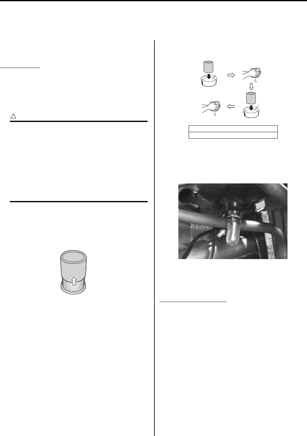
Maintenance and Lubrication: 0B-1
General In formation
Maintenance and Lubrication
Repair Instructions
Air Cleaner Element Inspection and Cleaning
(LT-A750XP/ZK9)
B931G40206030
Clean element
Every 1 000 km (600 miles, 3 months)
If the air cleaner is clogged with dust, intake resistance
will be increased, with a resultant decrease in power
output and an increase in fuel consumption. Check and
clean the air cleaner element in the following manner.
CAUTION
!
• If driving under dusty conditions, clean the
air cleaner element more frequently. The
surest way to accelerate engine wear is to
operate the engine without the element or
to use a torn element. Make sure that the
air cleaner is in good condition at all times.
Life of the engine depends largely on this
component.
• Inspect the air cleaner element for tears. A
torn element must be replaced.
1) Remove the air cleaner element. Refer to “Air
Cleaner Element Removal and Installation in Section
1D in related manual”.
2) Separate the polyurethane from element.
3) Fill a wash pan of a proper size with a non-
flammable cleaning solvent. Immerse the air cleaner
element in the cleaning solvent and wash it.
4) Press the air cleaner element between the palms of
both hands to remove the excess solvent: do not
twist or wring the element or it will tear.
5) Immerse the element in motor oil, and then squeeze
out the excess oil leaving the element slightly wet.
6) After cleaning the air cleaner element, reinstall the
removed parts.
7) Drain water from the air cleaner box by removing the
drain plug.
Reinstall the drain plug.
Steering System Inspection (LT-A750XP/ZK9)
B931G40206031
Inspect steering system
Initially at 200 km (100 miles, 1 month) and every 1
000 km (600 miles, 3 months) thereafter
Steering should be adjusted properly for smooth turning
of handlebars and safe running.
1) Place the vehicle on level ground.
2) Make sure the tire pressure for right and left tires in
the same and set to the proper specification.
3) Set the front wheels in the straight position.
4) Place a load of 75 kg (165 lbs) on the seat.
I831G1020002-01
“A”: Non-flammable cleaning solvent
“B”: Motor oil SAE #30 or SAE 10W-40
“A”
“B”
I931G3020009-01
I831G1020004-01
PartShark.com
877-999-5686
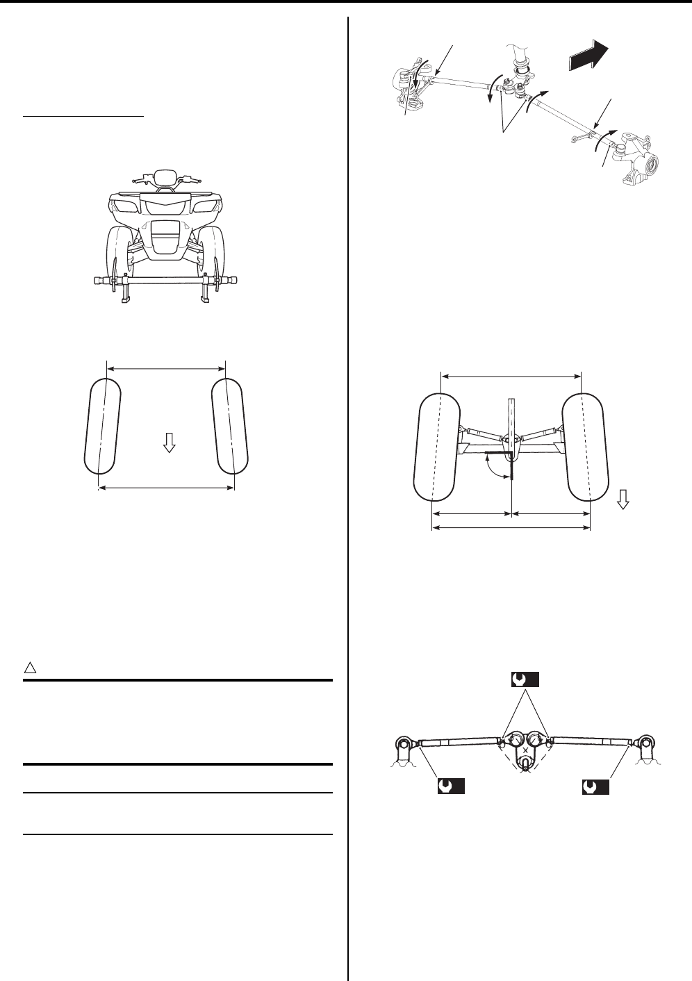
0B-2 Maintenance and Lubrication:
5) Measure the distances (“A” and “B”) between the
front wheels. Subtract the measurement of “A” from
that of “B” to find the toe-out. If the toe-out is not
within specification, adjust the tie-rod to the right or
left until the toe-out is within the specified range.
Toe-out (“B” – “A”)
Standard: 5 r 4 mm (0.20 r 0.16 in)
If the toe-out is out of specification, bring it into the
specified range. Refer to “Toe Adjustment (LT-A750XP/
ZK9) (Page 0B-2)”.
Toe Adjustment (LT-A750XP/ZK9)
B931G40206032
Adjust the toe-out as follows:
1) Loosen the lock-nuts (1), (2) on each tie-rod.
CAUTION
!
• The lock-nuts (2) have left-hand threads.
• When loosening and tightening the lock-
nuts, hold the tie-rod end with a open end
wrench.
NOTE
Hold the concave part “a” of tie-rod with a
wrench.
2) Temporarily tighten the four lock-nuts.
3) Check that the distances “C” and “D” are equal, as
shown. If the distances are not equal, adjust the tie-
rod to the right or left until the toe-out is within
specification. Check the toe-out again by measuring
distances “A” and “B”.
4) If the toe-out is not within specification, repeat the
adjustment as above until the proper toe-out is
obtained and distances “C” and “D” become equal.
5) After adjustment has been made, tighten the four
lock-nuts to the specified torque.
Tightening torque
Tie-rod lock-nut (a): 29 N·m (2.9 kgf-m, 21.0 lbf-
ft)
I931H1020057-01
FWD
“A”
“B”
I831G1020059-04
2
1
1
“a”
“a”
FWD
I931H1020079-02
“C”
Right angle
(90
°
)
FWD
“A”
“B”
“D”
I831G1020088-04
(a)
(a)
(a)
I831G1020089-01
PartShark.com
877-999-5686
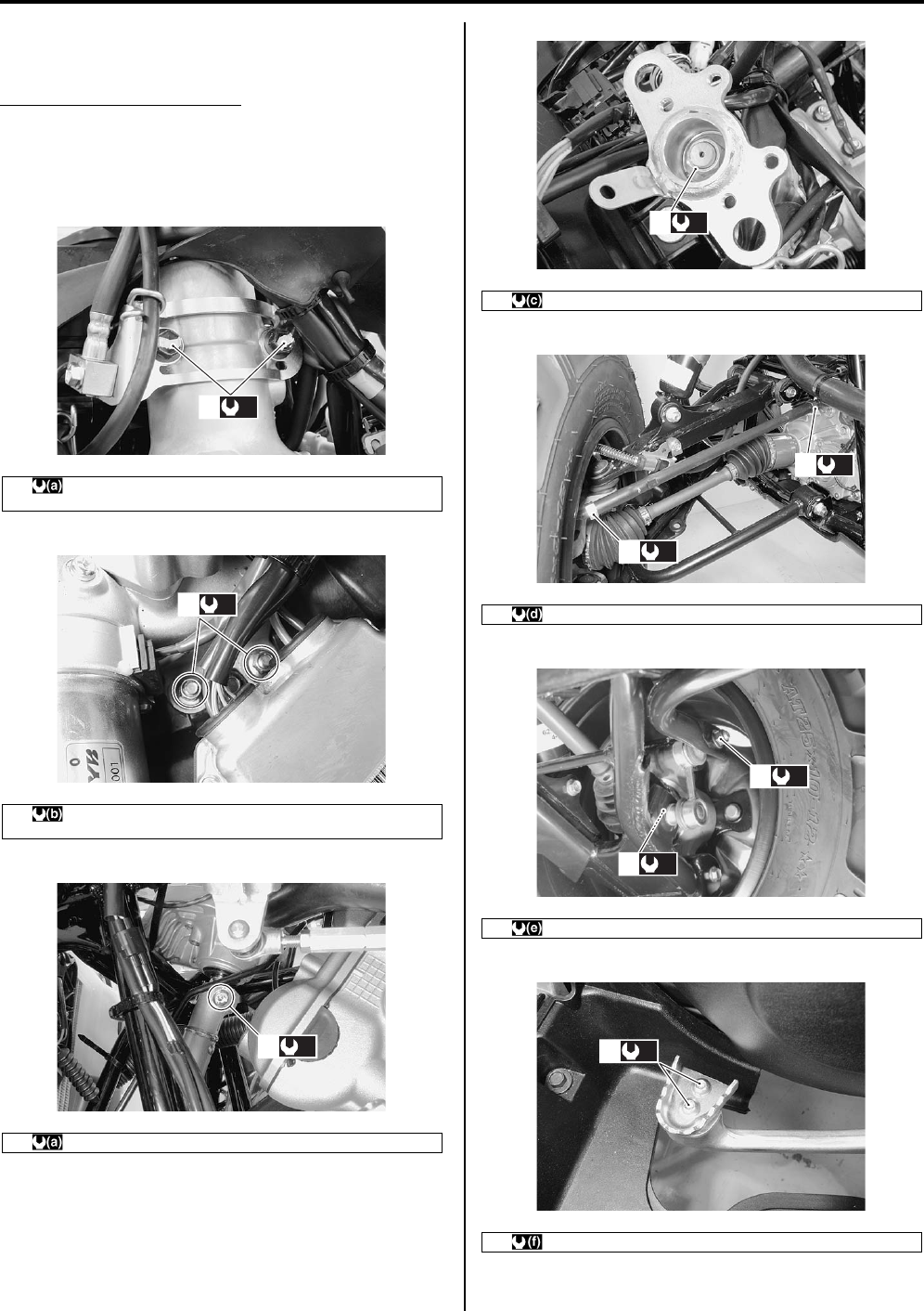
Maintenance and Lubrication: 0B-3
Chassis Bolt and Nut Inspection (LT-A750XP/
ZK9)
B931G40206033
Tighten chassis bolt and nut
Initially at 200 km (100 miles, 1 month) and every 1
000 km (600 miles, 3 months) thereafter
Check that all chassis bolts and nuts are tightened to
their specified torque.
1 EPS body assembly mounting bolt (Upper) 26 Nm (2.6 kgf-m,
19.0 lbf-ft)
2 EPS body assembly mounting nut (Lower) 28 Nm (2.8 kgf-m,
20.0 lbf-ft)
3 Steering shaft bolt 26 Nm (2.6 kgf-m, 19.0 lbf-ft)
(a)
1
I931G3020001-01
(b)
2
I931G3020002-01
(a)
3
I931G3020003-01
4 Steering shaft upper nut 120 Nm (12.0 kgf-m, 87.0 lbf-ft)
5 Tie-rod lock-nut 29 Nm (2.9 kgf-m, 21.0 lbf-ft)
6 Rear stabilizer joint nut 60 Nm (6.0 kgf-m, 43.5 lbf-ft)
7 Rear brake pedal screw 4.5 Nm (0.45 kgf-m, 3.0 lbf-ft)
(c)
4
I931G3020004-02
(d)
5
(d)
5
I931G3020005-02
(e)
6
(e)
6
I931G3020007-02
(f)
7
I931G3020008-01
PartShark.com
877-999-5686
0B-4 Maintenance and Lubrication:
Specifications
Tightening Torque Specifications
B931G40207001
NOTE
The specified tightening torque is described in the following.
“Chassis Bolt and Nut Inspection (LT-A750XP/ZK9) (Page 0B-3)”
Reference:
For the tightening torque of fastener not specified in this section, refer to “Tightening Torque List (LT-A750XP/ZK9) in
Section 0C (Page 0C-7)”.
Fastening part Tightening torque Note
Nm kgf-m lbf-ft
Tie-rod lock-nut 29 2.9 21.0 )(Page 0B-2)
PartShark.com
877-999-5686
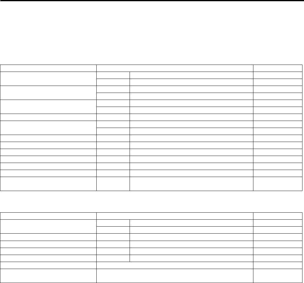
Service Data: 0C-1
General In formation
Service Data
Specifications
Service Data (LT-A750XP/ZK9)
B931G40307003
Valve + Valve Guide
Unit: mm (in)
Camshaft + Cylinder Head
Unit: mm (in)
Item Standard Limit
Valve diam. IN. 36.0 (1.42) —
EX. 33.0 (1.30) —
Tappet clearance (When cold) IN. 0.10 – 0.20 (0.004 – 0.008) —
EX. 0.20 – 0.30 (0.008 – 0.012) —
Valve guide to valve stem clearance IN. 0.010 – 0.037 (0.0004 – 0.0015) —
EX. 0.030 – 0.057 (0.0012 – 0.0022) —
Valve guide I.D. IN. & EX. 5.500 – 5.512 (0.2165 – 0.2170) —
Valve stem O.D. IN. 5.475 – 5.490 (0.2156 – 0.2161) —
EX. 5.455 – 5.470 (0.2148 – 0.2154) —
Valve stem deflection IN. & EX. — 0.35 (0.014)
Valve stem runout IN. & EX. — 0.05 (0.002)
Valve head thickness IN. & EX. — 0.5 (0.02)
Valve seat width IN. & EX. 0.9 – 1.1 (0.035 – 0.043) —
Valve head radial runout IN. & EX. — 0.03 (0.001)
Valve spring free length IN. & EX. — 46.1 (1.81)
Valve spring tension IN. & EX. 182 – 210 N (18.6 – 21.4 kgf, 41.0 – 47.2 lbs)
at length 36.35 mm (1.43 in) —
Item Standard Limit
Cam height IN. 36.330 – 36.380 (1.4303 – 1.4323) 36.030 (1.4185)
EX. 35.300 – 35.350 (1.3898 – 1.3917) 35.000 (1.3780)
Camshaft journal oil clearance IN. & EX. 0.019 – 0.053 (0.0007 – 0.0021) 0.150 (0.0059)
Camshaft journal holder I.D. IN. & EX. 22.012 – 22.025 (0.8666 – 0.8671) —
Camshaft journal O.D. IN. & EX. 21.972 – 21.993 (0.8650 – 0.8659) —
Camshaft runout IN. & EX. — 0.10 (0.004)
Cylinder head distortion — 0.05 (0.002)
Cam drive idle gear/sprocket thrust
clearance 0.15 – 0.27 (0.006 – 0.011) —
PartShark.com
877-999-5686
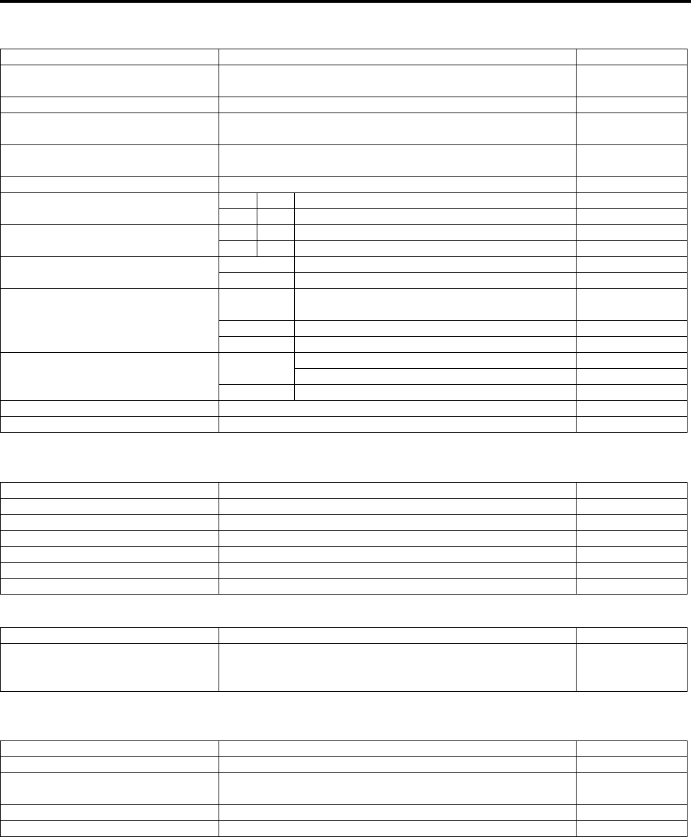
0C-2 Service Data:
Cylinder + Piston + Piston Ring
Unit: mm (in)
Conrod + Crankshaft
Unit: mm (in)
Oil Pump
Clutch
Unit: mm (in)
Item Standard Limit
Compression pressure
(Automatic-decomp. actuated) Approx. 1 000 kPa (10.0 kgf/cm2, 142 psi) —
Piston-to-cylinder clearance 0.030 – 0.040 (0.0012 – 0.0016) 0.120 (0.0047)
Cylinder bore 104.000 – 104.015 (4.0945 – 4.0951) Nicks or
Scratches
Piston diam. 103.965 – 103.980 (4.0931 – 4.0937)
Measure at 15 mm (0.6 in) from the skirt end. 103.880 (4.0898)
Cylinder distortion — 0.05 (0.002)
Piston ring free end gap 1st R Approx. 13.1 (0.52) 10.5 (0.41)
2nd RN Approx. 14.6 (0.57) 11.7 (0.46)
Piston ring end gap 1st R 0.10 – 0.25 (0.004 – 0.010) 0.50 (0.020)
2nd RN 0.10 – 0.25 (0.004 – 0.010) 0.50 (0.020)
Piston ring-to-groove clearance 1st — 0.180 (0.0071)
2nd — 0.150 (0.0059)
Piston ring groove width
1st 0.83 – 0.85 (0.0327 – 0.0335)
1.30 – 1.32 (0.0512 – 0.0520) —
2nd 1.01 – 1.03 (0.0398 – 0.0406) —
Oil 2.01 – 2.03 (0.0791 – 0.0799) —
Piston ring thickness 1st 0.76 – 0.81 (0.0299 – 0.0319) —
1.08 – 1.10 (0.0425 – 0.0433) —
2nd 0.97 – 0.99 (0.0382 – 0.0390) —
Piston pin bore I.D. 23.002 – 23.008 (0.9056 – 0.9058) 23.030 (0.9067)
Piston pin O.D. 22.992 – 23.000 (0.9052 – 0.9055) 22.980 (0.9047)
Item Standard Limit
Conrod small end I.D. 23.006 – 23.014 (0.9057 – 0.9061) 23.040 (0.9071)
Conrod deflection — 3.0 (0.12)
Conrod big end side clearance 0.10 – 0.75 (0.004 – 0.030) 1.0 (0.04)
Conrod big end width 24.95 – 25.00 (0.982 – 0.984) —
Crank web to web width 72.9 – 73.1 (2.87 – 2.88) —
Crankshaft runout — 0.08 (0.003)
Item Standard Limit
Oil pressure (at 60 qC, 140 qF)
140 – 180 kPa
(1.4 – 1.8 kgf/cm2, 20 – 26 psi)
at 3 000 r/min
—
Item Standard Limit
Clutch wheel I.D. 140.0 – 140.2 (5.512 – 5.520) 140.5 (5.53)
Clutch shoe — No groove at any
part
Clutch engagement r/min 1 500 – 2 000 r/min —
Clutch lock-up r/min 3 500 – 4 000 r/min —
PartShark.com
877-999-5686

Service Data: 0C-3
Drive Train
Unit: mm (in) Except ratio
Thermostat + Radiator + Fan + Coolant
Item Standard Limit
Automatic transmission ratio Variable change (2.763 – 0.780) —
Secondary reduction ratio 2.158 (40/21 x 17/15) —
Final reduction ratio Front 3.600 (36/10) —
Rear 3.600 (36/10) —
Transfer gear ratio
Low 2.562 (41/16) —
High 1.240 (31/25) —
Reverse 1.882 (32/17) —
Drive V-belt width 34.3 (1.35) 33.3 (1.31)
Movable driven face spring free
length 160.0 (6.30) 152.0 (6.00)
Shift fork to groove
clearance
Low 0.10 – 0.30 (0.0040 – 0.0120) 0.50 (0.020)
High 0.10 – 0.30 (0.0040 – 0.0120) 0.50 (0.020)
Reverse 0.10 – 0.30 (0.0040 – 0.0120) 0.50 (0.020)
Shift fork groove
width
Low 5.50 – 5.60 (0.217 – 0.220) —
High 5.50 – 5.60 (0.217 – 0.220) —
Reverse 5.50 – 5.60 (0.217 – 0.220) —
Shift fork thickness
Low 5.30 – 5.40 (0.209 – 0.213) —
High 5.30 – 5.40 (0.209 – 0.213) —
Reverse 5.30 – 5.40 (0.209 – 0.213) —
Front/Rear output shaft bevel gear
backlash 0.03 – 0.15 (0.001 – 0.006) —
Front drive (differential) gear
backlash 0.05 – 0.10 (0.002 – 0.004) —
Rear drive (final)
gear backlash
Without gear
cover
specification
0.02 – 0.06 (0.0008 – 0.0024) —
Gear cover
assembled
specification
0.08 – 0.15 (0.0031 – 0.0059) —
Front differential gear oil type Hypoid gear oil SAE #90, API grade GL-5 —
Rear drive gear oil type Mobil 424 or equivalent gear oil —
Front differential gear oil capacity 500 ml (16.9/17.6 US/lmp oz) —
Final gear oil capacity 770 ml (26.0/27.1 US/lmp oz) —
Item Standard Note
Thermostat valve opening
temperature Approx. 82 qC (180 qF)
Thermostat valve lift 8 mm (0.31 in) and over at 95 qC (203 qF)
ECT sensor resistance
20 qC
(68 qF) Approx. 2.45 k:
50 qC
(122 qF) Approx. 0.811 k:
80 qC
(176 qF) Approx. 0.318 k:
110 qC
(230 qF) Approx. 0.142 k:
Radiator cap valve opening
pressure 110 – 140 kPa (1.1 – 1.4 kgf/cm2, 15.6 – 19.9 psi)
Cooling fan thermo-switch operating
temperature
OFF o ON Approx. 93 qC (199 qF)
ON o OFF Approx. 87 qC (189 qF)
Engine coolant type Use an antifreeze/coolant compatible with aluminum
radiator, mixed with distilled water only, at the ratio of 50:50.
Engine coolant Reservoir Approx. 250 ml (0.26/0.22 US/lmp qt)
Engine Approx. 2 200 ml (2.32/1.94 US/lmp qt)
PartShark.com
877-999-5686

0C-4 Service Data:
Injector + Fuel Pump + Fuel Pressure Regulator
FI Sensors + Secondary Throttle Valve Actuator
Throttle Body
Item Specification Note
Injector resistance 11 – 13 : at 20 qC (68 qF)
Fuel pump discharge amount 55.5 ml (1.88/1.95 US/lmp qt) and more/10 sec.
Fuel pressure regulator operating
set pressure Approx. 294 kPa (2.9 kgf/cm2, 41 psi)
Item Specification Note
CKP sensor resistance 150 – 250 :
CKP sensor peak voltage 5.0 V and more When cranking
IAP sensor input voltage 4.5 – 5.5 V
IAP sensor output voltage Approx. 2.63 V at idle speed
TP sensor input voltage 4.5 – 5.5 V
TP sensor output voltage Closed Approx. 1.1 V
Opened Approx. 4.3 V
ECT sensor input voltage 4.5 – 5.5 V
ECT sensor output voltage 0.15 – 4.85 V
ECT sensor resistance Approx. 2.45 k: at 20 qC (68 qF)
IAT sensor input voltage 4.5 – 5.5 V
IAT sensor output voltage 0.15 – 4.85 V
IAT sensor resistance Approx. 1.60 k: at 20 qC (68 qF)
TO sensor resistance 19 – 20 k:
TO sensor voltage Normal 0.4 – 1.4 V
Leaning 3.7 – 4.4 V When leaning 65q
GP switch voltage 0.6 V and more From 1st to Top
Injector voltage Battery voltage
Ignition coil primary peak voltage 80 V and more When cranking
ISC valve resistance Approx. 31 k: at 20 qC (68 qF)
Item Specification
Bore size 42 mm
I.D. No. 31G0
Idle r/min 1 300 r 100 r/min
Fast idle r/min 1 500 – 2 000 r/min (When cold engine)
Throttle cable play 3 – 5 mm (0.12 – 0.20 in)
PartShark.com
877-999-5686
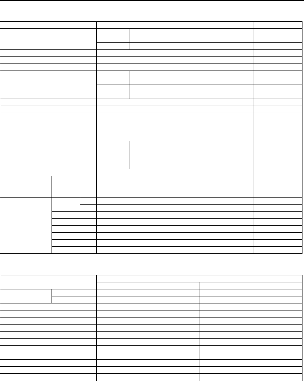
Service Data: 0C-5
Electrical
Unit: mm (in)
Wattage
Unit: W
Item Specification Note
Spark plug Type NGK: CR6E
DENSO: U20ESR-N
Gap 0.7 – 0.8 (0.028 – 0.031)
Spark performance Over 8 (0.3) at 1 atm.
CKP sensor resistance 150 – 250 :
CKP sensor peak voltage 5.0 V and more
Ignition coil resistance
Primary 0.1 – 0.6 :Terminal –
Ground
Secondary 12 – 19 k:Plug cap –
Terminal
Ignition coil primary peak voltage 80 V and more When cranking
Generator coil resistance 0.4 – 1.0 :
Generator maximum output Approx. 400 W at 5 000 r/min
Generator no-load voltage
(When engine is cold) 75 V (AC) and more at 5 000 r/min
Regulated voltage 13.5 – 15.5 V at 5 000 r/min
Starter motor brush length Standard 12.0 (0.47)
Limit 6.5 (0.26)
Starter torque limiter slip torque Standard 41.2 – 62.8 Nm
(4.2 – 6.4 kgf-m, 14.5 – 32.5 lbf-ft)
Starter relay resistance 3 – 5 :
Battery
Type
designation YTX20CH-BS
Capacity 12 V 64.8 kC (18 Ah)/10 HR
Fuse size
Headlight HI 10 A
LO 10 A
Power source 10 A
Ignition 15 A
Fuel 10 A
Fan 15 A
Main 30 A
EPS 40 A
Item Specification
P-24, 28, 33 P-17
Headlight HI 35 x 2 m
LO 35 x 2 m
Auxiliary headlight 35/35 m
Brake light/Taillight 21/5 m
Reversing light — 21
Speedometer light LED m
High beam indicator light — LED
Neutral indicator light LED m
FI indicator light/Engine coolant
temp. indicator light LED m
Reverse indicator light LED m
Differential lock indicator light LED m
EPS indicator light LED m
PartShark.com
877-999-5686
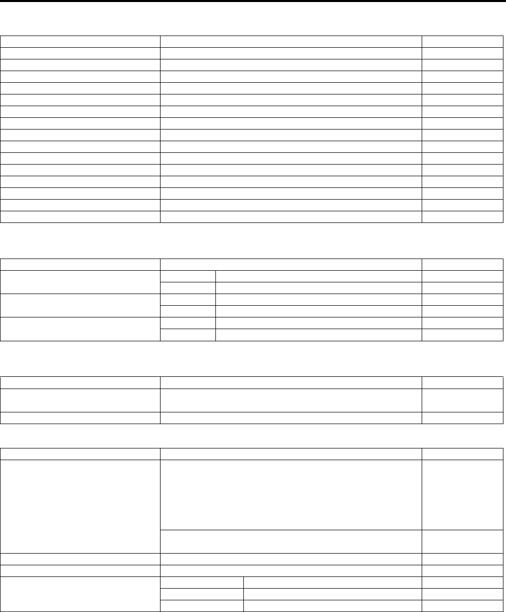
0C-6 Service Data:
Brake + Wheel
Unit: mm (in)
Tire
Unit: mm (in)
Suspension
Unit: mm (in)
Fuel + Oil
Item Standard/Specification Limit
Rear brake pedal height 12.5 – 22.5 (0.5 – 0.9) —
Rear brake pedal free travel 20 – 30 (0.8 – 1.2) —
Front brake disc thickness — 3.0 (0.20)
Front brake disc runout — 0.30 (0.012)
Front master cylinder bore 12.700 – 12.743 (0.5000 – 0.5017) —
Front master cylinder piston diam. 12.657 – 12.684 (0.4983 – 0.4994) —
Front brake caliper cylinder bore 33.960 – 34.010 (1.3370 – 1.3390) —
Front brake caliper piston diam. 33.878 – 33.928 (1.3338 – 1.3357) —
Rear brake lever play 6 – 8 (0.2 – 0.3) —
Brake fluid type DOT 4 —
Steering angle 46q (right & left) —
Turning radius 3.1 m (10.2 ft) —
Toe-out (With 75 kg, 165 lbs) 5 r 4 mm (0.20 r 0.16) —
Camber –1.3q—
Caster 3.3q—
Item Standard Limit
Cold inflation tire pressure
(Solo riding)
Front 35 kPa (0.35 kgf/cm2, 5.1 psi) —
Rear 30 kPa (0.30 kgf/cm2, 4.4 psi) —
Tire size Front AT25 x 8-12 , tubeless —
Rear AT25 x 10-12 , tubeless —
Tire tread depth Front — 4.0 (0.16)
Rear — 4.0 (0.16)
Item Standard Limit
Front shock absorber spring
adjustor 2/5 position —
Rear shock absorber spring adjustor 2/5 position —
Item Specification Note
Fuel type
Use only unleaded gasoline of at least 87 pump octane (R/2
+ M/2) or 91 octane or higher rated by the Research
Method. Gasoline containing MTBE (Methyl Tertiary Butyl
Ether), less than 10% ethanol, or less than 5% methanol
with appropriate cosolvents and corrosion inhibitor is
permissible.
P-28, 33
Gasoline used should be graded 91 octane or higher.
An unleaded gasoline type is recommended. Others
Fuel tank capacity 17.5 L (4.6/3.8 US/lmp gal)
Engine oil type SAE 10 W-40, API SF/SG or SH/SJ with JASO MA
Engine oil capacity
Change 2 300 ml (2.4/2.0 US/lmp qt)
Filter change 2 500 ml (2.6/2.2 US/lmp qt)
Overhaul 3 000 ml (3.2/2.6 US/lmp qt)
PartShark.com
877-999-5686

Service Data: 0C-7
Tightening Torque List (LT-A750XP/ZK9)
B931G40307004
Engine
Item Nmkgf—mlbf—ft
Spark plug 11 1.1 8.0
Cylinder head cover bolt Initial 10 1.0 7.0
Final 14 1.4 10.5
Cam drive idle gear/sprocket shaft 41 4.1 29.5
Intake pipe bolt 9 0.9 6.5
Cylinder head bolt (M6) 10 1.0 7.0
Cylinder head bolt (L200) Initial 25 2.5 18.0
Final 37 3.7 27.0
Cylinder head bolt (L: 70) 10 1.0 7.0
Cylinder head bolt (L: 100) 10 1.0 7.0
Camshaft journal holder bolt 10 1.0 7.0
Cam chain tension adjuster bolt 10 1.0 7.0
Cam chain tension adjuster cap bolt 7 0.7 5.0
Crankcase bolt (M6) 10 1.0 7.0
Crankcase bolt (M8) 26 2.6 19.0
Valve timing inspection plug 23 2.3 16.5
Clutch shoe nut 150 15.0 108.5
Movable drive face bolt 110 11.0 79.5
Movable driven face bolt 110 11.0 79.5
Movable driven face ring nut 110 11.0 79.5
V-belt outer cover bolt 8 0.8 6.0
V-belt inner cover bolt 9 0.9 6.5
Generator rotor nut 160 16.0 115.5
Generator stator set bolt 11 1.1 8.0
Speed sensor bolt 10 1.0 7.0
Starter clutch bolt 26 2.6 19.0
Exhaust pipe nut 23 2.3 16.5
Muffler connecting bolt 23 2.3 16.5
Muffler mounting bolt 23 2.3 16.5
Engine oil drain plug 21 2.1 15.0
Engine coolant drain plug 13 1.3 9.5
Drive bevel gear nut 100 10.0 72.5
Front output shaft nut 100 10.0 72.5
Engine mounting nut 60 6.0 43.5
Engine mounting damper stopper bolt 23 2.3 16.5
Rear output shaft nut 100 10.0 72.5
Crank balancer drive gear nut 150 15.0 108.5
Crank balancer driven gear bolt 50 5.0 36.0
Starter motor mounting bolt 10 1.0 7.0
Starter motor lead wire connecting nut 6 0.6 4.5
Starter motor housing bolt 5 0.5 3.5
Main oil gallery plug 18 1.8 13.0
Air cleaner box mounting bolt 4.5 0.45 3.0
Left crankshaft spacer nut 38 3.8 27.5
Oil gallery plug (Cylinder head) 10 1.0 7.0
PartShark.com
877-999-5686

0C-8 Service Data:
Drive Train
FI System, Intake Air System and Fuel System
Cooling System
Item Nmkgf—mlbf—ft
4WD/Diff-lock actuator mounting bolt 22 2.2 16.0
Front drive (Differential) gear case bolt 22 2.2 16.0
Front drive (Differential) gear case mounting nut 50 5.0 36.0
Front drive (Differential) gear oil level plug 8.5 0.85 6.0
Front drive (Differential) gear oil filler plug 35 3.5 25.5
Front drive (Differential) gear oil drain plug 32 3.2 23.0
Final drive gear nut 100 10.0 72.5
Final drive gear bearing stopper 100 10.0 72.5
Final gear case bolt (M8) 26 2.6 19.0
Final gear case bolt (M10) 55 5.5 40.0
Final gear mounting nut 65 6.5 47.0
Final gear mounting bolt 65 6.5 47.0
Rear propeller shaft boot clamp screw 2 0.2 1.5
Final gear oil drain plug 23 2.3 16.5
Rear propeller shaft coupling nut 100 10.0 72.5
Front output shaft bolt 10 1.0 7.0
Rear output shaft nut 100 10.0 72.5
Rear output shaft drive bevel gear nut 100 10.0 72.5
Rear output shaft driven gear nut 100 10.0 72.5
Front propeller shaft boot clamp screw 1.3 0.13 1.0
Rear propeller shaft boot clamp screw 2 0.2 1.5
Item Nmkgf—mlbf—ft
CKP sensor mounting bolt 6 0.6 4.5
CKP sensor bracket bolt 6 0.6 4.5
Fuel delivery pipe mounting screw 5 0.5 3.5
Fuel pump retainer 35 3.5 25.5
ECT sensor 18 1.8 13.0
ISC valve mounting screw 2 0.2 1.5
TP sensor mounting screw 2 0.2 1.5
Item Nmkgf—mlbf—ft
Water pump cover screw 6 0.6 4.5
Water pump mounting bolt 10 1.0 7.0
Cooling fan thermo-switch 17 1.7 12.5
Thermostat cover bolt 23 2.3 16.5
Cooling fan assembly mounting bolt 8.5 0.85 6.0
Water bypass union 12 1.2 8.5
PartShark.com
877-999-5686

Service Data: 0C-9
Chassis
Item Nmkgf—mlbf—ft
Handlebar clamp bolt 26 2.6 19.0
Handlebar holder nut 60 6.0 43.5
Rear brake lever holder clamp bolt 10 1.0 7.0
Throttle lever case bolt 2 0.2 1.5
Steering shaft upper nut 120 12.0 87.0
Steering shaft bolt 26 2.6 19.0
EPS control unit mounting nut 12 1.2 8.5
EPS body assembly mounting bolt 26 2.6 19.0
EPS body assembly mounting nut 28 2.8 20.0
Steering shaft lower nut 162 16.2 117.0
Front suspension arm pivot nut (Upper) 60 6.0 43.5
Front suspension arm pivot nut (Lower) 65 6.5 47.0
Steering knuckle end nut (Upper and Lower) 29 2.9 21.0
Tie-rod end nut 29 2.9 21.0
Tie-rod lock-nut 29 2.9 21.0
Front shock absorber mounting bolt (Upper) 55 5.5 40.0
Front shock absorber mounting nut (Lower) 60 6.0 43.5
Front wheel hub nut 110 11.0 79.5
Rear wheel hub nut 121 12.1 87.5
Wheel set nut (Front and Rear) 60 6.0 43.5
Front brake hose union bolt 23 2.3 16.5
Front brake air bleeder valve 6 0.6 4.5
Front brake pad mounting pin 17 1.7 12.5
Front brake caliper mounting bolt 26 2.6 19.0
Caliper holder pin 18 1.8 13.0
Caliper holder slide pin 23 2.3 16.5
Brake pipe flare nut 16 1.6 11.5
Front brake disc mounting bolt 23 2.3 16.5
Brake master cylinder mounting bolt 10 1.0 7.0
Footrest mounting bolt (M8) 26 2.6 19.0
Footrest mounting bolt (M10) 55 5.5 40.0
Rear stabilizer joint nut 60 6.0 43.5
Rear shock absorber mounting nut (Upper and Lower) 60 6.0 43.5
Rear suspension arm pivot nut (Upper and Lower) 60 6.0 43.5
Rear knuckle end nut (Upper and Lower) 60 6.0 43.5
Rear brake cam lever nut 11 1.1 8.0
Rear brake case bolt 26 2.6 19.0
Rear brake pedal shaft nut 60 6.0 43.5
Rear brake pedal screw 4.5 0.45 3.0
Trailer towing bolt 60 6.0 43.5
Brake lever pivot bolt and nut 6 0.6 4.5
Brake lever pivot bolt lock-nut 6 0.6 4.5
Front propeller shaft boot clamp screw 1.3 0.13 1.0
Rear propeller shaft boot clamp screw 2 0.2 1.5
PartShark.com
877-999-5686
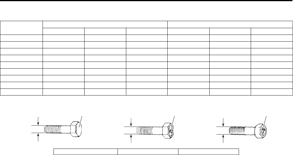
0C-10 Service Data:
Tightening Torque Chart
For other bolts and nuts not listed in the preceding page, refer to this chart:
Bolt Diameter
“a” (mm)
Conventional or “4” marked bolt “7” marked bolt
Nmkgf—mlbf—ft Nmkgf—mlbf—ft
4 1.5 0.15 1.0 2.3 0.23 1.5
5 3 0.3 2.0 4.5 0.45 3.0
6 5.5 0.55 4.0 10 1.0 7.0
8 13 1.3 9.5 23 2.3 16.5
10 29 2.9 21.0 50 5.0 36.0
12 45 4.5 32.5 85 8.5 61.5
14 65 6.5 47.0 135 13.5 97.5
16 105 10.5 76.0 210 21.0 152.0
18 160 16.0 115.5 240 24.0 173.5
321
“a” “a” “a”
I649G1030001-04
1. Conventional bolt 2. “4” marked bolt 3. “7” marked bolt
PartShark.com
877-999-5686

Table of Contents 1- i
1
Section 1
CONTENTS
Engine
Precautions …………………………………………. 1-*
Precautions…………..……………………………..………….1-*
Precautions for Engine…………..…………….………….1-*
Engine General Information and
Diagnosis …………………………………………..1A-*
General Description ………………………..……………. 1A-*
Injection Timing Description……………………..…….1A-*
Schematic and Routing Diagram…..………………. 1A-*
FI System Wiring Diagram ……..…………….………..1A-*
Terminal Alignment of ECM Coupler………………..1A-*
Component Location ………..………….………….…… 1A-*
FI System Parts Location……….…………….………..1A-*
Diagnostic Information and Procedures………… 1A-*
Engine Symptom Diagnosis ………….………………..1A-*
Self-Diagnostic Procedures ………….………………..1A-*
Use of SDS Diagnosis Reset Procedures…………1A-*
Show Data When Trouble (Displaying Data at
the Time of DTC) …….………………..…………….….1A-*
SDS Check ……………………….…………….…………..1A-*
DTC Table…………..…………….……………….………..1A-*
Fail-Safe Function Table …………..………………..….1A-*
FI System Troubleshooting ….…………….…………..1A-*
Malfunction Code and Defective Condition
Table ……………..…………….……………….…………..1A-*
DTC “C12” (P0335): CKP Sensor Circuit
Malfunction.……………….……………..………………..1A-*
DTC “C13” (P0105-H/L): IAP Sensor Circuit
Malfunction.……………….……………..………………..1A-*
DTC “C14” (P0120-H/L): TP Sensor Circuit
Malfunction.……………….……………..………………..1A-*
DTC “C15” (P0115-H/L): ECT Sensor Circuit
Malfunction.……………….……………..………………..1A-*
DTC “C20” (P1752): Diff-lock Relay Circuit
Malfunction.……………….……………..………………..1A-*
DTC “C21” (P0110-H/L): IAT Sensor Circuit
Malfunction.……………….……………..………………..1A-*
DTC “C23” (P1651-H/L): TO Sensor Circuit
Malfunction.……………….……………..………………..1A-*
DTC “C24” (P0351): Ignition Coil Circuit
Malfunction.……………….……………..………………..1A-*
DTC “C32” (P0201): Fuel Injector Circuit
Malfunction.……………….……………..………………..1A-*
DTC “C40” (P05057): ISC Valve Circuit
Malfunction…..…………….………………..…………… 1A-*
DTC “C41” (P230-H/L): FP Relay Circuit
Malfunction…..…………….………………..…………… 1A-*
Specifications………..…………………….………………. 1A-*
Service Data……………………….……………….……… 1A-*
Special Tools and Equipment ……………………….. 1A-*
Special Tool ………………………………………..……… 1A-*
Emission Control Devices …………………..1B-*
Precautions………………………………………..………… 1B-*
Precautions for Emission Control Devices ………. 1B-*
Repair Instructions ………………………………….…… 1B-*
Crankcase Breather (PCV) Hose Inspection……. 1B-*
Crankcase Breather (PCV) Hose Removal
and Installation …………………………………..……… 1B-*
Engine Electrical Devices ……………………1C-*
Precautions………………………………………..………… 1C-*
Precautions for Engine Electrical Device ………… 1C-*
Component Location ……………………………….…… 1C-*
Engine Electrical Components Location …………. 1C-*
Diagnostic Information and Procedures………… 1C-*
Engine Symptom Diagnosis …….…………….……… 1C-*
Repair Instructions ………………………………….…… 1C-*
ECM Removal and Installation……………….……… 1C-*
CKP Sensor Inspection …………..…………….……… 1C-*
CKP Sensor Removal and Installation ……………. 1C-*
IAP Sensor Inspection…………….…………….……… 1C-*
IAP Sensor Removal and Installation……………… 1C-*
TP Sensor Inspection………..……………….………… 1C-*
TP Sensor Removal and Installation………………. 1C-*
TP Sensor Adjustment …..………………..…………… 1C-*
IAT Sensor Inspection…………….…………….……… 1C-*
IAT Sensor Removal and Installation……………... 1C-*
ECT Sensor Removal and Installation ………….... 1C-*
ECT Sensor Inspection …………..…………….……… 1C-*
TO Sensor Inspection ……………………..…………… 1C-*
TO Sensor Removal and Installation ……………… 1C-*
ISC Valve Inspection……..…………….…………….... 1C-*
ISC Valve Removal and Installation………..……… 1C-*
GP Switch Inspection ………..……………….………… 1C-*
GP Switch Removal and Installation ………………. 1C-*
Specifications………..…………………….………………. 1C-*
NOTE
For the items with asterisk (*) in the “CONTENTS” below, refer to the same section of the service manual
mentioned in the “FOREWORD” of this manual.
PartShark.com
877-999-5686

1-ii Table of Contents
Service Data…..……………….…………….……………. 1C-*
Tightening Torque Specifications..………….……… 1C-*
Special Tools and Equipment ……………………….. 1C-*
Recommended Service Material …………….……… 1C-*
Special Tool …………………………….…………….…… 1C-*
Engine Mechanical …………………………….. 1D-*
Schematic and Routing Diagram…..………………. 1D-*
Throttle Cable Routing Diagram….………….……… 1D-*
Diagnostic Information and Procedures………… 1D-*
Engine Mechanical Symptom Diagnosis…………. 1D-*
Compression Pressure Check ……………….……… 1D-*
Repair Instructions ……..…………….………….……… 1D-*
Engine Components Removable with the
Engine in Place .……………….……………..………… 1D-*
Air Cleaner Element Removal and Installation …. 1D-*
Air Cleaner Element Inspection and Cleaning …. 1D-*
Air Cleaner Box Removal and Installation……….. 1D-*
Throttle Cable Removal and Installation …………. 1D-*
Throttle Cable Inspection ………..…………….……… 1D-*
Throttle Cable Play Inspection and
Adjustment ………..…………….………………..……… 1D-*
Throttle Body Components ……..…………….……… 1D-*
Throttle Body Construction…………………….……… 1D-*
Throttle Body Removal and Installation ………….. 1D-*
Throttle Body Disassembly and Assembly………. 1D-*
Throttle Body Inspection and Cleaning …………… 1D-*
Engine Assembly Removal ………..………….……… 1D-*
Engine Assembly Installation …..………………….… 1D-*
Engine Top Side Disassembly ……………….……… 1D-*
Engine Top Side Assembly …………………………… 1D-*
Valve Clearance Inspection and Adjustment …… 1D-*
Camshaft Inspection ……..…………….………………. 1D-*
Camshaft Sprocket Inspection ………………………. 1D-*
Cam Chain Tension Adjuster Inspection…………. 1D-*
Cam Chain Guide Removal and Installation ……. 1D-*
Cam Chain Guide Inspection .……………..………… 1D-*
Cam Chain Tensioner Inspection..………….……… 1D-*
Cylinder Head Disassembly and Assembly …….. 1D-*
Cylinder Head Related Parts Inspection …………. 1D-*
Valve Guide Replacement …………………….……… 1D-*
Valve Seat Repair ………………………………..……… 1D-*
Cam Drive Idle Gear / Sprocket Thrust
Clearance Inspection and Adjustment ………….. 1D-*
Cylinder Disassembly and Assembly ……………… 1D-*
Cylinder Inspection.…………….………………..……… 1D-*
Piston Ring Removal and Installation …………….. 1D-*
Piston and Piston Ring Inspection ………….……… 1D-*
Engine Bottom Side Disassembly …………..……… 1D-*
Engine Bottom Side Assembly……………….……… 1D-*
Conrod and Crankshaft Inspection……….………… 1D-*
Width Between Crankshaft Webs …………..……… 1D-*
Crankshaft Oil Seal Inspection…………….………… 1D-*
Bearing Inspection ………..…………….………………. 1D-*
Bearing Removal and Installation .………….……… 1D-*
Specifications….…………….…………….………………. 1D-*
Service Data…..……………….…………….……………. 1D-*
Tightening Torque Specifications..………….……… 1D-*
Special Tools and Equipment ……………………….. 1D-*
Recommended Service Material .…………….…….. 1D-*
Special Tool ……………………………………………….. 1D-*
Engine Lubrication System ………………… 1E-*
Precautions………………………….…………….………… 1E-*
Precautions for Engine Oil ……….…………….…….. 1E-*
Schematic and Routing Diagram …………………… 1E-*
Engine Lubrication System Chart Diagram ……… 1E-*
Diagnostic Information and Procedures………… 1E-*
Engine Lubrication Symptom Diagnosis …………. 1E-*
Oil Pressure Check ……..…………….………….…….. 1E-*
Repair Instructions ………………………….…………… 1E-*
Engine Oil and Filter Replacement ………….…….. 1E-*
Engine Oil Level Inspection…………………….…….. 1E-*
Oil Sump Filter Removal and Installation ………… 1E-*
Oil Sump Filter Inspection and Cleaning…………. 1E-*
Oil Jet Removal and Installation.………….………… 1E-*
Oil Jet Inspection..…………….……………….………… 1E-*
Oil Pump Removal and Installation ………………… 1E-*
Oil Pump Inspection …….……………….……………... 1E-*
Specifications…..………………….…………………..….. 1E-*
Service Data…………………….……………….………… 1E-*
Tightening Torque Specifications…………………… 1E-*
Special Tools and Equipment .………………………. 1E-*
Recommended Service Material .…………….…….. 1E-*
Special Tool ……………………………………………….. 1E-*
Engine Cooling System ……………………… 1F-*
Precautions..………………..…………….……………….…1F-*
Precautions for Engine Cooling System……………1F-*
Precautions for Engine Coolant …..………….………1F-*
General Description ….……………..…………….………1F-*
Engine Coolant Description…………………….………1F-*
Schematic and Routing Diagram …………………….1F-*
Cooling Circuit Diagram ….…………….…………….…1F-*
Water Hose Routing Diagram …..…………….………1F-*
Diagnostic Information and Procedures………….1F-*
Engine Cooling Symptom Diagnosis………..………1F-*
Repair Instructions ………………………….…………….1F-*
Cooling Circuit Inspection ………..…………….………1F-*
Radiator Cap Inspection…………..…………….………1F-*
Radiator Inspection and Cleaning …..……………….1F-*
Cooling Fan Assembly / Radiator Removal
and Installation ……………………………………………1F-*
Water Hose Removal and Installation………………1F-*
Cooling Fan Inspection ………………………….………1F-*
Radiator Reservoir Tank Removal and
Installation ………….…………….………………..………1F-*
Radiator Reservoir Tank Inspection …………………1F-*
Water Hose Inspection……………………….………….1F-*
ECT Sensor Removal and Installation ……..………1F-*
ECT Sensor Inspection ………………………….………1F-*
Cooling Fan Thermo-switch Removal and
Installation ………….…………….………………..………1F-*
Cooling Fan Thermo-switch Inspection…………….1F-*
Thermostat Removal and Installation……………….1F-*
Thermostat Inspection……………..…………….………1F-*
Water Pump Components………..…………….………1F-*
Water Pump Removal and Installation……………..1F-*
PartShark.com
877-999-5686

Table of Contents 1-iii
Water Pump Disassembly and Assembly …………1F-*
Water Pump Related Parts Inspection ……………..1F-*
Specifications…….……………….…………….…………..1F-*
Service Data ………….……………….……………..…….1F-*
Tightening Torque Specifications…..………….…….1F-*
Special Tools and Equipment …………………………1F-*
Recommended Service Material ..……………………1F-*
Special Tool …………..…………………………..………..1F-*
Fuel System ……………………………….………1G-*
Precautions….……………….……………..………………. 1G-*
Precautions for Fuel System ……..……………..…… 1G-*
General Description ……………….………………..…… 1G-*
Fuel System Description …………..……………..…… 1G-*
Schematic and Routing Diagram……..……………. 1G-*
Fuel Hose Routing Diagram………….………….…… 1G-*
Fuel Tank Breather Hose Routing Diagram…….. 1G-*
Diagnostic Information and Procedures..………. 1G-*
Fuel System Diagnosis …………………..……………. 1G-*
Repair Instructions …….………………………………… 1G-*
Fuel Pressure Inspection ……………..…………….… 1G-*
Fuel Pump Inspection ………………………………….. 1G-*
Fuel Discharge Amount Inspection …..……………. 1G-*
Fuel Pump Relay Inspection …………………….…… 1G-*
Fuel Hose Inspection ………….…………………..…… 1G-*
Fuel Feed Hose Removal and Installation ………. 1G-*
Fuel Level Gauge Inspection ….…………….………. 1G-*
Fuel Level Indicator Inspection ….……………..…… 1G-*
Fuel Tank Removal and Installation.………….…… 1G-*
Fuel Pump Components ……..……………….………. 1G-*
Fuel Pump Assembly Removal and
Installation……………………….…………….…………. 1G-*
Fuel Pump Disassembly and Assembly….………. 1G-*
Fuel Mesh Filter Inspection and Cleaning……….. 1G-*
Fuel Injector Inspection and Cleaning………..…… 1G-*
Fuel Injector / Fuel Delivery Pipe Removal
and Installation………..………………………………… 1G-*
Fuel Tank Pressure Control (FTPC) Valve
Removal and Installation…………….…………….… 1G-*
Fuel Tank Pressure Control (FTPC) Valve
Inspection……………………..…………….……………. 1G-*
Specifications……….……………….………….…………. 1G-*
Service Data ………….……………….……………..…… 1G-*
Tightening Torque Specifications…..………….…… 1G-*
Special Tools and Equipment ……………………….. 1G-*
Special Tool ….………………..…………….……………. 1G-*
Ignition System…………………………………..1H-*
General Description ………………………..……………. 1H-*
Override Switch Description………………….………. 1H-*
Schematic and Routing Diagram…..………………. 1H-*
Ignition System Diagram………..…………….………. 1H-*
Ignition System Components Location …………… 1H-*
Diagnostic Information and Procedures………… 1H-*
Ignition System Symptom Diagnosis………………. 1H-*
No Spark or Poor Spark…………………….…………. 1H-*
Repair Instructions …….…………….………….………. 1H-*
Spark Plug Cap and Spark Plug Removal and
Installation ………….…………….……………….……… 1H-*
Spark Plug Inspection and Cleaning ………………. 1H-*
Ignition Coil and Plug Cap Inspection …………….. 1H-*
CKP Sensor Inspection …………..…………….……… 1H-*
CKP Sensor Removal and Installation ……………. 1H-*
Engine Stop Switch Inspection……………….……… 1H-*
Ignition Switch Inspection………..…………….……… 1H-*
Ignition Switch Removal and Installation…………. 1H-*
Override Switch Inspection ………..………….……… 1H-*
Specifications………..…………………….………………. 1H-*
Service Data……………………….……………….……… 1H-*
Tightening Torque Specifications…..………………. 1H-*
Special Tools and Equipment ……………………….. 1H-*
Special Tool ………………………………………..……… 1H-*
Starting System …………………………………..1I-1
Schematic and Routing Diagram……………………..1I-*
Starting System Diagram …………..…………….……..1I-*
Component Location ……………………………….……..1I-*
Starting System Components Location……………..1I-*
Diagnostic Information and Procedures…………..1I-*
Starting System Symptom Diagnosis………………..1I-*
Starter Motor will not Run…………..…………….……..1I-*
Starter Motor Runs but Does not Crank the
Engine …………………………..……………….………….. 1I-*
Engine Does not Turn Though the Starter
Motor Runs…..…………….………………..……………..1I-*
Repair Instructions ……………………………….………. 1I-1
Starter Motor Components……………………….……..1I-*
Starter Motor Removal and Installation……………..1I-*
Starter Motor Disassembly and Assembly …………1I-*
Starter Motor Inspection…………….…………….……..1I-*
Starter Relay Removal and Installation……………..1I-*
Starter Relay Inspection…………….…………….……..1I-*
Neutral Relay Removal and Installation …………….1I-*
Neutral Relay Inspection ……………………………..….1I-*
Neutral Relay Diode Inspection……..………….……..1I-*
Parking Brake Relay Removal and Installation ……1I-*
Parking Brake Relay Inspection …….………….……..1I-*
Parking Brake Switch Inspection……………….……..1I-*
Gear Position Switch Inspection ………………………1I-*
Starter Torque Limiter / Starter Clutch
Removal and Installation…….…………….…………..1I-*
Starter Driven Gear Bearing Removal and
Installation ………….…………….……………….……….. 1I-*
Starter Related Parts Inspection ……………….……..1I-*
Starter Button Inspection……………………….………..1I-*
Recoil Starter Components ………..…………….……..1I-*
Recoil Starter Assembly Removal and
Installation ………….…………….……………….……….. 1I-*
Recoil Starter Disassembly and Assembly ………..1I-*
Recoil Starter Inspection …………………………………1I-*
Starter Motor Components (LT-A750XP/ZK9) ….. 1I-1
Starter Motor Removal and Installation (LT-
A750XP/ZK9) …………..…………….………….………. 1I-2
Starter Motor Disassembly and Assembly
(LT-A750XP/ZK9)………..………………..……………. 1I-2
PartShark.com
877-999-5686

1-iv Table of Contents
Starter Motor Related Parts Inspection (LT-
A750XP/ZK9) ………..…………………………..………. 1I-3
Specifications….…………….…………….……………….. 1I-5
Service Data…..……………….…………….……………… 1I-*
Service Data (LT-A750XP/ZK9) …….……………….. 1I-5
Tightening Torque Specifications..………….………. 1I-5
Special Tools and Equipment ………………………… 1I-5
Recommended Service Material …………….………. 1I-5
Special Tool …………………………….…………….……. 1I-5
Charging System………………………………..1J-1
Schematic and Routing Diagram…………………….1J-*
Charging System Diagram …………………….………. 1J-*
Component Location ………..…………….……………..1J-*
Charging System Components Location………….. 1J-*
Diagnostic Information and Procedures…………. 1J-*
Charging System Symptom Diagnosis…………….. 1J-*
Battery Runs Down Quickly ……….…………….……. 1J-*
Repair Instructions …………………………………….… 1J-1
Battery Current Leakage Inspection………..………. 1J-*
Regulated Voltage Inspection ……….……………….. 1J-*
Generator Inspection…………………………….………. 1J-*
Generator Removal and Installation.……………….. 1J-*
Regulator / Rectifier Inspection ..…………….………. 1J-*
Battery Components …………………………………….. 1J-*
Battery Charging ……………………….……………….… 1J-*
Battery Removal and Installation …………….……… 1J-*
Battery Visual Inspection………………….……………. 1J-*
Generator Removal and Installation (LT-
A750XP/ZK9) ……………………………………..…….. 1J-1
Battery Removal and Installation (LT-
A750XP/ZK9) ……………………………………..…….. 1J-2
Specifications…..………………….…………….………… 1J-3
Service Data…………………….……………….…………. 1J-*
Tightening Torque Specifications…………………… 1J-3
Special Tools and Equipment .………………………. 1J-3
Recommended Service Material .…………….…….. 1J-3
Special Tool …………………………..…………….…….. 1J-3
Exhaust System………………………………….1K-*
Precautions………………………….…………….………… 1K-*
Precautions for Exhaust System .…………….…….. 1K-*
Repair Instructions ………………………….…………… 1K-*
Exhaust System Construction …..…………….…….. 1K-*
Exhaust Pipe / Muffler Removal and
Installation ………….…………….………………..…….. 1K-*
Exhaust System Inspection…………………….…….. 1K-*
Spark Arrester Inspection……………………….…….. 1K-*
Specifications…..………………….…………………..….. 1K-*
Tightening Torque Specifications…………………… 1K-*
PartShark.com
877-999-5686
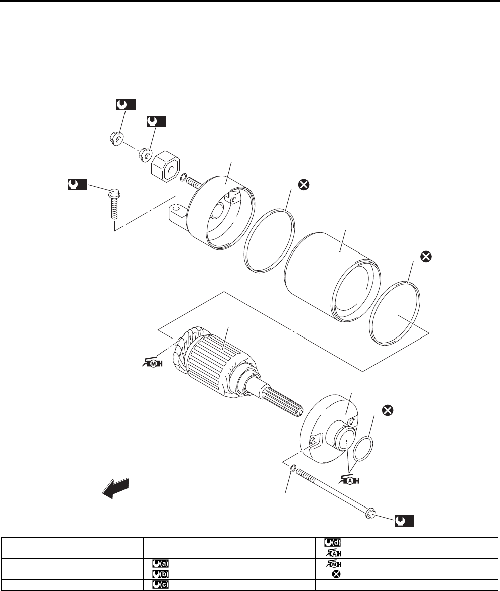
Starting System: 1I-1
Engine
Starting System
Repair Instructions
Starter Motor Components (LT-A750XP/ZK9)
B931G41906022
1
2
5
6
3
4
5
7
(a)
(b)
(c)
(d)
FWD
I931G3190012-03
1. O-ring 6. Starter motor case : 5 Nm (0.5 kgf-m, 3.5 lbf-ft)
2. Housing end (Inside) 7. Housing end (Outside) : Apply grease to sliding surface.
3. O-ring : 6 Nm (0.6 kgf-m, 4.5 lbf-ft) : Apply moly paste to sliding surface.
4. Armature : 11 Nm (1.1 kgf-m, 8.0 lbf-ft) : Do not reuse.
5. Square-ring : 10 Nm (1.0 kgf-m, 7.0 lbf-ft)
PartShark.com
877-999-5686
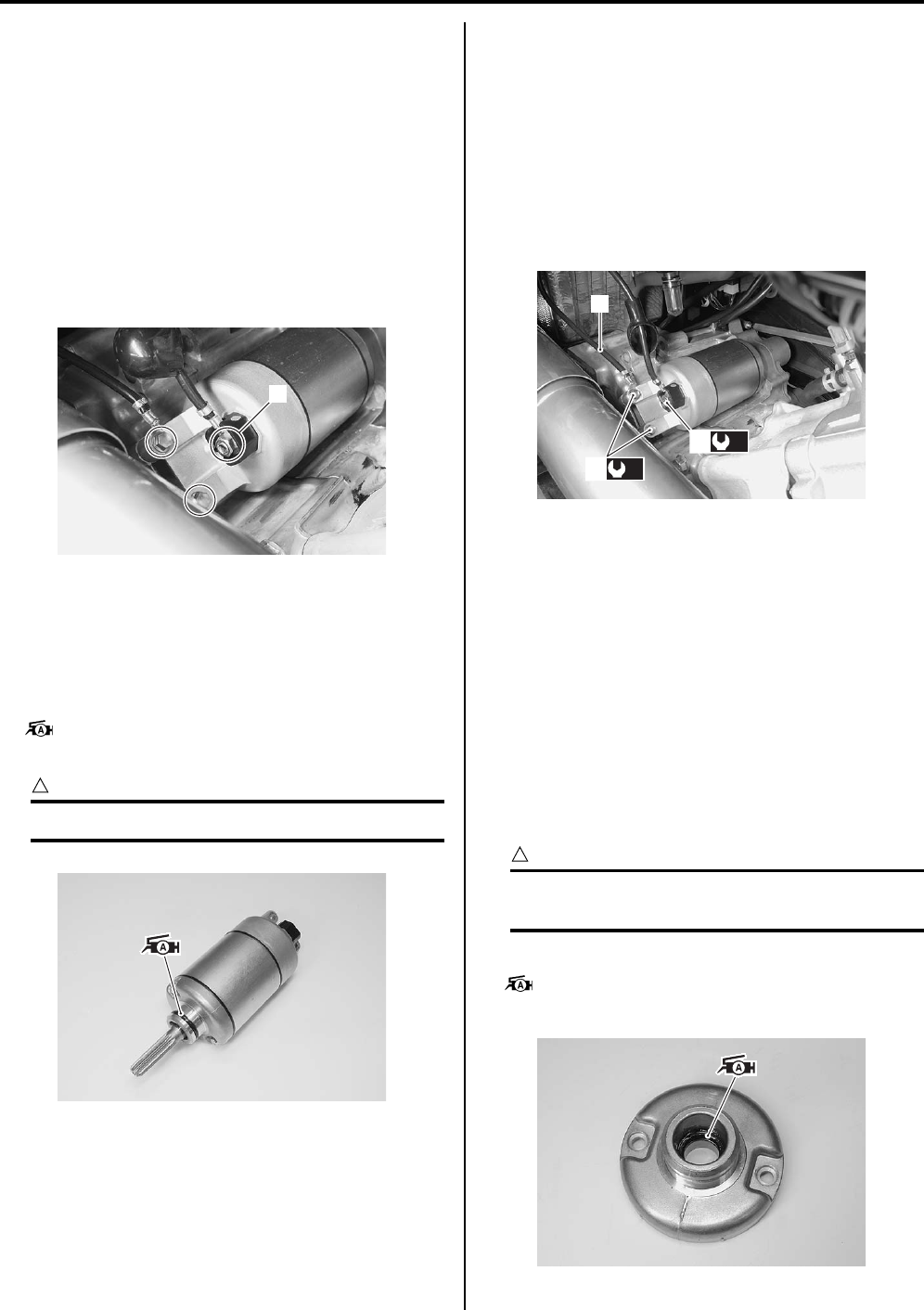
1I-2 Starting System:
Starter Motor Removal and Installation (LT—
A750XP/ZK9)
B931G41906023
Removal
1) Turn the ignition switch OFF and disconnect the
battery (–) lead wire. Refer to “Battery Removal and
Installation (LT-A750XP/ZK9) in Section 1J
(Page 1J-2)”.
2) Remove the right side cover. Refer to“Front Side
Exterior Parts Removal and Installation in Section
9D in related manual”.
3) Remove the starter motor lead wire (1).
4) Remove the starter motor.
Installation
Install the starter motor in the reverse order of removal.
Pay attention to the following points:
• Apply grease to the starter motor O-ring.
: Grease 99000–25010 (SUZUKI SUPER
GREASE “A” or equivalent)
CAUTION
!
Replace the O-ring with a new one.
• Tighten the starter motor mounting bolts (1) with the
battery (–) lead wire (2) and starter motor lead wire
mounting nut (3) to the specified torque. Refer to
“Wiring Harness Routing Diagram (LT-A750XP/ZK9)
in Section 9A (Page 9A-4)”.
Tightening torque
Starter motor mounting bolt (a): 10 N·m (1.0 kgf-
m, 7.0 lbf-ft)
Starter motor lead wire mounting nut (b): 6 N·m (
0.6 kgf-m, 4.5 lbf-ft)
Starter Motor Disassembly and Assembly (LT—
A750XP/ZK9)
B931G41906024
Refer to “Starter Motor Removal and Installation in
related manual”.
Disassembly
Disassemble the starter motor as shown in the starter
motor components diagram. Refer to “Starter Motor
Components in related manual”.
Assembly
Reassemble the starter motor in the reverse order of
removal. Pay attention to the following points:
CAUTION
!
Replace the O-rings with new ones to prevent
oil leakage and moisture.
• Apply grease to the lip of the oil seal.
: Grease 99000–25010 (SUZUKI SUPER
GREASE “A” or equivalent)
1
I931G3190001-02
I931G3190002-02
(a)
1
(b)
3
2
I931G3190003-02
I931G3190004-02
PartShark.com
877-999-5686
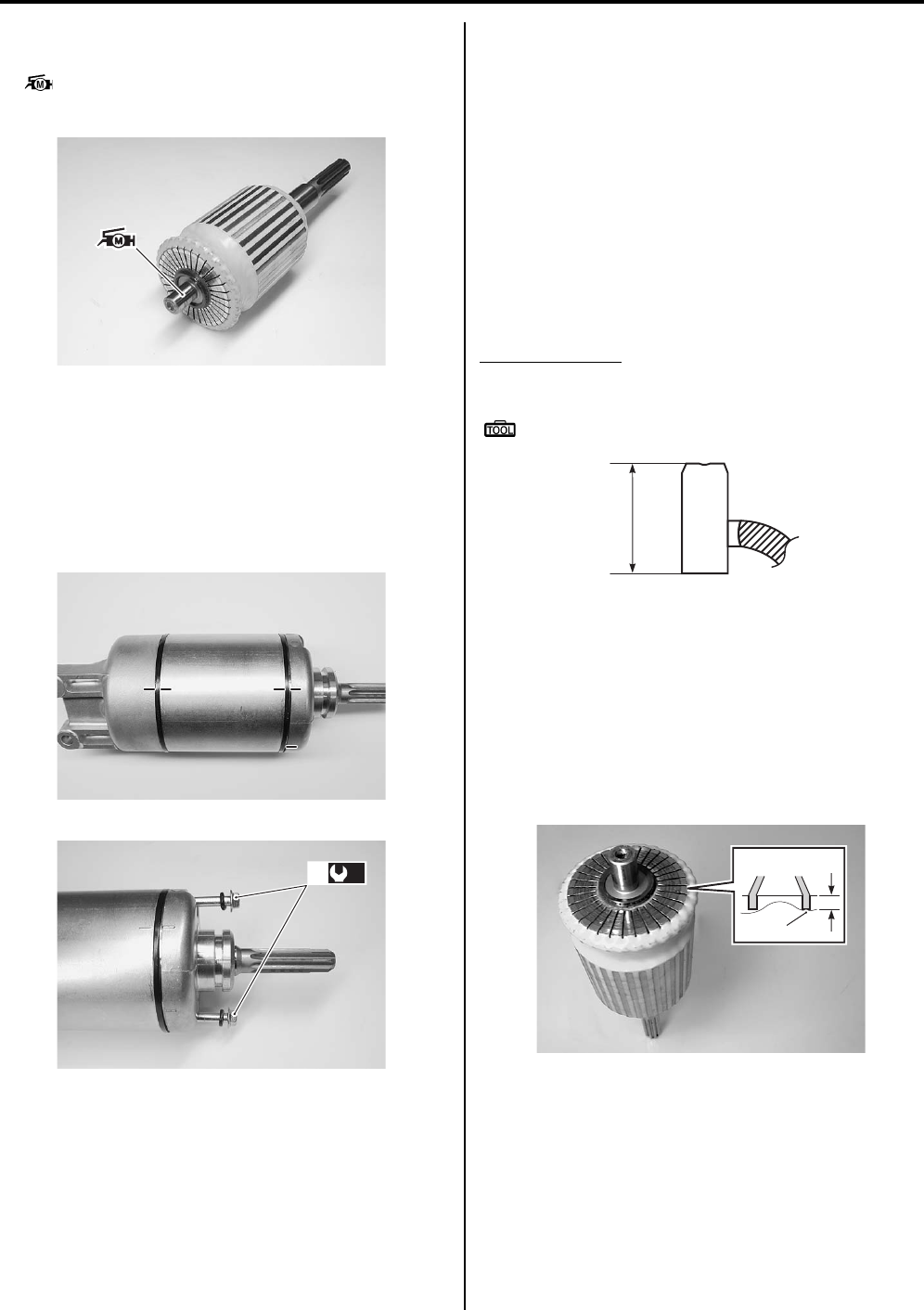
Starting System: 1I-3
• Apply a small quantity of moly paste to the armature
shaft.
: Moly paste 99000–25140 (SUZUKI Moly
paste or equivalent)
• Align the match mark on the starter motor case with
the match mark on the housing end.
• Tighten the starter motor housing bolts (2) to the
specified torque.
Tightening torque
Starter motor housing bolt (a): 5 N·m (0.5 kgf-m,
3.5 lbf-ft)
Starter Motor Related Parts Inspection (LT—
A750XP/ZK9)
B931G41906025
Refer to “Starter Motor Disassembly and Assembly in
related manual”.
Carbon Brush
Inspect the carbon brushes for abnormal wear, cracks or
smoothness in the brush holder.
If either carbon brush is defective, replace the brush
holder set with a new one.
Measure the length “a” of the carbon brushes using a
vernier calipers. If the measurement is less than the
service limit, replace the housing end assembly with a
new one.
Brush length “a”
Service limit: 6.5 mm (0.26 in)
Special tool
: 09900–20102 (Vernier calipers (200 mm))
Commutator
Inspect the commutator for discoloration, abnormal wear
or undercut “A”.
If the commutator is abnormally worn, replace the
armature.
If the commutator surface is discolored, polish it with
#400 sandpaper and wipe it using a clean, dry cloth.
If there is no undercut, scrape out the insulator (1) with a
saw blade.
I931G3190005-02
I931G3190006-02
(a)
2
I931G3190007-03
“a”
I718H1190013-01
“A”
1
I931G3190008-02
PartShark.com
877-999-5686
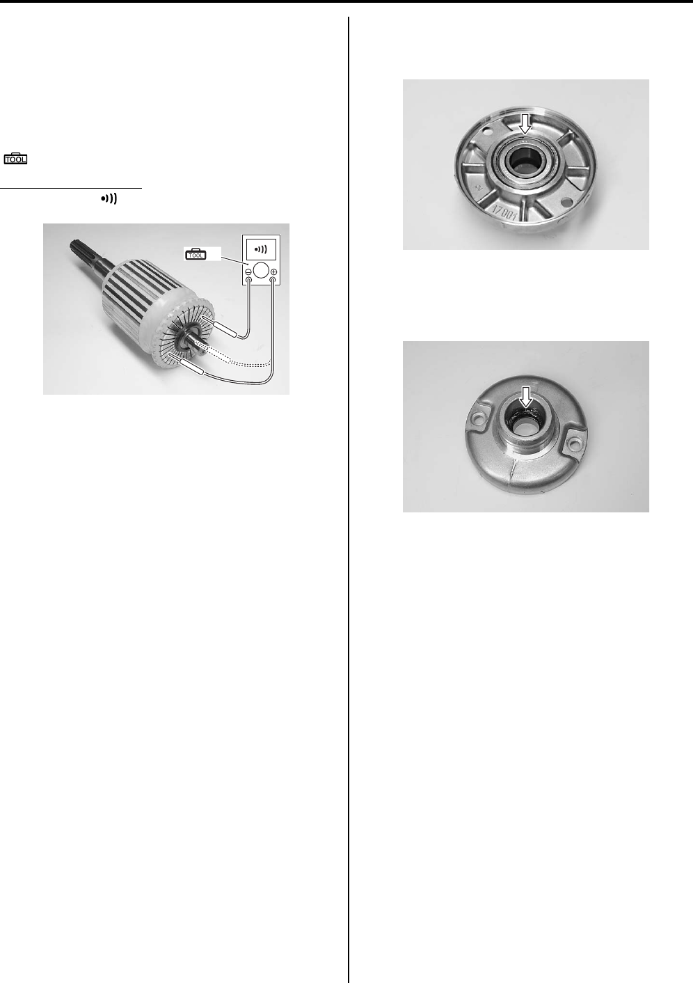
1I-4 Starting System:
Armature Coil
Measure for continuity between each segment. Measure
for continuity between each segment and the armature
shaft.
If there is no continuity between the segments or there is
continuity between the segments and shaft, replace the
armature with a new one.
Special tool
(A): 09900–25008 (Multi circuit tester set)
Tester knob indication
Continuity set ( )
Bearing
Check the bearing of housing end for damage.
If any damage is found, replace the housing end.
Oil Seal
Check the seal lip for damage. If any damage is found,
replace the housing end (Inside).
(A)
I931G3190009-02
I931G3190010-02
I931G3190011-02
PartShark.com
877-999-5686
Starting System: 1I-5
Specifications
Service Data (LT-A750XP/ZK9)
B931G41907002
Unit: mm (in)
Tightening Torque Specifications
B931G41907003
NOTE
The specified tightening torque is described in the following.
“Starter Motor Components (LT-A750XP/ZK9) (Page 1I-1)”
Reference:
For the tightening torque of fastener not specified in this section, refer to “Tightening Torque List (LT-A750XP/ZK9) in
Section 0C (Page 0C-7)”.
Special Tools and Equipment
Recommended Service Material
B931G41908001
NOTE
Required service material is also described in the following.
“Starter Motor Components (LT-A750XP/ZK9) (Page 1I-1)”
Special Tool
B931G41908002
Item Specification Note
Starter motor brush length Standard 12.0 (0.47)
Limit 6.5 (0.26)
Starter torque limiter slip torque Standard 41.2 – 62.8 Nm
(4.2 – 6.4 kgf-m, 14.5 – 32.5 lbf-ft)
Starter relay resistance 3 – 5 :
Fastening part Tightening torque Note
Nm kgf-m lbf-ft
Starter motor mounting bolt 10 1.0 7.0 )(Page 1I-2)
Starter motor lead wire mounting nut 6 0.6 4.5 )(Page 1I-2)
Starter motor housing bolt 5 0.5 3.5 )(Page 1I-3)
Material SUZUKI recommended product or Specification Note
Grease SUZUKI SUPER GREASE “A” or
equivalent
P/No.: 99000–25010 )(Page 1I-2) / )(Page 1I-2)
Moly paste SUZUKI Moly paste or equivalent P/No.: 99000–25140 )(Page 1I-3)
09900–20102 09900–25008
Vernier calipers (200 mm) Multi circuit tester set
)(Page 1I-3) )(Page 1I-4)
PartShark.com
877-999-5686
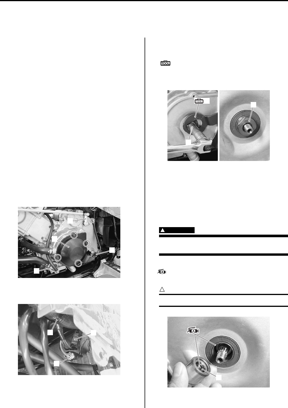
1J-1 Charging System:
Engine
Charging System
Repair Instructions
Generator Removal and Installation (LT—
A750XP/ZK9)
B931G41A06010
Removal
1) Disconnect the (–) battery lead wire. Refer to
“Battery Removal and Installation (LT-A750XP/ZK9)
(Page 1J-2)”.
2) Drain engine oil. Refer to “Engine Oil and Filter
Replacement in Section 0B in related manual”.
3) Remove the left inner fender. Refer to “Front Side
Exterior Parts Removal and Installation in Section
9D in related manual”.
4) Remove the left mud guard. Refer to “Rear Side
Exterior Parts Removal and Installation in Section
9D in related manual”.
5) Drain engine coolant. Refer to “Cooling System
Inspection in Section 0B in related manual”.
6) Remove the water pump assembly (1). Refer to
“Water Pump Removal and Installation in Section 1F
in related manual”.
7) Disconnect the gearshift lever arm (2) and speed
sensor coupler (3).
Remove the recoil cover (4).
9) Disconnect the CKP sensor coupler (5) and
generator coupler (6) and remove the clamp (7).
10) Hold the left crankshaft spacer (8) with the special
tool.
Special tool
(A): 09930–44530 (Rotor holder)
11) Remove the left crankshaft spacer nut (9) and
spacer (8).
12) Remove the generator cover. Refer to “Generator
Removal and Installation in related manual”.
Installation
Install the generator in the reverse order of removal. Pay
attention to the following points:
• Install the generator cover. Refer to “Generator
Removal and Installation in related manual”.
WARNING
!
Be careful not to pinch the finger between the
generator cover and the crankcase.
• Apply grease to the O-ring (1) and oil seal lip.
: Grease 99000–25010 (SUZUKI SUPER
GREASE “A” or equivalent)
CAUTION
!
Replace the O-ring (1) with a new one.
2
4
1
3
I931G31A0001-01
6
7
5
I931G31A0008-01
9
(A) 8
I931G31A0002-01
1
I931G31A0003-01
PartShark.com
877-999-5686
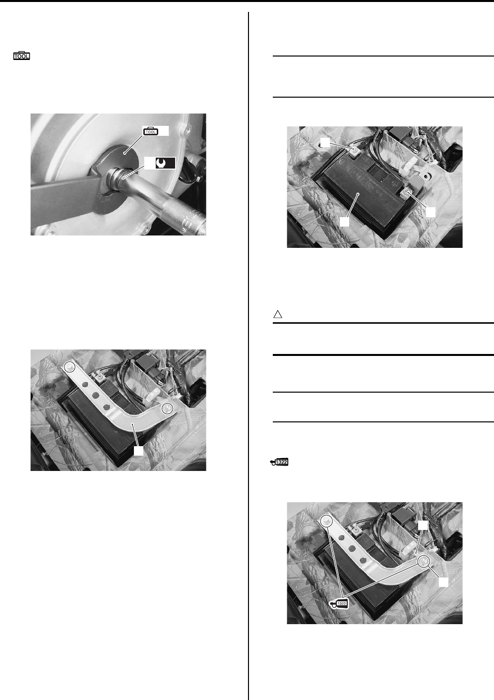
Charging System: 1J-2
• Tighten the crankshaft spacer nut (2) to the specified
torque with the special tool.
Special tool
(A): 09930–44530 (Rotor holder)
Tightening torque
Left crankshaft spacer nut (a): 38 N·m (3.8 kgf-m,
27.5 lbf-ft)
Battery Removal and Installation (LT-A750XP/
ZK9)
B931G41A06011
Removal
1) Remove the seat. Refer to “Seat Removal and
Installation in Section 9D in related manual”.
2) Remove the battery stay (1).
3) Disconnect the battery (–) lead wire (2).
4) Disconnect the battery (+) lead wire (3).
NOTE
Be sure to disconnect the battery (–) lead
wire (2) first, then disconnect the battery (+)
lead wire (3).
5) Remove the battery (4).
Installation
Install the battery in the reverse order of removal.
Pay attention to following point:
CAUTION
!
Never use anything except the specified
battery.
• Tighten the battery mounting bolts securely.
NOTE
Fit the EPS fuse bracket (2) to the mounting
bolt (1).
• Apply thread lock to the battery stay mounting bolts
and tighten them securely.
: Thread lock cement 99000–32110
(THREAD LOCK CEMENT SUPER “1322” or
equivalent)
(A)
(a)
2
I931G31A0004-01
1
I931G31A0005-01
2
4
3
I931G31A0006-01
1
2
I931G31A0007-02
PartShark.com
877-999-5686
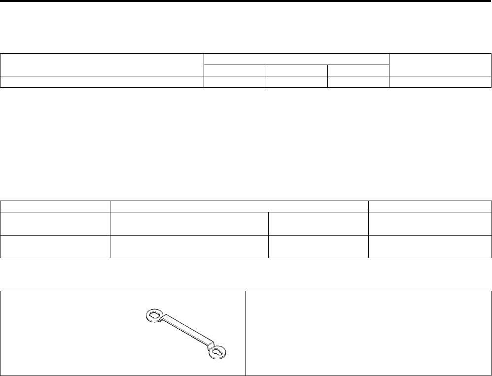
1J-3 Charging System:
Specifications
Tightening Torque Specifications
B931G41A07002
Reference:
For the tightening torque of fastener not specified in this section, refer to “Tightening Torque List (LT-A750XP/ZK9) in
Section 0C (Page 0C-7)”.
Special Tools and Equipment
Recommended Service Material
B931G41A08001
Special Tool
B931G41A08002
Fastening part Tightening torque Note
Nm kgf-m lbf-ft
Left crankshaft spacer nut 38 3.8 27.5 )(Page 1J-2)
Material SUZUKI recommended product or Specification Note
Grease SUZUKI SUPER GREASE “A” or
equivalent
P/No.: 99000–25010 )(Page 1J-1)
Thread lock cement THREAD LOCK CEMENT SUPER
“1322” or equivalent
P/No.: 99000–32110 )(Page 1J-2)
09930–44530
Rotor holder
)(Page 1J-1) / )(Page 1J-
2)
PartShark.com
877-999-5686

Table of Contents 3- i
3
Section 3
CONTENTS
Driveline / Axle
Precautions …………………………………………. 3-*
Precautions…………..……………………………..………….3-*
Precautions for Driveline / Axle ….……………..……… 3-*
Drive Chain / Drive Train / Drive Shaft… 3A-1
Diagnostic Information and Procedures………… 3A-*
Drive Shaft Symptom Diagnosis ..……………..…….3A-*
Repair Instructions …….…………….………….……….3A-1
Front Drive Shaft Components ….………….………..3A-*
Front Drive Shaft Assembly Removal and
Installation……………………………………..…………..3A-*
Front Drive Shaft Disassembly and Assembly …..3A-*
Front Drive Shaft Inspection …..………………..…….3A-*
Rear Drive Shaft Components …..………….………..3A-*
Rear Drive Shaft Assembly Removal and
Installation……………………………………..…………..3A-*
Rear Drive Shaft Disassembly and Assembly……3A-*
Rear Drive Shaft Inspection ………………….………..3A-*
Front Drive Shaft Components (LT-A750XP/
ZK9) …………..…………….………………..……………. 3A-1
Front Drive Shaft Disassembly and Assembly
(LT-A750XP/ZK9) ………….……………….…………. 3A-2
Front Drive Shaft Inspection (LT-A750XP/
ZK9) …………..…………….………………..……………. 3A-4
Rear Drive Shaft Components (LT-A750XP/
ZK9) …………..…………….………………..……………. 3A-5
Rear Drive Shaft Disassembly and Assembly
(LT-A750XP/ZK9) ………….……………….…………. 3A-5
Rear Drive Shaft Inspection (LT-A750XP/
ZK9) …………..…………….………………..……………. 3A-5
Special Tools and Equipment ………………………..3A-6
Recommended Service Material ..………….………. 3A-6
Special Tool …………..…………………………..……….3A-6
Differential………………………………………….3B-*
Diagnostic Information and Procedures………… 3B-*
Drive Train Symptom Diagnosis……….……………..3B-*
DTC “C20” (P1752) Diff-lock Relay Circuit
Malfunction.……………….……………..………………..3B-*
Repair Instructions …….…………….………….………. 3B-*
Front Drive (Differential) Components ……………..3B-*
Front Drive (Differential) Construction……………...3B-*
Front Drive (Differential) Gear Oil Level
Inspection……………………..…………….……………..3B-*
Front Drive (Differential) Gear Oil
Replacement ……………………………………..……… 3B-*
Front Drive (Differential) Assembly Removal
and Installation …………………………………..……… 3B-*
Front Drive (Differential) Assembly
Disassembly and Assembly ……..………….……… 3B-*
Front Drive (Differential) Related Parts
Inspection……….……………..……………….………… 3B-*
Breather Rubber Case Inspection.………….……… 3B-*
Front Drive (Differential) Gear Shim
Inspection and Selection ….…………….…………… 3B-*
2WD/4WD/Diff-lock System Inspection…………… 3B-*
Rear Drive Breather Hose Routing Diagram……. 3B-*
Final Gear Components ………….…………….……… 3B-*
Final Gear Construction ………….…………….……… 3B-*
Final Gear Oil Level Inspection …..………….……… 3B-*
Final Gear Oil Replacement.………………….……… 3B-*
Final Gear Assembly Removal and
Installation ………….…………….……………….……… 3B-*
Final Gear Assembly Disassembly and
Assembly…..…………….……………….…………….... 3B-*
Final Gear Related Parts Inspection ………………. 3B-*
Final Gear Shim Inspection and Selection ………. 3B-*
Specifications………..…………………….………………. 3B-*
Service Data……………………….……………….……… 3B-*
Tightening Torque Specifications…..………………. 3B-*
Special Tools and Equipment ……………………….. 3B-*
Recommended Service Material …………….……… 3B-*
Special Tool ………………………………………..……… 3B-*
Transfer ……………………………………………..3C-*
Diagnostic Information and Procedures………… 3C-*
Transfer Symptom Diagnosis………..………….…… 3C-*
Repair Instructions ………………………………….…… 3C-*
Transfer Components ……….……………….………… 3C-*
Transfer Removal and Installation …………………. 3C-*
Transfer Construction…….………….……………….... 3C-*
Counter Shaft / Reverse Idle Gear
Disassembly and Assembly ……..………….……… 3C-*
Gearshift Cam Components………….………………. 3C-*
Gearshift System Construction ……..………………. 3C-*
Gearshift Cam Disassembly and Assembly …….. 3C-*
Transfer Gear Bearing Removal and
Installation ………….…………….……………….……… 3C-*
Transfer Gear Bearing Inspection .………….……… 3C-*
NOTE
For the items with asterisk (*) in the “CONTENTS” below, refer to the same section of the service manual
mentioned in the “FOREWORD” of this manual.
PartShark.com
877-999-5686

3-ii Table of Contents
Transfer Related Parts Inspection…………..……… 3C-*
Transfer Related Bearing Inspection………………. 3C-*
Gear Position (GP) Switch Inspection…..………… 3C-*
Gear Position (GP) Switch Removal and
Installation………………………………………………… 3C-*
Gearshift Shaft No. 2 / Gearshift Cam Plate
Removal and Installation……….…………….……… 3C-*
Gearshift Linkage Inspection…………………………. 3C-*
Gearshift Shaft Oil Seal Removal and
Installation………………………………………………… 3C-*
Specifications….…………….…………….………………. 3C-*
Service Data…..……………….…………….……………. 3C-*
Special Tools and Equipment ……………………….. 3C-*
Recommended Service Material …………….……… 3C-*
Special Tool …………………………….…………….…… 3C-*
Propeller Shafts………………………………….3D-*
Repair Instructions ……..…………….………….……… 3D-*
Front Output Shaft Components ………….………… 3D-*
Front Output Shaft Removal and Installation …… 3D-*
Front Output Shaft Disassembly and
Assembly …….……………….…………….……………. 3D-*
Front Output Shaft Related Parts Inspection …… 3D-*
Rear Output Shaft Components……..……………… 3D-*
Rear Output Shaft Removal and Installation……. 3D-*
Rear Output Shaft Disassembly and
Assembly..…………….………………..…………….….. 3D-*
Rear Output Shaft Related Parts Inspection ……. 3D-*
Rear Output Shaft Drive Bevel Gear Shim
Inspection and Adjustment………..………….…….. 3D-*
Front Propeller Shaft Components….……………… 3D-*
Front Propeller Shaft Removal and
Installation ………….…………….………………..…….. 3D-*
Front Propeller Shaft Related Parts
Inspection…..…………….……………….……………... 3D-*
Rear Propeller Shaft Components ….……………… 3D-*
Rear Propeller Shaft Removal and Installation …. 3D-*
Rear Propeller Shaft Related Parts Inspection …. 3D-*
Specifications…..………………….…………………..….. 3D-*
Service Data…………………….……………….………… 3D-*
Tightening Torque Specifications…………………… 3D-*
Special Tools and Equipment .………………………. 3D-*
Recommended Service Material .…………….…….. 3D-*
Special Tool ……………………………………………….. 3D-*
PartShark.com
877-999-5686
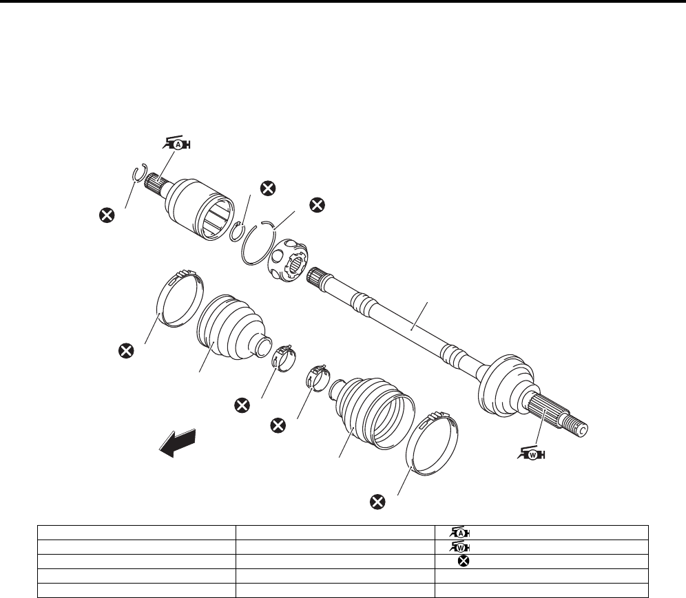
Drive Chain / Drive Train / Drive Shaft: 3A-1
Driveline / Axle
Drive Chain / Drive Train / Drive Shaft
Repair Instructions
Front Drive Shaft Components (LT-A750XP/ZK9)
B931G43106009
FWD
1
2
3
7
6
5
4
8
9
10
I931H1310012-03
1. Circlip 6. Inner boot band (Small) : Apply grease.
2. Snap ring 7. Drive shaft : Apply water resistance grease.
3. Stopper ring 8. Outer boot band (Small) : Do not reuse.
4. Inner boot band (Large) 9. Outer boot
5. Inner boot 10. Outer boot band (Large)
PartShark.com
877-999-5686

3A-2 Drive Chain / Drive Train / Drive Shaft:
Front Drive Shaft Disassembly and Assembly
(LT-A750XP/ZK9)
B931G43106010
Refer to “Front Drive Shaft Assembly Removal and
Installation in related manual”.
Disassembly
CAUTION
!
Do not disassemble the wheel side joint. If
any damages are found, replace it with a new
one.
1) Remove the boot band of the differential side joint.
2) Slide the boot toward the center of the front drive
shaft and remove the stopper ring from the outer
race.
3) Remove the outer race from the front drive shaft.
4) Wipe off any grease and remove the snap ring.
Special tool
(A): 09900–06107 (Snap ring remover (Open
type))
5) Remove the cage from the front drive shaft.
6) Remove the boot band of the small diameter side.
I931H1310003-03
I831G1310006-01
I831G1310007-01
(A)
I831G1310022-01
I831G1310009-01
I931H1310004-02
PartShark.com
877-999-5686
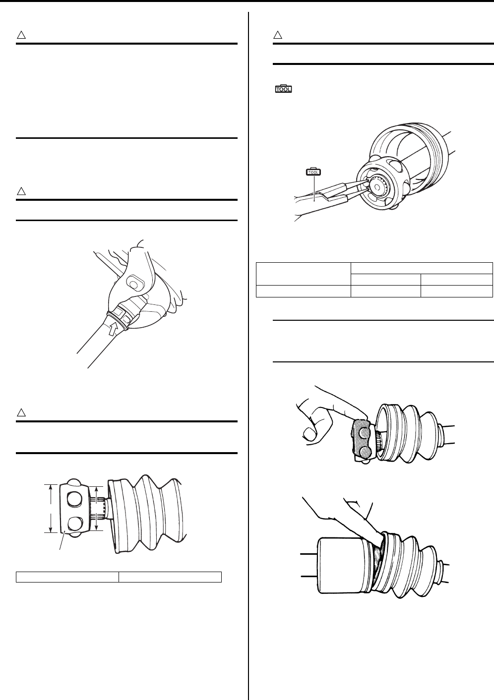
Drive Chain / Drive Train / Drive Shaft: 3A-3
Assembly
CAUTION
!
• Wash all parts before installation, clean the
inside and outside of the boots with a
cloth.
• Do not wash the boots in any commercially
available degreaser, such as gasoline or
kerosene. Washing in a degreaser causes
deterioration of the boots.
1) Fit a boot on the drive shaft end, fitting the small
diameter side of the boot to the shaft groove, fix its
end with a new boot band.
CAUTION
!
Replace the boot band with a new one.
2) Install the cage (1) on the shaft.
CAUTION
!
Install the cage with the large diameter side
“A” facing the shaft end.
3) Install the new snap ring to the cage.
CAUTION
!
Replace the snap ring with a new one.
Special tool
(A): 09900–06107 (Snap ring remover (Open
type))
4) Apply grease to the entire surface of the cage and
the inside of the outer race.
NOTE
The tube of joint grease is included in the
wheel side boot set or wheel side joint
assembly of spare parts.
“A”: Large diameter “B”: Small diameter
I931H1310005-02
1
“A” “B”
I831G1310012-02
Position
Wheel side Differential side
Grease: Quantity 60 g (2.1 oz) 60 g (2.1 oz)
(A)
I831G1310023-01
I831G1310013-01
I831G1310014-01
PartShark.com
877-999-5686
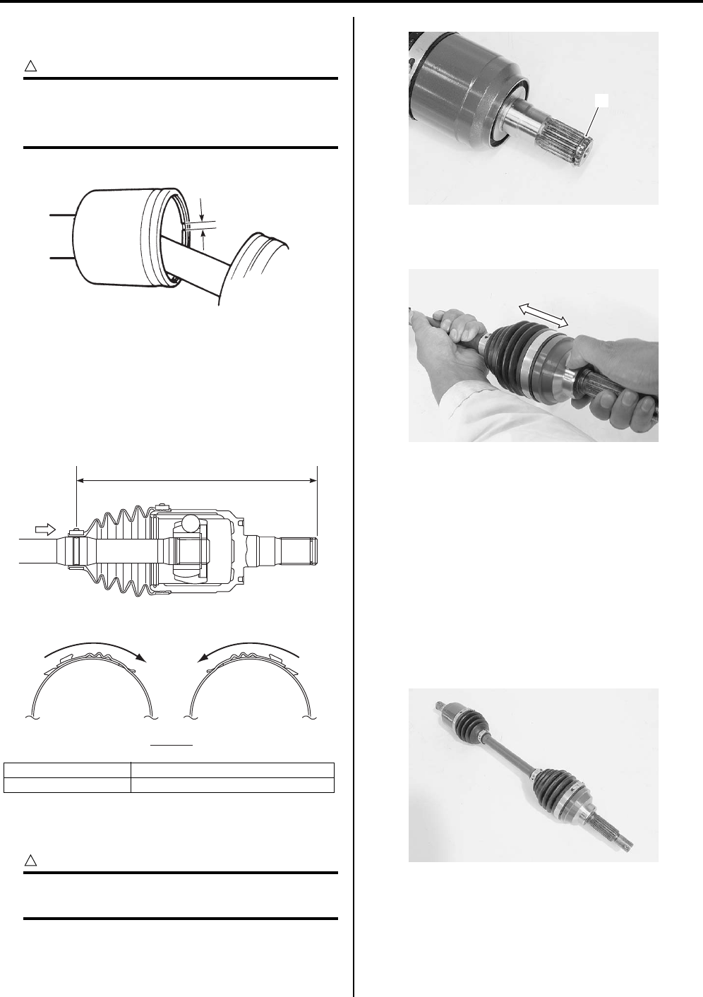
3A-4 Drive Chain / Drive Train / Drive Shaft:
5) Insert the cage into the outer race and install the new
stopper ring to the groove of the outer race.
CAUTION
!
• Replace the stopper ring with a new one.
• Position the opening of stopper ring “C”
so that it will not be lined up with a ball.
6) After installing the boot on the outer race, insert a
screw driver into the boot on the outer race side and
allow air to enter the boot so that the air pressure in
the boot becomes the same as the atmospheric
pressure at the positions indicated in the figure.
7) Fix the boot on the outer race with a new boot band,
taking care not to distort the boot.
Install the circlip (2) into the groove of front drive
shaft spline.
CAUTION
!
The removed circlip must be replaced with a
new one.
9) Inspect the axle play by using a push-and-pull
motion given to the axle shaft and wheel spindle.
Front Drive Shaft Inspection (LT-A750XP/ZK9)
B931G43106011
Inspect the front drive shaft in the following procedures:
1) Remove the front drive shaft assembly. Refer to
“Front Drive Shaft Assembly Removal and
Installation in related manual”.
2) Check the drive shaft boots for twist and grease leak.
If any defects are found, replace the defective parts
with new ones.
3) Inspect the boots, circlip and boot bands for wear or
damage. If any damages are found, replace them
with new ones.
4) Install the front drive shaft assembly. Refer to “Front
Drive Shaft Assembly Removal and Installation in
related manual”.
“D”: Right side “F”: Rotation direction
“E”: Left side “a”: 182.1 mm (7.2 in)
“C”
I831G1310015-01
A
VIEW A
“F”
“D” “E”
“F”
“a”
I931H1310006-03
2
I931H1310007-01
I931H1310008-01
I931H1310009-01
PartShark.com
877-999-5686
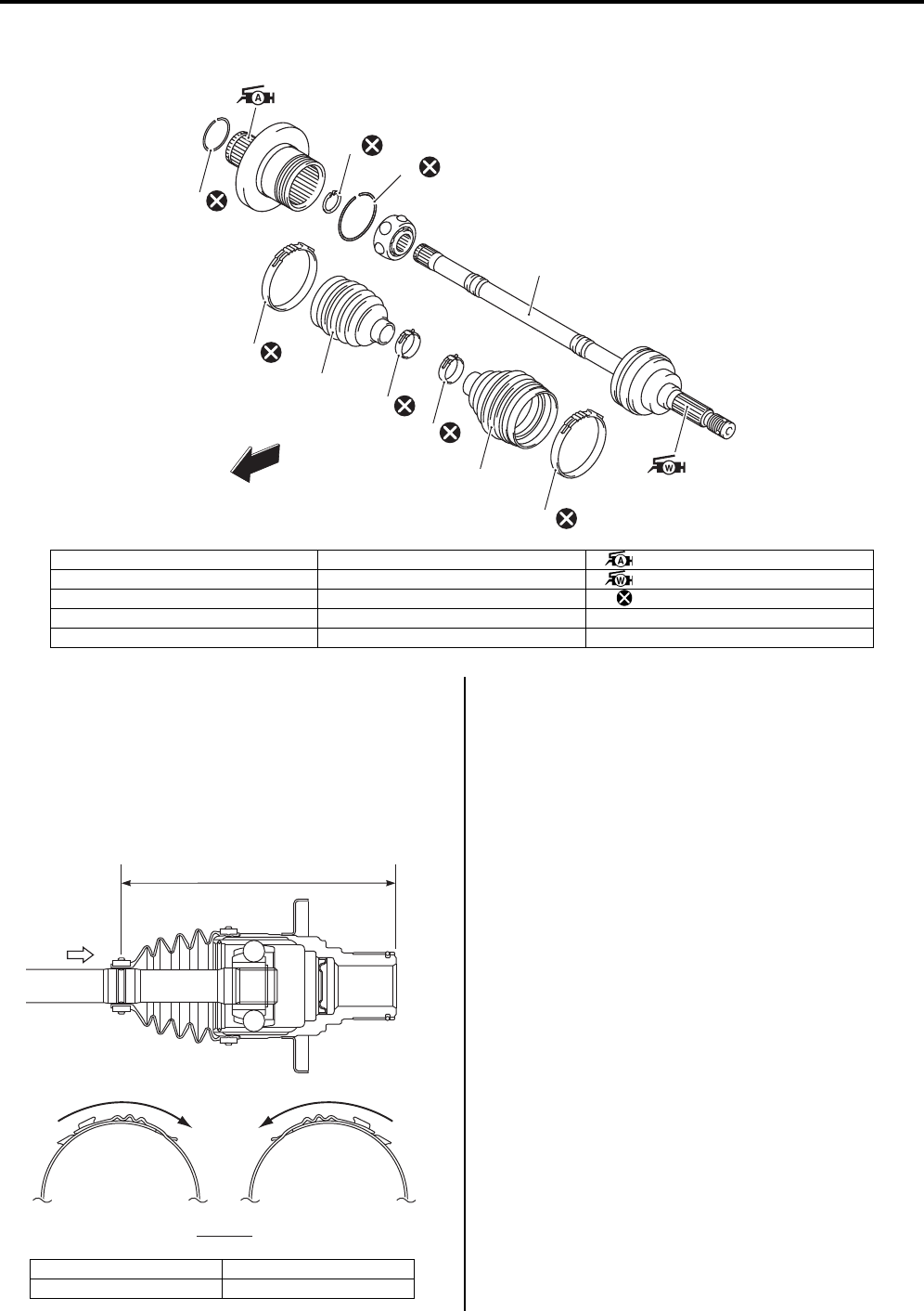
Drive Chain / Drive Train / Drive Shaft: 3A-5
Rear Drive Shaft Components (LT-A750XP/ZK9)
B931G43106012
Rear Drive Shaft Disassembly and Assembly
(LT-A750XP/ZK9)
B931G43106013
Refer to “Rear Drive Shaft Assembly Removal and
Installation in related manual”.
Rear drive shaft disassembly and assembly are the
same manner of front drive shaft disassembly and
assembly except for the position of inner boot bond.
Rear Drive Shaft Inspection (LT-A750XP/ZK9)
B931G43106014
Refer to “Rear Drive Shaft Assembly Removal and
Installation in related manual”.
Rear drive shaft inspection as the same manner of front
drive shaft.
FWD
1
4
5
6
8
9
2
7
3
10
I931H1310013-04
1. Circlip 6. Inner boot band (Small) : Apply grease.
2. Snap ring 7. Drive shaft : Apply water resistance grease.
3. Stopper ring 8. Outer boot band (Small) : Do not reuse.
4. Inner boot band (Large) 9. Outer boot
5. Inner boot 10. Outer boot band (Large)
“B”: Right side “D”: Rotation direction
“C”: Left side “a”: 166 mm (6.5 in)
A
VIEW A
“D”
“B” “C”
“D”
“a”
I931G3310001-01
PartShark.com
877-999-5686
3A-6 Drive Chain / Drive Train / Drive Shaft:
Special Tools and Equipment
Recommended Service Material
B931G43108001
NOTE
Required service material is also described in the following.
“Front Drive Shaft Components (LT-A750XP/ZK9) (Page 3A-1)”
“Rear Drive Shaft Components (LT-A750XP/ZK9) (Page 3A-5)”
Special Tool
B931G43108002
09900–06107
Snap ring remover (Open
type)
)(Page 3A-2) / )(Page 3A-
3)
PartShark.com
877-999-5686

Table of Contents 4- i
4
Section 4
CONTENTS
Brake
Precautions …………………………………………. 4-*
Precautions…………..……………………………..………….4-*
Precautions for Brake System …..……………..……… 4-*
Brake Fluid Information…………….……………..……… 4-*
Brake Control System and Diagnosis … 4A-1
Schematic and Routing Diagram…..……………….4A-1
Front Brake Hose Routing Diagram .………….…….4A-*
Rear Blake Cable Routing Diagram……….………..4A-*
Front Brake Hose Routing Diagram (LT-
A750XP/ZK9) …………….………………..……………. 4A-1
Diagnostic Information and Procedures………… 4A-*
Brake Symptom Diagnosis………..………….………..4A-*
Repair Instructions …….…………….………….……….4A-2
Brake Pedal Height Inspection and
Adjustment ………..…………….……………….………..4A-*
Front Brake Light Switch Inspection ………………..4A-*
Rear Brake Light Switch Inspection ……….………..4A-*
Rear Brake Switch Inspection and Adjustment …..4A-*
Parking / Rear Brake Light Switch Inspection ……4A-*
Parking Brake Lever Switch Inspection…………….4A-*
Brake Fluid Level Check ……..…………….…………..4A-*
Front Brake Hose Inspection ………..………….…….4A-*
Air Bleeding from Front Brake Fluid Circuit……….4A-*
Brake Fluid Replacement………….……………..…….4A-*
Front Brake Hose Removal and Installation………4A-*
Rear Brake Cable Removal and Installation ……..4A-*
Front Brake Master Cylinder Components………..4A-*
Front Brake Master Cylinder Assembly
Removal and Installation…………………….………..4A-*
Front Brake Master Cylinder / Brake Lever
Disassembly and Assembly …….………….………..4A-*
Front Brake Master Cylinder Parts Inspection …..4A-*
Rear Brake Pedal Construction ………………..…….4A-*
Rear Brake Pedal Removal and Installation ……..4A-*
Front Brake Hose Removal and Installation
(LT-A750XP/ZK9) ………….……………….…………. 4A-2
Rear Brake Pedal Construction (LT-A750XP/
ZK9) …………..…………….………………..……………. 4A-3
Rear Brake Pedal Removal and Installation
(LT-A750XP/ZK9) ………….……………….…………. 4A-3
Specifications…….……………….…………….………….4A-5
Service Data ………….……………….……………..…….4A-*
Tightening Torque Specifications.………….……….4A-5
Special Tools and Equipment ………………………..4A-5
Special Tool ………………………………………..……… 4A-*
Recommended Service Material …………….………4A-5
Front Brakes ……………………………..……….4B-*
Precautions………………………………………..………… 4B-*
Precautions for Front Brakes …..…………….……… 4B-*
Repair Instructions ………………………………….…… 4B-*
Front Brake Components …………..………….……… 4B-*
Front Brake Pad Inspection…………………………… 4B-*
Front Brake Pad Replacement…………………….... 4B-*
Front Brake Caliper Removal and Installation….. 4B-*
Front Brake Caliper Disassembly and
Assembly…..…………….……………….…………….... 4B-*
Front Brake Caliper Parts Inspection ……………… 4B-*
Front Brake Disc Removal and Installation ……… 4B-*
Front Brake Disc Inspection …….…………….……… 4B-*
Specifications………..…………………….………………. 4B-*
Service Data……………………….……………….……… 4B-*
Tightening Torque Specifications…..………………. 4B-*
Special Tools and Equipment ……………………….. 4B-*
Recommended Service Material …………….……… 4B-*
Special Tool ………………………………………..……… 4B-*
Rear Brakes………………………………………..4C-*
Precautions………………………………………..………… 4C-*
Precautions for Rear Brake…..…………….………… 4C-*
Repair Instructions ………………………………….…… 4C-*
Rear Brake Components……………………….……… 4C-*
Rear Brake Friction Plate Inspection………………. 4C-*
Rear Brake Friction Plate Replacement………….. 4C-*
Rear Brake Assembly Removal and
Installation ………….…………….……………….……… 4C-*
Rear Brake Disassembly and Assembly …………. 4C-*
Rear Brake Parts Inspection ………………….……… 4C-*
Specifications………..…………………….………………. 4C-*
Service Data……………………….……………….……… 4C-*
Tightening Torque Specifications…..………………. 4C-*
Special Tools and Equipment ……………………….. 4C-*
Recommended Service Material …………….……… 4C-*
Special Tool ………………………………………..……… 4C-*
Parking Brake …………………………………….4D-*
Schematic and Routing Diagram…..………………. 4D-*
NOTE
For the items with asterisk (*) in the “CONTENTS” below, refer to the same section of the service manual
mentioned in the “FOREWORD” of this manual.
PartShark.com
877-999-5686

4-ii Table of Contents
Parking / Rear Brake Cable Routing Diagram …. 4D-*
Repair Instructions ……..…………….………….……… 4D-*
Parking / Rear Brake Inspection and
Adjustment ………..…………….………………..……… 4D-*
Parking / Rear Brake Cable Removal and
Installation………………………………………………… 4D-*
Parking / Rear Brake Lever Components ……….. 4D-*
Parking / Rear Brake Lever Removal and
Installation ………….…………….………………..…….. 4D-*
Parking / Rear Brake Light Switch Inspection ….. 4D-*
Parking / Rear Brake Relay Inspection …………… 4D-*
Specifications…..………………….…………………..….. 4D-*
Tightening Torque Specifications…………………… 4D-*
Special Tools and Equipment .………………………. 4D-*
Recommended Service Material .…………….…….. 4D-*
PartShark.com
877-999-5686
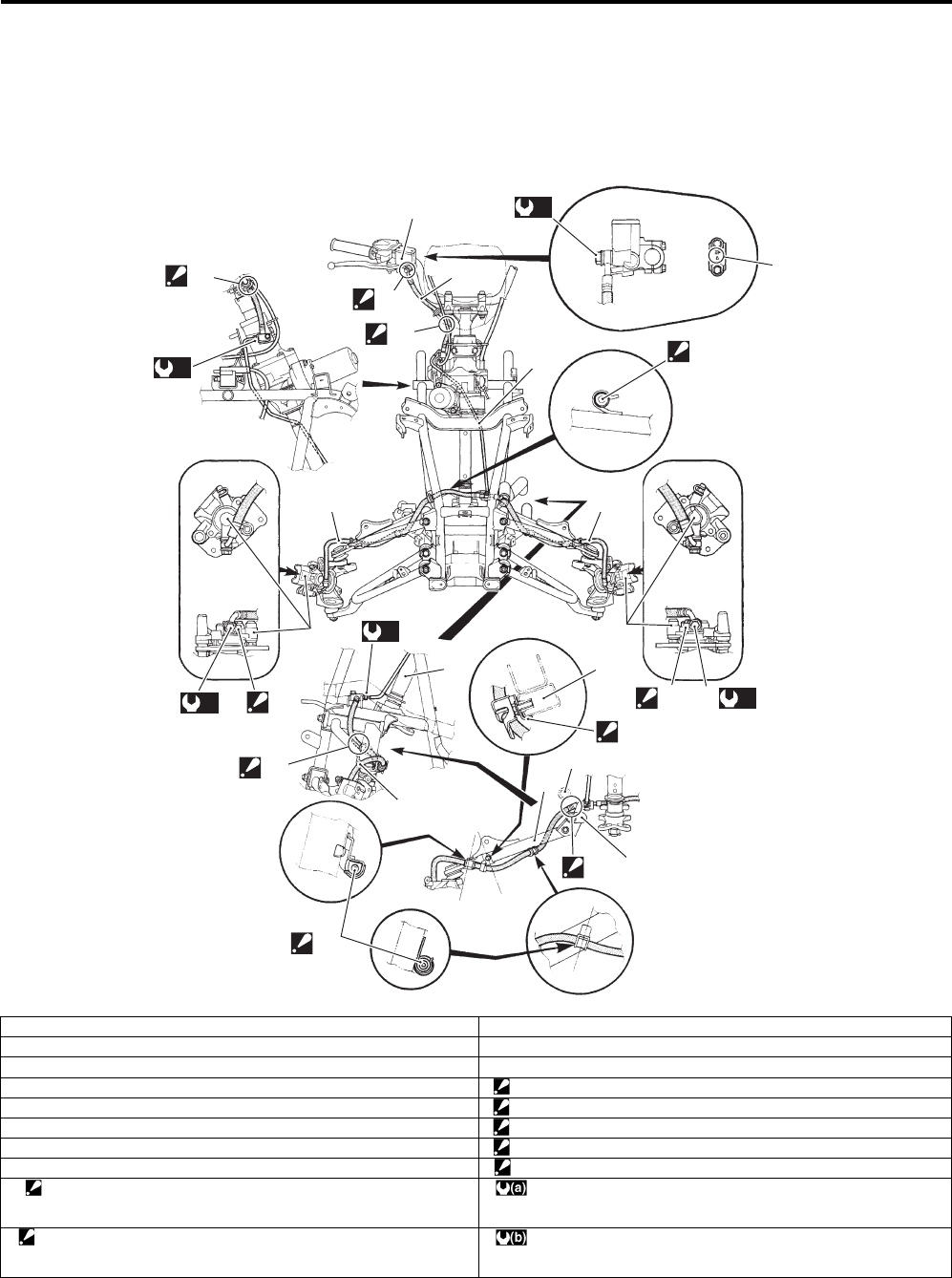
Brake Control System and Diagnosis: 4A-1
Brake
Brake Control System and Diagnosis
Schematic and Routing Diagram
Front Brake Hose Routing Diagram (LT-A750XP/ZK9)
B931G44102003
1
“B”
2
“C”
3
4
55
7
4
(a)
89
4
(a)
8
9
10
11
11
12
(a)
8
11
“E” 6
“F”
(b)
“D”
(b)
“A”
“D”
“D”
I931H1410043-05
1. Master cylinder 11. Suspension upper arm
2. Front brake hose No. 1 12. Radiator hose
3. Front brake pipe “A”: UP mark
4. Front brake hose No. 2 “B”: After the brake hose union has contacted the reservoir bottom.
5. Front brake caliper “C”: Pass the brake hose behind the throttle cable.
6. Frame “D”: Fix the brake hose to the it guide firmly.
7. Steering shaft “E”: Pass the brake hose No. 2 between the radiator lower hose and frame.
8. Union bolt “F”: Pass the brake hose inside of the suspension arm.
9. Stopper
: After the brake hose union has contacted the stopper, tighten the
union bolt.
:23 Nm (2.3 kgf-m, 16.5 lbf-ft)
10. Stopper
: After the brake hose clamp has contacted the suspension upper arm,
tighten the stopper bolt.
:16 Nm (1.6 kgf-m, 11.5 lbf-ft)
PartShark.com
877-999-5686
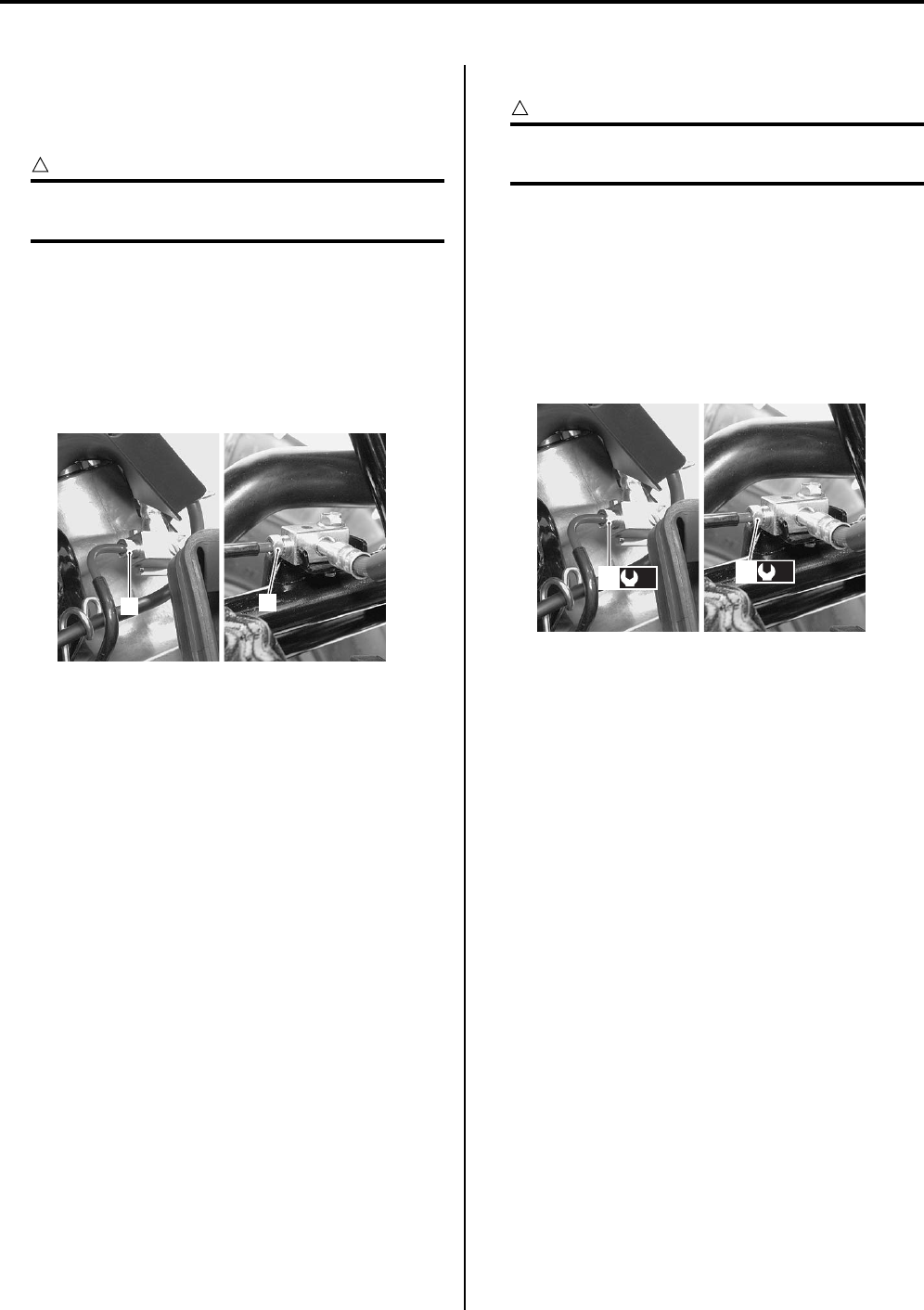
4A-2 Brake Control System and Diagnosis:
Repair Instructions
Front Brake Hose Removal and Installation (LT—
A750XP/ZK9)
B931G44106019
Removal
CAUTION
!
Make sure that the vehicle is supported
securely.
1) Remove the front fender. Refer to “Front Side
Exterior Parts Removal and Installation in Section
9D in related manual”.
2) Drain brake fluid. Refer to “Brake Fluid Replacement
in related manual”.
3) Loosen the flare nuts (1) and disconnect the brake
pipe.
4) Remove the front brake hoses as shown in the front
brake hose routing diagram. Refer to “Front Brake
Hose Routing Diagram (LT-A750XP/ZK9) (Page 4A-
1)”.
Installation
CAUTION
!
The seal washers should be replaced with the
new ones to prevent fluid leakage.
1) Install the front brake hose as shown in the front
brake hose routing diagram. Refer to “Front Brake
Hose Routing Diagram in related manual”.
2) Tighten the brake flare nut (1) to the specified
torque.
Tightening torque
Brake pipe flare nut (a): 16 N·m (1.6 kgf-m, 11.5
lbf-ft)
3) Bleed air from the front brake system. Refer to “Air
Bleeding from Front Brake Fluid Circuit in related
manual”.
4) Install the front fender. Refer to “Front Side Exterior
Parts Removal and Installation in Section 9D in
related manual”.
11
I931G3410001-02
(a)
1(a)
1
I931G3410009-01
PartShark.com
877-999-5686
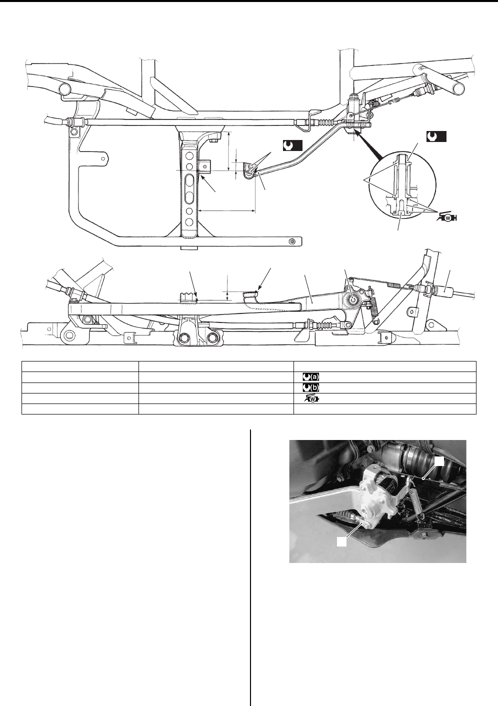
Brake Control System and Diagnosis: 4A-3
Rear Brake Pedal Construction (LT-A750XP/ZK9)
B931G44106020
Rear Brake Pedal Removal and Installation (LT—
A750XP/ZK9)
B931G44106021
Removal
1) Remove the right inner fender. Refer to “Front Side
Exterior Parts Removal and Installation in Section
9D in related manual”.
2) Remove the right mud guard. Refer to “Rear Side
Exterior Parts Removal and Installation in Section
9D in related manual”.
3) Remove the rear brake light switch spring (1).
4) Disconnect the rear brake cable (2). Refer to “Rear
Brake Cable Removal and Installation in related
manual”.
“a”
“A”
“b”
“c”
“B”
3
(a)
5
4
2
4
1
“B”
“A”
(b)
6
I931G3410002-01
1. Rear brake pedal 6. Rear brake pedal screw “B”: Anchoring point (Pedal side)
2. Rear brake light switch “a”: 12.5 – 22.5 mm (0.49 – 0.89 in) : 60 Nm (6.0 kgf-m, 43.5 lbf-ft)
3. Washer “b”: 83.2 mm (3.28 in) : 4.5 Nm (0.45 kgf-m, 3.0 lbf-ft)
4. Rear brake pedal shaft “c”: 17.5 mm (0.69 in) : Apply water resistance grease.
5. Rear brake pedal shaft nut “A”: Anchoring point (Footrest side)
2
1
I931G3410003-02
PartShark.com
877-999-5686
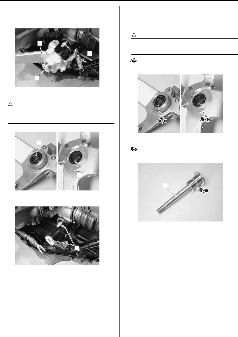
4A-4 Brake Control System and Diagnosis:
5) Remove the rear brake pedal shaft (3).
6) Remove the rear brake pedal (4) and rear brake
pedal spring (5).
7) Remove the dust seals (6) if necessary.
CAUTION
!
If there are wear or damage, replace the dust
seals (6) with new ones.
Remove the washers (7).
Installation
Install the rear brake pedal in the reverse order of
removal. Pay attention to the following points:
• Apply grease to the lip of dust seals and washers.
CAUTION
!
Never reuse the removed dust seals with new
ones.
: Grease 99000–25160 (Water resistance
grease or equivalent)
• Apply grease to the rear brake pedal shaft (1).
: Grease 99000–25160 (Water resistance
grease or equivalent)
4
3
5
I931G3410010-01
6
6
I931G3410004-01
7
I931G3410005-01
I931G3410006-02
1
I931H1410035-01
PartShark.com
877-999-5686
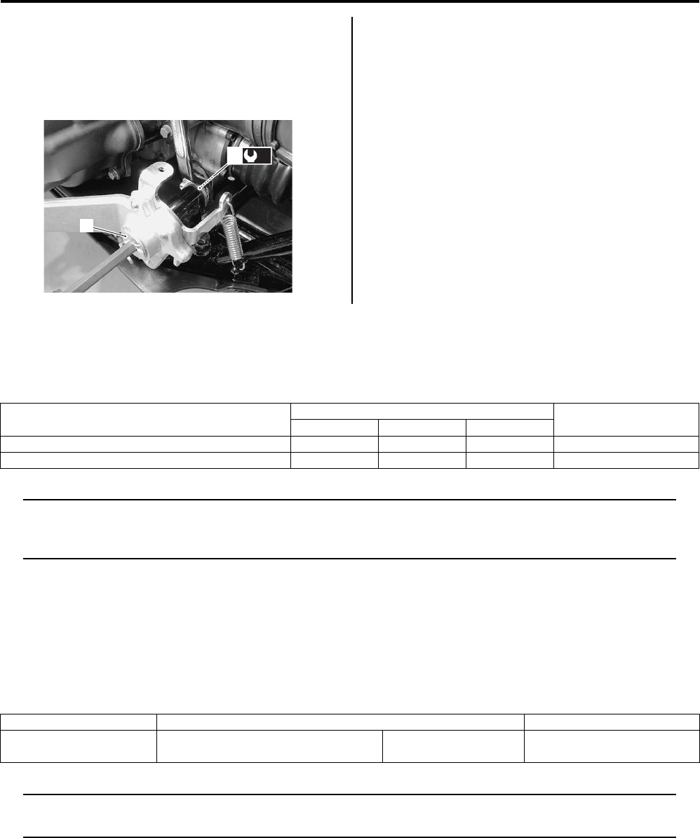
Brake Control System and Diagnosis: 4A-5
• Install the rear brake pedal shaft (1) and tighten the
brake pedal shaft nut (2) to the specified torque.
Tightening torque
Rear brake pedal shaft nut (a): 60 N·m (6.0 kgf-m,
43.5 lbf-ft)
• After installed rear brake cable, adjust the adjuster
nut. Refer to “Rear Brake Pedal / Rear Brake (Parking
Brake) Lever Inspection and Adjustment in Section 0B
in related manual”.
• Install the removed parts.
Specifications
Tightening Torque Specifications
B931G44107002
NOTE
The specified tightening torque is described in the following.
“Front Brake Hose Routing Diagram (LT-A750XP/ZK9) (Page 4A-1)”
“Rear Brake Pedal Construction (LT-A750XP/ZK9) (Page 4A-3)”
Reference:
For the tightening torque of fastener not specified in this section, refer to “Tightening Torque List (LT-A750XP/ZK9) in
Section 0C (Page 0C-7)”.
Special Tools and Equipment
Recommended Service Material
B931G44108003
NOTE
Required service material is also described in the following.
“Rear Brake Pedal Construction (LT-A750XP/ZK9) (Page 4A-3)”
1
(a)
2
I931G3410007-01
Fastening part Tightening torque Note
Nm kgf-m lbf-ft
Brake pipe flare nut 16 1.6 11.5 )(Page 4A-2)
Rear brake pedal shaft nut 60 6.0 43.5 )(Page 4A-5)
Material SUZUKI recommended product or Specification Note
Grease Water resistance grease or
equivalent
P/No.: 99000–25160 )(Page 4A-4) / )(Page 4A-
4)
PartShark.com
877-999-5686

4A-6 Brake Control System and Diagnosis:
PartShark.com
877-999-5686

Table of Contents 6- i
6
Section 6
CONTENTS
Steering
Precautions ………………………………………….6-1
Precautions…………..……………………………..………… 6-1
Precautions for Steering …………..……………..……… 6-*
Precautions for Steering (LT-A750XP/ZK9)………. 6-1
Steering General Diagnosis……………….. 6A-1
Diagnostic Information and Procedures…………6A-1
Steering Symptom Diagnosis………..………….…….6A-*
Steering Symptom Diagnosis (LT-A750XP/
ZK9) …………..…………….………………..……………. 6A-1
Steering / Handlebar………………………….. 6B-1
Repair Instructions …….…………….………….……….6B-1
Steering / Handlebars Components.………….…….6B-*
Steering / Handlebars Assembly Construction …..6B-*
Handlebars Removal and Installation ………..…….6B-*
Handlebars Inspection ………..…………….…………..6B-*
Steering Shaft Removal and Installation …………..6B-*
Tie-rod / Tie-rod End Removal and
Installation……………………………………..…………..6B-*
Steering Parts Inspection………….……………..…….6B-*
Steering / Handlebars Components (LT-
A750XP/ZK9) …………….………………..……………. 6B-1
Steering / Handlebars Assembly Construction
(LT-A750XP/ZK9) ………….……………….…………. 6B-2
Handlebars Removal and Installation (LT-
A750XP/ZK9) …………….………………..……………. 6B-3
Handlebars Inspection (LT-A750XP/ZK9)……….. 6B-5
Steering Shaft Removal and Installation (LT-
A750XP/ZK9) …………….………………..……………. 6B-6
Tie-rod / Tie-rod End Removal and
Installation (LT-A750XP/ZK9) ………..……………. 6B-8
Steering Related Parts Inspection (LT-
A750XP/ZK9) …………….………………..……………. 6B-9
Specifications…….……………….…………….………..6B-10
Service Data ………….……………….……………..…….6B-*
Service Data (LT-A750XP/ZK9)……….………….. 6B-10
Tightening Torque Specifications.………….……..6B-11
Special Tools and Equipment ………………………6B-11
Recommended Service Material..………….……..6B-11
Special Tool …………..…………………………..……..6B-11
Power Assisted Steering System……….. 6C-1
Precautions…………..…………………………..………….6C-1
Precautions for EPS (LT-A750XP/ZK9) …………..6C-1
P/S System Note (LT-A750XP/ZK9) ….……………6C-1
Precautions in Diagnosing Troubles (LT-
A750XP/ZK9) …………..………………………..………6C-1
General Description ….…………………………..………6C-2
P/S System Description (LT-A750XP/ZK9)………6C-2
EPS Diagnosis General Description (LT-
A750XP/ZK9) …………..………………………..………6C-5
Self Diagnostic System Description (LT-
A750XP/ZK9) …………..………………………..………6C-5
Fail-safe Function Description (LT-A750XP/
ZK9) ………………………….………………..……………6C-5
Schematic and Routing Diagram…..……………….6C-6
EPS Wiring Diagram (LT-A750XP/ZK9)…………..6C-6
EPS Control Unit Diagram (LT-A750XP/ZK9)…..6C-7
EPS System Wiring Harness Routing
Diagram (LT-A750XP/ZK9) ………………………….6C-8
Component Location …………………………….………6C-8
EPS Components Location (LT-A750XP/
ZK9) ………………………….………………..……………6C-8
Diagnostic Information and Procedures…………6C-9
EPS Troubleshooting (LT-A750XP/ZK9)………….6C-9
Pre-diagnosis Inspection (LT-A750XP/ZK9) …..6C-10
EPS System Check (LT-A750XP/ZK9) ………….6C-12
DTC (Diagnostic Trouble Code) Output (LT-
A750XP/ZK9) …………..…………….………………..6C-19
DTC (Diagnostic Trouble Code) Deleting (LT-
A750XP/ZK9) …………..…………….………………..6C-21
SDS Check (LT-A750XP/ZK9) ……………………..6C-24
DTC Table (LT-A750XP/ZK9) ….…………….…….6C-25
DTC “C1111”: Torque Sensor (Main) Circuit
Malfunction (LT-A750XP/ZK9) ….………………..6C-26
DTC “C1113”: Torque Sensor (Main / Sub)
Circuit Correlation Malfunction (LT-A750XP/
ZK9) ………………………….………………..………….6C-29
DTC “C1114”: Torque Sensor Power Supply
Circuit Malfunction (LT-A750XP/ZK9) ………….6C-33
DTC “C1115”: Torque Sensor (Sub) Circuit
Malfunction (LT-A750XP/ZK9) ….………………..6C-35
DTC “C1121”: Vehicle Speed Signal Circuit
Malfunction (LT-A750XP/ZK9) ….………………..6C-38
DTC “C1122”: Engine Speed Signal Circuit
Malfunction (LT-A750XP/ZK9) ….………………..6C-41
DTC “C1141”, “C1142”, “C1143”, “C1145”
EPS Motor Circuit Malfunction (LT-A750XP/
ZK9) ………………………….………………..………….6C-44
NOTE
For the items with asterisk (*) in the “CONTENTS” below, refer to the same section of the service manual
mentioned in the “FOREWORD” of this manual.
PartShark.com
877-999-5686

6-ii Table of Contents
DTC “C1153” EPS Control Unit Supply
Voltage Circuit Malfunction (LT-A750XP/
ZK9) ………………………….……………….…………..6C-46
DTC “C1152”, “C1154”, “C1155” EPS Control
Unit Malfunction (LT-A750XP/ZK9)……………..6C-47
Repair Instructions ……………………………………..6C-48
EPS Control Unit Construction (LT-A750XP/
ZK9) ………………………….……………….…………..6C-48
EPS Control Unit Removal and Installation
(LT-A750XP/ZK9) ………….…………………………6C-48
EPS Body Assembly Components (LT-
A750XP/ZK9) ………………………….……………….6C-50
EPS Body Assembly Removal and
Installation (LT-A750XP/ZK9) …………………….6C-50
EPS Motor Inspection (LT-A750XP/ZK9)……….6C-53
Specifications…..………………….…………………..…6C-54
Tightening Torque Specifications………………….6C-54
Special Tools and Equipment ………………………6C-54
Recommended Service Material .…………….……6C-54
Special Tool …………………….…………….………….6C-55
PartShark.com
877-999-5686

Precautions: 6-1
Steeri ng
Precautions
Precautions
Precautions for Steering (LT-A750XP/ZK9)
B931G46000002
Refer to “General Precautions in Section 00 in related manual” and “Precautions for EPS (LT-A750XP/ZK9) in Section
00 (Page 00-1)”.
PartShark.com
877-999-5686
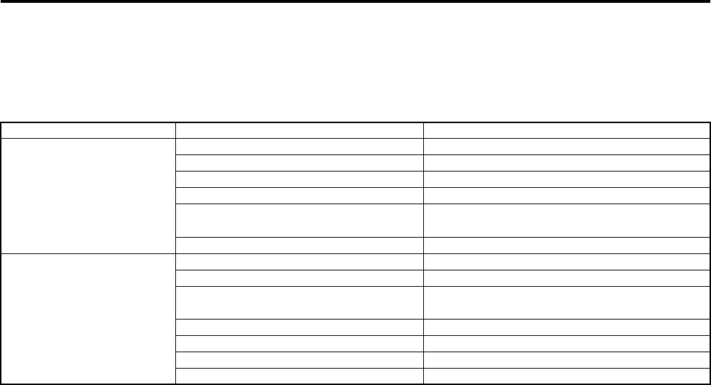
6A-1 Steering General Diagnosis:
Steeri ng
Steering General Diagnosis
Diagnostic Information and Procedures
Steering Symptom Diagnosis (LT-A750XP/ZK9)
B931G46104002
Condition Possible cause Correction / Reference Item
Heavy Steering Distorted steering shaft. Replace.
Improper front wheel alignment. Adjust.
Insufficiently lubricated. Lubricate.
Not enough pressure in tires. Adjust.
Worn or incorrect tire or wrong tire
pressure.
Adjust or replace.
Malfunctioning EPS, if equipped. Inspect EPS system.
Wobbly Handlebars Distorted front steering shaft. Replace.
Crooked tire. Replace.
Worn or incorrect tire or wrong tire
pressure.
Adjust or replace.
Worn bearing/race in steering stem. Replace.
Worn steering shaft holder bushing. Replace.
Worn steering knuckle ends or ball stud. Replace.
Worn front wheel hub bearings. Replace.
PartShark.com
877-999-5686
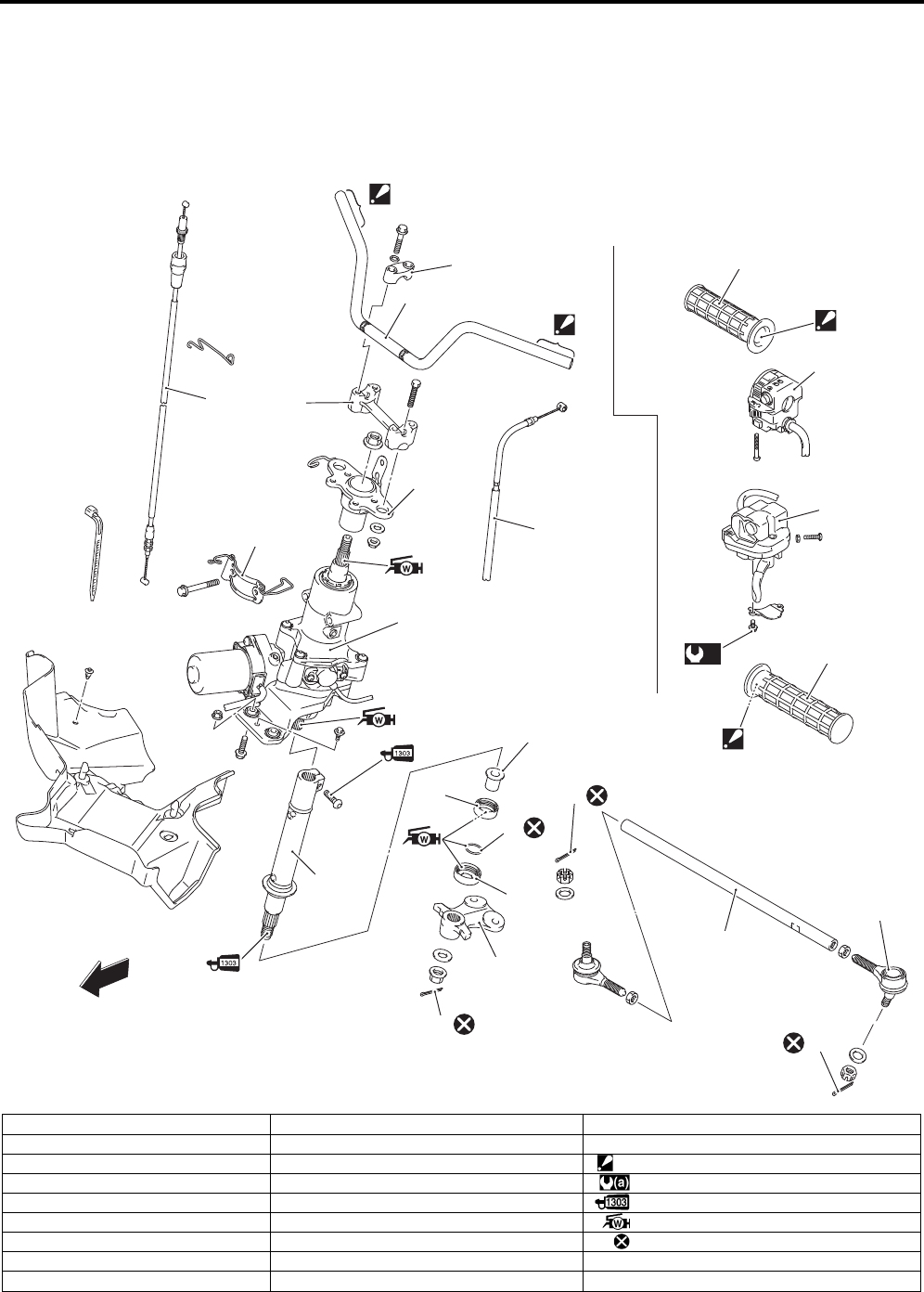
Steering / Handlebar: 6B-1
Steeri ng
Steering / Handlebar
Repair Instructions
Steering / Handlebars Components (LT-A750XP/ZK9)
B931G46206008
1
2
3
4
5
7
12
13
14
15
16
17
18
12
“A”
“A”
“A”
12
20
20
19
“A”
(a)
10
11
9
FWD
8
6
I931G3620028-02
1. Handlebars 10. Lower dust seal 19. Handlebar left switch assembly
2. Handlebar upper clamp 11. Steering arm plate 20. Handle grip
3. Handlebar holder 12. Cotter pin “A”: Apply grip bond.
4. Steering shaft plate 13. Tie-rod : 4 Nm (0.4 kgf-m, 3.0 lbf-ft)
5. EPS body assembly 14. Tie-rod end : Apply thread lock to the thread part.
6. Steering shaft 15. Cable guide : Apply water resistance grease.
7. Steering shaft bushing 16. Throttle cable : Do not reuse.
8. Dust seal 17. Parking brake cable
9. O-ring 18. Throttle case assembly
PartShark.com
877-999-5686
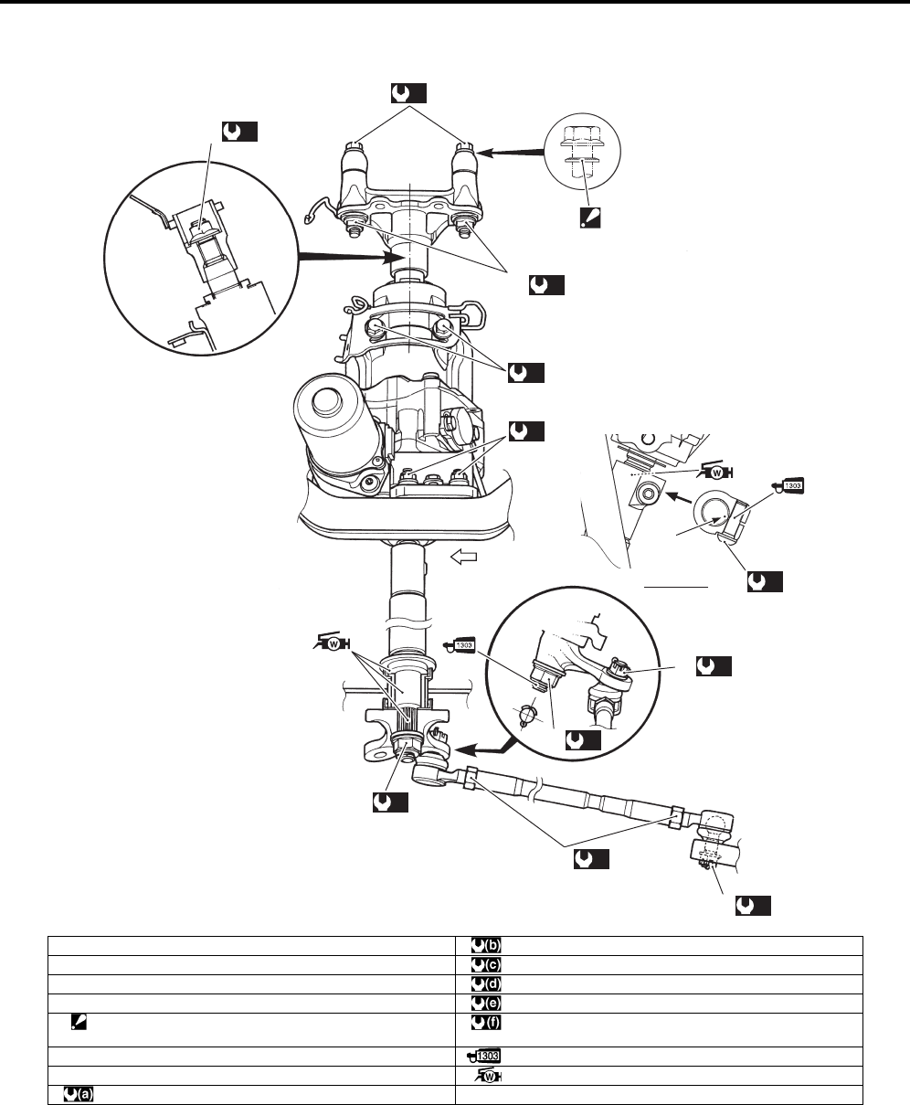
6B-2 Steering / Handlebar:
Steering / Handlebars Assembly Construction (LT-A750XP/ZK9)
B931G46206009
(a)
(a)
(f)
(e)
6
(d)
3
(c)
4
(c)
2
(d)
3
(c)
2
(a)
“B”
VIEW A
A
5
(a)
(b)
1
I931H1620037-06
1. Handlebar holder nut : 60 Nm (6.0 kgf-m, 43.5 lbf-ft)
2. Tie-rod end nut : 29 Nm (2.9 kgf-m, 21.0 lbf-ft)
3. Steering shaft lower nut : 162 Nm (16.2 kgf-m, 117.0 lbf-ft)
4. Tie-rod nut : 120 Nm (12.0 kgf-m, 87.0 lbf-ft)
5. Washer
: The conical side of washer faces outside.
:28 Nm (2.8 kgf-m, 20.0 lbf-ft)
6. Steering shaft upper nut : Apply thread lock to the thread part.
“B”: Red mark : Apply water resistance grease.
:26 Nm (2.6 kgf-m, 19.0 lbf-ft)
PartShark.com
877-999-5686
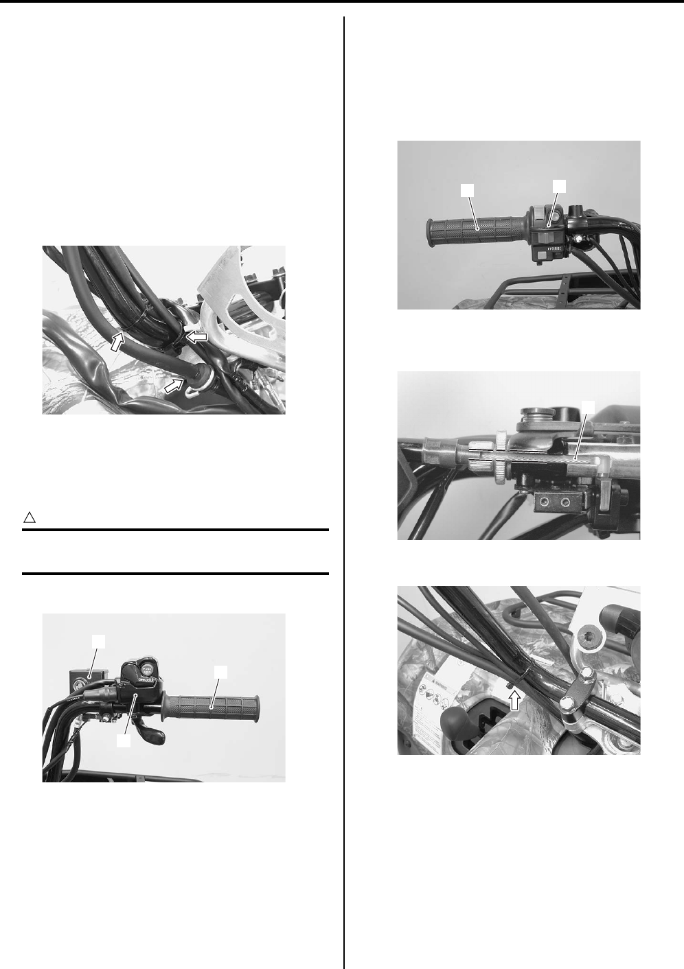
Steering / Handlebar: 6B-3
Handlebars Removal and Installation (LT—
A750XP/ZK9)
B931G46206010
Removal
1) Remove the auxiliary headlight cover. Refer to
“Auxiliary Headlight Removal and Installation in
Section 9B in related manual”
2) Remove the combination meter. Refer to
“Combination Meter Removal and Installation in
Section 9C in related manual”.
3) Remove the clamps.
4) Disconnect the brake hose from the hose guide.
5) Remove the following parts from the handlebars
(right side).
a) Right grip (1)
b) Front brake master cylinder/Front brake lever (2)
CAUTION
!
Do not turn the front brake master cylinder
upside down.
c) Throttle lever case (3)
6) Remove the following parts from left handlebars (left
side).
a) Left grip (4)
b) Left switch box (5)
c) Horn button (For P-17, 24)
d) Emergency switch (For P-17)
7) Disconnect the parking brake cable (6) from left
brake lever.
Remove the clamp.
I931G3620001-01
1
2
3
I931G3620002-01
45
I931G3620003-01
6
I931H1620004-01
I931G3620004-01
PartShark.com
877-999-5686
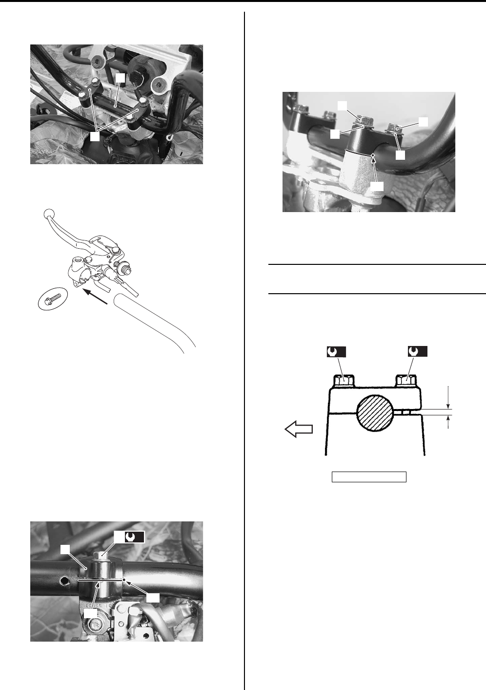
6B-4 Steering / Handlebar:
9) Remove the handlebar upper clamps (7) and
handlebars (8).
10) Remove the left brake lever from the handlebars (left
side).
Installation
Install the handlebars in the reverse order of removal.
Pay attention to the following points:
• Install the left brake lever (1) to the handlebars.
• Align the punch mark “A” on the handlebars with the
mating surface “B” of rear brake lever (1).
• Tighten the rear brake lever holder clamp bolt (2) to
the specified torque.
Tightening torque
Rear brake lever holder clamp bolt (a): 11 N·m (
1.1 kgf-m, 8.0 lbf-ft)
• Install the washers (3) and bolts (4) as shown in the
steering/handlebars construction. Refer to “Steering /
Handlebars Assembly Construction (LT-A750XP/ZK9)
(Page 6B-2)”.
• Set the handlebars so that its punch mark “B” aligns
with the mating surface of the left handlebar holder.
• Tighten the handlebar clamp bolts (4) to the specified
torque.
NOTE
First tighten the handlebar clamp bolts (4)
(front ones) to the specified torque.
Tightening torque
Handlebar clamp bolt (b): 26 N·m (2.6 kgf-m, 19.0
lbf-ft)
8
7
I931G3620027-01
I831G1620006-05
(a)
2
1
“A”
“B”
I931H1620008-01
“a”: Clearance
4
4
3
3
“B”
I931H1620009-02
“a”
(b)
4
(b)
FWD
I931H1620010-01
PartShark.com
877-999-5686
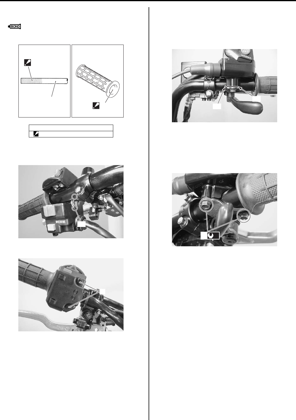
Steering / Handlebar: 6B-5
• Apply adhesive agent to the handlebar right and left
end and right and left grip inner wall.
: Handle grip bond (Handle Grip Bond
(commercially available))
• Insert the projection “D” of the left handlebar switch
assembly into the hole of the handlebars.
• Tighten the left handlebar switch screws (6).
• Install the master cylinder. Refer to “Front Brake
Master Cylinder Assembly Removal and Installation in
Section 4A in related manual”.
• Align the punch mark “E” on the handlebars with the
mating surface “F” of the throttle lever case.
• Tighten the throttle lever case bolts (7) to the specified
torque.
Tightening torque
Throttle lever case bolt (c): 4 N·m (0.4 kgf-m, 3.0
lbf-ft)
Handlebars Inspection (LT-A750XP/ZK9)
B931G46206011
Refer to “Handlebars Inspection in related manual”.
5. Handlebar
“C”: Apply handle grip bond.
“C”
“C”
5
I831G1620014-02
“D”
I931G3620005-01
6
I931G3620006-01
“E”
“F”
I931G3620007-01
(c)
7
I931G3620008-01
PartShark.com
877-999-5686
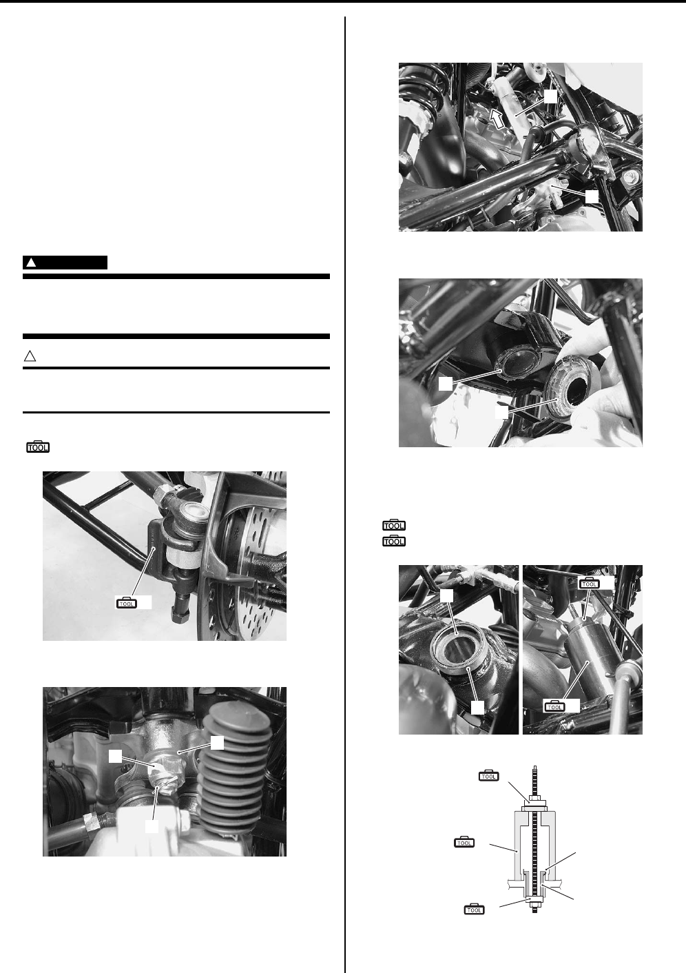
6B-6 Steering / Handlebar:
Steering Shaft Removal and Installation (LT—
A750XP/ZK9)
B931G46206012
Removal
1) Remove the EPS control unit. Refer to “EPS Control
Unit Removal and Installation (LT-A750XP/ZK9) in
Section 6C (Page 6C-48)”.
2) Remove the EPS body assembly. Refer to “EPS
Body Assembly Removal and Installation (LT—
A750XP/ZK9) in Section 6C (Page 6C-50)”.
3) Disconnect the tie-rod ends with the special tool.
Refer to “Front Wheel Hub / Steering Knuckle
Removal and Installation in Section 2B in related
manual”.
WARNING
!
When using the tie-rod end remover, keep
clear of the tie-rod end because it may come
loose with some force and could strike you.
CAUTION
!
Make sure that the vehicle is supported
securely.
Special tool
(A): 09942–72410 (Tie-rod end remover)
4) Remove the cotter pin (1), nut (2) and washer (3).
5) Remove the steering arm plate (4) and steering shaft
(5).
6) Remove the lower dust seal (6) and O-ring (7).
7) Remove the steering shaft bushing (8) and dust seal
(9) with the special tools and suitable socket wrench.
Special tool
(B): 09924–84521 (Bearing installer set)
(C): 09930–30721 (Rotor remover)
(A)
I931G3620009-01
1
2
3
I931G3620010-01
4
5
I931G3620011-01
6
7
I931G3620012-01
8
9
(B)
(C)
I931G3620013-02
(B)
(C)
8
9
(B)
I931H1620020-02
PartShark.com
877-999-5686
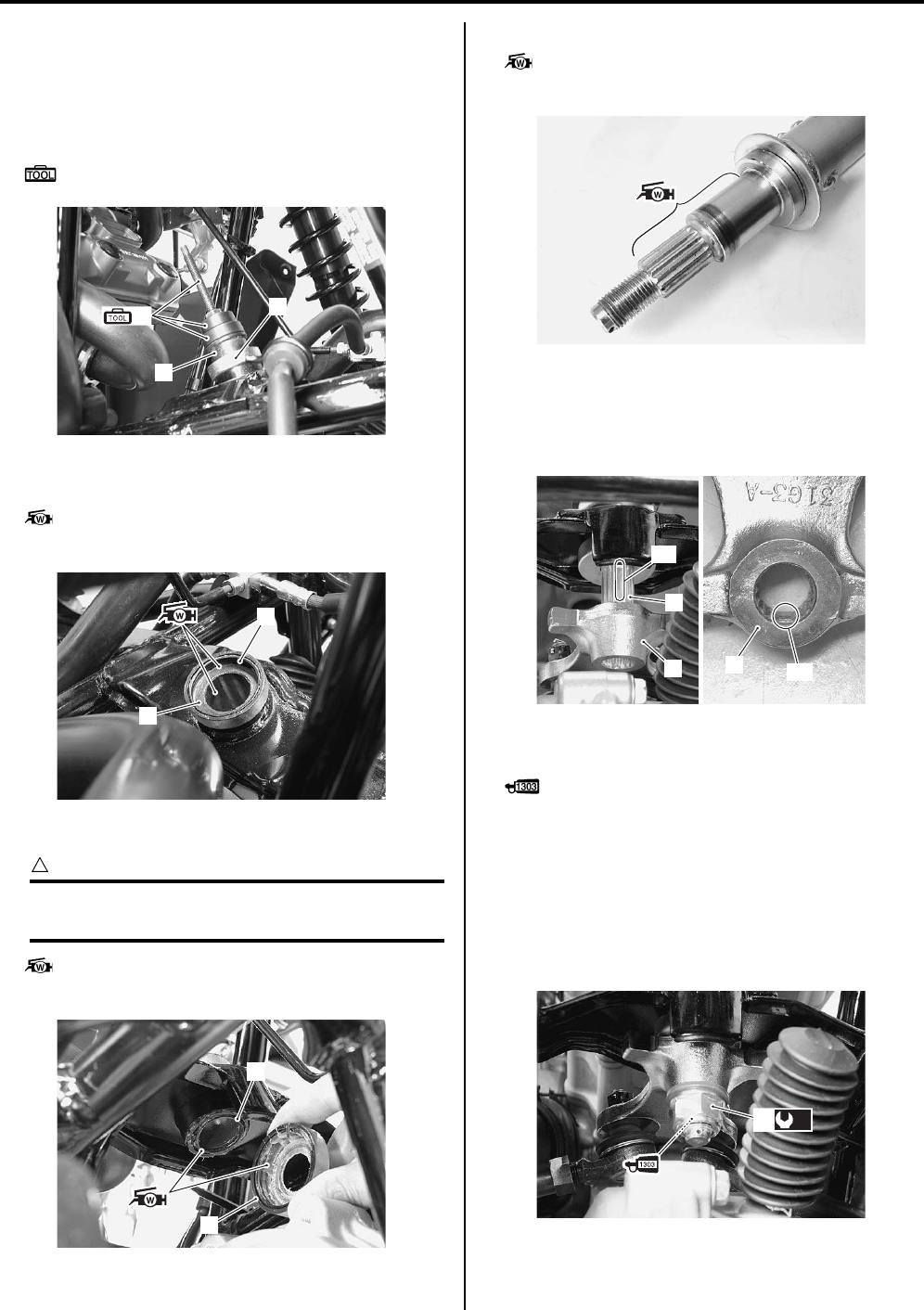
Steering / Handlebar: 6B-7
Installation
Install the steering shaft in the reverse order of removal.
Pay attention to the following points:
• Install the steering shaft bushing (1) along with dust
seal (2) with the special tool.
Special tool
(A): 09924–84521 (Bearing installer set)
• Apply grease to the steering shaft bushing (1) and
dust seal (2) and install them.
: Grease 99000–25160 (Water resistance
grease or equivalent)
• Apply grease to the lower dust seal (3) and O-ring (4).
CAUTION
!
The removed O-ring must be replaced with a
new one.
: Grease 99000–25160 (Water resistance
grease or equivalent)
• Apply grease to the steering shaft.
: Grease 99000–25160 (Water resistance
grease or equivalent)
• Install the steering shaft.
• When installing the steering arm plate (5), align the
wide spline “A” of steering shaft (6) with the wide
spline “B” of steering arm plate (5).
• Apply a small quality thread lock to the thread part of
steering shaft.
: Thread lock cement 99000–32030
(THREAD LOCK CEMENT SUPER “1303” or
equivalent)
• Tighten the steering shaft lower nut (7) to the specified
torque.
Tightening torque
Steering shaft lower nut (a): 162 N·m (16.2 kgf-m,
117.0 lbf-ft)
(A) 2
1
I931G3620014-01
2
1
I931G3620015-01
4
3
I931G3620016-01
I931G3620017-01
6
5
“A”
“B”
6
I931G3620018-01
(a)
7
I931G3620019-01
PartShark.com
877-999-5686
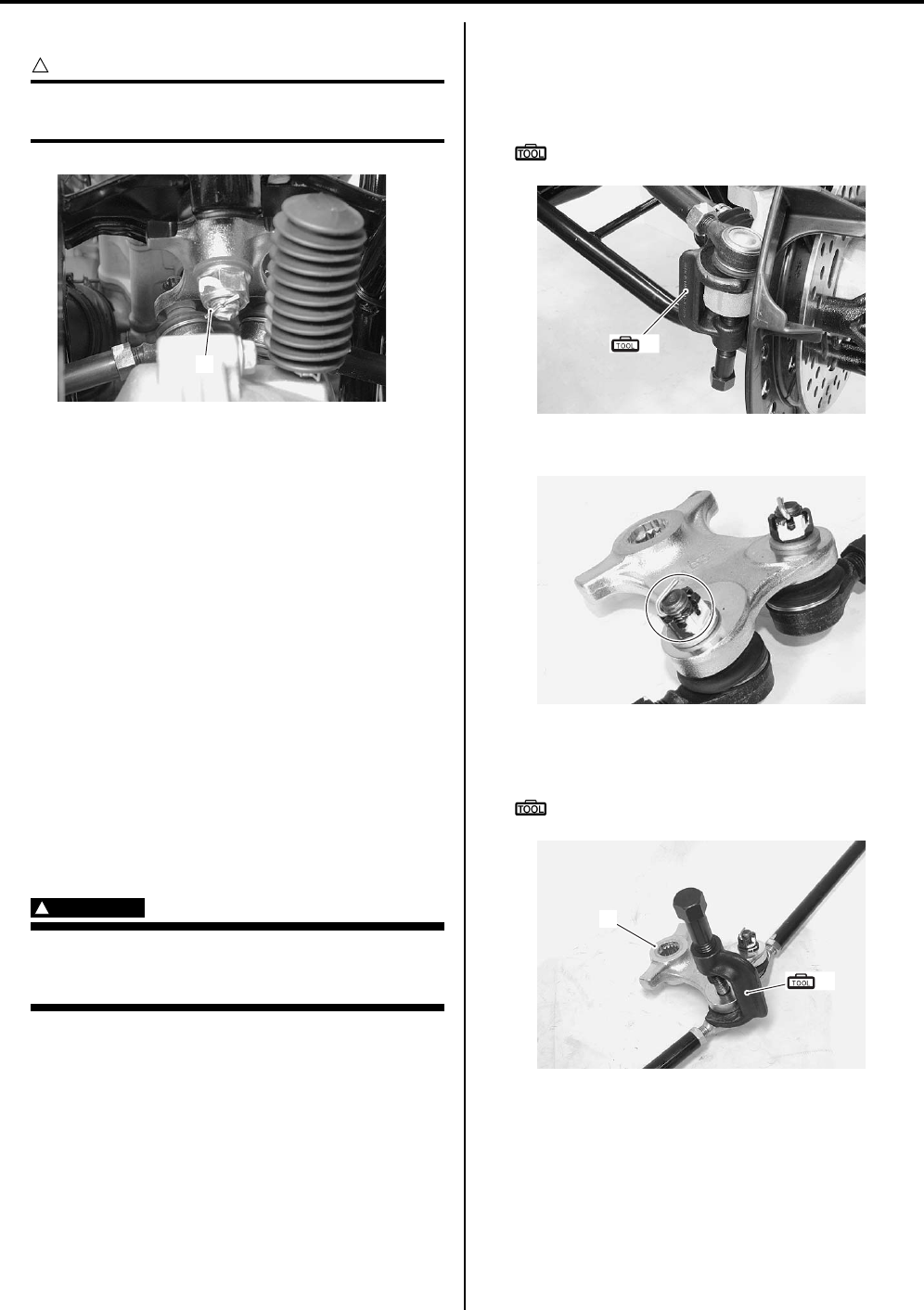
6B-8 Steering / Handlebar:
• Install the cotter pin (8).
CAUTION
!
The removed cotter pin (8) must be replaced
with a new one.
• Install EPS body assembly. Refer to “EPS Body
Assembly Removal and Installation (LT-A750XP/ZK9)
in Section 6C (Page 6C-50)”.
• Install the EPS control unit. Refer to “EPS Control Unit
Removal and Installation (LT-A750XP/ZK9) in Section
6C (Page 6C-48)”.
• Install the handlebars. Refer to “Handlebars Removal
and Installation in related manual”.
• Install the front fender. Refer to “Front Side Exterior
Parts Removal and Installation in Section 9D in
related manual”.
• Install the front wheels. Refer to “Front / Rear Wheel
Removal and Installation in Section 2D in related
manual”.
• After installing these parts, adjust the toe. Refer to
“Toe Adjustment (LT-A750XP/ZK9) in Section 0B
(Page 0B-2)”.
Tie-rod / Tie-rod End Removal and Installation
(LT-A750XP/ZK9)
B931G46206013
WARNING
!
When using the tie-rod end remover, keep
clear of the tie-rod end because it may come
loose with some force and could strike you.
Removal
1) Remove the tie-rod end with the special tool. Refer
to “Front Wheel Hub / Steering Knuckle Removal
and Installation in Section 2B in related manual”.
Special tool
(A): 09942–72410 (Tie-rod end remover)
2) Remove the cotter pin, tie-rod end nut and washer.
3) Remove the steering arm plate (1) with a special
tool.
Special tool
(A): 09942–72410 (Tie rod end remover)
8
I931G3620020-01
(A)
I931G3620021-01
I931G3620022-01
1
(A)
I931H1620030-01
PartShark.com
877-999-5686
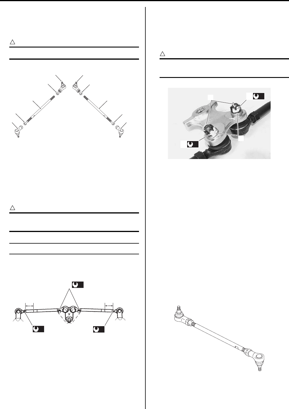
Steering / Handlebar: 6B-9
4) Remove the other tie-rod end in the same manner as
described previously.
5) Separate the tie-rod ends (2), nuts (3), (4) and tie-
rods (5).
CAUTION
!
The lock-nuts (3) have left-hand threads.
Installation
Install the tie-rod in the reverse order of removal. Pay
attention to the following points:
• When installing the tie-rods, make sure the short side
“a” of tie-rod come outside.
• Push the tie-rod to tie-rod lock-nut tightening direction.
• Tighten the lock-nuts to the specification.
CAUTION
!
When tightening the lock-nuts, hold the tie-
rod end with a open end wrench.
NOTE
The lock-nuts (1) have left-hand threads.
Tightening torque
Tie-rod lock-nut (a): 29 N·m (2.9 kgf-m, 21.0 lbf-ft)
• Install the washers (2) and tighten the rod end nuts (3)
(steering arm plate side) to the specified torque.
Tightening torque
Tie-rod end nut (b): 29 N·m (2.9 kgf-m, 21.0 lbf-ft)
• Install the cotter pins (4).
CAUTION
!
The removed cotter pins (4) must be replaced
with new ones.
• Install the tie-rod ends (steering knuckle side). Refer
to “Front Wheel Hub / Steering Knuckle Removal and
Installation in Section 2B in related manual”.
• After installed wheels, inspect the toe-out. If the toe-
out is out of specification, bring it into the specified
range. Refer to “Steering System Inspection in
Section 0B in related manual” and “Toe Adjustment
(LT-A750XP/ZK9) in Section 0B (Page 0B-2)”.
Steering Related Parts Inspection (LT-A750XP/
ZK9)
B931G46206014
Refer to “Steering Shaft Removal and Installation (LT—
A750XP/ZK9) (Page 6B-6)” and “Tie-rod / Tie-rod End
Removal and Installation (LT-A750XP/ZK9) (Page 6B-
8)”.
Tie—rod
Inspect the tie-rod for distortion or damage. If any
defects are found, replace the tie-rod with a new one.
2
2 2
2
3
44
5 5
3
I831G1620039-02
“a”
“a”
(a)
1
(a) (a)
I831G1620040-03
4
2
(b)
3
(b)
3
I931G3620023-01
I931G3620024-01
PartShark.com
877-999-5686
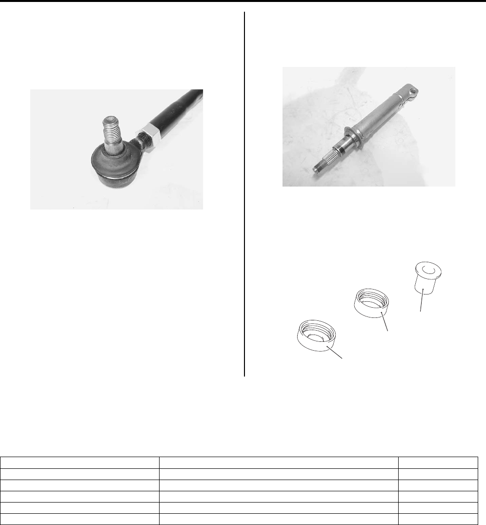
6B-10 Steering / Handlebar:
Tie-rod End
Inspect the tie-rod ends for smooth movement. If there
are any abnormalities, replace the tie-rod ends with new
ones. Inspect the tie-rod end boots for wear or damage.
If any defects are found, replace the tie-rod ends with
new ones.
Steering Shaft
Inspect the steering shaft for distortion or bend. If any
defects are found, replace the steering shaft with a new
one.
Steering Shaft Bushing and Dust Seal
Inspect the steering shaft bushing (1), dust seal (2) and
lower dust seal (3) for wear or damage. If any defects
are found, replace them with new ones.
Specifications
Service Data (LT-A750XP/ZK9)
B931G46207002
Wheel
I931G3620025-01
I931H1620034-01
3
2
1
I931H1620035-01
Item Standard Limit
Steering angle 46q (right & left) —
Turning radius 3.1 m (10.2 ft) —
Toe-out (with 75 kg, 165 lbs) 5 r 4 mm (0.20 r 0.16 in) —
Camber –1.3q—
Caster 3.3q—
PartShark.com
877-999-5686
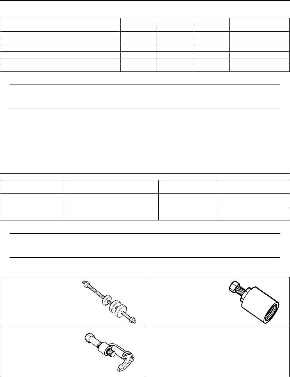
Steering / Handlebar: 6B-11
Tightening Torque Specifications
B931G46207003
NOTE
The specified tightening torque is described in the following.
“Steering / Handlebars Components (LT—A750XP/ZK9) (Page 6B-1)”
“Steering / Handlebars Assembly Construction (LT-A750XP/ZK9) (Page 6B-2)”
Reference:
For the tightening torque of fastener not specified in this section, refer to “Tightening Torque List (LT-A750XP/ZK9) in
Section 0C (Page 0C-7)”.
Special Tools and Equipment
Recommended Service Material
B931G46208001
NOTE
Required service material is also described in the following.
“Steering / Handlebars Components (LT—A750XP/ZK9) (Page 6B-1)”
“Steering / Handlebars Assembly Construction (LT-A750XP/ZK9) (Page 6B-2)”
Special Tool
B931G46208002
Fastening part Tightening torque Note
Nm kgf-m lbf-ft
Rear brake lever holder clamp bolt 11 1.1 8.0 )(Page 6B-4)
Handlebar clamp bolt 26 2.6 19.0 )(Page 6B-4)
Throttle lever case bolt 4 0.4 3.0 )(Page 6B-5)
Steering shaft lower nut 162 16.2 117.0 )(Page 6B-7)
Tie-rod lock-nut 29 2.9 21.0 )(Page 6B-9)
Tie-rod end nut 29 2.9 21.0 )(Page 6B-9)
Material SUZUKI recommended product or Specification Note
Grease Water resistance grease or
equivalent
P/No.: 99000–25160 )(Page 6B-7) / )(Page 6B-
7) / )(Page 6B-7)
Handle grip bond Handle Grip Bond (commercially
available)
—)(Page 6B-5)
Thread lock cement THREAD LOCK CEMENT SUPER
“1303” or equivalent
P/No.: 99000–32030 )(Page 6B-7)
09924–84521 09930–30721
Bearing installer set Rotor remover
)(Page 6B-6) / )(Page 6B-
7)
)(Page 6B-6)
09942–72410
Tie-rod end remover
)(Page 6B-6) / )(Page 6B-
/ )(Page 6B-8)
PartShark.com
877-999-5686
6C-1 Power Assisted Steering System:
Steeri ng
Power Assisted Steering System
Precautions
Precautions for EPS (LT-A750XP/ZK9)
B931G46300001
Refer to “General Precautions in Section 00 in related manual” and “Precautions for EPS (LT-A750XP/ZK9) in Section
00 (Page 00-1)”.
NOTE
When repairing EPS system, remove the front fender. Refer to “Front Side Exterior Parts Removal and
Installation in Section 9D in related manual”.
P/S System Note (LT-A750XP/ZK9)
B931G46300002
CAUTION
!
Never remove the torque sensor to prevent accident and damage.
NOTE
EPS body assembly fasteners are important attaching parts in that they could affect the performance
of vital parts and systems, and/or could result in major repair expense. Do not use a replacement part
of lesser quality or substitute design. Torque values must be used as specified during reassembly to
assure proper retention of these parts.
Precautions in Diagnosing Troubles (LT-A750XP/ZK9)
B931G46300003
• Take a note of DTC indicated on the SDS tool or EPS indicator light.
• Before inspection, be sure to read “Precautions for Electrical Circuit Service in Section 00 in related manual” and
“Precautions for EPS (LT-A750XP/ZK9) in Section 00 (Page 00-1)” and understand what is written there.
• DTC C1122 (engine speed signal failure) is indicated when ignition switch is at ON position and engine is not
running, but it means there is nothing abnormal if indication changes to a normal one when engine is started.
• As DTC is stored in memory of the EPS control unit, be sure to clear memory after repair by performing the
procedure described in “DTC (Diagnostic Trouble Code) Deleting (LT-A750XP/ZK9) (Page 6C-21)”.
PartShark.com
877-999-5686
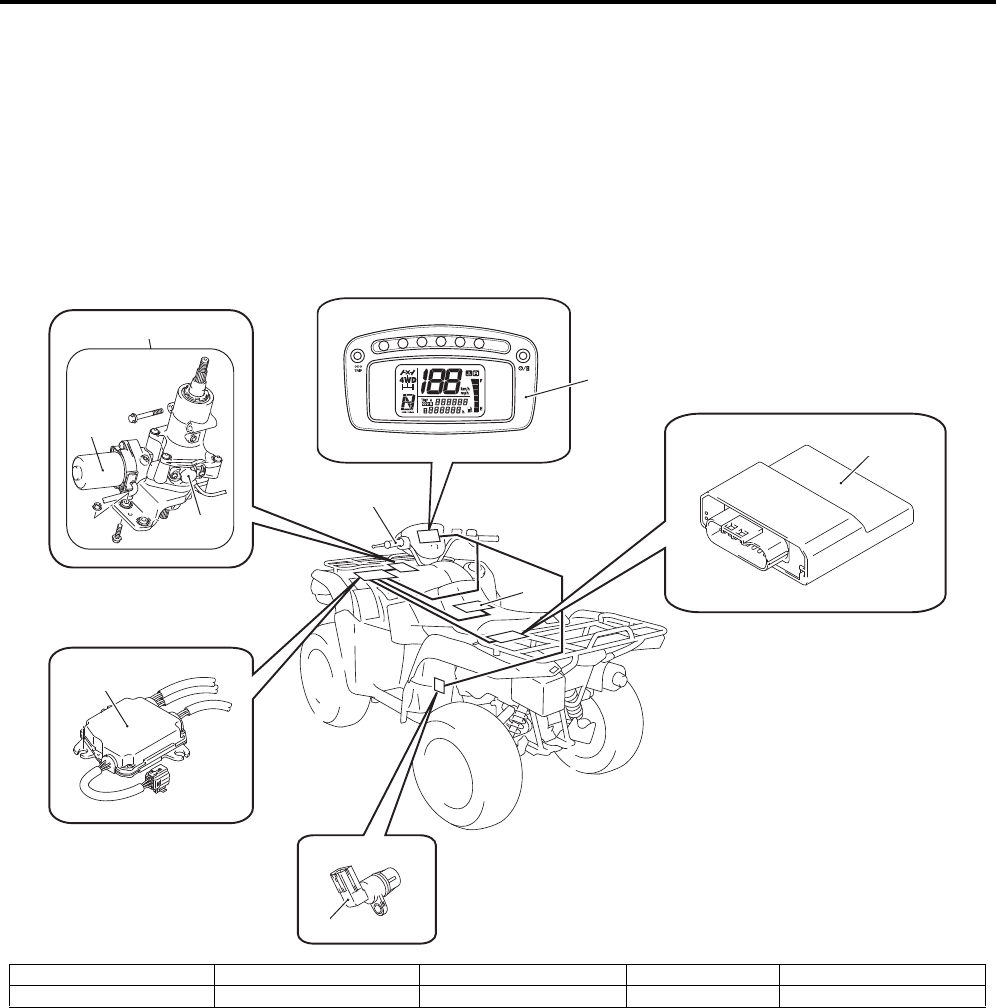
Power Assisted Steering System: 6C-2
General Description
P/S System Description (LT-A750XP/ZK9)
B931G46301001
This electronic power steering (EPS) system consists of a EPS control unit (2), a torque sensor (3), a EPS motor (4).
In this system, the EPS control unit determines the level and direction of the assist force for the handlebars (1)
according to the signal from the torque sensor and the vehicle speed signal from speed sensor (9). The EPS control
unit runs the motor so as to assist the operation of the handlebars (1). Take a note of DTC indicated on the EPS
indicator light.
The EPS diagnoses troubles which may occur in the area including the following components when the ignition switch
is ON and the engine is running. When the EPS control unit detects any malfunction, it stops the motor operation.
1
6
4
7
8
9
3
2
5
I931H1630001-04
1. Handlebars 3. Torque sensor 5. EPS body assembly 7. Battery 9. Speed sensor
2. EPS control unit 4. EPS motor 6. Combination meter 8. ECM
PartShark.com
877-999-5686
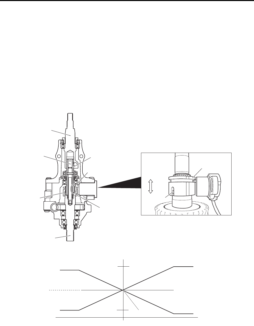
6C-3 Power Assisted Steering System:
Detecting Principle
The column shaft is connected to the input shaft by means of serration. The output shaft and input shaft are connected
via torsion bar. When torque is inputted from the column shaft, a relative angular displacement occurs between the
input shaft and the output shaft due to twist of the torsion bar. As the sleeve is engaged with a fixed pin, such an
angular displacement of the sleeve is converted to a linear displacement due to helical spline arrangement.
By the return spring of torque sensor lever, the sleeve is always forced to one side within its annular groove. The
sleeve’s linear displacement causes the torque sensor lever to turn, which is then converted to a voltage signal to
supply to EPS control unit.
The torque sensor is a double circuit of main and sub, when the handlebars is in neutral position (no torsional torque
applied to the steering wheel), each torque sensor (main and sub) output is 2.5 V and in this state the EPS control unit
determines the steering torque as 0. During operating the handlebars, the EPS control unit processes the main torque
sensor input signal to determine the steering torque required for the current condition. The relation between the
steering direction of the EPS control unit and the output voltage is as follows: The direction is determined to be right
turn steering “a” if the main torque sensor output voltage is lower than 2.5 V and to be left turn steering if the voltage is
higher than 2.5 V for controlling the steering direction in the case of normal steering operation.
Conversely, the direction is determined to be left turn steering “b” if the sub torque sensor output voltage is lower than
2.5 V and to be right turn steering if the voltage is higher than 2.5 V for controlling the steering direction.
Column shaft
Torsion bar Input shaft
Pin
Sleeve
Output shaft
“a”
“b”
Helical spline
Pin
Sleeve
I931H1630002-05
Voltage
Main Sub
Neutral position
Steering torque
Left steering Right steering
2.5 V
“a”“b”
I931H1630003-02
PartShark.com
877-999-5686
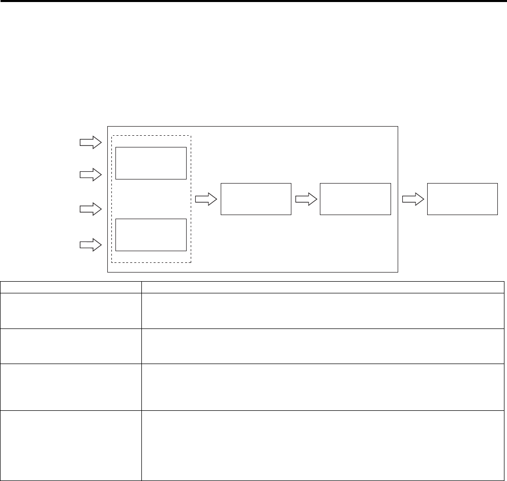
Power Assisted Steering System: 6C-4
Control System
In the EPS control unit, the steering assist control determines the basic power assist force and the convergence
control improves the steering operation feeling. The controller determines the target motor current by the calculation of
these controls and the maximum current limiting control and it also regulates the motor current so that the target motor
current and the actual current are matched.
Power steering control input / output flow chart
EPS control unit
EPS motor
Steering assist
control
Convergence
control
Vehicle speed
signal
Motor angular
speed (estimated)
Torque sensor
Motor current
(actual)
Target current
calculation
Maximum corrent
control
I931G3630073-01
Control Description
Steering assist control
This control determines the steering assist current on the basis of steering torque as
detected by the torque sensor and of speed signal supplied from the speed sensor.
This is the fundamental control necessary for the P/S system.
Convergence control
This control prevents convergence from deteriorating at a high speed by making
current (compensating current) flow in the direction to keep the steering from
turning, thereby improving vehicle maneuvering stability.
Maximum current control
If the steering input is sustained at a standstill, the motor continues to draw the
maximum current for full-assist and the motor and EPS control unit may get
overheated. To prevent this condition from occurring, this control limits and
gradually reduces the maximum current flowing through the motor.
Failsafe control
In the EPS control unit, a failsafe function is integrated in the motor circuit for the
purpose of safety. With the failsafe circuit in normal condition, the system is ON for
the motor to draw current. If an abnormal condition is detected in the P/S system by
the self-diagnostic function, the system turns OFF the circuit to interrupt the current
supply to the motor so that the system can stop operation. Refer to “Fail-safe
Function Description (LT—A750XP/ZK9) (Page 6C-5)”.
PartShark.com
877-999-5686
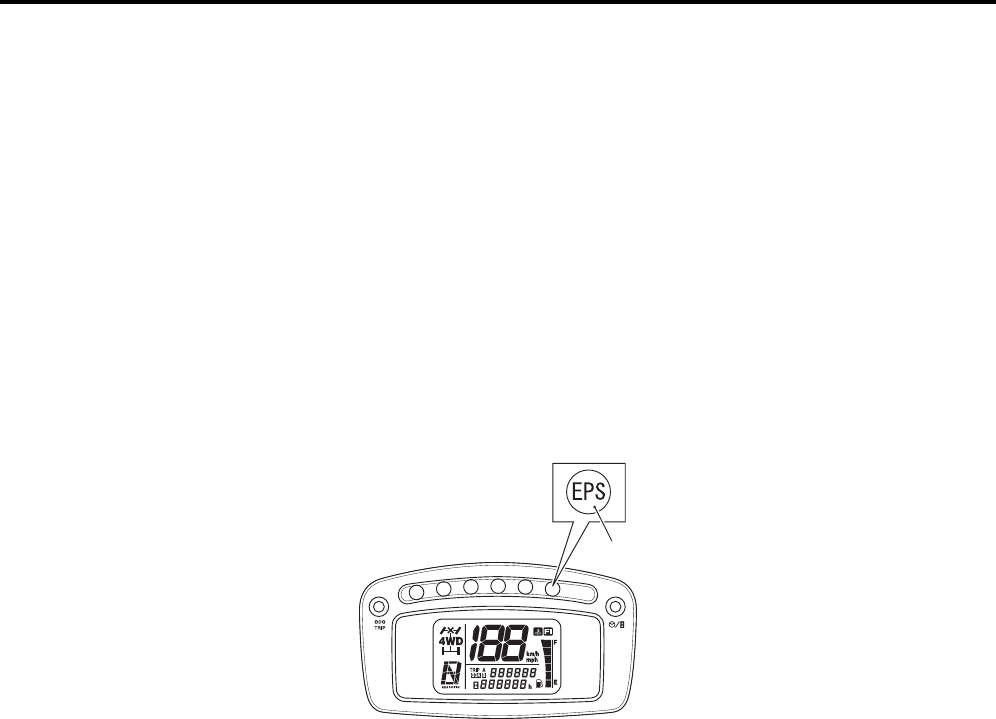
6C-5 Power Assisted Steering System:
EPS Diagnosis General Description (LT-A750XP/ZK9)
B931G46301002
The P/S system in this vehicle is controlled by the EPS control unit. The EPS control unit has an self diagnostic system
which detects a malfunction in this system. When diagnosing troubles, be sure to have full understanding of the outline
of “Self Diagnostic System Description (LT-A750XP/ZK9) (Page 6C-5)” and each item in “Precautions in Diagnosing
Troubles (LT-A750XP/ZK9) (Page 6C-1)”, and then execute diagnosis according to “EPS System Check (LT-A750XP/
ZK9) (Page 6C-12)”.
Self Diagnostic System Description (LT-A750XP/ZK9)
B931G46301003
The EPS control unit performs the self diagnosis on the system and operates the “EPS” warning light (1) as follows.
• The “EPS” warning light lights when the ignition switch is turned to ON position (but the engine at stop) regardless
of the condition of the P/S control system. This is only to check if the “EPS” warning light is operated properly.
• If the areas monitored by the EPS control unit is free from any trouble after the engine start (while engine is
running), the “EPS” warning light turns OFF.
• When the EPS control unit detects a trouble which has occurred in the monitored areas the “EPS” warning light
comes ON while the engine is running to warn the driver of such occurrence of the trouble and at the same time it
stores the exact trouble area in memory inside of the EPS control unit.
Fail-safe Function Description (LT-A750XP/ZK9)
B931G46301004
If malfunction occurs in the EPS system, this sets fail-safe relay OFF. Consequently, the indicator light ON, and no
current will be applied to motor solenoid valve inactivating EPS and turning EPS indicator light ON. In this case, it
functions as the normal steering. If malfunctions occurs while EPS is being activated, the fail-safe relay will be set
OFF. Refer to “EPS Control Unit Diagram (LT—A750XP/ZK9) (Page 6C-7)”.
1
I931H1630005-01
PartShark.com
877-999-5686
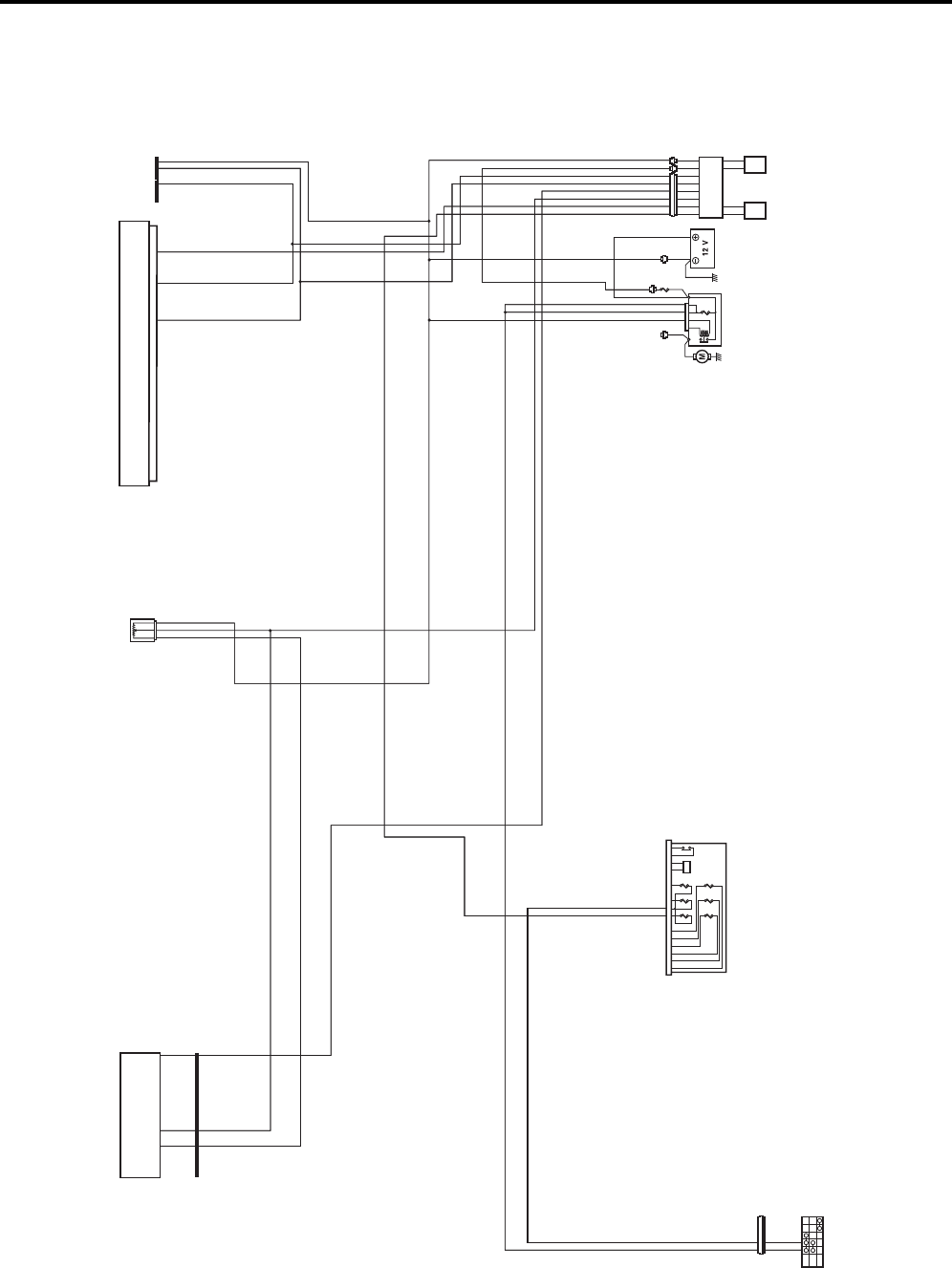
Power Assisted Steering System: 6C-6
Schematic and Routing Diagram
EPS Wiring Diagram (LT-A750XP/ZK9)
B931G46302001
Refer to “Wire Color Symbols in Section 0A in related manual”.
ON2
ON1
OFF
123
45 6
1
IGNITION
SWITCH
FUSE BOX 1. HEAD HI
2. HEAD LO
3. FUEL
4. IGNITION
5. FAN
6. POWER SOURCE
10 A
10 A
10 A
15 A
15 A
10 A
STARTER
MOTOR STARTER
RELAY
1: MAIN (30 A) BATTERY
SPEEDOMETER ECM
EPS UNIT
EPS
MOTOR
TORQUE
SENSOR
O/Y
R
O/Y
O
O
O
Bl/B
Bl/B
Y
Gr/R
W/R
W/R
Gr/R
B/W
Bl/B
Bl/B
Gr/R
W/R
W/R
Gr/R
B/W
B/W
B/WB/W
B/W
Bl/B
Bl/B
Y
Gr/R
Gr/R
W/R
W/R
R/B
R/B
B/W
O/Y
O/Y
B/W
B/W
R
R
W
W
R/B
R/B
R
R/B
R/B
R/B
R/B
SPEED
SENSOR
B/W
B/W
B/W
B/W
I931G3630070-01
PartShark.com
877-999-5686
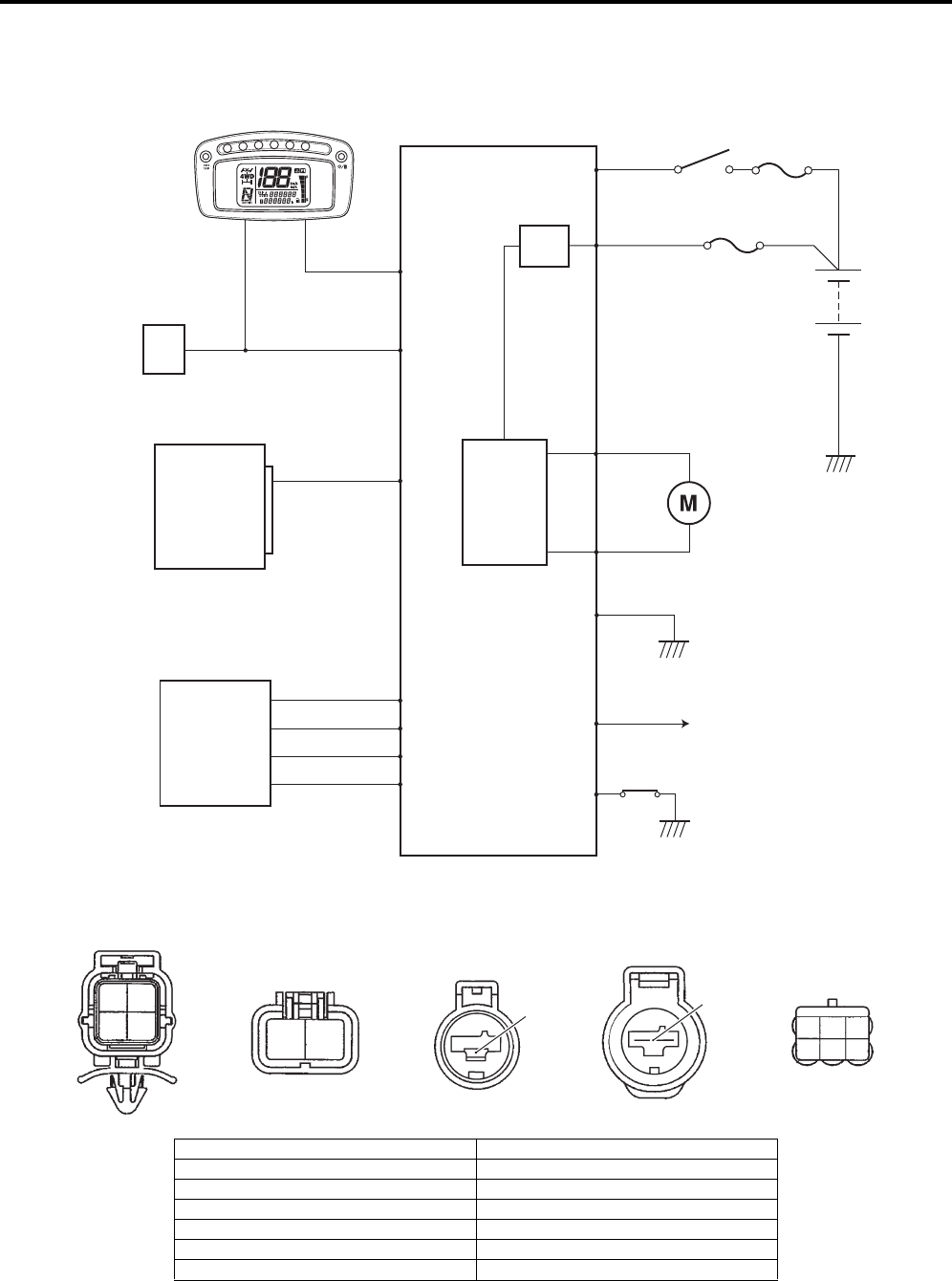
6C-7 Power Assisted Steering System:
EPS Control Unit Diagram (LT-A750XP/ZK9)
B931G46302002
Refer to “Wire Color Symbols in Section 0A in related manual”.
EPS control unit coupler (EPS control unit harness end)
30 A
40 A
Ignition
switch
EPS
MAIN
Fail-safe
relay
EPS
motor
Speed sensor
(Vehicle speed)
Speedometer
ECM
TACHO
Motor drive circuit
EPS countrol unit
SDS
Mode selsct switch
Torque sensor
4
5
1
31
6
3
7
9
10
8
2
12
11
14
13
Y
W
Bl/B
R
G
W
B
O/Y
R/B
B
R
B/W
Gr/R
W/R
I931G3630071-01
10 9
87
123
456
1112
1314
I931H1630092-01
1. Engine speed signal 8. Power source
2. Ignition signal for EPS control unit 9. Motor output (–)
3. Mode select switch 10. Motor output (+)
4. “EPS” warning light 11. Torque sensor signal (Main)
5. Vehicle speed signal 12. Power supply for torque sensor
6. SDS 13. Ground for torque sensor
7. Ground for EPS control unit 14. Torque sensor signal (Sub)
PartShark.com
877-999-5686
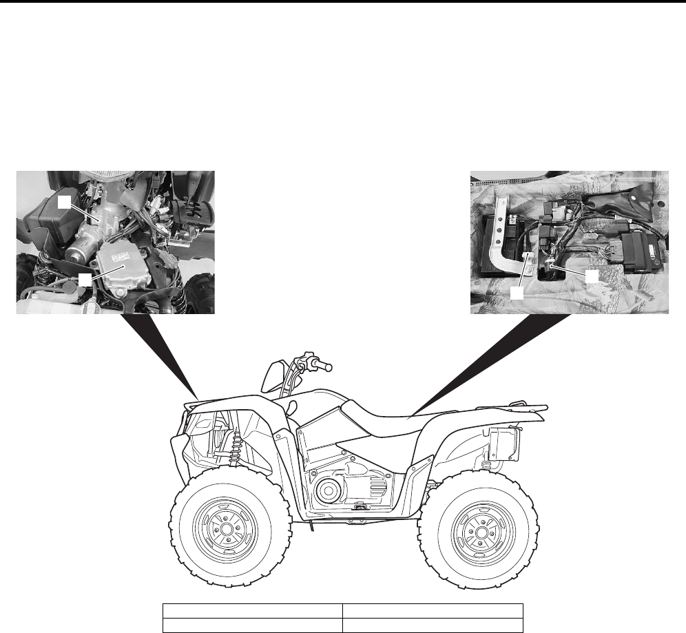
Power Assisted Steering System: 6C-8
EPS System Wiring Harness Routing Diagram (LT-A750XP/ZK9)
B931G46302003
Refer to “Wiring Harness Routing Diagram (LT-A750XP/ZK9) in Section 9A (Page 9A-4)”.
Component Location
EPS Components Location (LT-A750XP/ZK9)
B931G46303001
1
2
3
4
I931G3630002-02
1. EPS control unit 3. Fuse (EPS)
2. EPS body assembly 4. Mode select coupler
PartShark.com
877-999-5686
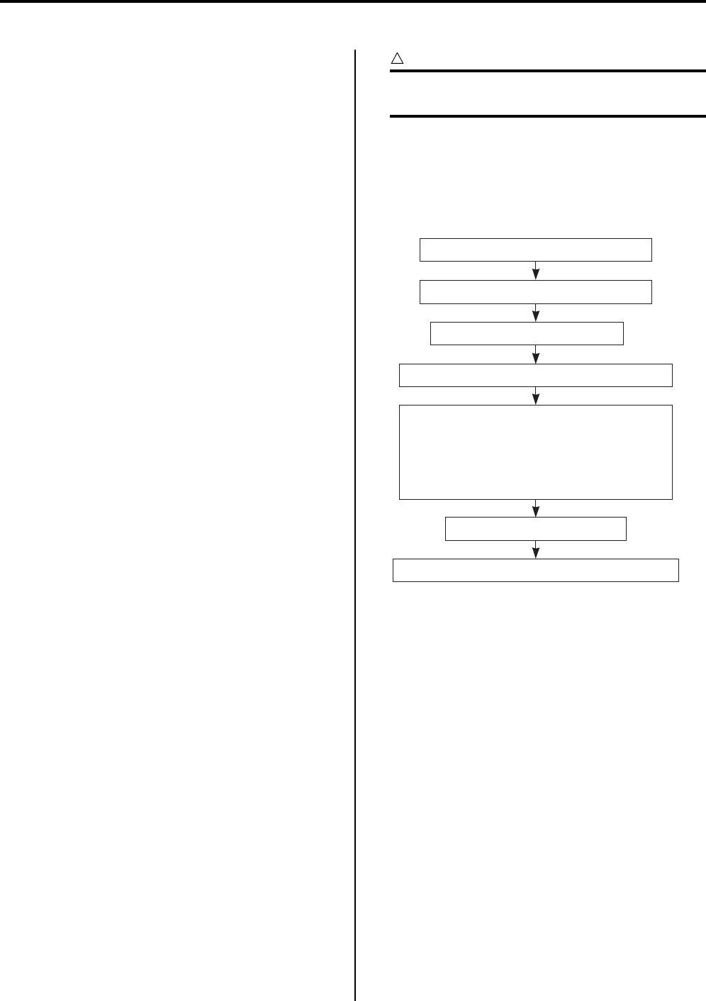
6C-9 Power Assisted Steering System:
Diagnostic Information and Procedures
EPS Troubleshooting (LT-A750XP/ZK9)
B931G46304001
The EPS is equipped with a self-diagnosis function. The
detected malfunction is stored as a diagnostic trouble
code which causes the EPS indicator light to light up or
flash in set patterns to indicate the malfunction.
Diagnostic trouble codes saved in the memory remain
stored even through the ignition switch is turned OFF
and they cannot be deleted without performing the DTC
erasing procedure. In order to repair the EPS correctly,
ask the customer for the exact circumstances under
which the malfunction occurred, then check the EPS
indicator light and the output diagnostic trouble codes.
Explain to the customer that depending on how the
vehicle is operated, the EPS indicator light may light up
even though the EPS is operating correctly.
Troubleshooting Procedure
Troubleshooting should be proceed as follows. If the
order is performed incorrectly or any part is omitted, an
error in misdiagnosis may result.
1) Gather information from the customer.
2) Perform the pre-diagnosis inspection. Refer to “Pre-
diagnosis Inspection (LT-A750XP/ZK9) (Page 6C-
10)”.
3) Inspect the EPS indicator light. Refer to “EPS
System Check (LT-A750XP/ZK9) (Page 6C-12)”.
4) Output the DTCs stored in the EPS control unit.
Refer to “DTC (Diagnostic Trouble Code) Output (LT—
A750XP/ZK9) (Page 6C-19)”.
5) Perform appropriate troubleshooting procedures
according to the DTCs output. Refer to “DTC Table
(LT-A750XP/ZK9) (Page 6C-25)”.
If troubleshooting procedures cannot be performed,
try to determine the cause of the malfunction
according to the information gathered in 1) through
4) and inspect the wiring. Refer to “EPS Wiring
Diagram (LT-A750XP/ZK9) (Page 6C-6)” and “EPS
Control Unit Diagram (LT-A750XP/ZK9) (Page 6C-
7)”.
CAUTION
!
Each time a resistance is measured, the
ignition switch should be set to OFF.
6) Inspect the EPS components. Refer to “EPS Motor
Inspection (LT-A750XP/ZK9) (Page 6C-53)”.
7) Delete the DTCs and check the power steering
operation. Refer to “DTC (Diagnostic Trouble Code)
Deleting (LT-A750XP/ZK9) (Page 6C-21)”.
Basic Troubleshooting Diagram
1) Gather information from the customer.
2) Perform the pre-diagnosis inspection.
3) Inspect the EPS indicator light.
6) Inspect the EPS components.
4) Output the DTCs stored in the EPS control unit.
5) Perform appropriate troubleshooting proce-
dures according to the DTCs output.
If troubleshooting procedures cannot be per-
formed, try to determine the cause of the mal-
function according to the information gathered
in 1) through 4) and inspect the wiring.
7) Delete the DTCs and check the steering operation.
I931G3630069-01
PartShark.com
877-999-5686
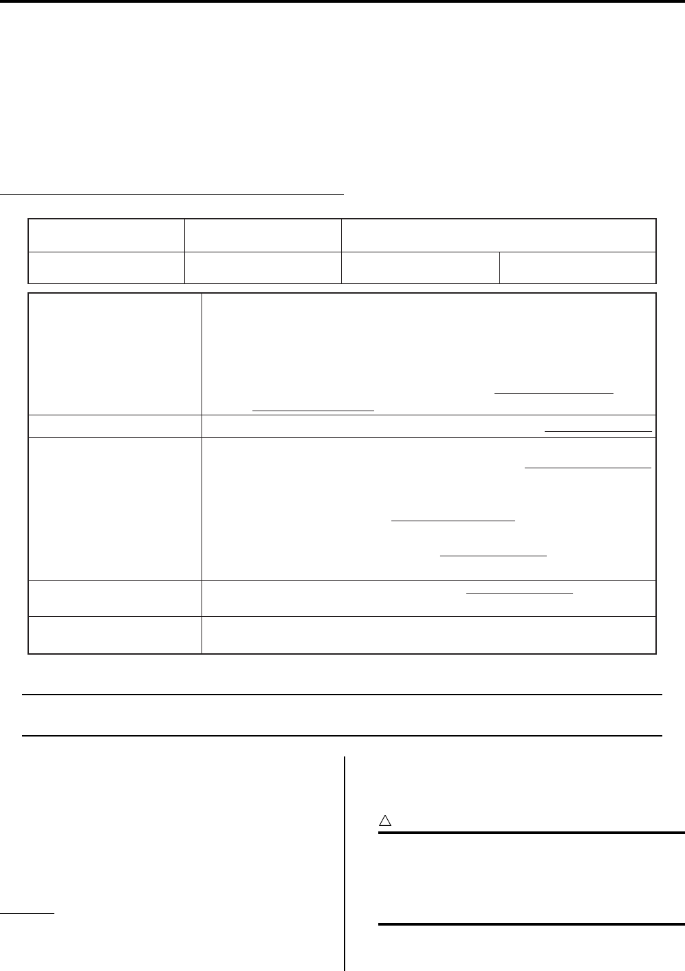
Power Assisted Steering System: 6C-10
Information Gathering
To properly diagnose a malfunction, one must not make guesses or assumptions about the circumstances that caused
it. Proper diagnosis and repair require duplicating the situation in which the malfunction occurred. If a diagnosis is
made without duplicating the malfunction, even an experienced service technician may make a misdiagnosis and not
perform the servicing procedure correctly, resulting in the malfunction not being repaired. Therefore, in order to
properly diagnose and repair the vehicle, the customer must be questioned about the conditions at the time that the
malfunction occurred making “Information gathering” very important. In order that the information obtained from the
customer to be used as a reference during troubleshooting, it is necessary to ask certain important questions
concerning the malfunction. Therefore, a questionnaire has been created to improve the information-gathering
procedure.
EXAMPLE: CUSTOMER PROBLEM INSPECTION FORM
NOTE
This form is a standard sample. The form should be modified according to conditions and
characteristic of each market.
Pre-diagnosis Inspection (LT-A750XP/ZK9)
B931G46304002
The mechanical of the steering system should be
inspected prior to performing any electrical checks.
These inspections may find problems that the EPS could
not detect; thus, shortening repair time.
Tire
Tire type
Tire type
Front: DUNLOP KT411
Rear: DUNLOP KT415
Tire pressure
Refer to “Tire Inspection in Section 0B in related
manual”.
CAUTION
!
The standard tire fitted on this vehicle is
AT25 x 8 – 12
for front and AT25 x 10 – 12
for rear. The use of tires other than those
specified may cause instability. It is highly
recommended to use a SUZUKI Genuine Tire.
Customer’s name:
Date of issue:
Model:
Date Reg.
VIN:
Date of problem: Mileage:
Problem Symptoms
Handlebars feels heavy
Vehicle pulls to one side during straight driving
Poor recovery from turns
Too much play in steering
Abnormal noise while vehicle is running: from motor,
other
Other
Frequency of Occurrence Continuous/Intermittent ( times a day, a month)/other
Vehicle at stop & ignition switch ON:
When starting: at initial start only/at every start/Other
Vehicle speed while: while accelerating/while decelerating/at stop/
while turning/while running at constant speed/
other
Road surface condition: Paved road/rough road/snow-covered
road/other
Chain equipment:
Weather: fair/cloudy/rain/snow/other
Temperature: °F ( °C)
First check: Normal code/malfunction code ( )
Second check after driving test: Normal code/malfunction code ( )
Conditions for Occurrence
of Problem
Environmental Condition
DTC
•
•
•
•
•
•
•
•
•
•
•
•
•
•
•
•
I931H1630009-03
PartShark.com
877-999-5686
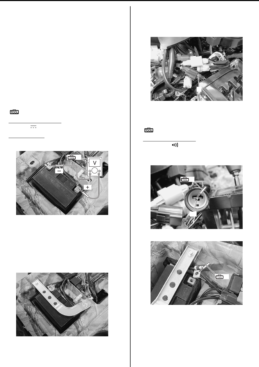
6C-11 Power Assisted Steering System:
Steering Related Parts
Refer to “Steering Parts Inspection in Section 6B in
related manual”.
Battery
Battery voltage inspection
1) Turn the ignition switch OFF.
2) Remove the seat. Refer to “Seat Removal and
Installation in Section 9D in related manual”.
3) Measure the voltage between the (+) and (–) battery
terminals using the multi circuit tester.
If the voltage is less than 12.0 V, charge or replace
the battery and inspect the charging system. Refer to
“Battery Runs Down Quickly in Section 1J in related
manual”.
Special tool
(A): 09900–25008 (Multi circuit tester set)
Tester knob indication
Voltage ( )
Battery voltage
12.0 V and more
4) Reinstall the seat.
EPS control unit ground wire inspection
1) Turn the ignition switch OFF.
2) Remove the seat. Refer to “Seat Removal and
Installation in Section 9D in related manual”.
3) Disconnect the battery (–) lead wire.
4) Remove the front fender. Refer to “Front Side
Exterior Parts Removal and Installation in Section
9D in related manual”.
5) Disconnect the EPS control unit coupler (1).
6) Check for continuity between terminal “A” at the
coupler and the battery (–) terminal.
Special tool
(A): 09900–25008 (Multi circuit tester set)
Tester knob indication
Continuity ( )
EPS control unit coupler (Vehicle harness end)
(ޓ)
(ޓ)
(A)
I931G3630003-01
I931G3630004-01
1
I931G3630005-01
“A”
(A)
I931G3630006-01
(A)
I931G3630007-01
PartShark.com
877-999-5686
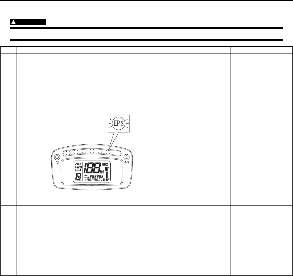
Power Assisted Steering System: 6C-12
EPS System Check (LT-A750XP/ZK9)
B931G46304003
WARNING
!
Carry out test drive in light traffic area to prevent an accident.
Step Action Yes No
1 1) Perform “Customer Complaint Analysis”.
Was customer complaint analysis performed according to
instruction?
Go to Step 2. Perform customer
complaint analysis.
2 1) Check for operation of the “EPS” warning lamp when
turning the ignition switch ON.
2) If OK, start engine, run it idle and check “EPS” warning
lamp remains ON continuously.
Is “EPS” warning lamp remains ON continuously?
Go to Step 3. • Go to Step 4.
• DTC output (Refer to
“DTC (Diagnostic
Trouble Code) Output
(LT-A750XP/ZK9)
(Page 6C-19)”.)
3(The EPS indicator light lights up)
1) Start the engine.
Does the EPS indicator light go off?
Normal (No DTC exists) • DTC output (Refer to
“DTC (Diagnostic
Trouble Code) Output
(LT-A750XP/ZK9)
(Page 6C-19)”.)
• If DTC can not be
output (the EPS
indicator light does
not flash), go to Step
7.
I931H1630015-02
PartShark.com
877-999-5686
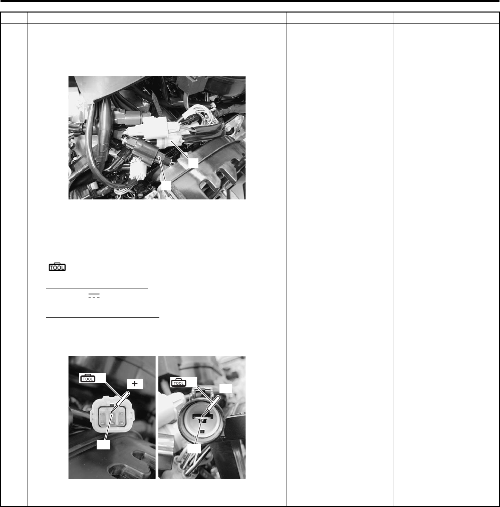
6C-13 Power Assisted Steering System:
4(The EPS indicator light does not light up)
1) Turn the ignition switch OFF.
2) Disconnect the EPS control unit coupler (1) and (2).
3) Turn the ignition switch ON with the EPS control unit
coupler disconnected, measure the voltage between
terminal “A” and terminal “B” at the coupler.
Special tool
(A): 09900–25008 (Multi circuit tester set)
Tester knob indication
Voltage ( )
Normal value (“A” – “B”)
Battery voltage (12.0 V and more)
EPS control unit coupler (Vehicle harness end)
Is the voltage between “A” and “B” normal?
Go to Step 5. Inspect the wire
harness. (Faulty ignition
or ground wire)
Step Action Yes No
1
2
I931G3630008-01
“A”
(A) (ޓ)
“B”
(A) (–)
I931G3630009-01
PartShark.com
877-999-5686
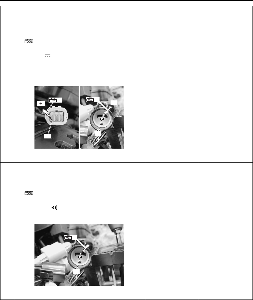
Power Assisted Steering System: 6C-14
5 1) Turn the ignition switch ON with the EPS control unit
coupler disconnected, measure the voltage between
terminal “A” and terminal “B” at the coupler.
Special tool
(A): 09900–25008 (Multi circuit tester set)
Tester knob indication
Voltage ( )
Normal value (“A” – “B”)
1.0 V and more
EPS control unit coupler (Vehicle harness end)
Is the voltage between “A” and “B” normal?
Go to Step 6. • Inspect the wire
harness. (Faulty
indicator light wire)
• Indicator light is
blown.
6 1) Turn the ignition switch OFF.
2) Check for continuity between terminal “A” at the coupler
and body ground.
Special tool
(A): 09900–25008 (Multi circuit tester set)
Tester knob indication
Continuity ( )
EPS control unit coupler (Vehicle harness end)
Are there continuity between “A” and body ground?
Replace the EPS
control unit.
Inspect the wire
harness. (Faulty ground
wire)
Step Action Yes No
“A”
(A)
(ޓ)
“B”
(A) (–)
I931G3630010-01
“A”
(A)
I931G3630011-01
PartShark.com
877-999-5686
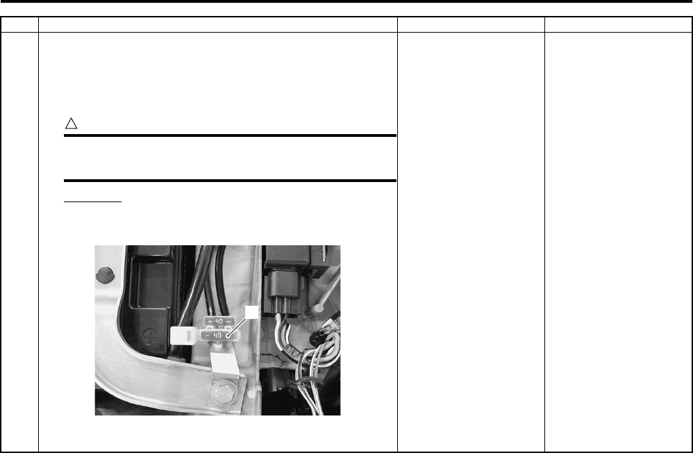
6C-15 Power Assisted Steering System:
7(The EPS indicator light does not go off)
1) Remove the seat. Refer to “Seat Removal and
Installation in Section 9D in related manual”.
2) Open the fuse box and inspect the ignition fuse (1).
CAUTION
!
If a fuse is blown, find the cause of the problem
and correct it before replacing the fuse.
EPS fuse
40 A
Is the ignition fuse OK?
Go to Step 8. Replace the EPS fuse.
Step Action Yes No
1
I931H1630016-01
PartShark.com
877-999-5686
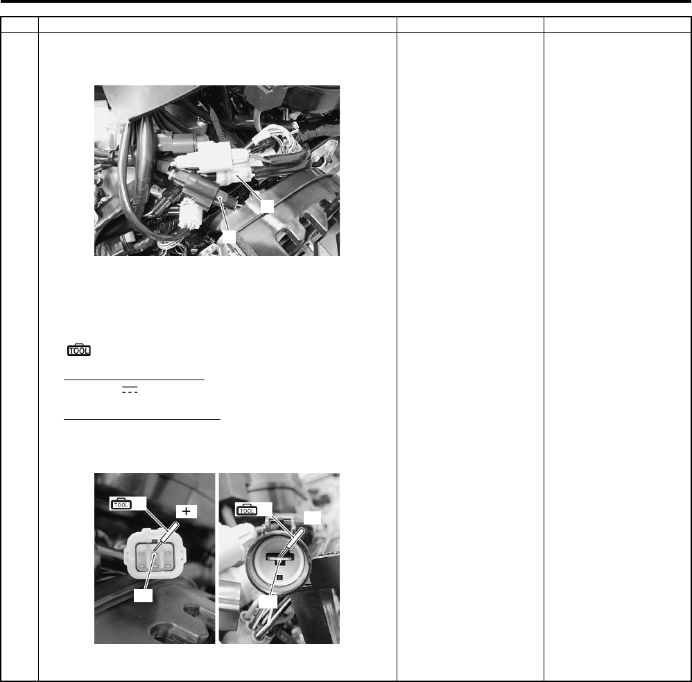
Power Assisted Steering System: 6C-16
8 1) Turn the ignition switch OFF.
2) Disconnect the EPS control unit coupler (1) and (2).
3) Turn the ignition switch ON with the EPS control unit
coupler disconnected, measure the voltage between
terminal “A” and terminal “B” at the coupler.
Special tool
(A): 09900–25008 (Multi circuit tester set)
Tester knob indication
Voltage ( )
Normal value (“A” – “B”)
Battery voltage (12.0 V and more)
EPS control unit coupler (Vehicle harness end)
Is the voltage between “A” and “B” normal?
Go to Step 9. Inspect the wire
harness. (Faulty ignition
or ground wire)
Step Action Yes No
1
2
I931G3630008-01
“A”
(A) (ޓ)
“B”
(A) (–)
I931G3630009-01
PartShark.com
877-999-5686
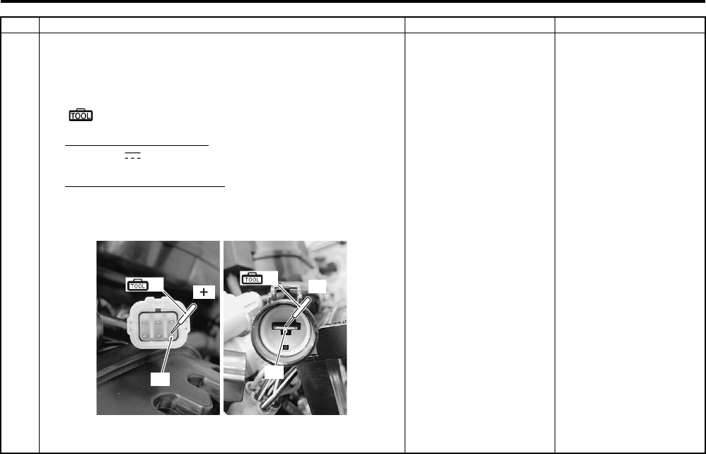
6C-17 Power Assisted Steering System:
9 1) Turn the ignition switch ON with the EPS control unit
coupler disconnected, measure the voltage between
terminal “A” and terminal “B” at the coupler.
Special tool
(A): 09900–25008 (Multi circuit tester set)
Tester knob indication
Voltage ( )
Normal value (“A” – “B”)
1.0 V and more
EPS control unit coupler (Vehicle harness end)
Is the voltage between “A” and “B” normal?
Go to Step 10. Inspect the wire
harness. (Faulty
indicator light wire)
Step Action Yes No
“A”
(A) (ޓ)
“B”
(A) (–)
I931G3630012-01
PartShark.com
877-999-5686
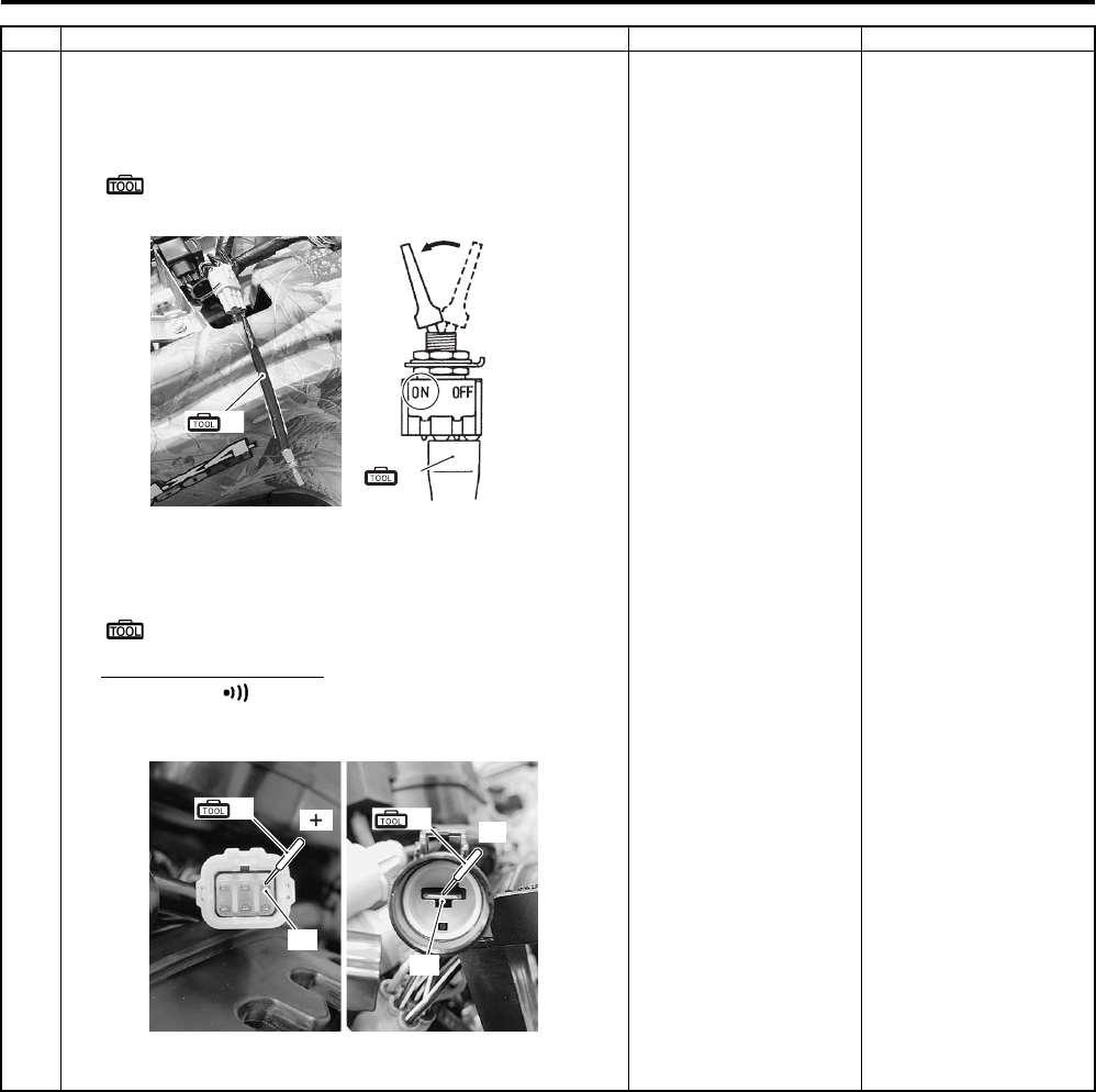
Power Assisted Steering System: 6C-18
10 1) Turn the ignition switch OFF.
2) Short the mode select coupler terminals using the
special tool.
Special tool
(A): 09930–82710 (Mode select switch)
3) Check for continuity between terminal “A” and terminal
“B” at the coupler.
Special tool
(A): 09900–25008 (Multi circuit tester set)
Tester knob indication
Continuity ( )
EPS control unit coupler (Vehicle harness end)
Is there continuity between “A” and “B”?
Replace the EPS
control unit.
Inspect the wire
harness. (Faulty mode
select switch wire)
Step Action Yes No
(A)
(A)
I931G3630013-01
“A”
(A) (ޓ)
“B”
(A) (–)
I931G3630014-01
PartShark.com
877-999-5686
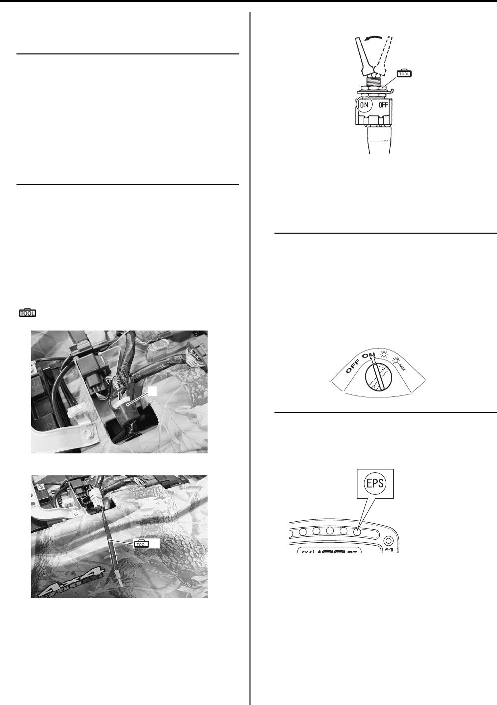
6C-19 Power Assisted Steering System:
DTC (Diagnostic Trouble Code) Output (LT—
A750XP/ZK9)
B931G46304004
NOTE
• Even through the EPS is operating
correctly, a DTC is memorized in any of the
following conditions.
– Previous malfunctions were repaired,
but the DTCs were not deleted.
• After carrying out DTC deleting and EPS
operation check, explain to the customer
that the EPS is operating correctly. Refer to
“DTC (Diagnostic Trouble Code) Deleting
(LT-A750XP/ZK9) (Page 6C-21)”.
Use of Mode Select Switch
Connect the special tool to the mode select coupler to
output the memorized DTCs on the EPS indicator light.
1) Turn the ignition switch OFF.
2) Remove the seat. Refer to “Seat Removal and
Installation in Section 9D in related manual”.
3) Connect the special tool to the mode select coupler
(1).
Special tool
(A): 09930–82710 (Mode select switch)
4) Switch the special tool to ON.
5) Turn the ignition switch ON.
The EPS indicator light starts flashing to indicate the
DTC. Refer to “DTC Table (LT-A750XP/ZK9)
(Page 6C-25)”.
NOTE
• If there is a DTC, the EPS indicator light
keeps flashing cyclically and repeatedly.
• If there is no DTC, the EPS indicator light
keeps lighting on.
• When outputting DTCs, never turn the
ignition switch to headlight ON position or
auxiliary headlight ON position in order to
prevent the battery from discharging.
6) Turn the ignition switch OFF and disconnect the
special tool.
1
I931G3630015-01
(A)
I931G3630017-01
(A)
I931H1630028-01
I931G3630018-01
I931H1630029-01
PartShark.com
877-999-5686
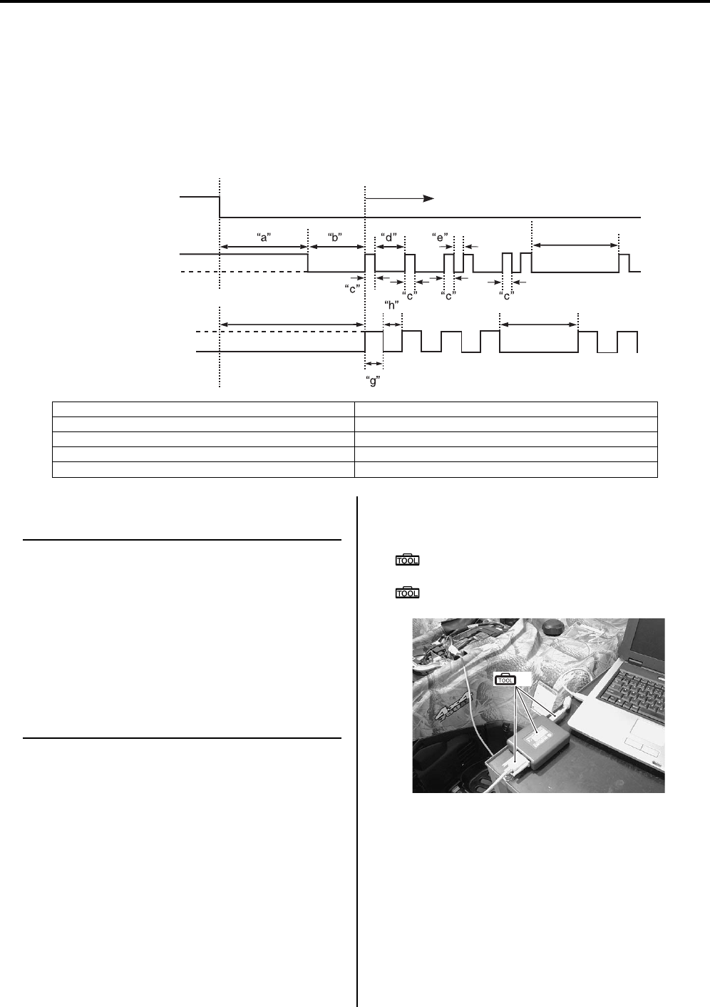
Power Assisted Steering System: 6C-20
Understanding the DTC (Diagnostic Trouble Code)
A four-digit DTC is shown through the flashing pattern of the EPS indicator light. A number between 1 and 9 is
represented by the number of times that the EPS indicator light lights up in interval of 0.3 seconds and the separation
between the each digit are indicated by the light staying off for 1 seconds. In addition, the separation between the start
code and the DTC is indicated by the light being off for 3 seconds. After the start code is displayed, DTCs appear from
the smallest number code.
If no DTCs are memorized, the EPS indicator light keeps blinking by the four times at same interval.
Use of SDS
NOTE
• Don’t disconnect couplers from EPS
control unit, the battery cable from the
battery, EPS control unit ground wire
harness from the engine or main fuse
before confirming the malfunction code
(self-diagnostic trouble code) stored in
memory. Such disconnection may erase
the memorized information in EPS control
unit memory.
• DTC stored in EPS control unit memory
can be checked by the SDS.
1) Remove the seat. Refer to “Seat Removal and
Installation in Section 9D in related manual”.
2) Set up the SDS tool. (Refer to the SDS operation
manual for further details.)
Special tool
(A): 09904–41010 (SUZUKI Diagnostic
system set)
(B): 99565–01010–020 (CD-ROM Ver.20)
“f”
“b”
“i”
ON
ON
ON
OFF
OFF
ON
Ignition switch
Engine start
Output start
Mode select switch
EPS indicator light
(Malfunction exists)
EPS indicator light
(No malfunction exists)
Code 1122
I931H1630030-04
“a”: Initial minimum light ON time (About 3 seconds) “f”: Indicator light OFF time (5 seconds)
“b”: Error code interval (About 3 seconds) “g”: Normal code light ON time (1 seconds)
“c”: Code light ON time (0.3 seconds) “h”: Normal code light OFF time (1 seconds)
“d”: Main-sub code interval (1 seconds) “i”: Interval (3 seconds)
“e”: Sub code (0.3 seconds)
(A)
I931G3630019-01
PartShark.com
877-999-5686
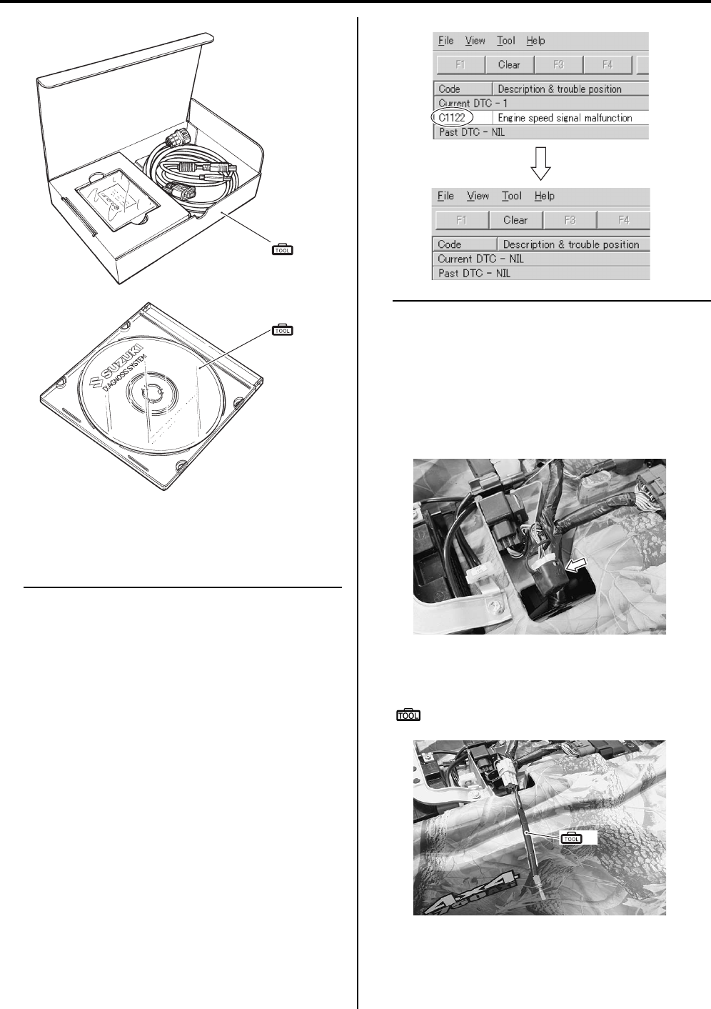
6C-21 Power Assisted Steering System:
3) Read the DTC (Diagnostic Trouble Code) and show
data when trouble (displaying data at the time of
DTC) according to instructions displayed on SDS.
NOTE
• Not only is SDS used for detecting
Diagnostic Trouble Codes but also for
reproducing and checking on screen the
failure condition as described by
customers using the trigger.
• How to use trigger. (Refer to the SDS
operation manual for further details.)
• When DTC is checked, DTC “C1122” is
displayed with ignition switch turned ON.
However, if the engine is started and the
display disappears, it is not a trouble.
4) Close the SDS tool and turn the ignition switch OFF.
DTC (Diagnostic Trouble Code) Deleting (LT—
A750XP/ZK9)
B931G46304005
Use of Mode Select Switch
1) Remove the seat. Refer to “Seat Removal and
Installation in Section 9D in related manual”.
2) Connect the special tool to the mode select coupler
and output the DTCs.
Special tool
(A): 09930–82720 (Mode selection switch)
(A)
(B)
I705H1110116-03
I931H1630032-01
I931G3630020-01
(A)
I931G3630021-01
PartShark.com
877-999-5686
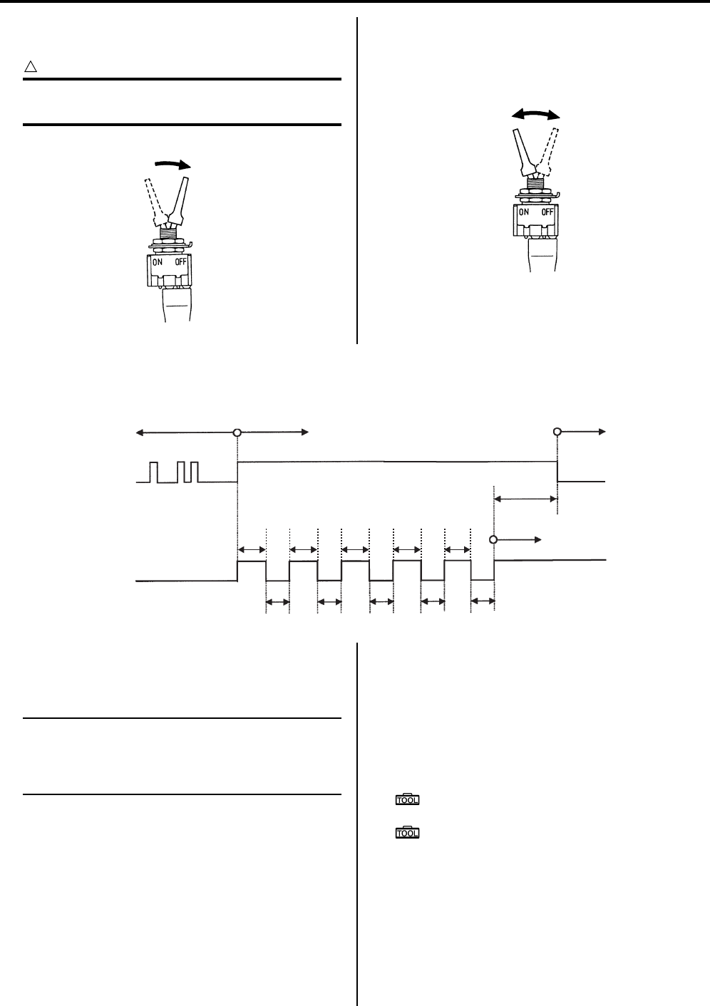
Power Assisted Steering System: 6C-22
3) While the DTCs are being output, set the special tool
to OFF.
CAUTION
!
The DTC deletion mode starts 11.5 seconds
after the switch is set to OFF.
4) In the DTC deletion mode, switch the mode coupler
switch OFF to ON five times or more within 10
seconds, each time leaving it at ON for more than 1
second.
DTC Deleting Diagram
5) After deleting the DTCs, repeat the code output
procedure and make sure that no DTCs remain (the
EPS indicator light no longer flashes).
NOTE
If any DTCs remain, perform the appropriate
procedures, then delete the codes. If DTCs
are left stored, confusion may occur and
unnecessary repairs may be made.
6) Afterwards, start the engine and turn the handlebars
to check that the EPS activates correctly.
7) Disconnect the mode select switch and reinstall the
seat.
Use of SDS
1) Remove the seat. Refer to “Seat Removal and
Installation in Section 9D in related manual”.
2) After repairing the trouble, turn OFF the ignition
switch.
3) Set up the SDS tool. (Refer to the SDS operation
manual for further details.)
Special tool
: 09904–41010 (SUZUKI Diagnostic system
set)
: 99565–01010–020 (CD-ROM Ver.20)
4) Turn the ignition switch ON.
I718H1450050-01
I718H1450051-01
Permitted range of
erasing DTC Cleaning complete
1 sec.
1 sec. 1 sec.
1 sec. 1 sec.
1 sec.
1 sec.
1 sec. 1 sec.
1 sec.
EPS indicator
light
DTC indication
OFF
ON
Mode select
switch ON
ON
Cleaning
start
1.5 sec.
OFF
1 sec.
1 sec.
1 sec.
1 sec.
1 sec.
1 sec.
1 sec.
1 sec.
1 sec.
1 sec.
1 sec.
1 sec. 1 sec.
1 sec. 1 sec.
1 sec.
1 sec.
1 sec. 1 sec.
1 sec.
I931H1630035-04
PartShark.com
877-999-5686
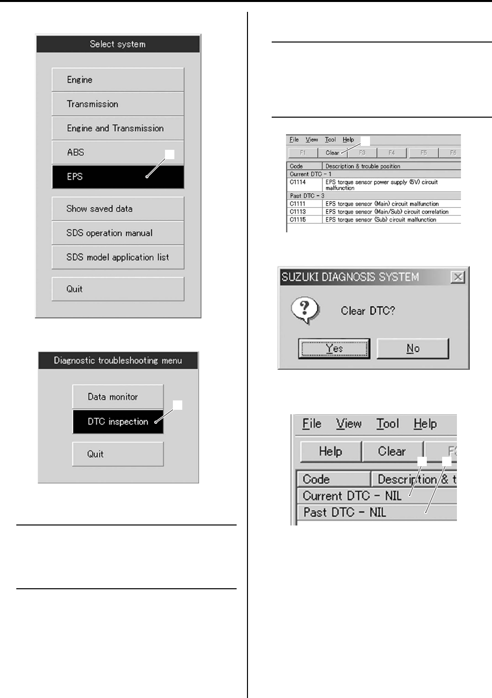
6C-23 Power Assisted Steering System:
5) Click the “EPS” button (1).
6) Click the “DTC inspection” button (2).
7) Check the DTC.
NOTE
The previous malfunction history code (Past
DTC) still remains stored in the EPS control
unit. Therefore, erase the history code
memorized in the EPS control unit using SDS
tool.
Click “Clear” (3) to delete history code (Past DTC).
NOTE
The DTC is memorized in the EPS control
unit also when the wire coupler of any sensor
is disconnected. Therefore, when a wire
coupler has been disconnected at the time of
diagnosis, erase the stored malfunction
history code using SDS.
9) Follow the displayed instructions.
10) Check that both “Current DTC” (4) and “Past DTC”
(5) are deleted (NIL).
11) Close the SDS tool and turn the ignition switch OFF.
12) Disconnect the SDS tool and install the sheet.
13) Start the engine and the handlebars to check that the
EPS activates correctly.
1
I931H1630101-02
2
I931H1630103-01
3
I931H1630036-02
I705H1110006-01
5
4
I931H1630102-01
PartShark.com
877-999-5686
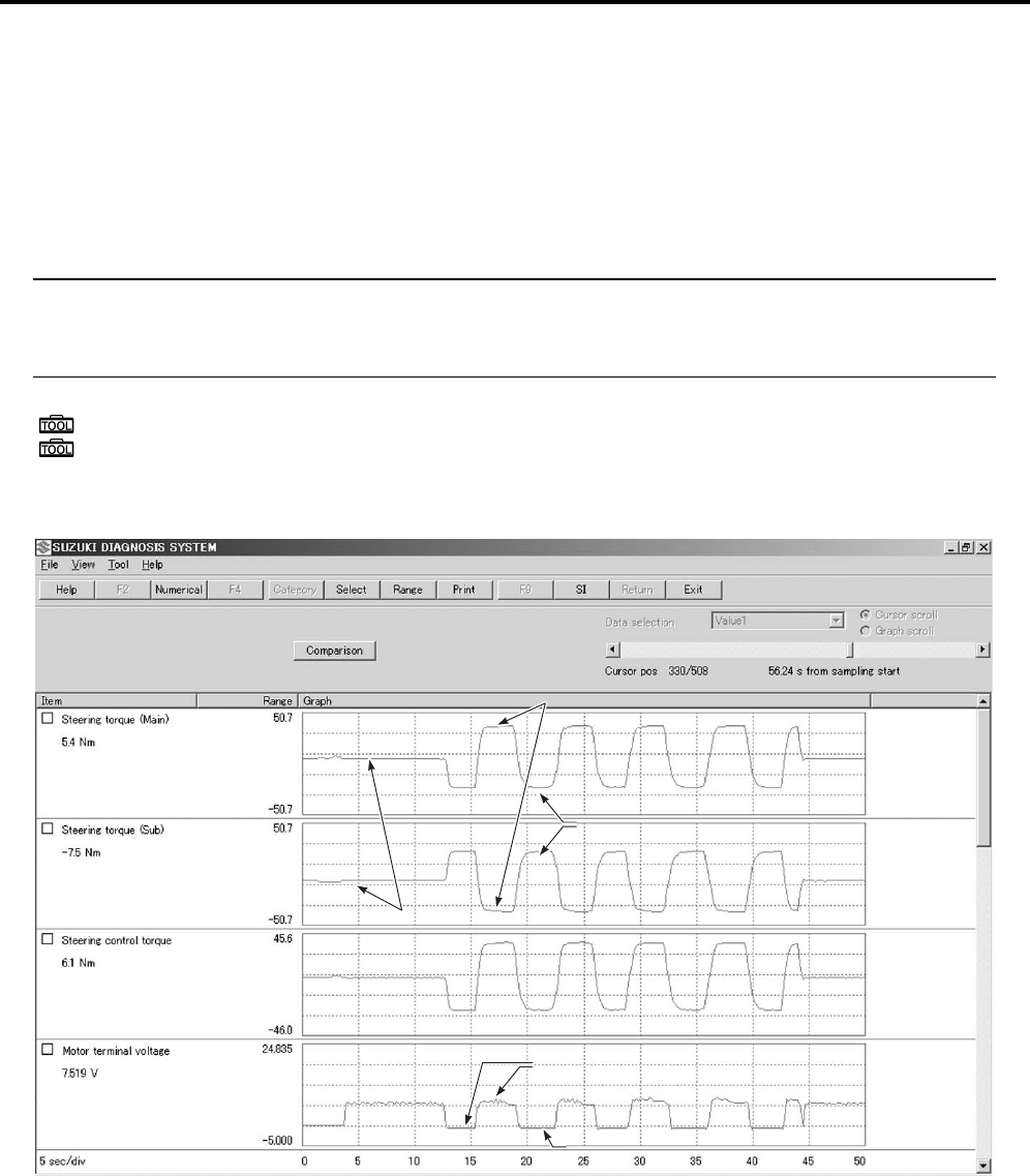
Power Assisted Steering System: 6C-24
SDS Check (LT-A750XP/ZK9)
B931G46304006
Using SDS, take the sample of data from the new vehicle and at the time of periodic maintenance at your dealer.
Save the data in the computer or by printing and filing the hard copies. The saved or filed data are useful for
troubleshooting as they can be compared periodically with changes over time or failure conditions of the vehicle.
For example, when a vehicle is brought in for service but the troubleshooting is difficult, comparison with the normal
data that have been saved or filed can allow the specific EPS failure to be determined.
1) Remove the seat. Refer to “Seat Removal and Installation in Section 9D in related manual”.
2) Set up the SDS tool. (Refer to “SDS operation manual for further details.)
NOTE
• Before taking the sample of data, check and clear the Past DTC. Refer to “DTC (Diagnostic Trouble
Code) Deleting (LT-A750XP/ZK9) (Page 6C-21)”.
• A number of different data under a fixed condition as shown should be saved or filed as sample.
Special tool
: 09904–41010 (SUZUKI Diagnostic system set)
: 99565–01010–020 (CD-ROM Ver.20)
DATA sampled from EPS system
Handlebars is
center position
Check the torque when turning
Check the torque when turning
the handlebars right turn
the handlebars right turn
Check the torque when turning
Check the torque when turning
the handlebars left turn
Check the motor terminal voltage XX V
Check the motor terminal voltage XX V
Handlebars is
center position
Check the torque when turning
the handlebars right turn
Check the torque when turning
the handlebars left turn
There is no display 0V and less
There is no display 0V and less
There is no display 0V and less
Check the motor terminal voltage XX V
I931H1630104-03
PartShark.com
877-999-5686
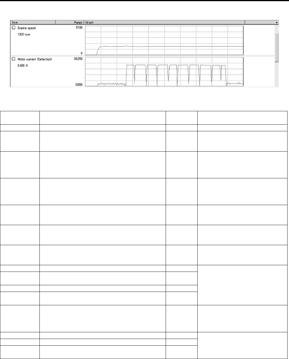
6C-25 Power Assisted Steering System:
Scroll the screen
DTC Table (LT-A750XP/ZK9)
B931G46304007
*1: It goes off after running the engine.
I931G3630066-01
DTC Malfunction cause Indicator
status Reference
None Normal ON *1—
C1111 Torque sensor (main) circuit voltage failure ON
Refer to “DTC “C1111”: Torque
Sensor (Main) Circuit Malfunction
(LT-A750XP/ZK9) (Page 6C-26)”.
C1113 Torque sensor (main) and (sub) circuit voltage
difference high ON
Refer to “DTC “C1113”: Torque
Sensor (Main / Sub) Circuit
Correlation Malfunction (LT—
A750XP/ZK9) (Page 6C-29)”.
C1114 Torque sensor 5 V power supply circuit failure ON
Refer to “DTC “C1114”: Torque
Sensor Power Supply Circuit
Malfunction (LT-A750XP/ZK9)
(Page 6C-33)”.
C1115 Torque sensor (sub) circuit voltage failure ON
Refer to “DTC “C1115”: Torque
Sensor (Sub) Circuit Malfunction
(LT-A750XP/ZK9) (Page 6C-35)”.
C1121 Vehicle speed signal not input OFF
Refer to “DTC “C1121”: Vehicle
Speed Signal Circuit Malfunction
(LT-A750XP/ZK9) (Page 6C-38)”.
C1122 Engine speed signal circuit failure *1ON
Refer to “DTC “C1122”: Engine
Speed Signal Circuit Malfunction
(LT-A750XP/ZK9) (Page 6C-41)”.
C1141 EPS motor circuit voltage abnormal ON
Refer to “DTC “C1141”, “C1142”,
“C1143”, “C1145” EPS Motor Circuit
Malfunction (LT-A750XP/ZK9)
(Page 6C-44)”.
C1142 EPS motor circuit actual current and EPS motor
circuit target current difference high ON
C1143 EPS motor circuit current excessive ON
C1145 EPS motor circuit current low command with EPS
control unit target current ON
C1153 EPS control unit power supply circuit failure OFF
Refer to “DTC “C1153” EPS Control
Unit Supply Voltage Circuit
Malfunction (LT-A750XP/ZK9)
(Page 6C-46)”.
C1152 Relay welding (EPS control unit internal circuit) ON Refer to “DTC “C1152”, “C1154”,
“C1155” EPS Control Unit
Malfunction (LT-A750XP/ZK9)
(Page 6C-47)”.
C1154 Relay failure (EPS control unit internal circuit) OFF
C1155 EPS control unit failure OFF
PartShark.com
877-999-5686

Power Assisted Steering System: 6C-26
DTC “C1111”: Torque Sensor (Main) Circuit Malfunction (LT-A750XP/ZK9)
B931G46304008
Troubleshooting
CAUTION
!
Never remove the torque sensor to prevent accident and damage.
NOTE
• After repairing the trouble, clear the DTC using a SDS tool or mode coupler switch. Refer to “DTC
(Diagnostic Trouble Code) Deleting (LT—A750XP/ZK9) (Page 6C-21)”.
• DTC “C1111” and “C1113” are indicated at the same time due to the malfunction of the same torque
sensor circuit.
Possible Cause
• Faulty torque sensor signal circuit.
• Faulty torque sensor.
• Faulty EPS control unit.
PartShark.com
877-999-5686
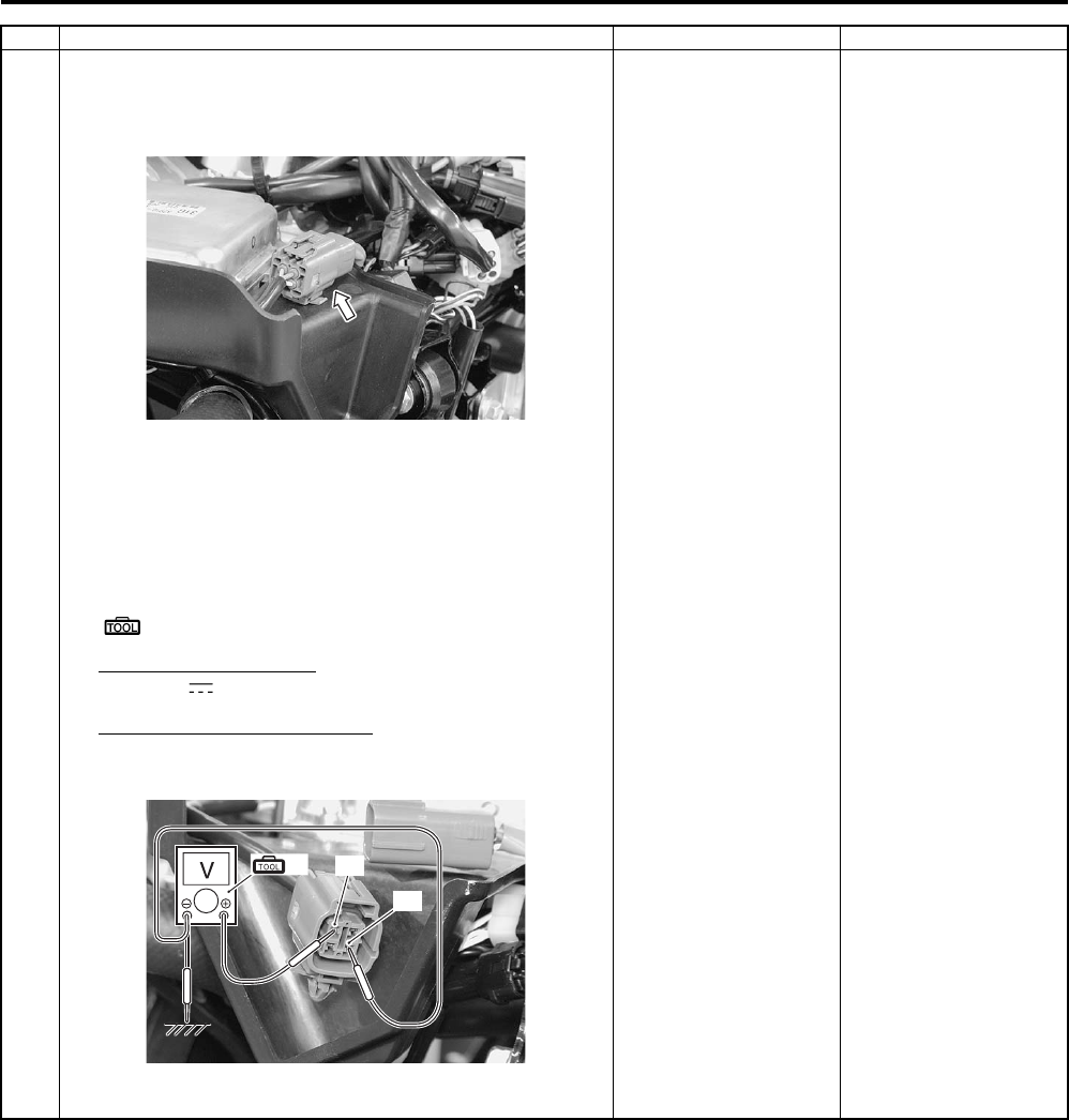
6C-27 Power Assisted Steering System:
Step Action Yes No
1 1) Turn the ignition switch OFF.
2) Check the torque sensor coupler for loose or poor
contact. If OK, measure the torque sensor input voltage.
3) Disconnect the torque sensor coupler.
4) Turn the ignition switch ON.
5) Measure the input voltage between R wire “A” and
ground. If OK, then measure the voltage at the R wire
“A” and B wire “B”.
Special tool
(A): 09900–25008 (Multi circuit tester set)
Tester knob indication
Voltage ( )
Torque sensor input voltage
5.0 V
Is voltage OK?
Go to Step 2. • Loose or poor
contacts on the
torque sensor.
• Power supply circuit
(R wire) or ground
circuit (B wire) open.
• If check result is not
satisfactory, replace
the EPS control unit
with a new one. Refer
to “EPS Control Unit
Removal and
Installation (LT—
A750XP/ZK9)
(Page 6C-48)”.
I931G3630022-01
(A) “A”
“B”
I931G3630024-01
PartShark.com
877-999-5686
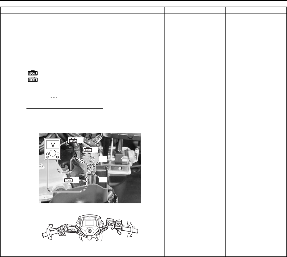
Power Assisted Steering System: 6C-28
2 1) Turn the ignition switch OFF.
2) Connect the torque sensor coupler.
3) Insert the needle-point probes to lead wire coupler.
4) Turn the ignition switch ON.
5) Measure the voltage between G wire “A” and B wire “B”
by turning the handlebars left and right.
Special tool
(A): 09900–25008 (Multi circuit tester set)
(B): 09900–25009 (Needle-point probe set)
Tester knob indication
Voltage ( )
Torque sensor (main) voltage
Handlebars is left turn: Approx. 3.0 V
Handlebars is right turn: Approx. 2.0 V
Is voltage OK?
• Replace the EPS
control unit with a
known good one, and
inspect it again. Refer
to “EPS Control Unit
Removal and
Installation (LT—
A750XP/ZK9)
(Page 6C-48)”.
• R wire terminal or G
wire terminal circuit
open (torque sensor
side).
• If check result is not
satisfactory, replace
the torque sensor
(EPS body assembly)
with a new one. Refer
to “EPS Body
Assembly Removal
and Installation (LT—
A750XP/ZK9)
(Page 6C-50)”.
Step Action Yes No
(A)
“A”
“B”
(B)
(B)
I931G3630025-01
I931H1630042-01
PartShark.com
877-999-5686
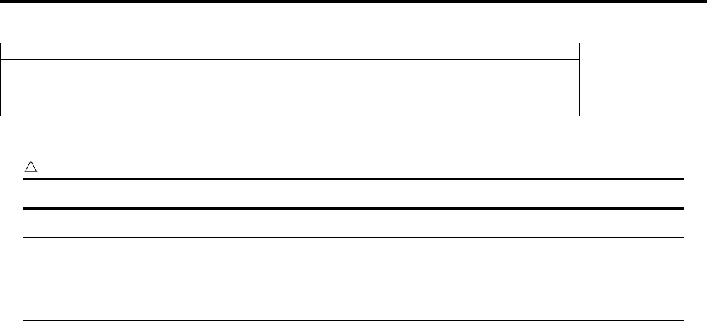
6C-29 Power Assisted Steering System:
DTC “C1113”: Torque Sensor (Main / Sub) Circuit Correlation Malfunction (LT-A750XP/ZK9)
B931G46304009
Troubleshooting
CAUTION
!
Never remove the torque sensor to prevent accident and damage.
NOTE
• After repairing the trouble, clear the DTC using a SDS tool or mode coupler switch. Refer to “DTC
(Diagnostic Trouble Code) Deleting (LT-A750XP/ZK9) (Page 6C-21)”.
• DTC “C1113” and “C1115” are indicated at the same time due to the malfunction of the same torque
sensor circuit.
Possible Cause
• Faulty torque sensor signal circuit.
• Faulty torque sensor.
• Faulty EPS control unit.
PartShark.com
877-999-5686
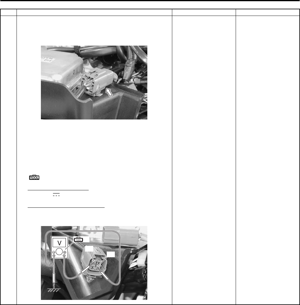
Power Assisted Steering System: 6C-30
Step Action Yes No
1 1) Turn the ignition switch OFF.
2) Check the torque sensor coupler for loose or poor
contact. If OK, measure the torque sensor input voltage.
3) Disconnect the torque sensor coupler.
4) Turn the ignition switch ON.
5) Measure the input voltage between R wire “A” and
ground. If OK, then measure the voltage at the R wire
“A” and B wire “B”.
Special tool
(A): 09900–25008 (Multi circuit tester set)
Tester knob indication
Voltage ( )
Torque sensor input voltage
5.0 V
Go to Step 2. • Loose or poor
contacts on the
torque sensor.
• Power supply circuit
(R wire) open.
• Power source or
power supply circuit
shorted to torque
sensor (main or sub)
circuit.
• Torque sensor (main
or sub) circuit open.
• If check result is not
satisfactory, replace
the EPS control unit
with a new one. Refer
to “EPS Control Unit
Removal and
Installation (LT—
A750XP/ZK9)
(Page 6C-48)”.
I931G3630026-01
“A”
“B”
(A)
I931G3630027-01
PartShark.com
877-999-5686
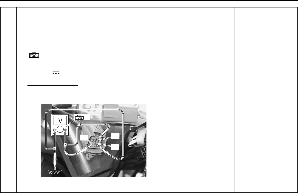
6C-31 Power Assisted Steering System:
1 6) Next, measure the voltage between G wire “C” and
ground, G wire “C” and B wire “B”, W wire “D” and
ground and W wire “D” and B wire “B”. If the voltage of
each measurement is 0 V OK.
Special tool
(A): 09900–25008 (Multi circuit tester set)
Tester knob indication
Voltage ( )
Measuring voltage
0 V
Is voltage OK?
Go to Step 2. • Loose or poor
contacts on the
torque sensor.
• Power supply circuit
(R wire) open.
• Power source or
power supply circuit
shorted to torque
sensor (main or sub)
circuit.
• Torque sensor (main
or sub) circuit open.
• If check result is not
satisfactory, replace
the EPS control unit
with a new one. Refer
to “EPS Control Unit
Removal and
Installation (LT—
A750XP/ZK9)
(Page 6C-48)”.
Step Action Yes No
(A)
“C”
“B”
“D”
I931G3630028-01
PartShark.com
877-999-5686
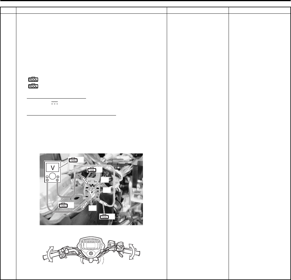
Power Assisted Steering System: 6C-32
2 1) Turn the ignition switch OFF.
2) Connect the torque sensor coupler.
3) Insert the needle-point probes to lead wire coupler.
4) Measure the torque sensor (main) voltage between G
wire “A” and B wire “B”. Also, measure the torque sensor
(sub) voltage between W wire “C” and B wire “B” by full
turning the handlebars left and right.
Special tool
(A): 09900–25008 (Multi circuit tester set)
(B): 09900–25009 (Needle-point probe set)
Tester knob indication
Voltage ( )
Torque sensor (main/sub) voltage
Handlebars left turn (Main): Approx. 3.0 V
Handlebars left turn (Sub): Approx. 2.0 V
Handlebars right turn (Main): Approx. 2.0 V
Handlebars right turn (Sub): Approx. 3.0 V
Is voltage OK?
• G, W and B wire open
or shorted to ground
or poor torque sensor
coupler connection.
• If wire and
connection are OK,
intermittent trouble or
faulty EPS control
unit.
• Replace the EPS
control unit with a
known good one, and
inspect it again. Refer
to “EPS Control Unit
Removal and
Installation (LT—
A750XP/ZK9)
(Page 6C-48)”.
If check result is not
satisfactory, replace the
torque sensor (EPS
body assembly) with a
new one. Refer to “EPS
Body Assembly
Removal and
Installation (LT-A750XP/
ZK9) (Page 6C-50)”.
Step Action Yes No
(B)
“A”
“B”
(A)
“C”
(B)
(B)
I931H1630096-06
I931H1630042-01
PartShark.com
877-999-5686
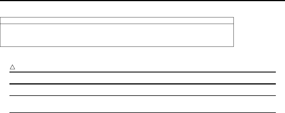
6C-33 Power Assisted Steering System:
DTC “C1114”: Torque Sensor Power Supply Circuit Malfunction (LT-A750XP/ZK9)
B931G46304010
Troubleshooting
CAUTION
!
Never remove the torque sensor to prevent accident and damage.
NOTE
After repairing the trouble, clear the DTC using a SDS tool or mode coupler switch. Refer to “DTC
(Diagnostic Trouble Code) Deleting (LT-A750XP/ZK9) (Page 6C-21)”.
Possible Cause
• Faulty torque sensor signal circuit.
• Faulty torque sensor.
• Faulty EPS control unit.
PartShark.com
877-999-5686
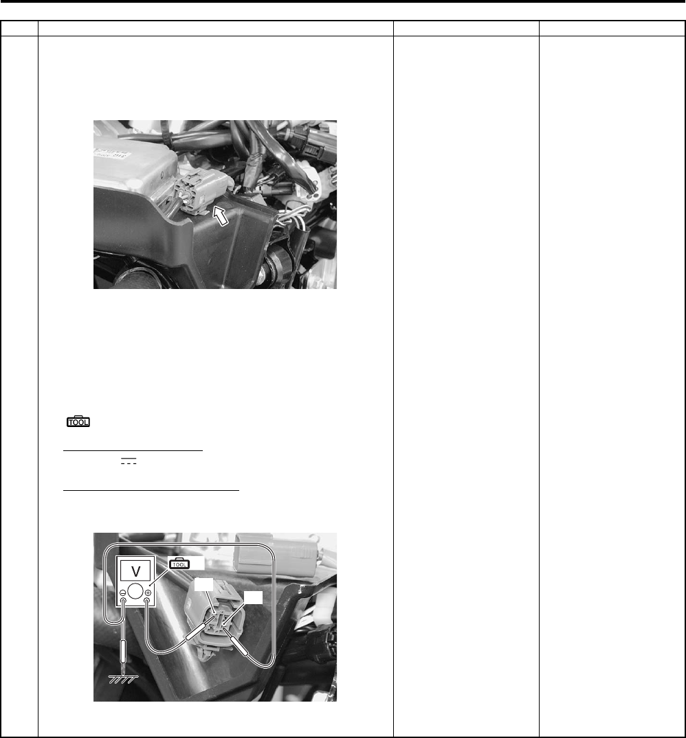
Power Assisted Steering System: 6C-34
Step Action Yes No
1 1) Turn the ignition switch OFF.
2) Check the EPS control unit power source couplers for
loose or poor contact. If OK, measure the torque sensor
input voltage.
3) Disconnect the torque sensor coupler.
4) Turn the ignition switch ON.
5) Measure the voltage between R wire “A” and B wire “B”.
If OK, then measure the voltage at the R wire “A” and
ground.
Special tool
(A): 09900–25008 (Multi circuit tester set)
Tester knob indication
Voltage ( )
Torque sensor input voltage
5.0 V
Is voltage OK?
• If wire and
connection are OK,
intermittent trouble or
faulty EPS body
assembly.
• Replace the EPS
body assembly with a
known good one, and
inspect it again. Refer
to “EPS Body
Assembly Removal
and Installation (LT—
A750XP/ZK9)
(Page 6C-50)”.
• Power supply circuit
(R wire) shorted to
ground.
• If check result is not
satisfactory, replace
the EPS control unit
with a new one. Refer
to “EPS Control Unit
Removal and
Installation (LT—
A750XP/ZK9)
(Page 6C-48)”.
I931G3630029-01
“A”
“B”
(A)
I931G3630027-01
PartShark.com
877-999-5686

6C-35 Power Assisted Steering System:
DTC “C1115”: Torque Sensor (Sub) Circuit Malfunction (LT-A750XP/ZK9)
B931G46304011
Troubleshooting
CAUTION
!
Never remove the torque sensor to prevent accident and damage.
NOTE
After repairing the trouble, clear the DTC using a SDS tool or mode coupler switch. Refer to “DTC
(Diagnostic Trouble Code) Deleting (LT-A750XP/ZK9) (Page 6C-21)”.
Possible Cause
• Faulty torque sensor signal circuit.
• Faulty torque sensor.
• Faulty EPS control unit.
PartShark.com
877-999-5686
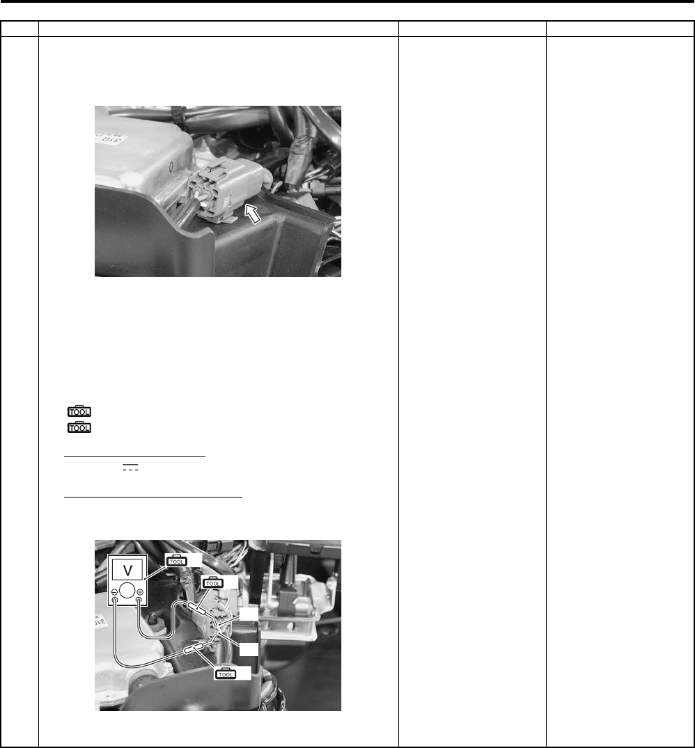
Power Assisted Steering System: 6C-36
Step Action Yes No
1 1) Turn the ignition switch OFF.
2) Check the torque sensor coupler for loose or poor
contact. If OK, measure the torque sensor input voltage.
3) Disconnect the torque sensor coupler.
4) Turn the ignition switch ON.
5) Measure the input voltage between R wire “A” and
ground. If OK, then measure the input voltage between
R wire “A” and B wire “B”.
Special tool
(A): 09900–25008 (Multi circuit tester set)
(B): 09900–25009 (Needle-point probe set)
Tester knob indication
Voltage ( )
Torque sensor input voltage
5.0 V
Is voltage OK?
Go to step 2. • Loose or poor
contacts on the
torque sensor.
• Power supply circuit
(R wire) or ground
circuit (B wire) open.
• If check result is not
satisfactory, replace
the EPS control unit
with a new one. Refer
to “EPS Control Unit
Removal and
Installation (LT—
A750XP/ZK9)
(Page 6C-48)”.
I931G3630026-01
(A)
“A”
“B”
(B)
(B)
I931G3630032-01
PartShark.com
877-999-5686
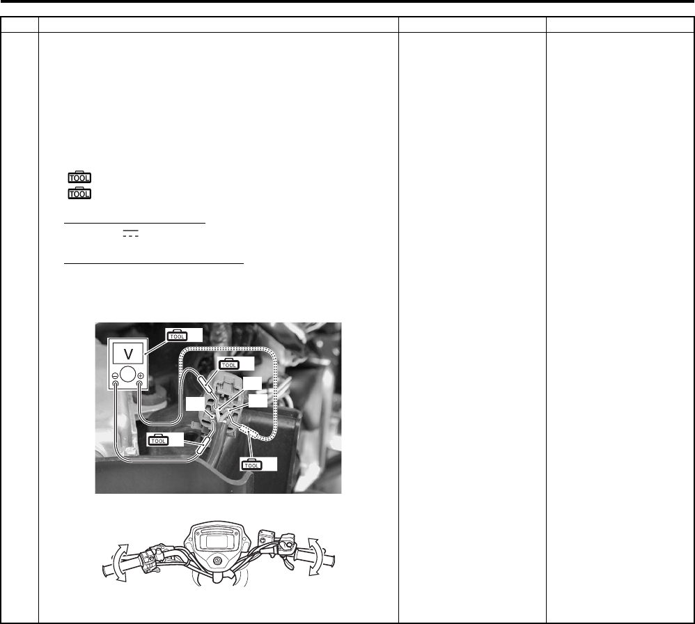
6C-37 Power Assisted Steering System:
2 1) Turn the ignition switch OFF.
2) Connect the torque sensor coupler.
3) Insert the needle-point probes to lead wire coupler.
4) Turn the ignition switch ON.
5) Measure the voltage between W wire “A” and B wire “B”
by turning the handlebars left and right.
Special tool
(A): 09900–25008 (Multi circuit tester set)
(B): 09900–25009 (Needle-point probe set)
Tester knob indication
Voltage ( )
Torque sensor (Sub) voltage
Handlebars is left turn: Approx. 2.0 V
Handlebars is right turn: Approx 3.0 V
Is voltage OK?
• Replace the EPS
control unit with a
known good one, and
inspect it again. Refer
to “EPS Control Unit
Removal and
Installation (LT—
A750XP/ZK9)
(Page 6C-48)”.
• R wire terminal or W
wire terminal circuit
open (torque sensor
side).
• If check result is not
satisfactory, replace
the torque sensor
(EPS body assembly)
with a new one. Refer
to “Steering Shaft
Removal and
Installation in Section
6B in related
manual”.
Step Action Yes No
(B)
“A”
“B”
(A)
“C”
(B)
(B)
I931G3630030-02
I931H1630042-01
PartShark.com
877-999-5686
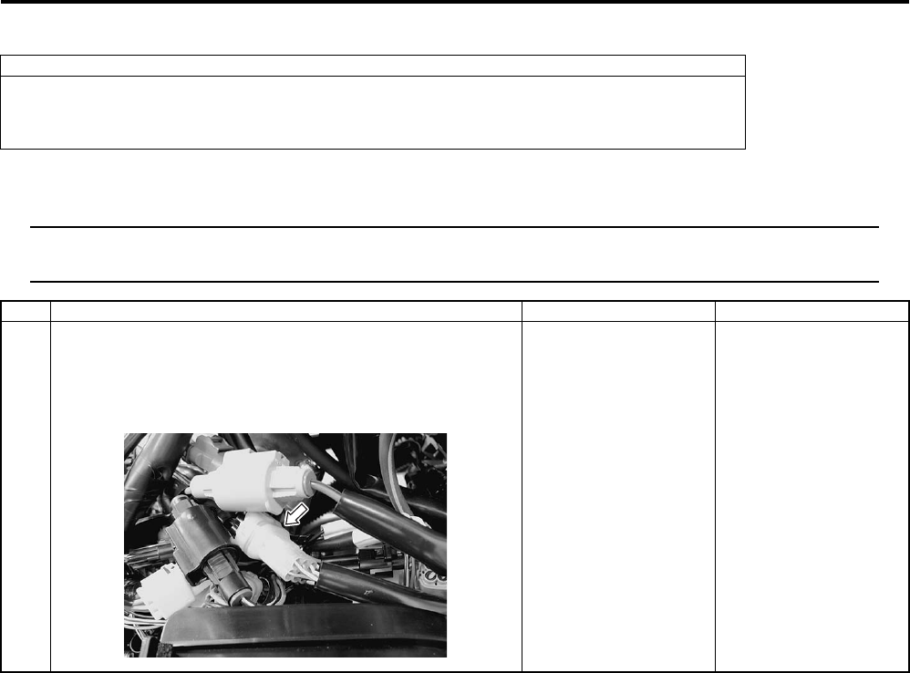
Power Assisted Steering System: 6C-38
DTC “C1121”: Vehicle Speed Signal Circuit Malfunction (LT-A750XP/ZK9)
B931G46304012
Troubleshooting
NOTE
After repairing the trouble, clear the DTC using a SDS tool or mode coupler switch. Refer to “DTC
(Diagnostic Trouble Code) Deleting (LT-A750XP/ZK9) (Page 6C-21)”.
Possible Cause
• Faulty vehicle speed signal circuit.
• Faulty speed sensor.
• Faulty EPS control unit.
Step Action Yes No
1 1) Turn the ignition switch OFF.
2) Check the EPS control unit connector for loose or poor
contact. If OK, then check the vehicle speed signal lead
wire continuity.
Go to step 2. Bl/B wire open.
I931G3630031-01
PartShark.com
877-999-5686
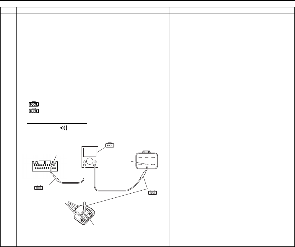
6C-39 Power Assisted Steering System:
1 3) Disconnect the EPS control unit coupler [B], speed
sensor coupler [C] and combination meter coupler [A].
Refer to “Speed Sensor Removal and Installation in
Section 9C in related manual” and “Combination Meter
Removal and Installation in Section 9C in related
manual”.
4) Check the continuity between the Bl/B wire of EPS
control unit coupler [B] and Bl/B wire of speed sensor
[C]. Also, check the continuity between the Bl/B wire of
EPS control unit coupler [B] and Bl/B wire of combination
meter [A].
Special tool
(A): 09900–25008 (Multi circuit tester set)
(B): 09900–25009 (Needle-point probe set)
Tester knob indication
Continuity ( )
Is continuity OK?
Go to step 2. Bl/B wire open.
Step Action Yes No
(A)
?
[A] [B]
[C]
“C”
“A”
(B)
“B”
(B)
I931H1630050-03
PartShark.com
877-999-5686
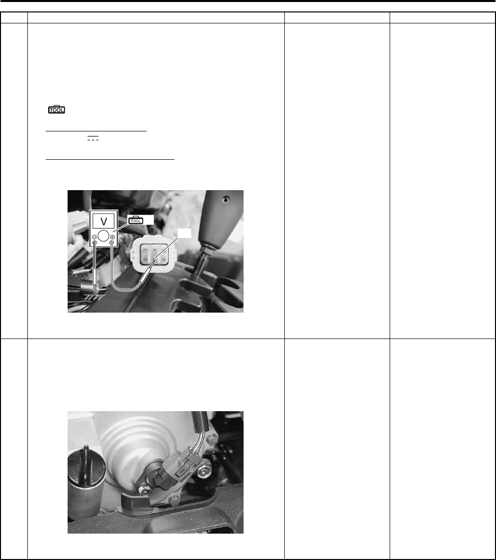
Power Assisted Steering System: 6C-40
2 1) Connect the combination meter coupler and speed
sensor coupler.
2) Turn the ignition switch ON.
3) Measure the voltage between the Bl/B wire “A” and
ground.
Special tool
(A): 09900–25008 (Multi circuit tester set)
Tester knob indication
Voltage ( )
Vehicle speed signal voltage
5.0 V
Is voltage OK?
Go to step 3. Bl/B wire shorted to
ground.
3 1) Remove the engine side cover. Refer to “Rear Side
Exterior Parts Removal and Installation in Section 9D in
related manual”.
2) Inspect the speed sensor. Refer to “Speed Sensor
Inspection in Section 9C in related manual”.
Is speed sensor OK?
Replace the EPS
control unit. Refer to
“EPS Control Unit
Removal and
Installation (LT-A750XP/
ZK9) (Page 6C-48)”.
Replace the speed
sensor. Refer to “Speed
Sensor Removal and
Installation in Section
9C in related manual”.
Step Action Yes No
“A”
(A)
I931G3630033-01
I931G3630034-01
PartShark.com
877-999-5686
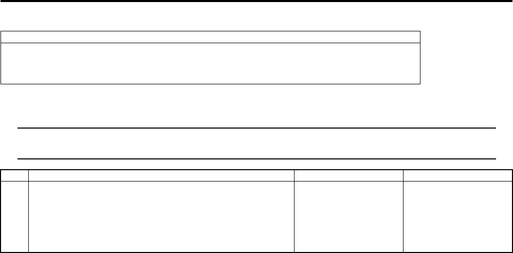
6C-41 Power Assisted Steering System:
DTC “C1122”: Engine Speed Signal Circuit Malfunction (LT-A750XP/ZK9)
B931G46304013
Troubleshooting
NOTE
Start the engine after repairing the DTC and check that the indicator light is turned OFF. Refer to
“Precautions in Diagnosing Troubles (LT-A750XP/ZK9) (Page 6C-1)”.
Possible Cause
• Faulty engine speed signal circuit.
• Faulty ECM.
• Faulty EPS control unit.
Step Action Yes No
1 1) Setup the SDS tool (Refer to the SDS operation manual
for further details.) or connect the mode select switch.
2) Click “Engine” and check the DTC code.
Is not DTC “C12 (P0335)” displayed?
Go to step 2. Inspect the CKP sensor.
Refer to “DTC “C12”
(P0335): CKP Sensor
Circuit Malfunction in
Section 1A in related
manual”.
PartShark.com
877-999-5686
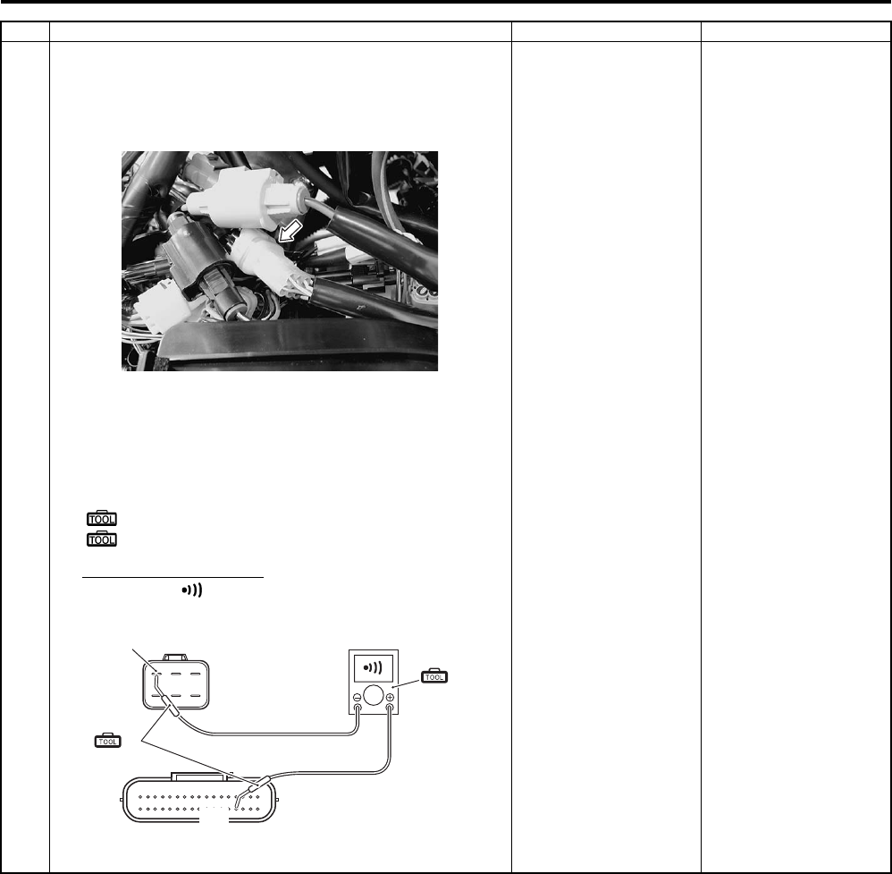
Power Assisted Steering System: 6C-42
2 1) Turn the ignition switch OFF.
2) Check the EPS control unit coupler for loose or poor
contact. If OK, then measure the engine speed signal
lead wire continuity.
3) Disconnect the EPS control unit coupler and ECM
coupler.
4) Check the continuity between the W wire “A” and
terminal “31”.
Special tool
(A): 09900–25008 (Multi circuit tester set)
(B): 09900–25009 (Needle-point probe set)
Tester knob indication
Continuity ( )
Is continuity OK?
Go to step 3. W wire open.
Step Action Yes No
I931G3630031-01
“B”
(A)
“31”
(B)
I931H1630052-02
PartShark.com
877-999-5686
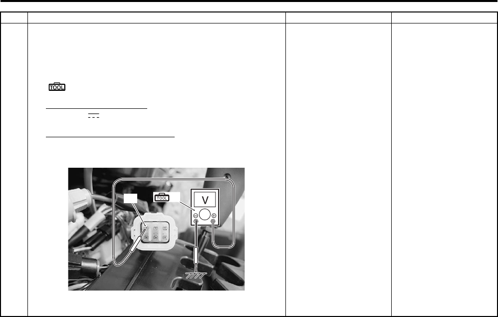
6C-43 Power Assisted Steering System:
3 1) Connect the ECM coupler.
2) Start the engine.
3) Measure the voltage between W wire “A” and ground.
Special tool
(A): 09900–25008 (Multi circuit tester set)
Tester knob indication
Voltage ( )
Engine speed signal voltage
It changes between 0 – 12 V
Is voltage OK?
Replace the EPS
control unit with a new
one. Refer to “EPS
Control Unit Removal
and Installation (LT—
A750XP/ZK9)
(Page 6C-48)”.
Replace the ECM with a
new one. Refer to “EPS
Control Unit Removal
and Installation (LT—
A750XP/ZK9)
(Page 6C-48)”.
Step Action Yes No
“A” (A)
I931G3630035-01
PartShark.com
877-999-5686
Power Assisted Steering System: 6C-44
DTC “C1141”, “C1142”, “C1143”, “C1145” EPS Motor Circuit Malfunction (LT-A750XP/ZK9)
B931G46304014
Troubleshooting
Possible Cause
• Faulty EPS motor circuit.
• Faulty EPS motor.
• EPS control unit malfunction.
Step Action Yes No
1 1) Turn the ignition switch OFF.
2) Check the EPS motor coupler for loose or poor contact.
If OK, measure the EPS motor voltage.
3) Insert the needle-point probes to lead wire coupler.
4) Start the engine and turn the handlebars left turn.
5) Measure the voltage between R wire “A” and B wire “B”.
Special tool
(A): 09900–25008 (Multi circuit tester set)
(B): 09900–25009 (Needle-point probe set)
Tester knob indication
Voltage ( )
EPS motor voltage
Approx. 7.0 V
Is voltage OK?
Go to step 2. R wire or B wire open or
R wire shorted to
ground.
I931G3630036-01
I931H1630093-01
(A)
(B)
I931G3630037-01
PartShark.com
877-999-5686
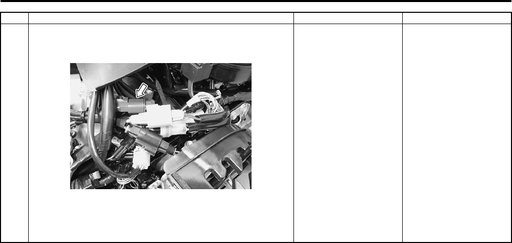
6C-45 Power Assisted Steering System:
2 1) Turn the ignition switch OFF.
2) Disconnect the EPS motor coupler.
3) Inspect the continuity of the EPS motor. Refer to “EPS
Motor Inspection (LT-A750XP/ZK9) (Page 6C-53)”.
Is continuity OK?
Replace the EPS
control unit with a
known good one, and
inspect it again. Refer to
“EPS Control Unit
Removal and
Installation (LT-A750XP/
ZK9) (Page 6C-48)”.
Replace the EPS motor
(EPS body assembly)
with a new one. Refer to
“EPS Body Assembly
Removal and
Installation (LT-A750XP/
ZK9) (Page 6C-50)”.
Step Action Yes No
I931G3630038-01
PartShark.com
877-999-5686
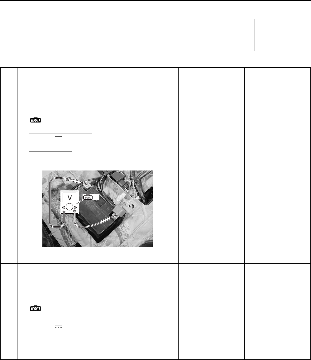
Power Assisted Steering System: 6C-46
DTC “C1153” EPS Control Unit Supply Voltage Circuit Malfunction (LT-A750XP/ZK9)
B931G46304015
Troubleshooting
Possible Cause
• Faulty regulator/rectifier.
• Faulty EPS control unit.
• Faulty wire harness, etc.
Step Action Yes No
1 1) Remove the seat. Refer to “Seat Removal and
Installation in Section 9D in related manual”.
2) Measure the voltage between the (+) and (–) battery
terminals using the multi circuit tester.
Special tool
(A): 09900–25008 (Multi circuit tester set)
Tester knob indication
Voltage ( )
Battery voltage
12.0 V and more
Is the voltage over 12 V?
Go to Step 2. Charge or replace the
battery.
2 1) Start the engine at 5 000 r/min with the dimmer switch
set to HI.
2) Measure the voltage between the (+) and (–) battery
terminals.
Special tool
: 09900–25008 (Multi circuit tester set)
Tester knob indication
Voltage ( )
Regulated voltage
13.5 – 15.0 V at 5 000 r/min
Is the voltage 13.5 – 15.0 V?
Go to Step 3. Inspect the regulator/
rectifier. Refer to
“Regulator / Rectifier
Inspection in Section 1J
in related manual”.
(A)
I931G3630039-01
PartShark.com
877-999-5686
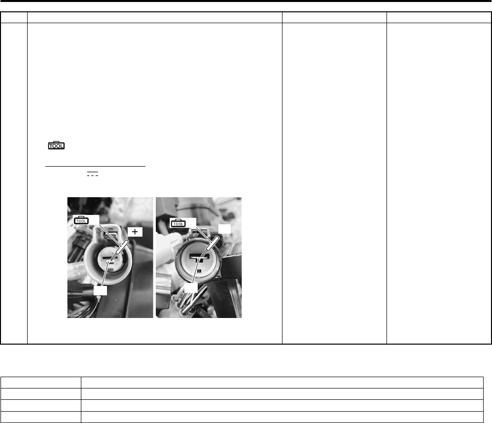
6C-47 Power Assisted Steering System:
DTC “C1152”, “C1154”, “C1155” EPS Control Unit Malfunction (LT-A750XP/ZK9)
B931G46304016
Troubleshooting
• Replace the EPS control unit. Refer to “EPS Control Unit Removal and Installation (LT-A750XP/ZK9) (Page 6C-
48)”.
3 1) Turn the ignition switch OFF.
2) Check the EPS control unit coupler for loose or poor
contacts. If OK, then disconnect the EPS control unit
coupler.
3) Start the engine at 5 000 r/min with the dimmer switch
set to HI.
4) Measure the voltage between terminal “A” and terminal
“B” at the coupler.
Special tool
(A): 09900–25008 (Multi circuit tester set)
Tester knob indication
Voltage ( )
Is the voltage same as Step 2?
Replace the EPS
control unit.
Inspect the wire
harness. (Faulty ignition
or ground wire)
Step Action Yes No
“A” “B”
(A) (A)
(ޓ)(–)
I931G3630040-01
Possible Cause
C1152 • Relay welding (EPS control unit internal circuit)
C1154 • Relay malfunction (EPS control unit internal circuit)
C1155 • EPS control unit malfunction
PartShark.com
877-999-5686
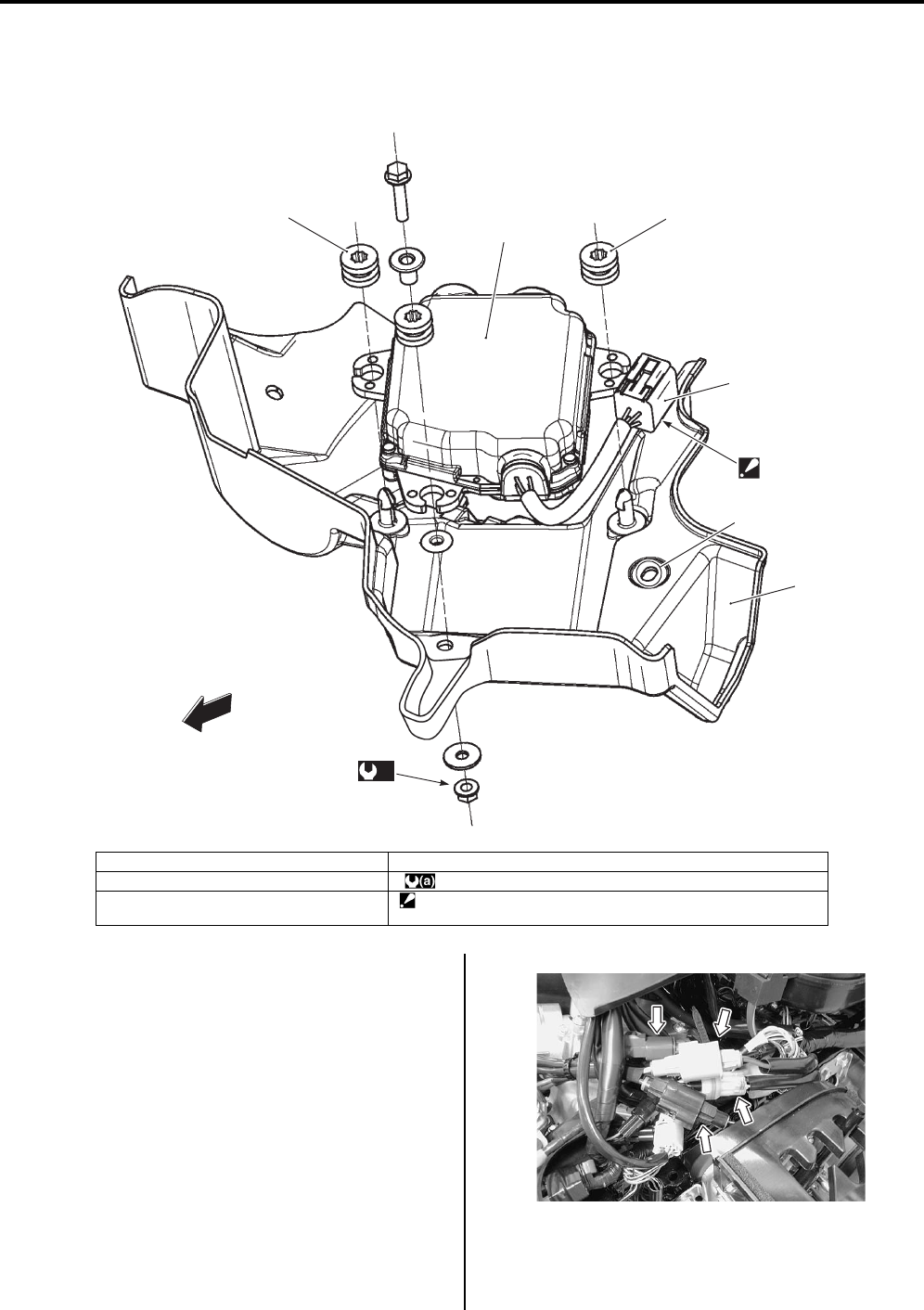
Power Assisted Steering System: 6C-48
Repair Instructions
EPS Control Unit Construction (LT-A750XP/ZK9)
B931G46306001
EPS Control Unit Removal and Installation (LT—
A750XP/ZK9)
B931G46306002
Removal
1) Disconnect the battery (–) lead wire. Refer to
“Battery Removal and Installation (LT-A750XP/ZK9)
in Section 1J (Page 1J-2)”.
2) Remove the front fender. Refer to “Front Side
Exterior Parts Removal and Installation in Section
9D in related manual”.
3) Disconnect the EPS control unit couplers.
1
2
3
3
“B”
4
“A”
(a)
FWD
I931H1630056-02
1. EPS control unit 4. Torque sensor coupler
2. EPS control unit plate : 12 Nm (1.2 kgf-m, 8.5 lbf-ft)
3. Cushion “B”: Install the clip of the torque sensor coupler to the hole “A” of the
EPS control unit plate.
I931G3630041-01
PartShark.com
877-999-5686
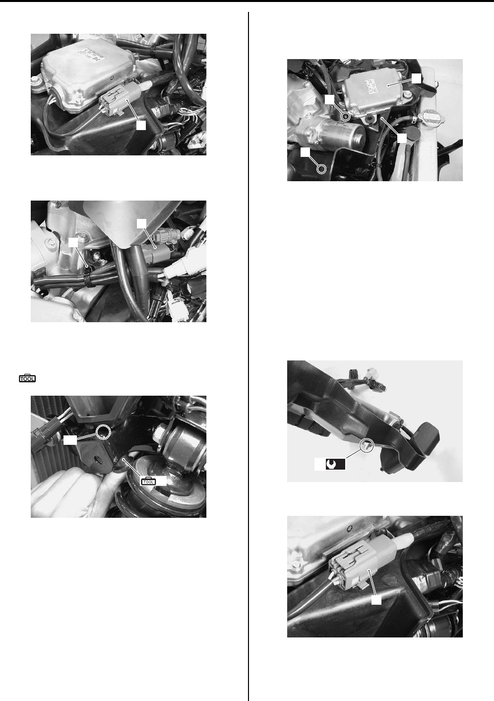
6C-49 Power Assisted Steering System:
4) Disconnect the torque sensor coupler (1).
5) Remove the clamp (2) and release the EPS motor
lead wire (3).
6) Release the clip part “A” of the EPS control unit plate
with the special tool.
Special tool
(A): 09942–83110 (Clip remover)
7) Remove the fastener (4) and bolt (5).
Remove the EPS control unit (6) along with the EPS
control unit plate (7).
9) Remove the EPS control unit (6) from the EPS
control unit plate (7) as shown in the EPS control unit
construction. Refer to “EPS Control Unit
Construction (LT-A750XP/ZK9) (Page 6C-48)”.
Installation
Install the EPS control unit in the reverse order of
removal. Pay attention to the following points:
• Tighten the EPS control unit mounting nut (1) to the
specified torque.
Tightening torque
EPS control unit mounting nut (a): 12 N·m (1.2
kgf-m, 8.5 lbf-ft)
• Connect the torque sensor lead wire (2).
1
I931G3630042-01
2
3
I931G3630043-01
(A)
“A”
I931G3630044-01
6
7
5
4
I931G3630045-01
(a)
1
I931G3630046-01
2
I931G3630047-01
PartShark.com
877-999-5686
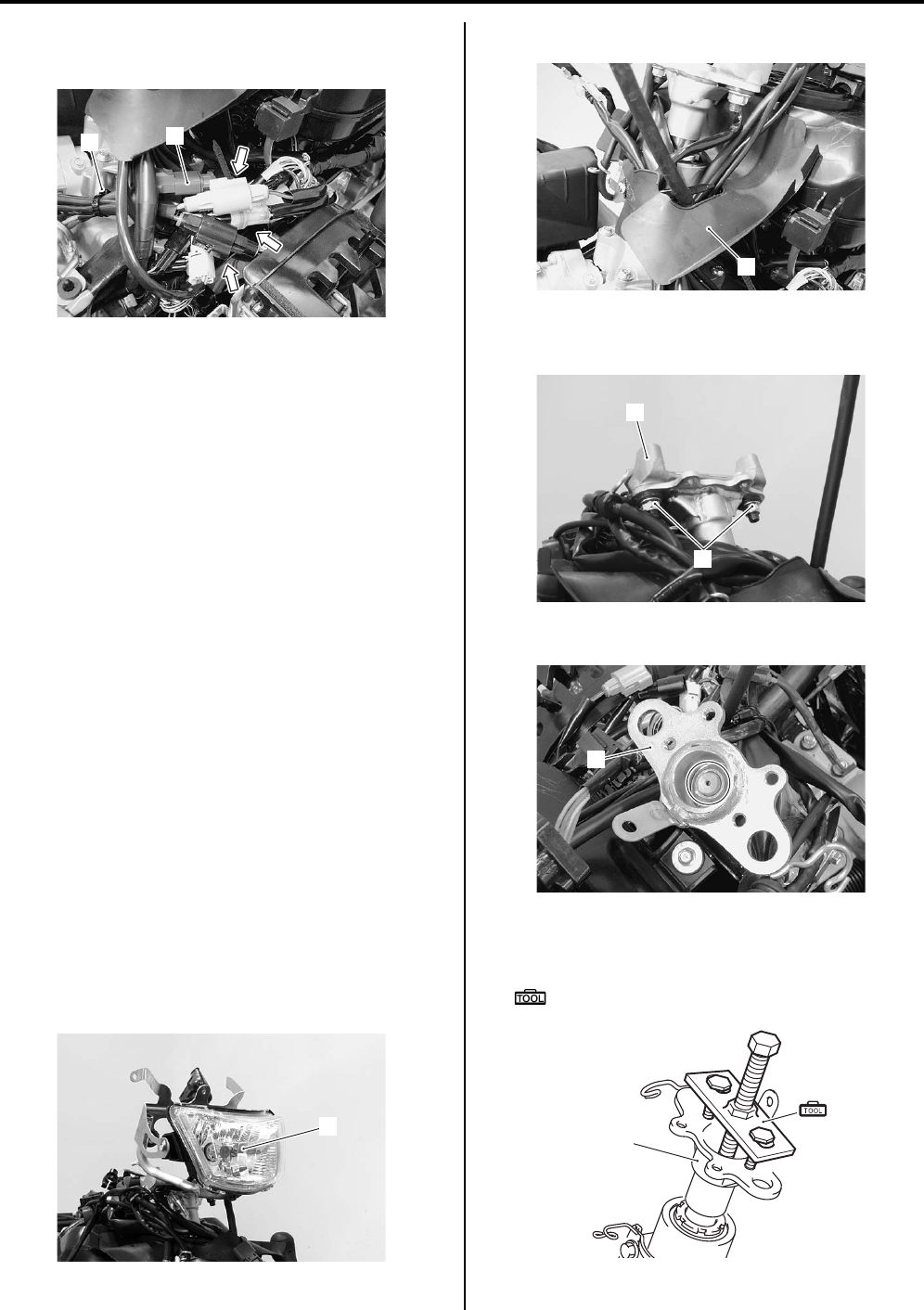
Power Assisted Steering System: 6C-50
• Connect the EPS motor coupler (3) and clamp (4).
• Connect the other EPS control unit couplers.
• Install the front fender. Refer to “Front Side Exterior
Parts Removal and Installation in Section 9D in
related manual”.
EPS Body Assembly Components (LT-A750XP/
ZK9)
B931G46306003
Refer to “Steering / Handlebars Components (LT—
A750XP/ZK9) in Section 6B (Page 6B-1)”.
EPS Body Assembly Removal and Installation
(LT-A750XP/ZK9)
B931G46306004
Refer to “Steering / Handlebars Components (LT—
A750XP/ZK9) in Section 6B (Page 6B-1)”.
Refer to “Steering / Handlebars Assembly Construction
(LT-A750XP/ZK9) in Section 6B (Page 6B-2)”.
Removal
1) Remove the handlebars. Refer to “Handlebars
Removal and Installation (LT-A750XP/ZK9) in
Section 6B (Page 6B-3)”.
2) Remove the combination meter. Refer to
“Combination Meter Removal and Installation in
Section 9C in related manual”.
3) Remove the front fender. Refer to “Front Side
Exterior Parts Removal and Installation in Section
9D in related manual”.
4) Remove the auxiliary headlight (1). Refer to
“Auxiliary Headlight Removal and Installation in
Section 9B in related manual”.
5) Remove the center cover (2).
6) Remove the handlebar holder (3) by removing the
nuts (4).
7) Remove the steering shaft upper nut (5).
Remove the steering shaft plate (6) with the special
tool.
Special tool
(A): 09944–36011 (Steering wheel remover)
3
4
I931G3630048-01
1
I931G3630049-01
2
I931G3630050-01
4
3
I931G3630051-01
5
I931G3630068-01
(A)
6
I931G3630052-01
PartShark.com
877-999-5686
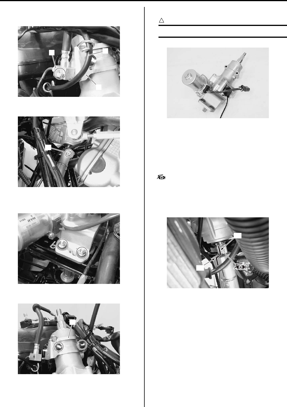
6C-51 Power Assisted Steering System:
9) Remove the front brake hose union (7) and throttle
cable (8) from the cable guide (9).
10) Remove the steering shaft bolt (10).
11) Remove the EPS body assembly mounting nuts and
bolts.
12) Remove the cable guide (11).
13) Remove the EPS body assembly.
CAUTION
!
Never disassemble the EPS body assembly.
Installation
Refer to “Steering / Handlebars Assembly Construction
(LT-A750XP/ZK9) in Section 6B (Page 6B-2)”.
Install the EPS body assembly in the reverse order of
removal. Pay attention to the following points:
• Apply grease to the spline of the EPS body assembly.
: Grease 99000–25160 (Water resistance
grease or equivalent)
• When installing the EPS body assembly, align the
marking “A” of the EPS output shaft and slide “B” of
the steering shaft.
7
9
8
I931G3630053-01
10
I931G3630054-01
I931G3630055-01
11
I931G3630056-01
I931G3630057-02
“A”
“B”
I931G3630058-02
PartShark.com
877-999-5686
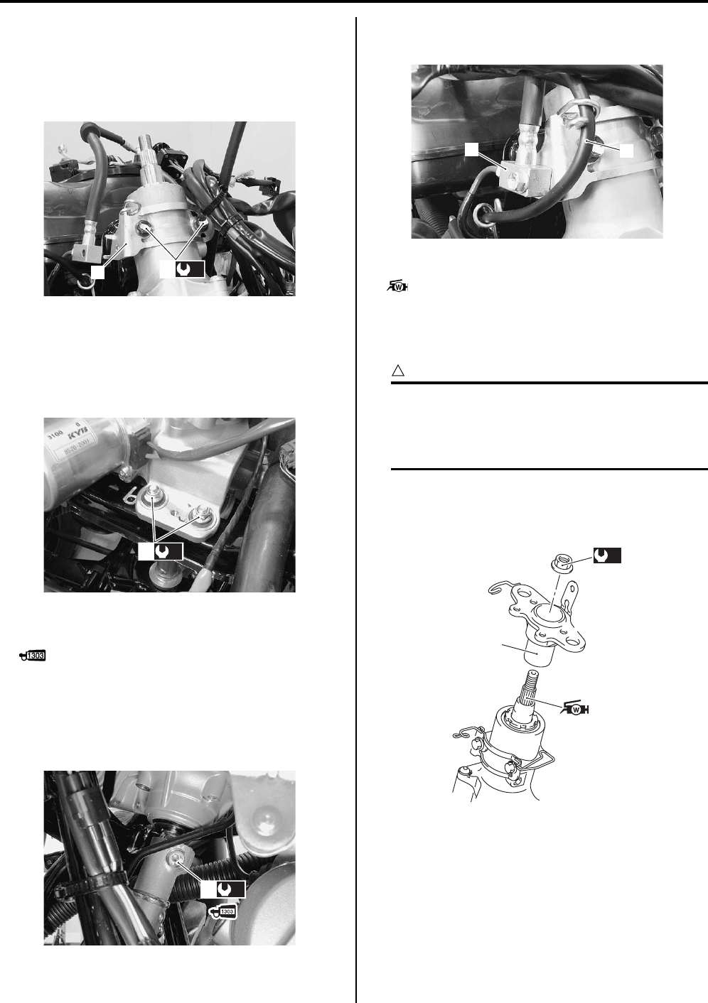
Power Assisted Steering System: 6C-52
• Install the cable guide (1) and tighten the bolts (2) to
the specified torque.
Tightening torque
EPS body assembly mounting bolt (a): 26 N·m (
2.6 kgf-m, 19.0 lbf-ft)
• Tighten the EPS body assembly mounting nuts (3) to
the specified torque.
Tightening torque
EPS body assembly mounting nut (b): 28 N·m (
2.8 kgf-m, 20.0 lbf-ft)
• Apply thread lock to the steering shaft bolt (4) and
tighten it to the specified torque.
: Thread lock cement 99000–32030
(THREAD LOCK CEMENT SUPER “1303” or
equivalent)
Tightening torque
Steering shaft bolt (c): 26 N·m (2.6 kgf-m, 19.0 lbf-
ft)
• Install the front brake hose union (5) and throttle cable
(6) to the cable guide.
• Apply grease to the spline of the EPS body assembly.
: Grease 99000–25160 (Water resistance
grease or equivalent)
• Install the steering shaft plate (7) and tighten the
steering shaft upper nut to the specified torque.
CAUTION
!
• Never use an impact wrench when
tightening the steering shaft upper nut.
• Never exceed the specified torque to
prevent EPS body assembly damage.
Tightening torque
Steering shaft upper nut (d): 120 N·m (12.0 kgf-
m, 87.0 lbf-ft)
(a)
2
1
I931G3630059-02
(b)
3
I931G3630060-02
(c)
4
I931G3630061-03
56
I931G3630062-02
(d)
7
I931G3630072-01
PartShark.com
877-999-5686
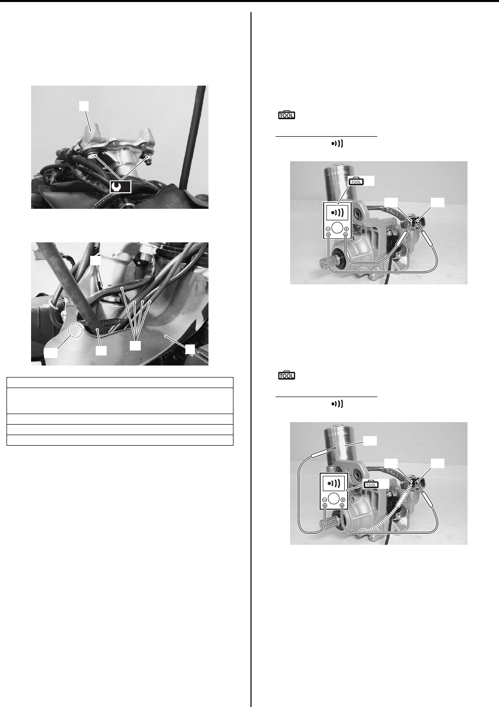
6C-53 Power Assisted Steering System:
• Install the handlebar holder (8) and tighten the nuts to
the specified torque.
Tightening torque
Handlebar holder nut (e): 60 N·m (6.0 kgf-m, 43.5
lbf-ft)
• Install the center cover (9).
• Install the auxiliary headlight. Refer to “Auxiliary
Headlight Removal and Installation in Section 9B in
related manual”.
• Install the front fender. Refer to “Front Side Exterior
Parts Removal and Installation in Section 9D in
related manual”.
• Install the handlebars. Refer to “Handlebars Removal
and Installation (LT-A750XP/ZK9) in Section 6B
(Page 6B-3)”.
• Install the combination meter. Refer to “Combination
Meter Removal and Installation in Section 9C in
related manual”.
EPS Motor Inspection (LT-A750XP/ZK9)
B931G46306005
1) Disconnect the EPS motor coupler.
2) First, check for insulation with the tester between
terminals “A” and “B”.
If continuity does not exist, replace the EPS body
assembly with a new one.
Special tool
(A): 09900–25008 (Multi circuit tester set)
Tester knob indication
Continuity ( )
3) Next, check for insulation with the tester between
terminal “A” and body ground “C” and terminal “B”
and body ground “C”.
If continuity is found, replace the EPS body
assembly with a new one.
Special tool
(A): 09900–25008 (Multi circuit tester set)
Tester knob indication
Continuity ( )
9. Center cover
10. Wiring harness (Left handlebar switch/Parking rear brake switch/
Parking rear brake light switch), (Emergency switch (For P-17) and
horn switch (For P-17, 24))
11. Parking/Rear brake cable
12. Steering shaft
“A”: Hooked point
8
(e)
I931G3630063-02
11
11 10
“A” 9
I931G3630064-02
“A”“B”
(A)
I931H1630107-02
“A”
“C”
“B”
(A)
I931H1630108-02
PartShark.com
877-999-5686
Power Assisted Steering System: 6C-54
Specifications
Tightening Torque Specifications
B931G46307001
NOTE
The specified tightening torque is described in the following.
“EPS Control Unit Construction (LT-A750XP/ZK9) (Page 6C-48)”
Reference:
For the tightening torque of fastener not specified in this section, refer to “Tightening Torque List (LT-A750XP/ZK9) in
Section 0C (Page 0C-7)”.
Special Tools and Equipment
Recommended Service Material
B931G46308001
Fastening part Tightening torque Note
Nm kgf-m lbf-ft
EPS control unit mounting nut 12 1.2 8.5 )(Page 6C-49)
EPS body assembly mounting bolt 26 2.6 19.0 )(Page 6C-52)
EPS body assembly mounting nut 28 2.8 20.0 )(Page 6C-52)
Steering shaft bolt 26 2.6 19.0 )(Page 6C-52)
Steering shaft upper nut 120 12.0 87.0 )(Page 6C-52)
Handlebar holder nut 60 6.0 43.5 )(Page 6C-53)
Material SUZUKI recommended product or Specification Note
Grease Water resistance grease or
equivalent
P/No.: 99000–25160 )(Page 6C-51) /
)(Page 6C-52)
Thread lock cement THREAD LOCK CEMENT SUPER
“1303” or equivalent
P/No.: 99000–32030 )(Page 6C-52)
PartShark.com
877-999-5686
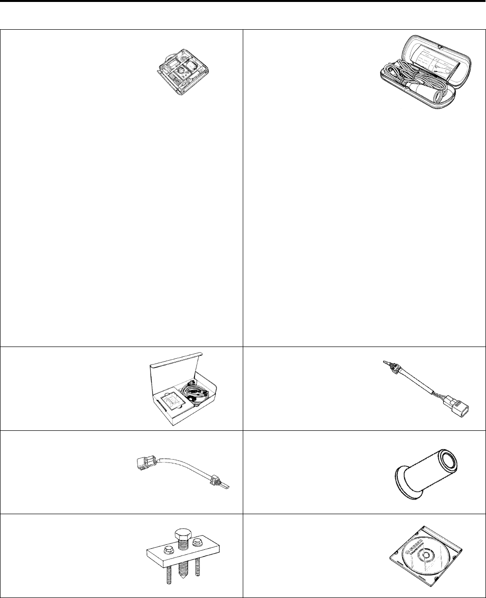
6C-55 Power Assisted Steering System:
Special Tool
B931G46308002
09900–25008 09900–25009
Multi circuit tester set Needle-point probe set
)(Page 6C-11) /
)(Page 6C-11) /
)(Page 6C-13) /
)(Page 6C-14) /
)(Page 6C-14) /
)(Page 6C-16) /
)(Page 6C-17) /
)(Page 6C-18) /
)(Page 6C-27) /
)(Page 6C-28) /
)(Page 6C-30) /
)(Page 6C-31) /
)(Page 6C-32) /
)(Page 6C-34) /
)(Page 6C-36) /
)(Page 6C-37) /
)(Page 6C-39) /
)(Page 6C-40) /
)(Page 6C-42) /
)(Page 6C-43) /
)(Page 6C-44) /
)(Page 6C-46) /
)(Page 6C-46) /
)(Page 6C-47) /
)(Page 6C-53) /
)(Page 6C-53)
)(Page 6C-28) /
)(Page 6C-32) /
)(Page 6C-36) /
)(Page 6C-37) /
)(Page 6C-39) /
)(Page 6C-42) /
)(Page 6C-44)
09904–41010 09930–82710
SUZUKI Diagnostic system
set
Mode select switch
)(Page 6C-20) /
)(Page 6C-22) /
)(Page 6C-24)
)(Page 6C-18) /
)(Page 6C-19)
09930–82720 09942–83110
Mode selection switch Clip remover
)(Page 6C-21) )(Page 6C-49)
09944–36011 99565–01010–020
Steering wheel remover CD-ROM Ver.20
)(Page 6C-50) )(Page 6C-20) /
)(Page 6C-22) /
)(Page 6C-24)
PartShark.com
877-999-5686

Table of Contents 9- i
9
Section 9
CONTENTS
Body and Accessories
Precautions …………………………………………. 9-*
Precautions…………..……………………………..………….9-*
Precautions for Electrical System ….………….……… 9-*
Component Location ………………..……………..………9-*
Electrical Components Location .…………..…………. 9-*
Wiring Systems…………………………………. 9A-1
Schematic and Routing Diagram…..……………….9A-1
Wiring Diagram ………………….…………….…………..9A-*
Wiring Harness Routing Diagram…..………….…….9A-*
Wiring Diagram (LT-A750XP/ZK9)…………………. 9A-1
Wiring Harness Routing Diagram (LT-
A750XP/ZK9) …………….………………..……………. 9A-4
Specifications…….……………….…………….………….9A-7
Service Data ………….……………….……………..…….9A-*
Tightening Torque Specifications.………….……….9A-7
Lighting Systems………………………………..9B-*
Repair Instructions …….…………….………….………. 9B-*
Headlight Components …………….……………..…….9B-*
Headlight Removal and Installation .………………..9B-*
Headlight Bulb Replacement ….…………………..….9B-*
Headlight Beam Adjustment ……..………….………..9B-*
Auxiliary Headlight Components ……………………..9B-*
Auxiliary Headlight Removal and Installation…….9B-*
Auxiliary Headlight Bulb Replacement ……………..9B-*
Auxiliary Headlight Beam Adjustment ………..…….9B-*
Rear Combination Light components.………..…….9B-*
Rear Combination Light Removal and
Installation……………………………………..…………..9B-*
Rear Combination Light Bulb Replacement………9B-*
Reversing Light Bulb Replacement (For P-17) .….9B-*
Reversing Light Relay Inspection (For P-17) …….9B-*
Dimmer Switch Inspection………………….…………..9B-*
Specifications…….……………….…………….…………. 9B-*
Service Data ………….……………….……………..…….9B-*
Special Tools and Equipment ……………………….. 9B-*
Special Tool …………..…………………………..………..9B-*
Combination Meter / Fuel Meter / Horn…9C-*
General Description ………………………..……………. 9C-*
Combination Meter System Description………….. 9C-*
Repair Instructions …….…………….………….………. 9C-*
Combination Meter Components ……..……………. 9C-*
Combination Meter Removal and Installation ….. 9C-*
Combination Meter Disassembly and
Assembly…..…………….……………….…………….... 9C-*
Combination Meter Inspection ……………….……… 9C-*
Engine Coolant Temperature Indicator Light
Inspection……….……………..……………….………… 9C-*
Engine Coolant Temperature Removal and
Installation ………….…………….……………….……… 9C-*
Fuel Level Indicator Inspection ..…………….……… 9C-*
Fuel Level Gauge Inspection ………………………… 9C-*
Speedometer Inspection ……………………….……… 9C-*
Speed Sensor Removal and Installation …………. 9C-*
Speed Sensor Inspection ……..…………….………… 9C-*
Ignition Switch Inspection………..…………….……… 9C-*
Ignition Switch Removal and Installation…………. 9C-*
Horn Inspection (For P-17, 24)……………….……… 9C-*
Horn Removal and Installation (For P-17, 24)….. 9C-*
Specifications………..…………………….………………. 9C-*
Service Data……………………….……………….……… 9C-*
Tightening Torque Specifications…..………………. 9C-*
Special Tools and Equipment ……………………….. 9C-*
Recommended Service Material …………….……… 9C-*
Special Tool ………………………………………..……… 9C-*
Exterior Parts ……………………………………..9D-*
Repair Instructions ………………………………….…… 9D-*
Exterior Parts Construction ……..…………….……… 9D-*
Rear Fender Heat Shield Construction …………… 9D-*
Fuel Tank Lower Cover Heat Shield
Installation ………….…………….……………….……… 9D-*
Fastener Removal and Installation………….……… 9D-*
Front Side Exterior Parts Removal and
Installation ………….…………….……………….……… 9D-*
Rear Side Exterior Parts Removal and
Installation ………….…………….……………….……… 9D-*
Seat Removal and Installation ………………………. 9D-*
Under Cover Components …………………….……… 9D-*
Under Cover Removal and Installation …………… 9D-*
Body Structure………………………………….. 9E-1
Repair Instructions ……………………………….………9E-1
Body Frame Construction ………….………….……… 9E-*
Footrest Construction….……………….…………….... 9E-*
Footrest Removal and Installation.………….……… 9E-*
Carrier Construction ………….……………….………… 9E-*
NOTE
For the items with asterisk (*) in the “CONTENTS” below, refer to the same section of the service manual
mentioned in the “FOREWORD” of this manual.
PartShark.com
877-999-5686

9-ii Table of Contents
Front Carrier Removal and Installation …………… 9E-*
Rear Carrier Removal and Installation ……………. 9E-*
Front Grip Bar Construction ……….………….……… 9E-*
Front Grip Bar Removal and Installation …………. 9E-*
Trailer Towing Construction ……….………….……… 9E-*
Trailer Towing Removal and Instruction………….. 9E-*
Body Frame Construction (LT-A750XP/ZK9)……9E-1
Specifications…..………………….…………………..….. 9E-*
Tightening Torque Specifications…………………… 9E-*
Special Tools and Equipment .……………………….9E-1
Recommended Service Material .…………….……..9E-1
PartShark.com
877-999-5686

Wiring Systems: 9A-1
Body and Acc essories
Wiring Systems
Schematic and Routing Diagram
Wiring Diagram (LT-A750XP/ZK9)
B931G49102003
Refer to “Wire Color Symbols in Section 0A in related manual”.
PartShark.com
877-999-5686
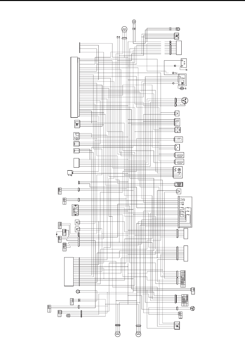
9A-2 Wiring Systems:
For P-17
ON
OFF
HORN
HEADLIGHT
(L)
SPEEDOMETER
BRAKE
LEVER
SWITCH
(L)
REAR
BRAKE
SWITCH
BACKUP
LIGHT
ECM
REAR
COMBINATION
LIGHT
ON
OFF
PUSH
BRAKE
LEVER
SWITCH
SET
SECEDE
EMERGENCY
SWITCH
HORN
BUTTON
AUXILIARY
HEADLIGHT
HEADLIGHT
(R)
HI
LO
RUN
OFF
PUSH
DIMMER
SWITCH
ENGINE
STOP
SWITCH OVER RIDE
SWITCH
START
BUTTON
PUSH
LOW
POSITION
DIODE
HIGH
POSITION
DIODE
4WD/
DIFF-LOCK
RELAY
POWER
SOURCE
M
REGULATOR/
RECTIFIER
FUEL
PUMP
FUEL
PUMP
RELAY
IGNITION
COIL
SPEED
SENSOR TO
SENSOR
BACKUP
LIGHT
RELAY BACK BUZZER
1
STARTER
MOTOR STARTER
RELAY
1: MAIN (30 A)
BATTERY
EPS CONTROL UNIT
CKP
SENSOR
GENERATOR
ECT
SENSOR
IAT
SENSOR
IAP
SENSOR
TP
SENSOR
RESISTOR
PARKING
BRAKE
RELAY
NEUTRAL
RELAY
DIODE
123
45 6
FUSE BOX
4WD/
DIFF-LOCK
DIODE
INJECTOR ISC VALVE
1. HEAD HI
2. HEAD LO
3. FUEL
4. IGNITION
5. FAN
6. POWER SOURCE
10 A
10 A
10 A
15 A
15 A
10 A
2WD
4WD
LOCK
GEAR
POSITION
SWITCH
4WD/DIFF-LOCK
SWITCH 4WD/DIFF-LOCK
ACTUATOR
ON
OFF
ON
OFF
ON3
ON2
ON1
OFF
COOLING
FAN
THERMO-
SWITCH
COOLING
FAN
MOTOR
IGNITION
SWITCH
PARKING
BRAKE
SWITCH
DIFF-LOCK
RELAY
ON
OFF
B/W
Bl/W
O/Y
W/B
B/W
Bl/R
Bl
R/G
O/Y
R/B
Bl/B
W/R
B/Y
O/Y
B/W
W/G
B/G
Y/B
B/W
Bl/W
O/Y
W/B
B/W
Bl/R
Bl
R/G
R
R/B
Bl/B
W
W/R
B/Y
B/W
W/G
B/G
Y/B
G
Y
Y
G
O/Y
O
O/Y
O
O/Y
O/Y
B/W
B/W
B/W
O/G
P
B
B
G
B/W
O/G
O
Bl/R
Gr
B/W
B/W
W/B
Gr
B/W
R
R
B
W/B
O/Y
Y
B/W
W
Y
B/W
W
Y
B/W
W
Y
B/W
W
Y/Bl
W/Bl
O/Bl
O/W
Y/G
B/W
Br
Br Br
Br
Gr
W/R
W/Y
W/G
Gr
O/W
Y/G
B/W
Y/Bl
W/Bl
Y/G
B/W
Gr
W/R
W/Y
W/G
Gr
W
Y
Y/G
B/W
O/Bl
O
O/W
O
O/W
R
Y
Y
Y
B/W
Br/W
B/Br
R/B
Bl/B
B/W
Y/R
B/W
B/W
R
Br/W
B/Br
R/B
Bl/B
B/W
Y/B
Y/B
B
Y/R
B/W
O/Y
W/B
O/Y
W/B
B/W
B/W
W/B
W/B
W/B
B/W
B/W
W/B
O/Y
O/Y
O/B
O/B
B/W
O/Y
Bl
Bl/R
B
B/W
Bl/R
Y
Bl
O/Y
W/B
W/B
B
B
O
Y/Bl
O/W
O/W
R/B
W/B
Gr/W
O/W
R/B
B/R
B/W
W/Y
Bl/G
Br/W
B/Bl
G/B
R/G
B/Lg
Y/Bl
Y/R
Y/B
Gr/R
B/G
B/Br
Br
Bl/B
W/R
Dg
B/Y
Y/R
Y/Bl
R/B
W/B
Gr/W
R/B
B/R
R
B/W
W/Y
Bl/G
Br/W
B/Bl
B
G/B
Y
R/G
G
B
Y/Bl
Y/R
Y/B
Gr/R
B/G
B/Br
Br
Bl/B
W/R
B/Y
Y/R
O/W
B/Lg
Dg
W/Bl
P/W
O/W
W/R
Gr/R
B/W
W/Bl
W
P/W
W/R
Gr/R
B/W
O/W
Y/B
B/W
B/W
B
Y/B
B/W
R
R
R/B
B/W
B/W
B/W
Bl/G
Bl
Bl/G
B
Bl
W
Y
Y
Y
Y
Y
Y
B/Bl
B/Br
Dg
B/Br
B/Br
G/B
B/Br
B/R
B/W
B/Bl
B/W
B/Bl
Bl/B
B/Bl
B/Br
B/Br
B/Br
G/B
R
R
W/Y
W/Y
Gr
Gr
Y
B/Br
B/R
B/W
B/Bl
B/W
B/Bl
Bl/B
Dg
W/Bl
Gr/W
Y/R
B/Lg
R/B
P/W
R/B
W/Bl
Y/Bl
W/Bl
R/B
O/Y
O/R
O/B
Y/G
B/Bl
O/Y
Y/B
W/Bl
W
Gr/W
Y/R
R/B
P/W
G
R/B
W/Bl
R
W
Y
Y/Bl
W/Bl
R/B
Y/G
B/Bl
Y/B
B/Lg
O/Y
O
O/R
O/B
O/Y
Bl/R
Bl/R
O/Y
R
O/Y
R
B/W
B/W
O/Y
O/Y
O/Y
W
Bl/B
Y
Gr/R
W/R
R/B
B/W
Bl/R
O
W/Bl
Br
B/G
B/Y
B/W
Br
Br
R/G
B/W
Y
Bl/B
Bl/R
W/R
W/G
B/W
O
Bl/R
B
W/Bl
Br
B/G
B/Y
B/W
W
Br
Br
R/G
B/W
Bl/B
Bl/R
W/R
W/G
B/W
Bl
Bl
Bl
B/W
B/W
Bl
R
W
G
O
Br
Gr
Bl
W
Br
Gr
G
B
Bl
Y
O/Y
B/R
B/R
O/Y
B/R
O/R
B/W
B/R
O/Bl
Bl/W
B/R
B/W
B/R
R
Bl/W
Y
O
O/Bl
O/R
Bl
Gr
B
Bl
R
Gr
P
O/R
O
O/R
O/Y
Y/B
B/G
Y/B
B
B/G
O/Y
R
R
B
I931G3910901-02
PartShark.com
877-999-5686
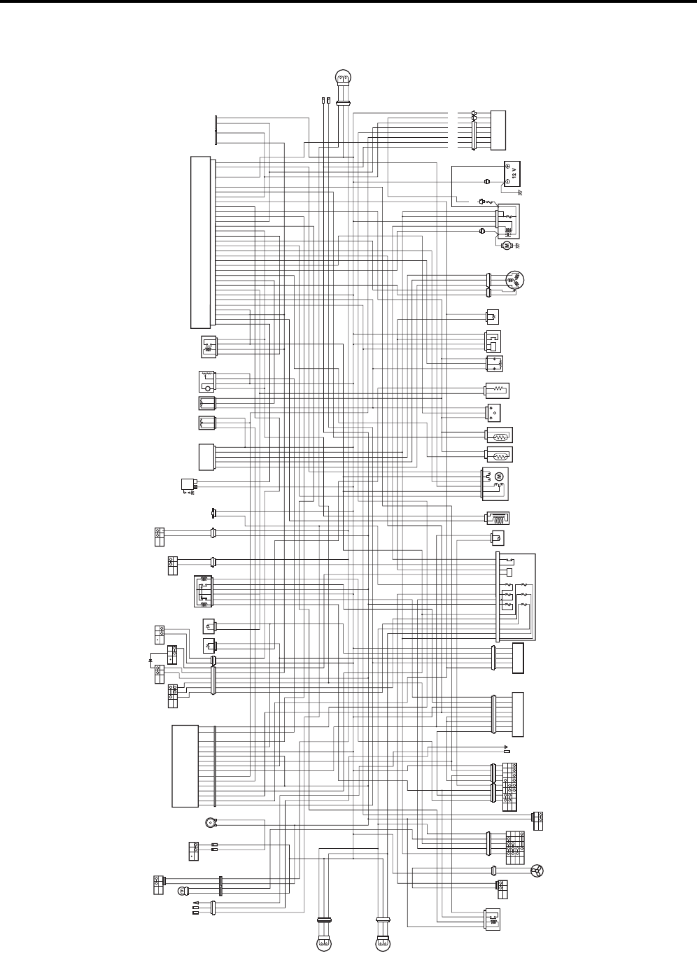
Wiring Systems: 9A-3
For P-24, 28, 33
ON
OFF
HORN
HEADLIGHT
(L)
SPEEDOMETER
BRAKE
LEVER
SWITCH
(L)
REAR
BRAKE
SWITCH
ECM
REAR
COMBINATION
LIGHT
OPTION
ON
OFF
PUSH
BRAKE
LEVER
SWITCH
HORN
BUTTON
AUXILIARY
HEADLIGHT
HEADLIGHT
(R)
HI
LO
RUN
OFF
PUSH
DIMMER
SWITCH
ENGINE
STOP
SWITCH OVER RIDE
SWITCH
START
BUTTON
PUSH
LOW
POSITION
DIODE
HIGH
POSITION
DIODE
4WD/
DIFF-LOCK
RELAY
POWER
SOURCE
M
REGULATOR/
RECTIFIER
FUEL
PUMP
FUEL
PUMP
RELAY
IGNITION
COIL
SPEED
SENSOR TO
SENSOR
1
STARTER
MOTOR STARTER
RELAY
1: MAIN (30 A) BATTERY
EPS CONTOL UNT
CKP
SENSOR
GENERATOR
ECT
SENSOR
IAT
SENSOR
IAP
SENSOR
TP
SENSOR
RESISTOR
PARKING
BRAKE
RELAY
NEUTRAL
RELAY
DIODE
123
45 6
FUSE BOX
4WD/
DIFF-LOCK
DIODE
INJECTOR ISC VALVE
1. HEAD HI
2. HEAD LO
3. FUEL
4. IGNITION
5. FAN
6. POWER SOURCE
10 A
10 A
10 A
15 A
15 A
10 A
2WD
4WD
LOCK
GEAR
POSITION
SWITCH
4WD/DIFF-LOCK
SWITCH 4WD/DIFF-LOCK
ACTUATOR
ON
OFF
ON
OFF
ON3
ON2
ON1
OFF
COOLING
FAN
THERMO-
SWITCH
COOLING
FAN
MOTOR
IGNITION
SWITCH
PARKING
BRAKE
SWITCH
DIFF-LOCK
RELAY
ON
OFF
B/W
Bl/W
O/Y
W/B
B/W
Bl/R
Bl
R/G
O/Y
R/B
Bl/B
W/R
B/Y
O/Y
B/W
W/G
B/G
Y/B
B/W
Bl/W
W/B
B/W
Bl/R
Bl
R/G
R
R/B
Bl/B
W
W/R
B/Y
B/W
W/G
B/G
Y/B
G
Y
G
O/Y
O
O/Y
O/Y
B/W
B/W
B/W
P
B
B
G
B/W
Bl/R
Gr
B/W
W/B
Gr
B/W
W/B
O/Y
Y
B/W
W
Y
B/W
W
Y
B/W
W
Y
B/W
W
Y/Bl
W/Bl
O/Bl
O/W
Y/G
B/W
Br
Br Br
Br
Gr
W/R
W/Y
W/G
Gr
O/W
Y/G
B/W
Y/Bl
W/Bl
Y/G
B/W
Gr
W/R
W/Y
W/G
Gr
W
Y
Y/G
B/W
O/Bl
O/Y
O/Y
O/W
O
O/W
R
Y
Y
Y
B/W
Br/W
B/Br
R/B
Bl/B
B/W
Y/R
B/W
B/W
R
Br/W
B/Br
R/B
Bl/B
B/W
Y/B
Y/B
B
Y/R
B/W
O/Y
W/B
O/Y
W/B
B/W
B/W
W/B
W/B
W/B
B/W
B/W
W/B
O/Y
O/Y
O/B
O/B
B/W
O/Y
Bl
Bl/R
B
B/W
Bl/R
Y
Bl
O/Y
W/B
W/B
B
B
O
Y/Bl
O/W
O/W
R/B
W/B
Gr/W
O/W
R/B
B/R
B/W
W/Y
Bl/G
Br/W
B/Bl
G/B
R/G
B/Lg
Y/Bl
Y/R
Y/B
Gr/R
B/G
B/Br
Br
Bl/B
W/R
Dg
B/Y
Y/R
Y/Bl
R/B
W/B
Gr/W
R/B
B/R
R
B/W
W/Y
Bl/G
Br/W
B/Bl
B
G/B
Y
R/G
G
B
Y/Bl
Y/R
Y/B
Gr/R
B/G
B/Br
Br
Bl/B
W/R
B/Y
Y/R
O/W
B/Lg
Dg
W/Bl
P/W
O/W
W/R
Gr/R
B/W
W/Bl
W
P/W
W/R
Gr/R
B/W
O/W
Y/B
B/W
B/W
B
Y/B
B/W
R
R
R/B
B/W
B/W
B/W
Bl/G
Bl
Bl/G
B
Bl
W
Y
Y
Y
Y
Y
Y
B/Bl
B/Br
Dg
B/Br
B/Br
G/B
B/Br
B/R
B/W
B/Bl
B/W
B/Bl
Bl/B
B/Bl
B/Br
B/Br
B/Br
G/B
R
R
W/Y
W/Y
Gr
Gr
Y
B/Br
B/R
B/W
B/Bl
B/W
B/Bl
Bl/B
Dg
W/Bl
Gr/W
Y/R
B/Lg
R/B
P/W
R/B
W/Bl
Y/Bl
W/Bl
R/B
O/Y
O/R
O/B
Y/G
B/Bl
O/Y
Y/B
W/Bl
W
Gr/W
Y/R
R/B
P/W
G
R/B
W/Bl
R
W
Y
Y/Bl
W/Bl
R/B
Y/G
B/Bl
Y/B
B/Lg
O/Y
O
O/R
O/B
O/Y
O/Y
W
Bl/B
Y
Gr/R
W/R
R/B
B/W
Bl/R
O
W/Bl
Br
B/G
B/Y
B/W
Br
Br
R/G
B/W
Y
Bl/B
Bl/R
W/R
W/G
B/W
O
Bl/R
B
W/Bl
Br
B/G
B/Y
B/W
W
Br
Br
R/G
B/W
Bl/B
Bl/R
W/R
W/G
B/W
Bl
Bl
Bl
B/W
B/W
Bl
R
W
G
O
Br
Gr
Bl
W
Br
Gr
G
B
G
B
Bl
Y
O/Y
B/R
B/R
O/Y
B/R
O/R
B/W
B/R
O/Bl
Bl/W
B/R
B/W
B/R
R
Bl/W
Y
O
O/Bl
O/R
Bl
Gr
B
Bl
R
Gr
P
O/R
O
O/R
O/Y
Y/B
B/G
Y/B
B
B/G
O/Y
O/B
O/B
B
G
O
B
G
WINCH
(P-28, 33)
(P-24)
(P-24)
(P-28, 33)
I931G3910902-03
PartShark.com
877-999-5686
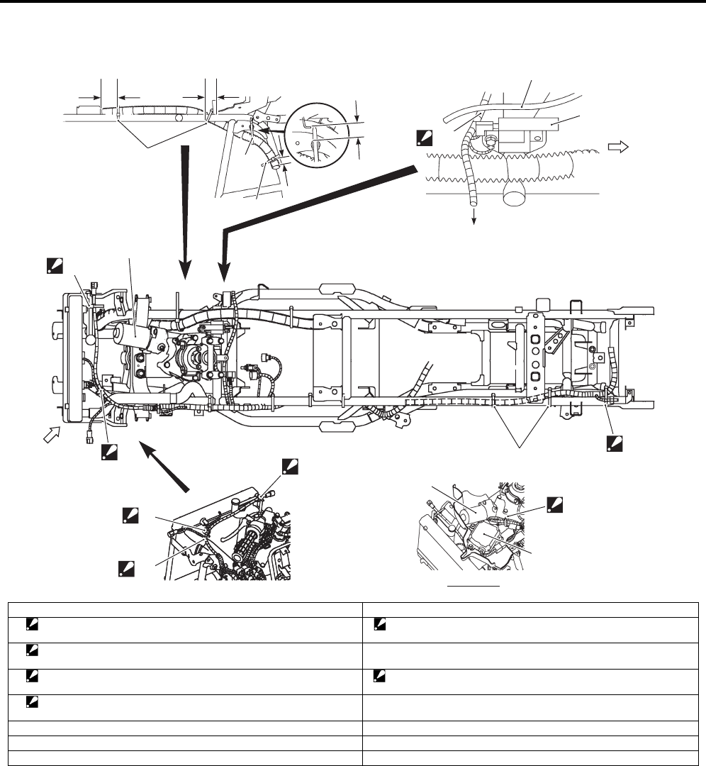
9A-4 Wiring Systems:
Wiring Harness Routing Diagram (LT-A750XP/ZK9)
B931G49102004
“b”
2
3
3
“B”
2
1
4
7
6
5
VIEW A
“A”
1
“a” “b”
1
1
“c” “D”
8
9
“C”
7
FWD
I931G3910905-02
1. Clamp 9. Throttle cable
2. Clamp
: Bind the wiring harness and hose with the clamp.
“B”: Pass the wiring harness and cooling fan lead wire over the radiator
hose.
3. Clamp
: Bind the wiring harness and cooling fan thermo switch with the clamp.
“C”: To power source.
4. Clamp
: Bind the wiring harness and back up relay (For P-17) with the clamp.
“D”: Pass the wiring harness under of the throttle cable.
5. Clamp
: Bind the EPS motor lead wire and EPS control unit lead wires.
“a”: 60 – 80 mm (2.4 – 3.2 in)
6. EPS control unit “b”: 20 – 30 mm (0.8 – 1.2 in)
7. EPS motor “c”: 10 – 15 mm (0.4 – 0.6 in)
8. Ignition coil
PartShark.com
877-999-5686
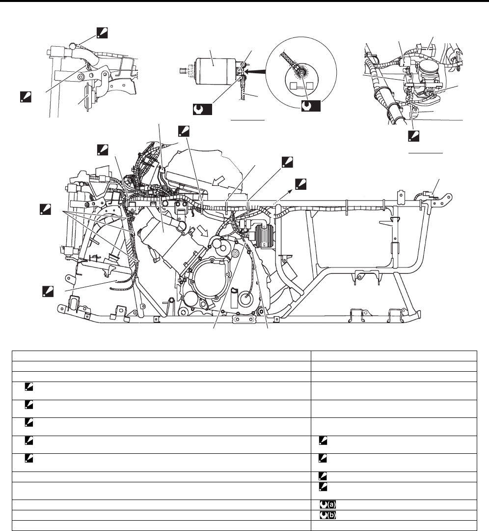
Wiring Systems: 9A-5
“A”
1
(b)
(a)
3
5
4
8
6
14
13
16 17
15
7
9
12
“C”
18
10
“E”
“D”
2
11
11
“F”
VIEW F
VIEW A
19
“B”
I931G3910903-02
1. Starter motor 14. Injector coupler
2. Starter motor terminal 15. TP sensor coupler
3. Engine earth 16. ISC valve coupler
4. Clamp
: Bind the wiring harness and rear brake cable with the clamp.
17. TO sensor
5. Clamp
: Bind the wiring harness and diff-lock actuator lead wire with the clamp.
18. Horn (For P-17, 24)
6. Clamp
: Bind the diff-lock actuator lead wire and rear brake switch lead wire with the clamp.
19. IAP sensor
7. Clamp
: Bind the rear brake switch lead wire with the clamp.
“B”: To rear fender top.
8. Clamp
: Bind the wiring harness, generator lead wire and gear position switch lead wire.
“C”: Slack the read wire.
9. Speed sensor lead wire. “D”: Pass the horn lead wire inside of the stay.
10. Clamp “E”: Pass the branch of left headlight lead wire
over the radiator hose.
11. Clamp : 10 Nm (1.0 kgf-m, 7.0 lbf-ft)
12. Back up relay (For P-17) :6 Nm (0.6 kgf-m, 4.5 lbf-ft)
13. ECT sensor coupler
PartShark.com
877-999-5686
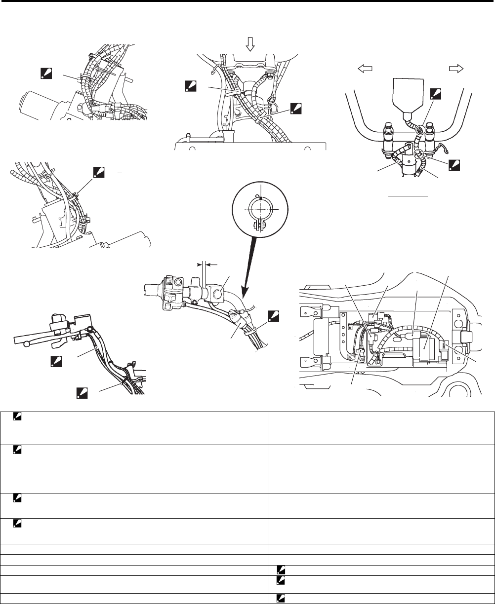
9A-6 Wiring Systems:
3
“a”
5
789
10
11
12
“A”VIEW
4
2
4
2
LH RH
“C”
14
13
6
1
“A”
“D”
“B”
I931H1910903-05
1. Clamp
: Bind the left handlebar switch lead wire, rear brake lever switch lead wire,
horn lead wire (For P-17, 24) and emergency switch lead wire (For P-17) with
the clamp. Cut the tip of clamp after clamping.
10. ECM
2. Clamp
: Bind the combination meter lead wire, 2WD/4WD/diff-lock switch lead wire,
ignition switch lead wire, front brake switch lead wire, parking/rear brake lever
switch lead wire, left handlebar switch lead wire, horn lead wire (For P-17, 24)
and emergency switch lead wire (For P-17) with the clamp. Cut the tip of clamp
after clamping.
11. Fuse box
3. Clamp
: Bind the front brake switch lead wire and 2WD/4WD/diff-lock switch lead wire
with the clamp. Cut the tip of clamp after clamping.
12. Fuse (EPS)
4. Clamp
: Bind the combination meter lead wire, 2WD/4WD/diff-lock lead wire and front
brake switch lead wire with the clamp.
13. Combination meter lead wire
5. Horn button (For P-17, 24) 14. Ignition switch lead wire
6. Emergency switch (For P-17) “a”: 10 – 15 mm (0.4 – 0.6 in)
7. Drive relay “B”: Pass the combination meter lead wire behind the upper bracket.
8. Starter relay “C”: Slack the combination meter lead wire under the combination
meter.
9. Fuel pump relay “D”: Pass the front brake switch lead wire behind the handlebars.
PartShark.com
877-999-5686
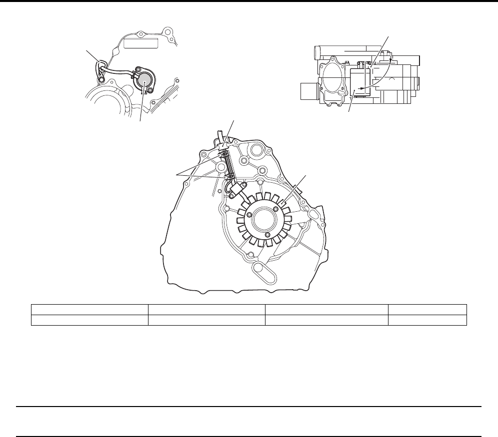
Wiring Systems: 9A-7
Specifications
Tightening Torque Specifications
B931G4910S002
NOTE
The specified tightening torque is described in the following.
“Wiring Harness Routing Diagram (LT-A750XP/ZK9) (Page 9A-4)”
Reference:
For the tightening torque of fastener not specified in this section, refer to “Tightening Torque List (LT-A750XP/ZK9) in
Section 0C (Page 0C-7)”.
1
2
3
“a”
4
5
6
6
I931G3910904-01
1. Starter motor 3. Generator stator 5. Grommet “a”: 90q
2. Gear position switch 4. Ground wire 6. Clamp
PartShark.com
877-999-5686
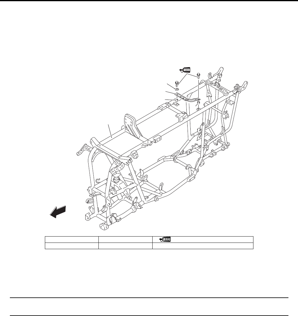
9E-1 Body Structure:
Body and Acc essories
Body Structure
Repair Instructions
Body Frame Construction (LT-A750XP/ZK9)
B931G49506011
Special Tools and Equipment
Recommended Service Material
B931G49508001
NOTE
Required service material is also described in the following.
“Body Frame Construction (LT—A750XP/ZK9) (Page 9E-1)”
FWD
3
2
4
4
1
I931G3950001-04
1. Frame 3. Washer : Apply thread lock to the thread part.
2. Battery plate 4. Spacer
PartShark.com
877-999-5686
Description
This PDF contains all the necessary instructions needed for any repair your 750AXi 750 AXi LT-A750X-XP 750rs 08-12 Suzuki King Quad.
This is the same information the dealer technicians and mechanics use to diagnose and repair your bike.
Whether its routine maintenance, such as tune-ups and brake service, or more extensive repairs involving engine/clutch disassembly.
This PDF provides the most reliable information to perform the job.
Accurate, clear and concise text, combined with detailed illustrations, make it possible for anyone with even a bit of basic mechanical knowledge to safely and easily service and repair their bike.
Comprehensive diagrams, in depth illustrations, and all the manufacturers specifications and technical information you will need is included.
Not only is this a complete repair manual, but it also includes all the scheduled service information, tech service bulletins, recall information.
Format: PDF
Year:2008-2009(08-09)
Compatibility:any windows,mac,linux
полный мануал по ремонту квадроциклов сузуки с мотором 750.

Дата публикации: 05 Февраля 2015
Эта инструкция содержит полное описание на SUZUKI LT-A750X/P эксплуатация обслуживание и ремонт.
это самая мощная модель утилитарного квадроцикла Suzuki серии King Quad, которая полностью оправдывает весь пафос своего названия. К конструктивным особенностям квадроцикла Suzuki KingQuad 750 можно отнести сравнительно небольшой вес, особенно для заявленной мощности квадроцикла в 49 л.с., а также грамотную развесовку. Как и в случае с младшей моделью Suzuki 400, сапуны редукторов надежно защищены чехлами. Задний тормоз Suzuki 750 находится в масляной ванне и встроен в редуктор. В базовой комплектации Suzuki Lt-a 750 оснащается электроусилителем руля.
Квадроцикл SUZUKI KingQuad LT-A 750 – это самая популярная модель квадроцикла из семейства квадроциклов Suzuki. Мощный двигатель рабочим объемом 750 куб.см, превосходный дизайн и впечатляющие ходовые характеристики делают эту модель одной из лучших в своем классе.
Двигатель
* Тип двигателя: 4-тактный, DOHC
* Количество и расположение цилиндров: 1
* Рабочий объем, куб. см: 722
* Система питания: Впрыск топлива
* Система смазки: Картер с масляной ванной
* Система зажигания: Электронная
* Система охлаждения: Жидкостная
* Система пуска: Электрическая
Массо-габаритные характеристики
* Общая длина: 2165
* Общая ширина: 1250
* Колесная база: 1285
* Дорожный просвет: 280
* Высота по сиденью: 920
* Снаряженная масса: 307
* Объем бака: 17,5
Ходовая часть
* Передняя подвеска: Независимая, на двух поперечных рычагах
* Задняя подвеска: Независимая, на двух поперечных рычагах
Тормозная система
* Передняя тормозная система: Гидравлическая; два диска
* Задняя тормозная система: Многодисковая в масляной ванне
Размерность шин
* Передняя шина: AT25x8-12
* Задняя шина% AT25x10-12
Источник
Suzuki King Quad 700750 FAQ + Взаимозаменяемые запчасти и другая информация


HeavyMetal
Команда АТВ Клуба
Друзья,в этой теме я решил собрать все основные данные по Suzuki King Quad 700750.
Ссылки на мануалы:
Пользовательский мануал на King Quad 750 2009 на русском
LT-A750XP_03A_L0_ru.pdf
Пользовательский мануал на King Quad 700 2007 на русском
Suzuki_LT-А700X_(рус).pdf
Ремонтный мануал на King Quad 750 2009 на английском
Ремонтный мануал Suzuki King Quad 750.pdf
Первый месяц — самый важный в сроке службы Вашего вездехода. В этот период особенно важна правильная обкатка для достижения максимального срока службы нового вездехода. Следующие принципы объясняют необходимые процедуры обкатки.
Во время первых 10 часов эксплуатации рекомендуем открывать дроссель менее, чем наполовину.
Скорость вращения двигателя должна быть различной в течение периода обкатки. Хотя очень важно, чтобы была некоторая нагрузка на узлах двигателя во время обкатки, но будьте осторожны, чтобы чрезмерно не нагрузить двигатель. Избегайте постоянной низкой
скорости движения. Постоянная работа двигателя на
низких оборотах может неправильно притереть движущиеся части.
Добавьте двигателю оборотов, не превышая рекомендуемого макси-
мального открытия дросселя.
График технического обслуживания

1.Моторное масло.
Поскольку на Сузах сцепление в масляной ванне,используйте только мотоциклетные масла,например линейку масел Motul,Castrol и других производителей мото масел с допуском JASO MA,или JASO MA2,или JASO T904
По классификации API масло должно быть стандрата SF или SG.Рекомендуемая вязкость масла должна соот-
ветствовать SAE 10W-40.

Проверка уровня масла:
Рекомендую проверять уровень масла перед каждым выездом,двигатель очень чувствителен к уровню масла.
Уровень проверяется так:Поставьте квадроцикл на ровную площадку,прогрейте его в течении 5 минут.Затем заглушите,и подождите 3 минуты.После этого выкрутите масляный щуп,протрите его от масла,и вставьте его в заливную горловину не закручивая.Уровень масла должен быть между точкой L и F на картинке.

Замена масла
Менять масло несложно.Прогреваем квадроцикл,ставим на ровную горизонтальную площадку.
Затем снимаем пластиковую крышку со стороны масляного щупа,и снимаем подкрылок с левой стороны по ходу движения.После этого откручиваем сливную пробку(если не ошибаюсь ключом на 17)Сливаем все масло.Затем откручиваем масляный фильтр(может потребоваться съемник для масляных фильтров,я использую цепной съемник,можно купить в любом магазине запчастей.)
Фильтр на всех Сузах 1 и тот-же-Hiflo(HF-138,неоригинальный),есть практически в любом магазине мото-запчастей.Также есть аналоги от Mann и BikeMaster.
При установке фильтра протрите установочную площадку,после этого смажьте резиновое кольцо на фильтре маслом.После этого хорошо закрутите его руками.
Не забудьте закрутить сливную пробку!И не затягивайте её сильно,пробку легко сорвать.
Залейте около 2400 грамм масла,затем заведите квадроцикл,прогрейте его в течении 5 минут,заглушите,и через 3 минуты проверьте уровень масла.При необходимости долейте.
2.Замена масла в переднем и заднем редукторе.
Рекомендую менять масла в редукторах 2 раза в год-перед зимним и перед летним сезоном.
Если часто преодолеваете броды необходимо периодически проверять состояние масла в редукторах,оно не должно быть серым или белесым.
В переднем редукторе используется трансмиссионное масло SAE90, имеющее рейтинг GL-5 по
классификации API.Зимой используйте масло SAE80.
Поставьте квадроцикл на ровную площадку,открутите заливную и сливную пробку редуктора,слейте масло.
Затем открутите контрольный болт(№2 на рисунке)

После этого заливайте масло до тех пор,пока оно не потечет из отверстия №2.Для залива масла удобнее всего использовать большой шприц с резиновой трубкой.
Емкость редкутора по мануалу — 500 мл.
В заднем редукторе используется специальное масло для систем мокрых тормозов-Mobil Fluid 424 или его аналоги,например Shell Donax TD SAE 5W-30.Не заливайте обычное трансмиссионное масло,иначе вы рискуете спалить тормоза.Масло заливается под горло(770 мл)
3.Свеча зажигания
Доступ к свече зажигания не очень удобен.Удобнее всего подбираться к ней со стороны правого колеса по ходу движения.Внимание,не теряйте родной свечной ключ,иначе выкрутить свечу будет проблематично!
На квадроцикле в стандарте установлена свеча NGK CR6E.Также можно использовать свечи NGK СR7E, DENSO
U20ESR-N и DENSO U22ESR-N.Чтобы определить, подходит ли Вам стандарт-ная свеча зажигания, посмотрите на цвет фарфорового изолятора через некоторое время после начала эксплуатации свечи. Светло-коричневый цвет означает, что свеча подходит. Белый или темный цвет изолятора означает, что надо использовать свечу другого типа.
4.Ремень вариатора
Когда ремень изношен квадроцикл начинает трогаться со скрипом,и отвечает на газ при старте с некоторым запозданием.Также теряется максимальная скорость.
Советую брать оригинальный ремень,аналоги показали себя не с лучшей стороны.
Номера аналогов: Ultimax UA 437,или Dayco XTX2234
Замена ремня:
Снимаем пластик с подножки.Затем откручиваем саму подножку(снимать не обязательно,нужно немного сдвинуть её вниз относительно крышки вариатора)После этого откручиваем крышку вариатора.Частенько болты в ней начинают прокручиваться-придется отдирать крышку,и вклеивать резьбовые втулки обратно в отверстия.
После снятия крышки откручиваем треногу,и вкручиваем 2 болта M6 в отверстия на ведомом шкиве,чтобы ослабить старый ремень,и поставить новый.
Собираем в обратной последовательности.Ничего сложного.
Проверка износа заднего тормоза:

Как перевести приборку из миль в километры?
Перевести приборку в режим одометра, затем на-
жать и удерживать кнопки (1) и (6) в
течение 2 секунд, чтобы переклю-
читься между км/ч и миль/ч.
5.Список взаимозаменяемых запчастей
Со временем будет дополняться.
Косточки стабилизатора подходят от Honda Civic, 1996—2000 , Cr-v, 1997—2001.Каталожный номер CLHO-2
Резинка стабилизатора — Febest SZSB-GVTF
Задние ступичные подшипники подходят от передних ступиц Сузуки Свифт. Оригинальный номер Сузуки —43440-84F00, номер Койо DAC3562W-5CS35 размеры — 35*62*40
Сальники задних ступиц — 47х62х7 и 48х65х7
Передние ступичные подшипники — всем известные DAC3055. Размеры 30*55*32.
Самый лучший вариант по цене и качеству — оригинал от Кавасаки, 92045-0123
Сальники передних ступиц — 38х55х6 и 38х55х8
Реле-регулятор подходит от квадроциклов STELSHSUN 500700. Каталожный номер:32100-058-0000
Также есть вариант подороже,но надёжней. От Хонды TRX 500. Каталожный номер 31600-hn2-013
Сальники на рычаги подвески перед. верх,зад. верхниз СС 16x24x7 . Брал здесь http://www.sf2rti.ru/
Внешний пыльник заднего ШРУСа подходит от Сузуки Свифт. Каталожный номер J2868000
Внутренний пыльник заднего ШРУСа подходит от Опеля. Каталожный номер D8064
6.Распространенные проблемы,и пути их решения
Горит Err вместо моточасов — здесь 2 варианта.Либо вы выключили зажигание,либо неисправна приборка(лечится только заменой приборки)
Не качает бензонасосгорит лампа ошибкиперегрева — в 90 процентах случаев замерзает реле бензонасоса.Его нужно снять,и отнести в тепло.
№23 по каталогу запчастей

Постоянный недозаряд аккумулятора,слабый ток зарядки. Как правило,лечится заменой реле-регулятора напряжения.Прекрасно подходит от квадроциклов Stels 500700 H БЕЗ ПЕРЕДЕЛОК
Квадр периодически глохнет,чихает,стреляет — скорее всего умирает бензонасос + грязь в баке.
Лечение по этой ссылке http://forum.atvclub.ru/showthread.php?21234-Бензонасос-СУЗА-7-5-2009-года-замена-на-аналог

сыч31
Андрей, маленькая ремарка — в линейке любого производителя есть масло для мотоциклетных 4тактных моторов, но БЕЗ допуска «для мокрых спеслений». я допустим как-то на заре своей квадродвижухи залил кастрол — какой-то мото 4-строк супер-пупер рс формула 10-60, у нас в городе супербайков много, а трактористов не очень, поэтому линейка мотюль проблемна. так вот, на этом кастроле допуска использования в «системах мокрого сцепления» не было и при включении селектора кпп при холодном мотооре в трансмисси проходил ощутимый толчок. на мотюле такого эффекта не наблюдаю. так что я бы добавил такой допуск в расшифровку требований к маслицу в двигатель.
———- Сообщение добавлено в 14:00 ———- Предыдущее сообщение создано в 13:59 ———-
HeavyMetal
Команда АТВ Клуба
Ремонтный мануал,страница 0a-4 :
Always select good quality engine
oil. Use of SF/SG or SH/SJ in API with MA in JASO.
Спецификация,страница 0a-9
Clutch Wet shoe, automatic, centrifugal type
Страница 5a-16
Смотрим картинки,и понимаем что сцепление плещется в маслице
+Я лично менял сцепление.
———- Сообщение добавлено в 13:10 ———- Предыдущее сообщение создано в 13:08 ———-
———- Сообщение добавлено в 13:11 ———- Предыдущее сообщение создано в 13:10 ———-
АлексПитер
Добавка в ФАК для тех кто еще не знает или не сталкивался.
Как читать CHEC ошибки:
Выключаем зажигание, под сидушкой разьем закрытый резинкой, открываем, находим белый/черный и белый/красный провода замыкаем их, включаем зажигание и на экране покажет ошибки.
Это так называемый dealer mode для включения которого производитель предлагает купить SWITCH MODE SELECTOR 09930-82720
Если есть усилитель, то лампочка усилителя будет мигать показывая своё состояние и ошибки.
Коды ошибок перечисленны в сервис-мануале.

dkill
Супермодератор
dkill
Супермодератор
стоит у меня шноркель.
1.диаметр на варик внутренний 50 вроде. копия шноркелей западных произвдителей.
в общем не хватает его, при +30 градусах и скорости по шоссе более 60 км в час и большой нагруженности квадра ремень начал перегреваться и отслаиваться что сопровождалось характерными стуками отлетевших кусочков об крышку. до этого ехали в режиме 50-60 и всё было ОК. вовремя заметил, остановился, дал остыть и продолжил с меньшей скоростью. всё ок. после залезли и в жёсткие говны и по полям прохватили и проблем не было.
2.ещё одна засада выяснилась после утопления. по левой стороне проходит под подножкой длинная труба шноркеля. так вот если квадр был утоплен то выгнать воду из неё практически не реально. отвернув пробку вариатора вы сольёте её тока из варика. методы решения проблемы тока ехать с вывернутой пробкой и попробовать наклонять квадр на правый бок. в последствии я установил ещё одну пробку прямо в эту трубу.
3.при утоплении сузы, вода попавшая в воздухан моментально проникает в картер двигателя по шлангу вентиляции картера. то есть глушить перед входом в глубокую воду в последний момент бесполезно. всё равно вода из коробки фильтра попадёт напрямую в картер. пока пошли следующим образом, удлиннили шланг вентиляции картера и петлёй провели его почти под приборкой и назад в корпус фильтра воздушного. наш дружище спиртусс предложил идею клапана от стиральной машинки, но о результатах пока ничего неизвестно.
dkill
Супермодератор
я вообще инженер-технолог авиационный
ждём!
———- Сообщение добавлено в 10:39 ———- Предыдущее сообщение создано в 09:47 ———-
Продолжаем добивать ФАК:
Спасибо ZUR за рассказ про кофр.
ОРИГИНАЛЬНЫЙ кофр SUZUKI King Quad 750 — установка и целесообразность
В свое время я был яростным сторонником мягкого кофра, приобрел очень качественны, оригинальный кофр MOOSE, состоящий из двух частей, сделано на самом деле очень качественно, но поездив в «своей» манере понял, что мне удобней будет пластиковый, и больше по объему , кофр, смотрел разные – некоторые модели ТАМАРАКа, но что то дороговаты, смотрел оригинальный БРП, что тоже не дёшов, но когда уводил его в отчую, не подошел тем, что мал по объему.
И совершенно случайно зайдя на сайт уважаемой фирмы, которую здесь многие знают (подсказка «Максим») я увидел оригинальный SUZUKI- вский кофр, пообшавщись с Максимом, тем более что он его сам на своем 750 эксплуатирует (в дальнейшем он подсказал «апгрейд» крепления, чем я воспользовался) я загорелся желанием и заказал у него, через 2 недели его доставили, и я понял что визуально это то что мне надо. Большой, с двумя крепкими замками, которые можно заблокировать при необходимости шпильками или повесить замочки, с изоляцией краев от воды. Все что было у меня раньще в 3-х емкостях я туда поместил + еще место осталось, снизу я вырезал ванный коврик, цвет конечно гламурный, но на скорость не влияет, сверху накрою паралоном, по эксплуатации отпишусь,
Итак порядок установки на Suzuki King Quad 750 :
1) Снимаем багажник и кладем его на наружнюю нижнюю часть кофра, видем две полосы с отверстиями, намечаем и просверливаем, потом кпо бокам прикладываем штатное крепление (то что маленькое) и тоже наметив просверливаем, потом изнутри обильно наносим силиконовый герметик и вставляем болты с круглой головкой (мебельные НЕПОДОЙДУТ), для перестраховки добавляем крупные шайбы , в качестве гайки советую «контргайку», а в штатных, где увы барашки, к ним к сожалению не смог подобрать гайки, кажется другой «шаг» резьбы, я нанес спец жидкость от раскручивания (забыл как это по-русски), в дальнейшем что нибудь придумаю.
2) Потом дно приведем в порядок и накроем гламурным ковриком, вроде все, далее фото, если вопросы прошу:
———- Сообщение добавлено в 11:26 ———- Предыдущее сообщение создано в 10:39 ———-
СУЗУКИ В ЭКСПЕДИЦИИ
добавлю ещё от себя пару фоток наших походных сузук.
может кому будет интересно размещение канистр и гермомешков. буду признателен если вы добавите что то от себя.
шли на неделю и старались ни в чём себе не отказывать в походных условиях, так что брали много всего.
к своему квадру к заднему бамперу приварили бугель-багажник из профиля квадрат 10*10мм оказалось очень прочно и функционально. гермомешок на 130 литров хоть и был великоват, но лежал очень надёжно и не шевелился.
оптимальным вариантом конечно мешок на 100 литров и чуть меньший размер «багажника».
по бокам кофра очень удобно размещать алюминиевые канистры по 10-15 литров, надо только приделать небольшие съёмные площадки к штатному заднему багажнику. подробных фоток к сожалению нет. надеемся марат-2 выложит. как правило все кофры немного уже квадра особенно если стоят диски с небольшим выносом, так что даже с канистрами маневрировать между деревьев так же просто как и без них.
ещё одну канистру на 5 литров с маслом удаёться легко закрепить в теле квадра над переднем редуктором если у вас конечно вынесен штатный радиатор что в походе является строгой необходимость так как ближайший кёрхер может быть в 50 или более км.
———- Сообщение добавлено в 12:12 ———- Предыдущее сообщение создано в 11:26 ———-
ЗАМЕНА БЕНЗОНАСОСА
Спасибо за отчёт по нему ZUR.
Ну что други, потратил я выходные, и слава богу не зря. Сняв бензонасос
) увидев
вытянув бензонасос – вынимаем сеточку, обратите внимание, что сетока фиксируется штекером, посему пока вы не вытяните бензонасос – сеточка не освободится.Потом берем и меняем один насос на другой, по идее можно было всунуть жигулевскую сеточку, но
А) хрен его знает может на насос негативно сказались многочисленные попытки запустить с учетом грязной сеточки,
Б) пусть будет лучше в запасе + для дальних поездок потрать те еще 1500-1600 р на доп.насос БОШ.
Чтобы совместить жигулевскую сеточку с футляром надо в этом месте АККУратно подрезать пластик
ВСЕ.
Далее собираем в обратном порядке, незабыв почистить внутренне подсиденьевое пространство и аккуратно расположив там провода.
от себя добавлю что можно поставить любой насос от инжекторных жигулей. всё будет работать.
dkill
Супермодератор
Вложения


Мотоазарт


———- Сообщение добавлено в 20:03 ———- Предыдущее сообщение создано в 20:00 ———-
dkill
Супермодератор
Пробка бензобака или почему воняет
Многие столкнулись с ситуацией когда на крутых подъёмах из под крышки бензобака начинал сочиться бензин. иногда просто чувствовался запах бензина. если поставить квадр на жопу то будет видно просто струйку бенза из под крышки. лично я при выезде на крутой берег из ручья вообще загорелся. хорошо что вода рябом и сапогом быстренько всё залил.
проблема в общем то в самой крышке. она просто не дотягивает прокладку. виной всему трещётка. с помощью 3 отвёрток крышка разбирается. я подложил просто под механизм кусочек провода и собрал. теперь крышка заворачивается на 1.5-2 оборота больше. ни запаха — ни капли.
dkill
Супермодератор
ЗАМЕНА ПЫЛЬНИКА ШРУСА
Спасибо за это скажем пользователю сыч31
Цитата:
——————————
Сообщение от Pingvin Samara
Порвал задний внешний пыльник.
как поменять самому?
——————————
Как я меняю пыльники шрусов.
На истину в последней инстанции не претендую, кому есть чего поправить – вэлкам.
В общем случае — вывешиваем соответствующее колесо квадра, снимаем колесо.
Замена пыльника заднего внутреннего шруса:
1 разболтить втулки рычагов задней подвески внешние (подшипник ступицы предпочитаю не трогать).
2 бокорезами надкусить хомуты пыльника внутреннего шруса и немного сдвинуть его по палке привода к колесу
3 тонкой отвёрткой или шилом поддеть и демонтировать из корпуса внутренней гранаты стопорное кольцо шруса
4 вынуть привод в сборе со ступицей и потрохами внутреннего шруса — корпус внутренней гранаты остаётся в редукторе. Удаляем старую смазку с попавшей чачей из корпуса гранаты.
тащим всё это на верстак и в тиски
5 снимаем стопорное колечко внутренней обоймы внутреннего шруса — стоит на торце палки — и снимаем потроха с сепаратором и шариками. шарики норовят выпасть — не потеряйте
6 сдвигаем по палке привода порванный чехол внутреннего шруса и снимаем его
7 запоминаем взаимное расположение внутренней обоймы и сепаратора и разбираем — вытаскиваем шарики, снимаем сепаратор, промываем потроха шруса (можно просто вытереть насухо ветошью, мне нравится пользоваться бумажными полотенцами). Собираем в обратной последовательности
8 надеваем новый внутренний пыльник на палку привода, сдвигаем его к внешнему шрусу – чтобы не мешал пока. Ставим части внутреннего шруса на вал привода в обратной последовательности, не забудем за стопорное кольцо на торце. Шарики норовят выпасть – мажем их и их посадочные места во внутренней обойме смазкой – обычно держатся.
9 смазываем дорожки для шариков во внутренней гранате смазкой и ставим сам привод в сборе с потрохами внутренней гранаты в корпус шруса, устанавливаем стопорное кольцо в корпус гранаты
10 стараемся как можно тщательнее удалить смазку с посадочных поясков пыльника на гранате
11 сдвигаем пыльник на место и обжимаем хомутами на гранате и на валу привода.
12 собираем подвеску
Замена пыльника заднего внешнего шруса:
1 до вывешивания квадра открутить гайку подшипника ступицы
2 поднять квадр на два боковых колеса (чтобы масло не вытекло из редуктора моста) и снять колесо
3 разболтить втулки рычагов внешние и снять ступицу в сборе со шлицев гранаты внешнего шруса, аккуратно – надо не повредить сальники ступичного подшипника
4 несильно, но резко дёргаем привод на себя — из редуктора моста выходит внутренняя граната легко и весь привод в сборе у тебя в руках. на шлицах внутренней гранаты есть пружинное стопорное кольцо (у ямах и китайцев цф даже есть такая болезнь — самопроизвольное выпадение внутренней гранаты из редуктора из-за косяков этого стопорного кольца, по уму оно одноразовое, но в атвбраза мне сказали не париться — сузука этими проблемами не страдает, можно снимать/ставить привод без смены колечка), а так же сальник редуктора, который неплохо бы не повредить при демонтаже и монтаже привода.
тащим всё это на верстак и в тиски
5 бокорезами надкусить хомуты пыльника внешнего шруса и сдвинуть его по палке привода к внутреннему шрусу
6 мыть шрус лучше с разбором. почему-то не у всех получается спрессовать внешнюю гранату с палки и её называют «запаянная» или «заваренная». в хороших тисках зажимается вал привода и ударом по внутренней обойме внешнего шруса через проставку (желательно бронза, хотя я использую второй молоток) граната сбивается со шлицев.
7 сдвигаем по палке привода порванный чехол шруса и снимаем его
8 запоминая взаимное расположение внутренней обоймы и сепаратора, разбираем гранату – проворачиваем сепаратор, вытаскиваем шарики, снимаем сепаратор, промываем потроха шруса (можно просто вытереть насухо ветошью, мне нравится пользоваться бумажными полотенцами). Собираем в обратной последовательности, закладываем свежую смазку
8 надеваем новый пыльник на палку привода, сдвигаем к внутреннему шрусу – чтобы не мешал пока. Ставим гранату внешнего шруса в сборе на шлицы вала привода соосно. Накручиваем ступичную гайку на резьбу заподлицо с торцом резьбовой части и ударом тяжёлого молотка напрессовываем внутреннюю обойму шруса на шлицы вала привода. на конце вала привода в пазу сидит стопорное кольцо — после переборки внешнего шарнира лично у меня с трудом удалось напрессовать гранату на вал обратно — это стопорное кольцо не хотело сидеть в своей проточке и так и норовило закуситься. хотя на всяких нивках и ваз2108 и иже с ними я таких проблем никогда не испытывал. Да минует вас чаша сия.
10 стараемся как можно тщательнее удалить смазку с посадочного пояска пыльника на гранате
11 сдвигаем пыльник на место и обжимаем хомутами на гранате и на валу привода.
12 вытираем от возможной грязи и смазываем тонким слоем смазки посадочный поясок сальника на внутренней гранате и сам сальник в корпусе редуктора, аккуратно (не повреди кромку сальника) и держа привод соосно редуктору, ставим внутреннюю гранату шлицами на шлицы в редукторе, на всякий случай слегка пытаемся покачивать гранату по/против часовой стрелки и резко нажимаем руками — привод должен сесть на место. если не сел, но чувствуется, что шлицы на гранате и в редукторе совпали (по/против часовой не проворачивается) — ударяем по ступичной гайке на внешнем шрусе молотком.
13 откручиваем гайку ступицы, ставим саму ступицу на шлицы внешней гранаты (не повреди сальники), заболтим внешние втулки задних рычагов (пользуясь моментом можно заложить в них любую консистентную водостойкую смазку, а заодно оценить возможные люфты в косточках задней подвески), накручиваем гайку ступицы, затягиваем.
Замена пыльника переднего внутреннего шруса:
Я меняю не снимая привода – прямо на квадре.
1 расшплинтовать и разболтить шаровые опоры, вывести их пальцы из посадочных мест в поворотном кулаке. рулевой наконечник не трогаем
2 бокорезами надкусить хомуты пыльника внутреннего шруса и немного сдвинуть его по палке привода к колесу
3 тонкой отвёрткой или шилом поддеть и демонтировать из корпуса внутренней гранаты стопорное кольцо шруса
4 повернуть кулак передней подвески вокруг рулевого шарнира вынуть потроха внутреннего шруса из корпуса внутренней гранаты, сам корпус гранаты остаётся в редукторе. Удаляем старую смазку с попавшей чачей из корпуса гранаты.
Подвижность внешней гранаты и поворотного кулака из-за отсоединённых шаровых опор позволяют в широких пределах вертеть привод не снимая его с квадра – работать достаточно удобно.
5 снимаем стопорное колечко внутренней части внутреннего шруса — стоит на торце палки — и снимаем потроха с сепаратором в сборе с шариками. шарики норовят выпасть — не потеряйте
6 сдвигаем по палке привода порванный чехол внутреннего шруса и снимаем его
7 запоминаем взаимное расположение внутренней обоймы и сепаратора, вытаскиваем шарики, снимаем сепаратор, промываем потроха шруса (можно просто вытереть насухо ветошью, мне нравится пользоваться бумажными полотенцами). Собираем в обратной последовательности
8 надеваем новый внутренний пыльник на палку привода, сдвигаем к внешнему шрусу – чтобы не мешал пока. Ставим части внутреннего шруса на вал привода в обратной последовательности, не забудем за стопорное кольцо на торце. Шарики норовят выпасть – мажем их и их посадочные места во внутренней обойме смазкой – обычно держатся.
9 смазываем дорожки для шариков во внутренней гранате смазкой и ставим сам привод в сборе с потрохами внутренней гранаты в корпус шруса, устанавливаем стопорное кольцо
10 стараемся как можно тщательнее удалить смазку с посадочного пояска пыльника на внутренней гранате
11 сдвигаем пыльник на место и обжимаем хомутами на гранате и на валу привода.
12 собираем подвеску в обратной последовательности. Гайки шаровых опор сильно тянуть не нужно – посадка пальца в кулаке конусная, момент там не нужен, а резьбу хорошо бы не сорвать. Шплинты корончатых гаек шаровых нужно загнуть подальше от чехла внешнего шруса – места там мало и если это сделать неаккуратно — может порвать резину пыльника.
Замена пыльника переднего внешнего шруса:
1 до вывешивания квадра открутить гайку подшипника ступицы
2 поднять квадр на два боковых колеса и снять колесо
3 расшплинтовать и разболтить нижнюю шаровую опору, вывести её палец из посадочного места в поворотном кулаке, поворачивая кулак вынуть шлицы внешнего шруса из ступицы. рулевой наконечник и вторую шаровую не трогаем
4 несильно, но резко дёргаем привод на себя — из редуктора выходит внутренняя граната легко и весь привод в сборе у тебя в руках. на шлицах внутренней гранаты есть пружинное стопорное кольцо, а так же сальник редуктора, который неплохо бы не повредить при демонтаже и монтаже привода.
тащим всё это на верстак и в тиски
5 бокорезами надкусить хомуты пыльника внешнего шруса и сдвинуть его по палке привода к внутреннему шрусу
6 мыть шрус лучше с разбором. почему-то не у всех получается спрессовать внешнюю гранату с палки и её называют «запаянная» или «заваренная» . в хороших тисках зажимается вал привода и ударами по внутреннему сепаратору внешнего шруса через проставку (желательно бронза, хотя я использую второй молоток) сбивается со шлицев.
7 сдвигаем по палке привода порванный чехол шруса и снимаем его
8 запоминаем взаимное расположение внутренней обоймы и сепаратора, разбираем гранату – проворачивая сепаратор, вытаскиваем шарики, снимаем сепаратор, промываем потроха шруса (можно просто вытереть насухо ветошью, мне нравится пользоваться бумажными полотенцами). Собираем в обратной последовательности, закладываем свежую смазку
8 надеваем новый пыльник на палку привода, сдвигаем к внутреннему шрусу – чтобы не мешал пока. Ставим гранату внешнего шруса в сборе на шлицы вала привода соосно. Накручиваем ступичную гайку на резьбу заподлицо с торцом резьбовой части и ударом тяжёлого молотка напрессовываем внутренний сепаратор шруса на шлицы вала привода.
9 стараемся как можно тщательнее удалить смазку с посадочного пояска пыльника на гранате
10 сдвигаем пыльник на место и обжимаем хомутами на гранате и на валу привода.
11 вытираем от возможной грязи и смазываем тонким слоем смазки посадочный поясок сальника редуктора моста на внутренней гранате и сам сальник в корпусе редуктора, аккуратно (не повреди кромку сальника) и держа привод соосно редуктору, ставим внутреннюю гранату шлицами на шлицы в редукторе, на всякий случай слегка пытаемся покачивать гранату по/против часовой стрелки и резко нажимаем руками — привод должен сесть на место. если не сел, но чувствуется, что шлицы на гранате и в редукторе совпали (по/против часовой не проворачивается) — ударяем по ступичной гайке на внешнем шрусе молотком.
10 откручиваем гайку ступицы, заводим шлицы внешней гранаты (не повредив сальники) в саму ступицу, заводим палец шаровой опоры в кулак, затягиваем и шплинтуем гайку шаровой, накручиваем гайку ступицы, затягиваем.
Маленькое отступление по поводу замены пыльника внешнего переднего шруса – кажется отсоединял только одну шаровую, полностью не уверен – сильно давно это было (тьфу*3).
Общие соображения по теме:
лучше работать на чистом квадре — меньше чачи на голову и в гранаты сыпаться будет.
работа по смене пыльников не сложная, но грязная.
Можно чехлы внешних шрусов менять не вынимая гранату внутреннего из редуктора моста, а разбирая внутренний шрус – кому как нравится.
смазку использую обычный шрус-4, кажется, где-то в Украине делают, Бердянск что-ли?.
при монтаже новых пыльников советую тирануть тонким слоем смазки все гофры изнутри (кроме самых крайних частей, которые контачат с палкой привода и посадочным пояском на гранатах) — иначе может просто жевать резину чехла и засирать резиновой крошкой потроха шруса.
Много смазки в шрусы закладывать не нужно – будет достаточно нанести тонким слоем на беговые дорожки шариков во внутренней и внешней обоймах, тонком слоем на внутреннюю поверхность чехла, да замазать свободные места между шариками и их гнёздами в сепараторе.
Не забываем после всех плясок с бубнами проверить затяжку всех резьбовых соединений, которые трогали в процессе. Особенно колёсные гайки – на литых дисках советую тянуть не сильно, а то уплывёт центральная дырка, проще после небольшого пробега слегка дотянуть.
По поводу затяжки подшипников ступицы – у нас вроде они двухрядные, нерегулируемые. Прикинув размеры подшипника можно предположить момент затяжки около 20 кг/м. т.е. проворачивая ступицу своим весом 90 кг становлюсь на вороток на расстоянии 20-25 см от гайки.
По поводу хомутов пыльников шрусов — кидайте в меня помидорами, но я все эти годы обжимаю обычными винтовыми нормовскими хомутами. травы и водорослей мотает не больше, чем у других, ни разу не сдвинуло хомут с места палкой или снегом/льдом — короче я проблем не испытывал. правда условия эксплуатации не самые жёсткие, хотя и в лес и в болота приходится лукаться, зимой езжу не меньше, чем обычно. общий пробег моей сузуки — больше 6,5 тык. гранату убил за это время одну – в болоте палка упёрлась в пыльник с родными хомутами и, не порвав его, просто сдвинула с гранаты. далее вылез из болота, 40-50 км грунтовок — вуаля, шрус начал похрустывать. несмотря на все уговоры опытных товарисчей — типа перебери и ездий так, у нас они годами хрустят — я поменял.
у меня почему-то чаще колются внутренние пыльники.
По поводу аналогов чехлов шруса — на внутреннем шрусе на передке или с любой стороны сзади временно можно использовать внешний пыльник от оки — там на одну гофру меньше, чем у нас на родных, поэтому на внешний передний шрус ставить не советую. почему временно? всё-таки качество резины не очень, колются гораздо легче родных и у меня они долго не ходили.
можно попробовать подобрать резинки покачественнее от маленьких иномарок — типа сузука свифт, дэу матиз, опели тоже маленькие есть. а то чего-то 25-40 долларов за резинку, пусть даже со смазкой (аналог шрус-4) и хомутами (которые хрен обожмёшь по человечески без специнструмента, да и с ним не факт, что получится) — перебор.
По поводу материала пыльников – резина/пластик. у меня сузука 2009 модельного года, пыльники резиновые. у ямаховодов вопрос обсуждался — они вроде сошлись во мнении, что старые резиновые пыльники лучше пластиковых нового образца. Может из-за того, что пластиковые труднее обжать ленточными хомутами.
всем удачи , желаю, чтобы пыльники подольше оставались целыми .
Источник