- Manuals
- Brands
- Shenzhen Guanhong Automation Manuals
- Control Systems
- SZGH-CNC990TDb series
- User manual
-
Contents
-
Table of Contents
-
Bookmarks
Quick Links
User Manual
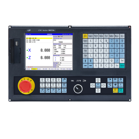
SZGH-CNC990TDb(c)
(series)
Lathe Control System
V1.2
Shenzhen Guanhong Automation CO.,LTD
Website:
www.szghauto.com
Add:Room 503 Anxin Building, No 536 Shenhui Road, Liuyue community, Henggang Street ,Longgang
District, Shenzhen City,Guangdong Province, ChinaProvince, China
Post code: 518115
Summary of Contents for Shenzhen Guanhong Automation SZGH-CNC990TDb series
-
Page 1
User Manual SZGH-CNC990TDb(c) (series) Lathe Control System V1.2 Shenzhen Guanhong Automation CO.,LTD Website: www.szghauto.com Add:Room 503 Anxin Building, No 536 Shenhui Road, Liuyue community, Henggang Street ,Longgang District, Shenzhen City,Guangdong Province, ChinaProvince, China Post code: 518115… -
Page 2: Table Of Contents
-Shenzhen Guanhong Automation Co.,Ltd.- SZGH-CNC990TDb(c) Series CONTENTS Chapter 1 Preface…………………………1 Chapter 2 System technical features……………………2 2.1 System constructions……………………….2 2.2 System technical parameter……………………… 2 2.3 System function…………………………2 2.4 System operation condition……………………… 3 Chapter 3 Operation explanation……………………. 4 3.1 Panel layout and switch(Two types)…
-
Page 3
-Shenzhen Guanhong Automation Co.,Ltd.- SZGH-CNC990TDb(c) Series (15) Screw thread loop (G92)………………………. 70 (16) Fixed cycle of tapping (G93)……………………..74 (17) End face loop(G94)……………………….75 (18) Fix loop (G22,G800)……………………….77 (19) Back start point(G26,G261,G262,G263,G264)………………..77 (20) Back to G25 point(G25,G61,G611/G612/G613/G614)………………77 (21) Return Reference (G28/G281/G282/G283/G284/G285/M800/ M881)…………78 (22) Setup workpiece coordinate system (G50)…………………. -
Page 5: Chapter 1 Preface
-Shenzhen Guanhong Automation Co.,Ltd.- SZGH-CNC990TDb(c) Series Chapter 1 Preface This CNC control system is one middle class flush type CNC control system, aiming specially at lathe and grinding machine. Based on modern computer technology, system move control core & PLC program running technology, and stable unique real time control engine subsystem PTAI, this system ensures the stabilization of operation.
-
Page 6: Chapter 2 System Technical Features
-Shenzhen Guanhong Automation Co.,Ltd.- SZGH-CNC990TDb(c) Series Chapter 2 System technical features 2.1 System constructions 32 bits high performance,high speed, low power consumption industrial grade ARM microprocessor. 64MB memory. 32Mb user store room. 640×480 8 inch real color LCD Displayer. Touch screen main and sub panel.
-
Page 7: System Operation Condition
-Shenzhen Guanhong Automation Co.,Ltd.- SZGH-CNC990TDb(c) Series program cycle, jump, call and different program ending. multiple positioning instruction:starting point,setting fixed point,etc. Linear, circular, spiral line interpolation instruction. program management instructions: program cycle, call, transfer and different program ending method, etc. 6 workpiece coordinates system .
-
Page 8: Chapter 3 Operation Explanation
-Shenzhen Guanhong Automation Co.,Ltd.- SZGH-CNC990TDb(c) Series Chapter 3 Operation explanation When using the CNC system, just master the parameter of system, edit program, manual operation, auto operation. Then you can operate the system easily. There are some details to instruct hereinafter.
-
Page 9
-Shenzhen Guanhong Automation Co.,Ltd.- SZGH-CNC990TDb(c) Series There are sixteen gears in feed override from 0% to 150%, by adjusting the key of feed override is for the following instruction:G01,G02,G03, the feed override of the fixed cycle and manual run effectively. -
Page 10: Manual Operation
-Shenzhen Guanhong Automation Co.,Ltd.- SZGH-CNC990TDb(c) Series “ ”spindle cw, ccw rotation “ ” coolant on/off “ ”for the shift between electric tool carrier and gang tool carrier “ ” for the shift between hand-driven continuous high speed and low speed.
-
Page 11
-Shenzhen Guanhong Automation Co.,Ltd.- SZGH-CNC990TDb(c) Series parameters. In manual condition,the system could process workpiece. 3.3.1 The key of manual operation (1) “F”: Taking mm/min as the unit to set the manual feed speed, the input range is from 1 to 30000mm/min. -
Page 12
-Shenzhen Guanhong Automation Co.,Ltd.- SZGH-CNC990TDb(c) Series Press the principal axis stop,display M05.At this condition,users can press the key to turn off or turn on. Press M03 turn on point for while. Press the coolant to turn on or turn off. -
Page 13
-Shenzhen Guanhong Automation Co.,Ltd.- SZGH-CNC990TDb(c) Series (21) “Coordinates feed”: Press “↑ ↓ ← →”correspond to feed A axis and Z axis’s positive or negative direction. (22) “Switch speed”: Press to switch the speed to system speed which is changed by No.1 No.2 parameter in speed parameter when it is in coordinate feed, loosen it that will be the… -
Page 14
-Shenzhen Guanhong Automation Co.,Ltd.- SZGH-CNC990TDb(c) Series of coordinate detects zero point and return to the pulsing signal of “Zero”, the data of lathe’s coordinate will be 0 automatically. Switch on the power supply of the system, release alarm and the button of emergency after the CNC is power off, the need to back to datum point to set lathe’s coordinate correctly. -
Page 15
-Shenzhen Guanhong Automation Co.,Ltd.- SZGH-CNC990TDb(c) Series Special Attention: Every time to power up the system must back to zero point to make sure the accuracy of lathe process. The system power off unusually or in an accident, it must back to zero point, otherwise could cause trouble. -
Page 16: Auto Operation
-Shenzhen Guanhong Automation Co.,Ltd.- SZGH-CNC990TDb(c) Series (6) Measure the diameter of workpiece(cylinder or bore). (7)Press “X” and import the above value of measurement into dialog box, press “Enter” to confirm. (8) Use the same method to cut end surface of workpiece. Stop feeding.
-
Page 17
-Shenzhen Guanhong Automation Co.,Ltd.- SZGH-CNC990TDb(c) Series arbitrary tool must use absolute coordinate to edit the program. Auto operation can’t move the manual coordinate. Running program selection: In the program interface, press “↑ ↓” to move the cursor to a program which is going to be carry out, press “C”key to select the program to carry out automatically. -
Page 18
-Shenzhen Guanhong Automation Co.,Ltd.- SZGH-CNC990TDb(c) Series The system has a function to run at some tool. At automatical process condition, press “G” and the number of tool to run(only the number of tool, not the number of compensation; Like: 0304, just import “03”), press “Enter”… -
Page 19
-Shenzhen Guanhong Automation Co.,Ltd.- SZGH-CNC990TDb(c) Series axis parameter is 1, external band switch takes in control, Adjust the speed of spindle arbitrarily in the process according to the different situation. (5) Stop in the process: At the continuous mode in process condition, press “… -
Page 20: Operate Safety, Prompt Alarm
-Shenzhen Guanhong Automation Co.,Ltd.- SZGH-CNC990TDb(c) Series the sending speed of PC as the NC, defeat otherwise. B. Instruction of USB-DNC USB-DNC is realized by U-disk, switch on U-disk and system, select program to execute in U-disk. Press “F6” to open U-disk in program interface, select corresponding program to press “F7” to execute program, press “Auto”…
-
Page 21: Parameters
-Shenzhen Guanhong Automation Co.,Ltd.- SZGH-CNC990TDb(c) Series (8) Emergency stop: Press the button of emergency stop. 3.6 Parameters At any status conditions, press “parameter” to enter the status to set the parameter. Parameter in this system includes “N-User parameter” “J-Speed parameter” “V-Axis parameter” “Q-Tool parameter”…
-
Page 22
-Shenzhen Guanhong Automation Co.,Ltd.- SZGH-CNC990TDb(c) Series 17,Running program need Sp run [1 mean Yes,0 mean No] 18,Set M20 the time of auto-running [Negative number mean immensity loop] 19,Set part count 20,G92 quit length(1/10 lead) 21,G01/G02/G03 line delay(ms)[>100] 22,G00 line delay(ms)[>100]… -
Page 23: Speed Parameter
-Shenzhen Guanhong Automation Co.,Ltd.- SZGH-CNC990TDb(c) Series 11,G76 finish turn times It is for default cycle times when it isn’t be set in G76 code.(times:1-99) 12,G76 quit length(1/10 lead) It is for default length of retract chamfer when it isn’t be set in G76 code.the length is 1/10 of thread lead.
-
Page 24
-Shenzhen Guanhong Automation Co.,Ltd.- SZGH-CNC990TDb(c) Series 5,G01/G02/G03 default speed(mm/min) 6,Null run speed(mm/min) 7,Feed axis`s manual speed(mm/min) 8,Spindle`s manual speed(rpm) 9,Beginning feed speed(mm/min) 10,Jump speed at continuous track(mm/min) 11,Limit G1G2G3 axis speed [1 mean Yes,0 mean No] 12,X G1G2G3 max speed(mm/min) -
Page 25
-Shenzhen Guanhong Automation Co.,Ltd.- SZGH-CNC990TDb(c) Series 1,X-axis’s G00 speed(mm/min) 2,Z-axis’s G00 speed(mm/min) It is rapid speed(also speed of G00) of X/Z axis,Max is 30000(unit:mm/min) Attention: the value depends on machine configuration,set wrong is very easy to trouble machine & accident. -
Page 26
-Shenzhen Guanhong Automation Co.,Ltd.- SZGH-CNC990TDb(c) Series Attention:This value depends on the machine structure,the heavier the load is ,the smaller the value is.With stepper system,the value should less than 15000. 16,Auto run acceleration [1-500] It is for set constant of acc/dec-eleration in auto.the range is 1-500.It is mainly for distinguish Auto and Manual,only the difference is too much,set it is effective. -
Page 27
-Shenzhen Guanhong Automation Co.,Ltd.- SZGH-CNC990TDb(c) Series It is valid when >=500,otherwise the ace/dec-eleration constant is with line type of each axis. 31,X go home rampit speed(mm/min) It is running speed when X-axis go home in forward direction.Unit:mm/min. the range is less than the G00 speed of X-axis. -
Page 28: Axis Parameter
-Shenzhen Guanhong Automation Co.,Ltd.- SZGH-CNC990TDb(c) Series It is the speed when handwheel stop.the bigger it is ,the shorter the stop time is. 58,Forcedly limit drop speed critical(mm/min) It is starting drop speed when it is force limit.when servo system, it is 1.
-
Page 29
-Shenzhen Guanhong Automation Co.,Ltd.- SZGH-CNC990TDb(c) Series 102,lathe C axis function[0 mean circumrotate axis,1 mean linear axis] 103,lathe C is circumrotate axis ,the machine coordinate : [0 Null;1 absolute coordinate plan,2 tool coordinate,3 All] 104.C(Y)-axis’s direction signal:[1 mean normal,0 mean reverse] 105.C(Y)-axis’s electron gear numerator(1-32767) -
Page 30
-Shenzhen Guanhong Automation Co.,Ltd.- SZGH-CNC990TDb(c) Series It is for whether the system check the signal of spindle encoder,also the spindle’s position feedback. When 1 mean check ,o mean no check.the spindle gear ration must be 1:1 with spindle encoder. 10,SP encode pulse It is feedback pulses of each rev of spindle encoder.also lines of SP-encoder) * 4. -
Page 31
-Shenzhen Guanhong Automation Co.,Ltd.- SZGH-CNC990TDb(c) Series 5mm,then: CMR/CMD = 5000 / (5 * 1000 ) = 1/ 1 That is to say,we can set the values as :CMR=1,CMD=1. Here ,the pulse equivalent is 0.001mm. Example2: The motor rotates one circle very 5000 pulses,after which the machine tool moves 10mm. -
Page 32
-Shenzhen Guanhong Automation Co.,Ltd.- SZGH-CNC990TDb(c) Series Attention:the value must be less than the length of one rev,otherwise,go wrong home. 31,Z check zero max length(unit:100um) It is the length that check zero pulse of encoder when go home and after disengaged switch. -
Page 33
-Shenzhen Guanhong Automation Co.,Ltd.- SZGH-CNC990TDb(c) Series It is time constant of Y-axis acc/dec-eleration,the bigger it is ,the faster the ace/dec-eleration is. Attention:This value depends on the machine structure,the heavier the load is ,the smaller the value is.With stepper system,the value should less than 15000. -
Page 34: Tool Parameter
-Shenzhen Guanhong Automation Co.,Ltd.- SZGH-CNC990TDb(c) Series 3.6.4 Tool parameter 1,Active tool function : [1 mean Yes,0 mean No] It is for whether activate electric turret(tool). Attention: 1.when the machine is with linear turret , ,the parameter be set as 0;…
-
Page 35
-Shenzhen Guanhong Automation Co.,Ltd.- SZGH-CNC990TDb(c) Series 11,Program edit number increase 12,Inner parameter 13,Does lock for Spindle & chuck(0 mean no) 14,Is available keys of lubricate&coolant as running(0 mean no) 15,Chuck clamp M10/loose M11 checking(1 mean need) 16,Finial forward M79/backward M78 checking(1 mean need) -
Page 36
-Shenzhen Guanhong Automation Co.,Ltd.- SZGH-CNC990TDb(c) Series 301,absolute encoder adress of lower 16bits muti-turn data 302,absolute encoder address of higher 16bits one-revolution data 303, absolute encoder address of lower 16bits one-revolution data 304, X-axis one resolution pulse 306, Z-axis one resolution pulse… -
Page 37
-Shenzhen Guanhong Automation Co.,Ltd.- SZGH-CNC990TDb(c) Series D2:“1”Automatic space before letter when edit program; D3:Null;the default is 0,it cannot be altered. D4:Null;the default is 0,it cannot be altered. D5:“1”Do not stopping SP and cooling when pressing “Restet”; D6:“1”G00 XZ’speed by oneself;… -
Page 38
-Shenzhen Guanhong Automation Co.,Ltd.- SZGH-CNC990TDb(c) Series 18,SP ALM1 (0 open,1 close) It is the type that system check ALM1 of Spindle(Pin5 in CN3),1 mean normal close,0 open. 19,Tool ALM2 (0 open,1 close) It is the type that system check ALM2 of tool(Pin2 in CN10),1 mean normal close,0 open. -
Page 39
-Shenzhen Guanhong Automation Co.,Ltd.- SZGH-CNC990TDb(c) Series 31,Is enable I/O PLC program It is for set running condition of system inner PLC,1 means ON,0 means OFF. Attention:it is usally used as adjusting parameter,it must be ON when actual use, otherwise system will abnormal. -
Page 40: Work Coordinate Parameter
-Shenzhen Guanhong Automation Co.,Ltd.- SZGH-CNC990TDb(c) Series valid when it >1). #205/#206/#207/#208 stand for X/Y/Z/A-axis. Press “G”key in Diaginous to clear alram and command & feedback’s position after alarm. 210, X-axis’s electron gear numerator[auto count: L screw(um)M encoder pulse] The paramter is numerator of X-axis electron gear,and also input screw lead and encoder lines,for example,when screw leas is 6mm,encoder’s resolution is 2500PPR,input : L6000M2500.
-
Page 41
-Shenzhen Guanhong Automation Co.,Ltd.- SZGH-CNC990TDb(c) Series In Lathe System,normally we only need one coordinate system(G53 coordinate system), also Machine Coordinate System. This parameter coordinate multiple functions, namely six workpiece coordinate system and a machine coordinate system G53. A machining program can set a workpiece coordinate system can also be set up multiple workpiece coordinate system, the workpiece coordinate system can be changed to move its origin. -
Page 42: Password
-Shenzhen Guanhong Automation Co.,Ltd.- SZGH-CNC990TDb(c) Series dialog,input the offset value(also Increments,example:offset 10mm in negative direction,also input -10),press “Enter”.It is okay. Explanation:1.when the parameter is altered well,the coordinate main screen will refresh the corresponding coordinate value soon. 2.brackets in these parameters,it means the sum ,which is offset or adjust every time.It is suitable to look for the offset every time.
-
Page 43
-Shenzhen Guanhong Automation Co.,Ltd.- SZGH-CNC990TDb(c) Series set adopt radius of the tool’s top. Setting method: Press “↑ ↓” to make cursor move to the corresponding tool and press “Enter” to popup a dialog box, input corresponding tool radius, press “Enter” at last. -
Page 44
-Shenzhen Guanhong Automation Co.,Ltd.- SZGH-CNC990TDb(c) Series The nose of tool point(A) is non-existent actually as follow picture. Setting posit tool is easier than setting actual center of tool (Hereinafter). Using posit tool to programmed do not need to consider the tool radius. The tool in the origin of the position relation as shown below. -
Page 45: Screw Compensation
-Shenzhen Guanhong Automation Co.,Ltd.- SZGH-CNC990TDb(c) Series of posit tool can be selected by the 8 kinds of corresponding number as shown below. The direction of posit tool of backward tool rest The direction of posit tool of forward tool rest Using No.0 posit tool or No.9 when the central nose of tool is coinciding with starting position.
-
Page 46
-Shenzhen Guanhong Automation Co.,Ltd.- SZGH-CNC990TDb(c) Series compensate the influence from the error of screw pitch to the prevision of operating Milling. The system adopts storage mode of screw compensation: Making the Milling’s datum point as the starting point when debugging, measured the error curve of screw, studied out the correctional curve according to the error curve, import the value of correctional curve into the correctional parameter and system is going to compensate according to the parameter in automatical running. -
Page 47
-Shenzhen Guanhong Automation Co.,Ltd.- SZGH-CNC990TDb(c) Series Enter the screw pitch interface and set basic parameter, press checking program to popup a dialog box and press “Enter” to generate corresponding checking program of screw compensation. The number of compensation points can be set freely, the maximum of each axis is 300 points. -
Page 48: Input/Output Diagnosis
-Shenzhen Guanhong Automation Co.,Ltd.- SZGH-CNC990TDb(c) Series Example 2:rotor axis: when movement per revolution is 360°,interval of points 45°,reference point compensation NO. 60, Compensation point NO. of farthest end in negative direction is usually same as reference point compensation point NO.
-
Page 49
-Shenzhen Guanhong Automation Co.,Ltd.- SZGH-CNC990TDb(c) Series information. System Diagnosis Interface(Input signal) System Diagnosis Interface(output signal) Checking interface of output signal In the interface of output or input, No.0 or No.1 stands for status, 1 means effective, 0 means no effect. -
Page 50: Operation Of Program
-Shenzhen Guanhong Automation Co.,Ltd.- SZGH-CNC990TDb(c) Series System Diagnosis Interface(Alarm messages) The first line in this interface shows the number of spindle encoder, the number of current and historical alarm information is record total 10, the superfluous part is clear automatically, only shows 10 alarm information recently.
-
Page 51
-Shenzhen Guanhong Automation Co.,Ltd.- SZGH-CNC990TDb(c) Series Center part of screen for program display,current program is showed by reverse display, move PgUp、PgDn to choose program, and then press“Enter”to edit current program. Functional keys ‘N’,‘T’,‘R’,‘Q’,‘A’,‘B’,‘C’,‘D’ include : “New /Search for program” ,“Copy”… -
Page 52
-Shenzhen Guanhong Automation Co.,Ltd.- SZGH-CNC990TDb(c) Series the letter,the letter in front of automatically generating space. If you want to enter a space, first enter a letter, and then delete this letter. (4) The character deletion: Press «Del» directly at the cursor position (5) Inset the line: Press «Enter»… -
Page 53
-Shenzhen Guanhong Automation Co.,Ltd.- SZGH-CNC990TDb(c) Series popup a dialog box to import a new name of program, to copy which is the same content but different name so that to modify, rename and back-up copy. 3.10.3 Delete Press “↑ ↓” in program main interface to select program which need to delete and press “Del”… -
Page 54
-Shenzhen Guanhong Automation Co.,Ltd.- SZGH-CNC990TDb(c) Series connects the USB port. Press “B” again to back to the system interface. A. The processing program management Copy the files or folder of U-disk into system After connecting the U-disk, press “B” to enter the U-disk directory in program main interface. -
Page 55: Chapter4 Programming
-Shenzhen Guanhong Automation Co.,Ltd.- SZGH-CNC990TDb(c) Series Chapter4 Programming Programming refers to process of using cnc language to describe machining track and actions based on the machining blueprint and technique requirement. 4.1 basic concepts program segment: is a complete command line consisted of instruction segment and data segment.
-
Page 56: Program Instruction
-Shenzhen Guanhong Automation Co.,Ltd.- SZGH-CNC990TDb(c) Series 4.2 Program instruction 4.2.1 Functional meaning of address symbol, data list. Functions Address Meaning Data range symbol Program segment No No of program segment Preparation function Content and mode of designalated 00-99 instruction operation…
-
Page 57
-Shenzhen Guanhong Automation Co.,Ltd.- SZGH-CNC990TDb(c) Series end face loop √ loop end √ G800 cancel loop √ ALL-Axis go starting point √ G261 X-Axis go starting point √ G262 Y-Axis go starting point √ G263 Z-Axis go starting point √… -
Page 58
-Shenzhen Guanhong Automation Co.,Ltd.- SZGH-CNC990TDb(c) Series Spindle on CCW √ Spindle Stop √ √ Coolant ON √ lant Coolnat OFF √ √ Chuck Tightens √ √ Chuck Looses √ Tailstock Forward √ Tailstock Backward √ √ Lubrication ON √ Lubrication OFF √… -
Page 59: Preparation Functions
-Shenzhen Guanhong Automation Co.,Ltd.- SZGH-CNC990TDb(c) Series Return No. Of workpiece plus one In Other parameter, P10=0, not +1 auto. Or Program Pause M87,no. of workpiece+1 Program Stop when input M22 Auto. End of Program M05,M09 end of program End and Restart program…
-
Page 60: Line Interpolation(G01)
-Shenzhen Guanhong Automation Co.,Ltd.- SZGH-CNC990TDb(c) Series Absolute program: G00 X20 Z0; Relative program: G00 U-60 W-40; attention: The nearest calculation when using absolute coordinate of rotating axis to programming, calculation by programming when using relative coordinate; G00 of every axis is set by parameter,the specified feeding speed with F is invalid. The speed rate of G00 can be divided into 5%~100%, total six gears, it can be selected by the key on panel.
-
Page 61: Screw Thread (G32)
-Shenzhen Guanhong Automation Co.,Ltd.- SZGH-CNC990TDb(c) Series G02 stands for Circular clockwise interpolation, and G03 for Circular counterclockwise interpolation. When tool system in different position,the direction is different. I is the 2 times of increment of X axis which is from starting point to center of circle (needless to double it when X axis is radius programming), K is the increment of Z axis which starting point to center of circle, and X Z are the terminal coordinates.
-
Page 62
-Shenzhen Guanhong Automation Co.,Ltd.- SZGH-CNC990TDb(c) Series Trapezoidal thread: offset the angle of SP in the second loop. Variable lead thread : continuous input G32 command, enter a thread length of each program, lead of thread(F) is different , the second cycle will not begin to detect the encoder synchronization signal. -
Page 63: Circularity Screw Thread(G332/G333)
-Shenzhen Guanhong Automation Co.,Ltd.- SZGH-CNC990TDb(c) Series G32 W-74.5 F4.0; G00 U62; W74.5; U-64; G32 W-74.5; G00 U64.0; W74.5; …… For example3: ..G00 X12 Z3.0; G32 X41.0 Z-41.5 F3.5; G00 X50; Z3; X10; G32 X39 Z-41.5;…
-
Page 64: Finish Machining Loop (G70)
-Shenzhen Guanhong Automation Co.,Ltd.- SZGH-CNC990TDb(c) Series Only one difference,if no detect signal,G311 will alarm hint,G31 no alarm and on. P:Line no. of jump, (no input X30-X39,jump to next),N line+(X00/X39+1000 or 2000),1000 means availability,then jump, 2000 mean invalidation,then jump. Example: G31 X50 Z100 F100 P331022 ;if X22 is valid then go to N33(line no.).
-
Page 65
-Shenzhen Guanhong Automation Co.,Ltd.- SZGH-CNC990TDb(c) Series N10 M03 S2000; N20 T0202; N30 G00 X176 Z2; N40 G72 W2 R1; N50 G72 P60 Q120 U2 W1 F100 ; N60 G00 Z-72; N70 G01 X160 Z-70 F80; N80 X120 W10; N90 W10;… -
Page 66: Column Thick Loop (G71)
-Shenzhen Guanhong Automation Co.,Ltd.- SZGH-CNC990TDb(c) Series N40 G73 U14 W14 R0.010; N50 G73 P60 Q110 U4 W2 F100; N60 G00 X80 Z2; N70 G01 Z-20 F80; N80 X120 W-10; N90 W-20; N100 G02 X160 W-20 R20; N110 G01 X180 W-10;…
-
Page 67: End Face Thick Loop(G72)
-Shenzhen Guanhong Automation Co.,Ltd.- SZGH-CNC990TDb(c) Series movement instruction. Attention 5: In program segment of NS to NF, can’t call subprogram. Attention 6: Use G71 to cut shape, four method as follows, the four mode is cutting according to the tool which is parallel Z axis, △ u, △ w fine machining allowance, as shown below:…
-
Page 68: Close Cutting Loop(G73)
-Shenzhen Guanhong Automation Co.,Ltd.- SZGH-CNC990TDb(c) Series Between A and A `, the program segment ns could contain G00 or G01, but can not contain X axis instruction, between A ` to B, the X and Z axis must be all increase or decrease graph, that’s a direction to increase or decrease.
-
Page 69: Slot Cutting Loop(G75)
-Shenzhen Guanhong Automation Co.,Ltd.- SZGH-CNC990TDb(c) Series For example: N10 G00 X0 Z10; N20 G74 R2; N30 G74 Z-80 Q10000 F800; N40 G00 X50 Z50; N50 M30; (12) Slot cutting loop(G75) Format: G75 R(e)_; G75 X(U)_ P(Δi)_ Z(w)_ Q(△k)_ F(f)_; e: backward distance;User parameter P10.
-
Page 70: Complex Screw Thread Loop(G76)
-Shenzhen Guanhong Automation Co.,Ltd.- SZGH-CNC990TDb(c) Series N80 T0100; N90 M30; (13) Complex screw thread loop(G76) As fig: Cutting method: Format: G76 P(b)(c)(m)(r)(a) Q(Δdmin) R(d) ; G76 X(U) Z(W) R(i) P(k) Q(Δd) F(f) L(L)[or SP]; B: 0———digression feed; 1———equidistance feed; 2———If the fist feed is too long in digression feed,so divide into two feed.
-
Page 71
-Shenzhen Guanhong Automation Co.,Ltd.- SZGH-CNC990TDb(c) Series Δd: First cut amount (with G32 threading) in microns; or feed times. P24 G76 parameters specified by the user of the Q (Δd) meaning [P24 = 8 roughing infeed table number]. When this parameter P24 = 8, the address of the word Q (Δd) says many times as needed to complete the roughing cycle, the default is 1;… -
Page 72: Column Or Taper Loop(G90)
-Shenzhen Guanhong Automation Co.,Ltd.- SZGH-CNC990TDb(c) Series executed. (d) in the program segment of G70, G71, G72, G73 and the program segment between P and Q,could not specify M98/M99. (e) In the program segment of G70, G71, G72, G73, can not have the following instruction within the program segment which is specified by P and Q.
-
Page 73
-Shenzhen Guanhong Automation Co.,Ltd.- SZGH-CNC990TDb(c) Series N70 G00 X100 Z100 ; N80 T0100 M09 ; N90 M05 ; N100 M30 ; Every cycle is backing to the starting point at the above program, so cause the situation of cutting endface A agin,modify the cycle part program as follow in order to improve efficiency: N50 G90 X45 Z-25 F100;… -
Page 74: Screw Thread Loop (G92)
-Shenzhen Guanhong Automation Co.,Ltd.- SZGH-CNC990TDb(c) Series (15) Screw thread loop (G92) Use G92 instruction, you can thread cutting process, from initial point of departure «cut — cut thread — let the knife — return thread machining starting point,» the four movements as a loop, with a block command to complete.
-
Page 75
-Shenzhen Guanhong Automation Co.,Ltd.- SZGH-CNC990TDb(c) Series N70 X28.04; N80 G00 X100 Z50; N90 T0100 M05; N100 M30; (2)Taper screw thread loop format: G92 X(U)_ Z(W)_ R_ F/I_ ; Cycle as shown in Fig, R is the X-axis direction in the thread cutting start point and the radius of the thread cutting end point difference. -
Page 76
-Shenzhen Guanhong Automation Co.,Ltd.- SZGH-CNC990TDb(c) Series system requires this value is less than 5000mm/min, such as: When processing F2, S1200,this value should be less than 20. (3) Deceleration or acceleration control in cutting thread cycle: At the end of thread, because of the index of deceleration control,cause the distance of pitch is inhomogeneous,the higher speed of spindle the longer of inhomogeneous pitch. -
Page 77
-Shenzhen Guanhong Automation Co.,Ltd.- SZGH-CNC990TDb(c) Series (5)Thread backs tail when fixed cycle in cutting thread Program format: G92 X Z F/I P; P: volume of backing tail: the default value of P could be set by P20 in User parameter (Default when powering on). -
Page 78: Fixed Cycle Of Tapping (G93)
-Shenzhen Guanhong Automation Co.,Ltd.- SZGH-CNC990TDb(c) Series 4)Taper cutting cycle of the end face G94: Attention 1: The data X(U)、 Z (W) 、 R are all mode value in fixed cycle of G90 G92 G94, the front data is always effective when there is not new specified X(U),Z(W),R, except the screw pitch I in inch thread process.
-
Page 79: End Face Loop(G94)
-Shenzhen Guanhong Automation Co.,Ltd.- SZGH-CNC990TDb(c) Series 2), Enter G19 into the program segment of X tapping,enter G17 into the program segment of Z tapping, enter G18 into the next program segment after finish tapping. For example: G93 G19 X-100 F2…
-
Page 80
-Shenzhen Guanhong Automation Co.,Ltd.- SZGH-CNC990TDb(c) Series For example: N10 M03 S1000; N20 T0101; N30 G00 X85 Z10 M08; N40 G01 Z5 F200; N50 G94 X30 Z-5 F100; N60 Z-10; N70 Z-15; N80 G00 X100 Z60 M09; N90 T0100 M05; N100 M30;… -
Page 81: Fix Loop (G22,G800)
-Shenzhen Guanhong Automation Co.,Ltd.- SZGH-CNC990TDb(c) Series …… N40 G01 X55 Z2 F200; N50 G94 X20 Z0 R-5 F100; N60 Z-5; N70 Z-10; N80 G00 X Z; …… R-5 in N50 program: R-5=-15-(-10)=-5mm= (18) Fix loop (G22,G800) G22 is a program loop instruction, G800 is the end of the cycle instruction. Both must be paired for parts machining process requires repeated occasions.
-
Page 82: Return Reference (G28/G281/G282/G283/G284/G285/M800/ M881)
-Shenzhen Guanhong Automation Co.,Ltd.- SZGH-CNC990TDb(c) Series Format: G25 ;Save current coordinate G61、G611、G612、G613、G614、G615; XZ, X,Y,Z,A,B For example: N0000 G0 X20 Z80 ; N0001 G01 U5 W-16 F200 ; N0002 W-100 ; N0003 G00 U10 ; N0004 Z80 ; N0005 G25 N0006 G01 U10 W-30 ;…
-
Page 83: Setup Workpiece Coordinate System (G50)
-Shenzhen Guanhong Automation Co.,Ltd.- SZGH-CNC990TDb(c) Series attention: 1. After turning on the power, if not process back to datum point manually at a time.When the instruction is G28,the motion from middle point to datum point is the same as backing to datum point manually.
-
Page 84: Constant Speed Cutting(G96/G97)
-Shenzhen Guanhong Automation Co.,Ltd.- SZGH-CNC990TDb(c) Series For example: N1 G00 X60 Z20 N2 G52 X0 Z-236 N3 T0101 N4 M03 S800 M08 N5 G01 Z35 F100 N6 X-1 N7 X70 N8 G71 U2 R1 N8 G71 P10 Q15 U0.5 W0.5 F150…
-
Page 85: Feed Mode(G98,G99)
-Shenzhen Guanhong Automation Co.,Ltd.- SZGH-CNC990TDb(c) Series Press «absolute coordinate» to change the spindle speed in the status of constant linear speed G96. Attention: G96: constant linear speed effective G97: cancel the function of constant linear speed G50 S: limit the maximum speed of spindle.
-
Page 86: Switch Millimeter And Inch(G20/G21)
-Shenzhen Guanhong Automation Co.,Ltd.- SZGH-CNC990TDb(c) Series Radius with absolute command value instruction (Z), the angle with absolute command (X). Format: ;cancel G16 IP-(XZ) ; pole coordinate For example: N1 G16 X0 Z0 N2 G01 X30.0 Z100.0 F200.0 N3 X150.0 N4 X270.0…
-
Page 87: Continue Feed Cutting(G60/G64)
-Shenzhen Guanhong Automation Co.,Ltd.- SZGH-CNC990TDb(c) Series c.Example: G04 X1; delay 1s. G04 P1000; delay 1s. G04 U1; delay 1s. d.Special application:G04 can be accurate stop instruction, such as processing corner kinds of workpiece, it appears over cutting sometimes, if use G04 instruction around the corner, it will clear the over cutting.
-
Page 88
-Shenzhen Guanhong Automation Co.,Ltd.- SZGH-CNC990TDb(c) Series Left and right compensate Tool parameter Attention:(1)G41/G42 without parameters, the compensation number (on behalf of the tool tip radius compensation corresponding values) specified by the T code. Its tip arc offset number and tool offset number corresponding compensation.Establish and canceled . -
Page 89: Work Coordinate(G53/G54/G55/G56/G57/G58/G59)
-Shenzhen Guanhong Automation Co.,Ltd.- SZGH-CNC990TDb(c) Series N9 G00 X30 N10 G40 X40 Z5 N11 M30 (31) Work coordinate(G53/G54/G55/G56/G57/G58/G59) Used to select the workpiece coordinate system or machine coordinate system. Format: G53(G54/G55/G56/G57/G58/G59) G53 machine coordinate G54 workpiece coordinate1 G55 workpiece coordinate 2…
-
Page 90
-Shenzhen Guanhong Automation Co.,Ltd.- SZGH-CNC990TDb(c) Series 1) Inside and outside It calls inside when the included angle of tool trajectory is over 180 degrees which is built by two program segments, it calls outside when the included angle is between 0 and 180 degrees. As… -
Page 91
-Shenzhen Guanhong Automation Co.,Ltd.- SZGH-CNC990TDb(c) Series A type B type Straight line->Arc A type B type 3) Tool motion in offset mode (a)Tool motion around the inside corner(180≤α) Straight line->Straight line Straight line->Arc Arc-> Straight line Arc->Arc (b)The tool motion around the outside corner of obtuse angle(90≤α<180)… -
Page 92
-Shenzhen Guanhong Automation Co.,Ltd.- SZGH-CNC990TDb(c) Series Arc-> Straight line Arc->Arc (c)The tool motion around the outside corner of acute angle(α<90) Straight line->Straight line Straight line->Arc Arc-> Straight line Arc->Arc 4) Tool motion in offset-cancel mode (a) Tool motion around the inside corner(180≤α)… -
Page 93: Automatical Beveling (I) And Smoothing(R)
-Shenzhen Guanhong Automation Co.,Ltd.- SZGH-CNC990TDb(c) Series Arc->Straight line A type B type (c)The tool motion around the outside corner of acute angle(α<90) The tool center will move to the tool vector radius vertex of the starting point in next program line.
-
Page 94: G01(G00) Z R Automatical Smoothing, The Coordinate In The Next Program Segment Must Be G01(G00) Y
-Shenzhen Guanhong Automation Co.,Ltd.- SZGH-CNC990TDb(c) Series G01(G00) Z. G01(G00) Z I automatical beveling, the coordinate in the next program segment must be G01(G00) X. G01(G00) X R automatical smoothing, the coordinate in the next program segment must be G01(G00) Z.
-
Page 95
-Shenzhen Guanhong Automation Co.,Ltd.- SZGH-CNC990TDb(c) Series M98 P L unconditionally subroutine call instruction. P subroutine path and name specified procedure call, L refers to a subroutine call number address. The M98 instruction can be omitted without writing, format: PP file name, the file name can be hidden files, hidden files first character must be a «HIDEFILE»… -
Page 96: Conditional Wait, Jump Instruction
-Shenzhen Guanhong Automation Co.,Ltd.- SZGH-CNC990TDb(c) Series (35) Conditional wait, jump instruction The system of M code is used for detecting the external input signal as the condition, as follows: Conditions wait M12 M13 instruction are used to detect the input signal M12, M12 in program line is to detect M12 input signal is effective to execute the next program line , M13 means to detect M12 input signal is invalid to execute the next program line.The instruction is in an independent line.
-
Page 97: F Feed Speed
-Shenzhen Guanhong Automation Co.,Ltd.- SZGH-CNC990TDb(c) Series F is used for specify the processing speed of feeding instruction G01 G02 G03. The range is 0.01-15000mm/min,feeding speed is Fx trimming speed, F has mode function. Executing the F instruction at the first, and then execute the motion instruction when the F instruction and motion instruction are in the same line.
-
Page 98
-Shenzhen Guanhong Automation Co.,Ltd.- SZGH-CNC990TDb(c) Series 4) The macro variables #1001—#1099 corresponds the X axis offset value of lathe T1—T99(Unit: micron) The macro variables #1401—#1499 corresponds the Z axis offset value of lathe T1—T99(Unit: micron) Could read the value, for example: #200=#1003; To read the X axis offset value of the third tool into macro variables #200. -
Page 99
-Shenzhen Guanhong Automation Co.,Ltd.- SZGH-CNC990TDb(c) Series 5. Unconditional transfer: GOTO N Transfer to the program line with sequence number appears error when specifying beyond the 1-99999, could use expression to specify the sequence number. For example: GOTO 5, GOTO#100 6.Conditional transfer: IF (Conditional expression) GOTO or THEN If the conditional expression specified met, execute this segment;… -
Page 100: User-Defined Macro Instruction(G120-G160,M880-M889)
-Shenzhen Guanhong Automation Co.,Ltd.- SZGH-CNC990TDb(c) Series Macro program:8000 N1 #2=#0+#1 N2 IF (#2 EQ 10)GOTO 4 N3 GOO X#2 N4 G00 Z#1 N5 M99 ;Return 9.Mode to call macro program:G66 G67 G67 instruction is to cancel G66 instruction.The format is the same as G65.
-
Page 101: Synthetic Instance For Programming
-Shenzhen Guanhong Automation Co.,Ltd.- SZGH-CNC990TDb(c) Series #83=#3 #84=#4 #85=#5 #86=#6 #87=#7 #88=#8 #89=#9 #90=#10 #91=#11 #92=#12 #93=#13 #94=#14 #95=#15 #96=#16 #97=#17 #98=#18 #99=#19 #100=#20 #30=#4003 #31=#4014 IF[#30 EQ 90] GOTO 1 #98=#5001+#98 #99=#5002+#99 N1 WHILE[#86 GT 0] DO 1 #35=#98+#87*COS[#80]…
-
Page 102
-Shenzhen Guanhong Automation Co.,Ltd.- SZGH-CNC990TDb(c) Series Program as follows: N10 M03 S1000; Start spindle N20 T0101; Choose the first tool and execute the first redeem N30 G00 X41.8 Z2 M08; Move fast to the cutting point,cutting fluid is on N40 G01 X48 Z-1 F100; Chamber N50 Z-60;… -
Page 103: Usage For Grinder
-Shenzhen Guanhong Automation Co.,Ltd.- SZGH-CNC990TDb(c) Series N320 T0300; Cancel redeem N330 M05; Stop spindle N340 M30; Program is over 4.5 Usage for grinder Use for ex-circle grinder with active measure and control instrument to process 1、Face grinding method T0101 ;Use M60 to choose the mode of face measurement ;Start the spindle of emery cutter…
-
Page 104: Chapter 5 System Installation And Connection
-Shenzhen Guanhong Automation Co.,Ltd.- SZGH-CNC990TDb(c) Series Chapter 5 System installation and connection 5.1 System installation and connection At first, users should check whether the hardware is complete, unwounded and compatible, such as: cnc system, driving power, servo motor, photoelectric encoder, electric tool carrier.
-
Page 105: System Rear View
-Shenzhen Guanhong Automation Co.,Ltd.- SZGH-CNC990TDb(c) Series 5.3 System rear view Attention: switching power supply L, N must be connected to AC 220V, current 0.5A through isolation transformer.
-
Page 106: Interface Connection Graph
-Shenzhen Guanhong Automation Co.,Ltd.- SZGH-CNC990TDb(c) Series 5.4 Interface Connection Graph 5.4.1 CN4 and electric tool carrier connection CN4 DB15(hole) electric tool carrier signal function availability +24V +24V 11、15 +24V Positive rotate Reverse rotate T1 signal T2 signal T3 signal T4 signal…
-
Page 107
-Shenzhen Guanhong Automation Co.,Ltd.- SZGH-CNC990TDb(c) Series tool reverse rotate to the position (total signal TOK), default is not to check. No.10 parameter:C Tool radius compensation’s establish(0 mean A,1 mean B) No.11 parameter:C Tool radius compensation’s cancel(0 mean A,1 mean B) No.20 parameter:Active tool mode[1 mean normal,0 mean coding tool]… -
Page 108
-Shenzhen Guanhong Automation Co.,Ltd.- SZGH-CNC990TDb(c) Series 5.4.2 CN9 and spindle encoder connection CN9 DB9(pin) spindle encoder signal function availability +A signal -A signal +B signal -B signal +Z signal -Z signal Encode input signal PA、PB、PC: Attention: 1. The output signal of encoder adopt the output way is line output, the power supply is +5V. -
Page 109
-Shenzhen Guanhong Automation Co.,Ltd.- SZGH-CNC990TDb(c) Series 5.4.3 CN6 and computer system connection CN6 DB9(hole) RS232 communication signal function Availability HALT pause CN6 connect fig: Attention: 1. Must use the exclusive communication software to connect exterior PC to data communication. 2. The signal line must adopt shielded twisted pair cable, the length is 10m at most. -
Page 110
-Shenzhen Guanhong Automation Co.,Ltd.- SZGH-CNC990TDb(c) Series 5.4.4 CN3 and machine electric device I/O1 connection CN3 DB25(hole) I/O1 machine signal signal function Availability +24V +24V +24V M36/Y0 M36/Y0 X axis Zero Z axis Zero Positive limit Negative limit M34/A0 M34/A0 ALM1… -
Page 111
-Shenzhen Guanhong Automation Co.,Ltd.- SZGH-CNC990TDb(c) Series 5.4.5 CN10 and machine electric device I/O2 connection CN10 DB25(hole) I/O2 machine signal signal function availability +24V +24V +24V ALM2 Machine alarm2 M01 input Huff YZO+ +Ymotor Zero signal YZO- -Ymotor Zero signal AZO+… -
Page 112
-Shenzhen Guanhong Automation Co.,Ltd.- SZGH-CNC990TDb(c) Series 5.4.6 CN5 and servo drive & motor connection CN5 DB25(pin) servo drive signal signal Function Availability X pulse signal + XCP+ XCP- X pulse signal — XDIR+ X direction signal + XDIR- X direction signal -… -
Page 113
-Shenzhen Guanhong Automation Co.,Ltd.- SZGH-CNC990TDb(c) Series parameter. 3. When system choosing C axis to be rotate axis, M800 instruction is backing to datum point of encoder, M75 input signal is to choose position control mode of spindle servo, M03/M04 is to close M75 signal, spindle servo is choosing speed control mode. -
Page 114
-Shenzhen Guanhong Automation Co.,Ltd.- SZGH-CNC990TDb(c) Series 5.4.7 CN11 and hand wheel, band switch connection CN11 DB15(pin) hand wheel, band switch connection signal function Availability A signal + A signal — B signal + B signal — STOP emergency stop OFF/VDK0… -
Page 115
-Shenzhen Guanhong Automation Co.,Ltd.- SZGH-CNC990TDb(c) Series parameter is 1 and can not use band switch to adjust spindle, feed and external stop running button, , so No.1 No.2 parameter in axis parameter only set to be “0”. A X Y Z X1 X10 X100 corresponding select feeding axis and shifting, No.33 No.34 parameter in other parameter only set to be 0. -
Page 116
-Shenzhen Guanhong Automation Co.,Ltd.- SZGH-CNC990TDb(c) Series 5.4.8 CN13 Position Feedback of coordinate axis (DB26 Optional) CN13 DB26 I/O signal Signal Function Effective voltage Ground of power supply 10,23 5V power supply 24V power supply +24V +24V RS485+ RS485- Positive signal A of X axis… -
Page 117
-Shenzhen Guanhong Automation Co.,Ltd.- SZGH-CNC990TDb(c) Series 5.4.9 Trimming method for the system matches the absolute bus type of motor 1. Turn on the power supply. 2. Set the motor mode of XYZA axis in Axis parameter of system. 3. Set the electrical gear in Axis parameter of system. -
Page 118: Installation Principle Of Lathe
-Shenzhen Guanhong Automation Co.,Ltd.- SZGH-CNC990TDb(c) Series 5.5 Installation Principle of Lathe 5.5.1 General, motion control I/O output port whose effective is «0V». Output Ports of Y00-Y23 are availability by «0V», the connection method as follow (take Y00 control relay as example): Special Attention: Because the output ports are the transistor output, thus the load electric current cannot be bigger than 150mA.
-
Page 119
-Shenzhen Guanhong Automation Co.,Ltd.- SZGH-CNC990TDb(c) Series Axis parameter: 21, XZ positive limited [0 open, 1 close] 22, XZ negative limited [0 open, 1 close] Attention: 1. X Z axis limited shares a signal to always open or close together, positive limited and negative limited corresponding stand for +L and –L signal. -
Page 120
-Shenzhen Guanhong Automation Co.,Ltd.- SZGH-CNC990TDb(c) Series At the function of setting floating zero point is invalid conditions, backing to zero point need to check approach switch signal and motor Z pulse signal. No.23 parameter in axis parameter is set to be “00000000”. -
Page 121
-Shenzhen Guanhong Automation Co.,Ltd.- SZGH-CNC990TDb(c) Series when X(No.30) Z(No.31) axis backing to zero point. Unit: 0.1mm. Attention: Its value must less than the distance of one round motor turns, otherwise cause the wrong home position. P31/P33 in Speed parameter:Set speed of reach to positive zero point switch: The speed of reaching to zero point switch when X(P31) Z(P33) axis home in Positive direction. -
Page 122
-Shenzhen Guanhong Automation Co.,Ltd.- SZGH-CNC990TDb(c) Series M03 signal, The intermediate relay is working and a group of normally open contact form a circuit with spindle rotation AC contactor. Attention:1. All the low level 0V of output signal is effective. 2.When the relays and others inductance load, must connected with the reverse diode to absorb the reverse current so as not to damage the system, if use the electromagnetic contactor, then plus resistive and capacitive spark circuit. -
Page 123
-Shenzhen Guanhong Automation Co.,Ltd.- SZGH-CNC990TDb(c) Series Attention: when spindle system is with gears,this is the speed of first gear. P37: To set the max speed of spindle(second gear), that’s the turning speed of corresponding 10V instruction voltage.Unit: rpm. P38: To set the max speed of spindle (Third gear), that’s the turning speed of corresponding 10V instruction voltage. -
Page 124
-Shenzhen Guanhong Automation Co.,Ltd.- SZGH-CNC990TDb(c) Series M10 and M71 corresponding control loose and tight of chuck when set to 1, system carry out chuck to tighten when relay M10 is effective, M71 is invalid, loosen chuck when M10 is invalid and M71 is effective. Output M10 when M10, output M71 when M11. -
Page 125
-Shenzhen Guanhong Automation Co.,Ltd.- SZGH-CNC990TDb(c) Series [ALM2,CN10-PIN2] , 0 means always open, 1 means always close. P27: To set the Emergency always open or close of system CN11, suggest setting always close for safe. P29 in other parameter is effective when appearing alarm, the output signal M67 is effective. -
Page 126: Electrical Appliance Plate Of Lathe
-Shenzhen Guanhong Automation Co.,Ltd.- SZGH-CNC990TDb(c) Series Attention: 1. M12 M14 M16 M18 and M28 are all multiple functions signal, only could choose one function to use. 2. All the low level 0V of output signal is effective. 5.6 Electrical appliance plate of lathe Our company produces the electrical appliance plate of lathe to choose as follows.
-
Page 127: Chapter 6 System’s Daily Maintenance And Repair
-Shenzhen Guanhong Automation Co.,Ltd.- SZGH-CNC990TDb(c) Series Chapter 6 System’s daily maintenance and repair In order to plenty use CNC system’s function and promote efficiency,the most important work is correctly using system , and notice system’s daily maintenance work, promote Mean Time Between Failures MTBF.Now this system’s maintenance method is introduced as follows:…
-
Page 128
-Shenzhen Guanhong Automation Co.,Ltd.- SZGH-CNC990TDb(c) Series 6.2.4 User’s program lose The DC battery on system main board can insure user’s program and parameter don’t lose.When system isn’t used for half year or system has been used for over two years , the battery maybe invalidate , therefore, should exchange battery.
-Shenzhen Guanhong Automation Co.,Ltd.-
SZGH-CNC990TDb(c) Series
(15) Screw thread loop (G92)…………………………………………………………………………………………………………………… 70
(16) Fixed cycle of tapping (G93)…………………………………………………………………………………………………………….. 74
(17) End face loop(G94)…………………………………………………………………………………………………………………………..75
(18) Fix loop (G22,G800)…………………………………………………………………………………………………………………………77
(24) Constant speed cutting(G96/G97)……………………………………………………………………………………………………… 80
(25) Feed mode(G98,G99)………………………………………………………………………………………………………………………..81
(26) Pole coordinate program(G15/G16)…………………………………………………………………………………………………… 81
(28) delay Instruction(G04)……………………………………………………………………………………………………………………… 82
(29) continue feed cutting(G60/G64)………………………………………………………………………………………………………… 83
(32) Radius compensation of tool C………………………………………………………………………………………………………….. 85
(34) Call sub-program (M97/M98/M99)…………………………………………………………………………………………………….90
(35) Conditional wait, jump instruction…………………………………………………………………………………………………….. 92
(36) T tool……………………………………………………………………………………………………………………………………………… 92
(37) S , SS SP speed………………………………………………………………………………………………………………………………92
(38) F feed speed……………………………………………………………………………………………………………………………………..93
4.4 Synthetic instance for programming……………………………………………………………………………………………………. 97
4.5 Usage for grinder………………………………………………………………………………………………………………………………. 99
5.1 System installation and connection……………………………………………………………………………………………………. 100
5.2 System installation dimension…………………………………………………………………………………………………………… 100
5.3 System rear view………………………………………………………………………………………………………………………………101
5.4 Interface Connection Graph……………………………………………………………………………………………………………….102
5.5 Installation Principle of Lathe………………………………………………………………………………………………………… 114
5.6 Electrical appliance plate of lathe……………………………………………………………………………………………………….122
6.1 System’s maintain…………………………………………………………………………………………………………………………….123
6.2 Ordinary trouble……………………………………………………………………………………………………………………………….123
Макропрогаммирование контроллеров NEWKER 990, NEWKER 1000, NEWKER 16, NEWKER 18, NEWKER 2000, SZGH-CNC1000, SZGH-CNC990
Для успешного понимания основ программирования контроллеров NEWKER необходимо немного углубится в организацию системы управления, давайте рассмотрим ее составляющие.
По классической схеме существует программно-аппаратное разделение на две подсистемы, которые взаимодействуют друг с другом через модальные и немодальные переменные разных типов.
Непосредственно система управления осями и интерполяцией (далее NC подсистема) отвечает за выполнение G-кода и более понятна, так как это первое, что мы видим при загрузке контроллера. Она содержит данные о параметрах станка и алгоритмы, необходимые для работы ЧПУ. Вторая подсистема представляет собой ПЛК (PLC подсистема) которая программируется на своем языке программирования (похож на Си, но имеет много элементов древнего BASIC), содержит предустановленные M макросы (такие как M03/04 и т. д.), при внесении которых в G-код PLC подсистема активирует соответствующие последовательности действий, а также, способна работать с входами/выходами системы на основе макропрограмм, написанных пользователем.
Как организовано взаимодействие этих двух подсистем?
Согласно документации пользователю доступны следующие варианты:
- Написание M макроса M880-M889, которые соответствуют файлам в памяти контроллера ProgramUser0-9.
- Написание G программы G100-G170, которые соответствуют фалам в памяти контроллера ProgramG100-170.
Отличий в данных двух вариантах практически нет, по крайней мере они не описаны в документации, эмпирическим путем я их пока тоже не нашел. Заявлено, что набор операторов G программ более широкий. Передача управления от NC к PLC происходит путем написания в G-коде команд (М881, G170 и т. д.) которые автоматически передадут управление PLC подсистеме и она перехватит управление до окончания действия макропрограммы, которая была вызвана. В свою очередь PLC система умеет управлять NC системой при помощи работы с переменными, которые использует последняя, а также, при помощи специальных операторов, типа MOVE, которые могут заставить NC подсистему переместить оси в нужное положение.
Для редактирования макросов доступно 2 способа, какой из них удобнее, решайте сами, я же подробно опишу каждый из них ниже.
Способ 1: непосредственно через интерфейс контроллера
- подключаем USB клавиатуру к контроллеру через порт USB
- нажимаем кнопку DIAGNOSIS
- нажимаем кнопку N на клавиатуре контроллера
- вводим пароль 111111
- во всплывающем диалоговом окне пишем М880 или М881 или М882 и тд, также, забегая вперед, через данный диалог можно выбрать программы для автосмены инструмента (введите T), M6, G100-G170 (также программы пользователя)
- далее Вы попадаете в окно редактирования, обратите внимание на верхнюю часть окна, в ней отображается имя файла, в котором будет сохранена Ваша программа
- кнопки внизу окна, такие как COMPIL и прочие работают при нажатии комбинации кнопки RAPID+N, T, R и так далее (описано внизу окна)
- отдельно стоит выделить режим TEACHIN, доступен на стойках 1000 серии без внешнего пульта, на 990 стойках необходим внешний пульт управления осями. Данный режим позволяет записать в макрос все перемещения которые Вы произведете при помощи пульта.
- При подключенной внешней клавиатуре можно приступать к написанию программы, если клавиатуры у вас нет, то можете использовать клавиатуру контроллера, клавиши с двойным назначением при одном нажатии выдают первое значение, при двойном нажатии выдают второе значение (например: буква Х имеет вторым значением букву О, которая появится в тексте при двойном нажатии кнопки Х.
Способ 2: программирование на компьютере через файлы подпрограмм
- создайте на компьютере текстовый файл, назовите его ProgramUser0, ProgramUser1 и т. д. до 9, либо ProgramG100, 101 и т. д до 170
- напишите свой код в файле, сохраните
- удалите расширение файла
- скопируйте файл на флешку (в связи с тем, что Windows создает директорию SYSTEM VOLUME INFORMATION в корне флешки, необходимо создать в корне папку с любым именем на латинском алфавите без пробелов и символов (например NEW) и скопировать файл в нее)
- вставьте флешку в контроллер
- нажмите кнопку PROGRAM
- нажмите кнопку B
- войдите в каталог, который вы создали ранее, в нашем случае NEW
- в нем будет отображен Ваш файл, нажмите RESTORE (буква Т, на 990 контроллере)
- введите код NEWNEW (стойка NEWKER) либо 111111
- подтвердите восстановление кнопкой Enrter
- после окончания процесса Вы можете войти в режим MDI и ввести команду M880 (если Ваш макрос содержится в файле ProgramUser0)
- нажмите кнопку Start (предварительно войдите в режим AUTO) и наблюдайте выполнение Вашего макроса.
HELLO WORLD или работаем с входами/выходами
Что нужно знать о работе с входами/выходами. Для начала нужно понять, как нам контролировать их работу для отладки процесса. В контроллере существует раздел DIAGNOSIS для данных целей, который вызывается по нажатию соответствующей кнопки на панели контроллера. Диалог DIAGNOSIS имеет вид таблиц с значениями входов, выходов и внутренних реле контроллера (bool), страницы перелистываются кнопками PGDN/PGUP.

В данных окнах мы видим выходы OUTPUT POINT, и входы INPUT POINT. Некоторые выходы и входы являются служебными и их использование не по назначению требует редактирования LADDER файла через контроллер или специальной программой, доступной у нас на сайте в разделе инструкций. Такие порты в обозначениях имеют краткое описание своей функции, например вход X00, также участвует в работе автосмены инструмента, о чем говорит обозначение X00/Т01, если Вы не используете автосмену, то можете смело на него вешать нужную Вам функцию. Входы и выходы в обозначениях которых есть М код, например Y00/М61 говорит о том, что данным кодом в G-коде или в MDI режиме Вы можете снимать значение входа или устанавливать значение выхода. Для выходов используется простое правило, так как М команды выходов являются модальными bool переменными, они требуют для деактивации ввода М команды отключения, то есть, выход будет активен, пока не получит М команду деактивации. Для всех выходов М код деактивации формируется по правилу минус 1 — активируем выход Y00 командой M61, деактивируем M61 — 1 = M60. Можете попробовать войти в режим MDI (кнопка М), написать M61, перейти в режим DIAGNOSIS и увидеть 1 на Y00, повторив все действия, но с командой M60, в режиме диагностики вы увидите Y00 = 0. М команды входов можно использовать для считывания значений этих входов, но это занятие неблагодарное поэтому лучше для этого использовать реле, о которых мы поговорим ниже.
М команды входов/выходов нужны, в первую очередь, для простых задач, если Вы не планируете копать макросы, а Вам просто нужно что-то активировать/деактивировать в процессе работы без условий и взаимосвязей, то вполне можно просто использовать соответствующую выходу команду в G-коде для реализации таких алгоритмов, но если Вам нужно активировать выход и получить сигнал о том, что что-то там действительно заработало и отдало сигнал на вход контроллера, то уже нужно писать программу и в программе макроса PLC подсистема примет Вашу М команду за обращение к реле, а имена реле выходов/входов не соответствуют их М командам, так что Ваш код будет мимо кассы, так сказать.
Итак, для работы с выходами через макрос, нам необходимо знать, что такое реле. Так уж сложилось, что имена реле в контроллерах NEWKER тоже начинаются с буквы М, что вносит некоторую путаницу и нужно понимать какая подсистема будет выполнять макрос в данный момент. PLC подсистема не работает с М командами NC системы, так как последние, по сути, являются предустановленными макросами для активации выходов и чтения входов. Прописав в макрос обращение к выходу Y02 через его М команду М65 PLC обратится к реле M65, которое отвечает за выход Y22, что мы можем увидеть в LADDER файле.

Таким образом, макрос внутри макроса использовать нельзя. Для примера я приведу таблицу, в которой приведено соответствие выходов разъема CN10 и реле в памяти PLC подсистемы.
| CN10 DB25 I/O | ||||||||
| Сигнал | NC макрос активации | NC макрос деактивации | имя в PLC | переменная в PLC | Пин | I/O | Назначение | Уровень |
| 0V | 1 | OUT | Земля источника | 0V | ||||
| +24V | 14 | OUT | +24V | +24V | ||||
| ALM2 | X24 | m88 | 2 | IN | Machine alarm2 | 0V | ||
| M24 | M24 | X26 | 3 | IN | M24 | 0V | ||
| M22 | M22 | X27 | m43 | 5 | IN | M01 input(Spindle back to zero) | 0V | |
| M59 | M59 | М58 | Y07 | m50 | 6 | OUT | Huff | 0V |
| M61 | M61 | М60 | Y00 | m59 | 19 | OUT | User-defined output 1 | 0V |
| M63 | M63 | М62 | Y01 | m63 | 7 | OUT | User-defined output 2 | 0V |
| M65 | M65 | М64 | Y02 | m52 | 20 | OUT | User-defined output 3 | 0V |
| M67 | M67 | М66 | Y03 | m60 | 8 | OUT | User-defined output 4 | 0V |
| M69 | M69 | М68 | Y04 | m105 | 21 | OUT | User-defined output 5 | 0V |
| M71 | M71 | М71 | Y05 | m56 | 9 | OUT | User-defined output 6 | 0V |
| M73 | M73 | М72 | Y06 | m57 | 22 | OUT | User-defined output 7 | 0V |
| M18 | M18 | X28 | m30 | 10 | IN | User-defined input 1 | 0V | |
| M28 | M28 | X25 | m73 | 23 | IN | User-defined input 2 | 0V | |
| M12 | M12 | X29 | m71 | 11 | IN | User-defined input 3 | 0V | |
| M14 | M14 | X30 | m74 | 24 | IN | User-defined input 4 | 0V | |
| M16 | M16 | X31 | m75 | 12 | IN | User-defined input 5 | 0V | |
| YZO+ | 16 | IN | +Y motor Zero signal | 5V | ||||
| YZO- | 15 | IN | -Y motor Zero signal | |||||
| AZO+ | 18 | IN | +A motor Zero signal | 5V | ||||
| AZO- | 17 | IN | -A motor Zero signal | |||||
| +10V | 25 | OUT | the second spindle converting | 0~10V | ||||
| 0V | 13 | OUT | 0V | 0V |
Реле в таблице обозначены с малой буквой m для размежевания с М командами, перечисленными в столбце «NC макрос» и «Сигнал», но при использовании в макросах имена реле должны быть написаны с заглавной буквы.
В работе с выходами в инструкции по программированию от производителя не описан один нюанс. Задекларировано, что для работы с входами/выходами в рамках макропрограммы можно использовать три варианта:
- обратится к смене состояния выхода через его имя, например выход Y00 активировать командой OUT+Y00, что приведет его в активное состояние.
- обратится к выходу через его реле, в данном случае это реле М63, согласно таблице, написав OUT+M63, мы получим тот же результат.
- обратится к регистру, который хранит значение состояния выхода Y00 напрямую, согласно документации это 16 битный регистр #1808, который хранит значения выходов Y00-Y15 (D0-15), но он хранит значение 15 выходов, что не очень удобно использовать, постоянно прописывая значения всех 15, да и не совсем нам это нужно.
Так вот, если Вы напишете в макросе OUT+Y00, то вы получите активацию выхода длиной в один цикл работы PLC, который равен очень короткому промежутку времени. Другими словами, выход моргнет и потухнет, почему так происходит? Если мы заглянем в LADDER файл, то мы увидим следующее:

Это означает, что по умолчанию у нас установлена зависимость между реле M59 и выходом Y00, так как мы меняем состояние выхода, не изменяя состояния реле, то на новом цикле PLC исправит это несоответствие и потушит Y00, поэтому для предсказуемой работы с выходами лучше обращаться к реле напрямую. Такая зависимость прописана для всех выходов, и нужно либо удалять строку в LAD файле, либо напрямую менять состояние реле, тогда на следующем цикле PLC присвоит выходу значение привязанного реле и все будет работать так, как запланировано.
Со входами все обстоит ровно наоборот, если Вы хотите проверить состояние входа, например, через оператор WAT, то лучше использовать имя входа напрямую.
Перейти к содержимому
- +79118382748
- sales@cnc2mill.ru
- +79118382748
CNC2MILL
Разработка и производство систем с ЧПУ
CNC2MILL
Разработка и производство систем с ЧПУ
| Архив документации на проект Yapsc 10v | yapsc v10 arxiv |
| Дополненная документация на Yapsc 10v ревизия 3. | yapsc_10v_man_EN_RU-rev3 |
| Таблица сравнений ЧПУ стоек cnc2mill | |
| Общая техническая документация на систему ЧПУ cnc2mill1000 | |
| Общая техническая документация на систему ЧПУ cnc2mill990 | |
| Общая техническая документация на систему ЧПУ cnc2mill1200 | |
| Документация и описание подключения драйвера ШД-5 | Руководство по эксплуатации драйвера ШД-5 |
| Набор схем по подключению стойки ЧПУ cnc2mill990 к токарному станку ТПК125. Реализованный проект. | Принципиальные схемы на стойку чпу cnc2mill990-V2 |
| Программирование для систем ЧПУ Fanuc-0i | ПРОГРАММИРОВАНИЕ ДЛЯ СИСТЕМЫ ЧПУ FANUC Oi Учебное пособие отлично подходит для изучения и дальнейшей работы со стойками ЧПУ серии cnc2mill990/1000/1200 |
Права защищены © 2023 CNC2MILL | При поддержке cnc2mill Theme