
-
Contents
-
Table of Contents
-
Bookmarks
Quick Links
Voltage regulator
®
TAPCON
230 Expert
Operating instructions
7817454/02 EN
Related Manuals for MR TAPCON 230 Expert
Summary of Contents for MR TAPCON 230 Expert
-
Page 1
Voltage regulator ® TAPCON 230 Expert Operating instructions 7817454/02 EN… -
Page 2
© All rights reserved by Maschinenfabrik Reinhausen Dissemination and reproduction of this document and use and disclosure of its content are strictly prohibited unless expressly permitted. Infringements will result in liability for compensation. All rights reserved in the event of the granting of patents, utility models or designs. -
Page 3: Table Of Contents
Table of contents Table of contents Introduction……………………. 7 Manufacturer………………………. 7 Completeness……………………….. 7 Safekeeping………………………. 7 Notation conventions …………………….. 7 1.4.1 Hazard communication system …………………….. 7 1.4.2 Information system………………………… 9 1.4.3 Instruction system ………………………… 9 1.4.4 Typographic conventions ………………………. 10 Safety…………………….. 11 Appropriate use …………………….. 11 Inappropriate use……………………..
-
Page 4
Table of contents 4.5.6 Connection diagram and grounding screw…………………. 26 4.5.7 Visualization ………………………….. 27 Packaging, transport and storage ……………… 33 Suitability, structure and production ……………….. 33 Markings ………………………. 33 Transportation, receipt and handling of shipments……………. 33 Storage of shipments…………………… 34 Mounting ……………………… 35 Preparation ………………………. -
Page 5
Table of contents Operation……………………… 67 System………………………… 67 9.1.1 General ………………………….. 67 9.1.2 Configuring the network ………………………. 69 9.1.3 Setting the device time………………………. 70 9.1.4 Setting the screensaver ………………………. 71 9.1.5 Configuring syslog…………………………. 72 9.1.6 SCADA………………………….. 74 9.1.7 Linking signals and events …………………….. 80 9.1.8 Configuring analog inputs ……………………… 83 9.1.9 Configuring digital inputs and outputs ……………………. 85 9.1.10… -
Page 6
Table of contents Fault elimination …………………. 141 11.1 General faults …………………….. 141 11.2 No regulation in AUTO mode…………………. 141 11.3 Unwanted on-load tap-change operation……………… 142 11.4 Human-machine interface………………….. 142 11.5 Incorrect measured values …………………. 142 11.6 Parallel operation faults …………………… 143 11.7 Tap position capture incorrect …………………. -
Page 7: Introduction
Download the operating instruc- tions from the device. The operating instructions are also available on the Maschinenfabrik Reinhausen GmbH website and in the MR Customer Portal. 1.4 Notation conventions 1.4.1 Hazard communication system Warnings in this technical file are displayed as follows.
-
Page 8
1 Introduction 1.4.1.1 Warning relating to section Warnings relating to sections refer to entire chapters or sections, sub-sec- tions or several paragraphs within this technical file. Warnings relating to sections use the following format: Type of danger! WARNING Source of the danger and outcome. ►… -
Page 9: Information System
1 Introduction Pictograms warn of dangers: Pictogram Definition Warning of a danger point Warning of dangerous electrical voltage Warning of combustible substances Warning of danger of tipping Warning of danger of crushing Table 2: Pictograms used in warning notices 1.4.2 Information system Information is designed to simplify and improve understanding of particular procedures.
-
Page 10: Typographic Conventions
1 Introduction Aim of action ü Requirements (optional). ► Step 1 of 1. ð Result of step (optional). ð Result of action (optional). Multi-step instructions Instructions which consist of several process steps are structured as follows: Aim of action ü Requirements (optional). 1.
-
Page 11: Safety
2 Safety 2 Safety ▪ Read this technical file through to familiarize yourself with the product. ▪ This technical file is a part of the product. ▪ Read and observe the safety instructions provided in this chapter. ▪ Read and observe the warnings in this technical file in order to avoid func- tion-related dangers.
-
Page 12: Inappropriate Use
2 Safety 2.2 Inappropriate use Use is considered to be inappropriate if the product is used other than as de- scribed in the Intended use section. In addition, observe the following: ▪ The product is not a protective device. Do not use it to handle safety-re- lated functions.
-
Page 13
2 Safety Invisible laser radiation Looking directly into the beam or the reflected beam can cause eye damage. The beam is emitted at the optical connections or at the end of the fiber-optic cables connected to them on the assemblies. Read the chapter «Technical Data»… -
Page 14: Personnel Qualification
2 Safety Ambient conditions To ensure reliable and safe operation, the product must only be operated under the ambient conditions specified in the technical data. ▪ Observe the specified operating conditions and requirements for the in- stallation location. Modifications and conversions Unauthorized or inappropriate changes to the product may lead to personal injury, material damage and operational faults.
-
Page 15: Personal Protective Equipment
2 Safety Operator The operator uses and operates the product in line with this technical file. The operating company provides the operator with instruction and training on the specific tasks and the associated potential dangers arising from im- proper handling. Technical Service We strongly recommend having maintenance, repairs and retrofitting carried out by our Technical Service department.
-
Page 16: Security
3 IT security 3 IT security Observe the following recommendations to operate the product safely. 3.1 General ▪ Ensure that only authorized personnel have access to the device. ▪ Only use the device within an ESP (electronic security perimeter). Do not connect the device to the Internet in an unprotected state.
-
Page 17: Communication Interfaces
Default setting; if you have modified the port for the control system proto- col, only the set port is open. Port is closed if you activate the device’s SSL encryption. SSH is disabled when MR service access is disabled. 3.5 Encryption standards The device supports the following TLS versions: ▪…
-
Page 18
3 IT security The device uses the following cipher suites for a TLS-secured connection: Key exchange Authentication Encryption Key length Operating Hash func- mode tion ECDHE WITH SHA265 ECDHE ECDSA SHA256 ECDH SHA256 SHA384 Table 6: Cipher suite The device uses the SHA512 hash function to save passwords. ®… -
Page 19: Product Description
4 Product description 4 Product description 4.1 Scope of delivery Check the shipment for completeness based on the shipping documents. ▪ Voltage regulator ▪ RJ45 patch cables ▪ Shield clamps ▪ Plug connectors ▪ Tension clamps ▪ Technical documents ▪ Additional nameplate ▪…
-
Page 20: Performance Features
4 Product description Summer Winter Control path Regulating transformer Automatic voltage regulator Load profile of the grid Desired value Line voltage Control variable Line voltage Measurement transformer Inputs Digital and analog Automatic voltage regulator SCADA Such as for parallel operation of up to 16 transformers Long-distance communication and control center Figure 2: Overview of voltage regulation…
-
Page 21: Operating Modes
4 Product description – Reactive power monitoring – Power factor monitoring ▪ Display of all measured values such as voltage, current, active power, ap- parent power and reactive power ▪ Tap position capture – Via BCD code – Via dual code –…
-
Page 22: Design
4 Product description Remote mode (REMOTE) In remote mode, you can make entries and issue commands using digital in- puts. AVR AUTO AVR MANUAL LOCAL REMOTE LOCAL REMOTE Automatic regulation Tap-change operation via operating controls Tap-change operation via inputs Tap-change operation via SCADA Value adjustment via SCADA…
-
Page 23: Leds
4 Product description 8 ENTER key Confirm selection/save modified parame- ters 9 LEFT cursor Navigate to the left in the menu 10 RIGHT cursor Navigate to the right in the menu 11 BACK key Exit the current menu. Return to the pre- vious menu level Only possible in manual mode.
-
Page 24: Connections And Fuses
4 Product description 4.5.3 Connections and fuses The connections are located on the rear of the device. You will find more in- formation on the connections in the Technical data [►Section 13, Page 147] section. Figure 5: Rear 1 F2 Internal fuse for the 2 X9 Power supply power supply…
-
Page 25: Nameplate
4 Product description Connections and terminals Figure 6: Connections/terminals 1 COM-X6 CAN bus/SCADA 2 COM-X5 Interface for patch cable for interface RS485/re- SCADA via fiber-optic cable sistor contact series 3 COM-X4 Fiber-optic cable 4 COM-X3 SCADA interface RS232 (SFP cage for the SFP module) 5 COM-X2 Interface for visual- 6 COM-X1…
-
Page 26: Safety Markings
4 Product description 4.5.5 Safety markings Warning of a danger point. Read the information given in the product oper- ating instructions. 4.5.6 Connection diagram and grounding screw Figure 8: Connection diagram/grounding screw 1 Grounding screw 2 Connection diagram ® TAPCON 230 Expert 7817454/02 EN Maschinenfabrik Reinhausen GmbH 2021…
-
Page 27: Visualization
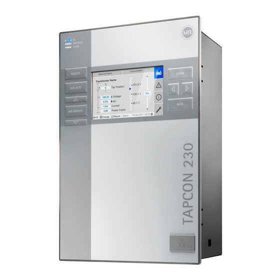
4 Product description 4.5.7 Visualization 4.5.7.1 Main screen Home Measured values Communication Transformer name Home 101.5 V Position Events 20 s 100.4 V Voltage 100.0 V 0.3% Information Current 40 mA 98.5 V Power factor Change Reboot admin 2020-04-15 10:08 Settings Figure 9: Home 1 Secondary navigation or naviga- 2 Primary navigation tion path 3 Status bar…
-
Page 28
4 Product description Measured values/display Transformer name Position Measured values Communication Voltage 100.4 V Transformer name Home 101.5 V Position 0.3% Events Current 40 mA 20 s 100.4 V Voltage 100.0 V 0.3% Power factor Information Current 40 mA 98.5 V Power factor Change Reboot admin 2020-04-15 10:08 Settings Figure 10: Measured values 1 Transformer name (can be edited) -
Page 29
4 Product description 4.5.7.2 Operating concept You can operate the device using the controls on the front panel or using the web-based Intuitive Control Interface visualization on a PC. The scope of function and structure of both options is virtually identical. User rights and user roles The device is equipped with a rights system and a roles system. -
Page 30
4 Product description 5. Select Time. In these operating instructions, the path for navigating to a parameter is al- ways shown in an abridged form: Go to Settings > Parameters > System > Time synchronization. Setting parameters There are various ways to configure the settings, depending on the parame- ter. -
Page 31
4 Product description Entering text 1. Use to select the text box and press ð If operating via the front panel, the keyboard appears. Figure 13: Entering text 2. Enter the desired text and confirm with 3. Press the Accept button to save the modified parameter. Parameter search You can use the quick search function in the parameter menu to search for a parameter. -
Page 32
4 Product description Expert mode The device has an expert mode for entering the parameters. You can enter the parameters directly on the overview screen of the respective menu in this mode. Figure 15: Expert mode To activate the expert mode, proceed as follows: 1. -
Page 33: Packaging, Transport And Storage
5 Packaging, transport and storage 5 Packaging, transport and storage 5.1 Suitability, structure and production The goods are packaged in a sturdy cardboard box. This ensures that the shipment is secure when in the intended transportation position and that none of its parts touch the loading surface of the means of transport or touch the ground after unloading.
-
Page 34: Storage Of Shipments
5 Packaging, transport and storage Visible damage If external transport damage is detected on receipt of the shipment, proceed as follows: ▪ Immediately record the transport damage found in the shipping docu- ments and have this countersigned by the carrier. ▪…
-
Page 35: Mounting
6 Mounting 6 Mounting DANGER Electric shock! Risk of fatal injury due to electrical voltage. Always observe the following safety regulations when working in or on electrical equipment. ► Disconnect the equipment. ► Lock the equipment to prevent an unintentional restart. ►…
-
Page 36: Minimum Distances
6 Mounting 6.2 Minimum distances NOTICE Damage to the device! Insufficient circulation of ambient air can result in damage to the device due to overheating. ► Keep the ventilation slots clear. ► Ensure sufficient distance to neighboring components. ► Only mount device in horizontal position (ventilation slots are at the top and bottom).
-
Page 37
6 Mounting Dimensions for the control panel cutout B: 202 mm (7.95 in) Figure 17: Dimensions for the cutout 1. Cut out the section for the control panel. Figure 18: Cutting out the section for the control panel 2. Slide the device into the cutout from the front and insert tension clamps. Figure 19: Inserting the device into the cutout ®… -
Page 38: Wall Mounting With Housing (Optional)
6 Mounting 3. Secure the device using the tension clamps. Figure 20: Securing device ð The device is mounted and can be wired up. 6.3.2 Wall mounting with housing (optional) For wall mounting, the device is fixed to the wall in a housing. The housing is an optional accessory.
-
Page 39
6 Mounting ► Fix the device on the wall from behind using 4 screws (M5) Figure 22: Wall mounting ð The device is mounted and can be wired up Proceed with wiring as shown in the connection diagram and as described in the Connecting device section. -
Page 40: Connecting Device
6 Mounting 6.4 Connecting device WARNING Electric shock! Connection errors can lead to death, injury or property damage. ► Ground the device with a protective conductor using the grounding screw on the housing. ► Note the phase difference of the secondary terminals for the current transformer and voltage transformer.
-
Page 41: Electromagnetic Compatibility
6 Mounting Excessive line capacitance can prevent the relay contacts from interrupting the contact current. In control circuits operated with alternating current, take into account the effect of the line capacitance of long control cables on the function of the relay contacts. If you want to route Ethernet connections from a control cabinet or building, we recommend using fiber-optic cables (in accordance with the IEC 61850-90-4 recommendation).
-
Page 42
6 Mounting ▪ Separate system parts must be joined by a potential equalization. ▪ The device and its wiring must be at least 10 m away from circuit-break- ers, load disconnectors and busbars. 6.4.2.2 Wiring requirement of operating site Note the following when wiring the operating site: ▪… -
Page 43
6 Mounting Figure 24: Recommended connection of the shielding 1 Connection of the shielding via a 2 Full-surface connection of the single conductor shielding 6.4.2.3 Wiring requirement in control cabinet Note the following when wiring in the control cabinet: ▪ The control cabinet where the device will be installed must be prepared in accordance with EMC requirements: –… -
Page 44: Connecting Cables To The System Periphery
6 Mounting Figure 25: Ground strap connection 6.4.3 Connecting cables to the system periphery To obtain a better overview when connecting cables, only use as many leads as necessary. To connect cables to the system periphery, proceed as follows: ü Use only the specified cables for wiring. Note the cable recommendation. ►…
-
Page 45
6 Mounting Variant 1: The connected devices share the same potential 1. Connect all devices to a potential equalization rail to equalize the poten- tial. 2. Connect the CAN bus cable shielding to all connected devices. Variant 2: The connected devices have different potential levels Note that the shielding is less effective with this variant. -
Page 46
6 Mounting ► Position the cable shielding, screw into place using the shield clamp pro- vided and provide strain relief (using a cable tie). Figure 27: Shield clamp and strain relief 6.4.4.2 Mounting terminating resistor of CAN bus If you want to operate the device in parallel operation, you need to mount a 120 Ω… -
Page 47: Connecting Scada
6 Mounting 6.4.5 Connecting SCADA NOTICE Damage to the device! Using the wrong data cable may damage the device. ► Only use data cables which comply with the description below. Depending on the control system used, you have to connect the device with one of the following versions.
-
Page 48
6 Mounting 6.4.5.2 Serial RS232 (D-SUB 9-pole) interface Data cable To connect the device via the RS232 interface, use a data cable with the fol- lowing structure: Figure 31: RS232 data cable (9-pole) D-SUB 9-pole plug connection Only use 9-pole D-SUB plugs with the following characteristics: ▪… -
Page 49
6 Mounting Connection 1. Connect the D-SUB 9-pole connector to the COM-X3 interface. 2. Connect the COM-X1 RJ45 interface to the CPU-X5 interface using the supplied patch cable. 6.4.5.3 Fiber-optic cable To ensure error-free data transmission, observe the information from the manufacturer of the fiber-optic cable and the following instructions: ▪… -
Page 50
6 Mounting 2. Remove the SFP module dust plug. Figure 34: Remove the dust protection 3. Insert the fiber-optic cable with LC duplex into the SFP module COM-X4 interface. 4. Connect the COM-X5 to the CPU-X2 using the supplied patch cable. Figure 35: Connecting CPU-X5 and COM-X2 ®… -
Page 51: Wiring Voltage Measurement/Current Measurement Ui
6 Mounting Serial fiber-optic cable You will need the CM-0847 FO converter if you want to connect your control system via the serial fiber-optic cable. ► Connect the serial fiber-optic cable and the converter to the CPU-X5 inter- face. 6.4.5.4 Ethernet interface ►…
-
Page 52: Wiring Analog Inputs Ai
6 Mounting 2. Current measurement: Feed the wires into the terminals UI:X7-2 (l) and UI:X7-1 (k) and fasten them using a screwdriver. Figure 37: UI:X7-2/1 6.4.7 Wiring analog inputs AI NOTICE Damage to the device and sensors! Incorrectly connected and configured analog inputs/outputs may result in damage to the device and sensor.
-
Page 53: Wiring Digital Inputs Di
6 Mounting Block diagram and wiring versions CAN bus AI 4 Controller Reinforced insulation Connection of a 2- Connection of a 4- Connection of a 3- Connection of a 4- conductor measuring conductor measuring conductor measuring conductor measuring transducer with current transducer with voltage transducer with current transducer with current…
-
Page 54: Wiring Digital Outputs Do
6 Mounting 6.4.9 Wiring digital outputs DO CAN bus DO 8 Controller Reinforced insulation 1-pole with 1-pole with connected connected 2-pole positive negative Figure 39: Block diagram for digital outputs 1. Feed the wires into the terminal of the plug connection diagram and fasten them using a screwdriver.
-
Page 55
6 Mounting Connecting the power supply ► Connect the power supply in accordance with the connection diagram [►Section 13.14, Page 160]. ® Maschinenfabrik Reinhausen GmbH 2021 7817454/02 EN TAPCON 230 Expert… -
Page 56: Performing Tests
► Prior to commissioning, check the supply voltage and the measured volt- age. ► Connecting the device to mains. ð The display shows the MR logo and then the operating screen. ð The voltage display LED on the top left of the device’s front panel lights ®…
-
Page 57: Initial Steps
7 Initial steps 7 Initial steps NOTICE Damage to device and system periphery An incorrectly connected device can cause damage to the device and sys- tem periphery. ► Check the entire configuration before commissioning. As soon as the device has powered up and the start screen is displayed, you will be asked to make the following settings: 7.1 Establishing connection to visualization A connection to the visualization can be established using two interfaces:…
-
Page 58
7 Initial steps 3. Connect the PC and the device via the front interface using an Ethernet cable (RJ45 plug). Figure 41: Establishing a connection via the front interface 4. Enter the visualization’s IP address http://192.168.165.1, or if SSL encryption is active, enter https://192.168.165.1 in the browser on the PC. -
Page 59
Download the operating instructions from the device to start device parame- terization. ► Select the MR logo in the status line. ð The operating instructions will be downloaded. The document is also available for download in the MR Customer Portal and on our website www.reinhausen.com. ® Maschinenfabrik Reinhausen GmbH 2021… -
Page 60: Commissioning
8 Commissioning 8 Commissioning NOTICE Damage to device and system periphery An incorrectly connected device can cause damage to the device and sys- tem periphery. ► Check the entire configuration before commissioning. 8.1 Commissioning wizard If you want the device to help when setting the relevant parameters, you can use the commissioning wizard.
-
Page 61: Checking Measured Values And Status Of Digital Inputs And Outputs
8 Commissioning When in delivery status, you can log in as the administrator as follows: ▪ User name: admin ▪ Password: admin During the function test, you must set the most important parameters. Details on the parameters listed can be found in the Operation [►Section 9, Page 67] chapter.
-
Page 62: Checking Parallel Operation
8 Commissioning 14. Press to select auto mode. ð If the actual voltage is outside the bandwidth, the device returns the on-load tap-changer to the original operating position after 20 sec- onds. 15. Press to select manual mode. 16. Set the delay time T2 to 10 seconds and activate it [►Page 117]. 17.
-
Page 63
8 Commissioning 8.2.3.1 Testing circulating reactive current minimization Note that the following prerequisites must be met for the «circulating reactive current minimization» parallel operation method: ▪ You must use current transformers with the same connection values for all transformers in parallel operation. ▪… -
Page 64
8 Commissioning 8.2.3.2 Testing the circulating reactive current blocking limit This section describes how to run the function test for circulating reactive current blocking. ü Set the circulating reactive current blocking limit to a value of 20%. 1. Press on one voltage regulator to select manual mode. 2. -
Page 65
8 Commissioning 8.2.3.3 Checking tap synchronization method NOTICE Damage resulting from formation of a circulating reactive cur- rent If the parameters are not set correctly, damage may result from the forma- tion of circulating reactive current and the resulting overload of transmission lines and transformers. -
Page 66
8 Commissioning 8. Press on the follower to select auto mode. ð The follower switches to the same tap position as the master. 9. Press on the master to select auto mode. 10. Press on the follower to select manual mode. 11. -
Page 67: Operation
9 Operation 9 Operation This chapter describes all the functions and setting options for the device. 9.1 System 9.1.1 General You can set general parameters in this menu item. 9.1.1.1 Setting general device functions You can set general device functions with the following parameters. 1.
-
Page 68
9 Operation Setting Description Hardware only The device accepts commands through digital inputs. SCADA only The device accepts commands via SCADA. Hardware and SCADA The device accepts commands via digital inputs and SCADA. Table 13: Selecting remote behavior 9.1.1.2 Set up automatic logout You can change the settings so that the device of a logged-in user automati- cally logs the user out after a certain period of inactivity. -
Page 69: Configuring The Network
9 Operation When in delivery status, you can log in as the administrator as follows: ▪ User name: admin ▪ Password: admin 1. Go to Settings > Parameters > System > General > Service user ac- cess activation. 2. Select the desired option. 3.
-
Page 70: Setting The Device Time
9 Operation Be sure to enter a valid network mask that is not 0.0.0.0, otherwise it will not be possible to connect to the device. Gateway address You can use this parameter to set the gateway’s IP address. If you set the value to 0.0.0.0, no gateway is used. SSL/TLS encryption You can use this parameter to set whether the process for accessing the vi- sualization should be carried out over an SSL/TLS-encrypted connection.
-
Page 71: Setting The Screensaver
9 Operation Time synchronization via SNTP You can use this parameter to activate time synchronization using an SNTP time server. SNTP time server You can use this parameter to enter the IP address of a SNTP time server. If you are using a time server, the device uses the time of the time server as the system time.
-
Page 72: Configuring Syslog
9 Operation 1. Go to Settings > Parameters > System > Screensaver. 2. Select the desired parameter. 3. Set the parameter. 4. Press the Accept button to save the modified parameter. Screensaver If you activate this function, the device fully switches off the display when the adjustable waiting period has expired if no key is pressed.
-
Page 73
9 Operation Activate syslog You can use this parameter to activate transmission of syslog messages via the device. Syslog standard You can use this parameter to adjust the transmission process and the for- mat for the syslog messages. You can select the following options: Standard Transport Message format… -
Page 74: Scada
9 Operation Severity level You can set which syslog messages the device will send. You can also acti- vate or deactivate messages for each severity level. Severity level Description The system is unusable. Emergency Immediate intervention required. Alert Critical state Critical Error state Error…
-
Page 75
9 Operation 9.1.6.2 Configuring IEC 60870-5-101 If you want to use the IEC 60870-5-101 control system protocol, you must set the following parameters. 1. Go to Settings > Parameters > System > IEC 60870-5-101. 2. Select the desired parameter. 3. Set the parameter. 4. -
Page 76
9 Operation Number of cause of transmission octets You can use this parameter to set how many octets are provided for the cause of transmission. ASDU single character confirmation You can use this parameter to set whether a confirmation is to be sent as single characters instead of as a complete message. -
Page 77
9 Operation ASDU sequence optimization With this parameter, you can set which method is to be used for optimizing the ASDU types. The standard enables optimization in order to be able to transfer multiple value changes in a telegram in a sequence of ascending in- formation object addresses. -
Page 78
9 Operation Receiver IP address You can use this parameter to set the IP address of the receiver. Modbus address You can use this parameter to set the Modbus address. Serial interface You can use this parameter to select the serial interface for data transmis- sion. -
Page 79
9 Operation 9.1.6.5.1 DNP3 transmission type You can use this parameter to set the transmission type. You can select the following options: ▪ TCP ▪ Serial Serial interface You can use this parameter to select the serial interface for data transmis- sion. -
Page 80: Linking Signals And Events
9 Operation Timeout for response confirmation You can use this parameter to set the timeout for response confirmation for unsolicited messages. Unsolicited messages You can use this parameter to set whether the device is to support unso- licited messages. If you activate unsolicited messages, the device sends a message via the control system every time a value is changed.
-
Page 81
9 Operation 9.1.7.1 Linking functions You can link the General purpose input or Generic SCADA command events with device functions. This allows you to remotely control the device using digital inputs or commands via the control system (SCADA). To establish the link, you have to enter the corresponding event number in the desired parameter. -
Page 82
9 Operation Target-tap-position operation If the assigned event is active, the device switches to the defined target tap position. Activate desired value 1 If the assigned event is active, the device activates the desired value 1. Activate desired value 2 If the assigned event is active, the device activates the desired value 2. -
Page 83: Configuring Analog Inputs
9 Operation 9.1.7.3 Linking status messages You can link each event with a status message. The device provides 10 generic status messages for this purpose. When you link a message to an event, the device sets the data point to «On» when the event occurs. When the event stops, the device sets the data point to «Off».
-
Page 84
9 Operation Correction factor and offset Setting a correction offsets systematic errors of the analog signals. The cor- rection is determined by multiplying a factor by the sum of the offset. The minimum and maximum values of the function values apply as a limit value for the correction. -
Page 85: Configuring Digital Inputs And Outputs
9 Operation Property Options Correction factor Set the correction factor (m) for the correction of the func- tion value (x). The corrected function value (y) is: y = (m * x) + t Correction offset Set the offset (t) for the correction of the function value (x).
-
Page 86
9 Operation Ensure that the configuration of the digital inputs and outputs is suitable for the functions used. Otherwise, malfunctions may occur in the device and the connected periphery. The following information is displayed in tabular form for configuring the digi- tal inputs and outputs. -
Page 87: Event Management
9 Operation 9.1.10 Event management The device is equipped with event management, which allows you to detect various device operating statuses and to adapt the behavior of the device. An overview of all possible events is given in the Event messages chapter. 9.1.10.1 Displaying and acknowledging events Displaying events ►…
-
Page 88: User Administration
9 Operation Events Event Time Home 18.03.2020 Limit value P>> 04:35:17/576 17.03.2020 Limit value P> 10:56:59/669 Events 16.03.2020 Limit value Q<< 08:22:11/125 12.03.2020 Limit value Q< 01:33:22/845 Information 10.02.2020 Ambient conditions … 14:21:49/602 1 / 100+ Filter Recorder Export CHANGE REBOOT admin 06.04.2020 13:08…
-
Page 89
9 Operation 9.1.11.1 User roles The access rights to the device functions and settings are controlled using a hierarchical system of roles. The system has five different roles with different access rights. Some of these access rights are fixed, but you can configure the access rights to particular parameters and events. -
Page 90
9 Operation Function Data display Diagnostics Operator Parameter Administrator configurator Set date and time Calibrate resistor contact se- ries Actuation of the RAISE, LOWER, REMOTE, AVR AUTO, and AVR MAN- UAL keys Configuring analog inputs and outputs Configuring digital inputs and outputs Table 25: Access rights permanently linked to the roles 9.1.11.2 Changing password All users can change their passwords provided that the user account is not… -
Page 91
9 Operation ▪ Active: You can activate or deactivate the user. Deactivated users cannot log in. The user data is still stored in the device. ▪ Auto login: You can activate the Auto-login function for a user. This user is automatically logged in when the system is restarted or another user logs out. -
Page 92: Hardware
9 Operation You can only change access rights if you are assigned an administrator role. When in delivery status, you can log in as the administrator as follows: ▪ User name: admin ▪ Password: admin 1. Go to Settings > Administration > Parameters/events. ð…
-
Page 93
9 Operation Option Description Event memory All event memory entries. Parameter list Parameter list with descriptive text and values (min, max, cur- rent). Event list Complete list of all possible events. SCADA configu- Control system configuration ration Operating In- Operating instructions, protocol specifications. structions Settings Configuration of parameters and events. -
Page 94
9 Operation 9.1.14.2 Importing data You can import the following data: Option Description System image Complete image of the system (software and configura- tion), with or without history. Settings All device settings: ▪ Parameter settings ▪ Event settings ▪ Administrative settings (users, access rights) The settings can also be imported from another device. -
Page 95: Power Grid
9 Operation 9.2 Power grid 9.2.1 Transformer data The transformation ratios and measuring set-up for the voltage and current transformers used in the system can be set with the following parameters. The device uses this information to calculate the corresponding measured values on the primary side of the current transformer (and therefore the transformer) from the recorded measured values.
-
Page 96
9 Operation Voltage-transformer circuit You can use this parameter to set your voltage transformer’s circuit. You can select the following options: Option Description 1 Ph phase voltage Measurement in 1-phase grid between the conductor and neutral conductor. 3 Ph differential voltage Measurement in 3-phase grid between 2 conductors 3 Ph phase voltage… -
Page 97
9 Operation 9.2.1.2.1 1-phase measurement Circuit 1-A ▪ The voltage transformer VT is connected to the phase conductor and the neutral conductor. ▪ The current transformer CT is looped into the phase conductor. ▪ The voltage U and current I are in phase. -
Page 98
9 Operation ▪ The voltage U and current I are in phase. ▪ The voltage drop on a phase conductor is determined by the current I If you use this circuit, set the device as follows: Parameter Option Voltage-transformer circuit 3 Ph phase voltage Current-transformer circuit 3 Ph phase current… -
Page 99
9 Operation Circuit 1-D ▪ The voltage transformer VT is connected to the phase conductors L1 and ▪ The current transformer CT is looped into the phase conductor L3. ▪ The current I is ahead of voltage U by 90°. This corresponds to a phase shift of -90°. -
Page 100: Voltage Monitoring
9 Operation If you use this circuit, set the device as follows: Parameter Option Voltage-transformer circuit 3 Ph differential voltage Current-transformer circuit 3 Ph phase current Phase angle correction 30° Table 34: Circuit 1-E Circuit 1-F ▪ The voltage transformer VT is connected to the phase conductors L1 and ▪…
-
Page 101
9 Operation If the measured value is higher than the upper limit (> or >>) or lower than the lower limit (< or <<), the device transmits an event message. U>> U> U< U<< Figure 45: Example of voltage monitoring with the limit value Overvoltage U> being exceeded U>>… -
Page 102: Current Monitoring
9 Operation Reaction You can use this parameter to set the behavior of the device if the measured value is higher than the upper limit (> or >>) or lower than the lower limit (< or <<). You can select the following options: Setting Behavior No reaction.
-
Page 103
9 Operation If the measured value is higher than the upper limit (> or >>) or lower than the lower limit (< or <<), the device transmits an event message. I>> I> I< I<< Figure 46: Example of current monitoring with the limit value I> being exceeded I>>… -
Page 104: Power Monitoring
9 Operation Reaction You can use this parameter to set the behavior of the device if the measured value is higher than the upper limit (> or >>) or lower than the lower limit (< or <<). You can select the following options: Setting Behavior No reaction.
-
Page 105
9 Operation Delay time You can use this parameter to set the delay time in order to delay the issuing of the event message. Reaction You can use this parameter to set the behavior of the device if the measured value is higher than the upper limit (>… -
Page 106: Power Flow Monitoring
9 Operation 9.2.5 Power flow monitoring A reversal of power flow occurs if the active power is negative. You can set the following parameters for this: ▪ Hysteresis ▪ Delay time ▪ Behavior 1. Go to Settings > Parameters > Grid > Power flow monitoring. 2.
-
Page 107: Tapcon® 2Xx Retrofit
9 Operation Setting Behavior Auto/manual blocking ▪ The Reversal of power flow event is issued. ▪ If Z compensation is activated, this function is deacti- vated. ▪ Automatic regulation is blocked. ▪ You cannot perform tap-change operations in manual mode. Target tap position ▪…
-
Page 108
9 Operation 1. Go to Settings > Parameters > Grid > TAPCON® 2xx retrofit. 2. Select the desired parameter. 3. Set the desired parameter. 4. Press the Accept button to save the modified parameter. TAPCON® 2xx retrofit You can use this parameter to activate or deactivate the Retrofit TAPCON® 2xx function. -
Page 109: On-Load Tap-Changer Regulator
9 Operation 9.3 On-load tap-changer regulator 9.3.1 Voltage regulation All of the parameters required for the control function are described in this section. 1. Go to Settings > Parameters > On-load tap-changer regulator > Volt- age regulation. 2. Select the desired parameter. 3.
-
Page 110
9 Operation 1. Go to Settings > Parameters > On-load tap-changer > Voltage regula- tion > Change remote desired value setting. 2. Select the desired option in the list. 3. Press the Accept button to save the modified parameter. Selecting a desired value You can use this parameter to select the desired value used for control. -
Page 111
9 Operation Setting desired value 1 1. Go to Settings > Parameters > Grid > Control > Desired value. 2. Enter the desired value. 3. Press the Accept button to save the modified parameter. Setting max. desired value setting With this parameter, you can set the desired value that corresponds to the maximum level of the analog signal level (e.g. -
Page 112
9 Operation Figure 49: Active power-dependent adjustment of desired voltage value Desired value Minimum desired value Measured active power Maximum desired value meas Active power at minimum de- Set desired value when mea- sired value sured active power = 0 Active power at maximum de- sired value Response to active power P being exceeded… -
Page 113
9 Operation Linear dependency with negative active power: If the measured active power P ≤ P ≤ 0, the desired value is calculated meas using the following equation: × P meas 0 — P Linear dependency with positive active power: If the measured active power 0 ≤ P ≤ P , the desired value is calculated meas… -
Page 114
9 Operation TDSC U0 You can use this parameter to set the desired value which is to be used when the measured active power is 0. 1. Go to Settings > Parameters > Control > TDSC U0. 2. Enter desired value at active power 0. 3. -
Page 115
9 Operation The following transformer values are used to determine the minimum band- width: Nominal voltage U = 11000 V Step voltage in tap position 4 U = 11275 V Step4 Step voltage in tap position 5 U = 11000 V Step5 Delay time T1 Delay time T1 delays the issuing of a tap-change command for a defined pe- riod. -
Page 116
9 Operation change command is issued after expiration of the set delay time T1. The on-load tap-changer carries out a tap-change in a raise or lower direction to return to the tolerance bandwidth. Figure 50: Behavior of the control function with delay time T1 1 Upper limit of bandwidth 4 Set delay time T1 2 Desired value… -
Page 117
9 Operation the device responds faster to large voltage changes in the grid. Regulation accuracy improves as a result but the frequency of tap-changes increases too. Figure 51: Diagram for integral time response ΔU/B Control deviation «ΔU» as % of desired value in relation to the set band- width «B»… -
Page 118: Line Drop Compensation
9 Operation starts to count down. Once delay time T2 is complete, a control impulse is again issued to the motor-drive unit for the tap change to return to the tol- erance bandwidth. Figure 52: Behavior of the regulation function with delay times T1 and T2 1 Upper limit of bandwidth 4 Set delay times T1 and T2.
-
Page 119
9 Operation 9.3.2.1 R&X compensation R&X compensation can compensate for voltage losses on the lines and therefore ensure correct voltage at the load. This requires precise line data. After you have entered all of the line data, the device automatically calcu- lates the ohmic and inductive voltage drop and takes this into account for au- tomatic voltage regulation. -
Page 120
9 Operation Ohmic resistance load You can use this parameter to set the ohmic resistance load. Inductive resistance load You can use this parameter to set the inductive resistance load. Length of line You can use this parameter to set the length of line. 9.3.2.2 Z compensation To keep the voltage constant for the consumer, you can use Z compensation to activate a current-dependent voltage increase. -
Page 121: Parallel Operation
9 Operation 1. Go to Settings > Parameters > On-load tap-changer regulator > Com- pensation. 2. Select the desired parameter. 3. Set the desired parameter. 4. Press the Accept button to save the modified parameter. Voltage increase You can use this parameter to set the current-dependent voltage increase ∆U.
-
Page 122
9 Operation 9.3.3.1.1 Tap synchronization With the tap synchronization parallel operation method, one voltage regu- lator works as the master and all others as followers. Master Follower Tap position CAN bus Figure 56: Tap synchronization The master handles voltage regulation and transmits its current tap positions to all followers via the CAN bus. -
Page 123
9 Operation Parameter Auto Master Follower Master/follower current blocking Master/follower switching characteristics Maximum tap difference Yes (if follower) Error if no communication present Behavior if no communi- cation present Parallel operation error delay time Table 42: Parameter 9.3.3.1.2 Circulating reactive current minimization with CAN bus communication With the circulating reactive current parallel operation method, parallel op- eration is carried out using the circulating reactive current minimization method. -
Page 124
9 Operation The circulating reactive current method is suited to transformers connected in parallel with a similar nominal output and short-circuit voltage U and to vector groups with the same and different step voltages. This does not re- quire any information about the tap position. Note that the following prerequisites must be met for the «circulating reactive current minimization»… -
Page 125
9 Operation current is added to the independently regulating voltage regulators as a cor- rection for the control deviation determined on the basis of the measurement voltage. This extra control deviation depends on how much the measured power factor deviates from the desired power factor. To use the power factor method, you need to know the conditions of your network in order to correctly set the device parameters. -
Page 126
9 Operation Only change the parallel operation method when the on-load tap-changers are not performing tap-change operations. Option Description Master The device is designated as Tap synchronization parallel the master. operation method Follower The device is designated as the follower. Auto. -
Page 127
9 Operation Desired power factor You can use this parameter to set the power factor, which the transformer has under normal operating conditions. If the measured power factor devi- ates from the desired one, the device calculates a correction which is added to the control deviation. -
Page 128
9 Operation 9.3.3.2.7 Setting master/follower switching characteristics You can use this parameter to set the switching characteristics for the tap synchronization parallel operation method. You can select the following op- tions: ▪ Sequentially: When a tap-change operation takes place, the master com- municates its new tap position to the followers via the CAN bus as soon as the master has completed its tap-change operation. -
Page 129
9 Operation You can select the following options: Option Description Independent regula- The device switches from parallel operation to normal auto- tion matic voltage regulation Auto blocking Automatic voltage regulation is blocked. cosφ interpolation Continuation of parallel operation with interpolated values (only possible with circulating reactive current parallel oper- ation method) Power factor… -
Page 130: U Bandwidth Monitoring
9 Operation 9.3.4 U bandwidth monitoring The following limit values are monitored via bandwidth monitoring. The set bandwidth [►Page 114] (upper/lower) of the voltage regulation is used for this purpose. Behavior If the measured value is higher than the upper limit or lower than the lower limit, the device triggers the Upper bandwidth limit value / Lower bandwidth limit value message.
-
Page 131
9 Operation Delay time You can use this parameter to set the delay time in order to delay the issuing of the event message. ® Maschinenfabrik Reinhausen GmbH 2021 7817454/02 EN TAPCON 230 Expert… -
Page 132: On-Load Tap-Changer
9 Operation 9.4 On-load tap-changer 9.4.1 Tap position monitoring You can set the limit value parameter for tap position monitoring: 1. Go to Settings > Parameters > On-load tap-changer > Tap position monitoring. 2. Select the desired parameter. 3. Set the desired parameter. 4.
-
Page 133: Tap Position Capture Method
9 Operation 9.4.2 Tap position capture method The current tap position of the on-load tap-changer is transmitted from the motor-drive unit to the device. You can use this parameter to select the type of tap position capture. In order to ensure proper function of the tap position capture, make sure that the inputs of the corresponding tap position capture method are acti- vated and correctly wired.
-
Page 134
9 Operation Pos. at min. analog signal You can use this parameter to set the tap position of the on-load tap- changer corresponding to the minimum analog signal (e.g. 4 mA for 4…20 mA signal). 1. Go to Settings > Analog tap position capture > Pos. at min. analog signal. -
Page 135: Target-Tap-Position Operation
9 Operation 9.4.3 Target-tap-position operation When target-tap-position operation is activated, the device automatically switches to this target tap position. 1. Go to Settings > Parameters > On-load tap-changer > Move to the de- fined target tap position. 2. Enter the target tap position. 3.
-
Page 136: Motor-Drive Unit And Control Cabinet
9 Operation 9.5 Motor-drive unit and control cabinet 9.5.1 Control of the motor-drive unit 9.5.1.1 Setting the switching pulse for controlling the motor-drive unit You can use the parameters Switching pulse type, Switching pulse time and Switching pulse pause to adapt the device switching pulse to the require- ments of the motor-drive unit controller.
-
Page 137
9 Operation Figure 60: Switching pulse time and switching pulse pause 1 Switching pulse time 2 Switching pulse pause Switching pulse time You can use this parameter to set the maximum duration of the switching pulse. The switching pulse resets after the switching pulse time has elapsed or if the device receives the Motor running signal beforehand or the tap posi- tion is changed. -
Page 138
9 Operation 3. Set the parameter. 4. Press the Accept button to save the modified parameter. Motor runtime You can use this parameter to set the motor runtime. Motor runtime monitoring You can use this parameter to activate or deactivate motor runtime monitor- ing. -
Page 139
9 Operation Switching direction monitoring is not active if you control the motor-drive unit with a continuous pulse [►Section 9.5.1.1, Page 136]. Also refer to 2 Setting the switching pulse for controlling the motor-drive unit [► 136] ® Maschinenfabrik Reinhausen GmbH 2021 7817454/02 EN TAPCON 230 Expert… -
Page 140: Maintenance And Care
10 Maintenance and care 10 Maintenance and care The device is maintenance-free. You can clean the device’s housing with a dry cloth. ® TAPCON 230 Expert 7817454/02 EN Maschinenfabrik Reinhausen GmbH 2021…
-
Page 141: Fault Elimination
11 Fault elimination 11 Fault elimination This chapter describes how to rectify simple operating faults. 11.1 General faults Characteristics/details Cause Remedy No function No power supply Check the power supply. ▪ Power supply LED does not Fuse tripped Contact Maschinenfabrik Reinhausen GmbH. light up No function Configuration error…
-
Page 142: Unwanted On-Load Tap-Change Operation
11 Fault elimination Characteristics/detail Cause Remedy Parallel operation active. Device is follower in parallel oper- No error. If necessary, deactivate parallel opera- ation. tion. CAN bus communication failure «Auto blocking» behavior is set. Check configuration. Table 49: No regulation in AUTO mode 11.3 Unwanted on-load tap-change operation Characteristics/detail Cause…
-
Page 143: Parallel Operation Faults
11 Fault elimination Characteristics/details Cause Remedy Measured voltage Voltage drop on the measuring Check the measured voltage. line. ▪ Measured value too low Measured voltage Possible sources of interference: Check the measured voltage. ▪ Measured value fluctuates ▪ Cables laid in parallel. Increase the distance from the source of inter- ference.
-
Page 144: Tap Position Capture Incorrect
11 Fault elimination Characteristics/details Cause Remedy Problem with master/follower par- Master and followers have differ- Check tap position capture or check why the allel operation method: ent tap positions. tap-change operation has not been undertaken (e.g. mechanical defect), then perform one of ▪…
-
Page 145: Other Faults
11 Fault elimination 11.8 Other faults If you cannot resolve a problem, please contact Maschinenfabrik Rein- hausen. Please have the following data to hand: ▪ Serial number – Nameplate – Info screen ▪ Software version Please provide answers to the following questions: ▪…
-
Page 146: Disposal
12 Disposal 12 Disposal Observe the national requirements applicable in the country of use. ® TAPCON 230 Expert 7817454/02 EN Maschinenfabrik Reinhausen GmbH 2021…
-
Page 147: Technical Data
13 Technical data 13 Technical data 13.1 Display elements Display 5″ TFT colour display LEDs 3 LEDs for operation display and messages ▪ POWER, AVR STATUS, ALARM ▪ RAISE, LOWER, AUTO, MANUAL, REMOTE 13.2 Materials Front Aluminum, plastic Tray/rear Stainless steel 13.3 Dimensions W x H x D 218 mm x 324 mm x 130 mm (8.58 in x 12.76 in x…
-
Page 148: Voltage Measurement And Current Measurement
13 Technical data Auxiliary power supply AUX DC DI 110 V DC for digital inputs The auxiliary power supply is used exclusively for the acquisition of up to 16 floating contacts. Output voltage : 110 V DC ± 2% (short-circuit proof) Max. output power 5 W Overvoltage category OC III…
-
Page 149: Central Processing Unit
13 Technical data Overload capability continu- 12.5 A Overload capacity short-term 500 A / 1 s Surge test voltage 5 kV, 1.2 µs / 50 µs (IEC 60255-27) Interface Description VT (U : 100/230/400 V AC) Table 59: Connection UI:X7 13.6 Central processing unit Processor ARM Cortex A9 processor 800 MHz 512 MB NVRAM (SRAM with battery 256 kB backup) Application memory…
-
Page 150
13 Technical data Interfaces Interface Description ER_NO ER_NC ER_COM WD_NO WD_NC WD_COM Table 60: Plug terminal CPU:X1 Interface X2, X3 Description RXD- RXD+ TXD- TXD+ Table 61: Ethernet interface CPU:X2/X3 Interface X4 Description TXD+/RXD+ TXD-/RXD- Table 62: Serial interface RS485 CPU:X4 ® TAPCON 230 Expert 7817454/02 EN Maschinenfabrik Reinhausen GmbH 2021… -
Page 151: Digital Inputs
13 Technical data Interface X5 Description DTR (O) DCD (I) RXD (I) TXD (O) VCC/OUT 5 V/12 V RTS (O) CTS (I) Table 63: Serial interface RS232 CPU:X5 13.7 Digital inputs DI 16 Inputs (plug-based electrical 2 x 8 isolation) Nominal voltage 110 V DC Max. operating voltage 143 V DC Logical 0 ≤…
-
Page 152: Digital Outputs
13 Technical data Interface Description Common reference (common) Common reference (common) Input 17 Input 16 Input 15 Input 14 Input 13 Input 12 Input 11 Input 10 Table 66: Connector X2 (group 1) 13.8 Digital outputs Voltage regulator ▪ 16 relays Relay outputs DC 24 up to 220 V, AC ▪…
-
Page 153
13 Technical data Figure 61: Contact load capacity of digital outputs with resistive load Electric shock! CAUTION The outputs of the DO assembly have plug-based electrical isolation. A mix- ture of voltage ranges (e.g. extra low voltage and low voltage) or various phases within a plug can lower the protection against electric shock. -
Page 154: Analog Inputs
13 Technical data Interface Description Common reference (common) output 5 Common reference (common) output 4 Output 5 Output 4 Table 70: Connector X3 (group 2) Interface Description Common reference (common) output 7 Common reference (common) output 6 Output 7 Output 6 Table 71: Connector X4 (group 3) 13.9 Analog inputs AI 4 Inputs (electrically isolated)
-
Page 155
13 Technical data Interface Description V0 U- voltage input V0 I- current input V0 I+ current output V0 U+ voltage output Table 73: Connector X1 (group 0) Interface Description V1 U- voltage input V1 I- current input V1 I+ current output V1 U+ voltage output Table 74: Connector X2 (group 1) Interface Description V2 U- voltage input… -
Page 156: Communication Interfaces
13 Technical data 13.10 Communication interfaces Description Assembly for converting interfaces and media Interfaces 1x RS232/RS485 (RJ45): COM X1 2x Ethernet (RJ45): COM X2, COM X5 1x RS232 (D-SUB): COM X3 1x duplex LC (SFP): COM X4 1x plug terminal 10-pin: COM X6 COM X1 Internal system interface for connecting the COM X6 interface to the central processing…
-
Page 157
13 Technical data Interface Description TxD+ TxD- RxD+ RxD- Table 78: COM X2, COM X5 (RJ45) Interface Description Table 79: COM X3 (RS232) Interface Description Fiber glass 50/125 and 62.5/125 multimode Table 80: COM X4 (duplex LC SFP) Interface Description GND (resistor contact series) I out (resistor contact series) U+ in (resistor contact series) U- in (resistor contact series) -
Page 158: Tap Position Capture / Resistor Contact Series
13 Technical data 13.11 Tap position capture / resistor contact series Electrical isolation Test voltage power-frequency withstand volt- age: 500 V ; 50 Hz; 1 min Tap position capture 35 tap positions, 2,000 ohms 13.12 Ambient conditions Operating temperature -25…+70°C Storage temperature -30…+85°C (with battery) Relative humidity 5…95%, non-condensing Contamination level…
-
Page 159
13 Technical data Climatic ambient conditions IEC 60068-2-1 (-25°C; 96 h) cold IEC 60068-2-2 (+70°C; 96 h) dry heat IEC 60068-2-78 (+40°C / 93% rH, 96 h) moist heat, constant IEC 60068-2-30 (+55°C, 6 cycles 12 + 12 hours) moist heat, cyclical Degree of protection test IEC 60529 Environmental durability tests IEC 60255-21-1 vibrations class 1 (3 cy- cles, 0.5g acceleration, 1 octave/min or 60 cycles, 1.0g acceleration, 1 octave/… -
Page 160: Connection Diagrams
13 Technical data 13.14 Connection diagrams Also refer to 2 TAPCON® 230 Expert [► 161] ® TAPCON 230 Expert 7817454/02 EN Maschinenfabrik Reinhausen GmbH 2021…
-
Page 161: Tapcon® 230 Expert
TAPCON® 230 — EXPERT CENTRAL PROCESSING UNIT POWER SUPPLY DIGITAL OUTPUTS DO 8-1 DIGITAL INPUTS DI 16-110V AC/DC N (L-) L1 (L+) 110V DC LANGUAGE: PROJECT: DATE 22.01.2021 X7,X1,X6 connection 01.10.21 LAINER EXEC. BECK TAPCON® 230 EXPERT BCD Signal 30.06.21 KAHN VERIFIED SHEET…
-
Page 162
TAPCON® 230 — EXPERT CENTRAL PROCESSING UNIT DIGITAL OUTPUTS DO 8-2 ANALOG INPUTS AI 4 COM — 120 Ω (II) 100% TAP POSITION POSITION TRANSMITTER MODULE, RESISTOR-TYPE (III) Ω LANGUAGE: PROJECT: DATE 22.01.2021 X7,X1,X6 connection 01.10.21 LAINER EXEC. BECK TAPCON® 230 EXPERT BCD Signal 30.06.21 KAHN… -
Page 163
CUSTOMER VISU / SERVICE RJ45 RJ45 RJ45 RJ45 SCADA ETHERNET LC 1310nm RJ45 RJ45 RJ45 SCADA SERIAL SIGNAL RS232 RJ45 SIGNAL Data — RS485 Data + RJ45 LANGUAGE: PROJECT: DATE 22.01.2021 X7,X1,X6 connection 01.10.21 LAINER EXEC. BECK TAPCON® 230 EXPERT BCD Signal 30.06.21 KAHN… -
Page 164: Glossary
Glossary Glossary Electromagnetic compatibility Abbreviation for fiber-optic cable SCADA General Purpose Input Technical processes are monitored and con- trolled using a computer system (Supervisory Control and Data Acquisition) General Purpose Output SNTP NTP (Network Time Protocol) is a standard for synchronizing clocks in computer systems using IED Capability Description packet-based communication networks.
-
Page 166
Maschinenfabrik Reinhausen GmbH Falkensteinstrasse 8 93059 Regensburg +49 (0)941 4090-0 sales@reinhausen.com www.reinhausen.com ® 7817454/02 EN — TAPCON 230 Expert — — 10/21 — Maschinenfabrik Reinhausen GmbH 2021 THE POWER BEHIND POWER.
-
Contents
-
Table of Contents
-
Bookmarks
Quick Links
Voltage regulator TAPCON® 230 basic
Operating Instructions 2117246/02
Related Manuals for MR TAPCON 230 basic
Summary of Contents for MR TAPCON 230 basic
-
Page 1
Voltage regulator TAPCON® 230 basic Operating Instructions 2117246/02… -
Page 2
© All rights reserved by Maschinenfabrik Reinhausen Copying and distribution of this document and utilization and communication of its contents are strictly prohibited unless expressly authorized. Offenders will be held liable for the payment of damages. All rights reserved in the event of the grant of a patent, utility model or ornamental design registration. -
Page 3: Table Of Contents
Table of Contents Table of Contents Introduction ……………… 9 1.1 Manufacturer ………………… 9 1.2 Subject to change without notice ………….. 9 1.3 Completeness ………………. 9 1.4 Supporting documents …………….10 1.5 Safekeeping ……………….. 10 1.6 Notation conventions …………….10 1.6.1 Abbreviations used …………………
-
Page 4
Table of Contents 3.1.1 Operating modes ………………..20 3.2 Scope of delivery ………………21 3.3 Hardware description …………….22 3.3.1 Internal design ………………..23 3.3.2 Communication Interfaces ……………… 24 3.4 Operation and indicator elements …………25 3.4.1 Operating concept ……………….. -
Page 5
Table of Contents 5.3.6 Removing door ………………..47 5.4 Connection ………………..48 5.4.1 Cable recommendation ………………48 5.4.2 Electromagnetic compatibility …………….48 5.4.3 Connecting the cables to the system periphery ……….54 5.4.4 Supplying the voltage regulator using an auxiliary voltage ……… -
Page 6
Table of Contents 7.3.3 Setting desired values ………………80 7.3.4 Setting desired value 2 ………………81 7.3.5 Setting desired value 3 ………………82 7.3.6 Selecting desired value ………………83 7.3.7 Bandwidth ………………….84 … -
Page 7
Electromagnetic compatibility …………….164 9.5.3 Environmental durability tests …………….164 9.5.4 Mechanical stability ………………. 165 Menu overview …………….. 167 MR worldwide …………….171 © Maschinenfabrik Reinhausen 2012 2117246/02 EN TAPCON® 230 basic… -
Page 9: Introduction
1 Introduction Introduction This technical file contains detailed descriptions on the safe and proper mounting, connection, commissioning and monitoring of the product. It also includes safety instructions and general information about the product. This technical file is intended solely for specially trained and authorized per- sonnel.
-
Page 10: Supporting Documents
1 Introduction Supporting documents The following documents apply to this product: Operating instructions Quick reference guide Connection diagrams Also observe generally valid legislation, standards, guidelines and specifica- tions on accident prevention and environmental protection in the respective country of use.
-
Page 11: Abbreviations Used
1 Introduction 1.6.1 Abbreviations used Abbreviation Definition °C Degrees Celsius Ampere Alternating Current Accessible Emission Limit (see GZS) ASCII American Standard Code for Information Interchange Bandwidth Binary Coded Decimal circa Controller Area Network Communication Interface Card Central Processing Unit Current Transformer Direct Current Deutsches Institut für Normung (German Institute for Standardization)
-
Page 12: Hazard Communication System
1 Introduction Abbreviation Definition Millimeter Millisecond Neutral Phase Phi (φ) Phase angle Parts per million Remote Terminal Unit Second SCADA Supervisory Control and Data Acquisition SNTP Simple Network Time Protocol Time Transmission Control Protocol Voltage Actual voltage Actual Desired voltage Desired Volt Verband der Elektrotechnik, Elektronik und Informati-…
-
Page 13: Information System
1 Introduction The following signal words are used: Signal word Hazard level Consequence of failure to comply Danger Immediate threat of danger Death or serious injury could occur Warning Possible threat of danger Death or serious injury could occur Possible dangerous situation Minor or moderate injury could oc- Caution Notice…
-
Page 14: Instruction System
1 Introduction 1.6.4 Instruction system This technical file contains single-step and multi-step instructions. Single-step instructions Instructions which consist of only a single process step are structured as fol- lows: Aim of action Requirement (optional) ► Step 1 of 1 Result of step (optional) Result of action (optional) (Figure optional) Multi-step instructions…
-
Page 15: Typographic Conventions
2 Safety 1.6.5 Typographic conventions The typographic conventions in this technical file are structured as follows: Typographic Definition convention Step of the procedure for software descriptions in the subsequent menu. > … > … Example: > Normset Designation of keys. UPPERCASE Example: «MENU key»…
-
Page 16: Appropriate Use
2 Safety Appropriate use The product and associated equipment and special tools supplied with it comply with the relevant legislation, regulations and standards, particularly health and safety requirements, applicable at the time of delivery. If used as intended and in compliance with the specified requirements and conditions in this technical file as well as the warning notices in this technical file and attached to the product, then the product does not present any ha- zards to people, property or the environment.
-
Page 17: Personnel Qualification
2 Safety Personnel qualification The product is designed solely for use in electrical energy systems and facili- ties operated by appropriately trained staff. This staff comprises people who are familiar with the installation, assembly, commissioning and operation of such products. Operator duty of care To prevent accidents, disruptions and damages as well as unacceptable ad- verse effects on the environment, those responsible for transport, installation,…
-
Page 19: Product Description
3 Product description Product description The device serves to keep constant the output voltage of a transformer with an on-load tap-changer. To do this, the device compares the transformer’s measured output voltage ) with a defined desired voltage (V ). The difference between V actual desired actual…
-
Page 20: Performance Features
3 Product description Performance features The voltage regulator is responsible for controlling tapped transformers. Apart from control tasks, the voltage regulator provides additional functions such as: Integrated protective functions: Undervoltage and overcurrent blocking Overvoltage detection with high-speed return …
-
Page 21: Scope Of Delivery
3 Product description Scope of delivery The following items are included in the delivery: Voltage regulator TAPCON® 230 Control panel bracket pre-mounted on housing 2 mounting brackets for wall mounting Covering strip for door Size 3 Allen key …
-
Page 22: Hardware Description
3 Product description Hardware description The housing can be secured to any wall. Alternatively it can also be fitted in a control panel and mounted on a cap rail. The LCD graphic display, LEDs and function keys are integrated in the front of the device.
-
Page 23: Internal Design
3 Product description 3.3.1 Internal design The device is controlled by a microregulator and includes isolated optocoupler inputs and floating output relay contacts in addition to the voltage and current transformers. Figure 3 Block diagram © Maschinenfabrik Reinhausen 2012 2117246/02 EN TAPCON®…
-
Page 24: Communication Interfaces
3 Product description 3.3.2 Communication Interfaces The parameters for the product can be set using a PC. The COM 1 (RS232) serial interface on the front panel is provided for this purpose. TAPCON®trol software is needed for parameterization. It can be obtained from the Download Center on the Maschinenfabrik Reinhausen website (www.reinhausen.com).
-
Page 25: Operation And Indicator Elements
3 Product description Operation and indicator elements The front of the device is split into different areas for operating the device and displaying information. Below you can see an overview of the individual ele- ments. Figure 5 Operating panel Adjusting screw for display contrast Keys for parameterization and configuration COM1 serial interface (RS232) Keys for operating the device…
-
Page 26: Operating Concept
3 Product description 3.4.1 Operating concept The voltage regulator’s operating panel is split into an operation control level and a level for parameterization and configuration. The keys for operating the device are completely separate from those used for parameterization. At the operation control level, key activation is signaled visually by means of LEDs.
-
Page 27: Description Of The Display
3 Product description 3.4.2 Description of the display The device has a monochrome display with graphics capabilities. Figure 6 Main screen Status line Measured voltage (V actual Reference voltage (V reference Other measured values (use to switch between them) Bandwidth (upper and lower limit) Time bar for delay time T1 Highlighting for reference voltage Highlighting for measured voltage (V…
-
Page 28
3 Product description In auto and manual mode the measured value display can be set using the keys. The following measured values can be displayed: Control deviation (dV) Current (I) Apparent power (S) Active power (P) … -
Page 29: Description Of Key Functions
3 Product description 3.4.3 Description of key functions Symbol Function RAISE In manual mode the motor-drive unit can be operated directly using this key. When RAISE is used, the motor-drive unit controls the on-load tap-changer and therefore changes the step voltage. LOWER In manual mode the motor-drive unit can be operated directly using this key.
-
Page 30: Description Of Leds
3 Product description 3.4.4 Description of LEDs LEDs above the display indicate various operating statuses or events. Figure 7 Description of LEDs Green Operating display Overcurrent blocking Undervoltage blocking Overvoltage blocking Green Parallel operation On Green NORMset On Yellow Configurable (LED1) Yellow Configurable (LED2) Yellow/green…
-
Page 31: Packaging, Transport And Storage
4 Packaging, transport and storage Packaging, transport and storage Packaging 4.1.1 Purpose The packaging is designed to protect the packaged goods both during trans- port and for loading and unloading as well as during periods of storage in such a way that no (detrimental) changes occur. The packaging must protect the goods against permitted transport stresses such as vibration, knocks and moisture (rain, snow, condensation).
-
Page 32: Markings
4 Packaging, transport and storage 4.1.3 Markings The packaging bears a signature with symbols with instructions for safe transport and correct storage. The following symbols apply to the dispatch (of non-hazardous goods). Adherence to these symbols is mandatory. Protect against moisture Fragile Figure 8 Shipping pictograms…
-
Page 33: Storage Of Shipments
4 Packaging, transport and storage After identifying the damage do not modify the condition of the shipment further and also retain the packaging material, until an inspection decision has been made by the transport company or the insurance company. …
-
Page 35: Mounting
5 Mounting Mounting Unpacking device The goods are packaged in a sturdy cardboard box. This ensures that the shipment remains in the intended transport position and that none of its com- ponents touches the load surface during transport or the floor after it is un- loaded.
-
Page 36
5 Mounting Remove the upper inlay from the packaging. The voltage regulator in the underlying inlay can now be freely accessed. Remove voltage regulator from the packag- ing. The voltage regulator has been unpacked and can be mounted. For mounting, proceed as described in the Mounting section. -
Page 37: Unpacking Individual Parts
5 Mounting Unpacking individual parts The upper inlay contains the following accessories: Figure 9 Individual parts in upper inlay Mounting bracket for wall mounting Covering strip for door Cap rail clip (optional) © Maschinenfabrik Reinhausen 2012 2117246/02 EN TAPCON® 230 basic…
-
Page 38: Mounting The Device
5 Mounting Mounting device After unpacking, mounting can begin. Mounting requires the Allen key, wrench 3 supplied. This is delivered along with the door key in a plastic bag attached to the inside of the inspection win- dow on the swing door. The following installation/mounting variants are possible: …
-
Page 39
5 Mounting Figure 10 Rear view Hexagonal recess head screw of mounting bracket Mounting bracket Hexagonal recess head screw of M connecting plate M connecting plate © Maschinenfabrik Reinhausen 2012 2117246/02 EN TAPCON® 230 basic… -
Page 40: Flush Panel Mounting
5 Mounting 5.3.2 Flush panel mounting For flush panel mounting the device is inserted through a cutout in the control panel and fixed to the control panel or control cabinet from behind using the mounting brackets. The diagram below shows the dimensions required for the control panel cu- tout.
-
Page 41
5 Mounting Figure 12 Mounting with flush panel mounting (side view, schematic) The device is mounted and can be wired up. When wiring, proceed as de- scribed in the Connection (on page 48) section. © Maschinenfabrik Reinhausen 2012 2117246/02 EN TAPCON®… -
Page 42: Wall Mounting
5 Mounting 5.3.3 Wall mounting For wall mounting, the device is fixed directly to the wall. Drill 4 holes, each 5.5 mm in diameter, in the wall as shown in the drilling template below. Figure 13 Drilling template for wall mounting To mount the device directly on the wall, proceed as follows: 1.
-
Page 43
5 Mounting Figure 14 Wall mounting (side view, schematic) The device is mounted and can be wired up. When wiring, proceed as de- scribed in the Connection (on page 48) section. © Maschinenfabrik Reinhausen 2012 2117246/02 EN TAPCON® 230 basic… -
Page 44: Wall Mounting With Mounting Brackets
5 Mounting 5.3.4 Wall mounting with mounting brackets As an alternative to mounting the device directly on the wall, it can be fixed to the wall using the mounting brackets supplied. Drill 4 holes, each 5.5 mm in diameter, in the wall as shown in the drilling template below.
-
Page 45: Cap Rail Mounting
5 Mounting Figure 16 Wall mounting with mounting brackets (view from above, schematic) The device is mounted and can be wired up. When wiring, proceed as de- scribed in the Connection (on page 48) section. 5.3.5 Cap rail mounting Alternatively, the device can be fitted with a cap rail clip (aluminum extrusion with central integrated wire spring).
-
Page 46
5 Mounting Figure 17 Cap rail mounting (side view, schematic) The device is mounted and can be wired up. When wiring, proceed as de- scribed in the Connection (on page 48) section. TAPCON® 230 basic 2117246/02 EN © Maschinenfabrik Reinhausen 2012… -
Page 47: Removing Door
5 Mounting 5.3.6 Removing door When the door is fitted, the device satisfies protection category IP54. The door may be dismounted if the device is used solely in a dry atmosphere pro- tected from environmental influences. The device then satisfies protection category IP21.
-
Page 48: Connection
5 Mounting Connection 5.4.1 Cable recommendation Please note the following recommendation from Maschinenfabrik Reinhausen when wiring the device. Cable Terminal Cable type Wire cross- Max. perm. section torque Signal inputs X4:13 to 24 shielded 1.5 mm² 0.6 Nm RS232 SUB-D shielded 0.25 mm²…
-
Page 49
5 Mounting 5.4.2.1 Wiring requirement of installation site Note the following when selecting the installation site: The system’s overvoltage protection must be effective. The system’s ground connection must comply with all technical regula- tions. Separate system parts must be joined by a potential equalization. … -
Page 50
5 Mounting Figure 19 Recommended wiring Cable duct for lines causing interference Interference-causing line (e.g. power line) Cable duct for lines susceptible to interference Line susceptible to interference (e.g. signal line) TAPCON® 230 basic 2117246/02 EN © Maschinenfabrik Reinhausen 2012… -
Page 51
5 Mounting Signal lines must be routed in a shielded cable. The individual conductors (outgoing conductors/return conductors) in the cable core must be twisted in pairs. The shield must be fully (360º) connected to the voltage regulator or a nearby ground rail. -
Page 52
5 Mounting overvoltage protection (lightning protection) collective grounding (main grounding rail) cable bushings in accordance with EMC requirements any contactor coils present must be interconnected The connection cables must be laid in contact with the grounded metal housing or in metallic cable ducts with a ground connection. -
Page 53
5 Mounting The diagram below shows the ground connection for wiring inside the device. Figure 22 Ground connection for wiring inside the device © Maschinenfabrik Reinhausen 2012 2117246/02 EN TAPCON® 230 basic… -
Page 54: Connecting The Cables To The System Periphery
5 Mounting 5.4.3 Connecting the cables to the system periphery Connect the lines to be wired to the device to the system periphery as shown in the connection diagrams supplied. WARNING Electric shock Connection mistakes may endanger life ► Earth the voltage regulator using the grounding screw on the housing. ►…
-
Page 55: Supplying The Voltage Regulator Using An Auxiliary Voltage
5 Mounting 5.4.4 Supplying the voltage regulator using an auxiliary voltage The device is normally supplied by the voltage transformer. If the voltage transformer does not provide the supply voltage and power (see «Technical Data» on page 161) needed for operation, the device must be supplied via a 88…265 V AC/DC, 50…60 Hz auxiliary supply.
-
Page 56: Wiring The Device
5 Mounting 5.4.5 Wiring the device To wire the device proceed as follows: 1. Remove 4 hexagon socket screws from cover plate and take off cover plate. Figure 24 Cover plate Hexagonal recess head screw of cover plate Cover plate Connection diagram 2.
-
Page 57
5 Mounting Figure 25 Connector (MIO card) Relay outputs (terminal X4) Signal inputs (terminal X4) Relay outputs (terminal X3) Current transformer connection (terminal X1) Voltage transformer and power supply (terminal X2) 3. Remove 4 hexagon socket screws from the M screw connection plate and remove the M screw connection plate. -
Page 58
5 Mounting Figure 26 Recommendation for cable bushing Cable Terminal Power supply X2: 3/4 Voltage measurement, current measurement X2:1/2, X1:5/6/9 Relay outputs X3:1-12, X4:1-12 Signal inputs X4:13-24 Any M screw connections not needed must be sealed with dummy plugs to ensure an IP54 degree of protection. -
Page 59: Function Check
Carry out a function check to test that the voltage regulator is wired correctly. Check the following: After being switched on, the screen displays the MR logo and then a vol- tage value. The green «Operating display» LED in the top left on the voltage regulator lights up.
-
Page 61: Commissioning
6 Commissioning Commissioning Several parameters need to be set and function tests performed before com- missioning the device. These are described in the following chapter. Commissioning NOTICE Damage to device and system periphery An incorrectly connected device can lead to damages in the device and system periphery.
-
Page 62: Configuration
6 Commissioning Configuration The relevant settings for commissioning are described in more detail in the following sections. 6.2.1 Setting the language You can change the display language. The following languages are available: English German French Spanish …
-
Page 63: Selecting Control Mode
6 Commissioning 6.2.2 Selecting control mode You can commission the device with limited parameterization (NORMset) or complete parameterization. Instead of complete parameterization, the NORMset mode enables easy and user-friendly commissioning with a limited set of parameters. If you select this mode, you have to set the desired voltage.
-
Page 64: Function Tests
6 Commissioning Function tests Before switching from manual mode to automatic mode and therefore activat- ing the automatic voltage regulation for your system, Maschinenfabrik Rein- hausen recommends carrying out function tests. These function tests are described in the following sections. 6.3.1 Function tests for control functions REMOTE mode must be disabled before you can control the on-load tap-…
-
Page 65
6 Commissioning After 20 s, the device returns the on-load tap-changer to the original operating position. 11. Press to select manual mode. 12. Press to lower the on-load tap-changer 1 step. 13. Press to select auto mode. After 20 s, the device returns the on-load tap-changer to the original operating position. -
Page 66: Function Tests For Additional Functions
6 Commissioning 6.3.2 Function tests for additional functions REMOTE mode must be disabled before you can control the on-load tap- changer manually in manual mode. The on-load tap-changer can only be controlled in manual mode using the keys. Setting V< undervoltage limit and checking undervoltage blocking Undervoltage blocking is activated as standard.
-
Page 67
6 Commissioning Setting V> overvoltage limit and checking overvoltage blocking Overvoltage blocking is activated as standard. 1. Press to select manual mode. 2. Set V> overvoltage detection to 115 %. 3. Set desired value 1 such that the measured voltage (V ) is above the V>… -
Page 68
6 Commissioning Checking and setting activation of desired value 2 and desired value 3 1. Press to select manual mode. 2. Set desired value 2 to the value you want. 3. Apply voltage L+ to terminal X4:17 (X4:17 = default setting). 4. -
Page 69
6 Commissioning Checking and setting Z compensation 1. Press to select manual mode. 2. Set parameters for line drop compensation and Z compensation to 0. 3. Select the control deviation (dV) display on the main screen (press necessary). The measured voltage must be within the bandwidth. 4. -
Page 71: Functions And Settings
7 Functions and settings Functions and settings This chapter describes all the functions and setting options for the device. The setting values appear in the relevant sections and in summary in the form of a table (page 150). The chapters are laid out following the menu structure of the device. The me- nu structure has the following structure: …
-
Page 72: Key Lock
7 Functions and settings Press to navigate to the next parameter screen. Press to navi- gate to the previous parameter screen. The parameter screens are arranged in a continuous loop. Press navigate from the last to the first parameter screen rapidly. Press to change functions or values.
-
Page 73: Deactivating Key Lock
7 Functions and settings 7.1.2 Deactivating key lock To deactivate the key lock, proceed as follows: ► Press at the same time. The key lock is deactivated. Parameters can be entered. NORMset As an alternative to parameterizing the voltage regulator manually, the NORMset mode enables easy commissioning of the voltage regulator with a limited set of parameters.
-
Page 74
7 Functions and settings After the desired voltage level and voltage transformer data have been en- tered, if NORMset is activated the voltage regulator checks the grid conditions and automatically adapts other settings, composed partly of predefined para- meters and default values. All other parameters required for simple voltage regulation are predefined in the factory. -
Page 75: Setting Desired Value 1
7 Functions and settings > Normset. <00> Normset activation. 2. To activate Normset, press select «On» 3. Press 4. Press to perform a manual tap-change operation. The LED for the NORMset operating display lights up. The NORMset mode is activated. 7.2.1 Setting desired value 1 Desired values set in kV apply to the primary voltage of the connected voltage…
-
Page 76: Setting The Primary Voltage
7 Functions and settings > Normset > 1x <01> Desired value 1. 2. Press to highlight a digit. The digit position you want is highlighted and the value can be changed. 3. Press to increase the value or reduce it. 4.
-
Page 77
7 Functions and settings To set the primary voltage, proceed as follows: > Normset > 2x <02> Primary voltage. 2. Press to highlight the decimal place. The decimal place is defined and the value can be changed. 3. Press to highlight a digit. The digit position you want is highlighted and the value can be changed. -
Page 78: Setting The Secondary Voltage
7 Functions and settings 7.2.3 Setting the secondary voltage The secondary voltage is displayed and entered in V. Setting range Step size Factory setting 57 V…123 V 0.1 V 100 V Table 11 Setting range for secondary voltage in V To set the secondary voltage, proceed as follows: >…
-
Page 79: Control Parameters
7 Functions and settings Control parameters This section describes all the functions, parameters and recommended setting ranges for voltage regulation. You will always find the description for a para- meter or parameter screen with the description for the corresponding subme- 7.3.1 Voltage regulation This submenu contains all the parameters required for the control function.
-
Page 80: Setting Desired Values
7 Functions and settings 7.3.3 Setting desired values Desired values are set in V as standard and apply to the secondary voltage of the voltage transformer. You can also set the desired value in relation to the voltage transformer’s primary voltage in kV. Setting in kV requires all voltage transformer data (see «Transformer data»…
-
Page 81: Setting Desired Value 2
7 Functions and settings 7.3.4 Setting desired value 2 Desired value 2 is activated if there is a continuous signal at GPI 5. The GPI 5 must have previously been configured (see «Configurable inputs and outputs» on page 135) for this. Setting range Step size Factory setting…
-
Page 82: Setting Desired Value 3
7 Functions and settings 7.3.5 Setting desired value 3 Desired value 3 is activated if there is a continuous signal at GPI 6. The GPI 6 must have previously been configured (see «Configurable inputs and outputs» on page 135) for this. Setting range Step size Factory setting…
-
Page 83: Selecting Desired Value
7 Functions and settings 7.3.6 Selecting desired value You can use this parameter to select the active desired value 1, 2 or 3. If you select the desired value using appropriately configured GPIs, this parameter’s setting is ignored. Refer to the Configuration (see «Configurable inputs and outputs» on page 135) section for more information about GPI configuration.
-
Page 84: Bandwidth
7 Functions and settings 7.3.7 Bandwidth The bandwidth is the permitted deviation of the measured voltage (V ) from Actual the selected desired value. If the measured voltage is inside the bandwidth, then no control commands are issued to the on-load tap-changer. If the measured voltage deviates from the specified bandwidth, a tap-change command occurs after the set delay time T1.
-
Page 85
7 Functions and settings 7.3.7.1 Visual display The deviation from the set bandwidth is shown visually in the device display. The measured voltage mark (V ) shows whether the measured voltage is actual above, within or below the set bandwidth. Progress of delay time T1 is indi- cated by the gradual filling of the time bar in the device display. -
Page 86
7 Functions and settings 7.3.7.2 Determining bandwidth In order to be able to set the value correctly, the transformer’s step voltage and nominal voltage must be known. The following value is recommended for the bandwidth «B %»: U [±B % ] 0.6 100 % nominal Step voltage of position n-1… -
Page 87
7 Functions and settings Following the recommendation for calculating bandwidth, our example results V Step4 Step5 [±B % ]0.6 100 % Nominal 11275 V11000 V [±B % ]0.6 100 % 11000 V [±B % ]1.5 % 7.3.7.3 Setting the bandwidth Setting range Step size Factory setting… -
Page 88: Setting Delay Time T1
7 Functions and settings 7.3.8 Setting delay time T1 Delay time T1 delays the issuing of a tap-change command for a defined pe- riod. This function prevents unnecessary tap-change operations if the toler- ance bandwidth is exited. If the current measured voltage exits the bandwidth, delay time T1 starts. This is shown in the display by the time bar filling and the remaining time being in- dicated.
-
Page 89
7 Functions and settings Setting range Step size Factory setting 0 s to 600 s 40 s Table 19 Setting range for delay time T1 To set the delay time T1, proceed as follows: > Control Parameters > Vol- tage Regulation > 5x <05>… -
Page 90: Setting Control Response T1
7 Functions and settings 7.3.9 Setting control response T1 The control response T1 can be set to linear or integral. Both kinds of control response are explained below. Linear control response T1 The device responds with a constant delay time which is independent of the control deviation.
-
Page 91: Activating/Deactivating Delay Time T2
7 Functions and settings To set the control response T1, proceed as follows: > Control Parameters > Vol- tage Regulation > 6x <06> Characteristics T1. 2. Press for the «T1 linear» setting or press for the «T1 integral» setting. 3. Press The control response T1 is set.
-
Page 92: Setting Delay Time T2
7 Functions and settings 7.3.11 Setting delay time T2 The following section describes how to set the delay time T2. Setting range Step size Factory setting 1 s…10 s 0.1 s 10 s Table 20 Setting range for delay time T2 In general, the delay time T2 should be greater than the pulse duration and the maximum operating time of the motor-drive unit.
-
Page 93
7 Functions and settings 7.3.12.1 Setting the undervoltage V< limit value Undervoltage blocking prevents tap change operations of the tap changer if there is a power cut. The voltage regulator output pulses are blocked and the red «V<» LED lights up as soon as the measured voltage (V ) falls below actual the set limit value. -
Page 94
7 Functions and settings 7.3.12.2 Setting signaling delay time for V< undervoltage To prevent the undervoltage relay from always activating as soon as a short- lived voltage dip occurs, a delay time can be set for this signal. The red «V<» LED will light up immediately in any case. -
Page 95
7 Functions and settings 7.3.12.3 Activating/deactivating V< undervoltage blocking The undervoltage blocking can be activated or deactivated. When blocking is deactivated and the voltage falls below the V< undervoltage limit value, the red «V<» LED lights up. Contact X4:1/3 closes and contact X4:2/3 opens.However, the control is not blocked. -
Page 96
7 Functions and settings 7.3.12.5 Setting V> overvoltage limit value When the overvoltage monitoring responds, the on-load tap-changer is ac- tuated by periodical activation of the motor-drive unit until the measured vol- tage (V ) is less than the set overvoltage limit value. Rapid return control This is controlled by the output relay for the «Lower»… -
Page 97
7 Functions and settings 7.3.12.6 Activating/deactivating V> overvoltage blocking You can activate and deactivate the overvoltage blocking. If overvoltage blocking is deactivated, then the rapid return control (page 96) is used. To activate/deactivate the overvoltage blocking, proceed as follows: > Control Parameters >… -
Page 98
7 Functions and settings 7.3.12.7 Setting limit value I> overcurrent The I> overcurrent blocking prevents tap-change operations during load cur- rents which are higher than the selected limit value (e.g. overload). As soon as the measured current exceeds the set limit value, control is blocked. -
Page 99
7 Functions and settings 7.3.12.8 Activating/deactivating I> overcurrent blocking You can set the I> overcurrent limit value and then activate/deactivate over- current blocking. When the overcurrent blocking is deactivated, the «I>» LED lights up and the relevant signalling relay is activated. Contact X4:1/3 closes and contact X4:2/3 opens.Regulation continues. -
Page 100
7 Functions and settings 7.3.12.9 Setting I< undercurrent limit value As soon as the measured current falls below the set limit value, control is blocked. Setting range Step size Factory setting 0 % to 210 % Table 25 Setting range for I< overcurrent limit value To set the I<… -
Page 101: Compensation
7 Functions and settings 7.3.12.11 Activating/deactivating regulator blocking with negative active power When regulator blocking is activated, the control is blocked if a negative active power flow is detected. However, this is only possible if the current transfor- mer connection is connected and correctly set. When regulator blocking is deactivated, then the sign of the active power does not affect the regulation.
-
Page 102
7 Functions and settings Comparison between line drop compensation and Z compensation Line drop compensation (vectorial compensation): provides more precise compensation of line voltage drops requires several parameters requires full knowledge of the line data Z compensation: … -
Page 103
7 Functions and settings Formula for calculating the ohmic voltage drop «Vr»: Formula for calculating the inductive voltage drop «Vx»: Calculation: = 5 A, k = 500 A/5 A, k = 30000 V/100 V, r = x = 10 Ω/km, L = 10 km ©… -
Page 104
7 Functions and settings If the active voltage drop «Vr» and reactive voltage drop «Vx» are set correctly, then the voltage at the line end remains constant irrespective of the load. Figure 30 Line drop compensation equivalent circuit Figure 31 Line drop compensation The settings for the compensation methods are described in more detail be- low. -
Page 105
7 Functions and settings 7.3.13.2 Selecting the compensation method Before setting a compensation, a compensation method must be selected. You can select between «LDC» for line drop compensation and «Z» for Z com- pensation. To set the compensation method, proceed as follows: >… -
Page 106
7 Functions and settings 7.3.13.3 Setting the ohmic voltage drop Vr The compensation effect can be rotated by 180° using the sign (-). If you do not want to use a method of compensation, you must enter a «0». Setting range Step size Factory setting -25 V…25 V… -
Page 107
7 Functions and settings 7.3.13.4 Setting the inductive voltage drop Vx The compensation effect can be rotated by 180° using the sign (-). If you do not want to use a method of compensation, you must enter a «0». Setting range Step size Factory setting -25 V…25 V… -
Page 108
7 Functions and settings 7.3.13.5 Setting Z compensation Z compensation can be used for example for minor changes to the phase an- gle φ. It can also be used for meshed grids. Z compensation is not however dependent on phase angle φ. To correctly set the parameters, you need to calculate the voltage increase (ΔV) taking the current into account. -
Page 109
7 Functions and settings Calculation: = 30000 V, U = 10000 V, I = 5 A, k = 5, I = 500 A Load The calculated voltage increase percentage relates to the desired value and must be entered in this screen. If you do not want to use a method of compensation, you must enter a «0». -
Page 110
7 Functions and settings Setting range Step size Factory setting 0 %…15 % 0.1 % of desired value Table 28 Setting range for Z compensation First you have to select the «Z» compensation method (page 105). To set the Z compensation, proceed as follows: >… -
Page 111: Configuration
7 Functions and settings 7.3.13.7 Setting the Z compensation limit value ΔV If Z compensation is activated, you must limit the maximum permissible in- crease in voltage, with reference to the desired value, to avoid excessive vol- tage on the transformer. Setting range Step size Factory setting…
-
Page 112: Transformer Data
7 Functions and settings 7.4.1 Transformer data The transformation ratios and measuring set-up for the voltage and current transformers used can be set in the relevant displays. The relevant settings are described in the following sections. 7.4.1.1 Setting the primary transformer voltage The device displays the secondary transformer voltage (in V) as standard.
-
Page 113
7 Functions and settings Setting range Step size Factory setting 0 kV… 9999 kV 1 kV 0 kV…999.9 kV 0.1 kV 0 kV 0 kV…99.99 kV 0.01 kV Table 31 Setting range for primary transformer voltage To set the primary transformer voltage, proceed as follows: >… -
Page 114
7 Functions and settings 7.4.1.2 Setting the secondary transformer voltage The secondary transformer voltage is displayed and entered in V. Setting range Step size Factory setting 57 V…123 V 0.1 V 100 V Table 32 Setting range for secondary transformer voltage To set the secondary transformer voltage, proceed as follows: >… -
Page 115
7 Functions and settings 7.4.1.3 Setting the primary transformer current In general the regulator displays the percentage current of the chosen mea- surement input. As soon as the primary transformer current (e.g. 50 A) is set on the regulator, the display in the Info menu switches over to «A» (amperes). The primary current is always displayed in amperes («A»… -
Page 116
7 Functions and settings Setting range Step size Factory setting 0 A – 9999 A Table 34 Setting range for primary transformer current To set the primary transformer current, proceed as follows: > Configuration > Transformer data > 2x <02> Primary Current. 2. -
Page 117
7 Functions and settings To set the current transformer connection, proceed as follows: > Configuration > Transformer data > 3x <03> Current Transformer Connection. 2. Press to to select a current trans- former connection 3. Press The current transformer connection is set. 7.4.1.5 Setting the phase difference for the current/voltage transformer The normal measuring circuit values can be set as follows:… -
Page 118
7 Functions and settings Circuit a (3 phase): Figure 33 Circuit a — phase difference «0 3PH» The voltage transformer VT is connected to the outer conductor L1 and neutral N. The current transformer CT is looped into the outer conductor L1. … -
Page 119
7 Functions and settings Circuit c: Figure 35 Circuit c — phase difference «90 3PH» The voltage transformer VT is connected to the outer conductors L1 and The current transformer CT is looped into the outer conductor L3. … -
Page 120
7 Functions and settings Circuit e: Figure 37 Circuit e — phase difference «-30 3PH» The voltage transformer VT is connected to the outer conductors L1 and The current transformer CT is looped into the outer conductor L1. … -
Page 121
7 Functions and settings To set the unit for the voltage display, proceed as follows: > Configuration > Transformer data > 5x <05> Display kV / V. 2. Press to to select the kV or V unit. 3. Press The unit for the voltage display is set. 7.4.1.7 Setting current display unit In this display, you can set the unit for the limit values displayed for overcur-… -
Page 122: General
7 Functions and settings 7.4.2 General This submenu enables general settings, which are also required for commis- sioning, to be made on the device. You can change the following general set- tings: Language Regulator ID Baud rate (COM1 setting) …
-
Page 123
7 Functions and settings 7.4.2.1 Setting the language You can change the display language. The following languages are available: English German French Spanish Italian Portuguese Russian > Configuration > General. <00> Language. 2. Press to select the required lan- guage. -
Page 124
7 Functions and settings 7.4.2.2 Setting the regulator ID The serial number and firmware version are features of a voltage regulator. The regulator ID is only used as an additional unique feature for identifying the voltage regulator when communicating with the TAPCON®-trol software. The regulator ID consists of a sequence of digits (maximum 4 digits). -
Page 125
7 Functions and settings To set the regulator ID, proceed as follows: > Configuration > General > <00> Regulator ID. 2. Press to change the first digit. If you wish to enter a multi-digit sequence, pro- ceed to step 3. If you do not wish to enter addi- tional digits, proceed to step 7: 3. -
Page 126
7 Functions and settings 7.4.2.3 Setting the baud rate In this screen you can set the baud rate for the COM1 interface. To do so, de- fine for example the transmission speed for communicating with the TAP- CON®-trol software. The following values can be set: … -
Page 127
7 Functions and settings Figure 38 Switching pulse in standard operating mode Set delay time T1 Start of first raise/lower switching pulse Switching pulse time Ti (1.5 seconds) Start of second raise/lower switching pulse In rapid return control mode the next switching pulse can only take place after 1.5 seconds. -
Page 128
7 Functions and settings A continuous pulse is output if you set the raise/lower switching pulse duration to 0. If the motor-drive unit does not start using the default setting (1.5 seconds), then please increase the pulse time. Setting range Step size Factory setting 0 s…10 s… -
Page 129
7 Functions and settings To set the operation counter, proceed as follows: > Configuration > General > <04> Operation Counter. 2. Press to highlight a digit. The digit position you want is highlighted and the value can be changed. 3. Press to increase the value or reduce it. -
Page 130
7 Functions and settings 7.4.2.7 Activating/deactivating the automatic key lock If this function is active and you do not press a key for 15 minutes, the keys are locked. You can also lock the keys manually (see «Key lock» on page 72). -
Page 131
7 Functions and settings To activate or deactivate function monitoring for voltages <30 V, proceed as follows: > Configuration > General > <07> Function Monitoring. 2. Press to to activate (ON)/deactivate (OFF) function monitoring. 3. Press The function monitoring is activated/deactivated for voltages <30 V. -
Page 132
7 Functions and settings 7.4.2.9 Monitoring motor runtime The motor-drive unit’s runtime can also be monitored by the voltage regulator. This function is used to identify motor-drive unit malfunctions during the tap- change operation and to trigger any actions needed. The corresponding control input must be correctly wired and parameterized to «Motor running»… -
Page 133
7 Functions and settings 7.4.2.10 Wiring and parameterizing control input/output relay If you want to monitor the motor runtime, the voltage regulator and motor- drive unit must be connected and parameterized as shown below. Figure 40 Wiring for motor runtime monitoring GPI «Motor running»… -
Page 134
7 Functions and settings To set the motor runtime, proceed as follows: > Configuration > General > <09> Motor Runtime. 2. Press to highlight a digit. The digit position you want is highlighted and the value can be changed. 3. Press to increase the value or reduce it. -
Page 135: Configurable Inputs And Outputs
7 Functions and settings 7.4.2.12 Activating Local/Remote This parameter has the same function as the key. In «Local» operating mode, you can operate the device from the front panel. In «Remote» operating mode, the device can only be remote controlled via the inputs. To activate «Local»…
-
Page 136
7 Functions and settings 7.4.3.1 Assigning function to inputs (GPIs) You can activate the inputs as follows: Statically using signal statuses The input signal must be continually present (status: high level). Dynamically using pulses A pulse (rising edge) is needed at the input. The input signal must change its status from «Low»… -
Page 137
7 Functions and settings If 2 inputs are assigned the same functionality (e.g. activate desired value 2), the device produces an event message (page 159). This also applies if you assign the same functionality via a static input (e. g. GPI 1 = «Desired value2») and via a pulsed input (e. -
Page 138
7 Functions and settings 7.4.3.2 Assigning function to outputs (GPOs) You can assign one of the following functions to each of the digital outputs (GPOs 1 and 2): Function Description No function selected. Local/Remote Message: «Local control / remote control». Undervoltage Message: «Undervoltage blocking». -
Page 139
7 Functions and settings 7.4.3.2.1 Setting GPO 1 — X4:9 To assign a function to digital output GPO 1 (on X4:9) or to deactivate it, pro- ceed as follows: > Configuration > User I/Os > <06> GPO 1 — X4:9. 2. -
Page 140: Led Selection
7 Functions and settings 7.4.4 LED selection You can use the settings in this sub-menu to assign functions to the 4 free LEDs. You can use labeling strips to label them. 7.4.4.1 Functions available An overview of all the functions which you can assign to the LEDs is provided in the table below: Function Description…
-
Page 141
7 Functions and settings 7.4.4.2 Assigning function A function can be assigned to an LED. As soon as the corresponding event occurs, the selected LED lights up. There are a total of 4 LEDs. To assign a function to an LED, proceed as follows (Example: «LED 1»): >… -
Page 142: Info
7 Functions and settings Info You can view general information about on the voltage regulator in this dis- play. You can call up the following information: Measured values Calculated values Functional reliability of the LEDs (LED test) …
-
Page 143: Displaying Measurement Values
7 Functions and settings To display the info screen, proceed as follows: ► > Info <00> Info. 7.5.2 Displaying measurement values The current measured values are shown in this display. The following meas- ured values can be displayed: Figure 42 Measured values Voltage V in V or kV Current I in % or A…
-
Page 144: Display Calculated Values
7 Functions and settings To display the measured values, proceed as follows: ► > Info > 1x <01> Measured values. 7.5.3 Display calculated values Calculated values are shown in this screen. The following values can be dis- played: Figure 43 Calculated values I active (active share) in % I blind (blind share) in %…
-
Page 145: Carrying Out Led Test
7 Functions and settings To display the calculated values, proceed as follows: ► > Info > 2x <02> Calculated Values. 7.5.4 Carrying out LED test You can check whether the LEDs are functioning properly. On the screen you can see which function key needs pressing to light up an LED. This function will only test the functional reliability of the respective LED.
-
Page 146: Displaying Mio Inputs
7 Functions and settings LED no. LED 1 AUTO LED 2 MANUAL LED 3 LOWER LED 4 RAISE LED 5 >I LED 6 <V LED 7 >V LED 8 Parallel operation LED 9 NORMSET All LEDs All LEDs Table 45 Selecting the LEDs for tests 7.5.5 Displaying MIO inputs…
-
Page 147: Displaying Mio Outputs
7 Functions and settings 7.5.6 Displaying MIO outputs The statuses of the relays are shown in this display. As soon as a relay has activated, status «1» is displayed. If status «0» is displayed, the relay hasn’t ac- tivated. To display the «MIO outputs», proceed as follows: ►…
-
Page 148: Displaying Memory Overview
7 Functions and settings 7.5.8 Displaying memory overview The memory overview can be used to display various database entries with the relevant number of data records. The information is not relevant for opera- tion. It is only needed for service checks. The following information can be displayed: …
-
Page 149
7 Functions and settings The following red events may occur: Undervoltage Overvoltage Overcurrent GPI parameter setting error The «GPI parameter setting error» event occurs if multiple inputs have been parameterized with the same function. If this event occurs, check all GPIs for correct function assignment and correct if necessary. -
Page 150: Summary Of Setting Ranges
7 Functions and settings Summary of setting ranges Parameter Setting range Step size Factory setting name 49 V…140 V 0.1 V 100 V 0 kV… 9999 kV 1 kV 1 kV Desired value 1/2/3 0 kV…999.9 kV 0.1 kV 1 kV 0 kV…99.99 kV 0.01 kV 1 kV…
-
Page 151
7 Functions and settings Parameter Setting range Step size Factory setting name Motor runtime 0 s…30 s 0.1 s Table 47 Summary of setting ranges © Maschinenfabrik Reinhausen 2012 2117246/02 EN TAPCON® 230 basic… -
Page 153: Fault Elimination
8 Fault elimination Fault elimination The following chapter describes how to eliminate simple operating faults and the meaning of possible event messages. Operating faults If faults occur in the device during operation, these can usually be remedied by the user. The tables below will assist you in recognizing and remedying faults.
-
Page 154: Man Machine Interface
8 Fault elimination Characteristics/detail Cause Remedy Blocking Undervoltage blocking acti- Check parameter. LED V< illuminated Correct if necessary. Blocking Overvoltage blocking active. Check parameter. LED V> illuminated Correct if necessary. Blocking Overcurrent blocking active. Check parameter. LED I> illuminated Correct if necessary.
-
Page 155: Incorrect Measured Values
8 Fault elimination Characteristics/detail Cause Remedy Display Display dimming is acti- Check settings for «Display dim- vated/deactivated. ming» function. Different brightness on several devices. LEDs Customized LED Check parameter. parameterization. Configurable LED lights Correct if necessary. LEDs Input signal not constant. Check input signal.
-
Page 156
8 Fault elimination Characteristics/detail Cause Remedy Line to current transformer Check wiring. interrupted. Measured current Short-circuiting jumper in Remove short-circuiting jumper. No measured value. current transformer not re- moved. Measured current Correct parameterization. Transmission ratio not cor- rectly parameterized. … -
Page 157: Customized Gpis/Gpos
8 Fault elimination 8.1.4 Customized GPIs/GPOs Characteristics/detail Cause Remedy Function expected from Parameterization has been Check active parameters. factory setting does not overwritten manually or via take place. TAPCON®-trol. Check source of DC voltage. Signal discontinuous. Intermittent DC voltage. Check signal transmitter. Check wiring.
-
Page 158: Other Faults
8 Fault elimination 8.1.6 Other faults If you cannot resolve a problem, please contact Maschinenfabrik Reinhausen. Please have the following data to hand: Serial number This can be found: Outer right side when viewed from the front Info screen ( >…
-
Page 159: Event Messages
8 Fault elimination Event messages Event (yellow/re Event message Remark Undervoltage Message is displayed in the event of undervol- tage. Parameter setting: Set undervoltage limit value (page 92). Overvoltage Message is displayed in the event of overvol- tage. Parameter setting: Set overvoltage limit value (page 96).
-
Page 160
8 Fault elimination Blocking: Lower Message is displayed if lower is blocked be- blocked because tap cause the corresponding tap position limit has position limit reached or been reached or exceeded. exceeded Blocking: Raise Message is displayed if raise is blocked be- blocked because tap cause the corresponding tap position limit has position limit reached or… -
Page 161: Technical Data
9 Technical Data Technical Data Indicator elements Display LCD, monochrome, graphics-capable 128 x 128 pixels LEDs 15 LEDs for operation display and messages of which 4 LEDs are freely programmable (2x yel- low, 1x yellow/green, 1x yellow/red) Table 54 Indicator elements Electrical data 110 (-20%)…350 V DC Power supply…
-
Page 162
9 Technical Data Figure 44 Front view and side view Figure 45 View from above with door fitted TAPCON® 230 basic 2117246/02 EN © Maschinenfabrik Reinhausen 2012… -
Page 163: Ambient Conditions
9 Technical Data Figure 46 View from below without door Ambient conditions Operating temperature -25°C…+70°C Storage temperature -40°C … +85° C Table 57 Dimensions and weight Tests 9.5.1 Electrical safety EN 61010-1 Safety requirements for electrical measurement and control and regulation equipment and labora- tory instruments IEC 61131-2 Dielectric test with operating frequency…
-
Page 164: Electromagnetic Compatibility
9 Technical Data 9.5.2 Electromagnetic compatibility IEC 61000-4-2 Electrostatic discharges (ESD) 8 kV /15 kV IEC 61000-4-3 Electromagnetic fields (HF) 20 V/m 80…3000 IEC 61000-4-4 Fast transients (burst) 6.5 kV IEC 61000-4-5 Surge transient immunity 2 kV (outer conduc- tor/outer conductor), 4 kV (outer conduc- tor/ground) IEC 61000-4-6 HF interference immunity (lines) 10 V, 150…
-
Page 165: Mechanical Stability
9 Technical Data 9.5.4 Mechanical stability IEC 60068-2-31 Drop and topple, unpacked 100 mm fall height IEC 60068-2-32 Free fall, unpacked 250 mm fall height IEC 255-21-1 Class 1 Bounce test IEC 255-21-2 Class 1 Shock and bump test IEC 255-21-3 Class 1 Seismic test Table 61 Mechanical stability…
-
Page 167: Menu Overview
10 Menu overview Menu overview The following sections give an overview of the relevant menus and submenus. Level 1 Level 2 Parameters Normset activation Desired value 1 Primary voltage Secondary voltage Desired value 1 Desired value 2 …
-
Page 168
10 Menu overview Level 1 Level 2 Parameters Compensation method Vr line drop compensation Vx line drop compensation Z compensation Z compensation limit value Primary voltage Secondary voltage Primary current Current transformer connection … -
Page 169
10 Menu overview Level 1 Level 2 Parameters GPI 1 — X4:13 GPI 2 — X4:14 GPI 3 — X4:15 GPI 4 — X4:16 GPI 5 — X4:17 GPI 6 — X4:18 GPO 1 — X4:9 … -
Page 171: Mr Worldwide
Italy Reinhausen Italia S.r.l. South Africa Brazil Via Alserio, 16 Reinhausen South Africa (Pty) Ltd. MR do Brasil Indústria Mecánica Ltda. 20159 Milan No. 15, Third Street, Booysens Reserve Av. Elias Yazbek, 465 Phone: +39 02 6943471 Johannesburg CEP: 06803-000…
-
Page 172
2117246/02 EN 03/12 Maschinenfabrik Reinhausen GmbH +49 941 4090 0 www.reinhausen.com Falkensteinstrasse 8 +49 941 4090 7001 93059 Regensburg, Germany sales@reinhausen.com…
Specifications:
|
Accompanying Data:
MR TAPCON 230 basic Controller, Industrial Equipment PDF Operating Instructions Manual (Updated: Saturday 4th of February 2023 04:54:56 AM)
Rating: 4.5 (rated by 47 users)
Compatible devices: TAPCON 230 VC, VACUTAP, TAPCON 260, MESSKO ZT-F2.1, VACUTAP VV III 250 Y/D, ECOTAP VPD CONTROL PRO, VACUTAP VR I HD-Ex, VACUTAP VM Series.
Recommended Documentation:
MR TAPCON 230 basic: Text of Operating Instructions Manual
(Ocr-Read Version Summary of Contents, UPD: 04 February 2023)
-
89, 8 Operation Maschinenfabrik Reinhausen GmbH 2019 892117246/05 EN TAPCON ® 230 basic MPS tripped MD in progr. DVL 2 Input for MPS tripped feedback. Input for MD in progr. feedback. Activate desired value level 2 DVL 3 Activate desired value level 3 Blk U raise Block tap-change operations (raise). Blk U low. Block tap-change operations (lower). P: DV 1 Activate desired value 1 P: DV…
-
30, 6 Mounting Maschinenfabrik Reinhausen GmbH 201930 2117246/05 ENTAPCON ® 230 basic Proceed with wiring as shown in the connection diagram and as described in the Connecting device [►Section 6.3, Page 34] section. 6.2.2 Wall mounting with mounting brackets As an alternative to mounting the device directly on the wall, it can be fixed to the wall using the mounting brackets supplied. Drill…
-
74, 8 Operation Maschinenfabrik Reinhausen GmbH 201974 2117246/05 ENTAPCON ® 230 basic Setting overvoltage U> as % The limit value is entered as a relative value (%) of the set desired value. To set the limit value, proceed as follows: 1. > Control parameter > Limit values > Press until the desired parameter is displayed. ð U> Overvoltage (%…
-
45, 7 Commissioning Maschinenfabrik Reinhausen GmbH 2019 452117246/05 EN TAPCON ® 230 basic 7. Set bandwidth depending on step voltage [►Section 8.4.3, Page 65]. 8. Set delay time T1 to 20 seconds [►Section 8.4.4, Page 66]. 9. Set control response T1 to linear [►Section 8.4.5, Page 67]. 10. Press to raise the on-load tap-changer 1 step. 11. Press to select a…
-
51, 8 Operation Maschinenfabrik Reinhausen GmbH 2019 512117246/05 EN TAPCON ® 230 basic Switching pulse in normal mode If you set the switching pulse time to 1.5seconds for example, after the set delay time T1 or delay time T2 there will be a switching pulse of 1.5sec- onds . The waiting time between 2 consecutive switching pulses corresponds to the set delay time T1 …
-
25, 5 Packaging, transport and storage Maschinenfabrik Reinhausen GmbH 2019 252117246/05 EN TAPCON ® 230 basic If a crate tips over, falls from a certain height (e.g. when slings tear) or is subject to an unbroken fall, damage must be expected regardless of the weight. Every delivered shipment must be checked for the following by the recipient before acceptance (acknowled…
-
40, 6 Mounting Maschinenfabrik Reinhausen GmbH 201940 2117246/05 ENTAPCON ® 230 basic To connect cables to the system periphery, proceed as follows: ü Use only the specified cables for wiring. Note the cable recommendation. ► Connect the lines to be wired to the device to the system periphery as shown in the connection diagrams supplied. 6.3.5 Supplying the voltage regulator using auxili…
-
64, 8 Operation Maschinenfabrik Reinhausen GmbH 201964 2117246/05 ENTAPCON ® 230 basic Options for setting the desired values The device provides the following ways of changing the desired voltage value during operation: ▪ Using the control parameters menu item via the operating screen ▪ Using binary inputs ▪ Using control system protocols if a communication card is rea…
-
62, 8 Operation Maschinenfabrik Reinhausen GmbH 201962 2117246/05 ENTAPCON ® 230 basic Behavior only with delay time T1 If the measured voltage U actual is within the set bandwidth , no control commands are issued to the motor-drive unit for the tap-change operation. Control commands will also not be issued to the motor-drive unit if the mea- sured voltage returns to the tolerance bandwi…
-
82, 8 Operation Maschinenfabrik Reinhausen GmbH 201982 2117246/05 ENTAPCON ® 230 basic ▪ Secondary current (current transformer connection) ▪ Transformer circuit The measured values displayed for the device are influenced by the settings for the above parameters. Note the table below. Parameter set Measured value display Primary voltage Secondary voltage…
-
46, 7 Commissioning Maschinenfabrik Reinhausen GmbH 201946 2117246/05 ENTAPCON ® 230 basic Checking undervoltage blocking U< 1. Press to select manual mode. 2. Set undervoltage U < [%] to 85%. 3. Set the U< blocking parameter to On [►Section , Page 71]. 4. Set desired value1 such that the measured voltage Uactual is below the undervoltage U< [%] limit value. Measured volta…
-
32, 6 Mounting Maschinenfabrik Reinhausen GmbH 201932 2117246/05 ENTAPCON ® 230 basic 6.2.4 Wall mounting For wall mounting, , the device is fixed directly to the wall. Drill 4 holes, each 5.5mm in diameter, in the wall as shown in the drilling template below. Figure20: Drilling template for wall mounting To mount the device directly on the wall, proceed as follows: ü Close the device&a…
-
36, 6 Mounting Maschinenfabrik Reinhausen GmbH 201936 2117246/05 ENTAPCON ® 230 basic ▪ Be aware of sharp edges because they can damage the fiber-optic cable’s coating during laying or can place mechanical loads on the coating later on. ▪ Provide a sufficient cable reserve near distributor cabinets. Lay the re- serve such that the fiber-optic cable is neither bent nor twisted when t…
-
116, Maschinenfabrik Reinhausen GmbH Falkensteinstrasse 8 93059 Regensburg +49 (0)941 4090-0 +49(0)941 4090-7001 [email protected] www.reinhausen.com 2117246/05 EN — TAPCON ® 230 basic — — 08/19 — Maschinenfabrik Reinhausen GmbH 2019 THE POWER BEHIND POWER.
…
MR TAPCON 230 basic: Recommended Instructions
AXP340 MODE S, GOT2000 Series, KEYLOCK 2270, USB2.0 Internal Multi-Card Reader TS0MFLRD8B, PM SERIES, FITCLIP PLUS


-
Linearantrieb / Linear actuator / Vérin électrique / Motore lineare / Motor linealVario 1Vario 2Stand 04/2016, TN: 2010854Operating instructions Please take care of the operating instructions!Montageanleitung Bitte bewahren Sie die Montageanleitung auf!DEInstructions de montage Veuillez conserver les présentes instructions de montage!FRIstruzioni per l‘uso La preghiamo di conser …
Vario 1 28
-
TechGrow | Innovative Growing Solutions Clima Micro Plus Temp/Humidity Fan Control Software Version 2.01 Handleiding | User Manual | Manuel | Manual Handbuch | Istruzioni per l’uso www.techgrow.nl …
Clima Micro Plus 34
-
Elektronischer Fahrtregler „V9.6 X“Best.-Nr. 20 69 29Bestimmungsgemäße VerwendungDas Produkt wird an einen Empfänger für Funkfernsteuerungen von Modellfahrzeugen angeschlossenund dient dort zur stufenlosen Drehzahlregelung von Elektromotoren (vorwärts/rückwärts), siehe Kapitel„Technische Daten“.Dieses Produkt erfüllt die gese …
V9.6 X 4
-
Chapter. 1 – Introduction DIN NANO FSC …
200NDINFSC 28
-
AF-650 GPTM General Purpose Drive Design and Installation GuideThe instructions do not purport to cover all details or variations in equipment nor to provide for every possible contingency to be met in connection with installation, operation or maintenance. Should further information be desired or should particular problems arise which are not covered suciently for the purchaser’s purposes, …
AF-650 GP 166
-
ASCON TECNOLOGIC — TLK33 — OPERATING INSTRUCTIONS — PAG. 1DIGITAL MICROPROCESSOR-BASED ELECTRONIC CONTROLLER WITH DIRECT COMMAND FOR PELTIER DEVICE This manual contains the information necessary for the product to be installed correctly and also instructions for its maintenance and use; we therefore recommend that the utmost attention is paid to the fol …
TLK 33 12
-
KX2Quick Reference GuideIn-Wall ControllerDescriptionThe KX2 in-wall controller has a clean, sleek design with twelve programmable hard buttons and a 2.8” color touchscreen. The hard buttons and graphic interface are fully programmable using RTI’s Integration Designer® software for full control of electronics throughout the building. A built-in infrared …
KX2 2
-
D30 Line Distance Protection SystemUR Series Instruction ManualD30 revision: 7.2xManual P/N: 1601-0116-AA5 (GEK-119556D)GE Grid Solutions650 Markland StreetMarkham, OntarioCanada L6C 0M1Tel: +1 905 927 7070 Fax: +1 905 927 5098Internet: http://www.GEGridSolutions.comGE Multilin’s Quality Management System is registered to ISO 9001:2008QMI # 005094UL # A3775*1601-0116-AA5 …
D30 series 684
-
Vdlodq`stqd chrok`VLs rgnvr btqqdms sdlodq`stqd/SX0 hm TWQ lncd `mc o`q`ldsdq `mc rds u`ktd enq d`bg rdsshmf fqnto hm o`q`ldsdq bg`mfd lncd4Gduh`shnm hmchb`snqLs rgnvr btqqdms sdlodq`stqd/SX0 cduh`shnma`rdc nm rds sdlodq`stqd/UX0 ax OHG4Uds sdlodq`stqd/UX0 hmchb`[email protected] Sqdrr `mx eqnms jdx nmbd sn bgdbj nq bg`mfd btqqdms rds sdlodq`stqd/UX04UX hmchb`snq vhkk ad RQ `mc oqdrds UX u` …
TC4S 2
-
D30 Line Distance Protection SystemUR Series Instruction ManualD30 revision: 7.0xManual P/N: 1601-0116-Y4 (GEK-113664C)GE Digital Energy650 Markland StreetMarkham, OntarioCanada L6C 0M1Tel: +1 905 927 7070 Fax: +1 905 927 5098Internet: http://www.GEDigitalEnergy.comIISO 9001GNEI LMIUTLTESIRGEEDRGE Multilin’s Quality Management System is registered to ISO 9001:2008QMI # 005094UL # …
D30D00HCHF8AH6AM6BP8BX7A 646
Additional Information:
Popular Right Now:
Operating Impressions, Questions and Answers:

Voltage Regulator TAPCON® 230Operating Instructions

2 225/01/01/0
Contents
Contents
1 General …………………………………………………………………………………………………………………………………………………………………………………….. 4
1.1 Safety instructions ………………………………………………………………………………………………………………………………………………………. 4
1.2 Specified application ………………………………………………………………………………………………………………………………………………….. 4
1.3 Design and performance features of the TAPCON® 230 ………………………………………………………………………………………… 5
2 Technical Data ………………………………………………………………………………………………………………………………………………………………………… 6
3 Operation ………………………………………………………………………………………………………………………………………………………………………………… 9
3.1 Input and output of data; functions ………………………………………………………………………………………………………………………… 9
3.2 Description of the front panel …………………………………………………………………………………………………………………………………… 10
3.2.1 Display ………………………………………………………………………………………………………………………………………………………………………….. 12
4 Parametering ………………………………………………………………………………………………………………………………………………………………………….. 11
4.1 Normset setting …………………………………………………………………………………………………………………………………………………………… 11
4.2 Setting the desired voltage level 1 ……………………………………………………………………………………………………………………………. 11
4.3 Setting the bandwidth ……………………………………………………………………………………………………………………………………………….. 11
4.4 Setting the delay time T1 or T2 (DELAY 1/DELAY 2) ……………………………………………………………………………………………….. 12
4.5 Setting the overvoltage detection (U>) with automatic return control ………………………………………………………………. 12
4.6 Setting the undervoltage blocking (U<) …………………………………………………………………………………………………………………… 12
4.7 Setting the overcurrent blocking (I>) ……………………………………………………………………………………………………………………….. 13
4.8 Measuring transformers (VT, CT configuration) ……………………………………………………………………………………………………….. 14
4.9 Setting the desired voltage levels DVL2 and DVL3 ………………………………………………………………………………………………….. 14
4.10 Line compensation ………………………………………………………………………………………………………………………………………………………. 14
4.10.1 Line drop compensation (LDC) ………………………………………………………………………………………………………………………. 14
4.10.2 Z-Compensation ……………………………………………………………………………………………………………………………………………… 15
4.11 Analog remote position indication (option) …………………………………………………………………………………………………………….. 15
4.12 Voltage regulator identification ………………………………………………………………………………………………………………………………… 16
4.13 Setting the unit to V or kV …………………………………………………………………………………………………………………………………………. 16
4.14 Selection of the display in the 4th line of the display …………………………………………………………………………………………….. 16
4.15 Language selection ……………………………………………………………………………………………………………………………………………………… 16

3225/01/01/0
Contents
NOTE
Data contained herein may differ in details from the equipment delivered. We reserve the right to make alterations withoutnotice.
5 Commissioning ……………………………………………………………………………………………………………………………………………………………………….. 17
5.1 Installation …………………………………………………………………………………………………………………………………………………………………… 17
5.2 Connection …………………………………………………………………………………………………………………………………………………………………… 17
5.3 Easy setting of operating modes with Normset ………………………………………………………………………………………………………. 18
5.4 Function tests; operational settings ………………………………………………………………………………………………………………………….. 18
5.5 Manual control of the on-load tap-changer …………………………………………………………………………………………………………… 18
6 Parallel control without system topology (Option) ………………………………………………………………………………………………………… 19
6.1 Parallel operation ………………………………………………………………………………………………………………………………………………………… 19
6.1.1 Parallel operation with „Minimum Circulating Reactive Current Method“ ……………………………………………… 206.1.2 System configuration; settings ……………………………………………………………………………………………………………………… 206.1.3 Setting the interference variable (CIRCUL. REAC. CURR. STABILITY) ………………………………………………………… 206.1.4 Setting the bandwidth for circulating reactive current (blocking threshold) …………………………………………. 20
6.1.5 Function tests, commissioning ………………………………………………………………………………………………………. 216.1.5.1 Preliminary settings ………………………………………………………………………………………………………………………… 216.1.5.2 Setting the interference variable (CIRCUL. REAC. CURR. STABILITY) ………………………………………… 216.1.5.3 Setting the circulating reactive current monitoring
(CIRCUL. REAC. CURR. MON. BANDWIDTH) ………………………………………………………………………………….. 21
6.2 Parallel operation according to synchronized tap-change operation Master/ Follower …………………………………….. 21
6.2.1 System configuration, settings ……………………………………………………………………………………………………… 226.2.1.1 Setting the tapping position range ………………………………………………………………………………………………. 226.2.1.2 Selecting the Master/Follower operation …………………………………………………………………………………….. 22
6.2.2 Function tests, commissioning and preliminary settings ……………………………………………………………………………. 22
6.3 Parallel operation with an existing parallel control unit SKB 30 to the principle of„minimum circulating reactive current“ …………………………………………………………………………………………………………………… 23
6.4 Disturbances during parallel operation …………………………………………………………………………………………………………………….. 23
7 Appendix ………………………………………………………………………………………………………………………………………………………………………………….. 23

4 225/01/01/0
1 General
1.1 Safety instructions
All personnel involved in installation, commissioning,maintenance or repair of this equipment must:
— be suitably qualified and- strictly observe these operating instructions.
Improper operation or misuse can lead to- serious or fatal injury,- damage to the equipment and property of the user
and- a reduction in the efficiency of the equipment.
Safety instructions in this manual are presented in three differentforms to emphasize important information.
WWWWWARNINGARNINGARNINGARNINGARNING
All relevant fire protection regulations must be strictlyobserved
1General
1.2 Specified application
The electronic voltage regulator TAPCON® 230 serves forautomatic control of transformers with a motor-driven on-load tap-changer. The motor-drive mechanism receives thecorresponding control commands from the voltage regulator.With these commands, the on-load tap-changer moves tothe next position and the transformer’s voltage value isadapted to the preset desired voltage level.
To allow individual adaptation of the control system to thevarious field service conditions encountered, influencingvariables such as time delay, bandwidth, and even line-dependent and load-dependent parameters can be pro-grammed for compensation of voltage-dependent and/orcurrent-dependent limits. As a special feature, the voltageregulator is also capable of controlling parallel transformeroperation.
WARNING
This information indicates particular danger to life andhealth. Disregarding such a warning can lead to serious orfatal injury.
CAUTION
This information indicates particular danger to the equip-ment or other property of the user. Serious or fatal injurycannot be excluded.
NOTE
These notes give important information on a certainsubject.
CAUTION
Installation, electrical connection and commissioning ofthe electronic voltage regulator may only be carried outby qualified, skilled personnel and only in accordance withthese operating instructions.It is the responsibility of the user to make sure that theelectronic voltage regulator is used for the specificapplication only. For safety reasons, any unauthorized andimproperly executed works, i.e. installation, modification,alteration of the equipment, electrical connection, orcommissioning of the equipment, are forbidden withoutfirst consulting MR!The trouble-free operation of the drive, the on-load tap-changer, and the transformer may be put at risk.

5225/01/01/0
1General
1.3 Design and performance features of theTAPCON® 230
The electronic voltage regulator TAPCON® 230 is mounted ina protective housing with hinged cover and inspection win-dow. The protective housing is suitable for both flush andprojected panel mounting.The front panel contains several function keys for setting theindividual operating parameters.
Display of the operating status is achieved by a 4-line, 16-digit alphanumeric LC display and light emitting diodes.
The electronic voltage regulator is controlled by a micro-controller (see appendix, block/connection diagram).Besides a voltage transformer and a current transformer itcontains optocoupler inputs with potential separation as wellas potential-free output relay contacts.
Apart from the usual well-known, versatile and individualsetting options for the ME control system, the TAPCON® 230voltage regulator also offers the option of fast and easyparametering by introducing the innovative „Normset“function.
The term „Normset“ function stands for an automatismwhich considerably simplifies the configuration of a voltageregulator. If the desired voltage level is entered while the„Normset“ function is active, the voltage regulator willexamine the given line/network conditions and proceed toperform an automatic adaptation of all further inputs(comprised in part of the pre-parametering and standardreference values) which used to be required for customaryregulators (also refer to the standard configuration accord-ing to Sub-menu 2).
The parameters of the regulator can be set by means of a PCvia the incorporated serial interface (RS232) integrated inthe controller; the appropriate PC software will be furnishedby MR.
A load-dependent line-voltage drop, e.g. of a spur line lead-ing from the transformer to the load, can be compensatedeither by line simulation (Line Drop Compensation) or byload-current dependent increase of the voltage level (Z com-pensation).
Trouble-free operation is ensured by the regulator’s inherentundervoltage blocking, overcurrent blocking and overvoltagemonitoring.
The functions of the TAPCON® 230 voltage regulator are justabout fully compatible with those of the earlier generationsof voltage regulators.
Parallel operation follows the principles of either minimumcirculating reactive current or the Master/Follower principle.
Parallel control of two groups comprised of up to 8 userstotal is possible without the need for a supplementary devicedue to the utilization of an internal bus system.
NOTE
When voltage regulation is effected by tap transformersand voltage regulators, it is assumed that a change of thetap position results in a significant voltage change. Whengenerators feed the voltage level to be regulated, however,quite different conditions may result so that a correctregulation of the voltage cannot be guaranteed. In suchcases MR should be consulted as early as the planningstage.

6 225/01/01/0
1Technical Data
2 Technical Data
Setting ranges
Standard settinge range Standard step width
Desired voltage level 1 85 – 140 V 0.5 Vsteps
Desired voltage level 2 85 – 140 V 0.5 Vsteps
Desired voltage level 3 85 – 140 V 0.5 Vsteps
Bandwidth ± 0,5 … ± 9 % 0.1 %
Delay time T1 1 … 180 s 1 s
Delay time T2 1 … 10 s 1 sSwitching pulse duration 1.5 s 0.5 s
LDC Ur = 0 … ± 25 V 0.1 VUx = 0 … ± 25 V 0.1 V
With optional Z compensation Voltage rise 0…15 % of desired voltage level 0.1 %selection limitation 0…15 % of desired voltage level 0.1 %
Undervoltage blocking 70 … 99 % of desired voltage level 1 %Overvoltage detection w/ 101 … 130 % of desired voltage level 1 %high speed returncontrol (interruptible) pulse signal 1.5 / 1.5 s
————
Overvoltage blocking 50 … 210 % 5 %Voltage transformer 0.1 … 999.9 kV/100 VCurrent transformer 100 … 5000 A/5/1/0.2 A
Measuring circuit Phase angle adjustablebetween current andvoltage circuit-30°, 0°, 30°, 90°and single-phase

7225/01/01/0
2Technical Data
Display 4-line, 16-digit LC display
1 LED lamp (green) for signalling status1 LED lamp (red) each for signalling U<, U>, I>1 LED lamp (green) for signalling ‚parallel operation active’ status1 LED lamp (green) for signalling ‚Normset active’ status
Inputs and outputs Input relays Output relays
1x manual control mode Rating of relay contacts:1x automatic control mode AC: 250 V 5 A1x group 1 parallel (optional) DC: 30 V 5 A; 110 V 0.4 A;1x group 2 parallel (optional) 220 V 0.3 A1x high-speed circuit breaker of voltage 1 x raise
limit monitoring indicator 1 x lower1 x analogue input of tapping position (optional) 1 x automatic control mode4- 20 mA; potentiometer 1 x status1 x desired voltage level 2 1x group interrupt U<, U>, I>1 x desired voltage level 3 1x monitoring (function monitoring)
Voltage transformer 85 … 140 V, measuring range 60 … 185 V,r.m.s. value 40 … 60 Hz, intrinsic consumption < 1 VA
Current transformer 0.2 / 1 / 5 A, 40 … 60 Hz, r.m.s. valueintrinsic consumption < 1 VA,overload capacity 2x In continuously, 40x In/1 s
Measuring errors Voltage measuring: < 0.3 % ± 40 ppm/°CCurent measuring: < 0.5 % ± 40 ppm/°C
Serial interfaces 1 x serial interface RS232 (COM1) forparametering via PCoptionally1 x CAN bus for parall operation1 x RS232 for parallel operation with digital MR parallel control unit SKB
Power supply 115 V (+25 % — 35 %) 40 — 60 Hz, can be changed over either fromthe measuring voltage or by separate change-over in the factory toa supply voltage of 230 VPower consumption approx. 5.5 VA (at 115V, idle state)

8 225/01/01/0
2Technical Data
Protective housing Steel-plate housing with inspection window for flush or projected panel mountingW x H x D: 216 x 326 x 137mmDegree of protection provided by enclosure: IP 44 according to IEC 60529Weight: approx. 5.4 kgs
Temperature limits Admissible ambient temperature for operation: -10 °C … + 60 °CAdmissible ambient temperature for storage and transport: -25 °C … +80 °C
Tests
IEC 255-5 Dielectric tests performed at 2.5 kV/1 min operating frequency and 5kV impulse voltage
IEC 61000-4-2 Interference immunity tests (EMC): electrostatic discharge 4 kV / 8 kV
IEC 61000-4-3 Interference immunity tests (EMV): electromagnetic fields 10 V/m80-1000 MHz
IEC 61000-4-4 Interference immunity tests (EMV): burst 1MHz, 4 kV
IEC 61000-4-5 Surge 4 kV
IEC 61000-4-6 HF interference immunity of leads: 10V, 150 kHz – 80 MHz
EN 50081-1 CE conformity
EN 50082-2 CE conformity
VDE 0435 Short-time current and continuous rating of the current transformer inputs,100 x In/1s and 2 x In/continuously
VDE 0100 Provisions governing the erection of electrical power installations featuring rated system voltagesup to 1,000 VGrounding conductors, protective conductors, equipotential bonding conductors,arrangement of operating elements
IEC 61010 / VDE 0411 Safety requirements for electrical equipment for measurement, control regulation andlaboratory use
VDE 0110 Provisions governing the rating of clearance in air and creepage distances in electrical equipment
IEC 60529 Determination of the degree of protection provided by enclosures: „Shock-hazard protection,protection against ingress of solid foreign bodies and protection against the ingress of water forelectrical equipment“ Level IP00
IEC 60068 Basic environmental test procedures
IEC 60068-2-1 Cold test for heat-dissipating specimens, with slow temperature change rate -10°C / 20 hours
IEC 60068-2-2 Dry-heat test for heat-dissipating specimens, with slow temperature change rate+70 °C / 16 hous
IEC 60068-2-3 Humid heat, constant+40 °C / 93 % / 56 days
IEC 60068-2-30 Humid heat, cyclical (12 + 12 hours)+ 55 °C / 93 % and + 25 °C / 95 % / 6 cycles
IEC 60068-2-31 Dropping and toppling in unpackaged condition from a drop height of 100 mm
IEC 61000-4-8 Power frequency magnetic field immunity test
IEC 61000-4-11 Voltage dips, short interruptions and voltage variations immunity tests

9225/01/01/0
3Operation
3 Operation
3.2 Description of the front panel (fig. 1)
Generally, the keys located at the front panel fall into twodifferent basic groups.• Operating keys• Function keys for menu guidance
The LED’s located in the front panel’s upper area serve forsignalling the following system statuses:
• Operating status display• Overcurrent blocking• Undervoltage blocking• Overvoltage monitoring• Parallel operation• NORMSET
Light-emittingdiodes
Change thewindows viathe Higher/Lower keys
Reset settingvaluesvia „SET“
Resetsetting values viathe Higher/Lower keys
Change-overbetween manualmode/automatic mode
LDC-Display
Parameteringinterface
3.1 Input and output of data; functions
The following instructions tell you how to call up the basicfunctions of the TAPCON® 230 voltage regulator and how toreset parameters.
1

10 225/01/01/0
3Operation
3.2.1 Display
The TAPCON® 230 contains a 4-line, 16-digit LC display.A distinction is made between the two following types ofdisplays: Basic display and parametering display.
a) Basic displayIn addition to the actual voltage level, the desired voltagelevel and the deviations the basic display indicates anadditional measuring value in the 4th line during normaloperation. Selection of this measuring value in the displaywindow „SELECT 4th LINE“.The following values are available:- Current I- Apparent power S- Reactive power Q- Active power P- Phase angle PHI- Power factor cos PHI- Frequency f- Status line- Position, optional
ACTUAL VOLT.LEVEL 64.90 kVDESIRED VOLT.LEVEL 66.00 kVdU% 1.67 %CURRENT I 253 A
b) Parametering display windowsThe TAPCON® 230 contains parametering display windowswhich serve to display set parameters and allow the user tomodify any previously set parameters to suit his specifica-tions.Generally, these windows are set up as follows:- 1st line: Title/designation of the parameter- 2nd line: Set value- 3rd line: Possible setting values and/or setting limits- 4th line: Serial number of the display
DESIRED VOLT.LEVEL SW1110V(85V- 140V)
02/29
LDC UR+ 20V(0V- +/-25V)
15/29
LDC UX+ 20V(0V- +/-25V)
16/29
CAN ADRESS1(1- 
25/29
VOLT.REG.IDENTIFIER1111(0- 9999)
26/29
DISPLAY V/kVkV(V/ kV)
27/29
SELECTION 4th LINECURRENT I(I,S,Q,P,PHI,..)
28/29
BANDWIDTH+0,6%(+/-0,5%- +/-9%)
03/29
Z-COMP VOLTRISE10%(0%- 15%)
17/29
Z-COMP LIMIT12%(0%- 15%)
18/29
SELECT PARALLELCIRCUL.REAC.CURR.CRC/MAST/FOLLOW
19/29
POS MIN0(-35 bis 35)
20/29
POS MAX35(-35 bis 35)
21/29
CIRCUL.REAC.CURR.STABILITY100(0- 100) 23/29
CIRCUL.REAC.CURR.BANDWIDTH10%(0%- 20%) 24/29
NORMSETONON/ OFF
01/29
DES.VOLTAGE LEVEL DVL1110V(85V- 140V)
02/29
DELAY T1110s(0s- 180s)
04/29
T1 LINEAR INTEGRALLINEAR(LINEAR/INTEGRAL)
05/29
DELAY T210s(PERM,1-10s,OFF)
06/29
OVERVOLTAGE U>110%(101%-130%)
07/29
UNDERVOLTAGE U<80%(70%- 99%)
08/29
OVERCURRENT I>150%(50%- 210%)
09/29
NOM.TRANSF.VOLTAGE110V(0.1kV- 999.1kV)
10/29
CURRENT1000A(100A- 5000A)
11/29
TRANSFORMER PHASE30(30,0,30,90,1PH)
12/29
DES.VOLT.LEVEL DVL2110V(85V- 140V)
13/29
DES.VOLT.LEVEL DV3110V(85V- 140V)
14/29
< <
< <LANGUAGEGERMANGERMAN / ENGLISH
29/29
TAPPING DIRECTIONNEGATIVEPOSITIVE / NEGATIVE
22/29
The displays are situated behind one another in a ring-shaped arrangement, as shown in the illustration to the right,and can be selected by operating the function keys SELECTand . The display will remain visible for as long asthe SELECT key is being pressed, plus an additional 10seconds after the SELECT key was released. It is possible tomove in both directions within the menu. As a result, displayno. 28 of the basic display can be reached just as quickly asdisplay no. 1.The preset value can be altered within the setting values and/or setting limits by operating the SET and func-tion keys. Once the SET key is released, the new value will beset to ‚active’.For parametering purposes, please use the displays listedbelow, the functions of which are explained in detail in thefollowing.

11225/01/01/0
3Parametering
4 Parametering
4.1 Normset setting
The term „Normset“ function stands for an automatismwhich considerably simplifies the configuration of a voltageregulator. The only thing left to do for the operator whencommissioning during the Normset mode is to enter thedesired voltage level and subsequently take the device intooperation.
All other parameters required for simple voltage regulationwill be preassigned at the factory (e.g. bandwidth of ± 1 %).Should the actual value exit the set bandwidth, an appro-priate switching operation will be initiated at the on-loadtap-changer. The voltage change ensuing from the switchingoperation corresponds to the transformer’s tap voltage and ischecked for plausibility by the regulator, using the presetbandwidth. The bandwidth value is then optimised in accord-ance with the results gleaned from this check.
If the next system deviation occurs, the new bandwidth willbe used as basis, which will be rechecked and readjusted, ifnecessary.
The time parameters are handled in the same way by theregulator, which ensures optimum self-adjustment of theregulator after only a few regulating sequences.
Should the marginal conditions change, the regulator willagain optimise itself automatically.
It goes without saying that mains-specific and/or customer-specific settings such as LDC, parallel operation or positionindication can still be done in the standard mode and will betaken into consideration during determination of theoptimum parameters.
4.2 Setting the desired voltage level 1
The setting of the desired voltage level refers either to thesecondary or to the primary voltage side of the voltagetransformer connected to the TAPCON® 230.‘V’ stands for the secondary voltage which is indicated inVolt. ‘kV’ stands for the primary voltage which is indicated inKilovolt. Press the SET and function keys to set thedesired voltage level.
NONONONONOTETETETETE
The parameters for undervoltage/overvoltage and over-current are not set by the Normset function. These para-meters have to be entered manually during commissioning/initiation
NORMSETONON/ OFF
01/29
DES.VOLAGE LEVEL DVL1110V(85V- 140V)
02/29
4.3 Setting the bandwidth
Set the bandwidth from ± 0.5 % to ± 9% in steps of 0.1 %by pressing the SET and function keys. The trans-former’s step voltage must be known to ensure propersetting of this value.
BANDWIDTH+/- 0,6%(+/-0,5%- +/-9%)
03/29
BBBBB (%)(%)(%)(%)(%) = = = = = Contr Contr Contr Contr Control rol rol rol rol range ange ange ange ange (%) ===== Contr Contr Contr Contr Control rol rol rol rol range ange ange ange ange (%)
No. of steps No. of positions No. of positions No. of positions No. of positions No. of positions -11111
For increased regulating sensitivity it is also possible to setlower values, although it is highly unadvisable to go beneath60 % of the computed value. Higher values will cause adecrease in regulating sensitivity.
If the measuring-circuit voltage is altered far enough duringoperation to exceed the set bandwidth, the presignal willrespond. An output pulse will be generated according to theset delay time.
If no compensation occurs for more than 15 min, the„function monitoring“ relay will respond (see connectiondiagram). The relay will not be reset until a shortfall of thebandwidth threshold has occurred.
Standard setting range: ± 0.5 – ±9 %Standard step width: 0.1 %

12 225/01/01/0
4Parametering
T1 Linear/integral
The delay time T1 can be set with linear or integral response.If a delay time with integral response „Int“ is set, the delaytime is automatically shortened according to the relation ofactual system deviation to set bandwidth, down to aminimum of 1 s (fig. 2).The desired time behavior can be set by pressing the SET and function keys.
4.4 Setting the delay time T1 or T2 (DELAY 1/DELAY 2)
The delay time starts as soon as the deviation exceeds the setbandwidth limits above or below. At the same time the cor-responding presignal arrow appears. If the deviation is stillpresent after the delay time has elapsed, an output pulse isemitted. If the deviation returns to within bandwidth limits,then the current delay time is cancelled immediately.
Delay time T1
The delay time can be set from 0….180 s by pressing the SETand function keys.
DELAY TIME T1110s(0s- 180s)
04/29
Delay of the delay timeU/B – voltage change U in % of the desired value, inrelation to the set bandwidth of B in ± % of the desiredvalue.
U [%]B [± %]
2
T1 LINEAR INTEGRALLINEAR(LINEAR/INTEGRAL)
05/29
Delay time T2
The delay time T2 will become effective only if more than one tapchange is required for reduction of the control deviation belowthe bandwidth limit. The set delay time 2 is then valid for allconsecutive output pulses.Set the delay time T2 for a range of 1.0 … 10 s by pressing theSET and function keys.If the voltage regulator is set to PERM, it will emit a continuoussignal. If it is set to OFF, the delay time T2 will be deactivated.
4.5 Setting the overvoltage detection (U>)with automatic return control
The response threshold can be set from 101 % to 130 % ofthe desired voltage level in steps of 1 % by pressing the SETand function keys.
In the event of an overvoltage detection response, the on-load tap-changer is operated by periodic pulses to the motordrive until the overvoltage falls below the response threshold.The motor drive is controlled by periodic pulses of 1.5 sthrough the „Lower“ output relay while the set delay time re-mains inactive during this operation. At the same time thealarm signalling LED lamp responds and a signalling relay isenergized (contacts 17/18/19) as long as overvoltage is pre-sent. If the voltage regulator regulates towards a higher vol-tage than the set limit U> due to an unfavourable parame-tering (e.g. too high LDC settings), it is prevented from ex-ceeding the limit. This condition is signalled by the signallingrelay for ‘function monitoring’, after 15 minutes.
4.6 Setting the undervoltage blocking (U<)
The response threshold for undervoltage blocking can be setfrom 60 % to 100 % of the desired voltage level in steps of1 % by pressing the function keys Set and .
Undervoltage blocking prevents tap change operations inthe event of a network breakdown. The voltage regulatoroutput pulses are blocked and the alarm signalling LED lampand a signalling relay (Contacts 17/18/19) respond when themeasuring voltage falls below the set blocking value. After adelay time of approx. 10 s, the associated signalling relay isenergized and remains that way. The signalling relay doesnot respond in case of a failure of the measuring-circuitvoltage or supply voltage (< 30 V).
OVERVOLTAGE U>110%(101%-130%)
07/29
UNDERVOLTAGE U<80%(70%- 99%)
08/29
DELAY TIME T210s(PERM,1-10s,OFF)
06/29
T1
<

13225/01/01/0
4Parametering
4.7 Setting the overcurrent blocking (I>)
The overcurrent blocking response threshold can be set from50 % to 210 % (of the rated current of the current trans-former) in steps of 1 % by pressing the Set andfunction keys. Overcurrent blocking prevents tap changeoperations in the presence of overload. The voltage regula-tor output pulses are blocked and the alarm signalling LEDlamp responds when the measured current exceeds the setblocking value. At the same time the corresponding signallingrelay is energized and remains energized (contacts 17/18/19).
OVERCURRENT I>150%(50%- 210%)
09/29
4.8 Measuring transformers(VT, CT CONFIGURATION)
The transformation ratios and measuring set-ups of thevoltage and current transformers used can be set in thecorresponding display windows by pressing the Set and function keys.
Rated transformer current
Primary voltage of the voltage transformer in A
Rated transformer voltage
Primary voltage of the voltage transformer in kV, in relationto 100 V secondary voltage.
Transformer phase, measuring circuit
Phase angle of the current/voltage transformer, see fig. 3 forexplanations.
NOM.TRANSF.VOLTAGE110V(0.1kV- 999.1kV)
10/29
CURRENT1000A(100A- 5000A)
11/29
TRANSFORMER PHASE30(30,0,30,90,1PH)
12/29
Setting values for customary measuring circuits:0° (for 1-phase systems)0° (for single-phase systems)0° (for three-phase systems)90° (for three-phase systems)30° (for three-phase systems)-30° (for three-phase systems)
3 intc230de
Configuration a Phase angle setting
Configuration a Phase angle setting
Configuration b Phase angle setting
Configuration c Phase angle setting
Configuration d Phase angle setting
Configuration e Phase angle setting
TAPCON® 230
TAPCON® 230
TAPCON® 230
TAPCON® 230
TAPCON® 230
TAPCON® 230

14 225/01/01/0
4Parametering
The voltage regulator TAPCON® 230 permits the preselectionof three different desired voltage levels, each of which willbe activated specifically in relation to the actuation of inputs13 and 14.No signal present at terminals 13 and 14 => Desired voltage
level 1 is activePresence of a signal at terminal 13 => Desired voltage
level 2 is activePresence of a signal at terminal 1 => Desired voltage
level 3 is active
Setting the desired voltage levels 2 and 3 is identical to thesetting procedure for the desired voltage level 1, i.e. byoperating the function keys SET and .
4.10 Line compensation
The line compensation, i.e. the inclusion of the voltage dropof a line connected to the transformer in the regulatingprocess, can be accomplished in two different ways.
Comparison between LDC and Z CompensationApplication of the vectorial compensation (LDC):- requires knowledge of the exact line data- permits a more accurate determination of the line voltage
drops
Application of the Z compensation:- can be used in the case of minor shifts of the phase
angle — can be also used in meshed network applications.
4.9 Setting the desired voltage levels DVL2 andDVL3
4.10.1 Line Drop Compensation (LDC)
Setting the resistive voltage drop UR
The calculated resistive voltage drop is set in the UR displayby pressing the function keys SET and . The effectof the compensation can be reversed by 180° (minus signpreceding the setting). If no compensation is desired, thenthe value „0“ is to be set.
NONONONONOTETETETETE
For the correct setting of the LDC it is necessary to calcu-late the resistive and inductive line voltage drop in relationto the secondary side of the voltage transformer in V andthe correct setting of the existing measuring transformerconfiguration according to paragraph 4.8
Setting the inductive voltage drop Ux
The calculated inductive voltage drop is set in the Ux displayby pressing the function keys SET and . The effectof the compensation can be reversed by 180° (minus signpreceding the setting). If no compensation is desired, thenthe value „0“ is to be set (condition at the time of delivery).
intVC13a
ULa
4
DES.VOLT.LEVEL DVL2110V(85V- 140V)
13/29
DES.VOLT.LEVEL DV3110V(85V- 140V)
14/29
LDC UR+ 20V(0V- +/-25V)
15/28
LDC UX+ 20V(0V- +/-25V)
16/28

15225/01/01/0
4Parametering
4.10.2 Z-Compensation
For correct setting of the parameters the voltage rise („U) hasto be calculated in consideration of the current.
Calculation of the required setting values:
Setting the limitation for ∆U (LIMIT)
The value is set by pressing the function keys SET and . If compensation is set to a certain value whileavoidance of excessive transformer voltage rises (e.g. in caseof an unusually high load) is desired, the limit values can beset to the desired voltage level.If no compensation is desired, the value „0“ is to be set.
Setting the voltage rise (VOLTRISE)
The calculated percentage of the voltage rise, referred to thedesired voltage level, is set by pressing the function keys SETand . If no compensation is desired, the value „0“ isto be set (link with LIMIT).
Z-COMP VOLTRISE10%(0%- 15%)
17/29
Z-COMP LIMIT12%(0%- 15%)
18/29
4.11 Analog remote position indication (option)
Optionally, the voltage regulator TAPCON® 230 is available withan analog control/activation of the remote position indication.This option requires an analog module.The following analog values can be processed:
• 4 – 20 mA• 0 – x Ohm
Press the SET and function keys to set therespective minimum and maximum positions.For POS MIN, please enter the position corresponding to e.g.4mA; for POS MAX, please enter the position correspondingto e.g. 20mA.The analog position indication will be included automaticallyif the TAPCON® 230 is equipped with the parallel operationoption.
POS MIN0(-35 bis 35)
20/29
POS MAX35(-35 bis 35)
21/29
Calculation of the required setting values:
UTr — ULoad IN . RCT∆U (%) = = = = = 100 • •
ULoad I
∆U = Setting of Z-Compensation in %
UTr = Transformer voltage at current I
ULa = Line end voltage at current I and with the sameservice position of the tap-changer
I = Load current in A
IN = Rated current in A of the selected current trans-former connection to the voltage regulator,i.e. 0.2 A or 1 A or 5 A
RCT = Current transformer ratio, e. g. 200 A / 5 A
If the active voltage drops Ur and reactive voltage drops Ux areset correctly, then the line end voltage will remain constantregardless of load.
Ur = IN . RCT . r . L (V) RVT
Ux = IN . RCT
. x . L (V) RVT
Where
Ur = LDC setting for resistive line voltage drop in V
Ux = LDC setting for inductive line voltage drop in V
IN = Rated current in A of the selected current trans-former connection to the voltage regulator,i.e. 0.2 A or 1 A or 5 A
RCT = Current transformer ratio, e. g. 200 A/ 5 A
RVT = Voltage transformer ratio, e. g.
30000 V /3
100 V
r = Ohmic resistance of line in Ω/ km per phasex = Inductive reactance of line in Ω / km per phaseL = Length of line in km

16 225/01/01/0
4Parametering
4.12 Voltage regulator identification
The voltage regulator contains a parametering interface toallow parametering via laptop. The required visualizationsoftware is included in the standard scope of delivery.The purpose of voltage regulator identifier is to assign aspecific ‘address’ to the individual voltage regulator topermit specified operation via visualization software.A number ranging between 0 and 9999 can be entered toserve as a „name“ by operating the SET andfunction keys.
4.14 Selection of the display in the 4th line ofthe display
The basic display of the voltage regulator TAPCON® 230 showsan additional measuring value in the 4th line. This measuringvalue can be set individually by operating the SET and function keys.
The following measuring values are available:
— Current I
— Apparent power S
— Reactive power Q
— Active power P
— Phase angle PHI
— Power factor cos PHI
— Frequency f
— Status line
— Position, optional
CAN ADRESSE1(1-
25/29DISPLAY V/kVkV(V/ kV)
27/29
4.13 Setting the unit to V or kV
The voltage regulator TAPCON® 230 allows the user to bothdisplay and enter the unit of the actual voltage level and thedesired voltage level in the basic display as well as the para-metering displays for the ‚desired voltage level 1, 2 and 3’ inthe primary voltage transformer unit kV.To that end it is indispensable that the rated voltage of thevoltage transformer be entered as indicated under paragraph4.8. Set the desired unit by operating the SET andfunction keys.
VOLT.REG.IDENTIFIER1111(0- 9999)
26/29
4.15 Language selection
The screen texts are available in two languages. Select thedesired language by operating the SET andfunction key.
SELECTION 4th LINECURRENT I(I,S,Q,P,PHI,..)
28/29

17225/01/01/0
5Commissioning
5 Commissioning
5.1 InstallationThe voltage regulator is suitable for both flush and projectedpanel mounting (see dimension diagram). Be sure to install thedevice in an easily accessible place in the control room or in aswitching cabinet attached to the transformer.
5.2 Connection
The voltage regulator is to be connected in accordance withthe wiring diagram (see Appendix).When connecting the equipment, please pay attention to:– the correct phase angle of the secondary terminals of
current transformer and potential transformer– correct connection of the output relays to the motor
drive unit– correct connection to earth of the housing.
The voltage regulator is normally fed by the voltage trans-former.
Connect the voltage transformer to terminals 1 and 2, andthe auxiliary voltage to terminals 3 and 4 (see fig. 5).
The TAPCON® 230 is optionally available with a supply input ofAC 230 V preset at the factory.
WARNING
Take care to properly connect the voltage regulator andthe housing to ground. Danger to life
intVC19
6
intVC18
TAPCON® 230
Required connection for use of the auxiliary voltage
5
NOTE
The TAPCON® 230 was developed in accordance with therelevant EMC standards. The following instructions must beobserved to ensure preservation of the EMC properties:
– Ensure correct connection to ground by means of theground screw attached to the housing, wire section notless than 4mm².
– Be sure to lead the individual power circuits (motor-drive control, inputs, outputs) in separate cables.
– Be sure to use only shielded cables for the paralleloperation data links. The screenings at both line endsmust be connected to ground via the grounding anglecable clamps at the housing included in the delivery(see fig. 6)
NOTE
When using an auxiliary voltage AC 115V, 50…60Hz, besure to remove the links between terminals 1/3 and 2/4
GROUND INTERFACE CABLE SHIELDINGS HERE

18 225/01/01/0
5Commissioning
5.3 Easy setting of operating modes withNormset
Prior to commissioning, be sure to check the entire circuityand the measuring and operating voltage. To assess theworking mode of the voltage regulator, the use of a regis-tering device to record the regulator voltage (actual voltagelevel) is highly recommended.The related transformer should be subject to normal load.
a) Select the MANUAL operating mode at TAPCON® 230
b) Select the NORMSET function as indicated under 4.1
c) Set the Desired Voltage Level 1 as indicated under 4.2.
If you do not require a voltage display of the primary voltagein kV you may now proceed to initiate the regulator byoperating the AUTO function key.If you do require a voltage display in kV, however, pleaseproceed as follows:
d) Set the rated transformer voltage and the ratedtransformer current as indicated under 4.8.
If you wish to configure the TAPCON®230 voltage regulatorto suit your specific requirements, please proceed asindicated under 5.4.
5.4 Function tests; operational settings
Prior to commissioning, be sure to check the entire circuityand the measuring and operating voltage. To assess theworking mode of the voltage regulator, the use of aregistering device to record the regulator voltage (actualvoltage level) is highly recommended. The related transfor-mer should be subject to normal load.
a) Select the MANUAL operating mode at TAPCON® 230
b) Set the transformation ratios of the transformers asspecified under paragraph 4.8, as well as the measuringcircuit.
c) Let the measured actual voltage (= voltage from thevoltage transformer) be indicated on the display of thevoltage regulator.
d) Let the current, power, and phase angle values beindicated on the display and compare these values withthose from possibly existing service measuringinstruments. If wrong signs are indicated, reverse thepolarity of the current or voltage transformer.
e) Set the desired voltage level. By manual control of themotor drive, bring the on-load tap-changer to the serviceposition so that the desired voltage level is obtained.
f) Set the VOLTAGE LEVEL to this value.
g) Set the bandwidth „“U max“ to 1.0 %. In most cases thevoltage regulator is now in a balanced state (no presignalLED lamp lights up). Otherwise change the desired voltagelevel in steps of 0.5 V until a balanced state is reached.
h) Set the bandwidth „“U max“ dependently of the stepvoltage (see paragraph 4.3).
i) Set the delay time T1 to 20s lin. as per paragraph 4.4; bymanual control, move the on-load tap-changer towards„Raise“ by one step, the presignal LED lamp for „Lower“must come on. Set the mode of operation to „AUTO“; 20 safter the presignal lamp lights up, the voltage regulatormust control the on-load tap-changer back to its pre-vious service position. The presignal LED lamp goes out.Set the mode of operation to „MANUAL“. Repeat thecontrol procedure towards „Lower“.
Set the operating delay time T2 to 10 s. Set the mode ofoperation to „MANUAL“. By manual control, move the on-load tap-changer towards „Raise“ by two steps, the pre-signal LED lamp for „Lower“ must come on.
Set the mode of operation to „AUTO“, then 20 s after thepresignal lamp has come on, the voltage regulator mustautomatically control the on-load tap-changer back toits previous service position by one step and after further10 s by another step.
Set the delay times T1 and T2 to the desired value. If T2 isnot utilized, the „OFF“ setting will be required.
When putting the transformer into service, it is recom-mended to set the delay time T1 provisionally to 100 s.Depending on the existing operating conditions, you maywant to determine the definitive setting only after sometime of observation. For this purpose it is recommendedto register the variation of the actual voltage and thenumber of tap change operations on a day-to-day basis.If an inverse response of the voltage regulator is desired,set an integral time response for the delay time 1. In thiscase the delay time is automatically shortened inverselyproportional to the deviation.j) a
k) Set the response threshold for undervoltage blocking U <to 85 %. Set the mode of operation to „MANUAL“ and setthe existing voltage level, e.g. 110 V, to 110 V / 0.85 H“130 V, so that the actual voltage now corresponds to theset percentage of the response threshold for the blockingvalue. The presignal LED lamp for „Raise“ must light up.Set the mode of operation switch to „AUTO“. Afterapprox.10 s the signalling relay „U <„ must be energized,the signalling contact (Contacts 17/18/19) will open; theoutput relay „Raise“ must not issue a control command.LED U < will now respond. Upon completion of this func-tion test you may now set the desired response thresholdfor undervoltage blocking.
l) Set the response threshold for overvoltage detection U>to 115 %. Set the mode of operation to „MANUAL“, e.g.110 V to 110 V / 1.15 ≈ 95 V so that the actual voltagenow corresponds to the set percentage of the responsethreshold for overvoltage detection. The presignal LEDlamp for „Lower“ must light up. Set the mode of opera-tion to „AUTO“.

19225/01/01/0
Commissioning 5Parallel operation without system topology (Option) 6
6.1 Parallel operation
The TAPCON®230 permits controlled parallel operation of8 transformers maximum, either in a busbar arrangementor in two groups.Parallel operation management is achieved via the CAN bus.
Activation of parallel operation is achieved via the status in-puts, the terminals 41, 42 and 43. This way it can be deter-mined in which group the associated transformer engaged inparallel operation is contained.
Parallel control is possible in two different ways:Parallel operation according to the principle of „minimumcirculating reactive current“or
Parallel operation according to the principle of tap-changesynchronicity (Master-Follower).Selection of the desired parallel operation principle is effec-ted via a menu point.
Select the menu point by operating the SELECT key and the keys and set the desired parallel operation prin-ciple by pressing the SET and function keys.
Connect the paralleling voltage regulators via the CAN businterface in both cases (fig. 7). The voltage regulatorsengaged in parallel operation will signal the status at theterminals 38/39/40.
6 Parallel operation without systemtopology (Option)
SELECT PARALLELCIRCUL.REAC.CURR.CRC/MAST/FOLLOW
19/29
CAN ADRESS1(1-
25/29
Menû Parameter CAN AddressTo permit regulator communication viaCAN bus, each individual regulatorneeds a separate identifier. Assign anumber between 1 and 8 as address to
each regulator by pressing the SET key and func-tion keys. No parallel operation will be possible if the addressis at zero (condition at the time of delivery).
The output relay „Lower“ must issue periodic controlcommands at 1.5 s intervals. The group signalling contact17/18/19 will close/open. LED U > will now respond.Now set the desired response threshold for overvoltagedetection to the initially desired voltage level.
m) Set the response threshold for overcurrent blocking I >.A function check is not necessary.
n) Setting the load drop LDC (as per paragraph 4.10.1). Setthe mode of operation to „MANUAL“.Settings for Ux = Ur = 0, no presignal LED lamp for Raise/Lower must light up.Setting of Ur = 20 V, Ux = 0 V, the presignal LED lamp for„Raise“ must light up.Setting of Ur = -20 V, Ux = 0 V, the presignal LED lampfor „Lower“ must light up (during this function check aminimum load current of 5 % of the rated current of thecurrent transformer must flow.)If the presignals appear in opposite direction, change thepolarity of the current transformer.The actually desired LDC can be set upon completion ofthe above settings.Set the mode of operation to AUTO.Check if the setting is correct by observing the voltage atthe line end during service and with different loads.When the setting is correct the voltage at the line endwill remain constant.
o) Setting of Z Compensation (as per paragraph 4.10.2) asan alternative to LDC. Set the mode of operation toMANUAL. Set the voltage rise to 0, the voltage regulatoris in a balanced state, no presignal LED lamp must lightup. Set the voltage rise to 15 %, the presignal LED lampfor „Raise“ must light up (during this functional check aload current of 10 % of the rated current of the currenttransformer must flow.) The desired values for Z Compen-sation can be set upon completion of the above settings.Set the mode of operation to AUTO. Check if the settingis correct by observing the voltage at a specific point inthe line and with different loads. When the setting iscorrect the voltage at the line end will remain constant.
p) Set the DESIRED VOLTAGE LEVEL 2 to the desired value(refer to paragraph 4.9). Set the mode of operation toMANUAL and connect L+ to terminal 13. According tothe set value for Desired Voltage Level 2, the presignal„Lower“ or „Raise“ must respond.
Please proceed in the same manner for DESIRED VOLTAGELEVEL 3 by connecting L+ to to terminal 14 signallingrelay for DESIRED VOLTAGE LEVEL 3. Set the mode ofoperation to AUTO.
5.5 Manual control of the on-load tap-changer
The manual control of the on load tap changer is possible ifthe buttons „hand“ and resp. or direction „raise“resp. „lower“ are pushed at same time.
NOTE
Please bear in mind that the CAN bus must be connectedwith a 120 ohm resistor at both ends (at the first and lastregulator). The resistor is included in the scope of delivery.
7

20 225/01/01/0
6Parallel operation without system topology (Option)
6.1.1 Parallel operation with „MinimumCirculating Reactive Current Method“
The circulating reactive current is computed from the trans-former currents and their respective phase angles. For correc-tion of the measuring circuit voltage, a voltage proportionalto the circulating reactive current is applied to self-suffi-ciently operating regulators. This correction voltage can beeither decreased or increased through adjustment of the„stability“ (see para-graph 6.1.3).
If an inadmissibly high circulating reactive current is detec-ted, all on-load tap-changers involved will be reset after only10 s, regardless of the delay time preset at the regulator.
This method is suitable for transformers of comparable out-put and uk, whether with uniform or with non-uniform stepvoltage. No information on tap position is required.
6.1.2 System configuration, settings
Feed the additional connections/terminals to the regulators(see fig. 8).
8
6.1.3 Setting the interference variable(CIRCUL. REAC. CURR. STABILITY)
Operate the SELECT key and the keys to select themenu point and press the SET and function keys toset a stability value between 0 and 100. The stability value isa measure used for determining the effect of the circulatingreactive current on the voltage regulator. If it is set to „0“, noeffects will occur. For a circulating reactive current equal tothe rated current of the voltage transformer, a setting valueof 10 would result in a voltage correction of 10 % in thevoltage regulators.
6.1.4 Setting the bandwidth for circulatingreactive current (blocking threshold)
CIRCUL.REAC.CURR.STABILITY100(0- 100) 23/29
CIRCUL.REAC.CURR.BANDWIDTH10%(0%- 20%) 24/29
Operate the SELECT key and the keys to select themenu point and press the SET and function keys toset the bandwidth from 0.5 to 20 % (in relation to the ratedcurrent of the voltage transformer). If the circulating reac-tive current exceeds the preset threshold value during paral-lel operation, the message „circulating reactive current“ willbe displayed in the status line and after a period of 30 s thesignalling relay contact (terminal 35/36/37) will respond.All voltage regulators engaged in parallel operation will beblocked.

21225/01/01/0
6Parallel operation without system topology (Option)
6.1.5 Function tests, commissioning
6.1.5.1 Preliminary settings
The current transformer inputs must be connected and thetransformer configuration must be parameterised correctly.The voltage regulators must be set to identical operatingparameters for the desired voltage, bandwidth, time delay 1,and line compensation, if applicable (LDC or Z Compensation,respectively).In all cases, set STABILITY to „0“ and Blocking to „20“.During parallel operation, time delay 2 must never be setbelow 8 s!All settings must be performed in the „Manual“ operatingmode.
6.1.5.2 Setting the interference variable(CIRCUL. REAC. CURR. STABILITY)
Individually set both transformers to identical voltage withthe on-load tap-changers so that both voltage regulators arein a balanced state (no presignal LED are lighting up, theindication of „d U %“ must be as low as possible, i.e. lowerthan the preset bandwidth „dU max“).
Now switch the transformers to parallel operation and enableparallel control (close contact at terminals 41 and 42, respec-tively).The voltage regulators must continue to remain in a balancedstate, the LED lamp „parallel operation“ on the front panel islighting up.Raise one of the two transformers by one voltage step andlower the other of the two transformers by one voltage step.Both regulators must continue to remain in a balanced state.Raise the setting value „CIRC.REAC.CURR.STABILITY“ of bothregulators in small steps starting with „0“ until the corres-ponding presignals appear (the regulator of the transformerwith the higher voltage step must show the tendency „lower“while the other transformer must show the tendency „raise“).Now add the setting values thus established and set theadded-up value for both regulators.Select the „Auto“ operating mode for both voltage regula-tors. Both voltage regulators must control the on-load tap-changers back into their previous service positions. The pre-signals will go out.If the previous service position cannot be achieved that way,the „CIRC.REAC.CURR. STABILITY“ setting needs to be in-creased. If the on-load tap-changers are regulating out ofsync („pumping“), this setting needs to be reduced.
NOTE
The prerequisite for the proper functioning of paralleloperation is the commissioning of the voltage regulatorsfor individual operation.
6.1.5.3 Setting the circulating reactive currentmonitoring(CIRCUL. REAC. CURR. MON. BANDWIDTH)
Switch over one of the two voltage regulators to the„Manual“ operating mode. Using the manual control, theassociated motor drive must now be reset to „Raise“ by themaximum admissible difference of the service positionsbetween the parallel operating transformers (e.g. by 1 … 2steps).Starting with the preset value of „20“, reset the blockingtowards a lower value in small steps until the message„Circulating reactive current“ appears in the status line of thedisplay (please wait 2 – 3 s between the individual steps).The bandwidth threshold of the circulating reactive currentmonitoring is reached as soon as this message appears.All voltage regulators will block all further regulating actionsand the signalling relay will respond (terminals 35/36/37).Now reset the blocking again towards a higher value untilthe message „circulating reactive current“ disappears fromthe status line of the display.
Again switch the voltage regulator back to the „Auto“operating mode. The motor drive will be automaticallycontrolled back to the original service position.Use the value established for the „Blocking“ threshold to setit for all of the other regulators.
6.2 Parallel operation according to synchro-nized tap-change operation Master/Follower
This method is suitable for transformers featuring an identi-cal rated current, identical step voltage, and an identicalnumber of service positions. The motor drive must signal thetap-change position by means of a current of 4 … 20mA(with 4mA corresponding to the lowest position and 20mAcorresponding to the highest position). Optionally the con-nection of a potentiometer contact range in the motor driveis possible in lieu of the injected current.
During parallel operation, actual voltage regulation is per-formed by one of the voltage regulators (Master function).The second voltage regulator (Follower) receives the tap-change position of the motor drive from the first regulator,for comparison with the tap-change position of its ownmotor drive. If a difference is noted, the motor drive inquestion will receive a suitable control pulse.

22 225/01/01/0
6.2.2 Function tests, commissioning andpreliminary settings
The voltage regulators must be set to identical operatingparameters for the desired voltage, bandwidth, time delay 1,and line compensation, if applicable.The tap position indication at the regulators must functioncorrectly.Select the „MANUAL“ operating mode at the voltage regulators.Individually set all on-load tap-changers involved in paralleloperation to identical voltage so that the voltage regulators arein a balanced state (no presignals are responding).Now switch the transformers to parallel operation and close thecontacts at terminals 41 and 42, respectively. The voltageregulators must continue to remain in a balanced state and theLED lamps „Parallel“ at the regulators must respond. Switch theFollower voltage regulator to the „AUTO“ operating mode.Use the manual control to raise the MASTER regulating unitengaged in the „MANUAL“ operating mode by one step; thefollower regulator now has to automatically drag along theassociated transformer to do the same.
During the short period while a tap position difference ispresent, the message „TAP DIFFERENCE“ will appear in the statusline of the display. If a follower regulator fails to drag along itsassociated transformer, regulating action will be blocked and asignalling relay will respond (terminals 35/36/37).
6Parallel operation without system topology (Option)
6.2.1 System configuration, settings
Lead the additional connections/terminals (see fig. 9) to theregulators.
6.2.1.1 Setting the tapping position range
Operate the SELECT key and the keys to select themenu point and set the respective lowest/highest tap posi-tions between –35 and +35 by pressing the SET andkeys. To perform a function check, set the deactivated trans-former for all positions of the entire tap position range whilechecking the position indicator.
Operate the SELECT key and the keys to select themenu point and assign the respective regulator as a Masteror a Follower by pressing the SET and keys.If both regulators were assigned as „Follower“ or „Master“during parallel operation, the regulators will be blocked (seesection 6.3 – Disturbances during parallel operation).
Note
The prerequisite for the proper functioning of paralleloperation is the commissioning of the voltage regulatorsfor individual operation
POS MIN0(-35 bis 35)
20/29
POS MAX35(-35 bis 35)
21/29
SELECT PARALLELCIRCUL.REAC.CURR.CRC/MAST/FOLLOW
19/29
6.2.1.2 Selecting the Master/Follower operation
TAPPING DIRECTIONNEGATIVEPOSITIVE / NEGATIVE
22/29
Since a comparison of the tap positions of the transformersjointly engaged in parallel operation is performed duringparallel operation in accordance with the principle of tap-change synchronicity (Master-Follower), it is imperative tomaintain identical position designations for all of thesetransformers, and to ensure that the „higher“ and „lower“signals will effect identical voltage changes in all thetransformers.
9
If this is not the case, e.g. if the „Higher“ command (highervoltage) is not equal to a higher position, it is also possible to„turn the tap direction“ within the voltage regulator.This function is activated/deactivated through operation ofthe SELECT key and the function keys.
Fig. 9Feed the tap position signals to the regulator at terminals44-45-46 (see connection diagram)

23225/01/01/0
6Parallel operation without system topology (Option)
6.4 Disturbances during parallel operation
During parallel operation the following messages will be displayedin the status line:
7 Appendix
Front view …………………………………………………………………………………………………………………………………………………………………………………….. TC230_1
Control panel set-up and mounting …………………………………………………………………………………………………………………………………………. 899564
Block/connection diagram — standard 230 V …………………………………………………………………………………………………………………………… 714813
Block/connection diagram — standard 115 V ……………………………………………………………………………………………………………………………. 714814
Block/connection diagram, 230 V, parallel operation option; analog input for position indication 0 — x Ohm ……………… 714815
Block/connection diagram, 115 V, parallel operation option; analog input for position indication 0 — x Ohm ……………… 714816
Block/connection diagram, 230 V, parallel operation option; analog input for position indication 4-20 mA ……………….. 714817
Block/connection diagram, 115 V, parallel operation option; analog input for position indication 4 — 20 mA ……………… 714818
Block/connection diagram, 230 V, parallel operation option with SKB 30 ………………………………………………………………………….. 714819
Block/connection diagram, 115 V, parallel operation option with SKB 30 ………………………………………………………………………….. 714820
Message Cause
CIRCULATING Circulat. reactive currentREACTIVE CURRENT was exceeded
TAP DIFFERENCE Synchronism disturbance(tap difference 2 steps)
>1 MASTER More than one Masterwas selected
NO MASTER No Master was selected
NO POSITION Failure of positionindication
DIFF. METHOD Different methods ofparallel operation wereselected
DATA TRANSFER Data transfer betweenthe regulators wasinterrupted
CAN ADDRESS ERROR Wrong CAN-Address seton the regulator
If any of the above disturbances occur, the regulators will beblocked.
6.3 Parallel operation with an existing parallelcontrol unit SKB 30 to the principle of„minimum circulating reactive current“
In case of an extension of a plant, it is possible to add optio-nal a communication module instead of the CAN-bus mo-dule on factory site in the voltage regulator TAPCON® 230 towork with an existing parallel control unit SKB 30.The wiring has to be done according to the schematics71481900 resp. 71482000 (see appendix).The setting for parallel control has to be done according tooperating instruction BA 117 on the parallel control unitSKB 30.
NOTE
If the communication module to SKB 30 is added, theparameters for parallel control are shown in the menus19 … 25 of the TAPCON® 230. Changes of the parametersmade here are however without effect.

24 225/01/01/0
7Appendix
TAPCON® 230Front view
TC230_1

25225/01/01/0
9 7Appendix
TAPCON® 230Control panel set-up and mounting
8995640E
Clamp forflush mounting
Remove crimp cable-entries for flushmounting
Bracketing fishplatefor panel mountig
Panel cutout forflush mounting

26 225/01/01/0
TAPCON® 230Block/connection diagram — standard 230 V
71481300
7Appendix

27225/01/01/0
TAPCON® 230Block/connection diagram — standard 115 V 71481400
9 7Appendix

28 225/01/01/0
TAPCON® 230Block/connection diagram, 230 V, parallel operation option;
analog input for position indication 0 — x Ohm
71481500
7Appendix

29225/01/01/0
TAPCON® 230Block/connection diagram, 115 V, parallel operation option;
analog input for position indication 0 — x Ohm
71481600
9 7Appendix

30 225/01/01/0
TAPCON® 230Block/connection diagram, 230 V, parallel operation option;
analog input for position indication 4-20 mA71481700
7Appendix

31225/01/01/0
TAPCON® 230Block/connection diagram, 115 V, parallel operation option;
analog input for position indication 4 — 20 mA71481800
9 7Appendix

32 225/01/01/0
TAPCON® 230Block/connection diagram, 230 V,
parallel operation option with SKB 3071481900
7Appendix

33225/01/01/0
TAPCON® 230Block/connection diagram, 115 V,
parallel operation option with SKB 3071482000
9 7Appendix

© Maschinenfabrik Reinhausen GmbH 2002Postfach 12 03 6093025 RegensburgGermanyPhone: (+49) 9 41 / 40 90-0Fax: (+49) 9 41 / 40 90-111Internet: http://www.reinhausen.comEmail: [email protected]
BA 225/01 en — 0702/500225/01/01/0F0102200Printed in Germany
Download or browse on-line these Manual for MR TAPCON 230 Controller.
Summary of Contents:
 |
[Page 1] MR TAPCON 230 Voltage Regulator TAPCON® 230 Quick Guide 4831166/00 |
 |
[Page 2] MR TAPCON 230 © All rights reserved by Maschinenfabrik Reinhausen Dissemination and reproduction of this document and use and disclosure of its content are strictly prohibited unless expressly permitted. Infringements will result in liability for compensation. Al… |
 |
[Page 3] MR TAPCON 230 Table of contents 3 Table of contents 1 Introduction…………………………………………………………………… 5 1.1 Manufacturer………………………………………………………………….. 5 1.2 Completeness……. |
 |
[Page 4] MR TAPCON 230 Table of contents 4 5 Overview of parameters……………………………………………….. 24 |
 |
[Page 5] MR TAPCON 230 1 Introduction 5 Introduction This technical file contains information for quick start-up of the product. It does not provide comprehensive operat- ing instructions. This technical file is intended solely for specially trained and authorized personne… |
 |
[Page 6] MR TAPCON 230 1 Introduction 6 Also observe generally valid legislation, standards and guidelines as well as specifications on accident preven- tion and environmental protection in the respective coun- try of use. Safekeeping This technical file and all supporting… |
 |
[Page 7] MR TAPCON 230 2 Safety 7 Safety This technical file does not replace the operating instruc- tions for the voltage regulator. The quick reference guide contains information that will provide a rapid introduction to operating the voltage regulator. ▪ For detailed … |
 |
[Page 8] MR TAPCON 230 3 Hardware 8 Hardware Operating controls The device has 15 pushbuttons. The illustration below is an overview of all the device’s operating controls. 3 3.1 |
 |
[Page 9] MR TAPCON 230 3 Hardware 9 Figure 1: Operating controls RAISE key: Sends control command for raise tap- change to the motor-drive unit in manual mode. LOWER key: Sends control command for lower tap- change to the motor-drive unit in manual mode. REMOTE key: Activa… |
 |
[Page 10] MR TAPCON 230 3 Hardware 10 NEXT key: Change measured value display and switch to next parameters. ENTER key: Confirm selection and save modified pa- rameters. ESC key: Escape current menu and select previous menu levels. MENU key: Select main menu. F1 to F5 funct… |
 |
[Page 11] MR TAPCON 230 3 Hardware 11 Figure 2: Indicator elements 1 Operating status LED, green 9 LED 3, function can be freely assigned, yellow/ green 2 Overcurrent blocking LED, red 10 LED 4, function can be freely assigned, yellow/red 3 Undervoltage blocking LED, red 11… |
 |
[Page 12] MR TAPCON 230 3 Hardware 12 (only for TAPCON® 230 pro and TAPCON® 230 expert) 6 NORMset active LED, green 14 Remote operating mode active LED 7 LED 1, function can be freely assigned, yellow 15 Lower tap-change active LED 8 LED 2, function can be freely assigned… |
 |
[Page 13] MR TAPCON 230 4 Functions and settings 13 Functions and settings This chapter gives a short summary of all important func- tions and possible settings of the voltage regulator. For details, see the voltage regulator’s operating instructions. Before carrying o… |
 |
[Page 14] MR TAPCON 230 4 Functions and settings 14 1. > Configuration > General. ð Language 2. Press or to select the required language. 3. Press . ð The language is set. NORMset NORMset mode is used for quickly starting voltage regu- lation. In NORMset m… |
 |
[Page 15] MR TAPCON 230 4 Functions and settings 15 A manual tap-change operation is required to activate NORMset. This is how the voltage regulator determines the bandwidth required. If the transformer is switched off, another manual tap- change operation is required. Proc… |
 |
[Page 16] MR TAPCON 230 4 Functions and settings 16 3. Press . ð The primary voltage is set. Setting the secondary voltage With this parameter, you can set the voltage transform- er’s secondary voltage. Proceed as follows to set the secondary voltage: 1. > NORM… |
 |
[Page 17] MR TAPCON 230 4 Functions and settings 17 Settings in kV are only possible if you have previously entered the parameters for primary and secondary volt- age. Proceed as follows to set the desired value: 1. > NORMset > Press until the desired parameter i… |
 |
[Page 18] MR TAPCON 230 4 Functions and settings 18 Proceed as follows to set the desired value: 1. > Control parameter > voltage regulator > Press until the desired parameter is dis- played. ð Desired value 1/Desired value 2/Desired val- ue 3. 2. If you ha… |
 |
[Page 19] MR TAPCON 230 4 Functions and settings 19 Proceed as follows to select a desired value: 1. > Control parameter > Voltage regula- tion > Press until the desired parameter is dis- played. ð Active Desired Volt. Level 2. Press or to select an act… |
 |
[Page 20] MR TAPCON 230 4 Functions and settings 20 4. Press . ð The delay time T1 is set. Setting control response T1 You can set the control response as linear or integral. Linear Device responds with a constant delay time which is in- dependent of the control deviation… |
 |
[Page 21] MR TAPCON 230 4 Functions and settings 21 Setting delay time T2 With this parameter, you can set delay time T2. Delay time T2 is used to compensate for large control devia- tions faster. Proceed as follows to set the delay time T2: 1. > Parameter > Cont… |
 |
[Page 22] MR TAPCON 230 4 Functions and settings 22 Information about device The info screen displays the following information: To display the info screen, proceed as follows: ► > Info. ð Info. By pressing , the following information screens are al- so displayed:… |
 |
[Page 23] MR TAPCON 230 4 Functions and settings 23 ▪ IEC 61850 card information 3 1 Only for TAPCON® 230 pro and TAPCON® 230 expert. 2 Only for TAPCON® 230 expert with CI card. 3 Only for TAPCON® 230 expert with IEC 61850 card. |
 |
[Page 24] MR TAPCON 230 5 Overview of parameters 24 Overview of parameters This section contains an overview of the relevant menus and parameters. The availability of individual parameters varies depending on the device ordered. Parameter Setting range Factory setting Curre… |
 |
[Page 25] MR TAPCON 230 5 Overview of parameters 25 Parameter Setting range Factory setting Current setting Control parameters > Limit values Undervoltage U< [%] 60…100 % 90 % Delay time U< 0…20 s 10.0 s Undervolt. blocking U< On, Off On U< below 30… |
 |
[Page 26] MR TAPCON 230 5 Overview of parameters 26 Parameter Setting range Factory setting Current setting Primary voltage 0…9,999 kV 0 kV Secondary voltage 57…123 V 100.0 V Primary current 0…10,000 A 0 a Current transformer connection Unknown; 1 A; 5 A Unknown… |
 |
[Page 27] MR TAPCON 230 5 Overview of parameters 27 Parameter Setting range Factory setting Current setting Motor runtime 0…30 s 0.0 s Manual/Automatic Manual, Auto Manual Local/Remote Local, Remote Local Configuration > Parallel operation 1) Parallel operation a… |
 |
[Page 28] MR TAPCON 230 5 Overview of parameters 28 Parameter Setting range Factory setting Current setting Max. tap difference 1…4 1 Follower tapping with- out U meas On, Off Off Configuration > Customer inputs/outputs GPI 1 – X4:13 see operating in- structions … |
 |
[Page 29] MR TAPCON 230 5 Overview of parameters 29 Parameter Setting range Factory setting Current setting LED2 GPI 2 LED3 yellow Off LED3 green Off LED4 yellow Off LED4 red Off Configuration > Tap position 1) Tap pos. capture see operating in- structions Off … |
 |
[Page 30] MR TAPCON 230 5 Overview of parameters 30 Parameter Setting range Factory setting Current setting Analog value desired value min 0…100 % 0.0 5 Analog value desired value max 0…100 % 100.0 % Minimum desired val- ue 0…140 V 80.0 V Maximum desired val- ue… |
 |
[Page 31] MR TAPCON 230 5 Overview of parameters 31 Parameter Setting range Factory setting Current setting Unsolicited messages On, Off Off Repeat unsolicited messages 0…100 3 Appl. confirm. Timeout confirmation 1…60 s 5 s RS485 transmit delay time 0…254 s 5 s … |
 |
[Page 32] MR TAPCON 230 5 Overview of parameters 32 3 Only for TAPCON® 230 expert with IEC 61850 card. |
 |
[Page 33] MR TAPCON 230 … |
 |
[Page 34] MR TAPCON 230 Maschinenfabrik Reinhausen GmbH Falkensteinstrasse 8 93059 Regensburg +49 (0)941 4090-0 +49(0)941 4090-7001 [email protected] www.reinhausen.com 4831166/00 ▪ 02/16 ▪ |