-
Contents
-
Table of Contents
-
Bookmarks
Quick Links
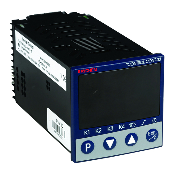
TCONTROL-CONT-03
COMPACT MICROPROCESSOR CONTROLLER
OPERATING AND INSTALLATION MANUAL
Related Manuals for nVent RAYCHEM TCONTROL-CONT-03
Summary of Contents for nVent RAYCHEM TCONTROL-CONT-03
-
Page 1
TCONTROL-CONT-03 COMPACT MICROPROCESSOR CONTROLLER OPERATING AND INSTALLATION MANUAL… -
Page 3: Table Of Contents
CONTENTS Section − 1 Introduction …………4 1.1 Preface ……………. 4 1.2 Type designation …………5 1.3 Scope of delivery …………5 1.4 Accessories …………..5 1.5 Type-dependent factory settings ……. 6 Section − 2 Installation …………9 2.1 Installation site and ambient conditions ….9 2.2 Dimensions …………..
-
Page 4: Introduction
Introduction Preface Please read this manual before commissioning the device. Keep the manual in a place accessible to all users at all times. Your comments are appreciated and may assist us in improving this manual. All necessary settings are described in this operating manual. Manipulations not described in the manual or expressly forbidden will jeopardize your warranty rights. Please contact the nearest subsidiary or the head office, should you encounter problems. The manual is valid from device software version 223.01.04 Chapter 4.7 “Display of the software version” Warning signs DANGER! This symbol indicates that Injury or death caused by electrical shock can/may occur, if the respective protective measures are not carried out. CAUTION! This symbol in combination with the signal word indicates that Damage to assets or data loss will occur, if the respective protective measures are not carried out.
-
Page 5: Type Designation
Type designation Type key Type description 702071/9-1131-23-00 TCONTROL-CONT-03 (nVent Part No.: nominal dimension 48 mm x 48 mm 1244-0006829) • 1 analog input • 3 relays 702071/9-1134-23-00 TCONTROL-CONT-03/MA (nVent Part No.: nominal dimension 48 mm x 48 mm 1244-0006830) • 1 analog input • 2 relays • 1 analog output (user configurable 0/4…20 mA or 0/2…10 V) 702071/9-1131-23-53 TCONTROL-CONT-03/COM (nVent Part No.:…
-
Page 6: Type-Dependent Factory Settings
The following tables show the type-dependent factory settings. The standard factory settings are shown in the respective sections of this manual. The settings for type TCONTROL-CONT-03 are also valid for type TCONTROL-CONT-03/COM. The settings for type TCONTROL-CONT-03/MA are also valid for type TCONTROL-CONT-03/COMA.
-
Page 7
Configuration level (ConF) cont… Parameter Factory setting for type TCONTROL- CONT-03 TCONTROL- CONT-03/MA Limit comparator 1 (LC1): Function (FnCt) Alarm value (AL) Response by Out of 1 (= ON) 1 (= ON) Range (ACrA) Limit comparator 2 (LC2): Function (FnCt) Alarm value (AL) 120.0 120.0 Response by Out of 1 (= ON) 1 (= ON) Range (ACrA) Binary outputs (OutL):… -
Page 8
User level (USEr) configuration Factory setting for type TCONTROL-CONT-03 TCONTROL-CONT-03/MA Parameter Name Parameter Name Set point 1 Set point 1 Limit comparator 1: Limit comparator 1: Limit Limit value value (Alarm value) (Alarm value) Limit comparator 2: Limit comparator 2: Limit Limit value value… -
Page 9: Installation
Installation Installation site and ambient conditions The ambient conditions at the installation site must meet the requirements specified in the technical data. Chapter 8.1 “Technical Data” The device is not suitable for use in areas with an explosion hazard (Ex areas). Cleaning the device front The device front can be cleaned using warm or hot water (possibly adding slightly acidic, neutral or slightly alkaline cleaning agent). It has a limited resistance to organic solvents (e. g. methylated spirits, white spirit, etc.). Do not use abrasive or high-pressure cleaning equipment. Dimensions Close mounting Minimum spacing of panel cut-outs horizontal vertical without setup plug > 8 mm >…
-
Page 10: Electrical Connection
Electrical connection Installation notes • The choice of cable, the installation and the electrical connection of the device must conform to the requirements of VDE 0100 “Regulations on the Installation of Power Circuits with Nominal Voltages below 1000 V” or the appropriate local regulations. • The electrical connection must only be carried out by qualified personnel. • The instrument shall be operated by mains protected with a branch circuitry overcurrent protection device not more than 20 Amps. For servicing/repairing a Disconnecting Device shall be provided to disconnect all conductors. • The load circuit must be fused for the maximum relay current, in order to prevent the output relay contacts becoming welded in the event of a short circuit occurring at that point. • The electromagnetic compatibility conforms to the standards and regulations cited in the technical data. •…
-
Page 11: Electrical Isolation
Electrical isolation 2300 V AC 30 V AC (1) Analog input 50 V DC (2) Binary inputs/Output K3 (Logics) (3) Setup interface 30 V AC 50 V DC (4) Voltage supply (5) RS485 interface (6) Analog output 2300 V AC (7) Outputs K1, K2 and K4 (relay) Connection diagram 0/4—20mA 0/2—10V (5.1) (5.2) 0/14V 0/2—10V (6.1) 0/4—20mA N(L-) (6.2) (6.3) (6.4)
-
Page 12: Operation
Operation Display and operating elements (1) Red 7-segment display (factory-setting: Process value); 4-digit, configurable decimal place (automatic adjustment on display overflow) (2) Green 7-segment display (factory-setting: Set point value); 4-digit, configurable decimal place, serves also for operator guide (display of parameter and level symbols) (3) Signals, yellow LED Switching states of the binary outputs 1 … 4 (display lit = ON) (4) Keys Programming key l eave level/function key Chapter 7.8 “Display/Operation/Service counter” Value reduction/previous parameter Value increase/next parameter (5) Signals, green LED • Manual mode active • Ramp function active •…
-
Page 13: User Level Configuration
A maximum of eight frequently used parameters can be made available in the User level. Use the Setup program to configure these parameters. O nce these parameters are selected a customer friendly name can be assigned. Names can consist out of maximum four characters (represented on 7-segment display). If no name is assigned the factory defaults will be used. Figure shows the menu of the Setup program (in case of TCONTROL-CONT-03/MA and …/COMA parameter 8 is switched off) nVent.com | 13…
-
Page 14: Defining Various User Levels
Defining various user levels Access to the individual levels can be inhibited. Operator, User Parameter Configuration Code level level level free free free free free inhibited free inhibited inhibited inhibited inhibited inhibited 1. For code entry use (simultaneously for > 5 s) 2. Change code by pressing (display blinks!) 3. Enter code using (Ex-factory: all levels enabled) 4. Return to the normal display using or automatic return after 180 s T he parameter and configuration level can also be inhibited via the binary function.
-
Page 15: Controller
Time entry A decimal place is mapped in the centre and on the right to display times. The time unit can be configured. Chapter 7.5 “Timer” Change value Select Parameter (bottom — green) (top — red) Parameter flashes 1. Select parameter by pressing 2. Change to the entry mode using (lower display blinks) 3.
-
Page 16: Display Of The Software Version
Changing to the manual mode I n the manual mode, the controller output value can be changed manually. 1. Change to the manual mode using function key (> 2 s) (ex-factory setting) The output value is displayed in percent in the lower display. The «Manual mode active» LED is also lit. 2. Change the output value using With a modulating controller, the actuator is opened or closed using the keys. The various levels can be accessed in the manual mode. T he Setup program can be used to configure the default output value on a changeover. The manual mode can also be inhibited. Chapter 7.2 “Controller” T he controller automatically changes to manual mode in the event of overrange/underrange and probe break. Manual mode exit 1. Exit the manual mode using function key (> 2 s) Operation via binary functions F urther operating possibilities for the fixed value controller can be realised via binary functions.
-
Page 17: Operator Level
Operator level Parameters Depending on the configuration, the following values are displayed: Symbol Meaning Set point value 1 (can be edited) SP 1 Set point value 2 (can be edited), only when switching SP 2 over to set point value 2 v Chapter 7.7 “Binary functions” Ramp set point value (only if configured) Chapter 7.3 “Ramp function” inP 1 Measured value of analog input 1 Output value Timer time (only if configured and timer is not running) Chapter 7.5 “Timer” Timer running time (only if timer runs) Chapter 7.5 “Timer” Residual timer running time (only if timer runs) Chapter 7.5 “Timer” Service counter display (only if service counter runs or as long as a reached limit value was not reset) Chapter 7.8 “Display/Operation/Service counter” Parameter level Normal display OPr/USEr PArA Parameter level PArA >2s…
-
Page 18
Value Parameters Symbol range Description Proportional 0…9999 Proportional band band At Pb1,2 = 0, the controller structure 0…9999 is ineffective. For the continuous controller Pb1,2 must be > 0. Derivative 0… Influences the differential component time 9999s of the controller output signal The larger the derivative time the higher the effectiveness of the D component. Reset time 0… Influences the integral component of 9999s the controller output signal The larger the reset time the lower the effectiveness of the I component. -
Page 19: Configuration Level
Standard factory settings are shown bold. Non-standard factory settings: Chapter 1.5 “Type-dependent factory settings” Parameter display independent of the controller type: Chapter 7.2 “Controller” Decimal places for some parameters depend on the device setting: Chapter 7.8 “Display/Operation/Service counter” Configuration level Normal display OPr /USEr PArA Configuration level ConF ConF…
-
Page 20
Analog selector Some parameters in the Configuration level allow users to select from a series of analog values. The list below shows all available options. Value Description Deactivated Analog input Process value Current set point value Ramp limit value Ramp set point value (Reserved) (Reserved) Set point value 1 Set point value 2 Controller output value (-100%…+100%) Controller output 1 (0…+100%; e. g. “Heating”) Controller output 2 (0…-100%; e. g. “Cooling”) Timer run time (time unit of the timer) Residual timer run time (time unit of the timer) (Reserved) (Reserved) (Reserved) 20 | nVent.com… -
Page 21: Analog Input
Analog input One analog input is available. ConF -> i nP -> Parameters Value / Selection Description Sensor type Pt100, 3 wire SEnS Pt1000, 3 wire Pt100, 2 wire Pt1000, 2 wire KTY 2 wire (reserved) Cu-CuNi T Fe-CuNi J Cu-CuNi U Fe-CuNi L NiCr-Ni K Pt10Rh-Pt S Pt13Rh-Pt R Pt30Rh-Pt6Rh B NiCrSi-NiSi N NiCr-CuNi E W5Re_W26Re C W3Re_W25Re D W3Re_W26Re 0……
-
Page 22
Value / Parameters Selection Description -1999 … The measured value correction (offset) Measured value offset 0 … +9999 is used to correct a measured value by a certain amount upward or downward. OFFS Examples: Measured value Offset Displayed value 294.7 +0.3 295.0 295.3 -0.3 295.0 -1999 … Scale low On transducers with standard signal, a level +9999 display value is assigned to the physical signal (scaling). Example: 0 … 20 mA = 0 … 1500°C. -1999 … Scale high The range of the physical signal can be level +9999… -
Page 23: Controller
Controller C ontroller type and controller input values, set point limit values, functions for manual mode and the presettings of self- optimization are set here. ConF -> Cntr -> Value / Parameters Selection Description Controller type 2-state controller 3-state controller CtyP Modulating controller Continuous controller Control Direct direction Inverse CACt (1) = Inverse: Output value Y of the controller is > 0, if process value x is smaller than set point value w (e.g. heating). (2) = Direct: Output value Y of the controller is > 0, if process value x is higher than set point value w (e.g. cooling).
-
Page 24: Ramp Function
Value / Parameters Selection Description Set point -1999 … The set point limitation prevents the entry limit low +9999 of values outside the default range. The set point limit values are not effective when entering set point default values Set point -1999 … via the interface. The correction value limit high +9999 is limited for external set point values with offset. (analog Determines the source of the controller Process value for controller selector) process value. Analog Page 16, Analog selector input…
-
Page 25
ConF -> rAFC -> Value / Parameters Selection Description deactivated Function Ramp Kelvin/Minute FnCt Ramp Kelvin/Hour Ramp Kelvin/Day The ramp limit value can be changed using keys. t2 t3 (1) = Set point value (2) = Process value t1: Power ON/Ramp start (w1 active) t2-t3: Mains failure/Manual mode/Probe break t4-t5: Ramp stop t6: Set point value changeover to w2 The ramp function can be stopped, cancelled and restarted using binary functions. Chapter 7.7 “Binary functions” Ramp rate 0.0… Value of ramp rate 999.9 (for functions 1 to 3 only) rASL 0…9999… -
Page 26: Limit Comparators
TIP! T he ramp function is cancelled in the event of a probe break or in manual mode. The outputs react in the same manner as for an overrange/underrange (configurable). Limit comparators L imit comparators can be used to monitor the process value against defined alarm limits. The way the limit comparators operate can be configured by the user (lk1 to lk8). Once an alarm limit (alarm set point) is exceeded, an alarm signal can be ouput or an internal function can be initiated. T here are 2 limit comparators available (LC1, LC2). The switching differential HySt can be user defined and will always be symmetrical in relation to the alarm set point (AL). Alarm value AL relative to the set point value w The limit comparator functions lk1 to lk6 monitor the process value x for an alarm value AL which is relative to the set point value w. This means that if the set point is changed the absolute…
-
Page 27
Fixed alarm value AL The limit comparator functions lk7 and lk8 monitor the process value x for a fixed alarm value AL to be set. HySt HySt ConF -> LC -> LC1, LC2 -> Value / Parameters Selection Description no function Function FnCt Function -1999 … Alarm value (limit value) to be monitored (see limit comparator functions lk1…lk8: +9999 alarm value AL) Alarm value range for lk1 and lk2: 0 … 9999 0… Hysteresis in respect to the alarm value Hysteresis 1 … (see limit comparator functions lk1…lk8: HySt 9999 hysteresis HySt) Switching state in the event of overrange Response by Out of Range… -
Page 28: Timer
Timer Timer signal A timer signal (tF1) is provided which can be transmitted via binary outputs or used for internal links, e. g. to switch off the controller (output value 0%) or to toggle the set point values. Chapter 7.6 “Outputs“ and Chapter 7.7 “Binary functions” The timer signal is active either when the timer runs or during the timer follow-up time (see below). The signal can be inverted via the “SiGn” parameter. Timer time The timer runs for the set time t1. Timer time, current timer running time and residual timer time can be displayed in the operator or User level (the timer time can also be changed here).
-
Page 29
Timer signal for t2 = 0 for t2 = 1…9999 (or -1) “Timer running” “Timer waiting” “Timer completed” for t2 = 0 for t2 = 1…9999 (or -1) Waiting time Timer time t1 + Waiting time Timer follow-up time t2 1 Timer started 4 Timer elapsed 2 Timer stopped… -
Page 30: Outputs
Value / Parameters Selection Description Set time t2 -1… This time (in seconds) can be used to 0… transmit a time limited or acknowledgeable (Timer follow- +9999 signal after the timer time has elapsed. up time) 0 = switched off 1…9999 = active for the set time -1 = active until acknowledged Acknowledgement: For t2 = -1 the timer follow-up time is infinite. Cancel the signal using a function…
-
Page 31
ConF -> OutP-> OutL -> Value / Parameters Selection Description No function Binary outputs Controller output 1 0ut1 (e.g.“Heating”, with inverse control direction) 0ut2 Controller output 2 (e.g. “Cooling”, see above) 0ut3 Binary input 0ut4 (reserved) Limit comparator 1 Limit comparator 2 Timer signal Timer runs Timer completed Timer waiting (reserved) (reserved) Tolerance band signal, ramp Ramp end signal Service alarm (reserved) Actuate the F key… -
Page 32: Binary Functions
Value / Parameters Selection Description -1999 … A value range of the output variable is Zero point 0… assigned to a physical output signal. 0Pnt +9999 The ex-factory setting corresponds to an output value of 0 … 100 % for controller -1999 … End value outputs. 100… No changes of the ex-factory setting are +9999 required for continuous controllers. For a 3-state controller, enter the following settings for cooling: Zero point = 0 / End value = -100 Example (function as a transducer): The analog output (0…20 mA) is to be used to put out the process value (value range: 150…500 °C), this means: 150…500°C = 0…20 mA Zero point: 150 / End value: 500 Binary functions…
-
Page 33
Further functions via Setup program In the Setup program binary functions can be combined with each other (selection under “Additional functions”). It is also possible to select “Text display” as an additional function. A maximum of 4 characters can be entered as text (“Text display” button) and displayed with a 7-segment display. The text appears in the lower display when the binary function is active. ConF -> b nF Value / Parameters Selection Description Binary inputs no function Start self-optimization b n 1 Abort self-optimization b n2 Change to manual mode Controller off (controller outputs are Limit switched off) comparators Switch on controller Inhibit manual mode Stop ramp… -
Page 34: Display/Operation/Service Counter
Display/Operation/Service counter Both displays can be adapted to the respective requirements by the configuration of the displayed value, the decimal place and the automatic change (timer). The time-out of the operation, the function key assignment and the level inhibit can also be configured. ConF -> d SP -> Value / Parameters Selection Description (Analog Display value for the upper display Upper display selector) d SU Process value Lower display (analog Display value for the lower display selector) d SL Current set point value Time appears in the lower display Display change to timer value (only effective after the timer is started)
-
Page 35
Value / Parameters Selection Description Function key Function if the key is briefly pressed in the short normal display (max. two seconds) no function (Push time Starting the timer < 2 seconds) Timer abort Stop timer/continue timer run Timer start/abort Display timer value (manual) Function key Function if the key is pressed for more than long two seconds in the normal display tASt Change to manual mode (Push time Starting the timer >2 seconds) -
Page 36
Value / Parameters Selection Description Service interval Number: Limit value for service counter (when select. “Number” in increm. of 1000) (Setup) 0… 0 = Service counter switched off 9999000 oCAL The service counter can be used to monitor Time (h): a binary signal in respect to number 0…999 (switch-on edge) or time (ON state). Time (d): 0…999 The service counter is started when entering a value > 0. When the limit value is exceeded, a signal is generated which can be put out to a binary output. The signal can only be acknowledged by resetting the limit value to zero (service counter switched off). -
Page 37
Controller Selection of the binary signal to be monitored Signal to be monitored output 1 Setting in the Setup program (-> Display/ (Setup) Operation/Service counter -> Service counter): — deactivated — Controller output 1 — Controller output 2 — Binary input 1 — Binary input 2 — Limit comparator 1 — Limit comparator 2 — Timer signal — Timer runs — Timer completed — Timer waiting — Tolerance band signal — Ramp end… -
Page 38: Interface
Interface The device can be integrated into a data network (Modbus) via an optional RS485 interface. ConF -> i ntF -> Value / Parameters Selection Description 9600 bps Baud rate 19200 bps bdrt 38400 bps 8 data bits, 1 stop bit, no parity Data format 8 data bits, 1 stop bit, odd parity 8 data bits, 1 stop bit, even parity 8 data bits, 2 stop bits, no parity 0…1… Address in data network Device address 0 ……
-
Page 39: Supplement
Supplement Technical Data Thermocouple input Designation Ambient Measuring Measuring temperature range accuracy coefficient Fe-CuNi “L” -200… +900 °C ≤ 0.25% 100 ppm/ K Fe-CuNi “J” 60584 -200…+1200 °C ≤ 0.25% 100 ppm/ K Cu-CuNi “U” -200… +600 °C ≤ 0.25% 100 ppm/ K Cu-CuNi “T” 60584 -200… +400 °C ≤ 0.25% 100 ppm/ K NiCr-Ni “K” 60584 -200…+1372 °C ≤ 0.25% 100 ppm/ K NiCr-CuNi “E” 60584 -200… +900 °C ≤ 0.25% 100 ppm/ K NiCrSi-NiSi “N”…
-
Page 40
RTD temperature probe input Designation, Measuring Measuring Ambient temperature Connection type range accuracy coefficient Pt100 EN -200… +850 °C 50 ppm/K 60751 2 wire connection 3 wire ≤ 0.4% connection ≤ 0.1% Pt1000 EN -200…+850 °C 50 ppm/ K 60751 2 wire connection 3 wire ≤ 0.2% connection ≤ 0.1% KTY11-6 -50…+150 °C 50 ppm/ K… -
Page 41
Binary inputs Potential-free contact open = inactive closed = active Measuring circuit monitoring In the event of a fault, the outputs change to defined statuses (configurable). Input sensor/ Overrange/ lead short- Input sensor/ Sensor underrange circuit lead break Thermocouple • – • Resistance • • • thermometer Voltage • • • 2—10 V (•) –… -
Page 42
Controller Controller type 2-state, 3-state, modulating controller, continuous controller Controller P/PI/PD/PID structures A/D converter 16 bit resolution Sampling cycle 250 ms time Timer Accuracy ±0.8 % ± 25 ppm/K Electrical data Supply voltage AC 110—240 V -15/+10%, 48—63 Hz (switch mode PSU) AC/DC 20—30 V, 48 — 63 Hz Electrical safety acc. to EN 61010, part 1 Overvoltage category III, pollution degree 2 Amperage max. 15 VA Data backup EEPROM Electrical at the back via screw terminals, connection Conductor cross section up to max. 1.3 mm Installation information on conductor cross sections Solid core ≤ 1.3 mm… -
Page 43: Alarm And Fault Messages
Operating position Protection type acc.to EN 60529, at the front IP 65, at the rear IP 20 Weight approx. 123 g (fully equipped) Interface Interface type RS485 Protocol Modbus Baud rate 9600, 19200, 38400 Device address 0—255 Max. number of stations Alarm and fault messages Thermocouple input Fault remedy Display Cause Test/repair/replace Binary function for Carry out the measure ALrt (factory-specific which a text display intended for this case text, can be was configured is changed)
-
Page 44: Self-Optimization
Self-optimization Principle Self-optimization (SO) is carried out according to the oscillation method and establishes the optimum controller parameters for PID or PI controllers. Depending on the configured controller type, the following controller parameters are defined: Proportional band (Pb), derivative time (dt), reset time (rt), cycle times (Cy), filter time constant (dF) Depending on the range of the control deviation, the controller selects between to methods a or b: a) SO in start-up phase b) SO at set point S = Switching level T = Start of self-optimization (SO) Prerequisites The following prerequisites must be fulfilled to be able to start self- optimization:…
-
Page 45
• For continuous controller only: Ensure that the function of the output (OutP -> OutA) is configured to controller output 1 and scaled to 0…100%. This means: Function (FnCt) = Controller output 1 (11) Zero point (0Pnt) = 0 End value (End) = 100 • For modulating controllers only: Determine the actuator time (tt) and set in the Parameter level Start of self-optimization 1. Simultaneously press the + keys (> 2 s) In the lower display, “tUnE” appears flashing. Self-optimization is completed when the display automatically changes to the standard display. The duration of self-optimization depends on the process. Canceling self-optimization 1. -
Page 46
46 | nVent.com… -
Page 47
nVent.com | 47… -
Page 48
België / Belgique Italia Россия Tel. +32 16 21 35 02 Tel. +39 02 577 61 51 Тел. +7 495 926 18 85 Fax +32 16 21 36 04 Fax +39 02 577 61 55 28 Факс +97 495 926 18 86 salesbelux@nvent.com salesit@nvent.com salesru@nvent.com Bulgaria Lietuva/Latvija/Eesti Serbia and Montenegro Tel. +359 5686 6886 Tel. +370 5 2136633 Tel. +381 230 401 770 Fax +359 5686 6886 Fax +370 5 2330084 Fax +381 230 401 770 salesee@nvent.com info.baltic@nvent.com salesee@nvent.com Česká Republika Magyarország Schweiz / Suisse Tel. +420 602 232 969 Tel. +36 1 253 7617 Tel. +41 (41) 766 30 80 czechinfo@nvent.com Fax +36 1 253 7618 Fax +41 (41) 766 30 81 saleshu@nvent.com infoBaar@nvent.com Denmark…
Hide thumbs
Also See for TCONTROL-CONT-03:
- Manual (80 pages)
-
Contents
-
Table of Contents
-
Bookmarks
Quick Links
All manuals and user guides at all-guides.com
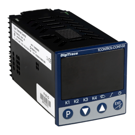
DigiTrace TCONTROL-CONT-03
Compact microprocessor controller
Régulateur compact géré par microprocesseur
Kompakter Mikroprozessorregler
INSTALL-160 Rev. 1
Modbus Manual
Notice Modbus
Modbus-Anleitung
2013-05-21/00521759
Related Manuals for DigiTrace TCONTROL-CONT-03
Summary of Contents for DigiTrace TCONTROL-CONT-03
-
Page 1
All manuals and user guides at all-guides.com DigiTrace TCONTROL-CONT-03 Compact microprocessor controller Régulateur compact géré par microprocesseur Kompakter Mikroprozessorregler INSTALL-160 Rev. 1 Modbus Manual Notice Modbus Modbus-Anleitung 2013-05-21/00521759… -
Page 2
All manuals and user guides at all-guides.com… -
Page 3: Table Of Contents
All manuals and user guides at all-guides.com Contents Introduction Preface ………………….5 Typographical conventions …………… 5 Protocol description Master-Slave principle …………….7 Transmission mode (RTU) …………….. 7 Device address ………………. 8 Timing of the communication …………..8 Structure of the data blocks …………..11 Function codes ………………
-
Page 4
All manuals and user guides at all-guides.com Contents… -
Page 5: Introduction
All manuals and user guides at all-guides.com 1 Introduction 1.1 Preface This operating manual is addressed to the system manufacturer with adequate technical background and PC related knowledge. Please read this operating manual prior to commissioning the device. Keep the manual in a place accessible to all users at all times. Your comments are appreciated and may assist us in improving this manual.
-
Page 6
All manuals and user guides at all-guides.com 1 Introduction… -
Page 7: Protocol Description
All manuals and user guides at all-guides.com 2 Protocol description 2.1 Master-Slave principle Communication between a master (e.g. PC) and a slave (e.g. measuring and control system) using Modbus takes place according to the master-slave principle, in the form of data request/instruction — response. Master Slave 1 Slave 2…
-
Page 8: Device Address
All manuals and user guides at all-guides.com 2 Protocol description 2.3 Device address The device address of the slave can be set between 0 and 254. Device address 0 is reserved. A maximum of 31 slaves can be addressed via the RS485 interface. There are two different forms of data exchange: Query Data request/instruction by the master to a slave via the corresponding device…
-
Page 9
All manuals and user guides at all-guides.com 2 Protocol description Timing Data request from master transmission time = n characters * 1000 * x bit/baud rate Marker for end of data request 3 characters * 1000 * x bit/baud rate Processing of data request by the slave (… -
Page 10
All manuals and user guides at all-guides.com 2 Protocol description Timing A data request runs according to the following timing scheme: scheme Data request Data request Master Response Slave End marker = 3 characters (time depending on the baud rate) This time depends on the internal processing. -
Page 11: Structure Of The Data Blocks
All manuals and user guides at all-guides.com 2 Protocol description Structure of the data blocks All data blocks have the same structure: Data structure Slave Function Data field Checksum address code CRC16 1 byte 1 byte x byte 2 bytes Each data block contains four fields: Slave address device address of a specific slave…
-
Page 12: Function Codes
All manuals and user guides at all-guides.com 2 Protocol description Function codes The functions described in the following are available for the readout of measured values, device and process data as well as to write specific data. Function- Function Function Limitation overview number…
-
Page 13: Write One Word
All manuals and user guides at all-guides.com 2 Protocol description 2.6.2 Write one word For the Write Word function, the data blocks for instruction and response are identical. Instruction Slave Function Word address Word value Checksum address 0x06 CRC16 1 byte 1 byte 2 byte 2 bytes…
-
Page 14: Write N Words
All manuals and user guides at all-guides.com 2 Protocol description 2.6.3 Write n words This function is used to write n (n 32) words starting from a specific address. Instruction Slave Function Address Number Number Word ChecksumC address 0x10 first word of words value(s)
-
Page 15: Transmission Format (Integer, Float And Text Values)
All manuals and user guides at all-guides.com 2 Protocol description Transmission format (integer, float and text values) Integer values Integer values are transmitted via the Modbus in the following format: The high byte first, followed by the low byte. Example Request of the integer value of address 0x0021, if value «4»…
-
Page 16
All manuals and user guides at all-guides.com 2 Protocol description Character Character strings (texts) are transmitted in the ASCII format. strings To mark the end, the last character to be transmitted can be a «» (texts) (ASCII code 0x00). Characters after this mark are without significance. -
Page 17
All manuals and user guides at all-guides.com 2 Protocol description Checksum (CRC16) The checksum (CRC16) serves to recognize transmission errors. If an error is identified during evaluation, the device concerned does not respond. Calculation CRC = 0xFFFF scheme CRC = CRC XOR ByteOfMessage For (1 to CRC = SHR(CRC) if (flag shifted right = 1)
 -
Page 18: Checksum (Crc16)
All manuals and user guides at all-guides.com 2 Protocol description Error processing Error codes The following error codes exist: invalid function invalid parameter address or too many words are to be read or written write access to parameter denied Response in Slave Function Error code…
-
Page 19: Rs485 Interface
All manuals and user guides at all-guides.com 3 RS485 interface 3.1 Connection diagram This device can be ordered with an RS485 interface as an option. Please refer to the Operating and Installation manual INSTALL-148 for the type designation. N(L-) RxD/TxD L1(L+) (1) RS485 interface Connect the interface line shielding to earth on one side in the…
-
Page 20: Configuration
All manuals and user guides at all-guides.com 3 RS485 interface Configuration The following table shows the possible Modbus interface settings to be ➔ carried out in the configuration level (ConF IntF) and/or in the setup program. For more detailed information about configuration, please refer to the Operating and Installation manual INSTALL-148.
-
Page 21: Modbus Addresses
All manuals and user guides at all-guides.com 4 Modbus addresses Data type, The following tables contain specifications of all process and device data including their addresses, data type and type of access. type of access Meaning: Read only access Write only access Read/write access Integer (8 or 16 bit) Bit x…
-
Page 22: Set Point Values
All manuals and user guides at all-guides.com 4 Modbus addresses Address Data type/ Access Signal designation bit number 0x0024 Limit comparators 1…2 Bit 0 Limit comparator 1 (= 0x0001) Bit 1 Limit comparator 2 (= 0x0002) 0x0025 Control of the binary outputs (individual) Bit 0 + Bit 8 Output K1 (= 0x0101) Bit 1 + Bit 9…
-
Page 23: Controller Parameters
All manuals and user guides at all-guides.com 4 Modbus addresses 4.3 Controller parameters Address Data type/ Access Signal designation bit number 0x3000 FLOAT Controller parameter XP1 0x3002 FLOAT Controller parameter XP2 0x3004 FLOAT Controller parameter TV 0x3006 FLOAT Controller parameter TN 0x300C FLOAT Controller parameter CY1…
-
Page 24: Commands
All manuals and user guides at all-guides.com 4 Modbus addresses Commands Address Data type/ Access Signal designation bit number 0x004D Binary functions CONTROLLER Bit 0 Self-optimization start (=0x0001) Bit 1 Self-optimization abort (=0x0002) Bit 2 Manual operation (= 0x0004) Bit 3 Automatic operation (= 0x0008) Bit 4 Controller off (= 0x0010)
-
Page 25: Ram Memory
All manuals and user guides at all-guides.com 4 Modbus addresses RAM memory Address Data type/ Access Signal designation bit number 0x3200 FLOAT Controller set point value (writable) 0x3202 FLOAT Controller actual value (writable) 0x3204 FLOAT Internal analog value 1 (writable) 0x3206 FLOAT Internal analog value 2 (writable)
-
Page 26
All manuals and user guides at all-guides.com 4 Modbus addresses… -
Page 27
All manuals and user guides at all-guides.com DigiTrace TCONTROL-CONT-03 Régulateur compact géré par microprocesseur INSTALL-160 Rev. 1 Notice Modbus 2013-05-21… -
Page 28
All manuals and user guides at all-guides.com… -
Page 29
All manuals and user guides at all-guides.com Sommaire Introduction Avant-propos ………………..5 Conventions typografiques …………… 5 Description du protocole Principe maître-esclave …………….7 Mode de transmission (RTU) …………..7 Adresse-appareil ………………8 Déroulement temporel de la transmission ……….8 Structure des blocs de données …………. 11 Code des fonctions ……………… -
Page 30
All manuals and user guides at all-guides.com Sommaire… -
Page 31: Avant-Propos
All manuals and user guides at all-guides.com 1 Introduction 1.1 Avant-propos Cette notice s’adresse aux constructeurs avec formation spécialisée et possé- dant des connaissances en PC. Lisez cette notice avant de mettre en service l’interface. Conservez cette notice dans un endroit accessible à tout moment à tous les utilisateurs.
-
Page 32
All manuals and user guides at all-guides.com 1 Introduction… -
Page 33: Description Du Protocole
All manuals and user guides at all-guides.com Description du protocole 2.1 Principe maître-esclave La communication entre un appareil maître (par ex. un PC) et un appareil es- clave (par ex. système de mesure et de régulation) avec le protocole ModBus se déroule selon le principe maître/esclave sous la forme demande de don- nées/instruction-réponse.
-
Page 34: Adresse-Appareil
All manuals and user guides at all-guides.com 2 Description du protocole 2.3 Adresse-appareil L’adresse appareil de l’esclave est réglable entre 0 et 254. L’adresse appareil 0 est réservée. L’interface RS485 permet d’adresser au maximum 31 esclaves. Il existe deux possibilités d’échange de données : Query Demande de données / instruction du maître à…
-
Page 35
All manuals and user guides at all-guides.com 2 Description du protocole Déroulement Demande de données du maître Temps de transfert = n caractères * 1000 * x bits / débit en baud Identificateur de fin de demande de données 3 caractères * 1000 * x bits / débit en baud Traitement de la demande de données par l’esclave (250 ms) Réponse de l’esclave Temps de transfert = n caractères * 1000 * x bits / débit en baud… -
Page 36
All manuals and user guides at all-guides.com 2 Description du protocole Chronogramme Une demande de données se déroule selon le chronogramme suivant : Demande de Demande de données données Maître Réponse Esclave Identificateur de fin = 3 caractères. La durée dépend du débit en baud. Cette durée dépend du traitement interne. -
Page 37: Structure Des Blocs De Données
All manuals and user guides at all-guides.com 2 Description du protocole Structure des blocs de données Tous les blocs de données ont la même structure : Structure des Adresse Code Données Somme de contrôle données de l’esclave de la fonction CRC16 1 octet 1 octet…
-
Page 38: Code Des Fonctions
All manuals and user guides at all-guides.com 2 Description du protocole Code des fonctions Les fonctions suivantes décrites sont disponibles pour la lecture de valeurs de mesure, de données de process et des appareils ainsi que pour l’écriture de données définies. Aperçu des Numéro Fonction…
-
Page 39: Ecriture D’un Mot
All manuals and user guides at all-guides.com 2 Description du protocole 2.6.2 Ecriture d’un mot Pour cette fonction, les blocs de données de l’ordre sont identiques aux blocs de données de la réponse. Ordre Adresse de Fonction Adresse mot Valeur mot Somme de l’esclave 0x06…
-
Page 40: Ecriture De N Mots
All manuals and user guides at all-guides.com 2 Description du protocole 2.6.3 Ecriture de n mots Avec cette fonction, n mots (n 32) peuvent être lus à partir d’une adresse dé- finie. Ordre Adresse Fonction Adresse Nombre Nombre Valeur(s) Somme de 0x10 1er mot…
-
Page 41: Format De Transmission (Valeurs Entières, Flottantes Et Texte)
All manuals and user guides at all-guides.com 2 Description du protocole Format de transmission (valeurs entières, flottantes et texte) Valeurs Avec le protocole Modbus, les valeurs entières sont transmises sous la forme entières suivante : d’abord l’octet de poids fort, ensuite l’octet de poids faible. Exemple Consultation de la valeur entière à…
-
Page 42
All manuals and user guides at all-guides.com 2 Description du protocole Chaînes de Les chaînes de caractères (textes) sont transmises en format ASCII. caractères Le dernier caractère (indicateur de fin) doit toujours être un «» (code (textes) ASCII 0x00). Les caractères qui suivent n’ont aucune importance. Le nombre de caractères max. -
Page 43: Somme De Contrôle (Crc16)
All manuals and user guides at all-guides.com 2 Description du protocole Somme de contrôle (CRC16) La somme de contrôle (CRC16) permet de détecter les erreurs de transmis- sion. Si une erreur est détectée lors de l’analyse, l’appareil correspondant ne répond pas. Mode de CRC = 0xFFFF calcul…
-
Page 44: Traitement Des Erreurs
All manuals and user guides at all-guides.com 2 Description du protocole Traitement des erreurs Code d’erreur Codes d’erreur possibles : fonction invalide Adresse de paramètres invalide ou nombre de mots ou de bits à lire ou à écrire trop élevé Paramètre protégé…
-
Page 45: Interface Rs485
All manuals and user guides at all-guides.com 3 Interface RS485 3.1 Schéma de raccordement Cet appareil peut être commandé avec une interface RS 485, en option. Vous trouverez des références de commande dans la noti- ce de mise en service et de montage INSTALL-150 (identification du type).
-
Page 46: Configuration
All manuals and user guides at all-guides.com 3 Interface RS485 Configuration Les différents réglages de l’interface Modbus qui sont effectués au niveau de ➔ configuration (ConF IntF) et/ou dans le logiciel Setup sont décrits dans le ta- bleau ci-dessous. Vous trouverez des informations complémentaires dans la notice de mise en service et de montage INSTALL-150.
-
Page 47: Adresses Modbus
All manuals and user guides at all-guides.com 4 Adresses Modbus Type de Vous trouverez dans le tableau ci-dessous toutes les valeurs de process (va- riables) avec leurs adresses, le type de données ainsi que le mode d’accès. données, type d’accès Signification : Lecture seule Ecriture seule…
-
Page 48
All manuals and user guides at all-guides.com 4 Adresses Modbus Adresses Type de Accès Désignation du signal données / numéro de 0x0023 Entrées binaires 1 et 2 (états de commutation 0 = ouverte / 1 = fermée) Bit 0 Entrée 1 (= 0x0001) Bit 1 Entrée 2 (= 0x0002) 0x0024… -
Page 49: Consignes
All manuals and user guides at all-guides.com 4 Adresses Modbus 4.2 Consignes Adresses Type de Accès Désignation du signal données / numéro de 0x3100 FLOAT Consigne W1 0x3102 FLOAT Consigne W2 4.3 Paramètres du régulateur Adresses Type de Accès Désignation du signal données / numéro bit 0x3000…
-
Page 50: Commandes
All manuals and user guides at all-guides.com 4 Adresses Modbus Commandes Adresses Type de Accès Désignation du signal données / numéro bit 0x004D Fonctions binaires REGULATEUR Bit 0 Démarrage de l’auto-optimisation (= 0x0001) Bit 1 Annulation de l’auto-optimisation (= 0x0002) Bit 2 Mode manuel (= 0x0004) Bit 3…
-
Page 51: Mémoire Ram
All manuals and user guides at all-guides.com 4 Adresses Modbus Mémoire RAM Adresses Type de Accès Désignation du signal données / numéro bit 0x3200 FLOAT Consigne du régulateur (lecture/écriture) 0x3202 FLOAT Valeur réelle du régulateur (lecture/écriture) 0x3204 FLOAT Valeur analogique interne 1 (lecture/écriture) 0x3206 FLOAT Valeur analogique interne 2 (lecture/écriture)
-
Page 52
All manuals and user guides at all-guides.com 4 Adresses Modbus… -
Page 53
All manuals and user guides at all-guides.com DigiTrace TCONTROL-CONT-03 Kompakter Mikroprozessorregler INSTALL-160 Rev. 1 Modbus-Anleitung 2013-05-21… -
Page 54
All manuals and user guides at all-guides.com… -
Page 55
All manuals and user guides at all-guides.com Inhalt Einleitung Vorwort ………………….5 Typografische Konventionen …………..5 Protokollbeschreibung Master-Slave-Prinzip …………….. 7 Übertragungsmodus (RTU) …………… 7 Geräteadresse ……………….. 8 Zeitlicher Ablauf der Kommunikation …………8 Aufbau der Datenblöcke …………….. 11 Funktionscodes ………………12 2.6.1 Lesen von n Worten ………………. -
Page 56
All manuals and user guides at all-guides.com Inhalt… -
Page 57: Vorwort
All manuals and user guides at all-guides.com 1 Einleitung 1.1 Vorwort Diese Anleitung wendet sich an den Anlagenhersteller mit fachbezogener Aus- bildung und PC-Kenntnissen. Lesen Sie diese Anleitung, bevor Sie mit Ihrer Arbeit am Gerät beginnen. Be- wahren Sie die Anleitung an einem für alle Benutzer jederzeit zugänglichen Platz auf.
-
Page 58
All manuals and user guides at all-guides.com 1 Einleitung… -
Page 59: Protokollbeschreibung
All manuals and user guides at all-guides.com 2 Protokollbeschreibung 2.1 Master-Slave-Prinzip Die Kommunikation zwischen einem Master (z. B. PC) und einem Slave (z. B. Mess- und Regelsystem) mit Modbus findet nach dem Master-Slave-Prinzip in Form von Datenanfrage/Anweisung — Antwort statt. Master Slave 1 Slave 2…
-
Page 60: Geräteadresse
All manuals and user guides at all-guides.com 2 Protokollbeschreibung 2.3 Geräteadresse Die Geräteadresse des Slaves ist zwischen 0 und 254 einstellbar. Die Geräte- adresse 0 ist reserviert. Über die RS485-Schnittstelle können maximal 31 Slaves angespro- chen werden. Es gibt zwei Varianten des Datenaustausches: Query Datenanfrage/Anweisung des Masters an einen Slave über die entsprechende Geräteadresse.
-
Page 61
All manuals and user guides at all-guides.com 2 Protokollbeschreibung Ablauf Datenanfrage vom Master Übertragungszeit = n Zeichen * 1000 * x Bit/Baudrate Kennzeichen für Datenanfrage-Ende 3 Zeichen * 1000 * x Bit/Baudrate Bearbeitung der Datenanfrage durch den Slave ( 250ms) Antwort des Slaves Übertragungszeit = n Zeichen * 1000 * x Bit/Baudrate Kennzeichen für Antwort-Ende… -
Page 62
All manuals and user guides at all-guides.com 2 Protokollbeschreibung Zeitschema Eine Datenanfrage läuft nach folgendem Zeitschema ab: Datenanfrage Datenanfrage Master Antwort Slave Endekennzeichen = 3 Zeichen (die Zeit ist von der Baudrate abhängig) Diese Zeit ist von der internen Bearbeitung abhängig. Die maximale Bearbeitungszeit liegt bei 250 ms. -
Page 63: Aufbau Der Datenblöcke
All manuals and user guides at all-guides.com 2 Protokollbeschreibung Aufbau der Datenblöcke Alle Datenblöcke haben die gleiche Struktur: Datenstruktur Slave- Funktions- Datenfeld Checksumme Adresse code CRC16 1 Byte 1 Byte x Byte 2 Bytes Jeder Datenblock enthält vier Felder: Slave-Adresse Geräteadresse eines bestimmten Slaves Funktionscode Funktionsauswahl (Lesen, Schreiben von Worten)
-
Page 64: Funktionscodes
All manuals and user guides at all-guides.com 2 Protokollbeschreibung Funktionscodes Die nachfolgend beschriebenen Funktionen stehen zum Auslesen von Mess- werten, Geräte- und Prozessdaten sowie zum Schreiben von bestimmten Da- ten zur Verfügung. Funktions- Funktions- Funktion Begrenzung übersicht nummer 0x03 oder 0x04 Lesen von n Worten max.
-
Page 65: Schreiben Eines Wortes
All manuals and user guides at all-guides.com 2 Protokollbeschreibung 2.6.2 Schreiben eines Wortes Bei der Funktion Wortschreiben sind die Datenblöcke für Anweisung und Ant- wort identisch. Anweisung Slave- Funktion Wortadresse Wortwert Checksumme Adresse 0x06 CRC16 1 Byte 1 Byte 2 Byte 2 Bytes 2 Byte Antwort…
-
Page 66: Schreiben Von N Worten
All manuals and user guides at all-guides.com 2 Protokollbeschreibung 2.6.3 Schreiben von n Worten Mit dieser Funktion werden n (n 32) Worte ab einer bestimmten Adresse ge- schrieben. Anweisung Slave- Funktion Adresse Wortan- Byte- Wort- Checksumme Adresse 0x10 erstes Wort zahl anzahl wert(e)
-
Page 67: Übertragungsformat (Integer-, Float- Und Text-Werte)
All manuals and user guides at all-guides.com 2 Protokollbeschreibung Übertragungsformat (Integer-, Float- und Text-Werte) Integer-Werte Integer-Werte werden über Modbus im folgenden Format übertragen: Zuerst das High-, dann das Low-Byte. Beispiel Abfrage des Integer-Wertes von Adresse 0x0021, wenn unter dieser Adresse der Wert «4»…
-
Page 68
All manuals and user guides at all-guides.com 2 Protokollbeschreibung Zeichenketten Zeichenketten (Texte) werden im ASCII-Format übertragen. (Texte) Als letztes Zeichen kann ein «» (ASCII-Code 0x00) als Endekennung übertragen werden. Danach folgende Zeichen haben keine Bedeu- tung. In den Adresstabellen ist die max. mögliche Zeichenanzahl im Daten- typ angegeben, z. -
Page 69: Checksumme (Crc16)
All manuals and user guides at all-guides.com 2 Protokollbeschreibung Checksumme (CRC16) Anhand der Checksumme (CRC16) werden Übertragungsfehler erkannt. Wird bei der Auswertung ein Fehler festgestellt, antwortet das entsprechende Gerät nicht. Berechnungs- CRC = 0xFFFF schema CRC = CRC XOR ByteOfMessage For (1 bis
CRC = SHR(CRC) if (rechts hinausgeschobenes Flag = 1) -
Page 70: Fehlerbehandlung
All manuals and user guides at all-guides.com 2 Protokollbeschreibung Fehlerbehandlung Fehlercodes Es existieren folgende Fehlercodes: ungültige Funktion ungültige Parameteradresse oder zu große Anzahl von Worten soll gelesen oder geschrieben werden Schreibzugriff auf Parameter verweigert Antwort im Slave- Funktion Fehlercode Checksumme Fehlerfall Adresse XX OR 80h…
-
Page 71: Rs485-Schnittstelle
All manuals and user guides at all-guides.com 3 RS485-Schnittstelle 3.1 Anschlussplan Dieses Gerät kann optional mit einer RS485-Schnittstelle bestellt werden. Bestellangaben finden Sie in der in der Betriebs- und Montageanleitung INSTALL-149 (Typenerklärung). N(L-) RxD/TxD L1(L+) (1) RS485-Schnittstelle Die Schirmung der Schnittstellenleitung ist einseitig im Schalt- schrank zu erden.
-
Page 72: Konfiguration
All manuals and user guides at all-guides.com 3 RS485-Schnittstelle Konfiguration Die folgende Tabelle zeigt die möglichen Einstellungen der Modbus-Schnitt- ➔ stelle, die in der Konfigurationsebene (ConF IntF) bzw. im Setup-Programm vorgenommen werden. Weitere Informationen zur Konfiguration können der Betriebs- und Montageanleitung INSTALL-149 entnommen werden.
-
Page 73: Modbus-Adressen
All manuals and user guides at all-guides.com 4 Modbus-Adressen Datentyp, In den folgenden Tabellen sind alle Prozess- und Gerätedaten mit ihren Adres- sen, dem Datentyp und der Zugriffsart aufgeführt. Zugriffsart Hierbei bedeutet: Zugriff nur lesend Zugriff nur schreibend Zugriff lesend und schreibend Integer (8 oder 16 Bit) Bit x Bit Nr.
-
Page 74
All manuals and user guides at all-guides.com 4 Modbus-Adressen Adresse Datentyp/ Zugriff Signalbezeichnung Bitnummer 0x0023 Binäreingänge 1…2 (Schaltzustände 0 = offen / 1 = geschlossen) Bit 0 Eingang 1 (= 0x0001) Bit 1 Eingang 2 (= 0x0002) 0x0024 Limitkomparatoren 1…2 Bit 0 Limitkomparator 1 (= 0x0001) Bit 1… -
Page 75: Sollwerte
All manuals and user guides at all-guides.com 4 Modbus-Adressen 4.2 Sollwerte Adresse Datentyp/ Zugriff Signalbezeichnung Bitnummer 0x3100 FLOAT Sollwert W1 0x3102 FLOAT Sollwert W2 4.3 Reglerparameter Adresse Datentyp/ Zugriff Signalbezeichnung Bitnummer 0x3000 FLOAT Regler-Parameter XP1 0x3002 FLOAT Regler-Parameter XP2 0x3004 FLOAT Regler-Parameter TV 0x3006…
-
Page 76: Kommandos
All manuals and user guides at all-guides.com 4 Modbus-Adressen Kommandos Adresse Datentyp/ Zugriff Signalbezeichnung Bitnummer 0x004D Binärfunktionen REGLER Bit 0 Selbstoptimierung Start (= 0x0001) Bit 1 Selbstoptimierung Abbruch (= 0x0002) Bit 2 Handbetrieb (= 0x0004) Bit 3 Automatikbetrieb (= 0x0008) Bit 4 Regler aus (= 0x0010) Bit 5…
-
Page 77: Ram-Speicher
All manuals and user guides at all-guides.com 4 Modbus-Adressen RAM-Speicher Adresse Datentyp/ Zugriff Signalbezeichnung Bitnummer 0x3200 FLOAT Regler-Sollwert (beschreibbar) 0x3202 FLOAT Regler-Istwert (beschreibbar) 0x3204 FLOAT Interner Analogwert 1 (beschreibbar) 0x3206 FLOAT Interner Analogwert 2 (beschreibbar) 0x3208 Interne Binärwerte (beschreibbar) Bit 0 + Bit 7 Binärwert L1 (= 0x0081) Bit 1 + Bit 7 Binärwert L2 (= 0x0082)
-
Page 78
All manuals and user guides at all-guides.com 4 Modbus-Adressen… -
Page 79
All manuals and user guides at all-guides.com… -
Page 80
All manuals and user guides at all-guides.com ITALIA BELGIË / BELGIQUE РОССИЯ Tel. +39 02 577 61 51 Тел. +7 495 926 18 85 Tel. +32 16 21 35 02 Fax +39 02 577 61 55 28 Факс +7 495 926 18 86 Fax +32 16 21 36 04 salesit@pentair.com salesru@pentair.com…
 CRC = SHR(CRC) if (flag shifted right = 1)
 Table of Contents for DigiTrace TCONTROL-CONT-03:
-
BELGIË / BELGIQUE Tel. +32 16 21 35 02 Fax +32 16 21 36 04 [email protected] BULGARIA Tel./fax +359 56 86 68 86 fax +359 56 86 68 86 [email protected] ČESKÁ REPUBLIKA Tel. +420 241 009 215 Fax +420 241 009 219 [email protected] DANMARK Tel. +45 70 11 04 00 Fax +45 70 11 04 01 [email protected] DEUTSCHLAND Tel. 0800 1818205 Fax 0800 1818204 [email protected] ESPAÑA Tel. +34 902 125 307 Fax +34 91 640 29 90 [email protected] FRANCE Tél. 0800 906045 Fax 0800 906003 [email protected]
-
4 Modbus-Adressen 22 0x0023 INT R/O Binäreingänge 1…2 (Schaltzustände 0 = offen / 1 = geschlossen) Bit 0 Eingang 1 (= 0x0001) Bit 1 Eingang 2 (= 0x0002) 0x0024 INT R/O Limitkomparatoren 1…2 Bit 0 Limitkomparator 1 (= 0x0001) Bit 1 Limitkomparator 2 (= 0x0002) 0x0025 INT R/W Ansteuerung Binärausgänge (einzeln) Bit 0 + Bit 8 Ausgang K1 (= 0x0101) Bit 1 + Bit 9 Ausgang K2 (= 0x0202) Bit 2 + Bit 10 Ausgang K3 (= 0x0404) Bit 3 + Bit 11 Ausgang K4 (= 0x0808) 0x0026 FLOAT R/O Analogeingang [mV] 0x0028 FLOAT R/O Interner Pt100 [Ohm
-
5 1 Einleitung 1.1 Vorwort Diese Anleitung wendet sich an den Anlagenhersteller mit fachbezogener Aus- bildung und PC-Kenntnissen. Lesen Sie diese Anleitung, bevor Sie mit Ihrer Arbeit am Gerät beginnen. Be- wahren Sie die Anleitung an einem für alle Benutzer jederzeit zugänglichen Platz auf. Mit Ihren Anregungen können Sie uns helfen, diese Anleitung zu ver- bessern. Alle erforderlichen Einstellungen sind in der vorliegenden Anleitung beschri
-
1 Einleitung 6
-
2 Protokollbeschreibung 16 Zeichenketten (Texte) Zeichenketten (Texte) werden im ASCII-Format übertragen. Beispiel für Datentyp TEXT4 Lesen des Textes (hier: «AbC «) unter Adresse 0x0067 (max. 4 Zeichen können gespeichert werden) ASCII-Code für «AbC » (mit einem Leerzeichen am Ende): 0x41, 0x62, 0x43, 0x20 Anfrage: 01 03 0067 0002 (+ 2 Byte CRC16) Slave-Adresse = 01 Funktion = 03, d. h.
-
15 2 Protocol description 2.7 Transmission format (integer, float and text values) Integer values Integer values are transmitted via the Modbus in the following format: The high byte first, followed by the low byte. Example Request of the integer value of address 0x0021, if value «4» (word value 0x0004) is written under this address. Request: 01 03 0021 0001 (+ 2 bytes CRC16) Response: 01 03 02 0004 (+ 2 bytes C
-
DigiTrace TCONTROL-CONT-03 Kompakter Mikroprozessorregler INSTALL-160 Rev. 1 Modbus-Anleitung 2013-05-21
-
2 Protokollbeschreibung 18 2.9 Fehlerbehandlung Fehlercodes Es existieren folgende Fehlercodes: 1 ungültige Funktion 2 ungültige Parameteradresse oder zu große Anzahl von Worten soll gelesen oder geschrieben werden 8 Schreibzugriff auf Parameter verweigert Antwort im Fehlerfall Der Funktionscode wird mit 0x80 verODERt, d. h., das MSB (most significant bit, engl. das höchstwertige Bit) wird auf 1 gesetzt. Beispiel Datenanfrage: Antwort (mit Fehlercode 2): Sonderfälle Wen
-
2 Description du protocole 14 2.6.3 Ecriture de n mots Avec cette fonction, n mots (n 32) peuvent être lus à partir d’une adresse dé- finie. Ordre Réponse Exemple Ecriture des consignes W1 et W2 Adresse mot = 0x3100 (consigne W1) Ordre : Réponse: Adresse de l’esclave Fonction 0x10 Adresse 1er mot Nombre de mot (max. 32) Nombre d’octets Valeur(s) mot Somme de contrôle CRC16 1 octet 1 octet 2 octets 2 octets 1 octet x octet(s) 2 octets Adresse de l’esclave Fonction 0x10 Adresse 1er mot Nombre de mot Somme de contrôle CRC16 1 octet
-
5 1 Introduction 1.1 Preface This operating manual is addressed to the system manufacturer with adequate technical background and PC related knowledge. Please read this operating manual prior to commissioning the device. Keep the manual in a place accessible to all users at all times. Your comments are appreciated and may assist us in improving this manual. All necessary settings are described in this operating manual. Should problems be encountered during commissioning, please refrain from carrying out any manipulations th
-
9 2 Protokollbeschreibung Ablauf Beispiel Kennzeichen für Datenanfrage- oder Antwort-Ende bei Datenformat 10/9 Bits Wartezeit = 3 Zeichen * 1000 * 10 Bit/Baudrate Datenanfrage vom Master Übertragungszeit = n Zeichen * 1000 * x Bit/Baudrate Kennzeichen für Datenanfrage-Ende 3 Zeichen * 1000 * x Bit/Baudrate Bearbeitung der Datenanfrage durch den Slave ( 250ms) Antwort des Slaves Übertragungszeit = n Zeichen
-
9 2 Description du protocole Déroulement Exemple Identificateurs de fin de demande de données et de réponse pour le format 10/9 Bits Temps d’attente = 3 caractères * 1000 * 10 bits / débit en baud Demande de données du maître Temps de transfert = n caractères * 1000 * x bits / débit en baud Identificateur de fin de demande de données 3 caractères * 1000 * x bits / débit en baud Traitement de la demande de don
-
19 3 RS485 interface 3.1 Connection diagram (1) RS485 interface v This device can be ordered with an RS485 interface as an option. Please refer to the Operating and Installation manual INSTALL-148 for the type designation. H Connect the interface line shielding to earth on one side in the switch cabinet. 1 2 5 6 N(L-) L1(L+) 14 13 17 20 21 22 23 RxD/TxD 19 18 24 (1) — +
Questions, Opinions and Exploitation Impressions:
You can ask a question, express your opinion or share our experience of DigiTrace TCONTROL-CONT-03 device using right now.
Download Manual of DigiTrace TCONTROL-CONT-03 Controller for Free or View it Online on All-Guides.com.

1

2

3

4

5

6

7

8

9

10

11

12

13

14

15

16

17

18

19

20

21

22

23

24

25

26

27

28

29

30

31

32

33

34

35

36

37

38

39

40

41

42

43

44

45

46

47

48

49

50

51

52

53

54

55

56

57

58

59

60

61

62

63

64

65

66

67

68

69

70

71

72

73

74

75

76

77

78

79

80

DigiTrace TCONTROL-CONT-03
Compact microprocessor controller
Régulateur compact géré par microprocesseur
Kompakter Mikroprozessorregler
INSTALL-160 Rev. 1
Modbus Manual
Notice Modbus
Modbus-Anleitung
2013-05-21/00521759
DigiTrace TCONTROL-CONT-03: Available Instructions
Note for Owners:
Guidesimo.com webproject is not a service center of DigiTrace trademark and does not carries out works for diagnosis and repair of faulty DigiTrace TCONTROL-CONT-03 equipment. For quality services, please contact an official service center of DigiTrace company. On our website you can read and download documentation for your DigiTrace TCONTROL-CONT-03 device for free and familiarize yourself with the technical specifications of device.
-
Viessmann 5223
BedienungsanleitungOperation ManualInnovation, die bewegt!5223Steuermodul für Licht-Ausfahrsignal Control module for colour light departure signal1. Wichtige Hinweise / Important information ………………………………………… 22. Einleitung / Introduction ………………………………………………………………….. 23. Anschluss / Connection ……………… …
5223 Control Unit, 8
-
DuoFern 9494-2
VBD 662-2 (12.16)ENDuoFern Multiple Wall Controller 9494-2Instruction manual for the electrical connection and for commissioningItem no. 3250 19 72 / Type: 9494-2 (flush-mounted device for 230 V/ 50 Hz) …
9494-2 Controller, 44
-
TECSYSTEM T154 Series
1MN0044 REV. 0 operates with ISO9001:2008 certified quality system http: //www.tecsystem.it R. 1.0 05/09/13 “Translations of the original instructions” ENGLISH TECSYSTEM S.r.l. 20094 Corsico (MI) Tel.: +39-024581861 Fax: +39-0248600783 T154 SERIES INSTRUCTION MANUAL …
T154 Series Computer Hardware, 20
-
MIIDEX LIGHTING Vision-EL 7656
• Conservez cette notice tant que vous utilisez l’appareil.• Le montage et l’entretien sont réservés à des personnes qualiées pouvant intervenir sur des produits devant être reliés manuellement à du courant 230V• Avant toute action de montage, coupez l’alimentation électrique.• Le câble extérieur souple de ce produit ne peut être remplacé ; si le câble est endommagé …
Vision-EL 7656 Controller, 2
-
Siemens REA23M
Commissioning and quick start 1. Remove controller from its base and open cover of the battery compartment. 2. Remove the black battery transit tab. The controller will switch itself on. 3. Close the battery compartment and replace the controller. 4. Switch on the boiler. Selecting the operating mode The operating mode selector enables you to select 5 different operating modes: …
REA23M Controller, 2
-
SENSIRION SFC5 Series
SFC5xxxQuick start guide for mass flow controller kit1.000.767 / 2104-EK-F5x-ENThank you for your interest in our mass flow controller solutions.Sensirion AGLaubisrütistrasse 50 · 8712 Stäfa · Switzerland · phone +41 44 306 40 00 · [email protected] www.sensirion.com …
SFC5 Series Controller, 2
-
BAGRAM RGB STX-1796
1www.stairslight.comRGBStairs lighting controllerRGB STX-1796STX-1796 controller is used for dynamic color (RGB) lighting of the stairs. The backli-ght is switched on with the subsequent steps, depending on the motion directions: ascending or descending while changing the color of lighting.The controller is adapted to control the RGB LED strips arranged in stair steps and possibly the staircase ha …
RGB STX-1796 Controller, 18
-
Linear LT1943
QUICK START GUIDE FOR DEMONSTRATION CIRCUIT 620 HIGH CURRENT QUAD OUTPUT SWITCHING REGULATORS FOR TFT-LCD PANELS 1 LT1943 DESCRIPTION Demonstration circuit 620 is a quad output power supply intended for use in large TFT-LCD panels. The circuit features the LT®1943 high current quad-output switching regulator and generates a 3.3V logic supply along with the triple output supply require …
LT1943 Controller, 7
-
NEC Express5800/R320g-E4
Chapter 1 Installing Operating System Chapter 2 Installing Bundled Software Chapter 3 Configuring the Separate Log Server Installation Guide (VMware) NEC Express Server Express5800 Series Express5800/R320g-E4 Express5800/R320g-M4 EXP320T, EXP320V 30.104.01-138.01July 2019© NEC Corporation 2019 …
Express5800/R320g-E4 Server, 82
-
dji Phantom 2 Vision +
Place the Phantom on its head (make sure battery is removed) Remove jack plug out of the camera Pull the frame careful out of the rubber holders (Careful: there is a wire connected to the camera) Manual DJI Phantom 2 Vision Dronexpert Gimbal …
Phantom 2 Vision + Camera Accessories, 14