- Manuals
- Brands
- YASKAWA Manuals
- Controller
- A1000 Series
Manuals and User Guides for YASKAWA A1000 Series. We have 16 YASKAWA A1000 Series manuals available for free PDF download: Technical Manual, Quick Start Manual, Installation Manual, Product Replacement Manual, Manual, Setup
YASKAWA A1000 Series Technical Manual (544 pages)
High Performance Vector Control Drive Models: 200 V Class: 0.4 to 110 kW 400 V Class: 0.4 to 355 kW
Brand: YASKAWA
|
Category: Controller
|
Size: 56.82 MB
Table of Contents
-
Table of Contents
5
-
Quick Reference
3
-
Table of Contents
5
-
-
I.1 Preface
16
-
Applicable Documentation
16
-
Symbols
16
-
Terms and Abbreviations
16
-
-
I.2 General Safety
17
-
Supplemental Safety Information
17
-
Safety Messages
18
-
Application Notes
19
-
Notes on Motor Operation
21
-
Applications with Specialized Motors
22
-
Drive Label Warnings
24
-
Warranty Information
24
-
-
-
Receiving
25
-
Section Safety
26
-
General Description
27
-
A1000 Model Selection
27
-
Control Mode Selection
28
-
-
Model Number and Nameplate Check
29
-
Nameplate
29
-
-
Drive Models and Enclosure Types
31
-
Component Names
32
-
IP20/NEMA Type 1 Enclosure
32
-
IP00 Enclosure
32
-
Front Views
35
-
-
Mechanical Installation
37
-
Section Safety
38
-
Installation Environment
40
-
-
2 Mechanical Installation
40
-
Installation Orientation and Spacing
40
-
Digital Operator Remote Usage
42
-
Exterior and Mounting Dimensions
46
-
-
-
Electrical Installation
51
-
Section Safety
52
-
Standard Connection Diagram
54
-
Main Circuit Connection Diagram
56
-
Three-Phase 200 V Class (CIMR-A 2A0169 to
56
-
Three-Phase 400 V Class (CIMR-A 4A0088 to 0675)
56
-
Terminal Block Configuration
57
-
Terminal Cover
59
-
-
CIMR-A 2A0004 to 0081, 4A0002 to 0044 (IP20/NEMA Type 1 Enclosure)
59
-
CIMR-A 2A0110 to 0415, 4A0058 to 0675 (IP00 Enclosure)
60
-
Digital Operator and
61
-
-
Removing/Reattaching the Digital Operator
61
-
Removing/Reattaching the Front Cover
61
-
Top Protective Cover
64
-
Removing the Top Protective Cover
64
-
Reattaching the Top Protective Cover
64
-
-
Main Circuit Wiring
65
-
-
Main Circuit Terminal Functions
65
-
Protecting Main Circuit Terminals
65
-
Wire Gauges and Tightening Torque
66
-
Main Circuit Terminal and Motor Wiring
70
-
Control Circuit Wiring
72
-
-
Control Circuit Connection Diagram
72
-
Control Circuit Terminal Block Functions
72
-
Terminal Configuration
73
-
Wiring the Control Circuit Terminal
74
-
Switches and Jumpers on the Terminal Board
76
-
Control I/O Connections
77
-
-
Sinking/Sourcing Mode Selection for Safe Disable Inputs
77
-
Sinking/Sourcing Mode Switch for Digital Inputs
77
-
Using the Pulse Train Output
78
-
Terminal A2 Input Signal Selection
79
-
Terminal A3 Analog/Ptc Input Selection
79
-
Terminal AM/FM Signal Selection
79
-
Memobus/Modbus Termination
80
-
Connect to a Pc
81
-
External Interlock
82
-
-
Drive Ready
82
-
Wiring Checklist
83
-
-
-
Start-Up Programming & Operation
85
-
Section Safety
86
-
Keys and Displays
87
-
Using the Digital Operator
87
-
LCD Display
88
-
ALARM (ALM) LED Displays
89
-
LO/RE LED and RUN LED Indications
89
-
Menu Structure for Digital Operator
90
-
The Drive and Programming Modes
91
-
Navigating the Drive and Programming Modes
91
-
Changing Parameter Settings or Values
92
-
Verifying Parameter Changes: Verify Menu
94
-
Simplified Setup Using the Setup Group
95
-
Switching between LOCAL and REMOTE
96
-
Start-Up Flowcharts
98
-
Flowchart A: Basic Start-Up and Motor Tuning
98
-
Subchart A-1: Simple Motor Setup Using V/F Control
99
-
Subchart A-2: High Performance Operation Using OLV or CLV
100
-
Subchart A-3: Operation with Permanent Magnet Motors
101
-
Powering up the Drive
102
-
Powering up the Drive and Operation Status Display
102
-
Application Selection
103
-
Setting 1: Water Supply Pump Application
103
-
Setting 2: Conveyor Application
103
-
Setting 3: Exhaust Fan Application
104
-
Setting 4: HVAC Fan Application
104
-
Setting 5: Compressor Application
105
-
Setting 6: Hoist Application
105
-
Notes on Controlling the Brake When Using the Hoist Application Preset
106
-
Setting 7: Traveling Application
108
-
Auto-Tuning
109
-
Types of Auto-Tuning
109
-
Before Auto-Tuning the Drive
111
-
Auto-Tuning Interruption and Fault Codes
112
-
Auto-Tuning Operation Example
112
-
Parameter Settings During Induction Motor Auto-Tuning: T1
114
-
Parameter Settings During PM Motor Auto-Tuning: T2
116
-
Parameter Settings During Inertia and Speed Control Loop Auto-Tuning: T3
119
-
No-Load Operation Test Run
121
-
Test Run with Load Connected
123
-
Test Run with the Load Connected
123
-
Verifying Parameter Settings and Backing up Changes
124
-
Backing up Parameter Values: O2-03
124
-
Parameter Access Level: A1-01
124
-
Password Settings: A1-04, A1-05
124
-
Copy Function
125
-
Test Run Checklist
126
-
-
-
Parameter Details
129
-
A1: Initialization
130
-
A: Initialization
130
-
A2: User Parameters
135
-
B1: Operation Mode Selection
136
-
B: Application
136
-
B2: DC Injection Braking and Short Circuit Braking
144
-
B3: Speed Search
146
-
B4: Delay Timers
151
-
B5: PID Control
152
-
B6: Dwell Function
161
-
B7: Droop Control (CLV, CLV/PM)
162
-
B8: Energy Saving
163
-
B9: Zero Servo
164
-
C1: Acceleration and Deceleration Times
165
-
C: Tuning
165
-
C2: S-Curve Characteristics
167
-
C3: Slip Compensation
167
-
C4: Torque Compensation
170
-
C5: Automatic Speed Regulator (ASR)
171
-
C6: Carrier Frequency
177
-
D: Reference Settings
180
-
-
D1: Frequency Reference
180
-
D2: Frequency Upper/Lower Limits
182
-
D3: Jump Frequency
182
-
D4: Frequency Reference Hold and Up/Down 2 Function
183
-
D5: Torque Control
188
-
D6: Field Weakening and Field Forcing
192
-
D7: Offset Frequency
193
-
E: Motor Parameters
194
-
-
E1: V/F Pattern for Motor 1
194
-
E2: Motor 1 Parameters
198
-
E3: V/F Pattern for Motor 2
201
-
E4: Motor 2 Parameters
202
-
E5: PM Motor Settings
204
-
F: Option Settings
206
-
-
F1: PG Speed Control Card Settings
206
-
F2: Analog Input Card Settings
209
-
F3: Digital Input Card Settings
209
-
F4: Analog Monitor Card Settings
210
-
F5: Digital Output Card Settings
211
-
F6: Communication Option Card
211
-
Canopen Parameters
213
-
CC-Link Parameters
213
-
Devicenet Parameters
213
-
H: Terminal Functions
214
-
-
MECHATROLINK Parameters
213
-
PROFIBUS-DP Parameters
213
-
H1: Multi-Function Digital Inputs
214
-
H2: Multi-Function Digital Outputs
224
-
H3: Multi-Function Analog Inputs
234
-
H4: Multi-Function Analog Outputs
239
-
H5: Memobus/Modbus Serial Communication
241
-
H6: Pulse Train Input/Output
241
-
L: Protection Functions
244
-
-
L1: Motor Protection
244
-
L2: Momentary Power Loss Ride-Thru
249
-
L3: Stall Prevention
255
-
L4: Speed Detection
262
-
L5: Fault Restart
263
-
L6: Torque Detection
264
-
L7: Torque Limit
267
-
L8: Drive Protection
269
-
N: Special Adjustments
275
-
-
N1: Hunting Prevention
275
-
N2: Speed Feedback Detection Control (AFR) Tuning
276
-
N3: High Slip Braking (HSB) and Overexcitation Braking
276
-
N5: Feed Forward Control
279
-
N6: Online Tuning
280
-
N8: PM Motor Control Tuning
281
-
O: Operator Related Settings
284
-
-
O1: Digital Operator Display Selection
284
-
O2: Digital Operator Keypad Functions
285
-
O3: Copy Function
287
-
O4: Maintenance Monitor Settings
288
-
Q: Driveworksez Parameters
289
-
R: Driveworksez Connection Parameters
289
-
T: Motor Tuning
290
-
U: Monitor Parameters
291
-
-
U1: Operation Status Monitors
291
-
U2: Fault Trace
291
-
U3: Fault History
291
-
U4: Maintenance Monitors
291
-
U5: PID Monitors
291
-
U6: Operation Status Monitors
291
-
U8: Driveworksez Monitors
292
-
-
Troubleshooting
293
-
Section Safety
294
-
Fine-Tuning Open Loop Vector Control
296
-
Fine-Tuning V/F Control and V/F Control with PG
296
-
Motor Performance Fine-Tuning
296
-
Fine-Tuning Closed Loop Vector Control
297
-
Fine-Tuning Open Loop Vector Control for PM Motors
297
-
Fine-Tuning Advanced Open Loop Vector Control for PM Motors
298
-
Fine-Tuning Closed Loop Vector Control for PM Motors
298
-
Parameters to Minimize Motor Hunting and Oscillation
299
-
Drive Alarms, Faults, and Errors
300
-
Types of Alarms, Faults, and Errors
300
-
-
Alarm and Error Displays
301
-
Fault Detection
306
-
-
Fault Displays, Causes, and Possible Solutions
306
-
Alarm Detection
319
-
-
Alarm Codes, Causes, and Possible Solutions
319
-
Operator Programming Errors
325
-
-
Ope Codes, Causes, and Possible Solutions
325
-
Auto-Tuning Fault Detection
328
-
-
Auto-Tuning Codes, Causes, and Possible Solutions
328
-
Copy Function Related Displays
332
-
-
Tasks, Errors, and Troubleshooting
332
-
Diagnosing and Resetting Faults
334
-
-
Fault Occurs Simultaneously with Power Loss
334
-
If the Drive Still Has Power after a Fault Occurs
334
-
Viewing Fault Trace Data after Fault
334
-
Fault Reset Methods
335
-
Troubleshooting Without Fault Display
336
-
Common Problems
336
-
Cannot Change Parameter Settings
336
-
Motor Does Not Rotate Properly after Pressing RUN Button or after
336
-
Entering External Run Command
337
-
Motor Is too Hot
338
-
Drive Does Not Allow Selection the Desired Auto-Tuning Mode
338
-
Ope02 Error Occurs When Lowering the Motor Rated Current Setting
338
-
Motor Stalls During Acceleration or Acceleration Time Is too Long
338
-
Reference Command
339
-
Excessive Motor Oscillation and Erratic Rotation
339
-
Deceleration Takes Longer than Expected with Dynamic Braking Enabled
339
-
Load Falls When Brake Is Applied (Hoist-Type Applications)
339
-
Noise from Drive or Output Lines When the Drive Is Powered on
340
-
Earth Leakage Circuit Breaker (ELCB) Trips During Run
340
-
Connected Machinery Vibrates When Motor Rotates
340
-
PID Output Fault
340
-
Insufficient Starting Torque
340
-
Output Frequency Is Not as High as Frequency Reference
341
-
Buzzing Sound from Motor at 2 Khz
341
-
Unstable Motor Speed When Using PM
341
-
Motor Does Not Restart after Power Loss
341
-
-
Advertisement
YASKAWA A1000 Series Technical Manual (628 pages)
High Performance Vector Control Drive
Type: CIMR-A series
Models: 200 V Class: 0.55 to 110 kW,
400 V Class: 0.55 to 630 kW
Brand: YASKAWA
|
Category: Controller
|
Size: 55.44 MB
Table of Contents
-
Table of Contents
5
-
YASKAWA ELECTRIC SIEP C710616 27G YASKAWA AC Drive A1000 Technical Manual
13
-
I.1 Preface
15
-
Applicable Documentation
16
-
I.2 General Safety
19
-
Application Notes
21
-
Notes on Motor Operation
23
-
Applications with Specialized Motors
24
-
Drive Label Warnings
25
-
Warranty Information
26
-
-
-
Receiving
27
-
Section Safety
28
-
General Description
29
-
General Description
31
-
Model Number and Nameplate Check
32
-
Drive Models and Enclosure Types
33
-
Drive Models and Enclosure Types
34
-
Component Names
35
-
Component Names
37
-
IP00 Enclosure
38
-
Front Views
42
-
2 Mechanical Installation
43
-
Section Safety
44
-
Mechanical Installation
48
-
Digital Operator Remote Usage
50
-
Exterior and Mounting Dimensions
52
-
-
-
-
Electrical Installation
57
-
Section Safety
58
-
Standard Connection Diagram
60
-
Standard Connection Diagram
62
-
Main Circuit Configurations
63
-
Main Circuit Configurations
65
-
Terminal Block Configuration
66
-
Terminal Block Configuration
67
-
Terminal Cover
68
-
Terminal Cover
69
-
Digital Operator and
70
-
Digital Operator and Front Cover
71
-
Top Protective Cover
74
-
Main Circuit Wiring
75
-
Protecting Main Circuit Terminals
76
-
Main Circuit Terminal and Motor Wiring
81
-
Control Circuit Wiring
83
-
-
Terminal Configuration
84
-
Wiring the Control Circuit Terminal
85
-
Switches and Jumpers on the Terminal Board
87
-
Control I/O Connections
88
-
-
Using the Pulse Train Output
89
-
Terminal A2 Input Signal Selection
90
-
Memobus/Modbus Termination
91
-
Connect to a Pc
92
-
External Interlock
93
-
Wiring Checklist
94
-
-
-
Start-Up Programming & Operation
97
-
Section Safety
98
-
Using the Digital Operator
99
-
LCD Display
100
-
ALARM (ALM) LED Displays
101
-
Menu Structure for Digital Operator
102
-
The Drive and Programming Modes
103
-
-
Changing Parameter Settings or Values
105
-
Verifying Parameter Changes: Verify Menu
106
-
Simplified Setup Using the Setup Group
107
-
Switching between LOCAL and REMOTE
108
-
Start-Up Flowcharts
109
-
Subchart A-1: Simple Motor Setup Using V/F Control
110
-
Subchart A-2: High Performance Operation Using OLV or CLV
111
-
Subchart A-3: Operation with Permanent Magnet Motors
112
-
Powering up the Drive
113
-
Application Selection
114
-
Setting 2: Conveyor Application
115
-
Setting 5: Compressor Application
116
-
Notes on Controlling the Brake When Using the Hoist Application Preset
117
-
Setting 7: Traveling Application
119
-
Auto-Tuning
120
-
Before Auto-Tuning the Drive
123
-
Auto-Tuning Interruption and Fault Codes
125
-
Parameter Settings During Induction Motor Auto-Tuning: T1
127
-
Parameter Settings During PM Motor Auto-Tuning: T2
130
-
Parameter Settings During Inertia and Speed Control Loop Auto-Tuning: T3
132
-
No-Load Operation Test Run
134
-
Test Run with Load Connected
136
-
Verifying Parameter Settings and Backing up Changes
137
-
Copy Function
138
-
Test Run Checklist
139
-
-
-
Parameter Details
141
-
A: Initialization
142
-
A2: User Parameters
147
-
B: Application
148
-
B2: DC Injection Braking and Short Circuit Braking
158
-
B3: Speed Search
160
-
B4: Delay Timers
166
-
B5: PID Control
167
-
B6: Dwell Function
178
-
B8: Energy Saving
179
-
B9: Zero Servo
181
-
C: Tuning
183
-
C2: S-Curve Characteristics
185
-
C4: Torque Compensation
188
-
C5: Automatic Speed Regulator (ASR)
190
-
C6: Carrier Frequency
195
-
D: Reference Settings
198
-
-
D2: Frequency Upper/Lower Limits
200
-
D4: Frequency Reference Hold and Up/Down 2 Function
201
-
D5: Torque Control
206
-
D6: Field Weakening and Field Forcing
210
-
D7: Offset Frequency
211
-
E: Motor Parameters
212
-
-
E2: Motor 1 Parameters
216
-
E3: V/F Pattern for Motor 2
219
-
E4: Motor 2 Parameters
220
-
E5: PM Motor Settings
222
-
F: Option Settings
225
-
-
F2: Analog Input Card Settings
228
-
F3: Digital Input Card Settings
229
-
F4: Analog Monitor Card Settings
230
-
F5: Digital Output Card Settings
231
-
H: Terminal Functions
235
-
-
H2: Multi-Function Digital Outputs
246
-
H3: Multi-Function Analog Inputs
257
-
H4: Multi-Function Analog Outputs
262
-
H5: Memobus/Modbus Serial Communication
264
-
L: Protection Functions
267
-
-
L2: Momentary Power Loss Ride-Thru
274
-
L3: Stall Prevention
281
-
L4: Speed Detection
288
-
L5: Fault Restart
290
-
L6: Torque Detection
291
-
L7: Torque Limit
294
-
L8: Drive Protection
295
-
L9: Drive Protection 2
301
-
N: Special Adjustments
302
-
-
N2: Speed Feedback Detection Control (AFR) Tuning
303
-
N5: Feed Forward Control
306
-
N6: Online Tuning
307
-
N8: PM Motor Control Tuning
308
-
O: Operator Related Settings
314
-
-
O2: Digital Operator Keypad Functions
315
-
O3: Copy Function
318
-
Q: Driveworksez Parameters
320
-
U: Monitor Parameters
321
-
U6: Control Monitors
322
-
-
-
Troubleshooting
323
-
Section Safety
324
-
Motor Performance Fine-Tuning
326
-
Fine-Tuning Closed Loop Vector Control
327
-
Fine-Tuning Advanced Open Loop Vector Control for PM Motors
328
-
Parameters to Minimize Motor Hunting and Oscillation
329
-
Drive Alarms, Faults, and Errors
330
-
Alarm and Error Displays
331
-
Fault Detection
336
-
Alarm Detection
350
-
Operator Programming Errors
357
-
Causes and Possible Solutions for a Blank and Unresponsive Digital Operator
359
-
Auto-Tuning Fault Detection
360
-
Copy Function Related Displays
364
-
Diagnosing and Resetting Faults
366
-
Fault Reset Methods
367
-
Troubleshooting Without Fault Display
368
-
External Run Command
369
-
Motor Is too Hot
370
-
Motor Stalls During Acceleration or Acceleration Time Is too Long
371
-
Deceleration Takes Longer than Expected with Dynamic Braking Enabled
372
-
PID Output Fault
373
-
Unstable Motor Speed When Using PM
374
-

YASKAWA A1000 Series Quick Start Manual (358 pages)
High Performance Vector Control Drive
Brand: YASKAWA
|
Category: Controller
|
Size: 14.79 MB
Table of Contents
-
Quick Reference
3
-
Table of Contents
5
-
Preface & General Safety
11
-
Preface
12
-
Applicable Documentation
12
-
I.1 Preface
12
-
-
General Safety
13
-
Supplemental Safety Information
13
-
I.2 General Safety
13
-
Safety Messages
14
-
General Application Precautions
15
-
Motor Application Precautions
18
-
Drive Label Warning Example
20
-
Warranty Information
20
-
-
-
1 Receiving
21
-
Model Number and Nameplate Check
22
-
Nameplate
22
-
-
-
2 Mechanical Installation
27
-
Mechanical Installation
28
-
Installation Environment
28
-
Installation Orientation and Spacing
28
-
Instructions on Installation Using the Eye Bolts
30
-
-
Flange Type Enclosure (NEMA 12 Backside) Dimensions & Heat Loss
41
-
Flange Type Models 2A0004 to 2A0012, 4A0002 to 4A0005, and 5A0003 and 5A0004
41
-
Flange Type Models 2A0018 and 2A0021, 4A0007 to 4A0011, and 5A0006 and 5A0009
44
-
Flange Type Models 2A0030 and 2A0040, 4A0018 and 4A0023, and 5A0011
47
-
Flange Type Model 4A0031
50
-
Flange Type Models 2A0056, 4A0038, and 5A0017 and 5A0022
52
-
Flange Type Models 2A0069 and 2A0081, 4A0044, and 5A0027 and 5A0032
55
-
Flange Type Models 2A0110 and 4A0058
58
-
Flange Type Models 2A0138, 4A0072, and 5A0041 and 5A0052
60
-
Flange Type Models 4A0088 and 4A0103
62
-
Flange Type Models 2A0169 and 2A0211, 4A0139 and 4A0165, and 5A0062 to 5A0099
64
-
Flange Type Models 2A0250 and 2A0312, 4A0208, and 5A0125 and 5A0145
67
-
Flange Type Models 2A0360 and 2A0415, 4A0250 to 4A0362, and 5A0192 and 5A0242
69
-
Flange Type Model 4A0414
72
-
Flange Type Models 4A0515 and 4A0675
74
-
Flange Type Models 4A0930 and 4A1200
76
-
-
-
3 Electrical Installation
79
-
Standard Connection Diagram
80
-
Main Circuit Connection Diagram
83
-
Three-Phase 200 V Class Models 2A0004 to 2A0081 Three-Phase 400 V Class Models 4A0002 to 4A0044 Three-Phase 600 V Class Models 5A0003 to 5A0032
83
-
Three-Phase 200 V Class Models 2A0110, 2A0138 Three-Phase 400 V Class Models 4A0058, 4A0072 Three-Phase 600 V Class Models 5A0041, 5A0052
83
-
Three-Phase 200 V Class Models 2A0169 to 2A0211 Three-Phase 400 V Class Models 4A0088 to 4A0139 Three-Phase 600 V Class Models 5A0062 to 5A0099
84
-
Three-Phase 200 V Class Models 2A0250 to 2A0415 Three-Phase 400 V Class Models 4A0165 to 4A0675 Three-Phase 600 V Class Models 5A0125 to 5A0242
84
-
Three-Phase 400 V Class Models 4A0930, 4A1200
85
-
12-Pulse Rectification
85
-
-
Terminal Cover
87
-
Models 2A0004 to 2A0081, 4A0002 to 4A0044, 5A0003 to 5A0032 (IP20/NEMA 1, UL Type 1 Enclosure)
87
-
Models 2A0110 to 2A0250, 4A0208 to 4A1200, and 5A0125 to 5A0242 (Ip00/Open Type Enclosure)
88
-
-
Digital Operator and
89
-
Removing/Reattaching the Digital Operator
89
-
Removing/Reattaching the
89
-
-
Top Protective Cover
92
-
Removing the Top Protective Cover
92
-
Reattaching the Top Protective Cover
92
-
-
Main Circuit Wiring
93
-
Main Circuit Terminal Functions
93
-
Protecting Main Circuit Terminals
94
-
Main Circuit Wire Gauges and Tightening Torques
94
-
Main Circuit Terminal and Motor Wiring
103
-
-
Control Circuit Wiring
105
-
Control Circuit Terminal Block Functions
105
-
Terminal Configuration
107
-
Wiring the Control Circuit Terminal
108
-
-
Control I/O Connections
110
-
Sinking/Sourcing Mode for Digital Inputs
110
-
Sinking/Sourcing Mode Selection for Safe Disable Inputs
111
-
Using the Pulse Train Output
112
-
Terminal A2 Input Signal Selection
113
-
Terminal A3 Analog/Ptc Input Selection
113
-
Terminal AM/FM Signal Selection
113
-
Terminal DM+ and DM- Output Signal Selection
114
-
-
Connect to a PC
115
-
Wiring Checklist
116
-
-
4 Start-Up Programming & Operation
119
-
Using the Digital Operator
120
-
Digital Operator Keys and Displays
120
-
LCD Display
121
-
ALARM (ALM) LED Displays
122
-
LO/RE LED and RUN LED Indications
122
-
Menu Structure for Digital Operator
123
-
-
The Drive and Programming Modes
124
-
Changing Parameter Settings or Values
124
-
Switching between LOCAL and REMOTE
126
-
-
Start-Up Flowcharts
127
-
Flowchart A: Basic Start-Up and Motor Tuning
128
-
Subchart A-1: Simple Motor Setup Using V/F Control
129
-
Subchart A-2: High Performance Operation Using OLV or CLV
130
-
Subchart A-3: Operation with Permanent Magnet Motors
131
-
-
Powering up the Drive
133
-
Powering up the Drive and Operation Status Display
133
-
-
Application Selection
134
-
Basic Drive Setup Adjustments
135
-
Auto-Tuning
164
-
Types of Auto-Tuning
164
-
Auto-Tuning Interruption and Fault Codes
167
-
Auto-Tuning Operation Example
169
-
-
No-Load Operation Test Run
171
-
Test Run with Load Connected
173
-
Test Run with the Load Connected
173
-
-
Test Run Checklist
174
-
-
5 Troubleshooting
177
-
Drive Alarms, Faults, and Errors
178
-
Types of Alarms, Faults, and Errors
178
-
-
Fault Detection
179
-
Fault Displays, Causes, and Possible Solutions
179
-
-
Alarm Detection
196
-
Alarm Codes, Causes, and Possible Solutions
196
-
-
Operator Programming Errors
203
-
Operator Programming Error Codes, Causes, and Possible Solutions
203
-
Causes and Possible Solutions for a Blank and Unresponsive Digital Operator
204
-
-
Auto-Tuning Fault Detection
205
-
Auto-Tuning Codes, Causes, and Possible Solutions
205
-
-
Copy Function Related Displays
211
-
Tasks, Errors, and Troubleshooting
211
-
Fault Reset Methods
211
-
-
-
6 Periodic Inspection & Maintenance
213
-
Inspection
214
-
Recommended Daily Inspection
214
-
Recommended Periodic Inspection
215
-
Storage Guidelines
216
-
-
Periodic Maintenance
217
-
Replacement Parts
217
-
-
Drive Replacement
219
-
Replacing the Drive
219
-
-
-
7 Peripheral Devices & Options
221
-
Option Card Installation
222
-
Prior to Installing the Option
222
-
PG Option Installation Example
223
-
-
-
Specifications
233
-
Heavy Duty and Normal Duty Ratings
234
-
Power Ratings
235
-
Three-Phase 200 V Class Drive Models 2A0004 to 2A0030
235
-
Three-Phase 200 V Class Drive Models 2A0040 to 2A0211
236
-
Three-Phase 200 V Class Drive Models 2A0250 to 2A0415
237
-
Three-Phase 400 V Class Drive Models 4A0002 to 4A0031
238
-
Three-Phase 400 V Class Drive Models 4A0038 to 4A0165
239
-
Three-Phase 400 V Class Drive Models 4A0208 to 4A1200
240
-
Three-Phase 600 V Class Drive Models 5A0003 to 5A0032
241
-
Three-Phase 600 V Class Drive Models 5A0041 to 5A0099
242
-
Three-Phase 600 V Class Drive Models 5A0125 to 5A0242
243
-
-
Drive Specifications
244
-
Drive Watt Loss Data
246
-
Advertisement
YASKAWA A1000 Series Technical Manual (257 pages)
Brand: YASKAWA
|
Category: Controller
|
Size: 14.89 MB
Table of Contents
-
Quick Reference
3
-
Table of Contents
5
-
Preface & General Safety
11
-
Preface
12
-
Applicable Documentation
12
-
I.1 Preface
12
-
-
General Safety
13
-
Supplemental Safety Information
13
-
I.2 General Safety
13
-
Safety Messages
14
-
General Application Precautions
15
-
Motor Application Precautions
18
-
Drive Label Warning Example
20
-
Warranty Information
20
-
-
-
1 Receiving
21
-
Model Number and Nameplate Check
22
-
Nameplate
22
-
-
-
2 Mechanical Installation
27
-
Mechanical Installation
28
-
Installation Environment
28
-
Installation Orientation and Spacing
28
-
-
-
3 Electrical Installation
37
-
Standard Connection Diagram
38
-
Main Circuit Connection Diagram
41
-
Three-Phase 200 V Class (CIMR-Ao2A0004 to 2A0081) Three-Phase 400 V Class (CIMR-Ao4A0002 to 4A0044) Three-Phase 600 V Class (CIMR-Ao5A0003 to 5A0032)
41
-
Three-Phase 200 V Class (CIMR-Ao2A0110, 2A0138) Three-Phase 400 V Class (CIMR-Ao4A0058, 4A0072) Three-Phase 600 V Class (CIMR-Ao5A0041, 5A0052)
41
-
Three-Phase 200 V Class (CIMR-Ao2A0169 to 2A0415) Three-Phase 400 V Class (CIMR-Ao4A0088 to 4A0675) Three-Phase 600 V Class (CIMR-Ao5A0062 to 5A0099)
41
-
Three-Phase 400 V Class (CIMR-Ao4A0930, 4A1200)
42
-
12-Phase Rectification
42
-
-
Terminal Cover
44
-
CIMR-Ao2A0004 to 2A0081, 4A0002 to 4A0044, 5A0003 to 5A0032
44
-
(IP20/NEMA Type 1 Enclosure)
44
-
CIMR-Ao2A0110 to 2A0415, 4A0058 to 4A1200 (IP00 Enclosure)
45
-
-
Digital Operator and
46
-
Removing/Reattaching the Digital Operator
46
-
Removing/Reattaching the
46
-
-
Top Protective Cover
49
-
Removing the Top Protective Cover
49
-
Reattaching the Top Protective Cover
49
-
-
Main Circuit Wiring
50
-
Main Circuit Terminal Functions
50
-
Protecting Main Circuit Terminals
51
-
Wire Gauges and Tightening Torque
52
-
Main Circuit Terminal and Motor Wiring
59
-
-
Control Circuit Wiring
61
-
Control Circuit Terminal Block Functions
61
-
Terminal Configuration
63
-
Wiring the Control Circuit Terminal
64
-
-
Control I/O Connections
66
-
Sinking/Sourcing Mode Switch for Digital Inputs
66
-
Sinking/Sourcing Mode Selection for Safe Disable Inputs
67
-
Using the Pulse Train Output
67
-
Terminal A2 Input Signal Selection
68
-
Terminal A3 Analog/Ptc Input Selection
68
-
Terminal AM/FM Signal Selection
69
-
-
Connect to a PC
70
-
Wiring Checklist
71
-
-
4 Start-Up Programming & Operation
73
-
Using the Digital Operator
74
-
Keys and Displays
74
-
LCD Display
75
-
ALARM (ALM) LED Displays
76
-
LO/RE LED and RUN LED Indications
76
-
Menu Structure for Digital Operator
77
-
-
The Drive and Programming Modes
78
-
Changing Parameter Settings or Values
78
-
Switching between LOCAL and REMOTE
79
-
-
Start-Up Flowcharts
81
-
Flowchart A: Basic Start-Up and Motor Tuning
82
-
Subchart A-1: Simple Motor Setup Using V/F Control
83
-
Subchart A-2: High Performance Operation Using OLV or CLV
84
-
Subchart A-3: Operation with Permanent Magnet Motors
85
-
-
Powering up the Drive
86
-
Powering up the Drive and Operation Status Display
86
-
-
Application Selection
87
-
Basic Drive Setup Adjustments
88
-
Auto-Tuning
116
-
Types of Auto-Tuning
116
-
Auto-Tuning Interruption and Fault Codes
119
-
Auto-Tuning Operation Example
119
-
-
No-Load Operation Test Run
122
-
Test Run with Load Connected
124
-
Test Run with the Load Connected
124
-
-
Test Run Checklist
125
-
-
5 Troubleshooting
127
-
Drive Alarms, Faults, and Errors
128
-
Types of Alarms, Faults, and Errors
128
-
-
Fault Detection
129
-
Fault Displays, Causes, and Possible Solutions
129
-
-
Alarm Detection
140
-
Alarm Codes, Causes, and Possible Solutions
140
-
-
Operator Programming Errors
143
-
Operator Programming Error Codes, Causes, and Possible Solutions
143
-
-
Auto-Tuning Fault Detection
144
-
Auto-Tuning Codes, Causes, and Possible Solutions
144
-
-
Copy Function Related Displays
148
-
Tasks, Errors, and Troubleshooting
148
-
Fault Reset Methods
148
-
-
-
6 Periodic Inspection & Maintenance
149
-
Inspection
150
-
Recommended Daily Inspection
150
-
Recommended Periodic Inspection
151
-
-
Periodic Maintenance
153
-
Replacement Parts
153
-
-
Drive Replacement
155
-
Replacing the Drive
155
-
-
-
7 Peripheral Devices & Options
157
-
Option Card Installation
158
-
Installing Option Cards
158
-
Installation Procedure
158
-
-
-
Specifications
161
-
Heavy Duty and Normal Duty Ratings
162
-
Power Ratings
163
-
Three-Phase 200 V Class Drive Models CIMR-Ao2A0004 to 2A0030
163
-
Three-Phase 200 V Class Drive Models CIMR-Ao2A0040 to 2A0211
164
-
Three-Phase 200 V Class Drive Models CIMR-Ao2A0250 to 2A0415
165
-
Three-Phase 400 V Class Drive Models CIMR-Ao4A0002 to 4A0031
166
-
Three-Phase 400 V Class Drive Models CIMR-Ao4A0038 to 4A0165
167
-
Three-Phase 400 V Class Drive Models CIMR-Ao4A0208 to 4A1200
168
-
Three-Phase 600 V Class Drive Models CIMR-Ao5A0003 to 5A0032
169
-
Three-Phase 600 V Class Drive Models CIMR-Ao5A0041 to 5A0099
170
-
-
Drive Specifications
171
-
Drive Watt Loss Data
173
-

YASKAWA A1000 Series Quick Start Manual (195 pages)
High Performance Vector Control Drive
Brand: YASKAWA
|
Category: Controller
|
Size: 20.58 MB
Table of Contents
-
Quick Reference
3
-
Table of Contents
5
-
Preface & General Safety
7
-
Preface
7
-
General Safety
7
-
-
1 Receiving
17
-
Model Number and Nameplate Check
17
-
-
2 Mechanical Installation
19
-
3 Electrical Installation
26
-
Standard Connection Diagram
26
-
Main Circuit Connection Diagram
28
-
Terminal Cover
29
-
Digital Operator and
31
-
Top Protective Cover
33
-
Main Circuit Wiring
34
-
Control I/O Connections
48
-
Terminal A2 Analog Input Signal Selection
50
-
Connect to a PC
51
-
Wiring Checklist
51
-
-
4 Start-Up Programming & Operation
53
-
Using the Digital Operator
53
-
The Drive and Programming Modes
56
-
Start-Up Flowcharts
58
-
Powering up the Drive
63
-
Application Selection
63
-
Basic Drive Setup Adjustments
64
-
Auto-Tuning
91
-
No-Load Operation Test Run
95
-
Test Run with Load Connected
96
-
Test Run Checklist
97
-
-
5 Troubleshooting
99
-
Drive Alarms, Faults, and Errors
99
-
Fault Detection
100
-
Alarm Detection
110
-
Operator Programming Errors
112
-
Auto-Tuning Fault Detection
113
-
Copy Function Related Displays
117
-
-
6 Periodic Inspection & Maintenance
118
-
Inspection
118
-
Periodic Maintenance
120
-
-
Specifications
124
-
Heavy Duty and Normal Duty Ratings
124
-
Three-Phase 200 V Class Drives
125
-
Three-Phase 400 V Class Drives
126
-
Drive Specifications
128
-
Drive Watt Loss Data
129
-
-
Parameter List
131
-
A: Initialization Parameters
131
-
B: Application
132
-
C: Tuning
137
-
D: References
141
-
E: Motor Parameters
144
-
F: Options
148
-
H: Multi-Function Terminals
154
-
L: Protection Function
162
-
N: Special Adjustment
168
-
O: Operator Related Settings
170
-
Q: Driveworksez Parameters
172
-
R: Driveworksez Connection Parameters
172
-
T: Motor Tuning
172
-
U: Monitors
175
-

YASKAWA A1000 Series Installation Manual (70 pages)
Brand: YASKAWA
|
Category: DC Drives
|
Size: 5.37 MB
Table of Contents
-
Table of Contents
3
-
Preface & General Safety
5
-
Preface
6
-
Applicable Documentation
6
-
General Safety
7
-
General Application Precautions
7
-
Receiving
9
-
Model Number and Nameplate Check
10
-
Nameplate
10
-
Component Names
12
-
Flange Type Enclosure (NEMA Type 12 Backside)
12
-
Mechanical Installation
13
-
Mechanical Installation
14
-
Installation Environment
14
-
Removing the Shipping Package Attachments
15
-
Dimensions
15
-
Panel Cut-Out Dimensions
21
-
Weight
25
-
Electrical Installation
27
-
Standard Connection Diagram
28
-
Main Circuit Connection Diagram
31
-
6-Phase/12-Pulse Input 400 V Class (CIMR-A 4T0058, 0072)
31
-
6-Phase/12-Pulse Input 400 V Class (CIMR-A 4T0088 to 0139)
31
-
6-Phase/12-Pulse Input 400 V Class (CIMR-A 4T0165 to 0675)
32
-
6-Phase/12-Pulse Rectification
33
-
Main Circuit Terminal Configuration
34
-
Main Circuit Wiring
37
-
Main Circuit Terminal Functions
37
-
Main Circuit Fuses
37
-
Wire Gauges and Tightening Torque
38
-
Wiring Checklist
41
-
Start-Up Programming & Operation
43
-
Powering up the Drive
44
-
Peripheral Devices & Options
45
-
Drive Options and Peripheral Devices
46
-
Connecting Peripheral Devices
48
-
Installing Peripheral Devices
49
-
Dynamic Braking Options
49
-
Specifications
51
-
Power Ratings
52
-
6-Phase/12 Pulse Input 400 V Class Drive Models CIMR-A 4T0058 to 0208
52
-
6-Phase/12 Pulse Input 400 V Class Drive Models CIMR-A 4T0208 to 0675
53
-
Drive Specifications
54
-
Drive Watt Loss Data
56
-
Drive Derating Data
57
-
Temperature Derating
57
-
Altitude Derating
57
-
Parameter List
59
-
L: Protection Function
60
-
L8: Drive Protection
60

YASKAWA A1000 Series Product Replacement Manual (44 pages)
Brand: YASKAWA
|
Category: Inverter
|
Size: 1.77 MB
Table of Contents
-
Table of Contents
1
-
Applicable Models
2
-
Replacement Checklist
4
-
Terminal Compatibility Chart
6
-
Main Circuit Terminals
6
-
Control Circuit Terminals, Signal Levels
12
-
Communication Circuit Terminals
15
-
Terminal Sizes and Wire Gauge
16
-
Dimensions and Installation Adapters
29
-
Exterior and Mounting Dimensions
29
-
UL Type 1 Kit
32
-
Adapters and Attachments to Match Mounting Dimensions
34
-
Braking Resistor Installation Attachment
36
-
Parameter Transition Guide
37
-
Parameter Setting Transition Instructions
37
-
Checking Modified Parameters with A1000 Verify Menu
37
-
Parameter Compatibility Table
38
-
Carrier Frequency and Rated Current Derating
40
-
Matching Keypad and Operator
42
-
Revision History
44

YASKAWA A1000 Series Quick Start Manual (52 pages)
Frequency High Performance Vector Control AC Drive
Brand: YASKAWA
|
Category: Controller
|
Size: 5.92 MB
Table of Contents
-
Table of Contents
3
-
Safety Instructions and General Warnings
4
-
Mechanical Installation
8
-
Figure
9
-
Electrical Installation
12
-
Keypad Operation
19
-
Start up
21
-
Parameter Table
26
-
Troubleshooting
31
-
Safe Disable Input Function
35
-
Ul Standards
38
YASKAWA A1000 Series Technical Manual (44 pages)
Brand: YASKAWA
|
Category: Controller
|
Size: 3.96 MB
Table of Contents
-
Table of Contents
3
-
Preface and Safety
4
-
Product Overview
6
-
Receiving
7
-
Option Components
8
-
Installation Procedure
10
-
Related Parameters
18
-
Option Data and I/O Maps
20
-
Parameter Process Data Object Formats
28
-
Troubleshooting
40
-
Specifications
42
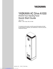
YASKAWA A1000 Series Quick Start Manual (44 pages)
IP23/54 Floor Standing Panel, 400 V Class: 90 to 315 kW
Brand: YASKAWA
|
Category: Controller
|
Size: 4 MB
Table of Contents
-
Table of Contents
3
-
Safety Instructions and General Warnings
4
-
Mechanical Installation
9
-
Electrical Installation
13
-
Keypad Operation
22
-
Start up
24
-
Parameter Table
29
-
Troubleshooting
34
-
Maintenance
38
-
Safe Disable Input Function
40

YASKAWA A1000 Series Manual (19 pages)
Brand: YASKAWA
|
Category: Controller
|
Size: 3 MB
Table of Contents
-
Table of Contents
3
-
Preface and Safety
5
-
Applicable Documentation
5
-
Supplemental Safety Information
5
-
Obtaining Support
5
-
Product Overview
6
-
Applicable Models
6
-
Application Selection
7
-
Traverse Anti-Phase
7
-
Basic Concept
7
-
Limitations
7
-
Control Modes, Symbols, and Terms
8
-
Related Parameters and Functions
9
-
Modified Parameters
9
-
Additional Parameters
9
-
Function Text
10
-
Monitor Function Text
10
-
Multi-Function Input Settings
10
-
Multi-Function Output Settings
10
-
Function Description
11
-
Machine Parameter Selection
11
-
Application Example
12
-
Software and Hardware Configuration for A1000 Traverse
12
-
Implementation
12
-
Sample Operating Parameters
12
-
Master and Slave Output Diagram: Standard Operation
13
-
Traverse Operation Exceeds Maximum Output Frequency
14
-
Changing Reference Frequency
14
-
Traverse Mode Operation with Changing Frequency Reference
15
-
Revision History
16

YASKAWA A1000 Series Installation Manual (31 pages)
Motor PG Feedback Line Driver Interface
Brand: YASKAWA
|
Category: Recording Equipment
|
Size: 3.18 MB
Table of Contents
-
Table of Contents
2
-
Preface and Safety
3
-
Product Overview
6
-
Receiving
7
-
Option Components
8
-
Installation Procedure
9
-
Related Parameters
21
-
Troubleshooting
24
-
Specifications
29
YASKAWA A1000 Series Installation Manual (30 pages)
AC Drive, Option, Analog Input
Brand: YASKAWA
|
Category: DC Drives
|
Size: 3.36 MB
Table of Contents
-
Table of Contents
3
-
Preface and Safety
4
-
Product Overview
7
-
Receiving
8
-
Option Components
9
-
Installation Procedure
10
-
Related Parameters
22
-
Troubleshooting
26
-
Specifications
28

YASKAWA A1000 Series Manual (36 pages)
AC Drive
Brand: YASKAWA
|
Category: DC Drives
|
Size: 1.71 MB
YASKAWA A1000 Series Installation Manual (24 pages)
AC Drive Option, 120 Vac Digital input
Brand: YASKAWA
|
Category: Controller
|
Size: 1.98 MB
Table of Contents
-
Table of Contents
3
-
Preface and Safety
4
-
Product Overview
7
-
Receiving
8
-
Option Components
9
-
Installation Procedure
10
-
Troubleshooting
21
-
Specifications
22
YASKAWA A1000 Series Setup (4 pages)
TCP Modbus Communication
Brand: YASKAWA
|
Category: Media Converter
|
Size: 0.89 MB
Advertisement
Related Products
-
YASKAWA A1000 HHP
-
YASKAWA A14
-
YASKAWA AO-A3
-
YASKAWA APMC-CP2700-E
-
YASKAWA AI-A3
-
YASKAWA ANTAIOS
-
YASKAWA A01
-
YASKAWA AC Drive
-
YASKAWA SGDV AE5A Series
-
YASKAWA ACS-500
YASKAWA Categories
Controller
DC Drives
Servo Drives
Robotics
Control Unit
More YASKAWA Manuals
Преобразователь частоты A1000 – это преобразователь частоты высочайшего уровня от компании YASKAWA. Он обеспечивает надёжность эксплуатации, экологические выгоды и экономию электроэнергии, а также множество иных эксплуатационных характеристик, ориентированных на пользователя, что делает данный преобразователь частоты превосходным выбором.
- Работа двигателей с постоянными магнитами без энкодера с максимальным крутящем моментом при нулевой скорости
-
Улучшенные функции автонастройки для автоматической корректировки параметров двигателя и постоянного анализа изменений во время работы двигателя для достижения самой высокой производительности оборудование
-
Улучшенный технология управления энергосбережением, которая повышает КПД и производительность оборудования при совместной работе с асинхронным и синхронным двигателем
- Доступны особые характеристики для высокой скорости вращения, позиционирования, кранов и лебёдок, электронного трансмиссионного вала
Технические характеристики
|
Тип: |
Преобразователь частоты общего назначения высочайшего уровня |
|
Диапазон: |
0,55 кВт — 630 кВт |
|
Максимальная мощность двигателя (кВт): |
3~200 VAC, 0.4 – 110 |
|
Применимые двигатели: |
Асинхронный двигатель (IM) |
|
Управление: |
Управление напряжением/частотой |
|
Диапазон регулирования скорости: |
Управление напряжением/частотой и Управление напряжением/частотой с PG 1:40 |
|
Регулировка крутящего момента: |
Стандарт |
|
Максимальная выходная частота: |
400 Гц |
|
Интерфейсные шины: |
RS-232C |
|
Стандарты: |
CE |
|
Степень защиты корпуса: |
IP00, IP20, IP54, NEMA1 |
|
Функции: |
Выключатель управления скоростью/крутящим моментом |
- Бренд
- Yaskawa
- Страна
- Япония
- Сегмент
- Общепромышленные преобразователи частоты
- Тип
- Преобразователь частоты
- Конструкция
- Общепромышленное применение
- Гарантия
- 3 года
-
Общий каталог Yaskawa A1000.pdf
Размер: 3 Мб
-
Техническое руководство A1000.pdf
Размер: 61 Мб
-
Инструкция по запуску Yaskawa A1000.pdf
Размер: 5 Мб
-
Каталог Yaskawa A1000+DriveWorkEZ 1.0.pdf
Размер: 9 Мб
- Manuals
- Brands
- YASKAWA Manuals
- Controller
- A1000 Series
- Manual
-
Contents
-
Table of Contents
-
Bookmarks
Quick Links
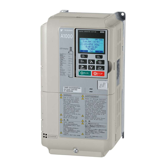
YASKAWA AC Drive-A1000
Traverse Application
Custom Software Supplement
Software Number: VSA91019
□
□□□□□□□
Drive Models: AU
A
To properly use the product, read this manual thoroughly and retain
for easy reference, inspection, and maintenance. Ensure the end user
receives this manual.
MANUAL NO. TM.A1000SW.029
□
Related Manuals for YASKAWA A1000
Summary of Contents for YASKAWA A1000
-
Page 1
YASKAWA AC Drive-A1000 Traverse Application Custom Software Supplement □ Software Number: VSA91019 □ □□□□□□□ Drive Models: AU To properly use the product, read this manual thoroughly and retain for easy reference, inspection, and maintenance. Ensure the end user receives this manual. -
Page 3
Yaskawa. No patent liability is assumed with respect to the use of the information contained herein. Moreover, because Yaskawa is constantly striving to improve its high-quality products, the information contained in this manual is subject to change without notice. -
Page 4
This Page Intentionally Blank YASKAWA TM.A1000SW.029 Traverse Application A1000 Custom Software Supplement… -
Page 5
Any warnings provided by Yaskawa must be promptly provided to the end user. Yaskawa offers an express warranty only as to the quality of its products in conforming to standards and specifications published in the Yaskawa manual. -
Page 6
Product Overview About This Product This custom software is designed specifically for use in Traverse applications. Applicable Models This custom Traverse application software is available for the A1000 drive models listed in Table Table 1 Applicable Models Voltage Class Models Software Version <1>… -
Page 7
80h (Disturbed WF Off) digital input to prevent damage to the motor or connected equipment. • The Traverse waveform can be configured to be smaller than the input resolution of the A1000 slave drive’s frequency reference. Ensure that Master Frequency Reference × P1-02 is significantly larger than (Slave Max Output Freq/2048) for proper control of the slave drive. -
Page 8
Parameter is available when operating the drive with Advanced Open Loop Vector for PM monitors. V/f w PG AOLV/PM Parameter is available when operating the drive with Closed Loop Vector for PM monitors. CLV/PM YASKAWA TM.A1000SW.029 Traverse Application A1000 Custom Software Supplement… -
Page 9
Monitor shift (U7-02, U7-03, and U7-04) in ms to Default: 0 ms (605h) Slv Scan Offset compensate for systematic delays. Range: -24 ~ 24 ms OLV/PM Table 4 Group Text Group Name Function Group Digital Operator Display Traverse Group Traverse YASKAWA TM.A1000SW.029 Traverse Application A1000 Custom Software Supplement… -
Page 10
Access Level Disturb UP Sts Open: The disturbed waveform frequency is decreasing Closed: The disturbed waveform frequency is increasing OLV/PM During Disturb Open: Disturbed waveform disabled Closed: Disturbed waveform being generated OLV/PM YASKAWA TM.A1000SW.029 Traverse Application A1000 Custom Software Supplement… -
Page 11
(spindle) for its frequency reference. U7-02 provides the slave a complete reference signal. U7-03 is used as a dither reference if the slave is to use its own base frequency reference as shown in Figure YASKAWA TM.A1000SW.029 Traverse Application A1000 Custom Software Supplement… -
Page 12
Standard Software Traverse Software Reference DIP Switch S1 Figure 1 Software and Hardware Configuration for A1000 Traverse Master Parameter Changes • H2-01 = 41h: Provide during disturb status output to slave. • H4-01 = 703: Provide disturbed frequency ripple to slave. -
Page 13
P1-02 x Freq Ref Frequency 0 Hz P1- 02 x Freq Ref Speed Agree Disturb UP Status multi-function output During Disturbed multi-unction output Figure 2 Master and Slave Output Diagram: Standard Operation YASKAWA TM.A1000SW.029 Traverse Application A1000 Custom Software Supplement… -
Page 14
Step changes in frequency reference will result in unintended jumps in the disturbed waveforms. Disable the Transverse function using the 80h, (Disturbed WF Off), to prevent damage to the motor or connected equipment before making large changes in the frequency reference. YASKAWA TM.A1000SW.029 Traverse Application A1000 Custom Software Supplement… -
Page 15
3 Application Selection Figure 4 Figure 4 Traverse Mode Operation with Changing Frequency Reference YASKAWA TM.A1000SW.029 Traverse Application A1000 Custom Software Supplement… -
Page 16
MANUAL NO. TM.A1000SW.029 Published in U.S.A. April 2013 10-4 Revision number Date of original Date of publication publication Date of Publication Revision Number Software Number Revised Content April 2013 VSA910190 First release YASKAWA TM.A1000SW.029 Traverse Application A1000 Custom Software Supplement… -
Page 18
YASKAWA AC Drive-A1000 Traverse Application Custom Software Supplement YASKAWA AMERICA, INC. 2121 Norman Drive South, Waukegan, IL 60085, U.S.A. Phone: (800) YASKAWA (927-5292) or 1-847-887-7000 Fax: 1-847-887-7310 http://www.yaskawa.com DRIVE CENTER (INVERTER PLANT) 2-13-1, Nishimiyaichi, Yukuhashi, Fukuoka, 824-8511, Japan Phone: 81-930-25-3844 Fax: 81-930-25-4369 http://www.yaskawa.co.jp…
 Loading…
![]()
YASKAWA AC Drive — A1000
Electronic Line Shaft with Alignment
Custom Software Supplement
Software Number: VSA91003□
Drive Models: AU□A□□□□□□□-064
AU□A□□□□□□□-065
To properly use the product, read this manual thoroughly and retain for easy reference, inspection, and maintenance. Ensure the end user receives this manual.
MANUAL NO. TM.A1000SW.064

Table of Contents
1 PREFACE AND SAFETY . . . . . . . . . . . . . . . . . . . . . . . . . . . . . . . . . . . . . . . . . . . 5 2 ELECTRONIC LINE SHAFT. . . . . . . . . . . . . . . . . . . . . . . . . . . . . . . . . . . . . . . . . 6 3 SIMPLE AUTOMATION ALIGNMENT . . . . . . . . . . . . . . . . . . . . . . . . . . . . . . . . 21 4 COMPREHENSIVE PARAMETER LIST . . . . . . . . . . . . . . . . . . . . . . . . . . . . . . 33
Refer to the A1000 Technical Manual for content not described in this document.
Copyright © 2011 YASKAWA ELECTRIC CORPORATION
All rights reserved. No part of this publication may be reproduced, stored in a retrieval system, or transmitted, in any form or by any means, mechanical, electronic, photocopying, recording, or otherwise, without the prior written permission of Yaskawa. No patent liability is assumed with respect to the use of the information contained herein. Moreover, because Yaskawa is constantly striving to improve its high-quality products, the information contained in this manual is subject to change without notice. Every precaution has been taken in the preparation of this manual. Yaskawa assumes no responsibility for errors or omissions. Neither is any liability assumed for damages resulting from the use of the information contained in this publication.
|
YASKAWA TM.A1000SW.064 Electronic Line Shaft with Alignment A1000 Custom Software Supplement |
3 |

This Page Intentionally Blank
|
4 |
YASKAWA TM.A1000SW.064 Electronic Line Shaft with Alignment A1000 Custom Software Supplement |

1 Preface and Safety
1 Preface and Safety
Yaskawa manufactures products used as components in a wide variety of industrial systems and equipment. The selection and application of Yaskawa products remain the responsibility of the equipment manufacturer or end user. Yaskawa accepts no responsibility for the way its products are incorporated into the final system design. Under no circumstances should any Yaskawa product be incorporated into any product or design as the exclusive or sole safety control. Without exception, all controls should be designed to detect faults dynamically and fail safely under all circumstances. All systems or equipment designed to incorporate a product manufactured by Yaskawa must be supplied to the end user with appropriate warnings and instructions as to the safe use and operation of that part. Any warnings provided by Yaskawa must be promptly provided to the end user. Yaskawa offers an express warranty only as to the quality of its products in conforming to standards and specifications published in the Yaskawa manual. NO OTHER WARRANTY, EXPRESS OR IMPLIED, IS OFFERED. Yaskawa assumes no liability for any personal injury, property damage, losses, or claims arising from misapplication of its products.
Applicable Documentation
The following manuals are available for the A1000 Drive:
Custom Software Supplement
SUPPLEMENT
Yaskawa AC Drive — Electric Line Shaft with Simple Automatic Alignment A1000 Custom Software Supplement Manual No: TM.A1000SW.064
Read this manual first. This supplement is an addendum to the A1000 Quick Start Guide and Technical Manual. It lists the effects of this custom software on the parameters in the drive and function descriptions in the manual.
To obtain the supplement access this site: U.S: http://www.yaskawa.com
Yaskawa Drive
Yaskawa AC Drive —
A1000 Quick Start Guide
Yaskawa AC Drive —
A1000 Technical Manual
To obtain instruction manuals for Yaskawa products access these sites: U.S.: http://www.yaskawa.com
Europe: http://www.yaskawa.eu.com Japan: http://www.e-mechatronics.com
Other areas: contact a Yaskawa representative.
For questions, contact the local Yaskawa sales office or the nearest Yaskawa representative.
Supplemental Safety Information
Read and understand this manual and the A1000 Quick Start Guide before installing, operating, or servicing this option unit. Install the drive according to the A1000 Quick Start Guide and local codes. Observe all cautions and warnings in this document and the standard drive technical manuals.
Refer to the A1000 Quick Start Guide and Technical Manual for safety information and to install and start-up the drive.
This document is a supplement to the standard drive technical manual. It describes the effects on the drive parameters and functions with the software installed.
•Custom software is provided to add functionality to a standard drive to enhance or enable use in a specific application.
•The software is loaded to the flash ROM area of the control board, and replaces the standard drive software.
Obtaining Support
When seeking support for a drive with custom software, it is imperative to provide the unique part number shown on the drive nameplate. The software is flashed to the control board memory and the operation of parameters, functions, and monitors are different than the standard drive software, as described herein.
Refer to Yaskawa office locations listed on the back cover of this manual.
|
YASKAWA TM.A1000SW.064 Electronic Line Shaft with Alignment A1000 Custom Software Supplement |
5 |

2 Electronic Line Shaft
2Electronic Line Shaft
Overview
The Electronic Line Shaft (ELS) function allows a drive to precisely follow the speed, direction, and phase of a master encoder (PG) signal. The follower can match its position (phase angle) to the master within several quadrature encoder counts.
The ELS function is used in applications where the machinery being driven requires two mechanically isolated and motor-driven moving parts to maintain a constant position relationship. The gear ratio between the master and the follower is infinitely adjustable.
NOTICE: Damage to equipment. Equipment damage may occur if the ELS function is used with two or more motors mechanically coupled to drive the same load. Do not use Electronic Line Shaft functionality to drive two or more motors that are mechanically coupled to the same driven load.
In addition, a gear ratio adjustment, or “draw”, can be added to the speed reference via parameter setting, analog input, multi-function input MOP, or serial communication. It is also possible to run the drive in a pure speed follower mode for applications that do not require matched position.
|
Input Channel |
PG |
|||
|
Pulse Monitor Output |
||||
|
PG-X3 |
||||
|
A1000 |
M |
||||||||
|
Master Drive |
|||||||||
|
Channel 1 Input |
PG-X3 |
PG |
|||||||
|
Channel 2 Input |
PG-X3 |
M |
|||||||
A1000
Follower Drive
Figure 1 Typical Configuration Connection
|
6 |
YASKAWA TM.A1000SW.064 Electronic Line Shaft with Alignment A1000 Custom Software Supplement |

2 Electronic Line Shaft
Basic Concepts and Principles
The master encoder signal is fed into a PG option card installed in the CN5-B port of the follower (PG Channel 2). When using V/f w/PG or CLV control modes, the encoder signal of the follower is fed into a PG option card installed in the CN5-C port of the follower (PG Channel 1) and the master encoder speed is multiplied by the programmed gear ratio to determine the frequency reference of the follower.
Setting parameter P1-01 to 4 or 5 configures the drive for ELS and ELS Signed Run modes. These configurations determine the error between the master and follower position and this error is fed into a PI controller, which is then added to the previously calculated frequency reference. The position regulator is disabled when the drive is configured only as a speed follower (non-ELS modes).
|
Speed Calculation |
|||||||||||||||||
|
+ |
|||||||||||||||||
|
Master Encoder |
Gear |
Frequency |
|||||||||||||||
|
Calculation |
+ |
Reference |
|||||||||||||||
|
Speed |
|||||||||||||||||
|
Position Regulator |
ELS Mode |
||||||||||||||||
|
Enabled |
|||||||||||||||||
|
Master Encoder |
Gear |
+ |
Position Error |
PI |
|||||||||||||
|
Pulse Count |
Calculation |
— |
Accumulator |
Controller |
|||||||||||||
|
Follower Encoder |
|||||||||||||||||
|
Pulse Count |
Figure 2 Simplified Block Diagram of ELS Function
The Signed Run mode ELS functions identically to the standard ELS mode with the following exceptions:
•When a reverse Run command is given, the follower will match the velocity and phase of the master, but in the opposite direction (i.e., if the master runs in the forward direction, the follower will run in reverse direction and if the master runs in the reverse direction, the follower will run in the forward direction).
•When a forward Run command is present, the follower will run in the same direction as the master.
Changes from the Standard Product
• The Motor 2 Selection multi-function input setting is deleted (only Motor 1 can be used).
• The follower drive uses acceleration and deceleration times of zero during Electronic Line Shaft operation (P1-01 = 4 or 5).
• PG 2 related parameters F1-31 and F1-32 are always available and no longer require selecting Motor 2 via digital input.
Limitations
•For ELS and ELS Signed Run modes (P1-01 = 4 or 5), Yaskawa recommends using Closed Loop Vector (A1-02 = 3) control mode.
•For Speed Follower Both Directions, ELS, and ELS Signed Run modes (P1-01 = 1, 4, or 5), install master and follower encoder feedback cards and set to quadrature encoder input (F1-21 and F1-37 = 1).
•For Speed Follower Both Directions mode (P1-01 = 1), set the master encoder input to quadrature encoder input (F1-37 = 1).
•For ELS and ELS Signed Run modes (P1-01 = 4 or 5), express the gear ratio exactly, including remainder, to prevent phase drift.
•Use the proper option card port for each encoder (PG) input. (CN5-B: Master Encoder, CN5-C: Follower Encoder).
•DriveWorksEZ is not currently supported with software version VSA910030.
•The LED keypad is not fully supported; some alarms and faults may not display properly on the LED keypad.
|
YASKAWA TM.A1000SW.064 Electronic Line Shaft with Alignment A1000 Custom Software Supplement |
7 |

2Electronic Line Shaft
Related Parameters and Functions
Table 1 lists terms and symbols used in this section to indicate which parameters are available in which control modes.
|
Table 1 Symbols and Icons Used in Parameter Descriptions |
||
|
Symbol |
Description |
|
|
All Modes |
Parameter is available in all control modes. |
|
|
V/f |
Parameter is available when operating the drive with V/f Control. |
|
|
V/f w PG |
Parameter is available when operating the drive with V/f with PG Control. |
|
|
OLV |
Parameter is available when operating the drive with Open Loop Vector. |
|
|
CLV |
Parameter is available when operating the drive with Closed Loop Vector. |
|
|
OLV/PM |
Parameter is available when operating the drive with Open Loop Vector for PM motors. |
|
|
AOLV/PM |
Parameter is available when operating the drive with Advanced Open Loop Vector for PM motors. |
|
|
CLV/PM |
Parameter is available when operating the drive with Closed Loop Vector for PM motors. |
|
|
Parameter is NOT available when operating the drive in the control mode. |
||
|
Parameter can be changed during run. |
||
|
Motor 2 |
Refers to a second motor when the drive is operating two motors. Switch between these motors using the multi-function input |
|
|
terminals. |
||
The parameters in the tables below are used to set up the drive for operation with the software.
Table 2 Modified Parameters
|
No. |
Name |
||||||
|
(Addr. |
Description |
Values |
|||||
|
(Digital Operator Display) |
|||||||
|
Hex) |
|||||||
|
F1-01 PG1 Pulses per Revolution |
V/f |
V/f w PG |
OLV |
CLV |
Default: 1024 ppr |
||
|
OLV/PM |
AOLV/PM |
CLV/PM |
Min: 1 |
||||
|
(380) |
(PG Pulses/Rev) |
||||||
|
Sets the number of pulses for a PG option card connected to port CN5-C. |
Max.: 60000 |
||||||
|
V/f |
V/f w PG |
OLV |
CLV |
||||
|
OLV/PM |
AOLV/PM |
CLV/PM |
|||||
|
Operation Selection at PG Open |
Sets the operation when a PGo is detected on a PG option card connected to port |
||||||
|
F1-02 |
CN5-C. |
Default: 1 |
|||||
|
Circuit (PGo) |
|||||||
|
(381) |
0: Ramp to Stop |
Range: 0 to 4 |
|||||
|
(PG Fdbk Loss Sel) |
|||||||
|
1: Coast to Stop |
|||||||
2:Fast Stop
3:Alarm Only
4:No Alarm Display
|
V/f |
V/f w PG |
OLV |
CLV |
||||
|
F1-05 |
PG 1 Rotation Selection |
OLV/PM |
AOLV/PM |
CLV/PM |
Default: 0 |
||
|
Sets the direction of forward travel for the PG card installed in CN5-C. |
|||||||
|
(384) |
(PG1 Rotation Sel) |
Range: 0, 1 |
0:Pulse A Leads
1:Pulse B Leads
|
F1-14 |
PG Open-Circuit Detection Time |
V/f |
V/f w PG |
OLV |
CLV |
Default: 2.0 s |
|
|
OLV/PM |
AOLV/PM |
CLV/PM |
Min: 0.0 |
||||
|
(38D) |
(PGO Detect Time) |
||||||
|
Sets the amount of time required to trigger a PG Open fault (PGo). |
Max.: 10.0 |
||||||
|
V/f |
V/f w PG |
OLV |
CLV |
||||
|
F1-21 |
PG 1 Signal Selection |
OLV/PM |
AOLV/PM |
CLV/PM |
Default: 1 |
||
|
Selects single-channel/quadrature detection mode for the PG option card 1. |
|||||||
|
(3BC) |
(PG1 Signal Sel) |
Range: 0, 1 |
0:A Pulse Detection
1:AB Pulse Detection
|
8 |
YASKAWA TM.A1000SW.064 Electronic Line Shaft with Alignment A1000 Custom Software Supplement |

|
2 |
Electronic Line Shaft |
|||||||
|
No. |
Name |
|||||||
|
(Addr. |
Description |
Values |
||||||
|
(Digital Operator Display) |
||||||||
|
Hex) |
||||||||
|
F1-31 PG 2 Pulses per Revolution |
V/f |
V/f w PG |
OLV |
CLV |
Default: 1024 ppr |
|||
|
OLV/PM |
AOLV/PM |
CLV/PM |
Min: 1 |
|||||
|
(3B0) |
(PG Pulses/Rev 2) |
|||||||
|
Sets the number of pulses for a PG option card connected to port CN5-B. |
Max.: 60000 |
|||||||
|
V/f |
V/f w PG |
OLV |
CLV |
|||||
|
F1-32 PG 2 Rotation Selection |
OLV/PM |
AOLV/PM |
CLV/PM |
Default: 0 |
||||
|
Sets the direction of forward travel for a PG option card installed in port |
||||||||
|
(3B1) |
(PG Rotation Sel2) |
Range: 0, 1 |
||||||
|
CN5-B. |
||||||||
0:Pulse A Leads
1:Pulse B Leads
|
V/f |
V/f w PG |
OLV |
CLV |
||||
|
F1-36 |
PG Option Card Disconnect |
OLV/PM |
AOLV/PM |
CLV/PM |
Default: 1 |
||
|
Determines whether the drive detects a fault when a PGo is detected on a PG |
|||||||
|
Detection 2 |
|||||||
|
(3B5) |
Range: 0, 1 |
||||||
|
(Hardware PGO Ch2) |
option card installed in port CN5-B. |
||||||
0:Disabled
1:Enabled
|
V/f |
V/f w PG |
OLV |
CLV |
|||
|
F1-37 PG 2 Signal Selection |
OLV/PM |
AOLV/PM |
CLV/PM |
Default: 1 |
||
|
Selects single-channel/quadrature detection mode for the PG option card 2 |
||||||
|
(3BD) (PG2 Signal Sel) |
Range: 0, 1 |
|||||
|
installed in port CN5-B. |
||||||
0:A Pulse Detection
1:AB Pulse Detection
Table 3 Additional Parameters
|
No. |
Name |
||||
|
(Addr. |
Description |
Values |
|||
|
(Digital Operator Display) |
|||||
|
Hex) |
|||||
|
V/f |
V/f w PG |
OLV |
CLV |
OLV/PM AOLV/PM CLV/PM
Selects the follower mode.
0:Disabled. Follower mode is disabled and the follower drive runs from the normal frequency reference (b1-01).
1:Speed — Both Dir. The follower drive follows the master encoder speed in both direction (follower Run command direction has no effect).
2:Speed — Fwd Dir. The follower drive follows the master encoder speed only
|
P1-01 |
Follower Mode Selection |
when the master is running in the forward direction. Follower direction is |
Default: 0 |
|||||
|
determined by follower Run command direction. |
||||||||
|
(600) |
(Follower Mode) |
Range: 0 to 5 |
||||||
|
3: Speed Abs Val. The follower drive follows the master encoder speed but |
||||||||
|
ignores the master encoder direction (motion is always in the direction of the |
||||||||
|
follower Run command). |
||||||||
|
4: Elec Line Shaft. The follower drive follows the master encoder speed and |
||||||||
|
position (both directions). A reverse Run command is treated as a forward |
||||||||
|
Run command; there is no directional effect. |
||||||||
|
5: ELS — Sign Run. The follower drive follows the master encoder speed and |
||||||||
|
position (both directions). When a forward Run command is present the drive |
||||||||
|
follows the master in the same direction. When a reverse Run command is |
||||||||
|
present the drive follows in the opposite direction of the master. |
||||||||
|
P1-02 |
Replaced by F1-31 |
|||||||
|
P1-03 |
Ratio Numerator (Upper 4 |
V/f |
V/f w PG |
OLV |
CLV |
Default: 1000 |
||
|
(602) |
||||||||
|
Digits) |
OLV/PM |
AOLV/PM |
CLV/PM |
Min: 0 |
||||
|
(Ratio Num High) |
Sets the upper four digits of the primary gear ratio numerator. |
Max.: 9999 |
||||||
|
YASKAWA TM.A1000SW.064 Electronic Line Shaft with Alignment A1000 Custom Software Supplement |
9 |

2 Electronic Line Shaft
|
No. |
Name |
||||||
|
(Addr. |
Description |
Values |
|||||
|
(Digital Operator Display) |
|||||||
|
Hex) |
|||||||
|
P1-04 |
Ratio Denominator (Upper 4 |
V/f |
V/f w PG |
OLV |
CLV |
Default: 1000 |
|
|
(603) |
|||||||
|
Digits) |
OLV/PM |
AOLV/PM |
CLV/PM |
Min: 0 |
|||
|
(Ratio Den High) |
Sets the upper four digits of the primary gear ratio denominator. |
Max.: 9999 |
|||||
|
P1-05 |
Ratio Numerator (Lower 4 |
V/f |
V/f w PG |
OLV |
CLV |
Default: 0 |
|
|
(604) |
|||||||
|
Digits) |
OLV/PM |
AOLV/PM |
CLV/PM |
Min: 0 |
|||
|
(Ratio Num Low) |
Sets the lower four digits of the primary gear ratio numerator. |
Max.: 9999 |
|||||
|
P1-06 |
Ratio Denominator (Lower 4 |
V/f |
V/f w PG |
OLV |
CLV |
Default: 0 |
|
|
(605) |
|||||||
|
Digits) |
OLV/PM |
AOLV/PM |
CLV/PM |
Min: 0 |
|||
|
(Ratio Den Low) |
Sets the lower four digits of the primary gear ratio denominator. |
Max.: 9999 |
|||||
|
P1-07 |
Ratio 2 Numerator |
V/f |
V/f w PG |
OLV |
CLV |
Default: 1 |
|
|
(606) |
OLV/PM |
AOLV/PM |
CLV/PM |
||||
|
Min: 1 |
|||||||
|
(Ratio 2 Num) |
Sets the numerator of the secondary gear ratio. Active when a multi-function |
||||||
|
Max.: 65535 |
|||||||
|
digital input is set to 81 (Ratio 2 Select) and the input is closed. |
|||||||
|
P1-08 |
Ratio 2 Denominator |
V/f |
V/f w PG |
OLV |
CLV |
Default: 1 |
|
|
(607) |
OLV/PM |
AOLV/PM |
CLV/PM |
||||
|
Min: 1 |
|||||||
|
(Ratio 2 Den) |
Sets the numerator of the secondary gear ratio. Active when a multi-function |
||||||
|
Max.: 65535 |
|||||||
|
digital input is set to 81 (Ratio 2 Select) and the input is closed. |
|||||||
|
V/f |
V/f w PG |
OLV |
CLV |
||||
|
Position Error Accumulation |
OLV/PM |
AOLV/PM |
CLV/PM |
||||
|
P1-09 |
Selects when the position error accumulator is enabled in the follower drive. |
Default: 0 |
|||||
|
Selection |
|||||||
|
(608) |
0: Only During Run. Position error is only calculated when the follower drive is |
Range: 0, 1 |
|||||
|
(Pos Accum Select) |
|||||||
|
running (not during High-Slip Braking). |
|||||||
|
1: Always. Position error is calculated whenever power is applied to the drive. |
|||||||
|
Note: ELS modes only. |
|||||||
|
V/f |
V/f w PG |
OLV |
CLV |
||||
|
OLV/PM |
AOLV/PM |
CLV/PM |
|||||
|
Selects the units used for the follower drive Position Error Monitor (U7-08). |
|||||||
|
P1-10 |
0: Encoder Counts. Position error is displayed in quadrature follower encoder |
||||||
|
Position Units Selection |
counts (cnts). |
Default: 0 |
|||||
|
(609) |
1: Motor Revs. Position error is displayed in follower motor revolutions |
||||||
|
(Position Units) |
(0.001 rev). |
Range: 0 to 3 |
|||||
2:Motor Degrees. Position error is displayed in follower motor degrees (0.1 degree).
3:Motor Radians. Position error is displayed in follower motor radians (0.001 rad).
Note: ELS modes only.
|
P2-01 |
V/f |
V/f w PG |
OLV |
CLV |
|||
|
Digital Ratio Adjustment |
OLV/PM |
AOLV/PM |
CLV/PM |
Default: 0.00% |
|||
|
(60A) |
|||||||
|
Sets the digital gear ratio adjustment of the follower drive. The gear ratio |
Min: -99.99 |
||||||
|
(Digital RatioAdj) |
|||||||
|
Max.: 99.99 |
|||||||
|
adjustment is also influenced by the analog, MOP, and communication gear |
|||||||
|
ratio adjustments. |
|||||||
|
P2-02 |
MOP Adjust Time |
V/f |
V/f w PG |
OLV |
CLV |
Default: 50.0 s |
|
|
(60B) |
OLV/PM |
AOLV/PM |
CLV/PM |
||||
|
Min: 0.0 |
|||||||
|
(MOP Adjust Time) |
Sets the time for the MOP ratio adjustment to change by 100.00% when the |
||||||
|
Max.: 6000.0 |
|||||||
|
MOP Adjust Increase or MOP Adjust Decrease multi-function input is closed. |
|||||||
|
P2-03 |
Gear Ratio Adjustment Ramp |
V/f |
V/f w PG |
OLV |
CLV |
Default: 10.0 s |
|
|
(60C) |
OLV/PM |
AOLV/PM |
CLV/PM |
||||
|
Time |
Min: 0.0 |
||||||
|
Sets the time for the composite gear ratio adjustment of the follower drive to |
|||||||
|
(Ratio Adj Ramp) |
Max.: 6000.0 |
||||||
|
change by 100.00%. |
|
10 |
YASKAWA TM.A1000SW.064 Electronic Line Shaft with Alignment A1000 Custom Software Supplement |
![]()
|
2 Electronic Line Shaft |
|||||||
|
No. |
Name |
||||||
|
(Addr. |
Description |
Values |
|||||
|
(Digital Operator Display) |
|||||||
|
Hex) |
|||||||
|
V/f |
V/f w PG |
OLV |
CLV |
||||
|
OLV/PM |
AOLV/PM |
CLV/PM |
|||||
|
Selects the advance/retard functionality of the follower drive. |
|||||||
|
P2-04 |
Advance/Retard Mode Selection |
0: Continuous. The follower will advance or retard continuously while the |
Default: 0 |
||||
|
Advance Follower or Retard Follower multi-function input is closed. Parameter |
|||||||
|
(60D) |
(Adv/Ret Mode Sel) |
P2-05 sets the amount of advance/retard encoder counts per second. |
Range: 0, 1 |
||||
|
1: Step. The follower will advance or retard by the amount set in parameter |
|||||||
|
P2-05 each time the Advance Follower or Retard Follower multi-function input |
|||||||
|
is closed. |
|||||||
|
Note: ELS modes only. |
|||||||
|
V/f |
V/f w PG |
OLV |
CLV |
||||
|
P2-05 |
Advance/Retard Amount |
OLV/PM |
AOLV/PM |
CLV/PM |
Default: 2048 cnts |
||
|
(60E) |
Sets the number of quadrature follower encoder counts the follower will |
||||||
|
Min: 0 |
|||||||
|
(Adv/Ret Amount) |
advance or retard per second when parameter P2-04 is set to 0. |
Max.: 65535 |
|||||
|
Sets the step amount of the advance/retard function when P2-04 is set to 1. |
|||||||
|
Note: ELS modes only. |
|||||||
|
V/f |
V/f w PG |
OLV |
CLV |
||||
|
P2-06 |
Follower Deviation Level |
OLV/PM |
AOLV/PM |
CLV/PM |
Default: 4096 cnts |
||
|
Sets the amount of position error in quadrature follower encoder counts that will |
Min: 0 |
||||||
|
(60F) |
(Follower Dev Lvl) |
||||||
|
activate the follower deviation detection. |
Max.: 65535 |
||||||
|
Note: ELS modes only. |
|||||||
|
V/f |
V/f w PG |
OLV |
CLV |
||||
|
OLV/PM |
AOLV/PM |
CLV/PM |
|||||
|
Selects the follower drive action when the position error exceeds the P2-06 |
|||||||
|
P2-07 |
Follower Deviation Selection |
setting. |
Default: 2 |
||||
|
(610) |
(Follower Dev Sel) |
0: No Detection. The drive continues to run. |
Range: 0 to 2 |
1:Alarm Only. The drive continues to run and an FdEv alarm flashes on the digital operator.
2:Coast to Stop (Fault). The FdEv fault is displayed, the drive contact is activated, and the motor coasts to stop.
P2-08 No longer required
|
V/f |
V/f w PG |
OLV |
CLV |
||||
|
P2-09 |
MOP Adjustment Memorization |
OLV/PM |
AOLV/PM |
CLV/PM |
Default: 0 |
||
|
Selects whether the MOP gear adjustment is memorized when the drive loses |
|||||||
|
at Power Off |
|||||||
|
(612) |
Range: 0, 1 |
||||||
|
(MOP mem @ Pwr Off) |
power. |
||||||
0:Disabled. MOP adjustment is not memorized at power down.
1:Enabled. MOP adjustment is memorized at power down.
|
P3-01 |
Position P Gain |
V/f |
V/f w PG |
OLV |
CLV |
Default: 5.00 |
|
(614) |
OLV/PM |
AOLV/PM |
CLV/PM |
|||
|
Min: 0.00 |
||||||
|
(Position P Gain) |
Sets the proportional gain of the position regulator PI loop. |
|||||
|
Max.: 100.00 |
||||||
|
Note: ELS modes only. |
||||||
|
P3-02 |
Position I Time |
V/f |
V/f w PG |
OLV |
CLV |
Default: 0.00 s |
|
(615) |
OLV/PM |
AOLV/PM |
CLV/PM |
|||
|
Min: 0.00 |
||||||
|
(Position I Time) |
Sets the integral time of the position regulator PI loop. |
|||||
|
Max.: 50.00 |
||||||
|
Note: ELS modes only. |
||||||
|
P3-03 |
Position Regulator Filter Time |
V/f |
V/f w PG |
OLV |
CLV |
Default: 0.00 s |
|
(616) |
OLV/PM |
AOLV/PM |
CLV/PM |
|||
|
Min: 0.00 |
||||||
|
(Pos Filter Time) |
||||||
|
Sets the filter time of the position regulator output. This is a first order lag filter. Max.: 1.50 |
||||||
|
Note: ELS modes only. |
|
YASKAWA TM.A1000SW.064 Electronic Line Shaft with Alignment A1000 Custom Software Supplement |
11 |

2 Electronic Line Shaft
|
No. |
Name |
|||||||||||
|
(Addr. |
Description |
Values |
||||||||||
|
(Digital Operator Display) |
||||||||||||
|
Hex) |
||||||||||||
|
P3-04 |
V/f |
V/f w PG |
OLV |
CLV |
||||||||
|
Position PI Limit |
OLV/PM |
AOLV/PM |
CLV/PM |
Default: 8.00% |
||||||||
|
(617) |
||||||||||||
|
Sets the limit (+/-) of the position regulator output as a percentage of the |
Min: 0.00 |
|||||||||||
|
(Pos PI Limit) |
||||||||||||
|
Max.: 10.00 |
||||||||||||
|
maximum output frequency (E1-04). |
||||||||||||
|
Note: ELS modes only. |
||||||||||||
|
V/f |
V/f w PG |
OLV |
CLV |
|||||||||
|
OLV/PM |
AOLV/PM |
CLV/PM |
||||||||||
|
P3-05 |
Position Regulator Trim Mode |
Selects how the position regulator output is used to trim the follower drive |
Default: 0 |
|||||||||
|
(618) |
speed reference (master encoder frequency). |
|||||||||||
|
(Pos Trim Mode) |
0: Constant. The position regulator output is independent of the master encoder |
Range: 0, 1 |
||||||||||
|
speed reference. |
||||||||||||
|
1: Speed Prop. The position regulator output is proportional to the master |
||||||||||||
|
encoder speed reference. |
||||||||||||
|
Note: ELS modes only. |
||||||||||||
|
V/f |
V/f w PG |
OLV |
CLV |
|||||||||
|
P3-06 |
Speed Proportional Position Trim |
OLV/PM |
AOLV/PM |
CLV/PM |
Default: 10.00% |
|||||||
|
(619) |
Sets the lower limit of the position regulator trim when P3-05 is set to 1. |
|||||||||||
|
Lower Limit |
Min: 0.00 |
|||||||||||
|
(SpdProp LowerLim) |
Set in terms of percentage of follower reference after gear ratio adjustment. |
Max.: 100.00 |
||||||||||
|
Refer to Function Description on page 16 for examples of how this factors into |
||||||||||||
|
calculations. |
||||||||||||
|
V/f |
V/f w PG |
OLV |
CLV |
|||||||||
|
P3-07 |
Ratio Change Speed Agree |
OLV/PM |
AOLV/PM |
CLV/PM |
Default: 0.5 Hz |
|||||||
|
Sets the frequency width used to determine “Speed Agree” when the drive is |
||||||||||||
|
(61A) |
||||||||||||
|
Width |
Min: 0.0 |
|||||||||||
|
accelerating or decelerating due to one of the following factors: |
||||||||||||
|
(RatioChg SpdAgrF) |
Gear ratio change |
Max.: 20.0 |
||||||||||
|
Change in state of the Follower Disable multi-function input |
||||||||||||
|
Change in the state of the Run command. |
||||||||||||
|
Table 4 Function Group Text |
||||||||||||
|
Function Group |
Function Group Name |
|||||||||||
|
(Digital Operator Display) |
||||||||||||
|
P |
Coordinated Motor |
|||||||||||
|
(Coordinated Motor) |
||||||||||||
|
Table 5 Function Text |
||||||||||||
|
Function No. |
Function Name |
|||||||||||
|
(Digital Operator Display) |
||||||||||||
|
P1 |
Follower Configuration |
|||||||||||
|
(Follower Config) |
||||||||||||
|
P2 |
Follower Motor Tuning |
|||||||||||
|
(Follower Tuning) |
||||||||||||
|
P3 |
Position Regulator Tuning |
|||||||||||
|
(Pos Reg Tuning) |
||||||||||||
|
Table 6 Monitor Group Text |
||||||||||||
|
Monitor Group |
Monitor Name |
Description |
||||||||||
|
(Digital Operator Display) |
||||||||||||
|
U7 |
Coordinated Motor Monitor Group |
Coordinated Motor state indicators |
||||||||||
|
(CoordinatedMotor) |
||||||||||||
|
12 |
YASKAWA TM.A1000SW.064 Electronic Line Shaft with Alignment A1000 Custom Software Supplement |

|
2 |
Electronic Line Shaft |
|||||||
|
Table 7 Monitors |
||||||||
|
No. |
Monitor Name |
Analog Output |
||||||
|
(Addr. |
(Digital Operator |
Description |
Unit |
|||||
|
Scaling |
||||||||
|
Hex) |
Display) |
|||||||
|
V/f |
V/f w PG |
OLV |
CLV |
|||||
|
U7-02 |
Master Encoder |
OLV/PM |
AOLV/PM |
CLV/PM |
Full scale: |
|||
|
Reference |
Displays the frequency of the master encoder before gear ratios and MOP |
Maximum Output |
0.1 Hz |
|||||
|
(661) |
||||||||
|
(Master PG Fref) |
Frequency (E1-04) |
|||||||
|
gains are applied. |
||||||||
|
Note: Display/Modbus values are limited to -3276.8 to 3276.7 <1>. |
||||||||
|
V/f |
V/f w PG |
OLV |
CLV |
|||||
|
U7-03 |
Follower Reference after |
OLV/PM |
AOLV/PM |
CLV/PM |
Full scale: |
|||
|
Gear Ratio |
Displays the frequency of the master encoder after the active gear ratio |
Maximum Output |
0.1 Hz |
|||||
|
(662) |
||||||||
|
(Fref After Gear) |
Frequency (E1-04) |
|||||||
|
(P1-03 to P1-08) is applied. |
||||||||
|
Note: Display/Modbus values are limited to -3276.8 to 3276.7 <1>. |
||||||||
|
V/f |
V/f w PG |
OLV |
CLV |
|||||
|
U7-04 |
Gear Ratio Adjustment |
OLV/PM |
AOLV/PM |
CLV/PM |
Full scale: |
0.01% |
||
|
(663) |
(Gear Ratio Adj) |
Displays the total gear ratio adjustment (sum of the digital, analog, MOP, |
100.00% |
|||||
|
and communication adjustments). |
||||||||
|
V/f |
V/f w PG |
OLV |
CLV |
|||||
|
U7-05 |
Follower Reference after |
OLV/PM |
AOLV/PM |
CLV/PM |
Full scale: |
|||
|
Gear Ratio Adjustment |
Displays the frequency of the master encoder after the digital, analog, MOP, |
Maximum Output |
0.1 Hz |
|||||
|
(664) |
||||||||
|
(Fref After Adj) |
Frequency (E1-04) |
|||||||
|
and communication gear ratio adjustments are applied. |
||||||||
|
Note: Display/Modbus values are limited to -3276.8 to 3276.7 <1>. |
||||||||
|
V/f |
V/f w PG |
OLV |
CLV |
|||||
|
OLV/PM |
AOLV/PM |
CLV/PM |
Full scale: |
|||||
|
Displays the number of quadrature encoder counts per 5 ms from the master |
||||||||
|
U7-06 |
Master Counts/5ms |
Counts/5 ms at |
cnts |
|||||
|
(665) |
(Master Cts/5ms) |
drive. |
Maximum Output |
|||||
|
This monitor is representative only and should only be used to confirm that |
Frequency (E1-04) |
|||||||
|
encoder counts are being received. |
||||||||
|
Note: ELS modes only. |
||||||||
|
V/f |
V/f w PG |
OLV |
CLV |
|||||
|
OLV/PM |
AOLV/PM |
CLV/PM |
Full scale: |
|||||
|
Displays the number of quadrature encoder counts per 5 ms from the |
||||||||
|
U7-07 |
Follower Counts/5ms |
Counts/5 ms at |
cnts |
|||||
|
(666) |
(Follower Cts/5ms) |
follower drive. |
Maximum Output |
|||||
|
This monitor is representative only and should only be used to confirm that |
Frequency (E1-04) |
|||||||
|
encoder counts are being received. |
||||||||
|
Note: ELS modes only. |
||||||||
|
V/f |
V/f w PG |
OLV |
CLV |
|||||
|
OLV/PM |
AOLV/PM |
CLV/PM |
Full scale: |
|||||
|
Displays the position error between the master and follower encoders in |
||||||||
|
U7-08 |
Position Error |
Counts/5 ms at |
P1-10 |
|||||
|
(667) |
(Position Error) |
quadrature follower encoder counts. |
Maximum Output |
<2> <3> |
||||
|
Note: ELS modes only. |
Frequency (E1-04) |
|||||||
|
Note: Modbus values are limited to -3276.8 to 3276.7. Display values are |
||||||||
|
limited to -9999 to 99999 <1>. |
||||||||
|
Position Regulator P |
V/f |
V/f w PG |
OLV |
CLV |
||||
|
U7-09 |
OLV/PM |
AOLV/PM |
CLV/PM |
Full scale: |
||||
|
Output |
0.01% |
|||||||
|
(668) |
Displays the proportional gain contribution of the position PI regulator. |
100.00% |
||||||
|
(Position P Out) |
||||||||
|
Note: ELS modes only. |
||||||||
|
Position Regulator I |
V/f |
V/f w PG |
OLV |
CLV |
||||
|
U7-10 |
OLV/PM |
AOLV/PM |
CLV/PM |
Full scale: |
||||
|
Output |
0.01% |
|||||||
|
(669) |
Displays the output of the integrator of the position PI regulator. |
100.00% |
||||||
|
(Position I Out) |
||||||||
|
Note: ELS modes only. |
|
YASKAWA TM.A1000SW.064 Electronic Line Shaft with Alignment A1000 Custom Software Supplement |
13 |

2 Electronic Line Shaft
|
No. |
Monitor Name |
Analog Output |
||||||
|
(Addr. |
(Digital Operator |
Description |
Unit |
|||||
|
Scaling |
||||||||
|
Hex) |
Display) |
|||||||
|
Position Regulator PI |
V/f |
V/f w PG |
OLV |
CLV |
||||
|
U7-11 |
OLV/PM |
AOLV/PM |
CLV/PM |
Full scale: |
||||
|
Output |
0.01% |
|||||||
|
(66A) |
Displays the output of the position PI regulator. |
100.00% |
||||||
|
(Position PI Out) |
||||||||
|
Note: ELS modes only. |
<1> When the internal value is outside of the maximum/minimum value range that can be displayed on the keypad, the monitor will display the maximum/minimum value and the display name of the monitor will flash, alternating between “OVER” and the monitor name.
<2> Unit is dependent on the setting of the Position Units Selection (P1-10).
<3> When reading by network communication (register 667), the unit is fixed at quadrature encoder counts.
Table 8 MEMOBUS Registers
|
MEMOBUS |
Description |
Scaling |
|
|
Address |
|||
|
Network Communication Gear Ratio Adjustment. |
|||
|
Allows gear ratio adjustment via network communication. The total gear ratio adjustment is |
|||
|
00DH |
the sum of the analog, digital, MOP, and network communication ratio adjustments. |
1 = 0.01% |
|
|
Data is interpreted as signed, so the adjustment can be set from -327.67% to 327.67%. |
|||
|
Note: The ENTER command is not required when writing to this register. |
|||
|
Network Communication Advance/Retard Counts. |
|||
|
Allows for advancing/retarding of the follower drive via network communication. |
|||
|
Data is interpreted as signed, so the advance/retard counts can be set from –32768 to 32767. |
|||
|
00EH |
This is set in quadrature follower encoder counts. After this register is set, its data returns to |
1 = 1 quadrature encoder count |
|
|
zero automatically. |
|||
|
Note: ELS modes only. |
|||
|
Note: The ENTER command is not required when writing to this register. |
Table 9 Multi-Function Output Settings (H1- )
|
Setting |
Description |
||
|
V/f |
V/f w PG |
OLV |
CLV |
|
OLV/PM |
AOLV/PM |
CLV/PM |
80Follower Disable
Closed: Follower mode (P1-01) is disabled and the follower drive will follow the normal frequency reference (based on b1-01 setting) and use the selected Accel/Decel times.
Note: ELS modes only.
OLV/PM AOLV/PM CLV/PM
81Ratio 2 Select
Closed: Gear Ratio 2 (P1-07 and P1-08) is selected. When in ELS mode (P1-01 is set to 4 or 5), the follower drive will clear its position error and follow the C1-03 and C1-04 Accel/Decel times to ramp to the new ratio. Upon reaching speed agree, the position loop will re-enable.
OLV/PM AOLV/PM CLV/PM
82Advance Follower
Closed: Follower position is advanced relative to the master encoder. No position error is accumulated. Refer to the descriptions for parameters P2-04 and P2-05 for details.
Note: ELS modes only.
OLV/PM AOLV/PM CLV/PM
83Retard Follower
Closed: Follower position is retarded relative to the master encoder. No position error is accumulated. Refer to the descriptions for parameters P2-04 and P2-05 for details.
Note: ELS modes only.
|
14 |
YASKAWA TM.A1000SW.064 Electronic Line Shaft with Alignment A1000 Custom Software Supplement |
Описание модельного ряда
- Мощность 0,55 — 630 кВт
- Инвертор общего назначения высшей категории
- Векторное регулирование с датчиком обратной связи
- Перегрузочная способность 150% в течение 1 минуты
- Глубина регулирования до 1:1500
- Управление при нулевой скорости без датчика
- Высокий пусковой крутящий момент
- Встроенный программируемый контроллер
- Регулирование IM, iPM, sPM, SR двигателей
- Встроенный RS-485
Схема маркировки
Модельный ряд
Интерфейсные карты
SI-ES3
Коммуникационная плата EtherCAT
SI-EP3
Коммуникационная плата ProfiNet
SI-P3
Коммуникационная плата ProfibusDP
SI-EN3
Коммуникационная плата EtherNet IP
SI-EN3D
Коммуникационная плата Dual Port EtherNet IP
SI-S3
Коммуникационная плата CANopen
SI-N3
Коммуникационная плата DeviceNET
SI-ET3
Коммуникационная плата Mechatrolink III
SI-T3
Коммуникационная плата Mechatrolink II
SI-C3
Коммуникационная плата CCLink
SI-EL3
Коммуникационная плата Powerlink
SI-EM3
Коммуникационная плата Modbus TCP
SI-EM3D
Коммуникационная плата Dual Port Modbus TCP
Карты обратной связи
PG-X3
Плата обратной связи, для подключения энкодера. Line driver.
Фазы А,B и Z, дифференц. вход (уровень RS-422), макс.частота 300кГц, питание
энкодера:+5.5 или +12В, имп. выход контроля: RS-422
PG-B3
Плата обратной связи, для подключения энкодера. Фазы А, B, Z
(комплем./открытый коллектор вход), макс.частота 50 кГц, питание энкодера:+12В, имп. выход контроля: откр. коллектор +24В
PG-E3
Плата обратной связи, для подключения энкодера ERN1387 (HEIDENHAIN), максимальная входная частота 20 кГц, питание энкодера 5 В
PG-F3
Плата обратной связи, для подключения энкодера с интерфейсами EnDat 2.1/01, EnDat 2.2/01, EnDat 2.2/22 (HEIDENHAIN) /HIPERFACE
(SICK STEGMANN) , Энкодеры HEIDENHAIN ECN1313, ECN113, ECN413, ECN1325, ECN125, ECN425 / SICK STEGMANN SRS50/60, SKS36, SFS60
PG-RT3
Плата обратной связи, для подключения резольвера. Рекомендуемый тип TS2640N321E64 Tamagawa Seiki Co., Ltd, 4096 имп/оборот
Тормозные резисторы
Входные фильтры и дроссели
Выходные фильтры и дроссели
Примечания
Выходной дроссель переменного тока, выходная частота до 120 Гц. *При частоте несущей 8 кГц применяйте MDB 400/46
Выходной дроссель переменного тока, выходная частота до 50 Гц. *При частоте несущей 8 кГц применяйте MR3 400/37