Оглавление
- Подключение Ingenico iPP320
- Какие кабели можно использовать
- Как использовать терминал
- Чтение карт
- Перегрузка Ingenico iPP320
- Возможные ошибки и их устранение
- Таблица. Ошибки в работе с терминалом Ingenico iPP320
- Похожее
Терминал эквайринга Ingenico iPP320 является довольно распространенным устройством для приема оплаты банковскими картами. Он соответствует всем современным условиям, в том числе требованиям стандарта безопасности PCI PTS. Рассмотрим, как его подключить и использовать.
Подключение Ingenico iPP320
Перед установкой терминал должен быть расположен неподалеку от источника питания на ровной поверхности. Нельзя устанавливать устройство вблизи источников тепла, вибрации и электромагнитных излучений, поэтому он должен располагаться на отдалении от компьютеров, видео терминалов, систем защиты. Использовать устройство можно при плюсовых температурах, но не выше 45 градусов. Максимальная влажность — 85%.
Подключение терминала к ККТ осуществляется через специальный разъем IPP320/350. Как присоединить кабель, показано на следующем изображении:

Для коммуникации Ingenico iPP320 используется специальный разъем

Можно закрепить разъем специальными болтами (приобретаются отдельно)
Какие кабели можно использовать
Далее изображены разновидности кабелей, которые подойдут для подключения терминала к кассе :
Обратите внимание! Если вы собираетесь использовать MagicBox, нужно подключить Ethermet перед блоком питания. Иначе MagicBox может выйти из строя. Кроме того, это может вызвать проблемы со связью. Если на MagicBox используется Ethernet, следует подключить внешнее питание.
Как использовать терминал
Чтение карт
Терминал может работать с картами всех типов — наделенных магнитной полосой, чипом, а также поддерживающих технологию бесконтактной оплаты.
Магнитная полоса. Карта располагается в боковом ридере, при этом магнитная полоса направлена в сторону терминала (см. изображение ниже). Далее следует провести картой через ридер одним движением. Проводить картой нужно не слишком быстро и не слишком медленно. Иначе данные могут не считаться, и придется проводить картой еще раз.
Карта с чипом. Карта вставляется чипом в ридер в нижней части терминала, при этом чип должен быть направленным вверх (см. изображение ниже).

Как вставляют карту в терминал
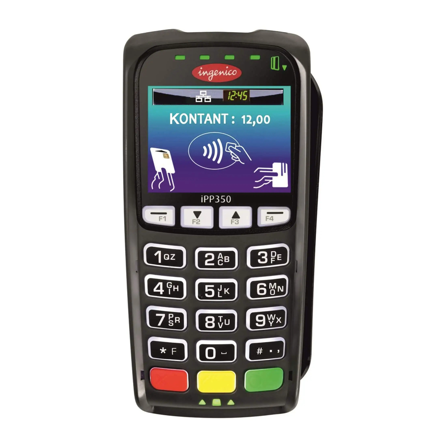
Бесконтактное чтение. Карта прилагается к активной зоне над дисплеем на расстоянии примерно 1 см. Держать ее у дисплея нужно до тех пор, пока транзакция не пройдет.
В терминале Ingenico iPP320 предусмотрено четыре индикатора статусов:
- В начале транзакции загорается индикатор, расположенный слева. Это говорит о том, что терминал используется, но чтение карты не производится.
- После приложения карты к активной зоне по очереди загораются остальные индикаторы. Когда все они загорелись, и терминал издал звук подтверждения транзакции, считает, что она окончена.
Обратите внимание! Если вы планируете использовать возможность бесконтактной оплаты, следует подключить к терминалу блок питания. Энергии, поступающей через usb-кабель, может быть недостаточно для проведения таких операций. В итоге карты могут читаться нестабильно, а сам терминал может перезагрузиться.
Перегрузка Ingenico iPP320
Чтобы принудительно перезагрузить терминал, нужно нажать одновременно:
- кнопку со значком «.»;
- желтую кнопку «Исправление».

Кнопку с точкой и желтую клавишу следует нажать одновременно
Клавиши нажимаются одновременно и удерживаются до тех пор, пока терминал не начнет перегружаться.
Если вы используете кассу Атол Sigma, узнайте, как подключить к ней Ingenico iPP320.
Возможные ошибки и их устранение
В следующей таблице мы собрали ошибки, которые могут возникать при работе с терминалом, а также способы их самостоятельного устранения.
Таблица. Ошибки в работе с терминалом Ingenico iPP320
|
Проблема |
Как решить |
|
Терминал не включается или не подключается к телефонной линии: |
|
|
Не удается установить телефонное подключение: |
|
|
Не читается карта: |
|
Рекомендуем прочитать статью Ingenico IPP 320: подключение эквайринга от РФИ Банка
Пин-пады iPP320 C98 — это устройства, благодаря которым можно принимать платежи разными способами, включая оплату с мобильных телефонов с помощью опции NFC.
Приобрести данный пин-пад Вы можете по ссылке: https://mirbeznala.ru/product/ingenico-ipp-320-a98/
Подробнее о том, как подключить пин-пад iPP320 C98 расскажем далее.

1 Строение устройства
Пин-пад терминал оборудован следующим функционалом:
- Удобная клавиатура, состоящая из 15 клавиш;
- Экран с подсветкой (в моделях IPP320) или цветной графический экран (в моделях IPP350);
- Ридер для магнитных карт;
- Ридер смарт-карт;
- Бесконтактный определитель;
- Слот для USB;
- Защитный козырь для ввода пароля;
Подзарядка устройства осуществляется через блок питания или USB.

Соединение с коммуникаций к пин-паду осуществляется через специальный разъем.

1.1 Условия эксплуатации пин-падов
Прежде чем купить пин-пад, нужно разобраться в условиях его применения, ведь только при соблюдении определенных стандартов и норм аппарат будет работать долго и бесперебойно.
Параметры рабочей среды
|
Разрешенный диапазон температурного режима |
от +5°C до +45°C |
|
Максимальный уровень влажности |
85% при t +55°C |
|
Условия хранения в автономном режиме |
|
|
Температурный режим |
-20°C, +70°C |
|
Максимальный уровень влажности возддуха |
85% при t +55°C |
2 Порядок подключения
Терминал нужно расположить на ровной поверхности, чтобы оставался свободный доступ к розетке и телефонной линии. Исключите попадания на него тепла, влаги, пыли, вибраций и электромагнитных волн.
Бесперебойная деятельность кассовой установки возможна лишь при соблюдении условий эксплуатаций.
Кабель нужно подсоединить к пин-паду:

Иногда, разъем закрепляют с помощью болтов, которые придется приобретать дополнительно.

Чтобы отсоединить кабель, достаточно открутить болты и убрать кабель, потянув его за ручку:

Для обслуживания пин-падов iPP320 C98 используют кабели, представленные ниже:
1) USB 5V, 500 mA.

2) Адаптер Power over Ethernet 48V (1.3W).

3) Провод RS232 8–12 V, 450 mA.

4) MagicBox 8–12 V, 450 mA.

MagicBox применяется при подключении нескольких коммуникаций.
Чтобы magicbox работал стабильно и бесперебойно, важно подключать ethermet до блока питания. Также приветствуется применение внешнего питания.
Продлить срок службы кабеля можно путем закрепления его активной части на месте установки.

2.1 Подключение модуля считывания бесконтактных карт
Установка модуля осуществляется следующим образом:
1) Открыть заднюю крышку пин-пада;

2) Установить модуль, считывающий бесконтактные виды карт.

3) Закрыть крышку и закрепить ее болтиком. Отметим, что в стандартной комплектации устройства болт не предусмотрен, его придется приобретать отдельно.

3 Работа с картами
3.1 Чтение магнитных карт и чип-карт
Для работы с магнитными и чип-картами, нужно вставить ее в считыватель магнитной стороной вправо. Теперь нужно провести карту через магнитную полосу. Делайте это не быстро и не медленно, что устройство успело правильно прочитать данные карты.
Для прочтения чип-карты, нужно вставить ее чипом вверх.

3.2 Опциональное бесконтактное чтение карт
При работе с бесконтактными картами, нужно приложить ее к активной части терминала над дисплеем. Расстояние должно быть примерно 1 см. В таком состоянии удерживайте карту до окончания операции. На терминале представлены мигающие лампочки, которые говорят о статусе операции.
Если во время транзакции загорается левая зеленая лампочка, то это признак того, что карта не считывается.
При успешном проведении операции на дисплее по очереди загорятся все 4 лампочки и раздается специальный сигнал. Теперь можно убирать карту.

|
Если Вы применяете бесконтактный ридер, то подключение блока подзарядки считается обязательным. Только портом USB не обойтись, так как это может привести к нехватке питания, нестабильной работе терминала и перегрузке устройства. |
|
|
|
4 Основы работы с настройками терминала
4.1 Как перезагрузить пос-устройство
Перезагрузка терминала осуществляется одновременным нажатием кнопок «.» и желтой клавиши. Нужно удерживать кнопки в таком положении до тех пор, пока не начнется перезагрузка.

4.2 Как перейти в системное меню
Открыть меню пос-устройства можно после его перезагрузки. Как только на дисплее появятся 3 линии «—», следует нажать на клавишу «2».
Выйти из меню можно несколько раз нажав на красную клавишу или запустив перезагрузку. Эти действия приведут к удалению прикладного ПО и всех его параметров с памяти устройства.
После удаления ПО, в устройстве остаются криптоключи. Чтобы удалить их, нужно применить нужный пункт прикладного программного обеспечения.
Полная очистка пос-устройства, включая операционную систему, можно выполнить с помощью алгоритма действий:
1) Во время перезагрузки на экране отобразится знак «:-)». Как только увидели его, нужно нажать и удерживать клавишу F1 до тех пор, пока не увидите знак «*».
2) Теперь по очереди жмите на клавиши F4, F2, F3. При нажатии на каждую. Кнопку должен появляться символ «*».
3) Успевайте набирать комбинацию клавиш в течение 2-3 секунд.
После этих действий, устройство целиком форматируется и переходит в режим загрузки.
4.3 Загрузка программного обеспечения
Есть несколько способов загрузки ПО на терминал. О них расскажем далее.
1. При включении или перезагрузке устройства появляется знак «:-)». Как только его увидели или даже раньше, жмите и удерживайте клавишу «↑» до тех пор, пока не появится сообщение «LLT».
2. Воспользовавшись системным меню. Для загрузки новых параметров, выберите «Download menu» -> «Local download». На дисплее увидите сообщение «LLT».
3. Воспользовавшись Telium manager. В последних моделях программных обеспечений можно открыть административное меню и перейти в «Telium manager», при этом не удалив ПО. После чего нужно будет нажать на клавишу «F» и выбрать из списка «Telium manager». Посе завершения настроек можно выйти на главное меню с помощью красной клавиши. Чтобы вернуться в прикладное программное обеспечение, произведите перезагрузку терминала.
4. Из главного меню, нажав «Telium manager», далее «F». Вам нужно выбрать раздел «Telium manager», а затем «2 — Evolution», «1 — Load», «1 — Local». На дисплее высветится сообщение «LLT».
5 Ошибки и их устранение
Терминал не реагирует, не включается и не видит связь с телефонной линией
· Нужно проверить исправность кабеля питания и телефонного провода.
· Стоит проверить состояние электросети.
Телефонная связь не устанавливается
· Проверьте свободность телефонной линии.
· Проверьте правильность настроек телефонной линии и номер вызова. Обратитесь в службу поддержки.
Оплата по карте не проходит (карта не читается)
· Убедитесь в правильности расположения магнитной карты.
· Попробуйте повторить транзакцию.
· Проверьте магнитную полосу на наличие повреждений.
· Убедитесь в правильном расположении смарт-карты в считыватель.
Приобрести данный пин-пад Вы можете по ссылке: https://mirbeznala.ru/product/ingenico-ipp-320-a98/
ingenico iPP320 / iPP350 Installation and Quick Reference Guide
")
iPP320 (with PIN shield)
")
iPP350 (without PIN shield)
Introduction
Ingenico’s iPP300 secure electronic payment devices include the iPP320 and the iPP350. Each device consists of the following:
- 2.7″ graphical monochrome LCD display (iPP320)
- 2.7″ TFT color QVGA display (iPP350)
- Bi-directional magnetic stripe reader
- Smart card reader
- ADA-friendly keypad
- PIN privacy shield (field-installable)
- Integrated contactless card reader. *
For details on these features, see the Specifications section in this document.
For the contactless card reader function to work properly, no metallic adapter or hood should be used on or around the device and, particularly do not use a locally added metallic PIN privacy shield or mounting cradle. Using a metallic adapter on or near the device can severely degrade the contactless reader’s performance. Metal can cause electromagnetic field interference which can negatively impact the contactless function.
Device Installation
The installation procedure includes:
- Selecting the device location
- Connecting the device
- Connecting an interface cable and power supply (if required)
- Attaching the PIN privacy shield (if desired)
Each step is described in the sections that follow.
Box Contents
Carefully inspect the carton and contents for any shipping damage. If the device is damaged, file a claim immediately with the shipping company and notify your device provider.
- Remove the contents from the box. You should have:
- iPP300 terminal
- This guide
- Connection cable or i3070 cable adapter
- Power supply (if required)
- PIN privacy shield (optional)
- 3 x m2.5 screws (optional)
- Application User Guide (optional)
- Save the carton and packing material for repackaging or moving/shipping the device in the future.
Selecting the Device Location
The iPP300 may be mounted on a flat surface or customer stand (recommended). Ingenico recommends physically securing the device to avoid theft. For additional anti-theft security, attach a Kensington Locking cable (or similar device) to the key lock slot on the left side of the device.
Power may be provided from a host Point of Sale (POS) system or from an Ingenico power supply. If using an Ingenico power supply, the device must be placed close to an easily-accessible power outlet.
Do not place the iPP300 on a PC monitor, adjacent to an electronically active security tag deactivation system, or near other sources of magnetic fields.
The iPP300 must be at least 12 inches away from an electronically active type of security tag deactivation pad. There are two types of security tag deactivation systems:
- An electronically active system sends out a powerful and potentially disruptive signal to deactivate a security tag. If the iPP300 is placed too close to the system’s pad, or placed above the pad, malfunctions may occur.
- A passive system is a permanent magnet type that does not send out a signal. This type does not affect the iPP300.
Connecting the Terminal
Do not connect power to the iPP300 device until instructed to do so.
Use the provided cable or cable adapter to connect your device. If using an i3070 cable adapter, existing i3070 communication cables can be used.
- Place the iPP300 device in front of you with the bottom of the unit facing up. Be careful not to place the device on a surface where the device can be scratched or damaged.
- Pull the cable’s retraction handle up on the device’s HDMI connector end of the cable as shown in figure 1 below.
- Place the cable connector in the port and push firmly in place.

Figure 1: Cable Placed in iPP300 Port - If desired, use two of the supplied m2.5 screws to secure cable to the base of the iPP300.
- Push the handle on the cable down to secure the cable in place.
- Connect the other end of the cable into the POS or PC as appropriate
- Remove the protective film from the graphical display screen.

The use of screws is optional. When using the iPP300 without a contactless card reader* or SAMs, there are no screw related operational security issues.
Cables and power supply
Refer to your equipment provider or Ingenico representative for details of appropriate cables and power supplies available. Only Ingenico recommended cables may be used. Use of non Ingenico accessories may result in damage and void any warranty.
| Connection Type | Description |
| Ethernet | 8-pin RJ45. Use to connect Ethernet 10/100 BASE-T. |
| USB | USB 2.0 Host high speed. 5V, 500mA max. Supports peripheral USB devices. |
| RS-232 | 9-pin MiniDIN9 port. Use for RS-232 and USB 2.0 full speed connections. |
| Power Supply | Some cables have a power supply input plug at the host end of the cable (the end furthest away from the iPP300). Do not plug in the Power Supply until you are instructed to do so. |
To avoid accidental damage, secure cables and power cords.
Connecting a Power Supply
Use only an Ingenico-provided power supply where a separate DC power supply is required. If the device is powered directly from a POS, power may be provided via the USB port (power through the USB 2.0 port is rated at 5V, 500mA). Use of non-Ingenico power supplies may result in damage. Damage of this type is not covered by warranty.
Connect the cable to the iPP300’s port before connecting the device to power. Only use the power supply provided by Ingenico.
- If your device came with a power supply, plug the power supply connector into the jack on the interface cable as shown in figure 2 below.
Figure 2: Sample Cable Conversion - Plug the power supply into a power outlet. The iPP300 will self-initialize when power is applied.

Attaching the PIN Privacy Shield (Optional)
A PIN privacy shield may be provided for optional use. To attach the PIN privacy shield, do the following:
- Remove the protective tabs from the double sided adhesive tape pads on the PIN shield.
- Align the hooked ends of the PIN privacy shield into the slots on the outside bottom edges of the keypad (near the red [Cancel] key and the green [Enter] key).
- Push the PIN privacy shield down onto the device to secure it. The device can be used immediately, but avoid undue strain on the PIN shield for 24hrs to allow the adhesive tape to fully cure for a strong and permanent grip.
| Part # | Description |
| 296 111 328 | PIN privacy shield (optional) |
Operations
Powering On
After you apply power to the iPP300 device, the device is ready for use. The iPP300 device may be left on indefinitely, or may be disconnected from power as necessary.
Restarting the Device
To restart the terminal, press the yellow [Clear] key and [#.,] simultaneously. Alternatively, disconnect and reconnect the device’s power source.
Using a Magnetic Stripe Card
The iPP300 device’s magnetic stripe reader reads debit, credit, and all standard magnetic stripe cards. When the application prompts for a magnetic stripe card, the magnetic stripe logo on the top upper right side of the device illuminates. Be sure the magnetic stripe side of the card is facing toward the iPP300 graphical display screen. Slide the card in either direction. For best results, slide the card in a continuous motion.
Using a Smart Card
When the application prompts the cardholder for a smart card, the smart card logos will illuminate. Insert the smart card into the slot on the front of the device with the chip facing up and towards the slot. Green lights located on top of the smart card reader slot, under software control, can prompt the cardholder when to insert or remove a card.
It is necessary for the card to remain in the reader slot until the application indicates that it can be removed.
If PIN entry is required, the keypad can also be programmed to illuminate under application control.
Using a Contactless Card
The iPP300 contactless card reader reads contactless payment cards. When prompted, hold the contactless payment card close to the active zone around the display. A series of green lights illuminate on the top of the device when the contactless card has been read.
* Contactless reader capability is Optional on early PCIPTS V2 and V3 models.
Troubleshooting
Magnetic Card Reader Does Not Work Properly
- Slide the card through the magnetic stripe reader as described in Swiping a Magnetic Stripe Card.
- Swipe the card at a faster or slower steady speed.
- Swipe the card in a different direction.
- Inspect the magnetic stripe on the card to make sure it is not scratched or badly worn.
- To determine if there is a problem with the card:
- If your host device (POS) has a magnetic stripe reader, try swiping the card there.
- If you have another working iPP300 device, try swiping the card there.
- If there is still a problem, contact your Help Desk.
No Information Visible on Screen
- Make sure that the iPP300 cable connector is fully inserted into the back of the device.
- Restart the device (see Restarting the Device above).
- Unplug the device and examine the connector’s pins. If there are any pins that are bent, or if other damage is visible, replace the cable or adapter.
- If you have another working iPP300 device, swap the devices to determine if the problem is with the device, cable, POS, PC, or power supply.
- Reset the host by turning it off and back on again.
Specifications
Processors: Main Processor: RISC 32-bit ARM9, 450 MIPS. Integrated Crypto Processor: RISC 32-bit ARM7, 50 MIPS.
Operating System (OS): Telium 2 with HTML GUI.
Display: iPP320: graphical monochrome LCD, resolution of 128 x 64. iPP350: graphical active 2.7″ TFT color QVGA, resolution of 320 x 240 with 4096 colors.
Memory: 32 MB SDRAM, 128 MB Flash.
Keypad: 19 keys including four (4) function keys; raised markings, ADA-friendly. White backlit.
SAMs: 3 SAM slots.
Buzzer: 65 dB at 1 meter.
Communications: HOST port: RS-232, USB, Ethernet (TCP/IP).
Dimensions (without PIN privacy shield): 6.3″ x 3.3″ x 1.6″ (168 mm x 83 mm x 41 mm)
Weight (without PIN privacy shield and cable): 9.5 oz. (269 g).
Face Plate Standard Color: Ingenico gray.
Magnetic Stripe Card Reader: Bi-directional magnetic stripe card reader, triple track. Magnetic Stripe logo illuminates.
Smart Card Reader: EMV L1 and L2 certified – meets EMV levels 1.0 — 4.0 specifications. Complies with IS 7816 — 1/2/3. Smart card icons illuminate.
Contactless: Integrated contactless card reader.
Supports ISO 18443 A/B, MIFARE Classic, MIFARE DESFire.
(* Please Note: Contactless reader capability is Optional on early PCIPTS V2 and V3 models. PCIPTS V4 approved models are supplied with contactless capability as a standard feature.)
Power: Powered through USB (rated at 5V, 500 mA). Unit can also be powered from a RS-232 or Ethernet cable with an appropriate power supply. Power via Ethernet is supported in selected models only. Contact your Ingenico representative for details on specific model numbers.
Safety: UL/CSA 60951-1
Security: PCI PTS 2.x and Interac (Canada).
RFID: IC and FCC: Part 15B and Part 15C.
Environmental Requirements
The device is designed to operate in the following environment:
- Operating temperature of 41°F to 113°F (+5°C to +45°C)
- Operating humidity of 85% RH (non-condensing) at 131°F (+55°C)
- Storage temperature of -4°F to 158°F (-20°C to +70°C)
- Storage humidity of 85% at 131°F (+55°C)
Any liquid spill on or around the device must be removed immediately.
More Information
For more information on cleaning, troubleshooting, operating the device, features, specifications, and accessories, please contact your equipment’s supplier.
Security
Your device fulfills current applicable PCIPTS security requirements. Physical (antitheft) security can be enhanced by the use of a Kensington Locking cable (or similar device) attached to the key lock slot.
You are strongly advised to ensure that privileged access to your device is only granted to staff that have been independently verified as being trustworthy.
Security Assurance
Perform the following tasks daily to ensure the security and compliance of your device:
Checking the Device’s Integrity
Ensure that no attempts have been made to tamper with the device, using the following method:
- Check the device and ensure that there is NO external damage, particularly around the keypad, display, and card reader areas.
- Ensure the keypad is firmly in place.
- Ensure that there are NO additional cables protruding from the device or associated equipment.
- Ensure that there are NO holes drilled into the device’s housing.
Alert Irruption
- Your iPP300 device detects any tampered state.
- In this state the device will repeatedly flash the message «Alert Irruption!» and further use of the device will not be possible. If you observe the «Alert Irruption!» message, you should contact your helpdesk immediately.
Note on PCI PTS v4 iPP300 models
PCI PTS v4 security requirements stipulate that the terminal must reboot at least once every 24 hours. If the reboot is not initiated through the connected device within 24 hours, the terminal will automatically reboot. Please refer to the relevant application guide for further information.
Checking the Installation Site
- Ensure that there are NO security cameras focusing on the device.
- Ensure that there are NO objects nearby in which cameras could be hidden.
- Ensure that the device CANNOT be observed from outside (any window or door opening) during customer Pin entry.
NEVER ask the customer to divulge their PIN. Customers should be advised to ensure that they are not being observed when entering their PIN.
Lithium Battery
The IPP3X0 is fitted with a lithium battery which is not accessible to the user.
Customer Service
Only qualified Ingenico repair facilities may open the unit for any reason. To request an RMA for return and repair of a defective unit please e-mail the appropriate customer support department per below.
Customer Service – USA
Customerservice.us@ingenico.com
Customer Service-Canada
TCChelpdesk@Ingenico.com
Compliance
U.S. Federal Communications Commission Warning
FCC standard compliance marking certifies that the product stipulated here: IPP3X0XXXXXXX conforms to the following harmonized standards: part 15 subpart B of the FCC rules. This class (B) digital apparatus complies with Canadian ICES-003.
Changes or modifications not expressly approved by the party responsible for compliance could void the user’s authority to operate the equipment.
NOTE: This equipment has been tested and found to comply with the limits for a Class B digital device, pursuant to Part 15 of the FCC Rules. These limits are designed to provide reasonable protection against harmful interference in a residential installation. This equipment generates, uses, and can radiate radio frequency energy and, if not installed and used in accordance with the instruction, may cause harmful interference to radio communications. However, there is no guarantee that interference will not occur in a particular installation. If this equipment does cause harmful interference to radio or television reception which can be determined by turning the equipment off and on, the user is encouraged to try to correct interference by one or more of the following measures:
- Reorient or relocate the receiving antenna
- Increase the separation between the equipment and receiver
- Connect the equipment to an outlet on a circuit different from that to which the receiver is connected
- Consult the dealer or an experienced radio/TV technician for help
Industry Canada Warning
Under Industry Canada regulations, this radio transmitter may only operate using an antenna of a type and maximum (or lesser) gain approved for the transmitter by Industry Canada. To reduce potential radio interference to other users, the antenna type and its gain should be so chosen that the equivalent isotropically radiated power (e.i.r.p.) is not more than that necessary for successful communication.
This device complies with Industry Canada license-exempt RSS standard(s). Operation is subject to the following two conditions: (1) this device may not cause interference, and (2) this device must accept any interference, including interference that may cause undesired operation of the device.
Ingenico Inc.
3025 Windward Plaza, Alpharetta, GA 30005.
Tel: +1.678.456.1200
Fax: +1.678.456.1201
www.ingenico.us
Ingenico Canada, Inc.
5180 Orbitor Drive, 2nd Floor, Mississauga, Ontario, L4W 5L9
Tel +1 905.212. 9ING
Fax: +1 905.212. 9155
http://www.ingenico.ca

Documents / Resources
References
Download manual
Here you can download full pdf version of manual, it may contain additional safety instructions, warranty information, FCC rules, etc.
Download ingenico iPP320 / iPP350 Installation and Quick Reference Guide
Подключение Ingenico iPP320 с приемом пластиковых карт
Прежде чем подключать эквайринг терминал, его следует разместить на ровную плоскость, располагающуюся вблизи источника питания. Не желательно ставить устройство рядом с объектами, излучающих вибрационные, тепловые и электромагнитные волны, по этой причине эквайринг следует устанавливать подальше от компьютера и других типов техники. Использование терминала допустимо и при довольно высокой температурном режиме, до +45 градусов по Цельсию, с относительной влажностью воздуха до 85%. Терминал подключается к контрольно-кассовой технике (ККТ) с использованием специального порта (разъема) IPP320/350.
Виды применяемых кабелей подключения
- Ethernet (через адаптер питания);
- USB;
- RS232 (через адаптер питания);
- MagicBox (USB-питание или через адаптер)
Стоит отметить, что при использовании подключения MagicBox-кабеля следует подключить Ethernet перед блоком питания. В случае если этого не сделать, у Вас возникнут нарушения в работе самого устройства или проблемы со связью
Важные моменты использования терминала, действия с банковскими картами
- Эквайринговый аппарат может принимать все виды пластиковых карт (магнитные, карты с чипом и бесконтактные, кредитный карта)
- Карты с магнитной полосой. Для этой банковской карты учтен особый фронтальный ридер, где расположение магнитной полосы смотрит в сторону POS-устройства. Оплата осуществляется при помощи одного плавного движения карты через ридер, важно, не спешить и слишком не медлить, для того чтобы данные подтвердились считыванию без вторичных попыток
- Карты с чипом. Считывание данных проводиться в специальном ридере, который размещается внизу устройства, карту следует держать чипом кверху.
- Бесконтактные карты. Данные карты прикладываются к области монитора. Саму карту необходимо держать на расстоянии до 1 см, пока не услышите звуковой сигнал подтверждения оплаты.
В POS-терминале есть четыре индикатора оповещения о статусе терминала
Первоначально при совершении транзакции загорается левый индикатор. Он дает понять, что устройство готово к работе, однако считывание информации с карты ещё не прошло. В случае с бесконтактной картой во время прикладывания к терминалу, по очереди загораются остальные 3 индикатора. Когда они загораются все, и вы услышали звуковое оповещение, считается, что оплата прошла успешно.
Стоит отметить: в случае работы эквайринг аппарата с бесконтактной картой, стоит подключить эквайринг устройство к зарядному устройству, так как может не хватить электричества, поступающего через USB-кабель, в противном случае эквайринг может уйти на перезагрузку системы.
Купить эквайринговый аппарат можно перейдя по ссылке: https://compik-s.ru/kassyi/ekvayring.Всегда в наличии коды активации оператора фискальных данных (ОФД), услуги под ключь контрольно-кассовой техники. Мы работаем по всей территории Российской Федерации