-
Contents
-
Table of Contents
-
Bookmarks
Quick Links
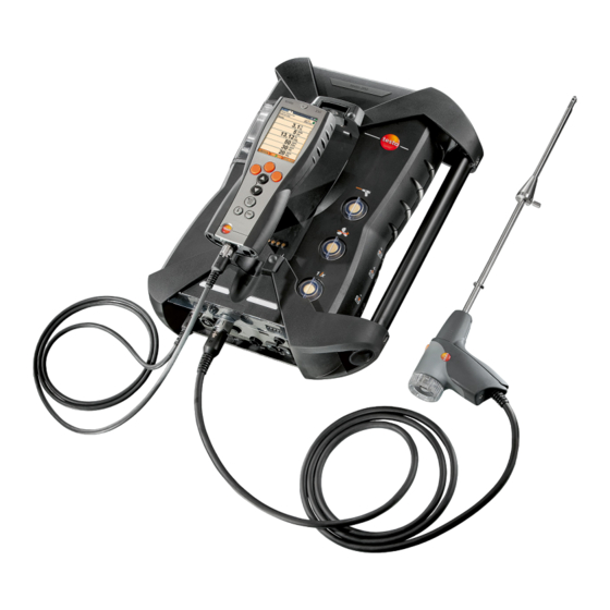
testo 350 · Flue gas analyzer
Instruction manual
800.561.8187
information@itm.co
www.
.com
Related Manuals for TESTO 350
Summary of Contents for TESTO 350
-
Page 1
350 · Flue gas analyzer Instruction manual 800.561.8187 information@itm.co www. .com… -
Page 2: Table Of Contents
1 Contents Contents Contents ………………..3 Safety and the environment …………..6 2.1. About this document ……………. 6 2.2. Ensure safety ………………. 7 2.3. Protecting the environment ………….. 9 Specifications ………………10 3.1. Use ………………..10 3.2. Technical data …………….11 3.2.1.
-
Page 3
1 Contents 5.2.4. Connecting system components …………..34 5.2.4.1. Connection using contact strip …………34 5.2.4.2. Connection using a Data bus cable (accessory part to a bus system) ………… 35 ® 5.2.4.3. Connection via Bluetooth (option) ……….38 5.2.5. Switching on ………………..39 5.2.6. -
Page 4
1 Contents 6.2. Measuring ………………68 6.2.1. Preparing for measurement …………….68 6.2.2. Using the flue gas probe …………….70 6.2.3. Applications ………………..70 6.2.3.1. Flue Gas, Flue Gas + m/s, Flue Gas + Δp, Program for all meas. boxes, Flue Gas before + after catalyst ……….. 72 6.2.3.2. -
Page 5: Safety And The Environment
2 Safety and the environment Safety and the environment 2.1. About this document This document describes the product testo 350 with the device setting Country version | Germany. > Please read this documentation through carefully and familiarize yourself with the product before putting it to use. Pay particular attention to the safety instructions and warning advice in order to prevent injuries and damage to the products.
-
Page 6: Ensure Safety
Use only original spare parts from Testo. > Any further or additional work must only be carried out by authorised personnel. Testo will otherwise refuse to accept responsibility for the proper functioning of the measuring instrument after repair and for the validity of certifications.
-
Page 7
2 Safety and the environment > Temperatures given on probes/sensors relate only to the measuring range of the sensors. Do not expose handles and feed lines to any temperatures in excess of 70 °C unless they are expressly permitted for higher temperatures. >… -
Page 8: Protecting The Environment
> At the end of its useful life, send the product to the separate collection for electric and electronic devices (observe local regulations) or return the product to Testo for disposal. 800.561.8187 information@itm.co www.
-
Page 9: Specifications
3 Specifications Specifications 3.1. The testo 350 is a portable flue gas analyser for professional flue gas analysis. The instrument consists of the Control Unit (control unit for displaying readings and controlling the meas. box) and the meas. box (measuring instrument). Plug-type contacts, databus ®…
-
Page 10: Technical Data
3 Specifications testo 350 must not be used: • for continuous measurements • as a safety (alarm) device • to measure combustion gases (before the actual combustion process) ® testo 350 with Bluetooth option: The use of the wireless module is subject to the…
-
Page 11
The FCC demands that the user is to be informed that with any changes and modifications to the device, which have not been explicitly approved by testo AG, the right of the user to use this device will become null and void. -
Page 12: Declaration Of Conformity
3 Specifications 3.2.3. Declaration of Conformity 800.561.8187 information@itm.co www. .com…
-
Page 13: Measurement Ranges And Resolution
3 Specifications 3.2.4. Measurement ranges and resolution Analysis box Measurement Measurement Resolution parameter range 0…25vol.% 0.01vol.% CO, H -comp. 0…10000ppm 1ppm -comp. 0…500ppm 0.1ppm 0…4000ppm 1ppm 0…300ppm 0.1ppm 0…500ppm 0.1ppm 0…5000ppm 1ppm 0…300ppm 0.1ppm -(IR) 0…50vol.% 0.01Vol.% (0…25Vol.%) 0.1Vol.% (> 25Vol.%) 1, 2 CxHy Natural gas:…
-
Page 14: Accuracy And Response Time
3 Specifications 3.2.5. Accuracy and response time Analysis box Measurement Accuracy Response parameter time ±0.2Vol.% < 20s (t95) CO, H -comp. ±10ppm (0…199ppm) < 40s (t90) ±5% of reading (200…2000ppm) ±10% of reading (rest of range) -comp. ±2ppm (0…39.9ppm CO) <…
-
Page 15: Measurement Range Extension For Individual Slot (Option)
3 Specifications Measurement Response Accuracy parameter time Type K (NiCr-Ni) ±0.4°C (-100 to 200°C) ±1°C (rest of range) Type S ±1°C (0 to 1760°C) (Pt10Rh-Pt) Combustion air ±0.2°C (-10…50°C) ±3°C Offset — (VT) via permanently installed NTC 3.2.6. Measurement range extension for individual slot (option) Measurement Max.
-
Page 16: Fresh Air Valve (Option)
3 Specifications 3.2.7. Fresh air valve (option) Dilution of all sensors, dilution factor 5 6, 7 Measurement Measurement Accuracy parameter range The reading does not appear in the display. 2500…50000ppm ±5% of reading CO, H -comp. (-150…0hPa) -comp. 500…2500ppm ±5% of reading (-100…0hPa) ±5% of reading 500…2500ppm…
-
Page 17: Other Instrument Data
NO sensor: 12 months -(IR) sensor: 24 months Flue gas probe: 24 months Thermocouple: 12 months Rech. battery: 12 months Terms of warranty Terms of warranty: see website www.testo.com/warranty Control unit Feature Values Power supply • Li-ion rech. batt. •…
-
Page 18
3 Specifications Feature Values Housing material PC, TPE Weight 440g Display Graphic colour display, 240 x 320 pixels Dimensions 88 x 38 x 220mm Analysis box Feature Values Power supply via rech. batt. Li-ion rech. batt. via internal mains unit: 100V AC/0.45A — 240V AC/ 0.2A (50-60Hz) via DC-input (option) 11V…40V DC/ 1 — 4A… -
Page 19: Product Description
4 Product description Product description 4.1. Control Unit 4.1.1. Overview 1 IrDA interface 2 Switch On / Off 800.561.8187 information@itm.co www. .com…
-
Page 20: Keyboard
(e.g. monitors, computers or credit cards). 4 Display 5 Keyboard 6 Contact bar for meas. box (on rear) 7 Interfaces: USB 2.0, charger, Testo Data bus 4.1.2. Keyboard Functions Switch measuring instrument on / off…
-
Page 21: Display
4 Product description 4.1.3. Display 1 Status bar (dark grey background): • Display of date and time (valid for control unit and meas. box). ® • Display of Bluetooth status, power supply and remaining rech. batt. capacity (valid for control unit): Icon Feature ®…
-
Page 22: Connections / Interfaces
4 Function display for function keys. 4.1.4. Connections / interfaces 1 USB 2.0 2 Testo Data bus 3 Connecting socket for mains unit 0554 1096 4 Guide groove for locking with meas. box 800.561.8187 information@itm.co www.
-
Page 23: Menu Guidance For Control Unit
4 Product description 4.1.5. Menu guidance for control unit Main menu Menu Description Measurement records Display of saved measurement records Device settings Date/Time Set date, time, time format: Power Options Automatic instrument shut-down on / off Display backlight in battery operation on / off Display brightness Set display brightness Printer…
-
Page 24: Meas. Box
4 Product description 4.2. Meas. box 4.2.1. Overview 800.561.8187 information@itm.co www. .com…
-
Page 25: Status Display
4 Product description 1 Condensate trap and condensate container, 2 Locking/unlocking button for Control Unit 3 Measuring gas particle filter 4 Filter fresh air inlet (option: fresh air valve / measurement range extension overall (5x)) 5 Contact bar for connection to Control Unit 6 Guide pins for locking with Control Unit 7 Diluting gas filter 8 Status display…
-
Page 26: Connections / Interfaces
9 DC-voltage input 11…40V DC (option) 10 Covering cap gas channel access (only for servicing purposes) Plugged in covering cap: Position ( ) must not be changed! 11 Pressure ports p+ and p- 12 Testo Data bus 800.561.8187 information@itm.co www. .com…
-
Page 27: Functions / Instrument Options
4 Product description 4.2.4. Functions / instrument options Some functions are available as optional extras. The functions your meas. box is equipped with (condition as delivered) can be read on the identification plate on the bottom side of the meas. box. Imprint Description CO, NO, NO…
-
Page 28: Menu Guidance Meas. Box
4 Product description 4.2.5. Menu guidance meas. box Main menu Menu Description Applications Select an application in accordance with the measuring task to be performed Folders Create and manage folders and locations Fuels Select and configure fuels Measurement Display and manage measurement records records Device…
-
Page 29: Modular Flue Gas Probe
4 Product description Main menu Menu Description Instrument Error diagnosis Display of present errors diagnosis Gas path check Perform tightness test Sensor diagnosis Perform sensor diagnosis Device information Display of device information 4.2.6. Modular flue gas probe 1 Removable filter chamber with window and particle filter 2 Probe handle 3 Connecting cable 4 Connector plug for measuring instrument…
-
Page 30: First Steps
7h (charging with mains adapter) or approx. 14h (charging via Testo Data bus). In the case of Testo data bus cables >90 m, the rechargeable battery for the control unit can no longer be charged via the Testo data bus cables when the control unit is switched off.
-
Page 31: Charging The Rech. Batt. Of The Meas. Box
Charging via meas. box ✓ Control Unit is locked to meas. box or is connected via the Testo Data bus cable. ✓ The meas. box is supplied via the mains unit. During operation with low charge power or in switched off state.
-
Page 32: Connecting Probes / Sensors
5 First steps Meas. box via internal mains unit > Connect the mains cable to meas. box and mains socket. The meas. box is powered via the internal mains unit. If the meas. box is switched off the rech. batt. charging process will start automatically.
-
Page 33: Connecting System Components
5 First steps > Occupying the trigger input, with supply via instrument voltage (12 V): In case of supply via instrument voltage the flue gas analyser can only be started via the trigger input from switched off state when the mains plug is plugged in. 5.2.4.
-
Page 34: Connection Using A Data Bus Cable (Accessory Part To A Bus System)
Before connecting to a bus system, all analyzer units must first be equipped with the identical country version and firmware version. If testo easyEmission software is connected via a control unit to measuring boxes, the number of measuring boxes must not be changed. To add new measuring boxes, end…
-
Page 35
→ [OK]. → → → Bus address The bus address of each component connected to the Testo data bus must be unambiguous. The bus address of the connected component can be changed, if necessary. Bus Address → [Edit]. 2. Setting a new bus address: ], [◄], [►]. -
Page 36
Electrical termination of the bus system The Data bus system is linear in structure. The Control Unit or the Testo Data bus controller with USB connection represents the beginning of the line. The end is represented by the last components connected in the 800.561.8187… -
Page 37: Connection Via Bluetooth ® (Option)
5 First steps system (meas. box or analog output box). This component must have a defined electrical termination. An analog output box is the furthest subscriber. > Plug the Data bus termination plug into the Data bus socket on the analog output box. A meas.
-
Page 38: Switching On
5 First steps 5.2.5. Switching on Before switching on > Connect all system components. > Connect all required probes / sensors. > Connect all system components to the electric power supply. When switching on the Control Unit should be plugged on the contact strip of the meas. box connected with a Data bus cable plugged to the mains cable of the meas.
-
Page 39: Entering Values
5 First steps 5.2.7. Entering values Some functions require values (numbers, units, characters) to be entered. Depending on the function that is chosen, the values are entered via either a list field or an input editor. List field 1. Select the value to be changed (numerical value, unit): [▲], [▼], [◄], [►] (depending on the selected function).
-
Page 40: Printing / Saving Data
(only available via Control Unit tab) > → Search for boxes → [OK]. Meas. boxes connected via Testo Data bus: are displayed (tabs) Meas. boxes connected via Bluetooth ® • Meas. box found: Meas. box and Control Unit are connected automatically •…
-
Page 41: Confirming An Error Message
5 First steps 5.2.10. Confirming an error message If an error occurs, an error message is shown in the display. > Confirming an error message: [OK]. Errors which have occurred and have not yet been rectified are indicated by a warning symbol in the status bar. Not yet rectified error messages can be displayed in the menu Error diagnosis, see Sensor diagnosis, page 47.
-
Page 42
5 First steps Activating a location: > Select the location → [OK]. The location is activated and the menu Measurement Type opened. Creating a new location: A location is always created in a folder. 1. Select the folder in which the location is to be created. [Options] location→… -
Page 43
5 First steps Parameter Description Pressure The absolute pressure influences the calculation absolute of flow speed, volume flow, mass flow and flue gas dew point. The factory setting is 980mbar. To achieve a higher accuracy, the values can be adjusted to the actual ambient conditions. If a CO -(IR) module is installed, the absolute pressure value measured there… -
Page 44: Measurement Records
5 First steps Create a new folder: [Options] → New Folder → [OK]. 2. Enter values or make settings. 3. Finalise the entry: [Finished]. Other folder options: • Edit Folder: Make changes to an existing folder. • Copy Folder: Make a copy of an existing folder. •…
-
Page 45: Instrument Diagnosis
5 First steps Display record: 1. Choose the desired record from the detailed view. 2. [Data]. Options > [Options] → [Delete All Records]: The readings of all locations will be deleted. > [Options] → [Copy All Records]: The readings of all locations will be copied.
-
Page 46: Gas Path Check
5 First steps 5.5.2. Gas path check (only available via Meas. Box tab) Check the flue gas analyser regularly for leaks, to ensure accurate measurements. The leak test requires a plastic cap 0193 0039, comes with the flue gas probe). Gas path check →…
-
Page 47: Using The Product
6 Using the product Using the product 6.1. Performing settings 6.1.1. Assigning the right hand function key Options The right function key can have a function from the menu assigned to it. The menu Options is accessed via the left function key and is available in many different menus.
-
Page 48
6 Using the product Factor Ratio of diluting gas: Measuring gas no dilution 1 : 1 4 : 1 x 10 9 : 1 x 20 19 : 1 x 40 39 : 1 Auto dilution 4 : 1 If the dilution stage auto-dilution is selected, dilution (5x) is activated automatically when the set switch-off threshold of the… -
Page 49: Measurement View
6 Using the product Calling up the function: > → Device settings → [OK] → Dilution → [OK] to dilute all (x5): → [Change]. 1. Select [On] / [Off]. 2. Select setting: 3. Confirm the entry: [OK]. 6.1.2.2. Measurement view (only available via Meas.
-
Page 50
6 Using the product Display Measurement parameter Nitrogen monoxide Nitrogen dioxide Nitrogen oxide Sulphur dioxide Hydrogen sulphide Hydrocarbon Hydrogen (this is only an indicator value and is used to compensate the cross-sensitivity) λ Air ratio SmNum ø Mean smoke number Oil deposits Oil deposits yes/no Flow velocity… -
Page 51: Units
6 Using the product Options: > [Options] → Number of lines: Change the number of measuring values per display page. > [Options] → Blank line: Insert the empty line before the selected line. > [Options] → Delete line: Delete the selected line. >…
-
Page 52: Date / Time
6 Using the product 6.1.2.4. Date / time This function is available in both the meas. box and the Control Unit. Changes are accepted for the Control unit and for the meas. box. Date, time mode and time can be set. Calling up the function: >…
-
Page 53: Bluetooth
To be able to transfer data to a record printer via infrared or Bluetooth interface, the printer used must be enabled. The following printers can be used with the testo 350: — infrared high-speed printer (order no. 0554 0549) ®…
-
Page 54: Language
Information concerning assignment table, basis of calculation and country version see www.testo.com/download-center If several components with different country versions are connected, the components will automatically change to the country version of the Control Unit when the Control Unit is connected.
-
Page 55: Password Protection
6 Using the product The system is restarted. If the control unit is connected via Bluetooth to the measuring box, when the measuring box is restarted, the control unit should be used to search again for the measuring box (see Search for meas. boxes, page 41.) 6.1.2.11.
-
Page 56: Analog Input
6 Using the product 6.1.2.12. Analog input (Only available via Meas. Box tab) Power cable 0554 0007 (accessory) is required. An analog signal is read in by an external instrument. The signal is scaled and assigned to a physical parameter. The calculated value is displayed.
-
Page 57: Fuels
Recommended test gas concentrations and compositions can be found in the Testo Test Gas Manual (order no. 0980 2313 version D) or in the Download Centre. Calling up the function:…
-
Page 58: Cxhy-Sensor
6 Using the product Sensor settings [OK] NO2 addition > → → → → [Change]. Possibly: > Enter the password: [Enter] → Enter password → [Next] → [OK]. Setting the NO addition: > Set parameter → [OK]. 6.1.4.2. CxHy-Sensor The CxHy-Sensor can be activated / deactivated. CxHy-Sensor menu under Sensor settings…
-
Page 59: Sensor Protection
(calibrated) and, if required, adjusted. The calibration/adjustment can be carried out by the user or by a qualified service centre approved by Testo. To ensure that specific accuracies are retained, Testo recommends testing every six months and recalibration when required.
-
Page 60
6 Using the product Adjustments made with low gas concentrations can lead to accuracy deviations in the upper measuring ranges. The sensor protection (shut-down function) is not deactivated. The test gas concentration should therefore be lower than the set thresholds for the sensor protection. The function of to dilute all (x5) is automatically… -
Page 61
6 Using the product Perform calibration / adjustment of CO-, SO -, NO -, NO-, O S-, CxHy-sensors: WARNING Dangerous gases Danger of poisoning! > Observe safety regulations / accident prevention regulations when handling test gas. > Use test gases in well ventilated rooms only. Application of test gas via service adapter (0554 1205) is recommended, or apply test gas directly to the probe tip to avoid possible absorptions in the gas path. -
Page 62
6 Using the product Perform calibration / adjustment of the CO -(IR) sensor Check the CO -(IR)-sensor with the absorption filter to obtain accurate readings. The displayed CO -value should be <0.03%CO . If the value is higher, perform calibration and gradient adjustment. -
Page 63: Ppmh Counter
6 Using the product 6.1.4.5. ppmh counter The current ppm/h value can be displayed for the CO, COlow, NO, NOlow sensors. The hour meter can be reset for the NO sensor, which uses a replaceable filter for neutralizing transverse gases. Calling up the function: >…
-
Page 64: Negative Value
6 Using the product Options > [Options] → [Print]: the current adjustment data for all sensors is printed out. [Options] → [Graphic]: the status of the selected sensor is > graphically displayed. Threshold Explanation 100% Full capacity Reduced sensor sensitivity. Recommendation: Acquire a replacement sensor Replace sensor…
-
Page 65
6 Using the product Activating / deactivating a program: > Select the program: [▲], [▼] → [Enable] or [Disable]. When activating a program: The program is activated and the measurement type matching the program is opened. Editing the measuring program: Adjustable parameters: Parameter Function… -
Page 66
6 Using the product Parameter Function Determining the stop criterion Stop • The measuring program is stopped at any time (the function key automatically changes to the start function) • Time The recoding of readings stops at a desired time. •… -
Page 67: Measuring
• plugged vertically to the wall bracket by the handle To prevent measuring errors the position of the testo 350 must not be changed during a measurement. Under ambient temperatures of <10°C the CO…
-
Page 68
6 Using the product During then zeroing phase During the zeroing phase the sensors of the flue gas analyser are zeroed. Zero point and drift of the sensors are checked. The value is set to 21% O > Make sure that the ambient air is free of interfering gases (e.g. CO, NO) during the zeroing phase! Before the measurement >… -
Page 69: Using The Flue Gas Probe
6 Using the product 6.2.2. Using the flue gas probe Checking the thermocouple > Make sure that the thermocouple of the flue gas probe does not touch the probe basket. Bend the thermocouple back if necessary. Aligning the flue gas probe >…
-
Page 70
For this measurement type, both analyzer units must have a fresh air valve. If one of the two meas. boxes is equipped with a measurement range extension (individual dilution), the test 350 will automatically recommend this meas. box to be used for Before cat. -
Page 71: Flue Gas, Flue Gas + M/S, Flue Gas + Δp, Program For All Meas
6 Using the product 6.2.3.1. Flue Gas, Flue Gas + m/s, Flue Gas + Δp, Program for all meas. boxes, Flue Gas before + after catalyst The flue gas menus (Measurement Type) are the central measuring menus, which – in addition to the readings measured with this function –…
-
Page 72
6 Using the product Calling up the function: ✓ Application selected. → [OK]. > Choose the measurement type: Options [Options] → Save: The readings are saved in a record. > [Options] → Print: The readings from a record are printed. >… -
Page 73: Draught-Measurement
Do not measure for longer than 5 min, as the drift of the pressure sensor could have the effect that the readings are outside the tolerance limits. The automatic pressure zeroing (retrofit by Testo Service) automatically zeroes the pressure sensor at regular intervals (60s), to prevent the typical drift of the pressure sensor.
-
Page 74: Smoke Number/Hct
6 Using the product Options: > [Options] → Save: The readings are saved in a record. > [Options] → Print: The readings from a record are printed. > [Options] → Show Graphic: The readings are displayed in form of a line graph. >…
-
Page 75: Oil Flow Rate
6 Using the product Options: > [Options] → Print: The readings from a record are printed. > [Options] → Save: The readings are saved in a record. > [Options] → Enter Gas Flow: Set the gas flow value. > [Options] →…
-
Page 76
6 Using the product Call up function: Measurement Type Solid Fuel [OK]. > → → Carrying out a measurement: 1. Select start, stop, gas phase, rinsing time, measurement rate and stability time parameters: [▲], [▼], sometimes [►] → [Edit]. 2. Enter values: [▲], [▼] and sometimes [◄], [►]… -
Page 77: Analog Outputs
6 Using the product > [Options] Recalibrate (this function is not available during a measurement): the gas sensor zeroing begins. > [Options] → Folders/Locations (this function is not available during a measurement): the folder Folders/Locations opened. > [Options] → Show mean values: mean values are displayed.
-
Page 78
The current value is set to 3.5 mA as start value for a non-adjusted analog output box and for cases of faults. Connections The channels are electrically isolated towards the Testo databus. However, the individual channels are not electrically isolated among each other. -
Page 79
6 Using the product In both channels the positive output is connected to the ground connection of the recorder. The interfaces work correctly. Calling up the function: > → Analog outputs → [OK]. Configuration of analog outputs 1. Press [Edit]. 2. -
Page 80: Maintaining The Product
Maintaining the product 7.1. Changing the rechargeable battery Control Unit The rech. batt. pack can only be changed by the Testo service. Meas. box ✓ The meas. box must not be connected to a mains socket. ✓ The meas. box must be switched off.
-
Page 81: Cleaning The Flue Gas Analyser
The CO -(IR) sensor can only be changed / retrofitted by the Testo Service. When changing the sensor, the current switch-off threshold values are only preserved if the analyzer unit is not disconnected from the rechargeable battery. If the switch-…
-
Page 82
7 Maintaining the product 4. Take the sensor out of the bracket. 5. Pull the hose connections off the connecting nipples of the defective sensor / the bridge. 6. Remove the defective sensor /bridge from the slot. > NO- / NO sensors: Remove the auxiliary circuit board. -
Page 83
7 Maintaining the product Slot Sensors S, CO, CO , NO, NO , SO S, CO, COl , NO, NO , SO -(IR), NO S, CO, CO , NO, , SO CO, CO , NO, NO , SO , CxHy CO, CO , NO, NO , SO… -
Page 84: Replacing The Filter For No Sensors
7 Maintaining the product 7.4. Replacing the filter for NO sensors ✓ The measuring instrument must be switched off and isolated from the mains supply. 1. Place the measuring instrument on its front. 2. Open the cover of the sensor compartment (locking clip) and take it off.
-
Page 85: Cleaning The Modular Flue Gas Probe
7 Maintaining the product 7.6. Cleaning the modular flue gas probe ✓ Disconnect the flue gas probe from the measuring instrument prior to cleaning. 1. Release the probe catch by pressing the key on the probe handle and remove the probe module. 2.
-
Page 86: Condensate Trap / Condensate Container
7 Maintaining the product 7.9. Condensate trap / condensate container With the gas preparation option fitted, the condensate is separated from the measuring gas and is led into a condensate container that is isolated from the gas path. In the case of longer measurements with moist flue gas, the condensate can be led off using a tube without any external air being carried along.
-
Page 87: Checking / Replacing The Dirt Filter
7 Maintaining the product 2. Unlock the condensate trap / condensate container and pull it vertically off the meas. box. 3. Open the drain plug (1) and let the condensate run out into a sink. 4. Wipe off any drops still on the condensate outlet with a cloth and close the condensate outlet.
-
Page 88
7 Maintaining the product 1. Open the filter chamber: Turn the filter cover anti-clockwise and take it off. 2. Remove the dirt filter and replace it with a new one 0554 3381). 3. Attach the filter cover and lock by turning it clockwise. The rib on the filter cover must be parallel to the handle. -
Page 89: Cleaning / Replacing The Pump
7 Maintaining the product 7.11. Cleaning / replacing the pump ✓ The meas. box must be switched off and isolated from the mains supply. 1. Empty the condensate container. 2. Place the meas. box on its front. 3. Open the cover of the service compartment (locking clip) on the back of the meas.
-
Page 90: Changing The Main Gas Pump
7 Maintaining the product 4. Loosen the 4 fastening screws (Torx spanner T 9) on the pump head of the main gas pump. 5. Pull off the pump head. 6. Remove the two circlips from the depressions of the pump head (front and rear).
-
Page 91: Changing The Condensate Pump
7 Maintaining the product 7.11.3. Changing the condensate pump The condensate pump is only available in instruments with the gas preparation (GP) option. 1. Unlock an remove the cover. 2. Unlock the two lateral clip locks of the condensate pump and pull off the pump head.
-
Page 92: Replacing The Motor Of The Condensate Pump
7 Maintaining the product 7.11.4. Replacing the motor of the condensate pump The condensate pump is only available in instruments with the gas preparation (GP) option. 1. Unlock and remove the cover. 2. Unlock the two lateral clip locks of the condensate pump and pull off the pump head.
-
Page 93
7 Maintaining the product 4. Loosen the motor on the condensate pump (short anti- clockwise turn). 5. Take the motor of the condensate pump out of the bracket. 6. Loosen the plug connector, remove the motor. 7. Push on the plug connector of the new motor. 8. -
Page 94: Replacing The Filtration Non-Woven In The Gas Cooler
7 Maintaining the product 7.12. Replacing the filtration non-woven in the gas cooler The filtration non-woven is included in the filter set 0554 3381 ✓ The meas. box must be switched off and isolated from the mains supply. 1. Unlock the condensate trap and pull it vertically off the measuring box.
-
Page 95: Recommended Maintenance Cycles
Control Unit, the condensate watchdog needs to be dried. If the message appears repetitively, the flue gas analyser must be returned to the Testo Service. Drying the condensate watchdog ✓ The meas. box must be switched off and isolated from the mains supply.
-
Page 96
7 Maintaining the product 3. Remove the measuring electrodes and clean them with a dry cloth. The housing may still contain condensate residues. 4. Clean out all condensate and wipe the housing with a dry cloth. 5. Reinsert the cleaned measuring electrodes. 6. -
Page 97: Tips And Assistance
Dilution Gas flow rate in dilution path too high / too low > Please contact your local dealer or the Testo Customer Service. sensor exhausted > Replace the O sensor … Signal too high Signal of indicated sensor is too high.
-
Page 98
Bluetooth via Bluetooth connection directly via the measuring box. If we could not answer your question, please contact your dealer or Testo Customer Service. Contact data see back of this document or website www.testo.com/service-contact. 800.561.8187 information@itm.co www. -
Page 99: Accessories And Spare Parts
8.2. Accessories and spare parts Printer Description Article no. test Infrared high-speed printer 0554 0549 ® testo Bluetooth printer including rechargeable 0554 0620 battery and mains unit Spare thermal paper for printer, permanent ink 0554 0568 Filter Description Article no.
-
Page 100
Article no. 0393 0000 CO, H2-comp. filter cannot be changed 0393 0104 NO, filter not replaceable 0393 0150 0393 0200 0393 0250 0393 0251 2low 0393 0152 -H2-comp. 0393 0102 -(IR) Testo-Sevice 0393 0350 CxHy 0393 0300 800.561.8187 information@itm.co www. .com… -
Page 101
0554 2150 sensor 0554 2200 sensor 0554 2250 sensor 0554 2152 -H2-comp. sensor 0554 2102 -(IR) sensor Testo-Sevice S sensor 0554 2350 CxHy-sensor 0554 2300 ® Bluetooth module for Control Unit and meas. box Testo-Sevice Gas cooler / gas preparation… -
Page 102: Updating The Instrument Software
If the battery is not fully charged, this will affect the firmware update. The flue gas analyser must then be sent in to Testo Service. Once the instrument software has been updated, the descriptions in the operating instructions will no longer match the instrument functions.
-
Page 103
The status display flashes alternately green and red. This process may take a few minutes. 8. Remove the connecting cable from the meas. box 350. After updating of the instrument software (Firmware) has been completed the meas. box will automatically reboot and is ready for use. -
Page 104: Appendix
9 Appendix Appendix Recommendation for emission measurements over an extended period of time The following table shows recommendations for rinse times for measurements with high concentrations and recommendations for calibration cycles for emission measurements over an extended period (via a measuring program): >…
-
Page 105
O shut-down…) -(IR) no rinse cycles required If the testo 350 is not used for measurements over an extended period, but rather, for example, for random measurements during start-up, servicing and adjustment of industrial combustion systems, process systems, power… -
Page 106
9 Appendix Cross-sensitivities This table is valid for new sensors with possibly unused filters, and for cross-gas concentrations in the ppm-range (down to less than 1000ppm). The value «0» means: <1% cross-sensitivity. Cross-gas Target gas CO(H CO(H <5% <-2% -20% <5% -110% <5%… -
Page 107
9 Appendix Target gas Cross-gas 100% <3% -80% <3% -80% CxHy 130% no data no data no data <10% Is compensated with indication H from the CO(H ) sensor 800.561.8187 information@itm.co www. .com…

Testo 350-S Control Unit in combination with Testo 350-S / -XL Flue Gas Analyzer Instruction manual en 2 General notes General notes Please read this documentation through carefully and familiarise yourself with the operation of the product before putting it to use. Keep this document to hand so that you can refer to it when necessary. This document describes the country-specific GB version of the testo 350-S measuring system, comprising testo 350-S control unit and testo 350-S flue gas analyzer. Some functions that are available as an option with the testo 350-S flue gas analyzer are standard in the testo 350-XL. The functionality and handling of both flue gas analysers in combination with the testo 350-S control unit are the same. This means that the functions and operations described here also apply for a testo 350-S control unit in combination with a testo 350-XL flue gas analyzer. Identification Symbol Text Print Meaning Comments Warning advice: Warning! Serious physical injury could be caused if the specified precautionary measures are not taken. Read the warning advice carefully and take the specified precautionary measures! Warning advice: Caution! Slight physical injury or damage to equipment could occur if the specified precautionary measures are not taken. Read the warning advice carefully and take the specified precautionary measures! Important. Please pay particular attention. Text appears on the instrument display - Key Press the key. Function key with the function Print. xyz Short form for operating steps. Press function key. See Short form, p. 3. General notes 3 Short form This document uses a short form for describing operating steps (e. g. calling up a function). Example: Calling up the Diagnostic function Short form: 1 (1) ¬ Device ¬ . (2) (3) 2 Diagnostic ¬ . (4) (5) Steps required: 1 Open Main menu: . 2 Select menu item Device: 3 Confirm selection: 4 Select function Diagnostic: 5 Confirm selection: , . . . , . 4 Content Content General notes ................................................................................................2 Content ..........................................................................................................4 A. Safety instructions ................................................................................7 B. Intended purpose ..................................................................................9 C. Product description ............................................................................10 C.1 Control Unit ................................................................................10 C.1.1 C.1.2 C.1.3 C.1.4 C.1.5 C.2 Flue gas analyzer ........................................................................15 C.2.1 C.2.2 C.2.3 C.2.4 C.2.5 D. E. Control unit overview ................................................................10 Keypad ....................................................................................11 Display ....................................................................................11 Control unit connections/interfaces ..........................................14 Control unit power supply ........................................................14 Flue gas analyzer overview ......................................................15 LED status display ..................................................................16 Flue gas analyzer connections/interfaces ................................16 Flue gas analyzer power supply ..............................................17 Functions/instrument options ..................................................17 C.3 Flue gas probe ............................................................................17 Commissioning ....................................................................................18 Operation ............................................................................................19 E.1 Mains unit, batteries/rechargeable batteries ................................19 E.1.1 E.1.2 E.1.3 E.1.4 E.2 Probes/sensors ..........................................................................22 E.2.1 E.2.2 E.3 Changing batteries ..................................................................19 Charging batteries ....................................................................20 Mains operation ......................................................................21 Direct voltage input ..................................................................21 Connecting probes/sensors ....................................................22 Using the flue gas probe ..........................................................22 Basic operating steps ..................................................................23 E.3.1 E.3.2 E.3.3 E.3.4 E.3.5 E.3.6 Connecting system components ..............................................23 Switching the measuring system on ........................................24 Calling up a function ................................................................25 Assigning function keys ............................................................26 Entering values /names ............................................................27 Printing data ............................................................................28 Content 5 E.3.7 E.3.8 E.4 Setting the measuring system up ................................................29 E.4.1 E.4.2 E.4.3 E.4.4 E.4.5 E.4.6 E.4.7 E.5 Setting the language ................................................................29 Setting the date/time ................................................................29 Setting fuel ..............................................................................29 Editing display ..........................................................................30 Setting locations ......................................................................31 Changing the instrument name ................................................32 Setting up printer ....................................................................32 Regular care ................................................................................33 E.5.1 E.5.2 E.5.3 F. Saving data ..............................................................................28 Switching the measuring system off ........................................28 Condensate trap / Condensate container ................................33 Checking/replacing the particle filter ........................................34 Checking for system leaks ......................................................34 Main menu ..........................................................................................35 F.1 Memory ......................................................................................35 F.1.1 F.1.2 F.1.3 F.1.4 F.2 Sensors ......................................................................................37 F.2.1 F.2.2 F.2.3 F.3 Spot number/HCT ..................................................................40 Fuel ..........................................................................................41 O2ref/CO2max ........................................................................41 Parameter ................................................................................41 Dilution ....................................................................................42 Dew point / ambient air ............................................................42 Device ........................................................................................43 F.4.1 F.4.2 F.4.3 F.4.4 F.4.5 F.4.6 F.5 Recal. ......................................................................................37 Printing sensor data ................................................................40 Sensor status ..........................................................................40 Input ............................................................................................40 F.3.1 F.3.2 F.3.3 F.3.4 F.3.5 F.3.6 F.4 Read out ..................................................................................35 Program ..................................................................................35 Deleting memory ......................................................................37 Free memory? ..........................................................................37 Change date ............................................................................43 View ........................................................................................43 Printer ......................................................................................43 Diagnostic ................................................................................44 Configuration ..........................................................................44 Password ................................................................................44 Service ........................................................................................45 F.5.1 F.5.2 F.5.3 F.5.4 Operation values ......................................................................45 Switch-off ................................................................................45 Address ..................................................................................45 Device data ..............................................................................45 6 Content F.5.5 F.5.6 G. H. I. J. Measuring ............................................................................................47 G.1 Preparing measurements ............................................................47 G.2 Flue gas measurement ................................................................48 G.3 Draught/differential pressure measurement ..............................................................................48 G.4 Velocity measurement ..................................................................49 G.5 Differential temperature measurement ..........................................50 G.6 Measurement program/solid fuel measurement ..........................50 Care and maintenance ........................................................................51 H.1 Cleaning the measuring instrument ..............................................51 H.2 Changing/retrofitting measuring cells ..........................................51 H.3 Recalibrating measuring cells ......................................................52 H.4 Cleaning the flue gas probe ........................................................53 H.5 Replacing probe preliminary filter ................................................53 H.6 Replacing thermocouple ..............................................................53 H.7 Changing the printer paper ..........................................................54 H.8 Changing batteries/rechargeable batteries ..................................54 H.9 Changing the condensate pump ..................................................54 Questions and answers ......................................................................55 Technical data ....................................................................................56 J.1 Tests and accreditations ..............................................................56 J.2 Measuring ranges and accuracies ..............................................58 J.3 Other instrument data ..................................................................60 J.4 Principles of calculation ..............................................................61 J.4.1 J.4.2 K. Language ................................................................................46 Bus Address ............................................................................46 Fuel parameters ......................................................................61 Calculation formulae ................................................................61 J.5 Recommended rinsing times ......................................................64 Accessories/spare parts ....................................................................65 Content 7 A. Safety instructions Avoid electrical hazards: Never use the measuring instrument and probes to measure on or near live parts! Protect the measuring instrument: Never store the measuring instrument/measuring cells together with solvents (e.g. acetone). Do not use any desiccants. For products with Bluetooth® (Option) Changes or modifications, which are not expressly approved by the responsible official body, can lead to a withdrawal of operating permission. The instruments may not be switched on during a flight. For this reason, the following points must be checked before entering an airport: No programs which automatically start at a pre-determined time may be installed (see flue gas analyzer) Switch off instruments (Control Unit and flue gas analyzer.) Disconnect Control Unit and flue gas analyzer from all external voltage supplies. (mains cable, external batteries, ...) All 3 control lamps on the flue gas analyzer must be off. The display of the control unit must be switched off. Product safety/preserving warranty claims: Operate the measuring instrument only within the parameters specified in the technical data. Handle the measuring instrument properly and according to its intended purpose only. Never apply force! Temperatures given on probes/sensors relate only to the measuring range of the sensors. Do not expose handles and feed lines to any temperatures in excess of 70 °C unless they are expressly permitted for higher temperatures. Open the measuring instrument only when this is expressly described in the instruction manual for maintenance purposes. 8 A. Safety instructions Carry out only the maintenance and repair work that is described in the instruction manual. Follow the prescribed steps exactly. For safety reasons, use only original spare parts from Testo. Any additional work must only be carried out by authorised personnel. Testo will otherwise refuse to accept responsibility for the proper functioning of the measuring instrument after repair and for the validity of certifications. Ensure correct disposal: Dispose of defective rechargeable batteries and spent batteries at the provided collection points. Send the measuring instrument directly to us at the end of its useful life. We will ensure that it is disposed of in an environmentally friendly manner. B. Intended purpose 9 B. Intended purpose This chapter describes the areas of application for which the measuring instrument is intended. The testo 350-S is a portable measuring system for professional flue gas analysis. The measuring system comprises the control unit and the flue gas analyzer (measuring instrument). The testo 350-S was designed for the following tasks/applications: · Servicing/configuration of industrial combustion plants (process systems, power stations) · Emissions checking and verification of compliance with emissions guidelines during the servicing/assembly of burners/boilers in the industrial sector · Measurements on gas turbines/engines of all kinds The testo 350-S must not be used: · for continuous measurements · as a safety (alarm) device The Bluetooth® option may be operated in the combination Control Unit testo 350-S and flue gas analyzer testo 350-S / -XL only in countries in which Bluetooth® is permitted (see Technical Data). 10 C. Product description C.1 Control unit C. Product description This chapter provides an overview of the individual components of the product. C.1 Control Unit The control unit is used to control, read from and program the flue gas analyzer. C.1.1 Control unit overview Printer Display Keypad Interfaces: PC (RS232), Testo data bus (data) Battery compartment (on rear) Contact strips for connecting to the flue gas analyzer (on rear) Magnetic holders (on rear) Strong magnets Damage to other devices! Keep a safe distance from products which could be damaged by magnetism (e.g. monitors, computers, pacemakers, credit cards). C. Product description 11 C.1 Control unit C.1.2 Keypad Key Functions Function key (4x): Call up instrument functions or control measurement; the relevant function is shown on the display in the function bar (see Display, section Function bar, below Switch the measuring instrument on/off. "Readings" view is open: Open the main menu. "Select function" or "Enter value/name" view is open: back to the "Readings" view. Abort selected processes or a selection or leave submenus. The main menu can always be reached by scrolling back one menu window at a time. Switch display light on/off or start the automatic timer. "Readings" view is open: Open system configuration. "Select function" or "Enter value/name" view is open: Confirm a selection/input. / Scroll up/down, select a function, increase/reduce a value. / Select function: The function keys may also be assigned further functions in addition to the 4 functions displayed in the function bar. If this is the case, small arrows appear above the function bar in the display. C.1.3 Display The display will show different content according to the view that is active at the time. Status line (active in all views) The status line displays the selected function or status information: Activated function -o or Instrument status: Symbol flashes Meaning Error present that has not yet been rectified Battery warning Measurement program is active Measurement program running CO dilution is active, dilution factor 2x to 40x Dilution overall (x5) is active rotates alternating Searching for connected system components Flue gas measurement running Activated location Device address (bus address) of the activated instrument Displayed page/total number of pages, scroll between the pages: / . 12 C. Product description C.1 Control unit Function bar (active in all views) The function bar shows the function that is assigned to the individual function keys at the time. The assignment of the function keys can change according to the menu. The function keys can be configured with the following functions: Function / ESC OK Curr. Change Test End Info / Description Scroll up/down, select a function, increase/reduce a value. Same function as for the keys / . Abort selected processes or a selection or leave submenus. The main menu can always be reached by scrolling back one menu window at a time. Same function as for the key . "Readings" view is open: Open system configuration. "Select function" or "Enter value/name" view is open: Confirm a selection/input. Same function as for the key . Accept the currently highlighted value. Edit the setting Start a test printout. Accept settings and end the function. Switch between upper-case and lower-case text Delete a character in front of the cursor. Insert a space. Display an overview of the settings. Reset value to the factory setting. Add the actual measured/calculated value as an input value. When entering the date/time: select individual numbers. Additional functions can be assigned individually, see Assigning function keys, p. 26. If an arrow appears above the function bar, it means that the / keys can be used to call up further functions to which a function key was assigned. C. Product description 13 C.1 Control unit View: Readings The measurement view displays the readings and the relevant parameters and units of measurement: Reading Parameter Unit of measurement 6 or 3 readings are displayed on each page (this can be set using the Zoom function key). View: Select function Selected function Available functions; the one currently selected has a black background View: Enter values Selected function Minimum/current stored/maximum value that can be entered Input matrix for selecting the desired numbers; the selected number has a black background Input value Function bar View: Enter name Selected function Input matrix for selecting the desired symbols (letters/numbers/special characters); the selected symbol has a black background Display of the entered name Function bar 14 C. Product description C.1 Control unit C.1.4 Control unit connections/interfaces RS232: PC interface Data: Interface to system components (Testo data bus) Contact strips (on rear): Connection to the flue gas analyzer (Testo data bus) C.1.5 Control unit power supply Ordinary or rechargeable batteries must always be inserted in the control unit as otherwise no connection can be established with other system components and the date/time setting will be lost. The batteries/rechargeable batteries in the control unit are only there to power the clock and establish a connection to the flue gas analyzer. The control unit cannot function if it is not connected to a flue gas analyzer. It will then switch itself off after 15s. Power is supplied by 4 rechargeable batteries/batteries (1.5 V, mignon, type AA). C. Product description 15 C.2 Flue gas analyzer C.2 Flue gas analyzer The readings are taken with the help of the flue gas analyzer. C.2.1 Flue gas analyzer overview Contact strips for connection to the control unit Status LEDs Particle filter Fresh air inlet filter (fresh air valve option, dilution overall (x5) function) CO dilution air filter (CO measuring range extension option) Gas outlet 1+2 Fresh air inlet Condensate trap or condensate container (see Condensate trap /Condensate container, p. 33) Unlocking lever for contact strips 16 C. Product description C.2 Flue gas analyzer C.2.2 LED status display The status LEDs indicate the device status of the flue gas analyzer: Status Display Power supply (LED ): Mains operation Rechargeable battery operation (battery fully charged) Rechargeable battery operation (battery low) Battery recharging, instrument switched off green/steady green/flashing red/flashing off Mode (LED ): Measurement Fresh air/zeroing Error green/steady green/flashing red/flashing Battery recharging (LED ): Recharging battery (rapid charge) Battery fully charged, trickle charge green/flashing green/steady C.2.3 Flue gas analyzer connections/interfaces Mains supply socket (110/230 V 50/60 Hz) Data: Interfaces to system components (Testo data bus) Dilution air inlet (CO measuring range extension option) Trigger/alarm: Interface for trigger/alarm signal Ambient air temperature (AmbT) /temperature T2 probe connection Flue gas temperature (FT) /temperature T1 probe connection Gas connections (e.g. flue gas probe, Pitot tube) C. Product description 17 C.2 Flue gas analyzer C.2.4 Flue gas analyzer power supply The flue gas analyzer is powered optionally by the integrated mains unit or by the testo rechargeable battery pack (0554 1098). C.2.5 Functions/instrument options Some functions are available as optional extras. The functions that your flue gas analyzer has (condition on delivery) can be read on the identification plate on the underside of the device. Symbol Function CO, NO, NO2, SO2, NO_low, CO_low, CxHy/HC, H2S, O2, CO2-IR CO-1/x Measuring cell of the corresponding type is connected GP Contains FCC ID:PI401B IC ID:1931B-BISMII Measuring range extension, gas dilution for measuring high CO values Fresh air valve, gas dilution (overall (x5)) for measuring high flue gas values Gas preparation, for greater accuracy through reduced and constant measuring gas dew point temperature Trigger input for controlling the start/stop of measurement programs Bluetooth® C.3 Flue gas probe Probe handle with connections for probe shaft and gas tubes/thermocouple line Probe shaft Thermocouple connector (for measuring flue gas temperature) Connector for gas tubes 18 D. Commissioning D. Commissioning This chapter describes the steps required to commission the product. Control Unit: Remove the protective film from the display. There must always be batteries or rechargeable batteries in the control unit as otherwise it will not be possible to establish a connection to other system components. 1 Open the battery compartment on the rear of the control unit (clip lock). 2 Insert batteries/rechargeable batteries (4x mignon, type AA). Observe the polarity! 3 Close the battery compartment. Flue gas analyzer: The flue gas analyzer is supplied with a rechargeable battery pack (05541098) already inserted. Charge the battery up fully before using the flue gas analyzer (see Charging batteries, p. 20). To power the flue gas analyzer using the integrated mains unit, connect the mains lead to the mains connection socket. E. Operation 19 E.1 Mains unit, batteries / rechargeable batteries E. Operation This chapter describes the steps that have to be executed frequently when configuring the measuring system or using the product. Please read this chapter carefully. This chapter explains the basic operating concepts of the measuring instrument. The following chapters of this document will assume you are already familiar with the contents. E.1 Mains unit, batteries/rechargeable batteries If the power supply to the control unit is interrupted for a long time (e.g. batteries/rechargeable batteries low), the date/time setting will be lost. The measuring system cannot be started if the batteries/rechargeable batteries are low. E.1.1 Changing batteries Control Unit The Control Unit must be switched off. Change the batteries within 1 minute in order to ensure that the Date/Time setting is not lost. 1 Open battery compartment on the rear of the Control Unit (clip fastening). 2 Remove batteries or battery pack. For battery pack: Disconnect plug connection. 3 For battery pack (0515 0097): Connect plug connection. Insert batteries (4 x Mignon, Type AA) or battery pack For battery pack: Note marking on plug. Do not kink or crush wiring! For batteries: Observe polarity! 4 Close battery compartment. 20 E. Operation E.1 Mains unit, batteries / rechargeable batteries Flue gas analyzer The flue gas analyzer must not be connected to a mains socket. The flue gas analyzer must be switched off. 1 Open the battery compartment on the rear of the flue gas analyzer (2 clip locks, ). 2 Remove the rechargeable battery pack from the battery compartment and disconnect the connector . Use only Testo rechargeable battery pack 0515 0098. When inserting the rechargeable battery pack, make sure that the leads do not get kinked or squashed. 3 Connect the connector of the new rechargeable battery pack in the battery compartment and insert the rechargeable battery pack into the compartment. 4 Close the battery compartment. E.1.2 Charging batteries Control Unit Charging batteries in the Control Unit is possible from Version 2.10. Flue gas analyzer The rechargeable battery pack should only be charged at an ambient temperature of ±10...+25 °C. If the rechargeable battery pack has discharged completely, the charging time at room temperature is approx. 4-5 hours. The flue gas analyzer must be switched off. It is not possible to charge the rechargeable battery pack during operation. Connect the mains cable to the flue gas analyzer and a mains socket. - The charging process will start automatically. The charge status is indicated on the "Battery charging" LED: Status Display Recharging battery (rapid charge) Battery fully charged, trickle charge green/flashing green/steady E. Operation 21 E.1 Mains unit, batteries / rechargeable batteries - The fan of the flue gas analyzer can run during the charging process. Rechargeable battery care Do not totally discharge the rechargeable battery pack. When the battery warning symbol ( ) lights up, charge the battery pack as soon as possible. Store the battery only charged and at low temperatures, however not below 0 °C. During longer breaks in operation, discharge and recharge the battery every 3-4 months. Conservation charging not longer than 2 days. E.1.3 Mains operation Connect the mains cable to the flue gas analyzer and a mains socket. - The flue gas analyzer is powered via the mains unit. - If the flue gas analyzer is switched off and a rechargeable battery pack is inserted, the charging process will start automatically. Battery charging stops when the measuring system is switched on using the control unit. E.1.4 Direct voltage input The flue gas analyzer can additionally be supplied via an external direct voltage source (11 to 40 V DC). For the connection, - Cable with adapter for the cigarette lighter and adapter for connection to the flue gas analyzer (order no. 0554 1336) - Cable with battery terminals and adapter for connection to the flue gas analyzer (order no. 0554 1337) are available. If the flue gas analyzer is switched off, the internal rechargeable battery of the instrument can be charged using an external direct voltage source (11 to 40 V DC). 22 E. Operation E.2 Probes / sensors E.2 Probes/sensors E.2.1 Connecting probes/sensors Probe detection is carried out during the activation process: Probes that are required must always be connected before the measuring instrument is switched on, or the measuring system must be switched off and then on again after a change of probe so that the correct data can be read. Connect the required probes/sensors to the corresponding connections. E.2.2 Using the flue gas probe Checking the thermocouple The thermocouple of the flue gas probe must not lie against the probe cage. Check before use. Bend the thermocouple back if necessary. Aligning the flue gas probe The flue gas must be able to flow freely past the thermocouple. Align the probe by turning it as required. The tip of the probe must be in the centre of the flue gas flow. RGS Align the flue gas probe in the flue gas duct so that the tip is in the centre of the flow (area of the highest flue gas temperature). E. Operation 23 E.3 Basic operating steps E.3 Basic operating steps E.3.1 Connecting system components Only a flue gas analyzer can be connected to the testo 350-S control unit. The testo 350-M/XL control unit is required if several system components are to be connected in parallel. Connection using contact strips 1 Place the control unit on the flue gas analyzer so that the guide nose on the left side of the control unit () is above the guide groove of the flue gas analyzer (). 2 Press the control unit against the flue gas analyzer until you hear it engage. Connection using a data bus cable (accessory part) Use only Testo data bus cables . Do not lay data bus cables near power cables. The data bus cable may not be disconnected under load Connect the data bus cable to the Data sockets of the control unit and flue gas analyzer. Connection via Bluetooth ® During first commissioning or if a connection to the standard analyzer is not possible, the Control Unit searches for flue gas analysers in the vicinity. - A flue gas analyzer has been found: Flue gas analyzer and Control Unit are automatically connected, analyzer becomes standard - Several flue gas analyzers have been found: The flue gas analyzers found are displayed for selection - No flue gas analyzer found: Error display If a CAN connection exists, and the Bluetooth® standard instrument is not the one currently connected, the vicinity will be searched. For operation without mains connection, the Control Unit must be docked onto the analyzer in order to switch on the unit. The control unit can then be removed. Switching to Bluetooth® - The unit automatically switches to Bluetooth® as soon as the Control Unit is separated 24 E. Operation E.3 Basic operating steps from the analyzer. An hourglass is shown during switchover. On completion, the display goes out and an audible signal sounds. - Switching over to a different analyzer during Bluetooth® operation. Call up flue gas analyzer list and press function button Search. - All analyzers are displayed. Select desired instrument. - After switching off, Bluetooth® remains switched on in analyzer (in mains operation only), a new connection is thus possible at any time. E.3.2 Switching the measuring system on Before switching the measuring system on, check that: · All system components are properly connected. · All the necessary probes/sensors are connected. · The power supply of all system components is guaranteed. Measuring the ambient air temperature (AmbT) If no ambient air temperature probe is connected, the temperature measured by the thermocouple of the flue gas probe during the zeroing phase is used as the ambient air temperature. All dependent parameters are calculated using this value. This method of measuring ambient air temperature is sufficient for systems dependent on ambient air. The flue gas probe should be near the intake duct of the burner during the zeroing phase - not in the flue gas duct! If an ambient air temperature probe is connected, the ambient air temperature is measured continuously by this probe. The flue gas probe can be in the flue gas duct even during the zeroing phase. Zeroing phase During the zeroing phase the measuring cells of the flue gas analyzer are zeroed. There must be no interfering gases (e.g. CO, NO) in the ambient air during zeroing! Switching on: Press . - The initialisation screen is displayed and the data bus is scanned for connected system components (this takes up to 60 s). - The zeroing phase starts (this takes 60 s). - Measurement view is opened. E. Operation 25 E.3 Basic operating steps E.3.3 Calling up a function Functions can be called up using function keys or from a selection list. Calling up a function using a function key Only particular functions can be called up using a function key, see Display, section Function bar, p. 11. If an arrow appears above the function bar, it means that the / keys can be used to call up further functions to which a function key was assigned. Press the function key that is assigned the desired function. Calling up a function using a selection list Selection lists appear e.g. when the main menu is called up (press view). 1 Select function: Press or . - The selected function is shown with a black background. 2 Confirm selection: Press . - The selected function is called up. in Measurement 26 E. Operation E.3 Basic operating steps E.3.4 Assigning function keys The function keys that are shown on the display depend on the view that is selected. Only the function keys that can be used in the particular view are displayed. - Measurement view is opened. 1 Press , release and immediately afterwards press the function key to be assigned. - A selection list showing the functions that can be assigned to a function key appears. 2 Select the function with or and confirm with : Function Description PStart, PStop Start the measuring gas pump and display readings or stop the measuring gas pump (the function key switches between the two options automatically) Zoom in (display 6 or 3 readings per page) Move the CO sensor manually into the gas path or move it away manually and flush the sensor with fresh air (the function key switches between the two options automatically) Zero the pressure sensor and activate velocity measurement or switch off velocity measurement (the function key switches between the two options automatically) Save readings Start 2-channel temperature measurement, displaying the differential temperature Zero the pressure sensor and start differential pressure measurement (draught measurement) Start or stop the measurement program (the function key switches between the two options automatically) Print readings Activate the printer line feed Start the zeroing phase manually (duration: 60 s) Switch manually between exposing the measuring cells to measuring gas or fresh air (the function key switches between the two options automatically) Display unrectified errors The function key does not trigger any function Only with CO measuring range extension or fresh air valve option: Call up the Dilution Dilution function, see Dilution, p. 42 Only with the HC module option: Switch the HC sensor on or off (the function key switches between the two options automatically) Zoom CO on, CO off v On, v Off Mem. DeltaT DeltaP Start, Stop Print LF Dr Zero Gas, Air Diag. (leer) 1 x 1), auto or (5 x) HC on, HC off E. Operation 27 E.3 Basic operating steps E.3.5 Entering values /names Some functions require values (figures) or a name (characters) to be entered. Inputs are made using an input editor. Input editor for values 1 Select the value (character): Press . 2 Accept the value: Press , , , . Options: Accept the current reading: . Delete a character in front of the cursor: Accept the currently highlighted value: . Curr. . Select individual number (only when inputting date/time): , . 3 Repeat steps 1 and 2 as required. 4 Accept settings: Press End . Input editor for names 1 Select the value (character): Press . 2 Accept the value: Press , , , . Options: Switch between upper-case and lower-case letters: . Delete a character in front of the cursor: Insert space: . 3 Repeat steps 1 and 2 as required. 4 Accept settings: Press End . . 28 E. Operation E.3 Basic operating steps E.3.6 Printing data To print readings, a function key must be assigned the Print function, see Assigning funtion keys, p. 26. Only those readings that were assigned a display field in the Measurement view will be printed. Print readings: Print . The measurement data that are currently stored can be printed out while a measurement program is running. 1 Open the Main menu: Press 2 Memory ¬ ¬ Read out ¬ . . 3 Select the protocol for the current measurement and confirm with 4 Print readings: Print . . E.3.7 Saving data To save readings a function key must be assigned the function Mem. , see Assigning function keys, p. 26. Only those readings that were assigned a display field in the Measurement view will be saved. Save readings: Mem. . E.3.8 Switching the measuring system off Unsaved readings are lost when the measuring system is switched off! Rinse phase During the rinse phase the measuring cells of the flue gas analyzer are rinsed with fresh air. The duration of the rinse phase depends on the gas concentration in the measuring cells. The rinse phase is ended once a certain threshold value is reached. Switching off: Press . - The rinse phase starts. - The measuring system switches itself off. It is normal for the fan of the flue gas analyzer to run on for a while. - If the flue gas analyzer is connected to a mains socket and a rechargeable battery pack is inserted, the charging process will start automatically. E. Operation 29 E.4 Setting the measuring system up E.4 Setting the measuring system up E.4.1 Setting the language - Measurement view is opened. 1 Open the Main menu: Press 2 Service ¬ . ¬ Language or Sprache ¬ 3 Select the language and confirm with . . E.4.2 Setting the date/time - Measurement view is opened. - No measurement program is active (otherwise the function is locked). 1 Open the Main menu: Press 2 Device ¬ . . ¬ Change date ¬ 3 Select the date or time with , and press - The input editor is opened. 4 Enter values and accept settings with E.4.3 Setting fuel - Measurement view is opened. 1 Open the Main menu: Press 2 Input ¬ ¬ Fuel ¬ . . 3 Select the fuel and confirm with . End . Change . 30 E. Operation E.4 Setting the measuring system up E.4.4 Editing display Only those parameters and units of measurement to which a display field was assigned in the Measurement view are displayed in the Measurement view, in the saved measurement protocols and on printouts of readings. The assignment of parameters/units of measurement to the individual display fields in the Measurement view can be changed. The following parameters and units are available (may vary from one instrument to another): Display Parameter O2 CO Oxygen Carbon monoxide NO SO2 NO2 CxHy H2 NOx FT AmbT deltaT T1 T2 qA CO2 Lamb Eta dCO Units % ppm, %, g/GJ, mgm3, mgKW Nitrogen monoxide ppm, %, g/GJ, mgm3, mgKW Sulphur dioxide ppm, %, g/GJ mgm3, mgKW Nitrogen dioxide ppm, %, g/GJ mgm3, mgKW Hydrocarbons ppm, %, g/GJ mgm3, mgKW Hydrogen ppm Nitrogen oxides ppm, %, g/GJ, mgm3, mgKW Flue gas temperature °C, °F Combustion air temperature °C, °F Differential temperature T1-T2 °C, °F Temp. sensor connection T1 °C, °F Temp. sensor connection T2 °C, °F Flue gas loss % Carbon dioxide % Air ratio Efficiency % Carbon monoxide undiluted ppm Display Parameter SSN oild HCT O2rf CO2m deltaP Smoke number Oil derivative Heat carrier temperature Oxygen reference value Max. carbon dioxide value Differential pressure Drgh Flue draught Volt Recharbeable battery voltage Flue gas analyzer Instrument temperature Operating hours Pump output Flow rate Volumetric flow rate IntT O/h Pump Spd Vol Units °C, °F % % mbar, hPa, mmWS, inW mbar, hPa, mmWS, inW V °C, °F h l/m m/s m3/s, m3/m, m3/h, m3/T, m3/J td Flue gas dew point temperature °C, °F MCO, MSO2, Mass flow kg/h, kg/T, t/h, MNOx t/T, t/J Fuel Fuel DilF Dilution stage CO RTim Gas residual time until next min rinse phase (measurement program) - Measurement view is opened. 1 Open the Main menu: Press 2 Device ¬ ¬ View ¬ . . - The parameter and the unit of the display fields is displayed. 3 Select the display field to be changed with , Options: Insert a new display field: Insert ¬ . Delete the current display field: Delete ¬ . , , and confirm with . E. Operation 31 E.4 Setting the measuring system up 4 Select the Parameter and confirm with . 5 Select the parameter that is to be assigned to the display field and confirm with . 6 Select the unit of measurement that is to be assigned to the parameter and confirm with . E.4.5 Setting locations The memory in the testo 350-S is organised in such a way that what is known as a "location" must be activated to identify a saved measurement. The default location is called Noname. On saving, readings are assigned to whichever location is active at the time of saving. Several measurements can be saved for each location. It is also possible to organise locations in folders/subfolders. The maximum possible number of measurements that can be saved depends on whether each individual measurement is saved under its own location or all measurements are stored exclusively under one location. Unsaved readings are lost when the measuring instrument is switched off! Creating/copying/editing/deleting a folder/location: - Measurement view is opened. 1 Open location management: Press . - Available folders ( ) are displayed. ) and locations ( If the folder/location is to be created in an existing folder: Select the folder and confirm with . If a folder/location is to be edited, deleted or copied: Select the folder so that it is given a colour background. 2 Press Change . Options: To print saved measurement data records of the selected location: Print location ¬ . To display information about the selected location: Info ¬ 3 Select the desired option and confirm with . . 4 When creating, copying or editing a folder/location: Enter the name and confirm with End . 32 E. Operation E.4 Setting the measuring system up Activating a location: - Measurement view is opened. 1 Open location management: Press - Available folders ( . ) and locations ( 2 Open the Edit function: Press ) are displayed. Change . 3 Select the desired folder or location and confirm with . If a folder was selected: Repeat the process. - Measurement view is opened. E.4.6 Changing the instrument name - Measurement view is opened. 1 Open location management: Press 2 Press . . - The connected instruments are displayed. 3 Select the instrument and press Change 4 Enter the name and confirm with End . . E.4.7 Setting up printer The control unit must be switched off. 1 Open the paper compartment: Grip the cover by the side recesses and pull up (). 2 Push the end of the paper roll, with the outside (= printable side) facing down, as far as possible into the back slot (). 3 Switch on Control Unit, press: . 4 During the installation phase, press LfDr 12 to 13 times in order to feed the paper through (). The paper may initially need to be pushed lightly by hand until the transport roller grips. 5 Place the paper roll in the paper compartment () and close. E. Operation 33 E.5 Regular care E.5 Regular care E.5.1 Condensate trap / Condensate container With gas preparation (GP, optional) fitted, the condensate is separated from the measuring gas and is led into a condensate container that is isolated from the gas path. In the case of longer measurements with moist flue gas, the condensate can be led off using a tube without any external air being carried along. On instruments without gas preparation, the measuring gas is led through a condensate trap. This must always be kept closed during measurement so as to prevent external air being drawn in. The fill level of the condensate trap/condensate container is indicated by the markings. Emptying the condensate trap/condensate container The condensate consists of a weak mix of acids. Avoid contact with the skin. Make sure that the condensate does not run over the housing. Condensate entering the gas path. Damage to the measuring cells and flue gas pump! Do not empty the condensate trap/condensate container while the flue gas pump is in operation. 1 Pull the condensate trap/condensate container () horizontally from the flue gas analyzer. 2 Open the drain plug () and allow the condensate to drain into a sink. 3 Wipe off any drops still on the condensate outlet using a cloth and close the condensate outlet. 4 Attach the condensate trap/condensate container to the flue gas analyzer. 34 E. Operation E.5 Regular care E.5.2 Checking/replacing the particle filter Checking the particle filter: Check the particle filter of the flue gas analyzer for contamination at regular intervals: Check visually by looking through the window of the filter chambers. Replace the filter if there are signs of contamination. Replacing the particle filter: The filter chamber may contain condensate. 1 Open the filter chamber: Turn the filter cover () anticlockwise and remove. 2 Remove the spent filter and replace it with a new one (0554 3381). 3 Attach the filter cover and lock by turning it clockwise. The cross part of the filter cover must be aligned with the markings on the housing (). E.5.3 Checking for system leaks Check the measuring system for leaks at regular intervals. This will help to ensure accurate measurement. The leak test requires a plastic cap (0193 0039, comes with the flue gas probe). The instrument must be switched on. A function key must be assigned the function Pstart (start measuring gas pump), see Assigning function keys, p. 26. A display field of the Measurement view must be assigned the parameter Pump (flue gas pump volumetric flow rate), see Editing display, p.30. - Measurement view is opened. 1 Place the plastic cap on the tip of the flue gas probe so that the openings are completely covered. 2 Press PStart . - Volumetric flow rate less than or equal to 0.1 l/min: measuring system is not leaking. -o or- Volumetric flow rate greater than 0.1 l/min: measuring system is leaking. Check the probe and flue gas analyzer for leaks. F. Main menu 35 F.1 Memory F. Main menu This chapter describes the functions available in the main menu. Familiarity with the contents of the chapter Operation (see p. 19) is assumed. F.1 Memory F.1.1 Read out Viewing/printing saved measurement data: 1 ¬ Memory ¬ 2 Read out ¬ . . 3 Select the measurement data record. Option: View the properties of the measurement data record: 4 Confirm with Info , return with . . Option: Print a measurement data record: F.1.2 Print . Program The solid fuel measurement program is only available with instruments equipped with the measurement range extension CO option of a CO measurement cell (not COlow) and gas preparation. The measurement program solid fuel measurement cannot be altered. The Trigger function (trigger signal as the start/end criterion) is only available on instruments with the trigger input option. Instrument settings cannot be changed if a program is active or running. 36 F. Main menu F.1 Memory Saving (= activating) a measurement program/solid fuel measurement: 1 . ¬ Memory ¬ 2 Program ¬ . 3 Select the measurement program and confirm with 4 Select Save and confirm with . . - The measurement program is activated. Deleting (= deactivating) a measurement program/solid fuel measurement: 1 . ¬ Memory ¬ 2 Program ¬ . 3 Select the measurement program and confirm with 4 Delete ¬ . . - The measurement program is deactivated (not deleted!). Viewing the properties of the measurement program/solid fuel measurement: 1 . ¬ Memory ¬ 2 Program ¬ . 3 Select the measurement program. 4 Press Info -o or¬ Info ¬ . - The properties of the selected measurement program/solid fuel measurement are displayed. 5 To leave the function without activating a program/solid fuel measurement: To leave the function and activate a program/solid fuel measurement: . Editing a measurement program: 1 ¬ Memory ¬ 2 Program ¬ . . 3 Select the measurement program and confirm with . 4 Select the first parameter for defining the measurement program and confirm with . 5 Enter the properties/values and confirm. 6 Repeat the process for other parameters. . F. Main menu 37 F.2 Sensors F.1.3 Deleting memory Clearing the whole memory (folders, locations and measurement data): 1 . ¬ Memory ¬ 2 Delete momory ¬ . 3 No ¬ -o orYes ¬ : Cancel the function. F.1.4 Free memory? : Clear the memory. Viewing free memory space: 1 ¬ Memory ¬ 2 T_FREE memory? ¬ . . F.2 Sensors F.2.1 Recal. CO, SO2, NO2, NO and O2 measuring cells can be tested and recalibrated; CO2(IR) measuring cells can be recalibrated. A recalibration of O2 only lasts until zeroing is performed. Calibration data are stored in the measuring cell, not in the instrument! If obviously unrealistic readings are displayed, the measuring cells should be checked and recalibrated as required. To ensure that specific accuracies are retained, Testo recommends testing every six months and recalibration when required. Dangerous gases Danger of poisoning! Observe safety regulations/accident prevention regulations when handling test gases. Use test gases in well ventilated rooms only. 38 F. Main menu F.2 Sensors Recalibration with low gas concentrations can lead to deviations in accuracy in the upper measuring ranges. Sensor protection (Switch-off function) is not deactivated in recalibration. The test gas concentration should therefore be lower than the set thresholds for the sensor protection. The dilution function overall (x5) is automatically deactivated in recalibration. If the instrument is fitted with an HC measuring cell, this should be switched off before test gas is applied. The following conditions must be met when recalibrating: · Use absorption-free tube material · Switch the measuring instrument on at least 20 min before recalibration (warming-up) · Use clean air for gas zeroing · Charge the test gas via calibration adapter (0554 1205, recommended) or the tip of the probe · Maximum overpressure of the test gas: 30 hPa (recommended: unpressurised via bypass) · Charge the test gas for at least 3 min Recommended test gas concentrations and compositions are given in Testo's field guide to test gases. The recalibration function can be protected by means of a password. The password may be customised, see Parameter, p. 41. Performing CO2(IR) recalibration: Zero point calibration must be performed before CO2(IR) is recalibrated. Gradient adjustment (2nd calibration point) can be carried out subsequently if necessary. Zero point calibration requires a test gas of 0 % CO2 or a CO2 filter (absorption filter). If using a CO2 filter, please follow the corresponding instructions for use. 1 ¬ Sensors ¬ 2 Recal. ¬ . . 3 If password protection is activated: Enter the password ¬ 4 CO2i ¬ End . . 5 Connect the CO2 filter or apply test gas (0 % CO) and confirm with . - A rinse phase is started. 6 When the rinse phase is over start zero point calibration with Start . - Once a stable actual value is reached, the zero point is automatically calibrated. F. Main menu 39 F.2 Sensors 7 Repeat zero point calibration: Zeropoint calibr. ¬ -o orEnd the function: -o orPerform gradient adjustment: Gradient ¬ . . 8 Enter the test gas concentration (nominal value) ¬ 9 Start gradient adjustment with Start Start . . - Once a stable actual value is reached, the gradient is automatically calibrated. A test gas check can be carried out to check the recalibration: 10 End the function without carrying out a check: -o orCarry out a check: . 11 Enter the test gas concentration (nominal value) (or a different concentration as in recalibration) ¬ Start . - Once a stable actual value is reached, the result of the test gas check is displayed. 12 Save the nominal value/actual value and date/time of the test without calibrating the sensor and end the function: Mem. . Testing/recalibrating CO/SO2/NO2/NO/O2 measuring cells: 1 ¬ Sensors ¬ 2 Recal. ¬ . . 3 If password protection is activated: Enter the password ¬ 4 Select the sensor ¬ End . . 5 Enter the test gas concentration (nominal value) ¬ End . 6 Charge the sensor with test gas and wait until the actual value is stable. 7 Save the nominal value/actual value and date/time of the test without calibrating the sensor and end the function: Mem. . -o orCalibrate the sensor: OK . A test gas check can be carried out to check the recalibration: 8 End the function without carrying out a check: -o orCarry out a check: . 9 Enter the test gas concentration (nominal value) (or a different concentration as in recalibration) ¬ End . 40 F. Main menu F.3 Input 10 Charge the sensor with test gas and wait until the actual value is stable. 11 Save the nominal value/actual value and date/time of the test without calibrating the sensor and end the function: Mem. . F.2.2 Printing sensor data Printing saved sensor data: 1 . ¬ Sensors ¬ 2 Print cal. data ¬ F.2.3 . Sensor status Viewing the calibration date and sensitivity of the sensors: 1 . ¬ Sensors ¬ 2 sensor status ¬ . F.3 Input F.3.1 Spot number/HCT The Spot number/HCT function is only available if it is displayed, see Configuration, p.44. Entering smoke numbers/heat carrier temperature and oil derivative: 1 ¬ Input ¬ 2 Spot number/HCT ¬ . . 3 Smoke number 1 ¬ . 4 Enter the value ¬ Ende . 5 Repeat step 4 for Smoke number 2, Smoke number 3 and Heat carrier temp. . 4 Select oil derivative No or Yes ¬ . - An overview of the entered values is displayed. F. Main menu 41 F.3 Input F.3.2 Fuel Selecting fuel: 1 ¬ Input ¬ 2 Fuel ¬ . . 3 Select the fuel¬ F.3.3 . O2ref/CO2max The O2 reference value and the max. CO2 concentration are fuel-specific coefficients. The input values always refer to the fuel that is set at the time. The O2ref/CO2max function can be protected by means of a password. The password may be customised, see Parameter, on this page. Entering the O2 reference value/max. CO2 concentration: 1 ¬ Input ¬ 2 O2ref/CO2max ¬ . . 3 If password protection is activated: Enter the password ¬ 4 Select O2ref or CO2max ¬ 5 Enter the value ¬ F.3.4 End End . . . Parameter Entering calculation parameters: Some calculated variables relate to particular reference values (ambient conditions or factors for certain probes). These can be entered by means of the parameter function. The following values can be entered for the individual parameters Parameter Value input Pres. from height: Enter the barometric pressure, metres above sea level and differential pressure Absolute: Enter the absolute pressure directly or have the absolute pressure calculated from the values of the barometric pressure, metres above sea level and differential pressure parameters with . This value depends on the type of Pitot tube that is used Circle: Enter the diameter Square: Enter the side length Rectangle: Enter the side lengths a and b Area: Enter the cross-section area This should be set at 1.00 for all standard applications Pitot factor Cross section Offset factor 42 F. Main menu F.3 Input 1 . ¬ Input ¬ 2 Parameter ¬ . 3 Select the parameter ¬ . 4 Enter the value(s) ¬ . End Viewing the settings of the calculation parameters: 1 . ¬ Input ¬ 2 Parameter ¬ 3 Info ¬ F.3.5 . . Dilution The CO measuring range extension (optional) and dilution overall (x5) (fresh air valve option) functions can be set. To enable measuring range extension for CO or dilution for all measuring cells, the measuring gas is diluted with fresh air by means of a valve. This results in a higher measuring range. It is possible to choose various CO dilution factors between 2x and 40x. If the dilution stage auto is selected, dilution (5x) is activated automatically when the set CO shut-off threshold is reached. If overall (5x) is selected, all measuring cells are diluted (5x). The measurement channels O2, CO2(IR), HC, CO2, qA, Lambda, Eta and all measurement channels for flow velocity measurement are blanked out when dilution overall is selected. The measuring range extension/dilution is deactivated with 1 x. 1 ¬ Input ¬ 2 Dilution ¬ . . 3 Select the dilution factor ¬ F.3.6 . Dew point / ambient air Entering ambient air parameters: The Temperature/ambient air, Humidity/ambient air and Dew point/ambient air parameters influence the calculation of qA (flue gas loss), TP (flue gas dew point) and mass flows. For all standard applications the parameters should be set to the default settings (Temperature/ambient air: 20.0 °C, Humidity/ambient air: 80.0 %, Dew point/ambient air: 16.4 °C). To achieve greater accuracy, the values can be adjusted to the actual ambient conditions. F. Main menu 43 F.4 Instrument The Dew point/ambient air parameter can be calculated from the values of the Temperature/ ambient air und Humidity/ambient air parameters. . 1 . ¬ Input ¬ 2 Dew point/ambient air ¬ . 3 Select the parameter ¬ . 4 Enter the value(s) ¬ . End F.4 Device F.4.1 Change date Setting the date/time: - No measurement program is active (otherwise the function is locked). 1 . ¬ Device ¬ 2 Change date ¬ . 3 Select the date or time ¬ 4 Enter the values ¬ F.4.2 Change . . End View The assignment of parameters/units of measurement to the individual display fields in the Measurement view can be changed, see Editing display, p. 30. F.4.3 Printer Setting the contrast: 1 ¬ Device ¬ 2 Printer ¬ 3 Contrast ¬ . . . 4 Set the contrast with , . Option: Start a test printout: 5 End . Test . 44 F. Main menu F.4 Instrument Entering header/footer text: 1 . ¬ Device ¬ 2 Printer ¬ . 3 Print text ¬ . 4 Select the line ¬ 5 Enter the text ¬ F.4.4 . End . Diagnostic Viewing error messages: 1 . ¬ Device ¬ 2 Diagnostic ¬ F.4.5 . Configuration The smoke number/HCT function (see Spot number /H C T, p. 40) can be displayed/hidden. Displaying/hiding the smoke number/HCT function: 1 . ¬ Device ¬ 2 Configuration ¬ . 3 Spot number/HCT menu ¬ 4 Select the option ¬ F.4.6 . . Password The recalibration, O2ref/CO2max and shut-off functions can be protected by means of a password. This function allows the password to be changed. When 0000 (default setting) is entered the password query in the specific functions is deactivated. If the password is changed, the new one must be stored at a secure location. The functions mentioned above cannot be accessed without a valid password. Entering/changing the password: 1 ¬ Device ¬ 2 Password ¬ . . 3 If a password has already been set: Enter the current password ¬ 4 Enter the new password ¬ End . End . F. Main menu 45 F.5 Service F.5 Service F.5.1 Operation values Displaying operating values: 1 . ¬ Service ¬ 2 Op. values ¬ F.5.2 . Switch-off Threshold values can be set in order to protect the sensors against overloading. If these values are exceeded, the sensors are switched off automatically. The switch-off function can be protected by means of a password. The password may be customised, see Parameter, p. 41. Setting switch-off thresholds: 1 . ¬ Service ¬ 2 Switch-off ¬ . 3 If password protection is activated: Enter the password ¬ 4 Select the sensor ¬ . 5 Enter the threshold value ¬ F.5.3 End . Address Displaying the Testo service address: 1 . ¬ Service ¬ 2 Address ¬ F.5.4 . Device data Displaying device data: 1 . ¬ Service ¬ 2 Device data ¬ . End . 46 F. Main menu F.5 Service F.5.5 Language Setting the menu language: 1 . ¬ Service ¬ 2 Language or Sprache ¬ . 3 Select the language ¬ F.5.6 . Bus Address To enable the system components to communicate via the Testo databus, each system component has its own bus address. Each address can be changed. We recommend that you do not change the preset address. Changing the bus address: The changed bus address will not be active until the next time the measuring system is started. 1 . ¬ Service ¬ 2 Bus Address ¬ 3 Enter the value ¬ . End . F.5.6.1 Bluetooth® option When using the Bluetooth® option, the bus address is changed - immediately when Bluetooth® conection is active - in active CAN connection when switching to Bluetooth® G. Measuring 47 G.1 Preparing measurements G. Measuring This chapter describes the measuring tasks that can be carried out with the product. Familiarity with the contents of the chapter Operation (see p. 19) is assumed. G.1 Preparing measurements Setting the measuring system up: Set the fuel of the combustion plant that is to be measured, see Setting fuel, p. 29. Assign the necessary parameters and units of measurement to a display field in the Measurement view, see Editing display, p. 30. Activate the location to which the readings are to be assigned, see Setting locations, p. 31. Keeping gas outlets free: When measuring, make sure that the gas outlets of the flue gas analyzer are exposed so as to allow the gas to escape unhindered. Otherwise the measurement results may be distorted. Measurements with the HC measuring cell: Gases that could form an ignitable mixture when exposed to air must not be measured: Dangerous mixture of gases Danger of explosion! Always perform measurements in flue gas ducts. There must always be sufficient oxygen in the flue gas to prevent the HC measuring cell being destroyed. If the O2 content is less than 2 %, the HC measuring cell will switch off automatically (safety function). Higher concentrations of silicones, H2S and sulphurous hydrocarbons can also lead to the destruction of the HC measuring cell. 48 G. Measuring G.2 Flue gas measurement Zeroing takes place automatically when the HC measuring cell is activated ( HC On ). To ensure that accurate HC readings are obtained, you should then wait about 10 min (with the instrument switched on) before starting another zeroing process ( Zero ). To prevent the HC measuring cell from drifting during lengthy measurement operations, zeroing should be carried out occasionally ( Zero ). G.2 Flue gas measurement For a flue gas measurement to be performed, a function key must be assigned the function PStart (start measuring gas pump), see Assigning function keys, p. 26. A multi-hole probe is used to measure dCO (undiluted carbon monoxide). After measurements involving high concentrations and long durations, the instrument should be rinsed with fresh air so that the measuring cells can regenerate themselves again, see the chapter Recommended rinsing times, p. 64. Measuring: 1 Start measuring: PStart . - The readings are displayed. 2 Stop measuring and record the readings: PStop . G.3 Draught/differential pressure measurement For draught/differential pressure to be measured, a function key must be assigned the function DeltaP (draught/differential pressure measurement), see Assigning function keys, p. 26. Measuring: Do not measure for longer than 5 min, as a drift of the pressure sensor can result in readings outside the tolerance limits. Do not change between rechargeable battery and mains operation during the draught/differential pressure measurement (voltage fluctuations influence the measurement result)! If you conduct the draught/differential pressure measurement after a flue gas measurement, a head of pressure still exists in the hose after the pump has stopped. It must be dispelled. This occurs within approx. 30 seconds. Remove any traces of condensation in the flue gas probe (shake out the probe with the tip towards the floor). G. Measuring 49 G.4 Velocity measurement When measuring the gas flow pressure of e.g. gas heaters: Dangerous mixture of gases Danger of explosion! Make sure there are no leaks between the sampling point and the measuring instrument. Do not smoke or use naked flames during measurement. 1 Depressurise pressure inputs (ambient pressure). 2 Start the measurement: DeltaP . - The pressure sensors are zeroed. 3 Pressurise the pressure inputs. - The readings are displayed. 4 Stop measuring: . - If a display field is assigned the parameter DeltaP, the reading is copied into the Measurement view. G.4 Velocity measurement For a velocity measurement to be performed, a function key must be assigned the function V On (velocity measurement), see Assigning function keys, p. 26. For the readings to be displayed, a display field must be assigned the necessary velocity parameter (Spd, Vol, MCO, MSO2, MNOx). A temperature probe must be connected to the flue gas temperature probe input. For correct measurement results, the parameters Pres., Pitot factor, Cross section and Dew point/ambient air (if calculating the mass flow) must be set. Flow velocity measurement can be carried out parallel to exhaust gas measurement. Measuring: Do not measure for longer than 5 min, as a drift of the pressure sensor can result in readings outside the tolerance limits. 1 Depressurise pressure inlets (ambient pressure). 2 Start the measurement: v On . - The pressure sensors are zeroed. 3 Pressurise pressure inlets/insert the Pitot tube into the flow duct. - The readings are displayed. 4 Stop measuring and record the readings: v Off . 50 G. Measuring G.5 differential temperature measurement G.5 Differential temperature measurement In order to carry out a differential temperature measurement, a function key must be assigned the function deltaT, see Assigning function keys, p. 26. Carrying out measurement: 1 Start measurement: deltaT . - The measurement values are displayed (T1 = FT, T2 = AT, deltaT = T1 - T2). 2 End measurement and freeze readings: OK . G.6 Measurement program/solid fuel measurement The solid fuel measurement program is only available with instruments equipped with the measurement range extension CO option of a CO measurement cell (not COlow) and gas preparation. For a measurement program/solid fuel measurement to be performed, a function key must be assigned the function Start (start measurement program/solid fuel measurement), see Assigning function keys, p. 26. Draught, differential pressure and velocity readings cannot be determined within one measurement program. The measurement program/solid fuel measurement must be activated, see Program, p. 35. Measuring: testoterm 1 Insert flue gas probe (with probe pre-filter) into the flue gas pipe and position in the core flow 2 Start pump - Observe measurement values until the O2 < 20 %, in order for values to be calculated 3 PStart Start measurement program / solid fuel measurement: Start (without flushing phase). - The measurement program/solid fuel measurement runs until the set end criterion (15 min/ 900 measurement values) has been reached. This is always followed by a rinse phase (duration: 2 min). H. Care and maintenance 51 H.1 Cleaning the measuring instrument - The measurement program/solid fuel measurement remains active even after the program has come to an end. Deactivate the measurement program/solid fuel measurement, see Program, p. 35. H. Care and maintenance This chapter describes the steps and action required in order to keep the product functioning properly. See also Regular care, p. 33. H.1 Cleaning the measuring instrument If the housing of the measuring instrument is dirty, clean it with a damp cloth. Do not use any aggressive cleaning agents or solvents! Weak household cleaning agents and soap suds may be used. H.2 Changing/retrofitting measuring cells A slot bridge (0192 1552) must be inserted in slots which are not occupied by a measuring cell. Used measuring cells must be disposed of as special waste! The CO2(IR) measuring cell can only be changed/retrofitted by a Testo service centre. The flue gas analyzer must be switched off and isolated from the mains supply. 1 Place the flue gas analyzer on its front. 2 Open the cover of the measuring cell compartment (clip lock) and remove. 3 If applicable: pull the measuring cell heater from the faulty measuring cell. 4 Pull tube connections from the connecting nipples of the faulty measuring cell/bridge and remove the faulty measuring cell/bridge from the slot. 52 H. Care and maintenance H.3 Recalibrating measuring cells Do not remove shorting jumpers/auxiliary circuit boards of the new measuring cells until immediately before installation. Do not leave the measuring cells without a shorting jumper/auxiliary circuit boards for longer than 15 min. CO, COlow, NO2, SO2, H2S measuring cell: Remove the shorting jumpers. NO/NOlow measuring cell: Remove the auxiliary circuit board. Measuring cells must be connected at the slots provided for that purpose. These are marked accordingly. Position Measuring cell 1 2 3 4 5 6 O2 CO/H2, COlow/H2 NO, NOlow NO2, SO2, H2S, CO2 (IR)yp NO2, SO2, H2S, NO2, SO2, H2S, HC 5 Insert a new measuring cell/bridge in the slot. 6 If applicable: connect the measuring cell heater to the measuring cell. 7 Attach tube connections to the connecting nipples of the measuring cell/bridge. 8 Replace the cover of the measuring cell compartment and close. After replacing an O2 measuring cell, wait for an equalisation period of 60 min to elapse before using the instrument again. After installation (connection to the supply voltage), an NO measuring cell needs about 2 h before it is operational. H.3 Recalibrating measuring cells See Sensors, p. 37. H. Care and maintenance 53 H.4 Cleaning the flue gas probe H.4 Cleaning the flue gas probe Detach the flue gas probe from the measuring instrument before cleaning. 1 Loosen the threaded ring of the probe shaft from the probe handle by turning it anticlockwise and pull off the probe shaft. Probe shafts with preliminary filter: unscrew the preliminary filter. 2 Place the probe shaft and move it about in hot water. Then blow out with air or clean with a round brush (e.g. brass). Probe shafts with preliminary filter: blow compressed air through the preliminary filter. For thorough cleaning, use an ultrasonic bath or a cleaner for dentures. Screw the preliminary filter back on to the probe shaft after cleaning. 3 Attach the probe shaft back on the probe handle and secure by turning the threaded ring clockwise. H.5 Replacing probe preliminary filter Unscrew the preliminary filter from the probe shaft and screw on a new filter. H.6 Replacing thermocouple Remove the thermocouple only if defective. 1 Pull the bend protection spring of the rearmost tube outlet from the guide by turning it anticlockwise. 2 Pull the tube with thermocouple line from the guide. 3 Extract the thermocouple by pulling the line out of the probe handle and to the rear. 4 Pull the bend protection spring over the thermocouple and remove it. 5 Extract the line of the thermocouple from the slit tube. 6 Insert the line of the new thermocouple into the slit tube. 7 Push the bend protection spring over the thermocouple and the slit tube. 54 H. Care and maintenance H.7 Changing the printer paper 8 Carefully push the thermocouple through the probe handle and into the probe shaft, making sure that the thermocouple does not kink! 9 Push the slit tube into the guide. 10 Push the bend protection spring over the guide by pressing and simultaneously turning it clockwise. H.7 Changing the printer paper See Setting up printer, p. 32. H.8 Changing batteries/rechargeable batteries See Changing batteries, p. 19. H.9 Changing the condensate pump The condensate pump is only available in instruments with the gas preparation (GP) option. 1 Empty the condensation trap. 2 Place the flue gas analyzer on its front, undo both screws of the pump compartment cover and remove the cover. 3 Unlock the two lateral clip locks of the condensate pump and withdraw the pump. 4 Pull the inlet and outlet tube from the connecting nipples of the flue gas analyzer. 5 Remove the bend protection spring from the inlet tube and push it onto the inlet tube of the new pump. 6 Attach the inlet and outlet tube to the connecting nipples of the flue gas analyzer. 7 Push onto the motor shaft until the clip locks engage. Make sure that the tubes are not pinched or constrained. 8 Attach the cover. I. Questions and answers 55 I. Questions and answers This chapter gives answers to frequently asked questions. Question Possible causes Rech. battery low Measuring instrument keeps switching itself off or measuring system will not switch on NO value drifts Batteries/rech. batteries empty. Switch to mains operation. Charge rechargeable battery or switch to mains operation (see Operation, p. 19). Aux. voltage for NO measuring cell was interrupted, e.g. by change of cell Wait until cell is regenerated. Stable NO measuring not possible until approx. 2 h after. Double module Gas cooling system One measuring cell of the same type is already inserted. Gas flow rate in dilution path too high / too low. Signal of indicated measuring cell is too high. Signal of indicated measuring cell drifts too much (faulty). Reading of indicated measuring cell is above the set switch-off threshold Instrument temperature is outside the operating temperature range Gas flow rate too low (filter clogged) or gas flow rate to high (positive pressure). Gas cooler not working (faulty). Cell temperature too high O2 cell temperature outside the specifications Dilution O2 cell used up ... signal too high ... Signal not stable ... Switch-off Instrument temperature Pump volumetric flow rate Remedy Please contact your dealer or Testo customer service. Replace O2 measuring cell. Wait until regenerated (additional zeroing starts automatically). Replacing measuring cell. Check gas path/filter. Please contact your dealer or Testo customer service. - If we could not answer your question, please contact your dealer or Testo Customer Service. Contact details can be found on the guarantee card or on the Internet under www.testo.com. 56 J. Technical data J.1 Tests and accreditations J. Technical data J.1 Tests and accreditations · This product fulfils the guidelines in compliance with2004/108/EG according to the conformity certificate · This product is TÜV tested, test mark: TÜV By RgG 211 · Option Bluetooth® Type: Ezurio BISM 2 TRBLU23-00200-03 Product notice Bluetooth®: QPN47077B Identification Bluetooth®: B02456 Company Bluetooth®: 10274 Certification: EU countries Belgium (BE), Bulgaria (BG), Denmark (DK), Germany (DE), Estonia (EE), Finland (FI), France (FR), Greece (GR), Ireland (IE), Italy (IT), Latvia (LV), Lithuania (LT), Luxembourg (LU), Malta (MT), Netherlands (NL), Austria (AT), Poland (PL), Portugal (PT), Romania (RO), Sweden (SE), Slovakia (SK), Slovenia (SI), Spain (ES), Czech Republic (CZ), Hungary (HU), United Kingdom (GB) and Republic of Cyprus (CY). Other EFTA Countries Iceland, Liechtentein, Norway and Switzerland Non-E European countries Japan, Canada, USA Information of the FCC (Federal Communcations Commision) Contains FCC ID: PI403B - Paragraph 15.19 Labeling requirements - This instrument fulfills Part 15 of the FCC guidelines - Commissioning of this instrument is subject to the two conditions: 1. This instrument may not cause any dangerous interference 2. This device must accept any interference received, including interference that may cause undesired operation. Changes The FCC requires that the user is informed of the fact that all changes and modifications to the instrument which are not expressly authorized by Testo AG can invalidate the user’s right to use the instrument. J. Technical data 57 J.1 Tests and accreditations EC conformity declaration 58 J. Technical data J.2 Measuring ranges and accuracies J.2 Measuring ranges and accuracies Testo 350-S flue gas analyzer Parameter Measuring range Accuracy Resolution Response time 1) O2 CO, H2-comp. 0...25 vol.% 0...10000 ppm 0.01 vol.% 1 ppm 20 s (t95) 40 s (t90) COlow, H2-comp. 0...500 ppm 0.1 ppm 40 s (t90) CO2(IR) 0...50 vol.% NO2 0...500 ppm SO2 0...5000 ppm NOlow 0...300 ppm NO 0...3000 ppm H2S 0...300 ppm 1) Recommended ±0.2 vol.% ±10 ppm (0...99 ppm) ±5 % of reading (100...2,000 ppm) ±10 % of reading (2,001...10,000 ppm) ±2 ppm (0.0...39.9 ppm) ±5 % of reading (40.0...500.0 ppm) ±0.3 vol.%+1 % of reading (0.00...25.00 vol.%) ±0.5 vol.%+1.5 % of reading (25.1...50.0 vol.%) ±5 ppm (0.0...99.0 ppm) ±5 % of reading (100.0...500.0 ppm) ±5 ppm (0...99 ppm) ±5 % of reading (100...2,000 ppm) ±10 % of reading (2,001...5,000 ppm) ±2 ppm (0.0...39.9 ppm) ±5 % of reading (40.0...300.0 ppm) ±5 ppm (0...99 ppm) ±5 % of reading (100...1,999 ppm) ±10 % of reading (2,000...3,000 ppm) ±2 ppm (0...39.9 ppm) ±5 % of reading (40.0...300 ppm) 0.01 vol.% 10 s (t90) 0.1 vol.% 0.1 ppm 40 s (t90) 1 ppm 30 s (t90) 0.1 ppm 30 s (t90) 1 ppm 30 s (t90) 0.1 ppm 35 s (t90) minimum duration of measurement to guarantee correct readings: 3 min. J. Technical data 59 J.2 Measuring ranges and accuracies Parameter Measuring range Accuracy HC 2) 100...40,000 ppm ±400 ppm (methane) ±10 % of reading 100...21,000 ppm (propane) 100...18,000 ppm (butane) -40...40 hPa ±0.03 hPa ±1.5 % of reading -200...200 hPa ±0.5 hPa ±1,5 % of reading -40...1,200°C ±0.5 °C ±0.5 % of reading 0...120 % -20.0...99.9 % - Draught dP Temperature Efficiency Flue gas loss Resolution Response time 1) (100...40,000 ppm) (rest of range) 10 ppm 40 s (t90) (-2.99...2.99 hPa) (rest of range) (-49.9...49.9 hPa) (rest of range) (-40.0...99.9 °C) (rest of range) 0.01 hPa - 0.1 hPa - 0.1 °C depending on the probe - 0.1 % 0.1 % 1) Recommended minimum duration of measurement to guarantee correct readings: 3 min O2 requirement in flue gas: 2 % + 2x reading (methane), 2 % + 5x reading (propane), 2 % + 6.5x reading (butane); calibrated in factory to methane, response factor: 1.5 (propane), 2 (butane) 2) Min. Testo 350-S flue gas analyzer, CO dilution (CO measuring range extension option) Parameter Measuring range Accuracy CO, H2-comp. 0...400,000 ppm (maximum) 0...20,000 ppm (maximum) +2 % of reading additional error COlow, H2-comp. +2 % of reading additional error Testo 350-S flue gas analyzer, dilution overall (fresh air valve option) Parameter Measuring range Accuracy dP 1) CO, H2-comp. COlow, H2-comp. NO2 SO2 NOlow NO H2S 2500...50000ppm 2500...50000ppm 2500...50000ppm 500...25000ppm 300...1500ppm 1500...15000ppm 200...1500ppm ±5 % of reading additional error ±5 % of reading additional error ±5 % of reading additional error ±5 % of reading additional error ±5 % of reading additional error ±5 % of reading additional error ±5 % of reading additional error -150...0 hPa -100...0 hPa -50...0 hPa -100...0 hPa -150...0 hPa -100...0 hPa -100...0 hPa 1) Accuracies only valid in the range of the given pressure difference (pressure at the probe tip) 60 J. Technical data J.3 Other instrument data J.3 Other instrument data Characteristic Values Measuring system Operating temperature Storage/transport temperature Housing Guarantee (according to Testo guarantee terms) -5...45 °C -20...50 °C ABS Measuring instrument: 24 months (excluding printing mechanism) Measuring cells: 12 months, O2 measuring cell: 18 months, CO2(IR) measuring cell: 24 months Flue gas probe: 24 months, thermocouple: 12 months Rechargeable battery: 12 months testo 350-S control unit Power supply Battery service life Dimensions (L x W x H) Weight 4x mignon AA 1.5V approx. 2 years 252 x 115 x 58 mm approx. 850 g Testo 350-S flue gas analyzer Power supply Rechargeable battery pack (8.4 V/4.5 Ah) Integrated mains unit (90-260 V, 47-63 Hz, 0.3 A/230 VAC, 0.5 A/110 VAC) approx. 4-5 h Rech. battery charge time Dimensions (L x W x H) 395 x 275 x 95 mm Weight approx. 3,200 g Memory 250,000 readings Max. flue gas positive pressure 50 hPa Max. vacuum 200 hPa Pump volumetric flow rate 0.8 m/s, monitored Diluting gas Fresh air or nitrogen Max. flue gas dust load 20 g/m3 Max. humidity load 70 °Ctd at measuring inlet Trigger input (optional) Voltage: 5...12 V (falling or rising flank) Pulse width: >1 s Load: 5 V/max. 5 mA, 12 V/max.40 mA Option Bluetooth® Range < 100m J. Technical data 61 J.4 Principles of calculation J.4 Principles of calculation J.4.1 Fuel parameters Fuel A2 1) B 1) f 1) CO2max 2) O2 reference 2) FBr 3) Light fuel oil Natural gas LPG Anthracite Anthracite briquettes Wood fuels, coke Brown coal, peat Coke oven gas Heavy fuel oil Fuel 1 2) Fuel 2 2) 0.68 0.66 0.63 0.60 0.68 0.66 0.007 0.009 0.008 0.011 0.007 0.009 0.74 0.75 0.74 0.90 0.61 - 15.4 vol.% 11.9 vol.% 13.7 vol.% 20.5 vol.% 18.9 vol.% 20.3 vol.% 19.8 vol.% 10.3 vol.% 15.9 vol.% 15.4 Vol.% 11.9 Vol.% 3 vol.% 3 vol.% 3 vol.% 8 vol.% 8 vol.% 8 vol.% 8 vol.% 3 vol.% 3 vol.% 3 Vol.% 3 Vol.% 0.2464 0.2411 0.2763 0.2633 0.3175 0.2532 0.2617 0.2220 0.2458 0.2462 0.2411 1) Fuel-specific parameter setting, values can be customised 3) Conversion factor mg/m3 to ing/GJ 2) Default J.4.2 Calculation formulae Carbon dioxide: CO2 = CO2max x (O2ref - O2) O2ref C02max: O2ref: O2: Flue gas loss: ( qA = (FT-AmbT) x ( A2 O2ref - O2 +B )) - C c FT: AmbT: A2 / B: O2ref: O2: Cc: Fuel-specific carbon dioxide value O2 reference value Measured oxygen content as % Flue gas temperature Combustion air temperature Fuel-specific parameters O2 reference value Measured oxygen content as % Calculated value taking into account the recovered condensation heat when the dew point is undershot (for condensing furnaces). 62 J. Technical data J.4 Principles of calculation If the fuel-sspecific parameters A2 and B are zero, qA is calculated using the Siegert formula: qA = f x (FT - AmbT) CO2 Efficiency: η = 100 - qA Air ratio: λ= CO2max CO2 FT: AmbT: f: CO2: Flue gas temperature Combustion air temperature Fuel-specific parameter Calculated carbon dioxide value qA: Calculated flue gas loss C02max: Fuel-specific carbon dioxide value Calculated carbon dioxide value CO2: Nitrogen oxides: Carbon monoxide undiluted: no NO2 measuring cell inserted: NOx = NO + (NO2add x NO) NO2-measuring cell inserted: NOx = NO + NO2 uCO = CO x λ NO: NO2add: CO: λ: Flue gas dew point: td = ( ln ( ln Flow speed: v= Volume flow V =vxa FH20 x PAbs 610,78 FH20 x PAbs 610,78 ) x 234,175 ) - 17,08085 575 x Δ P x (AT + 273,15) xα Pabs FH20: PAbs: Measured nitrogen monoxide value Nitrogen addition factor Measured carbon monoxide value Calculated air ratio Flue gas-specific water vapour content as vol.% Absolute pressure in mbar/hPa Pabs: Δ P: AT: α: Absolute pressure Differential pressure Flue gas temperature Pitot tube factor v: a: Flow speed Cross-sectional area J. Technical data 63 J.4 Principles of calculation Mass flow: Mass flow CO: MCO = CO [kg/h] [ppm] x FGas x 1.25 [kg/m3] x Z Mass flow NOx: MNOx = NOx [kg/h] [ppm] x FGas x 2.05 [kg/m3] x Z Mass flow SO2: MSO2 = SO2 [kg/h] [ppm] x FGas x 2.86 [kg/m3] x Z Fgas: T: Z: Calculation term Z: Fuel-specific humidity value Dew point Calculation term (see below) 273.15 x Pabs [mbar] Z = 273.15 +T [°C] x 1013 x V [m3/s] x 10-66 [1/ppm] x 3600 Conversion from ppm to mg/m3: O2ref - O2Bez O2ref - O2 x CO [ppm] x 1.25 Carbon monoxide CO [mg/m3] = Nitrogen oxides: NOx [mg/m3] = O2ref - O2Bez x NOx [ppm] x 2.05 O2ref - O2 Sulphur dioxide: SO2 [mg/m3] = O2ref - O2Bez O2ref - O2 x SO2 [ppm] x 2.86 O2ref: O2: O2Bez: O2 reference value Measured oxygen content as % Fuel-specific oxygen reference number as % 64 J. Technical data J.5 Recommended rinsing times J.5 Recommended rinsing times Recommended rinsing times for measurements involving high concentrations and lengthy measurements: Rinsing the instrument: Expose the probe to fresh air and start flue gas measurement. Parameter Concentration [ppm] Meas. period [min] Recommended rinsing time [min] CO 50 100 200 500 1,000 2,000 4,000 8,000 10 20 50 100 200 500 50 100 200 500 1,000 2,000 3,000 10 20 50 100 200 300 10 20 50 100 200 500 50 100 200 500 1,000 2,000 5,000 10 20 50 100 200 300 60 30 20 10 10 10 5 5 60 30 20 10 10 10 60 45 30 20 10 10 5 60 45 30 20 10 10 60 45 30 20 10 10 60 30 20 15 10 10 5 40 30 20 10 5 5 5 5 10 10 15 20 30 60 5 5 10 10 15 20 5 5 5 10 10 20 30 5 5 5 10 10 20 5 5 5 10 10 20 5 5 10 10 10 20 40 5 5 10 10 10 20 COlow NO NOlow NO2 SO2 H2S K. Accessories / spare parts 65 K. Accessories/spare parts This chapter gives important accessory and spare parts for the product. Designation Article no. Flue gas probes Flue gas probe, 335 mm incl. cone, thermocouple NiCr-Ni (TI), Tmax 500 °C, 2.2 m tube Flue gas probe, 700 mm incl. cone, thermocouple NiCr-Ni (TI), Tmax 500 °C, 2.2 m tube 0600 7451 0600 7452 Measuring cells (for retrofitting) CO COlow NO NOlow NO2 SO2 CxHy H2S CO2(IR) 0554 3993 0554 3925 0554 3935 0554 3928 0554 3926 0554 3927 0554 3929 0554 3930 on request Measuring cells (replacement) O2 CO COlow NO NOlow NO2 SO2 CxHy H2S 0390 0070 0390 0088 0390 0078 0390 0093 0390 0077 0390 0075 0390 0081 0390 0076 0390 0079 Miscellaneous Thermal paper for printer (6 rolls) RS232 connecting cable for control unit/PC Battery pack for flue gas analyzer Battery pack for Control Unit Rechargeable battery pack for flue gas analyzer Cable with adapter for cigarette lighter and adapter for connection to the flue gas analyzer Cable with battery terminals and adapter for connection to the flue gas analyzer Filter for flue gas analyzer, 20 pieces, yellow Transport case for flue gas analyzer, control unit, probes and accessories 0554 0569 0409 0178 0515 0098 0515 0097 0515 0098 0554 1336 0554 1337 0554 3381 0516 0351 For a complete list of all accessories and spare parts, please refer to the product catalogues and brochures or look up our website www.testo.com 66 Notes Notes 67 testo AG Postfach 11 40, 79849 Lenzkirch Testo-Straße 1, 79853 Lenzkirch Telefon: (07653) 681-0 Fax: (07653) 681-100 E-Mail: [email protected] Internet: http://www.testo.com 0970.3505/02/T/dr/18.07.2008
Назначение блока анализатора дымовых газов testo 350-S/-XL
testo 350 является гибкой портативной системой анализа дымовых газов, состоящей из блока анализатора и управляющего модуля в двух версиях: testo 350-S (базовая версия) и testo 350-XL (расширенная версия). Блок анализатора дымовых testo 350-S снабжен сенсором O2, функцией измерения дифференциального давления, 2 гнездами для зондов температуры, разъемом для соединения с шиной данных Testo, встроенным аккумулятором, логгером данных. Можно установить максимум 6 измерительных модулей по выбору (CO, NO, NO2, HC, SO2, H2S или CO2 NDIR (инфракрасный сенсор)). Расширенная версия анализатора, testo 350-XL, снабжена всеми функциями testo 350-S с дополнительными особенностями — в блок уже встроенны: сенсоры CO (с функцией отключения и продувки), NO, NO2, блок пробоподготовки Пельтье, автоматическая продувка свежего воздуха через клапан (вкл. расширение диапазона измерений с коэффициентом разбавления 5 для всех сенсоров), память.
Анализатор testo 350-S может быть дооснащен всеми функциями анализатора testo 350-XL. Модели прибора внесены в Государственный Реестр Средств измерений РФ.