-
Contents
-
Table of Contents
-
Troubleshooting
-
Bookmarks
Quick Links
Manual Supplement
00809-0900-4530, Rev AC
April 2019
™
Rosemount
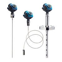
5300 Level Transmitter
High Level Supervision
Related Manuals for Emerson Rosemount 5300
Summary of Contents for Emerson Rosemount 5300
-
Page 1
Manual Supplement 00809-0900-4530, Rev AC April 2019 ™ Rosemount 5300 Level Transmitter High Level Supervision… -
Page 2: Table Of Contents
Manual Supplement April 2019 Contents Safety messages………………………3 Introduction……………………..4 Installation……………………… 7 Configure the High Level Supervision function…………….14 Perform High Level Supervision test………………. 22 Perform proof test for SIS applications………………24 Preventive maintenance………………….33 Service and troubleshooting…………………..35 Product Data Sheet for High Level Supervision…………….38 Rosemount 5300 Level Transmitter…
-
Page 3: Safety Messages
April 2019 Manual Supplement Safety messages WARNING Failure to follow safe installation and servicing guidelines could result in death or serious injury. • Only qualified personnel should install the equipment. • Use the equipment only as specified in this guide and the Reference Manual.
-
Page 4: Introduction
Manual Supplement April 2019 Introduction The High Level Supervision (HLS) function in the Rosemount 5300 Level Transmitter is used to monitor a high level alarm limit. A reference reflector is mounted on the probe at the position of the alarm limit. The HLS function is also included in several Proof tests for Safety Instrumented System (SIS) applications.
-
Page 5
April 2019 Manual Supplement corresponding to the surface level, but if the reference reflector echo is not found and no valid surface echo is detected at or above the reference reflector, then the device will alert this condition. High Level Supervision kit Figure 2-1: Kit for Model Code HL1 and HL2 A. -
Page 6
Manual Supplement April 2019 Required equipment Measuring tape Marker pen Standard tools, e.g. screwdriver, wrench, pliers Rosemount Radar Master • Version 3.G0 or later Rosemount 5300 firmware • Version 2.H0 or later • High Level Supervision software option enabled Rosemount 5300 Level Transmitter… -
Page 7: Installation
April 2019 Manual Supplement Installation Note Make sure to follow the instructions carefully for successful installation. Verify reference reflector in kit matches application Different reference reflectors are used depending on the installation environment. Procedure Select reference reflector according to Table 3-1.
-
Page 8
Manual Supplement April 2019 Mounting considerations for the reference reflector Figure 3-2: Mounting Range A. Upper Reference Point B. 20 in. (500 mm) to 157.5 in. (4000 mm) C. Minimum 20 in. (500 mm) Rosemount 5300 Level Transmitter… -
Page 9
April 2019 Manual Supplement Figure 3-3: Interfering Objects A. Minimum 20 in. (500 mm) Figure 3-4: Process Inlets A. Minimum 2 in. (50 mm) Manual Supplement… -
Page 10
Manual Supplement April 2019 Figure 3-5: Nozzle Installation A. Minimum 20 in. (500 mm) Table 3-2: Nozzle Considerations Description Recommendation Minimum Nozzle Diameter (D): 3 in. (75 mm) Recommended maximum Nozzle 8 in. (200 mm) Diameter (D): Recommended maximum Nozzle Height 4 in. -
Page 11
April 2019 Manual Supplement Calculate where to position the reference reflector Procedure 1. Determine the distance X, High Level Alarm Limit. (Distance from Upper Reference Point to High Level Alarm Limit.) X, High Level Alarm Limit: Figure 3-7: Positioning the Reference Reflector A. -
Page 12
Manual Supplement April 2019 Mount the reference reflector Procedure 1. Place the device with the probe on the ground or a work bench. 2. Mark where to place the reference reflector. 3. Place the reference reflector on the probe. 4. Fasten the screws. a) Tighten both screws loosely first. -
Page 13
April 2019 Manual Supplement 5. Mount the device on the tank. Note It is recommended to continue with configuration of High Level Supervision before tightening the bolts to avoid re-work. Gasket For further instruction, see the Rosemount 5300 Reference Manual. Wiring diagram ®… -
Page 14: Configure The High Level Supervision Function
Manual Supplement April 2019 Configure the High Level Supervision function Prerequisites Rosemount Radar Master must be used to configure the High Level Supervision function. Procedure 1. Connect to device. a) Start Rosemount Radar Master. b) Connect to device (see Figure 3-8).
-
Page 15
If the Level Supervision tab is missing, it indicates the device does not support High Level Supervision. You may upgrade device to enable the functionality. Contact your local Emerson representative for more information. b) Select the Use High Level Supervision checkbox and click Store. -
Page 16
Manual Supplement April 2019 Need help? See section Service and troubleshooting if calibration fails. 5. Verify Calibrated Reflector Echo Distance. Compare the Reference Reflector Physical Distance (Z) with the Calibrated Reflector Echo Distance reported by device. The calibration is correct if the reference reflector echo appears 0.4 in. -
Page 17
April 2019 Manual Supplement Compare the High Level Alarm Limit in your host system with the Calibrated Reflector Echo Distance reported by device. The High Level Alarm Limit in the host system should be between 1.2 in. (30 mm) to 2.4 in. (60 mm) below the Calibrated Reflector Echo Distance. -
Page 18
Manual Supplement April 2019 Device mounting type Calibrated Reflector Echo Amplitude 3-in. to 6-in. pipe/chamber Between -700 mV and -2200 mV (inner diameter) 8-in. pipe/chamber or bigger Between -700 mV and -1800 mV (inner diameter) or Open tank (tank without pipe) Need help? See section Service and troubleshooting… -
Page 19
April 2019 Manual Supplement Figure 4-4: Surface Threshold A. 10 in. (250 mm) B. 900 mV or 1500 mV Need help? See section Set surface threshold manually around reference reflector if threshold deviates from required value. 9. Continue with configuration of device using Guided Setup. a) Select Setup →… -
Page 20
Manual Supplement April 2019 Perform a High Level Supervision Test following the procedure in section Perform High Level Supervision test. 11. Make sure process connection on tank is securely closed. For further instruction, see the Rosemount 5300 Reference Manual. Gasket Configuration parameters 4.1.1 Alarm behavior… -
Page 21
April 2019 Manual Supplement 4.1.2 Test Mode Timeout Defines how long the device will wait until it automatically exits the test mode. Manual Supplement… -
Page 22: Perform High Level Supervision Test
Manual Supplement April 2019 Perform High Level Supervision test Perform High Level Supervision test using Rosemount Radar Master Prerequisites The product surface level should be at least 20 in. (500 mm) below the reference reflector during the test. The product surface level cannot be within 6 in. (150 mm) of the reference reflector.
-
Page 23
April 2019 Manual Supplement The product surface level cannot be within 6 in. (150 mm) of the reference reflector. The device will exit the test mode if the level rises within this area during test, and instead output the current level measurement reading. It will not enter the test mode if the surface already is within this distance. -
Page 24: Perform Proof Test For Sis Applications
Manual Supplement April 2019 Perform proof test for SIS applications Overview The following proof tests are recommended. If an error is found in the safety function, the measuring system must be switched out of service and the process held in a safe state by means of other measures. Note For a valid result, always perform the proof test on the product that will be stored in the tank while the device is in operation.
-
Page 25
April 2019 Manual Supplement Suggested comprehensive proof-test using reference reflector (High Level Supervision) 6.3.1 Suggested comprehensive proof-test using reference reflector (High Level Supervision) with Rosemount Radar Master The suggested proof-test described below will detect 94 percent of possible DU failures in the Rosemount 5300 Level Transmitters. Procedure 1. -
Page 26
Manual Supplement April 2019 a) Select Setup → Advanced. b) Select the Level Supervision tab. c) Select Start/Stop Test Mode. d) Verify that the output from the device corresponds to the alarm limit in the host system. e) End test mode by clicking Start/Stop Test Mode. The device will automatically exit the test mode after 30 minutes (default). -
Page 27
April 2019 Manual Supplement 4. Using Loop Test, enter current value (mA) representing low alarm current. Verify that analog output current is correct using the reference meter. a) Select Configure → Manual Setup → Device Setup → Analog Output. b) Click Loop Test and select Other. c) Enter current value representing low alarm current. -
Page 28
Manual Supplement April 2019 a) Select Tools → Lock/Unlock Configuration Area. b) Enter password to unlock. 3. Using Loop Test, enter current value (mA) representing high alarm current. Verify that analog output current is correct using the reference meter. a) Select Setup → Output → Analog Out 1 and click Loop test. b) Enter current value representing high alarm current. -
Page 29
April 2019 Manual Supplement 6.4.2 Suggested comprehensive, fully remote proof-test using reference reflector (High Level Supervision) with AMS Device Manager and handheld communicator The suggested proof-test described below will detect 86 percent of possible DU failures in the Rosemount 5300 Level Transmitters. Procedure 1. -
Page 30
Manual Supplement April 2019 b) Click Write Protect and follow the instructions. 6. Perform High Level Supervision test. a) Select Configure → Alert Setup → Level Supervision. b) Select Start/Stop Test Mode. c) Verify that the output from the device corresponds to the alarm limit in the host system. -
Page 31
April 2019 Manual Supplement 6.5.2 Suggested proof-test using reference reflector (High Level Supervision) with AMS Device Manager and handheld communicator The suggested proof-test described below will detect 82 percent of possible DU failures in the Rosemount 5300 Level Transmitters. Procedure 1. -
Page 32
Manual Supplement April 2019 The device will automatically exit the test mode after 30 minutes [default]. 3. Remove the bypass and otherwise restore normal operation. 6.6.2 Suggested fully remote proof-test using reference reflector (High Level Supervision) with AMS Device Manager and handheld communicator The suggested proof-test described below will detect 74 percent of possible DU failures in the Rosemount 5300 Level Transmitters. -
Page 33: Preventive Maintenance
April 2019 Manual Supplement Preventive maintenance Review the reference reflector echo properties The reference reflector echo may be affected by the environment in the vessel over time. If there is buildup on the probe, this may affect the reference reflector echo. You can review the reference reflector echo properties to make sure they are not deviating from the time of calibration.
-
Page 34
Manual Supplement April 2019 a) Inspect the reference reflector if the value is close to boundaries and deviating from Calibrated Reflector Echo Amplitude. b) Clean the reference reflector in case of buildup. Rosemount 5300 Level Transmitter… -
Page 35: Service And Troubleshooting
April 2019 Manual Supplement Service and troubleshooting Calibration fails Cause The device is not able to identify the reference reflector. Recommended actions 1. In Rosemount Radar Master, select Setup → Echo Curve. 2. Read the echo curve and locate the negative peak from the reference reflector (at the proximity of the physical distance to the lower side of the reference reflector).
-
Page 36
Use the short reference reflector if the amplitude is too strong. • Use the long reference reflector if the amplitude is too weak. Contact your local Emerson representative if the other reference reflector type is required for your application. Change reference reflector position… -
Page 37
April 2019 Manual Supplement 2. Drag and drop the Amplitude Threshold Curve (ATC) points to adjust the Surface Threshold in an interval around the reflector. Adjust ATC points depending on application: Device mounting type Surface Threshold 3-in. to 6-in. pipe/chamber (inner diameter) 1500 mV 8-in. -
Page 38: Product Data Sheet For High Level Supervision
Manual Supplement April 2019 Product Data Sheet for High Level Supervision Ordering information For models 5301 and 5302 Only available with HART 4-20 mA output (code H) Only available with standard operating temperature and pressure (code S) Only available with 316L SST (EN 1.4404) material of construction (material model code 1) Only available with flexible single lead probes, 4 mm (probe type 5A, 5B) Not available with remote housing mounting (code B1, B2, B3)
-
Page 39
April 2019 Manual Supplement Performance specification Measurement Performance Reference accuracy Measurement accuracy depends on the dielectric constant of close to reference the product. reflector • Water (dielectric constant = 80): +/- 1 in. (25 mm) • Oil (dielectric constant = 2): +/- 1.8 in. (45 mm) Reference accuracy See Rosemount 5300 Product Data Sheet for accuracy in in other regions… -
Page 40
Manual Supplement April 2019 Table 9-1: Different Measurement Scenarios and Resulting Output Measurement Analog Output Digital alert HLS Alarm ® condition (HART indicated on command 48) device display RR not verified and product Alarm surface identified below RR (configurable) RR not verified and no Alarm product surface found (configurable) -
Page 41
April 2019 Manual Supplement Manual Supplement… -
Page 42
Manual Supplement April 2019 Rosemount 5300 Level Transmitter… -
Page 43
April 2019 Manual Supplement Manual Supplement… -
Page 44
The Emerson logo is a Twitter.com/Rosemount_News trademark and service mark of Emerson Electric Facebook.com/Rosemount Co. Rosemount is mark of one of the Emerson Youtube.com/user/ family of companies. All other marks are the RosemountMeasurement property of their respective owners.
Приложение A. Справочные данные
Июнь 2015 г.
A.1.9
Руководство по эксплуатации
00809-0107-
4530, Ред. DB
Измерения границы раздела сред
Прибор Rosemount 5302 наилучшим образом подходит для измерения уровня границы раздела нефти и воды, а также других жидкостей со значительно отличающейся диэлектрической проницаемостью. Для измерения уровня границы раздела сред можно также использовать прибор Rosemount 5301 в исполнении, когда зонд полностью погружен в жидкость.
Рисунок A-8. Измерение уровня границы раздела сред с полностью погруженным зондом
Уровень границы раздела сред
Уровень продукта
Уровень границы раздела сред
Измерение границы раздела сред
Измерение уровня границы раздела сред с полностью погруженным зондом
Для измерения уровня границы раздела сред необходимо наличие следующих условий:
Диэлектрическая проницаемость верхнего продукта должна быть известна и неизменна. ПО Radar Master имеет встроенный калькулятор диэлектрической проницаемости для оказания помощи пользователю при определении диэлектрической проницаемости верхнего продукта.
Диэлектрическая проницаемость верхнего продукта должна быть ниже, чем у нижнего.
Разность между значениями диэлектрической проницаемости двух продуктов должна быть не меньше 6.
Максимальная диэлектрическая проницаемость верхнего продукта должна составлять 8 при использовании одинарных зондов, 10 для коаксиальных и 7 для двойных зондов.
Толщина слоя верхнего продукта должна быть выше 0,13 м для всех зондов, за исключением коаксиальных зондов для установок ВТВД, для которых требуется 0,2 м для различения эхосигналов от двух жидкостей.
Иногда между двумя продуктами возникает эмульсионный слой (смесь продуктов), который, в зависимости от его характеристик, влияет на измерение уровня границы раздела сред. В проблемных случаях, связанных с измерениями в условиях образования эмульсии, необходимо проконсультироваться с местным представительством Emerson Process Management.
Для получения информации относительно максимально допустимой толщины слоя продукта и диапазона
измерения см. «Диапазон измерения границы раздела сред» на стр. 235
.
230
Приложение A. Справочные данные
- Manuals
- Brands
- Rosemount Manuals
- Radar
- 5300 Series
Manuals and User Guides for Rosemount 5300 Series. We have 2 Rosemount 5300 Series manuals available for free PDF download: Reference Manual, User Manual
Rosemount 5300 Series Reference Manual (432 pages)
00809-0100-4530, Rev DD
Brand: Rosemount
|
Category: Radar
|
Size: 23.37 MB
Table of Contents
-
Table of Contents
3
-
1 Section 1: Introduction
15
-
Using this Manual
15
-
Product Recycling/Disposal
16
-
-
2 Section 2: Transmitter Overview
18
-
Theory of Operation
18
-
Applications
19
-
Components of the Transmitter
22
-
System Architecture
24
-
Probe Selection Guide
26
-
Measuring Range
28
-
Process Characteristics
29
-
Contamination/Product Build-Up
29
-
Bridging
29
-
Foam
29
-
Vapor
29
-
Boiling Hydrocarbons
29
-
Interface
30
-
-
Vessel Characteristics
31
-
Heating Coils, Agitators
31
-
Tank Shape
31
-
-
Installation Procedure
32
-
-
3 Section 3: Mechanical Installation
33
-
Safety Messages
33
-
Mounting Considerations
34
-
Process Connection
34
-
Installation in Non-Metallic Tanks and Open-Air Applications
36
-
Installation in Concrete Silos
37
-
Considerations for Solid Applications
38
-
Mounting in Chamber/Still Pipe
39
-
Replacing a Displacer in an Existing Displacer Chamber
43
-
Free Space
44
-
Recommended Mounting Position for Liquids
45
-
Recommended Mounting for Solids
46
-
Insulated Tanks
47
-
Installation and Configuration Considerations for ESD Systems
48
-
-
Mounting
49
-
Flange Connection
50
-
Threaded Connection
52
-
Tri Clamp Connection
53
-
Bracket Mounting
54
-
Shortening the Probe
56
-
Using a Segmented Probe
59
-
Anchoring
70
-
Mounting a Centering Disc for Pipe Installations
73
-
-
-
4 Section 4: Electrical Installation
79
-
Safety Messages
79
-
Cable/Conduit Entries
80
-
Grounding
80
-
Cable Selection
81
-
Hazardous Areas
81
-
Connecting the Transmitter
82
-
Hart
84
-
Power Requirements
84
-
Maximum Loop Resistance
85
-
Non-Intrinsically Safe Output
86
-
Intrinsically Safe Output
87
-
-
Foundation
88
-
OUNDATION Fieldbus
88
-
Power Requirements
88
-
FOUNDATION Fieldbus
89
-
Connecting Fieldbus Devices
89
-
Non-Intrinsically Safe Output
90
-
Intrinsically Safe Output
91
-
-
Optional Devices
92
-
Tri-Loop™ HART-To-Analog Converter
92
-
751 Field Signal Indicator
93
-
-
-
5 Section 5: Configuration
95
-
Safety Messages
95
-
Overview
96
-
Basic Configuration
96
-
Echo Tuning
96
-
LCD Configuration
96
-
Advanced Configuration
96
-
Configuration Tools
97
-
-
Host System Integration
98
-
Confirm System Readiness
98
-
Set Alarm Limits
99
-
-
Basic Configuration Parameters
102
-
Measurement Units
102
-
Tank and Probe Geometry
102
-
Tank Environment
104
-
Volume Configuration
105
-
Analog Output (HART)
108
-
-
Basic Configuration Using a Field Communicator
109
-
Basic Configuration Using Rosemount Radar Master
112
-
System Requirements
112
-
Help in RRM
112
-
Installing the RRM Software for HART Communication
113
-
Specifying the COM Port
114
-
To Set the COM Port Buffers
114
-
Installing the RRM Software for FOUNDATION Fieldbus
115
-
Specifying Measurement Units
117
-
Using the Setup Functions
117
-
Guided Setup
118
-
-
Basic Configuration Using AMS Suite (HART)
132
-
Basic Configuration Using Deltav
133
-
Process Conditions
136
-
Foundation
138
-
Assigning Device Tag and Node Address
138
-
Foundation Fieldbus Block Operation
139
-
-
Configure the AI Block
141
-
Application Example 1
145
-
Application Example 2
146
-
Application Example 3
147
-
-
Tri-Loop ™ HART-To-Analog Converter
149
-
Tri-Loop™ HART-To-Analog Converter
149
-
-
HART Multi-Drop Configuration
151
-
-
6 Section 6: Operation
153
-
Safety Messages
153
-
Viewing Measurement Data
154
-
Using the Display Panel
154
-
Specifying Display Panel Variables
154
-
Viewing Measurement Data in RRM
159
-
Viewing Measurement Data in AMS Suite
160
-
Viewing Measurement Data in Deltav
161
-
-
-
7 Section 7: Service and Troubleshooting
164
-
Safety Messages
164
-
Analyzing the Measurement Signal
165
-
Using the Echo Curve Analyzer
167
-
Using Rosemount Radar Master
167
-
Using the Echo Curve Analyzer with a Field Communicator
171
-
-
Product Surface Peak Not Found
173
-
Interface Peak Not Found
174
-
Disturbance Echo Handling
175
-
Amplitude Threshold Curve
175
-
Disturbances at the Top of the Tank
176
-
Signal Quality Metrics
176
-
-
Interface Measurements with Fully Submerged Probes
176
-
Analog Output Calibration
177
-
Level and Distance Calibration
178
-
Logging Measurement Data
180
-
Backing up the Transmitter Configuration
181
-
Configuration Report
182
-
Reset to Factory Settings
183
-
Diagnostics
184
-
Using the Simulation Mode
186
-
Enter Service Mode in RRM
188
-
Viewing Input and Holding Registers
188
-
Write Protecting a Transmitter
188
-
Removing the Transmitter Head
190
-
Changing a Probe
191
-
Probe and Firmware Compatibility
191
-
Check Firmware and Probe Version
192
-
Changing the Probe
193
-
-
Troubleshooting Guide
195
-
Diagnostic Messages
198
-
Device Status
198
-
Errors
199
-
Warnings
201
-
Measurement Status
202
-
Interface Status
204
-
Volume Calculation Status
205
-
Analog Output Status
206
-
-
LCD Error Messages
207
-
LED Error Messages
208
-
Foundation Fieldbus Error Messages
209
-
Resource Block
209
-
Transducer Block
210
-
Analog Input (AI) Function Block
211
-
-
Service Support
212
-
-
8 Section 8: Safety Instrumented Systems (4-20 Ma Only)
215
-
Safety Messages
215
-
Terms and Definitions
216
-
Safety Instrumented System (SIS) Certification
217
-
Safety-Certified Identification
217
-
Functional Specifications
218
-
Installation in SIS Applications
218
-
Configuring in SIS Applications
219
-
SIS Operation and Maintenance
221
-
Suggested Comprehensive Proof Test
222
-
Suggested Comprehensive, Fully Remote Proof Test
225
-
Suggested Partial Proof Test
225
-
-
Inspection
226
-
Specifications
226
-
-
Aappendix A: Specifications and Reference Data
229
-
A.1 Functional Specifications
229
-
A.1.1 General
229
-
A.1.2 Start-Up Sequence
229
-
Ma HART ® (Output Option Code H)
229
-
Foundation™ Fieldbus
231
-
(Output Option Code F)
231
-
Modbus ® (Output Option Code M)
231
-
A.1.6 Display and Configuration
232
-
A.1.7 Diagnostics
233
-
Process Temperature and Pressure Rating
233
-
A.1.9 Ambient Temperature
235
-
A.1.10Storage Temperature
235
-
A.1.11Flange Rating
235
-
A.1.12Tri Clamp Rating
236
-
A.1.13Plate Design
236
-
A.1.14Conditions Used for Flange Strength Calculations
237
-
A.1.15Interface Measurements
238
-
A.1.16High Pressure Steam Applications
238
-
-
A.2 Performance Specifications
240
-
A.2.1 General
240
-
A.2.2 Environment
240
-
A.2.3 Measuring Range
241
-
A.2.4 Accuracy over Measuring Range
244
-
-
A.3 Physical Specifications
246
-
A.3.1 Material Selection
246
-
A.3.2 Housing and Enclosure
246
-
A.3.3 Tank Connection
246
-
A.3.4 Flange Dimensions
246
-
A.3.5 Vented Flanges
246
-
Pressure Equipment Directive (PED)
246
-
A.3.7 Probes
247
-
Material Exposed to Tank Atmosphere
248
-
Weight
249
-
A.3.10Engineered Solutions
249
-
A.3.9 Weight
249
-
-
A.4 Dimensional Drawings
250
-
A.5 Special Flanges
266
-
A.6 Flushing Connection Rings
266
-
A.7 Ordering Information
267
-
A.8 Spare Parts and Accessories
284
-
-
-
Bappendix B: Product Certifications
299
-
Safety Messages
299
-
B.1 Safety Messages
299
-
B.2 European Directive Information
300
-
Safety Instrumented Systems (SIS)
300
-
Hazardous Locations Certifications
300
-
B.4.1 North-American Certifications
300
-
B.4.2 European Certifications
301
-
Technical Regulations Customs Union (EAC) Certifications
302
-
B.4.4 Brazilian Certifications
303
-
B.4.5 Chinese Certifications
303
-
B.4.6 Japanese Certifications
304
-
B.4.7 Iecex Certifications
304
-
B.4.8 Other Certifications
305
-
-
B.5 Combination Approvals
305
-
B.6 Approval Drawings
305
-
Product Certifications
306
-
-
Cappendix C: Advanced Configuration
311
-
Safety Messages
311
-
C.1 Safety Messages
311
-
User Defined Upper Reference Point
313
-
Handling of Disturbances from Nozzle
314
-
Use the Trim Near Zone Function
314
-
Changing the Hold off Distance/Upper Null Zone (UNZ)
316
-
-
Threshold Settings
318
-
C.4 Threshold Settings
318
-
Probe End Projection
324
-
Guided Probe End Projection Setup
325
-
-
Echo Tracking
326
-
C.6 Echo Tracking
326
-
Dielectric Constant Settings
328
-
Static Vapor Compensation
328
-
Lower Product
328
-
-
Dynamic Vapor Compensation
329
-
Check if Dynamic Vapor Compensation Function Is Supported
330
-
Review Installation Guidelines
331
-
Calibrate Dynamic Vapor Compensation Function
334
-
-
Signal Quality Metrics
338
-
Viewing Signal Quality Metrics in RRM
340
-
-
-
Dappendix D: Remote Mounting
341
-
Remote Housing, New Units
341
-
Remote Connection, Field Retrofit
341
-
Installing Remote Housing
342
-
Remote Housing Configuration
344
-
-
Eappendix E: Level Transducer Block
345
-
Overview
345
-
Definition
345
-
E.1 Overview
345
-
Channel Definitions
346
-
-
Parameters and Descriptions
347
-
Supported Units
354
-
Unit Codes
354
-
E.3 Supported Units
354
-
-
Diagnostics Device Errors
356
-
-
Fappendix F: Register Transducer Block
359
-
Overview
359
-
Register Access Transducer Block Parameters
359
-
F.1 Overview
359
-
-
-
Gappendix G: Advanced Configuration Transducer Block
363
-
Overview
363
-
Advanced Configuration Transducer Block Parameters
363
-
G.1 Overview
363
-
-
-
Happendix H: Resource Transducer Block
367
-
Overview
367
-
Parameters and Descriptions
367
-
H.1 Overview
367
-
Alerts
371
-
H.2.1 Alerts
371
-
Alarm Priority
374
-
H.2.2 Alarm Priority
374
-
H.2.3 Process Alarms
375
-
-
Process Alarms
375
-
Recommended Actions for Alerts
375
-
-
-
Iappendix I: Analog-Input Block
380
-
Simulation
380
-
I.1 Simulation
380
-
Damping
381
-
Signal Conversion
381
-
I.2 Damping
381
-
Block Errors
383
-
Modes
383
-
I.4 Block Errors
383
-
Alarm Detection
384
-
Status Handling
384
-
I.6 Alarm Detection
384
-
-
Advanced Features
385
-
I.7 Advanced Features
385
-
Configure the AI Block
386
-
-
Jappendix J: Rosemount 5300 Series with HART to Modbus
389
-
Safety Messages
389
-
Introduction
390
-
J.2 Introduction
390
-
Workflow
391
-
Mechanical Installation
391
-
J.3 Workflow
391
-
Electrical Installation
392
-
J.5 Electrical Installation
392
-
Connection Terminals
393
-
J.5.1 Connection Terminals
393
-
Installation Cases
394
-
J.5.2 RS-485 Bus
394
-
RS-485 Bus
394
-
External HART Devices (Slaves)
396
-
-
Establish HART Communication
397
-
Connect to the MA/MB Terminals
397
-
Connect to the HART Terminals
399
-
-
Transmitter Configuration
400
-
Modbus Communication Protocol Configuration
400
-
J.7 Transmitter Configuration
400
-
Using RRM to Change Communication Parameters
401
-
Modbus RTU Communication Setup
402
-
Using a Field Communicator to Change Communication Parameters
402
-
Levelmaster Communication Setup
404
-
Modbus ASCII Communication Setup
406
-
-
Alarm Handling
408
-
J.9 Alarm Handling
408
-
Use Heartbeat to Detect Errors
410
-
Use Status Information to Evaluate Measurement Validity
410
-
Verify Alarm Output
410
-
-
Common Modbus Host Configuration
411
-
Input Registers
411
-
-
Specific Modbus Host Configuration
415
-
Emerson Process Management ROC800 Series
416
-
Emerson Process Management Floboss 107
417
-
J.11.2 Emerson Process Management Floboss 107
417
-
ABB Totalflow
418
-
Thermo Electron Autopilot
418
-
J.11.3 ABB Totalflow
418
-
Bristol Controlwave Micro
419
-
Scadapack
420
-
Kimray Inc. DACC 2000/3000
420
-
J.11.6 Scadapack
420
-
-
Troubleshooting
421
-
J.12 Troubleshooting
421
-
HMC Firmware Upgrade in Rosemount Radar Master
422
-
Specifications
426
-
J.14 Specifications
426
-
Advertisement
Rosemount 5300 Series User Manual (10 pages)
Level Transmitters
with HART and Modbus
Brand: Rosemount
|
Category: Measuring Instruments
|
Size: 0.9 MB
Table of Contents
-
Table of Contents
2
-
Rosemount Vericase Overview
2
-
Check Rosemount Vericase and Verification Sheet
3
-
Performing a Verification on a Rosemount 5300
4
-
Transmitter
4
-
Performing a Verification on a Rosemount 3308
6
-
Transmitter
6
-
Generating a Report
8
-
Appendix
9
Advertisement
Related Products
-
Rosemount 5600 Series
-
Rosemount Oxymitter 5000
-
Rosemount 54E
-
Rosemount 5708
-
Rosemount 5402
-
Rosemount 5401
-
Rosemount 5081-P
-
Rosemount Series 8700
Rosemount Categories
Measuring Instruments
Transmitter
Accessories
Analytical Instruments
Touch Panel
More Rosemount Manuals