-
Contents
-
Table of Contents
-
Bookmarks
Quick Links
Ultrasonic Flowmeter USZ 08
OPERATING INSTRUCTIONS
Serving the Gas
Industry Worldwide
by Honeywell
STATUS JUNE 2015
Related Manuals for RMG USZ 08 series
Summary of Contents for RMG USZ 08 series
-
Page 1
Ultrasonic Flowmeter USZ 08 OPERATING INSTRUCTIONS Serving the Gas Industry Worldwide by Honeywell STATUS JUNE 2015… -
Page 2: Table Of Contents
CONTENTS ……………………………………. INTRODUCTION ………………. 1 Geometric arrangement of the paths of the USZ 08-6P ……..3 Geometric arrangement of the paths of the USZ 08-3P ……..4 Survey of equations used ………………. 10 Equations for the ERZ 2000 USC / USE 09-C …………. 10 Path velocity ……………………….
-
Page 3
CONTENTS ……………………………………. RMGVIEW DIAGNOSTIC SOFTWARE ……….37 Functions ………………….37 Installation ………………….37 System requirements ………………..37 Installing the program ………………..37 Connecting a PC ………………..38 Calibration switch of the USE 09 …………… 38 Operating the program ……………… -
Page 4
CONTENTS ……………………………………. ALARM- UND WARNING MESSAGES USE 09 ……..53 Alarm messages ………………..53 Warning messages ………………..54 Hints ……………………55 BRIEF DESCRIPTION OF THE USE09 MODBUS …….. 56 Parameterizing Modbus ………………56 TECHNICAL SPECIFICATIONS …………59 … -
Page 5
CONTENTS ……………………………………………………………………….Manual USZ 08 · EN05 · 2015-06… -
Page 6: Introduction
INTRODUCTION ……………………………………. Introduction By means of the transit times of ultrasonic pulses, the USZ 08 ultrasonic flowmeter measures the flow velocity of the gas from which it calculates the flow rate at measurement conditions. Here use is made of the fact that ultrasonic pulses move faster in the direction of flow than in the opposite direction.
-
Page 7
INTRODUCTION ……………………………………. For non-fiscal metering also the 2-path design of typ USZ 08-2P can be used. This version is equivalent to a reduced 6-path design, which only has the two acoustic paths in the middle plain. Signals are evaluated by the USE 09(-C) ultrasonic electronic system which is installed on the meter case. -
Page 8: Geometric Arrangement Of The Paths Of The Usz 08-6P
INTRODUCTION ……………………………………. Geometric arrangement of the paths of the USZ 08-6P Level 1 TD2.1 (TD1.1) TD1.2 (TD2.2) Paths 1&2 Level 2 TD4.1 (TD3.1) TD3.2 (TD4.2) Paths 3&4 Level 3 TD6.1 (TD5.1) TD5.2 (TD6.2) Paths 5&6 90° TD1.1 TD2.2 Level 1 TD2.1 TD1.2 TD3.1…
-
Page 9: Geometric Arrangement Of The Paths Of The Usz 08-3P
INTRODUCTION ……………………………………. Geometric arrangement of the paths of the USZ 08-3P Reflector Level 1 TD1.1 TD1.2 Path 1 Level 2 TD2.1 TD2.2 Path 2 Level 3 TD3.1 TD3.2 Path 3 Reflector Reflector 90° Level 1 TD1.1 TD1.2 TD2.1 TD2.2 Level 2 Reflection on the inner wall of the pipe Reflector Level 3…
-
Page 10
INTRODUCTION ……………………………………………………………………….Manual USZ 08 · EN05 · 2015-06… -
Page 11
INTRODUCTION ……………………………………. Drw.-No.057286.4 TD 1.1 TD 2.2 Pos. direction of flow TD 2.1 TD 1.2 TD 3.1 TD 4.2 Pos. direction of flow TD 4.1 TD 3.2 TD 5.1 TD 6.2 Pos. direction of flow TD 6.1 TD 5.2 ……………………………………. Manual USZ 08 ·… -
Page 12
INTRODUCTION ……………………………………. Drw.-No.057288.4 Pos. direction of flow Reflector Path 1 TD 1.1 TD 1.2 TD 2.1 TD 2.2 Path 2 Inner wall of pipe Pos. direction of flow Pos. direction of flow Reflector Path 3 TD 3.1 TD 3.2 ……………………………………. Manual USZ 08 ·… -
Page 13
INTRODUCTION ……………………………………. Front view: Side view: Top view: Clearance for changing transducers S0: meter without pressure S1: meter pressurized, * Meter body from with special tool cast steel Weight (kg) 100 (4”) —— 150 (6”) —— 140* 200 (8”) 1520 260* 250 (10”) 1550… -
Page 14
INTRODUCTION ……………………………………. Drw. No.057287.4 Front view: Side view: Top view: Connection diagram of the three paths acc. to Drw. No. 057288.4 A1/ A2 100 ( 4”) 50° 50° 50° 150 ( 6”) 50° 50° 50° 200 ( 8”) 1000 40° 40°… -
Page 15: Survey Of Equations Used
INTRODUCTION ……………………………………. Survey of equations used Equations for the ERZ 2000 USC / USE 09-C Path velocity = Flow velocity, (m/s) measured in path i = Transit time in direction 1 (path i) = Transit time in direction 2 (path i) …
-
Page 16: Base Correction Of The Gas Meter
INTRODUCTION ……………………………………. Base correction of the gas meter Polynomial The base correction of the meter is performed via a quartic polynomial which reproduces the error curve. v v v v Error equation: Deviation of the error curve Weighted flow velocity corrected by Reynolds number (m/s)
-
Page 17: Installation And Commissioning
INSTALLATION AND COMMISSIONING ……………………………………. Installation and commissioning Installation of the meter The USZ 08 ultrasonic flowmeter is to be operated with an inlet pipe and an outlet pipe. The following details are identical to the requirements of the PTB approval certificate and are therefore binding for custody transfer metering.
-
Page 18: Pipe Diameter
INSTALLATION AND COMMISSIONING ……………………………………. Pipe diameter Ø i = D-2% … D+5% Ø i = D-2% Ø i = D … D+5% The inside diameters of the inlet and outlet pipes may be up to 2% smaller or up to 5% larger than the inside diameter of the meter.
-
Page 19: Seals
……………………………………. Seals It must be guaranteed that flange seals of RMG turbine meters do not protrude from the flange into the gas line. All seals approved as per DVGW can be used depending on the requirements for stability and reli- ability.
-
Page 20: Screws
INSTALLATION AND COMMISSIONING ……………………………………. Spiral seals ANSI 300 PN 64 ANSI 600 2″ 69.9 85.9 69.9 85.9 3″ 101.6 120.7 101.6 120.7 4″ 127.0 149.4 120.7 149.4 6″ 182.6 209.6 174.8 209.6 8″ 233.4 263.7 225.6 263.7 10″ 287.3 317.5 274.6 317.5 12″…
-
Page 21: Electrical Connections
INSTALLATION AND COMMISSIONING ……………………………………. Electrical connections Terminal assignments of the measuring element The USZ 08 ultrasonic flowmeter with the Terminals USE 09 ultrasonic electronic system is on the supplied with two case variants: electronics — with the mere electronics case: here card connection is to be made directly at the electronics card (standard with the…
-
Page 22: Erz 2000(-Ng) Terminals
INSTALLATION AND COMMISSIONING ……………………………………. The RS 485 0 interface is used for servicing. The RMGView service and diagnostic software which is required for this purpose is described from page 35 onwards. A second Flow Computer can optionally be connected to the RS 485 2 interface if an appropriate optional USE 09 card is used.
-
Page 23
The plug-in module which was included in the delivery with older devices has the following pin assignment. USE 09 Terminating ERZ 2000 module Terminating resistors for RS 485 (USE 09 with ERZ 2000) 330 Ω RMG MESSTECHNIK GMBH 35510 Butzbach ……………………………………. Manual USZ 08 · EN05 · 2015-06… -
Page 24: Earthing And Screening
INSTALLATION AND COMMISSIONING ……………………………………. Earthing and screening Potential, Potential, measurement measurement installation installation Ex d electronics case Ex e terminal housing Equipotential bonding wire, min. 4 mm Mains Data Use shielded cables from a length of 1 m (this also applies to power cords). Apply the shields to the cable glands.
-
Page 25: Start-Up
INSTALLATION AND COMMISSIONING ……………………………………. Start-up After the meter has been installed and the ERZ 2000 USC has been connected, the parameters of the meter have to be checked on the computer. They are listed on the verification certificate of the meter together with the coordinates.
-
Page 26: Operating The Ultrasonic Computer
OPERATING THE ULTRASONIC COMPUTER ……………………………………. Operating the ultrasonic computer General information about the ERZ 2000 USC Overview of functions Depending on the software installed, the ERZ 2000 device family is equipped with an integrated functional unit for direct connection to the ultrasonic measuring element (called IGM for Industrial Gas Meter in the software).
-
Page 27: Gas Meter / Volume Data Logging
OPERATING THE ULTRASONIC COMPUTER ……………………………………. Usually, the variant of the device is set in the factory when the device is parameterized and cannot be changed on site anymore. If the switching facility has not been locked in the factory, it is possible to change the setting subsequently.
-
Page 28
OPERATING THE ULTRASONIC COMPUTER ……………………………………. The DZU operating mode (15) requires another functional unit (remote unit) to be interconnected between the measuring head and the volume corrector. This is either the external USZ 9000 remote unit which represents the main totalizer from the point of view of custody transfer metering or the USE 09-C ultrasonic electronic system with an integrated controller and main totalizer. -
Page 29: Special Information: «Parameters For The Volume At Measurement Conditions In Conjunction With Ultrasonic Flowmeters
OPERATING THE ULTRASONIC COMPUTER ……………………………………. Special information: «Parameters for the volume at measurement conditions in conjunction with ultrasonic flowmeters» DZU: ERZ 2000 with USE 09-C ultrasonic flowmeter control unit If you choose this mode, the FH ultrasonic flowmeter diagnosis function is of importance. Here the following information will be shown: The average velocity of sound measured, indication of the unit, gas velocities of paths 1 to 6, velocities of sound of paths 1 to 6, AGC (automatic gain control) levels for upstream and…
-
Page 30: Error Curve Linearization Of Volume Metering When Using The Use 09-C
OPERATING THE ULTRASONIC COMPUTER ……………………………………. Error curve linearization of volume metering when using the USE 09-C The error curve linearization of the gas meter can optionally be performed using three different methods. Error curve linearization with polynomial related to the flow rate Error curve linearization with polynomial related to the Reynolds number Error curve linearization using the interpolation point method These methods are identical to the methods used in the case of turbine meters.
-
Page 31
OPERATING THE ULTRASONIC COMPUTER ……………………………………. EN ID display IGM 1 ID display IGM 2 Access Line Designation Value Unit As EN ID display IGM 1 Identification ID display IGM 3 Version As EN ID display IGM 1 Checksum Relay delay time 0 ms ID display IGM 4 Batches… -
Page 32
40 Meas.quality 6 Not only the fields for path nos. 7 and 8 prepared for extensions were left out in the above table, but also system messages for RMG service engineers (lines 43 to 74)……………………………………Manual USZ 08 · EN05 · 2015-06… -
Page 33
OPERATING THE ULTRASONIC COMPUTER ……………………………………. GI ultrasonic volume transmitter Access Line Designation Value Unit Number of measured values used to calculate replacement values. Here a coefficient matrix is formed which is used to reconstruct a failed path by means of a replacement value. The higher the number parameterized here, the better the No. -
Page 34
OPERATING THE ULTRASONIC COMPUTER ……………………………………. Counts the communication timeouts regarding IGM 2. The 18 Timeout IGM 2 9999 numerical values run up to 9999 and then stop. The numerical values can be reset by means of IGM Reset (GI 21). 19 Timeout IGM 3 9999 dito… -
Page 35
OPERATING THE ULTRASONIC COMPUTER ……………………………………. In addition to the above parameters, please note further parameters from function GB Flow parameters! To ensure correct flow rate calculation, you must enter the precise inside diameter of the meter in coordinate GB-55 (nominal diameter). You can find this information in the annex to the verification certificate. -
Page 36
OPERATING THE ULTRASONIC COMPUTER ……………………………………. GN base correction, ultrasonic flowmeter Access Line Designation Value Unit A § base corr. factor 0.00000 % E § 10 Base correction 0.00000e+00 E § 21 Coeff. A-2 dir. 1 0.00000e+00 E § 22 Coeff. A-1 dir. 1 0.00000e+00 E §… -
Page 37
OPERATING THE ULTRASONIC COMPUTER ……………………………………. Function GP effects of correction shows the measured values before and after the various effects of the polynomials. GP effects of correction Access Line Designation Value Unit A § Velo. uncorr. 0.000 m/s 0.000 m/s A §… -
Page 38
OPERATING THE ULTRASONIC COMPUTER ……………………………………. HN path 1 Access Line Designation Value Unit A § Corrected velocity 0.000 m/s Path velocity as used for flow determination. Status of determination of HN 01. Uncertain Specified status after a restart of the corrector or setting with signed-off path. -
Page 39
OPERATING THE ULTRASONIC COMPUTER ……………………………………. Mean value of the velocity of sound of all the other Comparison VOS 0.00000 m/s undisturbed paths (except for path 1), to calculate HN 09. Deviation in percent of the velocity of sound of path 1 from the VOS-deviation 0.000 % mean value of all the other undisturbed paths (except for path… -
Page 40: Acknowledging Alarm And Warning Messages And Events
OPERATING THE ULTRASONIC COMPUTER ……………………………………. Acknowledging alarm and warning messages and events Functioning of alarm and warning messages Warning and alarm messages are indicated by a yellow (warning) or red (alarm) LED on the front panel of the device. The warning relay or alarm relay closes parallel to this. The active message is indicated by a flashing LED.
-
Page 41
OPERATING THE ULTRASONIC COMPUTER ……………………………………. 82-3 Path 5 communic Path 5 communication quality less than demanded 82-4 Path 6 communic Path 6 communication quality less than demanded 82-5 Path 7 communic Path 7 communication quality less than demanded 82-6 Path 8 communic Path 8 communication quality less than demanded Hints in connection with the operation of an ultrasonic flowmeter 82-7… -
Page 42: Rmgview Diagnostic Software
RMGVIEW DIAGNOSTIC SOFTWARE ……………………………………. RMGView diagnostic software Functions The RMGView diagnostic software allows the USE 09 measuring electronic system to be directly accessed with a PC. The program provides the following features: Reading out all available data from an ultrasonic flowmeter using the USE 09. …
-
Page 43: Connecting A Pc
RMGVIEW DIAGNOSTIC SOFTWARE ……………………………………. Connecting a PC Use the RS 485-0 interface to connect a PC to the measuring element of the USZ 08. To do this, you need an interface converter for RS 485 to RS 232 or USB. If available, you can also use a 9-pin sub D connector in the control cabinet to connect the PC to the service interface.
-
Page 44: Use 09 Measured Values And Parameters
USE 09 MEASURED VALUES AND PARAMETERS ……………………………………. USE 09 measured values and parameters Access Using the RMGView diagnostic software, you can display and, if necessary, also edit all measured values and parameters of the USE 09 ultrasonic electronic system. However, you have to distinguish whether you want to use the controller functions of the USE 09-C or of the ERZ 2000 USC.
-
Page 45: Pressure (Option)
USE 09 MEASURED VALUES AND PARAMETERS ……………………………………. Pressure (option) Value Unit Modbus Description A-01 A pressure bar_a 6252 F Indication of the pressure at measurement conditions A-03 A current input 6254 F Indication of the input value in mA A-05 E p min value bar_a 1392…
-
Page 46: Use09-C Flow Rate Qm
USE 09 MEASURED VALUES AND PARAMETERS ……………………………………. USE09-C flow rate Qm Value Unit Modbus Description D-01 A vol. flow rate Qm &Q T Volumetric flow rate Qm after all corrections (as amount) with upstream/downstream identification D-02 A vol. flow rate Qm &Q 6230 F Volumetric flow rate Qm after all corrections (Qm lower limit will be…
-
Page 47: Use09-C Polynomials
USE 09 MEASURED VALUES AND PARAMETERS ……………………………………. USE09-C polynomials Value Unit Modbus Description G-01 E err. curve lin. 2093 M Error curve linearization mode (OFF, POLYNOMIAL) G-02 E const m2 d.1 1276 F Error polynomial for direction 1 G-03 E const m1 d.1 1278 F Error polynomial for direction 1 G-04…
-
Page 48: Serial Ports
USE 09 MEASURED VALUES AND PARAMETERS ……………………………………. I-06 C c-out select 2158 Current output, selection of the measured value (Modbus reg.) I-07 C c-out mode 2159 M Current output, operating mode (OFF, SET VALUE, 0-20mA, 4-20mA) I-08 C c-out err mode 2160 M Current output, operating mode if a fault occurs (OFF, MIN, MAX) I-09…
-
Page 49: Dsp, Fpga Values
USE 09 MEASURED VALUES AND PARAMETERS ……………………………………. DSP, FPGA values Value Unit Modbus Description K-20 A DSP status 4004 DSP status (bit-coded) K-21 A DSP error 4003 DSP error (bit-coded) K-22 A DSP bytes received 7034 Counts the telegrams received from the DSP K-23 A FPGA status 4006…
-
Page 50: Use09 Measured Values
USE 09 MEASURED VALUES AND PARAMETERS ……………………………………. USE09 measured values Value Unit Modbus Description AB-01 A VOS average &v 6228 F Average velocity of sound through all paths AB-02 A p.1 AGC average 6056 F Path x.1 average AGC through all paths AB-03 A p.2 AGC average 6076 F Path x.2 average AGC through all paths…
-
Page 51: Time And Date
AF-04 E unit no 2562 L ID: Measuring element No. AF-05 E manufacturer 2151 M ID: Manufacturer of the USE09 (RMG) AF-06 E model (year) 2152 ID: Year of construction of the USE09 (DZU interface) ……………………………………. Manual USZ 08 · EN05 · 2015-06…
-
Page 52
USE 09 MEASURED VALUES AND PARAMETERS ……………………………………. AF-07 E meter size T ID: Meter size AF-08 E nominal diameter DN 2210 ID: Nominal diameter DN AF-09 E Pressure rating T ID: Pressure rating AF-10 E pipe flange type 2211 M ID: Flange standard (PN, ANSI) AF-11 E pipe flange value 2212 ID: Flange value… -
Page 53: Mode
USE 09 MEASURED VALUES AND PARAMETERS ……………………………………. AF-54 E sensor 5.1 built 2299 ID: Sensor 5/1 year of construction AF-55 E sensor 5.2 no. T ID: Sensor 5/2 No. AF-56 E sensor 5.2 length 1542 F ID: Sensor 5/2 length AF-57 E sensor 5.2 built 2300 ID: Sensor 5/2 year of construction…
-
Page 54: Faults
USE 09 MEASURED VALUES AND PARAMETERS ……………………………………. Faults Value Unit Modbus Description AH-01 A fault message T Fault message as rolling text AH-02 A fault time 7500 U Date and time of the fault AH-03 N clear fault 2126 M Clear fault (NO, YES) AH-04 E fault mode 2127 M Fault mode below Qm-min (NORMAL, ALL)
-
Page 55: Path# Parameters
USE 09 MEASURED VALUES AND PARAMETERS ……………………………………. AI-18 E Attenuator on 2142 Limit for the attenuator ON AI-19 E Attenuator off 2143 Limit for the attenuator OFF AI-20 E Attenuator HV 2144 Limit for the attenuator HV mode AI-21 C amp. regulator mode 2145 M Operating mode of amplitude control (SET VALUE, ON, STOP) AI-22 C amp.
-
Page 56: Service
USE 09 MEASURED VALUES AND PARAMETERS ……………………………………. AK (…AR)-21 A p# blanking count 2540 L Path# blanking count AK (…AR)-22 E path-# decay time 1120 F Path# decay time at the end of measurement AK (…AR)-23 E path-# path length 1140 F Path# length of path AK (…AR)-24 E path-# axial dist.
-
Page 57: Data Logger
USE 09 MEASURED VALUES AND PARAMETERS ……………………………………. AS-28 A adc-p binary val. 7502 L Pressure input, transmitter value AS-29 A adc-t binary val. 7504 L PT100 input, transmitter value AS-30 E max. sys. temp. °C 1440 F System temperature, max. value AS-31 E time max.
-
Page 58: Alarm- Und Warning Messages Use 09
ALARM- UND WARNING MESSAGES USE 09 ……………………………………. Alarm- und warning messages USE 09 Alarm messages Message Explanation No Error Error-free operation Power Off Power failure in the meantime FPGA Timeout FPGA communication: no response from FPGA FPGA CRC FPGA communication: incorrect checksum DSP-SPI Timeout DSP communication: no response from the serial peripheral interface (data bus) of the digital signal processor…
-
Page 59: Warning Messages
ALARM- UND WARNING MESSAGES USE 09 ……………………………………. DSP path2 Critical path fault. Fault bits are to be read off separately in Path2 Failure DSP path3 Critical path fault. Fault bits are to be read off separately in Path3 Failure DSP path4 Critical path fault.
-
Page 60: Hints
ALARM- UND WARNING MESSAGES USE 09 ……………………………………. P8 c min/max Velocity of sound from path 8 outside of the min./max. limits (reserve) p1.1 amplitude Amplitude of the signal from sensor 1.1 too small p2.1 amplitude Amplitude of the signal from sensor 2.1 too small p3.1 amplitude Amplitude of the signal from sensor 3.1 too small p4.1 amplitude…
-
Page 61: Brief Description Of The Use09 Modbus
BRIEF DESCRIPTION OF THE USE09 MODBUS ……………………………………. Brief description of the USE09 Modbus Parameterizing Modbus The USE09 has three serial interfaces: — interface – 0 is reserved for servicing (RMGView). — interface – 1 has been designed for exchanging data with volume correctors. — interface –…
-
Page 62
BRIEF DESCRIPTION OF THE USE09 MODBUS ……………………………………. Example (Modbus query / response): Query: Modbus — ASCII Modbus — RTU Start Char Slave Address Function Starting Address Hi Starting Address Lo Register = 4002 (0FA2) No. of Points Hi No. of Points Lo Number = 0001 (0001) LRC / CRC carriage return… -
Page 63
2 is 6022 and the velocity of sound for path 6 is to be found under address 6020 + 5 * 2 = 6030. Please contact RMG Messtechnik to obtain the complete Modbus register assignments for the USE09. -
Page 64: Technical Specifications
TECHNICAL SPECIFICATIONS ……………………………………. Technical specifications Power supply: Measuring element: 24 VDC ERZ 2000 USC: 24 VDC or 230 VAC Power input: Measuring element: USE 09: 5 W USE 09C: 15 W ERZ 2000 USC: 24 W Protection class: IP 65 Interfaces: RS 485 0 (for RMGView): 9600 / 19200 / 38400 / 57600 baud…
-
Page 65: Seal Diagrams
SEAL DIAGRAMS ……………………………………. Seal diagrams Seals of the USE 09 ultrasonic electronic system Side view: Seal Top view: approx. 260 mm Drw. No.: 059504.4 Status: 14.03.2007 ……………………………………. Manual USZ 08 · EN05 · 2015-06…
-
Page 66: Seals Of The Use 09-C-Lt Ultrasonic Electronic System
SEAL DIAGRAMS ……………………………………. Seals of the USE 09-C-LT ultrasonic electronic system Side view Seal Top view approx. 395 Drw. No.: 060377.4 Status: 04.05.2009 ……………………………………. Manual USZ 08 · EN05 · 2015-06…
-
Page 67: Seals Of The Measuring Element Of Type Usz 08-6P (With Use 09)
SEAL DIAGRAMS ……………………………………. Seals of the measuring element of type USZ 08-6P (with USE 09) Front view: Seals of the USE09 ultrasonic electronic system acc. to Drw. No. 059504.4 Seals of the type plate acc. to Drw. No. 060319.4 Messwerk USZ08- Q max 7.241 Q min…
-
Page 68: Seals Of The Measuring Element Of Type Usz 08-6P (With Use 09-C)
SEAL DIAGRAMS ……………………………………. Seals of the measuring element of type USZ 08-6P (with USE 09-C) Front view: Seals of the USE09-C and USE09-C-LT ultrasonic electronic system Seals of the acc. to Drw. No. 060377.4 type plate acc. to Drw. No. 061243.4 Top view: Seals of the pressure tap acc.
-
Page 69: Seals Of The Type Plate Of The Usz 08 Measuring Element
Seals of the type plate of the USZ 08 measuring element Device with PTB approval 60mm Seal Drw. No.: 060319.4 Status: 27.03.2008 Device with MID approval MXX 0102 DE-09-MI002-XXXXXX = -40°C…55°C Seal RMG Messtechnik GmbH Butzbach / Germany Drw.-No.: 061243.4 Status: 04.05.2009 ……………………………………. Manual USZ 08 · EN05 · 2015-06…
-
Page 70: Annex
ANNEX ……………………………………. Annex Type examination certificates ……………………………………. Manual USZ 08 · EN05 · 2015-06…
.jpg)
Цена: по запросу
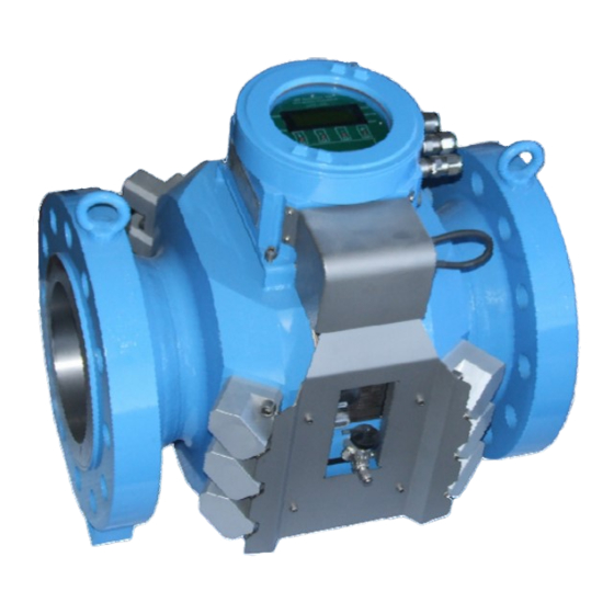
Счетчики газа ультразвуковые модели USZ 08 предназначены для измерений и вычислений объема и объемного расхода природного газа, попутного нефтяного газа, пропана, бутана и других газов при рабочих условиях.
Принцип действия счетчиков основан на методе измерения разности между временем прохождения ультразвуковых импульсов по потоку и против потока газа. Измеренная разность времени, пропорциональна скорости потока, преобразуется в значение объемного расхода.
Ультразвуковой счётчик USZ 08 представляет собой современное измерительное устройство, которое характеризуется высокой надежностью, точностью и стабильностью в работе. Большой измерительный диапазон счетчика позволяет его использовать на газовых станциях с сильно колеблющимся расходом газа.
- Применение
- Преимущества
- Характеристики
- Документация
Сфера применения этих приборов широка:
- газоизмерительные станции;
- узлы учета газа крупных промышленных потребителей: ГРЭС, ТЭЦ, ГТУ;
- узлы учета газа на газораспределительных сетях;
- газоперерабатывающие предприятия;
- крупные промышленные потребители (стекольные, машиностроительные и металлургические заводы);
- и другие объекты нефтегазовой, химической и энергетической отраслей.
- нечувствительность к загрязнениям;
- простое управление;
- независимость от изменений давления;
- электронный метод измерения гарантирует минимальное время реагирования;
- многоступенчатый процесс коррекции обеспечивает максимальную точность;
- двунаправленный принцип работы позволяет использовать оборудование в газовых хранилищах, где заполнение и откачка выполняются по одной и той же нитке;
- чувствительные компоненты отсутствуют, поэтому устройство надёжно защищено от перегрузок;
- наличие импульсных выходов позволяет подключить практически любой преобразователь расхода.
- Диапазон измерений расхода газа при рабочих условиях, м3/ч от 6 до 110 000
- Пределы допускаемой относительной погрешности измерений объемного расхода и объема газа при рабочих условиях, %:
|
0,05 Qmax ≤ Q ≤ Q max: |
Qmin ≤ Q < 0,05Qmax |
|
|
При использовании поверочной установки на природном газе при избыточном давлении |
± 0,3 |
± 0,5 |
|
При поверке на поверочной установке на воздухе при атмосферном давлении |
± 0,5 |
± 0,7 |
|
При имитационном методе проверки (в том числе для первичной поверки) для DN 200 и более |
± 0,5 |
± 0,7 |
|
При имитационном методе проверки (в том числе для первичной поверки) для типоразмеров менее DN 200 |
± 1,0 |
± 1,4 |
- Диаметр условного прохода, мм (дюйм): от 100 (4″) до 1000 (40″).
- Диапазон значений скоростей измеряемого газа, м/c: от -40 до +40
- Диапазон допустимых отклонений внутреннего диаметра входных и выходных участков ИТ по отношению к внутреннему диаметру фланцев на входе и выходе счетчика, %: –2… +5.
- Диапазон абсолютного давления измеряемого газа, МПа, (бар): 0,1…30 (1…300).
- Диапазон температур измеряемого газа, *С: от -40 до +80
- Напряжение питания (постоянный ток): 24 В (+10/-15%).
- Потребляемая мощность: 15 Вт.
- Выходные сигналы:
- токовый 0/4 – 20 мА, свободно программируемый, гальванически развязанный;
- импульсный, 2 шт.;
- RS — 485/232, 3 шт.;
- контактный, 2 шт.
- Взрывозащита: II2 G Ex de IIC T5/T6 BVS 07 ATEX E 035.
- Степень защиты IP 65.
- Габаритные размеры (в зависимости от типоразмера), не более, мм:
- Длина от 300 до 1500.
- Ширина от 415 до 1400.
- Высота от 330 до 1200.
- Масса, кг от 90 до 2950.
- Срок службы: 30 лет.
- Интервал между поверками 4 года.
- Наличие методики имитационной поверки.
Почему покупать ультразвуковой счётчик газа USZ 08 лучше у нас:
- Мы обладаем статусом официального дистрибьютора RMG Messtechnik в России;
- Мы являемся официальным сервисным центром RMG Messtechnik в России;
- У нас более чем 10-летний опыт работы в области поставок газового оборудования;
- У нас вы получите индивидуальный подход;
- Вы получите бесплатные экспертные консультации по подбору оборудования для вашей задачи;
- Мы гарантируем со своей стороны ответственность, компетентность, профессионализм;
- Мы организуем доставку по России и странам СНГ и таможенную очистку при ввозе товара;
- Мы осуществим пуско-наладку, гарантийное и постгарантийное техническое обслуживание;
Чтобы заказать ультразвуковой счётчик газа, напишите на электронный адрес info@rmg-rus.ru или позвоните по номеру: +7 (495) 230-84-83. Менеджер ООО «РМГ РУС» предоставит актуальную информацию по всем вопросам сотрудничества.

Описание
| Применение | Применим, начиная с абсолютного давления pn = 1 бар |
|---|---|
| Высокая стабильность против помех благодаря 6 измерительным лучам, размещенным на 3 уровнях | |
| Испытан согласно TR G13 / OIML | |
| Поверка воздухом с испытанием высоким давлением согласно TR G7 | |
| Высокая скорость потока (до 40 м/с), тем самым возможно применение меньших номинальных внутренних диаметров | |
| Замена датчиков без повторной калибровки | |
| Высокая точность измерения | |
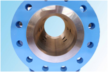
| Надежные и устойчивые к загрязнению датчики из титана | |
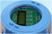
| Простое управление на управляющем вычислительном устройстве с функцией преобразователя из серии корректоров объема газа ERZ 2000 | |
| Исполнение с собственным счетным механизмом и импульсными выходами | |
| Опция: исполнение с собственным измерительным механизмом и импульсными выходами | |
| Испытан DIN-DVGW и имеет допуск PTB | |
| Макс. допустимое давление PS | = 100 бар (опционально 250 бар) |
| Макс. рабочее давление pmax | до 100 бар (опционально 250 бар) |
| Размер счетчика | G 650 до G 25000 (от Qmax 1000 м3/ч до Qmax 40000 м3/ч) |
| Макс. диапазон измерения | 1 : 50 до 1 : 125 |
| Подключение | фланец DIN Ру 10/Ру 16, Ру 100 и фланец по ANSI 150, ANSI 300, ANSI 600 (опционально ANSI 900, ANSI 1500) в Ду 100, Ду 150, Ду 200, Ду 250, Ду 300, Ду 400, Ду 500, Ду 600, (опционально Ду 750, Ду 800, Ду 900, Ду 1000) |
- Home
- Brands
- RMG
- Measuring Instruments
- USZ 08 series
- Operating Instructions Manual
Manual for RMG USZ 08 series Measuring Instruments (70 pages)
Specifications:
|
RMG USZ 08 series: Read PDF Manual Online
Accompanying Data:
RMG USZ 08 series Measuring Instruments PDF Operating Instructions Manual (Updated: Friday 11th of November 2022 01:59:24 PM)
Rating: 4.8 (rated by 97 users)
Compatible devices: EC 900, TRZ 04, EC 24, TME400-VMF, ERZ2000-NG, TRZ 03, PGC 9300, DWAWLC-040.
Recommended Documentation:
RMG USZ 08 series: Text of Operating Instructions Manual
(Ocr-Read Version Summary of Contents, UPD: 11 November 2022)
-
61, BRIEF DESCRIPTION OF THE USE09 MODBUS ……………………………………………………………………………………………………………………………………………………………………………………… ……………………………………………………………………………………………………………………………………..…
-
11, INTRODUCTION ……………………………………………………………………………………………………………………………………………………………………………………… ……………………………………………………………………………………………………………………………………
-
69, SEAL DIAGRAMS ……………………………………………………………………………………………………………………………………………………………………………………… …………………………………………………………………………………………………………………………………………….…
-
3, CONTENTS ……………………………………………………………………………………………………………………………………………………………………………………… ……………………………………………………………………………………………………………………………………………
-
40, OPERATING THE ULTRASONIC COMPUTER ……………………………………………………………………………………………………………………………………………………………………………………… …………………………………………………………………………………………………………………………….…
-
37, OPERATING THE ULTRASONIC COMPUTER ……………………………………………………………………………………………………………………………………………………………………………………… ……………………………………………………………………………………………………………….…
-
23, INSTALLATION AND COMMISSIONING ……………………………………………………………………………………………………………………………………………………………………………………… ……………………………………………………………………………………………………………………
-
70, ANNEX ……………………………………………………………………………………………………………………………………………………………………………………… ……………………………………………………………………………………………………………………………………………………………….…
-
30, OPERATING THE ULTRASONIC COMPUTER ……………………………………………………………………………………………………………………………………………………………………………………… …………………………………………………………………………………………………………………………..…
-
17, INSTALLATION AND COMMISSIONING ……………………………………………………………………………………………………………………………………………………………………………………… ……………………………………………………………………………………………………………………………….…
-
54, USE 09 MEASURED VALUES AND PARAMETERS ……………………………………………………………………………………………………………………………………………………………………………………… ………………………………………………………………………………………………………..…
-
1, b y Hone y wel l Serving the Gas Industry Worldwide Ultrasonic Flowmeter USZ 08 OPERATING INSTRUCTIONS STATUS JUNE 2015
… -
56, USE 09 MEASURED VALUES AND PARAMETERS ……………………………………………………………………………………………………………………………………………………………………………………… ……………………………………………………………………………………………………………………………
-
14, INTRODUCTION ……………………………………………………………………………………………………………………………………………………………………………………… ………………………………………………………………………………………………………………………………………………………….…
DOC-b90edd64:
RMG USZ 08 series: Recommended Instructions
RXD10 — RADIO CASSETTE W/CD, CD3424, DVD 1, ET2700 series, BUTLER 3300, 1WSHR


-
Assisting the automationindustry since 1986 User manualMETERSRP-73•Firmware: v.5.21 or higher•Input type: 0/4-20 mA, 0/1-5V, 0/2-10V•Two-colour displayRead the user’s manual carefully before starting to use the unit or software. Producer reserves the right to implement changes without prior notice. 2014.12.17 SRP-73_INSSXEN_v.2.10.002 …
SRP-73 56
-
Electromatic Equipment Co., Inc. -20- NOTES Electromatic Equipment Co., Inc. -1- TABLE OF CONTENTS 1.0 Positioning the instrument ……………………………………………. 2 2.0 Calibration curves …………………………………………………….. 2 3.0 Description of definitons ………………………� …
RH6 11
-
NDT INTERNATIONAL, INC. 711 S. Creek Road (610) 793-1700 West Chester, PA 19382 FAX (610) 793-1702 www.ndtint.com E-mail: [email protected] Operating Instruction Manual Revision 2 NDT-710 Ultrasonic Thickness Gauge …
NDT-710 15
-
DE Bedienungsanleitung# 1459 Kolostrometer1. Bestimmungsgemäßer ZweckDas Kolostrometer ist ein Messgerät zur Bestimmung der Kolostralmilchqualität. Es misst den Gehalt an Gammaglobulinen mittels der spezifischen Dichte.2. Aufbau1 Saugball 2 Glaspipette 3 Spindel mit Farbmarkierung 4 Ansaugschlauch3. Anleitung• Ziehen Sie den unteren Teil mit Ansaugschlauch von der gläs …
1459 2
-
1INSTALLATION ANDOPERATION MANUALForm 8296/16All quality FoamPro products are ruggedly designed, accurately machined, carefully assembled, thoroughly inspected and tested. In order to maintain the high quality of your unit, and to keep it in a ready condition, it is important to follow the instructions on care and operation. Proper use and good preventive maintenance will lengthen the l …
2001 Series 44
-
IntroducciónADVERTENCIAAsegúrese de leer y seguir los procedimientos de seguridad para evitar shock eléctrico y/o lesiones. LA KPS-PA420 es una pinza digital segura, fiable y portátil de 3 ½ dígitos. Capaz de medir corriente AC, tensión AC/DC, resistencia, caída de tensión del diodo, y continuidad, es ideal tanto para el uso doméstico como profesional.Instruc …
KPS-PA420 MINI 2
-
User’s ManualPaperless RecorderSupmea Automation Co.,Ltd.U-R2-MYEN1www.supmea.comHeadquarters5th floor,Building 4,Singapore Hangzhou Science Technology Park,No. 6 street,Hangzhou Economic Development Area,Hangzhou 310018,ChinaSingapore office2 Venture Drive #11-30 Vision Exchange SingaporeMalaysia officeNo 3, Jalan Emas Jaya 1, Taman Industries Emas jaya T …
6000f 55
-
VTMSVaccine Temperature Monitoring SystemPRODUCT USER GUIDETABLE OF CONTENTS2 Quick Start Steps3 Product Overview4 Software Installation5 Activating & Deploying the Data Logger5 Channel Programming6 Product Maintenance7 Troubleshooting8 Compliance Information9 Need Help?www.GlobalTestSupply.comFind Quality Products Online at: [email protected] …
VTMS 9
-
Min.-/Max.-DruckwertMin.-/Max. Pressure ValueValeur de pression Min./Max.Aktueller DruckwertActual Pressure ValueValeur de pression actuelleSELECTENTER Min./Max.DruckanschlussPressure ConnectionRaccord pressionHochgenaues, eigensicheres digitales Manometer zum Einsatz in explosionsgefährdeten Bereichen.Highly Precise, Intrinsically Safe Digital Manometer for use i …
LEX 1 Ei 8
Additional Information:
Popular Right Now:
Operating Impressions, Questions and Answers:
Table of Contents for RMG USZ 08 series:
-
USE 09 MEASURED VALUES AND PARAMETERS ……………………………………………………………………………………………………………………………………………………………………………………… ……………………………………………………………………………………………………………………………………………….
-
BRIEF DESCRIPTION OF THE USE09 MODBUS ……………………………………………………………………………………………………………………………………………………………………………………… ……………………………………………………………………………………………………………………………………………………………………………………… Manual USZ 08 · EN05 · 2015-06 56 Brief
-
INTRODUCTION ……………………………………………………………………………………………………………………………………………………………………………………… ……………………………………………………………………………………………………………………………………………………………………………………… Manual USZ 08 · EN05 · 2
-
INSTALLATION AND COMMISSIONING ……………………………………………………………………………………………………………………………………………………………………………………… ………………………………………………………………………………………………………………………………………………………….
-
CONTENTS ……………………………………………………………………………………………………………………………………………………………………………………… ……………………………………………………………………………………………………………………………………………………………………………………… Manual USZ 08 · EN05 · 2015-06
-
OPERATING THE ULTRASONIC COMPUTER ……………………………………………………………………………………………………………………………………………………………………………………… ……………………………………………………………………………………………………………………………………………………………………………………… Manual USZ 08 · EN05 · 2015-06 30 In addition to
-
INTRODUCTION ……………………………………………………………………………………………………………………………………………………………………………………… ……………………………………………………………………………………………………………………………………………………………………………………… Manual USZ 08 · EN05 · 2015-06 1 Introd
-
OPERATING THE ULTRASONIC COMPUTER ……………………………………………………………………………………………………………………………………………………………………………………… ……………………………………………………………………………………………………………………………………………………………………………………… Manual USZ
-
INTRODUCTION ……………………………………………………………………………………………………………………………………………………………………………………… ……………………………………………………………………………………………………………………………………………………………………………………… Manual USZ 08 · EN05 · 2015-06 7 Inner wall of pipe Pos. d
-
INSTALLATION AND COMMISSIONING ……………………………………………………………………………………………………………………………………………………………………………………… ……………………………………………………………………………………………………………………………………………………………………………………… Manual USZ 08 · EN05 · 2015-06 20 Start-up After the meter has been installed and th
-
OPERATING THE ULTRASONIC COMPUTER ……………………………………………………………………………………………………………………………………………………………………………………… …………………………………………………………………………………………………………………………………………………………………………………..
-
INSTALLATION AND COMMISSIONING ……………………………………………………………………………………………………………………………………………………………………………………… ……………………………………………………………………………………………………………………………………………………………………………………… Manual USZ 08 · EN05 · 2015-06 16 Electrical connections Terminal assignm
-
INTRODUCTION ……………………………………………………………………………………………………………………………………………………………………………………… ……………………………………………………………………………………………………………………………………………………………………………………… Manual USZ 08 · EN05 · 2015-06 5 1. Measuring element type USZ 08-6P/3P 2. Signal pro
-
RMGVIEW DIAGNOSTIC SOFTWARE ……………………………………………………………………………………………………………………………………………………………………………………… ……………………………………………………………………………………………………………………………………………………………………………………… Manual USZ
-
OPERATING THE ULTRASONIC COMPUTER ……………………………………………………………………………………………………………………………………………………………………………………… ………………………………………………………………………………………………………………………………………………………………………………………
-
SEAL DIAGRAMS ……………………………………………………………………………………………………………………………………………………………………………………… ……………………………………………………………………………………………………………………………………………………………………………………… Manual USZ 08 · EN05 · 2015
Questions, Opinions and Exploitation Impressions:
You can ask a question, express your opinion or share our experience of RMG USZ 08 series device using right now.