-
Contents
-
Table of Contents
-
Troubleshooting
-
Bookmarks
Related Manuals for Mindray DP-50
Summary of Contents for Mindray DP-50
-
Page 1
DP-50/DP-50T/DP-50 PT/DP-50Expert/DP-50 Pro/DP-50S/DP-50W/DP-70/DP-70T/D P-70 Pro/DP-70 Expert/DP-70C/DP-50 Vet/DP-70 Vet/DP-50 Exp Vet Digital Ultrasonic Diagnostic Imaging System Service Manual Revision 6.0… -
Page 3: Table Of Contents
Table of Content Table of Content……………………i Revision History ……………………I Intellectual Property Statement ………………II Applicable for……………………II Statement ……………………… III Responsibility on the Manufacturer Party …………… III Customer Service Department ………………III Preface……………………1-1 Meaning of Signal Words ………………..1-1 Meaning of Symbols ………………….
-
Page 4
Installing Peripherals ………………….. 3-8 3.4.1 Footswitch Installation ………………..3-8 3.4.2 Video Printer Installation………………. 3-8 3.4.3 Installing a Graph / Text Printer …………….3-9 3.4.1 Installing Printer Adapter ………………3-9 3.4.2 Installing External DVD-R/W ……………… 3-14 System Configuration ………………..3-14 3.5.1 Power ON / OFF ……………….. -
Page 5
6.5.1 Product Configuration ………………..6-7 6.5.2 Log Maintenance ………………… 6-7 Display Parameter Setting ………………..6-9 HDD Partition …………………… 6-10 Field Replacement Unit ……………….. 7-1 Explosive View …………………… 7-2 Assembly Explosive View ………………..7-3 7.2.1 Monitor Assembly (A0) ………………… 7-3 7.2.2 Operation Panel Assembly (B0) ……………. -
Page 6
10.1.2 Care and Maintenance Items …………….. 10-2 10.2 Cleaning ……………………10-3 10.2.1 Clean the System ………………..10-3 10.2.2 Content ……………………10-3 10.2.3 Clean the Peripherals ………………… 10-6 10.3 Checking ……………………10-6 10.3.1 General check ………………….10-6 10.3.2 System Function Check ………………10-7 10.3.3 Peripherals and Options Check ……………. -
Page 7: Revision History
Revision History Mindray may revise this publication from time to time without written notice. Revision Date Reason for Change 2019.06 Initial release 2019.08 Update the probe board FRU and add new FRUs in chapter 7. 2020.02 Update monitor assembly procedure and relevant FRUs.
-
Page 8: Intellectual Property Statement
Intellectual Property Statement SHENZHEN MINDRAY BIO-MEDICAL ELECTRONICS CO., LTD. (hereinafter called Mindray) owns the intellectual property rights to this Mindray product and this manual. This manual may referring to information protected by copyright or patents and does not convey any license under the patent rights or copyright of Mindray, or of others.
-
Page 9: Statement
Mindray or repairs by people other than Mindray authorized personnel.
-
Page 11: Preface
Preface This chapter describes important issues related to safety precautions, as well as the labels and icons on the ultrasound machine. Meaning of Signal Words In this operator’s manual, the signal words DANGER, WARNING, CAUTION and NOTE are used regarding safety and other important instructions. The signal words and their meanings are defined as follows.
-
Page 12: Warning Labels
1.2.2 Warning Labels Warning Labels Meaning Please carefully read this manual before use device. The following labels are a. Do not place the device on a sloped surface. Otherwise the available when the system device may slide, resulting in personal injury or the device works with the mobile malfunction.
-
Page 13
Symbol Meaning Location panel Battery indicator Standby indicator Lower right corner on the control panel Hard disk indicator Probe port A Rear panel Probe port B This product is provided with a CE marking in accordance with the regulations stated in Council Directive 93 / 42 / EEC concerning Medical Devices. -
Page 14: Safety Precautions
Do not use any cables other than the cables provided with the device by Mindray. 3. Use the cable provided with this system to connect the printer. Other cables may result in electric shock.
-
Page 15: Mechanical Safety
The user is not allowed to open the covers and panel of the system, neither NOTE: device disassemble is allowed. To ensure the system performance and safety, only Mindray engineers or engineers authorized by Mindray can perform maintenance. Only technical professionals from Mindray or engineers authorized by Mindray after training can perform maintenance.
-
Page 17: Product Specifications
Product Specifications Overview 2.1.1 Intended Use The digital ultrasonic diagnostic imaging system is intended for use in clinical ultrasonic diagnosis. 2.1.2 Introduction of Each Unit Right View Product Specifications 2-1…
-
Page 18
Left View Rear View 2-2 Product Specifications… -
Page 19: I/O Panel
Bottom View Name Function Probe holder Used to place the probe Display Displays the image and parameters during scanning Control Panel Refer to the 2.1.5 Control Panel. USB ports Used to connect USB devices Handle Used to carry the machine Interface panel used for inputting and outputting signals, refer to I/O Panel 2.1.3 I/O Panel.
-
Page 20: Power Supply Panel
Symbol Function Network port USB ports Separate video output, connecting video printer or LCD Remote control port VGA signal output Composite video output Power indicator 2.1.4 Power Supply Panel Name Function Power inlet AC power inlet Used for equipotential connection, that balances the protective Equipotential terminal earth potentials between the system and other electrical equipment.
-
Page 21: Control Panel
2.1.5 Control Panel Name Description Function Off: when system is turned off; Power button Green: when system is turned on by pressing this button. Exit Press to exit the current status to the previous status. Press to display or hide the help information on Help screen.
-
Page 22
Name Description Function User-defined key You can assign a function to the key. Biopsy Press to show or hide the biopsy guide line. Setup Press to open/close the setup menu. Press to delete the comment, etc. Alphanumeric Same as on PC keys Press to enter Dual mode from non-Dual mode;… -
Page 23
Name Description Function Rotate: to adjust the gain Gain/ iTouch Press: to enter/ exit iTouch Move to adjust time gain compensation. Focus Press: to switch between Focus and Freq./THI; Freq./THI Rotate: to adjust corresponding parameter Depth Press: to switch between Depth and Zoom; Zoom Rotate: to adjust corresponding parameter Save 1… -
Page 24: Peripherals Supported
2.1.6 Peripherals Supported Item Model Graph / text printer HP OFFICEJET PRO 8100 Digital Color Video SONY UP-D25MD Printer MITSUBISHI P93W-Z Black and White Video Analog Printer SONY UP-X898MD Footswitch (1-pedal (not for CE region); 2-pedal; 3-pedal) LAN Accessory LPA11 (only for CE region) If the ultrasound system cannot recognize the SONY UP-X898MD printer automatically, you may need to change the settings on the printer: push <PUSH ENTER>…
-
Page 25: Monitor Specification
2.2.4 Monitor Specification Voltage Dimension 15 inch Resolution 1024×768 Adjustable angle ≤60 degree Product Specifications 2-9…
-
Page 27: System Installation
System Installation Preparations for Installation NOTE: Do not install the machine in the following locations: Locations near heat generators; Locations of high humidity; Locations with flammable gases. 3.1.1 Electrical Requirements 3.1.1.1 Requirement of Regulated Power Supply Requirement of power supply is referring to 2.2.2.Due to the difference of the power supply stability of different districts, please advise the user to adopt a regulator of good quality and performance such as an on-line UPS.
-
Page 28: Installation Condition
3.1.2 Installation Condition 3.1.2.1 Space Requirements Place the system with the necessary accessories at a proper position for convenient use. 1. Place the system in a room with good ventilation or having an air conditioning unit. 2. Leave at least 20cm clearance around the system to ensure effective cooling. 3.
-
Page 29: Unpacking
3.2.1 Unpacking Use the scissor to clip the 2 rubber belts as follows: Use a knife to open the tapes: Take out the operation manual: Take out the probe box 1: Take out the accessory box: System Installation 3-3…
-
Page 30
Take out the probe box2, as follows (the box is below the accessory box): Hold the handle tightly and pull the machine with the surrounding foam: Remove the surrounding protective foam to take out the main system. 3-4 System Installation… -
Page 31: Checking
3.2.2 Checking 1. After unpacking, check the objects in the container with the package list to see if anything is in short supply or is wrong. 2. Inspect and make sure there is no damage to the machine, no indentation, no cracks. Installation of Main Unit 3.3.1 Installing Battery…
-
Page 32: Display Adjusting
3.3.3 Display Adjusting 1. Open the display as described in 3.3.2. 2. Put the finger on the rim of the display and pull the display to tilt the display (60 degrees max.). 3. Tear off the screen protective film. Tilt the display Figure 3-3 Open and tilt the display Press <Fn>+ directional keys to adjust brightness and contrast.
-
Page 33: Installing Probe Holder
NOTE: On the monitor, the brightness adjustment comes before contrast. After readjusting the monitor’s contrast and brightness, adjust all preset and peripheral settings. 3.3.4 Installing Probe Holder Fix the probe holder hanger into the groove of the main unit, and push downwards to confirm the installation.
-
Page 34: Installing Peripherals
NOTE: Before inserting the connector into the probe port, inspect the connector pin. If the pin is bent, do not use the probe until it has been inspected / repaired / replaced. Installing Peripherals For the models of the supported peripherals, please refer to “2.1.3 Supported Peripherals”. 3.4.1 Footswitch Installation Connecting: Take 971-SWNOM as an example: insert the USB connector to the system…
-
Page 35: Installing A Graph / Text Printer
Video cable Remote port Figure 3-6 Installing Analog Video Printer Digital Video Printer Connect one terminal of the data cable of the video printer to the USB port of the ultrasound system and the other terminal to the video input port of the video printer; Insert the power cord to a power supply receptacle that is well grounded.
-
Page 36
Name Function 1. Power Button Powers on the printer adapter. 2. USB port Connects the printer to the printer adapter. 3. Network port Connects the printer adapter to the Ultrasound system. Power inlet Connects the printer adapter to power by using the auxiliary output port of the Ultrasound system. -
Page 37
System Connection Note: A maximum of 6 text/graph printers can be connected to the printer adapter at the same time. Before power on, perform the following steps: Connect the printer adapter to the ultrasound system using Shielded Ethernet cable; Connect the printer adapter to the ultrasound system using AC power cord together with the power adapter;… -
Page 38
Open the Network page via [Setup] [Network Preset] [Local TCP/IP]. Select Static; Set the IP Address to any value from 192.168.1.1 to 192.168.1.200 (192.168.1.10 is excluded, because it belongs to the printer adapter); Set the Subnet Mask to 255.255.255.0 and Gateway to 192.168.1.254; Click [Save]. -
Page 39
Printer Adapter Preset Open the Printer Adapter page via [Setup] [Print Preset] [Printer Adapter]. Set the IP Address to 192.168.1.10 and Port number to 6666. Click [Add], and the Printer Adapter name is displayed in the Service List. Print Preset … -
Page 40: Installing External Dvd-R/W
3.4.2 Installing External DVD-R/W Connect the USB cable connector of the external DVD recorder to the USB port in the ultrasound system. cable Figure 3-7 Installing External DVD System Configuration 3.5.1 Power ON / OFF Connect the system power cord to the AC power, and make sure the ultrasound system and other optional devices are correctly connected.
-
Page 41: System Preset
3.5.3 System Preset Press the <Setup> key to enter the [Setup] menu. Click <System Preset> to enter the screen as follows: Region System Installation 3-15…
-
Page 42
In the Region page, set the system language, date format, date, time and hospital related information, etc. General Click <System Preset> to enter: In this page, set the time of standby, brightness/contrast and color temperature of display,etc. Key Config 3-16 System Installation… -
Page 43
Function of keyboard keys <Print>, <Save>, F1 and the footswitch keys (left, mid, right) are user-defined. Key brightness, key volume, trackball backlight and trackball sensitivity can be adjusted. Image Preset Click [Image Preset] to enter: System Installation 3-17… -
Page 44: Print Preset
General image parameters can be set in this page. 3.5.4 Print Preset Press <Setup> and click [Print Preset] to set video printer, graph/text printer parameters: After connecting the local printer, Click “Printer Driver”, the system will display the printer name and status (Ready) automatically which already installed printer driver successfully.
-
Page 45
Return “Printer Service” page, Select the corresponding service from the printer list and increase the service. The system integrates drivers of HP printers, after HP printers are connected, drivers will be installed automatically (about 10s).If auto installation fails, icon will display on the right lower corner of the screen to warn you that manual installation is necessary. -
Page 46: Network Preset
After successful connection, the newly added network printer name will be shown in the printer driver list. NOTE: Before connect the network printer, make sure the ultrasound system and the printer are in the same network domain, and the network is working normally. The IP address and the server name should be valid, e.g.
-
Page 47
DICOM Setting Enter the AE Title of the ultrasound system, port and PDU according to the actual situation, and then click [OK] to exit the screen. NOTE: AE Title should be the same with the SCU AE Title preset in the server (PACS/RIS/HIS). -
Page 48
Only when the system is configured with DICOM basic function module, and installed DICOM Work list, MPPS, DICOM Structured Reporting and Query/ Retrieve modules, can the corresponding preset settings be found in DICOM Service screen. The DICOM Service Setting is used to set properties of DICOM services as Storage, Print, Work list, MPPS, Storage Commitment and Query/ Retrieve. -
Page 49: System Information
3.5.6 System Information In System Information screen, it displays the product configuration, software version, hardware & boards, and driver related information. You can check the product information here. 1. Press the <Setup> and click [System Info] to enter system information screen. 2.
-
Page 51: Hardware Principle
Hardware Principle General Structure of Hardware System Monitor Probe IO board board 4D drive board Main module board Control panel Hard disk Speaker Battery DC-DC connecting Charge/ Battery board discharge board Ultrasound signal AC-DC Power supply board Comm&control AC IN Figure 4-1 Schematic Diagram of System As a portable black-and-white ultrasonic product, the system supports two probe slots.
-
Page 52: Main Unit
Main Unit The main unit mainly involves 3 boards: Probe board (Two probe ports) Main board IO board 4D drive board (optional) 4.2.1 Probe Board A+5V LC filter A+95V +95V 3.3V/5V BOARD ID A-95V -95V PRB_A_VDD_EN, PRB_A_VCC_EN Power ON/OFF D+3V3…
-
Page 53: Main Board
Support 4D probe; recognize the probe via the ID code; switch the 4D drive signal via the electrical relay to make the 4D probe work normally. 4.2.2 Main board The main board could be divided into two parts: front-end of the main board and back-end of the main board.
-
Page 54
BF FPGA combines 64-channel echo signal to output to DSP FPGA, and DSP FPGA is sent to signal processing to a single image which is uploaded to CPU module by PCIE_PHY, then CPU module performs post processing. PCI_PHY implements PCIE interface switching. … -
Page 55: Io Broad
Back-end of the main board MUL FPGA implements display ports, it also supports display assembly, video and s-video interface of IO board. Multifunction FPGA on the back-end of the main board is to implement the REMOTE port on the IO panel. The CPU module implements interfaces including USB, Ethernet and VGA on the IO …
-
Page 56: Drive Board (Optional)
4.2.4 4D Drive Board (Optional) Communication & 4D Drive Board Ultrasonic si gnal Control Power supply Communication signal Voltage control Motor driving signal Power probe amplication 4D probe Hall return signal Amplifies 4D drive signal power and output signal matching the power requirement to drive the …
-
Page 57: Ultrasound System Indicator
Function: On the back-end of the main board, a special monitor IC is used to monitor signal voltages and clock battery power that are provided to the main board by the main unit box power supply module. The system temperature is detected in three positions: BF FPGA, CPU module and power …
-
Page 58: Display
4.2.7 Display Parameter High-voltage Inverter board board screen Display Brightness 3.3V 3.3V LVDS ON/OFF control IO board Brightness 3.3V control triode triode LVDS Control signal Brightness of switch Multifunction FPGA Main board Figure 4-8 Principle Diagram of Display Monitor mainly consists of the inverter board, LCD and the parameter board. Function describes as following: The inverter board produces high voltage to illuminate backlight of LCD which is adjusted …
-
Page 59: Control Panel
4.2.8 Control Panel Trackball TGC board Control panel PCBA ADC curcuit FPGA 5 status backlight Trackball indicators scan scan backlight Main driver curcuit board Main Interface Functional control Single- chip button encoder scan board +12V PWM generating Double- curcuit encoder board Buzzer driver curcuit Buzzer…
-
Page 60: Power System
Power System Power supply module DC-DC Main board boar POWER 14.8V,6600mAh drive board Display Battery in place ARM control signal MUL FPGA Control signal AC in place Restart automatically Power on/off signal control Battery connecting board CPU module Power 12V、5V Temperature signal management Battery in…
-
Page 61: System Power-On Control
Power Support circuit module or function Remarks description 3 +5V HDD, Control panel, Front-end of main board, Probe board 4 -5V Front-end of main board 5 5Vst CPU module 6 VDD Front-end of main board, Back-end of main board, Display 7 1V2 Back-end of main board (FPGA core voltage) 8 1V8A…
-
Page 62
Controlling signal Description Remarks SUS_S3_N CPU module output effectively represents that CPU system has been in the standby status, when 5VSTB which is controlled by power management FPGA is in the charging status. SUS_S4_N CPU module output effectively represents that CPU system has been in the dormancy status. -
Page 63
Pressing power button (Control panel) Receiving PWR_BTN_N effective (Power management FPGA) Is AC in place? (Ppower management FPGA) CPU_PWR_BTN_N is valid PWR_5VSTB_EN_N is valid (Power management FPGA) (Power management FPGA) SUS_S3_N and SUS_S4_N 5VSTB start-up is invalid(CPU module) (Power supply module) Indicating PWR_5VSTB_OK_N is valid 5VSTB_CPU… -
Page 65: Function And Performance Checking Method
The chapter supplies the method to verify main function and performance of product. This is only used for reference, not preventive execution. Function checking and testing of this part shall be carried out by Mindray service engineers and the user together.
-
Page 66: General Exam
General exam 5.3.1 Check Flow Check the control panel Check the monitor Check DVD Check peripherals Check I/O ports 5.3.2 Checking Content 5.3.2.1 Check Control Panel Procedure Standard Check the functions of all keys and knobs All keys and knobs are effective. Follow the direction: left to right, and up to down.
-
Page 67
5.3.2.2 Check the Display Procedure Standard Press “<Fn>+< >”, the brightness increases; and press Adjust LCD brightness “<Fn>+< >”, the brightness decreases. Adjust LCD contrast Press “<Fn>+< >”, the contrast increases; and press Display color temperature … -
Page 68: Function Checks
bar Code scanner: The bar code is correctly displayed on the screen. Perform code bar scanning when the ultrasound system is running normally. 5.3.2.5 Check IO Ports Procedure Standard Checking IO ports: The contents displayed on the VGA/LCD are the same …
-
Page 69: Checking Content
5.4.2 Checking Content 5.4.2.1 B Mode In B Mode scanning, the image parameter area in the right corner of the screen will display the real-time parameter values as follows: Display Image Parameters Frequency Depth Gain Frame Rate B Dynamic Range Parameters that can be adjusted to optimize the B Mode image are indicated in the following.
-
Page 70
Focus Position Adjustment The focus position will change in correspondence with the knob rotates. Press <Focus/Freq./THI.> light Focus indicator, rotate the knob Frequency adjustment Rotate clockwise to increase Press Rotate anticlockwise to decrease <Focus/Freq./THI.> light on the Freq./THI “FR” will be changed relevantly. indicator, rotate the knob iTouch iTouch sign will be displayed in the image area to activate image effect… -
Page 71
mode menu-> parameter. [Line Density] The higher the line density, the higher the resolution, and the lower the frame rate. iClear Click [iClear] to adjust, off represents no iClear is turned on, and the bigger the value the stronger the effect. The bigger the value the more clearly the mode menu->… -
Page 72
Menu Procedure Standard Speed Click [Speed], and rotate the multifunction knob to adjust the parameter. B mode menu-> [Speed] The lower the value the faster the refreshing. Display Format There are 4 formats available for image display: L/R, V1:1, V1:2, Full. M mode menu->… -
Page 73
5.4.2.4 PW Mode In PW Mode scanning, the image parameter area in the right corner of the screen will display the real-time parameter values as follows: Display Angle Pulse Sample Sample Image PW/CW Wall Frequency Repetition Volume Volume Angle Parameters Gain Filter… -
Page 74
Press <ESC> or <Cine> cine review. The images are still frozen but the system exits cine review. Auto Review Region Total frames Start mark Current frame Playback mark End mark 5.4.2.6 Measurement Procedure Standard In B mode Enter the application measurement mode. … -
Page 75: Performance Test
Performance Test 5.5.1 Test Process Resolution Detection depth Geometric Position Accuracy Blackout area test Record the exam images 5.5.2 Test Content The image used here is only for reference, stick to the image effect in the real NOTE: situation. Requirements: Display: set the contrast and brightness at the clinical application value (or the default status) Operation environment: dark room, simulating the clinical application environment.
-
Page 76
In condition that the transverse resolution testing targets are horizontally displayed, record the minimal distance of two targets that can be clearly recognized. Repeat the operation above for the transverse resolution testing targets at other depths. As shown in figure below. Axial resolution … -
Page 77
When using the convex probe, keep the transverse resolution testing targets to NOTE: be displayed near the midline. When using a linear probe with steer function, do not turn on the steer function when perform the transverse resolution test. Zoom in the region where the targets located if necessary. The diameter of the target point at a certain depth is equal to the transverse resolution at the depth. -
Page 78
5.5.2.3 Geometric positioning accuracy Longitudinal geometric positioning accuracy Test Step: Do adjustments as the way in testing the maximum depth. Record the distance by 20mm each segment on the longitudinal targets line using the measurement caliper; Select the value with the greatest error (to 20mm), calculate the accuracy using the formula below The measurement caliper should be positioned at the upper edge of the target, NOTE:… -
Page 79
Transverse geometric positioning accuracy Test Step: Cover the scan surface of the phantom with water or couple gel, gently contact the probe with the scan surface Adjust the depth, making the transverse targets to be displayed in the image. Adjust the focus point to be posited beside the transverse targets (the standard is not clear) Adjust parameters like gain, TGC, making each transverse targets to be clearly displayed. -
Page 80
5.5.2.4 Blackout Area Test Step: Cover the scan surface of the phantom with water or couple gel, gently contact the probe with the scan surface Adjust the depth at a lower value, and set the focus at the nearest place to the scan surface. Decrease the value of parameters like AP, Gain until the background noise just can be seen. -
Page 81: Software Upgrade And Maintenance
Software Upgrade and Maintenance WARNING: DO NOT directly remove a USB memory device; otherwise, the USB memory device and / or the system may be damaged. Enter the Maintenance Window NOTE: Log on the system with the identity of Service before perform system maintenance. To log on the system: When access control function has not been activated: press “Ctrl+/”…
-
Page 82: System Software Installation/ Restoration
System Software Installation/ Restoration Refer to recovery guide. Installation of Optional Devices Copy the optional devices to the U disk, then insert it to the USB port of the ultrasound system; Enter [Preset], click [Maintenance] to enter [Option] menu to select the option module to be installed.
-
Page 83
3. Click [Install]. Select key file from the dialog box, and then click [OK]. 4. The options become Installed after the key files are installed. The corresponding function is activated after returning from preset. Note: After all modules are installed, please go to the previous interface to confirm. Trial: select the corresponding software package, and then click [Trial]. -
Page 84
Note: the promotion function is only applied to the uninstalled key. If the optional key is installed, the promotion function is disabled. 2. Select the key to be promoted. 3. Click [OK] to complete the promotion. Note: it is unavailable to use promotion for multiple optional keys. For the optional key which is promoted, it can also be installed. -
Page 85: Data Backup And Storage
Return to the system preset interface. The option status changes into Uninstalled. The uninstalling function is exclusive to internal users. The service engineers must Note: log in the system with the account of Service, and then conduct the uninstallation. Data Backup and Storage 6.4.1 Manage Settings Press <Setup>…
-
Page 86: Patient Data Backup And Restore
6.4.1.1 Back up the Preset Data 1. On Manage Settings page, Click [Export] to open the [Export Data] dialogue box. 2. Select the path to save data. 3. Click [OK], a progress bar will appear and the preset data of the selected items will be exported to the specified path.
-
Page 87: Software Maintenance
Software Maintenance 6.5.1 Product Configuration NOTE: [Config] is available on the Maintenance menu only if the operator logged on the system as Service. Make the product configuration file—PCF file (generated by the production line or already archived PCF file) according to specific requirements and copy to the USB disk. Connect the USB disk to the machine, click [Config] and load the file in the popped up dialogue box.
-
Page 88
Select the path in the Browse page to save the log, and click [OK]. When the log is exported, the system prompts “Export succeed!” click [OK] to return to the Maintenance menu. The log can be exported to the external USB storage device only, make sure the NOTE: connection between U disk and ultrasound is normal before the exporting. -
Page 89: Display Parameter Setting
NOTE: Before uploading the log, make sure the ultrasound system has been connected to network, otherwise, the system may warn “could not connect to server” The server (smtp.163.com) is already specified by the system, the user doesn’t have to select it. Display Parameter Setting NOTE: In normal condition, when changing display assembly or main board assembly, the…
-
Page 90: Hdd Partition
3. Click the upper icon in the screen (prompts “Update” if you put the cursor on it), the update step is carried out, if fails, please send to R&D center. Figure 6-1 Main Monitor Maintenance Screen 4. After update is successful, restart the machine after power off to make the data effective. HDD Partition …
-
Page 91
structured report related data file and DICOM viewing software Report report template obd.bin OBD data file version.txt Version file Comment Comment file AnatomyImage Anatomical images Measurement Measurement library Doppler program and related boot configuration main file and plug-ins, remote desktop server Multilanguage string file exe videoplay… -
Page 92
selftest Self test log appmon_window_monitor.txt Appmon monitor log message.txt Warning message PeriLog.txt Peripheral log commentlog.txt Comment log burn_cd_msg.txt Burn log error.txt System error log PATIENTDATA Main patient database path Preset Current User preset data temporary Temporary file PatientBack Patient back up data E drive Catalog Data… -
Page 93: Field Replacement Unit
Field Replacement Unit This chapter lists the details of the Field Replaceable Units (FRU) of the system. Please refer to the explosive view and the FRU table below. Level 0 represent the main Assembly of the system, and the whole system is divided into 4 Assembly. Level X represent the main parts of Level 0 Assembly.
-
Page 94: Explosive View
Explosive View 7-2 Field Replacement Unit…
-
Page 95: Assembly Explosive View
Assembly Explosive View 7.2.1 Monitor Assembly (A0) Order Number Part Name Qty. Remark 115-063844-00 Monitor Assembly(1117Vet/1116/1156/FRU) Field Replacement Unit 7-3…
-
Page 96
Order Number Part Name Qty. Remark 115-068553-00 Monitor Damper(FRU) 7-4 Field Replacement Unit… -
Page 97: Operation Panel Assembly (B0)
7.2.2 Operation Panel Assembly (B0) Order Number Part Name Qty. Remark 115-063914-00 Control Panel Assembly(1156/FRU) 115-063841-00 Dual Encodes Assembly(FRU) With trackball connecting line Field Replacement Unit 7-5…
-
Page 98
Order Number Part Name Qty. Remark 115-063842-00 Single Encode Assembly(FRU) With harness 801-1150-00015-00 optical trackball unit(FRU) With trackball connecting line 801-1150-00016-00 TGC Adjustment Board(FRU) With STC connecting line 115-063875-00 Bottom Cover of Control Panel(Vet) 115-063925-00 Bottom Cover of Control Panel(1156Human) 049-001795-00 keyboard Overlay With four pieces of encode knob and… -
Page 99: Core Assembly (C0)
Order Number Part Name Qty. Remark B1-1 049-001743-00 silcon keyboard 7.2.3 Core Assembly (C0) Field Replacement Unit 7-7…
-
Page 100
OS as well after replacement. 115-063913-00 is obsolete. Please use 115-063913-01 Probe Board Assy(1117/1156/Two Sockets) 115-063913-01 to order. 801-1150-00005-00 IO Board CE only. When applying, please 115-063916-00 HDD(DP-50/CE/FRU) remark: Software version, Serial number of unit. CE only. When applying, please 115-063917-00 HDD(DP-50T/CE/FRU) remark:… -
Page 101
Order Number Part Name Qty. Remark number of unit. CE only. When applying, please 115-063918-00 HDD(DP-50 PT/CE/FRU) remark: Software version, Serial number of unit. CE only. When applying, please 115-063919-00 HDD(DP-50Expert/CE/FRU) remark: Software version, Serial number of unit. CE only. When applying, please… -
Page 102
CE only. When applying, please 115-067388-00 HDD(DP-70C/CE/FRU) remark: Software version, Serial number of unit. CE only. When applying, please 115-068758-00 HDD(DP-50 Expert Vet/CE/FRU) remark: Software version, Serial number of unit. CE only. When applying, please 115-068756-00 HDD(DP-70 Vet/CE/FRU) remark: Software… -
Page 103
Order Number Part Name Qty. Remark number of unit. 115-063836-00 Power Supply Module(FRU) 115-063845-00 Main Unit Fan(FRU) 115-063886-00 Battery Connection Board(FRU) 115-063877-00 FrontCover Assy of MU(1117Vet/1116/1156) 043-011251-00 Handle 115-044346-00 4D Module Kit Optional 043-003940-00 Probe Holster Small 043-004917-00 large probe holster 115-011470-00 one-piece lithium-ion Battery Pack CE only… -
Page 104: Cable Set Of Main Unit (D0)
Order Number Part Name Qty. Remark C6-1 115-051844-00 AC-DC board( FRU) C6-2 115-051845-00 DC-DC Board( FRU) C6-3 115-063846-00 Power Supply Fan(FRU) 7.2.4 Cable Set of Main Unit (D0) Order Number Part Name Qty. Remark Include D2~D9, but only one piece for 115-063885-00 Cable Set of Main Unit(FRU) each of them.
-
Page 105: 台车(E0
Order Number Part Name Qty. Remark Control panel PCBA J7-TGC STC connecting line assembly J1 7.2.5 UMT-170 台车(E0) Order Number Part Number Qty. Remark 115-037617-01 Probe holder & cup bracket(FRU) Field Replacement Unit 7-13…
-
Page 106
Order Number Part Number Qty. Remark 115-070488-00 Bin(FRU) UMT-170 Trolley Caster 115-070487-00 Spanner(FRU) 7-14 Field Replacement Unit… -
Page 107: Structure And Assembly/Disassembly
Structure and Assembly/Disassembly Structure of the Complete System Figure 8-1 Overall Exploded View Name Name Holder Null turning axis of keyboard Rear cover assembly of main unit Control panel Assembly of main unit rack Bottom cover of control panel Display assembly Preparations 8.2.1 Tools Required…
-
Page 108: Engineers Required
8.2.2 Engineers Required Only technical professionals from Mindray or engineers authorized by Mindray after training can perform maintenance and check. 8.2.3 Assembly/Disassembly Required You should perform the following preparations before the disassembling of ultrasound equipment. When you stop the scanning and the image capture, you should power off the system and disconnect the system from the AC power supply, then pull out AC power cables.
-
Page 109: Battery Connecting Board
NOTE: The illustration of disassemble is provided for reference only, and the concrete picture depends on the actual model. 8.3.1 Battery Connecting Board Press the clasp of the battery cover, and then rotate the battery cover down to open it. Figure 8-2 Disassembly of Battery (1) Slide battery to the right side pressing it all the time, and then remove the battery when the battery pops on the recommended distance.
-
Page 110: Power Supply Module
Figure 8-5 Disassembly of Rear Cover Assembly of Main Unit (2) Remove panhead screws with washers (2 M3X6) fixed on the main unit box, and then take off the battery connecting board. Figure 8-6 Removing the Battery Connecting Board 8.3.2 Power Supply Module 1.
-
Page 111
Figure 8-8 Disassemble the Power Module Assembly (1) Figure 8-9 Disassemble the Power Module Assembly (2) Figure 8-10 Disassemble the Power Module Assembly (3) Remove panhead screws with washers (2 M3X6) fixed on power module assembly to take out the lower baffle and remove cables connecting the battery conversion board and the main board. -
Page 112
Remove three cables Figure 8-12 Disassemble the cables 8.3.2.1 Power module Fan After removing panhead screws with washers (5 M3X6) fixed on the power module assembly and pulling out the plug of the fan connecting cables and power input outlet connecting cables, you can take off the rear panel of power supply assembly. -
Page 113
Figure 8-15 Disassemble the Power Module Fan During the assembly, fan label must be pasted towards the surface of the machine, NOTE: and don’t confuse with fans of other products. 8.3.2.2 DC-DC Power Board Remove panhead screws with washers M3X6 (4) used to fix the DC-DC power board. Figure 8-16 Disassemble the DC-DC Power Board (1) Remove the plug of fan cable. -
Page 114: Io Broad
8.3.2.3 AC-DC Power Board Remove panhead screws with washers M3X6 (5) used to fix the AC-DC power board (one of the screws should be removed after the fan is removed). Figure 8-19 Disassemble the AC-DC Power Board (1) After removing the connecting plug between DC-DC power board and AC-DC power board, and the connecting plug between AC-DC power board and power input, you could take out the AC-DC power board.
-
Page 115: Probe Board
NOTE: Make sure that you could pull out and push into the IO board sockets vertically when pulling out and assembling the IO board assembly on the position of the handle. Remove panhead screws with washers M3X6 (4) used to secure the IO board, and then you could take out the IO board.
-
Page 116
Remove panhead screws with washers (2 M3X6) which are fixed on the main unit, take out the upper baffle and then pull out two cables connecting the main board to the power module assembly. Figure 8-24 Disassemble the Main Board Assembly (1) Remove the probe board assembly (referring to 8.3.4 the 2 step) and the IO assembly (referring to 8.3.3 step 3) -
Page 117: Control Panel Assembly
After replacing the CPU module, key file must be generated once again according to the new MAC address and written into HDD of the machine. Or else, the configuration function of the product will be lost. After removing the CPU module, Remove panhead screws with washers (12 M3X6) fixed on the main unit box, you can take off the board.
-
Page 118
Figure 8-29 Disassemble the Control Panel Assembly (1) Hold the upper edge of control panel assembly, and open up the control panel. Figure 8-30 Disassemble the Control Panel Assembly (2) After removing one countersunk head self-tapping screw PT3X10 fixed on the control panel and take out the plug of the keyboard and the main unit connecting cables, you could remove the control panel assembly. -
Page 119
Figure 8-32 Disassemble the Encoder Board (1) After removing the connecting cable plug on the control panel and taking out countersunk head self-tapping screw PT3X10(7) used to secure the encoder board, you could remove the encoder boards. Figure 8-33 Disassemble the Encoder Board (2) 8.3.6.2 Trackball Remove the connecting cable plug of trackball, and countersunk head self-tapping screw… -
Page 120
Figure 8-35 Disassembly of the TGC Board (1) After removing the connecting cable plug of TGC board and removing screws PT3X10 (4) fixed on the TGC board, you could remove the TGC board. Figure 8-36 Disassembly of the TGC Board (2) 8.3.6.4 Buzzer After removing the connecting cable plug of buzzer on the control panel and taking out the… -
Page 121: Display Assembly
Remove 18 PT3X10 self-tapping screws fixed on the control panel. Figure 8-38 Disassemble the Control Panel (1) Pull out the control panel and silicon key from the keyboard cover and then dispatch them apart. Take out the silicon key. Silicon key (upper) Control panel PCBA (lower)
-
Page 122: Hard Disk
Cut off cable ties connecting the main unit on the display by diagonal cutting pliers, and then pull out the corresponding cable plugs. Figure 8-41 Disassemble the Display assembly Pull the display assembly upwards to make it separated from the main unit. Figure 8-42 View of Display Assembly 8.3.8 Hard Disk…
-
Page 123: Speaker
Tilt the display Figure 8-43 Disassembly of HDD (1) Remove panhead screw with washer (1 M3X8 ) which is installed on the rack of the main unit front cover, then remove the HDD cover assembly (including HDD cover, HDD cover metal part and conductive foam ).
-
Page 124
2. Remove 4 combination screws M3X8 used to fix the monitor assembly by using the cross screwdriver. Figure 8-46 Disassembly of Speaker (1) 3. Remove cables connecting the speaker and cables connecting the control panel from machine core unit, and cut the cable ties by using wire cutters. Figure 8-47 Disassembly of Speaker (2) 4. -
Page 125: Printer Adapter (Optional)
5. Remove 4 panhead screws with washers (M3X6) used to fix the speaker assembly from the front cover of the main unit to take out the speaker assembly. Figure 8-49 Disassembly of Speaker (4) 6. Remove 4 panhead screws (M2X8) from the speaker assembly to disassemble the speaker assembly.
-
Page 126
Type-2 screwdriver screws. 8.3.10.3 Engineers Required Only technical professionals from Mindray or engineers authorized by Mindray after training can perform the maintenance and the check. 8.3.10.4 Requirements You should perform the following preparations before disassembling the ultrasound device. Power off the printer adapter, and disconnect all the AC power. -
Page 127
Structure and Assembly/Disassembly 8-21… -
Page 129: System Diagnosis And Support
System Diagnosis and Support General Status Indicator 9.1.1 Status Indicators of the Control Panel Status Icon Status definition and indicators Position indicators Power-on The indicator is not on when the system is turned off; The Control Panel status Press the key, the indicator blinks green at power on. indicator on the upper After power on, the indicator is green.
-
Page 130: Status Indicator Of The Power Supply On The Io Board
Screen-saver default is and the backlight of the freezing status automatically. “mindray” showing on the control panel both monitor. restore to the previous 9-2 System Diagnosis and Support…
-
Page 131: Starting Process Of The Whole System
The system is frozen. status. Ultrasound imaging hardware system is in the dormancy mode The system is on the power-off status: when Press the power switch for a connected the AC power short time, and then the system Starting the system by Power-off supply the AC indicator is is turned off by choosing from…
-
Page 132: Start Process Of Complete System
9.2.1 Start Process of Complete System 9.2.1.1 Powered on by AC Basic Procedures Phenomenon The original status: no indication Finishing loading The AC status indicator on the control panel lights on, but the 3.3VSTB,Finishing loading indicators of HDD and standby are off. 5VSTB Press the power button, The Power-on status indicator flashes continuously on the control…
-
Page 133: Start-Up Process Of Bios
9.2.2 Start-up Process of BIOS The start-up process of BIOS is a black-box operation, and the primary description is as following: Basic Procedures Basic phenomenon Self-test after the system power-on The LCD is blank screen in a short time. Initialization& The settings of record system & BIOS start-up display Providing the resident programmer library &…
-
Page 134: Start-Up Of Doppler
9.2.4 Start-up of Doppler 9.2.4.1 Procedure of Startup Linux app initialization Initialize Related PC HDD peripherals along with PC initialization PC software initialization Initialize ultrasonic Ultrasonic HDD initialization Finish related Ultrasonic startup ,operation and software application of ultrasonic initialization software Finish initialization 9.2.4.2…
-
Page 135
Platform Initializing gui… initialization Ultrasonic software Peripheral Initializing ultrasound peripheral… The total initialization initialization increment is 1 Imaging Initializing ultrasound image… The total initialization increments are 2 Application Initializing ultrasound application… The total initialization increment is 1 Finishing Initialization completed… The total initialization increment is 1… -
Page 136: Alarming And Abnormal Information
Initializing Set related information of the zoom, languages, font In increments of 1. locale… library and input Construct widget factory Configure the GUI layer Set menu items Initialize function library Construct UICenter Initializing Configure the application layer In increments of 1. gui……
-
Page 137: Turning On The System Configuration File Is Abnormal
9.3.1 Turning on the System Configuration File is Abnormal Alarming tips LOG record Suggestion Fail to open the file none Reinstall the system software. «SystemConfiguration.ini», and please check HDD data. 9.3.2 The voltage of system power is abnormal Alarming tips LOG record Suggestion ×××: System Monitor: Power supply alert! [VBAT], Current…
-
Page 138: Fan Alarming
[VVV] represents the current value, and [LLL] represents the first limit of CPU temperature. Temperature The log records are the same The second alarming, XX temperature of CPU [VVV] represents the current value, and [LLL] Shut down represents the second limit of CPU temperature. Suggestion as above (XX means inversion timing,…
-
Page 139: Phv Related Alarming
replace with new battery please change the battery Replace battery and confirm Battery I2C error, the malfunction module. Shutdown State Stop the illegal operation. Battery Hot Plug, Shutdown State 9.3.6 PHV Related Alarming Alarming tips LOG record Potential reason Alarm! Something is wrong with the programmed High-voltage voltage of power module, which make…
-
Page 141: Care And Maintenance
Care and Maintenance 10.1 Overview These procedures in this chapter are recommended. 10.1.1 Tools, Measurement Devices and Consumables Table 10-1 Tools and Measurement Devices Tool/Measurement Devices Qty. Remarks Resin or plastic container 1 pcs Can accommodate two probes Soft brush 1 pcs About a toothbrush size Small plastic basin…
-
Page 142: Care And Maintenance Items
10.1.2 Care and Maintenance Items Table 10-3 Maintenance Items and Frequency Maintain content Frequency Method Clean display Monthly Referring to 9.2.1 Clean trackball Monthly Same as the above Clean control panel Monthly Same as the above Clean probes (the head) Every time after using Same as the above Clean probe cable and the surface of…
-
Page 143: Cleaning
10.2 Cleaning 10.2.1 Clean the System 10.2.1.1 Flow of Cleaning Power off and pull out the power cables Clean display Clean trackball Clean control panel Clean probe Clean holders Clean cover Figure 10-1 View of Cleaning Maintenance Before cleaning the system, be sure to turn off the power and WARNING: disconnect the power cord from the outlet.
-
Page 144
Trackball is one of important interface parts, which are embedded into the main unit keyboard, and part of which is exploded to be operated by users in order to implement variety of module’s control functions. Trackball is one of the most using frequency of input assemblies on the whole operation panel, and the trackball similar to a multi-directory caster can rotate in every direction drived manually, due to the feature, gas or dust can enter into module internal easily, as a result, contamination of lens would lead to the failure of the trackball. -
Page 145
Clean control panel Tools: dry soft cloth, mild soapy water Method: Use dry soft cloth to clean the surface of the system. If the system is dirty, moisten the soft cloth with mild soapy water and wipe off any stains. Use dry soft cloth to remove any moisture and allow all hard surfaces to completely air-dry. -
Page 146: Clean The Peripherals
10.2.3 Clean the Peripherals Do the cleaning maintenance according to your actual peripheral configuration; items which are not configured can be skipped. Table 10-4 Peripherals Cleaning List Content Description First wipe off dust or stain attached to the cover of printer with Color and B/W video soft dry cloth, then clean the inside of printer.
-
Page 147: System Function Check
Content Method Check the battery periodically : a) Check if battery can be charged normally when power-on: That the current capacity is 100% or capacity increases after a short time indicates that the battery can be charged normally. It takes less than 2 minutes to increase 1% capacity when the total Battery capacity is less than 90% and it takes more time when the…
-
Page 148: Peripherals And Options Check
10.3.3 Peripherals and Options Check If the system is not configured with any module or peripheral, the corresponding items checking can be skipped. Table 10-7 Options, Peripherals and Accessories Check list Content Method Color and B/W video Check if the output of video printer is normal. printer Graph / text printer Check if the output of graph / text printer is normal.
-
Page 149: Electrical Safety Inspection
10.3.5 Electrical Safety Inspection Only technical professionals from Mindray or engineers authorized by Mindray after training can perform electric safety inspection. Please refer to appendix A: Electrical Safety Inspection for details. Care and Maintenance 10-9…
-
Page 151: Troubleshooting Of Regular Malfunctions
Troubleshooting of Regular Malfunctions 11.1 System cannot be powered on 11.1.1 Module or Board Related Descriptions Remarks Battery Li-ion 14.8V 6600mAh LI34I002A Power supply module CPU module 11.1.2 Key Points Supporting Troubleshooting Key Points Supporting Troubleshooting Remarks AC power indicator Located on control panel Power-on status indicator Backlight of the power button…
-
Page 152: System Cannot Start Up Normally
The AC input is normal ,AC power indicator Power supply module fails Replace power remains off; supply module Power indicators: off AC power indicator: ON; Power supply module fails Replace power supply module Power-on status indicator: off after power button pressed Power indicators: off AC power indicator: ON;…
-
Page 153: Image Fault
interface BIOS start-up graphics is normally CPU module failure Replace CPU module displayed, but it cannot be kept on Enters BIOS start-up graphics. Cannot find operating system, Find the failure cause the HDD or OS in HDD may by entering BIOS No LINUX start-up graphics be damaged.
-
Page 154: Key Points Supporting Troubleshooting
4D drive board IO board 11.3.2 Key Points Supporting Troubleshooting Key Points Supporting Troubleshooting Remarks Image feature, including dark strips and noise Images appearance when contact occurs between different types of probe in different interface of probe socket. 11.3.3 Troubleshooting Fault Cause Analysis Measure…
-
Page 155: Probe Socket System Malfunction
probe. The image abnormality may be caused by Replace the probe, or the swivel of the 4D probe or the 4D drive replace the 4D drive board board. It is suggested to replace the probe first, and then replace the 4D drive board. 11.4 Probe Socket System Malfunction 11.4.1 Module or Board Related Descriptions…
-
Page 156: Io Interface System
11.5 IO Interface System 11.5.1 Module or Board Related Descriptions Remarks Main board CPU module IO board Speaker 11.5.2 Key Points Supporting Troubleshooting Key Points Supporting Troubleshooting Remarks Working condition of the control panel Confirm if the USB main device is functional since the control panel is connected by internal USB cable Working condition of each USB port…
-
Page 157: Control Panel
11.6 Control Panel 11.6.1 Module or Board Related Descriptions Remarks Silicon key Control panel Dual encoder module Single encoder module Trackball module TGC module 11.6.2 Key Points Supporting Troubleshooting Points Supporting Remarks Troubleshooting Backlight of control panel To confirm if the control panel is powered on normally; Key sound of the control panel.
-
Page 158: Lcd Display
speed in system preset; Degenerated trackball Replace the trackball module performance All key of control panel are Single encoder malfunction Replace the encoder board normal, Single encoder failed. All key of control panel are TGC board malfunction Replace TGC board normal, Single key of TGC failed.
-
Page 159
The color of some mode key turns on orange. monitor board or monitor malfunction assembly No display (blank screen) on the LCD, with backlight only; or, disordered screen. Replace CPU module Control panel powered on normally and no key CPU module indicator turns on orange. -
Page 160: Printer Adapter Related Troubleshooting
11.8 Printer Adapter Related Troubleshooting Failure Description Cause Analysis Measure The ultrasound system Connect the ultrasound and the printer adapter system to the printer are not properly adapter again using connected. Ethernet cables. Check whether the indicator on the printer adapter flashes The following icon is displayed at the normally after power-on, bottom right corner of the ultrasound…
-
Page 161
The indicator on the printer Errors occur when the adapter turns orange, and the printing printer adapter runs. Disconnect and connect the fails. power adapter, power on the printer adapter again, and verify whether the printing is normal after 1 minute. -
Page 163: Electrical Safety Inspection
Appendix A ELECTRICAL SAFETY INSPECTION The following electrical safety tests are recommended as part of a comprehensive preventive maintenance program. They are a proven means of detecting abnormalities that, if undetected, could prove dangerous to either the patient or the operator. Additional tests may be required according to local regulations.
-
Page 164
ELECTRICAL SAFETY INSPECTION 1- Power Cord Plug TEST PROCEDURE The Power Plug The Power Plug Pins No broken or bent pin. No discolored pins. The Plug Body No physical damage to the plug body. No physical damage to the strain relief. No plug The Strain Relief warmth for device in use. -
Page 165
ELECTRICAL SAFETY INSPECTION Device Enclosure And Accessories TEST PROCEDURE Visual Inspection No physical damage to the enclosure and accessories. No physical damage to meters, switches, connectors, etc. No residue of fluid spillage (e.g., water, coffee, The Enclosure and Accessories chemicals, etc.). -
Page 166
ELECTRICAL SAFETY INSPECTION Device Labeling TEST PROCEDURE Check the labels provided by the manufacturer or the healthcare facility is present and legible. Main Unit Label Integrated Warning Labels Slope and High Voltage Caution Label Don’t Stress Label … -
Page 167
ELECTRICAL SAFETY INSPECTION 4- Protective Earth Resistance VOERVIEW Protective Earth Resistance is measured using the RED test lead attached to the DUT Protective Earth terminal or Protective Earth Metal enclosure or equipotential terminal. Select the test current by pressing SOFT KEY 3 to toggle between 1AMP, 10AMP, and 25AMP. The front panel outlet power is turned off for this test. -
Page 168
ELECTRICAL SAFETY INSPECTION 4- Protective Earth Resistance metal area. Press shortcut key 3. The Protective Earth Resistance test is displayed. Press SOFT KEY 3 to select a test current (1AMP, 10AMP, or 25AMP). The selected test current is displayed in the upper right corner of the display. Press START TEST to start the test. -
Page 169
ELECTRICAL SAFETY INSPECTION Earth Leakage Test OVERVIEW Run an Earth Leakage test on the device being tested before performing any other leakage tests. Leakage current is measured the following ways: ♦ Earth Leakage Current, leakage current measured through DUT outlet Earth ♦… -
Page 170
ELECTRICAL SAFETY INSPECTION Earth Leakage Test Figure 1 Earth leakage test Failure Check any short-circuits of the Y capacitor on power unit. Replace a new one if any portion defective. Check any broken of the Power Unit. Replace a new one if any portion defective. Inspect mains wiring for bad crimps, poor connections, or damage. -
Page 171
ELECTRICAL SAFETY INSPECTION Patient Leakage Current OVERVIEW Patient leakage currents are measured between a selected applied part and mains earth. All measurements may have either a true RMS or a DC-only response. TEST PROCEDURE Prepare Perform a calibration from the Mains on Applied Part menu. The following outlet conditions apply when performing this test: Normal Polarity, Earth Open, Outlet ON Normal Polarity, Outlet ON… -
Page 172
ELECTRICAL SAFETY INSPECTION Patient Leakage Current 601PRO. Press the print data key at any time to generate a printout of the latest measurement. Figure 2 patient leakage Current Note 1, In addition to Probes ,Patient leakage current test should be perform if ECG or PCG parts used;… -
Page 173
ELECTRICAL SAFETY INSPECTION Patient Leakage Current LIMITS All countries For BF ECG input and transducer 100μA Normal Condition 500μA Single Fault Condition Electrical Safety Inspection A-11… -
Page 174
ELECTRICAL SAFETY INSPECTION Mains on Applied Part Leakage OVERVIEW The Mains on Applied Part test applies a test voltage, which is 110% of the mains voltage, through a limiting resistance, to selected applied part terminals. Current measurements are then taken between the selected applied part and earth. Measurements are taken with the test voltage (110% of mains) to applied parts in the normal and reverse polarity conditions as indicated on the display. -
Page 175
ELECTRICAL SAFETY INSPECTION Mains on Applied Part Leakage Attach the applied parts to the 601PRO applied part terminals. Attach the red terminal lead to a conductive part on the DUT enclosure. Press shortcut key 7. The Mains on Applied Part test is displayed. Select the desired outlet configuration and applied part to test using the appropriate SOFT KEYS: Press START TEST (SOFT KEY 1) to begin the test. -
Page 176
ELECTRICAL SAFETY INSPECTION Mains on Applied Part Leakage user or owner to correct any deviations. As a work around, check the other outlets to see if they could be used instead. Change another probe to confirm if the fail is caused by console. Inspect wiring for bad crimps, poor connections, or damage. -
Page 177
ELECTRICAL SAFETY INSPECTION FORM (Class I equipment) Overall assessment: □ Scheduled inspection Test item: 1, 2, 3, 9 □ Unopened repair type Test item: 1, 2, 3, 9 □ Opened repair type, not modify the power part Test item: 1, 2, 3, 4, 5, 9 including transformer or patient circuit board □… -
Page 179: Appendix B Phantom Usage Illustration
Appendix B Phantom Usage Illustration Note: The use of Phantom is not required during Preventive Maintenance. Customer may use it as part of their Quality Assurance Program tests。 Note: Best storage and operating temperature of phantom is 10℃~35℃,do not use phantom beyond the specified temperature range, otherwise tested performance indicators may be affected.
-
Page 180
Targets disposal of Phantom KS107BD A1——A4 Axial resolution target group B1——B4 Lateral resolution target group Longitudinal target group Horizontal target group E1——E3 Mimic sacs with diameters of 2, 4, 6mm 4. Line Target System There are 8 groups of line targets disposed in TM material as shown in the figure. 1.A1——A4:… -
Page 181
Phantom Usage Illustration B-3… -
Page 183
P/N: 046-017661-00 (6.0)
PSHI — гармоническая визуализация с фазовым сдвигом Изолированная гармоническая визуализация для улучшения контрастного разрешения, обеспечивающая более четкое изображение с превосходным пространственным разрешением и меньшим уровнем шума. iBeam Позволяет использовать несколько углов сканирования для формирования единого изображения, что приводит к увеличению контрастного разрешения и улучшению визуализации. iClear
- Позволяет улучшить качество изображения, основываясь на автоматическом распознавании структур.
- Более четкие края и контуры.
- Плавное и однородное отображение тканей.
- Снижение зернистости в «областях без эхосигнала».
Формирование мульти-луча Увеличение скорости обработки сигнала от одного луча до 4 раз, что позволяет достигать превосходного разрешения по времени и более высокой частоты кадров. iScape Дает полный и расширенный обзор анатомических структур посредством панорамной визуализации, в сочетании с индикатором скорости и функцией прямого / обратного сканирования, делая процесс более легким, последовательным и управляемым. ExFOV В Вашем распоряжении окажется самая полная диагностическая информация благодаря детализированной визуализации анатомической структуры на всех конвексных и линейных датчиках. Трапециевидная визуализация Большая точность и полнота диагностической информации обеспечиваются благодаря улучшенному обзору анатомических структур на всех линейных датчиках. B-Steer Ваш инструмент для более глубокой биопсии: обеспечивает маневрирование УЗ-луча, чтобы улучшить видимость иглы, нервных волокон и мелких сосудов. Оптимизация рабочих операций Auto IMT инструмент для определение толщины комплекса интима-медиа, позволяет выполнять автоматическое измерение толщины передней и задней стенки, предоставляющее точную информацию о состоянии сонной артерии. iStorage непосредственная передача изображений и отчетов на ПК по сетевому кабелю. iZoom функция обеспечивает мгновенное переключение в полноэкранный режим нажатием одной клавиши.
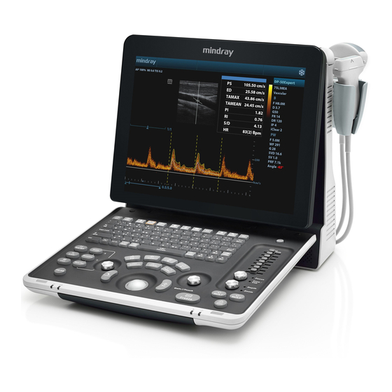
Mindray DP-50 — цифровая черно-белая ультразвуковая система портативного типа, оснащенная жидкокристаллическим широкоугольным монитором с диагональю 15 дюймов и возможностью изменения наклона для улучшения обзора и удобства врача. УЗИ сканер может работать от аккумулятора, а также от сети. Отличаясь компактными габаритами и имея сравнительно небольшой вес (всего 7,5 кг), легко размещается в помещениях с ограниченным пространством.
Вы можете заказать или купить со склада в наличии УЗИ аппарат Mindray DP-50 по выгодной цене, от надежного официального дистрибьютора с доставкой в любой город по всей России.
Технические характеристики
Область применения
- Акушерство и гинекология
- Педиатрия
- Абдоминальные исследования
- Исследования сосудов
- Урология
- Ортопедия
- Исследования органов малого таза
- Мускулы и сухожилия
- Сонография при брюшных травмах
- Периферические сосуды
- Транскраниальные исследования
- Интраоперационные применение
Технические характеристики
- Широкоугольный 15-дюймовый ЖК-монитор высокого разрешения с изменяемым углом наклона для лучшего обзора
- Одновременное подключение двух датчиков
- USB-порт – 4 шт.
- VGA – 1 шт.
- S-video – 1 шт.
- Широкий выбор мультичастотных датчиков от 2,0 до 14,0 МГц
- Цифровое формирование луча
- Встроенный жёсткий диск 320 Гб
- Кинопамять
- DICOM 3.0
- Вес – 7,5 кг
- Габариты 19 х 41х 38 см
- qwerty-клавиатура с подсветкой и трекбол
- Мобильная тележка UMT-150
- Водонепроницаемый ножной переключатель (максимум 3 клавишами), с функцией программирования
- Наборы для биопсии для всех типов датчиков
- Сумка-рюкзак для быстрой транспортировки
- Запасные аккумуляторы, с встроенным светодиодным индикатором заряда батареи
- Термовидеопринтер для печати фотографий
- DVR-RW рекордер для записи на CD/DVD диски
Технологии и режимы
PSHI — гармоническая визуализация с фазовым сдвигом
Изолированная гармоническая визуализация для улучшения контрастного разрешения, обеспечивающая более четкое изображение с превосходным пространственным разрешением и меньшим уровнем шума.
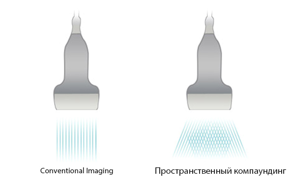
iBeam
Позволяет использовать несколько углов сканирования для формирования единого изображения, что приводит к увеличению контрастного разрешения и улучшению визуализации.
iClear
- Позволяет улучшить качество изображения, основываясь на автоматическом распознавании структур.
- Более четкие края и контуры.
- Плавное и однородное отображение тканей.
- Снижение зернистости в «областях без эхосигнала».
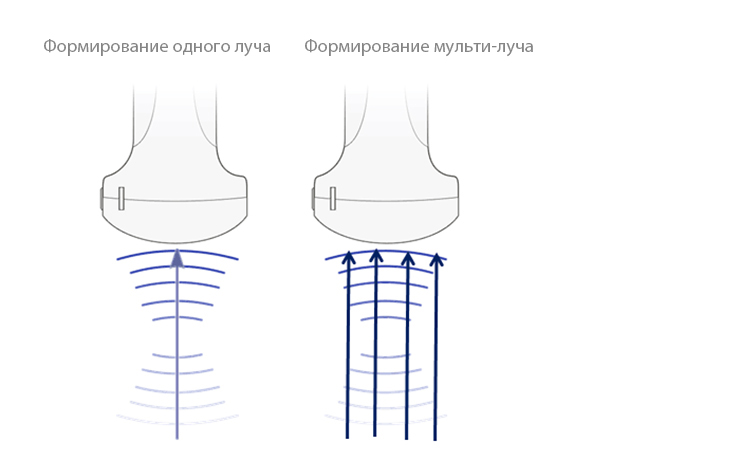
Формирование мульти-луча
Увеличение скорости обработки сигнала от одного луча до 4 раз, что позволяет достигать превосходного разрешения по времени и более высокой частоты кадров.
iScape
Дает полный и расширенный обзор анатомических структур посредством панорамной визуализации, в сочетании с индикатором скорости и функцией прямого / обратного сканирования, делая процесс более легким, последовательным и управляемым.
ExFOV
В Вашем распоряжении окажется самая полная диагностическая информация благодаря детализированной визуализации анатомической структуры на всех конвексных и линейных датчиках.
Трапециевидная визуализация
Большая точность и полнота диагностической информации обеспечиваются благодаря улучшенному обзору анатомических структур на всех линейных датчиках.
B-Steer
Ваш инструмент для более глубокой биопсии: обеспечивает маневрирование УЗ-луча, чтобы улучшить видимость иглы, нервных волокон и мелких сосудов.
Оптимизация рабочих операций
Auto IMT
инструмент для определение толщины комплекса интима-медиа, позволяет выполнять автоматическое измерение толщины передней и задней стенки, предоставляющее точную информацию о состоянии сонной артерии.
iStorage
непосредственная передача изображений и отчетов на ПК по сетевому кабелю.
iZoom
функция обеспечивает мгновенное переключение в полноэкранный режим нажатием одной клавиши.
Клинические изображения оборудования
Документы на оборудование
Преимущества аппаратов Mindray DP-50
Монохромный УЗИ сканер Mindray DP-50 является новой разработкой в отрасли медицины. Оборудование предназначено для использования в клиниках, диагностических центрах и прочих лечебных учреждениях, где существует необходимость проведения процедуры УЗИ. Аппарат отлично справляется с любыми задачами. При этом ультразвуковой сканер можно транспортировать для работы на выезде. Транспортирование возможно в специальной переносной сумке, которая предоставляется производителем. Приемлемая стоимость компактного оборудования является одним из главных преимуществ. Поддержка X-Treme Engine обеспечивает стабильно высокое качество изображения. Аппарат по доступной цене содержит все необходимые опции, включая технологию удаления шумов и тканевую гармонику. Интуитивно понятное управление способствует легкости освоения функционала. На практике купить DP-50 стараются многие диагностические клиники. Ведь наличие оборудования данной модификации позволяет обустроить современный кабинет для проведения процедуры УЗИ.
Технические характеристики УЗИ Mindray DP-50
- Регулируемый монитор на 15 дюймов
- Панель управления с опцией откидывания
- 2 порта для внешних датчиков
- 4 USB-порта для дополнительного оборудования
- Учет пациентов через iStation
Режимы сканирования УЗИ сканера Mindray DP-50
- Режим работы THI
- Поддержка PSHI
- B Steer для улучшения визуализации
- iClear для удаления зернистости
- iBeam технология сложносоставного сканирования
- Автоматическая оптимизация с iTouch
- Изображение на весь экран (технология iZoom)
- Трапециевидное изображение
- DICOM 3.0
- Псевдоокрашивание
Дополнительные возможности и компоненты:
- Передвижная тележка
- DVR-RW привод
- Видео-принтер
- Запасной АКБ
- Напольный переключатель с 3 клавишами
- Адаптеры на все типы датчиков для биопсии
- Сумка для перевозки
Купить УЗИ аппарат Mindray DP-50 на выгодных условиях.
Ультразвуковая диагностическая система
Обзор
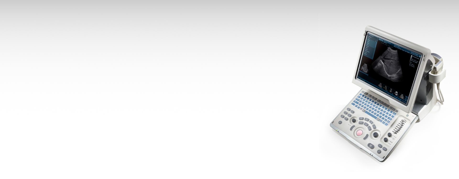
УЗ-сканер DP-50 представляет собой новое поколение черно-белых ультразвуковых систем компании Mindray. Он оснащен передовыми технологиями визуализации, обеспечивающими более глубокое проникновение и быстрое получение изображений при более высоком разрешении. УЗ-сканер DP-50 отлично подходит для всех клинических ситуаций благодаря своей новой высокотехнологичной конструкции, повышенной мобильности и удобству эксплуатации.
Функции
PSHITM(гармоническая визуализация с фазовым сдвигом)
Изолированная гармоническая визуализация для улучшения контрастного разрешения, обеспечивающая более четкое изображение с превосходным пространственным разрешением и меньшим уровнем шума.
iBeamTM
Позволяет использовать несколько углов сканирования для формирования единого изображения, что приводит к увеличению контрастного разрешения и улучшению визуализации.
iClearTM
Позволяет улучшить качество изображения, основываясь на автоматическом распознавании структур.
- Более четкие края и контуры
- Плавное и однородное отображение тканей
- Снижение зернистости в «областях без эхосигнала»
Формирование мульти-луча
Увеличение скорости обработки сигнала от одного луча до 4 раз, что позволяет достигать превосходного разрешения по времени и более высокой частоты кадров.
iScapeTM
Дает полный и расширенный обзор анатомических структур посредством панорамной визуализации, в сочетании с индикатором скорости и функцией прямого / обратного сканирования, делая процесс более легким, последовательным и управляемым.
ExFOV
В Вашем распоряжении окажется самая полная диагностическая информация благодаря детализированной визуализации анатомической структуры на всех конвексных и линейных датчиках.
Трапециевидная визуализация
Большая точность и полнота диагностической информации обеспечиваются благодаря улучшенному обзору анатомических структур на всех линейных датчиках.
B-SteerTM
Ваш инструмент для более глубокой биопсии: обеспечивает маневрирование УЗ-луча, чтобы улучшить видимость иглы, нервных волокон и мелких сосудов.
Auto IMT (автоматическое определение толщины комплекса интима-медиа)
Автоматическое измерение толщины передней и задней стенки, предоставляющее точную информацию о состоянии сонной артерии.
Выполнение рабочих операций
iStorageTM
Непосредственная передача изображений и отчетов на ПК по сетевому кабелю.
iZoomTM
Обеспечивает мгновенное переключение в полноэкранный режим нажатием одной клавиши.
Эргономика
- Обтекаемая, компактная форма
- Удобная клавиатура и панель управления
- Легкая, повышенной мобильности конструкция
- 15″ ЖК-монитор высокого разрешения с широким углом обзора и функцией наклона для лучшего просмотра
.jpg)
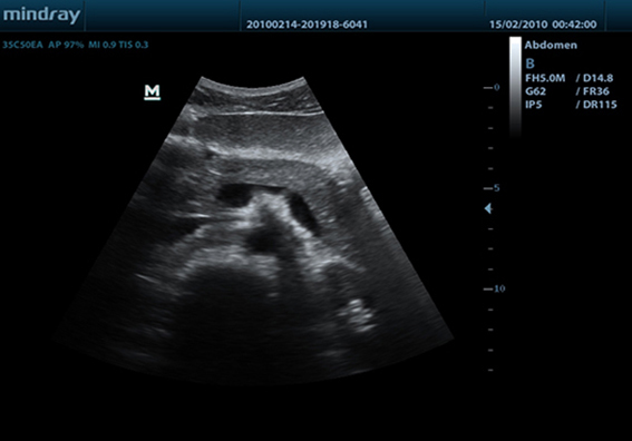
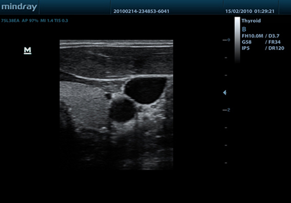
Клинические изображения
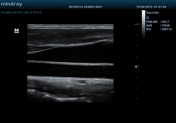
-

Сонная артерия
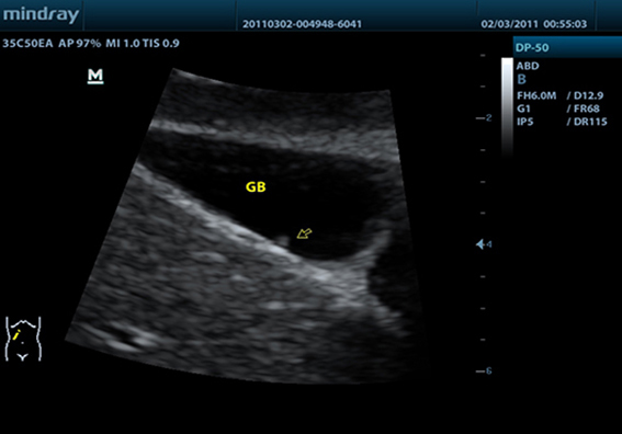
-
Полип желчного пузыря
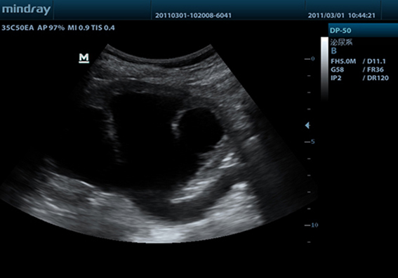
-
Гидронефроз
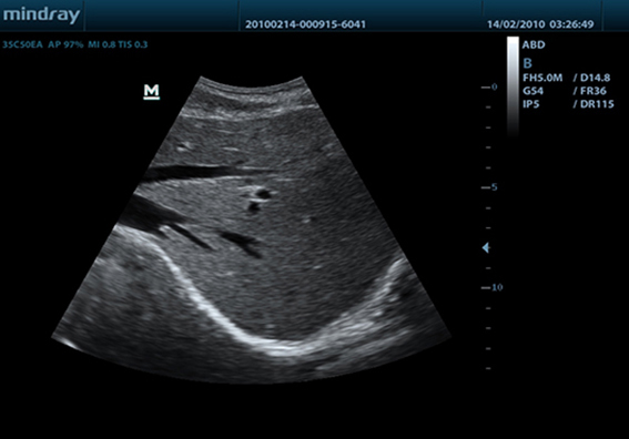
-
Печень
-
Поджелудочная железа
-
Щитовидная железа
Датчики
-
Convex
- 35C50EA
- 35C20EA
- 65C15EA
-
Endocavity
- 65EC10EA
- 65EB10EA
- 65EC10ED
- 65EL60EA
-
Linear
- 75L38EA
- 75L53EA
- 10L24EA
- 75LT38EA
Медик-Сервис – официальный дистрибьютор Mindray в России

Портативный ультразвуковой сканер Mindray DP-50
Mindray DP-50 – портативная цифровая ультразвуковая система с ЖК монитором 15 дюймов (1024Х768)
и встроенными аккумуляторными батареями (опция) позволяющими работать в автономном режиме до 2-х часов.
Достоинства Mindray DP-50:
— THI — режим тканевой гармоники
— IMT автоматический расчет толщины стенок сосудов
— iTouch автоматической оптимизации изображения нажатием одной клавиши
— iClear технология подавления помех и получения четких ультразвуковых изображений высокого разрешения
— 4 USB порта: два сзади и два сбоку, Wi-Fi — беспроводная передача данных
— диапазон сканируемых частот от 2,0 до 14,0 МГц
— карты колоризации (псевдоокрашивание).
— время загрузки прибора до рабочего состояния — всего 6 с
— два порта для одновременного подключения 2-ух датчиков.
DP-50 – портативный УЗИ сканер разработан на базе новой платформы X-treme engine, используемой в хорошо зарекомендовавших себя цветных сканерах с доплером моделей DC-3, DC-7, DC-6. Эта платформа открывает возможности для расширений до уровня цветных сканеров и совместимости с широким диапазоном периферийного оборудования. X-treme означает интеллект, высокую скорость обработки данных, многоуровневую передачу сигналов, а также возможность оптимизации изображения и модульного расширения.
Эргономичность:
— портативность и легкий вес
— большой монитор с широким углом зрения
— высокая мобильность
— решение проблемы энергопитания
Качество изображения:
— iBeam: функция улучшения разрешающей способности изображения
— iClear: функция подавления шумов на изображении для улучшения детализации и контрастности изображения
— изображение на основе гармоник с фазовым сдвигом
— трапецевидное изображение, псевдоокрашивание и B Steer
Продуктивность:
— iTouch: функция оптимизации изображения нажатием одной клавиши
— iZoom: увеличение рассматриваемого участка изображения на весь экран
— iStation: интеллектуальная платформа управления информацией о пациенте
Область использования:
— у постели больного
— в полевых условиях
— в операционных
— в спортивной медицине
Технические параметры:
— монитор: ЖК 15 дюймов (1024 Х 768), с регулировкой угла наклона
— операционная система: LINUX
— клавиатура: два уровня задней подсветки
— трекбол: оптический с возможностью устанавливать расцветку
— время загрузки ультразвуковой системы: 6 секунд
— масса: 7,5 кг
Применяемые датчики DP-50:
Конвексный датчик 35C50EA (2.0/3.5/4.5/5.0/Н5.0/Н6.0) R50
Линейный датчик 75L38EA (5.0/7.5/8.5/10.0/Н8.0/Н10.0 МГц, 38 мм)
Линейный датчик 75L53EA (5.0/7.5/8.5/10.0/Н8.0/Н10.0 МГц, 50 мм)
Линейный датчик высокочастотный 10L24EA (8.0/10.0/12.0/14.0/Н10.0/Н12.0 МГц, 24 мм)
Микроконвексный датчик 65C15EA (5.0/6.5/7.5/8.5/Н8.0/Н9.0 МГц, R-15 )
Внутриполостной датчик 65EC10EA (5.0/6.5/7.5/8.5/Н8.0/Н9.0 МГц, R-10 )
Би-плановый внутриполосной двухплоскостной датчик 65EB10EA (5.0/6.5/7.5/8.5/Н8.0/Н9.0 МГц, R-10 )
(5.0/6.5/7.5/8.5/Н8.0/Н9.0 МГц, R-10 )
Мобильная тележка UMT-150
Аккумуляторная батарея
Водонепроницаемый ножной переключатель (максимум 3 клавишами), с функцией программирования
Наборы для биопсии для всех типов датчиков
Сумка-рюкзак для быстрой транспортировки
Термовидеопринтер для печати фотографий
DVR-RW рекордер для записи на CD/DVD диски