- Manuals
- Brands
- Veeder-Root Manuals
- Music Mixer
- TLS-450
- Setup and operation
-
Contents
-
Table of Contents
-
Bookmarks
Quick Links
Manual No: 577013-940
●
Revision: F
TLS-450 Setup and Operation
Screens Manual
Related Manuals for Veeder-Root TLS-450
Summary of Contents for Veeder-Root TLS-450
-
Page 1
Manual No: 577013-940 ● Revision: F TLS-450 Setup and Operation Screens Manual… -
Page 2
Customer Service will work with production facility to have the replacement product shipped as soon as possible. If “lost” equipment is delivered at a later date and is not needed, Veeder-Root will allow a Return to Stock without a restocking fee. -
Page 3: Table Of Contents
TLS-450 Setup and Operation Screens Manual Contents INTRODUCTION ……………………….1 Contractor Certification Requirements ………………..1 Related Manuals ……………………… 1 Safety Precautions ……………………..1 Safety Warnings ……………………… 2 Front Panel Layout ……………………… 3 Item 1 — Integral Printer ……………………. 3 Item 2 — System Visual Status LEDs ………………..3 Item 3 — Touch Screen ……………………..
-
Page 4
TLS-450 Setup and Operation Screens Manual Device Setup — Groundwater Sensor …………………. 57 Device Setup — Vapor Sensor ……………………. 58 Device Setup — Line Pressure Sensor ………………..60 Device Setup — LV/MDIM ……………………61 Tank Setup — General ……………………..63 Tank Setup — Limits …………………….. -
Page 5
TLS-450 Setup and Operation Screens Manual RS-232/RS-485, Internal Modem, Satellite Hughes H-JBox and Satellite S-Sat Comm Devices – General (page 1) ……………………… 134 Ethernet Comm Devices – General (page 2) ………………. 136 Ethernet Comm Devices – General (page 3) ………………. 138 Ethernet Comm Devices –… -
Page 6
TLS-450 Setup and Operation Screens Manual Printer Setup Screen 2 ……………………182 Setup a Printer with the Get Printers Button ………………182 Setup a Network Printer with URI Field ……………….. 183 Removing Printers ……………………..183 Printer Setup — Status ……………………… 184 Printer Setup –… -
Page 7
TLS-450 Setup and Operation Screens Manual Add Delivery Ticket ……………………..220 Delivery Report — Adjusted Delivery Report ………………222 Report Column Descriptions ………………….222 Control Button (on right of screen) ………………..223 BIR Reports ……………………….224 Reconciliation Report — Reconciliation ………………..224 Report Column Descriptions …………………. -
Page 8
TLS-450 Setup and Operation Screens Manual Report Column Descriptions ………………….254 Control Buttons (right of screen) …………………. 255 PLLD Diagnostics — Mid-Range Test Results ………………256 Report Column Descriptions ………………….256 Control Buttons (right of screen) …………………. 257 PLLD Diagnostics — No-Vent Aborts ………………… 258 Report Column Descriptions …………………. -
Page 9
TLS-450 Setup and Operation Screens Manual Column Descriptions ……………………289 Control Buttons (right of screen) …………………. 289 Sequential Testing Procedure ………………….289 Inspection Testing Procedure ………………….290 Relays and External Inputs Diagnostics — External Inputs …………..291 Report Column Descriptions ………………….291 External Input Diagnostic Screen Refresh Rate ……………. -
Page 10
TLS-450 Setup and Operation Screens Manual Control Buttons (right of screen) …………………. 316 LPR Sensor Diagnostics — Channel …………………. 317 Report Description ……………………..317 Diagnostics — Line Pressure Sensor — Channel screen refresh rate ……….318 Control Buttons (right of screen) …………………. 318 AccuChart II ………………………. -
Page 11
TLS-450 Setup and Operation Screens Manual Table of Device Identifiers ……………………361 Table of Module Device Identifiers ………………….. 362 Table of Standard Abbreviations ………………….362 Table of Unit Abbreviations ……………………363 Table of Unit Conversions ……………………364 Table of Mag Probe Features ………………….. 364… -
Page 12: Introduction
TLS-450 Setup and Operation Screens Manual INTRODUCTION This manual details currently available setup, operation and diagnostic screens for the TLS-450 Console. Depending on your console type and its installed features, you may only see (and be able to program) some of the screens and/or fields. Skip over the material in this document that does not apply to your particular installation.
-
Page 13: Safety Warnings
If you have not been trained in proper service procedures and hazards involved, refer all service to a qualified Veeder-Root Service Representative. ATTEMPTING TO SERVICE TANK MONITORS AND EQUIPMENT WITHOUT PROPER TRAINING CAN CAUSE DAMAGE TO PROPERTY, ENVIRONMENT, RESULTING IN PERSONAL INJURY OR DEATH.
-
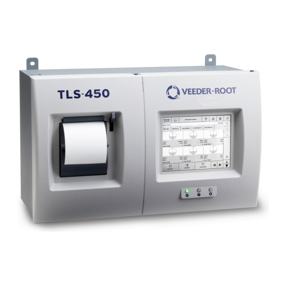
Page 14: Front Panel Layout
The X symbol is beneath a red LED. When the red LED is lit, there is at least one alarm (major) active. Item 3 — Touch Screen The TLS-450 graphical user interface is a touch sensitive screen providing quick access to operational reports, setup parameters, diagnostic information for all configured devices (tanks, sensors, etc.) and Online Help.
-
Page 15: Navigating The Touch Screens
TLS-450 Setup and Operation Screens Manual Navigating the Touch Screens After power up, the TLS-450 displays the System Status — All Tanks (Home) screen (see figure below) which contains system information and access to setup, reports, and diagnostics screens as defined in the legend below the figure.
-
Page 16
TLS-450 Setup and Operation Screens Manual Area/Touch Button Action/Description message «All Functions Normal» is displayed. When an alarm occurs, the System Status box will flash and display the alarm, warning or notice message. Once the alarms have been acknowledged, the System Status box will no longer flash. The alarm message will continue to display in the System Status box until the cause of the alarm has been corrected. -
Page 17: Setup, Operation, Diagnostic Touch Screen Layout
TLS-450 Setup and Operation Screens Manual Area/Touch Button Action/Description Delivery Report button — Touching this button accesses the following Delivery Reports: — Manual Delivery Report — Adjusted Delivery Report — Ticketed Delivery Report Inventory Report button — Touching this button accesses the following Inventory…
-
Page 18
TLS-450 Setup and Operation Screens Manual The data area displays the information associated with any selected setup, report or diagnostic screen. Tabs at the top of the data area (All Tanks, All Sensors, User Defined 1, etc. in the diagram below), if… -
Page 19: Online Help Touch Screen Layout
TLS-450 Setup and Operation Screens Manual Online Help Touch screen Layout Touching the help (?) button at the top of any Setup, Report (Operation) or Diagnostic screen displays the online help topic for that screen. The help screen layout is shown below: Item 1 — Online Help Table of Contents button Touch this button to display the online help table of contents.
-
Page 20: Entering Data
TLS-450 Setup and Operation Screens Manual Entering Data You enter setup parameters, confirm/cancel setup field entries, select reports, etc., using any one of a variety of touch buttons, drop-down lists and specialty dialog boxes that are easy to understand and use.
-
Page 21: Specialty Dialog Keypads
TLS-450 Setup and Operation Screens Manual Specialty Dialog Keypads The Specialty Dialogs section of the online help describes the function of all buttons on each of the following keypads — there are some multi-function buttons in these keypads which you should…
-
Page 22
TLS-450 Setup and Operation Screens Manual Cancel — touch this button to discard any selections that have been made. touch this button to move the cursor to the left. touch this button to move the cursor to the right. Caps On — touch this button to turn on or off caps. -
Page 23
TLS-450 Setup and Operation Screens Manual Notes: • Touching the ‘+’ and ‘-‘ buttons will toggle the sign of the number between positive and negative. The negative sign character will be shown to the left of the numeric entry. The positive sign will not be shown. It will be disabled if range for value does not include negative numbers. -
Page 24
TLS-450 Setup and Operation Screens Manual Clear All — touch this button to clear the entire entry. Back — touch this button to remove a character to the left of the cursor. OK — touch this button to apply the selection. -
Page 25: Initial Console Setup Sequence
Connect necessary cabling to the Comm devices. Connect power wiring to the console. Initial Startup Procedure A site that has a brand new TLS-450 without Wireless 2 devices 1. Power up the TLS-450 Console and wait 5 minutes until the device ‘Discover Mode’ is Complete. 2. Setup the TLS-450 Console A site that has a brand new TLS-450 with Wireless 2 devices 1.
-
Page 26
TLS-450 Setup and Operation Screens Manual 1. Date and Time Setup 2. Headers Setup 3. Display Setup 4. Devices (probes, sensors, relays) Setup 5. Communication Setup 6. Tanks Setup (in order of the Tab Screens left to right) 7. Pumps and line Setup (in order of the Tab Screens left to right) 8. -
Page 27: Understanding Alarms
TLS-450 Setup and Operation Screens Manual Understanding Alarms What Happens When An Alarm Is Posted? When the console posts an alarm, the console beeper sounds, the front panel LED associated with the alarm type lights, the Alarm Report button/System Status box both flash and the System Status box…
-
Page 28: How Do I Learn More About An Alarm And What To Do About It
TLS-450 Setup and Operation Screens Manual The Active Alarm Report screen shows all active and unacknowledged alarms and warnings. Once you have examined this list, touch the Alarm Report button a second time to acknowledge the unacknowledged alarms and silence the console beeper (the Alarm Report button and System Status box will also stop flashing when you acknowledge alarms).
-
Page 29
TLS-450 Setup and Operation Screens Manual Next touch anywhere in the desired alarm’s row to display an Alarm Help screen in which its cause and a suggested corrective action are shown (see Delivery Needed alarm example below): You can touch the More About Active Alarms link at the bottom of the Alarm Help screen to display a… -
Page 30
Leaking tanks can create serious environmental and health hazards. If you have not been trained in proper service procedures and hazards involved, refer all service to a qualified Veeder-Root Service Representative. Attempting to service tank monitors and equipment without proper training can cause damage to property, environment, resulting in personal injury or death. -
Page 31: Changing Printer Paper
TLS-450 Setup and Operation Screens Manual Changing Printer Paper The integral printer is mounted in the left-hand door of the console. The printer uses only V-R thermal roll paper (P/N 514100-456) and it must be installed correctly so the thermal sensitive side faces the print head.
-
Page 32: Setup Screens
TLS-450 Setup and Operation Screens Manual SETUP SCREENS Main Setup The Main Setup menu screen contains touch button navigators to all device setups in the console. If a button is dimmed, it is a disabled feature that is unavailable. Available system setups are discussed below.
-
Page 33: Date And Time Setup
TLS-450 Setup and Operation Screens Manual Date and Time Setup Date & Time Setup — Daylight Savings This section contains the Daylight Savings time setup for the console. Most of the United States begins Daylight Saving Time at 2:00 a.m. on the second Sunday in March and reverts to Standard Time on the first Sunday in November.
-
Page 34
TLS-450 Setup and Operation Screens Manual Select Month Allowable Selections: January – December. Default: MAR Select Week Number Allowable Selections: First, Second, Third, Fourth, Last. Default: SECOND Select Day of Week Allowable Selections: Sunday – Saturday. Default: SUN Start Time Allowable Selections: See below. -
Page 35: Date & Time Setup — Date & Time Set
TLS-450 Setup and Operation Screens Manual Date & Time Setup — Date & Time Set This screen lets you enter the current Date and Time for the console. Set Current Date Enter the current date. Allowable selections: Month: 1 — 12, Day: 1 — 31, Year: 1970 — 2038…
-
Page 36: Display Setup — Language And Units
TLS-450 Setup and Operation Screens Manual Display Setup — Language and Units The Display Setup — Language and Units screen lets you select the language and units to be used in all screens and print outs. System Language Allowable selections: English, Chinese, French, or Spanish…
-
Page 37: Display Setup — Date & Time Format
TLS-450 Setup and Operation Screens Manual Display Setup — Date & Time Format The Display Setup — Date & Time Format screen lets you select the date format to be used in all screens and print outs. Date Format Allowable selections: YYYY_MM_DD, DD_MM_YYYY, MM_DD_YYYY, MON_DD_YYYY…
-
Page 38: Display Setup — Number Format
TLS-450 Setup and Operation Screens Manual Display Setup — Number Format The Display Setup — Number Format screen lets you select the numerical separators to be used in all screens and print outs. Decimal Separator Allowable selections: «,» or «.»…
-
Page 39: Display Setup — System Status
TLS-450 Setup and Operation Screens Manual Display Setup — System Status The setup for the System Status Screen enables the view of various status tabs on the home (main) screen. Available tab screens include: All Tanks, All Sensors, and up to 3 User Defined tabs in which you can assign a combination of tanks and sensors as desired.
-
Page 40
TLS-450 Setup and Operation Screens Manual All Sensors Tab Selecting Enable in the All Sensors Tab field and then touching the Advanced Setup button to the right of the field opens the Display Setup — All Sensors Tab Advanced Setup screen. In this screen you select informational text to display in the sensor graphic displayed on the home screen (System Status ‘All Sensors’) and on any System Status ‘User Defined’ screens, if assigned. -
Page 41: Display — All Tanks — All Tanks Tab Advanced Setup
TLS-450 Setup and Operation Screens Manual Display — All Tanks — All Tanks Tab Advanced Setup The Display — All Tanks Tab Advanced Setup screen lets you configure informational text and/or icons (e.g., bell for alarm conditions) that will graphically represent the status of each tank. Selections made in this screen will apply to all tanks and will comprise the tank status graphic displayed on the home screen (System Status «All Tanks») and on any System Status «User Defined»…
-
Page 42
TLS-450 Setup and Operation Screens Manual Fuel Height Allowable selections: Enabled, Disabled. Default: Disabled Ullage 100% Allowable selections: Enabled, Disabled. Default: Disabled Ullage xx% Ullage xx% can always be selected but will only be displayed in the tank status graphic display if you enabled ‘User defined ullage’ in the Tank Setup — All Tanks Screen. -
Page 43: Display — All Tanks — Fuel Fill Selection
TLS-450 Setup and Operation Screens Manual Display — All Tanks — Fuel Fill Selection The Display — All Tanks — Fuel Fill Selection screen lets you select the pattern of the fuel in the tank status graphic. Fuel Fill Selection This selection lets you configure the fuel patterns to display as fuel levels in a selected tank.
-
Page 44: Display Setup — All Sensors Tab Advanced Setup
TLS-450 Setup and Operation Screens Manual Display Setup — All Sensors Tab Advanced Setup This screen lets you configure informational text and/or icons (e.g., bell for alarm conditions) that will represent the status of each sensor type. Selections made in each sensor tab screen will apply to all…
-
Page 45: Type A (2-Wire Cl) Sensors
TLS-450 Setup and Operation Screens Manual Category Allowable selections: Enabled, Disabled Default: Disabled Type A (2-wire CL) Sensors Sensor Label Allowable selections: Enabled, Disabled Default: Disabled Alarm Condition Icon Allowable selections: Enabled, Disabled Default: Disabled Model Allowable selections: Enabled, Disabled…
-
Page 46: Ground Water Sensors
TLS-450 Setup and Operation Screens Manual Alarm Condition Icon Allowable selections: Enabled, Disabled Default: Disabled Fuel Height Allowable selections: Enabled, Disabled Default: Disabled Water Height Allowable selections: Enabled, Disabled Default: Disabled Temperature Allowable selections: Enabled, Disabled Default: Disabled Ground Water Sensors…
-
Page 47: Line Pressure Sensors
TLS-450 Setup and Operation Screens Manual Line Pressure Sensors Sensor Label Allowable selections: Enabled, Disabled Default: Disabled Alarm Condition Icon Allowable selections: Enabled, Disabled Default: Disabled Pressure Allowable selections: Enabled, Disabled Default: Disabled…
-
Page 48: User Defined 1-3 Tabs
TLS-450 Setup and Operation Screens Manual User Defined 1-3 Tabs Display Setup — User Defined 1 — 3 Tabs User Defined tab screens show a graphical status view (created in Tank/Sensor Display Setups) of selected devices in the system. You can select which devices are to be included in each of these tab screens.
-
Page 49: Headers Setup
TLS-450 Setup and Operation Screens Manual Headers Setup This section contains the four report Header Station Information fields. It also contains the options of adding a fax sender’s name and fax number to the header info set. Use the header to identify site location, phone number, etc.
-
Page 50
TLS-450 Setup and Operation Screens Manual Fax Sender Name Enter the header info to be sent at the top of faxes transmitted by the console. Allowable selections: Alphanumeric Text Field Length — 30 Characters Default: Empty Fax (Sender) Number Enter the phone number the console will dial from when transmitting faxes. -
Page 51: Security — System Security
TLS-450 Setup and Operation Screens Manual Security — System Security This screen establishes front panel and web access control for the console. By enabling this security feature, Log-In /Log-Out modes are established which prevent unauthorized tampering of console setups. Log-In Mode Requires the Front Panel / Web Security selection be enabled and a correct password entered by the user.
-
Page 52
TLS-450 Setup and Operation Screens Manual are logged in. When this button is touched a Log-out dialog will display the message «Are you sure you want to Logout?» OK — logs the current user out and returns to the System Status screen in log-out mode. -
Page 53: Device Setup — Probes
TLS-450 Setup and Operation Screens Manual Device Setup — Probes This screen allows you to setup probes connected to the console. Only the probes and quantity enabled for your console will be configurable. You access each of your site’s probe setups by touching the desired button at the bottom of the screen.
-
Page 54
TLS-450 Setup and Operation Screens Manual Serial Number (Read Only) Probe Type (Read only) Float Type Enter the installed Mag probe float size. The console automatically recognizes which Mag probe type you have installed and will display only the applicable float size options. Only select «Custom» if the literature that was shipped with the float specifically states that you must choose this float size selection, i.e.,… -
Page 55
TLS-450 Setup and Operation Screens Manual 1″ & 2″ CUSTOM FLOAT DEFAULTS 2″ Floats 1″ Floats Water Fuel Invalid Water Water Fuel Invalid Water Circuit Code Name Type Offset Offset Fuel Min. Offset Offset Fuel Min. C000 MAG1 -3.160 2.520 9.500… -
Page 56: Device Setup — Relays
TLS-450 Setup and Operation Screens Manual Device Setup — Relays This screen allows you to setup monitored relays. You must enter data individually for each relay. Alarm assignment to a relay is done in the Automatic Events Setup — Device Tasks screen.
-
Page 57
TLS-450 Setup and Operation Screens Manual • MOMENTARY — The On/Off state is determined by assigned alarms/warnings. However, relay returns to the inactive state after the Alarm button is touched to acknowledge the alarm. • PUMP COMM CONTROL — Select this relay type only when a set of line manifolded pumps are using Red Jacket IQ Controllers, and you want to run PLLD precision line leak tests. -
Page 58: Device Setup — External Inputs
TLS-450 Setup and Operation Screens Manual Device Setup — External Inputs This screen allows you to setup external input devices that have been connected to the console. Configured Allowable selections: Enabled, Disabled Default: Disabled Address Allowable selections: Choose from drop-down list of available external inputs, Not Assigned…
-
Page 59
TLS-450 Setup and Operation Screens Manual the generator shuts Off, the system returns to its Leak Test mode. GENERATOR ON and GENERATOR OFF messages are printed whenever the generator turns on and off. This selection also generates the External Input alarm. -
Page 60: Device Setup — Liquid Sensor
TLS-450 Setup and Operation Screens Manual Device Setup — Liquid Sensor This screen allows you to setup Liquid Sensors connected to the console. You access each of your site’s liquid sensor setups by touching the desired button at the bottom of the screen.
-
Page 61
TLS-450 Setup and Operation Screens Manual Model Select the sensor’s model from the drop down list. Allowable selections: • Tri-State (Single Float) • Normally Closed • Dual Point Hydrostatic • Dual Float Discriminating • Dual Float High Vapor • Interceptor Sensor •… -
Page 62: Device Setup — Type A Sensor
TLS-450 Setup and Operation Screens Manual Device Setup — Type A Sensor This screen allows you to setup Type A (2-wire) sensors connected to the console. You access each of your site’s Type A sensor setups by touching the desired button at the bottom of the screen.
-
Page 63
TLS-450 Setup and Operation Screens Manual Category Select the sensor’s category (location) from the drop down list. Allowable selections: Other Sensors, Annular Space, Dispenser Pan, Monitor Well, STP Sump, Containment Sump Default: Other Sensors… -
Page 64: Device Setup — Type B Sensor
TLS-450 Setup and Operation Screens Manual Device Setup — Type B Sensor This screen allows you to setup Type B (3-wire) sensors connected to the console. You access each of your site’s Type B sensor setups by touching the desired button at the bottom of the screen.
-
Page 65
TLS-450 Setup and Operation Screens Manual Model Select the sensor’s model from the drop down list. Allowable selections: Ultra/Z-1 (4Site Pan/Sump — Standard), Ultra/Z-1 HV (4Site Pan/Sump — High Vapor) Default: Ultra/Z-1 Category Select the sensor’s category (location) from the drop down list. -
Page 66: Device Setup — Mag Sensor
TLS-450 Setup and Operation Screens Manual Device Setup — Mag Sensor This screen allows you to setup Mag Sensors connected to the console. The Mag Sensor defines the fields that are available for editing, the ranges for each field, and the default value. The Mag Sensor cannot be setup until its device address has been assigned.
-
Page 67
TLS-450 Setup and Operation Screens Manual Printout example notes: 1. The ‘<‘ (drop below) or ‘>’ (rise above) symbols in the printout example indicate the point (threshold) at which the Alarm/Warning will be triggered. 2. The Programmable column indicates if the Alarm/Warning threshold is or is not programmable. -
Page 68: Device Setup — Groundwater Sensor
TLS-450 Setup and Operation Screens Manual Device Setup — Groundwater Sensor This screen allows you to setup Groundwater sensors connected to the console. You access each of your site’s Groundwater sensor setups by touching the desired button at the bottom of the screen.
-
Page 69: Device Setup — Vapor Sensor
TLS-450 Setup and Operation Screens Manual Device Setup — Vapor Sensor This screen allows you to setup Vapor sensors connected to the console. You access each of your site’s Vapor sensor setups by touching the desired button at the bottom of the screen.
-
Page 70
TLS-450 Setup and Operation Screens Manual Threshold The Threshold field lets you enter vapor levels to identify a leak or serious spillover and to trigger the vapor alarm. Thresholds are in ohms and must be calculated for each vapor sensor according to the procedure described below. -
Page 71: Device Setup — Line Pressure Sensor
TLS-450 Setup and Operation Screens Manual Device Setup — Line Pressure Sensor This screen allows you to setup Pressurized Line Leak Detection (PLLD) pressure sensors that have been connected to the console. Configured Allowable selections: Enabled, Disabled Default: Disabled Address…
-
Page 72: Device Setup — Lv/Mdim
TLS-450 Setup and Operation Screens Manual Device Setup — LV/MDIM This screen allows you to setup Low Voltage Mechanical Dispenser Interface Modules (LVDIMs) and Mechanical Dispenser Interface Modules (MDIMs) installed in the console. You access each of your site’s LVDIM or MDIM setups by touching the desired button at the bottom of the screen.
-
Page 73
TLS-450 Setup and Operation Screens Manual Pulse Conversion Allowable selections: 1/2, 2.5, 10, 25, 100, 250, 500, 1000 or Custom Default: 1/2 Custom This field is only available if Custom is selected for Pulse Conversion above. Enter a custom pulse… -
Page 74: Tank Setup — General
TLS-450 Setup and Operation Screens Manual Tank Setup — General The Tank Setup — General screen lets you enter parameters for individual tanks. Configured To configure a tank the following must be true: A probe must be assigned to the tank 2.
-
Page 75
TLS-450 Setup and Operation Screens Manual Tank Label This value is a description field for the tank. Usually it is based on the name of the product in the tank. It should be unique for each tank. It is not the description value associated with the product code assigned to the tank. -
Page 76
TLS-450 Setup and Operation Screens Manual Thermal Coefficient To ensure proper leak test performance, you must enter the Coefficient of Thermal Expansion for the fuel in the tank. The system requires these values to establish proper temperature compensation factors during a leak test and for use in calculating temperature compensated volume. If you know your product’s thermal coefficient enter that value. -
Page 77
TLS-450 Setup and Operation Screens Manual Pump Threshold (%) This feature is for line manifolded tanks and is only enabled when you have the Dispense Mode set to Manifolded:Sequential (See Setup/Pumps and Lines/Lines). When the tank’s volume drops below the entered Pump Threshold percentage, pumping will switch over immediately to the next available tank in the line manifolded set. -
Page 78: Tank Setup — Limits
TLS-450 Setup and Operation Screens Manual Tank Setup — Limits The Tank Setup — Limits screen sets Tank capacity values, along with Tank Alarm set points. These values apply to the currently selected Tank. Maximum Volume (Label Volume) Maximum or Label Volume alarm warns when the level of fluid in the tank exceeds the volume you enter here.
-
Page 79
Delivery Overfill (% of Maximum Volume) Delivery Overfill Alarms warn of a potential overfill during a Delivery. When the Volume reaches this value, the TLS-450 Console can activate an Overfill Alarm, and triggers a printout showing the Tank number, date, time, and product. -
Page 80
TLS-450 Setup and Operation Screens Manual High Water Alarm Set this value at a level lower than the Pump Pickup value for the submersible Pump or suction Line (See Figure 1). When Console detects that the Water level in the Tank is higher than the High Water Alarm value an Alarm is posted. -
Page 81
TLS-450 Setup and Operation Screens Manual MEDIUM FILTER The Medium Filter, like the Low Filter detects that a Delivery is occurring when the fuel level in the Tank increases by 25 Gallons per Minute (GPM). Medium Filter — High Water Alarm During a Delivery if the Console detects a High Water Alarm condition for three minutes, it posts both a High Water Alarm and a High Water Warning after the Delivery completes. -
Page 82
TLS-450 Setup and Operation Screens Manual High Filter — Maximum Height for the No-Delay Condition If water level is 10 inches or more for three minutes, then the Console posts a High Water Alarm and High Water Warning, even when a Delivery is in progress. -
Page 83: Tank Setup — Environmental Tests
TLS-450 Setup and Operation Screens Manual Tank Setup — Environmental Tests This screen provides a choice of disabling a tank test (default), or enabling SLD or CSLD tests for a selected tank. Once a Tank Test Method has been chosen, the corresponding setup parameters for either SLD or CSLD will be displayed in the data view area.
-
Page 84
TLS-450 Setup and Operation Screens Manual — — — If Tank Test Method Selected is SLD — — — Leak Test Rate Allowable selections: 0.2 gph (0.76 lph), 0.1 gph (0.38 lph) Default: 0.2 gph (0.76 lph) Periodic Test Type Two periodic SLD test types are available: 1. -
Page 85
TLS-450 Setup and Operation Screens Manual Test Frequency Touch the Calendar button to select the desired frequency for SLD tests as described below: Field Range, Min, Max Default Visible If: On Date, Annually by Date, Annually by Day of Month,… -
Page 86
TLS-450 Setup and Operation Screens Manual Leak Min. Annual (% full volume) This value tells the system the minimum tank volume required to record a passed annual test. The value reflects federal, state, and local requirements. Allowable selections: 0 — 100%… -
Page 87
TLS-450 Setup and Operation Screens Manual — — — If Tank Test Method Selected is CSLD — — — Gross Test Auto-Confirm When enabled, this feature may reduce false alarms. Two tests in a row must fail before a Gross Leak Test Fail alarm is posted. -
Page 88
TLS-450 Setup and Operation Screens Manual CSLD Evap. Compensation Evaporation Compensation should only be enabled on individual tanks which have exhibited evidence of consistent, extreme vapor loss due to fuel evaporation, which interferes with normal CSLD leak detection monitoring by causing false leak alarms. -
Page 89: Tank Setup — All Tanks
TLS-450 Setup and Operation Screens Manual Tank Setup — All Tanks This screen contains parameters that apply across all tanks in the system. User Ullage Ullage is the volume (space) in the tank as product is dispensed. This field lets you enable display of the User Ullage volume as well as enable the User Ullage% field.
-
Page 90
TLS-450 Setup and Operation Screens Manual TC Reference This field lets you enter the temperature compensation (TC) Reference temperature for all volume calculations. This temperature is determined by your location. In the U.S., the reference temperature used to calculate TC volume is normally 60°F. In other countries, this value may differ. Canada, for example, uses 15°C. -
Page 91
TLS-450 Setup and Operation Screens Manual Days Before Annual Warning Allowable Selection: 0 — 365 Default: 355 days Days Before Annual Alarm Allowable Selection: 0 — 365 Default: 365 days TC Density Allowable Selection: Enabled/Disabled Default: Disabled Density Method Allowable Selection: GOST, API… -
Page 92: Tank Setup — Product
TLS-450 Setup and Operation Screens Manual Tank Setup — Product This screen lets you view, edit product labels for all tanks in the system and determine the content of Reconciliation reports. Report Column Descriptions Product # This column contains the product number.
-
Page 93
TLS-450 Setup and Operation Screens Manual Product # Read-only field — displays the product number. Product Label Touch the keypad to the right of this field to change the product label (This label will appear on the right side of the Reconciliation report title bar). -
Page 94: Tank Setup — Product Mapping
TLS-450 Setup and Operation Screens Manual Tank Setup — Product Mapping This screen allows you to view and/or assign a product to a tank. These assignments group single and manifolded tanks into product-summarized Reconciliation reports. Report Column Descriptions Tank(s) This column contains the Tank number.
-
Page 95
TLS-450 Setup and Operation Screens Manual Tank(s) Read-only field displays the selected tank (e.g. T1). Product If the selected tank has a product assigned, it will appear in this field (e.g., F1: Regular Unleaded). If the selected tank has no product assigned, Not Assigned will appear in this field. Touch the down arrow to the right of this field to edit or assign a product to the selected tank. -
Page 96: Tank Setup — View All Products
TLS-450 Setup and Operation Screens Manual Tank Setup — View All Products Touch the ‘View All Products’ button to display the Tank Setup -View All Products screen. This screen displays all Product/Tank assignments.
-
Page 97: Tank Setup — Chart
TLS-450 Setup and Operation Screens Manual Tank Setup — Chart This screen allows you to manually setup a tank chart using one of four tank profiles: 1 point, 4 point, 20 point or linear. You must enter the diameter and full volume before selecting a tank chart (See…
-
Page 98
TLS-450 Setup and Operation Screens Manual is 5% of 96″ or 4.8″). This selection can be used for all rounded- and dished-end tanks. • Linear — This method requires only the 100% (full) volume to profile the tank. When using the linear tank profile you must enter the inside height of the tank in place of the inside diameter of the tank in Tank Diameter setup (see above). -
Page 99: Tank Setup — Manual Calibration
TLS-450 Setup and Operation Screens Manual Tank Setup — Manual Calibration This screen allows you to (jump to the paragraph by touching the link): • View an existing manually calibrated chart, • Add a new manually calibrated chart, or •…
-
Page 100: Adding A New Manually Calibrated Tank Chart
TLS-450 Setup and Operation Screens Manual • Point — This column lists the entered points of the chart . • Height — This column lists the height of product in the tank at each chart point. • Volume Change — This is read-only field showing the change in volume between chart points.
-
Page 101
TLS-450 Setup and Operation Screens Manual 8. Repeat the procedure in Step 6 until all points are entered. 9. After at least 10 points are entered, the Make Chart button on the right of the screen will become active. Touch this button to make the chart based on your entered points. Notice that the newly created chart will appear in the report area of the screen and its Status will be ‘Ready’. -
Page 102
TLS-450 Setup and Operation Screens Manual 10. After at least 10 points are entered, the Make Chart button on the right of the screen will become active. Touch this button to make the chart based on your entered points. Notice that the newly created chart will appear in the report area of the screen and its Status will be ‘Ready’. -
Page 103: Control Buttons (Right Of Screen)
TLS-450 Setup and Operation Screens Manual touch the Check (OK) key to make this chart active for the selected tank. The Warning Update Schedule is active and may override your choice of active chart message indicates that the Update Schedule selection made in…
-
Page 104
TLS-450 Setup and Operation Screens Manual Volume New Chart — This field is blank — You enter the tank chart value or the metered volume dispensed or dropped for this point. Edit Chart — Displays the volume entered for this point. Allowable range: 0 to… -
Page 105: Tank Setup — Tank Charts
TLS-450 Setup and Operation Screens Manual Tank Setup – Tank Charts This screen lists the active and inactive charts for the selected tank. Content of the report’s columns are described below: Name (Chart) This is the name you entered for the chart.
-
Page 106: Control Buttons (Right Of Screen)
TLS-450 Setup and Operation Screens Manual Status This column lists the chart’s status. Possible messages include: Active, Ready, Incomplete, Bad Point, Calculating Quality Quality is a combination of data sufficiency and goodness-of-fit. The higher the sufficiency and/or the better the fit, the higher the quality will be. NOTE: This column contains data only if chart type is Automatic or Remote.
-
Page 107: Tank Setup — Siphon Sets
TLS-450 Setup and Operation Screens Manual Tank Setup — Siphon Sets The Siphon Set tab is used to view and edit information about siphon manifolded sets in the system. Each set is composed of a list of tanks that are siphon manifolded together (See Figure 1 below).
-
Page 108
TLS-450 Setup and Operation Screens Manual Individual Siphon Set Buttons (bottom of screen) Touching the individual buttons for Siphon Sets at the bottom of the screen will show parameter entry fields for siphon setup. A multi-select list of tanks will be provided for picking the tanks to include in the siphon set. The list will contain tanks that are both configured and non-configured. -
Page 109: Tank Setup — Accuchart Ii
TLS-450 Setup and Operation Screens Manual Tank Setup — AccuChart II Update Schedule Descriptions of the available AccuChart II calibration update methods are listed below. • Immediate — The active chart is updated every time AccuChart II generates a chart. Any resulting changes in product volume go into effect immediately.
-
Page 110
TLS-450 Setup and Operation Screens Manual • Never — The system will never automatically make any AccuChart II generated chart the active chart. Note: If you have entered another chart type, e.g., a 20 point chart for one of your tanks (ref. -
Page 111
AccuChart II Notes 1. If the TLS-450 is powered down during one of the Immediate or Periodic updates, or if a time/date change is made at this time, the update will be missed. If this occurs during the final Periodic update, or at the end of the calibration period for Immediate and Complete update selections, the calibration will be attempted at the next date change. -
Page 112: Pumps And Lines
TLS-450 Setup and Operation Screens Manual Pumps and Lines PLLD Setup Overview The steps below outline basic PLLD setup for standard line leak detection configurations. 1) Configure Relays in Device Setup section a. Set ‘Label’ b. Select desired address from ‘Address’ drop-down c.
-
Page 113: Pumps And Lines Setup — Pumps
TLS-450 Setup and Operation Screens Manual Pumps and Lines Setup — Pumps This tab screen allows you to configure the site’s pumps that will be monitored by the console. Configured This selection sets up the console to monitor the selected pump. The maximum number of pumps that can be configured is equal to the maximum number of tanks as defined by your console’s installed features.
-
Page 114
TLS-450 Setup and Operation Screens Manual • Pump Sense — This input is used to identify a tank active condition. A pump sense input assignment is required for this mode selection. There is no pump control assignment for this mode selection. -
Page 115: Pumps And Lines Setup — Lines
TLS-450 Setup and Operation Screens Manual Pumps and Lines Setup — Lines A line consists of one or more pumps in the site. Lines are collections of pumps that are treated as a group or set. Each line or line set is given a name or label that can be used by the console to refer to the pumps in the line.
-
Page 116
TLS-450 Setup and Operation Screens Manual Allowable selections: None, PLLD. Default: None Pressure Sensor Allowable selections: Choose from drop-down list of available sensors (you should pick the pressure sensor assigned to this line), Not Assigned. Default: Not Assigned Manifolded Allowable selections: Yes, No. Default: No Dispense Mode This field is disabled for edit unless the Manifolded field is set to «Yes». -
Page 117: Pumps And Lines Setup — All Lines
TLS-450 Setup and Operation Screens Manual Pumps and Lines Setup — All Lines The line leak detection system cannot test a line when AC power to the submersible pump is shut off. Since the line leak system automatically attempts to conduct a test whenever it receives a signal that the dispenser is off, it is necessary to lock out line tests when the station or fueling site is shut down and submersible pump power is off.
-
Page 118: Line Lockout Schedule — Individual
TLS-450 Setup and Operation Screens Manual Stop Time Allowable selections: HH:MM am/pm. Default:12 pm Line Lockout Schedule — Individual Individual schedule allows you to enter up to seven separate lockout schedules. You program each lockout period with an Event Start day and time, and an Event End day and time. For example, lockouts 1 through 5 could be programmed to lock out the line leak test each day from Monday through Friday to accommodate hours when the station is closed.
-
Page 119: Pumps And Lines Setup — All Plld
TLS-450 Setup and Operation Screens Manual Pumps and Lines Setup — All PLLD This tab screen lets you setup test parameters for all Pressurized Line Leak Detectors (requires PLLD option). Line Re-Enable Method Allowable selections: Pass line test, Alarm acknowledge…
-
Page 120
TLS-450 Setup and Operation Screens Manual Days Before Periodic Alarm Allowable selections: 0 — 30 days Default: 30 days Annual Test Needed Warning Annual Test Needed Warning, when enabled, informs you that a line will soon be out of compliance because an Annual test has not completed within the required time. -
Page 121: Pumps And Lines Setup — Plld
TLS-450 Setup and Operation Screens Manual Pumps and Lines Setup — PLLD In this screen you setup parameters for individual lines having Pressurized Line Leak Detection or PLLD. It will only be visible for consoles having the PLLD option. Also, if Leak Monitoring is not enabled (in Lines Setup) for at least one line then none of the PLLD screens will be editable.
-
Page 122
TLS-450 Setup and Operation Screens Manual Allowable selections: See Table 1 below. Default: Environflex PP1503/2503 TABLE 1. Line Length, 1.5 Diameter Line Length, 2.0 Diameter Line 2.5 Diameter Line Length, 3.0 Length, and 1st Line Length Diameter Line Length, and 2nd… -
Page 123
TLS-450 Setup and Operation Screens Manual 1st Line Length Allowable selections: See Table 1 above Default is 0 and will cause a data setup warning. 1st Line Diameter Allowable selections: 0 to 3.00 in (0 to 76.20mm) Default is 0 and user can set this field back to default. It will cause a data setup warning if associated line length is non-zero and Line Diameter is still default. -
Page 124
TLS-450 Setup and Operation Screens Manual the test blockout period, the test sequence repeats after the next dispense. This selection also enables manual 0.2 gph (0.76lph) testing. • Monthly — At the beginning of every month until a test has passed. This selection also enables manual 0.2 gph (0.76lph) testing. -
Page 125: Custom Alarms
TLS-450 Setup and Operation Screens Manual Custom Alarms Custom Alarms Setup — Enable The Custom Alarms Setup — Enable screen gives you the option of entering custom alarm labels that will accompany the system’s alarm labels in printouts and in the system status display.
-
Page 126: Custom Alarms Setup — View
TLS-450 Setup and Operation Screens Manual Custom Alarms Setup — View The Custom Alarms Setup — View screen lets you view a report listing all of the alarms that have either custom alarm labels and/or modified indication flags i.e., LCD flag, LED flag and Beeper flag.
-
Page 127
TLS-450 Setup and Operation Screens Manual Custom Alarm Description Lists the custom alarm label (if any). LCD Indication Lists if a LCD flag is enabled/disabled following an alarm by this device. LED Indication Lists if the front panel LED flag is enabled/disabled following an alarm by this device. -
Page 128: Custom Alarms — Setup
TLS-450 Setup and Operation Screens Manual Custom Alarms — Setup The Custom Alarms Setup screen can be used to enter a custom alarm label and also select the alarm indicators for the alarm. The data view area contains the list of alarm categories. Touching a category displays all of the standard alarm labels within that alarm category.
-
Page 129: Control Button (On Right Of Screen)
TLS-450 Setup and Operation Screens Manual BEEP Indication The console beeper will activate when this alarm occurs. Allowable selections: Enabled/ Disabled Default selection: Enabled Alarm Description The standard alarm label is listed for this alarm. Custom Alarm Label Enter your custom alarm label that will be displayed along with the standard alarm label when this alarm occurs.
-
Page 130: Custom Help
TLS-450 Setup and Operation Screens Manual Custom Help Custom Help Setup — Enable The Custom Help Setup Enable screen allows you to add custom help text to console online help topics and to select whether on not to display the custom help text and allow access to the custom help edit feature.
-
Page 131: Custom Help Setup — Alarms
TLS-450 Setup and Operation Screens Manual Custom Help Setup — Alarms The Custom Help Setup — Alarm screen lets you create custom text that is assigned to a selected alarm and that will display when that alarm occurs and the user requests cause/action information about the alarm.
-
Page 132: Inventory
TLS-450 Setup and Operation Screens Manual Inventory Inventory Setup — Shift Close Method This screen lets you setup daily shifts. At least one shift must be selected or the feature is disabled. Shift Close Method Touch the down arrow to select either ‘Timed’ or ‘Manual’ shift close method.
-
Page 133
TLS-450 Setup and Operation Screens Manual 3. A new Shift Inventory report will be created and will include the shift number, and allow you to access current or historical reports. Allowable selections: Timed, Manual Default: Timed Shift Close Timeout Select a Shift Close Timeout period (Manual Shift Close Method only). -
Page 134: Inventory Setup — Shift Times
TLS-450 Setup and Operation Screens Manual Inventory Setup — Shift Times When the selected shift close method is ‘Timed’, this screen lets you setup start times for each of the previously selected number of timed shifts (up to eight). Shift 1 (up to Shift
 Touch the down arrow to the right of each shift to select a desired start time.
 -
Page 135: Inventory Setup — Inventory Report Times
TLS-450 Setup and Operation Screens Manual Inventory Setup — Inventory Report Times This screen lets you setup Inventory Report Times. Reporting Interval Allowable selections: Disabled, 5 min, 10 min, 15 min, 20 min, 30 min, 1 hr, 2 hrs, 3 hrs, 4 hrs, 6 hrs, 8…
-
Page 136: Delivery
TLS-450 Setup and Operation Screens Manual Delivery Delivery Setup Delivery Method Allowable selections: Standard, Manual or Automatic Quiet Period Default: Standard Ticketed Delivery When you enable ticketed delivery, you can manually enter ticketed volumes using the receipts from delivery trucks. Enabling this feature generates reports showing delivery variances between ticketed volume and gauged volume and book variance.
-
Page 137: Reconciliation
TLS-450 Setup and Operation Screens Manual Reconciliation Reconciliation Setup — General This screen lets you setup general Reconciliation parameters. Product Threshold Alarm If enabled, the Product Threshold Alarm will be activated when the programmed threshold for discrepancies between the fuel delivered amount and the dispensed fuel amount is exceeded. The system default is 1.00% of total meter sales (throughput) plus 130 gallons (492 litres) offset.
-
Page 138
TLS-450 Setup and Operation Screens Manual • Minute: 0 to 59 • Meridiem: AM, PM (if 12 hour format) Default: 02:00 (02:00 AM if 12 hour format) Week Close Day Allowable selections: Sunday to Saturday Default: Sunday Alarm Threshold Delivery Type Alarm Threshold Delivery Type field is disabled (grayed out) when Ticketed Delivery is disabled. -
Page 139: Reconciliation Setup — Threshold Alarms
TLS-450 Setup and Operation Screens Manual Reconciliation Setup — Threshold Alarms This screen contains information that allows you to select up to four reconciliation compliance monitoring test protocols. You select one or more threshold determining references for each test protocol. The reference selections are: throughput, tank capacity, deliveries, or a fixed value.
-
Page 140
TLS-450 Setup and Operation Screens Manual • Rolling Consecutive — You define the number of rolling days. A test will pass when one of the daily variance thresholds is below the threshold set within the rolling period. For a test to fail, ‘all’ daily variance thresholds must exceed the threshold set for each day within the rolling period. -
Page 141
TLS-450 Setup and Operation Screens Manual % of Deliveries This Alarm Threshold is the discrepancy between the Fuel Delivery amount and the Variance amount (Physical Inventory — Calculated Inventory). The system default is 1.00% of total Fuel Delivery plus 130 gallons (492 litres) offset. In the U.S. the EPA has set this default as a criteria not to be exceeded. -
Page 142: Comm
TLS-450 Setup and Operation Screens Manual Comm Comm Setup — General The Comm Devices area of Main Setup provides an interface to configure communication devices. The features ordered with your console will determine which communication devices are available. The selection of setup fields presented to the user for a particular Comm Device will depend on the type of communication device detected.
-
Page 143
TLS-450 Setup and Operation Screens Manual Refer to the two tables below to identify permissible slots and configurable ports for Comm Devices: C = Configurable, NC = Non-Configurable Slot 1 Slot 2 Comm Comm Port Port Port Port Device Type… -
Page 144: Comm Setup Procedure
TLS-450 Setup and Operation Screens Manual Comm Setup Procedure There are four Comm Device — General Setups within this topic. Touch the applicable link below to jump to the desired setup: RS-232/RS-485, Internal Modem, Satellite Hughes H-JBox and Satellite S-Sat Comm…
-
Page 145: Rs-232/Rs-485, Internal Modem, Satellite Hughes H-Jbox And Satellite S-Sat Comm Devices — General
TLS-450 Setup and Operation Screens Manual RS-232/RS-485, Internal Modem, Satellite Hughes H-JBox and Satellite S-Sat Comm Devices – General (page 1) The General tab screen pages hold dropdowns to choose and enable this group of Comm Devices and to set up their communication properties.
-
Page 146
TLS-450 Setup and Operation Screens Manual Device Device The Auto detection mechanism may further restrict the Comm Device Type choices available to choose from in case a Device is already available in the slot. If there is no Device in the slot, then all supported options for that specific slot will be available. -
Page 147: Ethernet Comm Devices — General
TLS-450 Setup and Operation Screens Manual (H-JBOX, S-SAT Comm Devices) Allowable selections: 1 or 2 Default: 1 Satellite Connection String (Satellite H-JBox Comm Devices Only) Allowable selections: Alphanumeric, maximum 30 Characters Default: Empty DTR state (Satellite S-SAT Comm Devices Only)
-
Page 148
TLS-450 Setup and Operation Screens Manual Allowable selections: Yes, No Default: Yes Host Name NOTE: Changing the Host Name will require a reboot of the console. A blank Host Name is not allowed. Setup — These rules only apply in a multi-Ethernet Comm Device configuration. The Host Name of the Ethernet Comm Device that is the Default Gateway (Yes) will be used and can be changed. -
Page 149: Ethernet Comm Devices — General
TLS-450 Setup and Operation Screens Manual Ethernet Comm Devices – General (page 3) Subnet Mask NOTE: Changing the Subnet Mask will require a reboot of the console. Format — The format of this field will use the IPv4 dot-decimal notation, e.g. 192.0.2.235 Allowable selections: Numeric XXX.XXX.XXX.XXX (0 to 255 each field).
-
Page 150
TLS-450 Setup and Operation Screens Manual HTTP Port In a multi-Ethernet Comm Device configuration, a change to this Field for one Ethernet Comm Device will be reflected in the same Field of the other Ethernet Comm Devices (will be made the same). -
Page 151: Comm Setup — Modem
TLS-450 Setup and Operation Screens Manual Comm Setup — Modem This screen lets you enter device-specific parameters for the Modem Device. Dial Type Allowable selections: Tone, Pulse Default: Tone Dial-Tone Interval Select a no dial tone alarm wait interval. Allowable selections: 0001 to 9999 hours. Default: 32…
-
Page 152: Edim Comm Devices — General
TLS-450 Setup and Operation Screens Manual EDIM Comm Devices – General (page 1) Configured When the card is auto-detected, this field will be enabled but grayed out. Allowable selections: Enabled, Disabled. Default: Disabled Slot Read only when slot is detected, otherwise enter the configurable slot number (EDIMs 1,2,3 or 4)
-
Page 153: Edim Comm Devices — General
TLS-450 Setup and Operation Screens Manual The Auto detection mechanism may restrict the DIM Device Type choices available to choose from in case a Device is already available in the slot. If there is no Device in the slot, then all supported options for that specific slot will be available.
-
Page 154
TLS-450 Setup and Operation Screens Manual Default: Unknown Table 1. EDIMs Quick Reference Chart Baud Software Rate Parity Data Bits Stop Bits DIM P/N Rev. Protocol (Default) (Default) (Default) (Default) Notes 330280- GilbarcoEDIM 349643 (Gilbarco GSite) 1200 Even 330280- VRProtocolDIM… -
Page 155: (Edim) Comm Setup — Dim
TLS-450 Setup and Operation Screens Manual (EDIM) Comm Setup — DIM This screen allows you to enter EDIM reporting parameters. Units Reported Allowable selections: U.S., Metric, or Imperial Default: U.S. Suppress Communication Alarm This selection is for V-R Protocol only.
-
Page 156: Cdim Comm Devices — General
TLS-450 Setup and Operation Screens Manual CDIM Comm Devices – General (page 1) Configured When the card is auto-detected, this field will be enabled but grayed out. Allowable selections: Enabled, Disabled Default: Disabled Slot Read only when slot is detected, otherwise enter the configurable slot number (CDIMs 1,2 or 4 [preferred]).
-
Page 157: Cdim Comm Devices — General
TLS-450 Setup and Operation Screens Manual Device The Auto detection mechanism may restrict the DIM Device Type choices available to choose from in case a Device is already available in the slot. If the DIM Device is auto-detected, this field will be enabled but grayed out.
-
Page 158
TLS-450 Setup and Operation Screens Manual DIM Protocol Touch the down arrow to the right of this field and enter the applicable DIM Protocol for your DIM card. Allowable selections: Gilbarco CL, Wayne CL or Unknown Default: Unknown CDIM Quick Reference Chart… -
Page 159: Comm Setup — Advanced
TLS-450 Setup and Operation Screens Manual Comm Setup — Advanced There are three Comm Device — Advanced Setups within this topic. Touch the applicable link below to jump to the desired setup: • RS-232/RS-485, Internal Modem, Satellite Hughes H-JBox, Satellite S-Sat and Ethernet Comm Devices — Advanced Tab Setups •…
-
Page 160: Edim Advanced Tab Setups
TLS-450 Setup and Operation Screens Manual Security Code A Case-sensitive code (Alpha and Enhanced Numeric (also punctuation characters), no spaces allowed and no control characters. Each character will be represented by an asterisk in the field. Allowable selections: A six-character alpha-numeric string…
-
Page 161: Cdim Advanced Tab Setups
TLS-450 Setup and Operation Screens Manual RS-232 End of Message When this field is disabled, the 2 following fields (ETX Characters — Display and ETX Characters — Computer) will be disabled. When this field is set to ‘Enabled’, both fields will become enabled and the keypad will be accessible.
-
Page 162: Cdim Advanced Tab Setups
TLS-450 Setup and Operation Screens Manual ETX Characters — Display Accepts non-printable characters through the GUI. Enter hex value as string with an opening and closing bracket. Convert text string to char value and save or show. Example: Enter [0x06][0x15]…
-
Page 163: Comm Setup — All Comms
TLS-450 Setup and Operation Screens Manual Comm Setup — All Comms This screen allows you to assign Euro Protocol prefixes and formats to RS-232 and EDIM messages. Euro Protocol Prefix — International Option This feature is for European applications only.
-
Page 164: Automatic Events
TLS-450 Setup and Operation Screens Manual Automatic Events Automatic Events Setup — Address Book The Automatic Events Setup — Address Book screen contains a record of your list of contact names and their outbound connectivity details. Report Column Descriptions Contact ID This column shows the assigned numeric identifier for each contact you have set up (1 — 25).
-
Page 165: Control Buttons (On Right Of Screen)
TLS-450 Setup and Operation Screens Manual Fax Number This column lists the Fax modem phone number of the Contact Entry. If a Contact needs a Fax transmission, then this column contains the Fax number, otherwise the field is empty. Remote Host Address and Port This column lists the remote host TCP/IP address and port of the Contact Entry .
-
Page 166: Add/Edit Contact Entry — Contacts
TLS-450 Setup and Operation Screens Manual Add/Edit Contact Entry — Contacts The Add/Edit Contact Entry screen lets you add a contact to the address book or edit an entry if you selected a contact in the address book. Contact Name Add a new contact or edit the displayed contact.
-
Page 167: Add/Edit Contact Entry — Modem
TLS-450 Setup and Operation Screens Manual Add/Edit Contact Entry — Modem The Add Contact Entry — Modem screen lets you add/edit communication parameters for modem outbound connectivity for the current contact. This connection method is available if a modem is installed in the console.
-
Page 168: Control Buttons (Lower Right Of Screen)
TLS-450 Setup and Operation Screens Manual Number of Retries Allowable selection: Numeric, 3 to 99 Default: 3 Retry Delay Time Allowable selection: Numeric, 1 to 99 minutes Default: 3 Control Buttons (lower right of screen) Save If editing a contact’s modem information, touch this button to save the current record entries to the database.
-
Page 169: Add/Edit Contact Entry — Fax
TLS-450 Setup and Operation Screens Manual Add/Edit Contact Entry — Fax The Add Contact Entry — Fax screen lets you add/edit communication parameters for fax outbound connectivity for the current contact. This connection method is available if a fax modem card is installed in the console.
-
Page 170: Control Buttons (Lower Right Of Screen)
TLS-450 Setup and Operation Screens Manual Number of Retries Allowable selection: Numeric, 3 to 99 Default: 3 Retry Delay Time Allowable selection: Numeric, 1 to 99 minutes Default: 3 Control Buttons (lower right of screen) Save If editing a contact’s fax information, touch this button to save the current record entries to the database. It will not clear the screen.
-
Page 171: Add/Edit Contact Entry — Tcp/Ip
TLS-450 Setup and Operation Screens Manual Add/Edit Contact Entry — TCP/IP The Add Contact Entry — TCP/IP screen lets you add/edit communication parameters for TCP/IP outbound connectivity for the current contact. This connection method is available if an Ethernet Comm Device is installed in the console.
-
Page 172: Control Buttons (Lower Right Of Screen)
TLS-450 Setup and Operation Screens Manual Allowable selections: Available Ethernet Comm Devices. Default selection: First Ethernet Comm Device on List (if available, otherwise, Empty) Num of Retries Allowable selection: Numeric, 3 to 99 Default: 3 Retry Delay Time Allowable selection: Numeric, 1 to 99 minutes…
-
Page 173: Add/Edit Contact Entry — Satellite
TLS-450 Setup and Operation Screens Manual Add/Edit Contact Entry — Satellite The Add Contact Entry — Satellite screen lets you add/edit communication parameters for satellite outbound connectivity for the current contact. This connection method is available if a satellite Comm Device is installed in the console.
-
Page 174: Control Buttons (Lower Right Of Screen)
TLS-450 Setup and Operation Screens Manual Retry Delay Time Allowable selection: Numeric, 1 to 99 minutes Default: 3 Control Buttons (lower right of screen) Save If editing a contact’s Satellite information, touch this button to save the current record entries to the database.
-
Page 175: Add/Edit Contact Entry — Email
TLS-450 Setup and Operation Screens Manual Add/Edit Contact Entry — Email The Add Contact Entry — Email screen lets you add/edit communication parameters for e-mail outbound connectivity for the current contact. This connection method is available if an e-mail feature is installed in the console.
-
Page 176: Automatic Events Setup — Task Log
TLS-450 Setup and Operation Screens Manual Automatic Events Setup — Task Log The Automatic Events Setup — Task Log screen contains a History (Log) listing the results of assigned Automatic Event Activities that have occurred. Report Column Descriptions Event Time This column shows the date and time when the task is triggered.
-
Page 177: Control Buttons (On Right Of Screen)
TLS-450 Setup and Operation Screens Manual Last Attempt Time The date and time when the Task was last attempted. Attempts The number of Task Attempts. Note: Each retry attempt is not added to the log. Instead, both the retry count of the existing record and the date and time are updated.
-
Page 178: Automatic Events Setup — All Tasks
TLS-450 Setup and Operation Screens Manual Automatic Events Setup — All Tasks The Automatic Events Setup — All Tasks screen shows a report-like description of all Automatic Tasks (Device, Print and Auto Connect) you have set up. Individual Tasks can involve many combinations of Reports or Actions, Times, Events, Contacts and Connection Modes.
-
Page 179: Control Buttons (On Right Of Screen)
TLS-450 Setup and Operation Screens Manual Report/Action This column describes the Action to be performed (e.g., Outbound Connection). Contact This column describes the organization/person to be contacted (e.g., ABC Mgmt.). Device/Connection Mode This column lists the Device Label that is involved in performing the function. When a Contact is involved in the Automatic Action, it represents the Device used and Format of the Data to be transmitted (e.g.,…
-
Page 180: Automatic Events Setup — Device Tasks
TLS-450 Setup and Operation Screens Manual Automatic Events Setup — Device Tasks The Automatic Events Setup — Device Tasks screen shows a report-like description of Automatic Events you have set up. The control buttons on the right of the screen let you add a new Device task, edit a selected Device task in the report, delete a selected Device task in the report or modify (filter) the contents of the report.
-
Page 181: Control Buttons (On Right Of Screen)
TLS-450 Setup and Operation Screens Manual Action This column describes the Action to be performed (e.g., Relay Off). Device/Connection Mode This column lists the Label of the Device (e.g., Relay 1) that is involved in performing the function. Control Buttons (on right of screen) Add Task Touch this button to add a new Device task.
-
Page 182: Automatic Events — Add Tasks — Device
TLS-450 Setup and Operation Screens Manual Automatic Events — Add Tasks — Device The Automatic Events — Add Tasks — Device screen for Add or Edit a Task displays selections to control a Device Automatically. Event (Field) Devices have NO controllable action. The action is determined by their setup. That is, if a relay is ‘normally open’ and the event happens the relay will change to closed.
-
Page 183: Automatic Events Setup — Print Tasks
TLS-450 Setup and Operation Screens Manual Automatic Events Setup — Print Tasks The Automatic Events Setup — Print Tasks screen shows a report-like description of printer related automatic activities you have set up. The control buttons on the right of the screen let you add a new Print task, edit a selected Print task in the report, delete a selected Print task in the report or modify (filter) the contents of the report.
-
Page 184: Control Buttons (On Right Of Screen)
TLS-450 Setup and Operation Screens Manual Report This column describes the Name of Report to be printed (e.g., Delivery Report). Printer This column lists the Printer Device Label that is involved in printing (e.g., Front Desk Printer). Control Buttons (on right of screen) Add Task Touch this button to add a new print task.
-
Page 185: Automatic Events Add Tasks — Print
TLS-450 Setup and Operation Screens Manual Automatic Events Add Tasks — Print The Automatic Events Add Tasks — Print screen for Add or Edit a Task displays selections to Print Automatically. Time (Field) This dialog provides drop-down lists to select a time frequency for the new print task: •…
-
Page 186
TLS-450 Setup and Operation Screens Manual Event (Field) Touch this button to the select the event(s) from the drop-down lists that will trigger the new task: • Alarms • Notifications • External Inputs Default: Field is empty. Printer (Field) Select a Printer from the dropdown list of available printers. -
Page 187: Automatic Events Setup — Auto Connect Tasks
TLS-450 Setup and Operation Screens Manual Automatic Events Setup – Auto Connect Tasks The Automatic Events Setup — Auto Connect Tasks screen shows a report-like description of Auto- Connect-Related automatic activities you have set up. The control buttons on the right of the screen let you add a new task, edit a selected task in the report, delete a selected task in the report or modify (filter) the contents of the report.
-
Page 188: Control Buttons (On Right Of Screen)
TLS-450 Setup and Operation Screens Manual Time/Event This column lists the timed or event action that triggers the automatic event to be executed (e.g., Weekly on Monday at 6:00 AM). Report/Action This column describes the name of report transmitted or action to be performed (e.g., Inventory Report).
-
Page 189: Automatic Events — Add Tasks — Auto Connect
TLS-450 Setup and Operation Screens Manual Automatic Events — Add Tasks — Auto Connect The Automatic Events- Add Tasks-Auto Connect screen lets you add a task to auto connect in computer mode or non-computer mode. Make selections from the entry fields below as required.
-
Page 190
TLS-450 Setup and Operation Screens Manual Default: Field is empty. Event (Field) Touch this button to the select the event(s) from the dropdown lists that will trigger the new task: • Alarms • Notifications (Notifications cannot be assigned for ‘Device’ action tasks) •… -
Page 191: Meter
TLS-450 Setup and Operation Screens Manual Meter Meter Setup This screen allows you apply temperature compensation corrections to volume amounts received from the site’s dispenser meters. TC Meters This feature allows you to choose whether or not to calculate Business Inventory Reconciliation (BIR) volumes using the Temperature Compensation (TC) value.
-
Page 192: Printer Setup — Setup
TLS-450 Setup and Operation Screens Manual Printer Setup — Setup Printer Setup Screen 1 This screen can configure printers connected locally to the USB port, or connected remotely through a communications network. You can also display printer status, and show jobs in printer queues.
-
Page 193: Printer Setup Screen 2
TLS-450 Setup and Operation Screens Manual Printer Setup Screen 2 Setup a Printer with the Get Printers Button • Touch the Get Printers button on the right. The button dims to indicate that the console is searching for printers. •…
-
Page 194: Setup A Network Printer With Uri Field
TLS-450 Setup and Operation Screens Manual • Select a Paper Size to adjust the size of the printed page. The selections that you see depend on the print driver selected. • Select Enabled in the Configured drop-down list. Touch the Check button…
-
Page 195: Printer Setup — Status
TLS-450 Setup and Operation Screens Manual Printer Setup — Status This screen displays the current status of connected printers. Touch a PRINTER button on the bottom of the screen to select a printer screen number. Name The Label assigned to this printer when it was added in the Printer Setup screen.
-
Page 196
TLS-450 Setup and Operation Screens Manual Model The make and model of the printer, for example HP LaserJet. This information is obtained from the software driver associated with the printer, so it may be generic in nature. State The current printer state; for example Printing a Job, Stopped. -
Page 197: Printer Setup — Jobs
TLS-450 Setup and Operation Screens Manual Printer Setup – Jobs This screen displays a list of jobs in the printer queue. Job ID An identification number assigned by the console to the print job. Start Time The time the job started.
-
Page 198: Reports
TLS-450 Setup and Operation Screens Manual REPORTS Active Alarm Report The Active Alarm Report screen is the primary alarm report and shows all active and unacknowledged TLS alarms and warnings. You access this screen by touching the Alarm Access button at the top of the console screen.
-
Page 199: Active Alarm Report Screen Refresh Rate
TLS-450 Setup and Operation Screens Manual Label This column lists the label of the device that is in alarm. If it is a general system alarm, this column will be blank. Alarm Description This column lists the name of the alarm. If custom alarms are enabled, the custom alarm label will be displayed.
-
Page 200: Alarm History Report
TLS-450 Setup and Operation Screens Manual Alarm History Report The Alarm History Report screen displays alarms for all devices, regardless of priority level and state. TLS alarm events are added to the history when an alarm becomes active, is acknowledged or is cleared.
-
Page 201: Control Buttons (On Right Of Screen)
TLS-450 Setup and Operation Screens Manual Active Time This column lists the date/time the alarm was posted. Clear Date/Time This column lists the date/time the alarm was cleared. Control Buttons (on right of screen) Help Mode Touching this button changes the report from a single- to a double-spaced row format. Touch an alarm and a dialog displays the cause of the selected alarm and the console’s standard alarm corrective action.
-
Page 202: Priority Alarm History Report
TLS-450 Setup and Operation Screens Manual Priority Alarm History Report The Priority Alarm History Report screen displays priority alarms. TLS alarm events are added to the history when an alarm becomes active, is acknowledged or is cleared. The default view is the 100 most recent alarm events.
-
Page 203: Control Buttons (On Right Of Screen)
TLS-450 Setup and Operation Screens Manual Clear Date/Time This column lists date/time the alarm was cleared. Control Buttons (on right of screen) Help Mode Touching this button changes the report from a single- to a double-spaced row format. Touch an alarm and a dialog displays the cause of the selected alarm and the console’s standard alarm corrective action.
-
Page 204: Non-Priority Alarm History Report
TLS-450 Setup and Operation Screens Manual Non-Priority Alarm History Report The Non-Priority Alarm History report displays non-priority alarms. TLS alarm events are added to the history when an alarm becomes active, is acknowledged or is cleared. The default view is the 100 most recent alarm/warning events.
-
Page 205: Control Buttons (On Right Of Screen)
TLS-450 Setup and Operation Screens Manual Active Time This column lists the date/time the alarm was posted. Clear Date/Time This column lists the date/time the alarm was cleared. Control Buttons (on right of screen) Help Mode Touching this button changes the report from a single- to a double-spaced row format. Touch an alarm and a dialog displays the cause of the selected alarm and the console’s standard alarm corrective action.
-
Page 206: Inventory Reports
TLS-450 Setup and Operation Screens Manual Inventory Reports Inventory Reports — Current Inventory The Inventory Reports — Current Inventory screen lists inventory data for all currently active and configured tanks. Note: References to probes are for probes that assigned to the tank. If the tank has no assigned probe, and probe data is not available, the related field(s) will be blank.
-
Page 207: Current Inventory Report Screen Refresh Rate
TLS-450 Setup and Operation Screens Manual Mass This column will not display if the probe does not measure density. Allowable range: Depends on tank volume and fuel density Fuel Density This column will not display if the probe does not measure density.
-
Page 208: Inventory Reports — Inventory History
TLS-450 Setup and Operation Screens Manual Inventory Reports — Inventory History The Inventory Reports — Inventory History screen displays the inventory history. The default view is the most recent 10 inventory history records for All Tanks. The Inventory History report close times are configured in system setup, Date & Time — Report Times.
-
Page 209: Control Button (On Right Of Screen)
TLS-450 Setup and Operation Screens Manual Allowable range: 0 to 264,172 gal (0 to 999,999L) Mass This column will not display if the probe does not measure density. Allowable range: Depends on tank volume and fuel density Fuel Density This column will not display if the probe does not measure density.
-
Page 210: Inventory Reports — Shift Inventory
TLS-450 Setup and Operation Screens Manual Inventory Reports — Shift Inventory The Inventory Report — Shift Inventory screen displays the data for all enabled shifts. Up to four completed shifts can be displayed. Only data for shifts that have closed as well as the current shift will be displayed. Each shift record is displayed on two lines.
-
Page 211
TLS-450 Setup and Operation Screens Manual Mass This column will not display if the probe does not measure density. Allowable range: Depends on tank volume and fuel density Fuel Density This column will not display if the probe does not measure density. -
Page 212: Environmental Reports
TLS-450 Setup and Operation Screens Manual Environmental Reports Environmental Reports — Combined Tank Test The Environmental Reports — Combined Tank Test screen displays both Static Leak Detect (SLD) and Continuous Statistical Leak Detection (CLSD) test results on one report. This is a historic report and displays only results with a status of Passed.
-
Page 213: Report Column Descriptions
TLS-450 Setup and Operation Screens Manual Report Column Descriptions Test Type Possible messages: • Fullest Annual • Fullest Periodic • Last Annual • Last Gross • Last Periodic Date & Time Date and time of test. Test Method Possible messages: •…
-
Page 214: Line Leak Report Passed Test Results
TLS-450 Setup and Operation Screens Manual Line Leak Report Passed Test Results The Line Leak Reports — Passed Test Results displays information about most-recent and historical line leak tests. This report area is visible only if your console has the PLLD option.
-
Page 215: Control Button (On Right Of Screen)
TLS-450 Setup and Operation Screens Manual Gross Test Prev. 24 Hours This column lists the number of gross tests passed in the previous 24 hours. This column is for Gross tests only and may be blank. There will be only one entry of Gross test history per line.
-
Page 216: Environmental Reports — Sensor Status
TLS-450 Setup and Operation Screens Manual Environmental Reports — Sensor Status The Sensor Status Report — All Sensors screen displays a report with the current status of the following stand-alone sensors: • Liquid • Type A (2-Wire CL) • Type B (3-Wire CL) •…
-
Page 217
TLS-450 Setup and Operation Screens Manual Sensor Location This column lists the location of the sensor, e.g., Regular STP Pump. Status This column lists the sensor status, as applicable. Possible messages (depending on sensor type): • Normal • Fuel Alarm •… -
Page 218: Environmental Reports — Sensor Status History
TLS-450 Setup and Operation Screens Manual Environmental Reports — Sensor Status History The Sensor Status History report displays the status of all sensors over a selected time period. There can be multiple records (or rows) displayed for each sensor, depending on the number of alarm events during the selected time period.
-
Page 219: Control Buttons (On Right Of Screen)
TLS-450 Setup and Operation Screens Manual Status This column lists the sensor status, as applicable. Possible messages include: • Normal • Fuel Alarm • Out Alarm • Short Alarm • Water Alarm • Water Out Alarm • High Liquid Alarm •…
-
Page 220
TLS-450 Setup and Operation Screens Manual Touch this button to open a dialog box and select a specific time span for the report. Option selections: Week, Month, Year, Date Range (Date From and Date To only), All Records Period range: Previous, Previous n selections. -
Page 221: Delivery Reports
TLS-450 Setup and Operation Screens Manual Delivery Reports Delivery Report — Manual Delivery The Manual Delivery report screen allows you to perform a manual delivery and is available only if the Delivery Method selected in Delivery Setup is Manual. Units are as selected in Display Setup — Language &…
-
Page 222: Control Buttons (Right Side Of Screen)
TLS-450 Setup and Operation Screens Manual Control Buttons (Right Side of Screen) The Start and Stop buttons are used to perform a manual delivery to a selected tank. 1. You must determine the tank getting the delivery is in a quiet period by visual inspection of volume change (This volume is the Tank’s Inventory Volume).
-
Page 223: Last Delivery Report
TLS-450 Setup and Operation Screens Manual Last Delivery Report The Last Delivery Report screen serves as the default screen for the Fuel Management Reports. The purpose of the Last Delivery Report is to show the most recent increase in a tank’s inventory.
-
Page 224: Report Column Descriptions
TLS-450 Setup and Operation Screens Manual Report Column Descriptions Start/End Date & Time Allowable range: 01/01/2005 to 12/31/2038 (MMDDYYYYY) 00:00 to 23:59 (HH:MM) Fuel Volume Allowable range: 0 to 264,172 gal (0 to 999,999L) Fuel TC Volume The Fuel TC Volume column will not be displayed unless the Print TC Volume feature is enabled in System Setup and the probe measures temperature.
-
Page 225: Delivery History Report
TLS-450 Setup and Operation Screens Manual Delivery History Report The Delivery History Report screen shows the last 10 deliveries for the selected tank. Each delivery record contains three lines: • Start — This line contains date/tank data recorded at the start of the delivery.
-
Page 226: Control Button (On Right Of Screen)
TLS-450 Setup and Operation Screens Manual Final Volume Allowable range: 0 to 264,172 gal (0 to 999,999L) Fuel TC Volume The Fuel TC Volume column will not be displayed unless the Print TC Volume feature is enabled in System Setup and the probe measures temperature.
-
Page 227: Delivery Report — Ticketed Delivery Report
TLS-450 Setup and Operation Screens Manual Delivery Report — Ticketed Delivery Report The Ticketed Delivery Report lets you view, add or edit ticketed deliveries to the selected tank. If a delivery is in progress the data for all the columns will be 0. While a delivery is in progress, the Add button in the right column is not selectable.
-
Page 228: Control Button (On Right Of Screen)
TLS-450 Setup and Operation Screens Manual Ticket — Gauge The ticket volume minus gauge volume. Start Temp Temperature of fuel in tank before the delivery. End Temp Temperature of fuel in tank after the delivery. Est. Delivery Temp Estimated temperature of the delivered fuel which the TLS derived by looking at the volume and temperature before and after the delivery and doing a mass/thermal-energy calculation.
-
Page 229: Edit Delivery Ticket
TLS-450 Setup and Operation Screens Manual Edit Delivery Ticket This screen allows you to Edit a selected ticketed delivery record for the selected tank. Touch the Back button to return to ‘Ticketed Delivery’ screen. Delivery End Time Date and time delivery ended Tank This is a read-only field showing the Tank receiving the delivery.
-
Page 230: Control Button (On Right Of Screen)
TLS-450 Setup and Operation Screens Manual TC Delivery Volume Visible only if TC Volume is selected for TC Ticketed Delivery in Delivery Setup. Delivered TC volume as entered from the delivery ticket. Bill of Lading Bill of lading entry. Allowable selection: Up to 20 alpha-numeric characters Delivery ID Delivery identification entry.
-
Page 231: Add Delivery Ticket
TLS-450 Setup and Operation Screens Manual Add Delivery Ticket This screen allows you to Add a ticketed delivery record for the selected tank. Touch the Back button to return to ‘Ticketed Delivery’ screen. Delivery End Date Date delivery ended. Delivery End Time Time delivery ended.
-
Page 232
TLS-450 Setup and Operation Screens Manual Delivery Volume Delivered volume as entered from the delivery ticket. Allowable selection: 0 to 264,172 gal (0 to 999,999 liters) TC Delivery Volume Visible only if TC Volume is selected for TC Ticketed Delivery in Delivery Setup. -
Page 233: Delivery Report — Adjusted Delivery Report
TLS-450 Setup and Operation Screens Manual Delivery Report — Adjusted Delivery Report This screen allows you to view adjusted delivery reports. Units are as selected in Display Setup — Language & Units. Report Column Descriptions Start Date Delivery Start Date and Time — MM/DD/YYYY HH:MM (default format)
-
Page 234: Control Button (On Right Of Screen)
TLS-450 Setup and Operation Screens Manual Adjusted Delivery This column displays the volume delivered. TC Adjusted Delivery Temperature compensated volume delivered. NOTE: This column only visible if Temperature Compensation is enabled (ref. Tank Setup — All Tanks). Control Button (on right of screen) Select Range Touch the Select Range button to change the range of the data displayed.
-
Page 235: Bir Reports
TLS-450 Setup and Operation Screens Manual BIR Reports Reconciliation Report — Reconciliation NOTES: For Reconciliation Reports, the following conditions are true: • The current Rolling Report starts N days ago and runs to yesterday. • The previous Rolling Report starts N+1 days ago, and runs to the day before yesterday.
-
Page 236: Report Column Descriptions
TLS-450 Setup and Operation Screens Manual Report Column Descriptions Date & Time This column contains the date/time of report (MM/DD/YYYY HH:MM — default format) Shift# This column contains the number of the shift at the time of the report (not visible if shifts are not being used).
-
Page 237
TLS-450 Setup and Operation Screens Manual Date&Time This field is read only and displays the date and time in the MM/DD/YYYY HH:MM format (default). Tank This field displays the tank label. The Tank field defaults to the lowest tank number in the product group. -
Page 238
TLS-450 Setup and Operation Screens Manual (1) If Summary Period in Reconciliation Setup is Monthly — Current Month, displayed in terms of a By Month Range (Start is Current Month, End is Current Month) (2) If Summary Period in Reconciliation Setup is Rolling — Current (Displayed as… -
Page 239: Reconciliation Reports — Book Variance Report
TLS-450 Setup and Operation Screens Manual Reconciliation Reports — Book Variance Report NOTES: 1. Book Variance report only appears when TC Ticketed Delivery is enabled in Delivery Setup. 2. For Reconciliation Reports, the following conditions are true: • The current Rolling Report starts N days ago and runs to yesterday.
-
Page 240: Report Column Descriptions
TLS-450 Setup and Operation Screens Manual Report Column Descriptions Date & Time This column contains the date/time of report (MM/DD/YYYY HH:MM — default format) Opening Volume This column contains the measured volume at start of reconciliation period. Metered Sales This column contains the reported metered sales volume.
-
Page 241
TLS-450 Setup and Operation Screens Manual Daily a. Select Range -Week Range — Current, Previous and Previous N periods -Month Range — Current, Previous and Previous N periods -Rolling — Current, Previous, and Previous n periods -Date Range b. Filter… -
Page 242: Reconciliation Reports — Reconciliation Test Report
TLS-450 Setup and Operation Screens Manual Reconciliation Reports — Reconciliation Test Report This screen contains Reconciliation Variable Threshold test results. Report Column Descriptions End Date Date of test. Threshold Type Disabled, Monthly, Rolling Day, Daily, Rolling Consecutive Day Result Pass/Fail Sales Sales volume in system units.
-
Page 243: Control Buttons (On Right Side Of Screen)
TLS-450 Setup and Operation Screens Manual Delivery Delivered volumes in system units. Variance Variance in system units. Threshold Limit Volume in system units. Control Buttons (on right side of screen) More Touch this button to cause the ‘Reconciliation Test Report’ screen to scroll to the right displaying columns and data that are hidden on the right and are not displayed in the data area of the screen.
-
Page 244: Diagnostic Screens
TLS-450 Setup and Operation Screens Manual DIAGNOSTIC SCREENS Diagnostics Main Screen The Diagnostic main screen gives you access (depending on installed features) to the site’s current and historical tank and line test results. Also from Diagnostic screens, you can manually run tank tests, PLLD line tests and view technical data from monitored devices.
-
Page 245: Tank Test Diagnostics
TLS-450 Setup and Operation Screens Manual Tank Test Diagnostics Tank Test Diagnostics — CSLD Test Status The purpose of this screen is to display the CSLD current test status. The default view is all tanks. This report gives up-to-the-minute results; there is no history.
-
Page 246: Csld Test Status Refresh Rate
TLS-450 Setup and Operation Screens Manual Status Possible messages that will display in the Status column: • No Test • Test Pre-start • Test in progress • Test complete • Test abort • Test pre-delay • Test end delay Minutes Value range: 0.0 to 180.0 minutes…
-
Page 247: Tank Test Diagnostics — Csld Rate Table
TLS-450 Setup and Operation Screens Manual Tank Test Diagnostics — CSLD Rate Table The CSLD Rate Table diagnostic report lists detailed data for the last 30 days of CSLD leak tests. A maximum of 80 of the most recent tests are stored in the rate table. The default view is 30 days of data for all tanks.
-
Page 248: Control Buttons (Right Of Screen)
TLS-450 Setup and Operation Screens Manual 4 = Test rejected — excessive temperature change during test 6 = Test rejected -leak rate outlier Leak Rate Value range: -26.417 to 26.417 gal/hour (-99.999 to 99.999 L/hour) Avg Temp Value range: -40.0 to 140.0°F (-40.0 to 60.0°C) Top Temp Value range: -40.0 to 140.0°F (-40.0 to 60.0°C)
-
Page 249: Regulatory Compliance
TLS-450 Setup and Operation Screens Manual Clear Table You should manually clear the CSLD Rate Table if data, known to be inaccurate, had been stored in the table and the source of the inaccurate data was subsequently removed (e.g., after making tank plumbing repairs).
-
Page 250: Tank Test Diagnostics — Csld Monthly
TLS-450 Setup and Operation Screens Manual Tank Test Diagnostics — CSLD Monthly The CSLD Monthly Diagnostics report displays the 0.2 gph (0.76 lph) CSLD tests for the current or previous month with state changes for each test. The default view is all tanks for the current month.
-
Page 251: Csld Monthly Report Refresh Rate
TLS-450 Setup and Operation Screens Manual • No results available • Invalid • Increase • No idle data • Active CSLD Monthly Report Refresh Rate The CSLD Monthly Report data will be updated on change of state. Control Buttons (on right of screen)
-
Page 252: Tank Test Diagnostics — Sld Last Test
TLS-450 Setup and Operation Screens Manual Tank Test Diagnostics — SLD Last Test The SLD Last Test screen is a report showing the most recently completed SLD test results for all tanks or a specific tank. NOTE: Tanks must have the SLD Environmental Test Method enabled.
-
Page 253: Control Buttons (Right Of Screen)
TLS-450 Setup and Operation Screens Manual • Head Temp Chg (probe head temperature changed too much) • Insuf Smpl on First Per (insufficient TLS samples In first period) • Insuf Smpl on Last Per (insufficient TLS samples In last period) •…
-
Page 254: Tank Test Diagnostics — Sld In-Progress
TLS-450 Setup and Operation Screens Manual Tank Test Diagnostics — SLD In-Progress The SLD In-Progress report will display any SLD tests that are currently active, or in-progress. This screen will be refreshed every 30 seconds. The Status field will indicate if a SLD test is not active for the currently selected tank(s). All field values are displayed after the first period of the test (15 minutes for gross tests or 30 minutes for precision tests).
-
Page 255
TLS-450 Setup and Operation Screens Manual Test Type Value range: 0.1 gal/hr Test (0.38 L/hr Test), 0.2 gal/hr. Test (0.76 L/hr Test) Result Possible messages: • Invalid • Pass • Fail (may be blank) Reason More than one reason may be displayed in a comma separated list. The reasons may change as the test progresses. -
Page 256: Sld Test In-Progress Report Refresh Rate
TLS-450 Setup and Operation Screens Manual Threshold Value range: 0.00 to 9.99 gal (0.00 to 37.82L) Start Volume Value range: 0 to 264,172 gal (0 to 999,999L) Fuel Height Value range: 0 to 390.0 in. (0 to 9906.0mm) Percent Volume Value range: 0.0 to 100.0…
-
Page 257: Manual Static Leak Detect Screen
TLS-450 Setup and Operation Screens Manual Manual Static Leak Detect screen This screen displays when you touch the Manual Test button from any of the Tank Test Diagnostic SLD screens. You select all parameters necessary to start an SLD test using this dialog. This dialog allows you to start or stop an SLD test for All Tanks or a single tank.
-
Page 258: Test Control Buttons (On Right Of Screen)
TLS-450 Setup and Operation Screens Manual Test Rate Allowable selections: 0.1 gal/hr (0.38 ltr/hr), 0.2 gal/hr (0.76 ltr/hr) Default: 0.2 gal/hr Test Duration The Test Duration field will be present only when the Test Control is set to Timed Duration.
-
Page 259: Tank Test Diagnostics — Sld History
TLS-450 Setup and Operation Screens Manual Tank Test Diagnostics — SLD History The SLD history screen displays the recent 10 (Pass or Fail) records of gross test and all Pass and Fail records of precision tests. Invalid results are not displayed in this screen.
-
Page 260: Sld History Report Refresh Rate
TLS-450 Setup and Operation Screens Manual Hours Value range: 0.0 to 24.0 (blank for Gross test) Leak Rate Value range: -26.42 to 26.42 gal/hour (-99.99 to 99.99L/hour) Tank Volume Value range: 0 to 264,172gal (0 to 999,999L) %Volume Value range: 0.0 to 100.0 SLD History Report Refresh Rate The SLD History Report data will be refreshed every 30 seconds.
-
Page 261: Pumps And Lines
TLS-450 Setup and Operation Screens Manual Pumps and Lines PLLD Diagnostics — Manual Test The PLLD Diagnostics Manual Test screen lets you select all parameters necessary to start or stop PLLD tests (3.0 gph (11.3 lph), 0.2 gph (0.76 lph) or 0.1 gph (0.38 lph)) for individual lines or all lines at once.
-
Page 262: Report Column Descriptions
TLS-450 Setup and Operation Screens Manual Report Column Descriptions Test Value range: 0.1 (0.38), 0.2 (0.76), 3.0 (11.3) Test Status Possible messages include: • Queued (a test is pending) • In-progress (a test is in progress) PLLD Test Status Possible messages include: •…
-
Page 263: Plld Diagnostics — Plld Status
TLS-450 Setup and Operation Screens Manual PLLD Diagnostics — PLLD Status The PLLD Diagnostics screen displays a report with PLLD status information on all lines with PLLD. Report Column Descriptions # (PLLD line identifier) Device code followed by 1 to 32 (e.g., Q1)
-
Page 264: Plld Status — Refresh Rate
TLS-450 Setup and Operation Screens Manual • Test Complete • Test Delay • Test Pending • Testing at 0.1 (0.38) • Testing at 0.2 (0.76) • Testing at 3.0 (11.3) Pump (state) On, Off Handle (state) On, Off Pressure (measured on line) Value range: -14.000 to 99.999 psi (-96.485 to 689.173kPa)
-
Page 265: Plld Diagnostics — 3.0 Gph (11.3Lph) Test Results
TLS-450 Setup and Operation Screens Manual PLLD Diagnostics — 3.0 gph (11.3lph) Test Results The PLLD Diagnostics — 3.0 gph (11.3 lph) Tests screen displays a report with the last five 3.0 gph (11.3 lph) test results (including passed and failed tests) for all lines with PLLD.
-
Page 266: Control Buttons (Right Of Screen)
TLS-450 Setup and Operation Screens Manual Second Read The second pressure reading of the 3.0 (11.3) test. Value range: -14.0 to 99.9 psi (-96.5 to 689.2kPa) Status Possible messages: • Pass • Fail • High Pressure Control Buttons (right of screen)
-
Page 267: Plld Diagnostics — Mid-Range Test Results
TLS-450 Setup and Operation Screens Manual PLLD Diagnostics — Mid-Range Test Results The PLLD Diagnostics — Mid-Range Tests screen displays a report with the last five mid-range test results (including passed and failed tests) for all lines with PLLD. Report Column Descriptions Date/Time Value range: The Date and Time of the test.
-
Page 268: Control Buttons (Right Of Screen)
TLS-450 Setup and Operation Screens Manual Second Read The second pressure reading of the Mid-Range test. Value range: -14.0 to 99.9 psi (-96.5 to 689.2kPa) Status Possible messages: • Pass • Fail Control Buttons (right of screen) Setup Touch this button to open the PLLD Setup ‘Pump and Line Setup — PLLD’ screen.
-
Page 269: Plld Diagnostics — No-Vent Aborts
TLS-450 Setup and Operation Screens Manual PLLD Diagnostics — No-Vent Aborts The No-Vent Test Aborts Tab of the PLLD Diagnostics interface displays a report with No-Vent Test Aborts information about all lines with PLLD in the system. This screen will only be available if the 0.2 gph (0.76 lph) or 0.1 gph (0.39 lph) line leak test features are available.
-
Page 270: Control Buttons (Right Of Screen)
TLS-450 Setup and Operation Screens Manual Total Tests Number of total tests run. Value range: 0- 99 Control Buttons (right of screen) Setup Touch this button to open the PLLD Setup ‘Pump and Line Setup — PLLD’ screen. Diagnostics (line pressure sensor)
-
Page 271: Plld Diagnostics — 0.2 Gph (0.76 Lph) Test Results
TLS-450 Setup and Operation Screens Manual PLLD Diagnostics — 0.2 gph (0.76 lph) Test Results The PLLD Diagnostics 0.2 gph (0.76 lph) Tests screen displays a report with the last five 0.2 gph (0.76 lph) test results (including passed and failed tests) for all lines with PLLD.
-
Page 272: Control Buttons (Right Of Screen)
TLS-450 Setup and Operation Screens Manual Ratio Pump On Ratio = Ramp/Fail threshold (>1.0 = Fail and <1.0 = Pass) and is used to indicate how close the test is to fail the threshold. Large variations in ratio indicate an intermittent problem such as the valve not always seating properly.
-
Page 273: Plld Diagnostics — 0.1 Gph (0.38Lph) Test Results
TLS-450 Setup and Operation Screens Manual PLLD Diagnostics — 0.1 gph (0.38lph) Test Results The PLLD Diagnostics 0.1 gph (0.38 lph) Tests screen displays a report with the last five 0.1 gph (0.38 lph) test results (including passed and failed tests) for all lines with PLLD.
-
Page 274: Control Buttons (Right Of Screen)
TLS-450 Setup and Operation Screens Manual Ratio Pump On Ratio = Ramp/Fail threshold (>1.0 = Fail and <1.0 = Pass) and is used to indicate how close the test is to fail the threshold. Large variations in ratio indicate an intermittent problem such as the valve not always seating properly.
-
Page 275: Tank
TLS-450 Setup and Operation Screens Manual Tank Tank Diagnostics — 30 Second Inventory Samples The Tank Diagnostics 30 Second Samples report is a Moving Average Table. It is used to diagnose problems with several console features, such as CSLD, ISD, etc. This report shows the last 46 inventory samples.
-
Page 276: 30 Second Inventory Samples Refresh Rate
TLS-450 Setup and Operation Screens Manual Volume The volume field is temperature compensated volume if the probe has temperature measurement capability. If the probe cannot measure temperature or the TLS does not support temperature compensation, the standard volume will be displayed.
-
Page 277: Meter
TLS-450 Setup and Operation Screens Manual Meter Meter Diagnostics — Meter Events The Meter Events screen lists up to one page of time-ordered meter start/stop events. Date & Time Date/time of start or stop meter event. Fuel Position Fueling position reported by the POS terminal.
-
Page 278: Control Button (Right Side Of Screen)
TLS-450 Setup and Operation Screens Manual Transaction Volume Volume dispensed as reported by the POS terminal with stopped meter event. Control Button (Right side of Screen) Clear All The Clear All button is only enabled when at least one record is available. Touch this button to clear all…
-
Page 279: Meter Diagnostics — Tank Map
TLS-450 Setup and Operation Screens Manual Meter Diagnostics — Tank Map This screen displays the meter-to-tank map. This is the screen you want to use to verify meter mapping, or to view if the site should go unmapped, suspending BIR.
-
Page 280: Control Buttons (Right Side Of Screen)
TLS-450 Setup and Operation Screens Manual Tank/Blend Possible messages: • Tank Label • Blend Label • Unmapped • Probeless (unmonitored tanks, such as propane) • R (retired) — If an unmapped meter has not been reported by a POS within 24 hours of the last report, the meter is declared ‘retired’.
-
Page 281: Clear All
TLS-450 Setup and Operation Screens Manual Lock All This button is grayed out unless at least one record is in the data view area. Touch this button to lock all entries in the tank map. Unlock All This button is grayed out unless at least one record is in the data view area. Touch this button to unlock all entries in the tank map.
-
Page 282: Meter Diagnostics — Manual Mapping
TLS-450 Setup and Operation Screens Manual Meter Diagnostics — Manual Mapping The Manual Mapping diagnostic screen will help you assign meters to tanks with small volume dispensing events and to identify post-blend metering. This screen displays active events as they are reported by the POS terminal.
-
Page 283: Control Buttons (Right Side Of Screen)
TLS-450 Setup and Operation Screens Manual Tank/Blend Possible messages: Tank Label, Blend Label, Unmapped, Probeless or R (retired) User FP Fuel position as labeled by the station operator. Locked Possible messages: Yes or No. If yes, user has locked tank to meter mapping for this meter. Auto meter mapping will not change it.
-
Page 284: Reconciliation
TLS-450 Setup and Operation Screens Manual Reconciliation Reconciliation Diagnostics — Status This screen contains a list of causes for Reconciliation events. Report Column Description Reason Each of the possible reasons is described below: • DIM out/alarm/setup issues — Any dim alarms. All tanks will be set.
-
Page 285: Control Buttons (On Right Side Of Screen)
TLS-450 Setup and Operation Screens Manual • Meter-map — not complete — Set when any dim events received and one of the tanks is not mapped. All tanks will be set. • Meter-map — unstable/changes during period — Any time the meter map table is changed (reset, clear, unlock, lock, mapped).
-
Page 286: Reconciliation Diagnostics — Reconciliation
TLS-450 Setup and Operation Screens Manual Reconciliation Diagnostics — Reconciliation This screen contains every daily Reconciliation record, including total sales and variance for the day. If during the day an event occurred that could have affected the variance, the reasons column will show one or more possible causes.
-
Page 287: Report Column Descriptions
TLS-450 Setup and Operation Screens Manual Report Column Descriptions Date & Time Time the reconciliation record was added. Metered Sales The total metered sales over the defined reconciliation period. Variance Total variance over the defined reconciliation period. Reasons Possible messages: •…
-
Page 288: Control Buttons (On Right Side Of Screen)
TLS-450 Setup and Operation Screens Manual Control Buttons (on right side of screen) More Touching the ‘More’ button will shift the report over (right or left) to reveal additional columns outside of the data view area. BIR Report Touch this button to view the daily record Reconciliation Report for the selected product.
-
Page 289: Probe
TLS-450 Setup and Operation Screens Manual Probe Probe Diagnostics — General The Probe Diagnostics — General screen displays a report with general information about each probe. Report Column Descriptions Type Probe Type Description (e.g., Mag 1) Code Circuit Code (Hex number)
-
Page 290: Probe Diagnostics — General Screen Refresh Rate
TLS-450 Setup and Operation Screens Manual Serial No. Probe Serial Number Value range: 0 to 7 characters Date (Yr/Wk) Build Date by Year / Week Value range: YY/0 — 52 Revision Number Value range: 00 to 99 Gradient Probe Gradient Value range: 0.000 to 999.999…
-
Page 291: Probe Diagnostics — Reference Distance
TLS-450 Setup and Operation Screens Manual Probe Diagnostics — Reference Distance The Probe Diagnostics — Reference Distance screen displays a report with Original and Current Reference distances for each probe. Report Column Descriptions Type Probe Type Description (e.g., Mag 1) Serial No.
-
Page 292: Probe Diagnostics — Reference Distance Screen Refresh Rate
TLS-450 Setup and Operation Screens Manual Original Reference Original Reference Distance Reading Value: 0.00 to 390.00 in. (0.00 to 9906.00mm) Current Date Current Reference Distance Reading Date Value: Year, month, and day Current Reference Current Reference Distance Reading Value: 0.00 to 390.00 in. (0.00 to 9906.00mm) Probe Diagnostics — Reference Distance Screen Refresh Rate The Probe Reference Distance data will be refreshed every 30 seconds.
-
Page 293: Probe Diagnostics — Channel
TLS-450 Setup and Operation Screens Manual Probe Diagnostics — Channel The Probe Diagnostics — Channel screen displays a report with Channel data information for each probe. Report Description Each probe’s channel data is preceded by the following header information: •…
-
Page 294: Probe Diagnostics Channel Refresh Rate
TLS-450 Setup and Operation Screens Manual Probe Diagnostics Channel Refresh Rate The Probe Diagnostics Channel data will be refreshed every 5 seconds. Control Button (right of screen) Probe Setup Touch this button open the Device Setup — Probes screen.
-
Page 295: Probe Diagnostics — Mag Options
TLS-450 Setup and Operation Screens Manual Probe Diagnostics — Mag Options The Probe Diagnostics — Mag Options screen displays a report with options supported by Mag Probes. Report Column Descriptions Low Temp Indicates whether or not the probe supports the low temperature option.
-
Page 296: Probe Diagnostics — Mag Options Screen Refresh Rate
TLS-450 Setup and Operation Screens Manual Leak 0.1(0.38) Indicates whether or not the probe supports the leak 0.1 (gph [0.38 lph]) option. Possible messages: • • Leak 0.2 (0.76) Indicates whether or not the probe supports the leak 0.2 (gph [0.76 lph]) option.
-
Page 297: Probe Diagnostics — Communication
TLS-450 Setup and Operation Screens Manual Probe Diagnostics — Communication The Probe Diagnostics — Communication screen displays a report with communication health and status parameters for each probe. Report Column Descriptions Type Probe type (e.g., Mag 1) Status Probe Status.
-
Page 298: Probe Diagnostics — Communication Refresh Rate
TLS-450 Setup and Operation Screens Manual Samples Used Number of samples used. Value range: 0 to 4294967295 Parity Number of parity errors. Value range: 0 to 999999 Partial Number of partial errors. Value range: 0 to 999999 Comm Errors Number of comm errors.
-
Page 299: Relays & Inputs
TLS-450 Setup and Operation Screens Manual Relays & Inputs Relays and External Inputs Diagnostics — Relays The Relays and External Inputs Diagnostics — Relays screen lets you test all configured relays (except PLLD relays). Two types of relay tests are available: 1.
-
Page 300: Column Descriptions
TLS-450 Setup and Operation Screens Manual Column Descriptions Relay Selection Check boxes Check boxes are unchecked when the screen first opens. Relays can be individually selected / deselected by touching the check box by a specific relay. PLLD relays cannot be selected for these tests, so their check boxes will be grayed out in the relay list.
-
Page 301: Inspection Testing Procedure
TLS-450 Setup and Operation Screens Manual 2. For each selected relay, the system will perform the following sequence: • Save State: The current relay state will be saved before a test is run on that specific relay. • Highlight Relay: For the relay being tested, the screen will highlight that relay during its test.
-
Page 302: Relays And External Inputs Diagnostics — External Inputs
TLS-450 Setup and Operation Screens Manual Relays and External Inputs Diagnostics — External Inputs The Relays and External Inputs Diagnostics — External Inputs screen displays a report with diagnostic information about each external input. Report Column Descriptions # (External input identifier) External Input Identifier Value: Device code followed by 1 to 32 (e.g., I1)
-
Page 303: External Input Diagnostic Screen Refresh Rate
TLS-450 Setup and Operation Screens Manual Status External Input State Possible messages: Active, Inactive Duration Time the External Input has been in the current state. Value range: 0000 to 9999 days plus hh:mm:ss (e.g., 00001 03:05:48) Type The External Input type.
-
Page 304: Sensor
TLS-450 Setup and Operation Screens Manual Sensor Sensor Diagnostics — Liquid The Sensor Diagnostics — Liquid screen displays a report with information about each Liquid Sensor. Report Column Descriptions Type Sensor Type Description Possible messages: • Tri-State (Single Float) •…
-
Page 305: Sensor Diagnostics Liquid Sensor Refresh Rate
TLS-450 Setup and Operation Screens Manual Category Sensor Category Description Possible messages: • Other Sensors • Annular • Dispenser Pan • Monitoring Well • STP Sump • Containment Sump Sample Counter Sensor Sample Counter value Value range: 0 to 99…
-
Page 306: Sensor Diagnostics — Vapor
TLS-450 Setup and Operation Screens Manual Sensor Diagnostics — Vapor The Sensor Diagnostics — Vapor screen displays a report with information about each Vapor Sensor. Report Column Descriptions Category Sensor Category Description Possible messages: • Other Sensors • Annular •…
-
Page 307: Sensor Diagnostics Vapor Sensor Refresh Rate
TLS-450 Setup and Operation Screens Manual Value 1 Resistance value 1 Value range: 0 to 1000000000 Value 2 Resistance value 2 Value range: 0 to 1000000000 Vapor Concentration The Vapor Concentration value in Parts Per Million Value range: 0 to 999999999…
-
Page 308: Sensor Diagnostics — Groundwater
TLS-450 Setup and Operation Screens Manual Sensor Diagnostics — Groundwater The Sensor Diagnostics — Groundwater screen displays a report with information about each Groundwater Sensor. Report Column Descriptions Category Sensor Category Description Possible messages: • Other Sensors • Annular •…
-
Page 309: Sensor Diagnostics Groundwater Sensor Refresh Rate
TLS-450 Setup and Operation Screens Manual Value 1 Resistance value 1 Value range: 0 to 1000000000 Value 2 Resistance value 2 Value range: 0 to 1000000000 Status Sensor Status Possible messages: • Normal • Unknown • Setup Data Warning •…
-
Page 310: Sensor Diagnostics — 2-Wire Cl
TLS-450 Setup and Operation Screens Manual Sensor Diagnostics — 2-Wire CL The Sensor Diagnostics 2-Wire CL screen displays a report with information about each Type A 2-Wire CL Sensor. Report Column Descriptions Type Sensor Type Description Possible messages: • ULTRA 2 •…
-
Page 311: Sensor Diagnostics 2-Wire Cl Sensor Refresh Rate
TLS-450 Setup and Operation Screens Manual • Containment Sump Sample Counter Sensor Sample Counter value Value range: 0 to 99 Value Resistance or current value Value range: 0 to 1000000000 (Resistance Value) or 0.0 to 50.0 (Current Value in microamps)
-
Page 312: Sensor Diagnostics — 3-Wire Cl
TLS-450 Setup and Operation Screens Manual Sensor Diagnostics — 3-Wire CL The Sensor Diagnostics 3-Wire CL screen displays a report with information about each Type B 3-Wire CL Sensor. Report Column Descriptions Type Sensor Type Description Possible messages: • Ultra/Z-1 (4Site Pan/Sump:Standard) •…
-
Page 313: Sensor Diagnostics 3-Wire Cl Sensor Refresh Rate
TLS-450 Setup and Operation Screens Manual • Monitoring Well • STP Sump • Containment Sump Sample Counter Sensor Sample Counter value Value range: 0 to 99 Value 1 Resistance or current value Value range: 0 to 1000000000 (Resistance Value) or 0.0 to 50.0 (Current Value in microamps)
-
Page 314: Mag Sensor
TLS-450 Setup and Operation Screens Manual Mag Sensor Mag Sensor Diagnostics — General The Mag Sensor Diagnostics — General screen displays a report with general diagnostic information about all Mag Sensors. Report Column Descriptions Type Sensor Type Description Possible messages: •…
-
Page 315: Mag Sensor Diagnostics — General Screen Refresh Rate
TLS-450 Setup and Operation Screens Manual • Communication Alarm • Fault Alarm • Install Alarm Serial Number Sensor Serial Number Value: XXXXXXX Date Sensor Date Code Value: Year/week (YY/WW) Fuel Height Fuel Height detected by the Mag Sensor Value range: 0.00 to 48.00 in. (0.00 to 1219.20mm)
-
Page 316: Mag Sensor Diagnostics — Comm
TLS-450 Setup and Operation Screens Manual Mag Sensor Diagnostics — Comm The Mag Sensor Diagnostics — Comm screen displays a report with communication diagnostic information about all Mag Sensors. Report Column Descriptions Samples Read Number of Samples Read Value range: 0 to 4294967295…
-
Page 317: Mag Sensor Diagnostics — Comm Screen Refresh Rate
TLS-450 Setup and Operation Screens Manual Partial Read Number of Partial Errors Value range: 0 to 999999 Comm Errors Number of Comm Errors Value range: 0 to 999999 Restarts Number of Restarts Value range: 0 to 999999 Mag Sensor Diagnostics — Comm Screen Refresh Rate The Mag Sensor Diagnostics — Comm data will be refreshed every 8 seconds.
-
Page 318: Mag Sensor Diagnostics — Constants
TLS-450 Setup and Operation Screens Manual Mag Sensor Diagnostics — Constants The Mag Sensor Diagnostics — Constants screen displays a report with constants diagnostic information about all Mag Sensors. Report Column Descriptions Serial Number Mag Sensor Serial Number Value: XXXXXXX…
-
Page 319: Control Buttons (Right Of Screen)
TLS-450 Setup and Operation Screens Manual Gradient Mag Sensor Gradient — counts per inch (no conversion here) Value range: 100.000 to 400.000 Min. Threshold Mag Sensor Minimum Threshold Value range: 0.1 to 144.0 in. (2.5 to 3657.6mm) Max. Threshold Mag Sensor Maximum Threshold Value range: 0.1 to 144.0 in.
-
Page 320: Mag Sensor Diagnostics — Channel
TLS-450 Setup and Operation Screens Manual Mag Sensor Diagnostics — Channel The Mag Sensor Diagnostics — Channel screen displays a report with channel diagnostic information about all Mag Sensors. Report Description Each Mag Sensor’s channel data is preceded by the following information: •…
-
Page 321: Mag Sensor Diagnostics — Channel Screen Refresh Rate
TLS-450 Setup and Operation Screens Manual Mag Sensor Diagnostics — Channel Screen Refresh Rate The Mag Sensor Diagnostics — Channel data will be refreshed every 8 seconds. Control Buttons (right of screen) Setup Touch this button open the Device Setup — Mag Sensor…
-
Page 322: Line Pressure Sensor
TLS-450 Setup and Operation Screens Manual Line Pressure Sensor LPR Sensor Diagnostics — General The LPR Sensor Diagnostics — General screen displays a report with general diagnostic information about all Line Pressure Sensors in the system. This screen is reached by selecting the Line Pressure Sensor icon in the diagnostic main screen.
-
Page 323: Diagnostics — Lpr Sensor — General Screen Refresh Rate
TLS-450 Setup and Operation Screens Manual Serial Number Sensor Serial Number Value: XXXXXXXXXX Date Build Date by Year / Week Value: Year/week (YY/WW) Pressure Pressure detected by the Line Pressure Sensor Value range: -14.000 to 99.999 psi (-96.485 to 689.173kPa) Diagnostics — LPR Sensor — General screen refresh rate The LPR Sensor Diagnostics — General data will be refreshed every second.
-
Page 324: Lpr Sensor Diagnostics — Communications
TLS-450 Setup and Operation Screens Manual LPR Sensor Diagnostics — Communications The LPR Sensor Diagnostics — Communication screen displays a report with communication diagnostic information for all Line Pressure Sensors. Report Column Descriptions Samples Read Number of Samples Read Value range: 0 to 4294967295…
-
Page 325: Diagnostics — Lpr Sensor — Comm Screen Refresh Rate
TLS-450 Setup and Operation Screens Manual Partial Read Number of Partial Errors Value range: 0 to 999999 Comm Errors Number of Comm Errors Value range: 0 to 999999 Restarts Number of Restarts Value range: 0 to 999999 Diagnostics — LPR Sensor — Comm screen refresh rate The LPR Sensor Diagnostics — Communication data will be refreshed every 8 seconds.
-
Page 326: Lpr Sensor Diagnostics — Constants
TLS-450 Setup and Operation Screens Manual LPR Sensor Diagnostics — Constants The LPR Sensor Diagnostics — Constants screen displays a report with constants diagnostic information about all Line Pressure Sensors in the system. Report Column Descriptions Serial Number Line Pressure Sensor Serial Number…
-
Page 327: Control Buttons (Right Of Screen)
TLS-450 Setup and Operation Screens Manual Slope Line Pressure Sensor Slope Value range: 0 to 65535 Offset Line Pressure Sensor Offset Value range: 0 to 65535 Control Buttons (right of screen) More Touching the ‘More’ button will shift the report over (right or left) to reveal additional columns outside of the data view area.
-
Page 328: Lpr Sensor Diagnostics — Channel
TLS-450 Setup and Operation Screens Manual LPR Sensor Diagnostics — Channel The LPR Sensor Diagnostics — Channel screen displays a report with channel diagnostic information about all Line Pressure Sensors. Report Description Each Line Pressure Sensor’s channel data is preceded by the following information: Sensor number:Label (e.g., Sensor 1:your label)
-
Page 329: Diagnostics — Line Pressure Sensor — Channel Screen Refresh Rate
TLS-450 Setup and Operation Screens Manual Date and time (time channel data was received) Channel data is read from the report as shown in the example below: Col. 0 Col. 1 Col. 2 Col. 3 Col. 4 Col. 5 Col. 6 Col.
-
Page 330: Accuchart Ii
TLS-450 Setup and Operation Screens Manual AccuChart II AccuChart II Diagnostics — Delivery Instructions This screen contains instructions to help you achieve calibration data over the range of the tank. Only tanks that are actively running AccuChart II and have actionable messages will appear in this report.
-
Page 331: Accuchart Ii Diagnostics — Time Ordered Comparison
TLS-450 Setup and Operation Screens Manual AccuChart II Diagnostics — Time Ordered Comparison This report lists all tank calibrating records applied to two selectable tank charts, over a selectable range, with variances displayed for each chart in adjoining columns. You can display the Variances as volumes or as percentage of sales volumes.
-
Page 332: Control Buttons (Right Side Of Screen)
TLS-450 Setup and Operation Screens Manual Control Buttons (Right side of screen) Comp. Touching the ‘Compare’ button will show the ‘Select Charts to Compare’ dialog. You select the tank charts to compare from the drop down list beside each field.
-
Page 333: Accuchart Ii Diagnostics — Histogram Comparison
TLS-450 Setup and Operation Screens Manual AccuChart II Diagnostics — Histogram Comparison This screen lets you view a histogram comparison of two charts using the same data from one tank. The plots depict the accuracy of each of the charts over the tank’s operating range — empty to full. The ideal goal of the calibration is to have one bar on the zero line across the full range of the tank (no error).
-
Page 334: Accuchart Ii Diagnostics — Error Plot Comparison
TLS-450 Setup and Operation Screens Manual AccuChart II Diagnostics — Error Plot Comparison This screen lets you view an error plot comparison of two charts using the same data from one tank. The plots depict the accuracy of each of the charts over the tank’s operating range — empty to full. The ideal goal of the calibration is to have all points on the zero line across the full range of the tank (no error).
-
Page 335: Accuchart Ii Diagnostics — Calibration Feedback
TLS-450 Setup and Operation Screens Manual AccuChart II Diagnostics — Calibration Feedback This screen contains alarms and warnings that are only issued for Automatic AccuChart II, not Manual Chart, or Remote Chart. Restarting calibration or the completion of calibration will clear these alarms, except where noted.
-
Page 336
TLS-450 Setup and Operation Screens Manual Status Message Possible messages include: • Insufficient data collection rate — Warning will be posted when the average number of records generated per day is less than N, and the throughput is below a threshold T. -
Page 337: Accuchart Ii Diagnostics — Data Sufficiency
TLS-450 Setup and Operation Screens Manual AccuChart II Diagnostics — Data Sufficiency This screen lets you view a histogram of the data collected for the tank’s calibration. The data in the chart will be for the current calibration if one is in progress, or for the last completed. The bars depict the concentration of data collected at different levels of the tank.
-
Page 338: Control Buttons (Right Side Of Screen)
TLS-450 Setup and Operation Screens Manual will restart and continue until the Data Sufficiency % achieves the upgraded Required Sufficiency % value. This field is updated at midnight of each day, or after you initiate a Calibrate Now procedure. Days Left to Calibration Completion This read-only field contains the days left in the chart calibration process.
-
Page 339: Modules
TLS-450 Setup and Operation Screens Manual Modules Module Diagnostics — Hardware Configuration This screen lists console’s module locations and hardware/software details. Report Column Descriptions Address This column contains the physical address of the module, B1.S4 = Master 450/slot 4 [module bay — behind right door], Slot 1 = Comm slot 1 [comm bay — behind left door]).
-
Page 340
TLS-450 Setup and Operation Screens Manual Serial Number This column contains the module’s serial number. HW Build Date This column contains the date the console was factory programmed. Firmware Revision This column contains the revision level of the console’s firmware. This column will be blank for all Comm Cards. -
Page 341: Module Diagnostics — Device Directory
TLS-450 Setup and Operation Screens Manual Module Diagnostics — Device Directory This screen lists the console’s installed modules and their connected devices. Report Column Descriptions Address This column contains the physical address of the device, e.g., B1.S1 = Universal Sensor Module, B1.S1.4 = device connected to terminal 4 of the USM in slot 1).
-
Page 342: Module Diagnostics — Device Assignments
TLS-450 Setup and Operation Screens Manual Module Diagnostics — Device Assignments This screen contains modules, their connected devices and the device’s primary and secondary assignments. Report Column Descriptions M/Err This column would be blank if everything is OK. If the device is a module, an ‘M’ will show up first. If there is an error it will be indicated by ‘!’ followed by a reason code.
-
Page 343
TLS-450 Setup and Operation Screens Manual Bus Address This column contains the bus address of the device, e.g., B1.S1.4 (Master 450, Slot 1, terminal 4). Type This column contains the device label, e.g., Probe NOTES: 1. If a module slot inside the console is not populated (or recognized by the system) type will be ‘None’. -
Page 344: Module Diagnostics — Comm
TLS-450 Setup and Operation Screens Manual Module Diagnostics — Comm This screen contains a report of data transmission and reception results for installed communication modules. Report Column Descriptions Comm Number This column contains the comm card number, e.g., Co 1.
-
Page 345: Control Buttons (Right Of Screen)
TLS-450 Setup and Operation Screens Manual Bytes Transmitted This column contains the number of bytes transmitted since the counter was reset. Parity Errors This column contains the number of parity errors since the counter was reset. Overrun Errors This column contains the number of overrun errors since the counter was reset.
-
Page 346: Module Diagnostics — Firmware Upgrade
TLS-450 Setup and Operation Screens Manual Module Diagnostics — Firmware Upgrade When new software has been installed in the console, newer module firmware may also be included for your console’s USM, IOM, MDIM and/or LVDIM modules. This screen lets you check for, and install, newer firmware for each of these modules (see procedure below).
-
Page 347: Control Buttons (Right Side Of Screen)
TLS-450 Setup and Operation Screens Manual Available Firmware Revision This column contains the available revision of device’s firmware, e.g. 001-B. If the current firmware revision is 001-A, and the available firmware revision is 001-B, you can install the latest firmware (B) to this device.
-
Page 348: Software Maintenance
Follow the steps below to connect a valid V-R Code/Features USB thumb drive or a V-R Recovery USB thumb drive to the TLS-450 console prior to performing Software Maintenance procedures. 1. Get the USB Adapter and upgrade i-button from the upgrade kit. Remove the plastic end cap from the USB Adapter and Insert the i-button in the adapter as shown in the diagram below: 2.
-
Page 349
TLS-450 Setup and Operation Screens Manual 6. Disconnect the Printer’s USB cable from its connector on the CPU board and insert the USB Adapter into the CPU connector (see below):… -
Page 350
TLS-450 Setup and Operation Screens Manual 7. Plug the USB Adapter into the CPU board’s printer USB port. 8. Close the door. 9. Turn on power to the console and follow the required Software Maintenance procedures. When you have completed the Software Maintenance procedure(s) reverse the steps 4 through 7 above to remove the thumbdrive and reattach the printer cable to its CPU board connector. -
Page 351: Software Maintenance — Backup Restore
TLS-450 Setup and Operation Screens Manual Software Maintenance — Backup Restore The Backup / Restore screen is used to control console system software/feature/data file backup, restore or revert operations. A valid V-R USB Recovery Thumb Drive is required for backup and recover operations.
-
Page 352
TLS-450 Setup and Operation Screens Manual Backup Button At regular intervals (ideally once a day), insert your V-R Recovery USB Thumb Drive in the console’s USB port and touch this button to launch a non-disruptive backup operation of all system setup and data files. -
Page 353: Software Maintenance — Download
TLS-450 Setup and Operation Screens Manual Software Maintenance — Download The Download tab screen is used to control USB downloads from either a valid V-R Code/Features USB thumb drive or a V-R Recovery USB thumb drive that is plugged into a USB port in the console.
-
Page 354: Download Screen Fields And Buttons
TLS-450 Setup and Operation Screens Manual pending updates, or to abort the operation. When the download is complete, the screen will display a dialog box notifying you of the results of the download and the status bar will return to ‘Waiting Selection’.
-
Page 355: Software Maintenance — Install
TLS-450 Setup and Operation Screens Manual Software Maintenance — Install The Install tab screen is use to control the installation of downloaded software. During the installation process, several dialog boxes will be displayed to inform you of key events. During Installation there must be no dispensing. However, the installation process only takes a few minutes.
-
Page 356: Install Screen Fields
TLS-450 Setup and Operation Screens Manual Install Screen Fields Status Bar Displays the current operation in progress. Possible messages include: • Idle • Scanning Devices • Reading Update List • Waiting Selection • Downloading Feature This column contains a list of features which are available to be installed. Multiple features may be installed concurrently.
-
Page 357: About
The About — System tab screen displays important information about your console’s software version and installed features. If you should be experiencing problems with the console, please have the information on this screen available with you before calling. The Veeder-Root Technical Support number is (800) 323-1799.
-
Page 358: Specialty Dialog Screens
TLS-450 Setup and Operation Screens Manual SPECIALTY DIALOG SCREENS Alpha Keypad Dialog The Alpha Keypad Dialog lets you enter letters of the alphabet for labels, names, etc. • Field Name Region This is the title area that displays the name of the field value being entered.
-
Page 359: Enhanced Numeric Keypad Dialog
TLS-450 Setup and Operation Screens Manual Enhanced Numeric Keypad Dialog The Enhanced Numeric Keypad Dialog provides characters that contain numeric and punctuation characters used by the alpha numeric fields for the currently selected language. This dialog is used to enter alpha numeric fields and special alpha numeric fields like phone numbers, IP addresses, etc.
-
Page 360: Numeric Keypad Dialog
TLS-450 Setup and Operation Screens Manual Numeric Keypad Dialog The Numeric Keypad dialog will display when you are required to enter integer and decimal entries: • Field Name Region This is the title area that displays the name of the field value being entered.
-
Page 361: Report Range Selection Dialogs
TLS-450 Setup and Operation Screens Manual Report Range Selection Dialogs The dialog boxes used to define a report’s content are shown below.
-
Page 362: Periodic Maintenance Checklist
PERIODIC MAINTENANCE CHECKLIST Veeder-Root environmental monitoring consoles installed in accordance with installation manual requirements are designed to detect and report conditions that inhibit proper operation. Veeder-Root consoles self-diagnose essential components, and if a component failure is detected, will not complete and report tank and line tests.
-
Page 363
TLS-450 Setup and Operation Screens Manual Maintenance Operation When to Perform What To Do 6. Verify line leak tests are being performed (if line leak installed). A. Owner or Station Attendant 1. Inspect probe cables for any cracking or swelling. -
Page 364
TLS-450 Setup and Operation Screens Manual Maintenance Operation When to Perform What To Do A. Owner or Station Attendant 1. Inspect sensor cable for any cracking or damage. 2. Verify sensor is firmly secured in an upright position on the bottom of the… -
Page 365
TLS-450 Setup and Operation Screens Manual Maintenance Operation When to Perform What To Do sensor in its upright position, the system should activate a ‘FUEL ALARM’. Turn the sensor upside down to be sure the system activates a ‘WATER ALARM’. If the sensor does not alarm in both conditions, replace the sensor. -
Page 366: References
TLS-450 Setup and Operation Screens Manual REFERENCES DIM Information Tables DIM Quick Reference Table SOFT- HARD- DEFAULT SETTINGS WARE WARE PASS PROTOCOL TYPE BAUD PARITY LENGTH STOP NOTES THRU 330280- Gilbarco 349643 GSite EDIM 1200 Even —— 330404- 349634 Gilbarco CL…
-
Page 367
TLS-450 Setup and Operation Screens Manual NOTES: Parameter string is never required. Will not generate Comm Alarm. Metric is the default setting for unit conversion. Requires ‘G’ in parameter string for gallon units. A two port CDIM. Normal CDIMs have 3 ports — CDIMII has two ports that monitor two comm channels each. -
Page 368
TLS-450 Setup and Operation Screens Manual STRING DESCRIPTION WAYNE IDPOS None SMART CRIND None TOMINAGA None BENNETT Send protocol of controller transmit line to TLS (Engr. use only) Send protocol of controller receiver line to TLS (Engr. use only) UK BLOCK… -
Page 369: Table Of Acronyms
TLS-450 Setup and Operation Screens Manual Table of Acronyms Veeder-Root Acronyms Business Inventory Reconciliation Bill of Lading CDIM Current Loop Dispenser Interface Module CRLD Continuous Reconciliation Leak Detect (Tank and Line) CSLD Continuous Statistical Leak Detection (Tank) CSTP Contained Submersible Turbine Pump…
-
Page 370
TLS-450 Setup and Operation Screens Manual National Electric Code NFPA National Fire Protection Association Normally Closed (relay) Normally Open (relay) National Pipe Thread Primary Maintenance Contractor Point of Sale Product Requirement Specification SCLD Secondary Containment Leak Detection Submersible Turbine Pump… -
Page 371: Table Of Alert Symbols
TLS-450 Setup and Operation Screens Manual Table of Alert Symbols Safety and Alert Symbols are used throughout the help files to alert you to important system and safety information. The table below explains symbols you may see when reading the online help setup and operation instructions for this equipment.
-
Page 372: Table Of Device Identifiers
TLS-450 Setup and Operation Screens Manual Table of Device Identifiers Short Device Long Device Device Type Identifier Identifier Full Device Identifier Air Flow Meter AfMeter Air Flow Meter Atmospheric Sensor AtmSns Atmospheric Sensor Automatic Event AutoEvt ——————- Contact Contact ——————-…
-
Page 373: Table Of Module Device Identifiers
TLS-450 Setup and Operation Screens Manual Table of Module Device Identifiers Short Device Long Device Module Type Identifier Identifier Full Device Identifier Universal Sensor Universal Sensor Module Module Relay/External Input Relay/External Input Module Module Table of Standard Abbreviations Word English Abbreviation…
-
Page 374: Table Of Unit Abbreviations
TLS-450 Setup and Operation Screens Manual Table of Unit Abbreviations Unit Abbreviation Gallon Litre Inch Centimeter Millimeter Degrees Fahrenheit °F Degrees Celcius °C Pounds per Square Inch Pascal Kilo-Pascal Foot Meter Pound Kilogram Year yr or Y (Date format) Month…
-
Page 375: Table Of Unit Conversions
TLS-450 Setup and Operation Screens Manual Table of Unit Conversions Unit Metric to U.S. Conversion U.S. to Metric Conversion Capacity gal = L/3.785 L = gal * 3.7850001 L Distance in = mm/25.4, in = cm/2.54 mm = in * 25.4, cm = in * 2.54 Temperature °F = ([9/5] * °C) + 32…
-
Page 376
Open Internet Explorer on your PC and enter the IP address of the console followed by /tls.html (lowercase) in the URL bar of the browser as shown below: http://xxxx.xxxx.xxxx.xxxx/tls.html (where xxxx.xxxx.xxxx.xxxx = console IP address). The TLS-450 Web Access home page will display the system status report (see example below):… -
Page 377
Web Access TLS-450 Web Pages Click on any of the tabs in the menu bar at the top of the home screen to display the desired page. Viewable pages are as follows (report content is dependent on installed hardware and console features): •… -
Page 378
• Mag Sensor • Status • Alarm History • • Current BIR Report • Previous BIR Report • Current Book Report • Previous Book Report • Test Results Report • • Diags This page lists hardware/software features about the TLS-450. -
Page 379
Web Access • RS-232 This page lets you communicate with the TLS-450 using RS-232 commands. • Setup This page lets you enter an access password and set page data refresh rates. • About This page displays your installed TLS-450 Web Access software version. -
Page 380
Appendix A Web Access Home Page The TLS-450 Web Home page is shown below: Refresh System Status Button Click on this button to refresh the report’s contents (applies if new data is available). -
Page 381
Web Access Web Access Reports — Inventory Page The TLS-450 Web Access Reports — Inventory page example is shown below:… -
Page 382
Appendix A Web Access Reports — Delivery Page The TLS-450 Web Access Reports — Delivery page example is shown below:… -
Page 383
Web Access Web Access Reports — Shift Page The TLS-450 Web Access Reports — Shift page example is shown below: Refer to the Inventory Reports — Shift Inventory topic in this manual for more information on this page. A Delivery Volume entry only appears if a delivery was made during the shift. A Totals Volume entry only appears if a delivery was made during the shift (Totals = start volume — end volume + delivery volume). -
Page 384
Appendix A Web Access Active Alarms Page The TLS-450 Web Access Active Alarms page is shown below:… -
Page 385
Web Access Web Access Priority Alarms Page The TLS-450 Web Access Priority Alarms page example is shown below:… -
Page 386
Appendix A Web Access Non-Priority Alarms Page The TLS-450 Web Access Non-Priority Alarms page example is shown below:… -
Page 387
Web Access Web Access Tanks — Status Page The TLS-450 Web Access Tanks — Status page example is shown below:… -
Page 388
Appendix A Web Access Tanks — Alarm History Page The TLS-450 Web Access Tanks — Alarm History page example is shown below:… -
Page 389
Web Access Web Access Tanks — Leak Test Results Page The TLS-450 Web Access Tanks — Leak Test Results page example is shown below:… -
Page 390
Appendix A Web Access Tanks — Leak Test History Page The TLS-450 Web Access Tanks — Leak Test History page example is shown below:… -
Page 391
Web Access Web Access Lines — Line Status The TLS-450 Web Access Lines — Line Status page example is shown below:… -
Page 392
Appendix A Web Access Lines — Alarm History Page The TLS-450 Web Access Lines — Alarm History page example is shown below:… -
Page 393
Web Access Web Access Lines — 0.2 Test Results Page The TLS-450 Web Access Lines — 0.2 Test Results page example is shown below:… -
Page 394
Appendix A Web Access Lines — 0.2 Test History Page The TLS-450 Web Access Lines — 0.2 Test History page example is shown below:… -
Page 395
Web Access Web Access Lines — 0.1 Test Results Page The TLS-450 Web Access Lines — 0.1 Test Results page example is shown below:… -
Page 396
Appendix A Web Access Lines — 0.1 Test History Page The TLS-450 Web Access Lines — 0.1 Test History page example is shown below:… -
Page 397
Web Access Web Access Sensors — Sensor Status Page The TLS-450 Web Access Sensors — Sensor Status page example is shown below: The Status page for liquid sensors is shown. Click on the arrow beside the select sensor field to open a dropdown list of available sensors. Select one to display a similar Status page for the selected sensor. -
Page 398
Appendix A Web Access Sensors — Alarm History Page The TLS-450 Web Access Sensors — Alarm History page example is shown below: The Alarm History page for liquid sensors is shown. Click on the arrow beside the select sensor field to open a dropdown list of available sensors. Select one to display a similar Alarm History page for the selected sensor. -
Page 399
Web Access Web Access BIR — Current BIR Report Page The TLS-450 Web Access BIR – Current BIR Report page example is shown below:… -
Page 400
Appendix A Web Access BIR — Previous BIR Report Page The TLS-450 Web Access BIR – Previous BIR Report page example is shown below:… -
Page 401
Web Access Web Access BIR — Current Book Report Page The TLS-450 Web Access BIR – Current Book Report page example is shown below:… -
Page 402
Appendix A Web Access BIR — Current Book Report Page The TLS-450 Web Access BIR – Current Book Report page example is shown below:… -
Page 403
Web Access Web Access BIR — Test Results Report Page The TLS-450 Web Access BIR – Test Results Report page example is shown below:… -
Page 404
Appendix A Web Access Diags Page The TLS-450 Web Access Diags page example is shown below: This page displays information about software/features installed in this TLS-450 console. -
Page 405
Type in the serial command Ixxxxx, e.g., I20200 (delivery report), in the field below the terminal window, click Enter and the TLS-450 will display the Delivery Report in the terminal window . Click the Clear button to clear the terminal window. Click the Reset Connections button and re-enter the command if the requested report does not display. -
Page 406
The TLS-450 Web Access Setup page example is shown below: Web Access Security Password To enable a security code to restrict access to the TLS-450 via Web Access, click the Security Code Enable box in this page and enter up to a six alph-numeric password in the field below. -
Page 407
Web Access Web Access About Page The TLS-450 Web Access About page example is shown below: This page displays the version of Veeder-Root’s Web Access software installed in the TLS-450 console. -
Page 408
For technical support, sales or other assistance, please visit: www.veeder.com…
 Touch the down arrow to the right of each shift to select a desired start time.
 Veeder-Root TLS-450PLUS: Available Instructions
Note for Owners:
Guidesimo.com webproject is not a service center of Veeder-Root trademark and does not carries out works for diagnosis and repair of faulty Veeder-Root TLS-450PLUS equipment. For quality services, please contact an official service center of Veeder-Root company. On our website you can read and download documentation for your Veeder-Root TLS-450PLUS device for free and familiarize yourself with the technical specifications of device.
-
Sharp TCADH2556RCZZ
XE-A206 Quick Start GuideThe following describes how to get the cash register ready for operate. Follow these steps before you use the cash register for the first time. Before you set up the cash register, prepare three new alkaline batteries LR6 («AA» size) which are necessary for memory backup. Find a stable and flat surface not subject to direct radiation, to placethe cash register. …
TCADH2556RCZZ Cash Register, 2
-
ACLAS CR35(B)
Aclas Pty Ltd Tel: (07) 3277 8989 http://www.aclas.com.au 1-1 CR35(B) CASH REGISTER QUICK START MANUAL 1 KEYBOARD 1.1 Keyboard Layout 1.2 Basic Key Functions -Use to feed the paper through the receipt printer. -Clerk login or change operation mode. -Use with a numerical key to input price. -Work as a calcu …
CR35(B) Cash Register, 6
-
Olivetti ECR 7100
Ease of use and outstanding reliability, plus the unmistakeable lookof Italian design. This is the Olivetti ECR 7100, the cash register with a fullrange of functions for small businesses and retailers: up to 14 departments,200 PLUs, 8 clerk codes and support for 4 payment systems.The ECR 7100 is ready to get down to business immediately, providingsales clerks with a host of intuitive features: an …
ECR 7100 Cash Register, 2
-
Japan Cach Machine G356E
1 ELECTRONIC CASH REGISTER G356E SERVICE MANUAL DOCUMENT No. 5140-02-03 REV.01 TITLE : G356E SERVICE MANUAL PREPARED BY K. SAKAUE 2004/4/21 APPROVED BY COPY RIGHT 2004 BY JAPAN CASH MACHINE CO., LTD. …
G356E Cash Register, 22
-
Sharp XE-A212
XE-A212XE-A212ELECTRONIC CASH REGISTERELEKTRONISCHE REGISTRIERKASSECAISSE ENREGISTREUSE ELECTRONIQUECAJA REGISTRADORA ELECTRONICAELEKTRONISCHE KASSAINSTRUCTION MANUALBEDIENUNGSANLEITUNGMANUEL D’INSTRUCTIONSMODELMODELLMODELEMODELOMODELMANUAL DE INSTRUCCIONESGEBRUIKSAANWIJZING …
XE-A212 Cash Register, 404
-
Casio V-R7000
DeutschFrançaisEspañolEnglishUser’s ManualManual del usuarioManuel de l’utilisateurBedienungsanleitungV-R7000V-R7100Touch Screen TerminalTerminal de pantalla táctilBorne de l’écran tactileTouchscreen-Terminal …
V-R7000 Cash Register, 36
-
POSIFLEX KS – 6215N
Part 1 FCC Notes: This equipment generates, uses, and can radiate radio frequency energy and, if not installed and used in accordance with the instructions manual, may cause interference to radio communications. It has been tested and found to comply with limits for a Class A digital device pursuant to subpart J of Part 15 of FCC Rules, which are designed to provide reasonable protection agai …
KS – 6215N Cash Register, 20
-
Royal ts1200mw
Contents1 WelcomeBefore Starting …………………………………………………………………………………………………..1Using the Programming Menu…………………………………………………………………….. 1Using Buttons …………………………………………………………………………………………………. 2What’s in the …
ts1200mw Cash Register, 158
-
ECR 650F
Page 1 Operating Instructions ECR 650F – 652F ____ ____________________________________________________________ OPERATING INSTRUCTIONS ELECTRONIC CASH REGISTER ECR 650F / …
650F Cash Register, 37
-
Ingenico iWL250 3G
Purchase1.Pressing the green button switches the terminal on.2. The <F> button opens the main menu.3. Pressing <1> opens the transaction menu. 1: Transactions4. Push the <1> button. “Purchase” is activated. 1: Purchase5.Enter the amount and confirm with .When you press 1, the amount is 1 EURO.Amounts less than “1” have to be preceded by the decimal mark, comma via the � …
iWL250 3G Payment Terminal, 7
Popular Cash Register User Guides:
Notice
Veeder-Root makes no warranty of any kind with regard to this publication, including, but not limited to, the implied warranties of
merchantability and fitness for a particular purpose.
Veeder-Root shall not be liable for errors contained herein or for incidental or consequential damages in connection with the
furnishing, performance, or use of this publication.
Veeder-Root reserves the right to change system options or features, or the information contained in this publication.
This publication contains proprietary information which is protected by copyright. All rights reserved. No part of this publication
may be modified or translated to another language without the prior written consent of Veeder-Root.
Contact TLS Systems Technical Support for additional troubleshooting information at 800-323-1799.
DAMAGE CLAIMS / LOST EQUIPMENT
Thoroughly examine all components and units as soon as they are received. If any cartons are damaged or missing, write a
complete and detailed description of the damage or shortage on the face of the freight bill. The carrier’s agent must verify the
inspection and sign the description. Refuse only the damaged product, not the entire shipment.
Veeder-Root must be notified of any damages and/or shortages within 30 days of receipt of the shipment, as stated in our Terms
and Conditions.
VEEDER-ROOT’S PREFERRED CARRIER
1.
Contact Veeder-Root Customer Service at 800-873-3313 with the specific part numbers and quantities that were missing
or received damaged.
2.
Fax signed Bill of Lading (BOL) to Veeder-Root Customer Service at 800-234-5350.
3.
Veeder-Root will file the claim with the carrier and replace the damaged/missing product at no charge to the customer.
Customer Service will work with production facility to have the replacement product shipped as soon as possible.
CUSTOMER’S PREFERRED CARRIER
1.
It is the customer’s responsibility to file a claim with their carrier.
2.
Customer may submit a replacement purchase order. Customer is responsible for all charges and freight associated with
replacement order. Customer Service will work with production facility to have the replacement product shipped as soon as
possible.
3.
If «lost» equipment is delivered at a later date and is not needed, Veeder-Root will allow a Return to Stock without a restocking
fee.
4.
Veeder-Root will NOT be responsible for any compensation when a customer chooses their own carrier.
RETURN SHIPPING
For the parts return procedure, please follow the appropriate instructions in the «General Returned Goods Policy» pages in the
«Policies and Literature» section of the Veeder-Root North American Environmental Products price list. Veeder-Root will not
accept any return product without a Return Goods Authorization (RGA) number clearly printed on the outside of the package.
©Veeder-Root 2011. All rights reserved
.
Новое поколение уровнемеров для осуществления коммерческого и экологического мониторинга топливных запасов на объектах хранения нефтепродуктов оптового и розничного звена, отвечающее всем запросам сегодняшнего дня и готовое к реализации требований дня завтрашнего.
Ключевые характеристики и отличительные особенности TLS 450:
- Поддержание точности калибровочных таблиц резервуаров в процессе их эксплуатации – применение запатентованного алгоритма автоматической калибровки резервуаров AccuChart™ позволяет учитывать их фактическую геометрию для достоверных расчетов. Данная функция применима и для объединенных резервуаров;
- Автоматическое выявление потерь топлива по объему и массе, естественного и искусственного происхождения с определением их источника – в TLS 450 доступны почасовая коммерческая сверка запасов топлива за последние сутки, коммерческая сверка за выбранный промежуток времени и вариационный анализ, выявляющий источник потерь;
- Непрерывный мониторинг утечек из резервуаров – за счет динамического обнаружения утечек высокоточный контроль герметичности резервуаров происходит без прекращения отпуска (продаж) топлива 24 часа в сутки;
- Безопасная работа при использовании погружных насосов для подачи топлива в ТРК – обнаружение утечек из напорных топливопроводов после каждого цикла отпуска топлива с отключением погружного насоса при падении давления в магистрали;
- Повышенная защита АЗС от экологических рисков – возможность подключения большого числа разнообразных дополнительных датчиков обнаружения утечек, контролирующих попадание нефтепродуктов в почву из ёмкостей и топливопроводов, а также в шахты резервуаров и поддоны ТРК;
- Удобство и легкость в использовании – консоль имеет монохромный сенсорный экран с диагональю 7.4 дюйма (VGA) и простую систему навигации, обеспечивающие четкое считывание данных по резервуарам одним взглядом и легкий доступ к детальной информации. Настройка уровнемера выполняется в режиме рlug and рlay («подключи и работай»). Интерфейсные модули измерительных зондов и контрольных датчиков унифицированы для более легкого подключения;
- Оперативное извещение о критических ситуациях с топливом и неисправностях уровнемера – система сигнализирует о достижении предустановленных значений уровней топлива и подтоварной воды в резервуарах, утечках из резервуаров и сбоях в работе уровнемера;
- Локальный и удаленный доступ к информации и настройкам системы – данные от уровнемера могут передаваться в полном объеме в систему управления, на ПК, встроенный опциональный принтер с увеличенной шириной ленты, а также в территориально удаленные системы посредством GSM-связи через встроенный опциональный модем. TLS 450 поддерживает связь по протоколам TCP/IP, что позволяет использовать уровнемер как сетевое устройство, и по IFSF LON;
- Интерактивность для улучшения безопасности работы станции – консоль имеет релейные входы / выходы, что позволяет активировать сигнальные и блокирующие устройства и принимать сигналы сторонней системы тревожной сигнализации;
- Защита от искажения данных от уровнемера и его несанкционированной перенастройки – в TLS 450 использована многоуровневая защита доступа;
- Функциональность «на вырост» для реализации новых потребностей заказчика – благодаря модульности TLS 450 отдельные опции возможны к установке при заказе системы либо в процессе её эксплуатации, без необходимости продолжительного отключения или демонтажа уровнемера.
Характеристики TLS 450:
- Ценовой сегмент — Премиум
- Функционал — Модульный (расширяемый)
- Макс. кол-во контролируемых резервуаров — 32
- Обнаружение подтоварной воды — Опция
- Прямое измерение плотности — Опция
- Расчет массы по введенной плотности — Нет
- Статическое обнаружение утечек из резервуаров — Опция
- Динамическое обнаружение утечек из резервуаров — Опция
- Обнаружение утечек из напорных топливопроводов — Опция
- Макс. кол-во подключаемых датчиков обнаружения утечек — 64
- Автоматическая калибровка резервуаров — Опция
- Коммерческая сверка запасов топлива — Опция
- Почасовая коммерческая сверка запасов топлива — Опция
- Вариационный анализ — Опция
- Макс. кол-во релейных входов / выходов — 16/20
- Коммуникационные порты RS-232 / 485 — Опция / Опция
- Коммуникационный порт USB — Да
- Поддержка TCP/IP — Опция
- Поддержка IFSF — Опция
- Поддержка GSM-связи — Опция
- Встроенный / внешний принтер — Опция / Нет
- Габаритные размеры (Ш х Г х В) — 466 х 280 х 225 мм
- Масса — 17 кг
Доставка
Доставка по России возможна любым удобным для заказчика способом. Возможные варианты:
Транспортная компания «Деловые линии»:
Ежедневно мы отправляем Ваши заказы данной транспортной компанией.
Примерные сроки и стоимость доставки можно посмотреть на сайте транспортной компании или узнать у наших сотрудников.
При выборе данной транспортной компании — доставка до терминала в г. Москва производится за наш счет!
Курьерская компания «СДЕК»:
Примерные сроки и стоимость доставки можно посмотреть на сайте компании. Точные стоимость и сроки доставки может рассчитать наш менеджер. Доставка осуществляется по указанному заказчиком адресу.
Другие транспортные компании и курьерские службы:
Наша компания работает с большинством известных транспортных компаний, таких как GTD (Кашалот), ПЭК, Ратек, Байкал-Сервис, Энергия, Dimex и т.д.
Если у Вас или Вашей организации есть договор с какой-либо транспортной компанией доставляющей для Вас грузы, мы можем передать Ваш заказ представителям транспортной компании у нас на складе.
Другие варианты:
Позвоните нам или напишите, обсудим предложенные Вами варианты.