Viessmann
Каскадные контроллеры Viessmann серии Vitotronic 333 и контроллеры отопительных контуров Vitotronic 050 для установки в шкафы управления. Технический паспорт.
Скачать
Pdf 735.32 Kb
Язык: RU
-
Contents
-
Table of Contents
-
Bookmarks
Quick Links
Operating Instructions
for the system user
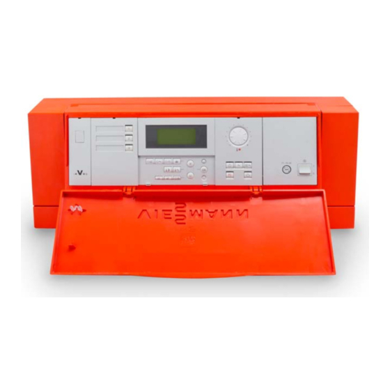
Vitotronic 050
Type HK3W and HK3S
Weather-compensated, digital heating circuit control units
VITOTRONIC 050
Vitotronic 050, Type HK3W
Vitotronic 050, Type HK3S
5592 395 GB
4/2001
File in service document ring binder
Related Manuals for Viessmann VIVOTRONIC 050 HK3W
Summary of Contents for Viessmann VIVOTRONIC 050 HK3W
-
Page 1
Operating Instructions for the system user Vitotronic 050 Type HK3W and HK3S Weather-compensated, digital heating circuit control units VITOTRONIC 050 Vitotronic 050, Type HK3W Vitotronic 050, Type HK3S 5592 395 GB 4/2001 File in service document ring binder… -
Page 2: For Your Safety
Introductory information For your safety Please follow these safety instructions closely to avoid the risk of injury to persons and damage to property. If you smell gas Work on the equipment Boiler room conditions H Don’t smoke! Don’t use naked Installation, initial start-up, mainte H Do not use a room in which the air flames or cause sparks (e.g.
-
Page 3: Table Of Contents
Index Page Useful tips Introductory information For your safety ………………..Instructions in brief Ready for operation The main controls…
-
Page 4: Ready For Operation The Main Controls
Ready for operation The main controls You can carry out all the settings for the heating circuits centrally on the con trol unit and on the built-in programming unit. If your system is equipped with remote controls, you can also use the remote controls for the settings.
-
Page 5: Overview Of Controls And Indicators
Ready for operation Overview of controls and indicators Heating circuit selector buttons (page 7) Display window Hinged cover of programming unit Normal room temperature (page
 Heating programs (page 7) Energy saving mode (page 10) Party mode (page 9) Only on Vitotronic 050, Type HK3W: Heating system on/off switch (page 11) Fuse Operating status indicator (green)
 -
Page 6
Ready for operation Overview of controls and indicators (continued) Other display symbols Adjustment of the display window Flashing data (These are not displayed continu contrast Data flashing in the display window ously, but appear according to sys Open the hinged cover on the pro means that new settings can be en tem type and operating status) gramming unit, press d and, at the… -
Page 7: Selecting The Heating Program (Winter, Summer)
Ready for operation Select the heating circuit before every setting and scanning operation With only one heating circuit connected, you can start making all settings straightaway. On heating systems with two or three heating circuits, the corresponding heating circuit must be selected before carrying out each setting and scan ning operation.
-
Page 8
Ready for operation Changing the room temperature In the «Central heating and domestic hot water» heating program, central heat ing takes place with alternating «normal room temperature» and «reduced room temperature» according to the selected time program (see page 12). You can set the required room temperature as follows: To change the «normal room temperature»… -
Page 9
Using the comfort functions Setting the party mode Switch on the party mode when you require central heating and domestic hot water (if a DHW cylinder is installed) for a short time independently of the preset heating and time program. To activate the party mode 1. -
Page 10: Activating The Energy Saving Mode
Using the comfort functions Activating the energy saving mode The energy saving mode is only possible in the «rw» heating program. Switch on the energy saving mode when you require particularly economic central heating for a short time. In the energy saving mode the preset room temperature is automatically lowered.
-
Page 11: Shutting Down The Control Unit/Heating Circuits
Switching on and off Starting up the control unit/heating circuits The initial start-up and matching of the heating circuits to local conditions and the structural characteristics of the building must be carried out by your heating contractor. 1. Switch on the mains voltage, e.g. at the separate fuse or a mains electrical isolator switch.
-
Page 12: Settings Time Programs
Settings Time programs You can select time programs for central heating, domestic hot water (if a DHW cylinder is installed) and the DHW circulation pump (if installed). The DHW circulation pump ensures that hot water is available at the taps when required.
-
Page 13
Settings Time programs (continued) Changing and scanning the time program for central heating 11. Open the hinged cover on the programming unit. 12. Press the heating circuit selector button; the button is lit. 13. A Press A; the «Central If you wish to exit the time program heating time program»… -
Page 14
Settings Time programs (continued) Changing and scanning the time program for central heating (continued) To exit the setting mode at any time 1. A Press A; the display changes to «Exit? Yes». 2. d Press d to confirm; the basic display appears. To scan the time phases Follow the procedure described on page 13, but without using the a… -
Page 15
Settings Time programs (continued) Changing and scanning the time program for domestic hot water heating and the DHW circulation pump The automatic mode is selected in the time program for domestic hot water and the DHW circulation pump, i.e. domestic hot water heating takes place in parallel with the central heating time program, but starts 30 minutes earlier. -
Page 16
Settings Time programs (continued) Changing and scanning the time program for domestic hot water heating and the DHW circulation pump (continued) 16. a/b Press a/b until one of Please note: the following displays ap If different time phases are set for pears in the display win individual days of the week and dow:… -
Page 17
Settings Time programs (continued) Changing and scanning the time program for domestic hot water heating and the DHW circulation pump (continued) To exit the setting mode at any time 1. B Press B; the display changes to «Exit? Yes». 2. d Press d to confirm;… -
Page 18: Changing The Domestic Hot Water Temperature
Settings Time programs (continued) Changing and scanning the time program for domestic hot water heating and the DHW circulation pump (continued) Domestic hot water heating on a one-off basis outside the programmed time phases 1. Press the heating circuit selector button;…
-
Page 19: Setting The Energy Saving Mode For The Holiday Period
Settings Setting the energy saving mode for the holiday period If you want to set your heating circuit to the minimum energy consumption, e.g. while you are away on holiday, choose the holiday program or the standby mode (see «Selecting the heating program» on page 7). Holiday program Example To protect house plants during…
-
Page 20
Settings Setting the energy saving mode for the holiday period (continued) 1. Open the cover on the program ming unit. 2. H Press H; the «Holiday If you want to erase the holiday program» display appears program during the setting pro in the display window. -
Page 21: Resetting The Time And Date
Other settings Resetting the time and date The time and date are preset in the factory and can be changed manually. There is no need manual resetting in conjunction with a radio clock receiver (accessory). 1. Open the hinged cover on the pro gramming unit.
-
Page 22: Changing The Heating Pattern
Other settings Changing the heating pattern The heating pattern is influenced by the outdoor temperature and the settings of the «shift» and «slope» of the «heating curve». Heating curves represent the relationship between the outdoor temperature and the flow temperature. Put simply: The lower the outdoor temperature, the higher the flow temperature.
-
Page 23
Other settings Changing the heating pattern (continued) Changing the heating pattern by adjusting the heating curve 1. Open the hinged cover on the pro gramming unit. 2. Press the heating circuit selector button; the button is lit. 3. I Press I for «Slope» As a guide, please refer to the Slope table headed «Change heating… -
Page 24
Other settings Changing the heating pattern (continued) Change heating pattern if … Action Example … the accommodation is too cold at Adjust the slope of the cold time of year heating curve upwards by Slope one increment … the accommodation is too warm Adjust the slope of the at cold time of year heating curve downwards… -
Page 25
Scanning Scanning temperatures and operating status information You can scan various current temperatures and operating status information depending on the system components connected and the settings made. H User no. in conjunction with other control units H Holiday program with dates of if entered departure and return H Holiday program active… -
Page 26: Remote Control
Troubleshooting guide Special displays It is not possible to make settings on Example Remote control the control unit, only on the remote «Normal room temperature» on control. the «ts» selector knob can only be set on the remote control. This display flashes when you have Example Without function pressed a button to which no func…
-
Page 27: Diagnosis And Correction
Troubleshooting guide Diagnosis and correction If a fault occurs, it will be indicated in the display window and by the flashing DFault red fault lamp (see page 5). Using the scan facility, you can read off the fault code yourself and inform ºC your heating contractor accordingly.
-
Page 28
Troubleshooting guide Diagnosis and correction (continued) Fault Cause Remedy The heating circuit remains cold Heating system switch «8» on the Switch on control unit turned to OFF Mains voltage is switched off Switch on mains voltage Fuse in the domestic power circuit Inform heating contractor or in the control unit has blown or tripped… -
Page 29: Servicing/Cleaning Instructions And Note On Disposal Of Unwanted Equipment
Servicing instructions/How to save energy Servicing/cleaning instructions and note on disposal of unwanted equipment Servicing Cleaning Note on disposal of unwanted equip Servicing of heating systems is re The equipment can be cleaned with ment quired under current heating system domestic cleaning agents available The unit contains an inbuilt, non-toxic regulations and standards (DIN 4755,…
-
Page 30: Alphabetical Index
Winter operation, 7 Work on the equipment, 2 Factory settings, 4, 5, 6, 7 Fault display, 5, 27 Reduced room temperature (night Viessmann Werke GmbH & Co Fault messages, 27 temperature), 5, 7, 8 D-35107 Allendorf Faults, 27 Remote control, 4, 26…
 Heating programs (page 7) Energy saving mode (page 10) Party mode (page 9) Only on Vitotronic 050, Type HK3W: Heating system on/off switch (page 11) Fuse Operating status indicator (green)
Specifications:
|
Accompanying Data:
Viessmann VIVOTRONIC 050 HK3W Control Unit PDF Operating Instructions Manual (Updated: Wednesday 16th of November 2022 11:03:53 PM)
Rating: 4.6 (rated by 99 users)
Compatible devices: SDIO, ViCare, EM-EA1 extension, VITOTRONIC SPS, EM-P1, PLC VITOCAL 350-HT PRO, VITOCONNECT OPTO2, Vitovolt 200.
Recommended Documentation:
Viessmann VIVOTRONIC 050 HK3W: Text of Operating Instructions Manual
(Ocr-Read Version Summary of Contents, UPD: 16 November 2022)
-
9, �…
-
2, �…
-
30, �…
-
27, …
-
8, �…
-
5, �…
-
11, �…
-
17, …
-
20, …
-
7, …
-
29, �…
-
18, …
-
1, …
-
4, …
Viessmann VIVOTRONIC 050 HK3W: Recommended Instructions
GC 18 G, SO Easy HDMI +, TVGO A03, ACT7580, ARCTIS A75238-GA


-
D-040L.IOM.ENG02 Installation, Operation & Maintenance COMBINATION AIR VALVE MODEL D-040L 1” The following is a step by step narrated description of the A.R.I. D-040L Combination Air Valve installation, operation and maintenance processes. The D-040L series Combination Air Valve has the features of both an air release valve and an air & vacu …
MODEL D-040L 1″ 11
-
Savant® Touch 8 inch Control Screen — White or Black (ITP-E8000x) Quick Reference Guide For Product Info ITP-E8000x | 009-1522-02 | 170816 45 Perseverance Way, Hyannis, MA 02601!Copyright © 2017 Savant Systems, LLC 1 of 2!Savant.com | 508.683.2500 Box Contents (1) Savant 8.0 inch In-Wall Touch Screen (1) Installation Kit (1) Installation Template (1) Mounting Bracket (For s …
ITP-E8000 Series 2
-
tGW-700 series tiny Modbus Gateway — QuickStart (Feb/2016) ICP DAS USA, Inc. | www.icpdas-usa.com | 1-310-517-9888 | 24309 Narbonne Ave. Suite 200. Lomita, CA 90717 1 Quick Start Guide for tGW-715 1 What’s in the Shipping Package? The package includes the following items: tGW-700 Series Quick Start (This Guide)Software CDDC Connec …
tGW-715 7
-
ANLEITUNG FÜR EINBAU, BEDIENUNG UND WARTUNGSchaltgerät/Elektrokomponenten für KESSELFäkalien-Rückstauautomat Staufix FKA Standard/ComfortStand 2015/04Name/Unterschrift Datum OrtSach-Nr. 010-845Stempel FachbetriebInstallationder Anlage wurde durchgeführt von Ihrem Fachbetrieb:Inbetriebnahme EinweisungTechn. Änderungen vorbehaltenSchaltgerät Spritzwasser-gesch …
Staufix FKA Standard 144
-
BedienungsanleitungOperation ManualInnovation, die bewegt!5066Zündmodul für GaslaternenIgnition module for gas lamps5067Leuchtstoffröhren-SimulatorFluorescent lamp-simulator50665067Auch zum Betrieb mit LED-Leuchten!For connection with LED lights!AC~DC=1. Wichtige Hinweise / Important information ……………………………………………….. 22. Einleitung / Introduction ….. …
5066 4
-
Sea Tel, Inc. 4030 Nelson Avenue Concord, CA 94520 Tel: (925) 798-7979 Fax: (925) 798-7986 Email: [email protected] Web: : www.cobham.comseatel Sea Tel EuropeUnit 1, Orion Industrial Centre Wide Lane, Swaythling Southampton, UK S0 18 2HJ Tel: 44 (0)23 80 671155 Fax: 44 (0)23 80 671166 Email: [email protected] Web: www.cobham.comseatel Sea Tel Inc doing business …
DAC-2202 115
-
For Technical Support: www.panduit.com/resources/install_maintain.aspINSTALLATION INSTRUCTIONS © Panduit Corp. 2017PN600APage 1 of 4TX6A Shielded Modular PlugT568B & T568APart Number: SPS6X88-C• Thread boot and collar onto cable.• Remove 1.5″ of the outer jacket using wire stripping tool (CJAST).• Cut foil flush with cable jacket. If cable is braided, form b …
T568B 4
-
CS2RS Series RS485 Closed Loop Stepper Drive User Manual1User ManualCS2RS SeriesRS485 Closed Loop Stepper DriveRevision 1.0For Models of CS2RS-D503, CS2RS-D507, CS2RS-D1008©2019 Leadshine Technology Co., Ltd.Address: Floor 11, Block A3, Nanshan iPark, Xueyuan Avenue 1001, Shenzhen, Guangdong, 518055, ChinaTel: (86)755-26409254 Fax: (86)755-26402718Web: www.leadshine.com Sales: [email protected] …
CS2RS Series 51
-
Centrale téléphonieZ.A de la Croix saint-MathieuB.P.10022 — 28320 GALLARDON — FRANCETel. (33) 02 37 33 69 69 — Fax. (33) 02 37 31 02 17 67e-mail : [email protected] : 7/2/11ALTEA 3 — BUSUSER’S GUIDEUSER’S GUIDEAltea 3 BUS CONTROL UNITOZ NOT GB 0906and ALTEA 3 — BUS — DSoption alarm report …
ALTEA 3-BUS 24
-
3110-02-001 Rev.: 12k2TAMPERGNDINxALARM1k1TAMPERGNDINxALARM1k1CIB+CIB -+12VGNDIM2-80BХарактеристика / CharacteristicsИНСТРУКЦИЯ ПО ПРИМЕНЕНИЮ / MANUAL INSRUCTIONSRUПеред установкой и введением в эксплуатацию устройства внимательно ознакомьтесь с инструкцией …
IM2-80B 2