Руководство в электронном виде по устройству, ремонту, техобслуживанию, диагностике неисправностей и устранению проблем в двигателе Nissan VQ37VHR.
Силовой агрегат VQ37VHR устанавливается на ряд моделей Ниссан, Инфинити и Мицубиши. Это бензиновый шестицилиндровый V-образный DOHC мотор объемом 3.7 литра с системой VVEL.
Мануал по ремонту мотора VQ37VHR приводит описание ремонта двигателя (в том числе и капитального), проблем, меток ГРМ, кодов неисправностей DTC, а также схемы электрооборудования.
Двигатель VQ37VHR устанавливается на следующие автомобили:
INFINITI G37 2008 — 2013
INFINITI Q50 2014 — 2015
INFINITI Q60 2014 — 2016
INFINITI M37 2011 — 2013
INFINITI Q70 2014 — 2018
INFINITI EX37 2009 — 2013
INFINITI QX50 2014 — 2017
INFINITI FX37 2009 — 2013
INFINITI QX70 2014 — 2017
NISSAN Skyline 2008 — н.в.
NISSAN Fuga 2009 — н.в.
NISSAN 370Z 2009 — н.в.
MITSUBISHI Proudia 2012 — н.в.
Язык инструкции: русский
Страниц всего: 132
VQ37VHR: руководство по ремонту скачать
Внимание! У Вас нет прав для просмотра скрытого текста.
Всем привет! Приготовьтесь, будет много букв!
Начнем. Должен был написать этот пост еще около полу года назад, но как-то руки не доходили. Все было сделано своими руками.
Когда брал машину, знал о проблеме падения давления в масляной системе из-за «выдутых пистолетов», спустя время решено было произвести замер этого самого давления. Результат был ожидаемый, но не самый приятный. ИТОГ: на горячую 0.2 бара, при норме 1-1.1 бар!
Машину сразу же поставил в гараж, слил масло. Были обнаружены золотые блестки и вкрапления в масле. НО, забегая вперед, напишу, что в итоге -ВСЕ ХОРОШО). Но, на тот момент, я был в трауре и приступил к разбору сердца своего Финика и самыми не спокойными мыслями.
Почитал людей, казалось чем-то не реальным, из возможных удобств только гараж, инструмент и яма.
Начинаем разбор, фото делал по мере возможности:
Полный размер
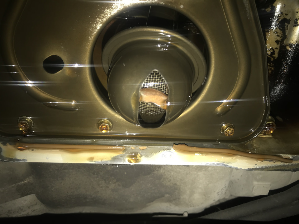
— Для начала, сливаем масло с ДВС и снимаем малый поддон, обнаруживаем в маслоприемнике куски
— Снимаем с верху весь декоративный пластик, открываем крышку антифриза и спускаемся обратно для его слива.
Полный размер
— После слива всего ОЖ приступаем к демонтажу патрубков ОЖ, бачков и так далее, снимаем все, что видит взор, это все будет мешать.
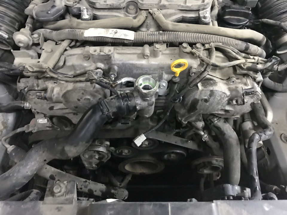
— Откручиваем трубку с интегрированной заливной горловиной, затем рывком тянем ее на себя, она сидит на уплотнителях, есть два варианта ее отсоединения, либо отсоединится сама горловина, а трубка останется, либо достанется горловина вместе с трубкой, разница не велика, для собственного успокоения будет не обходимо поменять оба уплотнителя этой трубки.
легко можно открутить только левую(по ходу авто)</b>, правая крышка подперта системой вспомогательных ремней и НИКАК нельзя ее достать, не открутив и демонтировав эту систему. Попутно, естественно, отсоединяем многочисленные разъемы.»>
— Снимаем ремень, ролики, натяжитель вспомогательных агрегатов, откручиваем насос ГУРа и оттягиваем его к телевизору, где закрепляем(забегая вперед, скажу, что жидкость ГУР слить тоже нужно).
-Только после полного снятия с лобовины всего навесного, открывается возможность демонтажа правой крышки фазовращателя, до этого момента откручивать ее смысла не имеет.
-Далее, снимаем генератор и откручиваем компрессор кондиционера, выпускать фреон НЕ НУЖНО, все отгибается и доступ ко всему есть, читал посты, что люди выпускали фреон, оказалось-ЗРЯ. Отдельное внимание заслуживают болты компрессора, чтобы открутить их нужны щупальца и очень много мата. Ключи туда практически никакие не лезут, а головка болта может за просто «слизаться», нужно учитывать это и четко работать инструментом не поддаваясь эмоциям, а то останется компрессор на своем месте на вечно(по крайней мере до снятия мотора целиком).
-Отдельное внимание заслуживает шкив коленвала, который закручен с исполинской силой, и чтоб открутить его,
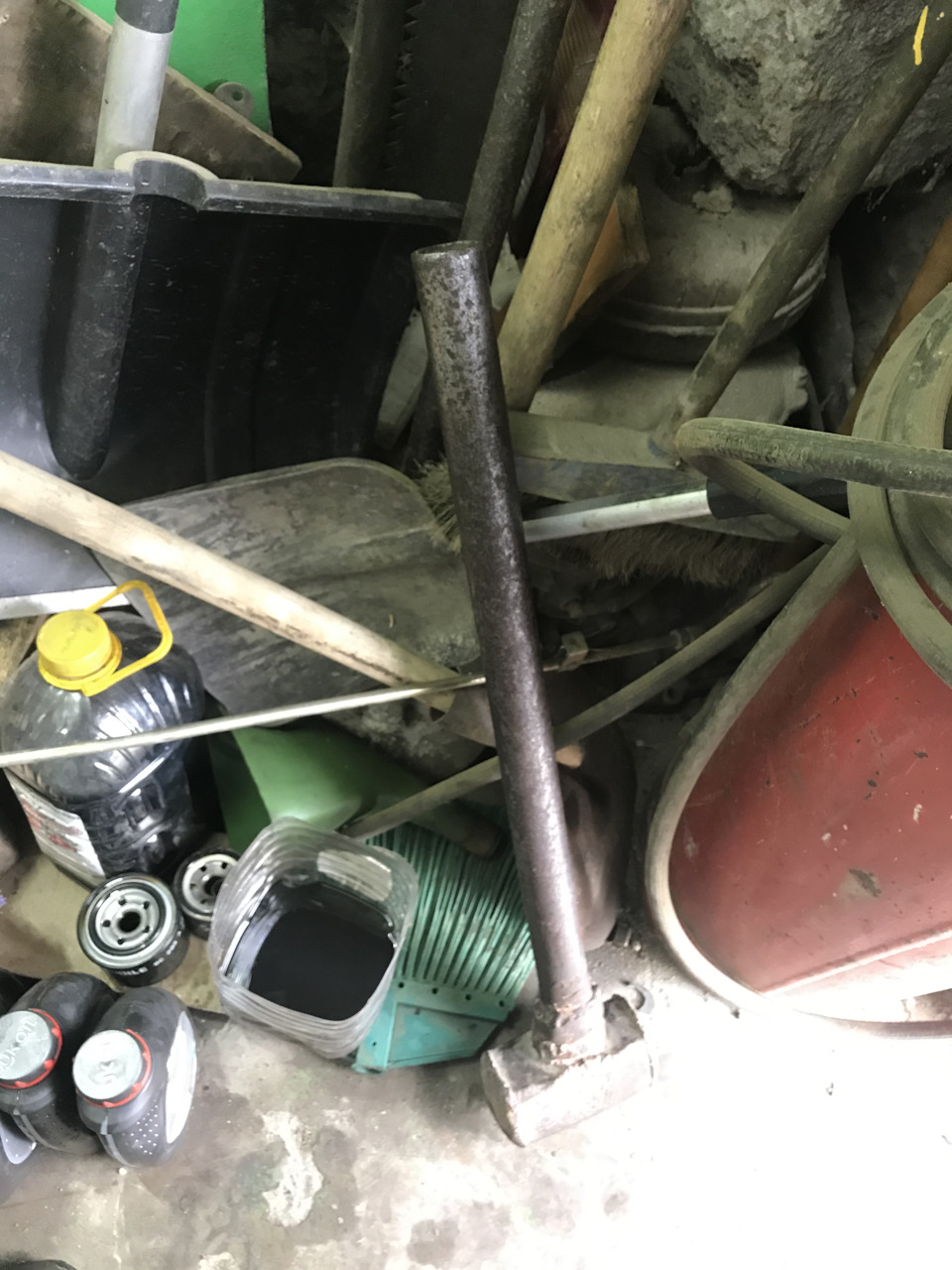
Полный размер
мне потребовался рычаг в виде трубы с наваренной кувалдой
и богатырская силушка, сорвал я его тоже далеко не с первого раза, тяжкое занятие.
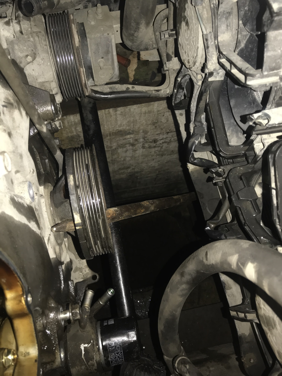
Полный размер
Так же заклинил шкив ломом и упер в край ямы.
-Наконец добрались до лицевой плиты мотора, откручиваем овер дохера болтов, читал, что нужно их помечать, помечал их цветом, т.к. болты разные, но по итогу никакого смысла в этом не увидел, посоветовал бы от нее просто сложить болты в отдельную коробку. При чем, есть пара болтов, которые откручиваются через масляный поддон.
—
Пред нами предстал виновник торжества,
Пред нами предстал виновник торжества,
но работа далекооо не закончена»>
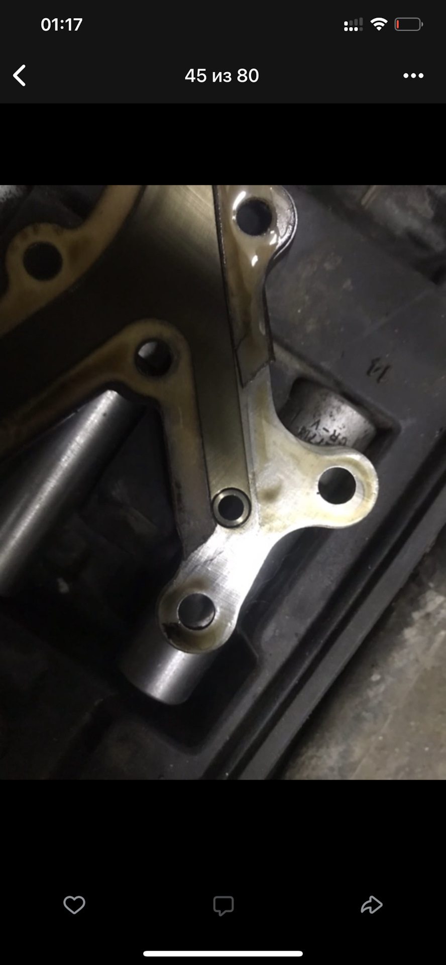
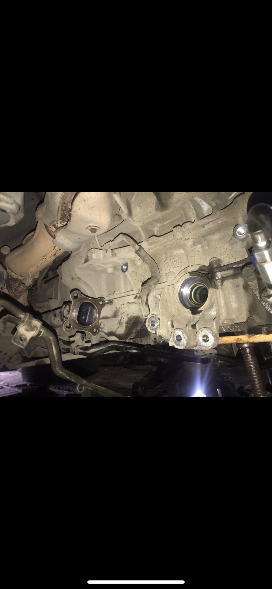
— Домкратим морду целиком, снимаем колеса, ставим финик на пни(не всегда ему на красивых тапках стоять), начинаем снимать привода(срываем центральный болт, откручиваем нижнюю шаровую и выбиваем ее, затем уводим в сторону стойку, не забываем открутить рулевой наконечник и выбить его тоже, достаем привод из ступицы.) У редуктора привод держится на болтах, откручиваем их, предварительно слив масло с редуктора, достаем привод с обеих сторон.).
-Фишка снятия приводов в том, что верхний(большой поддон) НЕВОЗМОЖНО снять на полноприводной версии без демонтажа приводов и самого редуктора, поверьте, я пытался, фишка в том, что редуктор входит в поддон и держит его мертво.
-На данном этапе стоит задача демонтажа подрамника, самая тяжелая работа, именно по весу, нижние рычаги его мы освободили,
держат его 4 гайки и 2 или 4 болта
, но перед этим необходимо снять усилитель, который находится снизу бампера(примерно в форме буквы П, если я правильно помню, там еще какой то пластик есть, держится этот усилитель на 4 болтах, если его не снять, то подрамник повиснет и просто не опустится. Так же не забываем про рулевой кардан, его мы ослабляем и по мере опускания подрамника делаем пометку о местоположении кардана относительно шлицевой.
В добавок, не забываем о подушке мотора, которая тоже должна быть демонтирована.
После всех манипуляций начинаем откручивать равномерно все болты, подпирая подрамник домкратами и опускаем его так же равномерно. Так же, попутно при открытии доступа отцепляем все возможные шланги и провода от подрамника, чтоб не порвать. Внимательно следим за трубками рейки, одну нужно открутить почти сразу, т.к. она жесткая, вторую трубку можно открутить уже на земле, т.к. бОльшая ее часть гибкая. Сняли-вытащили подальше, чтобы не мешал.
-Соответственно демонтируем редуктор, откручиваем от него кардан(предварительно пометив сочленение хвостовика редуктора и кардана, чтобы поставить как и было), откручиваем все возможные болты, которые его держат, если не изменяет память, их около 7, так же не забываем снять шланг сапуна с макушки редуктора,
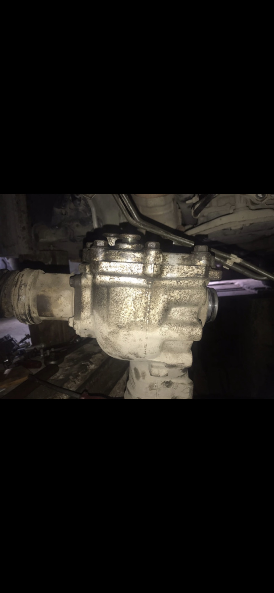
после чего отводим редуктор в бок, вытаскивая его из поддона и убираем восвояси, чтоб не мешал.
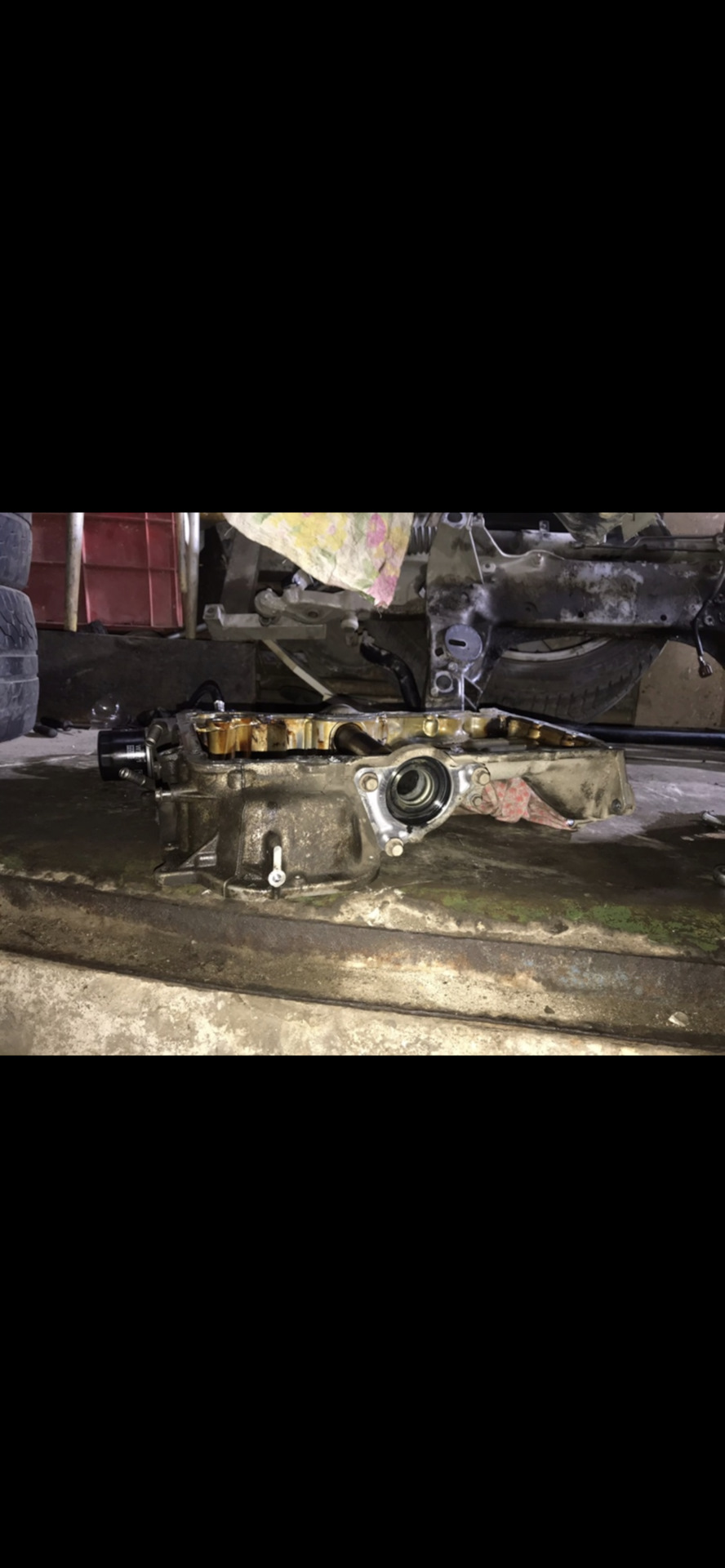
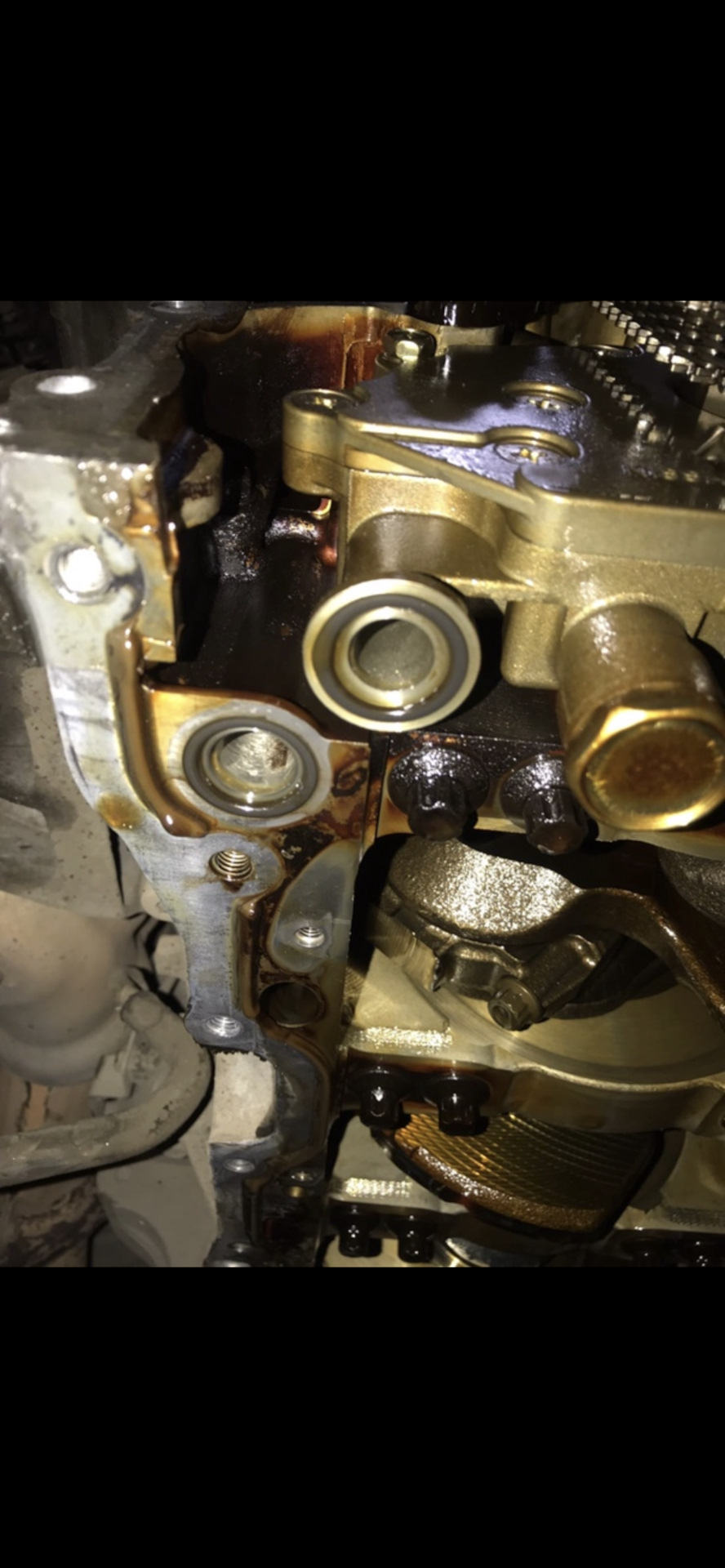
-Далее откручиваем опять овер дохера болтов от верхнего поддона
, плюс там есть два тайных болта (у венца маховика),
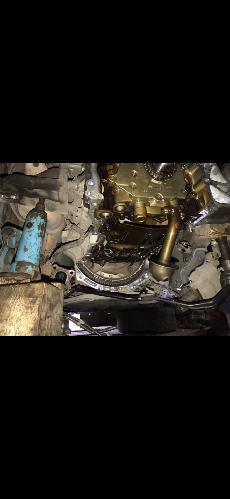
после чего большой поддон легко демонтируется и взору открывается коленвал, шатуны и <img src=
«>
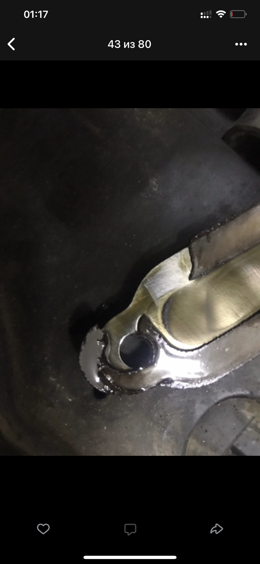
-Далее все как в обычном авто, начинаем демонтировать крышки шатунов и
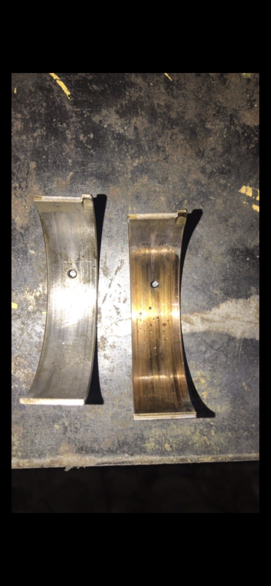
доставать вкладыши, внешний вид которых был удручающий
, НО, я успел, пострадали только и только они, шейки коленвала были в отличном состоянии! Проделываем операцию замены со всеми 6 шатунами, обратную сборку производим со специальной монтажной смазкой(к слову, у меня такого в городе никто не знал, пришлось попотеть чтобы ее добыть)…
Factory Workshop Manual
Make
Infiniti
Model
G37 Coupe
Engine and year
V6-3.7L (VQ37VHR) (2008)
Please navigate through the PDF using the options
provided by OnlyManuals.com on the sidebar.
This manual was submitted by
Anonymous
Date
1st January 2018
Infiniti G37 Coupe Workshop Manual (V6-3.7L (VQ37VHR) (2008))
G37 Coupe V6-3.7L (VQ37VHR) (2008) > Infiniti Workshop Manuals > Relays and Modules > Relays and Modules Accessories and Optional Equipment > Navigation Module > Component Information > Technical Service Bulletins >
Navigation System — HDD Navigation Map Data Updating
Technical Service Bulletin # 08-021B Date: 091211
Navigation System — HDD Navigation Map Data Updating
Classification: EL08-002B
Reference: ITB08-021B
Date: December 11, 2009
UPGRADING HDD NAVIGATION MAP DATA
APPLIED VEHICLES
SERVICE INFORMATION
The navigation system (if equipped) in the Applied Vehicles listed above has a HDD (Hard Disc
Drive) map data storage system. This bulletin contains the information and instructions for
updating/upgrading the map data with a new version.
An instruction manual for HDD Navigation Updates is also available in ASIST under
INFORMATION TOOL BOX > HD Navi. Tools > Hard Drive Navigation Update Manual.
When new versions of map data are available, customers can purchase a Coupon Number via the
internet or by calling NAVTEQ. The customer then takes their vehicle, along with the Coupon
Number, to an Infiniti dealer to have the new version of map data installed into their navigation
system. The time needed to install the new map data into the vehicle is approximately 30 minutes.
The HDD update kit (P/N: J-48850) is required to perform map data updates. One HDD update kit
was shipped to each dealer as part of the essential tool program. Refer to «HDD update kit (P/N:
J-48850-A) for kit details.
Make sure to use the newest Map Data Master Discs (2 disc set) when performing HDD Navigation
Map Data Upgrades.
^ As of the publication date of this bulletin, the newest disc set is 2010MY (09-10).
^ Additional Master Discs are available from TECH-MATE.
Information
IMPORTANT:
^ Make sure your ASIST has been freshly synchronized and all C-III upgrades have been installed.
(The HDD (Hard Disc Drive) rewrite software is
delivered via ASIST synchronization).
^ Before the map upgrade can be performed, a Coupon Number must be purchased from the web
or by calling NAVTEQ.
^ Before starting, it is recommend that you check the Current Map Version in the vehicle using the
vehicle’s navigation screen to make sure an upgrade
is needed (Refer to «Checking Current Map Version in the Vehicle Using the Vehicle’s Navigation
Screen»).
Overview of the HDD (Hard Disc Drive) Map Upgrade
Infiniti G37 Coupe Workshop Manual (V6-3.7L (VQ37VHR) (2008))
G37 Coupe V6-3.7L (VQ37VHR) (2008) > Infiniti Workshop Manuals > Relays and Modules > Relays and Modules Accessories and Optional Equipment > Navigation Module > Component Information > Technical Service Bulletins >
Navigation System — HDD Navigation Map Data Updating > Page 8
This procedure is divided into 7 sections. Complete each section in the order shown above.
Section 1 — Installing Updated MAP Into Consult-III
SECTION 1: INSTALLING THE UPDATE MAP INTO THE C-III
^ Once the newest version is installed into the C-III computer it can be used to upgrade many HDD
navigation systems. It is not necessary to install the
updated map each time you perform a map data upgrade.
^ If the newest map data is already installed in your C-III computer, you can skip to Section 2.
1. Connect the C-III DVD drive to the C-III computer with the USB cable.
2. Turn ON the C-III computer.
3. Open / start ASIST.
Infiniti G37 Coupe Workshop Manual (V6-3.7L (VQ37VHR) (2008))
G37 Coupe V6-3.7L (VQ37VHR) (2008) > Infiniti Workshop Manuals > Relays and Modules > Relays and Modules Accessories and Optional Equipment > Navigation Module > Component Information > Technical Service Bulletins >
Navigation System — HDD Navigation Map Data Updating > Page 9
4. Select Information Tool Box and HD Navi. Tools.
5. Select Install Map Update
Infiniti G37 Coupe Workshop Manual (V6-3.7L (VQ37VHR) (2008))
G37 Coupe V6-3.7L (VQ37VHR) (2008) > Infiniti Workshop Manuals > Relays and Modules > Relays and Modules Accessories and Optional Equipment > Navigation Module > Component Information > Technical Service Bulletins >
Navigation System — HDD Navigation Map Data Updating > Page 10
6. Select Installing updated map
7. Insert the Map Data Master Disc 1 into the C-III DVD drive.
8. Confirm the correct name of the DVD drive is displayed (see Figure 1-5).
^ «E» is likely the correct name for the DVD drive.
^ The DVD drive name may be different depending on the drive configuration of your C-III
computer.
9. Select START
^ Installation of the update map will start and a progress screen will display.
^ Installation will take several minutes.
^ At about 35% this message will display:
Infiniti G37 Coupe Workshop Manual (V6-3.7L (VQ37VHR) (2008))
G37 Coupe V6-3.7L (VQ37VHR) (2008) > Infiniti Workshop Manuals > Relays and Modules > Relays and Modules Accessories and Optional Equipment > Navigation Module > Component Information > Technical Service Bulletins >
Navigation System — HDD Navigation Map Data Updating > Page 11
^ When you get the above message, remove Disc 1; install Disc 2; then select YES.
^ When installation is complete the screen shown in Figure 1-8 will display.
10. Select OK
Infiniti G37 Coupe Workshop Manual (V6-3.7L (VQ37VHR) (2008))
G37 Coupe V6-3.7L (VQ37VHR) (2008) > Infiniti Workshop Manuals > Relays and Modules > Relays and Modules Accessories and Optional Equipment > Navigation Module > Component Information > Technical Service Bulletins >
Navigation System — HDD Navigation Map Data Updating > Page 12
11. Select EXIT
12. Remove Disc 2 from the DVD drive.
13. Select the Safely Remove Hardware icon on the «system tray» which is displayed in the bottom
right of the C-III computer screen.
^ You may need to click on the «expand arrow» to expand the icon selections.
14. Select Safely remove USB Mass Storage Device — Drive (E:)
^ The drive name will likely be E, but may be different depending on the drive configuration of your
C-III computer.
Infiniti G37 Coupe Workshop Manual (V6-3.7L (VQ37VHR) (2008))
G37 Coupe V6-3.7L (VQ37VHR) (2008) > Infiniti Workshop Manuals > Relays and Modules > Relays and Modules Accessories and Optional Equipment > Navigation Module > Component Information > Technical Service Bulletins >
Navigation System — HDD Navigation Map Data Updating > Page 13
15. Disconnect the C-III DVD drive from the C-III computer.
Section 2 — Connecting C-III to Hdd Navigation System
SECTION 2: CONNECTING C-III TO THE HDD NAVIGATION SYSTEM
^ All navigation components must be installed in the vehicle and connected correctly.
^ Make sure the vehicle battery is charged and connected.
^ Do not touch the CF (Compact Flash) adapter with wet hands.
CAUTION:
^ Do not turn the ignition ON when the C-III computer is connected to the navigation system with
the CF (Compact Flash) adapter.
^ Obey the following instructions; otherwise the CF Adapter, CF card slot, or navigation system
may be damaged.
1. Make sure the ignition is OFF.
2. Close any applications that are running on the C-III computer.
^ If the C-III computer is OFF, leave it OFF for now.
3. Connect USB cable to the C-III computer.
^ Make sure connector is fully inserted.
Infiniti G37 Coupe Workshop Manual (V6-3.7L (VQ37VHR) (2008))
G37 Coupe V6-3.7L (VQ37VHR) (2008) > Infiniti Workshop Manuals > Relays and Modules > Relays and Modules Accessories and Optional Equipment > Navigation Module > Component Information > Technical Service Bulletins >
Navigation System — HDD Navigation Map Data Updating > Page 14
4. Connect the other end of the USB cable to the CF (Compact Flash) adapter.
^ Make sure connector is fully inserted.
5. Carefully insert the CF adapter into the CF card slot of the vehicle audio/navigation system.
^ Label side UP.
^ Insert it all the way (firmly), to its stop.
Section 3 — Generating Certification Number
SECTION 3: GENERATING THE CERTIFICATION NUMBER
^ The Certification Number is different for each HDD (Hard Disc Drive) navigation system. Make
sure you are connected with the CF adaptor to the
system (vehicle) that you will be updating.
1. Turn ON the C-III computer.
2. Open / start ASIST.
Infiniti G37 Coupe Workshop Manual (V6-3.7L (VQ37VHR) (2008))
G37 Coupe V6-3.7L (VQ37VHR) (2008) > Infiniti Workshop Manuals > Relays and Modules > Relays and Modules Accessories and Optional Equipment > Navigation Module > Component Information > Technical Service Bulletins >
Navigation System — HDD Navigation Map Data Updating > Page 15
3. Select Information Tool Box and HD Navi. Tools.
4. Select Install Map Update
Infiniti G37 Coupe Workshop Manual (V6-3.7L (VQ37VHR) (2008))
G37 Coupe V6-3.7L (VQ37VHR) (2008) > Infiniti Workshop Manuals > Relays and Modules > Relays and Modules Accessories and Optional Equipment > Navigation Module > Component Information > Technical Service Bulletins >
Navigation System — HDD Navigation Map Data Updating > Page 16
5. Select Generation and confirmation of Certification number.
NOTE:
If the HDD Rewrite application was open/running when you connected to the navigation system
(plugged in the CF adapter), the navigation system may not be recognized and you may get an
error message. In this case, exit/close ASIST, then start it again (reopen it).
6. Click START
Infiniti G37 Coupe Workshop Manual (V6-3.7L (VQ37VHR) (2008))
G37 Coupe V6-3.7L (VQ37VHR) (2008) > Infiniti Workshop Manuals > Relays and Modules > Relays and Modules Accessories and Optional Equipment > Navigation Module > Component Information > Technical Service Bulletins >
Navigation System — HDD Navigation Map Data Updating > Page 17
NOTE:
^ If you get the message shown in Figure 3-5:
^ The map data installed in your C-III computer is the same or older than the map data in the
vehicle. The map update may not be needed.
a. Skip to Section 6 (disconnect C-III from the vehicle navigation system).
b. Check the map version in the vehicle (Refer to «Checking Current Map Version in the Vehicle
Using the vehicle’s Navigation Screen»).
7. Write down the Certification Number.
8. Select OK
Section 4 — Acquiring the Install Key
SECTION 4: ACQUIRING THE INSTALL KEY
^ Before starting this section, you need:
> A Coupon Number (purchased from NAVTEQ via the internet or by calling NAVTEQ.
> A Certification No. (generated from the vehicle HDD navigation unit in Section 3).
^ Your C-III computer must be connected to the Internet for this Section.
NOTE:
This section can also be done at your desktop ASIST or any computer with an Internet connection.
The internet address is https://www.nissan-mapupdate.com/cgi-bin/EN/N/HLPS0200.cgi
^ To access the license server to acquire an Install Key (Install Code), your Internet browser must
be set to accept cookies.
^ Once you have acquired the Install Key from the license server, cancellation and reissue of the
Install Key is not allowed.
^ The acquired Install Key is valid for only three days from the date of issue.
^ You can retry the upgrade operation by using the same Install Key at any time during the three
day period, but it cannot be used after the three day
period has expired.
^ If you forgot the Install Key during the three day period, you can obtain the same Key by
performing this section again. The key is still only valid for 3
Infiniti G37 Coupe Workshop Manual (V6-3.7L (VQ37VHR) (2008))
G37 Coupe V6-3.7L (VQ37VHR) (2008) > Infiniti Workshop Manuals > Relays and Modules > Relays and Modules Accessories and Optional Equipment > Navigation Module > Component Information > Technical Service Bulletins >
Navigation System — HDD Navigation Map Data Updating > Page 18
days from the original date of issue.
1. Select Information Tool Box and HD Navi. Tools.
2. Select Obtain Install Key #
Infiniti G37 Coupe Workshop Manual (V6-3.7L (VQ37VHR) (2008))
G37 Coupe V6-3.7L (VQ37VHR) (2008) > Infiniti Workshop Manuals > Relays and Modules > Relays and Modules Accessories and Optional Equipment > Navigation Module > Component Information > Technical Service Bulletins >
Navigation System — HDD Navigation Map Data Updating > Page 19
3. Enter UserID and Password.
4. Select Login
5. Enter the following numbers correctly (see Figure 4-4):
Infiniti G37 Coupe Workshop Manual (V6-3.7L (VQ37VHR) (2008))
G37 Coupe V6-3.7L (VQ37VHR) (2008) > Infiniti Workshop Manuals > Relays and Modules > Relays and Modules Accessories and Optional Equipment > Navigation Module > Component Information > Technical Service Bulletins >
Navigation System — HDD Navigation Map Data Updating > Page 20
^ Coupon No. (Coupon No. purchased from NAVTEQ)
^ Today’s Date
^ Certification No. (number generated from vehicle HDD navigation unit in Section 3)
6. Select CONTINUE
7. On the next screen (Confirmation of Install Key Request), confirm all the numbers you entered
are correct. (see Figure 4-5).
8. Select ISSUE
Infiniti G37 Coupe Workshop Manual (V6-3.7L (VQ37VHR) (2008))
G37 Coupe V6-3.7L (VQ37VHR) (2008) > Infiniti Workshop Manuals > Relays and Modules > Relays and Modules Accessories and Optional Equipment > Navigation Module > Component Information > Technical Service Bulletins >
Navigation System — HDD Navigation Map Data Updating > Page 21
9. Select PRINT to print the screen, or write down the Install Key exactly.
10. After printing the screen or writing down the Install Key, select COMPLETED.
11. Close the internet window.
Section 5 — Upgrading Map Data In Hdd Navigation System
SECTION 5: UPGRADING THE MAP DATA IN THE HDD NAVIGATION SYSTEM
^ Make sure to perform this operation on the same HDD navigation unit (vehicle) from which you
generated the Certification Number.
^ Upgrading the map data cannot be performed by using an Install Key that was acquired by using
a Certification Number generated from a different
HDD navigation system.
^ Make sure to use the same C-III that was used to generate the Certification Number.
1. Connect the C-III computer power cord (A.C. adapter or vehicle D.C. adapter).
^ Updating the map data will take a few minutes. Connecting the power cord will ensure the C-III
computer maintains power during the update.
^ Vehicle ignition must remain OFF.
Infiniti G37 Coupe Workshop Manual (V6-3.7L (VQ37VHR) (2008))
G37 Coupe V6-3.7L (VQ37VHR) (2008) > Infiniti Workshop Manuals > Relays and Modules > Relays and Modules Accessories and Optional Equipment > Navigation Module > Component Information > Technical Service Bulletins >
Navigation System — HDD Navigation Map Data Updating > Page 22
2. Select Information Tool Box and HD Navi. Tools.
3. Select Install Map Update
Infiniti G37 Coupe Workshop Manual (V6-3.7L (VQ37VHR) (2008))
G37 Coupe V6-3.7L (VQ37VHR) (2008) > Infiniti Workshop Manuals > Relays and Modules > Relays and Modules Accessories and Optional Equipment > Navigation Module > Component Information > Technical Service Bulletins >
Navigation System — HDD Navigation Map Data Updating > Page 23
4. Select Map update
5. Select NEXT
Infiniti G37 Coupe Workshop Manual (V6-3.7L (VQ37VHR) (2008))
G37 Coupe V6-3.7L (VQ37VHR) (2008) > Infiniti Workshop Manuals > Relays and Modules > Relays and Modules Accessories and Optional Equipment > Navigation Module > Component Information > Technical Service Bulletins >
Navigation System — HDD Navigation Map Data Updating > Page 24
6. Carefully enter the Install Key.
7. Select NEXT
8. Confirm the version number of «New version of map data» is higher than «Current version of map
data».
9. Select START
Infiniti G37 Coupe Workshop Manual (V6-3.7L (VQ37VHR) (2008))
G37 Coupe V6-3.7L (VQ37VHR) (2008) > Infiniti Workshop Manuals > Relays and Modules > Relays and Modules Accessories and Optional Equipment > Navigation Module > Component Information > Technical Service Bulletins >
Navigation System — HDD Navigation Map Data Updating > Page 25
^ Map update will begin and a progress bar will be displayed as shown in Figure 5-7.
^ When update is complete the screen in Figure 5-8 will display.
10. Select OK
NOTE:
If the update does not complete correctly, do the following:
a. Perform Section 6: Disconnecting the C-III and CF Adaptor.
b. Make sure the vehicle battery is sufficiently charged.
c. Perform Section 2 again: Connecting C-III to the HDD Navigation System.
d. Perform Section 5 again: Upgrading the Map Data in the HDD Navigation System.
Section 6 — Disconnecting the C-III/CF (Copmpact Flash) Adapter
SECTION 6: DISCONNECTING C-III and CF (Compact Flash) ADAPTER.
NOTE:
Infiniti G37 Coupe Workshop Manual (V6-3.7L (VQ37VHR) (2008))
G37 Coupe V6-3.7L (VQ37VHR) (2008) > Infiniti Workshop Manuals > Relays and Modules > Relays and Modules Accessories and Optional Equipment > Navigation Module > Component Information > Technical Service Bulletins >
Navigation System — HDD Navigation Map Data Updating > Page 26
Do not touch the CF (Compact Flash) adapter with wet hands.
1. Select EXIT
2 Select the Safely Remove Hardware icon on the «system tray» which is displayed in the bottom
right of the C-III computer screen.
^ You may need to click on the «expand arrow» to expand the icon selections.
3. Select Safely remove USB Mass Storage Device
Infiniti G37 Coupe Workshop Manual (V6-3.7L (VQ37VHR) (2008))
G37 Coupe V6-3.7L (VQ37VHR) (2008) > Infiniti Workshop Manuals > Relays and Modules > Relays and Modules Accessories and Optional Equipment > Navigation Module > Component Information > Technical Service Bulletins >
Navigation System — HDD Navigation Map Data Updating > Page 27
4. After the message «Safe to Remove Hardware» is displayed, disconnect the USB cable from the
C-III computer.
5. Push the Eject button at the right of the CF card slot and carefully remove the CF adapter.
NOTE:
When not in use, store the CF adapter in its original plastic bag.
Section 7 — Verifing Upgrade Results
SECTION 7: VERIFYING THE UPGRADE RESULT
^ When the map data upgrade operation is complete, confirm that the HDD navigation system is
operating correctly.
^ Make sure the CF adapter is disconnected from the navigation system before performing the
following steps.
1. Turn the ignition ON.
^ If the ignition is already ON, turn it OFF and then back ON.
2. The Program Loading screen as shown in Figure 7-1 will display.
^ This process may take only a few seconds to complete or it may take a few minutes.
Infiniti G37 Coupe Workshop Manual (V6-3.7L (VQ37VHR) (2008))
G37 Coupe V6-3.7L (VQ37VHR) (2008) > Infiniti Workshop Manuals > Relays and Modules > Relays and Modules Accessories and Optional Equipment > Navigation Module > Component Information > Technical Service Bulletins >
Navigation System — HDD Navigation Map Data Updating > Page 28
3. Select MAP, then ENTER.
^ Make sure the navigation map displays and the system functions correctly.
NOTE:
You can confirm the new map version in the vehicle using the navigation screen; refer to «Checking
Current map Version in the vehicle using the Vehicle’s navigation Screen».
^ If the fail-safe screen is displayed as shown in Figure 7-3, the map data upgrade failed.
^ Turn the ignition OFF; return to the beginning of the Service Procedure and follow all steps again
exactly as written.
Checking Current MAP Version In Vehicle Using Navigation Screen
Checking Current Map Version in the Vehicle Using the Vehicle’s Navigation Screen
^ Make sure the CF (Compact Flash) adapter is disconnected from the navigation system before
performing the following steps.
1. Turn the Ignition to ON or ACC, and turn ON the navigation system.
Infiniti G37 Coupe Workshop Manual (V6-3.7L (VQ37VHR) (2008))
G37 Coupe V6-3.7L (VQ37VHR) (2008) > Infiniti Workshop Manuals > Relays and Modules > Relays and Modules Accessories and Optional Equipment > Navigation Module > Component Information > Technical Service Bulletins >
Navigation System — HDD Navigation Map Data Updating > Page 29
2. Select INFO
3. Use the arrows and enter buttons on the Infiniti Controller to select Navigation Version.
^ The navigation / map version displays as shown in Figure 8-3.
HDD Update Kit (P/N: J-48850-A)
HDD update kit (P/N: J-48850)
Infiniti G37 Coupe Workshop Manual (V6-3.7L (VQ37VHR) (2008))
G37 Coupe V6-3.7L (VQ37VHR) (2008) > Infiniti Workshop Manuals > Relays and Modules > Relays and Modules Accessories and Optional Equipment > Navigation Module > Component Information > Technical Service Bulletins >
Navigation System — HDD Navigation Map Data Updating > Page 30
Kit Contents:
A. HDD Rewrite software (obsolete now available via ASIST synchronization)
B. 07-08 HDD Data Upgrade Master Disc 1 & 2 (superseded by 2010MY (09-10) discs).
C. CF (Compact Flash) Adapter
D. USB cable
^ New kits can be purchased from TECH-MATE.
Infiniti G37 Coupe Workshop Manual (V6-3.7L (VQ37VHR) (2008))
G37 Coupe V6-3.7L (VQ37VHR) (2008) > Infiniti Workshop Manuals > Relays and Modules > Relays and Modules Accessories and Optional Equipment > Navigation Module > Component Information > Technical Service Bulletins > Page
31
Navigation Module: Service and Repair
ON-VEHICLE REPAIR
PRESET SWITCH
DISASSEMBLY
VTL-23 Exploded View
Removal and Installation
REMOVAL
Refer to «Removal and Installation» (BASE AUDIO WITHOUT NAVIGATION), «Removal and
Installation» (BOSE AUDIO WITHOUT NAVIGATION), «Removal and Installation» (BOSE AUDIO
WITH NAVIGATION).
INSTALLATION
Installation is basically the reverse order of removal.
Infiniti G37 Coupe Workshop Manual (V6-3.7L (VQ37VHR) (2008))
G37 Coupe V6-3.7L (VQ37VHR) (2008) > Infiniti Workshop Manuals > Relays and Modules > Relays and Modules Accessories and Optional Equipment > Parking Assist Control Module > Component Information > Locations > Rear View
Monitor System
Infiniti G37 Coupe Workshop Manual (V6-3.7L (VQ37VHR) (2008))
G37 Coupe V6-3.7L (VQ37VHR) (2008) > Infiniti Workshop Manuals > Relays and Modules > Relays and Modules Accessories and Optional Equipment > Parking Assist Control Module > Component Information > Locations > Rear View
Monitor System > Page 36
Infiniti G37 Coupe Workshop Manual (V6-3.7L (VQ37VHR) (2008))
G37 Coupe V6-3.7L (VQ37VHR) (2008) > Infiniti Workshop Manuals > Relays and Modules > Relays and Modules Accessories and Optional Equipment > Parking Assist Control Module > Component Information > Locations > Rear View
Monitor System > Page 37
Infiniti G37 Coupe Workshop Manual (V6-3.7L (VQ37VHR) (2008))
G37 Coupe V6-3.7L (VQ37VHR) (2008) > Infiniti Workshop Manuals > Relays and Modules > Relays and Modules Accessories and Optional Equipment > Parking Assist Control Module > Component Information > Locations > Rear View
Monitor System > Page 38
Infiniti G37 Coupe Workshop Manual (V6-3.7L (VQ37VHR) (2008))
G37 Coupe V6-3.7L (VQ37VHR) (2008) > Infiniti Workshop Manuals > Relays and Modules > Relays and Modules Accessories and Optional Equipment > Parking Assist Control Module > Component Information > Locations > Page 39
Parking Assist Control Module: Adjustments
Adjustment
ADJUSTMENT
There may be a misalignment of possible route line center position of rear view monitor after
removing camera control unit. Therefore, correct neutral position with the following procedure.
1. Steer the steering wheel to the left-most and right-most ends. 2. Drive vehicle at 30 km/h (18.6
MPH) min. speed at least 100 m (328.1 ft).
Infiniti G37 Coupe Workshop Manual (V6-3.7L (VQ37VHR) (2008))
G37 Coupe V6-3.7L (VQ37VHR) (2008) > Infiniti Workshop Manuals > Relays and Modules > Relays and Modules Accessories and Optional Equipment > Parking Assist Control Module > Component Information > Locations > Page 40
Parking Assist Control Module: Service and Repair
BOSE AUDIO WITH NAVIGATION
CAMERA CONTROL UNIT
Exploded View
AV-629 Exploded View
Removal and Installation
REMOVAL
1. Remove rear wheel house finisher (RH), and then remove camera control unit.
INSTALLATION
Install in the reverse order of removal.
Infiniti G37 Coupe Workshop Manual (V6-3.7L (VQ37VHR) (2008))
G37 Coupe V6-3.7L (VQ37VHR) (2008) > Infiniti Workshop Manuals > Relays and Modules > Relays and Modules — Body
and Frame > Memory Positioning Module > Component Information > Service and Repair
Memory Positioning Module: Service and Repair
AUTOMATIC DRIVE POSITIONER CONTROL UNIT
Removal and Installation
REMOVAL
CAUTION: When removing and installing, use shop cloths to protect parts from damage.
1. Remove battery negative terminal.
2. Remove instrument driver lower panel. 3. Remove screws (A). 4. Remove automatic drive
positioner control unit (1).
INSTALLATION
Install in reverse order of removal.
CAUTION: Be sure to clump the harness to the right place.
Infiniti G37 Coupe Workshop Manual (V6-3.7L (VQ37VHR) (2008))
G37 Coupe V6-3.7L (VQ37VHR) (2008) > Infiniti Workshop Manuals > Relays and Modules > Relays and Modules — Body
and Frame > Power Seat Control Module > Component Information > Service and Repair > Driver Seat Control Unit
Power Seat Control Module: Service and Repair Driver Seat Control Unit
DRIVER SEAT CONTROL UNIT
Removal and Installation
REMOVAL
CAUTION: When removing and installing, use shop cloths to protect parts from damage.
1. Remove driver seat (1). 2. Remove mounting bolts (A). 3. Remove driver seat control unit (2).
INSTALLATION
Install in the reverse order of removal.
CAUTION: Be sure to clump the harness to the right place.
NOTE: After installing the driver seat, perform additional service when replacing control unit. Refer
to See: Body and Frame/Seats/Testing and Inspection/Programming and Relearning
Infiniti G37 Coupe Workshop Manual (V6-3.7L (VQ37VHR) (2008))
G37 Coupe V6-3.7L (VQ37VHR) (2008) > Infiniti Workshop Manuals > Relays and Modules > Relays and Modules — Body
and Frame > Power Seat Control Module > Component Information > Service and Repair > Driver Seat Control Unit > Page
49
Power Seat Control Module: Service and Repair Passenger Seat Control Unit
PASSENGER SEAT CONTROL UNIT
Removal and Installation
REMOVAL
CAUTION: When removing and installing, use shop cloths to protect parts from damage.
NOTE: The same procedure is also performed for driver side.
INSTALLATION
Install in the reverse order of removal.
CAUTION: Be sure to clamp the harness to the right place.
NOTE: After installing the driver seat, perform additional service when replacing control unit. Refer
to See: Body and Frame/Seats/Testing and Inspection/Programming and Relearning
Infiniti G37 Coupe Workshop Manual (V6-3.7L (VQ37VHR) (2008))
G37 Coupe V6-3.7L (VQ37VHR) (2008) > Infiniti Workshop Manuals > Relays and Modules > Relays and Modules — Body
and Frame > Power Seat Relay > Component Information > Testing and Inspection > Reclining Relay
Power Seat Relay: Testing and Inspection Reclining Relay
Backward
RECLINING RELAY
BACKWARD
BACKWARD : Diagnosis Procedure
Step 1
Infiniti G37 Coupe Workshop Manual (V6-3.7L (VQ37VHR) (2008))
G37 Coupe V6-3.7L (VQ37VHR) (2008) > Infiniti Workshop Manuals > Relays and Modules > Relays and Modules — Body
and Frame > Power Seat Relay > Component Information > Testing and Inspection > Reclining Relay > Page 54
Step 2-4
Infiniti G37 Coupe Workshop Manual (V6-3.7L (VQ37VHR) (2008))
G37 Coupe V6-3.7L (VQ37VHR) (2008) > Infiniti Workshop Manuals > Relays and Modules > Relays and Modules — Body
and Frame > Power Seat Relay > Component Information > Testing and Inspection > Reclining Relay > Page 55
Step 5-7
BACKWARD : Component Inspection (Reclining Relay)
Step 1
BACKWARD : Component Inspection (Diode 2)
Infiniti G37 Coupe Workshop Manual (V6-3.7L (VQ37VHR) (2008))
G37 Coupe V6-3.7L (VQ37VHR) (2008) > Infiniti Workshop Manuals > Relays and Modules > Relays and Modules — Body
and Frame > Power Seat Relay > Component Information > Testing and Inspection > Reclining Relay > Page 56
Step 1
Step 1 (Continued)
Forward
RECLINING RELAY
FORWARD
FORWARD : Diagnosis Procedure
Infiniti G37 Coupe Workshop Manual (V6-3.7L (VQ37VHR) (2008))
G37 Coupe V6-3.7L (VQ37VHR) (2008) > Infiniti Workshop Manuals > Relays and Modules > Relays and Modules — Body
and Frame > Power Seat Relay > Component Information > Testing and Inspection > Reclining Relay > Page 57
Step 1-3
Infiniti G37 Coupe Workshop Manual (V6-3.7L (VQ37VHR) (2008))
G37 Coupe V6-3.7L (VQ37VHR) (2008) > Infiniti Workshop Manuals > Relays and Modules > Relays and Modules — Body
and Frame > Power Seat Relay > Component Information > Testing and Inspection > Reclining Relay > Page 58
Step 3 (Continued)-6
Step 7
Infiniti G37 Coupe Workshop Manual (V6-3.7L (VQ37VHR) (2008))
G37 Coupe V6-3.7L (VQ37VHR) (2008) > Infiniti Workshop Manuals > Relays and Modules > Relays and Modules — Body
and Frame > Power Seat Relay > Component Information > Testing and Inspection > Reclining Relay > Page 59
FORWARD : Component Inspection (Reclining Relay)
Step 1
FORWARD : Component Inspection (Diode 1)
Step 1
Infiniti G37 Coupe Workshop Manual (V6-3.7L (VQ37VHR) (2008))
G37 Coupe V6-3.7L (VQ37VHR) (2008) > Infiniti Workshop Manuals > Relays and Modules > Relays and Modules — Body
and Frame > Power Seat Relay > Component Information > Testing and Inspection > Reclining Relay > Page 60
Power Seat Relay: Testing and Inspection Sliding Relay
Backward
SLIDING RELAY
BACKWARD
BACKWARD : Diagnosis Procedure
Step 1-3
Infiniti G37 Coupe Workshop Manual (V6-3.7L (VQ37VHR) (2008))
G37 Coupe V6-3.7L (VQ37VHR) (2008) > Infiniti Workshop Manuals > Relays and Modules > Relays and Modules — Body
and Frame > Power Seat Relay > Component Information > Testing and Inspection > Reclining Relay > Page 61
Step 3 (Continued)-6
Infiniti G37 Coupe Workshop Manual (V6-3.7L (VQ37VHR) (2008))
G37 Coupe V6-3.7L (VQ37VHR) (2008) > Infiniti Workshop Manuals > Relays and Modules > Relays and Modules — Body
and Frame > Power Seat Relay > Component Information > Testing and Inspection > Reclining Relay > Page 62
Step 6 (Continued)-8
BACKWARD : Component Inspection (Sliding Relay)
Infiniti G37 Coupe Workshop Manual (V6-3.7L (VQ37VHR) (2008))
G37 Coupe V6-3.7L (VQ37VHR) (2008) > Infiniti Workshop Manuals > Relays and Modules > Relays and Modules — Body
and Frame > Power Seat Relay > Component Information > Testing and Inspection > Reclining Relay > Page 63
Step 1
Forward
SLIDING RELAY
FORWARD
FORWARD : Diagnosis Procedure
Infiniti G37 Coupe Workshop Manual (V6-3.7L (VQ37VHR) (2008))
G37 Coupe V6-3.7L (VQ37VHR) (2008) > Infiniti Workshop Manuals > Relays and Modules > Relays and Modules — Body
and Frame > Power Seat Relay > Component Information > Testing and Inspection > Reclining Relay > Page 64
Step 1-3
Infiniti G37 Coupe Workshop Manual (V6-3.7L (VQ37VHR) (2008))
G37 Coupe V6-3.7L (VQ37VHR) (2008) > Infiniti Workshop Manuals > Relays and Modules > Relays and Modules — Body
and Frame > Power Seat Relay > Component Information > Testing and Inspection > Reclining Relay > Page 65
Step 3 (Continued)-6
Infiniti G37 Coupe Workshop Manual (V6-3.7L (VQ37VHR) (2008))
G37 Coupe V6-3.7L (VQ37VHR) (2008) > Infiniti Workshop Manuals > Relays and Modules > Relays and Modules — Body
and Frame > Power Seat Relay > Component Information > Testing and Inspection > Reclining Relay > Page 66
Step 6 (Continued)-8
FORWARD : Component Inspection (Sliding Relay)
Infiniti G37 Coupe Workshop Manual (V6-3.7L (VQ37VHR) (2008))
G37 Coupe V6-3.7L (VQ37VHR) (2008) > Infiniti Workshop Manuals > Relays and Modules > Relays and Modules — Body
and Frame > Power Seat Relay > Component Information > Testing and Inspection > Reclining Relay > Page 67
Step 1
Infiniti G37 Coupe Workshop Manual (V6-3.7L (VQ37VHR) (2008))
G37 Coupe V6-3.7L (VQ37VHR) (2008) > Infiniti Workshop Manuals > Relays and Modules > Relays and Modules — Body
and Frame > Sunroof / Moonroof Module > Component Information > Testing and Inspection
Sunroof / Moonroof Module: Testing and Inspection
INSPECTION AND ADJUSTMENT
ADDITIONAL SERVICE WHEN REPLACING CONTROL UNIT
ADDITIONAL SERVICE WHEN REPLACING CONTROL UNIT : Description
MEMORY RESET PROCEDURE
1. Please observe the following instructions at confirming the sunroof operation.
NOTE: Do not disconnect the electronic power while the sunroof is operating or within 5 seconds
after the sunroof stops (to wipe-out the memory of lid position and operating friction.)
2. Initialization of system should be conducted after the following conditions.
— When the sunroof motor is changed.
— When the sunroof does not operate normally. (Incomplete initialization conditions)
ADDITIONAL SERVICE WHEN REPLACING CONTROL UNIT : Special Repair Requirement
INITIALIZATION PROCEDURE
If the sunroof does not close or open automatically, use the following procedure to return sunroof
operation to normal.
1. Press the tilt up switch and start the tilt up operation. 2. Release the tilt up switch once, press the
tilt up switch again, press and hold the switch until lid pops up. 3. The glass lid will more toward tilt
up direction and will be stopped mechanically, and then it will be automatically fully closed. (press
and hold the
switch during this operation)
4. Release the switch again, and press the tilt up switch within the first 10 seconds. (press and hold
the switch) 5. After 4 seconds, the glass lid will be automatically operated in sequence of tilt down,
slide open and slide close. 6. After the glass lid stops, release the switch 0.5 second later. (press
and hold the switch during this operation) 7. If slide switch operates normally, this initialization is
done.
ANTI-PINCH FUNCTION
1. Full open the sunroof. 2. Place a piece of wood near fully closed position. 3. Close the sunroof
completely with auto-slide close.
Check that sunroof lowers for approximately 150 mm (5.91in) or 2 seconds with out pinching a
piece of wood and stops.
CAUTION: Do not check with hands and other part of body because they may be pinched. Do not get pinched.
— Depending on environment and driving conditions, if a similar impact or lord is applied to the
sunroof it may lower.
— Check that auto-slide operates before inspection when system initialization is performed.
— Perform initial setting when auto-slide operation or anti-pinch function does not operate normally.
Infiniti G37 Coupe Workshop Manual (V6-3.7L (VQ37VHR) (2008))
G37 Coupe V6-3.7L (VQ37VHR) (2008) > Infiniti Workshop Manuals > Relays and Modules > Relays and Modules — Brakes
and Traction Control > Electronic Brake Control Module > Component Information > Technical Service Bulletins > Customer
Interest: > 09-007 > Jan > 09 > Brakes — DTC C1142/ABS, SLIP, VDC OFF Lamps ON
Electronic Brake Control Module: Customer Interest Brakes — DTC C1142/ABS, SLIP, VDC OFF
Lamps ON
Classification: BR08-007
Reference: ITB09-007
Date: January 30, 2009
ABS DTC C1142 STORED
APPLIED VEHICLES: 2007 — 2008 G35 Sedan (V36) 2007 G35 Coupe (CV35) 2009 G37 Sedan
(V36) 2008 — 2009 G37 Coupe (CV36) 2006 — 2009 M35/M45 (Y50)
IF YOU CONFIRM
DTC code C1142 is stored in the ABS system,
NOTE:
If code C1142 is stored, the ABS, SLIP, and VDC OFF lights will likely be ON.
ACTIONS
Follow the flow chart in the Service Procedure for diagnostic and repair steps.
NOTE:
Make sure the brake pedal and stop lamp switch adjustments are correct, and the stop lamp switch
and circuit are operating correctly before replacing the ABS Actuator and Electronic Control Unit.
IMPORTANT:
The purpose of «ACTIONS» (above) is to give you a quick idea of the work you will be performing.
You MUST closely follow the entire Service Procedure as it contains information that is essential to
successfully completing this repair.
PARTS INFORMATION
Infiniti G37 Coupe Workshop Manual (V6-3.7L (VQ37VHR) (2008))
G37 Coupe V6-3.7L (VQ37VHR) (2008) > Infiniti Workshop Manuals > Relays and Modules > Relays and Modules — Brakes
and Traction Control > Electronic Brake Control Module > Component Information > Technical Service Bulletins > Customer
Interest: > 09-007 > Jan > 09 > Brakes — DTC C1142/ABS, SLIP, VDC OFF Lamps ON > Page 80
CLAIMS INFORMATION
Infiniti G37 Coupe Workshop Manual (V6-3.7L (VQ37VHR) (2008))
G37 Coupe V6-3.7L (VQ37VHR) (2008) > Infiniti Workshop Manuals > Relays and Modules > Relays and Modules — Brakes
and Traction Control > Electronic Brake Control Module > Component Information > Technical Service Bulletins > Customer
Interest: > 09-007 > Jan > 09 > Brakes — DTC C1142/ABS, SLIP, VDC OFF Lamps ON > Page 81
Infiniti G37 Coupe Workshop Manual (V6-3.7L (VQ37VHR) (2008))
G37 Coupe V6-3.7L (VQ37VHR) (2008) > Infiniti Workshop Manuals > Relays and Modules > Relays and Modules — Brakes
and Traction Control > Electronic Brake Control Module > Component Information > Technical Service Bulletins > Customer
Interest: > 09-007 > Jan > 09 > Brakes — DTC C1142/ABS, SLIP, VDC OFF Lamps ON > Page 82
SERVICE PROCEDURE
Infiniti G37 Coupe Workshop Manual (V6-3.7L (VQ37VHR) (2008))
G37 Coupe V6-3.7L (VQ37VHR) (2008) > Infiniti Workshop Manuals > Relays and Modules > Relays and Modules — Brakes
and Traction Control > Electronic Brake Control Module > Component Information > Technical Service Bulletins > All
Technical Service Bulletins for Electronic Brake Control Module: > 10-074 > Dec > 10 > ABS/TCS — CAN Diagnostic
Information
Electronic Brake Control Module: All Technical Service Bulletins ABS/TCS — CAN Diagnostic
Information
Classification: BR10-012
Reference: ITB10-074
Date: December 15, 2010
ABS / VDC CAN DIAGNOSIS INFORMATION
APPLIED VEHICLES: All 2005 — 2011 Infiniti vehicles with ABS and/or VDC
SERVICE INFORMATION
When diagnosing a vehicle with an ABS or VDC / SLIP warning light on with DTCs stored in the
ABS / VDC actuator control unit perform DTC diagnosis first.
^ Do not replace the ABS / VDC actuator control unit without being supported by the DTC
diagnosis.
^ Do not erase DTCS before performing DTC diagnosis.
^ Always fully diagnose before performing any repairs.
When DTC U1000 (CAN COMM CIRCUIT) is the only DTC stored in the ABS / VDC actuator
control unit use the REPAIR FLOW CHART shown below. This will assist in proper diagnosis
results and repairs in addition to using diagnostic information in the Electronic Service Manual
(ESM).
^ If DTC U1000 is found stored in other systems refer to NTB10-066 and the applicable ESM.
^ If other DTCs are found stored in ABS / VDC along with U1000 follow the diagnosis steps for
those DTCs in the applicable ESM.
CLAIMS INFORMATION
Refer to the current Infiniti Warranty Flat Rate Manual and use the appropriate claims coding for
repairs performed.
Infiniti G37 Coupe Workshop Manual (V6-3.7L (VQ37VHR) (2008))
G37 Coupe V6-3.7L (VQ37VHR) (2008) > Infiniti Workshop Manuals > Relays and Modules > Relays and Modules — Brakes
and Traction Control > Electronic Brake Control Module > Component Information > Technical Service Bulletins > All
Technical Service Bulletins for Electronic Brake Control Module: > 10-074 > Dec > 10 > ABS/TCS — CAN Diagnostic
Information > Page 88
Infiniti G37 Coupe Workshop Manual (V6-3.7L (VQ37VHR) (2008))
G37 Coupe V6-3.7L (VQ37VHR) (2008) > Infiniti Workshop Manuals > Relays and Modules > Relays and Modules — Brakes
and Traction Control > Electronic Brake Control Module > Component Information > Technical Service Bulletins > All
Technical Service Bulletins for Electronic Brake Control Module: > 10-074 > Dec > 10 > ABS/TCS — CAN Diagnostic
Information > Page 89
Repair Flow Chart
Infiniti G37 Coupe Workshop Manual (V6-3.7L (VQ37VHR) (2008))
G37 Coupe V6-3.7L (VQ37VHR) (2008) > Infiniti Workshop Manuals > Relays and Modules > Relays and Modules — Brakes
and Traction Control > Electronic Brake Control Module > Component Information > Technical Service Bulletins > All
Technical Service Bulletins for Electronic Brake Control Module: > 09-007 > Jan > 09 > Brakes — DTC C1142/ABS, SLIP,
VDC OFF Lamps ON
Electronic Brake Control Module: All Technical Service Bulletins Brakes — DTC C1142/ABS, SLIP,
VDC OFF Lamps ON
Classification: BR08-007
Reference: ITB09-007
Date: January 30, 2009
ABS DTC C1142 STORED
APPLIED VEHICLES: 2007 — 2008 G35 Sedan (V36) 2007 G35 Coupe (CV35) 2009 G37 Sedan
(V36) 2008 — 2009 G37 Coupe (CV36) 2006 — 2009 M35/M45 (Y50)
IF YOU CONFIRM
DTC code C1142 is stored in the ABS system,
NOTE:
If code C1142 is stored, the ABS, SLIP, and VDC OFF lights will likely be ON.
ACTIONS
Follow the flow chart in the Service Procedure for diagnostic and repair steps.
NOTE:
Make sure the brake pedal and stop lamp switch adjustments are correct, and the stop lamp switch
and circuit are operating correctly before replacing the ABS Actuator and Electronic Control Unit.
IMPORTANT:
The purpose of «ACTIONS» (above) is to give you a quick idea of the work you will be performing.
You MUST closely follow the entire Service Procedure as it contains information that is essential to
successfully completing this repair.
PARTS INFORMATION
Infiniti G37 Coupe Workshop Manual (V6-3.7L (VQ37VHR) (2008))
G37 Coupe V6-3.7L (VQ37VHR) (2008) > Infiniti Workshop Manuals > Relays and Modules > Relays and Modules — Brakes
and Traction Control > Electronic Brake Control Module > Component Information > Technical Service Bulletins > All
Technical Service Bulletins for Electronic Brake Control Module: > 09-007 > Jan > 09 > Brakes — DTC C1142/ABS, SLIP,
VDC OFF Lamps ON > Page 94
CLAIMS INFORMATION
Infiniti G37 Coupe Workshop Manual (V6-3.7L (VQ37VHR) (2008))
G37 Coupe V6-3.7L (VQ37VHR) (2008) > Infiniti Workshop Manuals > Relays and Modules > Relays and Modules — Brakes
and Traction Control > Electronic Brake Control Module > Component Information > Technical Service Bulletins > All
Technical Service Bulletins for Electronic Brake Control Module: > 09-007 > Jan > 09 > Brakes — DTC C1142/ABS, SLIP,
VDC OFF Lamps ON > Page 95
Infiniti G37 Coupe Workshop Manual (V6-3.7L (VQ37VHR) (2008))
G37 Coupe V6-3.7L (VQ37VHR) (2008) > Infiniti Workshop Manuals > Relays and Modules > Relays and Modules — Brakes
and Traction Control > Electronic Brake Control Module > Component Information > Technical Service Bulletins > All
Technical Service Bulletins for Electronic Brake Control Module: > 09-007 > Jan > 09 > Brakes — DTC C1142/ABS, SLIP,
VDC OFF Lamps ON > Page 96
SERVICE PROCEDURE
Infiniti G37 Coupe Workshop Manual (V6-3.7L (VQ37VHR) (2008))
G37 Coupe V6-3.7L (VQ37VHR) (2008) > Infiniti Workshop Manuals > Relays and Modules > Relays and Modules — Brakes
and Traction Control > Electronic Brake Control Module > Component Information > Technical Service Bulletins > All Other
Service Bulletins for Electronic Brake Control Module: > 10-074 > Dec > 10 > ABS/TCS — CAN Diagnostic Information
Electronic Brake Control Module: All Technical Service Bulletins ABS/TCS — CAN Diagnostic
Information
Classification: BR10-012
Reference: ITB10-074
Date: December 15, 2010
ABS / VDC CAN DIAGNOSIS INFORMATION
APPLIED VEHICLES: All 2005 — 2011 Infiniti vehicles with ABS and/or VDC
SERVICE INFORMATION
When diagnosing a vehicle with an ABS or VDC / SLIP warning light on with DTCs stored in the
ABS / VDC actuator control unit perform DTC diagnosis first.
^ Do not replace the ABS / VDC actuator control unit without being supported by the DTC
diagnosis.
^ Do not erase DTCS before performing DTC diagnosis.
^ Always fully diagnose before performing any repairs.
When DTC U1000 (CAN COMM CIRCUIT) is the only DTC stored in the ABS / VDC actuator
control unit use the REPAIR FLOW CHART shown below. This will assist in proper diagnosis
results and repairs in addition to using diagnostic information in the Electronic Service Manual
(ESM).
^ If DTC U1000 is found stored in other systems refer to NTB10-066 and the applicable ESM.
^ If other DTCs are found stored in ABS / VDC along with U1000 follow the diagnosis steps for
those DTCs in the applicable ESM.
CLAIMS INFORMATION
Refer to the current Infiniti Warranty Flat Rate Manual and use the appropriate claims coding for
repairs performed.
Infiniti G37 Coupe Workshop Manual (V6-3.7L (VQ37VHR) (2008))
G37 Coupe V6-3.7L (VQ37VHR) (2008) > Infiniti Workshop Manuals > Relays and Modules > Relays and Modules — Brakes
and Traction Control > Electronic Brake Control Module > Component Information > Technical Service Bulletins > All Other
Service Bulletins for Electronic Brake Control Module: > 10-074 > Dec > 10 > ABS/TCS — CAN Diagnostic Information >
Page 102
Infiniti G37 Coupe Workshop Manual (V6-3.7L (VQ37VHR) (2008))
G37 Coupe V6-3.7L (VQ37VHR) (2008) > Infiniti Workshop Manuals > Relays and Modules > Relays and Modules — Brakes
and Traction Control > Electronic Brake Control Module > Component Information > Technical Service Bulletins > All Other
Service Bulletins for Electronic Brake Control Module: > 10-074 > Dec > 10 > ABS/TCS — CAN Diagnostic Information >
Page 103
Repair Flow Chart
Infiniti G37 Coupe Workshop Manual (V6-3.7L (VQ37VHR) (2008))
G37 Coupe V6-3.7L (VQ37VHR) (2008) > Infiniti Workshop Manuals > Relays and Modules > Relays and Modules — Brakes
and Traction Control > Electronic Brake Control Module > Component Information > Locations > For USA
Electronic Brake Control Module: Locations For USA
Infiniti G37 Coupe Workshop Manual (V6-3.7L (VQ37VHR) (2008))
G37 Coupe V6-3.7L (VQ37VHR) (2008) > Infiniti Workshop Manuals > Relays and Modules > Relays and Modules — Brakes
and Traction Control > Electronic Brake Control Module > Component Information > Locations > For USA > Page 106
Infiniti G37 Coupe Workshop Manual (V6-3.7L (VQ37VHR) (2008))
G37 Coupe V6-3.7L (VQ37VHR) (2008) > Infiniti Workshop Manuals > Relays and Modules > Relays and Modules — Brakes
and Traction Control > Electronic Brake Control Module > Component Information > Locations > Page 107
Electronic Brake Control Module: Testing and Inspection
VALUES ON THE DIAGNOSIS TOOL
CAUTION: The display shows the control unit calculation data, so a normal value might be
displayed even in the event the output circuit (harness) is open or short-circuited.
CONSULT-III MONITOR ITEM (Part 1)
Infiniti G37 Coupe Workshop Manual (V6-3.7L (VQ37VHR) (2008))
G37 Coupe V6-3.7L (VQ37VHR) (2008) > Infiniti Workshop Manuals > Relays and Modules > Relays and Modules — Brakes
and Traction Control > Electronic Brake Control Module > Component Information > Locations > Page 108
CONSULT-III MONITOR ITEM (Part 2)
Infiniti G37 Coupe Workshop Manual (V6-3.7L (VQ37VHR) (2008))
G37 Coupe V6-3.7L (VQ37VHR) (2008) > Infiniti Workshop Manuals > Relays and Modules > Relays and Modules — Brakes
and Traction Control > Electronic Brake Control Module > Component Information > Locations > Page 109
CONSULT-III MONITOR ITEM (Part 3)
Infiniti G37 Coupe Workshop Manual (V6-3.7L (VQ37VHR) (2008))
G37 Coupe V6-3.7L (VQ37VHR) (2008) > Infiniti Workshop Manuals > Relays and Modules > Relays and Modules — Brakes
and Traction Control > Electronic Brake Control Module > Component Information > Locations > Page 110
CONSULT-III MONITOR ITEM (Part 4)
Infiniti G37 Coupe Workshop Manual (V6-3.7L (VQ37VHR) (2008))
G37 Coupe V6-3.7L (VQ37VHR) (2008) > Infiniti Workshop Manuals > Relays and Modules > Relays and Modules — Brakes
and Traction Control > Electronic Brake Control Module > Component Information > Locations > Page 111
Electronic Brake Control Module: Service and Repair
ADDITIONAL SERVICE WHEN REPLACING CONTROL UNIT
ADDITIONAL SERVICE WHEN REPLACING CONTROL UNIT: Description
After replacing the ABS actuator and electric unit (control unit), perform the neutral position
adjustment for the steering angle sensor.
ADDITIONAL SERVICE WHEN REPLACING CONTROL UNIT: Special Repair Requirement
1.PERFORM THE NEUTRAL POSITION ADJUSTMENT FOR THE STEERING ANGLE SENSOR
Perform the neutral position adjustment for the steering angle sensor.
>> Refer to BRC-8, «ADJUSTMENT OF STEERING ANGLE SENSOR NEUTRAL POSITION:
Special Repair Requirement». See: Brakes and Traction Control/Antilock Brakes / Traction Control
Systems/Steering Angle Sensor/Adjustments
Infiniti G37 Coupe Workshop Manual (V6-3.7L (VQ37VHR) (2008))
G37 Coupe V6-3.7L (VQ37VHR) (2008) > Infiniti Workshop Manuals > Relays and Modules > Relays and Modules — Brakes
and Traction Control > Traction Control Module > Component Information > Technical Service Bulletins > ABS/TCS — CAN
Diagnostic Information
Traction Control Module: Technical Service Bulletins ABS/TCS — CAN Diagnostic Information
Classification: BR10-012
Reference: ITB10-074
Date: December 15, 2010
ABS / VDC CAN DIAGNOSIS INFORMATION
APPLIED VEHICLES: All 2005 — 2011 Infiniti vehicles with ABS and/or VDC
SERVICE INFORMATION
When diagnosing a vehicle with an ABS or VDC / SLIP warning light on with DTCs stored in the
ABS / VDC actuator control unit perform DTC diagnosis first.
^ Do not replace the ABS / VDC actuator control unit without being supported by the DTC
diagnosis.
^ Do not erase DTCS before performing DTC diagnosis.
^ Always fully diagnose before performing any repairs.
When DTC U1000 (CAN COMM CIRCUIT) is the only DTC stored in the ABS / VDC actuator
control unit use the REPAIR FLOW CHART shown below. This will assist in proper diagnosis
results and repairs in addition to using diagnostic information in the Electronic Service Manual
(ESM).
^ If DTC U1000 is found stored in other systems refer to NTB10-066 and the applicable ESM.
^ If other DTCs are found stored in ABS / VDC along with U1000 follow the diagnosis steps for
those DTCs in the applicable ESM.
CLAIMS INFORMATION
Refer to the current Infiniti Warranty Flat Rate Manual and use the appropriate claims coding for
repairs performed.
Infiniti G37 Coupe Workshop Manual (V6-3.7L (VQ37VHR) (2008))
G37 Coupe V6-3.7L (VQ37VHR) (2008) > Infiniti Workshop Manuals > Relays and Modules > Relays and Modules — Brakes
and Traction Control > Traction Control Module > Component Information > Technical Service Bulletins > ABS/TCS — CAN
Diagnostic Information > Page 116
Infiniti G37 Coupe Workshop Manual (V6-3.7L (VQ37VHR) (2008))
G37 Coupe V6-3.7L (VQ37VHR) (2008) > Infiniti Workshop Manuals > Relays and Modules > Relays and Modules — Brakes
and Traction Control > Traction Control Module > Component Information > Technical Service Bulletins > ABS/TCS — CAN
Diagnostic Information > Page 117
Repair Flow Chart
Infiniti G37 Coupe Workshop Manual (V6-3.7L (VQ37VHR) (2008))
G37 Coupe V6-3.7L (VQ37VHR) (2008) > Infiniti Workshop Manuals > Relays and Modules > Relays and Modules — Brakes
and Traction Control > Traction Control Module > Component Information > Locations > VDC
Traction Control Module: Locations VDC
Infiniti G37 Coupe Workshop Manual (V6-3.7L (VQ37VHR) (2008))
G37 Coupe V6-3.7L (VQ37VHR) (2008) > Infiniti Workshop Manuals > Relays and Modules > Relays and Modules — Brakes
and Traction Control > Traction Control Module > Component Information > Locations > VDC > Page 120
Infiniti G37 Coupe Workshop Manual (V6-3.7L (VQ37VHR) (2008))
G37 Coupe V6-3.7L (VQ37VHR) (2008) > Infiniti Workshop Manuals > Relays and Modules > Relays and Modules — Brakes
and Traction Control > Traction Control Module > Component Information > Locations > VDC > Page 121
Traction Control Module: Locations TCS
Infiniti G37 Coupe Workshop Manual (V6-3.7L (VQ37VHR) (2008))
G37 Coupe V6-3.7L (VQ37VHR) (2008) > Infiniti Workshop Manuals > Relays and Modules > Relays and Modules — Brakes
and Traction Control > Traction Control Module > Component Information > Locations > VDC > Page 122
Infiniti G37 Coupe Workshop Manual (V6-3.7L (VQ37VHR) (2008))
G37 Coupe V6-3.7L (VQ37VHR) (2008) > Infiniti Workshop Manuals > Relays and Modules > Relays and Modules — Brakes
and Traction Control > Traction Control Module > Component Information > Locations > VDC > Page 123
Infiniti G37 Coupe Workshop Manual (V6-3.7L (VQ37VHR) (2008))
G37 Coupe V6-3.7L (VQ37VHR) (2008) > Infiniti Workshop Manuals > Relays and Modules > Relays and Modules — Brakes
and Traction Control > Traction Control Module > Component Information > Locations > VDC > Page 124
Traction Control Module: Locations ABS
Infiniti G37 Coupe Workshop Manual (V6-3.7L (VQ37VHR) (2008))
G37 Coupe V6-3.7L (VQ37VHR) (2008) > Infiniti Workshop Manuals > Relays and Modules > Relays and Modules — Brakes
and Traction Control > Traction Control Module > Component Information > Locations > VDC > Page 125
Infiniti G37 Coupe Workshop Manual (V6-3.7L (VQ37VHR) (2008))
G37 Coupe V6-3.7L (VQ37VHR) (2008) > Infiniti Workshop Manuals > Relays and Modules > Relays and Modules — Brakes
and Traction Control > Traction Control Module > Component Information > Locations > VDC > Page 126
Traction Control Module: Locations EBD
Infiniti G37 Coupe Workshop Manual (V6-3.7L (VQ37VHR) (2008))
G37 Coupe V6-3.7L (VQ37VHR) (2008) > Infiniti Workshop Manuals > Relays and Modules > Relays and Modules — Brakes
and Traction Control > Traction Control Module > Component Information > Locations > VDC > Page 127
Infiniti G37 Coupe Workshop Manual (V6-3.7L (VQ37VHR) (2008))
G37 Coupe V6-3.7L (VQ37VHR) (2008) > Infiniti Workshop Manuals > Relays and Modules > Relays and Modules — Brakes
and Traction Control > Traction Control Module > Component Information > Locations > Page 128
Traction Control Module: Service and Repair
ABS ACTUATOR AND ELECTRIC UNIT (CONTROL UNIT)
BRC-102 Exploded View
Removal and Installation
REMOVAL
CAUTION: ^
Before servicing, disconnect the battery cable from negative terminal.
^ To remove brake tube, use a flare nut wrench to prevent flare nuts and brake tube from being
damaged. To install, use flare nut crowfoot and torque wrench.
^ Do not apply excessive impact to ABS actuator and electric unit (control unit), such as dropping it.
^ Do not remove and install actuator by holding harness.
^ After work is completed, bleed air from brake tube.
1. Remove cowl top cover. 2. Disconnect ABS actuator and electric unit (control unit) connector. 3.
Loosen brake tube flare nuts, then remove brake tubes from ABS actuator and electric unit (control
unit). 4. Remove tire (front LH side). 5. Remove fender protector (rear): (front LH side). 6. Remove
ABS actuator and electric unit (control unit) bracket mounting nut. 7. Remove ABS actuator and
electric unit (control unit) from vehicle.
INSTALLATION
Note the following, and install in the reverse order of removal.
Infiniti G37 Coupe Workshop Manual (V6-3.7L (VQ37VHR) (2008))
G37 Coupe V6-3.7L (VQ37VHR) (2008) > Infiniti Workshop Manuals > Relays and Modules > Relays and Modules — Brakes
and Traction Control > Traction Control Module > Component Information > Locations > Page 129
CAUTION: ^
Before servicing, disconnect the battery cable from negative terminal.
^ To remove brake tube, use a flare nut wrench to prevent flare nuts and brake tube from being
damaged. To install, use flare nut crowfoot and torque wrench.
^ Do not apply excessive impact to ABS actuator and electric unit (control unit), such as dropping it.
^ Do not remove and install actuator by holding harness.
^ After work is completed, bleed air from brake tube.
^ After installing harness connector in the ABS actuator and electric unit (control unit), make sure
connector is securely locked.
^ When replacing ABS actuator and electric unit (control unit), make sure to adjust neutral position
of steering angle sensor. Refer to BRC-8, «ADJUSTMENT OF STEERING ANGLE SENSOR
NEUTRAL POSITION: Description». See: Brakes and Traction Control/Antilock Brakes / Traction
Control Systems/Steering Angle Sensor/Adjustments
Infiniti G37 Coupe Workshop Manual (V6-3.7L (VQ37VHR) (2008))
G37 Coupe V6-3.7L (VQ37VHR) (2008) > Infiniti Workshop Manuals > Relays and Modules > Relays and Modules — Cruise
Control > Cruise Control Module > Component Information > Service and Repair
Cruise Control Module: Service and Repair
INSPECTION AND ADJUSTMENT
ADDITIONAL SERVICE WHEN REPLACING CONTROL UNIT
ADDITIONAL SERVICE WHEN REPLACING CONTROL UNIT: Description
Always perform the laser beam aiming adjustment after replacing the ICC sensor integrated unit. In
addition, test the ICC system operations to see if it functions normally.
ADDITIONAL SERVICE WHEN REPLACING CONTROL UNIT: Special Repair Requirement
Step 1-2
Infiniti G37 Coupe Workshop Manual (V6-3.7L (VQ37VHR) (2008))
G37 Coupe V6-3.7L (VQ37VHR) (2008) > Infiniti Workshop Manuals > Relays and Modules > Relays and Modules — Cruise
Control > Cruise Control Relay > Component Information > Locations
Cruise Control Relay: Locations
Infiniti G37 Coupe Workshop Manual (V6-3.7L (VQ37VHR) (2008))
G37 Coupe V6-3.7L (VQ37VHR) (2008) > Infiniti Workshop Manuals > Relays and Modules > Relays and Modules — Cruise
Control > Cruise Control Relay > Component Information > Locations > Page 137
Infiniti G37 Coupe Workshop Manual (V6-3.7L (VQ37VHR) (2008))
G37 Coupe V6-3.7L (VQ37VHR) (2008) > Infiniti Workshop Manuals > Relays and Modules > Relays and Modules Lighting and Horns > Headlamp Alignment Control Module > Component Information > Locations
Infiniti G37 Coupe Workshop Manual (V6-3.7L (VQ37VHR) (2008))
G37 Coupe V6-3.7L (VQ37VHR) (2008) > Infiniti Workshop Manuals > Relays and Modules > Relays and Modules Lighting and Horns > Headlamp Alignment Control Module > Component Information > Locations > Page 142
Headlamp Alignment Control Module: Service and Repair
AFS CONTROL UNIT
Exploded View
EXL-196 Exploded View
Removal and Installation
REMOVAL
1. Remove the instrument driver lower panel. 2. Remove the instrument finisher A. 3. Remove AFS
control unit mounting bolt. 4. Disconnect AFS control unit connector. 5. Remove AFS control unit.
INSTALLATION
Install in the reverse order of removal.
Infiniti G37 Coupe Workshop Manual (V6-3.7L (VQ37VHR) (2008))
G37 Coupe V6-3.7L (VQ37VHR) (2008) > Infiniti Workshop Manuals > Relays and Modules > Relays and Modules Lighting and Horns > Headlamp Control Module > Component Information > Technical Service Bulletins > Lighting — Xenon
Headlamp Service Info.
Headlamp Control Module: Technical Service Bulletins Lighting — Xenon Headlamp Service Info.
Classification: EL10-022A
Reference: ITB10-027A
Date: June 29, 2010
XENON HEAD LAMP SERVICE
This bulletin has been amended. The Parts Information has been updated. Please discard previous
versions of this bulletin.
APPLIED VEHICLES: 2005 — 2011 Infiniti with xenon headlamps
IF YOU CONFIRM
A xenon headlamp is not functioning because of an issue inside the headlamp assembly (an
internal issue),
ACTION
Refer to the appropriate Service Manual, follow the diagnostic and repair information for xenon
headlamps.
NOTE:
^ In most cases, replacement of a bulb or HID control unit will solve the incident.
^ Do not replace the entire xenon headlamp assembly when a bulb or HID control unit is available
to solve the incident, if one should occur.
CLAIMS INFORMATION
^ Reference the current Nissan Flat Rate Manual and use the appropriate claims coding for the
repair performed.
^ For HID control unit replacement use Operation Code RJ36AA.
PARTS INFORMATION
Infiniti G37 Coupe Workshop Manual (V6-3.7L (VQ37VHR) (2008))
G37 Coupe V6-3.7L (VQ37VHR) (2008) > Infiniti Workshop Manuals > Relays and Modules > Relays and Modules Lighting and Horns > Headlamp Control Module > Component Information > Technical Service Bulletins > Lighting — Xenon
Headlamp Service Info. > Page 147
NOTE:
^ The HID control unit includes a starter (xenon bulb socket). For some models, the starter is not
replaceable. In this case, replace only the HID control
unit using the old starter.
^ Torque specification for the screw that holds the starter to the HID control unit is:
^ 1.3 — 1.7 Nm (0.13 — 0.17 k-gm, 12 — 15 in-lb)
Infiniti G37 Coupe Workshop Manual (V6-3.7L (VQ37VHR) (2008))
G37 Coupe V6-3.7L (VQ37VHR) (2008) > Infiniti Workshop Manuals > Relays and Modules > Relays and Modules — Power
and Ground Distribution > Power Distribution Module > Component Information > Technical Service Bulletins > Computers
Controls — IPDM Serviceability
Power Distribution Module: Technical Service Bulletins Computers Controls — IPDM Serviceability
Classification: EL09-015
Reference: ITB09-022
Date: April 27, 2009
IPDM SERVICE
APPLIED VEHICLES: 2007 — 2009 Infiniti Models with IPDM
SERVICE INFORMATION
The Intelligent Power Distribution Module (IPDM) is ONLY serviceable as an assembly.
The ONLY serviceable parts of an IPDM are the fuses.
^ Some IPDM designs have sections that appear to Relays Relays be serviceable relays.
^ These «relays» are NEVER to be removed.
^ These «relays» may have markings indicating they are similar. They are not «swappable».
CAUTION:
NEVER REMOVE relays from an IPDM.
Tampering with the relays of an IPDM may cause additional incidents with the vehicle. Such
incidents may include:
^ Headlights inoperative.
^ Radiator fan inoperative
^ Fog lamps inoperative
^ Wiper inoperative
Infiniti G37 Coupe Workshop Manual (V6-3.7L (VQ37VHR) (2008))
G37 Coupe V6-3.7L (VQ37VHR) (2008) > Infiniti Workshop Manuals > Relays and Modules > Relays and Modules — Power
and Ground Distribution > Power Distribution Module > Component Information > Locations > Power Generation Voltage
Variable Control System
Infiniti G37 Coupe Workshop Manual (V6-3.7L (VQ37VHR) (2008))
G37 Coupe V6-3.7L (VQ37VHR) (2008) > Infiniti Workshop Manuals > Relays and Modules > Relays and Modules — Power
and Ground Distribution > Power Distribution Module > Component Information > Locations > Power Generation Voltage
Variable Control System > Page 155
Infiniti G37 Coupe Workshop Manual (V6-3.7L (VQ37VHR) (2008))
G37 Coupe V6-3.7L (VQ37VHR) (2008) > Infiniti Workshop Manuals > Relays and Modules > Relays and Modules — Power
and Ground Distribution > Power Distribution Module > Component Information > Locations > Power Generation Voltage
Variable Control System > Page 156
Infiniti G37 Coupe Workshop Manual (V6-3.7L (VQ37VHR) (2008))
G37 Coupe V6-3.7L (VQ37VHR) (2008) > Infiniti Workshop Manuals > Relays and Modules > Relays and Modules — Power
and Ground Distribution > Power Distribution Module > Component Information > Locations > Power Generation Voltage
Variable Control System > Page 157
Infiniti G37 Coupe Workshop Manual (V6-3.7L (VQ37VHR) (2008))
G37 Coupe V6-3.7L (VQ37VHR) (2008) > Infiniti Workshop Manuals > Relays and Modules > Relays and Modules — Power
and Ground Distribution > Power Distribution Module > Component Information > Locations > Power Generation Voltage
Variable Control System > Page 158
Power Distribution Module: Locations
Infiniti G37 Coupe Workshop Manual (V6-3.7L (VQ37VHR) (2008))
G37 Coupe V6-3.7L (VQ37VHR) (2008) > Infiniti Workshop Manuals > Relays and Modules > Relays and Modules — Power
and Ground Distribution > Power Distribution Module > Component Information > Locations > Power Generation Voltage
Variable Control System > Page 159
Infiniti G37 Coupe Workshop Manual (V6-3.7L (VQ37VHR) (2008))
G37 Coupe V6-3.7L (VQ37VHR) (2008) > Infiniti Workshop Manuals > Relays and Modules > Relays and Modules — Power
and Ground Distribution > Power Distribution Module > Component Information > Locations > Power Generation Voltage
Variable Control System > Page 160
Infiniti G37 Coupe Workshop Manual (V6-3.7L (VQ37VHR) (2008))
G37 Coupe V6-3.7L (VQ37VHR) (2008) > Infiniti Workshop Manuals > Relays and Modules > Relays and Modules — Power
and Ground Distribution > Power Distribution Module > Component Information > Locations > Power Generation Voltage
Variable Control System > Page 161
Infiniti G37 Coupe Workshop Manual (V6-3.7L (VQ37VHR) (2008))
G37 Coupe V6-3.7L (VQ37VHR) (2008) > Infiniti Workshop Manuals > Relays and Modules > Relays and Modules — Power
and Ground Distribution > Power Distribution Module > Component Information > Locations > Page 162
Power Distribution Module: Service and Repair
ON-VEHICLE REPAIR
IPDM E/R (INTELLIGENT POWER DISTRIBUTION MODULE ENGINE ROOM)
Exploded View
PCS-34 Exploded View
Removal and Installation
CAUTION: IPDM E/R integrated relays are not serviceable parts, and must not be removed from
the unit.
REMOVAL
1. Disconnect the battery cable from the negative terminal.
2. Remove cowl top cover (RH). 3. Pull up the IPDM E/R assembly while pressing the pawl (A) on
the back of the IPDM E/R cover B (1).
Infiniti G37 Coupe Workshop Manual (V6-3.7L (VQ37VHR) (2008))
G37 Coupe V6-3.7L (VQ37VHR) (2008) > Infiniti Workshop Manuals > Relays and Modules > Relays and Modules — Power
and Ground Distribution > Power Distribution Module > Component Information > Locations > Page 163
4. Remove the IPDM E/R cover A while pressing the pawl (A) at the lower end of the IPDM E/R
cover A (1). 5. Disconnect the harness connector and remove IPDM E/R (2).
6. Remove the bolt (A) and remove the bracket (1) from the vehicle.
INSTALLATION
Install in the reverse order of removal.
Infiniti G37 Coupe Workshop Manual (V6-3.7L (VQ37VHR) (2008))
G37 Coupe V6-3.7L (VQ37VHR) (2008) > Infiniti Workshop Manuals > Relays and Modules > Relays and Modules — Power
and Ground Distribution > Power Distribution Relay > Component Information > Locations
Power Distribution Relay: Locations
Infiniti G37 Coupe Workshop Manual (V6-3.7L (VQ37VHR) (2008))
G37 Coupe V6-3.7L (VQ37VHR) (2008) > Infiniti Workshop Manuals > Relays and Modules > Relays and Modules — Power
and Ground Distribution > Power Distribution Relay > Component Information > Locations > Page 167
Power Distribution Relay: Description and Operation
STANDARDIZED RELAY
Description
NORMAL OPEN, NORMAL CLOSED AND MIXED TYPE RELAYS
TYPE OF STANDARDIZED RELAYS
Infiniti G37 Coupe Workshop Manual (V6-3.7L (VQ37VHR) (2008))
G37 Coupe V6-3.7L (VQ37VHR) (2008) > Infiniti Workshop Manuals > Relays and Modules > Relays and Modules — Power
and Ground Distribution > Power Distribution Relay > Component Information > Locations > Page 168
Infiniti G37 Coupe Workshop Manual (V6-3.7L (VQ37VHR) (2008))
G37 Coupe V6-3.7L (VQ37VHR) (2008) > Infiniti Workshop Manuals > Relays and Modules > Relays and Modules — Power
and Ground Distribution > Relay Box > Component Information > Technical Service Bulletins > Customer Interest: > 08-011
> Feb > 08 > Electrical — Relay Box Cover Replacement
Relay Box: Customer Interest Electrical — Relay Box Cover Replacement
Classification: EC07-013
Reference: ITB08-011
Date: February 22, 2008
APPLIED VEHICLE: 2008 G37 (CV36)
APPLIED DATE: Vehicles built before August 31, 2007
APPLIED VIN: Vehicles built before JNKCV64E(*)8M106604
SERVICE INFORMATION
If you are diagnosing issues related to the VVEL system or power to the radiator fans, be advised
the relay cover is incorrectly labeled as shown in Figure 1. Refer to Figure 2 for the correct relay
cover.
NOTE:
Remove and replace the relay box upper cover shown in Figure 1 with the relay box upper cover
listed in the Parts Information section of this bulletin and displayed in Figure 2.
SERVICE PROCEDURE
1. Remove the battery cover. See Figure 3.
Infiniti G37 Coupe Workshop Manual (V6-3.7L (VQ37VHR) (2008))
G37 Coupe V6-3.7L (VQ37VHR) (2008) > Infiniti Workshop Manuals > Relays and Modules > Relays and Modules — Power
and Ground Distribution > Relay Box > Component Information > Technical Service Bulletins > Customer Interest: > 08-011
> Feb > 08 > Electrical — Relay Box Cover Replacement > Page 177
2. Remove 5 clips (A) located on the hood lid cover (B). See Figure 4.
3. Remove the hood lid cover.
4. Refer to Figures 5 and 6 to locate the relay box upper cover.
5. Remove and replace the relay box upper cover.
6. Re-install the hood lid, clips, and battery cover in reverse order of removal.
PARTS INFORMATION
CLAIMS INFORMATION
Submit a Primary Failed Part (PP) line claim using the claims coding shown.
Disclaimer
Infiniti G37 Coupe Workshop Manual (V6-3.7L (VQ37VHR) (2008))
G37 Coupe V6-3.7L (VQ37VHR) (2008) > Infiniti Workshop Manuals > Relays and Modules > Relays and Modules — Power
and Ground Distribution > Relay Box > Component Information > Technical Service Bulletins > All Technical Service
Bulletins: > 08-011 > Feb > 08 > Electrical — Relay Box Cover Replacement
Relay Box: All Technical Service Bulletins Electrical — Relay Box Cover Replacement
Classification: EC07-013
Reference: ITB08-011
Date: February 22, 2008
APPLIED VEHICLE: 2008 G37 (CV36)
APPLIED DATE: Vehicles built before August 31, 2007
APPLIED VIN: Vehicles built before JNKCV64E(*)8M106604
SERVICE INFORMATION
If you are diagnosing issues related to the VVEL system or power to the radiator fans, be advised
the relay cover is incorrectly labeled as shown in Figure 1. Refer to Figure 2 for the correct relay
cover.
NOTE:
Remove and replace the relay box upper cover shown in Figure 1 with the relay box upper cover
listed in the Parts Information section of this bulletin and displayed in Figure 2.
SERVICE PROCEDURE
1. Remove the battery cover. See Figure 3.
Infiniti G37 Coupe Workshop Manual (V6-3.7L (VQ37VHR) (2008))
G37 Coupe V6-3.7L (VQ37VHR) (2008) > Infiniti Workshop Manuals > Relays and Modules > Relays and Modules — Power
and Ground Distribution > Relay Box > Component Information > Technical Service Bulletins > All Technical Service
Bulletins: > 08-011 > Feb > 08 > Electrical — Relay Box Cover Replacement > Page 183
2. Remove 5 clips (A) located on the hood lid cover (B). See Figure 4.
3. Remove the hood lid cover.
4. Refer to Figures 5 and 6 to locate the relay box upper cover.
5. Remove and replace the relay box upper cover.
6. Re-install the hood lid, clips, and battery cover in reverse order of removal.
PARTS INFORMATION
CLAIMS INFORMATION
Submit a Primary Failed Part (PP) line claim using the claims coding shown.
Disclaimer
Infiniti G37 Coupe Workshop Manual (V6-3.7L (VQ37VHR) (2008))
G37 Coupe V6-3.7L (VQ37VHR) (2008) > Infiniti Workshop Manuals > Relays and Modules > Relays and Modules — Power
and Ground Distribution > Relay Box > Component Information > Technical Service Bulletins > All Other Service Bulletins
for Relay Box: > 10-011A > Oct > 10 > Body — Door Accent Garnish Replacement
Front Door Panel: All Technical Service Bulletins Body — Door Accent Garnish Replacement
Classification: BT09-077A
Reference: ITB10-011A
Date: October 19, 2010
DOOR ACCENT GARNISH REPLACEMENT — NON ALUMINUM
APPLIED VEHICLES: 2006 — 2010 M35/45 (Y50) 2009 — 2011 FX35/50 (S51) 2008 — 2011 EX35
(J50) 2009 — 2011 G37 Sedan (V36) 2008 — 2011 G37 Coupe (CV36) 2009 — 2011 G37 Convertible
(HV36)
IF YOU CONFIRM
An accent garnish on a front or rear door panel (door finisher) needs to be replaced for any reason.
and
Is not an aluminum type garnish.
ACTION
Replace the accent garnish on all door panels:
^ For 2 door vehicle replace garnish on both doors.
^ For 4 door vehicles replace garnish on all 4 doors.
^ Use the kit listed in the Parts Information.
^ Refer to the Service Manual as needed for door panel removal and installation.
NOTE:
^ Do not replace an entire door panel (finisher) when replacing only the accent garnish will solve
the incident should one occur.
^ For vehicles with aluminum garnishes replace only the damaged garnish with the individual part
number listed in the electronic parts catalog (FAST or
equivalent).
Infiniti G37 Coupe Workshop Manual (V6-3.7L (VQ37VHR) (2008))
G37 Coupe V6-3.7L (VQ37VHR) (2008) > Infiniti Workshop Manuals > Relays and Modules > Relays and Modules — Power
and Ground Distribution > Relay Box > Component Information > Technical Service Bulletins > All Other Service Bulletins
for Relay Box: > 10-011A > Oct > 10 > Body — Door Accent Garnish Replacement > Page 189
PARTS INFORMATION
Infiniti G37 Coupe Workshop Manual (V6-3.7L (VQ37VHR) (2008))
G37 Coupe V6-3.7L (VQ37VHR) (2008) > Infiniti Workshop Manuals > Relays and Modules > Relays and Modules — Power
and Ground Distribution > Relay Box > Component Information > Technical Service Bulletins > All Other Service Bulletins
for Relay Box: > 10-011A > Oct > 10 > Body — Door Accent Garnish Replacement > Page 190
CLAIMS INFORMATION
Infiniti G37 Coupe Workshop Manual (V6-3.7L (VQ37VHR) (2008))
G37 Coupe V6-3.7L (VQ37VHR) (2008) > Infiniti Workshop Manuals > Relays and Modules > Relays and Modules — Power
and Ground Distribution > Relay Box > Component Information > Technical Service Bulletins > All Other Service Bulletins
for Relay Box: > 10-011A > Oct > 10 > Body — Door Accent Garnish Replacement > Page 196
PARTS INFORMATION
Infiniti G37 Coupe Workshop Manual (V6-3.7L (VQ37VHR) (2008))
G37 Coupe V6-3.7L (VQ37VHR) (2008) > Infiniti Workshop Manuals > Relays and Modules > Relays and Modules — Power
and Ground Distribution > Relay Box > Component Information > Technical Service Bulletins > All Other Service Bulletins
for Relay Box: > 10-011A > Oct > 10 > Body — Door Accent Garnish Replacement > Page 197
CLAIMS INFORMATION
Infiniti G37 Coupe Workshop Manual (V6-3.7L (VQ37VHR) (2008))
G37 Coupe V6-3.7L (VQ37VHR) (2008) > Infiniti Workshop Manuals > Relays and Modules > Relays and Modules Powertrain Management > Relays and Modules — Computers and Control Systems > Body Control Module > Component
Information > Locations
Infiniti G37 Coupe Workshop Manual (V6-3.7L (VQ37VHR) (2008))
G37 Coupe V6-3.7L (VQ37VHR) (2008) > Infiniti Workshop Manuals > Relays and Modules > Relays and Modules Powertrain Management > Relays and Modules — Computers and Control Systems > Body Control Module > Component
Information > Locations > Page 203
Body Control Module: Diagrams
TERMINAL LAYOUT
PHYSICAL VALUES
Infiniti G37 Coupe Workshop Manual (V6-3.7L (VQ37VHR) (2008))
G37 Coupe V6-3.7L (VQ37VHR) (2008) > Infiniti Workshop Manuals > Relays and Modules > Relays and Modules Powertrain Management > Relays and Modules — Computers and Control Systems > Body Control Module > Component
Information > Locations > Page 204
Terminal And Reference Values (Part 1)
Infiniti G37 Coupe Workshop Manual (V6-3.7L (VQ37VHR) (2008))
G37 Coupe V6-3.7L (VQ37VHR) (2008) > Infiniti Workshop Manuals > Relays and Modules > Relays and Modules Powertrain Management > Relays and Modules — Computers and Control Systems > Body Control Module > Component
Information > Locations > Page 205
Terminal And Reference Values (Part 2)
Infiniti G37 Coupe Workshop Manual (V6-3.7L (VQ37VHR) (2008))
G37 Coupe V6-3.7L (VQ37VHR) (2008) > Infiniti Workshop Manuals > Relays and Modules > Relays and Modules Powertrain Management > Relays and Modules — Computers and Control Systems > Body Control Module > Component
Information > Locations > Page 206
Terminal And Reference Values (Part 3)
Infiniti G37 Coupe Workshop Manual (V6-3.7L (VQ37VHR) (2008))
G37 Coupe V6-3.7L (VQ37VHR) (2008) > Infiniti Workshop Manuals > Relays and Modules > Relays and Modules Powertrain Management > Relays and Modules — Computers and Control Systems > Body Control Module > Component
Information > Locations > Page 207
Terminal And Reference Values (Part 4)
Infiniti G37 Coupe Workshop Manual (V6-3.7L (VQ37VHR) (2008))
G37 Coupe V6-3.7L (VQ37VHR) (2008) > Infiniti Workshop Manuals > Relays and Modules > Relays and Modules Powertrain Management > Relays and Modules — Computers and Control Systems > Body Control Module > Component
Information > Locations > Page 208
Terminal And Reference Values (Part 5)
Infiniti G37 Coupe Workshop Manual (V6-3.7L (VQ37VHR) (2008))
G37 Coupe V6-3.7L (VQ37VHR) (2008) > Infiniti Workshop Manuals > Relays and Modules > Relays and Modules Powertrain Management > Relays and Modules — Computers and Control Systems > Body Control Module > Component
Information > Locations > Page 209
Terminal And Reference Values (Part 6)
Infiniti G37 Coupe Workshop Manual (V6-3.7L (VQ37VHR) (2008))
G37 Coupe V6-3.7L (VQ37VHR) (2008) > Infiniti Workshop Manuals > Relays and Modules > Relays and Modules Powertrain Management > Relays and Modules — Computers and Control Systems > Body Control Module > Component
Information > Locations > Page 210
Terminal And Reference Values (Part 7)
Infiniti G37 Coupe Workshop Manual (V6-3.7L (VQ37VHR) (2008))
G37 Coupe V6-3.7L (VQ37VHR) (2008) > Infiniti Workshop Manuals > Relays and Modules > Relays and Modules Powertrain Management > Relays and Modules — Computers and Control Systems > Body Control Module > Component
Information > Locations > Page 211
Terminal And Reference Values (Part 
Infiniti G37 Coupe Workshop Manual (V6-3.7L (VQ37VHR) (2008))
G37 Coupe V6-3.7L (VQ37VHR) (2008) > Infiniti Workshop Manuals > Relays and Modules > Relays and Modules Powertrain Management > Relays and Modules — Computers and Control Systems > Body Control Module > Component
Information > Locations > Page 212
Terminal And Reference Values (Part 9)
Infiniti G37 Coupe Workshop Manual (V6-3.7L (VQ37VHR) (2008))
G37 Coupe V6-3.7L (VQ37VHR) (2008) > Infiniti Workshop Manuals > Relays and Modules > Relays and Modules Powertrain Management > Relays and Modules — Computers and Control Systems > Body Control Module > Component
Information > Locations > Page 213
Terminal And Reference Values (Part 10)
Infiniti G37 Coupe Workshop Manual (V6-3.7L (VQ37VHR) (2008))
G37 Coupe V6-3.7L (VQ37VHR) (2008) > Infiniti Workshop Manuals > Relays and Modules > Relays and Modules Powertrain Management > Relays and Modules — Computers and Control Systems > Body Control Module > Component
Information > Locations > Page 214
Terminal And Reference Values (Part 11)
Infiniti G37 Coupe Workshop Manual (V6-3.7L (VQ37VHR) (2008))
G37 Coupe V6-3.7L (VQ37VHR) (2008) > Infiniti Workshop Manuals > Relays and Modules > Relays and Modules Powertrain Management > Relays and Modules — Computers and Control Systems > Body Control Module > Component
Information > Locations > Page 215
Terminal And Reference Values (Part 12)
Infiniti G37 Coupe Workshop Manual (V6-3.7L (VQ37VHR) (2008))
G37 Coupe V6-3.7L (VQ37VHR) (2008) > Infiniti Workshop Manuals > Relays and Modules > Relays and Modules Powertrain Management > Relays and Modules — Computers and Control Systems > Body Control Module > Component
Information > Locations > Page 216
Terminal And Reference Values (Part 13)
Infiniti G37 Coupe Workshop Manual (V6-3.7L (VQ37VHR) (2008))
G37 Coupe V6-3.7L (VQ37VHR) (2008) > Infiniti Workshop Manuals > Relays and Modules > Relays and Modules Powertrain Management > Relays and Modules — Computers and Control Systems > Body Control Module > Component
Information > Locations > Page 217
Terminal And Reference Values (Part 14)
Infiniti G37 Coupe Workshop Manual (V6-3.7L (VQ37VHR) (2008))
G37 Coupe V6-3.7L (VQ37VHR) (2008) > Infiniti Workshop Manuals > Relays and Modules > Relays and Modules Powertrain Management > Relays and Modules — Computers and Control Systems > Body Control Module > Component
Information > Locations > Page 218
Terminal And Reference Values (Part 15)
Infiniti G37 Coupe Workshop Manual (V6-3.7L (VQ37VHR) (2008))
G37 Coupe V6-3.7L (VQ37VHR) (2008) > Infiniti Workshop Manuals > Relays and Modules > Relays and Modules Powertrain Management > Relays and Modules — Computers and Control Systems > Body Control Module > Component
Information > Locations > Page 219
Terminal And Reference Values (Part 16)
Infiniti G37 Coupe Workshop Manual (V6-3.7L (VQ37VHR) (2008))
G37 Coupe V6-3.7L (VQ37VHR) (2008) > Infiniti Workshop Manuals > Relays and Modules > Relays and Modules Powertrain Management > Relays and Modules — Computers and Control Systems > Body Control Module > Component
Information > Locations > Page 220
Terminal And Reference Values (Part 17)
Infiniti G37 Coupe Workshop Manual (V6-3.7L (VQ37VHR) (2008))
G37 Coupe V6-3.7L (VQ37VHR) (2008) > Infiniti Workshop Manuals > Relays and Modules > Relays and Modules Powertrain Management > Relays and Modules — Computers and Control Systems > Body Control Module > Component
Information > Locations > Page 221
Body Control Module: Service and Repair
ON-VEHICLE REPAIR
BCM (BODY CONTROL MODULE)
Exploded View
BCS-79 Exploded View
Removal and Installation
REMOVAL
1. Remove dash side finisher (passenger side). 2. Remove bolt and nut. 3. Remove BCM and
disconnect the connector.
INSTALLATION
Install in the reverse order of removal.
Infiniti G37 Coupe Workshop Manual (V6-3.7L (VQ37VHR) (2008))
G37 Coupe V6-3.7L (VQ37VHR) (2008) > Infiniti Workshop Manuals > Relays and Modules > Relays and Modules Powertrain Management > Relays and Modules — Computers and Control Systems > Engine Control Module > Component
Information > Technical Service Bulletins > Customer Interest: > 10-076A > Apr > 11 > Engine Controls — MIL ON/DTC
P1421 Stored
Engine Control Module: Customer Interest Engine Controls — MIL ON/DTC P1421 Stored
Classification: EC10-038A
Reference: ITB10-076A
Date: April 26, 2011
2008-2010 G37; MIL «ON» WITH DTC P1421 STORED
This bulletin has been amended. Several changes have been made throughout the bulletin. Please
discard all previous versions.
APPLIED VEHICLES: 2008 G37 Coupe (CV36) 2009-2010 G37 Sedan, Coupe & Convertible (V36,
CV36, HV36)
IF YOU CONFIRM
An Applied Vehicle has the MIL ON with DTC P1421 (Cold Start Control) stored in the ECM.
ACTIONS
1. Refer to step 2 in the ECM Reprogramming section of the Service Procedure to confirm this
bulletin applies to the vehicle you are working on.
2. If this bulletin applies reprogram the ECM.
3. If instructed reprogram the TCM.
CLAIMS INFORMATION
IMPORTANT:
The purpose of ACTIONS (above) is to give you a quick idea of the work you will be performing.
You MUST closely follow the entire SERVICE PROCEDURE as it contains information that is
essential to successfully completing this repair.
SERVICE PROCEDURE
ECM Reprogramming
1. Connect C-III to the vehicle to begin the reprogramming procedure.
If you are not familiar with the reprogramming procedure. Refer to «CONSULT-III (C-III) ECM
Reprogramming» general procedure.
Infiniti G37 Coupe Workshop Manual (V6-3.7L (VQ37VHR) (2008))
G37 Coupe V6-3.7L (VQ37VHR) (2008) > Infiniti Workshop Manuals > Relays and Modules > Relays and Modules Powertrain Management > Relays and Modules — Computers and Control Systems > Engine Control Module > Component
Information > Technical Service Bulletins > Customer Interest: > 10-076A > Apr > 11 > Engine Controls — MIL ON/DTC
P1421 Stored > Page 230
CAUTION
2. When you get to the ECM Reprogramming screen shown in Figure 1 confirm this bulletin applies
as follows.
A. On your C-III screen look at the Part Number column (see Figure 1):
^ If this column is blank (no part number listed) this bulletin does not apply. Close C-III and refer to
ASIST for further diagnostic information.
^ If a Part Number is listed write it on the Repair Order.
Infiniti G37 Coupe Workshop Manual (V6-3.7L (VQ37VHR) (2008))
G37 Coupe V6-3.7L (VQ37VHR) (2008) > Infiniti Workshop Manuals > Relays and Modules > Relays and Modules Powertrain Management > Relays and Modules — Computers and Control Systems > Engine Control Module > Component
Information > Technical Service Bulletins > Customer Interest: > 10-076A > Apr > 11 > Engine Controls — MIL ON/DTC
P1421 Stored > Page 231
Infiniti G37 Coupe Workshop Manual (V6-3.7L (VQ37VHR) (2008))
G37 Coupe V6-3.7L (VQ37VHR) (2008) > Infiniti Workshop Manuals > Relays and Modules > Relays and Modules Powertrain Management > Relays and Modules — Computers and Control Systems > Engine Control Module > Component
Information > Technical Service Bulletins > Customer Interest: > 10-076A > Apr > 11 > Engine Controls — MIL ON/DTC
P1421 Stored > Page 232
B. Compare the Part Number you wrote down to the numbers in the Current ECM Part Number
column in Table A.
^ If there is a match this bulletin applies. Continue with the reprogramming procedure.
NOTE:
If more than two lines (reprogramming options) display on your C-III screen use the one that does
not have either of the following message:
> «Caution Use ONLY with ITBXX-XXX»
> «Alert! For ECM Recovery ONLY»
^ If there is not a match, this bulletin does not apply. Close C-III and refer to ASIST for further
diagnostic information.
Infiniti G37 Coupe Workshop Manual (V6-3.7L (VQ37VHR) (2008))
G37 Coupe V6-3.7L (VQ37VHR) (2008) > Infiniti Workshop Manuals > Relays and Modules > Relays and Modules Powertrain Management > Relays and Modules — Computers and Control Systems > Engine Control Module > Component
Information > Technical Service Bulletins > Customer Interest: > 10-076A > Apr > 11 > Engine Controls — MIL ON/DTC
P1421 Stored > Page 233
3. If this bulletin applies and you have performed ECM reprogramming the screen in Figure 2
appears when reprogramming is complete.
NOTE:
If the screen in Figure 2 does not display (reprogramming does not complete).
2009-2010 G37 AT vehicles: Proceed to TCM Reprogramming.
All 2008 G37 vehicles, 2009-2010 G37 MT vehicles: Perform steps 4 and 5 below. DO NOT
perform TCM Reprogramming procedure.
4. Make sure to erase DTCs from all systems.
NOTE:
During reprogramming DTCs will set in several systems and must be erased.
5. Test drive the vehicle and make sure it operates correctly and the MIL is OFF.
^ If the MIL comes ON, go back to ASIST for further diagnostic information.
TCM Reprogramming (For 2009-2010 G37 AT vehicles ONLY)
^ Make sure to erase DTCs from all Systems.
^ If you are not familiar with the TCM reprogramming procedure. Refer to «CONSULT- III (C-III)
TCM Reprogramming» general procedure.
Infiniti G37 Coupe Workshop Manual (V6-3.7L (VQ37VHR) (2008))
G37 Coupe V6-3.7L (VQ37VHR) (2008) > Infiniti Workshop Manuals > Relays and Modules > Relays and Modules Powertrain Management > Relays and Modules — Computers and Control Systems > Engine Control Module > Component
Information > Technical Service Bulletins > Customer Interest: > 10-076A > Apr > 11 > Engine Controls — MIL ON/DTC
P1421 Stored > Page 234
1. Restart the C-III session by selecting the Home icon in the upper left corner of the screen (see
Figure 3).
2. Navigate C-III to the reprogramming screen shown in the Figure 3 example above.
NOTE:
^ Do not use the Reprogramming / Programming selection.
^ Select the Model and Model Year and then navigate to Direct Diagnosis> Reprogramming.
^ TCM initialization is not needed for 7 Speed AT reprogramming.
3. On your C-III screen look for a Transmission Part Number in the Part Number column (see
Figure 3 example).
^ If there is no Transmission Part Number listed proceed to step 6.
^ If a Transmission Part Number is listed write it on the Repair Order then proceed to step 4.
4. Compare the P/N you wrote down to the numbers in the Current TCM Part Number column in
Table B, above.
^ If there is a match continue with the TCM reprogramming procedure. If there is not a match
proceed to step 6.
Infiniti G37 Coupe Workshop Manual (V6-3.7L (VQ37VHR) (2008))
G37 Coupe V6-3.7L (VQ37VHR) (2008) > Infiniti Workshop Manuals > Relays and Modules > Relays and Modules Powertrain Management > Relays and Modules — Computers and Control Systems > Engine Control Module > Component
Information > Technical Service Bulletins > Customer Interest: > 10-076A > Apr > 11 > Engine Controls — MIL ON/DTC
P1421 Stored > Page 235
5. If you have performed TCM reprogramming the screen in Figure 4 displays when reprogramming
is complete.
6. Make sure to erase DTCs from all Systems.
NOTE:
During reprogramming DTCs will set in several systems and must be erased.
7. Test drive the vehicle and make sure it operates correctly and the MIL is OFF.
^ If the MIL comes ON go back to ASIST for further diagnostic information.
Infiniti G37 Coupe Workshop Manual (V6-3.7L (VQ37VHR) (2008))
G37 Coupe V6-3.7L (VQ37VHR) (2008) > Infiniti Workshop Manuals > Relays and Modules > Relays and Modules Powertrain Management > Relays and Modules — Computers and Control Systems > Engine Control Module > Component
Information > Technical Service Bulletins > Customer Interest: > 10-010C > Sep > 10 > Engine Controls — Low Battery
Voltage/No Start
Engine Control Module: Customer Interest Engine Controls — Low Battery Voltage/No Start
Classification: EL09-050C
Reference: ITB10-010C
Date: September 7, 2010
G37; BATTERY LOW VOLTAGE / NO START
This bulletin has been amended. The Applied Vehicles section and Table A has been revised. No
other changes have been made. Please discard all previous copies.
APPLIED VEHICLES: 2008-2010 G37 Coupe (CV36) 2009-2010 G37 Sedan (V6) 2009-2010 G37
Convertible (HV36)
IF YOU CONFIRM
An Applied Vehicle has a battery low voltage or «no start condition» due to a specific customer use
pattern (see Repair Overview flowchart»).
NOTE:
A battery low voltage condition may cause an engine no crank or no start condition.
ACTIONS
1. Confirm this bulletin applies (see Repair Overview flowchart).
NOTE:
If the customer use pattern DOES NOT MATCH the description in the Repair Overview this bulletin
DOES NOT APPLY. Go back to ASIST for further diagnostic and repair information.
2. If this bulletin applies use the Repair Overview flowchart to determine which repair procedures to
apply to your vehicle.
IMPORTANT:
The purpose of ACTIONS (above) is to give you a quick idea of the work you will be performing.
You MUST closely follow the entire Repair Overview as it contains information that is essential to
successfully completing this repair.
PARTS INFORMATION
Infiniti G37 Coupe Workshop Manual (V6-3.7L (VQ37VHR) (2008))
G37 Coupe V6-3.7L (VQ37VHR) (2008) > Infiniti Workshop Manuals > Relays and Modules > Relays and Modules Powertrain Management > Relays and Modules — Computers and Control Systems > Engine Control Module > Component
Information > Technical Service Bulletins > Customer Interest: > 10-010C > Sep > 10 > Engine Controls — Low Battery
Voltage/No Start > Page 240
CLAIMS INFORMATION
Infiniti G37 Coupe Workshop Manual (V6-3.7L (VQ37VHR) (2008))
G37 Coupe V6-3.7L (VQ37VHR) (2008) > Infiniti Workshop Manuals > Relays and Modules > Relays and Modules Powertrain Management > Relays and Modules — Computers and Control Systems > Engine Control Module > Component
Information > Technical Service Bulletins > Customer Interest: > 10-010C > Sep > 10 > Engine Controls — Low Battery
Voltage/No Start > Page 241
Repair Overview Flowchart
SERVICE PROCEDURE
ECM REPROGRAMMING
1. Begin the reprogramming procedure.
Infiniti G37 Coupe Workshop Manual (V6-3.7L (VQ37VHR) (2008))
G37 Coupe V6-3.7L (VQ37VHR) (2008) > Infiniti Workshop Manuals > Relays and Modules > Relays and Modules Powertrain Management > Relays and Modules — Computers and Control Systems > Engine Control Module > Component
Information > Technical Service Bulletins > Customer Interest: > 10-010C > Sep > 10 > Engine Controls — Low Battery
Voltage/No Start > Page 242
Caution
2. When you get to the ECM Reprogramming screen shown in Figure 1 confirm reprogramming is
needed as follows:
A. On your C-III screen look at the Part Number column (see Figure 1)
^ If this column is blank (no part number listed) proceed to VENT CONTROL VALVE TYPE
CHECK.
^ If a Part Number is listed write it on the Repair Order.
Infiniti G37 Coupe Workshop Manual (V6-3.7L (VQ37VHR) (2008))
G37 Coupe V6-3.7L (VQ37VHR) (2008) > Infiniti Workshop Manuals > Relays and Modules > Relays and Modules Powertrain Management > Relays and Modules — Computers and Control Systems > Engine Control Module > Component
Information > Technical Service Bulletins > Customer Interest: > 10-010C > Sep > 10 > Engine Controls — Low Battery
Voltage/No Start > Page 243
Infiniti G37 Coupe Workshop Manual (V6-3.7L (VQ37VHR) (2008))
G37 Coupe V6-3.7L (VQ37VHR) (2008) > Infiniti Workshop Manuals > Relays and Modules > Relays and Modules Powertrain Management > Relays and Modules — Computers and Control Systems > Engine Control Module > Component
Information > Technical Service Bulletins > Customer Interest: > 10-010C > Sep > 10 > Engine Controls — Low Battery
Voltage/No Start > Page 244
B. Compare the Part Number you wrote down to the numbers in the Current ECM Part Number
column in Table A.
^ If there is a match continue with the reprogramming procedure. If there is not a match proceed to
VENT CONTROL VALVE TYPE CHECK.
3. If you have performed ECM reprogramming the screen in Figure 2 appears when
reprogramming is complete.
NOTE:
If the screen in Figure 2 does NOT display (reprogramming does NOT complete).
VENT CONTROL VALVE TYPE CHECK — 2008 AND 2009 MODELS
For 2010 models proceed to BATTERY REPLACEMENT AND FINAL PROCESSES.
Infiniti G37 Coupe Workshop Manual (V6-3.7L (VQ37VHR) (2008))
G37 Coupe V6-3.7L (VQ37VHR) (2008) > Infiniti Workshop Manuals > Relays and Modules > Relays and Modules Powertrain Management > Relays and Modules — Computers and Control Systems > Engine Control Module > Component
Information > Technical Service Bulletins > Customer Interest: > 10-010C > Sep > 10 > Engine Controls — Low Battery
Voltage/No Start > Page 245
1. Compare the Vent Control Valve in your vehicle with the ones shown in the pictures above.
^ If it is the new style DO NOT REPLACE IT. Proceed to BATTERY REPLACEMENT AND FINAL
PROCESS.
^ If it is the old style REPLACE IT with the one from the Parts Information section of this bulletin
and then proceed to BATTERY REPLACEMENT
AND FINAL PROCESSES.
> Refer to the Electronic Service Manual for Vent Control Valve replacement information.
BATTERY REPLACEMENT AND FINAL PROCESSES
1. Replace the battery.
^ The battery part number is listed in the Parts Information section of this bulletin.
^ Reset / Re-initialize Clock Radio Presets Power Windows ATC and Rear View Monitor. (Refer to
Additional Service When Removing Battery
Negative Terminal in the GI section of the appropriate Service Manual for details.)
^ Make sure the replacement battery is fully charged and ready for service before releasing the
vehicle to the customer.
2. If the ECM was reprogrammed:
a. Erase DTCs from all systems. (During the reprogramming DTCs will set in several systems and
must be erased).
b. Test drive the vehicle. Make sure it operates correctly and the MIL is OFF.
^ If the MIL comes ON refer to ASIST for further diagnostic information.
^ Diagnosis and repairs beyond the ones described in the Repair Overview are not covered by this
bulletin.
Infiniti G37 Coupe Workshop Manual (V6-3.7L (VQ37VHR) (2008))
G37 Coupe V6-3.7L (VQ37VHR) (2008) > Infiniti Workshop Manuals > Relays and Modules > Relays and Modules Powertrain Management > Relays and Modules — Computers and Control Systems > Engine Control Module > Component
Information > Technical Service Bulletins > Customer Interest: > 08-028B > Oct > 09 > Engine Controls — Ticking Noise
From Left Bank Of Engine
Engine Control Module: Customer Interest Engine Controls — Ticking Noise From Left Bank Of
Engine
Classification: EC08-010B
Reference: ITB08-028B
Date: October 23, 2009
2008 G37 COUPE; NOISE FROM BANK 2 VVEL ACTUATOR
The ECM Part Number Table and ACTION have been amended. PARTS INFORMATION has been
deleted. Please discard all earlier versions of this bulletin.
APPLIED VEHICLE: 2008 G37 Coupe (CV36)
IF YOU CONFIRM:
A slight ticking / tapping / knocking noise coming from the Bank 2 (driver side) VVEL (Variable
Valve Event & Lift) actuator.
ACTION:
1. Refer to Step 2 in the SERVICE PROCEDURE to confirm this bulletin applies to the vehicle you
are working on.
2. If this bulletin applies; reprogram the ECM.
CLAIMS INFORMATION
IMPORTANT:
The purpose of ACTION (above) is to give you a quick idea of the work you will be performing. You
MUST closely follow the entire SERVICE PROCEDURE as it contains information that is essential
to successfully completing this repair.
SERVICE PROCEDURE
1. Connect C-III to the vehicle to begin the reprogramming procedure.
Infiniti G37 Coupe Workshop Manual (V6-3.7L (VQ37VHR) (2008))
G37 Coupe V6-3.7L (VQ37VHR) (2008) > Infiniti Workshop Manuals > Relays and Modules > Relays and Modules Powertrain Management > Relays and Modules — Computers and Control Systems > Engine Control Module > Component
Information > Technical Service Bulletins > Customer Interest: > 08-028B > Oct > 09 > Engine Controls — Ticking Noise
From Left Bank Of Engine > Page 250
2. When you get to the ECM Reprogramming screen shown in Figure 1, confirm this bulletin
applies as follows:
A. On your C-III screen, look at the Part Number column (see Figure 1):
^ If this column is blank (no part number listed), this bulletin does not apply. Close C-III and refer to
ASIST for further diagnostic information.
^ If a Part Number is listed, write it on the Repair Order.
B. Go to C below.
C. Compare the Part Number you wrote down to the numbers in the Current ECM Part Number
column in Table A.
^ If there is a match, this bulletin applies; continue with the reprogramming procedure.
NOTE:
If there are two lines (two reprogramming options) on your C-III screen, use the one that does not
have the message «Caution! Use ONLY with ITBXX-XXX».
^ If there is not a match, this bulletin does not apply. Close C-III and refer to ASIST for further
diagnostic information.
Infiniti G37 Coupe Workshop Manual (V6-3.7L (VQ37VHR) (2008))
G37 Coupe V6-3.7L (VQ37VHR) (2008) > Infiniti Workshop Manuals > Relays and Modules > Relays and Modules Powertrain Management > Relays and Modules — Computers and Control Systems > Engine Control Module > Component
Information > Technical Service Bulletins > Customer Interest: > 08-028B > Oct > 09 > Engine Controls — Ticking Noise
From Left Bank Of Engine > Page 251
3. If this bulletin applies and you have performed ECM reprogramming, the screen in Figure 2
displays when the reprogramming is completed.
4. Make sure to erase DTCs from all Systems.
NOTE:
During the reprogramming, DTCs will set in several systems and must be erased.
5. Test drive the vehicle and make sure it operates correctly and the Check Engine light is OFF.
^ If the Check Engine light comes ON; diagnose, perform repairs, and erase DTCs.
^ Diagnosis and repairs beyond the ECM reprogramming are not covered by this bulletin.
Infiniti G37 Coupe Workshop Manual (V6-3.7L (VQ37VHR) (2008))
G37 Coupe V6-3.7L (VQ37VHR) (2008) > Infiniti Workshop Manuals > Relays and Modules > Relays and Modules Powertrain Management > Relays and Modules — Computers and Control Systems > Engine Control Module > Component
Information > Technical Service Bulletins > All Technical Service Bulletins for Engine Control Module: > 10-076A > Apr > 11
> Engine Controls — MIL ON/DTC P1421 Stored
Engine Control Module: All Technical Service Bulletins Engine Controls — MIL ON/DTC P1421
Stored
Classification: EC10-038A
Reference: ITB10-076A
Date: April 26, 2011
2008-2010 G37; MIL «ON» WITH DTC P1421 STORED
This bulletin has been amended. Several changes have been made throughout the bulletin. Please
discard all previous versions.
APPLIED VEHICLES: 2008 G37 Coupe (CV36) 2009-2010 G37 Sedan, Coupe & Convertible (V36,
CV36, HV36)
IF YOU CONFIRM
An Applied Vehicle has the MIL ON with DTC P1421 (Cold Start Control) stored in the ECM.
ACTIONS
1. Refer to step 2 in the ECM Reprogramming section of the Service Procedure to confirm this
bulletin applies to the vehicle you are working on.
2. If this bulletin applies reprogram the ECM.
3. If instructed reprogram the TCM.
CLAIMS INFORMATION
IMPORTANT:
The purpose of ACTIONS (above) is to give you a quick idea of the work you will be performing.
You MUST closely follow the entire SERVICE PROCEDURE as it contains information that is
essential to successfully completing this repair.
SERVICE PROCEDURE
ECM Reprogramming
1. Connect C-III to the vehicle to begin the reprogramming procedure.
If you are not familiar with the reprogramming procedure. Refer to «CONSULT-III (C-III) ECM
Reprogramming» general procedure.
Infiniti G37 Coupe Workshop Manual (V6-3.7L (VQ37VHR) (2008))
G37 Coupe V6-3.7L (VQ37VHR) (2008) > Infiniti Workshop Manuals > Relays and Modules > Relays and Modules Powertrain Management > Relays and Modules — Computers and Control Systems > Engine Control Module > Component
Information > Technical Service Bulletins > All Technical Service Bulletins for Engine Control Module: > 10-076A > Apr > 11
> Engine Controls — MIL ON/DTC P1421 Stored > Page 257
CAUTION
2. When you get to the ECM Reprogramming screen shown in Figure 1 confirm this bulletin applies
as follows.
A. On your C-III screen look at the Part Number column (see Figure 1):
^ If this column is blank (no part number listed) this bulletin does not apply. Close C-III and refer to
ASIST for further diagnostic information.
^ If a Part Number is listed write it on the Repair Order.
Infiniti G37 Coupe Workshop Manual (V6-3.7L (VQ37VHR) (2008))
G37 Coupe V6-3.7L (VQ37VHR) (2008) > Infiniti Workshop Manuals > Relays and Modules > Relays and Modules Powertrain Management > Relays and Modules — Computers and Control Systems > Engine Control Module > Component
Information > Technical Service Bulletins > All Technical Service Bulletins for Engine Control Module: > 10-076A > Apr > 11
> Engine Controls — MIL ON/DTC P1421 Stored > Page 258
Infiniti G37 Coupe Workshop Manual (V6-3.7L (VQ37VHR) (2008))
G37 Coupe V6-3.7L (VQ37VHR) (2008) > Infiniti Workshop Manuals > Relays and Modules > Relays and Modules Powertrain Management > Relays and Modules — Computers and Control Systems > Engine Control Module > Component
Information > Technical Service Bulletins > All Technical Service Bulletins for Engine Control Module: > 10-076A > Apr > 11
> Engine Controls — MIL ON/DTC P1421 Stored > Page 259
B. Compare the Part Number you wrote down to the numbers in the Current ECM Part Number
column in Table A.
^ If there is a match this bulletin applies. Continue with the reprogramming procedure.
NOTE:
If more than two lines (reprogramming options) display on your C-III screen use the one that does
not have either of the following message:
> «Caution Use ONLY with ITBXX-XXX»
> «Alert! For ECM Recovery ONLY»
^ If there is not a match, this bulletin does not apply. Close C-III and refer to ASIST for further
diagnostic information.
Infiniti G37 Coupe Workshop Manual (V6-3.7L (VQ37VHR) (2008))
G37 Coupe V6-3.7L (VQ37VHR) (2008) > Infiniti Workshop Manuals > Relays and Modules > Relays and Modules Powertrain Management > Relays and Modules — Computers and Control Systems > Engine Control Module > Component
Information > Technical Service Bulletins > All Technical Service Bulletins for Engine Control Module: > 10-076A > Apr > 11
> Engine Controls — MIL ON/DTC P1421 Stored > Page 260
3. If this bulletin applies and you have performed ECM reprogramming the screen in Figure 2
appears when reprogramming is complete.
NOTE:
If the screen in Figure 2 does not display (reprogramming does not complete).
2009-2010 G37 AT vehicles: Proceed to TCM Reprogramming.
All 2008 G37 vehicles, 2009-2010 G37 MT vehicles: Perform steps 4 and 5 below. DO NOT
perform TCM Reprogramming procedure.
4. Make sure to erase DTCs from all systems.
NOTE:
During reprogramming DTCs will set in several systems and must be erased.
5. Test drive the vehicle and make sure it operates correctly and the MIL is OFF.
^ If the MIL comes ON, go back to ASIST for further diagnostic information.
TCM Reprogramming (For 2009-2010 G37 AT vehicles ONLY)
^ Make sure to erase DTCs from all Systems.
^ If you are not familiar with the TCM reprogramming procedure. Refer to «CONSULT- III (C-III)
TCM Reprogramming» general procedure.
Infiniti G37 Coupe Workshop Manual (V6-3.7L (VQ37VHR) (2008))
G37 Coupe V6-3.7L (VQ37VHR) (2008) > Infiniti Workshop Manuals > Relays and Modules > Relays and Modules Powertrain Management > Relays and Modules — Computers and Control Systems > Engine Control Module > Component
Information > Technical Service Bulletins > All Technical Service Bulletins for Engine Control Module: > 10-076A > Apr > 11
> Engine Controls — MIL ON/DTC P1421 Stored > Page 261
1. Restart the C-III session by selecting the Home icon in the upper left corner of the screen (see
Figure 3).
2. Navigate C-III to the reprogramming screen shown in the Figure 3 example above.
NOTE:
^ Do not use the Reprogramming / Programming selection.
^ Select the Model and Model Year and then navigate to Direct Diagnosis> Reprogramming.
^ TCM initialization is not needed for 7 Speed AT reprogramming.
3. On your C-III screen look for a Transmission Part Number in the Part Number column (see
Figure 3 example).
^ If there is no Transmission Part Number listed proceed to step 6.
^ If a Transmission Part Number is listed write it on the Repair Order then proceed to step 4.
4. Compare the P/N you wrote down to the numbers in the Current TCM Part Number column in
Table B, above.
^ If there is a match continue with the TCM reprogramming procedure. If there is not a match
proceed to step 6.
Infiniti G37 Coupe Workshop Manual (V6-3.7L (VQ37VHR) (2008))
G37 Coupe V6-3.7L (VQ37VHR) (2008) > Infiniti Workshop Manuals > Relays and Modules > Relays and Modules Powertrain Management > Relays and Modules — Computers and Control Systems > Engine Control Module > Component
Information > Technical Service Bulletins > All Technical Service Bulletins for Engine Control Module: > 10-076A > Apr > 11
> Engine Controls — MIL ON/DTC P1421 Stored > Page 262
5. If you have performed TCM reprogramming the screen in Figure 4 displays when reprogramming
is complete.
6. Make sure to erase DTCs from all Systems.
NOTE:
During reprogramming DTCs will set in several systems and must be erased.
7. Test drive the vehicle and make sure it operates correctly and the MIL is OFF.
^ If the MIL comes ON go back to ASIST for further diagnostic information.
Infiniti G37 Coupe Workshop Manual (V6-3.7L (VQ37VHR) (2008))
G37 Coupe V6-3.7L (VQ37VHR) (2008) > Infiniti Workshop Manuals > Relays and Modules > Relays and Modules Powertrain Management > Relays and Modules — Computers and Control Systems > Engine Control Module > Component
Information > Technical Service Bulletins > All Technical Service Bulletins for Engine Control Module: > 10-010C > Sep > 10
> Engine Controls — Low Battery Voltage/No Start
Engine Control Module: All Technical Service Bulletins Engine Controls — Low Battery Voltage/No
Start
Classification: EL09-050C
Reference: ITB10-010C
Date: September 7, 2010
G37; BATTERY LOW VOLTAGE / NO START
This bulletin has been amended. The Applied Vehicles section and Table A has been revised. No
other changes have been made. Please discard all previous copies.
APPLIED VEHICLES: 2008-2010 G37 Coupe (CV36) 2009-2010 G37 Sedan (V6) 2009-2010 G37
Convertible (HV36)
IF YOU CONFIRM
An Applied Vehicle has a battery low voltage or «no start condition» due to a specific customer use
pattern (see Repair Overview flowchart»).
NOTE:
A battery low voltage condition may cause an engine no crank or no start condition.
ACTIONS
1. Confirm this bulletin applies (see Repair Overview flowchart).
NOTE:
If the customer use pattern DOES NOT MATCH the description in the Repair Overview this bulletin
DOES NOT APPLY. Go back to ASIST for further diagnostic and repair information.
2. If this bulletin applies use the Repair Overview flowchart to determine which repair procedures to
apply to your vehicle.
IMPORTANT:
The purpose of ACTIONS (above) is to give you a quick idea of the work you will be performing.
You MUST closely follow the entire Repair Overview as it contains information that is essential to
successfully completing this repair.
PARTS INFORMATION
Infiniti G37 Coupe Workshop Manual (V6-3.7L (VQ37VHR) (2008))
G37 Coupe V6-3.7L (VQ37VHR) (2008) > Infiniti Workshop Manuals > Relays and Modules > Relays and Modules Powertrain Management > Relays and Modules — Computers and Control Systems > Engine Control Module > Component
Information > Technical Service Bulletins > All Technical Service Bulletins for Engine Control Module: > 10-010C > Sep > 10
> Engine Controls — Low Battery Voltage/No Start > Page 267
CLAIMS INFORMATION
Infiniti G37 Coupe Workshop Manual (V6-3.7L (VQ37VHR) (2008))
G37 Coupe V6-3.7L (VQ37VHR) (2008) > Infiniti Workshop Manuals > Relays and Modules > Relays and Modules Powertrain Management > Relays and Modules — Computers and Control Systems > Engine Control Module > Component
Information > Technical Service Bulletins > All Technical Service Bulletins for Engine Control Module: > 10-010C > Sep > 10
> Engine Controls — Low Battery Voltage/No Start > Page 268
Repair Overview Flowchart
SERVICE PROCEDURE
ECM REPROGRAMMING
1. Begin the reprogramming procedure.
Infiniti G37 Coupe Workshop Manual (V6-3.7L (VQ37VHR) (2008))
G37 Coupe V6-3.7L (VQ37VHR) (2008) > Infiniti Workshop Manuals > Relays and Modules > Relays and Modules Powertrain Management > Relays and Modules — Computers and Control Systems > Engine Control Module > Component
Information > Technical Service Bulletins > All Technical Service Bulletins for Engine Control Module: > 10-010C > Sep > 10
> Engine Controls — Low Battery Voltage/No Start > Page 269
Caution
2. When you get to the ECM Reprogramming screen shown in Figure 1 confirm reprogramming is
needed as follows:
A. On your C-III screen look at the Part Number column (see Figure 1)
^ If this column is blank (no part number listed) proceed to VENT CONTROL VALVE TYPE
CHECK.
^ If a Part Number is listed write it on the Repair Order.
Infiniti G37 Coupe Workshop Manual (V6-3.7L (VQ37VHR) (2008))
G37 Coupe V6-3.7L (VQ37VHR) (2008) > Infiniti Workshop Manuals > Relays and Modules > Relays and Modules Powertrain Management > Relays and Modules — Computers and Control Systems > Engine Control Module > Component
Information > Technical Service Bulletins > All Technical Service Bulletins for Engine Control Module: > 10-010C > Sep > 10
> Engine Controls — Low Battery Voltage/No Start > Page 270
Infiniti G37 Coupe Workshop Manual (V6-3.7L (VQ37VHR) (2008))
G37 Coupe V6-3.7L (VQ37VHR) (2008) > Infiniti Workshop Manuals > Relays and Modules > Relays and Modules Powertrain Management > Relays and Modules — Computers and Control Systems > Engine Control Module > Component
Information > Technical Service Bulletins > All Technical Service Bulletins for Engine Control Module: > 10-010C > Sep > 10
> Engine Controls — Low Battery Voltage/No Start > Page 271
B. Compare the Part Number you wrote down to the numbers in the Current ECM Part Number
column in Table A.
^ If there is a match continue with the reprogramming procedure. If there is not a match proceed to
VENT CONTROL VALVE TYPE CHECK.
3. If you have performed ECM reprogramming the screen in Figure 2 appears when
reprogramming is complete.
NOTE:
If the screen in Figure 2 does NOT display (reprogramming does NOT complete).
VENT CONTROL VALVE TYPE CHECK — 2008 AND 2009 MODELS
For 2010 models proceed to BATTERY REPLACEMENT AND FINAL PROCESSES.
Infiniti G37 Coupe Workshop Manual (V6-3.7L (VQ37VHR) (2008))
G37 Coupe V6-3.7L (VQ37VHR) (2008) > Infiniti Workshop Manuals > Relays and Modules > Relays and Modules Powertrain Management > Relays and Modules — Computers and Control Systems > Engine Control Module > Component
Information > Technical Service Bulletins > All Technical Service Bulletins for Engine Control Module: > 10-010C > Sep > 10
> Engine Controls — Low Battery Voltage/No Start > Page 272
1. Compare the Vent Control Valve in your vehicle with the ones shown in the pictures above.
^ If it is the new style DO NOT REPLACE IT. Proceed to BATTERY REPLACEMENT AND FINAL
PROCESS.
^ If it is the old style REPLACE IT with the one from the Parts Information section of this bulletin
and then proceed to BATTERY REPLACEMENT
AND FINAL PROCESSES.
> Refer to the Electronic Service Manual for Vent Control Valve replacement information.
BATTERY REPLACEMENT AND FINAL PROCESSES
1. Replace the battery.
^ The battery part number is listed in the Parts Information section of this bulletin.
^ Reset / Re-initialize Clock Radio Presets Power Windows ATC and Rear View Monitor. (Refer to
Additional Service When Removing Battery
Negative Terminal in the GI section of the appropriate Service Manual for details.)
^ Make sure the replacement battery is fully charged and ready for service before releasing the
vehicle to the customer.
2. If the ECM was reprogrammed:
a. Erase DTCs from all systems. (During the reprogramming DTCs will set in several systems and
must be erased).
b. Test drive the vehicle. Make sure it operates correctly and the MIL is OFF.
^ If the MIL comes ON refer to ASIST for further diagnostic information.
^ Diagnosis and repairs beyond the ones described in the Repair Overview are not covered by this
bulletin.
Infiniti G37 Coupe Workshop Manual (V6-3.7L (VQ37VHR) (2008))
G37 Coupe V6-3.7L (VQ37VHR) (2008) > Infiniti Workshop Manuals > Relays and Modules > Relays and Modules Powertrain Management > Relays and Modules — Computers and Control Systems > Engine Control Module > Component
Information > Technical Service Bulletins > All Technical Service Bulletins for Engine Control Module: > 10-038 > Jun > 10 >
Engine Controls — ECM Programming Interruption Recovery
Engine Control Module: All Technical Service Bulletins Engine Controls — ECM Programming
Interruption Recovery
Classification: EC10-016
Reference: ITB10-038
Date: June 21, 2010
ECM REPROGRAM INTERRUPTION RECOVERY PROCEDURE
SERVICE INFORMATION
A complete step-by-step General Procedure for CONSULT-III (C-III) ECM Reprogram Interruption
Recovery is now available in this bulletin as a attachment.
While performing ECM (Engine Control Module) reprogramming, the reprogramming may stop
(become interrupted) before it is 100% complete. One of two messages may appear:
^ The VI probe is disconnected on USB, please check the connection of the probe.
^ Reprogramming fail, «Error code 0».
In many cases, reprogramming recovery is possible and the ECM may not need to be replaced if
the complete ECM part number has been registered into the ECM before reprogramming stopped.
NOTE:
ECM is referred to as ECU in C-III.
The ECM Reprogram Interruption Recovery General Procedure applies to Technical Service
Bulletins that include ECM reprogramming published in April 2010 and later.
IMPORTANT: BEFORE STARTING REPROGRAMMING
^ Connect a battery charger to the vehicle battery.
^ Be sure to turn OFF all vehicle electrical loads.
^ For ECM reprogramming, the C-III MUST be connected to the VI using the USB cable.
^ Be sure to connect the AC Adapter.
Infiniti G37 Coupe Workshop Manual (V6-3.7L (VQ37VHR) (2008))
G37 Coupe V6-3.7L (VQ37VHR) (2008) > Infiniti Workshop Manuals > Relays and Modules > Relays and Modules Powertrain Management > Relays and Modules — Computers and Control Systems > Engine Control Module > Component
Information > Technical Service Bulletins > All Technical Service Bulletins for Engine Control Module: > 10-038 > Jun > 10 >
Engine Controls — ECM Programming Interruption Recovery > Page 277
Infiniti G37 Coupe Workshop Manual (V6-3.7L (VQ37VHR) (2008))
G37 Coupe V6-3.7L (VQ37VHR) (2008) > Infiniti Workshop Manuals > Relays and Modules > Relays and Modules Powertrain Management > Relays and Modules — Computers and Control Systems > Engine Control Module > Component
Information > Technical Service Bulletins > All Technical Service Bulletins for Engine Control Module: > 10-038 > Jun > 10 >
Engine Controls — ECM Programming Interruption Recovery > Page 278
Infiniti G37 Coupe Workshop Manual (V6-3.7L (VQ37VHR) (2008))
G37 Coupe V6-3.7L (VQ37VHR) (2008) > Infiniti Workshop Manuals > Relays and Modules > Relays and Modules Powertrain Management > Relays and Modules — Computers and Control Systems > Engine Control Module > Component
Information > Technical Service Bulletins > All Technical Service Bulletins for Engine Control Module: > 10-038 > Jun > 10 >
Engine Controls — ECM Programming Interruption Recovery > Page 279
Infiniti G37 Coupe Workshop Manual (V6-3.7L (VQ37VHR) (2008))
G37 Coupe V6-3.7L (VQ37VHR) (2008) > Infiniti Workshop Manuals > Relays and Modules > Relays and Modules Powertrain Management > Relays and Modules — Computers and Control Systems > Engine Control Module > Component
Information > Technical Service Bulletins > All Technical Service Bulletins for Engine Control Module: > 10-038 > Jun > 10 >
Engine Controls — ECM Programming Interruption Recovery > Page 280
Infiniti G37 Coupe Workshop Manual (V6-3.7L (VQ37VHR) (2008))
G37 Coupe V6-3.7L (VQ37VHR) (2008) > Infiniti Workshop Manuals > Relays and Modules > Relays and Modules Powertrain Management > Relays and Modules — Computers and Control Systems > Engine Control Module > Component
Information > Technical Service Bulletins > All Technical Service Bulletins for Engine Control Module: > 10-038 > Jun > 10 >
Engine Controls — ECM Programming Interruption Recovery > Page 281
Infiniti G37 Coupe Workshop Manual (V6-3.7L (VQ37VHR) (2008))
G37 Coupe V6-3.7L (VQ37VHR) (2008) > Infiniti Workshop Manuals > Relays and Modules > Relays and Modules Powertrain Management > Relays and Modules — Computers and Control Systems > Engine Control Module > Component
Information > Technical Service Bulletins > All Technical Service Bulletins for Engine Control Module: > 10-038 > Jun > 10 >
Engine Controls — ECM Programming Interruption Recovery > Page 282
Infiniti G37 Coupe Workshop Manual (V6-3.7L (VQ37VHR) (2008))
G37 Coupe V6-3.7L (VQ37VHR) (2008) > Infiniti Workshop Manuals > Relays and Modules > Relays and Modules Powertrain Management > Relays and Modules — Computers and Control Systems > Engine Control Module > Component
Information > Technical Service Bulletins > All Technical Service Bulletins for Engine Control Module: > 10-038 > Jun > 10 >
Engine Controls — ECM Programming Interruption Recovery > Page 283
Infiniti G37 Coupe Workshop Manual (V6-3.7L (VQ37VHR) (2008))
G37 Coupe V6-3.7L (VQ37VHR) (2008) > Infiniti Workshop Manuals > Relays and Modules > Relays and Modules Powertrain Management > Relays and Modules — Computers and Control Systems > Engine Control Module > Component
Information > Technical Service Bulletins > All Technical Service Bulletins for Engine Control Module: > 10-038 > Jun > 10 >
Engine Controls — ECM Programming Interruption Recovery > Page 284
Infiniti G37 Coupe Workshop Manual (V6-3.7L (VQ37VHR) (2008))
G37 Coupe V6-3.7L (VQ37VHR) (2008) > Infiniti Workshop Manuals > Relays and Modules > Relays and Modules Powertrain Management > Relays and Modules — Computers and Control Systems > Engine Control Module > Component
Information > Technical Service Bulletins > All Technical Service Bulletins for Engine Control Module: > 10-038 > Jun > 10 >
Engine Controls — ECM Programming Interruption Recovery > Page 285
Infiniti G37 Coupe Workshop Manual (V6-3.7L (VQ37VHR) (2008))
G37 Coupe V6-3.7L (VQ37VHR) (2008) > Infiniti Workshop Manuals > Relays and Modules > Relays and Modules Powertrain Management > Relays and Modules — Computers and Control Systems > Engine Control Module > Component
Information > Technical Service Bulletins > All Technical Service Bulletins for Engine Control Module: > 10-038 > Jun > 10 >
Engine Controls — ECM Programming Interruption Recovery > Page 286
Infiniti G37 Coupe Workshop Manual (V6-3.7L (VQ37VHR) (2008))
G37 Coupe V6-3.7L (VQ37VHR) (2008) > Infiniti Workshop Manuals > Relays and Modules > Relays and Modules Powertrain Management > Relays and Modules — Computers and Control Systems > Engine Control Module > Component
Information > Technical Service Bulletins > All Technical Service Bulletins for Engine Control Module: > 10-038 > Jun > 10 >
Engine Controls — ECM Programming Interruption Recovery > Page 287
Infiniti G37 Coupe Workshop Manual (V6-3.7L (VQ37VHR) (2008))
G37 Coupe V6-3.7L (VQ37VHR) (2008) > Infiniti Workshop Manuals > Relays and Modules > Relays and Modules Powertrain Management > Relays and Modules — Computers and Control Systems > Engine Control Module > Component
Information > Technical Service Bulletins > All Technical Service Bulletins for Engine Control Module: > 10-038 > Jun > 10 >
Engine Controls — ECM Programming Interruption Recovery > Page 288
Infiniti G37 Coupe Workshop Manual (V6-3.7L (VQ37VHR) (2008))
G37 Coupe V6-3.7L (VQ37VHR) (2008) > Infiniti Workshop Manuals > Relays and Modules > Relays and Modules Powertrain Management > Relays and Modules — Computers and Control Systems > Engine Control Module > Component
Information > Technical Service Bulletins > All Technical Service Bulletins for Engine Control Module: > 10-038 > Jun > 10 >
Engine Controls — ECM Programming Interruption Recovery > Page 289
Infiniti G37 Coupe Workshop Manual (V6-3.7L (VQ37VHR) (2008))
G37 Coupe V6-3.7L (VQ37VHR) (2008) > Infiniti Workshop Manuals > Relays and Modules > Relays and Modules Powertrain Management > Relays and Modules — Computers and Control Systems > Engine Control Module > Component
Information > Technical Service Bulletins > All Technical Service Bulletins for Engine Control Module: > 10-038 > Jun > 10 >
Engine Controls — ECM Programming Interruption Recovery > Page 290
Attachment — General Procedure
Infiniti G37 Coupe Workshop Manual (V6-3.7L (VQ37VHR) (2008))
G37 Coupe V6-3.7L (VQ37VHR) (2008) > Infiniti Workshop Manuals > Relays and Modules > Relays and Modules Powertrain Management > Relays and Modules — Computers and Control Systems > Engine Control Module > Component
Information > Technical Service Bulletins > All Technical Service Bulletins for Engine Control Module: > 08-028B > Oct > 09
> Engine Controls — Ticking Noise From Left Bank Of Engine
Engine Control Module: All Technical Service Bulletins Engine Controls — Ticking Noise From Left
Bank Of Engine
Classification: EC08-010B
Reference: ITB08-028B
Date: October 23, 2009
2008 G37 COUPE; NOISE FROM BANK 2 VVEL ACTUATOR
The ECM Part Number Table and ACTION have been amended. PARTS INFORMATION has been
deleted. Please discard all earlier versions of this bulletin.
APPLIED VEHICLE: 2008 G37 Coupe (CV36)
IF YOU CONFIRM:
A slight ticking / tapping / knocking noise coming from the Bank 2 (driver side) VVEL (Variable
Valve Event & Lift) actuator.
ACTION:
1. Refer to Step 2 in the SERVICE PROCEDURE to confirm this bulletin applies to the vehicle you
are working on.
2. If this bulletin applies; reprogram the ECM.
CLAIMS INFORMATION
IMPORTANT:
The purpose of ACTION (above) is to give you a quick idea of the work you will be performing. You
MUST closely follow the entire SERVICE PROCEDURE as it contains information that is essential
to successfully completing this repair.
SERVICE PROCEDURE
1. Connect C-III to the vehicle to begin the reprogramming procedure.
Infiniti G37 Coupe Workshop Manual (V6-3.7L (VQ37VHR) (2008))
G37 Coupe V6-3.7L (VQ37VHR) (2008) > Infiniti Workshop Manuals > Relays and Modules > Relays and Modules Powertrain Management > Relays and Modules — Computers and Control Systems > Engine Control Module > Component
Information > Technical Service Bulletins > All Technical Service Bulletins for Engine Control Module: > 08-028B > Oct > 09
> Engine Controls — Ticking Noise From Left Bank Of Engine > Page 295
2. When you get to the ECM Reprogramming screen shown in Figure 1, confirm this bulletin
applies as follows:
A. On your C-III screen, look at the Part Number column (see Figure 1):
^ If this column is blank (no part number listed), this bulletin does not apply. Close C-III and refer to
ASIST for further diagnostic information.
^ If a Part Number is listed, write it on the Repair Order.
B. Go to C below.
C. Compare the Part Number you wrote down to the numbers in the Current ECM Part Number
column in Table A.
^ If there is a match, this bulletin applies; continue with the reprogramming procedure.
NOTE:
If there are two lines (two reprogramming options) on your C-III screen, use the one that does not
have the message «Caution! Use ONLY with ITBXX-XXX».
^ If there is not a match, this bulletin does not apply. Close C-III and refer to ASIST for further
diagnostic information.
Infiniti G37 Coupe Workshop Manual (V6-3.7L (VQ37VHR) (2008))
G37 Coupe V6-3.7L (VQ37VHR) (2008) > Infiniti Workshop Manuals > Relays and Modules > Relays and Modules Powertrain Management > Relays and Modules — Computers and Control Systems > Engine Control Module > Component
Information > Technical Service Bulletins > All Technical Service Bulletins for Engine Control Module: > 08-028B > Oct > 09
> Engine Controls — Ticking Noise From Left Bank Of Engine > Page 296
3. If this bulletin applies and you have performed ECM reprogramming, the screen in Figure 2
displays when the reprogramming is completed.
4. Make sure to erase DTCs from all Systems.
NOTE:
During the reprogramming, DTCs will set in several systems and must be erased.
5. Test drive the vehicle and make sure it operates correctly and the Check Engine light is OFF.
^ If the Check Engine light comes ON; diagnose, perform repairs, and erase DTCs.
^ Diagnosis and repairs beyond the ECM reprogramming are not covered by this bulletin.
Infiniti G37 Coupe Workshop Manual (V6-3.7L (VQ37VHR) (2008))
G37 Coupe V6-3.7L (VQ37VHR) (2008) > Infiniti Workshop Manuals > Relays and Modules > Relays and Modules Powertrain Management > Relays and Modules — Computers and Control Systems > Engine Control Module > Component
Information > Technical Service Bulletins > All Technical Service Bulletins for Engine Control Module: > 00-038C > Apr > 04
> Engine Controls — ECM Replacement Procedures
Technical Service Bulletin # 00-038C Date: 040416
Engine Controls — ECM Replacement Procedures
Classification: EC00-008c
Reference: ITB00-038c
Date: April 16, 2004
ECM REPLACEMENT PROCEDURES
ATTENTION:
THIS BULLETIN HAS BEEN REVISED.
^ The Service Procedures for replacing an ECM on an Applied vehicle were revised.
^ Please use this bulletin ITB00-038c for complete information.
^ Discard all previously distributed copies of ITB00-038.
APPLIED VEHICLES: All 2000 and later 1999 Q45 (FY33) 1999 QX4 (JR5O) from VIN
JNRAR07**XW060101
IF YOU CONFIRM:
The Electronic Control Module (ECM) needs to be replaced on a 2000 MY and later vehicle, or an
Applied 1999 MY vehicle (see above).
ACTIONS:
^ Re-register all customer keys if the vehicle has ECM based NATS (see step 1).
^ Check ASIST for any new updates for the new ECM you’re installing (see steps 2 — 4).
^ Perform the «ACCELERATOR PEDAL & THROTTLE VALVE CLOSED POSITION LEARNING»
procedure (see step 5).
^ After installing the new ECM, perform the «IDLE AIR VOL LEARNING» procedure (when
applicable) using CONSULT-II. See step 6.
^ For 2005 and later vehicles, enter the vehicle VIN into the new ECM (see step 7).
CAUTION:
Failure to perform all the work steps in the specified order can cause poor engine running, MIL
«ON», or vehicle emission test rejection.
IMPORTANT:
The purpose of «ACTIONS» (above) is to give you a quick idea of the work you will be performing.
You MUST closely follow the entire Service Procedure as it contains information that is essential to
successfully completing this repair.
Infiniti G37 Coupe Workshop Manual (V6-3.7L (VQ37VHR) (2008))
G37 Coupe V6-3.7L (VQ37VHR) (2008) > Infiniti Workshop Manuals > Relays and Modules > Relays and Modules Powertrain Management > Relays and Modules — Computers and Control Systems > Engine Control Module > Component
Information > Technical Service Bulletins > All Technical Service Bulletins for Engine Control Module: > 00-038C > Apr > 04
> Engine Controls — ECM Replacement Procedures > Page 301
CLAIMS INFORMATION
Infiniti G37 Coupe Workshop Manual (V6-3.7L (VQ37VHR) (2008))
G37 Coupe V6-3.7L (VQ37VHR) (2008) > Infiniti Workshop Manuals > Relays and Modules > Relays and Modules Powertrain Management > Relays and Modules — Computers and Control Systems > Engine Control Module > Component
Information > Technical Service Bulletins > All Technical Service Bulletins for Engine Control Module: > 00-038C > Apr > 04
> Engine Controls — ECM Replacement Procedures > Page 302
Disclaimer
Service Procedure
Check NATS On The Vehicle
1. Check to see if the vehicle you’re working on has ECM based NATS V2.0 or V5.0.
a. If the vehicle has ECM based NATS V2.0 or V5.0 it will NOT start after you install a service
replacement ECM. So you’ll have to re-register all ignition keys including spare keys with
CONSULT-II and the purple NATS card. After you do this proceed with step 2.
^ If you do not know how to re-register the keys refer to the ESM for the NATS key re-registration
procedure.
b. If the vehicle has BCM based NATS (instead of ECM based NATS V2.0 or V5.0) you do NOT
have to re-register the ignition or spare keys. Proceed with step 2.
Check For ECM Data Updates in ASIST
2. In ASIST select [CONSULT Utilities] >> [ECM/TCM Data]. Then choose Model and Model Year
(see Figure 1).
3. Look for ECM Data Updates (listed by ECM P/Ns and vehicle configuration) in the top center
display panel of the ASIST screen (see Figure 1).
a. If there is no updates listed for your vehicle configuration you do NOT have to reprogram the
service replacement ECM. Proceed with step 5.
b. If there is updates listed for your vehicle configuration see if they apply to the service
replacement ECM you’re going to install. Do this by performing step 4.
4. Select the configuration on the screen for the vehicle you’re working on. Then confirm that your
ECM is listed in the «Replaces 23710-XXXXX, -XXXXX etc» section in the lower center Details
panel of the ASIST screen (see Figure 1).
a. If your ECM is listed in the Details panel you must reprogram the ECM with the latest data
update. After you do this proceed with step 5.
CAUTION:
The 1999-2000 Q45 and 1999-2000 QX4 have a gray CONSULT connector AND a white GST
connector. Do NOT attempt to perform the ECM Reprogramming procedure with CONSULT-II
connected to the gray CONSULT connector. See the appropriate ESM for further details if
necessary.
b. If your ECM is NOT listed in the Details panel you do NOT have to reprogram the ECM. Proceed
with step 5.
Accelerator Pedal & Throttle Valve Closed Position Learning
5. Perform the Accelerator Pedal & Throttle Valve Closed Position Learning as follows:
a. Make sure the accelerator pedal is fully released.
b. Turn the ignition switch «ON» for 2 seconds.
Infiniti G37 Coupe Workshop Manual (V6-3.7L (VQ37VHR) (2008))
G37 Coupe V6-3.7L (VQ37VHR) (2008) > Infiniti Workshop Manuals > Relays and Modules > Relays and Modules Powertrain Management > Relays and Modules — Computers and Control Systems > Engine Control Module > Component
Information > Technical Service Bulletins > All Technical Service Bulletins for Engine Control Module: > 00-038C > Apr > 04
> Engine Controls — ECM Replacement Procedures > Page 303
c. Turn the ignition switch OFF for 10 seconds.
d. Turn the ignition switch «ON» for 2 seconds then
e. Turn the ignition switch «OFF» again for 10 seconds (see Figure 2).
f. Proceed with step 6.
Perform Idle Air Volume Learning (IAVL)
NOTE:
Make sure all electrical loads are turned OFF, including A/C, defroster, radio, lights, etc. while
performing the following procedures. Also, make sure the engine cooling fans are NOT operating
during the following procedures.
6. Perform the Idle Air Volume Learning procedure as follows:
a. Connect CONSULT-II to the vehicle.
b. Warm up engine and transmission to operating temperature.
c. In the [CONSULT WORK SUPPORT] mode, select [IDLE AIR VOL LEARN]. See Figure 3.
NOTE:
^ If IDLE AIR VOL LEARN is not shown as a SELECT WORK ITEM on CONSULT, the vehicle
does not need the procedure.
^ In this case only, this bulletin is complete, no further action is needed.
Infiniti G37 Coupe Workshop Manual (V6-3.7L (VQ37VHR) (2008))
G37 Coupe V6-3.7L (VQ37VHR) (2008) > Infiniti Workshop Manuals > Relays and Modules > Relays and Modules Powertrain Management > Relays and Modules — Computers and Control Systems > Engine Control Module > Component
Information > Technical Service Bulletins > All Technical Service Bulletins for Engine Control Module: > 00-038C > Apr > 04
> Engine Controls — ECM Replacement Procedures > Page 304
d. Press [START] on the «IDLE AIR VOL LEARN» screen. See Figure 4.
e. Press [START] on the «WORK SUPPORT» screen to begin the Idle Air Volume Learning (IAVL)
procedure. See Figure 5.
^ The IAVL procedure will take several minutes to complete.
^ CONSULT will display «Please Wait» in the center of the screen while the IAVL procedure is in
process. See Figure 6.
Infiniti G37 Coupe Workshop Manual (V6-3.7L (VQ37VHR) (2008))
G37 Coupe V6-3.7L (VQ37VHR) (2008) > Infiniti Workshop Manuals > Relays and Modules > Relays and Modules Powertrain Management > Relays and Modules — Computers and Control Systems > Engine Control Module > Component
Information > Technical Service Bulletins > All Technical Service Bulletins for Engine Control Module: > 00-038C > Apr > 04
> Engine Controls — ECM Replacement Procedures > Page 305
^ CONSULT will display «CMPLT» in the top right corner of the screen when the IAVL procedure is
finished. See Figure 7.
f. Once the IAVL procedure is finished proceed with step 7.
For 2005 and Later MY Vehicles ONLY: Enter VIN Into New Service Replacement ECM
7. Enter the VIN into the new service replacement ECM as follows:
a. Select [ENGINE] on the select System screen. See Figure 8.
Infiniti G37 Coupe Workshop Manual (V6-3.7L (VQ37VHR) (2008))
G37 Coupe V6-3.7L (VQ37VHR) (2008) > Infiniti Workshop Manuals > Relays and Modules > Relays and Modules Powertrain Management > Relays and Modules — Computers and Control Systems > Engine Control Module > Component
Information > Technical Service Bulletins > All Technical Service Bulletins for Engine Control Module: > 00-038C > Apr > 04
> Engine Controls — ECM Replacement Procedures > Page 306
b. Select [WORK SUPPORT] on the select Diag Mode screen. See Figure 9.
c. Scroll down and select [VIN REGISTRATION] on the select Work Item screen. See Figure 10.
d. Press [START] on the «VIN Registration» screen. See Figure 11.
Infiniti G37 Coupe Workshop Manual (V6-3.7L (VQ37VHR) (2008))
G37 Coupe V6-3.7L (VQ37VHR) (2008) > Infiniti Workshop Manuals > Relays and Modules > Relays and Modules Powertrain Management > Relays and Modules — Computers and Control Systems > Engine Control Module > Component
Information > Technical Service Bulletins > All Technical Service Bulletins for Engine Control Module: > 00-038C > Apr > 04
> Engine Controls — ECM Replacement Procedures > Page 307
e. Select [INPUT] on the «VIN Registration» screen. See Figure 12.
f. Enter the entire VIN using the keyboard. See Figure 13.
^ Use [CHNG] to switch between the letters and numbers keyboard screens.
g. Once the entire VIN is entered select [ENTER] on the Keyboard screen. See Figure 14.
Infiniti G37 Coupe Workshop Manual (V6-3.7L (VQ37VHR) (2008))
G37 Coupe V6-3.7L (VQ37VHR) (2008) > Infiniti Workshop Manuals > Relays and Modules > Relays and Modules Powertrain Management > Relays and Modules — Computers and Control Systems > Engine Control Module > Component
Information > Technical Service Bulletins > All Technical Service Bulletins for Engine Control Module: > 00-038C > Apr > 04
> Engine Controls — ECM Replacement Procedures > Page 308
h. Select [INPUT] on the VIN Registration screen and enter the entire VIN again. See Figure 15.
^ You MUST enter the VIN a second time for confirmation purposes.
i. Once the entire VIN is entered (a second time) select [ENTER] on the Keyboard screen. See
Figure 16.
j. Select [START] on the «VIN Registration» screen to complete the VIN registration process. See
Figure 17.
Infiniti G37 Coupe Workshop Manual (V6-3.7L (VQ37VHR) (2008))
G37 Coupe V6-3.7L (VQ37VHR) (2008) > Infiniti Workshop Manuals > Relays and Modules > Relays and Modules Powertrain Management > Relays and Modules — Computers and Control Systems > Engine Control Module > Component
Information > Technical Service Bulletins > All Technical Service Bulletins for Engine Control Module: > 00-038C > Apr > 04
> Engine Controls — ECM Replacement Procedures > Page 309
k. Turn the ignition switch OFF and wait at least 10 seconds.
Infiniti G37 Coupe Workshop Manual (V6-3.7L (VQ37VHR) (2008))
G37 Coupe V6-3.7L (VQ37VHR) (2008) > Infiniti Workshop Manuals > Relays and Modules > Relays and Modules Powertrain Management > Relays and Modules — Computers and Control Systems > Engine Control Module > Component
Information > Technical Service Bulletins > All Other Service Bulletins for Engine Control Module: > 10-038 > Jun > 10 >
Engine Controls — ECM Programming Interruption Recovery
Engine Control Module: All Technical Service Bulletins Engine Controls — ECM Programming
Interruption Recovery
Classification: EC10-016
Reference: ITB10-038
Date: June 21, 2010
ECM REPROGRAM INTERRUPTION RECOVERY PROCEDURE
SERVICE INFORMATION
A complete step-by-step General Procedure for CONSULT-III (C-III) ECM Reprogram Interruption
Recovery is now available in this bulletin as a attachment.
While performing ECM (Engine Control Module) reprogramming, the reprogramming may stop
(become interrupted) before it is 100% complete. One of two messages may appear:
^ The VI probe is disconnected on USB, please check the connection of the probe.
^ Reprogramming fail, «Error code 0».
In many cases, reprogramming recovery is possible and the ECM may not need to be replaced if
the complete ECM part number has been registered into the ECM before reprogramming stopped.
NOTE:
ECM is referred to as ECU in C-III.
The ECM Reprogram Interruption Recovery General Procedure applies to Technical Service
Bulletins that include ECM reprogramming published in April 2010 and later.
IMPORTANT: BEFORE STARTING REPROGRAMMING
^ Connect a battery charger to the vehicle battery.
^ Be sure to turn OFF all vehicle electrical loads.
^ For ECM reprogramming, the C-III MUST be connected to the VI using the USB cable.
^ Be sure to connect the AC Adapter.
Infiniti G37 Coupe Workshop Manual (V6-3.7L (VQ37VHR) (2008))
G37 Coupe V6-3.7L (VQ37VHR) (2008) > Infiniti Workshop Manuals > Relays and Modules > Relays and Modules Powertrain Management > Relays and Modules — Computers and Control Systems > Engine Control Module > Component
Information > Technical Service Bulletins > All Other Service Bulletins for Engine Control Module: > 10-038 > Jun > 10 >
Engine Controls — ECM Programming Interruption Recovery > Page 315
Infiniti G37 Coupe Workshop Manual (V6-3.7L (VQ37VHR) (2008))
G37 Coupe V6-3.7L (VQ37VHR) (2008) > Infiniti Workshop Manuals > Relays and Modules > Relays and Modules Powertrain Management > Relays and Modules — Computers and Control Systems > Engine Control Module > Component
Information > Technical Service Bulletins > All Other Service Bulletins for Engine Control Module: > 10-038 > Jun > 10 >
Engine Controls — ECM Programming Interruption Recovery > Page 316
Infiniti G37 Coupe Workshop Manual (V6-3.7L (VQ37VHR) (2008))
G37 Coupe V6-3.7L (VQ37VHR) (2008) > Infiniti Workshop Manuals > Relays and Modules > Relays and Modules Powertrain Management > Relays and Modules — Computers and Control Systems > Engine Control Module > Component
Information > Technical Service Bulletins > All Other Service Bulletins for Engine Control Module: > 10-038 > Jun > 10 >
Engine Controls — ECM Programming Interruption Recovery > Page 317
Infiniti G37 Coupe Workshop Manual (V6-3.7L (VQ37VHR) (2008))
G37 Coupe V6-3.7L (VQ37VHR) (2008) > Infiniti Workshop Manuals > Relays and Modules > Relays and Modules Powertrain Management > Relays and Modules — Computers and Control Systems > Engine Control Module > Component
Information > Technical Service Bulletins > All Other Service Bulletins for Engine Control Module: > 10-038 > Jun > 10 >
Engine Controls — ECM Programming Interruption Recovery > Page 318
Infiniti G37 Coupe Workshop Manual (V6-3.7L (VQ37VHR) (2008))
G37 Coupe V6-3.7L (VQ37VHR) (2008) > Infiniti Workshop Manuals > Relays and Modules > Relays and Modules Powertrain Management > Relays and Modules — Computers and Control Systems > Engine Control Module > Component
Information > Technical Service Bulletins > All Other Service Bulletins for Engine Control Module: > 10-038 > Jun > 10 >
Engine Controls — ECM Programming Interruption Recovery > Page 319
Infiniti G37 Coupe Workshop Manual (V6-3.7L (VQ37VHR) (2008))
G37 Coupe V6-3.7L (VQ37VHR) (2008) > Infiniti Workshop Manuals > Relays and Modules > Relays and Modules Powertrain Management > Relays and Modules — Computers and Control Systems > Engine Control Module > Component
Information > Technical Service Bulletins > All Other Service Bulletins for Engine Control Module: > 10-038 > Jun > 10 >
Engine Controls — ECM Programming Interruption Recovery > Page 320
Infiniti G37 Coupe Workshop Manual (V6-3.7L (VQ37VHR) (2008))
G37 Coupe V6-3.7L (VQ37VHR) (2008) > Infiniti Workshop Manuals > Relays and Modules > Relays and Modules Powertrain Management > Relays and Modules — Computers and Control Systems > Engine Control Module > Component
Information > Technical Service Bulletins > All Other Service Bulletins for Engine Control Module: > 10-038 > Jun > 10 >
Engine Controls — ECM Programming Interruption Recovery > Page 321
Infiniti G37 Coupe Workshop Manual (V6-3.7L (VQ37VHR) (2008))
G37 Coupe V6-3.7L (VQ37VHR) (2008) > Infiniti Workshop Manuals > Relays and Modules > Relays and Modules Powertrain Management > Relays and Modules — Computers and Control Systems > Engine Control Module > Component
Information > Technical Service Bulletins > All Other Service Bulletins for Engine Control Module: > 10-038 > Jun > 10 >
Engine Controls — ECM Programming Interruption Recovery > Page 322
Infiniti G37 Coupe Workshop Manual (V6-3.7L (VQ37VHR) (2008))
G37 Coupe V6-3.7L (VQ37VHR) (2008) > Infiniti Workshop Manuals > Relays and Modules > Relays and Modules Powertrain Management > Relays and Modules — Computers and Control Systems > Engine Control Module > Component
Information > Technical Service Bulletins > All Other Service Bulletins for Engine Control Module: > 10-038 > Jun > 10 >
Engine Controls — ECM Programming Interruption Recovery > Page 323
Infiniti G37 Coupe Workshop Manual (V6-3.7L (VQ37VHR) (2008))
G37 Coupe V6-3.7L (VQ37VHR) (2008) > Infiniti Workshop Manuals > Relays and Modules > Relays and Modules Powertrain Management > Relays and Modules — Computers and Control Systems > Engine Control Module > Component
Information > Technical Service Bulletins > All Other Service Bulletins for Engine Control Module: > 10-038 > Jun > 10 >
Engine Controls — ECM Programming Interruption Recovery > Page 324
Infiniti G37 Coupe Workshop Manual (V6-3.7L (VQ37VHR) (2008))
G37 Coupe V6-3.7L (VQ37VHR) (2008) > Infiniti Workshop Manuals > Relays and Modules > Relays and Modules Powertrain Management > Relays and Modules — Computers and Control Systems > Engine Control Module > Component
Information > Technical Service Bulletins > All Other Service Bulletins for Engine Control Module: > 10-038 > Jun > 10 >
Engine Controls — ECM Programming Interruption Recovery > Page 325
Infiniti G37 Coupe Workshop Manual (V6-3.7L (VQ37VHR) (2008))
G37 Coupe V6-3.7L (VQ37VHR) (2008) > Infiniti Workshop Manuals > Relays and Modules > Relays and Modules Powertrain Management > Relays and Modules — Computers and Control Systems > Engine Control Module > Component
Information > Technical Service Bulletins > All Other Service Bulletins for Engine Control Module: > 10-038 > Jun > 10 >
Engine Controls — ECM Programming Interruption Recovery > Page 326
Infiniti G37 Coupe Workshop Manual (V6-3.7L (VQ37VHR) (2008))
G37 Coupe V6-3.7L (VQ37VHR) (2008) > Infiniti Workshop Manuals > Relays and Modules > Relays and Modules Powertrain Management > Relays and Modules — Computers and Control Systems > Engine Control Module > Component
Information > Technical Service Bulletins > All Other Service Bulletins for Engine Control Module: > 10-038 > Jun > 10 >
Engine Controls — ECM Programming Interruption Recovery > Page 327
Infiniti G37 Coupe Workshop Manual (V6-3.7L (VQ37VHR) (2008))
G37 Coupe V6-3.7L (VQ37VHR) (2008) > Infiniti Workshop Manuals > Relays and Modules > Relays and Modules Powertrain Management > Relays and Modules — Computers and Control Systems > Engine Control Module > Component
Information > Technical Service Bulletins > All Other Service Bulletins for Engine Control Module: > 10-038 > Jun > 10 >
Engine Controls — ECM Programming Interruption Recovery > Page 328
Attachment — General Procedure
Infiniti G37 Coupe Workshop Manual (V6-3.7L (VQ37VHR) (2008))
G37 Coupe V6-3.7L (VQ37VHR) (2008) > Infiniti Workshop Manuals > Relays and Modules > Relays and Modules Powertrain Management > Relays and Modules — Computers and Control Systems > Engine Control Module > Component
Information > Technical Service Bulletins > All Other Service Bulletins for Engine Control Module: > 00-038C > Apr > 04 >
Engine Controls — ECM Replacement Procedures
Technical Service Bulletin # 00-038C Date: 040416
Engine Controls — ECM Replacement Procedures
Classification: EC00-008c
Reference: ITB00-038c
Date: April 16, 2004
ECM REPLACEMENT PROCEDURES
ATTENTION:
THIS BULLETIN HAS BEEN REVISED.
^ The Service Procedures for replacing an ECM on an Applied vehicle were revised.
^ Please use this bulletin ITB00-038c for complete information.
^ Discard all previously distributed copies of ITB00-038.
APPLIED VEHICLES: All 2000 and later 1999 Q45 (FY33) 1999 QX4 (JR5O) from VIN
JNRAR07**XW060101
IF YOU CONFIRM:
The Electronic Control Module (ECM) needs to be replaced on a 2000 MY and later vehicle, or an
Applied 1999 MY vehicle (see above).
ACTIONS:
^ Re-register all customer keys if the vehicle has ECM based NATS (see step 1).
^ Check ASIST for any new updates for the new ECM you’re installing (see steps 2 — 4).
^ Perform the «ACCELERATOR PEDAL & THROTTLE VALVE CLOSED POSITION LEARNING»
procedure (see step 5).
^ After installing the new ECM, perform the «IDLE AIR VOL LEARNING» procedure (when
applicable) using CONSULT-II. See step 6.
^ For 2005 and later vehicles, enter the vehicle VIN into the new ECM (see step 7).
CAUTION:
Failure to perform all the work steps in the specified order can cause poor engine running, MIL
«ON», or vehicle emission test rejection.
IMPORTANT:
The purpose of «ACTIONS» (above) is to give you a quick idea of the work you will be performing.
You MUST closely follow the entire Service Procedure as it contains information that is essential to
successfully completing this repair.
Infiniti G37 Coupe Workshop Manual (V6-3.7L (VQ37VHR) (2008))
G37 Coupe V6-3.7L (VQ37VHR) (2008) > Infiniti Workshop Manuals > Relays and Modules > Relays and Modules Powertrain Management > Relays and Modules — Computers and Control Systems > Engine Control Module > Component
Information > Technical Service Bulletins > All Other Service Bulletins for Engine Control Module: > 00-038C > Apr > 04 >
Engine Controls — ECM Replacement Procedures > Page 333
CLAIMS INFORMATION
Infiniti G37 Coupe Workshop Manual (V6-3.7L (VQ37VHR) (2008))
G37 Coupe V6-3.7L (VQ37VHR) (2008) > Infiniti Workshop Manuals > Relays and Modules > Relays and Modules Powertrain Management > Relays and Modules — Computers and Control Systems > Engine Control Module > Component
Information > Technical Service Bulletins > All Other Service Bulletins for Engine Control Module: > 00-038C > Apr > 04 >
Engine Controls — ECM Replacement Procedures > Page 334
Disclaimer
Service Procedure
Check NATS On The Vehicle
1. Check to see if the vehicle you’re working on has ECM based NATS V2.0 or V5.0.
a. If the vehicle has ECM based NATS V2.0 or V5.0 it will NOT start after you install a service
replacement ECM. So you’ll have to re-register all ignition keys including spare keys with
CONSULT-II and the purple NATS card. After you do this proceed with step 2.
^ If you do not know how to re-register the keys refer to the ESM for the NATS key re-registration
procedure.
b. If the vehicle has BCM based NATS (instead of ECM based NATS V2.0 or V5.0) you do NOT
have to re-register the ignition or spare keys. Proceed with step 2.
Check For ECM Data Updates in ASIST
2. In ASIST select [CONSULT Utilities] >> [ECM/TCM Data]. Then choose Model and Model Year
(see Figure 1).
3. Look for ECM Data Updates (listed by ECM P/Ns and vehicle configuration) in the top center
display panel of the ASIST screen (see Figure 1).
a. If there is no updates listed for your vehicle configuration you do NOT have to reprogram the
service replacement ECM. Proceed with step 5.
b. If there is updates listed for your vehicle configuration see if they apply to the service
replacement ECM you’re going to install. Do this by performing step 4.
4. Select the configuration on the screen for the vehicle you’re working on. Then confirm that your
ECM is listed in the «Replaces 23710-XXXXX, -XXXXX etc» section in the lower center Details
panel of the ASIST screen (see Figure 1).
a. If your ECM is listed in the Details panel you must reprogram the ECM with the latest data
update. After you do this proceed with step 5.
CAUTION:
The 1999-2000 Q45 and 1999-2000 QX4 have a gray CONSULT connector AND a white GST
connector. Do NOT attempt to perform the ECM Reprogramming procedure with CONSULT-II
connected to the gray CONSULT connector. See the appropriate ESM for further details if
necessary.
b. If your ECM is NOT listed in the Details panel you do NOT have to reprogram the ECM. Proceed
with step 5.
Accelerator Pedal & Throttle Valve Closed Position Learning
5. Perform the Accelerator Pedal & Throttle Valve Closed Position Learning as follows:
a. Make sure the accelerator pedal is fully released.
b. Turn the ignition switch «ON» for 2 seconds.
Infiniti G37 Coupe Workshop Manual (V6-3.7L (VQ37VHR) (2008))
G37 Coupe V6-3.7L (VQ37VHR) (2008) > Infiniti Workshop Manuals > Relays and Modules > Relays and Modules Powertrain Management > Relays and Modules — Computers and Control Systems > Engine Control Module > Component
Information > Technical Service Bulletins > All Other Service Bulletins for Engine Control Module: > 00-038C > Apr > 04 >
Engine Controls — ECM Replacement Procedures > Page 335
c. Turn the ignition switch OFF for 10 seconds.
d. Turn the ignition switch «ON» for 2 seconds then
e. Turn the ignition switch «OFF» again for 10 seconds (see Figure 2).
f. Proceed with step 6.
Perform Idle Air Volume Learning (IAVL)
NOTE:
Make sure all electrical loads are turned OFF, including A/C, defroster, radio, lights, etc. while
performing the following procedures. Also, make sure the engine cooling fans are NOT operating
during the following procedures.
6. Perform the Idle Air Volume Learning procedure as follows:
a. Connect CONSULT-II to the vehicle.
b. Warm up engine and transmission to operating temperature.
c. In the [CONSULT WORK SUPPORT] mode, select [IDLE AIR VOL LEARN]. See Figure 3.
NOTE:
^ If IDLE AIR VOL LEARN is not shown as a SELECT WORK ITEM on CONSULT, the vehicle
does not need the procedure.
^ In this case only, this bulletin is complete, no further action is needed.
Infiniti G37 Coupe Workshop Manual (V6-3.7L (VQ37VHR) (2008))
G37 Coupe V6-3.7L (VQ37VHR) (2008) > Infiniti Workshop Manuals > Relays and Modules > Relays and Modules Powertrain Management > Relays and Modules — Computers and Control Systems > Engine Control Module > Component
Information > Technical Service Bulletins > All Other Service Bulletins for Engine Control Module: > 00-038C > Apr > 04 >
Engine Controls — ECM Replacement Procedures > Page 336
d. Press [START] on the «IDLE AIR VOL LEARN» screen. See Figure 4.
e. Press [START] on the «WORK SUPPORT» screen to begin the Idle Air Volume Learning (IAVL)
procedure. See Figure 5.
^ The IAVL procedure will take several minutes to complete.
^ CONSULT will display «Please Wait» in the center of the screen while the IAVL procedure is in
process. See Figure 6.
Infiniti G37 Coupe Workshop Manual (V6-3.7L (VQ37VHR) (2008))
G37 Coupe V6-3.7L (VQ37VHR) (2008) > Infiniti Workshop Manuals > Relays and Modules > Relays and Modules Powertrain Management > Relays and Modules — Computers and Control Systems > Engine Control Module > Component
Information > Technical Service Bulletins > All Other Service Bulletins for Engine Control Module: > 00-038C > Apr > 04 >
Engine Controls — ECM Replacement Procedures > Page 337
^ CONSULT will display «CMPLT» in the top right corner of the screen when the IAVL procedure is
finished. See Figure 7.
f. Once the IAVL procedure is finished proceed with step 7.
For 2005 and Later MY Vehicles ONLY: Enter VIN Into New Service Replacement ECM
7. Enter the VIN into the new service replacement ECM as follows:
a. Select [ENGINE] on the select System screen. See Figure 8.
Infiniti G37 Coupe Workshop Manual (V6-3.7L (VQ37VHR) (2008))
G37 Coupe V6-3.7L (VQ37VHR) (2008) > Infiniti Workshop Manuals > Relays and Modules > Relays and Modules Powertrain Management > Relays and Modules — Computers and Control Systems > Engine Control Module > Component
Information > Technical Service Bulletins > All Other Service Bulletins for Engine Control Module: > 00-038C > Apr > 04 >
Engine Controls — ECM Replacement Procedures > Page 338
b. Select [WORK SUPPORT] on the select Diag Mode screen. See Figure 9.
c. Scroll down and select [VIN REGISTRATION] on the select Work Item screen. See Figure 10.
d. Press [START] on the «VIN Registration» screen. See Figure 11.
Infiniti G37 Coupe Workshop Manual (V6-3.7L (VQ37VHR) (2008))
G37 Coupe V6-3.7L (VQ37VHR) (2008) > Infiniti Workshop Manuals > Relays and Modules > Relays and Modules Powertrain Management > Relays and Modules — Computers and Control Systems > Engine Control Module > Component
Information > Technical Service Bulletins > All Other Service Bulletins for Engine Control Module: > 00-038C > Apr > 04 >
Engine Controls — ECM Replacement Procedures > Page 339
e. Select [INPUT] on the «VIN Registration» screen. See Figure 12.
f. Enter the entire VIN using the keyboard. See Figure 13.
^ Use [CHNG] to switch between the letters and numbers keyboard screens.
g. Once the entire VIN is entered select [ENTER] on the Keyboard screen. See Figure 14.
Infiniti G37 Coupe Workshop Manual (V6-3.7L (VQ37VHR) (2008))
G37 Coupe V6-3.7L (VQ37VHR) (2008) > Infiniti Workshop Manuals > Relays and Modules > Relays and Modules Powertrain Management > Relays and Modules — Computers and Control Systems > Engine Control Module > Component
Information > Technical Service Bulletins > All Other Service Bulletins for Engine Control Module: > 00-038C > Apr > 04 >
Engine Controls — ECM Replacement Procedures > Page 340
h. Select [INPUT] on the VIN Registration screen and enter the entire VIN again. See Figure 15.
^ You MUST enter the VIN a second time for confirmation purposes.
i. Once the entire VIN is entered (a second time) select [ENTER] on the Keyboard screen. See
Figure 16.
j. Select [START] on the «VIN Registration» screen to complete the VIN registration process. See
Figure 17.
Infiniti G37 Coupe Workshop Manual (V6-3.7L (VQ37VHR) (2008))
G37 Coupe V6-3.7L (VQ37VHR) (2008) > Infiniti Workshop Manuals > Relays and Modules > Relays and Modules Powertrain Management > Relays and Modules — Computers and Control Systems > Engine Control Module > Component
Information > Technical Service Bulletins > All Other Service Bulletins for Engine Control Module: > 00-038C > Apr > 04 >
Engine Controls — ECM Replacement Procedures > Page 341
k. Turn the ignition switch OFF and wait at least 10 seconds.
Infiniti G37 Coupe Workshop Manual (V6-3.7L (VQ37VHR) (2008))
G37 Coupe V6-3.7L (VQ37VHR) (2008) > Infiniti Workshop Manuals > Relays and Modules > Relays and Modules Powertrain Management > Relays and Modules — Computers and Control Systems > Engine Control Module > Component
Information > Technical Service Bulletins > Page 342
Engine Control Module: Locations
Infiniti G37 Coupe Workshop Manual (V6-3.7L (VQ37VHR) (2008))
G37 Coupe V6-3.7L (VQ37VHR) (2008) > Infiniti Workshop Manuals > Relays and Modules > Relays and Modules Powertrain Management > Relays and Modules — Computers and Control Systems > Engine Control Module > Component
Information > Technical Service Bulletins > Page 343
Infiniti G37 Coupe Workshop Manual (V6-3.7L (VQ37VHR) (2008))
G37 Coupe V6-3.7L (VQ37VHR) (2008) > Infiniti Workshop Manuals > Relays and Modules > Relays and Modules Powertrain Management > Relays and Modules — Computers and Control Systems > Engine Control Module > Component
Information > Technical Service Bulletins > Page 344
Engine Control Module: Diagrams
TERMINAL LAYOUT
PHYSICAL VALUES
NOTE:
— ECM is located behind the instrument assist lower panel. For this inspection, remove passenger
side instrument lower panel.
— Specification data are reference values and are measured between each terminal and ground.
— Pulse signal is measured by CONSULT-III.
Infiniti G37 Coupe Workshop Manual (V6-3.7L (VQ37VHR) (2008))
G37 Coupe V6-3.7L (VQ37VHR) (2008) > Infiniti Workshop Manuals > Relays and Modules > Relays and Modules Powertrain Management > Relays and Modules — Computers and Control Systems > Engine Control Module > Component
Information > Technical Service Bulletins > Page 345
Terminals And Reference Values (Part 1)
Infiniti G37 Coupe Workshop Manual (V6-3.7L (VQ37VHR) (2008))
G37 Coupe V6-3.7L (VQ37VHR) (2008) > Infiniti Workshop Manuals > Relays and Modules > Relays and Modules Powertrain Management > Relays and Modules — Computers and Control Systems > Engine Control Module > Component
Information > Technical Service Bulletins > Page 346
Terminals And Reference Values (Part 2)
Infiniti G37 Coupe Workshop Manual (V6-3.7L (VQ37VHR) (2008))
G37 Coupe V6-3.7L (VQ37VHR) (2008) > Infiniti Workshop Manuals > Relays and Modules > Relays and Modules Powertrain Management > Relays and Modules — Computers and Control Systems > Engine Control Module > Component
Information > Technical Service Bulletins > Page 347
Terminals And Reference Values (Part 3)
Infiniti G37 Coupe Workshop Manual (V6-3.7L (VQ37VHR) (2008))
G37 Coupe V6-3.7L (VQ37VHR) (2008) > Infiniti Workshop Manuals > Relays and Modules > Relays and Modules Powertrain Management > Relays and Modules — Computers and Control Systems > Engine Control Module > Component
Information > Technical Service Bulletins > Page 348
Terminals And Reference Values (Part 4)
Infiniti G37 Coupe Workshop Manual (V6-3.7L (VQ37VHR) (2008))
G37 Coupe V6-3.7L (VQ37VHR) (2008) > Infiniti Workshop Manuals > Relays and Modules > Relays and Modules Powertrain Management > Relays and Modules — Computers and Control Systems > Engine Control Module > Component
Information > Technical Service Bulletins > Page 349
Terminals And Reference Values (Part 5)
Infiniti G37 Coupe Workshop Manual (V6-3.7L (VQ37VHR) (2008))
G37 Coupe V6-3.7L (VQ37VHR) (2008) > Infiniti Workshop Manuals > Relays and Modules > Relays and Modules Powertrain Management > Relays and Modules — Computers and Control Systems > Engine Control Module > Component
Information > Technical Service Bulletins > Page 350
Terminals And Reference Values (Part 6)
Infiniti G37 Coupe Workshop Manual (V6-3.7L (VQ37VHR) (2008))
G37 Coupe V6-3.7L (VQ37VHR) (2008) > Infiniti Workshop Manuals > Relays and Modules > Relays and Modules Powertrain Management > Relays and Modules — Computers and Control Systems > Engine Control Module > Component
Information > Technical Service Bulletins > Page 351
Terminals And Reference Values (Part 7)
Infiniti G37 Coupe Workshop Manual (V6-3.7L (VQ37VHR) (2008))
G37 Coupe V6-3.7L (VQ37VHR) (2008) > Infiniti Workshop Manuals > Relays and Modules > Relays and Modules Powertrain Management > Relays and Modules — Computers and Control Systems > Engine Control Module > Component
Information > Technical Service Bulletins > Page 352
Terminals And Reference Values (Part
Infiniti G37 Coupe Workshop Manual (V6-3.7L (VQ37VHR) (2008))
G37 Coupe V6-3.7L (VQ37VHR) (2008) > Infiniti Workshop Manuals > Relays and Modules > Relays and Modules Powertrain Management > Relays and Modules — Computers and Control Systems > Engine Control Module > Component
Information > Technical Service Bulletins > Page 353
Terminals And Reference Values (Part 9)
Infiniti G37 Coupe Workshop Manual (V6-3.7L (VQ37VHR) (2008))
G37 Coupe V6-3.7L (VQ37VHR) (2008) > Infiniti Workshop Manuals > Relays and Modules > Relays and Modules Powertrain Management > Relays and Modules — Computers and Control Systems > Engine Control Module > Component
Information > Technical Service Bulletins > Page 354
Terminals And Reference Values (Part 10)
Infiniti G37 Coupe Workshop Manual (V6-3.7L (VQ37VHR) (2008))
G37 Coupe V6-3.7L (VQ37VHR) (2008) > Infiniti Workshop Manuals > Relays and Modules > Relays and Modules Powertrain Management > Relays and Modules — Computers and Control Systems > Engine Control Module > Component
Information > Technical Service Bulletins > Page 355
Terminals And Reference Values (Part 11)
Terminals And Reference Values (Part 12)
Infiniti G37 Coupe Workshop Manual (V6-3.7L (VQ37VHR) (2008))
G37 Coupe V6-3.7L (VQ37VHR) (2008) > Infiniti Workshop Manuals > Relays and Modules > Relays and Modules Powertrain Management > Relays and Modules — Computers and Control Systems > Engine Control Module > Component
Information > Technical Service Bulletins > Page 356
Engine Control Module: Testing and Inspection
TERMINAL LAYOUT
PHYSICAL VALUES
NOTE:
— ECM is located behind the instrument assist lower panel. For this inspection, remove passenger
side instrument lower panel.
— Specification data are reference values and are measured between each terminal and ground.
— Pulse signal is measured by CONSULT-III.
Infiniti G37 Coupe Workshop Manual (V6-3.7L (VQ37VHR) (2008))
G37 Coupe V6-3.7L (VQ37VHR) (2008) > Infiniti Workshop Manuals > Relays and Modules > Relays and Modules Powertrain Management > Relays and Modules — Computers and Control Systems > Engine Control Module > Component
Information > Technical Service Bulletins > Page 357
Terminals And Reference Values (Part 1)
Infiniti G37 Coupe Workshop Manual (V6-3.7L (VQ37VHR) (2008))
G37 Coupe V6-3.7L (VQ37VHR) (2008) > Infiniti Workshop Manuals > Relays and Modules > Relays and Modules Powertrain Management > Relays and Modules — Computers and Control Systems > Engine Control Module > Component
Information > Technical Service Bulletins > Page 358
Terminals And Reference Values (Part 2)
Infiniti G37 Coupe Workshop Manual (V6-3.7L (VQ37VHR) (2008))
G37 Coupe V6-3.7L (VQ37VHR) (2008) > Infiniti Workshop Manuals > Relays and Modules > Relays and Modules Powertrain Management > Relays and Modules — Computers and Control Systems > Engine Control Module > Component
Information > Technical Service Bulletins > Page 359
Terminals And Reference Values (Part 3)
Infiniti G37 Coupe Workshop Manual (V6-3.7L (VQ37VHR) (2008))
G37 Coupe V6-3.7L (VQ37VHR) (2008) > Infiniti Workshop Manuals > Relays and Modules > Relays and Modules Powertrain Management > Relays and Modules — Computers and Control Systems > Engine Control Module > Component
Information > Technical Service Bulletins > Page 360
Terminals And Reference Values (Part 4)
Infiniti G37 Coupe Workshop Manual (V6-3.7L (VQ37VHR) (2008))
G37 Coupe V6-3.7L (VQ37VHR) (2008) > Infiniti Workshop Manuals > Relays and Modules > Relays and Modules Powertrain Management > Relays and Modules — Computers and Control Systems > Engine Control Module > Component
Information > Technical Service Bulletins > Page 361
Terminals And Reference Values (Part 5)
Infiniti G37 Coupe Workshop Manual (V6-3.7L (VQ37VHR) (2008))
G37 Coupe V6-3.7L (VQ37VHR) (2008) > Infiniti Workshop Manuals > Relays and Modules > Relays and Modules Powertrain Management > Relays and Modules — Computers and Control Systems > Engine Control Module > Component
Information > Technical Service Bulletins > Page 362
Terminals And Reference Values (Part 6)
Infiniti G37 Coupe Workshop Manual (V6-3.7L (VQ37VHR) (2008))
G37 Coupe V6-3.7L (VQ37VHR) (2008) > Infiniti Workshop Manuals > Relays and Modules > Relays and Modules Powertrain Management > Relays and Modules — Computers and Control Systems > Engine Control Module > Component
Information > Technical Service Bulletins > Page 363
Terminals And Reference Values (Part 7)
Infiniti G37 Coupe Workshop Manual (V6-3.7L (VQ37VHR) (2008))
G37 Coupe V6-3.7L (VQ37VHR) (2008) > Infiniti Workshop Manuals > Relays and Modules > Relays and Modules Powertrain Management > Relays and Modules — Computers and Control Systems > Engine Control Module > Component
Information > Technical Service Bulletins > Page 364
Terminals And Reference Values (Part
Infiniti G37 Coupe Workshop Manual (V6-3.7L (VQ37VHR) (2008))
G37 Coupe V6-3.7L (VQ37VHR) (2008) > Infiniti Workshop Manuals > Relays and Modules > Relays and Modules Powertrain Management > Relays and Modules — Computers and Control Systems > Engine Control Module > Component
Information > Technical Service Bulletins > Page 365
Terminals And Reference Values (Part 9)
Infiniti G37 Coupe Workshop Manual (V6-3.7L (VQ37VHR) (2008))
G37 Coupe V6-3.7L (VQ37VHR) (2008) > Infiniti Workshop Manuals > Relays and Modules > Relays and Modules Powertrain Management > Relays and Modules — Computers and Control Systems > Engine Control Module > Component
Information > Technical Service Bulletins > Page 366
Terminals And Reference Values (Part 10)
Infiniti G37 Coupe Workshop Manual (V6-3.7L (VQ37VHR) (2008))
G37 Coupe V6-3.7L (VQ37VHR) (2008) > Infiniti Workshop Manuals > Relays and Modules > Relays and Modules Powertrain Management > Relays and Modules — Computers and Control Systems > Engine Control Module > Component
Information > Technical Service Bulletins > Page 367
Terminals And Reference Values (Part 11)
Terminals And Reference Values (Part 12)
Infiniti G37 Coupe Workshop Manual (V6-3.7L (VQ37VHR) (2008))
G37 Coupe V6-3.7L (VQ37VHR) (2008) > Infiniti Workshop Manuals > Relays and Modules > Relays and Modules Powertrain Management > Relays and Modules — Computers and Control Systems > Engine Control Module > Component
Information > Service and Repair > Additional Service When Replacing Control Unit
Engine Control Module: Service and Repair Additional Service When Replacing Control Unit
ADDITIONAL SERVICE WHEN REPLACING CONTROL UNIT (ECM)
ADDITIONAL SERVICE WHEN REPLACING CONTROL UNIT (ECM): Description
When replacing ECM, this procedure must be performed.
ADDITIONAL SERVICE WHEN REPLACING CONTROL UNIT (ECM): Special Repair
Requirement
Step 1-5
Infiniti G37 Coupe Workshop Manual (V6-3.7L (VQ37VHR) (2008))
G37 Coupe V6-3.7L (VQ37VHR) (2008) > Infiniti Workshop Manuals > Relays and Modules > Relays and Modules Powertrain Management > Relays and Modules — Computers and Control Systems > Engine Control Module > Component
Information > Service and Repair > Additional Service When Replacing Control Unit > Page 370
Engine Control Module: Service and Repair VIN Registration
VIN REGISTRATION
VIN REGISTRATION: Description
VIN Registration is an operation to registering VIN in ECM. It must be performed each time ECM is
replaced.
NOTE: Accurate VIN which is registered in ECM may be required for Inspection & Maintenance
(I/M).
VIN REGISTRATION: Special Repair Requirement
Step 1-2
Infiniti G37 Coupe Workshop Manual (V6-3.7L (VQ37VHR) (2008))
G37 Coupe V6-3.7L (VQ37VHR) (2008) > Infiniti Workshop Manuals > Relays and Modules > Relays and Modules Restraint Systems > Air Bag Control Module > Component Information > Service and Repair
Air Bag Control Module: Service and Repair
DIAGNOSIS SENSOR UNIT
Exploded View
SR-16 Exploded View
Removal and Installation
WARNING:
— Before servicing, turn ignition switch OFF, disconnect both battery terminals and wait at least 3
minutes.
— Before disconnecting the air bag sensor unit harness connector, be sure to disconnect the each
harness connector of the air bag module and pre-tensioner seat belt to prevent air bag deployment
by static electricity and pre-tensioner seat belt operation.
— Do not use air tools or electric tools for servicing.
REMOVAL
1. Disconnect each connector of all air bag modules and pre-tensioner seat belts. 2. Remove the
center console assembly. 3. Remove the center console rear bracket. 4. Disconnect diagnosis
sensor unit harness connector. 5. Remove TORX bolts, ground bolt, and then remove diagnosis
sensor unit.
CAUTION: Do not use old TORX bolts after removal; replace with new TORX bolts.
— Replace the diagnosis sensor unit if it has been dropped or sustained an impact.
— Replace the diagnosis sensor unit of deployed SRS air bag and deployed SRS front seat belt
pre-tensioner.
INSTALLATION
Infiniti G37 Coupe Workshop Manual (V6-3.7L (VQ37VHR) (2008))
G37 Coupe V6-3.7L (VQ37VHR) (2008) > Infiniti Workshop Manuals > Relays and Modules > Relays and Modules Restraint Systems > Air Bag Control Module > Component Information > Service and Repair > Page 375
Install in the reverse order of removal.
CAUTION:
— Do not damage the harness while installing.
— In the case that a malfunction is detected by the air bag warning lamp, reset by the self-diagnosis
function and delete the memory by CONSULT-III.
— In the case that a malfunction is still detected after the above operation, perform self-diagnosis to
repair malfunctions.
— After the work is completed, check that no system malfunction is detected by air bag warning
lamp. Refer to SRC-15, «Diagnosis Description». See: Restraint Systems/Air Bag Systems/Testing
and Inspection/Initial Inspection and Diagnostic Overview
ECU DISCRIMINATED NO.
After replacing the diagnosis sensor unit, confirm that the diagnosis sensor unit identification is
correct for the vehicle as equipped.
Infiniti G37 Coupe Workshop Manual (V6-3.7L (VQ37VHR) (2008))
G37 Coupe V6-3.7L (VQ37VHR) (2008) > Infiniti Workshop Manuals > Relays and Modules > Relays and Modules Restraint Systems > Seat Belt Control Module > Component Information > Locations
Infiniti G37 Coupe Workshop Manual (V6-3.7L (VQ37VHR) (2008))
G37 Coupe V6-3.7L (VQ37VHR) (2008) > Infiniti Workshop Manuals > Relays and Modules > Relays and Modules Restraint Systems > Seat Belt Control Module > Component Information > Locations > Page 379
Seat Belt Control Module: Service and Repair
PRE-CRASH SEAT BELT CONTROL UNIT
Exploded View
SBC-40 Exploded View
Removal and Installation
REMOVAL
1. Remove the glove box. 2. Disconnect the pre-crash seat belt control unit connector (A). 3.
Remove the screws. 4. Remove the pre-crash seat belt control unit (1).
INSTALLATION
Install in the reverse order of removal.
Infiniti G37 Coupe Workshop Manual (V6-3.7L (VQ37VHR) (2008))
G37 Coupe V6-3.7L (VQ37VHR) (2008) > Infiniti Workshop Manuals > Relays and Modules > Relays and Modules Restraint Systems > Seat Occupant Classification Module — Air Bag > Component Information > Technical Service Bulletins
> Recalls for Seat Occupant Classification Module — Air Bag: > 08-045D > Dec > 08 > Recall — Occupant Classification
System Inspection
Technical Service Bulletin # 08-045D Date: 081204
Recall — Occupant Classification System Inspection
Reference: ITB08-045D
Date: December 4, 2008
VOLUNTARY RECALL CAMPAIGN
2007 — 2008 PASSENGER AIR BAG OCCUPANT CLASSIFICATION SYSTEM (OCS)
This bulletin has been amended. Instruction for the AC adapter has been expanded. Please
discard previous versions of this bulletin.
CAMPAIGN ID #: P8243
NHTSA #: 08-521
APPLIED VEHICLES: 2007-2008 G35 Sedan (V36) 2008 G37 Coupe (CV36) 2008 EX35 (J50)
Check Infiniti Net to confirm campaign eligibility.
INTRODUCTION
Infiniti is conducting a Voluntary Recall Campaign to inspect the Occupant Classification System
(OCS) Varistor located in the front passenger seat cushion. A special tool will be used for the
inspection. If the inspection results are OK, no further action is necessary. If the special tool
indicates an OCS Varistor issue, the seat cushion assembly will be replaced. We anticipate that
less than 1% of the affected vehicles will require seat cushion replacement.
IDENTIFICATION NUMBER
Infiniti has assigned identification number P8243 to this campaign. This number must appear on all
communications and documentation of any nature dealing with this campaign.
DEALER RESPONSIBILITY
It is the dealer’s responsibility to check Infiniti Net for the campaign status on each vehicle falling
within the range of this voluntary safety recall which for any reason enters the service department.
This includes vehicles purchased from private parties or presented by transient (tourist) owners
and vehicles in a dealer’s inventory. Federal law requires that new vehicles in dealer inventory
which are the subject of a safety recall must be corrected prior to sale. Failure to do so can result in
civil penalties by the National Highway Traffic Safety Administration. While federal law applies only
to new vehicles, Infiniti strongly encourages dealers to correct any used vehicles in their inventory
before they are retailed.
Infiniti G37 Coupe Workshop Manual (V6-3.7L (VQ37VHR) (2008))
G37 Coupe V6-3.7L (VQ37VHR) (2008) > Infiniti Workshop Manuals > Relays and Modules > Relays and Modules Restraint Systems > Seat Occupant Classification Module — Air Bag > Component Information > Technical Service Bulletins
> Recalls for Seat Occupant Classification Module — Air Bag: > 08-045D > Dec > 08 > Recall — Occupant Classification
System Inspection > Page 388
REQUIRED SPECIAL TOOLS
OCS Varistor Check Tool Kit — J-49787
^ Additional tools can be ordered from TECH-MATE.
MAT Cable Information and Instructions:
The MAT cable is good for only 100 connections (50 for each end).
^ MAT cable P/N — 551243
^ Cable end connectors are identical (interchangeable).
The MAT cable ends have identifying marks which allow the user to keep track or how many times
each end has been used.
^ One end of the cable is marked with a «Blue Band» as shown.
^ One end is «Plain» as shown.
Infiniti G37 Coupe Workshop Manual (V6-3.7L (VQ37VHR) (2008))
G37 Coupe V6-3.7L (VQ37VHR) (2008) > Infiniti Workshop Manuals > Relays and Modules > Relays and Modules Restraint Systems > Seat Occupant Classification Module — Air Bag > Component Information > Technical Service Bulletins
> Recalls for Seat Occupant Classification Module — Air Bag: > 08-045D > Dec > 08 > Recall — Occupant Classification
System Inspection > Page 389
A «Usage Card» is included with each tool kit and with each replacement MAT cable.
Each time the tool is used, fill in one of the squares on the Usage Card.
^ One side of the card has 50 squares for the Blue Band End of Cable.
^ The other side of the card has 50 squares for the Plain End of Cable.
1. Plug one end of the MAT cable into the MAT port on the Varistor Test Tool.
2. Leave this end plugged into the tool for 50 vehicle inspections (until one side of the Usage Card
is full).
^ Do not unplug the MAT cable from the test tool between each vehicle inspection.
3. When one side of the usage card is full, (all 50 squares are filled) switch ends of the MAT cable.
4. When both sides of the Usage Card are full, replace the MAT cable with a new one.
^ Replacement MAT cables (P/N 551243) are available from TECH-MATE.
Testing the Varistor Test Tool
^ This test must be completed once each day before use.
1. Attach the correct AC plug style to the AC/DC Power Cord.
^ The AC/DC power cord has several plug styles to accommodate different global markets.
^ Select and attach the AC plug style for the U.S. market.
CAUTION:
Infiniti G37 Coupe Workshop Manual (V6-3.7L (VQ37VHR) (2008))
G37 Coupe V6-3.7L (VQ37VHR) (2008) > Infiniti Workshop Manuals > Relays and Modules > Relays and Modules Restraint Systems > Seat Occupant Classification Module — Air Bag > Component Information > Technical Service Bulletins
> Recalls for Seat Occupant Classification Module — Air Bag: > 08-045D > Dec > 08 > Recall — Occupant Classification
System Inspection > Page 390
^ To install the AC plug to the AC/DC Power Cord:
a. Set the plug straight down onto the Power Cord tabs. (see Figure E)
b. Once the adapter is on the tabs, slide the adapter on to lock it in place. (see Figure F)
DO NOT TRY TO SLIDE THE ADAPTER ONTO THE POWER CORD TABS. THE TABS WILL
BREAK IF THIS IS TRIED.
Infiniti G37 Coupe Workshop Manual (V6-3.7L (VQ37VHR) (2008))
G37 Coupe V6-3.7L (VQ37VHR) (2008) > Infiniti Workshop Manuals > Relays and Modules > Relays and Modules Restraint Systems > Seat Occupant Classification Module — Air Bag > Component Information > Technical Service Bulletins
> Recalls for Seat Occupant Classification Module — Air Bag: > 08-045D > Dec > 08 > Recall — Occupant Classification
System Inspection > Page 391
2. Attach the AC/DC Power Cord and one end of MAT cable, and then turn on the Varistor Test
Tool.
^ One end of MAT cable should be plugged into the MAT port.
3. Connect the other end of the MAT cable to the «Check NG» port as shown.
4. Make sure the LEDs turn ON as shown above.
Infiniti G37 Coupe Workshop Manual (V6-3.7L (VQ37VHR) (2008))
G37 Coupe V6-3.7L (VQ37VHR) (2008) > Infiniti Workshop Manuals > Relays and Modules > Relays and Modules Restraint Systems > Seat Occupant Classification Module — Air Bag > Component Information > Technical Service Bulletins
> Recalls for Seat Occupant Classification Module — Air Bag: > 08-045D > Dec > 08 > Recall — Occupant Classification
System Inspection > Page 392
5. Move MAT connector from «Check NG» to «Check OK» port as shown.
6. Make sure the LEDs turn ON as shown above.
7. Push the Start button on the Varistor Test Tool.
8. After pressing the Start button, make sure the LEDs turn ON as shown above.
Infiniti G37 Coupe Workshop Manual (V6-3.7L (VQ37VHR) (2008))
G37 Coupe V6-3.7L (VQ37VHR) (2008) > Infiniti Workshop Manuals > Relays and Modules > Relays and Modules Restraint Systems > Seat Occupant Classification Module — Air Bag > Component Information > Technical Service Bulletins
> Recalls for Seat Occupant Classification Module — Air Bag: > 08-045D > Dec > 08 > Recall — Occupant Classification
System Inspection > Page 393
9. Wait about 10 minutes — make sure the LEDs turn ON as shown above.
10. When LEDs turn ON as listed above the Varistor Test Tool is OK.
11. Mark the usage card twice. One mark for each connection made in this test.
Infiniti G37 Coupe Workshop Manual (V6-3.7L (VQ37VHR) (2008))
G37 Coupe V6-3.7L (VQ37VHR) (2008) > Infiniti Workshop Manuals > Relays and Modules > Relays and Modules Restraint Systems > Seat Occupant Classification Module — Air Bag > Component Information > Technical Service Bulletins
> Recalls for Seat Occupant Classification Module — Air Bag: > 08-045D > Dec > 08 > Recall — Occupant Classification
System Inspection > Page 394
PARTS INFORMATION
Infiniti G37 Coupe Workshop Manual (V6-3.7L (VQ37VHR) (2008))
G37 Coupe V6-3.7L (VQ37VHR) (2008) > Infiniti Workshop Manuals > Relays and Modules > Relays and Modules Restraint Systems > Seat Occupant Classification Module — Air Bag > Component Information > Technical Service Bulletins
> Recalls for Seat Occupant Classification Module — Air Bag: > 08-045D > Dec > 08 > Recall — Occupant Classification
System Inspection > Page 395
CLAIMS INFORMATION
Disclaimer
Service Procedure
SERVICE PROCEDURE
Infiniti G37 Coupe Workshop Manual (V6-3.7L (VQ37VHR) (2008))
G37 Coupe V6-3.7L (VQ37VHR) (2008) > Infiniti Workshop Manuals > Relays and Modules > Relays and Modules Restraint Systems > Seat Occupant Classification Module — Air Bag > Component Information > Technical Service Bulletins
> Recalls for Seat Occupant Classification Module — Air Bag: > 08-045D > Dec > 08 > Recall — Occupant Classification
System Inspection > Page 396
Steps 1 and 2.
3. Write down the radio station presets.
Infiniti G37 Coupe Workshop Manual (V6-3.7L (VQ37VHR) (2008))
G37 Coupe V6-3.7L (VQ37VHR) (2008) > Infiniti Workshop Manuals > Relays and Modules > Relays and Modules Restraint Systems > Seat Occupant Classification Module — Air Bag > Component Information > Technical Service Bulletins
> Recalls for Seat Occupant Classification Module — Air Bag: > 08-045D > Dec > 08 > Recall — Occupant Classification
System Inspection > Page 397
4. Turn the ignition OFF.
5. Disconnect both battery cables — negative cable first.
6. Wait at least 3 minutes.
7. Connect the power cord to the Varistor Test Tool.
^ The AC to 18 volt DC power cable has several plug styles to accommodate different global
markets.
^ Select and attach the AC plug style for the U.S. market.
8. Look under the passenger seat; locate and disconnect the OCS connector and connect the MAT
cable.
^ The OCS connector is an 8 pin white connector (only 3 of the pins are used/filled).
^ This is an example — the connector location may be different for your vehicle.
Infiniti G37 Coupe Workshop Manual (V6-3.7L (VQ37VHR) (2008))
G37 Coupe V6-3.7L (VQ37VHR) (2008) > Infiniti Workshop Manuals > Relays and Modules > Relays and Modules Restraint Systems > Seat Occupant Classification Module — Air Bag > Component Information > Technical Service Bulletins
> Recalls for Seat Occupant Classification Module — Air Bag: > 08-045D > Dec > 08 > Recall — Occupant Classification
System Inspection > Page 398
NOTE:
^ Figure 3 shows the Varistor Test Tool connected to a vehicle.
^ Make sure to mark the «Usage Card». Refer to Required Special Tools for Usage Card
information.
9. Turn ON the Varistor Test Tool.
Infiniti G37 Coupe Workshop Manual (V6-3.7L (VQ37VHR) (2008))
G37 Coupe V6-3.7L (VQ37VHR) (2008) > Infiniti Workshop Manuals > Relays and Modules > Relays and Modules Restraint Systems > Seat Occupant Classification Module — Air Bag > Component Information > Technical Service Bulletins
> Recalls for Seat Occupant Classification Module — Air Bag: > 08-045D > Dec > 08 > Recall — Occupant Classification
System Inspection > Page 399
10. Make sure the LEDs turn ON as shown above.
11. Push the Start button on the Varistor Test Tool.
12. After pressing the Start button, make sure the LEDs turn ON as shown above.
NOTE:
«OK» LED should be OFF.
13. Wait for OCS inspection to complete — about 10 minutes.
NOTE:
Expected results — Less than 1% will test NG. More than 99% will test OK.
Actual inspection results shown above.
NG results:
NG results are expected to be very low (less than 1% of vehicles tested).
If you get a NG result, do the following:
a. Remove / disconnect both ends of the MAT cable that you are using.
Infiniti G37 Coupe Workshop Manual (V6-3.7L (VQ37VHR) (2008))
G37 Coupe V6-3.7L (VQ37VHR) (2008) > Infiniti Workshop Manuals > Relays and Modules > Relays and Modules Restraint Systems > Seat Occupant Classification Module — Air Bag > Component Information > Technical Service Bulletins
> Recalls for Seat Occupant Classification Module — Air Bag: > 08-045D > Dec > 08 > Recall — Occupant Classification
System Inspection > Page 400
b. Get another serviceable new MAT cable and connect it to the Varistor Test Tool and the vehicle
seat.
^ Make sure to mark the usage card for each MAT cable connection.
c. Repeat the OCS inspection test (steps 9 though 13).
d. After repeating the test with a second MAT cable (NG result 2 times), replace the OCS / seat
cushion.
^ See OCS / seat cushion replacement below.
NOTE:
^ If the second test is a NG result (same as the first), the original cable can continue to be used for
the remainder of its «usage card» life.
^ If the second test is an OK result (different than the first) the original cable should be discarded.
OCS / Seat Cushion Replacement
Only for N/G test results in step 13, or DTC B1022 is stored
^ If not already done:
^ Record radio station presets.
^ Turn the ignition OFF, disconnect both battery cables negative cable first.
^ Wait at least 3 minutes.
^ Be careful: Do not scratch or otherwise damage interior parts.
^ Refer to the SE section of the appropriate Service Manual for Seat Cushion replacement
information.
NOTE:
The Service Manual may caution against disassembly of the passenger seat cushion from the seat
frame. It may also instruct that the cushion and frame be replaced as an assembly. Due to changes
in parts manufacturing and availability, the seat cushion can now be replaced separately from the
seat frame on Model and Year vehicles affected by this campaign.
> Make sure each seat cushion hook and strap is properly connected/attached in its original
location.
> Torque mounting bolts according to the appropriate Service Manual.
> WARNING: Make sure all mounting and support clips for electrical connectors and harness are
reinstalled in their original locations.
> Retain the old seat cushion for 30 days for possible inspection by Infiniti.
14. Reconnect the OCS vehicle harness connector.
15. Connect the battery cables positive cable first.
Infiniti G37 Coupe Workshop Manual (V6-3.7L (VQ37VHR) (2008))
G37 Coupe V6-3.7L (VQ37VHR) (2008) > Infiniti Workshop Manuals > Relays and Modules > Relays and Modules Restraint Systems > Seat Occupant Classification Module — Air Bag > Component Information > Technical Service Bulletins
> Recalls for Seat Occupant Classification Module — Air Bag: > 08-045D > Dec > 08 > Recall — Occupant Classification
System Inspection > Page 401
16. Check the Air Bag warning light and the Occupant Detection System warning light as follows:
a. Sit in the driver seat and watch the warning lights as you turn the ignition ON.
b. Both warning lights should turn ON for 5 — 7 seconds, and then go OFF.
c. If either warning light does not turn ON at all, does not turn OFF, or blinks, refer to the Service
Manual for diagnosis and repair.
NOTE:
Diagnosis and repair beyond replacement of the OCS (passenger seat cushion) is not covered by
this bulletin/campaign.
17. Reset the clock and the radio station presets.
18. Refer to the Service Manual and perform the following as needed:
^ Power Window Initialization
^ Accelerator Pedal Released Position Learning
^ Throttle Valve Closed Position Learning
^ Idle Air Volume Learning
^ Rear View Monitor Guiding Line Adjustment
^ Rear View Monitor/Around View Monitor Predicted Course Line Center Position Adjustment
NOTE:
You may need to inform the customer that their Automatic Drive Position System will need to be
reset.
Infiniti G37 Coupe Workshop Manual (V6-3.7L (VQ37VHR) (2008))
G37 Coupe V6-3.7L (VQ37VHR) (2008) > Infiniti Workshop Manuals > Relays and Modules > Relays and Modules Restraint Systems > Seat Occupant Classification Module — Air Bag > Component Information > Technical Service Bulletins
> Recalls for Seat Occupant Classification Module — Air Bag: > 08-045D > Dec > 08 > Recall — Occupant Classification
System Inspection > Page 402
Infiniti G37 Coupe Workshop Manual (V6-3.7L (VQ37VHR) (2008))
G37 Coupe V6-3.7L (VQ37VHR) (2008) > Infiniti Workshop Manuals > Relays and Modules > Relays and Modules Restraint Systems > Seat Occupant Classification Module — Air Bag > Component Information > Technical Service Bulletins
> Recalls for Seat Occupant Classification Module — Air Bag: > NHTSA08V521000 > Oct > 08 > Recall 08V521000: OCS
Control Unit Replacement
Seat Occupant Classification Module — Air Bag: Recalls Recall 08V521000: OCS Control Unit
Replacement
VEHICLE MAKE/MODEL: MODEL YEAR(S): Infiniti/EX35 2007-2008 Infiniti/G35 Sedan 2007-2008
Infiniti/G37 2007-2008 Nissan/350Z 2007-2008 Nissan/Altima 2007-2008 Nissan/Murano
2007-2008 Nissan/Rogue 2007-2008 MANUFACTURER: Nissan North America, Inc.
MFR’S REPORT DATE: October 02, 2008
NHTSA CAMPAIGN ID NUMBER: 08V521000
NHTSA ACTION NUMBER: N/A COMPONENT: Electrical System: Software
POTENTIAL NUMBER OF UNITS AFFECTED: 204361
SUMMARY: Nissan is recalling 204,361 M/Y 2007-2008 Altima, Altima Coupe, 350Z, Murano,
Rogue; and Infiniti G35 Sedan, G37 Coupe and EX35 passenger vehicles equipped with
Continental Automotive Systems «Occupant Classification System» (OCS) control units. A varistor
in the OCS control unit located in the passenger seat cushion may have been manufactured out of
specification. Under certain conditions, this could cause an interruption of signal between the OCS
and the Air Bag Control Unit (ACU). CONSEQUENCE: This could result in the passenger air bag
being suppressed which could fail to provide adequate protection in the event of a crash.
REMEDY: Dealers will test the signal between the OCS and ACU systems using a special tool to
check that it is functioning as designed. If necessary, the seat cushion (containing OCS hardware)
will be replaced with a new one manufactured to specification. The recall is expected to begin on or
before November 3, 2008. Owners may contact Nissan at 1-800-647-7261 or Infiniti at
1-800-662-6200.
NOTES: Customers may also contact The National Highway Traffic Safety Administration’s Vehicle
Safety Hotline at 1-888-327-4236 (TTY 1-800-424-9153), or go to http://www.safercar.gov.
Infiniti G37 Coupe Workshop Manual (V6-3.7L (VQ37VHR) (2008))
G37 Coupe V6-3.7L (VQ37VHR) (2008) > Infiniti Workshop Manuals > Relays and Modules > Relays and Modules Restraint Systems > Seat Occupant Classification Module — Air Bag > Component Information > Technical Service Bulletins
> All Technical Service Bulletins for Seat Occupant Classification Module — Air Bag: > 08-045D > Dec > 08 > Recall Occupant Classification System Inspection
Technical Service Bulletin # 08-045D Date: 081204
Recall — Occupant Classification System Inspection
Reference: ITB08-045D
Date: December 4, 2008
VOLUNTARY RECALL CAMPAIGN
2007 — 2008 PASSENGER AIR BAG OCCUPANT CLASSIFICATION SYSTEM (OCS)
This bulletin has been amended. Instruction for the AC adapter has been expanded. Please
discard previous versions of this bulletin.
CAMPAIGN ID #: P8243
NHTSA #: 08-521
APPLIED VEHICLES: 2007-2008 G35 Sedan (V36) 2008 G37 Coupe (CV36) 2008 EX35 (J50)
Check Infiniti Net to confirm campaign eligibility.
INTRODUCTION
Infiniti is conducting a Voluntary Recall Campaign to inspect the Occupant Classification System
(OCS) Varistor located in the front passenger seat cushion. A special tool will be used for the
inspection. If the inspection results are OK, no further action is necessary. If the special tool
indicates an OCS Varistor issue, the seat cushion assembly will be replaced. We anticipate that
less than 1% of the affected vehicles will require seat cushion replacement.
IDENTIFICATION NUMBER
Infiniti has assigned identification number P8243 to this campaign. This number must appear on all
communications and documentation of any nature dealing with this campaign.
DEALER RESPONSIBILITY
It is the dealer’s responsibility to check Infiniti Net for the campaign status on each vehicle falling
within the range of this voluntary safety recall which for any reason enters the service department.
This includes vehicles purchased from private parties or presented by transient (tourist) owners
and vehicles in a dealer’s inventory. Federal law requires that new vehicles in dealer inventory
which are the subject of a safety recall must be corrected prior to sale. Failure to do so can result in
civil penalties by the National Highway Traffic Safety Administration. While federal law applies only
to new vehicles, Infiniti strongly encourages dealers to correct any used vehicles in their inventory
before they are retailed.
Infiniti G37 Coupe Workshop Manual (V6-3.7L (VQ37VHR) (2008))
G37 Coupe V6-3.7L (VQ37VHR) (2008) > Infiniti Workshop Manuals > Relays and Modules > Relays and Modules Restraint Systems > Seat Occupant Classification Module — Air Bag > Component Information > Technical Service Bulletins
> All Technical Service Bulletins for Seat Occupant Classification Module — Air Bag: > 08-045D > Dec > 08 > Recall Occupant Classification System Inspection > Page 412
REQUIRED SPECIAL TOOLS
OCS Varistor Check Tool Kit — J-49787
^ Additional tools can be ordered from TECH-MATE.
MAT Cable Information and Instructions:
The MAT cable is good for only 100 connections (50 for each end).
^ MAT cable P/N — 551243
^ Cable end connectors are identical (interchangeable).
The MAT cable ends have identifying marks which allow the user to keep track or how many times
each end has been used.
^ One end of the cable is marked with a «Blue Band» as shown.
^ One end is «Plain» as shown.
Infiniti G37 Coupe Workshop Manual (V6-3.7L (VQ37VHR) (2008))
G37 Coupe V6-3.7L (VQ37VHR) (2008) > Infiniti Workshop Manuals > Relays and Modules > Relays and Modules Restraint Systems > Seat Occupant Classification Module — Air Bag > Component Information > Technical Service Bulletins
> All Technical Service Bulletins for Seat Occupant Classification Module — Air Bag: > 08-045D > Dec > 08 > Recall Occupant Classification System Inspection > Page 413
A «Usage Card» is included with each tool kit and with each replacement MAT cable.
Each time the tool is used, fill in one of the squares on the Usage Card.
^ One side of the card has 50 squares for the Blue Band End of Cable.
^ The other side of the card has 50 squares for the Plain End of Cable.
1. Plug one end of the MAT cable into the MAT port on the Varistor Test Tool.
2. Leave this end plugged into the tool for 50 vehicle inspections (until one side of the Usage Card
is full).
^ Do not unplug the MAT cable from the test tool between each vehicle inspection.
3. When one side of the usage card is full, (all 50 squares are filled) switch ends of the MAT cable.
4. When both sides of the Usage Card are full, replace the MAT cable with a new one.
^ Replacement MAT cables (P/N 551243) are available from TECH-MATE.
Testing the Varistor Test Tool
^ This test must be completed once each day before use.
1. Attach the correct AC plug style to the AC/DC Power Cord.
^ The AC/DC power cord has several plug styles to accommodate different global markets.
^ Select and attach the AC plug style for the U.S. market.
CAUTION:
Infiniti G37 Coupe Workshop Manual (V6-3.7L (VQ37VHR) (2008))
G37 Coupe V6-3.7L (VQ37VHR) (2008) > Infiniti Workshop Manuals > Relays and Modules > Relays and Modules Restraint Systems > Seat Occupant Classification Module — Air Bag > Component Information > Technical Service Bulletins
> All Technical Service Bulletins for Seat Occupant Classification Module — Air Bag: > 08-045D > Dec > 08 > Recall Occupant Classification System Inspection > Page 414
^ To install the AC plug to the AC/DC Power Cord:
a. Set the plug straight down onto the Power Cord tabs. (see Figure E)
b. Once the adapter is on the tabs, slide the adapter on to lock it in place. (see Figure F)
DO NOT TRY TO SLIDE THE ADAPTER ONTO THE POWER CORD TABS. THE TABS WILL
BREAK IF THIS IS TRIED.
Infiniti G37 Coupe Workshop Manual (V6-3.7L (VQ37VHR) (2008))
G37 Coupe V6-3.7L (VQ37VHR) (2008) > Infiniti Workshop Manuals > Relays and Modules > Relays and Modules Restraint Systems > Seat Occupant Classification Module — Air Bag > Component Information > Technical Service Bulletins
> All Technical Service Bulletins for Seat Occupant Classification Module — Air Bag: > 08-045D > Dec > 08 > Recall Occupant Classification System Inspection > Page 415
2. Attach the AC/DC Power Cord and one end of MAT cable, and then turn on the Varistor Test
Tool.
^ One end of MAT cable should be plugged into the MAT port.
3. Connect the other end of the MAT cable to the «Check NG» port as shown.
4. Make sure the LEDs turn ON as shown above.
Infiniti G37 Coupe Workshop Manual (V6-3.7L (VQ37VHR) (2008))
G37 Coupe V6-3.7L (VQ37VHR) (2008) > Infiniti Workshop Manuals > Relays and Modules > Relays and Modules Restraint Systems > Seat Occupant Classification Module — Air Bag > Component Information > Technical Service Bulletins
> All Technical Service Bulletins for Seat Occupant Classification Module — Air Bag: > 08-045D > Dec > 08 > Recall Occupant Classification System Inspection > Page 416
5. Move MAT connector from «Check NG» to «Check OK» port as shown.
6. Make sure the LEDs turn ON as shown above.
7. Push the Start button on the Varistor Test Tool.
8. After pressing the Start button, make sure the LEDs turn ON as shown above.
Infiniti G37 Coupe Workshop Manual (V6-3.7L (VQ37VHR) (2008))
G37 Coupe V6-3.7L (VQ37VHR) (2008) > Infiniti Workshop Manuals > Relays and Modules > Relays and Modules Restraint Systems > Seat Occupant Classification Module — Air Bag > Component Information > Technical Service Bulletins
> All Technical Service Bulletins for Seat Occupant Classification Module — Air Bag: > 08-045D > Dec > 08 > Recall Occupant Classification System Inspection > Page 417
9. Wait about 10 minutes — make sure the LEDs turn ON as shown above.
10. When LEDs turn ON as listed above the Varistor Test Tool is OK.
11. Mark the usage card twice. One mark for each connection made in this test.
Infiniti G37 Coupe Workshop Manual (V6-3.7L (VQ37VHR) (2008))
G37 Coupe V6-3.7L (VQ37VHR) (2008) > Infiniti Workshop Manuals > Relays and Modules > Relays and Modules Restraint Systems > Seat Occupant Classification Module — Air Bag > Component Information > Technical Service Bulletins
> All Technical Service Bulletins for Seat Occupant Classification Module — Air Bag: > 08-045D > Dec > 08 > Recall Occupant Classification System Inspection > Page 418
PARTS INFORMATION
Infiniti G37 Coupe Workshop Manual (V6-3.7L (VQ37VHR) (2008))
G37 Coupe V6-3.7L (VQ37VHR) (2008) > Infiniti Workshop Manuals > Relays and Modules > Relays and Modules Restraint Systems > Seat Occupant Classification Module — Air Bag > Component Information > Technical Service Bulletins
> All Technical Service Bulletins for Seat Occupant Classification Module — Air Bag: > 08-045D > Dec > 08 > Recall Occupant Classification System Inspection > Page 419
CLAIMS INFORMATION
Disclaimer
Service Procedure
SERVICE PROCEDURE
Infiniti G37 Coupe Workshop Manual (V6-3.7L (VQ37VHR) (2008))
G37 Coupe V6-3.7L (VQ37VHR) (2008) > Infiniti Workshop Manuals > Relays and Modules > Relays and Modules Restraint Systems > Seat Occupant Classification Module — Air Bag > Component Information > Technical Service Bulletins
> All Technical Service Bulletins for Seat Occupant Classification Module — Air Bag: > 08-045D > Dec > 08 > Recall Occupant Classification System Inspection > Page 420
Steps 1 and 2.
3. Write down the radio station presets.
Infiniti G37 Coupe Workshop Manual (V6-3.7L (VQ37VHR) (2008))
G37 Coupe V6-3.7L (VQ37VHR) (2008) > Infiniti Workshop Manuals > Relays and Modules > Relays and Modules Restraint Systems > Seat Occupant Classification Module — Air Bag > Component Information > Technical Service Bulletins
> All Technical Service Bulletins for Seat Occupant Classification Module — Air Bag: > 08-045D > Dec > 08 > Recall Occupant Classification System Inspection > Page 421
4. Turn the ignition OFF.
5. Disconnect both battery cables — negative cable first.
6. Wait at least 3 minutes.
7. Connect the power cord to the Varistor Test Tool.
^ The AC to 18 volt DC power cable has several plug styles to accommodate different global
markets.
^ Select and attach the AC plug style for the U.S. market.
8. Look under the passenger seat; locate and disconnect the OCS connector and connect the MAT
cable.
^ The OCS connector is an 8 pin white connector (only 3 of the pins are used/filled).
^ This is an example — the connector location may be different for your vehicle.
Infiniti G37 Coupe Workshop Manual (V6-3.7L (VQ37VHR) (2008))
G37 Coupe V6-3.7L (VQ37VHR) (2008) > Infiniti Workshop Manuals > Relays and Modules > Relays and Modules Restraint Systems > Seat Occupant Classification Module — Air Bag > Component Information > Technical Service Bulletins
> All Technical Service Bulletins for Seat Occupant Classification Module — Air Bag: > 08-045D > Dec > 08 > Recall Occupant Classification System Inspection > Page 422
NOTE:
^ Figure 3 shows the Varistor Test Tool connected to a vehicle.
^ Make sure to mark the «Usage Card». Refer to Required Special Tools for Usage Card
information.
9. Turn ON the Varistor Test Tool.
Infiniti G37 Coupe Workshop Manual (V6-3.7L (VQ37VHR) (2008))
G37 Coupe V6-3.7L (VQ37VHR) (2008) > Infiniti Workshop Manuals > Relays and Modules > Relays and Modules Restraint Systems > Seat Occupant Classification Module — Air Bag > Component Information > Technical Service Bulletins
> All Technical Service Bulletins for Seat Occupant Classification Module — Air Bag: > 08-045D > Dec > 08 > Recall Occupant Classification System Inspection > Page 423
10. Make sure the LEDs turn ON as shown above.
11. Push the Start button on the Varistor Test Tool.
12. After pressing the Start button, make sure the LEDs turn ON as shown above.
NOTE:
«OK» LED should be OFF.
13. Wait for OCS inspection to complete — about 10 minutes.
NOTE:
Expected results — Less than 1% will test NG. More than 99% will test OK.
Actual inspection results shown above.
NG results:
NG results are expected to be very low (less than 1% of vehicles tested).
If you get a NG result, do the following:
a. Remove / disconnect both ends of the MAT cable that you are using.
Infiniti G37 Coupe Workshop Manual (V6-3.7L (VQ37VHR) (2008))
G37 Coupe V6-3.7L (VQ37VHR) (2008) > Infiniti Workshop Manuals > Relays and Modules > Relays and Modules Restraint Systems > Seat Occupant Classification Module — Air Bag > Component Information > Technical Service Bulletins
> All Technical Service Bulletins for Seat Occupant Classification Module — Air Bag: > 08-045D > Dec > 08 > Recall Occupant Classification System Inspection > Page 424
b. Get another serviceable new MAT cable and connect it to the Varistor Test Tool and the vehicle
seat.
^ Make sure to mark the usage card for each MAT cable connection.
c. Repeat the OCS inspection test (steps 9 though 13).
d. After repeating the test with a second MAT cable (NG result 2 times), replace the OCS / seat
cushion.
^ See OCS / seat cushion replacement below.
NOTE:
^ If the second test is a NG result (same as the first), the original cable can continue to be used for
the remainder of its «usage card» life.
^ If the second test is an OK result (different than the first) the original cable should be discarded.
OCS / Seat Cushion Replacement
Only for N/G test results in step 13, or DTC B1022 is stored
^ If not already done:
^ Record radio station presets.
^ Turn the ignition OFF, disconnect both battery cables negative cable first.
^ Wait at least 3 minutes.
^ Be careful: Do not scratch or otherwise damage interior parts.
^ Refer to the SE section of the appropriate Service Manual for Seat Cushion replacement
information.
NOTE:
The Service Manual may caution against disassembly of the passenger seat cushion from the seat
frame. It may also instruct that the cushion and frame be replaced as an assembly. Due to changes
in parts manufacturing and availability, the seat cushion can now be replaced separately from the
seat frame on Model and Year vehicles affected by this campaign.
> Make sure each seat cushion hook and strap is properly connected/attached in its original
location.
> Torque mounting bolts according to the appropriate Service Manual.
> WARNING: Make sure all mounting and support clips for electrical connectors and harness are
reinstalled in their original locations.
> Retain the old seat cushion for 30 days for possible inspection by Infiniti.
14. Reconnect the OCS vehicle harness connector.
15. Connect the battery cables positive cable first.
Infiniti G37 Coupe Workshop Manual (V6-3.7L (VQ37VHR) (2008))
G37 Coupe V6-3.7L (VQ37VHR) (2008) > Infiniti Workshop Manuals > Relays and Modules > Relays and Modules Restraint Systems > Seat Occupant Classification Module — Air Bag > Component Information > Technical Service Bulletins
> All Technical Service Bulletins for Seat Occupant Classification Module — Air Bag: > 08-045D > Dec > 08 > Recall Occupant Classification System Inspection > Page 425
16. Check the Air Bag warning light and the Occupant Detection System warning light as follows:
a. Sit in the driver seat and watch the warning lights as you turn the ignition ON.
b. Both warning lights should turn ON for 5 — 7 seconds, and then go OFF.
c. If either warning light does not turn ON at all, does not turn OFF, or blinks, refer to the Service
Manual for diagnosis and repair.
NOTE:
Diagnosis and repair beyond replacement of the OCS (passenger seat cushion) is not covered by
this bulletin/campaign.
17. Reset the clock and the radio station presets.
18. Refer to the Service Manual and perform the following as needed:
^ Power Window Initialization
^ Accelerator Pedal Released Position Learning
^ Throttle Valve Closed Position Learning
^ Idle Air Volume Learning
^ Rear View Monitor Guiding Line Adjustment
^ Rear View Monitor/Around View Monitor Predicted Course Line Center Position Adjustment
NOTE:
You may need to inform the customer that their Automatic Drive Position System will need to be
reset.
Infiniti G37 Coupe Workshop Manual (V6-3.7L (VQ37VHR) (2008))
G37 Coupe V6-3.7L (VQ37VHR) (2008) > Infiniti Workshop Manuals > Relays and Modules > Relays and Modules Restraint Systems > Seat Occupant Classification Module — Air Bag > Component Information > Technical Service Bulletins
> All Technical Service Bulletins for Seat Occupant Classification Module — Air Bag: > 08-045D > Dec > 08 > Recall Occupant Classification System Inspection > Page 426
Infiniti G37 Coupe Workshop Manual (V6-3.7L (VQ37VHR) (2008))
G37 Coupe V6-3.7L (VQ37VHR) (2008) > Infiniti Workshop Manuals > Relays and Modules > Relays and Modules Restraint Systems > Seat Occupant Classification Module — Air Bag > Component Information > Technical Service Bulletins
> All Technical Service Bulletins for Seat Occupant Classification Module — Air Bag: > NHTSA08V521000 > Oct > 08 >
Recall 08V521000: OCS Control Unit Replacement
Seat Occupant Classification Module — Air Bag: All Technical Service Bulletins Recall 08V521000:
OCS Control Unit Replacement
VEHICLE MAKE/MODEL: MODEL YEAR(S): Infiniti/EX35 2007-2008 Infiniti/G35 Sedan 2007-2008
Infiniti/G37 2007-2008 Nissan/350Z 2007-2008 Nissan/Altima 2007-2008 Nissan/Murano
2007-2008 Nissan/Rogue 2007-2008 MANUFACTURER: Nissan North America, Inc.
MFR’S REPORT DATE: October 02, 2008
NHTSA CAMPAIGN ID NUMBER: 08V521000
NHTSA ACTION NUMBER: N/A COMPONENT: Electrical System: Software
POTENTIAL NUMBER OF UNITS AFFECTED: 204361
SUMMARY: Nissan is recalling 204,361 M/Y 2007-2008 Altima, Altima Coupe, 350Z, Murano,
Rogue; and Infiniti G35 Sedan, G37 Coupe and EX35 passenger vehicles equipped with
Continental Automotive Systems «Occupant Classification System» (OCS) control units. A varistor
in the OCS control unit located in the passenger seat cushion may have been manufactured out of
specification. Under certain conditions, this could cause an interruption of signal between the OCS
and the Air Bag Control Unit (ACU). CONSEQUENCE: This could result in the passenger air bag
being suppressed which could fail to provide adequate protection in the event of a crash.
REMEDY: Dealers will test the signal between the OCS and ACU systems using a special tool to
check that it is functioning as designed. If necessary, the seat cushion (containing OCS hardware)
will be replaced with a new one manufactured to specification. The recall is expected to begin on or
before November 3, 2008. Owners may contact Nissan at 1-800-647-7261 or Infiniti at
1-800-662-6200.
NOTES: Customers may also contact The National Highway Traffic Safety Administration’s Vehicle
Safety Hotline at 1-888-327-4236 (TTY 1-800-424-9153), or go to http://www.safercar.gov.
Infiniti G37 Coupe Workshop Manual (V6-3.7L (VQ37VHR) (2008))
G37 Coupe V6-3.7L (VQ37VHR) (2008) > Infiniti Workshop Manuals > Relays and Modules > Relays and Modules Restraint Systems > Seat Occupant Classification Module — Air Bag > Component Information > Locations > Component
Locations
Seat Occupant Classification Module — Air Bag: Component Locations
Infiniti G37 Coupe Workshop Manual (V6-3.7L (VQ37VHR) (2008))
G37 Coupe V6-3.7L (VQ37VHR) (2008) > Infiniti Workshop Manuals > Relays and Modules > Relays and Modules Restraint Systems > Seat Occupant Classification Module — Air Bag > Component Information > Locations > Component
Locations > Page 433
Infiniti G37 Coupe Workshop Manual (V6-3.7L (VQ37VHR) (2008))
G37 Coupe V6-3.7L (VQ37VHR) (2008) > Infiniti Workshop Manuals > Relays and Modules > Relays and Modules Restraint Systems > Seat Occupant Classification Module — Air Bag > Component Information > Locations > Component
Locations > Page 434
Infiniti G37 Coupe Workshop Manual (V6-3.7L (VQ37VHR) (2008))
G37 Coupe V6-3.7L (VQ37VHR) (2008) > Infiniti Workshop Manuals > Relays and Modules > Relays and Modules Restraint Systems > Seat Occupant Classification Module — Air Bag > Component Information > Locations > Page 435
Seat Occupant Classification Module — Air Bag: Service and Repair
OCCUPANT CLASSIFICATION SYSTEM CONTROL UNIT
Removal and Installation
For removal and installation
The occupant classification system control unit and seat sensor mat are an integral part of the front
passenger seat cushion and are replaced as an assembly.
Infiniti G37 Coupe Workshop Manual (V6-3.7L (VQ37VHR) (2008))
G37 Coupe V6-3.7L (VQ37VHR) (2008) > Infiniti Workshop Manuals > Relays and Modules > Relays and Modules Steering and Suspension > Relays and Modules — Steering > Steering Control Module > Component Information >
Locations > Without 4WAS
Infiniti G37 Coupe Workshop Manual (V6-3.7L (VQ37VHR) (2008))
G37 Coupe V6-3.7L (VQ37VHR) (2008) > Infiniti Workshop Manuals > Relays and Modules > Relays and Modules Steering and Suspension > Relays and Modules — Steering > Steering Control Module > Component Information >
Locations > Without 4WAS > Page 442
Steering Control Module: Locations With 4WAS
Infiniti G37 Coupe Workshop Manual (V6-3.7L (VQ37VHR) (2008))
G37 Coupe V6-3.7L (VQ37VHR) (2008) > Infiniti Workshop Manuals > Relays and Modules > Relays and Modules Steering and Suspension > Relays and Modules — Steering > Steering Control Module > Component Information >
Locations > Without 4WAS > Page 443
Infiniti G37 Coupe Workshop Manual (V6-3.7L (VQ37VHR) (2008))
G37 Coupe V6-3.7L (VQ37VHR) (2008) > Infiniti Workshop Manuals > Relays and Modules > Relays and Modules Steering and Suspension > Relays and Modules — Steering > Steering Control Module > Component Information > Service
and Repair > Without 4WAS
Steering Control Module: Service and Repair Without 4WAS
POWER STEERING CONTROL UNIT
STC-24 Exploded View
Removal and Installation
REMOVAL
1. Remove glove box assembly.
2. Remove power steering control unit screws. 3. Remove power steering control unit (1). 4.
Disconnect power steering control unit connector.
INSTALLATION
Install in the reverse order of removal.
Infiniti G37 Coupe Workshop Manual (V6-3.7L (VQ37VHR) (2008))
G37 Coupe V6-3.7L (VQ37VHR) (2008) > Infiniti Workshop Manuals > Relays and Modules > Relays and Modules Steering and Suspension > Relays and Modules — Steering > Steering Control Module > Component Information > Service
and Repair > Without 4WAS > Page 446
Steering Control Module: Service and Repair With 4WAS
Additional Service When Replacing Control Unit: Description
ADDITIONAL SERVICE WHEN REPLACING CONTROL UNIT: Description
^ Perform 4WAS front actuator adjustment after replacing 4WAS front control unit.
^ Perform 4WAS front actuator adjustment when performing any service below.
— 4WAS front actuator and the steering components (including wheel alignment) removal. Refer to
STC-27, «4WAS FRONT ACTUATOR NEUTRAL POSITION ADJUSTMENT: Special Repair
Requirement (Pattern 1)». See: Steering and Suspension/Steering/Description and Operation/With
4WAS/4WAS Front Actuator Neutral Position Adjustment
CAUTION: ^
Check the following items before the removal:
— 4WAS warning lamp is turned OFF after the engine starts.
— Self-diagnosis of each control unit of 4WAS system (4WAS front control unit/4WAS main control
unit) is performed. Check that 4WAS system is controlled properly.
— 4WAS front actuator and the steering components (including wheel alignment) installation. Refer
to STC-28, «4WAS FRONT ACTUATOR NEUTRAL POSITION ADJUSTMENT: Special Repair
Requirement (Pattern 2)». See: Steering and Suspension/Steering/Testing and
Inspection/Programming and Relearning/4WAS Front Actuator Neutral Position Adjustment
— 4WAS front control unit and the steering angle sensor replacement. Refer to STC-28, «4WAS
FRONT ACTUATOR NEUTRAL POSITION ADJUSTMENT: Special Repair Requirement (Pattern
1)». See: Steering and Suspension/Steering/Testing and Inspection/Programming and
Relearning/4WAS Front Actuator Neutral Position Adjustment
— When driving while misaligning the steering wheel position (center) after installing 4WAS front
actuator. Refer to STC-30, «4WAS FRONT ACTUATOR NEUTRAL POSITION ADJUSTMENT:
Special Repair Requirement (Pattern 4)». See: Steering and Suspension/Steering/Testing and
Inspection/Programming and Relearning/4WAS Front Actuator Neutral Position Adjustment
4WAS Front Control Unit
4WAS FRONT CONTROL UNIT
STC-177 Exploded View
Removal and Installation
REMOVAL
1. Turn the ignition switch OFF. 2. Remove the instrument driver lower panel. 3. Disconnect 4WAS
front control unit connectors.
CAUTION:
Infiniti G37 Coupe Workshop Manual (V6-3.7L (VQ37VHR) (2008))
G37 Coupe V6-3.7L (VQ37VHR) (2008) > Infiniti Workshop Manuals > Relays and Modules > Relays and Modules Steering and Suspension > Relays and Modules — Steering > Steering Control Module > Component Information > Service
and Repair > Without 4WAS > Page 447
Disconnect 4WAS front control unit connectors 10 minutes after turning the ignition switch OFF.
4. Remove the bolts of 4WAS front control unit. 5. Remove the 4WAS front control unit (1).
INSTALLATION
Note following, and install in the reverse order of removal. ^
Perform 4WAS front actuator adjustment after replacing 4WAS front control unit. Refer to STC-28,
«4WAS FRONT ACTUATOR NEUTRAL POSITION ADJUSTMENT: Special Repair Requirement
(Pattern 3)». See: Steering and Suspension/Steering/Testing and Inspection/Programming and
Relearning/4WAS Front Actuator Neutral Position Adjustment
4WAS Main Control Unit
4WAS MAIN CONTROL UNIT
STC-178 Exploded View
Removal and Installation
1. Turn the ignition switch OFF. 2. Remove the rear wheel house finisher. 3. Disconnect 4WAS
main control unit connectors, 4WAS rear motor relay connector and noise suppressor connectors.
Infiniti G37 Coupe Workshop Manual (V6-3.7L (VQ37VHR) (2008))
G37 Coupe V6-3.7L (VQ37VHR) (2008) > Infiniti Workshop Manuals > Relays and Modules > Relays and Modules Steering and Suspension > Relays and Modules — Steering > Steering Control Module > Component Information > Service
and Repair > Without 4WAS > Page 448
4. Remove the 4WAS main control unit bolt and nuts. 5. Remove the 4WAS main control unit (1).
INSTALLATION
Install in the reverse order of removal.
Infiniti G37 Coupe Workshop Manual (V6-3.7L (VQ37VHR) (2008))
G37 Coupe V6-3.7L (VQ37VHR) (2008) > Infiniti Workshop Manuals > Relays and Modules > Relays and Modules Steering and Suspension > Relays and Modules — Wheels and Tires > Tire Pressure Monitor Receiver / Transponder >
Component Information > Specifications
WT-96 Exploded View
Infiniti G37 Coupe Workshop Manual (V6-3.7L (VQ37VHR) (2008))
G37 Coupe V6-3.7L (VQ37VHR) (2008) > Infiniti Workshop Manuals > Relays and Modules > Relays and Modules Steering and Suspension > Relays and Modules — Wheels and Tires > Tire Pressure Monitor Receiver / Transponder >
Component Information > Specifications > Page 453
Infiniti G37 Coupe Workshop Manual (V6-3.7L (VQ37VHR) (2008))
G37 Coupe V6-3.7L (VQ37VHR) (2008) > Infiniti Workshop Manuals > Relays and Modules > Relays and Modules Transmission and Drivetrain > Relays and Modules — A/T > Control Module, A/T > Component Information > Technical
Service Bulletins > A/T — 5 Speed A/T DTC Diagnostics
Control Module: Technical Service Bulletins A/T — 5 Speed A/T DTC Diagnostics
Classification: AT09-017A
Reference: ITB10-006A
Date: February 11, 2010
5 SPEED A/T DTC DIAGNOSES FOR P1701, P1702, P1703, P1704, P1705, P1754, P1759,
P1764, P1769, P1774
This bulletin has been amended. Additional DTCs were applied. Discard all previous copies.
APPLIED VEHICLES: 2003 — 2010 Infiniti vehicles with 5-Speed A/T
APPLIED TRANSMISSION: RE5R05A ONLY
SERVICE INFORMATION
If one or more DTCs listed below are found stored in Self Diagnosis, use the REPAIR FLOW
CHART shown below to assist in diagnosis.
^ DTCs: P1701, P1702, P1703, P1704, P1705, P1754, P1759, P1764, P1769, P1774.
IMPORTANT NOTE:
If DTC(s) not listed above is/are found stored in Self Diagnosis, this bulletin does not apply. Refer
to ASIST and the appropriate Service Manual for diagnostic procedure(s) as needed.
Infiniti G37 Coupe Workshop Manual (V6-3.7L (VQ37VHR) (2008))
G37 Coupe V6-3.7L (VQ37VHR) (2008) > Infiniti Workshop Manuals > Relays and Modules > Relays and Modules Transmission and Drivetrain > Relays and Modules — A/T > Control Module, A/T > Component Information > Technical
Service Bulletins > A/T — 5 Speed A/T DTC Diagnostics > Page 460
REPAIR FLOW CHART
Infiniti G37 Coupe Workshop Manual (V6-3.7L (VQ37VHR) (2008))
G37 Coupe V6-3.7L (VQ37VHR) (2008) > Infiniti Workshop Manuals > Relays and Modules > Relays and Modules Transmission and Drivetrain > Relays and Modules — A/T > Shift Interlock Control Module > Component Information >
Locations
Infiniti G37 Coupe Workshop Manual (V6-3.7L (VQ37VHR) (2008))
G37 Coupe V6-3.7L (VQ37VHR) (2008) > Infiniti Workshop Manuals > Relays and Modules > Relays and Modules Transmission and Drivetrain > Relays and Modules — A/T > Shift Interlock Relay > Component Information > Locations
Infiniti G37 Coupe Workshop Manual (V6-3.7L (VQ37VHR) (2008))
G37 Coupe V6-3.7L (VQ37VHR) (2008) > Infiniti Workshop Manuals > Relays and Modules > Relays and Modules Windows and Glass > Heated Glass Element Relay > Component Information > Locations
Infiniti G37 Coupe Workshop Manual (V6-3.7L (VQ37VHR) (2008))
G37 Coupe V6-3.7L (VQ37VHR) (2008) > Infiniti Workshop Manuals > Relays and Modules > Relays and Modules Windows and Glass > Power Window Control Module > Component Information > Technical Service Bulletins > Customer
Interest for Power Window Control Module: > 07-025 > Sep > 07 > Body — Erratic Door Window Operation
Power Window Control Module: Customer Interest Body — Erratic Door Window Operation
AMClassification: ELO7-029
Reference: ITB07-035
Date: September 6, 2007
2008 G37 COUPE; DOOR WINDOW OPERATION
APPLIED VEHICLES: 2008 G37 Coupe (CV36)
IF YOU CONFIRM
Upon opening either the driver’s or passenger’s door:
The door window automatically rolls down more than the normal* approximate one (1) inch.
AND
The door windows cannot be raised with the door open.
AND
The battery state-of-charge is low.
OR
The battery (for whatever reason) had been temporarily disconnected.
*NOTE:
The power window has an automatic adjusting function. When the door is being opened the
window is automatically lowered slightly to avoid contact between the window and the side roof
panel. When the door is closed the window is automatically raised slightly.
ACTIONS
If the battery state-of-charge is low: Service the battery as indicated by use of the Battery Service
Center using standard Warranty procedures.
Re-initialize the windows using the following procedure:
NOTE:
This procedure can also be found on page 2-51 of the G37 Owner’s Manual.
1. Push the ignition switch to the ON position.
2. Close the door.
3. Open the window more than halfway by operating the power window switch.
4. Pull the power window switch and hold it to close the window and then hold the switch more than
3 seconds after the window is closed completely.
5. Release the power window switch. Operate the window by the automatic function to confirm the
initialization is complete.
6. Performs steps 2 through 5 above for the other window.
Infiniti G37 Coupe Workshop Manual (V6-3.7L (VQ37VHR) (2008))
G37 Coupe V6-3.7L (VQ37VHR) (2008) > Infiniti Workshop Manuals > Relays and Modules > Relays and Modules Windows and Glass > Power Window Control Module > Component Information > Technical Service Bulletins > Customer
Interest for Power Window Control Module: > 07-025 > Sep > 07 > Body — Erratic Door Window Operation > Page 479
Disclaimer
Infiniti G37 Coupe Workshop Manual (V6-3.7L (VQ37VHR) (2008))
G37 Coupe V6-3.7L (VQ37VHR) (2008) > Infiniti Workshop Manuals > Relays and Modules > Relays and Modules Windows and Glass > Power Window Control Module > Component Information > Technical Service Bulletins > Customer
Interest for Power Window Control Module: > 07-035 > Sep > 07 > Body — Erratic Front Door Window Operation
Power Window Control Module: Customer Interest Body — Erratic Front Door Window Operation
AMClassification: EL07-029
Reference: ITB07-035
Date: September 6, 2007
2008 G37 COUPE; DOOR WINDOW OPERATION
APPLIED VEHICLES: 2008 G37 Coupe (CV36)
IF YOU CONFIRM
Upon opening either the driver’s or passenger’s door:
The door window automatically rolls down more than the normal* approximate one (1) inch.
AND
The door windows cannot be raised with the door open.
AND
The battery state-of-charge is low.
OR
The battery (for whatever reason) had been temporarily disconnected.
*NOTE:
The power window has an automatic adjusting function. When the door is being opened the
window is automatically lowered slightly to avoid contact between the window and the side roof
panel. When the door is closed the window is automatically raised slightly.
ACTIONS
If the battery state-of-charge is low: Service the battery as indicated by use of the Battery Service
Center using standard Warranty procedures.
Re-initialize the windows using the following procedure:
NOTE:
This procedure can also be found on page 2-51 of the G37 Owner’s Manual.
1. Push the ignition switch to the ON position.
2. Close the door.
3. Open the window more than halfway by operating the power window switch.
4. Pull the power window switch and hold it to close the window and then hold the switch more than
3 seconds after the window is closed completely.
5. Release the power window switch. Operate the window by the automatic function to confirm the
initialization is complete.
6. Performs steps 2 through 5 above for the other window.
Infiniti G37 Coupe Workshop Manual (V6-3.7L (VQ37VHR) (2008))
G37 Coupe V6-3.7L (VQ37VHR) (2008) > Infiniti Workshop Manuals > Relays and Modules > Relays and Modules Windows and Glass > Power Window Control Module > Component Information > Technical Service Bulletins > Customer
Interest for Power Window Control Module: > 07-035 > Sep > 07 > Body — Erratic Front Door Window Operation > Page 484
Disclaimer
Infiniti G37 Coupe Workshop Manual (V6-3.7L (VQ37VHR) (2008))
G37 Coupe V6-3.7L (VQ37VHR) (2008) > Infiniti Workshop Manuals > Relays and Modules > Relays and Modules Windows and Glass > Power Window Control Module > Component Information > Technical Service Bulletins > All
Technical Service Bulletins for Power Window Control Module: > 07-025 > Sep > 07 > Body — Erratic Door Window
Operation
Power Window Control Module: All Technical Service Bulletins Body — Erratic Door Window
Operation
AMClassification: ELO7-029
Reference: ITB07-035
Date: September 6, 2007
2008 G37 COUPE; DOOR WINDOW OPERATION
APPLIED VEHICLES: 2008 G37 Coupe (CV36)
IF YOU CONFIRM
Upon opening either the driver’s or passenger’s door:
The door window automatically rolls down more than the normal* approximate one (1) inch.
AND
The door windows cannot be raised with the door open.
AND
The battery state-of-charge is low.
OR
The battery (for whatever reason) had been temporarily disconnected.
*NOTE:
The power window has an automatic adjusting function. When the door is being opened the
window is automatically lowered slightly to avoid contact between the window and the side roof
panel. When the door is closed the window is automatically raised slightly.
ACTIONS
If the battery state-of-charge is low: Service the battery as indicated by use of the Battery Service
Center using standard Warranty procedures.
Re-initialize the windows using the following procedure:
NOTE:
This procedure can also be found on page 2-51 of the G37 Owner’s Manual.
1. Push the ignition switch to the ON position.
2. Close the door.
3. Open the window more than halfway by operating the power window switch.
4. Pull the power window switch and hold it to close the window and then hold the switch more than
3 seconds after the window is closed completely.
5. Release the power window switch. Operate the window by the automatic function to confirm the
initialization is complete.
6. Performs steps 2 through 5 above for the other window.
Infiniti G37 Coupe Workshop Manual (V6-3.7L (VQ37VHR) (2008))
G37 Coupe V6-3.7L (VQ37VHR) (2008) > Infiniti Workshop Manuals > Relays and Modules > Relays and Modules Windows and Glass > Power Window Control Module > Component Information > Technical Service Bulletins > All
Technical Service Bulletins for Power Window Control Module: > 07-025 > Sep > 07 > Body — Erratic Door Window
Operation > Page 490
Disclaimer
Infiniti G37 Coupe Workshop Manual (V6-3.7L (VQ37VHR) (2008))
G37 Coupe V6-3.7L (VQ37VHR) (2008) > Infiniti Workshop Manuals > Relays and Modules > Relays and Modules Windows and Glass > Power Window Control Module > Component Information > Technical Service Bulletins > All
Technical Service Bulletins for Power Window Control Module: > 07-035 > Sep > 07 > Body — Erratic Front Door Window
Operation
Power Window Control Module: All Technical Service Bulletins Body — Erratic Front Door Window
Operation
AMClassification: EL07-029
Reference: ITB07-035
Date: September 6, 2007
2008 G37 COUPE; DOOR WINDOW OPERATION
APPLIED VEHICLES: 2008 G37 Coupe (CV36)
IF YOU CONFIRM
Upon opening either the driver’s or passenger’s door:
The door window automatically rolls down more than the normal* approximate one (1) inch.
AND
The door windows cannot be raised with the door open.
AND
The battery state-of-charge is low.
OR
The battery (for whatever reason) had been temporarily disconnected.
*NOTE:
The power window has an automatic adjusting function. When the door is being opened the
window is automatically lowered slightly to avoid contact between the window and the side roof
panel. When the door is closed the window is automatically raised slightly.
ACTIONS
If the battery state-of-charge is low: Service the battery as indicated by use of the Battery Service
Center using standard Warranty procedures.
Re-initialize the windows using the following procedure:
NOTE:
This procedure can also be found on page 2-51 of the G37 Owner’s Manual.
1. Push the ignition switch to the ON position.
2. Close the door.
3. Open the window more than halfway by operating the power window switch.
4. Pull the power window switch and hold it to close the window and then hold the switch more than
3 seconds after the window is closed completely.
5. Release the power window switch. Operate the window by the automatic function to confirm the
initialization is complete.
6. Performs steps 2 through 5 above for the other window.
Infiniti G37 Coupe Workshop Manual (V6-3.7L (VQ37VHR) (2008))
G37 Coupe V6-3.7L (VQ37VHR) (2008) > Infiniti Workshop Manuals > Relays and Modules > Relays and Modules Windows and Glass > Power Window Control Module > Component Information > Technical Service Bulletins > All
Technical Service Bulletins for Power Window Control Module: > 07-035 > Sep > 07 > Body — Erratic Front Door Window
Operation > Page 495
Disclaimer
Infiniti G37 Coupe Workshop Manual (V6-3.7L (VQ37VHR) (2008))
G37 Coupe V6-3.7L (VQ37VHR) (2008) > Infiniti Workshop Manuals > Sensors and Switches > Sensors and Switches Accessories and Optional Equipment > Distance Sensor, Cruise Control > Component Information > Adjustments
Distance Sensor: Adjustments
ICC SENSOR INTEGRATED UNIT
Inspection and Adjustment
ADJUSTMENT
Always perform the laser beam aiming adjustment after replacing or removing/installing the ICC
sensor integrated unit. Refer to CCS-7, «LASER BEAM AIMING ADJUSTMENT: Special Repair
Requirement (Preparation)». See: Cruise Control/Adjustments
INSPECTION
Always perform the laser beam aiming adjustment and the ICC system operation inspection after
replacing or removing/installing the ICC sensor integrated unit. Refer to CCS-11, «ACTION TEST:
Special Repair Requirement (Vehicle-To-Vehicle Distance Control Mode)». See: Cruise
Control/Testing and Inspection/Initial Inspection and Diagnostic Overview/Action Test
Infiniti G37 Coupe Workshop Manual (V6-3.7L (VQ37VHR) (2008))
G37 Coupe V6-3.7L (VQ37VHR) (2008) > Infiniti Workshop Manuals > Sensors and Switches > Sensors and Switches Accessories and Optional Equipment > Distance Sensor, Cruise Control > Component Information > Adjustments > Page
501
Distance Sensor: Service and Repair
ON-VEHICLE REPAIR
ICC SENSOR INTEGRATED UNIT
Exploded View
LEATHER GRADE TYPE
CCS-111 Exploded View
SPORT GRADE TYPE
CCS-111 Exploded View
Removal and Installation
REMOVAL
1. Remove the front bumper fascia.
Infiniti G37 Coupe Workshop Manual (V6-3.7L (VQ37VHR) (2008))
G37 Coupe V6-3.7L (VQ37VHR) (2008) > Infiniti Workshop Manuals > Sensors and Switches > Sensors and Switches Accessories and Optional Equipment > Distance Sensor, Cruise Control > Component Information > Adjustments > Page
502
2. Disconnect ICC sensor integrated unit connector. 3. Remove mounting bolts from ICC sensor
integrated unit. 4. Remove ICC sensor integrated unit.
INSTALLATION
Install in the reverse order of removal.
Infiniti G37 Coupe Workshop Manual (V6-3.7L (VQ37VHR) (2008))
G37 Coupe V6-3.7L (VQ37VHR) (2008) > Infiniti Workshop Manuals > Sensors and Switches > Sensors and Switches Accessories and Optional Equipment > Hood Sensor/Switch (For Alarm) > Component Information > Locations
Infiniti G37 Coupe Workshop Manual (V6-3.7L (VQ37VHR) (2008))
G37 Coupe V6-3.7L (VQ37VHR) (2008) > Infiniti Workshop Manuals > Sensors and Switches > Sensors and Switches Accessories and Optional Equipment > Lock Cylinder Switch > Component Information > Locations
Infiniti G37 Coupe Workshop Manual (V6-3.7L (VQ37VHR) (2008))
G37 Coupe V6-3.7L (VQ37VHR) (2008) > Infiniti Workshop Manuals > Sensors and Switches > Sensors and Switches Accessories and Optional Equipment > Shock Sensor, Antitheft > Component Information > Technical Service Bulletins >
Customer Interest for Shock Sensor: > 09-025 > May > 09 > Antitheft — Windows Move When Closing Glove Box
Shock Sensor: Customer Interest Antitheft — Windows Move When Closing Glove Box
Classification: EL09-003
Reference: ITB09-025
Date: May 12, 2009
2008 — 2009 G37 COUPE; WINDOWS MOVE DOWN / UP WHEN GLOVE BOX IS CLOSED
APPLIED VEHICLE: 2008 — 2009 G37 Coupe (CV36) with Vehicle Security System (VSS)
accessory impact sensor installed.
IF YOU CONFIRM
When the glove box is pushed from open to close the side windows move down about an inch and
then back up.
ACTION:
1. Disconnect the impact sensor brown wire.
2. Reconnect the impact sensor brown wire in the new (correct) location (see Service Procedure).
CLAIMS INFORMATION
IMPORTANT:
The purpose of «ACTIONS» (above) is to give you a quick idea of the work you will be performing.
You MUST closely follow the entire Service Procedure as it contains information that is essential to
successfully completing this repair.
SERVICE PROCEDURE
1. Write down the radio station presets.
2. Write down / record the following customer settings for the ATC (Automatic Temperature
Control) system. (Refer to the Service Manual as needed):
^ Temperature Setting Trimmer
^ Foot Position Setting Trimmer
^ Inlet Port Memory Function
3. Turn the ignition OFF.
4. Disconnect the negative battery cable.
Infiniti G37 Coupe Workshop Manual (V6-3.7L (VQ37VHR) (2008))
G37 Coupe V6-3.7L (VQ37VHR) (2008) > Infiniti Workshop Manuals > Sensors and Switches > Sensors and Switches Accessories and Optional Equipment > Shock Sensor, Antitheft > Component Information > Technical Service Bulletins >
Customer Interest for Shock Sensor: > 09-025 > May > 09 > Antitheft — Windows Move When Closing Glove Box > Page
517
5. Remove / disconnect the impact sensor Brown wire from the Light Green wire in BCM connector
123, cavity 124 (see Figure 1).
^ To access the BCM, refer to the Service Manual.
^ Do not damage the Posi-Tap(R) — it will be reused to reattach the brown wire.
^ If needed, refer to Posi-Tap(R).
6. Tap / connect the impact sensor Brown wire to the Red wire in BCM connector 121, cavity 50
(see Figure 2).
^ Reuse the Posi-Tap®(R) for wire connection.
^ If needed, refer to Posi-Tap(R).
Infiniti G37 Coupe Workshop Manual (V6-3.7L (VQ37VHR) (2008))
G37 Coupe V6-3.7L (VQ37VHR) (2008) > Infiniti Workshop Manuals > Sensors and Switches > Sensors and Switches Accessories and Optional Equipment > Shock Sensor, Antitheft > Component Information > Technical Service Bulletins >
Customer Interest for Shock Sensor: > 09-025 > May > 09 > Antitheft — Windows Move When Closing Glove Box > Page
518
7. Apply electrical tape to the Posi-Tap(R) and Brown wire as shown in Figure 3.
a). Secure the brown wire to the side of the Posi-Tap® with electrical tape ( 2 revolutions).
b). Secure the Red wire with electrical tape as shown ( 2 revolutions).
8. Connect the negative battery cable.
9. Reset the clock and the radio station presets.
10. Refer to the Service Manual for the following «reset / relearn» procedures:
^ Power Window Initialization
^ ATC Temperature Setting Trimmer (A/C system)
^ ATC Foot Position Setting Trimmer (A/C system)
^ ATC Inlet Port Memory Function (A/C system)
^ Rear View Monitor Possible Route Line Center Position Adjustment (if equipped)
11. Inform the customer they will need to «reset» their Automatic Drive Positioner.
Posi-Tap(R) Use
1. Tap vehicle wire.
a). Remove cap (slot side) from tap body.
b). Slide cap around vehicle wire.
Infiniti G37 Coupe Workshop Manual (V6-3.7L (VQ37VHR) (2008))
G37 Coupe V6-3.7L (VQ37VHR) (2008) > Infiniti Workshop Manuals > Sensors and Switches > Sensors and Switches Accessories and Optional Equipment > Shock Sensor, Antitheft > Component Information > Technical Service Bulletins >
Customer Interest for Shock Sensor: > 09-025 > May > 09 > Antitheft — Windows Move When Closing Glove Box > Page
519
c). Tighten the tap TIGHT with finger pressure.
2. Inspect the tap to ensure correct installation.
3. Tap the wire from the Impact Sensor.
a). Remove tap from non-pierce side.
b). Remove protective stub from wire (new wire only).
c). Insert the wire through the non-pierce side opening.
d). Spread the individual strands into a fan Shape.
e). Insert wire into the tap body and ensure that it is all the way in.
f). Tighten the tap TIGHT with finger pressure.
Infiniti G37 Coupe Workshop Manual (V6-3.7L (VQ37VHR) (2008))
G37 Coupe V6-3.7L (VQ37VHR) (2008) > Infiniti Workshop Manuals > Sensors and Switches > Sensors and Switches Accessories and Optional Equipment > Shock Sensor, Antitheft > Component Information > Technical Service Bulletins >
Customer Interest for Shock Sensor: > 09-025 > May > 09 > Antitheft — Windows Move When Closing Glove Box > Page
520
4. Inspect the tap to ensure correct installation.
Infiniti G37 Coupe Workshop Manual (V6-3.7L (VQ37VHR) (2008))
G37 Coupe V6-3.7L (VQ37VHR) (2008) > Infiniti Workshop Manuals > Sensors and Switches > Sensors and Switches Accessories and Optional Equipment > Shock Sensor, Antitheft > Component Information > Technical Service Bulletins >
All Technical Service Bulletins for Shock Sensor: > 09-025 > May > 09 > Antitheft — Windows Move When Closing Glove
Box
Shock Sensor: All Technical Service Bulletins Antitheft — Windows Move When Closing Glove Box
Classification: EL09-003
Reference: ITB09-025
Date: May 12, 2009
2008 — 2009 G37 COUPE; WINDOWS MOVE DOWN / UP WHEN GLOVE BOX IS CLOSED
APPLIED VEHICLE: 2008 — 2009 G37 Coupe (CV36) with Vehicle Security System (VSS)
accessory impact sensor installed.
IF YOU CONFIRM
When the glove box is pushed from open to close the side windows move down about an inch and
then back up.
ACTION:
1. Disconnect the impact sensor brown wire.
2. Reconnect the impact sensor brown wire in the new (correct) location (see Service Procedure).
CLAIMS INFORMATION
IMPORTANT:
The purpose of «ACTIONS» (above) is to give you a quick idea of the work you will be performing.
You MUST closely follow the entire Service Procedure as it contains information that is essential to
successfully completing this repair.
SERVICE PROCEDURE
1. Write down the radio station presets.
2. Write down / record the following customer settings for the ATC (Automatic Temperature
Control) system. (Refer to the Service Manual as needed):
^ Temperature Setting Trimmer
^ Foot Position Setting Trimmer
^ Inlet Port Memory Function
3. Turn the ignition OFF.
4. Disconnect the negative battery cable.
Infiniti G37 Coupe Workshop Manual (V6-3.7L (VQ37VHR) (2008))
G37 Coupe V6-3.7L (VQ37VHR) (2008) > Infiniti Workshop Manuals > Sensors and Switches > Sensors and Switches Accessories and Optional Equipment > Shock Sensor, Antitheft > Component Information > Technical Service Bulletins >
All Technical Service Bulletins for Shock Sensor: > 09-025 > May > 09 > Antitheft — Windows Move When Closing Glove
Box > Page 526
5. Remove / disconnect the impact sensor Brown wire from the Light Green wire in BCM connector
123, cavity 124 (see Figure 1).
^ To access the BCM, refer to the Service Manual.
^ Do not damage the Posi-Tap(R) — it will be reused to reattach the brown wire.
^ If needed, refer to Posi-Tap(R).
6. Tap / connect the impact sensor Brown wire to the Red wire in BCM connector 121, cavity 50
(see Figure 2).
^ Reuse the Posi-Tap®(R) for wire connection.
^ If needed, refer to Posi-Tap(R).
Infiniti G37 Coupe Workshop Manual (V6-3.7L (VQ37VHR) (2008))
G37 Coupe V6-3.7L (VQ37VHR) (2008) > Infiniti Workshop Manuals > Sensors and Switches > Sensors and Switches Accessories and Optional Equipment > Shock Sensor, Antitheft > Component Information > Technical Service Bulletins >
All Technical Service Bulletins for Shock Sensor: > 09-025 > May > 09 > Antitheft — Windows Move When Closing Glove
Box > Page 527
7. Apply electrical tape to the Posi-Tap(R) and Brown wire as shown in Figure 3.
a). Secure the brown wire to the side of the Posi-Tap® with electrical tape ( 2 revolutions).
b). Secure the Red wire with electrical tape as shown ( 2 revolutions).
8. Connect the negative battery cable.
9. Reset the clock and the radio station presets.
10. Refer to the Service Manual for the following «reset / relearn» procedures:
^ Power Window Initialization
^ ATC Temperature Setting Trimmer (A/C system)
^ ATC Foot Position Setting Trimmer (A/C system)
^ ATC Inlet Port Memory Function (A/C system)
^ Rear View Monitor Possible Route Line Center Position Adjustment (if equipped)
11. Inform the customer they will need to «reset» their Automatic Drive Positioner.
Posi-Tap(R) Use
1. Tap vehicle wire.
a). Remove cap (slot side) from tap body.
b). Slide cap around vehicle wire.
Infiniti G37 Coupe Workshop Manual (V6-3.7L (VQ37VHR) (2008))
G37 Coupe V6-3.7L (VQ37VHR) (2008) > Infiniti Workshop Manuals > Sensors and Switches > Sensors and Switches Accessories and Optional Equipment > Shock Sensor, Antitheft > Component Information > Technical Service Bulletins >
All Technical Service Bulletins for Shock Sensor: > 09-025 > May > 09 > Antitheft — Windows Move When Closing Glove
Box > Page 528
c). Tighten the tap TIGHT with finger pressure.
2. Inspect the tap to ensure correct installation.
3. Tap the wire from the Impact Sensor.
a). Remove tap from non-pierce side.
b). Remove protective stub from wire (new wire only).
c). Insert the wire through the non-pierce side opening.
d). Spread the individual strands into a fan Shape.
e). Insert wire into the tap body and ensure that it is all the way in.
f). Tighten the tap TIGHT with finger pressure.
Infiniti G37 Coupe Workshop Manual (V6-3.7L (VQ37VHR) (2008))
G37 Coupe V6-3.7L (VQ37VHR) (2008) > Infiniti Workshop Manuals > Sensors and Switches > Sensors and Switches Accessories and Optional Equipment > Shock Sensor, Antitheft > Component Information > Technical Service Bulletins >
All Technical Service Bulletins for Shock Sensor: > 09-025 > May > 09 > Antitheft — Windows Move When Closing Glove
Box > Page 529
4. Inspect the tap to ensure correct installation.
Infiniti G37 Coupe Workshop Manual (V6-3.7L (VQ37VHR) (2008))
G37 Coupe V6-3.7L (VQ37VHR) (2008) > Infiniti Workshop Manuals > Sensors and Switches > Sensors and Switches Body and Frame > Hood Switch / Sensor > Hood Sensor/Switch (For Alarm) > Component Information > Locations
Infiniti G37 Coupe Workshop Manual (V6-3.7L (VQ37VHR) (2008))
G37 Coupe V6-3.7L (VQ37VHR) (2008) > Infiniti Workshop Manuals > Sensors and Switches > Sensors and Switches Body and Frame > Power Mirror Switch > Component Information > Locations
Infiniti G37 Coupe Workshop Manual (V6-3.7L (VQ37VHR) (2008))
G37 Coupe V6-3.7L (VQ37VHR) (2008) > Infiniti Workshop Manuals > Sensors and Switches > Sensors and Switches Body and Frame > Power Mirror Switch > Component Information > Service and Repair > With ADP
Power Mirror Switch: Service and Repair With ADP
DOOR MIRROR REMOTE CONTROL SWITCH
Removal and Installation
REMOVAL
1. Remove the power window main switch finisher (2).
2. Remove door mirror remote control switch (1) from power window main switch finisher (2) using
screwdriver (A).
INSTALLATION
Install in the reverse order of removal.
Infiniti G37 Coupe Workshop Manual (V6-3.7L (VQ37VHR) (2008))
G37 Coupe V6-3.7L (VQ37VHR) (2008) > Infiniti Workshop Manuals > Sensors and Switches > Sensors and Switches Body and Frame > Power Mirror Switch > Component Information > Service and Repair > With ADP > Page 540
Power Mirror Switch: Service and Repair Without ADP
DOOR MIRROR REMOTE CONTROL SWITCH
Removal and Installation
REMOVAL
1. Remove the power window main switch finisher (2).
2. Remove door mirror remote control switch (1) from power window main switch finisher (2) using
screwdriver (A).
INSTALLATION
Install in the reverse order of removal.
Infiniti G37 Coupe Workshop Manual (V6-3.7L (VQ37VHR) (2008))
G37 Coupe V6-3.7L (VQ37VHR) (2008) > Infiniti Workshop Manuals > Sensors and Switches > Sensors and Switches Body and Frame > Power Seat Motor Position Sensor > Component Information > Testing and Inspection > Driver Side
Power Seat Motor Position Sensor: Testing and Inspection Driver Side
SLIDING SENSOR
DRIVER SIDE
DRIVER SIDE : Description
— The sliding sensor is installed on the seat slide cushion frame.
— The pulse signal is transmitted to the driver seat control unit when sliding is operated.
— The driver seat control unit counts the pulse and calculates the sliding amount of the seat.
DRIVER SIDE : Component Function Check
Step 1
DRIVER SIDE : Diagnosis Procedure
Infiniti G37 Coupe Workshop Manual (V6-3.7L (VQ37VHR) (2008))
G37 Coupe V6-3.7L (VQ37VHR) (2008) > Infiniti Workshop Manuals > Sensors and Switches > Sensors and Switches Body and Frame > Power Seat Motor Position Sensor > Component Information > Testing and Inspection > Driver Side >
Page 545
Step 1-2
Infiniti G37 Coupe Workshop Manual (V6-3.7L (VQ37VHR) (2008))
G37 Coupe V6-3.7L (VQ37VHR) (2008) > Infiniti Workshop Manuals > Sensors and Switches > Sensors and Switches Body and Frame > Power Seat Motor Position Sensor > Component Information > Testing and Inspection > Driver Side >
Page 546
Step 2 (Continued)-5
Infiniti G37 Coupe Workshop Manual (V6-3.7L (VQ37VHR) (2008))
G37 Coupe V6-3.7L (VQ37VHR) (2008) > Infiniti Workshop Manuals > Sensors and Switches > Sensors and Switches Body and Frame > Power Seat Motor Position Sensor > Component Information > Testing and Inspection > Driver Side >
Page 547
Step 5 (Continued)-6
Infiniti G37 Coupe Workshop Manual (V6-3.7L (VQ37VHR) (2008))
G37 Coupe V6-3.7L (VQ37VHR) (2008) > Infiniti Workshop Manuals > Sensors and Switches > Sensors and Switches Body and Frame > Power Seat Motor Position Sensor > Component Information > Testing and Inspection > Driver Side >
Page 548
Power Seat Motor Position Sensor: Testing and Inspection Passenger Side
SLIDING SENSOR
PASSENGER SIDE
PASSENGER SIDE : Description
— The sliding sensor is installed on the seat slide cushion frame.
— The pulse signal is transmitted to the passenger seat control unit when sliding is operated.
— The passenger seat control unit counts the pulse and calculates the sliding amount of the seat.
PASSENGER SIDE : Diagnosis Procedure
Step 1-2
Infiniti G37 Coupe Workshop Manual (V6-3.7L (VQ37VHR) (2008))
G37 Coupe V6-3.7L (VQ37VHR) (2008) > Infiniti Workshop Manuals > Sensors and Switches > Sensors and Switches Body and Frame > Power Seat Motor Position Sensor > Component Information > Testing and Inspection > Driver Side >
Page 549
Step 2 (Continued)-6
Infiniti G37 Coupe Workshop Manual (V6-3.7L (VQ37VHR) (2008))
G37 Coupe V6-3.7L (VQ37VHR) (2008) > Infiniti Workshop Manuals > Sensors and Switches > Sensors and Switches Body and Frame > Power Seat Switch > Component Information > Testing and Inspection > Forward Switch
Power Seat Switch: Testing and Inspection Forward Switch
Driver Side
FORWARD SWITCH
DRIVER SIDE
DRIVER SIDE : Description
Forward switch is installed on seat back frame. Forward switch detects condition of seat back.
DRIVER SIDE : Component Function Check
Step 1
DRIVER SIDE : Diagnosis Procedure
Infiniti G37 Coupe Workshop Manual (V6-3.7L (VQ37VHR) (2008))
G37 Coupe V6-3.7L (VQ37VHR) (2008) > Infiniti Workshop Manuals > Sensors and Switches > Sensors and Switches Body and Frame > Power Seat Switch > Component Information > Testing and Inspection > Forward Switch > Page 554
Step 1-2
Infiniti G37 Coupe Workshop Manual (V6-3.7L (VQ37VHR) (2008))
G37 Coupe V6-3.7L (VQ37VHR) (2008) > Infiniti Workshop Manuals > Sensors and Switches > Sensors and Switches Body and Frame > Power Seat Switch > Component Information > Testing and Inspection > Forward Switch > Page 555
Step 3-5
DRIVER SIDE : Component Inspection
Step 1
Passenger Side
FORWARD SWITCH
PASSENGER SIDE
PASSENGER SIDE : Description
Forward switch is installed on seat back frame. Forward switch detects condition of seat back.
PASSENGER SIDE : Diagnosis Procedure
Infiniti G37 Coupe Workshop Manual (V6-3.7L (VQ37VHR) (2008))
G37 Coupe V6-3.7L (VQ37VHR) (2008) > Infiniti Workshop Manuals > Sensors and Switches > Sensors and Switches Body and Frame > Power Seat Switch > Component Information > Testing and Inspection > Forward Switch > Page 556
Step 1
Infiniti G37 Coupe Workshop Manual (V6-3.7L (VQ37VHR) (2008))
G37 Coupe V6-3.7L (VQ37VHR) (2008) > Infiniti Workshop Manuals > Sensors and Switches > Sensors and Switches Body and Frame > Power Seat Switch > Component Information > Testing and Inspection > Forward Switch > Page 557
Step 1 (Continued)-5
Step 5 (Continued)
PASSENGER SIDE : Component Inspection
Infiniti G37 Coupe Workshop Manual (V6-3.7L (VQ37VHR) (2008))
G37 Coupe V6-3.7L (VQ37VHR) (2008) > Infiniti Workshop Manuals > Sensors and Switches > Sensors and Switches Body and Frame > Power Seat Switch > Component Information > Testing and Inspection > Forward Switch > Page 558
Step 1
Infiniti G37 Coupe Workshop Manual (V6-3.7L (VQ37VHR) (2008))
G37 Coupe V6-3.7L (VQ37VHR) (2008) > Infiniti Workshop Manuals > Sensors and Switches > Sensors and Switches Body and Frame > Power Seat Switch > Component Information > Testing and Inspection > Forward Switch > Page 559
Power Seat Switch: Testing and Inspection Power Seat Switch
Driver Side
POWER SEAT SWITCH
DRIVER SIDE
DRIVER SIDE : Description
With a built-in reclining switch, sliding switch and lifting switch, power seat switch controls the
power supplied to each motor.
DRIVER SIDE : Component Function Check
Step 1
DRIVER SIDE : Diagnosis Procedure
Infiniti G37 Coupe Workshop Manual (V6-3.7L (VQ37VHR) (2008))
G37 Coupe V6-3.7L (VQ37VHR) (2008) > Infiniti Workshop Manuals > Sensors and Switches > Sensors and Switches Body and Frame > Power Seat Switch > Component Information > Testing and Inspection > Forward Switch > Page 560
Step 1-4
DRIVER SIDE : Component Inspection
Infiniti G37 Coupe Workshop Manual (V6-3.7L (VQ37VHR) (2008))
G37 Coupe V6-3.7L (VQ37VHR) (2008) > Infiniti Workshop Manuals > Sensors and Switches > Sensors and Switches Body and Frame > Power Seat Switch > Component Information > Testing and Inspection > Forward Switch > Page 561
Step 1-4
Infiniti G37 Coupe Workshop Manual (V6-3.7L (VQ37VHR) (2008))
G37 Coupe V6-3.7L (VQ37VHR) (2008) > Infiniti Workshop Manuals > Sensors and Switches > Sensors and Switches Body and Frame > Power Seat Switch > Component Information > Testing and Inspection > Forward Switch > Page 562
Step 4 (Continued)-5
Passenger Side
POWER SEAT SWITCH
PASSENGER SIDE
PASSENGER SIDE : Description
With a built-in reclining switch, sliding switch and lifting switch, power seat switch controls the
power supplied to each motor.
PASSENGER SIDE : Component Function Check
Infiniti G37 Coupe Workshop Manual (V6-3.7L (VQ37VHR) (2008))
G37 Coupe V6-3.7L (VQ37VHR) (2008) > Infiniti Workshop Manuals > Sensors and Switches > Sensors and Switches Body and Frame > Power Seat Switch > Component Information > Testing and Inspection > Forward Switch > Page 563
Step 1
PASSENGER SIDE : Diagnosis Procedure
Infiniti G37 Coupe Workshop Manual (V6-3.7L (VQ37VHR) (2008))
G37 Coupe V6-3.7L (VQ37VHR) (2008) > Infiniti Workshop Manuals > Sensors and Switches > Sensors and Switches Body and Frame > Power Seat Switch > Component Information > Testing and Inspection > Forward Switch > Page 564
Step 1-5
Infiniti G37 Coupe Workshop Manual (V6-3.7L (VQ37VHR) (2008))
G37 Coupe V6-3.7L (VQ37VHR) (2008) > Infiniti Workshop Manuals > Sensors and Switches > Sensors and Switches Body and Frame > Power Seat Switch > Component Information > Testing and Inspection > Forward Switch > Page 565
Step 5 (Continued)
PASSENGER SIDE : Component Inspection
Step 1-3
Infiniti G37 Coupe Workshop Manual (V6-3.7L (VQ37VHR) (2008))
G37 Coupe V6-3.7L (VQ37VHR) (2008) > Infiniti Workshop Manuals > Sensors and Switches > Sensors and Switches Body and Frame > Power Seat Switch > Component Information > Testing and Inspection > Forward Switch > Page 566
Step 4-5
Infiniti G37 Coupe Workshop Manual (V6-3.7L (VQ37VHR) (2008))
G37 Coupe V6-3.7L (VQ37VHR) (2008) > Infiniti Workshop Manuals > Sensors and Switches > Sensors and Switches Body and Frame > Power Seat Switch > Component Information > Testing and Inspection > Forward Switch > Page 567
Power Seat Switch: Testing and Inspection Power Walk-In Switch
Driver Side
POWER WALK-IN SWITCH
DRIVER SIDE
DRIVER SIDE : Description
Power walk-in switch is installed on seat back. The operation signal is inputted to driver seat
control unit when power walk-in switch is operated.
DRIVER SIDE : Component Function Check
Step 1
DRIVER SIDE : Diagnosis Procedure
Infiniti G37 Coupe Workshop Manual (V6-3.7L (VQ37VHR) (2008))
G37 Coupe V6-3.7L (VQ37VHR) (2008) > Infiniti Workshop Manuals > Sensors and Switches > Sensors and Switches Body and Frame > Power Seat Switch > Component Information > Testing and Inspection > Forward Switch > Page 568
Step 1-3
Step 3 (Continued)-5
Infiniti G37 Coupe Workshop Manual (V6-3.7L (VQ37VHR) (2008))
G37 Coupe V6-3.7L (VQ37VHR) (2008) > Infiniti Workshop Manuals > Sensors and Switches > Sensors and Switches Body and Frame > Power Seat Switch > Component Information > Testing and Inspection > Forward Switch > Page 569
DRIVER SIDE : Component Inspection
Step 1
Passenger Side
POWER WALK-IN SWITCH
PASSENGER SIDE
PASSENGER SIDE : Description
Power walk-in switch is installed on seat back. The operation signal is inputted to passenger seat
control unit when power walk-in switch is operated.
PASSENGER SIDE : Diagnosis Procedure
Step 1
Infiniti G37 Coupe Workshop Manual (V6-3.7L (VQ37VHR) (2008))
G37 Coupe V6-3.7L (VQ37VHR) (2008) > Infiniti Workshop Manuals > Sensors and Switches > Sensors and Switches Body and Frame > Power Seat Switch > Component Information > Testing and Inspection > Forward Switch > Page 570
Step 1 (Continued)-5
PASSENGER SIDE : Component Inspection
Infiniti G37 Coupe Workshop Manual (V6-3.7L (VQ37VHR) (2008))
G37 Coupe V6-3.7L (VQ37VHR) (2008) > Infiniti Workshop Manuals > Sensors and Switches > Sensors and Switches Body and Frame > Power Seat Switch > Component Information > Testing and Inspection > Forward Switch > Page 571
Step 1
Infiniti G37 Coupe Workshop Manual (V6-3.7L (VQ37VHR) (2008))
G37 Coupe V6-3.7L (VQ37VHR) (2008) > Infiniti Workshop Manuals > Sensors and Switches > Sensors and Switches Body and Frame > Power Seat Switch > Component Information > Testing and Inspection > Forward Switch > Page 572
Power Seat Switch: Testing and Inspection Seat Belt Buckle Switch
Driver Side
SEAT BELT BUCKLE SWITCH
DRIVER SIDE
DRIVER SIDE : Description Seat belt buckle switch is installed in seat belt buckle. Seat belt buckle
switch detects condition of seat belt.
DRIVER SIDE : Component Function Check
Step 1
DRIVER SIDE : Diagnosis Procedure
Infiniti G37 Coupe Workshop Manual (V6-3.7L (VQ37VHR) (2008))
G37 Coupe V6-3.7L (VQ37VHR) (2008) > Infiniti Workshop Manuals > Sensors and Switches > Sensors and Switches Body and Frame > Power Seat Switch > Component Information > Testing and Inspection > Forward Switch > Page 573
Step 1-3
Infiniti G37 Coupe Workshop Manual (V6-3.7L (VQ37VHR) (2008))
G37 Coupe V6-3.7L (VQ37VHR) (2008) > Infiniti Workshop Manuals > Sensors and Switches > Sensors and Switches Body and Frame > Power Seat Switch > Component Information > Testing and Inspection > Forward Switch > Page 574
Step 3 (Continued)-5
DRIVER SIDE : Component Inspection
Step 1
Passenger Side
SEAT BELT BUCKLE SWITCH
PASSENGER SIDE
PASSENGER SIDE : Description Seat belt buckle switch is installed in seat belt buckle. Seat belt
buckle switch detects condition of seat belt.
PASSENGER SIDE : Diagnosis Procedure
Infiniti G37 Coupe Workshop Manual (V6-3.7L (VQ37VHR) (2008))
G37 Coupe V6-3.7L (VQ37VHR) (2008) > Infiniti Workshop Manuals > Sensors and Switches > Sensors and Switches Body and Frame > Power Seat Switch > Component Information > Testing and Inspection > Forward Switch > Page 575
Step 1
Infiniti G37 Coupe Workshop Manual (V6-3.7L (VQ37VHR) (2008))
G37 Coupe V6-3.7L (VQ37VHR) (2008) > Infiniti Workshop Manuals > Sensors and Switches > Sensors and Switches Body and Frame > Power Seat Switch > Component Information > Testing and Inspection > Forward Switch > Page 576
Step 1 (Continued)-5
PASSENGER SIDE : Component Inspection
Infiniti G37 Coupe Workshop Manual (V6-3.7L (VQ37VHR) (2008))
G37 Coupe V6-3.7L (VQ37VHR) (2008) > Infiniti Workshop Manuals > Sensors and Switches > Sensors and Switches Body and Frame > Power Seat Switch > Component Information > Testing and Inspection > Forward Switch > Page 577
Step 1
Infiniti G37 Coupe Workshop Manual (V6-3.7L (VQ37VHR) (2008))
G37 Coupe V6-3.7L (VQ37VHR) (2008) > Infiniti Workshop Manuals > Sensors and Switches > Sensors and Switches Body and Frame > Power Seat Switch > Component Information > Testing and Inspection > Forward Switch > Page 578
Power Seat Switch: Testing and Inspection
Driver Side
FORWARD SWITCH
DRIVER SIDE
DRIVER SIDE : Description
Forward switch is installed on seat back frame. Forward switch detects condition of seat back.
DRIVER SIDE : Component Function Check
Step 1
DRIVER SIDE : Diagnosis Procedure
Infiniti G37 Coupe Workshop Manual (V6-3.7L (VQ37VHR) (2008))
G37 Coupe V6-3.7L (VQ37VHR) (2008) > Infiniti Workshop Manuals > Sensors and Switches > Sensors and Switches Body and Frame > Power Seat Switch > Component Information > Testing and Inspection > Forward Switch > Page 579
Step 1-2
Infiniti G37 Coupe Workshop Manual (V6-3.7L (VQ37VHR) (2008))
G37 Coupe V6-3.7L (VQ37VHR) (2008) > Infiniti Workshop Manuals > Sensors and Switches > Sensors and Switches Body and Frame > Power Seat Switch > Component Information > Testing and Inspection > Forward Switch > Page 580
Step 3-5
DRIVER SIDE : Component Inspection
Step 1
Passenger Side
FORWARD SWITCH
PASSENGER SIDE
PASSENGER SIDE : Description
Forward switch is installed on seat back frame. Forward switch detects condition of seat back.
PASSENGER SIDE : Diagnosis Procedure
Infiniti G37 Coupe Workshop Manual (V6-3.7L (VQ37VHR) (2008))
G37 Coupe V6-3.7L (VQ37VHR) (2008) > Infiniti Workshop Manuals > Sensors and Switches > Sensors and Switches Body and Frame > Power Seat Switch > Component Information > Testing and Inspection > Forward Switch > Page 581
Step 1
Infiniti G37 Coupe Workshop Manual (V6-3.7L (VQ37VHR) (2008))
G37 Coupe V6-3.7L (VQ37VHR) (2008) > Infiniti Workshop Manuals > Sensors and Switches > Sensors and Switches Body and Frame > Power Seat Switch > Component Information > Testing and Inspection > Forward Switch > Page 582
Step 1 (Continued)-5
Step 5 (Continued)
PASSENGER SIDE : Component Inspection
Infiniti G37 Coupe Workshop Manual (V6-3.7L (VQ37VHR) (2008))
G37 Coupe V6-3.7L (VQ37VHR) (2008) > Infiniti Workshop Manuals > Sensors and Switches > Sensors and Switches Body and Frame > Power Seat Switch > Component Information > Testing and Inspection > Forward Switch > Page 583
Step 1
Driver Side
POWER SEAT SWITCH
DRIVER SIDE
DRIVER SIDE : Description
With a built-in reclining switch, sliding switch and lifting switch, power seat switch controls the
power supplied to each motor.
DRIVER SIDE : Component Function Check
Step 1
DRIVER SIDE : Diagnosis Procedure
Infiniti G37 Coupe Workshop Manual (V6-3.7L (VQ37VHR) (2008))
G37 Coupe V6-3.7L (VQ37VHR) (2008) > Infiniti Workshop Manuals > Sensors and Switches > Sensors and Switches Body and Frame > Power Seat Switch > Component Information > Testing and Inspection > Forward Switch > Page 584
Step 1-4
DRIVER SIDE : Component Inspection
Infiniti G37 Coupe Workshop Manual (V6-3.7L (VQ37VHR) (2008))
G37 Coupe V6-3.7L (VQ37VHR) (2008) > Infiniti Workshop Manuals > Sensors and Switches > Sensors and Switches Body and Frame > Power Seat Switch > Component Information > Testing and Inspection > Forward Switch > Page 585
Step 1-4
Infiniti G37 Coupe Workshop Manual (V6-3.7L (VQ37VHR) (2008))
G37 Coupe V6-3.7L (VQ37VHR) (2008) > Infiniti Workshop Manuals > Sensors and Switches > Sensors and Switches Body and Frame > Power Seat Switch > Component Information > Testing and Inspection > Forward Switch > Page 586
Step 4 (Continued)-5
Passenger Side
POWER SEAT SWITCH
PASSENGER SIDE
PASSENGER SIDE : Description
With a built-in reclining switch, sliding switch and lifting switch, power seat switch controls the
power supplied to each motor.
PASSENGER SIDE : Component Function Check
Infiniti G37 Coupe Workshop Manual (V6-3.7L (VQ37VHR) (2008))
G37 Coupe V6-3.7L (VQ37VHR) (2008) > Infiniti Workshop Manuals > Sensors and Switches > Sensors and Switches Body and Frame > Power Seat Switch > Component Information > Testing and Inspection > Forward Switch > Page 587
Step 1
PASSENGER SIDE : Diagnosis Procedure
Infiniti G37 Coupe Workshop Manual (V6-3.7L (VQ37VHR) (2008))
G37 Coupe V6-3.7L (VQ37VHR) (2008) > Infiniti Workshop Manuals > Sensors and Switches > Sensors and Switches Body and Frame > Power Seat Switch > Component Information > Testing and Inspection > Forward Switch > Page 588
Step 1-5
Infiniti G37 Coupe Workshop Manual (V6-3.7L (VQ37VHR) (2008))
G37 Coupe V6-3.7L (VQ37VHR) (2008) > Infiniti Workshop Manuals > Sensors and Switches > Sensors and Switches Body and Frame > Power Seat Switch > Component Information > Testing and Inspection > Forward Switch > Page 589
Step 5 (Continued)
PASSENGER SIDE : Component Inspection
Step 1-3
Infiniti G37 Coupe Workshop Manual (V6-3.7L (VQ37VHR) (2008))
G37 Coupe V6-3.7L (VQ37VHR) (2008) > Infiniti Workshop Manuals > Sensors and Switches > Sensors and Switches Body and Frame > Power Seat Switch > Component Information > Testing and Inspection > Forward Switch > Page 590
Step 4-5
Driver Side
POWER WALK-IN SWITCH
DRIVER SIDE
DRIVER SIDE : Description
Power walk-in switch is installed on seat back. The operation signal is inputted to driver seat
control unit when power walk-in switch is operated.
DRIVER SIDE : Component Function Check
Infiniti G37 Coupe Workshop Manual (V6-3.7L (VQ37VHR) (2008))
G37 Coupe V6-3.7L (VQ37VHR) (2008) > Infiniti Workshop Manuals > Sensors and Switches > Sensors and Switches Body and Frame > Power Seat Switch > Component Information > Testing and Inspection > Forward Switch > Page 591
Step 1
DRIVER SIDE : Diagnosis Procedure
Step 1-3
Infiniti G37 Coupe Workshop Manual (V6-3.7L (VQ37VHR) (2008))
G37 Coupe V6-3.7L (VQ37VHR) (2008) > Infiniti Workshop Manuals > Sensors and Switches > Sensors and Switches Body and Frame > Power Seat Switch > Component Information > Testing and Inspection > Forward Switch > Page 592
Step 3 (Continued)-5
DRIVER SIDE : Component Inspection
Step 1
Passenger Side
POWER WALK-IN SWITCH
PASSENGER SIDE
PASSENGER SIDE : Description
Power walk-in switch is installed on seat back. The operation signal is inputted to passenger seat
control unit when power walk-in switch is operated.
PASSENGER SIDE : Diagnosis Procedure
Infiniti G37 Coupe Workshop Manual (V6-3.7L (VQ37VHR) (2008))
G37 Coupe V6-3.7L (VQ37VHR) (2008) > Infiniti Workshop Manuals > Sensors and Switches > Sensors and Switches Body and Frame > Power Seat Switch > Component Information > Testing and Inspection > Forward Switch > Page 593
Step 1
Infiniti G37 Coupe Workshop Manual (V6-3.7L (VQ37VHR) (2008))
G37 Coupe V6-3.7L (VQ37VHR) (2008) > Infiniti Workshop Manuals > Sensors and Switches > Sensors and Switches Body and Frame > Power Seat Switch > Component Information > Testing and Inspection > Forward Switch > Page 594
Step 1 (Continued)-5
PASSENGER SIDE : Component Inspection
Step 1
Driver Side
SEAT BELT BUCKLE SWITCH
DRIVER SIDE
DRIVER SIDE : Description Seat belt buckle switch is installed in seat belt buckle. Seat belt buckle
switch detects condition of seat belt.
DRIVER SIDE : Component Function Check
Step 1
DRIVER SIDE : Diagnosis Procedure
Infiniti G37 Coupe Workshop Manual (V6-3.7L (VQ37VHR) (2008))
G37 Coupe V6-3.7L (VQ37VHR) (2008) > Infiniti Workshop Manuals > Sensors and Switches > Sensors and Switches Body and Frame > Power Seat Switch > Component Information > Testing and Inspection > Forward Switch > Page 595
Step 1-3
Infiniti G37 Coupe Workshop Manual (V6-3.7L (VQ37VHR) (2008))
G37 Coupe V6-3.7L (VQ37VHR) (2008) > Infiniti Workshop Manuals > Sensors and Switches > Sensors and Switches Body and Frame > Power Seat Switch > Component Information > Testing and Inspection > Forward Switch > Page 596
Step 3 (Continued)-5
DRIVER SIDE : Component Inspection
Step 1
Passenger Side
SEAT BELT BUCKLE SWITCH
PASSENGER SIDE
PASSENGER SIDE : Description Seat belt buckle switch is installed in seat belt buckle. Seat belt
buckle switch detects condition of seat belt.
PASSENGER SIDE : Diagnosis Procedure
Infiniti G37 Coupe Workshop Manual (V6-3.7L (VQ37VHR) (2008))
G37 Coupe V6-3.7L (VQ37VHR) (2008) > Infiniti Workshop Manuals > Sensors and Switches > Sensors and Switches Body and Frame > Power Seat Switch > Component Information > Testing and Inspection > Forward Switch > Page 597
Step 1
Infiniti G37 Coupe Workshop Manual (V6-3.7L (VQ37VHR) (2008))
G37 Coupe V6-3.7L (VQ37VHR) (2008) > Infiniti Workshop Manuals > Sensors and Switches > Sensors and Switches Body and Frame > Power Seat Switch > Component Information > Testing and Inspection > Forward Switch > Page 598
Step 1 (Continued)-5
PASSENGER SIDE : Component Inspection
Infiniti G37 Coupe Workshop Manual (V6-3.7L (VQ37VHR) (2008))
G37 Coupe V6-3.7L (VQ37VHR) (2008) > Infiniti Workshop Manuals > Sensors and Switches > Sensors and Switches Body and Frame > Power Seat Switch > Component Information > Testing and Inspection > Forward Switch > Page 599
Step 1
Driver Side
SLIDING LIMIT SWITCH
DRIVER SIDE
DRIVER SIDE : Description
Sliding limit switch is installed on seat cushion frame. Sliding limit switch detects condition of seat
sliding.
DRIVER SIDE : Component Function Check
Step 1
DRIVER SIDE : Diagnosis Procedure
Infiniti G37 Coupe Workshop Manual (V6-3.7L (VQ37VHR) (2008))
G37 Coupe V6-3.7L (VQ37VHR) (2008) > Infiniti Workshop Manuals > Sensors and Switches > Sensors and Switches Body and Frame > Power Seat Switch > Component Information > Testing and Inspection > Forward Switch > Page 600
Step 1-3
Infiniti G37 Coupe Workshop Manual (V6-3.7L (VQ37VHR) (2008))
G37 Coupe V6-3.7L (VQ37VHR) (2008) > Infiniti Workshop Manuals > Sensors and Switches > Sensors and Switches Body and Frame > Power Seat Switch > Component Information > Testing and Inspection > Forward Switch > Page 601
Step 3 (Continued)-5
DRIVER SIDE : Component Inspection
Step 1
Passenger Side
SLIDING LIMIT SWITCH
PASSENGER SIDE
PASSENGER SIDE : Description
Sliding limit switch is installed on seat cushion frame. Sliding limit switch detects condition of seat
sliding.
PASSENGER SIDE : Diagnosis Procedure
Step 1
Infiniti G37 Coupe Workshop Manual (V6-3.7L (VQ37VHR) (2008))
G37 Coupe V6-3.7L (VQ37VHR) (2008) > Infiniti Workshop Manuals > Sensors and Switches > Sensors and Switches Body and Frame > Power Seat Switch > Component Information > Testing and Inspection > Forward Switch > Page 602
Step 1 (Continued)-5
PASSENGER SIDE : Component Inspection
Infiniti G37 Coupe Workshop Manual (V6-3.7L (VQ37VHR) (2008))
G37 Coupe V6-3.7L (VQ37VHR) (2008) > Infiniti Workshop Manuals > Sensors and Switches > Sensors and Switches Body and Frame > Power Seat Switch > Component Information > Testing and Inspection > Forward Switch > Page 603
Step 1
Sliding Switch
SLIDING SWITCH
SEATBACK
SEATBACK : Description
Sliding switch is equipped on the seat back. The operation signal inputted to passenger seat
control unit when sliding switch (seat back) is operated.
SEATBACK : Component Function Check
Step 1
SEATBACK : Diagnosis Procedure
Infiniti G37 Coupe Workshop Manual (V6-3.7L (VQ37VHR) (2008))
G37 Coupe V6-3.7L (VQ37VHR) (2008) > Infiniti Workshop Manuals > Sensors and Switches > Sensors and Switches Body and Frame > Power Seat Switch > Component Information > Testing and Inspection > Forward Switch > Page 604
Step 1-3
Infiniti G37 Coupe Workshop Manual (V6-3.7L (VQ37VHR) (2008))
G37 Coupe V6-3.7L (VQ37VHR) (2008) > Infiniti Workshop Manuals > Sensors and Switches > Sensors and Switches Body and Frame > Power Seat Switch > Component Information > Testing and Inspection > Forward Switch > Page 605
Step 3 (Continued)-6
SEATBACK : Component Inspection
Step 1
Infiniti G37 Coupe Workshop Manual (V6-3.7L (VQ37VHR) (2008))
G37 Coupe V6-3.7L (VQ37VHR) (2008) > Infiniti Workshop Manuals > Sensors and Switches > Sensors and Switches Body and Frame > Power Seat Switch > Component Information > Service and Repair > Sliding Switch
Power Seat Switch: Service and Repair Sliding Switch
SLIDING SWITCH
SEATBACK
SEATBACK : Removal and Installation
REMOVAL
CAUTION: When removing and installing, use shop cloths to protect parts from damage.
1. Remove seat back pad. 2. Remove screws (A). 3. Disconnect seat sliding switch (seat back)
connector. 4. Remove seat sliding switch (seat back) (2) from seat back frame (1).
INSTALLATION
Install in the reverse order of removal.
CAUTION: Be sure to clamp the harness to the right place.
NOTE: After installing the driver seat, perform additional service when removing battery negative
terminal. Refer to SE-7, «ADDITIONAL SERVICE WHEN REMOVING BATTERY NEGATIVE
TERMINAL : Special Repair Requirement». See: Body and Frame/Seats/Testing and Inspection
Infiniti G37 Coupe Workshop Manual (V6-3.7L (VQ37VHR) (2008))
G37 Coupe V6-3.7L (VQ37VHR) (2008) > Infiniti Workshop Manuals > Sensors and Switches > Sensors and Switches Body and Frame > Power Seat Switch > Component Information > Service and Repair > Sliding Switch > Page 608
Power Seat Switch: Service and Repair Lumbar Support Switch
LUMBAR SUPPORT SWITCH
Removal and Installation
REMOVAL
CAUTION: When removing and installing, use shop cloths to protect parts from damage.
1. Remove seat cushion outer finisher (1). 2. Remove lumbar support switch (2).
INSTALLATION
Install in the reverse order of removal.
CAUTION: Be sure to clamp the harness to the right place.
NOTE: After installing the driver seat, perform additional service when removing battery negative
terminal. Refer to SE-7, «ADDITIONAL SERVICE WHEN REMOVING BATTERY NEGATIVE
TERMINAL : Special Repair Requirement». See: Body and Frame/Seats/Testing and Inspection
Infiniti G37 Coupe Workshop Manual (V6-3.7L (VQ37VHR) (2008))
G37 Coupe V6-3.7L (VQ37VHR) (2008) > Infiniti Workshop Manuals > Sensors and Switches > Sensors and Switches Body and Frame > Power Seat Switch > Component Information > Service and Repair > Sliding Switch > Page 609
Power Seat Switch: Service and Repair Power Seat Switch
POWER SEAT SWITCH
Removal and Installation
REMOVAL
CAUTION: When removing and installing, use shop cloths to protect parts from damage.
NOTE: The same procedure is also performed for driver side and passenger side.
1. Remove the seat cushion outer finisher (1). 2. Remove the screws (A). 3. Remove the power
seat switch (2) from the seat cushion outer finisher (1).
INSTALLATION
Install in the reverse order of removal.
CAUTION: Be sure to clamp the harness to the right place.
NOTE: After installing the driver seat or passenger side, perform additional service when removing
battery negative terminal. Refer to SE-7, «ADDITIONAL SERVICE WHEN REMOVING BATTERY
NEGATIVE TERMINAL : Special Repair Requirement». See: Body and Frame/Seats/Testing and
Inspection
Infiniti G37 Coupe Workshop Manual (V6-3.7L (VQ37VHR) (2008))
G37 Coupe V6-3.7L (VQ37VHR) (2008) > Infiniti Workshop Manuals > Sensors and Switches > Sensors and Switches Body and Frame > Power Seat Switch > Component Information > Service and Repair > Sliding Switch > Page 610
Power Seat Switch: Service and Repair Side Support Switch
SIDE SUPPORT SWITCH
Removal and Installation
REMOVAL
CAUTION: When removing and installing, use shop cloths to protect parts from damage.
1. Remove seat cushion outer finisher (1).
2. Remove screws (A). 3. Remove side support switch (2) from seat cushion outer finisher.
INSTALLATION
Install in the reverse order of removal.
CAUTION: Be sure to clamp the harness to the right place.
NOTE: After installing the driver seat, perform additional service when removing battery negative
terminal. Refer to SE-7, «ADDITIONAL SERVICE WHEN REMOVING BATTERY NEGATIVE
TERMINAL : Special Repair Requirement». See: Body and Frame/Seats/Testing and Inspection
Infiniti G37 Coupe Workshop Manual (V6-3.7L (VQ37VHR) (2008))
G37 Coupe V6-3.7L (VQ37VHR) (2008) > Infiniti Workshop Manuals > Sensors and Switches > Sensors and Switches Body and Frame > Power Trunk / Liftgate Lock Switch > Component Information > Service and Repair > Trunk Lid Opener
Request Switch
Power Trunk / Liftgate Lock Switch: Service and Repair Trunk Lid Opener Request Switch
TRUNK LID OPENER REQUEST SWITCH
Removal and Installation
REMOVAL
1. Remove the rear combination lamp LH (1).
2. Remove the trunk lid opener request switch connector (B). 3. Remove the trunk lid opener
request switch mounting screw (A), and then remove trunk lid opener request switch (2) from rear
combination lamp
LH (1).
INSTALLATION
Install in the reverse order of removal.
Infiniti G37 Coupe Workshop Manual (V6-3.7L (VQ37VHR) (2008))
G37 Coupe V6-3.7L (VQ37VHR) (2008) > Infiniti Workshop Manuals > Sensors and Switches > Sensors and Switches Body and Frame > Power Trunk / Liftgate Lock Switch > Component Information > Service and Repair > Trunk Lid Opener
Request Switch > Page 615
Power Trunk / Liftgate Lock Switch: Service and Repair Trunk Lid Opener Switch
TRUNK LID OPENER SWITCH
Removal and Installation
REMOVAL
1. Remove the instrument driver lower panel.
2. Remove the trunk lid opener switch (1) from instrument driver lower panel, and then remove
pawl (A). Press trunk lid opener switch (1) front side
to disengage from instrument driver lower panel.
INSTALLATION
Install in the reverse order of removal
Infiniti G37 Coupe Workshop Manual (V6-3.7L (VQ37VHR) (2008))
G37 Coupe V6-3.7L (VQ37VHR) (2008) > Infiniti Workshop Manuals > Sensors and Switches > Sensors and Switches Body and Frame > Power Trunk / Liftgate Lock Switch > Component Information > Service and Repair > Trunk Lid Opener
Request Switch > Page 616
Power Trunk / Liftgate Lock Switch: Service and Repair Trunk Lid Opener Cancel Switch
TRUNK LID OPENER CANCEL SWITCH
Removal and Installation
REMOVAL
1. Remove the instrument assist lower panel.
2. Remove the trunk lid opener cancel switch (1) from instrument assist lower panel, and then
remove pawl (A). Press trunk lid opener cancel switch
(1) back side to disengage from instrument assist lower panel.
INSTALLATION
Install in the reverse order of removal.
Infiniti G37 Coupe Workshop Manual (V6-3.7L (VQ37VHR) (2008))
G37 Coupe V6-3.7L (VQ37VHR) (2008) > Infiniti Workshop Manuals > Sensors and Switches > Sensors and Switches Body and Frame > Seat Memory Switch > Component Information > Locations
Infiniti G37 Coupe Workshop Manual (V6-3.7L (VQ37VHR) (2008))
G37 Coupe V6-3.7L (VQ37VHR) (2008) > Infiniti Workshop Manuals > Sensors and Switches > Sensors and Switches Body and Frame > Seat Memory Switch > Component Information > Locations > Page 620
Seat Memory Switch: Testing and Inspection
TILT & TELESCOPIC SWITCH
Description
Tilt and telescopic switch as a unit, transmit switch operation signal to automatic drive positioner
control unit.
Component Function Check
Step 1
Diagnosis Procedure
Step 1-2
Infiniti G37 Coupe Workshop Manual (V6-3.7L (VQ37VHR) (2008))
G37 Coupe V6-3.7L (VQ37VHR) (2008) > Infiniti Workshop Manuals > Sensors and Switches > Sensors and Switches Body and Frame > Seat Memory Switch > Component Information > Locations > Page 621
Step 2 (Continued)-5
Component Inspection
Step 1
Infiniti G37 Coupe Workshop Manual (V6-3.7L (VQ37VHR) (2008))
G37 Coupe V6-3.7L (VQ37VHR) (2008) > Infiniti Workshop Manuals > Sensors and Switches > Sensors and Switches Body and Frame > Seat Memory Switch > Component Information > Locations > Page 622
Step 1 (Continued)
Infiniti G37 Coupe Workshop Manual (V6-3.7L (VQ37VHR) (2008))
G37 Coupe V6-3.7L (VQ37VHR) (2008) > Infiniti Workshop Manuals > Sensors and Switches > Sensors and Switches Body and Frame > Seat Memory Switch > Component Information > Locations > Page 623
Seat Memory Switch: Service and Repair
SEAT MEMORY SWITCH
Removal and Installation
REMOVAL
CAUTION: When removing and installing, use shop cloths to protect parts from damage.
1. Disconnect battery negative terminal.
2. Remove front door finisher (1). 3. Press pawls and remove seat memory switch (2) from front
door finisher (1).
INSTALLATION
Install in reverse order of removal.
CAUTION: Be sure to clump the harness to the right place.
Infiniti G37 Coupe Workshop Manual (V6-3.7L (VQ37VHR) (2008))
G37 Coupe V6-3.7L (VQ37VHR) (2008) > Infiniti Workshop Manuals > Sensors and Switches > Sensors and Switches Brakes and Traction Control > Brake Booster Vacuum Sensor > Component Information > Service and Repair
Brake Booster Vacuum Sensor: Service and Repair
BRAKE BOOSTER PRESSURE SENSOR
BR-36 Exploded View
Removal and Installation
REMOVAL
1. Remove master cylinder cover. 2. Remove brake booster pressure sensor. 3. Remove vacuum
hose.
INSTALLATION
Note the following, installation is the reverse order of removal.
CAUTION:
^ Insert vacuum hose at least 25 mm (0.98 in) (A).
^ Never use lubricating oil during assembly.
^ Face the marking side vehicle front when assembling (brake booster side).
^ Face the marking side connector when assembling (brake booster pressure sensor side).
Inspection
INSPECTION AFTER REMOVAL
^ Check for correct assembly, damage and deterioration.
^ Check for brake booster pressure sensor. Refer to EC-352, «Component Inspection».
Infiniti G37 Coupe Workshop Manual (V6-3.7L (VQ37VHR) (2008))
G37 Coupe V6-3.7L (VQ37VHR) (2008) > Infiniti Workshop Manuals > Sensors and Switches > Sensors and Switches Brakes and Traction Control > Braking Sensor/Switch > Component Information > Service and Repair
Braking Sensor/Switch: Service and Repair
ON-VEHICLE MAINTENANCE
BRAKE PEDAL STROKE SENSOR
Exploded View
SBC-39 Exploded View
Removal and Installation
REMOVAL
1. Remove the driver instrument panel (lower). 2. Disconnect the brake pedal stroke sensor
connector (A). 3. Remove the screws. 4. Remove the brake pedal stroke sensor (1).
INSTALLATION
Install in the reverse order of removal.
Infiniti G37 Coupe Workshop Manual (V6-3.7L (VQ37VHR) (2008))
G37 Coupe V6-3.7L (VQ37VHR) (2008) > Infiniti Workshop Manuals > Sensors and Switches > Sensors and Switches Brakes and Traction Control > Distance Sensor, Cruise Control > Component Information > Adjustments
Distance Sensor: Adjustments
ICC SENSOR INTEGRATED UNIT
Inspection and Adjustment
ADJUSTMENT
Always perform the laser beam aiming adjustment after replacing or removing/installing the ICC
sensor integrated unit. Refer to CCS-7, «LASER BEAM AIMING ADJUSTMENT: Special Repair
Requirement (Preparation)». See: Cruise Control/Adjustments
INSPECTION
Always perform the laser beam aiming adjustment and the ICC system operation inspection after
replacing or removing/installing the ICC sensor integrated unit. Refer to CCS-11, «ACTION TEST:
Special Repair Requirement (Vehicle-To-Vehicle Distance Control Mode)». See: Cruise
Control/Testing and Inspection/Initial Inspection and Diagnostic Overview/Action Test
Infiniti G37 Coupe Workshop Manual (V6-3.7L (VQ37VHR) (2008))
G37 Coupe V6-3.7L (VQ37VHR) (2008) > Infiniti Workshop Manuals > Sensors and Switches > Sensors and Switches Brakes and Traction Control > Distance Sensor, Cruise Control > Component Information > Adjustments > Page 634
Distance Sensor: Service and Repair
ON-VEHICLE REPAIR
ICC SENSOR INTEGRATED UNIT
Exploded View
LEATHER GRADE TYPE
CCS-111 Exploded View
SPORT GRADE TYPE
CCS-111 Exploded View
Removal and Installation
REMOVAL
1. Remove the front bumper fascia.
Infiniti G37 Coupe Workshop Manual (V6-3.7L (VQ37VHR) (2008))
G37 Coupe V6-3.7L (VQ37VHR) (2008) > Infiniti Workshop Manuals > Sensors and Switches > Sensors and Switches Brakes and Traction Control > Distance Sensor, Cruise Control > Component Information > Adjustments > Page 635
2. Disconnect ICC sensor integrated unit connector. 3. Remove mounting bolts from ICC sensor
integrated unit. 4. Remove ICC sensor integrated unit.
INSTALLATION
Install in the reverse order of removal.
Infiniti G37 Coupe Workshop Manual (V6-3.7L (VQ37VHR) (2008))
G37 Coupe V6-3.7L (VQ37VHR) (2008) > Infiniti Workshop Manuals > Sensors and Switches > Sensors and Switches Brakes and Traction Control > Steering Angle Sensor, Traction Control > Component Information > Locations > VDC
Steering Angle Sensor: Locations VDC
Infiniti G37 Coupe Workshop Manual (V6-3.7L (VQ37VHR) (2008))
G37 Coupe V6-3.7L (VQ37VHR) (2008) > Infiniti Workshop Manuals > Sensors and Switches > Sensors and Switches Brakes and Traction Control > Steering Angle Sensor, Traction Control > Component Information > Locations > VDC >
Page 640
Infiniti G37 Coupe Workshop Manual (V6-3.7L (VQ37VHR) (2008))
G37 Coupe V6-3.7L (VQ37VHR) (2008) > Infiniti Workshop Manuals > Sensors and Switches > Sensors and Switches Brakes and Traction Control > Steering Angle Sensor, Traction Control > Component Information > Locations > VDC >
Page 641
Steering Angle Sensor: Locations TCS
Infiniti G37 Coupe Workshop Manual (V6-3.7L (VQ37VHR) (2008))
G37 Coupe V6-3.7L (VQ37VHR) (2008) > Infiniti Workshop Manuals > Sensors and Switches > Sensors and Switches Brakes and Traction Control > Steering Angle Sensor, Traction Control > Component Information > Locations > VDC >
Page 642
Infiniti G37 Coupe Workshop Manual (V6-3.7L (VQ37VHR) (2008))
G37 Coupe V6-3.7L (VQ37VHR) (2008) > Infiniti Workshop Manuals > Sensors and Switches > Sensors and Switches Brakes and Traction Control > Steering Angle Sensor, Traction Control > Component Information > Locations > VDC >
Page 643
Infiniti G37 Coupe Workshop Manual (V6-3.7L (VQ37VHR) (2008))
G37 Coupe V6-3.7L (VQ37VHR) (2008) > Infiniti Workshop Manuals > Sensors and Switches > Sensors and Switches Brakes and Traction Control > Steering Angle Sensor, Traction Control > Component Information > Locations > VDC >
Page 644
Steering Angle Sensor: Locations ABS
Infiniti G37 Coupe Workshop Manual (V6-3.7L (VQ37VHR) (2008))
G37 Coupe V6-3.7L (VQ37VHR) (2008) > Infiniti Workshop Manuals > Sensors and Switches > Sensors and Switches Brakes and Traction Control > Steering Angle Sensor, Traction Control > Component Information > Locations > VDC >
Page 645
Infiniti G37 Coupe Workshop Manual (V6-3.7L (VQ37VHR) (2008))
G37 Coupe V6-3.7L (VQ37VHR) (2008) > Infiniti Workshop Manuals > Sensors and Switches > Sensors and Switches Brakes and Traction Control > Steering Angle Sensor, Traction Control > Component Information > Locations > VDC >
Page 646
Steering Angle Sensor: Locations EBD
Infiniti G37 Coupe Workshop Manual (V6-3.7L (VQ37VHR) (2008))
G37 Coupe V6-3.7L (VQ37VHR) (2008) > Infiniti Workshop Manuals > Sensors and Switches > Sensors and Switches Brakes and Traction Control > Steering Angle Sensor, Traction Control > Component Information > Locations > VDC >
Page 647
Infiniti G37 Coupe Workshop Manual (V6-3.7L (VQ37VHR) (2008))
G37 Coupe V6-3.7L (VQ37VHR) (2008) > Infiniti Workshop Manuals > Sensors and Switches > Sensors and Switches Brakes and Traction Control > Steering Angle Sensor, Traction Control > Component Information > Locations > Page 648
Steering Angle Sensor: Testing and Inspection
ADJUSTMENT OF STEERING ANGLE SENSOR NEUTRAL POSITION
ADJUSTMENT OF STEERING ANGLE SENSOR NEUTRAL POSITION: Description
In case of doing work that applies to the list below, make sure to adjust neutral position of steering
angle sensor before running vehicle.
ADJUSTMENT OF STEERING ANGLE SENSOR NEUTRAL POSITION: Special Repair
Requirement
ADJUSTMENT OF STEERING ANGLE SENSOR NEUTRAL POSITION
CAUTION: To adjust neutral position of steering angle sensor, make sure to use CONSULT-III.
(Adjustment cannot be done without CONSULT-III.)
1.ALIGN THE VEHICLE STATUS
Stop vehicle with front wheels in straight-ahead position.
>> GO TO 2.
2.PERFORM THE NEUTRAL POSITION ADJUSTMENT FOR THE STEERING ANGLE SENSOR
1. On the CONSULT-III screen, touch «WORK SUPPORT» and «ST ANG SEN ADJUSTMENT» in
order. 2. Touch «START».
CAUTION: Do not touch steering wheel while adjusting steering angle sensor.
3. After approximately 10 seconds, touch «END».
NOTE: After approximately 60 seconds, it ends automatically.
4. Turn ignition switch OFF, then turn it ON again.
CAUTION: Be sure to perform above operation.
>> GO TO 3.
3.CHECK DATA MONITOR
1. Run vehicle with front wheels in straight-ahead position, then stop. 2. Select «DATA MONITOR».
Then make sure «STR ANGLE SIG» is within 0 ± 2.5 degrees. Is the steering angle within the
specified range?
YES >> GO TO 4. NO >>
Perform the neutral position adjustment for the steering angle sensor again, GO TO 1.
4.ERASE THE SELF-DIAGNOSIS MEMORY
Infiniti G37 Coupe Workshop Manual (V6-3.7L (VQ37VHR) (2008))
G37 Coupe V6-3.7L (VQ37VHR) (2008) > Infiniti Workshop Manuals > Sensors and Switches > Sensors and Switches Brakes and Traction Control > Steering Angle Sensor, Traction Control > Component Information > Locations > Page 649
Erase the self-diagnosis memories of the ABS actuator and electric unit (control unit), ECM, 4WAS
and ICC. ^
ABS actuator and electric unit (control unit): Refer to BRC-26, «CONSULT-III Function». See:
Brakes and Traction Control/Antilock Brakes / Traction Control Systems/Testing and
Inspection/Scan Tool Testing and Procedures/Consult-III Function
^ ECM: Refer to EC-120, «CONSULT-III Function».
^ 4WAS ^
4WAS FRONT CONTROL UNIT: Refer to STC-39, «CONSULT-III Function [4WAS(FRONT)]».
^ 4WAS MAIN CONTROL UNIT: Refer to STC-43, «CONSULT-III Function
[4WAS(MAIN)/RAS/HICAS]».
^ ICC: Refer to CCS-23, «CONSULT-III Function (ICC)».
Are the memories erased?
YES >> INSPECTION END NO >>
Check the items indicated by the self-diagnosis.
Infiniti G37 Coupe Workshop Manual (V6-3.7L (VQ37VHR) (2008))
G37 Coupe V6-3.7L (VQ37VHR) (2008) > Infiniti Workshop Manuals > Sensors and Switches > Sensors and Switches Brakes and Traction Control > Steering Angle Sensor, Traction Control > Component Information > Locations > Page 650
Steering Angle Sensor: Adjustments
ADJUSTMENT OF STEERING ANGLE SENSOR NEUTRAL POSITION
ADJUSTMENT OF STEERING ANGLE SENSOR NEUTRAL POSITION: Description
In case of doing work that applies to the list below, make sure to adjust neutral position of steering
angle sensor before running vehicle.
ADJUSTMENT OF STEERING ANGLE SENSOR NEUTRAL POSITION: Special Repair
Requirement
ADJUSTMENT OF STEERING ANGLE SENSOR NEUTRAL POSITION
CAUTION: To adjust neutral position of steering angle sensor, make sure to use CONSULT-III.
(Adjustment cannot be done without CONSULT-III.)
1.ALIGN THE VEHICLE STATUS
Stop vehicle with front wheels in straight-ahead position.
>> GO TO 2.
2.PERFORM THE NEUTRAL POSITION ADJUSTMENT FOR THE STEERING ANGLE SENSOR
1. On the CONSULT-III screen, touch «WORK SUPPORT» and «ST ANG SEN ADJUSTMENT» in
order. 2. Touch «START».
CAUTION: Do not touch steering wheel while adjusting steering angle sensor.
3. After approximately 10 seconds, touch «END».
NOTE: After approximately 60 seconds, it ends automatically.
4. Turn ignition switch OFF, then turn it ON again.
CAUTION: Be sure to perform above operation.
>> GO TO 3.
3.CHECK DATA MONITOR
1. Run vehicle with front wheels in straight-ahead position, then stop. 2. Select «DATA MONITOR».
Then make sure «STR ANGLE SIG» is within 0 ± 2.5 degrees. Is the steering angle within the
specified range?
YES >> GO TO 4. NO >>
Perform the neutral position adjustment for the steering angle sensor again, GO TO 1.
4.ERASE THE SELF-DIAGNOSIS MEMORY
Infiniti G37 Coupe Workshop Manual (V6-3.7L (VQ37VHR) (2008))
G37 Coupe V6-3.7L (VQ37VHR) (2008) > Infiniti Workshop Manuals > Sensors and Switches > Sensors and Switches Brakes and Traction Control > Steering Angle Sensor, Traction Control > Component Information > Locations > Page 651
Erase the self-diagnosis memories of the ABS actuator and electric unit (control unit), ECM, 4WAS
and ICC. ^
ABS actuator and electric unit (control unit): Refer to BRC-26, «CONSULT-III Function». See:
Brakes and Traction Control/Antilock Brakes / Traction Control Systems/Testing and
Inspection/Scan Tool Testing and Procedures/Consult-III Function
^ ECM: Refer to EC-120, «CONSULT-III Function».
^ 4WAS ^
4WAS FRONT CONTROL UNIT: Refer to STC-39, «CONSULT-III Function [4WAS(FRONT)]».
^ 4WAS MAIN CONTROL UNIT: Refer to STC-43, «CONSULT-III Function
[4WAS(MAIN)/RAS/HICAS]».
^ ICC: Refer to CCS-23, «CONSULT-III Function (ICC)».
Are the memories erased?
YES >> INSPECTION END NO >>
Check the items indicated by the self-diagnosis.
Infiniti G37 Coupe Workshop Manual (V6-3.7L (VQ37VHR) (2008))
G37 Coupe V6-3.7L (VQ37VHR) (2008) > Infiniti Workshop Manuals > Sensors and Switches > Sensors and Switches Brakes and Traction Control > Steering Angle Sensor, Traction Control > Component Information > Locations > Page 652
Steering Angle Sensor: Service and Repair
Removal and Installation
BRC-105 Exploded View
REMOVAL
1. Remove spiral cable assembly. 2. Remove steering angle sensor from spiral cable assembly.
INSTALLATION
Note the following, and install in the reverse order of removal.
CAUTION: ^
After work, make sure to adjust neutral position of steering angle sensor. Refer to BRC-8,
«ADJUSTMENT OF STEERING ANGLE SENSOR NEUTRAL POSITION: Description». See:
Adjustments
^ Perform 4WAS front actuator adjustment. Refer to STC-27, «4WAS FRONT ACTUATOR
NEUTRAL POSITION ADJUSTMENT: Description».
Infiniti G37 Coupe Workshop Manual (V6-3.7L (VQ37VHR) (2008))
G37 Coupe V6-3.7L (VQ37VHR) (2008) > Infiniti Workshop Manuals > Sensors and Switches > Sensors and Switches Brakes and Traction Control > Traction Control Switch > Component Information > Locations > VDC
Traction Control Switch: Locations VDC
Infiniti G37 Coupe Workshop Manual (V6-3.7L (VQ37VHR) (2008))
G37 Coupe V6-3.7L (VQ37VHR) (2008) > Infiniti Workshop Manuals > Sensors and Switches > Sensors and Switches Brakes and Traction Control > Traction Control Switch > Component Information > Locations > VDC > Page 657
Infiniti G37 Coupe Workshop Manual (V6-3.7L (VQ37VHR) (2008))
G37 Coupe V6-3.7L (VQ37VHR) (2008) > Infiniti Workshop Manuals > Sensors and Switches > Sensors and Switches Brakes and Traction Control > Traction Control Switch > Component Information > Locations > VDC > Page 658
Traction Control Switch: Locations TCS
Infiniti G37 Coupe Workshop Manual (V6-3.7L (VQ37VHR) (2008))
G37 Coupe V6-3.7L (VQ37VHR) (2008) > Infiniti Workshop Manuals > Sensors and Switches > Sensors and Switches Brakes and Traction Control > Traction Control Switch > Component Information > Locations > VDC > Page 659
Infiniti G37 Coupe Workshop Manual (V6-3.7L (VQ37VHR) (2008))
G37 Coupe V6-3.7L (VQ37VHR) (2008) > Infiniti Workshop Manuals > Sensors and Switches > Sensors and Switches Brakes and Traction Control > Traction Control Switch > Component Information > Locations > VDC > Page 660
Infiniti G37 Coupe Workshop Manual (V6-3.7L (VQ37VHR) (2008))
G37 Coupe V6-3.7L (VQ37VHR) (2008) > Infiniti Workshop Manuals > Sensors and Switches > Sensors and Switches Brakes and Traction Control > Traction Control Switch > Component Information > Locations > VDC > Page 661
Traction Control Switch: Locations ABS
Infiniti G37 Coupe Workshop Manual (V6-3.7L (VQ37VHR) (2008))
G37 Coupe V6-3.7L (VQ37VHR) (2008) > Infiniti Workshop Manuals > Sensors and Switches > Sensors and Switches Brakes and Traction Control > Traction Control Switch > Component Information > Locations > VDC > Page 662
Infiniti G37 Coupe Workshop Manual (V6-3.7L (VQ37VHR) (2008))
G37 Coupe V6-3.7L (VQ37VHR) (2008) > Infiniti Workshop Manuals > Sensors and Switches > Sensors and Switches Brakes and Traction Control > Traction Control Switch > Component Information > Locations > VDC > Page 663
Traction Control Switch: Locations EBD
Infiniti G37 Coupe Workshop Manual (V6-3.7L (VQ37VHR) (2008))
G37 Coupe V6-3.7L (VQ37VHR) (2008) > Infiniti Workshop Manuals > Sensors and Switches > Sensors and Switches Brakes and Traction Control > Traction Control Switch > Component Information > Locations > VDC > Page 664
Infiniti G37 Coupe Workshop Manual (V6-3.7L (VQ37VHR) (2008))
G37 Coupe V6-3.7L (VQ37VHR) (2008) > Infiniti Workshop Manuals > Sensors and Switches > Sensors and Switches Brakes and Traction Control > Wheel Speed Sensor > Component Information > Technical Service Bulletins > ABS/TCS Wheel Speed Sensor Diagnostics
Wheel Speed Sensor: Technical Service Bulletins ABS/TCS — Wheel Speed Sensor Diagnostics
Classification: BR10-008
Reference: ITB10-056
Date: August 24, 2010
INFINITI; ABS/VDC WHEEL SPEED SENSOR DIAGNOSIS
APPLIED VEHICLES: 2007-2011 Infiniti vehicles equipped with ABS/VDC
SERVICE INFORMATION
This bulletin is being released to assist in accurate diagnosis when DTC:
^ C1101-C1104 [Wheel Speed Sensor 1] And/or
^ C1105-C1108 [Wheel Speed Sensor 2] is stored in the related ECU.
See below for additional diagnostic information.
Use of CONSULT-III and/or Wheel Sensor Tester Essential Tool J-45741 is recommended for
more efficient diagnosis.
IMPORTANT:
> ALWAYS fully diagnose the code before performing any repairs.
> DO NOT replace a sensor based on DTC alone without confirming a specific issue.
To diagnose a potential wheel speed sensor incident these basic steps should be followed.
1. Check the codes from the control unit and determine whether there is a wheel speed sensor
DTC and which wheel it is from. Check the sensor outputs using CONSULT-III DATA MONITOR
where applicable.
2. Go to the sensor and rotor at issue. Check for damage debris contamination and the electrical
connection.
3. With key off, disconnect the sensor and check the connector for any damage, including
damaged terminal, terminal «push-out», female terminal «Spread-open», and any oxidation or dirt.
4. Check the wheel speed sensor output signal directly at the sensor. This is done with Wheel
Sensor Tester Essential Tool J-45741. Make sure the key is off before disconnecting any
connectors. While checking signal output move around the wires to see if movement produces an
interruption.
NOTE:
^ Use the Tester. DO NOT test a wheel speed sensor with a «continuity» (test) light.
^ A good result from the Tester will most likely remove any concern of an incident with the wheel
speed sensor itself.
5. Check continuity of circuits. Use the applicable Electronic Service Manual to find the wheel
speed sensor circuit being inspected at the control unit. Check pin to pin continuity from the control
unit connector to the wheel speed sensor connector-wire harness side.
CAUTION:
Do not damage the connectors.
After checking continuity on each individual circuit pin to pin:
^ Check continuity between the two separate wheel speed sensor circuits to ensure there is no
continuity across (between) the two separate circuits.
^ Check each circuit to ensure there is no continuity to ground.
The steps above are general diagnostic guidelines. Always consult the applicable Electronic
Service Manual for specific instructions on the diagnosis and repair of DTCs.
Infiniti G37 Coupe Workshop Manual (V6-3.7L (VQ37VHR) (2008))
G37 Coupe V6-3.7L (VQ37VHR) (2008) > Infiniti Workshop Manuals > Sensors and Switches > Sensors and Switches Brakes and Traction Control > Wheel Speed Sensor > Component Information > Locations > VDC
Wheel Speed Sensor: Locations VDC
Infiniti G37 Coupe Workshop Manual (V6-3.7L (VQ37VHR) (2008))
G37 Coupe V6-3.7L (VQ37VHR) (2008) > Infiniti Workshop Manuals > Sensors and Switches > Sensors and Switches Brakes and Traction Control > Wheel Speed Sensor > Component Information > Locations > VDC > Page 671
Infiniti G37 Coupe Workshop Manual (V6-3.7L (VQ37VHR) (2008))
G37 Coupe V6-3.7L (VQ37VHR) (2008) > Infiniti Workshop Manuals > Sensors and Switches > Sensors and Switches Brakes and Traction Control > Wheel Speed Sensor > Component Information > Locations > VDC > Page 672
Wheel Speed Sensor: Locations TCS
Infiniti G37 Coupe Workshop Manual (V6-3.7L (VQ37VHR) (2008))
G37 Coupe V6-3.7L (VQ37VHR) (2008) > Infiniti Workshop Manuals > Sensors and Switches > Sensors and Switches Brakes and Traction Control > Wheel Speed Sensor > Component Information > Locations > VDC > Page 673
Infiniti G37 Coupe Workshop Manual (V6-3.7L (VQ37VHR) (2008))
G37 Coupe V6-3.7L (VQ37VHR) (2008) > Infiniti Workshop Manuals > Sensors and Switches > Sensors and Switches Brakes and Traction Control > Wheel Speed Sensor > Component Information > Locations > VDC > Page 674
Infiniti G37 Coupe Workshop Manual (V6-3.7L (VQ37VHR) (2008))
G37 Coupe V6-3.7L (VQ37VHR) (2008) > Infiniti Workshop Manuals > Sensors and Switches > Sensors and Switches Brakes and Traction Control > Wheel Speed Sensor > Component Information > Locations > VDC > Page 675
Wheel Speed Sensor: Locations ABS
Infiniti G37 Coupe Workshop Manual (V6-3.7L (VQ37VHR) (2008))
G37 Coupe V6-3.7L (VQ37VHR) (2008) > Infiniti Workshop Manuals > Sensors and Switches > Sensors and Switches Brakes and Traction Control > Wheel Speed Sensor > Component Information > Locations > VDC > Page 676
Infiniti G37 Coupe Workshop Manual (V6-3.7L (VQ37VHR) (2008))
G37 Coupe V6-3.7L (VQ37VHR) (2008) > Infiniti Workshop Manuals > Sensors and Switches > Sensors and Switches Brakes and Traction Control > Wheel Speed Sensor > Component Information > Locations > VDC > Page 677
Wheel Speed Sensor: Locations EBD
Infiniti G37 Coupe Workshop Manual (V6-3.7L (VQ37VHR) (2008))
G37 Coupe V6-3.7L (VQ37VHR) (2008) > Infiniti Workshop Manuals > Sensors and Switches > Sensors and Switches Brakes and Traction Control > Wheel Speed Sensor > Component Information > Locations > VDC > Page 678
Infiniti G37 Coupe Workshop Manual (V6-3.7L (VQ37VHR) (2008))
G37 Coupe V6-3.7L (VQ37VHR) (2008) > Infiniti Workshop Manuals > Sensors and Switches > Sensors and Switches Brakes and Traction Control > Wheel Speed Sensor > Component Information > Service and Repair > Sensor Rotor
Wheel Speed Sensor: Service and Repair Sensor Rotor
Front
FRONT SENSOR ROTOR
FRONT SENSOR ROTOR: Removal and Installation
REMOVAL
Sensor rotor cannot be disassembled. Remove the sensor rotor together with hub bearing
assembly.
INSTALLATION
Sensor rotor cannot be disassembled. Remove the sensor rotor together with hub bearing
assembly.
Rear
REAR SENSOR ROTOR
BRC-101 Exploded View
REAR SENSOR ROTOR: Removal and Installation
REMOVAL
^ Follow the procedure below to remove rear sensor rotor. ^
Remove side flange.
^ Using a bearing replacer (suitable tool) and puller (suitable tool), remove sensor rotor from side
flange.
INSTALLATION
CAUTION: Do not reuse sensor rotor.
^ Follow the procedure below to install rear sensor rotor. ^
Using a drifts, press rear sensor rotor onto side flange.
A: Drift [SST: ST30720000 (J-25405)]
Infiniti G37 Coupe Workshop Manual (V6-3.7L (VQ37VHR) (2008))
G37 Coupe V6-3.7L (VQ37VHR) (2008) > Infiniti Workshop Manuals > Sensors and Switches > Sensors and Switches Brakes and Traction Control > Wheel Speed Sensor > Component Information > Service and Repair > Sensor Rotor > Page
681
B: Drift [SST: ST27863000 ( — )] C: Drift [SST: KV40104710 ( — )]
^ Install side flange.
Infiniti G37 Coupe Workshop Manual (V6-3.7L (VQ37VHR) (2008))
G37 Coupe V6-3.7L (VQ37VHR) (2008) > Infiniti Workshop Manuals > Sensors and Switches > Sensors and Switches Brakes and Traction Control > Wheel Speed Sensor > Component Information > Service and Repair > Sensor Rotor > Page
682
Wheel Speed Sensor: Service and Repair Wheel Speed Sensor
Removal and Installation
BRC-100 Exploded View
NOTE: The above figure (front side) shows left side. Right side is the mirror image.
REMOVAL
Pay attention to the following when removing sensor.
CAUTION: ^
Do not twist sensor harness as much as possible, when removing it. Pull sensors out without
pulling sensor harness.
^ Take care to avoid damaging sensor edges or rotor teeth. Remove wheel sensor first before
removing front or rear wheel hub. This is to avoid damage to sensor wiring and loss of sensor
function.
INSTALLATION
Pay attention to the following when installing wheel sensor. Tighten installation bolts to the
specified torques. ^
When installing, make sure there is no foreign material such as iron chips on and in the mounting
hole of the wheel sensor. Make sure no foreign material has been caught in the sensor rotor.
Remove any foreign material and clean the mount.
^ When installing wheel sensor, be sure to press rubber grommets in until they lock at locations
shown above in the figure. When installed, harness must not be twisted.
Infiniti G37 Coupe Workshop Manual (V6-3.7L (VQ37VHR) (2008))
G37 Coupe V6-3.7L (VQ37VHR) (2008) > Infiniti Workshop Manuals > Sensors and Switches > Sensors and Switches Brakes and Traction Control > Yaw Rate Sensor > Component Information > Locations > VDC
Yaw Rate Sensor: Locations VDC
Infiniti G37 Coupe Workshop Manual (V6-3.7L (VQ37VHR) (2008))
G37 Coupe V6-3.7L (VQ37VHR) (2008) > Infiniti Workshop Manuals > Sensors and Switches > Sensors and Switches Brakes and Traction Control > Yaw Rate Sensor > Component Information > Locations > VDC > Page 687
Infiniti G37 Coupe Workshop Manual (V6-3.7L (VQ37VHR) (2008))
G37 Coupe V6-3.7L (VQ37VHR) (2008) > Infiniti Workshop Manuals > Sensors and Switches > Sensors and Switches Brakes and Traction Control > Yaw Rate Sensor > Component Information > Locations > VDC > Page 688
Yaw Rate Sensor: Locations TCS
Infiniti G37 Coupe Workshop Manual (V6-3.7L (VQ37VHR) (2008))
G37 Coupe V6-3.7L (VQ37VHR) (2008) > Infiniti Workshop Manuals > Sensors and Switches > Sensors and Switches Brakes and Traction Control > Yaw Rate Sensor > Component Information > Locations > VDC > Page 689
Infiniti G37 Coupe Workshop Manual (V6-3.7L (VQ37VHR) (2008))
G37 Coupe V6-3.7L (VQ37VHR) (2008) > Infiniti Workshop Manuals > Sensors and Switches > Sensors and Switches Brakes and Traction Control > Yaw Rate Sensor > Component Information > Locations > VDC > Page 690
Infiniti G37 Coupe Workshop Manual (V6-3.7L (VQ37VHR) (2008))
G37 Coupe V6-3.7L (VQ37VHR) (2008) > Infiniti Workshop Manuals > Sensors and Switches > Sensors and Switches Brakes and Traction Control > Yaw Rate Sensor > Component Information > Locations > VDC > Page 691
Yaw Rate Sensor: Locations ABS
Infiniti G37 Coupe Workshop Manual (V6-3.7L (VQ37VHR) (2008))
G37 Coupe V6-3.7L (VQ37VHR) (2008) > Infiniti Workshop Manuals > Sensors and Switches > Sensors and Switches Brakes and Traction Control > Yaw Rate Sensor > Component Information > Locations > VDC > Page 692
Infiniti G37 Coupe Workshop Manual (V6-3.7L (VQ37VHR) (2008))
G37 Coupe V6-3.7L (VQ37VHR) (2008) > Infiniti Workshop Manuals > Sensors and Switches > Sensors and Switches Brakes and Traction Control > Yaw Rate Sensor > Component Information > Locations > VDC > Page 693
Yaw Rate Sensor: Locations EBD
Infiniti G37 Coupe Workshop Manual (V6-3.7L (VQ37VHR) (2008))
G37 Coupe V6-3.7L (VQ37VHR) (2008) > Infiniti Workshop Manuals > Sensors and Switches > Sensors and Switches Brakes and Traction Control > Yaw Rate Sensor > Component Information > Locations > VDC > Page 694
Infiniti G37 Coupe Workshop Manual (V6-3.7L (VQ37VHR) (2008))
G37 Coupe V6-3.7L (VQ37VHR) (2008) > Infiniti Workshop Manuals > Sensors and Switches > Sensors and Switches Brakes and Traction Control > Yaw Rate Sensor > Component Information > Locations > Page 695
Yaw Rate Sensor: Service and Repair
YAW RATE/SIDE G SENSOR
BRC-104 Exploded View
Removal and Installation
REMOVAL
CAUTION: ^
Do not drop or strike yaw rate/side G sensor, or do not use power tool etc., because yaw rate/side
G sensor is sensitive to the impact.
1. Remove center console. 2. Disconnect yaw rate/side G sensor harness connector. 3. Remove
mounting bolts. Remove yaw rate/side G sensor.
INSTALLATION
Note the following, and install in the reverse order of removal.
CAUTION: ^
Do not drop or strike yaw rate/side G sensor, or do not use power tool etc., because yaw rate/side
G sensor is sensitive to the impact.
Infiniti G37 Coupe Workshop Manual (V6-3.7L (VQ37VHR) (2008))
G37 Coupe V6-3.7L (VQ37VHR) (2008) > Infiniti Workshop Manuals > Sensors and Switches > Sensors and Switches Cruise Control > Brake Switch (Cruise Control) > Component Information > Locations
Brake Switch (Cruise Control): Locations
Infiniti G37 Coupe Workshop Manual (V6-3.7L (VQ37VHR) (2008))
G37 Coupe V6-3.7L (VQ37VHR) (2008) > Infiniti Workshop Manuals > Sensors and Switches > Sensors and Switches Cruise Control > Brake Switch (Cruise Control) > Component Information > Locations > Page 700
Infiniti G37 Coupe Workshop Manual (V6-3.7L (VQ37VHR) (2008))
G37 Coupe V6-3.7L (VQ37VHR) (2008) > Infiniti Workshop Manuals > Sensors and Switches > Sensors and Switches Cruise Control > Clutch Switch, Cruise Control > Component Information > Locations
Clutch Switch: Locations
Infiniti G37 Coupe Workshop Manual (V6-3.7L (VQ37VHR) (2008))
G37 Coupe V6-3.7L (VQ37VHR) (2008) > Infiniti Workshop Manuals > Sensors and Switches > Sensors and Switches Cruise Control > Clutch Switch, Cruise Control > Component Information > Locations > Page 704
Infiniti G37 Coupe Workshop Manual (V6-3.7L (VQ37VHR) (2008))
G37 Coupe V6-3.7L (VQ37VHR) (2008) > Infiniti Workshop Manuals > Sensors and Switches > Sensors and Switches Cruise Control > Cruise Control Switch > Component Information > Locations
Cruise Control Switch: Locations
Infiniti G37 Coupe Workshop Manual (V6-3.7L (VQ37VHR) (2008))
G37 Coupe V6-3.7L (VQ37VHR) (2008) > Infiniti Workshop Manuals > Sensors and Switches > Sensors and Switches Cruise Control > Cruise Control Switch > Component Information > Locations > Page 708
Infiniti G37 Coupe Workshop Manual (V6-3.7L (VQ37VHR) (2008))
G37 Coupe V6-3.7L (VQ37VHR) (2008) > Infiniti Workshop Manuals > Sensors and Switches > Sensors and Switches Engine > Oil Pressure Switch (For Fuel Pump) > Component Information > Locations
Infiniti G37 Coupe Workshop Manual (V6-3.7L (VQ37VHR) (2008))
G37 Coupe V6-3.7L (VQ37VHR) (2008) > Infiniti Workshop Manuals > Sensors and Switches > Sensors and Switches HVAC > Ambient Temperature Sensor / Switch HVAC > Component Information > Locations
Infiniti G37 Coupe Workshop Manual (V6-3.7L (VQ37VHR) (2008))
G37 Coupe V6-3.7L (VQ37VHR) (2008) > Infiniti Workshop Manuals > Sensors and Switches > Sensors and Switches HVAC > Ambient Temperature Sensor / Switch HVAC > Component Information > Service and Repair > Ambient Sensor
Ambient Temperature Sensor / Switch HVAC: Service and Repair Ambient Sensor
AMBIENT SENSOR
Exploded View
VTL-25 Exploded View
Removal and Installation
REMOVAL
1. Remove front grille.
2. Disconnect ambient sensor connector, and then remove ambient sensor (1).
INSTALLATION
Installation is basically the reverse order of removal.
Infiniti G37 Coupe Workshop Manual (V6-3.7L (VQ37VHR) (2008))
G37 Coupe V6-3.7L (VQ37VHR) (2008) > Infiniti Workshop Manuals > Sensors and Switches > Sensors and Switches HVAC > Ambient Temperature Sensor / Switch HVAC > Component Information > Service and Repair > Ambient Sensor >
Page 719
Ambient Temperature Sensor / Switch HVAC: Service and Repair Intake Sensor
INTAKE SENSOR
Exploded View
VTL-28 Exploded View (Part 1)
Infiniti G37 Coupe Workshop Manual (V6-3.7L (VQ37VHR) (2008))
G37 Coupe V6-3.7L (VQ37VHR) (2008) > Infiniti Workshop Manuals > Sensors and Switches > Sensors and Switches HVAC > Ambient Temperature Sensor / Switch HVAC > Component Information > Service and Repair > Ambient Sensor >
Page 720
VTL-28 Exploded View (Part 2)
Removal and Installation
REMOVAL
1. Remove low-pressure pipe 1 and high-pressure pipe 2.
CAUTION: Cap or wrap the joint of the A/C piping with suitable material such as vinyl tape to avoid
the entry of air.
2. Slide evaporator (1) to passenger side, and then remove intake sensor (2).
INSTALLATION
Installation is basically the reverse order of removal.
CAUTION:
— Replace O-rings with new ones. Then apply compressor oil to them when installing.
— Mark the mounting position of intake sensor bracket prior to removal so that the reinstalled sensor
can be located in the same position.
— Female-side piping connection is thin and easy to deform. Slowly insert the male-side piping
straight in axial direction.
— Insert piping securely until a click is heard.
— After piping connection is completed, pull male-side piping by hand to make sure that connection
does not come loose.
— Check for leakages when recharging refrigerant.
Infiniti G37 Coupe Workshop Manual (V6-3.7L (VQ37VHR) (2008))
G37 Coupe V6-3.7L (VQ37VHR) (2008) > Infiniti Workshop Manuals > Sensors and Switches > Sensors and Switches HVAC > Cabin Temperature Sensor / Switch > Component Information > Locations
Infiniti G37 Coupe Workshop Manual (V6-3.7L (VQ37VHR) (2008))
G37 Coupe V6-3.7L (VQ37VHR) (2008) > Infiniti Workshop Manuals > Sensors and Switches > Sensors and Switches HVAC > Cabin Temperature Sensor / Switch > Component Information > Locations > Page 724
Cabin Temperature Sensor / Switch: Service and Repair
IN-VEHICLE SENSOR
Exploded View
VTL-26 Exploded View
Removal and Installation
REMOVAL
1. Remove instrument driver lower panel.
2. Remove mounting screw (A), and then remove in-vehicle sensor (1).
INSTALLATION
Installation is basically the reverse order of removal.
Infiniti G37 Coupe Workshop Manual (V6-3.7L (VQ37VHR) (2008))
G37 Coupe V6-3.7L (VQ37VHR) (2008) > Infiniti Workshop Manuals > Sensors and Switches > Sensors and Switches HVAC > Evaporator Temperature Sensor / Switch > Component Information > Locations
Infiniti G37 Coupe Workshop Manual (V6-3.7L (VQ37VHR) (2008))
G37 Coupe V6-3.7L (VQ37VHR) (2008) > Infiniti Workshop Manuals > Sensors and Switches > Sensors and Switches HVAC > Refrigerant Pressure Sensor / Switch, HVAC > Component Information > Locations > Automatic Air Conditioner
Infiniti G37 Coupe Workshop Manual (V6-3.7L (VQ37VHR) (2008))
G37 Coupe V6-3.7L (VQ37VHR) (2008) > Infiniti Workshop Manuals > Sensors and Switches > Sensors and Switches HVAC > Refrigerant Pressure Sensor / Switch, HVAC > Component Information > Locations > Automatic Air Conditioner >
Page 732
Infiniti G37 Coupe Workshop Manual (V6-3.7L (VQ37VHR) (2008))
G37 Coupe V6-3.7L (VQ37VHR) (2008) > Infiniti Workshop Manuals > Sensors and Switches > Sensors and Switches HVAC > Refrigerant Pressure Sensor / Switch, HVAC > Component Information > Locations > Page 733
Refrigerant Pressure Sensor / Switch: Service and Repair
REFRIGERANT PRESSURE SENSOR
Exploded View
HA-52 Exploded View
Removal and Installation
REMOVAL
1. Remove liquid tank.
2. Fix the liquid tank (1) with a vise (A). Remove the refrigerant pressure sensor (2) with a wrench
(B).
CAUTION: Be careful not to damage liquid tank.
INSTALLATION
Installation is basically the reverse order of removal.
CAUTION:
— Apply compressor oil to O-ring of refrigerant pressure sensor when installing.
— Check for leakages when recharging refrigerant.
Infiniti G37 Coupe Workshop Manual (V6-3.7L (VQ37VHR) (2008))
G37 Coupe V6-3.7L (VQ37VHR) (2008) > Infiniti Workshop Manuals > Sensors and Switches > Sensors and Switches HVAC > Solar Sensor, HVAC > Component Information > Locations
Infiniti G37 Coupe Workshop Manual (V6-3.7L (VQ37VHR) (2008))
G37 Coupe V6-3.7L (VQ37VHR) (2008) > Infiniti Workshop Manuals > Sensors and Switches > Sensors and Switches HVAC > Solar Sensor, HVAC > Component Information > Locations > Page 737
Solar Sensor: Service and Repair
SUNLOAD SENSOR
Exploded View
VTL-27 Exploded View
Removal and Installation
REMOVAL
1. Remove front defroster grille (left).
2. Disconnect sunload sensor connector, and then remove sunload sensor (1).
INSTALLATION
Installation is basically the reverse order of removal.
Infiniti G37 Coupe Workshop Manual (V6-3.7L (VQ37VHR) (2008))
G37 Coupe V6-3.7L (VQ37VHR) (2008) > Infiniti Workshop Manuals > Sensors and Switches > Sensors and Switches Instrument Panel > Door Switch > Component Information > Locations > Parking Brake Release Warning Chime
Infiniti G37 Coupe Workshop Manual (V6-3.7L (VQ37VHR) (2008))
G37 Coupe V6-3.7L (VQ37VHR) (2008) > Infiniti Workshop Manuals > Sensors and Switches > Sensors and Switches Instrument Panel > Door Switch > Component Information > Locations > Parking Brake Release Warning Chime > Page
743
Infiniti G37 Coupe Workshop Manual (V6-3.7L (VQ37VHR) (2008))
G37 Coupe V6-3.7L (VQ37VHR) (2008) > Infiniti Workshop Manuals > Sensors and Switches > Sensors and Switches Instrument Panel > Door Switch > Component Information > Locations > Parking Brake Release Warning Chime > Page
744
Infiniti G37 Coupe Workshop Manual (V6-3.7L (VQ37VHR) (2008))
G37 Coupe V6-3.7L (VQ37VHR) (2008) > Infiniti Workshop Manuals > Sensors and Switches > Sensors and Switches Instrument Panel > Door Switch > Component Information > Locations > Parking Brake Release Warning Chime > Page
745
Infiniti G37 Coupe Workshop Manual (V6-3.7L (VQ37VHR) (2008))
G37 Coupe V6-3.7L (VQ37VHR) (2008) > Infiniti Workshop Manuals > Sensors and Switches > Sensors and Switches Instrument Panel > Door Switch > Component Information > Locations > Page 746
Door Switch: Service and Repair
DOOR SWITCH
Removal and Installation
REMOVAL
1. Remove the door switch mounting bolt (A), and then remove door switch (1).
INSTALLATION
Install in the reverse order of removal.
Infiniti G37 Coupe Workshop Manual (V6-3.7L (VQ37VHR) (2008))
G37 Coupe V6-3.7L (VQ37VHR) (2008) > Infiniti Workshop Manuals > Sensors and Switches > Sensors and Switches Instrument Panel > Fuel Gauge Sender > Component Information > Service and Repair > Removal and Installation
Fuel Gauge Sender: Service and Repair Removal and Installation
ON-VEHICLE REPAIR
FUEL LEVEL SENSOR UNIT, FUEL FILTER AND FUEL PUMP ASSEMBLY
Exploded View
FL-5 Exploded View
Removal and Installation
WARNING: Read «General Precautions» when working on the fuel system. Refer to GI-25,
«General Precautions».
REMOVAL
1. Check fuel level on fuel gauge. If fuel gauge indicates more than the level as shown in the figure
(full or almost full), drain fuel from fuel tank until
fuel gauge indicates level as shown in the figure or below.
Infiniti G37 Coupe Workshop Manual (V6-3.7L (VQ37VHR) (2008))
G37 Coupe V6-3.7L (VQ37VHR) (2008) > Infiniti Workshop Manuals > Sensors and Switches > Sensors and Switches Instrument Panel > Fuel Gauge Sender > Component Information > Service and Repair > Removal and Installation > Page
751
NOTE: Because fuel will be spilled when removing main and sub fuel level sensor units for the top
of the fuel is above the main and sub fuel level sensor units installation surface.
— As a guide, fuel level becomes the position as shown in the figure or below when approximately
20 l (5-1/4 US gal, 4-3/8 Imp gal) of fuel are drained from fuel tank.
— In a case that fuel pump does not operate, perform the following procedure.
a. Insert hose of less than 25 mm (0.98 in) in diameter into fuel filler tube through fuel filler opening
to draw fuel from fuel filler tube. b. Disconnect fuel filler hose from fuel filler tube. c. Insert fuel tube
into fuel tank through fuel filler hose to draw fuel from fuel tank.
2. Release the fuel pressure from the fuel lines. Refer to EC-601, «Inspection». See: Engine,
Cooling and Exhaust/Engine/Cylinder Head
Assembly/Fuel Pressure Release/Service and Repair
3. Open fuel filler lid. 4. Open filler cap and release the pressure inside fuel tank. 5. Remove rear
seat cushion.
6. Peel off floor carpet, then remove inspection hole cover (1) units by turning clips (2) clockwise by
90 degrees.
Right side: Main fuel level sensor unit, fuel filter and fuel pump assembly Left side: Sub fuel level
sensor unit
7. Disconnect harness connector (3) and fuel feed tube (2).
Disconnect quick connector as follows:
Infiniti G37 Coupe Workshop Manual (V6-3.7L (VQ37VHR) (2008))
G37 Coupe V6-3.7L (VQ37VHR) (2008) > Infiniti Workshop Manuals > Sensors and Switches > Sensors and Switches Instrument Panel > Fuel Gauge Sender > Component Information > Service and Repair > Removal and Installation > Page
752
— Hold the sides of connector, push in tabs and pull out fuel feed tube. A: Pull B: Push in tabs
— If quick connector sticks to tube of main fuel level sensor unit, push and pull quick connector
several times until they start to move.Then disconnect them by pulling.
CAUTION:
— Quick connector (1) can be disconnected when the tabs (F) are completely depressed. Never
twist it more than necessary. B: Connection (Cross-section) D: To under floor fuel line E: To fuel
tank G: Disconnection
— Never use any tools to disconnected quick connector.
— Keep resin tube (C) away from heat. Be especially careful when welding near the resin tube.
— Prevent acid liquid such as battery electrolyte, etc. from getting on resin tube.
— Never bend or twist resin tube during installation and disconnection.
— Never remove the remaining retainer (2) on hard tube (or the equivalent) (A) except when resin
tube or retainer is replaced.
— When resin tube or hard tube (or the equivalent) is replaced, also replace retainer with new one.
Retainer color: Green
Infiniti G37 Coupe Workshop Manual (V6-3.7L (VQ37VHR) (2008))
G37 Coupe V6-3.7L (VQ37VHR) (2008) > Infiniti Workshop Manuals > Sensors and Switches > Sensors and Switches Instrument Panel > Fuel Gauge Sender > Component Information > Service and Repair > Removal and Installation > Page
753
— To keep the connecting portion clean and to avoid damage and foreign materials, cover them
completely with plastic bags (A) or something similar.
8. Remove main fuel level sensor unit, fuel filter and fuel pump assembly, and sub fuel level sensor
unit as follows:
CAUTION: Never bend float arm during removal.
— Avoid impacts such as falling when handling components.
a. Removal of main fuel level sensor unit, fuel filter and fuel pump assembly:
i. Remove retainer.
ii. Raise main fuel level sensor unit, fuel filter and fuel pump assembly, and using snap ring pliers
(A), remove fuel hose connector (1).
2: Fuel hose
CAUTION: Be careful not to damage fuel hose connector by expanding them excessively.
b. Removal of sub fuel level sensor unit:
i. Remove retainer.
ii. Raise and release sub fuel level sensor unit to remove.
INSTALLATION
Note to the following, and install in the reverse order of removal.
Fuel hose
— When installing fuel hose connector (1) insert them fully until a click sound of full stopper
engagement is heard. 2 : Fuel hose
Infiniti G37 Coupe Workshop Manual (V6-3.7L (VQ37VHR) (2008))
G37 Coupe V6-3.7L (VQ37VHR) (2008) > Infiniti Workshop Manuals > Sensors and Switches > Sensors and Switches Instrument Panel > Fuel Gauge Sender > Component Information > Service and Repair > Removal and Installation > Page
754
Main and Sub Fuel Level Sensor Unit
— Face main and sub fuel level sensor units as shown in the figure, and install them with the knock
pin (C) on back aligned with pin hole on fuel tank.
— Install retainer so that its notch becomes parallel with the notch on fuel tank.
— Tighten retainer mounting bolts evenly.
Quick Connector
— Connect quick connector as follows:
1. Check the connection for damage or any foreign materials. 2. Align the connector with the tube,
then insert the connector straight into the tube until a click sound is heard. 3. After connecting,
check that the connection is secure by following method.
— Pull the tube and the connector to check they are securely connected. A : Pull
— Visually confirm that the two retainer tabs are connected to the connector.
Inspection
Infiniti G37 Coupe Workshop Manual (V6-3.7L (VQ37VHR) (2008))
G37 Coupe V6-3.7L (VQ37VHR) (2008) > Infiniti Workshop Manuals > Sensors and Switches > Sensors and Switches Instrument Panel > Fuel Gauge Sender > Component Information > Service and Repair > Removal and Installation > Page
755
INSPECTION AFTER INSTALLATION
Use the following procedure to check for fuel leaks.
1. Turn ignition switch «ON» (with engine stopped), then check connections for leakage by applying
fuel pressure to fuel piping. 2. Start engine and let it idle and check there are no fuel leaks at the
fuel system connections.
Infiniti G37 Coupe Workshop Manual (V6-3.7L (VQ37VHR) (2008))
G37 Coupe V6-3.7L (VQ37VHR) (2008) > Infiniti Workshop Manuals > Sensors and Switches > Sensors and Switches Instrument Panel > Fuel Gauge Sender > Component Information > Service and Repair > Removal and Installation > Page
756
Fuel Gauge Sender: Service and Repair Disassembly and Assembly
DISASSEMBLY AND ASSEMBLY
FUEL LEVEL SENSOR UNIT, FUEL FILTER AND FUEL PUMP ASSEMBLY
Exploded View
FL-13 Exploded View
Disassembly
CAUTION: Sub fuel level sensor unit cannot be disassembled and should be replaced as a unit.
Remove fuel level sensor unit as follows:
1. Disconnect harness connector (A).
— Hold connector by fingers and pull it out, because there is no stopper release tab.
2. Using suitable tool, pull up tabs points as shown in the figure (two points) to release the lock.
1: Fuel level sensor unit A: Pull up tabs
CAUTION: Be careful not to damage it.
Infiniti G37 Coupe Workshop Manual (V6-3.7L (VQ37VHR) (2008))
G37 Coupe V6-3.7L (VQ37VHR) (2008) > Infiniti Workshop Manuals > Sensors and Switches > Sensors and Switches Instrument Panel > Fuel Gauge Sender > Component Information > Service and Repair > Removal and Installation > Page
757
3. After fixing tabs are disengaged, slide fuel level sensor unit (1) out in direction shown by the
arrow.
A : Pull
CAUTION: Never disassemble fuel filter and fuel pump assembly.
Assembly
CAUTION: Sub fuel level sensor unit cannot be disassembled and should be replaced as a unit.
1. Check for damage of fuel level sensor unit installation position on the side of fuel filter and fuel
pump assembly. 2. Slide fuel level sensor unit until it aligns to installation groove, then insert it until
it stops.
— After inserting, apply force in reverse direction (removal direction) to ensure it cannot be pulled
out.
3. Connect the black (A) and white (B) harnesses so that they are in the positions shown in the
figure.
— Securely insert harness connector until it stops.
Infiniti G37 Coupe Workshop Manual (V6-3.7L (VQ37VHR) (2008))
G37 Coupe V6-3.7L (VQ37VHR) (2008) > Infiniti Workshop Manuals > Sensors and Switches > Sensors and Switches Lighting and Horns > Ambient Light Sensor > Component Information > Locations
Infiniti G37 Coupe Workshop Manual (V6-3.7L (VQ37VHR) (2008))
G37 Coupe V6-3.7L (VQ37VHR) (2008) > Infiniti Workshop Manuals > Sensors and Switches > Sensors and Switches Lighting and Horns > Ambient Light Sensor > Component Information > Locations > Page 762
Ambient Light Sensor: Service and Repair
OPTICAL SENSOR
Exploded View
EXL-193 Exploded View
Removal and Installation
REMOVAL
1. Insert an appropriate tool between the optical sensor and the instrument upper panel. Pull out
the optical sensor upward. 2. Disconnect the connector. Remove the optical sensor.
INSTALLATION
Install in the reverse order of removal.
Infiniti G37 Coupe Workshop Manual (V6-3.7L (VQ37VHR) (2008))
G37 Coupe V6-3.7L (VQ37VHR) (2008) > Infiniti Workshop Manuals > Sensors and Switches > Sensors and Switches Lighting and Horns > Backup Lamp Switch > Component Information > Testing and Inspection
Backup Lamp Switch: Testing and Inspection
Component Parts Location
Component Inspection
1.CHECK BACK-UP LAMP SWITCH
Check continuity between back-up lamp switch terminals with control lever turned to 1st to 6th and
reverse position.
Is the inspection result normal?
YES >> INSPECTION END NO >>
Replace back up lamp switch.
Infiniti G37 Coupe Workshop Manual (V6-3.7L (VQ37VHR) (2008))
G37 Coupe V6-3.7L (VQ37VHR) (2008) > Infiniti Workshop Manuals > Sensors and Switches > Sensors and Switches Lighting and Horns > Brake Light Switch > Component Information > Technical Service Bulletins > Customer Interest for
Brake Light Switch: > 09-007 > Jan > 09 > Brakes — DTC C1142/ABS, SLIP, VDC OFF Lamps ON
Brake Light Switch: Customer Interest Brakes — DTC C1142/ABS, SLIP, VDC OFF Lamps ON
Classification: BR08-007
Reference: ITB09-007
Date: January 30, 2009
ABS DTC C1142 STORED
APPLIED VEHICLES: 2007 — 2008 G35 Sedan (V36) 2007 G35 Coupe (CV35) 2009 G37 Sedan
(V36) 2008 — 2009 G37 Coupe (CV36) 2006 — 2009 M35/M45 (Y50)
IF YOU CONFIRM
DTC code C1142 is stored in the ABS system,
NOTE:
If code C1142 is stored, the ABS, SLIP, and VDC OFF lights will likely be ON.
ACTIONS
Follow the flow chart in the Service Procedure for diagnostic and repair steps.
NOTE:
Make sure the brake pedal and stop lamp switch adjustments are correct, and the stop lamp switch
and circuit are operating correctly before replacing the ABS Actuator and Electronic Control Unit.
IMPORTANT:
The purpose of «ACTIONS» (above) is to give you a quick idea of the work you will be performing.
You MUST closely follow the entire Service Procedure as it contains information that is essential to
successfully completing this repair.
PARTS INFORMATION
Infiniti G37 Coupe Workshop Manual (V6-3.7L (VQ37VHR) (2008))
G37 Coupe V6-3.7L (VQ37VHR) (2008) > Infiniti Workshop Manuals > Sensors and Switches > Sensors and Switches Lighting and Horns > Brake Light Switch > Component Information > Technical Service Bulletins > Customer Interest for
Brake Light Switch: > 09-007 > Jan > 09 > Brakes — DTC C1142/ABS, SLIP, VDC OFF Lamps ON > Page 774
CLAIMS INFORMATION
Infiniti G37 Coupe Workshop Manual (V6-3.7L (VQ37VHR) (2008))
G37 Coupe V6-3.7L (VQ37VHR) (2008) > Infiniti Workshop Manuals > Sensors and Switches > Sensors and Switches Lighting and Horns > Brake Light Switch > Component Information > Technical Service Bulletins > Customer Interest for
Brake Light Switch: > 09-007 > Jan > 09 > Brakes — DTC C1142/ABS, SLIP, VDC OFF Lamps ON > Page 775
Infiniti G37 Coupe Workshop Manual (V6-3.7L (VQ37VHR) (2008))
G37 Coupe V6-3.7L (VQ37VHR) (2008) > Infiniti Workshop Manuals > Sensors and Switches > Sensors and Switches Lighting and Horns > Brake Light Switch > Component Information > Technical Service Bulletins > Customer Interest for
Brake Light Switch: > 09-007 > Jan > 09 > Brakes — DTC C1142/ABS, SLIP, VDC OFF Lamps ON > Page 776
SERVICE PROCEDURE
Infiniti G37 Coupe Workshop Manual (V6-3.7L (VQ37VHR) (2008))
G37 Coupe V6-3.7L (VQ37VHR) (2008) > Infiniti Workshop Manuals > Sensors and Switches > Sensors and Switches Lighting and Horns > Brake Light Switch > Component Information > Technical Service Bulletins > All Technical Service
Bulletins for Brake Light Switch: > 09-007 > Jan > 09 > Brakes — DTC C1142/ABS, SLIP, VDC OFF Lamps ON
Brake Light Switch: All Technical Service Bulletins Brakes — DTC C1142/ABS, SLIP, VDC OFF
Lamps ON
Classification: BR08-007
Reference: ITB09-007
Date: January 30, 2009
ABS DTC C1142 STORED
APPLIED VEHICLES: 2007 — 2008 G35 Sedan (V36) 2007 G35 Coupe (CV35) 2009 G37 Sedan
(V36) 2008 — 2009 G37 Coupe (CV36) 2006 — 2009 M35/M45 (Y50)
IF YOU CONFIRM
DTC code C1142 is stored in the ABS system,
NOTE:
If code C1142 is stored, the ABS, SLIP, and VDC OFF lights will likely be ON.
ACTIONS
Follow the flow chart in the Service Procedure for diagnostic and repair steps.
NOTE:
Make sure the brake pedal and stop lamp switch adjustments are correct, and the stop lamp switch
and circuit are operating correctly before replacing the ABS Actuator and Electronic Control Unit.
IMPORTANT:
The purpose of «ACTIONS» (above) is to give you a quick idea of the work you will be performing.
You MUST closely follow the entire Service Procedure as it contains information that is essential to
successfully completing this repair.
PARTS INFORMATION
Infiniti G37 Coupe Workshop Manual (V6-3.7L (VQ37VHR) (2008))
G37 Coupe V6-3.7L (VQ37VHR) (2008) > Infiniti Workshop Manuals > Sensors and Switches > Sensors and Switches Lighting and Horns > Brake Light Switch > Component Information > Technical Service Bulletins > All Technical Service
Bulletins for Brake Light Switch: > 09-007 > Jan > 09 > Brakes — DTC C1142/ABS, SLIP, VDC OFF Lamps ON > Page 782
CLAIMS INFORMATION
Infiniti G37 Coupe Workshop Manual (V6-3.7L (VQ37VHR) (2008))
G37 Coupe V6-3.7L (VQ37VHR) (2008) > Infiniti Workshop Manuals > Sensors and Switches > Sensors and Switches Lighting and Horns > Brake Light Switch > Component Information > Technical Service Bulletins > All Technical Service
Bulletins for Brake Light Switch: > 09-007 > Jan > 09 > Brakes — DTC C1142/ABS, SLIP, VDC OFF Lamps ON > Page 783
Infiniti G37 Coupe Workshop Manual (V6-3.7L (VQ37VHR) (2008))
G37 Coupe V6-3.7L (VQ37VHR) (2008) > Infiniti Workshop Manuals > Sensors and Switches > Sensors and Switches Lighting and Horns > Brake Light Switch > Component Information > Technical Service Bulletins > All Technical Service
Bulletins for Brake Light Switch: > 09-007 > Jan > 09 > Brakes — DTC C1142/ABS, SLIP, VDC OFF Lamps ON > Page 784
SERVICE PROCEDURE
Infiniti G37 Coupe Workshop Manual (V6-3.7L (VQ37VHR) (2008))
G37 Coupe V6-3.7L (VQ37VHR) (2008) > Infiniti Workshop Manuals > Sensors and Switches > Sensors and Switches Lighting and Horns > Combination Switch > Component Information > Locations > Parking, License Plate and Tail Lamps
System
Infiniti G37 Coupe Workshop Manual (V6-3.7L (VQ37VHR) (2008))
G37 Coupe V6-3.7L (VQ37VHR) (2008) > Infiniti Workshop Manuals > Sensors and Switches > Sensors and Switches Lighting and Horns > Combination Switch > Component Information > Locations > Parking, License Plate and Tail Lamps
System > Page 789
Infiniti G37 Coupe Workshop Manual (V6-3.7L (VQ37VHR) (2008))
G37 Coupe V6-3.7L (VQ37VHR) (2008) > Infiniti Workshop Manuals > Sensors and Switches > Sensors and Switches Lighting and Horns > Combination Switch > Component Information > Locations > Parking, License Plate and Tail Lamps
System > Page 790
Infiniti G37 Coupe Workshop Manual (V6-3.7L (VQ37VHR) (2008))
G37 Coupe V6-3.7L (VQ37VHR) (2008) > Infiniti Workshop Manuals > Sensors and Switches > Sensors and Switches Lighting and Horns > Combination Switch > Component Information > Locations > Parking, License Plate and Tail Lamps
System > Page 791
Infiniti G37 Coupe Workshop Manual (V6-3.7L (VQ37VHR) (2008))
G37 Coupe V6-3.7L (VQ37VHR) (2008) > Infiniti Workshop Manuals > Sensors and Switches > Sensors and Switches Lighting and Horns > Combination Switch > Component Information > Locations > Parking, License Plate and Tail Lamps
System > Page 792
Combination Switch: Locations
Infiniti G37 Coupe Workshop Manual (V6-3.7L (VQ37VHR) (2008))
G37 Coupe V6-3.7L (VQ37VHR) (2008) > Infiniti Workshop Manuals > Sensors and Switches > Sensors and Switches Lighting and Horns > Combination Switch > Component Information > Locations > Parking, License Plate and Tail Lamps
System > Page 793
Infiniti G37 Coupe Workshop Manual (V6-3.7L (VQ37VHR) (2008))
G37 Coupe V6-3.7L (VQ37VHR) (2008) > Infiniti Workshop Manuals > Sensors and Switches > Sensors and Switches Lighting and Horns > Combination Switch > Component Information > Locations > Parking, License Plate and Tail Lamps
System > Page 794
Infiniti G37 Coupe Workshop Manual (V6-3.7L (VQ37VHR) (2008))
G37 Coupe V6-3.7L (VQ37VHR) (2008) > Infiniti Workshop Manuals > Sensors and Switches > Sensors and Switches Lighting and Horns > Combination Switch > Component Information > Locations > Parking, License Plate and Tail Lamps
System > Page 795
Infiniti G37 Coupe Workshop Manual (V6-3.7L (VQ37VHR) (2008))
G37 Coupe V6-3.7L (VQ37VHR) (2008) > Infiniti Workshop Manuals > Sensors and Switches > Sensors and Switches Lighting and Horns > Combination Switch > Component Information > Locations > Parking, License Plate and Tail Lamps
System > Page 796
Infiniti G37 Coupe Workshop Manual (V6-3.7L (VQ37VHR) (2008))
G37 Coupe V6-3.7L (VQ37VHR) (2008) > Infiniti Workshop Manuals > Sensors and Switches > Sensors and Switches Lighting and Horns > Combination Switch > Component Information > Locations > Parking, License Plate and Tail Lamps
System > Page 797
Infiniti G37 Coupe Workshop Manual (V6-3.7L (VQ37VHR) (2008))
G37 Coupe V6-3.7L (VQ37VHR) (2008) > Infiniti Workshop Manuals > Sensors and Switches > Sensors and Switches Lighting and Horns > Combination Switch > Component Information > Locations > Parking, License Plate and Tail Lamps
System > Page 798
Infiniti G37 Coupe Workshop Manual (V6-3.7L (VQ37VHR) (2008))
G37 Coupe V6-3.7L (VQ37VHR) (2008) > Infiniti Workshop Manuals > Sensors and Switches > Sensors and Switches Lighting and Horns > Combination Switch > Component Information > Locations > Parking, License Plate and Tail Lamps
System > Page 799
Infiniti G37 Coupe Workshop Manual (V6-3.7L (VQ37VHR) (2008))
G37 Coupe V6-3.7L (VQ37VHR) (2008) > Infiniti Workshop Manuals > Sensors and Switches > Sensors and Switches Lighting and Horns > Combination Switch > Component Information > Locations > Page 800
Combination Switch: Service and Repair
COMBINATION SWITCH
Exploded View
BCS-80 Exploded View
REMOVAL
1. Remove steering column cover. 2. Remove screws. 3. Disconnect the connector. 4. Pull up the
combination switch to remove it.
INSTALLATION
Install in the reverse order of removal.
Infiniti G37 Coupe Workshop Manual (V6-3.7L (VQ37VHR) (2008))
G37 Coupe V6-3.7L (VQ37VHR) (2008) > Infiniti Workshop Manuals > Sensors and Switches > Sensors and Switches Lighting and Horns > Door Switch > Component Information > Locations > Parking Brake Release Warning Chime
Infiniti G37 Coupe Workshop Manual (V6-3.7L (VQ37VHR) (2008))
G37 Coupe V6-3.7L (VQ37VHR) (2008) > Infiniti Workshop Manuals > Sensors and Switches > Sensors and Switches Lighting and Horns > Door Switch > Component Information > Locations > Parking Brake Release Warning Chime > Page
805
Infiniti G37 Coupe Workshop Manual (V6-3.7L (VQ37VHR) (2008))
G37 Coupe V6-3.7L (VQ37VHR) (2008) > Infiniti Workshop Manuals > Sensors and Switches > Sensors and Switches Lighting and Horns > Door Switch > Component Information > Locations > Parking Brake Release Warning Chime > Page
806
Infiniti G37 Coupe Workshop Manual (V6-3.7L (VQ37VHR) (2008))
G37 Coupe V6-3.7L (VQ37VHR) (2008) > Infiniti Workshop Manuals > Sensors and Switches > Sensors and Switches Lighting and Horns > Door Switch > Component Information > Locations > Parking Brake Release Warning Chime > Page
807
Infiniti G37 Coupe Workshop Manual (V6-3.7L (VQ37VHR) (2008))
G37 Coupe V6-3.7L (VQ37VHR) (2008) > Infiniti Workshop Manuals > Sensors and Switches > Sensors and Switches Lighting and Horns > Door Switch > Component Information > Locations > Page 808
Door Switch: Service and Repair
DOOR SWITCH
Removal and Installation
REMOVAL
1. Remove the door switch mounting bolt (A), and then remove door switch (1).
INSTALLATION
Install in the reverse order of removal.
Infiniti G37 Coupe Workshop Manual (V6-3.7L (VQ37VHR) (2008))
G37 Coupe V6-3.7L (VQ37VHR) (2008) > Infiniti Workshop Manuals > Sensors and Switches > Sensors and Switches Lighting and Horns > Hazard Warning Switch > Component Information > Locations
Infiniti G37 Coupe Workshop Manual (V6-3.7L (VQ37VHR) (2008))
G37 Coupe V6-3.7L (VQ37VHR) (2008) > Infiniti Workshop Manuals > Sensors and Switches > Sensors and Switches Lighting and Horns > Headlamp Alignment Sensor > Component Information > Locations
Infiniti G37 Coupe Workshop Manual (V6-3.7L (VQ37VHR) (2008))
G37 Coupe V6-3.7L (VQ37VHR) (2008) > Infiniti Workshop Manuals > Sensors and Switches > Sensors and Switches Lighting and Horns > Headlamp Alignment Sensor > Component Information > Service and Repair > Procedures
Headlamp Alignment Sensor: Procedures
INSPECTION AND ADJUSTMENT
ADDITIONAL SERVICE WHEN REPLACING CONTROL UNIT
ADDITIONAL SERVICE WHEN REPLACING CONTROL UNIT: Description
Perform «LEVELIZER ADJUSTMENT» with CONSULT-III when replacing the height sensor.
ADDITIONAL SERVICE WHEN REPLACING CONTROL UNIT: Special Repair Requirement
Step 1
Infiniti G37 Coupe Workshop Manual (V6-3.7L (VQ37VHR) (2008))
G37 Coupe V6-3.7L (VQ37VHR) (2008) > Infiniti Workshop Manuals > Sensors and Switches > Sensors and Switches Lighting and Horns > Headlamp Alignment Sensor > Component Information > Service and Repair > Procedures > Page
817
Headlamp Alignment Sensor: Removal and Replacement
HEIGHT SENSOR
Exploded View
EXL-199 Exploded View
Removal and Installation
REMOVAL
1. Remove the height sensor mounting nut. 2. Remove the height sensor lever link bracket
mounting bolt. 3. Disconnect the height sensor connector. 4. Disconnect the height sensor.
INSTALLATION
Install in the reverse order of removal.
CAUTION: Perform the levelizer adjustment when removing the height sensor. Refer to EXL-7,
«LEVELIZER ADJUSTMENT: Special Repair Requirement». See: Lighting and
Horns/Headlamp/Adjustments
Infiniti G37 Coupe Workshop Manual (V6-3.7L (VQ37VHR) (2008))
G37 Coupe V6-3.7L (VQ37VHR) (2008) > Infiniti Workshop Manuals > Sensors and Switches > Sensors and Switches Lighting and Horns > Headlamp Alignment Switch > Component Information > Locations
Infiniti G37 Coupe Workshop Manual (V6-3.7L (VQ37VHR) (2008))
G37 Coupe V6-3.7L (VQ37VHR) (2008) > Infiniti Workshop Manuals > Sensors and Switches > Sensors and Switches Lighting and Horns > Headlamp Alignment Switch > Component Information > Locations > Page 821
Headlamp Alignment Switch: Service and Repair
AFS SWITCH
Exploded View
EXL-198 Exploded View
Removal and Installation
REMOVAL
1. Remove the instrument driver lower panel. 2. Widen the pawl. And then remove AFS switch.
INSTALLATION
Install in the reverse order of removal.
Infiniti G37 Coupe Workshop Manual (V6-3.7L (VQ37VHR) (2008))
G37 Coupe V6-3.7L (VQ37VHR) (2008) > Infiniti Workshop Manuals > Sensors and Switches > Sensors and Switches Lighting and Horns > Trunk Lamp Switch > Component Information > Locations > Interior Room Lamp Battery Saver
System
Infiniti G37 Coupe Workshop Manual (V6-3.7L (VQ37VHR) (2008))
G37 Coupe V6-3.7L (VQ37VHR) (2008) > Infiniti Workshop Manuals > Sensors and Switches > Sensors and Switches Lighting and Horns > Trunk Lamp Switch > Component Information > Locations > Interior Room Lamp Battery Saver
System > Page 826
Infiniti G37 Coupe Workshop Manual (V6-3.7L (VQ37VHR) (2008))
G37 Coupe V6-3.7L (VQ37VHR) (2008) > Infiniti Workshop Manuals > Sensors and Switches > Sensors and Switches Lighting and Horns > Turn Signal Switch > Component Information > Service and Repair
Turn Signal Switch: Service and Repair
LIGHTING AND TURN SIGNAL SWITCH
Exploded View
Lighting and turn signal switch is integrated in the combination switch. BCS-80, «Exploded View».
BCS-80 Exploded View
Infiniti G37 Coupe Workshop Manual (V6-3.7L (VQ37VHR) (2008))
G37 Coupe V6-3.7L (VQ37VHR) (2008) > Infiniti Workshop Manuals > Sensors and Switches > Sensors and Switches Powertrain Management > Sensors and Switches — Computers and Control Systems > Accelerator Pedal Position Sensor >
Component Information > Locations
Accelerator Pedal Position Sensor: Locations
Infiniti G37 Coupe Workshop Manual (V6-3.7L (VQ37VHR) (2008))
G37 Coupe V6-3.7L (VQ37VHR) (2008) > Infiniti Workshop Manuals > Sensors and Switches > Sensors and Switches Powertrain Management > Sensors and Switches — Computers and Control Systems > Accelerator Pedal Position Sensor >
Component Information > Locations > Page 835
Accelerator Pedal Position Sensor: Service and Repair
ON-VEHICLE REPAIR
ACCELERATOR CONTROL SYSTEM
Exploded View
ACC-3 Exploded View
Removal and Installation
REMOVAL
1. Remove the cap and the inside mounting bolt. 2. Remove accelerator pedal assembly. 3.
Disconnect accelerator pedal position sensor harness connector.
CAUTION: Never disassemble accelerator lever. Never remove accelerator pedal position sensor from
accelerator lever.
— Avoid impact from dropping etc. during handling.
— Be careful to keep accelerator lever away from water.
INSTALLATION
Installation is the reverse order of removal.
Inspection
INSPECTION AFTER INSTALLATION
— Check accelerator pedal moves smoothly within the whole operation range when it is fully
depressed and released.
— Check accelerator pedal securely returns to the fully released position.
— For the electrical inspection of accelerator pedal position sensor, refer to EC-458, See: Powertrain
Management/Computers and Control Systems/Testing and Inspection/Diagnostic Trouble Code
Tests and Associated Procedures/P Code Charts/P2122 «Description», EC-462, «Description» See:
Powertrain Management/Computers and Control Systems/Testing and Inspection/Diagnostic
Trouble Code Tests and Associated Procedures/P Code Charts/P2127 and EC-466, «Description».
See: Powertrain Management/Computers and Control Systems/Testing and Inspection/Diagnostic
Trouble Code Tests and Associated Procedures/P Code Charts/P2138
CAUTION: When harness connector of accelerator pedal position sensor is disconnected, perform
Accelerator Pedal Released Position Learning. Refer to EC-18, «ACCELERATOR PEDAL
RELEASED POSITION LEARNING : Description». See: Powertrain Management/Computers and
Control Systems/Testing and Inspection/Programming and Relearning/Accelerator Pedal Released
Position Learning
Infiniti G37 Coupe Workshop Manual (V6-3.7L (VQ37VHR) (2008))
G37 Coupe V6-3.7L (VQ37VHR) (2008) > Infiniti Workshop Manuals > Sensors and Switches > Sensors and Switches Powertrain Management > Sensors and Switches — Computers and Control Systems > Air Flow Meter/Sensor > Component
Information > Technical Service Bulletins > Engine Controls — Air Flow Meter Service Procedure
Air Flow Meter/Sensor: Technical Service Bulletins Engine Controls — Air Flow Meter Service
Procedure
Classification: EC05-012A
Reference: ITB05-051A
Date: July 21, 2008
AIR FLOW METER SERVICE
This bulletin has been amended. Applied Vehicles has been updated. Please discard previous
copies of this bulletin.
APPLIED VEHICLES: 2003 — 2008 G35 (V35/V36 and CV35) 2004 — 2008 FX45/FX35 (S50) 2006 2008 M45/M35 (Y50) 2008 G37 (CV36) 2005 — 2006 Q45 (F50) 2008 EX35 (J50)
IF YOU CONFIRM
The airflow meter needs to be replaced for any reason,
ACTION
1. Remove the top of the air filter box with airflow meter assembly from the vehicle.
2. Remove the airflow meter sensor from the airflow meter housing.
3. Thoroughly clean the air filter box and the airflow meter housing.
4. Install a new airflow meter sensor.
^ Do Not replace the entire airflow meter housing; replace only the sensor listed in the Parts
information.
5. Reinstall the top of the air filter box with airflow meter assembly back into the vehicle with a new
Genuine Nissan air filter.
IMPORTANT:
The purpose of «ACTION» (above) is to give you a quick idea of the work you will be performing.
You MUST closely follow the entire Service Procedure as it contains information that is essential to
successfully completing this repair.
PARTS INFORMATION
CLAIM INFORMATION
SERVICE PROCEDURE
1. Remove the top of the air filter box with airflow meter assembly from the vehicle.
^ Refer to section EC in the appropriate Electronic Service Manual (ESM) for vehicle specific
removal information.
Infiniti G37 Coupe Workshop Manual (V6-3.7L (VQ37VHR) (2008))
G37 Coupe V6-3.7L (VQ37VHR) (2008) > Infiniti Workshop Manuals > Sensors and Switches > Sensors and Switches Powertrain Management > Sensors and Switches — Computers and Control Systems > Air Flow Meter/Sensor > Component
Information > Technical Service Bulletins > Engine Controls — Air Flow Meter Service Procedure > Page 840
2. Remove the airflow meter sensor from the airflow meter housing.
^ It’s held on with 2 T20 Tamper Resistant Torx(R) screws.
3. Thoroughly clean the air filter box and the airflow meter housing.
^ Wipe out the entire inside area of the airflow meter housing with a clean rag (see Figure 2).
^ Use low-pressure compressed air or a shop vacuum to clean out all dust, dirt, and debris from
inside both halves of the air filter box and inside of the airflow meter housing (see Figures 2 and 3).
Infiniti G37 Coupe Workshop Manual (V6-3.7L (VQ37VHR) (2008))
G37 Coupe V6-3.7L (VQ37VHR) (2008) > Infiniti Workshop Manuals > Sensors and Switches > Sensors and Switches Powertrain Management > Sensors and Switches — Computers and Control Systems > Air Flow Meter/Sensor > Component
Information > Technical Service Bulletins > Engine Controls — Air Flow Meter Service Procedure > Page 841
CAUTION:
Cover the ducting from the throttle body with a clean shop towel or other method so dirt or debris
can not enter the engine intake manifold.
4. Install the new airflow meter sensor into the old airflow meter housing (see Figure 1).
^ Do Not replace the entire airflow meter housing; replace only the sensor listed in the Parts
information.
^ Tighten the screws to 1.2 — 1.8 N.m (0.12 — 0.18 Kg-m, 11 — 16 in-lb)
5. Reinstall the top of the air filter box with the airflow meter assembly back into the vehicle with a
new Genuine Nissan air filter.
IMPORTANT:
^ A new Genuine Nissan air filter element must be used for all warranty claims and any other claim
for which Nissan pays.
^ A new Genuine Nissan air filter element is designed to be compatible with the Nissan airflow
meter and has proven to provide adequate dust protection.
^ It is strongly recommended that customers continue using genuine Nissan air filters when
replacement is required for routine maintenance.
Disclaimer
Infiniti G37 Coupe Workshop Manual (V6-3.7L (VQ37VHR) (2008))
G37 Coupe V6-3.7L (VQ37VHR) (2008) > Infiniti Workshop Manuals > Sensors and Switches > Sensors and Switches Powertrain Management > Sensors and Switches — Computers and Control Systems > Air Flow Meter/Sensor > Component
Information > Technical Service Bulletins > Page 842
Infiniti G37 Coupe Workshop Manual (V6-3.7L (VQ37VHR) (2008))
G37 Coupe V6-3.7L (VQ37VHR) (2008) > Infiniti Workshop Manuals > Sensors and Switches > Sensors and Switches Powertrain Management > Sensors and Switches — Computers and Control Systems > Air Flow Meter/Sensor > Component
Information > Technical Service Bulletins > Page 843
Air Flow Meter/Sensor: Locations
Infiniti G37 Coupe Workshop Manual (V6-3.7L (VQ37VHR) (2008))
G37 Coupe V6-3.7L (VQ37VHR) (2008) > Infiniti Workshop Manuals > Sensors and Switches > Sensors and Switches Powertrain Management > Sensors and Switches — Computers and Control Systems > Air Flow Meter/Sensor > Component
Information > Technical Service Bulletins > Page 844
Infiniti G37 Coupe Workshop Manual (V6-3.7L (VQ37VHR) (2008))
G37 Coupe V6-3.7L (VQ37VHR) (2008) > Infiniti Workshop Manuals > Sensors and Switches > Sensors and Switches Powertrain Management > Sensors and Switches — Computers and Control Systems > Air Flow Meter/Sensor > Component
Information > Technical Service Bulletins > Page 845
Air Flow Meter/Sensor: Service and Repair
AIR CLEANER AND AIR DUCT
EM-26 Exploded View
Removal and Installation
REMOVAL
1. Disconnect mass air flow sensor harness connector. 2. Disconnect PCV hose. 3. Remove air
cleaner case & mass air flow sensor assembly and air duct & air hose by disconnecting their joints.
^ Add marks as necessary for easier installation.
4. Remove mass air flow sensor from air cleaner case, as necessary
CAUTION: Handle mass air flow sensor according to the following instructions. ^
Never shock it.
^ Never disassemble it.
^ Never touch its sensor.
INSTALLATION
Note the following, and install in the reverse order of removal.
Inspection
INSPECTION AFTER REMOVAL
Infiniti G37 Coupe Workshop Manual (V6-3.7L (VQ37VHR) (2008))
G37 Coupe V6-3.7L (VQ37VHR) (2008) > Infiniti Workshop Manuals > Sensors and Switches > Sensors and Switches Powertrain Management > Sensors and Switches — Computers and Control Systems > Air Flow Meter/Sensor > Component
Information > Technical Service Bulletins > Page 846
Inspect air duct and resonator assembly for crack or tear. ^
If anything is found, replace air duct and resonator assembly.
Infiniti G37 Coupe Workshop Manual (V6-3.7L (VQ37VHR) (2008))
G37 Coupe V6-3.7L (VQ37VHR) (2008) > Infiniti Workshop Manuals > Sensors and Switches > Sensors and Switches Powertrain Management > Sensors and Switches — Computers and Control Systems > Battery Current Sensor >
Component Information > Description and Operation
Battery Current Sensor: Description and Operation
POWER GENERATION VOLTAGE VARIABLE CONTROL SYSTEM
System Diagram
System Description
By performing the power generation voltage variable control, the engine load due to the power
generation of the alternator is reduced and fuel consumption is decreased.
NOTE: When any malfunction is detected in the power generation voltage variable control system,
the power generation is performed according to the characteristic of the IC voltage regulator of the
alternator.
Component Description
Infiniti G37 Coupe Workshop Manual (V6-3.7L (VQ37VHR) (2008))
G37 Coupe V6-3.7L (VQ37VHR) (2008) > Infiniti Workshop Manuals > Sensors and Switches > Sensors and Switches Powertrain Management > Sensors and Switches — Computers and Control Systems > Camshaft Position Sensor >
Component Information > Locations
Camshaft Position Sensor: Locations
Infiniti G37 Coupe Workshop Manual (V6-3.7L (VQ37VHR) (2008))
G37 Coupe V6-3.7L (VQ37VHR) (2008) > Infiniti Workshop Manuals > Sensors and Switches > Sensors and Switches Powertrain Management > Sensors and Switches — Computers and Control Systems > Camshaft Position Sensor >
Component Information > Locations > Page 853
Infiniti G37 Coupe Workshop Manual (V6-3.7L (VQ37VHR) (2008))
G37 Coupe V6-3.7L (VQ37VHR) (2008) > Infiniti Workshop Manuals > Sensors and Switches > Sensors and Switches Powertrain Management > Sensors and Switches — Computers and Control Systems > Crankshaft Position Sensor >
Component Information > Locations
Crankshaft Position Sensor: Locations
Infiniti G37 Coupe Workshop Manual (V6-3.7L (VQ37VHR) (2008))
G37 Coupe V6-3.7L (VQ37VHR) (2008) > Infiniti Workshop Manuals > Sensors and Switches > Sensors and Switches Powertrain Management > Sensors and Switches — Computers and Control Systems > Crankshaft Position Sensor >
Component Information > Locations > Page 857
Infiniti G37 Coupe Workshop Manual (V6-3.7L (VQ37VHR) (2008))
G37 Coupe V6-3.7L (VQ37VHR) (2008) > Infiniti Workshop Manuals > Sensors and Switches > Sensors and Switches Powertrain Management > Sensors and Switches — Computers and Control Systems > Intake Air Temperature Sensor >
Component Information > Locations
Intake Air Temperature Sensor: Locations
Infiniti G37 Coupe Workshop Manual (V6-3.7L (VQ37VHR) (2008))
G37 Coupe V6-3.7L (VQ37VHR) (2008) > Infiniti Workshop Manuals > Sensors and Switches > Sensors and Switches Powertrain Management > Sensors and Switches — Computers and Control Systems > Intake Air Temperature Sensor >
Component Information > Locations > Page 861
Infiniti G37 Coupe Workshop Manual (V6-3.7L (VQ37VHR) (2008))
G37 Coupe V6-3.7L (VQ37VHR) (2008) > Infiniti Workshop Manuals > Sensors and Switches > Sensors and Switches Powertrain Management > Sensors and Switches — Computers and Control Systems > Knock Sensor > Component
Information > Locations
Knock Sensor: Locations
Infiniti G37 Coupe Workshop Manual (V6-3.7L (VQ37VHR) (2008))
G37 Coupe V6-3.7L (VQ37VHR) (2008) > Infiniti Workshop Manuals > Sensors and Switches > Sensors and Switches Powertrain Management > Sensors and Switches — Computers and Control Systems > Knock Sensor > Component
Information > Locations > Page 865
Infiniti G37 Coupe Workshop Manual (V6-3.7L (VQ37VHR) (2008))
G37 Coupe V6-3.7L (VQ37VHR) (2008) > Infiniti Workshop Manuals > Sensors and Switches > Sensors and Switches Powertrain Management > Sensors and Switches — Computers and Control Systems > Manifold Pressure/Vacuum Sensor >
Component Information > Locations
Manifold Pressure/Vacuum Sensor: Locations
Infiniti G37 Coupe Workshop Manual (V6-3.7L (VQ37VHR) (2008))
G37 Coupe V6-3.7L (VQ37VHR) (2008) > Infiniti Workshop Manuals > Sensors and Switches > Sensors and Switches Powertrain Management > Sensors and Switches — Computers and Control Systems > Manifold Pressure/Vacuum Sensor >
Component Information > Locations > Page 869
Infiniti G37 Coupe Workshop Manual (V6-3.7L (VQ37VHR) (2008))
G37 Coupe V6-3.7L (VQ37VHR) (2008) > Infiniti Workshop Manuals > Sensors and Switches > Sensors and Switches Powertrain Management > Sensors and Switches — Computers and Control Systems > Oxygen Sensor > Component
Information > Technical Service Bulletins > Engine Controls — Seized O2 Sensor Removal Procedure
Oxygen Sensor: Technical Service Bulletins Engine Controls — Seized O2 Sensor Removal
Procedure
Classification: EM09-016
Reference: ITB10-008
Date: January 19, 2010
REMOVAL PROCEDURE FOR SEIZED EXHAUST SENSOR
APPLIED VEHICLES: All Infiniti vehicles
SERVICE INFORMATION
If an exhaust sensor is seized in the exhaust manifold/catalyst/front tube perform the procedure
described in this bulletin to remove the sensor and prevent unnecessary replacement of the
exhaust manifold/catalyst/front tube.
In most cases this procedure is successful. This is because the threads of the exhaust sensors are
made of a softer material than the part they thread into on the exhaust manifold/catalyst/front tube.
NOTE:
The replacement of exhaust manifolds/catalysts/front tubes for stripped exhaust sensor threads
may not be considered a warrantable expense.
This procedure can be performed by two methods:
Method # 1. If the Sensor Can Be Easily Accessed
^ The procedure can be performed on the vehicle.
^ The exhaust manifold/catalyst/front tube will not have to be removed.
Method # 2. If the Sensor Cannot Be Easily Accessed
^ The exhaust manifold/catalyst/front tube must be removed from the vehicle.
^ The procedure will be performed with the part clamped in a vice.
Method # 2 is described in this bulletin. Method # 1 is the same as Method # 2 except that it is
performed on the vehicle.
SERVICE PROCEDURE
Rust Penetrant
Recommended rust penetrants to be used in this procedure:
NOTES:
^ Rust penetrant is considered a shop supply.
^ Nissan Rust Penetrant can be ordered through the Nissan Direct Ship Chemical Care Product
Program: Website order via link on dealer portal.
^ WD-40 is available from various local sources.
Removal Tool
^ When removing a seized exhaust sensor with a specialty socket (which contains a slit to
accommodate the wiring harness) it may spread open and strip the sensor.
^ Before this occurs it is recommended to cut the wiring harness from the sensor and use a box
end wrench or 6-point deep well socket.
1. Clamp the exhaust manifold/catalyst/front tube in a vice.
Infiniti G37 Coupe Workshop Manual (V6-3.7L (VQ37VHR) (2008))
G37 Coupe V6-3.7L (VQ37VHR) (2008) > Infiniti Workshop Manuals > Sensors and Switches > Sensors and Switches Powertrain Management > Sensors and Switches — Computers and Control Systems > Oxygen Sensor > Component
Information > Technical Service Bulletins > Engine Controls — Seized O2 Sensor Removal Procedure > Page 874
2. Spray the sensor with the rust penetrant for 2 to 3 seconds.
^ It is important that the spray is directed at the base of the sensor to ensure it penetrates into the
threads.
3. Loosen the sensor approximately 10 degrees.
4. Spray with rust penetrant again for 2 to 3 seconds.
5. Tighten the sensor 10 degrees then loosen the sensor 10 degrees.
Infiniti G37 Coupe Workshop Manual (V6-3.7L (VQ37VHR) (2008))
G37 Coupe V6-3.7L (VQ37VHR) (2008) > Infiniti Workshop Manuals > Sensors and Switches > Sensors and Switches Powertrain Management > Sensors and Switches — Computers and Control Systems > Oxygen Sensor > Component
Information > Technical Service Bulletins > Engine Controls — Seized O2 Sensor Removal Procedure > Page 875
^ Repeat this motion several times until the sensor begins to turn more easily.
6. Continue the tightening/loosening motion while gradually unscrewing the sensor. Stop when the
sensor will not unscrew any further.
7. Spray with rust penetrant again for 2 to 3 seconds.
8. Repeat steps 6 and 7 until the sensor is removed.
9. Use compressed air to remove any metal debris from inside the boss threads.
CAUTION:
DO NOT perform this step if the procedure is being done on the vehicle (Method # 1). Doing so
may cause metal debris to enter the engine cylinders.
10. If metal debris remains trapped in the boss threads use a spiral nylon brush to remove it.
11. Spray the boss threads with rust penetrant for 2 to 3 seconds.
12. Run a thread chaser through the boss to clean the threads.
^Use Kent Moore part number J-43897-18 or J43897-12.
13. Use compressed air to remove any remaining debris.
Infiniti G37 Coupe Workshop Manual (V6-3.7L (VQ37VHR) (2008))
G37 Coupe V6-3.7L (VQ37VHR) (2008) > Infiniti Workshop Manuals > Sensors and Switches > Sensors and Switches Powertrain Management > Sensors and Switches — Computers and Control Systems > Oxygen Sensor > Component
Information > Technical Service Bulletins > Engine Controls — Seized O2 Sensor Removal Procedure > Page 876
CAUTION:
DO NOT perform this step if the procedure is being done on the vehicle (Method # 1). Doing so
may cause metal debris to enter the engine cylinders.
14. If metal debris remains trapped in the boss threads use a spiral nylon brush to remove it.
15. Tilt the manifold/catalyst/front tube so that the metal debris falls out of the part.
16. Apply compressed air through the boss to blow out any remaining debris.
CAUTION:
DO NOT perform this step if the procedure is being done on the vehicle (Method # 1 ). Doing so
may cause metal debris to enter the engine cylinders.
17. Install the new sensor as described in the applicable Electronic Service Manual (ESM).
Disclaimer
Infiniti G37 Coupe Workshop Manual (V6-3.7L (VQ37VHR) (2008))
G37 Coupe V6-3.7L (VQ37VHR) (2008) > Infiniti Workshop Manuals > Sensors and Switches > Sensors and Switches Powertrain Management > Sensors and Switches — Computers and Control Systems > Oxygen Sensor > Component
Information > Locations > Component Locations
Oxygen Sensor: Component Locations
Infiniti G37 Coupe Workshop Manual (V6-3.7L (VQ37VHR) (2008))
G37 Coupe V6-3.7L (VQ37VHR) (2008) > Infiniti Workshop Manuals > Sensors and Switches > Sensors and Switches Powertrain Management > Sensors and Switches — Computers and Control Systems > Oxygen Sensor > Component
Information > Locations > Component Locations > Page 879
Infiniti G37 Coupe Workshop Manual (V6-3.7L (VQ37VHR) (2008))
G37 Coupe V6-3.7L (VQ37VHR) (2008) > Infiniti Workshop Manuals > Sensors and Switches > Sensors and Switches Powertrain Management > Sensors and Switches — Computers and Control Systems > Oxygen Sensor > Component
Information > Locations > Component Locations > Page 880
Infiniti G37 Coupe Workshop Manual (V6-3.7L (VQ37VHR) (2008))
G37 Coupe V6-3.7L (VQ37VHR) (2008) > Infiniti Workshop Manuals > Sensors and Switches > Sensors and Switches Powertrain Management > Sensors and Switches — Computers and Control Systems > Oxygen Sensor > Component
Information > Locations > Component Locations > Page 881
Infiniti G37 Coupe Workshop Manual (V6-3.7L (VQ37VHR) (2008))
G37 Coupe V6-3.7L (VQ37VHR) (2008) > Infiniti Workshop Manuals > Sensors and Switches > Sensors and Switches Powertrain Management > Sensors and Switches — Computers and Control Systems > Oxygen Sensor > Component
Information > Locations > Component Locations > Page 882
Infiniti G37 Coupe Workshop Manual (V6-3.7L (VQ37VHR) (2008))
G37 Coupe V6-3.7L (VQ37VHR) (2008) > Infiniti Workshop Manuals > Sensors and Switches > Sensors and Switches Powertrain Management > Sensors and Switches — Computers and Control Systems > Oxygen Sensor > Component
Information > Locations > Component Locations > Page 883
Infiniti G37 Coupe Workshop Manual (V6-3.7L (VQ37VHR) (2008))
G37 Coupe V6-3.7L (VQ37VHR) (2008) > Infiniti Workshop Manuals > Sensors and Switches > Sensors and Switches Powertrain Management > Sensors and Switches — Computers and Control Systems > Oxygen Sensor > Component
Information > Locations > Component Locations > Page 884
Infiniti G37 Coupe Workshop Manual (V6-3.7L (VQ37VHR) (2008))
G37 Coupe V6-3.7L (VQ37VHR) (2008) > Infiniti Workshop Manuals > Sensors and Switches > Sensors and Switches Powertrain Management > Sensors and Switches — Computers and Control Systems > Oxygen Sensor > Component
Information > Locations > Component Locations > Page 885
Infiniti G37 Coupe Workshop Manual (V6-3.7L (VQ37VHR) (2008))
G37 Coupe V6-3.7L (VQ37VHR) (2008) > Infiniti Workshop Manuals > Sensors and Switches > Sensors and Switches Powertrain Management > Sensors and Switches — Computers and Control Systems > Oxygen Sensor > Component
Information > Locations > Component Locations > Page 886
Infiniti G37 Coupe Workshop Manual (V6-3.7L (VQ37VHR) (2008))
G37 Coupe V6-3.7L (VQ37VHR) (2008) > Infiniti Workshop Manuals > Sensors and Switches > Sensors and Switches Powertrain Management > Sensors and Switches — Computers and Control Systems > Oxygen Sensor > Component
Information > Locations > Component Locations > Page 887
Infiniti G37 Coupe Workshop Manual (V6-3.7L (VQ37VHR) (2008))
G37 Coupe V6-3.7L (VQ37VHR) (2008) > Infiniti Workshop Manuals > Sensors and Switches > Sensors and Switches Powertrain Management > Sensors and Switches — Computers and Control Systems > Oxygen Sensor > Component
Information > Locations > Component Locations > Page 888
Infiniti G37 Coupe Workshop Manual (V6-3.7L (VQ37VHR) (2008))
G37 Coupe V6-3.7L (VQ37VHR) (2008) > Infiniti Workshop Manuals > Sensors and Switches > Sensors and Switches Powertrain Management > Sensors and Switches — Computers and Control Systems > Oxygen Sensor > Component
Information > Locations > Component Locations > Page 889
Infiniti G37 Coupe Workshop Manual (V6-3.7L (VQ37VHR) (2008))
G37 Coupe V6-3.7L (VQ37VHR) (2008) > Infiniti Workshop Manuals > Sensors and Switches > Sensors and Switches Powertrain Management > Sensors and Switches — Computers and Control Systems > Oxygen Sensor > Component
Information > Locations > Component Locations > Page 890
Infiniti G37 Coupe Workshop Manual (V6-3.7L (VQ37VHR) (2008))
G37 Coupe V6-3.7L (VQ37VHR) (2008) > Infiniti Workshop Manuals > Sensors and Switches > Sensors and Switches Powertrain Management > Sensors and Switches — Computers and Control Systems > Oxygen Sensor > Component
Information > Locations > Component Locations > Page 891
Infiniti G37 Coupe Workshop Manual (V6-3.7L (VQ37VHR) (2008))
G37 Coupe V6-3.7L (VQ37VHR) (2008) > Infiniti Workshop Manuals > Sensors and Switches > Sensors and Switches Powertrain Management > Sensors and Switches — Computers and Control Systems > Oxygen Sensor > Component
Information > Locations > Component Locations > Page 892
Infiniti G37 Coupe Workshop Manual (V6-3.7L (VQ37VHR) (2008))
G37 Coupe V6-3.7L (VQ37VHR) (2008) > Infiniti Workshop Manuals > Sensors and Switches > Sensors and Switches Powertrain Management > Sensors and Switches — Computers and Control Systems > Oxygen Sensor > Component
Information > Locations > Component Locations > Page 893
Infiniti G37 Coupe Workshop Manual (V6-3.7L (VQ37VHR) (2008))
G37 Coupe V6-3.7L (VQ37VHR) (2008) > Infiniti Workshop Manuals > Sensors and Switches > Sensors and Switches Powertrain Management > Sensors and Switches — Computers and Control Systems > Oxygen Sensor > Component
Information > Locations > Component Locations > Page 894
Infiniti G37 Coupe Workshop Manual (V6-3.7L (VQ37VHR) (2008))
G37 Coupe V6-3.7L (VQ37VHR) (2008) > Infiniti Workshop Manuals > Sensors and Switches > Sensors and Switches Powertrain Management > Sensors and Switches — Computers and Control Systems > Oxygen Sensor > Component
Information > Locations > Component Locations > Page 895
Infiniti G37 Coupe Workshop Manual (V6-3.7L (VQ37VHR) (2008))
G37 Coupe V6-3.7L (VQ37VHR) (2008) > Infiniti Workshop Manuals > Sensors and Switches > Sensors and Switches Powertrain Management > Sensors and Switches — Computers and Control Systems > Oxygen Sensor > Component
Information > Locations > Component Locations > Page 896
Infiniti G37 Coupe Workshop Manual (V6-3.7L (VQ37VHR) (2008))
G37 Coupe V6-3.7L (VQ37VHR) (2008) > Infiniti Workshop Manuals > Sensors and Switches > Sensors and Switches Powertrain Management > Sensors and Switches — Computers and Control Systems > Oxygen Sensor > Component
Information > Locations > Component Locations > Page 897
Infiniti G37 Coupe Workshop Manual (V6-3.7L (VQ37VHR) (2008))
G37 Coupe V6-3.7L (VQ37VHR) (2008) > Infiniti Workshop Manuals > Sensors and Switches > Sensors and Switches Powertrain Management > Sensors and Switches — Computers and Control Systems > Oxygen Sensor > Component
Information > Locations > Component Locations > Page 898
Infiniti G37 Coupe Workshop Manual (V6-3.7L (VQ37VHR) (2008))
G37 Coupe V6-3.7L (VQ37VHR) (2008) > Infiniti Workshop Manuals > Sensors and Switches > Sensors and Switches Powertrain Management > Sensors and Switches — Computers and Control Systems > Oxygen Sensor > Component
Information > Locations > Component Locations > Page 899
Infiniti G37 Coupe Workshop Manual (V6-3.7L (VQ37VHR) (2008))
G37 Coupe V6-3.7L (VQ37VHR) (2008) > Infiniti Workshop Manuals > Sensors and Switches > Sensors and Switches Powertrain Management > Sensors and Switches — Computers and Control Systems > Oxygen Sensor > Component
Information > Locations > Component Locations > Page 900
Infiniti G37 Coupe Workshop Manual (V6-3.7L (VQ37VHR) (2008))
G37 Coupe V6-3.7L (VQ37VHR) (2008) > Infiniti Workshop Manuals > Sensors and Switches > Sensors and Switches Powertrain Management > Sensors and Switches — Computers and Control Systems > Oxygen Sensor > Component
Information > Locations > Component Locations > Page 901
Infiniti G37 Coupe Workshop Manual (V6-3.7L (VQ37VHR) (2008))
G37 Coupe V6-3.7L (VQ37VHR) (2008) > Infiniti Workshop Manuals > Sensors and Switches > Sensors and Switches Powertrain Management > Sensors and Switches — Computers and Control Systems > Oxygen Sensor > Component
Information > Locations > Component Locations > Page 902
Infiniti G37 Coupe Workshop Manual (V6-3.7L (VQ37VHR) (2008))
G37 Coupe V6-3.7L (VQ37VHR) (2008) > Infiniti Workshop Manuals > Sensors and Switches > Sensors and Switches Powertrain Management > Sensors and Switches — Computers and Control Systems > Oxygen Sensor > Component
Information > Locations > Component Locations > Page 903
Infiniti G37 Coupe Workshop Manual (V6-3.7L (VQ37VHR) (2008))
G37 Coupe V6-3.7L (VQ37VHR) (2008) > Infiniti Workshop Manuals > Sensors and Switches > Sensors and Switches Powertrain Management > Sensors and Switches — Computers and Control Systems > Oxygen Sensor > Component
Information > Locations > Component Locations > Page 904
Infiniti G37 Coupe Workshop Manual (V6-3.7L (VQ37VHR) (2008))
G37 Coupe V6-3.7L (VQ37VHR) (2008) > Infiniti Workshop Manuals > Sensors and Switches > Sensors and Switches Powertrain Management > Sensors and Switches — Computers and Control Systems > Oxygen Sensor > Component
Information > Locations > Component Locations > Page 905
Infiniti G37 Coupe Workshop Manual (V6-3.7L (VQ37VHR) (2008))
G37 Coupe V6-3.7L (VQ37VHR) (2008) > Infiniti Workshop Manuals > Sensors and Switches > Sensors and Switches Powertrain Management > Sensors and Switches — Computers and Control Systems > Oxygen Sensor > Component
Information > Locations > Component Locations > Page 906
Oxygen Sensor: Connector Locations
Infiniti G37 Coupe Workshop Manual (V6-3.7L (VQ37VHR) (2008))
G37 Coupe V6-3.7L (VQ37VHR) (2008) > Infiniti Workshop Manuals > Sensors and Switches > Sensors and Switches Powertrain Management > Sensors and Switches — Computers and Control Systems > Oxygen Sensor > Component
Information > Locations > Component Locations > Page 907
Infiniti G37 Coupe Workshop Manual (V6-3.7L (VQ37VHR) (2008))
G37 Coupe V6-3.7L (VQ37VHR) (2008) > Infiniti Workshop Manuals > Sensors and Switches > Sensors and Switches Powertrain Management > Sensors and Switches — Computers and Control Systems > Oxygen Sensor > Component
Information > Locations > Component Locations > Page 908
Infiniti G37 Coupe Workshop Manual (V6-3.7L (VQ37VHR) (2008))
G37 Coupe V6-3.7L (VQ37VHR) (2008) > Infiniti Workshop Manuals > Sensors and Switches > Sensors and Switches Powertrain Management > Sensors and Switches — Computers and Control Systems > Oxygen Sensor > Component
Information > Locations > Component Locations > Page 909
Infiniti G37 Coupe Workshop Manual (V6-3.7L (VQ37VHR) (2008))
G37 Coupe V6-3.7L (VQ37VHR) (2008) > Infiniti Workshop Manuals > Sensors and Switches > Sensors and Switches Powertrain Management > Sensors and Switches — Computers and Control Systems > Oxygen Sensor > Component
Information > Locations > Component Locations > Page 910
Infiniti G37 Coupe Workshop Manual (V6-3.7L (VQ37VHR) (2008))
G37 Coupe V6-3.7L (VQ37VHR) (2008) > Infiniti Workshop Manuals > Sensors and Switches > Sensors and Switches Powertrain Management > Sensors and Switches — Computers and Control Systems > Oxygen Sensor > Component
Information > Locations > Component Locations > Page 911
Infiniti G37 Coupe Workshop Manual (V6-3.7L (VQ37VHR) (2008))
G37 Coupe V6-3.7L (VQ37VHR) (2008) > Infiniti Workshop Manuals > Sensors and Switches > Sensors and Switches Powertrain Management > Sensors and Switches — Computers and Control Systems > Oxygen Sensor > Component
Information > Locations > Component Locations > Page 912
Infiniti G37 Coupe Workshop Manual (V6-3.7L (VQ37VHR) (2008))
G37 Coupe V6-3.7L (VQ37VHR) (2008) > Infiniti Workshop Manuals > Sensors and Switches > Sensors and Switches Powertrain Management > Sensors and Switches — Computers and Control Systems > Oxygen Sensor > Component
Information > Locations > Component Locations > Page 913
Infiniti G37 Coupe Workshop Manual (V6-3.7L (VQ37VHR) (2008))
G37 Coupe V6-3.7L (VQ37VHR) (2008) > Infiniti Workshop Manuals > Sensors and Switches > Sensors and Switches Powertrain Management > Sensors and Switches — Computers and Control Systems > Oxygen Sensor > Component
Information > Locations > Component Locations > Page 914
Infiniti G37 Coupe Workshop Manual (V6-3.7L (VQ37VHR) (2008))
G37 Coupe V6-3.7L (VQ37VHR) (2008) > Infiniti Workshop Manuals > Sensors and Switches > Sensors and Switches Powertrain Management > Sensors and Switches — Computers and Control Systems > Oxygen Sensor > Component
Information > Locations > Component Locations > Page 915
Infiniti G37 Coupe Workshop Manual (V6-3.7L (VQ37VHR) (2008))
G37 Coupe V6-3.7L (VQ37VHR) (2008) > Infiniti Workshop Manuals > Sensors and Switches > Sensors and Switches Powertrain Management > Sensors and Switches — Computers and Control Systems > Power Steering Pressure Switch >
Component Information > Locations
Power Steering Pressure Switch: Locations
Infiniti G37 Coupe Workshop Manual (V6-3.7L (VQ37VHR) (2008))
G37 Coupe V6-3.7L (VQ37VHR) (2008) > Infiniti Workshop Manuals > Sensors and Switches > Sensors and Switches Powertrain Management > Sensors and Switches — Fuel Delivery and Air Induction > Accelerator Pedal Position Sensor >
Component Information > Locations
Accelerator Pedal Position Sensor: Locations
Infiniti G37 Coupe Workshop Manual (V6-3.7L (VQ37VHR) (2008))
G37 Coupe V6-3.7L (VQ37VHR) (2008) > Infiniti Workshop Manuals > Sensors and Switches > Sensors and Switches Powertrain Management > Sensors and Switches — Fuel Delivery and Air Induction > Accelerator Pedal Position Sensor >
Component Information > Locations > Page 923
Accelerator Pedal Position Sensor: Service and Repair
ON-VEHICLE REPAIR
ACCELERATOR CONTROL SYSTEM
Exploded View
ACC-3 Exploded View
Removal and Installation
REMOVAL
1. Remove the cap and the inside mounting bolt. 2. Remove accelerator pedal assembly. 3.
Disconnect accelerator pedal position sensor harness connector.
CAUTION: Never disassemble accelerator lever. Never remove accelerator pedal position sensor from
accelerator lever.
— Avoid impact from dropping etc. during handling.
— Be careful to keep accelerator lever away from water.
INSTALLATION
Installation is the reverse order of removal.
Inspection
INSPECTION AFTER INSTALLATION
— Check accelerator pedal moves smoothly within the whole operation range when it is fully
depressed and released.
— Check accelerator pedal securely returns to the fully released position.
— For the electrical inspection of accelerator pedal position sensor, refer to EC-458, See: Powertrain
Management/Computers and Control Systems/Testing and Inspection/Diagnostic Trouble Code
Tests and Associated Procedures/P Code Charts/P2122 «Description», EC-462, «Description» See:
Powertrain Management/Computers and Control Systems/Testing and Inspection/Diagnostic
Trouble Code Tests and Associated Procedures/P Code Charts/P2127 and EC-466, «Description».
See: Powertrain Management/Computers and Control Systems/Testing and Inspection/Diagnostic
Trouble Code Tests and Associated Procedures/P Code Charts/P2138
CAUTION: When harness connector of accelerator pedal position sensor is disconnected, perform
Accelerator Pedal Released Position Learning. Refer to EC-18, «ACCELERATOR PEDAL
RELEASED POSITION LEARNING : Description». See: Powertrain Management/Computers and
Control Systems/Testing and Inspection/Programming and Relearning/Accelerator Pedal Released
Position Learning
Infiniti G37 Coupe Workshop Manual (V6-3.7L (VQ37VHR) (2008))
G37 Coupe V6-3.7L (VQ37VHR) (2008) > Infiniti Workshop Manuals > Sensors and Switches > Sensors and Switches Powertrain Management > Sensors and Switches — Fuel Delivery and Air Induction > Air Flow Meter/Sensor > Component
Information > Technical Service Bulletins > Engine Controls — Air Flow Meter Service Procedure
Air Flow Meter/Sensor: Technical Service Bulletins Engine Controls — Air Flow Meter Service
Procedure
Classification: EC05-012A
Reference: ITB05-051A
Date: July 21, 2008
AIR FLOW METER SERVICE
This bulletin has been amended. Applied Vehicles has been updated. Please discard previous
copies of this bulletin.
APPLIED VEHICLES: 2003 — 2008 G35 (V35/V36 and CV35) 2004 — 2008 FX45/FX35 (S50) 2006 2008 M45/M35 (Y50) 2008 G37 (CV36) 2005 — 2006 Q45 (F50) 2008 EX35 (J50)
IF YOU CONFIRM
The airflow meter needs to be replaced for any reason,
ACTION
1. Remove the top of the air filter box with airflow meter assembly from the vehicle.
2. Remove the airflow meter sensor from the airflow meter housing.
3. Thoroughly clean the air filter box and the airflow meter housing.
4. Install a new airflow meter sensor.
^ Do Not replace the entire airflow meter housing; replace only the sensor listed in the Parts
information.
5. Reinstall the top of the air filter box with airflow meter assembly back into the vehicle with a new
Genuine Nissan air filter.
IMPORTANT:
The purpose of «ACTION» (above) is to give you a quick idea of the work you will be performing.
You MUST closely follow the entire Service Procedure as it contains information that is essential to
successfully completing this repair.
PARTS INFORMATION
CLAIM INFORMATION
SERVICE PROCEDURE
1. Remove the top of the air filter box with airflow meter assembly from the vehicle.
^ Refer to section EC in the appropriate Electronic Service Manual (ESM) for vehicle specific
removal information.
Infiniti G37 Coupe Workshop Manual (V6-3.7L (VQ37VHR) (2008))
G37 Coupe V6-3.7L (VQ37VHR) (2008) > Infiniti Workshop Manuals > Sensors and Switches > Sensors and Switches Powertrain Management > Sensors and Switches — Fuel Delivery and Air Induction > Air Flow Meter/Sensor > Component
Information > Technical Service Bulletins > Engine Controls — Air Flow Meter Service Procedure > Page 928
2. Remove the airflow meter sensor from the airflow meter housing.
^ It’s held on with 2 T20 Tamper Resistant Torx(R) screws.
3. Thoroughly clean the air filter box and the airflow meter housing.
^ Wipe out the entire inside area of the airflow meter housing with a clean rag (see Figure 2).
^ Use low-pressure compressed air or a shop vacuum to clean out all dust, dirt, and debris from
inside both halves of the air filter box and inside of the airflow meter housing (see Figures 2 and 3).
Infiniti G37 Coupe Workshop Manual (V6-3.7L (VQ37VHR) (2008))
G37 Coupe V6-3.7L (VQ37VHR) (2008) > Infiniti Workshop Manuals > Sensors and Switches > Sensors and Switches Powertrain Management > Sensors and Switches — Fuel Delivery and Air Induction > Air Flow Meter/Sensor > Component
Information > Technical Service Bulletins > Engine Controls — Air Flow Meter Service Procedure > Page 929
CAUTION:
Cover the ducting from the throttle body with a clean shop towel or other method so dirt or debris
can not enter the engine intake manifold.
4. Install the new airflow meter sensor into the old airflow meter housing (see Figure 1).
^ Do Not replace the entire airflow meter housing; replace only the sensor listed in the Parts
information.
^ Tighten the screws to 1.2 — 1.8 N.m (0.12 — 0.18 Kg-m, 11 — 16 in-lb)
5. Reinstall the top of the air filter box with the airflow meter assembly back into the vehicle with a
new Genuine Nissan air filter.
IMPORTANT:
^ A new Genuine Nissan air filter element must be used for all warranty claims and any other claim
for which Nissan pays.
^ A new Genuine Nissan air filter element is designed to be compatible with the Nissan airflow
meter and has proven to provide adequate dust protection.
^ It is strongly recommended that customers continue using genuine Nissan air filters when
replacement is required for routine maintenance.
Disclaimer
Infiniti G37 Coupe Workshop Manual (V6-3.7L (VQ37VHR) (2008))
G37 Coupe V6-3.7L (VQ37VHR) (2008) > Infiniti Workshop Manuals > Sensors and Switches > Sensors and Switches Powertrain Management > Sensors and Switches — Fuel Delivery and Air Induction > Air Flow Meter/Sensor > Component
Information > Technical Service Bulletins > Page 930
Infiniti G37 Coupe Workshop Manual (V6-3.7L (VQ37VHR) (2008))
G37 Coupe V6-3.7L (VQ37VHR) (2008) > Infiniti Workshop Manuals > Sensors and Switches > Sensors and Switches Powertrain Management > Sensors and Switches — Fuel Delivery and Air Induction > Air Flow Meter/Sensor > Component
Information > Technical Service Bulletins > Page 931
Air Flow Meter/Sensor: Locations
Infiniti G37 Coupe Workshop Manual (V6-3.7L (VQ37VHR) (2008))
G37 Coupe V6-3.7L (VQ37VHR) (2008) > Infiniti Workshop Manuals > Sensors and Switches > Sensors and Switches Powertrain Management > Sensors and Switches — Fuel Delivery and Air Induction > Air Flow Meter/Sensor > Component
Information > Technical Service Bulletins > Page 932
Infiniti G37 Coupe Workshop Manual (V6-3.7L (VQ37VHR) (2008))
G37 Coupe V6-3.7L (VQ37VHR) (2008) > Infiniti Workshop Manuals > Sensors and Switches > Sensors and Switches Powertrain Management > Sensors and Switches — Fuel Delivery and Air Induction > Air Flow Meter/Sensor > Component
Information > Technical Service Bulletins > Page 933
Air Flow Meter/Sensor: Service and Repair
AIR CLEANER AND AIR DUCT
EM-26 Exploded View
Removal and Installation
REMOVAL
1. Disconnect mass air flow sensor harness connector. 2. Disconnect PCV hose. 3. Remove air
cleaner case & mass air flow sensor assembly and air duct & air hose by disconnecting their joints.
^ Add marks as necessary for easier installation.
4. Remove mass air flow sensor from air cleaner case, as necessary
CAUTION: Handle mass air flow sensor according to the following instructions. ^
Never shock it.
^ Never disassemble it.
^ Never touch its sensor.
INSTALLATION
Note the following, and install in the reverse order of removal.
Inspection
INSPECTION AFTER REMOVAL
Infiniti G37 Coupe Workshop Manual (V6-3.7L (VQ37VHR) (2008))
G37 Coupe V6-3.7L (VQ37VHR) (2008) > Infiniti Workshop Manuals > Sensors and Switches > Sensors and Switches Powertrain Management > Sensors and Switches — Fuel Delivery and Air Induction > Air Flow Meter/Sensor > Component
Information > Technical Service Bulletins > Page 934
Inspect air duct and resonator assembly for crack or tear. ^
If anything is found, replace air duct and resonator assembly.
Infiniti G37 Coupe Workshop Manual (V6-3.7L (VQ37VHR) (2008))
G37 Coupe V6-3.7L (VQ37VHR) (2008) > Infiniti Workshop Manuals > Sensors and Switches > Sensors and Switches Powertrain Management > Sensors and Switches — Fuel Delivery and Air Induction > Oil Pressure Switch (For Fuel Pump) >
Component Information > Locations
Infiniti G37 Coupe Workshop Manual (V6-3.7L (VQ37VHR) (2008))
G37 Coupe V6-3.7L (VQ37VHR) (2008) > Infiniti Workshop Manuals > Sensors and Switches > Sensors and Switches Powertrain Management > Sensors and Switches — Ignition System > Camshaft Position Sensor > Component Information >
Locations
Camshaft Position Sensor: Locations
Infiniti G37 Coupe Workshop Manual (V6-3.7L (VQ37VHR) (2008))
G37 Coupe V6-3.7L (VQ37VHR) (2008) > Infiniti Workshop Manuals > Sensors and Switches > Sensors and Switches Powertrain Management > Sensors and Switches — Ignition System > Camshaft Position Sensor > Component Information >
Locations > Page 942
Infiniti G37 Coupe Workshop Manual (V6-3.7L (VQ37VHR) (2008))
G37 Coupe V6-3.7L (VQ37VHR) (2008) > Infiniti Workshop Manuals > Sensors and Switches > Sensors and Switches Powertrain Management > Sensors and Switches — Ignition System > Crankshaft Position Sensor > Component Information
> Locations
Crankshaft Position Sensor: Locations
Infiniti G37 Coupe Workshop Manual (V6-3.7L (VQ37VHR) (2008))
G37 Coupe V6-3.7L (VQ37VHR) (2008) > Infiniti Workshop Manuals > Sensors and Switches > Sensors and Switches Powertrain Management > Sensors and Switches — Ignition System > Crankshaft Position Sensor > Component Information
> Locations > Page 946
Infiniti G37 Coupe Workshop Manual (V6-3.7L (VQ37VHR) (2008))
G37 Coupe V6-3.7L (VQ37VHR) (2008) > Infiniti Workshop Manuals > Sensors and Switches > Sensors and Switches Powertrain Management > Sensors and Switches — Ignition System > Ignition Switch > Component Information > Locations
Ignition Switch: Locations
Infiniti G37 Coupe Workshop Manual (V6-3.7L (VQ37VHR) (2008))
G37 Coupe V6-3.7L (VQ37VHR) (2008) > Infiniti Workshop Manuals > Sensors and Switches > Sensors and Switches Powertrain Management > Sensors and Switches — Ignition System > Ignition Switch > Component Information > Locations
> Page 950
Ignition Switch: Service and Repair
PUSH BUTTON IGNITION SWITCH
Removal and Installation
REMOVAL
1. Remove the cluster lid A assembly.
2. Remove the push-button ignition switch (1) from cluster lid A assembly, and then remove pawl
(A). Press push-button ignition switch (1) back to
disengage from cluster lid A assembly.
INSTALLATION
Install in the reverse order of removal.
Infiniti G37 Coupe Workshop Manual (V6-3.7L (VQ37VHR) (2008))
G37 Coupe V6-3.7L (VQ37VHR) (2008) > Infiniti Workshop Manuals > Sensors and Switches > Sensors and Switches Powertrain Management > Sensors and Switches — Ignition System > Knock Sensor > Component Information > Locations
Knock Sensor: Locations
Infiniti G37 Coupe Workshop Manual (V6-3.7L (VQ37VHR) (2008))
G37 Coupe V6-3.7L (VQ37VHR) (2008) > Infiniti Workshop Manuals > Sensors and Switches > Sensors and Switches Powertrain Management > Sensors and Switches — Ignition System > Knock Sensor > Component Information > Locations >
Page 954
Infiniti G37 Coupe Workshop Manual (V6-3.7L (VQ37VHR) (2008))
G37 Coupe V6-3.7L (VQ37VHR) (2008) > Infiniti Workshop Manuals > Sensors and Switches > Sensors and Switches Restraint Systems > Impact Sensor > Component Information > Locations > SRS Air Bag System
Infiniti G37 Coupe Workshop Manual (V6-3.7L (VQ37VHR) (2008))
G37 Coupe V6-3.7L (VQ37VHR) (2008) > Infiniti Workshop Manuals > Sensors and Switches > Sensors and Switches Restraint Systems > Impact Sensor > Component Information > Locations > SRS Air Bag System > Page 960
Infiniti G37 Coupe Workshop Manual (V6-3.7L (VQ37VHR) (2008))
G37 Coupe V6-3.7L (VQ37VHR) (2008) > Infiniti Workshop Manuals > Sensors and Switches > Sensors and Switches Restraint Systems > Impact Sensor > Component Information > Service and Repair > Crash Zone Sensor
Impact Sensor: Service and Repair Crash Zone Sensor
CRASH ZONE SENSOR
Exploded View
SR-14 Exploded View
Removal and Installation
WARNING:
— Before servicing, turn ignition switch OFF, disconnect both battery terminals and wait at least 3
minutes.
— Do not use air tools or electric tools for servicing.
REMOVAL
1. Remove the reservoir tank. 2. Remove the crash zone sensor fixing nuts. 3. Disconnect crash
zone sensor harness connector.
CAUTION: Do not use old fixing nuts after removal; replace with new nuts.
— Replace the crash zone sensor if it has been dropped or sustained an impact.
— Replace the crash zone sensor of deployed SRS driver air bag and deployed SRS front
passenger air bag.
INSTALLATION
Install in the reverse order of removal.
CAUTION:
— Do not damage the harness while installing.
— In the case that a malfunction is detected by the air bag warning lamp, reset by the self-diagnosis
function and delete the memory by CONSULT-III.
— In the case that a malfunction is still detected after the above operation, perform self-diagnosis to
repair malfunctions.
— After the work is completed, check that no system malfunction is detected by air bag warning
lamp. Refer to SRC-15, «Diagnosis Description». See: Restraint Systems/Air Bag Systems/Testing
and Inspection/Initial Inspection and Diagnostic Overview
Infiniti G37 Coupe Workshop Manual (V6-3.7L (VQ37VHR) (2008))
G37 Coupe V6-3.7L (VQ37VHR) (2008) > Infiniti Workshop Manuals > Sensors and Switches > Sensors and Switches Restraint Systems > Impact Sensor > Component Information > Service and Repair > Crash Zone Sensor > Page 963
Impact Sensor: Service and Repair Side Air Bag (Satellite) Sensor
SIDE AIR BAG (SATELLITE) SENSOR
Exploded View
SR-15 Exploded View
Removal and Installation
WARNING:
— Before servicing, turn ignition switch OFF, disconnect both battery terminals and wait at least 3
minutes.
— Do not use air tools or electric tools for servicing.
REMOVAL
1. Remove the front seat belt. 2. Remove the satellite sensor fixing nuts. 3. Disconnect harness
connector and then remove satellite sensor.
CAUTION: Do not use old fixing nuts after removal; replace with new nuts.
— Replace the satellite sensor if it has been dropped or sustained an impact.
— Replace the satellite sensor of deployed SRS front side air bag module and deployed SRS side
curtain air bag module.
INSTALLATION
Install in the reverse order of removal.
CAUTION:
— Do not damage the harness while installing.
— In the case that a malfunction is detected by the air bag warning lamp, reset by the self-diagnosis
function and delete the memory by CONSULT-III.
— In the case that a malfunction is still detected after the above operation, perform self-diagnosis to
repair malfunctions.
— After the work is completed, check that no system malfunction is detected by air bag warning
lamp. Refer to SRC-15, «Diagnosis
Infiniti G37 Coupe Workshop Manual (V6-3.7L (VQ37VHR) (2008))
G37 Coupe V6-3.7L (VQ37VHR) (2008) > Infiniti Workshop Manuals > Sensors and Switches > Sensors and Switches Restraint Systems > Impact Sensor > Component Information > Service and Repair > Crash Zone Sensor > Page 964
Description». See: Restraint Systems/Air Bag Systems/Testing and Inspection/Initial Inspection and
Diagnostic Overview
Infiniti G37 Coupe Workshop Manual (V6-3.7L (VQ37VHR) (2008))
G37 Coupe V6-3.7L (VQ37VHR) (2008) > Infiniti Workshop Manuals > Sensors and Switches > Sensors and Switches Restraint Systems > Seat Belt Buckle Switch > Component Information > Locations > Component Locations
Seat Belt Buckle Switch: Component Locations
Infiniti G37 Coupe Workshop Manual (V6-3.7L (VQ37VHR) (2008))
G37 Coupe V6-3.7L (VQ37VHR) (2008) > Infiniti Workshop Manuals > Sensors and Switches > Sensors and Switches Restraint Systems > Seat Belt Buckle Switch > Component Information > Locations > Component Locations > Page 969
Infiniti G37 Coupe Workshop Manual (V6-3.7L (VQ37VHR) (2008))
G37 Coupe V6-3.7L (VQ37VHR) (2008) > Infiniti Workshop Manuals > Sensors and Switches > Sensors and Switches Restraint Systems > Seat Belt Buckle Switch > Component Information > Locations > Component Locations > Page 970
Infiniti G37 Coupe Workshop Manual (V6-3.7L (VQ37VHR) (2008))
G37 Coupe V6-3.7L (VQ37VHR) (2008) > Infiniti Workshop Manuals > Sensors and Switches > Sensors and Switches Restraint Systems > Seat Occupant Sensor > Component Information > Technical Service Bulletins > Recalls for Seat
Occupant Sensor: > 08-045D > Dec > 08 > Recall — Occupant Classification System Inspection
Technical Service Bulletin # 08-045D Date: 081204
Recall — Occupant Classification System Inspection
Reference: ITB08-045D
Date: December 4, 2008
VOLUNTARY RECALL CAMPAIGN
2007 — 2008 PASSENGER AIR BAG OCCUPANT CLASSIFICATION SYSTEM (OCS)
This bulletin has been amended. Instruction for the AC adapter has been expanded. Please
discard previous versions of this bulletin.
CAMPAIGN ID #: P8243
NHTSA #: 08-521
APPLIED VEHICLES: 2007-2008 G35 Sedan (V36) 2008 G37 Coupe (CV36) 2008 EX35 (J50)
Check Infiniti Net to confirm campaign eligibility.
INTRODUCTION
Infiniti is conducting a Voluntary Recall Campaign to inspect the Occupant Classification System
(OCS) Varistor located in the front passenger seat cushion. A special tool will be used for the
inspection. If the inspection results are OK, no further action is necessary. If the special tool
indicates an OCS Varistor issue, the seat cushion assembly will be replaced. We anticipate that
less than 1% of the affected vehicles will require seat cushion replacement.
IDENTIFICATION NUMBER
Infiniti has assigned identification number P8243 to this campaign. This number must appear on all
communications and documentation of any nature dealing with this campaign.
DEALER RESPONSIBILITY
It is the dealer’s responsibility to check Infiniti Net for the campaign status on each vehicle falling
within the range of this voluntary safety recall which for any reason enters the service department.
This includes vehicles purchased from private parties or presented by transient (tourist) owners
and vehicles in a dealer’s inventory. Federal law requires that new vehicles in dealer inventory
which are the subject of a safety recall must be corrected prior to sale. Failure to do so can result in
civil penalties by the National Highway Traffic Safety Administration. While federal law applies only
to new vehicles, Infiniti strongly encourages dealers to correct any used vehicles in their inventory
before they are retailed.
Infiniti G37 Coupe Workshop Manual (V6-3.7L (VQ37VHR) (2008))
G37 Coupe V6-3.7L (VQ37VHR) (2008) > Infiniti Workshop Manuals > Sensors and Switches > Sensors and Switches Restraint Systems > Seat Occupant Sensor > Component Information > Technical Service Bulletins > Recalls for Seat
Occupant Sensor: > 08-045D > Dec > 08 > Recall — Occupant Classification System Inspection > Page 979
REQUIRED SPECIAL TOOLS
OCS Varistor Check Tool Kit — J-49787
^ Additional tools can be ordered from TECH-MATE.
MAT Cable Information and Instructions:
The MAT cable is good for only 100 connections (50 for each end).
^ MAT cable P/N — 551243
^ Cable end connectors are identical (interchangeable).
The MAT cable ends have identifying marks which allow the user to keep track or how many times
each end has been used.
^ One end of the cable is marked with a «Blue Band» as shown.
^ One end is «Plain» as shown.
Infiniti G37 Coupe Workshop Manual (V6-3.7L (VQ37VHR) (2008))
G37 Coupe V6-3.7L (VQ37VHR) (2008) > Infiniti Workshop Manuals > Sensors and Switches > Sensors and Switches Restraint Systems > Seat Occupant Sensor > Component Information > Technical Service Bulletins > Recalls for Seat
Occupant Sensor: > 08-045D > Dec > 08 > Recall — Occupant Classification System Inspection > Page 980
A «Usage Card» is included with each tool kit and with each replacement MAT cable.
Each time the tool is used, fill in one of the squares on the Usage Card.
^ One side of the card has 50 squares for the Blue Band End of Cable.
^ The other side of the card has 50 squares for the Plain End of Cable.
1. Plug one end of the MAT cable into the MAT port on the Varistor Test Tool.
2. Leave this end plugged into the tool for 50 vehicle inspections (until one side of the Usage Card
is full).
^ Do not unplug the MAT cable from the test tool between each vehicle inspection.
3. When one side of the usage card is full, (all 50 squares are filled) switch ends of the MAT cable.
4. When both sides of the Usage Card are full, replace the MAT cable with a new one.
^ Replacement MAT cables (P/N 551243) are available from TECH-MATE.
Testing the Varistor Test Tool
^ This test must be completed once each day before use.
1. Attach the correct AC plug style to the AC/DC Power Cord.
^ The AC/DC power cord has several plug styles to accommodate different global markets.
^ Select and attach the AC plug style for the U.S. market.
CAUTION:
Infiniti G37 Coupe Workshop Manual (V6-3.7L (VQ37VHR) (2008))
G37 Coupe V6-3.7L (VQ37VHR) (2008) > Infiniti Workshop Manuals > Sensors and Switches > Sensors and Switches Restraint Systems > Seat Occupant Sensor > Component Information > Technical Service Bulletins > Recalls for Seat
Occupant Sensor: > 08-045D > Dec > 08 > Recall — Occupant Classification System Inspection > Page 981
^ To install the AC plug to the AC/DC Power Cord:
a. Set the plug straight down onto the Power Cord tabs. (see Figure E)
b. Once the adapter is on the tabs, slide the adapter on to lock it in place. (see Figure F)
DO NOT TRY TO SLIDE THE ADAPTER ONTO THE POWER CORD TABS. THE TABS WILL
BREAK IF THIS IS TRIED.
Infiniti G37 Coupe Workshop Manual (V6-3.7L (VQ37VHR) (2008))
G37 Coupe V6-3.7L (VQ37VHR) (2008) > Infiniti Workshop Manuals > Sensors and Switches > Sensors and Switches Restraint Systems > Seat Occupant Sensor > Component Information > Technical Service Bulletins > Recalls for Seat
Occupant Sensor: > 08-045D > Dec > 08 > Recall — Occupant Classification System Inspection > Page 982
2. Attach the AC/DC Power Cord and one end of MAT cable, and then turn on the Varistor Test
Tool.
^ One end of MAT cable should be plugged into the MAT port.
3. Connect the other end of the MAT cable to the «Check NG» port as shown.
4. Make sure the LEDs turn ON as shown above.
Infiniti G37 Coupe Workshop Manual (V6-3.7L (VQ37VHR) (2008))
G37 Coupe V6-3.7L (VQ37VHR) (2008) > Infiniti Workshop Manuals > Sensors and Switches > Sensors and Switches Restraint Systems > Seat Occupant Sensor > Component Information > Technical Service Bulletins > Recalls for Seat
Occupant Sensor: > 08-045D > Dec > 08 > Recall — Occupant Classification System Inspection > Page 983
5. Move MAT connector from «Check NG» to «Check OK» port as shown.
6. Make sure the LEDs turn ON as shown above.
7. Push the Start button on the Varistor Test Tool.
8. After pressing the Start button, make sure the LEDs turn ON as shown above.
Infiniti G37 Coupe Workshop Manual (V6-3.7L (VQ37VHR) (2008))
G37 Coupe V6-3.7L (VQ37VHR) (2008) > Infiniti Workshop Manuals > Sensors and Switches > Sensors and Switches Restraint Systems > Seat Occupant Sensor > Component Information > Technical Service Bulletins > Recalls for Seat
Occupant Sensor: > 08-045D > Dec > 08 > Recall — Occupant Classification System Inspection > Page 984
9. Wait about 10 minutes — make sure the LEDs turn ON as shown above.
10. When LEDs turn ON as listed above the Varistor Test Tool is OK.
11. Mark the usage card twice. One mark for each connection made in this test.
Infiniti G37 Coupe Workshop Manual (V6-3.7L (VQ37VHR) (2008))
G37 Coupe V6-3.7L (VQ37VHR) (2008) > Infiniti Workshop Manuals > Sensors and Switches > Sensors and Switches Restraint Systems > Seat Occupant Sensor > Component Information > Technical Service Bulletins > Recalls for Seat
Occupant Sensor: > 08-045D > Dec > 08 > Recall — Occupant Classification System Inspection > Page 985
PARTS INFORMATION
Infiniti G37 Coupe Workshop Manual (V6-3.7L (VQ37VHR) (2008))
G37 Coupe V6-3.7L (VQ37VHR) (2008) > Infiniti Workshop Manuals > Sensors and Switches > Sensors and Switches Restraint Systems > Seat Occupant Sensor > Component Information > Technical Service Bulletins > Recalls for Seat
Occupant Sensor: > 08-045D > Dec > 08 > Recall — Occupant Classification System Inspection > Page 986
CLAIMS INFORMATION
Disclaimer
Service Procedure
SERVICE PROCEDURE
Infiniti G37 Coupe Workshop Manual (V6-3.7L (VQ37VHR) (2008))
G37 Coupe V6-3.7L (VQ37VHR) (2008) > Infiniti Workshop Manuals > Sensors and Switches > Sensors and Switches Restraint Systems > Seat Occupant Sensor > Component Information > Technical Service Bulletins > Recalls for Seat
Occupant Sensor: > 08-045D > Dec > 08 > Recall — Occupant Classification System Inspection > Page 987
Steps 1 and 2.
3. Write down the radio station presets.
Infiniti G37 Coupe Workshop Manual (V6-3.7L (VQ37VHR) (2008))
G37 Coupe V6-3.7L (VQ37VHR) (2008) > Infiniti Workshop Manuals > Sensors and Switches > Sensors and Switches Restraint Systems > Seat Occupant Sensor > Component Information > Technical Service Bulletins > Recalls for Seat
Occupant Sensor: > 08-045D > Dec > 08 > Recall — Occupant Classification System Inspection > Page 988
4. Turn the ignition OFF.
5. Disconnect both battery cables — negative cable first.
6. Wait at least 3 minutes.
7. Connect the power cord to the Varistor Test Tool.
^ The AC to 18 volt DC power cable has several plug styles to accommodate different global
markets.
^ Select and attach the AC plug style for the U.S. market.
8. Look under the passenger seat; locate and disconnect the OCS connector and connect the MAT
cable.
^ The OCS connector is an 8 pin white connector (only 3 of the pins are used/filled).
^ This is an example — the connector location may be different for your vehicle.
Infiniti G37 Coupe Workshop Manual (V6-3.7L (VQ37VHR) (2008))
G37 Coupe V6-3.7L (VQ37VHR) (2008) > Infiniti Workshop Manuals > Sensors and Switches > Sensors and Switches Restraint Systems > Seat Occupant Sensor > Component Information > Technical Service Bulletins > Recalls for Seat
Occupant Sensor: > 08-045D > Dec > 08 > Recall — Occupant Classification System Inspection > Page 989
NOTE:
^ Figure 3 shows the Varistor Test Tool connected to a vehicle.
^ Make sure to mark the «Usage Card». Refer to Required Special Tools for Usage Card
information.
9. Turn ON the Varistor Test Tool.
Infiniti G37 Coupe Workshop Manual (V6-3.7L (VQ37VHR) (2008))
G37 Coupe V6-3.7L (VQ37VHR) (2008) > Infiniti Workshop Manuals > Sensors and Switches > Sensors and Switches Restraint Systems > Seat Occupant Sensor > Component Information > Technical Service Bulletins > Recalls for Seat
Occupant Sensor: > 08-045D > Dec > 08 > Recall — Occupant Classification System Inspection > Page 990
10. Make sure the LEDs turn ON as shown above.
11. Push the Start button on the Varistor Test Tool.
12. After pressing the Start button, make sure the LEDs turn ON as shown above.
NOTE:
«OK» LED should be OFF.
13. Wait for OCS inspection to complete — about 10 minutes.
NOTE:
Expected results — Less than 1% will test NG. More than 99% will test OK.
Actual inspection results shown above.
NG results:
NG results are expected to be very low (less than 1% of vehicles tested).
If you get a NG result, do the following:
a. Remove / disconnect both ends of the MAT cable that you are using.
Infiniti G37 Coupe Workshop Manual (V6-3.7L (VQ37VHR) (2008))
G37 Coupe V6-3.7L (VQ37VHR) (2008) > Infiniti Workshop Manuals > Sensors and Switches > Sensors and Switches Restraint Systems > Seat Occupant Sensor > Component Information > Technical Service Bulletins > Recalls for Seat
Occupant Sensor: > 08-045D > Dec > 08 > Recall — Occupant Classification System Inspection > Page 991
b. Get another serviceable new MAT cable and connect it to the Varistor Test Tool and the vehicle
seat.
^ Make sure to mark the usage card for each MAT cable connection.
c. Repeat the OCS inspection test (steps 9 though 13).
d. After repeating the test with a second MAT cable (NG result 2 times), replace the OCS / seat
cushion.
^ See OCS / seat cushion replacement below.
NOTE:
^ If the second test is a NG result (same as the first), the original cable can continue to be used for
the remainder of its «usage card» life.
^ If the second test is an OK result (different than the first) the original cable should be discarded.
OCS / Seat Cushion Replacement
Only for N/G test results in step 13, or DTC B1022 is stored
^ If not already done:
^ Record radio station presets.
^ Turn the ignition OFF, disconnect both battery cables negative cable first.
^ Wait at least 3 minutes.
^ Be careful: Do not scratch or otherwise damage interior parts.
^ Refer to the SE section of the appropriate Service Manual for Seat Cushion replacement
information.
NOTE:
The Service Manual may caution against disassembly of the passenger seat cushion from the seat
frame. It may also instruct that the cushion and frame be replaced as an assembly. Due to changes
in parts manufacturing and availability, the seat cushion can now be replaced separately from the
seat frame on Model and Year vehicles affected by this campaign.
> Make sure each seat cushion hook and strap is properly connected/attached in its original
location.
> Torque mounting bolts according to the appropriate Service Manual.
> WARNING: Make sure all mounting and support clips for electrical connectors and harness are
reinstalled in their original locations.
> Retain the old seat cushion for 30 days for possible inspection by Infiniti.
14. Reconnect the OCS vehicle harness connector.
15. Connect the battery cables positive cable first.
Infiniti G37 Coupe Workshop Manual (V6-3.7L (VQ37VHR) (2008))
G37 Coupe V6-3.7L (VQ37VHR) (2008) > Infiniti Workshop Manuals > Sensors and Switches > Sensors and Switches Restraint Systems > Seat Occupant Sensor > Component Information > Technical Service Bulletins > Recalls for Seat
Occupant Sensor: > 08-045D > Dec > 08 > Recall — Occupant Classification System Inspection > Page 992
16. Check the Air Bag warning light and the Occupant Detection System warning light as follows:
a. Sit in the driver seat and watch the warning lights as you turn the ignition ON.
b. Both warning lights should turn ON for 5 — 7 seconds, and then go OFF.
c. If either warning light does not turn ON at all, does not turn OFF, or blinks, refer to the Service
Manual for diagnosis and repair.
NOTE:
Diagnosis and repair beyond replacement of the OCS (passenger seat cushion) is not covered by
this bulletin/campaign.
17. Reset the clock and the radio station presets.
18. Refer to the Service Manual and perform the following as needed:
^ Power Window Initialization
^ Accelerator Pedal Released Position Learning
^ Throttle Valve Closed Position Learning
^ Idle Air Volume Learning
^ Rear View Monitor Guiding Line Adjustment
^ Rear View Monitor/Around View Monitor Predicted Course Line Center Position Adjustment
NOTE:
You may need to inform the customer that their Automatic Drive Position System will need to be
reset.
Infiniti G37 Coupe Workshop Manual (V6-3.7L (VQ37VHR) (2008))
G37 Coupe V6-3.7L (VQ37VHR) (2008) > Infiniti Workshop Manuals > Sensors and Switches > Sensors and Switches Restraint Systems > Seat Occupant Sensor > Component Information > Technical Service Bulletins > Recalls for Seat
Occupant Sensor: > 08-045D > Dec > 08 > Recall — Occupant Classification System Inspection > Page 993
Infiniti G37 Coupe Workshop Manual (V6-3.7L (VQ37VHR) (2008))
G37 Coupe V6-3.7L (VQ37VHR) (2008) > Infiniti Workshop Manuals > Sensors and Switches > Sensors and Switches Restraint Systems > Seat Occupant Sensor > Component Information > Technical Service Bulletins > All Technical Service
Bulletins for Seat Occupant Sensor: > 08-045D > Dec > 08 > Recall — Occupant Classification System Inspection
Technical Service Bulletin # 08-045D Date: 081204
Recall — Occupant Classification System Inspection
Reference: ITB08-045D
Date: December 4, 2008
VOLUNTARY RECALL CAMPAIGN
2007 — 2008 PASSENGER AIR BAG OCCUPANT CLASSIFICATION SYSTEM (OCS)
This bulletin has been amended. Instruction for the AC adapter has been expanded. Please
discard previous versions of this bulletin.
CAMPAIGN ID #: P8243
NHTSA #: 08-521
APPLIED VEHICLES: 2007-2008 G35 Sedan (V36) 2008 G37 Coupe (CV36) 2008 EX35 (J50)
Check Infiniti Net to confirm campaign eligibility.
INTRODUCTION
Infiniti is conducting a Voluntary Recall Campaign to inspect the Occupant Classification System
(OCS) Varistor located in the front passenger seat cushion. A special tool will be used for the
inspection. If the inspection results are OK, no further action is necessary. If the special tool
indicates an OCS Varistor issue, the seat cushion assembly will be replaced. We anticipate that
less than 1% of the affected vehicles will require seat cushion replacement.
IDENTIFICATION NUMBER
Infiniti has assigned identification number P8243 to this campaign. This number must appear on all
communications and documentation of any nature dealing with this campaign.
DEALER RESPONSIBILITY
It is the dealer’s responsibility to check Infiniti Net for the campaign status on each vehicle falling
within the range of this voluntary safety recall which for any reason enters the service department.
This includes vehicles purchased from private parties or presented by transient (tourist) owners
and vehicles in a dealer’s inventory. Federal law requires that new vehicles in dealer inventory
which are the subject of a safety recall must be corrected prior to sale. Failure to do so can result in
civil penalties by the National Highway Traffic Safety Administration. While federal law applies only
to new vehicles, Infiniti strongly encourages dealers to correct any used vehicles in their inventory
before they are retailed.
Infiniti G37 Coupe Workshop Manual (V6-3.7L (VQ37VHR) (2008))
G37 Coupe V6-3.7L (VQ37VHR) (2008) > Infiniti Workshop Manuals > Sensors and Switches > Sensors and Switches Restraint Systems > Seat Occupant Sensor > Component Information > Technical Service Bulletins > All Technical Service
Bulletins for Seat Occupant Sensor: > 08-045D > Dec > 08 > Recall — Occupant Classification System Inspection > Page
999
REQUIRED SPECIAL TOOLS
OCS Varistor Check Tool Kit — J-49787
^ Additional tools can be ordered from TECH-MATE.
MAT Cable Information and Instructions:
The MAT cable is good for only 100 connections (50 for each end).
^ MAT cable P/N — 551243
^ Cable end connectors are identical (interchangeable).
The MAT cable ends have identifying marks which allow the user to keep track or how many times
each end has been used.
^ One end of the cable is marked with a «Blue Band» as shown.
^ One end is «Plain» as shown.
Infiniti G37 Coupe Workshop Manual (V6-3.7L (VQ37VHR) (2008))
G37 Coupe V6-3.7L (VQ37VHR) (2008) > Infiniti Workshop Manuals > Sensors and Switches > Sensors and Switches Restraint Systems > Seat Occupant Sensor > Component Information > Technical Service Bulletins > All Technical Service
Bulletins for Seat Occupant Sensor: > 08-045D > Dec > 08 > Recall — Occupant Classification System Inspection > Page
1000
A «Usage Card» is included with each tool kit and with each replacement MAT cable.
Each time the tool is used, fill in one of the squares on the Usage Card.
^ One side of the card has 50 squares for the Blue Band End of Cable.
^ The other side of the card has 50 squares for the Plain End of Cable.
1. Plug one end of the MAT cable into the MAT port on the Varistor Test Tool.
2. Leave this end plugged into the tool for 50 vehicle inspections (until one side of the Usage Card
is full).
^ Do not unplug the MAT cable from the test tool between each vehicle inspection.
3. When one side of the usage card is full, (all 50 squares are filled) switch ends of the MAT cable.
4. When both sides of the Usage Card are full, replace the MAT cable with a new one.
^ Replacement MAT cables (P/N 551243) are available from TECH-MATE.
Testing the Varistor Test Tool
^ This test must be completed once each day before use.
1. Attach the correct AC plug style to the AC/DC Power Cord.
^ The AC/DC power cord has several plug styles to accommodate different global markets.
^ Select and attach the AC plug style for the U.S. market.
CAUTION:
Infiniti G37 Coupe Workshop Manual (V6-3.7L (VQ37VHR) (2008))
G37 Coupe V6-3.7L (VQ37VHR) (2008) > Infiniti Workshop Manuals > Sensors and Switches > Sensors and Switches Restraint Systems > Seat Occupant Sensor > Component Information > Technical Service Bulletins > All Technical Service
Bulletins for Seat Occupant Sensor: > 08-045D > Dec > 08 > Recall — Occupant Classification System Inspection > Page
1001
^ To install the AC plug to the AC/DC Power Cord:
a. Set the plug straight down onto the Power Cord tabs. (see Figure E)
b. Once the adapter is on the tabs, slide the adapter on to lock it in place. (see Figure F)
DO NOT TRY TO SLIDE THE ADAPTER ONTO THE POWER CORD TABS. THE TABS WILL
BREAK IF THIS IS TRIED.
Infiniti G37 Coupe Workshop Manual (V6-3.7L (VQ37VHR) (2008))
G37 Coupe V6-3.7L (VQ37VHR) (2008) > Infiniti Workshop Manuals > Sensors and Switches > Sensors and Switches Restraint Systems > Seat Occupant Sensor > Component Information > Technical Service Bulletins > All Technical Service
Bulletins for Seat Occupant Sensor: > 08-045D > Dec > 08 > Recall — Occupant Classification System Inspection > Page
1002
2. Attach the AC/DC Power Cord and one end of MAT cable, and then turn on the Varistor Test
Tool.
^ One end of MAT cable should be plugged into the MAT port.
3. Connect the other end of the MAT cable to the «Check NG» port as shown.
4. Make sure the LEDs turn ON as shown above.
Infiniti G37 Coupe Workshop Manual (V6-3.7L (VQ37VHR) (2008))
G37 Coupe V6-3.7L (VQ37VHR) (2008) > Infiniti Workshop Manuals > Sensors and Switches > Sensors and Switches Restraint Systems > Seat Occupant Sensor > Component Information > Technical Service Bulletins > All Technical Service
Bulletins for Seat Occupant Sensor: > 08-045D > Dec > 08 > Recall — Occupant Classification System Inspection > Page
1003
5. Move MAT connector from «Check NG» to «Check OK» port as shown.
6. Make sure the LEDs turn ON as shown above.
7. Push the Start button on the Varistor Test Tool.
8. After pressing the Start button, make sure the LEDs turn ON as shown above.
Infiniti G37 Coupe Workshop Manual (V6-3.7L (VQ37VHR) (2008))
G37 Coupe V6-3.7L (VQ37VHR) (2008) > Infiniti Workshop Manuals > Sensors and Switches > Sensors and Switches Restraint Systems > Seat Occupant Sensor > Component Information > Technical Service Bulletins > All Technical Service
Bulletins for Seat Occupant Sensor: > 08-045D > Dec > 08 > Recall — Occupant Classification System Inspection > Page
1004
9. Wait about 10 minutes — make sure the LEDs turn ON as shown above.
10. When LEDs turn ON as listed above the Varistor Test Tool is OK.
11. Mark the usage card twice. One mark for each connection made in this test.
Infiniti G37 Coupe Workshop Manual (V6-3.7L (VQ37VHR) (2008))
G37 Coupe V6-3.7L (VQ37VHR) (2008) > Infiniti Workshop Manuals > Sensors and Switches > Sensors and Switches Restraint Systems > Seat Occupant Sensor > Component Information > Technical Service Bulletins > All Technical Service
Bulletins for Seat Occupant Sensor: > 08-045D > Dec > 08 > Recall — Occupant Classification System Inspection > Page
1005
PARTS INFORMATION
Infiniti G37 Coupe Workshop Manual (V6-3.7L (VQ37VHR) (2008))
G37 Coupe V6-3.7L (VQ37VHR) (2008) > Infiniti Workshop Manuals > Sensors and Switches > Sensors and Switches Restraint Systems > Seat Occupant Sensor > Component Information > Technical Service Bulletins > All Technical Service
Bulletins for Seat Occupant Sensor: > 08-045D > Dec > 08 > Recall — Occupant Classification System Inspection > Page
1006
CLAIMS INFORMATION
Disclaimer
Service Procedure
SERVICE PROCEDURE
Infiniti G37 Coupe Workshop Manual (V6-3.7L (VQ37VHR) (2008))
G37 Coupe V6-3.7L (VQ37VHR) (2008) > Infiniti Workshop Manuals > Sensors and Switches > Sensors and Switches Restraint Systems > Seat Occupant Sensor > Component Information > Technical Service Bulletins > All Technical Service
Bulletins for Seat Occupant Sensor: > 08-045D > Dec > 08 > Recall — Occupant Classification System Inspection > Page
1007
Steps 1 and 2.
3. Write down the radio station presets.
Infiniti G37 Coupe Workshop Manual (V6-3.7L (VQ37VHR) (2008))
G37 Coupe V6-3.7L (VQ37VHR) (2008) > Infiniti Workshop Manuals > Sensors and Switches > Sensors and Switches Restraint Systems > Seat Occupant Sensor > Component Information > Technical Service Bulletins > All Technical Service
Bulletins for Seat Occupant Sensor: > 08-045D > Dec > 08 > Recall — Occupant Classification System Inspection > Page
1008
4. Turn the ignition OFF.
5. Disconnect both battery cables — negative cable first.
6. Wait at least 3 minutes.
7. Connect the power cord to the Varistor Test Tool.
^ The AC to 18 volt DC power cable has several plug styles to accommodate different global
markets.
^ Select and attach the AC plug style for the U.S. market.
8. Look under the passenger seat; locate and disconnect the OCS connector and connect the MAT
cable.
^ The OCS connector is an 8 pin white connector (only 3 of the pins are used/filled).
^ This is an example — the connector location may be different for your vehicle.
Infiniti G37 Coupe Workshop Manual (V6-3.7L (VQ37VHR) (2008))
G37 Coupe V6-3.7L (VQ37VHR) (2008) > Infiniti Workshop Manuals > Sensors and Switches > Sensors and Switches Restraint Systems > Seat Occupant Sensor > Component Information > Technical Service Bulletins > All Technical Service
Bulletins for Seat Occupant Sensor: > 08-045D > Dec > 08 > Recall — Occupant Classification System Inspection > Page
1009
NOTE:
^ Figure 3 shows the Varistor Test Tool connected to a vehicle.
^ Make sure to mark the «Usage Card». Refer to Required Special Tools for Usage Card
information.
9. Turn ON the Varistor Test Tool.
Infiniti G37 Coupe Workshop Manual (V6-3.7L (VQ37VHR) (2008))
G37 Coupe V6-3.7L (VQ37VHR) (2008) > Infiniti Workshop Manuals > Sensors and Switches > Sensors and Switches Restraint Systems > Seat Occupant Sensor > Component Information > Technical Service Bulletins > All Technical Service
Bulletins for Seat Occupant Sensor: > 08-045D > Dec > 08 > Recall — Occupant Classification System Inspection > Page
1010
10. Make sure the LEDs turn ON as shown above.
11. Push the Start button on the Varistor Test Tool.
12. After pressing the Start button, make sure the LEDs turn ON as shown above.
NOTE:
«OK» LED should be OFF.
13. Wait for OCS inspection to complete — about 10 minutes.
NOTE:
Expected results — Less than 1% will test NG. More than 99% will test OK.
Actual inspection results shown above.
NG results:
NG results are expected to be very low (less than 1% of vehicles tested).
If you get a NG result, do the following:
a. Remove / disconnect both ends of the MAT cable that you are using.
Infiniti G37 Coupe Workshop Manual (V6-3.7L (VQ37VHR) (2008))
G37 Coupe V6-3.7L (VQ37VHR) (2008) > Infiniti Workshop Manuals > Sensors and Switches > Sensors and Switches Restraint Systems > Seat Occupant Sensor > Component Information > Technical Service Bulletins > All Technical Service
Bulletins for Seat Occupant Sensor: > 08-045D > Dec > 08 > Recall — Occupant Classification System Inspection > Page
1011
b. Get another serviceable new MAT cable and connect it to the Varistor Test Tool and the vehicle
seat.
^ Make sure to mark the usage card for each MAT cable connection.
c. Repeat the OCS inspection test (steps 9 though 13).
d. After repeating the test with a second MAT cable (NG result 2 times), replace the OCS / seat
cushion.
^ See OCS / seat cushion replacement below.
NOTE:
^ If the second test is a NG result (same as the first), the original cable can continue to be used for
the remainder of its «usage card» life.
^ If the second test is an OK result (different than the first) the original cable should be discarded.
OCS / Seat Cushion Replacement
Only for N/G test results in step 13, or DTC B1022 is stored
^ If not already done:
^ Record radio station presets.
^ Turn the ignition OFF, disconnect both battery cables negative cable first.
^ Wait at least 3 minutes.
^ Be careful: Do not scratch or otherwise damage interior parts.
^ Refer to the SE section of the appropriate Service Manual for Seat Cushion replacement
information.
NOTE:
The Service Manual may caution against disassembly of the passenger seat cushion from the seat
frame. It may also instruct that the cushion and frame be replaced as an assembly. Due to changes
in parts manufacturing and availability, the seat cushion can now be replaced separately from the
seat frame on Model and Year vehicles affected by this campaign.
> Make sure each seat cushion hook and strap is properly connected/attached in its original
location.
> Torque mounting bolts according to the appropriate Service Manual.
> WARNING: Make sure all mounting and support clips for electrical connectors and harness are
reinstalled in their original locations.
> Retain the old seat cushion for 30 days for possible inspection by Infiniti.
14. Reconnect the OCS vehicle harness connector.
15. Connect the battery cables positive cable first.
Infiniti G37 Coupe Workshop Manual (V6-3.7L (VQ37VHR) (2008))
G37 Coupe V6-3.7L (VQ37VHR) (2008) > Infiniti Workshop Manuals > Sensors and Switches > Sensors and Switches Restraint Systems > Seat Occupant Sensor > Component Information > Technical Service Bulletins > All Technical Service
Bulletins for Seat Occupant Sensor: > 08-045D > Dec > 08 > Recall — Occupant Classification System Inspection > Page
1012
16. Check the Air Bag warning light and the Occupant Detection System warning light as follows:
a. Sit in the driver seat and watch the warning lights as you turn the ignition ON.
b. Both warning lights should turn ON for 5 — 7 seconds, and then go OFF.
c. If either warning light does not turn ON at all, does not turn OFF, or blinks, refer to the Service
Manual for diagnosis and repair.
NOTE:
Diagnosis and repair beyond replacement of the OCS (passenger seat cushion) is not covered by
this bulletin/campaign.
17. Reset the clock and the radio station presets.
18. Refer to the Service Manual and perform the following as needed:
^ Power Window Initialization
^ Accelerator Pedal Released Position Learning
^ Throttle Valve Closed Position Learning
^ Idle Air Volume Learning
^ Rear View Monitor Guiding Line Adjustment
^ Rear View Monitor/Around View Monitor Predicted Course Line Center Position Adjustment
NOTE:
You may need to inform the customer that their Automatic Drive Position System will need to be
reset.
Infiniti G37 Coupe Workshop Manual (V6-3.7L (VQ37VHR) (2008))
G37 Coupe V6-3.7L (VQ37VHR) (2008) > Infiniti Workshop Manuals > Sensors and Switches > Sensors and Switches Restraint Systems > Seat Occupant Sensor > Component Information > Technical Service Bulletins > All Technical Service
Bulletins for Seat Occupant Sensor: > 08-045D > Dec > 08 > Recall — Occupant Classification System Inspection > Page
1013
Infiniti G37 Coupe Workshop Manual (V6-3.7L (VQ37VHR) (2008))
G37 Coupe V6-3.7L (VQ37VHR) (2008) > Infiniti Workshop Manuals > Sensors and Switches > Sensors and Switches Starting and Charging > Battery Current Sensor > Component Information > Description and Operation
Battery Current Sensor: Description and Operation
POWER GENERATION VOLTAGE VARIABLE CONTROL SYSTEM
System Diagram
System Description
By performing the power generation voltage variable control, the engine load due to the power
generation of the alternator is reduced and fuel consumption is decreased.
NOTE: When any malfunction is detected in the power generation voltage variable control system,
the power generation is performed according to the characteristic of the IC voltage regulator of the
alternator.
Component Description
Infiniti G37 Coupe Workshop Manual (V6-3.7L (VQ37VHR) (2008))
G37 Coupe V6-3.7L (VQ37VHR) (2008) > Infiniti Workshop Manuals > Sensors and Switches > Sensors and Switches Starting and Charging > Clutch Switch > Component Information > Locations > Starting System
Infiniti G37 Coupe Workshop Manual (V6-3.7L (VQ37VHR) (2008))
G37 Coupe V6-3.7L (VQ37VHR) (2008) > Infiniti Workshop Manuals > Sensors and Switches > Sensors and Switches Starting and Charging > Clutch Switch > Component Information > Locations > Starting System > Page 1022
Clutch Switch: Locations Power Distribution System
Infiniti G37 Coupe Workshop Manual (V6-3.7L (VQ37VHR) (2008))
G37 Coupe V6-3.7L (VQ37VHR) (2008) > Infiniti Workshop Manuals > Sensors and Switches > Sensors and Switches Starting and Charging > Ignition Switch > Component Information > Locations
Ignition Switch: Locations
Infiniti G37 Coupe Workshop Manual (V6-3.7L (VQ37VHR) (2008))
G37 Coupe V6-3.7L (VQ37VHR) (2008) > Infiniti Workshop Manuals > Sensors and Switches > Sensors and Switches Starting and Charging > Ignition Switch > Component Information > Locations > Page 1026
Ignition Switch: Service and Repair
PUSH BUTTON IGNITION SWITCH
Removal and Installation
REMOVAL
1. Remove the cluster lid A assembly.
2. Remove the push-button ignition switch (1) from cluster lid A assembly, and then remove pawl
(A). Press push-button ignition switch (1) back to
disengage from cluster lid A assembly.
INSTALLATION
Install in the reverse order of removal.
Infiniti G37 Coupe Workshop Manual (V6-3.7L (VQ37VHR) (2008))
G37 Coupe V6-3.7L (VQ37VHR) (2008) > Infiniti Workshop Manuals > Sensors and Switches > Sensors and Switches Starting and Charging > Neutral Safety Switch > Component Information > Testing and Inspection
Neutral Safety Switch: Testing and Inspection
Component Parts Location
Component Inspection
1.CHECK PARK/NEUTRAL POSITION (PNP) SWITCH
Check continuity between park/neutral position (PNP) switch terminals with control lever turned to
1st to 6th and reverse position.
Is the inspection result normal?
YES >> INSPECTION END NO >>
Replace park/neutral position (PNP) switch.
Infiniti G37 Coupe Workshop Manual (V6-3.7L (VQ37VHR) (2008))
G37 Coupe V6-3.7L (VQ37VHR) (2008) > Infiniti Workshop Manuals > Sensors and Switches > Sensors and Switches Starting and Charging > Start / Stop Switch > Component Information > Service and Repair
Start / Stop Switch: Service and Repair
PUSH BUTTON IGNITION SWITCH
Removal and Installation
REMOVAL
1. Remove the cluster lid A assembly.
2. Remove the push-button ignition switch (1) from cluster lid A assembly, and then remove pawl
(A). Press push-button ignition switch (1) back to
disengage from cluster lid A assembly.
INSTALLATION
Install in the reverse order of removal.
Infiniti G37 Coupe Workshop Manual (V6-3.7L (VQ37VHR) (2008))
G37 Coupe V6-3.7L (VQ37VHR) (2008) > Infiniti Workshop Manuals > Sensors and Switches > Sensors and Switches Steering and Suspension > Sensors and Switches — Steering > Power Adjustable Steering Column Switch > Component
Information > Service and Repair
Power Adjustable Steering Column Switch: Service and Repair
TILT&TELESCOPIC; SWITCH
Removal and Installation
REMOVAL
CAUTION: When removing and installing, use shop cloths to protect parts from damage.
1. Disconnect battery negative terminal. 2. Remove the steering column mask (1).
3. Press pawls and remove tilt & telescopic switch (2) from the steering column mask (1).
INSTALLATION
Install in the reverse order of removal.
CAUTION: Clamp the harness in position.
NOTE: After installing the tilt & telescopic switch, perform additional service when removing battery
negative terminal. Refer to SE-7, «ADDITIONAL SERVICE WHEN REMOVING BATTERY
NEGATIVE TERMINAL : Special Repair Requirement». See: Body and Frame/Seats/Testing and
Inspection
Infiniti G37 Coupe Workshop Manual (V6-3.7L (VQ37VHR) (2008))
G37 Coupe V6-3.7L (VQ37VHR) (2008) > Infiniti Workshop Manuals > Sensors and Switches > Sensors and Switches Steering and Suspension > Sensors and Switches — Steering > Power Steering Pressure Switch > Component Information >
Locations
Power Steering Pressure Switch: Locations
Infiniti G37 Coupe Workshop Manual (V6-3.7L (VQ37VHR) (2008))
G37 Coupe V6-3.7L (VQ37VHR) (2008) > Infiniti Workshop Manuals > Sensors and Switches > Sensors and Switches Steering and Suspension > Sensors and Switches — Steering > Steering Angle Sensor > Component Information >
Locations
Infiniti G37 Coupe Workshop Manual (V6-3.7L (VQ37VHR) (2008))
G37 Coupe V6-3.7L (VQ37VHR) (2008) > Infiniti Workshop Manuals > Sensors and Switches > Sensors and Switches Steering and Suspension > Sensors and Switches — Steering > Steering Angle Sensor > Component Information >
Locations > Page 1044
Steering Angle Sensor: Adjustments
Adjustment
Perform 4WAS front actuator adjustment. Refer to STC-27, «4WAS FRONT ACTUATOR
NEUTRAL POSITION ADJUSTMENT: Description».
Infiniti G37 Coupe Workshop Manual (V6-3.7L (VQ37VHR) (2008))
G37 Coupe V6-3.7L (VQ37VHR) (2008) > Infiniti Workshop Manuals > Sensors and Switches > Sensors and Switches Steering and Suspension > Sensors and Switches — Steering > Steering Angle Sensor > Component Information >
Locations > Page 1045
Steering Angle Sensor: Service and Repair
STEERING ANGLE SENSOR
Exploded View
DISASSEMBLY
AV-632 Exploded View
Removal and Installation
REMOVAL
1. Remove spiral cable. 2. Remove steering angle sensor from spiral cable.
INSTALLATION
Install in the reverse order of removal.
Infiniti G37 Coupe Workshop Manual (V6-3.7L (VQ37VHR) (2008))
G37 Coupe V6-3.7L (VQ37VHR) (2008) > Infiniti Workshop Manuals > Sensors and Switches > Sensors and Switches Steering and Suspension > Sensors and Switches — Steering > Steering Column Position Sensor > Component Information
> Testing and Inspection
Steering Column Position Sensor: Testing and Inspection
TILT & TELESCOPIC SENSOR
Description
Tilt and telescopic sensor detects the position of steering wheel and transmits signals to automatic
drive positioner control unit.
Component Function Check
Step 1
Diagnosis Procedure
Infiniti G37 Coupe Workshop Manual (V6-3.7L (VQ37VHR) (2008))
G37 Coupe V6-3.7L (VQ37VHR) (2008) > Infiniti Workshop Manuals > Sensors and Switches > Sensors and Switches Steering and Suspension > Sensors and Switches — Steering > Steering Column Position Sensor > Component Information
> Testing and Inspection > Page 1049
Step 1-2
Step 2 (Continued)-4
Infiniti G37 Coupe Workshop Manual (V6-3.7L (VQ37VHR) (2008))
G37 Coupe V6-3.7L (VQ37VHR) (2008) > Infiniti Workshop Manuals > Sensors and Switches > Sensors and Switches Steering and Suspension > Sensors and Switches — Suspension > Steering Angle Sensor > Component Information >
Locations
Infiniti G37 Coupe Workshop Manual (V6-3.7L (VQ37VHR) (2008))
G37 Coupe V6-3.7L (VQ37VHR) (2008) > Infiniti Workshop Manuals > Sensors and Switches > Sensors and Switches Steering and Suspension > Sensors and Switches — Suspension > Steering Angle Sensor > Component Information >
Locations > Page 1054
Steering Angle Sensor: Adjustments
Adjustment
Perform 4WAS front actuator adjustment. Refer to STC-27, «4WAS FRONT ACTUATOR
NEUTRAL POSITION ADJUSTMENT: Description».
Infiniti G37 Coupe Workshop Manual (V6-3.7L (VQ37VHR) (2008))
G37 Coupe V6-3.7L (VQ37VHR) (2008) > Infiniti Workshop Manuals > Sensors and Switches > Sensors and Switches Steering and Suspension > Sensors and Switches — Suspension > Steering Angle Sensor > Component Information >
Locations > Page 1055
Steering Angle Sensor: Service and Repair
STEERING ANGLE SENSOR
Exploded View
DISASSEMBLY
AV-632 Exploded View
Removal and Installation
REMOVAL
1. Remove spiral cable. 2. Remove steering angle sensor from spiral cable.
INSTALLATION
Install in the reverse order of removal.
Infiniti G37 Coupe Workshop Manual (V6-3.7L (VQ37VHR) (2008))
G37 Coupe V6-3.7L (VQ37VHR) (2008) > Infiniti Workshop Manuals > Sensors and Switches > Sensors and Switches Steering and Suspension > Sensors and Switches — Wheels and Tires > Tire Pressure Sensor > Component Information >
Service and Repair
Tire Pressure Sensor: Service and Repair
TRANSMITTER
WT-96 Exploded View
Removal and Installation
REMOVAL
1. Deflate tire. Unscrew transmitter retaining nut and allow transmitter to fall into tire.
2. Gently bounce tire so that transmitter falls to bottom of tire. Place on tire changing machine and
break both tire beads ensuring that the transmitter
remains at the bottom of the tire.
3. Turn tire so that valve hole is at bottom and bounce so that transmitter (1) is near valve hole.
Carefully lift tire onto turntable and position valve
hole (and transmitter) 270 degree from mounting/dismounting head (2).
4. Lubricate tire well and remove first side of the tire. Reach inside the tire and remove the
transmitter.
INSTALLATION
Infiniti G37 Coupe Workshop Manual (V6-3.7L (VQ37VHR) (2008))
G37 Coupe V6-3.7L (VQ37VHR) (2008) > Infiniti Workshop Manuals > Sensors and Switches > Sensors and Switches Steering and Suspension > Sensors and Switches — Wheels and Tires > Tire Pressure Sensor > Component Information >
Service and Repair > Page 1060
1. Put first side of tire onto rim. 2. Mount transmitter on rim and tighten nut.
CAUTION: Speed for tightening nut should be less than 15 rpm.
3. Place wheel on turntable of tire machine. Ensure that transmitter (1) is 270 degree from
mounting head (2) when second side of tire is fitted.
NOTE: Do not touch transmitter at mounting head.
4. Lubricate tire well and fit second side of tire as normal. Ensure that tire does not rotate relative to
rim. 5. Inflate tire and fit to appropriate wheel position.
Infiniti G37 Coupe Workshop Manual (V6-3.7L (VQ37VHR) (2008))
G37 Coupe V6-3.7L (VQ37VHR) (2008) > Infiniti Workshop Manuals > Sensors and Switches > Sensors and Switches Steering and Suspension > Sensors and Switches — Wheels and Tires > Tire Pressure Warning Reset Switch > Component
Information > Locations
Infiniti G37 Coupe Workshop Manual (V6-3.7L (VQ37VHR) (2008))
G37 Coupe V6-3.7L (VQ37VHR) (2008) > Infiniti Workshop Manuals > Sensors and Switches > Sensors and Switches Transmission and Drivetrain > Sensors and Switches — A/T > Shift Interlock Switch > Component Information > Locations
Infiniti G37 Coupe Workshop Manual (V6-3.7L (VQ37VHR) (2008))
G37 Coupe V6-3.7L (VQ37VHR) (2008) > Infiniti Workshop Manuals > Sensors and Switches > Sensors and Switches Transmission and Drivetrain > Sensors and Switches — A/T > Transmission Speed Sensor, A/T > Component Information >
Service and Repair
Transmission Speed Sensor: Service and Repair
REVOLUTION SENSOR
TM-254 Exploded View
Removal and Installation
REMOVAL
1. Disconnect the battery cable from the negative terminal. 2. Drain ATF through drain plug. 3.
Remove exhaust front tube and center muffler with power tool. 4. Remove heat insulator. 5.
Remove rear propeller shaft. 6. Remove control rod. 7. Remove exhaust mounting bracket.
Infiniti G37 Coupe Workshop Manual (V6-3.7L (VQ37VHR) (2008))
G37 Coupe V6-3.7L (VQ37VHR) (2008) > Infiniti Workshop Manuals > Sensors and Switches > Sensors and Switches Transmission and Drivetrain > Sensors and Switches — A/T > Transmission Speed Sensor, A/T > Component Information >
Service and Repair > Page 1072
8. Disconnect heated oxygen sensor 2 harness connectors (A).
<—: Vehicle front <—: Bolt
9. Remove heated oxygen sensor 2 harness (B) from clips (1).
10. Remove bracket (2) from transmission assembly.
11. Remove clips (1).
3: Drain plug <—: Vehicle front <—: Oil pan mounting bolt
12. Remove oil pan (2) and oil pan gasket. 13. Support A/T assembly with a transmission jack.
CAUTION: When setting transmission jack, place wooden blocks to prevent from damaging control
valve with TCM and transmission case.
14. Remove rear engine mounting member with power tool. 15. Remove engine mounting insulator
(rear).
16. Remove tightening bolts for rear extension assembly and transmission case.
<—: Self-sealing bolt <—: Bolt
Infiniti G37 Coupe Workshop Manual (V6-3.7L (VQ37VHR) (2008))
G37 Coupe V6-3.7L (VQ37VHR) (2008) > Infiniti Workshop Manuals > Sensors and Switches > Sensors and Switches Transmission and Drivetrain > Sensors and Switches — A/T > Transmission Speed Sensor, A/T > Component Information >
Service and Repair > Page 1073
17. Tap rear extension assembly with a soft hammer (A).
18. Remove rear extension assembly (with needle bearing) from transmission case.
19. Disconnect revolution sensor connector (A).
CAUTION: Be careful not to damage connector.
20. Disengage terminal clip (<—).
21. Remove revolution sensor (1) from transmission case.
<—: Bolt
CAUTION: ^
Do not subject it to impact by dropping or hitting it.
Infiniti G37 Coupe Workshop Manual (V6-3.7L (VQ37VHR) (2008))
G37 Coupe V6-3.7L (VQ37VHR) (2008) > Infiniti Workshop Manuals > Sensors and Switches > Sensors and Switches Transmission and Drivetrain > Sensors and Switches — A/T > Transmission Speed Sensor, A/T > Component Information >
Service and Repair > Page 1074
^ Do not disassemble.
^ Do not allow metal filings, etc. to get on the sensor’s front edge magnetic area.
^ Do not place in an area affected by magnetism.
INSTALLATION
1. Install revolution sensor (1) in transmission case. Tighten a necessary bolt for revolution sensor
with specified torque.
<—: Bolt
CAUTION: ^
Do not subject it to impact by dropping or hitting it.
^ Do not disassemble.
^ Do not allow metal filings, etc. to get on the sensor’s front edge magnetic area.
^ Do not place in an area affected by magnetism.
2. Connect revolution sensor connector (A). 3. Engage revolution sensor harness with clip (<—).
Infiniti G37 Coupe Workshop Manual (V6-3.7L (VQ37VHR) (2008))
G37 Coupe V6-3.7L (VQ37VHR) (2008) > Infiniti Workshop Manuals > Sensors and Switches > Sensors and Switches Transmission and Drivetrain > Sensors and Switches — A/T > Transmission Speed Sensor, A/T > Component Information >
Service and Repair > Page 1075
4. Apply recommended sealant (Genuine Anaerobic Liquid Gasket or equivalent) to rear extension
assembly as shown in the figure.
A: Start and finish point shall be in the center of two bolts. B: 3 — 5 mm (0.12 — 0.20 in) Sealant
width (C): 1.0 — 2.0 mm (0.04 — 0.08 in) Sealant height (C): 0.4 — 1.0 mm (0.016 — 0.04 in)
CAUTION: Completely remove all moisture, oil and old sealant, etc. from transmission case and
rear extension assembly mounting surfaces.
5. Install rear extension assembly (with needle bearing) to transmission case.
CAUTION: Insert the tip of parking rod between the parking pole and the parking actuator support
when assembling the rear extension assembly.
6. Tighten rear extension assembly bolts to the specified torque.
1: Self-searing bolt A: Bolt
7. Install rear engine mounting member. 8. Install oil pan gasket to oil pan.
CAUTION: ^
Do not reuse oil pan gasket.
^ Install it in the direction to align hole positions.
^ Completely remove all moisture, oil and old gasket, etc. from oil pan gasket mounting surface.
9. Install oil pan (2) (with oil pan gasket) and clips (1) to transmission case.
<—: Vehicle front
Infiniti G37 Coupe Workshop Manual (V6-3.7L (VQ37VHR) (2008))
G37 Coupe V6-3.7L (VQ37VHR) (2008) > Infiniti Workshop Manuals > Sensors and Switches > Sensors and Switches Transmission and Drivetrain > Sensors and Switches — A/T > Transmission Speed Sensor, A/T > Component Information >
Service and Repair > Page 1076
<—: Oil pan mounting bolt
CAUTION: ^
Install it so that drain plug (3) comes to the position as shown in the figure.
^ Be careful not to pinch harnesses.
^ Completely remove all moisture, oil and old gasket, etc. from oil pan mounting surface.
10. Tighten oil pan mounting bolts to the specified torque in numerical order shown in the figure
after temporarily tightening them.
Tighten necessary oil pan mounting bolts with specified torque. <—: Vehicle front
CAUTION: Do not reuse oil pan mounting bolts.
11. Install drain plug to oil pan. Tighten a necessary drain plug with specified torque.
CAUTION: Do not reuse drain plug gasket.
12. Install bracket (2) to transmission assembly.
<—: Vehicle front <—: Bolt
13. Install heated oxygen sensor 2 harness (B) to clips (1). 14. Connect heated oxygen sensor 2
harness connector (A). 15. Install exhaust mounting bracket. 16. Install control rod. 17. Install rear
propeller shaft. 18. Install heat insulator. 19. Install exhaust front tube and center muffler. 20. Pour
ATF into A/T assembly. 21. Connect the battery cable to the negative terminal.
Inspection
INSPECTION AFTER REMOVAL
Infiniti G37 Coupe Workshop Manual (V6-3.7L (VQ37VHR) (2008))
G37 Coupe V6-3.7L (VQ37VHR) (2008) > Infiniti Workshop Manuals > Sensors and Switches > Sensors and Switches Transmission and Drivetrain > Sensors and Switches — A/T > Transmission Speed Sensor, A/T > Component Information >
Service and Repair > Page 1077
Check foreign materials in oil pan to help determine causes of malfunction. If the ATF is very dark,
smells burned, or contains foreign particles, the frictional material (clutches, band) may need
replacement. A tacky film that will not wipe clean indicates varnish build up. Varnish can cause
valves, servo, and clutches to stick and can inhibit pump pressure. ^
If frictional material is detected, perform A/T fluid cooler cleaning. Refer to TM-216, «Cleaning».
See: Transmission and Drivetrain/Automatic Transmission/Transaxle/Transmission Cooler/Service
and Repair/Cleaning
INSPECTION AFTER INSTALLATION
Check the following item after completing installation. ^
A/T fluid leakage and A/T fluid level. Refer to TM-214, «Inspection». See: Transmission and
Drivetrain/Automatic Transmission/Transaxle/Service and Repair/Procedures
^ A/T position. Refer to TM-226, «Inspection and Adjustment». See: Transmission and
Drivetrain/Automatic Transmission/Transaxle/Shifter A/T/Testing and Inspection
Infiniti G37 Coupe Workshop Manual (V6-3.7L (VQ37VHR) (2008))
G37 Coupe V6-3.7L (VQ37VHR) (2008) > Infiniti Workshop Manuals > Sensors and Switches > Sensors and Switches Windows and Glass > Heated Glass Element Switch > Component Information > Locations
Infiniti G37 Coupe Workshop Manual (V6-3.7L (VQ37VHR) (2008))
G37 Coupe V6-3.7L (VQ37VHR) (2008) > Infiniti Workshop Manuals > Sensors and Switches > Sensors and Switches Windows and Glass > Power Window Switch > Component Information > Locations
Infiniti G37 Coupe Workshop Manual (V6-3.7L (VQ37VHR) (2008))
G37 Coupe V6-3.7L (VQ37VHR) (2008) > Infiniti Workshop Manuals > Sensors and Switches > Sensors and Switches Windows and Glass > Power Window Switch > Component Information > Locations > Page 1085
Power Window Switch: Service and Repair
ON-VEHICLE REPAIR
POWER WINDOW MAIN SWITCH
Removal and Installation
REMOVAL
1. Remove the power window main switch finisher (2).
2. Power window main switch (1) is removed from power window main switch finisher (2) using
flat-head screw driver (A) etc.
CAUTION: Do not fold the pawl of power window main switch finisher.
NOTE: The same procedure is also performed for power window subswitch.
INSTALLATION
Install in the reverse order of removal.
NOTE: Power window main switch is exchanged or is detached it is necessary to do the
initialization procedure. Refer to PWC-4, «ADDITIONAL SERVICE WHEN REMOVING BATTERY
NEGATIVE TERMINAL : Special Repair Requirement». See: Windows and Glass/Windows/Testing
and Inspection/Programming and Relearning/Additional Service When Removing Battery Negative
Terminal
Infiniti G37 Coupe Workshop Manual (V6-3.7L (VQ37VHR) (2008))
G37 Coupe V6-3.7L (VQ37VHR) (2008) > Infiniti Workshop Manuals > Sensors and Switches > Sensors and Switches Wiper and Washer Systems > Washer Fluid Level Switch > Component Information > Locations
Infiniti G37 Coupe Workshop Manual (V6-3.7L (VQ37VHR) (2008))
G37 Coupe V6-3.7L (VQ37VHR) (2008) > Infiniti Workshop Manuals > Sensors and Switches > Sensors and Switches Wiper and Washer Systems > Washer Fluid Level Switch > Component Information > Locations > Page 1090
Washer Fluid Level Switch: Service and Repair
WASHER LEVEL SWITCH
Removal and Installation
The washer level switch must be replaced together with the washer tank as an assembly.
Infiniti G37 Coupe Workshop Manual (V6-3.7L (VQ37VHR) (2008))
G37 Coupe V6-3.7L (VQ37VHR) (2008) > Infiniti Workshop Manuals > Maintenance > Alignment > System Information >
Technical Service Bulletins > Customer Interest: > 08-046C > Apr > 11 > Steering/Tires — Pull/Drift/Steering Wheel
Off-Center
Alignment: Customer Interest Steering/Tires — Pull/Drift/Steering Wheel Off-Center
Classification: ST08-002C
Reference: ITB08-046C
Date: April 5, 2011
DIAGNOSIS OF VEHICLE PULL (DRIFT) AND STEERING WHEEL OFF CENTER
This bulletin has been amended. Changes have been made throughout the complete bulletin.
Please discard previous versions of this bulletin.
APPLIED VEHICLES: All Infititi
SERVICE INFORMATION
If a customers reports their «vehicle pulls» or the «steering wheel is off-center» use the Diagnostic
Flow Chart below and the other information in this bulletin to diagnose and correct the issue
Diagnostic Flow Chart
Infiniti G37 Coupe Workshop Manual (V6-3.7L (VQ37VHR) (2008))
G37 Coupe V6-3.7L (VQ37VHR) (2008) > Infiniti Workshop Manuals > Maintenance > Alignment > System Information >
Technical Service Bulletins > Customer Interest: > 08-046C > Apr > 11 > Steering/Tires — Pull/Drift/Steering Wheel
Off-Center > Page 1100
Road Test
Determine if the vehicle has a pull or steering wheel off-center issue that requires repair.
IMPORTANT:
^ If the vehicle has any tire issues such as:
> Tires that are different sizes (except when specified from the factory)
> Significant difference in the amount of wear between any of the tires
> Any other tire irregularity or damage to any tire
Replace the tire(s) or use known good tires from another vehicle for all road tests and diagnostics
in this bulletin.
^ Make sure tire pressure is set to the correct specification.
1. Install the following measuring tools on the vehicle:
^ Steering Wheel Offset Gauge
^ Road Crown Gauge
NOTE:
Refer to Special Tools for a description of these tools and an explanation of their use.
2. Obtain a watch with a second hand (preferably a stopwatch) to use during the road test.
3. Take the vehicle for a road test and confirm the customers concern.
^ Select a flat road where the vehicle can be driven in a straight line at a preferred speed of 60
mph.
^ During the road test make sure the vehicle is pointing straight. Don’t worry about steering wheel
position during the road test.
NOTE:
^ If you adjusted the tire pressure or changed the tires before the road test the issue may have
been resolved.
^ If there are cross winds strong enough to affect the vehicle straight line movement then diagnosis
cannot be performed.
4. Determine the vehicles issue — refer to the definitions of «Pull» and Steering Wheel «Off-center»
below.
5. When the road test is completed remove the Road Crown Gauge; leave the Steering Wheel
Off-Set Gauge in place until the Service Procedure is complete.
6. Refer to the Flow Chart for the next step.
Other Service Information
Infiniti G37 Coupe Workshop Manual (V6-3.7L (VQ37VHR) (2008))
G37 Coupe V6-3.7L (VQ37VHR) (2008) > Infiniti Workshop Manuals > Maintenance > Alignment > System Information >
Technical Service Bulletins > Customer Interest: > 08-046C > Apr > 11 > Steering/Tires — Pull/Drift/Steering Wheel
Off-Center > Page 1101
Customers may report that their vehicle’s steering wheel is «Off-center» because the steering wheel
spokes are tilted to the left or right when the vehicle continues straight ahead on a straight flat road
(see example in Figure 1).
If a vehicle’s steering wheel spokes are slightly off center while driving straight it may be the normal
result of road crown. Most roads in the United States are built with a «crown» to help rain water
drain from the road surface. The slope of the road crown varies from place to place.
Vehicles have a natural tendency to drift to the low side of the crown. The greater the slope of the
crown the faster the vehicle will drift in that direction.
Tires and vehicles are designed to counteract the effect of typical road crown but may not fully
counteract the effect of a highly crowned road.
Some freeways slope to both the left and right from the center. When driving on a freeway that
slopes in both directions a vehicle may exhibit a small amount of drift to the left when driving in the
left lane and a small amount of drift to the right when driving in the right lane.
This bulletin does not address road crown issues because they are not vehicle related, although
the customer may incorrectly perceive them to be.
Description/Definition of Steering Wheel «Off-center» Condition
The steering wheel spokes are tilted to the left or right 2 mm or more (see example in Figure 2)
when driving straight ahead on a straight flat road.
^ When driving straight on a highly crowned road the steering wheel may be turned (off-center) to
counteract the affect of the road crown. When road
testing for an off-center condition the vehicle should be driven on a straight flat road.
^ Although the vehicle does not pull in either direction the customer may perceive that the vehicle
pulls because it will respond if he or she tries to bring
the steering wheel back to center. This condition can occur if the tie rod length is uneven (not
adjusted correctly) from side to side.
Description/Definition of a Vehicle «Pull» Condition
The vehicle consistently drifts to one side while driving at a constant speed on a straight flat road.
Infiniti G37 Coupe Workshop Manual (V6-3.7L (VQ37VHR) (2008))
G37 Coupe V6-3.7L (VQ37VHR) (2008) > Infiniti Workshop Manuals > Maintenance > Alignment > System Information >
Technical Service Bulletins > Customer Interest: > 08-046C > Apr > 11 > Steering/Tires — Pull/Drift/Steering Wheel
Off-Center > Page 1102
^ A vehicle is said to pull if it completes a lane change in less than 7 seconds (with no steering
correction from the driver) when driving at 60 MPH on a
road with less than 2 degrees of road crown slope. All four wheels must pass into the other lane
during this time (7 seconds).
Infiniti G37 Coupe Workshop Manual (V6-3.7L (VQ37VHR) (2008))
G37 Coupe V6-3.7L (VQ37VHR) (2008) > Infiniti Workshop Manuals > Maintenance > Alignment > System Information >
Technical Service Bulletins > Customer Interest: > 08-046C > Apr > 11 > Steering/Tires — Pull/Drift/Steering Wheel
Off-Center > Page 1103
SPECIAL TOOLS
Infiniti G37 Coupe Workshop Manual (V6-3.7L (VQ37VHR) (2008))
G37 Coupe V6-3.7L (VQ37VHR) (2008) > Infiniti Workshop Manuals > Maintenance > Alignment > System Information >
Technical Service Bulletins > By Symptom: > 08-046C > Apr > 11 > Steering/Tires — Pull/Drift/Steering Wheel Off-Center
Alignment: By Symptom Steering/Tires — Pull/Drift/Steering Wheel Off-Center
Classification: ST08-002C
Reference: ITB08-046C
Date: April 5, 2011
DIAGNOSIS OF VEHICLE PULL (DRIFT) AND STEERING WHEEL OFF CENTER
This bulletin has been amended. Changes have been made throughout the complete bulletin.
Please discard previous versions of this bulletin.
APPLIED VEHICLES: All Infititi
SERVICE INFORMATION
If a customers reports their «vehicle pulls» or the «steering wheel is off-center» use the Diagnostic
Flow Chart below and the other information in this bulletin to diagnose and correct the issue
Diagnostic Flow Chart
Infiniti G37 Coupe Workshop Manual (V6-3.7L (VQ37VHR) (2008))
G37 Coupe V6-3.7L (VQ37VHR) (2008) > Infiniti Workshop Manuals > Maintenance > Alignment > System Information >
Technical Service Bulletins > By Symptom: > 08-046C > Apr > 11 > Steering/Tires — Pull/Drift/Steering Wheel Off-Center >
Page 1109
Road Test
Determine if the vehicle has a pull or steering wheel off-center issue that requires repair.
IMPORTANT:
^ If the vehicle has any tire issues such as:
> Tires that are different sizes (except when specified from the factory)
> Significant difference in the amount of wear between any of the tires
> Any other tire irregularity or damage to any tire
Replace the tire(s) or use known good tires from another vehicle for all road tests and diagnostics
in this bulletin.
^ Make sure tire pressure is set to the correct specification.
1. Install the following measuring tools on the vehicle:
^ Steering Wheel Offset Gauge
^ Road Crown Gauge
NOTE:
Refer to Special Tools for a description of these tools and an explanation of their use.
2. Obtain a watch with a second hand (preferably a stopwatch) to use during the road test.
3. Take the vehicle for a road test and confirm the customers concern.
^ Select a flat road where the vehicle can be driven in a straight line at a preferred speed of 60
mph.
^ During the road test make sure the vehicle is pointing straight. Don’t worry about steering wheel
position during the road test.
NOTE:
^ If you adjusted the tire pressure or changed the tires before the road test the issue may have
been resolved.
^ If there are cross winds strong enough to affect the vehicle straight line movement then diagnosis
cannot be performed.
4. Determine the vehicles issue — refer to the definitions of «Pull» and Steering Wheel «Off-center»
below.
5. When the road test is completed remove the Road Crown Gauge; leave the Steering Wheel
Off-Set Gauge in place until the Service Procedure is complete.
6. Refer to the Flow Chart for the next step.
Other Service Information
Infiniti G37 Coupe Workshop Manual (V6-3.7L (VQ37VHR) (2008))
G37 Coupe V6-3.7L (VQ37VHR) (2008) > Infiniti Workshop Manuals > Maintenance > Alignment > System Information >
Technical Service Bulletins > By Symptom: > 08-046C > Apr > 11 > Steering/Tires — Pull/Drift/Steering Wheel Off-Center >
Page 1110
Customers may report that their vehicle’s steering wheel is «Off-center» because the steering wheel
spokes are tilted to the left or right when the vehicle continues straight ahead on a straight flat road
(see example in Figure 1).
If a vehicle’s steering wheel spokes are slightly off center while driving straight it may be the normal
result of road crown. Most roads in the United States are built with a «crown» to help rain water
drain from the road surface. The slope of the road crown varies from place to place.
Vehicles have a natural tendency to drift to the low side of the crown. The greater the slope of the
crown the faster the vehicle will drift in that direction.
Tires and vehicles are designed to counteract the effect of typical road crown but may not fully
counteract the effect of a highly crowned road.
Some freeways slope to both the left and right from the center. When driving on a freeway that
slopes in both directions a vehicle may exhibit a small amount of drift to the left when driving in the
left lane and a small amount of drift to the right when driving in the right lane.
This bulletin does not address road crown issues because they are not vehicle related, although
the customer may incorrectly perceive them to be.
Description/Definition of Steering Wheel «Off-center» Condition
The steering wheel spokes are tilted to the left or right 2 mm or more (see example in Figure 2)
when driving straight ahead on a straight flat road.
^ When driving straight on a highly crowned road the steering wheel may be turned (off-center) to
counteract the affect of the road crown. When road
testing for an off-center condition the vehicle should be driven on a straight flat road.
^ Although the vehicle does not pull in either direction the customer may perceive that the vehicle
pulls because it will respond if he or she tries to bring
the steering wheel back to center. This condition can occur if the tie rod length is uneven (not
adjusted correctly) from side to side.
Description/Definition of a Vehicle «Pull» Condition
The vehicle consistently drifts to one side while driving at a constant speed on a straight flat road.
Infiniti G37 Coupe Workshop Manual (V6-3.7L (VQ37VHR) (2008))
G37 Coupe V6-3.7L (VQ37VHR) (2008) > Infiniti Workshop Manuals > Maintenance > Alignment > System Information >
Technical Service Bulletins > By Symptom: > 08-046C > Apr > 11 > Steering/Tires — Pull/Drift/Steering Wheel Off-Center >
Page 1111
^ A vehicle is said to pull if it completes a lane change in less than 7 seconds (with no steering
correction from the driver) when driving at 60 MPH on a
road with less than 2 degrees of road crown slope. All four wheels must pass into the other lane
during this time (7 seconds).
Infiniti G37 Coupe Workshop Manual (V6-3.7L (VQ37VHR) (2008))
G37 Coupe V6-3.7L (VQ37VHR) (2008) > Infiniti Workshop Manuals > Maintenance > Alignment > System Information >
Technical Service Bulletins > By Symptom: > 08-046C > Apr > 11 > Steering/Tires — Pull/Drift/Steering Wheel Off-Center >
Page 1112
SPECIAL TOOLS
Infiniti G37 Coupe Workshop Manual (V6-3.7L (VQ37VHR) (2008))
G37 Coupe V6-3.7L (VQ37VHR) (2008) > Infiniti Workshop Manuals > Maintenance > Alignment > System Information >
Technical Service Bulletins > All Technical Service Bulletins for Alignment: > 04-021C > Apr > 11 > Steering/Suspension Wheel Alignment Info.
Technical Service Bulletin # 04-021C Date: 110406
Steering/Suspension — Wheel Alignment Info.
Classification: WT04-005C
Reference: ITB04-021C
Date: April 6, 2011
WHEEL ALIGNMENT INFORMATION
This bulletin has been amended to correct some typographical errors in SERVICE INFORMATION.
No other changes have been made. Discard all previous versions of this bulletin.
APPLIED VEHICLES: All Infiniti
Warranty Claim Information:
In order to properly document any warranty alignment claim the following item MUST be attached
to the Repair Order:
^ A copy of the alignment machine printout showing the BEFORE and AFTER alignment readings.
IMPORTANT:
If you do not attach the above item to the Repair Order the claim may be denied (rejected or
charged back).
ALSO: A copy of the yearly alignment machine calibration certification must be held on file in the
Service Dept.
Service Information
SERVICE INFORMATION
^ When performing a wheel alignment it is important that you read and follow all of the instructions
supplied with your alignment equipment.
^ The information in this bulletin is not intended to be complete wheel alignment instructions.
^ Use the information in this bulletin as a supplement to the instructions for your equipment.
General Information and Recommendations
1. Four-Wheel Thrust Alignment should always be performed.
^ This type of alignment is recommended for all Infiniti vehicles.
^ The four-wheel thrust process ensures that the vehicle is properly aligned and helps ensure
proper «centering» of the steering wheel.
2. Use the right alignment machine.
^ You must use a quality alignment machine that will give accurate results when performing
alignment checks.
^ Refer to the Infiniti TECH-MATE Service Equipment Catalog for recommended alignment
equipment.
^ The alignment rack itself should be capable of accepting any Infiniti vehicle.
^ The rack should be checked to ensure that it is level.
3. Make sure the alignment machine is properly calibrated.
^ Your alignment equipment should be regularly calibrated in order to give accurate readings.
^ If any instrument that is part of the alignment machine is dropped or damaged calibration should
be checked immediately.
^ Check with the manufacturer of your specific equipment for their recommended
service/calibration schedule.
NOTE:
Infiniti G37 Coupe Workshop Manual (V6-3.7L (VQ37VHR) (2008))
G37 Coupe V6-3.7L (VQ37VHR) (2008) > Infiniti Workshop Manuals > Maintenance > Alignment > System Information >
Technical Service Bulletins > All Technical Service Bulletins for Alignment: > 04-021C > Apr > 11 > Steering/Suspension Wheel Alignment Info. > Page 1118
In order to properly document any warranty alignment claim the following item MUST be attached
to the Repair Order:
A copy of the alignment machine printout showing the BEFORE and AFTER alignment readings.
IMPORTANT:
If you do not attach the above item to the Repair Order the claim may be denied (rejected or
charged back).
ALSO: A copy of the yearly alignment machine calibration certification must be held on file in the
Service Dept.
4. Make sure the «turn plates» and «slide plates» are in good working order:
^ The surface of the front turn plates must be level with (the same height as) the rack surface.
If height is not the same; have the equipment repaired before performing any alignments.
Infiniti G37 Coupe Workshop Manual (V6-3.7L (VQ37VHR) (2008))
G37 Coupe V6-3.7L (VQ37VHR) (2008) > Infiniti Workshop Manuals > Maintenance > Alignment > System Information >
Technical Service Bulletins > All Technical Service Bulletins for Alignment: > 04-021C > Apr > 11 > Steering/Suspension Wheel Alignment Info. > Page 1119
^ Make sure the front turn plates:
> Do not wobble (no up/down movement).
> Operate (slide and turn) smoothly in all directions.
If there is any issue with the turn plate operation — have the equipment repaired before performing
any alignments.
^ Make sure the rear slide plates:
> Do not wobble (no up/down movement).
> Operate (slide) smoothly in all directions.
Infiniti G37 Coupe Workshop Manual (V6-3.7L (VQ37VHR) (2008))
G37 Coupe V6-3.7L (VQ37VHR) (2008) > Infiniti Workshop Manuals > Maintenance > Alignment > System Information >
Technical Service Bulletins > All Technical Service Bulletins for Alignment: > 04-021C > Apr > 11 > Steering/Suspension Wheel Alignment Info. > Page 1120
If there is any issue with the slide plate operation — have the equipment repaired before performing
any alignments.
5. Make sure the lock pins for the front «turn plates» and rear «slide plates» are in place.
NOTE:
Lock pins should remain in place until caster sweep.
The Alignment Process
IMPORTANT:
Use only the alignment specifications listed in the appropriate Service Manual when adjusting the
alignment.
1. Make sure the vehicle is straight on the alignment rack.
^ Vehicle must be straight (in line) with the alignment rack before entering the rack as shown in
Figure 4.
^ Do not straighten the vehicle while on the rack (see Figure 5).
^ If the vehicle needs to be straightened exit the alignment rack straighten the vehicle and then
re-enter the rack.
^ Once the vehicle is straight on the rack do not turn/center the steering wheel-keep the front
wheels straight.
2. Position vehicle on the front turn plates as follows:
Infiniti G37 Coupe Workshop Manual (V6-3.7L (VQ37VHR) (2008))
G37 Coupe V6-3.7L (VQ37VHR) (2008) > Infiniti Workshop Manuals > Maintenance > Alignment > System Information >
Technical Service Bulletins > All Technical Service Bulletins for Alignment: > 04-021C > Apr > 11 > Steering/Suspension Wheel Alignment Info. > Page 1121
^ Stop vehicle just behind the turn plates.
^ Center the turn plates to the tires.
Infiniti G37 Coupe Workshop Manual (V6-3.7L (VQ37VHR) (2008))
G37 Coupe V6-3.7L (VQ37VHR) (2008) > Infiniti Workshop Manuals > Maintenance > Alignment > System Information >
Technical Service Bulletins > All Technical Service Bulletins for Alignment: > 04-021C > Apr > 11 > Steering/Suspension Wheel Alignment Info. > Page 1122
^ Move the vehicle onto the turn plates by turning/pushing the rear wheel.
DO NOT push/pull on the vehicle body.
^ Center the front wheels on the turn plates.
Infiniti G37 Coupe Workshop Manual (V6-3.7L (VQ37VHR) (2008))
G37 Coupe V6-3.7L (VQ37VHR) (2008) > Infiniti Workshop Manuals > Maintenance > Alignment > System Information >
Technical Service Bulletins > All Technical Service Bulletins for Alignment: > 04-021C > Apr > 11 > Steering/Suspension Wheel Alignment Info. > Page 1123
^ Chock the left rear wheel.
Preliminary Checks:
3. Perform pre-alignment checks.
^ Tire condition (wear partial wear flaws etc.)
^ Road wheel condition (damage and deformation)
^ Tire pressure
^ Inspect for visible damage to any suspension components
^ Wheel bearing axial play
^ Ball joints of suspension arms
^ Shock absorber operation and visual check for oil leakage
^ Condition of axle and suspension (check for bushing cracks and slack)
^ Vehicle weight
> Empty — no cargo luggage or passengers
> Fuel level is full
> Engine coolant and lubricating oils at specified levels
> Spare tire, jack hand tools and floor mats in designated positions
NOTE:
Refer to the appropriate Service Manual for information about any of the above checks and
inspections.
4. Check the target mounts.
^ If there is any visual damage (bent worn cracked etc) have the equipment repaired before
performing any alignments.
Infiniti G37 Coupe Workshop Manual (V6-3.7L (VQ37VHR) (2008))
G37 Coupe V6-3.7L (VQ37VHR) (2008) > Infiniti Workshop Manuals > Maintenance > Alignment > System Information >
Technical Service Bulletins > All Technical Service Bulletins for Alignment: > 04-021C > Apr > 11 > Steering/Suspension Wheel Alignment Info. > Page 1124
^ Make sure the target mounts are properly adjusted and configured (see Figure 11).
NOTE:
The target mount example shown in Figure 11 is for Hunter «camera type» alignment machines.
Follow the operation manual for your specific equipment.
Infiniti G37 Coupe Workshop Manual (V6-3.7L (VQ37VHR) (2008))
G37 Coupe V6-3.7L (VQ37VHR) (2008) > Infiniti Workshop Manuals > Maintenance > Alignment > System Information >
Technical Service Bulletins > All Technical Service Bulletins for Alignment: > 04-021C > Apr > 11 > Steering/Suspension Wheel Alignment Info. > Page 1125
5. Make sure the targets are mounted correctly.
^ Mount the top claws first.
^ Claws must be flush against the wheel as shown in Figure 13.
Infiniti G37 Coupe Workshop Manual (V6-3.7L (VQ37VHR) (2008))
G37 Coupe V6-3.7L (VQ37VHR) (2008) > Infiniti Workshop Manuals > Maintenance > Alignment > System Information >
Technical Service Bulletins > All Technical Service Bulletins for Alignment: > 04-021C > Apr > 11 > Steering/Suspension Wheel Alignment Info. > Page 1126
^ Target must be flush against the center support as shown in Figure 14.
^ Make sure the targets are positioned with the arrow UP or level.
IMPORTANT:
Once you have set the target position DO NOT reset it at anytime during the alignment process.
Infiniti G37 Coupe Workshop Manual (V6-3.7L (VQ37VHR) (2008))
G37 Coupe V6-3.7L (VQ37VHR) (2008) > Infiniti Workshop Manuals > Maintenance > Alignment > System Information >
Technical Service Bulletins > All Technical Service Bulletins for Alignment: > 04-021C > Apr > 11 > Steering/Suspension Wheel Alignment Info. > Page 1127
6. Begin the alignment procedure.
^ Follow all of the instructions for your particular equipment.
^ Refer to the Service Manual for alignment specifications.
If your equipment requires «rolling compensation». follow these additional tips:
Infiniti G37 Coupe Workshop Manual (V6-3.7L (VQ37VHR) (2008))
G37 Coupe V6-3.7L (VQ37VHR) (2008) > Infiniti Workshop Manuals > Maintenance > Alignment > System Information >
Technical Service Bulletins > All Technical Service Bulletins for Alignment: > 04-021C > Apr > 11 > Steering/Suspension Wheel Alignment Info. > Page 1128
^ DO NOT push or pull on the vehicle body.
IMPORTANT:
After performing «rolling compensation», DO NOT reset the target position.
When performing «caster sweep». follow these tips:
^ Apply the brakes as shown.
^ Start the engine to allow brake boost.
^ Turn the engine OFF.
Infiniti G37 Coupe Workshop Manual (V6-3.7L (VQ37VHR) (2008))
G37 Coupe V6-3.7L (VQ37VHR) (2008) > Infiniti Workshop Manuals > Maintenance > Alignment > System Information >
Technical Service Bulletins > All Technical Service Bulletins for Alignment: > 04-021C > Apr > 11 > Steering/Suspension Wheel Alignment Info. > Page 1129
^ Remove all lock pins — front «turn plates» and rear «slide plates».
^ Make sure the bridge plate will not interfere with movement of the turn plate.
Put the bridge plate in the down position.
^ Perform caster sweep by turning the steering wheel from outside the vehicle.
Infiniti G37 Coupe Workshop Manual (V6-3.7L (VQ37VHR) (2008))
G37 Coupe V6-3.7L (VQ37VHR) (2008) > Infiniti Workshop Manuals > Maintenance > Alignment > System Information >
Technical Service Bulletins > All Technical Service Bulletins for Alignment: > 04-021C > Apr > 11 > Steering/Suspension Wheel Alignment Info. > Page 1130
^ DO NOT push/pull on the tire to perform the caster sweep.
7. Make sure the steering wheel is centered when performing toe-in measurements and
adjustments.
NOTE:
If you are using a Hunter alignment machine equipped with the WinToe-(R) Alignment Adjustment
System:
^ There is no need to lock the steering wheel. The WinToe(R) system is not affected by steering
system movement during the adjustment process.
^ Bumping the tire or re-centering the steering wheel when adjusting «near frozen» tie rods is not
necessary. This makes the adjustment process faster
and easier.
^ WinToe(R) eliminates the effect of lash in the steering system.
If you are using a John Bean alignment machine equipped with EZ Toe:
^ There is no need to lock the steering wheel. The EZ Toe system is not affected by steering
system movement during the adjustment process.
^ This software routine is an improved method of setting front toe making it easier to obtain a
centered steering wheel.
^ With EZ Toe it is possible to adjust toe with the steering wheel turned at any angle left or right.
This is helpful when setting toe on engine wall
mounted rack and pinion units.
IMPORTANT:
If during the alignment process the vehicle was lifted off of the rack; after lowering, make sure to
jounce (bounce) the vehicle before confirming adjustments are correct.
After you have checked and adjusted vehicle alignment
8. Print the BEFORE and AFTER measurements and attach them to the Repair Order.
9. Road test the vehicle to make sure the steering wheel is «centered» when driving on a straight
flat road.
Infiniti G37 Coupe Workshop Manual (V6-3.7L (VQ37VHR) (2008))
G37 Coupe V6-3.7L (VQ37VHR) (2008) > Infiniti Workshop Manuals > Maintenance > Alignment > System Information >
Technical Service Bulletins > All Technical Service Bulletins for Alignment: > 08-046C > Apr > 11 > Steering/Tires Pull/Drift/Steering Wheel Off-Center
Alignment: All Technical Service Bulletins Steering/Tires — Pull/Drift/Steering Wheel Off-Center
Classification: ST08-002C
Reference: ITB08-046C
Date: April 5, 2011
DIAGNOSIS OF VEHICLE PULL (DRIFT) AND STEERING WHEEL OFF CENTER
This bulletin has been amended. Changes have been made throughout the complete bulletin.
Please discard previous versions of this bulletin.
APPLIED VEHICLES: All Infititi
SERVICE INFORMATION
If a customers reports their «vehicle pulls» or the «steering wheel is off-center» use the Diagnostic
Flow Chart below and the other information in this bulletin to diagnose and correct the issue
Diagnostic Flow Chart
Infiniti G37 Coupe Workshop Manual (V6-3.7L (VQ37VHR) (2008))
G37 Coupe V6-3.7L (VQ37VHR) (2008) > Infiniti Workshop Manuals > Maintenance > Alignment > System Information >
Technical Service Bulletins > All Technical Service Bulletins for Alignment: > 08-046C > Apr > 11 > Steering/Tires Pull/Drift/Steering Wheel Off-Center > Page 1135
Road Test
Determine if the vehicle has a pull or steering wheel off-center issue that requires repair.
IMPORTANT:
^ If the vehicle has any tire issues such as:
> Tires that are different sizes (except when specified from the factory)
> Significant difference in the amount of wear between any of the tires
> Any other tire irregularity or damage to any tire
Replace the tire(s) or use known good tires from another vehicle for all road tests and diagnostics
in this bulletin.
^ Make sure tire pressure is set to the correct specification.
1. Install the following measuring tools on the vehicle:
^ Steering Wheel Offset Gauge
^ Road Crown Gauge
NOTE:
Refer to Special Tools for a description of these tools and an explanation of their use.
2. Obtain a watch with a second hand (preferably a stopwatch) to use during the road test.
3. Take the vehicle for a road test and confirm the customers concern.
^ Select a flat road where the vehicle can be driven in a straight line at a preferred speed of 60
mph.
^ During the road test make sure the vehicle is pointing straight. Don’t worry about steering wheel
position during the road test.
NOTE:
^ If you adjusted the tire pressure or changed the tires before the road test the issue may have
been resolved.
^ If there are cross winds strong enough to affect the vehicle straight line movement then diagnosis
cannot be performed.
4. Determine the vehicles issue — refer to the definitions of «Pull» and Steering Wheel «Off-center»
below.
5. When the road test is completed remove the Road Crown Gauge; leave the Steering Wheel
Off-Set Gauge in place until the Service Procedure is complete.
6. Refer to the Flow Chart for the next step.
Other Service Information
Infiniti G37 Coupe Workshop Manual (V6-3.7L (VQ37VHR) (2008))
G37 Coupe V6-3.7L (VQ37VHR) (2008) > Infiniti Workshop Manuals > Maintenance > Alignment > System Information >
Technical Service Bulletins > All Technical Service Bulletins for Alignment: > 08-046C > Apr > 11 > Steering/Tires Pull/Drift/Steering Wheel Off-Center > Page 1136
Customers may report that their vehicle’s steering wheel is «Off-center» because the steering wheel
spokes are tilted to the left or right when the vehicle continues straight ahead on a straight flat road
(see example in Figure 1).
If a vehicle’s steering wheel spokes are slightly off center while driving straight it may be the normal
result of road crown. Most roads in the United States are built with a «crown» to help rain water
drain from the road surface. The slope of the road crown varies from place to place.
Vehicles have a natural tendency to drift to the low side of the crown. The greater the slope of the
crown the faster the vehicle will drift in that direction.
Tires and vehicles are designed to counteract the effect of typical road crown but may not fully
counteract the effect of a highly crowned road.
Some freeways slope to both the left and right from the center. When driving on a freeway that
slopes in both directions a vehicle may exhibit a small amount of drift to the left when driving in the
left lane and a small amount of drift to the right when driving in the right lane.
This bulletin does not address road crown issues because they are not vehicle related, although
the customer may incorrectly perceive them to be.
Description/Definition of Steering Wheel «Off-center» Condition
The steering wheel spokes are tilted to the left or right 2 mm or more (see example in Figure 2)
when driving straight ahead on a straight flat road.
^ When driving straight on a highly crowned road the steering wheel may be turned (off-center) to
counteract the affect of the road crown. When road
testing for an off-center condition the vehicle should be driven on a straight flat road.
^ Although the vehicle does not pull in either direction the customer may perceive that the vehicle
pulls because it will respond if he or she tries to bring
the steering wheel back to center. This condition can occur if the tie rod length is uneven (not
adjusted correctly) from side to side.
Description/Definition of a Vehicle «Pull» Condition
The vehicle consistently drifts to one side while driving at a constant speed on a straight flat road.
Infiniti G37 Coupe Workshop Manual (V6-3.7L (VQ37VHR) (2008))
G37 Coupe V6-3.7L (VQ37VHR) (2008) > Infiniti Workshop Manuals > Maintenance > Alignment > System Information >
Technical Service Bulletins > All Technical Service Bulletins for Alignment: > 08-046C > Apr > 11 > Steering/Tires Pull/Drift/Steering Wheel Off-Center > Page 1137
^ A vehicle is said to pull if it completes a lane change in less than 7 seconds (with no steering
correction from the driver) when driving at 60 MPH on a
road with less than 2 degrees of road crown slope. All four wheels must pass into the other lane
during this time (7 seconds).
Infiniti G37 Coupe Workshop Manual (V6-3.7L (VQ37VHR) (2008))
G37 Coupe V6-3.7L (VQ37VHR) (2008) > Infiniti Workshop Manuals > Maintenance > Alignment > System Information >
Technical Service Bulletins > All Technical Service Bulletins for Alignment: > 08-046C > Apr > 11 > Steering/Tires Pull/Drift/Steering Wheel Off-Center > Page 1138
SPECIAL TOOLS
Infiniti G37 Coupe Workshop Manual (V6-3.7L (VQ37VHR) (2008))
G37 Coupe V6-3.7L (VQ37VHR) (2008) > Infiniti Workshop Manuals > Maintenance > Alignment > System Information >
Technical Service Bulletins > All Other Service Bulletins for Alignment: > 04-021C > Apr > 11 > Steering/Suspension Wheel Alignment Info.
Technical Service Bulletin # 04-021C Date: 110406
Steering/Suspension — Wheel Alignment Info.
Classification: WT04-005C
Reference: ITB04-021C
Date: April 6, 2011
WHEEL ALIGNMENT INFORMATION
This bulletin has been amended to correct some typographical errors in SERVICE INFORMATION.
No other changes have been made. Discard all previous versions of this bulletin.
APPLIED VEHICLES: All Infiniti
Warranty Claim Information:
In order to properly document any warranty alignment claim the following item MUST be attached
to the Repair Order:
^ A copy of the alignment machine printout showing the BEFORE and AFTER alignment readings.
IMPORTANT:
If you do not attach the above item to the Repair Order the claim may be denied (rejected or
charged back).
ALSO: A copy of the yearly alignment machine calibration certification must be held on file in the
Service Dept.
Service Information
SERVICE INFORMATION
^ When performing a wheel alignment it is important that you read and follow all of the instructions
supplied with your alignment equipment.
^ The information in this bulletin is not intended to be complete wheel alignment instructions.
^ Use the information in this bulletin as a supplement to the instructions for your equipment.
General Information and Recommendations
1. Four-Wheel Thrust Alignment should always be performed.
^ This type of alignment is recommended for all Infiniti vehicles.
^ The four-wheel thrust process ensures that the vehicle is properly aligned and helps ensure
proper «centering» of the steering wheel.
2. Use the right alignment machine.
^ You must use a quality alignment machine that will give accurate results when performing
alignment checks.
^ Refer to the Infiniti TECH-MATE Service Equipment Catalog for recommended alignment
equipment.
^ The alignment rack itself should be capable of accepting any Infiniti vehicle.
^ The rack should be checked to ensure that it is level.
3. Make sure the alignment machine is properly calibrated.
^ Your alignment equipment should be regularly calibrated in order to give accurate readings.
^ If any instrument that is part of the alignment machine is dropped or damaged calibration should
be checked immediately.
^ Check with the manufacturer of your specific equipment for their recommended
service/calibration schedule.
NOTE:
Infiniti G37 Coupe Workshop Manual (V6-3.7L (VQ37VHR) (2008))
G37 Coupe V6-3.7L (VQ37VHR) (2008) > Infiniti Workshop Manuals > Maintenance > Alignment > System Information >
Technical Service Bulletins > All Other Service Bulletins for Alignment: > 04-021C > Apr > 11 > Steering/Suspension Wheel Alignment Info. > Page 1144
In order to properly document any warranty alignment claim the following item MUST be attached
to the Repair Order:
A copy of the alignment machine printout showing the BEFORE and AFTER alignment readings.
IMPORTANT:
If you do not attach the above item to the Repair Order the claim may be denied (rejected or
charged back).
ALSO: A copy of the yearly alignment machine calibration certification must be held on file in the
Service Dept.
4. Make sure the «turn plates» and «slide plates» are in good working order:
^ The surface of the front turn plates must be level with (the same height as) the rack surface.
If height is not the same; have the equipment repaired before performing any alignments.
Infiniti G37 Coupe Workshop Manual (V6-3.7L (VQ37VHR) (2008))
G37 Coupe V6-3.7L (VQ37VHR) (2008) > Infiniti Workshop Manuals > Maintenance > Alignment > System Information >
Technical Service Bulletins > All Other Service Bulletins for Alignment: > 04-021C > Apr > 11 > Steering/Suspension Wheel Alignment Info. > Page 1145
^ Make sure the front turn plates:
> Do not wobble (no up/down movement).
> Operate (slide and turn) smoothly in all directions.
If there is any issue with the turn plate operation — have the equipment repaired before performing
any alignments.
^ Make sure the rear slide plates:
> Do not wobble (no up/down movement).
> Operate (slide) smoothly in all directions.
Infiniti G37 Coupe Workshop Manual (V6-3.7L (VQ37VHR) (2008))
G37 Coupe V6-3.7L (VQ37VHR) (2008) > Infiniti Workshop Manuals > Maintenance > Alignment > System Information >
Technical Service Bulletins > All Other Service Bulletins for Alignment: > 04-021C > Apr > 11 > Steering/Suspension Wheel Alignment Info. > Page 1146
If there is any issue with the slide plate operation — have the equipment repaired before performing
any alignments.
5. Make sure the lock pins for the front «turn plates» and rear «slide plates» are in place.
NOTE:
Lock pins should remain in place until caster sweep.
The Alignment Process
IMPORTANT:
Use only the alignment specifications listed in the appropriate Service Manual when adjusting the
alignment.
1. Make sure the vehicle is straight on the alignment rack.
^ Vehicle must be straight (in line) with the alignment rack before entering the rack as shown in
Figure 4.
^ Do not straighten the vehicle while on the rack (see Figure 5).
^ If the vehicle needs to be straightened exit the alignment rack straighten the vehicle and then
re-enter the rack.
^ Once the vehicle is straight on the rack do not turn/center the steering wheel-keep the front
wheels straight.
2. Position vehicle on the front turn plates as follows:
Infiniti G37 Coupe Workshop Manual (V6-3.7L (VQ37VHR) (2008))
G37 Coupe V6-3.7L (VQ37VHR) (2008) > Infiniti Workshop Manuals > Maintenance > Alignment > System Information >
Technical Service Bulletins > All Other Service Bulletins for Alignment: > 04-021C > Apr > 11 > Steering/Suspension Wheel Alignment Info. > Page 1147
^ Stop vehicle just behind the turn plates.
^ Center the turn plates to the tires.
Infiniti G37 Coupe Workshop Manual (V6-3.7L (VQ37VHR) (2008))
G37 Coupe V6-3.7L (VQ37VHR) (2008) > Infiniti Workshop Manuals > Maintenance > Alignment > System Information >
Technical Service Bulletins > All Other Service Bulletins for Alignment: > 04-021C > Apr > 11 > Steering/Suspension Wheel Alignment Info. > Page 1148
^ Move the vehicle onto the turn plates by turning/pushing the rear wheel.
DO NOT push/pull on the vehicle body.
^ Center the front wheels on the turn plates.
Infiniti G37 Coupe Workshop Manual (V6-3.7L (VQ37VHR) (2008))
G37 Coupe V6-3.7L (VQ37VHR) (2008) > Infiniti Workshop Manuals > Maintenance > Alignment > System Information >
Technical Service Bulletins > All Other Service Bulletins for Alignment: > 04-021C > Apr > 11 > Steering/Suspension Wheel Alignment Info. > Page 1149
^ Chock the left rear wheel.
Preliminary Checks:
3. Perform pre-alignment checks.
^ Tire condition (wear partial wear flaws etc.)
^ Road wheel condition (damage and deformation)
^ Tire pressure
^ Inspect for visible damage to any suspension components
^ Wheel bearing axial play
^ Ball joints of suspension arms
^ Shock absorber operation and visual check for oil leakage
^ Condition of axle and suspension (check for bushing cracks and slack)
^ Vehicle weight
> Empty — no cargo luggage or passengers
> Fuel level is full
> Engine coolant and lubricating oils at specified levels
> Spare tire, jack hand tools and floor mats in designated positions
NOTE:
Refer to the appropriate Service Manual for information about any of the above checks and
inspections.
4. Check the target mounts.
^ If there is any visual damage (bent worn cracked etc) have the equipment repaired before
performing any alignments.
Infiniti G37 Coupe Workshop Manual (V6-3.7L (VQ37VHR) (2008))
G37 Coupe V6-3.7L (VQ37VHR) (2008) > Infiniti Workshop Manuals > Maintenance > Alignment > System Information >
Technical Service Bulletins > All Other Service Bulletins for Alignment: > 04-021C > Apr > 11 > Steering/Suspension Wheel Alignment Info. > Page 1150
^ Make sure the target mounts are properly adjusted and configured (see Figure 11).
NOTE:
The target mount example shown in Figure 11 is for Hunter «camera type» alignment machines.
Follow the operation manual for your specific equipment.
Infiniti G37 Coupe Workshop Manual (V6-3.7L (VQ37VHR) (2008))
G37 Coupe V6-3.7L (VQ37VHR) (2008) > Infiniti Workshop Manuals > Maintenance > Alignment > System Information >
Technical Service Bulletins > All Other Service Bulletins for Alignment: > 04-021C > Apr > 11 > Steering/Suspension Wheel Alignment Info. > Page 1151
5. Make sure the targets are mounted correctly.
^ Mount the top claws first.
^ Claws must be flush against the wheel as shown in Figure 13.
Infiniti G37 Coupe Workshop Manual (V6-3.7L (VQ37VHR) (2008))
G37 Coupe V6-3.7L (VQ37VHR) (2008) > Infiniti Workshop Manuals > Maintenance > Alignment > System Information >
Technical Service Bulletins > All Other Service Bulletins for Alignment: > 04-021C > Apr > 11 > Steering/Suspension Wheel Alignment Info. > Page 1152
^ Target must be flush against the center support as shown in Figure 14.
^ Make sure the targets are positioned with the arrow UP or level.
IMPORTANT:
Once you have set the target position DO NOT reset it at anytime during the alignment process.
Infiniti G37 Coupe Workshop Manual (V6-3.7L (VQ37VHR) (2008))
G37 Coupe V6-3.7L (VQ37VHR) (2008) > Infiniti Workshop Manuals > Maintenance > Alignment > System Information >
Technical Service Bulletins > All Other Service Bulletins for Alignment: > 04-021C > Apr > 11 > Steering/Suspension Wheel Alignment Info. > Page 1153
6. Begin the alignment procedure.
^ Follow all of the instructions for your particular equipment.
^ Refer to the Service Manual for alignment specifications.
If your equipment requires «rolling compensation». follow these additional tips:
Infiniti G37 Coupe Workshop Manual (V6-3.7L (VQ37VHR) (2008))
G37 Coupe V6-3.7L (VQ37VHR) (2008) > Infiniti Workshop Manuals > Maintenance > Alignment > System Information >
Technical Service Bulletins > All Other Service Bulletins for Alignment: > 04-021C > Apr > 11 > Steering/Suspension Wheel Alignment Info. > Page 1154
^ DO NOT push or pull on the vehicle body.
IMPORTANT:
After performing «rolling compensation», DO NOT reset the target position.
When performing «caster sweep». follow these tips:
^ Apply the brakes as shown.
^ Start the engine to allow brake boost.
^ Turn the engine OFF.
Infiniti G37 Coupe Workshop Manual (V6-3.7L (VQ37VHR) (2008))
G37 Coupe V6-3.7L (VQ37VHR) (2008) > Infiniti Workshop Manuals > Maintenance > Alignment > System Information >
Technical Service Bulletins > All Other Service Bulletins for Alignment: > 04-021C > Apr > 11 > Steering/Suspension Wheel Alignment Info. > Page 1155
^ Remove all lock pins — front «turn plates» and rear «slide plates».
^ Make sure the bridge plate will not interfere with movement of the turn plate.
Put the bridge plate in the down position.
^ Perform caster sweep by turning the steering wheel from outside the vehicle.
Infiniti G37 Coupe Workshop Manual (V6-3.7L (VQ37VHR) (2008))
G37 Coupe V6-3.7L (VQ37VHR) (2008) > Infiniti Workshop Manuals > Maintenance > Alignment > System Information >
Technical Service Bulletins > All Other Service Bulletins for Alignment: > 04-021C > Apr > 11 > Steering/Suspension Wheel Alignment Info. > Page 1156
^ DO NOT push/pull on the tire to perform the caster sweep.
7. Make sure the steering wheel is centered when performing toe-in measurements and
adjustments.
NOTE:
If you are using a Hunter alignment machine equipped with the WinToe-(R) Alignment Adjustment
System:
^ There is no need to lock the steering wheel. The WinToe(R) system is not affected by steering
system movement during the adjustment process.
^ Bumping the tire or re-centering the steering wheel when adjusting «near frozen» tie rods is not
necessary. This makes the adjustment process faster
and easier.
^ WinToe(R) eliminates the effect of lash in the steering system.
If you are using a John Bean alignment machine equipped with EZ Toe:
^ There is no need to lock the steering wheel. The EZ Toe system is not affected by steering
system movement during the adjustment process.
^ This software routine is an improved method of setting front toe making it easier to obtain a
centered steering wheel.
^ With EZ Toe it is possible to adjust toe with the steering wheel turned at any angle left or right.
This is helpful when setting toe on engine wall
mounted rack and pinion units.
IMPORTANT:
If during the alignment process the vehicle was lifted off of the rack; after lowering, make sure to
jounce (bounce) the vehicle before confirming adjustments are correct.
After you have checked and adjusted vehicle alignment
8. Print the BEFORE and AFTER measurements and attach them to the Repair Order.
9. Road test the vehicle to make sure the steering wheel is «centered» when driving on a straight
flat road.
Infiniti G37 Coupe Workshop Manual (V6-3.7L (VQ37VHR) (2008))
G37 Coupe V6-3.7L (VQ37VHR) (2008) > Infiniti Workshop Manuals > Maintenance > Alignment > System Information >
Technical Service Bulletins > All Other Service Bulletins for Alignment: > 04-021C > Apr > 11 > Steering/Suspension Wheel Alignment Info. > Page 1162
In order to properly document any warranty alignment claim the following item MUST be attached
to the Repair Order:
A copy of the alignment machine printout showing the BEFORE and AFTER alignment readings.
IMPORTANT:
If you do not attach the above item to the Repair Order the claim may be denied (rejected or
charged back).
ALSO: A copy of the yearly alignment machine calibration certification must be held on file in the
Service Dept.
4. Make sure the «turn plates» and «slide plates» are in good working order:
^ The surface of the front turn plates must be level with (the same height as) the rack surface.
If height is not the same; have the equipment repaired before performing any alignments.
Infiniti G37 Coupe Workshop Manual (V6-3.7L (VQ37VHR) (2008))
G37 Coupe V6-3.7L (VQ37VHR) (2008) > Infiniti Workshop Manuals > Maintenance > Alignment > System Information >
Technical Service Bulletins > All Other Service Bulletins for Alignment: > 04-021C > Apr > 11 > Steering/Suspension Wheel Alignment Info. > Page 1163
^ Make sure the front turn plates:
> Do not wobble (no up/down movement).
> Operate (slide and turn) smoothly in all directions.
If there is any issue with the turn plate operation — have the equipment repaired before performing
any alignments.
^ Make sure the rear slide plates:
> Do not wobble (no up/down movement).
> Operate (slide) smoothly in all directions.
Infiniti G37 Coupe Workshop Manual (V6-3.7L (VQ37VHR) (2008))
G37 Coupe V6-3.7L (VQ37VHR) (2008) > Infiniti Workshop Manuals > Maintenance > Alignment > System Information >
Technical Service Bulletins > All Other Service Bulletins for Alignment: > 04-021C > Apr > 11 > Steering/Suspension Wheel Alignment Info. > Page 1164
If there is any issue with the slide plate operation — have the equipment repaired before performing
any alignments.
5. Make sure the lock pins for the front «turn plates» and rear «slide plates» are in place.
NOTE:
Lock pins should remain in place until caster sweep.
The Alignment Process
IMPORTANT:
Use only the alignment specifications listed in the appropriate Service Manual when adjusting the
alignment.
1. Make sure the vehicle is straight on the alignment rack.
^ Vehicle must be straight (in line) with the alignment rack before entering the rack as shown in
Figure 4.
^ Do not straighten the vehicle while on the rack (see Figure 5).
^ If the vehicle needs to be straightened exit the alignment rack straighten the vehicle and then
re-enter the rack.
^ Once the vehicle is straight on the rack do not turn/center the steering wheel-keep the front
wheels straight.
2. Position vehicle on the front turn plates as follows:
Infiniti G37 Coupe Workshop Manual (V6-3.7L (VQ37VHR) (2008))
G37 Coupe V6-3.7L (VQ37VHR) (2008) > Infiniti Workshop Manuals > Maintenance > Alignment > System Information >
Technical Service Bulletins > All Other Service Bulletins for Alignment: > 04-021C > Apr > 11 > Steering/Suspension Wheel Alignment Info. > Page 1165
^ Stop vehicle just behind the turn plates.
^ Center the turn plates to the tires.
Infiniti G37 Coupe Workshop Manual (V6-3.7L (VQ37VHR) (2008))
G37 Coupe V6-3.7L (VQ37VHR) (2008) > Infiniti Workshop Manuals > Maintenance > Alignment > System Information >
Technical Service Bulletins > All Other Service Bulletins for Alignment: > 04-021C > Apr > 11 > Steering/Suspension Wheel Alignment Info. > Page 1166
^ Move the vehicle onto the turn plates by turning/pushing the rear wheel.
DO NOT push/pull on the vehicle body.
^ Center the front wheels on the turn plates.
Infiniti G37 Coupe Workshop Manual (V6-3.7L (VQ37VHR) (2008))
G37 Coupe V6-3.7L (VQ37VHR) (2008) > Infiniti Workshop Manuals > Maintenance > Alignment > System Information >
Technical Service Bulletins > All Other Service Bulletins for Alignment: > 04-021C > Apr > 11 > Steering/Suspension Wheel Alignment Info. > Page 1167
^ Chock the left rear wheel.
Preliminary Checks:
3. Perform pre-alignment checks.
^ Tire condition (wear partial wear flaws etc.)
^ Road wheel condition (damage and deformation)
^ Tire pressure
^ Inspect for visible damage to any suspension components
^ Wheel bearing axial play
^ Ball joints of suspension arms
^ Shock absorber operation and visual check for oil leakage
^ Condition of axle and suspension (check for bushing cracks and slack)
^ Vehicle weight
> Empty — no cargo luggage or passengers
> Fuel level is full
> Engine coolant and lubricating oils at specified levels
> Spare tire, jack hand tools and floor mats in designated positions
NOTE:
Refer to the appropriate Service Manual for information about any of the above checks and
inspections.
4. Check the target mounts.
^ If there is any visual damage (bent worn cracked etc) have the equipment repaired before
performing any alignments.
Infiniti G37 Coupe Workshop Manual (V6-3.7L (VQ37VHR) (2008))
G37 Coupe V6-3.7L (VQ37VHR) (2008) > Infiniti Workshop Manuals > Maintenance > Alignment > System Information >
Technical Service Bulletins > All Other Service Bulletins for Alignment: > 04-021C > Apr > 11 > Steering/Suspension Wheel Alignment Info. > Page 1168
^ Make sure the target mounts are properly adjusted and configured (see Figure 11).
NOTE:
The target mount example shown in Figure 11 is for Hunter «camera type» alignment machines.
Follow the operation manual for your specific equipment.
Infiniti G37 Coupe Workshop Manual (V6-3.7L (VQ37VHR) (2008))
G37 Coupe V6-3.7L (VQ37VHR) (2008) > Infiniti Workshop Manuals > Maintenance > Alignment > System Information >
Technical Service Bulletins > All Other Service Bulletins for Alignment: > 04-021C > Apr > 11 > Steering/Suspension Wheel Alignment Info. > Page 1169
5. Make sure the targets are mounted correctly.
^ Mount the top claws first.
^ Claws must be flush against the wheel as shown in Figure 13.
Infiniti G37 Coupe Workshop Manual (V6-3.7L (VQ37VHR) (2008))
G37 Coupe V6-3.7L (VQ37VHR) (2008) > Infiniti Workshop Manuals > Maintenance > Alignment > System Information >
Technical Service Bulletins > All Other Service Bulletins for Alignment: > 04-021C > Apr > 11 > Steering/Suspension Wheel Alignment Info. > Page 1170
^ Target must be flush against the center support as shown in Figure 14.
^ Make sure the targets are positioned with the arrow UP or level.
IMPORTANT:
Once you have set the target position DO NOT reset it at anytime during the alignment process.
Infiniti G37 Coupe Workshop Manual (V6-3.7L (VQ37VHR) (2008))
G37 Coupe V6-3.7L (VQ37VHR) (2008) > Infiniti Workshop Manuals > Maintenance > Alignment > System Information >
Technical Service Bulletins > All Other Service Bulletins for Alignment: > 04-021C > Apr > 11 > Steering/Suspension Wheel Alignment Info. > Page 1171
6. Begin the alignment procedure.
^ Follow all of the instructions for your particular equipment.
^ Refer to the Service Manual for alignment specifications.
If your equipment requires «rolling compensation». follow these additional tips:
Infiniti G37 Coupe Workshop Manual (V6-3.7L (VQ37VHR) (2008))
G37 Coupe V6-3.7L (VQ37VHR) (2008) > Infiniti Workshop Manuals > Maintenance > Alignment > System Information >
Technical Service Bulletins > All Other Service Bulletins for Alignment: > 04-021C > Apr > 11 > Steering/Suspension Wheel Alignment Info. > Page 1172
^ DO NOT push or pull on the vehicle body.
IMPORTANT:
After performing «rolling compensation», DO NOT reset the target position.
When performing «caster sweep». follow these tips:
^ Apply the brakes as shown.
^ Start the engine to allow brake boost.
^ Turn the engine OFF.
Infiniti G37 Coupe Workshop Manual (V6-3.7L (VQ37VHR) (2008))
G37 Coupe V6-3.7L (VQ37VHR) (2008) > Infiniti Workshop Manuals > Maintenance > Alignment > System Information >
Technical Service Bulletins > All Other Service Bulletins for Alignment: > 04-021C > Apr > 11 > Steering/Suspension Wheel Alignment Info. > Page 1173
^ Remove all lock pins — front «turn plates» and rear «slide plates».
^ Make sure the bridge plate will not interfere with movement of the turn plate.
Put the bridge plate in the down position.
^ Perform caster sweep by turning the steering wheel from outside the vehicle.
Infiniti G37 Coupe Workshop Manual (V6-3.7L (VQ37VHR) (2008))
G37 Coupe V6-3.7L (VQ37VHR) (2008) > Infiniti Workshop Manuals > Maintenance > Alignment > System Information >
Technical Service Bulletins > All Other Service Bulletins for Alignment: > 04-021C > Apr > 11 > Steering/Suspension Wheel Alignment Info. > Page 1174
^ DO NOT push/pull on the tire to perform the caster sweep.
7. Make sure the steering wheel is centered when performing toe-in measurements and
adjustments.
NOTE:
If you are using a Hunter alignment machine equipped with the WinToe-(R) Alignment Adjustment
System:
^ There is no need to lock the steering wheel. The WinToe(R) system is not affected by steering
system movement during the adjustment process.
^ Bumping the tire or re-centering the steering wheel when adjusting «near frozen» tie rods is not
necessary. This makes the adjustment process faster
and easier.
^ WinToe(R) eliminates the effect of lash in the steering system.
If you are using a John Bean alignment machine equipped with EZ Toe:
^ There is no need to lock the steering wheel. The EZ Toe system is not affected by steering
system movement during the adjustment process.
^ This software routine is an improved method of setting front toe making it easier to obtain a
centered steering wheel.
^ With EZ Toe it is possible to adjust toe with the steering wheel turned at any angle left or right.
This is helpful when setting toe on engine wall
mounted rack and pinion units.
IMPORTANT:
If during the alignment process the vehicle was lifted off of the rack; after lowering, make sure to
jounce (bounce) the vehicle before confirming adjustments are correct.
After you have checked and adjusted vehicle alignment
8. Print the BEFORE and AFTER measurements and attach them to the Repair Order.
9. Road test the vehicle to make sure the steering wheel is «centered» when driving on a straight
flat road.
Infiniti G37 Coupe Workshop Manual (V6-3.7L (VQ37VHR) (2008))
G37 Coupe V6-3.7L (VQ37VHR) (2008) > Infiniti Workshop Manuals > Maintenance > Alignment > System Information >
Specifications > Front Suspension
Alignment: Specifications Front Suspension
Infiniti G37 Coupe Workshop Manual (V6-3.7L (VQ37VHR) (2008))
G37 Coupe V6-3.7L (VQ37VHR) (2008) > Infiniti Workshop Manuals > Maintenance > Alignment > System Information >
Specifications > Front Suspension > Page 1177
Alignment: Specifications Rear Suspension
Infiniti G37 Coupe Workshop Manual (V6-3.7L (VQ37VHR) (2008))
G37 Coupe V6-3.7L (VQ37VHR) (2008) > Infiniti Workshop Manuals > Maintenance > Alignment > System Information >
Specifications > Front Suspension > Page 1178
Alignment: Specifications Ride Height (Unladen*)
Front
Rear
Infiniti G37 Coupe Workshop Manual (V6-3.7L (VQ37VHR) (2008))
G37 Coupe V6-3.7L (VQ37VHR) (2008) > Infiniti Workshop Manuals > Maintenance > Alignment > System Information >
Specifications > Front Suspension > Page 1179
Infiniti G37 Coupe Workshop Manual (V6-3.7L (VQ37VHR) (2008))
G37 Coupe V6-3.7L (VQ37VHR) (2008) > Infiniti Workshop Manuals > Maintenance > Alignment > System Information >
Specifications > Front Suspension > Page 1180
Infiniti G37 Coupe Workshop Manual (V6-3.7L (VQ37VHR) (2008))
G37 Coupe V6-3.7L (VQ37VHR) (2008) > Infiniti Workshop Manuals > Maintenance > Alignment > System Information >
System Diagnosis > Front Suspension
Alignment: Testing and Inspection Front Suspension
Description
CAUTION: ^
Camber, caster, kingpin inclination angles cannot be adjusted.
^ If camber, caster, or kingpin inclination angle is outside the standard, check front suspension
parts for wear and damage. Replace suspect parts if a malfunction is detected.
^ Kingpin inclination angle is reference value, no inspection is required.
^ Measure wheel alignment under unladen conditions.
NOTE: «Unladen conditions» means that fuel, engine coolant, and lubricant are full. Spare tire, jack,
hand tools and mats are in designated positions.
General Information and Recommendations
^ A four-wheel thrust alignment should be performed.
— This type of alignment is recommended for any NISSAN/INFINITI vehicle.
— The four-wheel «thrust» process helps ensure that the vehicle is properly aligned and the steering
wheel is centered.
— The alignment rack itself should be capable of accepting any NISSAN/INFINITI vehicle.
— The rack should be checked to ensure that it is level.
^ Make sure the machine is properly calibrated.
— Your alignment equipment should be regularly calibrated in order to give correct information.
— Check with the manufacturer of your specific equipment for their recommended
Service/Calibration Schedule.
Alignment Process
IMPORTANT: Use only the alignment specifications listed in this Service Manual.
^ When displaying the alignment settings, many alignment machines use «indicators»: (Green/red,
plus or minus, Go/No Go). Do not use these indicators.
— The alignment specifications programmed into your machine that operate these indicators may
not be correct.
— This may result in an ERROR.
^ Some newer alignment machines are equipped with an «optional Rolling Compensation» method
to «compensate» the sensors (alignment targets or head units). Do not use this «Rolling
Compensation» method.
— Use the «Jacking Compensation Method». After installing the alignment targets or head units,
raise the vehicle and rotate the wheels 1/2 turn both ways.
— See Instructions in the alignment machine you’re using for more information on this.
Preliminary Check
Check the following: ^
Tires for improper air pressure and wear.
^ Road wheels for runout. Refer to WT-92, «Inspection». See: Wheels and Tires/Wheels/Testing
and Inspection
^ Wheel bearing axial end play. Refer to FAX-4, «Inspection». See: Wheels and Tires/Wheel
Hub/Testing and Inspection/Front Axle
^ Transverse link or upper link ball joint axial end play. Refer to FSU-25, «Ball Joint». See:
Specifications/Mechanical Specifications/Suspension/System Specifications/Front Suspension/Ball
Joint
^ Shock absorber operation.
^ Each mounting part of axle and suspension for looseness and deformation.
^ Each of suspension member, shock absorber, upper link and transverse link for cracks,
deformation and other damage.
^ Vehicle height (posture).
Infiniti G37 Coupe Workshop Manual (V6-3.7L (VQ37VHR) (2008))
G37 Coupe V6-3.7L (VQ37VHR) (2008) > Infiniti Workshop Manuals > Maintenance > Alignment > System Information >
System Diagnosis > Front Suspension > Page 1183
Alignment: Testing and Inspection Rear Suspension
Description
^ Measure wheel alignment under unladen conditions.
NOTE: «Unladen conditions» means that fuel, engine coolant, and lubricant are full. Spare tire, jack,
hand tools and mats are in designated positions.
General Information and Recommendations
^ A four-wheel thrust alignment should be performed.
— This type of alignment is recommended for any NISSAN/INFINITI vehicle.
— The four-wheel «thrust» process helps ensure that the vehicle is properly aligned and the steering
wheel is centered.
— The alignment rack itself should be capable of accepting any NISSAN/INFINITI vehicle.
— The rack should be checked to ensure that it is level.
^ Make sure the machine is properly calibrated.
— Your alignment equipment should be regularly calibrated in order to give correct information.
— Check with the manufacturer of your specific equipment for their recommended
Service/Calibration Schedule.
Alignment Process
IMPORTANT: Use only the alignment specifications listed in this Service Manual.
^ When displaying the alignment settings, many alignment machines use «indicators»: (Green/red,
plus or minus, Go/No Go). Do not use these indicators.
— The alignment specifications programmed into your machine that operate these indicators may
not be correct.
— This may result in an ERROR.
^ Some newer alignment machines are equipped with an optional «Rolling Compensation» method
to «compensate» the sensors (alignment targets or head units). Do not use this «Rolling
Compensation» method.
— Use the «Jacking Compensation Method». After installing the alignment targets or head units,
raise the vehicle and rotate the wheels 1/2 turn both ways.
— See Instructions in the alignment machine you’re using for more information on this.
Preliminary Check
Check the following: ^
Tires for improper air pressure and wear.
^ Road wheels for runout. Refer to WT-92, «Inspection». See: Wheels and Tires/Wheels/Testing
and Inspection
^ Wheel bearing axial end play. Refer to RAX-5, «Inspection». See: Wheels and Tires/Wheel
Hub/Testing and Inspection/Rear Axle
^ Ball joint axial end play of suspension arm. Refer to RSU-28, «Ball Joint». See:
Specifications/Mechanical Specifications/Suspension/System Specifications/Rear Suspension/Ball
Joint
^ Shock absorber operation.
^ Each mounting point of axle and suspension for looseness and deformation.
^ Each of front lower link, rear lower link, radius rod, rear suspension member, suspension arm and
shock absorber for cracks, deformation, and other damage.
^ Vehicle height (posture).
ADJUSTMENT
Camber
If outside the standard value, adjust with adjusting bolt (1) in front lower link (2). Standard
Infiniti G37 Coupe Workshop Manual (V6-3.7L (VQ37VHR) (2008))
G37 Coupe V6-3.7L (VQ37VHR) (2008) > Infiniti Workshop Manuals > Maintenance > Alignment > System Information >
System Diagnosis > Front Suspension > Page 1184
Camber: Refer to RSU-28, «Wheel Alignment». See: Specifications/Rear Suspension/Wheel
Alignment
CAUTION: After adjusting camber, be sure to check toe-in.
Toe-In
^ If toe-in is not within the specification, adjust with adjusting bolt (1) in rear lower link (2). Standard
Toe-in: Refer to RSU-28, «Wheel Alignment». See: Specifications/Rear Suspension/Wheel
Alignment
CAUTION: Be sure to adjust equally on RH and LH side with adjusting bolt.
— If toe-in is not still within the specification, inspect and replace any damaged or worn suspension
parts.
Infiniti G37 Coupe Workshop Manual (V6-3.7L (VQ37VHR) (2008))
G37 Coupe V6-3.7L (VQ37VHR) (2008) > Infiniti Workshop Manuals > Maintenance > Alignment > System Information >
Service and Repair > Front Suspension
Alignment: Service and Repair Front Suspension
Description
CAUTION: ^
Camber, caster, kingpin inclination angles cannot be adjusted.
^ If camber, caster, or kingpin inclination angle is outside the standard, check front suspension
parts for wear and damage. Replace suspect parts if a malfunction is detected.
^ Kingpin inclination angle is reference value, no inspection is required.
^ Measure wheel alignment under unladen conditions.
NOTE: «Unladen conditions» means that fuel, engine coolant, and lubricant are full. Spare tire, jack,
hand tools and mats are in designated positions.
General Information and Recommendations
^ A four-wheel thrust alignment should be performed.
— This type of alignment is recommended for any NISSAN/INFINITI vehicle.
— The four-wheel «thrust» process helps ensure that the vehicle is properly aligned and the steering
wheel is centered.
— The alignment rack itself should be capable of accepting any NISSAN/INFINITI vehicle.
— The rack should be checked to ensure that it is level.
^ Make sure the machine is properly calibrated.
— Your alignment equipment should be regularly calibrated in order to give correct information.
— Check with the manufacturer of your specific equipment for their recommended
Service/Calibration Schedule.
Alignment Process
IMPORTANT: Use only the alignment specifications listed in this Service Manual.
^ When displaying the alignment settings, many alignment machines use «indicators»: (Green/red,
plus or minus, Go/No Go). Do not use these indicators.
— The alignment specifications programmed into your machine that operate these indicators may
not be correct.
— This may result in an ERROR.
^ Some newer alignment machines are equipped with an «optional Rolling Compensation» method
to «compensate» the sensors (alignment targets or head units). Do not use this «Rolling
Compensation» method.
— Use the «Jacking Compensation Method». After installing the alignment targets or head units,
raise the vehicle and rotate the wheels 1/2 turn both ways.
— See Instructions in the alignment machine you’re using for more information on this.
Preliminary Check
Check the following: ^
Tires for improper air pressure and wear.
^ Road wheels for runout. Refer to WT-92, «Inspection». See: Wheels and Tires/Wheels/Testing
and Inspection
^ Wheel bearing axial end play. Refer to FAX-4, «Inspection». See: Wheels and Tires/Wheel
Hub/Testing and Inspection/Front Axle
^ Transverse link or upper link ball joint axial end play. Refer to FSU-25, «Ball Joint». See:
Specifications/Mechanical Specifications/Suspension/System Specifications/Front Suspension/Ball
Joint
^ Shock absorber operation.
^ Each mounting part of axle and suspension for looseness and deformation.
^ Each of suspension member, shock absorber, upper link and transverse link for cracks,
deformation and other damage.
^ Vehicle height (posture).
Infiniti G37 Coupe Workshop Manual (V6-3.7L (VQ37VHR) (2008))
G37 Coupe V6-3.7L (VQ37VHR) (2008) > Infiniti Workshop Manuals > Maintenance > Alignment > System Information >
Service and Repair > Front Suspension > Page 1187
Alignment: Service and Repair Rear Suspension
Inspection and Adjustment
MOUNTING INSPECTION
Make sure the mounting conditions (looseness, backlash) of each component and component
conditions (wear, damage) are normal.
BALL JOINT AXIAL END PLAY
Measure axial end play by placing and moving up/down with an iron bar or equivalent between
suspension arm and axle assembly. Standard End play: Refer to RSU-28, «Ball Joint». See:
Specifications/Mechanical Specifications/Suspension/System Specifications/Rear Suspension/Ball
Joint
CAUTION: Be careful not to damage ball joint boot.
SHOCK ABSORBER
Check for oil leakage, damage and replace if malfunction is detected.
Wheel Alignment Inspection
Description
^ Measure wheel alignment under unladen conditions.
NOTE: «Unladen conditions» means that fuel, engine coolant, and lubricant are full. Spare tire, jack,
hand tools and mats are in designated positions.
General Information and Recommendations
^ A four-wheel thrust alignment should be performed.
— This type of alignment is recommended for any NISSAN/INFINITI vehicle.
— The four-wheel «thrust» process helps ensure that the vehicle is properly aligned and the steering
wheel is centered.
— The alignment rack itself should be capable of accepting any NISSAN/INFINITI vehicle.
— The rack should be checked to ensure that it is level.
^ Make sure the machine is properly calibrated.
— Your alignment equipment should be regularly calibrated in order to give correct information.
— Check with the manufacturer of your specific equipment for their recommended
Service/Calibration Schedule.
Alignment Process
IMPORTANT: Use only the alignment specifications listed in this Service Manual.
^ When displaying the alignment settings, many alignment machines use «indicators»: (Green/red,
plus or minus, Go/No Go). Do not use these indicators.
— The alignment specifications programmed into your machine that operate these indicators may
not be correct.
— This may result in an ERROR.
^ Some newer alignment machines are equipped with an optional «Rolling Compensation» method
to «compensate» the sensors (alignment targets or head units). Do not use this «Rolling
Compensation» method.
— Use the «Jacking Compensation Method». After installing the alignment targets or head units,
raise the vehicle and rotate the wheels 1/2 turn both ways.
— See Instructions in the alignment machine you’re using for more information on this.
Preliminary Check
Check the following: ^
Tires for improper air pressure and wear.
^ Road wheels for runout. Refer to WT-92, «Inspection». See: Wheels and Tires/Wheels/Testing
and Inspection
^ Wheel bearing axial end play. Refer to RAX-5, «Inspection». See: Wheels and Tires/Wheel
Hub/Testing and Inspection/Rear Axle
^ Ball joint axial end play of suspension arm. Refer to RSU-28, «Ball Joint». See:
Specifications/Mechanical Specifications/Suspension/System Specifications/Rear Suspension/Ball
Joint
^ Shock absorber operation.
^ Each mounting point of axle and suspension for looseness and deformation.
^ Each of front lower link, rear lower link, radius rod, rear suspension member, suspension arm and
shock absorber for cracks, deformation, and other damage.
^ Vehicle height (posture).
ADJUSTMENT
Infiniti G37 Coupe Workshop Manual (V6-3.7L (VQ37VHR) (2008))
G37 Coupe V6-3.7L (VQ37VHR) (2008) > Infiniti Workshop Manuals > Maintenance > Alignment > System Information >
Service and Repair > Front Suspension > Page 1188
Camber
If outside the standard value, adjust with adjusting bolt (1) in front lower link (2). Standard Camber:
Refer to RSU-28, «Wheel Alignment». See: Specifications/Rear Suspension/Wheel Alignment
CAUTION: After adjusting camber, be sure to check toe-in.
Toe-In
^ If toe-in is not within the specification, adjust with adjusting bolt (1) in rear lower link (2). Standard
Toe-in: Refer to RSU-28, «Wheel Alignment». See: Specifications/Rear Suspension/Wheel
Alignment
CAUTION: Be sure to adjust equally on RH and LH side with adjusting bolt.
— If toe-in is not still within the specification, inspect and replace any damaged or worn suspension
parts.
Infiniti G37 Coupe Workshop Manual (V6-3.7L (VQ37VHR) (2008))
G37 Coupe V6-3.7L (VQ37VHR) (2008) > Infiniti Workshop Manuals > Maintenance > Tune-up and Engine Performance
Checks > Fuel Pressure > System Information > Specifications
Fuel Pressure: Specifications
Fuel Pressure
At idling: Approximately 350 kPa (3.57 kg/sq.cm, 51 psi)
Infiniti G37 Coupe Workshop Manual (V6-3.7L (VQ37VHR) (2008))
G37 Coupe V6-3.7L (VQ37VHR) (2008) > Infiniti Workshop Manuals > Maintenance > Tune-up and Engine Performance
Checks > Fuel Pressure > System Information > Specifications > Page 1193
Fuel Pressure: Testing and Inspection
FUEL PRESSURE CHECK
CAUTION: Before disconnecting fuel line, release fuel pressure from fuel line to eliminate danger.
NOTE:
— Prepare pans or saucers under the disconnected fuel line because the fuel may spill out. The fuel
pressure cannot be completely released because CV36 models do not have fuel return system.
— Use Fuel Pressure Gauge Kit (J-44321) to check fuel pressure.
1. Release fuel pressure to zero.
2. Install the inline fuel quick disconnected fitting (A) between fuel damper (1) and injector tube. 3.
Connect the fuel pressure test gauge (quick connector adapter hose) (B) to the inline fuel quick
disconnected fitting. 4. Turn ignition switch ON and check for fuel leakage. 5. Start engine and
check for fuel leakage. 6. Read the indication of fuel pressure gauge.
At idling: Approximately 350 kPa (3.57 kg/sq.cm, 51 psi)
7. If result is unsatisfactory, check fuel hoses and fuel tubes for clogging.
If OK, Replace «fuel filter and fuel pump assembly». If NG, Repair or replace.
Infiniti G37 Coupe Workshop Manual (V6-3.7L (VQ37VHR) (2008))
G37 Coupe V6-3.7L (VQ37VHR) (2008) > Infiniti Workshop Manuals > Maintenance > Tune-up and Engine Performance
Checks > Idle Speed > System Information > Specifications
Infiniti G37 Coupe Workshop Manual (V6-3.7L (VQ37VHR) (2008))
G37 Coupe V6-3.7L (VQ37VHR) (2008) > Infiniti Workshop Manuals > Maintenance > Tune-up and Engine Performance
Checks > Idle Speed > System Information > Specifications > Page 1197
Idle Speed: Testing and Inspection
IDLE SPEED
IDLE SPEED: Description
This describes how to check the idle speed. For the actual procedure, follow the instructions in
«BASIC INSPECTION».
IDLE SPEED: Special Repair Requirement
Step 1
Infiniti G37 Coupe Workshop Manual (V6-3.7L (VQ37VHR) (2008))
G37 Coupe V6-3.7L (VQ37VHR) (2008) > Infiniti Workshop Manuals > Maintenance > Tune-up and Engine Performance
Checks > Air Cleaner Housing > Air Filter Element > Component Information > Service and Repair
Air Filter Element: Service and Repair
AIR CLEANER FILTER
Removal and Installation
REMOVAL
1. Unhook clips (1).
2: Air cleaner case 3: Holder
2. Remove air cleaner filter (1) from air cleaner case (2).
3: Holder 4: Clip
INSTALLATION
Note the following, and install in the reverse order of removal. ^
Install the air cleaner filter by aligning the seal with the notch of air cleaner case.
Infiniti G37 Coupe Workshop Manual (V6-3.7L (VQ37VHR) (2008))
G37 Coupe V6-3.7L (VQ37VHR) (2008) > Infiniti Workshop Manuals > Maintenance > Tune-up and Engine Performance
Checks > Fuel Filter > Fuel Pressure Release > System Information > Service and Repair
Fuel Pressure Release: Service and Repair
ON-VEHICLE MAINTENANCE
FUEL PRESSURE
Inspection
FUEL PRESSURE RELEASE
With CONSULT-III
1. Turn ignition switch ON. 2. Perform «FUEL PRESSURE RELEASE» in «WORK SUPPORT»
mode with CONSULT-III. 3. Start engine. 4. After engine stalls, crank it two or three times to
release all fuel pressure. 5. Turn ignition switch OFF.
Without CONSULT-III
1. Remove fuel pump fuse (1) located in IPDM E/R (2). 2. Start engine. 3. After engine stalls, crank
it two or three times to release all fuel pressure. 4. Turn ignition switch OFF. 5. Reinstall fuel pump
fuse after servicing fuel system.
Infiniti G37 Coupe Workshop Manual (V6-3.7L (VQ37VHR) (2008))
G37 Coupe V6-3.7L (VQ37VHR) (2008) > Infiniti Workshop Manuals > Maintenance > Tune-up and Engine Performance
Checks > Firing Order > Component Information > Specifications
Firing Order: Specifications
Firing order: 1 — 2 — 3 — 4 — 5 — 6
Infiniti G37 Coupe Workshop Manual (V6-3.7L (VQ37VHR) (2008))
G37 Coupe V6-3.7L (VQ37VHR) (2008) > Infiniti Workshop Manuals > Maintenance > Tune-up and Engine Performance
Checks > Ignition Timing > Timing Marks and Indicators > System Information > Locations
Infiniti G37 Coupe Workshop Manual (V6-3.7L (VQ37VHR) (2008))
G37 Coupe V6-3.7L (VQ37VHR) (2008) > Infiniti Workshop Manuals > Maintenance > Tune-up and Engine Performance
Checks > Spark Plug > Component Information > Specifications
Spark Plug: Specifications
Spark Plug
Make ………………………………………………………………………………………………………………………………….
…………………………………………………………… DENSO Standard Type ………………………………………….
………………………………………………………………………………………………………………………………..
FXE24HR11 Gap(Nominal) …………………………………………………………………………………………………..
…………………………………………………………………………… 1.1(0.043)
Tourque ……………………………………………………………………………………………………………………………..
………………………………………….. 19.6 NMs (14 Ftlbs)
Infiniti G37 Coupe Workshop Manual (V6-3.7L (VQ37VHR) (2008))
G37 Coupe V6-3.7L (VQ37VHR) (2008) > Infiniti Workshop Manuals > Maintenance > Tune-up and Engine Performance
Checks > Spark Plug > Component Information > Specifications > Page 1216
Spark Plug: Application and ID
Spark Plug
Make ………………………………………………………………………………………………………………………………….
…………………………………………………………… DENSO Standard Type ………………………………………….
………………………………………………………………………………………………………………………………..
FXE24HR11 Gap(Nominal) …………………………………………………………………………………………………..
…………………………………………………………………………… 1.1(0.043)
Tourque ……………………………………………………………………………………………………………………………..
………………………………………….. 19.6 NMs (14 Ftlbs)
Infiniti G37 Coupe Workshop Manual (V6-3.7L (VQ37VHR) (2008))
G37 Coupe V6-3.7L (VQ37VHR) (2008) > Infiniti Workshop Manuals > Maintenance > Tune-up and Engine Performance
Checks > Spark Plug > Component Information > Service and Repair > Spark Plug
Spark Plug: Service and Repair Spark Plug
Removal and Installation
EM-15 Exploded View
REMOVAL
1. Remove engine cover with power tool. 2. Remove air cleaner case and air duct (RH and LH). 3.
Remove electric throttle control actuator. 4. Remove ignition coil.
5. Remove spark plug with a spark plug wrench (commercial service tool).
Infiniti G37 Coupe Workshop Manual (V6-3.7L (VQ37VHR) (2008))
G37 Coupe V6-3.7L (VQ37VHR) (2008) > Infiniti Workshop Manuals > Maintenance > Tune-up and Engine Performance
Checks > Spark Plug > Component Information > Service and Repair > Spark Plug > Page 1219
a: 14 mm (0.55 in)
INSTALLATION
Installation is the reverse order of removal.
Inspection
INSPECTION AFTER REMOVAL
Use the standard type spark plug for normal condition.
CAUTION:
^ Never drop or shock spark plug.
^ Never use a wire brush for cleaning.
^ If plug tip is covered with carbon, use spark plug cleaner to clean.
Cleaner air pressure: Less than 588 kPa (6 kg/cm2, 85 psi) Cleaning time: Less than 20 seconds
^ Check and adjustment of plug gap is not required between change intervals.
Infiniti G37 Coupe Workshop Manual (V6-3.7L (VQ37VHR) (2008))
G37 Coupe V6-3.7L (VQ37VHR) (2008) > Infiniti Workshop Manuals > Maintenance > Tune-up and Engine Performance
Checks > Spark Plug > Component Information > Service and Repair > Spark Plug > Page 1220
Spark Plug: Service and Repair Ignition Coil, Spark Plug and Rocker Cover
IGNITION COIL, SPARK PLUG AND ROCKER COVER
EM-45 Exploded View
Removal and Installation
REMOVAL
1. Remove the following parts:
^ Engine cover
^ Air cleaner case and air duct (RH and LH)
^ Intake manifold collector
2. Disconnect PCV hose from rocker cover. 3. Remove PCV valve and O-ring from rocker cover, if
necessary. 4. Remove oil filler cap from rocker cover, if necessary. 5. Remove ignition coil.
CAUTION: Never shock it.
6. Remove harness clips on the rocker cover.
Infiniti G37 Coupe Workshop Manual (V6-3.7L (VQ37VHR) (2008))
G37 Coupe V6-3.7L (VQ37VHR) (2008) > Infiniti Workshop Manuals > Maintenance > Tune-up and Engine Performance
Checks > Spark Plug > Component Information > Service and Repair > Spark Plug > Page 1221
7. Loosen bolts in reverse order shown in the figure.
A: Bank 1 B: Bank 2 <—: Engine front
8. Remove rocker cover gasket from rocker cover. 9. Use scraper to remove all traces of liquid
gasket from cylinder head and VVEL ladder assembly.
CAUTION: Never scratch or damage the mating surface when cleaning off old liquid gasket.
INSTALLATION
1. Apply liquid gasket to the position shown in the figure with the following procedure:
2: Actuator bracket (rear) 3: VVEL actuator sub assembly A: Liquid gasket application point b: 4
mm (0.16 in) c: 2.5 — 3.5 mm (0.098 — 0.138 in) d: 5 mm (0.20 in)
Infiniti G37 Coupe Workshop Manual (V6-3.7L (VQ37VHR) (2008))
G37 Coupe V6-3.7L (VQ37VHR) (2008) > Infiniti Workshop Manuals > Maintenance > Tune-up and Engine Performance
Checks > Spark Plug > Component Information > Service and Repair > Spark Plug > Page 1222
F: View C g: 10 mm (0.39 in) i: End surface of VVEL ladder assembly <—: Engine front
a. Refer to figure (E) to apply liquid gasket to joint part of VVEL ladder assembly (1) and cylinder
head. b. Refer to figure to apply liquid gasket in 90° to figure. Use Genuine RTV Silicone Sealant or
equivalent.
2. Install rocker cover gasket to rocker cover. 3. Install rocker cover.
^ Check that rocker cover gasket does not drop from the installation groove of rocker cover.
4. Tighten bolts in two steps separately in numerical order as shown in the figure.
A: Bank 1 B: Bank 2 <—: Engine front 1st step: 2.0 Nm (0.2 kg-m, 18 in-lb) 2nd step: 8.3 Nm (0.85
kg-m, 73 in-lb)
5. Install in the reverse order of removal after this step.
Infiniti G37 Coupe Workshop Manual (V6-3.7L (VQ37VHR) (2008))
G37 Coupe V6-3.7L (VQ37VHR) (2008) > Infiniti Workshop Manuals > Maintenance > Tune-up and Engine Performance
Checks > Compression Check > System Information > Specifications
Infiniti G37 Coupe Workshop Manual (V6-3.7L (VQ37VHR) (2008))
G37 Coupe V6-3.7L (VQ37VHR) (2008) > Infiniti Workshop Manuals > Maintenance > Tune-up and Engine Performance
Checks > Compression Check > System Information > Specifications > Page 1226
Compression Check: Testing and Inspection
COMPRESSION PRESSURE
Inspection
1. Warm up engine thoroughly. Then, stop it. 2. Release fuel pressure. Refer to EC-601,
«Inspection».
3. Disconnect fuel pump fuse (1) from IPDM E/R (2) to avoid fuel injection during measurement. 4.
Remove engine cover with power tool. 5. Remove ignition coil and spark plug from each cylinder.
6. Connect engine tachometer (not required in use of CONSULT-III).
7. Install compression gauge with an adapter (commercial service tool) onto spark plug hole.
^ Use the adapter whose picking up end inserted to spark plug hole is smaller than 20 mm (0.79 in)
in diameter. Otherwise, it may be caught by cylinder head during removal. a: 20 mm (0.79 in)
8. With accelerator pedal fully depressed, turn ignition switch to «START» for cranking. When the
gauge pointer stabilizes, read the compression
pressure and the engine rpm. Perform these steps to check each cylinder.
Compression pressure: Refer to EM-138, «General Specification». See: Engine, Cooling and
Exhaust/Engine/Specifications/Service Limits and General Specifications/General Specifications
CAUTION: ^
Measure a six-cylinder under the same conditions since a measurement depends on measurement
conditions (engine water temperature, etc.).
^ Always use a fully changed battery to obtain the specified engine speed.
^ If the engine speed is out of the specified range, check battery liquid for proper gravity. Check the
engine speed again with normal battery gravity.
^ If compression pressure is below the minimum value, check valve clearances and parts
associated with combustion chamber (valve, valve seat,
Infiniti G37 Coupe Workshop Manual (V6-3.7L (VQ37VHR) (2008))
G37 Coupe V6-3.7L (VQ37VHR) (2008) > Infiniti Workshop Manuals > Maintenance > Tune-up and Engine Performance
Checks > Compression Check > System Information > Specifications > Page 1227
piston, piston ring, cylinder bore, cylinder head, cylinder head gasket). After checking, measure
compression pressure again.
^ If a cylinder has low compression pressure, pour a small amount of engine oil into the spark plug
hole of the cylinder to re-check it for compression. ^
If the added engine oil improves the compression, piston rings may be worn out or damaged.
Check piston rings and replace if necessary.
^ If the compression pressure remains at low level despite the addition of engine oil, valves may be
malfunctioning. Check valves for damage. Replace valve or valve seat accordingly.
^ If two adjacent cylinders have respectively low compression pressure and their compression
remains low even after the addition of engine oil, cylinder head gaskets are leaking. In such a case,
replace cylinder head gaskets.
9. After inspection is completed, install removed parts.
10. Start the engine, and check that the engine runs smoothly. 11. Perform trouble diagnosis. If
DTC appears, erase it. Refer to EC-132, «Description».
Infiniti G37 Coupe Workshop Manual (V6-3.7L (VQ37VHR) (2008))
G37 Coupe V6-3.7L (VQ37VHR) (2008) > Infiniti Workshop Manuals > Maintenance > Tune-up and Engine Performance
Checks > Valve Clearance > System Information > Specifications > Valve Lifter
Infiniti G37 Coupe Workshop Manual (V6-3.7L (VQ37VHR) (2008))
G37 Coupe V6-3.7L (VQ37VHR) (2008) > Infiniti Workshop Manuals > Maintenance > Tune-up and Engine Performance
Checks > Valve Clearance > System Information > Specifications > Valve Lifter > Page 1232
Infiniti G37 Coupe Workshop Manual (V6-3.7L (VQ37VHR) (2008))
G37 Coupe V6-3.7L (VQ37VHR) (2008) > Infiniti Workshop Manuals > Maintenance > Tune-up and Engine Performance
Checks > Valve Clearance > System Information > Specifications > Valve Lifter > Page 1233
Valve Clearance: Specifications Available Valve Lifter
Infiniti G37 Coupe Workshop Manual (V6-3.7L (VQ37VHR) (2008))
G37 Coupe V6-3.7L (VQ37VHR) (2008) > Infiniti Workshop Manuals > Maintenance > Tune-up and Engine Performance
Checks > Valve Clearance > System Information > Specifications > Page 1234
Valve Clearance: Testing and Inspection
INSPECTION
Check valve clearance if applicable to the following cases:
Intake side:
^ At the removal and installation of VVEL ladder assembly or valve-related parts, or at the
occurrence of malfunction (poor starting, idle malfunction, unusual noise) due to aged deterioration
in valve clearance.
CAUTION: Valve clearance check on the intake side is not required after replacing the VVEL ladder
assembly & cylinder head assembly with a new one. (install new VVEL ladder assembly & cylinder
head assembly in factory shipped condition because it is factory-adjusted and inspected.)
NOTE: VVEL ladder assembly cannot be replaced as a single part, because it is machined
together with cylinder head assembly.
Exhaust side:
^ At the removal, installation, and replacement of camshaft (EXH) or valve-related parts, or at the
occurrence of malfunction (poor starting, idle malfunction, unusual noise) due to aged deterioration
in valve clearance.
1. Remove rocker covers (bank 1 and bank 2). 2. Measure the valve clearance as follows:
^ Use the feeler gauge (commercial service tool) of curved-tip. This allows the feeler gauge to
access the clearance between camshaft and valve lifter with ease. Valve clearance: Refer to
EM-139, «Camshaft». See: Specifications/Valve Clearance
NOTE: Be sure to note the following points when measuring valve clearance on the intake side.
^ Before measuring, check that the position of drive shaft nose is within the angle shown in the
figure. A: Bank 1 B: Feeler gauge (commercial service tool) c: 45° (drive shaft nose angle) D: View
<—: Insertion direction of feeler gauge on the bank 1 <—: Insertion direction of feeler gauge on the
bank 2
^ Refer to the illustration for the insertion direction of the feeler gauge since the direction depends
on the bank.
a. Set No. 1 cylinder at TDC of its compression stroke.
Infiniti G37 Coupe Workshop Manual (V6-3.7L (VQ37VHR) (2008))
G37 Coupe V6-3.7L (VQ37VHR) (2008) > Infiniti Workshop Manuals > Maintenance > Tune-up and Engine Performance
Checks > Valve Clearance > System Information > Specifications > Page 1235
^ Rotate crankshaft pulley clockwise to align timing mark (grooved line without color) with timing
indicator. <—: Timing mark (grooved line without color)
^ Check that exhaust cam nose on No. 1 cylinder (engine front side of bank 1) is located as shown
in the figure.
^ If not, turn crankshaft one revolution (360 degrees) and align as shown in the figure. 1: Camshaft
(EXH) (bank 1) <—: Engine front
^ By referring to the figure, measure the valve clearances at locations marked «x» as shown in the
table below (locations indicated in the figure).
Infiniti G37 Coupe Workshop Manual (V6-3.7L (VQ37VHR) (2008))
G37 Coupe V6-3.7L (VQ37VHR) (2008) > Infiniti Workshop Manuals > Maintenance > Tune-up and Engine Performance
Checks > Valve Clearance > System Information > Specifications > Page 1236
<—: Engine front
^ No. 1 cylinder at compression TDC
b. Rotate crankshaft 240° clockwise (when viewed from engine front) to align No. 3 cylinder at TDC
its compression stroke.
NOTE:
Mark a position 240° (b) from a corner of the hexagonal part of crankshaft pulley mounting bolt as
shown in the figure. Use the hexagonal part as a guide.
1: Crankshaft pulley A: Paint mark
^ By referring to the figure, measure the valve clearances at locations marked «x» as shown in the
table below (locations indicated in the figure). <—: Engine front
^ No. 3 cylinder at compression TDC
c. Rotate crankshaft 240° clockwise (when viewed from engine front) to align No. 5 cylinder at TDC
of compression stroke.
NOTE:
Infiniti G37 Coupe Workshop Manual (V6-3.7L (VQ37VHR) (2008))
G37 Coupe V6-3.7L (VQ37VHR) (2008) > Infiniti Workshop Manuals > Maintenance > Tune-up and Engine Performance
Checks > Valve Clearance > System Information > Specifications > Page 1237
Mark a position 240° (b) from a corner of the hexagonal part of crankshaft pulley mounting bolt as
shown in the figure. Use the hexagonal part as a guide.
1: Crankshaft pulley A: Paint mark
^ By referring to the figure, measure the valve clearances at locations marked «x» as shown in the
table below (locations indicated in the figure). <—: Engine front
^ No. 5 cylinder at compression TDC
3. Perform adjustment or replacement if the measured value is out of the standard.
^ Refer to «CAMSHAFT (EXH) VALVE CLEARANCE ADJUSTMENT». (Exhaust side)
^ Replace VVEL ladder assembly & cylinder head assembly.
CAUTION: Never adjust valve clearance on the intake side.
NOTE: Since the valve lifter (INT) cannot be replaced by the piece, VVEL ladder assembly &
cylinder head assembly replacement are required.
Infiniti G37 Coupe Workshop Manual (V6-3.7L (VQ37VHR) (2008))
G37 Coupe V6-3.7L (VQ37VHR) (2008) > Infiniti Workshop Manuals > Maintenance > Tune-up and Engine Performance
Checks > Valve Clearance > System Information > Specifications > Page 1238
Valve Clearance: Adjustments
CAMSHAFT (EXH) VALVE CLEARANCE ADJUSTMENT
^ Perform adjustment depending on selected head thickness of valve lifter (EXH).
CAUTION: Never adjust valve clearance on the intake side.
1. Measure the valve clearance. Refer to «INSPECTION». 2. Remove VVEL ladder assembly and
camshaft (EXH).
CAUTION: Never loosen adjusting bolts and mounting bolts (black color) of VVEL ladder assembly.
3. Remove valve lifter (EXH) at the locations that are out of the standard.
4. Measure the center thickness of the removed valve lifters (EXH) with a micrometer (A). 5. Use
the equation below to calculate valve lifter (EXH) thickness for replacement.
Valve lifter (EXH) thickness calculation: t = t1 + (C1 — C2)
t = Valve lifter (EXH) thickness to be replaced t1 = Removed valve lifter (EXH) thickness C1 =
Measured valve clearance C2 = Standard valve clearance:
Exhaust: 0.33 mm (0.013 in)
^ Thickness of new valve lifter (EXH) can be identified by stamp marks on the reverse side (inside
the cylinder). Stamp mark 788T indicates 7.88 mm (0.3102 in) in thickness. A: Stamp B: Thickness
of valve lifter (EXH)
Available thickness of valve lifter (EXH): 27 sizes with range 7.88 to 8.40 mm (0.3102 to 0.3307 in)
in steps of 0.02 mm (0.0008 in) (when manufactured at factory).
6. Install selected valve lifter (EXH). 7. Install VVEL ladder assembly and camshaft (EXH). 8.
Manually turn crankshaft pulley a few turns. 9. Check that the valve clearances for cold engine are
within the specifications by referring to the specified values. Refer to EM-17, «Inspection and
Adjustment». See: Testing and Inspection
10. Install all removed parts in the reverse order of removal. 11. Warm up the engine, and check for
unusual noise and vibration.
Infiniti G37 Coupe Workshop Manual (V6-3.7L (VQ37VHR) (2008))
G37 Coupe V6-3.7L (VQ37VHR) (2008) > Infiniti Workshop Manuals > Maintenance > Timing Component Alignment Marks
> Component Information > Locations
Infiniti G37 Coupe Workshop Manual (V6-3.7L (VQ37VHR) (2008))
G37 Coupe V6-3.7L (VQ37VHR) (2008) > Infiniti Workshop Manuals > Maintenance > Drive Belt > Component Information
> Technical Service Bulletins > Engine — Drive Belt Noise Diagnostics
Drive Belt: Technical Service Bulletins Engine — Drive Belt Noise Diagnostics
Classification: EM09-014
Reference: ITB10-005
Date: January 12, 2010
DRIVE BELT SYSTEM NOISE DIAGNOSIS
APPLIED VEHICLES: All Infiniti
IF YOU CONFIRM
There is noise coming from the drive belt(s) or drive belt pulley(s)
ACTION
Use the flow chart in this bulletin to help diagnose and identify the source / cause of the noise.
CLAIMS INFORMATION
Refer to the current Infiniti Warranty Flat Rate Manual and use the indicated claims coding for any
repairs performed.
Infiniti G37 Coupe Workshop Manual (V6-3.7L (VQ37VHR) (2008))
G37 Coupe V6-3.7L (VQ37VHR) (2008) > Infiniti Workshop Manuals > Maintenance > Drive Belt > Component Information
> Technical Service Bulletins > Engine — Drive Belt Noise Diagnostics > Page 1246
Infiniti G37 Coupe Workshop Manual (V6-3.7L (VQ37VHR) (2008))
G37 Coupe V6-3.7L (VQ37VHR) (2008) > Infiniti Workshop Manuals > Maintenance > Drive Belt > Component Information
> Technical Service Bulletins > Engine — Drive Belt Noise Diagnostics > Page 1247
DRIVE BELT / PULLEY NOISE DIAGNOSIS FLOW CHART
Infiniti G37 Coupe Workshop Manual (V6-3.7L (VQ37VHR) (2008))
G37 Coupe V6-3.7L (VQ37VHR) (2008) > Infiniti Workshop Manuals > Maintenance > Drive Belt > Component Information
> Technical Service Bulletins > Engine — Drive Belt Noise Diagnostics > Page 1248
Auto Tensioner Inspection (if equipped)
1. With the engine running at idle and the AC turned ON observe the pulley angular (side to side)
movement (see Example 1):
^ See above table for maximum movement specification.
^ Visual comparison of movement with a known good vehicle is recommended.
2. With the engine running at idle and the AC turned ON observe the pulley axial/lateral (back and
forth) movement (see Example 2):
^ Maximum movement specification is 1 mm.
^ Visual comparison of movement with a known good vehicle is recommended.
Infiniti G37 Coupe Workshop Manual (V6-3.7L (VQ37VHR) (2008))
G37 Coupe V6-3.7L (VQ37VHR) (2008) > Infiniti Workshop Manuals > Maintenance > Drive Belt > Component Information
> Technical Service Bulletins > Engine — Drive Belt Noise Diagnostics > Page 1249
Idler Pulley / Manual Tensioner Inspection (if equipped)
No more than 1 mm of pulley rock should be visible.
Alternator One-way Clutch Pulley Inspection
CAUTION:
Be careful not to damage the rotor.
NOTE:
The following steps can be done while the alternator is installed on the vehicle if the drive belt is
removed and the alternator electrical connectors are disconnected.
1. Secure the rotor using a medium size screwdriver and a rolled shop towel.
2. Turn the pulley clockwise when viewed from the front.
^ Pulley should be locked.
^ If it rotates in both directions replace the alternator.
3. Turn the pulley counterclockwise when viewed from the front.
^ Pulley should turn with some dragging
^ If it locks or has unusual resistance replace the alternator.
Infiniti G37 Coupe Workshop Manual (V6-3.7L (VQ37VHR) (2008))
G37 Coupe V6-3.7L (VQ37VHR) (2008) > Infiniti Workshop Manuals > Maintenance > Drive Belt > Component Information
> Technical Service Bulletins > Engine — Drive Belt Noise Diagnostics > Page 1250
Disclaimer
Infiniti G37 Coupe Workshop Manual (V6-3.7L (VQ37VHR) (2008))
G37 Coupe V6-3.7L (VQ37VHR) (2008) > Infiniti Workshop Manuals > Maintenance > Drive Belt > Component Information
> Technical Service Bulletins > Page 1251
Infiniti G37 Coupe Workshop Manual (V6-3.7L (VQ37VHR) (2008))
G37 Coupe V6-3.7L (VQ37VHR) (2008) > Infiniti Workshop Manuals > Maintenance > Drive Belt > Component Information
> Technical Service Bulletins > Page 1252
Drive Belt: Testing and Inspection
Checking
WARNING: Be sure to perform the this step when engine is stopped.
^ Check that the indicator (C) (notch on fixed side) of drive belt auto-tensioner is within the possible
use range (A).
NOTE: ^
Check the drive belt auto-tensioner indication when the engine is cold.
^ When new drive belt is installed, the indicator (notch on fixed side) should be within the range (B),
in the figure.
^ Visually check the entire drive belt for wear, damage or crack.
^ If the indicator (notch on fixed side) is out of the possible use range or belt is damaged, replace
drive belt.
Infiniti G37 Coupe Workshop Manual (V6-3.7L (VQ37VHR) (2008))
G37 Coupe V6-3.7L (VQ37VHR) (2008) > Infiniti Workshop Manuals > Maintenance > Drive Belt > Component Information
> Technical Service Bulletins > Page 1253
Drive Belt: Service and Repair
Removal and Installation
EM-12 Exploded View
REMOVAL
1. Remove engine undercover with power tool.
2. While securely holding the square hole (A) in pulley center of auto tensioner (1) with a spinner
handle, move spinner handle in the direction of
arrow (loosening direction of drive belt).
CAUTION: Never place hand in a location where pinching may occur if the holding tool accidentally
comes off.
<—: Loosening direction of drive belt
3. Under the above condition, insert a metallic bar of approximately 6 mm (0.24 in) in diameter
[hexagonal wrench (C) shown as example in the
figure] through the holding boss (B) to lock auto-tensioner pulley arm.
4. Remove drive belt.
INSTALLATION
Note the following, and install in the reverse order of removal.
CAUTION: ^
Check drive belt is securely installed around all pulleys.
^ Check drive belt is correctly engaged with the pulley groove.
^ Check for engine oil and engine coolant are not adhered drive belt and pulley groove.
Infiniti G37 Coupe Workshop Manual (V6-3.7L (VQ37VHR) (2008))
G37 Coupe V6-3.7L (VQ37VHR) (2008) > Infiniti Workshop Manuals > Maintenance > Drive Belt > Component Information
> Technical Service Bulletins > Page 1254
Inspection
INSPECTION AFTER INSTALLATION
^ Turn crankshaft pulley clockwise several times to equalize tension between each pulley, and then
confirm tension of drive belt at indicator (notch on fixed side) is within the possible use range.
Infiniti G37 Coupe Workshop Manual (V6-3.7L (VQ37VHR) (2008))
G37 Coupe V6-3.7L (VQ37VHR) (2008) > Infiniti Workshop Manuals > Maintenance > Filters > Air Cleaner Housing > Air
Filter Element > Component Information > Service and Repair
Air Filter Element: Service and Repair
AIR CLEANER FILTER
Removal and Installation
REMOVAL
1. Unhook clips (1).
2: Air cleaner case 3: Holder
2. Remove air cleaner filter (1) from air cleaner case (2).
3: Holder 4: Clip
INSTALLATION
Note the following, and install in the reverse order of removal. ^
Install the air cleaner filter by aligning the seal with the notch of air cleaner case.
Infiniti G37 Coupe Workshop Manual (V6-3.7L (VQ37VHR) (2008))
G37 Coupe V6-3.7L (VQ37VHR) (2008) > Infiniti Workshop Manuals > Maintenance > Filters > Cabin Air Filter >
Component Information > Service and Repair
Cabin Air Filter: Service and Repair
ON-VEHICLE MAINTENANCE
IN-CABIN MICROFILTER
Exploded View
VTL-21 Exploded View
Removal and Installation
REMOVAL
1. Remove instrument assist lower panel.
2. Remove filter cover (1), and then remove in-cabin microfilter (2).
INSTALLATION
Infiniti G37 Coupe Workshop Manual (V6-3.7L (VQ37VHR) (2008))
G37 Coupe V6-3.7L (VQ37VHR) (2008) > Infiniti Workshop Manuals > Maintenance > Filters > Cabin Air Filter >
Component Information > Service and Repair > Page 1263
Installation is basically the reverse order of removal.
Replacement
Replace in-cabin microfilter. Affix a caution label inside the glove box when replacing filter.
Infiniti G37 Coupe Workshop Manual (V6-3.7L (VQ37VHR) (2008))
G37 Coupe V6-3.7L (VQ37VHR) (2008) > Infiniti Workshop Manuals > Maintenance > Filters > Fuel Filter > Fuel Pressure
Release > System Information > Service and Repair
Fuel Pressure Release: Service and Repair
ON-VEHICLE MAINTENANCE
FUEL PRESSURE
Inspection
FUEL PRESSURE RELEASE
With CONSULT-III
1. Turn ignition switch ON. 2. Perform «FUEL PRESSURE RELEASE» in «WORK SUPPORT»
mode with CONSULT-III. 3. Start engine. 4. After engine stalls, crank it two or three times to
release all fuel pressure. 5. Turn ignition switch OFF.
Without CONSULT-III
1. Remove fuel pump fuse (1) located in IPDM E/R (2). 2. Start engine. 3. After engine stalls, crank
it two or three times to release all fuel pressure. 4. Turn ignition switch OFF. 5. Reinstall fuel pump
fuse after servicing fuel system.
Infiniti G37 Coupe Workshop Manual (V6-3.7L (VQ37VHR) (2008))
G37 Coupe V6-3.7L (VQ37VHR) (2008) > Infiniti Workshop Manuals > Maintenance > Filters > Oil Filter, Engine >
Component Information > Service and Repair
Oil Filter: Service and Repair
Removal and Installation
REMOVAL
CAUTION: ^
Oil filter is provided with relief valve. Use genuine NISSAN oil filter or equivalent.
^ Be careful not to get burned when engine and engine oil may be hot.
^ When removing, prepare a shop cloth to absorb any engine oil leakage or spillage.
^ Never allow engine oil to adhere to drive belts.
^ Completely wipe off any engine oil that adheres to engine and vehicle.
1. Remove engine undercover with power tool.
2. Using oil filter wrench [SST: KV10115801 (J38956)] (A), remove oil filter.
<—: Engine front
INSTALLATION
1. Remove foreign materials adhering to oil filter installation surface
2. Apply engine oil to the oil seal contact surface of new oil filter.
3. Screw oil filter manually until it touches the installation surface, then tighten it by 2/3 turn (A). Or
tighten to the specification.
Oil filter: 17.7 Nm (1.8 kg-m, 13 ft-lb)
Inspection
INSPECTION AFTER INSTALLATION
1. Check the engine oil level. Refer to LU-6, «Inspection». See: Fluids/Engine Oil/Testing and
Inspection 2. Start the engine, and check there is no leak of engine oil.
Infiniti G37 Coupe Workshop Manual (V6-3.7L (VQ37VHR) (2008))
G37 Coupe V6-3.7L (VQ37VHR) (2008) > Infiniti Workshop Manuals > Maintenance > Filters > Oil Filter, Engine >
Component Information > Service and Repair > Page 1271
3. Stop the engine and wait for 10 minutes. 4. Check the engine oil level, and adjust the level.
Refer to LU-6, «Inspection». See: Fluids/Engine Oil/Testing and Inspection
Infiniti G37 Coupe Workshop Manual (V6-3.7L (VQ37VHR) (2008))
G37 Coupe V6-3.7L (VQ37VHR) (2008) > Infiniti Workshop Manuals > Maintenance > Hoses > Coolant Line/Hose >
Component Information > Specifications
CO-24 Exploded View
Infiniti G37 Coupe Workshop Manual (V6-3.7L (VQ37VHR) (2008))
G37 Coupe V6-3.7L (VQ37VHR) (2008) > Infiniti Workshop Manuals > Maintenance > Hoses > Coolant Line/Hose >
Component Information > Specifications > Page 1276
Coolant Line/Hose: Service and Repair
WATER OUTLET AND WATER PIPING
CO-24 Exploded View
Removal and Installation
REMOVAL
1. Remove engine cover. 2. Remove reservoir tank. 3. Remove oil level gauge and guide. 4.
Remove air duct and air cleaner case assembly (RH and LH). 5. Remove engine undercover with
power tool. 6. Drain engine coolant from radiator drain plug at the bottom of radiator.
CAUTION: ^
Perform this step when the engine is cold.
^ Never spill engine coolant on drive belts.
7. Remove radiator hose (upper) and heater hose.
Infiniti G37 Coupe Workshop Manual (V6-3.7L (VQ37VHR) (2008))
G37 Coupe V6-3.7L (VQ37VHR) (2008) > Infiniti Workshop Manuals > Maintenance > Hoses > Coolant Line/Hose >
Component Information > Specifications > Page 1277
8. Separate engine harness removing their bracket from water outlet (rear). 9. Remove engine
coolant temperature sensor as necessary
CAUTION: Be careful not to damage engine coolant temperature sensor.
10. Remove heater pipe, water bypass pipe and water outlet pipe. 11. Remove water outlet (rear)
as necessary
NOTE: Removing engine assembly is required.
INSTALLATION
Note the following, and install in the reverse order of removal. ^
Securely insert each hose, and install clamp at a position where it does not interfere with the pipe
bulge.
^ When inserting water outlet pipe and water bypass pipe into water outlet, apply neutral detergent
to O-ring.
CAUTION: Never allow water outlet (rear) to nip O-rings when installing water outlet pipe and water
bypass pipe.
Inspection
INSPECTION AFTER INSTALLATION
^ Check that the reservoir tank cap is tightened.
^ Check for leaks of engine coolant using the radiator cap tester adapter [SST: EG17650301
(J33984-A)] and the radiator cap tester (commercial service tool). Refer to CO-8, «Inspection». See:
Engine, Cooling and Exhaust/Cooling System/Testing and Inspection/Initial Inspection and
Diagnostic Overview
^ Start and warm up the engine. Visually check that there is no leaks of engine coolant.
Infiniti G37 Coupe Workshop Manual (V6-3.7L (VQ37VHR) (2008))
G37 Coupe V6-3.7L (VQ37VHR) (2008) > Infiniti Workshop Manuals > Maintenance > Hoses > Hose/Line HVAC >
Component Information > Service and Repair > Low-Pressure Flexible Hose and Pipe 2
Hose/Line HVAC: Service and Repair Low-Pressure Flexible Hose and Pipe 2
LOW-PRESSURE FLEXIBLE HOSE AND PIPE 2
Exploded View
HA-40 Exploded View
Removal and Installation
REMOVAL
1. Use a refrigerant collecting equipment (for HFC-134a) to discharge the refrigerant. 2. Remove
engine cover. 3. Remove air cleaner case (LH) and air duct (LH). 4. Remove cowl top cover.
Infiniti G37 Coupe Workshop Manual (V6-3.7L (VQ37VHR) (2008))
G37 Coupe V6-3.7L (VQ37VHR) (2008) > Infiniti Workshop Manuals > Maintenance > Hoses > Hose/Line HVAC >
Component Information > Service and Repair > Low-Pressure Flexible Hose and Pipe 2 > Page 1282
5. Remove mounting bolt (A) from low-pressure flexible hose bracket (1).
6. Disconnect one-touch joint between low-pressure pipe 1 (1) and low-pressure pipe 2 (2) with
disconnector (A) (SST:9253089916).
CAUTION: Cap or wrap the joint of the A/C piping with suitable material such as vinyl tape to avoid
the entry of air.
7. Disconnect one-touch joint between low-pressure pipe 2 (1) and low-pressure flexible hose (2)
with disconnector (A) (SST:9253089916).
CAUTION: Cap or wrap the joint of the A/C piping with suitable material such as vinyl tape to avoid
the entry of air.
8. Remove low-pressure pipe 2 clip (B). 9. Remove low-pressure pipe 2.
10. Remove mounting nut (A) from low-pressure flexible hose (1).
CAUTION: Cap or wrap the joint of the A/C piping and compressor with suitable material such as
vinyl tape to avoid the entry of air.
11. Remove low-pressure flexible hose.
Infiniti G37 Coupe Workshop Manual (V6-3.7L (VQ37VHR) (2008))
G37 Coupe V6-3.7L (VQ37VHR) (2008) > Infiniti Workshop Manuals > Maintenance > Hoses > Hose/Line HVAC >
Component Information > Service and Repair > Low-Pressure Flexible Hose and Pipe 2 > Page 1283
INSTALLATION
Installation is basically the reverse order of removal.
CAUTION:
— Replace O-rings with new ones. Then apply compressor oil to them when installing.
— Female-side piping connection is thin and easy to deform. Slowly insert the male-side piping
straight in axial direction.
— Insert piping securely until a click is heard.
— After piping connection is completed, pull male-side piping by hand to make sure that connection
does not come loose.
— Check for leakages when recharging refrigerant.
Infiniti G37 Coupe Workshop Manual (V6-3.7L (VQ37VHR) (2008))
G37 Coupe V6-3.7L (VQ37VHR) (2008) > Infiniti Workshop Manuals > Maintenance > Hoses > Hose/Line HVAC >
Component Information > Service and Repair > Low-Pressure Flexible Hose and Pipe 2 > Page 1284
Hose/Line HVAC: Service and Repair High-Pressure Flexible Hose
HIGH-PRESSURE FLEXIBLE HOSE
Exploded View
HA-42 Exploded View
Removal and Installation
REMOVAL
1. Use a refrigerant collecting equipment (for HFC-134a) to discharge the refrigerant. 2. Remove
engine cover. 3. Remove air cleaner case (LH) and air duct (LH).
Infiniti G37 Coupe Workshop Manual (V6-3.7L (VQ37VHR) (2008))
G37 Coupe V6-3.7L (VQ37VHR) (2008) > Infiniti Workshop Manuals > Maintenance > Hoses > Hose/Line HVAC >
Component Information > Service and Repair > Low-Pressure Flexible Hose and Pipe 2 > Page 1285
4. Remove mounting bolt (A) from high-pressure flexible hose bracket (1).
5. Disconnect one-touch joint between high-pressure flexible hose (1) and condenser pipe
assembly (2) with disconnector (A) (SST: 9253089912).
CAUTION: Cap or wrap the joint of the A/C piping with suitable material such as vinyl tape to avoid
the entry of air.
6. Remove mounting nut (A) from high-pressure flexible hose (1), and then remove high-pressure
flexible hose.
CAUTION: Cap or wrap the joint of the A/C piping and compressor with suitable material such as
vinyl tape to avoid the entry of air.
INSTALLATION
Installation is basically the reverse order of removal.
CAUTION:
— Replace O-rings with new ones. Then apply compressor oil to them when installing.
— Female-side piping connection is thin and easy to deform. Slowly insert the male-side piping
straight in axial direction.
— Insert piping securely until a click is heard.
— After piping connection is completed, pull male-side piping by hand to make sure that connection
does not come loose.
— Check for leakages when recharging refrigerant.
Infiniti G37 Coupe Workshop Manual (V6-3.7L (VQ37VHR) (2008))
G37 Coupe V6-3.7L (VQ37VHR) (2008) > Infiniti Workshop Manuals > Maintenance > Hoses > Hose/Line HVAC >
Component Information > Service and Repair > Low-Pressure Flexible Hose and Pipe 2 > Page 1286
Hose/Line HVAC: Service and Repair High-Pressure Pipe 1(Engine Compartment)
HIGH-PRESSURE PIPE 1(ENGINE COMPARTMENT)
Exploded View
HA-44 Exploded View
Removal and Installation
REMOVAL
1. Remove low-pressure flexible hose and pipe 2.
Infiniti G37 Coupe Workshop Manual (V6-3.7L (VQ37VHR) (2008))
G37 Coupe V6-3.7L (VQ37VHR) (2008) > Infiniti Workshop Manuals > Maintenance > Hoses > Hose/Line HVAC >
Component Information > Service and Repair > Low-Pressure Flexible Hose and Pipe 2 > Page 1287
2. Remove mounting bolt (A) from high-pressure flexible hose bracket (1).
3. Remove high-pressure pipe 1 (1) from vehicle clips (A).
4. Disconnect one-touch joint between high-pressure pipe 1 (1) and high-pressure pipe 2 (2) with
disconnector (A) (SST:9253089908).
CAUTION: Cap or wrap the joint of the A/C piping with suitable material such as vinyl tape to avoid
the entry of air.
5. Disconnect one-touch joint between high-pressure pipe 1 and condenser pipe assembly with
disconnector (A) (SST:9253089908).
CAUTION: Cap or wrap the joint of the A/C piping with suitable material such as vinyl tape to avoid
the entry of air.
6. Remove vacuum hose. 7. Remove high-pressure pipe 1.
INSTALLATION
Installation is basically the reverse order of removal.
CAUTION:
— Replace O-rings with new ones. Then apply compressor oil to them when installing.
— Female-side piping connection is thin and easy to deform. Slowly insert the male-side piping
straight in axial direction.
— Insert piping securely until a click is heard.
— After piping connection is completed, pull male-side piping by hand to make sure that connection
does not come loose.
— Check for leakages when recharging refrigerant.
Infiniti G37 Coupe Workshop Manual (V6-3.7L (VQ37VHR) (2008))
G37 Coupe V6-3.7L (VQ37VHR) (2008) > Infiniti Workshop Manuals > Maintenance > Hoses > Hose/Line HVAC >
Component Information > Service and Repair > Low-Pressure Flexible Hose and Pipe 2 > Page 1288
Hose/Line HVAC: Service and Repair Low-Pressure Pipe 1 and High-Pressure Pipe 2
LOW-PRESSURE PIPE 1 AND HIGH-PRESSURE PIPE 2
Exploded View
HA-46 Exploded View
Removal and Installation
REMOVAL
1. Set the temperature at 18 °C (60 °F). Then disconnect the battery cable from the negative
terminal. 2. Use a refrigerant collecting equipment (for HFC-134a) to discharge the refrigerant. 3.
Remove cowl top cover.
Infiniti G37 Coupe Workshop Manual (V6-3.7L (VQ37VHR) (2008))
G37 Coupe V6-3.7L (VQ37VHR) (2008) > Infiniti Workshop Manuals > Maintenance > Hoses > Hose/Line HVAC >
Component Information > Service and Repair > Low-Pressure Flexible Hose and Pipe 2 > Page 1289
4. Disconnect one-touch joint between low-pressure pipe 1 (1) and low-pressure pipe 2 (2) with
disconnector (A) (SST:9253089916).
CAUTION: Cap or wrap the joint of the A/C piping with suitable material such as vinyl tape to avoid
the entry of air.
5. Disconnect one-touch joints between high-pressure pipe 1 (3) and high-pressure pipe 2 (4) with
disconnector (SST:9253089908).
CAUTION: Cap or wrap the joint of the A/C piping with suitable material such as vinyl tape to avoid
the entry of air.
6. Remove foot grille (right). 7. Remove blower unit. 8. Remove air mix door motor (passenger
side). 9. Remove mode door motor.
10. Remove main link (right) and max. cool door link (right).
11. Remove mounting screws (A), and then remove evaporator cover (1).
12. Remove mounting bolt (A), and then remove low-pressure pipe 1 (1) and high-pressure pipe 2
(2).
CAUTION: Cap or wrap the joint of the A/C piping and expansion valve with suitable material such
as vinyl tape to avoid the entry of air.
INSTALLATION
Installation is basically the reverse order of removal.
CAUTION:
— Replace O-rings with new ones. Then apply compressor oil to them when installing.
— Female-side piping connection is thin and easy to deform. Slowly insert the male-side piping
straight in axial direction.
— Insert piping securely until a click is heard.
— After piping connection is completed, pull male-side piping by hand to make sure that connection
does not come loose.
Infiniti G37 Coupe Workshop Manual (V6-3.7L (VQ37VHR) (2008))
G37 Coupe V6-3.7L (VQ37VHR) (2008) > Infiniti Workshop Manuals > Maintenance > Hoses > Hose/Line HVAC >
Component Information > Service and Repair > Low-Pressure Flexible Hose and Pipe 2 > Page 1290
— Check for leakages when recharging refrigerant.
Infiniti G37 Coupe Workshop Manual (V6-3.7L (VQ37VHR) (2008))
G37 Coupe V6-3.7L (VQ37VHR) (2008) > Infiniti Workshop Manuals > Maintenance > Hoses > Power Steering Line/Hose >
Component Information > Specifications
Power Steering Line/Hose: Specifications
ST-45 Exploded View
Infiniti G37 Coupe Workshop Manual (V6-3.7L (VQ37VHR) (2008))
G37 Coupe V6-3.7L (VQ37VHR) (2008) > Infiniti Workshop Manuals > Maintenance > Hoses > Power Steering Line/Hose >
Component Information > Specifications > Page 1294
ST-46 Exploded View
Infiniti G37 Coupe Workshop Manual (V6-3.7L (VQ37VHR) (2008))
G37 Coupe V6-3.7L (VQ37VHR) (2008) > Infiniti Workshop Manuals > Maintenance > Hoses > Power Steering Line/Hose >
Component Information > Specifications > Page 1295
Power Steering Line/Hose: Service and Repair
HYDRAULIC LINE
ST-45 Exploded View
Infiniti G37 Coupe Workshop Manual (V6-3.7L (VQ37VHR) (2008))
G37 Coupe V6-3.7L (VQ37VHR) (2008) > Infiniti Workshop Manuals > Maintenance > Hoses > Power Steering Line/Hose >
Component Information > Specifications > Page 1296
ST-46 Exploded View
Infiniti G37 Coupe Workshop Manual (V6-3.7L (VQ37VHR) (2008))
G37 Coupe V6-3.7L (VQ37VHR) (2008) > Infiniti Workshop Manuals > Maintenance > Fluids > Brake Fluid > Component
Information > Specifications
Brake Fluid: Specifications
Brake Fluid
Type ………………………………………………………………………………………………………. Nissan Super
Heavy Duty Brake Fluid or equivalent DOT 3 brake fluid
Infiniti G37 Coupe Workshop Manual (V6-3.7L (VQ37VHR) (2008))
G37 Coupe V6-3.7L (VQ37VHR) (2008) > Infiniti Workshop Manuals > Maintenance > Fluids > Brake Fluid > Component
Information > Service and Repair > Inspection
Brake Fluid: Service and Repair Inspection
Inspection
BRAKE FLUID LEVEL
^ Check that the fluid level in the reservoir tank is within the specified range (MAX — MIN lines).
^ Visually check for any brake fluid leakage around the reservoir tank.
^ Check the brake system for any leakage if the fluid level ‘is extremely low (lower than MIN).
^ Check the brake system for fluid leakage if the warning lamp remains illuminated even after the
parking brake is released.
BRAKE LINE
1. Check brake line (tubes and hoses) for cracks, deterioration or other damage. Replace any
damaged parts.
2. Check for fluid leakage by fully depressing brake pedal while engine is running.
CAUTION: If leakage occurs around joints, retighten or, if necessary, replace damaged parts.
Infiniti G37 Coupe Workshop Manual (V6-3.7L (VQ37VHR) (2008))
G37 Coupe V6-3.7L (VQ37VHR) (2008) > Infiniti Workshop Manuals > Maintenance > Fluids > Brake Fluid > Component
Information > Service and Repair > Inspection > Page 1303
Brake Fluid: Service and Repair Draining
Draining
CAUTION: ^
Never spill or splash brake fluid on painted surfaces. Brake fluid may seriously damage paint. Wipe
it off immediately and wash with water if it gets on a painted surface.
^ Turn the ignition switch OFF and disconnect the ABS actuator and electric unit (control unit)
connector or the battery negative terminal before performing work.
^ Cover crowfoot and flare nut wrench with a cloth as not to damage the caliper (front 4 piston type,
rear 2 piston type).
1. Connect a vinyl tube to the bleed valve. 2. Depress the brake pedal and loosen the bleeder valve
to gradually discharge brake fluid.
Infiniti G37 Coupe Workshop Manual (V6-3.7L (VQ37VHR) (2008))
G37 Coupe V6-3.7L (VQ37VHR) (2008) > Infiniti Workshop Manuals > Maintenance > Fluids > Brake Fluid > Component
Information > Service and Repair > Inspection > Page 1304
Brake Fluid: Service and Repair Refilling
Refilling
CAUTION: ^
Turn the ignition switch OFF and disconnect the ABS actuator and electric unit (control unit)
connector or the battery negative terminal before performing work.
^ Cover crowfoot and flare nut wrench with a cloth as not to damage the caliper (front 4 piston type,
rear 2 piston type).
1. Check that there is no foreign material in the reservoir tank, and refill with new brake fluid.
CAUTION: Never reuse drained brake fluid.
2. Loosen the bleeder valve, slowly depress the brake pedal to the full stroke, and then release the
pedal. Repeat this operation at intervals of 2 or 3
seconds until all brake fluid is discharged.. Then close the bleeder valve with the brake pedal
depressed. Repeat the same work on each wheel.
3. Perform the air bleeding.
Infiniti G37 Coupe Workshop Manual (V6-3.7L (VQ37VHR) (2008))
G37 Coupe V6-3.7L (VQ37VHR) (2008) > Infiniti Workshop Manuals > Maintenance > Fluids > Coolant > Component
Information > Specifications > Capacity Specifications
Coolant: Capacity Specifications
Coolant Capacity
w/ Reservoir Tank ………………………………………………………………………………………………………………..
…………………………………………. 9-1/2 U.s. qts (9.0 L)
Reservoir Tank ……………………………………………………………………………………………………………………
……………………………………………. 7/8 U.S. qts (0.8 L)
Infiniti G37 Coupe Workshop Manual (V6-3.7L (VQ37VHR) (2008))
G37 Coupe V6-3.7L (VQ37VHR) (2008) > Infiniti Workshop Manuals > Maintenance > Fluids > Coolant > Component
Information > Specifications > Capacity Specifications > Page 1309
Coolant: Fluid Type Specifications
Coolant Type …………………………………………………………………………………………………….. Genuine
NISSAN Long Life Anti-Freeze Coolant or equivalent.
50% / 50% mixture of Coolant and Distilled or Demineralized water.
Infiniti G37 Coupe Workshop Manual (V6-3.7L (VQ37VHR) (2008))
G37 Coupe V6-3.7L (VQ37VHR) (2008) > Infiniti Workshop Manuals > Maintenance > Fluids > Coolant > Component
Information > Specifications > Page 1310
Coolant: Service Precautions
Anti-Freeze Coolant Mixture Ratio
The engine cooling system is filled at the factory with a high-quality, year round, anti-freeze coolant
solution. The anti-freeze solution contains rust and corrosion inhibitors. Therefore, additional
cooling system additives are not necessary.
CAUTION: When adding or replacing coolant, be sure to use only Genuine NISSAN Long Life
Antifreeze/Coolant or equivalent with the proper mixture ratio of 50% anti-freeze and 50%
demineralized water/distilled water. Other types of coolant solutions may damage your cooling
system.
Infiniti G37 Coupe Workshop Manual (V6-3.7L (VQ37VHR) (2008))
G37 Coupe V6-3.7L (VQ37VHR) (2008) > Infiniti Workshop Manuals > Maintenance > Fluids > Fluid — A/T > Component
Information > Technical Service Bulletins > A/T — 7 Speed A/T, Fluid Level Checking/Filling
Fluid — A/T: Technical Service Bulletins A/T — 7 Speed A/T, Fluid Level Checking/Filling
Classification: TE09-002
Reference: ITB10-012
ESSENTIAL TOOL; J-49829 SEVEN SPEED A/T FILL PUMP
APPLIED VEHICLES: All Infiniti vehicles with Seven Speed A/T using Nissan Matic S ATF
SERVICE INFORMATION
When filling up checking the ATF level or if the pan of a RE7R01 series seven speed automatic
transmission has been drained or removed a special tool must be used.
^ This special tool is the «Transmission Fill Pump» J-49829.
^ This special tool is considered «Essential» and was sent to each dealer on January 19 2010. Your
Non-Vehicle account will be charged the introductory price of $177.85 plus applicable taxes and
freight.
^ For proper use of this tool go to SERVICE PROCEDURE.
CAUTION: Fill the Transmission Fill Pump with new Nissan Matic S ATF only. Never fill with any
other fluid.
SERVICE PROCEDURE
Infiniti G37 Coupe Workshop Manual (V6-3.7L (VQ37VHR) (2008))
G37 Coupe V6-3.7L (VQ37VHR) (2008) > Infiniti Workshop Manuals > Maintenance > Fluids > Fluid — A/T > Component
Information > Technical Service Bulletins > A/T — 7 Speed A/T, Fluid Level Checking/Filling > Page 1315
Check ATF Level
1. Park the vehicle on a lift.
2. Connect CONSULT III (C-III) to the vehicle.
3. Start the engine let it idle.
4. With C-III monitor ATF temperature.
5. Once the ATF temperature reaches approximately 104°F (40° C) shift the shift selector lever
(shift lever) in each gear position.
^ Return the shift lever to the P (Park) position.
^ Set the parking brake.
^ Leave the engine idling.
NOTE:
ATF temperature must be maintained at 95-11 3°F (35-45°C) during ATF level check.
6. Raise the vehicle as level on the lift.
7. Remove the overflow plug from the transmission pan (see Figure 1).
^ Have a drain pan positioned under the overflow plug hole.
^ At first an initial amount of fluid may come out. Do not be concerned.
NOTE:
The engine should be idling the whole time during fluid level check.
8. Check for a steady drip.
^ If fluid has a steady drip perform Step 9 to complete ATF level check. If fluid does not drip out
steadily skip Step 9 and go to Step 10.
9. Install a new overflow plug. This completes the ATF level check.
CAUTION:
Never reuse an overflow plug. Always use a new one with each ATF level check. Torque the filler
plug to 12.4 N.m (1.3 kg-m 9 ft lb).
Infiniti G37 Coupe Workshop Manual (V6-3.7L (VQ37VHR) (2008))
G37 Coupe V6-3.7L (VQ37VHR) (2008) > Infiniti Workshop Manuals > Maintenance > Fluids > Fluid — A/T > Component
Information > Technical Service Bulletins > A/T — 7 Speed A/T, Fluid Level Checking/Filling > Page 1316
10. If fluid does not drip out connect the Transmission Fill Pump (Pump) at the overflow plug hole
and pump in 0.5 liters of Nissan Matic S ATF (see
Figure 2).
NOTE:
Check to make sure fluid temperature is still within specified range.
11. Disconnect the pump’s hose at the quick disconnect (see Figure 2).
^ At first an initial amount of fluid may come out. Do not be concerned.
^ If fluid comes out as a steady drip perform Step 9 to complete ATF level check.
^ If fluid still does not come out as a steady drip repeat Step 10 until it does.
Once a steady drip is obtained perform Step 9 to complete ATF level check.
Refill After Draining / Removing The Pan
1. With the pan and drain plug installed connect the Transmission Fill Pump at the overflow plug
hole and then fill the pan with 3 liters (3-1/8 US
quarts 2-5/8 Imp. quarts) of Nissan Matic S ATF.
2. Perform Check ATF Level procedure starting with Step 2.
Disclaimer
Infiniti G37 Coupe Workshop Manual (V6-3.7L (VQ37VHR) (2008))
G37 Coupe V6-3.7L (VQ37VHR) (2008) > Infiniti Workshop Manuals > Maintenance > Fluids > Fluid — A/T > Component
Information > Technical Service Bulletins > A/T — 7 Speed A/T, Fluid Level Checking/Filling > Page 1317
Fluid — A/T: Technical Service Bulletins A/T — Special Fluid Requirement Information
Classification: AT07-005a
Reference: ITB08-022a
Date: August 8, 2008
INFINITI; SPECIAL AUTOMATIC TRANSMISSION FLUID REQUIREMENT
This bulletin has been amended to apply to all current production models and to update Parts
Information. Please discard all earlier versions.
APPLIED VEHICLES: 2004 to current Infiniti vehicles
SERVICE INFORMATION
If Warranty repairs are being done on a transmission listed in the chart below, the listed fluid must
be used. A claim to Infiniti for warranty, service contract, or goodwill repairs to the transmissions
listed below may be denied if Genuine Nissan ATF Fluid is not used as specified by the part
number in this bulletin.
If Customer Pay service or repair of the transmissions listed below is done, the fluid type listed in
the chart below must be used. Infiniti recommends the Genuine Nissan ATF fluid part number listed
below be used.
PARTS INFORMATION
Disclaimer
Infiniti G37 Coupe Workshop Manual (V6-3.7L (VQ37VHR) (2008))
G37 Coupe V6-3.7L (VQ37VHR) (2008) > Infiniti Workshop Manuals > Maintenance > Fluids > Fluid — A/T > Component
Information > Specifications > Capacity Specifications
Fluid — A/T: Capacity Specifications
Automatic Transmission Fluid
………………………………………………………………………………………………………………………………………
10-7/8 U.S. qts (10.3 L)
Infiniti G37 Coupe Workshop Manual (V6-3.7L (VQ37VHR) (2008))
G37 Coupe V6-3.7L (VQ37VHR) (2008) > Infiniti Workshop Manuals > Maintenance > Fluids > Fluid — A/T > Component
Information > Specifications > Capacity Specifications > Page 1320
Fluid — A/T: Fluid Type Specifications
Automatic Transmission Fluid Type
Recommended Fluid ……………………………………………………………………………………………………………
………………………………….. Nissan Matic Fluid J ATF
CAUTION: Use only Nissan Genuine ATF Matic Fluid J. Do not mix with other fluid. Using
automatic transmission fluid other than Nissan Genuine ATF Matic Fluid J will deteriorate in
driveability and automatic transmission durability, and may damage the automatic transmission,
which is not covered by the warranty.
Infiniti G37 Coupe Workshop Manual (V6-3.7L (VQ37VHR) (2008))
G37 Coupe V6-3.7L (VQ37VHR) (2008) > Infiniti Workshop Manuals > Maintenance > Fluids > Fluid — A/T > Component
Information > Service and Repair > Procedures
Fluid — A/T: Procedures
Inspection
A/T FLUID LEAKAGE AND A/T FLUID LEVEL CHECK
1. Warm up engine. 2. Check for A/T fluid leakage.
3. Before driving, A/T fluid level can be checked at A/T fluid temperatures of 30 to 50°C (86 to
122°F) using «COLD» range on A/T fluid level
gauge as follows.
a. Park vehicle on level surface and set parking brake. b. Start engine and move selector lever
through each gear position. Leave selector lever in «P» position. c. Check A/T fluid level with engine
idling.
d. Remove A/T fluid level gauge and wipe clean with lint-free paper.
CAUTION: When wiping away the A/T fluid level gauge, always use lint-free paper, not a cloth one.
e. Re-insert A/T fluid level gauge into A/T fluid charging pipe as far as it will go.
CAUTION: Firmly fix the A/T fluid level gauge to the A/T fluid charging pipe using a stopper
attached.
f. Remove A/T fluid level gauge and note reading. If reading is at low side of range, add ATF to the
A/T fluid charging pipe.
CAUTION: Do not overfill.
4. Drive vehicle for approximately 5 minutes in urban areas. 5. Make the A/T fluid temperature
approximately 65°C (149°F).
NOTE: A/T fluid level will be greatly affected by temperature as shown in figure. Therefore, be
certain to perform operation while checking data with CONSULT-III.
Infiniti G37 Coupe Workshop Manual (V6-3.7L (VQ37VHR) (2008))
G37 Coupe V6-3.7L (VQ37VHR) (2008) > Infiniti Workshop Manuals > Maintenance > Fluids > Fluid — A/T > Component
Information > Service and Repair > Procedures > Page 1323
a. Connect CONSULT-III to data link connector. b. Select «DATA MONITOR» mode for
«TRANSMISSION». c. Read out the value of «ATF TEMP 1». 6. Re-check A/T fluid level at A/T fluid
temperatures of approximately 65°C (149°F) using «HOT» range on A/T fluid level gauge.
CAUTION: ^
When wiping away the A/T fluid level gauge, always use lint-free paper, not a cloth one.
^ Firmly fix the A/T fluid level gauge to the A/T fluid charging pipe using a stopper attached.
7. Install the removed A/T fluid level gauge in the A/T fluid charging pipe.
A/T FLUID CONDITION CHECK
Check the A/T fluid condition.
Infiniti G37 Coupe Workshop Manual (V6-3.7L (VQ37VHR) (2008))
G37 Coupe V6-3.7L (VQ37VHR) (2008) > Infiniti Workshop Manuals > Maintenance > Fluids > Fluid — A/T > Component
Information > Service and Repair > Procedures > Page 1324
Fluid — A/T: Removal and Replacement
Changing
1. Warm up ATF. 2. Stop engine. 3. Drain ATF from drain plug and refill with new ATF. Always refill
same volume with drained ATF.
^ To replace the ATF, pour in new ATF at the A/T fluid charging pipe with the engine idling and at
the same time drain the old ATF from the radiator cooler hose return side.
^ When the color of the ATF coming out is about the same as the color of the new ATF, the
replacement is complete. The amount of new ATF to use should be 30 to 50% increase of the
stipulated amount. ATF: Refer to TM-329, «General Specification». See: Specifications/Mechanical
Specifications/Automatic Transmission/Transaxle/System Specifications/General Specification
Fluid capacity: Refer to TM-329, «General Specification». See: Specifications/Mechanical
Specifications/Automatic Transmission/Transaxle/System Specifications/General Specification
CAUTION: ^
Use only Genuine NISSAN Matic J ATF. Do not mix with other ATF.
^ Using ATF other than Genuine NISSAN Matic J ATF will cause deterioration in driveability and
A/T durability, and may damage the A/T, which is not covered by the NISSAN new vehicle limited
warranty.
^ When filling ATF, be careful not to scatter heat generating parts such as exhaust.
^ Do not reuse drain plug gasket.
Drain plug tightening torque: Refer to TM-232, «Exploded View». See: Transmission and
Drivetrain/Automatic Transmission/Transaxle/Valve Body/Service and Repair/Control Valve with
TCM
4. Run engine at idle speed for 5 minutes. 5. Check A/T fluid level and condition. Refer to TM-214,
«Inspection». See: Transmission and Drivetrain/Automatic Transmission/Transaxle/Service
and Repair/Procedures If ATF is still dirty, repeat step 2. through 5.
6. Install the removed A/T fluid level gauge into A/T fluid charging pipe.
Infiniti G37 Coupe Workshop Manual (V6-3.7L (VQ37VHR) (2008))
G37 Coupe V6-3.7L (VQ37VHR) (2008) > Infiniti Workshop Manuals > Maintenance > Fluids > Fluid — M/T > Component
Information > Specifications > Capacity Specifications
Fluid — M/T: Capacity Specifications
Manual Transmission Fluid
………………………………………………………………………………………………………………………………………….
6-1/4 U.S. pints (2.93 L)
Infiniti G37 Coupe Workshop Manual (V6-3.7L (VQ37VHR) (2008))
G37 Coupe V6-3.7L (VQ37VHR) (2008) > Infiniti Workshop Manuals > Maintenance > Fluids > Fluid — M/T > Component
Information > Specifications > Capacity Specifications > Page 1329
Fluid — M/T: Fluid Type Specifications
Manual Transmission Fluid
Genuine NISSAN Manual Transmission Fluid (MTF) HQ Multi 75W-85 or API GL-4, Viscosity SAE
75W-85 or 75W-90
Infiniti G37 Coupe Workshop Manual (V6-3.7L (VQ37VHR) (2008))
G37 Coupe V6-3.7L (VQ37VHR) (2008) > Infiniti Workshop Manuals > Maintenance > Fluids > Fluid — M/T > Component
Information > Specifications > Page 1330
Fluid — M/T: Service and Repair
LEAKAGE
Make sure that gear oil is not leaking from transmission or around it.
LEVEL
1. Remove filler plug (1). 2. Check oil level from filler plug mounting hole as shown in the figure.
CAUTION: Never start engine while checking oil level.
3. Set a gasket on filler plug and then install it to transmission case.
CAUTION: Never reuse gasket.
4. Tighten filler plug to the specified torque. Refer to TM-29, «Exploded View». See: Transmission
and Drivetrain/Manual
Transmission/Transaxle/Service and Repair/Overhaul/Exploded View
Infiniti G37 Coupe Workshop Manual (V6-3.7L (VQ37VHR) (2008))
G37 Coupe V6-3.7L (VQ37VHR) (2008) > Infiniti Workshop Manuals > Maintenance > Fluids > Fluid — Differential >
Component Information > Specifications > Capacity Specifications
Fluid — Differential: Capacity Specifications
Differential Fluid Capacity
Front ………………………………………………………………………………………………………………………………….
………………………………………………… 1-3/8 pt (0.65L)
Rear …………………………………………………………………………………………………………………………………..
………………………………………………………. 3 pt (1.40L)
Infiniti G37 Coupe Workshop Manual (V6-3.7L (VQ37VHR) (2008))
G37 Coupe V6-3.7L (VQ37VHR) (2008) > Infiniti Workshop Manuals > Maintenance > Fluids > Fluid — Differential >
Component Information > Specifications > Capacity Specifications > Page 1335
Fluid — Differential: Fluid Type Specifications
NOTE: For hot climates,viscosity SAE 90 is suitable for ambient temperatures above 0°C(32°F)
API GL-5 VISCOSITY (Preferred): …………………………………………………………………………………………
………………………………………………….. SAE 80W-90
Infiniti G37 Coupe Workshop Manual (V6-3.7L (VQ37VHR) (2008))
G37 Coupe V6-3.7L (VQ37VHR) (2008) > Infiniti Workshop Manuals > Maintenance > Fluids > Engine Oil > Component
Information > Technical Service Bulletins > Customer Interest: > 10-048 > Jul > 10 > Engine — Oil Level Is Too Low/Unusual
Engine Noises
Engine Oil: Customer Interest Engine — Oil Level Is Too Low/Unusual Engine Noises
Classification: EM10-006
Reference: ITB10-048
Date: July 30, 2010
2008 — 2010 G37; ENGINE OIL LEVEL IS LOW
APPLIED VEHICLES: 2009 — 2010 G37 Sedan (V36) 2008 — 2010 G37 Coupe (CV36) 2009 — 2010
G37 Convertible (HV36)
APPLIED ENGINE: VQ37VHR ONLY
APPLIED VIN / DATE
IF YOU CONFIRM
Engine oil level is low OR there is unusual engine noise.
ACTION
Use the «Repair Flow Chart» shown below to determine the complete repair procedures for a
specific vehicle.
CAUTION:
If the short engine is replaced as part of this bulletin, please advise the customer to follow the
Owner’s Manual Engine «Break-in Schedule» for the first 1,200 miles including:
^ DO NOT RUN THE ENGINE OVER 4,000 RPM.
^ DO NOT ACCELERATE AT FULL THROTTLE.
NOTE:
Check OBD-II «Engine» Self Diagnosis for any stored DTC codes and use the appropriate
Electronic Service Manual (ESM) to repair any DTC code found stored.
SERVICE PROCEDURE
Infiniti G37 Coupe Workshop Manual (V6-3.7L (VQ37VHR) (2008))
G37 Coupe V6-3.7L (VQ37VHR) (2008) > Infiniti Workshop Manuals > Maintenance > Fluids > Engine Oil > Component
Information > Technical Service Bulletins > Customer Interest: > 10-048 > Jul > 10 > Engine — Oil Level Is Too Low/Unusual
Engine Noises > Page 1344
Refer to the Repair Flow Chart above to determine the steps needed for this vehicle.
INITIAL ENGINE OIL LEVEL CHECK
^ This step should be performed only if you do not have verified Infiniti service history information
indicating the vehicle mileage at the last oil change.
^ Go to step 12 (oil level check after 1,000-3750 miles) if you do have verified vehicle mileage
information at the last oil change.
1. Park the vehicle on a level surface and apply the parking brake.
2. Make sure the engine has been OFF for more than 10 minutes.
^ This allows the engine oil to drain back into the engine pan.
^ Engine OFF for 30 minutes or more is ideal.
3. Remove the oil dip stick and wipe it clean.
Infiniti G37 Coupe Workshop Manual (V6-3.7L (VQ37VHR) (2008))
G37 Coupe V6-3.7L (VQ37VHR) (2008) > Infiniti Workshop Manuals > Maintenance > Fluids > Engine Oil > Component
Information > Technical Service Bulletins > Customer Interest: > 10-048 > Jul > 10 > Engine — Oil Level Is Too Low/Unusual
Engine Noises > Page 1345
4. Reinsert the dip stick all the way.
5. Pull the dip stick out again and check the oil level:
^ If the oil level is in this range (Figure 1);
^ Go to «Add Oil And Check For Noise».
^ Perform steps 6 and 7 only.
If the oil level is in this range (Figure 2; not registered on the dip stick at all):
^ Go to «Change Oil And Check For Noise».
^ Perform steps 8 through 11.
ADD OIL AND CHECK FOR NOISE
Oil level is found in the range shown in Figure 3; perform steps 6 and 7 only.
6. Add oil as needed to bring level to the H mark (completely full).
^ Recommended oil: API SERVICE SL / SAE 5W-30.
NOTE:
Oil that is added to the engine will take a few minutes to drain down to the engine pan. Wait at least
10 minutes before rechecking the oil level.
7. Check for unusual engine noises:
^ If there are no unusual engine noises; record the vehicle mileage; return the vehicle to the
customer; and ask the customer to return to the dealer after
Infiniti G37 Coupe Workshop Manual (V6-3.7L (VQ37VHR) (2008))
G37 Coupe V6-3.7L (VQ37VHR) (2008) > Infiniti Workshop Manuals > Maintenance > Fluids > Engine Oil > Component
Information > Technical Service Bulletins > Customer Interest: > 10-048 > Jul > 10 > Engine — Oil Level Is Too Low/Unusual
Engine Noises > Page 1346
1000 — 3750 miles to recheck oil level.
or
^ If there are any unusual engine noises, replace the short engine assy. using standard Warranty
Repair Practices.
NOTE:
For engine noise warranty claims, reference the current Infiniti Warranty Flat Rate Manual.
CHANGE OIL AND CHECK FOR NOISE
Oil level is found in the range shown in Figure 4, (not registered on the dip stick at all), perform
steps 8 though 11.
8. Change the oil and filter.
^ Make sure the oil is filled exactly to the H mark (completely full).
NOTE:
Oil that is added to the engine will take a few minutes to drain down to the engine pan. Wait at least
10 minutes before rechecking the oil level.
^ Recommended oil: API SERVICE SL / SAE 5W-30.
9. Check for unusual engine noise.
^ If there are no unusual engine noises; go to step 10;
or
^ If there are any unusual engine noises, replace the short engine assy. using standard Warranty
Repair Practices.
NOTE:
For engine noise warranty claims, reference the current Infiniti Warranty Flat Rate Manual.
10. Record the vehicle mileage.
11. Ask the customer to return to the dealer after 1000 — 3750 miles to recheck the engine oil level.
OIL LEVEL CHECK AFTER 1000 — 3750 MILES
12. Park the vehicle on a level surface with the engine stopped for at least ten (10) minutes.
IMPORTANT:
The 30 minute time period is ideal to allow all of the oil to drain back to the oil pan (crankcase).
Infiniti G37 Coupe Workshop Manual (V6-3.7L (VQ37VHR) (2008))
G37 Coupe V6-3.7L (VQ37VHR) (2008) > Infiniti Workshop Manuals > Maintenance > Fluids > Engine Oil > Component
Information > Technical Service Bulletins > Customer Interest: > 10-048 > Jul > 10 > Engine — Oil Level Is Too Low/Unusual
Engine Noises > Page 1347
13. Write down the exact oil level reading using the engine dipstick and ruler (see Figure 5).
^ To measure; line up the 0 mm edge of the ruler with the H mark on the dipstick.
^ The example in Figure 5 shows the oil level is 8 mm below the H mark.
14. Check service records for the last time the engine oil was filled.
NOTE:
For the purposes of this bulletin, the following documentation for oil level checked and filled will be
accepted.
=> Repair / work order from any Infiniti dealer showing the vehicle mileage and indicating service
for «check and refill oil level», or «oil and filter change».
15. Determine the number of miles driven since the last engine oil was filled.
16. Select the correct mileage range at the top of the Oil Consumption Chart below.
17. Use your ruler reading from step 2 to select the correct «mm» ruler reading at the left side of the
chart.
18. Write down your results (OK or NO GOOD) based on the intersecting points of the mileage and
«mm» ruler reading.
Infiniti G37 Coupe Workshop Manual (V6-3.7L (VQ37VHR) (2008))
G37 Coupe V6-3.7L (VQ37VHR) (2008) > Infiniti Workshop Manuals > Maintenance > Fluids > Engine Oil > Component
Information > Technical Service Bulletins > Customer Interest: > 10-048 > Jul > 10 > Engine — Oil Level Is Too Low/Unusual
Engine Noises > Page 1348
OIL CONSUMPTION CHART (FOR VQ37VHR ONLY)
If the oil level is in the No Good range:
a. Order a replacement Short Engine Assy. and Gasket Kit.
b. Schedule an appointment for short engine replacement.
c. Fill the engine oil to the «H» mark and release the vehicle to the customer.
NOTE:
Advise the customer to check the oil level at least every 1000 miles and make sure the oil level is
refilled to the «H» mark while waiting for the scheduled engine replacement date.
CAUTION:
If the short engine is replaced as part of this bulletin, please advise the customer to follow the
Owner’s Manual Engine «Break-In Schedule» for the first 1,200 miles including:
^ DO NOT RUN THE ENGINE OVER 4,000 RPM.
^ DO NOT ACCELERATE AT FULL THROTTLE.
If the oil level is in the OK range:
a. Fill the engine oil to the «H» mark on the dip stick.
b. Record the amount of oil added.
c. Record the vehicle mileage.
Infiniti G37 Coupe Workshop Manual (V6-3.7L (VQ37VHR) (2008))
G37 Coupe V6-3.7L (VQ37VHR) (2008) > Infiniti Workshop Manuals > Maintenance > Fluids > Engine Oil > Component
Information > Technical Service Bulletins > Customer Interest: > 10-048 > Jul > 10 > Engine — Oil Level Is Too Low/Unusual
Engine Noises > Page 1349
d. Release the vehicle to the customer.
^ No further action is needed.
^ Remind the customer to continue to check the oil level every 1000 miles or every other fuel fill up.
NOTE:
If the customer chooses, they may return up to 3 times for a 1000 — 3750 mile oil level check.
PARTS INFORMATION
CLAIMS INFORMATION
Infiniti G37 Coupe Workshop Manual (V6-3.7L (VQ37VHR) (2008))
G37 Coupe V6-3.7L (VQ37VHR) (2008) > Infiniti Workshop Manuals > Maintenance > Fluids > Engine Oil > Component
Information > Technical Service Bulletins > All Technical Service Bulletins: > 10-048 > Jul > 10 > Engine — Oil Level Is Too
Low/Unusual Engine Noises
Engine Oil: All Technical Service Bulletins Engine — Oil Level Is Too Low/Unusual Engine Noises
Classification: EM10-006
Reference: ITB10-048
Date: July 30, 2010
2008 — 2010 G37; ENGINE OIL LEVEL IS LOW
APPLIED VEHICLES: 2009 — 2010 G37 Sedan (V36) 2008 — 2010 G37 Coupe (CV36) 2009 — 2010
G37 Convertible (HV36)
APPLIED ENGINE: VQ37VHR ONLY
APPLIED VIN / DATE
IF YOU CONFIRM
Engine oil level is low OR there is unusual engine noise.
ACTION
Use the «Repair Flow Chart» shown below to determine the complete repair procedures for a
specific vehicle.
CAUTION:
If the short engine is replaced as part of this bulletin, please advise the customer to follow the
Owner’s Manual Engine «Break-in Schedule» for the first 1,200 miles including:
^ DO NOT RUN THE ENGINE OVER 4,000 RPM.
^ DO NOT ACCELERATE AT FULL THROTTLE.
NOTE:
Check OBD-II «Engine» Self Diagnosis for any stored DTC codes and use the appropriate
Electronic Service Manual (ESM) to repair any DTC code found stored.
SERVICE PROCEDURE
Infiniti G37 Coupe Workshop Manual (V6-3.7L (VQ37VHR) (2008))
G37 Coupe V6-3.7L (VQ37VHR) (2008) > Infiniti Workshop Manuals > Maintenance > Fluids > Engine Oil > Component
Information > Technical Service Bulletins > All Technical Service Bulletins: > 10-048 > Jul > 10 > Engine — Oil Level Is Too
Low/Unusual Engine Noises > Page 1355
Refer to the Repair Flow Chart above to determine the steps needed for this vehicle.
INITIAL ENGINE OIL LEVEL CHECK
^ This step should be performed only if you do not have verified Infiniti service history information
indicating the vehicle mileage at the last oil change.
^ Go to step 12 (oil level check after 1,000-3750 miles) if you do have verified vehicle mileage
information at the last oil change.
1. Park the vehicle on a level surface and apply the parking brake.
2. Make sure the engine has been OFF for more than 10 minutes.
^ This allows the engine oil to drain back into the engine pan.
^ Engine OFF for 30 minutes or more is ideal.
3. Remove the oil dip stick and wipe it clean.
Infiniti G37 Coupe Workshop Manual (V6-3.7L (VQ37VHR) (2008))
G37 Coupe V6-3.7L (VQ37VHR) (2008) > Infiniti Workshop Manuals > Maintenance > Fluids > Engine Oil > Component
Information > Technical Service Bulletins > All Technical Service Bulletins: > 10-048 > Jul > 10 > Engine — Oil Level Is Too
Low/Unusual Engine Noises > Page 1356
4. Reinsert the dip stick all the way.
5. Pull the dip stick out again and check the oil level:
^ If the oil level is in this range (Figure 1);
^ Go to «Add Oil And Check For Noise».
^ Perform steps 6 and 7 only.
If the oil level is in this range (Figure 2; not registered on the dip stick at all):
^ Go to «Change Oil And Check For Noise».
^ Perform steps 8 through 11.
ADD OIL AND CHECK FOR NOISE
Oil level is found in the range shown in Figure 3; perform steps 6 and 7 only.
6. Add oil as needed to bring level to the H mark (completely full).
^ Recommended oil: API SERVICE SL / SAE 5W-30.
NOTE:
Oil that is added to the engine will take a few minutes to drain down to the engine pan. Wait at least
10 minutes before rechecking the oil level.
7. Check for unusual engine noises:
^ If there are no unusual engine noises; record the vehicle mileage; return the vehicle to the
customer; and ask the customer to return to the dealer after
Infiniti G37 Coupe Workshop Manual (V6-3.7L (VQ37VHR) (2008))
G37 Coupe V6-3.7L (VQ37VHR) (2008) > Infiniti Workshop Manuals > Maintenance > Fluids > Engine Oil > Component
Information > Technical Service Bulletins > All Technical Service Bulletins: > 10-048 > Jul > 10 > Engine — Oil Level Is Too
Low/Unusual Engine Noises > Page 1357
1000 — 3750 miles to recheck oil level.
or
^ If there are any unusual engine noises, replace the short engine assy. using standard Warranty
Repair Practices.
NOTE:
For engine noise warranty claims, reference the current Infiniti Warranty Flat Rate Manual.
CHANGE OIL AND CHECK FOR NOISE
Oil level is found in the range shown in Figure 4, (not registered on the dip stick at all), perform
steps 8 though 11.
8. Change the oil and filter.
^ Make sure the oil is filled exactly to the H mark (completely full).
NOTE:
Oil that is added to the engine will take a few minutes to drain down to the engine pan. Wait at least
10 minutes before rechecking the oil level.
^ Recommended oil: API SERVICE SL / SAE 5W-30.
9. Check for unusual engine noise.
^ If there are no unusual engine noises; go to step 10;
or
^ If there are any unusual engine noises, replace the short engine assy. using standard Warranty
Repair Practices.
NOTE:
For engine noise warranty claims, reference the current Infiniti Warranty Flat Rate Manual.
10. Record the vehicle mileage.
11. Ask the customer to return to the dealer after 1000 — 3750 miles to recheck the engine oil level.
OIL LEVEL CHECK AFTER 1000 — 3750 MILES
12. Park the vehicle on a level surface with the engine stopped for at least ten (10) minutes.
IMPORTANT:
The 30 minute time period is ideal to allow all of the oil to drain back to the oil pan (crankcase).
Infiniti G37 Coupe Workshop Manual (V6-3.7L (VQ37VHR) (2008))
G37 Coupe V6-3.7L (VQ37VHR) (2008) > Infiniti Workshop Manuals > Maintenance > Fluids > Engine Oil > Component
Information > Technical Service Bulletins > All Technical Service Bulletins: > 10-048 > Jul > 10 > Engine — Oil Level Is Too
Low/Unusual Engine Noises > Page 1358
13. Write down the exact oil level reading using the engine dipstick and ruler (see Figure 5).
^ To measure; line up the 0 mm edge of the ruler with the H mark on the dipstick.
^ The example in Figure 5 shows the oil level is 8 mm below the H mark.
14. Check service records for the last time the engine oil was filled.
NOTE:
For the purposes of this bulletin, the following documentation for oil level checked and filled will be
accepted.
=> Repair / work order from any Infiniti dealer showing the vehicle mileage and indicating service
for «check and refill oil level», or «oil and filter change».
15. Determine the number of miles driven since the last engine oil was filled.
16. Select the correct mileage range at the top of the Oil Consumption Chart below.
17. Use your ruler reading from step 2 to select the correct «mm» ruler reading at the left side of the
chart.
18. Write down your results (OK or NO GOOD) based on the intersecting points of the mileage and
«mm» ruler reading.
Infiniti G37 Coupe Workshop Manual (V6-3.7L (VQ37VHR) (2008))
G37 Coupe V6-3.7L (VQ37VHR) (2008) > Infiniti Workshop Manuals > Maintenance > Fluids > Engine Oil > Component
Information > Technical Service Bulletins > All Technical Service Bulletins: > 10-048 > Jul > 10 > Engine — Oil Level Is Too
Low/Unusual Engine Noises > Page 1359
OIL CONSUMPTION CHART (FOR VQ37VHR ONLY)
If the oil level is in the No Good range:
a. Order a replacement Short Engine Assy. and Gasket Kit.
b. Schedule an appointment for short engine replacement.
c. Fill the engine oil to the «H» mark and release the vehicle to the customer.
NOTE:
Advise the customer to check the oil level at least every 1000 miles and make sure the oil level is
refilled to the «H» mark while waiting for the scheduled engine replacement date.
CAUTION:
If the short engine is replaced as part of this bulletin, please advise the customer to follow the
Owner’s Manual Engine «Break-In Schedule» for the first 1,200 miles including:
^ DO NOT RUN THE ENGINE OVER 4,000 RPM.
^ DO NOT ACCELERATE AT FULL THROTTLE.
If the oil level is in the OK range:
a. Fill the engine oil to the «H» mark on the dip stick.
b. Record the amount of oil added.
c. Record the vehicle mileage.
Infiniti G37 Coupe Workshop Manual (V6-3.7L (VQ37VHR) (2008))
G37 Coupe V6-3.7L (VQ37VHR) (2008) > Infiniti Workshop Manuals > Maintenance > Fluids > Engine Oil > Component
Information > Technical Service Bulletins > All Technical Service Bulletins: > 10-048 > Jul > 10 > Engine — Oil Level Is Too
Low/Unusual Engine Noises > Page 1360
d. Release the vehicle to the customer.
^ No further action is needed.
^ Remind the customer to continue to check the oil level every 1000 miles or every other fuel fill up.
NOTE:
If the customer chooses, they may return up to 3 times for a 1000 — 3750 mile oil level check.
PARTS INFORMATION
CLAIMS INFORMATION
Infiniti G37 Coupe Workshop Manual (V6-3.7L (VQ37VHR) (2008))
G37 Coupe V6-3.7L (VQ37VHR) (2008) > Infiniti Workshop Manuals > Maintenance > Fluids > Engine Oil > Component
Information > Technical Service Bulletins > All Technical Service Bulletins: > 08-039 > Aug > 08 > Engine — Engine Oil
Recommendation
Engine Oil: All Technical Service Bulletins Engine — Engine Oil Recommendation
Classification: EM08-004
Reference: ITB08-039
Date: August 6, 2008
ENGINE OIL RECOMMENDATION
APPLIED VEHICLES: 2008 — 2009 G37 (CV36) 2009 FX50 (S51) VK50 Engine Only
SERVICE INFORMATION
INFINITI recommends Genuine NISSAN Ester Engine Oil available at your INFINITI dealer.
PARTS INFORMATION
Disclaimer
Infiniti G37 Coupe Workshop Manual (V6-3.7L (VQ37VHR) (2008))
G37 Coupe V6-3.7L (VQ37VHR) (2008) > Infiniti Workshop Manuals > Maintenance > Fluids > Engine Oil > Component
Information > Technical Service Bulletins > All Other Service Bulletins for Engine Oil: > 09-025 > May > 09 > Antitheft Windows Move When Closing Glove Box
Shock Sensor: All Technical Service Bulletins Antitheft — Windows Move When Closing Glove Box
Classification: EL09-003
Reference: ITB09-025
Date: May 12, 2009
2008 — 2009 G37 COUPE; WINDOWS MOVE DOWN / UP WHEN GLOVE BOX IS CLOSED
APPLIED VEHICLE: 2008 — 2009 G37 Coupe (CV36) with Vehicle Security System (VSS)
accessory impact sensor installed.
IF YOU CONFIRM
When the glove box is pushed from open to close the side windows move down about an inch and
then back up.
ACTION:
1. Disconnect the impact sensor brown wire.
2. Reconnect the impact sensor brown wire in the new (correct) location (see Service Procedure).
CLAIMS INFORMATION
IMPORTANT:
The purpose of «ACTIONS» (above) is to give you a quick idea of the work you will be performing.
You MUST closely follow the entire Service Procedure as it contains information that is essential to
successfully completing this repair.
SERVICE PROCEDURE
1. Write down the radio station presets.
2. Write down / record the following customer settings for the ATC (Automatic Temperature
Control) system. (Refer to the Service Manual as needed):
^ Temperature Setting Trimmer
^ Foot Position Setting Trimmer
^ Inlet Port Memory Function
3. Turn the ignition OFF.
4. Disconnect the negative battery cable.
Infiniti G37 Coupe Workshop Manual (V6-3.7L (VQ37VHR) (2008))
G37 Coupe V6-3.7L (VQ37VHR) (2008) > Infiniti Workshop Manuals > Maintenance > Fluids > Engine Oil > Component
Information > Technical Service Bulletins > All Other Service Bulletins for Engine Oil: > 09-025 > May > 09 > Antitheft Windows Move When Closing Glove Box > Page 1370
5. Remove / disconnect the impact sensor Brown wire from the Light Green wire in BCM connector
123, cavity 124 (see Figure 1).
^ To access the BCM, refer to the Service Manual.
^ Do not damage the Posi-Tap(R) — it will be reused to reattach the brown wire.
^ If needed, refer to Posi-Tap(R).
6. Tap / connect the impact sensor Brown wire to the Red wire in BCM connector 121, cavity 50
(see Figure 2).
^ Reuse the Posi-Tap®(R) for wire connection.
^ If needed, refer to Posi-Tap(R).
Infiniti G37 Coupe Workshop Manual (V6-3.7L (VQ37VHR) (2008))
G37 Coupe V6-3.7L (VQ37VHR) (2008) > Infiniti Workshop Manuals > Maintenance > Fluids > Engine Oil > Component
Information > Technical Service Bulletins > All Other Service Bulletins for Engine Oil: > 09-025 > May > 09 > Antitheft Windows Move When Closing Glove Box > Page 1371
7. Apply electrical tape to the Posi-Tap(R) and Brown wire as shown in Figure 3.
a). Secure the brown wire to the side of the Posi-Tap® with electrical tape ( 2 revolutions).
b). Secure the Red wire with electrical tape as shown ( 2 revolutions).
8. Connect the negative battery cable.
9. Reset the clock and the radio station presets.
10. Refer to the Service Manual for the following «reset / relearn» procedures:
^ Power Window Initialization
^ ATC Temperature Setting Trimmer (A/C system)
^ ATC Foot Position Setting Trimmer (A/C system)
^ ATC Inlet Port Memory Function (A/C system)
^ Rear View Monitor Possible Route Line Center Position Adjustment (if equipped)
11. Inform the customer they will need to «reset» their Automatic Drive Positioner.
Posi-Tap(R) Use
1. Tap vehicle wire.
a). Remove cap (slot side) from tap body.
b). Slide cap around vehicle wire.
Infiniti G37 Coupe Workshop Manual (V6-3.7L (VQ37VHR) (2008))
G37 Coupe V6-3.7L (VQ37VHR) (2008) > Infiniti Workshop Manuals > Maintenance > Fluids > Engine Oil > Component
Information > Technical Service Bulletins > All Other Service Bulletins for Engine Oil: > 09-025 > May > 09 > Antitheft Windows Move When Closing Glove Box > Page 1372
c). Tighten the tap TIGHT with finger pressure.
2. Inspect the tap to ensure correct installation.
3. Tap the wire from the Impact Sensor.
a). Remove tap from non-pierce side.
b). Remove protective stub from wire (new wire only).
c). Insert the wire through the non-pierce side opening.
d). Spread the individual strands into a fan Shape.
e). Insert wire into the tap body and ensure that it is all the way in.
f). Tighten the tap TIGHT with finger pressure.
Infiniti G37 Coupe Workshop Manual (V6-3.7L (VQ37VHR) (2008))
G37 Coupe V6-3.7L (VQ37VHR) (2008) > Infiniti Workshop Manuals > Maintenance > Fluids > Engine Oil > Component
Information > Technical Service Bulletins > All Other Service Bulletins for Engine Oil: > 09-025 > May > 09 > Antitheft Windows Move When Closing Glove Box > Page 1373
4. Inspect the tap to ensure correct installation.
Infiniti G37 Coupe Workshop Manual (V6-3.7L (VQ37VHR) (2008))
G37 Coupe V6-3.7L (VQ37VHR) (2008) > Infiniti Workshop Manuals > Maintenance > Fluids > Engine Oil > Component
Information > Technical Service Bulletins > All Other Service Bulletins for Engine Oil: > 09-025 > May > 09 > Antitheft Windows Move When Closing Glove Box > Page 1379
5. Remove / disconnect the impact sensor Brown wire from the Light Green wire in BCM connector
123, cavity 124 (see Figure 1).
^ To access the BCM, refer to the Service Manual.
^ Do not damage the Posi-Tap(R) — it will be reused to reattach the brown wire.
^ If needed, refer to Posi-Tap(R).
6. Tap / connect the impact sensor Brown wire to the Red wire in BCM connector 121, cavity 50
(see Figure 2).
^ Reuse the Posi-Tap®(R) for wire connection.
^ If needed, refer to Posi-Tap(R).
Infiniti G37 Coupe Workshop Manual (V6-3.7L (VQ37VHR) (2008))
G37 Coupe V6-3.7L (VQ37VHR) (2008) > Infiniti Workshop Manuals > Maintenance > Fluids > Engine Oil > Component
Information > Technical Service Bulletins > All Other Service Bulletins for Engine Oil: > 09-025 > May > 09 > Antitheft Windows Move When Closing Glove Box > Page 1380
7. Apply electrical tape to the Posi-Tap(R) and Brown wire as shown in Figure 3.
a). Secure the brown wire to the side of the Posi-Tap® with electrical tape ( 2 revolutions).
b). Secure the Red wire with electrical tape as shown ( 2 revolutions).
8. Connect the negative battery cable.
9. Reset the clock and the radio station presets.
10. Refer to the Service Manual for the following «reset / relearn» procedures:
^ Power Window Initialization
^ ATC Temperature Setting Trimmer (A/C system)
^ ATC Foot Position Setting Trimmer (A/C system)
^ ATC Inlet Port Memory Function (A/C system)
^ Rear View Monitor Possible Route Line Center Position Adjustment (if equipped)
11. Inform the customer they will need to «reset» their Automatic Drive Positioner.
Posi-Tap(R) Use
1. Tap vehicle wire.
a). Remove cap (slot side) from tap body.
b). Slide cap around vehicle wire.
Infiniti G37 Coupe Workshop Manual (V6-3.7L (VQ37VHR) (2008))
G37 Coupe V6-3.7L (VQ37VHR) (2008) > Infiniti Workshop Manuals > Maintenance > Fluids > Engine Oil > Component
Information > Technical Service Bulletins > All Other Service Bulletins for Engine Oil: > 09-025 > May > 09 > Antitheft Windows Move When Closing Glove Box > Page 1381
c). Tighten the tap TIGHT with finger pressure.
2. Inspect the tap to ensure correct installation.
3. Tap the wire from the Impact Sensor.
a). Remove tap from non-pierce side.
b). Remove protective stub from wire (new wire only).
c). Insert the wire through the non-pierce side opening.
d). Spread the individual strands into a fan Shape.
e). Insert wire into the tap body and ensure that it is all the way in.
f). Tighten the tap TIGHT with finger pressure.
Infiniti G37 Coupe Workshop Manual (V6-3.7L (VQ37VHR) (2008))
G37 Coupe V6-3.7L (VQ37VHR) (2008) > Infiniti Workshop Manuals > Maintenance > Fluids > Engine Oil > Component
Information > Technical Service Bulletins > All Other Service Bulletins for Engine Oil: > 09-025 > May > 09 > Antitheft Windows Move When Closing Glove Box > Page 1382
4. Inspect the tap to ensure correct installation.
Infiniti G37 Coupe Workshop Manual (V6-3.7L (VQ37VHR) (2008))
G37 Coupe V6-3.7L (VQ37VHR) (2008) > Infiniti Workshop Manuals > Maintenance > Fluids > Engine Oil > Component
Information > Specifications > Capacity Specifications
Engine Oil: Capacity Specifications
Drain & Refill
w/ filter ……………………………………………………………………………………………………………………………….
………………………………………… 5-1/8 U.S. qts (4.9 L)
w/o filter ……………………………………………………………………………………………………………………………..
………………………………………… 4-7/8 U.S. qts (4.6 L)
Dry Engine ………………………………………………………………………………………………………………………….
…………………………………………… 6.0 U.S. qts (5.7 L)
Infiniti G37 Coupe Workshop Manual (V6-3.7L (VQ37VHR) (2008))
G37 Coupe V6-3.7L (VQ37VHR) (2008) > Infiniti Workshop Manuals > Maintenance > Fluids > Engine Oil > Component
Information > Specifications > Capacity Specifications > Page 1385
Engine Oil: Fluid Type Specifications
ENGINE OIL
Type …………………………………………………………………………………………………………………………………..
………………………………………. API Certification mark
Viscosity …………………………………………………………………………………………………………………………….
……………………………………………………… SAE 5W-30
Infiniti G37 Coupe Workshop Manual (V6-3.7L (VQ37VHR) (2008))
G37 Coupe V6-3.7L (VQ37VHR) (2008) > Infiniti Workshop Manuals > Maintenance > Fluids > Engine Oil > Component
Information > Specifications > Page 1386
Engine Oil: Service Precautions
Engine Oil Recommendation
NISSAN recommends the use of an energy conserving oil in order to improve fuel economy.
Select only engine oils that meet the American Petroleum Institute (API) certification and
International Lubricant Standardization and Approval Committee (ILSAC) certification and SAE
viscosity standard. These oils have the API certification mark on the front of the container. Oils
which do not have the specified quality label should not be used as they could cause engine
damage.
Infiniti G37 Coupe Workshop Manual (V6-3.7L (VQ37VHR) (2008))
G37 Coupe V6-3.7L (VQ37VHR) (2008) > Infiniti Workshop Manuals > Maintenance > Fluids > Engine Oil > Component
Information > Specifications > Page 1387
Engine Oil: Testing and Inspection
ENGINE OIL LEVEL
NOTE: Before starting engine, put vehicle horizontally and check the engine oil level. If engine is
already started, stop it and allow 10 minutes before checking.
1. Pull out oil level gauge and wipe it clean.
2. Insert oil level gauge and check the engine oil level is within the range (A) shown in the figure. 3.
If it is out of range, adjust it.
NOTE:
When checking the engine oil level, insert oil level gauge (1) with its tip aligned with oil level gauge
guide.
2: Engine cover <—: Engine front
ENGINE OIL APPEARANCE
^ Check engine oil for white turbidity or heavy contamination.
^ If engine oil becomes turbid and white, it is highly probable that it is contaminated with engine
coolant. Repair or replace damaged parts.
Infiniti G37 Coupe Workshop Manual (V6-3.7L (VQ37VHR) (2008))
G37 Coupe V6-3.7L (VQ37VHR) (2008) > Infiniti Workshop Manuals > Maintenance > Fluids > Engine Oil > Component
Information > Specifications > Page 1388
Engine Oil: Service and Repair
Draining
WARNING: ^
Be careful not to get burn yourself, as engine oil may be hot.
^ Prolonged and repeated contact with used engine oil may cause skin cancer. Try to avoid direct
skin contact with used engine oil. If skin contact is made, wash thoroughly with soap or hand
cleaner as soon as possible.
1. Warm up the engine, and check for engine oil leakage from engine components. Refer to LU-6,
«Inspection». See: Testing and Inspection 2. Stop the engine and wait for 10 minutes. 3. Loosen oil
filler cap. 4. Remove undercover with power tool. 5. Remove drain plug and then drain engine oil.
Refilling
1. Install drain plug with new washer.
CAUTION: Be sure to clean drain plug and install with new washer.
Tightening torque: Refer to EM-42, «Exploded View». See: Engine, Cooling and
Exhaust/Engine/Engine Lubrication/Oil Pan/Service and Repair/Lower
2. Refill with new engine oil.
Engine oil specification and viscosity: Refer to «Refilling»
Engine oil capacity: Refer to LU-15, «Periodical Maintenance Specification». See: Engine, Cooling
and Exhaust/Engine/Engine Lubrication/Specifications/Capacity Specifications
CAUTION: ^
When filling engine oil, do not pull out oil level gauge.
^ The refill capacity depends on the engine oil temperature and drain time. Use these specifications
for reference only.
^ Always use oil level gauge to determine the proper amount of engine oil in engine.
3. Warm up the engine and check area around drain plug and oil filter for engine oil leakage. 4.
Stop the engine and wait for 10 minutes. 5. Check the engine oil level. Refer to LU-6, «Inspection».
See: Testing and Inspection
Infiniti G37 Coupe Workshop Manual (V6-3.7L (VQ37VHR) (2008))
G37 Coupe V6-3.7L (VQ37VHR) (2008) > Infiniti Workshop Manuals > Maintenance > Fluids > Power Steering Fluid >
Component Information > Specifications
Power Steering Fluid: Specifications
Power Steering Fluid
Type …………………………………………………………………………………………………………………………………..
…………………… Genuine NISSAN PSF or equivalent
Infiniti G37 Coupe Workshop Manual (V6-3.7L (VQ37VHR) (2008))
G37 Coupe V6-3.7L (VQ37VHR) (2008) > Infiniti Workshop Manuals > Maintenance > Fluids > Power Steering Fluid >
Component Information > Specifications > Page 1392
Power Steering Fluid: Service and Repair
POWER STEERING FLUID
Inspection
FLUID LEVEL
1. Check fluid level with engine stopped.
2. Ensure that fluid level is between MIN and MAX. 3. Fluid levels at HOT and COLD are different.
Do not confuse them.
HOT: Fluid temperature 50 — 80°C (122 — 176°F) COLD: Fluid temperature 0 — 30°C (32 — 86°F)
Recommended fluid: Refer to MA-10, «Fluids and Lubricants». Fluid capacity: Refer to ST-47,
«General Specifications». See: Specifications/Mechanical Specifications/Steering/Steering
Gear/General Specifications
CAUTION: ^
The fluid level should not exceed the MAX line. Excessive fluid causes fluid leakage from the cap.
^ Never reuse drained power steering fluid.
FLUID LEAKAGE
^ Check hydraulic connections for fluid leakage, cracks, damage, looseness, or wear.
1. Run engine until the fluid temperature reaches 50 to 80°C (122 to 176°F) in reservoir tank, and
keep engine speed idle. 2. Turn steering wheel several times from full left stop to full right stop. 3.
Hold steering wheel at each lock position for five seconds and carefully, check for fluid leakage.
CAUTION: Never hold the steering wheel in a locked position for more than 10 seconds. (There is
the possibility that power steering oil pump assembly may be damaged.)
4. If fluid leakage at connections is noticed, then loosen flare nut and then retighten. Do not
overtighten connector as this can damage O-ring, washer
and connector.
5. If fluid leakage from oil pump is noticed, check oil pump. Refer to ST-38, «EXCEPT FOR SPORT
MODELS: Inspection» (Except for sport
models), ST-43, «SPORT MODELS: Inspection» (Sport models). See: Steering and
Suspension/Steering/Testing and Inspection/Component Tests and General Diagnostics/Except
For Sport Models See: Steering and Suspension/Steering/Testing and Inspection/Component
Tests and General Diagnostics/Sport Models
6. Check steering gear boots for accumulation of fluid indicating from steering gear.
Infiniti G37 Coupe Workshop Manual (V6-3.7L (VQ37VHR) (2008))
G37 Coupe V6-3.7L (VQ37VHR) (2008) > Infiniti Workshop Manuals > Maintenance > Fluids > Refrigerant > Component
Information > Technical Service Bulletins > Customer Interest for Refrigerant: > 09-041 > Sep > 09 > A/C — Refrigerant
Leaks At Connections
Refrigerant: Customer Interest A/C — Refrigerant Leaks At Connections
Classification: HA09-004
Reference: ITB09-041
Date: September 25, 2009
A/C SYSTEM O-RING SEAL LEAKS
APPLIED VEHICLES: All Infiniti vehicles with A/C system
IF YOU CONFIRM
A refrigerant leak at a refrigerant pipe/hose joint location,
NOTE:
Follow the leak detection information in the Service Manual to determine the source of refrigerant
leaks.
ACTIONS
NOTE:
The O-ring seal is the most common cause of a refrigerant leak at an A/C joint.
1. Inspect the metal surfaces of the pipe/hose joint for damage or contamination.
NOTE:
Do not replace a refrigerant pipe, hose, or other A/C component if an o-ring seal will solve the leak
incident, if it should occur.
2. If no damage is found to the joint metal surfaces, replace the O-ring seal.
CAUTION:
^ When replacing O-ring seals, use lint-free gloves,
^ Make sure no foreign material is introduced into the system when the joint is open.
^ Apply A/C oil to the O-ring before installation.
^ After recharging the system, recheck for leaks.
PARTS INFORMATION
Reference an electronic parts catalog (FAST or equivalent) for any needed parts.
CLAIMS INFORMATION
Reference the current Infiniti Warranty Flat Rate Manual and use the correct coding for repairs
performed.
Infiniti G37 Coupe Workshop Manual (V6-3.7L (VQ37VHR) (2008))
G37 Coupe V6-3.7L (VQ37VHR) (2008) > Infiniti Workshop Manuals > Maintenance > Fluids > Refrigerant > Component
Information > Technical Service Bulletins > All Technical Service Bulletins for Refrigerant: > 09-041 > Sep > 09 > A/C Refrigerant Leaks At Connections
Refrigerant: All Technical Service Bulletins A/C — Refrigerant Leaks At Connections
Classification: HA09-004
Reference: ITB09-041
Date: September 25, 2009
A/C SYSTEM O-RING SEAL LEAKS
APPLIED VEHICLES: All Infiniti vehicles with A/C system
IF YOU CONFIRM
A refrigerant leak at a refrigerant pipe/hose joint location,
NOTE:
Follow the leak detection information in the Service Manual to determine the source of refrigerant
leaks.
ACTIONS
NOTE:
The O-ring seal is the most common cause of a refrigerant leak at an A/C joint.
1. Inspect the metal surfaces of the pipe/hose joint for damage or contamination.
NOTE:
Do not replace a refrigerant pipe, hose, or other A/C component if an o-ring seal will solve the leak
incident, if it should occur.
2. If no damage is found to the joint metal surfaces, replace the O-ring seal.
CAUTION:
^ When replacing O-ring seals, use lint-free gloves,
^ Make sure no foreign material is introduced into the system when the joint is open.
^ Apply A/C oil to the O-ring before installation.
^ After recharging the system, recheck for leaks.
PARTS INFORMATION
Reference an electronic parts catalog (FAST or equivalent) for any needed parts.
CLAIMS INFORMATION
Reference the current Infiniti Warranty Flat Rate Manual and use the correct coding for repairs
performed.
Infiniti G37 Coupe Workshop Manual (V6-3.7L (VQ37VHR) (2008))
G37 Coupe V6-3.7L (VQ37VHR) (2008) > Infiniti Workshop Manuals > Maintenance > Fluids > Refrigerant > Component
Information > Specifications > Capacity Specifications
Infiniti G37 Coupe Workshop Manual (V6-3.7L (VQ37VHR) (2008))
G37 Coupe V6-3.7L (VQ37VHR) (2008) > Infiniti Workshop Manuals > Maintenance > Fluids > Refrigerant > Component
Information > Specifications > Capacity Specifications > Page 1408
Infiniti G37 Coupe Workshop Manual (V6-3.7L (VQ37VHR) (2008))
G37 Coupe V6-3.7L (VQ37VHR) (2008) > Infiniti Workshop Manuals > Maintenance > Fluids > Refrigerant Oil > Component
Information > Specifications > Capacity Specifications
Infiniti G37 Coupe Workshop Manual (V6-3.7L (VQ37VHR) (2008))
G37 Coupe V6-3.7L (VQ37VHR) (2008) > Infiniti Workshop Manuals > Maintenance > Fluids > Refrigerant Oil > Component
Information > Specifications > Capacity Specifications > Page 1413
Infiniti G37 Coupe Workshop Manual (V6-3.7L (VQ37VHR) (2008))
G37 Coupe V6-3.7L (VQ37VHR) (2008) > Infiniti Workshop Manuals > Maintenance > Fluids > Refrigerant Oil > Component
Information > Specifications > Page 1414
Refrigerant Oil: Service and Repair
ON-VEHICLE MAINTENANCE
LUBRICANT
Maintenance of Lubricant Quantity
The lubricant in the compressor circulates through the system the refrigerant. Add lubricant to
compressor when replacing any component or after a large refrigerant leakage occurred. It is
important to maintain the specified amount.
If lubricant quantity is not maintained properly, the following malfunctions may result:
— Lack of lubricant: May lead to a seized compressor.
— Excessive lubricant: Inadequate cooling (thermal exchange interference)
LUBRICANT
Name : NISSAN A/C System Oil Type S
LUBRICANT RETURN OPERATION
Adjust the lubricant quantity according to the test group shown below.
Step 1-3
Lubricant Adjusting Procedure for Components Replacement Except Compressor
Add the correct amount of lubricant to the system after replacing any of the following major
components. Amount of lubricant to be added:
Infiniti G37 Coupe Workshop Manual (V6-3.7L (VQ37VHR) (2008))
G37 Coupe V6-3.7L (VQ37VHR) (2008) > Infiniti Workshop Manuals > Maintenance > Fluids > Refrigerant Oil > Component
Information > Specifications > Page 1415
Lubricant Adjusting Procedure for Compressor Replacement
1. Check recovery/recycling recharging equipment gauges before connecting recovery/recycling
recharging equipment to vehicle. No refrigerant
pressure should be displayed. Recover refrigerant from equipment lines if NG.
2. Connect recovery/recycling recharging equipment to vehicle. Confirm refrigerant purity in supply
tank using recovery/recycling recharging
equipment and refrigerant identifier. Refer to «Working with HFC-134a (R-134a)»if NG.
3. Confirm refrigerant purity in vehicle A/C system using recovery/recycling recharging equipment
and refrigerant identifier. If NG, refer to
«Working with HFC-134a (R-134a)».
4. Discharge refrigerant into the refrigerant recovery/recycling equipment. Measure lubricant
discharged into the recovery/recycling equipment. 5. Drain the lubricant from the old (removed)
compressor into a graduated container and recover the amount of lubricant drained. 6. Drain the
lubricant from the new compressor into a separate. Then clean container. 7. Measure an amount of
new lubricant installed equal to amount drained from old compressor. Add this lubricant to new
compressor through the
suction port opening.
8. Measure an amount of new lubricant equal to the amount recovered during discharging. Add this
lubricant to new compressor through the suction
port opening.
9. Add another 5 ml (0.2 US fl oz., 0.2 Imp fl oz.) of lubricant at this time if the liquid tank also
needs to be replaced.
Do not add this 5 ml (0.2 US fl oz., 0.2 Imp fl oz.) of lubricant when replacing the compressor only.
Infiniti G37 Coupe Workshop Manual (V6-3.7L (VQ37VHR) (2008))
G37 Coupe V6-3.7L (VQ37VHR) (2008) > Infiniti Workshop Manuals > Maintenance > Brake Bleeding > System Information
> Service and Repair
Brake Bleeding: Service and Repair
Bleeding Brake System
CAUTION: ^
Turn the ignition switch OFF and disconnect the ABS actuator and electric unit (control unit)
connector or the battery negative terminal before performing the work.
^ Monitor the fluid level in the reservoir tank while performing the air bleeding.
^ Always use new brake fluid for refilling. Never reuse the drained brake fluid.
^ Cover crowfoot and flare nut wrench with a cloth as not to damage the caliper (front 4 piston type,
rear 2 piston type).
1. Connect a vinyl tube to the bleeder valve of the rear right brake. 2. Fully depress the brake pedal
4 to 5 times. 3. Loosen the bleeder valve and bleed air with the brake pedal depressed, and then
quickly tighten the bleeder valve. 4. Repeat steps 2 and 3 until all of the air is out of the brake line.
5. Tighten the bleeder valve to the specified torque. Refer to BR-43, «BRAKE CALIPER
ASSEMBLY (1 PISTON TYPE): Exploded View» [front
disc brake (1 piston type)], BR-47, «BRAKE CALIPER ASSEMBLY (4 PISTON TYPE): Exploded
View» [front disc brake (4 piston type), BR-56, «BRAKE CALIPER ASSEMBLY (1 PISTON TYPE):
Exploded View» [rear disc brake (1 piston type)], BR-59, «BRAKE CALIPER ASSEMBLY (2
PISTON TYPE): Exploded View» [rear disc brake (2 piston type)]. See: Brakes and Traction
Control/Disc Brake System/Brake Caliper/Service and Repair/Removal and Replacement/Front/1
Piston Type See: Brakes and Traction Control/Disc Brake System/Brake Caliper/Service and
Repair/Removal and Replacement/Front/4 Piston Type See: Brakes and Traction Control/Disc
Brake System/Brake Caliper/Service and Repair/Removal and Replacement/Rear/1 Piston Type
See: Brakes and Traction Control/Disc Brake System/Brake Caliper/Service and Repair/Removal
and Replacement/Rear/2 Piston Type
6. Perform steps 1 to 5 for the rear right brake —> front left brake —> rear left brake —> and front
right brake in order. 7. Check that the fluid level in the reservoir tank is within the specified range
after air bleeding. Refer to BR-11, «Inspection». See: Fluids/Brake
Fluid/Service and Repair/Inspection
8. Check each item of brake pedal. Adjust it if the measurement value is not the standard. Refer to
BR-7, «Inspection and Adjustment». See: Brakes
and Traction Control/Brake Pedal Assy/Testing and Inspection
Infiniti G37 Coupe Workshop Manual (V6-3.7L (VQ37VHR) (2008))
G37 Coupe V6-3.7L (VQ37VHR) (2008) > Infiniti Workshop Manuals > Maintenance > Air Bag(s) Arming and Disarming >
System Information > Service and Repair
Air Bag(s) Arming and Disarming: Service and Repair
CAUTION:
— Before servicing SRS, turn ignition switch OFF, disconnect both battery cables and wait at least 3
minutes.
— Always work from the side of driver air bag module.
— After the work is completed, perform self-diagnosis to make sure no malfunction is detected.
Infiniti G37 Coupe Workshop Manual (V6-3.7L (VQ37VHR) (2008))
G37 Coupe V6-3.7L (VQ37VHR) (2008) > Infiniti Workshop Manuals > Maintenance > Fuses and Circuit Breakers > Circuit
Breaker > Component Information > Testing and Inspection
Circuit Breaker: Testing and Inspection
Circuit Breaker
The PTC thermistor generates heat in response to current flow. The temperature (and resistance)
of the thermistor element varies with current flow. Excessive current flow will cause the element’s
temperature to rise. When the temperature reaches a specified level, the electrical resistance will
rise sharply to control the circuit current. Reduced current flow will cause the element to cool.
Resistance falls accordingly and normal circuit current flow is allowed to resume.
Infiniti G37 Coupe Workshop Manual (V6-3.7L (VQ37VHR) (2008))
G37 Coupe V6-3.7L (VQ37VHR) (2008) > Infiniti Workshop Manuals > Maintenance > Fuses and Circuit Breakers > Fuse >
Component Information > Locations > IPDM E/R (Intelligent Power Distribution Module Engine Room)
Infiniti G37 Coupe Workshop Manual (V6-3.7L (VQ37VHR) (2008))
G37 Coupe V6-3.7L (VQ37VHR) (2008) > Infiniti Workshop Manuals > Maintenance > Fuses and Circuit Breakers > Fuse >
Component Information > Locations > IPDM E/R (Intelligent Power Distribution Module Engine Room) > Page 1430
Infiniti G37 Coupe Workshop Manual (V6-3.7L (VQ37VHR) (2008))
G37 Coupe V6-3.7L (VQ37VHR) (2008) > Infiniti Workshop Manuals > Maintenance > Fuses and Circuit Breakers > Fuse >
Component Information > Locations > IPDM E/R (Intelligent Power Distribution Module Engine Room) > Page 1431
Infiniti G37 Coupe Workshop Manual (V6-3.7L (VQ37VHR) (2008))
G37 Coupe V6-3.7L (VQ37VHR) (2008) > Infiniti Workshop Manuals > Maintenance > Fuses and Circuit Breakers > Fuse >
Component Information > Locations > Page 1432
Fuse: Testing and Inspection
Fuse
— If fuse is blown, be sure to eliminate cause of malfunction before installing new fuse.
— Use fuse of specified rating. Never use fuse of more than specified rating.
— Do not partially install fuse; always insert it into fuse holder properly.
— Remove fuse for «ELECTRICAL PARTS (BAT)» if vehicle is not used for a long period of time.
Infiniti G37 Coupe Workshop Manual (V6-3.7L (VQ37VHR) (2008))
G37 Coupe V6-3.7L (VQ37VHR) (2008) > Infiniti Workshop Manuals > Maintenance > Fuses and Circuit Breakers > Fuse
Block > Component Information > Diagrams > IPDM E/R (Intelligent Power Distribution Module Engine Room)
Infiniti G37 Coupe Workshop Manual (V6-3.7L (VQ37VHR) (2008))
G37 Coupe V6-3.7L (VQ37VHR) (2008) > Infiniti Workshop Manuals > Maintenance > Fuses and Circuit Breakers > Fuse
Block > Component Information > Diagrams > IPDM E/R (Intelligent Power Distribution Module Engine Room) > Page 1437
Infiniti G37 Coupe Workshop Manual (V6-3.7L (VQ37VHR) (2008))
G37 Coupe V6-3.7L (VQ37VHR) (2008) > Infiniti Workshop Manuals > Maintenance > Fuses and Circuit Breakers > Fusible
Link > Component Information > Diagrams > Diagram Information and Instructions
Fusible Link: Diagram Information and Instructions
How to Read Harness Layout
HARNESS LAYOUT
How To Read Harness Layout
CONNECTOR SYMBOL
How to Read Wiring Diagrams
HOW TO READ WIRING DIAGRAMS
Connector symbols
Most of connector symbols in wiring diagrams are shown from the terminal side.
Infiniti G37 Coupe Workshop Manual (V6-3.7L (VQ37VHR) (2008))
G37 Coupe V6-3.7L (VQ37VHR) (2008) > Infiniti Workshop Manuals > Maintenance > Fuses and Circuit Breakers > Fusible
Link > Component Information > Diagrams > Diagram Information and Instructions > Page 1442
— Connector symbols shown from the terminal side are enclosed by a single line and followed by
the direction mark.
— Connector symbols shown from the harness side are enclosed by a double line and followed by
the direction mark.
— Certain systems and components, especially those related to OBD, may use a new style
slide-locking type harness connector. For description and how to disconnect, refer to «Description»,
«HARNESS CONNECTOR».
Male and female terminals
Connector guides for male terminals are shown in black and female terminals in white in wiring
diagrams.
Sample/wiring diagram -example-
Infiniti G37 Coupe Workshop Manual (V6-3.7L (VQ37VHR) (2008))
G37 Coupe V6-3.7L (VQ37VHR) (2008) > Infiniti Workshop Manuals > Maintenance > Fuses and Circuit Breakers > Fusible
Link > Component Information > Diagrams > Diagram Information and Instructions > Page 1443
Description
Infiniti G37 Coupe Workshop Manual (V6-3.7L (VQ37VHR) (2008))
G37 Coupe V6-3.7L (VQ37VHR) (2008) > Infiniti Workshop Manuals > Maintenance > Fuses and Circuit Breakers > Fusible
Link > Component Information > Diagrams > Diagram Information and Instructions > Page 1444
SWITCH POSITIONS
Switches are shown in wiring diagrams as if the vehicle is in the «normal» condition. A vehicle is in
the «normal» condition when:
Infiniti G37 Coupe Workshop Manual (V6-3.7L (VQ37VHR) (2008))
G37 Coupe V6-3.7L (VQ37VHR) (2008) > Infiniti Workshop Manuals > Maintenance > Fuses and Circuit Breakers > Fusible
Link > Component Information > Diagrams > Diagram Information and Instructions > Page 1445
— ignition switch is «OFF»,
— doors, hood and trunk lid/back door are closed,
— pedals are not depressed, and
— parking brake is released.
MULTIPLE SWITCH
The continuity of multiple switch is described in two ways as shown below.
— The switch chart is used in schematic diagrams.
— The switch diagram is used in wiring diagrams.
Harness Connector
HARNESS CONNECTOR
Infiniti G37 Coupe Workshop Manual (V6-3.7L (VQ37VHR) (2008))
G37 Coupe V6-3.7L (VQ37VHR) (2008) > Infiniti Workshop Manuals > Maintenance > Fuses and Circuit Breakers > Fusible
Link > Component Information > Diagrams > Diagram Information and Instructions > Page 1446
Description
HARNESS CONNECTOR (TAB-LOCKING TYPE)
— The tab-locking type connectors help prevent accidental looseness or disconnection.
— The tab-locking type connectors are disconnected by pushing or lifting the locking tab(s). Refer to
the figure below.
CAUTION: Never pull the harness or wires when disconnecting the connector.
HARNESS CONNECTOR (SLIDE-LOCKING TYPE)
— A new style slide-locking type connector is used on certain systems and components, especially
those related to OBD.
— The slide-locking type connectors help prevent incomplete locking and accidental looseness or
disconnection.
— The slide-locking type connectors are disconnected by pushing or pulling the slider. Refer to the
figure below.
CAUTION:
— Never pull the harness or wires when disconnecting the connector.
— Be careful not to damage the connector support bracket when disconnecting the connector.
Infiniti G37 Coupe Workshop Manual (V6-3.7L (VQ37VHR) (2008))
G37 Coupe V6-3.7L (VQ37VHR) (2008) > Infiniti Workshop Manuals > Maintenance > Fuses and Circuit Breakers > Fusible
Link > Component Information > Diagrams > Diagram Information and Instructions > Page 1447
HARNESS CONNECTOR (LEVER LOCKING TYPE)
— Lever locking type harness connectors are used on certain control units and control modules such
as ECM, ABS actuator and electric unit (control unit), etc.
— Lever locking type harness connectors are also used on super multiple junction (SMJ)
connectors.
— Always confirm the lever is fully locked in place by moving the lever as far as it will go to ensure
full connection.
CAUTION: Always confirm the lever is fully released (loosened) before attempting to disconnect or
connect these connectors to avoid damage to the connector housing or terminals.
Infiniti G37 Coupe Workshop Manual (V6-3.7L (VQ37VHR) (2008))
G37 Coupe V6-3.7L (VQ37VHR) (2008) > Infiniti Workshop Manuals > Maintenance > Fuses and Circuit Breakers > Fusible
Link > Component Information > Diagrams > Diagram Information and Instructions > Page 1448
Standardized Relay
STANDARDIZED RELAY
Description
NORMAL OPEN, NORMAL CLOSED AND MIXED TYPE RELAYS
TYPE OF STANDARDIZED RELAYS
Infiniti G37 Coupe Workshop Manual (V6-3.7L (VQ37VHR) (2008))
G37 Coupe V6-3.7L (VQ37VHR) (2008) > Infiniti Workshop Manuals > Maintenance > Fuses and Circuit Breakers > Fusible
Link > Component Information > Diagrams > Diagram Information and Instructions > Page 1449
Infiniti G37 Coupe Workshop Manual (V6-3.7L (VQ37VHR) (2008))
G37 Coupe V6-3.7L (VQ37VHR) (2008) > Infiniti Workshop Manuals > Maintenance > Fuses and Circuit Breakers > Fusible
Link > Component Information > Diagrams > Diagram Information and Instructions > Page 1450
Infiniti G37 Coupe Workshop Manual (V6-3.7L (VQ37VHR) (2008))
G37 Coupe V6-3.7L (VQ37VHR) (2008) > Infiniti Workshop Manuals > Maintenance > Fuses and Circuit Breakers > Fusible
Link > Component Information > Diagrams > Diagram Information and Instructions > Page 1451
Infiniti G37 Coupe Workshop Manual (V6-3.7L (VQ37VHR) (2008))
G37 Coupe V6-3.7L (VQ37VHR) (2008) > Infiniti Workshop Manuals > Maintenance > Fuses and Circuit Breakers > Fusible
Link > Component Information > Diagrams > Diagram Information and Instructions > Page 1452
Infiniti G37 Coupe Workshop Manual (V6-3.7L (VQ37VHR) (2008))
G37 Coupe V6-3.7L (VQ37VHR) (2008) > Infiniti Workshop Manuals > Maintenance > Fuses and Circuit Breakers > Fusible
Link > Component Information > Diagrams > Page 1453
Fusible Link: Testing and Inspection
Fusible Link
A melted fusible link can be detected either by visual inspection or by feeling with finger tip. If its
condition is questionable, use circuit tester or test lamp.
CAUTION:
— If fusible link should melt, it is possible that critical circuit (power supply or large current carrying
circuit) is shorted. In such a case, carefully check and eliminate cause of malfunction.
— Never wrap outside of fusible link with vinyl tape. Important: Never let fusible link touch any other
wiring harness, vinyl or rubber parts.
Infiniti G37 Coupe Workshop Manual (V6-3.7L (VQ37VHR) (2008))
G37 Coupe V6-3.7L (VQ37VHR) (2008) > Infiniti Workshop Manuals > Maintenance > Fuses and Circuit Breakers > Relay
Box > Component Information > Technical Service Bulletins > Customer Interest for Relay Box: > 08-011 > Feb > 08 >
Electrical — Relay Box Cover Replacement
Relay Box: Customer Interest Electrical — Relay Box Cover Replacement
Classification: EC07-013
Reference: ITB08-011
Date: February 22, 2008
APPLIED VEHICLE: 2008 G37 (CV36)
APPLIED DATE: Vehicles built before August 31, 2007
APPLIED VIN: Vehicles built before JNKCV64E(*)8M106604
SERVICE INFORMATION
If you are diagnosing issues related to the VVEL system or power to the radiator fans, be advised
the relay cover is incorrectly labeled as shown in Figure 1. Refer to Figure 2 for the correct relay
cover.
NOTE:
Remove and replace the relay box upper cover shown in Figure 1 with the relay box upper cover
listed in the Parts Information section of this bulletin and displayed in Figure 2.
SERVICE PROCEDURE
1. Remove the battery cover. See Figure 3.
Infiniti G37 Coupe Workshop Manual (V6-3.7L (VQ37VHR) (2008))
G37 Coupe V6-3.7L (VQ37VHR) (2008) > Infiniti Workshop Manuals > Maintenance > Fuses and Circuit Breakers > Relay
Box > Component Information > Technical Service Bulletins > Customer Interest for Relay Box: > 08-011 > Feb > 08 >
Electrical — Relay Box Cover Replacement > Page 1462
2. Remove 5 clips (A) located on the hood lid cover (B). See Figure 4.
3. Remove the hood lid cover.
4. Refer to Figures 5 and 6 to locate the relay box upper cover.
5. Remove and replace the relay box upper cover.
6. Re-install the hood lid, clips, and battery cover in reverse order of removal.
PARTS INFORMATION
CLAIMS INFORMATION
Submit a Primary Failed Part (PP) line claim using the claims coding shown.
Disclaimer
Infiniti G37 Coupe Workshop Manual (V6-3.7L (VQ37VHR) (2008))
G37 Coupe V6-3.7L (VQ37VHR) (2008) > Infiniti Workshop Manuals > Maintenance > Fuses and Circuit Breakers > Relay
Box > Component Information > Technical Service Bulletins > All Technical Service Bulletins for Relay Box: > 08-011 > Feb
> 08 > Electrical — Relay Box Cover Replacement
Relay Box: All Technical Service Bulletins Electrical — Relay Box Cover Replacement
Classification: EC07-013
Reference: ITB08-011
Date: February 22, 2008
APPLIED VEHICLE: 2008 G37 (CV36)
APPLIED DATE: Vehicles built before August 31, 2007
APPLIED VIN: Vehicles built before JNKCV64E(*)8M106604
SERVICE INFORMATION
If you are diagnosing issues related to the VVEL system or power to the radiator fans, be advised
the relay cover is incorrectly labeled as shown in Figure 1. Refer to Figure 2 for the correct relay
cover.
NOTE:
Remove and replace the relay box upper cover shown in Figure 1 with the relay box upper cover
listed in the Parts Information section of this bulletin and displayed in Figure 2.
SERVICE PROCEDURE
1. Remove the battery cover. See Figure 3.
Infiniti G37 Coupe Workshop Manual (V6-3.7L (VQ37VHR) (2008))
G37 Coupe V6-3.7L (VQ37VHR) (2008) > Infiniti Workshop Manuals > Maintenance > Fuses and Circuit Breakers > Relay
Box > Component Information > Technical Service Bulletins > All Technical Service Bulletins for Relay Box: > 08-011 > Feb
> 08 > Electrical — Relay Box Cover Replacement > Page 1468
2. Remove 5 clips (A) located on the hood lid cover (B). See Figure 4.
3. Remove the hood lid cover.
4. Refer to Figures 5 and 6 to locate the relay box upper cover.
5. Remove and replace the relay box upper cover.
6. Re-install the hood lid, clips, and battery cover in reverse order of removal.
PARTS INFORMATION
CLAIMS INFORMATION
Submit a Primary Failed Part (PP) line claim using the claims coding shown.
Disclaimer
Infiniti G37 Coupe Workshop Manual (V6-3.7L (VQ37VHR) (2008))
G37 Coupe V6-3.7L (VQ37VHR) (2008) > Infiniti Workshop Manuals > Maintenance > Service Reminder Indicators > Low
Tire Pressure Indicator > Component Information > Locations
Infiniti G37 Coupe Workshop Manual (V6-3.7L (VQ37VHR) (2008))
G37 Coupe V6-3.7L (VQ37VHR) (2008) > Infiniti Workshop Manuals > Maintenance > Service Reminder Indicators > Low
Tire Pressure Indicator > Component Information > Locations > Page 1473
Low Tire Pressure Indicator: Service and Repair
Tire Pressure Monitor Reset Procedure
The TPMS will activate only when the vehicle is driven at speeds above 16 MPH (25 km/h). Also,
this system may not detect a sudden drop in tire pressure (for example a flat tire while driving).
The low tire pressure warning light does not automatically turn off when the tire pressure is
adjusted. After the tire is inflated to the recommended pressure, the vehicle must be driven at
speeds above 16 MPH (25 km/h) for several minutes to activate the TPMS and turn off the low tire
pressure warning light. Use a tire pressure gauge to check the tire pressure.
Infiniti G37 Coupe Workshop Manual (V6-3.7L (VQ37VHR) (2008))
G37 Coupe V6-3.7L (VQ37VHR) (2008) > Infiniti Workshop Manuals > Maintenance > Service Reminder Indicators >
Maintenance Required Lamp/Indicator > Component Information > Service and Repair
Maintenance Required Lamp/Indicator: Service and Repair
Resetting The Distance For Changing The Engine Oil
Switches for the trip computer are located on the right side of the combination meter panel. To
operate the trip computer, push the side or front of the switches as shown above.
When the ignition switch is pushed to the ON position, modes of the trip computer can be selected
by pushing switch A.
Push switch A until the display reads: SETTING.
Switch A and switch B are used in the setting mode to select and decide on a menu.
Push switch A to move to the warning check mode. Push switch B to select other menus.
Infiniti G37 Coupe Workshop Manual (V6-3.7L (VQ37VHR) (2008))
G37 Coupe V6-3.7L (VQ37VHR) (2008) > Infiniti Workshop Manuals > Maintenance > Service Reminder Indicators >
Maintenance Required Lamp/Indicator > Component Information > Service and Repair > Page 1477
Go to the Maintenance submenu and select: ENGINE OIL to select or reset the distance for
changing the engine oil.
Infiniti G37 Coupe Workshop Manual (V6-3.7L (VQ37VHR) (2008))
G37 Coupe V6-3.7L (VQ37VHR) (2008) > Infiniti Workshop Manuals > Maintenance > Service Reminder Indicators >
Malfunction Indicator Lamp — A/T > Component Information > Locations
Malfunction Indicator Lamp — A/T: Locations
Without Paddle Shifter
NOTE: ^
The following components are included in A/T control device (2).
— Manual mode select switch
— Manual mode position select switch
— Shift position switch
^ The following components are included in control valve with TCM (8).
— TCM
— Turbine revolution sensor 1, 2
— Revolution sensor
— A/T fluid temperature sensor 1, 2
— PNP switch
— Line pressure solenoid valve
— Torque converter clutch solenoid valve
— Direct clutch solenoid valve
— High and low reverse clutch solenoid valve
— Input clutch solenoid valve
— Front brake solenoid valve
— Low coast brake solenoid valve
— ATF pressure switch 2
Infiniti G37 Coupe Workshop Manual (V6-3.7L (VQ37VHR) (2008))
G37 Coupe V6-3.7L (VQ37VHR) (2008) > Infiniti Workshop Manuals > Maintenance > Service Reminder Indicators >
Malfunction Indicator Lamp — A/T > Component Information > Locations > Page 1481
With Paddle Shifter
NOTE: ^
The following components are included in A/T control device (4).
— Manual mode select switch
— Manual mode position select switch
— Shift position switch
^ The following components are included in control valve with TCM (10).
— TCM
— Turbine revolution sensor 1, 2
— Revolution sensor
— A/T fluid temperature sensor 1, 2
— PNP switch
— Line pressure solenoid valve
— Torque converter clutch solenoid valve
— Direct clutch solenoid valve
— High and low reverse clutch solenoid valve
— Input clutch solenoid valve
— Front brake solenoid valve
— Low coast brake solenoid valve
— ATF pressure switch 2
Infiniti G37 Coupe Workshop Manual (V6-3.7L (VQ37VHR) (2008))
G37 Coupe V6-3.7L (VQ37VHR) (2008) > Infiniti Workshop Manuals > Maintenance > Wheels and Tires > Vehicle Lifting >
Component Information > Service and Repair
Vehicle Lifting: Service and Repair
Garage Jack and Safety Stand and 2-Pole Lift
WARNING:
— Park the vehicle on a level surface when using the jack. Make sure to avoid damaging pipes,
tubes, etc. under the vehicle.
— Never get under the vehicle while it is supported only by the jack. Always use safety stands when
you have to get under the vehicle.
— Place wheel chocks at both front and back of the wheels on the ground.
— When lifting the vehicle, open the lift arms as wide as possible and ensure that the front and rear
of the vehicle are well balanced.
— When setting the lift arm, do not allow the arm to contact the brake tubes, brake cable, fuel lines
and sill spoiler.
CAUTION: There is canister just behind Garage jack point rear. Jack up be carefully.
Board-On Lift
CAUTION: Make sure vehicle is empty when lifting.
— The board-on lift attachment (A) set at front end of vehicle should be set on the front of the sill
under the front door opening.
— Position attachments at front and rear ends of board-on lift.
Infiniti G37 Coupe Workshop Manual (V6-3.7L (VQ37VHR) (2008))
G37 Coupe V6-3.7L (VQ37VHR) (2008) > Infiniti Workshop Manuals > Maintenance > Wheels and Tires > Vehicle Lifting >
Component Information > Service and Repair > Page 1486
Vehicle Lifting: Tools and Equipment
LIFTING POINT
Commercial Service Tools
Commercial Service Tools
CAUTION:
— Every time the vehicle is lifted up, maintain the complete vehicle curb condition.
— Since the vehicle’s center of gravity changes when removing main parts on the front side (engine,
transmission, suspension etc.), support a jack up point on the rear side garage jack with a mission
jack or equivalent.
— Since the vehicle’s center of gravity changes when removing main parts on the rear side (rear
axle, suspension, etc.), support a jack up point on the front side garage jack with a mission jack or
equivalent.
— Be careful not to smash or do not do anything that would affect piping parts.
Infiniti G37 Coupe Workshop Manual (V6-3.7L (VQ37VHR) (2008))
G37 Coupe V6-3.7L (VQ37VHR) (2008) > Infiniti Workshop Manuals > Maintenance > Wheels and Tires > Relays and
Modules — Wheels and Tires > Tire Pressure Monitor Receiver / Transponder > Component Information > Specifications
WT-96 Exploded View
Infiniti G37 Coupe Workshop Manual (V6-3.7L (VQ37VHR) (2008))
G37 Coupe V6-3.7L (VQ37VHR) (2008) > Infiniti Workshop Manuals > Maintenance > Wheels and Tires > Relays and
Modules — Wheels and Tires > Tire Pressure Monitor Receiver / Transponder > Component Information > Specifications >
Page 1491
Infiniti G37 Coupe Workshop Manual (V6-3.7L (VQ37VHR) (2008))
G37 Coupe V6-3.7L (VQ37VHR) (2008) > Infiniti Workshop Manuals > Maintenance > Wheels and Tires > Sensors and
Switches — Wheels and Tires > Tire Pressure Sensor > Component Information > Service and Repair
Tire Pressure Sensor: Service and Repair
TRANSMITTER
WT-96 Exploded View
Removal and Installation
REMOVAL
1. Deflate tire. Unscrew transmitter retaining nut and allow transmitter to fall into tire.
2. Gently bounce tire so that transmitter falls to bottom of tire. Place on tire changing machine and
break both tire beads ensuring that the transmitter
remains at the bottom of the tire.
3. Turn tire so that valve hole is at bottom and bounce so that transmitter (1) is near valve hole.
Carefully lift tire onto turntable and position valve
hole (and transmitter) 270 degree from mounting/dismounting head (2).
4. Lubricate tire well and remove first side of the tire. Reach inside the tire and remove the
transmitter.
INSTALLATION
Infiniti G37 Coupe Workshop Manual (V6-3.7L (VQ37VHR) (2008))
G37 Coupe V6-3.7L (VQ37VHR) (2008) > Infiniti Workshop Manuals > Maintenance > Wheels and Tires > Sensors and
Switches — Wheels and Tires > Tire Pressure Sensor > Component Information > Service and Repair > Page 1496
1. Put first side of tire onto rim. 2. Mount transmitter on rim and tighten nut.
CAUTION: Speed for tightening nut should be less than 15 rpm.
3. Place wheel on turntable of tire machine. Ensure that transmitter (1) is 270 degree from
mounting head (2) when second side of tire is fitted.
NOTE: Do not touch transmitter at mounting head.
4. Lubricate tire well and fit second side of tire as normal. Ensure that tire does not rotate relative to
rim. 5. Inflate tire and fit to appropriate wheel position.
Infiniti G37 Coupe Workshop Manual (V6-3.7L (VQ37VHR) (2008))
G37 Coupe V6-3.7L (VQ37VHR) (2008) > Infiniti Workshop Manuals > Maintenance > Wheels and Tires > Sensors and
Switches — Wheels and Tires > Tire Pressure Warning Reset Switch > Component Information > Locations
Infiniti G37 Coupe Workshop Manual (V6-3.7L (VQ37VHR) (2008))
G37 Coupe V6-3.7L (VQ37VHR) (2008) > Infiniti Workshop Manuals > Maintenance > Wheels and Tires > Tire Monitoring
System > Low Tire Pressure Indicator > Component Information > Locations
Infiniti G37 Coupe Workshop Manual (V6-3.7L (VQ37VHR) (2008))
G37 Coupe V6-3.7L (VQ37VHR) (2008) > Infiniti Workshop Manuals > Maintenance > Wheels and Tires > Tire Monitoring
System > Low Tire Pressure Indicator > Component Information > Locations > Page 1504
Low Tire Pressure Indicator: Service and Repair
Tire Pressure Monitor Reset Procedure
The TPMS will activate only when the vehicle is driven at speeds above 16 MPH (25 km/h). Also,
this system may not detect a sudden drop in tire pressure (for example a flat tire while driving).
The low tire pressure warning light does not automatically turn off when the tire pressure is
adjusted. After the tire is inflated to the recommended pressure, the vehicle must be driven at
speeds above 16 MPH (25 km/h) for several minutes to activate the TPMS and turn off the low tire
pressure warning light. Use a tire pressure gauge to check the tire pressure.
Infiniti G37 Coupe Workshop Manual (V6-3.7L (VQ37VHR) (2008))
G37 Coupe V6-3.7L (VQ37VHR) (2008) > Infiniti Workshop Manuals > Maintenance > Wheels and Tires > Tire Monitoring
System > Tire Pressure Monitor Receiver / Transponder > Component Information > Specifications
WT-96 Exploded View
Infiniti G37 Coupe Workshop Manual (V6-3.7L (VQ37VHR) (2008))
G37 Coupe V6-3.7L (VQ37VHR) (2008) > Infiniti Workshop Manuals > Maintenance > Wheels and Tires > Tire Monitoring
System > Tire Pressure Monitor Receiver / Transponder > Component Information > Specifications > Page 1508
Infiniti G37 Coupe Workshop Manual (V6-3.7L (VQ37VHR) (2008))
G37 Coupe V6-3.7L (VQ37VHR) (2008) > Infiniti Workshop Manuals > Maintenance > Wheels and Tires > Tire Monitoring
System > Tire Pressure Sensor > Component Information > Service and Repair
Tire Pressure Sensor: Service and Repair
TRANSMITTER
WT-96 Exploded View
Removal and Installation
REMOVAL
1. Deflate tire. Unscrew transmitter retaining nut and allow transmitter to fall into tire.
2. Gently bounce tire so that transmitter falls to bottom of tire. Place on tire changing machine and
break both tire beads ensuring that the transmitter
remains at the bottom of the tire.
3. Turn tire so that valve hole is at bottom and bounce so that transmitter (1) is near valve hole.
Carefully lift tire onto turntable and position valve
hole (and transmitter) 270 degree from mounting/dismounting head (2).
4. Lubricate tire well and remove first side of the tire. Reach inside the tire and remove the
transmitter.
INSTALLATION
Infiniti G37 Coupe Workshop Manual (V6-3.7L (VQ37VHR) (2008))
G37 Coupe V6-3.7L (VQ37VHR) (2008) > Infiniti Workshop Manuals > Maintenance > Wheels and Tires > Tire Monitoring
System > Tire Pressure Sensor > Component Information > Service and Repair > Page 1512
1. Put first side of tire onto rim. 2. Mount transmitter on rim and tighten nut.
CAUTION: Speed for tightening nut should be less than 15 rpm.
3. Place wheel on turntable of tire machine. Ensure that transmitter (1) is 270 degree from
mounting head (2) when second side of tire is fitted.
NOTE: Do not touch transmitter at mounting head.
4. Lubricate tire well and fit second side of tire as normal. Ensure that tire does not rotate relative to
rim. 5. Inflate tire and fit to appropriate wheel position.
Infiniti G37 Coupe Workshop Manual (V6-3.7L (VQ37VHR) (2008))
G37 Coupe V6-3.7L (VQ37VHR) (2008) > Infiniti Workshop Manuals > Maintenance > Wheels and Tires > Tire Monitoring
System > Tire Pressure Warning Reset Switch > Component Information > Locations
Infiniti G37 Coupe Workshop Manual (V6-3.7L (VQ37VHR) (2008))
G37 Coupe V6-3.7L (VQ37VHR) (2008) > Infiniti Workshop Manuals > Maintenance > Wheels and Tires > Tires >
Component Information > Technical Service Bulletins > Tires — Mounting Information/Precautions
Technical Service Bulletin # 11-022 Date: 110321
Tires — Mounting Information/Precautions
Classification: WT 11-004
Reference: ITB11-022
Date: March 21, 2011
TIRE MOUNTING INFORMATION
APPLIED VEHICLES: All Infiniti
SERVICE INFORMATION
^ When mounting tires to wheels it is important that the tire bead is seated correctly.
^ A tire bead that is not seated correctly may cause a vehicle vibration.
^ High performance tires and tires with shorter sidewalls (low aspect tires) may require more care
to make sure the tire bead is seated correctly.
^ Follow the Tire Mounting Tips in this bulletin.
Tire Mounting Tips:
NOTE:
These tips are not intended to be a complete instruction for mounting tires to wheels. Make sure to
read and follow the instruction for your specific tire service equipment.
1. Clean the tire bead with an approved rubber cleaning fluid.
^ Rubber cleaning fluid is a locally sourced common product used in the tire service process.
2. Clean the wheel (flange and bead seat area), see Figure 2. Make sure to clean off all rust and
corrosion.
Infiniti G37 Coupe Workshop Manual (V6-3.7L (VQ37VHR) (2008))
G37 Coupe V6-3.7L (VQ37VHR) (2008) > Infiniti Workshop Manuals > Maintenance > Wheels and Tires > Tires >
Component Information > Technical Service Bulletins > Tires — Mounting Information/Precautions > Page 1520
3. Apply an approved tire lubricant to the tire and wheel in the areas shown in Figures 1 and 2.
^ Tire lubricant is a locally sourced common product used in the tire service process.
Tire:
^ Apply lube to the inner bead only, of both beads.
^ Do not apply lube to the flange area (outer bead area)
NOTE:
Too much tire lubricant may allow the tire to slip on the rim while driving. If this occurs, the tire may
become un-balanced.
Wheel:
^ Apply lube to the Safety Humps and Bead Sealing area.
^ Do not apply lube to the flange area.
4. Before inflating the tire:
^ If there are «match-mount» marks on the tire and rim, align the marks.
Infiniti G37 Coupe Workshop Manual (V6-3.7L (VQ37VHR) (2008))
G37 Coupe V6-3.7L (VQ37VHR) (2008) > Infiniti Workshop Manuals > Maintenance > Wheels and Tires > Tires >
Component Information > Technical Service Bulletins > Tires — Mounting Information/Precautions > Page 1521
^ Make sure the tire is evenly positioned on the lower safety humps.
5. WARNING: Do not exceed the tire manufactures recommended bead seating inflation pressure.
Generally this is 40psi.
If the bead does not seat with the appropriate pressure:
a. Break down the tire/rim assembly.
b. Re-apply lubricant as shown in Figures 1 and 2 above.
c. Remount the tire.
6. After inflating the tires inspect the bead area.
^ Make sure bead is seated uniformly (the same) around the entire circumference of the wheel.
NOTE:
Many tires have Aligning Rings that will help confirm the bead is uniformly seated.
If uniform; bead is seated correctly.
If not uniform;
1. Break down the tire/rim assembly.
2. Re-apply lubricant as shown in Figures 1 and 2.
3. Remount the tire.
Infiniti G37 Coupe Workshop Manual (V6-3.7L (VQ37VHR) (2008))
G37 Coupe V6-3.7L (VQ37VHR) (2008) > Infiniti Workshop Manuals > Maintenance > Wheels and Tires > Tires >
Component Information > Technical Service Bulletins > Tires — Mounting Information/Precautions > Page 1522
7. After the tire/wheel is balanced, apply an index mark to the tire at the location of the valve stem
(see Figure 6).
^ This index mark will allow you to tell if the tire has slipped on the rim (see Figure 7).
Tire to Rim Slippage:
^ Too much tire lubricant may allow the tire to slip on the rim while driving. If this occurs, the tire
may become un-balanced.
^ Overtime the tire lubricate will dry, eliminating the lubricant as a cause of tire slippage.
^ Some tire lubricants may require up to 24 hours to completely dry.
^ If slippage occurs, the tire/wheel will need to be re-balanced.
Infiniti G37 Coupe Workshop Manual (V6-3.7L (VQ37VHR) (2008))
G37 Coupe V6-3.7L (VQ37VHR) (2008) > Infiniti Workshop Manuals > Maintenance > Wheels and Tires > Tires >
Component Information > Technical Service Bulletins > Tires — Mounting Information/Precautions > Page 1523
Infiniti G37 Coupe Workshop Manual (V6-3.7L (VQ37VHR) (2008))
G37 Coupe V6-3.7L (VQ37VHR) (2008) > Infiniti Workshop Manuals > Maintenance > Wheels and Tires > Tires >
Component Information > Technical Service Bulletins > Tires — Mounting Information/Precautions > Page 1524
Tires: Technical Service Bulletins Tire Monitor System — Tire Pressure Information
Classification: WT08-004B
Reference: ITB08-015B
Date: January 25, 2011
TIRE PRESSURE INFORMATION FOR VEHICLES WITH TPMS
This bulletin has been amended. Information has been updated on each page. Please discard
previous versions of this bulletin.
APPLIED VEHICLES: All Infiniti vehicles with Tire Pressure Monitor System (TPMS)
SERVICE INFORMATION
The Low Tire Pressure Warning Lamp will illuminate (steady not flashing) if the tire pressure is low
in any of the four road tires.
^ This is not an indication of a malfunction. Rather it is a signal to the driver that the tire pressure in
the vehicle must be adjusted.
Tire pressure must be adjusted/corrected at or above the pressure shown on the TIRE AND
LOADING INFORMATION label before the Low Tire Pressure Warning Light will go OFF.
^ Regular tire pressure maintenance such as described in this bulletin is not covered under the
warranty.
The air pressure inside a tire can change due to several factors such as:
^ Seasonal temperature change
^ Tire temperature change due to driving
^ Natural pressure loss over time
Compensate for the above temperature factors when adjusting and setting tire pressure.
Each vehicle is equipped from the factory with a TIRE AND LOADING INFORMATION label.
This label lists the COLD tire pressure setting for the original tires on the specific vehicle.
NOTE: Tires are considered COLD after the vehicle has been parked for 3 or more hours or driven
less than 1 mile at moderate speeds.
When setting / adjusting tire pressure, make sure to use an accurate tire pressure gauge.
Use the following information for reference:
Infiniti G37 Coupe Workshop Manual (V6-3.7L (VQ37VHR) (2008))
G37 Coupe V6-3.7L (VQ37VHR) (2008) > Infiniti Workshop Manuals > Maintenance > Wheels and Tires > Tires >
Component Information > Technical Service Bulletins > Tires — Mounting Information/Precautions > Page 1525
Temperature:
^ Tire pressure changes approximately 0.8 psi for every 10°F of temperature change. As
temperature decreases, pressure decreases.
^ Tire pressure may change 3 — 5 psi between a Cold reading and a reading taken just after the
vehicle has been driven for several miles.
^ Seasonal temperature change can result in tire pressure that is low enough to turn on the Low
Tire Pressure Warning Light.
Example 1 — Seasonal Temperature Change:
^ The temperature of the vehicle is 70°F after sitting in the shop.
^ Ambient temperature outside the shop is 30°F or will soon fall to 30°F due to seasonal change.
^ Recommended pressure on the TIRE AND LOADING INFORMATION label is 35 psi.
^ The tire pressure should be compensated an additional +3 psi and adjusted to 38 psi to avoid
dropping below the label value when the vehicle
experiences cooler ambient air temperature.
^ Compensation should also be used in the PDI process as needed.
Example 2 — WARM Tires:
^ A vehicle arrives to the dealer after being driven across town.
^ The WARM tire pressure reading is 32 psi.
^ Recommended COLD tire pressure on the TIRE AND LOADING INFORMATION label is 35 psi.
^ The tire pressure should be compensated an additional +3 psi and adjusted to 38 psi to avoid
dropping below the label value when the tires cool.
Natural tire pressure loss overtime:
^ Vehicle tire pressure can naturally decrease by approximately 1.0 — 1.5 psi per month. This will
vary due to seasonal temperature change.
^ After 6 to 8 months tire pressure may be low enough to turn ON the Low Tire Pressure Warning
Light.
High Altitude
^ At high altitude locations a standard tire pressure gauge may show the tire pressure higher than
the TPMS system. If the gauge reading is not
accounted for this could result in turning ON the Low Tire Pressure Warning Light.
Infiniti G37 Coupe Workshop Manual (V6-3.7L (VQ37VHR) (2008))
G37 Coupe V6-3.7L (VQ37VHR) (2008) > Infiniti Workshop Manuals > Maintenance > Wheels and Tires > Tires >
Component Information > Technical Service Bulletins > Tires — Mounting Information/Precautions > Page 1526
^ Standard tire pressure gauge readings increase about 1.0 psi for every 2,200 ft of altitude
increase above sea level (up to 10,000 ft). See Graph 3.
^ For example if the TIRE AND LOADING INFORMATION label reads 33 psi then at an elevation
of 5,280 ft, the cold inflation pressure using a
gauge should be increased 2.5 psi to 35.5 psi.»
NOTE:
In the above example, C-III, Signal Tech II, or the vehicle information display (if equipped) would
show a tire pressure of 33 psi. If needed use C-III or Signal Tech-II to confirm tire pressure.
NOTE:
^ After correcting the tire pressure the vehicle may need to be driven at speeds above 16 mph to
activate the TPMS and turn off the low tire pressure
warning light.
^ If pressure compensation for temperature is used, the pressure should be re-checked and
adjusted at a later time when the tires are cold.
^ If after turning the ignition ON, the TPMS light flashes for one minute and then turns solid, refer to
ITB10-023 or ITB09-050.
Infiniti G37 Coupe Workshop Manual (V6-3.7L (VQ37VHR) (2008))
G37 Coupe V6-3.7L (VQ37VHR) (2008) > Infiniti Workshop Manuals > Maintenance > Wheels and Tires > Tires >
Component Information > Technical Service Bulletins > Page 1527
Infiniti G37 Coupe Workshop Manual (V6-3.7L (VQ37VHR) (2008))
G37 Coupe V6-3.7L (VQ37VHR) (2008) > Infiniti Workshop Manuals > Maintenance > Wheels and Tires > Wheels >
Component Information > Technical Service Bulletins > Tires — Mounting Information/Precautions
Technical Service Bulletin # 11-022 Date: 110321
Tires — Mounting Information/Precautions
Classification: WT 11-004
Reference: ITB11-022
Date: March 21, 2011
TIRE MOUNTING INFORMATION
APPLIED VEHICLES: All Infiniti
SERVICE INFORMATION
^ When mounting tires to wheels it is important that the tire bead is seated correctly.
^ A tire bead that is not seated correctly may cause a vehicle vibration.
^ High performance tires and tires with shorter sidewalls (low aspect tires) may require more care
to make sure the tire bead is seated correctly.
^ Follow the Tire Mounting Tips in this bulletin.
Tire Mounting Tips:
NOTE:
These tips are not intended to be a complete instruction for mounting tires to wheels. Make sure to
read and follow the instruction for your specific tire service equipment.
1. Clean the tire bead with an approved rubber cleaning fluid.
^ Rubber cleaning fluid is a locally sourced common product used in the tire service process.
2. Clean the wheel (flange and bead seat area), see Figure 2. Make sure to clean off all rust and
corrosion.
Infiniti G37 Coupe Workshop Manual (V6-3.7L (VQ37VHR) (2008))
G37 Coupe V6-3.7L (VQ37VHR) (2008) > Infiniti Workshop Manuals > Maintenance > Wheels and Tires > Wheels >
Component Information > Technical Service Bulletins > Tires — Mounting Information/Precautions > Page 1532
3. Apply an approved tire lubricant to the tire and wheel in the areas shown in Figures 1 and 2.
^ Tire lubricant is a locally sourced common product used in the tire service process.
Tire:
^ Apply lube to the inner bead only, of both beads.
^ Do not apply lube to the flange area (outer bead area)
NOTE:
Too much tire lubricant may allow the tire to slip on the rim while driving. If this occurs, the tire may
become un-balanced.
Wheel:
^ Apply lube to the Safety Humps and Bead Sealing area.
^ Do not apply lube to the flange area.
4. Before inflating the tire:
^ If there are «match-mount» marks on the tire and rim, align the marks.
Infiniti G37 Coupe Workshop Manual (V6-3.7L (VQ37VHR) (2008))
G37 Coupe V6-3.7L (VQ37VHR) (2008) > Infiniti Workshop Manuals > Maintenance > Wheels and Tires > Wheels >
Component Information > Technical Service Bulletins > Tires — Mounting Information/Precautions > Page 1533
^ Make sure the tire is evenly positioned on the lower safety humps.
5. WARNING: Do not exceed the tire manufactures recommended bead seating inflation pressure.
Generally this is 40psi.
If the bead does not seat with the appropriate pressure:
a. Break down the tire/rim assembly.
b. Re-apply lubricant as shown in Figures 1 and 2 above.
c. Remount the tire.
6. After inflating the tires inspect the bead area.
^ Make sure bead is seated uniformly (the same) around the entire circumference of the wheel.
NOTE:
Many tires have Aligning Rings that will help confirm the bead is uniformly seated.
If uniform; bead is seated correctly.
If not uniform;
1. Break down the tire/rim assembly.
2. Re-apply lubricant as shown in Figures 1 and 2.
3. Remount the tire.
Infiniti G37 Coupe Workshop Manual (V6-3.7L (VQ37VHR) (2008))
G37 Coupe V6-3.7L (VQ37VHR) (2008) > Infiniti Workshop Manuals > Maintenance > Wheels and Tires > Wheels >
Component Information > Technical Service Bulletins > Tires — Mounting Information/Precautions > Page 1534
7. After the tire/wheel is balanced, apply an index mark to the tire at the location of the valve stem
(see Figure 6).
^ This index mark will allow you to tell if the tire has slipped on the rim (see Figure 7).
Tire to Rim Slippage:
^ Too much tire lubricant may allow the tire to slip on the rim while driving. If this occurs, the tire
may become un-balanced.
^ Overtime the tire lubricate will dry, eliminating the lubricant as a cause of tire slippage.
^ Some tire lubricants may require up to 24 hours to completely dry.
^ If slippage occurs, the tire/wheel will need to be re-balanced.
Infiniti G37 Coupe Workshop Manual (V6-3.7L (VQ37VHR) (2008))
G37 Coupe V6-3.7L (VQ37VHR) (2008) > Infiniti Workshop Manuals > Maintenance > Wheels and Tires > Wheels >
Component Information > Technical Service Bulletins > Tires — Mounting Information/Precautions > Page 1535
Infiniti G37 Coupe Workshop Manual (V6-3.7L (VQ37VHR) (2008))
G37 Coupe V6-3.7L (VQ37VHR) (2008) > Infiniti Workshop Manuals > Maintenance > Wheels and Tires > Wheels >
Component Information > Technical Service Bulletins > Page 1536
Infiniti G37 Coupe Workshop Manual (V6-3.7L (VQ37VHR) (2008))
G37 Coupe V6-3.7L (VQ37VHR) (2008) > Infiniti Workshop Manuals > Maintenance > Wheels and Tires > Wheels >
Component Information > Technical Service Bulletins > Page 1537
Infiniti G37 Coupe Workshop Manual (V6-3.7L (VQ37VHR) (2008))
G37 Coupe V6-3.7L (VQ37VHR) (2008) > Infiniti Workshop Manuals > Maintenance > Wheels and Tires > Wheels >
Component Information > Technical Service Bulletins > Page 1538
Wheels: Testing and Inspection
ALUMINUM WHEEL
1. Check tires for wear and improper inflation. 2. Check wheels for deformation, cracks and other
damage. If deformed, remove wheel and check wheel runout. a. Remove tire from aluminum wheel
and mount on a tire balance machine.
b. Set dial indicator as shown in the figure. c. If the total runout value exceeds the limit, replace
aluminum wheel.
Lateral runout limit (A) Refer to WT-98, «Road Wheel». See: Specifications Vertical runout limit (B)
Refer to WT-98, «Road Wheel». See: Specifications
Infiniti G37 Coupe Workshop Manual (V6-3.7L (VQ37VHR) (2008))
G37 Coupe V6-3.7L (VQ37VHR) (2008) > Infiniti Workshop Manuals > Maintenance > Wheels and Tires > Wheels >
Component Information > Technical Service Bulletins > Page 1539
Wheels: Service and Repair
BALANCING WHEELS (BONDING WEIGHT TYPE)
Preparation Before Adjustment
Using releasing agent, remove double-faced adhesive tape from the road wheel.
CAUTION: ^
Be careful not scratch the road wheel during removal.
^ After removing double-faced adhesive tape, wipe clean traces of releasing agent from the road
wheel.
Wheel Balance Adjustment
^ If a tire balance machine has adhesion balance weight mode settings and drive-in weight mode
setting, select and adjust a drive-in weight mode suitable for road wheels.
1. Set road wheel on tire balance machine using the center hole as a guide. Start the tire balance
machine. 2. When inner and outer unbalance values are shown on the tire balance machine
indicator, multiply outer unbalance value by 5/3 to determine
balance weight that should be used. Select the outer balance weight with a value closest to the
calculated value above and install in to the designated outer position of, or at the designated angle
in relation to the road wheel.
CAUTION: ^
Do not install the inner balance weight before installing the outer balance weight.
^ Before installing the balance weight, be sure to clean the mating surface of the road wheel.
a. Indicated unbalance value x 5/3 = balance weight to be installed
Calculation example: 23 g (0.81 oz) x 5/3 = 38.33 g (1.35 oz) —> 37.5 g (1.32 oz) balance weight
(closer to calculated balance weight value)
NOTE: Note that balance weight value must be closer to the calculated balance weight value.
Example: 36.2 —> 35 g (1.23 oz) 36.3 —> 37.5 g (1.32 oz)
b. Installed balance weight in the position.
Infiniti G37 Coupe Workshop Manual (V6-3.7L (VQ37VHR) (2008))
G37 Coupe V6-3.7L (VQ37VHR) (2008) > Infiniti Workshop Manuals > Maintenance > Wheels and Tires > Wheels >
Component Information > Technical Service Bulletins > Page 1540
^ When installing balance weight (1) to road wheels, set it into the grooved area (A) on the inner
wall of the road wheel as shown in the figure so that the balance weight center (B) is aligned with
the tire balance machine indication position (angle)(C).
CAUTION: ^
Always use genuine NISSAN adhesion balance weights.
^ Balance weights are non-reusable; always replace with new ones.
^ Do not install more than three sheets of balance weight.
c. If calculated balance weight value exceeds 50 g (1.76 oz), install two balance weight sheets in
line with each other as shown in the figure.
CAUTION: Do not install one balance weight sheet on top another.
3. Start tire balance machine again. 4. Install drive-in balance weight on inner side of road wheel in
the tire balance machine indication position (angle).
CAUTION: Do not install more than two balance weight.
5. Start tire balance machine. Make sure that inner and outer residual unbalance values are 5 g
(0.17 oz) each or below. 6. If either residual unbalance value exceeds 5 g (0.17 oz), repeat
installation procedures.
TIRE ROTATION (for 18 inch wheel models)
Infiniti G37 Coupe Workshop Manual (V6-3.7L (VQ37VHR) (2008))
G37 Coupe V6-3.7L (VQ37VHR) (2008) > Infiniti Workshop Manuals > Maintenance > Wheels and Tires > Wheels >
Component Information > Technical Service Bulletins > Page 1541
^ Follow the maintenance schedule for tire rotation service intervals.
^ When installing the wheel, tighten wheel nuts to the specified torque.
CAUTION: ^
Do not include the T-type spare tire when rotating the tires.
^ When installing wheels, tighten them diagonally by dividing the work two to three times in order to
prevent the wheels from developing any distortion.
^ Be careful not to tighten wheel nut at torque exceeding the criteria for preventing strain of disc
rotor.
^ Use NISSAN genuine wheel nuts for aluminum wheels.
Wheel nuts tightening torque: Refer to WT-98, «Road Wheel». See: Specifications
^ Perform the ID registration, after tire rotation. Refer to WT-5, «ID REGISTRATION PROCEDURE:
Special Repair Requirement». See: Tire Monitoring System/Testing and Inspection/Programming
and Relearning/Transmitter ID Registration Procedure
TIRE ROTATION (for 19 inch wheel models)
^ Tire cannot be rotated in vehicle, as front tire are different size from rear tire and the direction of
wheel rotation is fixed in each tire. Wheel nuts tightening torque: Refer to WT-98, «Road Wheel».
See: Specifications
CAUTION: ^
Do not include the T-type spare tire when rotating the tires.
^ Use NISSAN genuine wheel nuts for aluminum wheels.
Safety Device Preventing from Being Incorrectly installed
FRONT BRAKE DISC ROTOR AND FRONT WHEEL
^ Front and rear wheel size for this model differs, therefore special pin (1) has been installed on the
front brake disc rotor (2). To accommodate this pin a hole (3) has been provided on the front wheel
(4) (the rear wheel does not have this hole.) and in some case the rear wheel is being mistakenly
installed on the front.
T-TYPE SPARE TIRE WHEEL
Infiniti G37 Coupe Workshop Manual (V6-3.7L (VQ37VHR) (2008))
G37 Coupe V6-3.7L (VQ37VHR) (2008) > Infiniti Workshop Manuals > Maintenance > Wheels and Tires > Wheels >
Component Information > Technical Service Bulletins > Page 1542
^ Regarding spare tire (for emergency) wheel, wrong assembly protection pin through hole (1) has
been set in addition to regular bolt holes (2) in order to enable installation to front wheel.
NOTE: Protection pin through hole of 18 inch spare wheel is non-through type.
Infiniti G37 Coupe Workshop Manual (V6-3.7L (VQ37VHR) (2008))
G37 Coupe V6-3.7L (VQ37VHR) (2008) > Infiniti Workshop Manuals > Maintenance > Wheels and Tires > Wheel Bearing >
Component Information > Technical Service Bulletins > Steering/Suspension — Wheel Bearing Collision Damage
Wheel Bearing: Technical Service Bulletins Steering/Suspension — Wheel Bearing Collision
Damage
Classification: FA10-007
Reference: ITB10-067
Date: October 21, 2010
WHEEL BEARING COLLISION DAMAGE
APPLIED VEHICLES: All Infiniti
SERVICE INFORMATION
Impacts to wheel bearings (such as a collision or other suspension damage) may create slight
indents in the bearing surfaces. These indents may not be visible but can cause bearing noise.
NOTE:
Hub/bearing replacement due to impact (collision or other suspension damage) is not a
warrantable repair.
If a vehicle has visible wheel or suspension damage due to impact (collision or other suspension
damage) it is recommended that the wheel bearing assembly be inspected as follows:
1. Remove the hub/bearing assembly from the vehicle.
2. Hold the hub/bearing assembly with both hands.
3. Rotate the hub/bearing assembly in both directions (clockwise and counterclockwise).
4. If any gritty or rough feeling is detected in the bearing replace it with a new one.
Infiniti G37 Coupe Workshop Manual (V6-3.7L (VQ37VHR) (2008))
G37 Coupe V6-3.7L (VQ37VHR) (2008) > Infiniti Workshop Manuals > Maintenance > Wheels and Tires > Wheel Bearing >
Component Information > Specifications > Front Axle
Infiniti G37 Coupe Workshop Manual (V6-3.7L (VQ37VHR) (2008))
G37 Coupe V6-3.7L (VQ37VHR) (2008) > Infiniti Workshop Manuals > Maintenance > Wheels and Tires > Wheel Bearing >
Component Information > Specifications > Front Axle > Page 1549
Infiniti G37 Coupe Workshop Manual (V6-3.7L (VQ37VHR) (2008))
G37 Coupe V6-3.7L (VQ37VHR) (2008) > Infiniti Workshop Manuals > Maintenance > Wheels and Tires > Wheel Bearing >
Component Information > Specifications > Page 1550
Wheel Bearing: Service and Repair
REAR WHEEL HUB AND HOUSING
RAX-7 Exploded View
Removal and Installation
REMOVAL
Wheel Hub and Bearing Assembly
1. Remove tire from vehicle with power tool. 2. Remove rear brake caliper with power tool. Hang it
in a place where it will not interfere with work.
CAUTION: Never depress brake pedal while brake caliper is removed.
3. Remove disc rotor.
CAUTION: ^
Put matching marks (A) on the wheel hub and bearing assembly and the disc rotor before removing
the disc rotor.
^ Never drop disc rotor.
4. Remove cotter pin, then loosen hub lock nut with a power tool.
Infiniti G37 Coupe Workshop Manual (V6-3.7L (VQ37VHR) (2008))
G37 Coupe V6-3.7L (VQ37VHR) (2008) > Infiniti Workshop Manuals > Maintenance > Wheels and Tires > Wheel Bearing >
Component Information > Specifications > Page 1551
5. Patch hub lock nut with a piece of wood. Hammer the wood to disengage wheel hub and bearing
assembly from drive shaft.
Take out the hub lock nut.
CAUTION: ^
Never place drive shaft joint at an extreme angle. Also be careful not to overextend slide joint.
^ Never allow drive shaft to hang down without support for counterpart such as joint sub-assembly,
and other parts.
NOTE: Use a suitable puller, if the wheel hub and bearing assembly and drive shaft cannot be
separated even after performing the above procedure.
6. Remove cotter pin, then loosen suspension arm mounting nut of axle housing. 7. Remove the
wheel hub and bearing assembly.
Axle Housing
1. Remove wheel hub and bearing assembly. 2. Remove parking brake shoe and parking brake
cable from back plate. 3. Remove mounting nuts in stabilizer side of stabilizer connecting rod with
power tool. 4. Remove axle side nuts and bolts on radius rod. 5. Remove coil spring. 6. Set suitable
jack under axle housing. 7. Remove mounting bolts and nuts in axle housing side of shock
absorber with power tool. 8. Remove axle side nuts and bolts on front lower link, separate front
lower link from axle housing. 9. Separate suspension arm from axle housing so as not to damage
ball joint boot using ball joint remover, and then remove axle housing from the
vehicle.
CAUTION: ^
Temporarily tighten nuts to prevent damage to threads and to prevent the ball joint remover from
coming off.
^ Never place drive shaft joint at an extreme angle. Also be careful not to overextend slide joint.
^ Never allow drive shaft to hang down without support for counterpart such as joint sub-assembly,
and other parts.
10. Remove anchor block mounting nuts, and then remove anchor block and back plate from axle
housing.
INSTALLATION
Note the following, and install in the reverse order of removal. ^
Perform the final tightening of each of parts under unladen conditions, which were removed when
removing wheel hub and bearing assembly and steering knuckle.
CAUTION: ^
Never reuse cotter pin.
^ Align the matching marks (A) that have been made during removal when reusing the disc rotor.
Infiniti G37 Coupe Workshop Manual (V6-3.7L (VQ37VHR) (2008))
G37 Coupe V6-3.7L (VQ37VHR) (2008) > Infiniti Workshop Manuals > Maintenance > Wheels and Tires > Wheel Bearing >
Component Information > Specifications > Page 1552
^ Never drop disc rotor.
Inspection
INSPECTION AFTER REMOVAL
Wheel Hub and Bearing Assembly
Check the wheel hub and bearing assembly for wear, cracks, and damage. Replace if there are.
Axle Housing
Check the axle housing for wear, cracks, and damage. Replace if there are.
Ball Joint Inspection
Check for boot breakage, axial looseness, and torque of suspension arm ball joint. Refer to RSU-5,
«Inspection and Adjustment». See: Alignment/Service and Repair/Rear Suspension/Inspection and
Adjustment
INSPECTION AFTER INSTALLATION
^ Check wheel alignment. Refer to RSU-6, «Wheel Alignment Inspection». See: Alignment/Testing
and Inspection/Rear Suspension
^ Adjust neutral position of steering angle sensor after checking wheel alignment. Refer to BRC-8,
«ADJUSTMENT OF STEERING ANGLE SENSOR NEUTRAL POSITION: Special Repair
Requirement».
^ Adjust parking brake operation (stroke). Refer to PB-3, «PEDAL TYPE: Inspection and
Adjustment». (pedal type), PB-4, «LEVER TYPE: Inspection and Adjustment» (lever type).
Infiniti G37 Coupe Workshop Manual (V6-3.7L (VQ37VHR) (2008))
G37 Coupe V6-3.7L (VQ37VHR) (2008) > Infiniti Workshop Manuals > Maintenance > Wheels and Tires > Wheel Hub >
Axle Nut > Component Information > Specifications
RAX-10 Exploded View (Part 1)
Infiniti G37 Coupe Workshop Manual (V6-3.7L (VQ37VHR) (2008))
G37 Coupe V6-3.7L (VQ37VHR) (2008) > Infiniti Workshop Manuals > Maintenance > Wheels and Tires > Wheel Fastener
> Component Information > Technical Service Bulletins > Wheels/Tires — Accessory Wheel Lock Installation/Removal
Wheel Fastener: Technical Service Bulletins Wheels/Tires — Accessory Wheel Lock
Installation/Removal
Classification WT09-003
Reference ITB09-034
Date July 14, 2009
ACCESSORY WHEEL LOCKS INSTALLATION AND REMOVAL
APPLIED VEHICLES: All Infiniti
SERVICE INFORMATION
Always use hand tools when installing or removing accessory wheel locknuts.
WARNING:
Do not use power tools to install or remove accessory wheel lock nuts.
Use of an impact wrench or other power tool may cause permanent damage to the wheel lock nut
and/or key.
CLAIMS INFORMATION
Accessory wheel locks, wheel lock keys, or vehicle wheels that are damaged due to improper
installation or removal will not be considered a manufacturer defect and will not be covered under
warranty.
Accessory Wheel Lock Installation / Removal Guidelines
^ For ease of removal, the wheel lock nut should always be the first lug nut removed.
^ If needed, clean threads on lug studs with a wire brush.
^ The wheel lock nut should always be the last lug nut tightened.
^ Always use the special key supplied in the wheel lock set to install and remove the wheel locks.
^ Always tighten the wheel lock nuts using a hand torque wrench to the torque specification in the
Service Manual.
Disclaimer
Infiniti G37 Coupe Workshop Manual (V6-3.7L (VQ37VHR) (2008))
G37 Coupe V6-3.7L (VQ37VHR) (2008) > Infiniti Workshop Manuals > Maintenance > Wheels and Tires > Wheel Fastener
> Component Information > Technical Service Bulletins > Page 1561
Wheel Fastener: Specifications
Wheel Fastener
(for 18 inch wheel models)
^ Follow the maintenance schedule for tire rotation service intervals.
^ When installing the wheel, tighten wheel nuts to the specified torque.
CAUTION: ^
Do not include the T-type spare tire when rotating the tires.
^ When installing wheels, tighten them diagonally by dividing the work two to three times in order to
prevent the wheels from developing any distortion.
^ Be careful not to tighten wheel nut at torque exceeding the criteria for preventing strain of disc
rotor.
^ Use NISSAN genuine wheel nuts for aluminum wheels.
Wheel nuts tightening torque: Refer to WT-98, «Road Wheel». See: Wheels/Specifications
^ Perform the ID registration, after tire rotation. Refer to WT-5, «ID REGISTRATION PROCEDURE:
Special Repair Requirement». See: Tire Monitoring System/Testing and Inspection/Programming
and Relearning/Transmitter ID Registration Procedure
(for 19 inch wheel models)
^ Tire cannot be rotated in vehicle, as front tire are different size from rear tire and the direction of
wheel rotation is fixed in each tire. Wheel nuts tightening torque: Refer to WT-98, «Road Wheel».
See: Wheels/Specifications
CAUTION: ^
Do not include the T-type spare tire when rotating the tires.
^ Use NISSAN genuine wheel nuts for aluminum wheels.
Infiniti G37 Coupe Workshop Manual (V6-3.7L (VQ37VHR) (2008))
G37 Coupe V6-3.7L (VQ37VHR) (2008) > Infiniti Workshop Manuals > Maintenance > Towing Information > System
Information > Technical Service Bulletins > Vehicle — Flat Towing Guideline
Towing Information: Technical Service Bulletins Vehicle — Flat Towing Guideline
Classification: GI99-002e
Reference: ITB99-014e
Date: August 8, 2008
LIMITATIONS ON FLAT TOWING OF INFINITI VEHICLES
This bulletin has been amended to apply to all current production models. Please discard all earlier
versions.
APPLIED VEHICLES: All Infiniti
APPLIED DATES: 1992-2009
SERVICE INFORMATION
This Bulletin contains important guidelines and limitations concerning towing of Infiniti vehicles with
all four wheels on the ground («flat towing»).
CAUTION:
Failure to follow these guidelines can result in severe transmission or drivetrain damage. For all
towing including «emergency towing» procedures refer to the Owners Manual.
1. 4WD/AWD vehicles equipped with Automatic Transmission:
^ DO NOT Flat Tow — doing so will damage internal transmission components.
^ DO NOT use a tow dolly — doing so will damage drivetrain components.
2. FWD vehicles equipped with Automatic Transmission:
^ DO NOT Flat Tow — doing so will damage internal transmission components.
^ An appropriate vehicle tow dolly MUST be placed under the vehicle’s front wheels.
^ Always follow the dolly manufacturer’s recommendations when using their product.
3. RWD vehicles equipped with Automatic Transmission:
^ DO NOT Flat Tow — doing so will damage internal transmission components.
^ An appropriate vehicle tow dolly MUST be placed under the vehicle’s rear wheels.
^ Always follow the dolly manufacturer’s recommendations when using their product.
4. 2WD vehicles equipped with a manual transmission:
^ Always flat tow with the manual transmission in Neutral.
^ Always flat tow a manual transmission vehicle facing forward.
^ Maximum speed while flat towing: 60 MPH.
^ After towing for 500 miles, stop. Start and idle the engine with the transmission in Neutral for two
minutes — failure to do so may cause damage to the transmission.
Infiniti G37 Coupe Workshop Manual (V6-3.7L (VQ37VHR) (2008))
G37 Coupe V6-3.7L (VQ37VHR) (2008) > Infiniti Workshop Manuals > Maintenance > Towing Information > System
Information > Technical Service Bulletins > Vehicle — Flat Towing Guideline > Page 1566
Disclaimer
Infiniti G37 Coupe Workshop Manual (V6-3.7L (VQ37VHR) (2008))
G37 Coupe V6-3.7L (VQ37VHR) (2008) > Infiniti Workshop Manuals > Maintenance > Towing Information > System
Information > Technical Service Bulletins > Page 1567
Towing Information: Service and Repair
Tow Truck Towing
CAUTION:
— All applicable state or Provincial (in Canada) laws and local laws regarding the towing operation
must be obeyed.
— It is necessary to use proper towing equipment to avoid possible damage to the vehicle during
towing operation. Towing is in accordance with Towing Procedure Manual at dealer.
— Always attach safety chains before towing.
— When towing, make sure that the transmission, steering system and powertrain are in good order.
If any unit is damaged, dollies must be used.
— Never tow an automatic transmission model from the rear (that is backward) with four wheels on
the ground. This may cause serious and expensive damage to the transmission.
2WD MODELS
INFINITI recommends that vehicle be towed with the driving (rear) wheels off the ground or that a
dolly be used as illustrated.
CAUTION:
— Never tow automatic transmission models with the rear wheels on the ground or four wheels on
the ground (forward or backward), as this may cause serious and expensive damage to the
transmission. If it is necessary to tow the vehicle with the front wheels raised, always use towing
dollies under the rear wheels.
— When towing rear wheel drive models with the front wheels on the ground or on towing dollies: Turn the ignition key to the OFF position, and secure the steering wheel in a straight ahead position
with a rope or similar device.Never secure the steering wheel by turning the ignition key to the
LOCK position. This may damage the steering lock mechanism.
— Move the selector lever to the N (Neutral) position.
— When the battery of vehicle equipped with the Intelligent Key system is discharged, your vehicle
should be towed with the front wheels on towing dollies or place the vehicle on a flat bed truck.
If the speed or distance must necessarily be greater, remove the propeller shaft before towing to
prevent damage to the transmission.
Vehicle Recovery (Freeing a Stuck Vehicle)
Infiniti G37 Coupe Workshop Manual (V6-3.7L (VQ37VHR) (2008))
G37 Coupe V6-3.7L (VQ37VHR) (2008) > Infiniti Workshop Manuals > Maintenance > Towing Information > System
Information > Technical Service Bulletins > Page 1568
FRONT
Securely install the vehicle recovery hook stored with jacking tools. Make sure that the hook is
properly secured in the stored place after use.
WARNING:
— Stand clear of a stuck vehicle.
— Do not spin your tires at high speed. This could cause them to explode and result in serious
injury. Parts of your vehicle could also overheat and be damaged.
CAUTION:
— Tow chains or cables must be attached only to the vehicle recovery hooks or main structural
members of the vehicle. Otherwise, the vehicle body will be damaged.
— Do not use the vehicle tie downs to free a vehicle stuck in sand, snow, mud, etc. Never tow the
vehicle using the vehicle tie downs or recovery hooks.
— Always pull the cable straight out from the front of the vehicle. Never pull on the hook at an angle.
— Pulling devices should be routed so they do not touch any part of the suspension, steering, brake
or cooling systems.
— Pulling devices such as ropes or canvas straps are not recommended for use in vehicle towing or
recovery.
REAR
WARNING:
— Rear hook is not available.
AUTOMATIC TRANSMISSION
To tow a vehicle equipped with an automatic transmission, an appropriate vehicle dolly MUST be
placed under the towed vehicle’s drive wheels. Always follow the dolly manufacture’s
recommendations when using their product. If the vehicle is stuck in sand, snow, mud, etc., use the
following procedure:
1. Turn off the Vehicle Dynamic Control System. 2. Make sure the area in front and behind the
vehicle is clear of obstructions. 3. Turn the steering wheel right and left to clear an area around the
front tires. 4. Slowly rock the vehicle forward and backward.
Shift back and forth between R (reverse) and D (drive). Apply the accelerator as little as possible to
maintain the rocking motion. Release the accelerator pedal before shifting between R and D. Do
not spin the tires above 35 mph (55 km/h).
5. If the vehicle can not be freed after a few tries, contact a professional towing service to remove
the vehicle.
Infiniti G37 Coupe Workshop Manual (V6-3.7L (VQ37VHR) (2008))
G37 Coupe V6-3.7L (VQ37VHR) (2008) > Infiniti Workshop Manuals > Maintenance > Vehicle Lifting > Component
Information > Service and Repair
Vehicle Lifting: Service and Repair
Garage Jack and Safety Stand and 2-Pole Lift
WARNING:
— Park the vehicle on a level surface when using the jack. Make sure to avoid damaging pipes,
tubes, etc. under the vehicle.
— Never get under the vehicle while it is supported only by the jack. Always use safety stands when
you have to get under the vehicle.
— Place wheel chocks at both front and back of the wheels on the ground.
— When lifting the vehicle, open the lift arms as wide as possible and ensure that the front and rear
of the vehicle are well balanced.
— When setting the lift arm, do not allow the arm to contact the brake tubes, brake cable, fuel lines
and sill spoiler.
CAUTION: There is canister just behind Garage jack point rear. Jack up be carefully.
Board-On Lift
CAUTION: Make sure vehicle is empty when lifting.
— The board-on lift attachment (A) set at front end of vehicle should be set on the front of the sill
under the front door opening.
— Position attachments at front and rear ends of board-on lift.
Infiniti G37 Coupe Workshop Manual (V6-3.7L (VQ37VHR) (2008))
G37 Coupe V6-3.7L (VQ37VHR) (2008) > Infiniti Workshop Manuals > Maintenance > Vehicle Lifting > Component
Information > Service and Repair > Page 1572
Vehicle Lifting: Tools and Equipment
LIFTING POINT
Commercial Service Tools
Commercial Service Tools
CAUTION:
— Every time the vehicle is lifted up, maintain the complete vehicle curb condition.
— Since the vehicle’s center of gravity changes when removing main parts on the front side (engine,
transmission, suspension etc.), support a jack up point on the rear side garage jack with a mission
jack or equivalent.
— Since the vehicle’s center of gravity changes when removing main parts on the rear side (rear
axle, suspension, etc.), support a jack up point on the front side garage jack with a mission jack or
equivalent.
— Be careful not to smash or do not do anything that would affect piping parts.
Infiniti G37 Coupe Workshop Manual (V6-3.7L (VQ37VHR) (2008))
G37 Coupe V6-3.7L (VQ37VHR) (2008) > Infiniti Workshop Manuals > Engine, Cooling and Exhaust > Engine > Access
Cover, Engine > Component Information > Service and Repair
Access Cover: Service and Repair
ENGINE COVER
EM-24 Exploded View
1: Engine cover
Removal and Installation
REMOVAL
Remove engine cover with power tool.
CAUTION: Never damage or scratch engine cover when installing or removing.
INSTALLATION
Installation is the reverse order of removal.
Infiniti G37 Coupe Workshop Manual (V6-3.7L (VQ37VHR) (2008))
G37 Coupe V6-3.7L (VQ37VHR) (2008) > Infiniti Workshop Manuals > Engine, Cooling and Exhaust > Engine > Actuators
and Solenoids — Engine > Variable Valve Timing Actuator > Component Information > Technical Service Bulletins >
Customer Interest for Variable Valve Timing Actuator: > 08-028B > Oct > 09 > Engine Controls — Ticking Noise From Left
Bank Of Engine
Variable Valve Timing Actuator: Customer Interest Engine Controls — Ticking Noise From Left Bank
Of Engine
Classification: EC08-010B
Reference: ITB08-028B
Date: October 23, 2009
2008 G37 COUPE; NOISE FROM BANK 2 VVEL ACTUATOR
The ECM Part Number Table and ACTION have been amended. PARTS INFORMATION has been
deleted. Please discard all earlier versions of this bulletin.
APPLIED VEHICLE: 2008 G37 Coupe (CV36)
IF YOU CONFIRM:
A slight ticking / tapping / knocking noise coming from the Bank 2 (driver side) VVEL (Variable
Valve Event & Lift) actuator.
ACTION:
1. Refer to Step 2 in the SERVICE PROCEDURE to confirm this bulletin applies to the vehicle you
are working on.
2. If this bulletin applies; reprogram the ECM.
CLAIMS INFORMATION
IMPORTANT:
The purpose of ACTION (above) is to give you a quick idea of the work you will be performing. You
MUST closely follow the entire SERVICE PROCEDURE as it contains information that is essential
to successfully completing this repair.
SERVICE PROCEDURE
1. Connect C-III to the vehicle to begin the reprogramming procedure.
Infiniti G37 Coupe Workshop Manual (V6-3.7L (VQ37VHR) (2008))
G37 Coupe V6-3.7L (VQ37VHR) (2008) > Infiniti Workshop Manuals > Engine, Cooling and Exhaust > Engine > Actuators
and Solenoids — Engine > Variable Valve Timing Actuator > Component Information > Technical Service Bulletins >
Customer Interest for Variable Valve Timing Actuator: > 08-028B > Oct > 09 > Engine Controls — Ticking Noise From Left
Bank Of Engine > Page 1587
2. When you get to the ECM Reprogramming screen shown in Figure 1, confirm this bulletin
applies as follows:
A. On your C-III screen, look at the Part Number column (see Figure 1):
^ If this column is blank (no part number listed), this bulletin does not apply. Close C-III and refer to
ASIST for further diagnostic information.
^ If a Part Number is listed, write it on the Repair Order.
B. Go to C below.
C. Compare the Part Number you wrote down to the numbers in the Current ECM Part Number
column in Table A.
^ If there is a match, this bulletin applies; continue with the reprogramming procedure.
NOTE:
If there are two lines (two reprogramming options) on your C-III screen, use the one that does not
have the message «Caution! Use ONLY with ITBXX-XXX».
^ If there is not a match, this bulletin does not apply. Close C-III and refer to ASIST for further
diagnostic information.
Infiniti G37 Coupe Workshop Manual (V6-3.7L (VQ37VHR) (2008))
G37 Coupe V6-3.7L (VQ37VHR) (2008) > Infiniti Workshop Manuals > Engine, Cooling and Exhaust > Engine > Actuators
and Solenoids — Engine > Variable Valve Timing Actuator > Component Information > Technical Service Bulletins >
Customer Interest for Variable Valve Timing Actuator: > 08-028B > Oct > 09 > Engine Controls — Ticking Noise From Left
Bank Of Engine > Page 1588
3. If this bulletin applies and you have performed ECM reprogramming, the screen in Figure 2
displays when the reprogramming is completed.
4. Make sure to erase DTCs from all Systems.
NOTE:
During the reprogramming, DTCs will set in several systems and must be erased.
5. Test drive the vehicle and make sure it operates correctly and the Check Engine light is OFF.
^ If the Check Engine light comes ON; diagnose, perform repairs, and erase DTCs.
^ Diagnosis and repairs beyond the ECM reprogramming are not covered by this bulletin.
Infiniti G37 Coupe Workshop Manual (V6-3.7L (VQ37VHR) (2008))
G37 Coupe V6-3.7L (VQ37VHR) (2008) > Infiniti Workshop Manuals > Engine, Cooling and Exhaust > Engine > Actuators
and Solenoids — Engine > Variable Valve Timing Actuator > Component Information > Technical Service Bulletins > All
Technical Service Bulletins for Variable Valve Timing Actuator: > 08-028B > Oct > 09 > Engine Controls — Ticking Noise
From Left Bank Of Engine
Variable Valve Timing Actuator: All Technical Service Bulletins Engine Controls — Ticking Noise
From Left Bank Of Engine
Classification: EC08-010B
Reference: ITB08-028B
Date: October 23, 2009
2008 G37 COUPE; NOISE FROM BANK 2 VVEL ACTUATOR
The ECM Part Number Table and ACTION have been amended. PARTS INFORMATION has been
deleted. Please discard all earlier versions of this bulletin.
APPLIED VEHICLE: 2008 G37 Coupe (CV36)
IF YOU CONFIRM:
A slight ticking / tapping / knocking noise coming from the Bank 2 (driver side) VVEL (Variable
Valve Event & Lift) actuator.
ACTION:
1. Refer to Step 2 in the SERVICE PROCEDURE to confirm this bulletin applies to the vehicle you
are working on.
2. If this bulletin applies; reprogram the ECM.
CLAIMS INFORMATION
IMPORTANT:
The purpose of ACTION (above) is to give you a quick idea of the work you will be performing. You
MUST closely follow the entire SERVICE PROCEDURE as it contains information that is essential
to successfully completing this repair.
SERVICE PROCEDURE
1. Connect C-III to the vehicle to begin the reprogramming procedure.
Infiniti G37 Coupe Workshop Manual (V6-3.7L (VQ37VHR) (2008))
G37 Coupe V6-3.7L (VQ37VHR) (2008) > Infiniti Workshop Manuals > Engine, Cooling and Exhaust > Engine > Actuators
and Solenoids — Engine > Variable Valve Timing Actuator > Component Information > Technical Service Bulletins > All
Technical Service Bulletins for Variable Valve Timing Actuator: > 08-028B > Oct > 09 > Engine Controls — Ticking Noise
From Left Bank Of Engine > Page 1594
2. When you get to the ECM Reprogramming screen shown in Figure 1, confirm this bulletin
applies as follows:
A. On your C-III screen, look at the Part Number column (see Figure 1):
^ If this column is blank (no part number listed), this bulletin does not apply. Close C-III and refer to
ASIST for further diagnostic information.
^ If a Part Number is listed, write it on the Repair Order.
B. Go to C below.
C. Compare the Part Number you wrote down to the numbers in the Current ECM Part Number
column in Table A.
^ If there is a match, this bulletin applies; continue with the reprogramming procedure.
NOTE:
If there are two lines (two reprogramming options) on your C-III screen, use the one that does not
have the message «Caution! Use ONLY with ITBXX-XXX».
^ If there is not a match, this bulletin does not apply. Close C-III and refer to ASIST for further
diagnostic information.
Infiniti G37 Coupe Workshop Manual (V6-3.7L (VQ37VHR) (2008))
G37 Coupe V6-3.7L (VQ37VHR) (2008) > Infiniti Workshop Manuals > Engine, Cooling and Exhaust > Engine > Actuators
and Solenoids — Engine > Variable Valve Timing Actuator > Component Information > Technical Service Bulletins > All
Technical Service Bulletins for Variable Valve Timing Actuator: > 08-028B > Oct > 09 > Engine Controls — Ticking Noise
From Left Bank Of Engine > Page 1595
3. If this bulletin applies and you have performed ECM reprogramming, the screen in Figure 2
displays when the reprogramming is completed.
4. Make sure to erase DTCs from all Systems.
NOTE:
During the reprogramming, DTCs will set in several systems and must be erased.
5. Test drive the vehicle and make sure it operates correctly and the Check Engine light is OFF.
^ If the Check Engine light comes ON; diagnose, perform repairs, and erase DTCs.
^ Diagnosis and repairs beyond the ECM reprogramming are not covered by this bulletin.
Infiniti G37 Coupe Workshop Manual (V6-3.7L (VQ37VHR) (2008))
G37 Coupe V6-3.7L (VQ37VHR) (2008) > Infiniti Workshop Manuals > Engine, Cooling and Exhaust > Engine > Actuators
and Solenoids — Engine > Variable Valve Timing Actuator > Component Information > Locations > Component Locations
Variable Valve Timing Actuator: Component Locations
Infiniti G37 Coupe Workshop Manual (V6-3.7L (VQ37VHR) (2008))
G37 Coupe V6-3.7L (VQ37VHR) (2008) > Infiniti Workshop Manuals > Engine, Cooling and Exhaust > Engine > Actuators
and Solenoids — Engine > Variable Valve Timing Actuator > Component Information > Locations > Component Locations >
Page 1598
Infiniti G37 Coupe Workshop Manual (V6-3.7L (VQ37VHR) (2008))
G37 Coupe V6-3.7L (VQ37VHR) (2008) > Infiniti Workshop Manuals > Engine, Cooling and Exhaust > Engine >
Compression Check > System Information > Specifications
Infiniti G37 Coupe Workshop Manual (V6-3.7L (VQ37VHR) (2008))
G37 Coupe V6-3.7L (VQ37VHR) (2008) > Infiniti Workshop Manuals > Engine, Cooling and Exhaust > Engine >
Compression Check > System Information > Specifications > Page 1602
Compression Check: Testing and Inspection
COMPRESSION PRESSURE
Inspection
1. Warm up engine thoroughly. Then, stop it. 2. Release fuel pressure. Refer to EC-601,
«Inspection».
3. Disconnect fuel pump fuse (1) from IPDM E/R (2) to avoid fuel injection during measurement. 4.
Remove engine cover with power tool. 5. Remove ignition coil and spark plug from each cylinder.
6. Connect engine tachometer (not required in use of CONSULT-III).
7. Install compression gauge with an adapter (commercial service tool) onto spark plug hole.
^ Use the adapter whose picking up end inserted to spark plug hole is smaller than 20 mm (0.79 in)
in diameter. Otherwise, it may be caught by cylinder head during removal. a: 20 mm (0.79 in)
8. With accelerator pedal fully depressed, turn ignition switch to «START» for cranking. When the
gauge pointer stabilizes, read the compression
pressure and the engine rpm. Perform these steps to check each cylinder.
Compression pressure: Refer to EM-138, «General Specification». See: Specifications/Service
Limits and General Specifications/General Specifications
CAUTION: ^
Measure a six-cylinder under the same conditions since a measurement depends on measurement
conditions (engine water temperature, etc.).
^ Always use a fully changed battery to obtain the specified engine speed.
^ If the engine speed is out of the specified range, check battery liquid for proper gravity. Check the
engine speed again with normal battery gravity.
^ If compression pressure is below the minimum value, check valve clearances and parts
associated with combustion chamber (valve, valve seat,
Infiniti G37 Coupe Workshop Manual (V6-3.7L (VQ37VHR) (2008))
G37 Coupe V6-3.7L (VQ37VHR) (2008) > Infiniti Workshop Manuals > Engine, Cooling and Exhaust > Engine >
Compression Check > System Information > Specifications > Page 1603
piston, piston ring, cylinder bore, cylinder head, cylinder head gasket). After checking, measure
compression pressure again.
^ If a cylinder has low compression pressure, pour a small amount of engine oil into the spark plug
hole of the cylinder to re-check it for compression. ^
If the added engine oil improves the compression, piston rings may be worn out or damaged.
Check piston rings and replace if necessary.
^ If the compression pressure remains at low level despite the addition of engine oil, valves may be
malfunctioning. Check valves for damage. Replace valve or valve seat accordingly.
^ If two adjacent cylinders have respectively low compression pressure and their compression
remains low even after the addition of engine oil, cylinder head gaskets are leaking. In such a case,
replace cylinder head gaskets.
9. After inspection is completed, install removed parts.
10. Start the engine, and check that the engine runs smoothly. 11. Perform trouble diagnosis. If
DTC appears, erase it. Refer to EC-132, «Description».
Infiniti G37 Coupe Workshop Manual (V6-3.7L (VQ37VHR) (2008))
G37 Coupe V6-3.7L (VQ37VHR) (2008) > Infiniti Workshop Manuals > Engine, Cooling and Exhaust > Engine > Camshaft,
Lifters and Push Rods > Camshaft Gear/Sprocket > Component Information > Specifications
Camshaft Gear/Sprocket: Specifications
EM-48 Exploded View (Part 1)
Infiniti G37 Coupe Workshop Manual (V6-3.7L (VQ37VHR) (2008))
G37 Coupe V6-3.7L (VQ37VHR) (2008) > Infiniti Workshop Manuals > Engine, Cooling and Exhaust > Engine > Camshaft,
Lifters and Push Rods > Camshaft Gear/Sprocket > Component Information > Specifications > Page 1608
EM-48 Exploded View (Part 2)
Infiniti G37 Coupe Workshop Manual (V6-3.7L (VQ37VHR) (2008))
G37 Coupe V6-3.7L (VQ37VHR) (2008) > Infiniti Workshop Manuals > Engine, Cooling and Exhaust > Engine > Camshaft,
Lifters and Push Rods > Camshaft, Engine > Component Information > Specifications > Service Limits and General
Specifications
Camshaft: Specifications Service Limits and General Specifications
Infiniti G37 Coupe Workshop Manual (V6-3.7L (VQ37VHR) (2008))
G37 Coupe V6-3.7L (VQ37VHR) (2008) > Infiniti Workshop Manuals > Engine, Cooling and Exhaust > Engine > Camshaft,
Lifters and Push Rods > Camshaft, Engine > Component Information > Specifications > Page 1613
Camshaft: Service and Repair
CAMSHAFT
EM-83 Exploded View
CAUTION: As for replacement of parts on the intake side as shown in the exploded view, replace
VVEL ladder assembly & cylinder head assembly. (Single part replacement is not possible.)
NOTE: VVEL ladder assembly cannot be replaced as a single part, because it is machined
together with cylinder head assembly.
Infiniti G37 Coupe Workshop Manual (V6-3.7L (VQ37VHR) (2008))
G37 Coupe V6-3.7L (VQ37VHR) (2008) > Infiniti Workshop Manuals > Engine, Cooling and Exhaust > Engine > Camshaft,
Lifters and Push Rods > Camshaft, Engine > Component Information > Specifications > Page 1614
NOTE: The figure shows an example of bank 2.
Disassembly and Assembly
DISASSEMBLY
CAUTION: Never loosen adjusting bolts (A) and mounting bolts (black color) (B), of VVEL ladder
assembly. If loosened, the stroke of cam lift becomes out of adjustment. In such case, replacement
of VVEL ladder assembly and cylinder head assembly is required.
NOTE: VVEL ladder assembly cannot be replaced as a single part, because it is machined
together with cylinder head assembly.
1. Remove rocker covers (bank 1 and bank 2). 2. Remove VVEL actuator sub assembly as follows:
CAUTION: VVEL actuator sub assembly and VVEL control shaft position sensor are non reusable.
Never remove them unless they are required.
a. Remove VVEL control shaft position sensor. b. Turn control shaft to the large lift side and fix it in
order to prevent the interference of the stopper surface.
^ If control shaft cannot be moved, set crankshaft in position referring to the information below. (To
displace cam nose) Bank 1: Turn 120° from No. 1 cylinder at TDC Bank 2: No. 1 cylinder at TDC
Infiniti G37 Coupe Workshop Manual (V6-3.7L (VQ37VHR) (2008))
G37 Coupe V6-3.7L (VQ37VHR) (2008) > Infiniti Workshop Manuals > Engine, Cooling and Exhaust > Engine > Camshaft,
Lifters and Push Rods > Camshaft, Engine > Component Information > Specifications > Page 1615
c. Fix two flat areas (C) of control shaft with a wrench to remove mounting bolts of control shaft.
A: Bank 1 B: Bank 2 <—: Engine front
CAUTION: ^
During the operation, never allow a wrench to interfere with other parts.
^ Fix control shaft to prevent the interference of the stopper surface.
d. Remove actuator bracket (rear).
^ Loosen mounting bolts in the reverse order as shown in the figure. A: Bank 1 B: Bank 2 <—:
Engine front
e. Remove VVEL actuator sub assembly.
^ Loosen mounting bolts in the reverse order as shown in the figure.
Infiniti G37 Coupe Workshop Manual (V6-3.7L (VQ37VHR) (2008))
G37 Coupe V6-3.7L (VQ37VHR) (2008) > Infiniti Workshop Manuals > Engine, Cooling and Exhaust > Engine > Camshaft,
Lifters and Push Rods > Camshaft, Engine > Component Information > Specifications > Page 1616
A: Bank 2 B: Bank 1
CAUTION: ^
When removing, prepare wastes because oil spills.
^ When installing, be careful with VVEL actuator sub assembly (bank 2) mounting bolt No. 1
because its length is different.
3. Remove front timing chain case, camshaft sprockets, and timing chain. 4. Remove rear timing
chain case. 5. Remove VVEL ladder assembly.
^ Loosen mounting bolts (gold color) in the reverse order as shown in the figure. A: Bank 1 B: Bank
2 <—: Engine front
CAUTION: ^
Never loosen adjusting bolts and mounting bolts (black color).
^ When removing VVEL ladder assembly, hold the drive shaft from below so as not to drop it.
6. Remove camshaft (EXH). 7. Remove valve lifter.
^ Identify installation positions, and store them without mixing them up.
8. Remove timing chain tensioners (secondary) (1) from cylinder head.
A: Bank 1 B: Bank 2
^ Remove timing chain tensioners (secondary) with its stopper pin (C) attached.
NOTE: Stopper pin should be attached when timing chain (secondary) is removed.
Infiniti G37 Coupe Workshop Manual (V6-3.7L (VQ37VHR) (2008))
G37 Coupe V6-3.7L (VQ37VHR) (2008) > Infiniti Workshop Manuals > Engine, Cooling and Exhaust > Engine > Camshaft,
Lifters and Push Rods > Camshaft, Engine > Component Information > Specifications > Page 1617
9. Remove oil filter from cylinder head, if necessary.
ASSEMBLY
1. Install timing chain tensioners (secondary) (1) on both sides of cylinder head.
A: Bank 1 B: Bank 2
^ Install timing chain tensioner with its stopper pin (C) attached.
^ Install timing chain tensioner with sliding part facing downward on cylinder head (bank 1), and
with sliding part facing upward on cylinder head (bank 2).
2. Install oil filter (1), if removed.
^ Do not project from the cylinder head (2) surface.
3. Install valve lifter.
^ Install it in the original position.
4. Install camshaft (EXH).
^ Distinction between camshaft (EXH) (bank 1 and bank 2) is performed with the identification
mark.
5. Install VVEL ladder assembly as follows:
Infiniti G37 Coupe Workshop Manual (V6-3.7L (VQ37VHR) (2008))
G37 Coupe V6-3.7L (VQ37VHR) (2008) > Infiniti Workshop Manuals > Engine, Cooling and Exhaust > Engine > Camshaft,
Lifters and Push Rods > Camshaft, Engine > Component Information > Specifications > Page 1618
a. Apply a continuous bead of liquid gasket with tube presser (commercial service tool) to the
cylinder head as shown in the figure.
A: Bank 1 B: Bank 2 C: 3.4 — 4.4 mm (0.134 — 0.173 in) dia <—: Engine front
Use Genuine RTV Silicone Sealant or equivalent.
b. Tighten mounting bolts in the following step, in numerical order as shown.
A: Bank 1 B: Bank 2 <—: Engine front
i. Tighten bolts in numerical order as shown. Torque: 1.96 Nm (0.20 kg-m, 1 ft-lb)
ii. Tighten bolts in numerical order as shown. Torque: 5.88 Nm (0.60 kg-m, 4 ft-lb)
iii. Tighten bolts in numerical order as shown. Torque: 10.4 Nm (1.1 kg-m, 8 ft-lb)
Infiniti G37 Coupe Workshop Manual (V6-3.7L (VQ37VHR) (2008))
G37 Coupe V6-3.7L (VQ37VHR) (2008) > Infiniti Workshop Manuals > Engine, Cooling and Exhaust > Engine > Camshaft,
Lifters and Push Rods > Camshaft, Engine > Component Information > Specifications > Page 1619
6. Measure difference in levels between front end faces of VVEL ladder assembly and cylinder
head.
Standard: -0.14 to 0.14 mm (-0.0055 to 0.0055 in)
^ Measure two positions (both intake and exhaust side) for a single bank.
^ If the measured value is out of the standard, re-install VVEL ladder assembly.
7. Install rear timing chain case. 8. Install camshaft sprockets and timing chains. 9. Install actuator
bracket (rear) as follows:
a. Apply a continuous bead of liquid gasket with tube presser (commercial service tool) to the
actuator bracket (rear) as shown in the figure.
A: Bank 1 B: Bank 2 C: 3.4 — 4.4 mm (0.134 — 0.173 in) dia <—: Engine front
Use Genuine RTV Silicone Sealant or equivalent.
CAUTION: Never apply gasket to the oil passage.
b. Tighten mounting bolts in the following steps, in numerical order as shown.
A: Bank 1 B: Bank 2 <—: Engine front
i. Tighten bolts in numerical order as shown. Torque: 1.96 Nm (0.20 kg-m, 1 ft-lb)
ii. Tighten bolts in numerical order as shown. Torque: 5.88 Nm (0.60 kg-m, 4 ft-lb)
iii. Tighten bolts in numerical order as shown. Torque: 31.4 Nm (3.2 kg-m, 23 ft-lb)
10. Install new VVEL actuator sub assembly as follows:
Infiniti G37 Coupe Workshop Manual (V6-3.7L (VQ37VHR) (2008))
G37 Coupe V6-3.7L (VQ37VHR) (2008) > Infiniti Workshop Manuals > Engine, Cooling and Exhaust > Engine > Camshaft,
Lifters and Push Rods > Camshaft, Engine > Component Information > Specifications > Page 1620
CAUTION: Regarding replacement, because VVEL actuator sub assembly and VVEL control shaft
position sensor are controlled on a one-on-one basis, replace them as a set.
NOTE:
^ VVEL actuator arm (B), is factory-fixed at 5.5° from the small lift with a holding jig (A).
^ The holding jig is supplied in the new VVEL actuator sub assembly.
CAUTION:
^ Never disassemble VVEL actuator sub assembly. [Never loosen actuator motor mounting bolts
(A) shown in the figure]
^ Never shock VVEL actuator sub assembly.
a. Move control shaft to the position of small lift stopper.
^ The position where a part of the stopper of control shaft contacts VVEL ladder bracket. 1: VVEL
ladder assembly (bank 2) 2: VVEL ladder assembly (bank 1)
Infiniti G37 Coupe Workshop Manual (V6-3.7L (VQ37VHR) (2008))
G37 Coupe V6-3.7L (VQ37VHR) (2008) > Infiniti Workshop Manuals > Engine, Cooling and Exhaust > Engine > Camshaft,
Lifters and Push Rods > Camshaft, Engine > Component Information > Specifications > Page 1621
A: Stopper of control shaft <—: Small lift side
CAUTION: Be careful not to damage the stopper surface.
^ If control shaft cannot be moved, set crankshaft in position referring to the information below. (To
displace cam nose) Bank 1: Turn 120° from No. 1 cylinder at TDC Bank 2: No. 1 cylinder at TDC
b. Hold two flat areas of control shaft with a wrench, and rotate the control shaft (5.5° from the
stopper) to the large lift side. (This is for aligning
the bolt hole of control shaft and the hole of VVEL actuator arm.)
1: VVEL actuator sub assembly (bank 1) A: Control shaft b: 5.5 degrees <—: Large lift side
c. Apply a continuous bead of liquid gasket with tube presser (commercial service tool) to the VVEL
actuator sub assembly as shown in the
figure.
Infiniti G37 Coupe Workshop Manual (V6-3.7L (VQ37VHR) (2008))
G37 Coupe V6-3.7L (VQ37VHR) (2008) > Infiniti Workshop Manuals > Engine, Cooling and Exhaust > Engine > Camshaft,
Lifters and Push Rods > Camshaft, Engine > Component Information > Specifications > Page 1622
1: VVEL actuator sub assembly (bank 2) 2: VVEL actuator sub assembly (bank 1) a: 4.0 — 5.6 mm
(0.157 — 0.220 in) b: 3.4 — 4.4 mm (0.134 — 0.173 in) dia.
Use Genuine RTV Silicone Sealant or equivalent.
CAUTION: Never apply gasket to the oil passage.
d. Install new VVEL actuator sub assembly.
^ Tighten mounting bolts in the following step, in numerical order as shown. A: Bank 2 B: Bank 1
CAUTION: ^
When installing, be careful with VVEL actuator sub assembly (bank 2) mounting bolt No. 1 because
its length is different.
^ Be sure to check that the VVEL actuator sub assembly is in contact with the cylinder head before
tightening the mounting bolts.
e. Remove holding jig. f.
Check that VVEL actuator arm bolt hole is aligned with control shaft tapped hole. If it is not aligned,
turn control shaft for alignment.
g. Fix two flat areas (C) of control shaft with a wrench to install mounting bolts of control shaft.
A: Bank 1 B: Bank 2 <—: Engine front
CAUTION: ^
During the operation, never allow a wrench to interfere with other parts.
^ Fix control shaft to prevent the interference of the stopper surface.
Infiniti G37 Coupe Workshop Manual (V6-3.7L (VQ37VHR) (2008))
G37 Coupe V6-3.7L (VQ37VHR) (2008) > Infiniti Workshop Manuals > Engine, Cooling and Exhaust > Engine > Camshaft,
Lifters and Push Rods > Camshaft, Engine > Component Information > Specifications > Page 1623
11. Install new VVEL control shaft position sensor as follows:
CAUTION: Regarding replacement, because VVEL actuator sub assembly and VVEL control shaft
position sensor are controlled on a one-on-one basis, replace them as a set.
a. Apply engine oil to O-ring or contact surface of O-ring.
b. Align matching marks (B), of VVEL control shaft position sensor and upper housing.
^ Face connector toward matching mark (A). C: Bank 2
c. Temporarily tighten bolt. d. Adjust VVEL control shaft position sensor after setting the engine
assembly in the vehicle. Refer to EC-21, «VVEL CONTROL SHAFT
POSITION SENSOR ADJUSTMENT: Description».
CAUTION: Be sure to adjust VVEL control shaft position sensor.
e. After adjusting VVEL control shaft position sensor, tighten bolts to the specified torque.
12. Inspect the valve clearance. Refer to EM-17, «Inspection and Adjustment». See: Cylinder Head
Assembly/Valve Clearance/Testing and Inspection 13. Install in the reverse order of removal after
this step.
Inspection
INSPECTION AFTER REMOVAL (EXHAUST SIDE)
Camshaft (EXH) Runout
1. Put V-block on precise flat table, and support No. 2 and 4 journals of camshaft.
Infiniti G37 Coupe Workshop Manual (V6-3.7L (VQ37VHR) (2008))
G37 Coupe V6-3.7L (VQ37VHR) (2008) > Infiniti Workshop Manuals > Engine, Cooling and Exhaust > Engine > Camshaft,
Lifters and Push Rods > Camshaft, Engine > Component Information > Specifications > Page 1624
CAUTION: Never support No. 1 journal (on the side of camshaft sprocket) because it has a
different diameter from the other three locations.
2. Set a dial indicator vertically to No. 3 journal. 3. Turn camshaft (EXH) to one direction with
hands, and measure the camshaft runout on a dial indicator. (Total indicator reading)
Standard and limit: Refer to EM-139, «Camshaft». See: Specifications/Service Limits and General
Specifications
4. If it exceeds the limit, replace camshaft (EXH).
Camshaft (EXH) Cam Height
^ Measure the camshaft (EXH) cam height with a micrometer.
Standard: Refer to EM-139, «Camshaft». See: Specifications/Service Limits and General
Specifications
^ If wear exceeds the limit, replace camshaft (EXH).
Camshaft (EXH) Journal Oil Clearance
CAMSHAFT (EXH) JOURNAL DIAMETER
^ Measure the outer diameter of camshaft (EXH) journal with a micrometer (A).
Standard: Refer to EM-139, «Camshaft». See: Specifications/Service Limits and General
Specifications
VVEL LADDER ASSEMBLY (EXH SIDE) INNER DIAMETER
^ Tighten VVEL ladder assembly bolts to the specified torque. Refer to «INSTALLATION» for the
tightening procedure.
^ Measure inner diameter (A) of VVEL ladder assembly (EXH side) with a bore gauge.
Standard: Refer to EM-139, «Camshaft». See: Specifications/Service Limits and General
Specifications
CAMSHAFT (EXH) JOURNAL OIL CLEARANCE
^ (Oil clearance) = [VVEL ladder assembly (EXH side) inner diameter] — [Camshaft (EXH) journal
diameter].
Infiniti G37 Coupe Workshop Manual (V6-3.7L (VQ37VHR) (2008))
G37 Coupe V6-3.7L (VQ37VHR) (2008) > Infiniti Workshop Manuals > Engine, Cooling and Exhaust > Engine > Camshaft,
Lifters and Push Rods > Camshaft, Engine > Component Information > Specifications > Page 1625
Standard and limit: Refer to EM-139, «Camshaft». See: Specifications/Service Limits and General
Specifications
^ If the calculated value exceeds the limit, replace either or both camshaft (EXH) and VVEL ladder
assembly & cylinder head assembly.
NOTE: VVEL ladder assembly cannot be replaced as a single part, because it is machined
together with cylinder head assembly.
Camshaft (EXH) End Play
^ Install a dial indicator in thrust direction on front end of camshaft. Measure the end play of a dial
indicator when camshaft (EXH) is moved forward/backward (in direction of axis).
Standard and limit: Refer to EM-139, «Camshaft». See: Specifications/Service Limits and General
Specifications
^ Measure the following parts if out of the limit. ^
Dimension «A» for camshaft (EXH) No. 1 journal
Standard: 27.500 — 27.548 mm (1.0827 — 1.0846 in)
^ Dimension «B» for cylinder head No. 1 journal bearing
Standard: 27.360 — 27.385 mm (1.0772 — 1.0781 in)
^ Refer to the standards above, and then replace camshaft (EXH) and/or VVEL ladder assembly &
cylinder head assembly.
NOTE: Cylinder head assembly cannot be replaced as a single part, because it is machined
together with VVEL ladder assembly.
Camshaft Sprocket (EXH) Runout
1. Put V-block on precise flat table, and support No. 2 and 4 journals of camshaft (EXH).
CAUTION: Never support No. 1 journal (on the side of camshaft sprocket) because it has a
different diameter from the other three locations.
2. Measure the camshaft sprocket (EXH) runout with a dial indicator. (Total indicator reading)
Limit: Refer to EM-139, «Camshaft». See: Specifications/Service Limits and General Specifications
3. If it exceeds the limit, replace camshaft sprocket (EXH).
Infiniti G37 Coupe Workshop Manual (V6-3.7L (VQ37VHR) (2008))
G37 Coupe V6-3.7L (VQ37VHR) (2008) > Infiniti Workshop Manuals > Engine, Cooling and Exhaust > Engine > Camshaft,
Lifters and Push Rods > Camshaft, Engine > Component Information > Specifications > Page 1626
Valve Lifter (EXH)
^ Check if surface of valve lifter has any wear or crack.
^ If wear or crack is found, replace valve lifter (EXH).
Valve Lifter Clearance (EXH)
VALVE LIFTER OUTER DIAMETER
^ Measure the outer diameter at 1/2 height of valve lifter with a micrometer (A) since valve lifter is
in barrel shape.
Standard: Refer to EM-139, «Camshaft». See: Specifications/Service Limits and General
Specifications
VALVE LIFTER HOLE DIAMETER
^ Measure the inner diameter of valve lifter hole of cylinder head with an inside micrometer.
Standard: Refer to EM-139, «Camshaft». See: Specifications/Service Limits and General
Specifications
VALVE LIFTER CLEARANCE
^ (Valve lifter clearance) = (Valve lifter hole diameter) — (Valve lifter outer diameter)
Standard: Refer to EM-139, «Camshaft». See: Specifications/Service Limits and General
Specifications
^ If the calculated value is out of the standard, referring to each standard of valve lifter outer
diameter and valve lifter hole diameter, replace either or both valve lifter and VVEL ladder assembly
& cylinder head assembly.
NOTE: Cylinder head assembly cannot be replaced as a single part, because it is machined
together with VVEL ladder assembly.
INSPECTION AFTER REMOVAL (INTAKE SIDE)
Drive Shaft End Play
Infiniti G37 Coupe Workshop Manual (V6-3.7L (VQ37VHR) (2008))
G37 Coupe V6-3.7L (VQ37VHR) (2008) > Infiniti Workshop Manuals > Engine, Cooling and Exhaust > Engine > Camshaft,
Lifters and Push Rods > Camshaft, Engine > Component Information > Specifications > Page 1627
^ Install a dial indicator in thrust direction on front end of drive shaft. Measure the end play of a dial
indicator when drive shaft is moved forward/backward (in direction of axis).
Standard and limit: Refer to EM-139, «Camshaft». See: Specifications/Service Limits and General
Specifications
^ Measure the following parts if out of the limit. ^
Dimension «A» for drive shaft No. 1 journal
Standard: 27.500 — 27.548 mm (1.0827 — 1.0846 in)
^ Dimension «B» for cylinder head No. 1 journal bearing
Standard: 27.360 — 27.385 mm (1.0772 — 1.0781 in)
^ If it exceeds the limit, replace VVEL ladder assembly & cylinder head assembly.
NOTE: Cylinder head assembly cannot be replaced as a single part, because it is machined
together with VVEL ladder assembly.
Camshaft Sprocket (INT) Runout
1. Put V-block on precise flat table, and support No. 2 and 4 journals of drive shaft.
CAUTION: Never support No. 1 journal (on the side of camshaft sprocket) because it has a
different diameter from the other three locations.
2. Measure the camshaft sprocket (INT) runout with a dial indicator. (Total indicator reading)
Limit: Refer to EM-139, «Camshaft». See: Specifications/Service Limits and General Specifications
3. If it exceeds the limit, replace camshaft sprocket (INT).
Valve Lifter (INT)
^ Check if surface of valve lifter has any wear or crack.
^ If wear or crack is found, replace VVEL ladder assembly & cylinder head assembly.
Infiniti G37 Coupe Workshop Manual (V6-3.7L (VQ37VHR) (2008))
G37 Coupe V6-3.7L (VQ37VHR) (2008) > Infiniti Workshop Manuals > Engine, Cooling and Exhaust > Engine > Camshaft,
Lifters and Push Rods > Camshaft, Engine > Component Information > Specifications > Page 1628
NOTE: Since the valve lifter (INT) cannot be replaced by the piece, VVEL ladder assembly &
cylinder head assembly replacement are required.
Valve Lifter Clearance (INT)
VALVE LIFTER OUTER DIAMETER
^ Measure the outer diameter at 1/2 height of valve lifter (INT) with a micrometer (A) since valve
lifter is in barrel shape.
Standard: Refer to EM-139, «Camshaft». See: Specifications/Service Limits and General
Specifications
VALVE LIFTER HOLE DIAMETER
^ Measure the inner diameter of valve lifter hole of cylinder head with an inside micrometer.
Standard: Refer to EM-139, «Camshaft». See: Specifications/Service Limits and General
Specifications
VALVE LIFTER CLEARANCE
^ (Valve lifter clearance) = (Valve lifter hole diameter) — (Valve lifter outer diameter)
Standard: Refer to EM-139, «Camshaft». See: Specifications/Service Limits and General
Specifications
^ If the calculated value is out of the standard, replace VVEL ladder assembly & cylinder head
assembly.
NOTE: Since the valve lifter (INT) cannot be replaced by the piece, VVEL ladder assembly &
cylinder head assembly replacement are required.
VVEL Ladder Assembly
DRIVE SHAFT OPERATIONAL CHECK
^ Hold the both ends of the drive shaft (A) and rotate it to check that it rotates smoothly.
Infiniti G37 Coupe Workshop Manual (V6-3.7L (VQ37VHR) (2008))
G37 Coupe V6-3.7L (VQ37VHR) (2008) > Infiniti Workshop Manuals > Engine, Cooling and Exhaust > Engine > Camshaft,
Lifters and Push Rods > Camshaft, Engine > Component Information > Specifications > Page 1629
CAUTION: Turn VVEL ladder assembly upside down to prevent the driveshaft from dropping off.
CONTROL SHAFT OPERATIONAL CHECK
^ Move control shaft (A) to the small stopper and large stopper to check that the control shaft
functions smoothly.
CAUTION: Turn VVEL ladder assembly upside down to prevent the drive shaft from dropping off.
RINK CHECK FOR BACK-LASH (BONDING)
^ Check that the link and the shaft of drive shaft and control shaft are not fixed.
^ Check this by moving drive shaft and control shaft in the axial and rotation directions.
^ If there is an unusualness related to the above three, replace VVEL ladder assembly & cylinder
head assembly.
NOTE: VVEL ladder assembly cannot be replaced as a single part, because it is machined
together with cylinder head assembly.
INSPECTION AFTER INSTALLATION
Inspection of Camshaft Sprocket (INT) Oil Groove
CAUTION: ^
Perform this inspection only when DTC P0011 is detected in self-diagnostic results of CONSULT-III
and it is directed according to inspection procedure. Refer to EC-107, «Diagnosis Description».
^ Check when engine is cold to prevent burns from the splashing engine oil.
1. Check engine oil level. Refer to LU-6, «Inspection». See: Engine Lubrication/Engine Oil/Testing
and Inspection 2. Perform the following procedure to prevent the engine from being unintentionally
started while checking.
a. Release the fuel pressure. Refer to EC-601, «Inspection». b. Disconnect ignition coil and injector
harness connectors.
3. Remove intake valve timing control solenoid valve.
Infiniti G37 Coupe Workshop Manual (V6-3.7L (VQ37VHR) (2008))
G37 Coupe V6-3.7L (VQ37VHR) (2008) > Infiniti Workshop Manuals > Engine, Cooling and Exhaust > Engine > Camshaft,
Lifters and Push Rods > Camshaft, Engine > Component Information > Specifications > Page 1630
4. Crank engine, and then check that engine oil comes out from intake valve timing control solenoid
valve hole (A). End crank after checking.
1: Intake valve timing control cover (bank 1) <—: Engine front
WARNING: Be careful not to touch rotating parts (drive belt, idler pulley, and crankshaft pulley,
etc.).
CAUTION: ^
Prevent splashing by using a shop cloth to prevent the worker from injury from engine oil and to
prevent engine oil contamination.
^ Prevent splashing by using a shop cloth to prevent engine oil from being splashed to engine and
vehicle. Especially, be careful no to apply engine oil to rubber parts of drive belt, engine mounting
insulator, etc. Wipe engine oil off immediately if it is splashed.
5. Perform the following inspection if engine oil does not come out from intake valve timing control
solenoid valve oil hole of the cylinder head.
^ Remove oil filter, and then clean it.
^ Clean oil groove between oil strainer and intake valve timing control solenoid valve.
6. Remove components between intake valve timing control solenoid valve and camshaft sprocket
(INT), and then check each oil groove for
clogging. ^
Clean oil groove if necessary.
7. After inspection, install removed parts in the reverse order.
Inspection for Leakage
The following are procedures for checking fluid leakage, lubricant leakage. ^
Before starting engine, check oil/fluid levels including engine coolant and engine oil. If any are less
than the required quantity, fill them to the specified level.
^ Follow the procedure below to check for fuel leakage. ^
Turn ignition switch to the «ON» position (with engine stopped). With fuel pressure applied to fuel
piping, check for fuel leakage at connection points.
^ Start engine. With engine speed increased, check again for fuel leakage at connection points.
^ Run engine to check for unusual noise and vibration.
NOTE: If hydraulic pressure inside chain tensioner drops after removal/installation, slack in guide
may generate a pounding noise during and just after the engine start. However, this does not
indicate a malfunction. The noise will stop after hydraulic pressure rises.
^ Warm up engine thoroughly to check that there is no leakage of fuel, or any oil/fluids including
engine oil and engine coolant.
^ Bleed air from lines and hoses of applicable lines, such as in cooling system.
^ After cooling down engine, again check oil/fluid levels including engine oil and engine coolant.
Refill them to the specified level, if necessary.
Infiniti G37 Coupe Workshop Manual (V6-3.7L (VQ37VHR) (2008))
G37 Coupe V6-3.7L (VQ37VHR) (2008) > Infiniti Workshop Manuals > Engine, Cooling and Exhaust > Engine > Camshaft,
Lifters and Push Rods > Lifter / Lash Adjuster, Valve > Component Information > Specifications > Valve Lifter
Infiniti G37 Coupe Workshop Manual (V6-3.7L (VQ37VHR) (2008))
G37 Coupe V6-3.7L (VQ37VHR) (2008) > Infiniti Workshop Manuals > Engine, Cooling and Exhaust > Engine > Camshaft,
Lifters and Push Rods > Lifter / Lash Adjuster, Valve > Component Information > Specifications > Valve Lifter > Page 1635
Lifter / Lash Adjuster: Specifications Available Valve Lifter
Infiniti G37 Coupe Workshop Manual (V6-3.7L (VQ37VHR) (2008))
G37 Coupe V6-3.7L (VQ37VHR) (2008) > Infiniti Workshop Manuals > Engine, Cooling and Exhaust > Engine > Camshaft,
Lifters and Push Rods > Variable Valve Timing Actuator > Component Information > Technical Service Bulletins > Customer
Interest for Variable Valve Timing Actuator: > 08-028B > Oct > 09 > Engine Controls — Ticking Noise From Left Bank Of
Engine
Variable Valve Timing Actuator: Customer Interest Engine Controls — Ticking Noise From Left Bank
Of Engine
Classification: EC08-010B
Reference: ITB08-028B
Date: October 23, 2009
2008 G37 COUPE; NOISE FROM BANK 2 VVEL ACTUATOR
The ECM Part Number Table and ACTION have been amended. PARTS INFORMATION has been
deleted. Please discard all earlier versions of this bulletin.
APPLIED VEHICLE: 2008 G37 Coupe (CV36)
IF YOU CONFIRM:
A slight ticking / tapping / knocking noise coming from the Bank 2 (driver side) VVEL (Variable
Valve Event & Lift) actuator.
ACTION:
1. Refer to Step 2 in the SERVICE PROCEDURE to confirm this bulletin applies to the vehicle you
are working on.
2. If this bulletin applies; reprogram the ECM.
CLAIMS INFORMATION
IMPORTANT:
The purpose of ACTION (above) is to give you a quick idea of the work you will be performing. You
MUST closely follow the entire SERVICE PROCEDURE as it contains information that is essential
to successfully completing this repair.
SERVICE PROCEDURE
1. Connect C-III to the vehicle to begin the reprogramming procedure.
Infiniti G37 Coupe Workshop Manual (V6-3.7L (VQ37VHR) (2008))
G37 Coupe V6-3.7L (VQ37VHR) (2008) > Infiniti Workshop Manuals > Engine, Cooling and Exhaust > Engine > Camshaft,
Lifters and Push Rods > Variable Valve Timing Actuator > Component Information > Technical Service Bulletins > Customer
Interest for Variable Valve Timing Actuator: > 08-028B > Oct > 09 > Engine Controls — Ticking Noise From Left Bank Of
Engine > Page 1644
2. When you get to the ECM Reprogramming screen shown in Figure 1, confirm this bulletin
applies as follows:
A. On your C-III screen, look at the Part Number column (see Figure 1):
^ If this column is blank (no part number listed), this bulletin does not apply. Close C-III and refer to
ASIST for further diagnostic information.
^ If a Part Number is listed, write it on the Repair Order.
B. Go to C below.
C. Compare the Part Number you wrote down to the numbers in the Current ECM Part Number
column in Table A.
^ If there is a match, this bulletin applies; continue with the reprogramming procedure.
NOTE:
If there are two lines (two reprogramming options) on your C-III screen, use the one that does not
have the message «Caution! Use ONLY with ITBXX-XXX».
^ If there is not a match, this bulletin does not apply. Close C-III and refer to ASIST for further
diagnostic information.
Infiniti G37 Coupe Workshop Manual (V6-3.7L (VQ37VHR) (2008))
G37 Coupe V6-3.7L (VQ37VHR) (2008) > Infiniti Workshop Manuals > Engine, Cooling and Exhaust > Engine > Camshaft,
Lifters and Push Rods > Variable Valve Timing Actuator > Component Information > Technical Service Bulletins > Customer
Interest for Variable Valve Timing Actuator: > 08-028B > Oct > 09 > Engine Controls — Ticking Noise From Left Bank Of
Engine > Page 1645
3. If this bulletin applies and you have performed ECM reprogramming, the screen in Figure 2
displays when the reprogramming is completed.
4. Make sure to erase DTCs from all Systems.
NOTE:
During the reprogramming, DTCs will set in several systems and must be erased.
5. Test drive the vehicle and make sure it operates correctly and the Check Engine light is OFF.
^ If the Check Engine light comes ON; diagnose, perform repairs, and erase DTCs.
^ Diagnosis and repairs beyond the ECM reprogramming are not covered by this bulletin.
Infiniti G37 Coupe Workshop Manual (V6-3.7L (VQ37VHR) (2008))
G37 Coupe V6-3.7L (VQ37VHR) (2008) > Infiniti Workshop Manuals > Engine, Cooling and Exhaust > Engine > Camshaft,
Lifters and Push Rods > Variable Valve Timing Actuator > Component Information > Technical Service Bulletins > All
Technical Service Bulletins for Variable Valve Timing Actuator: > 08-028B > Oct > 09 > Engine Controls — Ticking Noise
From Left Bank Of Engine
Variable Valve Timing Actuator: All Technical Service Bulletins Engine Controls — Ticking Noise
From Left Bank Of Engine
Classification: EC08-010B
Reference: ITB08-028B
Date: October 23, 2009
2008 G37 COUPE; NOISE FROM BANK 2 VVEL ACTUATOR
The ECM Part Number Table and ACTION have been amended. PARTS INFORMATION has been
deleted. Please discard all earlier versions of this bulletin.
APPLIED VEHICLE: 2008 G37 Coupe (CV36)
IF YOU CONFIRM:
A slight ticking / tapping / knocking noise coming from the Bank 2 (driver side) VVEL (Variable
Valve Event & Lift) actuator.
ACTION:
1. Refer to Step 2 in the SERVICE PROCEDURE to confirm this bulletin applies to the vehicle you
are working on.
2. If this bulletin applies; reprogram the ECM.
CLAIMS INFORMATION
IMPORTANT:
The purpose of ACTION (above) is to give you a quick idea of the work you will be performing. You
MUST closely follow the entire SERVICE PROCEDURE as it contains information that is essential
to successfully completing this repair.
SERVICE PROCEDURE
1. Connect C-III to the vehicle to begin the reprogramming procedure.
Infiniti G37 Coupe Workshop Manual (V6-3.7L (VQ37VHR) (2008))
G37 Coupe V6-3.7L (VQ37VHR) (2008) > Infiniti Workshop Manuals > Engine, Cooling and Exhaust > Engine > Camshaft,
Lifters and Push Rods > Variable Valve Timing Actuator > Component Information > Technical Service Bulletins > All
Technical Service Bulletins for Variable Valve Timing Actuator: > 08-028B > Oct > 09 > Engine Controls — Ticking Noise
From Left Bank Of Engine > Page 1651
2. When you get to the ECM Reprogramming screen shown in Figure 1, confirm this bulletin
applies as follows:
A. On your C-III screen, look at the Part Number column (see Figure 1):
^ If this column is blank (no part number listed), this bulletin does not apply. Close C-III and refer to
ASIST for further diagnostic information.
^ If a Part Number is listed, write it on the Repair Order.
B. Go to C below.
C. Compare the Part Number you wrote down to the numbers in the Current ECM Part Number
column in Table A.
^ If there is a match, this bulletin applies; continue with the reprogramming procedure.
NOTE:
If there are two lines (two reprogramming options) on your C-III screen, use the one that does not
have the message «Caution! Use ONLY with ITBXX-XXX».
^ If there is not a match, this bulletin does not apply. Close C-III and refer to ASIST for further
diagnostic information.
Infiniti G37 Coupe Workshop Manual (V6-3.7L (VQ37VHR) (2008))
G37 Coupe V6-3.7L (VQ37VHR) (2008) > Infiniti Workshop Manuals > Engine, Cooling and Exhaust > Engine > Camshaft,
Lifters and Push Rods > Variable Valve Timing Actuator > Component Information > Technical Service Bulletins > All
Technical Service Bulletins for Variable Valve Timing Actuator: > 08-028B > Oct > 09 > Engine Controls — Ticking Noise
From Left Bank Of Engine > Page 1652
3. If this bulletin applies and you have performed ECM reprogramming, the screen in Figure 2
displays when the reprogramming is completed.
4. Make sure to erase DTCs from all Systems.
NOTE:
During the reprogramming, DTCs will set in several systems and must be erased.
5. Test drive the vehicle and make sure it operates correctly and the Check Engine light is OFF.
^ If the Check Engine light comes ON; diagnose, perform repairs, and erase DTCs.
^ Diagnosis and repairs beyond the ECM reprogramming are not covered by this bulletin.
Infiniti G37 Coupe Workshop Manual (V6-3.7L (VQ37VHR) (2008))
G37 Coupe V6-3.7L (VQ37VHR) (2008) > Infiniti Workshop Manuals > Engine, Cooling and Exhaust > Engine > Camshaft,
Lifters and Push Rods > Variable Valve Timing Actuator > Component Information > Locations > Component Locations
Variable Valve Timing Actuator: Component Locations
Infiniti G37 Coupe Workshop Manual (V6-3.7L (VQ37VHR) (2008))
G37 Coupe V6-3.7L (VQ37VHR) (2008) > Infiniti Workshop Manuals > Engine, Cooling and Exhaust > Engine > Camshaft,
Lifters and Push Rods > Variable Valve Timing Actuator > Component Information > Locations > Component Locations >
Page 1655
Infiniti G37 Coupe Workshop Manual (V6-3.7L (VQ37VHR) (2008))
G37 Coupe V6-3.7L (VQ37VHR) (2008) > Infiniti Workshop Manuals > Engine, Cooling and Exhaust > Engine > Cylinder
Block Assembly > Connecting Rod Bearing > Component Information > Specifications > Service Limits and General
Specifications
Connecting Rod Bearing: Specifications Service Limits and General Specifications
Infiniti G37 Coupe Workshop Manual (V6-3.7L (VQ37VHR) (2008))
G37 Coupe V6-3.7L (VQ37VHR) (2008) > Infiniti Workshop Manuals > Engine, Cooling and Exhaust > Engine > Cylinder
Block Assembly > Connecting Rod Bearing > Component Information > Specifications > Service Limits and General
Specifications > Page 1661
Connecting Rod Bearing: Specifications Tightening Torque and Sequence
Rod Bearing Cap
Tighten connecting rod bolt as follows: Inspect the outer diameter of connecting rod bolt. Apply
engine oil to the threads and seats of connecting rod bolts. Tighten connecting rod bolts. Torque ….
…………………………………………………………………………………………………………………………………………..
……………. 28.4 Nm (2.9 kg-m, 21 ft-lb) Completely loosen connecting rod bolts. Torque ………………
…………………………………………………………………………………………………………………………………………..
………… 0 Nm (0 kg-m, 0 ft-lb) Tighten connecting rod bolts. Torque …………………………………………..
……………………………………………………………………………………………………………….. 24.5 Nm (2.5
kg-m, 18 ft-lb)
Then turn connecting rod bolts 90° clockwise (angle tightening).
CAUTION: Always use the angle wrench [SST: KV10112100 (BT8653 A)] (A). Never make
judgment by visual inspection.
After tightening connecting rod bolts, check that crankshaft rotates smoothly. Check the connecting
rod side clearance. Refer to EM-143, «Cylinder Block». See: Connecting Rod/Specifications/Service
Limits and General Specifications
CONNECTING ROD BOLT OUTER DIAMETER
Measure the outer diameters [(a), (b) and (c)] at the position shown in the figure. a
………………………………………………………………………………………………………………………………………
Value at the end of the smaller diameter of the bolt b
……………………………………………………………………………………………………….. Value at the end of the
smaller diameter of the bolt [opposite side of (a)] c
………………………………………………………………………………………………………………………………. Value
of the smallest diameter of the smaller of the bolt Obtain a mean value (d) of (a) and (b). Subtract
(c) from (d). Limit [(d) — (c)] ……………………………………………………………………………………………………
………………………………………………………. 0.09 mm (0.0035 in) If it exceeds the limit (large difference
in dimensions), replace the bolt with new one.
Infiniti G37 Coupe Workshop Manual (V6-3.7L (VQ37VHR) (2008))
G37 Coupe V6-3.7L (VQ37VHR) (2008) > Infiniti Workshop Manuals > Engine, Cooling and Exhaust > Engine > Cylinder
Block Assembly > Connecting Rod, Engine > Component Information > Specifications > Service Limits and General
Specifications
Connecting Rod: Specifications Service Limits and General Specifications
Infiniti G37 Coupe Workshop Manual (V6-3.7L (VQ37VHR) (2008))
G37 Coupe V6-3.7L (VQ37VHR) (2008) > Infiniti Workshop Manuals > Engine, Cooling and Exhaust > Engine > Cylinder
Block Assembly > Connecting Rod, Engine > Component Information > Specifications > Service Limits and General
Specifications > Page 1666
Connecting Rod: Specifications Tightening Torque and Sequence
Rod Bearing Cap
Tighten connecting rod bolt as follows: Inspect the outer diameter of connecting rod bolt. Apply
engine oil to the threads and seats of connecting rod bolts. Tighten connecting rod bolts. Torque ….
…………………………………………………………………………………………………………………………………………..
……………. 28.4 Nm (2.9 kg-m, 21 ft-lb) Completely loosen connecting rod bolts. Torque ………………
…………………………………………………………………………………………………………………………………………..
………… 0 Nm (0 kg-m, 0 ft-lb) Tighten connecting rod bolts. Torque …………………………………………..
……………………………………………………………………………………………………………….. 24.5 Nm (2.5
kg-m, 18 ft-lb)
Then turn connecting rod bolts 90° clockwise (angle tightening).
CAUTION: Always use the angle wrench [SST: KV10112100 (BT8653 A)] (A). Never make
judgment by visual inspection.
After tightening connecting rod bolts, check that crankshaft rotates smoothly. Check the connecting
rod side clearance. Refer to EM-143, «Cylinder Block». See: Service Limits and General
Specifications
CONNECTING ROD BOLT OUTER DIAMETER
Measure the outer diameters [(a), (b) and (c)] at the position shown in the figure. a
………………………………………………………………………………………………………………………………………
Value at the end of the smaller diameter of the bolt b
……………………………………………………………………………………………………….. Value at the end of the
smaller diameter of the bolt [opposite side of (a)] c
………………………………………………………………………………………………………………………………. Value
of the smallest diameter of the smaller of the bolt Obtain a mean value (d) of (a) and (b). Subtract
(c) from (d). Limit [(d) — (c)] ……………………………………………………………………………………………………
………………………………………………………. 0.09 mm (0.0035 in) If it exceeds the limit (large difference
in dimensions), replace the bolt with new one.
Infiniti G37 Coupe Workshop Manual (V6-3.7L (VQ37VHR) (2008))
G37 Coupe V6-3.7L (VQ37VHR) (2008) > Infiniti Workshop Manuals > Engine, Cooling and Exhaust > Engine > Cylinder
Block Assembly > Crankshaft Gear/Sprocket > Component Information > Specifications
Crankshaft Gear/Sprocket: Specifications
EM-48 Exploded View (Part 1)
Infiniti G37 Coupe Workshop Manual (V6-3.7L (VQ37VHR) (2008))
G37 Coupe V6-3.7L (VQ37VHR) (2008) > Infiniti Workshop Manuals > Engine, Cooling and Exhaust > Engine > Cylinder
Block Assembly > Crankshaft Gear/Sprocket > Component Information > Specifications > Page 1670
EM-48 Exploded View (Part 2)
Infiniti G37 Coupe Workshop Manual (V6-3.7L (VQ37VHR) (2008))
G37 Coupe V6-3.7L (VQ37VHR) (2008) > Infiniti Workshop Manuals > Engine, Cooling and Exhaust > Engine > Cylinder
Block Assembly > Crankshaft Main Bearing > Component Information > Specifications > Service Limits and General
Specifications
Crankshaft Main Bearing: Specifications Service Limits and General Specifications
Infiniti G37 Coupe Workshop Manual (V6-3.7L (VQ37VHR) (2008))
G37 Coupe V6-3.7L (VQ37VHR) (2008) > Infiniti Workshop Manuals > Engine, Cooling and Exhaust > Engine > Cylinder
Block Assembly > Crankshaft Main Bearing > Component Information > Specifications > Service Limits and General
Specifications > Page 1675
Crankshaft Main Bearing: Specifications Tightening Torque and Sequence
Main Bearing Cap
Tighten lower cylinder block bolts (No. 17 to 26) in numerical order as shown in the figure. <—:
Engine front 2 ……………………………………………………………………………………………………………………..
……………………………………………… 25.0 Nm (2.6 kg-m, 18 ft-lb) Repeat step b. Tighten lower
cylinder block bolt (No. 1 to 16) in numerical order as shown in the figure.
NOTE: Use TORX socket for bolts No.1 to 16.
Torque ……………………………………………………………………………………………………………………………….
…………………………… 35.3 Nm (3.6 kg-m, 26 ft-lb) Turn lower cylinder block bolt (No. 1 to 16) 90°
clockwise (angle tightening).
CAUTION:
Use the angle wrench [SST: KV10112100 (BT8653-A)] (A) to check tightening angle. Never make
judgment by visual inspection.
After installing lower cylinder block bolts, check that crankshaft can be rotated smoothly by hand.
Check the crankshaft end play. Refer to EM-143, «Cylinder Block». See:
Crankshaft/Specifications/Crankshaft
LOWER CYLINDER BLOCK BOLT OUTER DIAMETER
Measure the outer diameters (c), (d) at two positions as shown in the figure. a ……………………………
…………………………………………………………………………………………………………………………………………..
…………….. 20 mm (0.79 in) b ………………………………………………………………………………………………..
…………………………………………………………………………………….. 30 mm (1.18 in) e ………………………..
…………………………………………………………………………………………………………………………………………..
………………… 10 mm (0.39 in)
Infiniti G37 Coupe Workshop Manual (V6-3.7L (VQ37VHR) (2008))
G37 Coupe V6-3.7L (VQ37VHR) (2008) > Infiniti Workshop Manuals > Engine, Cooling and Exhaust > Engine > Cylinder
Block Assembly > Crankshaft Main Bearing > Component Information > Specifications > Service Limits and General
Specifications > Page 1676
If reduction appears in (a) range, regard it (c). Limit [(d) — (c)] …………………………………………………….
……………………………………………………………………………………………………… 0.11 mm (0.0043 in) If it
exceeds the limit (large difference in dimensions), replace lower cylinder block bolt with new one.
Infiniti G37 Coupe Workshop Manual (V6-3.7L (VQ37VHR) (2008))
G37 Coupe V6-3.7L (VQ37VHR) (2008) > Infiniti Workshop Manuals > Engine, Cooling and Exhaust > Engine > Cylinder
Block Assembly > Crankshaft, Engine > Component Information > Specifications > Cylinder Block
Infiniti G37 Coupe Workshop Manual (V6-3.7L (VQ37VHR) (2008))
G37 Coupe V6-3.7L (VQ37VHR) (2008) > Infiniti Workshop Manuals > Engine, Cooling and Exhaust > Engine > Cylinder
Block Assembly > Crankshaft, Engine > Component Information > Specifications > Cylinder Block > Page 1681
Crankshaft: Specifications Crankshaft
Infiniti G37 Coupe Workshop Manual (V6-3.7L (VQ37VHR) (2008))
G37 Coupe V6-3.7L (VQ37VHR) (2008) > Infiniti Workshop Manuals > Engine, Cooling and Exhaust > Engine > Cylinder
Block Assembly > Crankshaft, Engine > Component Information > Specifications > Cylinder Block > Page 1682
Infiniti G37 Coupe Workshop Manual (V6-3.7L (VQ37VHR) (2008))
G37 Coupe V6-3.7L (VQ37VHR) (2008) > Infiniti Workshop Manuals > Engine, Cooling and Exhaust > Engine > Cylinder
Block Assembly > Harmonic Balancer — Crankshaft Pulley > Component Information > Specifications
Harmonic Balancer — Crankshaft Pulley: Specifications
Crankshaft Pulley
Tighten crankshaft pulley bolt. Torque ……………………………………………………………………………………
………………………………………………………………………. 44.1 Nm (4.5 kg-m, 33 ft-lb)
Tighten the bolt 90° (one mark) (b). Place a matching mark (A) on crankshaft pulley (2) aligning
with the matching (C) of crankshaft pulley bolt (1). Rotate crankshaft pulley in normal direction
(clockwise when viewed from front) to confirm it turns smoothly.
Infiniti G37 Coupe Workshop Manual (V6-3.7L (VQ37VHR) (2008))
G37 Coupe V6-3.7L (VQ37VHR) (2008) > Infiniti Workshop Manuals > Engine, Cooling and Exhaust > Engine > Cylinder
Block Assembly > Piston, Engine > Component Information > Specifications
Piston: Specifications
AVAILABLE PISTON
PISTON RING
PISTON PIN
Infiniti G37 Coupe Workshop Manual (V6-3.7L (VQ37VHR) (2008))
G37 Coupe V6-3.7L (VQ37VHR) (2008) > Infiniti Workshop Manuals > Engine, Cooling and Exhaust > Engine > Cylinder
Block Assembly > Piston Ring, Engine > Component Information > Specifications
Infiniti G37 Coupe Workshop Manual (V6-3.7L (VQ37VHR) (2008))
G37 Coupe V6-3.7L (VQ37VHR) (2008) > Infiniti Workshop Manuals > Engine, Cooling and Exhaust > Engine > Cylinder
Head Assembly > Valve Clearance > System Information > Specifications > Valve Lifter
Infiniti G37 Coupe Workshop Manual (V6-3.7L (VQ37VHR) (2008))
G37 Coupe V6-3.7L (VQ37VHR) (2008) > Infiniti Workshop Manuals > Engine, Cooling and Exhaust > Engine > Cylinder
Head Assembly > Valve Clearance > System Information > Specifications > Valve Lifter > Page 1697
Infiniti G37 Coupe Workshop Manual (V6-3.7L (VQ37VHR) (2008))
G37 Coupe V6-3.7L (VQ37VHR) (2008) > Infiniti Workshop Manuals > Engine, Cooling and Exhaust > Engine > Cylinder
Head Assembly > Valve Clearance > System Information > Specifications > Valve Lifter > Page 1698
Valve Clearance: Specifications Available Valve Lifter
Infiniti G37 Coupe Workshop Manual (V6-3.7L (VQ37VHR) (2008))
G37 Coupe V6-3.7L (VQ37VHR) (2008) > Infiniti Workshop Manuals > Engine, Cooling and Exhaust > Engine > Cylinder
Head Assembly > Valve Clearance > System Information > Specifications > Page 1699
Valve Clearance: Testing and Inspection
INSPECTION
Check valve clearance if applicable to the following cases:
Intake side:
^ At the removal and installation of VVEL ladder assembly or valve-related parts, or at the
occurrence of malfunction (poor starting, idle malfunction, unusual noise) due to aged deterioration
in valve clearance.
CAUTION: Valve clearance check on the intake side is not required after replacing the VVEL ladder
assembly & cylinder head assembly with a new one. (install new VVEL ladder assembly & cylinder
head assembly in factory shipped condition because it is factory-adjusted and inspected.)
NOTE: VVEL ladder assembly cannot be replaced as a single part, because it is machined
together with cylinder head assembly.
Exhaust side:
^ At the removal, installation, and replacement of camshaft (EXH) or valve-related parts, or at the
occurrence of malfunction (poor starting, idle malfunction, unusual noise) due to aged deterioration
in valve clearance.
1. Remove rocker covers (bank 1 and bank 2). 2. Measure the valve clearance as follows:
^ Use the feeler gauge (commercial service tool) of curved-tip. This allows the feeler gauge to
access the clearance between camshaft and valve lifter with ease. Valve clearance: Refer to
EM-139, «Camshaft». See: Specifications/Valve Clearance
NOTE: Be sure to note the following points when measuring valve clearance on the intake side.
^ Before measuring, check that the position of drive shaft nose is within the angle shown in the
figure. A: Bank 1 B: Feeler gauge (commercial service tool) c: 45° (drive shaft nose angle) D: View
<—: Insertion direction of feeler gauge on the bank 1 <—: Insertion direction of feeler gauge on the
bank 2
^ Refer to the illustration for the insertion direction of the feeler gauge since the direction depends
on the bank.
a. Set No. 1 cylinder at TDC of its compression stroke.
Infiniti G37 Coupe Workshop Manual (V6-3.7L (VQ37VHR) (2008))
G37 Coupe V6-3.7L (VQ37VHR) (2008) > Infiniti Workshop Manuals > Engine, Cooling and Exhaust > Engine > Cylinder
Head Assembly > Valve Clearance > System Information > Specifications > Page 1700
^ Rotate crankshaft pulley clockwise to align timing mark (grooved line without color) with timing
indicator. <—: Timing mark (grooved line without color)
^ Check that exhaust cam nose on No. 1 cylinder (engine front side of bank 1) is located as shown
in the figure.
^ If not, turn crankshaft one revolution (360 degrees) and align as shown in the figure. 1: Camshaft
(EXH) (bank 1) <—: Engine front
^ By referring to the figure, measure the valve clearances at locations marked «x» as shown in the
table below (locations indicated in the figure).
Infiniti G37 Coupe Workshop Manual (V6-3.7L (VQ37VHR) (2008))
G37 Coupe V6-3.7L (VQ37VHR) (2008) > Infiniti Workshop Manuals > Engine, Cooling and Exhaust > Engine > Cylinder
Head Assembly > Valve Clearance > System Information > Specifications > Page 1701
<—: Engine front
^ No. 1 cylinder at compression TDC
b. Rotate crankshaft 240° clockwise (when viewed from engine front) to align No. 3 cylinder at TDC
its compression stroke.
NOTE:
Mark a position 240° (b) from a corner of the hexagonal part of crankshaft pulley mounting bolt as
shown in the figure. Use the hexagonal part as a guide.
1: Crankshaft pulley A: Paint mark
^ By referring to the figure, measure the valve clearances at locations marked «x» as shown in the
table below (locations indicated in the figure). <—: Engine front
^ No. 3 cylinder at compression TDC
c. Rotate crankshaft 240° clockwise (when viewed from engine front) to align No. 5 cylinder at TDC
of compression stroke.
NOTE:
Infiniti G37 Coupe Workshop Manual (V6-3.7L (VQ37VHR) (2008))
G37 Coupe V6-3.7L (VQ37VHR) (2008) > Infiniti Workshop Manuals > Engine, Cooling and Exhaust > Engine > Cylinder
Head Assembly > Valve Clearance > System Information > Specifications > Page 1702
Mark a position 240° (b) from a corner of the hexagonal part of crankshaft pulley mounting bolt as
shown in the figure. Use the hexagonal part as a guide.
1: Crankshaft pulley A: Paint mark
^ By referring to the figure, measure the valve clearances at locations marked «x» as shown in the
table below (locations indicated in the figure). <—: Engine front
^ No. 5 cylinder at compression TDC
3. Perform adjustment or replacement if the measured value is out of the standard.
^ Refer to «CAMSHAFT (EXH) VALVE CLEARANCE ADJUSTMENT». (Exhaust side)
^ Replace VVEL ladder assembly & cylinder head assembly.
CAUTION: Never adjust valve clearance on the intake side.
NOTE: Since the valve lifter (INT) cannot be replaced by the piece, VVEL ladder assembly &
cylinder head assembly replacement are required.
Infiniti G37 Coupe Workshop Manual (V6-3.7L (VQ37VHR) (2008))
G37 Coupe V6-3.7L (VQ37VHR) (2008) > Infiniti Workshop Manuals > Engine, Cooling and Exhaust > Engine > Cylinder
Head Assembly > Valve Clearance > System Information > Specifications > Page 1703
Valve Clearance: Adjustments
CAMSHAFT (EXH) VALVE CLEARANCE ADJUSTMENT
^ Perform adjustment depending on selected head thickness of valve lifter (EXH).
CAUTION: Never adjust valve clearance on the intake side.
1. Measure the valve clearance. Refer to «INSPECTION». 2. Remove VVEL ladder assembly and
camshaft (EXH).
CAUTION: Never loosen adjusting bolts and mounting bolts (black color) of VVEL ladder assembly.
3. Remove valve lifter (EXH) at the locations that are out of the standard.
4. Measure the center thickness of the removed valve lifters (EXH) with a micrometer (A). 5. Use
the equation below to calculate valve lifter (EXH) thickness for replacement.
Valve lifter (EXH) thickness calculation: t = t1 + (C1 — C2)
t = Valve lifter (EXH) thickness to be replaced t1 = Removed valve lifter (EXH) thickness C1 =
Measured valve clearance C2 = Standard valve clearance:
Exhaust: 0.33 mm (0.013 in)
^ Thickness of new valve lifter (EXH) can be identified by stamp marks on the reverse side (inside
the cylinder). Stamp mark 788T indicates 7.88 mm (0.3102 in) in thickness. A: Stamp B: Thickness
of valve lifter (EXH)
Available thickness of valve lifter (EXH): 27 sizes with range 7.88 to 8.40 mm (0.3102 to 0.3307 in)
in steps of 0.02 mm (0.0008 in) (when manufactured at factory).
6. Install selected valve lifter (EXH). 7. Install VVEL ladder assembly and camshaft (EXH). 8.
Manually turn crankshaft pulley a few turns. 9. Check that the valve clearances for cold engine are
within the specifications by referring to the specified values. Refer to EM-17, «Inspection and
Adjustment». See: Testing and Inspection
10. Install all removed parts in the reverse order of removal. 11. Warm up the engine, and check for
unusual noise and vibration.
Infiniti G37 Coupe Workshop Manual (V6-3.7L (VQ37VHR) (2008))
G37 Coupe V6-3.7L (VQ37VHR) (2008) > Infiniti Workshop Manuals > Engine, Cooling and Exhaust > Engine > Cylinder
Head Assembly > Fuel Pressure Release > System Information > Service and Repair
Fuel Pressure Release: Service and Repair
ON-VEHICLE MAINTENANCE
FUEL PRESSURE
Inspection
FUEL PRESSURE RELEASE
With CONSULT-III
1. Turn ignition switch ON. 2. Perform «FUEL PRESSURE RELEASE» in «WORK SUPPORT»
mode with CONSULT-III. 3. Start engine. 4. After engine stalls, crank it two or three times to
release all fuel pressure. 5. Turn ignition switch OFF.
Without CONSULT-III
1. Remove fuel pump fuse (1) located in IPDM E/R (2). 2. Start engine. 3. After engine stalls, crank
it two or three times to release all fuel pressure. 4. Turn ignition switch OFF. 5. Reinstall fuel pump
fuse after servicing fuel system.
Infiniti G37 Coupe Workshop Manual (V6-3.7L (VQ37VHR) (2008))
G37 Coupe V6-3.7L (VQ37VHR) (2008) > Infiniti Workshop Manuals > Engine, Cooling and Exhaust > Engine > Cylinder
Head Assembly > Valve Cover > Component Information > Service and Repair
Valve Cover: Service and Repair
IGNITION COIL, SPARK PLUG AND ROCKER COVER
EM-45 Exploded View
Removal and Installation
REMOVAL
1. Remove the following parts:
^ Engine cover
^ Air cleaner case and air duct (RH and LH)
^ Intake manifold collector
2. Disconnect PCV hose from rocker cover. 3. Remove PCV valve and O-ring from rocker cover, if
necessary. 4. Remove oil filler cap from rocker cover, if necessary. 5. Remove ignition coil.
CAUTION: Never shock it.
6. Remove harness clips on the rocker cover.
Infiniti G37 Coupe Workshop Manual (V6-3.7L (VQ37VHR) (2008))
G37 Coupe V6-3.7L (VQ37VHR) (2008) > Infiniti Workshop Manuals > Engine, Cooling and Exhaust > Engine > Cylinder
Head Assembly > Valve Cover > Component Information > Service and Repair > Page 1710
7. Loosen bolts in reverse order shown in the figure.
A: Bank 1 B: Bank 2 <—: Engine front
8. Remove rocker cover gasket from rocker cover. 9. Use scraper to remove all traces of liquid
gasket from cylinder head and VVEL ladder assembly.
CAUTION: Never scratch or damage the mating surface when cleaning off old liquid gasket.
INSTALLATION
1. Apply liquid gasket to the position shown in the figure with the following procedure:
2: Actuator bracket (rear) 3: VVEL actuator sub assembly A: Liquid gasket application point b: 4
mm (0.16 in) c: 2.5 — 3.5 mm (0.098 — 0.138 in) d: 5 mm (0.20 in)
Infiniti G37 Coupe Workshop Manual (V6-3.7L (VQ37VHR) (2008))
G37 Coupe V6-3.7L (VQ37VHR) (2008) > Infiniti Workshop Manuals > Engine, Cooling and Exhaust > Engine > Cylinder
Head Assembly > Valve Cover > Component Information > Service and Repair > Page 1711
F: View C g: 10 mm (0.39 in) i: End surface of VVEL ladder assembly <—: Engine front
a. Refer to figure (E) to apply liquid gasket to joint part of VVEL ladder assembly (1) and cylinder
head. b. Refer to figure to apply liquid gasket in 90° to figure. Use Genuine RTV Silicone Sealant or
equivalent.
2. Install rocker cover gasket to rocker cover. 3. Install rocker cover.
^ Check that rocker cover gasket does not drop from the installation groove of rocker cover.
4. Tighten bolts in two steps separately in numerical order as shown in the figure.
A: Bank 1 B: Bank 2 <—: Engine front 1st step: 2.0 Nm (0.2 kg-m, 18 in-lb) 2nd step: 8.3 Nm (0.85
kg-m, 73 in-lb)
5. Install in the reverse order of removal after this step.
Infiniti G37 Coupe Workshop Manual (V6-3.7L (VQ37VHR) (2008))
G37 Coupe V6-3.7L (VQ37VHR) (2008) > Infiniti Workshop Manuals > Engine, Cooling and Exhaust > Engine > Cylinder
Head Assembly > Valve Guide > Component Information > Specifications
Infiniti G37 Coupe Workshop Manual (V6-3.7L (VQ37VHR) (2008))
G37 Coupe V6-3.7L (VQ37VHR) (2008) > Infiniti Workshop Manuals > Engine, Cooling and Exhaust > Engine > Cylinder
Head Assembly > Valve Seat > Component Information > Specifications
Valve Seat: Specifications
Infiniti G37 Coupe Workshop Manual (V6-3.7L (VQ37VHR) (2008))
G37 Coupe V6-3.7L (VQ37VHR) (2008) > Infiniti Workshop Manuals > Engine, Cooling and Exhaust > Engine > Cylinder
Head Assembly > Valve Spring > Component Information > Specifications
Infiniti G37 Coupe Workshop Manual (V6-3.7L (VQ37VHR) (2008))
G37 Coupe V6-3.7L (VQ37VHR) (2008) > Infiniti Workshop Manuals > Engine, Cooling and Exhaust > Engine > Cylinder
Head Assembly > Valve, Intake/Exhaust > Component Information > Specifications
Valve: Specifications
Infiniti G37 Coupe Workshop Manual (V6-3.7L (VQ37VHR) (2008))
G37 Coupe V6-3.7L (VQ37VHR) (2008) > Infiniti Workshop Manuals > Engine, Cooling and Exhaust > Engine > Drive Belts,
Mounts, Brackets and Accessories > Drive Belt > Component Information > Technical Service Bulletins > Engine — Drive
Belt Noise Diagnostics
Drive Belt: Technical Service Bulletins Engine — Drive Belt Noise Diagnostics
Classification: EM09-014
Reference: ITB10-005
Date: January 12, 2010
DRIVE BELT SYSTEM NOISE DIAGNOSIS
APPLIED VEHICLES: All Infiniti
IF YOU CONFIRM
There is noise coming from the drive belt(s) or drive belt pulley(s)
ACTION
Use the flow chart in this bulletin to help diagnose and identify the source / cause of the noise.
CLAIMS INFORMATION
Refer to the current Infiniti Warranty Flat Rate Manual and use the indicated claims coding for any
repairs performed.
Infiniti G37 Coupe Workshop Manual (V6-3.7L (VQ37VHR) (2008))
G37 Coupe V6-3.7L (VQ37VHR) (2008) > Infiniti Workshop Manuals > Engine, Cooling and Exhaust > Engine > Drive Belts,
Mounts, Brackets and Accessories > Drive Belt > Component Information > Technical Service Bulletins > Engine — Drive
Belt Noise Diagnostics > Page 1729
Infiniti G37 Coupe Workshop Manual (V6-3.7L (VQ37VHR) (2008))
G37 Coupe V6-3.7L (VQ37VHR) (2008) > Infiniti Workshop Manuals > Engine, Cooling and Exhaust > Engine > Drive Belts,
Mounts, Brackets and Accessories > Drive Belt > Component Information > Technical Service Bulletins > Engine — Drive
Belt Noise Diagnostics > Page 1730
DRIVE BELT / PULLEY NOISE DIAGNOSIS FLOW CHART
Infiniti G37 Coupe Workshop Manual (V6-3.7L (VQ37VHR) (2008))
G37 Coupe V6-3.7L (VQ37VHR) (2008) > Infiniti Workshop Manuals > Engine, Cooling and Exhaust > Engine > Drive Belts,
Mounts, Brackets and Accessories > Drive Belt > Component Information > Technical Service Bulletins > Engine — Drive
Belt Noise Diagnostics > Page 1731
Auto Tensioner Inspection (if equipped)
1. With the engine running at idle and the AC turned ON observe the pulley angular (side to side)
movement (see Example 1):
^ See above table for maximum movement specification.
^ Visual comparison of movement with a known good vehicle is recommended.
2. With the engine running at idle and the AC turned ON observe the pulley axial/lateral (back and
forth) movement (see Example 2):
^ Maximum movement specification is 1 mm.
^ Visual comparison of movement with a known good vehicle is recommended.
Infiniti G37 Coupe Workshop Manual (V6-3.7L (VQ37VHR) (2008))
G37 Coupe V6-3.7L (VQ37VHR) (2008) > Infiniti Workshop Manuals > Engine, Cooling and Exhaust > Engine > Drive Belts,
Mounts, Brackets and Accessories > Drive Belt > Component Information > Technical Service Bulletins > Engine — Drive
Belt Noise Diagnostics > Page 1732
Idler Pulley / Manual Tensioner Inspection (if equipped)
No more than 1 mm of pulley rock should be visible.
Alternator One-way Clutch Pulley Inspection
CAUTION:
Be careful not to damage the rotor.
NOTE:
The following steps can be done while the alternator is installed on the vehicle if the drive belt is
removed and the alternator electrical connectors are disconnected.
1. Secure the rotor using a medium size screwdriver and a rolled shop towel.
2. Turn the pulley clockwise when viewed from the front.
^ Pulley should be locked.
^ If it rotates in both directions replace the alternator.
3. Turn the pulley counterclockwise when viewed from the front.
^ Pulley should turn with some dragging
^ If it locks or has unusual resistance replace the alternator.
Infiniti G37 Coupe Workshop Manual (V6-3.7L (VQ37VHR) (2008))
G37 Coupe V6-3.7L (VQ37VHR) (2008) > Infiniti Workshop Manuals > Engine, Cooling and Exhaust > Engine > Drive Belts,
Mounts, Brackets and Accessories > Drive Belt > Component Information > Technical Service Bulletins > Engine — Drive
Belt Noise Diagnostics > Page 1733
Disclaimer
Infiniti G37 Coupe Workshop Manual (V6-3.7L (VQ37VHR) (2008))
G37 Coupe V6-3.7L (VQ37VHR) (2008) > Infiniti Workshop Manuals > Engine, Cooling and Exhaust > Engine > Drive Belts,
Mounts, Brackets and Accessories > Drive Belt > Component Information > Technical Service Bulletins > Page 1734
Infiniti G37 Coupe Workshop Manual (V6-3.7L (VQ37VHR) (2008))
G37 Coupe V6-3.7L (VQ37VHR) (2008) > Infiniti Workshop Manuals > Engine, Cooling and Exhaust > Engine > Drive Belts,
Mounts, Brackets and Accessories > Drive Belt > Component Information > Technical Service Bulletins > Page 1735
Drive Belt: Testing and Inspection
Checking
WARNING: Be sure to perform the this step when engine is stopped.
^ Check that the indicator (C) (notch on fixed side) of drive belt auto-tensioner is within the possible
use range (A).
NOTE: ^
Check the drive belt auto-tensioner indication when the engine is cold.
^ When new drive belt is installed, the indicator (notch on fixed side) should be within the range (B),
in the figure.
^ Visually check the entire drive belt for wear, damage or crack.
^ If the indicator (notch on fixed side) is out of the possible use range or belt is damaged, replace
drive belt.
Infiniti G37 Coupe Workshop Manual (V6-3.7L (VQ37VHR) (2008))
G37 Coupe V6-3.7L (VQ37VHR) (2008) > Infiniti Workshop Manuals > Engine, Cooling and Exhaust > Engine > Drive Belts,
Mounts, Brackets and Accessories > Drive Belt > Component Information > Technical Service Bulletins > Page 1736
Drive Belt: Service and Repair
Removal and Installation
EM-12 Exploded View
REMOVAL
1. Remove engine undercover with power tool.
2. While securely holding the square hole (A) in pulley center of auto tensioner (1) with a spinner
handle, move spinner handle in the direction of
arrow (loosening direction of drive belt).
CAUTION: Never place hand in a location where pinching may occur if the holding tool accidentally
comes off.
<—: Loosening direction of drive belt
3. Under the above condition, insert a metallic bar of approximately 6 mm (0.24 in) in diameter
[hexagonal wrench (C) shown as example in the
figure] through the holding boss (B) to lock auto-tensioner pulley arm.
4. Remove drive belt.
INSTALLATION
Note the following, and install in the reverse order of removal.
CAUTION: ^
Check drive belt is securely installed around all pulleys.
^ Check drive belt is correctly engaged with the pulley groove.
^ Check for engine oil and engine coolant are not adhered drive belt and pulley groove.
Infiniti G37 Coupe Workshop Manual (V6-3.7L (VQ37VHR) (2008))
G37 Coupe V6-3.7L (VQ37VHR) (2008) > Infiniti Workshop Manuals > Engine, Cooling and Exhaust > Engine > Drive Belts,
Mounts, Brackets and Accessories > Drive Belt > Component Information > Technical Service Bulletins > Page 1737
Inspection
INSPECTION AFTER INSTALLATION
^ Turn crankshaft pulley clockwise several times to equalize tension between each pulley, and then
confirm tension of drive belt at indicator (notch on fixed side) is within the possible use range.
Infiniti G37 Coupe Workshop Manual (V6-3.7L (VQ37VHR) (2008))
G37 Coupe V6-3.7L (VQ37VHR) (2008) > Infiniti Workshop Manuals > Engine, Cooling and Exhaust > Engine > Drive Belts,
Mounts, Brackets and Accessories > Drive Belt Tensioner > Component Information > Service and Repair
Drive Belt Tensioner: Service and Repair
DRIVE BELT AUTO TENSIONER AND IDLER PULLEY
EM-25 Exploded View
Removal and Installation
Removal
1. Remove drive belt.
^ Keep auto-tensioner pulley arm locked after drive belt is removed.
2. Remove auto-tensioner and idler pulley.
^ Keep auto-tensioner pulley arm locked to install or remove auto-tensioner.
Installation
Installation is the reverse order of removal.
CAUTION: If there is damage greater than peeled paint, replace drive belt auto-tensioner.
Infiniti G37 Coupe Workshop Manual (V6-3.7L (VQ37VHR) (2008))
G37 Coupe V6-3.7L (VQ37VHR) (2008) > Infiniti Workshop Manuals > Engine, Cooling and Exhaust > Engine > Drive Belts,
Mounts, Brackets and Accessories > Engine Mount > Component Information > Service and Repair
EM-67 Exploded View
Infiniti G37 Coupe Workshop Manual (V6-3.7L (VQ37VHR) (2008))
G37 Coupe V6-3.7L (VQ37VHR) (2008) > Infiniti Workshop Manuals > Engine, Cooling and Exhaust > Engine > Engine
Lubrication > Engine Oil Pressure > Component Information > Specifications
Infiniti G37 Coupe Workshop Manual (V6-3.7L (VQ37VHR) (2008))
G37 Coupe V6-3.7L (VQ37VHR) (2008) > Infiniti Workshop Manuals > Engine, Cooling and Exhaust > Engine > Engine
Lubrication > Engine Oil Pressure > Component Information > Specifications > Page 1748
Engine Oil Pressure: Testing and Inspection
OIL PRESSURE CHECK
WARNING: ^
Be careful not to get burn yourself, as engine oil may be hot.
^ Oil pressure check should be done in «Neutral position» (M/T models) or «Parking position» (A/T
models).
1. Check the engine oil level. Refer to LU-6, «Inspection». See: Engine Oil/Testing and Inspection 2.
Remove engine undercover with power tool.
3. Disconnect harness connector at oil pressure switch, and remove oil pressure switch using deep
socket (commercial service tool).
1: Oil pressure switch <—: Engine front
CAUTION: Never drop or shock oil pressure switch.
4. Install the oil pressure gauge [SST: ST25051001 (J25695-1)] (A) and hose [SST: ST25052000
(J25695-2)] (B). 5. Start the engine and warm it up to normal operating temperature. 6. Check the
engine oil pressure with engine running under no-load.
NOTE: When the engine oil temperature is low, the engine oil pressure becomes high.
Engine oil pressure: Refer to LU-15, «Engine Oil Pressure». See: Specifications
If difference is extreme, check engine oil passage and oil pump for engine oil leaks.
7. After the inspections, install oil pressure switch as follows:
a. Remove old liquid gasket adhering to oil pressure switch and the mating surface. b. Apply liquid
gasket and tighten oil pressure switch to the specification.
Use Genuine RTV Silicone Sealant or equivalent.
Tightening torque: Refer to EM-42, «Exploded View». See: Oil Pan/Service and Repair/Lower
c. After warming up engine, check there is no leakage of engine oil with running engine.
Infiniti G37 Coupe Workshop Manual (V6-3.7L (VQ37VHR) (2008))
G37 Coupe V6-3.7L (VQ37VHR) (2008) > Infiniti Workshop Manuals > Engine, Cooling and Exhaust > Engine > Engine
Lubrication > Engine Oil > Component Information > Technical Service Bulletins > Customer Interest: > 10-048 > Jul > 10 >
Engine — Oil Level Is Too Low/Unusual Engine Noises
Engine Oil: Customer Interest Engine — Oil Level Is Too Low/Unusual Engine Noises
Classification: EM10-006
Reference: ITB10-048
Date: July 30, 2010
2008 — 2010 G37; ENGINE OIL LEVEL IS LOW
APPLIED VEHICLES: 2009 — 2010 G37 Sedan (V36) 2008 — 2010 G37 Coupe (CV36) 2009 — 2010
G37 Convertible (HV36)
APPLIED ENGINE: VQ37VHR ONLY
APPLIED VIN / DATE
IF YOU CONFIRM
Engine oil level is low OR there is unusual engine noise.
ACTION
Use the «Repair Flow Chart» shown below to determine the complete repair procedures for a
specific vehicle.
CAUTION:
If the short engine is replaced as part of this bulletin, please advise the customer to follow the
Owner’s Manual Engine «Break-in Schedule» for the first 1,200 miles including:
^ DO NOT RUN THE ENGINE OVER 4,000 RPM.
^ DO NOT ACCELERATE AT FULL THROTTLE.
NOTE:
Check OBD-II «Engine» Self Diagnosis for any stored DTC codes and use the appropriate
Electronic Service Manual (ESM) to repair any DTC code found stored.
SERVICE PROCEDURE
Infiniti G37 Coupe Workshop Manual (V6-3.7L (VQ37VHR) (2008))
G37 Coupe V6-3.7L (VQ37VHR) (2008) > Infiniti Workshop Manuals > Engine, Cooling and Exhaust > Engine > Engine
Lubrication > Engine Oil > Component Information > Technical Service Bulletins > Customer Interest: > 10-048 > Jul > 10 >
Engine — Oil Level Is Too Low/Unusual Engine Noises > Page 1757
Refer to the Repair Flow Chart above to determine the steps needed for this vehicle.
INITIAL ENGINE OIL LEVEL CHECK
^ This step should be performed only if you do not have verified Infiniti service history information
indicating the vehicle mileage at the last oil change.
^ Go to step 12 (oil level check after 1,000-3750 miles) if you do have verified vehicle mileage
information at the last oil change.
1. Park the vehicle on a level surface and apply the parking brake.
2. Make sure the engine has been OFF for more than 10 minutes.
^ This allows the engine oil to drain back into the engine pan.
^ Engine OFF for 30 minutes or more is ideal.
3. Remove the oil dip stick and wipe it clean.
Infiniti G37 Coupe Workshop Manual (V6-3.7L (VQ37VHR) (2008))
G37 Coupe V6-3.7L (VQ37VHR) (2008) > Infiniti Workshop Manuals > Engine, Cooling and Exhaust > Engine > Engine
Lubrication > Engine Oil > Component Information > Technical Service Bulletins > Customer Interest: > 10-048 > Jul > 10 >
Engine — Oil Level Is Too Low/Unusual Engine Noises > Page 1758
4. Reinsert the dip stick all the way.
5. Pull the dip stick out again and check the oil level:
^ If the oil level is in this range (Figure 1);
^ Go to «Add Oil And Check For Noise».
^ Perform steps 6 and 7 only.
If the oil level is in this range (Figure 2; not registered on the dip stick at all):
^ Go to «Change Oil And Check For Noise».
^ Perform steps 8 through 11.
ADD OIL AND CHECK FOR NOISE
Oil level is found in the range shown in Figure 3; perform steps 6 and 7 only.
6. Add oil as needed to bring level to the H mark (completely full).
^ Recommended oil: API SERVICE SL / SAE 5W-30.
NOTE:
Oil that is added to the engine will take a few minutes to drain down to the engine pan. Wait at least
10 minutes before rechecking the oil level.
7. Check for unusual engine noises:
^ If there are no unusual engine noises; record the vehicle mileage; return the vehicle to the
customer; and ask the customer to return to the dealer after
Infiniti G37 Coupe Workshop Manual (V6-3.7L (VQ37VHR) (2008))
G37 Coupe V6-3.7L (VQ37VHR) (2008) > Infiniti Workshop Manuals > Engine, Cooling and Exhaust > Engine > Engine
Lubrication > Engine Oil > Component Information > Technical Service Bulletins > Customer Interest: > 10-048 > Jul > 10 >
Engine — Oil Level Is Too Low/Unusual Engine Noises > Page 1759
1000 — 3750 miles to recheck oil level.
or
^ If there are any unusual engine noises, replace the short engine assy. using standard Warranty
Repair Practices.
NOTE:
For engine noise warranty claims, reference the current Infiniti Warranty Flat Rate Manual.
CHANGE OIL AND CHECK FOR NOISE
Oil level is found in the range shown in Figure 4, (not registered on the dip stick at all), perform
steps 8 though 11.
8. Change the oil and filter.
^ Make sure the oil is filled exactly to the H mark (completely full).
NOTE:
Oil that is added to the engine will take a few minutes to drain down to the engine pan. Wait at least
10 minutes before rechecking the oil level.
^ Recommended oil: API SERVICE SL / SAE 5W-30.
9. Check for unusual engine noise.
^ If there are no unusual engine noises; go to step 10;
or
^ If there are any unusual engine noises, replace the short engine assy. using standard Warranty
Repair Practices.
NOTE:
For engine noise warranty claims, reference the current Infiniti Warranty Flat Rate Manual.
10. Record the vehicle mileage.
11. Ask the customer to return to the dealer after 1000 — 3750 miles to recheck the engine oil level.
OIL LEVEL CHECK AFTER 1000 — 3750 MILES
12. Park the vehicle on a level surface with the engine stopped for at least ten (10) minutes.
IMPORTANT:
The 30 minute time period is ideal to allow all of the oil to drain back to the oil pan (crankcase).
Infiniti G37 Coupe Workshop Manual (V6-3.7L (VQ37VHR) (2008))
G37 Coupe V6-3.7L (VQ37VHR) (2008) > Infiniti Workshop Manuals > Engine, Cooling and Exhaust > Engine > Engine
Lubrication > Engine Oil > Component Information > Technical Service Bulletins > Customer Interest: > 10-048 > Jul > 10 >
Engine — Oil Level Is Too Low/Unusual Engine Noises > Page 1760
13. Write down the exact oil level reading using the engine dipstick and ruler (see Figure 5).
^ To measure; line up the 0 mm edge of the ruler with the H mark on the dipstick.
^ The example in Figure 5 shows the oil level is 8 mm below the H mark.
14. Check service records for the last time the engine oil was filled.
NOTE:
For the purposes of this bulletin, the following documentation for oil level checked and filled will be
accepted.
=> Repair / work order from any Infiniti dealer showing the vehicle mileage and indicating service
for «check and refill oil level», or «oil and filter change».
15. Determine the number of miles driven since the last engine oil was filled.
16. Select the correct mileage range at the top of the Oil Consumption Chart below.
17. Use your ruler reading from step 2 to select the correct «mm» ruler reading at the left side of the
chart.
18. Write down your results (OK or NO GOOD) based on the intersecting points of the mileage and
«mm» ruler reading.
Infiniti G37 Coupe Workshop Manual (V6-3.7L (VQ37VHR) (2008))
G37 Coupe V6-3.7L (VQ37VHR) (2008) > Infiniti Workshop Manuals > Engine, Cooling and Exhaust > Engine > Engine
Lubrication > Engine Oil > Component Information > Technical Service Bulletins > Customer Interest: > 10-048 > Jul > 10 >
Engine — Oil Level Is Too Low/Unusual Engine Noises > Page 1761
OIL CONSUMPTION CHART (FOR VQ37VHR ONLY)
If the oil level is in the No Good range:
a. Order a replacement Short Engine Assy. and Gasket Kit.
b. Schedule an appointment for short engine replacement.
c. Fill the engine oil to the «H» mark and release the vehicle to the customer.
NOTE:
Advise the customer to check the oil level at least every 1000 miles and make sure the oil level is
refilled to the «H» mark while waiting for the scheduled engine replacement date.
CAUTION:
If the short engine is replaced as part of this bulletin, please advise the customer to follow the
Owner’s Manual Engine «Break-In Schedule» for the first 1,200 miles including:
^ DO NOT RUN THE ENGINE OVER 4,000 RPM.
^ DO NOT ACCELERATE AT FULL THROTTLE.
If the oil level is in the OK range:
a. Fill the engine oil to the «H» mark on the dip stick.
b. Record the amount of oil added.
c. Record the vehicle mileage.
Infiniti G37 Coupe Workshop Manual (V6-3.7L (VQ37VHR) (2008))
G37 Coupe V6-3.7L (VQ37VHR) (2008) > Infiniti Workshop Manuals > Engine, Cooling and Exhaust > Engine > Engine
Lubrication > Engine Oil > Component Information > Technical Service Bulletins > Customer Interest: > 10-048 > Jul > 10 >
Engine — Oil Level Is Too Low/Unusual Engine Noises > Page 1762
d. Release the vehicle to the customer.
^ No further action is needed.
^ Remind the customer to continue to check the oil level every 1000 miles or every other fuel fill up.
NOTE:
If the customer chooses, they may return up to 3 times for a 1000 — 3750 mile oil level check.
PARTS INFORMATION
CLAIMS INFORMATION
Infiniti G37 Coupe Workshop Manual (V6-3.7L (VQ37VHR) (2008))
G37 Coupe V6-3.7L (VQ37VHR) (2008) > Infiniti Workshop Manuals > Engine, Cooling and Exhaust > Engine > Engine
Lubrication > Engine Oil > Component Information > Technical Service Bulletins > All Technical Service Bulletins for Engine
Oil: > 10-048 > Jul > 10 > Engine — Oil Level Is Too Low/Unusual Engine Noises
Engine Oil: All Technical Service Bulletins Engine — Oil Level Is Too Low/Unusual Engine Noises
Classification: EM10-006
Reference: ITB10-048
Date: July 30, 2010
2008 — 2010 G37; ENGINE OIL LEVEL IS LOW
APPLIED VEHICLES: 2009 — 2010 G37 Sedan (V36) 2008 — 2010 G37 Coupe (CV36) 2009 — 2010
G37 Convertible (HV36)
APPLIED ENGINE: VQ37VHR ONLY
APPLIED VIN / DATE
IF YOU CONFIRM
Engine oil level is low OR there is unusual engine noise.
ACTION
Use the «Repair Flow Chart» shown below to determine the complete repair procedures for a
specific vehicle.
CAUTION:
If the short engine is replaced as part of this bulletin, please advise the customer to follow the
Owner’s Manual Engine «Break-in Schedule» for the first 1,200 miles including:
^ DO NOT RUN THE ENGINE OVER 4,000 RPM.
^ DO NOT ACCELERATE AT FULL THROTTLE.
NOTE:
Check OBD-II «Engine» Self Diagnosis for any stored DTC codes and use the appropriate
Electronic Service Manual (ESM) to repair any DTC code found stored.
SERVICE PROCEDURE
Infiniti G37 Coupe Workshop Manual (V6-3.7L (VQ37VHR) (2008))
G37 Coupe V6-3.7L (VQ37VHR) (2008) > Infiniti Workshop Manuals > Engine, Cooling and Exhaust > Engine > Engine
Lubrication > Engine Oil > Component Information > Technical Service Bulletins > All Technical Service Bulletins for Engine
Oil: > 10-048 > Jul > 10 > Engine — Oil Level Is Too Low/Unusual Engine Noises > Page 1768
Refer to the Repair Flow Chart above to determine the steps needed for this vehicle.
INITIAL ENGINE OIL LEVEL CHECK
^ This step should be performed only if you do not have verified Infiniti service history information
indicating the vehicle mileage at the last oil change.
^ Go to step 12 (oil level check after 1,000-3750 miles) if you do have verified vehicle mileage
information at the last oil change.
1. Park the vehicle on a level surface and apply the parking brake.
2. Make sure the engine has been OFF for more than 10 minutes.
^ This allows the engine oil to drain back into the engine pan.
^ Engine OFF for 30 minutes or more is ideal.
3. Remove the oil dip stick and wipe it clean.
Infiniti G37 Coupe Workshop Manual (V6-3.7L (VQ37VHR) (2008))
G37 Coupe V6-3.7L (VQ37VHR) (2008) > Infiniti Workshop Manuals > Engine, Cooling and Exhaust > Engine > Engine
Lubrication > Engine Oil > Component Information > Technical Service Bulletins > All Technical Service Bulletins for Engine
Oil: > 10-048 > Jul > 10 > Engine — Oil Level Is Too Low/Unusual Engine Noises > Page 1769
4. Reinsert the dip stick all the way.
5. Pull the dip stick out again and check the oil level:
^ If the oil level is in this range (Figure 1);
^ Go to «Add Oil And Check For Noise».
^ Perform steps 6 and 7 only.
If the oil level is in this range (Figure 2; not registered on the dip stick at all):
^ Go to «Change Oil And Check For Noise».
^ Perform steps 8 through 11.
ADD OIL AND CHECK FOR NOISE
Oil level is found in the range shown in Figure 3; perform steps 6 and 7 only.
6. Add oil as needed to bring level to the H mark (completely full).
^ Recommended oil: API SERVICE SL / SAE 5W-30.
NOTE:
Oil that is added to the engine will take a few minutes to drain down to the engine pan. Wait at least
10 minutes before rechecking the oil level.
7. Check for unusual engine noises:
^ If there are no unusual engine noises; record the vehicle mileage; return the vehicle to the
customer; and ask the customer to return to the dealer after
Infiniti G37 Coupe Workshop Manual (V6-3.7L (VQ37VHR) (2008))
G37 Coupe V6-3.7L (VQ37VHR) (2008) > Infiniti Workshop Manuals > Engine, Cooling and Exhaust > Engine > Engine
Lubrication > Engine Oil > Component Information > Technical Service Bulletins > All Technical Service Bulletins for Engine
Oil: > 10-048 > Jul > 10 > Engine — Oil Level Is Too Low/Unusual Engine Noises > Page 1770
1000 — 3750 miles to recheck oil level.
or
^ If there are any unusual engine noises, replace the short engine assy. using standard Warranty
Repair Practices.
NOTE:
For engine noise warranty claims, reference the current Infiniti Warranty Flat Rate Manual.
CHANGE OIL AND CHECK FOR NOISE
Oil level is found in the range shown in Figure 4, (not registered on the dip stick at all), perform
steps 8 though 11.
8. Change the oil and filter.
^ Make sure the oil is filled exactly to the H mark (completely full).
NOTE:
Oil that is added to the engine will take a few minutes to drain down to the engine pan. Wait at least
10 minutes before rechecking the oil level.
^ Recommended oil: API SERVICE SL / SAE 5W-30.
9. Check for unusual engine noise.
^ If there are no unusual engine noises; go to step 10;
or
^ If there are any unusual engine noises, replace the short engine assy. using standard Warranty
Repair Practices.
NOTE:
For engine noise warranty claims, reference the current Infiniti Warranty Flat Rate Manual.
10. Record the vehicle mileage.
11. Ask the customer to return to the dealer after 1000 — 3750 miles to recheck the engine oil level.
OIL LEVEL CHECK AFTER 1000 — 3750 MILES
12. Park the vehicle on a level surface with the engine stopped for at least ten (10) minutes.
IMPORTANT:
The 30 minute time period is ideal to allow all of the oil to drain back to the oil pan (crankcase).
Infiniti G37 Coupe Workshop Manual (V6-3.7L (VQ37VHR) (2008))
G37 Coupe V6-3.7L (VQ37VHR) (2008) > Infiniti Workshop Manuals > Engine, Cooling and Exhaust > Engine > Engine
Lubrication > Engine Oil > Component Information > Technical Service Bulletins > All Technical Service Bulletins for Engine
Oil: > 10-048 > Jul > 10 > Engine — Oil Level Is Too Low/Unusual Engine Noises > Page 1771
13. Write down the exact oil level reading using the engine dipstick and ruler (see Figure 5).
^ To measure; line up the 0 mm edge of the ruler with the H mark on the dipstick.
^ The example in Figure 5 shows the oil level is 8 mm below the H mark.
14. Check service records for the last time the engine oil was filled.
NOTE:
For the purposes of this bulletin, the following documentation for oil level checked and filled will be
accepted.
=> Repair / work order from any Infiniti dealer showing the vehicle mileage and indicating service
for «check and refill oil level», or «oil and filter change».
15. Determine the number of miles driven since the last engine oil was filled.
16. Select the correct mileage range at the top of the Oil Consumption Chart below.
17. Use your ruler reading from step 2 to select the correct «mm» ruler reading at the left side of the
chart.
18. Write down your results (OK or NO GOOD) based on the intersecting points of the mileage and
«mm» ruler reading.
Infiniti G37 Coupe Workshop Manual (V6-3.7L (VQ37VHR) (2008))
G37 Coupe V6-3.7L (VQ37VHR) (2008) > Infiniti Workshop Manuals > Engine, Cooling and Exhaust > Engine > Engine
Lubrication > Engine Oil > Component Information > Technical Service Bulletins > All Technical Service Bulletins for Engine
Oil: > 10-048 > Jul > 10 > Engine — Oil Level Is Too Low/Unusual Engine Noises > Page 1772
OIL CONSUMPTION CHART (FOR VQ37VHR ONLY)
If the oil level is in the No Good range:
a. Order a replacement Short Engine Assy. and Gasket Kit.
b. Schedule an appointment for short engine replacement.
c. Fill the engine oil to the «H» mark and release the vehicle to the customer.
NOTE:
Advise the customer to check the oil level at least every 1000 miles and make sure the oil level is
refilled to the «H» mark while waiting for the scheduled engine replacement date.
CAUTION:
If the short engine is replaced as part of this bulletin, please advise the customer to follow the
Owner’s Manual Engine «Break-In Schedule» for the first 1,200 miles including:
^ DO NOT RUN THE ENGINE OVER 4,000 RPM.
^ DO NOT ACCELERATE AT FULL THROTTLE.
If the oil level is in the OK range:
a. Fill the engine oil to the «H» mark on the dip stick.
b. Record the amount of oil added.
c. Record the vehicle mileage.
Infiniti G37 Coupe Workshop Manual (V6-3.7L (VQ37VHR) (2008))
G37 Coupe V6-3.7L (VQ37VHR) (2008) > Infiniti Workshop Manuals > Engine, Cooling and Exhaust > Engine > Engine
Lubrication > Engine Oil > Component Information > Technical Service Bulletins > All Technical Service Bulletins for Engine
Oil: > 10-048 > Jul > 10 > Engine — Oil Level Is Too Low/Unusual Engine Noises > Page 1773
d. Release the vehicle to the customer.
^ No further action is needed.
^ Remind the customer to continue to check the oil level every 1000 miles or every other fuel fill up.
NOTE:
If the customer chooses, they may return up to 3 times for a 1000 — 3750 mile oil level check.
PARTS INFORMATION
CLAIMS INFORMATION
Infiniti G37 Coupe Workshop Manual (V6-3.7L (VQ37VHR) (2008))
G37 Coupe V6-3.7L (VQ37VHR) (2008) > Infiniti Workshop Manuals > Engine, Cooling and Exhaust > Engine > Engine
Lubrication > Engine Oil > Component Information > Technical Service Bulletins > All Technical Service Bulletins for Engine
Oil: > 08-039 > Aug > 08 > Engine — Engine Oil Recommendation
Engine Oil: All Technical Service Bulletins Engine — Engine Oil Recommendation
Classification: EM08-004
Reference: ITB08-039
Date: August 6, 2008
ENGINE OIL RECOMMENDATION
APPLIED VEHICLES: 2008 — 2009 G37 (CV36) 2009 FX50 (S51) VK50 Engine Only
SERVICE INFORMATION
INFINITI recommends Genuine NISSAN Ester Engine Oil available at your INFINITI dealer.
PARTS INFORMATION
Disclaimer
Infiniti G37 Coupe Workshop Manual (V6-3.7L (VQ37VHR) (2008))
G37 Coupe V6-3.7L (VQ37VHR) (2008) > Infiniti Workshop Manuals > Engine, Cooling and Exhaust > Engine > Engine
Lubrication > Engine Oil > Component Information > Technical Service Bulletins > All Other Service Bulletins for Engine Oil:
> 08-039 > Aug > 08 > Engine — Engine Oil Recommendation
Engine Oil: All Technical Service Bulletins Engine — Engine Oil Recommendation
Classification: EM08-004
Reference: ITB08-039
Date: August 6, 2008
ENGINE OIL RECOMMENDATION
APPLIED VEHICLES: 2008 — 2009 G37 (CV36) 2009 FX50 (S51) VK50 Engine Only
SERVICE INFORMATION
INFINITI recommends Genuine NISSAN Ester Engine Oil available at your INFINITI dealer.
PARTS INFORMATION
Disclaimer
Infiniti G37 Coupe Workshop Manual (V6-3.7L (VQ37VHR) (2008))
G37 Coupe V6-3.7L (VQ37VHR) (2008) > Infiniti Workshop Manuals > Engine, Cooling and Exhaust > Engine > Engine
Lubrication > Engine Oil > Component Information > Specifications > Capacity Specifications
Engine Oil: Capacity Specifications
Drain & Refill
w/ filter ……………………………………………………………………………………………………………………………….
………………………………………… 5-1/8 U.S. qts (4.9 L)
w/o filter ……………………………………………………………………………………………………………………………..
………………………………………… 4-7/8 U.S. qts (4.6 L)
Dry Engine ………………………………………………………………………………………………………………………….
…………………………………………… 6.0 U.S. qts (5.7 L)
Infiniti G37 Coupe Workshop Manual (V6-3.7L (VQ37VHR) (2008))
G37 Coupe V6-3.7L (VQ37VHR) (2008) > Infiniti Workshop Manuals > Engine, Cooling and Exhaust > Engine > Engine
Lubrication > Engine Oil > Component Information > Specifications > Capacity Specifications > Page 1785
Engine Oil: Fluid Type Specifications
ENGINE OIL
Type …………………………………………………………………………………………………………………………………..
………………………………………. API Certification mark
Viscosity …………………………………………………………………………………………………………………………….
……………………………………………………… SAE 5W-30
Infiniti G37 Coupe Workshop Manual (V6-3.7L (VQ37VHR) (2008))
G37 Coupe V6-3.7L (VQ37VHR) (2008) > Infiniti Workshop Manuals > Engine, Cooling and Exhaust > Engine > Engine
Lubrication > Engine Oil > Component Information > Specifications > Page 1786
Engine Oil: Service Precautions
Engine Oil Recommendation
NISSAN recommends the use of an energy conserving oil in order to improve fuel economy.
Select only engine oils that meet the American Petroleum Institute (API) certification and
International Lubricant Standardization and Approval Committee (ILSAC) certification and SAE
viscosity standard. These oils have the API certification mark on the front of the container. Oils
which do not have the specified quality label should not be used as they could cause engine
damage.
Infiniti G37 Coupe Workshop Manual (V6-3.7L (VQ37VHR) (2008))
G37 Coupe V6-3.7L (VQ37VHR) (2008) > Infiniti Workshop Manuals > Engine, Cooling and Exhaust > Engine > Engine
Lubrication > Engine Oil > Component Information > Specifications > Page 1787
Engine Oil: Testing and Inspection
ENGINE OIL LEVEL
NOTE: Before starting engine, put vehicle horizontally and check the engine oil level. If engine is
already started, stop it and allow 10 minutes before checking.
1. Pull out oil level gauge and wipe it clean.
2. Insert oil level gauge and check the engine oil level is within the range (A) shown in the figure. 3.
If it is out of range, adjust it.
NOTE:
When checking the engine oil level, insert oil level gauge (1) with its tip aligned with oil level gauge
guide.
2: Engine cover <—: Engine front
ENGINE OIL APPEARANCE
^ Check engine oil for white turbidity or heavy contamination.
^ If engine oil becomes turbid and white, it is highly probable that it is contaminated with engine
coolant. Repair or replace damaged parts.
Infiniti G37 Coupe Workshop Manual (V6-3.7L (VQ37VHR) (2008))
G37 Coupe V6-3.7L (VQ37VHR) (2008) > Infiniti Workshop Manuals > Engine, Cooling and Exhaust > Engine > Engine
Lubrication > Engine Oil > Component Information > Specifications > Page 1788
Engine Oil: Service and Repair
Draining
WARNING: ^
Be careful not to get burn yourself, as engine oil may be hot.
^ Prolonged and repeated contact with used engine oil may cause skin cancer. Try to avoid direct
skin contact with used engine oil. If skin contact is made, wash thoroughly with soap or hand
cleaner as soon as possible.
1. Warm up the engine, and check for engine oil leakage from engine components. Refer to LU-6,
«Inspection». See: Testing and Inspection 2. Stop the engine and wait for 10 minutes. 3. Loosen oil
filler cap. 4. Remove undercover with power tool. 5. Remove drain plug and then drain engine oil.
Refilling
1. Install drain plug with new washer.
CAUTION: Be sure to clean drain plug and install with new washer.
Tightening torque: Refer to EM-42, «Exploded View». See: Oil Pan/Service and Repair/Lower
2. Refill with new engine oil.
Engine oil specification and viscosity: Refer to «Refilling»
Engine oil capacity: Refer to LU-15, «Periodical Maintenance Specification». See:
Specifications/Capacity Specifications
CAUTION: ^
When filling engine oil, do not pull out oil level gauge.
^ The refill capacity depends on the engine oil temperature and drain time. Use these specifications
for reference only.
^ Always use oil level gauge to determine the proper amount of engine oil in engine.
3. Warm up the engine and check area around drain plug and oil filter for engine oil leakage. 4.
Stop the engine and wait for 10 minutes. 5. Check the engine oil level. Refer to LU-6, «Inspection».
See: Testing and Inspection
Infiniti G37 Coupe Workshop Manual (V6-3.7L (VQ37VHR) (2008))
G37 Coupe V6-3.7L (VQ37VHR) (2008) > Infiniti Workshop Manuals > Engine, Cooling and Exhaust > Engine > Engine
Lubrication > Oil Cooler, Engine > Component Information > Service and Repair
Oil Cooler: Service and Repair
Removal and Installation
LU-10 Exploded View
REMOVAL
WARNING: Be careful not to get burn yourself, as engine oil and engine coolant may be hot.
NOTE: When removing oil cooler only, step 2 is unnecessary.
1. Remove engine undercover with power tool. 2. Drain engine coolant from radiator and cylinder
block.
NOTE: Perform this step when removing water pipes.
3. Disconnect water hoses from oil cooler.
^ When removing oil cooler only, pinching water hoses near oil cooler to prevent engine coolant
from spilling out.
^ Remaining engine coolant in piping will come out. Use a tray to collect it.
CAUTION:
Infiniti G37 Coupe Workshop Manual (V6-3.7L (VQ37VHR) (2008))
G37 Coupe V6-3.7L (VQ37VHR) (2008) > Infiniti Workshop Manuals > Engine, Cooling and Exhaust > Engine > Engine
Lubrication > Oil Cooler, Engine > Component Information > Service and Repair > Page 1792
^ Perform this step when the engine is cold.
^ Never spill engine coolant on drive belts.
4. Using oil filter wrench [SST: KV10115801 (J38956)], remove oil filter.
CAUTION: Never spill engine oil on drive belts.
5. Remove connector bolt, and oil cooler.
CAUTION: Never spill engine oil to rubber parts such as drive belts and engine mounting insulator.
6. Remove water pipes, as necessary
INSTALLATION
Note the following, and install in the reverse order of removal. ^
Check that no foreign objects are adhering to the installation planes of oil filter and oil cooler
bracket.
^ Align cutout on oil cooler with protrusion on oil pan side, and tighten connector bolt.
1: Oil cooler A: Engine right side B: Cutout C: Protrusion <—: Engine front
Inspection
INSPECTION AFTER REMOVAL
Oil Cooler
Check oil cooler for cracks. Check oil cooler for clogging by blowing through engine coolant inlet. If
necessary, replace oil cooler.
Relief Valve
Check relief valve with the following procedure. ^
Press steel ball of relief valve using a clean plastic stick. Check that valve moves smoothly and
proper spring repulsion is felt.
^ Replace relief valve, if necessary, with the following procedure. ^
Remove the relief valve by prying using a screwdriver.
CAUTION: Be careful not to damage the mounting hole.
^ Press in the relief valve until it reaches a depth of 7 mm (0.28 in) from end surface of oil pan
(upper) using approximately 10 mm (0.39 in) diameter drift.
CAUTION: Carefully press in the relief valve by aligning its mounting hole side with the axle center
so as not to cause deformation.
INSPECTION AFTER INSTALLATION
1. Check the engine oil level and the engine coolant level and add engine oil and engine coolant.
Refer to LU-6, «Inspection» and CO-8,
«Inspection». See: Engine Oil/Testing and Inspection See: Cooling System/Testing and
Inspection/Initial Inspection and Diagnostic Overview
2. Start the engine, and check there is no leaks of engine oil or engine coolant.
Infiniti G37 Coupe Workshop Manual (V6-3.7L (VQ37VHR) (2008))
G37 Coupe V6-3.7L (VQ37VHR) (2008) > Infiniti Workshop Manuals > Engine, Cooling and Exhaust > Engine > Engine
Lubrication > Oil Cooler, Engine > Component Information > Service and Repair > Page 1793
3. Stop the engine and wait for 10 minutes. 4. Check the engine oil level and the engine coolant
level again. Refer to LU-6, «Inspection» and CO-8, «Inspection».
See: Engine Oil/Testing and Inspection See: Cooling System/Testing and Inspection/Initial
Inspection and Diagnostic Overview
Infiniti G37 Coupe Workshop Manual (V6-3.7L (VQ37VHR) (2008))
G37 Coupe V6-3.7L (VQ37VHR) (2008) > Infiniti Workshop Manuals > Engine, Cooling and Exhaust > Engine > Engine
Lubrication > Oil Filter, Engine > Component Information > Service and Repair
Oil Filter: Service and Repair
Removal and Installation
REMOVAL
CAUTION: ^
Oil filter is provided with relief valve. Use genuine NISSAN oil filter or equivalent.
^ Be careful not to get burned when engine and engine oil may be hot.
^ When removing, prepare a shop cloth to absorb any engine oil leakage or spillage.
^ Never allow engine oil to adhere to drive belts.
^ Completely wipe off any engine oil that adheres to engine and vehicle.
1. Remove engine undercover with power tool.
2. Using oil filter wrench [SST: KV10115801 (J38956)] (A), remove oil filter.
<—: Engine front
INSTALLATION
1. Remove foreign materials adhering to oil filter installation surface
2. Apply engine oil to the oil seal contact surface of new oil filter.
3. Screw oil filter manually until it touches the installation surface, then tighten it by 2/3 turn (A). Or
tighten to the specification.
Oil filter: 17.7 Nm (1.8 kg-m, 13 ft-lb)
Inspection
INSPECTION AFTER INSTALLATION
1. Check the engine oil level. Refer to LU-6, «Inspection». See: Engine Oil/Testing and Inspection 2.
Start the engine, and check there is no leak of engine oil.
Infiniti G37 Coupe Workshop Manual (V6-3.7L (VQ37VHR) (2008))
G37 Coupe V6-3.7L (VQ37VHR) (2008) > Infiniti Workshop Manuals > Engine, Cooling and Exhaust > Engine > Engine
Lubrication > Oil Filter, Engine > Component Information > Service and Repair > Page 1797
3. Stop the engine and wait for 10 minutes. 4. Check the engine oil level, and adjust the level.
Refer to LU-6, «Inspection». See: Engine Oil/Testing and Inspection
Infiniti G37 Coupe Workshop Manual (V6-3.7L (VQ37VHR) (2008))
G37 Coupe V6-3.7L (VQ37VHR) (2008) > Infiniti Workshop Manuals > Engine, Cooling and Exhaust > Engine > Engine
Lubrication > Oil Pan, Engine > Component Information > Specifications
Oil Pan: Specifications
Oil Pan
Lower
EM-42 Exploded View
Infiniti G37 Coupe Workshop Manual (V6-3.7L (VQ37VHR) (2008))
G37 Coupe V6-3.7L (VQ37VHR) (2008) > Infiniti Workshop Manuals > Engine, Cooling and Exhaust > Engine > Engine
Lubrication > Oil Pan, Engine > Component Information > Specifications > Page 1801
Tighten mounting bolts in numerical order as shown in the figure. <—: Engine front
Upper
EM-75 Exploded View
Infiniti G37 Coupe Workshop Manual (V6-3.7L (VQ37VHR) (2008))
G37 Coupe V6-3.7L (VQ37VHR) (2008) > Infiniti Workshop Manuals > Engine, Cooling and Exhaust > Engine > Engine
Lubrication > Oil Pan, Engine > Component Information > Specifications > Page 1802
Tighten mounting bolts in numerical order as shown in the figure. <—: Engine front There are two
types of mounting bolts. Refer to the following for locating bolts. M8 x 90 mm (3.54 in) …………………
…………………………………………………………………………………………………………………………………………..
……. 7, 10, 13 M8 x 25 mm (0.98 in) ……………………………………………………………………………………….
………………………………………………………………. Except the above
Infiniti G37 Coupe Workshop Manual (V6-3.7L (VQ37VHR) (2008))
G37 Coupe V6-3.7L (VQ37VHR) (2008) > Infiniti Workshop Manuals > Engine, Cooling and Exhaust > Engine > Engine
Lubrication > Oil Pan, Engine > Component Information > Service and Repair > Lower
Oil Pan: Service and Repair Lower
Removal and Installation
EM-42 Exploded View
REMOVAL
CAUTION: Drain engine oil when the engine is hot to avoid the danger of being scalded.
1. Remove engine undercover with power tool. 2. Remove oil pan (lower) as follows:
Infiniti G37 Coupe Workshop Manual (V6-3.7L (VQ37VHR) (2008))
G37 Coupe V6-3.7L (VQ37VHR) (2008) > Infiniti Workshop Manuals > Engine, Cooling and Exhaust > Engine > Engine
Lubrication > Oil Pan, Engine > Component Information > Service and Repair > Lower > Page 1805
a. Loosen mounting bolts in reverse order as shown in the figure to remove.
<—: Engine front
b. Insert the seal cutter [SST: KV10111100 (J37228)] (A) between oil pan (upper) and oil pan
(lower).
CAUTION: ^
Be careful not to damage the mating surfaces.
^ Never insert a screwdriver. This damages the mating surfaces.
c. Slide the seal cutter by tapping on the side of tool with a hammer. Remove oil pan (lower).
INSTALLATION
1. Install oil pan (lower) as follows:
a. Use scraper (A) to remove old liquid gasket from mating surfaces.
^ Remove old liquid gasket from the bolt holes and thread.
CAUTION: Never scratch or damage the mating surfaces when cleaning off old liquid gasket.
Infiniti G37 Coupe Workshop Manual (V6-3.7L (VQ37VHR) (2008))
G37 Coupe V6-3.7L (VQ37VHR) (2008) > Infiniti Workshop Manuals > Engine, Cooling and Exhaust > Engine > Engine
Lubrication > Oil Pan, Engine > Component Information > Service and Repair > Lower > Page 1806
b. Apply a continuous bead of liquid gasket with the tube presser (commercial service tool) (A) to
the oil pan (lower) as shown in the figure.
Use Genuine RTV Silicone Sealant or equivalent.
CAUTION: Attaching should be done within 5 minutes after coating.
b: 4.0 — 5.0 mm (0.157 — 0.197 in)
c. Install oil pan (lower).
^ Tighten mounting bolts in numerical order as shown in the figure. <—: Engine front
2. Install oil pan drain plug.
^ Refer to the figure of the components of on the prior page for installation direction of drain plug
washer.
3. Install in the reverse order of removal after this step.
NOTE: Wait at least 30 minutes after oil pan is installed before pouring engine oil.
Inspection
INSPECTION AFTER REMOVAL
Clean oil strainer if any object is attached.
INSPECTION AFTER INSTALLATION
1. Check the engine oil level and adjust engine oil. Refer to LU-6, «Inspection». See: Engine
Oil/Testing and Inspection 2. Start engine, and check there is no leakage of engine oil. 3. Stop
engine and wait for 10 minutes. 4. Check the engine oil level again. Refer to LU-6, «Inspection».
See: Engine Oil/Testing and Inspection
Infiniti G37 Coupe Workshop Manual (V6-3.7L (VQ37VHR) (2008))
G37 Coupe V6-3.7L (VQ37VHR) (2008) > Infiniti Workshop Manuals > Engine, Cooling and Exhaust > Engine > Engine
Lubrication > Oil Pan, Engine > Component Information > Service and Repair > Lower > Page 1807
Oil Pan: Service and Repair Upper
OIL PAN (UPPER) AND OIL STRAINER
EM-75 Exploded View
Disassembly and Assembly
REMOVAL
CAUTION: Never drain engine oil when the engine is hot to avoid the danger of being scalded.
1. Remove oil level gauge, oil pressure switch and oil temperature sensor. 2. Remove oil pan
(lower).
Infiniti G37 Coupe Workshop Manual (V6-3.7L (VQ37VHR) (2008))
G37 Coupe V6-3.7L (VQ37VHR) (2008) > Infiniti Workshop Manuals > Engine, Cooling and Exhaust > Engine > Engine
Lubrication > Oil Pan, Engine > Component Information > Service and Repair > Lower > Page 1808
3. Remove oil strainer. 4. Loosen mounting bolts in the reverse order as shown in the figure with
power tool to remove.
<—: Engine front
^ Insert the seal cutter [SST: KV10111100 (J37228)] between oil pan (upper) and lower cylinder
block. Slide seal cutter by tapping on the side of tool with a hammer. Remove oil pan (upper).
CAUTION: ^
Be careful not to damage the mating surfaces.
^ Never insert a screwdriver, because this damages the mating surfaces.
5. Remove O-rings (2) from bottom of lower cylinder block (1) and oil pump (3).
<—: Engine front
INSTALLATION
1. Install oil pan (upper) as follows:
a. Use a scraper (A) to remove old liquid gasket from mating surfaces.
CAUTION: Never scratch or damage the mating surfaces when cleaning off old liquid gasket.
^ Also remove old liquid gasket from mating surface of lower cylinder block.
^ Remove old liquid gasket from the bolt holes and threads.
Infiniti G37 Coupe Workshop Manual (V6-3.7L (VQ37VHR) (2008))
G37 Coupe V6-3.7L (VQ37VHR) (2008) > Infiniti Workshop Manuals > Engine, Cooling and Exhaust > Engine > Engine
Lubrication > Oil Pan, Engine > Component Information > Service and Repair > Lower > Page 1809
b. Install new O-rings (2) on the bottom of lower cylinder block (1) and oil pump (3).
<—: Engine front
c. Apply a continuous bead of liquid gasket with the tube presser (commercial service tool) to the
cylinder block mating surface of oil pan
(upper) to a limited portion as shown in the figure.
a: 4.0 — 5.0 mm (0.157 — 0.197 in) <—: Engine front
Use Genuine RTV Silicone Sealant or equivalent.
CAUTION: ^
For bolt holes with [triangle] marks (7 locations), apply liquid gasket outside the holes.
^ Attaching should be done within 5 minutes after coating.
d. Install oil pan (upper).
CAUTION: Never misalign both O-rings during installation.
^ Tighten mounting bolts in numerical order as shown in the figure. <—: Engine front
^ There are two types of mounting bolts. Refer to the following for locating bolts. M8 x 90 mm (3.54
in): 7, 10, 13 M8 x 25 mm (0.98 in): Except the above
2. Install oil strainer to oil pump. 3. Install oil pan (lower). 4. Install oil pan drain plug.
^ Refer to the figure of components on the prior page for installation direction of drain plug washer.
5. Install in the reverse order of removal after this step.
NOTE:
Infiniti G37 Coupe Workshop Manual (V6-3.7L (VQ37VHR) (2008))
G37 Coupe V6-3.7L (VQ37VHR) (2008) > Infiniti Workshop Manuals > Engine, Cooling and Exhaust > Engine > Engine
Lubrication > Oil Pan, Engine > Component Information > Service and Repair > Lower > Page 1810
Wait at least 30 minutes after oil pan is installed before pouring engine oil.
Inspection
INSPECTION AFTER REMOVAL
Clean oil strainer if any object is attached.
INSPECTION AFTER INSTALLATION
1. Check the engine oil level and adjust engine oil. Refer to LU-6, «Inspection». See: Engine
Oil/Testing and Inspection 2. Start engine, and check there is no leakage of engine oil. 3. Stop
engine and wait for 10 minutes. 4. Check the engine oil level again. Refer to LU-6, «Inspection».
See: Engine Oil/Testing and Inspection
Infiniti G37 Coupe Workshop Manual (V6-3.7L (VQ37VHR) (2008))
G37 Coupe V6-3.7L (VQ37VHR) (2008) > Infiniti Workshop Manuals > Engine, Cooling and Exhaust > Engine > Engine
Lubrication > Oil Pressure Switch (For Fuel Pump) > Component Information > Locations
Infiniti G37 Coupe Workshop Manual (V6-3.7L (VQ37VHR) (2008))
G37 Coupe V6-3.7L (VQ37VHR) (2008) > Infiniti Workshop Manuals > Engine, Cooling and Exhaust > Engine > Engine
Lubrication > Oil Pump, Engine > Engine Oil Pressure > Component Information > Specifications
Infiniti G37 Coupe Workshop Manual (V6-3.7L (VQ37VHR) (2008))
G37 Coupe V6-3.7L (VQ37VHR) (2008) > Infiniti Workshop Manuals > Engine, Cooling and Exhaust > Engine > Engine
Lubrication > Oil Pump, Engine > Engine Oil Pressure > Component Information > Specifications > Page 1818
Engine Oil Pressure: Testing and Inspection
OIL PRESSURE CHECK
WARNING: ^
Be careful not to get burn yourself, as engine oil may be hot.
^ Oil pressure check should be done in «Neutral position» (M/T models) or «Parking position» (A/T
models).
1. Check the engine oil level. Refer to LU-6, «Inspection». See: Engine Oil/Testing and Inspection 2.
Remove engine undercover with power tool.
3. Disconnect harness connector at oil pressure switch, and remove oil pressure switch using deep
socket (commercial service tool).
1: Oil pressure switch <—: Engine front
CAUTION: Never drop or shock oil pressure switch.
4. Install the oil pressure gauge [SST: ST25051001 (J25695-1)] (A) and hose [SST: ST25052000
(J25695-2)] (B). 5. Start the engine and warm it up to normal operating temperature. 6. Check the
engine oil pressure with engine running under no-load.
NOTE: When the engine oil temperature is low, the engine oil pressure becomes high.
Engine oil pressure: Refer to LU-15, «Engine Oil Pressure». See: Specifications
If difference is extreme, check engine oil passage and oil pump for engine oil leaks.
7. After the inspections, install oil pressure switch as follows:
a. Remove old liquid gasket adhering to oil pressure switch and the mating surface. b. Apply liquid
gasket and tighten oil pressure switch to the specification.
Use Genuine RTV Silicone Sealant or equivalent.
Tightening torque: Refer to EM-42, «Exploded View». See: Oil Pan/Service and Repair/Lower
c. After warming up engine, check there is no leakage of engine oil with running engine.
Infiniti G37 Coupe Workshop Manual (V6-3.7L (VQ37VHR) (2008))
G37 Coupe V6-3.7L (VQ37VHR) (2008) > Infiniti Workshop Manuals > Engine, Cooling and Exhaust > Engine > Intake
Manifold > Component Information > Specifications > Service Limits and General Specifications
Infiniti G37 Coupe Workshop Manual (V6-3.7L (VQ37VHR) (2008))
G37 Coupe V6-3.7L (VQ37VHR) (2008) > Infiniti Workshop Manuals > Engine, Cooling and Exhaust > Engine > Intake
Manifold > Component Information > Specifications > Service Limits and General Specifications > Page 1823
Intake Manifold: Specifications Tightening Torque and Sequence
Intake Manifold
If stud bolts were removed, install them and tighten to the torque specified below. Torque ……………
…………………………………………………………………………………………………………………………………………..
……. 10.8 Nm (1.1 kg-m, 8 ft-lb)
Tighten all mounting bolts to the specified torque in two or more steps in numerical order as shown
in the figure. <—: Engine front
CAUTION: Install intake manifold with the marks (put on the intake manifold and the cylinder head
before removal) aligned. Tighten mounting bolts from the outside of manifold to the inside. 1st step
…………………………………………………………………………………………………………………………………………..
…………………. 7.4 Nm (0.75 kg-m, 5 ft-lb) 2nd step and after ……………………………………………………..
………………………………………………………………………………………. 25.5 Nm (2.6 kg-m, 19 ft-lb)
Infiniti G37 Coupe Workshop Manual (V6-3.7L (VQ37VHR) (2008))
G37 Coupe V6-3.7L (VQ37VHR) (2008) > Infiniti Workshop Manuals > Engine, Cooling and Exhaust > Engine > Intake
Manifold > Component Information > Service and Repair > Intake Manifold Collector
Intake Manifold: Service and Repair Intake Manifold Collector
Removal and Installation
EM-28 Exploded View
REMOVAL
WARNING: Never drain engine coolant when the engine is hot to avoid the danger of being
scalded.
1. Remove engine cover with power tool. 2. Remove air cleaner case and air duct (RH and LH). 3.
Remove electric throttle control actuator as follows:
a. Drain engine coolant. When water hoses are disconnected, attach plug to prevent engine
coolant leakage.
CAUTION: ^
Perform this step when engine is cold.
^ Never spill engine coolant on drive belt.
Infiniti G37 Coupe Workshop Manual (V6-3.7L (VQ37VHR) (2008))
G37 Coupe V6-3.7L (VQ37VHR) (2008) > Infiniti Workshop Manuals > Engine, Cooling and Exhaust > Engine > Intake
Manifold > Component Information > Service and Repair > Intake Manifold Collector > Page 1826
b. Disconnect water hoses from electric throttle control actuator. When engine coolant is not
drained from radiator, attach plug to water hoses to
prevent engine coolant leakage.
c. Disconnect harness connector.
d. Loosen mounting bolts in reverse order as shown in the figure.
NOTE: ^
When removing only intake manifold collector, move electric throttle control actuator without
disconnecting the water hose.
^ The figure shows the electric throttle control actuator (bank 1) viewed from the air duct side.
^ Viewed from the air duct side, the order of loosening mounting bolts of electric throttle control
actuator (bank 2) is the same as that of the electric throttle control actuator (bank 1).
CAUTION: Handle carefully to avoid any shock to electric throttle control actuator.
4. Disconnect vacuum hose, PCV hose and EVAP hose from intake manifold collector. 5. Remove
EVAP canister purge volume control solenoid valve and EVAP tube assembly from intake manifold
collector.
6. Loosen mounting bolts and nuts with power tool in the reverse order as shown in the figure to
remove intake manifold collector.
<—: Engine front
INSTALLATION
Note the following, and install in the reverse order of removal.
INTAKE MANIFOLD COLLECTOR
^ If stud bolts were removed, install them and tighten to the torque specified below.
Torque: 10.8 Nm (1.1 kg-m, 8 ft-lb)
^ Tighten mounting bolts and nuts in numerical order as shown in the figure.
Infiniti G37 Coupe Workshop Manual (V6-3.7L (VQ37VHR) (2008))
G37 Coupe V6-3.7L (VQ37VHR) (2008) > Infiniti Workshop Manuals > Engine, Cooling and Exhaust > Engine > Intake
Manifold > Component Information > Service and Repair > Intake Manifold Collector > Page 1827
<—: Engine front
WATER HOSE
^ Insert hose by 27 to 32 mm (1.06 to 1.26 in) from connector end.
^ Clamp hose at location of 3 to 7 mm (0.12 to 0.28 in) from hose end.
ELECTRIC THROTTLE CONTROL ACTUATOR (BANK 1 AND BANK 2)
^ Tighten in numerical order as shown in the figure.
NOTE: ^
The figure shows the electric throttle control actuator (bank 1) viewed from the air duct side.
^ Viewed from the air duct side, the order of tightening mounting bolts of electric throttle control
actuator (bank 2) is the same as that of the electric throttle control actuator (bank 1).
^ Perform the «Throttle Valve Closed Position Learning» when harness connector of electric throttle
control actuator is disconnected. Refer to EC-18, «THROTTLE VALVE CLOSED POSITION
LEARNING: Description».
^ Perform the «Idle Air Volume Learning» and «Throttle Valve Closed Position Learning» when
electric throttle control actuator is replaced. Refer to EC-19, «IDLE AIR VOLUME LEARNING:
Description» and EC-18, «THROTTLE VALVE CLOSED POSITION LEARNING: Description».
Infiniti G37 Coupe Workshop Manual (V6-3.7L (VQ37VHR) (2008))
G37 Coupe V6-3.7L (VQ37VHR) (2008) > Infiniti Workshop Manuals > Engine, Cooling and Exhaust > Engine > Intake
Manifold > Component Information > Service and Repair > Intake Manifold Collector > Page 1828
Intake Manifold: Service and Repair Intake Manifold
Removal and Installation
EM-31 Exploded View
REMOVAL
1. Release fuel pressure. 2. Remove intake manifold collector. 3. Remove fuel tube and fuel
injector assembly.
4. Loosen mounting bolts in reverse order as shown in the figure to remove intake manifold with
power tool.
<—: Engine front
CAUTION: ^
Cover engine openings to avoid entry of foreign materials.
^ Put a mark on the intake manifold and the cylinder head with paint before removal because they
need to be installed in the specified direction.
^ Loosen mounting bolts from the inside of manifold to the outside.
5. Remove gaskets.
INSTALLATION
Note the following, and install in the reverse order of removal.
INTAKE MANIFOLD
^ If stud bolts were removed, install them and tighten to the torque specified below.
Torque: 10.8 Nm (1.1 kg-m, 8 ft-lb)
Infiniti G37 Coupe Workshop Manual (V6-3.7L (VQ37VHR) (2008))
G37 Coupe V6-3.7L (VQ37VHR) (2008) > Infiniti Workshop Manuals > Engine, Cooling and Exhaust > Engine > Intake
Manifold > Component Information > Service and Repair > Intake Manifold Collector > Page 1829
^ Tighten all mounting bolts to the specified torque in two or more steps in numerical order as
shown in the figure.
<—: Engine front
CAUTION: ^
Install intake manifold with the marks (put on the intake manifold and the cylinder head before
removal) aligned.
^ Tighten mounting bolts from the outside of manifold to the inside. 1st step: 7.4 Nm (0.75 kg-m, 5
ft-lb) 2nd step and after: 25.5 Nm (2.6 kg-m, 19 ft-lb)
Inspection
INSPECTION AFTER REMOVAL
Surface Distortion
^ Check the surface distortion of the intake manifold mating surface with a straightedge (A) and a
feeler gauge (B).
Limit: Refer to EM-139, «Intake Manifold». See: Specifications/Service Limits and General
Specifications
^ If it exceeds the limit, replace intake manifold.
Infiniti G37 Coupe Workshop Manual (V6-3.7L (VQ37VHR) (2008))
G37 Coupe V6-3.7L (VQ37VHR) (2008) > Infiniti Workshop Manuals > Engine, Cooling and Exhaust > Engine > Seals and
Gaskets, Engine > Crankshaft Main Bearing Seal > Component Information > Service and Repair
Crankshaft Main Bearing Seal: Service and Repair
REAR OIL SEAL: Removal and Installation
REMOVAL
1. Remove transmission assembly. 2. Remove drive plate (A/T models) or flywheel (M/T models).
3. Remove rear oil seal with a suitable tool.
CAUTION:
Be careful not to damage crankshaft and cylinder block.
INSTALLATION
1. Install rear oil seal.
^ Install rear oil seal so that each seal lip is oriented as shown in the figure. A: Oil seal lip B: Dust
seal lip <—: Engine inside <—: Engine outside
^ Press in rear oil seal (1) to the position as shown in the figure.
B: Cylinder block rear end face a: 0 — 0.5 mm (0 — 0.020 in)
Infiniti G37 Coupe Workshop Manual (V6-3.7L (VQ37VHR) (2008))
G37 Coupe V6-3.7L (VQ37VHR) (2008) > Infiniti Workshop Manuals > Engine, Cooling and Exhaust > Engine > Seals and
Gaskets, Engine > Crankshaft Main Bearing Seal > Component Information > Service and Repair > Page 1834
^ Using a suitable drift (A), press-fit until the height of rear oil seal is level with the mounting
surface. ^
Suitable drift: outer diameter 100 mm (3.94 in), inner diameter 85 mm (3.35 in).
CAUTION: ^
Be careful not to damage crankshaft and cylinder block.
^ Press-fit straight and avoid causing burrs or tilting oil seal.
2. Install in the reverse order of removal after this step.
Infiniti G37 Coupe Workshop Manual (V6-3.7L (VQ37VHR) (2008))
G37 Coupe V6-3.7L (VQ37VHR) (2008) > Infiniti Workshop Manuals > Engine, Cooling and Exhaust > Engine > Seals and
Gaskets, Engine > Front Crankshaft Seal > Component Information > Service and Repair
Front Crankshaft Seal: Service and Repair
FRONT OIL SEAL: Removal and Installation
REMOVAL
1. Remove the following parts:
^ Engine undercover with power tool.
^ Drive belts
^ Crankshaft pulley
2. Remove front oil seal using a suitable tool.
CAUTION: Be careful not to damage front timing chain case and crankshaft.
INSTALLATION
1. Apply new engine oil to both oil seal lip and dust seal lip of new front oil seal. 2. Install front oil
seal.
^ Install front oil seal so that each seal lip is oriented as shown in the figure. A: Oil seal lip B: Dust
seal lip <—: Engine inside <—: Engine outside
^ Using a suitable drift, press-fit until the height of front oil seal is level with the mounting surface. ^
Suitable drift: outer diameter 60 mm (2.36 in), inner diameter 50 mm (1.97 in).
^ Check that the garter spring is in position and seal lips are not inverted.
CAUTION: ^
Be careful not to damage front timing chain case and crankshaft.
Infiniti G37 Coupe Workshop Manual (V6-3.7L (VQ37VHR) (2008))
G37 Coupe V6-3.7L (VQ37VHR) (2008) > Infiniti Workshop Manuals > Engine, Cooling and Exhaust > Engine > Seals and
Gaskets, Engine > Front Crankshaft Seal > Component Information > Service and Repair > Page 1838
^ Press-fit straight and avoid causing burrs or tilting oil seal.
3. Install in the reverse order of removal after this step.
Infiniti G37 Coupe Workshop Manual (V6-3.7L (VQ37VHR) (2008))
G37 Coupe V6-3.7L (VQ37VHR) (2008) > Infiniti Workshop Manuals > Engine, Cooling and Exhaust > Engine > Seals and
Gaskets, Engine > Valve Guide Seal > Component Information > Service and Repair
Valve Guide Seal: Service and Repair
VALVE OIL SEAL (EXH): Removal and Installation
REMOVAL
NOTE: Since the valve oil seal (INT) cannot be replaced by the piece, VVEL ladder assembly &
cylinder head assembly replacement is required.
1. Remove camshaft (EXH) and VVEL ladder assembly. 2. Remove valve lifter (EXH). 3. Turn
crankshaft until the cylinder requiring new oil seal (EXH) is at TDC. This prevents valve from
dropping into cylinder. 4. Remove valve collet (EXH).
^ Compress valve spring (EXH) with the valve spring compressor [SST: KV10116200 (J26336-A)]
(A), the attachment [SST: KV10115900 (J26336-20)] (C), and the adapter [SST: KV10109220 ( — )]
(B). Remove valve collet (EXH) with a magnet hand.
CAUTION: When working, be careful not to damage valve lifter holes.
5. Remove valve spring retainer (EXH) and valve spring (EXH).
6. Remove valve oil seal (EXH) using the valve oil seal puller [SST: KV10107902 (J38959)] (A).
INSTALLATION
1. Apply new engine oil on new valve oil seal (EXH) joint and seal lip.
2. Using the valve oil seal drift [SST: KV10115600 (J38958)] (A), press fit valve seal (EXH) to
height (b) shown in figure.
NOTE:
Infiniti G37 Coupe Workshop Manual (V6-3.7L (VQ37VHR) (2008))
G37 Coupe V6-3.7L (VQ37VHR) (2008) > Infiniti Workshop Manuals > Engine, Cooling and Exhaust > Engine > Seals and
Gaskets, Engine > Valve Guide Seal > Component Information > Service and Repair > Page 1842
Dimension: Height measured before valve spring seat (EXH) installation
Height (b): 14.3 — 14.9 mm (0.563 — 0.587 in)
3. Install in the reverse order of removal after this step.
Infiniti G37 Coupe Workshop Manual (V6-3.7L (VQ37VHR) (2008))
G37 Coupe V6-3.7L (VQ37VHR) (2008) > Infiniti Workshop Manuals > Engine, Cooling and Exhaust > Engine > Sensors
and Switches — Engine > Oil Pressure Switch (For Fuel Pump) > Component Information > Locations
Infiniti G37 Coupe Workshop Manual (V6-3.7L (VQ37VHR) (2008))
G37 Coupe V6-3.7L (VQ37VHR) (2008) > Infiniti Workshop Manuals > Engine, Cooling and Exhaust > Engine > Timing
Components > Camshaft Gear/Sprocket > Component Information > Specifications
Camshaft Gear/Sprocket: Specifications
EM-48 Exploded View (Part 1)
Infiniti G37 Coupe Workshop Manual (V6-3.7L (VQ37VHR) (2008))
G37 Coupe V6-3.7L (VQ37VHR) (2008) > Infiniti Workshop Manuals > Engine, Cooling and Exhaust > Engine > Timing
Components > Camshaft Gear/Sprocket > Component Information > Specifications > Page 1851
EM-48 Exploded View (Part 2)
Infiniti G37 Coupe Workshop Manual (V6-3.7L (VQ37VHR) (2008))
G37 Coupe V6-3.7L (VQ37VHR) (2008) > Infiniti Workshop Manuals > Engine, Cooling and Exhaust > Engine > Timing
Components > Crankshaft Gear/Sprocket > Component Information > Specifications
Crankshaft Gear/Sprocket: Specifications
EM-48 Exploded View (Part 1)
Infiniti G37 Coupe Workshop Manual (V6-3.7L (VQ37VHR) (2008))
G37 Coupe V6-3.7L (VQ37VHR) (2008) > Infiniti Workshop Manuals > Engine, Cooling and Exhaust > Engine > Timing
Components > Crankshaft Gear/Sprocket > Component Information > Specifications > Page 1855
EM-48 Exploded View (Part 2)
Infiniti G37 Coupe Workshop Manual (V6-3.7L (VQ37VHR) (2008))
G37 Coupe V6-3.7L (VQ37VHR) (2008) > Infiniti Workshop Manuals > Engine, Cooling and Exhaust > Engine > Timing
Components > Timing Chain > Component Information > Service and Repair
Timing Chain: Service and Repair
Removal and Installation
EM-48 Exploded View (Part 1)
Infiniti G37 Coupe Workshop Manual (V6-3.7L (VQ37VHR) (2008))
G37 Coupe V6-3.7L (VQ37VHR) (2008) > Infiniti Workshop Manuals > Engine, Cooling and Exhaust > Engine > Timing
Components > Timing Chain > Component Information > Service and Repair > Page 1859
EM-48 Exploded View (Part 2)
REMOVAL
1. Release the fuel pressure. Refer to EC-601, «Inspection». 2. Disconnect the battery cable from
the negative terminal. 3. Remove engine cover with power tool. 4. Remove radiator reservoir tank.
5. Remove air duct and air cleaner case assembly (RH and LH). 6. Remove engine undercover
with power tool. 7. Drain engine coolant from radiator.
CAUTION: ^
Perform this step when the engine is cold.
^ Never spill engine coolant on drive belt.
8. Remove radiator hose (upper and lower). 9. Drain engine oil.
CAUTION: Perform this step when the engine is cold.
10. Remove radiator cooling fan assembly. 11. Remove drive belt. 12. Separate engine harnesses
by removing their brackets from front timing chain case. 13. Remove oil cooler tube. 14. Remove
intake manifold collector. 15. Remove fuel sub tube mounting bolt. 16. Remove oil level gauge and
oil level gauge guide. 17. Remove A/C compressor from bracket with piping connected, and
temporarily secure it aside. 18. Remove power steering oil pump from bracket with piping
connected, and temporarily secure it aside. 19. Remove power steering oil pump bracket. 20.
Remove idler pulley, drive belt auto-tensioner and bracket. 21. Remove alternator and alternator
bracket. 22. Remove water pipe.
Infiniti G37 Coupe Workshop Manual (V6-3.7L (VQ37VHR) (2008))
G37 Coupe V6-3.7L (VQ37VHR) (2008) > Infiniti Workshop Manuals > Engine, Cooling and Exhaust > Engine > Timing
Components > Timing Chain > Component Information > Service and Repair > Page 1860
23. Remove camshaft position sensor (PHASE).
A: Keep free from magnetic materials
CAUTION: ^
Handle carefully to avoid dropping and shocks.
^ Never disassemble.
^ Never allow metal powder to adhere to magnetic part at sensor tip.
^ Never place sensors in a location where they are exposed to magnetism.
24. Remove intake valve timing control covers and gasket as follows:
a. Disconnect intake valve timing control solenoid valve harness connector.
b. Loosen mounting bolts in reverse order as shown in the figure.
A: Bank 1 B: Bank 2 C: Dowel pin hole
CAUTION: Shaft is internally jointed with camshaft sprocket (INT) center hole. When removing,
keep it horizontal until it is completely disconnected.
c. Shaft is engaged with camshaft sprocket (INT) center hole on inside. Pull straight out so that it
does not tilt until the joint is disengaged.
25. Remove intake valve timing control solenoid valve, if necessary.
CAUTION: Intake valve timing control solenoid valve is non reusable. Never remove it unless
required.
26. Remove rocker covers (bank 1 and bank 2). 27. Obtain No.1 cylinder at TDC of its compression
stroke as follows:
a. Rotate crankshaft pulley clockwise to align timing mark (grooved line without color) with timing
indicator.
<—: Timing mark (grooved line without color)
Infiniti G37 Coupe Workshop Manual (V6-3.7L (VQ37VHR) (2008))
G37 Coupe V6-3.7L (VQ37VHR) (2008) > Infiniti Workshop Manuals > Engine, Cooling and Exhaust > Engine > Timing
Components > Timing Chain > Component Information > Service and Repair > Page 1861
b. Check that exhaust cam noses on No.1 cylinder (engine front side of bank 1) is located as
shown in the figure.
1: Camshaft (EXH) (bank 1) <—: Engine front
^ If not, turn crankshaft one revolution (360 degrees) and align as shown in the figure.
28. Remove crankshaft pulley as follows:
a. Remove rear cover plate and set the ring gear stopper [SST: KV10118600 (J-48641)] (A) as
shown in the figure.
1: Oil pan (upper) 2: Flywheel (M/T models) or drive plate (A/T models) <—: Vehicle front
b. Loosen crankshaft pulley bolt and rotate bolt seating surface at 10 mm (0.39 in) from its original
position.
1: Crankshaft pulley
CAUTION: Never remove crankshaft pulley bolt because it is used as a supporting point for
suitable puller.
c. Place suitable puller tab on holes of crankshaft pulley, and pull crankshaft pulley through.
Infiniti G37 Coupe Workshop Manual (V6-3.7L (VQ37VHR) (2008))
G37 Coupe V6-3.7L (VQ37VHR) (2008) > Infiniti Workshop Manuals > Engine, Cooling and Exhaust > Engine > Timing
Components > Timing Chain > Component Information > Service and Repair > Page 1862
CAUTION: Never put suitable puller tab on crankshaft pulley periphery, because this damages
internal damper.
29. Remove oil pan (lower).
30. Loosen two mounting bolts in front of oil pan (upper) with power tool in reverse order as shown
in the figure.
<—: Engine front
31. Remove front timing chain case as follows:
a. Loosen mounting bolts in reverse order as shown in the figure.
b. Insert a suitable tool (A) into the notch at the top of front timing chain case as shown. c. Pry off
case by moving the suitable tool as shown.
^ Use the seal cutter [SST: KV10111100 (J37228)] to cut liquid gasket for removal.
CAUTION: ^
Never use a screwdriver or a similar item.
^ After removal, handle front timing chain case carefully so it does not tilt, cant, or warp under a
load.
Infiniti G37 Coupe Workshop Manual (V6-3.7L (VQ37VHR) (2008))
G37 Coupe V6-3.7L (VQ37VHR) (2008) > Infiniti Workshop Manuals > Engine, Cooling and Exhaust > Engine > Timing
Components > Timing Chain > Component Information > Service and Repair > Page 1863
32. Remove front oil seal from front timing chain case using a suitable tool.
^ Use a screwdriver for removal.
CAUTION: Be careful not to damage front timing chain case.
33. Remove O-ring (1) from rear timing chain case.
A: Bank 1 B: Bank 2
34. Remove timing chain tensioner (primary) as follows:
a. Remove lower mounting bolt (1). b. Loosen upper mounting bolt (2) slowly, and then turn timing
chain tensioner (primary) (3) on the upper mounting bolt so that plunger (4) is
fully expanded.
NOTE: Even if plunger is fully expanded, it does not drop from the body of timing chain tensioner
(primary).
c. Remove upper mounting bolt, and then remove timing chain tensioner (primary).
Infiniti G37 Coupe Workshop Manual (V6-3.7L (VQ37VHR) (2008))
G37 Coupe V6-3.7L (VQ37VHR) (2008) > Infiniti Workshop Manuals > Engine, Cooling and Exhaust > Engine > Timing
Components > Timing Chain > Component Information > Service and Repair > Page 1864
35. Remove internal chain guide (1), slack guide (2) and tension guide (3). 36. Remove timing
chain (primary) and crankshaft sprocket.
CAUTION: After removing timing chain (primary), never turn crankshaft and camshaft separately,
or valves strike the piston heads.
37. Remove timing chain (secondary) and camshaft sprockets as follows:
a. Attach suitable stopper pin (C) to the timing chain tensioners (secondary) (1), (2).
A: Bank 1 B: Bank 2
NOTE: ^
Use approximately 0.5 mm (0.02 in) dia. hard metal pin as a stopper pin.
^ For removal of timing chain tensioners (secondary), refer to EM-83, «Exploded View». See:
Camshaft, Lifters and Push Rods/Camshaft/Service and Repair (Removing VVEL ladder assembly
is required.)
b. Remove camshaft sprocket (EXH) mounting bolt.
^ Secure the hexagonal portion of camshaft (EXH) using a wrench to loosen mounting bolt.
CAUTION: Never loosen the mounting bolt by securing anything other than the camshaft (EXH)
hexagonal portion or with tensioning the timing chain.
c. Remove camshaft sprocket (INT) mounting bolt.
Infiniti G37 Coupe Workshop Manual (V6-3.7L (VQ37VHR) (2008))
G37 Coupe V6-3.7L (VQ37VHR) (2008) > Infiniti Workshop Manuals > Engine, Cooling and Exhaust > Engine > Timing
Components > Timing Chain > Component Information > Service and Repair > Page 1865
^ Secure the hexagonal portion (located in between journal No. 1 and journal No. 2) of drive shaft
(A) using a wrench to loosen mounting bolt. 1: Camshaft (EXH) (bank 2) <—: Engine front
CAUTION: ^ Never loosen the mounting bolt by securing anything other than the drive shaft
hexagonal portion or with tensioning the timing
chain.
^ When holding the hexagonal part of drive shaft on the intake side with a wrench, be careful not to
allow the wrench to cause
interference with other parts.
^ Never disassemble camshaft sprocket (INT). [Never loosen bolts (A) as shown in the figure.]
d. Remove timing chain (secondary) together with camshaft sprockets.
38. Use a scraper to remove all traces of old liquid gasket from front and rear timing chain cases
and oil pan (upper), and liquid gasket mating
surfaces.
CAUTION: Be careful not to allow gasket fragments to enter oil pan.
Infiniti G37 Coupe Workshop Manual (V6-3.7L (VQ37VHR) (2008))
G37 Coupe V6-3.7L (VQ37VHR) (2008) > Infiniti Workshop Manuals > Engine, Cooling and Exhaust > Engine > Timing
Components > Timing Chain > Component Information > Service and Repair > Page 1866
39. Remove old liquid gasket from bolt hole and thread.
A: Remove old liquid gasket that is stuck B: Bolt hole
INSTALLATION
NOTE: The figure below shows the relationship between the matching mark on each timing chain
and that on the corresponding sprocket with the components installed.
Infiniti G37 Coupe Workshop Manual (V6-3.7L (VQ37VHR) (2008))
G37 Coupe V6-3.7L (VQ37VHR) (2008) > Infiniti Workshop Manuals > Engine, Cooling and Exhaust > Engine > Timing
Components > Timing Chain > Component Information > Service and Repair > Page 1867
1. Check that dowel pin (A) and crankshaft key (1) are located as shown in the figure. (No. 1
cylinder at compression TDC)
NOTE: Though camshaft does not stop at the position as shown in the figure, for the placement of
cam noses, it is generally accepted that camshaft is placed in the same direction as that of the
figure.
Camshaft dowel pin: At cylinder head upper face side in each bank. Crankshaft key: At cylinder
head side of bank 1.
2. Install timing chains (secondary) and camshaft sprockets as follows:
CAUTION: Matching marks between timing chain and sprockets slip easily. Confirm all matching
mark positions repeatedly during the installation process.
a. Push plunger of timing chain tensioner (secondary) and keep it pressed in with a stopper pin (A).
b. Install timing chains (secondary) and camshaft sprockets.
NOTE:
Infiniti G37 Coupe Workshop Manual (V6-3.7L (VQ37VHR) (2008))
G37 Coupe V6-3.7L (VQ37VHR) (2008) > Infiniti Workshop Manuals > Engine, Cooling and Exhaust > Engine > Timing
Components > Timing Chain > Component Information > Service and Repair > Page 1868
Figure shows bank 1 (rear view).
A: Camshaft sprocket (INT) back face B: Orange link C: Dowel groove D: Matching mark (oval) E:
Matching mark (2 oval: on front face) F: Matching mark (circle) G: Camshaft sprocket (EXH) back
face H: Matching mark (2 circle: on front face) I: Timing chain (secondary)
^ Align the matching marks on timing chain (secondary) (orange link) with the ones on intake and
exhaust camshaft sprockets (punched), and install them.
NOTE: ^ Matching marks for camshaft sprockets (INT) are on the back side of camshaft sprockets
(secondary). ^ There are two types of matching marks, the circle and oval types. They should be
used for the bank 1 and bank 2, respectively.
Bank 1: Use circle type Bank 2: Use oval type
^ Align dowel pin camshafts with the pin groove on sprockets, and install them.
^ In case that positions of each matching mark and each dowel pin do not fit with matching parts,
make fine adjustment to the position holding the hexagonal portion on camshaft (EXH) or drive
shaft with wrench or equivalent tool.
^ Mounting bolts for camshaft sprockets must be tightened in the next step. Tightening them by
hand is sufficient to prevent the dislocation of dowel pins.
^ It may be difficult to visually check the dislocation of matching marks during and after installation.
To make the matching easier, make a matching mark on the top of sprocket teeth and its extended
line in advance with paint. A: Matching mark (painted) B: Matching mark (orange link)
c. Tighten camshaft sprocket (EXH) mounting bolt.
^ Secure camshaft (EXH) using a wrench at the hexagonal portion to tighten mounting bolt.
d. After confirming the matching marks are aligned, tighten camshaft sprocket (INT) mounting bolt.
^ Secure the hexagonal portion (located in between journal No. 1 and journal No. 2) of drive shaft
(A) using a wrench to tighten mounting bolt. 1: Camshaft (EXH) (bank 2) <—: Engine front
CAUTION: When holding the hexagonal part of drive shaft on the intake side with a wrench, be
careful not to allow the wrench to cause interference with other parts.
Infiniti G37 Coupe Workshop Manual (V6-3.7L (VQ37VHR) (2008))
G37 Coupe V6-3.7L (VQ37VHR) (2008) > Infiniti Workshop Manuals > Engine, Cooling and Exhaust > Engine > Timing
Components > Timing Chain > Component Information > Service and Repair > Page 1869
e. Pull stopper pins (C) out from timing chain tensioners (secondary) (1), (2).
A: Bank 1 B: Bank 2
3. Install timing chain (primary) as follows:
a. Install crankshaft sprocket (1).
A: Matching mark (front side) <—: Engine front
^ Check that the matching marks on crankshaft sprocket face the front of the engine.
b. Install timing chain (primary).
^ Install timing chain (primary) so that the matching mark (punched) (B) on camshaft sprocket (INT)
(1) is aligned with the yellow link (A) on timing chain, while the matching mark (notched) (C) on
crankshaft sprocket (2) is aligned with the orange link (D) one on timing chain, as shown in the
figure. 3: Water pump
^ When it is difficult to align matching marks of timing chain (primary) with each sprocket, gradually
turn drive shaft using wrench on the hexagonal portion to align it with the matching marks.
Infiniti G37 Coupe Workshop Manual (V6-3.7L (VQ37VHR) (2008))
G37 Coupe V6-3.7L (VQ37VHR) (2008) > Infiniti Workshop Manuals > Engine, Cooling and Exhaust > Engine > Timing
Components > Timing Chain > Component Information > Service and Repair > Page 1870
4. Install internal chain guide (1), slack guide (2), and tension guide (3).
CAUTION:
Never overtighten slack guide mounting bolt (2). It is normal for a gap (A) to exist under the bolt
seats when mounting bolt are tightened to the specification.
1: Slack guide 3: Cylinder block
5. Install the timing chain tensioner (primary) with the following procedure:
a. Pull plunger stopper tab (A) up (or turn lever downward) so as to remove plunger stopper tab
from the ratchet of plunger (D).
NOTE: Plunger stopper tab and lever (C) are synchronized.
b. Push plunger into the inside of tensioner body. c. Hold plunger in the fully compressed position
by engaging plunger stopper tab with the tip of ratchet.
Infiniti G37 Coupe Workshop Manual (V6-3.7L (VQ37VHR) (2008))
G37 Coupe V6-3.7L (VQ37VHR) (2008) > Infiniti Workshop Manuals > Engine, Cooling and Exhaust > Engine > Timing
Components > Timing Chain > Component Information > Service and Repair > Page 1871
d. To secure lever, insert stopper pin (E) through hole of lever into tensioner body hole (B).
^ The lever parts and the plunger stopper tab are synchronized. Therefore, the plunger is secured
under this condition.
NOTE: Figure shows the example of 1.2 mm (0.047 in) diameter thin screwdriver being used as the
stopper pin.
e. Install timing chain tensioner (primary) (1).
^ Remove any dirt and foreign materials completely from the back and the mounting surfaces of
timing chain tensioner (primary).
f. Pull out stopper pin (A) after installing, and then release plunger.
6. Check again that the matching marks on sprockets and timing chain have not slipped out of
alignment.
7. Install new O-rings (1) on rear timing chain case.
A: Bank 1 B: Bank 2
8. Install new front oil seal on front timing chain case.
<—: Engine inside <—: Engine outside
^ Apply new engine oil to both oil seal lip (A) and dust seal lip (B).
^ Install it so that each seal lip is oriented as shown in the figure.
Infiniti G37 Coupe Workshop Manual (V6-3.7L (VQ37VHR) (2008))
G37 Coupe V6-3.7L (VQ37VHR) (2008) > Infiniti Workshop Manuals > Engine, Cooling and Exhaust > Engine > Timing
Components > Timing Chain > Component Information > Service and Repair > Page 1872
^ Using a suitable drift [outer diameter: 60 mm (2.36 in)] (A), press-fit oil seal until it becomes flush
with front timing chain case end face.
^ Check that the garter spring is in position and seal lip is not inverted.
9. Install front timing chain case as follows:
^ Check that O-rings stay in place during installation to rear timing chain case.
a. Apply a continuous bead of liquid gasket with the tube presser (commercial service tool) to front
timing chain case back side as shown in the
figure. Use Genuine RTV Silicone Sealant or equivalent.
B: Protrusion C: 3.4 — 4.4 mm (0.134 — 0.173 in) dia. d: 2.6 — 3.6 mm (0.102 — 0.142 in) dia. e: 4.0 5.6 mm (0.157 — 0.220 in)
b. Apply liquid gasket to top surface of oil pan (upper) as shown in the figure.
A: 4.0 — 5.0 mm (0.157 — 0.197 in) dia.
Use Genuine RTV Silicone Sealant or equivalent.
Infiniti G37 Coupe Workshop Manual (V6-3.7L (VQ37VHR) (2008))
G37 Coupe V6-3.7L (VQ37VHR) (2008) > Infiniti Workshop Manuals > Engine, Cooling and Exhaust > Engine > Timing
Components > Timing Chain > Component Information > Service and Repair > Page 1873
c. Assemble front timing chain case.
1: Front timing chain case 2: Oil pan (upper) 3: Cylinder block <—: Engine front
CAUTION: ^
Be careful not to damage front oil seal by interference with front end of crankshaft.
^ Attaching should be done within 5 minutes after liquid gasket application.
d. Install front timing chain case fitting its dowel pin hole together with dowel pin on rear timing
chain case.
e. Tighten mounting bolts to the specified torque in numerical order as shown in the figure.
^ There are two types of mounting bolts. Refer to the following for locating bolts. M10 bolts: 1, 2, 3,
4, 5, 6, 7: 55.0 Nm (5.6 kg-m, 41 ft-lb) M6 bolts: Except the above: 12.7 Nm (1.3 kg-m, 9 ft-lb)
f. After all bolts are tightened, retighten them to the specified torque in numerical order shown in
the figure.
CAUTION: Be sure to wipe off any excessive liquid gasket leaking on surface mating with oil pan
(upper).
g. Install two mounting bolts in front of oil pan (upper) in numerical order shown in the figure.
<—: Engine front Tightening torque: Refer to EM-75, «Exploded View». See: Engine Lubrication/Oil
Pan/Service and Repair/Upper
10. Install intake valve timing control covers as follows:
Infiniti G37 Coupe Workshop Manual (V6-3.7L (VQ37VHR) (2008))
G37 Coupe V6-3.7L (VQ37VHR) (2008) > Infiniti Workshop Manuals > Engine, Cooling and Exhaust > Engine > Timing
Components > Timing Chain > Component Information > Service and Repair > Page 1874
a. Install new seal rings (1) in shaft grooves.
A: Bank 2
CAUTION: When replacing seal ring, replace all rings with new ones.
NOTE: The figure shows an example of bank 2.
b. Install intake valve timing control cover with new gasket to front timing chain case.
CAUTION: ^
Align the center of both shaft holes of the shaft and the intake side camshaft sprocket, and then
insert them.
^ Be careful not to drop the seal ring from the shaft groove.
c. Being careful not to move seal ring from the installation groove, align dowel pins on front timing
chain case with dowel pin holes (C) to install
intake valve timing control covers.
A: Bank 1 B: Bank 2
d. Tighten mounting bolts in numerical order as shown in the figure.
^ After all bolts are tightened, tighten No.1 bolt to the specified torque again.
11. Install oil pan (lower). 12. Install rocker covers (bank 1 and bank 2). 13. Install crankshaft pulley
as follows:
a. Fix crankshaft using the ring gear stopper [SST: KV10118600 (J-48641)]. b. Install crankshaft
pulley, taking care not to damage front oil seal.
^ When press-fitting crankshaft pulley with plastic hammer, tap on its center portion (not
circumference).
c. Tighten crankshaft pulley bolt.
Torque: 44.1 Nm (4.5 kg-m, 33 ft-lb)
Infiniti G37 Coupe Workshop Manual (V6-3.7L (VQ37VHR) (2008))
G37 Coupe V6-3.7L (VQ37VHR) (2008) > Infiniti Workshop Manuals > Engine, Cooling and Exhaust > Engine > Timing
Components > Timing Chain > Component Information > Service and Repair > Page 1875
d. Tighten the bolt 90° (one mark) (b).
^ Place a matching mark (A) on crankshaft pulley (2) aligning with the matching (C) of crankshaft
pulley bolt (1).
e. Rotate crankshaft pulley in normal direction (clockwise when viewed from front) to confirm it
turns smoothly.
14. For the following operations, perform steps in the reverse order of removal.
Inspection
INSPECTION AFTER REMOVAL
Timing Chain
Check for cracks and any excessive wear at link plates and roller links of timing chain. Replace
timing chain as necessary.
A: Crack B: Wear
INSPECTION AFTER INSTALLATION
Inspection for Leakage
The following are procedures for checking fluid leakage, lubricant leakage. ^
Before starting engine, check oil/fluid levels including engine coolant and engine oil. If any are less
than the required quantity, fill them to the specified level.
^ Follow the procedure below to check for fuel leakage. ^
Turn ignition switch to the «ON» position (with engine stopped). With fuel pressure applied to fuel
piping, check for fuel leakage at connection points.
^ Start engine. With engine speed increased, check again for fuel leakage at connection points.
^ Run engine to check for unusual noise and vibration.
NOTE: If hydraulic pressure inside chain tensioner drops after removal/installation, slack in guide
may generate a pounding noise during and just after the engine start. However, this does not
indicate a malfunction. The noise will stop after hydraulic pressure rises.
^ Warm up engine thoroughly to check that there is no leakage of fuel, or any oil/fluids including
engine oil and engine coolant.
^ Bleed air from lines and hoses of applicable lines, such as in cooling system.
^ After cooling down engine, again check oil/fluid levels including engine oil and engine coolant.
Refill them to the specified level, if necessary.
Infiniti G37 Coupe Workshop Manual (V6-3.7L (VQ37VHR) (2008))
G37 Coupe V6-3.7L (VQ37VHR) (2008) > Infiniti Workshop Manuals > Engine, Cooling and Exhaust > Engine > Timing
Components > Timing Chain Tensioner > Component Information > Specifications
Timing Chain Tensioner: Specifications
EM-48 Exploded View (Part 1)
Infiniti G37 Coupe Workshop Manual (V6-3.7L (VQ37VHR) (2008))
G37 Coupe V6-3.7L (VQ37VHR) (2008) > Infiniti Workshop Manuals > Engine, Cooling and Exhaust > Engine > Timing
Components > Timing Chain Tensioner > Component Information > Specifications > Page 1879
EM-48 Exploded View (Part 2)
Infiniti G37 Coupe Workshop Manual (V6-3.7L (VQ37VHR) (2008))
G37 Coupe V6-3.7L (VQ37VHR) (2008) > Infiniti Workshop Manuals > Engine, Cooling and Exhaust > Engine > Timing
Components > Timing Component Alignment Marks > Component Information > Locations
Infiniti G37 Coupe Workshop Manual (V6-3.7L (VQ37VHR) (2008))
G37 Coupe V6-3.7L (VQ37VHR) (2008) > Infiniti Workshop Manuals > Engine, Cooling and Exhaust > Engine > Timing
Components > Timing Cover > Component Information > Specifications
Timing Cover: Specifications
Timing Cover
Tighten mounting bolts in numerical order as shown in the figure. There are three types of
mounting bolts. Refer to the following for locating bolts. Bolt length: Bolt position 20 mm (0.79 in) …
…………………………………………………………………………………………………………………………………………..
…………….. 1, 2, 3, 6, 7, 8, 9, 10 16 mm (0.63 in) ……………………………………………………………………..
…………………………………………………………………………………………… 4, 5, 11, 12, 13 Torque …………..
…………………………………………………………………………………………………………………………………………..
…….. 12.7 Nm (1.3 kg-m, 9 ft-lb) 16 mm (0.63 in) …………………………………………………………………….
………………………………………………………………………………………… Except the above Torque ………….
…………………………………………………………………………………………………………………………………………..
……. 15.0 Nm (1.5 kg-m, 11 ft-lb) After all bolts are tightened, retighten them to the specified torque
in numerical order shown in the figure.
Infiniti G37 Coupe Workshop Manual (V6-3.7L (VQ37VHR) (2008))
G37 Coupe V6-3.7L (VQ37VHR) (2008) > Infiniti Workshop Manuals > Engine, Cooling and Exhaust > Engine > Timing
Components > Timing Cover > Component Information > Specifications > Page 1886
Timing Cover: Service and Repair
REAR TIMING CHAIN CASE
EM-78 Exploded View (Part 1)
Infiniti G37 Coupe Workshop Manual (V6-3.7L (VQ37VHR) (2008))
G37 Coupe V6-3.7L (VQ37VHR) (2008) > Infiniti Workshop Manuals > Engine, Cooling and Exhaust > Engine > Timing
Components > Timing Cover > Component Information > Specifications > Page 1887
EM-79 Exploded View (Part 1)
Disassembly and Assembly
DISASSEMBLY
1. Remove front timing chain case and timing chain. 2. Remove water pump. 3. Remove oil pan
(upper). 4. Remove rear timing chain case as follows:
a. Loosen mounting bolts in reverse order as shown in the figure. b. Cut liquid gasket using the
seal cutter [SST: KV10111100 (J37228)] and remove rear timing chain case.
CAUTION:
^ Never remove plate metal cover (1) of oil passage.
^ After removal, handle rear timing chain case carefully so it does not tilt, cant, or warp under a
load.
Infiniti G37 Coupe Workshop Manual (V6-3.7L (VQ37VHR) (2008))
G37 Coupe V6-3.7L (VQ37VHR) (2008) > Infiniti Workshop Manuals > Engine, Cooling and Exhaust > Engine > Timing
Components > Timing Cover > Component Information > Specifications > Page 1888
5. Remove O-rings (1) from cylinder block.
<—: Engine front
6. Use a scraper to remove all traces of liquid gasket from rear timing chain cases and opposite
mating surfaces.
7. Remove old liquid gasket from bolt hole and thread.
A: Remove old liquid gasket that is stuck B: Bolt hole
ASSEMBLY
1. Install rear timing chain case as follows:
a. Install new O-rings (1) onto cylinder block.
<—: Engine front
b. Apply liquid gasket with the tube presser (commercial service tool) to rear timing chain case
back side as shown in the figure.
Use Genuine RTV Silicone Sealant or equivalent.
CAUTION: ^
For A in the figure, completely wipe off liquid gasket extended on a portion touching at engine
coolant.
^ Apply liquid gasket on installation position of water pump and cylinder head completely.
Infiniti G37 Coupe Workshop Manual (V6-3.7L (VQ37VHR) (2008))
G37 Coupe V6-3.7L (VQ37VHR) (2008) > Infiniti Workshop Manuals > Engine, Cooling and Exhaust > Engine > Timing
Components > Timing Cover > Component Information > Specifications > Page 1889
c. Align rear timing chain case with dowel pins (bank 1 and bank 2) on cylinder block and install
rear timing chain case.
^ Check that O-rings stay in place during installation to cylinder block.
d. Tighten mounting bolts in numerical order as shown in the figure.
^ There are three types of mounting bolts. Refer to the following for locating bolts. Bolt length: Bolt
position
20 mm (0.79 in): 1, 2, 3, 6, 7, 8, 9, 10 16 mm (0.63 in): 4, 5, 11, 12, 13: 12.7 Nm (1.3 kg-m, 9 ft-lb)
16 mm (0.63 in): Except the above: 15.0 Nm (1.5 kg-m, 11 ft-lb)
e. After all bolts are tightened, retighten them to the specified torque in numerical order shown in
the figure.
^ If liquid gasket protrudes, wipe it off immediately.
Infiniti G37 Coupe Workshop Manual (V6-3.7L (VQ37VHR) (2008))
G37 Coupe V6-3.7L (VQ37VHR) (2008) > Infiniti Workshop Manuals > Engine, Cooling and Exhaust > Engine > Timing
Components > Timing Cover > Component Information > Specifications > Page 1890
f. After installing rear timing chain case, check the surface height difference between the following
parts on the oil pan (upper) mounting surface.
1: Rear timing chain case 2: Lower cylinder block Standard Rear timing chain case to lower
cylinder block: -0.24 to 0.14 mm (-0.0094 to 0.0055 in)
^ If not within the standard, repeat the installation procedure.
2. Install water pump with new O-rings. 3. Install timing chains, camshaft sprockets and front timing
chain case.
^ After installing front timing chain case, check the surface height difference between the following
parts on the oil pan (upper) mounting surface. 1: Front timing chain case 2: Rear timing chain case
3: Lower cylinder block Standard
Front timing chain case to rear timing chain case: -0.14 to 0.14 mm (-0.0055 to 0.0055 in)
^ If not within the standard, repeat the installation procedure.
4. Install in the reverse order of removal after this step.
Infiniti G37 Coupe Workshop Manual (V6-3.7L (VQ37VHR) (2008))
G37 Coupe V6-3.7L (VQ37VHR) (2008) > Infiniti Workshop Manuals > Engine, Cooling and Exhaust > Engine > Timing
Components > Variable Valve Timing > Variable Valve Timing Actuator > Component Information > Technical Service
Bulletins > Customer Interest for Variable Valve Timing Actuator: > 08-028B > Oct > 09 > Engine Controls — Ticking Noise
From Left Bank Of Engine
Variable Valve Timing Actuator: Customer Interest Engine Controls — Ticking Noise From Left Bank
Of Engine
Classification: EC08-010B
Reference: ITB08-028B
Date: October 23, 2009
2008 G37 COUPE; NOISE FROM BANK 2 VVEL ACTUATOR
The ECM Part Number Table and ACTION have been amended. PARTS INFORMATION has been
deleted. Please discard all earlier versions of this bulletin.
APPLIED VEHICLE: 2008 G37 Coupe (CV36)
IF YOU CONFIRM:
A slight ticking / tapping / knocking noise coming from the Bank 2 (driver side) VVEL (Variable
Valve Event & Lift) actuator.
ACTION:
1. Refer to Step 2 in the SERVICE PROCEDURE to confirm this bulletin applies to the vehicle you
are working on.
2. If this bulletin applies; reprogram the ECM.
CLAIMS INFORMATION
IMPORTANT:
The purpose of ACTION (above) is to give you a quick idea of the work you will be performing. You
MUST closely follow the entire SERVICE PROCEDURE as it contains information that is essential
to successfully completing this repair.
SERVICE PROCEDURE
1. Connect C-III to the vehicle to begin the reprogramming procedure.
Infiniti G37 Coupe Workshop Manual (V6-3.7L (VQ37VHR) (2008))
G37 Coupe V6-3.7L (VQ37VHR) (2008) > Infiniti Workshop Manuals > Engine, Cooling and Exhaust > Engine > Timing
Components > Variable Valve Timing > Variable Valve Timing Actuator > Component Information > Technical Service
Bulletins > Customer Interest for Variable Valve Timing Actuator: > 08-028B > Oct > 09 > Engine Controls — Ticking Noise
From Left Bank Of Engine > Page 1900
2. When you get to the ECM Reprogramming screen shown in Figure 1, confirm this bulletin
applies as follows:
A. On your C-III screen, look at the Part Number column (see Figure 1):
^ If this column is blank (no part number listed), this bulletin does not apply. Close C-III and refer to
ASIST for further diagnostic information.
^ If a Part Number is listed, write it on the Repair Order.
B. Go to C below.
C. Compare the Part Number you wrote down to the numbers in the Current ECM Part Number
column in Table A.
^ If there is a match, this bulletin applies; continue with the reprogramming procedure.
NOTE:
If there are two lines (two reprogramming options) on your C-III screen, use the one that does not
have the message «Caution! Use ONLY with ITBXX-XXX».
^ If there is not a match, this bulletin does not apply. Close C-III and refer to ASIST for further
diagnostic information.
Infiniti G37 Coupe Workshop Manual (V6-3.7L (VQ37VHR) (2008))
G37 Coupe V6-3.7L (VQ37VHR) (2008) > Infiniti Workshop Manuals > Engine, Cooling and Exhaust > Engine > Timing
Components > Variable Valve Timing > Variable Valve Timing Actuator > Component Information > Technical Service
Bulletins > Customer Interest for Variable Valve Timing Actuator: > 08-028B > Oct > 09 > Engine Controls — Ticking Noise
From Left Bank Of Engine > Page 1901
3. If this bulletin applies and you have performed ECM reprogramming, the screen in Figure 2
displays when the reprogramming is completed.
4. Make sure to erase DTCs from all Systems.
NOTE:
During the reprogramming, DTCs will set in several systems and must be erased.
5. Test drive the vehicle and make sure it operates correctly and the Check Engine light is OFF.
^ If the Check Engine light comes ON; diagnose, perform repairs, and erase DTCs.
^ Diagnosis and repairs beyond the ECM reprogramming are not covered by this bulletin.
Infiniti G37 Coupe Workshop Manual (V6-3.7L (VQ37VHR) (2008))
G37 Coupe V6-3.7L (VQ37VHR) (2008) > Infiniti Workshop Manuals > Engine, Cooling and Exhaust > Engine > Timing
Components > Variable Valve Timing > Variable Valve Timing Actuator > Component Information > Technical Service
Bulletins > All Technical Service Bulletins for Variable Valve Timing Actuator: > 08-028B > Oct > 09 > Engine Controls Ticking Noise From Left Bank Of Engine
Variable Valve Timing Actuator: All Technical Service Bulletins Engine Controls — Ticking Noise
From Left Bank Of Engine
Classification: EC08-010B
Reference: ITB08-028B
Date: October 23, 2009
2008 G37 COUPE; NOISE FROM BANK 2 VVEL ACTUATOR
The ECM Part Number Table and ACTION have been amended. PARTS INFORMATION has been
deleted. Please discard all earlier versions of this bulletin.
APPLIED VEHICLE: 2008 G37 Coupe (CV36)
IF YOU CONFIRM:
A slight ticking / tapping / knocking noise coming from the Bank 2 (driver side) VVEL (Variable
Valve Event & Lift) actuator.
ACTION:
1. Refer to Step 2 in the SERVICE PROCEDURE to confirm this bulletin applies to the vehicle you
are working on.
2. If this bulletin applies; reprogram the ECM.
CLAIMS INFORMATION
IMPORTANT:
The purpose of ACTION (above) is to give you a quick idea of the work you will be performing. You
MUST closely follow the entire SERVICE PROCEDURE as it contains information that is essential
to successfully completing this repair.
SERVICE PROCEDURE
1. Connect C-III to the vehicle to begin the reprogramming procedure.
Infiniti G37 Coupe Workshop Manual (V6-3.7L (VQ37VHR) (2008))
G37 Coupe V6-3.7L (VQ37VHR) (2008) > Infiniti Workshop Manuals > Engine, Cooling and Exhaust > Engine > Timing
Components > Variable Valve Timing > Variable Valve Timing Actuator > Component Information > Technical Service
Bulletins > All Technical Service Bulletins for Variable Valve Timing Actuator: > 08-028B > Oct > 09 > Engine Controls Ticking Noise From Left Bank Of Engine > Page 1907
2. When you get to the ECM Reprogramming screen shown in Figure 1, confirm this bulletin
applies as follows:
A. On your C-III screen, look at the Part Number column (see Figure 1):
^ If this column is blank (no part number listed), this bulletin does not apply. Close C-III and refer to
ASIST for further diagnostic information.
^ If a Part Number is listed, write it on the Repair Order.
B. Go to C below.
C. Compare the Part Number you wrote down to the numbers in the Current ECM Part Number
column in Table A.
^ If there is a match, this bulletin applies; continue with the reprogramming procedure.
NOTE:
If there are two lines (two reprogramming options) on your C-III screen, use the one that does not
have the message «Caution! Use ONLY with ITBXX-XXX».
^ If there is not a match, this bulletin does not apply. Close C-III and refer to ASIST for further
diagnostic information.
Infiniti G37 Coupe Workshop Manual (V6-3.7L (VQ37VHR) (2008))
G37 Coupe V6-3.7L (VQ37VHR) (2008) > Infiniti Workshop Manuals > Engine, Cooling and Exhaust > Engine > Timing
Components > Variable Valve Timing > Variable Valve Timing Actuator > Component Information > Technical Service
Bulletins > All Technical Service Bulletins for Variable Valve Timing Actuator: > 08-028B > Oct > 09 > Engine Controls Ticking Noise From Left Bank Of Engine > Page 1908
3. If this bulletin applies and you have performed ECM reprogramming, the screen in Figure 2
displays when the reprogramming is completed.
4. Make sure to erase DTCs from all Systems.
NOTE:
During the reprogramming, DTCs will set in several systems and must be erased.
5. Test drive the vehicle and make sure it operates correctly and the Check Engine light is OFF.
^ If the Check Engine light comes ON; diagnose, perform repairs, and erase DTCs.
^ Diagnosis and repairs beyond the ECM reprogramming are not covered by this bulletin.
Infiniti G37 Coupe Workshop Manual (V6-3.7L (VQ37VHR) (2008))
G37 Coupe V6-3.7L (VQ37VHR) (2008) > Infiniti Workshop Manuals > Engine, Cooling and Exhaust > Engine > Timing
Components > Variable Valve Timing > Variable Valve Timing Actuator > Component Information > Locations > Component
Locations
Variable Valve Timing Actuator: Component Locations
Infiniti G37 Coupe Workshop Manual (V6-3.7L (VQ37VHR) (2008))
G37 Coupe V6-3.7L (VQ37VHR) (2008) > Infiniti Workshop Manuals > Engine, Cooling and Exhaust > Engine > Timing
Components > Variable Valve Timing > Variable Valve Timing Actuator > Component Information > Locations > Component
Locations > Page 1911
Infiniti G37 Coupe Workshop Manual (V6-3.7L (VQ37VHR) (2008))
G37 Coupe V6-3.7L (VQ37VHR) (2008) > Infiniti Workshop Manuals > Engine, Cooling and Exhaust > Engine > Tune-up
and Engine Performance Checks > Fuel Pressure > System Information > Specifications
Fuel Pressure: Specifications
Fuel Pressure
At idling: Approximately 350 kPa (3.57 kg/sq.cm, 51 psi)
Infiniti G37 Coupe Workshop Manual (V6-3.7L (VQ37VHR) (2008))
G37 Coupe V6-3.7L (VQ37VHR) (2008) > Infiniti Workshop Manuals > Engine, Cooling and Exhaust > Engine > Tune-up
and Engine Performance Checks > Fuel Pressure > System Information > Specifications > Page 1916
Fuel Pressure: Testing and Inspection
FUEL PRESSURE CHECK
CAUTION: Before disconnecting fuel line, release fuel pressure from fuel line to eliminate danger.
NOTE:
— Prepare pans or saucers under the disconnected fuel line because the fuel may spill out. The fuel
pressure cannot be completely released because CV36 models do not have fuel return system.
— Use Fuel Pressure Gauge Kit (J-44321) to check fuel pressure.
1. Release fuel pressure to zero.
2. Install the inline fuel quick disconnected fitting (A) between fuel damper (1) and injector tube. 3.
Connect the fuel pressure test gauge (quick connector adapter hose) (B) to the inline fuel quick
disconnected fitting. 4. Turn ignition switch ON and check for fuel leakage. 5. Start engine and
check for fuel leakage. 6. Read the indication of fuel pressure gauge.
At idling: Approximately 350 kPa (3.57 kg/sq.cm, 51 psi)
7. If result is unsatisfactory, check fuel hoses and fuel tubes for clogging.
If OK, Replace «fuel filter and fuel pump assembly». If NG, Repair or replace.
Infiniti G37 Coupe Workshop Manual (V6-3.7L (VQ37VHR) (2008))
G37 Coupe V6-3.7L (VQ37VHR) (2008) > Infiniti Workshop Manuals > Engine, Cooling and Exhaust > Engine > Tune-up
and Engine Performance Checks > Idle Speed > System Information > Specifications
Infiniti G37 Coupe Workshop Manual (V6-3.7L (VQ37VHR) (2008))
G37 Coupe V6-3.7L (VQ37VHR) (2008) > Infiniti Workshop Manuals > Engine, Cooling and Exhaust > Engine > Tune-up
and Engine Performance Checks > Idle Speed > System Information > Specifications > Page 1920
Idle Speed: Testing and Inspection
IDLE SPEED
IDLE SPEED: Description
This describes how to check the idle speed. For the actual procedure, follow the instructions in
«BASIC INSPECTION».
IDLE SPEED: Special Repair Requirement
Step 1
Infiniti G37 Coupe Workshop Manual (V6-3.7L (VQ37VHR) (2008))
G37 Coupe V6-3.7L (VQ37VHR) (2008) > Infiniti Workshop Manuals > Engine, Cooling and Exhaust > Engine > Tune-up
and Engine Performance Checks > Air Cleaner Housing > Air Filter Element > Component Information > Service and Repair
Air Filter Element: Service and Repair
AIR CLEANER FILTER
Removal and Installation
REMOVAL
1. Unhook clips (1).
2: Air cleaner case 3: Holder
2. Remove air cleaner filter (1) from air cleaner case (2).
3: Holder 4: Clip
INSTALLATION
Note the following, and install in the reverse order of removal. ^
Install the air cleaner filter by aligning the seal with the notch of air cleaner case.
Infiniti G37 Coupe Workshop Manual (V6-3.7L (VQ37VHR) (2008))
G37 Coupe V6-3.7L (VQ37VHR) (2008) > Infiniti Workshop Manuals > Engine, Cooling and Exhaust > Engine > Tune-up
and Engine Performance Checks > Fuel Filter > Fuel Pressure Release > System Information > Service and Repair
Fuel Pressure Release: Service and Repair
ON-VEHICLE MAINTENANCE
FUEL PRESSURE
Inspection
FUEL PRESSURE RELEASE
With CONSULT-III
1. Turn ignition switch ON. 2. Perform «FUEL PRESSURE RELEASE» in «WORK SUPPORT»
mode with CONSULT-III. 3. Start engine. 4. After engine stalls, crank it two or three times to
release all fuel pressure. 5. Turn ignition switch OFF.
Without CONSULT-III
1. Remove fuel pump fuse (1) located in IPDM E/R (2). 2. Start engine. 3. After engine stalls, crank
it two or three times to release all fuel pressure. 4. Turn ignition switch OFF. 5. Reinstall fuel pump
fuse after servicing fuel system.
Infiniti G37 Coupe Workshop Manual (V6-3.7L (VQ37VHR) (2008))
G37 Coupe V6-3.7L (VQ37VHR) (2008) > Infiniti Workshop Manuals > Engine, Cooling and Exhaust > Engine > Tune-up
and Engine Performance Checks > Firing Order > Component Information > Specifications
Firing Order: Specifications
Firing order: 1 — 2 — 3 — 4 — 5 — 6
Infiniti G37 Coupe Workshop Manual (V6-3.7L (VQ37VHR) (2008))
G37 Coupe V6-3.7L (VQ37VHR) (2008) > Infiniti Workshop Manuals > Engine, Cooling and Exhaust > Engine > Tune-up
and Engine Performance Checks > Ignition Timing > Timing Marks and Indicators > System Information > Locations
Infiniti G37 Coupe Workshop Manual (V6-3.7L (VQ37VHR) (2008))
G37 Coupe V6-3.7L (VQ37VHR) (2008) > Infiniti Workshop Manuals > Engine, Cooling and Exhaust > Engine > Tune-up
and Engine Performance Checks > Spark Plug > Component Information > Specifications
Spark Plug: Specifications
Spark Plug
Make ………………………………………………………………………………………………………………………………….
…………………………………………………………… DENSO Standard Type ………………………………………….
………………………………………………………………………………………………………………………………..
FXE24HR11 Gap(Nominal) …………………………………………………………………………………………………..
…………………………………………………………………………… 1.1(0.043)
Tourque ……………………………………………………………………………………………………………………………..
………………………………………….. 19.6 NMs (14 Ftlbs)
Infiniti G37 Coupe Workshop Manual (V6-3.7L (VQ37VHR) (2008))
G37 Coupe V6-3.7L (VQ37VHR) (2008) > Infiniti Workshop Manuals > Engine, Cooling and Exhaust > Engine > Tune-up
and Engine Performance Checks > Spark Plug > Component Information > Specifications > Page 1939
Spark Plug: Application and ID
Spark Plug
Make ………………………………………………………………………………………………………………………………….
…………………………………………………………… DENSO Standard Type ………………………………………….
………………………………………………………………………………………………………………………………..
FXE24HR11 Gap(Nominal) …………………………………………………………………………………………………..
…………………………………………………………………………… 1.1(0.043)
Tourque ……………………………………………………………………………………………………………………………..
………………………………………….. 19.6 NMs (14 Ftlbs)
Infiniti G37 Coupe Workshop Manual (V6-3.7L (VQ37VHR) (2008))
G37 Coupe V6-3.7L (VQ37VHR) (2008) > Infiniti Workshop Manuals > Engine, Cooling and Exhaust > Engine > Tune-up
and Engine Performance Checks > Spark Plug > Component Information > Service and Repair > Spark Plug
Spark Plug: Service and Repair Spark Plug
Removal and Installation
EM-15 Exploded View
REMOVAL
1. Remove engine cover with power tool. 2. Remove air cleaner case and air duct (RH and LH). 3.
Remove electric throttle control actuator. 4. Remove ignition coil.
5. Remove spark plug with a spark plug wrench (commercial service tool).
Infiniti G37 Coupe Workshop Manual (V6-3.7L (VQ37VHR) (2008))
G37 Coupe V6-3.7L (VQ37VHR) (2008) > Infiniti Workshop Manuals > Engine, Cooling and Exhaust > Engine > Tune-up
and Engine Performance Checks > Spark Plug > Component Information > Service and Repair > Spark Plug > Page 1942
a: 14 mm (0.55 in)
INSTALLATION
Installation is the reverse order of removal.
Inspection
INSPECTION AFTER REMOVAL
Use the standard type spark plug for normal condition.
CAUTION:
^ Never drop or shock spark plug.
^ Never use a wire brush for cleaning.
^ If plug tip is covered with carbon, use spark plug cleaner to clean.
Cleaner air pressure: Less than 588 kPa (6 kg/cm2, 85 psi) Cleaning time: Less than 20 seconds
^ Check and adjustment of plug gap is not required between change intervals.
Infiniti G37 Coupe Workshop Manual (V6-3.7L (VQ37VHR) (2008))
G37 Coupe V6-3.7L (VQ37VHR) (2008) > Infiniti Workshop Manuals > Engine, Cooling and Exhaust > Engine > Tune-up
and Engine Performance Checks > Spark Plug > Component Information > Service and Repair > Spark Plug > Page 1943
Spark Plug: Service and Repair Ignition Coil, Spark Plug and Rocker Cover
IGNITION COIL, SPARK PLUG AND ROCKER COVER
EM-45 Exploded View
Removal and Installation
REMOVAL
1. Remove the following parts:
^ Engine cover
^ Air cleaner case and air duct (RH and LH)
^ Intake manifold collector
2. Disconnect PCV hose from rocker cover. 3. Remove PCV valve and O-ring from rocker cover, if
necessary. 4. Remove oil filler cap from rocker cover, if necessary. 5. Remove ignition coil.
CAUTION: Never shock it.
6. Remove harness clips on the rocker cover.
Infiniti G37 Coupe Workshop Manual (V6-3.7L (VQ37VHR) (2008))
G37 Coupe V6-3.7L (VQ37VHR) (2008) > Infiniti Workshop Manuals > Engine, Cooling and Exhaust > Engine > Tune-up
and Engine Performance Checks > Spark Plug > Component Information > Service and Repair > Spark Plug > Page 1944
7. Loosen bolts in reverse order shown in the figure.
A: Bank 1 B: Bank 2 <—: Engine front
8. Remove rocker cover gasket from rocker cover. 9. Use scraper to remove all traces of liquid
gasket from cylinder head and VVEL ladder assembly.
CAUTION: Never scratch or damage the mating surface when cleaning off old liquid gasket.
INSTALLATION
1. Apply liquid gasket to the position shown in the figure with the following procedure:
2: Actuator bracket (rear) 3: VVEL actuator sub assembly A: Liquid gasket application point b: 4
mm (0.16 in) c: 2.5 — 3.5 mm (0.098 — 0.138 in) d: 5 mm (0.20 in)
Infiniti G37 Coupe Workshop Manual (V6-3.7L (VQ37VHR) (2008))
G37 Coupe V6-3.7L (VQ37VHR) (2008) > Infiniti Workshop Manuals > Engine, Cooling and Exhaust > Engine > Tune-up
and Engine Performance Checks > Spark Plug > Component Information > Service and Repair > Spark Plug > Page 1945
F: View C g: 10 mm (0.39 in) i: End surface of VVEL ladder assembly <—: Engine front
a. Refer to figure (E) to apply liquid gasket to joint part of VVEL ladder assembly (1) and cylinder
head. b. Refer to figure to apply liquid gasket in 90° to figure. Use Genuine RTV Silicone Sealant or
equivalent.
2. Install rocker cover gasket to rocker cover. 3. Install rocker cover.
^ Check that rocker cover gasket does not drop from the installation groove of rocker cover.
4. Tighten bolts in two steps separately in numerical order as shown in the figure.
A: Bank 1 B: Bank 2 <—: Engine front 1st step: 2.0 Nm (0.2 kg-m, 18 in-lb) 2nd step: 8.3 Nm (0.85
kg-m, 73 in-lb)
5. Install in the reverse order of removal after this step.
Infiniti G37 Coupe Workshop Manual (V6-3.7L (VQ37VHR) (2008))
G37 Coupe V6-3.7L (VQ37VHR) (2008) > Infiniti Workshop Manuals > Engine, Cooling and Exhaust > Engine > Tune-up
and Engine Performance Checks > Compression Check > System Information > Specifications
Infiniti G37 Coupe Workshop Manual (V6-3.7L (VQ37VHR) (2008))
G37 Coupe V6-3.7L (VQ37VHR) (2008) > Infiniti Workshop Manuals > Engine, Cooling and Exhaust > Engine > Tune-up
and Engine Performance Checks > Compression Check > System Information > Specifications > Page 1949
Compression Check: Testing and Inspection
COMPRESSION PRESSURE
Inspection
1. Warm up engine thoroughly. Then, stop it. 2. Release fuel pressure. Refer to EC-601,
«Inspection».
3. Disconnect fuel pump fuse (1) from IPDM E/R (2) to avoid fuel injection during measurement. 4.
Remove engine cover with power tool. 5. Remove ignition coil and spark plug from each cylinder.
6. Connect engine tachometer (not required in use of CONSULT-III).
7. Install compression gauge with an adapter (commercial service tool) onto spark plug hole.
^ Use the adapter whose picking up end inserted to spark plug hole is smaller than 20 mm (0.79 in)
in diameter. Otherwise, it may be caught by cylinder head during removal. a: 20 mm (0.79 in)
8. With accelerator pedal fully depressed, turn ignition switch to «START» for cranking. When the
gauge pointer stabilizes, read the compression
pressure and the engine rpm. Perform these steps to check each cylinder.
Compression pressure: Refer to EM-138, «General Specification». See: Specifications/Service
Limits and General Specifications/General Specifications
CAUTION: ^
Measure a six-cylinder under the same conditions since a measurement depends on measurement
conditions (engine water temperature, etc.).
^ Always use a fully changed battery to obtain the specified engine speed.
^ If the engine speed is out of the specified range, check battery liquid for proper gravity. Check the
engine speed again with normal battery gravity.
^ If compression pressure is below the minimum value, check valve clearances and parts
associated with combustion chamber (valve, valve seat,
Infiniti G37 Coupe Workshop Manual (V6-3.7L (VQ37VHR) (2008))
G37 Coupe V6-3.7L (VQ37VHR) (2008) > Infiniti Workshop Manuals > Engine, Cooling and Exhaust > Engine > Tune-up
and Engine Performance Checks > Compression Check > System Information > Specifications > Page 1950
piston, piston ring, cylinder bore, cylinder head, cylinder head gasket). After checking, measure
compression pressure again.
^ If a cylinder has low compression pressure, pour a small amount of engine oil into the spark plug
hole of the cylinder to re-check it for compression. ^
If the added engine oil improves the compression, piston rings may be worn out or damaged.
Check piston rings and replace if necessary.
^ If the compression pressure remains at low level despite the addition of engine oil, valves may be
malfunctioning. Check valves for damage. Replace valve or valve seat accordingly.
^ If two adjacent cylinders have respectively low compression pressure and their compression
remains low even after the addition of engine oil, cylinder head gaskets are leaking. In such a case,
replace cylinder head gaskets.
9. After inspection is completed, install removed parts.
10. Start the engine, and check that the engine runs smoothly. 11. Perform trouble diagnosis. If
DTC appears, erase it. Refer to EC-132, «Description».
Infiniti G37 Coupe Workshop Manual (V6-3.7L (VQ37VHR) (2008))
G37 Coupe V6-3.7L (VQ37VHR) (2008) > Infiniti Workshop Manuals > Engine, Cooling and Exhaust > Engine > Tune-up
and Engine Performance Checks > Valve Clearance > System Information > Specifications > Valve Lifter
Infiniti G37 Coupe Workshop Manual (V6-3.7L (VQ37VHR) (2008))
G37 Coupe V6-3.7L (VQ37VHR) (2008) > Infiniti Workshop Manuals > Engine, Cooling and Exhaust > Engine > Tune-up
and Engine Performance Checks > Valve Clearance > System Information > Specifications > Valve Lifter > Page 1955
Infiniti G37 Coupe Workshop Manual (V6-3.7L (VQ37VHR) (2008))
G37 Coupe V6-3.7L (VQ37VHR) (2008) > Infiniti Workshop Manuals > Engine, Cooling and Exhaust > Engine > Tune-up
and Engine Performance Checks > Valve Clearance > System Information > Specifications > Valve Lifter > Page 1956
Valve Clearance: Specifications Available Valve Lifter
Infiniti G37 Coupe Workshop Manual (V6-3.7L (VQ37VHR) (2008))
G37 Coupe V6-3.7L (VQ37VHR) (2008) > Infiniti Workshop Manuals > Engine, Cooling and Exhaust > Engine > Tune-up
and Engine Performance Checks > Valve Clearance > System Information > Specifications > Page 1957
Valve Clearance: Testing and Inspection
INSPECTION
Check valve clearance if applicable to the following cases:
Intake side:
^ At the removal and installation of VVEL ladder assembly or valve-related parts, or at the
occurrence of malfunction (poor starting, idle malfunction, unusual noise) due to aged deterioration
in valve clearance.
CAUTION: Valve clearance check on the intake side is not required after replacing the VVEL ladder
assembly & cylinder head assembly with a new one. (install new VVEL ladder assembly & cylinder
head assembly in factory shipped condition because it is factory-adjusted and inspected.)
NOTE: VVEL ladder assembly cannot be replaced as a single part, because it is machined
together with cylinder head assembly.
Exhaust side:
^ At the removal, installation, and replacement of camshaft (EXH) or valve-related parts, or at the
occurrence of malfunction (poor starting, idle malfunction, unusual noise) due to aged deterioration
in valve clearance.
1. Remove rocker covers (bank 1 and bank 2). 2. Measure the valve clearance as follows:
^ Use the feeler gauge (commercial service tool) of curved-tip. This allows the feeler gauge to
access the clearance between camshaft and valve lifter with ease. Valve clearance: Refer to
EM-139, «Camshaft». See: Specifications/Valve Clearance
NOTE: Be sure to note the following points when measuring valve clearance on the intake side.
^ Before measuring, check that the position of drive shaft nose is within the angle shown in the
figure. A: Bank 1 B: Feeler gauge (commercial service tool) c: 45° (drive shaft nose angle) D: View
<—: Insertion direction of feeler gauge on the bank 1 <—: Insertion direction of feeler gauge on the
bank 2
^ Refer to the illustration for the insertion direction of the feeler gauge since the direction depends
on the bank.
a. Set No. 1 cylinder at TDC of its compression stroke.
Infiniti G37 Coupe Workshop Manual (V6-3.7L (VQ37VHR) (2008))
G37 Coupe V6-3.7L (VQ37VHR) (2008) > Infiniti Workshop Manuals > Engine, Cooling and Exhaust > Engine > Tune-up
and Engine Performance Checks > Valve Clearance > System Information > Specifications > Page 1958
^ Rotate crankshaft pulley clockwise to align timing mark (grooved line without color) with timing
indicator. <—: Timing mark (grooved line without color)
^ Check that exhaust cam nose on No. 1 cylinder (engine front side of bank 1) is located as shown
in the figure.
^ If not, turn crankshaft one revolution (360 degrees) and align as shown in the figure. 1: Camshaft
(EXH) (bank 1) <—: Engine front
^ By referring to the figure, measure the valve clearances at locations marked «x» as shown in the
table below (locations indicated in the figure).
Infiniti G37 Coupe Workshop Manual (V6-3.7L (VQ37VHR) (2008))
G37 Coupe V6-3.7L (VQ37VHR) (2008) > Infiniti Workshop Manuals > Engine, Cooling and Exhaust > Engine > Tune-up
and Engine Performance Checks > Valve Clearance > System Information > Specifications > Page 1959
<—: Engine front
^ No. 1 cylinder at compression TDC
b. Rotate crankshaft 240° clockwise (when viewed from engine front) to align No. 3 cylinder at TDC
its compression stroke.
NOTE:
Mark a position 240° (b) from a corner of the hexagonal part of crankshaft pulley mounting bolt as
shown in the figure. Use the hexagonal part as a guide.
1: Crankshaft pulley A: Paint mark
^ By referring to the figure, measure the valve clearances at locations marked «x» as shown in the
table below (locations indicated in the figure). <—: Engine front
^ No. 3 cylinder at compression TDC
c. Rotate crankshaft 240° clockwise (when viewed from engine front) to align No. 5 cylinder at TDC
of compression stroke.
NOTE:
Infiniti G37 Coupe Workshop Manual (V6-3.7L (VQ37VHR) (2008))
G37 Coupe V6-3.7L (VQ37VHR) (2008) > Infiniti Workshop Manuals > Engine, Cooling and Exhaust > Engine > Tune-up
and Engine Performance Checks > Valve Clearance > System Information > Specifications > Page 1960
Mark a position 240° (b) from a corner of the hexagonal part of crankshaft pulley mounting bolt as
shown in the figure. Use the hexagonal part as a guide.
1: Crankshaft pulley A: Paint mark
^ By referring to the figure, measure the valve clearances at locations marked «x» as shown in the
table below (locations indicated in the figure). <—: Engine front
^ No. 5 cylinder at compression TDC
3. Perform adjustment or replacement if the measured value is out of the standard.
^ Refer to «CAMSHAFT (EXH) VALVE CLEARANCE ADJUSTMENT». (Exhaust side)
^ Replace VVEL ladder assembly & cylinder head assembly.
CAUTION: Never adjust valve clearance on the intake side.
NOTE: Since the valve lifter (INT) cannot be replaced by the piece, VVEL ladder assembly &
cylinder head assembly replacement are required.
Infiniti G37 Coupe Workshop Manual (V6-3.7L (VQ37VHR) (2008))
G37 Coupe V6-3.7L (VQ37VHR) (2008) > Infiniti Workshop Manuals > Engine, Cooling and Exhaust > Engine > Tune-up
and Engine Performance Checks > Valve Clearance > System Information > Specifications > Page 1961
Valve Clearance: Adjustments
CAMSHAFT (EXH) VALVE CLEARANCE ADJUSTMENT
^ Perform adjustment depending on selected head thickness of valve lifter (EXH).
CAUTION: Never adjust valve clearance on the intake side.
1. Measure the valve clearance. Refer to «INSPECTION». 2. Remove VVEL ladder assembly and
camshaft (EXH).
CAUTION: Never loosen adjusting bolts and mounting bolts (black color) of VVEL ladder assembly.
3. Remove valve lifter (EXH) at the locations that are out of the standard.
4. Measure the center thickness of the removed valve lifters (EXH) with a micrometer (A). 5. Use
the equation below to calculate valve lifter (EXH) thickness for replacement.
Valve lifter (EXH) thickness calculation: t = t1 + (C1 — C2)
t = Valve lifter (EXH) thickness to be replaced t1 = Removed valve lifter (EXH) thickness C1 =
Measured valve clearance C2 = Standard valve clearance:
Exhaust: 0.33 mm (0.013 in)
^ Thickness of new valve lifter (EXH) can be identified by stamp marks on the reverse side (inside
the cylinder). Stamp mark 788T indicates 7.88 mm (0.3102 in) in thickness. A: Stamp B: Thickness
of valve lifter (EXH)
Available thickness of valve lifter (EXH): 27 sizes with range 7.88 to 8.40 mm (0.3102 to 0.3307 in)
in steps of 0.02 mm (0.0008 in) (when manufactured at factory).
6. Install selected valve lifter (EXH). 7. Install VVEL ladder assembly and camshaft (EXH). 8.
Manually turn crankshaft pulley a few turns. 9. Check that the valve clearances for cold engine are
within the specifications by referring to the specified values. Refer to EM-17, «Inspection and
Adjustment». See: Testing and Inspection
10. Install all removed parts in the reverse order of removal. 11. Warm up the engine, and check for
unusual noise and vibration.
Infiniti G37 Coupe Workshop Manual (V6-3.7L (VQ37VHR) (2008))
G37 Coupe V6-3.7L (VQ37VHR) (2008) > Infiniti Workshop Manuals > Engine, Cooling and Exhaust > Engine > Water
Pump > Component Information > Specifications
CO-19 Exploded View
Infiniti G37 Coupe Workshop Manual (V6-3.7L (VQ37VHR) (2008))
G37 Coupe V6-3.7L (VQ37VHR) (2008) > Infiniti Workshop Manuals > Engine, Cooling and Exhaust > Engine > Water
Pump > Component Information > Specifications > Page 1965
Water Pump: Service and Repair
Removal and Installation
CO-19 Exploded View
CAUTION: ^
When removing water pump assembly, be careful not to get engine coolant on drive belts.
^ Water pump cannot be disassembled and should be replaced as a unit.
^ After installing water pump, connect hose and clamp securely, then check for leaks using the
radiator cap tester (commercial service tool) and the radiator cap tester adapter [SST:
EG17650301 (J33984-A)].
REMOVAL
1. Remove engine cover. 2. Release the fuel pressure. Refer to EC-601, «Inspection». 3.
Disconnect the battery cable from the negative terminal. 4. Remove air duct and air cleaner case
assembly (RH and LH). 5. Remove reservoir tank. 6. Separate engine harness removing their
brackets from front timing chain case. 7. Remove engine undercover with power tool. 8. Drain
engine oil.
CAUTION: ^
Perform this step when the engine is cold.
^ Never spill engine oil on drive belts.
9. Drain engine coolant from radiator.
CAUTION: ^
Perform this step when the engine is cold.
^ Never spill engine coolant on drive belts.
10. Remove cooling fan assembly. 11. Remove radiator hose (upper and lower). 12. Remove front
timing chain case. 13. Remove timing chain tensioner (primary) as follows:
Infiniti G37 Coupe Workshop Manual (V6-3.7L (VQ37VHR) (2008))
G37 Coupe V6-3.7L (VQ37VHR) (2008) > Infiniti Workshop Manuals > Engine, Cooling and Exhaust > Engine > Water
Pump > Component Information > Specifications > Page 1966
a. Remove lower mounting bolt (1). b. Loosen upper mounting bolt (2) slowly, and then turn chain
tensioner (primary) (3) on the upper mounting bolt so that plunger (4) is fully
expanded.
NOTE: Even if plunger is fully expanded, it is not dropped from the body of timing chain tensioner
(primary).
c. Remove upper mounting bolt, and then remove timing chain tensioner (primary).
14. Remove water pump as follows:
a. Remove three water pump mounting bolts. Secure a gap between water pump gear and timing
chain, by turning crankshaft counterclockwise
until timing chain looseness on water pump sprocket becomes maximum.
b. Screw M8 bolts (A) [pitch: 1.25 mm (0.049 in) length: approx. 50 mm (1.97 in)] into water pumps
upper and lower mounting bolt holes until
they reach timing chain case. Then, alternately tighten each bolt for a half turn, and pull out water
pump (1).
CAUTION: ^
Pull straight out while preventing vane from contacting socket in installation area.
^ Remove water pump without causing sprocket to contact timing chain.
c. Remove M8 bolts and O-rings from water pump.
CAUTION: Never disassemble water pump.
INSTALLATION
1. Install new O-rings to water pump.
^ Apply engine oil to O-ring (1) and engine coolant to O-ring (3) as shown in the figure. 2: Water
pump
^ Locate O-ring with yellow paint mark (A) to front side.
Infiniti G37 Coupe Workshop Manual (V6-3.7L (VQ37VHR) (2008))
G37 Coupe V6-3.7L (VQ37VHR) (2008) > Infiniti Workshop Manuals > Engine, Cooling and Exhaust > Engine > Water
Pump > Component Information > Specifications > Page 1967
^ Locate O-ring with light blue paint mark (B) to rear side.
2. Install water pump.
CAUTION: Never allow cylinder block to nip O-rings when installing water pump.
^ Check timing chain and water pump sprocket are engaged.
^ Insert water pump by tightening mounting bolts alternately and evenly.
3. Install timing chain tensioner (primary) as follows:
a. Turn crankshaft clockwise so that timing chain on the timing chain tensioner (primary) side is
loose.
b. Pull plunger stopper tab (A) up (or turn lever downward) so as to remove plunger stopper tab
from the ratchet of plunger (D).
NOTE: Plunger stopper tab and lever (C) are synchronized.
c. Push plunger into the inside of tensioner body d. Hold plunger in the fully compressed position
by engaging plunger stopper tab with the tip of ratchet. e. To secure lever, insert stopper pin
through hole of lever into tensioner body hole (B).
^ The lever parts and the tab are synchronized. Therefore, the plunger will be secured under this
condition.
NOTE: Figure shows the example of 1.2 mm (0.047 in) diameter thin screwdriver being used as the
stopper pin.
f. Install timing chain tensioner (primary). ^
Remove dust and foreign material completely from backside of timing chain tensioner (primary) and
from installation area of rear timing chain case.
g. Remove stopper pin. h. Check again that timing chain and water pump sprocket are engaged.
4. Install in the reverse order of removal for remaining parts.
^ After starting engine, let idle for three minutes, then rev engine up to 3,000 rpm under no load to
purge air from the high-pressure chamber of chain tensioner. Engine may produce a rattling noise.
This indicates that air still remains in the chamber and is not a matter of concern.
Inspection
INSPECTION AFTER REMOVAL
^ Check for badly rusted or corroded water pump body assembly.
^ Check for rough operation due to excessive end play.
^ If anything is found, replace water pump.
Infiniti G37 Coupe Workshop Manual (V6-3.7L (VQ37VHR) (2008))
G37 Coupe V6-3.7L (VQ37VHR) (2008) > Infiniti Workshop Manuals > Engine, Cooling and Exhaust > Engine > Water
Pump > Component Information > Specifications > Page 1968
INSPECTION AFTER INSTALLATION
^ Check that the reservoir tank cap is tightened.
^ Check for leaks of engine coolant using the radiator cap tester adapter [SST: EG17650301
(J33984-A)] and the radiator cap tester (commercial service tool). Refer to CO-8, «Inspection». See:
Cooling System/Testing and Inspection/Initial Inspection and Diagnostic Overview
^ Start and warm up the engine. Visually check that there is no leaks of engine coolant.
Infiniti G37 Coupe Workshop Manual (V6-3.7L (VQ37VHR) (2008))
G37 Coupe V6-3.7L (VQ37VHR) (2008) > Infiniti Workshop Manuals > Engine, Cooling and Exhaust > Cooling System >
Coolant > Component Information > Specifications > Capacity Specifications
Coolant: Capacity Specifications
Coolant Capacity
w/ Reservoir Tank ………………………………………………………………………………………………………………..
…………………………………………. 9-1/2 U.s. qts (9.0 L)
Reservoir Tank ……………………………………………………………………………………………………………………
……………………………………………. 7/8 U.S. qts (0.8 L)
Infiniti G37 Coupe Workshop Manual (V6-3.7L (VQ37VHR) (2008))
G37 Coupe V6-3.7L (VQ37VHR) (2008) > Infiniti Workshop Manuals > Engine, Cooling and Exhaust > Cooling System >
Coolant > Component Information > Specifications > Capacity Specifications > Page 1974
Coolant: Fluid Type Specifications
Coolant Type …………………………………………………………………………………………………….. Genuine
NISSAN Long Life Anti-Freeze Coolant or equivalent.
50% / 50% mixture of Coolant and Distilled or Demineralized water.
Infiniti G37 Coupe Workshop Manual (V6-3.7L (VQ37VHR) (2008))
G37 Coupe V6-3.7L (VQ37VHR) (2008) > Infiniti Workshop Manuals > Engine, Cooling and Exhaust > Cooling System >
Coolant > Component Information > Specifications > Page 1975
Coolant: Service Precautions
Anti-Freeze Coolant Mixture Ratio
The engine cooling system is filled at the factory with a high-quality, year round, anti-freeze coolant
solution. The anti-freeze solution contains rust and corrosion inhibitors. Therefore, additional
cooling system additives are not necessary.
CAUTION: When adding or replacing coolant, be sure to use only Genuine NISSAN Long Life
Antifreeze/Coolant or equivalent with the proper mixture ratio of 50% anti-freeze and 50%
demineralized water/distilled water. Other types of coolant solutions may damage your cooling
system.
Infiniti G37 Coupe Workshop Manual (V6-3.7L (VQ37VHR) (2008))
G37 Coupe V6-3.7L (VQ37VHR) (2008) > Infiniti Workshop Manuals > Engine, Cooling and Exhaust > Cooling System >
Coolant Line/Hose > Component Information > Specifications
CO-24 Exploded View
Infiniti G37 Coupe Workshop Manual (V6-3.7L (VQ37VHR) (2008))
G37 Coupe V6-3.7L (VQ37VHR) (2008) > Infiniti Workshop Manuals > Engine, Cooling and Exhaust > Cooling System >
Coolant Line/Hose > Component Information > Specifications > Page 1979
Coolant Line/Hose: Service and Repair
WATER OUTLET AND WATER PIPING
CO-24 Exploded View
Removal and Installation
REMOVAL
1. Remove engine cover. 2. Remove reservoir tank. 3. Remove oil level gauge and guide. 4.
Remove air duct and air cleaner case assembly (RH and LH). 5. Remove engine undercover with
power tool. 6. Drain engine coolant from radiator drain plug at the bottom of radiator.
CAUTION: ^
Perform this step when the engine is cold.
^ Never spill engine coolant on drive belts.
7. Remove radiator hose (upper) and heater hose.
Infiniti G37 Coupe Workshop Manual (V6-3.7L (VQ37VHR) (2008))
G37 Coupe V6-3.7L (VQ37VHR) (2008) > Infiniti Workshop Manuals > Engine, Cooling and Exhaust > Cooling System >
Coolant Line/Hose > Component Information > Specifications > Page 1980
8. Separate engine harness removing their bracket from water outlet (rear). 9. Remove engine
coolant temperature sensor as necessary
CAUTION: Be careful not to damage engine coolant temperature sensor.
10. Remove heater pipe, water bypass pipe and water outlet pipe. 11. Remove water outlet (rear)
as necessary
NOTE: Removing engine assembly is required.
INSTALLATION
Note the following, and install in the reverse order of removal. ^
Securely insert each hose, and install clamp at a position where it does not interfere with the pipe
bulge.
^ When inserting water outlet pipe and water bypass pipe into water outlet, apply neutral detergent
to O-ring.
CAUTION: Never allow water outlet (rear) to nip O-rings when installing water outlet pipe and water
bypass pipe.
Inspection
INSPECTION AFTER INSTALLATION
^ Check that the reservoir tank cap is tightened.
^ Check for leaks of engine coolant using the radiator cap tester adapter [SST: EG17650301
(J33984-A)] and the radiator cap tester (commercial service tool). Refer to CO-8, «Inspection». See:
Testing and Inspection/Initial Inspection and Diagnostic Overview
^ Start and warm up the engine. Visually check that there is no leaks of engine coolant.
Infiniti G37 Coupe Workshop Manual (V6-3.7L (VQ37VHR) (2008))
G37 Coupe V6-3.7L (VQ37VHR) (2008) > Infiniti Workshop Manuals > Engine, Cooling and Exhaust > Cooling System >
Coolant Outlet > Component Information > Specifications
CO-24 Exploded View
Infiniti G37 Coupe Workshop Manual (V6-3.7L (VQ37VHR) (2008))
G37 Coupe V6-3.7L (VQ37VHR) (2008) > Infiniti Workshop Manuals > Engine, Cooling and Exhaust > Cooling System >
Coolant Outlet > Component Information > Specifications > Page 1984
Coolant Outlet: Service and Repair
WATER OUTLET AND WATER PIPING
CO-24 Exploded View
Removal and Installation
REMOVAL
1. Remove engine cover. 2. Remove reservoir tank. 3. Remove oil level gauge and guide. 4.
Remove air duct and air cleaner case assembly (RH and LH). 5. Remove engine undercover with
power tool. 6. Drain engine coolant from radiator drain plug at the bottom of radiator.
CAUTION: ^
Perform this step when the engine is cold.
^ Never spill engine coolant on drive belts.
7. Remove radiator hose (upper) and heater hose.
Infiniti G37 Coupe Workshop Manual (V6-3.7L (VQ37VHR) (2008))
G37 Coupe V6-3.7L (VQ37VHR) (2008) > Infiniti Workshop Manuals > Engine, Cooling and Exhaust > Cooling System >
Coolant Outlet > Component Information > Specifications > Page 1985
8. Separate engine harness removing their bracket from water outlet (rear). 9. Remove engine
coolant temperature sensor as necessary
CAUTION: Be careful not to damage engine coolant temperature sensor.
10. Remove heater pipe, water bypass pipe and water outlet pipe. 11. Remove water outlet (rear)
as necessary
NOTE: Removing engine assembly is required.
INSTALLATION
Note the following, and install in the reverse order of removal. ^
Securely insert each hose, and install clamp at a position where it does not interfere with the pipe
bulge.
^ When inserting water outlet pipe and water bypass pipe into water outlet, apply neutral detergent
to O-ring.
CAUTION: Never allow water outlet (rear) to nip O-rings when installing water outlet pipe and water
bypass pipe.
Inspection
INSPECTION AFTER INSTALLATION
^ Check that the reservoir tank cap is tightened.
^ Check for leaks of engine coolant using the radiator cap tester adapter [SST: EG17650301
(J33984-A)] and the radiator cap tester (commercial service tool). Refer to CO-8, «Inspection». See:
Testing and Inspection/Initial Inspection and Diagnostic Overview
^ Start and warm up the engine. Visually check that there is no leaks of engine coolant.
Infiniti G37 Coupe Workshop Manual (V6-3.7L (VQ37VHR) (2008))
G37 Coupe V6-3.7L (VQ37VHR) (2008) > Infiniti Workshop Manuals > Engine, Cooling and Exhaust > Cooling System >
Radiator Cooling Fan > Radiator Cooling Fan Motor > Component Information > Testing and Inspection
Radiator Cooling Fan Motor: Testing and Inspection
COOLING FAN
Description
COOLING FAN CONTROL MODULE
Cooling fan control module receives ON/OFF pulse duty signal from IPDM E/R. Corresponding to
this ON/OFF pulse duty signal, cooling fan control module sends cooling fan motor operating
voltage to cooling fan motor. The revolution speed of cooling fan motor is controlled by duty cycle
of the voltage.
COOLING FAN MOTOR
Cooling fan motor receives cooling fan motor operating voltage from cooling fan control module.
The revolution speed of cooling fan motor is controlled by duty cycle of the voltage.
Component Function Check
Step 1
Diagnosis Procedure
Infiniti G37 Coupe Workshop Manual (V6-3.7L (VQ37VHR) (2008))
G37 Coupe V6-3.7L (VQ37VHR) (2008) > Infiniti Workshop Manuals > Engine, Cooling and Exhaust > Cooling System >
Radiator Cooling Fan > Radiator Cooling Fan Motor > Component Information > Testing and Inspection > Page 1990
Step 1-2
Infiniti G37 Coupe Workshop Manual (V6-3.7L (VQ37VHR) (2008))
G37 Coupe V6-3.7L (VQ37VHR) (2008) > Infiniti Workshop Manuals > Engine, Cooling and Exhaust > Cooling System >
Radiator Cooling Fan > Radiator Cooling Fan Motor > Component Information > Testing and Inspection > Page 1991
Step 3-7
Infiniti G37 Coupe Workshop Manual (V6-3.7L (VQ37VHR) (2008))
G37 Coupe V6-3.7L (VQ37VHR) (2008) > Infiniti Workshop Manuals > Engine, Cooling and Exhaust > Cooling System >
Radiator Cooling Fan > Radiator Cooling Fan Motor > Component Information > Testing and Inspection > Page 1992
Step 7 (Continued)-11
Component Inspection (Cooling Fan Motor)
Step 1
Infiniti G37 Coupe Workshop Manual (V6-3.7L (VQ37VHR) (2008))
G37 Coupe V6-3.7L (VQ37VHR) (2008) > Infiniti Workshop Manuals > Engine, Cooling and Exhaust > Cooling System >
Radiator Cooling Fan > Radiator Cooling Fan Motor > Component Information > Testing and Inspection > Page 1993
Step 1 (Continued)
Component Inspection (Cooling Fan Relay)
Step 1
Infiniti G37 Coupe Workshop Manual (V6-3.7L (VQ37VHR) (2008))
G37 Coupe V6-3.7L (VQ37VHR) (2008) > Infiniti Workshop Manuals > Engine, Cooling and Exhaust > Cooling System >
Heater Core > Component Information > Service and Repair
Heater Core: Service and Repair
HEATER CORE
Exploded View
VTL-42 Exploded View (Part 1)
Infiniti G37 Coupe Workshop Manual (V6-3.7L (VQ37VHR) (2008))
G37 Coupe V6-3.7L (VQ37VHR) (2008) > Infiniti Workshop Manuals > Engine, Cooling and Exhaust > Cooling System >
Heater Core > Component Information > Service and Repair > Page 1997
VTL-42 Exploded View (Part 2)
Removal and Installation
REMOVAL
1. Remove heater & cooling unit assembly.
2. Remove mounting screws (A), and then remove heater pipe cover (1). 3. Remove mounting
screws (B), and then remove foot duct (left) (2). 4. Slide heater core (3) to leftward (as shown in the
figure).
INSTALLATION
Installation is basically the reverse order of removal.
Infiniti G37 Coupe Workshop Manual (V6-3.7L (VQ37VHR) (2008))
G37 Coupe V6-3.7L (VQ37VHR) (2008) > Infiniti Workshop Manuals > Engine, Cooling and Exhaust > Cooling System >
Lamps and Indicators — Cooling System > Temperature Gauge > Component Information > Locations
Infiniti G37 Coupe Workshop Manual (V6-3.7L (VQ37VHR) (2008))
G37 Coupe V6-3.7L (VQ37VHR) (2008) > Infiniti Workshop Manuals > Engine, Cooling and Exhaust > Cooling System >
Lamps and Indicators — Cooling System > Temperature Gauge > Component Information > Locations > Page 2002
Temperature Gauge: Description and Operation
ENGINE COOLANT TEMPERATURE GAUGE
ENGINE COOLANT TEMPERATURE GAUGE: System Diagram
ENGINE COOLANT TEMPERATURE GAUGE: System Description
— ECM converses a signal from engine coolant temperature sensor to engine coolant temperature
signal, and transmits to unified meter and A/C amp. with CAN communication line.
— Unified meter and A/C amp. transmits engine coolant temperature signal to combination meter
with communication line.
— Combination meter converses engine coolant temperature signal to the angle signal, and
commands to engine coolant temperature gauge.
ENGINE COOLANT TEMPERATURE GAUGE: Component Description
Infiniti G37 Coupe Workshop Manual (V6-3.7L (VQ37VHR) (2008))
G37 Coupe V6-3.7L (VQ37VHR) (2008) > Infiniti Workshop Manuals > Engine, Cooling and Exhaust > Cooling System >
Radiator > Component Information > Specifications
Infiniti G37 Coupe Workshop Manual (V6-3.7L (VQ37VHR) (2008))
G37 Coupe V6-3.7L (VQ37VHR) (2008) > Infiniti Workshop Manuals > Engine, Cooling and Exhaust > Cooling System >
Radiator > Component Information > Specifications > Page 2006
Radiator: Testing and Inspection
RADIATOR: Inspection
Check radiator for mud or clogging. If necessary, clean radiator as follows: ^
Be careful not to bend or damage radiator fins.
^ When radiator is cleaned without removal, remove all surrounding parts such as radiator cooling
fan assembly and horns. Then tape harness and connectors to prevent water from entering.
1. Apply water by hose to the back side of the radiator core vertically downward. 2. Apply water
again to all radiator core surfaces once per minute. 3. Stop washing if any stains no longer flow out
from radiator. 4. Blow air into the back side of radiator core vertically downward.
^ Use compressed air lower than 490 kPa (5 kg/cm2, 71 psi) and keep distance more than 30 cm
(11.8 in).
5. Blow air again into all the radiator core surfaces once per minute until no water sprays out.
Infiniti G37 Coupe Workshop Manual (V6-3.7L (VQ37VHR) (2008))
G37 Coupe V6-3.7L (VQ37VHR) (2008) > Infiniti Workshop Manuals > Engine, Cooling and Exhaust > Cooling System >
Radiator > Component Information > Specifications > Page 2007
Radiator: Service and Repair
Removal and Installation
CO-14 Exploded View
REMOVAL
WARNING: Never remove radiator cap when engine is hot. Serious burns could occur from
high-pressure engine coolant escaping from radiator. Wrap a thick cloth around the cap. Slowly
turn it a quarter of a turn to release built-up pressure. Carefully remove radiator cap by turning it all
the way.
1. Remove the following parts:
^ Engine undercover with power tool.
Infiniti G37 Coupe Workshop Manual (V6-3.7L (VQ37VHR) (2008))
G37 Coupe V6-3.7L (VQ37VHR) (2008) > Infiniti Workshop Manuals > Engine, Cooling and Exhaust > Cooling System >
Radiator > Component Information > Specifications > Page 2008
^ Engine cover
^ Air cleaner case (RH and LH)
^ Reservoir tank
^ Radiator core support ornament, radiator core support center and horn
^ Hood lock
2. Remove condenser pipe assembly. 3. Drain engine coolant from radiator.
CAUTION: ^
Perform this step when the engine is cold.
^ Never spill engine coolant on drive belts.
4. Disconnect A/T fluid cooler hoses from radiator. (A/T models)
^ Install blind plug to avoid leakage of A/T fluid.
5. Remove radiator hoses (upper and lower) and reservoir tank hose.
CAUTION: Be careful not to allow engine coolant to contact drive belts.
6. Remove cooling fan assembly.
CAUTION: Never damage or scratch radiator & condenser assembly core when removing.
7. Rotate two radiator upper mount brackets 90° in direction as shown in the figure, and remove
them.
1: Radiator upper mount bracket A: Turn 90°counterclockwise
8. Remove radiator & condenser assembly as follows:
CAUTION: Be careful not to damage radiator & condenser assembly core.
a. Lift up and pull the radiator & condenser assembly (1) forward, and then remove the mounting
rubber (lower) (3) from the radiator core
support (2).
<—: Vehicle front
Infiniti G37 Coupe Workshop Manual (V6-3.7L (VQ37VHR) (2008))
G37 Coupe V6-3.7L (VQ37VHR) (2008) > Infiniti Workshop Manuals > Engine, Cooling and Exhaust > Cooling System >
Radiator > Component Information > Specifications > Page 2009
b. Remove radiator & condenser assembly (1) from front of radiator core support (2).
<—: Vehicle front
INSTALLATION
Installation is the reverse order of removal.
Inspection
INSPECTION AFTER INSTALLATION
^ Check that the reservoir tank cap is tightened.
^ Check for leaks of engine coolant using the radiator cap tester adapter [SST: EG17650301
(J33984-A)] and the radiator cap tester (commercial service tool). Refer to CO-8, «Inspection». See:
Testing and Inspection/Initial Inspection and Diagnostic Overview
^ Start and warm up the engine. Visually check that there is no leaks of engine coolant and A/T
fluid (A/T models).
Infiniti G37 Coupe Workshop Manual (V6-3.7L (VQ37VHR) (2008))
G37 Coupe V6-3.7L (VQ37VHR) (2008) > Infiniti Workshop Manuals > Engine, Cooling and Exhaust > Cooling System >
Radiator Cap > Component Information > Testing and Inspection
Radiator Cap: Testing and Inspection
RADIATOR CAP: Inspection
^ Check valve seat of radiator cap. ^
Check if valve seat is swollen to the extent that the edge of the plunger cannot be seen when
watching it vertically from the top.
^ Check if valve seat has no soil and damage.
A: Valve seat B: Metal plunger
^ Pull negative-pressure valve to open it, and check that it close completely when released. ^
Check that there is no dirt or damage on the valve seat of radiator cap negative-pressure valve.
^ Check that there are no unusualness in the opening and closing conditions of negative-pressure
valve.
^ Check radiator cap relief pressure.
Standard and limit: Refer to CO-26, «Radiator». See: Radiator/Specifications
^ When connecting radiator cap to the radiator cap tester and the radiator cap tester adapter
(commercial service tool) (A), apply engine coolant to the cap seal surface.
^ Replace radiator cap if there is an unusualness related to the above three.
CAUTION: When installing radiator cap, thoroughly wipe out the water outlet (front) filler neck to
remove any waxy residue or foreign material.
Infiniti G37 Coupe Workshop Manual (V6-3.7L (VQ37VHR) (2008))
G37 Coupe V6-3.7L (VQ37VHR) (2008) > Infiniti Workshop Manuals > Engine, Cooling and Exhaust > Cooling System >
Temperature Gauge > Component Information > Locations
Infiniti G37 Coupe Workshop Manual (V6-3.7L (VQ37VHR) (2008))
G37 Coupe V6-3.7L (VQ37VHR) (2008) > Infiniti Workshop Manuals > Engine, Cooling and Exhaust > Cooling System >
Temperature Gauge > Component Information > Locations > Page 2016
Temperature Gauge: Description and Operation
ENGINE COOLANT TEMPERATURE GAUGE
ENGINE COOLANT TEMPERATURE GAUGE: System Diagram
ENGINE COOLANT TEMPERATURE GAUGE: System Description
— ECM converses a signal from engine coolant temperature sensor to engine coolant temperature
signal, and transmits to unified meter and A/C amp. with CAN communication line.
— Unified meter and A/C amp. transmits engine coolant temperature signal to combination meter
with communication line.
— Combination meter converses engine coolant temperature signal to the angle signal, and
commands to engine coolant temperature gauge.
ENGINE COOLANT TEMPERATURE GAUGE: Component Description
Infiniti G37 Coupe Workshop Manual (V6-3.7L (VQ37VHR) (2008))
G37 Coupe V6-3.7L (VQ37VHR) (2008) > Infiniti Workshop Manuals > Engine, Cooling and Exhaust > Cooling System >
Thermostat, Engine Cooling > Component Information > Specifications > Mechanical Specifications
CO-22 Exploded View
Infiniti G37 Coupe Workshop Manual (V6-3.7L (VQ37VHR) (2008))
G37 Coupe V6-3.7L (VQ37VHR) (2008) > Infiniti Workshop Manuals > Engine, Cooling and Exhaust > Cooling System >
Thermostat, Engine Cooling > Component Information > Specifications > Mechanical Specifications > Page 2021
Infiniti G37 Coupe Workshop Manual (V6-3.7L (VQ37VHR) (2008))
G37 Coupe V6-3.7L (VQ37VHR) (2008) > Infiniti Workshop Manuals > Engine, Cooling and Exhaust > Cooling System >
Thermostat, Engine Cooling > Component Information > Specifications > Page 2022
Thermostat: Service and Repair
WATER INLET AND THERMOSTAT ASSEMBLY
CO-22 Exploded View
Removal and Installation
REMOVAL
1. Remove engine cover. 2. Remove air duct and air cleaner case assembly (LH). 3. Remove
reservoir tank. 4. Remove oil cooler water pipe mounting bolt, and move aside water pipe. 5.
Remove engine undercover with power tool. 6. Drain engine coolant from radiator drain plug at the
bottom of radiator.
CAUTION: ^
Perform this step when the engine is cold.
^ Never spill engine coolant on drive belts.
7. Disconnect radiator hose (lower). 8. Disconnect intake valve timing control valve harness
connector (LH), and remove intake valve timing control solenoid.
9. Remove water inlet and thermostat assembly (1).
CAUTION: Never disassemble water inlet and thermostat assembly. Replace them as a unit, if
necessary.
A: Do not loosen these screw.
INSTALLATION
Infiniti G37 Coupe Workshop Manual (V6-3.7L (VQ37VHR) (2008))
G37 Coupe V6-3.7L (VQ37VHR) (2008) > Infiniti Workshop Manuals > Engine, Cooling and Exhaust > Cooling System >
Thermostat, Engine Cooling > Component Information > Specifications > Page 2023
Note the following, and install in the reverse order of removal. ^
Be careful not to spill engine coolant over engine room. Use rag to absorb engine coolant.
Inspection
INSPECTION AFTER REMOVAL
1. Check valve seating condition at ordinary room temperatures. It should seat tightly.
2. Check valve operation.
Thermostat (Standard): Refer to CO-26, «Thermostat». See: Specifications/Pressure, Vacuum and
Temperature Specifications
^ If the malfunctioning condition, when valve seating at ordinary room temperature, or measured
values are out of the standard, replace water inlet and thermostat assembly.
INSPECTION AFTER INSTALLATION
^ Check that the reservoir tank cap is tightened.
^ Check for leaks of engine coolant using the radiator cap tester adapter [SST: EG17650301
(J33984-A)] and the radiator cap tester (commercial service tool). Refer to CO-8, «Inspection». See:
Testing and Inspection/Initial Inspection and Diagnostic Overview
^ Start and warm up the engine. Visually check that there is no leaks of engine coolant.
Infiniti G37 Coupe Workshop Manual (V6-3.7L (VQ37VHR) (2008))
G37 Coupe V6-3.7L (VQ37VHR) (2008) > Infiniti Workshop Manuals > Engine, Cooling and Exhaust > Cooling System >
Thermostat Housing, Engine Cooling > Component Information > Specifications
CO-22 Exploded View
Infiniti G37 Coupe Workshop Manual (V6-3.7L (VQ37VHR) (2008))
G37 Coupe V6-3.7L (VQ37VHR) (2008) > Infiniti Workshop Manuals > Engine, Cooling and Exhaust > Cooling System >
Thermostat Housing, Engine Cooling > Component Information > Specifications > Page 2027
Thermostat Housing: Service and Repair
WATER INLET AND THERMOSTAT ASSEMBLY
CO-22 Exploded View
Removal and Installation
REMOVAL
1. Remove engine cover. 2. Remove air duct and air cleaner case assembly (LH). 3. Remove
reservoir tank. 4. Remove oil cooler water pipe mounting bolt, and move aside water pipe. 5.
Remove engine undercover with power tool. 6. Drain engine coolant from radiator drain plug at the
bottom of radiator.
CAUTION: ^
Perform this step when the engine is cold.
^ Never spill engine coolant on drive belts.
7. Disconnect radiator hose (lower). 8. Disconnect intake valve timing control valve harness
connector (LH), and remove intake valve timing control solenoid.
9. Remove water inlet and thermostat assembly (1).
CAUTION: Never disassemble water inlet and thermostat assembly. Replace them as a unit, if
necessary.
A: Do not loosen these screw.
INSTALLATION
Infiniti G37 Coupe Workshop Manual (V6-3.7L (VQ37VHR) (2008))
G37 Coupe V6-3.7L (VQ37VHR) (2008) > Infiniti Workshop Manuals > Engine, Cooling and Exhaust > Cooling System >
Thermostat Housing, Engine Cooling > Component Information > Specifications > Page 2028
Note the following, and install in the reverse order of removal. ^
Be careful not to spill engine coolant over engine room. Use rag to absorb engine coolant.
Inspection
INSPECTION AFTER REMOVAL
1. Check valve seating condition at ordinary room temperatures. It should seat tightly.
2. Check valve operation.
Thermostat (Standard): Refer to CO-26, «Thermostat». See: Thermostat/Specifications/Pressure,
Vacuum and Temperature Specifications
^ If the malfunctioning condition, when valve seating at ordinary room temperature, or measured
values are out of the standard, replace water inlet and thermostat assembly.
INSPECTION AFTER INSTALLATION
^ Check that the reservoir tank cap is tightened.
^ Check for leaks of engine coolant using the radiator cap tester adapter [SST: EG17650301
(J33984-A)] and the radiator cap tester (commercial service tool). Refer to CO-8, «Inspection». See:
Testing and Inspection/Initial Inspection and Diagnostic Overview
^ Start and warm up the engine. Visually check that there is no leaks of engine coolant.
Infiniti G37 Coupe Workshop Manual (V6-3.7L (VQ37VHR) (2008))
G37 Coupe V6-3.7L (VQ37VHR) (2008) > Infiniti Workshop Manuals > Engine, Cooling and Exhaust > Cooling System >
Water Pump > Component Information > Specifications
CO-19 Exploded View
Infiniti G37 Coupe Workshop Manual (V6-3.7L (VQ37VHR) (2008))
G37 Coupe V6-3.7L (VQ37VHR) (2008) > Infiniti Workshop Manuals > Engine, Cooling and Exhaust > Cooling System >
Water Pump > Component Information > Specifications > Page 2032
Water Pump: Service and Repair
Removal and Installation
CO-19 Exploded View
CAUTION: ^
When removing water pump assembly, be careful not to get engine coolant on drive belts.
^ Water pump cannot be disassembled and should be replaced as a unit.
^ After installing water pump, connect hose and clamp securely, then check for leaks using the
radiator cap tester (commercial service tool) and the radiator cap tester adapter [SST:
EG17650301 (J33984-A)].
REMOVAL
1. Remove engine cover. 2. Release the fuel pressure. Refer to EC-601, «Inspection». 3.
Disconnect the battery cable from the negative terminal. 4. Remove air duct and air cleaner case
assembly (RH and LH). 5. Remove reservoir tank. 6. Separate engine harness removing their
brackets from front timing chain case. 7. Remove engine undercover with power tool. 8. Drain
engine oil.
CAUTION: ^
Perform this step when the engine is cold.
^ Never spill engine oil on drive belts.
9. Drain engine coolant from radiator.
CAUTION: ^
Perform this step when the engine is cold.
^ Never spill engine coolant on drive belts.
10. Remove cooling fan assembly. 11. Remove radiator hose (upper and lower). 12. Remove front
timing chain case. 13. Remove timing chain tensioner (primary) as follows:
Infiniti G37 Coupe Workshop Manual (V6-3.7L (VQ37VHR) (2008))
G37 Coupe V6-3.7L (VQ37VHR) (2008) > Infiniti Workshop Manuals > Engine, Cooling and Exhaust > Cooling System >
Water Pump > Component Information > Specifications > Page 2033
a. Remove lower mounting bolt (1). b. Loosen upper mounting bolt (2) slowly, and then turn chain
tensioner (primary) (3) on the upper mounting bolt so that plunger (4) is fully
expanded.
NOTE: Even if plunger is fully expanded, it is not dropped from the body of timing chain tensioner
(primary).
c. Remove upper mounting bolt, and then remove timing chain tensioner (primary).
14. Remove water pump as follows:
a. Remove three water pump mounting bolts. Secure a gap between water pump gear and timing
chain, by turning crankshaft counterclockwise
until timing chain looseness on water pump sprocket becomes maximum.
b. Screw M8 bolts (A) [pitch: 1.25 mm (0.049 in) length: approx. 50 mm (1.97 in)] into water pumps
upper and lower mounting bolt holes until
they reach timing chain case. Then, alternately tighten each bolt for a half turn, and pull out water
pump (1).
CAUTION: ^
Pull straight out while preventing vane from contacting socket in installation area.
^ Remove water pump without causing sprocket to contact timing chain.
c. Remove M8 bolts and O-rings from water pump.
CAUTION: Never disassemble water pump.
INSTALLATION
1. Install new O-rings to water pump.
^ Apply engine oil to O-ring (1) and engine coolant to O-ring (3) as shown in the figure. 2: Water
pump
^ Locate O-ring with yellow paint mark (A) to front side.
Infiniti G37 Coupe Workshop Manual (V6-3.7L (VQ37VHR) (2008))
G37 Coupe V6-3.7L (VQ37VHR) (2008) > Infiniti Workshop Manuals > Engine, Cooling and Exhaust > Cooling System >
Water Pump > Component Information > Specifications > Page 2034
^ Locate O-ring with light blue paint mark (B) to rear side.
2. Install water pump.
CAUTION: Never allow cylinder block to nip O-rings when installing water pump.
^ Check timing chain and water pump sprocket are engaged.
^ Insert water pump by tightening mounting bolts alternately and evenly.
3. Install timing chain tensioner (primary) as follows:
a. Turn crankshaft clockwise so that timing chain on the timing chain tensioner (primary) side is
loose.
b. Pull plunger stopper tab (A) up (or turn lever downward) so as to remove plunger stopper tab
from the ratchet of plunger (D).
NOTE: Plunger stopper tab and lever (C) are synchronized.
c. Push plunger into the inside of tensioner body d. Hold plunger in the fully compressed position
by engaging plunger stopper tab with the tip of ratchet. e. To secure lever, insert stopper pin
through hole of lever into tensioner body hole (B).
^ The lever parts and the tab are synchronized. Therefore, the plunger will be secured under this
condition.
NOTE: Figure shows the example of 1.2 mm (0.047 in) diameter thin screwdriver being used as the
stopper pin.
f. Install timing chain tensioner (primary). ^
Remove dust and foreign material completely from backside of timing chain tensioner (primary) and
from installation area of rear timing chain case.
g. Remove stopper pin. h. Check again that timing chain and water pump sprocket are engaged.
4. Install in the reverse order of removal for remaining parts.
^ After starting engine, let idle for three minutes, then rev engine up to 3,000 rpm under no load to
purge air from the high-pressure chamber of chain tensioner. Engine may produce a rattling noise.
This indicates that air still remains in the chamber and is not a matter of concern.
Inspection
INSPECTION AFTER REMOVAL
^ Check for badly rusted or corroded water pump body assembly.
^ Check for rough operation due to excessive end play.
^ If anything is found, replace water pump.
Infiniti G37 Coupe Workshop Manual (V6-3.7L (VQ37VHR) (2008))
G37 Coupe V6-3.7L (VQ37VHR) (2008) > Infiniti Workshop Manuals > Engine, Cooling and Exhaust > Cooling System >
Water Pump > Component Information > Specifications > Page 2035
INSPECTION AFTER INSTALLATION
^ Check that the reservoir tank cap is tightened.
^ Check for leaks of engine coolant using the radiator cap tester adapter [SST: EG17650301
(J33984-A)] and the radiator cap tester (commercial service tool). Refer to CO-8, «Inspection». See:
Testing and Inspection/Initial Inspection and Diagnostic Overview
^ Start and warm up the engine. Visually check that there is no leaks of engine coolant.
Infiniti G37 Coupe Workshop Manual (V6-3.7L (VQ37VHR) (2008))
G37 Coupe V6-3.7L (VQ37VHR) (2008) > Infiniti Workshop Manuals > Engine, Cooling and Exhaust > Exhaust System >
Catalytic Converter > Component Information > Service and Repair
Catalytic Converter: Service and Repair
Removal and Installation
EX-5 Exploded View
REMOVAL
^ Disconnect each joint and mounting using power tool.
^ Remove heated oxygen sensor 2 as follows:
Infiniti G37 Coupe Workshop Manual (V6-3.7L (VQ37VHR) (2008))
G37 Coupe V6-3.7L (VQ37VHR) (2008) > Infiniti Workshop Manuals > Engine, Cooling and Exhaust > Exhaust System >
Catalytic Converter > Component Information > Service and Repair > Page 2040
^ Using heated oxygen sensor wrench [SST: KV10114400 (J38365)] (C), removal heated oxygen
sensor 2.
A: Bank 2 B: Bank 1 <—: Vehicle front
CAUTION: Be careful not to damage heated oxygen sensor 2.
INSTALLATION
Note the following, and install in the reverse order of removal. ^
Check for deformation of the grommets (13 and 15 of Components).
^ Insert the collar (12 of Components) vertically.
^ Temporarily tighten nuts and bolts when installing exhaust pipe assembly. Tighten them to the
specified torque when connecting the vehicle rear to the vehicle front.
CAUTION: ^
Always replace exhaust tube gaskets with new ones when reassembling.
^ Discard any heated oxygen sensor which has been dropped onto a hard surface such as a
concrete floor. Use a new one.
^ Before installing a new heated oxygen sensor, clean exhaust system threads using the heated
oxygen sensor thread cleaner [commercial service tool: J-43897-18 or J-43897-12], and apply the
anti-seize lubricant (commercial service tool).
^ Never over torque heated oxygen sensor. Doing so may cause damage to heated oxygen sensor,
resulting in the «MIL» coming on.
^ If heat insulator is badly deformed, repair or replace it. If deposits such as mud pile up on the
heat insulator, remove them.
^ When installing heat insulator avoid large gaps or interference between heat insulator and each
exhaust pipe.
^ Remove deposits from the sealing surface of each connection. Connect them securely to avoid
gases leakage.
^ Temporarily tighten mounting nuts on the exhaust manifold side and mounting bolts on the
vehicle side. Check each part for unusual interference, and then tighten them to the specified
torque.
^ When installing each mounting rubber, avoid twisting or unusual extension in up/down and
right/left directions.
Inspection
INSPECTION AFTER INSTALLATION
^ Check clearance between tail tube and rear bumper is even.
^ With engine running, check exhaust tube joints for gas leakage and unusual noises.
^ Check to ensure that mounting brackets and mounting rubbers are installed properly and free
from undue stress. Improper installation could result in excessive noise and vibration.
Infiniti G37 Coupe Workshop Manual (V6-3.7L (VQ37VHR) (2008))
G37 Coupe V6-3.7L (VQ37VHR) (2008) > Infiniti Workshop Manuals > Engine, Cooling and Exhaust > Exhaust System >
Exhaust Manifold > Component Information > Specifications > Service Limits and General Specifications
Infiniti G37 Coupe Workshop Manual (V6-3.7L (VQ37VHR) (2008))
G37 Coupe V6-3.7L (VQ37VHR) (2008) > Infiniti Workshop Manuals > Engine, Cooling and Exhaust > Exhaust System >
Exhaust Manifold > Component Information > Specifications > Service Limits and General Specifications > Page 2045
Exhaust Manifold: Specifications Tightening Torque and Sequence
EM-33 Exploded View
Exhaust Manifold
If stud bolts were removed, install them and tighten to the torque specified below. Tightening torque
…………………………………………………………………………………………………………………………………………..
…… Refer to «Exploded View».
Infiniti G37 Coupe Workshop Manual (V6-3.7L (VQ37VHR) (2008))
G37 Coupe V6-3.7L (VQ37VHR) (2008) > Infiniti Workshop Manuals > Engine, Cooling and Exhaust > Exhaust System >
Exhaust Manifold > Component Information > Specifications > Service Limits and General Specifications > Page 2046
Install exhaust manifold and tighten mounting bolts in numerical order as shown in the figure. A:
Bank 1 B: Bank 2 <—: Engine front
NOTE: Tighten nuts the No. 1 and 2 in two steps. The numerical order No. 7 and 8 shows the
second step.
Infiniti G37 Coupe Workshop Manual (V6-3.7L (VQ37VHR) (2008))
G37 Coupe V6-3.7L (VQ37VHR) (2008) > Infiniti Workshop Manuals > Engine, Cooling and Exhaust > Exhaust System >
Exhaust Manifold > Component Information > Specifications > Page 2047
Exhaust Manifold: Service and Repair
Removal and Installation
EM-33 Exploded View
REMOVAL
WARNING: Perform the work when the exhaust and cooling system have completely cooled down.
NOTE: When removing bank 1 side parts only, steps 1, 4 and 7 are unnecessary.
1. Drain engine coolant. 2. Remove engine cover with power tool. 3. Remove air cleaner case and
air duct (RH and LH). 4. Remove water pipe and water hose. 5. Remove engine undercover with
power tool. 6. Remove exhaust front tube and three way catalysts (bank 1 and bank 2). 7.
Disconnect steering lower joint at power steering gear assembly side, and release steering lower
shaft. 8. Disconnect air fuel ratio sensor (bank 1 and bank 2) harness connectors and remove
harness clip.
Infiniti G37 Coupe Workshop Manual (V6-3.7L (VQ37VHR) (2008))
G37 Coupe V6-3.7L (VQ37VHR) (2008) > Infiniti Workshop Manuals > Engine, Cooling and Exhaust > Exhaust System >
Exhaust Manifold > Component Information > Specifications > Page 2048
9. Using the heated oxygen sensor wrench [SST: KV10114400 (J38365)] (C), remove air fuel ratio
sensor (bank 1 and bank 2).
A: Bank 2 B: Bank 1
CAUTION: ^
Be careful not to damage air fuel ratio sensor.
^ Discard any air fuel ratio sensor that has been dropped onto a hard surface such as a concrete
floor. Replace with a new sensor.
10. Remove exhaust manifold cover (upper) (bank 1 and bank 2).
11. Loosen mounting nuts in the reverse order as shown in the figure to remove exhaust manifold.
NOTE: Disregard the numerical order No. 7 and 8 in removal.
A: Bank 1 B: Bank 2 <—: Engine front
12. Remove gaskets.
CAUTION: Cover engine openings to avoid entry of foreign materials.
INSTALLATION
Note the following, and install in the reverse order of removal.
EXHAUST MANIFOLD GASKET
Infiniti G37 Coupe Workshop Manual (V6-3.7L (VQ37VHR) (2008))
G37 Coupe V6-3.7L (VQ37VHR) (2008) > Infiniti Workshop Manuals > Engine, Cooling and Exhaust > Exhaust System >
Exhaust Manifold > Component Information > Specifications > Page 2049
^ Install exhaust manifold gasket in direction shown in the figure. (Follow the same procedure for
both banks.)
A: Bank 1 B: Triangle press C: Bank 2 <—: Engine front
EXHAUST MANIFOLD
^ If stud bolts were removed, install them and tighten to the torque specified below.
Tightening torque: Refer to «Exploded View».
^ Install exhaust manifold and tighten mounting bolts in numerical order as shown in the figure.
A: Bank 1 B: Bank 2 <—: Engine front
NOTE: Tighten nuts the No. 1 and 2 in two steps. The numerical order No. 7 and 8 shows the
second step.
AIR FUEL RATIO SENSOR
CAUTION: ^
Before installing a new air fuel ratio sensor, clean exhaust system threads using heated oxygen
sensor thread cleaner tool (Commercial Service Tool: J-43897-18 or J-43897-12) and apply
anti-seize lubricant.
^ Never apply excessive torque to air fuel ratio sensor. Doing so may cause damage to air fuel ratio
sensor, resulting in the «MIL» illuminating.
Inspection
INSPECTION AFTER REMOVAL
Surface Distortion
Infiniti G37 Coupe Workshop Manual (V6-3.7L (VQ37VHR) (2008))
G37 Coupe V6-3.7L (VQ37VHR) (2008) > Infiniti Workshop Manuals > Engine, Cooling and Exhaust > Exhaust System >
Exhaust Manifold > Component Information > Specifications > Page 2050
^ Check the surface distortion of the exhaust manifold mating surface with a straightedge (A) and a
feeler gauge (B).
Limit: Refer to EM-139, «Exhaust Manifold». See: Specifications/Service Limits and General
Specifications
^ If it exceeds the limit, replace exhaust manifold.
Infiniti G37 Coupe Workshop Manual (V6-3.7L (VQ37VHR) (2008))
G37 Coupe V6-3.7L (VQ37VHR) (2008) > Infiniti Workshop Manuals > Engine, Cooling and Exhaust > Exhaust System >
Muffler > Component Information > Technical Service Bulletins > Customer Interest: > 08-023A > Nov > 09 > Exhaust
System — Rattling Noises From Main Muffler
Muffler: Customer Interest Exhaust System — Rattling Noises From Main Muffler
Classification: FE08-002A
Reference: ITB08-023A
Date: November 24, 2009
2008 — 2009 G37 COUPE; RATTLE IN MAIN MUFFLER
This bulletin has been amended. The Applied Vehicles, VIN and Date, have been updated, and the
Parts Information has been changed. Please discard earlier versions of this bulletin.
APPLIED VEHICLE: 2008 — 2009 G37 Coupe (CV36)
APPLIED VIN: 2008 all VINs 2009 vehicles built before JNKCV64(**)9M 605009
APPLIED DATE: Vehicles built before February 26, 2009.
IF YOU CONFIRM:
There is a rattle sound coming from inside the main (rear) muffler assembly.
ACTION:
Replace the muffler assembly with the one listed in the Parts Information section of this bulletin.
^ Reference the Electronic Service Manual for muffler replacement information.
PARTS INFORMATION
CLAIMS INFORMATION
Infiniti G37 Coupe Workshop Manual (V6-3.7L (VQ37VHR) (2008))
G37 Coupe V6-3.7L (VQ37VHR) (2008) > Infiniti Workshop Manuals > Engine, Cooling and Exhaust > Exhaust System >
Muffler > Component Information > Technical Service Bulletins > All Technical Service Bulletins: > 08-023A > Nov > 09 >
Exhaust System — Rattling Noises From Main Muffler
Muffler: All Technical Service Bulletins Exhaust System — Rattling Noises From Main Muffler
Classification: FE08-002A
Reference: ITB08-023A
Date: November 24, 2009
2008 — 2009 G37 COUPE; RATTLE IN MAIN MUFFLER
This bulletin has been amended. The Applied Vehicles, VIN and Date, have been updated, and the
Parts Information has been changed. Please discard earlier versions of this bulletin.
APPLIED VEHICLE: 2008 — 2009 G37 Coupe (CV36)
APPLIED VIN: 2008 all VINs 2009 vehicles built before JNKCV64(**)9M 605009
APPLIED DATE: Vehicles built before February 26, 2009.
IF YOU CONFIRM:
There is a rattle sound coming from inside the main (rear) muffler assembly.
ACTION:
Replace the muffler assembly with the one listed in the Parts Information section of this bulletin.
^ Reference the Electronic Service Manual for muffler replacement information.
PARTS INFORMATION
CLAIMS INFORMATION
Infiniti G37 Coupe Workshop Manual (V6-3.7L (VQ37VHR) (2008))
G37 Coupe V6-3.7L (VQ37VHR) (2008) > Infiniti Workshop Manuals > Engine, Cooling and Exhaust > Exhaust System >
Muffler > Component Information > Technical Service Bulletins > All Other Service Bulletins for Muffler: > 09-026 > May >
09 > Brakes — Parking Brake Lamp On With Pedal Released
Parking Brake Warning Lamp: All Technical Service Bulletins Brakes — Parking Brake Lamp On
With Pedal Released
Classification: EL09-06
Reference: 09-026
Date: May 12, 2009
PARKING BRAKE LIGHT SWITCH REPAIR PROCEDURE
APPLIED VEHICLES NOTE:
Vehicles with foot-operated parking brake ONLY.
APPLIED VINs / DATES
IF YOU CONFIRM
The parking brake light remains on when the foot operated parking brake pedal is released.
AND
The parking brake switch is damaged as described in the Service Procedure section of this bulletin.
ACTION
Replace the parking brake pedal assembly with the one listed in Parts Information.
Refer to the Service Procedure in this bulletin.
NOTE:
^ Do NOT replace the switch alone. Instead, REPLACE the ENTIRE PEDAL ASSEMBLY.
^ The parking brake cables DO NOT need to be removed for this procedure.
^ The new parking brake pedal assembly comes with a new switch.
IMPORTANT:
The purpose of «ACTIONS» (above) is to give you a quick idea of the work you will be performing.
You MUST closely follow the entire Service
Infiniti G37 Coupe Workshop Manual (V6-3.7L (VQ37VHR) (2008))
G37 Coupe V6-3.7L (VQ37VHR) (2008) > Infiniti Workshop Manuals > Engine, Cooling and Exhaust > Exhaust System >
Muffler > Component Information > Technical Service Bulletins > All Other Service Bulletins for Muffler: > 09-026 > May >
09 > Brakes — Parking Brake Lamp On With Pedal Released > Page 2069
Procedure as it contains information that is essential to successfully completing this repair.
PARTS INFORMATION
CLAIMS INFORMATION
SERVICE PROCEDURE
1. Remove the LH lower finisher.
2. Inspect the foot-operated parking brake switch:
Infiniti G37 Coupe Workshop Manual (V6-3.7L (VQ37VHR) (2008))
G37 Coupe V6-3.7L (VQ37VHR) (2008) > Infiniti Workshop Manuals > Engine, Cooling and Exhaust > Exhaust System >
Muffler > Component Information > Technical Service Bulletins > All Other Service Bulletins for Muffler: > 09-026 > May >
09 > Brakes — Parking Brake Lamp On With Pedal Released > Page 2070
^ Lightly check to see if the switch rotates loosely. If the switch rotates loosely, the pin is damaged.
This bulletin applies. Proceed to step 3.
^ If the switch is not loose and does not rotate, this bulletin does not apply. Return to ASIST for
further diagnostic assistance.
NOTE:
Switch is shown removed for illustrative purpose.
3. Remove parking brake adjusting nut located at the top of the parking brake assembly.
CAUTION:
Do NOT reuse adjusting nut after replacing PEDAL. Replace adjusting nut with a new one listed in
Parts Information.
NOTE:
The parking brake cables DO NOT need to be removed for this procedure.
4. Disconnect parking brake switch harness connector.
Infiniti G37 Coupe Workshop Manual (V6-3.7L (VQ37VHR) (2008))
G37 Coupe V6-3.7L (VQ37VHR) (2008) > Infiniti Workshop Manuals > Engine, Cooling and Exhaust > Exhaust System >
Muffler > Component Information > Technical Service Bulletins > All Other Service Bulletins for Muffler: > 09-026 > May >
09 > Brakes — Parking Brake Lamp On With Pedal Released > Page 2071
5. Remove 4 bolts attaching the device assembly to the bulkhead.
6. Remove pedal assembly.
7. Install a new pedal assembly in reverse order of removal.
NOTE:
Refer to the appropriate section of the Electronic Service Manual for pedal assembly mounting nut
torque specifications for the vehicle.
8. Install a new adjusting nut from the Parts Information section of this bulletin.
9. Adjust foot-operated parking brake cable. Refer to the appropriate section in the Electronic
Service Manual for adjustment procedure.
Infiniti G37 Coupe Workshop Manual (V6-3.7L (VQ37VHR) (2008))
G37 Coupe V6-3.7L (VQ37VHR) (2008) > Infiniti Workshop Manuals > Engine, Cooling and Exhaust > Exhaust System >
Muffler > Component Information > Technical Service Bulletins > All Other Service Bulletins for Muffler: > 09-026 > May >
09 > Brakes — Parking Brake Lamp On With Pedal Released > Page 2077
Procedure as it contains information that is essential to successfully completing this repair.
PARTS INFORMATION
CLAIMS INFORMATION
SERVICE PROCEDURE
1. Remove the LH lower finisher.
2. Inspect the foot-operated parking brake switch:
Infiniti G37 Coupe Workshop Manual (V6-3.7L (VQ37VHR) (2008))
G37 Coupe V6-3.7L (VQ37VHR) (2008) > Infiniti Workshop Manuals > Engine, Cooling and Exhaust > Exhaust System >
Muffler > Component Information > Technical Service Bulletins > All Other Service Bulletins for Muffler: > 09-026 > May >
09 > Brakes — Parking Brake Lamp On With Pedal Released > Page 2078
^ Lightly check to see if the switch rotates loosely. If the switch rotates loosely, the pin is damaged.
This bulletin applies. Proceed to step 3.
^ If the switch is not loose and does not rotate, this bulletin does not apply. Return to ASIST for
further diagnostic assistance.
NOTE:
Switch is shown removed for illustrative purpose.
3. Remove parking brake adjusting nut located at the top of the parking brake assembly.
CAUTION:
Do NOT reuse adjusting nut after replacing PEDAL. Replace adjusting nut with a new one listed in
Parts Information.
NOTE:
The parking brake cables DO NOT need to be removed for this procedure.
4. Disconnect parking brake switch harness connector.
Infiniti G37 Coupe Workshop Manual (V6-3.7L (VQ37VHR) (2008))
G37 Coupe V6-3.7L (VQ37VHR) (2008) > Infiniti Workshop Manuals > Engine, Cooling and Exhaust > Exhaust System >
Muffler > Component Information > Technical Service Bulletins > All Other Service Bulletins for Muffler: > 09-026 > May >
09 > Brakes — Parking Brake Lamp On With Pedal Released > Page 2079
5. Remove 4 bolts attaching the device assembly to the bulkhead.
6. Remove pedal assembly.
7. Install a new pedal assembly in reverse order of removal.
NOTE:
Refer to the appropriate section of the Electronic Service Manual for pedal assembly mounting nut
torque specifications for the vehicle.
8. Install a new adjusting nut from the Parts Information section of this bulletin.
9. Adjust foot-operated parking brake cable. Refer to the appropriate section in the Electronic
Service Manual for adjustment procedure.
Infiniti G37 Coupe Workshop Manual (V6-3.7L (VQ37VHR) (2008))
G37 Coupe V6-3.7L (VQ37VHR) (2008) > Infiniti Workshop Manuals > Powertrain Management > Relays and Modules Powertrain Management > Relays and Modules — Computers and Control Systems > Body Control Module > Component
Information > Locations
Infiniti G37 Coupe Workshop Manual (V6-3.7L (VQ37VHR) (2008))
G37 Coupe V6-3.7L (VQ37VHR) (2008) > Infiniti Workshop Manuals > Powertrain Management > Relays and Modules Powertrain Management > Relays and Modules — Computers and Control Systems > Body Control Module > Component
Information > Locations > Page 2086
Body Control Module: Diagrams
TERMINAL LAYOUT
PHYSICAL VALUES
Infiniti G37 Coupe Workshop Manual (V6-3.7L (VQ37VHR) (2008))
G37 Coupe V6-3.7L (VQ37VHR) (2008) > Infiniti Workshop Manuals > Powertrain Management > Relays and Modules Powertrain Management > Relays and Modules — Computers and Control Systems > Body Control Module > Component
Information > Locations > Page 2087
Terminal And Reference Values (Part 1)
Infiniti G37 Coupe Workshop Manual (V6-3.7L (VQ37VHR) (2008))
G37 Coupe V6-3.7L (VQ37VHR) (2008) > Infiniti Workshop Manuals > Powertrain Management > Relays and Modules Powertrain Management > Relays and Modules — Computers and Control Systems > Body Control Module > Component
Information > Locations > Page 2088
Terminal And Reference Values (Part 2)
Infiniti G37 Coupe Workshop Manual (V6-3.7L (VQ37VHR) (2008))
G37 Coupe V6-3.7L (VQ37VHR) (2008) > Infiniti Workshop Manuals > Powertrain Management > Relays and Modules Powertrain Management > Relays and Modules — Computers and Control Systems > Body Control Module > Component
Information > Locations > Page 2089
Terminal And Reference Values (Part 3)
Infiniti G37 Coupe Workshop Manual (V6-3.7L (VQ37VHR) (2008))
G37 Coupe V6-3.7L (VQ37VHR) (2008) > Infiniti Workshop Manuals > Powertrain Management > Relays and Modules Powertrain Management > Relays and Modules — Computers and Control Systems > Body Control Module > Component
Information > Locations > Page 2090
Terminal And Reference Values (Part 4)
Infiniti G37 Coupe Workshop Manual (V6-3.7L (VQ37VHR) (2008))
G37 Coupe V6-3.7L (VQ37VHR) (2008) > Infiniti Workshop Manuals > Powertrain Management > Relays and Modules Powertrain Management > Relays and Modules — Computers and Control Systems > Body Control Module > Component
Information > Locations > Page 2091
Terminal And Reference Values (Part 5)
Infiniti G37 Coupe Workshop Manual (V6-3.7L (VQ37VHR) (2008))
G37 Coupe V6-3.7L (VQ37VHR) (2008) > Infiniti Workshop Manuals > Powertrain Management > Relays and Modules Powertrain Management > Relays and Modules — Computers and Control Systems > Body Control Module > Component
Information > Locations > Page 2092
Terminal And Reference Values (Part 6)
Infiniti G37 Coupe Workshop Manual (V6-3.7L (VQ37VHR) (2008))
G37 Coupe V6-3.7L (VQ37VHR) (2008) > Infiniti Workshop Manuals > Powertrain Management > Relays and Modules Powertrain Management > Relays and Modules — Computers and Control Systems > Body Control Module > Component
Information > Locations > Page 2093
Terminal And Reference Values (Part 7)
Infiniti G37 Coupe Workshop Manual (V6-3.7L (VQ37VHR) (2008))
G37 Coupe V6-3.7L (VQ37VHR) (2008) > Infiniti Workshop Manuals > Powertrain Management > Relays and Modules Powertrain Management > Relays and Modules — Computers and Control Systems > Body Control Module > Component
Information > Locations > Page 2094
Terminal And Reference Values (Part
Infiniti G37 Coupe Workshop Manual (V6-3.7L (VQ37VHR) (2008))
G37 Coupe V6-3.7L (VQ37VHR) (2008) > Infiniti Workshop Manuals > Powertrain Management > Relays and Modules Powertrain Management > Relays and Modules — Computers and Control Systems > Body Control Module > Component
Information > Locations > Page 2095
Terminal And Reference Values (Part 9)
Infiniti G37 Coupe Workshop Manual (V6-3.7L (VQ37VHR) (2008))
G37 Coupe V6-3.7L (VQ37VHR) (2008) > Infiniti Workshop Manuals > Powertrain Management > Relays and Modules Powertrain Management > Relays and Modules — Computers and Control Systems > Body Control Module > Component
Information > Locations > Page 2096
Terminal And Reference Values (Part 10)
Infiniti G37 Coupe Workshop Manual (V6-3.7L (VQ37VHR) (2008))
G37 Coupe V6-3.7L (VQ37VHR) (2008) > Infiniti Workshop Manuals > Powertrain Management > Relays and Modules Powertrain Management > Relays and Modules — Computers and Control Systems > Body Control Module > Component
Information > Locations > Page 2097
Terminal And Reference Values (Part 11)
Infiniti G37 Coupe Workshop Manual (V6-3.7L (VQ37VHR) (2008))
G37 Coupe V6-3.7L (VQ37VHR) (2008) > Infiniti Workshop Manuals > Powertrain Management > Relays and Modules Powertrain Management > Relays and Modules — Computers and Control Systems > Body Control Module > Component
Information > Locations > Page 2098
Terminal And Reference Values (Part 12)
Infiniti G37 Coupe Workshop Manual (V6-3.7L (VQ37VHR) (2008))
G37 Coupe V6-3.7L (VQ37VHR) (2008) > Infiniti Workshop Manuals > Powertrain Management > Relays and Modules Powertrain Management > Relays and Modules — Computers and Control Systems > Body Control Module > Component
Information > Locations > Page 2099
Terminal And Reference Values (Part 13)
Infiniti G37 Coupe Workshop Manual (V6-3.7L (VQ37VHR) (2008))
G37 Coupe V6-3.7L (VQ37VHR) (2008) > Infiniti Workshop Manuals > Powertrain Management > Relays and Modules Powertrain Management > Relays and Modules — Computers and Control Systems > Body Control Module > Component
Information > Locations > Page 2100
Terminal And Reference Values (Part 14)
Infiniti G37 Coupe Workshop Manual (V6-3.7L (VQ37VHR) (2008))
G37 Coupe V6-3.7L (VQ37VHR) (2008) > Infiniti Workshop Manuals > Powertrain Management > Relays and Modules Powertrain Management > Relays and Modules — Computers and Control Systems > Body Control Module > Component
Information > Locations > Page 2101
Terminal And Reference Values (Part 15)
Infiniti G37 Coupe Workshop Manual (V6-3.7L (VQ37VHR) (2008))
G37 Coupe V6-3.7L (VQ37VHR) (2008) > Infiniti Workshop Manuals > Powertrain Management > Relays and Modules Powertrain Management > Relays and Modules — Computers and Control Systems > Body Control Module > Component
Information > Locations > Page 2102
Terminal And Reference Values (Part 16)
Infiniti G37 Coupe Workshop Manual (V6-3.7L (VQ37VHR) (2008))
G37 Coupe V6-3.7L (VQ37VHR) (2008) > Infiniti Workshop Manuals > Powertrain Management > Relays and Modules Powertrain Management > Relays and Modules — Computers and Control Systems > Body Control Module > Component
Information > Locations > Page 2103
Terminal And Reference Values (Part 17)
Infiniti G37 Coupe Workshop Manual (V6-3.7L (VQ37VHR) (2008))
G37 Coupe V6-3.7L (VQ37VHR) (2008) > Infiniti Workshop Manuals > Powertrain Management > Relays and Modules Powertrain Management > Relays and Modules — Computers and Control Systems > Body Control Module > Component
Information > Locations > Page 2104
Body Control Module: Service and Repair
ON-VEHICLE REPAIR
BCM (BODY CONTROL MODULE)
Exploded View
BCS-79 Exploded View
Removal and Installation
REMOVAL
1. Remove dash side finisher (passenger side). 2. Remove bolt and nut. 3. Remove BCM and
disconnect the connector.
INSTALLATION
Install in the reverse order of removal.
Infiniti G37 Coupe Workshop Manual (V6-3.7L (VQ37VHR) (2008))
G37 Coupe V6-3.7L (VQ37VHR) (2008) > Infiniti Workshop Manuals > Powertrain Management > Relays and Modules Powertrain Management > Relays and Modules — Computers and Control Systems > Engine Control Module > Component
Information > Technical Service Bulletins > Customer Interest: > 10-076A > Apr > 11 > Engine Controls — MIL ON/DTC
P1421 Stored
Engine Control Module: Customer Interest Engine Controls — MIL ON/DTC P1421 Stored
Classification: EC10-038A
Reference: ITB10-076A
Date: April 26, 2011
2008-2010 G37; MIL «ON» WITH DTC P1421 STORED
This bulletin has been amended. Several changes have been made throughout the bulletin. Please
discard all previous versions.
APPLIED VEHICLES: 2008 G37 Coupe (CV36) 2009-2010 G37 Sedan, Coupe & Convertible (V36,
CV36, HV36)
IF YOU CONFIRM
An Applied Vehicle has the MIL ON with DTC P1421 (Cold Start Control) stored in the ECM.
ACTIONS
1. Refer to step 2 in the ECM Reprogramming section of the Service Procedure to confirm this
bulletin applies to the vehicle you are working on.
2. If this bulletin applies reprogram the ECM.
3. If instructed reprogram the TCM.
CLAIMS INFORMATION
IMPORTANT:
The purpose of ACTIONS (above) is to give you a quick idea of the work you will be performing.
You MUST closely follow the entire SERVICE PROCEDURE as it contains information that is
essential to successfully completing this repair.
SERVICE PROCEDURE
ECM Reprogramming
1. Connect C-III to the vehicle to begin the reprogramming procedure.
If you are not familiar with the reprogramming procedure. Refer to «CONSULT-III (C-III) ECM
Reprogramming» general procedure.
Infiniti G37 Coupe Workshop Manual (V6-3.7L (VQ37VHR) (2008))
G37 Coupe V6-3.7L (VQ37VHR) (2008) > Infiniti Workshop Manuals > Powertrain Management > Relays and Modules Powertrain Management > Relays and Modules — Computers and Control Systems > Engine Control Module > Component
Information > Technical Service Bulletins > Customer Interest: > 10-076A > Apr > 11 > Engine Controls — MIL ON/DTC
P1421 Stored > Page 2113
CAUTION
2. When you get to the ECM Reprogramming screen shown in Figure 1 confirm this bulletin applies
as follows.
A. On your C-III screen look at the Part Number column (see Figure 1):
^ If this column is blank (no part number listed) this bulletin does not apply. Close C-III and refer to
ASIST for further diagnostic information.
^ If a Part Number is listed write it on the Repair Order.
Infiniti G37 Coupe Workshop Manual (V6-3.7L (VQ37VHR) (2008))
G37 Coupe V6-3.7L (VQ37VHR) (2008) > Infiniti Workshop Manuals > Powertrain Management > Relays and Modules Powertrain Management > Relays and Modules — Computers and Control Systems > Engine Control Module > Component
Information > Technical Service Bulletins > Customer Interest: > 10-076A > Apr > 11 > Engine Controls — MIL ON/DTC
P1421 Stored > Page 2114
Infiniti G37 Coupe Workshop Manual (V6-3.7L (VQ37VHR) (2008))
G37 Coupe V6-3.7L (VQ37VHR) (2008) > Infiniti Workshop Manuals > Powertrain Management > Relays and Modules Powertrain Management > Relays and Modules — Computers and Control Systems > Engine Control Module > Component
Information > Technical Service Bulletins > Customer Interest: > 10-076A > Apr > 11 > Engine Controls — MIL ON/DTC
P1421 Stored > Page 2115
B. Compare the Part Number you wrote down to the numbers in the Current ECM Part Number
column in Table A.
^ If there is a match this bulletin applies. Continue with the reprogramming procedure.
NOTE:
If more than two lines (reprogramming options) display on your C-III screen use the one that does
not have either of the following message:
> «Caution Use ONLY with ITBXX-XXX»
> «Alert! For ECM Recovery ONLY»
^ If there is not a match, this bulletin does not apply. Close C-III and refer to ASIST for further
diagnostic information.
Infiniti G37 Coupe Workshop Manual (V6-3.7L (VQ37VHR) (2008))
G37 Coupe V6-3.7L (VQ37VHR) (2008) > Infiniti Workshop Manuals > Powertrain Management > Relays and Modules Powertrain Management > Relays and Modules — Computers and Control Systems > Engine Control Module > Component
Information > Technical Service Bulletins > Customer Interest: > 10-076A > Apr > 11 > Engine Controls — MIL ON/DTC
P1421 Stored > Page 2116
3. If this bulletin applies and you have performed ECM reprogramming the screen in Figure 2
appears when reprogramming is complete.
NOTE:
If the screen in Figure 2 does not display (reprogramming does not complete).
2009-2010 G37 AT vehicles: Proceed to TCM Reprogramming.
All 2008 G37 vehicles, 2009-2010 G37 MT vehicles: Perform steps 4 and 5 below. DO NOT
perform TCM Reprogramming procedure.
4. Make sure to erase DTCs from all systems.
NOTE:
During reprogramming DTCs will set in several systems and must be erased.
5. Test drive the vehicle and make sure it operates correctly and the MIL is OFF.
^ If the MIL comes ON, go back to ASIST for further diagnostic information.
TCM Reprogramming (For 2009-2010 G37 AT vehicles ONLY)
^ Make sure to erase DTCs from all Systems.
^ If you are not familiar with the TCM reprogramming procedure. Refer to «CONSULT- III (C-III)
TCM Reprogramming» general procedure.
Infiniti G37 Coupe Workshop Manual (V6-3.7L (VQ37VHR) (2008))
G37 Coupe V6-3.7L (VQ37VHR) (2008) > Infiniti Workshop Manuals > Powertrain Management > Relays and Modules Powertrain Management > Relays and Modules — Computers and Control Systems > Engine Control Module > Component
Information > Technical Service Bulletins > Customer Interest: > 10-076A > Apr > 11 > Engine Controls — MIL ON/DTC
P1421 Stored > Page 2117
1. Restart the C-III session by selecting the Home icon in the upper left corner of the screen (see
Figure 3).
2. Navigate C-III to the reprogramming screen shown in the Figure 3 example above.
NOTE:
^ Do not use the Reprogramming / Programming selection.
^ Select the Model and Model Year and then navigate to Direct Diagnosis> Reprogramming.
^ TCM initialization is not needed for 7 Speed AT reprogramming.
3. On your C-III screen look for a Transmission Part Number in the Part Number column (see
Figure 3 example).
^ If there is no Transmission Part Number listed proceed to step 6.
^ If a Transmission Part Number is listed write it on the Repair Order then proceed to step 4.
4. Compare the P/N you wrote down to the numbers in the Current TCM Part Number column in
Table B, above.
^ If there is a match continue with the TCM reprogramming procedure. If there is not a match
proceed to step 6.
Infiniti G37 Coupe Workshop Manual (V6-3.7L (VQ37VHR) (2008))
G37 Coupe V6-3.7L (VQ37VHR) (2008) > Infiniti Workshop Manuals > Powertrain Management > Relays and Modules Powertrain Management > Relays and Modules — Computers and Control Systems > Engine Control Module > Component
Information > Technical Service Bulletins > Customer Interest: > 10-076A > Apr > 11 > Engine Controls — MIL ON/DTC
P1421 Stored > Page 2118
5. If you have performed TCM reprogramming the screen in Figure 4 displays when reprogramming
is complete.
6. Make sure to erase DTCs from all Systems.
NOTE:
During reprogramming DTCs will set in several systems and must be erased.
7. Test drive the vehicle and make sure it operates correctly and the MIL is OFF.
^ If the MIL comes ON go back to ASIST for further diagnostic information.
Infiniti G37 Coupe Workshop Manual (V6-3.7L (VQ37VHR) (2008))
G37 Coupe V6-3.7L (VQ37VHR) (2008) > Infiniti Workshop Manuals > Powertrain Management > Relays and Modules Powertrain Management > Relays and Modules — Computers and Control Systems > Engine Control Module > Component
Information > Technical Service Bulletins > Customer Interest: > 10-010C > Sep > 10 > Engine Controls — Low Battery
Voltage/No Start
Engine Control Module: Customer Interest Engine Controls — Low Battery Voltage/No Start
Classification: EL09-050C
Reference: ITB10-010C
Date: September 7, 2010
G37; BATTERY LOW VOLTAGE / NO START
This bulletin has been amended. The Applied Vehicles section and Table A has been revised. No
other changes have been made. Please discard all previous copies.
APPLIED VEHICLES: 2008-2010 G37 Coupe (CV36) 2009-2010 G37 Sedan (V6) 2009-2010 G37
Convertible (HV36)
IF YOU CONFIRM
An Applied Vehicle has a battery low voltage or «no start condition» due to a specific customer use
pattern (see Repair Overview flowchart»).
NOTE:
A battery low voltage condition may cause an engine no crank or no start condition.
ACTIONS
1. Confirm this bulletin applies (see Repair Overview flowchart).
NOTE:
If the customer use pattern DOES NOT MATCH the description in the Repair Overview this bulletin
DOES NOT APPLY. Go back to ASIST for further diagnostic and repair information.
2. If this bulletin applies use the Repair Overview flowchart to determine which repair procedures to
apply to your vehicle.
IMPORTANT:
The purpose of ACTIONS (above) is to give you a quick idea of the work you will be performing.
You MUST closely follow the entire Repair Overview as it contains information that is essential to
successfully completing this repair.
PARTS INFORMATION
Infiniti G37 Coupe Workshop Manual (V6-3.7L (VQ37VHR) (2008))
G37 Coupe V6-3.7L (VQ37VHR) (2008) > Infiniti Workshop Manuals > Powertrain Management > Relays and Modules Powertrain Management > Relays and Modules — Computers and Control Systems > Engine Control Module > Component
Information > Technical Service Bulletins > Customer Interest: > 10-010C > Sep > 10 > Engine Controls — Low Battery
Voltage/No Start > Page 2123
CLAIMS INFORMATION
Infiniti G37 Coupe Workshop Manual (V6-3.7L (VQ37VHR) (2008))
G37 Coupe V6-3.7L (VQ37VHR) (2008) > Infiniti Workshop Manuals > Powertrain Management > Relays and Modules Powertrain Management > Relays and Modules — Computers and Control Systems > Engine Control Module > Component
Information > Technical Service Bulletins > Customer Interest: > 10-010C > Sep > 10 > Engine Controls — Low Battery
Voltage/No Start > Page 2124
Repair Overview Flowchart
SERVICE PROCEDURE
ECM REPROGRAMMING
1. Begin the reprogramming procedure.
Infiniti G37 Coupe Workshop Manual (V6-3.7L (VQ37VHR) (2008))
G37 Coupe V6-3.7L (VQ37VHR) (2008) > Infiniti Workshop Manuals > Powertrain Management > Relays and Modules Powertrain Management > Relays and Modules — Computers and Control Systems > Engine Control Module > Component
Information > Technical Service Bulletins > Customer Interest: > 10-010C > Sep > 10 > Engine Controls — Low Battery
Voltage/No Start > Page 2125
Caution
2. When you get to the ECM Reprogramming screen shown in Figure 1 confirm reprogramming is
needed as follows:
A. On your C-III screen look at the Part Number column (see Figure 1)
^ If this column is blank (no part number listed) proceed to VENT CONTROL VALVE TYPE
CHECK.
^ If a Part Number is listed write it on the Repair Order.
Infiniti G37 Coupe Workshop Manual (V6-3.7L (VQ37VHR) (2008))
G37 Coupe V6-3.7L (VQ37VHR) (2008) > Infiniti Workshop Manuals > Powertrain Management > Relays and Modules Powertrain Management > Relays and Modules — Computers and Control Systems > Engine Control Module > Component
Information > Technical Service Bulletins > Customer Interest: > 10-010C > Sep > 10 > Engine Controls — Low Battery
Voltage/No Start > Page 2126
Infiniti G37 Coupe Workshop Manual (V6-3.7L (VQ37VHR) (2008))
G37 Coupe V6-3.7L (VQ37VHR) (2008) > Infiniti Workshop Manuals > Powertrain Management > Relays and Modules Powertrain Management > Relays and Modules — Computers and Control Systems > Engine Control Module > Component
Information > Technical Service Bulletins > Customer Interest: > 10-010C > Sep > 10 > Engine Controls — Low Battery
Voltage/No Start > Page 2127
B. Compare the Part Number you wrote down to the numbers in the Current ECM Part Number
column in Table A.
^ If there is a match continue with the reprogramming procedure. If there is not a match proceed to
VENT CONTROL VALVE TYPE CHECK.
3. If you have performed ECM reprogramming the screen in Figure 2 appears when
reprogramming is complete.
NOTE:
If the screen in Figure 2 does NOT display (reprogramming does NOT complete).
VENT CONTROL VALVE TYPE CHECK — 2008 AND 2009 MODELS
For 2010 models proceed to BATTERY REPLACEMENT AND FINAL PROCESSES.
Infiniti G37 Coupe Workshop Manual (V6-3.7L (VQ37VHR) (2008))
G37 Coupe V6-3.7L (VQ37VHR) (2008) > Infiniti Workshop Manuals > Powertrain Management > Relays and Modules Powertrain Management > Relays and Modules — Computers and Control Systems > Engine Control Module > Component
Information > Technical Service Bulletins > Customer Interest: > 10-010C > Sep > 10 > Engine Controls — Low Battery
Voltage/No Start > Page 2128
1. Compare the Vent Control Valve in your vehicle with the ones shown in the pictures above.
^ If it is the new style DO NOT REPLACE IT. Proceed to BATTERY REPLACEMENT AND FINAL
PROCESS.
^ If it is the old style REPLACE IT with the one from the Parts Information section of this bulletin
and then proceed to BATTERY REPLACEMENT
AND FINAL PROCESSES.
> Refer to the Electronic Service Manual for Vent Control Valve replacement information.
BATTERY REPLACEMENT AND FINAL PROCESSES
1. Replace the battery.
^ The battery part number is listed in the Parts Information section of this bulletin.
^ Reset / Re-initialize Clock Radio Presets Power Windows ATC and Rear View Monitor. (Refer to
Additional Service When Removing Battery
Negative Terminal in the GI section of the appropriate Service Manual for details.)
^ Make sure the replacement battery is fully charged and ready for service before releasing the
vehicle to the customer.
2. If the ECM was reprogrammed:
a. Erase DTCs from all systems. (During the reprogramming DTCs will set in several systems and
must be erased).
b. Test drive the vehicle. Make sure it operates correctly and the MIL is OFF.
^ If the MIL comes ON refer to ASIST for further diagnostic information.
^ Diagnosis and repairs beyond the ones described in the Repair Overview are not covered by this
bulletin.
Infiniti G37 Coupe Workshop Manual (V6-3.7L (VQ37VHR) (2008))
G37 Coupe V6-3.7L (VQ37VHR) (2008) > Infiniti Workshop Manuals > Powertrain Management > Relays and Modules Powertrain Management > Relays and Modules — Computers and Control Systems > Engine Control Module > Component
Information > Technical Service Bulletins > Customer Interest: > 08-028B > Oct > 09 > Engine Controls — Ticking Noise
From Left Bank Of Engine
Engine Control Module: Customer Interest Engine Controls — Ticking Noise From Left Bank Of
Engine
Classification: EC08-010B
Reference: ITB08-028B
Date: October 23, 2009
2008 G37 COUPE; NOISE FROM BANK 2 VVEL ACTUATOR
The ECM Part Number Table and ACTION have been amended. PARTS INFORMATION has been
deleted. Please discard all earlier versions of this bulletin.
APPLIED VEHICLE: 2008 G37 Coupe (CV36)
IF YOU CONFIRM:
A slight ticking / tapping / knocking noise coming from the Bank 2 (driver side) VVEL (Variable
Valve Event & Lift) actuator.
ACTION:
1. Refer to Step 2 in the SERVICE PROCEDURE to confirm this bulletin applies to the vehicle you
are working on.
2. If this bulletin applies; reprogram the ECM.
CLAIMS INFORMATION
IMPORTANT:
The purpose of ACTION (above) is to give you a quick idea of the work you will be performing. You
MUST closely follow the entire SERVICE PROCEDURE as it contains information that is essential
to successfully completing this repair.
SERVICE PROCEDURE
1. Connect C-III to the vehicle to begin the reprogramming procedure.
Infiniti G37 Coupe Workshop Manual (V6-3.7L (VQ37VHR) (2008))
G37 Coupe V6-3.7L (VQ37VHR) (2008) > Infiniti Workshop Manuals > Powertrain Management > Relays and Modules Powertrain Management > Relays and Modules — Computers and Control Systems > Engine Control Module > Component
Information > Technical Service Bulletins > Customer Interest: > 08-028B > Oct > 09 > Engine Controls — Ticking Noise
From Left Bank Of Engine > Page 2133
2. When you get to the ECM Reprogramming screen shown in Figure 1, confirm this bulletin
applies as follows:
A. On your C-III screen, look at the Part Number column (see Figure 1):
^ If this column is blank (no part number listed), this bulletin does not apply. Close C-III and refer to
ASIST for further diagnostic information.
^ If a Part Number is listed, write it on the Repair Order.
B. Go to C below.
C. Compare the Part Number you wrote down to the numbers in the Current ECM Part Number
column in Table A.
^ If there is a match, this bulletin applies; continue with the reprogramming procedure.
NOTE:
If there are two lines (two reprogramming options) on your C-III screen, use the one that does not
have the message «Caution! Use ONLY with ITBXX-XXX».
^ If there is not a match, this bulletin does not apply. Close C-III and refer to ASIST for further
diagnostic information.
Infiniti G37 Coupe Workshop Manual (V6-3.7L (VQ37VHR) (2008))
G37 Coupe V6-3.7L (VQ37VHR) (2008) > Infiniti Workshop Manuals > Powertrain Management > Relays and Modules Powertrain Management > Relays and Modules — Computers and Control Systems > Engine Control Module > Component
Information > Technical Service Bulletins > Customer Interest: > 08-028B > Oct > 09 > Engine Controls — Ticking Noise
From Left Bank Of Engine > Page 2134
3. If this bulletin applies and you have performed ECM reprogramming, the screen in Figure 2
displays when the reprogramming is completed.
4. Make sure to erase DTCs from all Systems.
NOTE:
During the reprogramming, DTCs will set in several systems and must be erased.
5. Test drive the vehicle and make sure it operates correctly and the Check Engine light is OFF.
^ If the Check Engine light comes ON; diagnose, perform repairs, and erase DTCs.
^ Diagnosis and repairs beyond the ECM reprogramming are not covered by this bulletin.
Infiniti G37 Coupe Workshop Manual (V6-3.7L (VQ37VHR) (2008))
G37 Coupe V6-3.7L (VQ37VHR) (2008) > Infiniti Workshop Manuals > Powertrain Management > Relays and Modules Powertrain Management > Relays and Modules — Computers and Control Systems > Engine Control Module > Component
Information > Technical Service Bulletins > All Technical Service Bulletins for Engine Control Module: > 10-076A > Apr > 11
> Engine Controls — MIL ON/DTC P1421 Stored
Engine Control Module: All Technical Service Bulletins Engine Controls — MIL ON/DTC P1421
Stored
Classification: EC10-038A
Reference: ITB10-076A
Date: April 26, 2011
2008-2010 G37; MIL «ON» WITH DTC P1421 STORED
This bulletin has been amended. Several changes have been made throughout the bulletin. Please
discard all previous versions.
APPLIED VEHICLES: 2008 G37 Coupe (CV36) 2009-2010 G37 Sedan, Coupe & Convertible (V36,
CV36, HV36)
IF YOU CONFIRM
An Applied Vehicle has the MIL ON with DTC P1421 (Cold Start Control) stored in the ECM.
ACTIONS
1. Refer to step 2 in the ECM Reprogramming section of the Service Procedure to confirm this
bulletin applies to the vehicle you are working on.
2. If this bulletin applies reprogram the ECM.
3. If instructed reprogram the TCM.
CLAIMS INFORMATION
IMPORTANT:
The purpose of ACTIONS (above) is to give you a quick idea of the work you will be performing.
You MUST closely follow the entire SERVICE PROCEDURE as it contains information that is
essential to successfully completing this repair.
SERVICE PROCEDURE
ECM Reprogramming
1. Connect C-III to the vehicle to begin the reprogramming procedure.
If you are not familiar with the reprogramming procedure. Refer to «CONSULT-III (C-III) ECM
Reprogramming» general procedure.
Infiniti G37 Coupe Workshop Manual (V6-3.7L (VQ37VHR) (2008))
G37 Coupe V6-3.7L (VQ37VHR) (2008) > Infiniti Workshop Manuals > Powertrain Management > Relays and Modules Powertrain Management > Relays and Modules — Computers and Control Systems > Engine Control Module > Component
Information > Technical Service Bulletins > All Technical Service Bulletins for Engine Control Module: > 10-076A > Apr > 11
> Engine Controls — MIL ON/DTC P1421 Stored > Page 2140
CAUTION
2. When you get to the ECM Reprogramming screen shown in Figure 1 confirm this bulletin applies
as follows.
A. On your C-III screen look at the Part Number column (see Figure 1):
^ If this column is blank (no part number listed) this bulletin does not apply. Close C-III and refer to
ASIST for further diagnostic information.
^ If a Part Number is listed write it on the Repair Order.
Infiniti G37 Coupe Workshop Manual (V6-3.7L (VQ37VHR) (2008))
G37 Coupe V6-3.7L (VQ37VHR) (2008) > Infiniti Workshop Manuals > Powertrain Management > Relays and Modules Powertrain Management > Relays and Modules — Computers and Control Systems > Engine Control Module > Component
Information > Technical Service Bulletins > All Technical Service Bulletins for Engine Control Module: > 10-076A > Apr > 11
> Engine Controls — MIL ON/DTC P1421 Stored > Page 2141
Infiniti G37 Coupe Workshop Manual (V6-3.7L (VQ37VHR) (2008))
G37 Coupe V6-3.7L (VQ37VHR) (2008) > Infiniti Workshop Manuals > Powertrain Management > Relays and Modules Powertrain Management > Relays and Modules — Computers and Control Systems > Engine Control Module > Component
Information > Technical Service Bulletins > All Technical Service Bulletins for Engine Control Module: > 10-076A > Apr > 11
> Engine Controls — MIL ON/DTC P1421 Stored > Page 2142
B. Compare the Part Number you wrote down to the numbers in the Current ECM Part Number
column in Table A.
^ If there is a match this bulletin applies. Continue with the reprogramming procedure.
NOTE:
If more than two lines (reprogramming options) display on your C-III screen use the one that does
not have either of the following message:
> «Caution Use ONLY with ITBXX-XXX»
> «Alert! For ECM Recovery ONLY»
^ If there is not a match, this bulletin does not apply. Close C-III and refer to ASIST for further
diagnostic information.
Infiniti G37 Coupe Workshop Manual (V6-3.7L (VQ37VHR) (2008))
G37 Coupe V6-3.7L (VQ37VHR) (2008) > Infiniti Workshop Manuals > Powertrain Management > Relays and Modules Powertrain Management > Relays and Modules — Computers and Control Systems > Engine Control Module > Component
Information > Technical Service Bulletins > All Technical Service Bulletins for Engine Control Module: > 10-076A > Apr > 11
> Engine Controls — MIL ON/DTC P1421 Stored > Page 2143
3. If this bulletin applies and you have performed ECM reprogramming the screen in Figure 2
appears when reprogramming is complete.
NOTE:
If the screen in Figure 2 does not display (reprogramming does not complete).
2009-2010 G37 AT vehicles: Proceed to TCM Reprogramming.
All 2008 G37 vehicles, 2009-2010 G37 MT vehicles: Perform steps 4 and 5 below. DO NOT
perform TCM Reprogramming procedure.
4. Make sure to erase DTCs from all systems.
NOTE:
During reprogramming DTCs will set in several systems and must be erased.
5. Test drive the vehicle and make sure it operates correctly and the MIL is OFF.
^ If the MIL comes ON, go back to ASIST for further diagnostic information.
TCM Reprogramming (For 2009-2010 G37 AT vehicles ONLY)
^ Make sure to erase DTCs from all Systems.
^ If you are not familiar with the TCM reprogramming procedure. Refer to «CONSULT- III (C-III)
TCM Reprogramming» general procedure.
Infiniti G37 Coupe Workshop Manual (V6-3.7L (VQ37VHR) (2008))
G37 Coupe V6-3.7L (VQ37VHR) (2008) > Infiniti Workshop Manuals > Powertrain Management > Relays and Modules Powertrain Management > Relays and Modules — Computers and Control Systems > Engine Control Module > Component
Information > Technical Service Bulletins > All Technical Service Bulletins for Engine Control Module: > 10-076A > Apr > 11
> Engine Controls — MIL ON/DTC P1421 Stored > Page 2144
1. Restart the C-III session by selecting the Home icon in the upper left corner of the screen (see
Figure 3).
2. Navigate C-III to the reprogramming screen shown in the Figure 3 example above.
NOTE:
^ Do not use the Reprogramming / Programming selection.
^ Select the Model and Model Year and then navigate to Direct Diagnosis> Reprogramming.
^ TCM initialization is not needed for 7 Speed AT reprogramming.
3. On your C-III screen look for a Transmission Part Number in the Part Number column (see
Figure 3 example).
^ If there is no Transmission Part Number listed proceed to step 6.
^ If a Transmission Part Number is listed write it on the Repair Order then proceed to step 4.
4. Compare the P/N you wrote down to the numbers in the Current TCM Part Number column in
Table B, above.
^ If there is a match continue with the TCM reprogramming procedure. If there is not a match
proceed to step 6.
Infiniti G37 Coupe Workshop Manual (V6-3.7L (VQ37VHR) (2008))
G37 Coupe V6-3.7L (VQ37VHR) (2008) > Infiniti Workshop Manuals > Powertrain Management > Relays and Modules Powertrain Management > Relays and Modules — Computers and Control Systems > Engine Control Module > Component
Information > Technical Service Bulletins > All Technical Service Bulletins for Engine Control Module: > 10-076A > Apr > 11
> Engine Controls — MIL ON/DTC P1421 Stored > Page 2145
5. If you have performed TCM reprogramming the screen in Figure 4 displays when reprogramming
is complete.
6. Make sure to erase DTCs from all Systems.
NOTE:
During reprogramming DTCs will set in several systems and must be erased.
7. Test drive the vehicle and make sure it operates correctly and the MIL is OFF.
^ If the MIL comes ON go back to ASIST for further diagnostic information.
Infiniti G37 Coupe Workshop Manual (V6-3.7L (VQ37VHR) (2008))
G37 Coupe V6-3.7L (VQ37VHR) (2008) > Infiniti Workshop Manuals > Powertrain Management > Relays and Modules Powertrain Management > Relays and Modules — Computers and Control Systems > Engine Control Module > Component
Information > Technical Service Bulletins > All Technical Service Bulletins for Engine Control Module: > 10-010C > Sep > 10
> Engine Controls — Low Battery Voltage/No Start
Engine Control Module: All Technical Service Bulletins Engine Controls — Low Battery Voltage/No
Start
Classification: EL09-050C
Reference: ITB10-010C
Date: September 7, 2010
G37; BATTERY LOW VOLTAGE / NO START
This bulletin has been amended. The Applied Vehicles section and Table A has been revised. No
other changes have been made. Please discard all previous copies.
APPLIED VEHICLES: 2008-2010 G37 Coupe (CV36) 2009-2010 G37 Sedan (V6) 2009-2010 G37
Convertible (HV36)
IF YOU CONFIRM
An Applied Vehicle has a battery low voltage or «no start condition» due to a specific customer use
pattern (see Repair Overview flowchart»).
NOTE:
A battery low voltage condition may cause an engine no crank or no start condition.
ACTIONS
1. Confirm this bulletin applies (see Repair Overview flowchart).
NOTE:
If the customer use pattern DOES NOT MATCH the description in the Repair Overview this bulletin
DOES NOT APPLY. Go back to ASIST for further diagnostic and repair information.
2. If this bulletin applies use the Repair Overview flowchart to determine which repair procedures to
apply to your vehicle.
IMPORTANT:
The purpose of ACTIONS (above) is to give you a quick idea of the work you will be performing.
You MUST closely follow the entire Repair Overview as it contains information that is essential to
successfully completing this repair.
PARTS INFORMATION
Infiniti G37 Coupe Workshop Manual (V6-3.7L (VQ37VHR) (2008))
G37 Coupe V6-3.7L (VQ37VHR) (2008) > Infiniti Workshop Manuals > Powertrain Management > Relays and Modules Powertrain Management > Relays and Modules — Computers and Control Systems > Engine Control Module > Component
Information > Technical Service Bulletins > All Technical Service Bulletins for Engine Control Module: > 10-010C > Sep > 10
> Engine Controls — Low Battery Voltage/No Start > Page 2150
CLAIMS INFORMATION
Infiniti G37 Coupe Workshop Manual (V6-3.7L (VQ37VHR) (2008))
G37 Coupe V6-3.7L (VQ37VHR) (2008) > Infiniti Workshop Manuals > Powertrain Management > Relays and Modules Powertrain Management > Relays and Modules — Computers and Control Systems > Engine Control Module > Component
Information > Technical Service Bulletins > All Technical Service Bulletins for Engine Control Module: > 10-010C > Sep > 10
> Engine Controls — Low Battery Voltage/No Start > Page 2151
Repair Overview Flowchart
SERVICE PROCEDURE
ECM REPROGRAMMING
1. Begin the reprogramming procedure.
Infiniti G37 Coupe Workshop Manual (V6-3.7L (VQ37VHR) (2008))
G37 Coupe V6-3.7L (VQ37VHR) (2008) > Infiniti Workshop Manuals > Powertrain Management > Relays and Modules Powertrain Management > Relays and Modules — Computers and Control Systems > Engine Control Module > Component
Information > Technical Service Bulletins > All Technical Service Bulletins for Engine Control Module: > 10-010C > Sep > 10
> Engine Controls — Low Battery Voltage/No Start > Page 2152
Caution
2. When you get to the ECM Reprogramming screen shown in Figure 1 confirm reprogramming is
needed as follows:
A. On your C-III screen look at the Part Number column (see Figure 1)
^ If this column is blank (no part number listed) proceed to VENT CONTROL VALVE TYPE
CHECK.
^ If a Part Number is listed write it on the Repair Order.
Infiniti G37 Coupe Workshop Manual (V6-3.7L (VQ37VHR) (2008))
G37 Coupe V6-3.7L (VQ37VHR) (2008) > Infiniti Workshop Manuals > Powertrain Management > Relays and Modules Powertrain Management > Relays and Modules — Computers and Control Systems > Engine Control Module > Component
Information > Technical Service Bulletins > All Technical Service Bulletins for Engine Control Module: > 10-010C > Sep > 10
> Engine Controls — Low Battery Voltage/No Start > Page 2153
Infiniti G37 Coupe Workshop Manual (V6-3.7L (VQ37VHR) (2008))
G37 Coupe V6-3.7L (VQ37VHR) (2008) > Infiniti Workshop Manuals > Powertrain Management > Relays and Modules Powertrain Management > Relays and Modules — Computers and Control Systems > Engine Control Module > Component
Information > Technical Service Bulletins > All Technical Service Bulletins for Engine Control Module: > 10-010C > Sep > 10
> Engine Controls — Low Battery Voltage/No Start > Page 2154
B. Compare the Part Number you wrote down to the numbers in the Current ECM Part Number
column in Table A.
^ If there is a match continue with the reprogramming procedure. If there is not a match proceed to
VENT CONTROL VALVE TYPE CHECK.
3. If you have performed ECM reprogramming the screen in Figure 2 appears when
reprogramming is complete.
NOTE:
If the screen in Figure 2 does NOT display (reprogramming does NOT complete).
VENT CONTROL VALVE TYPE CHECK — 2008 AND 2009 MODELS
For 2010 models proceed to BATTERY REPLACEMENT AND FINAL PROCESSES.
Infiniti G37 Coupe Workshop Manual (V6-3.7L (VQ37VHR) (2008))
G37 Coupe V6-3.7L (VQ37VHR) (2008) > Infiniti Workshop Manuals > Powertrain Management > Relays and Modules Powertrain Management > Relays and Modules — Computers and Control Systems > Engine Control Module > Component
Information > Technical Service Bulletins > All Technical Service Bulletins for Engine Control Module: > 10-010C > Sep > 10
> Engine Controls — Low Battery Voltage/No Start > Page 2155
1. Compare the Vent Control Valve in your vehicle with the ones shown in the pictures above.
^ If it is the new style DO NOT REPLACE IT. Proceed to BATTERY REPLACEMENT AND FINAL
PROCESS.
^ If it is the old style REPLACE IT with the one from the Parts Information section of this bulletin
and then proceed to BATTERY REPLACEMENT
AND FINAL PROCESSES.
> Refer to the Electronic Service Manual for Vent Control Valve replacement information.
BATTERY REPLACEMENT AND FINAL PROCESSES
1. Replace the battery.
^ The battery part number is listed in the Parts Information section of this bulletin.
^ Reset / Re-initialize Clock Radio Presets Power Windows ATC and Rear View Monitor. (Refer to
Additional Service When Removing Battery
Negative Terminal in the GI section of the appropriate Service Manual for details.)
^ Make sure the replacement battery is fully charged and ready for service before releasing the
vehicle to the customer.
2. If the ECM was reprogrammed:
a. Erase DTCs from all systems. (During the reprogramming DTCs will set in several systems and
must be erased).
b. Test drive the vehicle. Make sure it operates correctly and the MIL is OFF.
^ If the MIL comes ON refer to ASIST for further diagnostic information.
^ Diagnosis and repairs beyond the ones described in the Repair Overview are not covered by this
bulletin.
Infiniti G37 Coupe Workshop Manual (V6-3.7L (VQ37VHR) (2008))
G37 Coupe V6-3.7L (VQ37VHR) (2008) > Infiniti Workshop Manuals > Powertrain Management > Relays and Modules Powertrain Management > Relays and Modules — Computers and Control Systems > Engine Control Module > Component
Information > Technical Service Bulletins > All Technical Service Bulletins for Engine Control Module: > 10-038 > Jun > 10 >
Engine Controls — ECM Programming Interruption Recovery
Engine Control Module: All Technical Service Bulletins Engine Controls — ECM Programming
Interruption Recovery
Classification: EC10-016
Reference: ITB10-038
Date: June 21, 2010
ECM REPROGRAM INTERRUPTION RECOVERY PROCEDURE
SERVICE INFORMATION
A complete step-by-step General Procedure for CONSULT-III (C-III) ECM Reprogram Interruption
Recovery is now available in this bulletin as a attachment.
While performing ECM (Engine Control Module) reprogramming, the reprogramming may stop
(become interrupted) before it is 100% complete. One of two messages may appear:
^ The VI probe is disconnected on USB, please check the connection of the probe.
^ Reprogramming fail, «Error code 0».
In many cases, reprogramming recovery is possible and the ECM may not need to be replaced if
the complete ECM part number has been registered into the ECM before reprogramming stopped.
NOTE:
ECM is referred to as ECU in C-III.
The ECM Reprogram Interruption Recovery General Procedure applies to Technical Service
Bulletins that include ECM reprogramming published in April 2010 and later.
IMPORTANT: BEFORE STARTING REPROGRAMMING
^ Connect a battery charger to the vehicle battery.
^ Be sure to turn OFF all vehicle electrical loads.
^ For ECM reprogramming, the C-III MUST be connected to the VI using the USB cable.
^ Be sure to connect the AC Adapter.
Infiniti G37 Coupe Workshop Manual (V6-3.7L (VQ37VHR) (2008))
G37 Coupe V6-3.7L (VQ37VHR) (2008) > Infiniti Workshop Manuals > Powertrain Management > Relays and Modules Powertrain Management > Relays and Modules — Computers and Control Systems > Engine Control Module > Component
Information > Technical Service Bulletins > All Technical Service Bulletins for Engine Control Module: > 10-038 > Jun > 10 >
Engine Controls — ECM Programming Interruption Recovery > Page 2160
Infiniti G37 Coupe Workshop Manual (V6-3.7L (VQ37VHR) (2008))
G37 Coupe V6-3.7L (VQ37VHR) (2008) > Infiniti Workshop Manuals > Powertrain Management > Relays and Modules Powertrain Management > Relays and Modules — Computers and Control Systems > Engine Control Module > Component
Information > Technical Service Bulletins > All Technical Service Bulletins for Engine Control Module: > 10-038 > Jun > 10 >
Engine Controls — ECM Programming Interruption Recovery > Page 2161
Infiniti G37 Coupe Workshop Manual (V6-3.7L (VQ37VHR) (2008))
G37 Coupe V6-3.7L (VQ37VHR) (2008) > Infiniti Workshop Manuals > Powertrain Management > Relays and Modules Powertrain Management > Relays and Modules — Computers and Control Systems > Engine Control Module > Component
Information > Technical Service Bulletins > All Technical Service Bulletins for Engine Control Module: > 10-038 > Jun > 10 >
Engine Controls — ECM Programming Interruption Recovery > Page 2162
Infiniti G37 Coupe Workshop Manual (V6-3.7L (VQ37VHR) (2008))
G37 Coupe V6-3.7L (VQ37VHR) (2008) > Infiniti Workshop Manuals > Powertrain Management > Relays and Modules Powertrain Management > Relays and Modules — Computers and Control Systems > Engine Control Module > Component
Information > Technical Service Bulletins > All Technical Service Bulletins for Engine Control Module: > 10-038 > Jun > 10 >
Engine Controls — ECM Programming Interruption Recovery > Page 2163
Infiniti G37 Coupe Workshop Manual (V6-3.7L (VQ37VHR) (2008))
G37 Coupe V6-3.7L (VQ37VHR) (2008) > Infiniti Workshop Manuals > Powertrain Management > Relays and Modules Powertrain Management > Relays and Modules — Computers and Control Systems > Engine Control Module > Component
Information > Technical Service Bulletins > All Technical Service Bulletins for Engine Control Module: > 10-038 > Jun > 10 >
Engine Controls — ECM Programming Interruption Recovery > Page 2164
Infiniti G37 Coupe Workshop Manual (V6-3.7L (VQ37VHR) (2008))
G37 Coupe V6-3.7L (VQ37VHR) (2008) > Infiniti Workshop Manuals > Powertrain Management > Relays and Modules Powertrain Management > Relays and Modules — Computers and Control Systems > Engine Control Module > Component
Information > Technical Service Bulletins > All Technical Service Bulletins for Engine Control Module: > 10-038 > Jun > 10 >
Engine Controls — ECM Programming Interruption Recovery > Page 2165
Infiniti G37 Coupe Workshop Manual (V6-3.7L (VQ37VHR) (2008))
G37 Coupe V6-3.7L (VQ37VHR) (2008) > Infiniti Workshop Manuals > Powertrain Management > Relays and Modules Powertrain Management > Relays and Modules — Computers and Control Systems > Engine Control Module > Component
Information > Technical Service Bulletins > All Technical Service Bulletins for Engine Control Module: > 10-038 > Jun > 10 >
Engine Controls — ECM Programming Interruption Recovery > Page 2166
Infiniti G37 Coupe Workshop Manual (V6-3.7L (VQ37VHR) (2008))
G37 Coupe V6-3.7L (VQ37VHR) (2008) > Infiniti Workshop Manuals > Powertrain Management > Relays and Modules Powertrain Management > Relays and Modules — Computers and Control Systems > Engine Control Module > Component
Information > Technical Service Bulletins > All Technical Service Bulletins for Engine Control Module: > 10-038 > Jun > 10 >
Engine Controls — ECM Programming Interruption Recovery > Page 2167
Infiniti G37 Coupe Workshop Manual (V6-3.7L (VQ37VHR) (2008))
G37 Coupe V6-3.7L (VQ37VHR) (2008) > Infiniti Workshop Manuals > Powertrain Management > Relays and Modules Powertrain Management > Relays and Modules — Computers and Control Systems > Engine Control Module > Component
Information > Technical Service Bulletins > All Technical Service Bulletins for Engine Control Module: > 10-038 > Jun > 10 >
Engine Controls — ECM Programming Interruption Recovery > Page 2168
Infiniti G37 Coupe Workshop Manual (V6-3.7L (VQ37VHR) (2008))
G37 Coupe V6-3.7L (VQ37VHR) (2008) > Infiniti Workshop Manuals > Powertrain Management > Relays and Modules Powertrain Management > Relays and Modules — Computers and Control Systems > Engine Control Module > Component
Information > Technical Service Bulletins > All Technical Service Bulletins for Engine Control Module: > 10-038 > Jun > 10 >
Engine Controls — ECM Programming Interruption Recovery > Page 2169
Infiniti G37 Coupe Workshop Manual (V6-3.7L (VQ37VHR) (2008))
G37 Coupe V6-3.7L (VQ37VHR) (2008) > Infiniti Workshop Manuals > Powertrain Management > Relays and Modules Powertrain Management > Relays and Modules — Computers and Control Systems > Engine Control Module > Component
Information > Technical Service Bulletins > All Technical Service Bulletins for Engine Control Module: > 10-038 > Jun > 10 >
Engine Controls — ECM Programming Interruption Recovery > Page 2170
Infiniti G37 Coupe Workshop Manual (V6-3.7L (VQ37VHR) (2008))
G37 Coupe V6-3.7L (VQ37VHR) (2008) > Infiniti Workshop Manuals > Powertrain Management > Relays and Modules Powertrain Management > Relays and Modules — Computers and Control Systems > Engine Control Module > Component
Information > Technical Service Bulletins > All Technical Service Bulletins for Engine Control Module: > 10-038 > Jun > 10 >
Engine Controls — ECM Programming Interruption Recovery > Page 2171
Infiniti G37 Coupe Workshop Manual (V6-3.7L (VQ37VHR) (2008))
G37 Coupe V6-3.7L (VQ37VHR) (2008) > Infiniti Workshop Manuals > Powertrain Management > Relays and Modules Powertrain Management > Relays and Modules — Computers and Control Systems > Engine Control Module > Component
Information > Technical Service Bulletins > All Technical Service Bulletins for Engine Control Module: > 10-038 > Jun > 10 >
Engine Controls — ECM Programming Interruption Recovery > Page 2172
Infiniti G37 Coupe Workshop Manual (V6-3.7L (VQ37VHR) (2008))
G37 Coupe V6-3.7L (VQ37VHR) (2008) > Infiniti Workshop Manuals > Powertrain Management > Relays and Modules Powertrain Management > Relays and Modules — Computers and Control Systems > Engine Control Module > Component
Information > Technical Service Bulletins > All Technical Service Bulletins for Engine Control Module: > 10-038 > Jun > 10 >
Engine Controls — ECM Programming Interruption Recovery > Page 2173
Attachment — General Procedure
Infiniti G37 Coupe Workshop Manual (V6-3.7L (VQ37VHR) (2008))
G37 Coupe V6-3.7L (VQ37VHR) (2008) > Infiniti Workshop Manuals > Powertrain Management > Relays and Modules Powertrain Management > Relays and Modules — Computers and Control Systems > Engine Control Module > Component
Information > Technical Service Bulletins > All Technical Service Bulletins for Engine Control Module: > 08-028B > Oct > 09
> Engine Controls — Ticking Noise From Left Bank Of Engine
Engine Control Module: All Technical Service Bulletins Engine Controls — Ticking Noise From Left
Bank Of Engine
Classification: EC08-010B
Reference: ITB08-028B
Date: October 23, 2009
2008 G37 COUPE; NOISE FROM BANK 2 VVEL ACTUATOR
The ECM Part Number Table and ACTION have been amended. PARTS INFORMATION has been
deleted. Please discard all earlier versions of this bulletin.
APPLIED VEHICLE: 2008 G37 Coupe (CV36)
IF YOU CONFIRM:
A slight ticking / tapping / knocking noise coming from the Bank 2 (driver side) VVEL (Variable
Valve Event & Lift) actuator.
ACTION:
1. Refer to Step 2 in the SERVICE PROCEDURE to confirm this bulletin applies to the vehicle you
are working on.
2. If this bulletin applies; reprogram the ECM.
CLAIMS INFORMATION
IMPORTANT:
The purpose of ACTION (above) is to give you a quick idea of the work you will be performing. You
MUST closely follow the entire SERVICE PROCEDURE as it contains information that is essential
to successfully completing this repair.
SERVICE PROCEDURE
1. Connect C-III to the vehicle to begin the reprogramming procedure.
Infiniti G37 Coupe Workshop Manual (V6-3.7L (VQ37VHR) (2008))
G37 Coupe V6-3.7L (VQ37VHR) (2008) > Infiniti Workshop Manuals > Powertrain Management > Relays and Modules Powertrain Management > Relays and Modules — Computers and Control Systems > Engine Control Module > Component
Information > Technical Service Bulletins > All Technical Service Bulletins for Engine Control Module: > 08-028B > Oct > 09
> Engine Controls — Ticking Noise From Left Bank Of Engine > Page 2178
2. When you get to the ECM Reprogramming screen shown in Figure 1, confirm this bulletin
applies as follows:
A. On your C-III screen, look at the Part Number column (see Figure 1):
^ If this column is blank (no part number listed), this bulletin does not apply. Close C-III and refer to
ASIST for further diagnostic information.
^ If a Part Number is listed, write it on the Repair Order.
B. Go to C below.
C. Compare the Part Number you wrote down to the numbers in the Current ECM Part Number
column in Table A.
^ If there is a match, this bulletin applies; continue with the reprogramming procedure.
NOTE:
If there are two lines (two reprogramming options) on your C-III screen, use the one that does not
have the message «Caution! Use ONLY with ITBXX-XXX».
^ If there is not a match, this bulletin does not apply. Close C-III and refer to ASIST for further
diagnostic information.
Infiniti G37 Coupe Workshop Manual (V6-3.7L (VQ37VHR) (2008))
G37 Coupe V6-3.7L (VQ37VHR) (2008) > Infiniti Workshop Manuals > Powertrain Management > Relays and Modules Powertrain Management > Relays and Modules — Computers and Control Systems > Engine Control Module > Component
Information > Technical Service Bulletins > All Technical Service Bulletins for Engine Control Module: > 08-028B > Oct > 09
> Engine Controls — Ticking Noise From Left Bank Of Engine > Page 2179
3. If this bulletin applies and you have performed ECM reprogramming, the screen in Figure 2
displays when the reprogramming is completed.
4. Make sure to erase DTCs from all Systems.
NOTE:
During the reprogramming, DTCs will set in several systems and must be erased.
5. Test drive the vehicle and make sure it operates correctly and the Check Engine light is OFF.
^ If the Check Engine light comes ON; diagnose, perform repairs, and erase DTCs.
^ Diagnosis and repairs beyond the ECM reprogramming are not covered by this bulletin.
Infiniti G37 Coupe Workshop Manual (V6-3.7L (VQ37VHR) (2008))
G37 Coupe V6-3.7L (VQ37VHR) (2008) > Infiniti Workshop Manuals > Powertrain Management > Relays and Modules Powertrain Management > Relays and Modules — Computers and Control Systems > Engine Control Module > Component
Information > Technical Service Bulletins > All Technical Service Bulletins for Engine Control Module: > 00-038C > Apr > 04
> Engine Controls — ECM Replacement Procedures
Technical Service Bulletin # 00-038C Date: 040416
Engine Controls — ECM Replacement Procedures
Classification: EC00-008c
Reference: ITB00-038c
Date: April 16, 2004
ECM REPLACEMENT PROCEDURES
ATTENTION:
THIS BULLETIN HAS BEEN REVISED.
^ The Service Procedures for replacing an ECM on an Applied vehicle were revised.
^ Please use this bulletin ITB00-038c for complete information.
^ Discard all previously distributed copies of ITB00-038.
APPLIED VEHICLES: All 2000 and later 1999 Q45 (FY33) 1999 QX4 (JR5O) from VIN
JNRAR07**XW060101
IF YOU CONFIRM:
The Electronic Control Module (ECM) needs to be replaced on a 2000 MY and later vehicle, or an
Applied 1999 MY vehicle (see above).
ACTIONS:
^ Re-register all customer keys if the vehicle has ECM based NATS (see step 1).
^ Check ASIST for any new updates for the new ECM you’re installing (see steps 2 — 4).
^ Perform the «ACCELERATOR PEDAL & THROTTLE VALVE CLOSED POSITION LEARNING»
procedure (see step 5).
^ After installing the new ECM, perform the «IDLE AIR VOL LEARNING» procedure (when
applicable) using CONSULT-II. See step 6.
^ For 2005 and later vehicles, enter the vehicle VIN into the new ECM (see step 7).
CAUTION:
Failure to perform all the work steps in the specified order can cause poor engine running, MIL
«ON», or vehicle emission test rejection.
IMPORTANT:
The purpose of «ACTIONS» (above) is to give you a quick idea of the work you will be performing.
You MUST closely follow the entire Service Procedure as it contains information that is essential to
successfully completing this repair.
Infiniti G37 Coupe Workshop Manual (V6-3.7L (VQ37VHR) (2008))
G37 Coupe V6-3.7L (VQ37VHR) (2008) > Infiniti Workshop Manuals > Powertrain Management > Relays and Modules Powertrain Management > Relays and Modules — Computers and Control Systems > Engine Control Module > Component
Information > Technical Service Bulletins > All Technical Service Bulletins for Engine Control Module: > 00-038C > Apr > 04
> Engine Controls — ECM Replacement Procedures > Page 2184
CLAIMS INFORMATION
Infiniti G37 Coupe Workshop Manual (V6-3.7L (VQ37VHR) (2008))
G37 Coupe V6-3.7L (VQ37VHR) (2008) > Infiniti Workshop Manuals > Powertrain Management > Relays and Modules Powertrain Management > Relays and Modules — Computers and Control Systems > Engine Control Module > Component
Information > Technical Service Bulletins > All Technical Service Bulletins for Engine Control Module: > 00-038C > Apr > 04
> Engine Controls — ECM Replacement Procedures > Page 2185
Disclaimer
Service Procedure
Check NATS On The Vehicle
1. Check to see if the vehicle you’re working on has ECM based NATS V2.0 or V5.0.
a. If the vehicle has ECM based NATS V2.0 or V5.0 it will NOT start after you install a service
replacement ECM. So you’ll have to re-register all ignition keys including spare keys with
CONSULT-II and the purple NATS card. After you do this proceed with step 2.
^ If you do not know how to re-register the keys refer to the ESM for the NATS key re-registration
procedure.
b. If the vehicle has BCM based NATS (instead of ECM based NATS V2.0 or V5.0) you do NOT
have to re-register the ignition or spare keys. Proceed with step 2.
Check For ECM Data Updates in ASIST
2. In ASIST select [CONSULT Utilities] >> [ECM/TCM Data]. Then choose Model and Model Year
(see Figure 1).
3. Look for ECM Data Updates (listed by ECM P/Ns and vehicle configuration) in the top center
display panel of the ASIST screen (see Figure 1).
a. If there is no updates listed for your vehicle configuration you do NOT have to reprogram the
service replacement ECM. Proceed with step 5.
b. If there is updates listed for your vehicle configuration see if they apply to the service
replacement ECM you’re going to install. Do this by performing step 4.
4. Select the configuration on the screen for the vehicle you’re working on. Then confirm that your
ECM is listed in the «Replaces 23710-XXXXX, -XXXXX etc» section in the lower center Details
panel of the ASIST screen (see Figure 1).
a. If your ECM is listed in the Details panel you must reprogram the ECM with the latest data
update. After you do this proceed with step 5.
CAUTION:
The 1999-2000 Q45 and 1999-2000 QX4 have a gray CONSULT connector AND a white GST
connector. Do NOT attempt to perform the ECM Reprogramming procedure with CONSULT-II
connected to the gray CONSULT connector. See the appropriate ESM for further details if
necessary.
b. If your ECM is NOT listed in the Details panel you do NOT have to reprogram the ECM. Proceed
with step 5.
Accelerator Pedal & Throttle Valve Closed Position Learning
5. Perform the Accelerator Pedal & Throttle Valve Closed Position Learning as follows:
a. Make sure the accelerator pedal is fully released.
b. Turn the ignition switch «ON» for 2 seconds.
Infiniti G37 Coupe Workshop Manual (V6-3.7L (VQ37VHR) (2008))
G37 Coupe V6-3.7L (VQ37VHR) (2008) > Infiniti Workshop Manuals > Powertrain Management > Relays and Modules Powertrain Management > Relays and Modules — Computers and Control Systems > Engine Control Module > Component
Information > Technical Service Bulletins > All Technical Service Bulletins for Engine Control Module: > 00-038C > Apr > 04
> Engine Controls — ECM Replacement Procedures > Page 2186
c. Turn the ignition switch OFF for 10 seconds.
d. Turn the ignition switch «ON» for 2 seconds then
e. Turn the ignition switch «OFF» again for 10 seconds (see Figure 2).
f. Proceed with step 6.
Perform Idle Air Volume Learning (IAVL)
NOTE:
Make sure all electrical loads are turned OFF, including A/C, defroster, radio, lights, etc. while
performing the following procedures. Also, make sure the engine cooling fans are NOT operating
during the following procedures.
6. Perform the Idle Air Volume Learning procedure as follows:
a. Connect CONSULT-II to the vehicle.
b. Warm up engine and transmission to operating temperature.
c. In the [CONSULT WORK SUPPORT] mode, select [IDLE AIR VOL LEARN]. See Figure 3.
NOTE:
^ If IDLE AIR VOL LEARN is not shown as a SELECT WORK ITEM on CONSULT, the vehicle
does not need the procedure.
^ In this case only, this bulletin is complete, no further action is needed.
Infiniti G37 Coupe Workshop Manual (V6-3.7L (VQ37VHR) (2008))
G37 Coupe V6-3.7L (VQ37VHR) (2008) > Infiniti Workshop Manuals > Powertrain Management > Relays and Modules Powertrain Management > Relays and Modules — Computers and Control Systems > Engine Control Module > Component
Information > Technical Service Bulletins > All Technical Service Bulletins for Engine Control Module: > 00-038C > Apr > 04
> Engine Controls — ECM Replacement Procedures > Page 2187
d. Press [START] on the «IDLE AIR VOL LEARN» screen. See Figure 4.
e. Press [START] on the «WORK SUPPORT» screen to begin the Idle Air Volume Learning (IAVL)
procedure. See Figure 5.
^ The IAVL procedure will take several minutes to complete.
^ CONSULT will display «Please Wait» in the center of the screen while the IAVL procedure is in
process. See Figure 6.
Infiniti G37 Coupe Workshop Manual (V6-3.7L (VQ37VHR) (2008))
G37 Coupe V6-3.7L (VQ37VHR) (2008) > Infiniti Workshop Manuals > Powertrain Management > Relays and Modules Powertrain Management > Relays and Modules — Computers and Control Systems > Engine Control Module > Component
Information > Technical Service Bulletins > All Technical Service Bulletins for Engine Control Module: > 00-038C > Apr > 04
> Engine Controls — ECM Replacement Procedures > Page 2188
^ CONSULT will display «CMPLT» in the top right corner of the screen when the IAVL procedure is
finished. See Figure 7.
f. Once the IAVL procedure is finished proceed with step 7.
For 2005 and Later MY Vehicles ONLY: Enter VIN Into New Service Replacement ECM
7. Enter the VIN into the new service replacement ECM as follows:
a. Select [ENGINE] on the select System screen. See Figure 8.
Infiniti G37 Coupe Workshop Manual (V6-3.7L (VQ37VHR) (2008))
G37 Coupe V6-3.7L (VQ37VHR) (2008) > Infiniti Workshop Manuals > Powertrain Management > Relays and Modules Powertrain Management > Relays and Modules — Computers and Control Systems > Engine Control Module > Component
Information > Technical Service Bulletins > All Technical Service Bulletins for Engine Control Module: > 00-038C > Apr > 04
> Engine Controls — ECM Replacement Procedures > Page 2189
b. Select [WORK SUPPORT] on the select Diag Mode screen. See Figure 9.
c. Scroll down and select [VIN REGISTRATION] on the select Work Item screen. See Figure 10.
d. Press [START] on the «VIN Registration» screen. See Figure 11.
Infiniti G37 Coupe Workshop Manual (V6-3.7L (VQ37VHR) (2008))
G37 Coupe V6-3.7L (VQ37VHR) (2008) > Infiniti Workshop Manuals > Powertrain Management > Relays and Modules Powertrain Management > Relays and Modules — Computers and Control Systems > Engine Control Module > Component
Information > Technical Service Bulletins > All Technical Service Bulletins for Engine Control Module: > 00-038C > Apr > 04
> Engine Controls — ECM Replacement Procedures > Page 2190
e. Select [INPUT] on the «VIN Registration» screen. See Figure 12.
f. Enter the entire VIN using the keyboard. See Figure 13.
^ Use [CHNG] to switch between the letters and numbers keyboard screens.
g. Once the entire VIN is entered select [ENTER] on the Keyboard screen. See Figure 14.
Infiniti G37 Coupe Workshop Manual (V6-3.7L (VQ37VHR) (2008))
G37 Coupe V6-3.7L (VQ37VHR) (2008) > Infiniti Workshop Manuals > Powertrain Management > Relays and Modules Powertrain Management > Relays and Modules — Computers and Control Systems > Engine Control Module > Component
Information > Technical Service Bulletins > All Technical Service Bulletins for Engine Control Module: > 00-038C > Apr > 04
> Engine Controls — ECM Replacement Procedures > Page 2191
h. Select [INPUT] on the VIN Registration screen and enter the entire VIN again. See Figure 15.
^ You MUST enter the VIN a second time for confirmation purposes.
i. Once the entire VIN is entered (a second time) select [ENTER] on the Keyboard screen. See
Figure 16.
j. Select [START] on the «VIN Registration» screen to complete the VIN registration process. See
Figure 17.
Infiniti G37 Coupe Workshop Manual (V6-3.7L (VQ37VHR) (2008))
G37 Coupe V6-3.7L (VQ37VHR) (2008) > Infiniti Workshop Manuals > Powertrain Management > Relays and Modules Powertrain Management > Relays and Modules — Computers and Control Systems > Engine Control Module > Component
Information > Technical Service Bulletins > All Technical Service Bulletins for Engine Control Module: > 00-038C > Apr > 04
> Engine Controls — ECM Replacement Procedures > Page 2192
k. Turn the ignition switch OFF and wait at least 10 seconds.
Infiniti G37 Coupe Workshop Manual (V6-3.7L (VQ37VHR) (2008))
G37 Coupe V6-3.7L (VQ37VHR) (2008) > Infiniti Workshop Manuals > Powertrain Management > Relays and Modules Powertrain Management > Relays and Modules — Computers and Control Systems > Engine Control Module > Component
Information > Technical Service Bulletins > All Other Service Bulletins for Engine Control Module: > 10-038 > Jun > 10 >
Engine Controls — ECM Programming Interruption Recovery
Engine Control Module: All Technical Service Bulletins Engine Controls — ECM Programming
Interruption Recovery
Classification: EC10-016
Reference: ITB10-038
Date: June 21, 2010
ECM REPROGRAM INTERRUPTION RECOVERY PROCEDURE
SERVICE INFORMATION
A complete step-by-step General Procedure for CONSULT-III (C-III) ECM Reprogram Interruption
Recovery is now available in this bulletin as a attachment.
While performing ECM (Engine Control Module) reprogramming, the reprogramming may stop
(become interrupted) before it is 100% complete. One of two messages may appear:
^ The VI probe is disconnected on USB, please check the connection of the probe.
^ Reprogramming fail, «Error code 0».
In many cases, reprogramming recovery is possible and the ECM may not need to be replaced if
the complete ECM part number has been registered into the ECM before reprogramming stopped.
NOTE:
ECM is referred to as ECU in C-III.
The ECM Reprogram Interruption Recovery General Procedure applies to Technical Service
Bulletins that include ECM reprogramming published in April 2010 and later.
IMPORTANT: BEFORE STARTING REPROGRAMMING
^ Connect a battery charger to the vehicle battery.
^ Be sure to turn OFF all vehicle electrical loads.
^ For ECM reprogramming, the C-III MUST be connected to the VI using the USB cable.
^ Be sure to connect the AC Adapter.
Infiniti G37 Coupe Workshop Manual (V6-3.7L (VQ37VHR) (2008))
G37 Coupe V6-3.7L (VQ37VHR) (2008) > Infiniti Workshop Manuals > Powertrain Management > Relays and Modules Powertrain Management > Relays and Modules — Computers and Control Systems > Engine Control Module > Component
Information > Technical Service Bulletins > All Other Service Bulletins for Engine Control Module: > 10-038 > Jun > 10 >
Engine Controls — ECM Programming Interruption Recovery > Page 2198
Infiniti G37 Coupe Workshop Manual (V6-3.7L (VQ37VHR) (2008))
G37 Coupe V6-3.7L (VQ37VHR) (2008) > Infiniti Workshop Manuals > Powertrain Management > Relays and Modules Powertrain Management > Relays and Modules — Computers and Control Systems > Engine Control Module > Component
Information > Technical Service Bulletins > All Other Service Bulletins for Engine Control Module: > 10-038 > Jun > 10 >
Engine Controls — ECM Programming Interruption Recovery > Page 2199
Infiniti G37 Coupe Workshop Manual (V6-3.7L (VQ37VHR) (2008))
G37 Coupe V6-3.7L (VQ37VHR) (2008) > Infiniti Workshop Manuals > Powertrain Management > Relays and Modules Powertrain Management > Relays and Modules — Computers and Control Systems > Engine Control Module > Component
Information > Technical Service Bulletins > All Other Service Bulletins for Engine Control Module: > 10-038 > Jun > 10 >
Engine Controls — ECM Programming Interruption Recovery > Page 2200
Infiniti G37 Coupe Workshop Manual (V6-3.7L (VQ37VHR) (2008))
G37 Coupe V6-3.7L (VQ37VHR) (2008) > Infiniti Workshop Manuals > Powertrain Management > Relays and Modules Powertrain Management > Relays and Modules — Computers and Control Systems > Engine Control Module > Component
Information > Technical Service Bulletins > All Other Service Bulletins for Engine Control Module: > 10-038 > Jun > 10 >
Engine Controls — ECM Programming Interruption Recovery > Page 2201
Infiniti G37 Coupe Workshop Manual (V6-3.7L (VQ37VHR) (2008))
G37 Coupe V6-3.7L (VQ37VHR) (2008) > Infiniti Workshop Manuals > Powertrain Management > Relays and Modules Powertrain Management > Relays and Modules — Computers and Control Systems > Engine Control Module > Component
Information > Technical Service Bulletins > All Other Service Bulletins for Engine Control Module: > 10-038 > Jun > 10 >
Engine Controls — ECM Programming Interruption Recovery > Page 2202
Infiniti G37 Coupe Workshop Manual (V6-3.7L (VQ37VHR) (2008))
G37 Coupe V6-3.7L (VQ37VHR) (2008) > Infiniti Workshop Manuals > Powertrain Management > Relays and Modules Powertrain Management > Relays and Modules — Computers and Control Systems > Engine Control Module > Component
Information > Technical Service Bulletins > All Other Service Bulletins for Engine Control Module: > 10-038 > Jun > 10 >
Engine Controls — ECM Programming Interruption Recovery > Page 2203
Infiniti G37 Coupe Workshop Manual (V6-3.7L (VQ37VHR) (2008))
G37 Coupe V6-3.7L (VQ37VHR) (2008) > Infiniti Workshop Manuals > Powertrain Management > Relays and Modules Powertrain Management > Relays and Modules — Computers and Control Systems > Engine Control Module > Component
Information > Technical Service Bulletins > All Other Service Bulletins for Engine Control Module: > 10-038 > Jun > 10 >
Engine Controls — ECM Programming Interruption Recovery > Page 2204
Infiniti G37 Coupe Workshop Manual (V6-3.7L (VQ37VHR) (2008))
G37 Coupe V6-3.7L (VQ37VHR) (2008) > Infiniti Workshop Manuals > Powertrain Management > Relays and Modules Powertrain Management > Relays and Modules — Computers and Control Systems > Engine Control Module > Component
Information > Technical Service Bulletins > All Other Service Bulletins for Engine Control Module: > 10-038 > Jun > 10 >
Engine Controls — ECM Programming Interruption Recovery > Page 2205
Infiniti G37 Coupe Workshop Manual (V6-3.7L (VQ37VHR) (2008))
G37 Coupe V6-3.7L (VQ37VHR) (2008) > Infiniti Workshop Manuals > Powertrain Management > Relays and Modules Powertrain Management > Relays and Modules — Computers and Control Systems > Engine Control Module > Component
Information > Technical Service Bulletins > All Other Service Bulletins for Engine Control Module: > 10-038 > Jun > 10 >
Engine Controls — ECM Programming Interruption Recovery > Page 2206
Infiniti G37 Coupe Workshop Manual (V6-3.7L (VQ37VHR) (2008))
G37 Coupe V6-3.7L (VQ37VHR) (2008) > Infiniti Workshop Manuals > Powertrain Management > Relays and Modules Powertrain Management > Relays and Modules — Computers and Control Systems > Engine Control Module > Component
Information > Technical Service Bulletins > All Other Service Bulletins for Engine Control Module: > 10-038 > Jun > 10 >
Engine Controls — ECM Programming Interruption Recovery > Page 2207
Infiniti G37 Coupe Workshop Manual (V6-3.7L (VQ37VHR) (2008))
G37 Coupe V6-3.7L (VQ37VHR) (2008) > Infiniti Workshop Manuals > Powertrain Management > Relays and Modules Powertrain Management > Relays and Modules — Computers and Control Systems > Engine Control Module > Component
Information > Technical Service Bulletins > All Other Service Bulletins for Engine Control Module: > 10-038 > Jun > 10 >
Engine Controls — ECM Programming Interruption Recovery > Page 2208
Infiniti G37 Coupe Workshop Manual (V6-3.7L (VQ37VHR) (2008))
G37 Coupe V6-3.7L (VQ37VHR) (2008) > Infiniti Workshop Manuals > Powertrain Management > Relays and Modules Powertrain Management > Relays and Modules — Computers and Control Systems > Engine Control Module > Component
Information > Technical Service Bulletins > All Other Service Bulletins for Engine Control Module: > 10-038 > Jun > 10 >
Engine Controls — ECM Programming Interruption Recovery > Page 2209
Infiniti G37 Coupe Workshop Manual (V6-3.7L (VQ37VHR) (2008))
G37 Coupe V6-3.7L (VQ37VHR) (2008) > Infiniti Workshop Manuals > Powertrain Management > Relays and Modules Powertrain Management > Relays and Modules — Computers and Control Systems > Engine Control Module > Component
Information > Technical Service Bulletins > All Other Service Bulletins for Engine Control Module: > 10-038 > Jun > 10 >
Engine Controls — ECM Programming Interruption Recovery > Page 2210
Infiniti G37 Coupe Workshop Manual (V6-3.7L (VQ37VHR) (2008))
G37 Coupe V6-3.7L (VQ37VHR) (2008) > Infiniti Workshop Manuals > Powertrain Management > Relays and Modules Powertrain Management > Relays and Modules — Computers and Control Systems > Engine Control Module > Component
Information > Technical Service Bulletins > All Other Service Bulletins for Engine Control Module: > 10-038 > Jun > 10 >
Engine Controls — ECM Programming Interruption Recovery > Page 2211
Attachment — General Procedure
Infiniti G37 Coupe Workshop Manual (V6-3.7L (VQ37VHR) (2008))
G37 Coupe V6-3.7L (VQ37VHR) (2008) > Infiniti Workshop Manuals > Powertrain Management > Relays and Modules Powertrain Management > Relays and Modules — Computers and Control Systems > Engine Control Module > Component
Information > Technical Service Bulletins > All Other Service Bulletins for Engine Control Module: > 00-038C > Apr > 04 >
Engine Controls — ECM Replacement Procedures
Technical Service Bulletin # 00-038C Date: 040416
Engine Controls — ECM Replacement Procedures
Classification: EC00-008c
Reference: ITB00-038c
Date: April 16, 2004
ECM REPLACEMENT PROCEDURES
ATTENTION:
THIS BULLETIN HAS BEEN REVISED.
^ The Service Procedures for replacing an ECM on an Applied vehicle were revised.
^ Please use this bulletin ITB00-038c for complete information.
^ Discard all previously distributed copies of ITB00-038.
APPLIED VEHICLES: All 2000 and later 1999 Q45 (FY33) 1999 QX4 (JR5O) from VIN
JNRAR07**XW060101
IF YOU CONFIRM:
The Electronic Control Module (ECM) needs to be replaced on a 2000 MY and later vehicle, or an
Applied 1999 MY vehicle (see above).
ACTIONS:
^ Re-register all customer keys if the vehicle has ECM based NATS (see step 1).
^ Check ASIST for any new updates for the new ECM you’re installing (see steps 2 — 4).
^ Perform the «ACCELERATOR PEDAL & THROTTLE VALVE CLOSED POSITION LEARNING»
procedure (see step 5).
^ After installing the new ECM, perform the «IDLE AIR VOL LEARNING» procedure (when
applicable) using CONSULT-II. See step 6.
^ For 2005 and later vehicles, enter the vehicle VIN into the new ECM (see step 7).
CAUTION:
Failure to perform all the work steps in the specified order can cause poor engine running, MIL
«ON», or vehicle emission test rejection.
IMPORTANT:
The purpose of «ACTIONS» (above) is to give you a quick idea of the work you will be performing.
You MUST closely follow the entire Service Procedure as it contains information that is essential to
successfully completing this repair.
Infiniti G37 Coupe Workshop Manual (V6-3.7L (VQ37VHR) (2008))
G37 Coupe V6-3.7L (VQ37VHR) (2008) > Infiniti Workshop Manuals > Powertrain Management > Relays and Modules Powertrain Management > Relays and Modules — Computers and Control Systems > Engine Control Module > Component
Information > Technical Service Bulletins > All Other Service Bulletins for Engine Control Module: > 00-038C > Apr > 04 >
Engine Controls — ECM Replacement Procedures > Page 2216
CLAIMS INFORMATION
Infiniti G37 Coupe Workshop Manual (V6-3.7L (VQ37VHR) (2008))
G37 Coupe V6-3.7L (VQ37VHR) (2008) > Infiniti Workshop Manuals > Powertrain Management > Relays and Modules Powertrain Management > Relays and Modules — Computers and Control Systems > Engine Control Module > Component
Information > Technical Service Bulletins > All Other Service Bulletins for Engine Control Module: > 00-038C > Apr > 04 >
Engine Controls — ECM Replacement Procedures > Page 2217
Disclaimer
Service Procedure
Check NATS On The Vehicle
1. Check to see if the vehicle you’re working on has ECM based NATS V2.0 or V5.0.
a. If the vehicle has ECM based NATS V2.0 or V5.0 it will NOT start after you install a service
replacement ECM. So you’ll have to re-register all ignition keys including spare keys with
CONSULT-II and the purple NATS card. After you do this proceed with step 2.
^ If you do not know how to re-register the keys refer to the ESM for the NATS key re-registration
procedure.
b. If the vehicle has BCM based NATS (instead of ECM based NATS V2.0 or V5.0) you do NOT
have to re-register the ignition or spare keys. Proceed with step 2.
Check For ECM Data Updates in ASIST
2. In ASIST select [CONSULT Utilities] >> [ECM/TCM Data]. Then choose Model and Model Year
(see Figure 1).
3. Look for ECM Data Updates (listed by ECM P/Ns and vehicle configuration) in the top center
display panel of the ASIST screen (see Figure 1).
a. If there is no updates listed for your vehicle configuration you do NOT have to reprogram the
service replacement ECM. Proceed with step 5.
b. If there is updates listed for your vehicle configuration see if they apply to the service
replacement ECM you’re going to install. Do this by performing step 4.
4. Select the configuration on the screen for the vehicle you’re working on. Then confirm that your
ECM is listed in the «Replaces 23710-XXXXX, -XXXXX etc» section in the lower center Details
panel of the ASIST screen (see Figure 1).
a. If your ECM is listed in the Details panel you must reprogram the ECM with the latest data
update. After you do this proceed with step 5.
CAUTION:
The 1999-2000 Q45 and 1999-2000 QX4 have a gray CONSULT connector AND a white GST
connector. Do NOT attempt to perform the ECM Reprogramming procedure with CONSULT-II
connected to the gray CONSULT connector. See the appropriate ESM for further details if
necessary.
b. If your ECM is NOT listed in the Details panel you do NOT have to reprogram the ECM. Proceed
with step 5.
Accelerator Pedal & Throttle Valve Closed Position Learning
5. Perform the Accelerator Pedal & Throttle Valve Closed Position Learning as follows:
a. Make sure the accelerator pedal is fully released.
b. Turn the ignition switch «ON» for 2 seconds.
Infiniti G37 Coupe Workshop Manual (V6-3.7L (VQ37VHR) (2008))
G37 Coupe V6-3.7L (VQ37VHR) (2008) > Infiniti Workshop Manuals > Powertrain Management > Relays and Modules Powertrain Management > Relays and Modules — Computers and Control Systems > Engine Control Module > Component
Information > Technical Service Bulletins > All Other Service Bulletins for Engine Control Module: > 00-038C > Apr > 04 >
Engine Controls — ECM Replacement Procedures > Page 2218
c. Turn the ignition switch OFF for 10 seconds.
d. Turn the ignition switch «ON» for 2 seconds then
e. Turn the ignition switch «OFF» again for 10 seconds (see Figure 2).
f. Proceed with step 6.
Perform Idle Air Volume Learning (IAVL)
NOTE:
Make sure all electrical loads are turned OFF, including A/C, defroster, radio, lights, etc. while
performing the following procedures. Also, make sure the engine cooling fans are NOT operating
during the following procedures.
6. Perform the Idle Air Volume Learning procedure as follows:
a. Connect CONSULT-II to the vehicle.
b. Warm up engine and transmission to operating temperature.
c. In the [CONSULT WORK SUPPORT] mode, select [IDLE AIR VOL LEARN]. See Figure 3.
NOTE:
^ If IDLE AIR VOL LEARN is not shown as a SELECT WORK ITEM on CONSULT, the vehicle
does not need the procedure.
^ In this case only, this bulletin is complete, no further action is needed.
Infiniti G37 Coupe Workshop Manual (V6-3.7L (VQ37VHR) (2008))
G37 Coupe V6-3.7L (VQ37VHR) (2008) > Infiniti Workshop Manuals > Powertrain Management > Relays and Modules Powertrain Management > Relays and Modules — Computers and Control Systems > Engine Control Module > Component
Information > Technical Service Bulletins > All Other Service Bulletins for Engine Control Module: > 00-038C > Apr > 04 >
Engine Controls — ECM Replacement Procedures > Page 2219
d. Press [START] on the «IDLE AIR VOL LEARN» screen. See Figure 4.
e. Press [START] on the «WORK SUPPORT» screen to begin the Idle Air Volume Learning (IAVL)
procedure. See Figure 5.
^ The IAVL procedure will take several minutes to complete.
^ CONSULT will display «Please Wait» in the center of the screen while the IAVL procedure is in
process. See Figure 6.
Infiniti G37 Coupe Workshop Manual (V6-3.7L (VQ37VHR) (2008))
G37 Coupe V6-3.7L (VQ37VHR) (2008) > Infiniti Workshop Manuals > Powertrain Management > Relays and Modules Powertrain Management > Relays and Modules — Computers and Control Systems > Engine Control Module > Component
Information > Technical Service Bulletins > All Other Service Bulletins for Engine Control Module: > 00-038C > Apr > 04 >
Engine Controls — ECM Replacement Procedures > Page 2220
^ CONSULT will display «CMPLT» in the top right corner of the screen when the IAVL procedure is
finished. See Figure 7.
f. Once the IAVL procedure is finished proceed with step 7.
For 2005 and Later MY Vehicles ONLY: Enter VIN Into New Service Replacement ECM
7. Enter the VIN into the new service replacement ECM as follows:
a. Select [ENGINE] on the select System screen. See Figure 8.
Infiniti G37 Coupe Workshop Manual (V6-3.7L (VQ37VHR) (2008))
G37 Coupe V6-3.7L (VQ37VHR) (2008) > Infiniti Workshop Manuals > Powertrain Management > Relays and Modules Powertrain Management > Relays and Modules — Computers and Control Systems > Engine Control Module > Component
Information > Technical Service Bulletins > All Other Service Bulletins for Engine Control Module: > 00-038C > Apr > 04 >
Engine Controls — ECM Replacement Procedures > Page 2221
b. Select [WORK SUPPORT] on the select Diag Mode screen. See Figure 9.
c. Scroll down and select [VIN REGISTRATION] on the select Work Item screen. See Figure 10.
d. Press [START] on the «VIN Registration» screen. See Figure 11.
Infiniti G37 Coupe Workshop Manual (V6-3.7L (VQ37VHR) (2008))
G37 Coupe V6-3.7L (VQ37VHR) (2008) > Infiniti Workshop Manuals > Powertrain Management > Relays and Modules Powertrain Management > Relays and Modules — Computers and Control Systems > Engine Control Module > Component
Information > Technical Service Bulletins > All Other Service Bulletins for Engine Control Module: > 00-038C > Apr > 04 >
Engine Controls — ECM Replacement Procedures > Page 2222
e. Select [INPUT] on the «VIN Registration» screen. See Figure 12.
f. Enter the entire VIN using the keyboard. See Figure 13.
^ Use [CHNG] to switch between the letters and numbers keyboard screens.
g. Once the entire VIN is entered select [ENTER] on the Keyboard screen. See Figure 14.
Infiniti G37 Coupe Workshop Manual (V6-3.7L (VQ37VHR) (2008))
G37 Coupe V6-3.7L (VQ37VHR) (2008) > Infiniti Workshop Manuals > Powertrain Management > Relays and Modules Powertrain Management > Relays and Modules — Computers and Control Systems > Engine Control Module > Component
Information > Technical Service Bulletins > All Other Service Bulletins for Engine Control Module: > 00-038C > Apr > 04 >
Engine Controls — ECM Replacement Procedures > Page 2223
h. Select [INPUT] on the VIN Registration screen and enter the entire VIN again. See Figure 15.
^ You MUST enter the VIN a second time for confirmation purposes.
i. Once the entire VIN is entered (a second time) select [ENTER] on the Keyboard screen. See
Figure 16.
j. Select [START] on the «VIN Registration» screen to complete the VIN registration process. See
Figure 17.
Infiniti G37 Coupe Workshop Manual (V6-3.7L (VQ37VHR) (2008))
G37 Coupe V6-3.7L (VQ37VHR) (2008) > Infiniti Workshop Manuals > Powertrain Management > Relays and Modules Powertrain Management > Relays and Modules — Computers and Control Systems > Engine Control Module > Component
Information > Technical Service Bulletins > All Other Service Bulletins for Engine Control Module: > 00-038C > Apr > 04 >
Engine Controls — ECM Replacement Procedures > Page 2224
k. Turn the ignition switch OFF and wait at least 10 seconds.
Infiniti G37 Coupe Workshop Manual (V6-3.7L (VQ37VHR) (2008))
G37 Coupe V6-3.7L (VQ37VHR) (2008) > Infiniti Workshop Manuals > Powertrain Management > Relays and Modules Powertrain Management > Relays and Modules — Computers and Control Systems > Engine Control Module > Component
Information > Technical Service Bulletins > Page 2225
Engine Control Module: Locations
Infiniti G37 Coupe Workshop Manual (V6-3.7L (VQ37VHR) (2008))
G37 Coupe V6-3.7L (VQ37VHR) (2008) > Infiniti Workshop Manuals > Powertrain Management > Relays and Modules Powertrain Management > Relays and Modules — Computers and Control Systems > Engine Control Module > Component
Information > Technical Service Bulletins > Page 2226
Infiniti G37 Coupe Workshop Manual (V6-3.7L (VQ37VHR) (2008))
G37 Coupe V6-3.7L (VQ37VHR) (2008) > Infiniti Workshop Manuals > Powertrain Management > Relays and Modules Powertrain Management > Relays and Modules — Computers and Control Systems > Engine Control Module > Component
Information > Technical Service Bulletins > Page 2227
Engine Control Module: Diagrams
TERMINAL LAYOUT
PHYSICAL VALUES
NOTE:
— ECM is located behind the instrument assist lower panel. For this inspection, remove passenger
side instrument lower panel.
— Specification data are reference values and are measured between each terminal and ground.
— Pulse signal is measured by CONSULT-III.
Infiniti G37 Coupe Workshop Manual (V6-3.7L (VQ37VHR) (2008))
G37 Coupe V6-3.7L (VQ37VHR) (2008) > Infiniti Workshop Manuals > Powertrain Management > Relays and Modules Powertrain Management > Relays and Modules — Computers and Control Systems > Engine Control Module > Component
Information > Technical Service Bulletins > Page 2228
Terminals And Reference Values (Part 1)
Infiniti G37 Coupe Workshop Manual (V6-3.7L (VQ37VHR) (2008))
G37 Coupe V6-3.7L (VQ37VHR) (2008) > Infiniti Workshop Manuals > Powertrain Management > Relays and Modules Powertrain Management > Relays and Modules — Computers and Control Systems > Engine Control Module > Component
Information > Technical Service Bulletins > Page 2229
Terminals And Reference Values (Part 2)
Infiniti G37 Coupe Workshop Manual (V6-3.7L (VQ37VHR) (2008))
G37 Coupe V6-3.7L (VQ37VHR) (2008) > Infiniti Workshop Manuals > Powertrain Management > Relays and Modules Powertrain Management > Relays and Modules — Computers and Control Systems > Engine Control Module > Component
Information > Technical Service Bulletins > Page 2230
Terminals And Reference Values (Part 3)
Infiniti G37 Coupe Workshop Manual (V6-3.7L (VQ37VHR) (2008))
G37 Coupe V6-3.7L (VQ37VHR) (2008) > Infiniti Workshop Manuals > Powertrain Management > Relays and Modules Powertrain Management > Relays and Modules — Computers and Control Systems > Engine Control Module > Component
Information > Technical Service Bulletins > Page 2231
Terminals And Reference Values (Part 4)
Infiniti G37 Coupe Workshop Manual (V6-3.7L (VQ37VHR) (2008))
G37 Coupe V6-3.7L (VQ37VHR) (2008) > Infiniti Workshop Manuals > Powertrain Management > Relays and Modules Powertrain Management > Relays and Modules — Computers and Control Systems > Engine Control Module > Component
Information > Technical Service Bulletins > Page 2232
Terminals And Reference Values (Part 5)
Infiniti G37 Coupe Workshop Manual (V6-3.7L (VQ37VHR) (2008))
G37 Coupe V6-3.7L (VQ37VHR) (2008) > Infiniti Workshop Manuals > Powertrain Management > Relays and Modules Powertrain Management > Relays and Modules — Computers and Control Systems > Engine Control Module > Component
Information > Technical Service Bulletins > Page 2233
Terminals And Reference Values (Part 6)
Infiniti G37 Coupe Workshop Manual (V6-3.7L (VQ37VHR) (2008))
G37 Coupe V6-3.7L (VQ37VHR) (2008) > Infiniti Workshop Manuals > Powertrain Management > Relays and Modules Powertrain Management > Relays and Modules — Computers and Control Systems > Engine Control Module > Component
Information > Technical Service Bulletins > Page 2234
Terminals And Reference Values (Part 7)
Infiniti G37 Coupe Workshop Manual (V6-3.7L (VQ37VHR) (2008))
G37 Coupe V6-3.7L (VQ37VHR) (2008) > Infiniti Workshop Manuals > Powertrain Management > Relays and Modules Powertrain Management > Relays and Modules — Computers and Control Systems > Engine Control Module > Component
Information > Technical Service Bulletins > Page 2235
Terminals And Reference Values (Part
Infiniti G37 Coupe Workshop Manual (V6-3.7L (VQ37VHR) (2008))
G37 Coupe V6-3.7L (VQ37VHR) (2008) > Infiniti Workshop Manuals > Powertrain Management > Relays and Modules Powertrain Management > Relays and Modules — Computers and Control Systems > Engine Control Module > Component
Information > Technical Service Bulletins > Page 2236
Terminals And Reference Values (Part 9)
Infiniti G37 Coupe Workshop Manual (V6-3.7L (VQ37VHR) (2008))
G37 Coupe V6-3.7L (VQ37VHR) (2008) > Infiniti Workshop Manuals > Powertrain Management > Relays and Modules Powertrain Management > Relays and Modules — Computers and Control Systems > Engine Control Module > Component
Information > Technical Service Bulletins > Page 2237
Terminals And Reference Values (Part 10)
Infiniti G37 Coupe Workshop Manual (V6-3.7L (VQ37VHR) (2008))
G37 Coupe V6-3.7L (VQ37VHR) (2008) > Infiniti Workshop Manuals > Powertrain Management > Relays and Modules Powertrain Management > Relays and Modules — Computers and Control Systems > Engine Control Module > Component
Information > Technical Service Bulletins > Page 2238
Terminals And Reference Values (Part 11)
Terminals And Reference Values (Part 12)
Infiniti G37 Coupe Workshop Manual (V6-3.7L (VQ37VHR) (2008))
G37 Coupe V6-3.7L (VQ37VHR) (2008) > Infiniti Workshop Manuals > Powertrain Management > Relays and Modules Powertrain Management > Relays and Modules — Computers and Control Systems > Engine Control Module > Component
Information > Technical Service Bulletins > Page 2239
Engine Control Module: Testing and Inspection
TERMINAL LAYOUT
PHYSICAL VALUES
NOTE:
— ECM is located behind the instrument assist lower panel. For this inspection, remove passenger
side instrument lower panel.
— Specification data are reference values and are measured between each terminal and ground.
— Pulse signal is measured by CONSULT-III.
Infiniti G37 Coupe Workshop Manual (V6-3.7L (VQ37VHR) (2008))
G37 Coupe V6-3.7L (VQ37VHR) (2008) > Infiniti Workshop Manuals > Powertrain Management > Relays and Modules Powertrain Management > Relays and Modules — Computers and Control Systems > Engine Control Module > Component
Information > Technical Service Bulletins > Page 2240
Terminals And Reference Values (Part 1)
Infiniti G37 Coupe Workshop Manual (V6-3.7L (VQ37VHR) (2008))
G37 Coupe V6-3.7L (VQ37VHR) (2008) > Infiniti Workshop Manuals > Powertrain Management > Relays and Modules Powertrain Management > Relays and Modules — Computers and Control Systems > Engine Control Module > Component
Information > Technical Service Bulletins > Page 2241
Terminals And Reference Values (Part 2)
Infiniti G37 Coupe Workshop Manual (V6-3.7L (VQ37VHR) (2008))
G37 Coupe V6-3.7L (VQ37VHR) (2008) > Infiniti Workshop Manuals > Powertrain Management > Relays and Modules Powertrain Management > Relays and Modules — Computers and Control Systems > Engine Control Module > Component
Information > Technical Service Bulletins > Page 2242
Terminals And Reference Values (Part 3)
Infiniti G37 Coupe Workshop Manual (V6-3.7L (VQ37VHR) (2008))
G37 Coupe V6-3.7L (VQ37VHR) (2008) > Infiniti Workshop Manuals > Powertrain Management > Relays and Modules Powertrain Management > Relays and Modules — Computers and Control Systems > Engine Control Module > Component
Information > Technical Service Bulletins > Page 2243
Terminals And Reference Values (Part 4)
Infiniti G37 Coupe Workshop Manual (V6-3.7L (VQ37VHR) (2008))
G37 Coupe V6-3.7L (VQ37VHR) (2008) > Infiniti Workshop Manuals > Powertrain Management > Relays and Modules Powertrain Management > Relays and Modules — Computers and Control Systems > Engine Control Module > Component
Information > Technical Service Bulletins > Page 2244
Terminals And Reference Values (Part 5)
Infiniti G37 Coupe Workshop Manual (V6-3.7L (VQ37VHR) (2008))
G37 Coupe V6-3.7L (VQ37VHR) (2008) > Infiniti Workshop Manuals > Powertrain Management > Relays and Modules Powertrain Management > Relays and Modules — Computers and Control Systems > Engine Control Module > Component
Information > Technical Service Bulletins > Page 2245
Terminals And Reference Values (Part 6)
Infiniti G37 Coupe Workshop Manual (V6-3.7L (VQ37VHR) (2008))
G37 Coupe V6-3.7L (VQ37VHR) (2008) > Infiniti Workshop Manuals > Powertrain Management > Relays and Modules Powertrain Management > Relays and Modules — Computers and Control Systems > Engine Control Module > Component
Information > Technical Service Bulletins > Page 2246
Terminals And Reference Values (Part 7)
Infiniti G37 Coupe Workshop Manual (V6-3.7L (VQ37VHR) (2008))
G37 Coupe V6-3.7L (VQ37VHR) (2008) > Infiniti Workshop Manuals > Powertrain Management > Relays and Modules Powertrain Management > Relays and Modules — Computers and Control Systems > Engine Control Module > Component
Information > Technical Service Bulletins > Page 2247
Terminals And Reference Values (Part
Infiniti G37 Coupe Workshop Manual (V6-3.7L (VQ37VHR) (2008))
G37 Coupe V6-3.7L (VQ37VHR) (2008) > Infiniti Workshop Manuals > Powertrain Management > Relays and Modules Powertrain Management > Relays and Modules — Computers and Control Systems > Engine Control Module > Component
Information > Technical Service Bulletins > Page 2248
Terminals And Reference Values (Part 9)
Infiniti G37 Coupe Workshop Manual (V6-3.7L (VQ37VHR) (2008))
G37 Coupe V6-3.7L (VQ37VHR) (2008) > Infiniti Workshop Manuals > Powertrain Management > Relays and Modules Powertrain Management > Relays and Modules — Computers and Control Systems > Engine Control Module > Component
Information > Technical Service Bulletins > Page 2249
Terminals And Reference Values (Part 10)
Infiniti G37 Coupe Workshop Manual (V6-3.7L (VQ37VHR) (2008))
G37 Coupe V6-3.7L (VQ37VHR) (2008) > Infiniti Workshop Manuals > Powertrain Management > Relays and Modules Powertrain Management > Relays and Modules — Computers and Control Systems > Engine Control Module > Component
Information > Technical Service Bulletins > Page 2250
Terminals And Reference Values (Part 11)
Terminals And Reference Values (Part 12)
Infiniti G37 Coupe Workshop Manual (V6-3.7L (VQ37VHR) (2008))
G37 Coupe V6-3.7L (VQ37VHR) (2008) > Infiniti Workshop Manuals > Powertrain Management > Relays and Modules Powertrain Management > Relays and Modules — Computers and Control Systems > Engine Control Module > Component
Information > Service and Repair > Additional Service When Replacing Control Unit
Engine Control Module: Service and Repair Additional Service When Replacing Control Unit
ADDITIONAL SERVICE WHEN REPLACING CONTROL UNIT (ECM)
ADDITIONAL SERVICE WHEN REPLACING CONTROL UNIT (ECM): Description
When replacing ECM, this procedure must be performed.
ADDITIONAL SERVICE WHEN REPLACING CONTROL UNIT (ECM): Special Repair
Requirement
Step 1-5
Infiniti G37 Coupe Workshop Manual (V6-3.7L (VQ37VHR) (2008))
G37 Coupe V6-3.7L (VQ37VHR) (2008) > Infiniti Workshop Manuals > Powertrain Management > Relays and Modules Powertrain Management > Relays and Modules — Computers and Control Systems > Engine Control Module > Component
Information > Service and Repair > Additional Service When Replacing Control Unit > Page 2253
Engine Control Module: Service and Repair VIN Registration
VIN REGISTRATION
VIN REGISTRATION: Description
VIN Registration is an operation to registering VIN in ECM. It must be performed each time ECM is
replaced.
NOTE: Accurate VIN which is registered in ECM may be required for Inspection & Maintenance
(I/M).
VIN REGISTRATION: Special Repair Requirement
Step 1-2
Infiniti G37 Coupe Workshop Manual (V6-3.7L (VQ37VHR) (2008))
G37 Coupe V6-3.7L (VQ37VHR) (2008) > Infiniti Workshop Manuals > Powertrain Management > Sensors and Switches Powertrain Management > Sensors and Switches — Computers and Control Systems > Accelerator Pedal Position Sensor >
Component Information > Locations
Accelerator Pedal Position Sensor: Locations
Infiniti G37 Coupe Workshop Manual (V6-3.7L (VQ37VHR) (2008))
G37 Coupe V6-3.7L (VQ37VHR) (2008) > Infiniti Workshop Manuals > Powertrain Management > Sensors and Switches Powertrain Management > Sensors and Switches — Computers and Control Systems > Accelerator Pedal Position Sensor >
Component Information > Locations > Page 2259
Accelerator Pedal Position Sensor: Service and Repair
ON-VEHICLE REPAIR
ACCELERATOR CONTROL SYSTEM
Exploded View
ACC-3 Exploded View
Removal and Installation
REMOVAL
1. Remove the cap and the inside mounting bolt. 2. Remove accelerator pedal assembly. 3.
Disconnect accelerator pedal position sensor harness connector.
CAUTION: Never disassemble accelerator lever. Never remove accelerator pedal position sensor from
accelerator lever.
— Avoid impact from dropping etc. during handling.
— Be careful to keep accelerator lever away from water.
INSTALLATION
Installation is the reverse order of removal.
Inspection
INSPECTION AFTER INSTALLATION
— Check accelerator pedal moves smoothly within the whole operation range when it is fully
depressed and released.
— Check accelerator pedal securely returns to the fully released position.
— For the electrical inspection of accelerator pedal position sensor, refer to EC-458, See:
Computers and Control Systems/Testing and Inspection/Diagnostic Trouble Code Tests and
Associated Procedures/P Code Charts/P2122 «Description», EC-462, «Description» See:
Computers and Control Systems/Testing and Inspection/Diagnostic Trouble Code Tests and
Associated Procedures/P Code Charts/P2127 and EC-466, «Description». See: Computers and
Control Systems/Testing and Inspection/Diagnostic Trouble Code Tests and Associated
Procedures/P Code Charts/P2138
CAUTION: When harness connector of accelerator pedal position sensor is disconnected, perform
Accelerator Pedal Released Position Learning. Refer to EC-18, «ACCELERATOR PEDAL
RELEASED POSITION LEARNING : Description». See: Computers and Control Systems/Testing
and Inspection/Programming and Relearning/Accelerator Pedal Released Position Learning
Infiniti G37 Coupe Workshop Manual (V6-3.7L (VQ37VHR) (2008))
G37 Coupe V6-3.7L (VQ37VHR) (2008) > Infiniti Workshop Manuals > Powertrain Management > Sensors and Switches Powertrain Management > Sensors and Switches — Computers and Control Systems > Air Flow Meter/Sensor > Component
Information > Technical Service Bulletins > Engine Controls — Air Flow Meter Service Procedure
Air Flow Meter/Sensor: Technical Service Bulletins Engine Controls — Air Flow Meter Service
Procedure
Classification: EC05-012A
Reference: ITB05-051A
Date: July 21, 2008
AIR FLOW METER SERVICE
This bulletin has been amended. Applied Vehicles has been updated. Please discard previous
copies of this bulletin.
APPLIED VEHICLES: 2003 — 2008 G35 (V35/V36 and CV35) 2004 — 2008 FX45/FX35 (S50) 2006 2008 M45/M35 (Y50) 2008 G37 (CV36) 2005 — 2006 Q45 (F50) 2008 EX35 (J50)
IF YOU CONFIRM
The airflow meter needs to be replaced for any reason,
ACTION
1. Remove the top of the air filter box with airflow meter assembly from the vehicle.
2. Remove the airflow meter sensor from the airflow meter housing.
3. Thoroughly clean the air filter box and the airflow meter housing.
4. Install a new airflow meter sensor.
^ Do Not replace the entire airflow meter housing; replace only the sensor listed in the Parts
information.
5. Reinstall the top of the air filter box with airflow meter assembly back into the vehicle with a new
Genuine Nissan air filter.
IMPORTANT:
The purpose of «ACTION» (above) is to give you a quick idea of the work you will be performing.
You MUST closely follow the entire Service Procedure as it contains information that is essential to
successfully completing this repair.
PARTS INFORMATION
CLAIM INFORMATION
SERVICE PROCEDURE
1. Remove the top of the air filter box with airflow meter assembly from the vehicle.
^ Refer to section EC in the appropriate Electronic Service Manual (ESM) for vehicle specific
removal information.
Infiniti G37 Coupe Workshop Manual (V6-3.7L (VQ37VHR) (2008))
G37 Coupe V6-3.7L (VQ37VHR) (2008) > Infiniti Workshop Manuals > Powertrain Management > Sensors and Switches Powertrain Management > Sensors and Switches — Computers and Control Systems > Air Flow Meter/Sensor > Component
Information > Technical Service Bulletins > Engine Controls — Air Flow Meter Service Procedure > Page 2264
2. Remove the airflow meter sensor from the airflow meter housing.
^ It’s held on with 2 T20 Tamper Resistant Torx(R) screws.
3. Thoroughly clean the air filter box and the airflow meter housing.
^ Wipe out the entire inside area of the airflow meter housing with a clean rag (see Figure 2).
^ Use low-pressure compressed air or a shop vacuum to clean out all dust, dirt, and debris from
inside both halves of the air filter box and inside of the airflow meter housing (see Figures 2 and 3).
Infiniti G37 Coupe Workshop Manual (V6-3.7L (VQ37VHR) (2008))
G37 Coupe V6-3.7L (VQ37VHR) (2008) > Infiniti Workshop Manuals > Powertrain Management > Sensors and Switches Powertrain Management > Sensors and Switches — Computers and Control Systems > Air Flow Meter/Sensor > Component
Information > Technical Service Bulletins > Engine Controls — Air Flow Meter Service Procedure > Page 2265
CAUTION:
Cover the ducting from the throttle body with a clean shop towel or other method so dirt or debris
can not enter the engine intake manifold.
4. Install the new airflow meter sensor into the old airflow meter housing (see Figure 1).
^ Do Not replace the entire airflow meter housing; replace only the sensor listed in the Parts
information.
^ Tighten the screws to 1.2 — 1.8 N.m (0.12 — 0.18 Kg-m, 11 — 16 in-lb)
5. Reinstall the top of the air filter box with the airflow meter assembly back into the vehicle with a
new Genuine Nissan air filter.
IMPORTANT:
^ A new Genuine Nissan air filter element must be used for all warranty claims and any other claim
for which Nissan pays.
^ A new Genuine Nissan air filter element is designed to be compatible with the Nissan airflow
meter and has proven to provide adequate dust protection.
^ It is strongly recommended that customers continue using genuine Nissan air filters when
replacement is required for routine maintenance.
Disclaimer
Infiniti G37 Coupe Workshop Manual (V6-3.7L (VQ37VHR) (2008))
G37 Coupe V6-3.7L (VQ37VHR) (2008) > Infiniti Workshop Manuals > Powertrain Management > Sensors and Switches Powertrain Management > Sensors and Switches — Computers and Control Systems > Air Flow Meter/Sensor > Component
Information > Technical Service Bulletins > Page 2266
Infiniti G37 Coupe Workshop Manual (V6-3.7L (VQ37VHR) (2008))
G37 Coupe V6-3.7L (VQ37VHR) (2008) > Infiniti Workshop Manuals > Powertrain Management > Sensors and Switches Powertrain Management > Sensors and Switches — Computers and Control Systems > Air Flow Meter/Sensor > Component
Information > Technical Service Bulletins > Page 2267
Air Flow Meter/Sensor: Locations
Infiniti G37 Coupe Workshop Manual (V6-3.7L (VQ37VHR) (2008))
G37 Coupe V6-3.7L (VQ37VHR) (2008) > Infiniti Workshop Manuals > Powertrain Management > Sensors and Switches Powertrain Management > Sensors and Switches — Computers and Control Systems > Air Flow Meter/Sensor > Component
Information > Technical Service Bulletins > Page 2268
Infiniti G37 Coupe Workshop Manual (V6-3.7L (VQ37VHR) (2008))
G37 Coupe V6-3.7L (VQ37VHR) (2008) > Infiniti Workshop Manuals > Powertrain Management > Sensors and Switches Powertrain Management > Sensors and Switches — Computers and Control Systems > Air Flow Meter/Sensor > Component
Information > Technical Service Bulletins > Page 2269
Air Flow Meter/Sensor: Service and Repair
AIR CLEANER AND AIR DUCT
EM-26 Exploded View
Removal and Installation
REMOVAL
1. Disconnect mass air flow sensor harness connector. 2. Disconnect PCV hose. 3. Remove air
cleaner case & mass air flow sensor assembly and air duct & air hose by disconnecting their joints.
^ Add marks as necessary for easier installation.
4. Remove mass air flow sensor from air cleaner case, as necessary
CAUTION: Handle mass air flow sensor according to the following instructions. ^
Never shock it.
^ Never disassemble it.
^ Never touch its sensor.
INSTALLATION
Note the following, and install in the reverse order of removal.
Inspection
INSPECTION AFTER REMOVAL
Infiniti G37 Coupe Workshop Manual (V6-3.7L (VQ37VHR) (2008))
G37 Coupe V6-3.7L (VQ37VHR) (2008) > Infiniti Workshop Manuals > Powertrain Management > Sensors and Switches Powertrain Management > Sensors and Switches — Computers and Control Systems > Air Flow Meter/Sensor > Component
Information > Technical Service Bulletins > Page 2270
Inspect air duct and resonator assembly for crack or tear. ^
If anything is found, replace air duct and resonator assembly.
Infiniti G37 Coupe Workshop Manual (V6-3.7L (VQ37VHR) (2008))
G37 Coupe V6-3.7L (VQ37VHR) (2008) > Infiniti Workshop Manuals > Powertrain Management > Sensors and Switches Powertrain Management > Sensors and Switches — Computers and Control Systems > Battery Current Sensor >
Component Information > Description and Operation
Battery Current Sensor: Description and Operation
POWER GENERATION VOLTAGE VARIABLE CONTROL SYSTEM
System Diagram
System Description
By performing the power generation voltage variable control, the engine load due to the power
generation of the alternator is reduced and fuel consumption is decreased.
NOTE: When any malfunction is detected in the power generation voltage variable control system,
the power generation is performed according to the characteristic of the IC voltage regulator of the
alternator.
Component Description
Infiniti G37 Coupe Workshop Manual (V6-3.7L (VQ37VHR) (2008))
G37 Coupe V6-3.7L (VQ37VHR) (2008) > Infiniti Workshop Manuals > Powertrain Management > Sensors and Switches Powertrain Management > Sensors and Switches — Computers and Control Systems > Camshaft Position Sensor >
Component Information > Locations
Camshaft Position Sensor: Locations
Infiniti G37 Coupe Workshop Manual (V6-3.7L (VQ37VHR) (2008))
G37 Coupe V6-3.7L (VQ37VHR) (2008) > Infiniti Workshop Manuals > Powertrain Management > Sensors and Switches Powertrain Management > Sensors and Switches — Computers and Control Systems > Camshaft Position Sensor >
Component Information > Locations > Page 2277
Infiniti G37 Coupe Workshop Manual (V6-3.7L (VQ37VHR) (2008))
G37 Coupe V6-3.7L (VQ37VHR) (2008) > Infiniti Workshop Manuals > Powertrain Management > Sensors and Switches Powertrain Management > Sensors and Switches — Computers and Control Systems > Crankshaft Position Sensor >
Component Information > Locations
Crankshaft Position Sensor: Locations
Infiniti G37 Coupe Workshop Manual (V6-3.7L (VQ37VHR) (2008))
G37 Coupe V6-3.7L (VQ37VHR) (2008) > Infiniti Workshop Manuals > Powertrain Management > Sensors and Switches Powertrain Management > Sensors and Switches — Computers and Control Systems > Crankshaft Position Sensor >
Component Information > Locations > Page 2281
Infiniti G37 Coupe Workshop Manual (V6-3.7L (VQ37VHR) (2008))
G37 Coupe V6-3.7L (VQ37VHR) (2008) > Infiniti Workshop Manuals > Powertrain Management > Sensors and Switches Powertrain Management > Sensors and Switches — Computers and Control Systems > Intake Air Temperature Sensor >
Component Information > Locations
Intake Air Temperature Sensor: Locations
Infiniti G37 Coupe Workshop Manual (V6-3.7L (VQ37VHR) (2008))
G37 Coupe V6-3.7L (VQ37VHR) (2008) > Infiniti Workshop Manuals > Powertrain Management > Sensors and Switches Powertrain Management > Sensors and Switches — Computers and Control Systems > Intake Air Temperature Sensor >
Component Information > Locations > Page 2285
Infiniti G37 Coupe Workshop Manual (V6-3.7L (VQ37VHR) (2008))
G37 Coupe V6-3.7L (VQ37VHR) (2008) > Infiniti Workshop Manuals > Powertrain Management > Sensors and Switches Powertrain Management > Sensors and Switches — Computers and Control Systems > Knock Sensor > Component
Information > Locations
Knock Sensor: Locations
Infiniti G37 Coupe Workshop Manual (V6-3.7L (VQ37VHR) (2008))
G37 Coupe V6-3.7L (VQ37VHR) (2008) > Infiniti Workshop Manuals > Powertrain Management > Sensors and Switches Powertrain Management > Sensors and Switches — Computers and Control Systems > Knock Sensor > Component
Information > Locations > Page 2289
Infiniti G37 Coupe Workshop Manual (V6-3.7L (VQ37VHR) (2008))
G37 Coupe V6-3.7L (VQ37VHR) (2008) > Infiniti Workshop Manuals > Powertrain Management > Sensors and Switches Powertrain Management > Sensors and Switches — Computers and Control Systems > Manifold Pressure/Vacuum Sensor >
Component Information > Locations
Manifold Pressure/Vacuum Sensor: Locations
Infiniti G37 Coupe Workshop Manual (V6-3.7L (VQ37VHR) (2008))
G37 Coupe V6-3.7L (VQ37VHR) (2008) > Infiniti Workshop Manuals > Powertrain Management > Sensors and Switches Powertrain Management > Sensors and Switches — Computers and Control Systems > Manifold Pressure/Vacuum Sensor >
Component Information > Locations > Page 2293
Infiniti G37 Coupe Workshop Manual (V6-3.7L (VQ37VHR) (2008))
G37 Coupe V6-3.7L (VQ37VHR) (2008) > Infiniti Workshop Manuals > Powertrain Management > Sensors and Switches Powertrain Management > Sensors and Switches — Computers and Control Systems > Oxygen Sensor > Component
Information > Technical Service Bulletins > Engine Controls — Seized O2 Sensor Removal Procedure
Oxygen Sensor: Technical Service Bulletins Engine Controls — Seized O2 Sensor Removal
Procedure
Classification: EM09-016
Reference: ITB10-008
Date: January 19, 2010
REMOVAL PROCEDURE FOR SEIZED EXHAUST SENSOR
APPLIED VEHICLES: All Infiniti vehicles
SERVICE INFORMATION
If an exhaust sensor is seized in the exhaust manifold/catalyst/front tube perform the procedure
described in this bulletin to remove the sensor and prevent unnecessary replacement of the
exhaust manifold/catalyst/front tube.
In most cases this procedure is successful. This is because the threads of the exhaust sensors are
made of a softer material than the part they thread into on the exhaust manifold/catalyst/front tube.
NOTE:
The replacement of exhaust manifolds/catalysts/front tubes for stripped exhaust sensor threads
may not be considered a warrantable expense.
This procedure can be performed by two methods:
Method # 1. If the Sensor Can Be Easily Accessed
^ The procedure can be performed on the vehicle.
^ The exhaust manifold/catalyst/front tube will not have to be removed.
Method # 2. If the Sensor Cannot Be Easily Accessed
^ The exhaust manifold/catalyst/front tube must be removed from the vehicle.
^ The procedure will be performed with the part clamped in a vice.
Method # 2 is described in this bulletin. Method # 1 is the same as Method # 2 except that it is
performed on the vehicle.
SERVICE PROCEDURE
Rust Penetrant
Recommended rust penetrants to be used in this procedure:
NOTES:
^ Rust penetrant is considered a shop supply.
^ Nissan Rust Penetrant can be ordered through the Nissan Direct Ship Chemical Care Product
Program: Website order via link on dealer portal.
^ WD-40 is available from various local sources.
Removal Tool
^ When removing a seized exhaust sensor with a specialty socket (which contains a slit to
accommodate the wiring harness) it may spread open and strip the sensor.
^ Before this occurs it is recommended to cut the wiring harness from the sensor and use a box
end wrench or 6-point deep well socket.
1. Clamp the exhaust manifold/catalyst/front tube in a vice.
Infiniti G37 Coupe Workshop Manual (V6-3.7L (VQ37VHR) (2008))
G37 Coupe V6-3.7L (VQ37VHR) (2008) > Infiniti Workshop Manuals > Powertrain Management > Sensors and Switches Powertrain Management > Sensors and Switches — Computers and Control Systems > Oxygen Sensor > Component
Information > Technical Service Bulletins > Engine Controls — Seized O2 Sensor Removal Procedure > Page 2298
2. Spray the sensor with the rust penetrant for 2 to 3 seconds.
^ It is important that the spray is directed at the base of the sensor to ensure it penetrates into the
threads.
3. Loosen the sensor approximately 10 degrees.
4. Spray with rust penetrant again for 2 to 3 seconds.
5. Tighten the sensor 10 degrees then loosen the sensor 10 degrees.
Infiniti G37 Coupe Workshop Manual (V6-3.7L (VQ37VHR) (2008))
G37 Coupe V6-3.7L (VQ37VHR) (2008) > Infiniti Workshop Manuals > Powertrain Management > Sensors and Switches Powertrain Management > Sensors and Switches — Computers and Control Systems > Oxygen Sensor > Component
Information > Technical Service Bulletins > Engine Controls — Seized O2 Sensor Removal Procedure > Page 2299
^ Repeat this motion several times until the sensor begins to turn more easily.
6. Continue the tightening/loosening motion while gradually unscrewing the sensor. Stop when the
sensor will not unscrew any further.
7. Spray with rust penetrant again for 2 to 3 seconds.
8. Repeat steps 6 and 7 until the sensor is removed.
9. Use compressed air to remove any metal debris from inside the boss threads.
CAUTION:
DO NOT perform this step if the procedure is being done on the vehicle (Method # 1). Doing so
may cause metal debris to enter the engine cylinders.
10. If metal debris remains trapped in the boss threads use a spiral nylon brush to remove it.
11. Spray the boss threads with rust penetrant for 2 to 3 seconds.
12. Run a thread chaser through the boss to clean the threads.
^Use Kent Moore part number J-43897-18 or J43897-12.
13. Use compressed air to remove any remaining debris.
Infiniti G37 Coupe Workshop Manual (V6-3.7L (VQ37VHR) (2008))
G37 Coupe V6-3.7L (VQ37VHR) (2008) > Infiniti Workshop Manuals > Powertrain Management > Sensors and Switches Powertrain Management > Sensors and Switches — Computers and Control Systems > Oxygen Sensor > Component
Information > Technical Service Bulletins > Engine Controls — Seized O2 Sensor Removal Procedure > Page 2300
CAUTION:
DO NOT perform this step if the procedure is being done on the vehicle (Method # 1). Doing so
may cause metal debris to enter the engine cylinders.
14. If metal debris remains trapped in the boss threads use a spiral nylon brush to remove it.
15. Tilt the manifold/catalyst/front tube so that the metal debris falls out of the part.
16. Apply compressed air through the boss to blow out any remaining debris.
CAUTION:
DO NOT perform this step if the procedure is being done on the vehicle (Method # 1 ). Doing so
may cause metal debris to enter the engine cylinders.
17. Install the new sensor as described in the applicable Electronic Service Manual (ESM).
Disclaimer
Infiniti G37 Coupe Workshop Manual (V6-3.7L (VQ37VHR) (2008))
G37 Coupe V6-3.7L (VQ37VHR) (2008) > Infiniti Workshop Manuals > Powertrain Management > Sensors and Switches Powertrain Management > Sensors and Switches — Computers and Control Systems > Oxygen Sensor > Component
Information > Locations > Component Locations
Oxygen Sensor: Component Locations
Infiniti G37 Coupe Workshop Manual (V6-3.7L (VQ37VHR) (2008))
G37 Coupe V6-3.7L (VQ37VHR) (2008) > Infiniti Workshop Manuals > Powertrain Management > Sensors and Switches Powertrain Management > Sensors and Switches — Computers and Control Systems > Oxygen Sensor > Component
Information > Locations > Component Locations > Page 2303
Infiniti G37 Coupe Workshop Manual (V6-3.7L (VQ37VHR) (2008))
G37 Coupe V6-3.7L (VQ37VHR) (2008) > Infiniti Workshop Manuals > Powertrain Management > Sensors and Switches Powertrain Management > Sensors and Switches — Computers and Control Systems > Oxygen Sensor > Component
Information > Locations > Component Locations > Page 2304
Infiniti G37 Coupe Workshop Manual (V6-3.7L (VQ37VHR) (2008))
G37 Coupe V6-3.7L (VQ37VHR) (2008) > Infiniti Workshop Manuals > Powertrain Management > Sensors and Switches Powertrain Management > Sensors and Switches — Computers and Control Systems > Oxygen Sensor > Component
Information > Locations > Component Locations > Page 2305
Infiniti G37 Coupe Workshop Manual (V6-3.7L (VQ37VHR) (2008))
G37 Coupe V6-3.7L (VQ37VHR) (2008) > Infiniti Workshop Manuals > Powertrain Management > Sensors and Switches Powertrain Management > Sensors and Switches — Computers and Control Systems > Oxygen Sensor > Component
Information > Locations > Component Locations > Page 2306
Infiniti G37 Coupe Workshop Manual (V6-3.7L (VQ37VHR) (2008))
G37 Coupe V6-3.7L (VQ37VHR) (2008) > Infiniti Workshop Manuals > Powertrain Management > Sensors and Switches Powertrain Management > Sensors and Switches — Computers and Control Systems > Oxygen Sensor > Component
Information > Locations > Component Locations > Page 2307
Infiniti G37 Coupe Workshop Manual (V6-3.7L (VQ37VHR) (2008))
G37 Coupe V6-3.7L (VQ37VHR) (2008) > Infiniti Workshop Manuals > Powertrain Management > Sensors and Switches Powertrain Management > Sensors and Switches — Computers and Control Systems > Oxygen Sensor > Component
Information > Locations > Component Locations > Page 2308
Infiniti G37 Coupe Workshop Manual (V6-3.7L (VQ37VHR) (2008))
G37 Coupe V6-3.7L (VQ37VHR) (2008) > Infiniti Workshop Manuals > Powertrain Management > Sensors and Switches Powertrain Management > Sensors and Switches — Computers and Control Systems > Oxygen Sensor > Component
Information > Locations > Component Locations > Page 2309
Infiniti G37 Coupe Workshop Manual (V6-3.7L (VQ37VHR) (2008))
G37 Coupe V6-3.7L (VQ37VHR) (2008) > Infiniti Workshop Manuals > Powertrain Management > Sensors and Switches Powertrain Management > Sensors and Switches — Computers and Control Systems > Oxygen Sensor > Component
Information > Locations > Component Locations > Page 2310
Infiniti G37 Coupe Workshop Manual (V6-3.7L (VQ37VHR) (2008))
G37 Coupe V6-3.7L (VQ37VHR) (2008) > Infiniti Workshop Manuals > Powertrain Management > Sensors and Switches Powertrain Management > Sensors and Switches — Computers and Control Systems > Oxygen Sensor > Component
Information > Locations > Component Locations > Page 2311
Infiniti G37 Coupe Workshop Manual (V6-3.7L (VQ37VHR) (2008))
G37 Coupe V6-3.7L (VQ37VHR) (2008) > Infiniti Workshop Manuals > Powertrain Management > Sensors and Switches Powertrain Management > Sensors and Switches — Computers and Control Systems > Oxygen Sensor > Component
Information > Locations > Component Locations > Page 2312
Infiniti G37 Coupe Workshop Manual (V6-3.7L (VQ37VHR) (2008))
G37 Coupe V6-3.7L (VQ37VHR) (2008) > Infiniti Workshop Manuals > Powertrain Management > Sensors and Switches Powertrain Management > Sensors and Switches — Computers and Control Systems > Oxygen Sensor > Component
Information > Locations > Component Locations > Page 2313
Infiniti G37 Coupe Workshop Manual (V6-3.7L (VQ37VHR) (2008))
G37 Coupe V6-3.7L (VQ37VHR) (2008) > Infiniti Workshop Manuals > Powertrain Management > Sensors and Switches Powertrain Management > Sensors and Switches — Computers and Control Systems > Oxygen Sensor > Component
Information > Locations > Component Locations > Page 2314
Infiniti G37 Coupe Workshop Manual (V6-3.7L (VQ37VHR) (2008))
G37 Coupe V6-3.7L (VQ37VHR) (2008) > Infiniti Workshop Manuals > Powertrain Management > Sensors and Switches Powertrain Management > Sensors and Switches — Computers and Control Systems > Oxygen Sensor > Component
Information > Locations > Component Locations > Page 2315
Infiniti G37 Coupe Workshop Manual (V6-3.7L (VQ37VHR) (2008))
G37 Coupe V6-3.7L (VQ37VHR) (2008) > Infiniti Workshop Manuals > Powertrain Management > Sensors and Switches Powertrain Management > Sensors and Switches — Computers and Control Systems > Oxygen Sensor > Component
Information > Locations > Component Locations > Page 2316
Infiniti G37 Coupe Workshop Manual (V6-3.7L (VQ37VHR) (2008))
G37 Coupe V6-3.7L (VQ37VHR) (2008) > Infiniti Workshop Manuals > Powertrain Management > Sensors and Switches Powertrain Management > Sensors and Switches — Computers and Control Systems > Oxygen Sensor > Component
Information > Locations > Component Locations > Page 2317
Infiniti G37 Coupe Workshop Manual (V6-3.7L (VQ37VHR) (2008))
G37 Coupe V6-3.7L (VQ37VHR) (2008) > Infiniti Workshop Manuals > Powertrain Management > Sensors and Switches Powertrain Management > Sensors and Switches — Computers and Control Systems > Oxygen Sensor > Component
Information > Locations > Component Locations > Page 2318
Infiniti G37 Coupe Workshop Manual (V6-3.7L (VQ37VHR) (2008))
G37 Coupe V6-3.7L (VQ37VHR) (2008) > Infiniti Workshop Manuals > Powertrain Management > Sensors and Switches Powertrain Management > Sensors and Switches — Computers and Control Systems > Oxygen Sensor > Component
Information > Locations > Component Locations > Page 2319
Infiniti G37 Coupe Workshop Manual (V6-3.7L (VQ37VHR) (2008))
G37 Coupe V6-3.7L (VQ37VHR) (2008) > Infiniti Workshop Manuals > Powertrain Management > Sensors and Switches Powertrain Management > Sensors and Switches — Computers and Control Systems > Oxygen Sensor > Component
Information > Locations > Component Locations > Page 2320
Infiniti G37 Coupe Workshop Manual (V6-3.7L (VQ37VHR) (2008))
G37 Coupe V6-3.7L (VQ37VHR) (2008) > Infiniti Workshop Manuals > Powertrain Management > Sensors and Switches Powertrain Management > Sensors and Switches — Computers and Control Systems > Oxygen Sensor > Component
Information > Locations > Component Locations > Page 2321
Infiniti G37 Coupe Workshop Manual (V6-3.7L (VQ37VHR) (2008))
G37 Coupe V6-3.7L (VQ37VHR) (2008) > Infiniti Workshop Manuals > Powertrain Management > Sensors and Switches Powertrain Management > Sensors and Switches — Computers and Control Systems > Oxygen Sensor > Component
Information > Locations > Component Locations > Page 2322
Infiniti G37 Coupe Workshop Manual (V6-3.7L (VQ37VHR) (2008))
G37 Coupe V6-3.7L (VQ37VHR) (2008) > Infiniti Workshop Manuals > Powertrain Management > Sensors and Switches Powertrain Management > Sensors and Switches — Computers and Control Systems > Oxygen Sensor > Component
Information > Locations > Component Locations > Page 2323
Infiniti G37 Coupe Workshop Manual (V6-3.7L (VQ37VHR) (2008))
G37 Coupe V6-3.7L (VQ37VHR) (2008) > Infiniti Workshop Manuals > Powertrain Management > Sensors and Switches Powertrain Management > Sensors and Switches — Computers and Control Systems > Oxygen Sensor > Component
Information > Locations > Component Locations > Page 2324
Infiniti G37 Coupe Workshop Manual (V6-3.7L (VQ37VHR) (2008))
G37 Coupe V6-3.7L (VQ37VHR) (2008) > Infiniti Workshop Manuals > Powertrain Management > Sensors and Switches Powertrain Management > Sensors and Switches — Computers and Control Systems > Oxygen Sensor > Component
Information > Locations > Component Locations > Page 2325
Infiniti G37 Coupe Workshop Manual (V6-3.7L (VQ37VHR) (2008))
G37 Coupe V6-3.7L (VQ37VHR) (2008) > Infiniti Workshop Manuals > Powertrain Management > Sensors and Switches Powertrain Management > Sensors and Switches — Computers and Control Systems > Oxygen Sensor > Component
Information > Locations > Component Locations > Page 2326
Infiniti G37 Coupe Workshop Manual (V6-3.7L (VQ37VHR) (2008))
G37 Coupe V6-3.7L (VQ37VHR) (2008) > Infiniti Workshop Manuals > Powertrain Management > Sensors and Switches Powertrain Management > Sensors and Switches — Computers and Control Systems > Oxygen Sensor > Component
Information > Locations > Component Locations > Page 2327
Infiniti G37 Coupe Workshop Manual (V6-3.7L (VQ37VHR) (2008))
G37 Coupe V6-3.7L (VQ37VHR) (2008) > Infiniti Workshop Manuals > Powertrain Management > Sensors and Switches Powertrain Management > Sensors and Switches — Computers and Control Systems > Oxygen Sensor > Component
Information > Locations > Component Locations > Page 2328
Infiniti G37 Coupe Workshop Manual (V6-3.7L (VQ37VHR) (2008))
G37 Coupe V6-3.7L (VQ37VHR) (2008) > Infiniti Workshop Manuals > Powertrain Management > Sensors and Switches Powertrain Management > Sensors and Switches — Computers and Control Systems > Oxygen Sensor > Component
Information > Locations > Component Locations > Page 2329
Infiniti G37 Coupe Workshop Manual (V6-3.7L (VQ37VHR) (2008))
G37 Coupe V6-3.7L (VQ37VHR) (2008) > Infiniti Workshop Manuals > Powertrain Management > Sensors and Switches Powertrain Management > Sensors and Switches — Computers and Control Systems > Oxygen Sensor > Component
Information > Locations > Component Locations > Page 2330
Oxygen Sensor: Connector Locations
Infiniti G37 Coupe Workshop Manual (V6-3.7L (VQ37VHR) (2008))
G37 Coupe V6-3.7L (VQ37VHR) (2008) > Infiniti Workshop Manuals > Powertrain Management > Sensors and Switches Powertrain Management > Sensors and Switches — Computers and Control Systems > Oxygen Sensor > Component
Information > Locations > Component Locations > Page 2331
Infiniti G37 Coupe Workshop Manual (V6-3.7L (VQ37VHR) (2008))
G37 Coupe V6-3.7L (VQ37VHR) (2008) > Infiniti Workshop Manuals > Powertrain Management > Sensors and Switches Powertrain Management > Sensors and Switches — Computers and Control Systems > Oxygen Sensor > Component
Information > Locations > Component Locations > Page 2332
Infiniti G37 Coupe Workshop Manual (V6-3.7L (VQ37VHR) (2008))
G37 Coupe V6-3.7L (VQ37VHR) (2008) > Infiniti Workshop Manuals > Powertrain Management > Sensors and Switches Powertrain Management > Sensors and Switches — Computers and Control Systems > Oxygen Sensor > Component
Information > Locations > Component Locations > Page 2333
Infiniti G37 Coupe Workshop Manual (V6-3.7L (VQ37VHR) (2008))
G37 Coupe V6-3.7L (VQ37VHR) (2008) > Infiniti Workshop Manuals > Powertrain Management > Sensors and Switches Powertrain Management > Sensors and Switches — Computers and Control Systems > Oxygen Sensor > Component
Information > Locations > Component Locations > Page 2334
Infiniti G37 Coupe Workshop Manual (V6-3.7L (VQ37VHR) (2008))
G37 Coupe V6-3.7L (VQ37VHR) (2008) > Infiniti Workshop Manuals > Powertrain Management > Sensors and Switches Powertrain Management > Sensors and Switches — Computers and Control Systems > Oxygen Sensor > Component
Information > Locations > Component Locations > Page 2335
Infiniti G37 Coupe Workshop Manual (V6-3.7L (VQ37VHR) (2008))
G37 Coupe V6-3.7L (VQ37VHR) (2008) > Infiniti Workshop Manuals > Powertrain Management > Sensors and Switches Powertrain Management > Sensors and Switches — Computers and Control Systems > Oxygen Sensor > Component
Information > Locations > Component Locations > Page 2336
Infiniti G37 Coupe Workshop Manual (V6-3.7L (VQ37VHR) (2008))
G37 Coupe V6-3.7L (VQ37VHR) (2008) > Infiniti Workshop Manuals > Powertrain Management > Sensors and Switches Powertrain Management > Sensors and Switches — Computers and Control Systems > Oxygen Sensor > Component
Information > Locations > Component Locations > Page 2337
Infiniti G37 Coupe Workshop Manual (V6-3.7L (VQ37VHR) (2008))
G37 Coupe V6-3.7L (VQ37VHR) (2008) > Infiniti Workshop Manuals > Powertrain Management > Sensors and Switches Powertrain Management > Sensors and Switches — Computers and Control Systems > Oxygen Sensor > Component
Information > Locations > Component Locations > Page 2338
Infiniti G37 Coupe Workshop Manual (V6-3.7L (VQ37VHR) (2008))
G37 Coupe V6-3.7L (VQ37VHR) (2008) > Infiniti Workshop Manuals > Powertrain Management > Sensors and Switches Powertrain Management > Sensors and Switches — Computers and Control Systems > Oxygen Sensor > Component
Information > Locations > Component Locations > Page 2339
Infiniti G37 Coupe Workshop Manual (V6-3.7L (VQ37VHR) (2008))
G37 Coupe V6-3.7L (VQ37VHR) (2008) > Infiniti Workshop Manuals > Powertrain Management > Sensors and Switches Powertrain Management > Sensors and Switches — Computers and Control Systems > Power Steering Pressure Switch >
Component Information > Locations
Power Steering Pressure Switch: Locations
Infiniti G37 Coupe Workshop Manual (V6-3.7L (VQ37VHR) (2008))
G37 Coupe V6-3.7L (VQ37VHR) (2008) > Infiniti Workshop Manuals > Powertrain Management > Sensors and Switches Powertrain Management > Sensors and Switches — Fuel Delivery and Air Induction > Accelerator Pedal Position Sensor >
Component Information > Locations
Accelerator Pedal Position Sensor: Locations
Infiniti G37 Coupe Workshop Manual (V6-3.7L (VQ37VHR) (2008))
G37 Coupe V6-3.7L (VQ37VHR) (2008) > Infiniti Workshop Manuals > Powertrain Management > Sensors and Switches Powertrain Management > Sensors and Switches — Fuel Delivery and Air Induction > Accelerator Pedal Position Sensor >
Component Information > Locations > Page 2347
Accelerator Pedal Position Sensor: Service and Repair
ON-VEHICLE REPAIR
ACCELERATOR CONTROL SYSTEM
Exploded View
ACC-3 Exploded View
Removal and Installation
REMOVAL
1. Remove the cap and the inside mounting bolt. 2. Remove accelerator pedal assembly. 3.
Disconnect accelerator pedal position sensor harness connector.
CAUTION: Never disassemble accelerator lever. Never remove accelerator pedal position sensor from
accelerator lever.
— Avoid impact from dropping etc. during handling.
— Be careful to keep accelerator lever away from water.
INSTALLATION
Installation is the reverse order of removal.
Inspection
INSPECTION AFTER INSTALLATION
— Check accelerator pedal moves smoothly within the whole operation range when it is fully
depressed and released.
— Check accelerator pedal securely returns to the fully released position.
— For the electrical inspection of accelerator pedal position sensor, refer to EC-458, See:
Computers and Control Systems/Testing and Inspection/Diagnostic Trouble Code Tests and
Associated Procedures/P Code Charts/P2122 «Description», EC-462, «Description» See:
Computers and Control Systems/Testing and Inspection/Diagnostic Trouble Code Tests and
Associated Procedures/P Code Charts/P2127 and EC-466, «Description». See: Computers and
Control Systems/Testing and Inspection/Diagnostic Trouble Code Tests and Associated
Procedures/P Code Charts/P2138
CAUTION: When harness connector of accelerator pedal position sensor is disconnected, perform
Accelerator Pedal Released Position Learning. Refer to EC-18, «ACCELERATOR PEDAL
RELEASED POSITION LEARNING : Description». See: Computers and Control Systems/Testing
and Inspection/Programming and Relearning/Accelerator Pedal Released Position Learning
Infiniti G37 Coupe Workshop Manual (V6-3.7L (VQ37VHR) (2008))
G37 Coupe V6-3.7L (VQ37VHR) (2008) > Infiniti Workshop Manuals > Powertrain Management > Sensors and Switches Powertrain Management > Sensors and Switches — Fuel Delivery and Air Induction > Air Flow Meter/Sensor > Component
Information > Technical Service Bulletins > Engine Controls — Air Flow Meter Service Procedure
Air Flow Meter/Sensor: Technical Service Bulletins Engine Controls — Air Flow Meter Service
Procedure
Classification: EC05-012A
Reference: ITB05-051A
Date: July 21, 2008
AIR FLOW METER SERVICE
This bulletin has been amended. Applied Vehicles has been updated. Please discard previous
copies of this bulletin.
APPLIED VEHICLES: 2003 — 2008 G35 (V35/V36 and CV35) 2004 — 2008 FX45/FX35 (S50) 2006 2008 M45/M35 (Y50) 2008 G37 (CV36) 2005 — 2006 Q45 (F50) 2008 EX35 (J50)
IF YOU CONFIRM
The airflow meter needs to be replaced for any reason,
ACTION
1. Remove the top of the air filter box with airflow meter assembly from the vehicle.
2. Remove the airflow meter sensor from the airflow meter housing.
3. Thoroughly clean the air filter box and the airflow meter housing.
4. Install a new airflow meter sensor.
^ Do Not replace the entire airflow meter housing; replace only the sensor listed in the Parts
information.
5. Reinstall the top of the air filter box with airflow meter assembly back into the vehicle with a new
Genuine Nissan air filter.
IMPORTANT:
The purpose of «ACTION» (above) is to give you a quick idea of the work you will be performing.
You MUST closely follow the entire Service Procedure as it contains information that is essential to
successfully completing this repair.
PARTS INFORMATION
CLAIM INFORMATION
SERVICE PROCEDURE
1. Remove the top of the air filter box with airflow meter assembly from the vehicle.
^ Refer to section EC in the appropriate Electronic Service Manual (ESM) for vehicle specific
removal information.
Infiniti G37 Coupe Workshop Manual (V6-3.7L (VQ37VHR) (2008))
G37 Coupe V6-3.7L (VQ37VHR) (2008) > Infiniti Workshop Manuals > Powertrain Management > Sensors and Switches Powertrain Management > Sensors and Switches — Fuel Delivery and Air Induction > Air Flow Meter/Sensor > Component
Information > Technical Service Bulletins > Engine Controls — Air Flow Meter Service Procedure > Page 2352
2. Remove the airflow meter sensor from the airflow meter housing.
^ It’s held on with 2 T20 Tamper Resistant Torx(R) screws.
3. Thoroughly clean the air filter box and the airflow meter housing.
^ Wipe out the entire inside area of the airflow meter housing with a clean rag (see Figure 2).
^ Use low-pressure compressed air or a shop vacuum to clean out all dust, dirt, and debris from
inside both halves of the air filter box and inside of the airflow meter housing (see Figures 2 and 3).
Infiniti G37 Coupe Workshop Manual (V6-3.7L (VQ37VHR) (2008))
G37 Coupe V6-3.7L (VQ37VHR) (2008) > Infiniti Workshop Manuals > Powertrain Management > Sensors and Switches Powertrain Management > Sensors and Switches — Fuel Delivery and Air Induction > Air Flow Meter/Sensor > Component
Information > Technical Service Bulletins > Engine Controls — Air Flow Meter Service Procedure > Page 2353
CAUTION:
Cover the ducting from the throttle body with a clean shop towel or other method so dirt or debris
can not enter the engine intake manifold.
4. Install the new airflow meter sensor into the old airflow meter housing (see Figure 1).
^ Do Not replace the entire airflow meter housing; replace only the sensor listed in the Parts
information.
^ Tighten the screws to 1.2 — 1.8 N.m (0.12 — 0.18 Kg-m, 11 — 16 in-lb)
5. Reinstall the top of the air filter box with the airflow meter assembly back into the vehicle with a
new Genuine Nissan air filter.
IMPORTANT:
^ A new Genuine Nissan air filter element must be used for all warranty claims and any other claim
for which Nissan pays.
^ A new Genuine Nissan air filter element is designed to be compatible with the Nissan airflow
meter and has proven to provide adequate dust protection.
^ It is strongly recommended that customers continue using genuine Nissan air filters when
replacement is required for routine maintenance.
Disclaimer
Infiniti G37 Coupe Workshop Manual (V6-3.7L (VQ37VHR) (2008))
G37 Coupe V6-3.7L (VQ37VHR) (2008) > Infiniti Workshop Manuals > Powertrain Management > Sensors and Switches Powertrain Management > Sensors and Switches — Fuel Delivery and Air Induction > Air Flow Meter/Sensor > Component
Information > Technical Service Bulletins > Page 2354
Infiniti G37 Coupe Workshop Manual (V6-3.7L (VQ37VHR) (2008))
G37 Coupe V6-3.7L (VQ37VHR) (2008) > Infiniti Workshop Manuals > Powertrain Management > Sensors and Switches Powertrain Management > Sensors and Switches — Fuel Delivery and Air Induction > Air Flow Meter/Sensor > Component
Information > Technical Service Bulletins > Page 2355
Air Flow Meter/Sensor: Locations
Infiniti G37 Coupe Workshop Manual (V6-3.7L (VQ37VHR) (2008))
G37 Coupe V6-3.7L (VQ37VHR) (2008) > Infiniti Workshop Manuals > Powertrain Management > Sensors and Switches Powertrain Management > Sensors and Switches — Fuel Delivery and Air Induction > Air Flow Meter/Sensor > Component
Information > Technical Service Bulletins > Page 2356
Infiniti G37 Coupe Workshop Manual (V6-3.7L (VQ37VHR) (2008))
G37 Coupe V6-3.7L (VQ37VHR) (2008) > Infiniti Workshop Manuals > Powertrain Management > Sensors and Switches Powertrain Management > Sensors and Switches — Fuel Delivery and Air Induction > Air Flow Meter/Sensor > Component
Information > Technical Service Bulletins > Page 2357
Air Flow Meter/Sensor: Service and Repair
AIR CLEANER AND AIR DUCT
EM-26 Exploded View
Removal and Installation
REMOVAL
1. Disconnect mass air flow sensor harness connector. 2. Disconnect PCV hose. 3. Remove air
cleaner case & mass air flow sensor assembly and air duct & air hose by disconnecting their joints.
^ Add marks as necessary for easier installation.
4. Remove mass air flow sensor from air cleaner case, as necessary
CAUTION: Handle mass air flow sensor according to the following instructions. ^
Never shock it.
^ Never disassemble it.
^ Never touch its sensor.
INSTALLATION
Note the following, and install in the reverse order of removal.
Inspection
INSPECTION AFTER REMOVAL
Infiniti G37 Coupe Workshop Manual (V6-3.7L (VQ37VHR) (2008))
G37 Coupe V6-3.7L (VQ37VHR) (2008) > Infiniti Workshop Manuals > Powertrain Management > Sensors and Switches Powertrain Management > Sensors and Switches — Fuel Delivery and Air Induction > Air Flow Meter/Sensor > Component
Information > Technical Service Bulletins > Page 2358
Inspect air duct and resonator assembly for crack or tear. ^
If anything is found, replace air duct and resonator assembly.
Infiniti G37 Coupe Workshop Manual (V6-3.7L (VQ37VHR) (2008))
G37 Coupe V6-3.7L (VQ37VHR) (2008) > Infiniti Workshop Manuals > Powertrain Management > Sensors and Switches Powertrain Management > Sensors and Switches — Fuel Delivery and Air Induction > Oil Pressure Switch (For Fuel Pump) >
Component Information > Locations
Infiniti G37 Coupe Workshop Manual (V6-3.7L (VQ37VHR) (2008))
G37 Coupe V6-3.7L (VQ37VHR) (2008) > Infiniti Workshop Manuals > Powertrain Management > Sensors and Switches Powertrain Management > Sensors and Switches — Ignition System > Camshaft Position Sensor > Component Information >
Locations
Camshaft Position Sensor: Locations
Infiniti G37 Coupe Workshop Manual (V6-3.7L (VQ37VHR) (2008))
G37 Coupe V6-3.7L (VQ37VHR) (2008) > Infiniti Workshop Manuals > Powertrain Management > Sensors and Switches Powertrain Management > Sensors and Switches — Ignition System > Camshaft Position Sensor > Component Information >
Locations > Page 2366
Infiniti G37 Coupe Workshop Manual (V6-3.7L (VQ37VHR) (2008))
G37 Coupe V6-3.7L (VQ37VHR) (2008) > Infiniti Workshop Manuals > Powertrain Management > Sensors and Switches Powertrain Management > Sensors and Switches — Ignition System > Crankshaft Position Sensor > Component Information
> Locations
Crankshaft Position Sensor: Locations
Infiniti G37 Coupe Workshop Manual (V6-3.7L (VQ37VHR) (2008))
G37 Coupe V6-3.7L (VQ37VHR) (2008) > Infiniti Workshop Manuals > Powertrain Management > Sensors and Switches Powertrain Management > Sensors and Switches — Ignition System > Crankshaft Position Sensor > Component Information
> Locations > Page 2370
Infiniti G37 Coupe Workshop Manual (V6-3.7L (VQ37VHR) (2008))
G37 Coupe V6-3.7L (VQ37VHR) (2008) > Infiniti Workshop Manuals > Powertrain Management > Sensors and Switches Powertrain Management > Sensors and Switches — Ignition System > Ignition Switch > Component Information > Locations
Ignition Switch: Locations
Infiniti G37 Coupe Workshop Manual (V6-3.7L (VQ37VHR) (2008))
G37 Coupe V6-3.7L (VQ37VHR) (2008) > Infiniti Workshop Manuals > Powertrain Management > Sensors and Switches Powertrain Management > Sensors and Switches — Ignition System > Ignition Switch > Component Information > Locations
> Page 2374
Ignition Switch: Service and Repair
PUSH BUTTON IGNITION SWITCH
Removal and Installation
REMOVAL
1. Remove the cluster lid A assembly.
2. Remove the push-button ignition switch (1) from cluster lid A assembly, and then remove pawl
(A). Press push-button ignition switch (1) back to
disengage from cluster lid A assembly.
INSTALLATION
Install in the reverse order of removal.
Infiniti G37 Coupe Workshop Manual (V6-3.7L (VQ37VHR) (2008))
G37 Coupe V6-3.7L (VQ37VHR) (2008) > Infiniti Workshop Manuals > Powertrain Management > Sensors and Switches Powertrain Management > Sensors and Switches — Ignition System > Knock Sensor > Component Information > Locations
Knock Sensor: Locations
Infiniti G37 Coupe Workshop Manual (V6-3.7L (VQ37VHR) (2008))
G37 Coupe V6-3.7L (VQ37VHR) (2008) > Infiniti Workshop Manuals > Powertrain Management > Sensors and Switches Powertrain Management > Sensors and Switches — Ignition System > Knock Sensor > Component Information > Locations >
Page 2378
Infiniti G37 Coupe Workshop Manual (V6-3.7L (VQ37VHR) (2008))
G37 Coupe V6-3.7L (VQ37VHR) (2008) > Infiniti Workshop Manuals > Powertrain Management > Tune-up and Engine
Performance Checks > Fuel Pressure > System Information > Specifications
Fuel Pressure: Specifications
Fuel Pressure
At idling: Approximately 350 kPa (3.57 kg/sq.cm, 51 psi)
Infiniti G37 Coupe Workshop Manual (V6-3.7L (VQ37VHR) (2008))
G37 Coupe V6-3.7L (VQ37VHR) (2008) > Infiniti Workshop Manuals > Powertrain Management > Tune-up and Engine
Performance Checks > Fuel Pressure > System Information > Specifications > Page 2383
Fuel Pressure: Testing and Inspection
FUEL PRESSURE CHECK
CAUTION: Before disconnecting fuel line, release fuel pressure from fuel line to eliminate danger.
NOTE:
— Prepare pans or saucers under the disconnected fuel line because the fuel may spill out. The fuel
pressure cannot be completely released because CV36 models do not have fuel return system.
— Use Fuel Pressure Gauge Kit (J-44321) to check fuel pressure.
1. Release fuel pressure to zero.
2. Install the inline fuel quick disconnected fitting (A) between fuel damper (1) and injector tube. 3.
Connect the fuel pressure test gauge (quick connector adapter hose) (B) to the inline fuel quick
disconnected fitting. 4. Turn ignition switch ON and check for fuel leakage. 5. Start engine and
check for fuel leakage. 6. Read the indication of fuel pressure gauge.
At idling: Approximately 350 kPa (3.57 kg/sq.cm, 51 psi)
7. If result is unsatisfactory, check fuel hoses and fuel tubes for clogging.
If OK, Replace «fuel filter and fuel pump assembly». If NG, Repair or replace.
Infiniti G37 Coupe Workshop Manual (V6-3.7L (VQ37VHR) (2008))
G37 Coupe V6-3.7L (VQ37VHR) (2008) > Infiniti Workshop Manuals > Powertrain Management > Tune-up and Engine
Performance Checks > Idle Speed > System Information > Specifications
Infiniti G37 Coupe Workshop Manual (V6-3.7L (VQ37VHR) (2008))
G37 Coupe V6-3.7L (VQ37VHR) (2008) > Infiniti Workshop Manuals > Powertrain Management > Tune-up and Engine
Performance Checks > Idle Speed > System Information > Specifications > Page 2387
Idle Speed: Testing and Inspection
IDLE SPEED
IDLE SPEED: Description
This describes how to check the idle speed. For the actual procedure, follow the instructions in
«BASIC INSPECTION».
IDLE SPEED: Special Repair Requirement
Step 1
Infiniti G37 Coupe Workshop Manual (V6-3.7L (VQ37VHR) (2008))
G37 Coupe V6-3.7L (VQ37VHR) (2008) > Infiniti Workshop Manuals > Powertrain Management > Tune-up and Engine
Performance Checks > Air Cleaner Housing > Air Filter Element > Component Information > Service and Repair
Air Filter Element: Service and Repair
AIR CLEANER FILTER
Removal and Installation
REMOVAL
1. Unhook clips (1).
2: Air cleaner case 3: Holder
2. Remove air cleaner filter (1) from air cleaner case (2).
3: Holder 4: Clip
INSTALLATION
Note the following, and install in the reverse order of removal. ^
Install the air cleaner filter by aligning the seal with the notch of air cleaner case.
Infiniti G37 Coupe Workshop Manual (V6-3.7L (VQ37VHR) (2008))
G37 Coupe V6-3.7L (VQ37VHR) (2008) > Infiniti Workshop Manuals > Powertrain Management > Tune-up and Engine
Performance Checks > Fuel Filter > Fuel Pressure Release > System Information > Service and Repair
Fuel Pressure Release: Service and Repair
ON-VEHICLE MAINTENANCE
FUEL PRESSURE
Inspection
FUEL PRESSURE RELEASE
With CONSULT-III
1. Turn ignition switch ON. 2. Perform «FUEL PRESSURE RELEASE» in «WORK SUPPORT»
mode with CONSULT-III. 3. Start engine. 4. After engine stalls, crank it two or three times to
release all fuel pressure. 5. Turn ignition switch OFF.
Without CONSULT-III
1. Remove fuel pump fuse (1) located in IPDM E/R (2). 2. Start engine. 3. After engine stalls, crank
it two or three times to release all fuel pressure. 4. Turn ignition switch OFF. 5. Reinstall fuel pump
fuse after servicing fuel system.
Infiniti G37 Coupe Workshop Manual (V6-3.7L (VQ37VHR) (2008))
G37 Coupe V6-3.7L (VQ37VHR) (2008) > Infiniti Workshop Manuals > Powertrain Management > Tune-up and Engine
Performance Checks > Firing Order > Component Information > Specifications
Firing Order: Specifications
Firing order: 1 — 2 — 3 — 4 — 5 — 6
Infiniti G37 Coupe Workshop Manual (V6-3.7L (VQ37VHR) (2008))
G37 Coupe V6-3.7L (VQ37VHR) (2008) > Infiniti Workshop Manuals > Powertrain Management > Tune-up and Engine
Performance Checks > Ignition Timing > Timing Marks and Indicators > System Information > Locations
Infiniti G37 Coupe Workshop Manual (V6-3.7L (VQ37VHR) (2008))
G37 Coupe V6-3.7L (VQ37VHR) (2008) > Infiniti Workshop Manuals > Powertrain Management > Tune-up and Engine
Performance Checks > Spark Plug > Component Information > Specifications
Spark Plug: Specifications
Spark Plug
Make ………………………………………………………………………………………………………………………………….
…………………………………………………………… DENSO Standard Type ………………………………………….
………………………………………………………………………………………………………………………………..
FXE24HR11 Gap(Nominal) …………………………………………………………………………………………………..
…………………………………………………………………………… 1.1(0.043)
Tourque ……………………………………………………………………………………………………………………………..
………………………………………….. 19.6 NMs (14 Ftlbs)
Infiniti G37 Coupe Workshop Manual (V6-3.7L (VQ37VHR) (2008))
G37 Coupe V6-3.7L (VQ37VHR) (2008) > Infiniti Workshop Manuals > Powertrain Management > Tune-up and Engine
Performance Checks > Spark Plug > Component Information > Specifications > Page 2406
Spark Plug: Application and ID
Spark Plug
Make ………………………………………………………………………………………………………………………………….
…………………………………………………………… DENSO Standard Type ………………………………………….
………………………………………………………………………………………………………………………………..
FXE24HR11 Gap(Nominal) …………………………………………………………………………………………………..
…………………………………………………………………………… 1.1(0.043)
Tourque ……………………………………………………………………………………………………………………………..
………………………………………….. 19.6 NMs (14 Ftlbs)
Infiniti G37 Coupe Workshop Manual (V6-3.7L (VQ37VHR) (2008))
G37 Coupe V6-3.7L (VQ37VHR) (2008) > Infiniti Workshop Manuals > Powertrain Management > Tune-up and Engine
Performance Checks > Spark Plug > Component Information > Service and Repair > Spark Plug
Spark Plug: Service and Repair Spark Plug
Removal and Installation
EM-15 Exploded View
REMOVAL
1. Remove engine cover with power tool. 2. Remove air cleaner case and air duct (RH and LH). 3.
Remove electric throttle control actuator. 4. Remove ignition coil.
5. Remove spark plug with a spark plug wrench (commercial service tool).
Infiniti G37 Coupe Workshop Manual (V6-3.7L (VQ37VHR) (2008))
G37 Coupe V6-3.7L (VQ37VHR) (2008) > Infiniti Workshop Manuals > Powertrain Management > Tune-up and Engine
Performance Checks > Spark Plug > Component Information > Service and Repair > Spark Plug > Page 2409
a: 14 mm (0.55 in)
INSTALLATION
Installation is the reverse order of removal.
Inspection
INSPECTION AFTER REMOVAL
Use the standard type spark plug for normal condition.
CAUTION:
^ Never drop or shock spark plug.
^ Never use a wire brush for cleaning.
^ If plug tip is covered with carbon, use spark plug cleaner to clean.
Cleaner air pressure: Less than 588 kPa (6 kg/cm2, 85 psi) Cleaning time: Less than 20 seconds
^ Check and adjustment of plug gap is not required between change intervals.
Infiniti G37 Coupe Workshop Manual (V6-3.7L (VQ37VHR) (2008))
G37 Coupe V6-3.7L (VQ37VHR) (2008) > Infiniti Workshop Manuals > Powertrain Management > Tune-up and Engine
Performance Checks > Spark Plug > Component Information > Service and Repair > Spark Plug > Page 2410
Spark Plug: Service and Repair Ignition Coil, Spark Plug and Rocker Cover
IGNITION COIL, SPARK PLUG AND ROCKER COVER
EM-45 Exploded View
Removal and Installation
REMOVAL
1. Remove the following parts:
^ Engine cover
^ Air cleaner case and air duct (RH and LH)
^ Intake manifold collector
2. Disconnect PCV hose from rocker cover. 3. Remove PCV valve and O-ring from rocker cover, if
necessary. 4. Remove oil filler cap from rocker cover, if necessary. 5. Remove ignition coil.
CAUTION: Never shock it.
6. Remove harness clips on the rocker cover.
Infiniti G37 Coupe Workshop Manual (V6-3.7L (VQ37VHR) (2008))
G37 Coupe V6-3.7L (VQ37VHR) (2008) > Infiniti Workshop Manuals > Powertrain Management > Tune-up and Engine
Performance Checks > Spark Plug > Component Information > Service and Repair > Spark Plug > Page 2411
7. Loosen bolts in reverse order shown in the figure.
A: Bank 1 B: Bank 2 <—: Engine front
8. Remove rocker cover gasket from rocker cover. 9. Use scraper to remove all traces of liquid
gasket from cylinder head and VVEL ladder assembly.
CAUTION: Never scratch or damage the mating surface when cleaning off old liquid gasket.
INSTALLATION
1. Apply liquid gasket to the position shown in the figure with the following procedure:
2: Actuator bracket (rear) 3: VVEL actuator sub assembly A: Liquid gasket application point b: 4
mm (0.16 in) c: 2.5 — 3.5 mm (0.098 — 0.138 in) d: 5 mm (0.20 in)
Infiniti G37 Coupe Workshop Manual (V6-3.7L (VQ37VHR) (2008))
G37 Coupe V6-3.7L (VQ37VHR) (2008) > Infiniti Workshop Manuals > Powertrain Management > Tune-up and Engine
Performance Checks > Spark Plug > Component Information > Service and Repair > Spark Plug > Page 2412
F: View C g: 10 mm (0.39 in) i: End surface of VVEL ladder assembly <—: Engine front
a. Refer to figure (E) to apply liquid gasket to joint part of VVEL ladder assembly (1) and cylinder
head. b. Refer to figure to apply liquid gasket in 90° to figure. Use Genuine RTV Silicone Sealant or
equivalent.
2. Install rocker cover gasket to rocker cover. 3. Install rocker cover.
^ Check that rocker cover gasket does not drop from the installation groove of rocker cover.
4. Tighten bolts in two steps separately in numerical order as shown in the figure.
A: Bank 1 B: Bank 2 <—: Engine front 1st step: 2.0 Nm (0.2 kg-m, 18 in-lb) 2nd step: 8.3 Nm (0.85
kg-m, 73 in-lb)
5. Install in the reverse order of removal after this step.
Infiniti G37 Coupe Workshop Manual (V6-3.7L (VQ37VHR) (2008))
G37 Coupe V6-3.7L (VQ37VHR) (2008) > Infiniti Workshop Manuals > Powertrain Management > Tune-up and Engine
Performance Checks > Compression Check > System Information > Specifications
Infiniti G37 Coupe Workshop Manual (V6-3.7L (VQ37VHR) (2008))
G37 Coupe V6-3.7L (VQ37VHR) (2008) > Infiniti Workshop Manuals > Powertrain Management > Tune-up and Engine
Performance Checks > Compression Check > System Information > Specifications > Page 2416
Compression Check: Testing and Inspection
COMPRESSION PRESSURE
Inspection
1. Warm up engine thoroughly. Then, stop it. 2. Release fuel pressure. Refer to EC-601,
«Inspection».
3. Disconnect fuel pump fuse (1) from IPDM E/R (2) to avoid fuel injection during measurement. 4.
Remove engine cover with power tool. 5. Remove ignition coil and spark plug from each cylinder.
6. Connect engine tachometer (not required in use of CONSULT-III).
7. Install compression gauge with an adapter (commercial service tool) onto spark plug hole.
^ Use the adapter whose picking up end inserted to spark plug hole is smaller than 20 mm (0.79 in)
in diameter. Otherwise, it may be caught by cylinder head during removal. a: 20 mm (0.79 in)
8. With accelerator pedal fully depressed, turn ignition switch to «START» for cranking. When the
gauge pointer stabilizes, read the compression
pressure and the engine rpm. Perform these steps to check each cylinder.
Compression pressure: Refer to EM-138, «General Specification». See: Engine, Cooling and
Exhaust/Engine/Specifications/Service Limits and General Specifications/General Specifications
CAUTION: ^
Measure a six-cylinder under the same conditions since a measurement depends on measurement
conditions (engine water temperature, etc.).
^ Always use a fully changed battery to obtain the specified engine speed.
^ If the engine speed is out of the specified range, check battery liquid for proper gravity. Check the
engine speed again with normal battery gravity.
^ If compression pressure is below the minimum value, check valve clearances and parts
associated with combustion chamber (valve, valve seat,
Infiniti G37 Coupe Workshop Manual (V6-3.7L (VQ37VHR) (2008))
G37 Coupe V6-3.7L (VQ37VHR) (2008) > Infiniti Workshop Manuals > Powertrain Management > Tune-up and Engine
Performance Checks > Compression Check > System Information > Specifications > Page 2417
piston, piston ring, cylinder bore, cylinder head, cylinder head gasket). After checking, measure
compression pressure again.
^ If a cylinder has low compression pressure, pour a small amount of engine oil into the spark plug
hole of the cylinder to re-check it for compression. ^
If the added engine oil improves the compression, piston rings may be worn out or damaged.
Check piston rings and replace if necessary.
^ If the compression pressure remains at low level despite the addition of engine oil, valves may be
malfunctioning. Check valves for damage. Replace valve or valve seat accordingly.
^ If two adjacent cylinders have respectively low compression pressure and their compression
remains low even after the addition of engine oil, cylinder head gaskets are leaking. In such a case,
replace cylinder head gaskets.
9. After inspection is completed, install removed parts.
10. Start the engine, and check that the engine runs smoothly. 11. Perform trouble diagnosis. If
DTC appears, erase it. Refer to EC-132, «Description».
Infiniti G37 Coupe Workshop Manual (V6-3.7L (VQ37VHR) (2008))
G37 Coupe V6-3.7L (VQ37VHR) (2008) > Infiniti Workshop Manuals > Powertrain Management > Tune-up and Engine
Performance Checks > Valve Clearance > System Information > Specifications > Valve Lifter
Infiniti G37 Coupe Workshop Manual (V6-3.7L (VQ37VHR) (2008))
G37 Coupe V6-3.7L (VQ37VHR) (2008) > Infiniti Workshop Manuals > Powertrain Management > Tune-up and Engine
Performance Checks > Valve Clearance > System Information > Specifications > Valve Lifter > Page 2422
Infiniti G37 Coupe Workshop Manual (V6-3.7L (VQ37VHR) (2008))
G37 Coupe V6-3.7L (VQ37VHR) (2008) > Infiniti Workshop Manuals > Powertrain Management > Tune-up and Engine
Performance Checks > Valve Clearance > System Information > Specifications > Valve Lifter > Page 2423
Valve Clearance: Specifications Available Valve Lifter
Infiniti G37 Coupe Workshop Manual (V6-3.7L (VQ37VHR) (2008))
G37 Coupe V6-3.7L (VQ37VHR) (2008) > Infiniti Workshop Manuals > Powertrain Management > Tune-up and Engine
Performance Checks > Valve Clearance > System Information > Specifications > Page 2424
Valve Clearance: Testing and Inspection
INSPECTION
Check valve clearance if applicable to the following cases:
Intake side:
^ At the removal and installation of VVEL ladder assembly or valve-related parts, or at the
occurrence of malfunction (poor starting, idle malfunction, unusual noise) due to aged deterioration
in valve clearance.
CAUTION: Valve clearance check on the intake side is not required after replacing the VVEL ladder
assembly & cylinder head assembly with a new one. (install new VVEL ladder assembly & cylinder
head assembly in factory shipped condition because it is factory-adjusted and inspected.)
NOTE: VVEL ladder assembly cannot be replaced as a single part, because it is machined
together with cylinder head assembly.
Exhaust side:
^ At the removal, installation, and replacement of camshaft (EXH) or valve-related parts, or at the
occurrence of malfunction (poor starting, idle malfunction, unusual noise) due to aged deterioration
in valve clearance.
1. Remove rocker covers (bank 1 and bank 2). 2. Measure the valve clearance as follows:
^ Use the feeler gauge (commercial service tool) of curved-tip. This allows the feeler gauge to
access the clearance between camshaft and valve lifter with ease. Valve clearance: Refer to
EM-139, «Camshaft». See: Specifications/Valve Clearance
NOTE: Be sure to note the following points when measuring valve clearance on the intake side.
^ Before measuring, check that the position of drive shaft nose is within the angle shown in the
figure. A: Bank 1 B: Feeler gauge (commercial service tool) c: 45° (drive shaft nose angle) D: View
<—: Insertion direction of feeler gauge on the bank 1 <—: Insertion direction of feeler gauge on the
bank 2
^ Refer to the illustration for the insertion direction of the feeler gauge since the direction depends
on the bank.
a. Set No. 1 cylinder at TDC of its compression stroke.
Infiniti G37 Coupe Workshop Manual (V6-3.7L (VQ37VHR) (2008))
G37 Coupe V6-3.7L (VQ37VHR) (2008) > Infiniti Workshop Manuals > Powertrain Management > Tune-up and Engine
Performance Checks > Valve Clearance > System Information > Specifications > Page 2425
^ Rotate crankshaft pulley clockwise to align timing mark (grooved line without color) with timing
indicator. <—: Timing mark (grooved line without color)
^ Check that exhaust cam nose on No. 1 cylinder (engine front side of bank 1) is located as shown
in the figure.
^ If not, turn crankshaft one revolution (360 degrees) and align as shown in the figure. 1: Camshaft
(EXH) (bank 1) <—: Engine front
^ By referring to the figure, measure the valve clearances at locations marked «x» as shown in the
table below (locations indicated in the figure).
Infiniti G37 Coupe Workshop Manual (V6-3.7L (VQ37VHR) (2008))
G37 Coupe V6-3.7L (VQ37VHR) (2008) > Infiniti Workshop Manuals > Powertrain Management > Tune-up and Engine
Performance Checks > Valve Clearance > System Information > Specifications > Page 2426
<—: Engine front
^ No. 1 cylinder at compression TDC
b. Rotate crankshaft 240° clockwise (when viewed from engine front) to align No. 3 cylinder at TDC
its compression stroke.
NOTE:
Mark a position 240° (b) from a corner of the hexagonal part of crankshaft pulley mounting bolt as
shown in the figure. Use the hexagonal part as a guide.
1: Crankshaft pulley A: Paint mark
^ By referring to the figure, measure the valve clearances at locations marked «x» as shown in the
table below (locations indicated in the figure). <—: Engine front
^ No. 3 cylinder at compression TDC
c. Rotate crankshaft 240° clockwise (when viewed from engine front) to align No. 5 cylinder at TDC
of compression stroke.
NOTE:
Infiniti G37 Coupe Workshop Manual (V6-3.7L (VQ37VHR) (2008))
G37 Coupe V6-3.7L (VQ37VHR) (2008) > Infiniti Workshop Manuals > Powertrain Management > Tune-up and Engine
Performance Checks > Valve Clearance > System Information > Specifications > Page 2427
Mark a position 240° (b) from a corner of the hexagonal part of crankshaft pulley mounting bolt as
shown in the figure. Use the hexagonal part as a guide.
1: Crankshaft pulley A: Paint mark
^ By referring to the figure, measure the valve clearances at locations marked «x» as shown in the
table below (locations indicated in the figure). <—: Engine front
^ No. 5 cylinder at compression TDC
3. Perform adjustment or replacement if the measured value is out of the standard.
^ Refer to «CAMSHAFT (EXH) VALVE CLEARANCE ADJUSTMENT». (Exhaust side)
^ Replace VVEL ladder assembly & cylinder head assembly.
CAUTION: Never adjust valve clearance on the intake side.
NOTE: Since the valve lifter (INT) cannot be replaced by the piece, VVEL ladder assembly &
cylinder head assembly replacement are required.
Infiniti G37 Coupe Workshop Manual (V6-3.7L (VQ37VHR) (2008))
G37 Coupe V6-3.7L (VQ37VHR) (2008) > Infiniti Workshop Manuals > Powertrain Management > Tune-up and Engine
Performance Checks > Valve Clearance > System Information > Specifications > Page 2428
Valve Clearance: Adjustments
CAMSHAFT (EXH) VALVE CLEARANCE ADJUSTMENT
^ Perform adjustment depending on selected head thickness of valve lifter (EXH).
CAUTION: Never adjust valve clearance on the intake side.
1. Measure the valve clearance. Refer to «INSPECTION». 2. Remove VVEL ladder assembly and
camshaft (EXH).
CAUTION: Never loosen adjusting bolts and mounting bolts (black color) of VVEL ladder assembly.
3. Remove valve lifter (EXH) at the locations that are out of the standard.
4. Measure the center thickness of the removed valve lifters (EXH) with a micrometer (A). 5. Use
the equation below to calculate valve lifter (EXH) thickness for replacement.
Valve lifter (EXH) thickness calculation: t = t1 + (C1 — C2)
t = Valve lifter (EXH) thickness to be replaced t1 = Removed valve lifter (EXH) thickness C1 =
Measured valve clearance C2 = Standard valve clearance:
Exhaust: 0.33 mm (0.013 in)
^ Thickness of new valve lifter (EXH) can be identified by stamp marks on the reverse side (inside
the cylinder). Stamp mark 788T indicates 7.88 mm (0.3102 in) in thickness. A: Stamp B: Thickness
of valve lifter (EXH)
Available thickness of valve lifter (EXH): 27 sizes with range 7.88 to 8.40 mm (0.3102 to 0.3307 in)
in steps of 0.02 mm (0.0008 in) (when manufactured at factory).
6. Install selected valve lifter (EXH). 7. Install VVEL ladder assembly and camshaft (EXH). 8.
Manually turn crankshaft pulley a few turns. 9. Check that the valve clearances for cold engine are
within the specifications by referring to the specified values. Refer to EM-17, «Inspection and
Adjustment». See: Testing and Inspection
10. Install all removed parts in the reverse order of removal. 11. Warm up the engine, and check for
unusual noise and vibration.
Infiniti G37 Coupe Workshop Manual (V6-3.7L (VQ37VHR) (2008))
G37 Coupe V6-3.7L (VQ37VHR) (2008) > Infiniti Workshop Manuals > Powertrain Management > Computers and Control
Systems > Accelerator Pedal Position Sensor > Component Information > Locations
Accelerator Pedal Position Sensor: Locations
Infiniti G37 Coupe Workshop Manual (V6-3.7L (VQ37VHR) (2008))
G37 Coupe V6-3.7L (VQ37VHR) (2008) > Infiniti Workshop Manuals > Powertrain Management > Computers and Control
Systems > Accelerator Pedal Position Sensor > Component Information > Locations > Page 2433
Accelerator Pedal Position Sensor: Service and Repair
ON-VEHICLE REPAIR
ACCELERATOR CONTROL SYSTEM
Exploded View
ACC-3 Exploded View
Removal and Installation
REMOVAL
1. Remove the cap and the inside mounting bolt. 2. Remove accelerator pedal assembly. 3.
Disconnect accelerator pedal position sensor harness connector.
CAUTION: Never disassemble accelerator lever. Never remove accelerator pedal position sensor from
accelerator lever.
— Avoid impact from dropping etc. during handling.
— Be careful to keep accelerator lever away from water.
INSTALLATION
Installation is the reverse order of removal.
Inspection
INSPECTION AFTER INSTALLATION
— Check accelerator pedal moves smoothly within the whole operation range when it is fully
depressed and released.
— Check accelerator pedal securely returns to the fully released position.
— For the electrical inspection of accelerator pedal position sensor, refer to EC-458, See: Testing
and Inspection/Diagnostic Trouble Code Tests and Associated Procedures/P Code Charts/P2122
«Description», EC-462, «Description» See: Testing and Inspection/Diagnostic Trouble Code Tests
and Associated Procedures/P Code Charts/P2127 and EC-466, «Description». See: Testing and
Inspection/Diagnostic Trouble Code Tests and Associated Procedures/P Code Charts/P2138
CAUTION: When harness connector of accelerator pedal position sensor is disconnected, perform
Accelerator Pedal Released Position Learning. Refer to EC-18, «ACCELERATOR PEDAL
RELEASED POSITION LEARNING : Description». See: Testing and Inspection/Programming and
Relearning/Accelerator Pedal Released Position Learning
Infiniti G37 Coupe Workshop Manual (V6-3.7L (VQ37VHR) (2008))
G37 Coupe V6-3.7L (VQ37VHR) (2008) > Infiniti Workshop Manuals > Powertrain Management > Computers and Control
Systems > Air Flow Meter/Sensor > Component Information > Technical Service Bulletins > Engine Controls — Air Flow
Meter Service Procedure
Air Flow Meter/Sensor: Technical Service Bulletins Engine Controls — Air Flow Meter Service
Procedure
Classification: EC05-012A
Reference: ITB05-051A
Date: July 21, 2008
AIR FLOW METER SERVICE
This bulletin has been amended. Applied Vehicles has been updated. Please discard previous
copies of this bulletin.
APPLIED VEHICLES: 2003 — 2008 G35 (V35/V36 and CV35) 2004 — 2008 FX45/FX35 (S50) 2006 2008 M45/M35 (Y50) 2008 G37 (CV36) 2005 — 2006 Q45 (F50) 2008 EX35 (J50)
IF YOU CONFIRM
The airflow meter needs to be replaced for any reason,
ACTION
1. Remove the top of the air filter box with airflow meter assembly from the vehicle.
2. Remove the airflow meter sensor from the airflow meter housing.
3. Thoroughly clean the air filter box and the airflow meter housing.
4. Install a new airflow meter sensor.
^ Do Not replace the entire airflow meter housing; replace only the sensor listed in the Parts
information.
5. Reinstall the top of the air filter box with airflow meter assembly back into the vehicle with a new
Genuine Nissan air filter.
IMPORTANT:
The purpose of «ACTION» (above) is to give you a quick idea of the work you will be performing.
You MUST closely follow the entire Service Procedure as it contains information that is essential to
successfully completing this repair.
PARTS INFORMATION
CLAIM INFORMATION
SERVICE PROCEDURE
1. Remove the top of the air filter box with airflow meter assembly from the vehicle.
^ Refer to section EC in the appropriate Electronic Service Manual (ESM) for vehicle specific
removal information.
Infiniti G37 Coupe Workshop Manual (V6-3.7L (VQ37VHR) (2008))
G37 Coupe V6-3.7L (VQ37VHR) (2008) > Infiniti Workshop Manuals > Powertrain Management > Computers and Control
Systems > Air Flow Meter/Sensor > Component Information > Technical Service Bulletins > Engine Controls — Air Flow
Meter Service Procedure > Page 2438
2. Remove the airflow meter sensor from the airflow meter housing.
^ It’s held on with 2 T20 Tamper Resistant Torx(R) screws.
3. Thoroughly clean the air filter box and the airflow meter housing.
^ Wipe out the entire inside area of the airflow meter housing with a clean rag (see Figure 2).
^ Use low-pressure compressed air or a shop vacuum to clean out all dust, dirt, and debris from
inside both halves of the air filter box and inside of the airflow meter housing (see Figures 2 and 3).
Infiniti G37 Coupe Workshop Manual (V6-3.7L (VQ37VHR) (2008))
G37 Coupe V6-3.7L (VQ37VHR) (2008) > Infiniti Workshop Manuals > Powertrain Management > Computers and Control
Systems > Air Flow Meter/Sensor > Component Information > Technical Service Bulletins > Engine Controls — Air Flow
Meter Service Procedure > Page 2439
CAUTION:
Cover the ducting from the throttle body with a clean shop towel or other method so dirt or debris
can not enter the engine intake manifold.
4. Install the new airflow meter sensor into the old airflow meter housing (see Figure 1).
^ Do Not replace the entire airflow meter housing; replace only the sensor listed in the Parts
information.
^ Tighten the screws to 1.2 — 1.8 N.m (0.12 — 0.18 Kg-m, 11 — 16 in-lb)
5. Reinstall the top of the air filter box with the airflow meter assembly back into the vehicle with a
new Genuine Nissan air filter.
IMPORTANT:
^ A new Genuine Nissan air filter element must be used for all warranty claims and any other claim
for which Nissan pays.
^ A new Genuine Nissan air filter element is designed to be compatible with the Nissan airflow
meter and has proven to provide adequate dust protection.
^ It is strongly recommended that customers continue using genuine Nissan air filters when
replacement is required for routine maintenance.
Disclaimer
Infiniti G37 Coupe Workshop Manual (V6-3.7L (VQ37VHR) (2008))
G37 Coupe V6-3.7L (VQ37VHR) (2008) > Infiniti Workshop Manuals > Powertrain Management > Computers and Control
Systems > Air Flow Meter/Sensor > Component Information > Technical Service Bulletins > Page 2440
Infiniti G37 Coupe Workshop Manual (V6-3.7L (VQ37VHR) (2008))
G37 Coupe V6-3.7L (VQ37VHR) (2008) > Infiniti Workshop Manuals > Powertrain Management > Computers and Control
Systems > Air Flow Meter/Sensor > Component Information > Technical Service Bulletins > Page 2441
Air Flow Meter/Sensor: Locations
Infiniti G37 Coupe Workshop Manual (V6-3.7L (VQ37VHR) (2008))
G37 Coupe V6-3.7L (VQ37VHR) (2008) > Infiniti Workshop Manuals > Powertrain Management > Computers and Control
Systems > Air Flow Meter/Sensor > Component Information > Technical Service Bulletins > Page 2442
Infiniti G37 Coupe Workshop Manual (V6-3.7L (VQ37VHR) (2008))
G37 Coupe V6-3.7L (VQ37VHR) (2008) > Infiniti Workshop Manuals > Powertrain Management > Computers and Control
Systems > Air Flow Meter/Sensor > Component Information > Technical Service Bulletins > Page 2443
Air Flow Meter/Sensor: Service and Repair
AIR CLEANER AND AIR DUCT
EM-26 Exploded View
Removal and Installation
REMOVAL
1. Disconnect mass air flow sensor harness connector. 2. Disconnect PCV hose. 3. Remove air
cleaner case & mass air flow sensor assembly and air duct & air hose by disconnecting their joints.
^ Add marks as necessary for easier installation.
4. Remove mass air flow sensor from air cleaner case, as necessary
CAUTION: Handle mass air flow sensor according to the following instructions. ^
Never shock it.
^ Never disassemble it.
^ Never touch its sensor.
INSTALLATION
Note the following, and install in the reverse order of removal.
Inspection
INSPECTION AFTER REMOVAL
Infiniti G37 Coupe Workshop Manual (V6-3.7L (VQ37VHR) (2008))
G37 Coupe V6-3.7L (VQ37VHR) (2008) > Infiniti Workshop Manuals > Powertrain Management > Computers and Control
Systems > Air Flow Meter/Sensor > Component Information > Technical Service Bulletins > Page 2444
Inspect air duct and resonator assembly for crack or tear. ^
If anything is found, replace air duct and resonator assembly.
Infiniti G37 Coupe Workshop Manual (V6-3.7L (VQ37VHR) (2008))
G37 Coupe V6-3.7L (VQ37VHR) (2008) > Infiniti Workshop Manuals > Powertrain Management > Computers and Control
Systems > Intake Air Temperature Sensor > Component Information > Locations
Intake Air Temperature Sensor: Locations
Infiniti G37 Coupe Workshop Manual (V6-3.7L (VQ37VHR) (2008))
G37 Coupe V6-3.7L (VQ37VHR) (2008) > Infiniti Workshop Manuals > Powertrain Management > Computers and Control
Systems > Intake Air Temperature Sensor > Component Information > Locations > Page 2448
Infiniti G37 Coupe Workshop Manual (V6-3.7L (VQ37VHR) (2008))
G37 Coupe V6-3.7L (VQ37VHR) (2008) > Infiniti Workshop Manuals > Powertrain Management > Computers and Control
Systems > Battery Current Sensor > Component Information > Description and Operation
Battery Current Sensor: Description and Operation
POWER GENERATION VOLTAGE VARIABLE CONTROL SYSTEM
System Diagram
System Description
By performing the power generation voltage variable control, the engine load due to the power
generation of the alternator is reduced and fuel consumption is decreased.
NOTE: When any malfunction is detected in the power generation voltage variable control system,
the power generation is performed according to the characteristic of the IC voltage regulator of the
alternator.
Component Description
Infiniti G37 Coupe Workshop Manual (V6-3.7L (VQ37VHR) (2008))
G37 Coupe V6-3.7L (VQ37VHR) (2008) > Infiniti Workshop Manuals > Powertrain Management > Computers and Control
Systems > Body Control Module > Component Information > Locations
Infiniti G37 Coupe Workshop Manual (V6-3.7L (VQ37VHR) (2008))
G37 Coupe V6-3.7L (VQ37VHR) (2008) > Infiniti Workshop Manuals > Powertrain Management > Computers and Control
Systems > Body Control Module > Component Information > Locations > Page 2455
Body Control Module: Diagrams
TERMINAL LAYOUT
PHYSICAL VALUES
Infiniti G37 Coupe Workshop Manual (V6-3.7L (VQ37VHR) (2008))
G37 Coupe V6-3.7L (VQ37VHR) (2008) > Infiniti Workshop Manuals > Powertrain Management > Computers and Control
Systems > Body Control Module > Component Information > Locations > Page 2456
Terminal And Reference Values (Part 1)
Infiniti G37 Coupe Workshop Manual (V6-3.7L (VQ37VHR) (2008))
G37 Coupe V6-3.7L (VQ37VHR) (2008) > Infiniti Workshop Manuals > Powertrain Management > Computers and Control
Systems > Body Control Module > Component Information > Locations > Page 2457
Terminal And Reference Values (Part 2)
Infiniti G37 Coupe Workshop Manual (V6-3.7L (VQ37VHR) (2008))
G37 Coupe V6-3.7L (VQ37VHR) (2008) > Infiniti Workshop Manuals > Powertrain Management > Computers and Control
Systems > Body Control Module > Component Information > Locations > Page 2458
Terminal And Reference Values (Part 3)
Infiniti G37 Coupe Workshop Manual (V6-3.7L (VQ37VHR) (2008))
G37 Coupe V6-3.7L (VQ37VHR) (2008) > Infiniti Workshop Manuals > Powertrain Management > Computers and Control
Systems > Body Control Module > Component Information > Locations > Page 2459
Terminal And Reference Values (Part 4)
Infiniti G37 Coupe Workshop Manual (V6-3.7L (VQ37VHR) (2008))
G37 Coupe V6-3.7L (VQ37VHR) (2008) > Infiniti Workshop Manuals > Powertrain Management > Computers and Control
Systems > Body Control Module > Component Information > Locations > Page 2460
Terminal And Reference Values (Part 5)
Infiniti G37 Coupe Workshop Manual (V6-3.7L (VQ37VHR) (2008))
G37 Coupe V6-3.7L (VQ37VHR) (2008) > Infiniti Workshop Manuals > Powertrain Management > Computers and Control
Systems > Body Control Module > Component Information > Locations > Page 2461
Terminal And Reference Values (Part 6)
Infiniti G37 Coupe Workshop Manual (V6-3.7L (VQ37VHR) (2008))
G37 Coupe V6-3.7L (VQ37VHR) (2008) > Infiniti Workshop Manuals > Powertrain Management > Computers and Control
Systems > Body Control Module > Component Information > Locations > Page 2462
Terminal And Reference Values (Part 7)
Infiniti G37 Coupe Workshop Manual (V6-3.7L (VQ37VHR) (2008))
G37 Coupe V6-3.7L (VQ37VHR) (2008) > Infiniti Workshop Manuals > Powertrain Management > Computers and Control
Systems > Body Control Module > Component Information > Locations > Page 2463
Terminal And Reference Values (Part
Infiniti G37 Coupe Workshop Manual (V6-3.7L (VQ37VHR) (2008))
G37 Coupe V6-3.7L (VQ37VHR) (2008) > Infiniti Workshop Manuals > Powertrain Management > Computers and Control
Systems > Body Control Module > Component Information > Locations > Page 2464
Terminal And Reference Values (Part 9)
Infiniti G37 Coupe Workshop Manual (V6-3.7L (VQ37VHR) (2008))
G37 Coupe V6-3.7L (VQ37VHR) (2008) > Infiniti Workshop Manuals > Powertrain Management > Computers and Control
Systems > Body Control Module > Component Information > Locations > Page 2465
Terminal And Reference Values (Part 10)
Infiniti G37 Coupe Workshop Manual (V6-3.7L (VQ37VHR) (2008))
G37 Coupe V6-3.7L (VQ37VHR) (2008) > Infiniti Workshop Manuals > Powertrain Management > Computers and Control
Systems > Body Control Module > Component Information > Locations > Page 2466
Terminal And Reference Values (Part 11)
Infiniti G37 Coupe Workshop Manual (V6-3.7L (VQ37VHR) (2008))
G37 Coupe V6-3.7L (VQ37VHR) (2008) > Infiniti Workshop Manuals > Powertrain Management > Computers and Control
Systems > Body Control Module > Component Information > Locations > Page 2467
Terminal And Reference Values (Part 12)
Infiniti G37 Coupe Workshop Manual (V6-3.7L (VQ37VHR) (2008))
G37 Coupe V6-3.7L (VQ37VHR) (2008) > Infiniti Workshop Manuals > Powertrain Management > Computers and Control
Systems > Body Control Module > Component Information > Locations > Page 2468
Terminal And Reference Values (Part 13)
Infiniti G37 Coupe Workshop Manual (V6-3.7L (VQ37VHR) (2008))
G37 Coupe V6-3.7L (VQ37VHR) (2008) > Infiniti Workshop Manuals > Powertrain Management > Computers and Control
Systems > Body Control Module > Component Information > Locations > Page 2469
Terminal And Reference Values (Part 14)
Infiniti G37 Coupe Workshop Manual (V6-3.7L (VQ37VHR) (2008))
G37 Coupe V6-3.7L (VQ37VHR) (2008) > Infiniti Workshop Manuals > Powertrain Management > Computers and Control
Systems > Body Control Module > Component Information > Locations > Page 2470
Terminal And Reference Values (Part 15)
Infiniti G37 Coupe Workshop Manual (V6-3.7L (VQ37VHR) (2008))
G37 Coupe V6-3.7L (VQ37VHR) (2008) > Infiniti Workshop Manuals > Powertrain Management > Computers and Control
Systems > Body Control Module > Component Information > Locations > Page 2471
Terminal And Reference Values (Part 16)
Infiniti G37 Coupe Workshop Manual (V6-3.7L (VQ37VHR) (2008))
G37 Coupe V6-3.7L (VQ37VHR) (2008) > Infiniti Workshop Manuals > Powertrain Management > Computers and Control
Systems > Body Control Module > Component Information > Locations > Page 2472
Terminal And Reference Values (Part 17)
Infiniti G37 Coupe Workshop Manual (V6-3.7L (VQ37VHR) (2008))
G37 Coupe V6-3.7L (VQ37VHR) (2008) > Infiniti Workshop Manuals > Powertrain Management > Computers and Control
Systems > Body Control Module > Component Information > Locations > Page 2473
Body Control Module: Service and Repair
ON-VEHICLE REPAIR
BCM (BODY CONTROL MODULE)
Exploded View
BCS-79 Exploded View
Removal and Installation
REMOVAL
1. Remove dash side finisher (passenger side). 2. Remove bolt and nut. 3. Remove BCM and
disconnect the connector.
INSTALLATION
Install in the reverse order of removal.
Infiniti G37 Coupe Workshop Manual (V6-3.7L (VQ37VHR) (2008))
G37 Coupe V6-3.7L (VQ37VHR) (2008) > Infiniti Workshop Manuals > Powertrain Management > Computers and Control
Systems > Camshaft Position Sensor > Component Information > Locations
Camshaft Position Sensor: Locations
Infiniti G37 Coupe Workshop Manual (V6-3.7L (VQ37VHR) (2008))
G37 Coupe V6-3.7L (VQ37VHR) (2008) > Infiniti Workshop Manuals > Powertrain Management > Computers and Control
Systems > Camshaft Position Sensor > Component Information > Locations > Page 2477
Infiniti G37 Coupe Workshop Manual (V6-3.7L (VQ37VHR) (2008))
G37 Coupe V6-3.7L (VQ37VHR) (2008) > Infiniti Workshop Manuals > Powertrain Management > Computers and Control
Systems > Crankshaft Position Sensor > Component Information > Locations
Crankshaft Position Sensor: Locations
Infiniti G37 Coupe Workshop Manual (V6-3.7L (VQ37VHR) (2008))
G37 Coupe V6-3.7L (VQ37VHR) (2008) > Infiniti Workshop Manuals > Powertrain Management > Computers and Control
Systems > Crankshaft Position Sensor > Component Information > Locations > Page 2481
Infiniti G37 Coupe Workshop Manual (V6-3.7L (VQ37VHR) (2008))
G37 Coupe V6-3.7L (VQ37VHR) (2008) > Infiniti Workshop Manuals > Powertrain Management > Computers and Control
Systems > Data Link Connector > Component Information > Locations
Infiniti G37 Coupe Workshop Manual (V6-3.7L (VQ37VHR) (2008))
G37 Coupe V6-3.7L (VQ37VHR) (2008) > Infiniti Workshop Manuals > Powertrain Management > Computers and Control
Systems > Electronic Throttle Actuator > Component Information > Locations
Electronic Throttle Actuator: Locations
Infiniti G37 Coupe Workshop Manual (V6-3.7L (VQ37VHR) (2008))
G37 Coupe V6-3.7L (VQ37VHR) (2008) > Infiniti Workshop Manuals > Powertrain Management > Computers and Control
Systems > Electronic Throttle Actuator > Component Information > Locations > Page 2488
Infiniti G37 Coupe Workshop Manual (V6-3.7L (VQ37VHR) (2008))
G37 Coupe V6-3.7L (VQ37VHR) (2008) > Infiniti Workshop Manuals > Powertrain Management > Computers and Control
Systems > Engine Control Module > Component Information > Technical Service Bulletins > Customer Interest: > 10-076A
> Apr > 11 > Engine Controls — MIL ON/DTC P1421 Stored
Engine Control Module: Customer Interest Engine Controls — MIL ON/DTC P1421 Stored
Classification: EC10-038A
Reference: ITB10-076A
Date: April 26, 2011
2008-2010 G37; MIL «ON» WITH DTC P1421 STORED
This bulletin has been amended. Several changes have been made throughout the bulletin. Please
discard all previous versions.
APPLIED VEHICLES: 2008 G37 Coupe (CV36) 2009-2010 G37 Sedan, Coupe & Convertible (V36,
CV36, HV36)
IF YOU CONFIRM
An Applied Vehicle has the MIL ON with DTC P1421 (Cold Start Control) stored in the ECM.
ACTIONS
1. Refer to step 2 in the ECM Reprogramming section of the Service Procedure to confirm this
bulletin applies to the vehicle you are working on.
2. If this bulletin applies reprogram the ECM.
3. If instructed reprogram the TCM.
CLAIMS INFORMATION
IMPORTANT:
The purpose of ACTIONS (above) is to give you a quick idea of the work you will be performing.
You MUST closely follow the entire SERVICE PROCEDURE as it contains information that is
essential to successfully completing this repair.
SERVICE PROCEDURE
ECM Reprogramming
1. Connect C-III to the vehicle to begin the reprogramming procedure.
If you are not familiar with the reprogramming procedure. Refer to «CONSULT-III (C-III) ECM
Reprogramming» general procedure.
Infiniti G37 Coupe Workshop Manual (V6-3.7L (VQ37VHR) (2008))
G37 Coupe V6-3.7L (VQ37VHR) (2008) > Infiniti Workshop Manuals > Powertrain Management > Computers and Control
Systems > Engine Control Module > Component Information > Technical Service Bulletins > Customer Interest: > 10-076A
> Apr > 11 > Engine Controls — MIL ON/DTC P1421 Stored > Page 2497
CAUTION
2. When you get to the ECM Reprogramming screen shown in Figure 1 confirm this bulletin applies
as follows.
A. On your C-III screen look at the Part Number column (see Figure 1):
^ If this column is blank (no part number listed) this bulletin does not apply. Close C-III and refer to
ASIST for further diagnostic information.
^ If a Part Number is listed write it on the Repair Order.
Infiniti G37 Coupe Workshop Manual (V6-3.7L (VQ37VHR) (2008))
G37 Coupe V6-3.7L (VQ37VHR) (2008) > Infiniti Workshop Manuals > Powertrain Management > Computers and Control
Systems > Engine Control Module > Component Information > Technical Service Bulletins > Customer Interest: > 10-076A
> Apr > 11 > Engine Controls — MIL ON/DTC P1421 Stored > Page 2498
Infiniti G37 Coupe Workshop Manual (V6-3.7L (VQ37VHR) (2008))
G37 Coupe V6-3.7L (VQ37VHR) (2008) > Infiniti Workshop Manuals > Powertrain Management > Computers and Control
Systems > Engine Control Module > Component Information > Technical Service Bulletins > Customer Interest: > 10-076A
> Apr > 11 > Engine Controls — MIL ON/DTC P1421 Stored > Page 2499
B. Compare the Part Number you wrote down to the numbers in the Current ECM Part Number
column in Table A.
^ If there is a match this bulletin applies. Continue with the reprogramming procedure.
NOTE:
If more than two lines (reprogramming options) display on your C-III screen use the one that does
not have either of the following message:
> «Caution Use ONLY with ITBXX-XXX»
> «Alert! For ECM Recovery ONLY»
^ If there is not a match, this bulletin does not apply. Close C-III and refer to ASIST for further
diagnostic information.
Infiniti G37 Coupe Workshop Manual (V6-3.7L (VQ37VHR) (2008))
G37 Coupe V6-3.7L (VQ37VHR) (2008) > Infiniti Workshop Manuals > Powertrain Management > Computers and Control
Systems > Engine Control Module > Component Information > Technical Service Bulletins > Customer Interest: > 10-076A
> Apr > 11 > Engine Controls — MIL ON/DTC P1421 Stored > Page 2500
3. If this bulletin applies and you have performed ECM reprogramming the screen in Figure 2
appears when reprogramming is complete.
NOTE:
If the screen in Figure 2 does not display (reprogramming does not complete).
2009-2010 G37 AT vehicles: Proceed to TCM Reprogramming.
All 2008 G37 vehicles, 2009-2010 G37 MT vehicles: Perform steps 4 and 5 below. DO NOT
perform TCM Reprogramming procedure.
4. Make sure to erase DTCs from all systems.
NOTE:
During reprogramming DTCs will set in several systems and must be erased.
5. Test drive the vehicle and make sure it operates correctly and the MIL is OFF.
^ If the MIL comes ON, go back to ASIST for further diagnostic information.
TCM Reprogramming (For 2009-2010 G37 AT vehicles ONLY)
^ Make sure to erase DTCs from all Systems.
^ If you are not familiar with the TCM reprogramming procedure. Refer to «CONSULT- III (C-III)
TCM Reprogramming» general procedure.
Infiniti G37 Coupe Workshop Manual (V6-3.7L (VQ37VHR) (2008))
G37 Coupe V6-3.7L (VQ37VHR) (2008) > Infiniti Workshop Manuals > Powertrain Management > Computers and Control
Systems > Engine Control Module > Component Information > Technical Service Bulletins > Customer Interest: > 10-076A
> Apr > 11 > Engine Controls — MIL ON/DTC P1421 Stored > Page 2501
1. Restart the C-III session by selecting the Home icon in the upper left corner of the screen (see
Figure 3).
2. Navigate C-III to the reprogramming screen shown in the Figure 3 example above.
NOTE:
^ Do not use the Reprogramming / Programming selection.
^ Select the Model and Model Year and then navigate to Direct Diagnosis> Reprogramming.
^ TCM initialization is not needed for 7 Speed AT reprogramming.
3. On your C-III screen look for a Transmission Part Number in the Part Number column (see
Figure 3 example).
^ If there is no Transmission Part Number listed proceed to step 6.
^ If a Transmission Part Number is listed write it on the Repair Order then proceed to step 4.
4. Compare the P/N you wrote down to the numbers in the Current TCM Part Number column in
Table B, above.
^ If there is a match continue with the TCM reprogramming procedure. If there is not a match
proceed to step 6.
Infiniti G37 Coupe Workshop Manual (V6-3.7L (VQ37VHR) (2008))
G37 Coupe V6-3.7L (VQ37VHR) (2008) > Infiniti Workshop Manuals > Powertrain Management > Computers and Control
Systems > Engine Control Module > Component Information > Technical Service Bulletins > Customer Interest: > 10-076A
> Apr > 11 > Engine Controls — MIL ON/DTC P1421 Stored > Page 2502
5. If you have performed TCM reprogramming the screen in Figure 4 displays when reprogramming
is complete.
6. Make sure to erase DTCs from all Systems.
NOTE:
During reprogramming DTCs will set in several systems and must be erased.
7. Test drive the vehicle and make sure it operates correctly and the MIL is OFF.
^ If the MIL comes ON go back to ASIST for further diagnostic information.
Infiniti G37 Coupe Workshop Manual (V6-3.7L (VQ37VHR) (2008))
G37 Coupe V6-3.7L (VQ37VHR) (2008) > Infiniti Workshop Manuals > Powertrain Management > Computers and Control
Systems > Engine Control Module > Component Information > Technical Service Bulletins > Customer Interest: > 10-010C
> Sep > 10 > Engine Controls — Low Battery Voltage/No Start
Engine Control Module: Customer Interest Engine Controls — Low Battery Voltage/No Start
Classification: EL09-050C
Reference: ITB10-010C
Date: September 7, 2010
G37; BATTERY LOW VOLTAGE / NO START
This bulletin has been amended. The Applied Vehicles section and Table A has been revised. No
other changes have been made. Please discard all previous copies.
APPLIED VEHICLES: 2008-2010 G37 Coupe (CV36) 2009-2010 G37 Sedan (V6) 2009-2010 G37
Convertible (HV36)
IF YOU CONFIRM
An Applied Vehicle has a battery low voltage or «no start condition» due to a specific customer use
pattern (see Repair Overview flowchart»).
NOTE:
A battery low voltage condition may cause an engine no crank or no start condition.
ACTIONS
1. Confirm this bulletin applies (see Repair Overview flowchart).
NOTE:
If the customer use pattern DOES NOT MATCH the description in the Repair Overview this bulletin
DOES NOT APPLY. Go back to ASIST for further diagnostic and repair information.
2. If this bulletin applies use the Repair Overview flowchart to determine which repair procedures to
apply to your vehicle.
IMPORTANT:
The purpose of ACTIONS (above) is to give you a quick idea of the work you will be performing.
You MUST closely follow the entire Repair Overview as it contains information that is essential to
successfully completing this repair.
PARTS INFORMATION
Infiniti G37 Coupe Workshop Manual (V6-3.7L (VQ37VHR) (2008))
G37 Coupe V6-3.7L (VQ37VHR) (2008) > Infiniti Workshop Manuals > Powertrain Management > Computers and Control
Systems > Engine Control Module > Component Information > Technical Service Bulletins > Customer Interest: > 10-010C
> Sep > 10 > Engine Controls — Low Battery Voltage/No Start > Page 2507
CLAIMS INFORMATION
Infiniti G37 Coupe Workshop Manual (V6-3.7L (VQ37VHR) (2008))
G37 Coupe V6-3.7L (VQ37VHR) (2008) > Infiniti Workshop Manuals > Powertrain Management > Computers and Control
Systems > Engine Control Module > Component Information > Technical Service Bulletins > Customer Interest: > 10-010C
> Sep > 10 > Engine Controls — Low Battery Voltage/No Start > Page 2508
Repair Overview Flowchart
SERVICE PROCEDURE
ECM REPROGRAMMING
1. Begin the reprogramming procedure.
Infiniti G37 Coupe Workshop Manual (V6-3.7L (VQ37VHR) (2008))
G37 Coupe V6-3.7L (VQ37VHR) (2008) > Infiniti Workshop Manuals > Powertrain Management > Computers and Control
Systems > Engine Control Module > Component Information > Technical Service Bulletins > Customer Interest: > 10-010C
> Sep > 10 > Engine Controls — Low Battery Voltage/No Start > Page 2509
Caution
2. When you get to the ECM Reprogramming screen shown in Figure 1 confirm reprogramming is
needed as follows:
A. On your C-III screen look at the Part Number column (see Figure 1)
^ If this column is blank (no part number listed) proceed to VENT CONTROL VALVE TYPE
CHECK.
^ If a Part Number is listed write it on the Repair Order.
Infiniti G37 Coupe Workshop Manual (V6-3.7L (VQ37VHR) (2008))
G37 Coupe V6-3.7L (VQ37VHR) (2008) > Infiniti Workshop Manuals > Powertrain Management > Computers and Control
Systems > Engine Control Module > Component Information > Technical Service Bulletins > Customer Interest: > 10-010C
> Sep > 10 > Engine Controls — Low Battery Voltage/No Start > Page 2510
Infiniti G37 Coupe Workshop Manual (V6-3.7L (VQ37VHR) (2008))
G37 Coupe V6-3.7L (VQ37VHR) (2008) > Infiniti Workshop Manuals > Powertrain Management > Computers and Control
Systems > Engine Control Module > Component Information > Technical Service Bulletins > Customer Interest: > 10-010C
> Sep > 10 > Engine Controls — Low Battery Voltage/No Start > Page 2511
B. Compare the Part Number you wrote down to the numbers in the Current ECM Part Number
column in Table A.
^ If there is a match continue with the reprogramming procedure. If there is not a match proceed to
VENT CONTROL VALVE TYPE CHECK.
3. If you have performed ECM reprogramming the screen in Figure 2 appears when
reprogramming is complete.
NOTE:
If the screen in Figure 2 does NOT display (reprogramming does NOT complete).
VENT CONTROL VALVE TYPE CHECK — 2008 AND 2009 MODELS
For 2010 models proceed to BATTERY REPLACEMENT AND FINAL PROCESSES.
Infiniti G37 Coupe Workshop Manual (V6-3.7L (VQ37VHR) (2008))
G37 Coupe V6-3.7L (VQ37VHR) (2008) > Infiniti Workshop Manuals > Powertrain Management > Computers and Control
Systems > Engine Control Module > Component Information > Technical Service Bulletins > Customer Interest: > 10-010C
> Sep > 10 > Engine Controls — Low Battery Voltage/No Start > Page 2512
1. Compare the Vent Control Valve in your vehicle with the ones shown in the pictures above.
^ If it is the new style DO NOT REPLACE IT. Proceed to BATTERY REPLACEMENT AND FINAL
PROCESS.
^ If it is the old style REPLACE IT with the one from the Parts Information section of this bulletin
and then proceed to BATTERY REPLACEMENT
AND FINAL PROCESSES.
> Refer to the Electronic Service Manual for Vent Control Valve replacement information.
BATTERY REPLACEMENT AND FINAL PROCESSES
1. Replace the battery.
^ The battery part number is listed in the Parts Information section of this bulletin.
^ Reset / Re-initialize Clock Radio Presets Power Windows ATC and Rear View Monitor. (Refer to
Additional Service When Removing Battery
Negative Terminal in the GI section of the appropriate Service Manual for details.)
^ Make sure the replacement battery is fully charged and ready for service before releasing the
vehicle to the customer.
2. If the ECM was reprogrammed:
a. Erase DTCs from all systems. (During the reprogramming DTCs will set in several systems and
must be erased).
b. Test drive the vehicle. Make sure it operates correctly and the MIL is OFF.
^ If the MIL comes ON refer to ASIST for further diagnostic information.
^ Diagnosis and repairs beyond the ones described in the Repair Overview are not covered by this
bulletin.
Infiniti G37 Coupe Workshop Manual (V6-3.7L (VQ37VHR) (2008))
G37 Coupe V6-3.7L (VQ37VHR) (2008) > Infiniti Workshop Manuals > Powertrain Management > Computers and Control
Systems > Engine Control Module > Component Information > Technical Service Bulletins > Customer Interest: > 08-028B
> Oct > 09 > Engine Controls — Ticking Noise From Left Bank Of Engine
Engine Control Module: Customer Interest Engine Controls — Ticking Noise From Left Bank Of
Engine
Classification: EC08-010B
Reference: ITB08-028B
Date: October 23, 2009
2008 G37 COUPE; NOISE FROM BANK 2 VVEL ACTUATOR
The ECM Part Number Table and ACTION have been amended. PARTS INFORMATION has been
deleted. Please discard all earlier versions of this bulletin.
APPLIED VEHICLE: 2008 G37 Coupe (CV36)
IF YOU CONFIRM:
A slight ticking / tapping / knocking noise coming from the Bank 2 (driver side) VVEL (Variable
Valve Event & Lift) actuator.
ACTION:
1. Refer to Step 2 in the SERVICE PROCEDURE to confirm this bulletin applies to the vehicle you
are working on.
2. If this bulletin applies; reprogram the ECM.
CLAIMS INFORMATION
IMPORTANT:
The purpose of ACTION (above) is to give you a quick idea of the work you will be performing. You
MUST closely follow the entire SERVICE PROCEDURE as it contains information that is essential
to successfully completing this repair.
SERVICE PROCEDURE
1. Connect C-III to the vehicle to begin the reprogramming procedure.
Infiniti G37 Coupe Workshop Manual (V6-3.7L (VQ37VHR) (2008))
G37 Coupe V6-3.7L (VQ37VHR) (2008) > Infiniti Workshop Manuals > Powertrain Management > Computers and Control
Systems > Engine Control Module > Component Information > Technical Service Bulletins > Customer Interest: > 08-028B
> Oct > 09 > Engine Controls — Ticking Noise From Left Bank Of Engine > Page 2517
2. When you get to the ECM Reprogramming screen shown in Figure 1, confirm this bulletin
applies as follows:
A. On your C-III screen, look at the Part Number column (see Figure 1):
^ If this column is blank (no part number listed), this bulletin does not apply. Close C-III and refer to
ASIST for further diagnostic information.
^ If a Part Number is listed, write it on the Repair Order.
B. Go to C below.
C. Compare the Part Number you wrote down to the numbers in the Current ECM Part Number
column in Table A.
^ If there is a match, this bulletin applies; continue with the reprogramming procedure.
NOTE:
If there are two lines (two reprogramming options) on your C-III screen, use the one that does not
have the message «Caution! Use ONLY with ITBXX-XXX».
^ If there is not a match, this bulletin does not apply. Close C-III and refer to ASIST for further
diagnostic information.
Infiniti G37 Coupe Workshop Manual (V6-3.7L (VQ37VHR) (2008))
G37 Coupe V6-3.7L (VQ37VHR) (2008) > Infiniti Workshop Manuals > Powertrain Management > Computers and Control
Systems > Engine Control Module > Component Information > Technical Service Bulletins > Customer Interest: > 08-028B
> Oct > 09 > Engine Controls — Ticking Noise From Left Bank Of Engine > Page 2518
3. If this bulletin applies and you have performed ECM reprogramming, the screen in Figure 2
displays when the reprogramming is completed.
4. Make sure to erase DTCs from all Systems.
NOTE:
During the reprogramming, DTCs will set in several systems and must be erased.
5. Test drive the vehicle and make sure it operates correctly and the Check Engine light is OFF.
^ If the Check Engine light comes ON; diagnose, perform repairs, and erase DTCs.
^ Diagnosis and repairs beyond the ECM reprogramming are not covered by this bulletin.
Infiniti G37 Coupe Workshop Manual (V6-3.7L (VQ37VHR) (2008))
G37 Coupe V6-3.7L (VQ37VHR) (2008) > Infiniti Workshop Manuals > Powertrain Management > Computers and Control
Systems > Engine Control Module > Component Information > Technical Service Bulletins > All Technical Service Bulletins
for Engine Control Module: > 10-076A > Apr > 11 > Engine Controls — MIL ON/DTC P1421 Stored
Engine Control Module: All Technical Service Bulletins Engine Controls — MIL ON/DTC P1421
Stored
Classification: EC10-038A
Reference: ITB10-076A
Date: April 26, 2011
2008-2010 G37; MIL «ON» WITH DTC P1421 STORED
This bulletin has been amended. Several changes have been made throughout the bulletin. Please
discard all previous versions.
APPLIED VEHICLES: 2008 G37 Coupe (CV36) 2009-2010 G37 Sedan, Coupe & Convertible (V36,
CV36, HV36)
IF YOU CONFIRM
An Applied Vehicle has the MIL ON with DTC P1421 (Cold Start Control) stored in the ECM.
ACTIONS
1. Refer to step 2 in the ECM Reprogramming section of the Service Procedure to confirm this
bulletin applies to the vehicle you are working on.
2. If this bulletin applies reprogram the ECM.
3. If instructed reprogram the TCM.
CLAIMS INFORMATION
IMPORTANT:
The purpose of ACTIONS (above) is to give you a quick idea of the work you will be performing.
You MUST closely follow the entire SERVICE PROCEDURE as it contains information that is
essential to successfully completing this repair.
SERVICE PROCEDURE
ECM Reprogramming
1. Connect C-III to the vehicle to begin the reprogramming procedure.
If you are not familiar with the reprogramming procedure. Refer to «CONSULT-III (C-III) ECM
Reprogramming» general procedure.
Infiniti G37 Coupe Workshop Manual (V6-3.7L (VQ37VHR) (2008))
G37 Coupe V6-3.7L (VQ37VHR) (2008) > Infiniti Workshop Manuals > Powertrain Management > Computers and Control
Systems > Engine Control Module > Component Information > Technical Service Bulletins > All Technical Service Bulletins
for Engine Control Module: > 10-076A > Apr > 11 > Engine Controls — MIL ON/DTC P1421 Stored > Page 2524
CAUTION
2. When you get to the ECM Reprogramming screen shown in Figure 1 confirm this bulletin applies
as follows.
A. On your C-III screen look at the Part Number column (see Figure 1):
^ If this column is blank (no part number listed) this bulletin does not apply. Close C-III and refer to
ASIST for further diagnostic information.
^ If a Part Number is listed write it on the Repair Order.
Infiniti G37 Coupe Workshop Manual (V6-3.7L (VQ37VHR) (2008))
G37 Coupe V6-3.7L (VQ37VHR) (2008) > Infiniti Workshop Manuals > Powertrain Management > Computers and Control
Systems > Engine Control Module > Component Information > Technical Service Bulletins > All Technical Service Bulletins
for Engine Control Module: > 10-076A > Apr > 11 > Engine Controls — MIL ON/DTC P1421 Stored > Page 2525
Infiniti G37 Coupe Workshop Manual (V6-3.7L (VQ37VHR) (2008))
G37 Coupe V6-3.7L (VQ37VHR) (2008) > Infiniti Workshop Manuals > Powertrain Management > Computers and Control
Systems > Engine Control Module > Component Information > Technical Service Bulletins > All Technical Service Bulletins
for Engine Control Module: > 10-076A > Apr > 11 > Engine Controls — MIL ON/DTC P1421 Stored > Page 2526
B. Compare the Part Number you wrote down to the numbers in the Current ECM Part Number
column in Table A.
^ If there is a match this bulletin applies. Continue with the reprogramming procedure.
NOTE:
If more than two lines (reprogramming options) display on your C-III screen use the one that does
not have either of the following message:
> «Caution Use ONLY with ITBXX-XXX»
> «Alert! For ECM Recovery ONLY»
^ If there is not a match, this bulletin does not apply. Close C-III and refer to ASIST for further
diagnostic information.
Infiniti G37 Coupe Workshop Manual (V6-3.7L (VQ37VHR) (2008))
G37 Coupe V6-3.7L (VQ37VHR) (2008) > Infiniti Workshop Manuals > Powertrain Management > Computers and Control
Systems > Engine Control Module > Component Information > Technical Service Bulletins > All Technical Service Bulletins
for Engine Control Module: > 10-076A > Apr > 11 > Engine Controls — MIL ON/DTC P1421 Stored > Page 2527
3. If this bulletin applies and you have performed ECM reprogramming the screen in Figure 2
appears when reprogramming is complete.
NOTE:
If the screen in Figure 2 does not display (reprogramming does not complete).
2009-2010 G37 AT vehicles: Proceed to TCM Reprogramming.
All 2008 G37 vehicles, 2009-2010 G37 MT vehicles: Perform steps 4 and 5 below. DO NOT
perform TCM Reprogramming procedure.
4. Make sure to erase DTCs from all systems.
NOTE:
During reprogramming DTCs will set in several systems and must be erased.
5. Test drive the vehicle and make sure it operates correctly and the MIL is OFF.
^ If the MIL comes ON, go back to ASIST for further diagnostic information.
TCM Reprogramming (For 2009-2010 G37 AT vehicles ONLY)
^ Make sure to erase DTCs from all Systems.
^ If you are not familiar with the TCM reprogramming procedure. Refer to «CONSULT- III (C-III)
TCM Reprogramming» general procedure.
Infiniti G37 Coupe Workshop Manual (V6-3.7L (VQ37VHR) (2008))
G37 Coupe V6-3.7L (VQ37VHR) (2008) > Infiniti Workshop Manuals > Powertrain Management > Computers and Control
Systems > Engine Control Module > Component Information > Technical Service Bulletins > All Technical Service Bulletins
for Engine Control Module: > 10-076A > Apr > 11 > Engine Controls — MIL ON/DTC P1421 Stored > Page 2528
1. Restart the C-III session by selecting the Home icon in the upper left corner of the screen (see
Figure 3).
2. Navigate C-III to the reprogramming screen shown in the Figure 3 example above.
NOTE:
^ Do not use the Reprogramming / Programming selection.
^ Select the Model and Model Year and then navigate to Direct Diagnosis> Reprogramming.
^ TCM initialization is not needed for 7 Speed AT reprogramming.
3. On your C-III screen look for a Transmission Part Number in the Part Number column (see
Figure 3 example).
^ If there is no Transmission Part Number listed proceed to step 6.
^ If a Transmission Part Number is listed write it on the Repair Order then proceed to step 4.
4. Compare the P/N you wrote down to the numbers in the Current TCM Part Number column in
Table B, above.
^ If there is a match continue with the TCM reprogramming procedure. If there is not a match
proceed to step 6.
Infiniti G37 Coupe Workshop Manual (V6-3.7L (VQ37VHR) (2008))
G37 Coupe V6-3.7L (VQ37VHR) (2008) > Infiniti Workshop Manuals > Powertrain Management > Computers and Control
Systems > Engine Control Module > Component Information > Technical Service Bulletins > All Technical Service Bulletins
for Engine Control Module: > 10-076A > Apr > 11 > Engine Controls — MIL ON/DTC P1421 Stored > Page 2529
5. If you have performed TCM reprogramming the screen in Figure 4 displays when reprogramming
is complete.
6. Make sure to erase DTCs from all Systems.
NOTE:
During reprogramming DTCs will set in several systems and must be erased.
7. Test drive the vehicle and make sure it operates correctly and the MIL is OFF.
^ If the MIL comes ON go back to ASIST for further diagnostic information.
Infiniti G37 Coupe Workshop Manual (V6-3.7L (VQ37VHR) (2008))
G37 Coupe V6-3.7L (VQ37VHR) (2008) > Infiniti Workshop Manuals > Powertrain Management > Computers and Control
Systems > Engine Control Module > Component Information > Technical Service Bulletins > All Technical Service Bulletins
for Engine Control Module: > 10-010C > Sep > 10 > Engine Controls — Low Battery Voltage/No Start
Engine Control Module: All Technical Service Bulletins Engine Controls — Low Battery Voltage/No
Start
Classification: EL09-050C
Reference: ITB10-010C
Date: September 7, 2010
G37; BATTERY LOW VOLTAGE / NO START
This bulletin has been amended. The Applied Vehicles section and Table A has been revised. No
other changes have been made. Please discard all previous copies.
APPLIED VEHICLES: 2008-2010 G37 Coupe (CV36) 2009-2010 G37 Sedan (V6) 2009-2010 G37
Convertible (HV36)
IF YOU CONFIRM
An Applied Vehicle has a battery low voltage or «no start condition» due to a specific customer use
pattern (see Repair Overview flowchart»).
NOTE:
A battery low voltage condition may cause an engine no crank or no start condition.
ACTIONS
1. Confirm this bulletin applies (see Repair Overview flowchart).
NOTE:
If the customer use pattern DOES NOT MATCH the description in the Repair Overview this bulletin
DOES NOT APPLY. Go back to ASIST for further diagnostic and repair information.
2. If this bulletin applies use the Repair Overview flowchart to determine which repair procedures to
apply to your vehicle.
IMPORTANT:
The purpose of ACTIONS (above) is to give you a quick idea of the work you will be performing.
You MUST closely follow the entire Repair Overview as it contains information that is essential to
successfully completing this repair.
PARTS INFORMATION
Infiniti G37 Coupe Workshop Manual (V6-3.7L (VQ37VHR) (2008))
G37 Coupe V6-3.7L (VQ37VHR) (2008) > Infiniti Workshop Manuals > Powertrain Management > Computers and Control
Systems > Engine Control Module > Component Information > Technical Service Bulletins > All Technical Service Bulletins
for Engine Control Module: > 10-010C > Sep > 10 > Engine Controls — Low Battery Voltage/No Start > Page 2534
CLAIMS INFORMATION
Infiniti G37 Coupe Workshop Manual (V6-3.7L (VQ37VHR) (2008))
G37 Coupe V6-3.7L (VQ37VHR) (2008) > Infiniti Workshop Manuals > Powertrain Management > Computers and Control
Systems > Engine Control Module > Component Information > Technical Service Bulletins > All Technical Service Bulletins
for Engine Control Module: > 10-010C > Sep > 10 > Engine Controls — Low Battery Voltage/No Start > Page 2535
Repair Overview Flowchart
SERVICE PROCEDURE
ECM REPROGRAMMING
1. Begin the reprogramming procedure.
Infiniti G37 Coupe Workshop Manual (V6-3.7L (VQ37VHR) (2008))
G37 Coupe V6-3.7L (VQ37VHR) (2008) > Infiniti Workshop Manuals > Powertrain Management > Computers and Control
Systems > Engine Control Module > Component Information > Technical Service Bulletins > All Technical Service Bulletins
for Engine Control Module: > 10-010C > Sep > 10 > Engine Controls — Low Battery Voltage/No Start > Page 2536
Caution
2. When you get to the ECM Reprogramming screen shown in Figure 1 confirm reprogramming is
needed as follows:
A. On your C-III screen look at the Part Number column (see Figure 1)
^ If this column is blank (no part number listed) proceed to VENT CONTROL VALVE TYPE
CHECK.
^ If a Part Number is listed write it on the Repair Order.
Infiniti G37 Coupe Workshop Manual (V6-3.7L (VQ37VHR) (2008))
G37 Coupe V6-3.7L (VQ37VHR) (2008) > Infiniti Workshop Manuals > Powertrain Management > Computers and Control
Systems > Engine Control Module > Component Information > Technical Service Bulletins > All Technical Service Bulletins
for Engine Control Module: > 10-010C > Sep > 10 > Engine Controls — Low Battery Voltage/No Start > Page 2537
Infiniti G37 Coupe Workshop Manual (V6-3.7L (VQ37VHR) (2008))
G37 Coupe V6-3.7L (VQ37VHR) (2008) > Infiniti Workshop Manuals > Powertrain Management > Computers and Control
Systems > Engine Control Module > Component Information > Technical Service Bulletins > All Technical Service Bulletins
for Engine Control Module: > 10-010C > Sep > 10 > Engine Controls — Low Battery Voltage/No Start > Page 2538
B. Compare the Part Number you wrote down to the numbers in the Current ECM Part Number
column in Table A.
^ If there is a match continue with the reprogramming procedure. If there is not a match proceed to
VENT CONTROL VALVE TYPE CHECK.
3. If you have performed ECM reprogramming the screen in Figure 2 appears when
reprogramming is complete.
NOTE:
If the screen in Figure 2 does NOT display (reprogramming does NOT complete).
VENT CONTROL VALVE TYPE CHECK — 2008 AND 2009 MODELS
For 2010 models proceed to BATTERY REPLACEMENT AND FINAL PROCESSES.
Infiniti G37 Coupe Workshop Manual (V6-3.7L (VQ37VHR) (2008))
G37 Coupe V6-3.7L (VQ37VHR) (2008) > Infiniti Workshop Manuals > Powertrain Management > Computers and Control
Systems > Engine Control Module > Component Information > Technical Service Bulletins > All Technical Service Bulletins
for Engine Control Module: > 10-010C > Sep > 10 > Engine Controls — Low Battery Voltage/No Start > Page 2539
1. Compare the Vent Control Valve in your vehicle with the ones shown in the pictures above.
^ If it is the new style DO NOT REPLACE IT. Proceed to BATTERY REPLACEMENT AND FINAL
PROCESS.
^ If it is the old style REPLACE IT with the one from the Parts Information section of this bulletin
and then proceed to BATTERY REPLACEMENT
AND FINAL PROCESSES.
> Refer to the Electronic Service Manual for Vent Control Valve replacement information.
BATTERY REPLACEMENT AND FINAL PROCESSES
1. Replace the battery.
^ The battery part number is listed in the Parts Information section of this bulletin.
^ Reset / Re-initialize Clock Radio Presets Power Windows ATC and Rear View Monitor. (Refer to
Additional Service When Removing Battery
Negative Terminal in the GI section of the appropriate Service Manual for details.)
^ Make sure the replacement battery is fully charged and ready for service before releasing the
vehicle to the customer.
2. If the ECM was reprogrammed:
a. Erase DTCs from all systems. (During the reprogramming DTCs will set in several systems and
must be erased).
b. Test drive the vehicle. Make sure it operates correctly and the MIL is OFF.
^ If the MIL comes ON refer to ASIST for further diagnostic information.
^ Diagnosis and repairs beyond the ones described in the Repair Overview are not covered by this
bulletin.
Infiniti G37 Coupe Workshop Manual (V6-3.7L (VQ37VHR) (2008))
G37 Coupe V6-3.7L (VQ37VHR) (2008) > Infiniti Workshop Manuals > Powertrain Management > Computers and Control
Systems > Engine Control Module > Component Information > Technical Service Bulletins > All Technical Service Bulletins
for Engine Control Module: > 10-038 > Jun > 10 > Engine Controls — ECM Programming Interruption Recovery
Engine Control Module: All Technical Service Bulletins Engine Controls — ECM Programming
Interruption Recovery
Classification: EC10-016
Reference: ITB10-038
Date: June 21, 2010
ECM REPROGRAM INTERRUPTION RECOVERY PROCEDURE
SERVICE INFORMATION
A complete step-by-step General Procedure for CONSULT-III (C-III) ECM Reprogram Interruption
Recovery is now available in this bulletin as a attachment.
While performing ECM (Engine Control Module) reprogramming, the reprogramming may stop
(become interrupted) before it is 100% complete. One of two messages may appear:
^ The VI probe is disconnected on USB, please check the connection of the probe.
^ Reprogramming fail, «Error code 0».
In many cases, reprogramming recovery is possible and the ECM may not need to be replaced if
the complete ECM part number has been registered into the ECM before reprogramming stopped.
NOTE:
ECM is referred to as ECU in C-III.
The ECM Reprogram Interruption Recovery General Procedure applies to Technical Service
Bulletins that include ECM reprogramming published in April 2010 and later.
IMPORTANT: BEFORE STARTING REPROGRAMMING
^ Connect a battery charger to the vehicle battery.
^ Be sure to turn OFF all vehicle electrical loads.
^ For ECM reprogramming, the C-III MUST be connected to the VI using the USB cable.
^ Be sure to connect the AC Adapter.
Infiniti G37 Coupe Workshop Manual (V6-3.7L (VQ37VHR) (2008))
G37 Coupe V6-3.7L (VQ37VHR) (2008) > Infiniti Workshop Manuals > Powertrain Management > Computers and Control
Systems > Engine Control Module > Component Information > Technical Service Bulletins > All Technical Service Bulletins
for Engine Control Module: > 10-038 > Jun > 10 > Engine Controls — ECM Programming Interruption Recovery > Page 2544
Infiniti G37 Coupe Workshop Manual (V6-3.7L (VQ37VHR) (2008))
G37 Coupe V6-3.7L (VQ37VHR) (2008) > Infiniti Workshop Manuals > Powertrain Management > Computers and Control
Systems > Engine Control Module > Component Information > Technical Service Bulletins > All Technical Service Bulletins
for Engine Control Module: > 10-038 > Jun > 10 > Engine Controls — ECM Programming Interruption Recovery > Page 2545
Infiniti G37 Coupe Workshop Manual (V6-3.7L (VQ37VHR) (2008))
G37 Coupe V6-3.7L (VQ37VHR) (2008) > Infiniti Workshop Manuals > Powertrain Management > Computers and Control
Systems > Engine Control Module > Component Information > Technical Service Bulletins > All Technical Service Bulletins
for Engine Control Module: > 10-038 > Jun > 10 > Engine Controls — ECM Programming Interruption Recovery > Page 2546
Infiniti G37 Coupe Workshop Manual (V6-3.7L (VQ37VHR) (2008))
G37 Coupe V6-3.7L (VQ37VHR) (2008) > Infiniti Workshop Manuals > Powertrain Management > Computers and Control
Systems > Engine Control Module > Component Information > Technical Service Bulletins > All Technical Service Bulletins
for Engine Control Module: > 10-038 > Jun > 10 > Engine Controls — ECM Programming Interruption Recovery > Page 2547
Infiniti G37 Coupe Workshop Manual (V6-3.7L (VQ37VHR) (2008))
G37 Coupe V6-3.7L (VQ37VHR) (2008) > Infiniti Workshop Manuals > Powertrain Management > Computers and Control
Systems > Engine Control Module > Component Information > Technical Service Bulletins > All Technical Service Bulletins
for Engine Control Module: > 10-038 > Jun > 10 > Engine Controls — ECM Programming Interruption Recovery > Page 2548
Infiniti G37 Coupe Workshop Manual (V6-3.7L (VQ37VHR) (2008))
G37 Coupe V6-3.7L (VQ37VHR) (2008) > Infiniti Workshop Manuals > Powertrain Management > Computers and Control
Systems > Engine Control Module > Component Information > Technical Service Bulletins > All Technical Service Bulletins
for Engine Control Module: > 10-038 > Jun > 10 > Engine Controls — ECM Programming Interruption Recovery > Page 2549
Infiniti G37 Coupe Workshop Manual (V6-3.7L (VQ37VHR) (2008))
G37 Coupe V6-3.7L (VQ37VHR) (2008) > Infiniti Workshop Manuals > Powertrain Management > Computers and Control
Systems > Engine Control Module > Component Information > Technical Service Bulletins > All Technical Service Bulletins
for Engine Control Module: > 10-038 > Jun > 10 > Engine Controls — ECM Programming Interruption Recovery > Page 2550
Infiniti G37 Coupe Workshop Manual (V6-3.7L (VQ37VHR) (2008))
G37 Coupe V6-3.7L (VQ37VHR) (2008) > Infiniti Workshop Manuals > Powertrain Management > Computers and Control
Systems > Engine Control Module > Component Information > Technical Service Bulletins > All Technical Service Bulletins
for Engine Control Module: > 10-038 > Jun > 10 > Engine Controls — ECM Programming Interruption Recovery > Page 2551
Infiniti G37 Coupe Workshop Manual (V6-3.7L (VQ37VHR) (2008))
G37 Coupe V6-3.7L (VQ37VHR) (2008) > Infiniti Workshop Manuals > Powertrain Management > Computers and Control
Systems > Engine Control Module > Component Information > Technical Service Bulletins > All Technical Service Bulletins
for Engine Control Module: > 10-038 > Jun > 10 > Engine Controls — ECM Programming Interruption Recovery > Page 2552
Infiniti G37 Coupe Workshop Manual (V6-3.7L (VQ37VHR) (2008))
G37 Coupe V6-3.7L (VQ37VHR) (2008) > Infiniti Workshop Manuals > Powertrain Management > Computers and Control
Systems > Engine Control Module > Component Information > Technical Service Bulletins > All Technical Service Bulletins
for Engine Control Module: > 10-038 > Jun > 10 > Engine Controls — ECM Programming Interruption Recovery > Page 2553
Infiniti G37 Coupe Workshop Manual (V6-3.7L (VQ37VHR) (2008))
G37 Coupe V6-3.7L (VQ37VHR) (2008) > Infiniti Workshop Manuals > Powertrain Management > Computers and Control
Systems > Engine Control Module > Component Information > Technical Service Bulletins > All Technical Service Bulletins
for Engine Control Module: > 10-038 > Jun > 10 > Engine Controls — ECM Programming Interruption Recovery > Page 2554
Infiniti G37 Coupe Workshop Manual (V6-3.7L (VQ37VHR) (2008))
G37 Coupe V6-3.7L (VQ37VHR) (2008) > Infiniti Workshop Manuals > Powertrain Management > Computers and Control
Systems > Engine Control Module > Component Information > Technical Service Bulletins > All Technical Service Bulletins
for Engine Control Module: > 10-038 > Jun > 10 > Engine Controls — ECM Programming Interruption Recovery > Page 2555
Infiniti G37 Coupe Workshop Manual (V6-3.7L (VQ37VHR) (2008))
G37 Coupe V6-3.7L (VQ37VHR) (2008) > Infiniti Workshop Manuals > Powertrain Management > Computers and Control
Systems > Engine Control Module > Component Information > Technical Service Bulletins > All Technical Service Bulletins
for Engine Control Module: > 10-038 > Jun > 10 > Engine Controls — ECM Programming Interruption Recovery > Page 2556
Infiniti G37 Coupe Workshop Manual (V6-3.7L (VQ37VHR) (2008))
G37 Coupe V6-3.7L (VQ37VHR) (2008) > Infiniti Workshop Manuals > Powertrain Management > Computers and Control
Systems > Engine Control Module > Component Information > Technical Service Bulletins > All Technical Service Bulletins
for Engine Control Module: > 10-038 > Jun > 10 > Engine Controls — ECM Programming Interruption Recovery > Page 2557
Attachment — General Procedure
Infiniti G37 Coupe Workshop Manual (V6-3.7L (VQ37VHR) (2008))
G37 Coupe V6-3.7L (VQ37VHR) (2008) > Infiniti Workshop Manuals > Powertrain Management > Computers and Control
Systems > Engine Control Module > Component Information > Technical Service Bulletins > All Technical Service Bulletins
for Engine Control Module: > 08-028B > Oct > 09 > Engine Controls — Ticking Noise From Left Bank Of Engine
Engine Control Module: All Technical Service Bulletins Engine Controls — Ticking Noise From Left
Bank Of Engine
Classification: EC08-010B
Reference: ITB08-028B
Date: October 23, 2009
2008 G37 COUPE; NOISE FROM BANK 2 VVEL ACTUATOR
The ECM Part Number Table and ACTION have been amended. PARTS INFORMATION has been
deleted. Please discard all earlier versions of this bulletin.
APPLIED VEHICLE: 2008 G37 Coupe (CV36)
IF YOU CONFIRM:
A slight ticking / tapping / knocking noise coming from the Bank 2 (driver side) VVEL (Variable
Valve Event & Lift) actuator.
ACTION:
1. Refer to Step 2 in the SERVICE PROCEDURE to confirm this bulletin applies to the vehicle you
are working on.
2. If this bulletin applies; reprogram the ECM.
CLAIMS INFORMATION
IMPORTANT:
The purpose of ACTION (above) is to give you a quick idea of the work you will be performing. You
MUST closely follow the entire SERVICE PROCEDURE as it contains information that is essential
to successfully completing this repair.
SERVICE PROCEDURE
1. Connect C-III to the vehicle to begin the reprogramming procedure.
Infiniti G37 Coupe Workshop Manual (V6-3.7L (VQ37VHR) (2008))
G37 Coupe V6-3.7L (VQ37VHR) (2008) > Infiniti Workshop Manuals > Powertrain Management > Computers and Control
Systems > Engine Control Module > Component Information > Technical Service Bulletins > All Technical Service Bulletins
for Engine Control Module: > 08-028B > Oct > 09 > Engine Controls — Ticking Noise From Left Bank Of Engine > Page 2562
2. When you get to the ECM Reprogramming screen shown in Figure 1, confirm this bulletin
applies as follows:
A. On your C-III screen, look at the Part Number column (see Figure 1):
^ If this column is blank (no part number listed), this bulletin does not apply. Close C-III and refer to
ASIST for further diagnostic information.
^ If a Part Number is listed, write it on the Repair Order.
B. Go to C below.
C. Compare the Part Number you wrote down to the numbers in the Current ECM Part Number
column in Table A.
^ If there is a match, this bulletin applies; continue with the reprogramming procedure.
NOTE:
If there are two lines (two reprogramming options) on your C-III screen, use the one that does not
have the message «Caution! Use ONLY with ITBXX-XXX».
^ If there is not a match, this bulletin does not apply. Close C-III and refer to ASIST for further
diagnostic information.
Infiniti G37 Coupe Workshop Manual (V6-3.7L (VQ37VHR) (2008))
G37 Coupe V6-3.7L (VQ37VHR) (2008) > Infiniti Workshop Manuals > Powertrain Management > Computers and Control
Systems > Engine Control Module > Component Information > Technical Service Bulletins > All Technical Service Bulletins
for Engine Control Module: > 08-028B > Oct > 09 > Engine Controls — Ticking Noise From Left Bank Of Engine > Page 2563
3. If this bulletin applies and you have performed ECM reprogramming, the screen in Figure 2
displays when the reprogramming is completed.
4. Make sure to erase DTCs from all Systems.
NOTE:
During the reprogramming, DTCs will set in several systems and must be erased.
5. Test drive the vehicle and make sure it operates correctly and the Check Engine light is OFF.
^ If the Check Engine light comes ON; diagnose, perform repairs, and erase DTCs.
^ Diagnosis and repairs beyond the ECM reprogramming are not covered by this bulletin.
Infiniti G37 Coupe Workshop Manual (V6-3.7L (VQ37VHR) (2008))
G37 Coupe V6-3.7L (VQ37VHR) (2008) > Infiniti Workshop Manuals > Powertrain Management > Computers and Control
Systems > Engine Control Module > Component Information > Technical Service Bulletins > All Technical Service Bulletins
for Engine Control Module: > 00-038C > Apr > 04 > Engine Controls — ECM Replacement Procedures
Technical Service Bulletin # 00-038C Date: 040416
Engine Controls — ECM Replacement Procedures
Classification: EC00-008c
Reference: ITB00-038c
Date: April 16, 2004
ECM REPLACEMENT PROCEDURES
ATTENTION:
THIS BULLETIN HAS BEEN REVISED.
^ The Service Procedures for replacing an ECM on an Applied vehicle were revised.
^ Please use this bulletin ITB00-038c for complete information.
^ Discard all previously distributed copies of ITB00-038.
APPLIED VEHICLES: All 2000 and later 1999 Q45 (FY33) 1999 QX4 (JR5O) from VIN
JNRAR07**XW060101
IF YOU CONFIRM:
The Electronic Control Module (ECM) needs to be replaced on a 2000 MY and later vehicle, or an
Applied 1999 MY vehicle (see above).
ACTIONS:
^ Re-register all customer keys if the vehicle has ECM based NATS (see step 1).
^ Check ASIST for any new updates for the new ECM you’re installing (see steps 2 — 4).
^ Perform the «ACCELERATOR PEDAL & THROTTLE VALVE CLOSED POSITION LEARNING»
procedure (see step 5).
^ After installing the new ECM, perform the «IDLE AIR VOL LEARNING» procedure (when
applicable) using CONSULT-II. See step 6.
^ For 2005 and later vehicles, enter the vehicle VIN into the new ECM (see step 7).
CAUTION:
Failure to perform all the work steps in the specified order can cause poor engine running, MIL
«ON», or vehicle emission test rejection.
IMPORTANT:
The purpose of «ACTIONS» (above) is to give you a quick idea of the work you will be performing.
You MUST closely follow the entire Service Procedure as it contains information that is essential to
successfully completing this repair.
Infiniti G37 Coupe Workshop Manual (V6-3.7L (VQ37VHR) (2008))
G37 Coupe V6-3.7L (VQ37VHR) (2008) > Infiniti Workshop Manuals > Powertrain Management > Computers and Control
Systems > Engine Control Module > Component Information > Technical Service Bulletins > All Technical Service Bulletins
for Engine Control Module: > 00-038C > Apr > 04 > Engine Controls — ECM Replacement Procedures > Page 2568
CLAIMS INFORMATION
Infiniti G37 Coupe Workshop Manual (V6-3.7L (VQ37VHR) (2008))
G37 Coupe V6-3.7L (VQ37VHR) (2008) > Infiniti Workshop Manuals > Powertrain Management > Computers and Control
Systems > Engine Control Module > Component Information > Technical Service Bulletins > All Technical Service Bulletins
for Engine Control Module: > 00-038C > Apr > 04 > Engine Controls — ECM Replacement Procedures > Page 2569
Disclaimer
Service Procedure
Check NATS On The Vehicle
1. Check to see if the vehicle you’re working on has ECM based NATS V2.0 or V5.0.
a. If the vehicle has ECM based NATS V2.0 or V5.0 it will NOT start after you install a service
replacement ECM. So you’ll have to re-register all ignition keys including spare keys with
CONSULT-II and the purple NATS card. After you do this proceed with step 2.
^ If you do not know how to re-register the keys refer to the ESM for the NATS key re-registration
procedure.
b. If the vehicle has BCM based NATS (instead of ECM based NATS V2.0 or V5.0) you do NOT
have to re-register the ignition or spare keys. Proceed with step 2.
Check For ECM Data Updates in ASIST
2. In ASIST select [CONSULT Utilities] >> [ECM/TCM Data]. Then choose Model and Model Year
(see Figure 1).
3. Look for ECM Data Updates (listed by ECM P/Ns and vehicle configuration) in the top center
display panel of the ASIST screen (see Figure 1).
a. If there is no updates listed for your vehicle configuration you do NOT have to reprogram the
service replacement ECM. Proceed with step 5.
b. If there is updates listed for your vehicle configuration see if they apply to the service
replacement ECM you’re going to install. Do this by performing step 4.
4. Select the configuration on the screen for the vehicle you’re working on. Then confirm that your
ECM is listed in the «Replaces 23710-XXXXX, -XXXXX etc» section in the lower center Details
panel of the ASIST screen (see Figure 1).
a. If your ECM is listed in the Details panel you must reprogram the ECM with the latest data
update. After you do this proceed with step 5.
CAUTION:
The 1999-2000 Q45 and 1999-2000 QX4 have a gray CONSULT connector AND a white GST
connector. Do NOT attempt to perform the ECM Reprogramming procedure with CONSULT-II
connected to the gray CONSULT connector. See the appropriate ESM for further details if
necessary.
b. If your ECM is NOT listed in the Details panel you do NOT have to reprogram the ECM. Proceed
with step 5.
Accelerator Pedal & Throttle Valve Closed Position Learning
5. Perform the Accelerator Pedal & Throttle Valve Closed Position Learning as follows:
a. Make sure the accelerator pedal is fully released.
b. Turn the ignition switch «ON» for 2 seconds.
Infiniti G37 Coupe Workshop Manual (V6-3.7L (VQ37VHR) (2008))
G37 Coupe V6-3.7L (VQ37VHR) (2008) > Infiniti Workshop Manuals > Powertrain Management > Computers and Control
Systems > Engine Control Module > Component Information > Technical Service Bulletins > All Technical Service Bulletins
for Engine Control Module: > 00-038C > Apr > 04 > Engine Controls — ECM Replacement Procedures > Page 2570
c. Turn the ignition switch OFF for 10 seconds.
d. Turn the ignition switch «ON» for 2 seconds then
e. Turn the ignition switch «OFF» again for 10 seconds (see Figure 2).
f. Proceed with step 6.
Perform Idle Air Volume Learning (IAVL)
NOTE:
Make sure all electrical loads are turned OFF, including A/C, defroster, radio, lights, etc. while
performing the following procedures. Also, make sure the engine cooling fans are NOT operating
during the following procedures.
6. Perform the Idle Air Volume Learning procedure as follows:
a. Connect CONSULT-II to the vehicle.
b. Warm up engine and transmission to operating temperature.
c. In the [CONSULT WORK SUPPORT] mode, select [IDLE AIR VOL LEARN]. See Figure 3.
NOTE:
^ If IDLE AIR VOL LEARN is not shown as a SELECT WORK ITEM on CONSULT, the vehicle
does not need the procedure.
^ In this case only, this bulletin is complete, no further action is needed.
Infiniti G37 Coupe Workshop Manual (V6-3.7L (VQ37VHR) (2008))
G37 Coupe V6-3.7L (VQ37VHR) (2008) > Infiniti Workshop Manuals > Powertrain Management > Computers and Control
Systems > Engine Control Module > Component Information > Technical Service Bulletins > All Technical Service Bulletins
for Engine Control Module: > 00-038C > Apr > 04 > Engine Controls — ECM Replacement Procedures > Page 2571
d. Press [START] on the «IDLE AIR VOL LEARN» screen. See Figure 4.
e. Press [START] on the «WORK SUPPORT» screen to begin the Idle Air Volume Learning (IAVL)
procedure. See Figure 5.
^ The IAVL procedure will take several minutes to complete.
^ CONSULT will display «Please Wait» in the center of the screen while the IAVL procedure is in
process. See Figure 6.
Infiniti G37 Coupe Workshop Manual (V6-3.7L (VQ37VHR) (2008))
G37 Coupe V6-3.7L (VQ37VHR) (2008) > Infiniti Workshop Manuals > Powertrain Management > Computers and Control
Systems > Engine Control Module > Component Information > Technical Service Bulletins > All Technical Service Bulletins
for Engine Control Module: > 00-038C > Apr > 04 > Engine Controls — ECM Replacement Procedures > Page 2572
^ CONSULT will display «CMPLT» in the top right corner of the screen when the IAVL procedure is
finished. See Figure 7.
f. Once the IAVL procedure is finished proceed with step 7.
For 2005 and Later MY Vehicles ONLY: Enter VIN Into New Service Replacement ECM
7. Enter the VIN into the new service replacement ECM as follows:
a. Select [ENGINE] on the select System screen. See Figure 8.
Infiniti G37 Coupe Workshop Manual (V6-3.7L (VQ37VHR) (2008))
G37 Coupe V6-3.7L (VQ37VHR) (2008) > Infiniti Workshop Manuals > Powertrain Management > Computers and Control
Systems > Engine Control Module > Component Information > Technical Service Bulletins > All Technical Service Bulletins
for Engine Control Module: > 00-038C > Apr > 04 > Engine Controls — ECM Replacement Procedures > Page 2573
b. Select [WORK SUPPORT] on the select Diag Mode screen. See Figure 9.
c. Scroll down and select [VIN REGISTRATION] on the select Work Item screen. See Figure 10.
d. Press [START] on the «VIN Registration» screen. See Figure 11.
Infiniti G37 Coupe Workshop Manual (V6-3.7L (VQ37VHR) (2008))
G37 Coupe V6-3.7L (VQ37VHR) (2008) > Infiniti Workshop Manuals > Powertrain Management > Computers and Control
Systems > Engine Control Module > Component Information > Technical Service Bulletins > All Technical Service Bulletins
for Engine Control Module: > 00-038C > Apr > 04 > Engine Controls — ECM Replacement Procedures > Page 2574
e. Select [INPUT] on the «VIN Registration» screen. See Figure 12.
f. Enter the entire VIN using the keyboard. See Figure 13.
^ Use [CHNG] to switch between the letters and numbers keyboard screens.
g. Once the entire VIN is entered select [ENTER] on the Keyboard screen. See Figure 14.
Infiniti G37 Coupe Workshop Manual (V6-3.7L (VQ37VHR) (2008))
G37 Coupe V6-3.7L (VQ37VHR) (2008) > Infiniti Workshop Manuals > Powertrain Management > Computers and Control
Systems > Engine Control Module > Component Information > Technical Service Bulletins > All Technical Service Bulletins
for Engine Control Module: > 00-038C > Apr > 04 > Engine Controls — ECM Replacement Procedures > Page 2575
h. Select [INPUT] on the VIN Registration screen and enter the entire VIN again. See Figure 15.
^ You MUST enter the VIN a second time for confirmation purposes.
i. Once the entire VIN is entered (a second time) select [ENTER] on the Keyboard screen. See
Figure 16.
j. Select [START] on the «VIN Registration» screen to complete the VIN registration process. See
Figure 17.
Infiniti G37 Coupe Workshop Manual (V6-3.7L (VQ37VHR) (2008))
G37 Coupe V6-3.7L (VQ37VHR) (2008) > Infiniti Workshop Manuals > Powertrain Management > Computers and Control
Systems > Engine Control Module > Component Information > Technical Service Bulletins > All Technical Service Bulletins
for Engine Control Module: > 00-038C > Apr > 04 > Engine Controls — ECM Replacement Procedures > Page 2576
k. Turn the ignition switch OFF and wait at least 10 seconds.
Infiniti G37 Coupe Workshop Manual (V6-3.7L (VQ37VHR) (2008))
G37 Coupe V6-3.7L (VQ37VHR) (2008) > Infiniti Workshop Manuals > Powertrain Management > Computers and Control
Systems > Engine Control Module > Component Information > Technical Service Bulletins > All Other Service Bulletins for
Engine Control Module: > 10-038 > Jun > 10 > Engine Controls — ECM Programming Interruption Recovery
Engine Control Module: All Technical Service Bulletins Engine Controls — ECM Programming
Interruption Recovery
Classification: EC10-016
Reference: ITB10-038
Date: June 21, 2010
ECM REPROGRAM INTERRUPTION RECOVERY PROCEDURE
SERVICE INFORMATION
A complete step-by-step General Procedure for CONSULT-III (C-III) ECM Reprogram Interruption
Recovery is now available in this bulletin as a attachment.
While performing ECM (Engine Control Module) reprogramming, the reprogramming may stop
(become interrupted) before it is 100% complete. One of two messages may appear:
^ The VI probe is disconnected on USB, please check the connection of the probe.
^ Reprogramming fail, «Error code 0».
In many cases, reprogramming recovery is possible and the ECM may not need to be replaced if
the complete ECM part number has been registered into the ECM before reprogramming stopped.
NOTE:
ECM is referred to as ECU in C-III.
The ECM Reprogram Interruption Recovery General Procedure applies to Technical Service
Bulletins that include ECM reprogramming published in April 2010 and later.
IMPORTANT: BEFORE STARTING REPROGRAMMING
^ Connect a battery charger to the vehicle battery.
^ Be sure to turn OFF all vehicle electrical loads.
^ For ECM reprogramming, the C-III MUST be connected to the VI using the USB cable.
^ Be sure to connect the AC Adapter.
Infiniti G37 Coupe Workshop Manual (V6-3.7L (VQ37VHR) (2008))
G37 Coupe V6-3.7L (VQ37VHR) (2008) > Infiniti Workshop Manuals > Powertrain Management > Computers and Control
Systems > Engine Control Module > Component Information > Technical Service Bulletins > All Other Service Bulletins for
Engine Control Module: > 10-038 > Jun > 10 > Engine Controls — ECM Programming Interruption Recovery > Page 2582
Infiniti G37 Coupe Workshop Manual (V6-3.7L (VQ37VHR) (2008))
G37 Coupe V6-3.7L (VQ37VHR) (2008) > Infiniti Workshop Manuals > Powertrain Management > Computers and Control
Systems > Engine Control Module > Component Information > Technical Service Bulletins > All Other Service Bulletins for
Engine Control Module: > 10-038 > Jun > 10 > Engine Controls — ECM Programming Interruption Recovery > Page 2583
Infiniti G37 Coupe Workshop Manual (V6-3.7L (VQ37VHR) (2008))
G37 Coupe V6-3.7L (VQ37VHR) (2008) > Infiniti Workshop Manuals > Powertrain Management > Computers and Control
Systems > Engine Control Module > Component Information > Technical Service Bulletins > All Other Service Bulletins for
Engine Control Module: > 10-038 > Jun > 10 > Engine Controls — ECM Programming Interruption Recovery > Page 2584
Infiniti G37 Coupe Workshop Manual (V6-3.7L (VQ37VHR) (2008))
G37 Coupe V6-3.7L (VQ37VHR) (2008) > Infiniti Workshop Manuals > Powertrain Management > Computers and Control
Systems > Engine Control Module > Component Information > Technical Service Bulletins > All Other Service Bulletins for
Engine Control Module: > 10-038 > Jun > 10 > Engine Controls — ECM Programming Interruption Recovery > Page 2585
Infiniti G37 Coupe Workshop Manual (V6-3.7L (VQ37VHR) (2008))
G37 Coupe V6-3.7L (VQ37VHR) (2008) > Infiniti Workshop Manuals > Powertrain Management > Computers and Control
Systems > Engine Control Module > Component Information > Technical Service Bulletins > All Other Service Bulletins for
Engine Control Module: > 10-038 > Jun > 10 > Engine Controls — ECM Programming Interruption Recovery > Page 2586
Infiniti G37 Coupe Workshop Manual (V6-3.7L (VQ37VHR) (2008))
G37 Coupe V6-3.7L (VQ37VHR) (2008) > Infiniti Workshop Manuals > Powertrain Management > Computers and Control
Systems > Engine Control Module > Component Information > Technical Service Bulletins > All Other Service Bulletins for
Engine Control Module: > 10-038 > Jun > 10 > Engine Controls — ECM Programming Interruption Recovery > Page 2587
Infiniti G37 Coupe Workshop Manual (V6-3.7L (VQ37VHR) (2008))
G37 Coupe V6-3.7L (VQ37VHR) (2008) > Infiniti Workshop Manuals > Powertrain Management > Computers and Control
Systems > Engine Control Module > Component Information > Technical Service Bulletins > All Other Service Bulletins for
Engine Control Module: > 10-038 > Jun > 10 > Engine Controls — ECM Programming Interruption Recovery > Page 2588
Infiniti G37 Coupe Workshop Manual (V6-3.7L (VQ37VHR) (2008))
G37 Coupe V6-3.7L (VQ37VHR) (2008) > Infiniti Workshop Manuals > Powertrain Management > Computers and Control
Systems > Engine Control Module > Component Information > Technical Service Bulletins > All Other Service Bulletins for
Engine Control Module: > 10-038 > Jun > 10 > Engine Controls — ECM Programming Interruption Recovery > Page 2589
Infiniti G37 Coupe Workshop Manual (V6-3.7L (VQ37VHR) (2008))
G37 Coupe V6-3.7L (VQ37VHR) (2008) > Infiniti Workshop Manuals > Powertrain Management > Computers and Control
Systems > Engine Control Module > Component Information > Technical Service Bulletins > All Other Service Bulletins for
Engine Control Module: > 10-038 > Jun > 10 > Engine Controls — ECM Programming Interruption Recovery > Page 2590
Infiniti G37 Coupe Workshop Manual (V6-3.7L (VQ37VHR) (2008))
G37 Coupe V6-3.7L (VQ37VHR) (2008) > Infiniti Workshop Manuals > Powertrain Management > Computers and Control
Systems > Engine Control Module > Component Information > Technical Service Bulletins > All Other Service Bulletins for
Engine Control Module: > 10-038 > Jun > 10 > Engine Controls — ECM Programming Interruption Recovery > Page 2591
Infiniti G37 Coupe Workshop Manual (V6-3.7L (VQ37VHR) (2008))
G37 Coupe V6-3.7L (VQ37VHR) (2008) > Infiniti Workshop Manuals > Powertrain Management > Computers and Control
Systems > Engine Control Module > Component Information > Technical Service Bulletins > All Other Service Bulletins for
Engine Control Module: > 10-038 > Jun > 10 > Engine Controls — ECM Programming Interruption Recovery > Page 2592
Infiniti G37 Coupe Workshop Manual (V6-3.7L (VQ37VHR) (2008))
G37 Coupe V6-3.7L (VQ37VHR) (2008) > Infiniti Workshop Manuals > Powertrain Management > Computers and Control
Systems > Engine Control Module > Component Information > Technical Service Bulletins > All Other Service Bulletins for
Engine Control Module: > 10-038 > Jun > 10 > Engine Controls — ECM Programming Interruption Recovery > Page 2593
Infiniti G37 Coupe Workshop Manual (V6-3.7L (VQ37VHR) (2008))
G37 Coupe V6-3.7L (VQ37VHR) (2008) > Infiniti Workshop Manuals > Powertrain Management > Computers and Control
Systems > Engine Control Module > Component Information > Technical Service Bulletins > All Other Service Bulletins for
Engine Control Module: > 10-038 > Jun > 10 > Engine Controls — ECM Programming Interruption Recovery > Page 2594
Infiniti G37 Coupe Workshop Manual (V6-3.7L (VQ37VHR) (2008))
G37 Coupe V6-3.7L (VQ37VHR) (2008) > Infiniti Workshop Manuals > Powertrain Management > Computers and Control
Systems > Engine Control Module > Component Information > Technical Service Bulletins > All Other Service Bulletins for
Engine Control Module: > 10-038 > Jun > 10 > Engine Controls — ECM Programming Interruption Recovery > Page 2595
Attachment — General Procedure
Infiniti G37 Coupe Workshop Manual (V6-3.7L (VQ37VHR) (2008))
G37 Coupe V6-3.7L (VQ37VHR) (2008) > Infiniti Workshop Manuals > Powertrain Management > Computers and Control
Systems > Engine Control Module > Component Information > Technical Service Bulletins > All Other Service Bulletins for
Engine Control Module: > 00-038C > Apr > 04 > Engine Controls — ECM Replacement Procedures
Technical Service Bulletin # 00-038C Date: 040416
Engine Controls — ECM Replacement Procedures
Classification: EC00-008c
Reference: ITB00-038c
Date: April 16, 2004
ECM REPLACEMENT PROCEDURES
ATTENTION:
THIS BULLETIN HAS BEEN REVISED.
^ The Service Procedures for replacing an ECM on an Applied vehicle were revised.
^ Please use this bulletin ITB00-038c for complete information.
^ Discard all previously distributed copies of ITB00-038.
APPLIED VEHICLES: All 2000 and later 1999 Q45 (FY33) 1999 QX4 (JR5O) from VIN
JNRAR07**XW060101
IF YOU CONFIRM:
The Electronic Control Module (ECM) needs to be replaced on a 2000 MY and later vehicle, or an
Applied 1999 MY vehicle (see above).
ACTIONS:
^ Re-register all customer keys if the vehicle has ECM based NATS (see step 1).
^ Check ASIST for any new updates for the new ECM you’re installing (see steps 2 — 4).
^ Perform the «ACCELERATOR PEDAL & THROTTLE VALVE CLOSED POSITION LEARNING»
procedure (see step 5).
^ After installing the new ECM, perform the «IDLE AIR VOL LEARNING» procedure (when
applicable) using CONSULT-II. See step 6.
^ For 2005 and later vehicles, enter the vehicle VIN into the new ECM (see step 7).
CAUTION:
Failure to perform all the work steps in the specified order can cause poor engine running, MIL
«ON», or vehicle emission test rejection.
IMPORTANT:
The purpose of «ACTIONS» (above) is to give you a quick idea of the work you will be performing.
You MUST closely follow the entire Service Procedure as it contains information that is essential to
successfully completing this repair.
Infiniti G37 Coupe Workshop Manual (V6-3.7L (VQ37VHR) (2008))
G37 Coupe V6-3.7L (VQ37VHR) (2008) > Infiniti Workshop Manuals > Powertrain Management > Computers and Control
Systems > Engine Control Module > Component Information > Technical Service Bulletins > All Other Service Bulletins for
Engine Control Module: > 00-038C > Apr > 04 > Engine Controls — ECM Replacement Procedures > Page 2600
CLAIMS INFORMATION
Infiniti G37 Coupe Workshop Manual (V6-3.7L (VQ37VHR) (2008))
G37 Coupe V6-3.7L (VQ37VHR) (2008) > Infiniti Workshop Manuals > Powertrain Management > Computers and Control
Systems > Engine Control Module > Component Information > Technical Service Bulletins > All Other Service Bulletins for
Engine Control Module: > 00-038C > Apr > 04 > Engine Controls — ECM Replacement Procedures > Page 2601
Disclaimer
Service Procedure
Check NATS On The Vehicle
1. Check to see if the vehicle you’re working on has ECM based NATS V2.0 or V5.0.
a. If the vehicle has ECM based NATS V2.0 or V5.0 it will NOT start after you install a service
replacement ECM. So you’ll have to re-register all ignition keys including spare keys with
CONSULT-II and the purple NATS card. After you do this proceed with step 2.
^ If you do not know how to re-register the keys refer to the ESM for the NATS key re-registration
procedure.
b. If the vehicle has BCM based NATS (instead of ECM based NATS V2.0 or V5.0) you do NOT
have to re-register the ignition or spare keys. Proceed with step 2.
Check For ECM Data Updates in ASIST
2. In ASIST select [CONSULT Utilities] >> [ECM/TCM Data]. Then choose Model and Model Year
(see Figure 1).
3. Look for ECM Data Updates (listed by ECM P/Ns and vehicle configuration) in the top center
display panel of the ASIST screen (see Figure 1).
a. If there is no updates listed for your vehicle configuration you do NOT have to reprogram the
service replacement ECM. Proceed with step 5.
b. If there is updates listed for your vehicle configuration see if they apply to the service
replacement ECM you’re going to install. Do this by performing step 4.
4. Select the configuration on the screen for the vehicle you’re working on. Then confirm that your
ECM is listed in the «Replaces 23710-XXXXX, -XXXXX etc» section in the lower center Details
panel of the ASIST screen (see Figure 1).
a. If your ECM is listed in the Details panel you must reprogram the ECM with the latest data
update. After you do this proceed with step 5.
CAUTION:
The 1999-2000 Q45 and 1999-2000 QX4 have a gray CONSULT connector AND a white GST
connector. Do NOT attempt to perform the ECM Reprogramming procedure with CONSULT-II
connected to the gray CONSULT connector. See the appropriate ESM for further details if
necessary.
b. If your ECM is NOT listed in the Details panel you do NOT have to reprogram the ECM. Proceed
with step 5.
Accelerator Pedal & Throttle Valve Closed Position Learning
5. Perform the Accelerator Pedal & Throttle Valve Closed Position Learning as follows:
a. Make sure the accelerator pedal is fully released.
b. Turn the ignition switch «ON» for 2 seconds.
Infiniti G37 Coupe Workshop Manual (V6-3.7L (VQ37VHR) (2008))
G37 Coupe V6-3.7L (VQ37VHR) (2008) > Infiniti Workshop Manuals > Powertrain Management > Computers and Control
Systems > Engine Control Module > Component Information > Technical Service Bulletins > All Other Service Bulletins for
Engine Control Module: > 00-038C > Apr > 04 > Engine Controls — ECM Replacement Procedures > Page 2602
c. Turn the ignition switch OFF for 10 seconds.
d. Turn the ignition switch «ON» for 2 seconds then
e. Turn the ignition switch «OFF» again for 10 seconds (see Figure 2).
f. Proceed with step 6.
Perform Idle Air Volume Learning (IAVL)
NOTE:
Make sure all electrical loads are turned OFF, including A/C, defroster, radio, lights, etc. while
performing the following procedures. Also, make sure the engine cooling fans are NOT operating
during the following procedures.
6. Perform the Idle Air Volume Learning procedure as follows:
a. Connect CONSULT-II to the vehicle.
b. Warm up engine and transmission to operating temperature.
c. In the [CONSULT WORK SUPPORT] mode, select [IDLE AIR VOL LEARN]. See Figure 3.
NOTE:
^ If IDLE AIR VOL LEARN is not shown as a SELECT WORK ITEM on CONSULT, the vehicle
does not need the procedure.
^ In this case only, this bulletin is complete, no further action is needed.
Infiniti G37 Coupe Workshop Manual (V6-3.7L (VQ37VHR) (2008))
G37 Coupe V6-3.7L (VQ37VHR) (2008) > Infiniti Workshop Manuals > Powertrain Management > Computers and Control
Systems > Engine Control Module > Component Information > Technical Service Bulletins > All Other Service Bulletins for
Engine Control Module: > 00-038C > Apr > 04 > Engine Controls — ECM Replacement Procedures > Page 2603
d. Press [START] on the «IDLE AIR VOL LEARN» screen. See Figure 4.
e. Press [START] on the «WORK SUPPORT» screen to begin the Idle Air Volume Learning (IAVL)
procedure. See Figure 5.
^ The IAVL procedure will take several minutes to complete.
^ CONSULT will display «Please Wait» in the center of the screen while the IAVL procedure is in
process. See Figure 6.
Infiniti G37 Coupe Workshop Manual (V6-3.7L (VQ37VHR) (2008))
G37 Coupe V6-3.7L (VQ37VHR) (2008) > Infiniti Workshop Manuals > Powertrain Management > Computers and Control
Systems > Engine Control Module > Component Information > Technical Service Bulletins > All Other Service Bulletins for
Engine Control Module: > 00-038C > Apr > 04 > Engine Controls — ECM Replacement Procedures > Page 2604
^ CONSULT will display «CMPLT» in the top right corner of the screen when the IAVL procedure is
finished. See Figure 7.
f. Once the IAVL procedure is finished proceed with step 7.
For 2005 and Later MY Vehicles ONLY: Enter VIN Into New Service Replacement ECM
7. Enter the VIN into the new service replacement ECM as follows:
a. Select [ENGINE] on the select System screen. See Figure 8.
Infiniti G37 Coupe Workshop Manual (V6-3.7L (VQ37VHR) (2008))
G37 Coupe V6-3.7L (VQ37VHR) (2008) > Infiniti Workshop Manuals > Powertrain Management > Computers and Control
Systems > Engine Control Module > Component Information > Technical Service Bulletins > All Other Service Bulletins for
Engine Control Module: > 00-038C > Apr > 04 > Engine Controls — ECM Replacement Procedures > Page 2605
b. Select [WORK SUPPORT] on the select Diag Mode screen. See Figure 9.
c. Scroll down and select [VIN REGISTRATION] on the select Work Item screen. See Figure 10.
d. Press [START] on the «VIN Registration» screen. See Figure 11.
Infiniti G37 Coupe Workshop Manual (V6-3.7L (VQ37VHR) (2008))
G37 Coupe V6-3.7L (VQ37VHR) (2008) > Infiniti Workshop Manuals > Powertrain Management > Computers and Control
Systems > Engine Control Module > Component Information > Technical Service Bulletins > All Other Service Bulletins for
Engine Control Module: > 00-038C > Apr > 04 > Engine Controls — ECM Replacement Procedures > Page 2606
e. Select [INPUT] on the «VIN Registration» screen. See Figure 12.
f. Enter the entire VIN using the keyboard. See Figure 13.
^ Use [CHNG] to switch between the letters and numbers keyboard screens.
g. Once the entire VIN is entered select [ENTER] on the Keyboard screen. See Figure 14.
Infiniti G37 Coupe Workshop Manual (V6-3.7L (VQ37VHR) (2008))
G37 Coupe V6-3.7L (VQ37VHR) (2008) > Infiniti Workshop Manuals > Powertrain Management > Computers and Control
Systems > Engine Control Module > Component Information > Technical Service Bulletins > All Other Service Bulletins for
Engine Control Module: > 00-038C > Apr > 04 > Engine Controls — ECM Replacement Procedures > Page 2607
h. Select [INPUT] on the VIN Registration screen and enter the entire VIN again. See Figure 15.
^ You MUST enter the VIN a second time for confirmation purposes.
i. Once the entire VIN is entered (a second time) select [ENTER] on the Keyboard screen. See
Figure 16.
j. Select [START] on the «VIN Registration» screen to complete the VIN registration process. See
Figure 17.
Infiniti G37 Coupe Workshop Manual (V6-3.7L (VQ37VHR) (2008))
G37 Coupe V6-3.7L (VQ37VHR) (2008) > Infiniti Workshop Manuals > Powertrain Management > Computers and Control
Systems > Engine Control Module > Component Information > Technical Service Bulletins > All Other Service Bulletins for
Engine Control Module: > 00-038C > Apr > 04 > Engine Controls — ECM Replacement Procedures > Page 2608
k. Turn the ignition switch OFF and wait at least 10 seconds.
Infiniti G37 Coupe Workshop Manual (V6-3.7L (VQ37VHR) (2008))
G37 Coupe V6-3.7L (VQ37VHR) (2008) > Infiniti Workshop Manuals > Powertrain Management > Computers and Control
Systems > Engine Control Module > Component Information > Technical Service Bulletins > Page 2609
Engine Control Module: Locations
Infiniti G37 Coupe Workshop Manual (V6-3.7L (VQ37VHR) (2008))
G37 Coupe V6-3.7L (VQ37VHR) (2008) > Infiniti Workshop Manuals > Powertrain Management > Computers and Control
Systems > Engine Control Module > Component Information > Technical Service Bulletins > Page 2610
Infiniti G37 Coupe Workshop Manual (V6-3.7L (VQ37VHR) (2008))
G37 Coupe V6-3.7L (VQ37VHR) (2008) > Infiniti Workshop Manuals > Powertrain Management > Computers and Control
Systems > Engine Control Module > Component Information > Technical Service Bulletins > Page 2611
Engine Control Module: Diagrams
TERMINAL LAYOUT
PHYSICAL VALUES
NOTE:
— ECM is located behind the instrument assist lower panel. For this inspection, remove passenger
side instrument lower panel.
— Specification data are reference values and are measured between each terminal and ground.
— Pulse signal is measured by CONSULT-III.
Infiniti G37 Coupe Workshop Manual (V6-3.7L (VQ37VHR) (2008))
G37 Coupe V6-3.7L (VQ37VHR) (2008) > Infiniti Workshop Manuals > Powertrain Management > Computers and Control
Systems > Engine Control Module > Component Information > Technical Service Bulletins > Page 2612
Terminals And Reference Values (Part 1)
Infiniti G37 Coupe Workshop Manual (V6-3.7L (VQ37VHR) (2008))
G37 Coupe V6-3.7L (VQ37VHR) (2008) > Infiniti Workshop Manuals > Powertrain Management > Computers and Control
Systems > Engine Control Module > Component Information > Technical Service Bulletins > Page 2613
Terminals And Reference Values (Part 2)
Infiniti G37 Coupe Workshop Manual (V6-3.7L (VQ37VHR) (2008))
G37 Coupe V6-3.7L (VQ37VHR) (2008) > Infiniti Workshop Manuals > Powertrain Management > Computers and Control
Systems > Engine Control Module > Component Information > Technical Service Bulletins > Page 2614
Terminals And Reference Values (Part 3)
Infiniti G37 Coupe Workshop Manual (V6-3.7L (VQ37VHR) (2008))
G37 Coupe V6-3.7L (VQ37VHR) (2008) > Infiniti Workshop Manuals > Powertrain Management > Computers and Control
Systems > Engine Control Module > Component Information > Technical Service Bulletins > Page 2615
Terminals And Reference Values (Part 4)
Infiniti G37 Coupe Workshop Manual (V6-3.7L (VQ37VHR) (2008))
G37 Coupe V6-3.7L (VQ37VHR) (2008) > Infiniti Workshop Manuals > Powertrain Management > Computers and Control
Systems > Engine Control Module > Component Information > Technical Service Bulletins > Page 2616
Terminals And Reference Values (Part 5)
Infiniti G37 Coupe Workshop Manual (V6-3.7L (VQ37VHR) (2008))
G37 Coupe V6-3.7L (VQ37VHR) (2008) > Infiniti Workshop Manuals > Powertrain Management > Computers and Control
Systems > Engine Control Module > Component Information > Technical Service Bulletins > Page 2617
Terminals And Reference Values (Part 6)
Infiniti G37 Coupe Workshop Manual (V6-3.7L (VQ37VHR) (2008))
G37 Coupe V6-3.7L (VQ37VHR) (2008) > Infiniti Workshop Manuals > Powertrain Management > Computers and Control
Systems > Engine Control Module > Component Information > Technical Service Bulletins > Page 2618
Terminals And Reference Values (Part 7)
Infiniti G37 Coupe Workshop Manual (V6-3.7L (VQ37VHR) (2008))
G37 Coupe V6-3.7L (VQ37VHR) (2008) > Infiniti Workshop Manuals > Powertrain Management > Computers and Control
Systems > Engine Control Module > Component Information > Technical Service Bulletins > Page 2619
Terminals And Reference Values (Part
Infiniti G37 Coupe Workshop Manual (V6-3.7L (VQ37VHR) (2008))
G37 Coupe V6-3.7L (VQ37VHR) (2008) > Infiniti Workshop Manuals > Powertrain Management > Computers and Control
Systems > Engine Control Module > Component Information > Technical Service Bulletins > Page 2620
Terminals And Reference Values (Part 9)
Infiniti G37 Coupe Workshop Manual (V6-3.7L (VQ37VHR) (2008))
G37 Coupe V6-3.7L (VQ37VHR) (2008) > Infiniti Workshop Manuals > Powertrain Management > Computers and Control
Systems > Engine Control Module > Component Information > Technical Service Bulletins > Page 2621
Terminals And Reference Values (Part 10)
Infiniti G37 Coupe Workshop Manual (V6-3.7L (VQ37VHR) (2008))
G37 Coupe V6-3.7L (VQ37VHR) (2008) > Infiniti Workshop Manuals > Powertrain Management > Computers and Control
Systems > Engine Control Module > Component Information > Technical Service Bulletins > Page 2622
Terminals And Reference Values (Part 11)
Terminals And Reference Values (Part 12)
Infiniti G37 Coupe Workshop Manual (V6-3.7L (VQ37VHR) (2008))
G37 Coupe V6-3.7L (VQ37VHR) (2008) > Infiniti Workshop Manuals > Powertrain Management > Computers and Control
Systems > Engine Control Module > Component Information > Technical Service Bulletins > Page 2623
Engine Control Module: Testing and Inspection
TERMINAL LAYOUT
PHYSICAL VALUES
NOTE:
— ECM is located behind the instrument assist lower panel. For this inspection, remove passenger
side instrument lower panel.
— Specification data are reference values and are measured between each terminal and ground.
— Pulse signal is measured by CONSULT-III.
Infiniti G37 Coupe Workshop Manual (V6-3.7L (VQ37VHR) (2008))
G37 Coupe V6-3.7L (VQ37VHR) (2008) > Infiniti Workshop Manuals > Powertrain Management > Computers and Control
Systems > Engine Control Module > Component Information > Technical Service Bulletins > Page 2624
Terminals And Reference Values (Part 1)
Infiniti G37 Coupe Workshop Manual (V6-3.7L (VQ37VHR) (2008))
G37 Coupe V6-3.7L (VQ37VHR) (2008) > Infiniti Workshop Manuals > Powertrain Management > Computers and Control
Systems > Engine Control Module > Component Information > Technical Service Bulletins > Page 2625
Terminals And Reference Values (Part 2)
Infiniti G37 Coupe Workshop Manual (V6-3.7L (VQ37VHR) (2008))
G37 Coupe V6-3.7L (VQ37VHR) (2008) > Infiniti Workshop Manuals > Powertrain Management > Computers and Control
Systems > Engine Control Module > Component Information > Technical Service Bulletins > Page 2626
Terminals And Reference Values (Part 3)
Infiniti G37 Coupe Workshop Manual (V6-3.7L (VQ37VHR) (2008))
G37 Coupe V6-3.7L (VQ37VHR) (2008) > Infiniti Workshop Manuals > Powertrain Management > Computers and Control
Systems > Engine Control Module > Component Information > Technical Service Bulletins > Page 2627
Terminals And Reference Values (Part 4)
Infiniti G37 Coupe Workshop Manual (V6-3.7L (VQ37VHR) (2008))
G37 Coupe V6-3.7L (VQ37VHR) (2008) > Infiniti Workshop Manuals > Powertrain Management > Computers and Control
Systems > Engine Control Module > Component Information > Technical Service Bulletins > Page 2628
Terminals And Reference Values (Part 5)
Infiniti G37 Coupe Workshop Manual (V6-3.7L (VQ37VHR) (2008))
G37 Coupe V6-3.7L (VQ37VHR) (2008) > Infiniti Workshop Manuals > Powertrain Management > Computers and Control
Systems > Engine Control Module > Component Information > Technical Service Bulletins > Page 2629
Terminals And Reference Values (Part 6)
Infiniti G37 Coupe Workshop Manual (V6-3.7L (VQ37VHR) (2008))
G37 Coupe V6-3.7L (VQ37VHR) (2008) > Infiniti Workshop Manuals > Powertrain Management > Computers and Control
Systems > Engine Control Module > Component Information > Technical Service Bulletins > Page 2630
Terminals And Reference Values (Part 7)
Infiniti G37 Coupe Workshop Manual (V6-3.7L (VQ37VHR) (2008))
G37 Coupe V6-3.7L (VQ37VHR) (2008) > Infiniti Workshop Manuals > Powertrain Management > Computers and Control
Systems > Engine Control Module > Component Information > Technical Service Bulletins > Page 2631
Terminals And Reference Values (Part
Infiniti G37 Coupe Workshop Manual (V6-3.7L (VQ37VHR) (2008))
G37 Coupe V6-3.7L (VQ37VHR) (2008) > Infiniti Workshop Manuals > Powertrain Management > Computers and Control
Systems > Engine Control Module > Component Information > Technical Service Bulletins > Page 2632
Terminals And Reference Values (Part 9)
Infiniti G37 Coupe Workshop Manual (V6-3.7L (VQ37VHR) (2008))
G37 Coupe V6-3.7L (VQ37VHR) (2008) > Infiniti Workshop Manuals > Powertrain Management > Computers and Control
Systems > Engine Control Module > Component Information > Technical Service Bulletins > Page 2633
Terminals And Reference Values (Part 10)
Infiniti G37 Coupe Workshop Manual (V6-3.7L (VQ37VHR) (2008))
G37 Coupe V6-3.7L (VQ37VHR) (2008) > Infiniti Workshop Manuals > Powertrain Management > Computers and Control
Systems > Engine Control Module > Component Information > Technical Service Bulletins > Page 2634
Terminals And Reference Values (Part 11)
Terminals And Reference Values (Part 12)
Infiniti G37 Coupe Workshop Manual (V6-3.7L (VQ37VHR) (2008))
G37 Coupe V6-3.7L (VQ37VHR) (2008) > Infiniti Workshop Manuals > Powertrain Management > Computers and Control
Systems > Engine Control Module > Component Information > Service and Repair > Additional Service When Replacing
Control Unit
Engine Control Module: Service and Repair Additional Service When Replacing Control Unit
ADDITIONAL SERVICE WHEN REPLACING CONTROL UNIT (ECM)
ADDITIONAL SERVICE WHEN REPLACING CONTROL UNIT (ECM): Description
When replacing ECM, this procedure must be performed.
ADDITIONAL SERVICE WHEN REPLACING CONTROL UNIT (ECM): Special Repair
Requirement
Step 1-5
Infiniti G37 Coupe Workshop Manual (V6-3.7L (VQ37VHR) (2008))
G37 Coupe V6-3.7L (VQ37VHR) (2008) > Infiniti Workshop Manuals > Powertrain Management > Computers and Control
Systems > Engine Control Module > Component Information > Service and Repair > Additional Service When Replacing
Control Unit > Page 2637
Engine Control Module: Service and Repair VIN Registration
VIN REGISTRATION
VIN REGISTRATION: Description
VIN Registration is an operation to registering VIN in ECM. It must be performed each time ECM is
replaced.
NOTE: Accurate VIN which is registered in ECM may be required for Inspection & Maintenance
(I/M).
VIN REGISTRATION: Special Repair Requirement
Step 1-2
Infiniti G37 Coupe Workshop Manual (V6-3.7L (VQ37VHR) (2008))
G37 Coupe V6-3.7L (VQ37VHR) (2008) > Infiniti Workshop Manuals > Powertrain Management > Computers and Control
Systems > Information Bus > Component Information > Locations
Infiniti G37 Coupe Workshop Manual (V6-3.7L (VQ37VHR) (2008))
G37 Coupe V6-3.7L (VQ37VHR) (2008) > Infiniti Workshop Manuals > Powertrain Management > Computers and Control
Systems > Information Bus > Component Information > Diagrams > Diagram Information and Instructions
Information Bus: Diagram Information and Instructions
How to Read Harness Layout
HARNESS LAYOUT
How To Read Harness Layout
CONNECTOR SYMBOL
How to Read Wiring Diagrams
HOW TO READ WIRING DIAGRAMS
Connector symbols
Most of connector symbols in wiring diagrams are shown from the terminal side.
Infiniti G37 Coupe Workshop Manual (V6-3.7L (VQ37VHR) (2008))
G37 Coupe V6-3.7L (VQ37VHR) (2008) > Infiniti Workshop Manuals > Powertrain Management > Computers and Control
Systems > Information Bus > Component Information > Diagrams > Diagram Information and Instructions > Page 2643
— Connector symbols shown from the terminal side are enclosed by a single line and followed by
the direction mark.
— Connector symbols shown from the harness side are enclosed by a double line and followed by
the direction mark.
— Certain systems and components, especially those related to OBD, may use a new style
slide-locking type harness connector. For description and how to disconnect, refer to «Description»,
«HARNESS CONNECTOR».
Male and female terminals
Connector guides for male terminals are shown in black and female terminals in white in wiring
diagrams.
Sample/wiring diagram -example-
Infiniti G37 Coupe Workshop Manual (V6-3.7L (VQ37VHR) (2008))
G37 Coupe V6-3.7L (VQ37VHR) (2008) > Infiniti Workshop Manuals > Powertrain Management > Computers and Control
Systems > Information Bus > Component Information > Diagrams > Diagram Information and Instructions > Page 2644
Description
Infiniti G37 Coupe Workshop Manual (V6-3.7L (VQ37VHR) (2008))
G37 Coupe V6-3.7L (VQ37VHR) (2008) > Infiniti Workshop Manuals > Powertrain Management > Computers and Control
Systems > Information Bus > Component Information > Diagrams > Diagram Information and Instructions > Page 2645
SWITCH POSITIONS
Switches are shown in wiring diagrams as if the vehicle is in the «normal» condition. A vehicle is in
the «normal» condition when:
Infiniti G37 Coupe Workshop Manual (V6-3.7L (VQ37VHR) (2008))
G37 Coupe V6-3.7L (VQ37VHR) (2008) > Infiniti Workshop Manuals > Powertrain Management > Computers and Control
Systems > Information Bus > Component Information > Diagrams > Diagram Information and Instructions > Page 2646
— ignition switch is «OFF»,
— doors, hood and trunk lid/back door are closed,
— pedals are not depressed, and
— parking brake is released.
MULTIPLE SWITCH
The continuity of multiple switch is described in two ways as shown below.
— The switch chart is used in schematic diagrams.
— The switch diagram is used in wiring diagrams.
Harness Connector
HARNESS CONNECTOR
Infiniti G37 Coupe Workshop Manual (V6-3.7L (VQ37VHR) (2008))
G37 Coupe V6-3.7L (VQ37VHR) (2008) > Infiniti Workshop Manuals > Powertrain Management > Computers and Control
Systems > Information Bus > Component Information > Diagrams > Diagram Information and Instructions > Page 2647
Description
HARNESS CONNECTOR (TAB-LOCKING TYPE)
— The tab-locking type connectors help prevent accidental looseness or disconnection.
— The tab-locking type connectors are disconnected by pushing or lifting the locking tab(s). Refer to
the figure below.
CAUTION: Never pull the harness or wires when disconnecting the connector.
HARNESS CONNECTOR (SLIDE-LOCKING TYPE)
— A new style slide-locking type connector is used on certain systems and components, especially
those related to OBD.
— The slide-locking type connectors help prevent incomplete locking and accidental looseness or
disconnection.
— The slide-locking type connectors are disconnected by pushing or pulling the slider. Refer to the
figure below.
CAUTION:
— Never pull the harness or wires when disconnecting the connector.
— Be careful not to damage the connector support bracket when disconnecting the connector.
Infiniti G37 Coupe Workshop Manual (V6-3.7L (VQ37VHR) (2008))
G37 Coupe V6-3.7L (VQ37VHR) (2008) > Infiniti Workshop Manuals > Powertrain Management > Computers and Control
Systems > Information Bus > Component Information > Diagrams > Diagram Information and Instructions > Page 2648
HARNESS CONNECTOR (LEVER LOCKING TYPE)
— Lever locking type harness connectors are used on certain control units and control modules such
as ECM, ABS actuator and electric unit (control unit), etc.
— Lever locking type harness connectors are also used on super multiple junction (SMJ)
connectors.
— Always confirm the lever is fully locked in place by moving the lever as far as it will go to ensure
full connection.
CAUTION: Always confirm the lever is fully released (loosened) before attempting to disconnect or
connect these connectors to avoid damage to the connector housing or terminals.
Infiniti G37 Coupe Workshop Manual (V6-3.7L (VQ37VHR) (2008))
G37 Coupe V6-3.7L (VQ37VHR) (2008) > Infiniti Workshop Manuals > Powertrain Management > Computers and Control
Systems > Information Bus > Component Information > Diagrams > Diagram Information and Instructions > Page 2649
Standardized Relay
STANDARDIZED RELAY
Description
NORMAL OPEN, NORMAL CLOSED AND MIXED TYPE RELAYS
TYPE OF STANDARDIZED RELAYS
Infiniti G37 Coupe Workshop Manual (V6-3.7L (VQ37VHR) (2008))
G37 Coupe V6-3.7L (VQ37VHR) (2008) > Infiniti Workshop Manuals > Powertrain Management > Computers and Control
Systems > Information Bus > Component Information > Diagrams > Diagram Information and Instructions > Page 2650
Infiniti G37 Coupe Workshop Manual (V6-3.7L (VQ37VHR) (2008))
G37 Coupe V6-3.7L (VQ37VHR) (2008) > Infiniti Workshop Manuals > Powertrain Management > Computers and Control
Systems > Information Bus > Component Information > Diagrams > Diagram Information and Instructions > Page 2651
Infiniti G37 Coupe Workshop Manual (V6-3.7L (VQ37VHR) (2008))
G37 Coupe V6-3.7L (VQ37VHR) (2008) > Infiniti Workshop Manuals > Powertrain Management > Computers and Control
Systems > Information Bus > Component Information > Diagrams > Diagram Information and Instructions > Page 2652
Infiniti G37 Coupe Workshop Manual (V6-3.7L (VQ37VHR) (2008))
G37 Coupe V6-3.7L (VQ37VHR) (2008) > Infiniti Workshop Manuals > Powertrain Management > Computers and Control
Systems > Information Bus > Component Information > Diagrams > Diagram Information and Instructions > Page 2653
Information Bus: Electrical Diagrams
CAN COMMUNICATION SYSTEM
Wiring Diagram — CAN SYSTEM Wiring Diagram — CAN System — Part 1
Infiniti G37 Coupe Workshop Manual (V6-3.7L (VQ37VHR) (2008))
G37 Coupe V6-3.7L (VQ37VHR) (2008) > Infiniti Workshop Manuals > Powertrain Management > Computers and Control
Systems > Information Bus > Component Information > Diagrams > Diagram Information and Instructions > Page 2654
Wiring Diagram — CAN System — Part 2
Infiniti G37 Coupe Workshop Manual (V6-3.7L (VQ37VHR) (2008))
G37 Coupe V6-3.7L (VQ37VHR) (2008) > Infiniti Workshop Manuals > Powertrain Management > Computers and Control
Systems > Information Bus > Component Information > Diagrams > Diagram Information and Instructions > Page 2655
Wiring Diagram — CAN System — Part 3
Infiniti G37 Coupe Workshop Manual (V6-3.7L (VQ37VHR) (2008))
G37 Coupe V6-3.7L (VQ37VHR) (2008) > Infiniti Workshop Manuals > Powertrain Management > Computers and Control
Systems > Information Bus > Component Information > Diagrams > Diagram Information and Instructions > Page 2656
Wiring Diagram — CAN System — Part 4
Infiniti G37 Coupe Workshop Manual (V6-3.7L (VQ37VHR) (2008))
G37 Coupe V6-3.7L (VQ37VHR) (2008) > Infiniti Workshop Manuals > Powertrain Management > Computers and Control
Systems > Information Bus > Component Information > Diagrams > Diagram Information and Instructions > Page 2657
Wiring Diagram — CAN System — Part 5
Infiniti G37 Coupe Workshop Manual (V6-3.7L (VQ37VHR) (2008))
G37 Coupe V6-3.7L (VQ37VHR) (2008) > Infiniti Workshop Manuals > Powertrain Management > Computers and Control
Systems > Information Bus > Component Information > Diagrams > Diagram Information and Instructions > Page 2658
Wiring Diagram — CAN System — Part 6
Infiniti G37 Coupe Workshop Manual (V6-3.7L (VQ37VHR) (2008))
G37 Coupe V6-3.7L (VQ37VHR) (2008) > Infiniti Workshop Manuals > Powertrain Management > Computers and Control
Systems > Information Bus > Component Information > Service Precautions > Customer Safety Information
Information Bus: Customer Safety Information
PRECAUTIONS
Precaution for Supplemental Restraint System (SRS) «AIR BAG» and «SEAT BELT
PRE-TENSIONER»
The Supplemental Restraint System such as «AIR BAG» and «SEAT BELT PRE-TENSIONER»,
used along with a front seat belt, helps to reduce the risk or severity of injury to the driver and front
passenger for certain types of collision. This system includes seat belt switch inputs and dual stage
front air bag modules. The SRS system uses the seat belt switches to determine the front air bag
deployment, and may only deploy one front air bag, depending on the severity of a collision and
whether the front occupants are belted or unbelted. Information necessary to service the system
safely is included in the «SRS AIRBAG» and «SEAT BELT».
WARNING:
— To avoid rendering the SRS inoperative, which could increase the risk of personal injury or death
in the event of a collision which would result in air bag inflation, all maintenance must be performed
by an authorized NISSAN/INFINITI dealer.
— Improper maintenance, including incorrect removal and installation of the SRS, can lead to
personal injury caused by unintentional activation of the system. For removal of Spiral Cable and
Air Bag Module, see the «SRS AIRBAG».
— Do not use electrical test equipment on any circuit related to the SRS unless instructed. SRS
wiring harnesses can be identified by yellow and/or orange harnesses or harness connectors.
Infiniti G37 Coupe Workshop Manual (V6-3.7L (VQ37VHR) (2008))
G37 Coupe V6-3.7L (VQ37VHR) (2008) > Infiniti Workshop Manuals > Powertrain Management > Computers and Control
Systems > Information Bus > Component Information > Service Precautions > Customer Safety Information > Page 2661
Information Bus: Technician Safety Information
Precaution For Battery Service
Precaution for Battery Service
Before disconnecting the battery, lower both the driver and passenger windows. This will prevent
any interference between the window edge and the vehicle when the door is opened/closed. During
normal operation, the window slightly raises and lowers automatically to prevent any window to
vehicle interference. The automatic window function will not work with the battery disconnected.
Supplemental Restraint System (SRS) «Air Bag» and «Seat Belt Pre-Tensioner»
PRECAUTIONS
Precaution for Supplemental Restraint System (SRS) «AIR BAG» and «SEAT BELT
PRE-TENSIONER»
The Supplemental Restraint System such as «AIR BAG» and «SEAT BELT PRE-TENSIONER»,
used along with a front seat belt, helps to reduce the risk or severity of injury to the driver and front
passenger for certain types of collision. This system includes seat belt switch inputs and dual stage
front air bag modules. The SRS system uses the seat belt switches to determine the front air bag
deployment, and may only deploy one front air bag, depending on the severity of a collision and
whether the front occupants are belted or unbelted. Information necessary to service the system
safely is included in the «SRS AIRBAG» and «SEAT BELT».
WARNING:
— To avoid rendering the SRS inoperative, which could increase the risk of personal injury or death
in the event of a collision which would result in air bag inflation, all maintenance must be performed
by an authorized NISSAN/INFINITI dealer.
— Improper maintenance, including incorrect removal and installation of the SRS, can lead to
personal injury caused by unintentional activation of the system. For removal of Spiral Cable and
Air Bag Module, see the «SRS AIRBAG».
— Do not use electrical test equipment on any circuit related to the SRS unless instructed. SRS
wiring harnesses can be identified by yellow and/or orange harnesses or harness connectors.
Infiniti G37 Coupe Workshop Manual (V6-3.7L (VQ37VHR) (2008))
G37 Coupe V6-3.7L (VQ37VHR) (2008) > Infiniti Workshop Manuals > Powertrain Management > Computers and Control
Systems > Information Bus > Component Information > Service Precautions > Customer Safety Information > Page 2662
Information Bus: Vehicle Damage Warnings
Precautions For Trouble Diagnosis
PRECAUTIONS
Precautions for Trouble Diagnosis
CAUTION:
— Never apply 7.0 V or more to the measurement terminal.
— Use a tester with open terminal voltage of 7.0 V or less.
— Turn the ignition switch OFF and disconnect the battery cable from the negative terminal when
checking the harness.
Precautions For Harness Repair
Precautions for Harness Repair
— Solder the repaired area and wrap tape around the soldered area.
NOTE: A fray of twisted lines must be within 110 mm (4.33 in).
— Bypass connection is never allowed at the repaired area.
NOTE: Bypass connection may cause CAN communication error. The spliced wire becomes
separated and the characteristics of twisted line are lost.
— Replace the applicable harness as an assembly if error is detected on the shield lines of CAN
communication line.
Precaution For Battery Service
Precaution for Battery Service
Before disconnecting the battery, lower both the driver and passenger windows. This will prevent
any interference between the window edge and the vehicle when the door is opened/closed. During
normal operation, the window slightly raises and lowers automatically to prevent any window to
vehicle interference. The automatic window function will not work with the battery disconnected.
Precautions For Trouble Diagnosis
Precautions for Trouble Diagnosis
CAUTION:
— Never apply 7.0 V or more to the measurement terminal.
— Use a tester with open terminal voltage of 7.0 V or less.
— Turn the ignition switch OFF and disconnect the battery cable from the negative terminal when
checking the harness.
Precautions For Harness Repair
Precautions for Harness Repair
Infiniti G37 Coupe Workshop Manual (V6-3.7L (VQ37VHR) (2008))
G37 Coupe V6-3.7L (VQ37VHR) (2008) > Infiniti Workshop Manuals > Powertrain Management > Computers and Control
Systems > Information Bus > Component Information > Service Precautions > Customer Safety Information > Page 2663
— Solder the repaired area and wrap tape around the soldered area.
NOTE: A fray of twisted lines must be within 110 mm (4.33 in).
— Bypass connection is never allowed at the repaired area.
NOTE: Bypass connection may cause CAN communication error. The spliced wire becomes
separated and the characteristics of twisted line are lost.
— Replace the applicable harness as an assembly if error is detected on the shield lines of CAN
communication line.
Supplemental Restraint System (SRS) «Air Bag» and «Seat Belt Pre-Tensioner»
PRECAUTIONS
Precaution for Supplemental Restraint System (SRS) «AIR BAG» and «SEAT BELT
PRE-TENSIONER»
The Supplemental Restraint System such as «AIR BAG» and «SEAT BELT PRE-TENSIONER»,
used along with a front seat belt, helps to reduce the risk or severity of injury to the driver and front
passenger for certain types of collision. This system includes seat belt switch inputs and dual stage
front air bag modules. The SRS system uses the seat belt switches to determine the front air bag
deployment, and may only deploy one front air bag, depending on the severity of a collision and
whether the front occupants are belted or unbelted. Information necessary to service the system
safely is included in the «SRS AIRBAG» and «SEAT BELT».
WARNING:
— To avoid rendering the SRS inoperative, which could increase the risk of personal injury or death
in the event of a collision which would result in air bag inflation, all maintenance must be performed
by an authorized NISSAN/INFINITI dealer.
— Improper maintenance, including incorrect removal and installation of the SRS, can lead to
personal injury caused by unintentional activation of the system. For removal of Spiral Cable and
Air Bag Module, see the «SRS AIRBAG».
— Do not use electrical test equipment on any circuit related to the SRS unless instructed. SRS
wiring harnesses can be identified by yellow and/or orange harnesses or harness connectors.
Infiniti G37 Coupe Workshop Manual (V6-3.7L (VQ37VHR) (2008))
G37 Coupe V6-3.7L (VQ37VHR) (2008) > Infiniti Workshop Manuals > Powertrain Management > Computers and Control
Systems > Information Bus > Component Information > Application and ID > CAN System Specification Chart
Information Bus: Application and ID CAN System Specification Chart
FUNCTION DIAGNOSIS
CAN COMMUNICATION SYSTEM
CAN System Specification Chart
Determine CAN system type from the following specification chart.
NOTE: Refer to LAN-16, «Trouble Diagnosis Procedure» for how to use CAN system specification
chart. See: Testing and Inspection/Initial Inspection and Diagnostic Overview/CAN
Fundamental/Diagnosis and Repair Workflow
VEHICLE EQUIPMENT IDENTIFICATION INFORMATION
NOTE: Check CAN system type from the vehicle shape and equipment.
Infiniti G37 Coupe Workshop Manual (V6-3.7L (VQ37VHR) (2008))
G37 Coupe V6-3.7L (VQ37VHR) (2008) > Infiniti Workshop Manuals > Powertrain Management > Computers and Control
Systems > Information Bus > Component Information > Application and ID > CAN System Specification Chart > Page 2666
Information Bus: Application and ID CAN Communication Signal Chart
CAN Communication Signal Chart
Refer to LAN-15, «How to Use CAN Communication Signal Chart» for how to use CAN
communication signal chart. See: Testing and Inspection/Initial Inspection and Diagnostic
Overview/CAN Fundamental/Trouble Diagnosis
NOTE: Refer to LAN-21, «Abbreviation List» for the abbreviations of the connecting units. See:
Testing and Inspection/Initial Inspection and Diagnostic Overview/CAN Fundamental/Abbreviation
List
CAN Communication Signal Chart (Part 1)
Infiniti G37 Coupe Workshop Manual (V6-3.7L (VQ37VHR) (2008))
G37 Coupe V6-3.7L (VQ37VHR) (2008) > Infiniti Workshop Manuals > Powertrain Management > Computers and Control
Systems > Information Bus > Component Information > Application and ID > CAN System Specification Chart > Page 2667
CAN Communication Signal Chart (Part 2)
Infiniti G37 Coupe Workshop Manual (V6-3.7L (VQ37VHR) (2008))
G37 Coupe V6-3.7L (VQ37VHR) (2008) > Infiniti Workshop Manuals > Powertrain Management > Computers and Control
Systems > Information Bus > Component Information > Application and ID > CAN System Specification Chart > Page 2668
CAN Communication Signal Chart (Part 3)
Infiniti G37 Coupe Workshop Manual (V6-3.7L (VQ37VHR) (2008))
G37 Coupe V6-3.7L (VQ37VHR) (2008) > Infiniti Workshop Manuals > Powertrain Management > Computers and Control
Systems > Information Bus > Component Information > Application and ID > CAN System Specification Chart > Page 2669
CAN Communication Signal Chart (Part 4)
NOTE: CAN data of the air bag diagnosis sensor unit is not used by usual service work, thus it is
omitted.
Infiniti G37 Coupe Workshop Manual (V6-3.7L (VQ37VHR) (2008))
G37 Coupe V6-3.7L (VQ37VHR) (2008) > Infiniti Workshop Manuals > Powertrain Management > Computers and Control
Systems > Information Bus > Component Information > Description and Operation > CAN Communication System
Information Bus: Description and Operation CAN Communication System
FUNCTION DIAGNOSIS
CAN COMMUNICATION SYSTEM
System Description
— CAN communication is a multiplex communication system. This enables the system to transmit
and receive large quantities of data at high speed by connecting control units with two
communication lines (CAN-H and CAN-L).
— Control units on the CAN network transmit signals using the CAN communication control circuit.
They receive only necessary signals from other control units to operate various functions.
— CAN communication lines adopt twisted-pair line style (two lines twisted) for noise immunity.
System Diagram
Each control unit passes an electric current to the termination circuits when transmitting CAN
communication signal. The termination circuits produce an electrical potential difference between
CAN-H and CAN-L. CAN communication system transmits and receives CAN communication
signals by the potential difference.
CAN Communication Control Circuit
Infiniti G37 Coupe Workshop Manual (V6-3.7L (VQ37VHR) (2008))
G37 Coupe V6-3.7L (VQ37VHR) (2008) > Infiniti Workshop Manuals > Powertrain Management > Computers and Control
Systems > Information Bus > Component Information > Description and Operation > CAN Communication System > Page
2672
Infiniti G37 Coupe Workshop Manual (V6-3.7L (VQ37VHR) (2008))
G37 Coupe V6-3.7L (VQ37VHR) (2008) > Infiniti Workshop Manuals > Powertrain Management > Computers and Control
Systems > Information Bus > Component Information > Description and Operation > CAN Communication System > Page
2673
Information Bus: Description and Operation Diag ON CAN
DIAG ON CAN
Description
«Diag on CAN» is a diagnosis using CAN communication instead of previous DDL1 and DDL2
communication lines, between control units and diagnosis unit.
System Diagram
Infiniti G37 Coupe Workshop Manual (V6-3.7L (VQ37VHR) (2008))
G37 Coupe V6-3.7L (VQ37VHR) (2008) > Infiniti Workshop Manuals > Powertrain Management > Computers and Control
Systems > Information Bus > Component Information > Testing and Inspection > Initial Inspection and Diagnostic Overview
Information Bus: Initial Inspection and Diagnostic Overview
Trouble Diagnosis
TROUBLE DIAGNOSIS
Condition of Error Detection
«U1000» or «U1001» is indicated on SELF-DIAG RESULTS on CONSULT-III if CAN communication
signal is not transmitted or received between units for 2 seconds or more.
CAN COMMUNICATION SYSTEM ERROR
— CAN communication line open (CAN-H, CAN-L, or both)
— CAN communication line short (ground, between CAN communication lines, other harnesses)
— Error of CAN communication control circuit of the unit connected to CAN communication line
WHEN «U1000» OR «U1001» IS INDICATED EVEN THOUGH CAN COMMUNICATION SYSTEM
IS NORMAL
— Removal/installation of parts: Error may be detected when removing and installing CAN
communication unit and related parts while turning the ignition switch ON. (A DTC except for CAN
communication may be detected.)
— Fuse blown out (removed): CAN communication of the unit may cease.
— Voltage drop: Error may be detected if voltage drops due to discharged battery when turning the
ignition switch ON (Depending on the control unit which carries out CAN communication).
— Error may be detected if the power supply circuit of the control unit, which carries out CAN
communication, malfunctions (Depending on the control unit which carries out CAN
communication).
— Error may be detected if reprogramming is not completed normally.
NOTE: CAN communication system is normal if «U1000» or «U1001» is indicated on SELF-DIAG
RESULTS of CONSULT-III under the above conditions. Erase the memory of the self-diagnosis of
each unit.
Symptom When Error Occurs in CAN Communication System
In CAN communication system, multiple units mutually transmit and receive signals. Each unit
cannot transmit and receive signals if any error occurs on CAN communication line. Under this
condition, multiple control units related to the root cause malfunction or go into fail-safe mode.
ERROR EXAMPLE
NOTE:
— Each vehicle differs in symptom of each unit under fail-safe mode and CAN communication line
wiring.
— Refer to LAN-21, «Abbreviation List» for the unit abbreviation. See: CAN
Fundamental/Abbreviation List
Infiniti G37 Coupe Workshop Manual (V6-3.7L (VQ37VHR) (2008))
G37 Coupe V6-3.7L (VQ37VHR) (2008) > Infiniti Workshop Manuals > Powertrain Management > Computers and Control
Systems > Information Bus > Component Information > Testing and Inspection > Initial Inspection and Diagnostic Overview
> Page 2676
Example: TCM branch line open circuit
Example: Data link connector branch line open circuit
Infiniti G37 Coupe Workshop Manual (V6-3.7L (VQ37VHR) (2008))
G37 Coupe V6-3.7L (VQ37VHR) (2008) > Infiniti Workshop Manuals > Powertrain Management > Computers and Control
Systems > Information Bus > Component Information > Testing and Inspection > Initial Inspection and Diagnostic Overview
> Page 2677
NOTE:
— When data link connector branch line is open, transmission and reception of CAN communication
signals are not affected. Therefore, no symptoms occur. However, be sure to repair malfunctioning
circuit.
— The model (all units on CAN communication system are Diag on CAN) cannot perform CAN
diagnosis with CONSULT-III if the following error occurs. The error is judged by the symptom.
Example: Main Line Between Data Link Connector and ABS Actuator and Electric Unit (Control
Unit) Open Circuit
Infiniti G37 Coupe Workshop Manual (V6-3.7L (VQ37VHR) (2008))
G37 Coupe V6-3.7L (VQ37VHR) (2008) > Infiniti Workshop Manuals > Powertrain Management > Computers and Control
Systems > Information Bus > Component Information > Testing and Inspection > Initial Inspection and Diagnostic Overview
> Page 2678
Example: CAN-H, CAN-L Harness Short Circuit
Infiniti G37 Coupe Workshop Manual (V6-3.7L (VQ37VHR) (2008))
G37 Coupe V6-3.7L (VQ37VHR) (2008) > Infiniti Workshop Manuals > Powertrain Management > Computers and Control
Systems > Information Bus > Component Information > Testing and Inspection > Initial Inspection and Diagnostic Overview
> Page 2679
CAN Diagnosis with CONSULT-III
CAN diagnosis on CONSULT-III extracts the root cause by receiving the following information.
— Response to the system call
— Control unit diagnosis information
— Self-diagnosis
— CAN diagnostic support monitor
Self-Diagnosis
U1000-U1010
CAN Diagnostic Support Monitor
MONITOR ITEM (CONSULT-III)
Infiniti G37 Coupe Workshop Manual (V6-3.7L (VQ37VHR) (2008))
G37 Coupe V6-3.7L (VQ37VHR) (2008) > Infiniti Workshop Manuals > Powertrain Management > Computers and Control
Systems > Information Bus > Component Information > Testing and Inspection > Initial Inspection and Diagnostic Overview
> Page 2680
MONITOR ITEM (ON-BOARD DIAGNOSIS)
NOTE: For some models, CAN communication diagnosis result is received from the vehicle
monitor.
Infiniti G37 Coupe Workshop Manual (V6-3.7L (VQ37VHR) (2008))
G37 Coupe V6-3.7L (VQ37VHR) (2008) > Infiniti Workshop Manuals > Powertrain Management > Computers and Control
Systems > Information Bus > Component Information > Testing and Inspection > Initial Inspection and Diagnostic Overview
> Page 2681
How to Use CAN Communication Signal Chart
The CAN communication signal chart lists the signals needed for trouble diagnosis. It is useful for
detecting the root cause by finding a signal related to the symptom, and by checking transmission
and reception unit.
Diagnosis and Repair Workflow
BASIC INSPECTION
DIAGNOSIS AND REPAIR WORKFLOW
Trouble Diagnosis Flow Chart
Infiniti G37 Coupe Workshop Manual (V6-3.7L (VQ37VHR) (2008))
G37 Coupe V6-3.7L (VQ37VHR) (2008) > Infiniti Workshop Manuals > Powertrain Management > Computers and Control
Systems > Information Bus > Component Information > Testing and Inspection > Initial Inspection and Diagnostic Overview
> Page 2682
Trouble Diagnosis Procedure
INTERVIEW WITH CUSTOMER
Interview with the customer is important to detect the root cause of CAN communication system
errors and to understand vehicle condition and symptoms for proper trouble diagnosis.
Points in interview
— What: Parts name, system name
— When: Date, Frequency
— Where: Road condition, Place
— In what condition: Driving condition/environment
— Result: Symptom
NOTE:
— Check normal units as well as error symptoms. Example: Circuit between ECM and the combination meter is judged normal if the customer
indicates tachometer functions normally.
— When a CAN communication system error is present, multiple control units may malfunction or go
into fail-safe mode.
— Indication of the combination meter is important to detect the root cause because it is the most
obvious to the customer, and it performs CAN communication with many units.
Infiniti G37 Coupe Workshop Manual (V6-3.7L (VQ37VHR) (2008))
G37 Coupe V6-3.7L (VQ37VHR) (2008) > Infiniti Workshop Manuals > Powertrain Management > Computers and Control
Systems > Information Bus > Component Information > Testing and Inspection > Initial Inspection and Diagnostic Overview
> Page 2683
INSPECTION OF VEHICLE CONDITION
Check whether the symptom is reproduced or not.
NOTE: Do not turn the ignition switch OFF or disconnect the battery cable while reproducing the
error. The error may temporarily correct itself, making it difficult to determine the root cause.
CHECK OF CAN SYSTEM TYPE (HOW TO USE CAN SYSTEM TYPE SPECIFICATION CHART)
Determine CAN system type based on vehicle equipment.
NOTE:
— This chart is used if CONSULT-III does not automatically recognize CAN system type.
— There are two styles for CAN system type specification charts. Depending on the number of
available system types, either style A or style B may be used.
CAN System Type Specification Chart (Style A)
NOTE: CAN system type is easily checked with the vehicle equipment identification information
shown in the chart.
Infiniti G37 Coupe Workshop Manual (V6-3.7L (VQ37VHR) (2008))
G37 Coupe V6-3.7L (VQ37VHR) (2008) > Infiniti Workshop Manuals > Powertrain Management > Computers and Control
Systems > Information Bus > Component Information > Testing and Inspection > Initial Inspection and Diagnostic Overview
> Page 2684
CAN System Type Specification Chart (Style B)
NOTE: CAN system type is easily checked with the vehicle equipment identification information
shown in the chart.
Infiniti G37 Coupe Workshop Manual (V6-3.7L (VQ37VHR) (2008))
G37 Coupe V6-3.7L (VQ37VHR) (2008) > Infiniti Workshop Manuals > Powertrain Management > Computers and Control
Systems > Information Bus > Component Information > Testing and Inspection > Initial Inspection and Diagnostic Overview
> Page 2685
CREATE INTERVIEW SHEET
Fill out the symptom described by the customer, vehicle condition, and CAN system type on the
interview sheet.
Interview Sheet (Example)
Infiniti G37 Coupe Workshop Manual (V6-3.7L (VQ37VHR) (2008))
G37 Coupe V6-3.7L (VQ37VHR) (2008) > Infiniti Workshop Manuals > Powertrain Management > Computers and Control
Systems > Information Bus > Component Information > Testing and Inspection > Initial Inspection and Diagnostic Overview
> Page 2686
DETECT THE ROOT CAUSE
CAN diagnosis function of CONSULT-III detects the root cause.
Infiniti G37 Coupe Workshop Manual (V6-3.7L (VQ37VHR) (2008))
G37 Coupe V6-3.7L (VQ37VHR) (2008) > Infiniti Workshop Manuals > Powertrain Management > Computers and Control
Systems > Information Bus > Component Information > Testing and Inspection > Initial Inspection and Diagnostic Overview
> Page 2687
Infiniti G37 Coupe Workshop Manual (V6-3.7L (VQ37VHR) (2008))
G37 Coupe V6-3.7L (VQ37VHR) (2008) > Infiniti Workshop Manuals > Powertrain Management > Computers and Control
Systems > Information Bus > Component Information > Testing and Inspection > Initial Inspection and Diagnostic Overview
> Page 2688
Information Bus: Component Tests and General Diagnostics
Malfunction Area Chart
MALFUNCTION AREA CHART
Main Line
Branch Line
Short Circuit
Main Line Between BCM and DLC Circuit
MAIN LINE BETWEEN BCM AND DLC CIRCUIT
Diagnosis Procedure
INSPECTION PROCEDURE
Infiniti G37 Coupe Workshop Manual (V6-3.7L (VQ37VHR) (2008))
G37 Coupe V6-3.7L (VQ37VHR) (2008) > Infiniti Workshop Manuals > Powertrain Management > Computers and Control
Systems > Information Bus > Component Information > Testing and Inspection > Initial Inspection and Diagnostic Overview
> Page 2689
Step 1
Main Line Between DLC and ADP Circuit
MAIN LINE BETWEEN DLC AND ADP CIRCUIT
Diagnosis Procedure
INSPECTION PROCEDURE
Infiniti G37 Coupe Workshop Manual (V6-3.7L (VQ37VHR) (2008))
G37 Coupe V6-3.7L (VQ37VHR) (2008) > Infiniti Workshop Manuals > Powertrain Management > Computers and Control
Systems > Information Bus > Component Information > Testing and Inspection > Initial Inspection and Diagnostic Overview
> Page 2690
Step 1-3
Main Line Between ADP and ABS Circuit
MAIN LINE BETWEEN ADP AND ABS CIRCUIT
Diagnosis Procedure
Infiniti G37 Coupe Workshop Manual (V6-3.7L (VQ37VHR) (2008))
G37 Coupe V6-3.7L (VQ37VHR) (2008) > Infiniti Workshop Manuals > Powertrain Management > Computers and Control
Systems > Information Bus > Component Information > Testing and Inspection > Initial Inspection and Diagnostic Overview
> Page 2691
Step 1-4
ECM Branch Line Circuit
ECM BRANCH LINE CIRCUIT
Diagnosis Procedure
Infiniti G37 Coupe Workshop Manual (V6-3.7L (VQ37VHR) (2008))
G37 Coupe V6-3.7L (VQ37VHR) (2008) > Infiniti Workshop Manuals > Powertrain Management > Computers and Control
Systems > Information Bus > Component Information > Testing and Inspection > Initial Inspection and Diagnostic Overview
> Page 2692
Step 1-3
A-Bag Branch Line Circuit
A-BAG BRANCH LINE CIRCUIT
Diagnosis Procedure
Step 1
AV Branch Line Circuit
AV BRANCH LINE CIRCUIT
Diagnosis Procedure
Infiniti G37 Coupe Workshop Manual (V6-3.7L (VQ37VHR) (2008))
G37 Coupe V6-3.7L (VQ37VHR) (2008) > Infiniti Workshop Manuals > Powertrain Management > Computers and Control
Systems > Information Bus > Component Information > Testing and Inspection > Initial Inspection and Diagnostic Overview
> Page 2693
Step 1-3
PSB Branch Line Circuit
PSB BRANCH LINE CIRCUIT
Diagnosis Procedure
Infiniti G37 Coupe Workshop Manual (V6-3.7L (VQ37VHR) (2008))
G37 Coupe V6-3.7L (VQ37VHR) (2008) > Infiniti Workshop Manuals > Powertrain Management > Computers and Control
Systems > Information Bus > Component Information > Testing and Inspection > Initial Inspection and Diagnostic Overview
> Page 2694
Step 1-3
TCM Branch Line Circuit
TCM BRANCH LINE CIRCUIT
Diagnosis Procedure
Infiniti G37 Coupe Workshop Manual (V6-3.7L (VQ37VHR) (2008))
G37 Coupe V6-3.7L (VQ37VHR) (2008) > Infiniti Workshop Manuals > Powertrain Management > Computers and Control
Systems > Information Bus > Component Information > Testing and Inspection > Initial Inspection and Diagnostic Overview
> Page 2695
Step 1-3
BCM Branch Line Circuit
BCM BRANCH LINE CIRCUIT
Diagnosis Procedure
Infiniti G37 Coupe Workshop Manual (V6-3.7L (VQ37VHR) (2008))
G37 Coupe V6-3.7L (VQ37VHR) (2008) > Infiniti Workshop Manuals > Powertrain Management > Computers and Control
Systems > Information Bus > Component Information > Testing and Inspection > Initial Inspection and Diagnostic Overview
> Page 2696
Step 1-3
AFS Branch Line Circuit
AFS BRANCH LINE CIRCUIT
Diagnosis Procedure
Infiniti G37 Coupe Workshop Manual (V6-3.7L (VQ37VHR) (2008))
G37 Coupe V6-3.7L (VQ37VHR) (2008) > Infiniti Workshop Manuals > Powertrain Management > Computers and Control
Systems > Information Bus > Component Information > Testing and Inspection > Initial Inspection and Diagnostic Overview
> Page 2697
Step 1-3
DLC Branch Line Circuit
DLC BRANCH LINE CIRCUIT
Diagnosis Procedure
Step 1-2
M&A; Branch Line Circuit
Infiniti G37 Coupe Workshop Manual (V6-3.7L (VQ37VHR) (2008))
G37 Coupe V6-3.7L (VQ37VHR) (2008) > Infiniti Workshop Manuals > Powertrain Management > Computers and Control
Systems > Information Bus > Component Information > Testing and Inspection > Initial Inspection and Diagnostic Overview
> Page 2698
M&A; BRANCH LINE CIRCUIT
Diagnosis Procedure
Step 1-3
STRG Branch Line Circuit
STRG BRANCH LINE CIRCUIT
Diagnosis Procedure
Infiniti G37 Coupe Workshop Manual (V6-3.7L (VQ37VHR) (2008))
G37 Coupe V6-3.7L (VQ37VHR) (2008) > Infiniti Workshop Manuals > Powertrain Management > Computers and Control
Systems > Information Bus > Component Information > Testing and Inspection > Initial Inspection and Diagnostic Overview
> Page 2699
Step 1-3
RAS Branch Line Circuit
RAS BRANCH LINE CIRCUIT
Diagnosis Procedure
Infiniti G37 Coupe Workshop Manual (V6-3.7L (VQ37VHR) (2008))
G37 Coupe V6-3.7L (VQ37VHR) (2008) > Infiniti Workshop Manuals > Powertrain Management > Computers and Control
Systems > Information Bus > Component Information > Testing and Inspection > Initial Inspection and Diagnostic Overview
> Page 2700
Step 1-3
ADP Branch Line Circuit
ADP BRANCH LINE CIRCUIT
Diagnosis Procedure
Infiniti G37 Coupe Workshop Manual (V6-3.7L (VQ37VHR) (2008))
G37 Coupe V6-3.7L (VQ37VHR) (2008) > Infiniti Workshop Manuals > Powertrain Management > Computers and Control
Systems > Information Bus > Component Information > Testing and Inspection > Initial Inspection and Diagnostic Overview
> Page 2701
Step 1-3
ABS Branch Line Circuit
ABS BRANCH LINE CIRCUIT
Diagnosis Procedure
Infiniti G37 Coupe Workshop Manual (V6-3.7L (VQ37VHR) (2008))
G37 Coupe V6-3.7L (VQ37VHR) (2008) > Infiniti Workshop Manuals > Powertrain Management > Computers and Control
Systems > Information Bus > Component Information > Testing and Inspection > Initial Inspection and Diagnostic Overview
> Page 2702
Step 1-3
ICC Branch Line Circuit
ICC BRANCH LINE CIRCUIT
Diagnosis Procedure
Infiniti G37 Coupe Workshop Manual (V6-3.7L (VQ37VHR) (2008))
G37 Coupe V6-3.7L (VQ37VHR) (2008) > Infiniti Workshop Manuals > Powertrain Management > Computers and Control
Systems > Information Bus > Component Information > Testing and Inspection > Initial Inspection and Diagnostic Overview
> Page 2703
Step 1-3
IPDM-E Branch Line Circuit
IPDM-E BRANCH LINE CIRCUIT
Diagnosis Procedure
Infiniti G37 Coupe Workshop Manual (V6-3.7L (VQ37VHR) (2008))
G37 Coupe V6-3.7L (VQ37VHR) (2008) > Infiniti Workshop Manuals > Powertrain Management > Computers and Control
Systems > Information Bus > Component Information > Testing and Inspection > Initial Inspection and Diagnostic Overview
> Page 2704
Step 1-3
CAN Communication Circuit
CAN COMMUNICATION CIRCUIT
Diagnosis Procedure
Infiniti G37 Coupe Workshop Manual (V6-3.7L (VQ37VHR) (2008))
G37 Coupe V6-3.7L (VQ37VHR) (2008) > Infiniti Workshop Manuals > Powertrain Management > Computers and Control
Systems > Information Bus > Component Information > Testing and Inspection > Initial Inspection and Diagnostic Overview
> Page 2705
Step 1-5
Infiniti G37 Coupe Workshop Manual (V6-3.7L (VQ37VHR) (2008))
G37 Coupe V6-3.7L (VQ37VHR) (2008) > Infiniti Workshop Manuals > Powertrain Management > Computers and Control
Systems > Information Bus > Component Information > Testing and Inspection > Initial Inspection and Diagnostic Overview
> Page 2706
Step 5 (Continued)-6
ADP Branch Line Circuit
ADP BRANCH LINE CIRCUIT
Diagnosis Procedure
Infiniti G37 Coupe Workshop Manual (V6-3.7L (VQ37VHR) (2008))
G37 Coupe V6-3.7L (VQ37VHR) (2008) > Infiniti Workshop Manuals > Powertrain Management > Computers and Control
Systems > Information Bus > Component Information > Testing and Inspection > Initial Inspection and Diagnostic Overview
> Page 2707
Step 1-3
Main Line Between ADP and ABS Circuit
MAIN LINE BETWEEN ADP AND ABS CIRCUIT
Diagnosis Procedure
Step 1-4
Infiniti G37 Coupe Workshop Manual (V6-3.7L (VQ37VHR) (2008))
G37 Coupe V6-3.7L (VQ37VHR) (2008) > Infiniti Workshop Manuals > Powertrain Management > Computers and Control
Systems > Information Bus > Component Information > Testing and Inspection > Initial Inspection and Diagnostic Overview
> Page 2708
Main Line Between BCM and DLC Circuit
COMPONENT DIAGNOSIS
MAIN LINE BETWEEN BCM AND DLC CIRCUIT
Diagnosis Procedure
INSPECTION PROCEDURE
Step 1
ECM Branch Line Circuit
ECM BRANCH LINE CIRCUIT
Diagnosis Procedure
Infiniti G37 Coupe Workshop Manual (V6-3.7L (VQ37VHR) (2008))
G37 Coupe V6-3.7L (VQ37VHR) (2008) > Infiniti Workshop Manuals > Powertrain Management > Computers and Control
Systems > Information Bus > Component Information > Testing and Inspection > Initial Inspection and Diagnostic Overview
> Page 2709
Step 1-3
A-Bag Branch Line Circuit
A-BAG BRANCH LINE CIRCUIT
Diagnosis Procedure
Step 1
AV Branch Line Circuit
AV BRANCH LINE CIRCUIT
Diagnosis Procedure
Infiniti G37 Coupe Workshop Manual (V6-3.7L (VQ37VHR) (2008))
G37 Coupe V6-3.7L (VQ37VHR) (2008) > Infiniti Workshop Manuals > Powertrain Management > Computers and Control
Systems > Information Bus > Component Information > Testing and Inspection > Initial Inspection and Diagnostic Overview
> Page 2710
Step 1-3
BCM Branch Line Circuit
BCM BRANCH LINE CIRCUIT
Diagnosis Procedure
Infiniti G37 Coupe Workshop Manual (V6-3.7L (VQ37VHR) (2008))
G37 Coupe V6-3.7L (VQ37VHR) (2008) > Infiniti Workshop Manuals > Powertrain Management > Computers and Control
Systems > Information Bus > Component Information > Testing and Inspection > Initial Inspection and Diagnostic Overview
> Page 2711
Step 1-3
DLC Branch Line Circuit
DLC BRANCH LINE CIRCUIT
Diagnosis Procedure
Step 1-2
M&A; Branch Line Circuit
M&A; BRANCH LINE CIRCUIT
Infiniti G37 Coupe Workshop Manual (V6-3.7L (VQ37VHR) (2008))
G37 Coupe V6-3.7L (VQ37VHR) (2008) > Infiniti Workshop Manuals > Powertrain Management > Computers and Control
Systems > Information Bus > Component Information > Testing and Inspection > Initial Inspection and Diagnostic Overview
> Page 2712
Diagnosis Procedure
Step 1-3
Main Line Between DLC and ADP Circuit
MAIN LINE BETWEEN DLC AND ADP CIRCUIT
Diagnosis Procedure
INSPECTION PROCEDURE
Infiniti G37 Coupe Workshop Manual (V6-3.7L (VQ37VHR) (2008))
G37 Coupe V6-3.7L (VQ37VHR) (2008) > Infiniti Workshop Manuals > Powertrain Management > Computers and Control
Systems > Information Bus > Component Information > Testing and Inspection > Initial Inspection and Diagnostic Overview
> Page 2713
Step 1-3
STRG Branch Line Circuit
STRG BRANCH LINE CIRCUIT
Diagnosis Procedure
Infiniti G37 Coupe Workshop Manual (V6-3.7L (VQ37VHR) (2008))
G37 Coupe V6-3.7L (VQ37VHR) (2008) > Infiniti Workshop Manuals > Powertrain Management > Computers and Control
Systems > Information Bus > Component Information > Testing and Inspection > Initial Inspection and Diagnostic Overview
> Page 2714
Step 1-3
ABS Branch Line Circuit
ABS BRANCH LINE CIRCUIT
Diagnosis Procedure
Infiniti G37 Coupe Workshop Manual (V6-3.7L (VQ37VHR) (2008))
G37 Coupe V6-3.7L (VQ37VHR) (2008) > Infiniti Workshop Manuals > Powertrain Management > Computers and Control
Systems > Information Bus > Component Information > Testing and Inspection > Initial Inspection and Diagnostic Overview
> Page 2715
Step 1-3
IPDM-E Branch Line Circuit
IPDM-E BRANCH LINE CIRCUIT
Diagnosis Procedure
Infiniti G37 Coupe Workshop Manual (V6-3.7L (VQ37VHR) (2008))
G37 Coupe V6-3.7L (VQ37VHR) (2008) > Infiniti Workshop Manuals > Powertrain Management > Computers and Control
Systems > Information Bus > Component Information > Testing and Inspection > Initial Inspection and Diagnostic Overview
> Page 2716
Step 1-3
CAN Communication Circuit
CAN COMMUNICATION CIRCUIT
Diagnosis Procedure
Infiniti G37 Coupe Workshop Manual (V6-3.7L (VQ37VHR) (2008))
G37 Coupe V6-3.7L (VQ37VHR) (2008) > Infiniti Workshop Manuals > Powertrain Management > Computers and Control
Systems > Information Bus > Component Information > Testing and Inspection > Initial Inspection and Diagnostic Overview
> Page 2717
Step 1-5
Infiniti G37 Coupe Workshop Manual (V6-3.7L (VQ37VHR) (2008))
G37 Coupe V6-3.7L (VQ37VHR) (2008) > Infiniti Workshop Manuals > Powertrain Management > Computers and Control
Systems > Information Bus > Component Information > Testing and Inspection > Initial Inspection and Diagnostic Overview
> Page 2718
Step 5 (Continued)-6
A-Bag Branch Line Circuit
A-BAG BRANCH LINE CIRCUIT
Diagnosis Procedure
Step 1
ABS Branch Line Circuit
ABS BRANCH LINE CIRCUIT
Diagnosis Procedure
Infiniti G37 Coupe Workshop Manual (V6-3.7L (VQ37VHR) (2008))
G37 Coupe V6-3.7L (VQ37VHR) (2008) > Infiniti Workshop Manuals > Powertrain Management > Computers and Control
Systems > Information Bus > Component Information > Testing and Inspection > Initial Inspection and Diagnostic Overview
> Page 2719
Step 1-3
ADP Branch Line Circuit
ADP BRANCH LINE CIRCUIT
Diagnosis Procedure
Infiniti G37 Coupe Workshop Manual (V6-3.7L (VQ37VHR) (2008))
G37 Coupe V6-3.7L (VQ37VHR) (2008) > Infiniti Workshop Manuals > Powertrain Management > Computers and Control
Systems > Information Bus > Component Information > Testing and Inspection > Initial Inspection and Diagnostic Overview
> Page 2720
Step 1-3
AV Branch Line Circuit
AV BRANCH LINE CIRCUIT
Diagnosis Procedure
Infiniti G37 Coupe Workshop Manual (V6-3.7L (VQ37VHR) (2008))
G37 Coupe V6-3.7L (VQ37VHR) (2008) > Infiniti Workshop Manuals > Powertrain Management > Computers and Control
Systems > Information Bus > Component Information > Testing and Inspection > Initial Inspection and Diagnostic Overview
> Page 2721
Step 1-3
BCM Branch Line Circuit
BCM BRANCH LINE CIRCUIT
Diagnosis Procedure
Infiniti G37 Coupe Workshop Manual (V6-3.7L (VQ37VHR) (2008))
G37 Coupe V6-3.7L (VQ37VHR) (2008) > Infiniti Workshop Manuals > Powertrain Management > Computers and Control
Systems > Information Bus > Component Information > Testing and Inspection > Initial Inspection and Diagnostic Overview
> Page 2722
Step 1-3
CAN Communication Circuit
CAN COMMUNICATION CIRCUIT
Diagnosis Procedure
Infiniti G37 Coupe Workshop Manual (V6-3.7L (VQ37VHR) (2008))
G37 Coupe V6-3.7L (VQ37VHR) (2008) > Infiniti Workshop Manuals > Powertrain Management > Computers and Control
Systems > Information Bus > Component Information > Testing and Inspection > Initial Inspection and Diagnostic Overview
> Page 2723
Step 1-5
Infiniti G37 Coupe Workshop Manual (V6-3.7L (VQ37VHR) (2008))
G37 Coupe V6-3.7L (VQ37VHR) (2008) > Infiniti Workshop Manuals > Powertrain Management > Computers and Control
Systems > Information Bus > Component Information > Testing and Inspection > Initial Inspection and Diagnostic Overview
> Page 2724
Step 5 (Continued)-6
DLC Branch Line Circuit
DLC BRANCH LINE CIRCUIT
Diagnosis Procedure
Step 1-2
ECM Branch Line Circuit
ECM BRANCH LINE CIRCUIT
Diagnosis Procedure
Infiniti G37 Coupe Workshop Manual (V6-3.7L (VQ37VHR) (2008))
G37 Coupe V6-3.7L (VQ37VHR) (2008) > Infiniti Workshop Manuals > Powertrain Management > Computers and Control
Systems > Information Bus > Component Information > Testing and Inspection > Initial Inspection and Diagnostic Overview
> Page 2725
Step 1-3
IPDM-E Branch Line Circuit
IPDM-E BRANCH LINE CIRCUIT
Diagnosis Procedure
Infiniti G37 Coupe Workshop Manual (V6-3.7L (VQ37VHR) (2008))
G37 Coupe V6-3.7L (VQ37VHR) (2008) > Infiniti Workshop Manuals > Powertrain Management > Computers and Control
Systems > Information Bus > Component Information > Testing and Inspection > Initial Inspection and Diagnostic Overview
> Page 2726
Step 1-3
M&A; Branch Line Circuit
M&A; BRANCH LINE CIRCUIT
Diagnosis Procedure
Infiniti G37 Coupe Workshop Manual (V6-3.7L (VQ37VHR) (2008))
G37 Coupe V6-3.7L (VQ37VHR) (2008) > Infiniti Workshop Manuals > Powertrain Management > Computers and Control
Systems > Information Bus > Component Information > Testing and Inspection > Initial Inspection and Diagnostic Overview
> Page 2727
Step 1-3
Main Line Between ADP and ABS Circuit
MAIN LINE BETWEEN ADP AND ABS CIRCUIT
Diagnosis Procedure
Infiniti G37 Coupe Workshop Manual (V6-3.7L (VQ37VHR) (2008))
G37 Coupe V6-3.7L (VQ37VHR) (2008) > Infiniti Workshop Manuals > Powertrain Management > Computers and Control
Systems > Information Bus > Component Information > Testing and Inspection > Initial Inspection and Diagnostic Overview
> Page 2728
Step 1-4
Main Line Between BCM and DLC Circuit
COMPONENT DIAGNOSIS
MAIN LINE BETWEEN BCM AND DLC CIRCUIT
Diagnosis Procedure
Infiniti G37 Coupe Workshop Manual (V6-3.7L (VQ37VHR) (2008))
G37 Coupe V6-3.7L (VQ37VHR) (2008) > Infiniti Workshop Manuals > Powertrain Management > Computers and Control
Systems > Information Bus > Component Information > Testing and Inspection > Initial Inspection and Diagnostic Overview
> Page 2729
INSPECTION PROCEDURE
Step 1
Main Line Between DLC and ADP Circuit
MAIN LINE BETWEEN DLC AND ADP CIRCUIT
Diagnosis Procedure
INSPECTION PROCEDURE
Infiniti G37 Coupe Workshop Manual (V6-3.7L (VQ37VHR) (2008))
G37 Coupe V6-3.7L (VQ37VHR) (2008) > Infiniti Workshop Manuals > Powertrain Management > Computers and Control
Systems > Information Bus > Component Information > Testing and Inspection > Initial Inspection and Diagnostic Overview
> Page 2730
Step 1-3
RAS Branch Line Circuit
RAS BRANCH LINE CIRCUIT
Diagnosis Procedure
Infiniti G37 Coupe Workshop Manual (V6-3.7L (VQ37VHR) (2008))
G37 Coupe V6-3.7L (VQ37VHR) (2008) > Infiniti Workshop Manuals > Powertrain Management > Computers and Control
Systems > Information Bus > Component Information > Testing and Inspection > Initial Inspection and Diagnostic Overview
> Page 2731
Step 1-3
STRG Branch Line Circuit
STRG BRANCH LINE CIRCUIT
Diagnosis Procedure
Infiniti G37 Coupe Workshop Manual (V6-3.7L (VQ37VHR) (2008))
G37 Coupe V6-3.7L (VQ37VHR) (2008) > Infiniti Workshop Manuals > Powertrain Management > Computers and Control
Systems > Information Bus > Component Information > Testing and Inspection > Initial Inspection and Diagnostic Overview
> Page 2732
Step 1-3
AFS Branch Line Circuit
AFS BRANCH LINE CIRCUIT
Diagnosis Procedure
Infiniti G37 Coupe Workshop Manual (V6-3.7L (VQ37VHR) (2008))
G37 Coupe V6-3.7L (VQ37VHR) (2008) > Infiniti Workshop Manuals > Powertrain Management > Computers and Control
Systems > Information Bus > Component Information > Testing and Inspection > Initial Inspection and Diagnostic Overview
> Page 2733
Step 1-3
ICC Branch Line Circuit
ICC BRANCH LINE CIRCUIT
Diagnosis Procedure
Infiniti G37 Coupe Workshop Manual (V6-3.7L (VQ37VHR) (2008))
G37 Coupe V6-3.7L (VQ37VHR) (2008) > Infiniti Workshop Manuals > Powertrain Management > Computers and Control
Systems > Information Bus > Component Information > Testing and Inspection > Initial Inspection and Diagnostic Overview
> Page 2734
Step 1-3
Main Line Between BCM and DLC Circuit
COMPONENT DIAGNOSIS
MAIN LINE BETWEEN BCM AND DLC CIRCUIT
Diagnosis Procedure
INSPECTION PROCEDURE
Step 1
Infiniti G37 Coupe Workshop Manual (V6-3.7L (VQ37VHR) (2008))
G37 Coupe V6-3.7L (VQ37VHR) (2008) > Infiniti Workshop Manuals > Powertrain Management > Computers and Control
Systems > Information Bus > Component Information > Testing and Inspection > Initial Inspection and Diagnostic Overview
> Page 2735
Main Line Between DLC and ADP Circuit
MAIN LINE BETWEEN DLC AND ADP CIRCUIT
Diagnosis Procedure
INSPECTION PROCEDURE
Step 1-3
Main Line Between ADP and ABS Circuit
MAIN LINE BETWEEN ADP AND ABS CIRCUIT
Diagnosis Procedure
Infiniti G37 Coupe Workshop Manual (V6-3.7L (VQ37VHR) (2008))
G37 Coupe V6-3.7L (VQ37VHR) (2008) > Infiniti Workshop Manuals > Powertrain Management > Computers and Control
Systems > Information Bus > Component Information > Testing and Inspection > Initial Inspection and Diagnostic Overview
> Page 2736
Step 1-4
ECM Branch Line Circuit
ECM BRANCH LINE CIRCUIT
Diagnosis Procedure
Infiniti G37 Coupe Workshop Manual (V6-3.7L (VQ37VHR) (2008))
G37 Coupe V6-3.7L (VQ37VHR) (2008) > Infiniti Workshop Manuals > Powertrain Management > Computers and Control
Systems > Information Bus > Component Information > Testing and Inspection > Initial Inspection and Diagnostic Overview
> Page 2737
Step 1-3
A-Bag Branch Line Circuit
A-BAG BRANCH LINE CIRCUIT
Diagnosis Procedure
Step 1
AV Branch Line Circuit
AV BRANCH LINE CIRCUIT
Diagnosis Procedure
Infiniti G37 Coupe Workshop Manual (V6-3.7L (VQ37VHR) (2008))
G37 Coupe V6-3.7L (VQ37VHR) (2008) > Infiniti Workshop Manuals > Powertrain Management > Computers and Control
Systems > Information Bus > Component Information > Testing and Inspection > Initial Inspection and Diagnostic Overview
> Page 2738
Step 1-3
BCM Branch Line Circuit
BCM BRANCH LINE CIRCUIT
Diagnosis Procedure
Infiniti G37 Coupe Workshop Manual (V6-3.7L (VQ37VHR) (2008))
G37 Coupe V6-3.7L (VQ37VHR) (2008) > Infiniti Workshop Manuals > Powertrain Management > Computers and Control
Systems > Information Bus > Component Information > Testing and Inspection > Initial Inspection and Diagnostic Overview
> Page 2739
Step 1-3
DLC Branch Line Circuit
DLC BRANCH LINE CIRCUIT
Diagnosis Procedure
Step 1-2
M&A; Branch Line Circuit
M&A; BRANCH LINE CIRCUIT
Infiniti G37 Coupe Workshop Manual (V6-3.7L (VQ37VHR) (2008))
G37 Coupe V6-3.7L (VQ37VHR) (2008) > Infiniti Workshop Manuals > Powertrain Management > Computers and Control
Systems > Information Bus > Component Information > Testing and Inspection > Initial Inspection and Diagnostic Overview
> Page 2740
Diagnosis Procedure
Step 1-3
PSB Branch Line Circuit
PSB BRANCH LINE CIRCUIT
Diagnosis Procedure
Infiniti G37 Coupe Workshop Manual (V6-3.7L (VQ37VHR) (2008))
G37 Coupe V6-3.7L (VQ37VHR) (2008) > Infiniti Workshop Manuals > Powertrain Management > Computers and Control
Systems > Information Bus > Component Information > Testing and Inspection > Initial Inspection and Diagnostic Overview
> Page 2741
Step 1-3
STRG Branch Line Circuit
STRG BRANCH LINE CIRCUIT
Diagnosis Procedure
Infiniti G37 Coupe Workshop Manual (V6-3.7L (VQ37VHR) (2008))
G37 Coupe V6-3.7L (VQ37VHR) (2008) > Infiniti Workshop Manuals > Powertrain Management > Computers and Control
Systems > Information Bus > Component Information > Testing and Inspection > Initial Inspection and Diagnostic Overview
> Page 2742
Step 1-3
ADP Branch Line Circuit
ADP BRANCH LINE CIRCUIT
Diagnosis Procedure
Infiniti G37 Coupe Workshop Manual (V6-3.7L (VQ37VHR) (2008))
G37 Coupe V6-3.7L (VQ37VHR) (2008) > Infiniti Workshop Manuals > Powertrain Management > Computers and Control
Systems > Information Bus > Component Information > Testing and Inspection > Initial Inspection and Diagnostic Overview
> Page 2743
Step 1-3
ABS Branch Line Circuit
ABS BRANCH LINE CIRCUIT
Diagnosis Procedure
Infiniti G37 Coupe Workshop Manual (V6-3.7L (VQ37VHR) (2008))
G37 Coupe V6-3.7L (VQ37VHR) (2008) > Infiniti Workshop Manuals > Powertrain Management > Computers and Control
Systems > Information Bus > Component Information > Testing and Inspection > Initial Inspection and Diagnostic Overview
> Page 2744
Step 1-3
IPDM-E Branch Line Circuit
IPDM-E BRANCH LINE CIRCUIT
Diagnosis Procedure
Infiniti G37 Coupe Workshop Manual (V6-3.7L (VQ37VHR) (2008))
G37 Coupe V6-3.7L (VQ37VHR) (2008) > Infiniti Workshop Manuals > Powertrain Management > Computers and Control
Systems > Information Bus > Component Information > Testing and Inspection > Initial Inspection and Diagnostic Overview
> Page 2745
Step 1-3
CAN Communication Circuit
CAN COMMUNICATION CIRCUIT
Diagnosis Procedure
Infiniti G37 Coupe Workshop Manual (V6-3.7L (VQ37VHR) (2008))
G37 Coupe V6-3.7L (VQ37VHR) (2008) > Infiniti Workshop Manuals > Powertrain Management > Computers and Control
Systems > Information Bus > Component Information > Testing and Inspection > Initial Inspection and Diagnostic Overview
> Page 2746
Step 1-5
Infiniti G37 Coupe Workshop Manual (V6-3.7L (VQ37VHR) (2008))
G37 Coupe V6-3.7L (VQ37VHR) (2008) > Infiniti Workshop Manuals > Powertrain Management > Computers and Control
Systems > Information Bus > Component Information > Testing and Inspection > Initial Inspection and Diagnostic Overview
> Page 2747
Step 5 (Continued)-6
AFS Branch Line Circuit
AFS BRANCH LINE CIRCUIT
Diagnosis Procedure
Step 1-3
ICC Branch Line Circuit
ICC BRANCH LINE CIRCUIT
Diagnosis Procedure
Infiniti G37 Coupe Workshop Manual (V6-3.7L (VQ37VHR) (2008))
G37 Coupe V6-3.7L (VQ37VHR) (2008) > Infiniti Workshop Manuals > Powertrain Management > Computers and Control
Systems > Information Bus > Component Information > Testing and Inspection > Initial Inspection and Diagnostic Overview
> Page 2748
Step 1-3
Main Line Between BCM and DLC Circuit
COMPONENT DIAGNOSIS
MAIN LINE BETWEEN BCM AND DLC CIRCUIT
Diagnosis Procedure
INSPECTION PROCEDURE
Infiniti G37 Coupe Workshop Manual (V6-3.7L (VQ37VHR) (2008))
G37 Coupe V6-3.7L (VQ37VHR) (2008) > Infiniti Workshop Manuals > Powertrain Management > Computers and Control
Systems > Information Bus > Component Information > Testing and Inspection > Initial Inspection and Diagnostic Overview
> Page 2749
Step 1
Main Line Between DLC and ADP Circuit
MAIN LINE BETWEEN DLC AND ADP CIRCUIT
Diagnosis Procedure
INSPECTION PROCEDURE
Step 1-3
Main Line Between ADP and ABS Circuit
MAIN LINE BETWEEN ADP AND ABS CIRCUIT
Diagnosis Procedure
Infiniti G37 Coupe Workshop Manual (V6-3.7L (VQ37VHR) (2008))
G37 Coupe V6-3.7L (VQ37VHR) (2008) > Infiniti Workshop Manuals > Powertrain Management > Computers and Control
Systems > Information Bus > Component Information > Testing and Inspection > Initial Inspection and Diagnostic Overview
> Page 2750
Step 1-4
ECM Branch Line Circuit
ECM BRANCH LINE CIRCUIT
Diagnosis Procedure
Infiniti G37 Coupe Workshop Manual (V6-3.7L (VQ37VHR) (2008))
G37 Coupe V6-3.7L (VQ37VHR) (2008) > Infiniti Workshop Manuals > Powertrain Management > Computers and Control
Systems > Information Bus > Component Information > Testing and Inspection > Initial Inspection and Diagnostic Overview
> Page 2751
Step 1-3
A-Bag Branch Line Circuit
A-BAG BRANCH LINE CIRCUIT
Diagnosis Procedure
Step 1
AV Branch Line Circuit
AV BRANCH LINE CIRCUIT
Diagnosis Procedure
Infiniti G37 Coupe Workshop Manual (V6-3.7L (VQ37VHR) (2008))
G37 Coupe V6-3.7L (VQ37VHR) (2008) > Infiniti Workshop Manuals > Powertrain Management > Computers and Control
Systems > Information Bus > Component Information > Testing and Inspection > Initial Inspection and Diagnostic Overview
> Page 2752
Step 1-3
BCM Branch Line Circuit
BCM BRANCH LINE CIRCUIT
Diagnosis Procedure
Infiniti G37 Coupe Workshop Manual (V6-3.7L (VQ37VHR) (2008))
G37 Coupe V6-3.7L (VQ37VHR) (2008) > Infiniti Workshop Manuals > Powertrain Management > Computers and Control
Systems > Information Bus > Component Information > Testing and Inspection > Initial Inspection and Diagnostic Overview
> Page 2753
Step 1-3
DLC Branch Line Circuit
DLC BRANCH LINE CIRCUIT
Diagnosis Procedure
Step 1-2
M&A; Branch Line Circuit
M&A; BRANCH LINE CIRCUIT
Infiniti G37 Coupe Workshop Manual (V6-3.7L (VQ37VHR) (2008))
G37 Coupe V6-3.7L (VQ37VHR) (2008) > Infiniti Workshop Manuals > Powertrain Management > Computers and Control
Systems > Information Bus > Component Information > Testing and Inspection > Initial Inspection and Diagnostic Overview
> Page 2754
Diagnosis Procedure
Step 1-3
PSB Branch Line Circuit
PSB BRANCH LINE CIRCUIT
Diagnosis Procedure
Infiniti G37 Coupe Workshop Manual (V6-3.7L (VQ37VHR) (2008))
G37 Coupe V6-3.7L (VQ37VHR) (2008) > Infiniti Workshop Manuals > Powertrain Management > Computers and Control
Systems > Information Bus > Component Information > Testing and Inspection > Initial Inspection and Diagnostic Overview
> Page 2755
Step 1-3
STRG Branch Line Circuit
STRG BRANCH LINE CIRCUIT
Diagnosis Procedure
Infiniti G37 Coupe Workshop Manual (V6-3.7L (VQ37VHR) (2008))
G37 Coupe V6-3.7L (VQ37VHR) (2008) > Infiniti Workshop Manuals > Powertrain Management > Computers and Control
Systems > Information Bus > Component Information > Testing and Inspection > Initial Inspection and Diagnostic Overview
> Page 2756
Step 1-3
RAS Branch Line Circuit
RAS BRANCH LINE CIRCUIT
Diagnosis Procedure
Infiniti G37 Coupe Workshop Manual (V6-3.7L (VQ37VHR) (2008))
G37 Coupe V6-3.7L (VQ37VHR) (2008) > Infiniti Workshop Manuals > Powertrain Management > Computers and Control
Systems > Information Bus > Component Information > Testing and Inspection > Initial Inspection and Diagnostic Overview
> Page 2757
Step 1-3
ADP Branch Line Circuit
ADP BRANCH LINE CIRCUIT
Diagnosis Procedure
Infiniti G37 Coupe Workshop Manual (V6-3.7L (VQ37VHR) (2008))
G37 Coupe V6-3.7L (VQ37VHR) (2008) > Infiniti Workshop Manuals > Powertrain Management > Computers and Control
Systems > Information Bus > Component Information > Testing and Inspection > Initial Inspection and Diagnostic Overview
> Page 2758
Step 1-3
ABS Branch Line Circuit
ABS BRANCH LINE CIRCUIT
Diagnosis Procedure
Infiniti G37 Coupe Workshop Manual (V6-3.7L (VQ37VHR) (2008))
G37 Coupe V6-3.7L (VQ37VHR) (2008) > Infiniti Workshop Manuals > Powertrain Management > Computers and Control
Systems > Information Bus > Component Information > Testing and Inspection > Initial Inspection and Diagnostic Overview
> Page 2759
Step 1-3
IPDM-E Branch Line Circuit
IPDM-E BRANCH LINE CIRCUIT
Diagnosis Procedure
Infiniti G37 Coupe Workshop Manual (V6-3.7L (VQ37VHR) (2008))
G37 Coupe V6-3.7L (VQ37VHR) (2008) > Infiniti Workshop Manuals > Powertrain Management > Computers and Control
Systems > Information Bus > Component Information > Testing and Inspection > Initial Inspection and Diagnostic Overview
> Page 2760
Step 1-3
CAN Communication Circuit
CAN COMMUNICATION CIRCUIT
Diagnosis Procedure
Infiniti G37 Coupe Workshop Manual (V6-3.7L (VQ37VHR) (2008))
G37 Coupe V6-3.7L (VQ37VHR) (2008) > Infiniti Workshop Manuals > Powertrain Management > Computers and Control
Systems > Information Bus > Component Information > Testing and Inspection > Initial Inspection and Diagnostic Overview
> Page 2761
Step 1-5
Infiniti G37 Coupe Workshop Manual (V6-3.7L (VQ37VHR) (2008))
G37 Coupe V6-3.7L (VQ37VHR) (2008) > Infiniti Workshop Manuals > Powertrain Management > Computers and Control
Systems > Information Bus > Component Information > Testing and Inspection > Initial Inspection and Diagnostic Overview
> Page 2762
Step 5 (Continued)-6
Main Line Between BCM and DLC Circuit
COMPONENT DIAGNOSIS
MAIN LINE BETWEEN BCM AND DLC CIRCUIT
Diagnosis Procedure
INSPECTION PROCEDURE
Step 1
Main Line Between DLC and ADP Circuit
MAIN LINE BETWEEN DLC AND ADP CIRCUIT
Diagnosis Procedure
INSPECTION PROCEDURE
Infiniti G37 Coupe Workshop Manual (V6-3.7L (VQ37VHR) (2008))
G37 Coupe V6-3.7L (VQ37VHR) (2008) > Infiniti Workshop Manuals > Powertrain Management > Computers and Control
Systems > Information Bus > Component Information > Testing and Inspection > Initial Inspection and Diagnostic Overview
> Page 2763
Step 1-3
Main Line Between ADP and ABS Circuit
MAIN LINE BETWEEN ADP AND ABS CIRCUIT
Diagnosis Procedure
Infiniti G37 Coupe Workshop Manual (V6-3.7L (VQ37VHR) (2008))
G37 Coupe V6-3.7L (VQ37VHR) (2008) > Infiniti Workshop Manuals > Powertrain Management > Computers and Control
Systems > Information Bus > Component Information > Testing and Inspection > Initial Inspection and Diagnostic Overview
> Page 2764
Step 1-4
ECM Branch Line Circuit
ECM BRANCH LINE CIRCUIT
Diagnosis Procedure
Infiniti G37 Coupe Workshop Manual (V6-3.7L (VQ37VHR) (2008))
G37 Coupe V6-3.7L (VQ37VHR) (2008) > Infiniti Workshop Manuals > Powertrain Management > Computers and Control
Systems > Information Bus > Component Information > Testing and Inspection > Initial Inspection and Diagnostic Overview
> Page 2765
Step 1-3
A-Bag Branch Line Circuit
A-BAG BRANCH LINE CIRCUIT
Diagnosis Procedure
Step 1
AV Branch Line Circuit
AV BRANCH LINE CIRCUIT
Diagnosis Procedure
Infiniti G37 Coupe Workshop Manual (V6-3.7L (VQ37VHR) (2008))
G37 Coupe V6-3.7L (VQ37VHR) (2008) > Infiniti Workshop Manuals > Powertrain Management > Computers and Control
Systems > Information Bus > Component Information > Testing and Inspection > Initial Inspection and Diagnostic Overview
> Page 2766
Step 1-3
BCM Branch Line Circuit
BCM BRANCH LINE CIRCUIT
Diagnosis Procedure
Infiniti G37 Coupe Workshop Manual (V6-3.7L (VQ37VHR) (2008))
G37 Coupe V6-3.7L (VQ37VHR) (2008) > Infiniti Workshop Manuals > Powertrain Management > Computers and Control
Systems > Information Bus > Component Information > Testing and Inspection > Initial Inspection and Diagnostic Overview
> Page 2767
Step 1-3
DLC Branch Line Circuit
DLC BRANCH LINE CIRCUIT
Diagnosis Procedure
Step 1-2
M&A; Branch Line Circuit
M&A; BRANCH LINE CIRCUIT
Infiniti G37 Coupe Workshop Manual (V6-3.7L (VQ37VHR) (2008))
G37 Coupe V6-3.7L (VQ37VHR) (2008) > Infiniti Workshop Manuals > Powertrain Management > Computers and Control
Systems > Information Bus > Component Information > Testing and Inspection > Initial Inspection and Diagnostic Overview
> Page 2768
Diagnosis Procedure
Step 1-3
STRG Branch Line Circuit
STRG BRANCH LINE CIRCUIT
Diagnosis Procedure
Infiniti G37 Coupe Workshop Manual (V6-3.7L (VQ37VHR) (2008))
G37 Coupe V6-3.7L (VQ37VHR) (2008) > Infiniti Workshop Manuals > Powertrain Management > Computers and Control
Systems > Information Bus > Component Information > Testing and Inspection > Initial Inspection and Diagnostic Overview
> Page 2769
Step 1-3
ADP Branch Line Circuit
ADP BRANCH LINE CIRCUIT
Diagnosis Procedure
Infiniti G37 Coupe Workshop Manual (V6-3.7L (VQ37VHR) (2008))
G37 Coupe V6-3.7L (VQ37VHR) (2008) > Infiniti Workshop Manuals > Powertrain Management > Computers and Control
Systems > Information Bus > Component Information > Testing and Inspection > Initial Inspection and Diagnostic Overview
> Page 2770
Step 1-3
ABS Branch Line Circuit
ABS BRANCH LINE CIRCUIT
Diagnosis Procedure
Infiniti G37 Coupe Workshop Manual (V6-3.7L (VQ37VHR) (2008))
G37 Coupe V6-3.7L (VQ37VHR) (2008) > Infiniti Workshop Manuals > Powertrain Management > Computers and Control
Systems > Information Bus > Component Information > Testing and Inspection > Initial Inspection and Diagnostic Overview
> Page 2771
Step 1-3
IPDM-E Branch Line Circuit
IPDM-E BRANCH LINE CIRCUIT
Diagnosis Procedure
Infiniti G37 Coupe Workshop Manual (V6-3.7L (VQ37VHR) (2008))
G37 Coupe V6-3.7L (VQ37VHR) (2008) > Infiniti Workshop Manuals > Powertrain Management > Computers and Control
Systems > Information Bus > Component Information > Testing and Inspection > Initial Inspection and Diagnostic Overview
> Page 2772
Step 1-3
CAN Communication Circuit
CAN COMMUNICATION CIRCUIT
Diagnosis Procedure
Infiniti G37 Coupe Workshop Manual (V6-3.7L (VQ37VHR) (2008))
G37 Coupe V6-3.7L (VQ37VHR) (2008) > Infiniti Workshop Manuals > Powertrain Management > Computers and Control
Systems > Information Bus > Component Information > Testing and Inspection > Initial Inspection and Diagnostic Overview
> Page 2773
Step 1-5
Infiniti G37 Coupe Workshop Manual (V6-3.7L (VQ37VHR) (2008))
G37 Coupe V6-3.7L (VQ37VHR) (2008) > Infiniti Workshop Manuals > Powertrain Management > Computers and Control
Systems > Information Bus > Component Information > Testing and Inspection > Initial Inspection and Diagnostic Overview
> Page 2774
Step 5 (Continued)-6
TCM Branch Line Circuit
TCM BRANCH LINE CIRCUIT
Diagnosis Procedure
Step 1-3
Main Line Between BCM and DLC Circuit
COMPONENT DIAGNOSIS
Infiniti G37 Coupe Workshop Manual (V6-3.7L (VQ37VHR) (2008))
G37 Coupe V6-3.7L (VQ37VHR) (2008) > Infiniti Workshop Manuals > Powertrain Management > Computers and Control
Systems > Information Bus > Component Information > Testing and Inspection > Initial Inspection and Diagnostic Overview
> Page 2775
MAIN LINE BETWEEN BCM AND DLC CIRCUIT
Diagnosis Procedure
INSPECTION PROCEDURE
Step 1
Main Line Between DLC and ADP Circuit
MAIN LINE BETWEEN DLC AND ADP CIRCUIT
Diagnosis Procedure
INSPECTION PROCEDURE
Infiniti G37 Coupe Workshop Manual (V6-3.7L (VQ37VHR) (2008))
G37 Coupe V6-3.7L (VQ37VHR) (2008) > Infiniti Workshop Manuals > Powertrain Management > Computers and Control
Systems > Information Bus > Component Information > Testing and Inspection > Initial Inspection and Diagnostic Overview
> Page 2776
Step 1-3
Main Line Between ADP and ABS Circuit
MAIN LINE BETWEEN ADP AND ABS CIRCUIT
Diagnosis Procedure
Infiniti G37 Coupe Workshop Manual (V6-3.7L (VQ37VHR) (2008))
G37 Coupe V6-3.7L (VQ37VHR) (2008) > Infiniti Workshop Manuals > Powertrain Management > Computers and Control
Systems > Information Bus > Component Information > Testing and Inspection > Initial Inspection and Diagnostic Overview
> Page 2777
Step 1-4
ECM Branch Line Circuit
ECM BRANCH LINE CIRCUIT
Diagnosis Procedure
Infiniti G37 Coupe Workshop Manual (V6-3.7L (VQ37VHR) (2008))
G37 Coupe V6-3.7L (VQ37VHR) (2008) > Infiniti Workshop Manuals > Powertrain Management > Computers and Control
Systems > Information Bus > Component Information > Testing and Inspection > Initial Inspection and Diagnostic Overview
> Page 2778
Step 1-3
A-Bag Branch Line Circuit
A-BAG BRANCH LINE CIRCUIT
Diagnosis Procedure
Step 1
AV Branch Line Circuit
AV BRANCH LINE CIRCUIT
Diagnosis Procedure
Infiniti G37 Coupe Workshop Manual (V6-3.7L (VQ37VHR) (2008))
G37 Coupe V6-3.7L (VQ37VHR) (2008) > Infiniti Workshop Manuals > Powertrain Management > Computers and Control
Systems > Information Bus > Component Information > Testing and Inspection > Initial Inspection and Diagnostic Overview
> Page 2779
Step 1-3
BCM Branch Line Circuit
BCM BRANCH LINE CIRCUIT
Diagnosis Procedure
Infiniti G37 Coupe Workshop Manual (V6-3.7L (VQ37VHR) (2008))
G37 Coupe V6-3.7L (VQ37VHR) (2008) > Infiniti Workshop Manuals > Powertrain Management > Computers and Control
Systems > Information Bus > Component Information > Testing and Inspection > Initial Inspection and Diagnostic Overview
> Page 2780
Step 1-3
DLC Branch Line Circuit
DLC BRANCH LINE CIRCUIT
Diagnosis Procedure
Step 1-2
M&A; Branch Line Circuit
M&A; BRANCH LINE CIRCUIT
Infiniti G37 Coupe Workshop Manual (V6-3.7L (VQ37VHR) (2008))
G37 Coupe V6-3.7L (VQ37VHR) (2008) > Infiniti Workshop Manuals > Powertrain Management > Computers and Control
Systems > Information Bus > Component Information > Testing and Inspection > Initial Inspection and Diagnostic Overview
> Page 2781
Diagnosis Procedure
Step 1-3
STRG Branch Line Circuit
STRG BRANCH LINE CIRCUIT
Diagnosis Procedure
Infiniti G37 Coupe Workshop Manual (V6-3.7L (VQ37VHR) (2008))
G37 Coupe V6-3.7L (VQ37VHR) (2008) > Infiniti Workshop Manuals > Powertrain Management > Computers and Control
Systems > Information Bus > Component Information > Testing and Inspection > Initial Inspection and Diagnostic Overview
> Page 2782
Step 1-3
RAS Branch Line Circuit
RAS BRANCH LINE CIRCUIT
Diagnosis Procedure
Infiniti G37 Coupe Workshop Manual (V6-3.7L (VQ37VHR) (2008))
G37 Coupe V6-3.7L (VQ37VHR) (2008) > Infiniti Workshop Manuals > Powertrain Management > Computers and Control
Systems > Information Bus > Component Information > Testing and Inspection > Initial Inspection and Diagnostic Overview
> Page 2783
Step 1-3
ADP Branch Line Circuit
ADP BRANCH LINE CIRCUIT
Diagnosis Procedure
Infiniti G37 Coupe Workshop Manual (V6-3.7L (VQ37VHR) (2008))
G37 Coupe V6-3.7L (VQ37VHR) (2008) > Infiniti Workshop Manuals > Powertrain Management > Computers and Control
Systems > Information Bus > Component Information > Testing and Inspection > Initial Inspection and Diagnostic Overview
> Page 2784
Step 1-3
ABS Branch Line Circuit
ABS BRANCH LINE CIRCUIT
Diagnosis Procedure
Infiniti G37 Coupe Workshop Manual (V6-3.7L (VQ37VHR) (2008))
G37 Coupe V6-3.7L (VQ37VHR) (2008) > Infiniti Workshop Manuals > Powertrain Management > Computers and Control
Systems > Information Bus > Component Information > Testing and Inspection > Initial Inspection and Diagnostic Overview
> Page 2785
Step 1-3
IPDM-E Branch Line Circuit
IPDM-E BRANCH LINE CIRCUIT
Diagnosis Procedure
Infiniti G37 Coupe Workshop Manual (V6-3.7L (VQ37VHR) (2008))
G37 Coupe V6-3.7L (VQ37VHR) (2008) > Infiniti Workshop Manuals > Powertrain Management > Computers and Control
Systems > Information Bus > Component Information > Testing and Inspection > Initial Inspection and Diagnostic Overview
> Page 2786
Step 1-3
CAN Communication Circuit
CAN COMMUNICATION CIRCUIT
Diagnosis Procedure
Infiniti G37 Coupe Workshop Manual (V6-3.7L (VQ37VHR) (2008))
G37 Coupe V6-3.7L (VQ37VHR) (2008) > Infiniti Workshop Manuals > Powertrain Management > Computers and Control
Systems > Information Bus > Component Information > Testing and Inspection > Initial Inspection and Diagnostic Overview
> Page 2787
Step 1-5
Infiniti G37 Coupe Workshop Manual (V6-3.7L (VQ37VHR) (2008))
G37 Coupe V6-3.7L (VQ37VHR) (2008) > Infiniti Workshop Manuals > Powertrain Management > Computers and Control
Systems > Information Bus > Component Information > Testing and Inspection > Initial Inspection and Diagnostic Overview
> Page 2788
Step 5 (Continued)-6
TCM Branch Line Circuit
TCM BRANCH LINE CIRCUIT
Diagnosis Procedure
Step 1-3
ADP Branch Line Circuit
ADP BRANCH LINE CIRCUIT
Infiniti G37 Coupe Workshop Manual (V6-3.7L (VQ37VHR) (2008))
G37 Coupe V6-3.7L (VQ37VHR) (2008) > Infiniti Workshop Manuals > Powertrain Management > Computers and Control
Systems > Information Bus > Component Information > Testing and Inspection > Initial Inspection and Diagnostic Overview
> Page 2789
Diagnosis Procedure
Step 1-3
AFS Branch Line Circuit
AFS BRANCH LINE CIRCUIT
Diagnosis Procedure
Infiniti G37 Coupe Workshop Manual (V6-3.7L (VQ37VHR) (2008))
G37 Coupe V6-3.7L (VQ37VHR) (2008) > Infiniti Workshop Manuals > Powertrain Management > Computers and Control
Systems > Information Bus > Component Information > Testing and Inspection > Initial Inspection and Diagnostic Overview
> Page 2790
Step 1-3
ICC Branch Line Circuit
ICC BRANCH LINE CIRCUIT
Diagnosis Procedure
Infiniti G37 Coupe Workshop Manual (V6-3.7L (VQ37VHR) (2008))
G37 Coupe V6-3.7L (VQ37VHR) (2008) > Infiniti Workshop Manuals > Powertrain Management > Computers and Control
Systems > Information Bus > Component Information > Testing and Inspection > Initial Inspection and Diagnostic Overview
> Page 2791
Step 1-3
Main Line Between ADP and ABS Circuit
MAIN LINE BETWEEN ADP AND ABS CIRCUIT
Diagnosis Procedure
Infiniti G37 Coupe Workshop Manual (V6-3.7L (VQ37VHR) (2008))
G37 Coupe V6-3.7L (VQ37VHR) (2008) > Infiniti Workshop Manuals > Powertrain Management > Computers and Control
Systems > Information Bus > Component Information > Testing and Inspection > Initial Inspection and Diagnostic Overview
> Page 2792
Step 1-4
Main Line Between BCM and DLC Circuit
COMPONENT DIAGNOSIS
MAIN LINE BETWEEN BCM AND DLC CIRCUIT
Diagnosis Procedure
Infiniti G37 Coupe Workshop Manual (V6-3.7L (VQ37VHR) (2008))
G37 Coupe V6-3.7L (VQ37VHR) (2008) > Infiniti Workshop Manuals > Powertrain Management > Computers and Control
Systems > Information Bus > Component Information > Testing and Inspection > Initial Inspection and Diagnostic Overview
> Page 2793
INSPECTION PROCEDURE
Step 1
Main Line Between DLC and ADP Circuit
MAIN LINE BETWEEN DLC AND ADP CIRCUIT
Diagnosis Procedure
INSPECTION PROCEDURE
Infiniti G37 Coupe Workshop Manual (V6-3.7L (VQ37VHR) (2008))
G37 Coupe V6-3.7L (VQ37VHR) (2008) > Infiniti Workshop Manuals > Powertrain Management > Computers and Control
Systems > Information Bus > Component Information > Testing and Inspection > Initial Inspection and Diagnostic Overview
> Page 2794
Step 1-3
ECM Branch Line Circuit
ECM BRANCH LINE CIRCUIT
Diagnosis Procedure
Infiniti G37 Coupe Workshop Manual (V6-3.7L (VQ37VHR) (2008))
G37 Coupe V6-3.7L (VQ37VHR) (2008) > Infiniti Workshop Manuals > Powertrain Management > Computers and Control
Systems > Information Bus > Component Information > Testing and Inspection > Initial Inspection and Diagnostic Overview
> Page 2795
Step 1-3
A-Bag Branch Line Circuit
A-BAG BRANCH LINE CIRCUIT
Diagnosis Procedure
Step 1
AV Branch Line Circuit
AV BRANCH LINE CIRCUIT
Diagnosis Procedure
Infiniti G37 Coupe Workshop Manual (V6-3.7L (VQ37VHR) (2008))
G37 Coupe V6-3.7L (VQ37VHR) (2008) > Infiniti Workshop Manuals > Powertrain Management > Computers and Control
Systems > Information Bus > Component Information > Testing and Inspection > Initial Inspection and Diagnostic Overview
> Page 2796
Step 1-3
BCM Branch Line Circuit
BCM BRANCH LINE CIRCUIT
Diagnosis Procedure
Infiniti G37 Coupe Workshop Manual (V6-3.7L (VQ37VHR) (2008))
G37 Coupe V6-3.7L (VQ37VHR) (2008) > Infiniti Workshop Manuals > Powertrain Management > Computers and Control
Systems > Information Bus > Component Information > Testing and Inspection > Initial Inspection and Diagnostic Overview
> Page 2797
Step 1-3
PSB Branch Line Circuit
PSB BRANCH LINE CIRCUIT
Diagnosis Procedure
Infiniti G37 Coupe Workshop Manual (V6-3.7L (VQ37VHR) (2008))
G37 Coupe V6-3.7L (VQ37VHR) (2008) > Infiniti Workshop Manuals > Powertrain Management > Computers and Control
Systems > Information Bus > Component Information > Testing and Inspection > Initial Inspection and Diagnostic Overview
> Page 2798
Step 1-3
TCM Branch Line Circuit
TCM BRANCH LINE CIRCUIT
Diagnosis Procedure
Infiniti G37 Coupe Workshop Manual (V6-3.7L (VQ37VHR) (2008))
G37 Coupe V6-3.7L (VQ37VHR) (2008) > Infiniti Workshop Manuals > Powertrain Management > Computers and Control
Systems > Information Bus > Component Information > Testing and Inspection > Initial Inspection and Diagnostic Overview
> Page 2799
Step 1-3
DLC Branch Line Circuit
DLC BRANCH LINE CIRCUIT
Diagnosis Procedure
Step 1-2
Infiniti G37 Coupe Workshop Manual (V6-3.7L (VQ37VHR) (2008))
G37 Coupe V6-3.7L (VQ37VHR) (2008) > Infiniti Workshop Manuals > Powertrain Management > Computers and Control
Systems > Information Bus > Component Information > Testing and Inspection > Initial Inspection and Diagnostic Overview
> Page 2800
M&A; Branch Line Circuit
M&A; BRANCH LINE CIRCUIT
Diagnosis Procedure
Step 1-3
STRG Branch Line Circuit
STRG BRANCH LINE CIRCUIT
Diagnosis Procedure
Infiniti G37 Coupe Workshop Manual (V6-3.7L (VQ37VHR) (2008))
G37 Coupe V6-3.7L (VQ37VHR) (2008) > Infiniti Workshop Manuals > Powertrain Management > Computers and Control
Systems > Information Bus > Component Information > Testing and Inspection > Initial Inspection and Diagnostic Overview
> Page 2801
Step 1-3
ABS Branch Line Circuit
ABS BRANCH LINE CIRCUIT
Diagnosis Procedure
Infiniti G37 Coupe Workshop Manual (V6-3.7L (VQ37VHR) (2008))
G37 Coupe V6-3.7L (VQ37VHR) (2008) > Infiniti Workshop Manuals > Powertrain Management > Computers and Control
Systems > Information Bus > Component Information > Testing and Inspection > Initial Inspection and Diagnostic Overview
> Page 2802
Step 1-3
IPDM-E Branch Line Circuit
IPDM-E BRANCH LINE CIRCUIT
Diagnosis Procedure
Infiniti G37 Coupe Workshop Manual (V6-3.7L (VQ37VHR) (2008))
G37 Coupe V6-3.7L (VQ37VHR) (2008) > Infiniti Workshop Manuals > Powertrain Management > Computers and Control
Systems > Information Bus > Component Information > Testing and Inspection > Initial Inspection and Diagnostic Overview
> Page 2803
Step 1-3
CAN Communication Circuit
CAN COMMUNICATION CIRCUIT
Diagnosis Procedure
Infiniti G37 Coupe Workshop Manual (V6-3.7L (VQ37VHR) (2008))
G37 Coupe V6-3.7L (VQ37VHR) (2008) > Infiniti Workshop Manuals > Powertrain Management > Computers and Control
Systems > Information Bus > Component Information > Testing and Inspection > Initial Inspection and Diagnostic Overview
> Page 2804
Step 1-5
Infiniti G37 Coupe Workshop Manual (V6-3.7L (VQ37VHR) (2008))
G37 Coupe V6-3.7L (VQ37VHR) (2008) > Infiniti Workshop Manuals > Powertrain Management > Computers and Control
Systems > Information Bus > Component Information > Testing and Inspection > Initial Inspection and Diagnostic Overview
> Page 2805
Step 5 (Continued)-6
A-Bag Branch Line Circuit
A-BAG BRANCH LINE CIRCUIT
Diagnosis Procedure
Step 1
ABS Branch Line Circuit
ABS BRANCH LINE CIRCUIT
Diagnosis Procedure
Infiniti G37 Coupe Workshop Manual (V6-3.7L (VQ37VHR) (2008))
G37 Coupe V6-3.7L (VQ37VHR) (2008) > Infiniti Workshop Manuals > Powertrain Management > Computers and Control
Systems > Information Bus > Component Information > Testing and Inspection > Initial Inspection and Diagnostic Overview
> Page 2806
Step 1-3
ADP Branch Line Circuit
ADP BRANCH LINE CIRCUIT
Diagnosis Procedure
Infiniti G37 Coupe Workshop Manual (V6-3.7L (VQ37VHR) (2008))
G37 Coupe V6-3.7L (VQ37VHR) (2008) > Infiniti Workshop Manuals > Powertrain Management > Computers and Control
Systems > Information Bus > Component Information > Testing and Inspection > Initial Inspection and Diagnostic Overview
> Page 2807
Step 1-3
AFS Branch Line Circuit
AFS BRANCH LINE CIRCUIT
Diagnosis Procedure
Infiniti G37 Coupe Workshop Manual (V6-3.7L (VQ37VHR) (2008))
G37 Coupe V6-3.7L (VQ37VHR) (2008) > Infiniti Workshop Manuals > Powertrain Management > Computers and Control
Systems > Information Bus > Component Information > Testing and Inspection > Initial Inspection and Diagnostic Overview
> Page 2808
Step 1-3
AV Branch Line Circuit
AV BRANCH LINE CIRCUIT
Diagnosis Procedure
Infiniti G37 Coupe Workshop Manual (V6-3.7L (VQ37VHR) (2008))
G37 Coupe V6-3.7L (VQ37VHR) (2008) > Infiniti Workshop Manuals > Powertrain Management > Computers and Control
Systems > Information Bus > Component Information > Testing and Inspection > Initial Inspection and Diagnostic Overview
> Page 2809
Step 1-3
BCM Branch Line Circuit
BCM BRANCH LINE CIRCUIT
Diagnosis Procedure
Infiniti G37 Coupe Workshop Manual (V6-3.7L (VQ37VHR) (2008))
G37 Coupe V6-3.7L (VQ37VHR) (2008) > Infiniti Workshop Manuals > Powertrain Management > Computers and Control
Systems > Information Bus > Component Information > Testing and Inspection > Initial Inspection and Diagnostic Overview
> Page 2810
Step 1-3
CAN Communication Circuit
CAN COMMUNICATION CIRCUIT
Diagnosis Procedure
Infiniti G37 Coupe Workshop Manual (V6-3.7L (VQ37VHR) (2008))
G37 Coupe V6-3.7L (VQ37VHR) (2008) > Infiniti Workshop Manuals > Powertrain Management > Computers and Control
Systems > Information Bus > Component Information > Testing and Inspection > Initial Inspection and Diagnostic Overview
> Page 2811
Step 1-5
Infiniti G37 Coupe Workshop Manual (V6-3.7L (VQ37VHR) (2008))
G37 Coupe V6-3.7L (VQ37VHR) (2008) > Infiniti Workshop Manuals > Powertrain Management > Computers and Control
Systems > Information Bus > Component Information > Testing and Inspection > Initial Inspection and Diagnostic Overview
> Page 2812
Step 5 (Continued)-6
DLC Branch Line Circuit
DLC BRANCH LINE CIRCUIT
Diagnosis Procedure
Step 1-2
ECM Branch Line Circuit
ECM BRANCH LINE CIRCUIT
Diagnosis Procedure
Infiniti G37 Coupe Workshop Manual (V6-3.7L (VQ37VHR) (2008))
G37 Coupe V6-3.7L (VQ37VHR) (2008) > Infiniti Workshop Manuals > Powertrain Management > Computers and Control
Systems > Information Bus > Component Information > Testing and Inspection > Initial Inspection and Diagnostic Overview
> Page 2813
Step 1-3
ICC Branch Line Circuit
ICC BRANCH LINE CIRCUIT
Diagnosis Procedure
Infiniti G37 Coupe Workshop Manual (V6-3.7L (VQ37VHR) (2008))
G37 Coupe V6-3.7L (VQ37VHR) (2008) > Infiniti Workshop Manuals > Powertrain Management > Computers and Control
Systems > Information Bus > Component Information > Testing and Inspection > Initial Inspection and Diagnostic Overview
> Page 2814
Step 1-3
IPDM-E Branch Line Circuit
IPDM-E BRANCH LINE CIRCUIT
Diagnosis Procedure
Infiniti G37 Coupe Workshop Manual (V6-3.7L (VQ37VHR) (2008))
G37 Coupe V6-3.7L (VQ37VHR) (2008) > Infiniti Workshop Manuals > Powertrain Management > Computers and Control
Systems > Information Bus > Component Information > Testing and Inspection > Initial Inspection and Diagnostic Overview
> Page 2815
Step 1-3
M&A; Branch Line Circuit
M&A; BRANCH LINE CIRCUIT
Diagnosis Procedure
Infiniti G37 Coupe Workshop Manual (V6-3.7L (VQ37VHR) (2008))
G37 Coupe V6-3.7L (VQ37VHR) (2008) > Infiniti Workshop Manuals > Powertrain Management > Computers and Control
Systems > Information Bus > Component Information > Testing and Inspection > Initial Inspection and Diagnostic Overview
> Page 2816
Step 1-3
Main Line Between ADP and ABS Circuit
MAIN LINE BETWEEN ADP AND ABS CIRCUIT
Diagnosis Procedure
Infiniti G37 Coupe Workshop Manual (V6-3.7L (VQ37VHR) (2008))
G37 Coupe V6-3.7L (VQ37VHR) (2008) > Infiniti Workshop Manuals > Powertrain Management > Computers and Control
Systems > Information Bus > Component Information > Testing and Inspection > Initial Inspection and Diagnostic Overview
> Page 2817
Step 1-4
Main Line Between BCM and DLC Circuit
COMPONENT DIAGNOSIS
MAIN LINE BETWEEN BCM AND DLC CIRCUIT
Diagnosis Procedure
Infiniti G37 Coupe Workshop Manual (V6-3.7L (VQ37VHR) (2008))
G37 Coupe V6-3.7L (VQ37VHR) (2008) > Infiniti Workshop Manuals > Powertrain Management > Computers and Control
Systems > Information Bus > Component Information > Testing and Inspection > Initial Inspection and Diagnostic Overview
> Page 2818
INSPECTION PROCEDURE
Step 1
Main Line Between DLC and ADP Circuit
MAIN LINE BETWEEN DLC AND ADP CIRCUIT
Diagnosis Procedure
INSPECTION PROCEDURE
Infiniti G37 Coupe Workshop Manual (V6-3.7L (VQ37VHR) (2008))
G37 Coupe V6-3.7L (VQ37VHR) (2008) > Infiniti Workshop Manuals > Powertrain Management > Computers and Control
Systems > Information Bus > Component Information > Testing and Inspection > Initial Inspection and Diagnostic Overview
> Page 2819
Step 1-3
PSB Branch Line Circuit
PSB BRANCH LINE CIRCUIT
Diagnosis Procedure
Infiniti G37 Coupe Workshop Manual (V6-3.7L (VQ37VHR) (2008))
G37 Coupe V6-3.7L (VQ37VHR) (2008) > Infiniti Workshop Manuals > Powertrain Management > Computers and Control
Systems > Information Bus > Component Information > Testing and Inspection > Initial Inspection and Diagnostic Overview
> Page 2820
Step 1-3
RAS Branch Line Circuit
RAS BRANCH LINE CIRCUIT
Diagnosis Procedure
Infiniti G37 Coupe Workshop Manual (V6-3.7L (VQ37VHR) (2008))
G37 Coupe V6-3.7L (VQ37VHR) (2008) > Infiniti Workshop Manuals > Powertrain Management > Computers and Control
Systems > Information Bus > Component Information > Testing and Inspection > Initial Inspection and Diagnostic Overview
> Page 2821
Step 1-3
STRG Branch Line Circuit
STRG BRANCH LINE CIRCUIT
Diagnosis Procedure
Infiniti G37 Coupe Workshop Manual (V6-3.7L (VQ37VHR) (2008))
G37 Coupe V6-3.7L (VQ37VHR) (2008) > Infiniti Workshop Manuals > Powertrain Management > Computers and Control
Systems > Information Bus > Component Information > Testing and Inspection > Initial Inspection and Diagnostic Overview
> Page 2822
Step 1-3
TCM Branch Line Circuit
TCM BRANCH LINE CIRCUIT
Diagnosis Procedure
Infiniti G37 Coupe Workshop Manual (V6-3.7L (VQ37VHR) (2008))
G37 Coupe V6-3.7L (VQ37VHR) (2008) > Infiniti Workshop Manuals > Powertrain Management > Computers and Control
Systems > Information Bus > Component Information > Testing and Inspection > Initial Inspection and Diagnostic Overview
> Page 2823
Step 1-3
Infiniti G37 Coupe Workshop Manual (V6-3.7L (VQ37VHR) (2008))
G37 Coupe V6-3.7L (VQ37VHR) (2008) > Infiniti Workshop Manuals > Powertrain Management > Computers and Control
Systems > Knock Sensor > Component Information > Locations
Knock Sensor: Locations
Infiniti G37 Coupe Workshop Manual (V6-3.7L (VQ37VHR) (2008))
G37 Coupe V6-3.7L (VQ37VHR) (2008) > Infiniti Workshop Manuals > Powertrain Management > Computers and Control
Systems > Knock Sensor > Component Information > Locations > Page 2827
Infiniti G37 Coupe Workshop Manual (V6-3.7L (VQ37VHR) (2008))
G37 Coupe V6-3.7L (VQ37VHR) (2008) > Infiniti Workshop Manuals > Powertrain Management > Computers and Control
Systems > Manifold Pressure/Vacuum Sensor > Component Information > Locations
Manifold Pressure/Vacuum Sensor: Locations
Infiniti G37 Coupe Workshop Manual (V6-3.7L (VQ37VHR) (2008))
G37 Coupe V6-3.7L (VQ37VHR) (2008) > Infiniti Workshop Manuals > Powertrain Management > Computers and Control
Systems > Manifold Pressure/Vacuum Sensor > Component Information > Locations > Page 2831
Infiniti G37 Coupe Workshop Manual (V6-3.7L (VQ37VHR) (2008))
G37 Coupe V6-3.7L (VQ37VHR) (2008) > Infiniti Workshop Manuals > Powertrain Management > Computers and Control
Systems > Oxygen Sensor > Component Information > Technical Service Bulletins > Engine Controls — Seized O2 Sensor
Removal Procedure
Oxygen Sensor: Technical Service Bulletins Engine Controls — Seized O2 Sensor Removal
Procedure
Classification: EM09-016
Reference: ITB10-008
Date: January 19, 2010
REMOVAL PROCEDURE FOR SEIZED EXHAUST SENSOR
APPLIED VEHICLES: All Infiniti vehicles
SERVICE INFORMATION
If an exhaust sensor is seized in the exhaust manifold/catalyst/front tube perform the procedure
described in this bulletin to remove the sensor and prevent unnecessary replacement of the
exhaust manifold/catalyst/front tube.
In most cases this procedure is successful. This is because the threads of the exhaust sensors are
made of a softer material than the part they thread into on the exhaust manifold/catalyst/front tube.
NOTE:
The replacement of exhaust manifolds/catalysts/front tubes for stripped exhaust sensor threads
may not be considered a warrantable expense.
This procedure can be performed by two methods:
Method # 1. If the Sensor Can Be Easily Accessed
^ The procedure can be performed on the vehicle.
^ The exhaust manifold/catalyst/front tube will not have to be removed.
Method # 2. If the Sensor Cannot Be Easily Accessed
^ The exhaust manifold/catalyst/front tube must be removed from the vehicle.
^ The procedure will be performed with the part clamped in a vice.
Method # 2 is described in this bulletin. Method # 1 is the same as Method # 2 except that it is
performed on the vehicle.
SERVICE PROCEDURE
Rust Penetrant
Recommended rust penetrants to be used in this procedure:
NOTES:
^ Rust penetrant is considered a shop supply.
^ Nissan Rust Penetrant can be ordered through the Nissan Direct Ship Chemical Care Product
Program: Website order via link on dealer portal.
^ WD-40 is available from various local sources.
Removal Tool
^ When removing a seized exhaust sensor with a specialty socket (which contains a slit to
accommodate the wiring harness) it may spread open and strip the sensor.
^ Before this occurs it is recommended to cut the wiring harness from the sensor and use a box
end wrench or 6-point deep well socket.
1. Clamp the exhaust manifold/catalyst/front tube in a vice.
Infiniti G37 Coupe Workshop Manual (V6-3.7L (VQ37VHR) (2008))
G37 Coupe V6-3.7L (VQ37VHR) (2008) > Infiniti Workshop Manuals > Powertrain Management > Computers and Control
Systems > Oxygen Sensor > Component Information > Technical Service Bulletins > Engine Controls — Seized O2 Sensor
Removal Procedure > Page 2836
2. Spray the sensor with the rust penetrant for 2 to 3 seconds.
^ It is important that the spray is directed at the base of the sensor to ensure it penetrates into the
threads.
3. Loosen the sensor approximately 10 degrees.
4. Spray with rust penetrant again for 2 to 3 seconds.
5. Tighten the sensor 10 degrees then loosen the sensor 10 degrees.
Infiniti G37 Coupe Workshop Manual (V6-3.7L (VQ37VHR) (2008))
G37 Coupe V6-3.7L (VQ37VHR) (2008) > Infiniti Workshop Manuals > Powertrain Management > Computers and Control
Systems > Oxygen Sensor > Component Information > Technical Service Bulletins > Engine Controls — Seized O2 Sensor
Removal Procedure > Page 2837
^ Repeat this motion several times until the sensor begins to turn more easily.
6. Continue the tightening/loosening motion while gradually unscrewing the sensor. Stop when the
sensor will not unscrew any further.
7. Spray with rust penetrant again for 2 to 3 seconds.
8. Repeat steps 6 and 7 until the sensor is removed.
9. Use compressed air to remove any metal debris from inside the boss threads.
CAUTION:
DO NOT perform this step if the procedure is being done on the vehicle (Method # 1). Doing so
may cause metal debris to enter the engine cylinders.
10. If metal debris remains trapped in the boss threads use a spiral nylon brush to remove it.
11. Spray the boss threads with rust penetrant for 2 to 3 seconds.
12. Run a thread chaser through the boss to clean the threads.
^Use Kent Moore part number J-43897-18 or J43897-12.
13. Use compressed air to remove any remaining debris.
Infiniti G37 Coupe Workshop Manual (V6-3.7L (VQ37VHR) (2008))
G37 Coupe V6-3.7L (VQ37VHR) (2008) > Infiniti Workshop Manuals > Powertrain Management > Computers and Control
Systems > Oxygen Sensor > Component Information > Technical Service Bulletins > Engine Controls — Seized O2 Sensor
Removal Procedure > Page 2838
CAUTION:
DO NOT perform this step if the procedure is being done on the vehicle (Method # 1). Doing so
may cause metal debris to enter the engine cylinders.
14. If metal debris remains trapped in the boss threads use a spiral nylon brush to remove it.
15. Tilt the manifold/catalyst/front tube so that the metal debris falls out of the part.
16. Apply compressed air through the boss to blow out any remaining debris.
CAUTION:
DO NOT perform this step if the procedure is being done on the vehicle (Method # 1 ). Doing so
may cause metal debris to enter the engine cylinders.
17. Install the new sensor as described in the applicable Electronic Service Manual (ESM).
Disclaimer
Infiniti G37 Coupe Workshop Manual (V6-3.7L (VQ37VHR) (2008))
G37 Coupe V6-3.7L (VQ37VHR) (2008) > Infiniti Workshop Manuals > Powertrain Management > Computers and Control
Systems > Oxygen Sensor > Component Information > Locations > Component Locations
Oxygen Sensor: Component Locations
Infiniti G37 Coupe Workshop Manual (V6-3.7L (VQ37VHR) (2008))
G37 Coupe V6-3.7L (VQ37VHR) (2008) > Infiniti Workshop Manuals > Powertrain Management > Computers and Control
Systems > Oxygen Sensor > Component Information > Locations > Component Locations > Page 2841
Infiniti G37 Coupe Workshop Manual (V6-3.7L (VQ37VHR) (2008))
G37 Coupe V6-3.7L (VQ37VHR) (2008) > Infiniti Workshop Manuals > Powertrain Management > Computers and Control
Systems > Oxygen Sensor > Component Information > Locations > Component Locations > Page 2842
Infiniti G37 Coupe Workshop Manual (V6-3.7L (VQ37VHR) (2008))
G37 Coupe V6-3.7L (VQ37VHR) (2008) > Infiniti Workshop Manuals > Powertrain Management > Computers and Control
Systems > Oxygen Sensor > Component Information > Locations > Component Locations > Page 2843
Infiniti G37 Coupe Workshop Manual (V6-3.7L (VQ37VHR) (2008))
G37 Coupe V6-3.7L (VQ37VHR) (2008) > Infiniti Workshop Manuals > Powertrain Management > Computers and Control
Systems > Oxygen Sensor > Component Information > Locations > Component Locations > Page 2844
Infiniti G37 Coupe Workshop Manual (V6-3.7L (VQ37VHR) (2008))
G37 Coupe V6-3.7L (VQ37VHR) (2008) > Infiniti Workshop Manuals > Powertrain Management > Computers and Control
Systems > Oxygen Sensor > Component Information > Locations > Component Locations > Page 2845
Infiniti G37 Coupe Workshop Manual (V6-3.7L (VQ37VHR) (2008))
G37 Coupe V6-3.7L (VQ37VHR) (2008) > Infiniti Workshop Manuals > Powertrain Management > Computers and Control
Systems > Oxygen Sensor > Component Information > Locations > Component Locations > Page 2846
Infiniti G37 Coupe Workshop Manual (V6-3.7L (VQ37VHR) (2008))
G37 Coupe V6-3.7L (VQ37VHR) (2008) > Infiniti Workshop Manuals > Powertrain Management > Computers and Control
Systems > Oxygen Sensor > Component Information > Locations > Component Locations > Page 2847
Infiniti G37 Coupe Workshop Manual (V6-3.7L (VQ37VHR) (2008))
G37 Coupe V6-3.7L (VQ37VHR) (2008) > Infiniti Workshop Manuals > Powertrain Management > Computers and Control
Systems > Oxygen Sensor > Component Information > Locations > Component Locations > Page 2848
Infiniti G37 Coupe Workshop Manual (V6-3.7L (VQ37VHR) (2008))
G37 Coupe V6-3.7L (VQ37VHR) (2008) > Infiniti Workshop Manuals > Powertrain Management > Computers and Control
Systems > Oxygen Sensor > Component Information > Locations > Component Locations > Page 2849
Infiniti G37 Coupe Workshop Manual (V6-3.7L (VQ37VHR) (2008))
G37 Coupe V6-3.7L (VQ37VHR) (2008) > Infiniti Workshop Manuals > Powertrain Management > Computers and Control
Systems > Oxygen Sensor > Component Information > Locations > Component Locations > Page 2850
Infiniti G37 Coupe Workshop Manual (V6-3.7L (VQ37VHR) (2008))
G37 Coupe V6-3.7L (VQ37VHR) (2008) > Infiniti Workshop Manuals > Powertrain Management > Computers and Control
Systems > Oxygen Sensor > Component Information > Locations > Component Locations > Page 2851
Infiniti G37 Coupe Workshop Manual (V6-3.7L (VQ37VHR) (2008))
G37 Coupe V6-3.7L (VQ37VHR) (2008) > Infiniti Workshop Manuals > Powertrain Management > Computers and Control
Systems > Oxygen Sensor > Component Information > Locations > Component Locations > Page 2852
Infiniti G37 Coupe Workshop Manual (V6-3.7L (VQ37VHR) (2008))
G37 Coupe V6-3.7L (VQ37VHR) (2008) > Infiniti Workshop Manuals > Powertrain Management > Computers and Control
Systems > Oxygen Sensor > Component Information > Locations > Component Locations > Page 2853
Infiniti G37 Coupe Workshop Manual (V6-3.7L (VQ37VHR) (2008))
G37 Coupe V6-3.7L (VQ37VHR) (2008) > Infiniti Workshop Manuals > Powertrain Management > Computers and Control
Systems > Oxygen Sensor > Component Information > Locations > Component Locations > Page 2854
Infiniti G37 Coupe Workshop Manual (V6-3.7L (VQ37VHR) (2008))
G37 Coupe V6-3.7L (VQ37VHR) (2008) > Infiniti Workshop Manuals > Powertrain Management > Computers and Control
Systems > Oxygen Sensor > Component Information > Locations > Component Locations > Page 2855
Infiniti G37 Coupe Workshop Manual (V6-3.7L (VQ37VHR) (2008))
G37 Coupe V6-3.7L (VQ37VHR) (2008) > Infiniti Workshop Manuals > Powertrain Management > Computers and Control
Systems > Oxygen Sensor > Component Information > Locations > Component Locations > Page 2856
Infiniti G37 Coupe Workshop Manual (V6-3.7L (VQ37VHR) (2008))
G37 Coupe V6-3.7L (VQ37VHR) (2008) > Infiniti Workshop Manuals > Powertrain Management > Computers and Control
Systems > Oxygen Sensor > Component Information > Locations > Component Locations > Page 2857
Infiniti G37 Coupe Workshop Manual (V6-3.7L (VQ37VHR) (2008))
G37 Coupe V6-3.7L (VQ37VHR) (2008) > Infiniti Workshop Manuals > Powertrain Management > Computers and Control
Systems > Oxygen Sensor > Component Information > Locations > Component Locations > Page 2858
Infiniti G37 Coupe Workshop Manual (V6-3.7L (VQ37VHR) (2008))
G37 Coupe V6-3.7L (VQ37VHR) (2008) > Infiniti Workshop Manuals > Powertrain Management > Computers and Control
Systems > Oxygen Sensor > Component Information > Locations > Component Locations > Page 2859
Infiniti G37 Coupe Workshop Manual (V6-3.7L (VQ37VHR) (2008))
G37 Coupe V6-3.7L (VQ37VHR) (2008) > Infiniti Workshop Manuals > Powertrain Management > Computers and Control
Systems > Oxygen Sensor > Component Information > Locations > Component Locations > Page 2860
Infiniti G37 Coupe Workshop Manual (V6-3.7L (VQ37VHR) (2008))
G37 Coupe V6-3.7L (VQ37VHR) (2008) > Infiniti Workshop Manuals > Powertrain Management > Computers and Control
Systems > Oxygen Sensor > Component Information > Locations > Component Locations > Page 2861
Infiniti G37 Coupe Workshop Manual (V6-3.7L (VQ37VHR) (2008))
G37 Coupe V6-3.7L (VQ37VHR) (2008) > Infiniti Workshop Manuals > Powertrain Management > Computers and Control
Systems > Oxygen Sensor > Component Information > Locations > Component Locations > Page 2862
Infiniti G37 Coupe Workshop Manual (V6-3.7L (VQ37VHR) (2008))
G37 Coupe V6-3.7L (VQ37VHR) (2008) > Infiniti Workshop Manuals > Powertrain Management > Computers and Control
Systems > Oxygen Sensor > Component Information > Locations > Component Locations > Page 2863
Infiniti G37 Coupe Workshop Manual (V6-3.7L (VQ37VHR) (2008))
G37 Coupe V6-3.7L (VQ37VHR) (2008) > Infiniti Workshop Manuals > Powertrain Management > Computers and Control
Systems > Oxygen Sensor > Component Information > Locations > Component Locations > Page 2864
Infiniti G37 Coupe Workshop Manual (V6-3.7L (VQ37VHR) (2008))
G37 Coupe V6-3.7L (VQ37VHR) (2008) > Infiniti Workshop Manuals > Powertrain Management > Computers and Control
Systems > Oxygen Sensor > Component Information > Locations > Component Locations > Page 2865
Infiniti G37 Coupe Workshop Manual (V6-3.7L (VQ37VHR) (2008))
G37 Coupe V6-3.7L (VQ37VHR) (2008) > Infiniti Workshop Manuals > Powertrain Management > Computers and Control
Systems > Oxygen Sensor > Component Information > Locations > Component Locations > Page 2866
Infiniti G37 Coupe Workshop Manual (V6-3.7L (VQ37VHR) (2008))
G37 Coupe V6-3.7L (VQ37VHR) (2008) > Infiniti Workshop Manuals > Powertrain Management > Computers and Control
Systems > Oxygen Sensor > Component Information > Locations > Component Locations > Page 2867
Infiniti G37 Coupe Workshop Manual (V6-3.7L (VQ37VHR) (2008))
G37 Coupe V6-3.7L (VQ37VHR) (2008) > Infiniti Workshop Manuals > Powertrain Management > Computers and Control
Systems > Oxygen Sensor > Component Information > Locations > Component Locations > Page 2868
Oxygen Sensor: Connector Locations
Infiniti G37 Coupe Workshop Manual (V6-3.7L (VQ37VHR) (2008))
G37 Coupe V6-3.7L (VQ37VHR) (2008) > Infiniti Workshop Manuals > Powertrain Management > Computers and Control
Systems > Oxygen Sensor > Component Information > Locations > Component Locations > Page 2869
Infiniti G37 Coupe Workshop Manual (V6-3.7L (VQ37VHR) (2008))
G37 Coupe V6-3.7L (VQ37VHR) (2008) > Infiniti Workshop Manuals > Powertrain Management > Computers and Control
Systems > Oxygen Sensor > Component Information > Locations > Component Locations > Page 2870
Infiniti G37 Coupe Workshop Manual (V6-3.7L (VQ37VHR) (2008))
G37 Coupe V6-3.7L (VQ37VHR) (2008) > Infiniti Workshop Manuals > Powertrain Management > Computers and Control
Systems > Oxygen Sensor > Component Information > Locations > Component Locations > Page 2871
Infiniti G37 Coupe Workshop Manual (V6-3.7L (VQ37VHR) (2008))
G37 Coupe V6-3.7L (VQ37VHR) (2008) > Infiniti Workshop Manuals > Powertrain Management > Computers and Control
Systems > Oxygen Sensor > Component Information > Locations > Component Locations > Page 2872
Infiniti G37 Coupe Workshop Manual (V6-3.7L (VQ37VHR) (2008))
G37 Coupe V6-3.7L (VQ37VHR) (2008) > Infiniti Workshop Manuals > Powertrain Management > Computers and Control
Systems > Oxygen Sensor > Component Information > Locations > Component Locations > Page 2873
Infiniti G37 Coupe Workshop Manual (V6-3.7L (VQ37VHR) (2008))
G37 Coupe V6-3.7L (VQ37VHR) (2008) > Infiniti Workshop Manuals > Powertrain Management > Computers and Control
Systems > Oxygen Sensor > Component Information > Locations > Component Locations > Page 2874
Infiniti G37 Coupe Workshop Manual (V6-3.7L (VQ37VHR) (2008))
G37 Coupe V6-3.7L (VQ37VHR) (2008) > Infiniti Workshop Manuals > Powertrain Management > Computers and Control
Systems > Oxygen Sensor > Component Information > Locations > Component Locations > Page 2875
Infiniti G37 Coupe Workshop Manual (V6-3.7L (VQ37VHR) (2008))
G37 Coupe V6-3.7L (VQ37VHR) (2008) > Infiniti Workshop Manuals > Powertrain Management > Computers and Control
Systems > Oxygen Sensor > Component Information > Locations > Component Locations > Page 2876
Infiniti G37 Coupe Workshop Manual (V6-3.7L (VQ37VHR) (2008))
G37 Coupe V6-3.7L (VQ37VHR) (2008) > Infiniti Workshop Manuals > Powertrain Management > Computers and Control
Systems > Oxygen Sensor > Component Information > Locations > Component Locations > Page 2877
Infiniti G37 Coupe Workshop Manual (V6-3.7L (VQ37VHR) (2008))
G37 Coupe V6-3.7L (VQ37VHR) (2008) > Infiniti Workshop Manuals > Powertrain Management > Computers and Control
Systems > Power Steering Pressure Switch > Component Information > Locations
Power Steering Pressure Switch: Locations
Infiniti G37 Coupe Workshop Manual (V6-3.7L (VQ37VHR) (2008))
G37 Coupe V6-3.7L (VQ37VHR) (2008) > Infiniti Workshop Manuals > Powertrain Management > Computers and Control
Systems > Relays and Modules — Computers and Control Systems > Body Control Module > Component Information >
Locations
Infiniti G37 Coupe Workshop Manual (V6-3.7L (VQ37VHR) (2008))
G37 Coupe V6-3.7L (VQ37VHR) (2008) > Infiniti Workshop Manuals > Powertrain Management > Computers and Control
Systems > Relays and Modules — Computers and Control Systems > Body Control Module > Component Information >
Locations > Page 2885
Body Control Module: Diagrams
TERMINAL LAYOUT
PHYSICAL VALUES
Infiniti G37 Coupe Workshop Manual (V6-3.7L (VQ37VHR) (2008))
G37 Coupe V6-3.7L (VQ37VHR) (2008) > Infiniti Workshop Manuals > Powertrain Management > Computers and Control
Systems > Relays and Modules — Computers and Control Systems > Body Control Module > Component Information >
Locations > Page 2886
Terminal And Reference Values (Part 1)
Infiniti G37 Coupe Workshop Manual (V6-3.7L (VQ37VHR) (2008))
G37 Coupe V6-3.7L (VQ37VHR) (2008) > Infiniti Workshop Manuals > Powertrain Management > Computers and Control
Systems > Relays and Modules — Computers and Control Systems > Body Control Module > Component Information >
Locations > Page 2887
Terminal And Reference Values (Part 2)
Infiniti G37 Coupe Workshop Manual (V6-3.7L (VQ37VHR) (2008))
G37 Coupe V6-3.7L (VQ37VHR) (2008) > Infiniti Workshop Manuals > Powertrain Management > Computers and Control
Systems > Relays and Modules — Computers and Control Systems > Body Control Module > Component Information >
Locations > Page 2888
Terminal And Reference Values (Part 3)
Infiniti G37 Coupe Workshop Manual (V6-3.7L (VQ37VHR) (2008))
G37 Coupe V6-3.7L (VQ37VHR) (2008) > Infiniti Workshop Manuals > Powertrain Management > Computers and Control
Systems > Relays and Modules — Computers and Control Systems > Body Control Module > Component Information >
Locations > Page 2889
Terminal And Reference Values (Part 4)
Infiniti G37 Coupe Workshop Manual (V6-3.7L (VQ37VHR) (2008))
G37 Coupe V6-3.7L (VQ37VHR) (2008) > Infiniti Workshop Manuals > Powertrain Management > Computers and Control
Systems > Relays and Modules — Computers and Control Systems > Body Control Module > Component Information >
Locations > Page 2890
Terminal And Reference Values (Part 5)
Infiniti G37 Coupe Workshop Manual (V6-3.7L (VQ37VHR) (2008))
G37 Coupe V6-3.7L (VQ37VHR) (2008) > Infiniti Workshop Manuals > Powertrain Management > Computers and Control
Systems > Relays and Modules — Computers and Control Systems > Body Control Module > Component Information >
Locations > Page 2891
Terminal And Reference Values (Part 6)
Infiniti G37 Coupe Workshop Manual (V6-3.7L (VQ37VHR) (2008))
G37 Coupe V6-3.7L (VQ37VHR) (2008) > Infiniti Workshop Manuals > Powertrain Management > Computers and Control
Systems > Relays and Modules — Computers and Control Systems > Body Control Module > Component Information >
Locations > Page 2892
Terminal And Reference Values (Part 7)
Infiniti G37 Coupe Workshop Manual (V6-3.7L (VQ37VHR) (2008))
G37 Coupe V6-3.7L (VQ37VHR) (2008) > Infiniti Workshop Manuals > Powertrain Management > Computers and Control
Systems > Relays and Modules — Computers and Control Systems > Body Control Module > Component Information >
Locations > Page 2893
Terminal And Reference Values (Part
Infiniti G37 Coupe Workshop Manual (V6-3.7L (VQ37VHR) (2008))
G37 Coupe V6-3.7L (VQ37VHR) (2008) > Infiniti Workshop Manuals > Powertrain Management > Computers and Control
Systems > Relays and Modules — Computers and Control Systems > Body Control Module > Component Information >
Locations > Page 2894
Terminal And Reference Values (Part 9)
Infiniti G37 Coupe Workshop Manual (V6-3.7L (VQ37VHR) (2008))
G37 Coupe V6-3.7L (VQ37VHR) (2008) > Infiniti Workshop Manuals > Powertrain Management > Computers and Control
Systems > Relays and Modules — Computers and Control Systems > Body Control Module > Component Information >
Locations > Page 2895
Terminal And Reference Values (Part 10)
Infiniti G37 Coupe Workshop Manual (V6-3.7L (VQ37VHR) (2008))
G37 Coupe V6-3.7L (VQ37VHR) (2008) > Infiniti Workshop Manuals > Powertrain Management > Computers and Control
Systems > Relays and Modules — Computers and Control Systems > Body Control Module > Component Information >
Locations > Page 2896
Terminal And Reference Values (Part 11)
Infiniti G37 Coupe Workshop Manual (V6-3.7L (VQ37VHR) (2008))
G37 Coupe V6-3.7L (VQ37VHR) (2008) > Infiniti Workshop Manuals > Powertrain Management > Computers and Control
Systems > Relays and Modules — Computers and Control Systems > Body Control Module > Component Information >
Locations > Page 2897
Terminal And Reference Values (Part 12)
Infiniti G37 Coupe Workshop Manual (V6-3.7L (VQ37VHR) (2008))
G37 Coupe V6-3.7L (VQ37VHR) (2008) > Infiniti Workshop Manuals > Powertrain Management > Computers and Control
Systems > Relays and Modules — Computers and Control Systems > Body Control Module > Component Information >
Locations > Page 2898
Terminal And Reference Values (Part 13)
Infiniti G37 Coupe Workshop Manual (V6-3.7L (VQ37VHR) (2008))
G37 Coupe V6-3.7L (VQ37VHR) (2008) > Infiniti Workshop Manuals > Powertrain Management > Computers and Control
Systems > Relays and Modules — Computers and Control Systems > Body Control Module > Component Information >
Locations > Page 2899
Terminal And Reference Values (Part 14)
Infiniti G37 Coupe Workshop Manual (V6-3.7L (VQ37VHR) (2008))
G37 Coupe V6-3.7L (VQ37VHR) (2008) > Infiniti Workshop Manuals > Powertrain Management > Computers and Control
Systems > Relays and Modules — Computers and Control Systems > Body Control Module > Component Information >
Locations > Page 2900
Terminal And Reference Values (Part 15)
Infiniti G37 Coupe Workshop Manual (V6-3.7L (VQ37VHR) (2008))
G37 Coupe V6-3.7L (VQ37VHR) (2008) > Infiniti Workshop Manuals > Powertrain Management > Computers and Control
Systems > Relays and Modules — Computers and Control Systems > Body Control Module > Component Information >
Locations > Page 2901
Terminal And Reference Values (Part 16)
Infiniti G37 Coupe Workshop Manual (V6-3.7L (VQ37VHR) (2008))
G37 Coupe V6-3.7L (VQ37VHR) (2008) > Infiniti Workshop Manuals > Powertrain Management > Computers and Control
Systems > Relays and Modules — Computers and Control Systems > Body Control Module > Component Information >
Locations > Page 2902
Terminal And Reference Values (Part 17)
Infiniti G37 Coupe Workshop Manual (V6-3.7L (VQ37VHR) (2008))
G37 Coupe V6-3.7L (VQ37VHR) (2008) > Infiniti Workshop Manuals > Powertrain Management > Computers and Control
Systems > Relays and Modules — Computers and Control Systems > Body Control Module > Component Information >
Locations > Page 2903
Body Control Module: Service and Repair
ON-VEHICLE REPAIR
BCM (BODY CONTROL MODULE)
Exploded View
BCS-79 Exploded View
Removal and Installation
REMOVAL
1. Remove dash side finisher (passenger side). 2. Remove bolt and nut. 3. Remove BCM and
disconnect the connector.
INSTALLATION
Install in the reverse order of removal.
Infiniti G37 Coupe Workshop Manual (V6-3.7L (VQ37VHR) (2008))
G37 Coupe V6-3.7L (VQ37VHR) (2008) > Infiniti Workshop Manuals > Powertrain Management > Computers and Control
Systems > Relays and Modules — Computers and Control Systems > Engine Control Module > Component Information >
Technical Service Bulletins > Customer Interest: > 10-076A > Apr > 11 > Engine Controls — MIL ON/DTC P1421 Stored
Engine Control Module: Customer Interest Engine Controls — MIL ON/DTC P1421 Stored
Classification: EC10-038A
Reference: ITB10-076A
Date: April 26, 2011
2008-2010 G37; MIL «ON» WITH DTC P1421 STORED
This bulletin has been amended. Several changes have been made throughout the bulletin. Please
discard all previous versions.
APPLIED VEHICLES: 2008 G37 Coupe (CV36) 2009-2010 G37 Sedan, Coupe & Convertible (V36,
CV36, HV36)
IF YOU CONFIRM
An Applied Vehicle has the MIL ON with DTC P1421 (Cold Start Control) stored in the ECM.
ACTIONS
1. Refer to step 2 in the ECM Reprogramming section of the Service Procedure to confirm this
bulletin applies to the vehicle you are working on.
2. If this bulletin applies reprogram the ECM.
3. If instructed reprogram the TCM.
CLAIMS INFORMATION
IMPORTANT:
The purpose of ACTIONS (above) is to give you a quick idea of the work you will be performing.
You MUST closely follow the entire SERVICE PROCEDURE as it contains information that is
essential to successfully completing this repair.
SERVICE PROCEDURE
ECM Reprogramming
1. Connect C-III to the vehicle to begin the reprogramming procedure.
If you are not familiar with the reprogramming procedure. Refer to «CONSULT-III (C-III) ECM
Reprogramming» general procedure.
Infiniti G37 Coupe Workshop Manual (V6-3.7L (VQ37VHR) (2008))
G37 Coupe V6-3.7L (VQ37VHR) (2008) > Infiniti Workshop Manuals > Powertrain Management > Computers and Control
Systems > Relays and Modules — Computers and Control Systems > Engine Control Module > Component Information >
Technical Service Bulletins > Customer Interest: > 10-076A > Apr > 11 > Engine Controls — MIL ON/DTC P1421 Stored >
Page 2912
CAUTION
2. When you get to the ECM Reprogramming screen shown in Figure 1 confirm this bulletin applies
as follows.
A. On your C-III screen look at the Part Number column (see Figure 1):
^ If this column is blank (no part number listed) this bulletin does not apply. Close C-III and refer to
ASIST for further diagnostic information.
^ If a Part Number is listed write it on the Repair Order.
Infiniti G37 Coupe Workshop Manual (V6-3.7L (VQ37VHR) (2008))
G37 Coupe V6-3.7L (VQ37VHR) (2008) > Infiniti Workshop Manuals > Powertrain Management > Computers and Control
Systems > Relays and Modules — Computers and Control Systems > Engine Control Module > Component Information >
Technical Service Bulletins > Customer Interest: > 10-076A > Apr > 11 > Engine Controls — MIL ON/DTC P1421 Stored >
Page 2913
Infiniti G37 Coupe Workshop Manual (V6-3.7L (VQ37VHR) (2008))
G37 Coupe V6-3.7L (VQ37VHR) (2008) > Infiniti Workshop Manuals > Powertrain Management > Computers and Control
Systems > Relays and Modules — Computers and Control Systems > Engine Control Module > Component Information >
Technical Service Bulletins > Customer Interest: > 10-076A > Apr > 11 > Engine Controls — MIL ON/DTC P1421 Stored >
Page 2914
B. Compare the Part Number you wrote down to the numbers in the Current ECM Part Number
column in Table A.
^ If there is a match this bulletin applies. Continue with the reprogramming procedure.
NOTE:
If more than two lines (reprogramming options) display on your C-III screen use the one that does
not have either of the following message:
> «Caution Use ONLY with ITBXX-XXX»
> «Alert! For ECM Recovery ONLY»
^ If there is not a match, this bulletin does not apply. Close C-III and refer to ASIST for further
diagnostic information.
Infiniti G37 Coupe Workshop Manual (V6-3.7L (VQ37VHR) (2008))
G37 Coupe V6-3.7L (VQ37VHR) (2008) > Infiniti Workshop Manuals > Powertrain Management > Computers and Control
Systems > Relays and Modules — Computers and Control Systems > Engine Control Module > Component Information >
Technical Service Bulletins > Customer Interest: > 10-076A > Apr > 11 > Engine Controls — MIL ON/DTC P1421 Stored >
Page 2915
3. If this bulletin applies and you have performed ECM reprogramming the screen in Figure 2
appears when reprogramming is complete.
NOTE:
If the screen in Figure 2 does not display (reprogramming does not complete).
2009-2010 G37 AT vehicles: Proceed to TCM Reprogramming.
All 2008 G37 vehicles, 2009-2010 G37 MT vehicles: Perform steps 4 and 5 below. DO NOT
perform TCM Reprogramming procedure.
4. Make sure to erase DTCs from all systems.
NOTE:
During reprogramming DTCs will set in several systems and must be erased.
5. Test drive the vehicle and make sure it operates correctly and the MIL is OFF.
^ If the MIL comes ON, go back to ASIST for further diagnostic information.
TCM Reprogramming (For 2009-2010 G37 AT vehicles ONLY)
^ Make sure to erase DTCs from all Systems.
^ If you are not familiar with the TCM reprogramming procedure. Refer to «CONSULT- III (C-III)
TCM Reprogramming» general procedure.
Infiniti G37 Coupe Workshop Manual (V6-3.7L (VQ37VHR) (2008))
G37 Coupe V6-3.7L (VQ37VHR) (2008) > Infiniti Workshop Manuals > Powertrain Management > Computers and Control
Systems > Relays and Modules — Computers and Control Systems > Engine Control Module > Component Information >
Technical Service Bulletins > Customer Interest: > 10-076A > Apr > 11 > Engine Controls — MIL ON/DTC P1421 Stored >
Page 2916
1. Restart the C-III session by selecting the Home icon in the upper left corner of the screen (see
Figure 3).
2. Navigate C-III to the reprogramming screen shown in the Figure 3 example above.
NOTE:
^ Do not use the Reprogramming / Programming selection.
^ Select the Model and Model Year and then navigate to Direct Diagnosis> Reprogramming.
^ TCM initialization is not needed for 7 Speed AT reprogramming.
3. On your C-III screen look for a Transmission Part Number in the Part Number column (see
Figure 3 example).
^ If there is no Transmission Part Number listed proceed to step 6.
^ If a Transmission Part Number is listed write it on the Repair Order then proceed to step 4.
4. Compare the P/N you wrote down to the numbers in the Current TCM Part Number column in
Table B, above.
^ If there is a match continue with the TCM reprogramming procedure. If there is not a match
proceed to step 6.
Infiniti G37 Coupe Workshop Manual (V6-3.7L (VQ37VHR) (2008))
G37 Coupe V6-3.7L (VQ37VHR) (2008) > Infiniti Workshop Manuals > Powertrain Management > Computers and Control
Systems > Relays and Modules — Computers and Control Systems > Engine Control Module > Component Information >
Technical Service Bulletins > Customer Interest: > 10-076A > Apr > 11 > Engine Controls — MIL ON/DTC P1421 Stored >
Page 2917
5. If you have performed TCM reprogramming the screen in Figure 4 displays when reprogramming
is complete.
6. Make sure to erase DTCs from all Systems.
NOTE:
During reprogramming DTCs will set in several systems and must be erased.
7. Test drive the vehicle and make sure it operates correctly and the MIL is OFF.
^ If the MIL comes ON go back to ASIST for further diagnostic information.
Infiniti G37 Coupe Workshop Manual (V6-3.7L (VQ37VHR) (2008))
G37 Coupe V6-3.7L (VQ37VHR) (2008) > Infiniti Workshop Manuals > Powertrain Management > Computers and Control
Systems > Relays and Modules — Computers and Control Systems > Engine Control Module > Component Information >
Technical Service Bulletins > Customer Interest: > 10-010C > Sep > 10 > Engine Controls — Low Battery Voltage/No Start
Engine Control Module: Customer Interest Engine Controls — Low Battery Voltage/No Start
Classification: EL09-050C
Reference: ITB10-010C
Date: September 7, 2010
G37; BATTERY LOW VOLTAGE / NO START
This bulletin has been amended. The Applied Vehicles section and Table A has been revised. No
other changes have been made. Please discard all previous copies.
APPLIED VEHICLES: 2008-2010 G37 Coupe (CV36) 2009-2010 G37 Sedan (V6) 2009-2010 G37
Convertible (HV36)
IF YOU CONFIRM
An Applied Vehicle has a battery low voltage or «no start condition» due to a specific customer use
pattern (see Repair Overview flowchart»).
NOTE:
A battery low voltage condition may cause an engine no crank or no start condition.
ACTIONS
1. Confirm this bulletin applies (see Repair Overview flowchart).
NOTE:
If the customer use pattern DOES NOT MATCH the description in the Repair Overview this bulletin
DOES NOT APPLY. Go back to ASIST for further diagnostic and repair information.
2. If this bulletin applies use the Repair Overview flowchart to determine which repair procedures to
apply to your vehicle.
IMPORTANT:
The purpose of ACTIONS (above) is to give you a quick idea of the work you will be performing.
You MUST closely follow the entire Repair Overview as it contains information that is essential to
successfully completing this repair.
PARTS INFORMATION
Infiniti G37 Coupe Workshop Manual (V6-3.7L (VQ37VHR) (2008))
G37 Coupe V6-3.7L (VQ37VHR) (2008) > Infiniti Workshop Manuals > Powertrain Management > Computers and Control
Systems > Relays and Modules — Computers and Control Systems > Engine Control Module > Component Information >
Technical Service Bulletins > Customer Interest: > 10-010C > Sep > 10 > Engine Controls — Low Battery Voltage/No Start >
Page 2922
CLAIMS INFORMATION
Infiniti G37 Coupe Workshop Manual (V6-3.7L (VQ37VHR) (2008))
G37 Coupe V6-3.7L (VQ37VHR) (2008) > Infiniti Workshop Manuals > Powertrain Management > Computers and Control
Systems > Relays and Modules — Computers and Control Systems > Engine Control Module > Component Information >
Technical Service Bulletins > Customer Interest: > 10-010C > Sep > 10 > Engine Controls — Low Battery Voltage/No Start >
Page 2923
Repair Overview Flowchart
SERVICE PROCEDURE
ECM REPROGRAMMING
1. Begin the reprogramming procedure.
Infiniti G37 Coupe Workshop Manual (V6-3.7L (VQ37VHR) (2008))
G37 Coupe V6-3.7L (VQ37VHR) (2008) > Infiniti Workshop Manuals > Powertrain Management > Computers and Control
Systems > Relays and Modules — Computers and Control Systems > Engine Control Module > Component Information >
Technical Service Bulletins > Customer Interest: > 10-010C > Sep > 10 > Engine Controls — Low Battery Voltage/No Start >
Page 2924
Caution
2. When you get to the ECM Reprogramming screen shown in Figure 1 confirm reprogramming is
needed as follows:
A. On your C-III screen look at the Part Number column (see Figure 1)
^ If this column is blank (no part number listed) proceed to VENT CONTROL VALVE TYPE
CHECK.
^ If a Part Number is listed write it on the Repair Order.
Infiniti G37 Coupe Workshop Manual (V6-3.7L (VQ37VHR) (2008))
G37 Coupe V6-3.7L (VQ37VHR) (2008) > Infiniti Workshop Manuals > Powertrain Management > Computers and Control
Systems > Relays and Modules — Computers and Control Systems > Engine Control Module > Component Information >
Technical Service Bulletins > Customer Interest: > 10-010C > Sep > 10 > Engine Controls — Low Battery Voltage/No Start >
Page 2925
Infiniti G37 Coupe Workshop Manual (V6-3.7L (VQ37VHR) (2008))
G37 Coupe V6-3.7L (VQ37VHR) (2008) > Infiniti Workshop Manuals > Powertrain Management > Computers and Control
Systems > Relays and Modules — Computers and Control Systems > Engine Control Module > Component Information >
Technical Service Bulletins > Customer Interest: > 10-010C > Sep > 10 > Engine Controls — Low Battery Voltage/No Start >
Page 2926
B. Compare the Part Number you wrote down to the numbers in the Current ECM Part Number
column in Table A.
^ If there is a match continue with the reprogramming procedure. If there is not a match proceed to
VENT CONTROL VALVE TYPE CHECK.
3. If you have performed ECM reprogramming the screen in Figure 2 appears when
reprogramming is complete.
NOTE:
If the screen in Figure 2 does NOT display (reprogramming does NOT complete).
VENT CONTROL VALVE TYPE CHECK — 2008 AND 2009 MODELS
For 2010 models proceed to BATTERY REPLACEMENT AND FINAL PROCESSES.
Infiniti G37 Coupe Workshop Manual (V6-3.7L (VQ37VHR) (2008))
G37 Coupe V6-3.7L (VQ37VHR) (2008) > Infiniti Workshop Manuals > Powertrain Management > Computers and Control
Systems > Relays and Modules — Computers and Control Systems > Engine Control Module > Component Information >
Technical Service Bulletins > Customer Interest: > 10-010C > Sep > 10 > Engine Controls — Low Battery Voltage/No Start >
Page 2927
1. Compare the Vent Control Valve in your vehicle with the ones shown in the pictures above.
^ If it is the new style DO NOT REPLACE IT. Proceed to BATTERY REPLACEMENT AND FINAL
PROCESS.
^ If it is the old style REPLACE IT with the one from the Parts Information section of this bulletin
and then proceed to BATTERY REPLACEMENT
AND FINAL PROCESSES.
> Refer to the Electronic Service Manual for Vent Control Valve replacement information.
BATTERY REPLACEMENT AND FINAL PROCESSES
1. Replace the battery.
^ The battery part number is listed in the Parts Information section of this bulletin.
^ Reset / Re-initialize Clock Radio Presets Power Windows ATC and Rear View Monitor. (Refer to
Additional Service When Removing Battery
Negative Terminal in the GI section of the appropriate Service Manual for details.)
^ Make sure the replacement battery is fully charged and ready for service before releasing the
vehicle to the customer.
2. If the ECM was reprogrammed:
a. Erase DTCs from all systems. (During the reprogramming DTCs will set in several systems and
must be erased).
b. Test drive the vehicle. Make sure it operates correctly and the MIL is OFF.
^ If the MIL comes ON refer to ASIST for further diagnostic information.
^ Diagnosis and repairs beyond the ones described in the Repair Overview are not covered by this
bulletin.
Infiniti G37 Coupe Workshop Manual (V6-3.7L (VQ37VHR) (2008))
G37 Coupe V6-3.7L (VQ37VHR) (2008) > Infiniti Workshop Manuals > Powertrain Management > Computers and Control
Systems > Relays and Modules — Computers and Control Systems > Engine Control Module > Component Information >
Technical Service Bulletins > Customer Interest: > 08-028B > Oct > 09 > Engine Controls — Ticking Noise From Left Bank Of
Engine
Engine Control Module: Customer Interest Engine Controls — Ticking Noise From Left Bank Of
Engine
Classification: EC08-010B
Reference: ITB08-028B
Date: October 23, 2009
2008 G37 COUPE; NOISE FROM BANK 2 VVEL ACTUATOR
The ECM Part Number Table and ACTION have been amended. PARTS INFORMATION has been
deleted. Please discard all earlier versions of this bulletin.
APPLIED VEHICLE: 2008 G37 Coupe (CV36)
IF YOU CONFIRM:
A slight ticking / tapping / knocking noise coming from the Bank 2 (driver side) VVEL (Variable
Valve Event & Lift) actuator.
ACTION:
1. Refer to Step 2 in the SERVICE PROCEDURE to confirm this bulletin applies to the vehicle you
are working on.
2. If this bulletin applies; reprogram the ECM.
CLAIMS INFORMATION
IMPORTANT:
The purpose of ACTION (above) is to give you a quick idea of the work you will be performing. You
MUST closely follow the entire SERVICE PROCEDURE as it contains information that is essential
to successfully completing this repair.
SERVICE PROCEDURE
1. Connect C-III to the vehicle to begin the reprogramming procedure.
Infiniti G37 Coupe Workshop Manual (V6-3.7L (VQ37VHR) (2008))
G37 Coupe V6-3.7L (VQ37VHR) (2008) > Infiniti Workshop Manuals > Powertrain Management > Computers and Control
Systems > Relays and Modules — Computers and Control Systems > Engine Control Module > Component Information >
Technical Service Bulletins > Customer Interest: > 08-028B > Oct > 09 > Engine Controls — Ticking Noise From Left Bank Of
Engine > Page 2932
2. When you get to the ECM Reprogramming screen shown in Figure 1, confirm this bulletin
applies as follows:
A. On your C-III screen, look at the Part Number column (see Figure 1):
^ If this column is blank (no part number listed), this bulletin does not apply. Close C-III and refer to
ASIST for further diagnostic information.
^ If a Part Number is listed, write it on the Repair Order.
B. Go to C below.
C. Compare the Part Number you wrote down to the numbers in the Current ECM Part Number
column in Table A.
^ If there is a match, this bulletin applies; continue with the reprogramming procedure.
NOTE:
If there are two lines (two reprogramming options) on your C-III screen, use the one that does not
have the message «Caution! Use ONLY with ITBXX-XXX».
^ If there is not a match, this bulletin does not apply. Close C-III and refer to ASIST for further
diagnostic information.
Infiniti G37 Coupe Workshop Manual (V6-3.7L (VQ37VHR) (2008))
G37 Coupe V6-3.7L (VQ37VHR) (2008) > Infiniti Workshop Manuals > Powertrain Management > Computers and Control
Systems > Relays and Modules — Computers and Control Systems > Engine Control Module > Component Information >
Technical Service Bulletins > Customer Interest: > 08-028B > Oct > 09 > Engine Controls — Ticking Noise From Left Bank Of
Engine > Page 2933
3. If this bulletin applies and you have performed ECM reprogramming, the screen in Figure 2
displays when the reprogramming is completed.
4. Make sure to erase DTCs from all Systems.
NOTE:
During the reprogramming, DTCs will set in several systems and must be erased.
5. Test drive the vehicle and make sure it operates correctly and the Check Engine light is OFF.
^ If the Check Engine light comes ON; diagnose, perform repairs, and erase DTCs.
^ Diagnosis and repairs beyond the ECM reprogramming are not covered by this bulletin.
Infiniti G37 Coupe Workshop Manual (V6-3.7L (VQ37VHR) (2008))
G37 Coupe V6-3.7L (VQ37VHR) (2008) > Infiniti Workshop Manuals > Powertrain Management > Computers and Control
Systems > Relays and Modules — Computers and Control Systems > Engine Control Module > Component Information >
Technical Service Bulletins > All Technical Service Bulletins for Engine Control Module: > 10-076A > Apr > 11 > Engine
Controls — MIL ON/DTC P1421 Stored
Engine Control Module: All Technical Service Bulletins Engine Controls — MIL ON/DTC P1421
Stored
Classification: EC10-038A
Reference: ITB10-076A
Date: April 26, 2011
2008-2010 G37; MIL «ON» WITH DTC P1421 STORED
This bulletin has been amended. Several changes have been made throughout the bulletin. Please
discard all previous versions.
APPLIED VEHICLES: 2008 G37 Coupe (CV36) 2009-2010 G37 Sedan, Coupe & Convertible (V36,
CV36, HV36)
IF YOU CONFIRM
An Applied Vehicle has the MIL ON with DTC P1421 (Cold Start Control) stored in the ECM.
ACTIONS
1. Refer to step 2 in the ECM Reprogramming section of the Service Procedure to confirm this
bulletin applies to the vehicle you are working on.
2. If this bulletin applies reprogram the ECM.
3. If instructed reprogram the TCM.
CLAIMS INFORMATION
IMPORTANT:
The purpose of ACTIONS (above) is to give you a quick idea of the work you will be performing.
You MUST closely follow the entire SERVICE PROCEDURE as it contains information that is
essential to successfully completing this repair.
SERVICE PROCEDURE
ECM Reprogramming
1. Connect C-III to the vehicle to begin the reprogramming procedure.
If you are not familiar with the reprogramming procedure. Refer to «CONSULT-III (C-III) ECM
Reprogramming» general procedure.
Infiniti G37 Coupe Workshop Manual (V6-3.7L (VQ37VHR) (2008))
G37 Coupe V6-3.7L (VQ37VHR) (2008) > Infiniti Workshop Manuals > Powertrain Management > Computers and Control
Systems > Relays and Modules — Computers and Control Systems > Engine Control Module > Component Information >
Technical Service Bulletins > All Technical Service Bulletins for Engine Control Module: > 10-076A > Apr > 11 > Engine
Controls — MIL ON/DTC P1421 Stored > Page 2939
CAUTION
2. When you get to the ECM Reprogramming screen shown in Figure 1 confirm this bulletin applies
as follows.
A. On your C-III screen look at the Part Number column (see Figure 1):
^ If this column is blank (no part number listed) this bulletin does not apply. Close C-III and refer to
ASIST for further diagnostic information.
^ If a Part Number is listed write it on the Repair Order.
Infiniti G37 Coupe Workshop Manual (V6-3.7L (VQ37VHR) (2008))
G37 Coupe V6-3.7L (VQ37VHR) (2008) > Infiniti Workshop Manuals > Powertrain Management > Computers and Control
Systems > Relays and Modules — Computers and Control Systems > Engine Control Module > Component Information >
Technical Service Bulletins > All Technical Service Bulletins for Engine Control Module: > 10-076A > Apr > 11 > Engine
Controls — MIL ON/DTC P1421 Stored > Page 2940
Infiniti G37 Coupe Workshop Manual (V6-3.7L (VQ37VHR) (2008))
G37 Coupe V6-3.7L (VQ37VHR) (2008) > Infiniti Workshop Manuals > Powertrain Management > Computers and Control
Systems > Relays and Modules — Computers and Control Systems > Engine Control Module > Component Information >
Technical Service Bulletins > All Technical Service Bulletins for Engine Control Module: > 10-076A > Apr > 11 > Engine
Controls — MIL ON/DTC P1421 Stored > Page 2941
B. Compare the Part Number you wrote down to the numbers in the Current ECM Part Number
column in Table A.
^ If there is a match this bulletin applies. Continue with the reprogramming procedure.
NOTE:
If more than two lines (reprogramming options) display on your C-III screen use the one that does
not have either of the following message:
> «Caution Use ONLY with ITBXX-XXX»
> «Alert! For ECM Recovery ONLY»
^ If there is not a match, this bulletin does not apply. Close C-III and refer to ASIST for further
diagnostic information.
Infiniti G37 Coupe Workshop Manual (V6-3.7L (VQ37VHR) (2008))
G37 Coupe V6-3.7L (VQ37VHR) (2008) > Infiniti Workshop Manuals > Powertrain Management > Computers and Control
Systems > Relays and Modules — Computers and Control Systems > Engine Control Module > Component Information >
Technical Service Bulletins > All Technical Service Bulletins for Engine Control Module: > 10-076A > Apr > 11 > Engine
Controls — MIL ON/DTC P1421 Stored > Page 2942
3. If this bulletin applies and you have performed ECM reprogramming the screen in Figure 2
appears when reprogramming is complete.
NOTE:
If the screen in Figure 2 does not display (reprogramming does not complete).
2009-2010 G37 AT vehicles: Proceed to TCM Reprogramming.
All 2008 G37 vehicles, 2009-2010 G37 MT vehicles: Perform steps 4 and 5 below. DO NOT
perform TCM Reprogramming procedure.
4. Make sure to erase DTCs from all systems.
NOTE:
During reprogramming DTCs will set in several systems and must be erased.
5. Test drive the vehicle and make sure it operates correctly and the MIL is OFF.
^ If the MIL comes ON, go back to ASIST for further diagnostic information.
TCM Reprogramming (For 2009-2010 G37 AT vehicles ONLY)
^ Make sure to erase DTCs from all Systems.
^ If you are not familiar with the TCM reprogramming procedure. Refer to «CONSULT- III (C-III)
TCM Reprogramming» general procedure.
Infiniti G37 Coupe Workshop Manual (V6-3.7L (VQ37VHR) (2008))
G37 Coupe V6-3.7L (VQ37VHR) (2008) > Infiniti Workshop Manuals > Powertrain Management > Computers and Control
Systems > Relays and Modules — Computers and Control Systems > Engine Control Module > Component Information >
Technical Service Bulletins > All Technical Service Bulletins for Engine Control Module: > 10-076A > Apr > 11 > Engine
Controls — MIL ON/DTC P1421 Stored > Page 2943
1. Restart the C-III session by selecting the Home icon in the upper left corner of the screen (see
Figure 3).
2. Navigate C-III to the reprogramming screen shown in the Figure 3 example above.
NOTE:
^ Do not use the Reprogramming / Programming selection.
^ Select the Model and Model Year and then navigate to Direct Diagnosis> Reprogramming.
^ TCM initialization is not needed for 7 Speed AT reprogramming.
3. On your C-III screen look for a Transmission Part Number in the Part Number column (see
Figure 3 example).
^ If there is no Transmission Part Number listed proceed to step 6.
^ If a Transmission Part Number is listed write it on the Repair Order then proceed to step 4.
4. Compare the P/N you wrote down to the numbers in the Current TCM Part Number column in
Table B, above.
^ If there is a match continue with the TCM reprogramming procedure. If there is not a match
proceed to step 6.
Infiniti G37 Coupe Workshop Manual (V6-3.7L (VQ37VHR) (2008))
G37 Coupe V6-3.7L (VQ37VHR) (2008) > Infiniti Workshop Manuals > Powertrain Management > Computers and Control
Systems > Relays and Modules — Computers and Control Systems > Engine Control Module > Component Information >
Technical Service Bulletins > All Technical Service Bulletins for Engine Control Module: > 10-076A > Apr > 11 > Engine
Controls — MIL ON/DTC P1421 Stored > Page 2944
5. If you have performed TCM reprogramming the screen in Figure 4 displays when reprogramming
is complete.
6. Make sure to erase DTCs from all Systems.
NOTE:
During reprogramming DTCs will set in several systems and must be erased.
7. Test drive the vehicle and make sure it operates correctly and the MIL is OFF.
^ If the MIL comes ON go back to ASIST for further diagnostic information.
Infiniti G37 Coupe Workshop Manual (V6-3.7L (VQ37VHR) (2008))
G37 Coupe V6-3.7L (VQ37VHR) (2008) > Infiniti Workshop Manuals > Powertrain Management > Computers and Control
Systems > Relays and Modules — Computers and Control Systems > Engine Control Module > Component Information >
Technical Service Bulletins > All Technical Service Bulletins for Engine Control Module: > 10-010C > Sep > 10 > Engine
Controls — Low Battery Voltage/No Start
Engine Control Module: All Technical Service Bulletins Engine Controls — Low Battery Voltage/No
Start
Classification: EL09-050C
Reference: ITB10-010C
Date: September 7, 2010
G37; BATTERY LOW VOLTAGE / NO START
This bulletin has been amended. The Applied Vehicles section and Table A has been revised. No
other changes have been made. Please discard all previous copies.
APPLIED VEHICLES: 2008-2010 G37 Coupe (CV36) 2009-2010 G37 Sedan (V6) 2009-2010 G37
Convertible (HV36)
IF YOU CONFIRM
An Applied Vehicle has a battery low voltage or «no start condition» due to a specific customer use
pattern (see Repair Overview flowchart»).
NOTE:
A battery low voltage condition may cause an engine no crank or no start condition.
ACTIONS
1. Confirm this bulletin applies (see Repair Overview flowchart).
NOTE:
If the customer use pattern DOES NOT MATCH the description in the Repair Overview this bulletin
DOES NOT APPLY. Go back to ASIST for further diagnostic and repair information.
2. If this bulletin applies use the Repair Overview flowchart to determine which repair procedures to
apply to your vehicle.
IMPORTANT:
The purpose of ACTIONS (above) is to give you a quick idea of the work you will be performing.
You MUST closely follow the entire Repair Overview as it contains information that is essential to
successfully completing this repair.
PARTS INFORMATION
Infiniti G37 Coupe Workshop Manual (V6-3.7L (VQ37VHR) (2008))
G37 Coupe V6-3.7L (VQ37VHR) (2008) > Infiniti Workshop Manuals > Powertrain Management > Computers and Control
Systems > Relays and Modules — Computers and Control Systems > Engine Control Module > Component Information >
Technical Service Bulletins > All Technical Service Bulletins for Engine Control Module: > 10-010C > Sep > 10 > Engine
Controls — Low Battery Voltage/No Start > Page 2949
CLAIMS INFORMATION
Infiniti G37 Coupe Workshop Manual (V6-3.7L (VQ37VHR) (2008))
G37 Coupe V6-3.7L (VQ37VHR) (2008) > Infiniti Workshop Manuals > Powertrain Management > Computers and Control
Systems > Relays and Modules — Computers and Control Systems > Engine Control Module > Component Information >
Technical Service Bulletins > All Technical Service Bulletins for Engine Control Module: > 10-010C > Sep > 10 > Engine
Controls — Low Battery Voltage/No Start > Page 2950
Repair Overview Flowchart
SERVICE PROCEDURE
ECM REPROGRAMMING
1. Begin the reprogramming procedure.
Infiniti G37 Coupe Workshop Manual (V6-3.7L (VQ37VHR) (2008))
G37 Coupe V6-3.7L (VQ37VHR) (2008) > Infiniti Workshop Manuals > Powertrain Management > Computers and Control
Systems > Relays and Modules — Computers and Control Systems > Engine Control Module > Component Information >
Technical Service Bulletins > All Technical Service Bulletins for Engine Control Module: > 10-010C > Sep > 10 > Engine
Controls — Low Battery Voltage/No Start > Page 2951
Caution
2. When you get to the ECM Reprogramming screen shown in Figure 1 confirm reprogramming is
needed as follows:
A. On your C-III screen look at the Part Number column (see Figure 1)
^ If this column is blank (no part number listed) proceed to VENT CONTROL VALVE TYPE
CHECK.
^ If a Part Number is listed write it on the Repair Order.
Infiniti G37 Coupe Workshop Manual (V6-3.7L (VQ37VHR) (2008))
G37 Coupe V6-3.7L (VQ37VHR) (2008) > Infiniti Workshop Manuals > Powertrain Management > Computers and Control
Systems > Relays and Modules — Computers and Control Systems > Engine Control Module > Component Information >
Technical Service Bulletins > All Technical Service Bulletins for Engine Control Module: > 10-010C > Sep > 10 > Engine
Controls — Low Battery Voltage/No Start > Page 2952
Infiniti G37 Coupe Workshop Manual (V6-3.7L (VQ37VHR) (2008))
G37 Coupe V6-3.7L (VQ37VHR) (2008) > Infiniti Workshop Manuals > Powertrain Management > Computers and Control
Systems > Relays and Modules — Computers and Control Systems > Engine Control Module > Component Information >
Technical Service Bulletins > All Technical Service Bulletins for Engine Control Module: > 10-010C > Sep > 10 > Engine
Controls — Low Battery Voltage/No Start > Page 2953
B. Compare the Part Number you wrote down to the numbers in the Current ECM Part Number
column in Table A.
^ If there is a match continue with the reprogramming procedure. If there is not a match proceed to
VENT CONTROL VALVE TYPE CHECK.
3. If you have performed ECM reprogramming the screen in Figure 2 appears when
reprogramming is complete.
NOTE:
If the screen in Figure 2 does NOT display (reprogramming does NOT complete).
VENT CONTROL VALVE TYPE CHECK — 2008 AND 2009 MODELS
For 2010 models proceed to BATTERY REPLACEMENT AND FINAL PROCESSES.
Infiniti G37 Coupe Workshop Manual (V6-3.7L (VQ37VHR) (2008))
G37 Coupe V6-3.7L (VQ37VHR) (2008) > Infiniti Workshop Manuals > Powertrain Management > Computers and Control
Systems > Relays and Modules — Computers and Control Systems > Engine Control Module > Component Information >
Technical Service Bulletins > All Technical Service Bulletins for Engine Control Module: > 10-010C > Sep > 10 > Engine
Controls — Low Battery Voltage/No Start > Page 2954
1. Compare the Vent Control Valve in your vehicle with the ones shown in the pictures above.
^ If it is the new style DO NOT REPLACE IT. Proceed to BATTERY REPLACEMENT AND FINAL
PROCESS.
^ If it is the old style REPLACE IT with the one from the Parts Information section of this bulletin
and then proceed to BATTERY REPLACEMENT
AND FINAL PROCESSES.
> Refer to the Electronic Service Manual for Vent Control Valve replacement information.
BATTERY REPLACEMENT AND FINAL PROCESSES
1. Replace the battery.
^ The battery part number is listed in the Parts Information section of this bulletin.
^ Reset / Re-initialize Clock Radio Presets Power Windows ATC and Rear View Monitor. (Refer to
Additional Service When Removing Battery
Negative Terminal in the GI section of the appropriate Service Manual for details.)
^ Make sure the replacement battery is fully charged and ready for service before releasing the
vehicle to the customer.
2. If the ECM was reprogrammed:
a. Erase DTCs from all systems. (During the reprogramming DTCs will set in several systems and
must be erased).
b. Test drive the vehicle. Make sure it operates correctly and the MIL is OFF.
^ If the MIL comes ON refer to ASIST for further diagnostic information.
^ Diagnosis and repairs beyond the ones described in the Repair Overview are not covered by this
bulletin.
Infiniti G37 Coupe Workshop Manual (V6-3.7L (VQ37VHR) (2008))
G37 Coupe V6-3.7L (VQ37VHR) (2008) > Infiniti Workshop Manuals > Powertrain Management > Computers and Control
Systems > Relays and Modules — Computers and Control Systems > Engine Control Module > Component Information >
Technical Service Bulletins > All Technical Service Bulletins for Engine Control Module: > 10-038 > Jun > 10 > Engine
Controls — ECM Programming Interruption Recovery
Engine Control Module: All Technical Service Bulletins Engine Controls — ECM Programming
Interruption Recovery
Classification: EC10-016
Reference: ITB10-038
Date: June 21, 2010
ECM REPROGRAM INTERRUPTION RECOVERY PROCEDURE
SERVICE INFORMATION
A complete step-by-step General Procedure for CONSULT-III (C-III) ECM Reprogram Interruption
Recovery is now available in this bulletin as a attachment.
While performing ECM (Engine Control Module) reprogramming, the reprogramming may stop
(become interrupted) before it is 100% complete. One of two messages may appear:
^ The VI probe is disconnected on USB, please check the connection of the probe.
^ Reprogramming fail, «Error code 0».
In many cases, reprogramming recovery is possible and the ECM may not need to be replaced if
the complete ECM part number has been registered into the ECM before reprogramming stopped.
NOTE:
ECM is referred to as ECU in C-III.
The ECM Reprogram Interruption Recovery General Procedure applies to Technical Service
Bulletins that include ECM reprogramming published in April 2010 and later.
IMPORTANT: BEFORE STARTING REPROGRAMMING
^ Connect a battery charger to the vehicle battery.
^ Be sure to turn OFF all vehicle electrical loads.
^ For ECM reprogramming, the C-III MUST be connected to the VI using the USB cable.
^ Be sure to connect the AC Adapter.
Infiniti G37 Coupe Workshop Manual (V6-3.7L (VQ37VHR) (2008))
G37 Coupe V6-3.7L (VQ37VHR) (2008) > Infiniti Workshop Manuals > Powertrain Management > Computers and Control
Systems > Relays and Modules — Computers and Control Systems > Engine Control Module > Component Information >
Technical Service Bulletins > All Technical Service Bulletins for Engine Control Module: > 10-038 > Jun > 10 > Engine
Controls — ECM Programming Interruption Recovery > Page 2959
Infiniti G37 Coupe Workshop Manual (V6-3.7L (VQ37VHR) (2008))
G37 Coupe V6-3.7L (VQ37VHR) (2008) > Infiniti Workshop Manuals > Powertrain Management > Computers and Control
Systems > Relays and Modules — Computers and Control Systems > Engine Control Module > Component Information >
Technical Service Bulletins > All Technical Service Bulletins for Engine Control Module: > 10-038 > Jun > 10 > Engine
Controls — ECM Programming Interruption Recovery > Page 2960
Infiniti G37 Coupe Workshop Manual (V6-3.7L (VQ37VHR) (2008))
G37 Coupe V6-3.7L (VQ37VHR) (2008) > Infiniti Workshop Manuals > Powertrain Management > Computers and Control
Systems > Relays and Modules — Computers and Control Systems > Engine Control Module > Component Information >
Technical Service Bulletins > All Technical Service Bulletins for Engine Control Module: > 10-038 > Jun > 10 > Engine
Controls — ECM Programming Interruption Recovery > Page 2961
Infiniti G37 Coupe Workshop Manual (V6-3.7L (VQ37VHR) (2008))
G37 Coupe V6-3.7L (VQ37VHR) (2008) > Infiniti Workshop Manuals > Powertrain Management > Computers and Control
Systems > Relays and Modules — Computers and Control Systems > Engine Control Module > Component Information >
Technical Service Bulletins > All Technical Service Bulletins for Engine Control Module: > 10-038 > Jun > 10 > Engine
Controls — ECM Programming Interruption Recovery > Page 2962
Infiniti G37 Coupe Workshop Manual (V6-3.7L (VQ37VHR) (2008))
G37 Coupe V6-3.7L (VQ37VHR) (2008) > Infiniti Workshop Manuals > Powertrain Management > Computers and Control
Systems > Relays and Modules — Computers and Control Systems > Engine Control Module > Component Information >
Technical Service Bulletins > All Technical Service Bulletins for Engine Control Module: > 10-038 > Jun > 10 > Engine
Controls — ECM Programming Interruption Recovery > Page 2963
Infiniti G37 Coupe Workshop Manual (V6-3.7L (VQ37VHR) (2008))
G37 Coupe V6-3.7L (VQ37VHR) (2008) > Infiniti Workshop Manuals > Powertrain Management > Computers and Control
Systems > Relays and Modules — Computers and Control Systems > Engine Control Module > Component Information >
Technical Service Bulletins > All Technical Service Bulletins for Engine Control Module: > 10-038 > Jun > 10 > Engine
Controls — ECM Programming Interruption Recovery > Page 2964
Infiniti G37 Coupe Workshop Manual (V6-3.7L (VQ37VHR) (2008))
G37 Coupe V6-3.7L (VQ37VHR) (2008) > Infiniti Workshop Manuals > Powertrain Management > Computers and Control
Systems > Relays and Modules — Computers and Control Systems > Engine Control Module > Component Information >
Technical Service Bulletins > All Technical Service Bulletins for Engine Control Module: > 10-038 > Jun > 10 > Engine
Controls — ECM Programming Interruption Recovery > Page 2965
Infiniti G37 Coupe Workshop Manual (V6-3.7L (VQ37VHR) (2008))
G37 Coupe V6-3.7L (VQ37VHR) (2008) > Infiniti Workshop Manuals > Powertrain Management > Computers and Control
Systems > Relays and Modules — Computers and Control Systems > Engine Control Module > Component Information >
Technical Service Bulletins > All Technical Service Bulletins for Engine Control Module: > 10-038 > Jun > 10 > Engine
Controls — ECM Programming Interruption Recovery > Page 2966
Infiniti G37 Coupe Workshop Manual (V6-3.7L (VQ37VHR) (2008))
G37 Coupe V6-3.7L (VQ37VHR) (2008) > Infiniti Workshop Manuals > Powertrain Management > Computers and Control
Systems > Relays and Modules — Computers and Control Systems > Engine Control Module > Component Information >
Technical Service Bulletins > All Technical Service Bulletins for Engine Control Module: > 10-038 > Jun > 10 > Engine
Controls — ECM Programming Interruption Recovery > Page 2967
Infiniti G37 Coupe Workshop Manual (V6-3.7L (VQ37VHR) (2008))
G37 Coupe V6-3.7L (VQ37VHR) (2008) > Infiniti Workshop Manuals > Powertrain Management > Computers and Control
Systems > Relays and Modules — Computers and Control Systems > Engine Control Module > Component Information >
Technical Service Bulletins > All Technical Service Bulletins for Engine Control Module: > 10-038 > Jun > 10 > Engine
Controls — ECM Programming Interruption Recovery > Page 2968
Infiniti G37 Coupe Workshop Manual (V6-3.7L (VQ37VHR) (2008))
G37 Coupe V6-3.7L (VQ37VHR) (2008) > Infiniti Workshop Manuals > Powertrain Management > Computers and Control
Systems > Relays and Modules — Computers and Control Systems > Engine Control Module > Component Information >
Technical Service Bulletins > All Technical Service Bulletins for Engine Control Module: > 10-038 > Jun > 10 > Engine
Controls — ECM Programming Interruption Recovery > Page 2969
Infiniti G37 Coupe Workshop Manual (V6-3.7L (VQ37VHR) (2008))
G37 Coupe V6-3.7L (VQ37VHR) (2008) > Infiniti Workshop Manuals > Powertrain Management > Computers and Control
Systems > Relays and Modules — Computers and Control Systems > Engine Control Module > Component Information >
Technical Service Bulletins > All Technical Service Bulletins for Engine Control Module: > 10-038 > Jun > 10 > Engine
Controls — ECM Programming Interruption Recovery > Page 2970
Infiniti G37 Coupe Workshop Manual (V6-3.7L (VQ37VHR) (2008))
G37 Coupe V6-3.7L (VQ37VHR) (2008) > Infiniti Workshop Manuals > Powertrain Management > Computers and Control
Systems > Relays and Modules — Computers and Control Systems > Engine Control Module > Component Information >
Technical Service Bulletins > All Technical Service Bulletins for Engine Control Module: > 10-038 > Jun > 10 > Engine
Controls — ECM Programming Interruption Recovery > Page 2971
Infiniti G37 Coupe Workshop Manual (V6-3.7L (VQ37VHR) (2008))
G37 Coupe V6-3.7L (VQ37VHR) (2008) > Infiniti Workshop Manuals > Powertrain Management > Computers and Control
Systems > Relays and Modules — Computers and Control Systems > Engine Control Module > Component Information >
Technical Service Bulletins > All Technical Service Bulletins for Engine Control Module: > 10-038 > Jun > 10 > Engine
Controls — ECM Programming Interruption Recovery > Page 2972
Attachment — General Procedure
Infiniti G37 Coupe Workshop Manual (V6-3.7L (VQ37VHR) (2008))
G37 Coupe V6-3.7L (VQ37VHR) (2008) > Infiniti Workshop Manuals > Powertrain Management > Computers and Control
Systems > Relays and Modules — Computers and Control Systems > Engine Control Module > Component Information >
Technical Service Bulletins > All Technical Service Bulletins for Engine Control Module: > 08-028B > Oct > 09 > Engine
Controls — Ticking Noise From Left Bank Of Engine
Engine Control Module: All Technical Service Bulletins Engine Controls — Ticking Noise From Left
Bank Of Engine
Classification: EC08-010B
Reference: ITB08-028B
Date: October 23, 2009
2008 G37 COUPE; NOISE FROM BANK 2 VVEL ACTUATOR
The ECM Part Number Table and ACTION have been amended. PARTS INFORMATION has been
deleted. Please discard all earlier versions of this bulletin.
APPLIED VEHICLE: 2008 G37 Coupe (CV36)
IF YOU CONFIRM:
A slight ticking / tapping / knocking noise coming from the Bank 2 (driver side) VVEL (Variable
Valve Event & Lift) actuator.
ACTION:
1. Refer to Step 2 in the SERVICE PROCEDURE to confirm this bulletin applies to the vehicle you
are working on.
2. If this bulletin applies; reprogram the ECM.
CLAIMS INFORMATION
IMPORTANT:
The purpose of ACTION (above) is to give you a quick idea of the work you will be performing. You
MUST closely follow the entire SERVICE PROCEDURE as it contains information that is essential
to successfully completing this repair.
SERVICE PROCEDURE
1. Connect C-III to the vehicle to begin the reprogramming procedure.
Infiniti G37 Coupe Workshop Manual (V6-3.7L (VQ37VHR) (2008))
G37 Coupe V6-3.7L (VQ37VHR) (2008) > Infiniti Workshop Manuals > Powertrain Management > Computers and Control
Systems > Relays and Modules — Computers and Control Systems > Engine Control Module > Component Information >
Technical Service Bulletins > All Technical Service Bulletins for Engine Control Module: > 08-028B > Oct > 09 > Engine
Controls — Ticking Noise From Left Bank Of Engine > Page 2977
2. When you get to the ECM Reprogramming screen shown in Figure 1, confirm this bulletin
applies as follows:
A. On your C-III screen, look at the Part Number column (see Figure 1):
^ If this column is blank (no part number listed), this bulletin does not apply. Close C-III and refer to
ASIST for further diagnostic information.
^ If a Part Number is listed, write it on the Repair Order.
B. Go to C below.
C. Compare the Part Number you wrote down to the numbers in the Current ECM Part Number
column in Table A.
^ If there is a match, this bulletin applies; continue with the reprogramming procedure.
NOTE:
If there are two lines (two reprogramming options) on your C-III screen, use the one that does not
have the message «Caution! Use ONLY with ITBXX-XXX».
^ If there is not a match, this bulletin does not apply. Close C-III and refer to ASIST for further
diagnostic information.
Infiniti G37 Coupe Workshop Manual (V6-3.7L (VQ37VHR) (2008))
G37 Coupe V6-3.7L (VQ37VHR) (2008) > Infiniti Workshop Manuals > Powertrain Management > Computers and Control
Systems > Relays and Modules — Computers and Control Systems > Engine Control Module > Component Information >
Technical Service Bulletins > All Technical Service Bulletins for Engine Control Module: > 08-028B > Oct > 09 > Engine
Controls — Ticking Noise From Left Bank Of Engine > Page 2978
3. If this bulletin applies and you have performed ECM reprogramming, the screen in Figure 2
displays when the reprogramming is completed.
4. Make sure to erase DTCs from all Systems.
NOTE:
During the reprogramming, DTCs will set in several systems and must be erased.
5. Test drive the vehicle and make sure it operates correctly and the Check Engine light is OFF.
^ If the Check Engine light comes ON; diagnose, perform repairs, and erase DTCs.
^ Diagnosis and repairs beyond the ECM reprogramming are not covered by this bulletin.
Infiniti G37 Coupe Workshop Manual (V6-3.7L (VQ37VHR) (2008))
G37 Coupe V6-3.7L (VQ37VHR) (2008) > Infiniti Workshop Manuals > Powertrain Management > Computers and Control
Systems > Relays and Modules — Computers and Control Systems > Engine Control Module > Component Information >
Technical Service Bulletins > All Technical Service Bulletins for Engine Control Module: > 00-038C > Apr > 04 > Engine
Controls — ECM Replacement Procedures
Technical Service Bulletin # 00-038C Date: 040416
Engine Controls — ECM Replacement Procedures
Classification: EC00-008c
Reference: ITB00-038c
Date: April 16, 2004
ECM REPLACEMENT PROCEDURES
ATTENTION:
THIS BULLETIN HAS BEEN REVISED.
^ The Service Procedures for replacing an ECM on an Applied vehicle were revised.
^ Please use this bulletin ITB00-038c for complete information.
^ Discard all previously distributed copies of ITB00-038.
APPLIED VEHICLES: All 2000 and later 1999 Q45 (FY33) 1999 QX4 (JR5O) from VIN
JNRAR07**XW060101
IF YOU CONFIRM:
The Electronic Control Module (ECM) needs to be replaced on a 2000 MY and later vehicle, or an
Applied 1999 MY vehicle (see above).
ACTIONS:
^ Re-register all customer keys if the vehicle has ECM based NATS (see step 1).
^ Check ASIST for any new updates for the new ECM you’re installing (see steps 2 — 4).
^ Perform the «ACCELERATOR PEDAL & THROTTLE VALVE CLOSED POSITION LEARNING»
procedure (see step 5).
^ After installing the new ECM, perform the «IDLE AIR VOL LEARNING» procedure (when
applicable) using CONSULT-II. See step 6.
^ For 2005 and later vehicles, enter the vehicle VIN into the new ECM (see step 7).
CAUTION:
Failure to perform all the work steps in the specified order can cause poor engine running, MIL
«ON», or vehicle emission test rejection.
IMPORTANT:
The purpose of «ACTIONS» (above) is to give you a quick idea of the work you will be performing.
You MUST closely follow the entire Service Procedure as it contains information that is essential to
successfully completing this repair.
Infiniti G37 Coupe Workshop Manual (V6-3.7L (VQ37VHR) (2008))
G37 Coupe V6-3.7L (VQ37VHR) (2008) > Infiniti Workshop Manuals > Powertrain Management > Computers and Control
Systems > Relays and Modules — Computers and Control Systems > Engine Control Module > Component Information >
Technical Service Bulletins > All Technical Service Bulletins for Engine Control Module: > 00-038C > Apr > 04 > Engine
Controls — ECM Replacement Procedures > Page 2983
CLAIMS INFORMATION
Infiniti G37 Coupe Workshop Manual (V6-3.7L (VQ37VHR) (2008))
G37 Coupe V6-3.7L (VQ37VHR) (2008) > Infiniti Workshop Manuals > Powertrain Management > Computers and Control
Systems > Relays and Modules — Computers and Control Systems > Engine Control Module > Component Information >
Technical Service Bulletins > All Technical Service Bulletins for Engine Control Module: > 00-038C > Apr > 04 > Engine
Controls — ECM Replacement Procedures > Page 2984
Disclaimer
Service Procedure
Check NATS On The Vehicle
1. Check to see if the vehicle you’re working on has ECM based NATS V2.0 or V5.0.
a. If the vehicle has ECM based NATS V2.0 or V5.0 it will NOT start after you install a service
replacement ECM. So you’ll have to re-register all ignition keys including spare keys with
CONSULT-II and the purple NATS card. After you do this proceed with step 2.
^ If you do not know how to re-register the keys refer to the ESM for the NATS key re-registration
procedure.
b. If the vehicle has BCM based NATS (instead of ECM based NATS V2.0 or V5.0) you do NOT
have to re-register the ignition or spare keys. Proceed with step 2.
Check For ECM Data Updates in ASIST
2. In ASIST select [CONSULT Utilities] >> [ECM/TCM Data]. Then choose Model and Model Year
(see Figure 1).
3. Look for ECM Data Updates (listed by ECM P/Ns and vehicle configuration) in the top center
display panel of the ASIST screen (see Figure 1).
a. If there is no updates listed for your vehicle configuration you do NOT have to reprogram the
service replacement ECM. Proceed with step 5.
b. If there is updates listed for your vehicle configuration see if they apply to the service
replacement ECM you’re going to install. Do this by performing step 4.
4. Select the configuration on the screen for the vehicle you’re working on. Then confirm that your
ECM is listed in the «Replaces 23710-XXXXX, -XXXXX etc» section in the lower center Details
panel of the ASIST screen (see Figure 1).
a. If your ECM is listed in the Details panel you must reprogram the ECM with the latest data
update. After you do this proceed with step 5.
CAUTION:
The 1999-2000 Q45 and 1999-2000 QX4 have a gray CONSULT connector AND a white GST
connector. Do NOT attempt to perform the ECM Reprogramming procedure with CONSULT-II
connected to the gray CONSULT connector. See the appropriate ESM for further details if
necessary.
b. If your ECM is NOT listed in the Details panel you do NOT have to reprogram the ECM. Proceed
with step 5.
Accelerator Pedal & Throttle Valve Closed Position Learning
5. Perform the Accelerator Pedal & Throttle Valve Closed Position Learning as follows:
a. Make sure the accelerator pedal is fully released.
b. Turn the ignition switch «ON» for 2 seconds.
Infiniti G37 Coupe Workshop Manual (V6-3.7L (VQ37VHR) (2008))
G37 Coupe V6-3.7L (VQ37VHR) (2008) > Infiniti Workshop Manuals > Powertrain Management > Computers and Control
Systems > Relays and Modules — Computers and Control Systems > Engine Control Module > Component Information >
Technical Service Bulletins > All Technical Service Bulletins for Engine Control Module: > 00-038C > Apr > 04 > Engine
Controls — ECM Replacement Procedures > Page 2985
c. Turn the ignition switch OFF for 10 seconds.
d. Turn the ignition switch «ON» for 2 seconds then
e. Turn the ignition switch «OFF» again for 10 seconds (see Figure 2).
f. Proceed with step 6.
Perform Idle Air Volume Learning (IAVL)
NOTE:
Make sure all electrical loads are turned OFF, including A/C, defroster, radio, lights, etc. while
performing the following procedures. Also, make sure the engine cooling fans are NOT operating
during the following procedures.
6. Perform the Idle Air Volume Learning procedure as follows:
a. Connect CONSULT-II to the vehicle.
b. Warm up engine and transmission to operating temperature.
c. In the [CONSULT WORK SUPPORT] mode, select [IDLE AIR VOL LEARN]. See Figure 3.
NOTE:
^ If IDLE AIR VOL LEARN is not shown as a SELECT WORK ITEM on CONSULT, the vehicle
does not need the procedure.
^ In this case only, this bulletin is complete, no further action is needed.
Infiniti G37 Coupe Workshop Manual (V6-3.7L (VQ37VHR) (2008))
G37 Coupe V6-3.7L (VQ37VHR) (2008) > Infiniti Workshop Manuals > Powertrain Management > Computers and Control
Systems > Relays and Modules — Computers and Control Systems > Engine Control Module > Component Information >
Technical Service Bulletins > All Technical Service Bulletins for Engine Control Module: > 00-038C > Apr > 04 > Engine
Controls — ECM Replacement Procedures > Page 2986
d. Press [START] on the «IDLE AIR VOL LEARN» screen. See Figure 4.
e. Press [START] on the «WORK SUPPORT» screen to begin the Idle Air Volume Learning (IAVL)
procedure. See Figure 5.
^ The IAVL procedure will take several minutes to complete.
^ CONSULT will display «Please Wait» in the center of the screen while the IAVL procedure is in
process. See Figure 6.
Infiniti G37 Coupe Workshop Manual (V6-3.7L (VQ37VHR) (2008))
G37 Coupe V6-3.7L (VQ37VHR) (2008) > Infiniti Workshop Manuals > Powertrain Management > Computers and Control
Systems > Relays and Modules — Computers and Control Systems > Engine Control Module > Component Information >
Technical Service Bulletins > All Technical Service Bulletins for Engine Control Module: > 00-038C > Apr > 04 > Engine
Controls — ECM Replacement Procedures > Page 2987
^ CONSULT will display «CMPLT» in the top right corner of the screen when the IAVL procedure is
finished. See Figure 7.
f. Once the IAVL procedure is finished proceed with step 7.
For 2005 and Later MY Vehicles ONLY: Enter VIN Into New Service Replacement ECM
7. Enter the VIN into the new service replacement ECM as follows:
a. Select [ENGINE] on the select System screen. See Figure 8.
Infiniti G37 Coupe Workshop Manual (V6-3.7L (VQ37VHR) (2008))
G37 Coupe V6-3.7L (VQ37VHR) (2008) > Infiniti Workshop Manuals > Powertrain Management > Computers and Control
Systems > Relays and Modules — Computers and Control Systems > Engine Control Module > Component Information >
Technical Service Bulletins > All Technical Service Bulletins for Engine Control Module: > 00-038C > Apr > 04 > Engine
Controls — ECM Replacement Procedures > Page 2988
b. Select [WORK SUPPORT] on the select Diag Mode screen. See Figure 9.
c. Scroll down and select [VIN REGISTRATION] on the select Work Item screen. See Figure 10.
d. Press [START] on the «VIN Registration» screen. See Figure 11.
Infiniti G37 Coupe Workshop Manual (V6-3.7L (VQ37VHR) (2008))
G37 Coupe V6-3.7L (VQ37VHR) (2008) > Infiniti Workshop Manuals > Powertrain Management > Computers and Control
Systems > Relays and Modules — Computers and Control Systems > Engine Control Module > Component Information >
Technical Service Bulletins > All Technical Service Bulletins for Engine Control Module: > 00-038C > Apr > 04 > Engine
Controls — ECM Replacement Procedures > Page 2989
e. Select [INPUT] on the «VIN Registration» screen. See Figure 12.
f. Enter the entire VIN using the keyboard. See Figure 13.
^ Use [CHNG] to switch between the letters and numbers keyboard screens.
g. Once the entire VIN is entered select [ENTER] on the Keyboard screen. See Figure 14.
Infiniti G37 Coupe Workshop Manual (V6-3.7L (VQ37VHR) (2008))
G37 Coupe V6-3.7L (VQ37VHR) (2008) > Infiniti Workshop Manuals > Powertrain Management > Computers and Control
Systems > Relays and Modules — Computers and Control Systems > Engine Control Module > Component Information >
Technical Service Bulletins > All Technical Service Bulletins for Engine Control Module: > 00-038C > Apr > 04 > Engine
Controls — ECM Replacement Procedures > Page 2990
h. Select [INPUT] on the VIN Registration screen and enter the entire VIN again. See Figure 15.
^ You MUST enter the VIN a second time for confirmation purposes.
i. Once the entire VIN is entered (a second time) select [ENTER] on the Keyboard screen. See
Figure 16.
j. Select [START] on the «VIN Registration» screen to complete the VIN registration process. See
Figure 17.
Infiniti G37 Coupe Workshop Manual (V6-3.7L (VQ37VHR) (2008))
G37 Coupe V6-3.7L (VQ37VHR) (2008) > Infiniti Workshop Manuals > Powertrain Management > Computers and Control
Systems > Relays and Modules — Computers and Control Systems > Engine Control Module > Component Information >
Technical Service Bulletins > All Technical Service Bulletins for Engine Control Module: > 00-038C > Apr > 04 > Engine
Controls — ECM Replacement Procedures > Page 2991
k. Turn the ignition switch OFF and wait at least 10 seconds.
Infiniti G37 Coupe Workshop Manual (V6-3.7L (VQ37VHR) (2008))
G37 Coupe V6-3.7L (VQ37VHR) (2008) > Infiniti Workshop Manuals > Powertrain Management > Computers and Control
Systems > Relays and Modules — Computers and Control Systems > Engine Control Module > Component Information >
Technical Service Bulletins > All Other Service Bulletins for Engine Control Module: > 10-038 > Jun > 10 > Engine Controls
— ECM Programming Interruption Recovery
Engine Control Module: All Technical Service Bulletins Engine Controls — ECM Programming
Interruption Recovery
Classification: EC10-016
Reference: ITB10-038
Date: June 21, 2010
ECM REPROGRAM INTERRUPTION RECOVERY PROCEDURE
SERVICE INFORMATION
A complete step-by-step General Procedure for CONSULT-III (C-III) ECM Reprogram Interruption
Recovery is now available in this bulletin as a attachment.
While performing ECM (Engine Control Module) reprogramming, the reprogramming may stop
(become interrupted) before it is 100% complete. One of two messages may appear:
^ The VI probe is disconnected on USB, please check the connection of the probe.
^ Reprogramming fail, «Error code 0».
In many cases, reprogramming recovery is possible and the ECM may not need to be replaced if
the complete ECM part number has been registered into the ECM before reprogramming stopped.
NOTE:
ECM is referred to as ECU in C-III.
The ECM Reprogram Interruption Recovery General Procedure applies to Technical Service
Bulletins that include ECM reprogramming published in April 2010 and later.
IMPORTANT: BEFORE STARTING REPROGRAMMING
^ Connect a battery charger to the vehicle battery.
^ Be sure to turn OFF all vehicle electrical loads.
^ For ECM reprogramming, the C-III MUST be connected to the VI using the USB cable.
^ Be sure to connect the AC Adapter.
Infiniti G37 Coupe Workshop Manual (V6-3.7L (VQ37VHR) (2008))
G37 Coupe V6-3.7L (VQ37VHR) (2008) > Infiniti Workshop Manuals > Powertrain Management > Computers and Control
Systems > Relays and Modules — Computers and Control Systems > Engine Control Module > Component Information >
Technical Service Bulletins > All Other Service Bulletins for Engine Control Module: > 10-038 > Jun > 10 > Engine Controls
— ECM Programming Interruption Recovery > Page 2997
Infiniti G37 Coupe Workshop Manual (V6-3.7L (VQ37VHR) (2008))
G37 Coupe V6-3.7L (VQ37VHR) (2008) > Infiniti Workshop Manuals > Powertrain Management > Computers and Control
Systems > Relays and Modules — Computers and Control Systems > Engine Control Module > Component Information >
Technical Service Bulletins > All Other Service Bulletins for Engine Control Module: > 10-038 > Jun > 10 > Engine Controls
— ECM Programming Interruption Recovery > Page 2998
Infiniti G37 Coupe Workshop Manual (V6-3.7L (VQ37VHR) (2008))
G37 Coupe V6-3.7L (VQ37VHR) (2008) > Infiniti Workshop Manuals > Powertrain Management > Computers and Control
Systems > Relays and Modules — Computers and Control Systems > Engine Control Module > Component Information >
Technical Service Bulletins > All Other Service Bulletins for Engine Control Module: > 10-038 > Jun > 10 > Engine Controls
— ECM Programming Interruption Recovery > Page 2999
Infiniti G37 Coupe Workshop Manual (V6-3.7L (VQ37VHR) (2008))
G37 Coupe V6-3.7L (VQ37VHR) (2008) > Infiniti Workshop Manuals > Powertrain Management > Computers and Control
Systems > Relays and Modules — Computers and Control Systems > Engine Control Module > Component Information >
Technical Service Bulletins > All Other Service Bulletins for Engine Control Module: > 10-038 > Jun > 10 > Engine Controls
— ECM Programming Interruption Recovery > Page 3000
Infiniti G37 Coupe Workshop Manual (V6-3.7L (VQ37VHR) (2008))
G37 Coupe V6-3.7L (VQ37VHR) (2008) > Infiniti Workshop Manuals > Powertrain Management > Computers and Control
Systems > Relays and Modules — Computers and Control Systems > Engine Control Module > Component Information >
Technical Service Bulletins > All Other Service Bulletins for Engine Control Module: > 10-038 > Jun > 10 > Engine Controls
— ECM Programming Interruption Recovery > Page 3001
Infiniti G37 Coupe Workshop Manual (V6-3.7L (VQ37VHR) (2008))
G37 Coupe V6-3.7L (VQ37VHR) (2008) > Infiniti Workshop Manuals > Powertrain Management > Computers and Control
Systems > Relays and Modules — Computers and Control Systems > Engine Control Module > Component Information >
Technical Service Bulletins > All Other Service Bulletins for Engine Control Module: > 10-038 > Jun > 10 > Engine Controls
— ECM Programming Interruption Recovery > Page 3002
Infiniti G37 Coupe Workshop Manual (V6-3.7L (VQ37VHR) (2008))
G37 Coupe V6-3.7L (VQ37VHR) (2008) > Infiniti Workshop Manuals > Powertrain Management > Computers and Control
Systems > Relays and Modules — Computers and Control Systems > Engine Control Module > Component Information >
Technical Service Bulletins > All Other Service Bulletins for Engine Control Module: > 10-038 > Jun > 10 > Engine Controls
— ECM Programming Interruption Recovery > Page 3003
Infiniti G37 Coupe Workshop Manual (V6-3.7L (VQ37VHR) (2008))
G37 Coupe V6-3.7L (VQ37VHR) (2008) > Infiniti Workshop Manuals > Powertrain Management > Computers and Control
Systems > Relays and Modules — Computers and Control Systems > Engine Control Module > Component Information >
Technical Service Bulletins > All Other Service Bulletins for Engine Control Module: > 10-038 > Jun > 10 > Engine Controls
— ECM Programming Interruption Recovery > Page 3004
Infiniti G37 Coupe Workshop Manual (V6-3.7L (VQ37VHR) (2008))
G37 Coupe V6-3.7L (VQ37VHR) (2008) > Infiniti Workshop Manuals > Powertrain Management > Computers and Control
Systems > Relays and Modules — Computers and Control Systems > Engine Control Module > Component Information >
Technical Service Bulletins > All Other Service Bulletins for Engine Control Module: > 10-038 > Jun > 10 > Engine Controls
— ECM Programming Interruption Recovery > Page 3005
Infiniti G37 Coupe Workshop Manual (V6-3.7L (VQ37VHR) (2008))
G37 Coupe V6-3.7L (VQ37VHR) (2008) > Infiniti Workshop Manuals > Powertrain Management > Computers and Control
Systems > Relays and Modules — Computers and Control Systems > Engine Control Module > Component Information >
Technical Service Bulletins > All Other Service Bulletins for Engine Control Module: > 10-038 > Jun > 10 > Engine Controls
— ECM Programming Interruption Recovery > Page 3006
Infiniti G37 Coupe Workshop Manual (V6-3.7L (VQ37VHR) (2008))
G37 Coupe V6-3.7L (VQ37VHR) (2008) > Infiniti Workshop Manuals > Powertrain Management > Computers and Control
Systems > Relays and Modules — Computers and Control Systems > Engine Control Module > Component Information >
Technical Service Bulletins > All Other Service Bulletins for Engine Control Module: > 10-038 > Jun > 10 > Engine Controls
— ECM Programming Interruption Recovery > Page 3007
Infiniti G37 Coupe Workshop Manual (V6-3.7L (VQ37VHR) (2008))
G37 Coupe V6-3.7L (VQ37VHR) (2008) > Infiniti Workshop Manuals > Powertrain Management > Computers and Control
Systems > Relays and Modules — Computers and Control Systems > Engine Control Module > Component Information >
Technical Service Bulletins > All Other Service Bulletins for Engine Control Module: > 10-038 > Jun > 10 > Engine Controls
— ECM Programming Interruption Recovery > Page 3008
Infiniti G37 Coupe Workshop Manual (V6-3.7L (VQ37VHR) (2008))
G37 Coupe V6-3.7L (VQ37VHR) (2008) > Infiniti Workshop Manuals > Powertrain Management > Computers and Control
Systems > Relays and Modules — Computers and Control Systems > Engine Control Module > Component Information >
Technical Service Bulletins > All Other Service Bulletins for Engine Control Module: > 10-038 > Jun > 10 > Engine Controls
— ECM Programming Interruption Recovery > Page 3009
Infiniti G37 Coupe Workshop Manual (V6-3.7L (VQ37VHR) (2008))
G37 Coupe V6-3.7L (VQ37VHR) (2008) > Infiniti Workshop Manuals > Powertrain Management > Computers and Control
Systems > Relays and Modules — Computers and Control Systems > Engine Control Module > Component Information >
Technical Service Bulletins > All Other Service Bulletins for Engine Control Module: > 10-038 > Jun > 10 > Engine Controls
— ECM Programming Interruption Recovery > Page 3010
Attachment — General Procedure
Infiniti G37 Coupe Workshop Manual (V6-3.7L (VQ37VHR) (2008))
G37 Coupe V6-3.7L (VQ37VHR) (2008) > Infiniti Workshop Manuals > Powertrain Management > Computers and Control
Systems > Relays and Modules — Computers and Control Systems > Engine Control Module > Component Information >
Technical Service Bulletins > All Other Service Bulletins for Engine Control Module: > 00-038C > Apr > 04 > Engine
Controls — ECM Replacement Procedures
Technical Service Bulletin # 00-038C Date: 040416
Engine Controls — ECM Replacement Procedures
Classification: EC00-008c
Reference: ITB00-038c
Date: April 16, 2004
ECM REPLACEMENT PROCEDURES
ATTENTION:
THIS BULLETIN HAS BEEN REVISED.
^ The Service Procedures for replacing an ECM on an Applied vehicle were revised.
^ Please use this bulletin ITB00-038c for complete information.
^ Discard all previously distributed copies of ITB00-038.
APPLIED VEHICLES: All 2000 and later 1999 Q45 (FY33) 1999 QX4 (JR5O) from VIN
JNRAR07**XW060101
IF YOU CONFIRM:
The Electronic Control Module (ECM) needs to be replaced on a 2000 MY and later vehicle, or an
Applied 1999 MY vehicle (see above).
ACTIONS:
^ Re-register all customer keys if the vehicle has ECM based NATS (see step 1).
^ Check ASIST for any new updates for the new ECM you’re installing (see steps 2 — 4).
^ Perform the «ACCELERATOR PEDAL & THROTTLE VALVE CLOSED POSITION LEARNING»
procedure (see step 5).
^ After installing the new ECM, perform the «IDLE AIR VOL LEARNING» procedure (when
applicable) using CONSULT-II. See step 6.
^ For 2005 and later vehicles, enter the vehicle VIN into the new ECM (see step 7).
CAUTION:
Failure to perform all the work steps in the specified order can cause poor engine running, MIL
«ON», or vehicle emission test rejection.
IMPORTANT:
The purpose of «ACTIONS» (above) is to give you a quick idea of the work you will be performing.
You MUST closely follow the entire Service Procedure as it contains information that is essential to
successfully completing this repair.
Infiniti G37 Coupe Workshop Manual (V6-3.7L (VQ37VHR) (2008))
G37 Coupe V6-3.7L (VQ37VHR) (2008) > Infiniti Workshop Manuals > Powertrain Management > Computers and Control
Systems > Relays and Modules — Computers and Control Systems > Engine Control Module > Component Information >
Technical Service Bulletins > All Other Service Bulletins for Engine Control Module: > 00-038C > Apr > 04 > Engine
Controls — ECM Replacement Procedures > Page 3015
CLAIMS INFORMATION
Infiniti G37 Coupe Workshop Manual (V6-3.7L (VQ37VHR) (2008))
G37 Coupe V6-3.7L (VQ37VHR) (2008) > Infiniti Workshop Manuals > Powertrain Management > Computers and Control
Systems > Relays and Modules — Computers and Control Systems > Engine Control Module > Component Information >
Technical Service Bulletins > All Other Service Bulletins for Engine Control Module: > 00-038C > Apr > 04 > Engine
Controls — ECM Replacement Procedures > Page 3016
Disclaimer
Service Procedure
Check NATS On The Vehicle
1. Check to see if the vehicle you’re working on has ECM based NATS V2.0 or V5.0.
a. If the vehicle has ECM based NATS V2.0 or V5.0 it will NOT start after you install a service
replacement ECM. So you’ll have to re-register all ignition keys including spare keys with
CONSULT-II and the purple NATS card. After you do this proceed with step 2.
^ If you do not know how to re-register the keys refer to the ESM for the NATS key re-registration
procedure.
b. If the vehicle has BCM based NATS (instead of ECM based NATS V2.0 or V5.0) you do NOT
have to re-register the ignition or spare keys. Proceed with step 2.
Check For ECM Data Updates in ASIST
2. In ASIST select [CONSULT Utilities] >> [ECM/TCM Data]. Then choose Model and Model Year
(see Figure 1).
3. Look for ECM Data Updates (listed by ECM P/Ns and vehicle configuration) in the top center
display panel of the ASIST screen (see Figure 1).
a. If there is no updates listed for your vehicle configuration you do NOT have to reprogram the
service replacement ECM. Proceed with step 5.
b. If there is updates listed for your vehicle configuration see if they apply to the service
replacement ECM you’re going to install. Do this by performing step 4.
4. Select the configuration on the screen for the vehicle you’re working on. Then confirm that your
ECM is listed in the «Replaces 23710-XXXXX, -XXXXX etc» section in the lower center Details
panel of the ASIST screen (see Figure 1).
a. If your ECM is listed in the Details panel you must reprogram the ECM with the latest data
update. After you do this proceed with step 5.
CAUTION:
The 1999-2000 Q45 and 1999-2000 QX4 have a gray CONSULT connector AND a white GST
connector. Do NOT attempt to perform the ECM Reprogramming procedure with CONSULT-II
connected to the gray CONSULT connector. See the appropriate ESM for further details if
necessary.
b. If your ECM is NOT listed in the Details panel you do NOT have to reprogram the ECM. Proceed
with step 5.
Accelerator Pedal & Throttle Valve Closed Position Learning
5. Perform the Accelerator Pedal & Throttle Valve Closed Position Learning as follows:
a. Make sure the accelerator pedal is fully released.
b. Turn the ignition switch «ON» for 2 seconds.
Infiniti G37 Coupe Workshop Manual (V6-3.7L (VQ37VHR) (2008))
G37 Coupe V6-3.7L (VQ37VHR) (2008) > Infiniti Workshop Manuals > Powertrain Management > Computers and Control
Systems > Relays and Modules — Computers and Control Systems > Engine Control Module > Component Information >
Technical Service Bulletins > All Other Service Bulletins for Engine Control Module: > 00-038C > Apr > 04 > Engine
Controls — ECM Replacement Procedures > Page 3017
c. Turn the ignition switch OFF for 10 seconds.
d. Turn the ignition switch «ON» for 2 seconds then
e. Turn the ignition switch «OFF» again for 10 seconds (see Figure 2).
f. Proceed with step 6.
Perform Idle Air Volume Learning (IAVL)
NOTE:
Make sure all electrical loads are turned OFF, including A/C, defroster, radio, lights, etc. while
performing the following procedures. Also, make sure the engine cooling fans are NOT operating
during the following procedures.
6. Perform the Idle Air Volume Learning procedure as follows:
a. Connect CONSULT-II to the vehicle.
b. Warm up engine and transmission to operating temperature.
c. In the [CONSULT WORK SUPPORT] mode, select [IDLE AIR VOL LEARN]. See Figure 3.
NOTE:
^ If IDLE AIR VOL LEARN is not shown as a SELECT WORK ITEM on CONSULT, the vehicle
does not need the procedure.
^ In this case only, this bulletin is complete, no further action is needed.
Infiniti G37 Coupe Workshop Manual (V6-3.7L (VQ37VHR) (2008))
G37 Coupe V6-3.7L (VQ37VHR) (2008) > Infiniti Workshop Manuals > Powertrain Management > Computers and Control
Systems > Relays and Modules — Computers and Control Systems > Engine Control Module > Component Information >
Technical Service Bulletins > All Other Service Bulletins for Engine Control Module: > 00-038C > Apr > 04 > Engine
Controls — ECM Replacement Procedures > Page 3018
d. Press [START] on the «IDLE AIR VOL LEARN» screen. See Figure 4.
e. Press [START] on the «WORK SUPPORT» screen to begin the Idle Air Volume Learning (IAVL)
procedure. See Figure 5.
^ The IAVL procedure will take several minutes to complete.
^ CONSULT will display «Please Wait» in the center of the screen while the IAVL procedure is in
process. See Figure 6.
Infiniti G37 Coupe Workshop Manual (V6-3.7L (VQ37VHR) (2008))
G37 Coupe V6-3.7L (VQ37VHR) (2008) > Infiniti Workshop Manuals > Powertrain Management > Computers and Control
Systems > Relays and Modules — Computers and Control Systems > Engine Control Module > Component Information >
Technical Service Bulletins > All Other Service Bulletins for Engine Control Module: > 00-038C > Apr > 04 > Engine
Controls — ECM Replacement Procedures > Page 3019
^ CONSULT will display «CMPLT» in the top right corner of the screen when the IAVL procedure is
finished. See Figure 7.
f. Once the IAVL procedure is finished proceed with step 7.
For 2005 and Later MY Vehicles ONLY: Enter VIN Into New Service Replacement ECM
7. Enter the VIN into the new service replacement ECM as follows:
a. Select [ENGINE] on the select System screen. See Figure 8.
Infiniti G37 Coupe Workshop Manual (V6-3.7L (VQ37VHR) (2008))
G37 Coupe V6-3.7L (VQ37VHR) (2008) > Infiniti Workshop Manuals > Powertrain Management > Computers and Control
Systems > Relays and Modules — Computers and Control Systems > Engine Control Module > Component Information >
Technical Service Bulletins > All Other Service Bulletins for Engine Control Module: > 00-038C > Apr > 04 > Engine
Controls — ECM Replacement Procedures > Page 3020
b. Select [WORK SUPPORT] on the select Diag Mode screen. See Figure 9.
c. Scroll down and select [VIN REGISTRATION] on the select Work Item screen. See Figure 10.
d. Press [START] on the «VIN Registration» screen. See Figure 11.
Infiniti G37 Coupe Workshop Manual (V6-3.7L (VQ37VHR) (2008))
G37 Coupe V6-3.7L (VQ37VHR) (2008) > Infiniti Workshop Manuals > Powertrain Management > Computers and Control
Systems > Relays and Modules — Computers and Control Systems > Engine Control Module > Component Information >
Technical Service Bulletins > All Other Service Bulletins for Engine Control Module: > 00-038C > Apr > 04 > Engine
Controls — ECM Replacement Procedures > Page 3021
e. Select [INPUT] on the «VIN Registration» screen. See Figure 12.
f. Enter the entire VIN using the keyboard. See Figure 13.
^ Use [CHNG] to switch between the letters and numbers keyboard screens.
g. Once the entire VIN is entered select [ENTER] on the Keyboard screen. See Figure 14.
Infiniti G37 Coupe Workshop Manual (V6-3.7L (VQ37VHR) (2008))
G37 Coupe V6-3.7L (VQ37VHR) (2008) > Infiniti Workshop Manuals > Powertrain Management > Computers and Control
Systems > Relays and Modules — Computers and Control Systems > Engine Control Module > Component Information >
Technical Service Bulletins > All Other Service Bulletins for Engine Control Module: > 00-038C > Apr > 04 > Engine
Controls — ECM Replacement Procedures > Page 3022
h. Select [INPUT] on the VIN Registration screen and enter the entire VIN again. See Figure 15.
^ You MUST enter the VIN a second time for confirmation purposes.
i. Once the entire VIN is entered (a second time) select [ENTER] on the Keyboard screen. See
Figure 16.
j. Select [START] on the «VIN Registration» screen to complete the VIN registration process. See
Figure 17.
Infiniti G37 Coupe Workshop Manual (V6-3.7L (VQ37VHR) (2008))
G37 Coupe V6-3.7L (VQ37VHR) (2008) > Infiniti Workshop Manuals > Powertrain Management > Computers and Control
Systems > Relays and Modules — Computers and Control Systems > Engine Control Module > Component Information >
Technical Service Bulletins > All Other Service Bulletins for Engine Control Module: > 00-038C > Apr > 04 > Engine
Controls — ECM Replacement Procedures > Page 3023
k. Turn the ignition switch OFF and wait at least 10 seconds.
Infiniti G37 Coupe Workshop Manual (V6-3.7L (VQ37VHR) (2008))
G37 Coupe V6-3.7L (VQ37VHR) (2008) > Infiniti Workshop Manuals > Powertrain Management > Computers and Control
Systems > Relays and Modules — Computers and Control Systems > Engine Control Module > Component Information >
Technical Service Bulletins > Page 3024
Engine Control Module: Locations
Infiniti G37 Coupe Workshop Manual (V6-3.7L (VQ37VHR) (2008))
G37 Coupe V6-3.7L (VQ37VHR) (2008) > Infiniti Workshop Manuals > Powertrain Management > Computers and Control
Systems > Relays and Modules — Computers and Control Systems > Engine Control Module > Component Information >
Technical Service Bulletins > Page 3025
Infiniti G37 Coupe Workshop Manual (V6-3.7L (VQ37VHR) (2008))
G37 Coupe V6-3.7L (VQ37VHR) (2008) > Infiniti Workshop Manuals > Powertrain Management > Computers and Control
Systems > Relays and Modules — Computers and Control Systems > Engine Control Module > Component Information >
Technical Service Bulletins > Page 3026
Engine Control Module: Diagrams
TERMINAL LAYOUT
PHYSICAL VALUES
NOTE:
— ECM is located behind the instrument assist lower panel. For this inspection, remove passenger
side instrument lower panel.
— Specification data are reference values and are measured between each terminal and ground.
— Pulse signal is measured by CONSULT-III.
Infiniti G37 Coupe Workshop Manual (V6-3.7L (VQ37VHR) (2008))
G37 Coupe V6-3.7L (VQ37VHR) (2008) > Infiniti Workshop Manuals > Powertrain Management > Computers and Control
Systems > Relays and Modules — Computers and Control Systems > Engine Control Module > Component Information >
Technical Service Bulletins > Page 3027
Terminals And Reference Values (Part 1)
Infiniti G37 Coupe Workshop Manual (V6-3.7L (VQ37VHR) (2008))
G37 Coupe V6-3.7L (VQ37VHR) (2008) > Infiniti Workshop Manuals > Powertrain Management > Computers and Control
Systems > Relays and Modules — Computers and Control Systems > Engine Control Module > Component Information >
Technical Service Bulletins > Page 3028
Terminals And Reference Values (Part 2)
Infiniti G37 Coupe Workshop Manual (V6-3.7L (VQ37VHR) (2008))
G37 Coupe V6-3.7L (VQ37VHR) (2008) > Infiniti Workshop Manuals > Powertrain Management > Computers and Control
Systems > Relays and Modules — Computers and Control Systems > Engine Control Module > Component Information >
Technical Service Bulletins > Page 3029
Terminals And Reference Values (Part 3)
Infiniti G37 Coupe Workshop Manual (V6-3.7L (VQ37VHR) (2008))
G37 Coupe V6-3.7L (VQ37VHR) (2008) > Infiniti Workshop Manuals > Powertrain Management > Computers and Control
Systems > Relays and Modules — Computers and Control Systems > Engine Control Module > Component Information >
Technical Service Bulletins > Page 3030
Terminals And Reference Values (Part 4)
Infiniti G37 Coupe Workshop Manual (V6-3.7L (VQ37VHR) (2008))
G37 Coupe V6-3.7L (VQ37VHR) (2008) > Infiniti Workshop Manuals > Powertrain Management > Computers and Control
Systems > Relays and Modules — Computers and Control Systems > Engine Control Module > Component Information >
Technical Service Bulletins > Page 3031
Terminals And Reference Values (Part 5)
Infiniti G37 Coupe Workshop Manual (V6-3.7L (VQ37VHR) (2008))
G37 Coupe V6-3.7L (VQ37VHR) (2008) > Infiniti Workshop Manuals > Powertrain Management > Computers and Control
Systems > Relays and Modules — Computers and Control Systems > Engine Control Module > Component Information >
Technical Service Bulletins > Page 3032
Terminals And Reference Values (Part 6)
Infiniti G37 Coupe Workshop Manual (V6-3.7L (VQ37VHR) (2008))
G37 Coupe V6-3.7L (VQ37VHR) (2008) > Infiniti Workshop Manuals > Powertrain Management > Computers and Control
Systems > Relays and Modules — Computers and Control Systems > Engine Control Module > Component Information >
Technical Service Bulletins > Page 3033
Terminals And Reference Values (Part 7)
Infiniti G37 Coupe Workshop Manual (V6-3.7L (VQ37VHR) (2008))
G37 Coupe V6-3.7L (VQ37VHR) (2008) > Infiniti Workshop Manuals > Powertrain Management > Computers and Control
Systems > Relays and Modules — Computers and Control Systems > Engine Control Module > Component Information >
Technical Service Bulletins > Page 3034
Terminals And Reference Values (Part
Infiniti G37 Coupe Workshop Manual (V6-3.7L (VQ37VHR) (2008))
G37 Coupe V6-3.7L (VQ37VHR) (2008) > Infiniti Workshop Manuals > Powertrain Management > Computers and Control
Systems > Relays and Modules — Computers and Control Systems > Engine Control Module > Component Information >
Technical Service Bulletins > Page 3035
Terminals And Reference Values (Part 9)
Infiniti G37 Coupe Workshop Manual (V6-3.7L (VQ37VHR) (2008))
G37 Coupe V6-3.7L (VQ37VHR) (2008) > Infiniti Workshop Manuals > Powertrain Management > Computers and Control
Systems > Relays and Modules — Computers and Control Systems > Engine Control Module > Component Information >
Technical Service Bulletins > Page 3036
Terminals And Reference Values (Part 10)
Infiniti G37 Coupe Workshop Manual (V6-3.7L (VQ37VHR) (2008))
G37 Coupe V6-3.7L (VQ37VHR) (2008) > Infiniti Workshop Manuals > Powertrain Management > Computers and Control
Systems > Relays and Modules — Computers and Control Systems > Engine Control Module > Component Information >
Technical Service Bulletins > Page 3037
Terminals And Reference Values (Part 11)
Terminals And Reference Values (Part 12)
Infiniti G37 Coupe Workshop Manual (V6-3.7L (VQ37VHR) (2008))
G37 Coupe V6-3.7L (VQ37VHR) (2008) > Infiniti Workshop Manuals > Powertrain Management > Computers and Control
Systems > Relays and Modules — Computers and Control Systems > Engine Control Module > Component Information >
Technical Service Bulletins > Page 3038
Engine Control Module: Testing and Inspection
TERMINAL LAYOUT
PHYSICAL VALUES
NOTE:
— ECM is located behind the instrument assist lower panel. For this inspection, remove passenger
side instrument lower panel.
— Specification data are reference values and are measured between each terminal and ground.
— Pulse signal is measured by CONSULT-III.
Infiniti G37 Coupe Workshop Manual (V6-3.7L (VQ37VHR) (2008))
G37 Coupe V6-3.7L (VQ37VHR) (2008) > Infiniti Workshop Manuals > Powertrain Management > Computers and Control
Systems > Relays and Modules — Computers and Control Systems > Engine Control Module > Component Information >
Technical Service Bulletins > Page 3039
Terminals And Reference Values (Part 1)
Infiniti G37 Coupe Workshop Manual (V6-3.7L (VQ37VHR) (2008))
G37 Coupe V6-3.7L (VQ37VHR) (2008) > Infiniti Workshop Manuals > Powertrain Management > Computers and Control
Systems > Relays and Modules — Computers and Control Systems > Engine Control Module > Component Information >
Technical Service Bulletins > Page 3040
Terminals And Reference Values (Part 2)
Infiniti G37 Coupe Workshop Manual (V6-3.7L (VQ37VHR) (2008))
G37 Coupe V6-3.7L (VQ37VHR) (2008) > Infiniti Workshop Manuals > Powertrain Management > Computers and Control
Systems > Relays and Modules — Computers and Control Systems > Engine Control Module > Component Information >
Technical Service Bulletins > Page 3041
Terminals And Reference Values (Part 3)
Infiniti G37 Coupe Workshop Manual (V6-3.7L (VQ37VHR) (2008))
G37 Coupe V6-3.7L (VQ37VHR) (2008) > Infiniti Workshop Manuals > Powertrain Management > Computers and Control
Systems > Relays and Modules — Computers and Control Systems > Engine Control Module > Component Information >
Technical Service Bulletins > Page 3042
Terminals And Reference Values (Part 4)
Infiniti G37 Coupe Workshop Manual (V6-3.7L (VQ37VHR) (2008))
G37 Coupe V6-3.7L (VQ37VHR) (2008) > Infiniti Workshop Manuals > Powertrain Management > Computers and Control
Systems > Relays and Modules — Computers and Control Systems > Engine Control Module > Component Information >
Technical Service Bulletins > Page 3043
Terminals And Reference Values (Part 5)
Infiniti G37 Coupe Workshop Manual (V6-3.7L (VQ37VHR) (2008))
G37 Coupe V6-3.7L (VQ37VHR) (2008) > Infiniti Workshop Manuals > Powertrain Management > Computers and Control
Systems > Relays and Modules — Computers and Control Systems > Engine Control Module > Component Information >
Technical Service Bulletins > Page 3044
Terminals And Reference Values (Part 6)
Infiniti G37 Coupe Workshop Manual (V6-3.7L (VQ37VHR) (2008))
G37 Coupe V6-3.7L (VQ37VHR) (2008) > Infiniti Workshop Manuals > Powertrain Management > Computers and Control
Systems > Relays and Modules — Computers and Control Systems > Engine Control Module > Component Information >
Technical Service Bulletins > Page 3045
Terminals And Reference Values (Part 7)
Infiniti G37 Coupe Workshop Manual (V6-3.7L (VQ37VHR) (2008))
G37 Coupe V6-3.7L (VQ37VHR) (2008) > Infiniti Workshop Manuals > Powertrain Management > Computers and Control
Systems > Relays and Modules — Computers and Control Systems > Engine Control Module > Component Information >
Technical Service Bulletins > Page 3046
Terminals And Reference Values (Part
Infiniti G37 Coupe Workshop Manual (V6-3.7L (VQ37VHR) (2008))
G37 Coupe V6-3.7L (VQ37VHR) (2008) > Infiniti Workshop Manuals > Powertrain Management > Computers and Control
Systems > Relays and Modules — Computers and Control Systems > Engine Control Module > Component Information >
Technical Service Bulletins > Page 3047
Terminals And Reference Values (Part 9)
Infiniti G37 Coupe Workshop Manual (V6-3.7L (VQ37VHR) (2008))
G37 Coupe V6-3.7L (VQ37VHR) (2008) > Infiniti Workshop Manuals > Powertrain Management > Computers and Control
Systems > Relays and Modules — Computers and Control Systems > Engine Control Module > Component Information >
Technical Service Bulletins > Page 3048
Terminals And Reference Values (Part 10)
Infiniti G37 Coupe Workshop Manual (V6-3.7L (VQ37VHR) (2008))
G37 Coupe V6-3.7L (VQ37VHR) (2008) > Infiniti Workshop Manuals > Powertrain Management > Computers and Control
Systems > Relays and Modules — Computers and Control Systems > Engine Control Module > Component Information >
Technical Service Bulletins > Page 3049
Terminals And Reference Values (Part 11)
Terminals And Reference Values (Part 12)
Infiniti G37 Coupe Workshop Manual (V6-3.7L (VQ37VHR) (2008))
G37 Coupe V6-3.7L (VQ37VHR) (2008) > Infiniti Workshop Manuals > Powertrain Management > Computers and Control
Systems > Relays and Modules — Computers and Control Systems > Engine Control Module > Component Information >
Service and Repair > Additional Service When Replacing Control Unit
Engine Control Module: Service and Repair Additional Service When Replacing Control Unit
ADDITIONAL SERVICE WHEN REPLACING CONTROL UNIT (ECM)
ADDITIONAL SERVICE WHEN REPLACING CONTROL UNIT (ECM): Description
When replacing ECM, this procedure must be performed.
ADDITIONAL SERVICE WHEN REPLACING CONTROL UNIT (ECM): Special Repair
Requirement
Step 1-5
Infiniti G37 Coupe Workshop Manual (V6-3.7L (VQ37VHR) (2008))
G37 Coupe V6-3.7L (VQ37VHR) (2008) > Infiniti Workshop Manuals > Powertrain Management > Computers and Control
Systems > Relays and Modules — Computers and Control Systems > Engine Control Module > Component Information >
Service and Repair > Additional Service When Replacing Control Unit > Page 3052
Engine Control Module: Service and Repair VIN Registration
VIN REGISTRATION
VIN REGISTRATION: Description
VIN Registration is an operation to registering VIN in ECM. It must be performed each time ECM is
replaced.
NOTE: Accurate VIN which is registered in ECM may be required for Inspection & Maintenance
(I/M).
VIN REGISTRATION: Special Repair Requirement
Step 1-2
Infiniti G37 Coupe Workshop Manual (V6-3.7L (VQ37VHR) (2008))
G37 Coupe V6-3.7L (VQ37VHR) (2008) > Infiniti Workshop Manuals > Powertrain Management > Computers and Control
Systems > Sensors and Switches — Computers and Control Systems > Accelerator Pedal Position Sensor > Component
Information > Locations
Accelerator Pedal Position Sensor: Locations
Infiniti G37 Coupe Workshop Manual (V6-3.7L (VQ37VHR) (2008))
G37 Coupe V6-3.7L (VQ37VHR) (2008) > Infiniti Workshop Manuals > Powertrain Management > Computers and Control
Systems > Sensors and Switches — Computers and Control Systems > Accelerator Pedal Position Sensor > Component
Information > Locations > Page 3057
Accelerator Pedal Position Sensor: Service and Repair
ON-VEHICLE REPAIR
ACCELERATOR CONTROL SYSTEM
Exploded View
ACC-3 Exploded View
Removal and Installation
REMOVAL
1. Remove the cap and the inside mounting bolt. 2. Remove accelerator pedal assembly. 3.
Disconnect accelerator pedal position sensor harness connector.
CAUTION: Never disassemble accelerator lever. Never remove accelerator pedal position sensor from
accelerator lever.
— Avoid impact from dropping etc. during handling.
— Be careful to keep accelerator lever away from water.
INSTALLATION
Installation is the reverse order of removal.
Inspection
INSPECTION AFTER INSTALLATION
— Check accelerator pedal moves smoothly within the whole operation range when it is fully
depressed and released.
— Check accelerator pedal securely returns to the fully released position.
— For the electrical inspection of accelerator pedal position sensor, refer to EC-458, See: Testing
and Inspection/Diagnostic Trouble Code Tests and Associated Procedures/P Code Charts/P2122
«Description», EC-462, «Description» See: Testing and Inspection/Diagnostic Trouble Code Tests
and Associated Procedures/P Code Charts/P2127 and EC-466, «Description». See: Testing and
Inspection/Diagnostic Trouble Code Tests and Associated Procedures/P Code Charts/P2138
CAUTION: When harness connector of accelerator pedal position sensor is disconnected, perform
Accelerator Pedal Released Position Learning. Refer to EC-18, «ACCELERATOR PEDAL
RELEASED POSITION LEARNING : Description». See: Testing and Inspection/Programming and
Relearning/Accelerator Pedal Released Position Learning
Infiniti G37 Coupe Workshop Manual (V6-3.7L (VQ37VHR) (2008))
G37 Coupe V6-3.7L (VQ37VHR) (2008) > Infiniti Workshop Manuals > Powertrain Management > Computers and Control
Systems > Sensors and Switches — Computers and Control Systems > Air Flow Meter/Sensor > Component Information >
Technical Service Bulletins > Engine Controls — Air Flow Meter Service Procedure
Air Flow Meter/Sensor: Technical Service Bulletins Engine Controls — Air Flow Meter Service
Procedure
Classification: EC05-012A
Reference: ITB05-051A
Date: July 21, 2008
AIR FLOW METER SERVICE
This bulletin has been amended. Applied Vehicles has been updated. Please discard previous
copies of this bulletin.
APPLIED VEHICLES: 2003 — 2008 G35 (V35/V36 and CV35) 2004 — 2008 FX45/FX35 (S50) 2006 2008 M45/M35 (Y50) 2008 G37 (CV36) 2005 — 2006 Q45 (F50) 2008 EX35 (J50)
IF YOU CONFIRM
The airflow meter needs to be replaced for any reason,
ACTION
1. Remove the top of the air filter box with airflow meter assembly from the vehicle.
2. Remove the airflow meter sensor from the airflow meter housing.
3. Thoroughly clean the air filter box and the airflow meter housing.
4. Install a new airflow meter sensor.
^ Do Not replace the entire airflow meter housing; replace only the sensor listed in the Parts
information.
5. Reinstall the top of the air filter box with airflow meter assembly back into the vehicle with a new
Genuine Nissan air filter.
IMPORTANT:
The purpose of «ACTION» (above) is to give you a quick idea of the work you will be performing.
You MUST closely follow the entire Service Procedure as it contains information that is essential to
successfully completing this repair.
PARTS INFORMATION
CLAIM INFORMATION
SERVICE PROCEDURE
1. Remove the top of the air filter box with airflow meter assembly from the vehicle.
^ Refer to section EC in the appropriate Electronic Service Manual (ESM) for vehicle specific
removal information.
Infiniti G37 Coupe Workshop Manual (V6-3.7L (VQ37VHR) (2008))
G37 Coupe V6-3.7L (VQ37VHR) (2008) > Infiniti Workshop Manuals > Powertrain Management > Computers and Control
Systems > Sensors and Switches — Computers and Control Systems > Air Flow Meter/Sensor > Component Information >
Technical Service Bulletins > Engine Controls — Air Flow Meter Service Procedure > Page 3062
2. Remove the airflow meter sensor from the airflow meter housing.
^ It’s held on with 2 T20 Tamper Resistant Torx(R) screws.
3. Thoroughly clean the air filter box and the airflow meter housing.
^ Wipe out the entire inside area of the airflow meter housing with a clean rag (see Figure 2).
^ Use low-pressure compressed air or a shop vacuum to clean out all dust, dirt, and debris from
inside both halves of the air filter box and inside of the airflow meter housing (see Figures 2 and 3).
Infiniti G37 Coupe Workshop Manual (V6-3.7L (VQ37VHR) (2008))
G37 Coupe V6-3.7L (VQ37VHR) (2008) > Infiniti Workshop Manuals > Powertrain Management > Computers and Control
Systems > Sensors and Switches — Computers and Control Systems > Air Flow Meter/Sensor > Component Information >
Technical Service Bulletins > Engine Controls — Air Flow Meter Service Procedure > Page 3063
CAUTION:
Cover the ducting from the throttle body with a clean shop towel or other method so dirt or debris
can not enter the engine intake manifold.
4. Install the new airflow meter sensor into the old airflow meter housing (see Figure 1).
^ Do Not replace the entire airflow meter housing; replace only the sensor listed in the Parts
information.
^ Tighten the screws to 1.2 — 1.8 N.m (0.12 — 0.18 Kg-m, 11 — 16 in-lb)
5. Reinstall the top of the air filter box with the airflow meter assembly back into the vehicle with a
new Genuine Nissan air filter.
IMPORTANT:
^ A new Genuine Nissan air filter element must be used for all warranty claims and any other claim
for which Nissan pays.
^ A new Genuine Nissan air filter element is designed to be compatible with the Nissan airflow
meter and has proven to provide adequate dust protection.
^ It is strongly recommended that customers continue using genuine Nissan air filters when
replacement is required for routine maintenance.
Disclaimer
Infiniti G37 Coupe Workshop Manual (V6-3.7L (VQ37VHR) (2008))
G37 Coupe V6-3.7L (VQ37VHR) (2008) > Infiniti Workshop Manuals > Powertrain Management > Computers and Control
Systems > Sensors and Switches — Computers and Control Systems > Air Flow Meter/Sensor > Component Information >
Technical Service Bulletins > Page 3064
Infiniti G37 Coupe Workshop Manual (V6-3.7L (VQ37VHR) (2008))
G37 Coupe V6-3.7L (VQ37VHR) (2008) > Infiniti Workshop Manuals > Powertrain Management > Computers and Control
Systems > Sensors and Switches — Computers and Control Systems > Air Flow Meter/Sensor > Component Information >
Technical Service Bulletins > Page 3065
Air Flow Meter/Sensor: Locations
Infiniti G37 Coupe Workshop Manual (V6-3.7L (VQ37VHR) (2008))
G37 Coupe V6-3.7L (VQ37VHR) (2008) > Infiniti Workshop Manuals > Powertrain Management > Computers and Control
Systems > Sensors and Switches — Computers and Control Systems > Air Flow Meter/Sensor > Component Information >
Technical Service Bulletins > Page 3066
Infiniti G37 Coupe Workshop Manual (V6-3.7L (VQ37VHR) (2008))
G37 Coupe V6-3.7L (VQ37VHR) (2008) > Infiniti Workshop Manuals > Powertrain Management > Computers and Control
Systems > Sensors and Switches — Computers and Control Systems > Air Flow Meter/Sensor > Component Information >
Technical Service Bulletins > Page 3067
Air Flow Meter/Sensor: Service and Repair
AIR CLEANER AND AIR DUCT
EM-26 Exploded View
Removal and Installation
REMOVAL
1. Disconnect mass air flow sensor harness connector. 2. Disconnect PCV hose. 3. Remove air
cleaner case & mass air flow sensor assembly and air duct & air hose by disconnecting their joints.
^ Add marks as necessary for easier installation.
4. Remove mass air flow sensor from air cleaner case, as necessary
CAUTION: Handle mass air flow sensor according to the following instructions. ^
Never shock it.
^ Never disassemble it.
^ Never touch its sensor.
INSTALLATION
Note the following, and install in the reverse order of removal.
Inspection
INSPECTION AFTER REMOVAL
Infiniti G37 Coupe Workshop Manual (V6-3.7L (VQ37VHR) (2008))
G37 Coupe V6-3.7L (VQ37VHR) (2008) > Infiniti Workshop Manuals > Powertrain Management > Computers and Control
Systems > Sensors and Switches — Computers and Control Systems > Air Flow Meter/Sensor > Component Information >
Technical Service Bulletins > Page 3068
Inspect air duct and resonator assembly for crack or tear. ^
If anything is found, replace air duct and resonator assembly.
Infiniti G37 Coupe Workshop Manual (V6-3.7L (VQ37VHR) (2008))
G37 Coupe V6-3.7L (VQ37VHR) (2008) > Infiniti Workshop Manuals > Powertrain Management > Computers and Control
Systems > Sensors and Switches — Computers and Control Systems > Battery Current Sensor > Component Information >
Description and Operation
Battery Current Sensor: Description and Operation
POWER GENERATION VOLTAGE VARIABLE CONTROL SYSTEM
System Diagram
System Description
By performing the power generation voltage variable control, the engine load due to the power
generation of the alternator is reduced and fuel consumption is decreased.
NOTE: When any malfunction is detected in the power generation voltage variable control system,
the power generation is performed according to the characteristic of the IC voltage regulator of the
alternator.
Component Description
Infiniti G37 Coupe Workshop Manual (V6-3.7L (VQ37VHR) (2008))
G37 Coupe V6-3.7L (VQ37VHR) (2008) > Infiniti Workshop Manuals > Powertrain Management > Computers and Control
Systems > Sensors and Switches — Computers and Control Systems > Camshaft Position Sensor > Component Information
> Locations
Camshaft Position Sensor: Locations
Infiniti G37 Coupe Workshop Manual (V6-3.7L (VQ37VHR) (2008))
G37 Coupe V6-3.7L (VQ37VHR) (2008) > Infiniti Workshop Manuals > Powertrain Management > Computers and Control
Systems > Sensors and Switches — Computers and Control Systems > Camshaft Position Sensor > Component Information
> Locations > Page 3075
Infiniti G37 Coupe Workshop Manual (V6-3.7L (VQ37VHR) (2008))
G37 Coupe V6-3.7L (VQ37VHR) (2008) > Infiniti Workshop Manuals > Powertrain Management > Computers and Control
Systems > Sensors and Switches — Computers and Control Systems > Crankshaft Position Sensor > Component
Information > Locations
Crankshaft Position Sensor: Locations
Infiniti G37 Coupe Workshop Manual (V6-3.7L (VQ37VHR) (2008))
G37 Coupe V6-3.7L (VQ37VHR) (2008) > Infiniti Workshop Manuals > Powertrain Management > Computers and Control
Systems > Sensors and Switches — Computers and Control Systems > Crankshaft Position Sensor > Component
Information > Locations > Page 3079
Infiniti G37 Coupe Workshop Manual (V6-3.7L (VQ37VHR) (2008))
G37 Coupe V6-3.7L (VQ37VHR) (2008) > Infiniti Workshop Manuals > Powertrain Management > Computers and Control
Systems > Sensors and Switches — Computers and Control Systems > Intake Air Temperature Sensor > Component
Information > Locations
Intake Air Temperature Sensor: Locations
Infiniti G37 Coupe Workshop Manual (V6-3.7L (VQ37VHR) (2008))
G37 Coupe V6-3.7L (VQ37VHR) (2008) > Infiniti Workshop Manuals > Powertrain Management > Computers and Control
Systems > Sensors and Switches — Computers and Control Systems > Intake Air Temperature Sensor > Component
Information > Locations > Page 3083
Infiniti G37 Coupe Workshop Manual (V6-3.7L (VQ37VHR) (2008))
G37 Coupe V6-3.7L (VQ37VHR) (2008) > Infiniti Workshop Manuals > Powertrain Management > Computers and Control
Systems > Sensors and Switches — Computers and Control Systems > Knock Sensor > Component Information > Locations
Knock Sensor: Locations
Infiniti G37 Coupe Workshop Manual (V6-3.7L (VQ37VHR) (2008))
G37 Coupe V6-3.7L (VQ37VHR) (2008) > Infiniti Workshop Manuals > Powertrain Management > Computers and Control
Systems > Sensors and Switches — Computers and Control Systems > Knock Sensor > Component Information > Locations
> Page 3087
Infiniti G37 Coupe Workshop Manual (V6-3.7L (VQ37VHR) (2008))
G37 Coupe V6-3.7L (VQ37VHR) (2008) > Infiniti Workshop Manuals > Powertrain Management > Computers and Control
Systems > Sensors and Switches — Computers and Control Systems > Manifold Pressure/Vacuum Sensor > Component
Information > Locations
Manifold Pressure/Vacuum Sensor: Locations
Infiniti G37 Coupe Workshop Manual (V6-3.7L (VQ37VHR) (2008))
G37 Coupe V6-3.7L (VQ37VHR) (2008) > Infiniti Workshop Manuals > Powertrain Management > Computers and Control
Systems > Sensors and Switches — Computers and Control Systems > Manifold Pressure/Vacuum Sensor > Component
Information > Locations > Page 3091
Infiniti G37 Coupe Workshop Manual (V6-3.7L (VQ37VHR) (2008))
G37 Coupe V6-3.7L (VQ37VHR) (2008) > Infiniti Workshop Manuals > Powertrain Management > Computers and Control
Systems > Sensors and Switches — Computers and Control Systems > Oxygen Sensor > Component Information >
Technical Service Bulletins > Engine Controls — Seized O2 Sensor Removal Procedure
Oxygen Sensor: Technical Service Bulletins Engine Controls — Seized O2 Sensor Removal
Procedure
Classification: EM09-016
Reference: ITB10-008
Date: January 19, 2010
REMOVAL PROCEDURE FOR SEIZED EXHAUST SENSOR
APPLIED VEHICLES: All Infiniti vehicles
SERVICE INFORMATION
If an exhaust sensor is seized in the exhaust manifold/catalyst/front tube perform the procedure
described in this bulletin to remove the sensor and prevent unnecessary replacement of the
exhaust manifold/catalyst/front tube.
In most cases this procedure is successful. This is because the threads of the exhaust sensors are
made of a softer material than the part they thread into on the exhaust manifold/catalyst/front tube.
NOTE:
The replacement of exhaust manifolds/catalysts/front tubes for stripped exhaust sensor threads
may not be considered a warrantable expense.
This procedure can be performed by two methods:
Method # 1. If the Sensor Can Be Easily Accessed
^ The procedure can be performed on the vehicle.
^ The exhaust manifold/catalyst/front tube will not have to be removed.
Method # 2. If the Sensor Cannot Be Easily Accessed
^ The exhaust manifold/catalyst/front tube must be removed from the vehicle.
^ The procedure will be performed with the part clamped in a vice.
Method # 2 is described in this bulletin. Method # 1 is the same as Method # 2 except that it is
performed on the vehicle.
SERVICE PROCEDURE
Rust Penetrant
Recommended rust penetrants to be used in this procedure:
NOTES:
^ Rust penetrant is considered a shop supply.
^ Nissan Rust Penetrant can be ordered through the Nissan Direct Ship Chemical Care Product
Program: Website order via link on dealer portal.
^ WD-40 is available from various local sources.
Removal Tool
^ When removing a seized exhaust sensor with a specialty socket (which contains a slit to
accommodate the wiring harness) it may spread open and strip the sensor.
^ Before this occurs it is recommended to cut the wiring harness from the sensor and use a box
end wrench or 6-point deep well socket.
1. Clamp the exhaust manifold/catalyst/front tube in a vice.
Infiniti G37 Coupe Workshop Manual (V6-3.7L (VQ37VHR) (2008))
G37 Coupe V6-3.7L (VQ37VHR) (2008) > Infiniti Workshop Manuals > Powertrain Management > Computers and Control
Systems > Sensors and Switches — Computers and Control Systems > Oxygen Sensor > Component Information >
Technical Service Bulletins > Engine Controls — Seized O2 Sensor Removal Procedure > Page 3096
2. Spray the sensor with the rust penetrant for 2 to 3 seconds.
^ It is important that the spray is directed at the base of the sensor to ensure it penetrates into the
threads.
3. Loosen the sensor approximately 10 degrees.
4. Spray with rust penetrant again for 2 to 3 seconds.
5. Tighten the sensor 10 degrees then loosen the sensor 10 degrees.
Infiniti G37 Coupe Workshop Manual (V6-3.7L (VQ37VHR) (2008))
G37 Coupe V6-3.7L (VQ37VHR) (2008) > Infiniti Workshop Manuals > Powertrain Management > Computers and Control
Systems > Sensors and Switches — Computers and Control Systems > Oxygen Sensor > Component Information >
Technical Service Bulletins > Engine Controls — Seized O2 Sensor Removal Procedure > Page 3097
^ Repeat this motion several times until the sensor begins to turn more easily.
6. Continue the tightening/loosening motion while gradually unscrewing the sensor. Stop when the
sensor will not unscrew any further.
7. Spray with rust penetrant again for 2 to 3 seconds.
8. Repeat steps 6 and 7 until the sensor is removed.
9. Use compressed air to remove any metal debris from inside the boss threads.
CAUTION:
DO NOT perform this step if the procedure is being done on the vehicle (Method # 1). Doing so
may cause metal debris to enter the engine cylinders.
10. If metal debris remains trapped in the boss threads use a spiral nylon brush to remove it.
11. Spray the boss threads with rust penetrant for 2 to 3 seconds.
12. Run a thread chaser through the boss to clean the threads.
^Use Kent Moore part number J-43897-18 or J43897-12.
13. Use compressed air to remove any remaining debris.
Infiniti G37 Coupe Workshop Manual (V6-3.7L (VQ37VHR) (2008))
G37 Coupe V6-3.7L (VQ37VHR) (2008) > Infiniti Workshop Manuals > Powertrain Management > Computers and Control
Systems > Sensors and Switches — Computers and Control Systems > Oxygen Sensor > Component Information >
Technical Service Bulletins > Engine Controls — Seized O2 Sensor Removal Procedure > Page 3098
CAUTION:
DO NOT perform this step if the procedure is being done on the vehicle (Method # 1). Doing so
may cause metal debris to enter the engine cylinders.
14. If metal debris remains trapped in the boss threads use a spiral nylon brush to remove it.
15. Tilt the manifold/catalyst/front tube so that the metal debris falls out of the part.
16. Apply compressed air through the boss to blow out any remaining debris.
CAUTION:
DO NOT perform this step if the procedure is being done on the vehicle (Method # 1 ). Doing so
may cause metal debris to enter the engine cylinders.
17. Install the new sensor as described in the applicable Electronic Service Manual (ESM).
Disclaimer
Infiniti G37 Coupe Workshop Manual (V6-3.7L (VQ37VHR) (2008))
G37 Coupe V6-3.7L (VQ37VHR) (2008) > Infiniti Workshop Manuals > Powertrain Management > Computers and Control
Systems > Sensors and Switches — Computers and Control Systems > Oxygen Sensor > Component Information >
Locations > Component Locations
Oxygen Sensor: Component Locations
Infiniti G37 Coupe Workshop Manual (V6-3.7L (VQ37VHR) (2008))
G37 Coupe V6-3.7L (VQ37VHR) (2008) > Infiniti Workshop Manuals > Powertrain Management > Computers and Control
Systems > Sensors and Switches — Computers and Control Systems > Oxygen Sensor > Component Information >
Locations > Component Locations > Page 3101
Infiniti G37 Coupe Workshop Manual (V6-3.7L (VQ37VHR) (2008))
G37 Coupe V6-3.7L (VQ37VHR) (2008) > Infiniti Workshop Manuals > Powertrain Management > Computers and Control
Systems > Sensors and Switches — Computers and Control Systems > Oxygen Sensor > Component Information >
Locations > Component Locations > Page 3102
Infiniti G37 Coupe Workshop Manual (V6-3.7L (VQ37VHR) (2008))
G37 Coupe V6-3.7L (VQ37VHR) (2008) > Infiniti Workshop Manuals > Powertrain Management > Computers and Control
Systems > Sensors and Switches — Computers and Control Systems > Oxygen Sensor > Component Information >
Locations > Component Locations > Page 3103
Infiniti G37 Coupe Workshop Manual (V6-3.7L (VQ37VHR) (2008))
G37 Coupe V6-3.7L (VQ37VHR) (2008) > Infiniti Workshop Manuals > Powertrain Management > Computers and Control
Systems > Sensors and Switches — Computers and Control Systems > Oxygen Sensor > Component Information >
Locations > Component Locations > Page 3104
Infiniti G37 Coupe Workshop Manual (V6-3.7L (VQ37VHR) (2008))
G37 Coupe V6-3.7L (VQ37VHR) (2008) > Infiniti Workshop Manuals > Powertrain Management > Computers and Control
Systems > Sensors and Switches — Computers and Control Systems > Oxygen Sensor > Component Information >
Locations > Component Locations > Page 3105
Infiniti G37 Coupe Workshop Manual (V6-3.7L (VQ37VHR) (2008))
G37 Coupe V6-3.7L (VQ37VHR) (2008) > Infiniti Workshop Manuals > Powertrain Management > Computers and Control
Systems > Sensors and Switches — Computers and Control Systems > Oxygen Sensor > Component Information >
Locations > Component Locations > Page 3106
Infiniti G37 Coupe Workshop Manual (V6-3.7L (VQ37VHR) (2008))
G37 Coupe V6-3.7L (VQ37VHR) (2008) > Infiniti Workshop Manuals > Powertrain Management > Computers and Control
Systems > Sensors and Switches — Computers and Control Systems > Oxygen Sensor > Component Information >
Locations > Component Locations > Page 3107
Infiniti G37 Coupe Workshop Manual (V6-3.7L (VQ37VHR) (2008))
G37 Coupe V6-3.7L (VQ37VHR) (2008) > Infiniti Workshop Manuals > Powertrain Management > Computers and Control
Systems > Sensors and Switches — Computers and Control Systems > Oxygen Sensor > Component Information >
Locations > Component Locations > Page 3108
Infiniti G37 Coupe Workshop Manual (V6-3.7L (VQ37VHR) (2008))
G37 Coupe V6-3.7L (VQ37VHR) (2008) > Infiniti Workshop Manuals > Powertrain Management > Computers and Control
Systems > Sensors and Switches — Computers and Control Systems > Oxygen Sensor > Component Information >
Locations > Component Locations > Page 3109
Infiniti G37 Coupe Workshop Manual (V6-3.7L (VQ37VHR) (2008))
G37 Coupe V6-3.7L (VQ37VHR) (2008) > Infiniti Workshop Manuals > Powertrain Management > Computers and Control
Systems > Sensors and Switches — Computers and Control Systems > Oxygen Sensor > Component Information >
Locations > Component Locations > Page 3110
Infiniti G37 Coupe Workshop Manual (V6-3.7L (VQ37VHR) (2008))
G37 Coupe V6-3.7L (VQ37VHR) (2008) > Infiniti Workshop Manuals > Powertrain Management > Computers and Control
Systems > Sensors and Switches — Computers and Control Systems > Oxygen Sensor > Component Information >
Locations > Component Locations > Page 3111
Infiniti G37 Coupe Workshop Manual (V6-3.7L (VQ37VHR) (2008))
G37 Coupe V6-3.7L (VQ37VHR) (2008) > Infiniti Workshop Manuals > Powertrain Management > Computers and Control
Systems > Sensors and Switches — Computers and Control Systems > Oxygen Sensor > Component Information >
Locations > Component Locations > Page 3112
Infiniti G37 Coupe Workshop Manual (V6-3.7L (VQ37VHR) (2008))
G37 Coupe V6-3.7L (VQ37VHR) (2008) > Infiniti Workshop Manuals > Powertrain Management > Computers and Control
Systems > Sensors and Switches — Computers and Control Systems > Oxygen Sensor > Component Information >
Locations > Component Locations > Page 3113
Infiniti G37 Coupe Workshop Manual (V6-3.7L (VQ37VHR) (2008))
G37 Coupe V6-3.7L (VQ37VHR) (2008) > Infiniti Workshop Manuals > Powertrain Management > Computers and Control
Systems > Sensors and Switches — Computers and Control Systems > Oxygen Sensor > Component Information >
Locations > Component Locations > Page 3114
Infiniti G37 Coupe Workshop Manual (V6-3.7L (VQ37VHR) (2008))
G37 Coupe V6-3.7L (VQ37VHR) (2008) > Infiniti Workshop Manuals > Powertrain Management > Computers and Control
Systems > Sensors and Switches — Computers and Control Systems > Oxygen Sensor > Component Information >
Locations > Component Locations > Page 3115
Infiniti G37 Coupe Workshop Manual (V6-3.7L (VQ37VHR) (2008))
G37 Coupe V6-3.7L (VQ37VHR) (2008) > Infiniti Workshop Manuals > Powertrain Management > Computers and Control
Systems > Sensors and Switches — Computers and Control Systems > Oxygen Sensor > Component Information >
Locations > Component Locations > Page 3116
Infiniti G37 Coupe Workshop Manual (V6-3.7L (VQ37VHR) (2008))
G37 Coupe V6-3.7L (VQ37VHR) (2008) > Infiniti Workshop Manuals > Powertrain Management > Computers and Control
Systems > Sensors and Switches — Computers and Control Systems > Oxygen Sensor > Component Information >
Locations > Component Locations > Page 3117
Infiniti G37 Coupe Workshop Manual (V6-3.7L (VQ37VHR) (2008))
G37 Coupe V6-3.7L (VQ37VHR) (2008) > Infiniti Workshop Manuals > Powertrain Management > Computers and Control
Systems > Sensors and Switches — Computers and Control Systems > Oxygen Sensor > Component Information >
Locations > Component Locations > Page 3118
Infiniti G37 Coupe Workshop Manual (V6-3.7L (VQ37VHR) (2008))
G37 Coupe V6-3.7L (VQ37VHR) (2008) > Infiniti Workshop Manuals > Powertrain Management > Computers and Control
Systems > Sensors and Switches — Computers and Control Systems > Oxygen Sensor > Component Information >
Locations > Component Locations > Page 3119
Infiniti G37 Coupe Workshop Manual (V6-3.7L (VQ37VHR) (2008))
G37 Coupe V6-3.7L (VQ37VHR) (2008) > Infiniti Workshop Manuals > Powertrain Management > Computers and Control
Systems > Sensors and Switches — Computers and Control Systems > Oxygen Sensor > Component Information >
Locations > Component Locations > Page 3120
Infiniti G37 Coupe Workshop Manual (V6-3.7L (VQ37VHR) (2008))
G37 Coupe V6-3.7L (VQ37VHR) (2008) > Infiniti Workshop Manuals > Powertrain Management > Computers and Control
Systems > Sensors and Switches — Computers and Control Systems > Oxygen Sensor > Component Information >
Locations > Component Locations > Page 3121
Infiniti G37 Coupe Workshop Manual (V6-3.7L (VQ37VHR) (2008))
G37 Coupe V6-3.7L (VQ37VHR) (2008) > Infiniti Workshop Manuals > Powertrain Management > Computers and Control
Systems > Sensors and Switches — Computers and Control Systems > Oxygen Sensor > Component Information >
Locations > Component Locations > Page 3122
Infiniti G37 Coupe Workshop Manual (V6-3.7L (VQ37VHR) (2008))
G37 Coupe V6-3.7L (VQ37VHR) (2008) > Infiniti Workshop Manuals > Powertrain Management > Computers and Control
Systems > Sensors and Switches — Computers and Control Systems > Oxygen Sensor > Component Information >
Locations > Component Locations > Page 3123
Infiniti G37 Coupe Workshop Manual (V6-3.7L (VQ37VHR) (2008))
G37 Coupe V6-3.7L (VQ37VHR) (2008) > Infiniti Workshop Manuals > Powertrain Management > Computers and Control
Systems > Sensors and Switches — Computers and Control Systems > Oxygen Sensor > Component Information >
Locations > Component Locations > Page 3124
Infiniti G37 Coupe Workshop Manual (V6-3.7L (VQ37VHR) (2008))
G37 Coupe V6-3.7L (VQ37VHR) (2008) > Infiniti Workshop Manuals > Powertrain Management > Computers and Control
Systems > Sensors and Switches — Computers and Control Systems > Oxygen Sensor > Component Information >
Locations > Component Locations > Page 3125
Infiniti G37 Coupe Workshop Manual (V6-3.7L (VQ37VHR) (2008))
G37 Coupe V6-3.7L (VQ37VHR) (2008) > Infiniti Workshop Manuals > Powertrain Management > Computers and Control
Systems > Sensors and Switches — Computers and Control Systems > Oxygen Sensor > Component Information >
Locations > Component Locations > Page 3126
Infiniti G37 Coupe Workshop Manual (V6-3.7L (VQ37VHR) (2008))
G37 Coupe V6-3.7L (VQ37VHR) (2008) > Infiniti Workshop Manuals > Powertrain Management > Computers and Control
Systems > Sensors and Switches — Computers and Control Systems > Oxygen Sensor > Component Information >
Locations > Component Locations > Page 3127
Infiniti G37 Coupe Workshop Manual (V6-3.7L (VQ37VHR) (2008))
G37 Coupe V6-3.7L (VQ37VHR) (2008) > Infiniti Workshop Manuals > Powertrain Management > Computers and Control
Systems > Sensors and Switches — Computers and Control Systems > Oxygen Sensor > Component Information >
Locations > Component Locations > Page 3128
Oxygen Sensor: Connector Locations
Infiniti G37 Coupe Workshop Manual (V6-3.7L (VQ37VHR) (2008))
G37 Coupe V6-3.7L (VQ37VHR) (2008) > Infiniti Workshop Manuals > Powertrain Management > Computers and Control
Systems > Sensors and Switches — Computers and Control Systems > Oxygen Sensor > Component Information >
Locations > Component Locations > Page 3129
Infiniti G37 Coupe Workshop Manual (V6-3.7L (VQ37VHR) (2008))
G37 Coupe V6-3.7L (VQ37VHR) (2008) > Infiniti Workshop Manuals > Powertrain Management > Computers and Control
Systems > Sensors and Switches — Computers and Control Systems > Oxygen Sensor > Component Information >
Locations > Component Locations > Page 3130
Infiniti G37 Coupe Workshop Manual (V6-3.7L (VQ37VHR) (2008))
G37 Coupe V6-3.7L (VQ37VHR) (2008) > Infiniti Workshop Manuals > Powertrain Management > Computers and Control
Systems > Sensors and Switches — Computers and Control Systems > Oxygen Sensor > Component Information >
Locations > Component Locations > Page 3131
Infiniti G37 Coupe Workshop Manual (V6-3.7L (VQ37VHR) (2008))
G37 Coupe V6-3.7L (VQ37VHR) (2008) > Infiniti Workshop Manuals > Powertrain Management > Computers and Control
Systems > Sensors and Switches — Computers and Control Systems > Oxygen Sensor > Component Information >
Locations > Component Locations > Page 3132
Infiniti G37 Coupe Workshop Manual (V6-3.7L (VQ37VHR) (2008))
G37 Coupe V6-3.7L (VQ37VHR) (2008) > Infiniti Workshop Manuals > Powertrain Management > Computers and Control
Systems > Sensors and Switches — Computers and Control Systems > Oxygen Sensor > Component Information >
Locations > Component Locations > Page 3133
Infiniti G37 Coupe Workshop Manual (V6-3.7L (VQ37VHR) (2008))
G37 Coupe V6-3.7L (VQ37VHR) (2008) > Infiniti Workshop Manuals > Powertrain Management > Computers and Control
Systems > Sensors and Switches — Computers and Control Systems > Oxygen Sensor > Component Information >
Locations > Component Locations > Page 3134
Infiniti G37 Coupe Workshop Manual (V6-3.7L (VQ37VHR) (2008))
G37 Coupe V6-3.7L (VQ37VHR) (2008) > Infiniti Workshop Manuals > Powertrain Management > Computers and Control
Systems > Sensors and Switches — Computers and Control Systems > Oxygen Sensor > Component Information >
Locations > Component Locations > Page 3135
Infiniti G37 Coupe Workshop Manual (V6-3.7L (VQ37VHR) (2008))
G37 Coupe V6-3.7L (VQ37VHR) (2008) > Infiniti Workshop Manuals > Powertrain Management > Computers and Control
Systems > Sensors and Switches — Computers and Control Systems > Oxygen Sensor > Component Information >
Locations > Component Locations > Page 3136
Infiniti G37 Coupe Workshop Manual (V6-3.7L (VQ37VHR) (2008))
G37 Coupe V6-3.7L (VQ37VHR) (2008) > Infiniti Workshop Manuals > Powertrain Management > Computers and Control
Systems > Sensors and Switches — Computers and Control Systems > Oxygen Sensor > Component Information >
Locations > Component Locations > Page 3137
Infiniti G37 Coupe Workshop Manual (V6-3.7L (VQ37VHR) (2008))
G37 Coupe V6-3.7L (VQ37VHR) (2008) > Infiniti Workshop Manuals > Powertrain Management > Computers and Control
Systems > Sensors and Switches — Computers and Control Systems > Power Steering Pressure Switch > Component
Information > Locations
Power Steering Pressure Switch: Locations
Infiniti G37 Coupe Workshop Manual (V6-3.7L (VQ37VHR) (2008))
G37 Coupe V6-3.7L (VQ37VHR) (2008) > Infiniti Workshop Manuals > Powertrain Management > Computers and Control
Systems > Variable Valve Timing Actuator > Component Information > Technical Service Bulletins > Customer Interest for
Variable Valve Timing Actuator: > 08-028B > Oct > 09 > Engine Controls — Ticking Noise From Left Bank Of Engine
Variable Valve Timing Actuator: Customer Interest Engine Controls — Ticking Noise From Left Bank
Of Engine
Classification: EC08-010B
Reference: ITB08-028B
Date: October 23, 2009
2008 G37 COUPE; NOISE FROM BANK 2 VVEL ACTUATOR
The ECM Part Number Table and ACTION have been amended. PARTS INFORMATION has been
deleted. Please discard all earlier versions of this bulletin.
APPLIED VEHICLE: 2008 G37 Coupe (CV36)
IF YOU CONFIRM:
A slight ticking / tapping / knocking noise coming from the Bank 2 (driver side) VVEL (Variable
Valve Event & Lift) actuator.
ACTION:
1. Refer to Step 2 in the SERVICE PROCEDURE to confirm this bulletin applies to the vehicle you
are working on.
2. If this bulletin applies; reprogram the ECM.
CLAIMS INFORMATION
IMPORTANT:
The purpose of ACTION (above) is to give you a quick idea of the work you will be performing. You
MUST closely follow the entire SERVICE PROCEDURE as it contains information that is essential
to successfully completing this repair.
SERVICE PROCEDURE
1. Connect C-III to the vehicle to begin the reprogramming procedure.
Infiniti G37 Coupe Workshop Manual (V6-3.7L (VQ37VHR) (2008))
G37 Coupe V6-3.7L (VQ37VHR) (2008) > Infiniti Workshop Manuals > Powertrain Management > Computers and Control
Systems > Variable Valve Timing Actuator > Component Information > Technical Service Bulletins > Customer Interest for
Variable Valve Timing Actuator: > 08-028B > Oct > 09 > Engine Controls — Ticking Noise From Left Bank Of Engine > Page
3149
2. When you get to the ECM Reprogramming screen shown in Figure 1, confirm this bulletin
applies as follows:
A. On your C-III screen, look at the Part Number column (see Figure 1):
^ If this column is blank (no part number listed), this bulletin does not apply. Close C-III and refer to
ASIST for further diagnostic information.
^ If a Part Number is listed, write it on the Repair Order.
B. Go to C below.
C. Compare the Part Number you wrote down to the numbers in the Current ECM Part Number
column in Table A.
^ If there is a match, this bulletin applies; continue with the reprogramming procedure.
NOTE:
If there are two lines (two reprogramming options) on your C-III screen, use the one that does not
have the message «Caution! Use ONLY with ITBXX-XXX».
^ If there is not a match, this bulletin does not apply. Close C-III and refer to ASIST for further
diagnostic information.
Infiniti G37 Coupe Workshop Manual (V6-3.7L (VQ37VHR) (2008))
G37 Coupe V6-3.7L (VQ37VHR) (2008) > Infiniti Workshop Manuals > Powertrain Management > Computers and Control
Systems > Variable Valve Timing Actuator > Component Information > Technical Service Bulletins > Customer Interest for
Variable Valve Timing Actuator: > 08-028B > Oct > 09 > Engine Controls — Ticking Noise From Left Bank Of Engine > Page
3150
3. If this bulletin applies and you have performed ECM reprogramming, the screen in Figure 2
displays when the reprogramming is completed.
4. Make sure to erase DTCs from all Systems.
NOTE:
During the reprogramming, DTCs will set in several systems and must be erased.
5. Test drive the vehicle and make sure it operates correctly and the Check Engine light is OFF.
^ If the Check Engine light comes ON; diagnose, perform repairs, and erase DTCs.
^ Diagnosis and repairs beyond the ECM reprogramming are not covered by this bulletin.
Infiniti G37 Coupe Workshop Manual (V6-3.7L (VQ37VHR) (2008))
G37 Coupe V6-3.7L (VQ37VHR) (2008) > Infiniti Workshop Manuals > Powertrain Management > Computers and Control
Systems > Variable Valve Timing Actuator > Component Information > Technical Service Bulletins > All Technical Service
Bulletins for Variable Valve Timing Actuator: > 08-028B > Oct > 09 > Engine Controls — Ticking Noise From Left Bank Of
Engine
Variable Valve Timing Actuator: All Technical Service Bulletins Engine Controls — Ticking Noise
From Left Bank Of Engine
Classification: EC08-010B
Reference: ITB08-028B
Date: October 23, 2009
2008 G37 COUPE; NOISE FROM BANK 2 VVEL ACTUATOR
The ECM Part Number Table and ACTION have been amended. PARTS INFORMATION has been
deleted. Please discard all earlier versions of this bulletin.
APPLIED VEHICLE: 2008 G37 Coupe (CV36)
IF YOU CONFIRM:
A slight ticking / tapping / knocking noise coming from the Bank 2 (driver side) VVEL (Variable
Valve Event & Lift) actuator.
ACTION:
1. Refer to Step 2 in the SERVICE PROCEDURE to confirm this bulletin applies to the vehicle you
are working on.
2. If this bulletin applies; reprogram the ECM.
CLAIMS INFORMATION
IMPORTANT:
The purpose of ACTION (above) is to give you a quick idea of the work you will be performing. You
MUST closely follow the entire SERVICE PROCEDURE as it contains information that is essential
to successfully completing this repair.
SERVICE PROCEDURE
1. Connect C-III to the vehicle to begin the reprogramming procedure.
Infiniti G37 Coupe Workshop Manual (V6-3.7L (VQ37VHR) (2008))
G37 Coupe V6-3.7L (VQ37VHR) (2008) > Infiniti Workshop Manuals > Powertrain Management > Computers and Control
Systems > Variable Valve Timing Actuator > Component Information > Technical Service Bulletins > All Technical Service
Bulletins for Variable Valve Timing Actuator: > 08-028B > Oct > 09 > Engine Controls — Ticking Noise From Left Bank Of
Engine > Page 3156
2. When you get to the ECM Reprogramming screen shown in Figure 1, confirm this bulletin
applies as follows:
A. On your C-III screen, look at the Part Number column (see Figure 1):
^ If this column is blank (no part number listed), this bulletin does not apply. Close C-III and refer to
ASIST for further diagnostic information.
^ If a Part Number is listed, write it on the Repair Order.
B. Go to C below.
C. Compare the Part Number you wrote down to the numbers in the Current ECM Part Number
column in Table A.
^ If there is a match, this bulletin applies; continue with the reprogramming procedure.
NOTE:
If there are two lines (two reprogramming options) on your C-III screen, use the one that does not
have the message «Caution! Use ONLY with ITBXX-XXX».
^ If there is not a match, this bulletin does not apply. Close C-III and refer to ASIST for further
diagnostic information.
Infiniti G37 Coupe Workshop Manual (V6-3.7L (VQ37VHR) (2008))
G37 Coupe V6-3.7L (VQ37VHR) (2008) > Infiniti Workshop Manuals > Powertrain Management > Computers and Control
Systems > Variable Valve Timing Actuator > Component Information > Technical Service Bulletins > All Technical Service
Bulletins for Variable Valve Timing Actuator: > 08-028B > Oct > 09 > Engine Controls — Ticking Noise From Left Bank Of
Engine > Page 3157
3. If this bulletin applies and you have performed ECM reprogramming, the screen in Figure 2
displays when the reprogramming is completed.
4. Make sure to erase DTCs from all Systems.
NOTE:
During the reprogramming, DTCs will set in several systems and must be erased.
5. Test drive the vehicle and make sure it operates correctly and the Check Engine light is OFF.
^ If the Check Engine light comes ON; diagnose, perform repairs, and erase DTCs.
^ Diagnosis and repairs beyond the ECM reprogramming are not covered by this bulletin.
Infiniti G37 Coupe Workshop Manual (V6-3.7L (VQ37VHR) (2008))
G37 Coupe V6-3.7L (VQ37VHR) (2008) > Infiniti Workshop Manuals > Powertrain Management > Computers and Control
Systems > Variable Valve Timing Actuator > Component Information > Locations > Component Locations
Variable Valve Timing Actuator: Component Locations
Infiniti G37 Coupe Workshop Manual (V6-3.7L (VQ37VHR) (2008))
G37 Coupe V6-3.7L (VQ37VHR) (2008) > Infiniti Workshop Manuals > Powertrain Management > Computers and Control
Systems > Variable Valve Timing Actuator > Component Information > Locations > Component Locations > Page 3160
Infiniti G37 Coupe Workshop Manual (V6-3.7L (VQ37VHR) (2008))
G37 Coupe V6-3.7L (VQ37VHR) (2008) > Infiniti Workshop Manuals > Powertrain Management > Emission Control
Systems > Catalytic Converter > Component Information > Service and Repair
Catalytic Converter: Service and Repair
Removal and Installation
EX-5 Exploded View
REMOVAL
^ Disconnect each joint and mounting using power tool.
^ Remove heated oxygen sensor 2 as follows:
Infiniti G37 Coupe Workshop Manual (V6-3.7L (VQ37VHR) (2008))
G37 Coupe V6-3.7L (VQ37VHR) (2008) > Infiniti Workshop Manuals > Powertrain Management > Emission Control
Systems > Catalytic Converter > Component Information > Service and Repair > Page 3165
^ Using heated oxygen sensor wrench [SST: KV10114400 (J38365)] (C), removal heated oxygen
sensor 2.
A: Bank 2 B: Bank 1 <—: Vehicle front
CAUTION: Be careful not to damage heated oxygen sensor 2.
INSTALLATION
Note the following, and install in the reverse order of removal. ^
Check for deformation of the grommets (13 and 15 of Components).
^ Insert the collar (12 of Components) vertically.
^ Temporarily tighten nuts and bolts when installing exhaust pipe assembly. Tighten them to the
specified torque when connecting the vehicle rear to the vehicle front.
CAUTION: ^
Always replace exhaust tube gaskets with new ones when reassembling.
^ Discard any heated oxygen sensor which has been dropped onto a hard surface such as a
concrete floor. Use a new one.
^ Before installing a new heated oxygen sensor, clean exhaust system threads using the heated
oxygen sensor thread cleaner [commercial service tool: J-43897-18 or J-43897-12], and apply the
anti-seize lubricant (commercial service tool).
^ Never over torque heated oxygen sensor. Doing so may cause damage to heated oxygen sensor,
resulting in the «MIL» coming on.
^ If heat insulator is badly deformed, repair or replace it. If deposits such as mud pile up on the
heat insulator, remove them.
^ When installing heat insulator avoid large gaps or interference between heat insulator and each
exhaust pipe.
^ Remove deposits from the sealing surface of each connection. Connect them securely to avoid
gases leakage.
^ Temporarily tighten mounting nuts on the exhaust manifold side and mounting bolts on the
vehicle side. Check each part for unusual interference, and then tighten them to the specified
torque.
^ When installing each mounting rubber, avoid twisting or unusual extension in up/down and
right/left directions.
Inspection
INSPECTION AFTER INSTALLATION
^ Check clearance between tail tube and rear bumper is even.
^ With engine running, check exhaust tube joints for gas leakage and unusual noises.
^ Check to ensure that mounting brackets and mounting rubbers are installed properly and free
from undue stress. Improper installation could result in excessive noise and vibration.
Infiniti G37 Coupe Workshop Manual (V6-3.7L (VQ37VHR) (2008))
G37 Coupe V6-3.7L (VQ37VHR) (2008) > Infiniti Workshop Manuals > Powertrain Management > Emission Control
Systems > Evaporative Emissions System > Canister Purge Control Valve > Component Information > Technical Service
Bulletins > Customer Interest for Canister Purge Control Valve: > 10-010C > Sep > 10 > Engine Controls — Low Battery
Voltage/No Start
Canister Purge Control Valve: Customer Interest Engine Controls — Low Battery Voltage/No Start
Classification: EL09-050C
Reference: ITB10-010C
Date: September 7, 2010
G37; BATTERY LOW VOLTAGE / NO START
This bulletin has been amended. The Applied Vehicles section and Table A has been revised. No
other changes have been made. Please discard all previous copies.
APPLIED VEHICLES: 2008-2010 G37 Coupe (CV36) 2009-2010 G37 Sedan (V6) 2009-2010 G37
Convertible (HV36)
IF YOU CONFIRM
An Applied Vehicle has a battery low voltage or «no start condition» due to a specific customer use
pattern (see Repair Overview flowchart»).
NOTE:
A battery low voltage condition may cause an engine no crank or no start condition.
ACTIONS
1. Confirm this bulletin applies (see Repair Overview flowchart).
NOTE:
If the customer use pattern DOES NOT MATCH the description in the Repair Overview this bulletin
DOES NOT APPLY. Go back to ASIST for further diagnostic and repair information.
2. If this bulletin applies use the Repair Overview flowchart to determine which repair procedures to
apply to your vehicle.
IMPORTANT:
The purpose of ACTIONS (above) is to give you a quick idea of the work you will be performing.
You MUST closely follow the entire Repair Overview as it contains information that is essential to
successfully completing this repair.
PARTS INFORMATION
Infiniti G37 Coupe Workshop Manual (V6-3.7L (VQ37VHR) (2008))
G37 Coupe V6-3.7L (VQ37VHR) (2008) > Infiniti Workshop Manuals > Powertrain Management > Emission Control
Systems > Evaporative Emissions System > Canister Purge Control Valve > Component Information > Technical Service
Bulletins > Customer Interest for Canister Purge Control Valve: > 10-010C > Sep > 10 > Engine Controls — Low Battery
Voltage/No Start > Page 3175
CLAIMS INFORMATION
Infiniti G37 Coupe Workshop Manual (V6-3.7L (VQ37VHR) (2008))
G37 Coupe V6-3.7L (VQ37VHR) (2008) > Infiniti Workshop Manuals > Powertrain Management > Emission Control
Systems > Evaporative Emissions System > Canister Purge Control Valve > Component Information > Technical Service
Bulletins > Customer Interest for Canister Purge Control Valve: > 10-010C > Sep > 10 > Engine Controls — Low Battery
Voltage/No Start > Page 3176
Repair Overview Flowchart
SERVICE PROCEDURE
ECM REPROGRAMMING
1. Begin the reprogramming procedure.
Infiniti G37 Coupe Workshop Manual (V6-3.7L (VQ37VHR) (2008))
G37 Coupe V6-3.7L (VQ37VHR) (2008) > Infiniti Workshop Manuals > Powertrain Management > Emission Control
Systems > Evaporative Emissions System > Canister Purge Control Valve > Component Information > Technical Service
Bulletins > Customer Interest for Canister Purge Control Valve: > 10-010C > Sep > 10 > Engine Controls — Low Battery
Voltage/No Start > Page 3177
Caution
2. When you get to the ECM Reprogramming screen shown in Figure 1 confirm reprogramming is
needed as follows:
A. On your C-III screen look at the Part Number column (see Figure 1)
^ If this column is blank (no part number listed) proceed to VENT CONTROL VALVE TYPE
CHECK.
^ If a Part Number is listed write it on the Repair Order.
Infiniti G37 Coupe Workshop Manual (V6-3.7L (VQ37VHR) (2008))
G37 Coupe V6-3.7L (VQ37VHR) (2008) > Infiniti Workshop Manuals > Powertrain Management > Emission Control
Systems > Evaporative Emissions System > Canister Purge Control Valve > Component Information > Technical Service
Bulletins > Customer Interest for Canister Purge Control Valve: > 10-010C > Sep > 10 > Engine Controls — Low Battery
Voltage/No Start > Page 3178
Infiniti G37 Coupe Workshop Manual (V6-3.7L (VQ37VHR) (2008))
G37 Coupe V6-3.7L (VQ37VHR) (2008) > Infiniti Workshop Manuals > Powertrain Management > Emission Control
Systems > Evaporative Emissions System > Canister Purge Control Valve > Component Information > Technical Service
Bulletins > Customer Interest for Canister Purge Control Valve: > 10-010C > Sep > 10 > Engine Controls — Low Battery
Voltage/No Start > Page 3179
B. Compare the Part Number you wrote down to the numbers in the Current ECM Part Number
column in Table A.
^ If there is a match continue with the reprogramming procedure. If there is not a match proceed to
VENT CONTROL VALVE TYPE CHECK.
3. If you have performed ECM reprogramming the screen in Figure 2 appears when
reprogramming is complete.
NOTE:
If the screen in Figure 2 does NOT display (reprogramming does NOT complete).
VENT CONTROL VALVE TYPE CHECK — 2008 AND 2009 MODELS
For 2010 models proceed to BATTERY REPLACEMENT AND FINAL PROCESSES.
Infiniti G37 Coupe Workshop Manual (V6-3.7L (VQ37VHR) (2008))
G37 Coupe V6-3.7L (VQ37VHR) (2008) > Infiniti Workshop Manuals > Powertrain Management > Emission Control
Systems > Evaporative Emissions System > Canister Purge Control Valve > Component Information > Technical Service
Bulletins > Customer Interest for Canister Purge Control Valve: > 10-010C > Sep > 10 > Engine Controls — Low Battery
Voltage/No Start > Page 3180
1. Compare the Vent Control Valve in your vehicle with the ones shown in the pictures above.
^ If it is the new style DO NOT REPLACE IT. Proceed to BATTERY REPLACEMENT AND FINAL
PROCESS.
^ If it is the old style REPLACE IT with the one from the Parts Information section of this bulletin
and then proceed to BATTERY REPLACEMENT
AND FINAL PROCESSES.
> Refer to the Electronic Service Manual for Vent Control Valve replacement information.
BATTERY REPLACEMENT AND FINAL PROCESSES
1. Replace the battery.
^ The battery part number is listed in the Parts Information section of this bulletin.
^ Reset / Re-initialize Clock Radio Presets Power Windows ATC and Rear View Monitor. (Refer to
Additional Service When Removing Battery
Negative Terminal in the GI section of the appropriate Service Manual for details.)
^ Make sure the replacement battery is fully charged and ready for service before releasing the
vehicle to the customer.
2. If the ECM was reprogrammed:
a. Erase DTCs from all systems. (During the reprogramming DTCs will set in several systems and
must be erased).
b. Test drive the vehicle. Make sure it operates correctly and the MIL is OFF.
^ If the MIL comes ON refer to ASIST for further diagnostic information.
^ Diagnosis and repairs beyond the ones described in the Repair Overview are not covered by this
bulletin.
Infiniti G37 Coupe Workshop Manual (V6-3.7L (VQ37VHR) (2008))
G37 Coupe V6-3.7L (VQ37VHR) (2008) > Infiniti Workshop Manuals > Powertrain Management > Emission Control
Systems > Evaporative Emissions System > Canister Purge Control Valve > Component Information > Technical Service
Bulletins > All Technical Service Bulletins for Canister Purge Control Valve: > 10-010C > Sep > 10 > Engine Controls — Low
Battery Voltage/No Start
Canister Purge Control Valve: All Technical Service Bulletins Engine Controls — Low Battery
Voltage/No Start
Classification: EL09-050C
Reference: ITB10-010C
Date: September 7, 2010
G37; BATTERY LOW VOLTAGE / NO START
This bulletin has been amended. The Applied Vehicles section and Table A has been revised. No
other changes have been made. Please discard all previous copies.
APPLIED VEHICLES: 2008-2010 G37 Coupe (CV36) 2009-2010 G37 Sedan (V6) 2009-2010 G37
Convertible (HV36)
IF YOU CONFIRM
An Applied Vehicle has a battery low voltage or «no start condition» due to a specific customer use
pattern (see Repair Overview flowchart»).
NOTE:
A battery low voltage condition may cause an engine no crank or no start condition.
ACTIONS
1. Confirm this bulletin applies (see Repair Overview flowchart).
NOTE:
If the customer use pattern DOES NOT MATCH the description in the Repair Overview this bulletin
DOES NOT APPLY. Go back to ASIST for further diagnostic and repair information.
2. If this bulletin applies use the Repair Overview flowchart to determine which repair procedures to
apply to your vehicle.
IMPORTANT:
The purpose of ACTIONS (above) is to give you a quick idea of the work you will be performing.
You MUST closely follow the entire Repair Overview as it contains information that is essential to
successfully completing this repair.
PARTS INFORMATION
Infiniti G37 Coupe Workshop Manual (V6-3.7L (VQ37VHR) (2008))
G37 Coupe V6-3.7L (VQ37VHR) (2008) > Infiniti Workshop Manuals > Powertrain Management > Emission Control
Systems > Evaporative Emissions System > Canister Purge Control Valve > Component Information > Technical Service
Bulletins > All Technical Service Bulletins for Canister Purge Control Valve: > 10-010C > Sep > 10 > Engine Controls — Low
Battery Voltage/No Start > Page 3186
CLAIMS INFORMATION
Infiniti G37 Coupe Workshop Manual (V6-3.7L (VQ37VHR) (2008))
G37 Coupe V6-3.7L (VQ37VHR) (2008) > Infiniti Workshop Manuals > Powertrain Management > Emission Control
Systems > Evaporative Emissions System > Canister Purge Control Valve > Component Information > Technical Service
Bulletins > All Technical Service Bulletins for Canister Purge Control Valve: > 10-010C > Sep > 10 > Engine Controls — Low
Battery Voltage/No Start > Page 3187
Repair Overview Flowchart
SERVICE PROCEDURE
ECM REPROGRAMMING
1. Begin the reprogramming procedure.
Infiniti G37 Coupe Workshop Manual (V6-3.7L (VQ37VHR) (2008))
G37 Coupe V6-3.7L (VQ37VHR) (2008) > Infiniti Workshop Manuals > Powertrain Management > Emission Control
Systems > Evaporative Emissions System > Canister Purge Control Valve > Component Information > Technical Service
Bulletins > All Technical Service Bulletins for Canister Purge Control Valve: > 10-010C > Sep > 10 > Engine Controls — Low
Battery Voltage/No Start > Page 3188
Caution
2. When you get to the ECM Reprogramming screen shown in Figure 1 confirm reprogramming is
needed as follows:
A. On your C-III screen look at the Part Number column (see Figure 1)
^ If this column is blank (no part number listed) proceed to VENT CONTROL VALVE TYPE
CHECK.
^ If a Part Number is listed write it on the Repair Order.
Infiniti G37 Coupe Workshop Manual (V6-3.7L (VQ37VHR) (2008))
G37 Coupe V6-3.7L (VQ37VHR) (2008) > Infiniti Workshop Manuals > Powertrain Management > Emission Control
Systems > Evaporative Emissions System > Canister Purge Control Valve > Component Information > Technical Service
Bulletins > All Technical Service Bulletins for Canister Purge Control Valve: > 10-010C > Sep > 10 > Engine Controls — Low
Battery Voltage/No Start > Page 3189
Infiniti G37 Coupe Workshop Manual (V6-3.7L (VQ37VHR) (2008))
G37 Coupe V6-3.7L (VQ37VHR) (2008) > Infiniti Workshop Manuals > Powertrain Management > Emission Control
Systems > Evaporative Emissions System > Canister Purge Control Valve > Component Information > Technical Service
Bulletins > All Technical Service Bulletins for Canister Purge Control Valve: > 10-010C > Sep > 10 > Engine Controls — Low
Battery Voltage/No Start > Page 3190
B. Compare the Part Number you wrote down to the numbers in the Current ECM Part Number
column in Table A.
^ If there is a match continue with the reprogramming procedure. If there is not a match proceed to
VENT CONTROL VALVE TYPE CHECK.
3. If you have performed ECM reprogramming the screen in Figure 2 appears when
reprogramming is complete.
NOTE:
If the screen in Figure 2 does NOT display (reprogramming does NOT complete).
VENT CONTROL VALVE TYPE CHECK — 2008 AND 2009 MODELS
For 2010 models proceed to BATTERY REPLACEMENT AND FINAL PROCESSES.
Infiniti G37 Coupe Workshop Manual (V6-3.7L (VQ37VHR) (2008))
G37 Coupe V6-3.7L (VQ37VHR) (2008) > Infiniti Workshop Manuals > Powertrain Management > Emission Control
Systems > Evaporative Emissions System > Canister Purge Control Valve > Component Information > Technical Service
Bulletins > All Technical Service Bulletins for Canister Purge Control Valve: > 10-010C > Sep > 10 > Engine Controls — Low
Battery Voltage/No Start > Page 3191
1. Compare the Vent Control Valve in your vehicle with the ones shown in the pictures above.
^ If it is the new style DO NOT REPLACE IT. Proceed to BATTERY REPLACEMENT AND FINAL
PROCESS.
^ If it is the old style REPLACE IT with the one from the Parts Information section of this bulletin
and then proceed to BATTERY REPLACEMENT
AND FINAL PROCESSES.
> Refer to the Electronic Service Manual for Vent Control Valve replacement information.
BATTERY REPLACEMENT AND FINAL PROCESSES
1. Replace the battery.
^ The battery part number is listed in the Parts Information section of this bulletin.
^ Reset / Re-initialize Clock Radio Presets Power Windows ATC and Rear View Monitor. (Refer to
Additional Service When Removing Battery
Negative Terminal in the GI section of the appropriate Service Manual for details.)
^ Make sure the replacement battery is fully charged and ready for service before releasing the
vehicle to the customer.
2. If the ECM was reprogrammed:
a. Erase DTCs from all systems. (During the reprogramming DTCs will set in several systems and
must be erased).
b. Test drive the vehicle. Make sure it operates correctly and the MIL is OFF.
^ If the MIL comes ON refer to ASIST for further diagnostic information.
^ Diagnosis and repairs beyond the ones described in the Repair Overview are not covered by this
bulletin.
Infiniti G37 Coupe Workshop Manual (V6-3.7L (VQ37VHR) (2008))
G37 Coupe V6-3.7L (VQ37VHR) (2008) > Infiniti Workshop Manuals > Powertrain Management > Emission Control
Systems > Evaporative Emissions System > Canister Purge Volume Control Valve > Component Information > Technical
Service Bulletins > Customer Interest for Canister Purge Volume Control Valve: > 10-010C > Sep > 10 > Engine Controls Low Battery Voltage/No Start
Canister Purge Volume Control Valve: Customer Interest Engine Controls — Low Battery Voltage/No
Start
Classification: EL09-050C
Reference: ITB10-010C
Date: September 7, 2010
G37; BATTERY LOW VOLTAGE / NO START
This bulletin has been amended. The Applied Vehicles section and Table A has been revised. No
other changes have been made. Please discard all previous copies.
APPLIED VEHICLES: 2008-2010 G37 Coupe (CV36) 2009-2010 G37 Sedan (V6) 2009-2010 G37
Convertible (HV36)
IF YOU CONFIRM
An Applied Vehicle has a battery low voltage or «no start condition» due to a specific customer use
pattern (see Repair Overview flowchart»).
NOTE:
A battery low voltage condition may cause an engine no crank or no start condition.
ACTIONS
1. Confirm this bulletin applies (see Repair Overview flowchart).
NOTE:
If the customer use pattern DOES NOT MATCH the description in the Repair Overview this bulletin
DOES NOT APPLY. Go back to ASIST for further diagnostic and repair information.
2. If this bulletin applies use the Repair Overview flowchart to determine which repair procedures to
apply to your vehicle.
IMPORTANT:
The purpose of ACTIONS (above) is to give you a quick idea of the work you will be performing.
You MUST closely follow the entire Repair Overview as it contains information that is essential to
successfully completing this repair.
PARTS INFORMATION
Infiniti G37 Coupe Workshop Manual (V6-3.7L (VQ37VHR) (2008))
G37 Coupe V6-3.7L (VQ37VHR) (2008) > Infiniti Workshop Manuals > Powertrain Management > Emission Control
Systems > Evaporative Emissions System > Canister Purge Volume Control Valve > Component Information > Technical
Service Bulletins > Customer Interest for Canister Purge Volume Control Valve: > 10-010C > Sep > 10 > Engine Controls Low Battery Voltage/No Start > Page 3200
CLAIMS INFORMATION
Infiniti G37 Coupe Workshop Manual (V6-3.7L (VQ37VHR) (2008))
G37 Coupe V6-3.7L (VQ37VHR) (2008) > Infiniti Workshop Manuals > Powertrain Management > Emission Control
Systems > Evaporative Emissions System > Canister Purge Volume Control Valve > Component Information > Technical
Service Bulletins > Customer Interest for Canister Purge Volume Control Valve: > 10-010C > Sep > 10 > Engine Controls Low Battery Voltage/No Start > Page 3201
Repair Overview Flowchart
SERVICE PROCEDURE
ECM REPROGRAMMING
1. Begin the reprogramming procedure.
Infiniti G37 Coupe Workshop Manual (V6-3.7L (VQ37VHR) (2008))
G37 Coupe V6-3.7L (VQ37VHR) (2008) > Infiniti Workshop Manuals > Powertrain Management > Emission Control
Systems > Evaporative Emissions System > Canister Purge Volume Control Valve > Component Information > Technical
Service Bulletins > Customer Interest for Canister Purge Volume Control Valve: > 10-010C > Sep > 10 > Engine Controls Low Battery Voltage/No Start > Page 3202
Caution
2. When you get to the ECM Reprogramming screen shown in Figure 1 confirm reprogramming is
needed as follows:
A. On your C-III screen look at the Part Number column (see Figure 1)
^ If this column is blank (no part number listed) proceed to VENT CONTROL VALVE TYPE
CHECK.
^ If a Part Number is listed write it on the Repair Order.
Infiniti G37 Coupe Workshop Manual (V6-3.7L (VQ37VHR) (2008))
G37 Coupe V6-3.7L (VQ37VHR) (2008) > Infiniti Workshop Manuals > Powertrain Management > Emission Control
Systems > Evaporative Emissions System > Canister Purge Volume Control Valve > Component Information > Technical
Service Bulletins > Customer Interest for Canister Purge Volume Control Valve: > 10-010C > Sep > 10 > Engine Controls Low Battery Voltage/No Start > Page 3203
Infiniti G37 Coupe Workshop Manual (V6-3.7L (VQ37VHR) (2008))
G37 Coupe V6-3.7L (VQ37VHR) (2008) > Infiniti Workshop Manuals > Powertrain Management > Emission Control
Systems > Evaporative Emissions System > Canister Purge Volume Control Valve > Component Information > Technical
Service Bulletins > Customer Interest for Canister Purge Volume Control Valve: > 10-010C > Sep > 10 > Engine Controls Low Battery Voltage/No Start > Page 3204
B. Compare the Part Number you wrote down to the numbers in the Current ECM Part Number
column in Table A.
^ If there is a match continue with the reprogramming procedure. If there is not a match proceed to
VENT CONTROL VALVE TYPE CHECK.
3. If you have performed ECM reprogramming the screen in Figure 2 appears when
reprogramming is complete.
NOTE:
If the screen in Figure 2 does NOT display (reprogramming does NOT complete).
VENT CONTROL VALVE TYPE CHECK — 2008 AND 2009 MODELS
For 2010 models proceed to BATTERY REPLACEMENT AND FINAL PROCESSES.
Infiniti G37 Coupe Workshop Manual (V6-3.7L (VQ37VHR) (2008))
G37 Coupe V6-3.7L (VQ37VHR) (2008) > Infiniti Workshop Manuals > Powertrain Management > Emission Control
Systems > Evaporative Emissions System > Canister Purge Volume Control Valve > Component Information > Technical
Service Bulletins > Customer Interest for Canister Purge Volume Control Valve: > 10-010C > Sep > 10 > Engine Controls Low Battery Voltage/No Start > Page 3205
1. Compare the Vent Control Valve in your vehicle with the ones shown in the pictures above.
^ If it is the new style DO NOT REPLACE IT. Proceed to BATTERY REPLACEMENT AND FINAL
PROCESS.
^ If it is the old style REPLACE IT with the one from the Parts Information section of this bulletin
and then proceed to BATTERY REPLACEMENT
AND FINAL PROCESSES.
> Refer to the Electronic Service Manual for Vent Control Valve replacement information.
BATTERY REPLACEMENT AND FINAL PROCESSES
1. Replace the battery.
^ The battery part number is listed in the Parts Information section of this bulletin.
^ Reset / Re-initialize Clock Radio Presets Power Windows ATC and Rear View Monitor. (Refer to
Additional Service When Removing Battery
Negative Terminal in the GI section of the appropriate Service Manual for details.)
^ Make sure the replacement battery is fully charged and ready for service before releasing the
vehicle to the customer.
2. If the ECM was reprogrammed:
a. Erase DTCs from all systems. (During the reprogramming DTCs will set in several systems and
must be erased).
b. Test drive the vehicle. Make sure it operates correctly and the MIL is OFF.
^ If the MIL comes ON refer to ASIST for further diagnostic information.
^ Diagnosis and repairs beyond the ones described in the Repair Overview are not covered by this
bulletin.
Infiniti G37 Coupe Workshop Manual (V6-3.7L (VQ37VHR) (2008))
G37 Coupe V6-3.7L (VQ37VHR) (2008) > Infiniti Workshop Manuals > Powertrain Management > Emission Control
Systems > Evaporative Emissions System > Canister Purge Volume Control Valve > Component Information > Technical
Service Bulletins > All Technical Service Bulletins for Canister Purge Volume Control Valve: > 10-010C > Sep > 10 > Engine
Controls — Low Battery Voltage/No Start
Canister Purge Volume Control Valve: All Technical Service Bulletins Engine Controls — Low
Battery Voltage/No Start
Classification: EL09-050C
Reference: ITB10-010C
Date: September 7, 2010
G37; BATTERY LOW VOLTAGE / NO START
This bulletin has been amended. The Applied Vehicles section and Table A has been revised. No
other changes have been made. Please discard all previous copies.
APPLIED VEHICLES: 2008-2010 G37 Coupe (CV36) 2009-2010 G37 Sedan (V6) 2009-2010 G37
Convertible (HV36)
IF YOU CONFIRM
An Applied Vehicle has a battery low voltage or «no start condition» due to a specific customer use
pattern (see Repair Overview flowchart»).
NOTE:
A battery low voltage condition may cause an engine no crank or no start condition.
ACTIONS
1. Confirm this bulletin applies (see Repair Overview flowchart).
NOTE:
If the customer use pattern DOES NOT MATCH the description in the Repair Overview this bulletin
DOES NOT APPLY. Go back to ASIST for further diagnostic and repair information.
2. If this bulletin applies use the Repair Overview flowchart to determine which repair procedures to
apply to your vehicle.
IMPORTANT:
The purpose of ACTIONS (above) is to give you a quick idea of the work you will be performing.
You MUST closely follow the entire Repair Overview as it contains information that is essential to
successfully completing this repair.
PARTS INFORMATION
Infiniti G37 Coupe Workshop Manual (V6-3.7L (VQ37VHR) (2008))
G37 Coupe V6-3.7L (VQ37VHR) (2008) > Infiniti Workshop Manuals > Powertrain Management > Emission Control
Systems > Evaporative Emissions System > Canister Purge Volume Control Valve > Component Information > Technical
Service Bulletins > All Technical Service Bulletins for Canister Purge Volume Control Valve: > 10-010C > Sep > 10 > Engine
Controls — Low Battery Voltage/No Start > Page 3211
CLAIMS INFORMATION
Infiniti G37 Coupe Workshop Manual (V6-3.7L (VQ37VHR) (2008))
G37 Coupe V6-3.7L (VQ37VHR) (2008) > Infiniti Workshop Manuals > Powertrain Management > Emission Control
Systems > Evaporative Emissions System > Canister Purge Volume Control Valve > Component Information > Technical
Service Bulletins > All Technical Service Bulletins for Canister Purge Volume Control Valve: > 10-010C > Sep > 10 > Engine
Controls — Low Battery Voltage/No Start > Page 3212
Repair Overview Flowchart
SERVICE PROCEDURE
ECM REPROGRAMMING
1. Begin the reprogramming procedure.
Infiniti G37 Coupe Workshop Manual (V6-3.7L (VQ37VHR) (2008))
G37 Coupe V6-3.7L (VQ37VHR) (2008) > Infiniti Workshop Manuals > Powertrain Management > Emission Control
Systems > Evaporative Emissions System > Canister Purge Volume Control Valve > Component Information > Technical
Service Bulletins > All Technical Service Bulletins for Canister Purge Volume Control Valve: > 10-010C > Sep > 10 > Engine
Controls — Low Battery Voltage/No Start > Page 3213
Caution
2. When you get to the ECM Reprogramming screen shown in Figure 1 confirm reprogramming is
needed as follows:
A. On your C-III screen look at the Part Number column (see Figure 1)
^ If this column is blank (no part number listed) proceed to VENT CONTROL VALVE TYPE
CHECK.
^ If a Part Number is listed write it on the Repair Order.
Infiniti G37 Coupe Workshop Manual (V6-3.7L (VQ37VHR) (2008))
G37 Coupe V6-3.7L (VQ37VHR) (2008) > Infiniti Workshop Manuals > Powertrain Management > Emission Control
Systems > Evaporative Emissions System > Canister Purge Volume Control Valve > Component Information > Technical
Service Bulletins > All Technical Service Bulletins for Canister Purge Volume Control Valve: > 10-010C > Sep > 10 > Engine
Controls — Low Battery Voltage/No Start > Page 3214
Infiniti G37 Coupe Workshop Manual (V6-3.7L (VQ37VHR) (2008))
G37 Coupe V6-3.7L (VQ37VHR) (2008) > Infiniti Workshop Manuals > Powertrain Management > Emission Control
Systems > Evaporative Emissions System > Canister Purge Volume Control Valve > Component Information > Technical
Service Bulletins > All Technical Service Bulletins for Canister Purge Volume Control Valve: > 10-010C > Sep > 10 > Engine
Controls — Low Battery Voltage/No Start > Page 3215
B. Compare the Part Number you wrote down to the numbers in the Current ECM Part Number
column in Table A.
^ If there is a match continue with the reprogramming procedure. If there is not a match proceed to
VENT CONTROL VALVE TYPE CHECK.
3. If you have performed ECM reprogramming the screen in Figure 2 appears when
reprogramming is complete.
NOTE:
If the screen in Figure 2 does NOT display (reprogramming does NOT complete).
VENT CONTROL VALVE TYPE CHECK — 2008 AND 2009 MODELS
For 2010 models proceed to BATTERY REPLACEMENT AND FINAL PROCESSES.
Infiniti G37 Coupe Workshop Manual (V6-3.7L (VQ37VHR) (2008))
G37 Coupe V6-3.7L (VQ37VHR) (2008) > Infiniti Workshop Manuals > Powertrain Management > Emission Control
Systems > Evaporative Emissions System > Canister Purge Volume Control Valve > Component Information > Technical
Service Bulletins > All Technical Service Bulletins for Canister Purge Volume Control Valve: > 10-010C > Sep > 10 > Engine
Controls — Low Battery Voltage/No Start > Page 3216
1. Compare the Vent Control Valve in your vehicle with the ones shown in the pictures above.
^ If it is the new style DO NOT REPLACE IT. Proceed to BATTERY REPLACEMENT AND FINAL
PROCESS.
^ If it is the old style REPLACE IT with the one from the Parts Information section of this bulletin
and then proceed to BATTERY REPLACEMENT
AND FINAL PROCESSES.
> Refer to the Electronic Service Manual for Vent Control Valve replacement information.
BATTERY REPLACEMENT AND FINAL PROCESSES
1. Replace the battery.
^ The battery part number is listed in the Parts Information section of this bulletin.
^ Reset / Re-initialize Clock Radio Presets Power Windows ATC and Rear View Monitor. (Refer to
Additional Service When Removing Battery
Negative Terminal in the GI section of the appropriate Service Manual for details.)
^ Make sure the replacement battery is fully charged and ready for service before releasing the
vehicle to the customer.
2. If the ECM was reprogrammed:
a. Erase DTCs from all systems. (During the reprogramming DTCs will set in several systems and
must be erased).
b. Test drive the vehicle. Make sure it operates correctly and the MIL is OFF.
^ If the MIL comes ON refer to ASIST for further diagnostic information.
^ Diagnosis and repairs beyond the ones described in the Repair Overview are not covered by this
bulletin.
Infiniti G37 Coupe Workshop Manual (V6-3.7L (VQ37VHR) (2008))
G37 Coupe V6-3.7L (VQ37VHR) (2008) > Infiniti Workshop Manuals > Powertrain Management > Emission Control
Systems > Evaporative Emissions System > Evaporative Check Valve > Component Information > Technical Service
Bulletins > Customer Interest for Evaporative Check Valve: > 10-010C > Sep > 10 > Engine Controls — Low Battery
Voltage/No Start
Evaporative Check Valve: Customer Interest Engine Controls — Low Battery Voltage/No Start
Classification: EL09-050C
Reference: ITB10-010C
Date: September 7, 2010
G37; BATTERY LOW VOLTAGE / NO START
This bulletin has been amended. The Applied Vehicles section and Table A has been revised. No
other changes have been made. Please discard all previous copies.
APPLIED VEHICLES: 2008-2010 G37 Coupe (CV36) 2009-2010 G37 Sedan (V6) 2009-2010 G37
Convertible (HV36)
IF YOU CONFIRM
An Applied Vehicle has a battery low voltage or «no start condition» due to a specific customer use
pattern (see Repair Overview flowchart»).
NOTE:
A battery low voltage condition may cause an engine no crank or no start condition.
ACTIONS
1. Confirm this bulletin applies (see Repair Overview flowchart).
NOTE:
If the customer use pattern DOES NOT MATCH the description in the Repair Overview this bulletin
DOES NOT APPLY. Go back to ASIST for further diagnostic and repair information.
2. If this bulletin applies use the Repair Overview flowchart to determine which repair procedures to
apply to your vehicle.
IMPORTANT:
The purpose of ACTIONS (above) is to give you a quick idea of the work you will be performing.
You MUST closely follow the entire Repair Overview as it contains information that is essential to
successfully completing this repair.
PARTS INFORMATION
Infiniti G37 Coupe Workshop Manual (V6-3.7L (VQ37VHR) (2008))
G37 Coupe V6-3.7L (VQ37VHR) (2008) > Infiniti Workshop Manuals > Powertrain Management > Emission Control
Systems > Evaporative Emissions System > Evaporative Check Valve > Component Information > Technical Service
Bulletins > Customer Interest for Evaporative Check Valve: > 10-010C > Sep > 10 > Engine Controls — Low Battery
Voltage/No Start > Page 3225
CLAIMS INFORMATION
Infiniti G37 Coupe Workshop Manual (V6-3.7L (VQ37VHR) (2008))
G37 Coupe V6-3.7L (VQ37VHR) (2008) > Infiniti Workshop Manuals > Powertrain Management > Emission Control
Systems > Evaporative Emissions System > Evaporative Check Valve > Component Information > Technical Service
Bulletins > Customer Interest for Evaporative Check Valve: > 10-010C > Sep > 10 > Engine Controls — Low Battery
Voltage/No Start > Page 3226
Repair Overview Flowchart
SERVICE PROCEDURE
ECM REPROGRAMMING
1. Begin the reprogramming procedure.
Infiniti G37 Coupe Workshop Manual (V6-3.7L (VQ37VHR) (2008))
G37 Coupe V6-3.7L (VQ37VHR) (2008) > Infiniti Workshop Manuals > Powertrain Management > Emission Control
Systems > Evaporative Emissions System > Evaporative Check Valve > Component Information > Technical Service
Bulletins > Customer Interest for Evaporative Check Valve: > 10-010C > Sep > 10 > Engine Controls — Low Battery
Voltage/No Start > Page 3227
Caution
2. When you get to the ECM Reprogramming screen shown in Figure 1 confirm reprogramming is
needed as follows:
A. On your C-III screen look at the Part Number column (see Figure 1)
^ If this column is blank (no part number listed) proceed to VENT CONTROL VALVE TYPE
CHECK.
^ If a Part Number is listed write it on the Repair Order.
Infiniti G37 Coupe Workshop Manual (V6-3.7L (VQ37VHR) (2008))
G37 Coupe V6-3.7L (VQ37VHR) (2008) > Infiniti Workshop Manuals > Powertrain Management > Emission Control
Systems > Evaporative Emissions System > Evaporative Check Valve > Component Information > Technical Service
Bulletins > Customer Interest for Evaporative Check Valve: > 10-010C > Sep > 10 > Engine Controls — Low Battery
Voltage/No Start > Page 3228
Infiniti G37 Coupe Workshop Manual (V6-3.7L (VQ37VHR) (2008))
G37 Coupe V6-3.7L (VQ37VHR) (2008) > Infiniti Workshop Manuals > Powertrain Management > Emission Control
Systems > Evaporative Emissions System > Evaporative Check Valve > Component Information > Technical Service
Bulletins > Customer Interest for Evaporative Check Valve: > 10-010C > Sep > 10 > Engine Controls — Low Battery
Voltage/No Start > Page 3229
B. Compare the Part Number you wrote down to the numbers in the Current ECM Part Number
column in Table A.
^ If there is a match continue with the reprogramming procedure. If there is not a match proceed to
VENT CONTROL VALVE TYPE CHECK.
3. If you have performed ECM reprogramming the screen in Figure 2 appears when
reprogramming is complete.
NOTE:
If the screen in Figure 2 does NOT display (reprogramming does NOT complete).
VENT CONTROL VALVE TYPE CHECK — 2008 AND 2009 MODELS
For 2010 models proceed to BATTERY REPLACEMENT AND FINAL PROCESSES.
Infiniti G37 Coupe Workshop Manual (V6-3.7L (VQ37VHR) (2008))
G37 Coupe V6-3.7L (VQ37VHR) (2008) > Infiniti Workshop Manuals > Powertrain Management > Emission Control
Systems > Evaporative Emissions System > Evaporative Check Valve > Component Information > Technical Service
Bulletins > Customer Interest for Evaporative Check Valve: > 10-010C > Sep > 10 > Engine Controls — Low Battery
Voltage/No Start > Page 3230
1. Compare the Vent Control Valve in your vehicle with the ones shown in the pictures above.
^ If it is the new style DO NOT REPLACE IT. Proceed to BATTERY REPLACEMENT AND FINAL
PROCESS.
^ If it is the old style REPLACE IT with the one from the Parts Information section of this bulletin
and then proceed to BATTERY REPLACEMENT
AND FINAL PROCESSES.
> Refer to the Electronic Service Manual for Vent Control Valve replacement information.
BATTERY REPLACEMENT AND FINAL PROCESSES
1. Replace the battery.
^ The battery part number is listed in the Parts Information section of this bulletin.
^ Reset / Re-initialize Clock Radio Presets Power Windows ATC and Rear View Monitor. (Refer to
Additional Service When Removing Battery
Negative Terminal in the GI section of the appropriate Service Manual for details.)
^ Make sure the replacement battery is fully charged and ready for service before releasing the
vehicle to the customer.
2. If the ECM was reprogrammed:
a. Erase DTCs from all systems. (During the reprogramming DTCs will set in several systems and
must be erased).
b. Test drive the vehicle. Make sure it operates correctly and the MIL is OFF.
^ If the MIL comes ON refer to ASIST for further diagnostic information.
^ Diagnosis and repairs beyond the ones described in the Repair Overview are not covered by this
bulletin.
Infiniti G37 Coupe Workshop Manual (V6-3.7L (VQ37VHR) (2008))
G37 Coupe V6-3.7L (VQ37VHR) (2008) > Infiniti Workshop Manuals > Powertrain Management > Emission Control
Systems > Evaporative Emissions System > Evaporative Check Valve > Component Information > Technical Service
Bulletins > All Technical Service Bulletins for Evaporative Check Valve: > 10-010C > Sep > 10 > Engine Controls — Low
Battery Voltage/No Start
Evaporative Check Valve: All Technical Service Bulletins Engine Controls — Low Battery Voltage/No
Start
Classification: EL09-050C
Reference: ITB10-010C
Date: September 7, 2010
G37; BATTERY LOW VOLTAGE / NO START
This bulletin has been amended. The Applied Vehicles section and Table A has been revised. No
other changes have been made. Please discard all previous copies.
APPLIED VEHICLES: 2008-2010 G37 Coupe (CV36) 2009-2010 G37 Sedan (V6) 2009-2010 G37
Convertible (HV36)
IF YOU CONFIRM
An Applied Vehicle has a battery low voltage or «no start condition» due to a specific customer use
pattern (see Repair Overview flowchart»).
NOTE:
A battery low voltage condition may cause an engine no crank or no start condition.
ACTIONS
1. Confirm this bulletin applies (see Repair Overview flowchart).
NOTE:
If the customer use pattern DOES NOT MATCH the description in the Repair Overview this bulletin
DOES NOT APPLY. Go back to ASIST for further diagnostic and repair information.
2. If this bulletin applies use the Repair Overview flowchart to determine which repair procedures to
apply to your vehicle.
IMPORTANT:
The purpose of ACTIONS (above) is to give you a quick idea of the work you will be performing.
You MUST closely follow the entire Repair Overview as it contains information that is essential to
successfully completing this repair.
PARTS INFORMATION
Infiniti G37 Coupe Workshop Manual (V6-3.7L (VQ37VHR) (2008))
G37 Coupe V6-3.7L (VQ37VHR) (2008) > Infiniti Workshop Manuals > Powertrain Management > Emission Control
Systems > Evaporative Emissions System > Evaporative Check Valve > Component Information > Technical Service
Bulletins > All Technical Service Bulletins for Evaporative Check Valve: > 10-010C > Sep > 10 > Engine Controls — Low
Battery Voltage/No Start > Page 3236
CLAIMS INFORMATION
Infiniti G37 Coupe Workshop Manual (V6-3.7L (VQ37VHR) (2008))
G37 Coupe V6-3.7L (VQ37VHR) (2008) > Infiniti Workshop Manuals > Powertrain Management > Emission Control
Systems > Evaporative Emissions System > Evaporative Check Valve > Component Information > Technical Service
Bulletins > All Technical Service Bulletins for Evaporative Check Valve: > 10-010C > Sep > 10 > Engine Controls — Low
Battery Voltage/No Start > Page 3237
Repair Overview Flowchart
SERVICE PROCEDURE
ECM REPROGRAMMING
1. Begin the reprogramming procedure.
Infiniti G37 Coupe Workshop Manual (V6-3.7L (VQ37VHR) (2008))
G37 Coupe V6-3.7L (VQ37VHR) (2008) > Infiniti Workshop Manuals > Powertrain Management > Emission Control
Systems > Evaporative Emissions System > Evaporative Check Valve > Component Information > Technical Service
Bulletins > All Technical Service Bulletins for Evaporative Check Valve: > 10-010C > Sep > 10 > Engine Controls — Low
Battery Voltage/No Start > Page 3238
Caution
2. When you get to the ECM Reprogramming screen shown in Figure 1 confirm reprogramming is
needed as follows:
A. On your C-III screen look at the Part Number column (see Figure 1)
^ If this column is blank (no part number listed) proceed to VENT CONTROL VALVE TYPE
CHECK.
^ If a Part Number is listed write it on the Repair Order.
Infiniti G37 Coupe Workshop Manual (V6-3.7L (VQ37VHR) (2008))
G37 Coupe V6-3.7L (VQ37VHR) (2008) > Infiniti Workshop Manuals > Powertrain Management > Emission Control
Systems > Evaporative Emissions System > Evaporative Check Valve > Component Information > Technical Service
Bulletins > All Technical Service Bulletins for Evaporative Check Valve: > 10-010C > Sep > 10 > Engine Controls — Low
Battery Voltage/No Start > Page 3239
Infiniti G37 Coupe Workshop Manual (V6-3.7L (VQ37VHR) (2008))
G37 Coupe V6-3.7L (VQ37VHR) (2008) > Infiniti Workshop Manuals > Powertrain Management > Emission Control
Systems > Evaporative Emissions System > Evaporative Check Valve > Component Information > Technical Service
Bulletins > All Technical Service Bulletins for Evaporative Check Valve: > 10-010C > Sep > 10 > Engine Controls — Low
Battery Voltage/No Start > Page 3240
B. Compare the Part Number you wrote down to the numbers in the Current ECM Part Number
column in Table A.
^ If there is a match continue with the reprogramming procedure. If there is not a match proceed to
VENT CONTROL VALVE TYPE CHECK.
3. If you have performed ECM reprogramming the screen in Figure 2 appears when
reprogramming is complete.
NOTE:
If the screen in Figure 2 does NOT display (reprogramming does NOT complete).
VENT CONTROL VALVE TYPE CHECK — 2008 AND 2009 MODELS
For 2010 models proceed to BATTERY REPLACEMENT AND FINAL PROCESSES.
Infiniti G37 Coupe Workshop Manual (V6-3.7L (VQ37VHR) (2008))
G37 Coupe V6-3.7L (VQ37VHR) (2008) > Infiniti Workshop Manuals > Powertrain Management > Emission Control
Systems > Evaporative Emissions System > Evaporative Check Valve > Component Information > Technical Service
Bulletins > All Technical Service Bulletins for Evaporative Check Valve: > 10-010C > Sep > 10 > Engine Controls — Low
Battery Voltage/No Start > Page 3241
1. Compare the Vent Control Valve in your vehicle with the ones shown in the pictures above.
^ If it is the new style DO NOT REPLACE IT. Proceed to BATTERY REPLACEMENT AND FINAL
PROCESS.
^ If it is the old style REPLACE IT with the one from the Parts Information section of this bulletin
and then proceed to BATTERY REPLACEMENT
AND FINAL PROCESSES.
> Refer to the Electronic Service Manual for Vent Control Valve replacement information.
BATTERY REPLACEMENT AND FINAL PROCESSES
1. Replace the battery.
^ The battery part number is listed in the Parts Information section of this bulletin.
^ Reset / Re-initialize Clock Radio Presets Power Windows ATC and Rear View Monitor. (Refer to
Additional Service When Removing Battery
Negative Terminal in the GI section of the appropriate Service Manual for details.)
^ Make sure the replacement battery is fully charged and ready for service before releasing the
vehicle to the customer.
2. If the ECM was reprogrammed:
a. Erase DTCs from all systems. (During the reprogramming DTCs will set in several systems and
must be erased).
b. Test drive the vehicle. Make sure it operates correctly and the MIL is OFF.
^ If the MIL comes ON refer to ASIST for further diagnostic information.
^ Diagnosis and repairs beyond the ones described in the Repair Overview are not covered by this
bulletin.
Infiniti G37 Coupe Workshop Manual (V6-3.7L (VQ37VHR) (2008))
G37 Coupe V6-3.7L (VQ37VHR) (2008) > Infiniti Workshop Manuals > Powertrain Management > Emission Control
Systems > Evaporative Emissions System > Evaporative Emission Control Canister > Canister Vent Valve > Component
Information > Technical Service Bulletins > Emissions — EVAP Canister Vent Control Valve Replacement
Canister Vent Valve: Technical Service Bulletins Emissions — EVAP Canister Vent Control Valve
Replacement
Classification: EC09-026
Reference: ITB09-062
Date: November 17, 2009
VENT CONTROL VALVE REPLACEMENT
APPLIED VEHICLES: All Infiniti models using Vent Control Valve P/Ns 14935-AM60A / AM60B
SERVICE INFORMATION
When replacing the EVAP canister vent control valve for any reason:
^ Use the one listed in the PARTS INFORMATION section of this bulletin.
^ For vent control valve replacement procedure, refer to the appropriate section of the Electronic
Service Manual (ESM) if needed.
^ When installing the new valve, do not add any lube to its o-ring.
^ Make sure to use the «new style» valve listed in PARTS INFORMATION.
PARTS INFORMATION
CLAIMS INFORMATION
Infiniti G37 Coupe Workshop Manual (V6-3.7L (VQ37VHR) (2008))
G37 Coupe V6-3.7L (VQ37VHR) (2008) > Infiniti Workshop Manuals > Powertrain Management > Emission Control
Systems > Positive Crankcase Ventilation > Component Information > Testing and Inspection
Positive Crankcase Ventilation: Testing and Inspection
POSITIVE CRANKCASE VENTILATION
Description
This system returns blow-by gas to the intake manifold. The positive crankcase ventilation (PCV)
valve is provided to conduct crankcase blow-by gas to the intake manifold.
During partial throttle operation of the engine, the intake manifold sucks the blow-by gas through
the PCV valve.
Normally, the capacity of the valve is sufficient to handle any blow-by and a small amount of
ventilating air.
The ventilating air is then drawn from the air inlet tubes into the crankcase. In this process the air
passes through the hose connecting air inlet tubes to rocker cover.
Under full-throttle condition, the manifold vacuum is insufficient to draw the blow-by flow through
the valve. The flow goes through the hose connection in the reverse direction.
On vehicles with an excessively high blow-by, the valve does not meet the requirement. This is
because some of the flow will go through the hose connection to the air inlet tubes under all
conditions.
Component Inspection
Infiniti G37 Coupe Workshop Manual (V6-3.7L (VQ37VHR) (2008))
G37 Coupe V6-3.7L (VQ37VHR) (2008) > Infiniti Workshop Manuals > Powertrain Management > Emission Control
Systems > Positive Crankcase Ventilation > Component Information > Testing and Inspection > Page 3250
Step 1
Step 1 (Continued)
Infiniti G37 Coupe Workshop Manual (V6-3.7L (VQ37VHR) (2008))
G37 Coupe V6-3.7L (VQ37VHR) (2008) > Infiniti Workshop Manuals > Powertrain Management > Fuel Delivery and Air
Induction > Fuel Pressure > System Information > Specifications
Fuel Pressure: Specifications
Fuel Pressure
At idling: Approximately 350 kPa (3.57 kg/sq.cm, 51 psi)
Infiniti G37 Coupe Workshop Manual (V6-3.7L (VQ37VHR) (2008))
G37 Coupe V6-3.7L (VQ37VHR) (2008) > Infiniti Workshop Manuals > Powertrain Management > Fuel Delivery and Air
Induction > Fuel Pressure > System Information > Specifications > Page 3255
Fuel Pressure: Testing and Inspection
FUEL PRESSURE CHECK
CAUTION: Before disconnecting fuel line, release fuel pressure from fuel line to eliminate danger.
NOTE:
— Prepare pans or saucers under the disconnected fuel line because the fuel may spill out. The fuel
pressure cannot be completely released because CV36 models do not have fuel return system.
— Use Fuel Pressure Gauge Kit (J-44321) to check fuel pressure.
1. Release fuel pressure to zero.
2. Install the inline fuel quick disconnected fitting (A) between fuel damper (1) and injector tube. 3.
Connect the fuel pressure test gauge (quick connector adapter hose) (B) to the inline fuel quick
disconnected fitting. 4. Turn ignition switch ON and check for fuel leakage. 5. Start engine and
check for fuel leakage. 6. Read the indication of fuel pressure gauge.
At idling: Approximately 350 kPa (3.57 kg/sq.cm, 51 psi)
7. If result is unsatisfactory, check fuel hoses and fuel tubes for clogging.
If OK, Replace «fuel filter and fuel pump assembly». If NG, Repair or replace.
Infiniti G37 Coupe Workshop Manual (V6-3.7L (VQ37VHR) (2008))
G37 Coupe V6-3.7L (VQ37VHR) (2008) > Infiniti Workshop Manuals > Powertrain Management > Fuel Delivery and Air
Induction > Fuel Pressure Release > System Information > Service and Repair
Fuel Pressure Release: Service and Repair
ON-VEHICLE MAINTENANCE
FUEL PRESSURE
Inspection
FUEL PRESSURE RELEASE
With CONSULT-III
1. Turn ignition switch ON. 2. Perform «FUEL PRESSURE RELEASE» in «WORK SUPPORT»
mode with CONSULT-III. 3. Start engine. 4. After engine stalls, crank it two or three times to
release all fuel pressure. 5. Turn ignition switch OFF.
Without CONSULT-III
1. Remove fuel pump fuse (1) located in IPDM E/R (2). 2. Start engine. 3. After engine stalls, crank
it two or three times to release all fuel pressure. 4. Turn ignition switch OFF. 5. Reinstall fuel pump
fuse after servicing fuel system.
Infiniti G37 Coupe Workshop Manual (V6-3.7L (VQ37VHR) (2008))
G37 Coupe V6-3.7L (VQ37VHR) (2008) > Infiniti Workshop Manuals > Powertrain Management > Fuel Delivery and Air
Induction > Idle Speed > System Information > Specifications
Infiniti G37 Coupe Workshop Manual (V6-3.7L (VQ37VHR) (2008))
G37 Coupe V6-3.7L (VQ37VHR) (2008) > Infiniti Workshop Manuals > Powertrain Management > Fuel Delivery and Air
Induction > Idle Speed > System Information > Specifications > Page 3262
Idle Speed: Testing and Inspection
IDLE SPEED
IDLE SPEED: Description
This describes how to check the idle speed. For the actual procedure, follow the instructions in
«BASIC INSPECTION».
IDLE SPEED: Special Repair Requirement
Step 1
Infiniti G37 Coupe Workshop Manual (V6-3.7L (VQ37VHR) (2008))
G37 Coupe V6-3.7L (VQ37VHR) (2008) > Infiniti Workshop Manuals > Powertrain Management > Fuel Delivery and Air
Induction > Accelerator Pedal > Component Information > Service and Repair
Accelerator Pedal: Service and Repair
ON-VEHICLE REPAIR
ACCELERATOR CONTROL SYSTEM
Exploded View
ACC-3 Exploded View
Removal and Installation
REMOVAL
1. Remove the cap and the inside mounting bolt. 2. Remove accelerator pedal assembly. 3.
Disconnect accelerator pedal position sensor harness connector.
CAUTION: Never disassemble accelerator lever. Never remove accelerator pedal position sensor from
accelerator lever.
— Avoid impact from dropping etc. during handling.
— Be careful to keep accelerator lever away from water.
INSTALLATION
Installation is the reverse order of removal.
Inspection
INSPECTION AFTER INSTALLATION
— Check accelerator pedal moves smoothly within the whole operation range when it is fully
depressed and released.
— Check accelerator pedal securely returns to the fully released position.
— For the electrical inspection of accelerator pedal position sensor, refer to EC-458, See:
Computers and Control Systems/Testing and Inspection/Diagnostic Trouble Code Tests and
Associated Procedures/P Code Charts/P2122 «Description», EC-462, «Description» See:
Computers and Control Systems/Testing and Inspection/Diagnostic Trouble Code Tests and
Associated Procedures/P Code Charts/P2127 and EC-466, «Description». See: Computers and
Control Systems/Testing and Inspection/Diagnostic Trouble Code Tests and Associated
Procedures/P Code Charts/P2138
CAUTION: When harness connector of accelerator pedal position sensor is disconnected, perform
Accelerator Pedal Released Position Learning. Refer to EC-18, «ACCELERATOR PEDAL
RELEASED POSITION LEARNING : Description». See: Computers and Control Systems/Testing
and Inspection/Programming and Relearning/Accelerator Pedal Released Position Learning
Infiniti G37 Coupe Workshop Manual (V6-3.7L (VQ37VHR) (2008))
G37 Coupe V6-3.7L (VQ37VHR) (2008) > Infiniti Workshop Manuals > Powertrain Management > Fuel Delivery and Air
Induction > Accelerator Pedal Position Sensor > Component Information > Locations
Accelerator Pedal Position Sensor: Locations
Infiniti G37 Coupe Workshop Manual (V6-3.7L (VQ37VHR) (2008))
G37 Coupe V6-3.7L (VQ37VHR) (2008) > Infiniti Workshop Manuals > Powertrain Management > Fuel Delivery and Air
Induction > Accelerator Pedal Position Sensor > Component Information > Locations > Page 3269
Accelerator Pedal Position Sensor: Service and Repair
ON-VEHICLE REPAIR
ACCELERATOR CONTROL SYSTEM
Exploded View
ACC-3 Exploded View
Removal and Installation
REMOVAL
1. Remove the cap and the inside mounting bolt. 2. Remove accelerator pedal assembly. 3.
Disconnect accelerator pedal position sensor harness connector.
CAUTION: Never disassemble accelerator lever. Never remove accelerator pedal position sensor from
accelerator lever.
— Avoid impact from dropping etc. during handling.
— Be careful to keep accelerator lever away from water.
INSTALLATION
Installation is the reverse order of removal.
Inspection
INSPECTION AFTER INSTALLATION
— Check accelerator pedal moves smoothly within the whole operation range when it is fully
depressed and released.
— Check accelerator pedal securely returns to the fully released position.
— For the electrical inspection of accelerator pedal position sensor, refer to EC-458, See:
Computers and Control Systems/Testing and Inspection/Diagnostic Trouble Code Tests and
Associated Procedures/P Code Charts/P2122 «Description», EC-462, «Description» See:
Computers and Control Systems/Testing and Inspection/Diagnostic Trouble Code Tests and
Associated Procedures/P Code Charts/P2127 and EC-466, «Description». See: Computers and
Control Systems/Testing and Inspection/Diagnostic Trouble Code Tests and Associated
Procedures/P Code Charts/P2138
CAUTION: When harness connector of accelerator pedal position sensor is disconnected, perform
Accelerator Pedal Released Position Learning. Refer to EC-18, «ACCELERATOR PEDAL
RELEASED POSITION LEARNING : Description». See: Computers and Control Systems/Testing
and Inspection/Programming and Relearning/Accelerator Pedal Released Position Learning
Infiniti G37 Coupe Workshop Manual (V6-3.7L (VQ37VHR) (2008))
G37 Coupe V6-3.7L (VQ37VHR) (2008) > Infiniti Workshop Manuals > Powertrain Management > Fuel Delivery and Air
Induction > Air Cleaner Housing > Air Filter Element > Component Information > Service and Repair
Air Filter Element: Service and Repair
AIR CLEANER FILTER
Removal and Installation
REMOVAL
1. Unhook clips (1).
2: Air cleaner case 3: Holder
2. Remove air cleaner filter (1) from air cleaner case (2).
3: Holder 4: Clip
INSTALLATION
Note the following, and install in the reverse order of removal. ^
Install the air cleaner filter by aligning the seal with the notch of air cleaner case.
Infiniti G37 Coupe Workshop Manual (V6-3.7L (VQ37VHR) (2008))
G37 Coupe V6-3.7L (VQ37VHR) (2008) > Infiniti Workshop Manuals > Powertrain Management > Fuel Delivery and Air
Induction > Air Flow Meter/Sensor > Component Information > Technical Service Bulletins > Engine Controls — Air Flow
Meter Service Procedure
Air Flow Meter/Sensor: Technical Service Bulletins Engine Controls — Air Flow Meter Service
Procedure
Classification: EC05-012A
Reference: ITB05-051A
Date: July 21, 2008
AIR FLOW METER SERVICE
This bulletin has been amended. Applied Vehicles has been updated. Please discard previous
copies of this bulletin.
APPLIED VEHICLES: 2003 — 2008 G35 (V35/V36 and CV35) 2004 — 2008 FX45/FX35 (S50) 2006 2008 M45/M35 (Y50) 2008 G37 (CV36) 2005 — 2006 Q45 (F50) 2008 EX35 (J50)
IF YOU CONFIRM
The airflow meter needs to be replaced for any reason,
ACTION
1. Remove the top of the air filter box with airflow meter assembly from the vehicle.
2. Remove the airflow meter sensor from the airflow meter housing.
3. Thoroughly clean the air filter box and the airflow meter housing.
4. Install a new airflow meter sensor.
^ Do Not replace the entire airflow meter housing; replace only the sensor listed in the Parts
information.
5. Reinstall the top of the air filter box with airflow meter assembly back into the vehicle with a new
Genuine Nissan air filter.
IMPORTANT:
The purpose of «ACTION» (above) is to give you a quick idea of the work you will be performing.
You MUST closely follow the entire Service Procedure as it contains information that is essential to
successfully completing this repair.
PARTS INFORMATION
CLAIM INFORMATION
SERVICE PROCEDURE
1. Remove the top of the air filter box with airflow meter assembly from the vehicle.
^ Refer to section EC in the appropriate Electronic Service Manual (ESM) for vehicle specific
removal information.
Infiniti G37 Coupe Workshop Manual (V6-3.7L (VQ37VHR) (2008))
G37 Coupe V6-3.7L (VQ37VHR) (2008) > Infiniti Workshop Manuals > Powertrain Management > Fuel Delivery and Air
Induction > Air Flow Meter/Sensor > Component Information > Technical Service Bulletins > Engine Controls — Air Flow
Meter Service Procedure > Page 3278
2. Remove the airflow meter sensor from the airflow meter housing.
^ It’s held on with 2 T20 Tamper Resistant Torx(R) screws.
3. Thoroughly clean the air filter box and the airflow meter housing.
^ Wipe out the entire inside area of the airflow meter housing with a clean rag (see Figure 2).
^ Use low-pressure compressed air or a shop vacuum to clean out all dust, dirt, and debris from
inside both halves of the air filter box and inside of the airflow meter housing (see Figures 2 and 3).
Infiniti G37 Coupe Workshop Manual (V6-3.7L (VQ37VHR) (2008))
G37 Coupe V6-3.7L (VQ37VHR) (2008) > Infiniti Workshop Manuals > Powertrain Management > Fuel Delivery and Air
Induction > Air Flow Meter/Sensor > Component Information > Technical Service Bulletins > Engine Controls — Air Flow
Meter Service Procedure > Page 3279
CAUTION:
Cover the ducting from the throttle body with a clean shop towel or other method so dirt or debris
can not enter the engine intake manifold.
4. Install the new airflow meter sensor into the old airflow meter housing (see Figure 1).
^ Do Not replace the entire airflow meter housing; replace only the sensor listed in the Parts
information.
^ Tighten the screws to 1.2 — 1.8 N.m (0.12 — 0.18 Kg-m, 11 — 16 in-lb)
5. Reinstall the top of the air filter box with the airflow meter assembly back into the vehicle with a
new Genuine Nissan air filter.
IMPORTANT:
^ A new Genuine Nissan air filter element must be used for all warranty claims and any other claim
for which Nissan pays.
^ A new Genuine Nissan air filter element is designed to be compatible with the Nissan airflow
meter and has proven to provide adequate dust protection.
^ It is strongly recommended that customers continue using genuine Nissan air filters when
replacement is required for routine maintenance.
Disclaimer
Infiniti G37 Coupe Workshop Manual (V6-3.7L (VQ37VHR) (2008))
G37 Coupe V6-3.7L (VQ37VHR) (2008) > Infiniti Workshop Manuals > Powertrain Management > Fuel Delivery and Air
Induction > Air Flow Meter/Sensor > Component Information > Technical Service Bulletins > Page 3280
Infiniti G37 Coupe Workshop Manual (V6-3.7L (VQ37VHR) (2008))
G37 Coupe V6-3.7L (VQ37VHR) (2008) > Infiniti Workshop Manuals > Powertrain Management > Fuel Delivery and Air
Induction > Air Flow Meter/Sensor > Component Information > Technical Service Bulletins > Page 3281
Air Flow Meter/Sensor: Locations
Infiniti G37 Coupe Workshop Manual (V6-3.7L (VQ37VHR) (2008))
G37 Coupe V6-3.7L (VQ37VHR) (2008) > Infiniti Workshop Manuals > Powertrain Management > Fuel Delivery and Air
Induction > Air Flow Meter/Sensor > Component Information > Technical Service Bulletins > Page 3282
Infiniti G37 Coupe Workshop Manual (V6-3.7L (VQ37VHR) (2008))
G37 Coupe V6-3.7L (VQ37VHR) (2008) > Infiniti Workshop Manuals > Powertrain Management > Fuel Delivery and Air
Induction > Air Flow Meter/Sensor > Component Information > Technical Service Bulletins > Page 3283
Air Flow Meter/Sensor: Service and Repair
AIR CLEANER AND AIR DUCT
EM-26 Exploded View
Removal and Installation
REMOVAL
1. Disconnect mass air flow sensor harness connector. 2. Disconnect PCV hose. 3. Remove air
cleaner case & mass air flow sensor assembly and air duct & air hose by disconnecting their joints.
^ Add marks as necessary for easier installation.
4. Remove mass air flow sensor from air cleaner case, as necessary
CAUTION: Handle mass air flow sensor according to the following instructions. ^
Never shock it.
^ Never disassemble it.
^ Never touch its sensor.
INSTALLATION
Note the following, and install in the reverse order of removal.
Inspection
INSPECTION AFTER REMOVAL
Infiniti G37 Coupe Workshop Manual (V6-3.7L (VQ37VHR) (2008))
G37 Coupe V6-3.7L (VQ37VHR) (2008) > Infiniti Workshop Manuals > Powertrain Management > Fuel Delivery and Air
Induction > Air Flow Meter/Sensor > Component Information > Technical Service Bulletins > Page 3284
Inspect air duct and resonator assembly for crack or tear. ^
If anything is found, replace air duct and resonator assembly.
Infiniti G37 Coupe Workshop Manual (V6-3.7L (VQ37VHR) (2008))
G37 Coupe V6-3.7L (VQ37VHR) (2008) > Infiniti Workshop Manuals > Powertrain Management > Fuel Delivery and Air
Induction > Fuel Filter > Fuel Pressure Release > System Information > Service and Repair
Fuel Pressure Release: Service and Repair
ON-VEHICLE MAINTENANCE
FUEL PRESSURE
Inspection
FUEL PRESSURE RELEASE
With CONSULT-III
1. Turn ignition switch ON. 2. Perform «FUEL PRESSURE RELEASE» in «WORK SUPPORT»
mode with CONSULT-III. 3. Start engine. 4. After engine stalls, crank it two or three times to
release all fuel pressure. 5. Turn ignition switch OFF.
Without CONSULT-III
1. Remove fuel pump fuse (1) located in IPDM E/R (2). 2. Start engine. 3. After engine stalls, crank
it two or three times to release all fuel pressure. 4. Turn ignition switch OFF. 5. Reinstall fuel pump
fuse after servicing fuel system.
Infiniti G37 Coupe Workshop Manual (V6-3.7L (VQ37VHR) (2008))
G37 Coupe V6-3.7L (VQ37VHR) (2008) > Infiniti Workshop Manuals > Powertrain Management > Fuel Delivery and Air
Induction > Fuel Injector > Component Information > Specifications
Fuel Injector: Specifications
Fuel Injector Resistance: 11.1 — 14.3 ohms [at 10 — 60 °C (60 — 140 °F)]
Infiniti G37 Coupe Workshop Manual (V6-3.7L (VQ37VHR) (2008))
G37 Coupe V6-3.7L (VQ37VHR) (2008) > Infiniti Workshop Manuals > Powertrain Management > Fuel Delivery and Air
Induction > Fuel Injector > Component Information > Specifications > Page 3292
Fuel Injector: Testing and Inspection
FUEL INJECTOR
Description
The fuel injector is a small, precise solenoid valve. When the ECM supplies a ground to the fuel
injector circuit, the coil in the fuel injector is energized. The energized coil pulls the ball valve back
and allows fuel to flow through the fuel injector into the intake manifold. The amount of fuel injected
depends upon the injection pulse duration. Pulse duration is the length of time the fuel injector
remains open. The ECM controls the injection pulse duration based on engine fuel needs.
Component Function Check
Step 1-2
Diagnosis Procedure
Step 1
Infiniti G37 Coupe Workshop Manual (V6-3.7L (VQ37VHR) (2008))
G37 Coupe V6-3.7L (VQ37VHR) (2008) > Infiniti Workshop Manuals > Powertrain Management > Fuel Delivery and Air
Induction > Fuel Injector > Component Information > Specifications > Page 3293
Step 1 (Continued)-5
Infiniti G37 Coupe Workshop Manual (V6-3.7L (VQ37VHR) (2008))
G37 Coupe V6-3.7L (VQ37VHR) (2008) > Infiniti Workshop Manuals > Powertrain Management > Fuel Delivery and Air
Induction > Fuel Injector > Component Information > Specifications > Page 3294
Step 5 (Continued)-6
Component Inspection
Step 1
Infiniti G37 Coupe Workshop Manual (V6-3.7L (VQ37VHR) (2008))
G37 Coupe V6-3.7L (VQ37VHR) (2008) > Infiniti Workshop Manuals > Powertrain Management > Fuel Delivery and Air
Induction > Fuel Injector > Component Information > Specifications > Page 3295
Fuel Injector: Service and Repair
FUEL INJECTOR AND FUEL TUBE
EM-36 Exploded View
CAUTION: Never remove or disassemble parts unless instructed as shown in the figure.
Removal and Installation
REMOVAL
WARNING: ^
Put a «CAUTION: FLAMMABLE» sign in the workshop.
^ Be sure to work in a well ventilated area and furnish workshop with a CO2 fire extinguisher.
^ Never smoke while servicing fuel system. Keep open flames and sparks away from the work
area.
^ Never drain engine coolant when the engine is hot to avoid the danger of being scalded.
1. Release fuel pressure. Refer to EC-601, «Inspection». 2. Disconnect battery cable from the
negative terminal. 3. Remove engine cover with power tool. 4. Remove air cleaner case and air
duct (RH and LH). 5. Remove intake manifold collector.
Infiniti G37 Coupe Workshop Manual (V6-3.7L (VQ37VHR) (2008))
G37 Coupe V6-3.7L (VQ37VHR) (2008) > Infiniti Workshop Manuals > Powertrain Management > Fuel Delivery and Air
Induction > Fuel Injector > Component Information > Specifications > Page 3296
6. Remove fuel feed hose (with damper) (1) from fuel sub-tube (2) and remove harness bracket (3).
<—: Engine front
NOTE: There is no fuel return route.
CAUTION: ^
While hoses are disconnected, plug them to prevent fuel from draining.
^ Never separate damper and hose.
7. When separating fuel feed hose (with damper) and centralized under-floor piping connection,
disconnect quick connector as follows:
a. Remove quick connector cap (2) from quick connector connection on right member side. b.
Disconnect fuel feed hose (with damper) (1) from bracket hose clamp. c. Disconnect quick
connector from centralized under-floor piping as follows:
CAUTION: Disconnect quick connector by using quick connector release [SST: — (J-45488)], not by
picking out retainer tabs.
i. With the sleeve side of quick connector release facing quick connector, install quick connector
release onto centralized under-floor piping.
ii. Insert quick connector release (A) into quick connector (2) until sleeve (B) contacts and goes no
further. Hold quick connector release on that position. 1: Centralized under-floor piping C: Insert
and retain D: Holding position E: Pull quick connector
CAUTION:
Infiniti G37 Coupe Workshop Manual (V6-3.7L (VQ37VHR) (2008))
G37 Coupe V6-3.7L (VQ37VHR) (2008) > Infiniti Workshop Manuals > Powertrain Management > Fuel Delivery and Air
Induction > Fuel Injector > Component Information > Specifications > Page 3297
Inserting quick connector release hard will not disconnect quick connector. Hold quick connector
release where it contacts and goes no further.
iii. Draw and pull out quick connector straight from centralized under-floor piping.
CAUTION: ^
Pull quick connector holding «D» position as shown in the figure.
^ Never pull with lateral force applied. O-ring inside quick connector may be damaged.
^ Prepare container and cloth beforehand because fuel will leak out.
^ Avoid fire and sparks.
^ Keep parts away from heat source. Especially, be careful when welding is performed around
them.
^ Never expose parts to battery electrolyte or other acids.
^ Never bend or twist connection between quick connector and fuel feed hose (with damper) during
installation/removal.
^ To keep the connecting portion clean and to avoid damage and foreign materials, cover them
completely with plastic bags, etc. (A) or a similar item.
8. Remove fuel sub tube mounting bolt. 9. Disconnect harness connector from fuel injector.
10. Loosen mounting bolts in reverse order as shown in the figure, and remove fuel tube and fuel
injector assembly.
<—: Engine front
CAUTION: Never tilt it, or remaining fuel in pipes may flow out from pipes.
11. Remove fuel injector (2) from fuel tube (4) as follows:
3: O-ring A: Installed condition B: Clip mounting groove
Infiniti G37 Coupe Workshop Manual (V6-3.7L (VQ37VHR) (2008))
G37 Coupe V6-3.7L (VQ37VHR) (2008) > Infiniti Workshop Manuals > Powertrain Management > Fuel Delivery and Air
Induction > Fuel Injector > Component Information > Specifications > Page 3298
a. Open and remove clip (1). b. Remove fuel injector from fuel tube by pulling straight.
CAUTION: ^
Be careful with remaining fuel that may go out from fuel tube.
^ Be careful not to damage injector nozzles during removal.
^ Never bump or drop fuel injector.
^ Never disassemble fuel injector.
12. Remove fuel sub-tube and fuel damper, if necessary.
INSTALLATION
1. Install fuel damper (4) as follows:
2: Cup 5: Clip C: Cut-out
a. Install new O-ring (1) to fuel tube as shown. When handling new O-ring, pay attention to the
following caution items:
CAUTION: ^
Handle O-ring with bare hands. Never wear gloves.
^ Lubricate O-ring with new engine oil.
^ Never clean O-ring with solvent.
^ Check that O-ring and its mating part are free of foreign material.
^ When installing O-ring, be careful not to scratch it with tool or fingernails. Also be careful not to
twist or stretch O-ring. If O-ring was stretched while it was being attached, do not insert it quickly
into fuel tube.
^ Insert new O-ring straight into fuel tube. Never twist it.
b. Install spacer (3) to fuel damper. c. Insert fuel damper straight into fuel tube.
CAUTION: ^
Insert straight, making sure that the axis is lined up.
^ Never pressure-fit with excessive force.
^ Reference value: 130 N (13.3 kg, 29.2 lb)
^ Insert fuel damper until (A) is touching (B) of fuel tube.
Infiniti G37 Coupe Workshop Manual (V6-3.7L (VQ37VHR) (2008))
G37 Coupe V6-3.7L (VQ37VHR) (2008) > Infiniti Workshop Manuals > Powertrain Management > Fuel Delivery and Air
Induction > Fuel Injector > Component Information > Specifications > Page 3299
d. Install the cut-out (A) of the clip (2) to the projection (B), which ensures that the fuel tube does
not move or rotate. e. Unlock the clip after making sure that the rib of the cup and the brim of the
fuel damper are mated each other and positioned in the holes (C) of
the clip.
1: Fuel tube
f. Check that the opening (B) and the slit (C) of the clip are positioned and fixed properly so it does
not rotate or pull out.
A: Under view
2. Install fuel sub-tube.
^ When handling new O-rings, be careful of the following caution items:
CAUTION: ^
Handle O-ring with bare hands. Never wear gloves.
^ Lubricate O-ring with new engine oil.
^ Never clean O-ring with solvent.
^ Check that O-ring and its mating part are free of foreign material.
^ When installing O-ring, be careful not to scratch it with tool or fingernails. Also be careful not to
twist or stretch O-ring. If O-ring was stretched while it was being attached, never insert it quickly
into fuel tube.
^ Insert new O-ring straight into fuel tube. Never decenter or twist it.
^ Insert fuel sub-tube straight into fuel tube.
^ Tighten mounting bolts evenly in turn.
^ After tightening mounting bolts, Check that there is no gap between flange and fuel tube.
3. Install new O-rings to fuel injector, paying attention to the following items.
CAUTION: ^
Upper and lower O-ring are different. Be careful not to confuse them. Fuel tube side: Black Nozzle
side: Green
^ Handle O-ring with bare hands. Never wear gloves.
^ Lubricate O-ring with new engine oil.
^ Never clean O-ring with solvent.
^ Check that O-ring and its mating part are free of foreign material.
^ When installing O-ring, be careful not to scratch it with tool or fingernails. Also be careful not to
twist or stretch O-ring. If O-ring was stretched while it was being attached, never insert it quickly
into fuel tube.
^ Insert O-ring straight into fuel injector. Never decenter or twist it.
Infiniti G37 Coupe Workshop Manual (V6-3.7L (VQ37VHR) (2008))
G37 Coupe V6-3.7L (VQ37VHR) (2008) > Infiniti Workshop Manuals > Powertrain Management > Fuel Delivery and Air
Induction > Fuel Injector > Component Information > Specifications > Page 3300
4. Install fuel injector to fuel tube as follows:
2: O-ring (Black) 4: O-ring (Green)
a. Insert clip (3) into clip mounting groove (F) on fuel injector (5).
CAUTION: ^
Never reuse clip. Replace it with a new one.
^ Be careful to keep clip from interfering with O-ring. If interference occurs, replace O-ring.
^ Insert clip so that protrusion (E) of fuel injector matches cut-out (C) of clip.
b. Insert fuel injector into fuel tube (1) with clip attached.
^ Insert it while matching it to the axial center.
^ Insert fuel injector so that protrusion (A) of fuel tube matches cutout (B), of clip.
^ Check that fuel tube flange (G) is securely fixed in flange fixing groove (D) on clip.
c. Check that installation is complete by checking that fuel injector does not rotate or come off.
^ Check that protrusions of fuel injectors and fuel tube are aligned with cutouts of clips after
installation.
5. Install fuel tube and fuel injector assembly to intake manifold.
CAUTION: Be careful not to let tip of injector nozzle come in contact with other parts.
^ Tighten mounting bolts in two steps in numerical order as shown in the figure. <—: Engine front
1st step: 10.1 Nm (1.0 kg-m, 7 ft-lb) 2nd step: 23.6 Nm (2.4 kg-m, 17 ft-lb)
6. Connect injector sub-harness. 7. Install fuel sub tube mounting bolt. 8. Connect fuel feed hose
(with damper).
^ Handling procedure of O-ring is the same as that of fuel damper and fuel sub-tube.
^ Insert fuel damper straight into fuel sub-tube.
^ Tighten mounting bolts evenly in turn.
Infiniti G37 Coupe Workshop Manual (V6-3.7L (VQ37VHR) (2008))
G37 Coupe V6-3.7L (VQ37VHR) (2008) > Infiniti Workshop Manuals > Powertrain Management > Fuel Delivery and Air
Induction > Fuel Injector > Component Information > Specifications > Page 3301
^ After tightening mounting bolts, check that there is no gap between flange and fuel sub-tube.
9. Connect quick connector between fuel feed hose (with damper) and centralized under-floor
piping connection as follows:
a. Check that no foreign substances are deposited in and around centralized under-floor piping and
quick connector, and that there is no damage
to them.
b. Thinly apply new engine oil around centralized under-floor piping from tip end to spool end.
c. Align center to insert quick connector (1) straightly into centralized under-floor piping.
B: Fitted condition <—: Upright insertion
^ Insert quick connector to centralized under-floor piping until top spool (2) is completely inside
quick connector and 2nd level spool (3) exposes just below quick connector.
CAUTION: ^
Hold (A) position as shown in the figure when inserting centralized under-floor piping into quick
connector.
^ Carefully align center to avoid inclined insertion to prevent damage to O-ring inside quick
connector.
^ Insert until a «click» sound is heard and the engagement is felt.
^ To avoid misidentification of engagement with a similar sound, be sure to perform the next step.
d. Pull quick connector by hand holding (A) position. Check that it is completely engaged
(connected) so that it does not come out from
centralized under-floor piping.
1: Centralized under-floor piping 2: Fuel feed hose B: Under view
e. Install quick connector cap (3) to quick connector connection.
^ Install quick connector cap with arrow on surface facing in the direction of quick connector (fuel
feed hose side).
CAUTION: If quick connector cap cannot be installed smoothly, quick connector may have not
been installed correctly. Check the connection again.
10. Install in the reverse order of removal after this step.
Inspection
INSPECTION AFTER INSTALLATION
Check for Fuel Leakage
1. Turn ignition switch «ON» (with the engine stopped). With fuel pressure applied to fuel piping,
check that there is no fuel leakage at connection
points.
NOTE: Use mirrors for checking at points out of clear sight.
Infiniti G37 Coupe Workshop Manual (V6-3.7L (VQ37VHR) (2008))
G37 Coupe V6-3.7L (VQ37VHR) (2008) > Infiniti Workshop Manuals > Powertrain Management > Fuel Delivery and Air
Induction > Fuel Injector > Component Information > Specifications > Page 3302
2. Start the engine. With engine speed increased, check that again that there is no fuel leakage at
connection points.
CAUTION: Never touch the engine immediately after it is stopped because the engine is extremely
hot.
Infiniti G37 Coupe Workshop Manual (V6-3.7L (VQ37VHR) (2008))
G37 Coupe V6-3.7L (VQ37VHR) (2008) > Infiniti Workshop Manuals > Powertrain Management > Fuel Delivery and Air
Induction > Fuel Line Coupler > Component Information > Service Precautions
Fuel Line Coupler: Service Precautions
Quick Connector
CAUTION:
— After connecting fuel tube quick connectors, check quick connectors are secure. 1 : Quick
connector 2 : Retainer A : hard tube (or the equivalent) B : Connection (cross-section) C : Resin
tube D : To under floor fuel line E : To fuel tank F : Tab G : Disconnection
— Ensure that connector and resin tube never contact any adjacent parts.
Infiniti G37 Coupe Workshop Manual (V6-3.7L (VQ37VHR) (2008))
G37 Coupe V6-3.7L (VQ37VHR) (2008) > Infiniti Workshop Manuals > Powertrain Management > Fuel Delivery and Air
Induction > Fuel Line Coupler > Component Information > Service Precautions > Page 3306
Fuel Line Coupler: Service and Repair
Disconnect quick connector as follows:
— Hold the sides of connector, push in tabs and pull out fuel feed tube. A : Pull B : Push in tabs
— If quick connector sticks to tube of main fuel level sensor unit, push and pull quick connector
several times until they start to move.Then disconnect them by pulling.
CAUTION:
— Quick connector (1) can be disconnected when the tabs (F) are completely depressed. Never
twist it more than necessary. B: Connection (Cross-section) D: To under floor fuel line E: To fuel
tank G: Disconnection
— Never use any tools to disconnected quick connector.
— Keep resin tube (C) away from heat. Be especially careful when welding near the resin tube.
— Prevent acid liquid such as battery electrolyte, etc. from getting on resin tube.
— Never bend or twist resin tube during installation and disconnection.
— Never remove the remaining retainer (2) on hard tube (or the equivalent) (A) except when resin
tube or retainer is replaced.
— When resin tube or hard tube (or the equivalent) is replaced, also replace retainer with new one.
Retainer color: Green
Infiniti G37 Coupe Workshop Manual (V6-3.7L (VQ37VHR) (2008))
G37 Coupe V6-3.7L (VQ37VHR) (2008) > Infiniti Workshop Manuals > Powertrain Management > Fuel Delivery and Air
Induction > Fuel Line Coupler > Component Information > Service Precautions > Page 3307
— To keep the connecting portion clean and to avoid damage and foreign materials, cover them
completely with plastic bags (A) or something similar.
Connect quick connector as follows:
1. Check the connection for damage or any foreign materials. 2. Align the connector with the tube,
then insert the connector straight into the tube until a click sound is heard. 3. After connecting,
check that the connection is secure by following method.
— Pull the tube and the connector to check they are securely connected. A : Pull
— Visually confirm that the two retainer tabs are connected to the connector.
Infiniti G37 Coupe Workshop Manual (V6-3.7L (VQ37VHR) (2008))
G37 Coupe V6-3.7L (VQ37VHR) (2008) > Infiniti Workshop Manuals > Powertrain Management > Fuel Delivery and Air
Induction > Fuel Pump > Fuel Pressure > System Information > Specifications
Fuel Pressure: Specifications
Fuel Pressure
At idling: Approximately 350 kPa (3.57 kg/sq.cm, 51 psi)
Infiniti G37 Coupe Workshop Manual (V6-3.7L (VQ37VHR) (2008))
G37 Coupe V6-3.7L (VQ37VHR) (2008) > Infiniti Workshop Manuals > Powertrain Management > Fuel Delivery and Air
Induction > Fuel Pump > Fuel Pressure > System Information > Specifications > Page 3312
Fuel Pressure: Testing and Inspection
FUEL PRESSURE CHECK
CAUTION: Before disconnecting fuel line, release fuel pressure from fuel line to eliminate danger.
NOTE:
— Prepare pans or saucers under the disconnected fuel line because the fuel may spill out. The fuel
pressure cannot be completely released because CV36 models do not have fuel return system.
— Use Fuel Pressure Gauge Kit (J-44321) to check fuel pressure.
1. Release fuel pressure to zero.
2. Install the inline fuel quick disconnected fitting (A) between fuel damper (1) and injector tube. 3.
Connect the fuel pressure test gauge (quick connector adapter hose) (B) to the inline fuel quick
disconnected fitting. 4. Turn ignition switch ON and check for fuel leakage. 5. Start engine and
check for fuel leakage. 6. Read the indication of fuel pressure gauge.
At idling: Approximately 350 kPa (3.57 kg/sq.cm, 51 psi)
7. If result is unsatisfactory, check fuel hoses and fuel tubes for clogging.
If OK, Replace «fuel filter and fuel pump assembly». If NG, Repair or replace.
Infiniti G37 Coupe Workshop Manual (V6-3.7L (VQ37VHR) (2008))
G37 Coupe V6-3.7L (VQ37VHR) (2008) > Infiniti Workshop Manuals > Powertrain Management > Fuel Delivery and Air
Induction > Fuel Rail > Component Information > Service and Repair
Fuel Rail: Service and Repair
FUEL INJECTOR AND FUEL TUBE
EM-36 Exploded View
CAUTION: Never remove or disassemble parts unless instructed as shown in the figure.
Removal and Installation
REMOVAL
WARNING: ^
Put a «CAUTION: FLAMMABLE» sign in the workshop.
^ Be sure to work in a well ventilated area and furnish workshop with a CO2 fire extinguisher.
^ Never smoke while servicing fuel system. Keep open flames and sparks away from the work
area.
^ Never drain engine coolant when the engine is hot to avoid the danger of being scalded.
1. Release fuel pressure. Refer to EC-601, «Inspection». 2. Disconnect battery cable from the
negative terminal. 3. Remove engine cover with power tool. 4. Remove air cleaner case and air
duct (RH and LH). 5. Remove intake manifold collector.
Infiniti G37 Coupe Workshop Manual (V6-3.7L (VQ37VHR) (2008))
G37 Coupe V6-3.7L (VQ37VHR) (2008) > Infiniti Workshop Manuals > Powertrain Management > Fuel Delivery and Air
Induction > Fuel Rail > Component Information > Service and Repair > Page 3316
6. Remove fuel feed hose (with damper) (1) from fuel sub-tube (2) and remove harness bracket (3).
<—: Engine front
NOTE: There is no fuel return route.
CAUTION: ^
While hoses are disconnected, plug them to prevent fuel from draining.
^ Never separate damper and hose.
7. When separating fuel feed hose (with damper) and centralized under-floor piping connection,
disconnect quick connector as follows:
a. Remove quick connector cap (2) from quick connector connection on right member side. b.
Disconnect fuel feed hose (with damper) (1) from bracket hose clamp. c. Disconnect quick
connector from centralized under-floor piping as follows:
CAUTION: Disconnect quick connector by using quick connector release [SST: — (J-45488)], not by
picking out retainer tabs.
i. With the sleeve side of quick connector release facing quick connector, install quick connector
release onto centralized under-floor piping.
ii. Insert quick connector release (A) into quick connector (2) until sleeve (B) contacts and goes no
further. Hold quick connector release on that position. 1: Centralized under-floor piping C: Insert
and retain D: Holding position E: Pull quick connector
CAUTION:
Infiniti G37 Coupe Workshop Manual (V6-3.7L (VQ37VHR) (2008))
G37 Coupe V6-3.7L (VQ37VHR) (2008) > Infiniti Workshop Manuals > Powertrain Management > Fuel Delivery and Air
Induction > Fuel Rail > Component Information > Service and Repair > Page 3317
Inserting quick connector release hard will not disconnect quick connector. Hold quick connector
release where it contacts and goes no further.
iii. Draw and pull out quick connector straight from centralized under-floor piping.
CAUTION: ^
Pull quick connector holding «D» position as shown in the figure.
^ Never pull with lateral force applied. O-ring inside quick connector may be damaged.
^ Prepare container and cloth beforehand because fuel will leak out.
^ Avoid fire and sparks.
^ Keep parts away from heat source. Especially, be careful when welding is performed around
them.
^ Never expose parts to battery electrolyte or other acids.
^ Never bend or twist connection between quick connector and fuel feed hose (with damper) during
installation/removal.
^ To keep the connecting portion clean and to avoid damage and foreign materials, cover them
completely with plastic bags, etc. (A) or a similar item.
8. Remove fuel sub tube mounting bolt. 9. Disconnect harness connector from fuel injector.
10. Loosen mounting bolts in reverse order as shown in the figure, and remove fuel tube and fuel
injector assembly.
<—: Engine front
CAUTION: Never tilt it, or remaining fuel in pipes may flow out from pipes.
11. Remove fuel injector (2) from fuel tube (4) as follows:
3: O-ring A: Installed condition B: Clip mounting groove
Infiniti G37 Coupe Workshop Manual (V6-3.7L (VQ37VHR) (2008))
G37 Coupe V6-3.7L (VQ37VHR) (2008) > Infiniti Workshop Manuals > Powertrain Management > Fuel Delivery and Air
Induction > Fuel Rail > Component Information > Service and Repair > Page 3318
a. Open and remove clip (1). b. Remove fuel injector from fuel tube by pulling straight.
CAUTION: ^
Be careful with remaining fuel that may go out from fuel tube.
^ Be careful not to damage injector nozzles during removal.
^ Never bump or drop fuel injector.
^ Never disassemble fuel injector.
12. Remove fuel sub-tube and fuel damper, if necessary.
INSTALLATION
1. Install fuel damper (4) as follows:
2: Cup 5: Clip C: Cut-out
a. Install new O-ring (1) to fuel tube as shown. When handling new O-ring, pay attention to the
following caution items:
CAUTION: ^
Handle O-ring with bare hands. Never wear gloves.
^ Lubricate O-ring with new engine oil.
^ Never clean O-ring with solvent.
^ Check that O-ring and its mating part are free of foreign material.
^ When installing O-ring, be careful not to scratch it with tool or fingernails. Also be careful not to
twist or stretch O-ring. If O-ring was stretched while it was being attached, do not insert it quickly
into fuel tube.
^ Insert new O-ring straight into fuel tube. Never twist it.
b. Install spacer (3) to fuel damper. c. Insert fuel damper straight into fuel tube.
CAUTION: ^
Insert straight, making sure that the axis is lined up.
^ Never pressure-fit with excessive force.
^ Reference value: 130 N (13.3 kg, 29.2 lb)
^ Insert fuel damper until (A) is touching (B) of fuel tube.
Infiniti G37 Coupe Workshop Manual (V6-3.7L (VQ37VHR) (2008))
G37 Coupe V6-3.7L (VQ37VHR) (2008) > Infiniti Workshop Manuals > Powertrain Management > Fuel Delivery and Air
Induction > Fuel Rail > Component Information > Service and Repair > Page 3319
d. Install the cut-out (A) of the clip (2) to the projection (B), which ensures that the fuel tube does
not move or rotate. e. Unlock the clip after making sure that the rib of the cup and the brim of the
fuel damper are mated each other and positioned in the holes (C) of
the clip.
1: Fuel tube
f. Check that the opening (B) and the slit (C) of the clip are positioned and fixed properly so it does
not rotate or pull out.
A: Under view
2. Install fuel sub-tube.
^ When handling new O-rings, be careful of the following caution items:
CAUTION: ^
Handle O-ring with bare hands. Never wear gloves.
^ Lubricate O-ring with new engine oil.
^ Never clean O-ring with solvent.
^ Check that O-ring and its mating part are free of foreign material.
^ When installing O-ring, be careful not to scratch it with tool or fingernails. Also be careful not to
twist or stretch O-ring. If O-ring was stretched while it was being attached, never insert it quickly
into fuel tube.
^ Insert new O-ring straight into fuel tube. Never decenter or twist it.
^ Insert fuel sub-tube straight into fuel tube.
^ Tighten mounting bolts evenly in turn.
^ After tightening mounting bolts, Check that there is no gap between flange and fuel tube.
3. Install new O-rings to fuel injector, paying attention to the following items.
CAUTION: ^
Upper and lower O-ring are different. Be careful not to confuse them. Fuel tube side: Black Nozzle
side: Green
^ Handle O-ring with bare hands. Never wear gloves.
^ Lubricate O-ring with new engine oil.
^ Never clean O-ring with solvent.
^ Check that O-ring and its mating part are free of foreign material.
^ When installing O-ring, be careful not to scratch it with tool or fingernails. Also be careful not to
twist or stretch O-ring. If O-ring was stretched while it was being attached, never insert it quickly
into fuel tube.
^ Insert O-ring straight into fuel injector. Never decenter or twist it.
Infiniti G37 Coupe Workshop Manual (V6-3.7L (VQ37VHR) (2008))
G37 Coupe V6-3.7L (VQ37VHR) (2008) > Infiniti Workshop Manuals > Powertrain Management > Fuel Delivery and Air
Induction > Fuel Rail > Component Information > Service and Repair > Page 3320
4. Install fuel injector to fuel tube as follows:
2: O-ring (Black) 4: O-ring (Green)
a. Insert clip (3) into clip mounting groove (F) on fuel injector (5).
CAUTION: ^
Never reuse clip. Replace it with a new one.
^ Be careful to keep clip from interfering with O-ring. If interference occurs, replace O-ring.
^ Insert clip so that protrusion (E) of fuel injector matches cut-out (C) of clip.
b. Insert fuel injector into fuel tube (1) with clip attached.
^ Insert it while matching it to the axial center.
^ Insert fuel injector so that protrusion (A) of fuel tube matches cutout (B), of clip.
^ Check that fuel tube flange (G) is securely fixed in flange fixing groove (D) on clip.
c. Check that installation is complete by checking that fuel injector does not rotate or come off.
^ Check that protrusions of fuel injectors and fuel tube are aligned with cutouts of clips after
installation.
5. Install fuel tube and fuel injector assembly to intake manifold.
CAUTION: Be careful not to let tip of injector nozzle come in contact with other parts.
^ Tighten mounting bolts in two steps in numerical order as shown in the figure. <—: Engine front
1st step: 10.1 Nm (1.0 kg-m, 7 ft-lb) 2nd step: 23.6 Nm (2.4 kg-m, 17 ft-lb)
6. Connect injector sub-harness. 7. Install fuel sub tube mounting bolt. 8. Connect fuel feed hose
(with damper).
^ Handling procedure of O-ring is the same as that of fuel damper and fuel sub-tube.
^ Insert fuel damper straight into fuel sub-tube.
^ Tighten mounting bolts evenly in turn.
Infiniti G37 Coupe Workshop Manual (V6-3.7L (VQ37VHR) (2008))
G37 Coupe V6-3.7L (VQ37VHR) (2008) > Infiniti Workshop Manuals > Powertrain Management > Fuel Delivery and Air
Induction > Fuel Rail > Component Information > Service and Repair > Page 3321
^ After tightening mounting bolts, check that there is no gap between flange and fuel sub-tube.
9. Connect quick connector between fuel feed hose (with damper) and centralized under-floor
piping connection as follows:
a. Check that no foreign substances are deposited in and around centralized under-floor piping and
quick connector, and that there is no damage
to them.
b. Thinly apply new engine oil around centralized under-floor piping from tip end to spool end.
c. Align center to insert quick connector (1) straightly into centralized under-floor piping.
B: Fitted condition <—: Upright insertion
^ Insert quick connector to centralized under-floor piping until top spool (2) is completely inside
quick connector and 2nd level spool (3) exposes just below quick connector.
CAUTION: ^
Hold (A) position as shown in the figure when inserting centralized under-floor piping into quick
connector.
^ Carefully align center to avoid inclined insertion to prevent damage to O-ring inside quick
connector.
^ Insert until a «click» sound is heard and the engagement is felt.
^ To avoid misidentification of engagement with a similar sound, be sure to perform the next step.
d. Pull quick connector by hand holding (A) position. Check that it is completely engaged
(connected) so that it does not come out from
centralized under-floor piping.
1: Centralized under-floor piping 2: Fuel feed hose B: Under view
e. Install quick connector cap (3) to quick connector connection.
^ Install quick connector cap with arrow on surface facing in the direction of quick connector (fuel
feed hose side).
CAUTION: If quick connector cap cannot be installed smoothly, quick connector may have not
been installed correctly. Check the connection again.
10. Install in the reverse order of removal after this step.
Inspection
INSPECTION AFTER INSTALLATION
Check for Fuel Leakage
1. Turn ignition switch «ON» (with the engine stopped). With fuel pressure applied to fuel piping,
check that there is no fuel leakage at connection
points.
NOTE: Use mirrors for checking at points out of clear sight.
Infiniti G37 Coupe Workshop Manual (V6-3.7L (VQ37VHR) (2008))
G37 Coupe V6-3.7L (VQ37VHR) (2008) > Infiniti Workshop Manuals > Powertrain Management > Fuel Delivery and Air
Induction > Fuel Rail > Component Information > Service and Repair > Page 3322
2. Start the engine. With engine speed increased, check that again that there is no fuel leakage at
connection points.
CAUTION: Never touch the engine immediately after it is stopped because the engine is extremely
hot.
Infiniti G37 Coupe Workshop Manual (V6-3.7L (VQ37VHR) (2008))
G37 Coupe V6-3.7L (VQ37VHR) (2008) > Infiniti Workshop Manuals > Powertrain Management > Fuel Delivery and Air
Induction > Fuel Tank > Fuel Gauge Sender > Component Information > Service and Repair > Removal and Installation
Fuel Gauge Sender: Service and Repair Removal and Installation
ON-VEHICLE REPAIR
FUEL LEVEL SENSOR UNIT, FUEL FILTER AND FUEL PUMP ASSEMBLY
Exploded View
FL-5 Exploded View
Removal and Installation
WARNING: Read «General Precautions» when working on the fuel system. Refer to GI-25,
«General Precautions».
REMOVAL
1. Check fuel level on fuel gauge. If fuel gauge indicates more than the level as shown in the figure
(full or almost full), drain fuel from fuel tank until
fuel gauge indicates level as shown in the figure or below.
Infiniti G37 Coupe Workshop Manual (V6-3.7L (VQ37VHR) (2008))
G37 Coupe V6-3.7L (VQ37VHR) (2008) > Infiniti Workshop Manuals > Powertrain Management > Fuel Delivery and Air
Induction > Fuel Tank > Fuel Gauge Sender > Component Information > Service and Repair > Removal and Installation >
Page 3328
NOTE: Because fuel will be spilled when removing main and sub fuel level sensor units for the top
of the fuel is above the main and sub fuel level sensor units installation surface.
— As a guide, fuel level becomes the position as shown in the figure or below when approximately
20 l (5-1/4 US gal, 4-3/8 Imp gal) of fuel are drained from fuel tank.
— In a case that fuel pump does not operate, perform the following procedure.
a. Insert hose of less than 25 mm (0.98 in) in diameter into fuel filler tube through fuel filler opening
to draw fuel from fuel filler tube. b. Disconnect fuel filler hose from fuel filler tube. c. Insert fuel tube
into fuel tank through fuel filler hose to draw fuel from fuel tank.
2. Release the fuel pressure from the fuel lines. Refer to EC-601, «Inspection». See: Fuel Filter/Fuel
Pressure Release/Service and Repair 3. Open fuel filler lid. 4. Open filler cap and release the
pressure inside fuel tank. 5. Remove rear seat cushion.
6. Peel off floor carpet, then remove inspection hole cover (1) units by turning clips (2) clockwise by
90 degrees.
Right side: Main fuel level sensor unit, fuel filter and fuel pump assembly Left side: Sub fuel level
sensor unit
7. Disconnect harness connector (3) and fuel feed tube (2).
Disconnect quick connector as follows:
Infiniti G37 Coupe Workshop Manual (V6-3.7L (VQ37VHR) (2008))
G37 Coupe V6-3.7L (VQ37VHR) (2008) > Infiniti Workshop Manuals > Powertrain Management > Fuel Delivery and Air
Induction > Fuel Tank > Fuel Gauge Sender > Component Information > Service and Repair > Removal and Installation >
Page 3329
— Hold the sides of connector, push in tabs and pull out fuel feed tube. A: Pull B: Push in tabs
— If quick connector sticks to tube of main fuel level sensor unit, push and pull quick connector
several times until they start to move.Then disconnect them by pulling.
CAUTION:
— Quick connector (1) can be disconnected when the tabs (F) are completely depressed. Never
twist it more than necessary. B: Connection (Cross-section) D: To under floor fuel line E: To fuel
tank G: Disconnection
— Never use any tools to disconnected quick connector.
— Keep resin tube (C) away from heat. Be especially careful when welding near the resin tube.
— Prevent acid liquid such as battery electrolyte, etc. from getting on resin tube.
— Never bend or twist resin tube during installation and disconnection.
— Never remove the remaining retainer (2) on hard tube (or the equivalent) (A) except when resin
tube or retainer is replaced.
— When resin tube or hard tube (or the equivalent) is replaced, also replace retainer with new one.
Retainer color: Green
Infiniti G37 Coupe Workshop Manual (V6-3.7L (VQ37VHR) (2008))
G37 Coupe V6-3.7L (VQ37VHR) (2008) > Infiniti Workshop Manuals > Powertrain Management > Fuel Delivery and Air
Induction > Fuel Tank > Fuel Gauge Sender > Component Information > Service and Repair > Removal and Installation >
Page 3330
— To keep the connecting portion clean and to avoid damage and foreign materials, cover them
completely with plastic bags (A) or something similar.
8. Remove main fuel level sensor unit, fuel filter and fuel pump assembly, and sub fuel level sensor
unit as follows:
CAUTION: Never bend float arm during removal.
— Avoid impacts such as falling when handling components.
a. Removal of main fuel level sensor unit, fuel filter and fuel pump assembly:
i. Remove retainer.
ii. Raise main fuel level sensor unit, fuel filter and fuel pump assembly, and using snap ring pliers
(A), remove fuel hose connector (1).
2: Fuel hose
CAUTION: Be careful not to damage fuel hose connector by expanding them excessively.
b. Removal of sub fuel level sensor unit:
i. Remove retainer.
ii. Raise and release sub fuel level sensor unit to remove.
INSTALLATION
Note to the following, and install in the reverse order of removal.
Fuel hose
— When installing fuel hose connector (1) insert them fully until a click sound of full stopper
engagement is heard. 2 : Fuel hose
Infiniti G37 Coupe Workshop Manual (V6-3.7L (VQ37VHR) (2008))
G37 Coupe V6-3.7L (VQ37VHR) (2008) > Infiniti Workshop Manuals > Powertrain Management > Fuel Delivery and Air
Induction > Fuel Tank > Fuel Gauge Sender > Component Information > Service and Repair > Removal and Installation >
Page 3331
Main and Sub Fuel Level Sensor Unit
— Face main and sub fuel level sensor units as shown in the figure, and install them with the knock
pin (C) on back aligned with pin hole on fuel tank.
— Install retainer so that its notch becomes parallel with the notch on fuel tank.
— Tighten retainer mounting bolts evenly.
Quick Connector
— Connect quick connector as follows:
1. Check the connection for damage or any foreign materials. 2. Align the connector with the tube,
then insert the connector straight into the tube until a click sound is heard. 3. After connecting,
check that the connection is secure by following method.
— Pull the tube and the connector to check they are securely connected. A : Pull
— Visually confirm that the two retainer tabs are connected to the connector.
Inspection
Infiniti G37 Coupe Workshop Manual (V6-3.7L (VQ37VHR) (2008))
G37 Coupe V6-3.7L (VQ37VHR) (2008) > Infiniti Workshop Manuals > Powertrain Management > Fuel Delivery and Air
Induction > Fuel Tank > Fuel Gauge Sender > Component Information > Service and Repair > Removal and Installation >
Page 3332
INSPECTION AFTER INSTALLATION
Use the following procedure to check for fuel leaks.
1. Turn ignition switch «ON» (with engine stopped), then check connections for leakage by applying
fuel pressure to fuel piping. 2. Start engine and let it idle and check there are no fuel leaks at the
fuel system connections.
Infiniti G37 Coupe Workshop Manual (V6-3.7L (VQ37VHR) (2008))
G37 Coupe V6-3.7L (VQ37VHR) (2008) > Infiniti Workshop Manuals > Powertrain Management > Fuel Delivery and Air
Induction > Fuel Tank > Fuel Gauge Sender > Component Information > Service and Repair > Removal and Installation >
Page 3333
Fuel Gauge Sender: Service and Repair Disassembly and Assembly
DISASSEMBLY AND ASSEMBLY
FUEL LEVEL SENSOR UNIT, FUEL FILTER AND FUEL PUMP ASSEMBLY
Exploded View
FL-13 Exploded View
Disassembly
CAUTION: Sub fuel level sensor unit cannot be disassembled and should be replaced as a unit.
Remove fuel level sensor unit as follows:
1. Disconnect harness connector (A).
— Hold connector by fingers and pull it out, because there is no stopper release tab.
2. Using suitable tool, pull up tabs points as shown in the figure (two points) to release the lock.
1: Fuel level sensor unit A: Pull up tabs
CAUTION: Be careful not to damage it.
Infiniti G37 Coupe Workshop Manual (V6-3.7L (VQ37VHR) (2008))
G37 Coupe V6-3.7L (VQ37VHR) (2008) > Infiniti Workshop Manuals > Powertrain Management > Fuel Delivery and Air
Induction > Fuel Tank > Fuel Gauge Sender > Component Information > Service and Repair > Removal and Installation >
Page 3334
3. After fixing tabs are disengaged, slide fuel level sensor unit (1) out in direction shown by the
arrow.
A : Pull
CAUTION: Never disassemble fuel filter and fuel pump assembly.
Assembly
CAUTION: Sub fuel level sensor unit cannot be disassembled and should be replaced as a unit.
1. Check for damage of fuel level sensor unit installation position on the side of fuel filter and fuel
pump assembly. 2. Slide fuel level sensor unit until it aligns to installation groove, then insert it until
it stops.
— After inserting, apply force in reverse direction (removal direction) to ensure it cannot be pulled
out.
3. Connect the black (A) and white (B) harnesses so that they are in the positions shown in the
figure.
— Securely insert harness connector until it stops.
Infiniti G37 Coupe Workshop Manual (V6-3.7L (VQ37VHR) (2008))
G37 Coupe V6-3.7L (VQ37VHR) (2008) > Infiniti Workshop Manuals > Powertrain Management > Fuel Delivery and Air
Induction > Oil Pressure Switch (For Fuel Pump) > Component Information > Locations
Infiniti G37 Coupe Workshop Manual (V6-3.7L (VQ37VHR) (2008))
G37 Coupe V6-3.7L (VQ37VHR) (2008) > Infiniti Workshop Manuals > Powertrain Management > Fuel Delivery and Air
Induction > Sensors and Switches — Fuel Delivery and Air Induction > Accelerator Pedal Position Sensor > Component
Information > Locations
Accelerator Pedal Position Sensor: Locations
Infiniti G37 Coupe Workshop Manual (V6-3.7L (VQ37VHR) (2008))
G37 Coupe V6-3.7L (VQ37VHR) (2008) > Infiniti Workshop Manuals > Powertrain Management > Fuel Delivery and Air
Induction > Sensors and Switches — Fuel Delivery and Air Induction > Accelerator Pedal Position Sensor > Component
Information > Locations > Page 3342
Accelerator Pedal Position Sensor: Service and Repair
ON-VEHICLE REPAIR
ACCELERATOR CONTROL SYSTEM
Exploded View
ACC-3 Exploded View
Removal and Installation
REMOVAL
1. Remove the cap and the inside mounting bolt. 2. Remove accelerator pedal assembly. 3.
Disconnect accelerator pedal position sensor harness connector.
CAUTION: Never disassemble accelerator lever. Never remove accelerator pedal position sensor from
accelerator lever.
— Avoid impact from dropping etc. during handling.
— Be careful to keep accelerator lever away from water.
INSTALLATION
Installation is the reverse order of removal.
Inspection
INSPECTION AFTER INSTALLATION
— Check accelerator pedal moves smoothly within the whole operation range when it is fully
depressed and released.
— Check accelerator pedal securely returns to the fully released position.
— For the electrical inspection of accelerator pedal position sensor, refer to EC-458, See:
Computers and Control Systems/Testing and Inspection/Diagnostic Trouble Code Tests and
Associated Procedures/P Code Charts/P2122 «Description», EC-462, «Description» See:
Computers and Control Systems/Testing and Inspection/Diagnostic Trouble Code Tests and
Associated Procedures/P Code Charts/P2127 and EC-466, «Description». See: Computers and
Control Systems/Testing and Inspection/Diagnostic Trouble Code Tests and Associated
Procedures/P Code Charts/P2138
CAUTION: When harness connector of accelerator pedal position sensor is disconnected, perform
Accelerator Pedal Released Position Learning. Refer to EC-18, «ACCELERATOR PEDAL
RELEASED POSITION LEARNING : Description». See: Computers and Control Systems/Testing
and Inspection/Programming and Relearning/Accelerator Pedal Released Position Learning
Infiniti G37 Coupe Workshop Manual (V6-3.7L (VQ37VHR) (2008))
G37 Coupe V6-3.7L (VQ37VHR) (2008) > Infiniti Workshop Manuals > Powertrain Management > Fuel Delivery and Air
Induction > Sensors and Switches — Fuel Delivery and Air Induction > Air Flow Meter/Sensor > Component Information >
Technical Service Bulletins > Engine Controls — Air Flow Meter Service Procedure
Air Flow Meter/Sensor: Technical Service Bulletins Engine Controls — Air Flow Meter Service
Procedure
Classification: EC05-012A
Reference: ITB05-051A
Date: July 21, 2008
AIR FLOW METER SERVICE
This bulletin has been amended. Applied Vehicles has been updated. Please discard previous
copies of this bulletin.
APPLIED VEHICLES: 2003 — 2008 G35 (V35/V36 and CV35) 2004 — 2008 FX45/FX35 (S50) 2006 2008 M45/M35 (Y50) 2008 G37 (CV36) 2005 — 2006 Q45 (F50) 2008 EX35 (J50)
IF YOU CONFIRM
The airflow meter needs to be replaced for any reason,
ACTION
1. Remove the top of the air filter box with airflow meter assembly from the vehicle.
2. Remove the airflow meter sensor from the airflow meter housing.
3. Thoroughly clean the air filter box and the airflow meter housing.
4. Install a new airflow meter sensor.
^ Do Not replace the entire airflow meter housing; replace only the sensor listed in the Parts
information.
5. Reinstall the top of the air filter box with airflow meter assembly back into the vehicle with a new
Genuine Nissan air filter.
IMPORTANT:
The purpose of «ACTION» (above) is to give you a quick idea of the work you will be performing.
You MUST closely follow the entire Service Procedure as it contains information that is essential to
successfully completing this repair.
PARTS INFORMATION
CLAIM INFORMATION
SERVICE PROCEDURE
1. Remove the top of the air filter box with airflow meter assembly from the vehicle.
^ Refer to section EC in the appropriate Electronic Service Manual (ESM) for vehicle specific
removal information.
Infiniti G37 Coupe Workshop Manual (V6-3.7L (VQ37VHR) (2008))
G37 Coupe V6-3.7L (VQ37VHR) (2008) > Infiniti Workshop Manuals > Powertrain Management > Fuel Delivery and Air
Induction > Sensors and Switches — Fuel Delivery and Air Induction > Air Flow Meter/Sensor > Component Information >
Technical Service Bulletins > Engine Controls — Air Flow Meter Service Procedure > Page 3347
2. Remove the airflow meter sensor from the airflow meter housing.
^ It’s held on with 2 T20 Tamper Resistant Torx(R) screws.
3. Thoroughly clean the air filter box and the airflow meter housing.
^ Wipe out the entire inside area of the airflow meter housing with a clean rag (see Figure 2).
^ Use low-pressure compressed air or a shop vacuum to clean out all dust, dirt, and debris from
inside both halves of the air filter box and inside of the airflow meter housing (see Figures 2 and 3).
Infiniti G37 Coupe Workshop Manual (V6-3.7L (VQ37VHR) (2008))
G37 Coupe V6-3.7L (VQ37VHR) (2008) > Infiniti Workshop Manuals > Powertrain Management > Fuel Delivery and Air
Induction > Sensors and Switches — Fuel Delivery and Air Induction > Air Flow Meter/Sensor > Component Information >
Technical Service Bulletins > Engine Controls — Air Flow Meter Service Procedure > Page 3348
CAUTION:
Cover the ducting from the throttle body with a clean shop towel or other method so dirt or debris
can not enter the engine intake manifold.
4. Install the new airflow meter sensor into the old airflow meter housing (see Figure 1).
^ Do Not replace the entire airflow meter housing; replace only the sensor listed in the Parts
information.
^ Tighten the screws to 1.2 — 1.8 N.m (0.12 — 0.18 Kg-m, 11 — 16 in-lb)
5. Reinstall the top of the air filter box with the airflow meter assembly back into the vehicle with a
new Genuine Nissan air filter.
IMPORTANT:
^ A new Genuine Nissan air filter element must be used for all warranty claims and any other claim
for which Nissan pays.
^ A new Genuine Nissan air filter element is designed to be compatible with the Nissan airflow
meter and has proven to provide adequate dust protection.
^ It is strongly recommended that customers continue using genuine Nissan air filters when
replacement is required for routine maintenance.
Disclaimer
Infiniti G37 Coupe Workshop Manual (V6-3.7L (VQ37VHR) (2008))
G37 Coupe V6-3.7L (VQ37VHR) (2008) > Infiniti Workshop Manuals > Powertrain Management > Fuel Delivery and Air
Induction > Sensors and Switches — Fuel Delivery and Air Induction > Air Flow Meter/Sensor > Component Information >
Technical Service Bulletins > Page 3349
Infiniti G37 Coupe Workshop Manual (V6-3.7L (VQ37VHR) (2008))
G37 Coupe V6-3.7L (VQ37VHR) (2008) > Infiniti Workshop Manuals > Powertrain Management > Fuel Delivery and Air
Induction > Sensors and Switches — Fuel Delivery and Air Induction > Air Flow Meter/Sensor > Component Information >
Technical Service Bulletins > Page 3350
Air Flow Meter/Sensor: Locations
Infiniti G37 Coupe Workshop Manual (V6-3.7L (VQ37VHR) (2008))
G37 Coupe V6-3.7L (VQ37VHR) (2008) > Infiniti Workshop Manuals > Powertrain Management > Fuel Delivery and Air
Induction > Sensors and Switches — Fuel Delivery and Air Induction > Air Flow Meter/Sensor > Component Information >
Technical Service Bulletins > Page 3351
Infiniti G37 Coupe Workshop Manual (V6-3.7L (VQ37VHR) (2008))
G37 Coupe V6-3.7L (VQ37VHR) (2008) > Infiniti Workshop Manuals > Powertrain Management > Fuel Delivery and Air
Induction > Sensors and Switches — Fuel Delivery and Air Induction > Air Flow Meter/Sensor > Component Information >
Technical Service Bulletins > Page 3352
Air Flow Meter/Sensor: Service and Repair
AIR CLEANER AND AIR DUCT
EM-26 Exploded View
Removal and Installation
REMOVAL
1. Disconnect mass air flow sensor harness connector. 2. Disconnect PCV hose. 3. Remove air
cleaner case & mass air flow sensor assembly and air duct & air hose by disconnecting their joints.
^ Add marks as necessary for easier installation.
4. Remove mass air flow sensor from air cleaner case, as necessary
CAUTION: Handle mass air flow sensor according to the following instructions. ^
Never shock it.
^ Never disassemble it.
^ Never touch its sensor.
INSTALLATION
Note the following, and install in the reverse order of removal.
Inspection
INSPECTION AFTER REMOVAL
Infiniti G37 Coupe Workshop Manual (V6-3.7L (VQ37VHR) (2008))
G37 Coupe V6-3.7L (VQ37VHR) (2008) > Infiniti Workshop Manuals > Powertrain Management > Fuel Delivery and Air
Induction > Sensors and Switches — Fuel Delivery and Air Induction > Air Flow Meter/Sensor > Component Information >
Technical Service Bulletins > Page 3353
Inspect air duct and resonator assembly for crack or tear. ^
If anything is found, replace air duct and resonator assembly.
Infiniti G37 Coupe Workshop Manual (V6-3.7L (VQ37VHR) (2008))
G37 Coupe V6-3.7L (VQ37VHR) (2008) > Infiniti Workshop Manuals > Powertrain Management > Fuel Delivery and Air
Induction > Sensors and Switches — Fuel Delivery and Air Induction > Oil Pressure Switch (For Fuel Pump) > Component
Information > Locations
Infiniti G37 Coupe Workshop Manual (V6-3.7L (VQ37VHR) (2008))
G37 Coupe V6-3.7L (VQ37VHR) (2008) > Infiniti Workshop Manuals > Powertrain Management > Ignition System > Firing
Order > Component Information > Specifications
Firing Order: Specifications
Firing order: 1 — 2 — 3 — 4 — 5 — 6
Infiniti G37 Coupe Workshop Manual (V6-3.7L (VQ37VHR) (2008))
G37 Coupe V6-3.7L (VQ37VHR) (2008) > Infiniti Workshop Manuals > Powertrain Management > Ignition System > Ignition
Timing > Timing Marks and Indicators > System Information > Locations
Infiniti G37 Coupe Workshop Manual (V6-3.7L (VQ37VHR) (2008))
G37 Coupe V6-3.7L (VQ37VHR) (2008) > Infiniti Workshop Manuals > Powertrain Management > Ignition System >
Camshaft Position Sensor > Component Information > Locations
Camshaft Position Sensor: Locations
Infiniti G37 Coupe Workshop Manual (V6-3.7L (VQ37VHR) (2008))
G37 Coupe V6-3.7L (VQ37VHR) (2008) > Infiniti Workshop Manuals > Powertrain Management > Ignition System >
Camshaft Position Sensor > Component Information > Locations > Page 3368
Infiniti G37 Coupe Workshop Manual (V6-3.7L (VQ37VHR) (2008))
G37 Coupe V6-3.7L (VQ37VHR) (2008) > Infiniti Workshop Manuals > Powertrain Management > Ignition System >
Crankshaft Position Sensor > Component Information > Locations
Crankshaft Position Sensor: Locations
Infiniti G37 Coupe Workshop Manual (V6-3.7L (VQ37VHR) (2008))
G37 Coupe V6-3.7L (VQ37VHR) (2008) > Infiniti Workshop Manuals > Powertrain Management > Ignition System >
Crankshaft Position Sensor > Component Information > Locations > Page 3372
Infiniti G37 Coupe Workshop Manual (V6-3.7L (VQ37VHR) (2008))
G37 Coupe V6-3.7L (VQ37VHR) (2008) > Infiniti Workshop Manuals > Powertrain Management > Ignition System > Ignition
Coil > Component Information > Service and Repair
Ignition Coil: Service and Repair
IGNITION COIL, SPARK PLUG AND ROCKER COVER
EM-45 Exploded View
Removal and Installation
REMOVAL
1. Remove the following parts:
^ Engine cover
^ Air cleaner case and air duct (RH and LH)
^ Intake manifold collector
2. Disconnect PCV hose from rocker cover. 3. Remove PCV valve and O-ring from rocker cover, if
necessary. 4. Remove oil filler cap from rocker cover, if necessary. 5. Remove ignition coil.
CAUTION: Never shock it.
6. Remove harness clips on the rocker cover.
Infiniti G37 Coupe Workshop Manual (V6-3.7L (VQ37VHR) (2008))
G37 Coupe V6-3.7L (VQ37VHR) (2008) > Infiniti Workshop Manuals > Powertrain Management > Ignition System > Ignition
Coil > Component Information > Service and Repair > Page 3376
7. Loosen bolts in reverse order shown in the figure.
A: Bank 1 B: Bank 2 <—: Engine front
8. Remove rocker cover gasket from rocker cover. 9. Use scraper to remove all traces of liquid
gasket from cylinder head and VVEL ladder assembly.
CAUTION: Never scratch or damage the mating surface when cleaning off old liquid gasket.
INSTALLATION
1. Apply liquid gasket to the position shown in the figure with the following procedure:
2: Actuator bracket (rear) 3: VVEL actuator sub assembly A: Liquid gasket application point b: 4
mm (0.16 in) c: 2.5 — 3.5 mm (0.098 — 0.138 in) d: 5 mm (0.20 in)
Infiniti G37 Coupe Workshop Manual (V6-3.7L (VQ37VHR) (2008))
G37 Coupe V6-3.7L (VQ37VHR) (2008) > Infiniti Workshop Manuals > Powertrain Management > Ignition System > Ignition
Coil > Component Information > Service and Repair > Page 3377
F: View C g: 10 mm (0.39 in) i: End surface of VVEL ladder assembly <—: Engine front
a. Refer to figure (E) to apply liquid gasket to joint part of VVEL ladder assembly (1) and cylinder
head. b. Refer to figure to apply liquid gasket in 90° to figure. Use Genuine RTV Silicone Sealant or
equivalent.
2. Install rocker cover gasket to rocker cover. 3. Install rocker cover.
^ Check that rocker cover gasket does not drop from the installation groove of rocker cover.
4. Tighten bolts in two steps separately in numerical order as shown in the figure.
A: Bank 1 B: Bank 2 <—: Engine front 1st step: 2.0 Nm (0.2 kg-m, 18 in-lb) 2nd step: 8.3 Nm (0.85
kg-m, 73 in-lb)
5. Install in the reverse order of removal after this step.
Infiniti G37 Coupe Workshop Manual (V6-3.7L (VQ37VHR) (2008))
G37 Coupe V6-3.7L (VQ37VHR) (2008) > Infiniti Workshop Manuals > Powertrain Management > Ignition System > Knock
Sensor > Component Information > Locations
Knock Sensor: Locations
Infiniti G37 Coupe Workshop Manual (V6-3.7L (VQ37VHR) (2008))
G37 Coupe V6-3.7L (VQ37VHR) (2008) > Infiniti Workshop Manuals > Powertrain Management > Ignition System > Knock
Sensor > Component Information > Locations > Page 3381
Infiniti G37 Coupe Workshop Manual (V6-3.7L (VQ37VHR) (2008))
G37 Coupe V6-3.7L (VQ37VHR) (2008) > Infiniti Workshop Manuals > Powertrain Management > Ignition System >
Sensors and Switches — Ignition System > Camshaft Position Sensor > Component Information > Locations
Camshaft Position Sensor: Locations
Infiniti G37 Coupe Workshop Manual (V6-3.7L (VQ37VHR) (2008))
G37 Coupe V6-3.7L (VQ37VHR) (2008) > Infiniti Workshop Manuals > Powertrain Management > Ignition System >
Sensors and Switches — Ignition System > Camshaft Position Sensor > Component Information > Locations > Page 3386
Infiniti G37 Coupe Workshop Manual (V6-3.7L (VQ37VHR) (2008))
G37 Coupe V6-3.7L (VQ37VHR) (2008) > Infiniti Workshop Manuals > Powertrain Management > Ignition System >
Sensors and Switches — Ignition System > Crankshaft Position Sensor > Component Information > Locations
Crankshaft Position Sensor: Locations
Infiniti G37 Coupe Workshop Manual (V6-3.7L (VQ37VHR) (2008))
G37 Coupe V6-3.7L (VQ37VHR) (2008) > Infiniti Workshop Manuals > Powertrain Management > Ignition System >
Sensors and Switches — Ignition System > Crankshaft Position Sensor > Component Information > Locations > Page 3390
Infiniti G37 Coupe Workshop Manual (V6-3.7L (VQ37VHR) (2008))
G37 Coupe V6-3.7L (VQ37VHR) (2008) > Infiniti Workshop Manuals > Powertrain Management > Ignition System >
Sensors and Switches — Ignition System > Ignition Switch > Component Information > Locations
Ignition Switch: Locations
Infiniti G37 Coupe Workshop Manual (V6-3.7L (VQ37VHR) (2008))
G37 Coupe V6-3.7L (VQ37VHR) (2008) > Infiniti Workshop Manuals > Powertrain Management > Ignition System >
Sensors and Switches — Ignition System > Ignition Switch > Component Information > Locations > Page 3394
Ignition Switch: Service and Repair
PUSH BUTTON IGNITION SWITCH
Removal and Installation
REMOVAL
1. Remove the cluster lid A assembly.
2. Remove the push-button ignition switch (1) from cluster lid A assembly, and then remove pawl
(A). Press push-button ignition switch (1) back to
disengage from cluster lid A assembly.
INSTALLATION
Install in the reverse order of removal.
Infiniti G37 Coupe Workshop Manual (V6-3.7L (VQ37VHR) (2008))
G37 Coupe V6-3.7L (VQ37VHR) (2008) > Infiniti Workshop Manuals > Powertrain Management > Ignition System >
Sensors and Switches — Ignition System > Knock Sensor > Component Information > Locations
Knock Sensor: Locations
Infiniti G37 Coupe Workshop Manual (V6-3.7L (VQ37VHR) (2008))
G37 Coupe V6-3.7L (VQ37VHR) (2008) > Infiniti Workshop Manuals > Powertrain Management > Ignition System >
Sensors and Switches — Ignition System > Knock Sensor > Component Information > Locations > Page 3398
Infiniti G37 Coupe Workshop Manual (V6-3.7L (VQ37VHR) (2008))
G37 Coupe V6-3.7L (VQ37VHR) (2008) > Infiniti Workshop Manuals > Powertrain Management > Ignition System > Spark
Plug > Component Information > Specifications
Spark Plug: Specifications
Spark Plug
Make ………………………………………………………………………………………………………………………………….
…………………………………………………………… DENSO Standard Type ………………………………………….
………………………………………………………………………………………………………………………………..
FXE24HR11 Gap(Nominal) …………………………………………………………………………………………………..
…………………………………………………………………………… 1.1(0.043)
Tourque ……………………………………………………………………………………………………………………………..
………………………………………….. 19.6 NMs (14 Ftlbs)
Infiniti G37 Coupe Workshop Manual (V6-3.7L (VQ37VHR) (2008))
G37 Coupe V6-3.7L (VQ37VHR) (2008) > Infiniti Workshop Manuals > Powertrain Management > Ignition System > Spark
Plug > Component Information > Specifications > Page 3402
Spark Plug: Application and ID
Spark Plug
Make ………………………………………………………………………………………………………………………………….
…………………………………………………………… DENSO Standard Type ………………………………………….
………………………………………………………………………………………………………………………………..
FXE24HR11 Gap(Nominal) …………………………………………………………………………………………………..
…………………………………………………………………………… 1.1(0.043)
Tourque ……………………………………………………………………………………………………………………………..
………………………………………….. 19.6 NMs (14 Ftlbs)
Infiniti G37 Coupe Workshop Manual (V6-3.7L (VQ37VHR) (2008))
G37 Coupe V6-3.7L (VQ37VHR) (2008) > Infiniti Workshop Manuals > Powertrain Management > Ignition System > Spark
Plug > Component Information > Service and Repair > Spark Plug
Spark Plug: Service and Repair Spark Plug
Removal and Installation
EM-15 Exploded View
REMOVAL
1. Remove engine cover with power tool. 2. Remove air cleaner case and air duct (RH and LH). 3.
Remove electric throttle control actuator. 4. Remove ignition coil.
5. Remove spark plug with a spark plug wrench (commercial service tool).
Infiniti G37 Coupe Workshop Manual (V6-3.7L (VQ37VHR) (2008))
G37 Coupe V6-3.7L (VQ37VHR) (2008) > Infiniti Workshop Manuals > Powertrain Management > Ignition System > Spark
Plug > Component Information > Service and Repair > Spark Plug > Page 3405
a: 14 mm (0.55 in)
INSTALLATION
Installation is the reverse order of removal.
Inspection
INSPECTION AFTER REMOVAL
Use the standard type spark plug for normal condition.
CAUTION:
^ Never drop or shock spark plug.
^ Never use a wire brush for cleaning.
^ If plug tip is covered with carbon, use spark plug cleaner to clean.
Cleaner air pressure: Less than 588 kPa (6 kg/cm2, 85 psi) Cleaning time: Less than 20 seconds
^ Check and adjustment of plug gap is not required between change intervals.
Infiniti G37 Coupe Workshop Manual (V6-3.7L (VQ37VHR) (2008))
G37 Coupe V6-3.7L (VQ37VHR) (2008) > Infiniti Workshop Manuals > Powertrain Management > Ignition System > Spark
Plug > Component Information > Service and Repair > Spark Plug > Page 3406
Spark Plug: Service and Repair Ignition Coil, Spark Plug and Rocker Cover
IGNITION COIL, SPARK PLUG AND ROCKER COVER
EM-45 Exploded View
Removal and Installation
REMOVAL
1. Remove the following parts:
^ Engine cover
^ Air cleaner case and air duct (RH and LH)
^ Intake manifold collector
2. Disconnect PCV hose from rocker cover. 3. Remove PCV valve and O-ring from rocker cover, if
necessary. 4. Remove oil filler cap from rocker cover, if necessary. 5. Remove ignition coil.
CAUTION: Never shock it.
6. Remove harness clips on the rocker cover.
Infiniti G37 Coupe Workshop Manual (V6-3.7L (VQ37VHR) (2008))
G37 Coupe V6-3.7L (VQ37VHR) (2008) > Infiniti Workshop Manuals > Powertrain Management > Ignition System > Spark
Plug > Component Information > Service and Repair > Spark Plug > Page 3407
7. Loosen bolts in reverse order shown in the figure.
A: Bank 1 B: Bank 2 <—: Engine front
8. Remove rocker cover gasket from rocker cover. 9. Use scraper to remove all traces of liquid
gasket from cylinder head and VVEL ladder assembly.
CAUTION: Never scratch or damage the mating surface when cleaning off old liquid gasket.
INSTALLATION
1. Apply liquid gasket to the position shown in the figure with the following procedure:
2: Actuator bracket (rear) 3: VVEL actuator sub assembly A: Liquid gasket application point b: 4
mm (0.16 in) c: 2.5 — 3.5 mm (0.098 — 0.138 in) d: 5 mm (0.20 in)
Infiniti G37 Coupe Workshop Manual (V6-3.7L (VQ37VHR) (2008))
G37 Coupe V6-3.7L (VQ37VHR) (2008) > Infiniti Workshop Manuals > Powertrain Management > Ignition System > Spark
Plug > Component Information > Service and Repair > Spark Plug > Page 3408
F: View C g: 10 mm (0.39 in) i: End surface of VVEL ladder assembly <—: Engine front
a. Refer to figure (E) to apply liquid gasket to joint part of VVEL ladder assembly (1) and cylinder
head. b. Refer to figure to apply liquid gasket in 90° to figure. Use Genuine RTV Silicone Sealant or
equivalent.
2. Install rocker cover gasket to rocker cover. 3. Install rocker cover.
^ Check that rocker cover gasket does not drop from the installation groove of rocker cover.
4. Tighten bolts in two steps separately in numerical order as shown in the figure.
A: Bank 1 B: Bank 2 <—: Engine front 1st step: 2.0 Nm (0.2 kg-m, 18 in-lb) 2nd step: 8.3 Nm (0.85
kg-m, 73 in-lb)
5. Install in the reverse order of removal after this step.
Infiniti G37 Coupe Workshop Manual (V6-3.7L (VQ37VHR) (2008))
G37 Coupe V6-3.7L (VQ37VHR) (2008) > Infiniti Workshop Manuals > Powertrain Management > Transmission Control
Systems > Actuators and Solenoids — Transmission and Drivetrain > Actuators and Solenoids — A/T > Shift Solenoid, A/T >
Component Information > Locations
Infiniti G37 Coupe Workshop Manual (V6-3.7L (VQ37VHR) (2008))
G37 Coupe V6-3.7L (VQ37VHR) (2008) > Infiniti Workshop Manuals > Powertrain Management > Transmission Control
Systems > Lamps and Indicators — Transmission and Drivetrain > Lamps and Indicators — A/T > Malfunction Indicator Lamp A/T > Component Information > Locations
Malfunction Indicator Lamp — A/T: Locations
Without Paddle Shifter
NOTE: ^
The following components are included in A/T control device (2).
— Manual mode select switch
— Manual mode position select switch
— Shift position switch
^ The following components are included in control valve with TCM (8).
— TCM
— Turbine revolution sensor 1, 2
— Revolution sensor
— A/T fluid temperature sensor 1, 2
— PNP switch
— Line pressure solenoid valve
— Torque converter clutch solenoid valve
— Direct clutch solenoid valve
— High and low reverse clutch solenoid valve
— Input clutch solenoid valve
— Front brake solenoid valve
— Low coast brake solenoid valve
— ATF pressure switch 2
Infiniti G37 Coupe Workshop Manual (V6-3.7L (VQ37VHR) (2008))
G37 Coupe V6-3.7L (VQ37VHR) (2008) > Infiniti Workshop Manuals > Powertrain Management > Transmission Control
Systems > Lamps and Indicators — Transmission and Drivetrain > Lamps and Indicators — A/T > Malfunction Indicator Lamp A/T > Component Information > Locations > Page 3420
With Paddle Shifter
NOTE: ^
The following components are included in A/T control device (4).
— Manual mode select switch
— Manual mode position select switch
— Shift position switch
^ The following components are included in control valve with TCM (10).
— TCM
— Turbine revolution sensor 1, 2
— Revolution sensor
— A/T fluid temperature sensor 1, 2
— PNP switch
— Line pressure solenoid valve
— Torque converter clutch solenoid valve
— Direct clutch solenoid valve
— High and low reverse clutch solenoid valve
— Input clutch solenoid valve
— Front brake solenoid valve
— Low coast brake solenoid valve
— ATF pressure switch 2
Infiniti G37 Coupe Workshop Manual (V6-3.7L (VQ37VHR) (2008))
G37 Coupe V6-3.7L (VQ37VHR) (2008) > Infiniti Workshop Manuals > Powertrain Management > Transmission Control
Systems > Lamps and Indicators — Transmission and Drivetrain > Lamps and Indicators — A/T > Shift Indicator > Component
Information > Locations
Infiniti G37 Coupe Workshop Manual (V6-3.7L (VQ37VHR) (2008))
G37 Coupe V6-3.7L (VQ37VHR) (2008) > Infiniti Workshop Manuals > Powertrain Management > Transmission Control
Systems > Lamps and Indicators — Transmission and Drivetrain > Lamps and Indicators — A/T > Shift Indicator > Component
Information > Locations > Page 3424
Shift Indicator: Description and Operation
SHIFT POSITION INDICATOR
SHIFT POSITION INDICATOR: System Diagram
SHIFT POSITION INDICATOR: System Description
Shift position is displayed in the information display LCD in the combination meter.
MANUAL MODE
When operated with A/T device
— Unified meter and A/C amp. inputs manual mode signal and manual mode shift-up/down signal
from A/T device (manual mode switch), and transmits the signals to TCM with CAN communication
line.
— TCM processes manual mode signal and manual mode shift-up/down signal, and transmits
manual mode indicator signal and shift position signal to unified meter and A/C amp. with CAN
communication line.
— Unified meter and A/C amp. transmits manual mode indicator signal and shift position signal to
combination meter with the communication line.
— Combination meter indicates A/T gear position and manual mode indicator, when receiving
manual mode indicator signal and shift position signal.
When operated with paddle shifter
— Unified meter and A/C amp. inputs manual mode signal from A/T device (manual mode switch) or
the paddle shifter-up/down signal from the paddle shifter, and transmits the signals to TCM with
CAN communication line.
— TCM processes manual mode signal and paddle shifter-up/down signal, and transmits manual
mode indicator signal and shift position signal to unified meter and A/C amp. with CAN
communication line.
— Unified meter and A/C amp. transmits manual mode indicator signal and shift position signal to
combination meter with the communication line.
— Combination meter indicates A/T gear position and manual mode indicator, when receiving
manual mode indicator signal and shift position signal.
NOT MANUAL MODE
— Unified meter and A/C amp. inputs not manual mode signal from A/T device (manual mode
switch), and transmits the signals to TCM with CAN communication line.
— TCM transmits shift position signal to unified meter and A/C amp. with CAN communication line.
— Unified meter and A/C amp. transmits shift position signal to combination meter with the
communication line.
— Combination meter indicates shift position when receiving shift position signal.
SHIFT POSITION INDICATOR: Component Description
Infiniti G37 Coupe Workshop Manual (V6-3.7L (VQ37VHR) (2008))
G37 Coupe V6-3.7L (VQ37VHR) (2008) > Infiniti Workshop Manuals > Powertrain Management > Transmission Control
Systems > Lamps and Indicators — Transmission and Drivetrain > Lamps and Indicators — A/T > Shift Indicator > Component
Information > Locations > Page 3425
Infiniti G37 Coupe Workshop Manual (V6-3.7L (VQ37VHR) (2008))
G37 Coupe V6-3.7L (VQ37VHR) (2008) > Infiniti Workshop Manuals > Powertrain Management > Transmission Control
Systems > Lamps and Indicators — Transmission and Drivetrain > Lamps and Indicators — A/T > Transmission Mode
Indicator — A/T > Component Information > Locations
Transmission Mode Indicator — A/T: Locations
Without Paddle Shifter
NOTE: ^
The following components are included in A/T control device (2).
— Manual mode select switch
— Manual mode position select switch
— Shift position switch
^ The following components are included in control valve with TCM (8).
— TCM
— Turbine revolution sensor 1, 2
— Revolution sensor
— A/T fluid temperature sensor 1, 2
— PNP switch
— Line pressure solenoid valve
— Torque converter clutch solenoid valve
— Direct clutch solenoid valve
— High and low reverse clutch solenoid valve
— Input clutch solenoid valve
— Front brake solenoid valve
— Low coast brake solenoid valve
— ATF pressure switch 2
Infiniti G37 Coupe Workshop Manual (V6-3.7L (VQ37VHR) (2008))
G37 Coupe V6-3.7L (VQ37VHR) (2008) > Infiniti Workshop Manuals > Powertrain Management > Transmission Control
Systems > Lamps and Indicators — Transmission and Drivetrain > Lamps and Indicators — A/T > Transmission Mode
Indicator — A/T > Component Information > Locations > Page 3429
With Paddle Shifter
NOTE: ^
The following components are included in A/T control device (4).
— Manual mode select switch
— Manual mode position select switch
— Shift position switch
^ The following components are included in control valve with TCM (10).
— TCM
— Turbine revolution sensor 1, 2
— Revolution sensor
— A/T fluid temperature sensor 1, 2
— PNP switch
— Line pressure solenoid valve
— Torque converter clutch solenoid valve
— Direct clutch solenoid valve
— High and low reverse clutch solenoid valve
— Input clutch solenoid valve
— Front brake solenoid valve
— Low coast brake solenoid valve
— ATF pressure switch 2
Infiniti G37 Coupe Workshop Manual (V6-3.7L (VQ37VHR) (2008))
G37 Coupe V6-3.7L (VQ37VHR) (2008) > Infiniti Workshop Manuals > Powertrain Management > Transmission Control
Systems > Relays and Modules — Transmission and Drivetrain > Relays and Modules — A/T > Control Module, A/T >
Component Information > Technical Service Bulletins > A/T — 5 Speed A/T DTC Diagnostics
Control Module: Technical Service Bulletins A/T — 5 Speed A/T DTC Diagnostics
Classification: AT09-017A
Reference: ITB10-006A
Date: February 11, 2010
5 SPEED A/T DTC DIAGNOSES FOR P1701, P1702, P1703, P1704, P1705, P1754, P1759,
P1764, P1769, P1774
This bulletin has been amended. Additional DTCs were applied. Discard all previous copies.
APPLIED VEHICLES: 2003 — 2010 Infiniti vehicles with 5-Speed A/T
APPLIED TRANSMISSION: RE5R05A ONLY
SERVICE INFORMATION
If one or more DTCs listed below are found stored in Self Diagnosis, use the REPAIR FLOW
CHART shown below to assist in diagnosis.
^ DTCs: P1701, P1702, P1703, P1704, P1705, P1754, P1759, P1764, P1769, P1774.
IMPORTANT NOTE:
If DTC(s) not listed above is/are found stored in Self Diagnosis, this bulletin does not apply. Refer
to ASIST and the appropriate Service Manual for diagnostic procedure(s) as needed.
Infiniti G37 Coupe Workshop Manual (V6-3.7L (VQ37VHR) (2008))
G37 Coupe V6-3.7L (VQ37VHR) (2008) > Infiniti Workshop Manuals > Powertrain Management > Transmission Control
Systems > Relays and Modules — Transmission and Drivetrain > Relays and Modules — A/T > Control Module, A/T >
Component Information > Technical Service Bulletins > A/T — 5 Speed A/T DTC Diagnostics > Page 3436
REPAIR FLOW CHART
Infiniti G37 Coupe Workshop Manual (V6-3.7L (VQ37VHR) (2008))
G37 Coupe V6-3.7L (VQ37VHR) (2008) > Infiniti Workshop Manuals > Powertrain Management > Transmission Control
Systems > Relays and Modules — Transmission and Drivetrain > Relays and Modules — A/T > Shift Interlock Control Module
> Component Information > Locations
Infiniti G37 Coupe Workshop Manual (V6-3.7L (VQ37VHR) (2008))
G37 Coupe V6-3.7L (VQ37VHR) (2008) > Infiniti Workshop Manuals > Powertrain Management > Transmission Control
Systems > Relays and Modules — Transmission and Drivetrain > Relays and Modules — A/T > Shift Interlock Relay >
Component Information > Locations
Infiniti G37 Coupe Workshop Manual (V6-3.7L (VQ37VHR) (2008))
G37 Coupe V6-3.7L (VQ37VHR) (2008) > Infiniti Workshop Manuals > Powertrain Management > Transmission Control
Systems > Sensors and Switches — Transmission and Drivetrain > Sensors and Switches — A/T > Shift Interlock Switch >
Component Information > Locations
Infiniti G37 Coupe Workshop Manual (V6-3.7L (VQ37VHR) (2008))
G37 Coupe V6-3.7L (VQ37VHR) (2008) > Infiniti Workshop Manuals > Powertrain Management > Transmission Control
Systems > Sensors and Switches — Transmission and Drivetrain > Sensors and Switches — A/T > Transmission Speed
Sensor, A/T > Component Information > Service and Repair
Transmission Speed Sensor: Service and Repair
REVOLUTION SENSOR
TM-254 Exploded View
Removal and Installation
REMOVAL
1. Disconnect the battery cable from the negative terminal. 2. Drain ATF through drain plug. 3.
Remove exhaust front tube and center muffler with power tool. 4. Remove heat insulator. 5.
Remove rear propeller shaft. 6. Remove control rod. 7. Remove exhaust mounting bracket.
Infiniti G37 Coupe Workshop Manual (V6-3.7L (VQ37VHR) (2008))
G37 Coupe V6-3.7L (VQ37VHR) (2008) > Infiniti Workshop Manuals > Powertrain Management > Transmission Control
Systems > Sensors and Switches — Transmission and Drivetrain > Sensors and Switches — A/T > Transmission Speed
Sensor, A/T > Component Information > Service and Repair > Page 3451
8. Disconnect heated oxygen sensor 2 harness connectors (A).
<—: Vehicle front <—: Bolt
9. Remove heated oxygen sensor 2 harness (B) from clips (1).
10. Remove bracket (2) from transmission assembly.
11. Remove clips (1).
3: Drain plug <—: Vehicle front <—: Oil pan mounting bolt
12. Remove oil pan (2) and oil pan gasket. 13. Support A/T assembly with a transmission jack.
CAUTION: When setting transmission jack, place wooden blocks to prevent from damaging control
valve with TCM and transmission case.
14. Remove rear engine mounting member with power tool. 15. Remove engine mounting insulator
(rear).
16. Remove tightening bolts for rear extension assembly and transmission case.
<—: Self-sealing bolt <—: Bolt
Infiniti G37 Coupe Workshop Manual (V6-3.7L (VQ37VHR) (2008))
G37 Coupe V6-3.7L (VQ37VHR) (2008) > Infiniti Workshop Manuals > Powertrain Management > Transmission Control
Systems > Sensors and Switches — Transmission and Drivetrain > Sensors and Switches — A/T > Transmission Speed
Sensor, A/T > Component Information > Service and Repair > Page 3452
17. Tap rear extension assembly with a soft hammer (A).
18. Remove rear extension assembly (with needle bearing) from transmission case.
19. Disconnect revolution sensor connector (A).
CAUTION: Be careful not to damage connector.
20. Disengage terminal clip (<—).
21. Remove revolution sensor (1) from transmission case.
<—: Bolt
CAUTION: ^
Do not subject it to impact by dropping or hitting it.
Infiniti G37 Coupe Workshop Manual (V6-3.7L (VQ37VHR) (2008))
G37 Coupe V6-3.7L (VQ37VHR) (2008) > Infiniti Workshop Manuals > Powertrain Management > Transmission Control
Systems > Sensors and Switches — Transmission and Drivetrain > Sensors and Switches — A/T > Transmission Speed
Sensor, A/T > Component Information > Service and Repair > Page 3453
^ Do not disassemble.
^ Do not allow metal filings, etc. to get on the sensor’s front edge magnetic area.
^ Do not place in an area affected by magnetism.
INSTALLATION
1. Install revolution sensor (1) in transmission case. Tighten a necessary bolt for revolution sensor
with specified torque.
<—: Bolt
CAUTION: ^
Do not subject it to impact by dropping or hitting it.
^ Do not disassemble.
^ Do not allow metal filings, etc. to get on the sensor’s front edge magnetic area.
^ Do not place in an area affected by magnetism.
2. Connect revolution sensor connector (A). 3. Engage revolution sensor harness with clip (<—).
Infiniti G37 Coupe Workshop Manual (V6-3.7L (VQ37VHR) (2008))
G37 Coupe V6-3.7L (VQ37VHR) (2008) > Infiniti Workshop Manuals > Powertrain Management > Transmission Control
Systems > Sensors and Switches — Transmission and Drivetrain > Sensors and Switches — A/T > Transmission Speed
Sensor, A/T > Component Information > Service and Repair > Page 3454
4. Apply recommended sealant (Genuine Anaerobic Liquid Gasket or equivalent) to rear extension
assembly as shown in the figure.
A: Start and finish point shall be in the center of two bolts. B: 3 — 5 mm (0.12 — 0.20 in) Sealant
width (C): 1.0 — 2.0 mm (0.04 — 0.08 in) Sealant height (C): 0.4 — 1.0 mm (0.016 — 0.04 in)
CAUTION: Completely remove all moisture, oil and old sealant, etc. from transmission case and
rear extension assembly mounting surfaces.
5. Install rear extension assembly (with needle bearing) to transmission case.
CAUTION: Insert the tip of parking rod between the parking pole and the parking actuator support
when assembling the rear extension assembly.
6. Tighten rear extension assembly bolts to the specified torque.
1: Self-searing bolt A: Bolt
7. Install rear engine mounting member. 8. Install oil pan gasket to oil pan.
CAUTION: ^
Do not reuse oil pan gasket.
^ Install it in the direction to align hole positions.
^ Completely remove all moisture, oil and old gasket, etc. from oil pan gasket mounting surface.
9. Install oil pan (2) (with oil pan gasket) and clips (1) to transmission case.
<—: Vehicle front
Infiniti G37 Coupe Workshop Manual (V6-3.7L (VQ37VHR) (2008))
G37 Coupe V6-3.7L (VQ37VHR) (2008) > Infiniti Workshop Manuals > Powertrain Management > Transmission Control
Systems > Sensors and Switches — Transmission and Drivetrain > Sensors and Switches — A/T > Transmission Speed
Sensor, A/T > Component Information > Service and Repair > Page 3455
<—: Oil pan mounting bolt
CAUTION: ^
Install it so that drain plug (3) comes to the position as shown in the figure.
^ Be careful not to pinch harnesses.
^ Completely remove all moisture, oil and old gasket, etc. from oil pan mounting surface.
10. Tighten oil pan mounting bolts to the specified torque in numerical order shown in the figure
after temporarily tightening them.
Tighten necessary oil pan mounting bolts with specified torque. <—: Vehicle front
CAUTION: Do not reuse oil pan mounting bolts.
11. Install drain plug to oil pan. Tighten a necessary drain plug with specified torque.
CAUTION: Do not reuse drain plug gasket.
12. Install bracket (2) to transmission assembly.
<—: Vehicle front <—: Bolt
13. Install heated oxygen sensor 2 harness (B) to clips (1). 14. Connect heated oxygen sensor 2
harness connector (A). 15. Install exhaust mounting bracket. 16. Install control rod. 17. Install rear
propeller shaft. 18. Install heat insulator. 19. Install exhaust front tube and center muffler. 20. Pour
ATF into A/T assembly. 21. Connect the battery cable to the negative terminal.
Inspection
INSPECTION AFTER REMOVAL
Infiniti G37 Coupe Workshop Manual (V6-3.7L (VQ37VHR) (2008))
G37 Coupe V6-3.7L (VQ37VHR) (2008) > Infiniti Workshop Manuals > Powertrain Management > Transmission Control
Systems > Sensors and Switches — Transmission and Drivetrain > Sensors and Switches — A/T > Transmission Speed
Sensor, A/T > Component Information > Service and Repair > Page 3456
Check foreign materials in oil pan to help determine causes of malfunction. If the ATF is very dark,
smells burned, or contains foreign particles, the frictional material (clutches, band) may need
replacement. A tacky film that will not wipe clean indicates varnish build up. Varnish can cause
valves, servo, and clutches to stick and can inhibit pump pressure. ^
If frictional material is detected, perform A/T fluid cooler cleaning. Refer to TM-216, «Cleaning».
See: Transmission and Drivetrain/Automatic Transmission/Transaxle/Transmission Cooler/Service
and Repair/Cleaning
INSPECTION AFTER INSTALLATION
Check the following item after completing installation. ^
A/T fluid leakage and A/T fluid level. Refer to TM-214, «Inspection». See: Transmission and
Drivetrain/Automatic Transmission/Transaxle/Service and Repair/Procedures
^ A/T position. Refer to TM-226, «Inspection and Adjustment». See: Transmission and
Drivetrain/Automatic Transmission/Transaxle/Shifter A/T/Testing and Inspection
Infiniti G37 Coupe Workshop Manual (V6-3.7L (VQ37VHR) (2008))
G37 Coupe V6-3.7L (VQ37VHR) (2008) > Infiniti Workshop Manuals > Powertrain Management > PROM — Programmable
Read Only Memory > Component Information > Technical Service Bulletins > Customer Interest: > 10-076A > Apr > 11 >
Engine Controls — MIL ON/DTC P1421 Stored
PROM — Programmable Read Only Memory: Customer Interest Engine Controls — MIL ON/DTC
P1421 Stored
Classification: EC10-038A
Reference: ITB10-076A
Date: April 26, 2011
2008-2010 G37; MIL «ON» WITH DTC P1421 STORED
This bulletin has been amended. Several changes have been made throughout the bulletin. Please
discard all previous versions.
APPLIED VEHICLES: 2008 G37 Coupe (CV36) 2009-2010 G37 Sedan, Coupe & Convertible (V36,
CV36, HV36)
IF YOU CONFIRM
An Applied Vehicle has the MIL ON with DTC P1421 (Cold Start Control) stored in the ECM.
ACTIONS
1. Refer to step 2 in the ECM Reprogramming section of the Service Procedure to confirm this
bulletin applies to the vehicle you are working on.
2. If this bulletin applies reprogram the ECM.
3. If instructed reprogram the TCM.
CLAIMS INFORMATION
IMPORTANT:
The purpose of ACTIONS (above) is to give you a quick idea of the work you will be performing.
You MUST closely follow the entire SERVICE PROCEDURE as it contains information that is
essential to successfully completing this repair.
SERVICE PROCEDURE
ECM Reprogramming
1. Connect C-III to the vehicle to begin the reprogramming procedure.
If you are not familiar with the reprogramming procedure. Refer to «CONSULT-III (C-III) ECM
Reprogramming» general procedure.
Infiniti G37 Coupe Workshop Manual (V6-3.7L (VQ37VHR) (2008))
G37 Coupe V6-3.7L (VQ37VHR) (2008) > Infiniti Workshop Manuals > Powertrain Management > PROM — Programmable
Read Only Memory > Component Information > Technical Service Bulletins > Customer Interest: > 10-076A > Apr > 11 >
Engine Controls — MIL ON/DTC P1421 Stored > Page 3465
CAUTION
2. When you get to the ECM Reprogramming screen shown in Figure 1 confirm this bulletin applies
as follows.
A. On your C-III screen look at the Part Number column (see Figure 1):
^ If this column is blank (no part number listed) this bulletin does not apply. Close C-III and refer to
ASIST for further diagnostic information.
^ If a Part Number is listed write it on the Repair Order.
Infiniti G37 Coupe Workshop Manual (V6-3.7L (VQ37VHR) (2008))
G37 Coupe V6-3.7L (VQ37VHR) (2008) > Infiniti Workshop Manuals > Powertrain Management > PROM — Programmable
Read Only Memory > Component Information > Technical Service Bulletins > Customer Interest: > 10-076A > Apr > 11 >
Engine Controls — MIL ON/DTC P1421 Stored > Page 3466
Infiniti G37 Coupe Workshop Manual (V6-3.7L (VQ37VHR) (2008))
G37 Coupe V6-3.7L (VQ37VHR) (2008) > Infiniti Workshop Manuals > Powertrain Management > PROM — Programmable
Read Only Memory > Component Information > Technical Service Bulletins > Customer Interest: > 10-076A > Apr > 11 >
Engine Controls — MIL ON/DTC P1421 Stored > Page 3467
B. Compare the Part Number you wrote down to the numbers in the Current ECM Part Number
column in Table A.
^ If there is a match this bulletin applies. Continue with the reprogramming procedure.
NOTE:
If more than two lines (reprogramming options) display on your C-III screen use the one that does
not have either of the following message:
> «Caution Use ONLY with ITBXX-XXX»
> «Alert! For ECM Recovery ONLY»
^ If there is not a match, this bulletin does not apply. Close C-III and refer to ASIST for further
diagnostic information.
Infiniti G37 Coupe Workshop Manual (V6-3.7L (VQ37VHR) (2008))
G37 Coupe V6-3.7L (VQ37VHR) (2008) > Infiniti Workshop Manuals > Powertrain Management > PROM — Programmable
Read Only Memory > Component Information > Technical Service Bulletins > Customer Interest: > 10-076A > Apr > 11 >
Engine Controls — MIL ON/DTC P1421 Stored > Page 3468
3. If this bulletin applies and you have performed ECM reprogramming the screen in Figure 2
appears when reprogramming is complete.
NOTE:
If the screen in Figure 2 does not display (reprogramming does not complete).
2009-2010 G37 AT vehicles: Proceed to TCM Reprogramming.
All 2008 G37 vehicles, 2009-2010 G37 MT vehicles: Perform steps 4 and 5 below. DO NOT
perform TCM Reprogramming procedure.
4. Make sure to erase DTCs from all systems.
NOTE:
During reprogramming DTCs will set in several systems and must be erased.
5. Test drive the vehicle and make sure it operates correctly and the MIL is OFF.
^ If the MIL comes ON, go back to ASIST for further diagnostic information.
TCM Reprogramming (For 2009-2010 G37 AT vehicles ONLY)
^ Make sure to erase DTCs from all Systems.
^ If you are not familiar with the TCM reprogramming procedure. Refer to «CONSULT- III (C-III)
TCM Reprogramming» general procedure.
Infiniti G37 Coupe Workshop Manual (V6-3.7L (VQ37VHR) (2008))
G37 Coupe V6-3.7L (VQ37VHR) (2008) > Infiniti Workshop Manuals > Powertrain Management > PROM — Programmable
Read Only Memory > Component Information > Technical Service Bulletins > Customer Interest: > 10-076A > Apr > 11 >
Engine Controls — MIL ON/DTC P1421 Stored > Page 3469
1. Restart the C-III session by selecting the Home icon in the upper left corner of the screen (see
Figure 3).
2. Navigate C-III to the reprogramming screen shown in the Figure 3 example above.
NOTE:
^ Do not use the Reprogramming / Programming selection.
^ Select the Model and Model Year and then navigate to Direct Diagnosis> Reprogramming.
^ TCM initialization is not needed for 7 Speed AT reprogramming.
3. On your C-III screen look for a Transmission Part Number in the Part Number column (see
Figure 3 example).
^ If there is no Transmission Part Number listed proceed to step 6.
^ If a Transmission Part Number is listed write it on the Repair Order then proceed to step 4.
4. Compare the P/N you wrote down to the numbers in the Current TCM Part Number column in
Table B, above.
^ If there is a match continue with the TCM reprogramming procedure. If there is not a match
proceed to step 6.
Infiniti G37 Coupe Workshop Manual (V6-3.7L (VQ37VHR) (2008))
G37 Coupe V6-3.7L (VQ37VHR) (2008) > Infiniti Workshop Manuals > Powertrain Management > PROM — Programmable
Read Only Memory > Component Information > Technical Service Bulletins > Customer Interest: > 10-076A > Apr > 11 >
Engine Controls — MIL ON/DTC P1421 Stored > Page 3470
5. If you have performed TCM reprogramming the screen in Figure 4 displays when reprogramming
is complete.
6. Make sure to erase DTCs from all Systems.
NOTE:
During reprogramming DTCs will set in several systems and must be erased.
7. Test drive the vehicle and make sure it operates correctly and the MIL is OFF.
^ If the MIL comes ON go back to ASIST for further diagnostic information.
Infiniti G37 Coupe Workshop Manual (V6-3.7L (VQ37VHR) (2008))
G37 Coupe V6-3.7L (VQ37VHR) (2008) > Infiniti Workshop Manuals > Powertrain Management > PROM — Programmable
Read Only Memory > Component Information > Technical Service Bulletins > Customer Interest: > 10-010C > Sep > 10 >
Engine Controls — Low Battery Voltage/No Start
PROM — Programmable Read Only Memory: Customer Interest Engine Controls — Low Battery
Voltage/No Start
Classification: EL09-050C
Reference: ITB10-010C
Date: September 7, 2010
G37; BATTERY LOW VOLTAGE / NO START
This bulletin has been amended. The Applied Vehicles section and Table A has been revised. No
other changes have been made. Please discard all previous copies.
APPLIED VEHICLES: 2008-2010 G37 Coupe (CV36) 2009-2010 G37 Sedan (V6) 2009-2010 G37
Convertible (HV36)
IF YOU CONFIRM
An Applied Vehicle has a battery low voltage or «no start condition» due to a specific customer use
pattern (see Repair Overview flowchart»).
NOTE:
A battery low voltage condition may cause an engine no crank or no start condition.
ACTIONS
1. Confirm this bulletin applies (see Repair Overview flowchart).
NOTE:
If the customer use pattern DOES NOT MATCH the description in the Repair Overview this bulletin
DOES NOT APPLY. Go back to ASIST for further diagnostic and repair information.
2. If this bulletin applies use the Repair Overview flowchart to determine which repair procedures to
apply to your vehicle.
IMPORTANT:
The purpose of ACTIONS (above) is to give you a quick idea of the work you will be performing.
You MUST closely follow the entire Repair Overview as it contains information that is essential to
successfully completing this repair.
PARTS INFORMATION
Infiniti G37 Coupe Workshop Manual (V6-3.7L (VQ37VHR) (2008))
G37 Coupe V6-3.7L (VQ37VHR) (2008) > Infiniti Workshop Manuals > Powertrain Management > PROM — Programmable
Read Only Memory > Component Information > Technical Service Bulletins > Customer Interest: > 10-010C > Sep > 10 >
Engine Controls — Low Battery Voltage/No Start > Page 3475
CLAIMS INFORMATION
Infiniti G37 Coupe Workshop Manual (V6-3.7L (VQ37VHR) (2008))
G37 Coupe V6-3.7L (VQ37VHR) (2008) > Infiniti Workshop Manuals > Powertrain Management > PROM — Programmable
Read Only Memory > Component Information > Technical Service Bulletins > Customer Interest: > 10-010C > Sep > 10 >
Engine Controls — Low Battery Voltage/No Start > Page 3476
Repair Overview Flowchart
SERVICE PROCEDURE
ECM REPROGRAMMING
1. Begin the reprogramming procedure.
Infiniti G37 Coupe Workshop Manual (V6-3.7L (VQ37VHR) (2008))
G37 Coupe V6-3.7L (VQ37VHR) (2008) > Infiniti Workshop Manuals > Powertrain Management > PROM — Programmable
Read Only Memory > Component Information > Technical Service Bulletins > Customer Interest: > 10-010C > Sep > 10 >
Engine Controls — Low Battery Voltage/No Start > Page 3477
Caution
2. When you get to the ECM Reprogramming screen shown in Figure 1 confirm reprogramming is
needed as follows:
A. On your C-III screen look at the Part Number column (see Figure 1)
^ If this column is blank (no part number listed) proceed to VENT CONTROL VALVE TYPE
CHECK.
^ If a Part Number is listed write it on the Repair Order.
Infiniti G37 Coupe Workshop Manual (V6-3.7L (VQ37VHR) (2008))
G37 Coupe V6-3.7L (VQ37VHR) (2008) > Infiniti Workshop Manuals > Powertrain Management > PROM — Programmable
Read Only Memory > Component Information > Technical Service Bulletins > Customer Interest: > 10-010C > Sep > 10 >
Engine Controls — Low Battery Voltage/No Start > Page 3478
Infiniti G37 Coupe Workshop Manual (V6-3.7L (VQ37VHR) (2008))
G37 Coupe V6-3.7L (VQ37VHR) (2008) > Infiniti Workshop Manuals > Powertrain Management > PROM — Programmable
Read Only Memory > Component Information > Technical Service Bulletins > Customer Interest: > 10-010C > Sep > 10 >
Engine Controls — Low Battery Voltage/No Start > Page 3479
B. Compare the Part Number you wrote down to the numbers in the Current ECM Part Number
column in Table A.
^ If there is a match continue with the reprogramming procedure. If there is not a match proceed to
VENT CONTROL VALVE TYPE CHECK.
3. If you have performed ECM reprogramming the screen in Figure 2 appears when
reprogramming is complete.
NOTE:
If the screen in Figure 2 does NOT display (reprogramming does NOT complete).
VENT CONTROL VALVE TYPE CHECK — 2008 AND 2009 MODELS
For 2010 models proceed to BATTERY REPLACEMENT AND FINAL PROCESSES.
Infiniti G37 Coupe Workshop Manual (V6-3.7L (VQ37VHR) (2008))
G37 Coupe V6-3.7L (VQ37VHR) (2008) > Infiniti Workshop Manuals > Powertrain Management > PROM — Programmable
Read Only Memory > Component Information > Technical Service Bulletins > Customer Interest: > 10-010C > Sep > 10 >
Engine Controls — Low Battery Voltage/No Start > Page 3480
1. Compare the Vent Control Valve in your vehicle with the ones shown in the pictures above.
^ If it is the new style DO NOT REPLACE IT. Proceed to BATTERY REPLACEMENT AND FINAL
PROCESS.
^ If it is the old style REPLACE IT with the one from the Parts Information section of this bulletin
and then proceed to BATTERY REPLACEMENT
AND FINAL PROCESSES.
> Refer to the Electronic Service Manual for Vent Control Valve replacement information.
BATTERY REPLACEMENT AND FINAL PROCESSES
1. Replace the battery.
^ The battery part number is listed in the Parts Information section of this bulletin.
^ Reset / Re-initialize Clock Radio Presets Power Windows ATC and Rear View Monitor. (Refer to
Additional Service When Removing Battery
Negative Terminal in the GI section of the appropriate Service Manual for details.)
^ Make sure the replacement battery is fully charged and ready for service before releasing the
vehicle to the customer.
2. If the ECM was reprogrammed:
a. Erase DTCs from all systems. (During the reprogramming DTCs will set in several systems and
must be erased).
b. Test drive the vehicle. Make sure it operates correctly and the MIL is OFF.
^ If the MIL comes ON refer to ASIST for further diagnostic information.
^ Diagnosis and repairs beyond the ones described in the Repair Overview are not covered by this
bulletin.
Infiniti G37 Coupe Workshop Manual (V6-3.7L (VQ37VHR) (2008))
G37 Coupe V6-3.7L (VQ37VHR) (2008) > Infiniti Workshop Manuals > Powertrain Management > PROM — Programmable
Read Only Memory > Component Information > Technical Service Bulletins > Customer Interest: > 08-028B > Oct > 09 >
Engine Controls — Ticking Noise From Left Bank Of Engine
PROM — Programmable Read Only Memory: Customer Interest Engine Controls — Ticking Noise
From Left Bank Of Engine
Classification: EC08-010B
Reference: ITB08-028B
Date: October 23, 2009
2008 G37 COUPE; NOISE FROM BANK 2 VVEL ACTUATOR
The ECM Part Number Table and ACTION have been amended. PARTS INFORMATION has been
deleted. Please discard all earlier versions of this bulletin.
APPLIED VEHICLE: 2008 G37 Coupe (CV36)
IF YOU CONFIRM:
A slight ticking / tapping / knocking noise coming from the Bank 2 (driver side) VVEL (Variable
Valve Event & Lift) actuator.
ACTION:
1. Refer to Step 2 in the SERVICE PROCEDURE to confirm this bulletin applies to the vehicle you
are working on.
2. If this bulletin applies; reprogram the ECM.
CLAIMS INFORMATION
IMPORTANT:
The purpose of ACTION (above) is to give you a quick idea of the work you will be performing. You
MUST closely follow the entire SERVICE PROCEDURE as it contains information that is essential
to successfully completing this repair.
SERVICE PROCEDURE
1. Connect C-III to the vehicle to begin the reprogramming procedure.
Infiniti G37 Coupe Workshop Manual (V6-3.7L (VQ37VHR) (2008))
G37 Coupe V6-3.7L (VQ37VHR) (2008) > Infiniti Workshop Manuals > Powertrain Management > PROM — Programmable
Read Only Memory > Component Information > Technical Service Bulletins > Customer Interest: > 08-028B > Oct > 09 >
Engine Controls — Ticking Noise From Left Bank Of Engine > Page 3485
2. When you get to the ECM Reprogramming screen shown in Figure 1, confirm this bulletin
applies as follows:
A. On your C-III screen, look at the Part Number column (see Figure 1):
^ If this column is blank (no part number listed), this bulletin does not apply. Close C-III and refer to
ASIST for further diagnostic information.
^ If a Part Number is listed, write it on the Repair Order.
B. Go to C below.
C. Compare the Part Number you wrote down to the numbers in the Current ECM Part Number
column in Table A.
^ If there is a match, this bulletin applies; continue with the reprogramming procedure.
NOTE:
If there are two lines (two reprogramming options) on your C-III screen, use the one that does not
have the message «Caution! Use ONLY with ITBXX-XXX».
^ If there is not a match, this bulletin does not apply. Close C-III and refer to ASIST for further
diagnostic information.
Infiniti G37 Coupe Workshop Manual (V6-3.7L (VQ37VHR) (2008))
G37 Coupe V6-3.7L (VQ37VHR) (2008) > Infiniti Workshop Manuals > Powertrain Management > PROM — Programmable
Read Only Memory > Component Information > Technical Service Bulletins > Customer Interest: > 08-028B > Oct > 09 >
Engine Controls — Ticking Noise From Left Bank Of Engine > Page 3486
3. If this bulletin applies and you have performed ECM reprogramming, the screen in Figure 2
displays when the reprogramming is completed.
4. Make sure to erase DTCs from all Systems.
NOTE:
During the reprogramming, DTCs will set in several systems and must be erased.
5. Test drive the vehicle and make sure it operates correctly and the Check Engine light is OFF.
^ If the Check Engine light comes ON; diagnose, perform repairs, and erase DTCs.
^ Diagnosis and repairs beyond the ECM reprogramming are not covered by this bulletin.
Infiniti G37 Coupe Workshop Manual (V6-3.7L (VQ37VHR) (2008))
G37 Coupe V6-3.7L (VQ37VHR) (2008) > Infiniti Workshop Manuals > Powertrain Management > PROM — Programmable
Read Only Memory > Component Information > Technical Service Bulletins > Customer Interest: > 07-048A > Feb > 08 >
Engine Controls — Engine RPM Increase While Braking
PROM — Programmable Read Only Memory: Customer Interest Engine Controls — Engine RPM
Increase While Braking
Classification: EC07-017a
Reference: ITB07-048a
Date: February 21, 2008
The bulletin has been amended. This version has a link to the CONSULT-III ECM Reprogramming
General Procedure, addition of Applied VIN and addition of Applied Date. Please discard all copies
of the earlier version.
APPLIED VEHICLE:
2008 G37 (CV36) with Automatic Transmission ONLY
APPLIED DATE: Built before December 6, 2007
APPLIED VIN: Built before JNKCV64E(*)8M 115669
IF YOU CONFIRM: The engine intermittently experiences a small RPM increase (less than 500
RPM) for a short duration during braking.
ACTIONS:
1. Refer to Step 2 in the Service Procedure to confirm this bulletin applies to the vehicle you are
working on.
2. If this bulletin applies; reprogram the ECM.
CLAIMS INFORMATION
Submit a Primary Failed Part (PP) line claim using the claims coding shown.
IMPORTANT:
The purpose of «ACTIONS» (above) is to give you a quick idea of the work you will be performing.
You MUST closely follow the entire Service Procedure as it contains information that is essential to
successfully completing this repair.
SERVICE PROCEDURE
1. Connect C-III to the vehicle to begin the reprogramming procedure.
2. When you get to the ECM Reprogramming screen shown, confirm this bulletin applies as
follows:
Infiniti G37 Coupe Workshop Manual (V6-3.7L (VQ37VHR) (2008))
G37 Coupe V6-3.7L (VQ37VHR) (2008) > Infiniti Workshop Manuals > Powertrain Management > PROM — Programmable
Read Only Memory > Component Information > Technical Service Bulletins > Customer Interest: > 07-048A > Feb > 08 >
Engine Controls — Engine RPM Increase While Braking > Page 3491
A. On your C-III screen, look at the Part Number column:
^ If this column is blank (no part number listed), this bulletin does not apply. Close C-III and refer to
ASIST for further diagnostic information.
^ If a Part Number is listed, write it on the Repair Order.
B. Go to C.
C. Compare the Part Number you wrote down to the numbers in the Current ECM Part Number
column.
^ If there is a match, this bulletin applies; continue with the reprogramming procedure.
NOTE:
If there are two lines (two reprogramming options) on your C-III screen, use the one that does not
have the message «Caution! Use ONLY with ITBXX-XXX».
^ If there is not a match, this bulletin does not apply. Close C-III and refer to ASIST for further
diagnostic information.
3. If this bulletin applies and you have performed ECM reprogramming, when complete the screen
shown appears. Print this screen and attach it to the Repair Order for Warranty documentation.
4. Make sure to erase DTCs from all Systems.
NOTE:
During the reprogramming DTCs will set in several systems and must be erased.
5. Test drive the vehicle and make sure it operates correctly and the Check Engine light is OFF.
^ If the Check Engine light comes ON; diagnose, perform repairs, and erase DTCs.
Infiniti G37 Coupe Workshop Manual (V6-3.7L (VQ37VHR) (2008))
G37 Coupe V6-3.7L (VQ37VHR) (2008) > Infiniti Workshop Manuals > Powertrain Management > PROM — Programmable
Read Only Memory > Component Information > Technical Service Bulletins > Customer Interest: > 07-048A > Feb > 08 >
Engine Controls — Engine RPM Increase While Braking > Page 3492
^ Diagnosis and repairs beyond the ECM reprogramming are not covered by this bulletin.
Disclaimer
Infiniti G37 Coupe Workshop Manual (V6-3.7L (VQ37VHR) (2008))
G37 Coupe V6-3.7L (VQ37VHR) (2008) > Infiniti Workshop Manuals > Powertrain Management > PROM — Programmable
Read Only Memory > Component Information > Technical Service Bulletins > All Technical Service Bulletins for PROM Programmable Read Only Memory: > 10-076A > Apr > 11 > Engine Controls — MIL ON/DTC P1421 Stored
PROM — Programmable Read Only Memory: All Technical Service Bulletins Engine Controls — MIL
ON/DTC P1421 Stored
Classification: EC10-038A
Reference: ITB10-076A
Date: April 26, 2011
2008-2010 G37; MIL «ON» WITH DTC P1421 STORED
This bulletin has been amended. Several changes have been made throughout the bulletin. Please
discard all previous versions.
APPLIED VEHICLES: 2008 G37 Coupe (CV36) 2009-2010 G37 Sedan, Coupe & Convertible (V36,
CV36, HV36)
IF YOU CONFIRM
An Applied Vehicle has the MIL ON with DTC P1421 (Cold Start Control) stored in the ECM.
ACTIONS
1. Refer to step 2 in the ECM Reprogramming section of the Service Procedure to confirm this
bulletin applies to the vehicle you are working on.
2. If this bulletin applies reprogram the ECM.
3. If instructed reprogram the TCM.
CLAIMS INFORMATION
IMPORTANT:
The purpose of ACTIONS (above) is to give you a quick idea of the work you will be performing.
You MUST closely follow the entire SERVICE PROCEDURE as it contains information that is
essential to successfully completing this repair.
SERVICE PROCEDURE
ECM Reprogramming
1. Connect C-III to the vehicle to begin the reprogramming procedure.
If you are not familiar with the reprogramming procedure. Refer to «CONSULT-III (C-III) ECM
Reprogramming» general procedure.
Infiniti G37 Coupe Workshop Manual (V6-3.7L (VQ37VHR) (2008))
G37 Coupe V6-3.7L (VQ37VHR) (2008) > Infiniti Workshop Manuals > Powertrain Management > PROM — Programmable
Read Only Memory > Component Information > Technical Service Bulletins > All Technical Service Bulletins for PROM Programmable Read Only Memory: > 10-076A > Apr > 11 > Engine Controls — MIL ON/DTC P1421 Stored > Page 3498
CAUTION
2. When you get to the ECM Reprogramming screen shown in Figure 1 confirm this bulletin applies
as follows.
A. On your C-III screen look at the Part Number column (see Figure 1):
^ If this column is blank (no part number listed) this bulletin does not apply. Close C-III and refer to
ASIST for further diagnostic information.
^ If a Part Number is listed write it on the Repair Order.
Infiniti G37 Coupe Workshop Manual (V6-3.7L (VQ37VHR) (2008))
G37 Coupe V6-3.7L (VQ37VHR) (2008) > Infiniti Workshop Manuals > Powertrain Management > PROM — Programmable
Read Only Memory > Component Information > Technical Service Bulletins > All Technical Service Bulletins for PROM Programmable Read Only Memory: > 10-076A > Apr > 11 > Engine Controls — MIL ON/DTC P1421 Stored > Page 3499
Infiniti G37 Coupe Workshop Manual (V6-3.7L (VQ37VHR) (2008))
G37 Coupe V6-3.7L (VQ37VHR) (2008) > Infiniti Workshop Manuals > Powertrain Management > PROM — Programmable
Read Only Memory > Component Information > Technical Service Bulletins > All Technical Service Bulletins for PROM Programmable Read Only Memory: > 10-076A > Apr > 11 > Engine Controls — MIL ON/DTC P1421 Stored > Page 3500
B. Compare the Part Number you wrote down to the numbers in the Current ECM Part Number
column in Table A.
^ If there is a match this bulletin applies. Continue with the reprogramming procedure.
NOTE:
If more than two lines (reprogramming options) display on your C-III screen use the one that does
not have either of the following message:
> «Caution Use ONLY with ITBXX-XXX»
> «Alert! For ECM Recovery ONLY»
^ If there is not a match, this bulletin does not apply. Close C-III and refer to ASIST for further
diagnostic information.
Infiniti G37 Coupe Workshop Manual (V6-3.7L (VQ37VHR) (2008))
G37 Coupe V6-3.7L (VQ37VHR) (2008) > Infiniti Workshop Manuals > Powertrain Management > PROM — Programmable
Read Only Memory > Component Information > Technical Service Bulletins > All Technical Service Bulletins for PROM Programmable Read Only Memory: > 10-076A > Apr > 11 > Engine Controls — MIL ON/DTC P1421 Stored > Page 3501
3. If this bulletin applies and you have performed ECM reprogramming the screen in Figure 2
appears when reprogramming is complete.
NOTE:
If the screen in Figure 2 does not display (reprogramming does not complete).
2009-2010 G37 AT vehicles: Proceed to TCM Reprogramming.
All 2008 G37 vehicles, 2009-2010 G37 MT vehicles: Perform steps 4 and 5 below. DO NOT
perform TCM Reprogramming procedure.
4. Make sure to erase DTCs from all systems.
NOTE:
During reprogramming DTCs will set in several systems and must be erased.
5. Test drive the vehicle and make sure it operates correctly and the MIL is OFF.
^ If the MIL comes ON, go back to ASIST for further diagnostic information.
TCM Reprogramming (For 2009-2010 G37 AT vehicles ONLY)
^ Make sure to erase DTCs from all Systems.
^ If you are not familiar with the TCM reprogramming procedure. Refer to «CONSULT- III (C-III)
TCM Reprogramming» general procedure.
Infiniti G37 Coupe Workshop Manual (V6-3.7L (VQ37VHR) (2008))
G37 Coupe V6-3.7L (VQ37VHR) (2008) > Infiniti Workshop Manuals > Powertrain Management > PROM — Programmable
Read Only Memory > Component Information > Technical Service Bulletins > All Technical Service Bulletins for PROM Programmable Read Only Memory: > 10-076A > Apr > 11 > Engine Controls — MIL ON/DTC P1421 Stored > Page 3502
1. Restart the C-III session by selecting the Home icon in the upper left corner of the screen (see
Figure 3).
2. Navigate C-III to the reprogramming screen shown in the Figure 3 example above.
NOTE:
^ Do not use the Reprogramming / Programming selection.
^ Select the Model and Model Year and then navigate to Direct Diagnosis> Reprogramming.
^ TCM initialization is not needed for 7 Speed AT reprogramming.
3. On your C-III screen look for a Transmission Part Number in the Part Number column (see
Figure 3 example).
^ If there is no Transmission Part Number listed proceed to step 6.
^ If a Transmission Part Number is listed write it on the Repair Order then proceed to step 4.
4. Compare the P/N you wrote down to the numbers in the Current TCM Part Number column in
Table B, above.
^ If there is a match continue with the TCM reprogramming procedure. If there is not a match
proceed to step 6.
Infiniti G37 Coupe Workshop Manual (V6-3.7L (VQ37VHR) (2008))
G37 Coupe V6-3.7L (VQ37VHR) (2008) > Infiniti Workshop Manuals > Powertrain Management > PROM — Programmable
Read Only Memory > Component Information > Technical Service Bulletins > All Technical Service Bulletins for PROM Programmable Read Only Memory: > 10-076A > Apr > 11 > Engine Controls — MIL ON/DTC P1421 Stored > Page 3503
5. If you have performed TCM reprogramming the screen in Figure 4 displays when reprogramming
is complete.
6. Make sure to erase DTCs from all Systems.
NOTE:
During reprogramming DTCs will set in several systems and must be erased.
7. Test drive the vehicle and make sure it operates correctly and the MIL is OFF.
^ If the MIL comes ON go back to ASIST for further diagnostic information.
Infiniti G37 Coupe Workshop Manual (V6-3.7L (VQ37VHR) (2008))
G37 Coupe V6-3.7L (VQ37VHR) (2008) > Infiniti Workshop Manuals > Powertrain Management > PROM — Programmable
Read Only Memory > Component Information > Technical Service Bulletins > All Technical Service Bulletins for PROM Programmable Read Only Memory: > 10-010C > Sep > 10 > Engine Controls — Low Battery Voltage/No Start
PROM — Programmable Read Only Memory: All Technical Service Bulletins Engine Controls — Low
Battery Voltage/No Start
Classification: EL09-050C
Reference: ITB10-010C
Date: September 7, 2010
G37; BATTERY LOW VOLTAGE / NO START
This bulletin has been amended. The Applied Vehicles section and Table A has been revised. No
other changes have been made. Please discard all previous copies.
APPLIED VEHICLES: 2008-2010 G37 Coupe (CV36) 2009-2010 G37 Sedan (V6) 2009-2010 G37
Convertible (HV36)
IF YOU CONFIRM
An Applied Vehicle has a battery low voltage or «no start condition» due to a specific customer use
pattern (see Repair Overview flowchart»).
NOTE:
A battery low voltage condition may cause an engine no crank or no start condition.
ACTIONS
1. Confirm this bulletin applies (see Repair Overview flowchart).
NOTE:
If the customer use pattern DOES NOT MATCH the description in the Repair Overview this bulletin
DOES NOT APPLY. Go back to ASIST for further diagnostic and repair information.
2. If this bulletin applies use the Repair Overview flowchart to determine which repair procedures to
apply to your vehicle.
IMPORTANT:
The purpose of ACTIONS (above) is to give you a quick idea of the work you will be performing.
You MUST closely follow the entire Repair Overview as it contains information that is essential to
successfully completing this repair.
PARTS INFORMATION
Infiniti G37 Coupe Workshop Manual (V6-3.7L (VQ37VHR) (2008))
G37 Coupe V6-3.7L (VQ37VHR) (2008) > Infiniti Workshop Manuals > Powertrain Management > PROM — Programmable
Read Only Memory > Component Information > Technical Service Bulletins > All Technical Service Bulletins for PROM Programmable Read Only Memory: > 10-010C > Sep > 10 > Engine Controls — Low Battery Voltage/No Start > Page 3508
CLAIMS INFORMATION
Infiniti G37 Coupe Workshop Manual (V6-3.7L (VQ37VHR) (2008))
G37 Coupe V6-3.7L (VQ37VHR) (2008) > Infiniti Workshop Manuals > Powertrain Management > PROM — Programmable
Read Only Memory > Component Information > Technical Service Bulletins > All Technical Service Bulletins for PROM Programmable Read Only Memory: > 10-010C > Sep > 10 > Engine Controls — Low Battery Voltage/No Start > Page 3509
Repair Overview Flowchart
SERVICE PROCEDURE
ECM REPROGRAMMING
1. Begin the reprogramming procedure.
Infiniti G37 Coupe Workshop Manual (V6-3.7L (VQ37VHR) (2008))
G37 Coupe V6-3.7L (VQ37VHR) (2008) > Infiniti Workshop Manuals > Powertrain Management > PROM — Programmable
Read Only Memory > Component Information > Technical Service Bulletins > All Technical Service Bulletins for PROM Programmable Read Only Memory: > 10-010C > Sep > 10 > Engine Controls — Low Battery Voltage/No Start > Page 3510
Caution
2. When you get to the ECM Reprogramming screen shown in Figure 1 confirm reprogramming is
needed as follows:
A. On your C-III screen look at the Part Number column (see Figure 1)
^ If this column is blank (no part number listed) proceed to VENT CONTROL VALVE TYPE
CHECK.
^ If a Part Number is listed write it on the Repair Order.
Infiniti G37 Coupe Workshop Manual (V6-3.7L (VQ37VHR) (2008))
G37 Coupe V6-3.7L (VQ37VHR) (2008) > Infiniti Workshop Manuals > Powertrain Management > PROM — Programmable
Read Only Memory > Component Information > Technical Service Bulletins > All Technical Service Bulletins for PROM Programmable Read Only Memory: > 10-010C > Sep > 10 > Engine Controls — Low Battery Voltage/No Start > Page 3511
Infiniti G37 Coupe Workshop Manual (V6-3.7L (VQ37VHR) (2008))
G37 Coupe V6-3.7L (VQ37VHR) (2008) > Infiniti Workshop Manuals > Powertrain Management > PROM — Programmable
Read Only Memory > Component Information > Technical Service Bulletins > All Technical Service Bulletins for PROM Programmable Read Only Memory: > 10-010C > Sep > 10 > Engine Controls — Low Battery Voltage/No Start > Page 3512
B. Compare the Part Number you wrote down to the numbers in the Current ECM Part Number
column in Table A.
^ If there is a match continue with the reprogramming procedure. If there is not a match proceed to
VENT CONTROL VALVE TYPE CHECK.
3. If you have performed ECM reprogramming the screen in Figure 2 appears when
reprogramming is complete.
NOTE:
If the screen in Figure 2 does NOT display (reprogramming does NOT complete).
VENT CONTROL VALVE TYPE CHECK — 2008 AND 2009 MODELS
For 2010 models proceed to BATTERY REPLACEMENT AND FINAL PROCESSES.
Infiniti G37 Coupe Workshop Manual (V6-3.7L (VQ37VHR) (2008))
G37 Coupe V6-3.7L (VQ37VHR) (2008) > Infiniti Workshop Manuals > Powertrain Management > PROM — Programmable
Read Only Memory > Component Information > Technical Service Bulletins > All Technical Service Bulletins for PROM Programmable Read Only Memory: > 10-010C > Sep > 10 > Engine Controls — Low Battery Voltage/No Start > Page 3513
1. Compare the Vent Control Valve in your vehicle with the ones shown in the pictures above.
^ If it is the new style DO NOT REPLACE IT. Proceed to BATTERY REPLACEMENT AND FINAL
PROCESS.
^ If it is the old style REPLACE IT with the one from the Parts Information section of this bulletin
and then proceed to BATTERY REPLACEMENT
AND FINAL PROCESSES.
> Refer to the Electronic Service Manual for Vent Control Valve replacement information.
BATTERY REPLACEMENT AND FINAL PROCESSES
1. Replace the battery.
^ The battery part number is listed in the Parts Information section of this bulletin.
^ Reset / Re-initialize Clock Radio Presets Power Windows ATC and Rear View Monitor. (Refer to
Additional Service When Removing Battery
Negative Terminal in the GI section of the appropriate Service Manual for details.)
^ Make sure the replacement battery is fully charged and ready for service before releasing the
vehicle to the customer.
2. If the ECM was reprogrammed:
a. Erase DTCs from all systems. (During the reprogramming DTCs will set in several systems and
must be erased).
b. Test drive the vehicle. Make sure it operates correctly and the MIL is OFF.
^ If the MIL comes ON refer to ASIST for further diagnostic information.
^ Diagnosis and repairs beyond the ones described in the Repair Overview are not covered by this
bulletin.
Infiniti G37 Coupe Workshop Manual (V6-3.7L (VQ37VHR) (2008))
G37 Coupe V6-3.7L (VQ37VHR) (2008) > Infiniti Workshop Manuals > Powertrain Management > PROM — Programmable
Read Only Memory > Component Information > Technical Service Bulletins > All Technical Service Bulletins for PROM Programmable Read Only Memory: > 10-038 > Jun > 10 > Engine Controls — ECM Programming Interruption Recovery
PROM — Programmable Read Only Memory: All Technical Service Bulletins Engine Controls — ECM
Programming Interruption Recovery
Classification: EC10-016
Reference: ITB10-038
Date: June 21, 2010
ECM REPROGRAM INTERRUPTION RECOVERY PROCEDURE
SERVICE INFORMATION
A complete step-by-step General Procedure for CONSULT-III (C-III) ECM Reprogram Interruption
Recovery is now available in this bulletin as a attachment.
While performing ECM (Engine Control Module) reprogramming, the reprogramming may stop
(become interrupted) before it is 100% complete. One of two messages may appear:
^ The VI probe is disconnected on USB, please check the connection of the probe.
^ Reprogramming fail, «Error code 0».
In many cases, reprogramming recovery is possible and the ECM may not need to be replaced if
the complete ECM part number has been registered into the ECM before reprogramming stopped.
NOTE:
ECM is referred to as ECU in C-III.
The ECM Reprogram Interruption Recovery General Procedure applies to Technical Service
Bulletins that include ECM reprogramming published in April 2010 and later.
IMPORTANT: BEFORE STARTING REPROGRAMMING
^ Connect a battery charger to the vehicle battery.
^ Be sure to turn OFF all vehicle electrical loads.
^ For ECM reprogramming, the C-III MUST be connected to the VI using the USB cable.
^ Be sure to connect the AC Adapter.
Infiniti G37 Coupe Workshop Manual (V6-3.7L (VQ37VHR) (2008))
G37 Coupe V6-3.7L (VQ37VHR) (2008) > Infiniti Workshop Manuals > Powertrain Management > PROM — Programmable
Read Only Memory > Component Information > Technical Service Bulletins > All Technical Service Bulletins for PROM Programmable Read Only Memory: > 10-038 > Jun > 10 > Engine Controls — ECM Programming Interruption Recovery >
Page 3518
Infiniti G37 Coupe Workshop Manual (V6-3.7L (VQ37VHR) (2008))
G37 Coupe V6-3.7L (VQ37VHR) (2008) > Infiniti Workshop Manuals > Powertrain Management > PROM — Programmable
Read Only Memory > Component Information > Technical Service Bulletins > All Technical Service Bulletins for PROM Programmable Read Only Memory: > 10-038 > Jun > 10 > Engine Controls — ECM Programming Interruption Recovery >
Page 3519
Infiniti G37 Coupe Workshop Manual (V6-3.7L (VQ37VHR) (2008))
G37 Coupe V6-3.7L (VQ37VHR) (2008) > Infiniti Workshop Manuals > Powertrain Management > PROM — Programmable
Read Only Memory > Component Information > Technical Service Bulletins > All Technical Service Bulletins for PROM Programmable Read Only Memory: > 10-038 > Jun > 10 > Engine Controls — ECM Programming Interruption Recovery >
Page 3520
Infiniti G37 Coupe Workshop Manual (V6-3.7L (VQ37VHR) (2008))
G37 Coupe V6-3.7L (VQ37VHR) (2008) > Infiniti Workshop Manuals > Powertrain Management > PROM — Programmable
Read Only Memory > Component Information > Technical Service Bulletins > All Technical Service Bulletins for PROM Programmable Read Only Memory: > 10-038 > Jun > 10 > Engine Controls — ECM Programming Interruption Recovery >
Page 3521
Infiniti G37 Coupe Workshop Manual (V6-3.7L (VQ37VHR) (2008))
G37 Coupe V6-3.7L (VQ37VHR) (2008) > Infiniti Workshop Manuals > Powertrain Management > PROM — Programmable
Read Only Memory > Component Information > Technical Service Bulletins > All Technical Service Bulletins for PROM Programmable Read Only Memory: > 10-038 > Jun > 10 > Engine Controls — ECM Programming Interruption Recovery >
Page 3522
Infiniti G37 Coupe Workshop Manual (V6-3.7L (VQ37VHR) (2008))
G37 Coupe V6-3.7L (VQ37VHR) (2008) > Infiniti Workshop Manuals > Powertrain Management > PROM — Programmable
Read Only Memory > Component Information > Technical Service Bulletins > All Technical Service Bulletins for PROM Programmable Read Only Memory: > 10-038 > Jun > 10 > Engine Controls — ECM Programming Interruption Recovery >
Page 3523
Infiniti G37 Coupe Workshop Manual (V6-3.7L (VQ37VHR) (2008))
G37 Coupe V6-3.7L (VQ37VHR) (2008) > Infiniti Workshop Manuals > Powertrain Management > PROM — Programmable
Read Only Memory > Component Information > Technical Service Bulletins > All Technical Service Bulletins for PROM Programmable Read Only Memory: > 10-038 > Jun > 10 > Engine Controls — ECM Programming Interruption Recovery >
Page 3524
Infiniti G37 Coupe Workshop Manual (V6-3.7L (VQ37VHR) (2008))
G37 Coupe V6-3.7L (VQ37VHR) (2008) > Infiniti Workshop Manuals > Powertrain Management > PROM — Programmable
Read Only Memory > Component Information > Technical Service Bulletins > All Technical Service Bulletins for PROM Programmable Read Only Memory: > 10-038 > Jun > 10 > Engine Controls — ECM Programming Interruption Recovery >
Page 3525
Infiniti G37 Coupe Workshop Manual (V6-3.7L (VQ37VHR) (2008))
G37 Coupe V6-3.7L (VQ37VHR) (2008) > Infiniti Workshop Manuals > Powertrain Management > PROM — Programmable
Read Only Memory > Component Information > Technical Service Bulletins > All Technical Service Bulletins for PROM Programmable Read Only Memory: > 10-038 > Jun > 10 > Engine Controls — ECM Programming Interruption Recovery >
Page 3526
Infiniti G37 Coupe Workshop Manual (V6-3.7L (VQ37VHR) (2008))
G37 Coupe V6-3.7L (VQ37VHR) (2008) > Infiniti Workshop Manuals > Powertrain Management > PROM — Programmable
Read Only Memory > Component Information > Technical Service Bulletins > All Technical Service Bulletins for PROM Programmable Read Only Memory: > 10-038 > Jun > 10 > Engine Controls — ECM Programming Interruption Recovery >
Page 3527
Infiniti G37 Coupe Workshop Manual (V6-3.7L (VQ37VHR) (2008))
G37 Coupe V6-3.7L (VQ37VHR) (2008) > Infiniti Workshop Manuals > Powertrain Management > PROM — Programmable
Read Only Memory > Component Information > Technical Service Bulletins > All Technical Service Bulletins for PROM Programmable Read Only Memory: > 10-038 > Jun > 10 > Engine Controls — ECM Programming Interruption Recovery >
Page 3528
Infiniti G37 Coupe Workshop Manual (V6-3.7L (VQ37VHR) (2008))
G37 Coupe V6-3.7L (VQ37VHR) (2008) > Infiniti Workshop Manuals > Powertrain Management > PROM — Programmable
Read Only Memory > Component Information > Technical Service Bulletins > All Technical Service Bulletins for PROM Programmable Read Only Memory: > 10-038 > Jun > 10 > Engine Controls — ECM Programming Interruption Recovery >
Page 3529
Infiniti G37 Coupe Workshop Manual (V6-3.7L (VQ37VHR) (2008))
G37 Coupe V6-3.7L (VQ37VHR) (2008) > Infiniti Workshop Manuals > Powertrain Management > PROM — Programmable
Read Only Memory > Component Information > Technical Service Bulletins > All Technical Service Bulletins for PROM Programmable Read Only Memory: > 10-038 > Jun > 10 > Engine Controls — ECM Programming Interruption Recovery >
Page 3530
Infiniti G37 Coupe Workshop Manual (V6-3.7L (VQ37VHR) (2008))
G37 Coupe V6-3.7L (VQ37VHR) (2008) > Infiniti Workshop Manuals > Powertrain Management > PROM — Programmable
Read Only Memory > Component Information > Technical Service Bulletins > All Technical Service Bulletins for PROM Programmable Read Only Memory: > 10-038 > Jun > 10 > Engine Controls — ECM Programming Interruption Recovery >
Page 3531
Attachment — General Procedure
Infiniti G37 Coupe Workshop Manual (V6-3.7L (VQ37VHR) (2008))
G37 Coupe V6-3.7L (VQ37VHR) (2008) > Infiniti Workshop Manuals > Powertrain Management > PROM — Programmable
Read Only Memory > Component Information > Technical Service Bulletins > All Technical Service Bulletins for PROM Programmable Read Only Memory: > 08-028B > Oct > 09 > Engine Controls — Ticking Noise From Left Bank Of Engine
PROM — Programmable Read Only Memory: All Technical Service Bulletins Engine Controls Ticking Noise From Left Bank Of Engine
Classification: EC08-010B
Reference: ITB08-028B
Date: October 23, 2009
2008 G37 COUPE; NOISE FROM BANK 2 VVEL ACTUATOR
The ECM Part Number Table and ACTION have been amended. PARTS INFORMATION has been
deleted. Please discard all earlier versions of this bulletin.
APPLIED VEHICLE: 2008 G37 Coupe (CV36)
IF YOU CONFIRM:
A slight ticking / tapping / knocking noise coming from the Bank 2 (driver side) VVEL (Variable
Valve Event & Lift) actuator.
ACTION:
1. Refer to Step 2 in the SERVICE PROCEDURE to confirm this bulletin applies to the vehicle you
are working on.
2. If this bulletin applies; reprogram the ECM.
CLAIMS INFORMATION
IMPORTANT:
The purpose of ACTION (above) is to give you a quick idea of the work you will be performing. You
MUST closely follow the entire SERVICE PROCEDURE as it contains information that is essential
to successfully completing this repair.
SERVICE PROCEDURE
1. Connect C-III to the vehicle to begin the reprogramming procedure.
Infiniti G37 Coupe Workshop Manual (V6-3.7L (VQ37VHR) (2008))
G37 Coupe V6-3.7L (VQ37VHR) (2008) > Infiniti Workshop Manuals > Powertrain Management > PROM — Programmable
Read Only Memory > Component Information > Technical Service Bulletins > All Technical Service Bulletins for PROM Programmable Read Only Memory: > 08-028B > Oct > 09 > Engine Controls — Ticking Noise From Left Bank Of Engine >
Page 3536
2. When you get to the ECM Reprogramming screen shown in Figure 1, confirm this bulletin
applies as follows:
A. On your C-III screen, look at the Part Number column (see Figure 1):
^ If this column is blank (no part number listed), this bulletin does not apply. Close C-III and refer to
ASIST for further diagnostic information.
^ If a Part Number is listed, write it on the Repair Order.
B. Go to C below.
C. Compare the Part Number you wrote down to the numbers in the Current ECM Part Number
column in Table A.
^ If there is a match, this bulletin applies; continue with the reprogramming procedure.
NOTE:
If there are two lines (two reprogramming options) on your C-III screen, use the one that does not
have the message «Caution! Use ONLY with ITBXX-XXX».
^ If there is not a match, this bulletin does not apply. Close C-III and refer to ASIST for further
diagnostic information.
Infiniti G37 Coupe Workshop Manual (V6-3.7L (VQ37VHR) (2008))
G37 Coupe V6-3.7L (VQ37VHR) (2008) > Infiniti Workshop Manuals > Powertrain Management > PROM — Programmable
Read Only Memory > Component Information > Technical Service Bulletins > All Technical Service Bulletins for PROM Programmable Read Only Memory: > 08-028B > Oct > 09 > Engine Controls — Ticking Noise From Left Bank Of Engine >
Page 3537
3. If this bulletin applies and you have performed ECM reprogramming, the screen in Figure 2
displays when the reprogramming is completed.
4. Make sure to erase DTCs from all Systems.
NOTE:
During the reprogramming, DTCs will set in several systems and must be erased.
5. Test drive the vehicle and make sure it operates correctly and the Check Engine light is OFF.
^ If the Check Engine light comes ON; diagnose, perform repairs, and erase DTCs.
^ Diagnosis and repairs beyond the ECM reprogramming are not covered by this bulletin.
Infiniti G37 Coupe Workshop Manual (V6-3.7L (VQ37VHR) (2008))
G37 Coupe V6-3.7L (VQ37VHR) (2008) > Infiniti Workshop Manuals > Powertrain Management > PROM — Programmable
Read Only Memory > Component Information > Technical Service Bulletins > All Technical Service Bulletins for PROM Programmable Read Only Memory: > 09-019 > Apr > 09 > Engine Controls — CONSULT-III(R) ECM Programming
Technical Service Bulletin # 09-019 Date: 090421
Engine Controls — CONSULT-III(R) ECM Programming
Classification: EC09-008
Reference: ITB09-019
Date: April 21, 2009
CONSULT-III ECM REPROGRAMMING PROCEDURE
APPLIED VEHICLES: All CONSULT-III (C-III) compatible Infiniti vehicles
SERVICE INFORMATION
A complete step-by-step General Procedure for C-III ECM Reprogramming is now available in the
on-line version of this bulletin.
This General Procedure is also available via hyperlink from specific C-III symptom-based Technical
Service Bulletins in ASIST.
CAUTION: BEFORE STARTING REPROGRAMMING
^ Connect a battery charger to the vehicle battery. If the 12V battery voltage drops during
reprogramming, the ECM may be damaged.
^ Be sure to turn OFF all vehicle electrical loads. If a vehicle electrical load remains ON, the ECM
may be damaged.
^ For ECM reprogramming, the C-III MUST be connected to the VI using the USB cable. Be sure to
connect the AC Adapter. If the C-III battery
voltage drops during reprogramming, the process will be interrupted and the ECM will be damaged.
General Procedure
Updated March 25, 2009
CONSULT-III (C-III) ECM REPROGRAMMING
A symptom based TSB is required before this procedure.
IMPORTANT: Before starting, make sure:
^ ASIST on the C-III computer has been freshly synchronized (updated).
^ All C-III software updates (if any) have been installed.
NOTE:
The C-III computer automatically gets applicable ECM reprogramming data during ASIST
synchronization.
Infiniti G37 Coupe Workshop Manual (V6-3.7L (VQ37VHR) (2008))
G37 Coupe V6-3.7L (VQ37VHR) (2008) > Infiniti Workshop Manuals > Powertrain Management > PROM — Programmable
Read Only Memory > Component Information > Technical Service Bulletins > All Technical Service Bulletins for PROM Programmable Read Only Memory: > 09-019 > Apr > 09 > Engine Controls — CONSULT-III(R) ECM Programming > Page
3542
^ C-III PCMCIA Card Adapter is installed.
^ C-III Security Card is installed.
^ A symptom based TSB is required before using this procedure.
^ A screen print for Warranty documentation can be done from C-III during this process while still
cable-connected to the vehicle.
1. Use the USB cable to connect the Vehicle Interface (VI) to the C-III computer and then connect
the VI to the vehicle.
CAUTION
2. Connect the AC Adapter to the C-III computer.
CAUTION
3. Connect a battery charger to the vehicle battery:
For Conventional Vehicles
^ Set the battery charger at a low charge rate.
NOTE:
Infiniti G37 Coupe Workshop Manual (V6-3.7L (VQ37VHR) (2008))
G37 Coupe V6-3.7L (VQ37VHR) (2008) > Infiniti Workshop Manuals > Powertrain Management > PROM — Programmable
Read Only Memory > Component Information > Technical Service Bulletins > All Technical Service Bulletins for PROM Programmable Read Only Memory: > 09-019 > Apr > 09 > Engine Controls — CONSULT-III(R) ECM Programming > Page
3543
The GR-8 (Battery and Electrical Diagnostic Station) set to «Power Supply» mode is recommended.
CAUTION
For Hybrid Vehicles
^ Use the GR-8 Battery and Electrical Diagnostic Station.
^ If needed, refer to Hybrid Service TSBs for connecting the GR-8 to the Hybrid 12V battery.
CAUTION
4. Turn the ignition ON with the engine OFF.
^ The engine must be OFF (not running) during the reprogramming procedure. For Hybrid vehicles,
Make sure the dash warning lights are ON and the
«READY» light is OFF.
^ Turn OFF all vehicle electrical loads such as exterior lights, interior lights, HVAC, blower, rear
defogger, audio, NAVI, seat heater, steering wheel
heater, etc.
CAUTION
5. Make sure the engine cooling fan(s) are not running.
If the cooling fans are running:
a. Turn the ignition OFF.
b. Wait for the engine to cool.
c. Turn the ignition ON (with engine OFF).
Infiniti G37 Coupe Workshop Manual (V6-3.7L (VQ37VHR) (2008))
G37 Coupe V6-3.7L (VQ37VHR) (2008) > Infiniti Workshop Manuals > Powertrain Management > PROM — Programmable
Read Only Memory > Component Information > Technical Service Bulletins > All Technical Service Bulletins for PROM Programmable Read Only Memory: > 09-019 > Apr > 09 > Engine Controls — CONSULT-III(R) ECM Programming > Page
3544
d. Make sure the engine cooling fans are not running.
6. Open / start ASIST on the C-III computer.
7. Select CONSULT Utilities, CONSULT-III, and Wait for the «Detecting VI/MI in progress»
message to clear.
8. Select the detected VI from the list. (See Figure 1.)
9. Select Connect. (See Figure 1.)
10. Wait for the «Checking the firmware version» message to clear.
11. Select ECM reprogramming / Programming (see Figure 2).
12. Select Select.
Infiniti G37 Coupe Workshop Manual (V6-3.7L (VQ37VHR) (2008))
G37 Coupe V6-3.7L (VQ37VHR) (2008) > Infiniti Workshop Manuals > Powertrain Management > PROM — Programmable
Read Only Memory > Component Information > Technical Service Bulletins > All Technical Service Bulletins for PROM Programmable Read Only Memory: > 09-019 > Apr > 09 > Engine Controls — CONSULT-III(R) ECM Programming > Page
3545
13. Select Confirm.
14. Select Diagnosis.
15. Wait for ECM Diagnosis to complete.
Infiniti G37 Coupe Workshop Manual (V6-3.7L (VQ37VHR) (2008))
G37 Coupe V6-3.7L (VQ37VHR) (2008) > Infiniti Workshop Manuals > Powertrain Management > PROM — Programmable
Read Only Memory > Component Information > Technical Service Bulletins > All Technical Service Bulletins for PROM Programmable Read Only Memory: > 09-019 > Apr > 09 > Engine Controls — CONSULT-III(R) ECM Programming > Page
3546
16. If there are no DTCs, select the «Repair» icon (see Figure 5).
^ If there are any DTCs other than those listed in the accompanying Symptom based TSB,
diagnose, perform repairs, and erase DTCs before continuing.
17. Select the «ECM Reprogram» icon. (See Figure 6.)
Infiniti G37 Coupe Workshop Manual (V6-3.7L (VQ37VHR) (2008))
G37 Coupe V6-3.7L (VQ37VHR) (2008) > Infiniti Workshop Manuals > Powertrain Management > PROM — Programmable
Read Only Memory > Component Information > Technical Service Bulletins > All Technical Service Bulletins for PROM Programmable Read Only Memory: > 09-019 > Apr > 09 > Engine Controls — CONSULT-III(R) ECM Programming > Page
3547
18. At this point, refer to the symptom based TSB that directed you to reprogram the ECM.
The symptom based TSB is required, in order to determine which reprogramming part number to
use.
19. Select Next
NOTE:
If the screen in Figure 8 appears, there is data stored in the VI. Select «Yes» to proceed with
Reprogramming.
Infiniti G37 Coupe Workshop Manual (V6-3.7L (VQ37VHR) (2008))
G37 Coupe V6-3.7L (VQ37VHR) (2008) > Infiniti Workshop Manuals > Powertrain Management > PROM — Programmable
Read Only Memory > Component Information > Technical Service Bulletins > All Technical Service Bulletins for PROM Programmable Read Only Memory: > 09-019 > Apr > 09 > Engine Controls — CONSULT-III(R) ECM Programming > Page
3548
20. The screen in Figure 9 is displayed during data transfer.
CAUTION:
During data transfer: ^ DO NOT disturb the VI, DDL, or USB connections.
^ DO NOT try to start the engine or turn the ignition OFF.
^ The engine fans may turn on. This is normal.
NOTE:
^ If «Transfer To VI» reaches 100%, and «Transfer To ECU» does not start, or
^ The Error in Figure 9A displays.
a. DO NOT replace the ECM. The ECM is not damaged.
b. Check / make sure the battery voltage is above 12 V and all vehicle electrical loads are turned
OFF (see step 3 and 4).
c. Select Cancel Data Transmission, then click on the «Home» icon (upper left corner of C-III
screen) and re-start from the beginning (step 1).
Infiniti G37 Coupe Workshop Manual (V6-3.7L (VQ37VHR) (2008))
G37 Coupe V6-3.7L (VQ37VHR) (2008) > Infiniti Workshop Manuals > Powertrain Management > PROM — Programmable
Read Only Memory > Component Information > Technical Service Bulletins > All Technical Service Bulletins for PROM Programmable Read Only Memory: > 09-019 > Apr > 09 > Engine Controls — CONSULT-III(R) ECM Programming > Page
3549
21. When the screen in Figure 10 appears, ECM reprogramming is complete.
NOTE:
If you can’t print the above screen:
a. Select the Print icon.
b. Select Save.
c. Select OK.
A copy of the screen is now saved in the Toughbook(R) PC.
NOTE:
If you saved a copy of the screen in Figure 10 and need to print it at a later date, you can find it in
the following file location:
At the bottom left corner of the computer screen click on Start.
In the Administrator window select My Computer.
Infiniti G37 Coupe Workshop Manual (V6-3.7L (VQ37VHR) (2008))
G37 Coupe V6-3.7L (VQ37VHR) (2008) > Infiniti Workshop Manuals > Powertrain Management > PROM — Programmable
Read Only Memory > Component Information > Technical Service Bulletins > All Technical Service Bulletins for PROM Programmable Read Only Memory: > 09-019 > Apr > 09 > Engine Controls — CONSULT-III(R) ECM Programming > Page
3550
In the My Computer screen select Local Disc (C).
In the Local Disc (C) screen select Consult III folder.
In the Consult III screen/folder select Application Data folder.
In the ApplicationData screen/folder select Print Images folder.
When the file was saved it was automatically given a file name using the current date and time.
Select and print the file/screen image that you want.
NOTE:
During reprogramming DTCs will set in several systems. DTCs must be erased from all systems.
Erase DTCs from all systems
22. Click on the «Home» icon (top left corner of the C-III screen).
23. Wait for the «Detecting VI/MI in progress» message to clear.
24. Select the detected VI from the list. (See Figure 12.)
25. Select Connect.
26. Wait for the «Checking the firmware version» message to clear.
Infiniti G37 Coupe Workshop Manual (V6-3.7L (VQ37VHR) (2008))
G37 Coupe V6-3.7L (VQ37VHR) (2008) > Infiniti Workshop Manuals > Powertrain Management > PROM — Programmable
Read Only Memory > Component Information > Technical Service Bulletins > All Technical Service Bulletins for PROM Programmable Read Only Memory: > 09-019 > Apr > 09 > Engine Controls — CONSULT-III(R) ECM Programming > Page
3551
27. Select the correct vehicle and model year from the list (see Figure 13 example).
28.Select Select
29. Make sure the correct vehicle is displayed (see Figure 14 example).
30. Select Confirm
Infiniti G37 Coupe Workshop Manual (V6-3.7L (VQ37VHR) (2008))
G37 Coupe V6-3.7L (VQ37VHR) (2008) > Infiniti Workshop Manuals > Powertrain Management > PROM — Programmable
Read Only Memory > Component Information > Technical Service Bulletins > All Technical Service Bulletins for PROM Programmable Read Only Memory: > 09-019 > Apr > 09 > Engine Controls — CONSULT-III(R) ECM Programming > Page
3552
31. Select Diagnosis
32. Wait for System Call to complete and CAN Diagnosis to reach 51%.
When the CAN diagnosis reaches 51%, the process icons in the Process Guide Area at the top of
the screen will light (become enabled).
33. When the icons light, click on the «Final Check» icon.
Infiniti G37 Coupe Workshop Manual (V6-3.7L (VQ37VHR) (2008))
G37 Coupe V6-3.7L (VQ37VHR) (2008) > Infiniti Workshop Manuals > Powertrain Management > PROM — Programmable
Read Only Memory > Component Information > Technical Service Bulletins > All Technical Service Bulletins for PROM Programmable Read Only Memory: > 09-019 > Apr > 09 > Engine Controls — CONSULT-III(R) ECM Programming > Page
3553
34. CAN diagnosis will run again. When it reaches 51% and the icons light, click on the
«Duplication Test» icon.
35. When the screen in Figure 18 appears, click on All Erase.
36. Click on Yes (see Figure 18).
37. Use the scroll bar to scroll down the page and make sure all DTCs are erased.
^ For any DTCs that do not erase: diagnose, perform repairs, and erase DTCs.
^ Refer to the Service Manual as needed.
Reprogramming is finished. Continue with the Procedure below.
38. Close C-III, then turn the ignition OFF.
Infiniti G37 Coupe Workshop Manual (V6-3.7L (VQ37VHR) (2008))
G37 Coupe V6-3.7L (VQ37VHR) (2008) > Infiniti Workshop Manuals > Powertrain Management > PROM — Programmable
Read Only Memory > Component Information > Technical Service Bulletins > All Technical Service Bulletins for PROM Programmable Read Only Memory: > 09-019 > Apr > 09 > Engine Controls — CONSULT-III(R) ECM Programming > Page
3554
39. Make sure the throttle is released and your foot is NOT pressing either the brake or clutch
(M/T) pedal;
40. Operate the ignition as shown in Figure 19.
NOTE:
For Hybrid vehicles, ignition ON = dash warning lights ON and the «READY» light OFF.
^ The above ignition cycle will reset ECM self learned Data.
41a. For Hybrid vehicles, skip to step 42.
41b. Start the engine and check the idle speed.
^ If idle speed is too low, perform Idle Air Volume Learning (IAVL). See the appropriate Service
Manual (ESM) for this procedure.
NOTE:
If the engine will not idle, hold the engine RPM at about 2000, then slowly bring it down to an idle.
IAVL can now be performed.
42. Test drive the vehicle; make sure it is operating correctly and the Check Engine light is OFF.
^ If the Check Engine light comes ON; diagnosis, repair, and erase DTCs.
Infiniti G37 Coupe Workshop Manual (V6-3.7L (VQ37VHR) (2008))
G37 Coupe V6-3.7L (VQ37VHR) (2008) > Infiniti Workshop Manuals > Powertrain Management > PROM — Programmable
Read Only Memory > Component Information > Technical Service Bulletins > All Technical Service Bulletins for PROM Programmable Read Only Memory: > 07-048A > Feb > 08 > Engine Controls — Engine RPM Increase While Braking
PROM — Programmable Read Only Memory: All Technical Service Bulletins Engine Controls Engine RPM Increase While Braking
Classification: EC07-017a
Reference: ITB07-048a
Date: February 21, 2008
The bulletin has been amended. This version has a link to the CONSULT-III ECM Reprogramming
General Procedure, addition of Applied VIN and addition of Applied Date. Please discard all copies
of the earlier version.
APPLIED VEHICLE:
2008 G37 (CV36) with Automatic Transmission ONLY
APPLIED DATE: Built before December 6, 2007
APPLIED VIN: Built before JNKCV64E(*)8M 115669
IF YOU CONFIRM: The engine intermittently experiences a small RPM increase (less than 500
RPM) for a short duration during braking.
ACTIONS:
1. Refer to Step 2 in the Service Procedure to confirm this bulletin applies to the vehicle you are
working on.
2. If this bulletin applies; reprogram the ECM.
CLAIMS INFORMATION
Submit a Primary Failed Part (PP) line claim using the claims coding shown.
IMPORTANT:
The purpose of «ACTIONS» (above) is to give you a quick idea of the work you will be performing.
You MUST closely follow the entire Service Procedure as it contains information that is essential to
successfully completing this repair.
SERVICE PROCEDURE
1. Connect C-III to the vehicle to begin the reprogramming procedure.
2. When you get to the ECM Reprogramming screen shown, confirm this bulletin applies as
follows:
Infiniti G37 Coupe Workshop Manual (V6-3.7L (VQ37VHR) (2008))
G37 Coupe V6-3.7L (VQ37VHR) (2008) > Infiniti Workshop Manuals > Powertrain Management > PROM — Programmable
Read Only Memory > Component Information > Technical Service Bulletins > All Technical Service Bulletins for PROM Programmable Read Only Memory: > 07-048A > Feb > 08 > Engine Controls — Engine RPM Increase While Braking > Page
3559
A. On your C-III screen, look at the Part Number column:
^ If this column is blank (no part number listed), this bulletin does not apply. Close C-III and refer to
ASIST for further diagnostic information.
^ If a Part Number is listed, write it on the Repair Order.
B. Go to C.
C. Compare the Part Number you wrote down to the numbers in the Current ECM Part Number
column.
^ If there is a match, this bulletin applies; continue with the reprogramming procedure.
NOTE:
If there are two lines (two reprogramming options) on your C-III screen, use the one that does not
have the message «Caution! Use ONLY with ITBXX-XXX».
^ If there is not a match, this bulletin does not apply. Close C-III and refer to ASIST for further
diagnostic information.
3. If this bulletin applies and you have performed ECM reprogramming, when complete the screen
shown appears. Print this screen and attach it to the Repair Order for Warranty documentation.
4. Make sure to erase DTCs from all Systems.
NOTE:
During the reprogramming DTCs will set in several systems and must be erased.
5. Test drive the vehicle and make sure it operates correctly and the Check Engine light is OFF.
^ If the Check Engine light comes ON; diagnose, perform repairs, and erase DTCs.
Infiniti G37 Coupe Workshop Manual (V6-3.7L (VQ37VHR) (2008))
G37 Coupe V6-3.7L (VQ37VHR) (2008) > Infiniti Workshop Manuals > Powertrain Management > PROM — Programmable
Read Only Memory > Component Information > Technical Service Bulletins > All Technical Service Bulletins for PROM Programmable Read Only Memory: > 07-048A > Feb > 08 > Engine Controls — Engine RPM Increase While Braking > Page
3560
^ Diagnosis and repairs beyond the ECM reprogramming are not covered by this bulletin.
Disclaimer
Infiniti G37 Coupe Workshop Manual (V6-3.7L (VQ37VHR) (2008))
G37 Coupe V6-3.7L (VQ37VHR) (2008) > Infiniti Workshop Manuals > Powertrain Management > PROM — Programmable
Read Only Memory > Component Information > Technical Service Bulletins > All Other Service Bulletins for PROM Programmable Read Only Memory: > 10-038 > Jun > 10 > Engine Controls — ECM Programming Interruption Recovery
PROM — Programmable Read Only Memory: All Technical Service Bulletins Engine Controls — ECM
Programming Interruption Recovery
Classification: EC10-016
Reference: ITB10-038
Date: June 21, 2010
ECM REPROGRAM INTERRUPTION RECOVERY PROCEDURE
SERVICE INFORMATION
A complete step-by-step General Procedure for CONSULT-III (C-III) ECM Reprogram Interruption
Recovery is now available in this bulletin as a attachment.
While performing ECM (Engine Control Module) reprogramming, the reprogramming may stop
(become interrupted) before it is 100% complete. One of two messages may appear:
^ The VI probe is disconnected on USB, please check the connection of the probe.
^ Reprogramming fail, «Error code 0».
In many cases, reprogramming recovery is possible and the ECM may not need to be replaced if
the complete ECM part number has been registered into the ECM before reprogramming stopped.
NOTE:
ECM is referred to as ECU in C-III.
The ECM Reprogram Interruption Recovery General Procedure applies to Technical Service
Bulletins that include ECM reprogramming published in April 2010 and later.
IMPORTANT: BEFORE STARTING REPROGRAMMING
^ Connect a battery charger to the vehicle battery.
^ Be sure to turn OFF all vehicle electrical loads.
^ For ECM reprogramming, the C-III MUST be connected to the VI using the USB cable.
^ Be sure to connect the AC Adapter.
Infiniti G37 Coupe Workshop Manual (V6-3.7L (VQ37VHR) (2008))
G37 Coupe V6-3.7L (VQ37VHR) (2008) > Infiniti Workshop Manuals > Powertrain Management > PROM — Programmable
Read Only Memory > Component Information > Technical Service Bulletins > All Other Service Bulletins for PROM Programmable Read Only Memory: > 10-038 > Jun > 10 > Engine Controls — ECM Programming Interruption Recovery >
Page 3566
Infiniti G37 Coupe Workshop Manual (V6-3.7L (VQ37VHR) (2008))
G37 Coupe V6-3.7L (VQ37VHR) (2008) > Infiniti Workshop Manuals > Powertrain Management > PROM — Programmable
Read Only Memory > Component Information > Technical Service Bulletins > All Other Service Bulletins for PROM Programmable Read Only Memory: > 10-038 > Jun > 10 > Engine Controls — ECM Programming Interruption Recovery >
Page 3567
Infiniti G37 Coupe Workshop Manual (V6-3.7L (VQ37VHR) (2008))
G37 Coupe V6-3.7L (VQ37VHR) (2008) > Infiniti Workshop Manuals > Powertrain Management > PROM — Programmable
Read Only Memory > Component Information > Technical Service Bulletins > All Other Service Bulletins for PROM Programmable Read Only Memory: > 10-038 > Jun > 10 > Engine Controls — ECM Programming Interruption Recovery >
Page 3568
Infiniti G37 Coupe Workshop Manual (V6-3.7L (VQ37VHR) (2008))
G37 Coupe V6-3.7L (VQ37VHR) (2008) > Infiniti Workshop Manuals > Powertrain Management > PROM — Programmable
Read Only Memory > Component Information > Technical Service Bulletins > All Other Service Bulletins for PROM Programmable Read Only Memory: > 10-038 > Jun > 10 > Engine Controls — ECM Programming Interruption Recovery >
Page 3569
Infiniti G37 Coupe Workshop Manual (V6-3.7L (VQ37VHR) (2008))
G37 Coupe V6-3.7L (VQ37VHR) (2008) > Infiniti Workshop Manuals > Powertrain Management > PROM — Programmable
Read Only Memory > Component Information > Technical Service Bulletins > All Other Service Bulletins for PROM Programmable Read Only Memory: > 10-038 > Jun > 10 > Engine Controls — ECM Programming Interruption Recovery >
Page 3570
Infiniti G37 Coupe Workshop Manual (V6-3.7L (VQ37VHR) (2008))
G37 Coupe V6-3.7L (VQ37VHR) (2008) > Infiniti Workshop Manuals > Powertrain Management > PROM — Programmable
Read Only Memory > Component Information > Technical Service Bulletins > All Other Service Bulletins for PROM Programmable Read Only Memory: > 10-038 > Jun > 10 > Engine Controls — ECM Programming Interruption Recovery >
Page 3571
Infiniti G37 Coupe Workshop Manual (V6-3.7L (VQ37VHR) (2008))
G37 Coupe V6-3.7L (VQ37VHR) (2008) > Infiniti Workshop Manuals > Powertrain Management > PROM — Programmable
Read Only Memory > Component Information > Technical Service Bulletins > All Other Service Bulletins for PROM Programmable Read Only Memory: > 10-038 > Jun > 10 > Engine Controls — ECM Programming Interruption Recovery >
Page 3572
Infiniti G37 Coupe Workshop Manual (V6-3.7L (VQ37VHR) (2008))
G37 Coupe V6-3.7L (VQ37VHR) (2008) > Infiniti Workshop Manuals > Powertrain Management > PROM — Programmable
Read Only Memory > Component Information > Technical Service Bulletins > All Other Service Bulletins for PROM Programmable Read Only Memory: > 10-038 > Jun > 10 > Engine Controls — ECM Programming Interruption Recovery >
Page 3573
Infiniti G37 Coupe Workshop Manual (V6-3.7L (VQ37VHR) (2008))
G37 Coupe V6-3.7L (VQ37VHR) (2008) > Infiniti Workshop Manuals > Powertrain Management > PROM — Programmable
Read Only Memory > Component Information > Technical Service Bulletins > All Other Service Bulletins for PROM Programmable Read Only Memory: > 10-038 > Jun > 10 > Engine Controls — ECM Programming Interruption Recovery >
Page 3574
Infiniti G37 Coupe Workshop Manual (V6-3.7L (VQ37VHR) (2008))
G37 Coupe V6-3.7L (VQ37VHR) (2008) > Infiniti Workshop Manuals > Powertrain Management > PROM — Programmable
Read Only Memory > Component Information > Technical Service Bulletins > All Other Service Bulletins for PROM Programmable Read Only Memory: > 10-038 > Jun > 10 > Engine Controls — ECM Programming Interruption Recovery >
Page 3575
Infiniti G37 Coupe Workshop Manual (V6-3.7L (VQ37VHR) (2008))
G37 Coupe V6-3.7L (VQ37VHR) (2008) > Infiniti Workshop Manuals > Powertrain Management > PROM — Programmable
Read Only Memory > Component Information > Technical Service Bulletins > All Other Service Bulletins for PROM Programmable Read Only Memory: > 10-038 > Jun > 10 > Engine Controls — ECM Programming Interruption Recovery >
Page 3576
Infiniti G37 Coupe Workshop Manual (V6-3.7L (VQ37VHR) (2008))
G37 Coupe V6-3.7L (VQ37VHR) (2008) > Infiniti Workshop Manuals > Powertrain Management > PROM — Programmable
Read Only Memory > Component Information > Technical Service Bulletins > All Other Service Bulletins for PROM Programmable Read Only Memory: > 10-038 > Jun > 10 > Engine Controls — ECM Programming Interruption Recovery >
Page 3577
Infiniti G37 Coupe Workshop Manual (V6-3.7L (VQ37VHR) (2008))
G37 Coupe V6-3.7L (VQ37VHR) (2008) > Infiniti Workshop Manuals > Powertrain Management > PROM — Programmable
Read Only Memory > Component Information > Technical Service Bulletins > All Other Service Bulletins for PROM Programmable Read Only Memory: > 10-038 > Jun > 10 > Engine Controls — ECM Programming Interruption Recovery >
Page 3578
Infiniti G37 Coupe Workshop Manual (V6-3.7L (VQ37VHR) (2008))
G37 Coupe V6-3.7L (VQ37VHR) (2008) > Infiniti Workshop Manuals > Powertrain Management > PROM — Programmable
Read Only Memory > Component Information > Technical Service Bulletins > All Other Service Bulletins for PROM Programmable Read Only Memory: > 10-038 > Jun > 10 > Engine Controls — ECM Programming Interruption Recovery >
Page 3579
Attachment — General Procedure
Infiniti G37 Coupe Workshop Manual (V6-3.7L (VQ37VHR) (2008))
G37 Coupe V6-3.7L (VQ37VHR) (2008) > Infiniti Workshop Manuals > Powertrain Management > PROM — Programmable
Read Only Memory > Component Information > Technical Service Bulletins > All Other Service Bulletins for PROM Programmable Read Only Memory: > 09-019 > Apr > 09 > Engine Controls — CONSULT-III(R) ECM Programming
Technical Service Bulletin # 09-019 Date: 090421
Engine Controls — CONSULT-III(R) ECM Programming
Classification: EC09-008
Reference: ITB09-019
Date: April 21, 2009
CONSULT-III ECM REPROGRAMMING PROCEDURE
APPLIED VEHICLES: All CONSULT-III (C-III) compatible Infiniti vehicles
SERVICE INFORMATION
A complete step-by-step General Procedure for C-III ECM Reprogramming is now available in the
on-line version of this bulletin.
This General Procedure is also available via hyperlink from specific C-III symptom-based Technical
Service Bulletins in ASIST.
CAUTION: BEFORE STARTING REPROGRAMMING
^ Connect a battery charger to the vehicle battery. If the 12V battery voltage drops during
reprogramming, the ECM may be damaged.
^ Be sure to turn OFF all vehicle electrical loads. If a vehicle electrical load remains ON, the ECM
may be damaged.
^ For ECM reprogramming, the C-III MUST be connected to the VI using the USB cable. Be sure to
connect the AC Adapter. If the C-III battery
voltage drops during reprogramming, the process will be interrupted and the ECM will be damaged.
General Procedure
Updated March 25, 2009
CONSULT-III (C-III) ECM REPROGRAMMING
A symptom based TSB is required before this procedure.
IMPORTANT: Before starting, make sure:
^ ASIST on the C-III computer has been freshly synchronized (updated).
^ All C-III software updates (if any) have been installed.
NOTE:
The C-III computer automatically gets applicable ECM reprogramming data during ASIST
synchronization.
Infiniti G37 Coupe Workshop Manual (V6-3.7L (VQ37VHR) (2008))
G37 Coupe V6-3.7L (VQ37VHR) (2008) > Infiniti Workshop Manuals > Powertrain Management > PROM — Programmable
Read Only Memory > Component Information > Technical Service Bulletins > All Other Service Bulletins for PROM Programmable Read Only Memory: > 09-019 > Apr > 09 > Engine Controls — CONSULT-III(R) ECM Programming > Page
3584
^ C-III PCMCIA Card Adapter is installed.
^ C-III Security Card is installed.
^ A symptom based TSB is required before using this procedure.
^ A screen print for Warranty documentation can be done from C-III during this process while still
cable-connected to the vehicle.
1. Use the USB cable to connect the Vehicle Interface (VI) to the C-III computer and then connect
the VI to the vehicle.
CAUTION
2. Connect the AC Adapter to the C-III computer.
CAUTION
3. Connect a battery charger to the vehicle battery:
For Conventional Vehicles
^ Set the battery charger at a low charge rate.
NOTE:
Infiniti G37 Coupe Workshop Manual (V6-3.7L (VQ37VHR) (2008))
G37 Coupe V6-3.7L (VQ37VHR) (2008) > Infiniti Workshop Manuals > Powertrain Management > PROM — Programmable
Read Only Memory > Component Information > Technical Service Bulletins > All Other Service Bulletins for PROM Programmable Read Only Memory: > 09-019 > Apr > 09 > Engine Controls — CONSULT-III(R) ECM Programming > Page
3585
The GR-8 (Battery and Electrical Diagnostic Station) set to «Power Supply» mode is recommended.
CAUTION
For Hybrid Vehicles
^ Use the GR-8 Battery and Electrical Diagnostic Station.
^ If needed, refer to Hybrid Service TSBs for connecting the GR-8 to the Hybrid 12V battery.
CAUTION
4. Turn the ignition ON with the engine OFF.
^ The engine must be OFF (not running) during the reprogramming procedure. For Hybrid vehicles,
Make sure the dash warning lights are ON and the
«READY» light is OFF.
^ Turn OFF all vehicle electrical loads such as exterior lights, interior lights, HVAC, blower, rear
defogger, audio, NAVI, seat heater, steering wheel
heater, etc.
CAUTION
5. Make sure the engine cooling fan(s) are not running.
If the cooling fans are running:
a. Turn the ignition OFF.
b. Wait for the engine to cool.
c. Turn the ignition ON (with engine OFF).
Infiniti G37 Coupe Workshop Manual (V6-3.7L (VQ37VHR) (2008))
G37 Coupe V6-3.7L (VQ37VHR) (2008) > Infiniti Workshop Manuals > Powertrain Management > PROM — Programmable
Read Only Memory > Component Information > Technical Service Bulletins > All Other Service Bulletins for PROM Programmable Read Only Memory: > 09-019 > Apr > 09 > Engine Controls — CONSULT-III(R) ECM Programming > Page
3586
d. Make sure the engine cooling fans are not running.
6. Open / start ASIST on the C-III computer.
7. Select CONSULT Utilities, CONSULT-III, and Wait for the «Detecting VI/MI in progress»
message to clear.
8. Select the detected VI from the list. (See Figure 1.)
9. Select Connect. (See Figure 1.)
10. Wait for the «Checking the firmware version» message to clear.
11. Select ECM reprogramming / Programming (see Figure 2).
12. Select Select.
Infiniti G37 Coupe Workshop Manual (V6-3.7L (VQ37VHR) (2008))
G37 Coupe V6-3.7L (VQ37VHR) (2008) > Infiniti Workshop Manuals > Powertrain Management > PROM — Programmable
Read Only Memory > Component Information > Technical Service Bulletins > All Other Service Bulletins for PROM Programmable Read Only Memory: > 09-019 > Apr > 09 > Engine Controls — CONSULT-III(R) ECM Programming > Page
3587
13. Select Confirm.
14. Select Diagnosis.
15. Wait for ECM Diagnosis to complete.
Infiniti G37 Coupe Workshop Manual (V6-3.7L (VQ37VHR) (2008))
G37 Coupe V6-3.7L (VQ37VHR) (2008) > Infiniti Workshop Manuals > Powertrain Management > PROM — Programmable
Read Only Memory > Component Information > Technical Service Bulletins > All Other Service Bulletins for PROM Programmable Read Only Memory: > 09-019 > Apr > 09 > Engine Controls — CONSULT-III(R) ECM Programming > Page
3588
16. If there are no DTCs, select the «Repair» icon (see Figure 5).
^ If there are any DTCs other than those listed in the accompanying Symptom based TSB,
diagnose, perform repairs, and erase DTCs before continuing.
17. Select the «ECM Reprogram» icon. (See Figure 6.)
Infiniti G37 Coupe Workshop Manual (V6-3.7L (VQ37VHR) (2008))
G37 Coupe V6-3.7L (VQ37VHR) (2008) > Infiniti Workshop Manuals > Powertrain Management > PROM — Programmable
Read Only Memory > Component Information > Technical Service Bulletins > All Other Service Bulletins for PROM Programmable Read Only Memory: > 09-019 > Apr > 09 > Engine Controls — CONSULT-III(R) ECM Programming > Page
3589
18. At this point, refer to the symptom based TSB that directed you to reprogram the ECM.
The symptom based TSB is required, in order to determine which reprogramming part number to
use.
19. Select Next
NOTE:
If the screen in Figure 8 appears, there is data stored in the VI. Select «Yes» to proceed with
Reprogramming.
Infiniti G37 Coupe Workshop Manual (V6-3.7L (VQ37VHR) (2008))
G37 Coupe V6-3.7L (VQ37VHR) (2008) > Infiniti Workshop Manuals > Powertrain Management > PROM — Programmable
Read Only Memory > Component Information > Technical Service Bulletins > All Other Service Bulletins for PROM Programmable Read Only Memory: > 09-019 > Apr > 09 > Engine Controls — CONSULT-III(R) ECM Programming > Page
3590
20. The screen in Figure 9 is displayed during data transfer.
CAUTION:
During data transfer: ^ DO NOT disturb the VI, DDL, or USB connections.
^ DO NOT try to start the engine or turn the ignition OFF.
^ The engine fans may turn on. This is normal.
NOTE:
^ If «Transfer To VI» reaches 100%, and «Transfer To ECU» does not start, or
^ The Error in Figure 9A displays.
a. DO NOT replace the ECM. The ECM is not damaged.
b. Check / make sure the battery voltage is above 12 V and all vehicle electrical loads are turned
OFF (see step 3 and 4).
c. Select Cancel Data Transmission, then click on the «Home» icon (upper left corner of C-III
screen) and re-start from the beginning (step 1).
Infiniti G37 Coupe Workshop Manual (V6-3.7L (VQ37VHR) (2008))
G37 Coupe V6-3.7L (VQ37VHR) (2008) > Infiniti Workshop Manuals > Powertrain Management > PROM — Programmable
Read Only Memory > Component Information > Technical Service Bulletins > All Other Service Bulletins for PROM Programmable Read Only Memory: > 09-019 > Apr > 09 > Engine Controls — CONSULT-III(R) ECM Programming > Page
3591
21. When the screen in Figure 10 appears, ECM reprogramming is complete.
NOTE:
If you can’t print the above screen:
a. Select the Print icon.
b. Select Save.
c. Select OK.
A copy of the screen is now saved in the Toughbook(R) PC.
NOTE:
If you saved a copy of the screen in Figure 10 and need to print it at a later date, you can find it in
the following file location:
At the bottom left corner of the computer screen click on Start.
In the Administrator window select My Computer.
Infiniti G37 Coupe Workshop Manual (V6-3.7L (VQ37VHR) (2008))
G37 Coupe V6-3.7L (VQ37VHR) (2008) > Infiniti Workshop Manuals > Powertrain Management > PROM — Programmable
Read Only Memory > Component Information > Technical Service Bulletins > All Other Service Bulletins for PROM Programmable Read Only Memory: > 09-019 > Apr > 09 > Engine Controls — CONSULT-III(R) ECM Programming > Page
3592
In the My Computer screen select Local Disc (C).
In the Local Disc (C) screen select Consult III folder.
In the Consult III screen/folder select Application Data folder.
In the ApplicationData screen/folder select Print Images folder.
When the file was saved it was automatically given a file name using the current date and time.
Select and print the file/screen image that you want.
NOTE:
During reprogramming DTCs will set in several systems. DTCs must be erased from all systems.
Erase DTCs from all systems
22. Click on the «Home» icon (top left corner of the C-III screen).
23. Wait for the «Detecting VI/MI in progress» message to clear.
24. Select the detected VI from the list. (See Figure 12.)
25. Select Connect.
26. Wait for the «Checking the firmware version» message to clear.
Infiniti G37 Coupe Workshop Manual (V6-3.7L (VQ37VHR) (2008))
G37 Coupe V6-3.7L (VQ37VHR) (2008) > Infiniti Workshop Manuals > Powertrain Management > PROM — Programmable
Read Only Memory > Component Information > Technical Service Bulletins > All Other Service Bulletins for PROM Programmable Read Only Memory: > 09-019 > Apr > 09 > Engine Controls — CONSULT-III(R) ECM Programming > Page
3593
27. Select the correct vehicle and model year from the list (see Figure 13 example).
28.Select Select
29. Make sure the correct vehicle is displayed (see Figure 14 example).
30. Select Confirm
Infiniti G37 Coupe Workshop Manual (V6-3.7L (VQ37VHR) (2008))
G37 Coupe V6-3.7L (VQ37VHR) (2008) > Infiniti Workshop Manuals > Powertrain Management > PROM — Programmable
Read Only Memory > Component Information > Technical Service Bulletins > All Other Service Bulletins for PROM Programmable Read Only Memory: > 09-019 > Apr > 09 > Engine Controls — CONSULT-III(R) ECM Programming > Page
3594
31. Select Diagnosis
32. Wait for System Call to complete and CAN Diagnosis to reach 51%.
When the CAN diagnosis reaches 51%, the process icons in the Process Guide Area at the top of
the screen will light (become enabled).
33. When the icons light, click on the «Final Check» icon.
Infiniti G37 Coupe Workshop Manual (V6-3.7L (VQ37VHR) (2008))
G37 Coupe V6-3.7L (VQ37VHR) (2008) > Infiniti Workshop Manuals > Powertrain Management > PROM — Programmable
Read Only Memory > Component Information > Technical Service Bulletins > All Other Service Bulletins for PROM Programmable Read Only Memory: > 09-019 > Apr > 09 > Engine Controls — CONSULT-III(R) ECM Programming > Page
3595
34. CAN diagnosis will run again. When it reaches 51% and the icons light, click on the
«Duplication Test» icon.
35. When the screen in Figure 18 appears, click on All Erase.
36. Click on Yes (see Figure 18).
37. Use the scroll bar to scroll down the page and make sure all DTCs are erased.
^ For any DTCs that do not erase: diagnose, perform repairs, and erase DTCs.
^ Refer to the Service Manual as needed.
Reprogramming is finished. Continue with the Procedure below.
38. Close C-III, then turn the ignition OFF.
Infiniti G37 Coupe Workshop Manual (V6-3.7L (VQ37VHR) (2008))
G37 Coupe V6-3.7L (VQ37VHR) (2008) > Infiniti Workshop Manuals > Powertrain Management > PROM — Programmable
Read Only Memory > Component Information > Technical Service Bulletins > All Other Service Bulletins for PROM Programmable Read Only Memory: > 09-019 > Apr > 09 > Engine Controls — CONSULT-III(R) ECM Programming > Page
3596
39. Make sure the throttle is released and your foot is NOT pressing either the brake or clutch
(M/T) pedal;
40. Operate the ignition as shown in Figure 19.
NOTE:
For Hybrid vehicles, ignition ON = dash warning lights ON and the «READY» light OFF.
^ The above ignition cycle will reset ECM self learned Data.
41a. For Hybrid vehicles, skip to step 42.
41b. Start the engine and check the idle speed.
^ If idle speed is too low, perform Idle Air Volume Learning (IAVL). See the appropriate Service
Manual (ESM) for this procedure.
NOTE:
If the engine will not idle, hold the engine RPM at about 2000, then slowly bring it down to an idle.
IAVL can now be performed.
42. Test drive the vehicle; make sure it is operating correctly and the Check Engine light is OFF.
^ If the Check Engine light comes ON; diagnosis, repair, and erase DTCs.
Infiniti G37 Coupe Workshop Manual (V6-3.7L (VQ37VHR) (2008))
G37 Coupe V6-3.7L (VQ37VHR) (2008) > Infiniti Workshop Manuals > Transmission and Drivetrain > Actuators and
Solenoids — Transmission and Drivetrain > Actuators and Solenoids — A/T > Shift Solenoid, A/T > Component Information >
Locations
Infiniti G37 Coupe Workshop Manual (V6-3.7L (VQ37VHR) (2008))
G37 Coupe V6-3.7L (VQ37VHR) (2008) > Infiniti Workshop Manuals > Transmission and Drivetrain > Automatic
Transmission/Transaxle > Actuators and Solenoids — A/T > Shift Solenoid, A/T > Component Information > Locations
Infiniti G37 Coupe Workshop Manual (V6-3.7L (VQ37VHR) (2008))
G37 Coupe V6-3.7L (VQ37VHR) (2008) > Infiniti Workshop Manuals > Transmission and Drivetrain > Automatic
Transmission/Transaxle > Control Module, A/T > Component Information > Technical Service Bulletins > A/T — 5 Speed A/T
DTC Diagnostics
Control Module: Technical Service Bulletins A/T — 5 Speed A/T DTC Diagnostics
Classification: AT09-017A
Reference: ITB10-006A
Date: February 11, 2010
5 SPEED A/T DTC DIAGNOSES FOR P1701, P1702, P1703, P1704, P1705, P1754, P1759,
P1764, P1769, P1774
This bulletin has been amended. Additional DTCs were applied. Discard all previous copies.
APPLIED VEHICLES: 2003 — 2010 Infiniti vehicles with 5-Speed A/T
APPLIED TRANSMISSION: RE5R05A ONLY
SERVICE INFORMATION
If one or more DTCs listed below are found stored in Self Diagnosis, use the REPAIR FLOW
CHART shown below to assist in diagnosis.
^ DTCs: P1701, P1702, P1703, P1704, P1705, P1754, P1759, P1764, P1769, P1774.
IMPORTANT NOTE:
If DTC(s) not listed above is/are found stored in Self Diagnosis, this bulletin does not apply. Refer
to ASIST and the appropriate Service Manual for diagnostic procedure(s) as needed.
Infiniti G37 Coupe Workshop Manual (V6-3.7L (VQ37VHR) (2008))
G37 Coupe V6-3.7L (VQ37VHR) (2008) > Infiniti Workshop Manuals > Transmission and Drivetrain > Automatic
Transmission/Transaxle > Control Module, A/T > Component Information > Technical Service Bulletins > A/T — 5 Speed A/T
DTC Diagnostics > Page 3612
REPAIR FLOW CHART
Infiniti G37 Coupe Workshop Manual (V6-3.7L (VQ37VHR) (2008))
G37 Coupe V6-3.7L (VQ37VHR) (2008) > Infiniti Workshop Manuals > Transmission and Drivetrain > Automatic
Transmission/Transaxle > Fluid — A/T > Component Information > Technical Service Bulletins > A/T — 7 Speed A/T, Fluid
Level Checking/Filling
Fluid — A/T: Technical Service Bulletins A/T — 7 Speed A/T, Fluid Level Checking/Filling
Classification: TE09-002
Reference: ITB10-012
ESSENTIAL TOOL; J-49829 SEVEN SPEED A/T FILL PUMP
APPLIED VEHICLES: All Infiniti vehicles with Seven Speed A/T using Nissan Matic S ATF
SERVICE INFORMATION
When filling up checking the ATF level or if the pan of a RE7R01 series seven speed automatic
transmission has been drained or removed a special tool must be used.
^ This special tool is the «Transmission Fill Pump» J-49829.
^ This special tool is considered «Essential» and was sent to each dealer on January 19 2010. Your
Non-Vehicle account will be charged the introductory price of $177.85 plus applicable taxes and
freight.
^ For proper use of this tool go to SERVICE PROCEDURE.
CAUTION: Fill the Transmission Fill Pump with new Nissan Matic S ATF only. Never fill with any
other fluid.
SERVICE PROCEDURE
Infiniti G37 Coupe Workshop Manual (V6-3.7L (VQ37VHR) (2008))
G37 Coupe V6-3.7L (VQ37VHR) (2008) > Infiniti Workshop Manuals > Transmission and Drivetrain > Automatic
Transmission/Transaxle > Fluid — A/T > Component Information > Technical Service Bulletins > A/T — 7 Speed A/T, Fluid
Level Checking/Filling > Page 3617
Check ATF Level
1. Park the vehicle on a lift.
2. Connect CONSULT III (C-III) to the vehicle.
3. Start the engine let it idle.
4. With C-III monitor ATF temperature.
5. Once the ATF temperature reaches approximately 104°F (40° C) shift the shift selector lever
(shift lever) in each gear position.
^ Return the shift lever to the P (Park) position.
^ Set the parking brake.
^ Leave the engine idling.
NOTE:
ATF temperature must be maintained at 95-11 3°F (35-45°C) during ATF level check.
6. Raise the vehicle as level on the lift.
7. Remove the overflow plug from the transmission pan (see Figure 1).
^ Have a drain pan positioned under the overflow plug hole.
^ At first an initial amount of fluid may come out. Do not be concerned.
NOTE:
The engine should be idling the whole time during fluid level check.
8. Check for a steady drip.
^ If fluid has a steady drip perform Step 9 to complete ATF level check. If fluid does not drip out
steadily skip Step 9 and go to Step 10.
9. Install a new overflow plug. This completes the ATF level check.
CAUTION:
Never reuse an overflow plug. Always use a new one with each ATF level check. Torque the filler
plug to 12.4 N.m (1.3 kg-m 9 ft lb).
Infiniti G37 Coupe Workshop Manual (V6-3.7L (VQ37VHR) (2008))
G37 Coupe V6-3.7L (VQ37VHR) (2008) > Infiniti Workshop Manuals > Transmission and Drivetrain > Automatic
Transmission/Transaxle > Fluid — A/T > Component Information > Technical Service Bulletins > A/T — 7 Speed A/T, Fluid
Level Checking/Filling > Page 3618
10. If fluid does not drip out connect the Transmission Fill Pump (Pump) at the overflow plug hole
and pump in 0.5 liters of Nissan Matic S ATF (see
Figure 2).
NOTE:
Check to make sure fluid temperature is still within specified range.
11. Disconnect the pump’s hose at the quick disconnect (see Figure 2).
^ At first an initial amount of fluid may come out. Do not be concerned.
^ If fluid comes out as a steady drip perform Step 9 to complete ATF level check.
^ If fluid still does not come out as a steady drip repeat Step 10 until it does.
Once a steady drip is obtained perform Step 9 to complete ATF level check.
Refill After Draining / Removing The Pan
1. With the pan and drain plug installed connect the Transmission Fill Pump at the overflow plug
hole and then fill the pan with 3 liters (3-1/8 US
quarts 2-5/8 Imp. quarts) of Nissan Matic S ATF.
2. Perform Check ATF Level procedure starting with Step 2.
Disclaimer
Infiniti G37 Coupe Workshop Manual (V6-3.7L (VQ37VHR) (2008))
G37 Coupe V6-3.7L (VQ37VHR) (2008) > Infiniti Workshop Manuals > Transmission and Drivetrain > Automatic
Transmission/Transaxle > Fluid — A/T > Component Information > Technical Service Bulletins > A/T — 7 Speed A/T, Fluid
Level Checking/Filling > Page 3619
Fluid — A/T: Technical Service Bulletins A/T — Special Fluid Requirement Information
Classification: AT07-005a
Reference: ITB08-022a
Date: August 8, 2008
INFINITI; SPECIAL AUTOMATIC TRANSMISSION FLUID REQUIREMENT
This bulletin has been amended to apply to all current production models and to update Parts
Information. Please discard all earlier versions.
APPLIED VEHICLES: 2004 to current Infiniti vehicles
SERVICE INFORMATION
If Warranty repairs are being done on a transmission listed in the chart below, the listed fluid must
be used. A claim to Infiniti for warranty, service contract, or goodwill repairs to the transmissions
listed below may be denied if Genuine Nissan ATF Fluid is not used as specified by the part
number in this bulletin.
If Customer Pay service or repair of the transmissions listed below is done, the fluid type listed in
the chart below must be used. Infiniti recommends the Genuine Nissan ATF fluid part number listed
below be used.
PARTS INFORMATION
Disclaimer
Infiniti G37 Coupe Workshop Manual (V6-3.7L (VQ37VHR) (2008))
G37 Coupe V6-3.7L (VQ37VHR) (2008) > Infiniti Workshop Manuals > Transmission and Drivetrain > Automatic
Transmission/Transaxle > Fluid — A/T > Component Information > Specifications > Capacity Specifications
Fluid — A/T: Capacity Specifications
Automatic Transmission Fluid
………………………………………………………………………………………………………………………………………
10-7/8 U.S. qts (10.3 L)
Infiniti G37 Coupe Workshop Manual (V6-3.7L (VQ37VHR) (2008))
G37 Coupe V6-3.7L (VQ37VHR) (2008) > Infiniti Workshop Manuals > Transmission and Drivetrain > Automatic
Transmission/Transaxle > Fluid — A/T > Component Information > Specifications > Capacity Specifications > Page 3622
Fluid — A/T: Fluid Type Specifications
Automatic Transmission Fluid Type
Recommended Fluid ……………………………………………………………………………………………………………
………………………………….. Nissan Matic Fluid J ATF
CAUTION: Use only Nissan Genuine ATF Matic Fluid J. Do not mix with other fluid. Using
automatic transmission fluid other than Nissan Genuine ATF Matic Fluid J will deteriorate in
driveability and automatic transmission durability, and may damage the automatic transmission,
which is not covered by the warranty.
Infiniti G37 Coupe Workshop Manual (V6-3.7L (VQ37VHR) (2008))
G37 Coupe V6-3.7L (VQ37VHR) (2008) > Infiniti Workshop Manuals > Transmission and Drivetrain > Automatic
Transmission/Transaxle > Fluid — A/T > Component Information > Service and Repair > Procedures
Fluid — A/T: Procedures
Inspection
A/T FLUID LEAKAGE AND A/T FLUID LEVEL CHECK
1. Warm up engine. 2. Check for A/T fluid leakage.
3. Before driving, A/T fluid level can be checked at A/T fluid temperatures of 30 to 50°C (86 to
122°F) using «COLD» range on A/T fluid level
gauge as follows.
a. Park vehicle on level surface and set parking brake. b. Start engine and move selector lever
through each gear position. Leave selector lever in «P» position. c. Check A/T fluid level with engine
idling.
d. Remove A/T fluid level gauge and wipe clean with lint-free paper.
CAUTION: When wiping away the A/T fluid level gauge, always use lint-free paper, not a cloth one.
e. Re-insert A/T fluid level gauge into A/T fluid charging pipe as far as it will go.
CAUTION: Firmly fix the A/T fluid level gauge to the A/T fluid charging pipe using a stopper
attached.
f. Remove A/T fluid level gauge and note reading. If reading is at low side of range, add ATF to the
A/T fluid charging pipe.
CAUTION: Do not overfill.
4. Drive vehicle for approximately 5 minutes in urban areas. 5. Make the A/T fluid temperature
approximately 65°C (149°F).
NOTE: A/T fluid level will be greatly affected by temperature as shown in figure. Therefore, be
certain to perform operation while checking data with CONSULT-III.
Infiniti G37 Coupe Workshop Manual (V6-3.7L (VQ37VHR) (2008))
G37 Coupe V6-3.7L (VQ37VHR) (2008) > Infiniti Workshop Manuals > Transmission and Drivetrain > Automatic
Transmission/Transaxle > Fluid — A/T > Component Information > Service and Repair > Procedures > Page 3625
a. Connect CONSULT-III to data link connector. b. Select «DATA MONITOR» mode for
«TRANSMISSION». c. Read out the value of «ATF TEMP 1». 6. Re-check A/T fluid level at A/T fluid
temperatures of approximately 65°C (149°F) using «HOT» range on A/T fluid level gauge.
CAUTION: ^
When wiping away the A/T fluid level gauge, always use lint-free paper, not a cloth one.
^ Firmly fix the A/T fluid level gauge to the A/T fluid charging pipe using a stopper attached.
7. Install the removed A/T fluid level gauge in the A/T fluid charging pipe.
A/T FLUID CONDITION CHECK
Check the A/T fluid condition.
Infiniti G37 Coupe Workshop Manual (V6-3.7L (VQ37VHR) (2008))
G37 Coupe V6-3.7L (VQ37VHR) (2008) > Infiniti Workshop Manuals > Transmission and Drivetrain > Automatic
Transmission/Transaxle > Fluid — A/T > Component Information > Service and Repair > Procedures > Page 3626
Fluid — A/T: Removal and Replacement
Changing
1. Warm up ATF. 2. Stop engine. 3. Drain ATF from drain plug and refill with new ATF. Always refill
same volume with drained ATF.
^ To replace the ATF, pour in new ATF at the A/T fluid charging pipe with the engine idling and at
the same time drain the old ATF from the radiator cooler hose return side.
^ When the color of the ATF coming out is about the same as the color of the new ATF, the
replacement is complete. The amount of new ATF to use should be 30 to 50% increase of the
stipulated amount. ATF: Refer to TM-329, «General Specification». See: Specifications/Mechanical
Specifications/General Specification Fluid capacity: Refer to TM-329, «General Specification». See:
Specifications/Mechanical Specifications/General Specification
CAUTION: ^
Use only Genuine NISSAN Matic J ATF. Do not mix with other ATF.
^ Using ATF other than Genuine NISSAN Matic J ATF will cause deterioration in driveability and
A/T durability, and may damage the A/T, which is not covered by the NISSAN new vehicle limited
warranty.
^ When filling ATF, be careful not to scatter heat generating parts such as exhaust.
^ Do not reuse drain plug gasket.
Drain plug tightening torque: Refer to TM-232, «Exploded View». See: Valve Body/Service and
Repair/Control Valve with TCM
4. Run engine at idle speed for 5 minutes. 5. Check A/T fluid level and condition. Refer to TM-214,
«Inspection». See: Service and Repair/Procedures
If ATF is still dirty, repeat step 2. through 5.
6. Install the removed A/T fluid level gauge into A/T fluid charging pipe.
Infiniti G37 Coupe Workshop Manual (V6-3.7L (VQ37VHR) (2008))
G37 Coupe V6-3.7L (VQ37VHR) (2008) > Infiniti Workshop Manuals > Transmission and Drivetrain > Automatic
Transmission/Transaxle > Fluid Line/Hose, A/T > Component Information > Service and Repair
Fluid Line/Hose: Service and Repair
A/T FLUID COOLER TUBE
TM-261 Exploded View
Removal and Installation
REMOVAL
1. Remove the engine lower cover with power tool. 2. Remove the exhaust mounting bracket. 3.
Remove the suspension member stay. 4. Pull out the A/T fluid cooler hose from the A/T fluid cooler
tube. 5. Remove the A/T fluid cooler tube from the A/T assembly and engine assembly. 6. Remove
the stabilizer bar. 7. Loosen the lower mounting nuts for the engine mounting insulators (RH and
LH). 8. Set a jack to the engine assembly and slightly lift the engine assembly.
CAUTION:
Infiniti G37 Coupe Workshop Manual (V6-3.7L (VQ37VHR) (2008))
G37 Coupe V6-3.7L (VQ37VHR) (2008) > Infiniti Workshop Manuals > Transmission and Drivetrain > Automatic
Transmission/Transaxle > Fluid Line/Hose, A/T > Component Information > Service and Repair > Page 3630
Do not pull the harnesses, hoses, etc. excessively.
9. Remove the A/T fluid cooler tube from the vehicle.
CAUTION: Be careful not to bend A/T fluid cooler tube.
INSTALLATION
Install in the reverse order of removal.
Inspection
INSPECTION AFTER INSTALLATION
Check for A/T fluid leakage and A/T fluid level after completing installation. Refer to TM-214,
«Inspection». See: Service and Repair/Procedures
Infiniti G37 Coupe Workshop Manual (V6-3.7L (VQ37VHR) (2008))
G37 Coupe V6-3.7L (VQ37VHR) (2008) > Infiniti Workshop Manuals > Transmission and Drivetrain > Automatic
Transmission/Transaxle > Fluid Pan, A/T > Component Information > Specifications
Fluid Pan: Specifications
Transmission Pan
TM-232 Exploded View
Tighten oil pan mounting bolts to the specified torque in numerical order shown in the figure after
temporarily tightening them. Tighten oil pan mounting bolts to the specified torque.
Infiniti G37 Coupe Workshop Manual (V6-3.7L (VQ37VHR) (2008))
G37 Coupe V6-3.7L (VQ37VHR) (2008) > Infiniti Workshop Manuals > Transmission and Drivetrain > Automatic
Transmission/Transaxle > Fluid Pan, A/T > Component Information > Specifications > Page 3634
<—: Vehicle front
CAUTION: Do not reuse oil pan mounting bolts.
Infiniti G37 Coupe Workshop Manual (V6-3.7L (VQ37VHR) (2008))
G37 Coupe V6-3.7L (VQ37VHR) (2008) > Infiniti Workshop Manuals > Transmission and Drivetrain > Automatic
Transmission/Transaxle > Fluid Pump, A/T > Component Information > Service and Repair
Fluid Pump: Service and Repair
OIL PUMP
TM-310 Exploded View
Disassembly
1. Remove oil pump housing from oil pump cover.
2. Remove oil pump housing oil seal using a flat-bladed screwdriver.
CAUTION: Be careful not to scratch oil pump housing.
Infiniti G37 Coupe Workshop Manual (V6-3.7L (VQ37VHR) (2008))
G37 Coupe V6-3.7L (VQ37VHR) (2008) > Infiniti Workshop Manuals > Transmission and Drivetrain > Automatic
Transmission/Transaxle > Fluid Pump, A/T > Component Information > Service and Repair > Page 3638
3. Remove O-ring from oil pump housing.
4. Remove O-ring from oil pump cover.
Assembly
1. Install O-ring to oil pump cover.
2. Install O-ring to oil pump housing.
Infiniti G37 Coupe Workshop Manual (V6-3.7L (VQ37VHR) (2008))
G37 Coupe V6-3.7L (VQ37VHR) (2008) > Infiniti Workshop Manuals > Transmission and Drivetrain > Automatic
Transmission/Transaxle > Fluid Pump, A/T > Component Information > Service and Repair > Page 3639
3. Using the drift, install oil pump housing oil seal to the oil pump housing until it is flush.
CAUTION: ^
Do not reuse oil seal.
^ Apply ATF to oil seal.
4. Install oil pump housing to oil pump cover. 5. Tighten bolts (<—) to the specified torque in
numerical order shown in the figure after temporarily tightening them.
Infiniti G37 Coupe Workshop Manual (V6-3.7L (VQ37VHR) (2008))
G37 Coupe V6-3.7L (VQ37VHR) (2008) > Infiniti Workshop Manuals > Transmission and Drivetrain > Automatic
Transmission/Transaxle > Lamps and Indicators — A/T > Malfunction Indicator Lamp — A/T > Component Information >
Locations
Malfunction Indicator Lamp — A/T: Locations
Without Paddle Shifter
NOTE: ^
The following components are included in A/T control device (2).
— Manual mode select switch
— Manual mode position select switch
— Shift position switch
^ The following components are included in control valve with TCM (8).
— TCM
— Turbine revolution sensor 1, 2
— Revolution sensor
— A/T fluid temperature sensor 1, 2
— PNP switch
— Line pressure solenoid valve
— Torque converter clutch solenoid valve
— Direct clutch solenoid valve
— High and low reverse clutch solenoid valve
— Input clutch solenoid valve
— Front brake solenoid valve
— Low coast brake solenoid valve
— ATF pressure switch 2
Infiniti G37 Coupe Workshop Manual (V6-3.7L (VQ37VHR) (2008))
G37 Coupe V6-3.7L (VQ37VHR) (2008) > Infiniti Workshop Manuals > Transmission and Drivetrain > Automatic
Transmission/Transaxle > Lamps and Indicators — A/T > Malfunction Indicator Lamp — A/T > Component Information >
Locations > Page 3644
With Paddle Shifter
NOTE: ^
The following components are included in A/T control device (4).
— Manual mode select switch
— Manual mode position select switch
— Shift position switch
^ The following components are included in control valve with TCM (10).
— TCM
— Turbine revolution sensor 1, 2
— Revolution sensor
— A/T fluid temperature sensor 1, 2
— PNP switch
— Line pressure solenoid valve
— Torque converter clutch solenoid valve
— Direct clutch solenoid valve
— High and low reverse clutch solenoid valve
— Input clutch solenoid valve
— Front brake solenoid valve
— Low coast brake solenoid valve
— ATF pressure switch 2
Infiniti G37 Coupe Workshop Manual (V6-3.7L (VQ37VHR) (2008))
G37 Coupe V6-3.7L (VQ37VHR) (2008) > Infiniti Workshop Manuals > Transmission and Drivetrain > Automatic
Transmission/Transaxle > Lamps and Indicators — A/T > Shift Indicator > Component Information > Locations
Infiniti G37 Coupe Workshop Manual (V6-3.7L (VQ37VHR) (2008))
G37 Coupe V6-3.7L (VQ37VHR) (2008) > Infiniti Workshop Manuals > Transmission and Drivetrain > Automatic
Transmission/Transaxle > Lamps and Indicators — A/T > Shift Indicator > Component Information > Locations > Page 3648
Shift Indicator: Description and Operation
SHIFT POSITION INDICATOR
SHIFT POSITION INDICATOR: System Diagram
SHIFT POSITION INDICATOR: System Description
Shift position is displayed in the information display LCD in the combination meter.
MANUAL MODE
When operated with A/T device
— Unified meter and A/C amp. inputs manual mode signal and manual mode shift-up/down signal
from A/T device (manual mode switch), and transmits the signals to TCM with CAN communication
line.
— TCM processes manual mode signal and manual mode shift-up/down signal, and transmits
manual mode indicator signal and shift position signal to unified meter and A/C amp. with CAN
communication line.
— Unified meter and A/C amp. transmits manual mode indicator signal and shift position signal to
combination meter with the communication line.
— Combination meter indicates A/T gear position and manual mode indicator, when receiving
manual mode indicator signal and shift position signal.
When operated with paddle shifter
— Unified meter and A/C amp. inputs manual mode signal from A/T device (manual mode switch) or
the paddle shifter-up/down signal from the paddle shifter, and transmits the signals to TCM with
CAN communication line.
— TCM processes manual mode signal and paddle shifter-up/down signal, and transmits manual
mode indicator signal and shift position signal to unified meter and A/C amp. with CAN
communication line.
— Unified meter and A/C amp. transmits manual mode indicator signal and shift position signal to
combination meter with the communication line.
— Combination meter indicates A/T gear position and manual mode indicator, when receiving
manual mode indicator signal and shift position signal.
NOT MANUAL MODE
— Unified meter and A/C amp. inputs not manual mode signal from A/T device (manual mode
switch), and transmits the signals to TCM with CAN communication line.
— TCM transmits shift position signal to unified meter and A/C amp. with CAN communication line.
— Unified meter and A/C amp. transmits shift position signal to combination meter with the
communication line.
— Combination meter indicates shift position when receiving shift position signal.
SHIFT POSITION INDICATOR: Component Description
Infiniti G37 Coupe Workshop Manual (V6-3.7L (VQ37VHR) (2008))
G37 Coupe V6-3.7L (VQ37VHR) (2008) > Infiniti Workshop Manuals > Transmission and Drivetrain > Automatic
Transmission/Transaxle > Lamps and Indicators — A/T > Shift Indicator > Component Information > Locations > Page 3649
Infiniti G37 Coupe Workshop Manual (V6-3.7L (VQ37VHR) (2008))
G37 Coupe V6-3.7L (VQ37VHR) (2008) > Infiniti Workshop Manuals > Transmission and Drivetrain > Automatic
Transmission/Transaxle > Lamps and Indicators — A/T > Transmission Mode Indicator — A/T > Component Information >
Locations
Transmission Mode Indicator — A/T: Locations
Without Paddle Shifter
NOTE: ^
The following components are included in A/T control device (2).
— Manual mode select switch
— Manual mode position select switch
— Shift position switch
^ The following components are included in control valve with TCM (8).
— TCM
— Turbine revolution sensor 1, 2
— Revolution sensor
— A/T fluid temperature sensor 1, 2
— PNP switch
— Line pressure solenoid valve
— Torque converter clutch solenoid valve
— Direct clutch solenoid valve
— High and low reverse clutch solenoid valve
— Input clutch solenoid valve
— Front brake solenoid valve
— Low coast brake solenoid valve
— ATF pressure switch 2
Infiniti G37 Coupe Workshop Manual (V6-3.7L (VQ37VHR) (2008))
G37 Coupe V6-3.7L (VQ37VHR) (2008) > Infiniti Workshop Manuals > Transmission and Drivetrain > Automatic
Transmission/Transaxle > Lamps and Indicators — A/T > Transmission Mode Indicator — A/T > Component Information >
Locations > Page 3653
With Paddle Shifter
NOTE: ^
The following components are included in A/T control device (4).
— Manual mode select switch
— Manual mode position select switch
— Shift position switch
^ The following components are included in control valve with TCM (10).
— TCM
— Turbine revolution sensor 1, 2
— Revolution sensor
— A/T fluid temperature sensor 1, 2
— PNP switch
— Line pressure solenoid valve
— Torque converter clutch solenoid valve
— Direct clutch solenoid valve
— High and low reverse clutch solenoid valve
— Input clutch solenoid valve
— Front brake solenoid valve
— Low coast brake solenoid valve
— ATF pressure switch 2
Infiniti G37 Coupe Workshop Manual (V6-3.7L (VQ37VHR) (2008))
G37 Coupe V6-3.7L (VQ37VHR) (2008) > Infiniti Workshop Manuals > Transmission and Drivetrain > Automatic
Transmission/Transaxle > Malfunction Indicator Lamp — A/T > Component Information > Locations
Malfunction Indicator Lamp — A/T: Locations
Without Paddle Shifter
NOTE: ^
The following components are included in A/T control device (2).
— Manual mode select switch
— Manual mode position select switch
— Shift position switch
^ The following components are included in control valve with TCM (8).
— TCM
— Turbine revolution sensor 1, 2
— Revolution sensor
— A/T fluid temperature sensor 1, 2
— PNP switch
— Line pressure solenoid valve
— Torque converter clutch solenoid valve
— Direct clutch solenoid valve
— High and low reverse clutch solenoid valve
— Input clutch solenoid valve
— Front brake solenoid valve
— Low coast brake solenoid valve
— ATF pressure switch 2
Infiniti G37 Coupe Workshop Manual (V6-3.7L (VQ37VHR) (2008))
G37 Coupe V6-3.7L (VQ37VHR) (2008) > Infiniti Workshop Manuals > Transmission and Drivetrain > Automatic
Transmission/Transaxle > Malfunction Indicator Lamp — A/T > Component Information > Locations > Page 3657
With Paddle Shifter
NOTE: ^
The following components are included in A/T control device (4).
— Manual mode select switch
— Manual mode position select switch
— Shift position switch
^ The following components are included in control valve with TCM (10).
— TCM
— Turbine revolution sensor 1, 2
— Revolution sensor
— A/T fluid temperature sensor 1, 2
— PNP switch
— Line pressure solenoid valve
— Torque converter clutch solenoid valve
— Direct clutch solenoid valve
— High and low reverse clutch solenoid valve
— Input clutch solenoid valve
— Front brake solenoid valve
— Low coast brake solenoid valve
— ATF pressure switch 2
Infiniti G37 Coupe Workshop Manual (V6-3.7L (VQ37VHR) (2008))
G37 Coupe V6-3.7L (VQ37VHR) (2008) > Infiniti Workshop Manuals > Transmission and Drivetrain > Automatic
Transmission/Transaxle > Parking Pawl, A/T > Component Information > Service and Repair
Parking Pawl: Service and Repair
PARKING COMPONENTS
TM-245 Exploded View
Removal and Installation
REMOVAL
1. Drain ATF through drain plug. 2. Remove exhaust front tube and center muffler with power tool.
3. Remove rear propeller shaft. 4. Remove control rod. 5. Support A/T assembly with a
transmission jack.
CAUTION: When setting transmission jack, be careful not to allow it to collide against the drain
plug.
6. Remove rear engine mounting member with power tool. 7. Remove engine mounting insulator
(rear).
Infiniti G37 Coupe Workshop Manual (V6-3.7L (VQ37VHR) (2008))
G37 Coupe V6-3.7L (VQ37VHR) (2008) > Infiniti Workshop Manuals > Transmission and Drivetrain > Automatic
Transmission/Transaxle > Parking Pawl, A/T > Component Information > Service and Repair > Page 3661
8. Remove tightening bolts for rear extension assembly and transmission case.
1: Self-sealing bolt A: Bolt
9. Tap rear extension assembly with a soft hammer (A).
10. Remove rear extension assembly (with needle bearing) from transmission case.
11. Remove bearing race (1) from output shaft (2).
Infiniti G37 Coupe Workshop Manual (V6-3.7L (VQ37VHR) (2008))
G37 Coupe V6-3.7L (VQ37VHR) (2008) > Infiniti Workshop Manuals > Transmission and Drivetrain > Automatic
Transmission/Transaxle > Parking Pawl, A/T > Component Information > Service and Repair > Page 3662
12. Remove output shaft (1) from transmission case by rotating left/right.
13. Remove parking gear (1) from output shaft (2).
14. Remove seal rings (1) from output shaft.
15. Remove needle bearing (1) from rear extension.
Infiniti G37 Coupe Workshop Manual (V6-3.7L (VQ37VHR) (2008))
G37 Coupe V6-3.7L (VQ37VHR) (2008) > Infiniti Workshop Manuals > Transmission and Drivetrain > Automatic
Transmission/Transaxle > Parking Pawl, A/T > Component Information > Service and Repair > Page 3663
16. Remove parking actuator support (1) from rear extension.
17. Remove parking pawl (with return spring) (1) and pawl shaft (2) from rear extension.
18. Remove return spring (1) from parking pawl (2).
19. Remove rear oil seal (1) from rear extension using flat-bladed screwdriver (A).
CAUTION: Be careful not to scratch rear extension.
INSTALLATION
Infiniti G37 Coupe Workshop Manual (V6-3.7L (VQ37VHR) (2008))
G37 Coupe V6-3.7L (VQ37VHR) (2008) > Infiniti Workshop Manuals > Transmission and Drivetrain > Automatic
Transmission/Transaxle > Parking Pawl, A/T > Component Information > Service and Repair > Page 3664
1. As shown in the figure, use a drift [SST: ST33400001 (J-26082)] (A) to drive rear oil seal into the
rear extension until it is flush.
CAUTION: ^
Do not reuse rear oil seal.
^ Apply ATF to rear oil seal.
2. Install return spring (1) to parking pawl (2).
3. Install parking pawl (with return spring) (1) and pawl shaft (2) to rear extension.
4. Install parking actuator support (1) to rear extension.
Infiniti G37 Coupe Workshop Manual (V6-3.7L (VQ37VHR) (2008))
G37 Coupe V6-3.7L (VQ37VHR) (2008) > Infiniti Workshop Manuals > Transmission and Drivetrain > Automatic
Transmission/Transaxle > Parking Pawl, A/T > Component Information > Service and Repair > Page 3665
5. Install bearing (1) to rear extension.
CAUTION: Check the direction of needle bearing.
6. Install seal rings (1) to output shaft.
7. Install parking gear (1) to output shaft (2).
8. Install output shaft (1) in transmission case.
Infiniti G37 Coupe Workshop Manual (V6-3.7L (VQ37VHR) (2008))
G37 Coupe V6-3.7L (VQ37VHR) (2008) > Infiniti Workshop Manuals > Transmission and Drivetrain > Automatic
Transmission/Transaxle > Parking Pawl, A/T > Component Information > Service and Repair > Page 3666
9. Install bearing race (1) to output shaft (2).
10. Apply recommended sealant (Genuine Anaerobic Liquid Gasket or equivalent) to rear
extension assembly as shown in the figure.
A: Start and finish point shall be in the center of two bolts. B: 3 — 5 mm (0.12 — 0.20 in) Sealant
width (C): 1.0 — 2.0 mm (0.04 — 0.08 in) Sealant height (C): 0.4 — 1.0 mm (0.016 — 0.04 in)
CAUTION: Completely remove all moisture, oil and old sealant, etc. from the transmission case
and rear extension assembly mounting surfaces.
11. Install rear extension assembly (with needle bearing) to transmission case.
CAUTION: Insert the tip of parking rod between the parking pawl and the parking actuator support
when assembling the rear extension assembly.
Infiniti G37 Coupe Workshop Manual (V6-3.7L (VQ37VHR) (2008))
G37 Coupe V6-3.7L (VQ37VHR) (2008) > Infiniti Workshop Manuals > Transmission and Drivetrain > Automatic
Transmission/Transaxle > Parking Pawl, A/T > Component Information > Service and Repair > Page 3667
12. Tighten rear extension assembly bolts to the specified torque.
1: Self-sealing bolt A: Bolt
13. Install engine mounting insulator (rear). 14. Install rear engine mounting member. 15. Install
control rod. 16. Install rear propeller shaft. 17. Install exhaust front tube and center muffler. 18.
Install drain plug to oil pan. Tighten a necessary drain plug with specified torque. Refer to TM-232,
«Exploded View». See: Valve Body/Service
and Repair/Control Valve with TCM
CAUTION: Do not reuse drain plug gasket.
19. Pour ATF into A/T assembly.
Inspection
INSPECTION AFTER REMOVAL
If the contact surface on parking actuator support (1), parking pawl (2) and etc. has excessive
wear, abrasion, bend, or any other damage, replace the components.
INSPECTION AFTER INSTALLATION
Check the following item after completing installation. ^
A/T fluid leakage and A/T fluid level. Refer to TM-214, «Inspection». See: Service and
Repair/Procedures
^ A/T position. Refer to TM-226, «Inspection and Adjustment». See: Shifter A/T/Testing and
Inspection
Infiniti G37 Coupe Workshop Manual (V6-3.7L (VQ37VHR) (2008))
G37 Coupe V6-3.7L (VQ37VHR) (2008) > Infiniti Workshop Manuals > Transmission and Drivetrain > Automatic
Transmission/Transaxle > Relays and Modules — A/T > Control Module, A/T > Component Information > Technical Service
Bulletins > A/T — 5 Speed A/T DTC Diagnostics
Control Module: Technical Service Bulletins A/T — 5 Speed A/T DTC Diagnostics
Classification: AT09-017A
Reference: ITB10-006A
Date: February 11, 2010
5 SPEED A/T DTC DIAGNOSES FOR P1701, P1702, P1703, P1704, P1705, P1754, P1759,
P1764, P1769, P1774
This bulletin has been amended. Additional DTCs were applied. Discard all previous copies.
APPLIED VEHICLES: 2003 — 2010 Infiniti vehicles with 5-Speed A/T
APPLIED TRANSMISSION: RE5R05A ONLY
SERVICE INFORMATION
If one or more DTCs listed below are found stored in Self Diagnosis, use the REPAIR FLOW
CHART shown below to assist in diagnosis.
^ DTCs: P1701, P1702, P1703, P1704, P1705, P1754, P1759, P1764, P1769, P1774.
IMPORTANT NOTE:
If DTC(s) not listed above is/are found stored in Self Diagnosis, this bulletin does not apply. Refer
to ASIST and the appropriate Service Manual for diagnostic procedure(s) as needed.
Infiniti G37 Coupe Workshop Manual (V6-3.7L (VQ37VHR) (2008))
G37 Coupe V6-3.7L (VQ37VHR) (2008) > Infiniti Workshop Manuals > Transmission and Drivetrain > Automatic
Transmission/Transaxle > Relays and Modules — A/T > Control Module, A/T > Component Information > Technical Service
Bulletins > A/T — 5 Speed A/T DTC Diagnostics > Page 3673
REPAIR FLOW CHART
Infiniti G37 Coupe Workshop Manual (V6-3.7L (VQ37VHR) (2008))
G37 Coupe V6-3.7L (VQ37VHR) (2008) > Infiniti Workshop Manuals > Transmission and Drivetrain > Automatic
Transmission/Transaxle > Relays and Modules — A/T > Shift Interlock Control Module > Component Information > Locations
Infiniti G37 Coupe Workshop Manual (V6-3.7L (VQ37VHR) (2008))
G37 Coupe V6-3.7L (VQ37VHR) (2008) > Infiniti Workshop Manuals > Transmission and Drivetrain > Automatic
Transmission/Transaxle > Relays and Modules — A/T > Shift Interlock Relay > Component Information > Locations
Infiniti G37 Coupe Workshop Manual (V6-3.7L (VQ37VHR) (2008))
G37 Coupe V6-3.7L (VQ37VHR) (2008) > Infiniti Workshop Manuals > Transmission and Drivetrain > Automatic
Transmission/Transaxle > Seals and Gaskets, A/T > System Information > Service and Repair
Seals and Gaskets: Service and Repair
REAR OIL SEAL
TM-252 Exploded View
Removal and Installation
REMOVAL
1. Remove exhaust front tube and center muffler with power tool. 2. Remove heat insulator. 3.
Remove rear propeller shaft.
4. Remove rear oil seal (1) using a flat-bladed screwdriver (A).
CAUTION: Be careful not to scratch rear extension assembly.
INSTALLATION
Infiniti G37 Coupe Workshop Manual (V6-3.7L (VQ37VHR) (2008))
G37 Coupe V6-3.7L (VQ37VHR) (2008) > Infiniti Workshop Manuals > Transmission and Drivetrain > Automatic
Transmission/Transaxle > Seals and Gaskets, A/T > System Information > Service and Repair > Page 3683
1. As shown in the figure, use the drift [SST: ST33400001 (J-26082)] (A) to drive rear oil seal into
rear extension assembly until it is flush.
CAUTION: ^
Do not reuse rear oil seal.
^ Apply ATF to rear oil seal.
2. Install rear propeller shaft. 3. Install heat insulator. 4. Install exhaust front tube and center
muffler.
Inspection
INSPECTION AFTER INSTALLATION
Check A/T fluid leakage and A/T fluid level after completing installation. Refer to TM-214,
«Inspection». See: Service and Repair/Procedures
Infiniti G37 Coupe Workshop Manual (V6-3.7L (VQ37VHR) (2008))
G37 Coupe V6-3.7L (VQ37VHR) (2008) > Infiniti Workshop Manuals > Transmission and Drivetrain > Automatic
Transmission/Transaxle > Sensors and Switches — A/T > Shift Interlock Switch > Component Information > Locations
Infiniti G37 Coupe Workshop Manual (V6-3.7L (VQ37VHR) (2008))
G37 Coupe V6-3.7L (VQ37VHR) (2008) > Infiniti Workshop Manuals > Transmission and Drivetrain > Automatic
Transmission/Transaxle > Sensors and Switches — A/T > Transmission Speed Sensor, A/T > Component Information >
Service and Repair
Transmission Speed Sensor: Service and Repair
REVOLUTION SENSOR
TM-254 Exploded View
Removal and Installation
REMOVAL
1. Disconnect the battery cable from the negative terminal. 2. Drain ATF through drain plug. 3.
Remove exhaust front tube and center muffler with power tool. 4. Remove heat insulator. 5.
Remove rear propeller shaft. 6. Remove control rod. 7. Remove exhaust mounting bracket.
Infiniti G37 Coupe Workshop Manual (V6-3.7L (VQ37VHR) (2008))
G37 Coupe V6-3.7L (VQ37VHR) (2008) > Infiniti Workshop Manuals > Transmission and Drivetrain > Automatic
Transmission/Transaxle > Sensors and Switches — A/T > Transmission Speed Sensor, A/T > Component Information >
Service and Repair > Page 3691
8. Disconnect heated oxygen sensor 2 harness connectors (A).
<—: Vehicle front <—: Bolt
9. Remove heated oxygen sensor 2 harness (B) from clips (1).
10. Remove bracket (2) from transmission assembly.
11. Remove clips (1).
3: Drain plug <—: Vehicle front <—: Oil pan mounting bolt
12. Remove oil pan (2) and oil pan gasket. 13. Support A/T assembly with a transmission jack.
CAUTION: When setting transmission jack, place wooden blocks to prevent from damaging control
valve with TCM and transmission case.
14. Remove rear engine mounting member with power tool. 15. Remove engine mounting insulator
(rear).
16. Remove tightening bolts for rear extension assembly and transmission case.
<—: Self-sealing bolt <—: Bolt
Infiniti G37 Coupe Workshop Manual (V6-3.7L (VQ37VHR) (2008))
G37 Coupe V6-3.7L (VQ37VHR) (2008) > Infiniti Workshop Manuals > Transmission and Drivetrain > Automatic
Transmission/Transaxle > Sensors and Switches — A/T > Transmission Speed Sensor, A/T > Component Information >
Service and Repair > Page 3692
17. Tap rear extension assembly with a soft hammer (A).
18. Remove rear extension assembly (with needle bearing) from transmission case.
19. Disconnect revolution sensor connector (A).
CAUTION: Be careful not to damage connector.
20. Disengage terminal clip (<—).
21. Remove revolution sensor (1) from transmission case.
<—: Bolt
CAUTION: ^
Do not subject it to impact by dropping or hitting it.
Infiniti G37 Coupe Workshop Manual (V6-3.7L (VQ37VHR) (2008))
G37 Coupe V6-3.7L (VQ37VHR) (2008) > Infiniti Workshop Manuals > Transmission and Drivetrain > Automatic
Transmission/Transaxle > Sensors and Switches — A/T > Transmission Speed Sensor, A/T > Component Information >
Service and Repair > Page 3693
^ Do not disassemble.
^ Do not allow metal filings, etc. to get on the sensor’s front edge magnetic area.
^ Do not place in an area affected by magnetism.
INSTALLATION
1. Install revolution sensor (1) in transmission case. Tighten a necessary bolt for revolution sensor
with specified torque.
<—: Bolt
CAUTION: ^
Do not subject it to impact by dropping or hitting it.
^ Do not disassemble.
^ Do not allow metal filings, etc. to get on the sensor’s front edge magnetic area.
^ Do not place in an area affected by magnetism.
2. Connect revolution sensor connector (A). 3. Engage revolution sensor harness with clip (<—).
Infiniti G37 Coupe Workshop Manual (V6-3.7L (VQ37VHR) (2008))
G37 Coupe V6-3.7L (VQ37VHR) (2008) > Infiniti Workshop Manuals > Transmission and Drivetrain > Automatic
Transmission/Transaxle > Sensors and Switches — A/T > Transmission Speed Sensor, A/T > Component Information >
Service and Repair > Page 3694
4. Apply recommended sealant (Genuine Anaerobic Liquid Gasket or equivalent) to rear extension
assembly as shown in the figure.
A: Start and finish point shall be in the center of two bolts. B: 3 — 5 mm (0.12 — 0.20 in) Sealant
width (C): 1.0 — 2.0 mm (0.04 — 0.08 in) Sealant height (C): 0.4 — 1.0 mm (0.016 — 0.04 in)
CAUTION: Completely remove all moisture, oil and old sealant, etc. from transmission case and
rear extension assembly mounting surfaces.
5. Install rear extension assembly (with needle bearing) to transmission case.
CAUTION: Insert the tip of parking rod between the parking pole and the parking actuator support
when assembling the rear extension assembly.
6. Tighten rear extension assembly bolts to the specified torque.
1: Self-searing bolt A: Bolt
7. Install rear engine mounting member. 8. Install oil pan gasket to oil pan.
CAUTION: ^
Do not reuse oil pan gasket.
^ Install it in the direction to align hole positions.
^ Completely remove all moisture, oil and old gasket, etc. from oil pan gasket mounting surface.
9. Install oil pan (2) (with oil pan gasket) and clips (1) to transmission case.
<—: Vehicle front
Infiniti G37 Coupe Workshop Manual (V6-3.7L (VQ37VHR) (2008))
G37 Coupe V6-3.7L (VQ37VHR) (2008) > Infiniti Workshop Manuals > Transmission and Drivetrain > Automatic
Transmission/Transaxle > Sensors and Switches — A/T > Transmission Speed Sensor, A/T > Component Information >
Service and Repair > Page 3695
<—: Oil pan mounting bolt
CAUTION: ^
Install it so that drain plug (3) comes to the position as shown in the figure.
^ Be careful not to pinch harnesses.
^ Completely remove all moisture, oil and old gasket, etc. from oil pan mounting surface.
10. Tighten oil pan mounting bolts to the specified torque in numerical order shown in the figure
after temporarily tightening them.
Tighten necessary oil pan mounting bolts with specified torque. <—: Vehicle front
CAUTION: Do not reuse oil pan mounting bolts.
11. Install drain plug to oil pan. Tighten a necessary drain plug with specified torque.
CAUTION: Do not reuse drain plug gasket.
12. Install bracket (2) to transmission assembly.
<—: Vehicle front <—: Bolt
13. Install heated oxygen sensor 2 harness (B) to clips (1). 14. Connect heated oxygen sensor 2
harness connector (A). 15. Install exhaust mounting bracket. 16. Install control rod. 17. Install rear
propeller shaft. 18. Install heat insulator. 19. Install exhaust front tube and center muffler. 20. Pour
ATF into A/T assembly. 21. Connect the battery cable to the negative terminal.
Inspection
INSPECTION AFTER REMOVAL
Infiniti G37 Coupe Workshop Manual (V6-3.7L (VQ37VHR) (2008))
G37 Coupe V6-3.7L (VQ37VHR) (2008) > Infiniti Workshop Manuals > Transmission and Drivetrain > Automatic
Transmission/Transaxle > Sensors and Switches — A/T > Transmission Speed Sensor, A/T > Component Information >
Service and Repair > Page 3696
Check foreign materials in oil pan to help determine causes of malfunction. If the ATF is very dark,
smells burned, or contains foreign particles, the frictional material (clutches, band) may need
replacement. A tacky film that will not wipe clean indicates varnish build up. Varnish can cause
valves, servo, and clutches to stick and can inhibit pump pressure. ^
If frictional material is detected, perform A/T fluid cooler cleaning. Refer to TM-216, «Cleaning».
See: Transmission Cooler/Service and Repair/Cleaning
INSPECTION AFTER INSTALLATION
Check the following item after completing installation. ^
A/T fluid leakage and A/T fluid level. Refer to TM-214, «Inspection». See: Service and
Repair/Procedures
^ A/T position. Refer to TM-226, «Inspection and Adjustment». See: Shifter A/T/Testing and
Inspection
Infiniti G37 Coupe Workshop Manual (V6-3.7L (VQ37VHR) (2008))
G37 Coupe V6-3.7L (VQ37VHR) (2008) > Infiniti Workshop Manuals > Transmission and Drivetrain > Automatic
Transmission/Transaxle > Shift Interlock, A/T > Shift Interlock Control Module > Component Information > Locations
Infiniti G37 Coupe Workshop Manual (V6-3.7L (VQ37VHR) (2008))
G37 Coupe V6-3.7L (VQ37VHR) (2008) > Infiniti Workshop Manuals > Transmission and Drivetrain > Automatic
Transmission/Transaxle > Shift Interlock, A/T > Shift Interlock Relay > Component Information > Locations
Infiniti G37 Coupe Workshop Manual (V6-3.7L (VQ37VHR) (2008))
G37 Coupe V6-3.7L (VQ37VHR) (2008) > Infiniti Workshop Manuals > Transmission and Drivetrain > Automatic
Transmission/Transaxle > Shift Interlock, A/T > Shift Interlock Switch > Component Information > Locations
Infiniti G37 Coupe Workshop Manual (V6-3.7L (VQ37VHR) (2008))
G37 Coupe V6-3.7L (VQ37VHR) (2008) > Infiniti Workshop Manuals > Transmission and Drivetrain > Automatic
Transmission/Transaxle > Shift Solenoid, A/T > Component Information > Locations
Infiniti G37 Coupe Workshop Manual (V6-3.7L (VQ37VHR) (2008))
G37 Coupe V6-3.7L (VQ37VHR) (2008) > Infiniti Workshop Manuals > Transmission and Drivetrain > Automatic
Transmission/Transaxle > Shifter A/T > Component Information > Technical Service Bulletins > Customer Interest for Shifter
A/T: > 10-004A > Jan > 10 > A/T, Interior — A/T Vinyl Shifter Boot Comes Loose
Shifter A/T: Customer Interest A/T, Interior — A/T Vinyl Shifter Boot Comes Loose
Classification: BT09-078a
Reference: ITB10-004a
Date: January 26, 2010
G35 SEDAN AND G37 SEDAN, COUPE, AND CONVERTIBLE; A/T SHIFTER VINYL BOOT
COMING OFF
This bulletin has been amended. has been corrected.
No other changes have been made.
APPLIED VEHICLES:
2007-2008 G35 Sedan (V36) with A/T only
2009-2010 G37 Sedan (V36) with A/T only
2007-2010 G37 Coupe (CV36) with A/T only
2009-2010 G37 Convertible (HV36) with A/T only
IF YOU CONFIRM:
The A/T insert finisher (boot) is separating or has come off the trim ring (see Figure 1).
NOTE:
Selector lever knob removed in Figure 1 for clarity.
ACTION:
Re-secure the boot to the trim ring with a tie strap.
^ Refer to SERVICE PROCEDURE in this bulletin.
NOTE:
Tie straps are considered as «shop supply».
IMPORTANT:
The purpose of ACTION (above) is to give you a quick idea of the work you will be performing. You
MUST closely follow the entire SERVICE PROCEDURE as it contains information that is essential
to successfully completing this repair.
Infiniti G37 Coupe Workshop Manual (V6-3.7L (VQ37VHR) (2008))
G37 Coupe V6-3.7L (VQ37VHR) (2008) > Infiniti Workshop Manuals > Transmission and Drivetrain > Automatic
Transmission/Transaxle > Shifter A/T > Component Information > Technical Service Bulletins > Customer Interest for Shifter
A/T: > 10-004A > Jan > 10 > A/T, Interior — A/T Vinyl Shifter Boot Comes Loose > Page 3718
CLAIMS INFORMATION
Submit a Primary Part (PP) type claim using the claims coding shown.
SERVICE PROCEDURE
1. Remove the console finisher.
^ Refer to the IP section of the Electronic Service Manual (ESM) as needed.
^ Perform repairs in a clean work environment.
2. Allow the boot to be in its natural folded position at the top (see Figure 2).
3. Insert the trim ring into the top of the boot (see Figure 3).
Infiniti G37 Coupe Workshop Manual (V6-3.7L (VQ37VHR) (2008))
G37 Coupe V6-3.7L (VQ37VHR) (2008) > Infiniti Workshop Manuals > Transmission and Drivetrain > Automatic
Transmission/Transaxle > Shifter A/T > Component Information > Technical Service Bulletins > Customer Interest for Shifter
A/T: > 10-004A > Jan > 10 > A/T, Interior — A/T Vinyl Shifter Boot Comes Loose > Page 3719
^ Align the point of the trim ring with the seam of the boot (see Figure 4).
4. Push the trim ring and boot down until it is inside out and then flip the finisher upside down (see
Figure 5).
5. Secure the boot to the trim ring by installing the plastic tie strap (shop supply) as shown in Figure
5.
^ Cut off the excess length of the tie strap (see Figure 5).
^ Locate the lock portion of the tie strap at the boot’s rear seam (see Figure 5).
^ The tie strap must be no more than 3.6 mm wide and should be about 150 mm long (see Figure
6).
^ When installed properly the tie strap will «seat» the boot into the groove in the trim ring (groove
shown in Figure 3).
Infiniti G37 Coupe Workshop Manual (V6-3.7L (VQ37VHR) (2008))
G37 Coupe V6-3.7L (VQ37VHR) (2008) > Infiniti Workshop Manuals > Transmission and Drivetrain > Automatic
Transmission/Transaxle > Shifter A/T > Component Information > Technical Service Bulletins > Customer Interest for Shifter
A/T: > 10-004A > Jan > 10 > A/T, Interior — A/T Vinyl Shifter Boot Comes Loose > Page 3720
6. Push the trim ring and boot back through to its normal position (see Figure 7).
^ If necessary twist the trim ring to align its «point» with the seam of the boot (see Figure 4 for
alignment).
7. Install the console finisher.
Refer to the IP section of the ESM as needed.
Disclaimer
Infiniti G37 Coupe Workshop Manual (V6-3.7L (VQ37VHR) (2008))
G37 Coupe V6-3.7L (VQ37VHR) (2008) > Infiniti Workshop Manuals > Transmission and Drivetrain > Automatic
Transmission/Transaxle > Shifter A/T > Component Information > Technical Service Bulletins > All Technical Service
Bulletins for Shifter A/T: > 10-004A > Jan > 10 > A/T, Interior — A/T Vinyl Shifter Boot Comes Loose
Shifter A/T: All Technical Service Bulletins A/T, Interior — A/T Vinyl Shifter Boot Comes Loose
Classification: BT09-078a
Reference: ITB10-004a
Date: January 26, 2010
G35 SEDAN AND G37 SEDAN, COUPE, AND CONVERTIBLE; A/T SHIFTER VINYL BOOT
COMING OFF
This bulletin has been amended. has been corrected.
No other changes have been made.
APPLIED VEHICLES:
2007-2008 G35 Sedan (V36) with A/T only
2009-2010 G37 Sedan (V36) with A/T only
2007-2010 G37 Coupe (CV36) with A/T only
2009-2010 G37 Convertible (HV36) with A/T only
IF YOU CONFIRM:
The A/T insert finisher (boot) is separating or has come off the trim ring (see Figure 1).
NOTE:
Selector lever knob removed in Figure 1 for clarity.
ACTION:
Re-secure the boot to the trim ring with a tie strap.
^ Refer to SERVICE PROCEDURE in this bulletin.
NOTE:
Tie straps are considered as «shop supply».
IMPORTANT:
The purpose of ACTION (above) is to give you a quick idea of the work you will be performing. You
MUST closely follow the entire SERVICE PROCEDURE as it contains information that is essential
to successfully completing this repair.
Infiniti G37 Coupe Workshop Manual (V6-3.7L (VQ37VHR) (2008))
G37 Coupe V6-3.7L (VQ37VHR) (2008) > Infiniti Workshop Manuals > Transmission and Drivetrain > Automatic
Transmission/Transaxle > Shifter A/T > Component Information > Technical Service Bulletins > All Technical Service
Bulletins for Shifter A/T: > 10-004A > Jan > 10 > A/T, Interior — A/T Vinyl Shifter Boot Comes Loose > Page 3726
CLAIMS INFORMATION
Submit a Primary Part (PP) type claim using the claims coding shown.
SERVICE PROCEDURE
1. Remove the console finisher.
^ Refer to the IP section of the Electronic Service Manual (ESM) as needed.
^ Perform repairs in a clean work environment.
2. Allow the boot to be in its natural folded position at the top (see Figure 2).
3. Insert the trim ring into the top of the boot (see Figure 3).
Infiniti G37 Coupe Workshop Manual (V6-3.7L (VQ37VHR) (2008))
G37 Coupe V6-3.7L (VQ37VHR) (2008) > Infiniti Workshop Manuals > Transmission and Drivetrain > Automatic
Transmission/Transaxle > Shifter A/T > Component Information > Technical Service Bulletins > All Technical Service
Bulletins for Shifter A/T: > 10-004A > Jan > 10 > A/T, Interior — A/T Vinyl Shifter Boot Comes Loose > Page 3727
^ Align the point of the trim ring with the seam of the boot (see Figure 4).
4. Push the trim ring and boot down until it is inside out and then flip the finisher upside down (see
Figure 5).
5. Secure the boot to the trim ring by installing the plastic tie strap (shop supply) as shown in Figure
5.
^ Cut off the excess length of the tie strap (see Figure 5).
^ Locate the lock portion of the tie strap at the boot’s rear seam (see Figure 5).
^ The tie strap must be no more than 3.6 mm wide and should be about 150 mm long (see Figure
6).
^ When installed properly the tie strap will «seat» the boot into the groove in the trim ring (groove
shown in Figure 3).
Infiniti G37 Coupe Workshop Manual (V6-3.7L (VQ37VHR) (2008))
G37 Coupe V6-3.7L (VQ37VHR) (2008) > Infiniti Workshop Manuals > Transmission and Drivetrain > Automatic
Transmission/Transaxle > Shifter A/T > Component Information > Technical Service Bulletins > All Technical Service
Bulletins for Shifter A/T: > 10-004A > Jan > 10 > A/T, Interior — A/T Vinyl Shifter Boot Comes Loose > Page 3728
6. Push the trim ring and boot back through to its normal position (see Figure 7).
^ If necessary twist the trim ring to align its «point» with the seam of the boot (see Figure 4 for
alignment).
7. Install the console finisher.
Refer to the IP section of the ESM as needed.
Disclaimer
Infiniti G37 Coupe Workshop Manual (V6-3.7L (VQ37VHR) (2008))
G37 Coupe V6-3.7L (VQ37VHR) (2008) > Infiniti Workshop Manuals > Transmission and Drivetrain > Automatic
Transmission/Transaxle > Shifter A/T > Component Information > Specifications > Control Device
TM-227 Exploded View
Infiniti G37 Coupe Workshop Manual (V6-3.7L (VQ37VHR) (2008))
G37 Coupe V6-3.7L (VQ37VHR) (2008) > Infiniti Workshop Manuals > Transmission and Drivetrain > Automatic
Transmission/Transaxle > Shifter A/T > Component Information > Specifications > Control Device > Page 3731
TM-230 Exploded View
Infiniti G37 Coupe Workshop Manual (V6-3.7L (VQ37VHR) (2008))
G37 Coupe V6-3.7L (VQ37VHR) (2008) > Infiniti Workshop Manuals > Transmission and Drivetrain > Automatic
Transmission/Transaxle > Shifter A/T > Component Information > Specifications > Page 3732
Shifter A/T: Locations
Without Paddle Shifter
NOTE: ^
The following components are included in A/T control device (2).
— Manual mode select switch
— Manual mode position select switch
— Shift position switch
^ The following components are included in control valve with TCM (8).
— TCM
— Turbine revolution sensor 1, 2
— Revolution sensor
— A/T fluid temperature sensor 1, 2
— PNP switch
— Line pressure solenoid valve
— Torque converter clutch solenoid valve
— Direct clutch solenoid valve
— High and low reverse clutch solenoid valve
— Input clutch solenoid valve
— Front brake solenoid valve
— Low coast brake solenoid valve
— ATF pressure switch 2
Infiniti G37 Coupe Workshop Manual (V6-3.7L (VQ37VHR) (2008))
G37 Coupe V6-3.7L (VQ37VHR) (2008) > Infiniti Workshop Manuals > Transmission and Drivetrain > Automatic
Transmission/Transaxle > Shifter A/T > Component Information > Specifications > Page 3733
With Paddle Shifter
NOTE: ^
The following components are included in A/T control device (4).
— Manual mode select switch
— Manual mode position select switch
— Shift position switch
^ The following components are included in control valve with TCM (10).
— TCM
— Turbine revolution sensor 1, 2
— Revolution sensor
— A/T fluid temperature sensor 1, 2
— PNP switch
— Line pressure solenoid valve
— Torque converter clutch solenoid valve
— Direct clutch solenoid valve
— High and low reverse clutch solenoid valve
— Input clutch solenoid valve
— Front brake solenoid valve
— Low coast brake solenoid valve
— ATF pressure switch 2
Infiniti G37 Coupe Workshop Manual (V6-3.7L (VQ37VHR) (2008))
G37 Coupe V6-3.7L (VQ37VHR) (2008) > Infiniti Workshop Manuals > Transmission and Drivetrain > Automatic
Transmission/Transaxle > Shifter A/T > Component Information > Specifications > Page 3734
Shifter A/T: Testing and Inspection
Inspection
1. Place selector lever in «P» position, and turn ignition switch ON (engine stop). 2. Check that
selector lever can be shifted to other than «P» position when brake pedal is depressed. Also check
that selector lever can be shifted
from «P» position only when brake pedal is depressed.
3. Shift the selector lever and check for excessive effort, sticking, noise or rattle. 4. Confirm that the
selector lever stops at each position by feeling the engagement when it is moved through all the
positions. Check whether or not
the actual position the selector lever matches the position shown by the shift position indicator and
the A/T body
5. The method of operating the lever to individual positions correctly is shown in the figure. 6. When
selector button is pressed in «P», «R», or «N» position without applying forward/backward force to
selector lever, check button operation for
sticking.
7. Confirm that the back-up lamps illuminate only when lever is placed in the «R» position. Confirm
that the back-up lamps does not illuminate when
selector lever is pushed against «R» position in the «P» or «N» position.
8. Confirm that the engine can only be started with the selector lever in the «P» and «N» positions.
(With selector lever in the «P» position, engine can
be started even when selector lever is moved forward and backward.)
9. Make sure that A/T is locked completely in «P» position.
10. When selector lever is set to manual shift gate, make sure that manual mode is displayed on
combination meter.
Shift the selector lever to «+» and «-» sides, and check that set shift position changes.
Infiniti G37 Coupe Workshop Manual (V6-3.7L (VQ37VHR) (2008))
G37 Coupe V6-3.7L (VQ37VHR) (2008) > Infiniti Workshop Manuals > Transmission and Drivetrain > Automatic
Transmission/Transaxle > Shifter A/T > Component Information > Specifications > Page 3735
Shifter A/T: Adjustments
ADJUSTMENT
1. Loosen nut (<—) of pivot pin (1). 2. Place PNP switch and selector lever in «P» position. 3. While
pressing lower lever (A) toward rear of vehicle (in «P» position direction), tighten nut (<—) to
specified torque. Refer to TM-227,
«Exploded View». See: Service and Repair/Control Device
Infiniti G37 Coupe Workshop Manual (V6-3.7L (VQ37VHR) (2008))
G37 Coupe V6-3.7L (VQ37VHR) (2008) > Infiniti Workshop Manuals > Transmission and Drivetrain > Automatic
Transmission/Transaxle > Shifter A/T > Component Information > Service and Repair > Control Device
Shifter A/T: Service and Repair Control Device
CONTROL DEVICE
TM-227 Exploded View
Removal and Installation
REMOVAL
1. Disconnect lower lever of control device and control rod. 2. Shift the selector lever to «N»
position.
Infiniti G37 Coupe Workshop Manual (V6-3.7L (VQ37VHR) (2008))
G37 Coupe V6-3.7L (VQ37VHR) (2008) > Infiniti Workshop Manuals > Transmission and Drivetrain > Automatic
Transmission/Transaxle > Shifter A/T > Component Information > Service and Repair > Control Device > Page 3738
3. Remove knob cover (A) below selector lever downward. 4. Pull lock pin (1) out of selector lever
knob (2). 5. Remove selector lever knob (2). 6. Remove console finisher assembly, rear upper
console assembly and console front bracket. 7. Disconnect A/T device harness connector. 8.
Remove control device assembly. 9. Remove the following parts if necessary. a. Selector lever
position indicator
i. Remove the cigarette lighter harness connector (A) from the console finisher assembly. <—:
Screw
ii. Remove the insert finisher (1) from the console finisher.
iii. Remove the selector lever position indicator.
b. Shift lock unit
i. Remove the shift lock unit from the control device assembly.
INSTALLATION
Install in the reverse order of removal.
Inspection and Adjustment
ADJUSTMENT AFTER INSTALLATION
Adjust the A/T positions after installing the control device. Refer to TM-226, «Inspection and
Adjustment». See: Testing and Inspection
INSPECTION AFTER INSTALLATION
Check the A/T positions after adjusting the A/T positions. Refer to TM-226, «Inspection and
Adjustment». See: Testing and Inspection
Infiniti G37 Coupe Workshop Manual (V6-3.7L (VQ37VHR) (2008))
G37 Coupe V6-3.7L (VQ37VHR) (2008) > Infiniti Workshop Manuals > Transmission and Drivetrain > Automatic
Transmission/Transaxle > Shifter A/T > Component Information > Service and Repair > Control Device > Page 3739
Shifter A/T: Service and Repair Paddle Shifter
PADDLE SHIFTER
TM-230 Exploded View
Removal and Installation
REMOVAL
1. Park the vehicle on a level surface. 2. Remove the driver air bag module. 3. Remove the
steering wheel. 4. Remove the column cover.
Infiniti G37 Coupe Workshop Manual (V6-3.7L (VQ37VHR) (2008))
G37 Coupe V6-3.7L (VQ37VHR) (2008) > Infiniti Workshop Manuals > Transmission and Drivetrain > Automatic
Transmission/Transaxle > Shifter A/T > Component Information > Service and Repair > Control Device > Page 3740
5. Remove the vehicle harness connector (C) and (D) from paddle shifter.
A. Side of paddle shifter (shift-down) B: Side of paddle shifter (shift-up)
6. Remove the paddle shifter mounting bolts (E) and nuts (F). 7. Remove the paddle shifter from
the steering column assembly.
INSTALLATION
Install in the reverse order of removal.
Infiniti G37 Coupe Workshop Manual (V6-3.7L (VQ37VHR) (2008))
G37 Coupe V6-3.7L (VQ37VHR) (2008) > Infiniti Workshop Manuals > Transmission and Drivetrain > Automatic
Transmission/Transaxle > Shift Linkage, A/T > Component Information > Specifications
TM-229 Exploded View
Infiniti G37 Coupe Workshop Manual (V6-3.7L (VQ37VHR) (2008))
G37 Coupe V6-3.7L (VQ37VHR) (2008) > Infiniti Workshop Manuals > Transmission and Drivetrain > Automatic
Transmission/Transaxle > Shift Linkage, A/T > Component Information > Specifications > Page 3744
Shift Linkage: Service and Repair
CONTROL ROD
TM-229 Exploded View
Removal and Installation
REMOVAL
1. Disconnect control device and control rod. 2. Remove manual lever from A/T assembly. 3.
Remove control rod from manual lever.
INSTALLATION
Install in the reverse order of removal.
Inspection and Adjustment
ADJUSTMENT AFTER INSTALLATION
Adjust A/T positions after installing control rod. Refer to TM-226, «Inspection and Adjustment». See:
Shifter A/T/Testing and Inspection
INSPECTION AFTER INSTALLATION
Check A/T positions after adjusting A/T positions. Refer to TM-226, «Inspection and Adjustment».
See: Shifter A/T/Testing and Inspection
Infiniti G37 Coupe Workshop Manual (V6-3.7L (VQ37VHR) (2008))
G37 Coupe V6-3.7L (VQ37VHR) (2008) > Infiniti Workshop Manuals > Transmission and Drivetrain > Automatic
Transmission/Transaxle > Transmission Cooler, A/T > Component Information > Service and Repair > Cleaning
Transmission Cooler: Service and Repair Cleaning
Cleaning
Whenever an A/T is replaced, the A/T fluid cooler mounted in the radiator must be inspected and
cleaned. Metal debris and friction material, if present, can become trapped in the A/T fluid cooler.
This debris can contaminate the newly serviced A/T or, in severe cases, can block or restrict the
flow of ATF. In either case, malfunction of the newly serviced A/T may result.
Debris, if present, may build up as ATF enters the cooler inlet. It will be necessary to back flush the
cooler through the cooler outlet in order to flush out any built up debris.
CLEANING PROCEDURE
1. Position an oil pan under the A/T inlet and outlet cooler hoses. 2. Identify the inlet and outlet fluid
cooler hoses.
3. Disconnect the A/T fluid cooler inlet and outlet rubber hoses from the steel cooler tubes or
by-pass valve.
NOTE: Replace the cooler hoses if rubber material from the hose remains on the tube fitting.
4. Allow any ATF that remains in the cooler hoses to drain into the oil pan.
5. Insert the extension adapter hose of a can of Transmission Cooler Cleaner (Nissan P/N
999MP-AM006) into the cooler outlet hose.
CAUTION: ^
Wear safety glasses and rubber gloves when spraying the Transmission Cooler Cleaner.
^ Spray Transmission Cooler Cleaner only with adequate ventilation.
^ Avoid contact with eyes and skin.
^ Do not breath vapors or spray mist.
6. Hold the hose and can as high as possible and spray Transmission Cooler Cleaner in a
continuous stream into the cooler outlet hose until ATF
flows out of the cooler inlet hose for 5 seconds.
Infiniti G37 Coupe Workshop Manual (V6-3.7L (VQ37VHR) (2008))
G37 Coupe V6-3.7L (VQ37VHR) (2008) > Infiniti Workshop Manuals > Transmission and Drivetrain > Automatic
Transmission/Transaxle > Transmission Cooler, A/T > Component Information > Service and Repair > Cleaning > Page
3749
7. Insert the tip of an air gun into the end of the cooler outlet hose. 8. Wrap a shop rag around the
air gun tip and of the cooler outlet hose. 9. Blow compressed air regulated to 5 to 9 kg/cm2 (70 to
130 psi) through the cooler outlet hose for 10 seconds to force out any remaining ATF.
10. Repeat steps 5 through 9 three additional times. 11. Position an oil pan under the banjo bolts
that connect the A/T fluid cooler steel lines to the A/T. 12. Remove the banjo bolts. 13. Flush each
steel line from the cooler side back toward the A/T by spraying Transmission Cooler Cleaner in a
continuous stream for 5 seconds. 14. Blow compressed air regulated to 5 to 9 kg/cm2 (70 to 130
psi) through each steel line from the cooler side back toward the A/T for 10 seconds to
force out any remaining ATF.
15. Ensure all debris is removed from the steel cooler lines. 16. Ensure all debris is removed from
the banjo bolts and fittings. 17. Perform «DIAGNOSIS PROCEDURE».
Diagnosis Procedure
NOTE: Insufficient cleaning of the cooler inlet hose exterior may lead to inaccurate debris
identification.
1. Position an oil pan under the A/T inlet and outlet cooler hoses. 2. Clean the exterior and tip of
the cooler inlet hose.
3. Insert the extension adapter hose of a can of Transmission Cooler Cleaner (Nissan P/N
999MP-AM006) into the cooler outlet hose.
CAUTION: ^
Wear safety glasses and rubber gloves when spraying the Transmission Cooler Cleaner.
^ Spray Transmission Cooler Cleaner only with adequate ventilation.
^ Avoid contact with eyes and skin.
^ Do not breath vapors or spray mist.
4. Hold the hose and can as high as possible and spray Transmission Cooler Cleaner in a
continuous stream into the cooler outlet hose until ATF
flows out of the cooler inlet hose for 5 seconds.
Infiniti G37 Coupe Workshop Manual (V6-3.7L (VQ37VHR) (2008))
G37 Coupe V6-3.7L (VQ37VHR) (2008) > Infiniti Workshop Manuals > Transmission and Drivetrain > Automatic
Transmission/Transaxle > Transmission Cooler, A/T > Component Information > Service and Repair > Cleaning > Page
3750
5. Tie a common white, basket-type coffee filter to the end of the cooler inlet hose.
6. Insert the tip of an air gun into the end of the cooler outlet hose. 7. Wrap a shop rag around the
air gun tip and end of cooler outlet hose. 8. Blow compressed air regulated to 5 to 9 kg/cm2 (70 to
130 psi) through the cooler outlet hose to force any remaining ATF into the coffee filter. 9. Remove
the coffee filter from the end of the cooler inlet hose.
10. Perform «INSPECTION PROCEDURE».
INSPECTION PROCEDURE
1. Inspect the coffee filter for debris. a. If small metal debris less than 1 mm (0.040 in) in size or
metal powder is found in the coffee filter, this is normal. If normal debris is found, the
A/T fluid cooler/radiator can be re-used and the procedure is ended.
b. If one or more pieces of debris are found that are over 1 mm (0.040 in) in size and/or peeled
clutch facing material is found in the coffee filter, the
A/T fluid cooler is not serviceable. The A/T fluid cooler/radiator must be replaced and the inspection
procedure is ended.
Infiniti G37 Coupe Workshop Manual (V6-3.7L (VQ37VHR) (2008))
G37 Coupe V6-3.7L (VQ37VHR) (2008) > Infiniti Workshop Manuals > Transmission and Drivetrain > Automatic
Transmission/Transaxle > Transmission Cooler, A/T > Component Information > Service and Repair > Cleaning > Page
3751
Transmission Cooler: Service and Repair Inspection
Inspection
After performing all procedures, ensure that all remaining oil is cleaned from all components.
Infiniti G37 Coupe Workshop Manual (V6-3.7L (VQ37VHR) (2008))
G37 Coupe V6-3.7L (VQ37VHR) (2008) > Infiniti Workshop Manuals > Transmission and Drivetrain > Automatic
Transmission/Transaxle > Transmission Mode Indicator — A/T > Component Information > Locations
Transmission Mode Indicator — A/T: Locations
Without Paddle Shifter
NOTE: ^
The following components are included in A/T control device (2).
— Manual mode select switch
— Manual mode position select switch
— Shift position switch
^ The following components are included in control valve with TCM (8).
— TCM
— Turbine revolution sensor 1, 2
— Revolution sensor
— A/T fluid temperature sensor 1, 2
— PNP switch
— Line pressure solenoid valve
— Torque converter clutch solenoid valve
— Direct clutch solenoid valve
— High and low reverse clutch solenoid valve
— Input clutch solenoid valve
— Front brake solenoid valve
— Low coast brake solenoid valve
— ATF pressure switch 2
Infiniti G37 Coupe Workshop Manual (V6-3.7L (VQ37VHR) (2008))
G37 Coupe V6-3.7L (VQ37VHR) (2008) > Infiniti Workshop Manuals > Transmission and Drivetrain > Automatic
Transmission/Transaxle > Transmission Mode Indicator — A/T > Component Information > Locations > Page 3755
With Paddle Shifter
NOTE: ^
The following components are included in A/T control device (4).
— Manual mode select switch
— Manual mode position select switch
— Shift position switch
^ The following components are included in control valve with TCM (10).
— TCM
— Turbine revolution sensor 1, 2
— Revolution sensor
— A/T fluid temperature sensor 1, 2
— PNP switch
— Line pressure solenoid valve
— Torque converter clutch solenoid valve
— Direct clutch solenoid valve
— High and low reverse clutch solenoid valve
— Input clutch solenoid valve
— Front brake solenoid valve
— Low coast brake solenoid valve
— ATF pressure switch 2
Infiniti G37 Coupe Workshop Manual (V6-3.7L (VQ37VHR) (2008))
G37 Coupe V6-3.7L (VQ37VHR) (2008) > Infiniti Workshop Manuals > Transmission and Drivetrain > Automatic
Transmission/Transaxle > Transmission Speed Sensor, A/T > Component Information > Service and Repair
Transmission Speed Sensor: Service and Repair
REVOLUTION SENSOR
TM-254 Exploded View
Removal and Installation
REMOVAL
1. Disconnect the battery cable from the negative terminal. 2. Drain ATF through drain plug. 3.
Remove exhaust front tube and center muffler with power tool. 4. Remove heat insulator. 5.
Remove rear propeller shaft. 6. Remove control rod. 7. Remove exhaust mounting bracket.
Infiniti G37 Coupe Workshop Manual (V6-3.7L (VQ37VHR) (2008))
G37 Coupe V6-3.7L (VQ37VHR) (2008) > Infiniti Workshop Manuals > Transmission and Drivetrain > Automatic
Transmission/Transaxle > Transmission Speed Sensor, A/T > Component Information > Service and Repair > Page 3759
8. Disconnect heated oxygen sensor 2 harness connectors (A).
<—: Vehicle front <—: Bolt
9. Remove heated oxygen sensor 2 harness (B) from clips (1).
10. Remove bracket (2) from transmission assembly.
11. Remove clips (1).
3: Drain plug <—: Vehicle front <—: Oil pan mounting bolt
12. Remove oil pan (2) and oil pan gasket. 13. Support A/T assembly with a transmission jack.
CAUTION: When setting transmission jack, place wooden blocks to prevent from damaging control
valve with TCM and transmission case.
14. Remove rear engine mounting member with power tool. 15. Remove engine mounting insulator
(rear).
16. Remove tightening bolts for rear extension assembly and transmission case.
<—: Self-sealing bolt <—: Bolt
Infiniti G37 Coupe Workshop Manual (V6-3.7L (VQ37VHR) (2008))
G37 Coupe V6-3.7L (VQ37VHR) (2008) > Infiniti Workshop Manuals > Transmission and Drivetrain > Automatic
Transmission/Transaxle > Transmission Speed Sensor, A/T > Component Information > Service and Repair > Page 3760
17. Tap rear extension assembly with a soft hammer (A).
18. Remove rear extension assembly (with needle bearing) from transmission case.
19. Disconnect revolution sensor connector (A).
CAUTION: Be careful not to damage connector.
20. Disengage terminal clip (<—).
21. Remove revolution sensor (1) from transmission case.
<—: Bolt
CAUTION: ^
Do not subject it to impact by dropping or hitting it.
Infiniti G37 Coupe Workshop Manual (V6-3.7L (VQ37VHR) (2008))
G37 Coupe V6-3.7L (VQ37VHR) (2008) > Infiniti Workshop Manuals > Transmission and Drivetrain > Automatic
Transmission/Transaxle > Transmission Speed Sensor, A/T > Component Information > Service and Repair > Page 3761
^ Do not disassemble.
^ Do not allow metal filings, etc. to get on the sensor’s front edge magnetic area.
^ Do not place in an area affected by magnetism.
INSTALLATION
1. Install revolution sensor (1) in transmission case. Tighten a necessary bolt for revolution sensor
with specified torque.
<—: Bolt
CAUTION: ^
Do not subject it to impact by dropping or hitting it.
^ Do not disassemble.
^ Do not allow metal filings, etc. to get on the sensor’s front edge magnetic area.
^ Do not place in an area affected by magnetism.
2. Connect revolution sensor connector (A). 3. Engage revolution sensor harness with clip (<—).
Infiniti G37 Coupe Workshop Manual (V6-3.7L (VQ37VHR) (2008))
G37 Coupe V6-3.7L (VQ37VHR) (2008) > Infiniti Workshop Manuals > Transmission and Drivetrain > Automatic
Transmission/Transaxle > Transmission Speed Sensor, A/T > Component Information > Service and Repair > Page 3762
4. Apply recommended sealant (Genuine Anaerobic Liquid Gasket or equivalent) to rear extension
assembly as shown in the figure.
A: Start and finish point shall be in the center of two bolts. B: 3 — 5 mm (0.12 — 0.20 in) Sealant
width (C): 1.0 — 2.0 mm (0.04 — 0.08 in) Sealant height (C): 0.4 — 1.0 mm (0.016 — 0.04 in)
CAUTION: Completely remove all moisture, oil and old sealant, etc. from transmission case and
rear extension assembly mounting surfaces.
5. Install rear extension assembly (with needle bearing) to transmission case.
CAUTION: Insert the tip of parking rod between the parking pole and the parking actuator support
when assembling the rear extension assembly.
6. Tighten rear extension assembly bolts to the specified torque.
1: Self-searing bolt A: Bolt
7. Install rear engine mounting member. 8. Install oil pan gasket to oil pan.
CAUTION: ^
Do not reuse oil pan gasket.
^ Install it in the direction to align hole positions.
^ Completely remove all moisture, oil and old gasket, etc. from oil pan gasket mounting surface.
9. Install oil pan (2) (with oil pan gasket) and clips (1) to transmission case.
<—: Vehicle front
Infiniti G37 Coupe Workshop Manual (V6-3.7L (VQ37VHR) (2008))
G37 Coupe V6-3.7L (VQ37VHR) (2008) > Infiniti Workshop Manuals > Transmission and Drivetrain > Automatic
Transmission/Transaxle > Transmission Speed Sensor, A/T > Component Information > Service and Repair > Page 3763
<—: Oil pan mounting bolt
CAUTION: ^
Install it so that drain plug (3) comes to the position as shown in the figure.
^ Be careful not to pinch harnesses.
^ Completely remove all moisture, oil and old gasket, etc. from oil pan mounting surface.
10. Tighten oil pan mounting bolts to the specified torque in numerical order shown in the figure
after temporarily tightening them.
Tighten necessary oil pan mounting bolts with specified torque. <—: Vehicle front
CAUTION: Do not reuse oil pan mounting bolts.
11. Install drain plug to oil pan. Tighten a necessary drain plug with specified torque.
CAUTION: Do not reuse drain plug gasket.
12. Install bracket (2) to transmission assembly.
<—: Vehicle front <—: Bolt
13. Install heated oxygen sensor 2 harness (B) to clips (1). 14. Connect heated oxygen sensor 2
harness connector (A). 15. Install exhaust mounting bracket. 16. Install control rod. 17. Install rear
propeller shaft. 18. Install heat insulator. 19. Install exhaust front tube and center muffler. 20. Pour
ATF into A/T assembly. 21. Connect the battery cable to the negative terminal.
Inspection
INSPECTION AFTER REMOVAL
Infiniti G37 Coupe Workshop Manual (V6-3.7L (VQ37VHR) (2008))
G37 Coupe V6-3.7L (VQ37VHR) (2008) > Infiniti Workshop Manuals > Transmission and Drivetrain > Automatic
Transmission/Transaxle > Transmission Speed Sensor, A/T > Component Information > Service and Repair > Page 3764
Check foreign materials in oil pan to help determine causes of malfunction. If the ATF is very dark,
smells burned, or contains foreign particles, the frictional material (clutches, band) may need
replacement. A tacky film that will not wipe clean indicates varnish build up. Varnish can cause
valves, servo, and clutches to stick and can inhibit pump pressure. ^
If frictional material is detected, perform A/T fluid cooler cleaning. Refer to TM-216, «Cleaning».
See: Transmission Cooler/Service and Repair/Cleaning
INSPECTION AFTER INSTALLATION
Check the following item after completing installation. ^
A/T fluid leakage and A/T fluid level. Refer to TM-214, «Inspection». See: Service and
Repair/Procedures
^ A/T position. Refer to TM-226, «Inspection and Adjustment». See: Shifter A/T/Testing and
Inspection
Infiniti G37 Coupe Workshop Manual (V6-3.7L (VQ37VHR) (2008))
G37 Coupe V6-3.7L (VQ37VHR) (2008) > Infiniti Workshop Manuals > Transmission and Drivetrain > Automatic
Transmission/Transaxle > Valve Body, A/T > Component Information > Technical Service Bulletins > A/T — 5 Speed A/T
DTC Diagnostics
Valve Body: Technical Service Bulletins A/T — 5 Speed A/T DTC Diagnostics
Classification: AT09-017A
Reference: ITB10-006A
Date: February 11, 2010
5 SPEED A/T DTC DIAGNOSES FOR P1701, P1702, P1703, P1704, P1705, P1754, P1759,
P1764, P1769, P1774
This bulletin has been amended. Additional DTCs were applied. Discard all previous copies.
APPLIED VEHICLES: 2003 — 2010 Infiniti vehicles with 5-Speed A/T
APPLIED TRANSMISSION: RE5R05A ONLY
SERVICE INFORMATION
If one or more DTCs listed below are found stored in Self Diagnosis, use the REPAIR FLOW
CHART shown below to assist in diagnosis.
^ DTCs: P1701, P1702, P1703, P1704, P1705, P1754, P1759, P1764, P1769, P1774.
IMPORTANT NOTE:
If DTC(s) not listed above is/are found stored in Self Diagnosis, this bulletin does not apply. Refer
to ASIST and the appropriate Service Manual for diagnostic procedure(s) as needed.
Infiniti G37 Coupe Workshop Manual (V6-3.7L (VQ37VHR) (2008))
G37 Coupe V6-3.7L (VQ37VHR) (2008) > Infiniti Workshop Manuals > Transmission and Drivetrain > Automatic
Transmission/Transaxle > Valve Body, A/T > Component Information > Technical Service Bulletins > A/T — 5 Speed A/T
DTC Diagnostics > Page 3769
REPAIR FLOW CHART
Infiniti G37 Coupe Workshop Manual (V6-3.7L (VQ37VHR) (2008))
G37 Coupe V6-3.7L (VQ37VHR) (2008) > Infiniti Workshop Manuals > Transmission and Drivetrain > Automatic
Transmission/Transaxle > Valve Body, A/T > Component Information > Technical Service Bulletins > Page 3770
Valve Body: Locations
Without Paddle Shifter
NOTE: ^
The following components are included in A/T control device (2).
— Manual mode select switch
— Manual mode position select switch
— Shift position switch
^ The following components are included in control valve with TCM (8).
— TCM
— Turbine revolution sensor 1, 2
— Revolution sensor
— A/T fluid temperature sensor 1, 2
— PNP switch
— Line pressure solenoid valve
— Torque converter clutch solenoid valve
— Direct clutch solenoid valve
— High and low reverse clutch solenoid valve
— Input clutch solenoid valve
— Front brake solenoid valve
— Low coast brake solenoid valve
— ATF pressure switch 2
Infiniti G37 Coupe Workshop Manual (V6-3.7L (VQ37VHR) (2008))
G37 Coupe V6-3.7L (VQ37VHR) (2008) > Infiniti Workshop Manuals > Transmission and Drivetrain > Automatic
Transmission/Transaxle > Valve Body, A/T > Component Information > Technical Service Bulletins > Page 3771
With Paddle Shifter
NOTE: ^
The following components are included in A/T control device (4).
— Manual mode select switch
— Manual mode position select switch
— Shift position switch
^ The following components are included in control valve with TCM (10).
— TCM
— Turbine revolution sensor 1, 2
— Revolution sensor
— A/T fluid temperature sensor 1, 2
— PNP switch
— Line pressure solenoid valve
— Torque converter clutch solenoid valve
— Direct clutch solenoid valve
— High and low reverse clutch solenoid valve
— Input clutch solenoid valve
— Front brake solenoid valve
— Low coast brake solenoid valve
— ATF pressure switch 2
Infiniti G37 Coupe Workshop Manual (V6-3.7L (VQ37VHR) (2008))
G37 Coupe V6-3.7L (VQ37VHR) (2008) > Infiniti Workshop Manuals > Transmission and Drivetrain > Automatic
Transmission/Transaxle > Valve Body, A/T > Component Information > Service and Repair > Control Valve with TCM
Valve Body: Service and Repair Control Valve with TCM
Control Valve With TCM
TM-232 Exploded View
Removal and Installation
REMOVAL
1. Disconnect the battery cable from the negative terminal. 2. Drain ATF through drain plug. 3.
Remove exhaust mounting bracket.
Infiniti G37 Coupe Workshop Manual (V6-3.7L (VQ37VHR) (2008))
G37 Coupe V6-3.7L (VQ37VHR) (2008) > Infiniti Workshop Manuals > Transmission and Drivetrain > Automatic
Transmission/Transaxle > Valve Body, A/T > Component Information > Service and Repair > Control Valve with TCM >
Page 3774
4. Disconnect heated oxygen sensor 2 harness connectors (A).
<—: Vehicle front <—: Bolt
5. Remove heated oxygen sensor 2 harness (B) from clips (1). 6. Remove bracket (2) from
transmission assembly 7. Disconnect A/T assembly harness connector.
8. Remove snap ring (1) from A/T assembly harness connector (A).
9. Push A/T assembly harness connector (A).
CAUTION: Be careful not to damage connector.
10. Remove clips (1).
3: Drain plug <—: Vehicle front
Infiniti G37 Coupe Workshop Manual (V6-3.7L (VQ37VHR) (2008))
G37 Coupe V6-3.7L (VQ37VHR) (2008) > Infiniti Workshop Manuals > Transmission and Drivetrain > Automatic
Transmission/Transaxle > Valve Body, A/T > Component Information > Service and Repair > Control Valve with TCM >
Page 3775
<—: Oil pan mounting bolt
11. Remove oil pan (2) and oil pan gasket.
12. Remove magnets (1) from oil pan.
13. Disconnect A/T fluid temperature sensor 2 connector (A).
CAUTION: Be careful not to damage connector.
14. Disengage terminal clips (<—).
15. Disconnect revolution sensor connector (A).
CAUTION: Be careful not to damage connector.
16. Disengage terminal clip (<—).
Infiniti G37 Coupe Workshop Manual (V6-3.7L (VQ37VHR) (2008))
G37 Coupe V6-3.7L (VQ37VHR) (2008) > Infiniti Workshop Manuals > Transmission and Drivetrain > Automatic
Transmission/Transaxle > Valve Body, A/T > Component Information > Service and Repair > Control Valve with TCM >
Page 3776
17. Remove bolts A, B and C from control valve with TCM.
<—: Vehicle front
18. Remove control valve with TCM from transmission case.
CAUTION: When removing, be careful with the manual valve (1) notch and manual plate (2) height.
Remove it vertically.
19. Remove A/T fluid temperature sensor 2 (1) with bracket (2) from control valve with TCM.
<—: Bolt
Infiniti G37 Coupe Workshop Manual (V6-3.7L (VQ37VHR) (2008))
G37 Coupe V6-3.7L (VQ37VHR) (2008) > Infiniti Workshop Manuals > Transmission and Drivetrain > Automatic
Transmission/Transaxle > Valve Body, A/T > Component Information > Service and Repair > Control Valve with TCM >
Page 3777
20. Remove bracket (1) from A/T fluid temperature sensor 2 (2).
21. Remove O-ring (1) from A/T assembly harness connector (A).
22. Disconnect TCM connectors (A) and (B)
CAUTION: Be careful not to damage connectors.
23. Remove A/T assembly harness connector (A) from control valve with TCM using flat-blade
screwdriver (B)
Infiniti G37 Coupe Workshop Manual (V6-3.7L (VQ37VHR) (2008))
G37 Coupe V6-3.7L (VQ37VHR) (2008) > Infiniti Workshop Manuals > Transmission and Drivetrain > Automatic
Transmission/Transaxle > Valve Body, A/T > Component Information > Service and Repair > Control Valve with TCM >
Page 3778
24. Disconnect TCM connector (A) and park/neutral position switch connector (B)
CAUTION: Be careful not to damage connectors.
INSTALLATION
1. Connect TCM connector (A) and park/neutral position switch connector (B).
2. Install A/T assembly harness connector (A) to control valve with TCM.
3. Connect TCM connectors (A) and (B).
Infiniti G37 Coupe Workshop Manual (V6-3.7L (VQ37VHR) (2008))
G37 Coupe V6-3.7L (VQ37VHR) (2008) > Infiniti Workshop Manuals > Transmission and Drivetrain > Automatic
Transmission/Transaxle > Valve Body, A/T > Component Information > Service and Repair > Control Valve with TCM >
Page 3779
4. Install new O-ring (1) in A/T assembly harness connector (A).
5. Install bracket (1) to A/T fluid temperature sensor 2 (2).
6. Install A/T fluid temperature sensor 2 (1) with bracket (2) in control valve with TCM. Tighten A/T
fluid temperature sensor 2 bolt to the specified
torque. <—: Bolt
CAUTION: Adjust bolt hole of bracket to bolt hole of control valve with TCM.
7. Install control valve with TCM. in transmission case.
CAUTION:
^ Make sure that turbine revolution sensor securely installs turbine revolution sensor hole (B) A:
Brake band
Infiniti G37 Coupe Workshop Manual (V6-3.7L (VQ37VHR) (2008))
G37 Coupe V6-3.7L (VQ37VHR) (2008) > Infiniti Workshop Manuals > Transmission and Drivetrain > Automatic
Transmission/Transaxle > Valve Body, A/T > Component Information > Service and Repair > Control Valve with TCM >
Page 3780
^ Hang down revolution sensor harness toward outside so as not to disturb installation of control
valve with TCM.
^ Adjust A/T assembly harness connector of control valve with TCM to terminal hole of
transmission case.
^ Assemble it so that manual valve (1) cutout is engaged with manual plate (2) projection.
8. Install bolts A, B and C in control valve with TCM.
<—: Vehicle front
9. Tighten bolt 1, 2 and 3 temporarily to prevent dislocation. After that tighten them in order (1 —>
2 —> 3), and then tighten other bolts. Tighten
control valve with TCM bolts to the specified torque. <—: Vehicle front
Infiniti G37 Coupe Workshop Manual (V6-3.7L (VQ37VHR) (2008))
G37 Coupe V6-3.7L (VQ37VHR) (2008) > Infiniti Workshop Manuals > Transmission and Drivetrain > Automatic
Transmission/Transaxle > Valve Body, A/T > Component Information > Service and Repair > Control Valve with TCM >
Page 3781
10. Connect A/T fluid temperature sensor 2 connector (A). 11. Engage terminal cord assembly and
A/T fluid temperature sensor 2 harness with terminal clips
12. Connect revolution sensor connector (A). 13. Engage revolution sensor harness with terminal
clip
14. Install magnets (1) in oil pan. 15. Install oil pan gasket to oil pan.
CAUTION: ^
Do not reuse oil pan gasket.
^ Install it in the direction to align hole positions.
^ Completely remove all moisture, oil and old gasket, etc. from oil pan gasket mounting surface.
16. Install oil pan (2) (with oil pan gasket) and clips (1) to transmission case.
<—: Vehicle front <—: Oil pan mounting bolt
Infiniti G37 Coupe Workshop Manual (V6-3.7L (VQ37VHR) (2008))
G37 Coupe V6-3.7L (VQ37VHR) (2008) > Infiniti Workshop Manuals > Transmission and Drivetrain > Automatic
Transmission/Transaxle > Valve Body, A/T > Component Information > Service and Repair > Control Valve with TCM >
Page 3782
CAUTION: ^
Install it so that drain plug (3) comes to the position as shown in the figure.
^ Be careful not to pinch harnesses.
^ Completely remove all moisture, oil and old gasket, etc. from oil pan mounting surface.
17. Tighten oil pan mounting bolts to the specified torque in numerical order shown in the figure
after temporarily tightening them.
Tighten oil pan mounting bolts to the specified torque. <—: Vehicle front
CAUTION: Do not reuse oil pan mounting bolts.
18. Install drain plug to oil pan. Tighten drain plug to the specified torque.
CAUTION: Do not reuse drain plug gasket.
19. Pull up A/T assembly harness connector (A).
CAUTION: Be careful not to damage connector.
20. Install snap ring (1) to A/T assembly harness connector (A). 21. Connect A/T assembly harness
connector.
Infiniti G37 Coupe Workshop Manual (V6-3.7L (VQ37VHR) (2008))
G37 Coupe V6-3.7L (VQ37VHR) (2008) > Infiniti Workshop Manuals > Transmission and Drivetrain > Automatic
Transmission/Transaxle > Valve Body, A/T > Component Information > Service and Repair > Control Valve with TCM >
Page 3783
22. Install bracket (2) to transmission assembly.
<—: Vehicle front <—: Bolt
23. Install heated oxygen sensor 2 harness (B) to clips (1). 24. Connect heated oxygen sensor 2
harness connector (A). 25. Install exhaust mounting bracket. 26. Pour ATF into A/T assembly. 27.
Connect the battery cable to the negative terminal.
Inspection
INSPECTION AFTER REMOVAL
Check foreign materials in oil pan to help determine causes of malfunction. If the ATF is very dark,
smells burned, or contains foreign particles, the frictional material (clutches, band) may need
replacement. A tacky film that will not wipe clean indicates varnish build up. Varnish can cause
valves, servo, and clutches to stick and can inhibit pump pressure. ^
If frictional material is detected, perform A/T fluid cooler cleaning. Refer to TM-216, «Cleaning».
See: Transmission Cooler/Service and Repair/Cleaning
INSPECTION AFTER INSTALLATION
Check for A/T fluid leakage and A/T fluid level after completing installation. Refer to TM-214,
«Inspection». See: Service and Repair/Procedures
Infiniti G37 Coupe Workshop Manual (V6-3.7L (VQ37VHR) (2008))
G37 Coupe V6-3.7L (VQ37VHR) (2008) > Infiniti Workshop Manuals > Transmission and Drivetrain > Automatic
Transmission/Transaxle > Valve Body, A/T > Component Information > Service and Repair > Control Valve with TCM >
Page 3784
Valve Body: Service and Repair A/T Fluid Temperature Sensor 2
A/T FLUID TEMPERATURE SENSOR 2
TM-241 Exploded View
Removal and Installation
REMOVAL
1. Disconnect the battery cable from the negative terminal. 2. Drain ATF through drain plug. 3.
Remove exhaust mounting bracket.
4. Disconnect heated oxygen sensor 2 harness connectors (A).
<—: Vehicle front <—: Bolt
5. Remove heated oxygen sensor 2 harness (B) from clips (1). 6. Remove bracket (2) from
transmission assembly.
Infiniti G37 Coupe Workshop Manual (V6-3.7L (VQ37VHR) (2008))
G37 Coupe V6-3.7L (VQ37VHR) (2008) > Infiniti Workshop Manuals > Transmission and Drivetrain > Automatic
Transmission/Transaxle > Valve Body, A/T > Component Information > Service and Repair > Control Valve with TCM >
Page 3785
7. Remove clips (1).
3: Drain plug <—: Vehicle front <—: Oil pan mounting bolt
8. Remove oil pan (2) and oil pan gasket.
9. Remove magnets (1) from oil pan.
10. Disconnect A/T fluid temperature sensor 2 connector (A).
CAUTION: Be careful not to damage connector.
11. Disengage terminal clip (<—).
12. Remove A/T fluid temperature sensor 2 (1) with bracket (2) from control valve with TCM.
Infiniti G37 Coupe Workshop Manual (V6-3.7L (VQ37VHR) (2008))
G37 Coupe V6-3.7L (VQ37VHR) (2008) > Infiniti Workshop Manuals > Transmission and Drivetrain > Automatic
Transmission/Transaxle > Valve Body, A/T > Component Information > Service and Repair > Control Valve with TCM >
Page 3786
<—: Bolt
13. Remove bracket (1) from A/T fluid temperature sensor 2 (2).
INSTALLATION
1. Install bracket (1) to A/T fluid temperature sensor 2 (2).
2. Install A/T fluid temperature sensor 2 (1) with bracket (2) in control valve with TCM. Tighten A/T
fluid temperature sensor 2 bolts to the specified
torque. <—: Bolt
3. Connect A/T fluid temperature sensor 2 connector (A). 4. Engage A/T fluid temperature sensor 2
harness with terminal clip (<—).
Infiniti G37 Coupe Workshop Manual (V6-3.7L (VQ37VHR) (2008))
G37 Coupe V6-3.7L (VQ37VHR) (2008) > Infiniti Workshop Manuals > Transmission and Drivetrain > Automatic
Transmission/Transaxle > Valve Body, A/T > Component Information > Service and Repair > Control Valve with TCM >
Page 3787
5. Install magnets (1) in oil pan. 6. Install oil pan gasket to oil pan.
CAUTION: ^
Do not reuse oil pan gasket.
^ Install it in the direction to align hole positions.
^ Completely remove all moisture, oil and old gasket, etc. from oil pan gasket mounting surface.
7. Install oil pan (2) (with oil pan gasket) and clips (1) to transmission case.
<—: Vehicle front <—: Oil pan mounting bolt
CAUTION: ^
Install it so that drain plug (3) comes to the position as shown in the figure.
^ Be careful not to pinch harnesses.
^ Completely remove all moisture, oil and old gasket, etc. from oil pan mounting surface.
8. Tighten oil pan mounting bolts to the specified torque in numerical order shown in the figure after
temporarily tightening them. Tighten oil pan
mounting bolts to the specified torque. <—: Vehicle front
CAUTION: Do not reuse oil pan mounting bolts.
9. Install drain plug to oil pan. Tighten drain plug to the specified torque.
CAUTION: Do not reuse drain plug gasket.
Infiniti G37 Coupe Workshop Manual (V6-3.7L (VQ37VHR) (2008))
G37 Coupe V6-3.7L (VQ37VHR) (2008) > Infiniti Workshop Manuals > Transmission and Drivetrain > Automatic
Transmission/Transaxle > Valve Body, A/T > Component Information > Service and Repair > Control Valve with TCM >
Page 3788
10. Install bracket (2) to transmission assembly.
<—: Vehicle front <—: Bolt
11. Install heated oxygen sensor 2 harness (B) to clips (1). 12. Connect heated oxygen sensor 2
harness connector (A). 13. Install exhaust mounting bracket. 14. Pour ATF into A/T assembly. 15.
Connect the battery cable to the negative terminal.
Inspection
INSPECTION AFTER REMOVAL
Check foreign materials in oil pan to help determine causes of malfunction. If the ATF is very dark,
smells burned, or contains foreign particles, the frictional material (clutches, band) may need
replacement. A tacky film that will not wipe clean indicates varnish build up. Varnish can cause
valves, servo, and clutches to stick and can inhibit pump pressure. ^
If frictional material is detected, perform A/T fluid cooler cleaning. Refer to TM-216, «Cleaning».
See: Transmission Cooler/Service and Repair/Cleaning
INSPECTION AFTER INSTALLATION
Check for A/T fluid leakage and A/T fluid level after completing installation. Refer to TM-214,
«Inspection». See: Service and Repair/Procedures
Infiniti G37 Coupe Workshop Manual (V6-3.7L (VQ37VHR) (2008))
G37 Coupe V6-3.7L (VQ37VHR) (2008) > Infiniti Workshop Manuals > Transmission and Drivetrain > Automatic
Transmission/Transaxle > Wiring Harness, A/T > Component Information > Locations
Wiring Harness: Locations
Without Paddle Shifter
NOTE: ^
The following components are included in A/T control device (2).
— Manual mode select switch
— Manual mode position select switch
— Shift position switch
^ The following components are included in control valve with TCM (8).
— TCM
— Turbine revolution sensor 1, 2
— Revolution sensor
— A/T fluid temperature sensor 1, 2
— PNP switch
— Line pressure solenoid valve
— Torque converter clutch solenoid valve
— Direct clutch solenoid valve
— High and low reverse clutch solenoid valve
— Input clutch solenoid valve
— Front brake solenoid valve
— Low coast brake solenoid valve
— ATF pressure switch 2
Infiniti G37 Coupe Workshop Manual (V6-3.7L (VQ37VHR) (2008))
G37 Coupe V6-3.7L (VQ37VHR) (2008) > Infiniti Workshop Manuals > Transmission and Drivetrain > Automatic
Transmission/Transaxle > Wiring Harness, A/T > Component Information > Locations > Page 3792
With Paddle Shifter
NOTE: ^
The following components are included in A/T control device (4).
— Manual mode select switch
— Manual mode position select switch
— Shift position switch
^ The following components are included in control valve with TCM (10).
— TCM
— Turbine revolution sensor 1, 2
— Revolution sensor
— A/T fluid temperature sensor 1, 2
— PNP switch
— Line pressure solenoid valve
— Torque converter clutch solenoid valve
— Direct clutch solenoid valve
— High and low reverse clutch solenoid valve
— Input clutch solenoid valve
— Front brake solenoid valve
— Low coast brake solenoid valve
— ATF pressure switch 2
Infiniti G37 Coupe Workshop Manual (V6-3.7L (VQ37VHR) (2008))
G37 Coupe V6-3.7L (VQ37VHR) (2008) > Infiniti Workshop Manuals > Transmission and Drivetrain > Clutch, M/T > Clutch
Disc, M/T > Component Information > Specifications
CL-19 Exploded View
Infiniti G37 Coupe Workshop Manual (V6-3.7L (VQ37VHR) (2008))
G37 Coupe V6-3.7L (VQ37VHR) (2008) > Infiniti Workshop Manuals > Transmission and Drivetrain > Clutch, M/T > Clutch
Disc, M/T > Component Information > Specifications > Page 3797
Clutch Disc: Service and Repair
CLUTCH DISC AND CLUTCH COVER
CL-19 Exploded View
CAUTION: ^
If transmission assembly is removed from the vehicle, always replace CSC (Concentric Slave
Cylinder) body and CSC tube. Return CSC body insert to original position to remove transmission
assembly. Dust on clutch disc sliding parts may damage seal of CSC body and may cause clutch
fluid leakage.
^ Never bring any grease to the clutch disc facing, pressure plate surface and flywheel surface.
^ When installing, be careful that grease applied to main drive gear does not adhere to clutch disc.
^ Never clean in solvent on clutch disc.
^ If flywheel is removed, align dowel pin with the smallest hole of flywheel.
Removal and Installation
CAUTION: If transmission assembly is removed from the vehicle, always replace CSC (Concentric
Slave Cylinder) body and CSC tube. Return CSC body insert to original position to remove
transmission assembly. Dust on clutch disc sliding parts may damage seal of CSC body and may
cause clutch fluid leakage.
REMOVAL
1. Remove transmission assembly from the vehicle. 2. Loosen clutch cover mounting bolts with
power tool. 3. Remove clutch cover and clutch disc.
CAUTION: Never drop clutch disc.
INSTALLATION
1. Clean clutch disc and main drive gear splines to remove grease and powder arisen from
abrasion. 2. Apply recommended grease to clutch disc and main drive gear splines.
CAUTION: Be sure to apply grease to the points specified. Otherwise, noise, poor disengagement,
or damage to the clutch may result. Excessive grease may cause slip or judder. And if it adheres to
seal of CSC body, it cause clutch fluid leakage. Wipe off excess grease. Wipe off any grease
oozing from the parts.
Infiniti G37 Coupe Workshop Manual (V6-3.7L (VQ37VHR) (2008))
G37 Coupe V6-3.7L (VQ37VHR) (2008) > Infiniti Workshop Manuals > Transmission and Drivetrain > Clutch, M/T > Clutch
Disc, M/T > Component Information > Specifications > Page 3798
3. Install clutch disc using the clutch aligning bar [SST: ST20670000 ( — )]
CAUTION: If either clutch disc or clutch cover is needed to be replaced, replace them as a set.
4. Install clutch cover. Pre-tighten clutch cover mounting bolts.
CAUTION: If either clutch disc or clutch cover is needed to be replaced, replace them as a set.
5. Tighten clutch cover mounting bolts evenly in two steps in the order shown in the figure. 6. Install
transmission assembly to the vehicle.
Inspection
INSPECTION AFTER REMOVAL
CLUTCH DISC
^ Measure circumferential runout relative to clutch disc center spline. If it is outside the
specification, replace clutch disc and clutch cover as a set. Runout limit/diameter of the area to be
measured: Refer to CL-22, «Clutch Disc». See: Specifications/Clutch Disc
^ Measure backlash to clutch disc spline and main drive gear spline at the circumference of clutch
disc. If outside the specification, replace clutch disc and clutch cover as a set. Maximum allowable
spline backlash (at outer edge of disc): Refer to CL-22, «Clutch Disc». See: Specifications/Clutch
Disc
^ Measure the depth «A» to clutch disc facing rivet heads using calipers. If it exceeds the allowable
wear limit, replace clutch disc and clutch cover as a set. Facing wear limit (depth to the rivet head):
Refer to CL-22, «Clutch Disc». See: Specifications/Clutch Disc
Infiniti G37 Coupe Workshop Manual (V6-3.7L (VQ37VHR) (2008))
G37 Coupe V6-3.7L (VQ37VHR) (2008) > Infiniti Workshop Manuals > Transmission and Drivetrain > Clutch, M/T > Clutch
Disc, M/T > Component Information > Specifications > Page 3799
CLUTCH COVER
Check diaphragm spring lever claws for unevenness with the lever still on the vehicle. If they
exceed the tolerance, adjust lever height using the diaphragm adjusting wrench [SST: ST20050240
( — )]. Tolerance for diaphragm spring lever unevenness: Refer to CL-22, «Clutch Cover». See:
Specifications/Clutch Cover ^
Check clutch cover thrust ring for wear or breakage. If wear or breakage is found, replace clutch
disc and clutch cover as a set.
NOTE: ^
Worn thrust ring will generate a beating noise when tapped at the rivet with a hammer.
^ Broken thrust ring will make a clinking sound when cover is shaken up and down.
^ If a trace of burn or discoloration is found on the clutch cover pressure plate to clutch disc contact
surface, repair the surface with sandpaper. If surface is damaged or distorted, replace clutch disc
and clutch cover as a set.
Infiniti G37 Coupe Workshop Manual (V6-3.7L (VQ37VHR) (2008))
G37 Coupe V6-3.7L (VQ37VHR) (2008) > Infiniti Workshop Manuals > Transmission and Drivetrain > Clutch, M/T > Clutch
Hydraulic System > Clutch Master Cylinder > Component Information > Specifications
CL-9 Exploded View
Infiniti G37 Coupe Workshop Manual (V6-3.7L (VQ37VHR) (2008))
G37 Coupe V6-3.7L (VQ37VHR) (2008) > Infiniti Workshop Manuals > Transmission and Drivetrain > Clutch, M/T > Clutch
Hydraulic System > Clutch Master Cylinder > Component Information > Service and Repair > Removal and Replacement
Clutch Master Cylinder: Removal and Replacement
CLUTCH MASTER CYLINDER
CL-9 Exploded View
Removal and Installation
REMOVAL
CAUTION: Keep painted surface on the body or other parts free of clutch fluid. If it spills, wipe up
immediately and wash the affected area with water.
1. Remove kicking plate inner and dash side finisher. 2. Remove instrument driver lower panel. 3.
Remove snap pin and clevis pin from clevis and then separate it from clutch pedal assembly. 4.
Remove brake master cylinder cover. 5. Remove brake booster pressure sensor. 6. Drain clutch
fluid in reservoir tank and then remove hose and clips.
Infiniti G37 Coupe Workshop Manual (V6-3.7L (VQ37VHR) (2008))
G37 Coupe V6-3.7L (VQ37VHR) (2008) > Infiniti Workshop Manuals > Transmission and Drivetrain > Clutch, M/T > Clutch
Hydraulic System > Clutch Master Cylinder > Component Information > Service and Repair > Removal and Replacement >
Page 3806
7. Remove reservoir tank assembly.
<—: Vehicle front
8. Remove clutch tube using a flare nut wrench.
9. Remove packing (1) and master cylinder assembly (2).
<—: Vehicle front
CAUTION: Never damage packing, brake booster, and dash lower.
INSTALLATION
CAUTION: Keep painted surface on the body or other parts free of clutch fluid. If it spills, wipe up
immediately and wash the affected area with water.
1. Check position of clevis (1) and push rod (2). If measurement is outside the standard length,
adjust position of clevis and push rod. After adjusting
length, tighten lock nut to the specified torque. Length «L»: Refer to CL-22, «Clutch Master
Cylinder». See: Specifications/Clutch Master Cylinder
Infiniti G37 Coupe Workshop Manual (V6-3.7L (VQ37VHR) (2008))
G37 Coupe V6-3.7L (VQ37VHR) (2008) > Infiniti Workshop Manuals > Transmission and Drivetrain > Clutch, M/T > Clutch
Hydraulic System > Clutch Master Cylinder > Component Information > Service and Repair > Removal and Replacement >
Page 3807
2. Install packing (1) and master cylinder assembly (2).
<—: Vehicle front
CAUTION: ^
Never damage packing, brake booster, and dash lower.
^ Be careful with the orientation of packing. The figure is the view from the vehicle forward.
3. Connect clutch tube to master cylinder assembly and temporarily tighten flare nut. 4. Install
master cylinder assembly and tighten mounting nuts to the specified torque. 5. Tighten clutch tube
flare nut to the specified torque using a flare nut torque wrench. Refer to CL-13, «Exploded View».
See: Hydraulic
Hose/Service and Repair
6. Set clevis to clutch pedal assembly. 7. Apply recommended grease to clevis pin and then insert
clevis pin to clevis. 8. Attach snap pin to clevis pin.
9. Install reservoir tank assembly.
<—: Vehicle front
Infiniti G37 Coupe Workshop Manual (V6-3.7L (VQ37VHR) (2008))
G37 Coupe V6-3.7L (VQ37VHR) (2008) > Infiniti Workshop Manuals > Transmission and Drivetrain > Clutch, M/T > Clutch
Hydraulic System > Clutch Master Cylinder > Component Information > Service and Repair > Removal and Replacement >
Page 3808
10. Install hose (1) and clips to reservoir tank assembly (2) and master cylinder assembly (3).
<—: Painted mark
CAUTION: Set hose with painted mark facing upward.
11. After completing this procedure, inspect and adjust for clutch pedal and then bleed the air from
the clutch hydraulic system. Refer to CL-5,
«Inspection and Adjustment» and CL-6, «Air Bleeding Procedure». See: Clutch Pedal
Assembly/Adjustments See: Service and Repair
12. Install brake booster pressure sensor. 13. Install brake master cylinder cover. 14. Install
instrument driver lower panel. 15. Install dash side finisher and kicking plate inner.
Infiniti G37 Coupe Workshop Manual (V6-3.7L (VQ37VHR) (2008))
G37 Coupe V6-3.7L (VQ37VHR) (2008) > Infiniti Workshop Manuals > Transmission and Drivetrain > Clutch, M/T > Clutch
Hydraulic System > Clutch Master Cylinder > Component Information > Service and Repair > Removal and Replacement >
Page 3809
Clutch Master Cylinder: Overhaul
CLUTCH MASTER CYLINDER
Disassembly and Assembly
DISASSEMBLY
1. Loosen push rod lock nut and then remove clevis and lock nut, if necessary.
NOTE: Clutch pedal height is controlled with position of clevis and push rod.
2. Remove boot.
3. Remove stopper ring. 4. Remove push rod while holding it securely to prevent piston assembly
popping out. 5. Remove piston assembly and return spring.
ASSEMBLY
1. Apply rubber lubricant to the internal surface of cylinder body, the sliding surface and piston cup
of piston assembly. 2. Insert return spring and piston assembly to cylinder body 3. Apply silicon
grease to push rod. 4. Install stopper ring while holding down push rod by hand to prevent piston
assembly from popping out.
CAUTION: Never reuse stopper ring.
5. Install boot to cylinder body. 6. Install lock nut and clevis to push rod.
7. Check and adjust the positions of clevis (1) and push rod (2). After adjusting length, tighten lock
nut to the specified torque.
Length «L»: Refer to CL-22, «Clutch Master Cylinder». See: Specifications/Clutch Master Cylinder
Inspection
INSPECTION AFTER DISASSEMBLY
Check for any of the conditions shown below. If any malfunction is found, replace the part
concerned. ^
Damaged cylinder internal wall, foreign matter, wear, corrosion.
^ Damaged or deformed reservoir tank.
^ Settling of return spring.
^ Cracked or deformed boot.
^ Cracked or deformed packing.
Infiniti G37 Coupe Workshop Manual (V6-3.7L (VQ37VHR) (2008))
G37 Coupe V6-3.7L (VQ37VHR) (2008) > Infiniti Workshop Manuals > Transmission and Drivetrain > Clutch, M/T > Clutch
Hydraulic System > Clutch Slave Cylinder > Component Information > Specifications
CL-15 Exploded View
Infiniti G37 Coupe Workshop Manual (V6-3.7L (VQ37VHR) (2008))
G37 Coupe V6-3.7L (VQ37VHR) (2008) > Infiniti Workshop Manuals > Transmission and Drivetrain > Clutch, M/T > Clutch
Hydraulic System > Clutch Slave Cylinder > Component Information > Specifications > Page 3813
Clutch Slave Cylinder: Service and Repair
CSC (CONCENTRIC SLAVE CYLINDER)
CL-15 Exploded View
Removal and Installation
CAUTION: ^
If transmission assembly is removed from the vehicle, always replace CSC (Concentric Slave
Cylinder) body and CSC tube. Return CSC body insert to original position to remove transmission
assembly. Dust on clutch disc sliding parts may damage seal of CSC body and may cause clutch
fluid leakage.
^ Never disassemble CSC body.
^ Keep painted surface on the body or other parts free of clutch fluid. If it spills, wipe up
immediately and wash the affected area with water.
REMOVAL
1. Remove transmission assembly from the vehicle.
2. Remove CSC tube mounting bolt.
Infiniti G37 Coupe Workshop Manual (V6-3.7L (VQ37VHR) (2008))
G37 Coupe V6-3.7L (VQ37VHR) (2008) > Infiniti Workshop Manuals > Transmission and Drivetrain > Clutch, M/T > Clutch
Hydraulic System > Clutch Slave Cylinder > Component Information > Specifications > Page 3814
3. Pull up the lock pin of the CSC body.
4. Pull out the CSC tube (1) from the CSC body (2). 5. Remove CSC tube and dust cover from
transmission case. 6. Remove air bleeder valve from CSC tube.
7. Remove CSC body from transmission case.
INSTALLATION
1. Install CSC body to transmission case and then tighten mounting bolts to the specified torque.
CAUTION: ^
Never reuse CSC body.
^ Never insert and operate CSC body because piston and stopper of CSC body components may
fall off.
Infiniti G37 Coupe Workshop Manual (V6-3.7L (VQ37VHR) (2008))
G37 Coupe V6-3.7L (VQ37VHR) (2008) > Infiniti Workshop Manuals > Transmission and Drivetrain > Clutch, M/T > Clutch
Hydraulic System > Clutch Slave Cylinder > Component Information > Specifications > Page 3815
2. Install dust cover to transmission case.
<—: Vehicle front
CAUTION: Be careful with the orientation of dust cover.
3. Insert CSC tube to dust cover.
CAUTION: ^
Never reuse CSC tube.
^ Be sure not to damage O-ring of CSC tube.
4. Press down the lock pin of the CSC body.
5. Insert the CSC tube (1) into the connector of the CSC body (2) until it clicks.
Infiniti G37 Coupe Workshop Manual (V6-3.7L (VQ37VHR) (2008))
G37 Coupe V6-3.7L (VQ37VHR) (2008) > Infiniti Workshop Manuals > Transmission and Drivetrain > Clutch, M/T > Clutch
Hydraulic System > Clutch Slave Cylinder > Component Information > Specifications > Page 3816
6. Install CSC tube mounting bolt and then tighten mounting bolt to the specified torque.
CAUTION:
Assemble the components checking that the bracket (A) on the CSC body and the nozzle (B)
closely contact each other before tightening the bolt. When assembled correctly, the components
should not move beyond the allowable looseness of the connector on the CSC body.
7. Install air bleeder valve to CSC tube and then tighten air bleeder valve to the specified torque. 8.
Install transmission assembly to the vehicle. 9. Bleed the air from the clutch hydraulic system.
Infiniti G37 Coupe Workshop Manual (V6-3.7L (VQ37VHR) (2008))
G37 Coupe V6-3.7L (VQ37VHR) (2008) > Infiniti Workshop Manuals > Transmission and Drivetrain > Clutch, M/T > Clutch
Hydraulic System > Hydraulic Hose, Clutch > Component Information > Specifications
CL-13 Exploded View
Infiniti G37 Coupe Workshop Manual (V6-3.7L (VQ37VHR) (2008))
G37 Coupe V6-3.7L (VQ37VHR) (2008) > Infiniti Workshop Manuals > Transmission and Drivetrain > Clutch, M/T > Clutch
Hydraulic System > Hydraulic Hose, Clutch > Component Information > Specifications > Page 3820
Hydraulic Hose: Service and Repair
CLUTCH PIPING
CL-13 Exploded View
Hydraulic Layout
Removal and Installation
CAUTION: Keep painted surface on the body or other parts free of clutch fluid. If it spills, wipe up
immediately and wash the affected area with water.
REMOVAL
Infiniti G37 Coupe Workshop Manual (V6-3.7L (VQ37VHR) (2008))
G37 Coupe V6-3.7L (VQ37VHR) (2008) > Infiniti Workshop Manuals > Transmission and Drivetrain > Clutch, M/T > Clutch
Hydraulic System > Hydraulic Hose, Clutch > Component Information > Specifications > Page 3821
Refer to the figure for removal procedure.
INSTALLATION
Refer to the figure for installation procedure.
^ To fix clutch hose on bracket, position clutch hose clasp on the emboss of bracket and drive lock
plate vertically from above.
CAUTION: ^
Never bend or twist clutch hose.
^ Never scratch or damage clutch hose.
^ Tighten clutch tube flare nut to the specified torque.
CAUTION: Never damage flare nut and clutch tube.
^ After installation, bleed the air from the clutch hydraulic system.
Infiniti G37 Coupe Workshop Manual (V6-3.7L (VQ37VHR) (2008))
G37 Coupe V6-3.7L (VQ37VHR) (2008) > Infiniti Workshop Manuals > Transmission and Drivetrain > Clutch, M/T > Clutch
Pedal Assembly > Component Information > Specifications
CL-7 Exploded View
Infiniti G37 Coupe Workshop Manual (V6-3.7L (VQ37VHR) (2008))
G37 Coupe V6-3.7L (VQ37VHR) (2008) > Infiniti Workshop Manuals > Transmission and Drivetrain > Clutch, M/T > Clutch
Pedal Assembly > Component Information > Specifications > Page 3825
Clutch Pedal Assembly: Adjustments
CLUTCH PEDAL
Inspection and Adjustment
INSPECTION
1. Make sure that clevis pin (1) floats freely in the bore of clutch pedal. It should not be bound by
clevis or clutch pedal. a. If clevis pin is not free, make sure that ASCD clutch switch (2) is not
applying pressure to clutch pedal causing clevis pin to bind. To adjust,
loosen lock nut (3) and turn ASCD clutch switch.
b. Tighten lock nut. Refer to CL-7, «Exploded View». See: Service and Repair c. Make sure that
clevis pin floats in the bore of clutch pedal. It should not be bound by clutch pedal. d. If clevis pin is
still not free, remove clevis pin and check for deformation or damage. Replace clevis pin if
necessary. Leave clevis pin removed for
step 2.
2. Check clutch pedal stroke for free range of movement. a. With clevis pin removed, manually
move clutch pedal up and down to determine if it moves freely. b. If any sticking is found, replace
related parts (bushing, clutch pedal assembly, etc.). Reassemble clutch pedal and again make sure
that clevis pin
floats freely in the bore of clutch pedal.
3. Check clutch hydraulic and system components (clutch master cylinder, CSC, etc.) for sticking or
binding. a. If any sticking or binding is found, repair or replace related parts as necessary. b. If
hydraulic system repair was necessary, bleed the clutch hydraulic system.
ADJUSTMENT
1. Adjust clutch interlock switch (1) position so that clearance between stopper rubber (2) and
thread end (A) of clutch interlock switch with clutch
pedal depressed is clearance «C». Clearance «C»: Refer to CL-22, «Clutch Pedal». See:
Specifications/Clutch Pedal
2. After adjusting clearance «C», tighten lock nut (3) to the specified torque. Refer to CL-7,
«Exploded View». See: Service and Repair
Infiniti G37 Coupe Workshop Manual (V6-3.7L (VQ37VHR) (2008))
G37 Coupe V6-3.7L (VQ37VHR) (2008) > Infiniti Workshop Manuals > Transmission and Drivetrain > Clutch, M/T > Clutch
Pedal Assembly > Component Information > Specifications > Page 3826
Clutch Pedal Assembly: Service and Repair
CLUTCH PEDAL
CL-7 Exploded View
Removal and Installation
REMOVAL
1. Remove kicking plate inner and dash side finisher. 2. Remove instrument driver lower panel.
3. Remove bracket (1) and harness bracket (2). 4. Disconnect ASCD clutch switch and clutch
interlock switch harness connectors and then disconnect clip of harness from clutch pedal
assembly. 5. Remove snap pin and clevis pin. 6. Remove clutch pedal assembly.
INSTALLATION
Infiniti G37 Coupe Workshop Manual (V6-3.7L (VQ37VHR) (2008))
G37 Coupe V6-3.7L (VQ37VHR) (2008) > Infiniti Workshop Manuals > Transmission and Drivetrain > Clutch, M/T > Clutch
Pedal Assembly > Component Information > Specifications > Page 3827
Note the following, and install in the reverse order of removal. ^
After installing clutch interlock switch, adjust the switch position. Refer to CL-5, «Inspection and
Adjustment». See: Adjustments
^ Tighten lock nut of ASCD clutch switch to the specified torque after installing clutch pedal
assembly and adjusting the pedal free play. Refer to CL-5, «Inspection and Adjustment». See:
Adjustments
Inspection
INSPECTION AFTER REMOVAL
Check clutch pedal for bend, damage, or a cracked weld. If bend, damage, or a cracked weld is
found, replace clutch pedal assembly.
Infiniti G37 Coupe Workshop Manual (V6-3.7L (VQ37VHR) (2008))
G37 Coupe V6-3.7L (VQ37VHR) (2008) > Infiniti Workshop Manuals > Transmission and Drivetrain > Clutch, M/T > Clutch
Switch > Component Information > Locations > Starting System
Infiniti G37 Coupe Workshop Manual (V6-3.7L (VQ37VHR) (2008))
G37 Coupe V6-3.7L (VQ37VHR) (2008) > Infiniti Workshop Manuals > Transmission and Drivetrain > Clutch, M/T > Clutch
Switch > Component Information > Locations > Starting System > Page 3832
Clutch Switch: Locations Power Distribution System
Infiniti G37 Coupe Workshop Manual (V6-3.7L (VQ37VHR) (2008))
G37 Coupe V6-3.7L (VQ37VHR) (2008) > Infiniti Workshop Manuals > Transmission and Drivetrain > Clutch, M/T >
Pressure Plate > Component Information > Specifications
Pressure Plate: Specifications
CL-19 Exploded View
Infiniti G37 Coupe Workshop Manual (V6-3.7L (VQ37VHR) (2008))
G37 Coupe V6-3.7L (VQ37VHR) (2008) > Infiniti Workshop Manuals > Transmission and Drivetrain > Clutch, M/T >
Pressure Plate > Component Information > Specifications > Page 3836
Pressure Plate: Service and Repair
CLUTCH DISC AND CLUTCH COVER
CL-19 Exploded View
CAUTION: ^
If transmission assembly is removed from the vehicle, always replace CSC (Concentric Slave
Cylinder) body and CSC tube. Return CSC body insert to original position to remove transmission
assembly. Dust on clutch disc sliding parts may damage seal of CSC body and may cause clutch
fluid leakage.
^ Never bring any grease to the clutch disc facing, pressure plate surface and flywheel surface.
^ When installing, be careful that grease applied to main drive gear does not adhere to clutch disc.
^ Never clean in solvent on clutch disc.
^ If flywheel is removed, align dowel pin with the smallest hole of flywheel.
Removal and Installation
CAUTION: If transmission assembly is removed from the vehicle, always replace CSC (Concentric
Slave Cylinder) body and CSC tube. Return CSC body insert to original position to remove
transmission assembly. Dust on clutch disc sliding parts may damage seal of CSC body and may
cause clutch fluid leakage.
REMOVAL
1. Remove transmission assembly from the vehicle. 2. Loosen clutch cover mounting bolts with
power tool. 3. Remove clutch cover and clutch disc.
CAUTION: Never drop clutch disc.
INSTALLATION
1. Clean clutch disc and main drive gear splines to remove grease and powder arisen from
abrasion. 2. Apply recommended grease to clutch disc and main drive gear splines.
CAUTION: Be sure to apply grease to the points specified. Otherwise, noise, poor disengagement,
or damage to the clutch may result. Excessive grease may cause slip or judder. And if it adheres to
seal of CSC body, it cause clutch fluid leakage. Wipe off excess grease. Wipe off any grease
oozing from the parts.
Infiniti G37 Coupe Workshop Manual (V6-3.7L (VQ37VHR) (2008))
G37 Coupe V6-3.7L (VQ37VHR) (2008) > Infiniti Workshop Manuals > Transmission and Drivetrain > Clutch, M/T >
Pressure Plate > Component Information > Specifications > Page 3837
3. Install clutch disc using the clutch aligning bar [SST: ST20670000 ( — )]
CAUTION: If either clutch disc or clutch cover is needed to be replaced, replace them as a set.
4. Install clutch cover. Pre-tighten clutch cover mounting bolts.
CAUTION: If either clutch disc or clutch cover is needed to be replaced, replace them as a set.
5. Tighten clutch cover mounting bolts evenly in two steps in the order shown in the figure. 6. Install
transmission assembly to the vehicle.
Inspection
INSPECTION AFTER REMOVAL
CLUTCH DISC
^ Measure circumferential runout relative to clutch disc center spline. If it is outside the
specification, replace clutch disc and clutch cover as a set. Runout limit/diameter of the area to be
measured: Refer to CL-22, «Clutch Disc». See: Specifications/Clutch Disc
^ Measure backlash to clutch disc spline and main drive gear spline at the circumference of clutch
disc. If outside the specification, replace clutch disc and clutch cover as a set. Maximum allowable
spline backlash (at outer edge of disc): Refer to CL-22, «Clutch Disc». See: Specifications/Clutch
Disc
^ Measure the depth «A» to clutch disc facing rivet heads using calipers. If it exceeds the allowable
wear limit, replace clutch disc and clutch cover as a set. Facing wear limit (depth to the rivet head):
Refer to CL-22, «Clutch Disc». See: Specifications/Clutch Disc
Infiniti G37 Coupe Workshop Manual (V6-3.7L (VQ37VHR) (2008))
G37 Coupe V6-3.7L (VQ37VHR) (2008) > Infiniti Workshop Manuals > Transmission and Drivetrain > Clutch, M/T >
Pressure Plate > Component Information > Specifications > Page 3838
CLUTCH COVER
Check diaphragm spring lever claws for unevenness with the lever still on the vehicle. If they
exceed the tolerance, adjust lever height using the diaphragm adjusting wrench [SST: ST20050240
( — )]. Tolerance for diaphragm spring lever unevenness: Refer to CL-22, «Clutch Cover». See:
Specifications/Clutch Cover ^
Check clutch cover thrust ring for wear or breakage. If wear or breakage is found, replace clutch
disc and clutch cover as a set.
NOTE: ^
Worn thrust ring will generate a beating noise when tapped at the rivet with a hammer.
^ Broken thrust ring will make a clinking sound when cover is shaken up and down.
^ If a trace of burn or discoloration is found on the clutch cover pressure plate to clutch disc contact
surface, repair the surface with sandpaper. If surface is damaged or distorted, replace clutch disc
and clutch cover as a set.
Infiniti G37 Coupe Workshop Manual (V6-3.7L (VQ37VHR) (2008))
G37 Coupe V6-3.7L (VQ37VHR) (2008) > Infiniti Workshop Manuals > Transmission and Drivetrain > Differential Assembly
> Fluid — Differential > Component Information > Specifications > Capacity Specifications
Fluid — Differential: Capacity Specifications
Differential Fluid Capacity
Front ………………………………………………………………………………………………………………………………….
………………………………………………… 1-3/8 pt (0.65L)
Rear …………………………………………………………………………………………………………………………………..
………………………………………………………. 3 pt (1.40L)
Infiniti G37 Coupe Workshop Manual (V6-3.7L (VQ37VHR) (2008))
G37 Coupe V6-3.7L (VQ37VHR) (2008) > Infiniti Workshop Manuals > Transmission and Drivetrain > Differential Assembly
> Fluid — Differential > Component Information > Specifications > Capacity Specifications > Page 3844
Fluid — Differential: Fluid Type Specifications
NOTE: For hot climates,viscosity SAE 90 is suitable for ambient temperatures above 0°C(32°F)
API GL-5 VISCOSITY (Preferred): …………………………………………………………………………………………
………………………………………………….. SAE 80W-90
Infiniti G37 Coupe Workshop Manual (V6-3.7L (VQ37VHR) (2008))
G37 Coupe V6-3.7L (VQ37VHR) (2008) > Infiniti Workshop Manuals > Transmission and Drivetrain > Differential Assembly
> Seals and Gaskets, Differential > System Information > Service and Repair > Rear Final Drive: R200
Seals and Gaskets: Service and Repair Rear Final Drive: R200
Front Oil Seal
FRONT OIL SEAL
DLN-27 Exploded View
Removal and Installation
Infiniti G37 Coupe Workshop Manual (V6-3.7L (VQ37VHR) (2008))
G37 Coupe V6-3.7L (VQ37VHR) (2008) > Infiniti Workshop Manuals > Transmission and Drivetrain > Differential Assembly
> Seals and Gaskets, Differential > System Information > Service and Repair > Rear Final Drive: R200 > Page 3849
REMOVAL
CAUTION: Verify identification stamp of replacement frequency put in the lower part of gear carrier
to determine replacement for collapsible spacer when replacing front oil seal. Refer to
«Identification stamp of replacement frequency of front oil seal». If collapsible spacer replacement is
necessary, remove final drive assembly and disassemble it to replace front oil seal and collapsible
spacer.
NOTE: The reuse of collapsible spacer is prohibited in principle. However, it is reusable on a
one-time basis only in cases when replacing front oil seal.
Identification stamp of replacement frequency of front oil seal
^ The diagonally shaded area in the figure shows stamping point for replacement frequency of front
oil seal.
^ The following table shows if collapsible spacer replacement is needed before replacing front oil
seal. When collapsible spacer replacement is required, disassemble final drive assembly to replace
collapsible spacer and front oil seal.
CAUTION: Make a stamping after replacing front oil seal.
^ After replacing front oil seal, make a stamping on the stamping point in accordance with the table
below in order to identify replacement frequency.
CAUTION: Make a stamping from left to right.
1. Drain gear oil. 2. Make a judgment if a collapsible spacer replacement is required. 3. Remove
center muffler with a power tool. 4. Remove rear wheel sensor. 5. Remove drive shaft from final
drive. Then suspend it by wire, etc.
Infiniti G37 Coupe Workshop Manual (V6-3.7L (VQ37VHR) (2008))
G37 Coupe V6-3.7L (VQ37VHR) (2008) > Infiniti Workshop Manuals > Transmission and Drivetrain > Differential Assembly
> Seals and Gaskets, Differential > System Information > Service and Repair > Rear Final Drive: R200 > Page 3850
6. Install attachment (A) [SST: KV40104100 ( — )] to side flange, and then pull out the side flange
with the sliding hammer (B) [SST: ST36230000
(J-25840-A)].
NOTE: Circular clip installation position: Final drive side
7. Remove propeller shaft.
8. Measure the total preload with the preload gauge (A) [SST: ST3127S000 (J-25765-A)].
NOTE: Record the preload measurement.
9. Put matching mark (B) on the end of the drive pinion. The matching mark (B) should be in line
with the matching mark (A) on companion flange
(1).
CAUTION: For matching mark, use paint. Never damage companion flange and drive pinion.
NOTE: The matching mark (A) on the final drive companion flange (1) indicates the maximum
vertical runout position.
Infiniti G37 Coupe Workshop Manual (V6-3.7L (VQ37VHR) (2008))
G37 Coupe V6-3.7L (VQ37VHR) (2008) > Infiniti Workshop Manuals > Transmission and Drivetrain > Differential Assembly
> Seals and Gaskets, Differential > System Information > Service and Repair > Rear Final Drive: R200 > Page 3851
10. Remove drive pinion lock nut using the flange wrench.
11. Remove companion flange using pullers.
12. Remove front oil seal using the puller (A) [SST: KV381054S0 (J-34286)].
INSTALLATION
1. Apply multi-purpose grease to front oil seal lips.
2. Install front oil seal using the drift (A) [SST: ST30720000 (J-25405)] as shown in figure.
CAUTION: ^
Never reuse oil seal.
^ Never incline oil seal when installing.
Infiniti G37 Coupe Workshop Manual (V6-3.7L (VQ37VHR) (2008))
G37 Coupe V6-3.7L (VQ37VHR) (2008) > Infiniti Workshop Manuals > Transmission and Drivetrain > Differential Assembly
> Seals and Gaskets, Differential > System Information > Service and Repair > Rear Final Drive: R200 > Page 3852
3. Align the matching mark (B) of drive pinion with the matching mark (A) of companion flange (1),
and then install the companion flange (1).
4. Apply anti-corrosion oil to the thread and seat of new drive pinion lock nut, and temporarily
tighten drive pinion lock nut to drive pinion.
CAUTION: Never reuse drive pinion lock nut.
5. Tighten drive pinion lock nut within the limits of specified torque so as to keep the pinion bearing
preload within a standard values.
A: Preload gauge [SST: ST3127S000 (J-25765-A)] Total preload torque: A value that add 0.1 — 0.4
Nm (0.01 — 0.04 kg-m) to the measured value when removing.
CAUTION: ^
Adjust to the lower limit of the drive pinion lock nut tightening torque first.
^ If the preload torque exceeds the specified value, replace collapsible spacer and tighten it again
to adjust. Never loosen drive pinion lock nut to adjust the preload torque.
6. Set a dial indicator (A) vertically to the tip of the drive pinion. 7. Rotate drive pinion to check for
runout.
Limit
Infiniti G37 Coupe Workshop Manual (V6-3.7L (VQ37VHR) (2008))
G37 Coupe V6-3.7L (VQ37VHR) (2008) > Infiniti Workshop Manuals > Transmission and Drivetrain > Differential Assembly
> Seals and Gaskets, Differential > System Information > Service and Repair > Rear Final Drive: R200 > Page 3853
Drive pinion runout: Refer to DLN-60, «Drive Pinion Runout». See: Specifications/Mechanical
Specifications/Rear Final Drive: R200/Drive Pinion Runout ^
If the runout value is still outside of the limit after the phase has been changed, possible causes are
an assembly malfunction of drive pinion and pinion bearing and malfunction of pinion bearing.
Check for these items and repair if necessary.
8. Make a stamping for identification of front oil seal replacement frequency. Refer to «Identification
stamp of replacement frequency of front oil
seal».
CAUTION: Make a stamping after replacing front oil seal.
9. Install propeller shaft.
10. Install side flange with the following procedure.
a. Attach the protector [SST: KV38107900 (J-39352)] to side oil seal. b. After the side flange is
inserted and the serrated part of side gear has engaged the serrated part of flange, remove the
protector. c. Put a suitable drift on the center of side flange, then drive it until sound changes.
NOTE: When installation is completed, driving sound of the side flange turns into a sound that
seems to affect the whole final drive.
d. Confirm that the dimension of the side flange (1) installation (Measurement A) in the figure
comes into the following.
Measurement «A»: 326 — 328 mm (12.83 — 12.91 in)
11. Install drive shaft. 12. Install rear wheel sensor. 13. Install center muffler. 14. Refill gear oil to
the final drive and check oil level. 15. Check the final drive for oil leakage. Refer to DLN-26,
«Inspection». See: Testing and Inspection/Initial Inspection and Diagnostic Overview/Rear
Final Drive: R200
Side Oil Seal
SIDE OIL SEAL
Infiniti G37 Coupe Workshop Manual (V6-3.7L (VQ37VHR) (2008))
G37 Coupe V6-3.7L (VQ37VHR) (2008) > Infiniti Workshop Manuals > Transmission and Drivetrain > Differential Assembly
> Seals and Gaskets, Differential > System Information > Service and Repair > Rear Final Drive: R200 > Page 3854
DLN-33 Exploded View
Removal and Installation
REMOVAL
1. Remove center muffler with a power tool. 2. Remove rear wheel sensor. 3. Remove drive shaft
from final drive with a power tool. Then suspend it by wire, etc.
Infiniti G37 Coupe Workshop Manual (V6-3.7L (VQ37VHR) (2008))
G37 Coupe V6-3.7L (VQ37VHR) (2008) > Infiniti Workshop Manuals > Transmission and Drivetrain > Differential Assembly
> Seals and Gaskets, Differential > System Information > Service and Repair > Rear Final Drive: R200 > Page 3855
4. Install attachment (A) [SST: KV40104100 to side flange, and then pull out the side flange with
the sliding hammer (B) [SST: ST36230000
(J-25840-A)].
NOTE: Circular clip installation position: Final drive side
5. Remove side oil seal, using a flat-bladed screwdriver.
CAUTION: Never damage gear carrier.
INSTALLATION
1. Apply multi-purpose grease to side oil seal lips.
2. Install side oil seal until it becomes flush with the case end, using the drift [SST: KV38100200
(J-26233)].
CAUTION: ^
Never reuse oil seal.
^ When installing, never incline oil seal.
Infiniti G37 Coupe Workshop Manual (V6-3.7L (VQ37VHR) (2008))
G37 Coupe V6-3.7L (VQ37VHR) (2008) > Infiniti Workshop Manuals > Transmission and Drivetrain > Differential Assembly
> Seals and Gaskets, Differential > System Information > Service and Repair > Rear Final Drive: R200 > Page 3856
3. Install side flange with the following procedure. a. Attach the protector [SST: KV38107900
(J-39352)] to side oil seal. b. After the side flange is inserted and the serrated part of side gear has
engaged the serrated part of flange, remove the protector. c. Put a suitable drift on the center of
side flange, then drive it until sound changes.
NOTE: When installation is completed, driving sound of the side flange turns into a sound that
seems to affect the whole final drive.
d. Confirm that the dimension of the side flange (1) installation (Measurement A) in the figure
comes into the following.
Measurement «A»: 326 — 328 mm (12.83 — 12.91 in)
4. Install drive shaft. 5. Install rear wheel sensor. 6. Install center muffler. 7. When oil leaks while
removing, check oil level after the installation. Refer to DLN-26, «Inspection». See: Testing and
Inspection/Initial Inspection
and Diagnostic Overview/Rear Final Drive: R200
Infiniti G37 Coupe Workshop Manual (V6-3.7L (VQ37VHR) (2008))
G37 Coupe V6-3.7L (VQ37VHR) (2008) > Infiniti Workshop Manuals > Transmission and Drivetrain > Differential Assembly
> Seals and Gaskets, Differential > System Information > Service and Repair > Rear Final Drive: R200 > Page 3857
Seals and Gaskets: Service and Repair Rear Final Drive: R200V
M/T
FRONT OIL SEAL
M/T
DLN-70 Exploded View
Infiniti G37 Coupe Workshop Manual (V6-3.7L (VQ37VHR) (2008))
G37 Coupe V6-3.7L (VQ37VHR) (2008) > Infiniti Workshop Manuals > Transmission and Drivetrain > Differential Assembly
> Seals and Gaskets, Differential > System Information > Service and Repair > Rear Final Drive: R200 > Page 3858
M/T: Removal and Installation
REMOVAL
CAUTION: Verify identification stamp of replacement frequency put in the lower part of gear carrier
to determine replacement for collapsible spacer when replacing front oil seal. Refer to
«Identification stamp of replacement frequency of front oil seal». If collapsible spacer replacement is
necessary, remove final drive assembly and disassemble it to replace front oil seal and collapsible
spacer.
NOTE: The reuse of collapsible spacer is prohibited in principle. However, it is reusable on a
onetime basis only in cases when replacing front oil seal.
Identification stamp of replacement frequency of front oil seal
^ The diagonally shaded area in the figure shows stamping point for replacement frequency of front
oil seal.
^ The following table shows if collapsible spacer replacement is needed before replacing front oil
seal. When collapsible spacer replacement is required, disassemble final drive assembly to replace
collapsible spacer and front oil seal.
CAUTION: Make a stamping after replacing front oil seal.
^ After replacing front oil seal, make a stamping on the stamping point in accordance with the table
below in order to identify replacement frequency.
CAUTION: Make a stamping made from left to right.
1. Drain gear oil. 2. Make a judgment if a collapsible spacer replacement is required. 3. Remove
center muffler with a power tool. 4. Remove rear wheel sensor. 5. Remove drive shaft from final
drive. Then suspend it by wire, etc.
Infiniti G37 Coupe Workshop Manual (V6-3.7L (VQ37VHR) (2008))
G37 Coupe V6-3.7L (VQ37VHR) (2008) > Infiniti Workshop Manuals > Transmission and Drivetrain > Differential Assembly
> Seals and Gaskets, Differential > System Information > Service and Repair > Rear Final Drive: R200 > Page 3859
6. Install attachment (A) [SST: KV40104100 ( — )] to side flange, and then pull out the side flange
with the sliding hammer (B) [SST: ST36230000
(J-25840-A)].
NOTE: Circular clip installation position: Final drive side
7. Remove propeller shaft.
8. Measure the total preload with the preload gauge (A) [SST: ST3127S000 (J-25765-A)].
NOTE: Record the preload measurement.
9. Put matching mark (B) on the end of the drive pinion. The matching mark (B) should be in line
with the matching mark (A) on companion flange
(1).
CAUTION: For matching mark, use paint. Never damage companion flange and drive pinion.
NOTE: The matching mark (A) on the final drive companion flange (1) indicates the maximum
vertical runout position.
Infiniti G37 Coupe Workshop Manual (V6-3.7L (VQ37VHR) (2008))
G37 Coupe V6-3.7L (VQ37VHR) (2008) > Infiniti Workshop Manuals > Transmission and Drivetrain > Differential Assembly
> Seals and Gaskets, Differential > System Information > Service and Repair > Rear Final Drive: R200 > Page 3860
10. Remove drive pinion lock nut using the flange wrench.
11. Remove companion flange using a puller.
12. Remove front oil seal using the puller (A) [SST: KV381054S0 (J-34286)].
INSTALLATION
1. Apply multi-purpose grease to front oil seal lips.
2. Install front oil seal using the drift (A) [SST: ST30720000 (J-25405)] as shown in figure.
CAUTION: ^
Never reuse oil seal.
^ Never incline oil seal when installing.
Infiniti G37 Coupe Workshop Manual (V6-3.7L (VQ37VHR) (2008))
G37 Coupe V6-3.7L (VQ37VHR) (2008) > Infiniti Workshop Manuals > Transmission and Drivetrain > Differential Assembly
> Seals and Gaskets, Differential > System Information > Service and Repair > Rear Final Drive: R200 > Page 3861
3. Align the matching mark (B) of drive pinion with the matching mark (A) of companion flange (1),
and then install the companion flange (1).
4. Apply anti-corrosion oil to the thread and seat of new drive pinion lock nut, and temporarily
tighten drive pinion lock nut to drive pinion.
CAUTION: Never reuse drive pinion lock nut.
5. Tighten drive pinion lock nut within the limits of specified torque so as to keep the pinion bearing
preload within a standard values.
A: Preload gauge [SST: ST3127S000 (J-25765-A)] Total preload torque: A value that add 0.1 — 0.4
Nm (0.01 — 0.04 kg-m) to the measured value when removing.
CAUTION: ^
Adjust to the lower limit of the drive pinion lock nut tightening torque first.
^ If the preload torque exceeds the specified value, replace collapsible spacer and tighten it again
to adjust. Never loosen drive pinion lock nut to adjust the preload torque.
6. Fit a dial indicator onto the companion flange face (inner side of the propeller shaft mounting bolt
holes). 7. Rotate the companion flange to check for runout.
Infiniti G37 Coupe Workshop Manual (V6-3.7L (VQ37VHR) (2008))
G37 Coupe V6-3.7L (VQ37VHR) (2008) > Infiniti Workshop Manuals > Transmission and Drivetrain > Differential Assembly
> Seals and Gaskets, Differential > System Information > Service and Repair > Rear Final Drive: R200 > Page 3862
Limit Companion flange runout: Refer to DLN-132, «Companion flange Runout (M/T Models)». See:
Specifications/Mechanical Specifications/Rear Final Drive: R200V/Companion Flange Runout (M/T
Models)
8. Fit a test indicator to the inner side of the companion flange (socket diameter). 9. Rotate the
companion flange to check for runout.
Limit Companion flange runout: Refer to DLN-132, «Companion flange Runout (M/T Models)». See:
Specifications/Mechanical Specifications/Rear Final Drive: R200V/Companion Flange Runout (M/T
Models)
10. If the runout value is outside the repair limit, follow the procedure below to adjust.
a. Check for runout while changing the phase between companion flange and drive pinion gear by
90° step, and search for the position where the
runout is the minimum.
b. If the runout value is still outside of the limit after the phase has been changed, possible causes
are be an assembly malfunction of drive pinion and
pinion bearing and malfunction of pinion bearing. Check for these items and repair if necessary.
c. If the runout value is still outside of the limit after the check and repair, replace companion
flange.
11. Make a stamping for identification of front oil seal replacement frequency. Refer to
«Identification stamp of replacement frequency of front oil
seal».
CAUTION: Make a stamping after replacing front oil seal.
12. Install propeller shaft.
13. Install side flange with the following procedure.
a. Attach the protector [SST: KV38107900 (J-39352)] to side oil seal. b. After the side flange is
inserted and the serrated part of side gear has engaged the serrated part of flange, remove the
protector. c. Put a suitable drift on the center of side flange, then drive it until sound changes.
NOTE: When installation is completed, driving sound of the side flange turns into a sound that
seems to affect the whole final drive.
d. Confirm that the dimension of the side flange (1) installation (Measurement A) in the figure
comes into the following.
Measurement «A»: 326 — 328 mm (12.83 — 12.91 in)
14. Install drive shaft. 15. Install rear wheel sensor. 16. Install center muffler. 17. Refill gear oil to
the final drive and check oil level. 18. Check the final drive for oil leakage. Refer to DLN-69,
«Inspection». See: Testing and Inspection/Initial Inspection and Diagnostic Overview/Rear
Final Drive: R200V
A/T
FRONT OIL SEAL
Infiniti G37 Coupe Workshop Manual (V6-3.7L (VQ37VHR) (2008))
G37 Coupe V6-3.7L (VQ37VHR) (2008) > Infiniti Workshop Manuals > Transmission and Drivetrain > Differential Assembly
> Seals and Gaskets, Differential > System Information > Service and Repair > Rear Final Drive: R200 > Page 3863
A/T
DLN-76 Exploded View
A/T: Removal and Installation
REMOVAL
CAUTION: Verify identification stamp of replacement frequency put in the lower part of gear carrier
to determine replacement for collapsible spacer
Infiniti G37 Coupe Workshop Manual (V6-3.7L (VQ37VHR) (2008))
G37 Coupe V6-3.7L (VQ37VHR) (2008) > Infiniti Workshop Manuals > Transmission and Drivetrain > Differential Assembly
> Seals and Gaskets, Differential > System Information > Service and Repair > Rear Final Drive: R200 > Page 3864
when replacing front oil seal. Refer to «Identification stamp of replacement frequency of front oil
seal». If collapsible spacer replacement is necessary, remove final drive assembly and disassemble
it to replace front oil seal and collapsible spacer.
NOTE: The reuse of collapsible spacer is prohibited in principle. However, it is reusable on a
onetime basis only in cases when replacing front oil seal.
Identification stamp of replacement frequency of front oil seal
^ The diagonally shaded area in the figure shows stamping point for replacement frequency of front
oil seal.
^ The following table shows if collapsible spacer replacement is needed before replacing front oil
seal. When collapsible spacer replacement is required, disassemble final drive assembly to replace
collapsible spacer and front oil seal.
CAUTION: Make a stamping after replacing front oil seal.
^ After replacing front oil seal, make a stamping on the stamping point in accordance with the table
below in order to identify replacement frequency.
CAUTION: Make a stamping from left to right.
1. Drain gear oil. 2. Make a judgment if a collapsible spacer replacement is required. 3. Remove
center muffler with a power tool. 4. Remove rear wheel sensor. 5. Remove drive shaft from final
drive. Then suspend it by wire, etc.
Infiniti G37 Coupe Workshop Manual (V6-3.7L (VQ37VHR) (2008))
G37 Coupe V6-3.7L (VQ37VHR) (2008) > Infiniti Workshop Manuals > Transmission and Drivetrain > Differential Assembly
> Seals and Gaskets, Differential > System Information > Service and Repair > Rear Final Drive: R200 > Page 3865
6. Install attachment (A) [SST: KV40104100 ( — )] to side flange, and then pull out the side flange
with the sliding hammer (B) [SST: ST36230000
(J-25840-A)].
NOTE: Circular clip installation position: Final drive side
7. Remove propeller shaft.
8. Measure the total preload with the preload gauge (A) [SST: ST3127S000 (J-25765-A)].
NOTE: Record the preload measurement.
9. Put matching mark (B) on the end of the drive pinion. The matching mark (B) should be in line
with the matching mark (A) on companion flange
(1).
CAUTION: For matching mark, use paint. Never damage companion flange and drive pinion.
NOTE: The matching mark (A) on the final drive companion flange (1) indicates the maximum
vertical runout position.
Infiniti G37 Coupe Workshop Manual (V6-3.7L (VQ37VHR) (2008))
G37 Coupe V6-3.7L (VQ37VHR) (2008) > Infiniti Workshop Manuals > Transmission and Drivetrain > Differential Assembly
> Seals and Gaskets, Differential > System Information > Service and Repair > Rear Final Drive: R200 > Page 3866
10. Remove drive pinion lock nut using the flange wrench.
11. Remove companion flange using pullers.
12. Remove front oil seal using the puller (A) [SST: KV381054S0 (J-34286)].
INSTALLATION
1. Apply multi-purpose grease to front oil seal lips.
2. Install front oil seal using the drift (A) [SST: ST30720000 (J-25405)] as shown in figure.
CAUTION: ^
Never reuse oil seal.
^ Never incline oil seal when installing.
Infiniti G37 Coupe Workshop Manual (V6-3.7L (VQ37VHR) (2008))
G37 Coupe V6-3.7L (VQ37VHR) (2008) > Infiniti Workshop Manuals > Transmission and Drivetrain > Differential Assembly
> Seals and Gaskets, Differential > System Information > Service and Repair > Rear Final Drive: R200 > Page 3867
3. Align the matching mark (B) of drive pinion with the matching mark (A) of companion flange (1),
and then install the companion flange (1).
4. Apply anti-corrosion oil to the thread and seat of new drive pinion lock nut, and temporarily
tighten drive pinion lock nut to drive pinion.
CAUTION: Never reuse drive pinion lock nut.
5. Tighten drive pinion lock nut within the limits of specified torque so as to keep the pinion bearing
preload within a standard values.
A: Preload gauge [SST: ST3127S000 (J-25765-A)] Total preload torque: A value that add 0.1 — 0.4
Nm (0.01 — 0.04 kg-m) to the measured value when removing.
CAUTION: ^
Adjust to the lower limit of the drive pinion lock nut tightening torque first.
^ If the preload torque exceeds the specified value, replace collapsible spacer and tighten it again
to adjust. Never loosen drive pinion lock nut to adjust the preload torque.
6. Set a dial indicator (A) vertically to the tip of the drive pinion. 7. Rotate drive pinion to check for
runout.
Infiniti G37 Coupe Workshop Manual (V6-3.7L (VQ37VHR) (2008))
G37 Coupe V6-3.7L (VQ37VHR) (2008) > Infiniti Workshop Manuals > Transmission and Drivetrain > Differential Assembly
> Seals and Gaskets, Differential > System Information > Service and Repair > Rear Final Drive: R200 > Page 3868
Limit Drive pinion runout: Refer to DLN-133, «Drive Pinion Runout (A/T Models)». See:
Specifications/Mechanical Specifications/Rear Final Drive: R200V/Drive Pinion Runout (A/T
Models) ^
If the runout value is still outside of the limit after the phase has been changed, possible causes are
be an assembly malfunction of drive pinion and pinion bearing and malfunction of pinion bearing.
Check for these items and repair if necessary.
8. Make a stamping for identification of front oil seal replacement frequency. Refer to «Identification
stamp of replacement frequency of front oil
seal».
CAUTION: Make a stamping after replacing front oil seal.
9. Install propeller shaft.
10. Install side flange with the following procedure.
a. Attach the protector [SST: KV38107900 (J-39352)] to side oil seal. b. After the side flange is
inserted and the serrated part of side gear has engaged the serrated part of flange, remove the
protector. c. Put a suitable drift on the center of side flange, then drive it until sound changes.
NOTE: When installation is completed, driving sound of the side flange turns into a sound that
seems to affect the whole final drive.
d. Confirm that the dimension of the side flange (1) installation (Measurement A) in the figure
comes into the following.
Measurement «A»: 326 — 328 mm (12.83 — 12.91 in)
11. Install drive shaft. 12. Install rear wheel sensor. 13. Install center muffler. 14. Refill gear oil to
the final drive and check oil level. 15. Check the final drive for oil leakage. Refer to DLN-69,
«Inspection». See: Testing and Inspection/Initial Inspection and Diagnostic Overview/Rear
Final Drive: R200V
M/T
SIDE OIL SEAL
M/T
Infiniti G37 Coupe Workshop Manual (V6-3.7L (VQ37VHR) (2008))
G37 Coupe V6-3.7L (VQ37VHR) (2008) > Infiniti Workshop Manuals > Transmission and Drivetrain > Differential Assembly
> Seals and Gaskets, Differential > System Information > Service and Repair > Rear Final Drive: R200 > Page 3869
DLN-82 Exploded View
M/T: Removal and Installation
REMOVAL
1. Remove center muffler with a power tool. 2. Remove rear wheel sensor. 3. Remove drive shaft
from final drive with a power tool. Then suspend it by wire, etc.
Infiniti G37 Coupe Workshop Manual (V6-3.7L (VQ37VHR) (2008))
G37 Coupe V6-3.7L (VQ37VHR) (2008) > Infiniti Workshop Manuals > Transmission and Drivetrain > Differential Assembly
> Seals and Gaskets, Differential > System Information > Service and Repair > Rear Final Drive: R200 > Page 3870
4. Install attachment (A) [SST: KV40104100 ( — )] to side flange, and then pull out the side flange
with the sliding hammer (B) [SST: ST36230000
(J-25840-A)].
NOTE: Circular clip installation position: Final drive side
5. Remove side oil seal, using a flat-bladed screwdriver.
CAUTION: Never damage gear carrier.
INSTALLATION
1. Apply multi-purpose grease to side oil seal lips.
2. Install side oil seal until it becomes flush with the case end, using the drift [SST: KV38100200
(J-26233)].
CAUTION: ^
Never reuse oil seal.
^ When installing, never incline oil seal.
Infiniti G37 Coupe Workshop Manual (V6-3.7L (VQ37VHR) (2008))
G37 Coupe V6-3.7L (VQ37VHR) (2008) > Infiniti Workshop Manuals > Transmission and Drivetrain > Differential Assembly
> Seals and Gaskets, Differential > System Information > Service and Repair > Rear Final Drive: R200 > Page 3871
3. Install side flange with the following procedure. a. Attach the protector [SST: KV38107900
(J-39352)] to side oil seal. b. After the side flange is inserted and the serrated part of side gear has
engaged the serrated part of flange, remove the protector. c. Put a suitable drift on the center of
side flange, then drive it until sound changes.
NOTE: When installation is completed, driving sound of the side flange turns into a sound that
seems to affect the whole final drive.
d. Confirm that the dimension of the side flange (1) installation (Measurement A) in the figure
comes into the following.
Measurement «A»: 326 — 328 mm (12.83 — 12.91 in)
4. Install drive shaft. 5. Install rear wheel sensor. 6. Install center muffler. 7. When oil leaks while
removing, check oil level after the installation. Refer to DLN-69, «Inspection». See: Testing and
Inspection/Initial Inspection
and Diagnostic Overview/Rear Final Drive: R200V
A/T
SIDE OIL SEAL
A/T
Infiniti G37 Coupe Workshop Manual (V6-3.7L (VQ37VHR) (2008))
G37 Coupe V6-3.7L (VQ37VHR) (2008) > Infiniti Workshop Manuals > Transmission and Drivetrain > Differential Assembly
> Seals and Gaskets, Differential > System Information > Service and Repair > Rear Final Drive: R200 > Page 3872
DLN-85 Exploded View
A/T: Removal and Installation
REMOVAL
1. Remove center muffler with a power tool. 2. Remove rear wheel sensor. 3. Remove drive shaft
from final drive with a power tool. Then suspend it by wire, etc.
Infiniti G37 Coupe Workshop Manual (V6-3.7L (VQ37VHR) (2008))
G37 Coupe V6-3.7L (VQ37VHR) (2008) > Infiniti Workshop Manuals > Transmission and Drivetrain > Differential Assembly
> Seals and Gaskets, Differential > System Information > Service and Repair > Rear Final Drive: R200 > Page 3873
4. Install attachment (A) [SST: KV40104100 ( — )] to side flange, and then pull out the side flange
with the sliding hammer (B) [SST: ST36230000
(J-25840-A)].
NOTE: Circular clip installation position: Final drive side
5. Remove side oil seal, using a flat-bladed screwdriver.
CAUTION: Never damage gear carrier.
INSTALLATION
1. Apply multi-purpose grease to side oil seal lips.
2. Install side oil seal until it becomes flush with the case end, using the drift [SST: KV38100200
(J-26233)].
CAUTION: ^
Never reuse oil seal.
^ When installing, never incline oil seal.
Infiniti G37 Coupe Workshop Manual (V6-3.7L (VQ37VHR) (2008))
G37 Coupe V6-3.7L (VQ37VHR) (2008) > Infiniti Workshop Manuals > Transmission and Drivetrain > Differential Assembly
> Seals and Gaskets, Differential > System Information > Service and Repair > Rear Final Drive: R200 > Page 3874
3. Install side flange with the following procedure. a. Attach the protector [SST: KV38107900
(J-39352)] to side oil seal. b. After the side flange is inserted and the serrated part of side gear has
engaged the serrated part of flange, remove the protector. c. Put a suitable drift on the center of
side flange, then drive it until sound changes.
NOTE: When installation is completed, driving sound of the side flange turns into a sound that
seems to affect the whole final drive.
d. Confirm that the dimension of the side flange (1) installation (Measurement A) in the figure
comes into the following.
Measurement «A»: 326 — 328 mm (12.83 — 12.91 in)
4. Install drive shaft. 5. Install rear wheel sensor. 6. Install center muffler. 7. When oil leaks while
removing, check oil level after the installation. Refer to DLN-69, «Inspection». See: Testing and
Inspection/Initial Inspection
and Diagnostic Overview/Rear Final Drive: R200V
Infiniti G37 Coupe Workshop Manual (V6-3.7L (VQ37VHR) (2008))
G37 Coupe V6-3.7L (VQ37VHR) (2008) > Infiniti Workshop Manuals > Transmission and Drivetrain > Drive Axles, Bearings
and Joints > Axle Shaft Assembly > Component Information > Technical Service Bulletins > Customer Interest for Axle
Shaft Assembly: > 08-018B > Jan > 09 > Drivetrain — Rear Axle Clicking Noises
Axle Shaft Assembly: Customer Interest Drivetrain — Rear Axle Clicking Noises
Classification: RA07-004B
Reference: ITB08-018B
Date: January 13, 2009
CLICKING NOISE FROM REAR AXLES
This bulletin contains amended Claims Information. Discard all earlier versions of this bulletin.
APPLIED VEHICLES: 2008 — 2009 G37 Coupe (CV36) 2009 FX35/FX50 (S51) 2008 — 2009 EX35
(J50) 2007 — 2009 M35/M45 (Y50)
APPLIED VEHICLES: 2007 — 2009 G35 Sedan (V36)
IF YOU CONFIRM:
A «clicking» noise is coming from the left and/or right rear axle (driveshaft) when accelerating from a
stop.
NOTE:
If any other types of noise are observed or heard under other conditions this bulletin does not
apply. Consult your ASIST service information for any other issue.
ACTION:
Remove both left and right driveshafts, clean the flange surface of the outer joints on the
driveshafts and apply a specific amount of Molykote M77 grease. Refer to the Service Procedure in
this bulletin for details.
NOTE:
This is the only approved service procedure to repair this incident.
IMPORTANT:
The purpose of «ACTIONS» (above) is to give you a quick idea of the work you will be performing.
You MUST closely follow the entire Service Procedure as it contains information that is essential to
successfully completing this repair.
PARTS INFORMATION
Infiniti G37 Coupe Workshop Manual (V6-3.7L (VQ37VHR) (2008))
G37 Coupe V6-3.7L (VQ37VHR) (2008) > Infiniti Workshop Manuals > Transmission and Drivetrain > Drive Axles, Bearings
and Joints > Axle Shaft Assembly > Component Information > Technical Service Bulletins > Customer Interest for Axle
Shaft Assembly: > 08-018B > Jan > 09 > Drivetrain — Rear Axle Clicking Noises > Page 3884
CLAIMS INFORMATION
SERVICE PROCEDURE
1. Remove one of the rear axles (driveshafts).
^ Refer to section RAX in the Service Manual for the driveshaft removal information.
IMPORTANT:
Make sure to mark the driveshaft and hub as shown in Figure 1 before removing the driveshaft.
^ Put a mark on the end of the driveshaft and a matching mark on the hub as shown in Figure 1.
NOTE:
These marks will be used when reinstalling the driveshaft.
2. Collect 1.2 — 4.0g of Molykote M77 grease.
^ This is the amount for one axle.
Infiniti G37 Coupe Workshop Manual (V6-3.7L (VQ37VHR) (2008))
G37 Coupe V6-3.7L (VQ37VHR) (2008) > Infiniti Workshop Manuals > Transmission and Drivetrain > Drive Axles, Bearings
and Joints > Axle Shaft Assembly > Component Information > Technical Service Bulletins > Customer Interest for Axle
Shaft Assembly: > 08-018B > Jan > 09 > Drivetrain — Rear Axle Clicking Noises > Page 3885
^ The approximate amount is illustrated in Figure 2.
^ Molykote M77 grease is listed in the Parts Information.
3. Clean the flange surface of the outer joint of the driveshaft.
4. Apply exactly 1.2 — 4.0g of Molykote M77 grease to the entire flat surface of the outer joint on the
driveshaft.
IMPORTANT:
The amount of grease used is critical for success of the repair. Do not use too much or too little.
^ Cover the width shown in «A» above.
Infiniti G37 Coupe Workshop Manual (V6-3.7L (VQ37VHR) (2008))
G37 Coupe V6-3.7L (VQ37VHR) (2008) > Infiniti Workshop Manuals > Transmission and Drivetrain > Drive Axles, Bearings
and Joints > Axle Shaft Assembly > Component Information > Technical Service Bulletins > Customer Interest for Axle
Shaft Assembly: > 08-018B > Jan > 09 > Drivetrain — Rear Axle Clicking Noises > Page 3886
^ Cover the entire circumference of that width.
^ Cover it evenly.
5. Re-install the driveshaft in reverse order of removal, making sure to:
a. Install the driveshaft 180° from the position it was removed.
^ Use the marks you made in step 1.
b. Replace the used center locknut with a new one.
c. Tighten the center locknut to 180 — 185 N-m (18.4 — 18.8 kg-m, 133 — 136 ft-lb) with a torque
wrench.
IMPORTANT:
^ DO NOT use a power tool (impact wrench) to tighten the center locknut.
^ If the center locknut is tightened more than 185 N-m (18.8 kg-m, 136 ft-lb), the clicking noise
could occur.
^ If the center locknut is tightened less than 180 N-m (18.4 kg-m, 133 ft-lb), looseness could occur.
^ If the center locknut is reused, the clicking noise could occur.
d. Install new side flange bolts.
^ Tighten them to 73 Nm (7.5 kg-m, 54 ft-lb).
^ Side flange bolts are listed in the Parts Information.
6. Perform steps 1-5 on the other driveshaft.
7. Test drive the vehicle and confirm the clicking noise is gone.
Infiniti G37 Coupe Workshop Manual (V6-3.7L (VQ37VHR) (2008))
G37 Coupe V6-3.7L (VQ37VHR) (2008) > Infiniti Workshop Manuals > Transmission and Drivetrain > Drive Axles, Bearings
and Joints > Axle Shaft Assembly > Component Information > Technical Service Bulletins > All Technical Service Bulletins
for Axle Shaft Assembly: > 08-018B > Jan > 09 > Drivetrain — Rear Axle Clicking Noises
Axle Shaft Assembly: All Technical Service Bulletins Drivetrain — Rear Axle Clicking Noises
Classification: RA07-004B
Reference: ITB08-018B
Date: January 13, 2009
CLICKING NOISE FROM REAR AXLES
This bulletin contains amended Claims Information. Discard all earlier versions of this bulletin.
APPLIED VEHICLES: 2008 — 2009 G37 Coupe (CV36) 2009 FX35/FX50 (S51) 2008 — 2009 EX35
(J50) 2007 — 2009 M35/M45 (Y50)
APPLIED VEHICLES: 2007 — 2009 G35 Sedan (V36)
IF YOU CONFIRM:
A «clicking» noise is coming from the left and/or right rear axle (driveshaft) when accelerating from a
stop.
NOTE:
If any other types of noise are observed or heard under other conditions this bulletin does not
apply. Consult your ASIST service information for any other issue.
ACTION:
Remove both left and right driveshafts, clean the flange surface of the outer joints on the
driveshafts and apply a specific amount of Molykote M77 grease. Refer to the Service Procedure in
this bulletin for details.
NOTE:
This is the only approved service procedure to repair this incident.
IMPORTANT:
The purpose of «ACTIONS» (above) is to give you a quick idea of the work you will be performing.
You MUST closely follow the entire Service Procedure as it contains information that is essential to
successfully completing this repair.
PARTS INFORMATION
Infiniti G37 Coupe Workshop Manual (V6-3.7L (VQ37VHR) (2008))
G37 Coupe V6-3.7L (VQ37VHR) (2008) > Infiniti Workshop Manuals > Transmission and Drivetrain > Drive Axles, Bearings
and Joints > Axle Shaft Assembly > Component Information > Technical Service Bulletins > All Technical Service Bulletins
for Axle Shaft Assembly: > 08-018B > Jan > 09 > Drivetrain — Rear Axle Clicking Noises > Page 3892
CLAIMS INFORMATION
SERVICE PROCEDURE
1. Remove one of the rear axles (driveshafts).
^ Refer to section RAX in the Service Manual for the driveshaft removal information.
IMPORTANT:
Make sure to mark the driveshaft and hub as shown in Figure 1 before removing the driveshaft.
^ Put a mark on the end of the driveshaft and a matching mark on the hub as shown in Figure 1.
NOTE:
These marks will be used when reinstalling the driveshaft.
2. Collect 1.2 — 4.0g of Molykote M77 grease.
^ This is the amount for one axle.
Infiniti G37 Coupe Workshop Manual (V6-3.7L (VQ37VHR) (2008))
G37 Coupe V6-3.7L (VQ37VHR) (2008) > Infiniti Workshop Manuals > Transmission and Drivetrain > Drive Axles, Bearings
and Joints > Axle Shaft Assembly > Component Information > Technical Service Bulletins > All Technical Service Bulletins
for Axle Shaft Assembly: > 08-018B > Jan > 09 > Drivetrain — Rear Axle Clicking Noises > Page 3893
^ The approximate amount is illustrated in Figure 2.
^ Molykote M77 grease is listed in the Parts Information.
3. Clean the flange surface of the outer joint of the driveshaft.
4. Apply exactly 1.2 — 4.0g of Molykote M77 grease to the entire flat surface of the outer joint on the
driveshaft.
IMPORTANT:
The amount of grease used is critical for success of the repair. Do not use too much or too little.
^ Cover the width shown in «A» above.
Infiniti G37 Coupe Workshop Manual (V6-3.7L (VQ37VHR) (2008))
G37 Coupe V6-3.7L (VQ37VHR) (2008) > Infiniti Workshop Manuals > Transmission and Drivetrain > Drive Axles, Bearings
and Joints > Axle Shaft Assembly > Component Information > Technical Service Bulletins > All Technical Service Bulletins
for Axle Shaft Assembly: > 08-018B > Jan > 09 > Drivetrain — Rear Axle Clicking Noises > Page 3894
^ Cover the entire circumference of that width.
^ Cover it evenly.
5. Re-install the driveshaft in reverse order of removal, making sure to:
a. Install the driveshaft 180° from the position it was removed.
^ Use the marks you made in step 1.
b. Replace the used center locknut with a new one.
c. Tighten the center locknut to 180 — 185 N-m (18.4 — 18.8 kg-m, 133 — 136 ft-lb) with a torque
wrench.
IMPORTANT:
^ DO NOT use a power tool (impact wrench) to tighten the center locknut.
^ If the center locknut is tightened more than 185 N-m (18.8 kg-m, 136 ft-lb), the clicking noise
could occur.
^ If the center locknut is tightened less than 180 N-m (18.4 kg-m, 133 ft-lb), looseness could occur.
^ If the center locknut is reused, the clicking noise could occur.
d. Install new side flange bolts.
^ Tighten them to 73 Nm (7.5 kg-m, 54 ft-lb).
^ Side flange bolts are listed in the Parts Information.
6. Perform steps 1-5 on the other driveshaft.
7. Test drive the vehicle and confirm the clicking noise is gone.
Infiniti G37 Coupe Workshop Manual (V6-3.7L (VQ37VHR) (2008))
G37 Coupe V6-3.7L (VQ37VHR) (2008) > Infiniti Workshop Manuals > Transmission and Drivetrain > Drive Axles, Bearings
and Joints > Axle Shaft Assembly > Component Information > Technical Service Bulletins > Page 3895
Infiniti G37 Coupe Workshop Manual (V6-3.7L (VQ37VHR) (2008))
G37 Coupe V6-3.7L (VQ37VHR) (2008) > Infiniti Workshop Manuals > Transmission and Drivetrain > Drive Axles, Bearings
and Joints > Axle Shaft Assembly > Component Information > Service Precautions > Technician Safety Information
Axle Shaft Assembly: Technician Safety Information
Precautions for Drive Shaft
CAUTION: Observe the following precautions when disassembling and assembling drive shaft. ^
Joint sub-assembly does not disassemble because it is non-overhaul parts.
^ Perform work in a location which is as dust-free as possible.
^ Before disassembling and assembling, clean the outside of parts.
^ Disassembled parts must be carefully reassembled in the correct order. If work is interrupted, a
clean cover must be placed over parts.
^ Paper shop cloths must be used. Fabric shop cloths must not be used because of the danger of
lint adhering to parts.
^ Disassembled parts (except for rubber parts) should be cleaned with kerosene which shall be
removed by blowing with air or wiping with paper shop cloths.
Infiniti G37 Coupe Workshop Manual (V6-3.7L (VQ37VHR) (2008))
G37 Coupe V6-3.7L (VQ37VHR) (2008) > Infiniti Workshop Manuals > Transmission and Drivetrain > Drive Axles, Bearings
and Joints > Axle Shaft Assembly > Component Information > Service Precautions > Technician Safety Information > Page
3898
Axle Shaft Assembly: Vehicle Damage Warnings
Precautions for Drive Shaft
CAUTION: Observe the following precautions when disassembling and assembling drive shaft. ^
Joint sub-assembly does not disassemble because it is non-overhaul parts.
^ Perform work in a location which is as dust-free as possible.
^ Before disassembling and assembling, clean the outside of parts.
^ Disassembled parts must be carefully reassembled in the correct order. If work is interrupted, a
clean cover must be placed over parts.
^ Paper shop cloths must be used. Fabric shop cloths must not be used because of the danger of
lint adhering to parts.
^ Disassembled parts (except for rubber parts) should be cleaned with kerosene which shall be
removed by blowing with air or wiping with paper shop cloths.
Infiniti G37 Coupe Workshop Manual (V6-3.7L (VQ37VHR) (2008))
G37 Coupe V6-3.7L (VQ37VHR) (2008) > Infiniti Workshop Manuals > Transmission and Drivetrain > Drive Axles, Bearings
and Joints > Axle Shaft Assembly > Component Information > Service Precautions > Page 3899
Axle Shaft Assembly: Testing and Inspection
REAR DRIVE SHAFT
Inspection
^ Check drive shaft mounting point and joint for looseness and other damage.
^ Check boot for cracks and other damage.
CAUTION: Replace entire drive shaft assembly when noise or vibration occur from drive shaft.
Infiniti G37 Coupe Workshop Manual (V6-3.7L (VQ37VHR) (2008))
G37 Coupe V6-3.7L (VQ37VHR) (2008) > Infiniti Workshop Manuals > Transmission and Drivetrain > Drive Axles, Bearings
and Joints > Axle Shaft Assembly > Component Information > Service and Repair > Removal and Replacement
Axle Shaft Assembly: Removal and Replacement
REAR DRIVE SHAFT
RAX-10 Exploded View (Part 1)
RAX-10 Exploded View (Part 2)
Removal and Installation
REMOVAL
1. Remove tire from vehicle with power tool. 2. Remove cotter pin, then loosen hub lock nut with
power tool. 3. Remove main muffler and center muffler.
Infiniti G37 Coupe Workshop Manual (V6-3.7L (VQ37VHR) (2008))
G37 Coupe V6-3.7L (VQ37VHR) (2008) > Infiniti Workshop Manuals > Transmission and Drivetrain > Drive Axles, Bearings
and Joints > Axle Shaft Assembly > Component Information > Service and Repair > Removal and Replacement > Page
3902
4. Patch hub lock nut with a piece of wood. Hammer the wood to disengage wheel hub and bearing
assembly from drive shaft.
Take out the hub lock nut.
CAUTION: ^
Never place drive shaft joint at an extreme angle. Also be careful not to overextend slide joint.
^ Never allow drive shaft to hang down without support for counterpart such as joint sub-assembly,
and other parts.
NOTE: Using a suitable puller if the wheel hub and bearing assembly and drive shaft cannot be
separated even after performing the above procedure.
5. Remove mounting bolts between side flange and drive shaft with power tool.
INSTALLATION
Note the following install in the reverse order of removal. ^
Perform final tightening of bolts and nuts at the shock absorber lower side (rubber bushing), under
unladen conditions with tires on level ground.
Infiniti G37 Coupe Workshop Manual (V6-3.7L (VQ37VHR) (2008))
G37 Coupe V6-3.7L (VQ37VHR) (2008) > Infiniti Workshop Manuals > Transmission and Drivetrain > Drive Axles, Bearings
and Joints > Axle Shaft Assembly > Component Information > Service and Repair > Removal and Replacement > Page
3903
Axle Shaft Assembly: Overhaul
REAR DRIVE SHAFT
Disassembly and Assembly
DISASSEMBLY
Rear Final Drive Side
1. Fix shaft with a vise.
CAUTION: Protect shaft when fixing with a vise using aluminum or copper plates.
2. Remove boot bands, and then remove boot from housing. 3. If plug needs to be removed, move
boot to wheel side, and take it out with a plastic hammer. 4. Put matching marks on housing and
shaft.
CAUTION: Use paint or similar substance for matching marks. Never scratch the surface.
5. Remove stopper ring with suitable tool, and pull out housing. 6. Put matching marks on ball
cage/steel ball/inner race assembly and shaft.
CAUTION: Use paint or similar substance for matching marks. Never scratch the surface.
7. Remove snap ring, then remove ball cage/steel ball/inner race assembly from shaft. 8. Remove
boot from shaft. 9. Remove old grease on housing with paper towels.
Wheel Side
1. Remove dust shield from drive shaft. 2. Fix shaft with a vise.
CAUTION: Protect shaft when fixing with a vise using aluminum or copper plates.
3. Remove boot bands. Then remove boot from joint sub-assembly.
Infiniti G37 Coupe Workshop Manual (V6-3.7L (VQ37VHR) (2008))
G37 Coupe V6-3.7L (VQ37VHR) (2008) > Infiniti Workshop Manuals > Transmission and Drivetrain > Drive Axles, Bearings
and Joints > Axle Shaft Assembly > Component Information > Service and Repair > Removal and Replacement > Page
3904
4. Screw the drive shaft puller (A) 30 mm (1.18 in) or more into the thread of joint sub-assembly,
and pull joint sub-assembly with a sliding hammer
(B) from shaft.
CAUTION: ^
If joint sub-assembly cannot be removed after five or more unsuccessful attempts, replace shaft
and joint sub assembly as a set.
^ Align sliding hammer and drive shaft and remove them by pulling directory.
5. Remove circular clip from shaft. 6. Remove boot from shaft. 7. While rotating ball cage, clean old
grease on joint sub-assembly with paper towels.
ASSEMBLY
Rear Final Drive Side
1. If plug (1) has been removed, use a drift to press in a new one.
<—: Press
A: Drift [SST: KV38100500 ( — )] B: Drift [SST: KV38102200 ( — )]
2. Wrap serrated part of shaft with tape (A). Install boot band and boot to shaft. Be careful not to
damage boot.
CAUTION: Never reuse boot and boot band.
3. Remove the tape wrapped around the serrated on shaft.
Infiniti G37 Coupe Workshop Manual (V6-3.7L (VQ37VHR) (2008))
G37 Coupe V6-3.7L (VQ37VHR) (2008) > Infiniti Workshop Manuals > Transmission and Drivetrain > Drive Axles, Bearings
and Joints > Axle Shaft Assembly > Component Information > Service and Repair > Removal and Replacement > Page
3905
4. Install ball cage/steel ball/inner race assembly (1) to shaft (2), and secure them tightly with a
snap ring (3).
CAUTION: Never reuse snap ring.
NOTE: Align matching marks painted when ball cage/steel ball/inner race assembly were removed.
5. Apply the appropriate amount of grease onto housing and slid surface.
NOTE: Align matching marks painted when housing were removed.
Standard Grease amount: Refer to RAX-16, «Drive Shaft». See: Specifications
6. Install stopper ring to housing. 7. After installed, pull shaft to check engagement between
housing and stopper ring.
8. Install boot securely into grooves (indicated by «*» marks) shown in the figure.
CAUTION: If there is grease on boot mounting surfaces (indicated by «*» marks) of shaft or
housing, boot may come off. Remove all grease from the surfaces.
9. To prevent from deformation of the boot, adjust the boot installation length to the value shown
below (L) by inserting the suitable tool into the
inside of boot from the large diameter side of boot and discharging inside air. Standard Boots
installed length (L): Refer to RAX-16, «Drive Shaft». See: Specifications
CAUTION: ^
If the boot installation length is outside the standard, it may cause breakage in boot.
^ Be careful not to touch the inside of the boot with the tip of tool.
Infiniti G37 Coupe Workshop Manual (V6-3.7L (VQ37VHR) (2008))
G37 Coupe V6-3.7L (VQ37VHR) (2008) > Infiniti Workshop Manuals > Transmission and Drivetrain > Drive Axles, Bearings
and Joints > Axle Shaft Assembly > Component Information > Service and Repair > Removal and Replacement > Page
3906
10. Secure large and small ends of boot with new boot bands as shown in the figure.
CAUTION: Never reuse boot band.
11. Secure housing and shaft, and then make sure that they are in the correct position when
rotating boot. Install them with new boot band when the
mounting positions become incorrect.
Wheel Side
1. Apply the specified amount of grease into joint sub-assembly (1) serration hole until grease
begins to ooze from ball groove and serration hole.
CAUTION: After applying grease, use a shop cloth to wipe off old grease that has oozed out.
2. Wrap serrated part of shaft with tape (A). Install boot band and boot to shaft. Be careful not to
damage boot.
CAUTION: Never reuse boot and boot band.
3. Remove the tape wrapped around the serrated on shaft. 4. Position circular clip on groove at the
shaft edge.
CAUTION: Never reuse circular clip.
NOTE: Drive joint inserter is recommended when installing circular clip.
5. Align both center axles of the shaft edge and joint sub-assembly. Then assemble shaft with
circular clip joint sub-assembly.
Infiniti G37 Coupe Workshop Manual (V6-3.7L (VQ37VHR) (2008))
G37 Coupe V6-3.7L (VQ37VHR) (2008) > Infiniti Workshop Manuals > Transmission and Drivetrain > Drive Axles, Bearings
and Joints > Axle Shaft Assembly > Component Information > Service and Repair > Removal and Replacement > Page
3907
6. Install joint sub-assembly to shaft using plastic hammer.
CAUTION: Confirm that joint sub-assembly is correctly engaged while rotating drive shaft.
7. Apply the balance of the specified amount of grease into the boot inside from large diameter side
of boot.
Standard Grease amount: Refer to RAX-16, «Drive Shaft». See: Specifications
8. Install the boot securely into grooves (indicated by «*» marks) shown in the figure.
CAUTION: If grease adheres to the boot mounting surface (with mark) on the shaft or housing,
boot may come off. Remove all grease from the surfaces.
9. To prevent from deformation of the boot, adjust the boot installation length to the specified value
shown below (L) by inserting the suitable tool
into inside of the boot from the large diameter side of boot and discharging the inside air. Standard
Boots installed length (L): Refer to RAX-16, «Drive Shaft». See: Specifications
CAUTION: ^
If the boot installation length is outside the standard, it may cause breakage in boot.
^ Be careful not to touch the inside of the boot with the tip of tool.
10. Secure the large and small ends of the boot with boot bands using the boot band crimping tool
(A) [SST: KV40107300 ( — )].
NOTE:
Infiniti G37 Coupe Workshop Manual (V6-3.7L (VQ37VHR) (2008))
G37 Coupe V6-3.7L (VQ37VHR) (2008) > Infiniti Workshop Manuals > Transmission and Drivetrain > Drive Axles, Bearings
and Joints > Axle Shaft Assembly > Component Information > Service and Repair > Removal and Replacement > Page
3908
Secure boot band so that dimension (M) meets the specification as shown in the figure.
Dimension «M»: 2.0 — 3.0 mm (0.079 — 0.118 in)
11. Secure joint sub-assembly and shaft, and then make sure that they are in the correct position
when rotating boot. Install them with boot band when
boot installation positions become incorrect.
12. Install dust shield to drive shaft.
Inspection
INSPECTION AFTER REMOVAL
^ Move joint up/down, left/right, and in the axial direction. Check for any rough movement or
significant looseness.
^ Check boot for cracks or other damage, and also for grease leakage.
^ If a malfunction is found, disassemble drive shaft, and then replace with new one.
Infiniti G37 Coupe Workshop Manual (V6-3.7L (VQ37VHR) (2008))
G37 Coupe V6-3.7L (VQ37VHR) (2008) > Infiniti Workshop Manuals > Transmission and Drivetrain > Drive Axles, Bearings
and Joints > Axle Shaft Assembly > Component Information > Tools and Equipment > Front Axle
Axle Shaft Assembly: Tools and Equipment Front Axle
Commercial Service Tool
Infiniti G37 Coupe Workshop Manual (V6-3.7L (VQ37VHR) (2008))
G37 Coupe V6-3.7L (VQ37VHR) (2008) > Infiniti Workshop Manuals > Transmission and Drivetrain > Drive Axles, Bearings
and Joints > Axle Shaft Assembly > Component Information > Tools and Equipment > Front Axle > Page 3911
Axle Shaft Assembly: Tools and Equipment Rear Axle
Special Service Tool
Commercial Service Tool
Infiniti G37 Coupe Workshop Manual (V6-3.7L (VQ37VHR) (2008))
G37 Coupe V6-3.7L (VQ37VHR) (2008) > Infiniti Workshop Manuals > Transmission and Drivetrain > Drive Axles, Bearings
and Joints > Wheel Bearing > Component Information > Technical Service Bulletins > Steering/Suspension — Wheel Bearing
Collision Damage
Wheel Bearing: Technical Service Bulletins Steering/Suspension — Wheel Bearing Collision
Damage
Classification: FA10-007
Reference: ITB10-067
Date: October 21, 2010
WHEEL BEARING COLLISION DAMAGE
APPLIED VEHICLES: All Infiniti
SERVICE INFORMATION
Impacts to wheel bearings (such as a collision or other suspension damage) may create slight
indents in the bearing surfaces. These indents may not be visible but can cause bearing noise.
NOTE:
Hub/bearing replacement due to impact (collision or other suspension damage) is not a
warrantable repair.
If a vehicle has visible wheel or suspension damage due to impact (collision or other suspension
damage) it is recommended that the wheel bearing assembly be inspected as follows:
1. Remove the hub/bearing assembly from the vehicle.
2. Hold the hub/bearing assembly with both hands.
3. Rotate the hub/bearing assembly in both directions (clockwise and counterclockwise).
4. If any gritty or rough feeling is detected in the bearing replace it with a new one.
Infiniti G37 Coupe Workshop Manual (V6-3.7L (VQ37VHR) (2008))
G37 Coupe V6-3.7L (VQ37VHR) (2008) > Infiniti Workshop Manuals > Transmission and Drivetrain > Drive Axles, Bearings
and Joints > Wheel Bearing > Component Information > Specifications > Front Axle
Infiniti G37 Coupe Workshop Manual (V6-3.7L (VQ37VHR) (2008))
G37 Coupe V6-3.7L (VQ37VHR) (2008) > Infiniti Workshop Manuals > Transmission and Drivetrain > Drive Axles, Bearings
and Joints > Wheel Bearing > Component Information > Specifications > Front Axle > Page 3918
Infiniti G37 Coupe Workshop Manual (V6-3.7L (VQ37VHR) (2008))
G37 Coupe V6-3.7L (VQ37VHR) (2008) > Infiniti Workshop Manuals > Transmission and Drivetrain > Drive Axles, Bearings
and Joints > Wheel Bearing > Component Information > Specifications > Page 3919
Wheel Bearing: Service and Repair
REAR WHEEL HUB AND HOUSING
RAX-7 Exploded View
Removal and Installation
REMOVAL
Wheel Hub and Bearing Assembly
1. Remove tire from vehicle with power tool. 2. Remove rear brake caliper with power tool. Hang it
in a place where it will not interfere with work.
CAUTION: Never depress brake pedal while brake caliper is removed.
3. Remove disc rotor.
CAUTION: ^
Put matching marks (A) on the wheel hub and bearing assembly and the disc rotor before removing
the disc rotor.
^ Never drop disc rotor.
4. Remove cotter pin, then loosen hub lock nut with a power tool.
Infiniti G37 Coupe Workshop Manual (V6-3.7L (VQ37VHR) (2008))
G37 Coupe V6-3.7L (VQ37VHR) (2008) > Infiniti Workshop Manuals > Transmission and Drivetrain > Drive Axles, Bearings
and Joints > Wheel Bearing > Component Information > Specifications > Page 3920
5. Patch hub lock nut with a piece of wood. Hammer the wood to disengage wheel hub and bearing
assembly from drive shaft.
Take out the hub lock nut.
CAUTION: ^
Never place drive shaft joint at an extreme angle. Also be careful not to overextend slide joint.
^ Never allow drive shaft to hang down without support for counterpart such as joint sub-assembly,
and other parts.
NOTE: Use a suitable puller, if the wheel hub and bearing assembly and drive shaft cannot be
separated even after performing the above procedure.
6. Remove cotter pin, then loosen suspension arm mounting nut of axle housing. 7. Remove the
wheel hub and bearing assembly.
Axle Housing
1. Remove wheel hub and bearing assembly. 2. Remove parking brake shoe and parking brake
cable from back plate. 3. Remove mounting nuts in stabilizer side of stabilizer connecting rod with
power tool. 4. Remove axle side nuts and bolts on radius rod. 5. Remove coil spring. 6. Set suitable
jack under axle housing. 7. Remove mounting bolts and nuts in axle housing side of shock
absorber with power tool. 8. Remove axle side nuts and bolts on front lower link, separate front
lower link from axle housing. 9. Separate suspension arm from axle housing so as not to damage
ball joint boot using ball joint remover, and then remove axle housing from the
vehicle.
CAUTION: ^
Temporarily tighten nuts to prevent damage to threads and to prevent the ball joint remover from
coming off.
^ Never place drive shaft joint at an extreme angle. Also be careful not to overextend slide joint.
^ Never allow drive shaft to hang down without support for counterpart such as joint sub-assembly,
and other parts.
10. Remove anchor block mounting nuts, and then remove anchor block and back plate from axle
housing.
INSTALLATION
Note the following, and install in the reverse order of removal. ^
Perform the final tightening of each of parts under unladen conditions, which were removed when
removing wheel hub and bearing assembly and steering knuckle.
CAUTION: ^
Never reuse cotter pin.
^ Align the matching marks (A) that have been made during removal when reusing the disc rotor.
Infiniti G37 Coupe Workshop Manual (V6-3.7L (VQ37VHR) (2008))
G37 Coupe V6-3.7L (VQ37VHR) (2008) > Infiniti Workshop Manuals > Transmission and Drivetrain > Drive Axles, Bearings
and Joints > Wheel Bearing > Component Information > Specifications > Page 3921
^ Never drop disc rotor.
Inspection
INSPECTION AFTER REMOVAL
Wheel Hub and Bearing Assembly
Check the wheel hub and bearing assembly for wear, cracks, and damage. Replace if there are.
Axle Housing
Check the axle housing for wear, cracks, and damage. Replace if there are.
Ball Joint Inspection
Check for boot breakage, axial looseness, and torque of suspension arm ball joint. Refer to RSU-5,
«Inspection and Adjustment». See: Maintenance/Alignment/Service and Repair/Rear
Suspension/Inspection and Adjustment
INSPECTION AFTER INSTALLATION
^ Check wheel alignment. Refer to RSU-6, «Wheel Alignment Inspection». See:
Maintenance/Alignment/Testing and Inspection/Rear Suspension
^ Adjust neutral position of steering angle sensor after checking wheel alignment. Refer to BRC-8,
«ADJUSTMENT OF STEERING ANGLE SENSOR NEUTRAL POSITION: Special Repair
Requirement».
^ Adjust parking brake operation (stroke). Refer to PB-3, «PEDAL TYPE: Inspection and
Adjustment». (pedal type), PB-4, «LEVER TYPE: Inspection and Adjustment» (lever type).
Infiniti G37 Coupe Workshop Manual (V6-3.7L (VQ37VHR) (2008))
G37 Coupe V6-3.7L (VQ37VHR) (2008) > Infiniti Workshop Manuals > Transmission and Drivetrain > Drive Axles, Bearings
and Joints > Wheel Hub > Axle Nut > Component Information > Specifications
RAX-10 Exploded View (Part 1)
Infiniti G37 Coupe Workshop Manual (V6-3.7L (VQ37VHR) (2008))
G37 Coupe V6-3.7L (VQ37VHR) (2008) > Infiniti Workshop Manuals > Transmission and Drivetrain > Drive/Propeller
Shafts, Bearings and Joints > Drive/Propeller Shaft > Component Information > Specifications > Rear Propeller Shaft:
3S80A
Drive/Propeller Shaft: Specifications Rear Propeller Shaft: 3S80A
DLN-7 Exploded View
Infiniti G37 Coupe Workshop Manual (V6-3.7L (VQ37VHR) (2008))
G37 Coupe V6-3.7L (VQ37VHR) (2008) > Infiniti Workshop Manuals > Transmission and Drivetrain > Drive/Propeller
Shafts, Bearings and Joints > Drive/Propeller Shaft > Component Information > Specifications > Rear Propeller Shaft:
3S80A > Page 3931
Infiniti G37 Coupe Workshop Manual (V6-3.7L (VQ37VHR) (2008))
G37 Coupe V6-3.7L (VQ37VHR) (2008) > Infiniti Workshop Manuals > Transmission and Drivetrain > Drive/Propeller
Shafts, Bearings and Joints > Drive/Propeller Shaft > Component Information > Specifications > Rear Propeller Shaft:
3S80A > Page 3932
Drive/Propeller Shaft: Specifications Rear Propeller Shaft: 3S80A-R
DLN-14 Exploded View
Infiniti G37 Coupe Workshop Manual (V6-3.7L (VQ37VHR) (2008))
G37 Coupe V6-3.7L (VQ37VHR) (2008) > Infiniti Workshop Manuals > Transmission and Drivetrain > Drive/Propeller
Shafts, Bearings and Joints > Drive/Propeller Shaft > Component Information > Specifications > Rear Propeller Shaft:
3S80A > Page 3933
Infiniti G37 Coupe Workshop Manual (V6-3.7L (VQ37VHR) (2008))
G37 Coupe V6-3.7L (VQ37VHR) (2008) > Infiniti Workshop Manuals > Transmission and Drivetrain > Drive/Propeller
Shafts, Bearings and Joints > Drive/Propeller Shaft > Component Information > Testing and Inspection > Initial Inspection
and Diagnostic Overview
Drive/Propeller Shaft: Initial Inspection and Diagnostic Overview
Rear Propeller Shaft: 3S80A
REAR PROPELLER SHAFT
Inspection
NOISE
^ Check the propeller shaft tube surface for dents or cracks. If damaged, replace propeller shaft
assembly.
^ If center bearing is noisy or damaged, replace propeller shaft assembly.
VIBRATION
If vibration is present at high speed, inspect propeller shaft runout first.
1. Measure propeller shaft runout at several points by rotating final drive companion flange with
hands.
Limit Propeller shaft runout: Refer to DLN-10, «Propeller Shaft Runout». See: Specifications/Rear
Propeller Shaft: 3S80A/Propeller Shaft Runout
2. If runout still exceeds specifications, separate propeller shaft at final drive companion flange;
then rotate companion flange 90, 180, 270 degrees
and install propeller shaft.
3. Check runout again. If runout still exceeds specifications, replace propeller shaft assembly. 4.
Check the vibration by driving vehicle.
RUNOUT MEASURING POINT
Propeller shaft runout measuring point (Point «[triangle]»). <—: Vehicle front
Dimension A: 192 mm (7.56 in) B: 172 mm (6.77 in) C: 170 mm (6.69 in)
Rear Propeller Shaft: 3S80A-R
REAR PROPELLER SHAFT
Inspection
NOISE
^ Check the propeller shaft tube surface for dents or cracks.
Infiniti G37 Coupe Workshop Manual (V6-3.7L (VQ37VHR) (2008))
G37 Coupe V6-3.7L (VQ37VHR) (2008) > Infiniti Workshop Manuals > Transmission and Drivetrain > Drive/Propeller
Shafts, Bearings and Joints > Drive/Propeller Shaft > Component Information > Testing and Inspection > Initial Inspection
and Diagnostic Overview > Page 3936
^ If damaged, replace propeller shaft assembly. If center bearing is noisy or damaged, replace
propeller shaft assembly.
VIBRATION
If vibration is present at high speed, inspect propeller shaft runout first.
1. Measure propeller shaft runout at several points by rotating final drive companion flange with
hands.
Limit Propeller shaft runout: Refer to DLN-18, «Propeller Shaft Runout». See: Specifications/Rear
Propeller Shaft: 3S80A-R/Propeller Shaft Runout
2. If runout still exceeds specifications, separate propeller shaft at final drive companion flange;
then rotate companion flange 120, 240 degrees and
install propeller shaft.
3. Check runout again. If runout still exceeds specifications, replace propeller shaft assembly. 4.
Check the vibration by driving vehicle.
RUNOUT MEASURING POINT
Propeller shaft runout measuring point (Point «[triangle]»). <—: Vehicle front
Dimension A: 192 mm (7.56 in) B: 172 mm (6.77 in) C: 172 mm (6.77 in)
Infiniti G37 Coupe Workshop Manual (V6-3.7L (VQ37VHR) (2008))
G37 Coupe V6-3.7L (VQ37VHR) (2008) > Infiniti Workshop Manuals > Transmission and Drivetrain > Drive/Propeller
Shafts, Bearings and Joints > Drive/Propeller Shaft > Component Information > Testing and Inspection > Initial Inspection
and Diagnostic Overview > Page 3937
Drive/Propeller Shaft: Symptom Related Diagnostic Procedures
Rear Propeller Shaft: 3S80A
NOISE, VIBRATION AND HARSHNESS (NVH) TROUBLESHOOTING
NVH Troubleshooting Chart
Rear Propeller Shaft: 3S80A-R
NOISE, VIBRATION AND HARSHNESS (NVH) TROUBLESHOOTING
Infiniti G37 Coupe Workshop Manual (V6-3.7L (VQ37VHR) (2008))
G37 Coupe V6-3.7L (VQ37VHR) (2008) > Infiniti Workshop Manuals > Transmission and Drivetrain > Drive/Propeller
Shafts, Bearings and Joints > Drive/Propeller Shaft > Component Information > Testing and Inspection > Initial Inspection
and Diagnostic Overview > Page 3938
NVH Troubleshooting Chart
Infiniti G37 Coupe Workshop Manual (V6-3.7L (VQ37VHR) (2008))
G37 Coupe V6-3.7L (VQ37VHR) (2008) > Infiniti Workshop Manuals > Transmission and Drivetrain > Drive/Propeller
Shafts, Bearings and Joints > Drive/Propeller Shaft > Component Information > Service and Repair > Rear Propeller Shaft:
3S80A
Drive/Propeller Shaft: Service and Repair Rear Propeller Shaft: 3S80A
REAR PROPELLER SHAFT
DLN-7 Exploded View
Removal and Installation
REMOVAL
1. Move the M/T shift lever to neutral position and release the parking brake. 2. Remove the floor
reinforcement. 3. Remove the center muffler with power tool.
4. Remove the heat plate (1).
Infiniti G37 Coupe Workshop Manual (V6-3.7L (VQ37VHR) (2008))
G37 Coupe V6-3.7L (VQ37VHR) (2008) > Infiniti Workshop Manuals > Transmission and Drivetrain > Drive/Propeller
Shafts, Bearings and Joints > Drive/Propeller Shaft > Component Information > Service and Repair > Rear Propeller Shaft:
3S80A > Page 3941
5. Put matching marks on propeller shaft flange yoke with final drive companion flange.
CAUTION: For matching marks, use paint. Never damage propeller shaft flange yoke and final
drive companion flange.
6. Loosen mounting nuts of center bearing mounting brackets.
CAUTION: Tighten mounting nuts temporarily.
7. Remove propeller shaft assembly fixing bolts and nuts. 8. Remove center bearing mounting
bracket fixing nuts. 9. Remove propeller shaft assembly.
CAUTION: ^
Never damage the rear oil seal of transmission.
^ If constant velocity joint was bent during propeller shaft assembly removal, installation, or
transportation, its boot may be damaged. Wrap boot interference area to metal part with shop cloth
or rubber to protect boot from breakage.
INSTALLATION
Note the following, and install in the reverse order of removal.
Infiniti G37 Coupe Workshop Manual (V6-3.7L (VQ37VHR) (2008))
G37 Coupe V6-3.7L (VQ37VHR) (2008) > Infiniti Workshop Manuals > Transmission and Drivetrain > Drive/Propeller
Shafts, Bearings and Joints > Drive/Propeller Shaft > Component Information > Service and Repair > Rear Propeller Shaft:
3S80A > Page 3942
^ Install center bearing mounting bracket (Upper) (1) with its arrow mark (A) facing forward.
^ Adjust position of center bearing mounting bracket (1, 2) sliding back and forth to prevent play in
thrust direction of center bearing insulator (3). Install bracket to vehicle.
^ Align matching marks to install propeller shaft flange yoke with final drive companion flange.
^ After assembly, perform a driving test to check propeller shaft vibration. If vibration occurred,
separate propeller shaft from final drive. Reinstall companion flange after rotating it by 90, 180, 270
degrees. Then perform driving test and check propeller shaft vibration again at each point.
^ If propeller shaft or final drive has been replaced, connect them as follows:
— Install the propeller shaft while aligning its matching mark (A) with the matching mark (B) on the
joint as close as possible.
CAUTION: Never damage the rear oil seal of transmission.
Inspection
APPEARANCE
^ Check propeller shaft for bend and damage. If damage is detected, replace propeller shaft
assembly.
Infiniti G37 Coupe Workshop Manual (V6-3.7L (VQ37VHR) (2008))
G37 Coupe V6-3.7L (VQ37VHR) (2008) > Infiniti Workshop Manuals > Transmission and Drivetrain > Drive/Propeller
Shafts, Bearings and Joints > Drive/Propeller Shaft > Component Information > Service and Repair > Rear Propeller Shaft:
3S80A > Page 3943
PROPELLER SHAFT RUNOUT
^ Check propeller shaft runout at measuring points. If runout exceeds specifications, replace
propeller shaft assembly. For measuring point, refer to DLN-6, «Inspection». See: Testing and
Inspection/Initial Inspection and Diagnostic Overview/Rear Propeller Shaft: 3S80A Limit Propeller
shaft runout: Refer to DLN-10, «Propeller Shaft Runout». See: Specifications/Rear Propeller Shaft:
3S80A/Propeller Shaft Runout
JOURNAL AXIAL PLAY
^ As shown in the figure, while fixing yoke on one side, check axial play of joint. If outside the
standard, replace propeller shaft assembly. Standard Journal axial play: Refer to DLN-10, «Journal
Axial Play». See: Specifications/Rear Propeller Shaft: 3S80A/Journal Axial Play
CAUTION: Never disassemble joints.
CENTER BEARING
^ Check center bearing for noise and damage. If noise or damage is detected, replace propeller
shaft assembly.
CAUTION: Never disassemble center bearing.
Infiniti G37 Coupe Workshop Manual (V6-3.7L (VQ37VHR) (2008))
G37 Coupe V6-3.7L (VQ37VHR) (2008) > Infiniti Workshop Manuals > Transmission and Drivetrain > Drive/Propeller
Shafts, Bearings and Joints > Drive/Propeller Shaft > Component Information > Service and Repair > Rear Propeller Shaft:
3S80A > Page 3944
Drive/Propeller Shaft: Service and Repair Rear Propeller Shaft: 3S80A-R
REAR PROPELLER SHAFT
DLN-14 Exploded View
Removal and Installation
REMOVAL
1. Move the A/T selector lever to N position and release the parking brake. 2. Remove the floor
reinforcement. 3. Remove the center muffler with power tool.
4. Remove the heat plate (1).
Infiniti G37 Coupe Workshop Manual (V6-3.7L (VQ37VHR) (2008))
G37 Coupe V6-3.7L (VQ37VHR) (2008) > Infiniti Workshop Manuals > Transmission and Drivetrain > Drive/Propeller
Shafts, Bearings and Joints > Drive/Propeller Shaft > Component Information > Service and Repair > Rear Propeller Shaft:
3S80A > Page 3945
5. Put matching marks on propeller shaft rubber coupling with final drive companion flange.
CAUTION: For matching marks, use paint. Never damage propeller shaft rubber coupling and final
drive companion flange.
6. Loosen mounting nuts of center bearing mounting brackets.
CAUTION: Tighten mounting nuts temporarily.
7. Remove propeller shaft assembly fixing bolts and nuts.
CAUTION: Never remove the rubber coupling from the propeller shaft assembly.
8. Slightly separate the rubber coupling (1) from the final drive companion flange (2).
CAUTION:
Infiniti G37 Coupe Workshop Manual (V6-3.7L (VQ37VHR) (2008))
G37 Coupe V6-3.7L (VQ37VHR) (2008) > Infiniti Workshop Manuals > Transmission and Drivetrain > Drive/Propeller
Shafts, Bearings and Joints > Drive/Propeller Shaft > Component Information > Service and Repair > Rear Propeller Shaft:
3S80A > Page 3946
Never damage the final drive companion flange and rubber coupling.
9. Remove center bearing mounting bracket fixing nuts.
CAUTION: ^
The angle (A), which the third axis rubber coupling (1) forms with the final drive companion flange
(2), must be 5° or less.
^ Never damage the grease seal (3).
^ Never damage the rubber coupling.
10. Slide the propeller shaft in the vehicle forward direction slightly. Separate the propeller shaft
from the final drive companion flange.
CAUTION: ^
The angle, which the third axis rubber coupling forms with the final drive companion flange, must
be 5° or less.
^ Never damage the grease seal.
^ Never damage the rubber coupling.
11. Remove the propeller shaft assembly from the vehicle.
CAUTION: Never damage the rear oil seal of transmission.
INSTALLATION
Note the following, and install in the reverse order of removal.
^ Install center bearing mounting bracket (Upper) (1) with its arrow mark (A) facing forward.
^ Adjust position of center bearing mounting bracket (1, 2) sliding back and forth to prevent play in
thrust direction of center bearing insulator (3). Install bracket to vehicle.
Infiniti G37 Coupe Workshop Manual (V6-3.7L (VQ37VHR) (2008))
G37 Coupe V6-3.7L (VQ37VHR) (2008) > Infiniti Workshop Manuals > Transmission and Drivetrain > Drive/Propeller
Shafts, Bearings and Joints > Drive/Propeller Shaft > Component Information > Service and Repair > Rear Propeller Shaft:
3S80A > Page 3947
^ Align matching marks to install propeller shaft rubber coupling to final drive companion flange.
^ After assembly, perform a driving test to check propeller shaft vibration. If vibration occurred,
separate propeller shaft from final drive. Reinstall companion flange after rotating it by 120, 240
degrees. Then perform driving test and check propeller shaft vibration again at each point.
^ If propeller shaft or final drive has been replaced, connect them as follows:
— Install the propeller shaft (1) while aligning its matching mark (A) with the matching mark (B) on
the joint as close as possible.
CAUTION:
^ The angle (A), which the third axis rubber coupling (1) forms with the final drive companion flange
(2), must be 5° or less.
^ Never damage the grease seal (3).
^ Never damage the rubber coupling.
^ Never damage the rear oil seal of transmission.
^ Never damage the rubber coupling, protect it with a shop towel or equivalent.
Inspection
APPEARANCE
^ Check propeller shaft for bend and damage. If damage is detected, replace propeller shaft
assembly.
PROPELLER SHAFT RUNOUT
Infiniti G37 Coupe Workshop Manual (V6-3.7L (VQ37VHR) (2008))
G37 Coupe V6-3.7L (VQ37VHR) (2008) > Infiniti Workshop Manuals > Transmission and Drivetrain > Drive/Propeller
Shafts, Bearings and Joints > Drive/Propeller Shaft > Component Information > Service and Repair > Rear Propeller Shaft:
3S80A > Page 3948
^ Check propeller shaft runout at measuring points. If runout exceeds specifications, replace
propeller shaft assembly. For measuring point, refer to DLN-13, «Inspection». See: Testing and
Inspection/Initial Inspection and Diagnostic Overview/Rear Propeller Shaft: 3S80A-R Limit
Propeller shaft runout: Refer to DLN-18, «Propeller Shaft Runout». See: Specifications/Rear
Propeller Shaft: 3S80A-R/Propeller Shaft Runout
JOURNAL AXIAL PLAY
^ As shown in the figure, while fixing yoke on one side, check axial play of joint. If outside the
standard, replace propeller shaft assembly. Standard Journal axial play: Refer to DLN-18, «Journal
Axial Play». See: Specifications/Rear Propeller Shaft: 3S80A-R/Journal Axial Play
CAUTION: Never disassemble joints.
CENTER BEARING
^ Check center bearing for noise and damage. If noise or damage is detected, replace propeller
shaft assembly.
CAUTION: Never disassemble center bearing.
Infiniti G37 Coupe Workshop Manual (V6-3.7L (VQ37VHR) (2008))
G37 Coupe V6-3.7L (VQ37VHR) (2008) > Infiniti Workshop Manuals > Transmission and Drivetrain > Drive/Propeller
Shafts, Bearings and Joints > Drive/Propeller Shaft > Component Information > Tools and Equipment > Rear Propeller
Shaft: 3S80A
Drive/Propeller Shaft: Tools and Equipment Rear Propeller Shaft: 3S80A
Commercial Service Tools
Infiniti G37 Coupe Workshop Manual (V6-3.7L (VQ37VHR) (2008))
G37 Coupe V6-3.7L (VQ37VHR) (2008) > Infiniti Workshop Manuals > Transmission and Drivetrain > Drive/Propeller
Shafts, Bearings and Joints > Drive/Propeller Shaft > Component Information > Tools and Equipment > Rear Propeller
Shaft: 3S80A > Page 3951
Drive/Propeller Shaft: Tools and Equipment Rear Propeller Shaft: 3S80A-R
Commercial Service Tools
Infiniti G37 Coupe Workshop Manual (V6-3.7L (VQ37VHR) (2008))
G37 Coupe V6-3.7L (VQ37VHR) (2008) > Infiniti Workshop Manuals > Transmission and Drivetrain > Flex Plate >
Component Information > Specifications
Flex Plate: Specifications
Flywheel/Flex Plate
Torque ……………………………………………………………………………………………………………………………….
…………………………… 88.0 Nm (9.0 kg-m, 65 ft-lb)
Infiniti G37 Coupe Workshop Manual (V6-3.7L (VQ37VHR) (2008))
G37 Coupe V6-3.7L (VQ37VHR) (2008) > Infiniti Workshop Manuals > Transmission and Drivetrain > Flex Plate >
Component Information > Specifications > Page 3955
Flex Plate: Testing and Inspection
DRIVE PLATE (A/T models)
^ Check drive plate and signal plate for deformation or damage.
CAUTION: ^
Never disassemble drive plate.
^ Never place drive plate with signal plate facing down.
^ When handling signal plate, take care not to damage or scratch it.
^ Handle signal plate in a manner that prevents it from becoming magnetized.
^ If anything is found, replace drive plate.
Infiniti G37 Coupe Workshop Manual (V6-3.7L (VQ37VHR) (2008))
G37 Coupe V6-3.7L (VQ37VHR) (2008) > Infiniti Workshop Manuals > Transmission and Drivetrain > Flywheel >
Component Information > Specifications
Flywheel: Specifications
Flywheel/Flex Plate
Torque ……………………………………………………………………………………………………………………………….
…………………………… 88.0 Nm (9.0 kg-m, 65 ft-lb)
Infiniti G37 Coupe Workshop Manual (V6-3.7L (VQ37VHR) (2008))
G37 Coupe V6-3.7L (VQ37VHR) (2008) > Infiniti Workshop Manuals > Transmission and Drivetrain > Flywheel >
Component Information > Specifications > Page 3959
Flywheel: Testing and Inspection
MOVEMENT AMOUNT OF FLYWHEEL (M/T models)
CAUTION: Never disassemble double mass flywheel.
Movement Amount in Radial (Rotation) Direction
Check the movement amount of radial (rotation) direction with the following procedure:
1. Install a bolt to clutch cover mounting hole, and place a torque wrench on the extended line of
the flywheel center line.
^ Tighten bolt at a force of 9.8 Nm (1.0 kg-m, 87 in-lb) to keep it from loosening.
2. Put a matching mark on circumferences of the two flywheel masses without applying any load
(measurement standard points).
1: Clutch cover mounting bolt 2: Flywheel (transaxle side) A: Torque wrench b: 9.8 Nm (1.0 kg-m,
87 in-lb)
3. Apply a force of 9.8 Nm (1.0 kg-m, 87 in-lb) in each direction, and mark the movement amount
on the mass on the transaxle side. 4. Measure the dimensions of movement amounts (C) and (D)
on circumference of the flywheel on the transaxle side.
Standard: Less than 29.9 mm (1.177 in)
^ If measured value is out of the standard, replace flywheel.
Infiniti G37 Coupe Workshop Manual (V6-3.7L (VQ37VHR) (2008))
G37 Coupe V6-3.7L (VQ37VHR) (2008) > Infiniti Workshop Manuals > Transmission and Drivetrain > Lamps and Indicators
— Transmission and Drivetrain > Lamps and Indicators — A/T > Malfunction Indicator Lamp — A/T > Component Information >
Locations
Malfunction Indicator Lamp — A/T: Locations
Without Paddle Shifter
NOTE: ^
The following components are included in A/T control device (2).
— Manual mode select switch
— Manual mode position select switch
— Shift position switch
^ The following components are included in control valve with TCM (8).
— TCM
— Turbine revolution sensor 1, 2
— Revolution sensor
— A/T fluid temperature sensor 1, 2
— PNP switch
— Line pressure solenoid valve
— Torque converter clutch solenoid valve
— Direct clutch solenoid valve
— High and low reverse clutch solenoid valve
— Input clutch solenoid valve
— Front brake solenoid valve
— Low coast brake solenoid valve
— ATF pressure switch 2
Infiniti G37 Coupe Workshop Manual (V6-3.7L (VQ37VHR) (2008))
G37 Coupe V6-3.7L (VQ37VHR) (2008) > Infiniti Workshop Manuals > Transmission and Drivetrain > Lamps and Indicators
— Transmission and Drivetrain > Lamps and Indicators — A/T > Malfunction Indicator Lamp — A/T > Component Information >
Locations > Page 3965
With Paddle Shifter
NOTE: ^
The following components are included in A/T control device (4).
— Manual mode select switch
— Manual mode position select switch
— Shift position switch
^ The following components are included in control valve with TCM (10).
— TCM
— Turbine revolution sensor 1, 2
— Revolution sensor
— A/T fluid temperature sensor 1, 2
— PNP switch
— Line pressure solenoid valve
— Torque converter clutch solenoid valve
— Direct clutch solenoid valve
— High and low reverse clutch solenoid valve
— Input clutch solenoid valve
— Front brake solenoid valve
— Low coast brake solenoid valve
— ATF pressure switch 2
Infiniti G37 Coupe Workshop Manual (V6-3.7L (VQ37VHR) (2008))
G37 Coupe V6-3.7L (VQ37VHR) (2008) > Infiniti Workshop Manuals > Transmission and Drivetrain > Lamps and Indicators
— Transmission and Drivetrain > Lamps and Indicators — A/T > Shift Indicator > Component Information > Locations
Infiniti G37 Coupe Workshop Manual (V6-3.7L (VQ37VHR) (2008))
G37 Coupe V6-3.7L (VQ37VHR) (2008) > Infiniti Workshop Manuals > Transmission and Drivetrain > Lamps and Indicators
— Transmission and Drivetrain > Lamps and Indicators — A/T > Shift Indicator > Component Information > Locations > Page
3969
Shift Indicator: Description and Operation
SHIFT POSITION INDICATOR
SHIFT POSITION INDICATOR: System Diagram
SHIFT POSITION INDICATOR: System Description
Shift position is displayed in the information display LCD in the combination meter.
MANUAL MODE
When operated with A/T device
— Unified meter and A/C amp. inputs manual mode signal and manual mode shift-up/down signal
from A/T device (manual mode switch), and transmits the signals to TCM with CAN communication
line.
— TCM processes manual mode signal and manual mode shift-up/down signal, and transmits
manual mode indicator signal and shift position signal to unified meter and A/C amp. with CAN
communication line.
— Unified meter and A/C amp. transmits manual mode indicator signal and shift position signal to
combination meter with the communication line.
— Combination meter indicates A/T gear position and manual mode indicator, when receiving
manual mode indicator signal and shift position signal.
When operated with paddle shifter
— Unified meter and A/C amp. inputs manual mode signal from A/T device (manual mode switch) or
the paddle shifter-up/down signal from the paddle shifter, and transmits the signals to TCM with
CAN communication line.
— TCM processes manual mode signal and paddle shifter-up/down signal, and transmits manual
mode indicator signal and shift position signal to unified meter and A/C amp. with CAN
communication line.
— Unified meter and A/C amp. transmits manual mode indicator signal and shift position signal to
combination meter with the communication line.
— Combination meter indicates A/T gear position and manual mode indicator, when receiving
manual mode indicator signal and shift position signal.
NOT MANUAL MODE
— Unified meter and A/C amp. inputs not manual mode signal from A/T device (manual mode
switch), and transmits the signals to TCM with CAN communication line.
— TCM transmits shift position signal to unified meter and A/C amp. with CAN communication line.
— Unified meter and A/C amp. transmits shift position signal to combination meter with the
communication line.
— Combination meter indicates shift position when receiving shift position signal.
SHIFT POSITION INDICATOR: Component Description
Infiniti G37 Coupe Workshop Manual (V6-3.7L (VQ37VHR) (2008))
G37 Coupe V6-3.7L (VQ37VHR) (2008) > Infiniti Workshop Manuals > Transmission and Drivetrain > Lamps and Indicators
— Transmission and Drivetrain > Lamps and Indicators — A/T > Shift Indicator > Component Information > Locations > Page
3970
Infiniti G37 Coupe Workshop Manual (V6-3.7L (VQ37VHR) (2008))
G37 Coupe V6-3.7L (VQ37VHR) (2008) > Infiniti Workshop Manuals > Transmission and Drivetrain > Lamps and Indicators
— Transmission and Drivetrain > Lamps and Indicators — A/T > Transmission Mode Indicator — A/T > Component Information
> Locations
Transmission Mode Indicator — A/T: Locations
Without Paddle Shifter
NOTE: ^
The following components are included in A/T control device (2).
— Manual mode select switch
— Manual mode position select switch
— Shift position switch
^ The following components are included in control valve with TCM (8).
— TCM
— Turbine revolution sensor 1, 2
— Revolution sensor
— A/T fluid temperature sensor 1, 2
— PNP switch
— Line pressure solenoid valve
— Torque converter clutch solenoid valve
— Direct clutch solenoid valve
— High and low reverse clutch solenoid valve
— Input clutch solenoid valve
— Front brake solenoid valve
— Low coast brake solenoid valve
— ATF pressure switch 2
Infiniti G37 Coupe Workshop Manual (V6-3.7L (VQ37VHR) (2008))
G37 Coupe V6-3.7L (VQ37VHR) (2008) > Infiniti Workshop Manuals > Transmission and Drivetrain > Lamps and Indicators
— Transmission and Drivetrain > Lamps and Indicators — A/T > Transmission Mode Indicator — A/T > Component Information
> Locations > Page 3974
With Paddle Shifter
NOTE: ^
The following components are included in A/T control device (4).
— Manual mode select switch
— Manual mode position select switch
— Shift position switch
^ The following components are included in control valve with TCM (10).
— TCM
— Turbine revolution sensor 1, 2
— Revolution sensor
— A/T fluid temperature sensor 1, 2
— PNP switch
— Line pressure solenoid valve
— Torque converter clutch solenoid valve
— Direct clutch solenoid valve
— High and low reverse clutch solenoid valve
— Input clutch solenoid valve
— Front brake solenoid valve
— Low coast brake solenoid valve
— ATF pressure switch 2
Infiniti G37 Coupe Workshop Manual (V6-3.7L (VQ37VHR) (2008))
G37 Coupe V6-3.7L (VQ37VHR) (2008) > Infiniti Workshop Manuals > Transmission and Drivetrain > Manual
Transmission/Transaxle > Fluid — M/T > Component Information > Specifications > Capacity Specifications
Fluid — M/T: Capacity Specifications
Manual Transmission Fluid
………………………………………………………………………………………………………………………………………….
6-1/4 U.S. pints (2.93 L)
Infiniti G37 Coupe Workshop Manual (V6-3.7L (VQ37VHR) (2008))
G37 Coupe V6-3.7L (VQ37VHR) (2008) > Infiniti Workshop Manuals > Transmission and Drivetrain > Manual
Transmission/Transaxle > Fluid — M/T > Component Information > Specifications > Capacity Specifications > Page 3980
Fluid — M/T: Fluid Type Specifications
Manual Transmission Fluid
Genuine NISSAN Manual Transmission Fluid (MTF) HQ Multi 75W-85 or API GL-4, Viscosity SAE
75W-85 or 75W-90
Infiniti G37 Coupe Workshop Manual (V6-3.7L (VQ37VHR) (2008))
G37 Coupe V6-3.7L (VQ37VHR) (2008) > Infiniti Workshop Manuals > Transmission and Drivetrain > Manual
Transmission/Transaxle > Fluid — M/T > Component Information > Specifications > Page 3981
Fluid — M/T: Service and Repair
LEAKAGE
Make sure that gear oil is not leaking from transmission or around it.
LEVEL
1. Remove filler plug (1). 2. Check oil level from filler plug mounting hole as shown in the figure.
CAUTION: Never start engine while checking oil level.
3. Set a gasket on filler plug and then install it to transmission case.
CAUTION: Never reuse gasket.
4. Tighten filler plug to the specified torque. Refer to TM-29, «Exploded View». See: Service and
Repair/Overhaul/Exploded View
Infiniti G37 Coupe Workshop Manual (V6-3.7L (VQ37VHR) (2008))
G37 Coupe V6-3.7L (VQ37VHR) (2008) > Infiniti Workshop Manuals > Transmission and Drivetrain > Manual
Transmission/Transaxle > Seals and Gaskets, M/T > System Information > Service and Repair
Seals and Gaskets: Service and Repair
Removal and Installation
REMOVAL
1. Remove propeller shaft assembly.
2. Remove rear oil seal using a puller [SST: KV381054S0 (J-34286)].
INSTALLATION
1. Apply multi-purpose grease to lip of rear oil seal (1). Drive in rear oil seal to rear extension using
the drift (A) [SST: ST33400001 (J-26082)].
Dimension «H»: 1.2 — 2.2 mm (0.047 — 0.087 in)
CAUTION: ^
Never reuse rear oil seal.
^ When installing, never incline rear oil seal.
2. Install propeller shaft assembly.
CAUTION: ^
If lubricant leak has occurred during the repair work, check oil level after finishing work. Refer to
TM-16, «Inspection». See: Service and Repair/Removal and Replacement/Inspection
Infiniti G37 Coupe Workshop Manual (V6-3.7L (VQ37VHR) (2008))
G37 Coupe V6-3.7L (VQ37VHR) (2008) > Infiniti Workshop Manuals > Transmission and Drivetrain > Manual
Transmission/Transaxle > Shifter M/T > Component Information > Service and Repair
Shifter M/T: Service and Repair
SHIFT CONTROL
TM-18 Exploded View
Removal and Installation
REMOVAL
1. Remove shift knob with the following procedure. a. Release metal clips on console finisher
assembly.
Infiniti G37 Coupe Workshop Manual (V6-3.7L (VQ37VHR) (2008))
G37 Coupe V6-3.7L (VQ37VHR) (2008) > Infiniti Workshop Manuals > Transmission and Drivetrain > Manual
Transmission/Transaxle > Shifter M/T > Component Information > Service and Repair > Page 3988
b. Lift console finisher assembly and then set a suitable pliers to control lever assembly.
CAUTION: Put waste cloth (A) between a suitable pliers and control lever assembly to avoid
damaging control lever assembly.
c. Set a suitable pliers to shift knob.
CAUTION: Put waste cloth (A) between a suitable pliers and shift knob to avoid damaging shift
knob.
d. Keeping control lever assembly in place with a suitable pliers, loosen shift knob with a suitable
pliers.
NOTE: Remove shift knob from control lever assembly keeping a suitable pliers in place because a
certain power to turn shift knob is still necessary even after adhesive is peeled.
e. Remove shift knob from control lever assembly. 2. Remove insulator and seat from control lever
assembly. 3. Remove console finisher assembly. 4. Remove center console assembly.
Infiniti G37 Coupe Workshop Manual (V6-3.7L (VQ37VHR) (2008))
G37 Coupe V6-3.7L (VQ37VHR) (2008) > Infiniti Workshop Manuals > Transmission and Drivetrain > Manual
Transmission/Transaxle > Shifter M/T > Component Information > Service and Repair > Page 3989
5. Remove felt.
6. Release boot from control lever housing. Then remove control rod mounting bolt and then
separate control lever assembly and control rod.
7. Remove hole cover mounting bolts and then remove hole cover.
8. Remove control lever boot B and hole insulator.
Infiniti G37 Coupe Workshop Manual (V6-3.7L (VQ37VHR) (2008))
G37 Coupe V6-3.7L (VQ37VHR) (2008) > Infiniti Workshop Manuals > Transmission and Drivetrain > Manual
Transmission/Transaxle > Shifter M/T > Component Information > Service and Repair > Page 3990
9. Remove control lever boot A.
10. Remove guide plate mounting bolts and then remove control lever assembly and control lever
spring from control lever housing.
CAUTION: Restrain guide plate while doing this because there is a danger control lever assembly
will fly out of control lever housing.
INSTALLATION
1. Set control lever spring, control lever assembly, and guide plate to control lever housing and
then temporarily tightening guide plate mounting
bolts.
CAUTION: Restrain guide plate while doing this because there is a danger control lever assembly
will fly out of control lever housing.
2. Install control lever assembly to control rod and then tighten bolt to the specified torque. 3. Install
boot to control lever housing.
CAUTION: Fit the boot to the groove on the control lever housing.
Infiniti G37 Coupe Workshop Manual (V6-3.7L (VQ37VHR) (2008))
G37 Coupe V6-3.7L (VQ37VHR) (2008) > Infiniti Workshop Manuals > Transmission and Drivetrain > Manual
Transmission/Transaxle > Shifter M/T > Component Information > Service and Repair > Page 3991
4. Install guide plate with the following procedure. a. After shifting control lever assembly into 6th
gear, push it toward reverse gear (to the right) until it comes to a stop. b. At the point where control
lever assembly stops, bring guide plate closer until guide plate stopper contacts control lever
assembly claw and then
temporarily tighten mounting bolt A.
c. After shifting control lever assembly into 5th gear, push it toward reverse gear (to the right) until it
comes to a stop. d. At the point where control lever assembly stops, bring guide plate closer until
guide plate stopper contacts control lever assembly claw and then
tighten mounting bolt C to the specified torque.
e. Tighten guide plate mounting bolts A and B to the specified torque.
Infiniti G37 Coupe Workshop Manual (V6-3.7L (VQ37VHR) (2008))
G37 Coupe V6-3.7L (VQ37VHR) (2008) > Infiniti Workshop Manuals > Transmission and Drivetrain > Manual
Transmission/Transaxle > Shifter M/T > Component Information > Service and Repair > Page 3992
5. Install control lever boot A.
CAUTION: Fit the control lever boot A to the groove on the control lever housing.
6. Install hole insulator and control lever boot B.
7. Install hole cover and then tighten hole cover mounting bolts to the specified torque.
8. Install felt. 9. Install center console assembly.
10. Install console finisher assembly.
Infiniti G37 Coupe Workshop Manual (V6-3.7L (VQ37VHR) (2008))
G37 Coupe V6-3.7L (VQ37VHR) (2008) > Infiniti Workshop Manuals > Transmission and Drivetrain > Manual
Transmission/Transaxle > Shifter M/T > Component Information > Service and Repair > Page 3993
11. Install seat and insulator to control lever assembly.
CAUTION: ^
Be careful with the orientation of seat.
^ Never reuse insulator.
12. Apply thread locking sealant to control lever assembly threads and then install shift knob.
^ Use Genuine Medium Strength Thread Locking Sealant or an equivalent.
CAUTION: Remove the remaining adhesive on control lever assembly and shift knob threads.
13. Put shift knob in the correct position as the following indicates.
a. When tightening shift knob, if shift knob comes to the proper position within 1/2 turn from the
position at which resistance begins to be felt,
tighten it 1 more turn to set it in the proper position. A: Proper position B: Start position on reaction
force <—: Vehicle front
b. If it takes more than 1/2 turn from the position at which resistance begins to be felt, tighten it to
set it in the proper position.
CAUTION: ^
Never adjust shift knob with loosing.
^ After adjusting to the proper position, until 30 minutes pass, never operate the shift intensely such
as screwing or turning shift knob to opposite direction since a locking sealant because stiff.
Inspection
After installing, confirm the following items: ^
When control lever assembly is shifted to each position, make sure there is no binding or
disconnection in each boot.
^ When shifted to each position, make sure there is no noise, binding, and backlash. Especially
when control lever assembly is shifted to 5th, 6th
Infiniti G37 Coupe Workshop Manual (V6-3.7L (VQ37VHR) (2008))
G37 Coupe V6-3.7L (VQ37VHR) (2008) > Infiniti Workshop Manuals > Transmission and Drivetrain > Manual
Transmission/Transaxle > Shifter M/T > Component Information > Service and Repair > Page 3994
without pressing downward, check for binding.
^ When control lever assembly is shifted to 1st-2nd side and 5th-6th side, confirm control lever
assembly returns to neutral position smoothly.
^ In any position other than reverse, confirm that control lever assembly can be pressed downward.
^ With control lever assembly pressed downward, confirm that it can be shifted to reverse.
^ When shifted from reverse to neutral position, confirm control lever assembly returns to neutral
position smoothly with spring power.
^ Without control lever assembly pressed downward, confirm that it cannot be shifted to reverse.
Infiniti G37 Coupe Workshop Manual (V6-3.7L (VQ37VHR) (2008))
G37 Coupe V6-3.7L (VQ37VHR) (2008) > Infiniti Workshop Manuals > Transmission and Drivetrain > Relays and Modules Transmission and Drivetrain > Relays and Modules — A/T > Control Module, A/T > Component Information > Technical
Service Bulletins > A/T — 5 Speed A/T DTC Diagnostics
Control Module: Technical Service Bulletins A/T — 5 Speed A/T DTC Diagnostics
Classification: AT09-017A
Reference: ITB10-006A
Date: February 11, 2010
5 SPEED A/T DTC DIAGNOSES FOR P1701, P1702, P1703, P1704, P1705, P1754, P1759,
P1764, P1769, P1774
This bulletin has been amended. Additional DTCs were applied. Discard all previous copies.
APPLIED VEHICLES: 2003 — 2010 Infiniti vehicles with 5-Speed A/T
APPLIED TRANSMISSION: RE5R05A ONLY
SERVICE INFORMATION
If one or more DTCs listed below are found stored in Self Diagnosis, use the REPAIR FLOW
CHART shown below to assist in diagnosis.
^ DTCs: P1701, P1702, P1703, P1704, P1705, P1754, P1759, P1764, P1769, P1774.
IMPORTANT NOTE:
If DTC(s) not listed above is/are found stored in Self Diagnosis, this bulletin does not apply. Refer
to ASIST and the appropriate Service Manual for diagnostic procedure(s) as needed.
Infiniti G37 Coupe Workshop Manual (V6-3.7L (VQ37VHR) (2008))
G37 Coupe V6-3.7L (VQ37VHR) (2008) > Infiniti Workshop Manuals > Transmission and Drivetrain > Relays and Modules Transmission and Drivetrain > Relays and Modules — A/T > Control Module, A/T > Component Information > Technical
Service Bulletins > A/T — 5 Speed A/T DTC Diagnostics > Page 4001
REPAIR FLOW CHART
Infiniti G37 Coupe Workshop Manual (V6-3.7L (VQ37VHR) (2008))
G37 Coupe V6-3.7L (VQ37VHR) (2008) > Infiniti Workshop Manuals > Transmission and Drivetrain > Relays and Modules Transmission and Drivetrain > Relays and Modules — A/T > Shift Interlock Control Module > Component Information >
Locations
Infiniti G37 Coupe Workshop Manual (V6-3.7L (VQ37VHR) (2008))
G37 Coupe V6-3.7L (VQ37VHR) (2008) > Infiniti Workshop Manuals > Transmission and Drivetrain > Relays and Modules Transmission and Drivetrain > Relays and Modules — A/T > Shift Interlock Relay > Component Information > Locations
Infiniti G37 Coupe Workshop Manual (V6-3.7L (VQ37VHR) (2008))
G37 Coupe V6-3.7L (VQ37VHR) (2008) > Infiniti Workshop Manuals > Transmission and Drivetrain > Sensors and Switches
— Transmission and Drivetrain > Sensors and Switches — A/T > Shift Interlock Switch > Component Information > Locations
Infiniti G37 Coupe Workshop Manual (V6-3.7L (VQ37VHR) (2008))
G37 Coupe V6-3.7L (VQ37VHR) (2008) > Infiniti Workshop Manuals > Transmission and Drivetrain > Sensors and Switches
— Transmission and Drivetrain > Sensors and Switches — A/T > Transmission Speed Sensor, A/T > Component Information >
Service and Repair
Transmission Speed Sensor: Service and Repair
REVOLUTION SENSOR
TM-254 Exploded View
Removal and Installation
REMOVAL
1. Disconnect the battery cable from the negative terminal. 2. Drain ATF through drain plug. 3.
Remove exhaust front tube and center muffler with power tool. 4. Remove heat insulator. 5.
Remove rear propeller shaft. 6. Remove control rod. 7. Remove exhaust mounting bracket.
Infiniti G37 Coupe Workshop Manual (V6-3.7L (VQ37VHR) (2008))
G37 Coupe V6-3.7L (VQ37VHR) (2008) > Infiniti Workshop Manuals > Transmission and Drivetrain > Sensors and Switches
— Transmission and Drivetrain > Sensors and Switches — A/T > Transmission Speed Sensor, A/T > Component Information >
Service and Repair > Page 4016
8. Disconnect heated oxygen sensor 2 harness connectors (A).
<—: Vehicle front <—: Bolt
9. Remove heated oxygen sensor 2 harness (B) from clips (1).
10. Remove bracket (2) from transmission assembly.
11. Remove clips (1).
3: Drain plug <—: Vehicle front <—: Oil pan mounting bolt
12. Remove oil pan (2) and oil pan gasket. 13. Support A/T assembly with a transmission jack.
CAUTION: When setting transmission jack, place wooden blocks to prevent from damaging control
valve with TCM and transmission case.
14. Remove rear engine mounting member with power tool. 15. Remove engine mounting insulator
(rear).
16. Remove tightening bolts for rear extension assembly and transmission case.
<—: Self-sealing bolt <—: Bolt
Infiniti G37 Coupe Workshop Manual (V6-3.7L (VQ37VHR) (2008))
G37 Coupe V6-3.7L (VQ37VHR) (2008) > Infiniti Workshop Manuals > Transmission and Drivetrain > Sensors and Switches
— Transmission and Drivetrain > Sensors and Switches — A/T > Transmission Speed Sensor, A/T > Component Information >
Service and Repair > Page 4017
17. Tap rear extension assembly with a soft hammer (A).
18. Remove rear extension assembly (with needle bearing) from transmission case.
19. Disconnect revolution sensor connector (A).
CAUTION: Be careful not to damage connector.
20. Disengage terminal clip (<—).
21. Remove revolution sensor (1) from transmission case.
<—: Bolt
CAUTION: ^
Do not subject it to impact by dropping or hitting it.
Infiniti G37 Coupe Workshop Manual (V6-3.7L (VQ37VHR) (2008))
G37 Coupe V6-3.7L (VQ37VHR) (2008) > Infiniti Workshop Manuals > Transmission and Drivetrain > Sensors and Switches
— Transmission and Drivetrain > Sensors and Switches — A/T > Transmission Speed Sensor, A/T > Component Information >
Service and Repair > Page 4018
^ Do not disassemble.
^ Do not allow metal filings, etc. to get on the sensor’s front edge magnetic area.
^ Do not place in an area affected by magnetism.
INSTALLATION
1. Install revolution sensor (1) in transmission case. Tighten a necessary bolt for revolution sensor
with specified torque.
<—: Bolt
CAUTION: ^
Do not subject it to impact by dropping or hitting it.
^ Do not disassemble.
^ Do not allow metal filings, etc. to get on the sensor’s front edge magnetic area.
^ Do not place in an area affected by magnetism.
2. Connect revolution sensor connector (A). 3. Engage revolution sensor harness with clip (<—).
Infiniti G37 Coupe Workshop Manual (V6-3.7L (VQ37VHR) (2008))
G37 Coupe V6-3.7L (VQ37VHR) (2008) > Infiniti Workshop Manuals > Transmission and Drivetrain > Sensors and Switches
— Transmission and Drivetrain > Sensors and Switches — A/T > Transmission Speed Sensor, A/T > Component Information >
Service and Repair > Page 4019
4. Apply recommended sealant (Genuine Anaerobic Liquid Gasket or equivalent) to rear extension
assembly as shown in the figure.
A: Start and finish point shall be in the center of two bolts. B: 3 — 5 mm (0.12 — 0.20 in) Sealant
width (C): 1.0 — 2.0 mm (0.04 — 0.08 in) Sealant height (C): 0.4 — 1.0 mm (0.016 — 0.04 in)
CAUTION: Completely remove all moisture, oil and old sealant, etc. from transmission case and
rear extension assembly mounting surfaces.
5. Install rear extension assembly (with needle bearing) to transmission case.
CAUTION: Insert the tip of parking rod between the parking pole and the parking actuator support
when assembling the rear extension assembly.
6. Tighten rear extension assembly bolts to the specified torque.
1: Self-searing bolt A: Bolt
7. Install rear engine mounting member. 8. Install oil pan gasket to oil pan.
CAUTION: ^
Do not reuse oil pan gasket.
^ Install it in the direction to align hole positions.
^ Completely remove all moisture, oil and old gasket, etc. from oil pan gasket mounting surface.
9. Install oil pan (2) (with oil pan gasket) and clips (1) to transmission case.
<—: Vehicle front
Infiniti G37 Coupe Workshop Manual (V6-3.7L (VQ37VHR) (2008))
G37 Coupe V6-3.7L (VQ37VHR) (2008) > Infiniti Workshop Manuals > Transmission and Drivetrain > Sensors and Switches
— Transmission and Drivetrain > Sensors and Switches — A/T > Transmission Speed Sensor, A/T > Component Information >
Service and Repair > Page 4020
<—: Oil pan mounting bolt
CAUTION: ^
Install it so that drain plug (3) comes to the position as shown in the figure.
^ Be careful not to pinch harnesses.
^ Completely remove all moisture, oil and old gasket, etc. from oil pan mounting surface.
10. Tighten oil pan mounting bolts to the specified torque in numerical order shown in the figure
after temporarily tightening them.
Tighten necessary oil pan mounting bolts with specified torque. <—: Vehicle front
CAUTION: Do not reuse oil pan mounting bolts.
11. Install drain plug to oil pan. Tighten a necessary drain plug with specified torque.
CAUTION: Do not reuse drain plug gasket.
12. Install bracket (2) to transmission assembly.
<—: Vehicle front <—: Bolt
13. Install heated oxygen sensor 2 harness (B) to clips (1). 14. Connect heated oxygen sensor 2
harness connector (A). 15. Install exhaust mounting bracket. 16. Install control rod. 17. Install rear
propeller shaft. 18. Install heat insulator. 19. Install exhaust front tube and center muffler. 20. Pour
ATF into A/T assembly. 21. Connect the battery cable to the negative terminal.
Inspection
INSPECTION AFTER REMOVAL
Infiniti G37 Coupe Workshop Manual (V6-3.7L (VQ37VHR) (2008))
G37 Coupe V6-3.7L (VQ37VHR) (2008) > Infiniti Workshop Manuals > Transmission and Drivetrain > Sensors and Switches
— Transmission and Drivetrain > Sensors and Switches — A/T > Transmission Speed Sensor, A/T > Component Information >
Service and Repair > Page 4021
Check foreign materials in oil pan to help determine causes of malfunction. If the ATF is very dark,
smells burned, or contains foreign particles, the frictional material (clutches, band) may need
replacement. A tacky film that will not wipe clean indicates varnish build up. Varnish can cause
valves, servo, and clutches to stick and can inhibit pump pressure. ^
If frictional material is detected, perform A/T fluid cooler cleaning. Refer to TM-216, «Cleaning».
See: Automatic Transmission/Transaxle/Transmission Cooler/Service and Repair/Cleaning
INSPECTION AFTER INSTALLATION
Check the following item after completing installation. ^
A/T fluid leakage and A/T fluid level. Refer to TM-214, «Inspection». See: Automatic
Transmission/Transaxle/Service and Repair/Procedures
^ A/T position. Refer to TM-226, «Inspection and Adjustment». See: Automatic
Transmission/Transaxle/Shifter A/T/Testing and Inspection
Infiniti G37 Coupe Workshop Manual (V6-3.7L (VQ37VHR) (2008))
G37 Coupe V6-3.7L (VQ37VHR) (2008) > Infiniti Workshop Manuals > Transmission and Drivetrain > Transmission Control
Systems > Actuators and Solenoids — Transmission and Drivetrain > Actuators and Solenoids — A/T > Shift Solenoid, A/T >
Component Information > Locations
Infiniti G37 Coupe Workshop Manual (V6-3.7L (VQ37VHR) (2008))
G37 Coupe V6-3.7L (VQ37VHR) (2008) > Infiniti Workshop Manuals > Transmission and Drivetrain > Transmission Control
Systems > Lamps and Indicators — Transmission and Drivetrain > Lamps and Indicators — A/T > Malfunction Indicator Lamp A/T > Component Information > Locations
Malfunction Indicator Lamp — A/T: Locations
Without Paddle Shifter
NOTE: ^
The following components are included in A/T control device (2).
— Manual mode select switch
— Manual mode position select switch
— Shift position switch
^ The following components are included in control valve with TCM (8).
— TCM
— Turbine revolution sensor 1, 2
— Revolution sensor
— A/T fluid temperature sensor 1, 2
— PNP switch
— Line pressure solenoid valve
— Torque converter clutch solenoid valve
— Direct clutch solenoid valve
— High and low reverse clutch solenoid valve
— Input clutch solenoid valve
— Front brake solenoid valve
— Low coast brake solenoid valve
— ATF pressure switch 2
Infiniti G37 Coupe Workshop Manual (V6-3.7L (VQ37VHR) (2008))
G37 Coupe V6-3.7L (VQ37VHR) (2008) > Infiniti Workshop Manuals > Transmission and Drivetrain > Transmission Control
Systems > Lamps and Indicators — Transmission and Drivetrain > Lamps and Indicators — A/T > Malfunction Indicator Lamp A/T > Component Information > Locations > Page 4033
With Paddle Shifter
NOTE: ^
The following components are included in A/T control device (4).
— Manual mode select switch
— Manual mode position select switch
— Shift position switch
^ The following components are included in control valve with TCM (10).
— TCM
— Turbine revolution sensor 1, 2
— Revolution sensor
— A/T fluid temperature sensor 1, 2
— PNP switch
— Line pressure solenoid valve
— Torque converter clutch solenoid valve
— Direct clutch solenoid valve
— High and low reverse clutch solenoid valve
— Input clutch solenoid valve
— Front brake solenoid valve
— Low coast brake solenoid valve
— ATF pressure switch 2
Infiniti G37 Coupe Workshop Manual (V6-3.7L (VQ37VHR) (2008))
G37 Coupe V6-3.7L (VQ37VHR) (2008) > Infiniti Workshop Manuals > Transmission and Drivetrain > Transmission Control
Systems > Lamps and Indicators — Transmission and Drivetrain > Lamps and Indicators — A/T > Shift Indicator > Component
Information > Locations
Infiniti G37 Coupe Workshop Manual (V6-3.7L (VQ37VHR) (2008))
G37 Coupe V6-3.7L (VQ37VHR) (2008) > Infiniti Workshop Manuals > Transmission and Drivetrain > Transmission Control
Systems > Lamps and Indicators — Transmission and Drivetrain > Lamps and Indicators — A/T > Shift Indicator > Component
Information > Locations > Page 4037
Shift Indicator: Description and Operation
SHIFT POSITION INDICATOR
SHIFT POSITION INDICATOR: System Diagram
SHIFT POSITION INDICATOR: System Description
Shift position is displayed in the information display LCD in the combination meter.
MANUAL MODE
When operated with A/T device
— Unified meter and A/C amp. inputs manual mode signal and manual mode shift-up/down signal
from A/T device (manual mode switch), and transmits the signals to TCM with CAN communication
line.
— TCM processes manual mode signal and manual mode shift-up/down signal, and transmits
manual mode indicator signal and shift position signal to unified meter and A/C amp. with CAN
communication line.
— Unified meter and A/C amp. transmits manual mode indicator signal and shift position signal to
combination meter with the communication line.
— Combination meter indicates A/T gear position and manual mode indicator, when receiving
manual mode indicator signal and shift position signal.
When operated with paddle shifter
— Unified meter and A/C amp. inputs manual mode signal from A/T device (manual mode switch) or
the paddle shifter-up/down signal from the paddle shifter, and transmits the signals to TCM with
CAN communication line.
— TCM processes manual mode signal and paddle shifter-up/down signal, and transmits manual
mode indicator signal and shift position signal to unified meter and A/C amp. with CAN
communication line.
— Unified meter and A/C amp. transmits manual mode indicator signal and shift position signal to
combination meter with the communication line.
— Combination meter indicates A/T gear position and manual mode indicator, when receiving
manual mode indicator signal and shift position signal.
NOT MANUAL MODE
— Unified meter and A/C amp. inputs not manual mode signal from A/T device (manual mode
switch), and transmits the signals to TCM with CAN communication line.
— TCM transmits shift position signal to unified meter and A/C amp. with CAN communication line.
— Unified meter and A/C amp. transmits shift position signal to combination meter with the
communication line.
— Combination meter indicates shift position when receiving shift position signal.
SHIFT POSITION INDICATOR: Component Description
Infiniti G37 Coupe Workshop Manual (V6-3.7L (VQ37VHR) (2008))
G37 Coupe V6-3.7L (VQ37VHR) (2008) > Infiniti Workshop Manuals > Transmission and Drivetrain > Transmission Control
Systems > Lamps and Indicators — Transmission and Drivetrain > Lamps and Indicators — A/T > Shift Indicator > Component
Information > Locations > Page 4038
Infiniti G37 Coupe Workshop Manual (V6-3.7L (VQ37VHR) (2008))
G37 Coupe V6-3.7L (VQ37VHR) (2008) > Infiniti Workshop Manuals > Transmission and Drivetrain > Transmission Control
Systems > Lamps and Indicators — Transmission and Drivetrain > Lamps and Indicators — A/T > Transmission Mode
Indicator — A/T > Component Information > Locations
Transmission Mode Indicator — A/T: Locations
Without Paddle Shifter
NOTE: ^
The following components are included in A/T control device (2).
— Manual mode select switch
— Manual mode position select switch
— Shift position switch
^ The following components are included in control valve with TCM (8).
— TCM
— Turbine revolution sensor 1, 2
— Revolution sensor
— A/T fluid temperature sensor 1, 2
— PNP switch
— Line pressure solenoid valve
— Torque converter clutch solenoid valve
— Direct clutch solenoid valve
— High and low reverse clutch solenoid valve
— Input clutch solenoid valve
— Front brake solenoid valve
— Low coast brake solenoid valve
— ATF pressure switch 2
Infiniti G37 Coupe Workshop Manual (V6-3.7L (VQ37VHR) (2008))
G37 Coupe V6-3.7L (VQ37VHR) (2008) > Infiniti Workshop Manuals > Transmission and Drivetrain > Transmission Control
Systems > Lamps and Indicators — Transmission and Drivetrain > Lamps and Indicators — A/T > Transmission Mode
Indicator — A/T > Component Information > Locations > Page 4042
With Paddle Shifter
NOTE: ^
The following components are included in A/T control device (4).
— Manual mode select switch
— Manual mode position select switch
— Shift position switch
^ The following components are included in control valve with TCM (10).
— TCM
— Turbine revolution sensor 1, 2
— Revolution sensor
— A/T fluid temperature sensor 1, 2
— PNP switch
— Line pressure solenoid valve
— Torque converter clutch solenoid valve
— Direct clutch solenoid valve
— High and low reverse clutch solenoid valve
— Input clutch solenoid valve
— Front brake solenoid valve
— Low coast brake solenoid valve
— ATF pressure switch 2
Infiniti G37 Coupe Workshop Manual (V6-3.7L (VQ37VHR) (2008))
G37 Coupe V6-3.7L (VQ37VHR) (2008) > Infiniti Workshop Manuals > Transmission and Drivetrain > Transmission Control
Systems > Relays and Modules — Transmission and Drivetrain > Relays and Modules — A/T > Control Module, A/T >
Component Information > Technical Service Bulletins > A/T — 5 Speed A/T DTC Diagnostics
Control Module: Technical Service Bulletins A/T — 5 Speed A/T DTC Diagnostics
Classification: AT09-017A
Reference: ITB10-006A
Date: February 11, 2010
5 SPEED A/T DTC DIAGNOSES FOR P1701, P1702, P1703, P1704, P1705, P1754, P1759,
P1764, P1769, P1774
This bulletin has been amended. Additional DTCs were applied. Discard all previous copies.
APPLIED VEHICLES: 2003 — 2010 Infiniti vehicles with 5-Speed A/T
APPLIED TRANSMISSION: RE5R05A ONLY
SERVICE INFORMATION
If one or more DTCs listed below are found stored in Self Diagnosis, use the REPAIR FLOW
CHART shown below to assist in diagnosis.
^ DTCs: P1701, P1702, P1703, P1704, P1705, P1754, P1759, P1764, P1769, P1774.
IMPORTANT NOTE:
If DTC(s) not listed above is/are found stored in Self Diagnosis, this bulletin does not apply. Refer
to ASIST and the appropriate Service Manual for diagnostic procedure(s) as needed.
Infiniti G37 Coupe Workshop Manual (V6-3.7L (VQ37VHR) (2008))
G37 Coupe V6-3.7L (VQ37VHR) (2008) > Infiniti Workshop Manuals > Transmission and Drivetrain > Transmission Control
Systems > Relays and Modules — Transmission and Drivetrain > Relays and Modules — A/T > Control Module, A/T >
Component Information > Technical Service Bulletins > A/T — 5 Speed A/T DTC Diagnostics > Page 4049
REPAIR FLOW CHART
Infiniti G37 Coupe Workshop Manual (V6-3.7L (VQ37VHR) (2008))
G37 Coupe V6-3.7L (VQ37VHR) (2008) > Infiniti Workshop Manuals > Transmission and Drivetrain > Transmission Control
Systems > Relays and Modules — Transmission and Drivetrain > Relays and Modules — A/T > Shift Interlock Control Module
> Component Information > Locations
Infiniti G37 Coupe Workshop Manual (V6-3.7L (VQ37VHR) (2008))
G37 Coupe V6-3.7L (VQ37VHR) (2008) > Infiniti Workshop Manuals > Transmission and Drivetrain > Transmission Control
Systems > Relays and Modules — Transmission and Drivetrain > Relays and Modules — A/T > Shift Interlock Relay >
Component Information > Locations
Infiniti G37 Coupe Workshop Manual (V6-3.7L (VQ37VHR) (2008))
G37 Coupe V6-3.7L (VQ37VHR) (2008) > Infiniti Workshop Manuals > Transmission and Drivetrain > Transmission Control
Systems > Sensors and Switches — Transmission and Drivetrain > Sensors and Switches — A/T > Shift Interlock Switch >
Component Information > Locations
Infiniti G37 Coupe Workshop Manual (V6-3.7L (VQ37VHR) (2008))
G37 Coupe V6-3.7L (VQ37VHR) (2008) > Infiniti Workshop Manuals > Transmission and Drivetrain > Transmission Control
Systems > Sensors and Switches — Transmission and Drivetrain > Sensors and Switches — A/T > Transmission Speed
Sensor, A/T > Component Information > Service and Repair
Transmission Speed Sensor: Service and Repair
REVOLUTION SENSOR
TM-254 Exploded View
Removal and Installation
REMOVAL
1. Disconnect the battery cable from the negative terminal. 2. Drain ATF through drain plug. 3.
Remove exhaust front tube and center muffler with power tool. 4. Remove heat insulator. 5.
Remove rear propeller shaft. 6. Remove control rod. 7. Remove exhaust mounting bracket.
Infiniti G37 Coupe Workshop Manual (V6-3.7L (VQ37VHR) (2008))
G37 Coupe V6-3.7L (VQ37VHR) (2008) > Infiniti Workshop Manuals > Transmission and Drivetrain > Transmission Control
Systems > Sensors and Switches — Transmission and Drivetrain > Sensors and Switches — A/T > Transmission Speed
Sensor, A/T > Component Information > Service and Repair > Page 4064
8. Disconnect heated oxygen sensor 2 harness connectors (A).
<—: Vehicle front <—: Bolt
9. Remove heated oxygen sensor 2 harness (B) from clips (1).
10. Remove bracket (2) from transmission assembly.
11. Remove clips (1).
3: Drain plug <—: Vehicle front <—: Oil pan mounting bolt
12. Remove oil pan (2) and oil pan gasket. 13. Support A/T assembly with a transmission jack.
CAUTION: When setting transmission jack, place wooden blocks to prevent from damaging control
valve with TCM and transmission case.
14. Remove rear engine mounting member with power tool. 15. Remove engine mounting insulator
(rear).
16. Remove tightening bolts for rear extension assembly and transmission case.
<—: Self-sealing bolt <—: Bolt
Infiniti G37 Coupe Workshop Manual (V6-3.7L (VQ37VHR) (2008))
G37 Coupe V6-3.7L (VQ37VHR) (2008) > Infiniti Workshop Manuals > Transmission and Drivetrain > Transmission Control
Systems > Sensors and Switches — Transmission and Drivetrain > Sensors and Switches — A/T > Transmission Speed
Sensor, A/T > Component Information > Service and Repair > Page 4065
17. Tap rear extension assembly with a soft hammer (A).
18. Remove rear extension assembly (with needle bearing) from transmission case.
19. Disconnect revolution sensor connector (A).
CAUTION: Be careful not to damage connector.
20. Disengage terminal clip (<—).
21. Remove revolution sensor (1) from transmission case.
<—: Bolt
CAUTION: ^
Do not subject it to impact by dropping or hitting it.
Infiniti G37 Coupe Workshop Manual (V6-3.7L (VQ37VHR) (2008))
G37 Coupe V6-3.7L (VQ37VHR) (2008) > Infiniti Workshop Manuals > Transmission and Drivetrain > Transmission Control
Systems > Sensors and Switches — Transmission and Drivetrain > Sensors and Switches — A/T > Transmission Speed
Sensor, A/T > Component Information > Service and Repair > Page 4066
^ Do not disassemble.
^ Do not allow metal filings, etc. to get on the sensor’s front edge magnetic area.
^ Do not place in an area affected by magnetism.
INSTALLATION
1. Install revolution sensor (1) in transmission case. Tighten a necessary bolt for revolution sensor
with specified torque.
<—: Bolt
CAUTION: ^
Do not subject it to impact by dropping or hitting it.
^ Do not disassemble.
^ Do not allow metal filings, etc. to get on the sensor’s front edge magnetic area.
^ Do not place in an area affected by magnetism.
2. Connect revolution sensor connector (A). 3. Engage revolution sensor harness with clip (<—).
Infiniti G37 Coupe Workshop Manual (V6-3.7L (VQ37VHR) (2008))
G37 Coupe V6-3.7L (VQ37VHR) (2008) > Infiniti Workshop Manuals > Transmission and Drivetrain > Transmission Control
Systems > Sensors and Switches — Transmission and Drivetrain > Sensors and Switches — A/T > Transmission Speed
Sensor, A/T > Component Information > Service and Repair > Page 4067
4. Apply recommended sealant (Genuine Anaerobic Liquid Gasket or equivalent) to rear extension
assembly as shown in the figure.
A: Start and finish point shall be in the center of two bolts. B: 3 — 5 mm (0.12 — 0.20 in) Sealant
width (C): 1.0 — 2.0 mm (0.04 — 0.08 in) Sealant height (C): 0.4 — 1.0 mm (0.016 — 0.04 in)
CAUTION: Completely remove all moisture, oil and old sealant, etc. from transmission case and
rear extension assembly mounting surfaces.
5. Install rear extension assembly (with needle bearing) to transmission case.
CAUTION: Insert the tip of parking rod between the parking pole and the parking actuator support
when assembling the rear extension assembly.
6. Tighten rear extension assembly bolts to the specified torque.
1: Self-searing bolt A: Bolt
7. Install rear engine mounting member. 8. Install oil pan gasket to oil pan.
CAUTION: ^
Do not reuse oil pan gasket.
^ Install it in the direction to align hole positions.
^ Completely remove all moisture, oil and old gasket, etc. from oil pan gasket mounting surface.
9. Install oil pan (2) (with oil pan gasket) and clips (1) to transmission case.
<—: Vehicle front
Infiniti G37 Coupe Workshop Manual (V6-3.7L (VQ37VHR) (2008))
G37 Coupe V6-3.7L (VQ37VHR) (2008) > Infiniti Workshop Manuals > Transmission and Drivetrain > Transmission Control
Systems > Sensors and Switches — Transmission and Drivetrain > Sensors and Switches — A/T > Transmission Speed
Sensor, A/T > Component Information > Service and Repair > Page 4068
<—: Oil pan mounting bolt
CAUTION: ^
Install it so that drain plug (3) comes to the position as shown in the figure.
^ Be careful not to pinch harnesses.
^ Completely remove all moisture, oil and old gasket, etc. from oil pan mounting surface.
10. Tighten oil pan mounting bolts to the specified torque in numerical order shown in the figure
after temporarily tightening them.
Tighten necessary oil pan mounting bolts with specified torque. <—: Vehicle front
CAUTION: Do not reuse oil pan mounting bolts.
11. Install drain plug to oil pan. Tighten a necessary drain plug with specified torque.
CAUTION: Do not reuse drain plug gasket.
12. Install bracket (2) to transmission assembly.
<—: Vehicle front <—: Bolt
13. Install heated oxygen sensor 2 harness (B) to clips (1). 14. Connect heated oxygen sensor 2
harness connector (A). 15. Install exhaust mounting bracket. 16. Install control rod. 17. Install rear
propeller shaft. 18. Install heat insulator. 19. Install exhaust front tube and center muffler. 20. Pour
ATF into A/T assembly. 21. Connect the battery cable to the negative terminal.
Inspection
INSPECTION AFTER REMOVAL
Infiniti G37 Coupe Workshop Manual (V6-3.7L (VQ37VHR) (2008))
G37 Coupe V6-3.7L (VQ37VHR) (2008) > Infiniti Workshop Manuals > Transmission and Drivetrain > Transmission Control
Systems > Sensors and Switches — Transmission and Drivetrain > Sensors and Switches — A/T > Transmission Speed
Sensor, A/T > Component Information > Service and Repair > Page 4069
Check foreign materials in oil pan to help determine causes of malfunction. If the ATF is very dark,
smells burned, or contains foreign particles, the frictional material (clutches, band) may need
replacement. A tacky film that will not wipe clean indicates varnish build up. Varnish can cause
valves, servo, and clutches to stick and can inhibit pump pressure. ^
If frictional material is detected, perform A/T fluid cooler cleaning. Refer to TM-216, «Cleaning».
See: Automatic Transmission/Transaxle/Transmission Cooler/Service and Repair/Cleaning
INSPECTION AFTER INSTALLATION
Check the following item after completing installation. ^
A/T fluid leakage and A/T fluid level. Refer to TM-214, «Inspection». See: Automatic
Transmission/Transaxle/Service and Repair/Procedures
^ A/T position. Refer to TM-226, «Inspection and Adjustment». See: Automatic
Transmission/Transaxle/Shifter A/T/Testing and Inspection
Infiniti G37 Coupe Workshop Manual (V6-3.7L (VQ37VHR) (2008))
G37 Coupe V6-3.7L (VQ37VHR) (2008) > Infiniti Workshop Manuals > Brakes and Traction Control > Antilock Brakes /
Traction Control Systems > ABS Light > Component Information > Locations > VDC
ABS Light: Locations VDC
Infiniti G37 Coupe Workshop Manual (V6-3.7L (VQ37VHR) (2008))
G37 Coupe V6-3.7L (VQ37VHR) (2008) > Infiniti Workshop Manuals > Brakes and Traction Control > Antilock Brakes /
Traction Control Systems > ABS Light > Component Information > Locations > VDC > Page 4076
Infiniti G37 Coupe Workshop Manual (V6-3.7L (VQ37VHR) (2008))
G37 Coupe V6-3.7L (VQ37VHR) (2008) > Infiniti Workshop Manuals > Brakes and Traction Control > Antilock Brakes /
Traction Control Systems > ABS Light > Component Information > Locations > VDC > Page 4077
ABS Light: Locations TCS
Infiniti G37 Coupe Workshop Manual (V6-3.7L (VQ37VHR) (2008))
G37 Coupe V6-3.7L (VQ37VHR) (2008) > Infiniti Workshop Manuals > Brakes and Traction Control > Antilock Brakes /
Traction Control Systems > ABS Light > Component Information > Locations > VDC > Page 4078
Infiniti G37 Coupe Workshop Manual (V6-3.7L (VQ37VHR) (2008))
G37 Coupe V6-3.7L (VQ37VHR) (2008) > Infiniti Workshop Manuals > Brakes and Traction Control > Antilock Brakes /
Traction Control Systems > ABS Light > Component Information > Locations > VDC > Page 4079
Infiniti G37 Coupe Workshop Manual (V6-3.7L (VQ37VHR) (2008))
G37 Coupe V6-3.7L (VQ37VHR) (2008) > Infiniti Workshop Manuals > Brakes and Traction Control > Antilock Brakes /
Traction Control Systems > ABS Light > Component Information > Locations > VDC > Page 4080
ABS Light: Locations ABS
Infiniti G37 Coupe Workshop Manual (V6-3.7L (VQ37VHR) (2008))
G37 Coupe V6-3.7L (VQ37VHR) (2008) > Infiniti Workshop Manuals > Brakes and Traction Control > Antilock Brakes /
Traction Control Systems > ABS Light > Component Information > Locations > VDC > Page 4081
Infiniti G37 Coupe Workshop Manual (V6-3.7L (VQ37VHR) (2008))
G37 Coupe V6-3.7L (VQ37VHR) (2008) > Infiniti Workshop Manuals > Brakes and Traction Control > Antilock Brakes /
Traction Control Systems > ABS Light > Component Information > Locations > VDC > Page 4082
ABS Light: Locations EBD
Infiniti G37 Coupe Workshop Manual (V6-3.7L (VQ37VHR) (2008))
G37 Coupe V6-3.7L (VQ37VHR) (2008) > Infiniti Workshop Manuals > Brakes and Traction Control > Antilock Brakes /
Traction Control Systems > ABS Light > Component Information > Locations > VDC > Page 4083
Infiniti G37 Coupe Workshop Manual (V6-3.7L (VQ37VHR) (2008))
G37 Coupe V6-3.7L (VQ37VHR) (2008) > Infiniti Workshop Manuals > Brakes and Traction Control > Antilock Brakes /
Traction Control Systems > Braking Sensor/Switch > Component Information > Service and Repair
Braking Sensor/Switch: Service and Repair
ON-VEHICLE MAINTENANCE
BRAKE PEDAL STROKE SENSOR
Exploded View
SBC-39 Exploded View
Removal and Installation
REMOVAL
1. Remove the driver instrument panel (lower). 2. Disconnect the brake pedal stroke sensor
connector (A). 3. Remove the screws. 4. Remove the brake pedal stroke sensor (1).
INSTALLATION
Install in the reverse order of removal.
Infiniti G37 Coupe Workshop Manual (V6-3.7L (VQ37VHR) (2008))
G37 Coupe V6-3.7L (VQ37VHR) (2008) > Infiniti Workshop Manuals > Brakes and Traction Control > Antilock Brakes /
Traction Control Systems > Electronic Brake Control Module > Component Information > Technical Service Bulletins >
Customer Interest: > 09-007 > Jan > 09 > Brakes — DTC C1142/ABS, SLIP, VDC OFF Lamps ON
Electronic Brake Control Module: Customer Interest Brakes — DTC C1142/ABS, SLIP, VDC OFF
Lamps ON
Classification: BR08-007
Reference: ITB09-007
Date: January 30, 2009
ABS DTC C1142 STORED
APPLIED VEHICLES: 2007 — 2008 G35 Sedan (V36) 2007 G35 Coupe (CV35) 2009 G37 Sedan
(V36) 2008 — 2009 G37 Coupe (CV36) 2006 — 2009 M35/M45 (Y50)
IF YOU CONFIRM
DTC code C1142 is stored in the ABS system,
NOTE:
If code C1142 is stored, the ABS, SLIP, and VDC OFF lights will likely be ON.
ACTIONS
Follow the flow chart in the Service Procedure for diagnostic and repair steps.
NOTE:
Make sure the brake pedal and stop lamp switch adjustments are correct, and the stop lamp switch
and circuit are operating correctly before replacing the ABS Actuator and Electronic Control Unit.
IMPORTANT:
The purpose of «ACTIONS» (above) is to give you a quick idea of the work you will be performing.
You MUST closely follow the entire Service Procedure as it contains information that is essential to
successfully completing this repair.
PARTS INFORMATION
Infiniti G37 Coupe Workshop Manual (V6-3.7L (VQ37VHR) (2008))
G37 Coupe V6-3.7L (VQ37VHR) (2008) > Infiniti Workshop Manuals > Brakes and Traction Control > Antilock Brakes /
Traction Control Systems > Electronic Brake Control Module > Component Information > Technical Service Bulletins >
Customer Interest: > 09-007 > Jan > 09 > Brakes — DTC C1142/ABS, SLIP, VDC OFF Lamps ON > Page 4095
CLAIMS INFORMATION
Infiniti G37 Coupe Workshop Manual (V6-3.7L (VQ37VHR) (2008))
G37 Coupe V6-3.7L (VQ37VHR) (2008) > Infiniti Workshop Manuals > Brakes and Traction Control > Antilock Brakes /
Traction Control Systems > Electronic Brake Control Module > Component Information > Technical Service Bulletins >
Customer Interest: > 09-007 > Jan > 09 > Brakes — DTC C1142/ABS, SLIP, VDC OFF Lamps ON > Page 4096
Infiniti G37 Coupe Workshop Manual (V6-3.7L (VQ37VHR) (2008))
G37 Coupe V6-3.7L (VQ37VHR) (2008) > Infiniti Workshop Manuals > Brakes and Traction Control > Antilock Brakes /
Traction Control Systems > Electronic Brake Control Module > Component Information > Technical Service Bulletins >
Customer Interest: > 09-007 > Jan > 09 > Brakes — DTC C1142/ABS, SLIP, VDC OFF Lamps ON > Page 4097
SERVICE PROCEDURE
Infiniti G37 Coupe Workshop Manual (V6-3.7L (VQ37VHR) (2008))
G37 Coupe V6-3.7L (VQ37VHR) (2008) > Infiniti Workshop Manuals > Brakes and Traction Control > Antilock Brakes /
Traction Control Systems > Electronic Brake Control Module > Component Information > Technical Service Bulletins > All
Technical Service Bulletins for Electronic Brake Control Module: > 10-074 > Dec > 10 > ABS/TCS — CAN Diagnostic
Information
Electronic Brake Control Module: All Technical Service Bulletins ABS/TCS — CAN Diagnostic
Information
Classification: BR10-012
Reference: ITB10-074
Date: December 15, 2010
ABS / VDC CAN DIAGNOSIS INFORMATION
APPLIED VEHICLES: All 2005 — 2011 Infiniti vehicles with ABS and/or VDC
SERVICE INFORMATION
When diagnosing a vehicle with an ABS or VDC / SLIP warning light on with DTCs stored in the
ABS / VDC actuator control unit perform DTC diagnosis first.
^ Do not replace the ABS / VDC actuator control unit without being supported by the DTC
diagnosis.
^ Do not erase DTCS before performing DTC diagnosis.
^ Always fully diagnose before performing any repairs.
When DTC U1000 (CAN COMM CIRCUIT) is the only DTC stored in the ABS / VDC actuator
control unit use the REPAIR FLOW CHART shown below. This will assist in proper diagnosis
results and repairs in addition to using diagnostic information in the Electronic Service Manual
(ESM).
^ If DTC U1000 is found stored in other systems refer to NTB10-066 and the applicable ESM.
^ If other DTCs are found stored in ABS / VDC along with U1000 follow the diagnosis steps for
those DTCs in the applicable ESM.
CLAIMS INFORMATION
Refer to the current Infiniti Warranty Flat Rate Manual and use the appropriate claims coding for
repairs performed.
Infiniti G37 Coupe Workshop Manual (V6-3.7L (VQ37VHR) (2008))
G37 Coupe V6-3.7L (VQ37VHR) (2008) > Infiniti Workshop Manuals > Brakes and Traction Control > Antilock Brakes /
Traction Control Systems > Electronic Brake Control Module > Component Information > Technical Service Bulletins > All
Technical Service Bulletins for Electronic Brake Control Module: > 10-074 > Dec > 10 > ABS/TCS — CAN Diagnostic
Information > Page 4103
Infiniti G37 Coupe Workshop Manual (V6-3.7L (VQ37VHR) (2008))
G37 Coupe V6-3.7L (VQ37VHR) (2008) > Infiniti Workshop Manuals > Brakes and Traction Control > Antilock Brakes /
Traction Control Systems > Electronic Brake Control Module > Component Information > Technical Service Bulletins > All
Technical Service Bulletins for Electronic Brake Control Module: > 10-074 > Dec > 10 > ABS/TCS — CAN Diagnostic
Information > Page 4104
Repair Flow Chart
Infiniti G37 Coupe Workshop Manual (V6-3.7L (VQ37VHR) (2008))
G37 Coupe V6-3.7L (VQ37VHR) (2008) > Infiniti Workshop Manuals > Brakes and Traction Control > Antilock Brakes /
Traction Control Systems > Electronic Brake Control Module > Component Information > Technical Service Bulletins > All
Technical Service Bulletins for Electronic Brake Control Module: > 09-007 > Jan > 09 > Brakes — DTC C1142/ABS, SLIP,
VDC OFF Lamps ON
Electronic Brake Control Module: All Technical Service Bulletins Brakes — DTC C1142/ABS, SLIP,
VDC OFF Lamps ON
Classification: BR08-007
Reference: ITB09-007
Date: January 30, 2009
ABS DTC C1142 STORED
APPLIED VEHICLES: 2007 — 2008 G35 Sedan (V36) 2007 G35 Coupe (CV35) 2009 G37 Sedan
(V36) 2008 — 2009 G37 Coupe (CV36) 2006 — 2009 M35/M45 (Y50)
IF YOU CONFIRM
DTC code C1142 is stored in the ABS system,
NOTE:
If code C1142 is stored, the ABS, SLIP, and VDC OFF lights will likely be ON.
ACTIONS
Follow the flow chart in the Service Procedure for diagnostic and repair steps.
NOTE:
Make sure the brake pedal and stop lamp switch adjustments are correct, and the stop lamp switch
and circuit are operating correctly before replacing the ABS Actuator and Electronic Control Unit.
IMPORTANT:
The purpose of «ACTIONS» (above) is to give you a quick idea of the work you will be performing.
You MUST closely follow the entire Service Procedure as it contains information that is essential to
successfully completing this repair.
PARTS INFORMATION
Infiniti G37 Coupe Workshop Manual (V6-3.7L (VQ37VHR) (2008))
G37 Coupe V6-3.7L (VQ37VHR) (2008) > Infiniti Workshop Manuals > Brakes and Traction Control > Antilock Brakes /
Traction Control Systems > Electronic Brake Control Module > Component Information > Technical Service Bulletins > All
Technical Service Bulletins for Electronic Brake Control Module: > 09-007 > Jan > 09 > Brakes — DTC C1142/ABS, SLIP,
VDC OFF Lamps ON > Page 4109
CLAIMS INFORMATION
Infiniti G37 Coupe Workshop Manual (V6-3.7L (VQ37VHR) (2008))
G37 Coupe V6-3.7L (VQ37VHR) (2008) > Infiniti Workshop Manuals > Brakes and Traction Control > Antilock Brakes /
Traction Control Systems > Electronic Brake Control Module > Component Information > Technical Service Bulletins > All
Technical Service Bulletins for Electronic Brake Control Module: > 09-007 > Jan > 09 > Brakes — DTC C1142/ABS, SLIP,
VDC OFF Lamps ON > Page 4110
Infiniti G37 Coupe Workshop Manual (V6-3.7L (VQ37VHR) (2008))
G37 Coupe V6-3.7L (VQ37VHR) (2008) > Infiniti Workshop Manuals > Brakes and Traction Control > Antilock Brakes /
Traction Control Systems > Electronic Brake Control Module > Component Information > Technical Service Bulletins > All
Technical Service Bulletins for Electronic Brake Control Module: > 09-007 > Jan > 09 > Brakes — DTC C1142/ABS, SLIP,
VDC OFF Lamps ON > Page 4111
SERVICE PROCEDURE
Infiniti G37 Coupe Workshop Manual (V6-3.7L (VQ37VHR) (2008))
G37 Coupe V6-3.7L (VQ37VHR) (2008) > Infiniti Workshop Manuals > Brakes and Traction Control > Antilock Brakes /
Traction Control Systems > Electronic Brake Control Module > Component Information > Technical Service Bulletins > All
Other Service Bulletins for Electronic Brake Control Module: > 10-074 > Dec > 10 > ABS/TCS — CAN Diagnostic Information
Electronic Brake Control Module: All Technical Service Bulletins ABS/TCS — CAN Diagnostic
Information
Classification: BR10-012
Reference: ITB10-074
Date: December 15, 2010
ABS / VDC CAN DIAGNOSIS INFORMATION
APPLIED VEHICLES: All 2005 — 2011 Infiniti vehicles with ABS and/or VDC
SERVICE INFORMATION
When diagnosing a vehicle with an ABS or VDC / SLIP warning light on with DTCs stored in the
ABS / VDC actuator control unit perform DTC diagnosis first.
^ Do not replace the ABS / VDC actuator control unit without being supported by the DTC
diagnosis.
^ Do not erase DTCS before performing DTC diagnosis.
^ Always fully diagnose before performing any repairs.
When DTC U1000 (CAN COMM CIRCUIT) is the only DTC stored in the ABS / VDC actuator
control unit use the REPAIR FLOW CHART shown below. This will assist in proper diagnosis
results and repairs in addition to using diagnostic information in the Electronic Service Manual
(ESM).
^ If DTC U1000 is found stored in other systems refer to NTB10-066 and the applicable ESM.
^ If other DTCs are found stored in ABS / VDC along with U1000 follow the diagnosis steps for
those DTCs in the applicable ESM.
CLAIMS INFORMATION
Refer to the current Infiniti Warranty Flat Rate Manual and use the appropriate claims coding for
repairs performed.
Infiniti G37 Coupe Workshop Manual (V6-3.7L (VQ37VHR) (2008))
G37 Coupe V6-3.7L (VQ37VHR) (2008) > Infiniti Workshop Manuals > Brakes and Traction Control > Antilock Brakes /
Traction Control Systems > Electronic Brake Control Module > Component Information > Technical Service Bulletins > All
Other Service Bulletins for Electronic Brake Control Module: > 10-074 > Dec > 10 > ABS/TCS — CAN Diagnostic Information
> Page 4117
Infiniti G37 Coupe Workshop Manual (V6-3.7L (VQ37VHR) (2008))
G37 Coupe V6-3.7L (VQ37VHR) (2008) > Infiniti Workshop Manuals > Brakes and Traction Control > Antilock Brakes /
Traction Control Systems > Electronic Brake Control Module > Component Information > Technical Service Bulletins > All
Other Service Bulletins for Electronic Brake Control Module: > 10-074 > Dec > 10 > ABS/TCS — CAN Diagnostic Information
> Page 4118
Repair Flow Chart
Infiniti G37 Coupe Workshop Manual (V6-3.7L (VQ37VHR) (2008))
G37 Coupe V6-3.7L (VQ37VHR) (2008) > Infiniti Workshop Manuals > Brakes and Traction Control > Antilock Brakes /
Traction Control Systems > Electronic Brake Control Module > Component Information > Locations > For USA
Electronic Brake Control Module: Locations For USA
Infiniti G37 Coupe Workshop Manual (V6-3.7L (VQ37VHR) (2008))
G37 Coupe V6-3.7L (VQ37VHR) (2008) > Infiniti Workshop Manuals > Brakes and Traction Control > Antilock Brakes /
Traction Control Systems > Electronic Brake Control Module > Component Information > Locations > For USA > Page 4121
Infiniti G37 Coupe Workshop Manual (V6-3.7L (VQ37VHR) (2008))
G37 Coupe V6-3.7L (VQ37VHR) (2008) > Infiniti Workshop Manuals > Brakes and Traction Control > Antilock Brakes /
Traction Control Systems > Electronic Brake Control Module > Component Information > Locations > Page 4122
Electronic Brake Control Module: Testing and Inspection
VALUES ON THE DIAGNOSIS TOOL
CAUTION: The display shows the control unit calculation data, so a normal value might be
displayed even in the event the output circuit (harness) is open or short-circuited.
CONSULT-III MONITOR ITEM (Part 1)
Infiniti G37 Coupe Workshop Manual (V6-3.7L (VQ37VHR) (2008))
G37 Coupe V6-3.7L (VQ37VHR) (2008) > Infiniti Workshop Manuals > Brakes and Traction Control > Antilock Brakes /
Traction Control Systems > Electronic Brake Control Module > Component Information > Locations > Page 4123
CONSULT-III MONITOR ITEM (Part 2)
Infiniti G37 Coupe Workshop Manual (V6-3.7L (VQ37VHR) (2008))
G37 Coupe V6-3.7L (VQ37VHR) (2008) > Infiniti Workshop Manuals > Brakes and Traction Control > Antilock Brakes /
Traction Control Systems > Electronic Brake Control Module > Component Information > Locations > Page 4124
CONSULT-III MONITOR ITEM (Part 3)
Infiniti G37 Coupe Workshop Manual (V6-3.7L (VQ37VHR) (2008))
G37 Coupe V6-3.7L (VQ37VHR) (2008) > Infiniti Workshop Manuals > Brakes and Traction Control > Antilock Brakes /
Traction Control Systems > Electronic Brake Control Module > Component Information > Locations > Page 4125
CONSULT-III MONITOR ITEM (Part 4)
Infiniti G37 Coupe Workshop Manual (V6-3.7L (VQ37VHR) (2008))
G37 Coupe V6-3.7L (VQ37VHR) (2008) > Infiniti Workshop Manuals > Brakes and Traction Control > Antilock Brakes /
Traction Control Systems > Electronic Brake Control Module > Component Information > Locations > Page 4126
Electronic Brake Control Module: Service and Repair
ADDITIONAL SERVICE WHEN REPLACING CONTROL UNIT
ADDITIONAL SERVICE WHEN REPLACING CONTROL UNIT: Description
After replacing the ABS actuator and electric unit (control unit), perform the neutral position
adjustment for the steering angle sensor.
ADDITIONAL SERVICE WHEN REPLACING CONTROL UNIT: Special Repair Requirement
1.PERFORM THE NEUTRAL POSITION ADJUSTMENT FOR THE STEERING ANGLE SENSOR
Perform the neutral position adjustment for the steering angle sensor.
>> Refer to BRC-8, «ADJUSTMENT OF STEERING ANGLE SENSOR NEUTRAL POSITION:
Special Repair Requirement». See: Steering Angle Sensor/Adjustments
Infiniti G37 Coupe Workshop Manual (V6-3.7L (VQ37VHR) (2008))
G37 Coupe V6-3.7L (VQ37VHR) (2008) > Infiniti Workshop Manuals > Brakes and Traction Control > Antilock Brakes /
Traction Control Systems > Hydraulic Control Assembly — Antilock Brakes > Component Information > Technical Service
Bulletins > Customer Interest for Hydraulic Control Assembly — Antilock Brakes: > 09-007 > Jan > 09 > Brakes — DTC
C1142/ABS, SLIP, VDC OFF Lamps ON
Hydraulic Control Assembly — Antilock Brakes: Customer Interest Brakes — DTC C1142/ABS, SLIP,
VDC OFF Lamps ON
Classification: BR08-007
Reference: ITB09-007
Date: January 30, 2009
ABS DTC C1142 STORED
APPLIED VEHICLES: 2007 — 2008 G35 Sedan (V36) 2007 G35 Coupe (CV35) 2009 G37 Sedan
(V36) 2008 — 2009 G37 Coupe (CV36) 2006 — 2009 M35/M45 (Y50)
IF YOU CONFIRM
DTC code C1142 is stored in the ABS system,
NOTE:
If code C1142 is stored, the ABS, SLIP, and VDC OFF lights will likely be ON.
ACTIONS
Follow the flow chart in the Service Procedure for diagnostic and repair steps.
NOTE:
Make sure the brake pedal and stop lamp switch adjustments are correct, and the stop lamp switch
and circuit are operating correctly before replacing the ABS Actuator and Electronic Control Unit.
IMPORTANT:
The purpose of «ACTIONS» (above) is to give you a quick idea of the work you will be performing.
You MUST closely follow the entire Service Procedure as it contains information that is essential to
successfully completing this repair.
PARTS INFORMATION
Infiniti G37 Coupe Workshop Manual (V6-3.7L (VQ37VHR) (2008))
G37 Coupe V6-3.7L (VQ37VHR) (2008) > Infiniti Workshop Manuals > Brakes and Traction Control > Antilock Brakes /
Traction Control Systems > Hydraulic Control Assembly — Antilock Brakes > Component Information > Technical Service
Bulletins > Customer Interest for Hydraulic Control Assembly — Antilock Brakes: > 09-007 > Jan > 09 > Brakes — DTC
C1142/ABS, SLIP, VDC OFF Lamps ON > Page 4135
CLAIMS INFORMATION
Infiniti G37 Coupe Workshop Manual (V6-3.7L (VQ37VHR) (2008))
G37 Coupe V6-3.7L (VQ37VHR) (2008) > Infiniti Workshop Manuals > Brakes and Traction Control > Antilock Brakes /
Traction Control Systems > Hydraulic Control Assembly — Antilock Brakes > Component Information > Technical Service
Bulletins > Customer Interest for Hydraulic Control Assembly — Antilock Brakes: > 09-007 > Jan > 09 > Brakes — DTC
C1142/ABS, SLIP, VDC OFF Lamps ON > Page 4136
Infiniti G37 Coupe Workshop Manual (V6-3.7L (VQ37VHR) (2008))
G37 Coupe V6-3.7L (VQ37VHR) (2008) > Infiniti Workshop Manuals > Brakes and Traction Control > Antilock Brakes /
Traction Control Systems > Hydraulic Control Assembly — Antilock Brakes > Component Information > Technical Service
Bulletins > Customer Interest for Hydraulic Control Assembly — Antilock Brakes: > 09-007 > Jan > 09 > Brakes — DTC
C1142/ABS, SLIP, VDC OFF Lamps ON > Page 4137
SERVICE PROCEDURE
Infiniti G37 Coupe Workshop Manual (V6-3.7L (VQ37VHR) (2008))
G37 Coupe V6-3.7L (VQ37VHR) (2008) > Infiniti Workshop Manuals > Brakes and Traction Control > Antilock Brakes /
Traction Control Systems > Hydraulic Control Assembly — Antilock Brakes > Component Information > Technical Service
Bulletins > All Technical Service Bulletins for Hydraulic Control Assembly — Antilock Brakes: > 09-007 > Jan > 09 > Brakes DTC C1142/ABS, SLIP, VDC OFF Lamps ON
Hydraulic Control Assembly — Antilock Brakes: All Technical Service Bulletins Brakes — DTC
C1142/ABS, SLIP, VDC OFF Lamps ON
Classification: BR08-007
Reference: ITB09-007
Date: January 30, 2009
ABS DTC C1142 STORED
APPLIED VEHICLES: 2007 — 2008 G35 Sedan (V36) 2007 G35 Coupe (CV35) 2009 G37 Sedan
(V36) 2008 — 2009 G37 Coupe (CV36) 2006 — 2009 M35/M45 (Y50)
IF YOU CONFIRM
DTC code C1142 is stored in the ABS system,
NOTE:
If code C1142 is stored, the ABS, SLIP, and VDC OFF lights will likely be ON.
ACTIONS
Follow the flow chart in the Service Procedure for diagnostic and repair steps.
NOTE:
Make sure the brake pedal and stop lamp switch adjustments are correct, and the stop lamp switch
and circuit are operating correctly before replacing the ABS Actuator and Electronic Control Unit.
IMPORTANT:
The purpose of «ACTIONS» (above) is to give you a quick idea of the work you will be performing.
You MUST closely follow the entire Service Procedure as it contains information that is essential to
successfully completing this repair.
PARTS INFORMATION
Infiniti G37 Coupe Workshop Manual (V6-3.7L (VQ37VHR) (2008))
G37 Coupe V6-3.7L (VQ37VHR) (2008) > Infiniti Workshop Manuals > Brakes and Traction Control > Antilock Brakes /
Traction Control Systems > Hydraulic Control Assembly — Antilock Brakes > Component Information > Technical Service
Bulletins > All Technical Service Bulletins for Hydraulic Control Assembly — Antilock Brakes: > 09-007 > Jan > 09 > Brakes DTC C1142/ABS, SLIP, VDC OFF Lamps ON > Page 4143
CLAIMS INFORMATION
Infiniti G37 Coupe Workshop Manual (V6-3.7L (VQ37VHR) (2008))
G37 Coupe V6-3.7L (VQ37VHR) (2008) > Infiniti Workshop Manuals > Brakes and Traction Control > Antilock Brakes /
Traction Control Systems > Hydraulic Control Assembly — Antilock Brakes > Component Information > Technical Service
Bulletins > All Technical Service Bulletins for Hydraulic Control Assembly — Antilock Brakes: > 09-007 > Jan > 09 > Brakes DTC C1142/ABS, SLIP, VDC OFF Lamps ON > Page 4144
Infiniti G37 Coupe Workshop Manual (V6-3.7L (VQ37VHR) (2008))
G37 Coupe V6-3.7L (VQ37VHR) (2008) > Infiniti Workshop Manuals > Brakes and Traction Control > Antilock Brakes /
Traction Control Systems > Hydraulic Control Assembly — Antilock Brakes > Component Information > Technical Service
Bulletins > All Technical Service Bulletins for Hydraulic Control Assembly — Antilock Brakes: > 09-007 > Jan > 09 > Brakes DTC C1142/ABS, SLIP, VDC OFF Lamps ON > Page 4145
SERVICE PROCEDURE
Infiniti G37 Coupe Workshop Manual (V6-3.7L (VQ37VHR) (2008))
G37 Coupe V6-3.7L (VQ37VHR) (2008) > Infiniti Workshop Manuals > Brakes and Traction Control > Antilock Brakes /
Traction Control Systems > Steering Angle Sensor, Traction Control > Component Information > Locations > VDC
Steering Angle Sensor: Locations VDC
Infiniti G37 Coupe Workshop Manual (V6-3.7L (VQ37VHR) (2008))
G37 Coupe V6-3.7L (VQ37VHR) (2008) > Infiniti Workshop Manuals > Brakes and Traction Control > Antilock Brakes /
Traction Control Systems > Steering Angle Sensor, Traction Control > Component Information > Locations > VDC > Page
4150
Infiniti G37 Coupe Workshop Manual (V6-3.7L (VQ37VHR) (2008))
G37 Coupe V6-3.7L (VQ37VHR) (2008) > Infiniti Workshop Manuals > Brakes and Traction Control > Antilock Brakes /
Traction Control Systems > Steering Angle Sensor, Traction Control > Component Information > Locations > VDC > Page
4151
Steering Angle Sensor: Locations TCS
Infiniti G37 Coupe Workshop Manual (V6-3.7L (VQ37VHR) (2008))
G37 Coupe V6-3.7L (VQ37VHR) (2008) > Infiniti Workshop Manuals > Brakes and Traction Control > Antilock Brakes /
Traction Control Systems > Steering Angle Sensor, Traction Control > Component Information > Locations > VDC > Page
4152
Infiniti G37 Coupe Workshop Manual (V6-3.7L (VQ37VHR) (2008))
G37 Coupe V6-3.7L (VQ37VHR) (2008) > Infiniti Workshop Manuals > Brakes and Traction Control > Antilock Brakes /
Traction Control Systems > Steering Angle Sensor, Traction Control > Component Information > Locations > VDC > Page
4153
Infiniti G37 Coupe Workshop Manual (V6-3.7L (VQ37VHR) (2008))
G37 Coupe V6-3.7L (VQ37VHR) (2008) > Infiniti Workshop Manuals > Brakes and Traction Control > Antilock Brakes /
Traction Control Systems > Steering Angle Sensor, Traction Control > Component Information > Locations > VDC > Page
4154
Steering Angle Sensor: Locations ABS
Infiniti G37 Coupe Workshop Manual (V6-3.7L (VQ37VHR) (2008))
G37 Coupe V6-3.7L (VQ37VHR) (2008) > Infiniti Workshop Manuals > Brakes and Traction Control > Antilock Brakes /
Traction Control Systems > Steering Angle Sensor, Traction Control > Component Information > Locations > VDC > Page
4155
Infiniti G37 Coupe Workshop Manual (V6-3.7L (VQ37VHR) (2008))
G37 Coupe V6-3.7L (VQ37VHR) (2008) > Infiniti Workshop Manuals > Brakes and Traction Control > Antilock Brakes /
Traction Control Systems > Steering Angle Sensor, Traction Control > Component Information > Locations > VDC > Page
4156
Steering Angle Sensor: Locations EBD
Infiniti G37 Coupe Workshop Manual (V6-3.7L (VQ37VHR) (2008))
G37 Coupe V6-3.7L (VQ37VHR) (2008) > Infiniti Workshop Manuals > Brakes and Traction Control > Antilock Brakes /
Traction Control Systems > Steering Angle Sensor, Traction Control > Component Information > Locations > VDC > Page
4157
Infiniti G37 Coupe Workshop Manual (V6-3.7L (VQ37VHR) (2008))
G37 Coupe V6-3.7L (VQ37VHR) (2008) > Infiniti Workshop Manuals > Brakes and Traction Control > Antilock Brakes /
Traction Control Systems > Steering Angle Sensor, Traction Control > Component Information > Locations > Page 4158
Steering Angle Sensor: Testing and Inspection
ADJUSTMENT OF STEERING ANGLE SENSOR NEUTRAL POSITION
ADJUSTMENT OF STEERING ANGLE SENSOR NEUTRAL POSITION: Description
In case of doing work that applies to the list below, make sure to adjust neutral position of steering
angle sensor before running vehicle.
ADJUSTMENT OF STEERING ANGLE SENSOR NEUTRAL POSITION: Special Repair
Requirement
ADJUSTMENT OF STEERING ANGLE SENSOR NEUTRAL POSITION
CAUTION: To adjust neutral position of steering angle sensor, make sure to use CONSULT-III.
(Adjustment cannot be done without CONSULT-III.)
1.ALIGN THE VEHICLE STATUS
Stop vehicle with front wheels in straight-ahead position.
>> GO TO 2.
2.PERFORM THE NEUTRAL POSITION ADJUSTMENT FOR THE STEERING ANGLE SENSOR
1. On the CONSULT-III screen, touch «WORK SUPPORT» and «ST ANG SEN ADJUSTMENT» in
order. 2. Touch «START».
CAUTION: Do not touch steering wheel while adjusting steering angle sensor.
3. After approximately 10 seconds, touch «END».
NOTE: After approximately 60 seconds, it ends automatically.
4. Turn ignition switch OFF, then turn it ON again.
CAUTION: Be sure to perform above operation.
>> GO TO 3.
3.CHECK DATA MONITOR
1. Run vehicle with front wheels in straight-ahead position, then stop. 2. Select «DATA MONITOR».
Then make sure «STR ANGLE SIG» is within 0 ± 2.5 degrees. Is the steering angle within the
specified range?
YES >> GO TO 4. NO >>
Perform the neutral position adjustment for the steering angle sensor again, GO TO 1.
4.ERASE THE SELF-DIAGNOSIS MEMORY
Infiniti G37 Coupe Workshop Manual (V6-3.7L (VQ37VHR) (2008))
G37 Coupe V6-3.7L (VQ37VHR) (2008) > Infiniti Workshop Manuals > Brakes and Traction Control > Antilock Brakes /
Traction Control Systems > Steering Angle Sensor, Traction Control > Component Information > Locations > Page 4159
Erase the self-diagnosis memories of the ABS actuator and electric unit (control unit), ECM, 4WAS
and ICC. ^
ABS actuator and electric unit (control unit): Refer to BRC-26, «CONSULT-III Function». See:
Testing and Inspection/Scan Tool Testing and Procedures/Consult-III Function
^ ECM: Refer to EC-120, «CONSULT-III Function».
^ 4WAS ^
4WAS FRONT CONTROL UNIT: Refer to STC-39, «CONSULT-III Function [4WAS(FRONT)]».
^ 4WAS MAIN CONTROL UNIT: Refer to STC-43, «CONSULT-III Function
[4WAS(MAIN)/RAS/HICAS]».
^ ICC: Refer to CCS-23, «CONSULT-III Function (ICC)».
Are the memories erased?
YES >> INSPECTION END NO >>
Check the items indicated by the self-diagnosis.
Infiniti G37 Coupe Workshop Manual (V6-3.7L (VQ37VHR) (2008))
G37 Coupe V6-3.7L (VQ37VHR) (2008) > Infiniti Workshop Manuals > Brakes and Traction Control > Antilock Brakes /
Traction Control Systems > Steering Angle Sensor, Traction Control > Component Information > Locations > Page 4160
Steering Angle Sensor: Adjustments
ADJUSTMENT OF STEERING ANGLE SENSOR NEUTRAL POSITION
ADJUSTMENT OF STEERING ANGLE SENSOR NEUTRAL POSITION: Description
In case of doing work that applies to the list below, make sure to adjust neutral position of steering
angle sensor before running vehicle.
ADJUSTMENT OF STEERING ANGLE SENSOR NEUTRAL POSITION: Special Repair
Requirement
ADJUSTMENT OF STEERING ANGLE SENSOR NEUTRAL POSITION
CAUTION: To adjust neutral position of steering angle sensor, make sure to use CONSULT-III.
(Adjustment cannot be done without CONSULT-III.)
1.ALIGN THE VEHICLE STATUS
Stop vehicle with front wheels in straight-ahead position.
>> GO TO 2.
2.PERFORM THE NEUTRAL POSITION ADJUSTMENT FOR THE STEERING ANGLE SENSOR
1. On the CONSULT-III screen, touch «WORK SUPPORT» and «ST ANG SEN ADJUSTMENT» in
order. 2. Touch «START».
CAUTION: Do not touch steering wheel while adjusting steering angle sensor.
3. After approximately 10 seconds, touch «END».
NOTE: After approximately 60 seconds, it ends automatically.
4. Turn ignition switch OFF, then turn it ON again.
CAUTION: Be sure to perform above operation.
>> GO TO 3.
3.CHECK DATA MONITOR
1. Run vehicle with front wheels in straight-ahead position, then stop. 2. Select «DATA MONITOR».
Then make sure «STR ANGLE SIG» is within 0 ± 2.5 degrees. Is the steering angle within the
specified range?
YES >> GO TO 4. NO >>
Perform the neutral position adjustment for the steering angle sensor again, GO TO 1.
4.ERASE THE SELF-DIAGNOSIS MEMORY
Infiniti G37 Coupe Workshop Manual (V6-3.7L (VQ37VHR) (2008))
G37 Coupe V6-3.7L (VQ37VHR) (2008) > Infiniti Workshop Manuals > Brakes and Traction Control > Antilock Brakes /
Traction Control Systems > Steering Angle Sensor, Traction Control > Component Information > Locations > Page 4161
Erase the self-diagnosis memories of the ABS actuator and electric unit (control unit), ECM, 4WAS
and ICC. ^
ABS actuator and electric unit (control unit): Refer to BRC-26, «CONSULT-III Function». See:
Testing and Inspection/Scan Tool Testing and Procedures/Consult-III Function
^ ECM: Refer to EC-120, «CONSULT-III Function».
^ 4WAS ^
4WAS FRONT CONTROL UNIT: Refer to STC-39, «CONSULT-III Function [4WAS(FRONT)]».
^ 4WAS MAIN CONTROL UNIT: Refer to STC-43, «CONSULT-III Function
[4WAS(MAIN)/RAS/HICAS]».
^ ICC: Refer to CCS-23, «CONSULT-III Function (ICC)».
Are the memories erased?
YES >> INSPECTION END NO >>
Check the items indicated by the self-diagnosis.
Infiniti G37 Coupe Workshop Manual (V6-3.7L (VQ37VHR) (2008))
G37 Coupe V6-3.7L (VQ37VHR) (2008) > Infiniti Workshop Manuals > Brakes and Traction Control > Antilock Brakes /
Traction Control Systems > Steering Angle Sensor, Traction Control > Component Information > Locations > Page 4162
Steering Angle Sensor: Service and Repair
Removal and Installation
BRC-105 Exploded View
REMOVAL
1. Remove spiral cable assembly. 2. Remove steering angle sensor from spiral cable assembly.
INSTALLATION
Note the following, and install in the reverse order of removal.
CAUTION: ^
After work, make sure to adjust neutral position of steering angle sensor. Refer to BRC-8,
«ADJUSTMENT OF STEERING ANGLE SENSOR NEUTRAL POSITION: Description». See:
Adjustments
^ Perform 4WAS front actuator adjustment. Refer to STC-27, «4WAS FRONT ACTUATOR
NEUTRAL POSITION ADJUSTMENT: Description».
Infiniti G37 Coupe Workshop Manual (V6-3.7L (VQ37VHR) (2008))
G37 Coupe V6-3.7L (VQ37VHR) (2008) > Infiniti Workshop Manuals > Brakes and Traction Control > Antilock Brakes /
Traction Control Systems > Traction Control Indicator Lamp > Component Information > Locations > VDC
Traction Control Indicator Lamp: Locations VDC
Infiniti G37 Coupe Workshop Manual (V6-3.7L (VQ37VHR) (2008))
G37 Coupe V6-3.7L (VQ37VHR) (2008) > Infiniti Workshop Manuals > Brakes and Traction Control > Antilock Brakes /
Traction Control Systems > Traction Control Indicator Lamp > Component Information > Locations > VDC > Page 4167
Infiniti G37 Coupe Workshop Manual (V6-3.7L (VQ37VHR) (2008))
G37 Coupe V6-3.7L (VQ37VHR) (2008) > Infiniti Workshop Manuals > Brakes and Traction Control > Antilock Brakes /
Traction Control Systems > Traction Control Indicator Lamp > Component Information > Locations > VDC > Page 4168
Traction Control Indicator Lamp: Locations TCS
Infiniti G37 Coupe Workshop Manual (V6-3.7L (VQ37VHR) (2008))
G37 Coupe V6-3.7L (VQ37VHR) (2008) > Infiniti Workshop Manuals > Brakes and Traction Control > Antilock Brakes /
Traction Control Systems > Traction Control Indicator Lamp > Component Information > Locations > VDC > Page 4169
Infiniti G37 Coupe Workshop Manual (V6-3.7L (VQ37VHR) (2008))
G37 Coupe V6-3.7L (VQ37VHR) (2008) > Infiniti Workshop Manuals > Brakes and Traction Control > Antilock Brakes /
Traction Control Systems > Traction Control Indicator Lamp > Component Information > Locations > VDC > Page 4170
Infiniti G37 Coupe Workshop Manual (V6-3.7L (VQ37VHR) (2008))
G37 Coupe V6-3.7L (VQ37VHR) (2008) > Infiniti Workshop Manuals > Brakes and Traction Control > Antilock Brakes /
Traction Control Systems > Traction Control Indicator Lamp > Component Information > Locations > VDC > Page 4171
Traction Control Indicator Lamp: Locations ABS
Infiniti G37 Coupe Workshop Manual (V6-3.7L (VQ37VHR) (2008))
G37 Coupe V6-3.7L (VQ37VHR) (2008) > Infiniti Workshop Manuals > Brakes and Traction Control > Antilock Brakes /
Traction Control Systems > Traction Control Indicator Lamp > Component Information > Locations > VDC > Page 4172
Infiniti G37 Coupe Workshop Manual (V6-3.7L (VQ37VHR) (2008))
G37 Coupe V6-3.7L (VQ37VHR) (2008) > Infiniti Workshop Manuals > Brakes and Traction Control > Antilock Brakes /
Traction Control Systems > Traction Control Indicator Lamp > Component Information > Locations > VDC > Page 4173
Traction Control Indicator Lamp: Locations EBD
Infiniti G37 Coupe Workshop Manual (V6-3.7L (VQ37VHR) (2008))
G37 Coupe V6-3.7L (VQ37VHR) (2008) > Infiniti Workshop Manuals > Brakes and Traction Control > Antilock Brakes /
Traction Control Systems > Traction Control Indicator Lamp > Component Information > Locations > VDC > Page 4174
Infiniti G37 Coupe Workshop Manual (V6-3.7L (VQ37VHR) (2008))
G37 Coupe V6-3.7L (VQ37VHR) (2008) > Infiniti Workshop Manuals > Brakes and Traction Control > Antilock Brakes /
Traction Control Systems > Traction Control Module > Component Information > Technical Service Bulletins > ABS/TCS CAN Diagnostic Information
Traction Control Module: Technical Service Bulletins ABS/TCS — CAN Diagnostic Information
Classification: BR10-012
Reference: ITB10-074
Date: December 15, 2010
ABS / VDC CAN DIAGNOSIS INFORMATION
APPLIED VEHICLES: All 2005 — 2011 Infiniti vehicles with ABS and/or VDC
SERVICE INFORMATION
When diagnosing a vehicle with an ABS or VDC / SLIP warning light on with DTCs stored in the
ABS / VDC actuator control unit perform DTC diagnosis first.
^ Do not replace the ABS / VDC actuator control unit without being supported by the DTC
diagnosis.
^ Do not erase DTCS before performing DTC diagnosis.
^ Always fully diagnose before performing any repairs.
When DTC U1000 (CAN COMM CIRCUIT) is the only DTC stored in the ABS / VDC actuator
control unit use the REPAIR FLOW CHART shown below. This will assist in proper diagnosis
results and repairs in addition to using diagnostic information in the Electronic Service Manual
(ESM).
^ If DTC U1000 is found stored in other systems refer to NTB10-066 and the applicable ESM.
^ If other DTCs are found stored in ABS / VDC along with U1000 follow the diagnosis steps for
those DTCs in the applicable ESM.
CLAIMS INFORMATION
Refer to the current Infiniti Warranty Flat Rate Manual and use the appropriate claims coding for
repairs performed.
Infiniti G37 Coupe Workshop Manual (V6-3.7L (VQ37VHR) (2008))
G37 Coupe V6-3.7L (VQ37VHR) (2008) > Infiniti Workshop Manuals > Brakes and Traction Control > Antilock Brakes /
Traction Control Systems > Traction Control Module > Component Information > Technical Service Bulletins > ABS/TCS CAN Diagnostic Information > Page 4179
Infiniti G37 Coupe Workshop Manual (V6-3.7L (VQ37VHR) (2008))
G37 Coupe V6-3.7L (VQ37VHR) (2008) > Infiniti Workshop Manuals > Brakes and Traction Control > Antilock Brakes /
Traction Control Systems > Traction Control Module > Component Information > Technical Service Bulletins > ABS/TCS CAN Diagnostic Information > Page 4180
Repair Flow Chart
Infiniti G37 Coupe Workshop Manual (V6-3.7L (VQ37VHR) (2008))
G37 Coupe V6-3.7L (VQ37VHR) (2008) > Infiniti Workshop Manuals > Brakes and Traction Control > Antilock Brakes /
Traction Control Systems > Traction Control Module > Component Information > Locations > VDC
Traction Control Module: Locations VDC
Infiniti G37 Coupe Workshop Manual (V6-3.7L (VQ37VHR) (2008))
G37 Coupe V6-3.7L (VQ37VHR) (2008) > Infiniti Workshop Manuals > Brakes and Traction Control > Antilock Brakes /
Traction Control Systems > Traction Control Module > Component Information > Locations > VDC > Page 4183
Infiniti G37 Coupe Workshop Manual (V6-3.7L (VQ37VHR) (2008))
G37 Coupe V6-3.7L (VQ37VHR) (2008) > Infiniti Workshop Manuals > Brakes and Traction Control > Antilock Brakes /
Traction Control Systems > Traction Control Module > Component Information > Locations > VDC > Page 4184
Traction Control Module: Locations TCS
Infiniti G37 Coupe Workshop Manual (V6-3.7L (VQ37VHR) (2008))
G37 Coupe V6-3.7L (VQ37VHR) (2008) > Infiniti Workshop Manuals > Brakes and Traction Control > Antilock Brakes /
Traction Control Systems > Traction Control Module > Component Information > Locations > VDC > Page 4185
Infiniti G37 Coupe Workshop Manual (V6-3.7L (VQ37VHR) (2008))
G37 Coupe V6-3.7L (VQ37VHR) (2008) > Infiniti Workshop Manuals > Brakes and Traction Control > Antilock Brakes /
Traction Control Systems > Traction Control Module > Component Information > Locations > VDC > Page 4186
Infiniti G37 Coupe Workshop Manual (V6-3.7L (VQ37VHR) (2008))
G37 Coupe V6-3.7L (VQ37VHR) (2008) > Infiniti Workshop Manuals > Brakes and Traction Control > Antilock Brakes /
Traction Control Systems > Traction Control Module > Component Information > Locations > VDC > Page 4187
Traction Control Module: Locations ABS
Infiniti G37 Coupe Workshop Manual (V6-3.7L (VQ37VHR) (2008))
G37 Coupe V6-3.7L (VQ37VHR) (2008) > Infiniti Workshop Manuals > Brakes and Traction Control > Antilock Brakes /
Traction Control Systems > Traction Control Module > Component Information > Locations > VDC > Page 4188
Infiniti G37 Coupe Workshop Manual (V6-3.7L (VQ37VHR) (2008))
G37 Coupe V6-3.7L (VQ37VHR) (2008) > Infiniti Workshop Manuals > Brakes and Traction Control > Antilock Brakes /
Traction Control Systems > Traction Control Module > Component Information > Locations > VDC > Page 4189
Traction Control Module: Locations EBD
Infiniti G37 Coupe Workshop Manual (V6-3.7L (VQ37VHR) (2008))
G37 Coupe V6-3.7L (VQ37VHR) (2008) > Infiniti Workshop Manuals > Brakes and Traction Control > Antilock Brakes /
Traction Control Systems > Traction Control Module > Component Information > Locations > VDC > Page 4190
Infiniti G37 Coupe Workshop Manual (V6-3.7L (VQ37VHR) (2008))
G37 Coupe V6-3.7L (VQ37VHR) (2008) > Infiniti Workshop Manuals > Brakes and Traction Control > Antilock Brakes /
Traction Control Systems > Traction Control Module > Component Information > Locations > Page 4191
Traction Control Module: Service and Repair
ABS ACTUATOR AND ELECTRIC UNIT (CONTROL UNIT)
BRC-102 Exploded View
Removal and Installation
REMOVAL
CAUTION: ^
Before servicing, disconnect the battery cable from negative terminal.
^ To remove brake tube, use a flare nut wrench to prevent flare nuts and brake tube from being
damaged. To install, use flare nut crowfoot and torque wrench.
^ Do not apply excessive impact to ABS actuator and electric unit (control unit), such as dropping it.
^ Do not remove and install actuator by holding harness.
^ After work is completed, bleed air from brake tube.
1. Remove cowl top cover. 2. Disconnect ABS actuator and electric unit (control unit) connector. 3.
Loosen brake tube flare nuts, then remove brake tubes from ABS actuator and electric unit (control
unit). 4. Remove tire (front LH side). 5. Remove fender protector (rear): (front LH side). 6. Remove
ABS actuator and electric unit (control unit) bracket mounting nut. 7. Remove ABS actuator and
electric unit (control unit) from vehicle.
INSTALLATION
Note the following, and install in the reverse order of removal.
Infiniti G37 Coupe Workshop Manual (V6-3.7L (VQ37VHR) (2008))
G37 Coupe V6-3.7L (VQ37VHR) (2008) > Infiniti Workshop Manuals > Brakes and Traction Control > Antilock Brakes /
Traction Control Systems > Traction Control Module > Component Information > Locations > Page 4192
CAUTION: ^
Before servicing, disconnect the battery cable from negative terminal.
^ To remove brake tube, use a flare nut wrench to prevent flare nuts and brake tube from being
damaged. To install, use flare nut crowfoot and torque wrench.
^ Do not apply excessive impact to ABS actuator and electric unit (control unit), such as dropping it.
^ Do not remove and install actuator by holding harness.
^ After work is completed, bleed air from brake tube.
^ After installing harness connector in the ABS actuator and electric unit (control unit), make sure
connector is securely locked.
^ When replacing ABS actuator and electric unit (control unit), make sure to adjust neutral position
of steering angle sensor. Refer to BRC-8, «ADJUSTMENT OF STEERING ANGLE SENSOR
NEUTRAL POSITION: Description». See: Steering Angle Sensor/Adjustments
Infiniti G37 Coupe Workshop Manual (V6-3.7L (VQ37VHR) (2008))
G37 Coupe V6-3.7L (VQ37VHR) (2008) > Infiniti Workshop Manuals > Brakes and Traction Control > Antilock Brakes /
Traction Control Systems > Traction Control Switch > Component Information > Locations > VDC
Traction Control Switch: Locations VDC
Infiniti G37 Coupe Workshop Manual (V6-3.7L (VQ37VHR) (2008))
G37 Coupe V6-3.7L (VQ37VHR) (2008) > Infiniti Workshop Manuals > Brakes and Traction Control > Antilock Brakes /
Traction Control Systems > Traction Control Switch > Component Information > Locations > VDC > Page 4197
Infiniti G37 Coupe Workshop Manual (V6-3.7L (VQ37VHR) (2008))
G37 Coupe V6-3.7L (VQ37VHR) (2008) > Infiniti Workshop Manuals > Brakes and Traction Control > Antilock Brakes /
Traction Control Systems > Traction Control Switch > Component Information > Locations > VDC > Page 4198
Traction Control Switch: Locations TCS
Infiniti G37 Coupe Workshop Manual (V6-3.7L (VQ37VHR) (2008))
G37 Coupe V6-3.7L (VQ37VHR) (2008) > Infiniti Workshop Manuals > Brakes and Traction Control > Antilock Brakes /
Traction Control Systems > Traction Control Switch > Component Information > Locations > VDC > Page 4199
Infiniti G37 Coupe Workshop Manual (V6-3.7L (VQ37VHR) (2008))
G37 Coupe V6-3.7L (VQ37VHR) (2008) > Infiniti Workshop Manuals > Brakes and Traction Control > Antilock Brakes /
Traction Control Systems > Traction Control Switch > Component Information > Locations > VDC > Page 4200
Infiniti G37 Coupe Workshop Manual (V6-3.7L (VQ37VHR) (2008))
G37 Coupe V6-3.7L (VQ37VHR) (2008) > Infiniti Workshop Manuals > Brakes and Traction Control > Antilock Brakes /
Traction Control Systems > Traction Control Switch > Component Information > Locations > VDC > Page 4201
Traction Control Switch: Locations ABS
Infiniti G37 Coupe Workshop Manual (V6-3.7L (VQ37VHR) (2008))
G37 Coupe V6-3.7L (VQ37VHR) (2008) > Infiniti Workshop Manuals > Brakes and Traction Control > Antilock Brakes /
Traction Control Systems > Traction Control Switch > Component Information > Locations > VDC > Page 4202
Infiniti G37 Coupe Workshop Manual (V6-3.7L (VQ37VHR) (2008))
G37 Coupe V6-3.7L (VQ37VHR) (2008) > Infiniti Workshop Manuals > Brakes and Traction Control > Antilock Brakes /
Traction Control Systems > Traction Control Switch > Component Information > Locations > VDC > Page 4203
Traction Control Switch: Locations EBD
Infiniti G37 Coupe Workshop Manual (V6-3.7L (VQ37VHR) (2008))
G37 Coupe V6-3.7L (VQ37VHR) (2008) > Infiniti Workshop Manuals > Brakes and Traction Control > Antilock Brakes /
Traction Control Systems > Traction Control Switch > Component Information > Locations > VDC > Page 4204
Infiniti G37 Coupe Workshop Manual (V6-3.7L (VQ37VHR) (2008))
G37 Coupe V6-3.7L (VQ37VHR) (2008) > Infiniti Workshop Manuals > Brakes and Traction Control > Antilock Brakes /
Traction Control Systems > Wheel Speed Sensor > Component Information > Technical Service Bulletins > ABS/TCS Wheel Speed Sensor Diagnostics
Wheel Speed Sensor: Technical Service Bulletins ABS/TCS — Wheel Speed Sensor Diagnostics
Classification: BR10-008
Reference: ITB10-056
Date: August 24, 2010
INFINITI; ABS/VDC WHEEL SPEED SENSOR DIAGNOSIS
APPLIED VEHICLES: 2007-2011 Infiniti vehicles equipped with ABS/VDC
SERVICE INFORMATION
This bulletin is being released to assist in accurate diagnosis when DTC:
^ C1101-C1104 [Wheel Speed Sensor 1] And/or
^ C1105-C1108 [Wheel Speed Sensor 2] is stored in the related ECU.
See below for additional diagnostic information.
Use of CONSULT-III and/or Wheel Sensor Tester Essential Tool J-45741 is recommended for
more efficient diagnosis.
IMPORTANT:
> ALWAYS fully diagnose the code before performing any repairs.
> DO NOT replace a sensor based on DTC alone without confirming a specific issue.
To diagnose a potential wheel speed sensor incident these basic steps should be followed.
1. Check the codes from the control unit and determine whether there is a wheel speed sensor
DTC and which wheel it is from. Check the sensor outputs using CONSULT-III DATA MONITOR
where applicable.
2. Go to the sensor and rotor at issue. Check for damage debris contamination and the electrical
connection.
3. With key off, disconnect the sensor and check the connector for any damage, including
damaged terminal, terminal «push-out», female terminal «Spread-open», and any oxidation or dirt.
4. Check the wheel speed sensor output signal directly at the sensor. This is done with Wheel
Sensor Tester Essential Tool J-45741. Make sure the key is off before disconnecting any
connectors. While checking signal output move around the wires to see if movement produces an
interruption.
NOTE:
^ Use the Tester. DO NOT test a wheel speed sensor with a «continuity» (test) light.
^ A good result from the Tester will most likely remove any concern of an incident with the wheel
speed sensor itself.
5. Check continuity of circuits. Use the applicable Electronic Service Manual to find the wheel
speed sensor circuit being inspected at the control unit. Check pin to pin continuity from the control
unit connector to the wheel speed sensor connector-wire harness side.
CAUTION:
Do not damage the connectors.
After checking continuity on each individual circuit pin to pin:
^ Check continuity between the two separate wheel speed sensor circuits to ensure there is no
continuity across (between) the two separate circuits.
^ Check each circuit to ensure there is no continuity to ground.
The steps above are general diagnostic guidelines. Always consult the applicable Electronic
Service Manual for specific instructions on the diagnosis and repair of DTCs.
Infiniti G37 Coupe Workshop Manual (V6-3.7L (VQ37VHR) (2008))
G37 Coupe V6-3.7L (VQ37VHR) (2008) > Infiniti Workshop Manuals > Brakes and Traction Control > Antilock Brakes /
Traction Control Systems > Wheel Speed Sensor > Component Information > Locations > VDC
Wheel Speed Sensor: Locations VDC
Infiniti G37 Coupe Workshop Manual (V6-3.7L (VQ37VHR) (2008))
G37 Coupe V6-3.7L (VQ37VHR) (2008) > Infiniti Workshop Manuals > Brakes and Traction Control > Antilock Brakes /
Traction Control Systems > Wheel Speed Sensor > Component Information > Locations > VDC > Page 4211
Infiniti G37 Coupe Workshop Manual (V6-3.7L (VQ37VHR) (2008))
G37 Coupe V6-3.7L (VQ37VHR) (2008) > Infiniti Workshop Manuals > Brakes and Traction Control > Antilock Brakes /
Traction Control Systems > Wheel Speed Sensor > Component Information > Locations > VDC > Page 4212
Wheel Speed Sensor: Locations TCS
Infiniti G37 Coupe Workshop Manual (V6-3.7L (VQ37VHR) (2008))
G37 Coupe V6-3.7L (VQ37VHR) (2008) > Infiniti Workshop Manuals > Brakes and Traction Control > Antilock Brakes /
Traction Control Systems > Wheel Speed Sensor > Component Information > Locations > VDC > Page 4213
Infiniti G37 Coupe Workshop Manual (V6-3.7L (VQ37VHR) (2008))
G37 Coupe V6-3.7L (VQ37VHR) (2008) > Infiniti Workshop Manuals > Brakes and Traction Control > Antilock Brakes /
Traction Control Systems > Wheel Speed Sensor > Component Information > Locations > VDC > Page 4214
Infiniti G37 Coupe Workshop Manual (V6-3.7L (VQ37VHR) (2008))
G37 Coupe V6-3.7L (VQ37VHR) (2008) > Infiniti Workshop Manuals > Brakes and Traction Control > Antilock Brakes /
Traction Control Systems > Wheel Speed Sensor > Component Information > Locations > VDC > Page 4215
Wheel Speed Sensor: Locations ABS
Infiniti G37 Coupe Workshop Manual (V6-3.7L (VQ37VHR) (2008))
G37 Coupe V6-3.7L (VQ37VHR) (2008) > Infiniti Workshop Manuals > Brakes and Traction Control > Antilock Brakes /
Traction Control Systems > Wheel Speed Sensor > Component Information > Locations > VDC > Page 4216
Infiniti G37 Coupe Workshop Manual (V6-3.7L (VQ37VHR) (2008))
G37 Coupe V6-3.7L (VQ37VHR) (2008) > Infiniti Workshop Manuals > Brakes and Traction Control > Antilock Brakes /
Traction Control Systems > Wheel Speed Sensor > Component Information > Locations > VDC > Page 4217
Wheel Speed Sensor: Locations EBD
Infiniti G37 Coupe Workshop Manual (V6-3.7L (VQ37VHR) (2008))
G37 Coupe V6-3.7L (VQ37VHR) (2008) > Infiniti Workshop Manuals > Brakes and Traction Control > Antilock Brakes /
Traction Control Systems > Wheel Speed Sensor > Component Information > Locations > VDC > Page 4218
Infiniti G37 Coupe Workshop Manual (V6-3.7L (VQ37VHR) (2008))
G37 Coupe V6-3.7L (VQ37VHR) (2008) > Infiniti Workshop Manuals > Brakes and Traction Control > Antilock Brakes /
Traction Control Systems > Wheel Speed Sensor > Component Information > Service and Repair > Sensor Rotor
Wheel Speed Sensor: Service and Repair Sensor Rotor
Front
FRONT SENSOR ROTOR
FRONT SENSOR ROTOR: Removal and Installation
REMOVAL
Sensor rotor cannot be disassembled. Remove the sensor rotor together with hub bearing
assembly.
INSTALLATION
Sensor rotor cannot be disassembled. Remove the sensor rotor together with hub bearing
assembly.
Rear
REAR SENSOR ROTOR
BRC-101 Exploded View
REAR SENSOR ROTOR: Removal and Installation
REMOVAL
^ Follow the procedure below to remove rear sensor rotor. ^
Remove side flange.
^ Using a bearing replacer (suitable tool) and puller (suitable tool), remove sensor rotor from side
flange.
INSTALLATION
CAUTION: Do not reuse sensor rotor.
^ Follow the procedure below to install rear sensor rotor. ^
Using a drifts, press rear sensor rotor onto side flange.
A: Drift [SST: ST30720000 (J-25405)]
Infiniti G37 Coupe Workshop Manual (V6-3.7L (VQ37VHR) (2008))
G37 Coupe V6-3.7L (VQ37VHR) (2008) > Infiniti Workshop Manuals > Brakes and Traction Control > Antilock Brakes /
Traction Control Systems > Wheel Speed Sensor > Component Information > Service and Repair > Sensor Rotor > Page
4221
B: Drift [SST: ST27863000 ( — )] C: Drift [SST: KV40104710 ( — )]
^ Install side flange.
Infiniti G37 Coupe Workshop Manual (V6-3.7L (VQ37VHR) (2008))
G37 Coupe V6-3.7L (VQ37VHR) (2008) > Infiniti Workshop Manuals > Brakes and Traction Control > Antilock Brakes /
Traction Control Systems > Wheel Speed Sensor > Component Information > Service and Repair > Sensor Rotor > Page
4222
Wheel Speed Sensor: Service and Repair Wheel Speed Sensor
Removal and Installation
BRC-100 Exploded View
NOTE: The above figure (front side) shows left side. Right side is the mirror image.
REMOVAL
Pay attention to the following when removing sensor.
CAUTION: ^
Do not twist sensor harness as much as possible, when removing it. Pull sensors out without
pulling sensor harness.
^ Take care to avoid damaging sensor edges or rotor teeth. Remove wheel sensor first before
removing front or rear wheel hub. This is to avoid damage to sensor wiring and loss of sensor
function.
INSTALLATION
Pay attention to the following when installing wheel sensor. Tighten installation bolts to the
specified torques. ^
When installing, make sure there is no foreign material such as iron chips on and in the mounting
hole of the wheel sensor. Make sure no foreign material has been caught in the sensor rotor.
Remove any foreign material and clean the mount.
^ When installing wheel sensor, be sure to press rubber grommets in until they lock at locations
shown above in the figure. When installed, harness must not be twisted.
Infiniti G37 Coupe Workshop Manual (V6-3.7L (VQ37VHR) (2008))
G37 Coupe V6-3.7L (VQ37VHR) (2008) > Infiniti Workshop Manuals > Brakes and Traction Control > Antilock Brakes /
Traction Control Systems > Yaw Rate Sensor > Component Information > Locations > VDC
Yaw Rate Sensor: Locations VDC
Infiniti G37 Coupe Workshop Manual (V6-3.7L (VQ37VHR) (2008))
G37 Coupe V6-3.7L (VQ37VHR) (2008) > Infiniti Workshop Manuals > Brakes and Traction Control > Antilock Brakes /
Traction Control Systems > Yaw Rate Sensor > Component Information > Locations > VDC > Page 4227
Infiniti G37 Coupe Workshop Manual (V6-3.7L (VQ37VHR) (2008))
G37 Coupe V6-3.7L (VQ37VHR) (2008) > Infiniti Workshop Manuals > Brakes and Traction Control > Antilock Brakes /
Traction Control Systems > Yaw Rate Sensor > Component Information > Locations > VDC > Page 4228
Yaw Rate Sensor: Locations TCS
Infiniti G37 Coupe Workshop Manual (V6-3.7L (VQ37VHR) (2008))
G37 Coupe V6-3.7L (VQ37VHR) (2008) > Infiniti Workshop Manuals > Brakes and Traction Control > Antilock Brakes /
Traction Control Systems > Yaw Rate Sensor > Component Information > Locations > VDC > Page 4229
Infiniti G37 Coupe Workshop Manual (V6-3.7L (VQ37VHR) (2008))
G37 Coupe V6-3.7L (VQ37VHR) (2008) > Infiniti Workshop Manuals > Brakes and Traction Control > Antilock Brakes /
Traction Control Systems > Yaw Rate Sensor > Component Information > Locations > VDC > Page 4230
Infiniti G37 Coupe Workshop Manual (V6-3.7L (VQ37VHR) (2008))
G37 Coupe V6-3.7L (VQ37VHR) (2008) > Infiniti Workshop Manuals > Brakes and Traction Control > Antilock Brakes /
Traction Control Systems > Yaw Rate Sensor > Component Information > Locations > VDC > Page 4231
Yaw Rate Sensor: Locations ABS
Infiniti G37 Coupe Workshop Manual (V6-3.7L (VQ37VHR) (2008))
G37 Coupe V6-3.7L (VQ37VHR) (2008) > Infiniti Workshop Manuals > Brakes and Traction Control > Antilock Brakes /
Traction Control Systems > Yaw Rate Sensor > Component Information > Locations > VDC > Page 4232
Infiniti G37 Coupe Workshop Manual (V6-3.7L (VQ37VHR) (2008))
G37 Coupe V6-3.7L (VQ37VHR) (2008) > Infiniti Workshop Manuals > Brakes and Traction Control > Antilock Brakes /
Traction Control Systems > Yaw Rate Sensor > Component Information > Locations > VDC > Page 4233
Yaw Rate Sensor: Locations EBD
Infiniti G37 Coupe Workshop Manual (V6-3.7L (VQ37VHR) (2008))
G37 Coupe V6-3.7L (VQ37VHR) (2008) > Infiniti Workshop Manuals > Brakes and Traction Control > Antilock Brakes /
Traction Control Systems > Yaw Rate Sensor > Component Information > Locations > VDC > Page 4234
Infiniti G37 Coupe Workshop Manual (V6-3.7L (VQ37VHR) (2008))
G37 Coupe V6-3.7L (VQ37VHR) (2008) > Infiniti Workshop Manuals > Brakes and Traction Control > Antilock Brakes /
Traction Control Systems > Yaw Rate Sensor > Component Information > Locations > Page 4235
Yaw Rate Sensor: Service and Repair
YAW RATE/SIDE G SENSOR
BRC-104 Exploded View
Removal and Installation
REMOVAL
CAUTION: ^
Do not drop or strike yaw rate/side G sensor, or do not use power tool etc., because yaw rate/side
G sensor is sensitive to the impact.
1. Remove center console. 2. Disconnect yaw rate/side G sensor harness connector. 3. Remove
mounting bolts. Remove yaw rate/side G sensor.
INSTALLATION
Note the following, and install in the reverse order of removal.
CAUTION: ^
Do not drop or strike yaw rate/side G sensor, or do not use power tool etc., because yaw rate/side
G sensor is sensitive to the impact.
Infiniti G37 Coupe Workshop Manual (V6-3.7L (VQ37VHR) (2008))
G37 Coupe V6-3.7L (VQ37VHR) (2008) > Infiniti Workshop Manuals > Brakes and Traction Control > Brake Bleeding >
System Information > Service and Repair
Brake Bleeding: Service and Repair
Bleeding Brake System
CAUTION: ^
Turn the ignition switch OFF and disconnect the ABS actuator and electric unit (control unit)
connector or the battery negative terminal before performing the work.
^ Monitor the fluid level in the reservoir tank while performing the air bleeding.
^ Always use new brake fluid for refilling. Never reuse the drained brake fluid.
^ Cover crowfoot and flare nut wrench with a cloth as not to damage the caliper (front 4 piston type,
rear 2 piston type).
1. Connect a vinyl tube to the bleeder valve of the rear right brake. 2. Fully depress the brake pedal
4 to 5 times. 3. Loosen the bleeder valve and bleed air with the brake pedal depressed, and then
quickly tighten the bleeder valve. 4. Repeat steps 2 and 3 until all of the air is out of the brake line.
5. Tighten the bleeder valve to the specified torque. Refer to BR-43, «BRAKE CALIPER
ASSEMBLY (1 PISTON TYPE): Exploded View» [front
disc brake (1 piston type)], BR-47, «BRAKE CALIPER ASSEMBLY (4 PISTON TYPE): Exploded
View» [front disc brake (4 piston type), BR-56, «BRAKE CALIPER ASSEMBLY (1 PISTON TYPE):
Exploded View» [rear disc brake (1 piston type)], BR-59, «BRAKE CALIPER ASSEMBLY (2
PISTON TYPE): Exploded View» [rear disc brake (2 piston type)]. See: Disc Brake System/Brake
Caliper/Service and Repair/Removal and Replacement/Front/1 Piston Type See: Disc Brake
System/Brake Caliper/Service and Repair/Removal and Replacement/Front/4 Piston Type See:
Disc Brake System/Brake Caliper/Service and Repair/Removal and Replacement/Rear/1 Piston
Type See: Disc Brake System/Brake Caliper/Service and Repair/Removal and
Replacement/Rear/2 Piston Type
6. Perform steps 1 to 5 for the rear right brake —> front left brake —> rear left brake —> and front
right brake in order. 7. Check that the fluid level in the reservoir tank is within the specified range
after air bleeding. Refer to BR-11, «Inspection». See: Hydraulic
System/Brake Fluid/Service and Repair/Inspection
8. Check each item of brake pedal. Adjust it if the measurement value is not the standard. Refer to
BR-7, «Inspection and Adjustment». See: Brake
Pedal Assy/Testing and Inspection
Infiniti G37 Coupe Workshop Manual (V6-3.7L (VQ37VHR) (2008))
G37 Coupe V6-3.7L (VQ37VHR) (2008) > Infiniti Workshop Manuals > Brakes and Traction Control > Brake Pedal Assy >
Component Information > Technical Service Bulletins > Customer Interest for Brake Pedal Assy: > 09-007 > Jan > 09 >
Brakes — DTC C1142/ABS, SLIP, VDC OFF Lamps ON
Brake Pedal Assy: Customer Interest Brakes — DTC C1142/ABS, SLIP, VDC OFF Lamps ON
Classification: BR08-007
Reference: ITB09-007
Date: January 30, 2009
ABS DTC C1142 STORED
APPLIED VEHICLES: 2007 — 2008 G35 Sedan (V36) 2007 G35 Coupe (CV35) 2009 G37 Sedan
(V36) 2008 — 2009 G37 Coupe (CV36) 2006 — 2009 M35/M45 (Y50)
IF YOU CONFIRM
DTC code C1142 is stored in the ABS system,
NOTE:
If code C1142 is stored, the ABS, SLIP, and VDC OFF lights will likely be ON.
ACTIONS
Follow the flow chart in the Service Procedure for diagnostic and repair steps.
NOTE:
Make sure the brake pedal and stop lamp switch adjustments are correct, and the stop lamp switch
and circuit are operating correctly before replacing the ABS Actuator and Electronic Control Unit.
IMPORTANT:
The purpose of «ACTIONS» (above) is to give you a quick idea of the work you will be performing.
You MUST closely follow the entire Service Procedure as it contains information that is essential to
successfully completing this repair.
PARTS INFORMATION
Infiniti G37 Coupe Workshop Manual (V6-3.7L (VQ37VHR) (2008))
G37 Coupe V6-3.7L (VQ37VHR) (2008) > Infiniti Workshop Manuals > Brakes and Traction Control > Brake Pedal Assy >
Component Information > Technical Service Bulletins > Customer Interest for Brake Pedal Assy: > 09-007 > Jan > 09 >
Brakes — DTC C1142/ABS, SLIP, VDC OFF Lamps ON > Page 4247
CLAIMS INFORMATION
Infiniti G37 Coupe Workshop Manual (V6-3.7L (VQ37VHR) (2008))
G37 Coupe V6-3.7L (VQ37VHR) (2008) > Infiniti Workshop Manuals > Brakes and Traction Control > Brake Pedal Assy >
Component Information > Technical Service Bulletins > Customer Interest for Brake Pedal Assy: > 09-007 > Jan > 09 >
Brakes — DTC C1142/ABS, SLIP, VDC OFF Lamps ON > Page 4248
Infiniti G37 Coupe Workshop Manual (V6-3.7L (VQ37VHR) (2008))
G37 Coupe V6-3.7L (VQ37VHR) (2008) > Infiniti Workshop Manuals > Brakes and Traction Control > Brake Pedal Assy >
Component Information > Technical Service Bulletins > Customer Interest for Brake Pedal Assy: > 09-007 > Jan > 09 >
Brakes — DTC C1142/ABS, SLIP, VDC OFF Lamps ON > Page 4249
SERVICE PROCEDURE
Infiniti G37 Coupe Workshop Manual (V6-3.7L (VQ37VHR) (2008))
G37 Coupe V6-3.7L (VQ37VHR) (2008) > Infiniti Workshop Manuals > Brakes and Traction Control > Brake Pedal Assy >
Component Information > Technical Service Bulletins > All Technical Service Bulletins for Brake Pedal Assy: > 09-007 >
Jan > 09 > Brakes — DTC C1142/ABS, SLIP, VDC OFF Lamps ON
Brake Pedal Assy: All Technical Service Bulletins Brakes — DTC C1142/ABS, SLIP, VDC OFF
Lamps ON
Classification: BR08-007
Reference: ITB09-007
Date: January 30, 2009
ABS DTC C1142 STORED
APPLIED VEHICLES: 2007 — 2008 G35 Sedan (V36) 2007 G35 Coupe (CV35) 2009 G37 Sedan
(V36) 2008 — 2009 G37 Coupe (CV36) 2006 — 2009 M35/M45 (Y50)
IF YOU CONFIRM
DTC code C1142 is stored in the ABS system,
NOTE:
If code C1142 is stored, the ABS, SLIP, and VDC OFF lights will likely be ON.
ACTIONS
Follow the flow chart in the Service Procedure for diagnostic and repair steps.
NOTE:
Make sure the brake pedal and stop lamp switch adjustments are correct, and the stop lamp switch
and circuit are operating correctly before replacing the ABS Actuator and Electronic Control Unit.
IMPORTANT:
The purpose of «ACTIONS» (above) is to give you a quick idea of the work you will be performing.
You MUST closely follow the entire Service Procedure as it contains information that is essential to
successfully completing this repair.
PARTS INFORMATION
Infiniti G37 Coupe Workshop Manual (V6-3.7L (VQ37VHR) (2008))
G37 Coupe V6-3.7L (VQ37VHR) (2008) > Infiniti Workshop Manuals > Brakes and Traction Control > Brake Pedal Assy >
Component Information > Technical Service Bulletins > All Technical Service Bulletins for Brake Pedal Assy: > 09-007 >
Jan > 09 > Brakes — DTC C1142/ABS, SLIP, VDC OFF Lamps ON > Page 4255
CLAIMS INFORMATION
Infiniti G37 Coupe Workshop Manual (V6-3.7L (VQ37VHR) (2008))
G37 Coupe V6-3.7L (VQ37VHR) (2008) > Infiniti Workshop Manuals > Brakes and Traction Control > Brake Pedal Assy >
Component Information > Technical Service Bulletins > All Technical Service Bulletins for Brake Pedal Assy: > 09-007 >
Jan > 09 > Brakes — DTC C1142/ABS, SLIP, VDC OFF Lamps ON > Page 4256
Infiniti G37 Coupe Workshop Manual (V6-3.7L (VQ37VHR) (2008))
G37 Coupe V6-3.7L (VQ37VHR) (2008) > Infiniti Workshop Manuals > Brakes and Traction Control > Brake Pedal Assy >
Component Information > Technical Service Bulletins > All Technical Service Bulletins for Brake Pedal Assy: > 09-007 >
Jan > 09 > Brakes — DTC C1142/ABS, SLIP, VDC OFF Lamps ON > Page 4257
SERVICE PROCEDURE
Infiniti G37 Coupe Workshop Manual (V6-3.7L (VQ37VHR) (2008))
G37 Coupe V6-3.7L (VQ37VHR) (2008) > Infiniti Workshop Manuals > Brakes and Traction Control > Brake Pedal Assy >
Component Information > Technical Service Bulletins > Page 4258
Brake Pedal Assy: Specifications
Brake Pedal Height
Check the height (H1) between the dash lower panel (1) and the brake pedal upper surface.
Standard Brake pedal height (H1)
………………………………………………………………………………………………………………………… Refer to
BR-63, «Brake Pedal». See:
Infiniti G37 Coupe Workshop Manual (V6-3.7L (VQ37VHR) (2008))
G37 Coupe V6-3.7L (VQ37VHR) (2008) > Infiniti Workshop Manuals > Brakes and Traction Control > Brake Pedal Assy >
Component Information > Technical Service Bulletins > Page 4259
Brake Pedal Assy: Testing and Inspection
Inspection and Adjustment
INSPECTION
Brake Pedal Height
Check the height (H1) between the dash lower panel (1) and the brake pedal upper surface.
Standard Brake pedal height (H1): Refer to BR-63, «Brake Pedal». See: Specifications
CAUTION: Remove the floor trim.
ASCD Brake Switch and Stop Lamp Switch
Check the clearance (C1 and C2) among ASCD brake switch (1) threaded end, stop lamp switch
(2) threaded end and the stopper rubber (3).
Standard Clearance (C1) between ASCD brake switch threaded end and the stopper rubber: Refer
to BR-63, «Brake Pedal». See: Specifications Clearance (C2) between the stop lamp switch
threaded end and the stopper rubber: Refer to BR-63, «Brake Pedal». See: Specifications
CAUTION: The stop lamp must turn off when the brake pedal is released.
NOTE: Pull the brake pedal pad to make the clearance between the stop lamp switch threaded end
and the stopper rubber. (The stopper rubber hits ASCD brake switch threaded end.)
Brake Pedal Play
Infiniti G37 Coupe Workshop Manual (V6-3.7L (VQ37VHR) (2008))
G37 Coupe V6-3.7L (VQ37VHR) (2008) > Infiniti Workshop Manuals > Brakes and Traction Control > Brake Pedal Assy >
Component Information > Technical Service Bulletins > Page 4260
Press the brake pedal. Check the brake pedal play (A) (stroke until fluid pressure occurs).
Standard Pedal play (A): Refer to BR-63, «Brake Pedal». See: Specifications
Brake Pedal Shaky Fitting
Check the brake pedal shaky fitting (B) (the stroke when pulling the brake pedal pad slightly from
the free play).
Standard Brake pedal shaky fitting (B): Refer to BR-63, «Brake Pedal». See: Specifications
Depressed Brake Pedal Height
Check the height between the dash lower panel (1) and the brake pedal upper surface (H2) when
depressing the brake pedal at 490 N (50 kg, 110 lb) while turning engine ON.
Standard Depressed brake pedal height (H2): Refer to BR-63, «Brake Pedal». See: Specifications
CAUTION: Remove the floor trim.
ADJUSTMENT
Brake Pedal Height
1. Disconnect the harness connector from ASCD brake switch and stop lamp switch. 2. Turn the
stop lamp switch 45° counterclockwise. 3. Loosen ASCD brake switch lock nut. Turn ASCD brake
switch counterclockwise.
4. Loosen the input rod lock nut (1). Adjust the brake pedal to the specification. Tighten the input
lock nut to the specification.
Refer to BR-33, «Exploded View». See: Power Brake Assist/Vacuum Brake Booster/Service and
Repair/Brake Booster
Infiniti G37 Coupe Workshop Manual (V6-3.7L (VQ37VHR) (2008))
G37 Coupe V6-3.7L (VQ37VHR) (2008) > Infiniti Workshop Manuals > Brakes and Traction Control > Brake Pedal Assy >
Component Information > Technical Service Bulletins > Page 4261
CAUTION: The threaded end of the input rod must project to the inner side (L) of the clevis (3).
Standard Brake pedal height (H1): Refer to BR-63, «Brake Pedal». See: Specifications
ASCD Brake Switch and Stop Lamp Switch
1. Disconnect the harness connector from ASCD brake switch and stop lamp switch. 2. Turn the
stop lamp switch 45° counterclockwise. 3. Loosen ASCD brake switch lock nut. Turn ASCD brake
switch counterclockwise.
4. Press the brake pedal pad slightly. Release the brake pedal. Turn ASCD brake switch (1) until
ASCD brake switch threaded end hits to the stopper
rubber (2) clockwise.
CAUTION: Never press-fit the input rod.
5. Tighten ASCD brake switch lock nut (3) to the specification. Refer to BR-19, «Exploded View».
See: Service and Repair
CAUTION: The clearance (C1) between the stopper rubber and the ASCD brake switch threaded
end must be the specified value. Refer to BR-63, «Brake Pedal». See: Specifications
6. Press-fit the stop lamp switch (4) until the stop lamp switch hits the stopper rubber 45° clockwise
while pulling the brake pedal pad slightly.
(ASCD brake switch threaded end hits the stopper rubber.)
CAUTION: ^
The clearance (C2) between the stopper rubber and the stop lamp switch threaded end must be
the specified value. Refer to BR-63, «Brake Pedal». See: Specifications
^ The stop lamp must turn off when the brake pedal is released.
Brake Pedal Play
1. Disconnect the harness connector from ASCD brake switch and stop lamp switch. 2. Turn the
stop lamp switch 45° counterclockwise. 3. Loosen ASCD brake switch lock nut. Turn ASCD brake
switch counterclockwise.
Infiniti G37 Coupe Workshop Manual (V6-3.7L (VQ37VHR) (2008))
G37 Coupe V6-3.7L (VQ37VHR) (2008) > Infiniti Workshop Manuals > Brakes and Traction Control > Brake Pedal Assy >
Component Information > Technical Service Bulletins > Page 4262
4. Press the brake pedal pad slightly Release the brake pedal. Turn ASCD brake switch (1) until
ASCD brake switch threaded end hits to the stopper
rubber (2) clockwise.
CAUTION: Never press-fit the input rod.
5. Tighten ASCD brake switch lock nut (3) to the specification. Refer to BR-19, «Exploded View».
See: Service and Repair
CAUTION: The clearance (C1) between the stopper rubber and the ASCD brake switch threaded
end must be the specified value. Refer to BR-63, «Brake Pedal». See: Specifications
6. Press-fit the stop lamp switch (4) until the stop lamp switch hits the stopper rubber 45° clockwise
while pulling the brake pedal pad slightly.
(ASCD brake switch threaded end hits the stopper rubber.)
CAUTION: ^
The clearance (C2) between the stopper rubber and the stop lamp switch threaded end must be
the specified value. Refer to BR-63, «Brake Pedal». See: Specifications
^ The stop lamp must turn off when the brake pedal is released.
Brake Pedal Shaky Fitting
1. Disconnect the harness connector from ASCD brake switch and stop lamp switch. 2. Turn the
stop lamp switch 45° counterclockwise. 3. Loosen ASCD brake switch lock nut. Turn ASCD brake
switch counterclockwise.
4. Press the brake pedal pad slightly Release the brake pedal. Turn ASCD brake switch (1) until
ASCD brake switch threaded end hits to the stopper
rubber (2) clockwise.
CAUTION: Never press-fit the input rod.
5. Tighten ASCD brake switch lock nut (3) to the specification. Refer to BR-19, «Exploded View».
See: Service and Repair
CAUTION: The clearance (C1) between the stopper rubber and the ASCD brake switch threaded
end must be the specified value. Refer to BR-63, «Brake Pedal». See: Specifications
6. Press-fit the stop lamp switch (4) until the stop lamp switch hits the stopper rubber 45° clockwise
while pulling the brake pedal pad slightly
(ASCD brake switch threaded end hits the stopper rubber.)
CAUTION: ^
The clearance (C2) between the stopper rubber and the stop lamp switch threaded end must be
the specified value. Refer to BR-63,
Infiniti G37 Coupe Workshop Manual (V6-3.7L (VQ37VHR) (2008))
G37 Coupe V6-3.7L (VQ37VHR) (2008) > Infiniti Workshop Manuals > Brakes and Traction Control > Brake Pedal Assy >
Component Information > Technical Service Bulletins > Page 4263
«Brake Pedal». See: Specifications
^ The stop lamp must turn off when the brake pedal is released.
Infiniti G37 Coupe Workshop Manual (V6-3.7L (VQ37VHR) (2008))
G37 Coupe V6-3.7L (VQ37VHR) (2008) > Infiniti Workshop Manuals > Brakes and Traction Control > Brake Pedal Assy >
Component Information > Technical Service Bulletins > Page 4264
Brake Pedal Assy: Adjustments
Inspection and Adjustment
INSPECTION
Brake Pedal Height
Check the height (H1) between the dash lower panel (1) and the brake pedal upper surface.
Standard Brake pedal height (H1): Refer to BR-63, «Brake Pedal». See: Specifications
CAUTION: Remove the floor trim.
ASCD Brake Switch and Stop Lamp Switch
Check the clearance (C1 and C2) among ASCD brake switch (1) threaded end, stop lamp switch
(2) threaded end and the stopper rubber (3).
Standard Clearance (C1) between ASCD brake switch threaded end and the stopper rubber: Refer
to BR-63, «Brake Pedal». See: Specifications Clearance (C2) between the stop lamp switch
threaded end and the stopper rubber: Refer to BR-63, «Brake Pedal». See: Specifications
CAUTION: The stop lamp must turn off when the brake pedal is released.
NOTE: Pull the brake pedal pad to make the clearance between the stop lamp switch threaded end
and the stopper rubber. (The stopper rubber hits ASCD brake switch threaded end.)
Brake Pedal Play
Infiniti G37 Coupe Workshop Manual (V6-3.7L (VQ37VHR) (2008))
G37 Coupe V6-3.7L (VQ37VHR) (2008) > Infiniti Workshop Manuals > Brakes and Traction Control > Brake Pedal Assy >
Component Information > Technical Service Bulletins > Page 4265
Press the brake pedal. Check the brake pedal play (A) (stroke until fluid pressure occurs).
Standard Pedal play (A): Refer to BR-63, «Brake Pedal». See: Specifications
Brake Pedal Shaky Fitting
Check the brake pedal shaky fitting (B) (the stroke when pulling the brake pedal pad slightly from
the free play).
Standard Brake pedal shaky fitting (B): Refer to BR-63, «Brake Pedal». See: Specifications
Depressed Brake Pedal Height
Check the height between the dash lower panel (1) and the brake pedal upper surface (H2) when
depressing the brake pedal at 490 N (50 kg, 110 lb) while turning engine ON.
Standard Depressed brake pedal height (H2): Refer to BR-63, «Brake Pedal». See: Specifications
CAUTION: Remove the floor trim.
ADJUSTMENT
Brake Pedal Height
1. Disconnect the harness connector from ASCD brake switch and stop lamp switch. 2. Turn the
stop lamp switch 45° counterclockwise. 3. Loosen ASCD brake switch lock nut. Turn ASCD brake
switch counterclockwise.
4. Loosen the input rod lock nut (1). Adjust the brake pedal to the specification. Tighten the input
lock nut to the specification.
Refer to BR-33, «Exploded View». See: Power Brake Assist/Vacuum Brake Booster/Service and
Repair/Brake Booster
Infiniti G37 Coupe Workshop Manual (V6-3.7L (VQ37VHR) (2008))
G37 Coupe V6-3.7L (VQ37VHR) (2008) > Infiniti Workshop Manuals > Brakes and Traction Control > Brake Pedal Assy >
Component Information > Technical Service Bulletins > Page 4266
CAUTION: The threaded end of the input rod must project to the inner side (L) of the clevis (3).
Standard Brake pedal height (H1): Refer to BR-63, «Brake Pedal». See: Specifications
ASCD Brake Switch and Stop Lamp Switch
1. Disconnect the harness connector from ASCD brake switch and stop lamp switch. 2. Turn the
stop lamp switch 45° counterclockwise. 3. Loosen ASCD brake switch lock nut. Turn ASCD brake
switch counterclockwise.
4. Press the brake pedal pad slightly. Release the brake pedal. Turn ASCD brake switch (1) until
ASCD brake switch threaded end hits to the stopper
rubber (2) clockwise.
CAUTION: Never press-fit the input rod.
5. Tighten ASCD brake switch lock nut (3) to the specification. Refer to BR-19, «Exploded View».
See: Service and Repair
CAUTION: The clearance (C1) between the stopper rubber and the ASCD brake switch threaded
end must be the specified value. Refer to BR-63, «Brake Pedal». See: Specifications
6. Press-fit the stop lamp switch (4) until the stop lamp switch hits the stopper rubber 45° clockwise
while pulling the brake pedal pad slightly.
(ASCD brake switch threaded end hits the stopper rubber.)
CAUTION: ^
The clearance (C2) between the stopper rubber and the stop lamp switch threaded end must be
the specified value. Refer to BR-63, «Brake Pedal». See: Specifications
^ The stop lamp must turn off when the brake pedal is released.
Brake Pedal Play
1. Disconnect the harness connector from ASCD brake switch and stop lamp switch. 2. Turn the
stop lamp switch 45° counterclockwise. 3. Loosen ASCD brake switch lock nut. Turn ASCD brake
switch counterclockwise.
Infiniti G37 Coupe Workshop Manual (V6-3.7L (VQ37VHR) (2008))
G37 Coupe V6-3.7L (VQ37VHR) (2008) > Infiniti Workshop Manuals > Brakes and Traction Control > Brake Pedal Assy >
Component Information > Technical Service Bulletins > Page 4267
4. Press the brake pedal pad slightly Release the brake pedal. Turn ASCD brake switch (1) until
ASCD brake switch threaded end hits to the stopper
rubber (2) clockwise.
CAUTION: Never press-fit the input rod.
5. Tighten ASCD brake switch lock nut (3) to the specification. Refer to BR-19, «Exploded View».
See: Service and Repair
CAUTION: The clearance (C1) between the stopper rubber and the ASCD brake switch threaded
end must be the specified value. Refer to BR-63, «Brake Pedal». See: Specifications
6. Press-fit the stop lamp switch (4) until the stop lamp switch hits the stopper rubber 45° clockwise
while pulling the brake pedal pad slightly.
(ASCD brake switch threaded end hits the stopper rubber.)
CAUTION: ^
The clearance (C2) between the stopper rubber and the stop lamp switch threaded end must be
the specified value. Refer to BR-63, «Brake Pedal». See: Specifications
^ The stop lamp must turn off when the brake pedal is released.
Brake Pedal Shaky Fitting
1. Disconnect the harness connector from ASCD brake switch and stop lamp switch. 2. Turn the
stop lamp switch 45° counterclockwise. 3. Loosen ASCD brake switch lock nut. Turn ASCD brake
switch counterclockwise.
4. Press the brake pedal pad slightly Release the brake pedal. Turn ASCD brake switch (1) until
ASCD brake switch threaded end hits to the stopper
rubber (2) clockwise.
CAUTION: Never press-fit the input rod.
5. Tighten ASCD brake switch lock nut (3) to the specification. Refer to BR-19, «Exploded View».
See: Service and Repair
CAUTION: The clearance (C1) between the stopper rubber and the ASCD brake switch threaded
end must be the specified value. Refer to BR-63, «Brake Pedal». See: Specifications
6. Press-fit the stop lamp switch (4) until the stop lamp switch hits the stopper rubber 45° clockwise
while pulling the brake pedal pad slightly
(ASCD brake switch threaded end hits the stopper rubber.)
CAUTION: ^
The clearance (C2) between the stopper rubber and the stop lamp switch threaded end must be
the specified value. Refer to BR-63,
Infiniti G37 Coupe Workshop Manual (V6-3.7L (VQ37VHR) (2008))
G37 Coupe V6-3.7L (VQ37VHR) (2008) > Infiniti Workshop Manuals > Brakes and Traction Control > Brake Pedal Assy >
Component Information > Technical Service Bulletins > Page 4268
«Brake Pedal». See: Specifications
^ The stop lamp must turn off when the brake pedal is released.
Infiniti G37 Coupe Workshop Manual (V6-3.7L (VQ37VHR) (2008))
G37 Coupe V6-3.7L (VQ37VHR) (2008) > Infiniti Workshop Manuals > Brakes and Traction Control > Brake Pedal Assy >
Component Information > Technical Service Bulletins > Page 4269
Brake Pedal Assy: Service and Repair
Removal and Installation
BR-19 Exploded View
REMOVAL
1. Remove instrument driver lower panel. 2. Remove steering column assembly. 3. Disconnect the
stop lamp switch and ASCD brake switch harness connectors. 4. Turn the stop lamp switch
counterclockwise to remove the stop lamp switch. 5. Loosen the lock nut for the ASCD brake
switch and remove the ASCD brake switch. 6. Remove snap pin and clevis pin from clevis of brake
booster. 7. Remove the cowl top. 8. Remove the instrument panel. 9. Slide the steering member
rearward.
10. Remove the brake pedal assembly.
INSTALLATION
Note the following, and installation in the reverse order of removal. ^
Apply the multi-purpose grease to the clevis pin and the mating faces. (Not necessary if grease has
been already applied)
NOTE: The clevis pin may be inserted in either direction.
Inspection and Adjustment
INSPECTION AFTER REMOVAL
Infiniti G37 Coupe Workshop Manual (V6-3.7L (VQ37VHR) (2008))
G37 Coupe V6-3.7L (VQ37VHR) (2008) > Infiniti Workshop Manuals > Brakes and Traction Control > Brake Pedal Assy >
Component Information > Technical Service Bulletins > Page 4270
^ Check for the following items and replace the brake pedal assembly if necessary.
<—: Vehicle front
^ Check the brake pedal upper rivet (A) for deformation.
^ Check the brake pedal for bend, damage, and cracks on the welded parts.
^ Check clevis pin and plastic stopper (A) for damage and deformation. If any is found, replace
clevis pin.
ADJUSTMENT AFTER INSTALLATION
Perform the brake pedal adjustment after installing the brake pedal assembly. Refer to BR-7,
«Inspection and Adjustment». See: Testing and Inspection
Infiniti G37 Coupe Workshop Manual (V6-3.7L (VQ37VHR) (2008))
G37 Coupe V6-3.7L (VQ37VHR) (2008) > Infiniti Workshop Manuals > Brakes and Traction Control > Brake Warning
Indicator > Component Information > Locations > VDC
Brake Warning Indicator: Locations VDC
Infiniti G37 Coupe Workshop Manual (V6-3.7L (VQ37VHR) (2008))
G37 Coupe V6-3.7L (VQ37VHR) (2008) > Infiniti Workshop Manuals > Brakes and Traction Control > Brake Warning
Indicator > Component Information > Locations > VDC > Page 4275
Infiniti G37 Coupe Workshop Manual (V6-3.7L (VQ37VHR) (2008))
G37 Coupe V6-3.7L (VQ37VHR) (2008) > Infiniti Workshop Manuals > Brakes and Traction Control > Brake Warning
Indicator > Component Information > Locations > VDC > Page 4276
Brake Warning Indicator: Locations TCS
Infiniti G37 Coupe Workshop Manual (V6-3.7L (VQ37VHR) (2008))
G37 Coupe V6-3.7L (VQ37VHR) (2008) > Infiniti Workshop Manuals > Brakes and Traction Control > Brake Warning
Indicator > Component Information > Locations > VDC > Page 4277
Infiniti G37 Coupe Workshop Manual (V6-3.7L (VQ37VHR) (2008))
G37 Coupe V6-3.7L (VQ37VHR) (2008) > Infiniti Workshop Manuals > Brakes and Traction Control > Brake Warning
Indicator > Component Information > Locations > VDC > Page 4278
Infiniti G37 Coupe Workshop Manual (V6-3.7L (VQ37VHR) (2008))
G37 Coupe V6-3.7L (VQ37VHR) (2008) > Infiniti Workshop Manuals > Brakes and Traction Control > Brake Warning
Indicator > Component Information > Locations > VDC > Page 4279
Brake Warning Indicator: Locations ABS
Infiniti G37 Coupe Workshop Manual (V6-3.7L (VQ37VHR) (2008))
G37 Coupe V6-3.7L (VQ37VHR) (2008) > Infiniti Workshop Manuals > Brakes and Traction Control > Brake Warning
Indicator > Component Information > Locations > VDC > Page 4280
Infiniti G37 Coupe Workshop Manual (V6-3.7L (VQ37VHR) (2008))
G37 Coupe V6-3.7L (VQ37VHR) (2008) > Infiniti Workshop Manuals > Brakes and Traction Control > Brake Warning
Indicator > Component Information > Locations > VDC > Page 4281
Brake Warning Indicator: Locations EBD
Infiniti G37 Coupe Workshop Manual (V6-3.7L (VQ37VHR) (2008))
G37 Coupe V6-3.7L (VQ37VHR) (2008) > Infiniti Workshop Manuals > Brakes and Traction Control > Brake Warning
Indicator > Component Information > Locations > VDC > Page 4282
Infiniti G37 Coupe Workshop Manual (V6-3.7L (VQ37VHR) (2008))
G37 Coupe V6-3.7L (VQ37VHR) (2008) > Infiniti Workshop Manuals > Brakes and Traction Control > Disc Brake System >
Brake Caliper > Component Information > Technical Service Bulletins > Customer Interest: > 09-009 > Feb > 09 > Brakes Front Brake Squeal/Squeak
Brake Caliper: Customer Interest Brakes — Front Brake Squeal/Squeak
Classification: BR08-008
Reference: ITB09-009
Date: February 10, 2009
FRONT BRAKE SQUEAL / SQUEAK NOISE
APPLIED VEHICLES: 2007 — 2008 G35 Sedan (V36) Sport Models ONLY 2008 — 2009 G37 Coupe
(CV36) Non-Sport Models ONLY
APPLIED VIN: Vehicles built before JNKCV6(****)M604451
APPLIED DATE: Vehicles built before November 7, 2008
IF YOU CONFIRM
Squeal/Squeak noise from front brakes.
ACTION
Replace the front brake pads and front brake hardware kit with the parts listed in the Parts
Information section of this bulletin.
Refer to the appropriate section of the Electronic Service Manual for removal and installation
procedure.
Road test the vehicle to confirm the issue is resolved.
PARTS INFORMATION
CLAIMS INFORMATION
Infiniti G37 Coupe Workshop Manual (V6-3.7L (VQ37VHR) (2008))
G37 Coupe V6-3.7L (VQ37VHR) (2008) > Infiniti Workshop Manuals > Brakes and Traction Control > Disc Brake System >
Brake Caliper > Component Information > Technical Service Bulletins > All Technical Service Bulletins: > 09-009 > Feb > 09
> Brakes — Front Brake Squeal/Squeak
Brake Caliper: All Technical Service Bulletins Brakes — Front Brake Squeal/Squeak
Classification: BR08-008
Reference: ITB09-009
Date: February 10, 2009
FRONT BRAKE SQUEAL / SQUEAK NOISE
APPLIED VEHICLES: 2007 — 2008 G35 Sedan (V36) Sport Models ONLY 2008 — 2009 G37 Coupe
(CV36) Non-Sport Models ONLY
APPLIED VIN: Vehicles built before JNKCV6(****)M604451
APPLIED DATE: Vehicles built before November 7, 2008
IF YOU CONFIRM
Squeal/Squeak noise from front brakes.
ACTION
Replace the front brake pads and front brake hardware kit with the parts listed in the Parts
Information section of this bulletin.
Refer to the appropriate section of the Electronic Service Manual for removal and installation
procedure.
Road test the vehicle to confirm the issue is resolved.
PARTS INFORMATION
CLAIMS INFORMATION
Infiniti G37 Coupe Workshop Manual (V6-3.7L (VQ37VHR) (2008))
G37 Coupe V6-3.7L (VQ37VHR) (2008) > Infiniti Workshop Manuals > Brakes and Traction Control > Disc Brake System >
Brake Caliper > Component Information > Technical Service Bulletins > All Other Service Bulletins for Brake Caliper: >
09-007 > Jan > 09 > Brakes — DTC C1142/ABS, SLIP, VDC OFF Lamps ON
Hydraulic Control Assembly — Antilock Brakes: All Technical Service Bulletins Brakes — DTC
C1142/ABS, SLIP, VDC OFF Lamps ON
Classification: BR08-007
Reference: ITB09-007
Date: January 30, 2009
ABS DTC C1142 STORED
APPLIED VEHICLES: 2007 — 2008 G35 Sedan (V36) 2007 G35 Coupe (CV35) 2009 G37 Sedan
(V36) 2008 — 2009 G37 Coupe (CV36) 2006 — 2009 M35/M45 (Y50)
IF YOU CONFIRM
DTC code C1142 is stored in the ABS system,
NOTE:
If code C1142 is stored, the ABS, SLIP, and VDC OFF lights will likely be ON.
ACTIONS
Follow the flow chart in the Service Procedure for diagnostic and repair steps.
NOTE:
Make sure the brake pedal and stop lamp switch adjustments are correct, and the stop lamp switch
and circuit are operating correctly before replacing the ABS Actuator and Electronic Control Unit.
IMPORTANT:
The purpose of «ACTIONS» (above) is to give you a quick idea of the work you will be performing.
You MUST closely follow the entire Service Procedure as it contains information that is essential to
successfully completing this repair.
PARTS INFORMATION
Infiniti G37 Coupe Workshop Manual (V6-3.7L (VQ37VHR) (2008))
G37 Coupe V6-3.7L (VQ37VHR) (2008) > Infiniti Workshop Manuals > Brakes and Traction Control > Disc Brake System >
Brake Caliper > Component Information > Technical Service Bulletins > All Other Service Bulletins for Brake Caliper: >
09-007 > Jan > 09 > Brakes — DTC C1142/ABS, SLIP, VDC OFF Lamps ON > Page 4302
CLAIMS INFORMATION
Infiniti G37 Coupe Workshop Manual (V6-3.7L (VQ37VHR) (2008))
G37 Coupe V6-3.7L (VQ37VHR) (2008) > Infiniti Workshop Manuals > Brakes and Traction Control > Disc Brake System >
Brake Caliper > Component Information > Technical Service Bulletins > All Other Service Bulletins for Brake Caliper: >
09-007 > Jan > 09 > Brakes — DTC C1142/ABS, SLIP, VDC OFF Lamps ON > Page 4303
Infiniti G37 Coupe Workshop Manual (V6-3.7L (VQ37VHR) (2008))
G37 Coupe V6-3.7L (VQ37VHR) (2008) > Infiniti Workshop Manuals > Brakes and Traction Control > Disc Brake System >
Brake Caliper > Component Information > Technical Service Bulletins > All Other Service Bulletins for Brake Caliper: >
09-007 > Jan > 09 > Brakes — DTC C1142/ABS, SLIP, VDC OFF Lamps ON > Page 4304
SERVICE PROCEDURE
Infiniti G37 Coupe Workshop Manual (V6-3.7L (VQ37VHR) (2008))
G37 Coupe V6-3.7L (VQ37VHR) (2008) > Infiniti Workshop Manuals > Brakes and Traction Control > Disc Brake System >
Brake Caliper > Component Information > Technical Service Bulletins > All Other Service Bulletins for Brake Caliper: >
09-007 > Jan > 09 > Brakes — DTC C1142/ABS, SLIP, VDC OFF Lamps ON > Page 4310
CLAIMS INFORMATION
Infiniti G37 Coupe Workshop Manual (V6-3.7L (VQ37VHR) (2008))
G37 Coupe V6-3.7L (VQ37VHR) (2008) > Infiniti Workshop Manuals > Brakes and Traction Control > Disc Brake System >
Brake Caliper > Component Information > Technical Service Bulletins > All Other Service Bulletins for Brake Caliper: >
09-007 > Jan > 09 > Brakes — DTC C1142/ABS, SLIP, VDC OFF Lamps ON > Page 4311
Infiniti G37 Coupe Workshop Manual (V6-3.7L (VQ37VHR) (2008))
G37 Coupe V6-3.7L (VQ37VHR) (2008) > Infiniti Workshop Manuals > Brakes and Traction Control > Disc Brake System >
Brake Caliper > Component Information > Technical Service Bulletins > All Other Service Bulletins for Brake Caliper: >
09-007 > Jan > 09 > Brakes — DTC C1142/ABS, SLIP, VDC OFF Lamps ON > Page 4312
SERVICE PROCEDURE
Infiniti G37 Coupe Workshop Manual (V6-3.7L (VQ37VHR) (2008))
G37 Coupe V6-3.7L (VQ37VHR) (2008) > Infiniti Workshop Manuals > Brakes and Traction Control > Disc Brake System >
Brake Caliper > Component Information > Service and Repair > Removal and Replacement
Brake Caliper: Removal and Replacement
1 Piston Type
BRAKE CALIPER ASSEMBLY (1 PISTON TYPE): Removal and Installation
BR-43 Exploded View
REMOVAL
WARNING: Clean any dust from the brake caliper and brake pads with a vacuum dust collector.
Never blow with compressed air.
CAUTION: Never depress the brake pedal. Brake fluid may splash while removing the brake hose.
1. Remove tires with power tool. 2. Fix the disc rotor using wheel nuts. 3. Drain brake fluid.
CAUTION: Never spill or splash brake fluid on the disc rotor.
4. Remove union bolt, and then disconnect brake hose from caliper assembly.
Infiniti G37 Coupe Workshop Manual (V6-3.7L (VQ37VHR) (2008))
G37 Coupe V6-3.7L (VQ37VHR) (2008) > Infiniti Workshop Manuals > Brakes and Traction Control > Disc Brake System >
Brake Caliper > Component Information > Service and Repair > Removal and Replacement > Page 4315
5. Remove torque member mounting bolts, and remove brake caliper assembly.
CAUTION: Never drop brake pads and caliper assembly.
6. Remove disc rotor.
CAUTION: ^
Put matching marks on the wheel hub and bearing assembly and the disc rotor before removing
the disc rotor.
^ Never drop disc rotor.
INSTALLATION
WARNING: Clean any dust from the brake caliper and brake pads with a vacuum dust collector.
Never blow with compressed air.
CAUTION: Never depress the brake pedal. Brake fluid may splash while removing the brake hose.
1. Install disc rotor.
CAUTION: Align the matching marks that have been made during removal when reusing the disc
rotor.
2. Install the brake caliper assembly to the vehicle and tighten the torque member mounting bolts to
the specified torque.
CAUTION: Never spill or splash any grease and moisture on the brake caliper assembly mounting
face, threads, mounting bolts and washers. Wipe out any grease and moisture.
3. Install brake hose to brake caliper assembly, and tighten union bolts to the specified torque. 4.
Refill with new brake fluid and perform the air bleeding.
CAUTION: ^
Never reuse drained brake fluid.
^ Never spill or splash brake fluid on the disc rotor.
5. Check that no drag feel is present for the front disc brake. 6. Install tires.
4 Piston Type
BRAKE CALIPER ASSEMBLY (4 PISTON TYPE): Removal and Installation
Infiniti G37 Coupe Workshop Manual (V6-3.7L (VQ37VHR) (2008))
G37 Coupe V6-3.7L (VQ37VHR) (2008) > Infiniti Workshop Manuals > Brakes and Traction Control > Disc Brake System >
Brake Caliper > Component Information > Service and Repair > Removal and Replacement > Page 4316
BR-47 Exploded View
REMOVAL
WARNING: Clean any dust from the brake caliper and brake pads with a vacuum dust collector.
Never blow with compressed air.
CAUTION: Never depress the brake pedal. Brake fluid may splash while removing the brake hose
and brake tube.
1. Remove tires with power tool. 2. Fix the disc rotor using wheel nuts. 3. Drain brake fluid.
CAUTION: Never spill or splash brake fluid on the disc rotor.
4. Loosen the flare nut with a flare nut wrench and separate the brake tube from caliper.
CAUTION: ^
Cover flare nut wrench with a cloth as not to damage the caliper.
^ Never scratch the flare nut and the brake tube.
^ Never bend sharply, twist or strongly pull out the brake tube.
^ Cover open end of brake tube when disconnecting to prevent entrance of dirt.
Infiniti G37 Coupe Workshop Manual (V6-3.7L (VQ37VHR) (2008))
G37 Coupe V6-3.7L (VQ37VHR) (2008) > Infiniti Workshop Manuals > Brakes and Traction Control > Disc Brake System >
Brake Caliper > Component Information > Service and Repair > Removal and Replacement > Page 4317
5. Remove caliper mounting bolts, and remove caliper.
CAUTION: Never drop brake pad and caliper.
6. Remove disc rotor.
CAUTION: ^
Put matching marks on the wheel hub and bearing assembly and the disc rotor before removing
the disc rotor.
^ Never drop disc rotor.
INSTALLATION
WARNING: Clean any dust from the brake caliper and brake pads with a vacuum dust collector.
Never blow with compressed air.
CAUTION: Never depress the brake pedal. Brake fluid may splash while removing the brake hose.
1. Install disc rotor.
CAUTION: Align the matching marks that have been made during removal when reusing the disc
rotor.
2. Install the brake caliper to the vehicle and tighten the caliper mounting bolts to the specified
torque.
CAUTION: Never spill or splash any grease and moisture on the caliper mounting face, threads,
mounting bolts and washers. Wipe out any grease and moisture.
3. Tighten the flare nut to the specified torque with a flare nut crowfoot and a torque wrench.
CAUTION: ^
Cover crowfoot with a cloth as not to damage the caliper.
^ Never scratch the flare nut and the brake tube.
4. Refill with new brake fluid and perform the air bleeding.
CAUTION: ^
Never reuse drained brake fluid.
^ Never spill or splash brake fluid on the disc rotor.
5. Check that no drag feel is present for the front disc brake. 6. Install tires.
1 Piston Type
BRAKE CALIPER ASSEMBLY (1 PISTON TYPE): Removal and Installation
Infiniti G37 Coupe Workshop Manual (V6-3.7L (VQ37VHR) (2008))
G37 Coupe V6-3.7L (VQ37VHR) (2008) > Infiniti Workshop Manuals > Brakes and Traction Control > Disc Brake System >
Brake Caliper > Component Information > Service and Repair > Removal and Replacement > Page 4318
BR-56 Exploded View
REMOVAL
WARNING: Clean any dust from the brake caliper and brake pads with a vacuum dust collector.
Never blow with compressed air.
CAUTION: Never depress the brake pedal. Brake fluid may splash while removing the brake hose.
1. Remove tires with power tool. 2. Fix the disc rotor using wheel nuts. 3. Drain brake fluid.
CAUTION: Never spill or splash brake fluid on the disc rotor.
Infiniti G37 Coupe Workshop Manual (V6-3.7L (VQ37VHR) (2008))
G37 Coupe V6-3.7L (VQ37VHR) (2008) > Infiniti Workshop Manuals > Brakes and Traction Control > Disc Brake System >
Brake Caliper > Component Information > Service and Repair > Removal and Replacement > Page 4319
4. Remove union bolt (1) and then disconnect brake hose (2) from caliper assembly. 5. Remove
torque member mounting bolts, and remove brake caliper assembly.
CAUTION: Never drop brake pads and caliper assembly.
6. Remove disc rotor.
CAUTION: ^
Put matching marks on the wheel hub and bearing assembly and the disc rotor before removing
the disc rotor.
^ Never drop disc rotor.
INSTALLATION
WARNING: Clean any dust from the brake caliper and brake pads with a vacuum dust collector.
Never blow with compressed air.
CAUTION: Never depress the brake pedal. Brake fluid may splash while removing the brake hose.
1. Install disc rotor.
CAUTION: Align the matching marks that have been made during removal when reusing the disc
rotor.
2. Install the brake caliper assembly to the vehicle and tighten the torque member mounting bolts to
the specified torque.
CAUTION: Never spill or splash any grease and moisture on the brake caliper assembly mounting
face, threads, mounting bolts, and washers. Wipe out any grease and moisture.
3. Install brake hose to brake caliper assembly, and tighten union bolts to the specified torque. 4.
Refill with new brake fluid and perform the air bleeding.
CAUTION ^
Never reuse drained brake fluid.
^ Never spill or splash brake fluid on the disc rotor.
5. Check that no drag feel is present for the rear disc brake. 6. Install tires.
2 Piston Type
BRAKE CALIPER ASSEMBLY (2 PISTON TYPE): Removal and Installation
Infiniti G37 Coupe Workshop Manual (V6-3.7L (VQ37VHR) (2008))
G37 Coupe V6-3.7L (VQ37VHR) (2008) > Infiniti Workshop Manuals > Brakes and Traction Control > Disc Brake System >
Brake Caliper > Component Information > Service and Repair > Removal and Replacement > Page 4320
BR-59 Exploded View
REMOVAL
WARNING: Clean any dust from the brake caliper and brake pads with a vacuum dust collector.
Never blow with compressed air.
CAUTION: Never depress the brake pedal. Brake fluid may splash while removing the brake hose
and brake tube.
1. Remove tires with power tool. 2. Fix the disc rotor using wheel nuts. 3. Drain brake fluid.
CAUTION: Never spill or splash brake fluid on the disc rotor.
4. Loosen the flare nut with a flare nut wrench and separate the brake tube from caliper.
CAUTION: ^
Cover flare nut wrench with a cloth as not to damage the caliper.
^ Never scratch the flare nut and the brake tube.
^ Never bend sharply, twist or strongly pull out the brake tube.
^ Cover open end of brake tube when disconnecting to prevent entrance of dirt.
Infiniti G37 Coupe Workshop Manual (V6-3.7L (VQ37VHR) (2008))
G37 Coupe V6-3.7L (VQ37VHR) (2008) > Infiniti Workshop Manuals > Brakes and Traction Control > Disc Brake System >
Brake Caliper > Component Information > Service and Repair > Removal and Replacement > Page 4321
5. Remove brake hose mounting bolt.
6. Remove caliper mounting bolts, and remove caliper.
CAUTION: Never drop brake pad and caliper.
7. Remove disc rotor.
CAUTION: ^
Put matching marks on the wheel hub and bearing assembly and the disc rotor before removing
the disc rotor.
^ Never drop disc rotor.
INSTALLATION
WARNING: Clean any dust from the brake caliper and brake pads with a vacuum dust collector.
Never blow with compressed air.
CAUTION: Never depress the brake pedal. Brake fluid may splash while removing the brake hose.
1. Install disc rotor.
CAUTION: Align the matching marks that have been made during removal when reusing the disc
rotor.
2. Install the brake caliper to the vehicle and tighten the caliper mounting bolts to the specified
torque.
CAUTION: Never spill or splash any grease and moisture on the caliper mounting face, threads,
mounting bolts and washers. Wipe out any grease and moisture.
3. Install the brake hose mounting bolt to the specified torque. 4. Tighten the flare nut to the
specified torque with a flare nut crowfoot and a torque wrench.
CAUTION: ^
Cover crowfoot with a cloth as not to damage the caliper.
^ Never scratch the flare nut and the brake tube.
5. Refill with new brake fluid and perform the air bleeding.
CAUTION: ^
Never reuse drained brake fluid.
^ Never spill or splash brake fluid on the disc rotor.
6. Check that no drag feel is present for the front disc brake. 7. Install tires.
Infiniti G37 Coupe Workshop Manual (V6-3.7L (VQ37VHR) (2008))
G37 Coupe V6-3.7L (VQ37VHR) (2008) > Infiniti Workshop Manuals > Brakes and Traction Control > Disc Brake System >
Brake Caliper > Component Information > Service and Repair > Removal and Replacement > Page 4322
Brake Caliper: Overhaul
1 Piston Type
BRAKE CALIPER ASSEMBLY (1 PISTON TYPE): Disassembly and Assembly
BR-43 Exploded View
DISASSEMBLY
NOTE: The torque member, brake pads, pad return spring and pad retainers never need to be
removed when disassembling and assembling the cylinder body.
1. Remove the protector and location pin and the sliding pin bolt, and remove the cylinder body
from the torque member.
CAUTION: Never drop pads, pad return spring and pad retainers from torque member.
2. Remove sliding pin and sliding pin boot from torque member.
Infiniti G37 Coupe Workshop Manual (V6-3.7L (VQ37VHR) (2008))
G37 Coupe V6-3.7L (VQ37VHR) (2008) > Infiniti Workshop Manuals > Brakes and Traction Control > Disc Brake System >
Brake Caliper > Component Information > Service and Repair > Removal and Replacement > Page 4323
3. Place a wooden block as shown in the figure, and blow air from union bolt mounting hole to
remove piston and piston boot.
CAUTION: Never get fingers caught in the pistons.
4. Remove piston seal from cylinder body using suitable tool.
CAUTION: Be careful not to damage a cylinder inner wall.
ASSEMBLY
1. Apply brake fluid to piston seal (1), and install them to cylinder body.
CAUTION: Never reuse piston seal.
2. Apply rubber grease to piston boot (1). Cover the piston (2) end with piston boot, and then install
cylinder side lip on piston boot securely into a
Infiniti G37 Coupe Workshop Manual (V6-3.7L (VQ37VHR) (2008))
G37 Coupe V6-3.7L (VQ37VHR) (2008) > Infiniti Workshop Manuals > Brakes and Traction Control > Disc Brake System >
Brake Caliper > Component Information > Service and Repair > Removal and Replacement > Page 4324
groove on cylinder body.
CAUTION: Never reuse piston boot.
3. Apply brake fluid to piston (1). Push piston into cylinder body by hand and push piston boot (2)
piston-side lip into the piston groove.
CAUTION: Press the piston evenly and vary the pressing point to pre vent cylinder inner wall from
being rubbed.
4. Install sliding pin and sliding pin boots to torque member. 5. Install the cylinder body to the
torque member and tighten the location pin and sliding pin bolt to the specified torque. 6. Install the
protector.
BRAKE CALIPER ASSEMBLY (1 PISTON TYPE): Inspection and Adjustment
INSPECTION AFTER DISASSEMBLY
Cylinder Body
Check the inner wall of the cylinder for rust, wear, cracks or damage. Replace the cylinder if any
abnormal condition is detected.
CAUTION: Always clean with new brake fluid. Never clean with mineral oil such as gasoline and
light oil.
Torque Member
^ Check the torque member for wear, cracks or damage. Replace the torque member if any
abnormal condition is detected.
^ Eliminate rust on the torque member. Replace them if rust is excessively attached.
Piston
Check the surface of the piston for rust, wear, cracks or damage. Replace the piston if any
abnormal condition is detected.
CAUTION: A piston sliding surface is plated. Never polish with sandpaper.
Location Pin, Protector and Bushing
Check the location pin, protector and bushing for rust, wear, cracks or damage. Replace the parts if
any abnormal condition is detected.
Sliding Pin and Sliding Pin Boot
Check the sliding pin and sliding boots for rust, wear, cracks or damage. Replace the parts if any
abnormal condition is detected.
4 Piston Type
BRAKE CALIPER ASSEMBLY (4 PISTON TYPE): Disassembly and Assembly
Infiniti G37 Coupe Workshop Manual (V6-3.7L (VQ37VHR) (2008))
G37 Coupe V6-3.7L (VQ37VHR) (2008) > Infiniti Workshop Manuals > Brakes and Traction Control > Disc Brake System >
Brake Caliper > Component Information > Service and Repair > Removal and Replacement > Page 4325
BR-47 Exploded View
DISASSEMBLY
1. Place a wooden block as shown in the figure, and blow air from union bolt mounting hole to
remove pistons and piston boots and retaining rings.
CAUTION: Never get fingers caught in the pistons.
Infiniti G37 Coupe Workshop Manual (V6-3.7L (VQ37VHR) (2008))
G37 Coupe V6-3.7L (VQ37VHR) (2008) > Infiniti Workshop Manuals > Brakes and Traction Control > Disc Brake System >
Brake Caliper > Component Information > Service and Repair > Removal and Replacement > Page 4326
2. Remove piston seal (1) from cylinder body using suitable tool (A).
CAUTION: Be careful not to damage a cylinder inner wall.
ASSEMBLY
1. Apply brake fluid to piston seals (1), and install them to caliper.
CAUTION: Never reuse piston seals.
2. Apply rubber grease to piston boots (1). Cover the piston (2) end with piston boots, and then
install caliper side lip on piston boot securely into a
groove on caliper.
CAUTION: Never reuse piston boots.
3. Apply brake fluid to piston. Push piston into caliper by hand and push piston boot piston-side lip
into the piston groove.
Infiniti G37 Coupe Workshop Manual (V6-3.7L (VQ37VHR) (2008))
G37 Coupe V6-3.7L (VQ37VHR) (2008) > Infiniti Workshop Manuals > Brakes and Traction Control > Disc Brake System >
Brake Caliper > Component Information > Service and Repair > Removal and Replacement > Page 4327
CAUTION: Press the piston evenly and vary the pressing point to pre vent caliper inner wall from
being rubbed.
4. Install the caliper to tighten the caliper mounting bolts to the specified torque.
BRAKE CALIPER ASSEMBLY (4 PISTON TYPE): Inspection and Adjustment
INSPECTION AFTER DISASSEMBLY
Caliper
Check the inner wall of the caliper for rust, wear, cracks or damage. Replace the caliper if any
abnormal condition is detected.
CAUTION: Always clean with new brake fluid. Never clean with mineral oil such as gasoline and
light oil.
Pistons
Check the surface of the piston for rust, wear, cracks or damage. Replace the piston if any
abnormal condition is detected.
CAUTION: A piston sliding surface is plated. Never polish with sandpaper.
1 Piston Type
BRAKE CALIPER ASSEMBLY (1 PISTON TYPE): Disassembly and Assembly
Infiniti G37 Coupe Workshop Manual (V6-3.7L (VQ37VHR) (2008))
G37 Coupe V6-3.7L (VQ37VHR) (2008) > Infiniti Workshop Manuals > Brakes and Traction Control > Disc Brake System >
Brake Caliper > Component Information > Service and Repair > Removal and Replacement > Page 4328
BR-56 Exploded View
DISASSEMBLY
NOTE: The torque member, brake pads, shims, shim cover and pad retainers never need to be
removed when disassembling and assembling the cylinder body
1. Remove the sliding pin bolt and remove the cylinder body from the torque member.
CAUTION: Never drop pads, shims, shim cover and pad retainers from torque member.
2. Remove sliding pin boots from torque member.
Infiniti G37 Coupe Workshop Manual (V6-3.7L (VQ37VHR) (2008))
G37 Coupe V6-3.7L (VQ37VHR) (2008) > Infiniti Workshop Manuals > Brakes and Traction Control > Disc Brake System >
Brake Caliper > Component Information > Service and Repair > Removal and Replacement > Page 4329
3. Place a wooden block as shown in the figure, and blow air from union bolt mounting hole to
remove piston and piston boot.
CAUTION: Never get fingers caught in the piston.
4. Remove piston seal from cylinder body using suitable tool.
CAUTION: Be careful not to damage a cylinder inner wall.
ASSEMBLY
1. Apply rubber grease to piston seal (1), and install them to cylinder body.
CAUTION: Never reuse piston seal.
2. Apply rubber grease to piston boot (1). Cover the piston (2) end with the piston boot, and then
install cylinder side lip on the piston boot securely
Infiniti G37 Coupe Workshop Manual (V6-3.7L (VQ37VHR) (2008))
G37 Coupe V6-3.7L (VQ37VHR) (2008) > Infiniti Workshop Manuals > Brakes and Traction Control > Disc Brake System >
Brake Caliper > Component Information > Service and Repair > Removal and Replacement > Page 4330
into the groove on cylinder body.
CAUTION: Never reuse piston boot.
3. Apply brake fluid to piston (1). Push piston into cylinder body by hand and push piston boot (2)
piston side lip into the piston groove.
CAUTION: Press the piston evenly and vary the pressing point to prevent cylinder inner wall from
being rubbed.
4. Install sliding pin boot to torque member. 5. Install the cylinder body to the torque member and
tighten the sliding pin bolt to the specified torque.
BRAKE CALIPER ASSEMBLY (1 PISTON TYPE): Inspection and Adjustment
INSPECTION AFTER DISASSEMBLY
Cylinder Body
Check the inner wall of the cylinder for rust, wear, cracks or damage. Replace the cylinder if any
abnormal condition is detected.
CAUTION: Always clean with new brake fluid. Never clean with mineral oil such as gasoline and
light oil.
Torque Member
Check the torque member for rust, wear, cracks or damage. Replace the member if any abnormal
condition is detected.
Piston
Check the piston for rust, wear, cracks or damage. Replace the piston if any abnormal condition is
detected.
CAUTION: A piston sliding surface is plated. Never polish with sandpaper.
Sliding Pin Bolt and Sliding Pin Boot
Check the sliding pin bolts and sliding pin boots for rust, wear, cracks or damage. Replace the
parts if any abnormal condition is detected.
2 Piston Type
BRAKE CALIPER ASSEMBLY (2 PISTON TYPE): Disassembly and Assembly
Infiniti G37 Coupe Workshop Manual (V6-3.7L (VQ37VHR) (2008))
G37 Coupe V6-3.7L (VQ37VHR) (2008) > Infiniti Workshop Manuals > Brakes and Traction Control > Disc Brake System >
Brake Caliper > Component Information > Service and Repair > Removal and Replacement > Page 4331
BR-59 Exploded View
DISASSEMBLY
1. Place a wooden block as shown in the figure, and blow air from union bolt mounting hole to
remove pistons and piston boots and retaining rings.
CAUTION: Never get fingers caught in the pistons.
Infiniti G37 Coupe Workshop Manual (V6-3.7L (VQ37VHR) (2008))
G37 Coupe V6-3.7L (VQ37VHR) (2008) > Infiniti Workshop Manuals > Brakes and Traction Control > Disc Brake System >
Brake Caliper > Component Information > Service and Repair > Removal and Replacement > Page 4332
2. Remove piston seal (1) from cylinder body using suitable tool.
CAUTION: Be careful not to damage a cylinder inner wall.
ASSEMBLY
1. Apply brake fluid to piston seals (1), and install them to caliper.
CAUTION: Never reuse piston seals.
2. Apply rubber grease to piston boots (1). Cover the piston (2) end with piston boots, and then
install caliper side lip on piston boot securely into a
groove on caliper.
CAUTION: Never reuse piston boots.
3. Apply brake fluid to piston. Push piston into caliper by hand and push piston boot piston-side lip
into the piston groove.
Infiniti G37 Coupe Workshop Manual (V6-3.7L (VQ37VHR) (2008))
G37 Coupe V6-3.7L (VQ37VHR) (2008) > Infiniti Workshop Manuals > Brakes and Traction Control > Disc Brake System >
Brake Caliper > Component Information > Service and Repair > Removal and Replacement > Page 4333
CAUTION: Press the piston evenly and vary the pressing point to prevent caliper inner wall from
being rubbed.
4. Install the caliper to tighten the caliper mounting bolts to the specified torque.
BRAKE CALIPER ASSEMBLY (2 PISTON TYPE): Inspection and Adjustment
INSPECTION AFTER DISASSEMBLY
Caliper
Check the inner wall of the caliper for rust, wear, cracks or damage. Replace the caliper if any
abnormal condition is detected.
CAUTION: Always clean with new brake fluid. Never clean with mineral oil such as gasoline and
light oil.
Pistons
Check the surface of the piston for rust, wear, cracks or damage. Replace the piston if any
abnormal condition is detected.
CAUTION: A piston sliding surface is plated. Never polish with sandpaper.
Infiniti G37 Coupe Workshop Manual (V6-3.7L (VQ37VHR) (2008))
G37 Coupe V6-3.7L (VQ37VHR) (2008) > Infiniti Workshop Manuals > Brakes and Traction Control > Disc Brake System >
Brake Pad > Component Information > Technical Service Bulletins > Customer Interest for Brake Pad: > 09-037B > Jan >
10 > Brakes — Judder/Vibration
Brake Pad: Customer Interest Brakes — Judder/Vibration
Classification: BR09-002b
Reference: ITB09-037b
Date: January 28, 2010
G COUPE AND SEDAN; BRAKE JUDDER
This bulletin has been amended. CLAIMS INFORMATION has been corrected. The SERVICE
PROCEDURE has been amended. Please discard all previous copies.
APPLIED VEHICLES: 2007-2009 G Sedan (V36) 2008-2009 G Coupe (CV36)
APPLIED VINS: 2007-2008 G Sedan — ALL 2008 G Coupe — ALL 2009 G Coupe vehicles built
between: JNKCV(*)4(**)9M 600008 and JNKCV(*)4(**)9M 652073 2009 G Sedan vehicles built
between: JNKCV(*)1(**)9M 010111 and JNKCV(*)1(**)9M 051571 or JNKCV(*)1(**)9M 300016
and JNKCV(*)1(**)9M 353912
APPLIED DATES:
Vehicles built before: October 6, 2008
IF YOU CONFIRM:
While braking especially when braking at highway speeds:
^ the steering wheel shakes and/or
^ the body vibrates and/or
^ the brake pedal pulsates (also known as «Brake Judder»)
IMPORTANT NOTES:
^ If incident occurs when cruising or coasting (not braking) it is not «Brake Judder» and may be
tire/wheel related. Refer to ASIST for further diagnostic assistance.
^ DO NOT CONFUSE «Brake Judder» with the rapid consistent-speed pedal pulsation that may be
felt and only occurs when ABS is activated during hard braking or on slippery road surfaces. In
contrast the pedal pulsation of Brake Judder may occur with light to moderate braking experienced
during normal driving conditions and the pulsation rate will vary (faster or slower) with vehicle
speed.
^ The purpose of «ACTIONS» is to give you a quick idea of the work you will be performing. You
MUST closely follow the entire Service Procedure as it contains information that is essential to
successfully completing this repair.
ACTIONS:
1. Identify the brake system by NMC Model Code or visual inspection.
2. Remove the front brake caliper and rotor.
3. Install the new front brake backing plate (splash guard assembly).
4. Inspect the front brake rotor to determine if resurfacing is possible or if replacement is
necessary.
Infiniti G37 Coupe Workshop Manual (V6-3.7L (VQ37VHR) (2008))
G37 Coupe V6-3.7L (VQ37VHR) (2008) > Infiniti Workshop Manuals > Brakes and Traction Control > Disc Brake System >
Brake Pad > Component Information > Technical Service Bulletins > Customer Interest for Brake Pad: > 09-037B > Jan >
10 > Brakes — Judder/Vibration > Page 4342
5. Reinstall the front brake caliper.
6. Inspect the brake pads and install the new brake pad kit and new hardware kit if replacement is
necessary.
7. Perform procedure on the other side of the vehicle.
IDENTIFY BRAKE SYSTEM BY NMC MODEL CODE
1. Log onto SERVICE-COMM and locate the vehicle’s 5-digit NMC MODEL code (see Figure 1).
^ Right down the NMC MODEL code.
^ This number will be compared to the NMC MODEL CODE/PISTON TYPE CHART to determine
which brake system you are working with and which parts you will use.
IDENTIFY BRAKE SYSTEM BY VISUAL INSPECTION
Infiniti G37 Coupe Workshop Manual (V6-3.7L (VQ37VHR) (2008))
G37 Coupe V6-3.7L (VQ37VHR) (2008) > Infiniti Workshop Manuals > Brakes and Traction Control > Disc Brake System >
Brake Pad > Component Information > Technical Service Bulletins > Customer Interest for Brake Pad: > 09-037B > Jan >
10 > Brakes — Judder/Vibration > Page 4343
This information will be compared to the NMC MODEL CODE/PISTON TYPE CHART to determine
which brake system you are working with and which parts you will use.
SERVICE PROCEDURE
1. Remove the front brake caliper assembly and rotor.
^ Refer to the BR section in the applicable Electronic Service Manual for removal information.
2. Install the new front brake backing plate (splash guard assembly-RH or LH) listed in the Parts
Information section.
3. Inspect the front brake rotor to determine if brake rotor resurfacing is possible or if replacement
is necessary.
Infiniti G37 Coupe Workshop Manual (V6-3.7L (VQ37VHR) (2008))
G37 Coupe V6-3.7L (VQ37VHR) (2008) > Infiniti Workshop Manuals > Brakes and Traction Control > Disc Brake System >
Brake Pad > Component Information > Technical Service Bulletins > Customer Interest for Brake Pad: > 09-037B > Jan >
10 > Brakes — Judder/Vibration > Page 4344
^ Refer to the BR section in the applicable Electronic Service Manual for brake rotor inspection
information.
^ Do not replace the rotors if both will measure at or above minimum thickness after resurfacing.
4. If rotor resurfacing is possible make sure to use the ProCut PFM Series on-car brake lathe.
5. If necessary replace both rotors with the new rotor listed in the Parts Information section. Do not
replace only one rotor.
6. Reinstall the brake caliper assembly.
7. Inspect the brake pads and install the new brake pad kit and the new hardware kit listed in the
Parts Information section if replacement is necessary.
^ Refer to the BR section in the applicable Electronic Service Manual for brake pad inspection and
installation information.
8. Perform this procedure on the other side of the vehicle.
CLAIMS INFORMATION
Submit a Primary Part (PP) type line claim using the claims coding shown.
PARTS INFORMATION
Infiniti G37 Coupe Workshop Manual (V6-3.7L (VQ37VHR) (2008))
G37 Coupe V6-3.7L (VQ37VHR) (2008) > Infiniti Workshop Manuals > Brakes and Traction Control > Disc Brake System >
Brake Pad > Component Information > Technical Service Bulletins > Customer Interest for Brake Pad: > 09-037B > Jan >
10 > Brakes — Judder/Vibration > Page 4345
NMC MODEL CODE / PISTON TYPE CHART
Disclaimer
Infiniti G37 Coupe Workshop Manual (V6-3.7L (VQ37VHR) (2008))
G37 Coupe V6-3.7L (VQ37VHR) (2008) > Infiniti Workshop Manuals > Brakes and Traction Control > Disc Brake System >
Brake Pad > Component Information > Technical Service Bulletins > Customer Interest for Brake Pad: > 09-009 > Feb > 09
> Brakes — Front Brake Squeal/Squeak
Brake Pad: Customer Interest Brakes — Front Brake Squeal/Squeak
Classification: BR08-008
Reference: ITB09-009
Date: February 10, 2009
FRONT BRAKE SQUEAL / SQUEAK NOISE
APPLIED VEHICLES: 2007 — 2008 G35 Sedan (V36) Sport Models ONLY 2008 — 2009 G37 Coupe
(CV36) Non-Sport Models ONLY
APPLIED VIN: Vehicles built before JNKCV6(****)M604451
APPLIED DATE: Vehicles built before November 7, 2008
IF YOU CONFIRM
Squeal/Squeak noise from front brakes.
ACTION
Replace the front brake pads and front brake hardware kit with the parts listed in the Parts
Information section of this bulletin.
Refer to the appropriate section of the Electronic Service Manual for removal and installation
procedure.
Road test the vehicle to confirm the issue is resolved.
PARTS INFORMATION
CLAIMS INFORMATION
Infiniti G37 Coupe Workshop Manual (V6-3.7L (VQ37VHR) (2008))
G37 Coupe V6-3.7L (VQ37VHR) (2008) > Infiniti Workshop Manuals > Brakes and Traction Control > Disc Brake System >
Brake Pad > Component Information > Technical Service Bulletins > Customer Interest for Brake Pad: > 00-024E > Aug >
07 > Brakes — Judder/Noise/Pedal Feel Diagnostics/Repair
Brake Pad: Customer Interest Brakes — Judder/Noise/Pedal Feel Diagnostics/Repair
Classification: BR00-005e
Reference: ITB00-024e
Date: August 8, 2007
ALL INFINITI; BRAKE NOISE/JUDDER/PEDAL FEEL DIAGNOSIS AND REPAIR
This bulletin has been amended. The Applied Vehicles have been updated. Please discard all
previous versions of this bulletin.
APPLIED VEHICLES: All Infiniti
SERVICE INFORMATION
^ This bulletin is to assist you in responding to customer questions about brake operation and
provides diagnostic and repair information for each item listed if any should occur.
^ Most brake issues fall into the following categories:
a. Brake Noise: A squeak squeal clunk or groan that occurs when the brakes are applied or
released.
b. Brake Judder: A vibration that can be felt in the vehicle steering wheel or brake pedal when the
brakes are applied.
c. Pedal Feel: The effort needed to operate the brakes is too high or too low.
SERVICE PROCEDURE
1. Verify the condition by road testing the vehicle with the customer.
2. Determine the specific brake issue based on the description in the Service Information above.
3. Follow the appropriate repair procedure(s) listed on the following pages for your specific issue.
BRAKE NOISE
^ Brakes can make a range of noises when applied or released. Some noises are normal and no
repair action should be taken.
^ Use the following descriptions to identify the specific type of brake noise and the appropriate
repair:
Squeak noise when the brakes are cold:
^ Usually occurs during the first few stops in the morning.
^ This is a normal condition. No service action is necessary
Squeak noise with the brakes at normal operating temperatures:
^ Refer to technical bulletins specific to the model of vehicle regarding this issue.
^ If there are no bulletins for the car you are working on install OE type pads using the information
listed under Brake Service of this bulletin and the appropriate Service Manual procedures.
Notes about brake pads and brake noise:
Original Equipment (OE) brake pads are installed on all current Infiniti vehicles at the factory.
^ The OE pads use a Non-asbestos Organic (NAO) compound. The NAO material provides state of
the art resistance to squeal noise.
Infiniti G37 Coupe Workshop Manual (V6-3.7L (VQ37VHR) (2008))
G37 Coupe V6-3.7L (VQ37VHR) (2008) > Infiniti Workshop Manuals > Brakes and Traction Control > Disc Brake System >
Brake Pad > Component Information > Technical Service Bulletins > Customer Interest for Brake Pad: > 00-024E > Aug >
07 > Brakes — Judder/Noise/Pedal Feel Diagnostics/Repair > Page 4354
^ These pads are available as service parts and must be used if replacing brake pads under the
terms of the Infiniti new car warranty.
Loud continuous squeak/squeal noise:
^ Occurs with or without braking.
^ This is a normal brake function. It occurs when the brake pad wear indicators contact the rotor.
^ It indicates the brake pads are worn out and need to be replaced. Install new brake pads using
the information listed under Brake Service on page 5 of this bulletin and the appropriate Service
Manual procedures.
Groan noise when slightly releasing the brakes after coming to a stop:
^ This is sometimes called «creep groan».
^ It is a normal condition. No repair or service is necessary.
Groan noise during stopping:
^ Usually caused by glazing of the rotors surface as a result of heavy or frequent braking.
^ Refer to technical bulletins specific to the model of vehicle regarding this issue.
^ Replace the brake pads then resurface the rotors and finish them with sand paper. Refer to Brake
Service on page 5 for additional detail.
Single clunk noise from front suspension when applying the brakes:
^ The noise is a result of the brake pads shifting in the direction of rotor rotation when the brakes
are applied.
^ Can be duplicated by lightly touching the brake pedal.
^ If the brake pedal is pushed hard the noise is less likely to occur.
^ Make sure the brake pads and pad hardware (shims springs clips etc) are installed correctly.
^ Refer to ASIST for vehicle specific brake service information.
^ Refer to Brake Service for additional detail.
Multiple clunk noise and/or pedal pulsation that occurs only one time after the engine is started:
^ This is a normal ABS Self Check noise. No service action is necessary.
^ The vehicle’s ABS system performs a self check. On some models this self check occurs with the
first application of the brakes after the engine is started. On other models the self check occurs the
first time the vehicle reaches 5 mph after the engine is started.
Rear Brake Squeal:
^ Usually due to an accumulation of brake dust and dirt between the pads/shoes and rotors or
drums.
^ Clean all dust and dirt from the brake shoes backing plates and related components.
WARNING:
Brake dust may be hazardous if inhaled. Refer to the Service Manual (ESM) for brake dust
precautions and use approved brake cleaning equipment.
^ Refer to ASIST (Service Bulletins and ESM) for correct installation and lubrication of brake pads
caliper parts and hardware.
CAUTION:
Do not get grease on the brake pad friction surface.
BRAKE JUDDER
Brake Judder is caused by rotor thickness variation and/or rotor run out.
Infiniti G37 Coupe Workshop Manual (V6-3.7L (VQ37VHR) (2008))
G37 Coupe V6-3.7L (VQ37VHR) (2008) > Infiniti Workshop Manuals > Brakes and Traction Control > Disc Brake System >
Brake Pad > Component Information > Technical Service Bulletins > Customer Interest for Brake Pad: > 00-024E > Aug >
07 > Brakes — Judder/Noise/Pedal Feel Diagnostics/Repair > Page 4355
Rotor Thickness Variation: When the inner and outer surface of the rotor are not flat and not
parallel the brake pads will travel in and out as they follow the low and high spots on the rotor (see
Figure 1).
Rotor Run Out: If the brake rotor is not true to the hub center the brake pads contact one point on
each side of the rotor with each wheel rotation even if the brakes are not applied. Over time this
point contact will cause the rotor to wear more in these areas and cause rotor thickness variation
(see Figure 2).
^ This motion of the brake pads is transferred through the caliper pistons and is felt in the brake
pedal as a pulsation. In severe cases it can also cause a back and forth oscillation in the steering
wheel.
Vehicle Storage:
^ If the vehicle is not operated for periods of time the area of the brake rotors not covered by the
brake pads will rust.
^ The friction characteristics between the rusted and un-rusted areas of the rotor braking surface
will be different.
^ This difference may cause brake judder at low and/or high mileage even after the rust wears off.
Lug Nut Overtorque:
^ Another contributor of brake judder is lug nut overtorque. This can occur if the lug nuts are over
tightened especially with an air impact wrench.
Brake Judder Repair
^ Brake judder issues must be corrected by turning the rotors with a ProCut(TM) PFM series
On-Car Brake Lathe.
^ Refer to ITB04-038 for additional information on using this lathe.
Infiniti G37 Coupe Workshop Manual (V6-3.7L (VQ37VHR) (2008))
G37 Coupe V6-3.7L (VQ37VHR) (2008) > Infiniti Workshop Manuals > Brakes and Traction Control > Disc Brake System >
Brake Pad > Component Information > Technical Service Bulletins > Customer Interest for Brake Pad: > 00-024E > Aug >
07 > Brakes — Judder/Noise/Pedal Feel Diagnostics/Repair > Page 4356
^ If the rotors are replaced make sure you index them to the axle hub to ensure minimum runout
(see Rotor Indexing).
PEDAL FEEL
^ Some customers may say that the brake pedal feels too high or low when applying the brakes.
^ This may indicate the brake system needs service or it may be the result of the customer
comparing the feel of the brakes in a new car with the feel of the brakes in a previous car.
^ Road test the vehicle with the customer. Compare brake operation to a know good vehicle and
determine if brake service is necessary. If so refer to the following service items:
a. Inspect the brake calipers and make sure they are correctly installed and sliding freely.
b. Inspect the front and rear brakes and make sure the brake pads and/or shoes are properly
installed.
c. Bleed all air from the brake system.
d. Make sure the brake pedal stroke and free play are adjusted correctly. Refer to the BR section of
the appropriate service manual.
NOTE:
Use Essential Tool J-46532 (Brake Pedal Height Tool) for brake pedal height check and
adjustment. This tool is available from TECH-MATE.
BRAKE SERVICE
To ensure a high quality brake service be sure to:
1. Finish rotors properly.
^ This is one of the most important aspects of preventing and eliminating brake noise.
^ Use the ProCut(TM) PFM series on-car brake lathe. It has been chosen as the approved tool for
rotor resurfacing (refer to 1TB04-038 for additional information).
2. Correctly install pads and shims.
IMPORTANT:
Correct installation and lubrication of brake pads and all caliper parts and hardware is essential for
proper brake operation and will help dampen noise-causing movement and vibrations.
^ Refer to ASIST (Service Bulletins and ESM) for correct installation and lubrication of brake pads
caliper parts and hardware.
CAUTION:
Do Not get grease on the brake pad friction surface.
3. Perform the following post-installation checks.
^ Confirm that brake pads fit snugly in the calipers. Replace worn components as necessary.
^ Test drive after repairs and burnish the new brakes. This will influence brake performance
including noise.
a. Drive the vehicle on a straight smooth road at about 30 mph (50 kph).
b. Use medium brake pedal/foot effort to bring the vehicle to a complete stop from about 30 mph
(50 kph). Adjust your pedal/foot pressure so that the vehicle stopping time is 3-5 seconds.
c. Cool the brake system by driving at about 30 mph (50 kph) for approximately one minute without
stopping.
d. Repeat steps 1, 2, and 3 ten times to complete the burnishing process.
4. Follow-up to ensure customer satisfaction safety and proper brake performance.
^ Confirm the procedures described in steps 2 — 4 above have been strictly followed.
Infiniti G37 Coupe Workshop Manual (V6-3.7L (VQ37VHR) (2008))
G37 Coupe V6-3.7L (VQ37VHR) (2008) > Infiniti Workshop Manuals > Brakes and Traction Control > Disc Brake System >
Brake Pad > Component Information > Technical Service Bulletins > Customer Interest for Brake Pad: > 00-024E > Aug >
07 > Brakes — Judder/Noise/Pedal Feel Diagnostics/Repair > Page 4357
ROTOR INDEXING
When installing a new rotor a rotor that has been surfaced off the car or a rotor that has been
removed for any reason use the following indexing procedure to ensure the minimum amount of
rotor run-out.
1. Make sure the rotor is fully contacting the hub. Clean the rotor-to-hub surface if it is rusty.
NOTE:
For cleaning the hub surface specifically around the wheel studs it is recommended to use the
Wheel Hub Cleaning Kit # J-42450-A which can be ordered from Nissan TECH-MATE.
2. Install the rotor and all lug nuts. Tighten the lug nuts to 40 ft-lbs (for this indexing process only).
3. Place a reference mark on the rotor and hub.
4. Measure rotor run-out with a dial indicator. If the run-out is above limit continue with step 5.
For more detail of the run-out limit refer to the ESM.
5. Remove the lug nuts and shift the position of the rotor one lug clockwise then reinstall the lug
nuts and torque to 40 ft-lbs (again for this indexing process only).
^ Repeat step 4 and 5 until the rotor is positioned with the least amount of runout.
6. After you find the position with the least amount of runout if the runout is still more than the limit
you’ll need to turn (resurface) the new rotors using the ProCut(TM) PFM Series on-car brake lathe.
CLAIMS INFORMATION
Please reference the current Infiniti «Warranty Flat Rate Manual» and submit your claim(s) using
the Operation Code (Op Code) or combination of Op Codes that best describes the operations
performed.
Disclaimer
Infiniti G37 Coupe Workshop Manual (V6-3.7L (VQ37VHR) (2008))
G37 Coupe V6-3.7L (VQ37VHR) (2008) > Infiniti Workshop Manuals > Brakes and Traction Control > Disc Brake System >
Brake Pad > Component Information > Technical Service Bulletins > All Technical Service Bulletins for Brake Pad: >
09-037B > Jan > 10 > Brakes — Judder/Vibration
Brake Pad: All Technical Service Bulletins Brakes — Judder/Vibration
Classification: BR09-002b
Reference: ITB09-037b
Date: January 28, 2010
G COUPE AND SEDAN; BRAKE JUDDER
This bulletin has been amended. CLAIMS INFORMATION has been corrected. The SERVICE
PROCEDURE has been amended. Please discard all previous copies.
APPLIED VEHICLES: 2007-2009 G Sedan (V36) 2008-2009 G Coupe (CV36)
APPLIED VINS: 2007-2008 G Sedan — ALL 2008 G Coupe — ALL 2009 G Coupe vehicles built
between: JNKCV(*)4(**)9M 600008 and JNKCV(*)4(**)9M 652073 2009 G Sedan vehicles built
between: JNKCV(*)1(**)9M 010111 and JNKCV(*)1(**)9M 051571 or JNKCV(*)1(**)9M 300016
and JNKCV(*)1(**)9M 353912
APPLIED DATES:
Vehicles built before: October 6, 2008
IF YOU CONFIRM:
While braking especially when braking at highway speeds:
^ the steering wheel shakes and/or
^ the body vibrates and/or
^ the brake pedal pulsates (also known as «Brake Judder»)
IMPORTANT NOTES:
^ If incident occurs when cruising or coasting (not braking) it is not «Brake Judder» and may be
tire/wheel related. Refer to ASIST for further diagnostic assistance.
^ DO NOT CONFUSE «Brake Judder» with the rapid consistent-speed pedal pulsation that may be
felt and only occurs when ABS is activated during hard braking or on slippery road surfaces. In
contrast the pedal pulsation of Brake Judder may occur with light to moderate braking experienced
during normal driving conditions and the pulsation rate will vary (faster or slower) with vehicle
speed.
^ The purpose of «ACTIONS» is to give you a quick idea of the work you will be performing. You
MUST closely follow the entire Service Procedure as it contains information that is essential to
successfully completing this repair.
ACTIONS:
1. Identify the brake system by NMC Model Code or visual inspection.
2. Remove the front brake caliper and rotor.
3. Install the new front brake backing plate (splash guard assembly).
4. Inspect the front brake rotor to determine if resurfacing is possible or if replacement is
necessary.
Infiniti G37 Coupe Workshop Manual (V6-3.7L (VQ37VHR) (2008))
G37 Coupe V6-3.7L (VQ37VHR) (2008) > Infiniti Workshop Manuals > Brakes and Traction Control > Disc Brake System >
Brake Pad > Component Information > Technical Service Bulletins > All Technical Service Bulletins for Brake Pad: >
09-037B > Jan > 10 > Brakes — Judder/Vibration > Page 4363
5. Reinstall the front brake caliper.
6. Inspect the brake pads and install the new brake pad kit and new hardware kit if replacement is
necessary.
7. Perform procedure on the other side of the vehicle.
IDENTIFY BRAKE SYSTEM BY NMC MODEL CODE
1. Log onto SERVICE-COMM and locate the vehicle’s 5-digit NMC MODEL code (see Figure 1).
^ Right down the NMC MODEL code.
^ This number will be compared to the NMC MODEL CODE/PISTON TYPE CHART to determine
which brake system you are working with and which parts you will use.
IDENTIFY BRAKE SYSTEM BY VISUAL INSPECTION
Infiniti G37 Coupe Workshop Manual (V6-3.7L (VQ37VHR) (2008))
G37 Coupe V6-3.7L (VQ37VHR) (2008) > Infiniti Workshop Manuals > Brakes and Traction Control > Disc Brake System >
Brake Pad > Component Information > Technical Service Bulletins > All Technical Service Bulletins for Brake Pad: >
09-037B > Jan > 10 > Brakes — Judder/Vibration > Page 4364
This information will be compared to the NMC MODEL CODE/PISTON TYPE CHART to determine
which brake system you are working with and which parts you will use.
SERVICE PROCEDURE
1. Remove the front brake caliper assembly and rotor.
^ Refer to the BR section in the applicable Electronic Service Manual for removal information.
2. Install the new front brake backing plate (splash guard assembly-RH or LH) listed in the Parts
Information section.
3. Inspect the front brake rotor to determine if brake rotor resurfacing is possible or if replacement
is necessary.
Infiniti G37 Coupe Workshop Manual (V6-3.7L (VQ37VHR) (2008))
G37 Coupe V6-3.7L (VQ37VHR) (2008) > Infiniti Workshop Manuals > Brakes and Traction Control > Disc Brake System >
Brake Pad > Component Information > Technical Service Bulletins > All Technical Service Bulletins for Brake Pad: >
09-037B > Jan > 10 > Brakes — Judder/Vibration > Page 4365
^ Refer to the BR section in the applicable Electronic Service Manual for brake rotor inspection
information.
^ Do not replace the rotors if both will measure at or above minimum thickness after resurfacing.
4. If rotor resurfacing is possible make sure to use the ProCut PFM Series on-car brake lathe.
5. If necessary replace both rotors with the new rotor listed in the Parts Information section. Do not
replace only one rotor.
6. Reinstall the brake caliper assembly.
7. Inspect the brake pads and install the new brake pad kit and the new hardware kit listed in the
Parts Information section if replacement is necessary.
^ Refer to the BR section in the applicable Electronic Service Manual for brake pad inspection and
installation information.
8. Perform this procedure on the other side of the vehicle.
CLAIMS INFORMATION
Submit a Primary Part (PP) type line claim using the claims coding shown.
PARTS INFORMATION
Infiniti G37 Coupe Workshop Manual (V6-3.7L (VQ37VHR) (2008))
G37 Coupe V6-3.7L (VQ37VHR) (2008) > Infiniti Workshop Manuals > Brakes and Traction Control > Disc Brake System >
Brake Pad > Component Information > Technical Service Bulletins > All Technical Service Bulletins for Brake Pad: >
09-037B > Jan > 10 > Brakes — Judder/Vibration > Page 4366
NMC MODEL CODE / PISTON TYPE CHART
Disclaimer
Infiniti G37 Coupe Workshop Manual (V6-3.7L (VQ37VHR) (2008))
G37 Coupe V6-3.7L (VQ37VHR) (2008) > Infiniti Workshop Manuals > Brakes and Traction Control > Disc Brake System >
Brake Pad > Component Information > Technical Service Bulletins > All Technical Service Bulletins for Brake Pad: > 09-009
> Feb > 09 > Brakes — Front Brake Squeal/Squeak
Brake Pad: All Technical Service Bulletins Brakes — Front Brake Squeal/Squeak
Classification: BR08-008
Reference: ITB09-009
Date: February 10, 2009
FRONT BRAKE SQUEAL / SQUEAK NOISE
APPLIED VEHICLES: 2007 — 2008 G35 Sedan (V36) Sport Models ONLY 2008 — 2009 G37 Coupe
(CV36) Non-Sport Models ONLY
APPLIED VIN: Vehicles built before JNKCV6(****)M604451
APPLIED DATE: Vehicles built before November 7, 2008
IF YOU CONFIRM
Squeal/Squeak noise from front brakes.
ACTION
Replace the front brake pads and front brake hardware kit with the parts listed in the Parts
Information section of this bulletin.
Refer to the appropriate section of the Electronic Service Manual for removal and installation
procedure.
Road test the vehicle to confirm the issue is resolved.
PARTS INFORMATION
CLAIMS INFORMATION
Infiniti G37 Coupe Workshop Manual (V6-3.7L (VQ37VHR) (2008))
G37 Coupe V6-3.7L (VQ37VHR) (2008) > Infiniti Workshop Manuals > Brakes and Traction Control > Disc Brake System >
Brake Pad > Component Information > Technical Service Bulletins > All Technical Service Bulletins for Brake Pad: >
00-024E > Aug > 07 > Brakes — Judder/Noise/Pedal Feel Diagnostics/Repair
Brake Pad: All Technical Service Bulletins Brakes — Judder/Noise/Pedal Feel Diagnostics/Repair
Classification: BR00-005e
Reference: ITB00-024e
Date: August 8, 2007
ALL INFINITI; BRAKE NOISE/JUDDER/PEDAL FEEL DIAGNOSIS AND REPAIR
This bulletin has been amended. The Applied Vehicles have been updated. Please discard all
previous versions of this bulletin.
APPLIED VEHICLES: All Infiniti
SERVICE INFORMATION
^ This bulletin is to assist you in responding to customer questions about brake operation and
provides diagnostic and repair information for each item listed if any should occur.
^ Most brake issues fall into the following categories:
a. Brake Noise: A squeak squeal clunk or groan that occurs when the brakes are applied or
released.
b. Brake Judder: A vibration that can be felt in the vehicle steering wheel or brake pedal when the
brakes are applied.
c. Pedal Feel: The effort needed to operate the brakes is too high or too low.
SERVICE PROCEDURE
1. Verify the condition by road testing the vehicle with the customer.
2. Determine the specific brake issue based on the description in the Service Information above.
3. Follow the appropriate repair procedure(s) listed on the following pages for your specific issue.
BRAKE NOISE
^ Brakes can make a range of noises when applied or released. Some noises are normal and no
repair action should be taken.
^ Use the following descriptions to identify the specific type of brake noise and the appropriate
repair:
Squeak noise when the brakes are cold:
^ Usually occurs during the first few stops in the morning.
^ This is a normal condition. No service action is necessary
Squeak noise with the brakes at normal operating temperatures:
^ Refer to technical bulletins specific to the model of vehicle regarding this issue.
^ If there are no bulletins for the car you are working on install OE type pads using the information
listed under Brake Service of this bulletin and the appropriate Service Manual procedures.
Notes about brake pads and brake noise:
Original Equipment (OE) brake pads are installed on all current Infiniti vehicles at the factory.
^ The OE pads use a Non-asbestos Organic (NAO) compound. The NAO material provides state of
the art resistance to squeal noise.
Infiniti G37 Coupe Workshop Manual (V6-3.7L (VQ37VHR) (2008))
G37 Coupe V6-3.7L (VQ37VHR) (2008) > Infiniti Workshop Manuals > Brakes and Traction Control > Disc Brake System >
Brake Pad > Component Information > Technical Service Bulletins > All Technical Service Bulletins for Brake Pad: >
00-024E > Aug > 07 > Brakes — Judder/Noise/Pedal Feel Diagnostics/Repair > Page 4375
^ These pads are available as service parts and must be used if replacing brake pads under the
terms of the Infiniti new car warranty.
Loud continuous squeak/squeal noise:
^ Occurs with or without braking.
^ This is a normal brake function. It occurs when the brake pad wear indicators contact the rotor.
^ It indicates the brake pads are worn out and need to be replaced. Install new brake pads using
the information listed under Brake Service on page 5 of this bulletin and the appropriate Service
Manual procedures.
Groan noise when slightly releasing the brakes after coming to a stop:
^ This is sometimes called «creep groan».
^ It is a normal condition. No repair or service is necessary.
Groan noise during stopping:
^ Usually caused by glazing of the rotors surface as a result of heavy or frequent braking.
^ Refer to technical bulletins specific to the model of vehicle regarding this issue.
^ Replace the brake pads then resurface the rotors and finish them with sand paper. Refer to Brake
Service on page 5 for additional detail.
Single clunk noise from front suspension when applying the brakes:
^ The noise is a result of the brake pads shifting in the direction of rotor rotation when the brakes
are applied.
^ Can be duplicated by lightly touching the brake pedal.
^ If the brake pedal is pushed hard the noise is less likely to occur.
^ Make sure the brake pads and pad hardware (shims springs clips etc) are installed correctly.
^ Refer to ASIST for vehicle specific brake service information.
^ Refer to Brake Service for additional detail.
Multiple clunk noise and/or pedal pulsation that occurs only one time after the engine is started:
^ This is a normal ABS Self Check noise. No service action is necessary.
^ The vehicle’s ABS system performs a self check. On some models this self check occurs with the
first application of the brakes after the engine is started. On other models the self check occurs the
first time the vehicle reaches 5 mph after the engine is started.
Rear Brake Squeal:
^ Usually due to an accumulation of brake dust and dirt between the pads/shoes and rotors or
drums.
^ Clean all dust and dirt from the brake shoes backing plates and related components.
WARNING:
Brake dust may be hazardous if inhaled. Refer to the Service Manual (ESM) for brake dust
precautions and use approved brake cleaning equipment.
^ Refer to ASIST (Service Bulletins and ESM) for correct installation and lubrication of brake pads
caliper parts and hardware.
CAUTION:
Do not get grease on the brake pad friction surface.
BRAKE JUDDER
Brake Judder is caused by rotor thickness variation and/or rotor run out.
Infiniti G37 Coupe Workshop Manual (V6-3.7L (VQ37VHR) (2008))
G37 Coupe V6-3.7L (VQ37VHR) (2008) > Infiniti Workshop Manuals > Brakes and Traction Control > Disc Brake System >
Brake Pad > Component Information > Technical Service Bulletins > All Technical Service Bulletins for Brake Pad: >
00-024E > Aug > 07 > Brakes — Judder/Noise/Pedal Feel Diagnostics/Repair > Page 4376
Rotor Thickness Variation: When the inner and outer surface of the rotor are not flat and not
parallel the brake pads will travel in and out as they follow the low and high spots on the rotor (see
Figure 1).
Rotor Run Out: If the brake rotor is not true to the hub center the brake pads contact one point on
each side of the rotor with each wheel rotation even if the brakes are not applied. Over time this
point contact will cause the rotor to wear more in these areas and cause rotor thickness variation
(see Figure 2).
^ This motion of the brake pads is transferred through the caliper pistons and is felt in the brake
pedal as a pulsation. In severe cases it can also cause a back and forth oscillation in the steering
wheel.
Vehicle Storage:
^ If the vehicle is not operated for periods of time the area of the brake rotors not covered by the
brake pads will rust.
^ The friction characteristics between the rusted and un-rusted areas of the rotor braking surface
will be different.
^ This difference may cause brake judder at low and/or high mileage even after the rust wears off.
Lug Nut Overtorque:
^ Another contributor of brake judder is lug nut overtorque. This can occur if the lug nuts are over
tightened especially with an air impact wrench.
Brake Judder Repair
^ Brake judder issues must be corrected by turning the rotors with a ProCut(TM) PFM series
On-Car Brake Lathe.
^ Refer to ITB04-038 for additional information on using this lathe.
Infiniti G37 Coupe Workshop Manual (V6-3.7L (VQ37VHR) (2008))
G37 Coupe V6-3.7L (VQ37VHR) (2008) > Infiniti Workshop Manuals > Brakes and Traction Control > Disc Brake System >
Brake Pad > Component Information > Technical Service Bulletins > All Technical Service Bulletins for Brake Pad: >
00-024E > Aug > 07 > Brakes — Judder/Noise/Pedal Feel Diagnostics/Repair > Page 4377
^ If the rotors are replaced make sure you index them to the axle hub to ensure minimum runout
(see Rotor Indexing).
PEDAL FEEL
^ Some customers may say that the brake pedal feels too high or low when applying the brakes.
^ This may indicate the brake system needs service or it may be the result of the customer
comparing the feel of the brakes in a new car with the feel of the brakes in a previous car.
^ Road test the vehicle with the customer. Compare brake operation to a know good vehicle and
determine if brake service is necessary. If so refer to the following service items:
a. Inspect the brake calipers and make sure they are correctly installed and sliding freely.
b. Inspect the front and rear brakes and make sure the brake pads and/or shoes are properly
installed.
c. Bleed all air from the brake system.
d. Make sure the brake pedal stroke and free play are adjusted correctly. Refer to the BR section of
the appropriate service manual.
NOTE:
Use Essential Tool J-46532 (Brake Pedal Height Tool) for brake pedal height check and
adjustment. This tool is available from TECH-MATE.
BRAKE SERVICE
To ensure a high quality brake service be sure to:
1. Finish rotors properly.
^ This is one of the most important aspects of preventing and eliminating brake noise.
^ Use the ProCut(TM) PFM series on-car brake lathe. It has been chosen as the approved tool for
rotor resurfacing (refer to 1TB04-038 for additional information).
2. Correctly install pads and shims.
IMPORTANT:
Correct installation and lubrication of brake pads and all caliper parts and hardware is essential for
proper brake operation and will help dampen noise-causing movement and vibrations.
^ Refer to ASIST (Service Bulletins and ESM) for correct installation and lubrication of brake pads
caliper parts and hardware.
CAUTION:
Do Not get grease on the brake pad friction surface.
3. Perform the following post-installation checks.
^ Confirm that brake pads fit snugly in the calipers. Replace worn components as necessary.
^ Test drive after repairs and burnish the new brakes. This will influence brake performance
including noise.
a. Drive the vehicle on a straight smooth road at about 30 mph (50 kph).
b. Use medium brake pedal/foot effort to bring the vehicle to a complete stop from about 30 mph
(50 kph). Adjust your pedal/foot pressure so that the vehicle stopping time is 3-5 seconds.
c. Cool the brake system by driving at about 30 mph (50 kph) for approximately one minute without
stopping.
d. Repeat steps 1, 2, and 3 ten times to complete the burnishing process.
4. Follow-up to ensure customer satisfaction safety and proper brake performance.
^ Confirm the procedures described in steps 2 — 4 above have been strictly followed.
Infiniti G37 Coupe Workshop Manual (V6-3.7L (VQ37VHR) (2008))
G37 Coupe V6-3.7L (VQ37VHR) (2008) > Infiniti Workshop Manuals > Brakes and Traction Control > Disc Brake System >
Brake Pad > Component Information > Technical Service Bulletins > All Technical Service Bulletins for Brake Pad: >
00-024E > Aug > 07 > Brakes — Judder/Noise/Pedal Feel Diagnostics/Repair > Page 4378
ROTOR INDEXING
When installing a new rotor a rotor that has been surfaced off the car or a rotor that has been
removed for any reason use the following indexing procedure to ensure the minimum amount of
rotor run-out.
1. Make sure the rotor is fully contacting the hub. Clean the rotor-to-hub surface if it is rusty.
NOTE:
For cleaning the hub surface specifically around the wheel studs it is recommended to use the
Wheel Hub Cleaning Kit # J-42450-A which can be ordered from Nissan TECH-MATE.
2. Install the rotor and all lug nuts. Tighten the lug nuts to 40 ft-lbs (for this indexing process only).
3. Place a reference mark on the rotor and hub.
4. Measure rotor run-out with a dial indicator. If the run-out is above limit continue with step 5.
For more detail of the run-out limit refer to the ESM.
5. Remove the lug nuts and shift the position of the rotor one lug clockwise then reinstall the lug
nuts and torque to 40 ft-lbs (again for this indexing process only).
^ Repeat step 4 and 5 until the rotor is positioned with the least amount of runout.
6. After you find the position with the least amount of runout if the runout is still more than the limit
you’ll need to turn (resurface) the new rotors using the ProCut(TM) PFM Series on-car brake lathe.
CLAIMS INFORMATION
Please reference the current Infiniti «Warranty Flat Rate Manual» and submit your claim(s) using
the Operation Code (Op Code) or combination of Op Codes that best describes the operations
performed.
Disclaimer
Infiniti G37 Coupe Workshop Manual (V6-3.7L (VQ37VHR) (2008))
G37 Coupe V6-3.7L (VQ37VHR) (2008) > Infiniti Workshop Manuals > Brakes and Traction Control > Disc Brake System >
Brake Pad > Component Information > Specifications > Front
Brake Pad: Specifications Front
Brake Pad
FRONT AND REAR CALIPER 1 PISTON TYPE
Pad length x width x thickness …………………………………………………………………………………………
116.1 x 51.7 x 10.3 mm (4.57 × 2.035 × 0.406 in)
FRONT CALIPER 4 PISTON, REAR CALIPER 2 PISTON TYPE
Pad length x width x thickness ………………………………………………………………………………………….
123.2 x 55.0 x 11.0 mm (4.85 x 2.165 x 0.433 in)
1 PISTON TYPE
Standard thickness ………………………………………………………………………………………………………………
……………………………………. 10.3 mm (0.406 in) Wear limit thickness ………………………………………….
……………………………………………………………………………………………………….. 2.0 mm (0.079 in)
4 PISTON TYPE
Standard thickness ………………………………………………………………………………………………………………
……………………………………. 11.0 mm (0.433 in) Wear limit thickness ………………………………………….
……………………………………………………………………………………………………….. 2.0 mm (0.079 in)
Infiniti G37 Coupe Workshop Manual (V6-3.7L (VQ37VHR) (2008))
G37 Coupe V6-3.7L (VQ37VHR) (2008) > Infiniti Workshop Manuals > Brakes and Traction Control > Disc Brake System >
Brake Pad > Component Information > Specifications > Front > Page 4381
Brake Pad: Specifications Rear
Brake Pad
FRONT AND REAR CALIPER 1 PISTON TYPE
Pad length x width x thickness ……………………………………………………………………………………………
83.0 x 33.0 x 8.5 mm (3.268 x 1.299 x 0.335 in)
FRONT CALIPER 4 PISTON, REAR CALIPER 2 PISTON TYPE
Pad length x width x thickness ……………………………………………………………………………………………
95.8 x 41.5 x 9.5 mm (3.772 x 1.634 x 0.374 in)
1 PISTON TYPE
Standard thickness ………………………………………………………………………………………………………………
……………………………………… 8.5 mm (0.335 in) Wear limit thickness ………………………………………….
……………………………………………………………………………………………………….. 2.0 mm (0.079 in)
2 PISTON TYPE
Standard thickness ………………………………………………………………………………………………………………
……………………………………… 8.5 mm (0.335 in) Wear limit thickness ………………………………………….
……………………………………………………………………………………………………….. 2.0 mm (0.079 in)
Infiniti G37 Coupe Workshop Manual (V6-3.7L (VQ37VHR) (2008))
G37 Coupe V6-3.7L (VQ37VHR) (2008) > Infiniti Workshop Manuals > Brakes and Traction Control > Disc Brake System >
Brake Pad > Component Information > Testing and Inspection > Front
Brake Pad: Testing and Inspection Front
BRAKE PAD: Inspection
PAD WEAR
1 Piston Type
Check pad thickness from an inspection hole on cylinder body. Check using a scale if necessary.
Standard Standard thickness: Refer to BR-64, «Front Disc Brake». See: Specifications/Front Disc
Brake Limit Wear limit thickness: Refer to BR-64, «Front Disc Brake». See: Specifications/Front
Disc Brake
4 Piston Type
Check pad thickness from an inspection hole on caliper. Check using a scale if necessary.
Standard Standard thickness: Refer to BR-64, «Front Disc Brake». See: Specifications/Front Disc
Brake Limit Wear limit thickness: Refer to BR-64, «Front Disc Brake». See: Specifications/Front
Disc Brake
Infiniti G37 Coupe Workshop Manual (V6-3.7L (VQ37VHR) (2008))
G37 Coupe V6-3.7L (VQ37VHR) (2008) > Infiniti Workshop Manuals > Brakes and Traction Control > Disc Brake System >
Brake Pad > Component Information > Testing and Inspection > Front > Page 4384
Brake Pad: Testing and Inspection Rear
BRAKE PAD: Inspection
PAD WEAR
1 Piston Type
Check pad thickness from an inspection hole on cylinder body. Check using a scale if necessary.
Standard Standard thickness: Refer to BR-64, «Rear Disc Brake». See: Specifications/Rear Disc
Brake Limit Wear limit thickness: Refer to BR-64, «Rear Disc Brake». See: Specifications/Rear Disc
Brake
2 Piston Type
Check pad thickness from an inspection hole on caliper. Check using a scale if necessary.
Standard Standard thickness: Refer to BR-64, «Rear Disc Brake». See: Specifications/Rear Disc
Brake Limit Wear limit thickness: Refer to BR-64, «Rear Disc Brake». See: Specifications/Rear Disc
Brake
Infiniti G37 Coupe Workshop Manual (V6-3.7L (VQ37VHR) (2008))
G37 Coupe V6-3.7L (VQ37VHR) (2008) > Infiniti Workshop Manuals > Brakes and Traction Control > Disc Brake System >
Brake Pad > Component Information > Service and Repair > Front
Brake Pad: Service and Repair Front
1 Piston Type
BRAKE PAD (1 PISTON TYPE): Removal and Installation
BR-39 Exploded View
REMOVAL
WARNING: Clean any dust from the brake caliper and brake pads with a vacuum dust collector.
Never blow with compressed air.
CAUTION: ^
Never depress the brake pedal while removing the brake pads because the piston may pop out.
^ Never spill or splash brake fluid on the disc rotor.
1. Remove tires with power tool. 2. Remove the protector and location pin. 3. Suspend the cylinder
body with suitable wire so that the brake hose will not stretch. Remove the pad return spring and
remove the brake pads from
the torque member.
CAUTION: ^
Never deform the pad return spring when removing the pad return spring.
^ Never deform the pad retainers when removing the pad retainers from the torque member.
^ Never damage the piston boot.
^ Never remove the shims from the brake pads.
^ Never drop the brake pads.
Infiniti G37 Coupe Workshop Manual (V6-3.7L (VQ37VHR) (2008))
G37 Coupe V6-3.7L (VQ37VHR) (2008) > Infiniti Workshop Manuals > Brakes and Traction Control > Disc Brake System >
Brake Pad > Component Information > Service and Repair > Front > Page 4387
INSTALLATION
WARNING: Clean any dust from the brake caliper and brake pads with a vacuum dust collector.
Never blow with compressed air.
CAUTION: ^
Never depress the brake pedal while removing the brake pads because the piston may pop out.
^ Never spill or splash brake fluid on the disc rotor.
1. Apply bentonite noise damping brake grease to the pad retainers before it to installing the torque
member if the pad retainers has been removed.
CAUTION: ^
Securely assemble the pad retainers so that it will not be lifted up from the torque member.
^ Never deform the pad retainers.
2. Install the brake pads to the torque member.
CAUTION: The brake pads is directional. Never mistake the direction. (See the figure)
<—: Direction of disc rotor rotation (Forward direction)
3. Install the pad return spring (1) to the brake pad (2).
CAUTION: Correctly insert the pad return spring into the pad return spring hole on the brake pad.
4. Install cylinder body to torque member.
CAUTION: ^
Never damage the piston boot.
^ In the case of replacing a pad with new one, check a brake fluid level in the reservoir tank
because brake fluid returns to master cylinder reservoir tank when pressing piston in.
NOTE: Use a disc brake piston tool to easily press piston.
5. Install the location pin and tighten it to the specified torque. 6. Install the protector. 7. Depress
the brake pedal several times to check that no drag feel is present for the front disc brake. 8. Install
tires.
Infiniti G37 Coupe Workshop Manual (V6-3.7L (VQ37VHR) (2008))
G37 Coupe V6-3.7L (VQ37VHR) (2008) > Infiniti Workshop Manuals > Brakes and Traction Control > Disc Brake System >
Brake Pad > Component Information > Service and Repair > Front > Page 4388
BRAKE PAD (1 PISTON TYPE): Inspection and Adjustment
INSPECTION AFTER REMOVAL
Eliminate rust on the pad retainers and the torque member. Replace them if rust is excessively
attached.
4 Piston Type
BRAKE PAD (4 PISTON TYPE): Removal and Installation
BR-41 Exploded View
REMOVAL
WARNING: Clean any dust from the brake caliper and brake pads with a vacuum dust collector.
Never blow with compressed air.
CAUTION: ^
Never depress the brake pedal while removing the brake pads because the piston may pop out.
^ Never spill or splash brake fluid on the disc rotor.
1. Remove tires with power tool.
Infiniti G37 Coupe Workshop Manual (V6-3.7L (VQ37VHR) (2008))
G37 Coupe V6-3.7L (VQ37VHR) (2008) > Infiniti Workshop Manuals > Brakes and Traction Control > Disc Brake System >
Brake Pad > Component Information > Service and Repair > Front > Page 4389
2. Remove clips (1) from pad pins.
3. Remove pad pins while holding down cross spring, then remove cross spring from caliper.
4. Using pliers, remove brake pads and shims from caliper.
CAUTION: ^
Never damage the piston boot.
^ Never drop the brake pads, shims.
INSTALLATION
WARNING: Clean any dust from the brake caliper and brake pads with a vacuum dust collector.
Never blow with compressed air.
CAUTION: ^
Never depress the brake pedal while removing the brake pads because the piston may pop out.
^ Never spill or splash brake fluid on the disc rotor.
1. Apply copper based brake grease to the mating faces between the brake pads and shims, and
install shims to the brake pad.
CAUTION: ^
Always replace the shims together when replacing the brake pad.
^ Never damage the piston boot.
^ In the case of replacing a pad with new one, check a brake fluid level in the reservoir tank
because brake fluid returns to master cylinder reservoir tank when pressing piston in.
2. Install upper pad pin from the inner side, then install firmly to the outer side through the hole in
the top of brake pad.
Infiniti G37 Coupe Workshop Manual (V6-3.7L (VQ37VHR) (2008))
G37 Coupe V6-3.7L (VQ37VHR) (2008) > Infiniti Workshop Manuals > Brakes and Traction Control > Disc Brake System >
Brake Pad > Component Information > Service and Repair > Front > Page 4390
3. Place the top of cross spring (1) over the upper pad pin (2), press in the cross spring, install
lower pad pin from the inner side to the outer side, and
secure cross spring.
4. Install clips to the pad pins.
CAUTION: If clip is not fully attached, pad pin or brake pad could fall out while vehicle is in motion.
5. Depress the brake pedal several times to check that no drag feel is present for the front disc
brake. 6. Install tires.
BRAKE PAD (4 PISTON TYPE): Inspection and Adjustment
INSPECTION AFTER REMOVAL
Replace the shims if rust is excessively attached.
Infiniti G37 Coupe Workshop Manual (V6-3.7L (VQ37VHR) (2008))
G37 Coupe V6-3.7L (VQ37VHR) (2008) > Infiniti Workshop Manuals > Brakes and Traction Control > Disc Brake System >
Brake Pad > Component Information > Service and Repair > Front > Page 4391
Brake Pad: Service and Repair Rear
1 Piston Type
BRAKE PAD (1 PISTON TYPE): Removal and Installation
BR-51 Exploded View
REMOVAL
WARNING: Clean any dust from the brake caliper and brake pads with a vacuum dust collector.
Never blow with compressed air.
CAUTION: ^
Never depress the brake pedal while removing the brake pads or the cylinder body because the
piston may pop out.
^ Never spill or splash brake fluid on the disc rotor.
1. Remove tires with power tool. 2. Remove the upper sliding pin bolt. 3. Suspend the cylinder body
with suitable wire so that the brake hose will not stretch. Remove the brake pads from the torque
member.
Infiniti G37 Coupe Workshop Manual (V6-3.7L (VQ37VHR) (2008))
G37 Coupe V6-3.7L (VQ37VHR) (2008) > Infiniti Workshop Manuals > Brakes and Traction Control > Disc Brake System >
Brake Pad > Component Information > Service and Repair > Front > Page 4392
CAUTION: ^
Never deform the pad retainers if removing the pad retainers.
^ Never damage the piston boot.
^ Never drop the brake pad, shims, and the shim cover.
INSTALLATION
WARNING: Clean any dust from the brake caliper and brake pads with a vacuum dust collector.
Never blow with compressed air.
CAUTION: ^
Never depress the brake pedal while removing the brake pads or the cylinder body because the
piston may pop out.
^ Never spill or splash brake fluid on the disc rotor.
1. Apply PBC (Poly Butyl Cuprysil) grease or silicone-based grease to the pad retainers before
installing it to the torque member if the pad retainers
has been removed.
CAUTION: ^
Securely assemble the pad retainers so that it will not be lifted up from the torque member.
^ Never deform the pad retainers.
2. Apply PBC (Poly Butyl Cuprysil) grease or silicone-based grease to the mating faces between
the shims and the shim cover and install them to the
brake pad.
CAUTION: Always replace the shims together with the shim cover when replacing the brake pad.
3. Install cylinder body and brake pads to torque member.
CAUTION: ^
Never damage the piston boot.
^ In the case of replacing a pads with new one, check a brake fluid level in the reservoir tank
because brake fluid returns to master cylinder reservoir tank when pressing piston in.
NOTE: Use a disc brake piston tool to easily press piston.
4. Install the upper sliding pin bolt and tighten it to the specified torque. 5. Depress the brake pedal
several times to check that no drag feel is present for the rear disc brake. 6. Install tires.
BRAKE PAD (1 PISTON TYPE): Inspection and Adjustment
INSPECTION AFTER REMOVAL
Replace the shims and the shim cover if rust is excessively attached.
2 Piston Type
BRAKE PAD (2 PISTON TYPE): Removal and Installation
Infiniti G37 Coupe Workshop Manual (V6-3.7L (VQ37VHR) (2008))
G37 Coupe V6-3.7L (VQ37VHR) (2008) > Infiniti Workshop Manuals > Brakes and Traction Control > Disc Brake System >
Brake Pad > Component Information > Service and Repair > Front > Page 4393
BR-53 Exploded View
REMOVAL
WARNING: Clean any dust from the brake caliper and brake pads with a vacuum dust collector.
Never blow with compressed air.
CAUTION: ^
Never depress the brake pedal while removing the brake pads or the cylinder body because the
piston may pop out.
^ Never spill or splash brake fluid on the disc rotor.
1. Remove tires with power tool.
Infiniti G37 Coupe Workshop Manual (V6-3.7L (VQ37VHR) (2008))
G37 Coupe V6-3.7L (VQ37VHR) (2008) > Infiniti Workshop Manuals > Brakes and Traction Control > Disc Brake System >
Brake Pad > Component Information > Service and Repair > Front > Page 4394
2. Remove clips from pad pins.
3. Remove pad pins while holding down cross spring, then remove cross spring from caliper.
4. Using pliers, remove brake pads, shims and shim covers from caliper.
CAUTION: ^
Never damage the piston boot.
^ Never drop the brake pad, shims, and the shim cover.
INSTALLATION
WARNING: Clean any dust from the brake caliper and brake pads with a vacuum dust collector.
Never blow with compressed air.
CAUTION: ^
Never depress the brake pedal while removing the brake pads because the piston may pop out.
^ Never spill or splash brake fluid on the disc rotor.
1. Apply Copper based brake grease to the mating faces between the brake pads and shims, and
install shims to the brake pad.
CAUTION: ^
Always replace the shims together when replacing the brake pad.
^ Never damage the piston boot.
^ In the case of replacing a pad with new one, check a brake fluid level in the reservoir tank
because brake fluid returns to master cylinder reservoir tank when pressing piston in.
2. Install upper pad pin from the inner side, then install firmly to the outer side through the hole in
the top of brake pad.
Infiniti G37 Coupe Workshop Manual (V6-3.7L (VQ37VHR) (2008))
G37 Coupe V6-3.7L (VQ37VHR) (2008) > Infiniti Workshop Manuals > Brakes and Traction Control > Disc Brake System >
Brake Pad > Component Information > Service and Repair > Front > Page 4395
3. Place the top of cross spring over the upper pad pin, press in the cross spring, install lower pad
pin from the inner side to the outer side, and secure
cross spring.
4. Install clips to the pad pins.
CAUTION: If clip is not fully attached, pad pin or brake pad could fall out while vehicle is in motion.
5. Depress the brake pedal several times to check that no drag fell is present for the rear disk
brake. 6. Install tires.
BRAKE PAD (2 PISTON TYPE): Inspection and Adjustment
INSPECTION AFTER REMOVAL
Replace the shims and the shim cover if rust is excessively attached.
Infiniti G37 Coupe Workshop Manual (V6-3.7L (VQ37VHR) (2008))
G37 Coupe V6-3.7L (VQ37VHR) (2008) > Infiniti Workshop Manuals > Brakes and Traction Control > Disc Brake System >
Brake Rotor/Disc > Component Information > Technical Service Bulletins > Customer Interest for Brake Rotor/Disc: >
09-037B > Jan > 10 > Brakes — Judder/Vibration
Brake Rotor/Disc: Customer Interest Brakes — Judder/Vibration
Classification: BR09-002b
Reference: ITB09-037b
Date: January 28, 2010
G COUPE AND SEDAN; BRAKE JUDDER
This bulletin has been amended. CLAIMS INFORMATION has been corrected. The SERVICE
PROCEDURE has been amended. Please discard all previous copies.
APPLIED VEHICLES: 2007-2009 G Sedan (V36) 2008-2009 G Coupe (CV36)
APPLIED VINS: 2007-2008 G Sedan — ALL 2008 G Coupe — ALL 2009 G Coupe vehicles built
between: JNKCV(*)4(**)9M 600008 and JNKCV(*)4(**)9M 652073 2009 G Sedan vehicles built
between: JNKCV(*)1(**)9M 010111 and JNKCV(*)1(**)9M 051571 or JNKCV(*)1(**)9M 300016
and JNKCV(*)1(**)9M 353912
APPLIED DATES:
Vehicles built before: October 6, 2008
IF YOU CONFIRM:
While braking especially when braking at highway speeds:
^ the steering wheel shakes and/or
^ the body vibrates and/or
^ the brake pedal pulsates (also known as «Brake Judder»)
IMPORTANT NOTES:
^ If incident occurs when cruising or coasting (not braking) it is not «Brake Judder» and may be
tire/wheel related. Refer to ASIST for further diagnostic assistance.
^ DO NOT CONFUSE «Brake Judder» with the rapid consistent-speed pedal pulsation that may be
felt and only occurs when ABS is activated during hard braking or on slippery road surfaces. In
contrast the pedal pulsation of Brake Judder may occur with light to moderate braking experienced
during normal driving conditions and the pulsation rate will vary (faster or slower) with vehicle
speed.
^ The purpose of «ACTIONS» is to give you a quick idea of the work you will be performing. You
MUST closely follow the entire Service Procedure as it contains information that is essential to
successfully completing this repair.
ACTIONS:
1. Identify the brake system by NMC Model Code or visual inspection.
2. Remove the front brake caliper and rotor.
3. Install the new front brake backing plate (splash guard assembly).
4. Inspect the front brake rotor to determine if resurfacing is possible or if replacement is
necessary.
Infiniti G37 Coupe Workshop Manual (V6-3.7L (VQ37VHR) (2008))
G37 Coupe V6-3.7L (VQ37VHR) (2008) > Infiniti Workshop Manuals > Brakes and Traction Control > Disc Brake System >
Brake Rotor/Disc > Component Information > Technical Service Bulletins > Customer Interest for Brake Rotor/Disc: >
09-037B > Jan > 10 > Brakes — Judder/Vibration > Page 4404
5. Reinstall the front brake caliper.
6. Inspect the brake pads and install the new brake pad kit and new hardware kit if replacement is
necessary.
7. Perform procedure on the other side of the vehicle.
IDENTIFY BRAKE SYSTEM BY NMC MODEL CODE
1. Log onto SERVICE-COMM and locate the vehicle’s 5-digit NMC MODEL code (see Figure 1).
^ Right down the NMC MODEL code.
^ This number will be compared to the NMC MODEL CODE/PISTON TYPE CHART to determine
which brake system you are working with and which parts you will use.
IDENTIFY BRAKE SYSTEM BY VISUAL INSPECTION
Infiniti G37 Coupe Workshop Manual (V6-3.7L (VQ37VHR) (2008))
G37 Coupe V6-3.7L (VQ37VHR) (2008) > Infiniti Workshop Manuals > Brakes and Traction Control > Disc Brake System >
Brake Rotor/Disc > Component Information > Technical Service Bulletins > Customer Interest for Brake Rotor/Disc: >
09-037B > Jan > 10 > Brakes — Judder/Vibration > Page 4405
This information will be compared to the NMC MODEL CODE/PISTON TYPE CHART to determine
which brake system you are working with and which parts you will use.
SERVICE PROCEDURE
1. Remove the front brake caliper assembly and rotor.
^ Refer to the BR section in the applicable Electronic Service Manual for removal information.
2. Install the new front brake backing plate (splash guard assembly-RH or LH) listed in the Parts
Information section.
3. Inspect the front brake rotor to determine if brake rotor resurfacing is possible or if replacement
is necessary.
Infiniti G37 Coupe Workshop Manual (V6-3.7L (VQ37VHR) (2008))
G37 Coupe V6-3.7L (VQ37VHR) (2008) > Infiniti Workshop Manuals > Brakes and Traction Control > Disc Brake System >
Brake Rotor/Disc > Component Information > Technical Service Bulletins > Customer Interest for Brake Rotor/Disc: >
09-037B > Jan > 10 > Brakes — Judder/Vibration > Page 4406
^ Refer to the BR section in the applicable Electronic Service Manual for brake rotor inspection
information.
^ Do not replace the rotors if both will measure at or above minimum thickness after resurfacing.
4. If rotor resurfacing is possible make sure to use the ProCut PFM Series on-car brake lathe.
5. If necessary replace both rotors with the new rotor listed in the Parts Information section. Do not
replace only one rotor.
6. Reinstall the brake caliper assembly.
7. Inspect the brake pads and install the new brake pad kit and the new hardware kit listed in the
Parts Information section if replacement is necessary.
^ Refer to the BR section in the applicable Electronic Service Manual for brake pad inspection and
installation information.
8. Perform this procedure on the other side of the vehicle.
CLAIMS INFORMATION
Submit a Primary Part (PP) type line claim using the claims coding shown.
PARTS INFORMATION
Infiniti G37 Coupe Workshop Manual (V6-3.7L (VQ37VHR) (2008))
G37 Coupe V6-3.7L (VQ37VHR) (2008) > Infiniti Workshop Manuals > Brakes and Traction Control > Disc Brake System >
Brake Rotor/Disc > Component Information > Technical Service Bulletins > Customer Interest for Brake Rotor/Disc: >
09-037B > Jan > 10 > Brakes — Judder/Vibration > Page 4407
NMC MODEL CODE / PISTON TYPE CHART
Disclaimer
Infiniti G37 Coupe Workshop Manual (V6-3.7L (VQ37VHR) (2008))
G37 Coupe V6-3.7L (VQ37VHR) (2008) > Infiniti Workshop Manuals > Brakes and Traction Control > Disc Brake System >
Brake Rotor/Disc > Component Information > Technical Service Bulletins > Customer Interest for Brake Rotor/Disc: >
00-024E > Aug > 07 > Brakes — Judder/Noise/Pedal Feel Diagnostics/Repair
Brake Rotor/Disc: Customer Interest Brakes — Judder/Noise/Pedal Feel Diagnostics/Repair
Classification: BR00-005e
Reference: ITB00-024e
Date: August 8, 2007
ALL INFINITI; BRAKE NOISE/JUDDER/PEDAL FEEL DIAGNOSIS AND REPAIR
This bulletin has been amended. The Applied Vehicles have been updated. Please discard all
previous versions of this bulletin.
APPLIED VEHICLES: All Infiniti
SERVICE INFORMATION
^ This bulletin is to assist you in responding to customer questions about brake operation and
provides diagnostic and repair information for each item listed if any should occur.
^ Most brake issues fall into the following categories:
a. Brake Noise: A squeak squeal clunk or groan that occurs when the brakes are applied or
released.
b. Brake Judder: A vibration that can be felt in the vehicle steering wheel or brake pedal when the
brakes are applied.
c. Pedal Feel: The effort needed to operate the brakes is too high or too low.
SERVICE PROCEDURE
1. Verify the condition by road testing the vehicle with the customer.
2. Determine the specific brake issue based on the description in the Service Information above.
3. Follow the appropriate repair procedure(s) listed on the following pages for your specific issue.
BRAKE NOISE
^ Brakes can make a range of noises when applied or released. Some noises are normal and no
repair action should be taken.
^ Use the following descriptions to identify the specific type of brake noise and the appropriate
repair:
Squeak noise when the brakes are cold:
^ Usually occurs during the first few stops in the morning.
^ This is a normal condition. No service action is necessary
Squeak noise with the brakes at normal operating temperatures:
^ Refer to technical bulletins specific to the model of vehicle regarding this issue.
^ If there are no bulletins for the car you are working on install OE type pads using the information
listed under Brake Service of this bulletin and the appropriate Service Manual procedures.
Notes about brake pads and brake noise:
Original Equipment (OE) brake pads are installed on all current Infiniti vehicles at the factory.
^ The OE pads use a Non-asbestos Organic (NAO) compound. The NAO material provides state of
the art resistance to squeal noise.
Infiniti G37 Coupe Workshop Manual (V6-3.7L (VQ37VHR) (2008))
G37 Coupe V6-3.7L (VQ37VHR) (2008) > Infiniti Workshop Manuals > Brakes and Traction Control > Disc Brake System >
Brake Rotor/Disc > Component Information > Technical Service Bulletins > Customer Interest for Brake Rotor/Disc: >
00-024E > Aug > 07 > Brakes — Judder/Noise/Pedal Feel Diagnostics/Repair > Page 4412
^ These pads are available as service parts and must be used if replacing brake pads under the
terms of the Infiniti new car warranty.
Loud continuous squeak/squeal noise:
^ Occurs with or without braking.
^ This is a normal brake function. It occurs when the brake pad wear indicators contact the rotor.
^ It indicates the brake pads are worn out and need to be replaced. Install new brake pads using
the information listed under Brake Service on page 5 of this bulletin and the appropriate Service
Manual procedures.
Groan noise when slightly releasing the brakes after coming to a stop:
^ This is sometimes called «creep groan».
^ It is a normal condition. No repair or service is necessary.
Groan noise during stopping:
^ Usually caused by glazing of the rotors surface as a result of heavy or frequent braking.
^ Refer to technical bulletins specific to the model of vehicle regarding this issue.
^ Replace the brake pads then resurface the rotors and finish them with sand paper. Refer to Brake
Service on page 5 for additional detail.
Single clunk noise from front suspension when applying the brakes:
^ The noise is a result of the brake pads shifting in the direction of rotor rotation when the brakes
are applied.
^ Can be duplicated by lightly touching the brake pedal.
^ If the brake pedal is pushed hard the noise is less likely to occur.
^ Make sure the brake pads and pad hardware (shims springs clips etc) are installed correctly.
^ Refer to ASIST for vehicle specific brake service information.
^ Refer to Brake Service for additional detail.
Multiple clunk noise and/or pedal pulsation that occurs only one time after the engine is started:
^ This is a normal ABS Self Check noise. No service action is necessary.
^ The vehicle’s ABS system performs a self check. On some models this self check occurs with the
first application of the brakes after the engine is started. On other models the self check occurs the
first time the vehicle reaches 5 mph after the engine is started.
Rear Brake Squeal:
^ Usually due to an accumulation of brake dust and dirt between the pads/shoes and rotors or
drums.
^ Clean all dust and dirt from the brake shoes backing plates and related components.
WARNING:
Brake dust may be hazardous if inhaled. Refer to the Service Manual (ESM) for brake dust
precautions and use approved brake cleaning equipment.
^ Refer to ASIST (Service Bulletins and ESM) for correct installation and lubrication of brake pads
caliper parts and hardware.
CAUTION:
Do not get grease on the brake pad friction surface.
BRAKE JUDDER
Brake Judder is caused by rotor thickness variation and/or rotor run out.
Infiniti G37 Coupe Workshop Manual (V6-3.7L (VQ37VHR) (2008))
G37 Coupe V6-3.7L (VQ37VHR) (2008) > Infiniti Workshop Manuals > Brakes and Traction Control > Disc Brake System >
Brake Rotor/Disc > Component Information > Technical Service Bulletins > Customer Interest for Brake Rotor/Disc: >
00-024E > Aug > 07 > Brakes — Judder/Noise/Pedal Feel Diagnostics/Repair > Page 4413
Rotor Thickness Variation: When the inner and outer surface of the rotor are not flat and not
parallel the brake pads will travel in and out as they follow the low and high spots on the rotor (see
Figure 1).
Rotor Run Out: If the brake rotor is not true to the hub center the brake pads contact one point on
each side of the rotor with each wheel rotation even if the brakes are not applied. Over time this
point contact will cause the rotor to wear more in these areas and cause rotor thickness variation
(see Figure 2).
^ This motion of the brake pads is transferred through the caliper pistons and is felt in the brake
pedal as a pulsation. In severe cases it can also cause a back and forth oscillation in the steering
wheel.
Vehicle Storage:
^ If the vehicle is not operated for periods of time the area of the brake rotors not covered by the
brake pads will rust.
^ The friction characteristics between the rusted and un-rusted areas of the rotor braking surface
will be different.
^ This difference may cause brake judder at low and/or high mileage even after the rust wears off.
Lug Nut Overtorque:
^ Another contributor of brake judder is lug nut overtorque. This can occur if the lug nuts are over
tightened especially with an air impact wrench.
Brake Judder Repair
^ Brake judder issues must be corrected by turning the rotors with a ProCut(TM) PFM series
On-Car Brake Lathe.
^ Refer to ITB04-038 for additional information on using this lathe.
Infiniti G37 Coupe Workshop Manual (V6-3.7L (VQ37VHR) (2008))
G37 Coupe V6-3.7L (VQ37VHR) (2008) > Infiniti Workshop Manuals > Brakes and Traction Control > Disc Brake System >
Brake Rotor/Disc > Component Information > Technical Service Bulletins > Customer Interest for Brake Rotor/Disc: >
00-024E > Aug > 07 > Brakes — Judder/Noise/Pedal Feel Diagnostics/Repair > Page 4414
^ If the rotors are replaced make sure you index them to the axle hub to ensure minimum runout
(see Rotor Indexing).
PEDAL FEEL
^ Some customers may say that the brake pedal feels too high or low when applying the brakes.
^ This may indicate the brake system needs service or it may be the result of the customer
comparing the feel of the brakes in a new car with the feel of the brakes in a previous car.
^ Road test the vehicle with the customer. Compare brake operation to a know good vehicle and
determine if brake service is necessary. If so refer to the following service items:
a. Inspect the brake calipers and make sure they are correctly installed and sliding freely.
b. Inspect the front and rear brakes and make sure the brake pads and/or shoes are properly
installed.
c. Bleed all air from the brake system.
d. Make sure the brake pedal stroke and free play are adjusted correctly. Refer to the BR section of
the appropriate service manual.
NOTE:
Use Essential Tool J-46532 (Brake Pedal Height Tool) for brake pedal height check and
adjustment. This tool is available from TECH-MATE.
BRAKE SERVICE
To ensure a high quality brake service be sure to:
1. Finish rotors properly.
^ This is one of the most important aspects of preventing and eliminating brake noise.
^ Use the ProCut(TM) PFM series on-car brake lathe. It has been chosen as the approved tool for
rotor resurfacing (refer to 1TB04-038 for additional information).
2. Correctly install pads and shims.
IMPORTANT:
Correct installation and lubrication of brake pads and all caliper parts and hardware is essential for
proper brake operation and will help dampen noise-causing movement and vibrations.
^ Refer to ASIST (Service Bulletins and ESM) for correct installation and lubrication of brake pads
caliper parts and hardware.
CAUTION:
Do Not get grease on the brake pad friction surface.
3. Perform the following post-installation checks.
^ Confirm that brake pads fit snugly in the calipers. Replace worn components as necessary.
^ Test drive after repairs and burnish the new brakes. This will influence brake performance
including noise.
a. Drive the vehicle on a straight smooth road at about 30 mph (50 kph).
b. Use medium brake pedal/foot effort to bring the vehicle to a complete stop from about 30 mph
(50 kph). Adjust your pedal/foot pressure so that the vehicle stopping time is 3-5 seconds.
c. Cool the brake system by driving at about 30 mph (50 kph) for approximately one minute without
stopping.
d. Repeat steps 1, 2, and 3 ten times to complete the burnishing process.
4. Follow-up to ensure customer satisfaction safety and proper brake performance.
^ Confirm the procedures described in steps 2 — 4 above have been strictly followed.
Infiniti G37 Coupe Workshop Manual (V6-3.7L (VQ37VHR) (2008))
G37 Coupe V6-3.7L (VQ37VHR) (2008) > Infiniti Workshop Manuals > Brakes and Traction Control > Disc Brake System >
Brake Rotor/Disc > Component Information > Technical Service Bulletins > Customer Interest for Brake Rotor/Disc: >
00-024E > Aug > 07 > Brakes — Judder/Noise/Pedal Feel Diagnostics/Repair > Page 4415
ROTOR INDEXING
When installing a new rotor a rotor that has been surfaced off the car or a rotor that has been
removed for any reason use the following indexing procedure to ensure the minimum amount of
rotor run-out.
1. Make sure the rotor is fully contacting the hub. Clean the rotor-to-hub surface if it is rusty.
NOTE:
For cleaning the hub surface specifically around the wheel studs it is recommended to use the
Wheel Hub Cleaning Kit # J-42450-A which can be ordered from Nissan TECH-MATE.
2. Install the rotor and all lug nuts. Tighten the lug nuts to 40 ft-lbs (for this indexing process only).
3. Place a reference mark on the rotor and hub.
4. Measure rotor run-out with a dial indicator. If the run-out is above limit continue with step 5.
For more detail of the run-out limit refer to the ESM.
5. Remove the lug nuts and shift the position of the rotor one lug clockwise then reinstall the lug
nuts and torque to 40 ft-lbs (again for this indexing process only).
^ Repeat step 4 and 5 until the rotor is positioned with the least amount of runout.
6. After you find the position with the least amount of runout if the runout is still more than the limit
you’ll need to turn (resurface) the new rotors using the ProCut(TM) PFM Series on-car brake lathe.
CLAIMS INFORMATION
Please reference the current Infiniti «Warranty Flat Rate Manual» and submit your claim(s) using
the Operation Code (Op Code) or combination of Op Codes that best describes the operations
performed.
Disclaimer
Infiniti G37 Coupe Workshop Manual (V6-3.7L (VQ37VHR) (2008))
G37 Coupe V6-3.7L (VQ37VHR) (2008) > Infiniti Workshop Manuals > Brakes and Traction Control > Disc Brake System >
Brake Rotor/Disc > Component Information > Technical Service Bulletins > All Technical Service Bulletins for Brake
Rotor/Disc: > 09-037B > Jan > 10 > Brakes — Judder/Vibration
Brake Rotor/Disc: All Technical Service Bulletins Brakes — Judder/Vibration
Classification: BR09-002b
Reference: ITB09-037b
Date: January 28, 2010
G COUPE AND SEDAN; BRAKE JUDDER
This bulletin has been amended. CLAIMS INFORMATION has been corrected. The SERVICE
PROCEDURE has been amended. Please discard all previous copies.
APPLIED VEHICLES: 2007-2009 G Sedan (V36) 2008-2009 G Coupe (CV36)
APPLIED VINS: 2007-2008 G Sedan — ALL 2008 G Coupe — ALL 2009 G Coupe vehicles built
between: JNKCV(*)4(**)9M 600008 and JNKCV(*)4(**)9M 652073 2009 G Sedan vehicles built
between: JNKCV(*)1(**)9M 010111 and JNKCV(*)1(**)9M 051571 or JNKCV(*)1(**)9M 300016
and JNKCV(*)1(**)9M 353912
APPLIED DATES:
Vehicles built before: October 6, 2008
IF YOU CONFIRM:
While braking especially when braking at highway speeds:
^ the steering wheel shakes and/or
^ the body vibrates and/or
^ the brake pedal pulsates (also known as «Brake Judder»)
IMPORTANT NOTES:
^ If incident occurs when cruising or coasting (not braking) it is not «Brake Judder» and may be
tire/wheel related. Refer to ASIST for further diagnostic assistance.
^ DO NOT CONFUSE «Brake Judder» with the rapid consistent-speed pedal pulsation that may be
felt and only occurs when ABS is activated during hard braking or on slippery road surfaces. In
contrast the pedal pulsation of Brake Judder may occur with light to moderate braking experienced
during normal driving conditions and the pulsation rate will vary (faster or slower) with vehicle
speed.
^ The purpose of «ACTIONS» is to give you a quick idea of the work you will be performing. You
MUST closely follow the entire Service Procedure as it contains information that is essential to
successfully completing this repair.
ACTIONS:
1. Identify the brake system by NMC Model Code or visual inspection.
2. Remove the front brake caliper and rotor.
3. Install the new front brake backing plate (splash guard assembly).
4. Inspect the front brake rotor to determine if resurfacing is possible or if replacement is
necessary.
Infiniti G37 Coupe Workshop Manual (V6-3.7L (VQ37VHR) (2008))
G37 Coupe V6-3.7L (VQ37VHR) (2008) > Infiniti Workshop Manuals > Brakes and Traction Control > Disc Brake System >
Brake Rotor/Disc > Component Information > Technical Service Bulletins > All Technical Service Bulletins for Brake
Rotor/Disc: > 09-037B > Jan > 10 > Brakes — Judder/Vibration > Page 4421
5. Reinstall the front brake caliper.
6. Inspect the brake pads and install the new brake pad kit and new hardware kit if replacement is
necessary.
7. Perform procedure on the other side of the vehicle.
IDENTIFY BRAKE SYSTEM BY NMC MODEL CODE
1. Log onto SERVICE-COMM and locate the vehicle’s 5-digit NMC MODEL code (see Figure 1).
^ Right down the NMC MODEL code.
^ This number will be compared to the NMC MODEL CODE/PISTON TYPE CHART to determine
which brake system you are working with and which parts you will use.
IDENTIFY BRAKE SYSTEM BY VISUAL INSPECTION
Infiniti G37 Coupe Workshop Manual (V6-3.7L (VQ37VHR) (2008))
G37 Coupe V6-3.7L (VQ37VHR) (2008) > Infiniti Workshop Manuals > Brakes and Traction Control > Disc Brake System >
Brake Rotor/Disc > Component Information > Technical Service Bulletins > All Technical Service Bulletins for Brake
Rotor/Disc: > 09-037B > Jan > 10 > Brakes — Judder/Vibration > Page 4422
This information will be compared to the NMC MODEL CODE/PISTON TYPE CHART to determine
which brake system you are working with and which parts you will use.
SERVICE PROCEDURE
1. Remove the front brake caliper assembly and rotor.
^ Refer to the BR section in the applicable Electronic Service Manual for removal information.
2. Install the new front brake backing plate (splash guard assembly-RH or LH) listed in the Parts
Information section.
3. Inspect the front brake rotor to determine if brake rotor resurfacing is possible or if replacement
is necessary.
Infiniti G37 Coupe Workshop Manual (V6-3.7L (VQ37VHR) (2008))
G37 Coupe V6-3.7L (VQ37VHR) (2008) > Infiniti Workshop Manuals > Brakes and Traction Control > Disc Brake System >
Brake Rotor/Disc > Component Information > Technical Service Bulletins > All Technical Service Bulletins for Brake
Rotor/Disc: > 09-037B > Jan > 10 > Brakes — Judder/Vibration > Page 4423
^ Refer to the BR section in the applicable Electronic Service Manual for brake rotor inspection
information.
^ Do not replace the rotors if both will measure at or above minimum thickness after resurfacing.
4. If rotor resurfacing is possible make sure to use the ProCut PFM Series on-car brake lathe.
5. If necessary replace both rotors with the new rotor listed in the Parts Information section. Do not
replace only one rotor.
6. Reinstall the brake caliper assembly.
7. Inspect the brake pads and install the new brake pad kit and the new hardware kit listed in the
Parts Information section if replacement is necessary.
^ Refer to the BR section in the applicable Electronic Service Manual for brake pad inspection and
installation information.
8. Perform this procedure on the other side of the vehicle.
CLAIMS INFORMATION
Submit a Primary Part (PP) type line claim using the claims coding shown.
PARTS INFORMATION
Infiniti G37 Coupe Workshop Manual (V6-3.7L (VQ37VHR) (2008))
G37 Coupe V6-3.7L (VQ37VHR) (2008) > Infiniti Workshop Manuals > Brakes and Traction Control > Disc Brake System >
Brake Rotor/Disc > Component Information > Technical Service Bulletins > All Technical Service Bulletins for Brake
Rotor/Disc: > 09-037B > Jan > 10 > Brakes — Judder/Vibration > Page 4424
NMC MODEL CODE / PISTON TYPE CHART
Disclaimer
Infiniti G37 Coupe Workshop Manual (V6-3.7L (VQ37VHR) (2008))
G37 Coupe V6-3.7L (VQ37VHR) (2008) > Infiniti Workshop Manuals > Brakes and Traction Control > Disc Brake System >
Brake Rotor/Disc > Component Information > Technical Service Bulletins > All Technical Service Bulletins for Brake
Rotor/Disc: > 00-024E > Aug > 07 > Brakes — Judder/Noise/Pedal Feel Diagnostics/Repair
Brake Rotor/Disc: All Technical Service Bulletins Brakes — Judder/Noise/Pedal Feel
Diagnostics/Repair
Classification: BR00-005e
Reference: ITB00-024e
Date: August 8, 2007
ALL INFINITI; BRAKE NOISE/JUDDER/PEDAL FEEL DIAGNOSIS AND REPAIR
This bulletin has been amended. The Applied Vehicles have been updated. Please discard all
previous versions of this bulletin.
APPLIED VEHICLES: All Infiniti
SERVICE INFORMATION
^ This bulletin is to assist you in responding to customer questions about brake operation and
provides diagnostic and repair information for each item listed if any should occur.
^ Most brake issues fall into the following categories:
a. Brake Noise: A squeak squeal clunk or groan that occurs when the brakes are applied or
released.
b. Brake Judder: A vibration that can be felt in the vehicle steering wheel or brake pedal when the
brakes are applied.
c. Pedal Feel: The effort needed to operate the brakes is too high or too low.
SERVICE PROCEDURE
1. Verify the condition by road testing the vehicle with the customer.
2. Determine the specific brake issue based on the description in the Service Information above.
3. Follow the appropriate repair procedure(s) listed on the following pages for your specific issue.
BRAKE NOISE
^ Brakes can make a range of noises when applied or released. Some noises are normal and no
repair action should be taken.
^ Use the following descriptions to identify the specific type of brake noise and the appropriate
repair:
Squeak noise when the brakes are cold:
^ Usually occurs during the first few stops in the morning.
^ This is a normal condition. No service action is necessary
Squeak noise with the brakes at normal operating temperatures:
^ Refer to technical bulletins specific to the model of vehicle regarding this issue.
^ If there are no bulletins for the car you are working on install OE type pads using the information
listed under Brake Service of this bulletin and the appropriate Service Manual procedures.
Notes about brake pads and brake noise:
Original Equipment (OE) brake pads are installed on all current Infiniti vehicles at the factory.
^ The OE pads use a Non-asbestos Organic (NAO) compound. The NAO material provides state of
the art resistance to squeal noise.
Infiniti G37 Coupe Workshop Manual (V6-3.7L (VQ37VHR) (2008))
G37 Coupe V6-3.7L (VQ37VHR) (2008) > Infiniti Workshop Manuals > Brakes and Traction Control > Disc Brake System >
Brake Rotor/Disc > Component Information > Technical Service Bulletins > All Technical Service Bulletins for Brake
Rotor/Disc: > 00-024E > Aug > 07 > Brakes — Judder/Noise/Pedal Feel Diagnostics/Repair > Page 4429
^ These pads are available as service parts and must be used if replacing brake pads under the
terms of the Infiniti new car warranty.
Loud continuous squeak/squeal noise:
^ Occurs with or without braking.
^ This is a normal brake function. It occurs when the brake pad wear indicators contact the rotor.
^ It indicates the brake pads are worn out and need to be replaced. Install new brake pads using
the information listed under Brake Service on page 5 of this bulletin and the appropriate Service
Manual procedures.
Groan noise when slightly releasing the brakes after coming to a stop:
^ This is sometimes called «creep groan».
^ It is a normal condition. No repair or service is necessary.
Groan noise during stopping:
^ Usually caused by glazing of the rotors surface as a result of heavy or frequent braking.
^ Refer to technical bulletins specific to the model of vehicle regarding this issue.
^ Replace the brake pads then resurface the rotors and finish them with sand paper. Refer to Brake
Service on page 5 for additional detail.
Single clunk noise from front suspension when applying the brakes:
^ The noise is a result of the brake pads shifting in the direction of rotor rotation when the brakes
are applied.
^ Can be duplicated by lightly touching the brake pedal.
^ If the brake pedal is pushed hard the noise is less likely to occur.
^ Make sure the brake pads and pad hardware (shims springs clips etc) are installed correctly.
^ Refer to ASIST for vehicle specific brake service information.
^ Refer to Brake Service for additional detail.
Multiple clunk noise and/or pedal pulsation that occurs only one time after the engine is started:
^ This is a normal ABS Self Check noise. No service action is necessary.
^ The vehicle’s ABS system performs a self check. On some models this self check occurs with the
first application of the brakes after the engine is started. On other models the self check occurs the
first time the vehicle reaches 5 mph after the engine is started.
Rear Brake Squeal:
^ Usually due to an accumulation of brake dust and dirt between the pads/shoes and rotors or
drums.
^ Clean all dust and dirt from the brake shoes backing plates and related components.
WARNING:
Brake dust may be hazardous if inhaled. Refer to the Service Manual (ESM) for brake dust
precautions and use approved brake cleaning equipment.
^ Refer to ASIST (Service Bulletins and ESM) for correct installation and lubrication of brake pads
caliper parts and hardware.
CAUTION:
Do not get grease on the brake pad friction surface.
BRAKE JUDDER
Brake Judder is caused by rotor thickness variation and/or rotor run out.
Infiniti G37 Coupe Workshop Manual (V6-3.7L (VQ37VHR) (2008))
G37 Coupe V6-3.7L (VQ37VHR) (2008) > Infiniti Workshop Manuals > Brakes and Traction Control > Disc Brake System >
Brake Rotor/Disc > Component Information > Technical Service Bulletins > All Technical Service Bulletins for Brake
Rotor/Disc: > 00-024E > Aug > 07 > Brakes — Judder/Noise/Pedal Feel Diagnostics/Repair > Page 4430
Rotor Thickness Variation: When the inner and outer surface of the rotor are not flat and not
parallel the brake pads will travel in and out as they follow the low and high spots on the rotor (see
Figure 1).
Rotor Run Out: If the brake rotor is not true to the hub center the brake pads contact one point on
each side of the rotor with each wheel rotation even if the brakes are not applied. Over time this
point contact will cause the rotor to wear more in these areas and cause rotor thickness variation
(see Figure 2).
^ This motion of the brake pads is transferred through the caliper pistons and is felt in the brake
pedal as a pulsation. In severe cases it can also cause a back and forth oscillation in the steering
wheel.
Vehicle Storage:
^ If the vehicle is not operated for periods of time the area of the brake rotors not covered by the
brake pads will rust.
^ The friction characteristics between the rusted and un-rusted areas of the rotor braking surface
will be different.
^ This difference may cause brake judder at low and/or high mileage even after the rust wears off.
Lug Nut Overtorque:
^ Another contributor of brake judder is lug nut overtorque. This can occur if the lug nuts are over
tightened especially with an air impact wrench.
Brake Judder Repair
^ Brake judder issues must be corrected by turning the rotors with a ProCut(TM) PFM series
On-Car Brake Lathe.
^ Refer to ITB04-038 for additional information on using this lathe.
Infiniti G37 Coupe Workshop Manual (V6-3.7L (VQ37VHR) (2008))
G37 Coupe V6-3.7L (VQ37VHR) (2008) > Infiniti Workshop Manuals > Brakes and Traction Control > Disc Brake System >
Brake Rotor/Disc > Component Information > Technical Service Bulletins > All Technical Service Bulletins for Brake
Rotor/Disc: > 00-024E > Aug > 07 > Brakes — Judder/Noise/Pedal Feel Diagnostics/Repair > Page 4431
^ If the rotors are replaced make sure you index them to the axle hub to ensure minimum runout
(see Rotor Indexing).
PEDAL FEEL
^ Some customers may say that the brake pedal feels too high or low when applying the brakes.
^ This may indicate the brake system needs service or it may be the result of the customer
comparing the feel of the brakes in a new car with the feel of the brakes in a previous car.
^ Road test the vehicle with the customer. Compare brake operation to a know good vehicle and
determine if brake service is necessary. If so refer to the following service items:
a. Inspect the brake calipers and make sure they are correctly installed and sliding freely.
b. Inspect the front and rear brakes and make sure the brake pads and/or shoes are properly
installed.
c. Bleed all air from the brake system.
d. Make sure the brake pedal stroke and free play are adjusted correctly. Refer to the BR section of
the appropriate service manual.
NOTE:
Use Essential Tool J-46532 (Brake Pedal Height Tool) for brake pedal height check and
adjustment. This tool is available from TECH-MATE.
BRAKE SERVICE
To ensure a high quality brake service be sure to:
1. Finish rotors properly.
^ This is one of the most important aspects of preventing and eliminating brake noise.
^ Use the ProCut(TM) PFM series on-car brake lathe. It has been chosen as the approved tool for
rotor resurfacing (refer to 1TB04-038 for additional information).
2. Correctly install pads and shims.
IMPORTANT:
Correct installation and lubrication of brake pads and all caliper parts and hardware is essential for
proper brake operation and will help dampen noise-causing movement and vibrations.
^ Refer to ASIST (Service Bulletins and ESM) for correct installation and lubrication of brake pads
caliper parts and hardware.
CAUTION:
Do Not get grease on the brake pad friction surface.
3. Perform the following post-installation checks.
^ Confirm that brake pads fit snugly in the calipers. Replace worn components as necessary.
^ Test drive after repairs and burnish the new brakes. This will influence brake performance
including noise.
a. Drive the vehicle on a straight smooth road at about 30 mph (50 kph).
b. Use medium brake pedal/foot effort to bring the vehicle to a complete stop from about 30 mph
(50 kph). Adjust your pedal/foot pressure so that the vehicle stopping time is 3-5 seconds.
c. Cool the brake system by driving at about 30 mph (50 kph) for approximately one minute without
stopping.
d. Repeat steps 1, 2, and 3 ten times to complete the burnishing process.
4. Follow-up to ensure customer satisfaction safety and proper brake performance.
^ Confirm the procedures described in steps 2 — 4 above have been strictly followed.
Infiniti G37 Coupe Workshop Manual (V6-3.7L (VQ37VHR) (2008))
G37 Coupe V6-3.7L (VQ37VHR) (2008) > Infiniti Workshop Manuals > Brakes and Traction Control > Disc Brake System >
Brake Rotor/Disc > Component Information > Technical Service Bulletins > All Technical Service Bulletins for Brake
Rotor/Disc: > 00-024E > Aug > 07 > Brakes — Judder/Noise/Pedal Feel Diagnostics/Repair > Page 4432
ROTOR INDEXING
When installing a new rotor a rotor that has been surfaced off the car or a rotor that has been
removed for any reason use the following indexing procedure to ensure the minimum amount of
rotor run-out.
1. Make sure the rotor is fully contacting the hub. Clean the rotor-to-hub surface if it is rusty.
NOTE:
For cleaning the hub surface specifically around the wheel studs it is recommended to use the
Wheel Hub Cleaning Kit # J-42450-A which can be ordered from Nissan TECH-MATE.
2. Install the rotor and all lug nuts. Tighten the lug nuts to 40 ft-lbs (for this indexing process only).
3. Place a reference mark on the rotor and hub.
4. Measure rotor run-out with a dial indicator. If the run-out is above limit continue with step 5.
For more detail of the run-out limit refer to the ESM.
5. Remove the lug nuts and shift the position of the rotor one lug clockwise then reinstall the lug
nuts and torque to 40 ft-lbs (again for this indexing process only).
^ Repeat step 4 and 5 until the rotor is positioned with the least amount of runout.
6. After you find the position with the least amount of runout if the runout is still more than the limit
you’ll need to turn (resurface) the new rotors using the ProCut(TM) PFM Series on-car brake lathe.
CLAIMS INFORMATION
Please reference the current Infiniti «Warranty Flat Rate Manual» and submit your claim(s) using
the Operation Code (Op Code) or combination of Op Codes that best describes the operations
performed.
Disclaimer
Infiniti G37 Coupe Workshop Manual (V6-3.7L (VQ37VHR) (2008))
G37 Coupe V6-3.7L (VQ37VHR) (2008) > Infiniti Workshop Manuals > Brakes and Traction Control > Disc Brake System >
Brake Rotor/Disc > Component Information > Specifications > Front
Brake Rotor/Disc: Specifications Front
Brake Rotor/Disc
FRONT AND REAR CALIPER 1 PISTON TYPE
Rotor outer diameter x thickness
……………………………………………………………………………………………………………. 330 x 32.0 mm
(12.99 x 1.260 in)
FRONT CALIPER 4 PISTON, REAR CALIPER 2 PISTON TYPE
Rotor outer diameter x thickness
……………………………………………………………………………………………………………. 355 x 32.0 mm
(13.98 x 1.260 in)
1 PISTON TYPE
Standard thickness ………………………………………………………………………………………………………………
……………………………………. 32.0 mm (1.260 in) Wear limit thickness ………………………………………….
……………………………………………………………………………………………………… 30.0 mm (1.181 in)
Thickness variation (measured at 8 positions)
…………………………………………………………………………………………………………… 0.015 mm (0.0006
in) Runout limit (with it attached to the vehicle)
……………………………………………………………………………………………………………. 0.035 mm (0.0014
in)
4 PISTON TYPE
Standard thickness ………………………………………………………………………………………………………………
……………………………………. 32.0 mm (1.260 in) Wear limit thickness ………………………………………….
……………………………………………………………………………………………………… 30.0 mm (1.181 in)
Thickness variation (measured at 8 positions)
…………………………………………………………………………………………………………… 0.015 mm (0.0006
in) Runout limit (with it attached to the vehicle)
……………………………………………………………………………………………………………. 0.035 mm (0.0014
in)
Infiniti G37 Coupe Workshop Manual (V6-3.7L (VQ37VHR) (2008))
G37 Coupe V6-3.7L (VQ37VHR) (2008) > Infiniti Workshop Manuals > Brakes and Traction Control > Disc Brake System >
Brake Rotor/Disc > Component Information > Specifications > Front > Page 4435
Brake Rotor/Disc: Specifications Rear
Brake Rotor/Disc
FRONT AND REAR CALIPER 1 PISTON TYPE
Rotor outer diameter x thickness
……………………………………………………………………………………………………………. 330 x 16.0 mm
(12.99 x 0.630 in)
FRONT CALIPER 4 PISTON, REAR CALIPER 2 PISTON TYPE
Rotor outer diameter x thickness
……………………………………………………………………………………………………………. 350 x 20.0 mm
(13.78 x 0.787 in)
1 PISTON TYPE
Standard thickness ………………………………………………………………………………………………………………
……………………………………. 16.0 mm (0.631 in) Wear limit thickness ………………………………………….
……………………………………………………………………………………………………… 15.0 mm (0.591 in)
Thickness variation (measured at 8 positions)
…………………………………………………………………………………………………………… 0.015 mm (0.0006
in) Runout limit (with it attached to the vehicle)
……………………………………………………………………………………………………………. 0.055 mm (0.0022
in)
2 PISTON TYPE
Standard thickness ………………………………………………………………………………………………………………
……………………………………. 20.0 mm (0.787 in) Wear limit thickness ………………………………………….
……………………………………………………………………………………………………… 18.0 mm (0.709 in)
Thickness variation (measured at 8 positions)
…………………………………………………………………………………………………………… 0.015 mm (0.0006
in) Runout limit (with it attached to the vehicle)
……………………………………………………………………………………………………………. 0.055 mm (0.0022
in)
Infiniti G37 Coupe Workshop Manual (V6-3.7L (VQ37VHR) (2008))
G37 Coupe V6-3.7L (VQ37VHR) (2008) > Infiniti Workshop Manuals > Brakes and Traction Control > Disc Brake System >
Brake Rotor/Disc > Component Information > Testing and Inspection > Front
Brake Rotor/Disc: Testing and Inspection Front
DISC ROTOR: Inspection
APPEARANCE
Check surface of disc rotor for uneven wear, cracks, and serious damage. Replace if there are.
RUNOUT
1. Fix the disc rotor to the wheel hub and bearing assembly with wheel nuts (2 points at least). 2.
Inspect the runout with a dial gauge. [Measured at 10 mm (0.39 in) inside the disc edge.]
Limit Runout limit: Refer to BR-64, «Front Disc Brake». See: Specifications/Front Disc Brake
NOTE: Check the wheel bearing axial end play before the inspection. Refer to FAX-4, «Inspection».
3. Find the installation position that has a minimum runout by shifting the disc rotor-to-wheel hub
and bearing assembly installation position by one
hole at a time if the runout exceeds the limit value.
4. Replace or lathe the disc rotor if the runout is outside the limit even after performing the above
operation. [When lathing, use the Pro-Cut PEM
On-Car brake Lathe (Tool No. 38-PFM90.5) or equivalent.]
THICKNESS
Check the thickness of the disc rotor using a micrometer. Replace the disc rotor if the thickness is
below the wear limit.
Limit Wear limit thickness: Refer to BR-64, «Front Disc Brake». See: Specifications/Front Disc
Brake
Infiniti G37 Coupe Workshop Manual (V6-3.7L (VQ37VHR) (2008))
G37 Coupe V6-3.7L (VQ37VHR) (2008) > Infiniti Workshop Manuals > Brakes and Traction Control > Disc Brake System >
Brake Rotor/Disc > Component Information > Testing and Inspection > Front > Page 4438
Brake Rotor/Disc: Testing and Inspection Rear
DISC ROTOR: Inspection
APPEARANCE
Check surface of disc rotor for uneven wear, cracks, and serious damage. Replace if there are.
RUNOUT
1. Fix the disc rotor to the wheel hub and bearing assembly with wheel nuts (2 points at least). 2.
Inspect the runout with a dial gauge. [Measured at 10 mm (0.39 in) inside disc edge.]
Limit Runout limit: Refer to BR-64, «Rear Disc Brake». See: Specifications/Rear Disc Brake
NOTE: Check the wheel bearing axial end play before the inspection. Refer to RAX-5, «Inspection».
3. Find the installation position that has a minimum runout by shifting the disc rotor-to-wheel hub
and bearing assembly installation position by one
hole at a time if the runout exceeds the limit value.
4. Replace or lathe the disc rotor if the runout is outside the limit even after performing the above
operation. [When lathing, use the Pro-Cut PEM
On-Car brake Lathe (Tool No. 38-PFM90.5) or equivalent.]
THICKNESS
Check the thickness of the disc rotor using a micrometer. Replace the disc rotor if the thickness is
below the wear limit.
Limit Wear limit thickness: Refer to BR-64, «Rear Disc Brake». See: Specifications/Rear Disc Brake
Infiniti G37 Coupe Workshop Manual (V6-3.7L (VQ37VHR) (2008))
G37 Coupe V6-3.7L (VQ37VHR) (2008) > Infiniti Workshop Manuals > Brakes and Traction Control > Hydraulic System,
Brakes > Brake Bleeding > System Information > Service and Repair
Brake Bleeding: Service and Repair
Bleeding Brake System
CAUTION: ^
Turn the ignition switch OFF and disconnect the ABS actuator and electric unit (control unit)
connector or the battery negative terminal before performing the work.
^ Monitor the fluid level in the reservoir tank while performing the air bleeding.
^ Always use new brake fluid for refilling. Never reuse the drained brake fluid.
^ Cover crowfoot and flare nut wrench with a cloth as not to damage the caliper (front 4 piston type,
rear 2 piston type).
1. Connect a vinyl tube to the bleeder valve of the rear right brake. 2. Fully depress the brake pedal
4 to 5 times. 3. Loosen the bleeder valve and bleed air with the brake pedal depressed, and then
quickly tighten the bleeder valve. 4. Repeat steps 2 and 3 until all of the air is out of the brake line.
5. Tighten the bleeder valve to the specified torque. Refer to BR-43, «BRAKE CALIPER
ASSEMBLY (1 PISTON TYPE): Exploded View» [front
disc brake (1 piston type)], BR-47, «BRAKE CALIPER ASSEMBLY (4 PISTON TYPE): Exploded
View» [front disc brake (4 piston type), BR-56, «BRAKE CALIPER ASSEMBLY (1 PISTON TYPE):
Exploded View» [rear disc brake (1 piston type)], BR-59, «BRAKE CALIPER ASSEMBLY (2
PISTON TYPE): Exploded View» [rear disc brake (2 piston type)]. See: Brake Caliper/Service and
Repair/Removal and Replacement/Front/1 Piston Type See: Brake Caliper/Service and
Repair/Removal and Replacement/Front/4 Piston Type See: Brake Caliper/Service and
Repair/Removal and Replacement/Rear/1 Piston Type See: Brake Caliper/Service and
Repair/Removal and Replacement/Rear/2 Piston Type
6. Perform steps 1 to 5 for the rear right brake —> front left brake —> rear left brake —> and front
right brake in order. 7. Check that the fluid level in the reservoir tank is within the specified range
after air bleeding. Refer to BR-11, «Inspection». See: Brake
Fluid/Service and Repair/Inspection
8. Check each item of brake pedal. Adjust it if the measurement value is not the standard. Refer to
BR-7, «Inspection and Adjustment». See: Brake
Pedal Assy/Testing and Inspection
Infiniti G37 Coupe Workshop Manual (V6-3.7L (VQ37VHR) (2008))
G37 Coupe V6-3.7L (VQ37VHR) (2008) > Infiniti Workshop Manuals > Brakes and Traction Control > Hydraulic System,
Brakes > Brake Caliper > Component Information > Technical Service Bulletins > Customer Interest for Brake Caliper: >
09-009 > Feb > 09 > Brakes — Front Brake Squeal/Squeak
Brake Caliper: Customer Interest Brakes — Front Brake Squeal/Squeak
Classification: BR08-008
Reference: ITB09-009
Date: February 10, 2009
FRONT BRAKE SQUEAL / SQUEAK NOISE
APPLIED VEHICLES: 2007 — 2008 G35 Sedan (V36) Sport Models ONLY 2008 — 2009 G37 Coupe
(CV36) Non-Sport Models ONLY
APPLIED VIN: Vehicles built before JNKCV6(****)M604451
APPLIED DATE: Vehicles built before November 7, 2008
IF YOU CONFIRM
Squeal/Squeak noise from front brakes.
ACTION
Replace the front brake pads and front brake hardware kit with the parts listed in the Parts
Information section of this bulletin.
Refer to the appropriate section of the Electronic Service Manual for removal and installation
procedure.
Road test the vehicle to confirm the issue is resolved.
PARTS INFORMATION
CLAIMS INFORMATION
Infiniti G37 Coupe Workshop Manual (V6-3.7L (VQ37VHR) (2008))
G37 Coupe V6-3.7L (VQ37VHR) (2008) > Infiniti Workshop Manuals > Brakes and Traction Control > Hydraulic System,
Brakes > Brake Caliper > Component Information > Technical Service Bulletins > All Technical Service Bulletins for Brake
Caliper: > 09-009 > Feb > 09 > Brakes — Front Brake Squeal/Squeak
Brake Caliper: All Technical Service Bulletins Brakes — Front Brake Squeal/Squeak
Classification: BR08-008
Reference: ITB09-009
Date: February 10, 2009
FRONT BRAKE SQUEAL / SQUEAK NOISE
APPLIED VEHICLES: 2007 — 2008 G35 Sedan (V36) Sport Models ONLY 2008 — 2009 G37 Coupe
(CV36) Non-Sport Models ONLY
APPLIED VIN: Vehicles built before JNKCV6(****)M604451
APPLIED DATE: Vehicles built before November 7, 2008
IF YOU CONFIRM
Squeal/Squeak noise from front brakes.
ACTION
Replace the front brake pads and front brake hardware kit with the parts listed in the Parts
Information section of this bulletin.
Refer to the appropriate section of the Electronic Service Manual for removal and installation
procedure.
Road test the vehicle to confirm the issue is resolved.
PARTS INFORMATION
CLAIMS INFORMATION
Infiniti G37 Coupe Workshop Manual (V6-3.7L (VQ37VHR) (2008))
G37 Coupe V6-3.7L (VQ37VHR) (2008) > Infiniti Workshop Manuals > Brakes and Traction Control > Hydraulic System,
Brakes > Brake Caliper > Component Information > Service and Repair > Removal and Replacement
Brake Caliper: Removal and Replacement
1 Piston Type
BRAKE CALIPER ASSEMBLY (1 PISTON TYPE): Removal and Installation
BR-43 Exploded View
REMOVAL
WARNING: Clean any dust from the brake caliper and brake pads with a vacuum dust collector.
Never blow with compressed air.
CAUTION: Never depress the brake pedal. Brake fluid may splash while removing the brake hose.
1. Remove tires with power tool. 2. Fix the disc rotor using wheel nuts. 3. Drain brake fluid.
CAUTION: Never spill or splash brake fluid on the disc rotor.
4. Remove union bolt, and then disconnect brake hose from caliper assembly.
Infiniti G37 Coupe Workshop Manual (V6-3.7L (VQ37VHR) (2008))
G37 Coupe V6-3.7L (VQ37VHR) (2008) > Infiniti Workshop Manuals > Brakes and Traction Control > Hydraulic System,
Brakes > Brake Caliper > Component Information > Service and Repair > Removal and Replacement > Page 4458
5. Remove torque member mounting bolts, and remove brake caliper assembly.
CAUTION: Never drop brake pads and caliper assembly.
6. Remove disc rotor.
CAUTION: ^
Put matching marks on the wheel hub and bearing assembly and the disc rotor before removing
the disc rotor.
^ Never drop disc rotor.
INSTALLATION
WARNING: Clean any dust from the brake caliper and brake pads with a vacuum dust collector.
Never blow with compressed air.
CAUTION: Never depress the brake pedal. Brake fluid may splash while removing the brake hose.
1. Install disc rotor.
CAUTION: Align the matching marks that have been made during removal when reusing the disc
rotor.
2. Install the brake caliper assembly to the vehicle and tighten the torque member mounting bolts to
the specified torque.
CAUTION: Never spill or splash any grease and moisture on the brake caliper assembly mounting
face, threads, mounting bolts and washers. Wipe out any grease and moisture.
3. Install brake hose to brake caliper assembly, and tighten union bolts to the specified torque. 4.
Refill with new brake fluid and perform the air bleeding.
CAUTION: ^
Never reuse drained brake fluid.
^ Never spill or splash brake fluid on the disc rotor.
5. Check that no drag feel is present for the front disc brake. 6. Install tires.
4 Piston Type
BRAKE CALIPER ASSEMBLY (4 PISTON TYPE): Removal and Installation
Infiniti G37 Coupe Workshop Manual (V6-3.7L (VQ37VHR) (2008))
G37 Coupe V6-3.7L (VQ37VHR) (2008) > Infiniti Workshop Manuals > Brakes and Traction Control > Hydraulic System,
Brakes > Brake Caliper > Component Information > Service and Repair > Removal and Replacement > Page 4459
BR-47 Exploded View
REMOVAL
WARNING: Clean any dust from the brake caliper and brake pads with a vacuum dust collector.
Never blow with compressed air.
CAUTION: Never depress the brake pedal. Brake fluid may splash while removing the brake hose
and brake tube.
1. Remove tires with power tool. 2. Fix the disc rotor using wheel nuts. 3. Drain brake fluid.
CAUTION: Never spill or splash brake fluid on the disc rotor.
4. Loosen the flare nut with a flare nut wrench and separate the brake tube from caliper.
CAUTION: ^
Cover flare nut wrench with a cloth as not to damage the caliper.
^ Never scratch the flare nut and the brake tube.
^ Never bend sharply, twist or strongly pull out the brake tube.
^ Cover open end of brake tube when disconnecting to prevent entrance of dirt.
Infiniti G37 Coupe Workshop Manual (V6-3.7L (VQ37VHR) (2008))
G37 Coupe V6-3.7L (VQ37VHR) (2008) > Infiniti Workshop Manuals > Brakes and Traction Control > Hydraulic System,
Brakes > Brake Caliper > Component Information > Service and Repair > Removal and Replacement > Page 4460
5. Remove caliper mounting bolts, and remove caliper.
CAUTION: Never drop brake pad and caliper.
6. Remove disc rotor.
CAUTION: ^
Put matching marks on the wheel hub and bearing assembly and the disc rotor before removing
the disc rotor.
^ Never drop disc rotor.
INSTALLATION
WARNING: Clean any dust from the brake caliper and brake pads with a vacuum dust collector.
Never blow with compressed air.
CAUTION: Never depress the brake pedal. Brake fluid may splash while removing the brake hose.
1. Install disc rotor.
CAUTION: Align the matching marks that have been made during removal when reusing the disc
rotor.
2. Install the brake caliper to the vehicle and tighten the caliper mounting bolts to the specified
torque.
CAUTION: Never spill or splash any grease and moisture on the caliper mounting face, threads,
mounting bolts and washers. Wipe out any grease and moisture.
3. Tighten the flare nut to the specified torque with a flare nut crowfoot and a torque wrench.
CAUTION: ^
Cover crowfoot with a cloth as not to damage the caliper.
^ Never scratch the flare nut and the brake tube.
4. Refill with new brake fluid and perform the air bleeding.
CAUTION: ^
Never reuse drained brake fluid.
^ Never spill or splash brake fluid on the disc rotor.
5. Check that no drag feel is present for the front disc brake. 6. Install tires.
1 Piston Type
BRAKE CALIPER ASSEMBLY (1 PISTON TYPE): Removal and Installation
Infiniti G37 Coupe Workshop Manual (V6-3.7L (VQ37VHR) (2008))
G37 Coupe V6-3.7L (VQ37VHR) (2008) > Infiniti Workshop Manuals > Brakes and Traction Control > Hydraulic System,
Brakes > Brake Caliper > Component Information > Service and Repair > Removal and Replacement > Page 4461
BR-56 Exploded View
REMOVAL
WARNING: Clean any dust from the brake caliper and brake pads with a vacuum dust collector.
Never blow with compressed air.
CAUTION: Never depress the brake pedal. Brake fluid may splash while removing the brake hose.
1. Remove tires with power tool. 2. Fix the disc rotor using wheel nuts. 3. Drain brake fluid.
CAUTION: Never spill or splash brake fluid on the disc rotor.
Infiniti G37 Coupe Workshop Manual (V6-3.7L (VQ37VHR) (2008))
G37 Coupe V6-3.7L (VQ37VHR) (2008) > Infiniti Workshop Manuals > Brakes and Traction Control > Hydraulic System,
Brakes > Brake Caliper > Component Information > Service and Repair > Removal and Replacement > Page 4462
4. Remove union bolt (1) and then disconnect brake hose (2) from caliper assembly. 5. Remove
torque member mounting bolts, and remove brake caliper assembly.
CAUTION: Never drop brake pads and caliper assembly.
6. Remove disc rotor.
CAUTION: ^
Put matching marks on the wheel hub and bearing assembly and the disc rotor before removing
the disc rotor.
^ Never drop disc rotor.
INSTALLATION
WARNING: Clean any dust from the brake caliper and brake pads with a vacuum dust collector.
Never blow with compressed air.
CAUTION: Never depress the brake pedal. Brake fluid may splash while removing the brake hose.
1. Install disc rotor.
CAUTION: Align the matching marks that have been made during removal when reusing the disc
rotor.
2. Install the brake caliper assembly to the vehicle and tighten the torque member mounting bolts to
the specified torque.
CAUTION: Never spill or splash any grease and moisture on the brake caliper assembly mounting
face, threads, mounting bolts, and washers. Wipe out any grease and moisture.
3. Install brake hose to brake caliper assembly, and tighten union bolts to the specified torque. 4.
Refill with new brake fluid and perform the air bleeding.
CAUTION ^
Never reuse drained brake fluid.
^ Never spill or splash brake fluid on the disc rotor.
5. Check that no drag feel is present for the rear disc brake. 6. Install tires.
2 Piston Type
BRAKE CALIPER ASSEMBLY (2 PISTON TYPE): Removal and Installation
Infiniti G37 Coupe Workshop Manual (V6-3.7L (VQ37VHR) (2008))
G37 Coupe V6-3.7L (VQ37VHR) (2008) > Infiniti Workshop Manuals > Brakes and Traction Control > Hydraulic System,
Brakes > Brake Caliper > Component Information > Service and Repair > Removal and Replacement > Page 4463
BR-59 Exploded View
REMOVAL
WARNING: Clean any dust from the brake caliper and brake pads with a vacuum dust collector.
Never blow with compressed air.
CAUTION: Never depress the brake pedal. Brake fluid may splash while removing the brake hose
and brake tube.
1. Remove tires with power tool. 2. Fix the disc rotor using wheel nuts. 3. Drain brake fluid.
CAUTION: Never spill or splash brake fluid on the disc rotor.
4. Loosen the flare nut with a flare nut wrench and separate the brake tube from caliper.
CAUTION: ^
Cover flare nut wrench with a cloth as not to damage the caliper.
^ Never scratch the flare nut and the brake tube.
^ Never bend sharply, twist or strongly pull out the brake tube.
^ Cover open end of brake tube when disconnecting to prevent entrance of dirt.
Infiniti G37 Coupe Workshop Manual (V6-3.7L (VQ37VHR) (2008))
G37 Coupe V6-3.7L (VQ37VHR) (2008) > Infiniti Workshop Manuals > Brakes and Traction Control > Hydraulic System,
Brakes > Brake Caliper > Component Information > Service and Repair > Removal and Replacement > Page 4464
5. Remove brake hose mounting bolt.
6. Remove caliper mounting bolts, and remove caliper.
CAUTION: Never drop brake pad and caliper.
7. Remove disc rotor.
CAUTION: ^
Put matching marks on the wheel hub and bearing assembly and the disc rotor before removing
the disc rotor.
^ Never drop disc rotor.
INSTALLATION
WARNING: Clean any dust from the brake caliper and brake pads with a vacuum dust collector.
Never blow with compressed air.
CAUTION: Never depress the brake pedal. Brake fluid may splash while removing the brake hose.
1. Install disc rotor.
CAUTION: Align the matching marks that have been made during removal when reusing the disc
rotor.
2. Install the brake caliper to the vehicle and tighten the caliper mounting bolts to the specified
torque.
CAUTION: Never spill or splash any grease and moisture on the caliper mounting face, threads,
mounting bolts and washers. Wipe out any grease and moisture.
3. Install the brake hose mounting bolt to the specified torque. 4. Tighten the flare nut to the
specified torque with a flare nut crowfoot and a torque wrench.
CAUTION: ^
Cover crowfoot with a cloth as not to damage the caliper.
^ Never scratch the flare nut and the brake tube.
5. Refill with new brake fluid and perform the air bleeding.
CAUTION: ^
Never reuse drained brake fluid.
^ Never spill or splash brake fluid on the disc rotor.
6. Check that no drag feel is present for the front disc brake. 7. Install tires.
Infiniti G37 Coupe Workshop Manual (V6-3.7L (VQ37VHR) (2008))
G37 Coupe V6-3.7L (VQ37VHR) (2008) > Infiniti Workshop Manuals > Brakes and Traction Control > Hydraulic System,
Brakes > Brake Caliper > Component Information > Service and Repair > Removal and Replacement > Page 4465
Brake Caliper: Overhaul
1 Piston Type
BRAKE CALIPER ASSEMBLY (1 PISTON TYPE): Disassembly and Assembly
BR-43 Exploded View
DISASSEMBLY
NOTE: The torque member, brake pads, pad return spring and pad retainers never need to be
removed when disassembling and assembling the cylinder body.
1. Remove the protector and location pin and the sliding pin bolt, and remove the cylinder body
from the torque member.
CAUTION: Never drop pads, pad return spring and pad retainers from torque member.
2. Remove sliding pin and sliding pin boot from torque member.
Infiniti G37 Coupe Workshop Manual (V6-3.7L (VQ37VHR) (2008))
G37 Coupe V6-3.7L (VQ37VHR) (2008) > Infiniti Workshop Manuals > Brakes and Traction Control > Hydraulic System,
Brakes > Brake Caliper > Component Information > Service and Repair > Removal and Replacement > Page 4466
3. Place a wooden block as shown in the figure, and blow air from union bolt mounting hole to
remove piston and piston boot.
CAUTION: Never get fingers caught in the pistons.
4. Remove piston seal from cylinder body using suitable tool.
CAUTION: Be careful not to damage a cylinder inner wall.
ASSEMBLY
1. Apply brake fluid to piston seal (1), and install them to cylinder body.
CAUTION: Never reuse piston seal.
2. Apply rubber grease to piston boot (1). Cover the piston (2) end with piston boot, and then install
cylinder side lip on piston boot securely into a
Infiniti G37 Coupe Workshop Manual (V6-3.7L (VQ37VHR) (2008))
G37 Coupe V6-3.7L (VQ37VHR) (2008) > Infiniti Workshop Manuals > Brakes and Traction Control > Hydraulic System,
Brakes > Brake Caliper > Component Information > Service and Repair > Removal and Replacement > Page 4467
groove on cylinder body.
CAUTION: Never reuse piston boot.
3. Apply brake fluid to piston (1). Push piston into cylinder body by hand and push piston boot (2)
piston-side lip into the piston groove.
CAUTION: Press the piston evenly and vary the pressing point to pre vent cylinder inner wall from
being rubbed.
4. Install sliding pin and sliding pin boots to torque member. 5. Install the cylinder body to the
torque member and tighten the location pin and sliding pin bolt to the specified torque. 6. Install the
protector.
BRAKE CALIPER ASSEMBLY (1 PISTON TYPE): Inspection and Adjustment
INSPECTION AFTER DISASSEMBLY
Cylinder Body
Check the inner wall of the cylinder for rust, wear, cracks or damage. Replace the cylinder if any
abnormal condition is detected.
CAUTION: Always clean with new brake fluid. Never clean with mineral oil such as gasoline and
light oil.
Torque Member
^ Check the torque member for wear, cracks or damage. Replace the torque member if any
abnormal condition is detected.
^ Eliminate rust on the torque member. Replace them if rust is excessively attached.
Piston
Check the surface of the piston for rust, wear, cracks or damage. Replace the piston if any
abnormal condition is detected.
CAUTION: A piston sliding surface is plated. Never polish with sandpaper.
Location Pin, Protector and Bushing
Check the location pin, protector and bushing for rust, wear, cracks or damage. Replace the parts if
any abnormal condition is detected.
Sliding Pin and Sliding Pin Boot
Check the sliding pin and sliding boots for rust, wear, cracks or damage. Replace the parts if any
abnormal condition is detected.
4 Piston Type
BRAKE CALIPER ASSEMBLY (4 PISTON TYPE): Disassembly and Assembly
Infiniti G37 Coupe Workshop Manual (V6-3.7L (VQ37VHR) (2008))
G37 Coupe V6-3.7L (VQ37VHR) (2008) > Infiniti Workshop Manuals > Brakes and Traction Control > Hydraulic System,
Brakes > Brake Caliper > Component Information > Service and Repair > Removal and Replacement > Page 4468
BR-47 Exploded View
DISASSEMBLY
1. Place a wooden block as shown in the figure, and blow air from union bolt mounting hole to
remove pistons and piston boots and retaining rings.
CAUTION: Never get fingers caught in the pistons.
Infiniti G37 Coupe Workshop Manual (V6-3.7L (VQ37VHR) (2008))
G37 Coupe V6-3.7L (VQ37VHR) (2008) > Infiniti Workshop Manuals > Brakes and Traction Control > Hydraulic System,
Brakes > Brake Caliper > Component Information > Service and Repair > Removal and Replacement > Page 4469
2. Remove piston seal (1) from cylinder body using suitable tool (A).
CAUTION: Be careful not to damage a cylinder inner wall.
ASSEMBLY
1. Apply brake fluid to piston seals (1), and install them to caliper.
CAUTION: Never reuse piston seals.
2. Apply rubber grease to piston boots (1). Cover the piston (2) end with piston boots, and then
install caliper side lip on piston boot securely into a
groove on caliper.
CAUTION: Never reuse piston boots.
3. Apply brake fluid to piston. Push piston into caliper by hand and push piston boot piston-side lip
into the piston groove.
Infiniti G37 Coupe Workshop Manual (V6-3.7L (VQ37VHR) (2008))
G37 Coupe V6-3.7L (VQ37VHR) (2008) > Infiniti Workshop Manuals > Brakes and Traction Control > Hydraulic System,
Brakes > Brake Caliper > Component Information > Service and Repair > Removal and Replacement > Page 4470
CAUTION: Press the piston evenly and vary the pressing point to pre vent caliper inner wall from
being rubbed.
4. Install the caliper to tighten the caliper mounting bolts to the specified torque.
BRAKE CALIPER ASSEMBLY (4 PISTON TYPE): Inspection and Adjustment
INSPECTION AFTER DISASSEMBLY
Caliper
Check the inner wall of the caliper for rust, wear, cracks or damage. Replace the caliper if any
abnormal condition is detected.
CAUTION: Always clean with new brake fluid. Never clean with mineral oil such as gasoline and
light oil.
Pistons
Check the surface of the piston for rust, wear, cracks or damage. Replace the piston if any
abnormal condition is detected.
CAUTION: A piston sliding surface is plated. Never polish with sandpaper.
1 Piston Type
BRAKE CALIPER ASSEMBLY (1 PISTON TYPE): Disassembly and Assembly
Infiniti G37 Coupe Workshop Manual (V6-3.7L (VQ37VHR) (2008))
G37 Coupe V6-3.7L (VQ37VHR) (2008) > Infiniti Workshop Manuals > Brakes and Traction Control > Hydraulic System,
Brakes > Brake Caliper > Component Information > Service and Repair > Removal and Replacement > Page 4471
BR-56 Exploded View
DISASSEMBLY
NOTE: The torque member, brake pads, shims, shim cover and pad retainers never need to be
removed when disassembling and assembling the cylinder body
1. Remove the sliding pin bolt and remove the cylinder body from the torque member.
CAUTION: Never drop pads, shims, shim cover and pad retainers from torque member.
2. Remove sliding pin boots from torque member.
Infiniti G37 Coupe Workshop Manual (V6-3.7L (VQ37VHR) (2008))
G37 Coupe V6-3.7L (VQ37VHR) (2008) > Infiniti Workshop Manuals > Brakes and Traction Control > Hydraulic System,
Brakes > Brake Caliper > Component Information > Service and Repair > Removal and Replacement > Page 4472
3. Place a wooden block as shown in the figure, and blow air from union bolt mounting hole to
remove piston and piston boot.
CAUTION: Never get fingers caught in the piston.
4. Remove piston seal from cylinder body using suitable tool.
CAUTION: Be careful not to damage a cylinder inner wall.
ASSEMBLY
1. Apply rubber grease to piston seal (1), and install them to cylinder body.
CAUTION: Never reuse piston seal.
2. Apply rubber grease to piston boot (1). Cover the piston (2) end with the piston boot, and then
install cylinder side lip on the piston boot securely
Infiniti G37 Coupe Workshop Manual (V6-3.7L (VQ37VHR) (2008))
G37 Coupe V6-3.7L (VQ37VHR) (2008) > Infiniti Workshop Manuals > Brakes and Traction Control > Hydraulic System,
Brakes > Brake Caliper > Component Information > Service and Repair > Removal and Replacement > Page 4473
into the groove on cylinder body.
CAUTION: Never reuse piston boot.
3. Apply brake fluid to piston (1). Push piston into cylinder body by hand and push piston boot (2)
piston side lip into the piston groove.
CAUTION: Press the piston evenly and vary the pressing point to prevent cylinder inner wall from
being rubbed.
4. Install sliding pin boot to torque member. 5. Install the cylinder body to the torque member and
tighten the sliding pin bolt to the specified torque.
BRAKE CALIPER ASSEMBLY (1 PISTON TYPE): Inspection and Adjustment
INSPECTION AFTER DISASSEMBLY
Cylinder Body
Check the inner wall of the cylinder for rust, wear, cracks or damage. Replace the cylinder if any
abnormal condition is detected.
CAUTION: Always clean with new brake fluid. Never clean with mineral oil such as gasoline and
light oil.
Torque Member
Check the torque member for rust, wear, cracks or damage. Replace the member if any abnormal
condition is detected.
Piston
Check the piston for rust, wear, cracks or damage. Replace the piston if any abnormal condition is
detected.
CAUTION: A piston sliding surface is plated. Never polish with sandpaper.
Sliding Pin Bolt and Sliding Pin Boot
Check the sliding pin bolts and sliding pin boots for rust, wear, cracks or damage. Replace the
parts if any abnormal condition is detected.
2 Piston Type
BRAKE CALIPER ASSEMBLY (2 PISTON TYPE): Disassembly and Assembly
Infiniti G37 Coupe Workshop Manual (V6-3.7L (VQ37VHR) (2008))
G37 Coupe V6-3.7L (VQ37VHR) (2008) > Infiniti Workshop Manuals > Brakes and Traction Control > Hydraulic System,
Brakes > Brake Caliper > Component Information > Service and Repair > Removal and Replacement > Page 4474
BR-59 Exploded View
DISASSEMBLY
1. Place a wooden block as shown in the figure, and blow air from union bolt mounting hole to
remove pistons and piston boots and retaining rings.
CAUTION: Never get fingers caught in the pistons.
Infiniti G37 Coupe Workshop Manual (V6-3.7L (VQ37VHR) (2008))
G37 Coupe V6-3.7L (VQ37VHR) (2008) > Infiniti Workshop Manuals > Brakes and Traction Control > Hydraulic System,
Brakes > Brake Caliper > Component Information > Service and Repair > Removal and Replacement > Page 4475
2. Remove piston seal (1) from cylinder body using suitable tool.
CAUTION: Be careful not to damage a cylinder inner wall.
ASSEMBLY
1. Apply brake fluid to piston seals (1), and install them to caliper.
CAUTION: Never reuse piston seals.
2. Apply rubber grease to piston boots (1). Cover the piston (2) end with piston boots, and then
install caliper side lip on piston boot securely into a
groove on caliper.
CAUTION: Never reuse piston boots.
3. Apply brake fluid to piston. Push piston into caliper by hand and push piston boot piston-side lip
into the piston groove.
Infiniti G37 Coupe Workshop Manual (V6-3.7L (VQ37VHR) (2008))
G37 Coupe V6-3.7L (VQ37VHR) (2008) > Infiniti Workshop Manuals > Brakes and Traction Control > Hydraulic System,
Brakes > Brake Caliper > Component Information > Service and Repair > Removal and Replacement > Page 4476
CAUTION: Press the piston evenly and vary the pressing point to prevent caliper inner wall from
being rubbed.
4. Install the caliper to tighten the caliper mounting bolts to the specified torque.
BRAKE CALIPER ASSEMBLY (2 PISTON TYPE): Inspection and Adjustment
INSPECTION AFTER DISASSEMBLY
Caliper
Check the inner wall of the caliper for rust, wear, cracks or damage. Replace the caliper if any
abnormal condition is detected.
CAUTION: Always clean with new brake fluid. Never clean with mineral oil such as gasoline and
light oil.
Pistons
Check the surface of the piston for rust, wear, cracks or damage. Replace the piston if any
abnormal condition is detected.
CAUTION: A piston sliding surface is plated. Never polish with sandpaper.
Infiniti G37 Coupe Workshop Manual (V6-3.7L (VQ37VHR) (2008))
G37 Coupe V6-3.7L (VQ37VHR) (2008) > Infiniti Workshop Manuals > Brakes and Traction Control > Hydraulic System,
Brakes > Brake Fluid > Component Information > Specifications
Brake Fluid: Specifications
Brake Fluid
Type ………………………………………………………………………………………………………. Nissan Super
Heavy Duty Brake Fluid or equivalent DOT 3 brake fluid
Infiniti G37 Coupe Workshop Manual (V6-3.7L (VQ37VHR) (2008))
G37 Coupe V6-3.7L (VQ37VHR) (2008) > Infiniti Workshop Manuals > Brakes and Traction Control > Hydraulic System,
Brakes > Brake Fluid > Component Information > Service and Repair > Inspection
Brake Fluid: Service and Repair Inspection
Inspection
BRAKE FLUID LEVEL
^ Check that the fluid level in the reservoir tank is within the specified range (MAX — MIN lines).
^ Visually check for any brake fluid leakage around the reservoir tank.
^ Check the brake system for any leakage if the fluid level ‘is extremely low (lower than MIN).
^ Check the brake system for fluid leakage if the warning lamp remains illuminated even after the
parking brake is released.
BRAKE LINE
1. Check brake line (tubes and hoses) for cracks, deterioration or other damage. Replace any
damaged parts.
2. Check for fluid leakage by fully depressing brake pedal while engine is running.
CAUTION: If leakage occurs around joints, retighten or, if necessary, replace damaged parts.
Infiniti G37 Coupe Workshop Manual (V6-3.7L (VQ37VHR) (2008))
G37 Coupe V6-3.7L (VQ37VHR) (2008) > Infiniti Workshop Manuals > Brakes and Traction Control > Hydraulic System,
Brakes > Brake Fluid > Component Information > Service and Repair > Inspection > Page 4482
Brake Fluid: Service and Repair Draining
Draining
CAUTION: ^
Never spill or splash brake fluid on painted surfaces. Brake fluid may seriously damage paint. Wipe
it off immediately and wash with water if it gets on a painted surface.
^ Turn the ignition switch OFF and disconnect the ABS actuator and electric unit (control unit)
connector or the battery negative terminal before performing work.
^ Cover crowfoot and flare nut wrench with a cloth as not to damage the caliper (front 4 piston type,
rear 2 piston type).
1. Connect a vinyl tube to the bleed valve. 2. Depress the brake pedal and loosen the bleeder valve
to gradually discharge brake fluid.
Infiniti G37 Coupe Workshop Manual (V6-3.7L (VQ37VHR) (2008))
G37 Coupe V6-3.7L (VQ37VHR) (2008) > Infiniti Workshop Manuals > Brakes and Traction Control > Hydraulic System,
Brakes > Brake Fluid > Component Information > Service and Repair > Inspection > Page 4483
Brake Fluid: Service and Repair Refilling
Refilling
CAUTION: ^
Turn the ignition switch OFF and disconnect the ABS actuator and electric unit (control unit)
connector or the battery negative terminal before performing work.
^ Cover crowfoot and flare nut wrench with a cloth as not to damage the caliper (front 4 piston type,
rear 2 piston type).
1. Check that there is no foreign material in the reservoir tank, and refill with new brake fluid.
CAUTION: Never reuse drained brake fluid.
2. Loosen the bleeder valve, slowly depress the brake pedal to the full stroke, and then release the
pedal. Repeat this operation at intervals of 2 or 3
seconds until all brake fluid is discharged.. Then close the bleeder valve with the brake pedal
depressed. Repeat the same work on each wheel.
3. Perform the air bleeding.
Infiniti G37 Coupe Workshop Manual (V6-3.7L (VQ37VHR) (2008))
G37 Coupe V6-3.7L (VQ37VHR) (2008) > Infiniti Workshop Manuals > Brakes and Traction Control > Hydraulic System,
Brakes > Brake Hose/Line > Component Information > Service and Repair > Front
Brake Hose/Line: Service and Repair Front
1 Piston Type
FRONT: Removal and Installation
BR-21 Exploded View
REMOVAL
CAUTION: Never spill or splash brake fluid on painted surfaces. Brake fluid may seriously damage
paint. Wipe it off immediately and wash with water if it gets on a painted surface.
1. Remove tires with power tool. 2. Drain brake fluid. 3. Loosen the flare nut with a flare nut wrench
and separate the brake tube from the hose.
CAUTION: ^
Never scratch the flare nut and the brake tube.
^ Never bend sharply, twist or strongly pull out the brake hoses and tubes.
^ Cover open end of brake tubes and hoses when disconnecting to prevent entrance of dirt.
4. Remove the union bolt and remove the brake hose from the brake caliper assembly.
Infiniti G37 Coupe Workshop Manual (V6-3.7L (VQ37VHR) (2008))
G37 Coupe V6-3.7L (VQ37VHR) (2008) > Infiniti Workshop Manuals > Brakes and Traction Control > Hydraulic System,
Brakes > Brake Hose/Line > Component Information > Service and Repair > Front > Page 4488
5. Remove the brake hose mounting nut. 6. Remove the lock plate and remove the brake hose.
INSTALLATION
CAUTION: Never spill or splash brake fluid on painted surfaces. Brake fluid may seriously damage
paint. Wipe it off immediately and wash with water if it gets on a painted surface.
1. Assemble the union bolt and the copper washer to the brake hose.
CAUTION: Never reuse the copper washer.
2. Align the brake hose pin to the projection (A) of the brake caliper assembly and tighten the union
bolt (1) to the specified torque. 3. Install the brake tube to the brake hose, temporarily tighten the
flare nut by hand until it does not rotate further, and fix the brake hose to the
bracket with the lock plate.
CAUTION: Check that all brake hoses and tubes are not twisted and bent.
4. Tighten the flare nut to the specified torque with a flare nut crow foot and a torque wrench.
CAUTION: Never scratch the flare nut and the brake tube.
5. Tighten the brake hose mounting nuts to the specified torque.
CAUTION: Never reuse the brake hose mounting nuts.
6. Refill with new brake fluid and perform the air bleeding.
CAUTION: Never reuse drained brake fluid.
7. Install tires.
4 Piston Type
FRONT: Removal and Installation
Infiniti G37 Coupe Workshop Manual (V6-3.7L (VQ37VHR) (2008))
G37 Coupe V6-3.7L (VQ37VHR) (2008) > Infiniti Workshop Manuals > Brakes and Traction Control > Hydraulic System,
Brakes > Brake Hose/Line > Component Information > Service and Repair > Front > Page 4489
BR-22 Exploded View
REMOVAL
CAUTION: Never spill or splash brake fluid on painted surfaces. Brake fluid may seriously damage
paint. Wipe it off immediately and wash with water if it gets on a painted surface.
1. Remove tires with power tool. 2. Drain brake fluid. 3. Loosen the flare nut with a flare nut wrench
and separate the brake tube from the brake hose and caliper.
CAUTION: ^
Cover flare nut wrench with a cloth as not to damage the caliper.
^ Never scratch the flare nut and the brake tube.
^ Never bend sharply, twist or strongly pull out the brake hoses and tubes.
^ Cover open end of brake tubes and hoses when disconnecting to prevent entrance of dirt.
4. Remove the brake tube mounting bolt and remove the brake tube. 5. Remove the brake hose
mounting nut. 6. Remove the lock plate and remove the brake hose.
INSTALLATION
CAUTION: Never spill or splash brake fluid on painted surfaces. Brake fluid may seriously damage
paint. Wipe it off immediately and wash with water if it gets on a painted surface.
1. Install the brake tube to the brake hose, temporarily tighten the flare nut by hand until it does not
rotate further, and fix the brake hose to the
Infiniti G37 Coupe Workshop Manual (V6-3.7L (VQ37VHR) (2008))
G37 Coupe V6-3.7L (VQ37VHR) (2008) > Infiniti Workshop Manuals > Brakes and Traction Control > Hydraulic System,
Brakes > Brake Hose/Line > Component Information > Service and Repair > Front > Page 4490
bracket with the lock plate.
CAUTION: Check that all brake hoses and tubes are not twisted and bent.
2. Tighten the brake hose mounting nuts to the specified torque.
CAUTION: Never reuse the brake hose mounting nuts.
3. Tighten the brake tube mounting bolt to the specified torque. 4. Tighten the flare nut to the
specified torque with a flare nut crowfoot and a torque wrench.
CAUTION: ^
Cover crowfoot with a cloth as not to damage the caliper.
^ Never scratch the flare nut and the brake tube.
5. Refill with new brake fluid and perform the air bleeding.
CAUTION: Never reuse drained brake fluid.
6. Install tires.
Inspection
FRONT: Inspection
INSPECTION AFTER INSTALLATION
1. Check the brake hoses and tubes for the following: no scratches; no twist and deformation; no
interference with other components when steering
the steering wheel; no looseness at connections.
2. Depress the brake pedal with a force of 785 N (80 kg, 176 lb) and hold down the pedal for
approximately 5 seconds with the engine running.
Check for any fluid leakage.
CAUTION: Retighten the applicable connection to the specified torque and repair any abnormal
(damaged worn or deformed) part if any brake fluid leakage is present.
Infiniti G37 Coupe Workshop Manual (V6-3.7L (VQ37VHR) (2008))
G37 Coupe V6-3.7L (VQ37VHR) (2008) > Infiniti Workshop Manuals > Brakes and Traction Control > Hydraulic System,
Brakes > Brake Hose/Line > Component Information > Service and Repair > Front > Page 4491
Brake Hose/Line: Service and Repair Rear
1 Piston Type
REAR: Removal and Installation
BR-25 Exploded View
REMOVAL
CAUTION: Never spill or splash brake fluid on painted surfaces. Brake fluid may seriously damage
paint. Wipe it off immediately and wash with water if it gets on a painted surface.
1. Remove tires with power tool. 2. Drain brake fluid. 3. Loosen the flare nut with a flare nut wrench
and separate the brake tube from the brake hose.
CAUTION: ^
Never scratch the flare nut and the brake tube.
^ Never sharply bend, twist or strongly pull the brake hoses and tubes.
^ Cover the open end of brake tubes and hoses when disconnecting to prevent entrance of dirt.
4. Remove the union bolt and remove the brake hose from the brake caliper assembly. 5. Remove
the lock plate and remove the brake hose from the vehicle.
INSTALLATION
CAUTION: Never spill or splash brake fluid on painted surfaces. Brake fluid may seriously damage
paint. Wipe it off immediately and wash with water if
Infiniti G37 Coupe Workshop Manual (V6-3.7L (VQ37VHR) (2008))
G37 Coupe V6-3.7L (VQ37VHR) (2008) > Infiniti Workshop Manuals > Brakes and Traction Control > Hydraulic System,
Brakes > Brake Hose/Line > Component Information > Service and Repair > Front > Page 4492
it gets on a painted surface.
1. Assemble the union bolt and the copper washer to the brake hose.
CAUTION: Never reuse copper washer.
2. Install the brake hose L-pin by aligning it with the brake caliper assembly positioning hole, and
tighten the union bolt (1) to the specified torque. 3. Connect the hose to the brake tube, temporarily
tighten the flare nut by hand until it does not rotate further, and fix the brake hose to the bracket
with the lock plate.
CAUTION: Check that the brake hoses and tubes are not twisted and bent.
4. Tighten the flare nut to the specified torque with a flare nut crowfoot and torque wrench.
CAUTION: Never scratch the flare nut and the brake tube.
5. Refill with new brake fluid and perform the air bleeding.
CAUTION: Never reuse drained brake fluid.
6. Install tires.
2 Piston Type
REAR: Removal and Installation
Infiniti G37 Coupe Workshop Manual (V6-3.7L (VQ37VHR) (2008))
G37 Coupe V6-3.7L (VQ37VHR) (2008) > Infiniti Workshop Manuals > Brakes and Traction Control > Hydraulic System,
Brakes > Brake Hose/Line > Component Information > Service and Repair > Front > Page 4493
BR-26 Exploded View
REMOVAL
CAUTION: Never spill or splash brake fluid on painted surfaces. Brake fluid may seriously damage
paint. Wipe it off immediately and wash with water if it gets on a painted surface.
1. Remove tires with power tool. 2. Drain brake fluid. 3. Loosen the flare nut with a flare nut wrench
and separate the brake tube from the brake hose and caliper.
CAUTION: ^
Cover flare nut wrench with a cloth as not to damage the caliper.
^ Never scratch the flare nut and the brake tube.
^ Never sharply bend, twist or strongly pull the brake hoses and tubes.
^ Cover the open end of brake tubes and hoses when disconnecting to prevent entrance of dirt.
4. Remove the brake hose mounting bolt. 5. Remove the lock plate and remove the brake hose
from the vehicle.
INSTALLATION
CAUTION: Never spill or splash brake fluid on painted surfaces. Brake fluid may seriously damage
paint. Wipe it off immediately and wash with water if it gets on a painted surface.
1. Connect the hose to the brake tube, temporarily tighten the flare nut by hand until it does not
rotate further, and fix the brake hose to the bracket
with the lock plate.
CAUTION: Check that the brake hoses and tubes are not twisted and bent.
2. Tighten the brake hose mounting bolt to the specified torque. 3. Tighten the flare nut to the
specified torque with a flare nut crowfoot and torque wrench.
Infiniti G37 Coupe Workshop Manual (V6-3.7L (VQ37VHR) (2008))
G37 Coupe V6-3.7L (VQ37VHR) (2008) > Infiniti Workshop Manuals > Brakes and Traction Control > Hydraulic System,
Brakes > Brake Hose/Line > Component Information > Service and Repair > Front > Page 4494
CAUTION: ^
Cover crowfoot with a cloth as not to damage the caliper.
^ Never scratch the flare nut and the brake tube.
4. Refill with new brake fluid and perform the air bleeding.
CAUTION: Never reuse drained brake fluid.
5. Install tires.
Inspection
REAR: Inspection
INSPECTION AFTER REMOVAL
1. Check the brake hoses and tubes for the following: no scratches; no twist and deformation; no
interference with other components when steering
the steering wheel; no looseness at connections.
2. Depress the brake pedal with a force of 785 N (80 kg, 176 lb) and hold down the pedal for
approximately 5 seconds with the engine running.
Check for any fluid leakage.
CAUTION: Retighten the applicable connection to the specified torque and repair any abnormal
(damaged, worn or deformed) part if any brake fluid leakage is present.
Infiniti G37 Coupe Workshop Manual (V6-3.7L (VQ37VHR) (2008))
G37 Coupe V6-3.7L (VQ37VHR) (2008) > Infiniti Workshop Manuals > Brakes and Traction Control > Hydraulic System,
Brakes > Hydraulic Control Assembly — Antilock Brakes > Component Information > Technical Service Bulletins > Customer
Interest for Hydraulic Control Assembly — Antilock Brakes: > 09-007 > Jan > 09 > Brakes — DTC C1142/ABS, SLIP, VDC
OFF Lamps ON
Hydraulic Control Assembly — Antilock Brakes: Customer Interest Brakes — DTC C1142/ABS, SLIP,
VDC OFF Lamps ON
Classification: BR08-007
Reference: ITB09-007
Date: January 30, 2009
ABS DTC C1142 STORED
APPLIED VEHICLES: 2007 — 2008 G35 Sedan (V36) 2007 G35 Coupe (CV35) 2009 G37 Sedan
(V36) 2008 — 2009 G37 Coupe (CV36) 2006 — 2009 M35/M45 (Y50)
IF YOU CONFIRM
DTC code C1142 is stored in the ABS system,
NOTE:
If code C1142 is stored, the ABS, SLIP, and VDC OFF lights will likely be ON.
ACTIONS
Follow the flow chart in the Service Procedure for diagnostic and repair steps.
NOTE:
Make sure the brake pedal and stop lamp switch adjustments are correct, and the stop lamp switch
and circuit are operating correctly before replacing the ABS Actuator and Electronic Control Unit.
IMPORTANT:
The purpose of «ACTIONS» (above) is to give you a quick idea of the work you will be performing.
You MUST closely follow the entire Service Procedure as it contains information that is essential to
successfully completing this repair.
PARTS INFORMATION
Infiniti G37 Coupe Workshop Manual (V6-3.7L (VQ37VHR) (2008))
G37 Coupe V6-3.7L (VQ37VHR) (2008) > Infiniti Workshop Manuals > Brakes and Traction Control > Hydraulic System,
Brakes > Hydraulic Control Assembly — Antilock Brakes > Component Information > Technical Service Bulletins > Customer
Interest for Hydraulic Control Assembly — Antilock Brakes: > 09-007 > Jan > 09 > Brakes — DTC C1142/ABS, SLIP, VDC
OFF Lamps ON > Page 4503
CLAIMS INFORMATION
Infiniti G37 Coupe Workshop Manual (V6-3.7L (VQ37VHR) (2008))
G37 Coupe V6-3.7L (VQ37VHR) (2008) > Infiniti Workshop Manuals > Brakes and Traction Control > Hydraulic System,
Brakes > Hydraulic Control Assembly — Antilock Brakes > Component Information > Technical Service Bulletins > Customer
Interest for Hydraulic Control Assembly — Antilock Brakes: > 09-007 > Jan > 09 > Brakes — DTC C1142/ABS, SLIP, VDC
OFF Lamps ON > Page 4504
Infiniti G37 Coupe Workshop Manual (V6-3.7L (VQ37VHR) (2008))
G37 Coupe V6-3.7L (VQ37VHR) (2008) > Infiniti Workshop Manuals > Brakes and Traction Control > Hydraulic System,
Brakes > Hydraulic Control Assembly — Antilock Brakes > Component Information > Technical Service Bulletins > Customer
Interest for Hydraulic Control Assembly — Antilock Brakes: > 09-007 > Jan > 09 > Brakes — DTC C1142/ABS, SLIP, VDC
OFF Lamps ON > Page 4505
SERVICE PROCEDURE
Infiniti G37 Coupe Workshop Manual (V6-3.7L (VQ37VHR) (2008))
G37 Coupe V6-3.7L (VQ37VHR) (2008) > Infiniti Workshop Manuals > Brakes and Traction Control > Hydraulic System,
Brakes > Hydraulic Control Assembly — Antilock Brakes > Component Information > Technical Service Bulletins > All
Technical Service Bulletins for Hydraulic Control Assembly — Antilock Brakes: > 09-007 > Jan > 09 > Brakes — DTC
C1142/ABS, SLIP, VDC OFF Lamps ON
Hydraulic Control Assembly — Antilock Brakes: All Technical Service Bulletins Brakes — DTC
C1142/ABS, SLIP, VDC OFF Lamps ON
Classification: BR08-007
Reference: ITB09-007
Date: January 30, 2009
ABS DTC C1142 STORED
APPLIED VEHICLES: 2007 — 2008 G35 Sedan (V36) 2007 G35 Coupe (CV35) 2009 G37 Sedan
(V36) 2008 — 2009 G37 Coupe (CV36) 2006 — 2009 M35/M45 (Y50)
IF YOU CONFIRM
DTC code C1142 is stored in the ABS system,
NOTE:
If code C1142 is stored, the ABS, SLIP, and VDC OFF lights will likely be ON.
ACTIONS
Follow the flow chart in the Service Procedure for diagnostic and repair steps.
NOTE:
Make sure the brake pedal and stop lamp switch adjustments are correct, and the stop lamp switch
and circuit are operating correctly before replacing the ABS Actuator and Electronic Control Unit.
IMPORTANT:
The purpose of «ACTIONS» (above) is to give you a quick idea of the work you will be performing.
You MUST closely follow the entire Service Procedure as it contains information that is essential to
successfully completing this repair.
PARTS INFORMATION
Infiniti G37 Coupe Workshop Manual (V6-3.7L (VQ37VHR) (2008))
G37 Coupe V6-3.7L (VQ37VHR) (2008) > Infiniti Workshop Manuals > Brakes and Traction Control > Hydraulic System,
Brakes > Hydraulic Control Assembly — Antilock Brakes > Component Information > Technical Service Bulletins > All
Technical Service Bulletins for Hydraulic Control Assembly — Antilock Brakes: > 09-007 > Jan > 09 > Brakes — DTC
C1142/ABS, SLIP, VDC OFF Lamps ON > Page 4511
CLAIMS INFORMATION
Infiniti G37 Coupe Workshop Manual (V6-3.7L (VQ37VHR) (2008))
G37 Coupe V6-3.7L (VQ37VHR) (2008) > Infiniti Workshop Manuals > Brakes and Traction Control > Hydraulic System,
Brakes > Hydraulic Control Assembly — Antilock Brakes > Component Information > Technical Service Bulletins > All
Technical Service Bulletins for Hydraulic Control Assembly — Antilock Brakes: > 09-007 > Jan > 09 > Brakes — DTC
C1142/ABS, SLIP, VDC OFF Lamps ON > Page 4512
Infiniti G37 Coupe Workshop Manual (V6-3.7L (VQ37VHR) (2008))
G37 Coupe V6-3.7L (VQ37VHR) (2008) > Infiniti Workshop Manuals > Brakes and Traction Control > Hydraulic System,
Brakes > Hydraulic Control Assembly — Antilock Brakes > Component Information > Technical Service Bulletins > All
Technical Service Bulletins for Hydraulic Control Assembly — Antilock Brakes: > 09-007 > Jan > 09 > Brakes — DTC
C1142/ABS, SLIP, VDC OFF Lamps ON > Page 4513
SERVICE PROCEDURE
Infiniti G37 Coupe Workshop Manual (V6-3.7L (VQ37VHR) (2008))
G37 Coupe V6-3.7L (VQ37VHR) (2008) > Infiniti Workshop Manuals > Brakes and Traction Control > Hydraulic System,
Brakes > Brake Master Cylinder > Component Information > Service and Repair > Procedures
Brake Master Cylinder: Procedures
Inspection
FLUID LEAK
^ Check for brake fluid leakage from the master cylinder mounting face, reservoir tank mounting
face and brake tube connections.
Infiniti G37 Coupe Workshop Manual (V6-3.7L (VQ37VHR) (2008))
G37 Coupe V6-3.7L (VQ37VHR) (2008) > Infiniti Workshop Manuals > Brakes and Traction Control > Hydraulic System,
Brakes > Brake Master Cylinder > Component Information > Service and Repair > Procedures > Page 4518
Brake Master Cylinder: Removal and Replacement
Removal and Installation
BR-30 Exploded View
REMOVAL
CAUTION: Never spill or splash brake fluid on painted surfaces. Brake fluid may seriously damage
paint. Wipe it off immediately and wash with water if it gets on a painted surface.
1. Remove the master cylinder cover. 2. Drain brake fluid. 3. Separate the brake fluid level switch
harness connector. 4. Separate the brake tube from the master cylinder assembly with a flare nut
wrench.
CAUTION: Never scratch the flare nut and the brake tube.
5. Remove the master cylinder assembly.
CAUTION: ^
Depress the brake pedal several times to release the vacuum pressure from the brake booster.
Then remove the master cylinder assembly.
^ Never depress the brake pedal after the master cylinder assembly is removed.
^ The piston of the master cylinder assembly is exposed. Never damage it when removing the
master cylinder.
^ The piston may drop off when pulled out strongly. Never hold the piston. Hold the cylinder body
when handling the master cylinder assembly.
Infiniti G37 Coupe Workshop Manual (V6-3.7L (VQ37VHR) (2008))
G37 Coupe V6-3.7L (VQ37VHR) (2008) > Infiniti Workshop Manuals > Brakes and Traction Control > Hydraulic System,
Brakes > Brake Master Cylinder > Component Information > Service and Repair > Procedures > Page 4519
INSTALLATION
CAUTION: Never spill or splash brake fluid on painted surfaces. Brake fluid may seriously damage
paint. Wipe it off immediately and wash with water if it gets on a painted surface.
Note the following, and installation in the reverse order of removal.
CAUTION: ^
Never depress the brake pedal after the master cylinder assembly is removed.
^ Apply PBC (Poly Butyl Cuprysil) silicone based grease to the brake booster [see (A) in the figure]
when installing the master cylinder assembly to the brake booster.
^ The piston of the master cylinder assembly is exposed. Never damage it when handling the
master cylinder and check that no dirt and dust are present on the piston before installation. Clean
it with new brake fluid if necessary.
^ The piston may drop off when pulled strongly. Never hold the piston. Hold the cylinder body when
handling the master cylinder assembly.
^ Never reuse the O ring.
^ Temporarily tighten the brake tube flare nut to the master cylinder assembly by hand. Then
tighten it to the specified torque with a flare nut crowfoot and torque wrench. Refer to BR-21,
«FRONT: Exploded View». See: Brake Hose/Line/Service and Repair/Front/Removal and
Installation
CAUTION: Never scratch the flare nut and the brake tube.
^ After installation, perform the air bleeding.
CAUTION: Never reuse drained brake fluid.
Infiniti G37 Coupe Workshop Manual (V6-3.7L (VQ37VHR) (2008))
G37 Coupe V6-3.7L (VQ37VHR) (2008) > Infiniti Workshop Manuals > Brakes and Traction Control > Hydraulic System,
Brakes > Brake Master Cylinder > Component Information > Service and Repair > Procedures > Page 4520
Brake Master Cylinder: Overhaul
Disassembly and Assembly
BR-30 Exploded View
DISASSEMBLY
CAUTION: ^
Never disassemble the cylinder body.
^ Remove the reservoir tank only when necessary.
1. Fix the master cylinder assembly to a vise.
CAUTION: Always set copper plates or cloth between them when fixing the cylinder body to a vise.
Never overtighten the vise.
2. Remove the reservoir tank mounting pin with a pin punch.
Infiniti G37 Coupe Workshop Manual (V6-3.7L (VQ37VHR) (2008))
G37 Coupe V6-3.7L (VQ37VHR) (2008) > Infiniti Workshop Manuals > Brakes and Traction Control > Hydraulic System,
Brakes > Brake Master Cylinder > Component Information > Service and Repair > Procedures > Page 4521
3. Remove the reservoir tank and grommet from the cylinder body.
CAUTION: Never drop the removed parts. The parts must not be reused if they are dropped.
ASSEMBLY
1. Apply new brake fluid to the grommet and install it to the cylinder body.
CAUTION: ^
Never use mineral oil such as gasoline or light oil.
^ Never reuse the grommets.
2. Install the reservoir tank to the cylinder body.
CAUTION: Never drop the parts when installing. The parts must not be reused if they are dropped.
3. Fix the cylinder body to a vise.
CAUTION: ^
Place the reservoir tank with the chamfered pin hole (<—) facing up.
^ Always set copper plates or cloth between them when fixing the cylinder body to a vise. Never
overtighten the vise.
4. Tilt the reservoir tank so that a mounting pin can be inserted. Insert a mounting pin. Return the
reservoir tank to the horizontal position. Insert
another mounting pin into the pin hole on the opposite side in the same manner after the mounting
pin passes through the cylinder body pin hole.
CAUTION: Never reuse the mounting pins.
Inspection
INSPECTION AFTER INSTALLATION
Fluid Leak
Check for brake fluid leakage from the cylinder body-to-brake booster mounting face, reservoir tank
mounting face and brake tube connections.
Infiniti G37 Coupe Workshop Manual (V6-3.7L (VQ37VHR) (2008))
G37 Coupe V6-3.7L (VQ37VHR) (2008) > Infiniti Workshop Manuals > Brakes and Traction Control > Parking Brake System
> Parking Brake Control > Component Information > Specifications
Infiniti G37 Coupe Workshop Manual (V6-3.7L (VQ37VHR) (2008))
G37 Coupe V6-3.7L (VQ37VHR) (2008) > Infiniti Workshop Manuals > Brakes and Traction Control > Parking Brake System
> Parking Brake Control > Component Information > Diagrams > Pedal Type
PB-7 Exploded View
Infiniti G37 Coupe Workshop Manual (V6-3.7L (VQ37VHR) (2008))
G37 Coupe V6-3.7L (VQ37VHR) (2008) > Infiniti Workshop Manuals > Brakes and Traction Control > Parking Brake System
> Parking Brake Control > Component Information > Diagrams > Pedal Type > Page 4528
PB-8 Exploded View
Infiniti G37 Coupe Workshop Manual (V6-3.7L (VQ37VHR) (2008))
G37 Coupe V6-3.7L (VQ37VHR) (2008) > Infiniti Workshop Manuals > Brakes and Traction Control > Parking Brake System
> Parking Brake Control > Component Information > Service and Repair > Pedal Type
Parking Brake Control: Service and Repair Pedal Type
PEDAL TYPE: Removal and Installation
PB-7 Exploded View
REMOVAL
1. Remove rear tires with power tool. 2. Remove instrument driver lower panel. 3. Disconnect
parking brake switch harness connector. 4. Remove adjusting nut and loosen front cable. 5.
Remove device assembly. 6. Remove center console. 7. Remove the heat insulator and center
muffler. 8. Separate front cable from rear cable, and remove front cable. 9. Remove parking brake
shoe, and remove rear cable from toggle lever.
10. Remove rear cable mounting bolts and nuts, pull out rear cable from vehicle.
INSTALLATION
Install in the reverse order of the removal.
Infiniti G37 Coupe Workshop Manual (V6-3.7L (VQ37VHR) (2008))
G37 Coupe V6-3.7L (VQ37VHR) (2008) > Infiniti Workshop Manuals > Brakes and Traction Control > Parking Brake System
> Parking Brake Control > Component Information > Service and Repair > Pedal Type > Page 4531
Parking Brake Control: Service and Repair Lever Type
LEVER TYPE: Removal and Installation
PB-8 Exploded View
REMOVAL
1. Remove rear tires with power tool. 2. Remove center console. 3. Disconnect parking brake
switch harness connector. 4. Remove adjusting nut and loosen front cable. 5. Remove device
assembly. 6. Remove the heat insulator and center muffler. 7. Separate front cable from rear cable,
and remove front cable. 8. Remove parking brake shoe, and remove rear cable from toggle lever.
9. Remove rear cable mounting bolts and nuts, pull out rear cable from vehicle.
INSTALLATION
Install in the reverse order of the removal.
Infiniti G37 Coupe Workshop Manual (V6-3.7L (VQ37VHR) (2008))
G37 Coupe V6-3.7L (VQ37VHR) (2008) > Infiniti Workshop Manuals > Brakes and Traction Control > Parking Brake System
> Parking Brake Pedal > Component Information > Technical Service Bulletins > Customer Interest for Parking Brake Pedal:
> 09-026 > May > 09 > Brakes — Parking Brake Lamp On With Pedal Released
Parking Brake Pedal: Customer Interest Brakes — Parking Brake Lamp On With Pedal Released
Classification: EL09-06
Reference: 09-026
Date: May 12, 2009
PARKING BRAKE LIGHT SWITCH REPAIR PROCEDURE
APPLIED VEHICLES NOTE:
Vehicles with foot-operated parking brake ONLY.
APPLIED VINs / DATES
IF YOU CONFIRM
The parking brake light remains on when the foot operated parking brake pedal is released.
AND
The parking brake switch is damaged as described in the Service Procedure section of this bulletin.
ACTION
Replace the parking brake pedal assembly with the one listed in Parts Information.
Refer to the Service Procedure in this bulletin.
NOTE:
^ Do NOT replace the switch alone. Instead, REPLACE the ENTIRE PEDAL ASSEMBLY.
^ The parking brake cables DO NOT need to be removed for this procedure.
^ The new parking brake pedal assembly comes with a new switch.
IMPORTANT:
The purpose of «ACTIONS» (above) is to give you a quick idea of the work you will be performing.
You MUST closely follow the entire Service
Infiniti G37 Coupe Workshop Manual (V6-3.7L (VQ37VHR) (2008))
G37 Coupe V6-3.7L (VQ37VHR) (2008) > Infiniti Workshop Manuals > Brakes and Traction Control > Parking Brake System
> Parking Brake Pedal > Component Information > Technical Service Bulletins > Customer Interest for Parking Brake Pedal:
> 09-026 > May > 09 > Brakes — Parking Brake Lamp On With Pedal Released > Page 4540
Procedure as it contains information that is essential to successfully completing this repair.
PARTS INFORMATION
CLAIMS INFORMATION
SERVICE PROCEDURE
1. Remove the LH lower finisher.
2. Inspect the foot-operated parking brake switch:
Infiniti G37 Coupe Workshop Manual (V6-3.7L (VQ37VHR) (2008))
G37 Coupe V6-3.7L (VQ37VHR) (2008) > Infiniti Workshop Manuals > Brakes and Traction Control > Parking Brake System
> Parking Brake Pedal > Component Information > Technical Service Bulletins > Customer Interest for Parking Brake Pedal:
> 09-026 > May > 09 > Brakes — Parking Brake Lamp On With Pedal Released > Page 4541
^ Lightly check to see if the switch rotates loosely. If the switch rotates loosely, the pin is damaged.
This bulletin applies. Proceed to step 3.
^ If the switch is not loose and does not rotate, this bulletin does not apply. Return to ASIST for
further diagnostic assistance.
NOTE:
Switch is shown removed for illustrative purpose.
3. Remove parking brake adjusting nut located at the top of the parking brake assembly.
CAUTION:
Do NOT reuse adjusting nut after replacing PEDAL. Replace adjusting nut with a new one listed in
Parts Information.
NOTE:
The parking brake cables DO NOT need to be removed for this procedure.
4. Disconnect parking brake switch harness connector.
Infiniti G37 Coupe Workshop Manual (V6-3.7L (VQ37VHR) (2008))
G37 Coupe V6-3.7L (VQ37VHR) (2008) > Infiniti Workshop Manuals > Brakes and Traction Control > Parking Brake System
> Parking Brake Pedal > Component Information > Technical Service Bulletins > Customer Interest for Parking Brake Pedal:
> 09-026 > May > 09 > Brakes — Parking Brake Lamp On With Pedal Released > Page 4542
5. Remove 4 bolts attaching the device assembly to the bulkhead.
6. Remove pedal assembly.
7. Install a new pedal assembly in reverse order of removal.
NOTE:
Refer to the appropriate section of the Electronic Service Manual for pedal assembly mounting nut
torque specifications for the vehicle.
8. Install a new adjusting nut from the Parts Information section of this bulletin.
9. Adjust foot-operated parking brake cable. Refer to the appropriate section in the Electronic
Service Manual for adjustment procedure.
Infiniti G37 Coupe Workshop Manual (V6-3.7L (VQ37VHR) (2008))
G37 Coupe V6-3.7L (VQ37VHR) (2008) > Infiniti Workshop Manuals > Brakes and Traction Control > Parking Brake System
> Parking Brake Pedal > Component Information > Technical Service Bulletins > All Technical Service Bulletins for Parking
Brake Pedal: > 09-026 > May > 09 > Brakes — Parking Brake Lamp On With Pedal Released
Parking Brake Pedal: All Technical Service Bulletins Brakes — Parking Brake Lamp On With Pedal
Released
Classification: EL09-06
Reference: 09-026
Date: May 12, 2009
PARKING BRAKE LIGHT SWITCH REPAIR PROCEDURE
APPLIED VEHICLES NOTE:
Vehicles with foot-operated parking brake ONLY.
APPLIED VINs / DATES
IF YOU CONFIRM
The parking brake light remains on when the foot operated parking brake pedal is released.
AND
The parking brake switch is damaged as described in the Service Procedure section of this bulletin.
ACTION
Replace the parking brake pedal assembly with the one listed in Parts Information.
Refer to the Service Procedure in this bulletin.
NOTE:
^ Do NOT replace the switch alone. Instead, REPLACE the ENTIRE PEDAL ASSEMBLY.
^ The parking brake cables DO NOT need to be removed for this procedure.
^ The new parking brake pedal assembly comes with a new switch.
IMPORTANT:
The purpose of «ACTIONS» (above) is to give you a quick idea of the work you will be performing.
You MUST closely follow the entire Service
Infiniti G37 Coupe Workshop Manual (V6-3.7L (VQ37VHR) (2008))
G37 Coupe V6-3.7L (VQ37VHR) (2008) > Infiniti Workshop Manuals > Brakes and Traction Control > Parking Brake System
> Parking Brake Pedal > Component Information > Technical Service Bulletins > All Technical Service Bulletins for Parking
Brake Pedal: > 09-026 > May > 09 > Brakes — Parking Brake Lamp On With Pedal Released > Page 4548
Procedure as it contains information that is essential to successfully completing this repair.
PARTS INFORMATION
CLAIMS INFORMATION
SERVICE PROCEDURE
1. Remove the LH lower finisher.
2. Inspect the foot-operated parking brake switch:
Infiniti G37 Coupe Workshop Manual (V6-3.7L (VQ37VHR) (2008))
G37 Coupe V6-3.7L (VQ37VHR) (2008) > Infiniti Workshop Manuals > Brakes and Traction Control > Parking Brake System
> Parking Brake Pedal > Component Information > Technical Service Bulletins > All Technical Service Bulletins for Parking
Brake Pedal: > 09-026 > May > 09 > Brakes — Parking Brake Lamp On With Pedal Released > Page 4549
^ Lightly check to see if the switch rotates loosely. If the switch rotates loosely, the pin is damaged.
This bulletin applies. Proceed to step 3.
^ If the switch is not loose and does not rotate, this bulletin does not apply. Return to ASIST for
further diagnostic assistance.
NOTE:
Switch is shown removed for illustrative purpose.
3. Remove parking brake adjusting nut located at the top of the parking brake assembly.
CAUTION:
Do NOT reuse adjusting nut after replacing PEDAL. Replace adjusting nut with a new one listed in
Parts Information.
NOTE:
The parking brake cables DO NOT need to be removed for this procedure.
4. Disconnect parking brake switch harness connector.
Infiniti G37 Coupe Workshop Manual (V6-3.7L (VQ37VHR) (2008))
G37 Coupe V6-3.7L (VQ37VHR) (2008) > Infiniti Workshop Manuals > Brakes and Traction Control > Parking Brake System
> Parking Brake Pedal > Component Information > Technical Service Bulletins > All Technical Service Bulletins for Parking
Brake Pedal: > 09-026 > May > 09 > Brakes — Parking Brake Lamp On With Pedal Released > Page 4550
5. Remove 4 bolts attaching the device assembly to the bulkhead.
6. Remove pedal assembly.
7. Install a new pedal assembly in reverse order of removal.
NOTE:
Refer to the appropriate section of the Electronic Service Manual for pedal assembly mounting nut
torque specifications for the vehicle.
8. Install a new adjusting nut from the Parts Information section of this bulletin.
9. Adjust foot-operated parking brake cable. Refer to the appropriate section in the Electronic
Service Manual for adjustment procedure.
Infiniti G37 Coupe Workshop Manual (V6-3.7L (VQ37VHR) (2008))
G37 Coupe V6-3.7L (VQ37VHR) (2008) > Infiniti Workshop Manuals > Brakes and Traction Control > Parking Brake System
> Parking Brake Pedal > Component Information > Testing and Inspection > Pedal Type
Parking Brake Pedal: Testing and Inspection Pedal Type
Pedal Stroke
Pedal Stroke
^ Operate the parking brake pedal with a force of 196 N (20 kg, 44 lb). Check that the pedal stroke
is within the specified number of notches. (Check it by listening to clicks of ratchet.)
Standard Number of notches: Refer to PB-12, «Parking Brake Control». See: Parking Brake
Control/Specifications
^ When parking brake warning lamp turns ON, check that the pedal stroke is within the specified
number of notches. (Check it by listening to clicks of ratchet.)
Standard Number of notches: Refer to PB-12, «Parking Brake Control». See: Parking Brake
Control/Specifications
Inspect Components
Inspect Components
^ Check each component for installation condition such as looseness.
^ Check the device assembly for bend, damage and cracks. Replace if necessary.
^ Check the cables and equalizer for wear, damage and cracks. Replace if necessary.
^ Check the parking brake switch, and replace it if necessary. Refer to BRC-72, «Component
Inspection». See: Antilock Brakes / Traction Control Systems/Testing and Inspection/Component
Tests and General Diagnostics/Parking Brake Switch
Infiniti G37 Coupe Workshop Manual (V6-3.7L (VQ37VHR) (2008))
G37 Coupe V6-3.7L (VQ37VHR) (2008) > Infiniti Workshop Manuals > Brakes and Traction Control > Parking Brake System
> Parking Brake Pedal > Component Information > Testing and Inspection > Pedal Type > Page 4553
Parking Brake Pedal: Testing and Inspection Lever Type
Lever Stroke
Lever Stroke
^ Operate the parking brake lever with a force of 196 N (20 kg, 44 lb). Check that the lever stroke is
within the specified number of notches. (Check it by listening to the clicks of the ratchet.)
Standard Number of notches: Refer to PB-12, «Parking Brake Control». See: Parking Brake
Control/Specifications
^ When parking brake warning lamp turns ON, check that the lever stroke is within the specified
number of notches. (Check it by listening to the clicks of the ratchet.)
Standard Number of notches: Refer to PB-12, «Parking Brake Control». See: Parking Brake
Control/Specifications
Inspect Components
Inspect Components
^ Check each component for installation condition such as looseness.
^ Check the device assembly for bend, damage and cracks. Replace if necessary
^ Check the cables and equalizer for wear, damage and cracks. Replace if necessary.
^ Check the parking brake switch, and replace it if necessary. Refer to BRC-72, «Component
Inspection». See: Antilock Brakes / Traction Control Systems/Testing and Inspection/Component
Tests and General Diagnostics/Parking Brake Switch
Infiniti G37 Coupe Workshop Manual (V6-3.7L (VQ37VHR) (2008))
G37 Coupe V6-3.7L (VQ37VHR) (2008) > Infiniti Workshop Manuals > Brakes and Traction Control > Parking Brake System
> Parking Brake Pedal > Component Information > Adjustments > Pedal Type
Parking Brake Pedal: Adjustments Pedal Type
ADJUSTMENT
^ To perform adjustment operations, remove rear tires with power tool.
1. Fix the disc rotor using wheel nuts.
2. Release the parking brake pedal by turning the adjusting nut (1) with a deep socket wrench and
loosening the cable.
3. Remove the adjusting hole plug from the disc rotor. Turn the adjuster (1) in the direction (A) as
shown in the figure using a suitable tool until the
disc rotor is locked.
4. Turn back the adjuster 5 or 6 notches from the locked position.. 5. Rotate the disc rotor to check
that there is no drag. Install the adjusting hole plug. 6. Adjust the cable with the following
procedure.
a. Operate the parking brake pedal with a force of 490 N (50 kg, 110 lb) for 10 strokes or more. b.
Adjust the parking brake pedal stroke by turning the adjusting nut with a deep socket wrench.
CAUTION: Never reuse the adjusting nut if the nut is removed.
c. Operate the parking brake pedal with a force of 196 N (20 kg, 44 lb). Check that the pedal stroke
is within the specified number of notches.
(Check it by listening to clicks of ratchet.)
Standard Number of notches: Refer to PB-12, «Parking Brake Control». See: Parking Brake
Control/Specifications
d. Rotate the disc rotor with the parking brake pedal released and check that there is no drag.
Infiniti G37 Coupe Workshop Manual (V6-3.7L (VQ37VHR) (2008))
G37 Coupe V6-3.7L (VQ37VHR) (2008) > Infiniti Workshop Manuals > Brakes and Traction Control > Parking Brake System
> Parking Brake Pedal > Component Information > Adjustments > Pedal Type > Page 4556
Parking Brake Pedal: Adjustments Lever Type
ADJUSTMENT
^ To perform adjustment operations, remove rear tires with power tool.
1. Fix the disc rotor using wheel nuts. 2. Remove the coin pocket.
3. Release the parking brake lever by turning the adjusting nut (1) with a deep socket wrench and
loosening the cable.
4. Remove the adjusting hole plug from the disc rotor. Turn the adjuster (1) in the direction (A) as
shown in the figure using a suitable tool until the
disc rotor is locked.
5. Turn back the adjuster 5 or 6 notches from the locked position.. 6. Rotate the disc rotor to check
that there is no drag. Install the adjusting hole plug. 7. Adjust the cable with the following
procedure.
a. Operate the parking brake lever with a force of 294 N (30 kg, 66 lb) for 10 strokes or more. b.
Adjust the parking brake lever stroke by turning the adjusting nut with a deep socket wrench.
CAUTION: Never reuse the adjusting nut if the nut is removed.
c. Operate the parking brake lever with a force of 196 N (20 kg, 44 lb). Check that the lever stroke
is within the specified number of notches.
(Check it by listening to the clicks of the ratchet.)
Standard Number of notches: Refer to PB-12, «Parking Brake Control». See: Parking Brake
Control/Specifications
d. Rotate the disc rotor with the parking brake lever released and check that there is no drag.
Infiniti G37 Coupe Workshop Manual (V6-3.7L (VQ37VHR) (2008))
G37 Coupe V6-3.7L (VQ37VHR) (2008) > Infiniti Workshop Manuals > Brakes and Traction Control > Parking Brake System
> Parking Brake Shoe > Component Information > Specifications
Infiniti G37 Coupe Workshop Manual (V6-3.7L (VQ37VHR) (2008))
G37 Coupe V6-3.7L (VQ37VHR) (2008) > Infiniti Workshop Manuals > Brakes and Traction Control > Parking Brake System
> Parking Brake Shoe > Component Information > Specifications > Page 4560
Parking Brake Shoe: Testing and Inspection
Inspection
Rotate the disc rotor and check for any drag.
Infiniti G37 Coupe Workshop Manual (V6-3.7L (VQ37VHR) (2008))
G37 Coupe V6-3.7L (VQ37VHR) (2008) > Infiniti Workshop Manuals > Brakes and Traction Control > Parking Brake System
> Parking Brake Shoe > Component Information > Specifications > Page 4561
Parking Brake Shoe: Service and Repair
Removal and Installation
PB-9 Exploded View
REMOVAL
WARNING: Clean any dust from the brake shoes and brake plates with a vacuum dust collector.
Never blow with compressed air.
1. Remove rear tires with power tool. 2. Remove disc rotor with parking brake completely in the
released position.
CAUTION: ^
Put matching marks on the disc rotor and the wheel hub and bearing assembly when reusing the
disc rotor.
^ Never drop disc rotor.
3. If disc rotor cannot be removed, remove as follows:
a. Fix the disc rotor with wheel nuts and remove the adjusting hole plug.
Infiniti G37 Coupe Workshop Manual (V6-3.7L (VQ37VHR) (2008))
G37 Coupe V6-3.7L (VQ37VHR) (2008) > Infiniti Workshop Manuals > Brakes and Traction Control > Parking Brake System
> Parking Brake Shoe > Component Information > Specifications > Page 4562
b. Using suitable tool, rotate adjuster (1) in direction (B) to retract and loosen brake shoe.
4. Remove anti-rattle pins, retainers, anti-rattle springs, and return spring, adjuster spring.
CAUTION: Never drop the removed parts.
5. Remove parking brake shoes, adjuster assembly, and toggle lever.
CAUTION: ^
The parking brake shoes for the front wheels are made of different materials from those for the rear
wheels. Never misidentify them when removing.
^ Never drop the removed parts.
6. For the removal of back plate, refer to RAX-7, «Exploded View».
INSTALLATION
Install in the reverse order of removal. ^
Apply PBC (Poly Butyl Cuprysil) grease or silicone-based grease to the back plate and brake shoe.
CAUTION: The parking brake shoes for the front wheels are made of different materials from those
for the rear wheels. Never misidentify them when removing and replacing.
^ Assemble adjusters so that threaded part is expanded when rotating it in the direction shown by
arrow.
A: For RH brake B: For LH brake <—: Vehicle front <—: Adjuster expands
^ Shorten adjuster by rotating it.
^ When disassembling after, apply PBC (Poly Butyl Cuprysil) grease or silicone-based grease to
threads.
^ Check brake shoe sliding surface and drum inner surface for grease. Wipe it off if it adhere on the
surfaces.
Inspection and Adjustment
INSPECTION AFTER REMOVAL
Lining Thickness Inspection
Infiniti G37 Coupe Workshop Manual (V6-3.7L (VQ37VHR) (2008))
G37 Coupe V6-3.7L (VQ37VHR) (2008) > Infiniti Workshop Manuals > Brakes and Traction Control > Parking Brake System
> Parking Brake Shoe > Component Information > Specifications > Page 4563
^ Check thickness (A) of lining.
Standard Standard thickness: Refer to PB-12, «Parking Drum Brake». See: Specifications Limit
Wear limit: Refer to PB-12, «Parking Drum Brake». See: Specifications
Drum Inner Diameter Inspection
^ Check inner diameter (B) of drum.
Standard Standard inner diameter: Refer to PB-12, «Parking Drum Brake». See: Specifications
Limit Wear limit of inner diameter: Refer to PB-12, «Parking Drum Brake». See: Specifications
Other Inspections
^ Check the lining for excessive wear, damage, and peeling. Replace if necessary
^ Check the brake shoe sliding surface for excessive wear and damage. Replace if necessary
^ Check the anti-rattle pin and retainer for excessive wear, damage and rust. Replace if necessary
^ Check the adjuster spring, return spring and anti-rattle spring for settling, excessive wear,
damage, and rust. Replace if necessary.
^ Check the adjuster for smoothness. Replace if necessary.
^ Check the toggle lever for excessive wear, damage and rust. Replace if necessary
^ Visually check inside of the drum for excessive wear, cracks, and damage with a pair of vernier
calipers. Replace if necessary.
ADJUSTMENT AFTER INSTALLATION
^ Adjust the parking brake pedal stroke or lever stroke. Refer to PB-3, «PEDAL TYPE: Inspection
and Adjust (pedal type), PB-4, «LEVER TYPE: Inspection and Adjustment» (lever type). See:
Parking Brake Pedal/Adjustments/Pedal Type See: Parking Brake Pedal/Adjustments/Lever Type
^ Perform break-in operation as follows after replacing brake shoe and/or disc rotor, or if brakes do
not function well.
1. Adjust parking brake pedal stroke or lever stroke to the specified amount. Refer to PB-3,
«PEDAL TYPE Inspection and Adjustment» (pedal
type), PB-4, «LEVER TYPE: Inspection and Adjustment» (lever type). See: Parking Brake
Pedal/Adjustments/Pedal Type See: Parking Brake Pedal/Adjustments/Lever Type
2. Perform parking brake break-in (drag on) operation by driving vehicle under the following
conditions:
Drive forward ^
Vehicle speed: Approx. 30 km/h (19 MPH) set (constant and forward)
^ Parking brake operating force: Approx. 294 N (30 kg, 66 lb) set constant
^ time: Approx. 35 sec.
CAUTION: To prevent lining from getting too hot, allow a cool off period of approximately 5 minutes
after every break-in operation.
3. After the break-in procedure, check parking brake pedal stroke or lever stroke of parking brake.
If it is out of the specification, adjust again. Refer
to PB-3, «PEDAL TYPE: Inspection and Adjustment» (pedal type), PB-4, «LEVER TYPE: Inspection
and Adjustment» (lever type). See: Parking Brake Pedal/Adjustments/Pedal Type See: Parking
Brake Pedal/Adjustments/Lever Type
Infiniti G37 Coupe Workshop Manual (V6-3.7L (VQ37VHR) (2008))
G37 Coupe V6-3.7L (VQ37VHR) (2008) > Infiniti Workshop Manuals > Brakes and Traction Control > Parking Brake System
> Parking Brake Shoe > Component Information > Specifications > Page 4564
INSPECTION AFTER REMOVAL
Lining Thickness Inspection
^ Check thickness (A) of lining.
Standard Standard thickness: Refer to PB-12, «Parking Drum Brake». See: Specifications Limit
Wear limit: Refer to PB-12, «Parking Drum Brake». See: Specifications
Drum Inner Diameter Inspection
^ Check inner diameter (B) of drum.
Standard Standard inner diameter: Refer to PB-12, «Parking Drum Brake». See: Specifications
Limit Wear limit of inner diameter: Refer to PB-12, «Parking Drum Brake». See: Specifications
Other Inspections
^ Check the lining for excessive wear, damage, and peeling. Replace if necessary
^ Check the brake shoe sliding surface for excessive wear and damage. Replace if necessary
^ Check the anti-rattle pin and retainer for excessive wear, damage and rust. Replace if necessary
^ Check the adjuster spring, return spring and anti-rattle spring for settling, excessive wear,
damage, and rust. Replace if necessary.
^ Check the adjuster for smoothness. Replace if necessary.
^ Check the toggle lever for excessive wear, damage and rust. Replace if necessary
^ Visually check inside of the drum for excessive wear, cracks, and damage with a pair of vernier
calipers. Replace if necessary.
ADJUSTMENT AFTER INSTALLATION
^ Adjust the parking brake pedal stroke or lever stroke. Refer to PB-3, «PEDAL TYPE: Inspection
and Adjust (pedal type), PB-4, «LEVER TYPE: Inspection and Adjustment» (lever type). See:
Parking Brake Pedal/Adjustments/Pedal Type See: Parking Brake Pedal/Adjustments/Lever Type
^ Perform break-in operation as follows after replacing brake shoe and/or disc rotor, or if brakes do
not function well.
1. Adjust parking brake pedal stroke or lever stroke to the specified amount. Refer to PB-3,
«PEDAL TYPE Inspection and Adjustment» (pedal
type), PB-4, «LEVER TYPE: Inspection and Adjustment» (lever type). See: Parking Brake
Pedal/Adjustments/Pedal Type See: Parking Brake Pedal/Adjustments/Lever Type
2. Perform parking brake break-in (drag on) operation by driving vehicle under the following
conditions:
Drive forward ^
Vehicle speed: Approx. 30 km/h (19 MPH) set (constant and forward)
^ Parking brake operating force: Approx. 294 N (30 kg, 66 lb) set constant
^ time: Approx. 35 sec.
CAUTION: To prevent lining from getting too hot, allow a cool off period of approximately 5 minutes
after every break-in operation.
Infiniti G37 Coupe Workshop Manual (V6-3.7L (VQ37VHR) (2008))
G37 Coupe V6-3.7L (VQ37VHR) (2008) > Infiniti Workshop Manuals > Brakes and Traction Control > Parking Brake System
> Parking Brake Shoe > Component Information > Specifications > Page 4565
3. After the break-in procedure, check parking brake pedal stroke or lever stroke of parking brake.
If it is out of the specification, adjust again. Refer
to PB-3, «PEDAL TYPE: Inspection and Adjustment» (pedal type), PB-4, «LEVER TYPE: Inspection
and Adjustment» (lever type). See: Parking Brake Pedal/Adjustments/Pedal Type See: Parking
Brake Pedal/Adjustments/Lever Type
Infiniti G37 Coupe Workshop Manual (V6-3.7L (VQ37VHR) (2008))
G37 Coupe V6-3.7L (VQ37VHR) (2008) > Infiniti Workshop Manuals > Brakes and Traction Control > Parking Brake System
> Parking Brake Warning Lamp > Component Information > Technical Service Bulletins > Customer Interest for Parking
Brake Warning Lamp: > 09-026 > May > 09 > Brakes — Parking Brake Lamp On With Pedal Released
Parking Brake Warning Lamp: Customer Interest Brakes — Parking Brake Lamp On With Pedal
Released
Classification: EL09-06
Reference: 09-026
Date: May 12, 2009
PARKING BRAKE LIGHT SWITCH REPAIR PROCEDURE
APPLIED VEHICLES NOTE:
Vehicles with foot-operated parking brake ONLY.
APPLIED VINs / DATES
IF YOU CONFIRM
The parking brake light remains on when the foot operated parking brake pedal is released.
AND
The parking brake switch is damaged as described in the Service Procedure section of this bulletin.
ACTION
Replace the parking brake pedal assembly with the one listed in Parts Information.
Refer to the Service Procedure in this bulletin.
NOTE:
^ Do NOT replace the switch alone. Instead, REPLACE the ENTIRE PEDAL ASSEMBLY.
^ The parking brake cables DO NOT need to be removed for this procedure.
^ The new parking brake pedal assembly comes with a new switch.
IMPORTANT:
The purpose of «ACTIONS» (above) is to give you a quick idea of the work you will be performing.
You MUST closely follow the entire Service
Infiniti G37 Coupe Workshop Manual (V6-3.7L (VQ37VHR) (2008))
G37 Coupe V6-3.7L (VQ37VHR) (2008) > Infiniti Workshop Manuals > Brakes and Traction Control > Parking Brake System
> Parking Brake Warning Lamp > Component Information > Technical Service Bulletins > Customer Interest for Parking
Brake Warning Lamp: > 09-026 > May > 09 > Brakes — Parking Brake Lamp On With Pedal Released > Page 4574
Procedure as it contains information that is essential to successfully completing this repair.
PARTS INFORMATION
CLAIMS INFORMATION
SERVICE PROCEDURE
1. Remove the LH lower finisher.
2. Inspect the foot-operated parking brake switch:
Infiniti G37 Coupe Workshop Manual (V6-3.7L (VQ37VHR) (2008))
G37 Coupe V6-3.7L (VQ37VHR) (2008) > Infiniti Workshop Manuals > Brakes and Traction Control > Parking Brake System
> Parking Brake Warning Lamp > Component Information > Technical Service Bulletins > Customer Interest for Parking
Brake Warning Lamp: > 09-026 > May > 09 > Brakes — Parking Brake Lamp On With Pedal Released > Page 4575
^ Lightly check to see if the switch rotates loosely. If the switch rotates loosely, the pin is damaged.
This bulletin applies. Proceed to step 3.
^ If the switch is not loose and does not rotate, this bulletin does not apply. Return to ASIST for
further diagnostic assistance.
NOTE:
Switch is shown removed for illustrative purpose.
3. Remove parking brake adjusting nut located at the top of the parking brake assembly.
CAUTION:
Do NOT reuse adjusting nut after replacing PEDAL. Replace adjusting nut with a new one listed in
Parts Information.
NOTE:
The parking brake cables DO NOT need to be removed for this procedure.
4. Disconnect parking brake switch harness connector.
Infiniti G37 Coupe Workshop Manual (V6-3.7L (VQ37VHR) (2008))
G37 Coupe V6-3.7L (VQ37VHR) (2008) > Infiniti Workshop Manuals > Brakes and Traction Control > Parking Brake System
> Parking Brake Warning Lamp > Component Information > Technical Service Bulletins > Customer Interest for Parking
Brake Warning Lamp: > 09-026 > May > 09 > Brakes — Parking Brake Lamp On With Pedal Released > Page 4576
5. Remove 4 bolts attaching the device assembly to the bulkhead.
6. Remove pedal assembly.
7. Install a new pedal assembly in reverse order of removal.
NOTE:
Refer to the appropriate section of the Electronic Service Manual for pedal assembly mounting nut
torque specifications for the vehicle.
8. Install a new adjusting nut from the Parts Information section of this bulletin.
9. Adjust foot-operated parking brake cable. Refer to the appropriate section in the Electronic
Service Manual for adjustment procedure.
Infiniti G37 Coupe Workshop Manual (V6-3.7L (VQ37VHR) (2008))
G37 Coupe V6-3.7L (VQ37VHR) (2008) > Infiniti Workshop Manuals > Brakes and Traction Control > Parking Brake System
> Parking Brake Warning Lamp > Component Information > Technical Service Bulletins > All Technical Service Bulletins for
Parking Brake Warning Lamp: > 09-026 > May > 09 > Brakes — Parking Brake Lamp On With Pedal Released
Parking Brake Warning Lamp: All Technical Service Bulletins Brakes — Parking Brake Lamp On
With Pedal Released
Classification: EL09-06
Reference: 09-026
Date: May 12, 2009
PARKING BRAKE LIGHT SWITCH REPAIR PROCEDURE
APPLIED VEHICLES NOTE:
Vehicles with foot-operated parking brake ONLY.
APPLIED VINs / DATES
IF YOU CONFIRM
The parking brake light remains on when the foot operated parking brake pedal is released.
AND
The parking brake switch is damaged as described in the Service Procedure section of this bulletin.
ACTION
Replace the parking brake pedal assembly with the one listed in Parts Information.
Refer to the Service Procedure in this bulletin.
NOTE:
^ Do NOT replace the switch alone. Instead, REPLACE the ENTIRE PEDAL ASSEMBLY.
^ The parking brake cables DO NOT need to be removed for this procedure.
^ The new parking brake pedal assembly comes with a new switch.
IMPORTANT:
The purpose of «ACTIONS» (above) is to give you a quick idea of the work you will be performing.
You MUST closely follow the entire Service
Infiniti G37 Coupe Workshop Manual (V6-3.7L (VQ37VHR) (2008))
G37 Coupe V6-3.7L (VQ37VHR) (2008) > Infiniti Workshop Manuals > Brakes and Traction Control > Parking Brake System
> Parking Brake Warning Lamp > Component Information > Technical Service Bulletins > All Technical Service Bulletins for
Parking Brake Warning Lamp: > 09-026 > May > 09 > Brakes — Parking Brake Lamp On With Pedal Released > Page 4582
Procedure as it contains information that is essential to successfully completing this repair.
PARTS INFORMATION
CLAIMS INFORMATION
SERVICE PROCEDURE
1. Remove the LH lower finisher.
2. Inspect the foot-operated parking brake switch:
Infiniti G37 Coupe Workshop Manual (V6-3.7L (VQ37VHR) (2008))
G37 Coupe V6-3.7L (VQ37VHR) (2008) > Infiniti Workshop Manuals > Brakes and Traction Control > Parking Brake System
> Parking Brake Warning Lamp > Component Information > Technical Service Bulletins > All Technical Service Bulletins for
Parking Brake Warning Lamp: > 09-026 > May > 09 > Brakes — Parking Brake Lamp On With Pedal Released > Page 4583
^ Lightly check to see if the switch rotates loosely. If the switch rotates loosely, the pin is damaged.
This bulletin applies. Proceed to step 3.
^ If the switch is not loose and does not rotate, this bulletin does not apply. Return to ASIST for
further diagnostic assistance.
NOTE:
Switch is shown removed for illustrative purpose.
3. Remove parking brake adjusting nut located at the top of the parking brake assembly.
CAUTION:
Do NOT reuse adjusting nut after replacing PEDAL. Replace adjusting nut with a new one listed in
Parts Information.
NOTE:
The parking brake cables DO NOT need to be removed for this procedure.
4. Disconnect parking brake switch harness connector.
Infiniti G37 Coupe Workshop Manual (V6-3.7L (VQ37VHR) (2008))
G37 Coupe V6-3.7L (VQ37VHR) (2008) > Infiniti Workshop Manuals > Brakes and Traction Control > Parking Brake System
> Parking Brake Warning Lamp > Component Information > Technical Service Bulletins > All Technical Service Bulletins for
Parking Brake Warning Lamp: > 09-026 > May > 09 > Brakes — Parking Brake Lamp On With Pedal Released > Page 4584
5. Remove 4 bolts attaching the device assembly to the bulkhead.
6. Remove pedal assembly.
7. Install a new pedal assembly in reverse order of removal.
NOTE:
Refer to the appropriate section of the Electronic Service Manual for pedal assembly mounting nut
torque specifications for the vehicle.
8. Install a new adjusting nut from the Parts Information section of this bulletin.
9. Adjust foot-operated parking brake cable. Refer to the appropriate section in the Electronic
Service Manual for adjustment procedure.
Infiniti G37 Coupe Workshop Manual (V6-3.7L (VQ37VHR) (2008))
G37 Coupe V6-3.7L (VQ37VHR) (2008) > Infiniti Workshop Manuals > Brakes and Traction Control > Power Brake Assist >
Brake Booster Vacuum Sensor > Component Information > Service and Repair
Brake Booster Vacuum Sensor: Service and Repair
BRAKE BOOSTER PRESSURE SENSOR
BR-36 Exploded View
Removal and Installation
REMOVAL
1. Remove master cylinder cover. 2. Remove brake booster pressure sensor. 3. Remove vacuum
hose.
INSTALLATION
Note the following, installation is the reverse order of removal.
CAUTION:
^ Insert vacuum hose at least 25 mm (0.98 in) (A).
^ Never use lubricating oil during assembly.
^ Face the marking side vehicle front when assembling (brake booster side).
^ Face the marking side connector when assembling (brake booster pressure sensor side).
Inspection
INSPECTION AFTER REMOVAL
^ Check for correct assembly, damage and deterioration.
^ Check for brake booster pressure sensor. Refer to EC-352, «Component Inspection».
Infiniti G37 Coupe Workshop Manual (V6-3.7L (VQ37VHR) (2008))
G37 Coupe V6-3.7L (VQ37VHR) (2008) > Infiniti Workshop Manuals > Brakes and Traction Control > Power Brake Assist >
Vacuum Brake Booster > Component Information > Testing and Inspection > Initial Inspection and Diagnostic Overview
Vacuum Brake Booster: Initial Inspection and Diagnostic Overview
OPERATION
Depress the brake pedal several times at 5-second intervals with the engine stopped. Start the
engine with the brake pedal fully depressed. Check that the clearance between brake pedal and
dash lower panel decreases.
NOTE: A slight impact with a small click may be felt on the pedal when the brake pedal is fully
depressed. This is a normal phenomenon due to the brake system operation.
Infiniti G37 Coupe Workshop Manual (V6-3.7L (VQ37VHR) (2008))
G37 Coupe V6-3.7L (VQ37VHR) (2008) > Infiniti Workshop Manuals > Brakes and Traction Control > Power Brake Assist >
Vacuum Brake Booster > Component Information > Testing and Inspection > Initial Inspection and Diagnostic Overview >
Page 4593
Vacuum Brake Booster: Component Tests and General Diagnostics
AIR TIGHT
^ Run the engine at idle for 1 minute to apply vacuum to the brake booster, and stop the engine.
Then depress the brake pedal several times at 5-second intervals until the accumulated vacuum is
released to atmospheric pressure. Check that the clearance between brake pedal and dash lower
panel gradually increases (A —> B —> C) each time the brake pedal is depressed when
performing this operation.
^ Depress the brake pedal with the engine running. Then stop the engine while holding down the
brake pedal. Check that the brake pedal stroke does not change after holding down the brake
pedal for 30 seconds or more.
NOTE: A slight impact with a small click may be felt on the pedal when the brake pedal is fully
depressed. This is a normal phenomenon due to the brake system operation.
Infiniti G37 Coupe Workshop Manual (V6-3.7L (VQ37VHR) (2008))
G37 Coupe V6-3.7L (VQ37VHR) (2008) > Infiniti Workshop Manuals > Brakes and Traction Control > Power Brake Assist >
Vacuum Brake Booster > Component Information > Service and Repair > Brake Booster
Vacuum Brake Booster: Service and Repair Brake Booster
Removal and installation
BR-33 Exploded View
REMOVAL
1. Remove master cylinder cover. 2. Remove cowl top. 3. Remove brake master cylinder
assembly.
CAUTION: ^
Depress the brake pedal several times to release the vacuum pressure from the brake booster.
Then remove the master cylinder assembly.
^ Never depress the brake pedal after the master cylinder assembly is removed.
^ The piston of the master cylinder assembly is exposed. Never damage it when removing the
master cylinder.
^ The piston may drop off when pulled out strongly. Never hold the piston. Hold the cylinder body
when handling the master cylinder assembly.
4. Remove vacuum hose from brake booster.
5. Remove snap pin (1) and clevis pin (2) from inside vehicle. 6. Remove nuts on brake booster
and brake pedal assembly. 7. Remove brake booster from dash panel in engine room side.
CAUTION: Never deform or bend the brake tubes.
Infiniti G37 Coupe Workshop Manual (V6-3.7L (VQ37VHR) (2008))
G37 Coupe V6-3.7L (VQ37VHR) (2008) > Infiniti Workshop Manuals > Brakes and Traction Control > Power Brake Assist >
Vacuum Brake Booster > Component Information > Service and Repair > Brake Booster > Page 4596
INSTALLATION
Note the following, and installation in the reverse order of removal.
CAUTION: ^
Be careful not to damage brake booster stud bolt threads. If brake booster is tilted during
installation, the dash panel may damage the threads.
^ Never deform or bend the brake tubes when installing the brake booster.
^ Always use a new gasket between the brake booster and the dash panel.
^ Replace the clevis pin if it is damaged. Refer to BR-20, «Inspection and Adjustment». See: Brake
Pedal Assy/Service and Repair
^ Install the brake pedal assembly and brake booster mounting nuts, and tighten it to the specified
torque.
^ After installation, perform the air bleeding.
CAUTION: Never reuse drained brake fluid.
Inspection and Adjustment
INSPECTION AFTER REMOVAL
Input Rod Length Inspection
1. Loosen the lock nut (1) and adjust the input rod (2) to the specified length (B).
Standard Input rod length (B): Refer to BR-63, «Brake Booster». See: Specifications/Brake Booster
2. Tighten the lock nut to the specified torque.
INSPECTION AFTER INSTALLATION
Operation
Depress the brake pedal several times at 5-second intervals with the engine stopped. Start the
engine with the brake pedal fully depressed. Check that the clearance between brake pedal and
dash lower pane decreases.
NOTE: A slight impact with a small click may be felt on the pedal when the brake pedal is fully
depressed. This is a normal phenomenon due to the brake system operation.
Air Tight
Infiniti G37 Coupe Workshop Manual (V6-3.7L (VQ37VHR) (2008))
G37 Coupe V6-3.7L (VQ37VHR) (2008) > Infiniti Workshop Manuals > Brakes and Traction Control > Power Brake Assist >
Vacuum Brake Booster > Component Information > Service and Repair > Brake Booster > Page 4597
^ Run the engine at idle for 1 minute to apply vacuum to the brake booster, and stop the engine.
Then depress the brake pedal several times at 5-second intervals until the accumulated vacuum is
released to atmospheric pressure. Check that the clearance between brake pedal and dash lower
panel gradually increases (A —> B —> C) each time the brake pedal is depressed when
performing this operation.
^ Depress the brake pedal with the engine running. Then stop the engine while holding down the
brake pedal. Check that the brake pedal stroke does not change after holding down the brake
pedal for 30 seconds or more.
NOTE: A slight impact with a small click may be felt on the pedal when the brake pedal is fully
depressed. This is a normal phenomenon due to the brake system operation.
ADJUSTMENT AFTER INSTALLATION
Perform the brake pedal adjustment after installing the brake pedal assembly. Refer to BR-7,
«Inspection and Adjustment». See: Brake Pedal Assy/Testing and Inspection
Infiniti G37 Coupe Workshop Manual (V6-3.7L (VQ37VHR) (2008))
G37 Coupe V6-3.7L (VQ37VHR) (2008) > Infiniti Workshop Manuals > Brakes and Traction Control > Power Brake Assist >
Vacuum Brake Booster > Component Information > Service and Repair > Brake Booster > Page 4598
Vacuum Brake Booster: Service and Repair Vacuum Lines
Removal and Installation
BR-37 Exploded View
REMOVAL
1. Remove the engine cover. 2. Remove the cowl top. 3. Remove the vacuum hose and tube.
INSTALLATION
Installation is the reverse order of removal.
CAUTION:
^ Because vacuum hose contains a check valve, it must be installed in the correct position. Refer
to the stamp to confirm correct installation. Brake booster will not operate normally if the hose is
installed in the wrong direction.
^ Insert vacuum hose at least 24 mm (0.94 in) (A).
^ Never use lubricating oil during assembly.
^ Face the marking side up when assembling.
Inspection
INSPECTION AFTER REMOVAL
Infiniti G37 Coupe Workshop Manual (V6-3.7L (VQ37VHR) (2008))
G37 Coupe V6-3.7L (VQ37VHR) (2008) > Infiniti Workshop Manuals > Brakes and Traction Control > Power Brake Assist >
Vacuum Brake Booster > Component Information > Service and Repair > Brake Booster > Page 4599
Appearance
Check for correct assembly, damage and deterioration.
Check Valve Airtightness
^ Use a handy vacuum pump (A) to check.
When connected to the booster side (B): Vacuum should decrease within 1.3 kPa (9.8 mmHg, 0.38
inHg) for 15 seconds under a vacuum of 66.7 kPa (-500 mmHg, -19.69 inHg). When connected to
the engine side (C): Vacuum should not exist.
^ Replace vacuum hose assembly if vacuum hose and check valve are malfunctioning.
Infiniti G37 Coupe Workshop Manual (V6-3.7L (VQ37VHR) (2008))
G37 Coupe V6-3.7L (VQ37VHR) (2008) > Infiniti Workshop Manuals > Brakes and Traction Control > Power Brake Assist >
Vacuum Brake Booster Check Valve > Component Information > Service and Repair
Vacuum Brake Booster Check Valve: Service and Repair
Check Valve Airtightness
^ Use a handy vacuum pump (A) to check.
When connected to the booster side (B): Vacuum should decrease within 1.3 kPa (9.8 mmHg, 0.38
inHg) for 15 seconds under a vacuum of 66.7 kPa (-500 mmHg, -19.69 inHg). When connected to
the engine side (C): Vacuum should not exist.
^ Replace vacuum hose assembly if vacuum hose and check valve are malfunctioning.
Infiniti G37 Coupe Workshop Manual (V6-3.7L (VQ37VHR) (2008))
G37 Coupe V6-3.7L (VQ37VHR) (2008) > Infiniti Workshop Manuals > Brakes and Traction Control > Relays and Modules Brakes and Traction Control > Electronic Brake Control Module > Component Information > Technical Service Bulletins >
Customer Interest: > 09-007 > Jan > 09 > Brakes — DTC C1142/ABS, SLIP, VDC OFF Lamps ON
Electronic Brake Control Module: Customer Interest Brakes — DTC C1142/ABS, SLIP, VDC OFF
Lamps ON
Classification: BR08-007
Reference: ITB09-007
Date: January 30, 2009
ABS DTC C1142 STORED
APPLIED VEHICLES: 2007 — 2008 G35 Sedan (V36) 2007 G35 Coupe (CV35) 2009 G37 Sedan
(V36) 2008 — 2009 G37 Coupe (CV36) 2006 — 2009 M35/M45 (Y50)
IF YOU CONFIRM
DTC code C1142 is stored in the ABS system,
NOTE:
If code C1142 is stored, the ABS, SLIP, and VDC OFF lights will likely be ON.
ACTIONS
Follow the flow chart in the Service Procedure for diagnostic and repair steps.
NOTE:
Make sure the brake pedal and stop lamp switch adjustments are correct, and the stop lamp switch
and circuit are operating correctly before replacing the ABS Actuator and Electronic Control Unit.
IMPORTANT:
The purpose of «ACTIONS» (above) is to give you a quick idea of the work you will be performing.
You MUST closely follow the entire Service Procedure as it contains information that is essential to
successfully completing this repair.
PARTS INFORMATION
Infiniti G37 Coupe Workshop Manual (V6-3.7L (VQ37VHR) (2008))
G37 Coupe V6-3.7L (VQ37VHR) (2008) > Infiniti Workshop Manuals > Brakes and Traction Control > Relays and Modules Brakes and Traction Control > Electronic Brake Control Module > Component Information > Technical Service Bulletins >
Customer Interest: > 09-007 > Jan > 09 > Brakes — DTC C1142/ABS, SLIP, VDC OFF Lamps ON > Page 4612
CLAIMS INFORMATION
Infiniti G37 Coupe Workshop Manual (V6-3.7L (VQ37VHR) (2008))
G37 Coupe V6-3.7L (VQ37VHR) (2008) > Infiniti Workshop Manuals > Brakes and Traction Control > Relays and Modules Brakes and Traction Control > Electronic Brake Control Module > Component Information > Technical Service Bulletins >
Customer Interest: > 09-007 > Jan > 09 > Brakes — DTC C1142/ABS, SLIP, VDC OFF Lamps ON > Page 4613
Infiniti G37 Coupe Workshop Manual (V6-3.7L (VQ37VHR) (2008))
G37 Coupe V6-3.7L (VQ37VHR) (2008) > Infiniti Workshop Manuals > Brakes and Traction Control > Relays and Modules Brakes and Traction Control > Electronic Brake Control Module > Component Information > Technical Service Bulletins >
Customer Interest: > 09-007 > Jan > 09 > Brakes — DTC C1142/ABS, SLIP, VDC OFF Lamps ON > Page 4614
SERVICE PROCEDURE
Infiniti G37 Coupe Workshop Manual (V6-3.7L (VQ37VHR) (2008))
G37 Coupe V6-3.7L (VQ37VHR) (2008) > Infiniti Workshop Manuals > Brakes and Traction Control > Relays and Modules Brakes and Traction Control > Electronic Brake Control Module > Component Information > Technical Service Bulletins > All
Technical Service Bulletins for Electronic Brake Control Module: > 10-074 > Dec > 10 > ABS/TCS — CAN Diagnostic
Information
Electronic Brake Control Module: All Technical Service Bulletins ABS/TCS — CAN Diagnostic
Information
Classification: BR10-012
Reference: ITB10-074
Date: December 15, 2010
ABS / VDC CAN DIAGNOSIS INFORMATION
APPLIED VEHICLES: All 2005 — 2011 Infiniti vehicles with ABS and/or VDC
SERVICE INFORMATION
When diagnosing a vehicle with an ABS or VDC / SLIP warning light on with DTCs stored in the
ABS / VDC actuator control unit perform DTC diagnosis first.
^ Do not replace the ABS / VDC actuator control unit without being supported by the DTC
diagnosis.
^ Do not erase DTCS before performing DTC diagnosis.
^ Always fully diagnose before performing any repairs.
When DTC U1000 (CAN COMM CIRCUIT) is the only DTC stored in the ABS / VDC actuator
control unit use the REPAIR FLOW CHART shown below. This will assist in proper diagnosis
results and repairs in addition to using diagnostic information in the Electronic Service Manual
(ESM).
^ If DTC U1000 is found stored in other systems refer to NTB10-066 and the applicable ESM.
^ If other DTCs are found stored in ABS / VDC along with U1000 follow the diagnosis steps for
those DTCs in the applicable ESM.
CLAIMS INFORMATION
Refer to the current Infiniti Warranty Flat Rate Manual and use the appropriate claims coding for
repairs performed.
Infiniti G37 Coupe Workshop Manual (V6-3.7L (VQ37VHR) (2008))
G37 Coupe V6-3.7L (VQ37VHR) (2008) > Infiniti Workshop Manuals > Brakes and Traction Control > Relays and Modules Brakes and Traction Control > Electronic Brake Control Module > Component Information > Technical Service Bulletins > All
Technical Service Bulletins for Electronic Brake Control Module: > 10-074 > Dec > 10 > ABS/TCS — CAN Diagnostic
Information > Page 4620
Infiniti G37 Coupe Workshop Manual (V6-3.7L (VQ37VHR) (2008))
G37 Coupe V6-3.7L (VQ37VHR) (2008) > Infiniti Workshop Manuals > Brakes and Traction Control > Relays and Modules Brakes and Traction Control > Electronic Brake Control Module > Component Information > Technical Service Bulletins > All
Technical Service Bulletins for Electronic Brake Control Module: > 10-074 > Dec > 10 > ABS/TCS — CAN Diagnostic
Information > Page 4621
Repair Flow Chart
Infiniti G37 Coupe Workshop Manual (V6-3.7L (VQ37VHR) (2008))
G37 Coupe V6-3.7L (VQ37VHR) (2008) > Infiniti Workshop Manuals > Brakes and Traction Control > Relays and Modules Brakes and Traction Control > Electronic Brake Control Module > Component Information > Technical Service Bulletins > All
Technical Service Bulletins for Electronic Brake Control Module: > 09-007 > Jan > 09 > Brakes — DTC C1142/ABS, SLIP,
VDC OFF Lamps ON
Electronic Brake Control Module: All Technical Service Bulletins Brakes — DTC C1142/ABS, SLIP,
VDC OFF Lamps ON
Classification: BR08-007
Reference: ITB09-007
Date: January 30, 2009
ABS DTC C1142 STORED
APPLIED VEHICLES: 2007 — 2008 G35 Sedan (V36) 2007 G35 Coupe (CV35) 2009 G37 Sedan
(V36) 2008 — 2009 G37 Coupe (CV36) 2006 — 2009 M35/M45 (Y50)
IF YOU CONFIRM
DTC code C1142 is stored in the ABS system,
NOTE:
If code C1142 is stored, the ABS, SLIP, and VDC OFF lights will likely be ON.
ACTIONS
Follow the flow chart in the Service Procedure for diagnostic and repair steps.
NOTE:
Make sure the brake pedal and stop lamp switch adjustments are correct, and the stop lamp switch
and circuit are operating correctly before replacing the ABS Actuator and Electronic Control Unit.
IMPORTANT:
The purpose of «ACTIONS» (above) is to give you a quick idea of the work you will be performing.
You MUST closely follow the entire Service Procedure as it contains information that is essential to
successfully completing this repair.
PARTS INFORMATION
Infiniti G37 Coupe Workshop Manual (V6-3.7L (VQ37VHR) (2008))
G37 Coupe V6-3.7L (VQ37VHR) (2008) > Infiniti Workshop Manuals > Brakes and Traction Control > Relays and Modules Brakes and Traction Control > Electronic Brake Control Module > Component Information > Technical Service Bulletins > All
Technical Service Bulletins for Electronic Brake Control Module: > 09-007 > Jan > 09 > Brakes — DTC C1142/ABS, SLIP,
VDC OFF Lamps ON > Page 4626
CLAIMS INFORMATION
Infiniti G37 Coupe Workshop Manual (V6-3.7L (VQ37VHR) (2008))
G37 Coupe V6-3.7L (VQ37VHR) (2008) > Infiniti Workshop Manuals > Brakes and Traction Control > Relays and Modules Brakes and Traction Control > Electronic Brake Control Module > Component Information > Technical Service Bulletins > All
Technical Service Bulletins for Electronic Brake Control Module: > 09-007 > Jan > 09 > Brakes — DTC C1142/ABS, SLIP,
VDC OFF Lamps ON > Page 4627
Infiniti G37 Coupe Workshop Manual (V6-3.7L (VQ37VHR) (2008))
G37 Coupe V6-3.7L (VQ37VHR) (2008) > Infiniti Workshop Manuals > Brakes and Traction Control > Relays and Modules Brakes and Traction Control > Electronic Brake Control Module > Component Information > Technical Service Bulletins > All
Technical Service Bulletins for Electronic Brake Control Module: > 09-007 > Jan > 09 > Brakes — DTC C1142/ABS, SLIP,
VDC OFF Lamps ON > Page 4628
SERVICE PROCEDURE
Infiniti G37 Coupe Workshop Manual (V6-3.7L (VQ37VHR) (2008))
G37 Coupe V6-3.7L (VQ37VHR) (2008) > Infiniti Workshop Manuals > Brakes and Traction Control > Relays and Modules Brakes and Traction Control > Electronic Brake Control Module > Component Information > Technical Service Bulletins > All
Other Service Bulletins for Electronic Brake Control Module: > 10-074 > Dec > 10 > ABS/TCS — CAN Diagnostic Information
Electronic Brake Control Module: All Technical Service Bulletins ABS/TCS — CAN Diagnostic
Information
Classification: BR10-012
Reference: ITB10-074
Date: December 15, 2010
ABS / VDC CAN DIAGNOSIS INFORMATION
APPLIED VEHICLES: All 2005 — 2011 Infiniti vehicles with ABS and/or VDC
SERVICE INFORMATION
When diagnosing a vehicle with an ABS or VDC / SLIP warning light on with DTCs stored in the
ABS / VDC actuator control unit perform DTC diagnosis first.
^ Do not replace the ABS / VDC actuator control unit without being supported by the DTC
diagnosis.
^ Do not erase DTCS before performing DTC diagnosis.
^ Always fully diagnose before performing any repairs.
When DTC U1000 (CAN COMM CIRCUIT) is the only DTC stored in the ABS / VDC actuator
control unit use the REPAIR FLOW CHART shown below. This will assist in proper diagnosis
results and repairs in addition to using diagnostic information in the Electronic Service Manual
(ESM).
^ If DTC U1000 is found stored in other systems refer to NTB10-066 and the applicable ESM.
^ If other DTCs are found stored in ABS / VDC along with U1000 follow the diagnosis steps for
those DTCs in the applicable ESM.
CLAIMS INFORMATION
Refer to the current Infiniti Warranty Flat Rate Manual and use the appropriate claims coding for
repairs performed.
Infiniti G37 Coupe Workshop Manual (V6-3.7L (VQ37VHR) (2008))
G37 Coupe V6-3.7L (VQ37VHR) (2008) > Infiniti Workshop Manuals > Brakes and Traction Control > Relays and Modules Brakes and Traction Control > Electronic Brake Control Module > Component Information > Technical Service Bulletins > All
Other Service Bulletins for Electronic Brake Control Module: > 10-074 > Dec > 10 > ABS/TCS — CAN Diagnostic Information
> Page 4634
Infiniti G37 Coupe Workshop Manual (V6-3.7L (VQ37VHR) (2008))
G37 Coupe V6-3.7L (VQ37VHR) (2008) > Infiniti Workshop Manuals > Brakes and Traction Control > Relays and Modules Brakes and Traction Control > Electronic Brake Control Module > Component Information > Technical Service Bulletins > All
Other Service Bulletins for Electronic Brake Control Module: > 10-074 > Dec > 10 > ABS/TCS — CAN Diagnostic Information
> Page 4635
Repair Flow Chart
Infiniti G37 Coupe Workshop Manual (V6-3.7L (VQ37VHR) (2008))
G37 Coupe V6-3.7L (VQ37VHR) (2008) > Infiniti Workshop Manuals > Brakes and Traction Control > Relays and Modules Brakes and Traction Control > Electronic Brake Control Module > Component Information > Locations > For USA
Electronic Brake Control Module: Locations For USA
Infiniti G37 Coupe Workshop Manual (V6-3.7L (VQ37VHR) (2008))
G37 Coupe V6-3.7L (VQ37VHR) (2008) > Infiniti Workshop Manuals > Brakes and Traction Control > Relays and Modules Brakes and Traction Control > Electronic Brake Control Module > Component Information > Locations > For USA > Page
4638
Infiniti G37 Coupe Workshop Manual (V6-3.7L (VQ37VHR) (2008))
G37 Coupe V6-3.7L (VQ37VHR) (2008) > Infiniti Workshop Manuals > Brakes and Traction Control > Relays and Modules Brakes and Traction Control > Electronic Brake Control Module > Component Information > Locations > Page 4639
Electronic Brake Control Module: Testing and Inspection
VALUES ON THE DIAGNOSIS TOOL
CAUTION: The display shows the control unit calculation data, so a normal value might be
displayed even in the event the output circuit (harness) is open or short-circuited.
CONSULT-III MONITOR ITEM (Part 1)
Infiniti G37 Coupe Workshop Manual (V6-3.7L (VQ37VHR) (2008))
G37 Coupe V6-3.7L (VQ37VHR) (2008) > Infiniti Workshop Manuals > Brakes and Traction Control > Relays and Modules Brakes and Traction Control > Electronic Brake Control Module > Component Information > Locations > Page 4640
CONSULT-III MONITOR ITEM (Part 2)
Infiniti G37 Coupe Workshop Manual (V6-3.7L (VQ37VHR) (2008))
G37 Coupe V6-3.7L (VQ37VHR) (2008) > Infiniti Workshop Manuals > Brakes and Traction Control > Relays and Modules Brakes and Traction Control > Electronic Brake Control Module > Component Information > Locations > Page 4641
CONSULT-III MONITOR ITEM (Part 3)
Infiniti G37 Coupe Workshop Manual (V6-3.7L (VQ37VHR) (2008))
G37 Coupe V6-3.7L (VQ37VHR) (2008) > Infiniti Workshop Manuals > Brakes and Traction Control > Relays and Modules Brakes and Traction Control > Electronic Brake Control Module > Component Information > Locations > Page 4642
CONSULT-III MONITOR ITEM (Part 4)
Infiniti G37 Coupe Workshop Manual (V6-3.7L (VQ37VHR) (2008))
G37 Coupe V6-3.7L (VQ37VHR) (2008) > Infiniti Workshop Manuals > Brakes and Traction Control > Relays and Modules Brakes and Traction Control > Electronic Brake Control Module > Component Information > Locations > Page 4643
Electronic Brake Control Module: Service and Repair
ADDITIONAL SERVICE WHEN REPLACING CONTROL UNIT
ADDITIONAL SERVICE WHEN REPLACING CONTROL UNIT: Description
After replacing the ABS actuator and electric unit (control unit), perform the neutral position
adjustment for the steering angle sensor.
ADDITIONAL SERVICE WHEN REPLACING CONTROL UNIT: Special Repair Requirement
1.PERFORM THE NEUTRAL POSITION ADJUSTMENT FOR THE STEERING ANGLE SENSOR
Perform the neutral position adjustment for the steering angle sensor.
>> Refer to BRC-8, «ADJUSTMENT OF STEERING ANGLE SENSOR NEUTRAL POSITION:
Special Repair Requirement». See: Antilock Brakes / Traction Control Systems/Steering Angle
Sensor/Adjustments
Infiniti G37 Coupe Workshop Manual (V6-3.7L (VQ37VHR) (2008))
G37 Coupe V6-3.7L (VQ37VHR) (2008) > Infiniti Workshop Manuals > Brakes and Traction Control > Relays and Modules Brakes and Traction Control > Traction Control Module > Component Information > Technical Service Bulletins > ABS/TCS
— CAN Diagnostic Information
Traction Control Module: Technical Service Bulletins ABS/TCS — CAN Diagnostic Information
Classification: BR10-012
Reference: ITB10-074
Date: December 15, 2010
ABS / VDC CAN DIAGNOSIS INFORMATION
APPLIED VEHICLES: All 2005 — 2011 Infiniti vehicles with ABS and/or VDC
SERVICE INFORMATION
When diagnosing a vehicle with an ABS or VDC / SLIP warning light on with DTCs stored in the
ABS / VDC actuator control unit perform DTC diagnosis first.
^ Do not replace the ABS / VDC actuator control unit without being supported by the DTC
diagnosis.
^ Do not erase DTCS before performing DTC diagnosis.
^ Always fully diagnose before performing any repairs.
When DTC U1000 (CAN COMM CIRCUIT) is the only DTC stored in the ABS / VDC actuator
control unit use the REPAIR FLOW CHART shown below. This will assist in proper diagnosis
results and repairs in addition to using diagnostic information in the Electronic Service Manual
(ESM).
^ If DTC U1000 is found stored in other systems refer to NTB10-066 and the applicable ESM.
^ If other DTCs are found stored in ABS / VDC along with U1000 follow the diagnosis steps for
those DTCs in the applicable ESM.
CLAIMS INFORMATION
Refer to the current Infiniti Warranty Flat Rate Manual and use the appropriate claims coding for
repairs performed.
Infiniti G37 Coupe Workshop Manual (V6-3.7L (VQ37VHR) (2008))
G37 Coupe V6-3.7L (VQ37VHR) (2008) > Infiniti Workshop Manuals > Brakes and Traction Control > Relays and Modules Brakes and Traction Control > Traction Control Module > Component Information > Technical Service Bulletins > ABS/TCS
— CAN Diagnostic Information > Page 4648
Infiniti G37 Coupe Workshop Manual (V6-3.7L (VQ37VHR) (2008))
G37 Coupe V6-3.7L (VQ37VHR) (2008) > Infiniti Workshop Manuals > Brakes and Traction Control > Relays and Modules Brakes and Traction Control > Traction Control Module > Component Information > Technical Service Bulletins > ABS/TCS
— CAN Diagnostic Information > Page 4649
Repair Flow Chart
Infiniti G37 Coupe Workshop Manual (V6-3.7L (VQ37VHR) (2008))
G37 Coupe V6-3.7L (VQ37VHR) (2008) > Infiniti Workshop Manuals > Brakes and Traction Control > Relays and Modules Brakes and Traction Control > Traction Control Module > Component Information > Locations > VDC
Traction Control Module: Locations VDC
Infiniti G37 Coupe Workshop Manual (V6-3.7L (VQ37VHR) (2008))
G37 Coupe V6-3.7L (VQ37VHR) (2008) > Infiniti Workshop Manuals > Brakes and Traction Control > Relays and Modules Brakes and Traction Control > Traction Control Module > Component Information > Locations > VDC > Page 4652
Infiniti G37 Coupe Workshop Manual (V6-3.7L (VQ37VHR) (2008))
G37 Coupe V6-3.7L (VQ37VHR) (2008) > Infiniti Workshop Manuals > Brakes and Traction Control > Relays and Modules Brakes and Traction Control > Traction Control Module > Component Information > Locations > VDC > Page 4653
Traction Control Module: Locations TCS
Infiniti G37 Coupe Workshop Manual (V6-3.7L (VQ37VHR) (2008))
G37 Coupe V6-3.7L (VQ37VHR) (2008) > Infiniti Workshop Manuals > Brakes and Traction Control > Relays and Modules Brakes and Traction Control > Traction Control Module > Component Information > Locations > VDC > Page 4654
Infiniti G37 Coupe Workshop Manual (V6-3.7L (VQ37VHR) (2008))
G37 Coupe V6-3.7L (VQ37VHR) (2008) > Infiniti Workshop Manuals > Brakes and Traction Control > Relays and Modules Brakes and Traction Control > Traction Control Module > Component Information > Locations > VDC > Page 4655
Infiniti G37 Coupe Workshop Manual (V6-3.7L (VQ37VHR) (2008))
G37 Coupe V6-3.7L (VQ37VHR) (2008) > Infiniti Workshop Manuals > Brakes and Traction Control > Relays and Modules Brakes and Traction Control > Traction Control Module > Component Information > Locations > VDC > Page 4656
Traction Control Module: Locations ABS
Infiniti G37 Coupe Workshop Manual (V6-3.7L (VQ37VHR) (2008))
G37 Coupe V6-3.7L (VQ37VHR) (2008) > Infiniti Workshop Manuals > Brakes and Traction Control > Relays and Modules Brakes and Traction Control > Traction Control Module > Component Information > Locations > VDC > Page 4657
Infiniti G37 Coupe Workshop Manual (V6-3.7L (VQ37VHR) (2008))
G37 Coupe V6-3.7L (VQ37VHR) (2008) > Infiniti Workshop Manuals > Brakes and Traction Control > Relays and Modules Brakes and Traction Control > Traction Control Module > Component Information > Locations > VDC > Page 4658
Traction Control Module: Locations EBD
Infiniti G37 Coupe Workshop Manual (V6-3.7L (VQ37VHR) (2008))
G37 Coupe V6-3.7L (VQ37VHR) (2008) > Infiniti Workshop Manuals > Brakes and Traction Control > Relays and Modules Brakes and Traction Control > Traction Control Module > Component Information > Locations > VDC > Page 4659
Infiniti G37 Coupe Workshop Manual (V6-3.7L (VQ37VHR) (2008))
G37 Coupe V6-3.7L (VQ37VHR) (2008) > Infiniti Workshop Manuals > Brakes and Traction Control > Relays and Modules Brakes and Traction Control > Traction Control Module > Component Information > Locations > Page 4660
Traction Control Module: Service and Repair
ABS ACTUATOR AND ELECTRIC UNIT (CONTROL UNIT)
BRC-102 Exploded View
Removal and Installation
REMOVAL
CAUTION: ^
Before servicing, disconnect the battery cable from negative terminal.
^ To remove brake tube, use a flare nut wrench to prevent flare nuts and brake tube from being
damaged. To install, use flare nut crowfoot and torque wrench.
^ Do not apply excessive impact to ABS actuator and electric unit (control unit), such as dropping it.
^ Do not remove and install actuator by holding harness.
^ After work is completed, bleed air from brake tube.
1. Remove cowl top cover. 2. Disconnect ABS actuator and electric unit (control unit) connector. 3.
Loosen brake tube flare nuts, then remove brake tubes from ABS actuator and electric unit (control
unit). 4. Remove tire (front LH side). 5. Remove fender protector (rear): (front LH side). 6. Remove
ABS actuator and electric unit (control unit) bracket mounting nut. 7. Remove ABS actuator and
electric unit (control unit) from vehicle.
INSTALLATION
Note the following, and install in the reverse order of removal.
Infiniti G37 Coupe Workshop Manual (V6-3.7L (VQ37VHR) (2008))
G37 Coupe V6-3.7L (VQ37VHR) (2008) > Infiniti Workshop Manuals > Brakes and Traction Control > Relays and Modules Brakes and Traction Control > Traction Control Module > Component Information > Locations > Page 4661
CAUTION: ^
Before servicing, disconnect the battery cable from negative terminal.
^ To remove brake tube, use a flare nut wrench to prevent flare nuts and brake tube from being
damaged. To install, use flare nut crowfoot and torque wrench.
^ Do not apply excessive impact to ABS actuator and electric unit (control unit), such as dropping it.
^ Do not remove and install actuator by holding harness.
^ After work is completed, bleed air from brake tube.
^ After installing harness connector in the ABS actuator and electric unit (control unit), make sure
connector is securely locked.
^ When replacing ABS actuator and electric unit (control unit), make sure to adjust neutral position
of steering angle sensor. Refer to BRC-8, «ADJUSTMENT OF STEERING ANGLE SENSOR
NEUTRAL POSITION: Description». See: Antilock Brakes / Traction Control Systems/Steering
Angle Sensor/Adjustments
Infiniti G37 Coupe Workshop Manual (V6-3.7L (VQ37VHR) (2008))
G37 Coupe V6-3.7L (VQ37VHR) (2008) > Infiniti Workshop Manuals > Brakes and Traction Control > Sensors and Switches
— Brakes and Traction Control > Brake Booster Vacuum Sensor > Component Information > Service and Repair
Brake Booster Vacuum Sensor: Service and Repair
BRAKE BOOSTER PRESSURE SENSOR
BR-36 Exploded View
Removal and Installation
REMOVAL
1. Remove master cylinder cover. 2. Remove brake booster pressure sensor. 3. Remove vacuum
hose.
INSTALLATION
Note the following, installation is the reverse order of removal.
CAUTION:
^ Insert vacuum hose at least 25 mm (0.98 in) (A).
^ Never use lubricating oil during assembly.
^ Face the marking side vehicle front when assembling (brake booster side).
^ Face the marking side connector when assembling (brake booster pressure sensor side).
Inspection
INSPECTION AFTER REMOVAL
^ Check for correct assembly, damage and deterioration.
^ Check for brake booster pressure sensor. Refer to EC-352, «Component Inspection».
Infiniti G37 Coupe Workshop Manual (V6-3.7L (VQ37VHR) (2008))
G37 Coupe V6-3.7L (VQ37VHR) (2008) > Infiniti Workshop Manuals > Brakes and Traction Control > Sensors and Switches
— Brakes and Traction Control > Braking Sensor/Switch > Component Information > Service and Repair
Braking Sensor/Switch: Service and Repair
ON-VEHICLE MAINTENANCE
BRAKE PEDAL STROKE SENSOR
Exploded View
SBC-39 Exploded View
Removal and Installation
REMOVAL
1. Remove the driver instrument panel (lower). 2. Disconnect the brake pedal stroke sensor
connector (A). 3. Remove the screws. 4. Remove the brake pedal stroke sensor (1).
INSTALLATION
Install in the reverse order of removal.
Infiniti G37 Coupe Workshop Manual (V6-3.7L (VQ37VHR) (2008))
G37 Coupe V6-3.7L (VQ37VHR) (2008) > Infiniti Workshop Manuals > Brakes and Traction Control > Sensors and Switches
— Brakes and Traction Control > Distance Sensor, Cruise Control > Component Information > Adjustments
Distance Sensor: Adjustments
ICC SENSOR INTEGRATED UNIT
Inspection and Adjustment
ADJUSTMENT
Always perform the laser beam aiming adjustment after replacing or removing/installing the ICC
sensor integrated unit. Refer to CCS-7, «LASER BEAM AIMING ADJUSTMENT: Special Repair
Requirement (Preparation)». See: Cruise Control/Adjustments
INSPECTION
Always perform the laser beam aiming adjustment and the ICC system operation inspection after
replacing or removing/installing the ICC sensor integrated unit. Refer to CCS-11, «ACTION TEST:
Special Repair Requirement (Vehicle-To-Vehicle Distance Control Mode)». See: Cruise
Control/Testing and Inspection/Initial Inspection and Diagnostic Overview/Action Test
Infiniti G37 Coupe Workshop Manual (V6-3.7L (VQ37VHR) (2008))
G37 Coupe V6-3.7L (VQ37VHR) (2008) > Infiniti Workshop Manuals > Brakes and Traction Control > Sensors and Switches
— Brakes and Traction Control > Distance Sensor, Cruise Control > Component Information > Adjustments > Page 4672
Distance Sensor: Service and Repair
ON-VEHICLE REPAIR
ICC SENSOR INTEGRATED UNIT
Exploded View
LEATHER GRADE TYPE
CCS-111 Exploded View
SPORT GRADE TYPE
CCS-111 Exploded View
Removal and Installation
REMOVAL
1. Remove the front bumper fascia.
Infiniti G37 Coupe Workshop Manual (V6-3.7L (VQ37VHR) (2008))
G37 Coupe V6-3.7L (VQ37VHR) (2008) > Infiniti Workshop Manuals > Brakes and Traction Control > Sensors and Switches
— Brakes and Traction Control > Distance Sensor, Cruise Control > Component Information > Adjustments > Page 4673
2. Disconnect ICC sensor integrated unit connector. 3. Remove mounting bolts from ICC sensor
integrated unit. 4. Remove ICC sensor integrated unit.
INSTALLATION
Install in the reverse order of removal.
Infiniti G37 Coupe Workshop Manual (V6-3.7L (VQ37VHR) (2008))
G37 Coupe V6-3.7L (VQ37VHR) (2008) > Infiniti Workshop Manuals > Brakes and Traction Control > Sensors and Switches
— Brakes and Traction Control > Steering Angle Sensor, Traction Control > Component Information > Locations > VDC
Steering Angle Sensor: Locations VDC
Infiniti G37 Coupe Workshop Manual (V6-3.7L (VQ37VHR) (2008))
G37 Coupe V6-3.7L (VQ37VHR) (2008) > Infiniti Workshop Manuals > Brakes and Traction Control > Sensors and Switches
— Brakes and Traction Control > Steering Angle Sensor, Traction Control > Component Information > Locations > VDC >
Page 4678
Infiniti G37 Coupe Workshop Manual (V6-3.7L (VQ37VHR) (2008))
G37 Coupe V6-3.7L (VQ37VHR) (2008) > Infiniti Workshop Manuals > Brakes and Traction Control > Sensors and Switches
— Brakes and Traction Control > Steering Angle Sensor, Traction Control > Component Information > Locations > VDC >
Page 4679
Steering Angle Sensor: Locations TCS
Infiniti G37 Coupe Workshop Manual (V6-3.7L (VQ37VHR) (2008))
G37 Coupe V6-3.7L (VQ37VHR) (2008) > Infiniti Workshop Manuals > Brakes and Traction Control > Sensors and Switches
— Brakes and Traction Control > Steering Angle Sensor, Traction Control > Component Information > Locations > VDC >
Page 4680
Infiniti G37 Coupe Workshop Manual (V6-3.7L (VQ37VHR) (2008))
G37 Coupe V6-3.7L (VQ37VHR) (2008) > Infiniti Workshop Manuals > Brakes and Traction Control > Sensors and Switches
— Brakes and Traction Control > Steering Angle Sensor, Traction Control > Component Information > Locations > VDC >
Page 4681
Infiniti G37 Coupe Workshop Manual (V6-3.7L (VQ37VHR) (2008))
G37 Coupe V6-3.7L (VQ37VHR) (2008) > Infiniti Workshop Manuals > Brakes and Traction Control > Sensors and Switches
— Brakes and Traction Control > Steering Angle Sensor, Traction Control > Component Information > Locations > VDC >
Page 4682
Steering Angle Sensor: Locations ABS
Infiniti G37 Coupe Workshop Manual (V6-3.7L (VQ37VHR) (2008))
G37 Coupe V6-3.7L (VQ37VHR) (2008) > Infiniti Workshop Manuals > Brakes and Traction Control > Sensors and Switches
— Brakes and Traction Control > Steering Angle Sensor, Traction Control > Component Information > Locations > VDC >
Page 4683
Infiniti G37 Coupe Workshop Manual (V6-3.7L (VQ37VHR) (2008))
G37 Coupe V6-3.7L (VQ37VHR) (2008) > Infiniti Workshop Manuals > Brakes and Traction Control > Sensors and Switches
— Brakes and Traction Control > Steering Angle Sensor, Traction Control > Component Information > Locations > VDC >
Page 4684
Steering Angle Sensor: Locations EBD
Infiniti G37 Coupe Workshop Manual (V6-3.7L (VQ37VHR) (2008))
G37 Coupe V6-3.7L (VQ37VHR) (2008) > Infiniti Workshop Manuals > Brakes and Traction Control > Sensors and Switches
— Brakes and Traction Control > Steering Angle Sensor, Traction Control > Component Information > Locations > VDC >
Page 4685
Infiniti G37 Coupe Workshop Manual (V6-3.7L (VQ37VHR) (2008))
G37 Coupe V6-3.7L (VQ37VHR) (2008) > Infiniti Workshop Manuals > Brakes and Traction Control > Sensors and Switches
— Brakes and Traction Control > Steering Angle Sensor, Traction Control > Component Information > Locations > Page 4686
Steering Angle Sensor: Testing and Inspection
ADJUSTMENT OF STEERING ANGLE SENSOR NEUTRAL POSITION
ADJUSTMENT OF STEERING ANGLE SENSOR NEUTRAL POSITION: Description
In case of doing work that applies to the list below, make sure to adjust neutral position of steering
angle sensor before running vehicle.
ADJUSTMENT OF STEERING ANGLE SENSOR NEUTRAL POSITION: Special Repair
Requirement
ADJUSTMENT OF STEERING ANGLE SENSOR NEUTRAL POSITION
CAUTION: To adjust neutral position of steering angle sensor, make sure to use CONSULT-III.
(Adjustment cannot be done without CONSULT-III.)
1.ALIGN THE VEHICLE STATUS
Stop vehicle with front wheels in straight-ahead position.
>> GO TO 2.
2.PERFORM THE NEUTRAL POSITION ADJUSTMENT FOR THE STEERING ANGLE SENSOR
1. On the CONSULT-III screen, touch «WORK SUPPORT» and «ST ANG SEN ADJUSTMENT» in
order. 2. Touch «START».
CAUTION: Do not touch steering wheel while adjusting steering angle sensor.
3. After approximately 10 seconds, touch «END».
NOTE: After approximately 60 seconds, it ends automatically.
4. Turn ignition switch OFF, then turn it ON again.
CAUTION: Be sure to perform above operation.
>> GO TO 3.
3.CHECK DATA MONITOR
1. Run vehicle with front wheels in straight-ahead position, then stop. 2. Select «DATA MONITOR».
Then make sure «STR ANGLE SIG» is within 0 ± 2.5 degrees. Is the steering angle within the
specified range?
YES >> GO TO 4. NO >>
Perform the neutral position adjustment for the steering angle sensor again, GO TO 1.
4.ERASE THE SELF-DIAGNOSIS MEMORY
Infiniti G37 Coupe Workshop Manual (V6-3.7L (VQ37VHR) (2008))
G37 Coupe V6-3.7L (VQ37VHR) (2008) > Infiniti Workshop Manuals > Brakes and Traction Control > Sensors and Switches
— Brakes and Traction Control > Steering Angle Sensor, Traction Control > Component Information > Locations > Page 4687
Erase the self-diagnosis memories of the ABS actuator and electric unit (control unit), ECM, 4WAS
and ICC. ^
ABS actuator and electric unit (control unit): Refer to BRC-26, «CONSULT-III Function». See:
Antilock Brakes / Traction Control Systems/Testing and Inspection/Scan Tool Testing and
Procedures/Consult-III Function
^ ECM: Refer to EC-120, «CONSULT-III Function».
^ 4WAS ^
4WAS FRONT CONTROL UNIT: Refer to STC-39, «CONSULT-III Function [4WAS(FRONT)]».
^ 4WAS MAIN CONTROL UNIT: Refer to STC-43, «CONSULT-III Function
[4WAS(MAIN)/RAS/HICAS]».
^ ICC: Refer to CCS-23, «CONSULT-III Function (ICC)».
Are the memories erased?
YES >> INSPECTION END NO >>
Check the items indicated by the self-diagnosis.
Infiniti G37 Coupe Workshop Manual (V6-3.7L (VQ37VHR) (2008))
G37 Coupe V6-3.7L (VQ37VHR) (2008) > Infiniti Workshop Manuals > Brakes and Traction Control > Sensors and Switches
— Brakes and Traction Control > Steering Angle Sensor, Traction Control > Component Information > Locations > Page 4688
Steering Angle Sensor: Adjustments
ADJUSTMENT OF STEERING ANGLE SENSOR NEUTRAL POSITION
ADJUSTMENT OF STEERING ANGLE SENSOR NEUTRAL POSITION: Description
In case of doing work that applies to the list below, make sure to adjust neutral position of steering
angle sensor before running vehicle.
ADJUSTMENT OF STEERING ANGLE SENSOR NEUTRAL POSITION: Special Repair
Requirement
ADJUSTMENT OF STEERING ANGLE SENSOR NEUTRAL POSITION
CAUTION: To adjust neutral position of steering angle sensor, make sure to use CONSULT-III.
(Adjustment cannot be done without CONSULT-III.)
1.ALIGN THE VEHICLE STATUS
Stop vehicle with front wheels in straight-ahead position.
>> GO TO 2.
2.PERFORM THE NEUTRAL POSITION ADJUSTMENT FOR THE STEERING ANGLE SENSOR
1. On the CONSULT-III screen, touch «WORK SUPPORT» and «ST ANG SEN ADJUSTMENT» in
order. 2. Touch «START».
CAUTION: Do not touch steering wheel while adjusting steering angle sensor.
3. After approximately 10 seconds, touch «END».
NOTE: After approximately 60 seconds, it ends automatically.
4. Turn ignition switch OFF, then turn it ON again.
CAUTION: Be sure to perform above operation.
>> GO TO 3.
3.CHECK DATA MONITOR
1. Run vehicle with front wheels in straight-ahead position, then stop. 2. Select «DATA MONITOR».
Then make sure «STR ANGLE SIG» is within 0 ± 2.5 degrees. Is the steering angle within the
specified range?
YES >> GO TO 4. NO >>
Perform the neutral position adjustment for the steering angle sensor again, GO TO 1.
4.ERASE THE SELF-DIAGNOSIS MEMORY
Infiniti G37 Coupe Workshop Manual (V6-3.7L (VQ37VHR) (2008))
G37 Coupe V6-3.7L (VQ37VHR) (2008) > Infiniti Workshop Manuals > Brakes and Traction Control > Sensors and Switches
— Brakes and Traction Control > Steering Angle Sensor, Traction Control > Component Information > Locations > Page 4689
Erase the self-diagnosis memories of the ABS actuator and electric unit (control unit), ECM, 4WAS
and ICC. ^
ABS actuator and electric unit (control unit): Refer to BRC-26, «CONSULT-III Function». See:
Antilock Brakes / Traction Control Systems/Testing and Inspection/Scan Tool Testing and
Procedures/Consult-III Function
^ ECM: Refer to EC-120, «CONSULT-III Function».
^ 4WAS ^
4WAS FRONT CONTROL UNIT: Refer to STC-39, «CONSULT-III Function [4WAS(FRONT)]».
^ 4WAS MAIN CONTROL UNIT: Refer to STC-43, «CONSULT-III Function
[4WAS(MAIN)/RAS/HICAS]».
^ ICC: Refer to CCS-23, «CONSULT-III Function (ICC)».
Are the memories erased?
YES >> INSPECTION END NO >>
Check the items indicated by the self-diagnosis.
Infiniti G37 Coupe Workshop Manual (V6-3.7L (VQ37VHR) (2008))
G37 Coupe V6-3.7L (VQ37VHR) (2008) > Infiniti Workshop Manuals > Brakes and Traction Control > Sensors and Switches
— Brakes and Traction Control > Steering Angle Sensor, Traction Control > Component Information > Locations > Page 4690
Steering Angle Sensor: Service and Repair
Removal and Installation
BRC-105 Exploded View
REMOVAL
1. Remove spiral cable assembly. 2. Remove steering angle sensor from spiral cable assembly.
INSTALLATION
Note the following, and install in the reverse order of removal.
CAUTION: ^
After work, make sure to adjust neutral position of steering angle sensor. Refer to BRC-8,
«ADJUSTMENT OF STEERING ANGLE SENSOR NEUTRAL POSITION: Description». See:
Adjustments
^ Perform 4WAS front actuator adjustment. Refer to STC-27, «4WAS FRONT ACTUATOR
NEUTRAL POSITION ADJUSTMENT: Description».
Infiniti G37 Coupe Workshop Manual (V6-3.7L (VQ37VHR) (2008))
G37 Coupe V6-3.7L (VQ37VHR) (2008) > Infiniti Workshop Manuals > Brakes and Traction Control > Sensors and Switches
— Brakes and Traction Control > Traction Control Switch > Component Information > Locations > VDC
Traction Control Switch: Locations VDC
Infiniti G37 Coupe Workshop Manual (V6-3.7L (VQ37VHR) (2008))
G37 Coupe V6-3.7L (VQ37VHR) (2008) > Infiniti Workshop Manuals > Brakes and Traction Control > Sensors and Switches
— Brakes and Traction Control > Traction Control Switch > Component Information > Locations > VDC > Page 4695
Infiniti G37 Coupe Workshop Manual (V6-3.7L (VQ37VHR) (2008))
G37 Coupe V6-3.7L (VQ37VHR) (2008) > Infiniti Workshop Manuals > Brakes and Traction Control > Sensors and Switches
— Brakes and Traction Control > Traction Control Switch > Component Information > Locations > VDC > Page 4696
Traction Control Switch: Locations TCS
Infiniti G37 Coupe Workshop Manual (V6-3.7L (VQ37VHR) (2008))
G37 Coupe V6-3.7L (VQ37VHR) (2008) > Infiniti Workshop Manuals > Brakes and Traction Control > Sensors and Switches
— Brakes and Traction Control > Traction Control Switch > Component Information > Locations > VDC > Page 4697
Infiniti G37 Coupe Workshop Manual (V6-3.7L (VQ37VHR) (2008))
G37 Coupe V6-3.7L (VQ37VHR) (2008) > Infiniti Workshop Manuals > Brakes and Traction Control > Sensors and Switches
— Brakes and Traction Control > Traction Control Switch > Component Information > Locations > VDC > Page 4698
Infiniti G37 Coupe Workshop Manual (V6-3.7L (VQ37VHR) (2008))
G37 Coupe V6-3.7L (VQ37VHR) (2008) > Infiniti Workshop Manuals > Brakes and Traction Control > Sensors and Switches
— Brakes and Traction Control > Traction Control Switch > Component Information > Locations > VDC > Page 4699
Traction Control Switch: Locations ABS
Infiniti G37 Coupe Workshop Manual (V6-3.7L (VQ37VHR) (2008))
G37 Coupe V6-3.7L (VQ37VHR) (2008) > Infiniti Workshop Manuals > Brakes and Traction Control > Sensors and Switches
— Brakes and Traction Control > Traction Control Switch > Component Information > Locations > VDC > Page 4700
Infiniti G37 Coupe Workshop Manual (V6-3.7L (VQ37VHR) (2008))
G37 Coupe V6-3.7L (VQ37VHR) (2008) > Infiniti Workshop Manuals > Brakes and Traction Control > Sensors and Switches
— Brakes and Traction Control > Traction Control Switch > Component Information > Locations > VDC > Page 4701
Traction Control Switch: Locations EBD
Infiniti G37 Coupe Workshop Manual (V6-3.7L (VQ37VHR) (2008))
G37 Coupe V6-3.7L (VQ37VHR) (2008) > Infiniti Workshop Manuals > Brakes and Traction Control > Sensors and Switches
— Brakes and Traction Control > Traction Control Switch > Component Information > Locations > VDC > Page 4702
Infiniti G37 Coupe Workshop Manual (V6-3.7L (VQ37VHR) (2008))
G37 Coupe V6-3.7L (VQ37VHR) (2008) > Infiniti Workshop Manuals > Brakes and Traction Control > Sensors and Switches
— Brakes and Traction Control > Wheel Speed Sensor > Component Information > Technical Service Bulletins > ABS/TCS Wheel Speed Sensor Diagnostics
Wheel Speed Sensor: Technical Service Bulletins ABS/TCS — Wheel Speed Sensor Diagnostics
Classification: BR10-008
Reference: ITB10-056
Date: August 24, 2010
INFINITI; ABS/VDC WHEEL SPEED SENSOR DIAGNOSIS
APPLIED VEHICLES: 2007-2011 Infiniti vehicles equipped with ABS/VDC
SERVICE INFORMATION
This bulletin is being released to assist in accurate diagnosis when DTC:
^ C1101-C1104 [Wheel Speed Sensor 1] And/or
^ C1105-C1108 [Wheel Speed Sensor 2] is stored in the related ECU.
See below for additional diagnostic information.
Use of CONSULT-III and/or Wheel Sensor Tester Essential Tool J-45741 is recommended for
more efficient diagnosis.
IMPORTANT:
> ALWAYS fully diagnose the code before performing any repairs.
> DO NOT replace a sensor based on DTC alone without confirming a specific issue.
To diagnose a potential wheel speed sensor incident these basic steps should be followed.
1. Check the codes from the control unit and determine whether there is a wheel speed sensor
DTC and which wheel it is from. Check the sensor outputs using CONSULT-III DATA MONITOR
where applicable.
2. Go to the sensor and rotor at issue. Check for damage debris contamination and the electrical
connection.
3. With key off, disconnect the sensor and check the connector for any damage, including
damaged terminal, terminal «push-out», female terminal «Spread-open», and any oxidation or dirt.
4. Check the wheel speed sensor output signal directly at the sensor. This is done with Wheel
Sensor Tester Essential Tool J-45741. Make sure the key is off before disconnecting any
connectors. While checking signal output move around the wires to see if movement produces an
interruption.
NOTE:
^ Use the Tester. DO NOT test a wheel speed sensor with a «continuity» (test) light.
^ A good result from the Tester will most likely remove any concern of an incident with the wheel
speed sensor itself.
5. Check continuity of circuits. Use the applicable Electronic Service Manual to find the wheel
speed sensor circuit being inspected at the control unit. Check pin to pin continuity from the control
unit connector to the wheel speed sensor connector-wire harness side.
CAUTION:
Do not damage the connectors.
After checking continuity on each individual circuit pin to pin:
^ Check continuity between the two separate wheel speed sensor circuits to ensure there is no
continuity across (between) the two separate circuits.
^ Check each circuit to ensure there is no continuity to ground.
The steps above are general diagnostic guidelines. Always consult the applicable Electronic
Service Manual for specific instructions on the diagnosis and repair of DTCs.
Infiniti G37 Coupe Workshop Manual (V6-3.7L (VQ37VHR) (2008))
G37 Coupe V6-3.7L (VQ37VHR) (2008) > Infiniti Workshop Manuals > Brakes and Traction Control > Sensors and Switches
— Brakes and Traction Control > Wheel Speed Sensor > Component Information > Locations > VDC
Wheel Speed Sensor: Locations VDC
Infiniti G37 Coupe Workshop Manual (V6-3.7L (VQ37VHR) (2008))
G37 Coupe V6-3.7L (VQ37VHR) (2008) > Infiniti Workshop Manuals > Brakes and Traction Control > Sensors and Switches
— Brakes and Traction Control > Wheel Speed Sensor > Component Information > Locations > VDC > Page 4709
Infiniti G37 Coupe Workshop Manual (V6-3.7L (VQ37VHR) (2008))
G37 Coupe V6-3.7L (VQ37VHR) (2008) > Infiniti Workshop Manuals > Brakes and Traction Control > Sensors and Switches
— Brakes and Traction Control > Wheel Speed Sensor > Component Information > Locations > VDC > Page 4710
Wheel Speed Sensor: Locations TCS
Infiniti G37 Coupe Workshop Manual (V6-3.7L (VQ37VHR) (2008))
G37 Coupe V6-3.7L (VQ37VHR) (2008) > Infiniti Workshop Manuals > Brakes and Traction Control > Sensors and Switches
— Brakes and Traction Control > Wheel Speed Sensor > Component Information > Locations > VDC > Page 4711
Infiniti G37 Coupe Workshop Manual (V6-3.7L (VQ37VHR) (2008))
G37 Coupe V6-3.7L (VQ37VHR) (2008) > Infiniti Workshop Manuals > Brakes and Traction Control > Sensors and Switches
— Brakes and Traction Control > Wheel Speed Sensor > Component Information > Locations > VDC > Page 4712
Infiniti G37 Coupe Workshop Manual (V6-3.7L (VQ37VHR) (2008))
G37 Coupe V6-3.7L (VQ37VHR) (2008) > Infiniti Workshop Manuals > Brakes and Traction Control > Sensors and Switches
— Brakes and Traction Control > Wheel Speed Sensor > Component Information > Locations > VDC > Page 4713
Wheel Speed Sensor: Locations ABS
Infiniti G37 Coupe Workshop Manual (V6-3.7L (VQ37VHR) (2008))
G37 Coupe V6-3.7L (VQ37VHR) (2008) > Infiniti Workshop Manuals > Brakes and Traction Control > Sensors and Switches
— Brakes and Traction Control > Wheel Speed Sensor > Component Information > Locations > VDC > Page 4714
Infiniti G37 Coupe Workshop Manual (V6-3.7L (VQ37VHR) (2008))
G37 Coupe V6-3.7L (VQ37VHR) (2008) > Infiniti Workshop Manuals > Brakes and Traction Control > Sensors and Switches
— Brakes and Traction Control > Wheel Speed Sensor > Component Information > Locations > VDC > Page 4715
Wheel Speed Sensor: Locations EBD
Infiniti G37 Coupe Workshop Manual (V6-3.7L (VQ37VHR) (2008))
G37 Coupe V6-3.7L (VQ37VHR) (2008) > Infiniti Workshop Manuals > Brakes and Traction Control > Sensors and Switches
— Brakes and Traction Control > Wheel Speed Sensor > Component Information > Locations > VDC > Page 4716
Infiniti G37 Coupe Workshop Manual (V6-3.7L (VQ37VHR) (2008))
G37 Coupe V6-3.7L (VQ37VHR) (2008) > Infiniti Workshop Manuals > Brakes and Traction Control > Sensors and Switches
— Brakes and Traction Control > Wheel Speed Sensor > Component Information > Service and Repair > Sensor Rotor
Wheel Speed Sensor: Service and Repair Sensor Rotor
Front
FRONT SENSOR ROTOR
FRONT SENSOR ROTOR: Removal and Installation
REMOVAL
Sensor rotor cannot be disassembled. Remove the sensor rotor together with hub bearing
assembly.
INSTALLATION
Sensor rotor cannot be disassembled. Remove the sensor rotor together with hub bearing
assembly.
Rear
REAR SENSOR ROTOR
BRC-101 Exploded View
REAR SENSOR ROTOR: Removal and Installation
REMOVAL
^ Follow the procedure below to remove rear sensor rotor. ^
Remove side flange.
^ Using a bearing replacer (suitable tool) and puller (suitable tool), remove sensor rotor from side
flange.
INSTALLATION
CAUTION: Do not reuse sensor rotor.
^ Follow the procedure below to install rear sensor rotor. ^
Using a drifts, press rear sensor rotor onto side flange.
A: Drift [SST: ST30720000 (J-25405)]
Infiniti G37 Coupe Workshop Manual (V6-3.7L (VQ37VHR) (2008))
G37 Coupe V6-3.7L (VQ37VHR) (2008) > Infiniti Workshop Manuals > Brakes and Traction Control > Sensors and Switches
— Brakes and Traction Control > Wheel Speed Sensor > Component Information > Service and Repair > Sensor Rotor >
Page 4719
B: Drift [SST: ST27863000 ( — )] C: Drift [SST: KV40104710 ( — )]
^ Install side flange.
Infiniti G37 Coupe Workshop Manual (V6-3.7L (VQ37VHR) (2008))
G37 Coupe V6-3.7L (VQ37VHR) (2008) > Infiniti Workshop Manuals > Brakes and Traction Control > Sensors and Switches
— Brakes and Traction Control > Wheel Speed Sensor > Component Information > Service and Repair > Sensor Rotor >
Page 4720
Wheel Speed Sensor: Service and Repair Wheel Speed Sensor
Removal and Installation
BRC-100 Exploded View
NOTE: The above figure (front side) shows left side. Right side is the mirror image.
REMOVAL
Pay attention to the following when removing sensor.
CAUTION: ^
Do not twist sensor harness as much as possible, when removing it. Pull sensors out without
pulling sensor harness.
^ Take care to avoid damaging sensor edges or rotor teeth. Remove wheel sensor first before
removing front or rear wheel hub. This is to avoid damage to sensor wiring and loss of sensor
function.
INSTALLATION
Pay attention to the following when installing wheel sensor. Tighten installation bolts to the
specified torques. ^
When installing, make sure there is no foreign material such as iron chips on and in the mounting
hole of the wheel sensor. Make sure no foreign material has been caught in the sensor rotor.
Remove any foreign material and clean the mount.
^ When installing wheel sensor, be sure to press rubber grommets in until they lock at locations
shown above in the figure. When installed, harness must not be twisted.
Infiniti G37 Coupe Workshop Manual (V6-3.7L (VQ37VHR) (2008))
G37 Coupe V6-3.7L (VQ37VHR) (2008) > Infiniti Workshop Manuals > Brakes and Traction Control > Sensors and Switches
— Brakes and Traction Control > Yaw Rate Sensor > Component Information > Locations > VDC
Yaw Rate Sensor: Locations VDC
Infiniti G37 Coupe Workshop Manual (V6-3.7L (VQ37VHR) (2008))
G37 Coupe V6-3.7L (VQ37VHR) (2008) > Infiniti Workshop Manuals > Brakes and Traction Control > Sensors and Switches
— Brakes and Traction Control > Yaw Rate Sensor > Component Information > Locations > VDC > Page 4725
Infiniti G37 Coupe Workshop Manual (V6-3.7L (VQ37VHR) (2008))
G37 Coupe V6-3.7L (VQ37VHR) (2008) > Infiniti Workshop Manuals > Brakes and Traction Control > Sensors and Switches
— Brakes and Traction Control > Yaw Rate Sensor > Component Information > Locations > VDC > Page 4726
Yaw Rate Sensor: Locations TCS
Infiniti G37 Coupe Workshop Manual (V6-3.7L (VQ37VHR) (2008))
G37 Coupe V6-3.7L (VQ37VHR) (2008) > Infiniti Workshop Manuals > Brakes and Traction Control > Sensors and Switches
— Brakes and Traction Control > Yaw Rate Sensor > Component Information > Locations > VDC > Page 4727
Infiniti G37 Coupe Workshop Manual (V6-3.7L (VQ37VHR) (2008))
G37 Coupe V6-3.7L (VQ37VHR) (2008) > Infiniti Workshop Manuals > Brakes and Traction Control > Sensors and Switches
— Brakes and Traction Control > Yaw Rate Sensor > Component Information > Locations > VDC > Page 4728
Infiniti G37 Coupe Workshop Manual (V6-3.7L (VQ37VHR) (2008))
G37 Coupe V6-3.7L (VQ37VHR) (2008) > Infiniti Workshop Manuals > Brakes and Traction Control > Sensors and Switches
— Brakes and Traction Control > Yaw Rate Sensor > Component Information > Locations > VDC > Page 4729
Yaw Rate Sensor: Locations ABS
Infiniti G37 Coupe Workshop Manual (V6-3.7L (VQ37VHR) (2008))
G37 Coupe V6-3.7L (VQ37VHR) (2008) > Infiniti Workshop Manuals > Brakes and Traction Control > Sensors and Switches
— Brakes and Traction Control > Yaw Rate Sensor > Component Information > Locations > VDC > Page 4730
Infiniti G37 Coupe Workshop Manual (V6-3.7L (VQ37VHR) (2008))
G37 Coupe V6-3.7L (VQ37VHR) (2008) > Infiniti Workshop Manuals > Brakes and Traction Control > Sensors and Switches
— Brakes and Traction Control > Yaw Rate Sensor > Component Information > Locations > VDC > Page 4731
Yaw Rate Sensor: Locations EBD
Infiniti G37 Coupe Workshop Manual (V6-3.7L (VQ37VHR) (2008))
G37 Coupe V6-3.7L (VQ37VHR) (2008) > Infiniti Workshop Manuals > Brakes and Traction Control > Sensors and Switches
— Brakes and Traction Control > Yaw Rate Sensor > Component Information > Locations > VDC > Page 4732
Infiniti G37 Coupe Workshop Manual (V6-3.7L (VQ37VHR) (2008))
G37 Coupe V6-3.7L (VQ37VHR) (2008) > Infiniti Workshop Manuals > Brakes and Traction Control > Sensors and Switches
— Brakes and Traction Control > Yaw Rate Sensor > Component Information > Locations > Page 4733
Yaw Rate Sensor: Service and Repair
YAW RATE/SIDE G SENSOR
BRC-104 Exploded View
Removal and Installation
REMOVAL
CAUTION: ^
Do not drop or strike yaw rate/side G sensor, or do not use power tool etc., because yaw rate/side
G sensor is sensitive to the impact.
1. Remove center console. 2. Disconnect yaw rate/side G sensor harness connector. 3. Remove
mounting bolts. Remove yaw rate/side G sensor.
INSTALLATION
Note the following, and install in the reverse order of removal.
CAUTION: ^
Do not drop or strike yaw rate/side G sensor, or do not use power tool etc., because yaw rate/side
G sensor is sensitive to the impact.
Infiniti G37 Coupe Workshop Manual (V6-3.7L (VQ37VHR) (2008))
G37 Coupe V6-3.7L (VQ37VHR) (2008) > Infiniti Workshop Manuals > Starting and Charging > Sensors and Switches Starting and Charging > Battery Current Sensor > Component Information > Description and Operation
Battery Current Sensor: Description and Operation
POWER GENERATION VOLTAGE VARIABLE CONTROL SYSTEM
System Diagram
System Description
By performing the power generation voltage variable control, the engine load due to the power
generation of the alternator is reduced and fuel consumption is decreased.
NOTE: When any malfunction is detected in the power generation voltage variable control system,
the power generation is performed according to the characteristic of the IC voltage regulator of the
alternator.
Component Description
Infiniti G37 Coupe Workshop Manual (V6-3.7L (VQ37VHR) (2008))
G37 Coupe V6-3.7L (VQ37VHR) (2008) > Infiniti Workshop Manuals > Starting and Charging > Sensors and Switches Starting and Charging > Clutch Switch > Component Information > Locations > Starting System
Infiniti G37 Coupe Workshop Manual (V6-3.7L (VQ37VHR) (2008))
G37 Coupe V6-3.7L (VQ37VHR) (2008) > Infiniti Workshop Manuals > Starting and Charging > Sensors and Switches Starting and Charging > Clutch Switch > Component Information > Locations > Starting System > Page 4743
Clutch Switch: Locations Power Distribution System
Infiniti G37 Coupe Workshop Manual (V6-3.7L (VQ37VHR) (2008))
G37 Coupe V6-3.7L (VQ37VHR) (2008) > Infiniti Workshop Manuals > Starting and Charging > Sensors and Switches Starting and Charging > Ignition Switch > Component Information > Locations
Ignition Switch: Locations
Infiniti G37 Coupe Workshop Manual (V6-3.7L (VQ37VHR) (2008))
G37 Coupe V6-3.7L (VQ37VHR) (2008) > Infiniti Workshop Manuals > Starting and Charging > Sensors and Switches Starting and Charging > Ignition Switch > Component Information > Locations > Page 4747
Ignition Switch: Service and Repair
PUSH BUTTON IGNITION SWITCH
Removal and Installation
REMOVAL
1. Remove the cluster lid A assembly.
2. Remove the push-button ignition switch (1) from cluster lid A assembly, and then remove pawl
(A). Press push-button ignition switch (1) back to
disengage from cluster lid A assembly.
INSTALLATION
Install in the reverse order of removal.
Infiniti G37 Coupe Workshop Manual (V6-3.7L (VQ37VHR) (2008))
G37 Coupe V6-3.7L (VQ37VHR) (2008) > Infiniti Workshop Manuals > Starting and Charging > Sensors and Switches Starting and Charging > Neutral Safety Switch > Component Information > Testing and Inspection
Neutral Safety Switch: Testing and Inspection
Component Parts Location
Component Inspection
1.CHECK PARK/NEUTRAL POSITION (PNP) SWITCH
Check continuity between park/neutral position (PNP) switch terminals with control lever turned to
1st to 6th and reverse position.
Is the inspection result normal?
YES >> INSPECTION END NO >>
Replace park/neutral position (PNP) switch.
Infiniti G37 Coupe Workshop Manual (V6-3.7L (VQ37VHR) (2008))
G37 Coupe V6-3.7L (VQ37VHR) (2008) > Infiniti Workshop Manuals > Starting and Charging > Sensors and Switches Starting and Charging > Start / Stop Switch > Component Information > Service and Repair
Start / Stop Switch: Service and Repair
PUSH BUTTON IGNITION SWITCH
Removal and Installation
REMOVAL
1. Remove the cluster lid A assembly.
2. Remove the push-button ignition switch (1) from cluster lid A assembly, and then remove pawl
(A). Press push-button ignition switch (1) back to
disengage from cluster lid A assembly.
INSTALLATION
Install in the reverse order of removal.
Infiniti G37 Coupe Workshop Manual (V6-3.7L (VQ37VHR) (2008))
G37 Coupe V6-3.7L (VQ37VHR) (2008) > Infiniti Workshop Manuals > Starting and Charging > Battery > Battery Cable >
Component Information > Service and Repair
Battery Cable: Service and Repair
BATTERY TERMINAL WITH FUSIBLE LINK
Exploded View
PG-97 Exploded View
Removal and Installation
REMOVAL
1. Disconnect the battery cable from the negative terminal. 2. Remove cover of battery positive
terminal.
3. Remove harness mounting nuts (1) to disconnect harness connector (2). 4. Remove fusible link
holder mounting nut (3) to disconnect battery terminal with fusible link (4).
INSTALLATION
Install in the reverse order of removal.
Harness mounting nut Torque: 13.2 N.m (1.3 kg-m, 10 ft-lb) Fusible link holder mounting nut
Torque: 13.2 N.m (1.3 kg-m, 10 ft-lb)
Infiniti G37 Coupe Workshop Manual (V6-3.7L (VQ37VHR) (2008))
G37 Coupe V6-3.7L (VQ37VHR) (2008) > Infiniti Workshop Manuals > Starting and Charging > Battery > Battery Current
Sensor > Component Information > Description and Operation
Battery Current Sensor: Description and Operation
POWER GENERATION VOLTAGE VARIABLE CONTROL SYSTEM
System Diagram
System Description
By performing the power generation voltage variable control, the engine load due to the power
generation of the alternator is reduced and fuel consumption is decreased.
NOTE: When any malfunction is detected in the power generation voltage variable control system,
the power generation is performed according to the characteristic of the IC voltage regulator of the
alternator.
Component Description
Infiniti G37 Coupe Workshop Manual (V6-3.7L (VQ37VHR) (2008))
G37 Coupe V6-3.7L (VQ37VHR) (2008) > Infiniti Workshop Manuals > Starting and Charging > Charging System >
Alternator > Alternator Pulley > Component Information > Testing and Inspection
Alternator Pulley: Testing and Inspection
Inspection
ALTERNATOR PULLEY INSPECTION
Perform the following.
— Make sure that alternator pulley does not rattle.
— Make sure that alternator pulley nut is tight. Refer to CHG-25, «Exploded View». See: Service and
Repair
Infiniti G37 Coupe Workshop Manual (V6-3.7L (VQ37VHR) (2008))
G37 Coupe V6-3.7L (VQ37VHR) (2008) > Infiniti Workshop Manuals > Starting and Charging > Starting System > Clutch
Switch > Component Information > Locations > Starting System
Infiniti G37 Coupe Workshop Manual (V6-3.7L (VQ37VHR) (2008))
G37 Coupe V6-3.7L (VQ37VHR) (2008) > Infiniti Workshop Manuals > Starting and Charging > Starting System > Clutch
Switch > Component Information > Locations > Starting System > Page 4771
Clutch Switch: Locations Power Distribution System
Infiniti G37 Coupe Workshop Manual (V6-3.7L (VQ37VHR) (2008))
G37 Coupe V6-3.7L (VQ37VHR) (2008) > Infiniti Workshop Manuals > Starting and Charging > Starting System > Ignition
Switch > Component Information > Locations
Ignition Switch: Locations
Infiniti G37 Coupe Workshop Manual (V6-3.7L (VQ37VHR) (2008))
G37 Coupe V6-3.7L (VQ37VHR) (2008) > Infiniti Workshop Manuals > Starting and Charging > Starting System > Ignition
Switch > Component Information > Locations > Page 4775
Ignition Switch: Service and Repair
PUSH BUTTON IGNITION SWITCH
Removal and Installation
REMOVAL
1. Remove the cluster lid A assembly.
2. Remove the push-button ignition switch (1) from cluster lid A assembly, and then remove pawl
(A). Press push-button ignition switch (1) back to
disengage from cluster lid A assembly.
INSTALLATION
Install in the reverse order of removal.
Infiniti G37 Coupe Workshop Manual (V6-3.7L (VQ37VHR) (2008))
G37 Coupe V6-3.7L (VQ37VHR) (2008) > Infiniti Workshop Manuals > Starting and Charging > Starting System > Keyless
Starting System > Keyless Start Transmitter > Component Information > Technical Service Bulletins > Customer Interest: >
08-051 > Dec > 08 > Keyless Systems — Intelligent Key Inoperative
Keyless Start Transmitter: Customer Interest Keyless Systems — Intelligent Key Inoperative
Classification: EL08-029
Reference: ITB08-051
Date: December 10, 2008
INTELLIGENT KEY INOPERATIVE
APPLIED VEHICLES: All Infiniti with Intelligent Key
IF YOU CONFIRM
The Intelligent Key is not functioning for any reason,
ACTIONS
1. Check the outside of the Key for physical damage.
^ See example of physical damage shown above.
NOTE:
Non-operation of the Intelligent Key due to physical damage is not covered under the vehicle
warranty.
2. Check for water intrusion inside the Key.
Infiniti G37 Coupe Workshop Manual (V6-3.7L (VQ37VHR) (2008))
G37 Coupe V6-3.7L (VQ37VHR) (2008) > Infiniti Workshop Manuals > Starting and Charging > Starting System > Keyless
Starting System > Keyless Start Transmitter > Component Information > Technical Service Bulletins > Customer Interest: >
08-051 > Dec > 08 > Keyless Systems — Intelligent Key Inoperative > Page 4785
^ See example of water intrusion shown above.
NOTE:
Non-operation of the Intelligent Key due to water intrusion is not covered under the vehicle
warranty.
3. Refer to the Service Manual for additional Intelligent Key diagnostic and repair information.
^ Reference the current Infiniti Warranty Flat Rate Manual for warranty information.
Disclaimer
Infiniti G37 Coupe Workshop Manual (V6-3.7L (VQ37VHR) (2008))
G37 Coupe V6-3.7L (VQ37VHR) (2008) > Infiniti Workshop Manuals > Starting and Charging > Starting System > Keyless
Starting System > Keyless Start Transmitter > Component Information > Technical Service Bulletins > All Technical Service
Bulletins for Keyless Start Transmitter: > 09-059 > Oct > 09 > Keyless Systems — Intelligent Key(R) Battery Replacement
Keyless Start Transmitter: All Technical Service Bulletins Keyless Systems — Intelligent Key(R)
Battery Replacement
Classification: EL09-043
Reference: ITB09-059
Date: October 28, 2009
INTELLIGENT KEY BATTERY REPLACEMENT AND BATTERY DISCHARGE INDICATOR
RESET
APPLIED VEHICLES: Vehicles equipped with the Intelligent Key type shown below.
IF YOU CONFIRM
^ The Intelligent Key is the type that has a notch on each side.
And
^ The battery in the Intelligent Key needs to be replaced for any reason.
ACTION
1. Open the Intelligent Key as described in the Service Procedure, and replace the battery.
2. Confirm the battery discharge indicator has reset/is not illuminated in the dot matrix display.
NOTES:
^ DO NOT insert a tool into the notches of the Intelligent Key to pry it open, as this may damage
the printed circuit board (PCB).
^ The battery is a maintenance item and is not warrantable.
SERVICE PROCEDURE
1. Remove the mechanical key from the Intelligent Key.
2. Place a piece of tape on the end of a small flathead screwdriver.
Infiniti G37 Coupe Workshop Manual (V6-3.7L (VQ37VHR) (2008))
G37 Coupe V6-3.7L (VQ37VHR) (2008) > Infiniti Workshop Manuals > Starting and Charging > Starting System > Keyless
Starting System > Keyless Start Transmitter > Component Information > Technical Service Bulletins > All Technical Service
Bulletins for Keyless Start Transmitter: > 09-059 > Oct > 09 > Keyless Systems — Intelligent Key(R) Battery Replacement >
Page 4791
3. Insert the screwdriver into either of the slots shown in Figure 1.
4. Turn the screwdriver until the two cover pieces separate (see Figure 2).
5. Replace the battery.
^ Make sure the + side of the battery faces the bottom cover piece.
6. Reattach the two cover pieces by pushing them together.
7. Turn on the vehicle and confirm the Intelligent Key battery discharge indicator is not illuminated
in the dot matrix display.
8. If the indicator is still illuminated:
a) Turn off and exit the vehicle, making sure to close the door.
b) Re-enter the vehicle and turn it on. The indicator should be off.
Infiniti G37 Coupe Workshop Manual (V6-3.7L (VQ37VHR) (2008))
G37 Coupe V6-3.7L (VQ37VHR) (2008) > Infiniti Workshop Manuals > Starting and Charging > Starting System > Keyless
Starting System > Keyless Start Transmitter > Component Information > Technical Service Bulletins > All Technical Service
Bulletins for Keyless Start Transmitter: > 08-051 > Dec > 08 > Keyless Systems — Intelligent Key Inoperative
Keyless Start Transmitter: All Technical Service Bulletins Keyless Systems — Intelligent Key
Inoperative
Classification: EL08-029
Reference: ITB08-051
Date: December 10, 2008
INTELLIGENT KEY INOPERATIVE
APPLIED VEHICLES: All Infiniti with Intelligent Key
IF YOU CONFIRM
The Intelligent Key is not functioning for any reason,
ACTIONS
1. Check the outside of the Key for physical damage.
^ See example of physical damage shown above.
NOTE:
Non-operation of the Intelligent Key due to physical damage is not covered under the vehicle
warranty.
2. Check for water intrusion inside the Key.
Infiniti G37 Coupe Workshop Manual (V6-3.7L (VQ37VHR) (2008))
G37 Coupe V6-3.7L (VQ37VHR) (2008) > Infiniti Workshop Manuals > Starting and Charging > Starting System > Keyless
Starting System > Keyless Start Transmitter > Component Information > Technical Service Bulletins > All Technical Service
Bulletins for Keyless Start Transmitter: > 08-051 > Dec > 08 > Keyless Systems — Intelligent Key Inoperative > Page 4796
^ See example of water intrusion shown above.
NOTE:
Non-operation of the Intelligent Key due to water intrusion is not covered under the vehicle
warranty.
3. Refer to the Service Manual for additional Intelligent Key diagnostic and repair information.
^ Reference the current Infiniti Warranty Flat Rate Manual for warranty information.
Disclaimer
Infiniti G37 Coupe Workshop Manual (V6-3.7L (VQ37VHR) (2008))
G37 Coupe V6-3.7L (VQ37VHR) (2008) > Infiniti Workshop Manuals > Starting and Charging > Starting System > Keyless
Starting System > Keyless Start Transmitter > Component Information > Technical Service Bulletins > All Other Service
Bulletins for Keyless Start Transmitter: > 09-059 > Oct > 09 > Keyless Systems — Intelligent Key(R) Battery Replacement
Keyless Start Transmitter: All Technical Service Bulletins Keyless Systems — Intelligent Key(R)
Battery Replacement
Classification: EL09-043
Reference: ITB09-059
Date: October 28, 2009
INTELLIGENT KEY BATTERY REPLACEMENT AND BATTERY DISCHARGE INDICATOR
RESET
APPLIED VEHICLES: Vehicles equipped with the Intelligent Key type shown below.
IF YOU CONFIRM
^ The Intelligent Key is the type that has a notch on each side.
And
^ The battery in the Intelligent Key needs to be replaced for any reason.
ACTION
1. Open the Intelligent Key as described in the Service Procedure, and replace the battery.
2. Confirm the battery discharge indicator has reset/is not illuminated in the dot matrix display.
NOTES:
^ DO NOT insert a tool into the notches of the Intelligent Key to pry it open, as this may damage
the printed circuit board (PCB).
^ The battery is a maintenance item and is not warrantable.
SERVICE PROCEDURE
1. Remove the mechanical key from the Intelligent Key.
2. Place a piece of tape on the end of a small flathead screwdriver.
Infiniti G37 Coupe Workshop Manual (V6-3.7L (VQ37VHR) (2008))
G37 Coupe V6-3.7L (VQ37VHR) (2008) > Infiniti Workshop Manuals > Starting and Charging > Starting System > Keyless
Starting System > Keyless Start Transmitter > Component Information > Technical Service Bulletins > All Other Service
Bulletins for Keyless Start Transmitter: > 09-059 > Oct > 09 > Keyless Systems — Intelligent Key(R) Battery Replacement >
Page 4802
3. Insert the screwdriver into either of the slots shown in Figure 1.
4. Turn the screwdriver until the two cover pieces separate (see Figure 2).
5. Replace the battery.
^ Make sure the + side of the battery faces the bottom cover piece.
6. Reattach the two cover pieces by pushing them together.
7. Turn on the vehicle and confirm the Intelligent Key battery discharge indicator is not illuminated
in the dot matrix display.
8. If the indicator is still illuminated:
a) Turn off and exit the vehicle, making sure to close the door.
b) Re-enter the vehicle and turn it on. The indicator should be off.
Infiniti G37 Coupe Workshop Manual (V6-3.7L (VQ37VHR) (2008))
G37 Coupe V6-3.7L (VQ37VHR) (2008) > Infiniti Workshop Manuals > Starting and Charging > Starting System > Neutral
Safety Switch > Component Information > Testing and Inspection
Neutral Safety Switch: Testing and Inspection
Component Parts Location
Component Inspection
1.CHECK PARK/NEUTRAL POSITION (PNP) SWITCH
Check continuity between park/neutral position (PNP) switch terminals with control lever turned to
1st to 6th and reverse position.
Is the inspection result normal?
YES >> INSPECTION END NO >>
Replace park/neutral position (PNP) switch.
Infiniti G37 Coupe Workshop Manual (V6-3.7L (VQ37VHR) (2008))
G37 Coupe V6-3.7L (VQ37VHR) (2008) > Infiniti Workshop Manuals > Starting and Charging > Starting System > Start /
Stop Switch > Component Information > Service and Repair
Start / Stop Switch: Service and Repair
PUSH BUTTON IGNITION SWITCH
Removal and Installation
REMOVAL
1. Remove the cluster lid A assembly.
2. Remove the push-button ignition switch (1) from cluster lid A assembly, and then remove pawl
(A). Press push-button ignition switch (1) back to
disengage from cluster lid A assembly.
INSTALLATION
Install in the reverse order of removal.
Infiniti G37 Coupe Workshop Manual (V6-3.7L (VQ37VHR) (2008))
G37 Coupe V6-3.7L (VQ37VHR) (2008) > Infiniti Workshop Manuals > Starting and Charging > Starting System > Starter
Motor > Starter Drive/Bendix > Component Information > Testing and Inspection
Starter Drive/Bendix: Testing and Inspection
Inspection
INSPECTION AFTER DISASSEMBLY
Pinion/Clutch Check
1. Inspect pinion teeth.
— Replace pinion if teeth are worn or damaged. (Also check condition of ring gear teeth.)
2. Inspect reduction gear teeth.
— Replace reduction gear if teeth are worn or damaged. (Also check condition of armature shaft
gear teeth.)
3. Check to see if pinion locks in one direction and rotates smoothly in the opposite direction.
— If it locks or rotates in both directions, or unusual resistance is evident, replace.
Infiniti G37 Coupe Workshop Manual (V6-3.7L (VQ37VHR) (2008))
G37 Coupe V6-3.7L (VQ37VHR) (2008) > Infiniti Workshop Manuals > Starting and Charging > Power and Ground
Distribution > Auxiliary Power Outlet > Component Information > Diagrams > Diagram Information and Instructions
Auxiliary Power Outlet: Diagram Information and Instructions
How to Read Harness Layout
HARNESS LAYOUT
How To Read Harness Layout
CONNECTOR SYMBOL
How to Read Wiring Diagrams
HOW TO READ WIRING DIAGRAMS
Connector symbols
Most of connector symbols in wiring diagrams are shown from the terminal side.
Infiniti G37 Coupe Workshop Manual (V6-3.7L (VQ37VHR) (2008))
G37 Coupe V6-3.7L (VQ37VHR) (2008) > Infiniti Workshop Manuals > Starting and Charging > Power and Ground
Distribution > Auxiliary Power Outlet > Component Information > Diagrams > Diagram Information and Instructions > Page
4818
— Connector symbols shown from the terminal side are enclosed by a single line and followed by
the direction mark.
— Connector symbols shown from the harness side are enclosed by a double line and followed by
the direction mark.
— Certain systems and components, especially those related to OBD, may use a new style
slide-locking type harness connector. For description and how to disconnect, refer to «Description»,
«HARNESS CONNECTOR».
Male and female terminals
Connector guides for male terminals are shown in black and female terminals in white in wiring
diagrams.
Sample/wiring diagram -example-
Infiniti G37 Coupe Workshop Manual (V6-3.7L (VQ37VHR) (2008))
G37 Coupe V6-3.7L (VQ37VHR) (2008) > Infiniti Workshop Manuals > Starting and Charging > Power and Ground
Distribution > Auxiliary Power Outlet > Component Information > Diagrams > Diagram Information and Instructions > Page
4819
Description
Infiniti G37 Coupe Workshop Manual (V6-3.7L (VQ37VHR) (2008))
G37 Coupe V6-3.7L (VQ37VHR) (2008) > Infiniti Workshop Manuals > Starting and Charging > Power and Ground
Distribution > Auxiliary Power Outlet > Component Information > Diagrams > Diagram Information and Instructions > Page
4820
SWITCH POSITIONS
Switches are shown in wiring diagrams as if the vehicle is in the «normal» condition. A vehicle is in
the «normal» condition when:
Infiniti G37 Coupe Workshop Manual (V6-3.7L (VQ37VHR) (2008))
G37 Coupe V6-3.7L (VQ37VHR) (2008) > Infiniti Workshop Manuals > Starting and Charging > Power and Ground
Distribution > Auxiliary Power Outlet > Component Information > Diagrams > Diagram Information and Instructions > Page
4821
— ignition switch is «OFF»,
— doors, hood and trunk lid/back door are closed,
— pedals are not depressed, and
— parking brake is released.
MULTIPLE SWITCH
The continuity of multiple switch is described in two ways as shown below.
— The switch chart is used in schematic diagrams.
— The switch diagram is used in wiring diagrams.
Harness Connector
HARNESS CONNECTOR
Infiniti G37 Coupe Workshop Manual (V6-3.7L (VQ37VHR) (2008))
G37 Coupe V6-3.7L (VQ37VHR) (2008) > Infiniti Workshop Manuals > Starting and Charging > Power and Ground
Distribution > Auxiliary Power Outlet > Component Information > Diagrams > Diagram Information and Instructions > Page
4822
Description
HARNESS CONNECTOR (TAB-LOCKING TYPE)
— The tab-locking type connectors help prevent accidental looseness or disconnection.
— The tab-locking type connectors are disconnected by pushing or lifting the locking tab(s). Refer to
the figure below.
CAUTION: Never pull the harness or wires when disconnecting the connector.
HARNESS CONNECTOR (SLIDE-LOCKING TYPE)
— A new style slide-locking type connector is used on certain systems and components, especially
those related to OBD.
— The slide-locking type connectors help prevent incomplete locking and accidental looseness or
disconnection.
— The slide-locking type connectors are disconnected by pushing or pulling the slider. Refer to the
figure below.
CAUTION:
— Never pull the harness or wires when disconnecting the connector.
— Be careful not to damage the connector support bracket when disconnecting the connector.
Infiniti G37 Coupe Workshop Manual (V6-3.7L (VQ37VHR) (2008))
G37 Coupe V6-3.7L (VQ37VHR) (2008) > Infiniti Workshop Manuals > Starting and Charging > Power and Ground
Distribution > Auxiliary Power Outlet > Component Information > Diagrams > Diagram Information and Instructions > Page
4823
HARNESS CONNECTOR (LEVER LOCKING TYPE)
— Lever locking type harness connectors are used on certain control units and control modules such
as ECM, ABS actuator and electric unit (control unit), etc.
— Lever locking type harness connectors are also used on super multiple junction (SMJ)
connectors.
— Always confirm the lever is fully locked in place by moving the lever as far as it will go to ensure
full connection.
CAUTION: Always confirm the lever is fully released (loosened) before attempting to disconnect or
connect these connectors to avoid damage to the connector housing or terminals.
Infiniti G37 Coupe Workshop Manual (V6-3.7L (VQ37VHR) (2008))
G37 Coupe V6-3.7L (VQ37VHR) (2008) > Infiniti Workshop Manuals > Starting and Charging > Power and Ground
Distribution > Auxiliary Power Outlet > Component Information > Diagrams > Diagram Information and Instructions > Page
4824
Standardized Relay
STANDARDIZED RELAY
Description
NORMAL OPEN, NORMAL CLOSED AND MIXED TYPE RELAYS
TYPE OF STANDARDIZED RELAYS
Infiniti G37 Coupe Workshop Manual (V6-3.7L (VQ37VHR) (2008))
G37 Coupe V6-3.7L (VQ37VHR) (2008) > Infiniti Workshop Manuals > Starting and Charging > Power and Ground
Distribution > Auxiliary Power Outlet > Component Information > Diagrams > Diagram Information and Instructions > Page
4825
Infiniti G37 Coupe Workshop Manual (V6-3.7L (VQ37VHR) (2008))
G37 Coupe V6-3.7L (VQ37VHR) (2008) > Infiniti Workshop Manuals > Starting and Charging > Power and Ground
Distribution > Auxiliary Power Outlet > Component Information > Diagrams > Diagram Information and Instructions > Page
4826
Infiniti G37 Coupe Workshop Manual (V6-3.7L (VQ37VHR) (2008))
G37 Coupe V6-3.7L (VQ37VHR) (2008) > Infiniti Workshop Manuals > Starting and Charging > Power and Ground
Distribution > Auxiliary Power Outlet > Component Information > Diagrams > Diagram Information and Instructions > Page
4827
Infiniti G37 Coupe Workshop Manual (V6-3.7L (VQ37VHR) (2008))
G37 Coupe V6-3.7L (VQ37VHR) (2008) > Infiniti Workshop Manuals > Starting and Charging > Power and Ground
Distribution > Auxiliary Power Outlet > Component Information > Diagrams > Diagram Information and Instructions > Page
4828
Auxiliary Power Outlet: Electrical Diagrams
Wiring Diagram — Power Socket — Part 1
Infiniti G37 Coupe Workshop Manual (V6-3.7L (VQ37VHR) (2008))
G37 Coupe V6-3.7L (VQ37VHR) (2008) > Infiniti Workshop Manuals > Starting and Charging > Power and Ground
Distribution > Auxiliary Power Outlet > Component Information > Diagrams > Diagram Information and Instructions > Page
4829
Wiring Diagram — Power Socket — Part 2
Infiniti G37 Coupe Workshop Manual (V6-3.7L (VQ37VHR) (2008))
G37 Coupe V6-3.7L (VQ37VHR) (2008) > Infiniti Workshop Manuals > Starting and Charging > Power and Ground
Distribution > Auxiliary Power Outlet > Component Information > Diagrams > Page 4830
Auxiliary Power Outlet: Service Precautions
PRECAUTIONS
Precaution for Supplemental Restraint System (SRS) «AIR BAG» and «SEAT BELT
PRE-TENSIONER»
The Supplemental Restraint System such as «AIR BAG» and «SEAT BELT PRE-TENSIONER»,
used along with a front seat belt, helps to reduce the risk or severity of injury to the driver and front
passenger for certain types of collision. This system includes seat belt switch inputs and dual stage
front air bag modules. The SRS system uses the seat belt switches to determine the front air bag
deployment, and may only deploy one front air bag, depending on the severity of a collision and
whether the front occupants are belted or unbelted. Information necessary to service the system
safely is included in the «SRS AIRBAG» and «SEAT BELT» systems.
WARNING:
— To avoid rendering the SRS inoperative, which could increase the risk of personal injury or death
in the event of a collision which would result in air bag inflation, all maintenance must be performed
by an authorized NISSAN/INFINITI dealer.
— Improper maintenance, including incorrect removal and installation of the SRS, can lead to
personal injury caused by unintentional activation of the system. For removal of Spiral Cable and
Air Bag Module, see the «SRS AIRBAG».
— Do not use electrical test equipment on any circuit related to the SRS unless instructed. SRS
wiring harnesses can be identified by yellow and/or orange harnesses or harness connectors.
Precaution for Battery Service
Before disconnecting the battery, lower both the driver and passenger windows. This will prevent
any interference between the window edge and the vehicle when the door is opened/closed. During
normal operation, the window slightly raises and lowers automatically to prevent any window to
vehicle interference. The automatic window function will not work with the battery disconnected.
Infiniti G37 Coupe Workshop Manual (V6-3.7L (VQ37VHR) (2008))
G37 Coupe V6-3.7L (VQ37VHR) (2008) > Infiniti Workshop Manuals > Starting and Charging > Power and Ground
Distribution > Auxiliary Power Outlet > Component Information > Diagrams > Page 4831
Auxiliary Power Outlet: Service and Repair
POWER SOCKET
Exploded View
PWO-8 Exploded View
Removal and Installation
REMOVAL
1. Remove rear upper console assembly (A/T models) or center console assembly (M/T models).
2. Disconnect power socket connector (A).
3. Pull out the inner socket (2) by pushing the ring pawl (B) from the inner socket hole (square). 4.
Remove ring (1) from console box while pressing pawls.
INSTALLATION
Install in the reverse order of removal.
NOTE: Align the inner socket and the ring cut out.
Infiniti G37 Coupe Workshop Manual (V6-3.7L (VQ37VHR) (2008))
G37 Coupe V6-3.7L (VQ37VHR) (2008) > Infiniti Workshop Manuals > Starting and Charging > Power and Ground
Distribution > Circuit Breaker > Component Information > Testing and Inspection
Circuit Breaker: Testing and Inspection
Circuit Breaker
The PTC thermistor generates heat in response to current flow. The temperature (and resistance)
of the thermistor element varies with current flow. Excessive current flow will cause the element’s
temperature to rise. When the temperature reaches a specified level, the electrical resistance will
rise sharply to control the circuit current. Reduced current flow will cause the element to cool.
Resistance falls accordingly and normal circuit current flow is allowed to resume.
Infiniti G37 Coupe Workshop Manual (V6-3.7L (VQ37VHR) (2008))
G37 Coupe V6-3.7L (VQ37VHR) (2008) > Infiniti Workshop Manuals > Starting and Charging > Power and Ground
Distribution > Fuse > Component Information > Locations > IPDM E/R (Intelligent Power Distribution Module Engine Room)
Infiniti G37 Coupe Workshop Manual (V6-3.7L (VQ37VHR) (2008))
G37 Coupe V6-3.7L (VQ37VHR) (2008) > Infiniti Workshop Manuals > Starting and Charging > Power and Ground
Distribution > Fuse > Component Information > Locations > IPDM E/R (Intelligent Power Distribution Module Engine Room)
> Page 4839
Infiniti G37 Coupe Workshop Manual (V6-3.7L (VQ37VHR) (2008))
G37 Coupe V6-3.7L (VQ37VHR) (2008) > Infiniti Workshop Manuals > Starting and Charging > Power and Ground
Distribution > Fuse > Component Information > Locations > IPDM E/R (Intelligent Power Distribution Module Engine Room)
> Page 4840
Infiniti G37 Coupe Workshop Manual (V6-3.7L (VQ37VHR) (2008))
G37 Coupe V6-3.7L (VQ37VHR) (2008) > Infiniti Workshop Manuals > Starting and Charging > Power and Ground
Distribution > Fuse > Component Information > Locations > Page 4841
Fuse: Testing and Inspection
Fuse
— If fuse is blown, be sure to eliminate cause of malfunction before installing new fuse.
— Use fuse of specified rating. Never use fuse of more than specified rating.
— Do not partially install fuse; always insert it into fuse holder properly.
— Remove fuse for «ELECTRICAL PARTS (BAT)» if vehicle is not used for a long period of time.
Infiniti G37 Coupe Workshop Manual (V6-3.7L (VQ37VHR) (2008))
G37 Coupe V6-3.7L (VQ37VHR) (2008) > Infiniti Workshop Manuals > Starting and Charging > Power and Ground
Distribution > Fuse Block > Component Information > Diagrams > IPDM E/R (Intelligent Power Distribution Module Engine
Room)
Infiniti G37 Coupe Workshop Manual (V6-3.7L (VQ37VHR) (2008))
G37 Coupe V6-3.7L (VQ37VHR) (2008) > Infiniti Workshop Manuals > Starting and Charging > Power and Ground
Distribution > Fuse Block > Component Information > Diagrams > IPDM E/R (Intelligent Power Distribution Module Engine
Room) > Page 4846
Infiniti G37 Coupe Workshop Manual (V6-3.7L (VQ37VHR) (2008))
G37 Coupe V6-3.7L (VQ37VHR) (2008) > Infiniti Workshop Manuals > Starting and Charging > Power and Ground
Distribution > Fusible Link > Component Information > Diagrams > Diagram Information and Instructions
Fusible Link: Diagram Information and Instructions
How to Read Harness Layout
HARNESS LAYOUT
How To Read Harness Layout
CONNECTOR SYMBOL
How to Read Wiring Diagrams
HOW TO READ WIRING DIAGRAMS
Connector symbols
Most of connector symbols in wiring diagrams are shown from the terminal side.
Infiniti G37 Coupe Workshop Manual (V6-3.7L (VQ37VHR) (2008))
G37 Coupe V6-3.7L (VQ37VHR) (2008) > Infiniti Workshop Manuals > Starting and Charging > Power and Ground
Distribution > Fusible Link > Component Information > Diagrams > Diagram Information and Instructions > Page 4851
— Connector symbols shown from the terminal side are enclosed by a single line and followed by
the direction mark.
— Connector symbols shown from the harness side are enclosed by a double line and followed by
the direction mark.
— Certain systems and components, especially those related to OBD, may use a new style
slide-locking type harness connector. For description and how to disconnect, refer to «Description»,
«HARNESS CONNECTOR».
Male and female terminals
Connector guides for male terminals are shown in black and female terminals in white in wiring
diagrams.
Sample/wiring diagram -example-
Infiniti G37 Coupe Workshop Manual (V6-3.7L (VQ37VHR) (2008))
G37 Coupe V6-3.7L (VQ37VHR) (2008) > Infiniti Workshop Manuals > Starting and Charging > Power and Ground
Distribution > Fusible Link > Component Information > Diagrams > Diagram Information and Instructions > Page 4852
Description
Infiniti G37 Coupe Workshop Manual (V6-3.7L (VQ37VHR) (2008))
G37 Coupe V6-3.7L (VQ37VHR) (2008) > Infiniti Workshop Manuals > Starting and Charging > Power and Ground
Distribution > Fusible Link > Component Information > Diagrams > Diagram Information and Instructions > Page 4853
SWITCH POSITIONS
Switches are shown in wiring diagrams as if the vehicle is in the «normal» condition. A vehicle is in
the «normal» condition when:
Infiniti G37 Coupe Workshop Manual (V6-3.7L (VQ37VHR) (2008))
G37 Coupe V6-3.7L (VQ37VHR) (2008) > Infiniti Workshop Manuals > Starting and Charging > Power and Ground
Distribution > Fusible Link > Component Information > Diagrams > Diagram Information and Instructions > Page 4854
— ignition switch is «OFF»,
— doors, hood and trunk lid/back door are closed,
— pedals are not depressed, and
— parking brake is released.
MULTIPLE SWITCH
The continuity of multiple switch is described in two ways as shown below.
— The switch chart is used in schematic diagrams.
— The switch diagram is used in wiring diagrams.
Harness Connector
HARNESS CONNECTOR
Infiniti G37 Coupe Workshop Manual (V6-3.7L (VQ37VHR) (2008))
G37 Coupe V6-3.7L (VQ37VHR) (2008) > Infiniti Workshop Manuals > Starting and Charging > Power and Ground
Distribution > Fusible Link > Component Information > Diagrams > Diagram Information and Instructions > Page 4855
Description
HARNESS CONNECTOR (TAB-LOCKING TYPE)
— The tab-locking type connectors help prevent accidental looseness or disconnection.
— The tab-locking type connectors are disconnected by pushing or lifting the locking tab(s). Refer to
the figure below.
CAUTION: Never pull the harness or wires when disconnecting the connector.
HARNESS CONNECTOR (SLIDE-LOCKING TYPE)
— A new style slide-locking type connector is used on certain systems and components, especially
those related to OBD.
— The slide-locking type connectors help prevent incomplete locking and accidental looseness or
disconnection.
— The slide-locking type connectors are disconnected by pushing or pulling the slider. Refer to the
figure below.
CAUTION:
— Never pull the harness or wires when disconnecting the connector.
— Be careful not to damage the connector support bracket when disconnecting the connector.
Infiniti G37 Coupe Workshop Manual (V6-3.7L (VQ37VHR) (2008))
G37 Coupe V6-3.7L (VQ37VHR) (2008) > Infiniti Workshop Manuals > Starting and Charging > Power and Ground
Distribution > Fusible Link > Component Information > Diagrams > Diagram Information and Instructions > Page 4856
HARNESS CONNECTOR (LEVER LOCKING TYPE)
— Lever locking type harness connectors are used on certain control units and control modules such
as ECM, ABS actuator and electric unit (control unit), etc.
— Lever locking type harness connectors are also used on super multiple junction (SMJ)
connectors.
— Always confirm the lever is fully locked in place by moving the lever as far as it will go to ensure
full connection.
CAUTION: Always confirm the lever is fully released (loosened) before attempting to disconnect or
connect these connectors to avoid damage to the connector housing or terminals.
Infiniti G37 Coupe Workshop Manual (V6-3.7L (VQ37VHR) (2008))
G37 Coupe V6-3.7L (VQ37VHR) (2008) > Infiniti Workshop Manuals > Starting and Charging > Power and Ground
Distribution > Fusible Link > Component Information > Diagrams > Diagram Information and Instructions > Page 4857
Standardized Relay
STANDARDIZED RELAY
Description
NORMAL OPEN, NORMAL CLOSED AND MIXED TYPE RELAYS
TYPE OF STANDARDIZED RELAYS
Infiniti G37 Coupe Workshop Manual (V6-3.7L (VQ37VHR) (2008))
G37 Coupe V6-3.7L (VQ37VHR) (2008) > Infiniti Workshop Manuals > Starting and Charging > Power and Ground
Distribution > Fusible Link > Component Information > Diagrams > Diagram Information and Instructions > Page 4858
Infiniti G37 Coupe Workshop Manual (V6-3.7L (VQ37VHR) (2008))
G37 Coupe V6-3.7L (VQ37VHR) (2008) > Infiniti Workshop Manuals > Starting and Charging > Power and Ground
Distribution > Fusible Link > Component Information > Diagrams > Diagram Information and Instructions > Page 4859
Infiniti G37 Coupe Workshop Manual (V6-3.7L (VQ37VHR) (2008))
G37 Coupe V6-3.7L (VQ37VHR) (2008) > Infiniti Workshop Manuals > Starting and Charging > Power and Ground
Distribution > Fusible Link > Component Information > Diagrams > Diagram Information and Instructions > Page 4860
Infiniti G37 Coupe Workshop Manual (V6-3.7L (VQ37VHR) (2008))
G37 Coupe V6-3.7L (VQ37VHR) (2008) > Infiniti Workshop Manuals > Starting and Charging > Power and Ground
Distribution > Fusible Link > Component Information > Diagrams > Diagram Information and Instructions > Page 4861
Infiniti G37 Coupe Workshop Manual (V6-3.7L (VQ37VHR) (2008))
G37 Coupe V6-3.7L (VQ37VHR) (2008) > Infiniti Workshop Manuals > Starting and Charging > Power and Ground
Distribution > Fusible Link > Component Information > Diagrams > Page 4862
Fusible Link: Testing and Inspection
Fusible Link
A melted fusible link can be detected either by visual inspection or by feeling with finger tip. If its
condition is questionable, use circuit tester or test lamp.
CAUTION:
— If fusible link should melt, it is possible that critical circuit (power supply or large current carrying
circuit) is shorted. In such a case, carefully check and eliminate cause of malfunction.
— Never wrap outside of fusible link with vinyl tape. Important: Never let fusible link touch any other
wiring harness, vinyl or rubber parts.
Infiniti G37 Coupe Workshop Manual (V6-3.7L (VQ37VHR) (2008))
G37 Coupe V6-3.7L (VQ37VHR) (2008) > Infiniti Workshop Manuals > Starting and Charging > Power and Ground
Distribution > Multiple Junction Connector > Component Information > Description and Operation
Multiple Junction Connector: Description and Operation
HARNESS CONNECTOR
Description
HARNESS CONNECTOR (TAB-LOCKING TYPE)
— The tab-locking type connectors help prevent accidental looseness or disconnection.
— The tab-locking type connectors are disconnected by pushing or lifting the locking tab(s). Refer to
the figure below.
CAUTION: Never pull the harness or wires when disconnecting the connector.
HARNESS CONNECTOR (SLIDE-LOCKING TYPE)
— A new style slide-locking type connector is used on certain systems and components, especially
those related to OBD.
— The slide-locking type connectors help prevent incomplete locking and accidental looseness or
disconnection.
— The slide-locking type connectors are disconnected by pushing or pulling the slider. Refer to the
figure below.
CAUTION:
— Never pull the harness or wires when disconnecting the connector.
— Be careful not to damage the connector support bracket when disconnecting the connector.
Infiniti G37 Coupe Workshop Manual (V6-3.7L (VQ37VHR) (2008))
G37 Coupe V6-3.7L (VQ37VHR) (2008) > Infiniti Workshop Manuals > Starting and Charging > Power and Ground
Distribution > Multiple Junction Connector > Component Information > Description and Operation > Page 4866
HARNESS CONNECTOR (LEVER LOCKING TYPE)
— Lever locking type harness connectors are used on certain control units and control modules such
as ECM, ABS actuator and electric unit (control unit), etc.
— Lever locking type harness connectors are also used on super multiple junction (SMJ)
connectors.
— Always confirm the lever is fully locked in place by moving the lever as far as it will go to ensure
full connection.
CAUTION: Always confirm the lever is fully released (loosened) before attempting to disconnect or
connect these connectors to avoid damage to the connector housing or terminals.
Infiniti G37 Coupe Workshop Manual (V6-3.7L (VQ37VHR) (2008))
G37 Coupe V6-3.7L (VQ37VHR) (2008) > Infiniti Workshop Manuals > Starting and Charging > Power and Ground
Distribution > Multiple Junction Connector > Component Information > Description and Operation > Page 4867
Infiniti G37 Coupe Workshop Manual (V6-3.7L (VQ37VHR) (2008))
G37 Coupe V6-3.7L (VQ37VHR) (2008) > Infiniti Workshop Manuals > Starting and Charging > Power and Ground
Distribution > Power Distribution Module > Component Information > Technical Service Bulletins > Computers Controls IPDM Serviceability
Power Distribution Module: Technical Service Bulletins Computers Controls — IPDM Serviceability
Classification: EL09-015
Reference: ITB09-022
Date: April 27, 2009
IPDM SERVICE
APPLIED VEHICLES: 2007 — 2009 Infiniti Models with IPDM
SERVICE INFORMATION
The Intelligent Power Distribution Module (IPDM) is ONLY serviceable as an assembly.
The ONLY serviceable parts of an IPDM are the fuses.
^ Some IPDM designs have sections that appear to Relays Relays be serviceable relays.
^ These «relays» are NEVER to be removed.
^ These «relays» may have markings indicating they are similar. They are not «swappable».
CAUTION:
NEVER REMOVE relays from an IPDM.
Tampering with the relays of an IPDM may cause additional incidents with the vehicle. Such
incidents may include:
^ Headlights inoperative.
^ Radiator fan inoperative
^ Fog lamps inoperative
^ Wiper inoperative
Infiniti G37 Coupe Workshop Manual (V6-3.7L (VQ37VHR) (2008))
G37 Coupe V6-3.7L (VQ37VHR) (2008) > Infiniti Workshop Manuals > Starting and Charging > Power and Ground
Distribution > Power Distribution Module > Component Information > Locations > Power Generation Voltage Variable
Control System
Infiniti G37 Coupe Workshop Manual (V6-3.7L (VQ37VHR) (2008))
G37 Coupe V6-3.7L (VQ37VHR) (2008) > Infiniti Workshop Manuals > Starting and Charging > Power and Ground
Distribution > Power Distribution Module > Component Information > Locations > Power Generation Voltage Variable
Control System > Page 4874
Infiniti G37 Coupe Workshop Manual (V6-3.7L (VQ37VHR) (2008))
G37 Coupe V6-3.7L (VQ37VHR) (2008) > Infiniti Workshop Manuals > Starting and Charging > Power and Ground
Distribution > Power Distribution Module > Component Information > Locations > Power Generation Voltage Variable
Control System > Page 4875
Infiniti G37 Coupe Workshop Manual (V6-3.7L (VQ37VHR) (2008))
G37 Coupe V6-3.7L (VQ37VHR) (2008) > Infiniti Workshop Manuals > Starting and Charging > Power and Ground
Distribution > Power Distribution Module > Component Information > Locations > Power Generation Voltage Variable
Control System > Page 4876
Infiniti G37 Coupe Workshop Manual (V6-3.7L (VQ37VHR) (2008))
G37 Coupe V6-3.7L (VQ37VHR) (2008) > Infiniti Workshop Manuals > Starting and Charging > Power and Ground
Distribution > Power Distribution Module > Component Information > Locations > Power Generation Voltage Variable
Control System > Page 4877
Power Distribution Module: Locations
Infiniti G37 Coupe Workshop Manual (V6-3.7L (VQ37VHR) (2008))
G37 Coupe V6-3.7L (VQ37VHR) (2008) > Infiniti Workshop Manuals > Starting and Charging > Power and Ground
Distribution > Power Distribution Module > Component Information > Locations > Power Generation Voltage Variable
Control System > Page 4878
Infiniti G37 Coupe Workshop Manual (V6-3.7L (VQ37VHR) (2008))
G37 Coupe V6-3.7L (VQ37VHR) (2008) > Infiniti Workshop Manuals > Starting and Charging > Power and Ground
Distribution > Power Distribution Module > Component Information > Locations > Power Generation Voltage Variable
Control System > Page 4879
Infiniti G37 Coupe Workshop Manual (V6-3.7L (VQ37VHR) (2008))
G37 Coupe V6-3.7L (VQ37VHR) (2008) > Infiniti Workshop Manuals > Starting and Charging > Power and Ground
Distribution > Power Distribution Module > Component Information > Locations > Power Generation Voltage Variable
Control System > Page 4880
Infiniti G37 Coupe Workshop Manual (V6-3.7L (VQ37VHR) (2008))
G37 Coupe V6-3.7L (VQ37VHR) (2008) > Infiniti Workshop Manuals > Starting and Charging > Power and Ground
Distribution > Power Distribution Module > Component Information > Locations > Page 4881
Power Distribution Module: Service and Repair
ON-VEHICLE REPAIR
IPDM E/R (INTELLIGENT POWER DISTRIBUTION MODULE ENGINE ROOM)
Exploded View
PCS-34 Exploded View
Removal and Installation
CAUTION: IPDM E/R integrated relays are not serviceable parts, and must not be removed from
the unit.
REMOVAL
1. Disconnect the battery cable from the negative terminal.
2. Remove cowl top cover (RH). 3. Pull up the IPDM E/R assembly while pressing the pawl (A) on
the back of the IPDM E/R cover B (1).
Infiniti G37 Coupe Workshop Manual (V6-3.7L (VQ37VHR) (2008))
G37 Coupe V6-3.7L (VQ37VHR) (2008) > Infiniti Workshop Manuals > Starting and Charging > Power and Ground
Distribution > Power Distribution Module > Component Information > Locations > Page 4882
4. Remove the IPDM E/R cover A while pressing the pawl (A) at the lower end of the IPDM E/R
cover A (1). 5. Disconnect the harness connector and remove IPDM E/R (2).
6. Remove the bolt (A) and remove the bracket (1) from the vehicle.
INSTALLATION
Install in the reverse order of removal.
Infiniti G37 Coupe Workshop Manual (V6-3.7L (VQ37VHR) (2008))
G37 Coupe V6-3.7L (VQ37VHR) (2008) > Infiniti Workshop Manuals > Starting and Charging > Power and Ground
Distribution > Power Distribution Relay > Component Information > Locations
Power Distribution Relay: Locations
Infiniti G37 Coupe Workshop Manual (V6-3.7L (VQ37VHR) (2008))
G37 Coupe V6-3.7L (VQ37VHR) (2008) > Infiniti Workshop Manuals > Starting and Charging > Power and Ground
Distribution > Power Distribution Relay > Component Information > Locations > Page 4886
Power Distribution Relay: Description and Operation
STANDARDIZED RELAY
Description
NORMAL OPEN, NORMAL CLOSED AND MIXED TYPE RELAYS
TYPE OF STANDARDIZED RELAYS
Infiniti G37 Coupe Workshop Manual (V6-3.7L (VQ37VHR) (2008))
G37 Coupe V6-3.7L (VQ37VHR) (2008) > Infiniti Workshop Manuals > Starting and Charging > Power and Ground
Distribution > Power Distribution Relay > Component Information > Locations > Page 4887
Infiniti G37 Coupe Workshop Manual (V6-3.7L (VQ37VHR) (2008))
G37 Coupe V6-3.7L (VQ37VHR) (2008) > Infiniti Workshop Manuals > Starting and Charging > Power and Ground
Distribution > Relays and Modules — Power and Ground Distribution > Power Distribution Module > Component Information
> Technical Service Bulletins > Computers Controls — IPDM Serviceability
Power Distribution Module: Technical Service Bulletins Computers Controls — IPDM Serviceability
Classification: EL09-015
Reference: ITB09-022
Date: April 27, 2009
IPDM SERVICE
APPLIED VEHICLES: 2007 — 2009 Infiniti Models with IPDM
SERVICE INFORMATION
The Intelligent Power Distribution Module (IPDM) is ONLY serviceable as an assembly.
The ONLY serviceable parts of an IPDM are the fuses.
^ Some IPDM designs have sections that appear to Relays Relays be serviceable relays.
^ These «relays» are NEVER to be removed.
^ These «relays» may have markings indicating they are similar. They are not «swappable».
CAUTION:
NEVER REMOVE relays from an IPDM.
Tampering with the relays of an IPDM may cause additional incidents with the vehicle. Such
incidents may include:
^ Headlights inoperative.
^ Radiator fan inoperative
^ Fog lamps inoperative
^ Wiper inoperative
Infiniti G37 Coupe Workshop Manual (V6-3.7L (VQ37VHR) (2008))
G37 Coupe V6-3.7L (VQ37VHR) (2008) > Infiniti Workshop Manuals > Starting and Charging > Power and Ground
Distribution > Relays and Modules — Power and Ground Distribution > Power Distribution Module > Component Information
> Locations > Power Generation Voltage Variable Control System
Infiniti G37 Coupe Workshop Manual (V6-3.7L (VQ37VHR) (2008))
G37 Coupe V6-3.7L (VQ37VHR) (2008) > Infiniti Workshop Manuals > Starting and Charging > Power and Ground
Distribution > Relays and Modules — Power and Ground Distribution > Power Distribution Module > Component Information
> Locations > Power Generation Voltage Variable Control System > Page 4895
Infiniti G37 Coupe Workshop Manual (V6-3.7L (VQ37VHR) (2008))
G37 Coupe V6-3.7L (VQ37VHR) (2008) > Infiniti Workshop Manuals > Starting and Charging > Power and Ground
Distribution > Relays and Modules — Power and Ground Distribution > Power Distribution Module > Component Information
> Locations > Power Generation Voltage Variable Control System > Page 4896
Infiniti G37 Coupe Workshop Manual (V6-3.7L (VQ37VHR) (2008))
G37 Coupe V6-3.7L (VQ37VHR) (2008) > Infiniti Workshop Manuals > Starting and Charging > Power and Ground
Distribution > Relays and Modules — Power and Ground Distribution > Power Distribution Module > Component Information
> Locations > Power Generation Voltage Variable Control System > Page 4897
Infiniti G37 Coupe Workshop Manual (V6-3.7L (VQ37VHR) (2008))
G37 Coupe V6-3.7L (VQ37VHR) (2008) > Infiniti Workshop Manuals > Starting and Charging > Power and Ground
Distribution > Relays and Modules — Power and Ground Distribution > Power Distribution Module > Component Information
> Locations > Power Generation Voltage Variable Control System > Page 4898
Power Distribution Module: Locations
Infiniti G37 Coupe Workshop Manual (V6-3.7L (VQ37VHR) (2008))
G37 Coupe V6-3.7L (VQ37VHR) (2008) > Infiniti Workshop Manuals > Starting and Charging > Power and Ground
Distribution > Relays and Modules — Power and Ground Distribution > Power Distribution Module > Component Information
> Locations > Power Generation Voltage Variable Control System > Page 4899
Infiniti G37 Coupe Workshop Manual (V6-3.7L (VQ37VHR) (2008))
G37 Coupe V6-3.7L (VQ37VHR) (2008) > Infiniti Workshop Manuals > Starting and Charging > Power and Ground
Distribution > Relays and Modules — Power and Ground Distribution > Power Distribution Module > Component Information
> Locations > Power Generation Voltage Variable Control System > Page 4900
Infiniti G37 Coupe Workshop Manual (V6-3.7L (VQ37VHR) (2008))
G37 Coupe V6-3.7L (VQ37VHR) (2008) > Infiniti Workshop Manuals > Starting and Charging > Power and Ground
Distribution > Relays and Modules — Power and Ground Distribution > Power Distribution Module > Component Information
> Locations > Power Generation Voltage Variable Control System > Page 4901
Infiniti G37 Coupe Workshop Manual (V6-3.7L (VQ37VHR) (2008))
G37 Coupe V6-3.7L (VQ37VHR) (2008) > Infiniti Workshop Manuals > Starting and Charging > Power and Ground
Distribution > Relays and Modules — Power and Ground Distribution > Power Distribution Module > Component Information
> Locations > Page 4902
Power Distribution Module: Service and Repair
ON-VEHICLE REPAIR
IPDM E/R (INTELLIGENT POWER DISTRIBUTION MODULE ENGINE ROOM)
Exploded View
PCS-34 Exploded View
Removal and Installation
CAUTION: IPDM E/R integrated relays are not serviceable parts, and must not be removed from
the unit.
REMOVAL
1. Disconnect the battery cable from the negative terminal.
2. Remove cowl top cover (RH). 3. Pull up the IPDM E/R assembly while pressing the pawl (A) on
the back of the IPDM E/R cover B (1).
Infiniti G37 Coupe Workshop Manual (V6-3.7L (VQ37VHR) (2008))
G37 Coupe V6-3.7L (VQ37VHR) (2008) > Infiniti Workshop Manuals > Starting and Charging > Power and Ground
Distribution > Relays and Modules — Power and Ground Distribution > Power Distribution Module > Component Information
> Locations > Page 4903
4. Remove the IPDM E/R cover A while pressing the pawl (A) at the lower end of the IPDM E/R
cover A (1). 5. Disconnect the harness connector and remove IPDM E/R (2).
6. Remove the bolt (A) and remove the bracket (1) from the vehicle.
INSTALLATION
Install in the reverse order of removal.
Infiniti G37 Coupe Workshop Manual (V6-3.7L (VQ37VHR) (2008))
G37 Coupe V6-3.7L (VQ37VHR) (2008) > Infiniti Workshop Manuals > Starting and Charging > Power and Ground
Distribution > Relays and Modules — Power and Ground Distribution > Power Distribution Relay > Component Information >
Locations
Power Distribution Relay: Locations
Infiniti G37 Coupe Workshop Manual (V6-3.7L (VQ37VHR) (2008))
G37 Coupe V6-3.7L (VQ37VHR) (2008) > Infiniti Workshop Manuals > Starting and Charging > Power and Ground
Distribution > Relays and Modules — Power and Ground Distribution > Power Distribution Relay > Component Information >
Locations > Page 4907
Power Distribution Relay: Description and Operation
STANDARDIZED RELAY
Description
NORMAL OPEN, NORMAL CLOSED AND MIXED TYPE RELAYS
TYPE OF STANDARDIZED RELAYS
Infiniti G37 Coupe Workshop Manual (V6-3.7L (VQ37VHR) (2008))
G37 Coupe V6-3.7L (VQ37VHR) (2008) > Infiniti Workshop Manuals > Starting and Charging > Power and Ground
Distribution > Relays and Modules — Power and Ground Distribution > Power Distribution Relay > Component Information >
Locations > Page 4908
Infiniti G37 Coupe Workshop Manual (V6-3.7L (VQ37VHR) (2008))
G37 Coupe V6-3.7L (VQ37VHR) (2008) > Infiniti Workshop Manuals > Starting and Charging > Power and Ground
Distribution > Relays and Modules — Power and Ground Distribution > Relay Box > Component Information > Technical
Service Bulletins > Customer Interest for Relay Box: > 08-011 > Feb > 08 > Electrical — Relay Box Cover Replacement
Relay Box: Customer Interest Electrical — Relay Box Cover Replacement
Classification: EC07-013
Reference: ITB08-011
Date: February 22, 2008
APPLIED VEHICLE: 2008 G37 (CV36)
APPLIED DATE: Vehicles built before August 31, 2007
APPLIED VIN: Vehicles built before JNKCV64E(*)8M106604
SERVICE INFORMATION
If you are diagnosing issues related to the VVEL system or power to the radiator fans, be advised
the relay cover is incorrectly labeled as shown in Figure 1. Refer to Figure 2 for the correct relay
cover.
NOTE:
Remove and replace the relay box upper cover shown in Figure 1 with the relay box upper cover
listed in the Parts Information section of this bulletin and displayed in Figure 2.
SERVICE PROCEDURE
1. Remove the battery cover. See Figure 3.
Infiniti G37 Coupe Workshop Manual (V6-3.7L (VQ37VHR) (2008))
G37 Coupe V6-3.7L (VQ37VHR) (2008) > Infiniti Workshop Manuals > Starting and Charging > Power and Ground
Distribution > Relays and Modules — Power and Ground Distribution > Relay Box > Component Information > Technical
Service Bulletins > Customer Interest for Relay Box: > 08-011 > Feb > 08 > Electrical — Relay Box Cover Replacement >
Page 4917
2. Remove 5 clips (A) located on the hood lid cover (B). See Figure 4.
3. Remove the hood lid cover.
4. Refer to Figures 5 and 6 to locate the relay box upper cover.
5. Remove and replace the relay box upper cover.
6. Re-install the hood lid, clips, and battery cover in reverse order of removal.
PARTS INFORMATION
CLAIMS INFORMATION
Submit a Primary Failed Part (PP) line claim using the claims coding shown.
Disclaimer
Infiniti G37 Coupe Workshop Manual (V6-3.7L (VQ37VHR) (2008))
G37 Coupe V6-3.7L (VQ37VHR) (2008) > Infiniti Workshop Manuals > Starting and Charging > Power and Ground
Distribution > Relays and Modules — Power and Ground Distribution > Relay Box > Component Information > Technical
Service Bulletins > All Technical Service Bulletins for Relay Box: > 08-011 > Feb > 08 > Electrical — Relay Box Cover
Replacement
Relay Box: All Technical Service Bulletins Electrical — Relay Box Cover Replacement
Classification: EC07-013
Reference: ITB08-011
Date: February 22, 2008
APPLIED VEHICLE: 2008 G37 (CV36)
APPLIED DATE: Vehicles built before August 31, 2007
APPLIED VIN: Vehicles built before JNKCV64E(*)8M106604
SERVICE INFORMATION
If you are diagnosing issues related to the VVEL system or power to the radiator fans, be advised
the relay cover is incorrectly labeled as shown in Figure 1. Refer to Figure 2 for the correct relay
cover.
NOTE:
Remove and replace the relay box upper cover shown in Figure 1 with the relay box upper cover
listed in the Parts Information section of this bulletin and displayed in Figure 2.
SERVICE PROCEDURE
1. Remove the battery cover. See Figure 3.
Infiniti G37 Coupe Workshop Manual (V6-3.7L (VQ37VHR) (2008))
G37 Coupe V6-3.7L (VQ37VHR) (2008) > Infiniti Workshop Manuals > Starting and Charging > Power and Ground
Distribution > Relays and Modules — Power and Ground Distribution > Relay Box > Component Information > Technical
Service Bulletins > All Technical Service Bulletins for Relay Box: > 08-011 > Feb > 08 > Electrical — Relay Box Cover
Replacement > Page 4923
2. Remove 5 clips (A) located on the hood lid cover (B). See Figure 4.
3. Remove the hood lid cover.
4. Refer to Figures 5 and 6 to locate the relay box upper cover.
5. Remove and replace the relay box upper cover.
6. Re-install the hood lid, clips, and battery cover in reverse order of removal.
PARTS INFORMATION
CLAIMS INFORMATION
Submit a Primary Failed Part (PP) line claim using the claims coding shown.
Disclaimer
Infiniti G37 Coupe Workshop Manual (V6-3.7L (VQ37VHR) (2008))
G37 Coupe V6-3.7L (VQ37VHR) (2008) > Infiniti Workshop Manuals > Starting and Charging > Power and Ground
Distribution > Relay Box > Component Information > Technical Service Bulletins > Customer Interest for Relay Box: >
08-011 > Feb > 08 > Electrical — Relay Box Cover Replacement
Relay Box: Customer Interest Electrical — Relay Box Cover Replacement
Classification: EC07-013
Reference: ITB08-011
Date: February 22, 2008
APPLIED VEHICLE: 2008 G37 (CV36)
APPLIED DATE: Vehicles built before August 31, 2007
APPLIED VIN: Vehicles built before JNKCV64E(*)8M106604
SERVICE INFORMATION
If you are diagnosing issues related to the VVEL system or power to the radiator fans, be advised
the relay cover is incorrectly labeled as shown in Figure 1. Refer to Figure 2 for the correct relay
cover.
NOTE:
Remove and replace the relay box upper cover shown in Figure 1 with the relay box upper cover
listed in the Parts Information section of this bulletin and displayed in Figure 2.
SERVICE PROCEDURE
1. Remove the battery cover. See Figure 3.
Infiniti G37 Coupe Workshop Manual (V6-3.7L (VQ37VHR) (2008))
G37 Coupe V6-3.7L (VQ37VHR) (2008) > Infiniti Workshop Manuals > Starting and Charging > Power and Ground
Distribution > Relay Box > Component Information > Technical Service Bulletins > Customer Interest for Relay Box: >
08-011 > Feb > 08 > Electrical — Relay Box Cover Replacement > Page 4932
2. Remove 5 clips (A) located on the hood lid cover (B). See Figure 4.
3. Remove the hood lid cover.
4. Refer to Figures 5 and 6 to locate the relay box upper cover.
5. Remove and replace the relay box upper cover.
6. Re-install the hood lid, clips, and battery cover in reverse order of removal.
PARTS INFORMATION
CLAIMS INFORMATION
Submit a Primary Failed Part (PP) line claim using the claims coding shown.
Disclaimer
Infiniti G37 Coupe Workshop Manual (V6-3.7L (VQ37VHR) (2008))
G37 Coupe V6-3.7L (VQ37VHR) (2008) > Infiniti Workshop Manuals > Starting and Charging > Power and Ground
Distribution > Relay Box > Component Information > Technical Service Bulletins > All Technical Service Bulletins for Relay
Box: > 08-011 > Feb > 08 > Electrical — Relay Box Cover Replacement
Relay Box: All Technical Service Bulletins Electrical — Relay Box Cover Replacement
Classification: EC07-013
Reference: ITB08-011
Date: February 22, 2008
APPLIED VEHICLE: 2008 G37 (CV36)
APPLIED DATE: Vehicles built before August 31, 2007
APPLIED VIN: Vehicles built before JNKCV64E(*)8M106604
SERVICE INFORMATION
If you are diagnosing issues related to the VVEL system or power to the radiator fans, be advised
the relay cover is incorrectly labeled as shown in Figure 1. Refer to Figure 2 for the correct relay
cover.
NOTE:
Remove and replace the relay box upper cover shown in Figure 1 with the relay box upper cover
listed in the Parts Information section of this bulletin and displayed in Figure 2.
SERVICE PROCEDURE
1. Remove the battery cover. See Figure 3.
Infiniti G37 Coupe Workshop Manual (V6-3.7L (VQ37VHR) (2008))
G37 Coupe V6-3.7L (VQ37VHR) (2008) > Infiniti Workshop Manuals > Starting and Charging > Power and Ground
Distribution > Relay Box > Component Information > Technical Service Bulletins > All Technical Service Bulletins for Relay
Box: > 08-011 > Feb > 08 > Electrical — Relay Box Cover Replacement > Page 4938
2. Remove 5 clips (A) located on the hood lid cover (B). See Figure 4.
3. Remove the hood lid cover.
4. Refer to Figures 5 and 6 to locate the relay box upper cover.
5. Remove and replace the relay box upper cover.
6. Re-install the hood lid, clips, and battery cover in reverse order of removal.
PARTS INFORMATION
CLAIMS INFORMATION
Submit a Primary Failed Part (PP) line claim using the claims coding shown.
Disclaimer
Infiniti G37 Coupe Workshop Manual (V6-3.7L (VQ37VHR) (2008))
G37 Coupe V6-3.7L (VQ37VHR) (2008) > Infiniti Workshop Manuals > Power and Ground Distribution > Auxiliary Power
Outlet > Component Information > Diagrams > Diagram Information and Instructions
Auxiliary Power Outlet: Diagram Information and Instructions
How to Read Harness Layout
HARNESS LAYOUT
How To Read Harness Layout
CONNECTOR SYMBOL
How to Read Wiring Diagrams
HOW TO READ WIRING DIAGRAMS
Connector symbols
Most of connector symbols in wiring diagrams are shown from the terminal side.
Infiniti G37 Coupe Workshop Manual (V6-3.7L (VQ37VHR) (2008))
G37 Coupe V6-3.7L (VQ37VHR) (2008) > Infiniti Workshop Manuals > Power and Ground Distribution > Auxiliary Power
Outlet > Component Information > Diagrams > Diagram Information and Instructions > Page 4944
— Connector symbols shown from the terminal side are enclosed by a single line and followed by
the direction mark.
— Connector symbols shown from the harness side are enclosed by a double line and followed by
the direction mark.
— Certain systems and components, especially those related to OBD, may use a new style
slide-locking type harness connector. For description and how to disconnect, refer to «Description»,
«HARNESS CONNECTOR».
Male and female terminals
Connector guides for male terminals are shown in black and female terminals in white in wiring
diagrams.
Sample/wiring diagram -example-
Infiniti G37 Coupe Workshop Manual (V6-3.7L (VQ37VHR) (2008))
G37 Coupe V6-3.7L (VQ37VHR) (2008) > Infiniti Workshop Manuals > Power and Ground Distribution > Auxiliary Power
Outlet > Component Information > Diagrams > Diagram Information and Instructions > Page 4945
Description
Infiniti G37 Coupe Workshop Manual (V6-3.7L (VQ37VHR) (2008))
G37 Coupe V6-3.7L (VQ37VHR) (2008) > Infiniti Workshop Manuals > Power and Ground Distribution > Auxiliary Power
Outlet > Component Information > Diagrams > Diagram Information and Instructions > Page 4946
SWITCH POSITIONS
Switches are shown in wiring diagrams as if the vehicle is in the «normal» condition. A vehicle is in
the «normal» condition when:
Infiniti G37 Coupe Workshop Manual (V6-3.7L (VQ37VHR) (2008))
G37 Coupe V6-3.7L (VQ37VHR) (2008) > Infiniti Workshop Manuals > Power and Ground Distribution > Auxiliary Power
Outlet > Component Information > Diagrams > Diagram Information and Instructions > Page 4947
— ignition switch is «OFF»,
— doors, hood and trunk lid/back door are closed,
— pedals are not depressed, and
— parking brake is released.
MULTIPLE SWITCH
The continuity of multiple switch is described in two ways as shown below.
— The switch chart is used in schematic diagrams.
— The switch diagram is used in wiring diagrams.
Harness Connector
HARNESS CONNECTOR
Infiniti G37 Coupe Workshop Manual (V6-3.7L (VQ37VHR) (2008))
G37 Coupe V6-3.7L (VQ37VHR) (2008) > Infiniti Workshop Manuals > Power and Ground Distribution > Auxiliary Power
Outlet > Component Information > Diagrams > Diagram Information and Instructions > Page 4948
Description
HARNESS CONNECTOR (TAB-LOCKING TYPE)
— The tab-locking type connectors help prevent accidental looseness or disconnection.
— The tab-locking type connectors are disconnected by pushing or lifting the locking tab(s). Refer to
the figure below.
CAUTION: Never pull the harness or wires when disconnecting the connector.
HARNESS CONNECTOR (SLIDE-LOCKING TYPE)
— A new style slide-locking type connector is used on certain systems and components, especially
those related to OBD.
— The slide-locking type connectors help prevent incomplete locking and accidental looseness or
disconnection.
— The slide-locking type connectors are disconnected by pushing or pulling the slider. Refer to the
figure below.
CAUTION:
— Never pull the harness or wires when disconnecting the connector.
— Be careful not to damage the connector support bracket when disconnecting the connector.
Infiniti G37 Coupe Workshop Manual (V6-3.7L (VQ37VHR) (2008))
G37 Coupe V6-3.7L (VQ37VHR) (2008) > Infiniti Workshop Manuals > Power and Ground Distribution > Auxiliary Power
Outlet > Component Information > Diagrams > Diagram Information and Instructions > Page 4949
HARNESS CONNECTOR (LEVER LOCKING TYPE)
— Lever locking type harness connectors are used on certain control units and control modules such
as ECM, ABS actuator and electric unit (control unit), etc.
— Lever locking type harness connectors are also used on super multiple junction (SMJ)
connectors.
— Always confirm the lever is fully locked in place by moving the lever as far as it will go to ensure
full connection.
CAUTION: Always confirm the lever is fully released (loosened) before attempting to disconnect or
connect these connectors to avoid damage to the connector housing or terminals.
Infiniti G37 Coupe Workshop Manual (V6-3.7L (VQ37VHR) (2008))
G37 Coupe V6-3.7L (VQ37VHR) (2008) > Infiniti Workshop Manuals > Power and Ground Distribution > Auxiliary Power
Outlet > Component Information > Diagrams > Diagram Information and Instructions > Page 4950
Standardized Relay
STANDARDIZED RELAY
Description
NORMAL OPEN, NORMAL CLOSED AND MIXED TYPE RELAYS
TYPE OF STANDARDIZED RELAYS
Infiniti G37 Coupe Workshop Manual (V6-3.7L (VQ37VHR) (2008))
G37 Coupe V6-3.7L (VQ37VHR) (2008) > Infiniti Workshop Manuals > Power and Ground Distribution > Auxiliary Power
Outlet > Component Information > Diagrams > Diagram Information and Instructions > Page 4951
Infiniti G37 Coupe Workshop Manual (V6-3.7L (VQ37VHR) (2008))
G37 Coupe V6-3.7L (VQ37VHR) (2008) > Infiniti Workshop Manuals > Power and Ground Distribution > Auxiliary Power
Outlet > Component Information > Diagrams > Diagram Information and Instructions > Page 4952
Infiniti G37 Coupe Workshop Manual (V6-3.7L (VQ37VHR) (2008))
G37 Coupe V6-3.7L (VQ37VHR) (2008) > Infiniti Workshop Manuals > Power and Ground Distribution > Auxiliary Power
Outlet > Component Information > Diagrams > Diagram Information and Instructions > Page 4953
Infiniti G37 Coupe Workshop Manual (V6-3.7L (VQ37VHR) (2008))
G37 Coupe V6-3.7L (VQ37VHR) (2008) > Infiniti Workshop Manuals > Power and Ground Distribution > Auxiliary Power
Outlet > Component Information > Diagrams > Diagram Information and Instructions > Page 4954
Auxiliary Power Outlet: Electrical Diagrams
Wiring Diagram — Power Socket — Part 1
Infiniti G37 Coupe Workshop Manual (V6-3.7L (VQ37VHR) (2008))
G37 Coupe V6-3.7L (VQ37VHR) (2008) > Infiniti Workshop Manuals > Power and Ground Distribution > Auxiliary Power
Outlet > Component Information > Diagrams > Diagram Information and Instructions > Page 4955
Wiring Diagram — Power Socket — Part 2
Infiniti G37 Coupe Workshop Manual (V6-3.7L (VQ37VHR) (2008))
G37 Coupe V6-3.7L (VQ37VHR) (2008) > Infiniti Workshop Manuals > Power and Ground Distribution > Auxiliary Power
Outlet > Component Information > Diagrams > Page 4956
Auxiliary Power Outlet: Service Precautions
PRECAUTIONS
Precaution for Supplemental Restraint System (SRS) «AIR BAG» and «SEAT BELT
PRE-TENSIONER»
The Supplemental Restraint System such as «AIR BAG» and «SEAT BELT PRE-TENSIONER»,
used along with a front seat belt, helps to reduce the risk or severity of injury to the driver and front
passenger for certain types of collision. This system includes seat belt switch inputs and dual stage
front air bag modules. The SRS system uses the seat belt switches to determine the front air bag
deployment, and may only deploy one front air bag, depending on the severity of a collision and
whether the front occupants are belted or unbelted. Information necessary to service the system
safely is included in the «SRS AIRBAG» and «SEAT BELT» systems.
WARNING:
— To avoid rendering the SRS inoperative, which could increase the risk of personal injury or death
in the event of a collision which would result in air bag inflation, all maintenance must be performed
by an authorized NISSAN/INFINITI dealer.
— Improper maintenance, including incorrect removal and installation of the SRS, can lead to
personal injury caused by unintentional activation of the system. For removal of Spiral Cable and
Air Bag Module, see the «SRS AIRBAG».
— Do not use electrical test equipment on any circuit related to the SRS unless instructed. SRS
wiring harnesses can be identified by yellow and/or orange harnesses or harness connectors.
Precaution for Battery Service
Before disconnecting the battery, lower both the driver and passenger windows. This will prevent
any interference between the window edge and the vehicle when the door is opened/closed. During
normal operation, the window slightly raises and lowers automatically to prevent any window to
vehicle interference. The automatic window function will not work with the battery disconnected.
Infiniti G37 Coupe Workshop Manual (V6-3.7L (VQ37VHR) (2008))
G37 Coupe V6-3.7L (VQ37VHR) (2008) > Infiniti Workshop Manuals > Power and Ground Distribution > Auxiliary Power
Outlet > Component Information > Diagrams > Page 4957
Auxiliary Power Outlet: Service and Repair
POWER SOCKET
Exploded View
PWO-8 Exploded View
Removal and Installation
REMOVAL
1. Remove rear upper console assembly (A/T models) or center console assembly (M/T models).
2. Disconnect power socket connector (A).
3. Pull out the inner socket (2) by pushing the ring pawl (B) from the inner socket hole (square). 4.
Remove ring (1) from console box while pressing pawls.
INSTALLATION
Install in the reverse order of removal.
NOTE: Align the inner socket and the ring cut out.
Infiniti G37 Coupe Workshop Manual (V6-3.7L (VQ37VHR) (2008))
G37 Coupe V6-3.7L (VQ37VHR) (2008) > Infiniti Workshop Manuals > Power and Ground Distribution > Circuit Breaker >
Component Information > Testing and Inspection
Circuit Breaker: Testing and Inspection
Circuit Breaker
The PTC thermistor generates heat in response to current flow. The temperature (and resistance)
of the thermistor element varies with current flow. Excessive current flow will cause the element’s
temperature to rise. When the temperature reaches a specified level, the electrical resistance will
rise sharply to control the circuit current. Reduced current flow will cause the element to cool.
Resistance falls accordingly and normal circuit current flow is allowed to resume.
Infiniti G37 Coupe Workshop Manual (V6-3.7L (VQ37VHR) (2008))
G37 Coupe V6-3.7L (VQ37VHR) (2008) > Infiniti Workshop Manuals > Power and Ground Distribution > Fuse > Component
Information > Locations > IPDM E/R (Intelligent Power Distribution Module Engine Room)
Infiniti G37 Coupe Workshop Manual (V6-3.7L (VQ37VHR) (2008))
G37 Coupe V6-3.7L (VQ37VHR) (2008) > Infiniti Workshop Manuals > Power and Ground Distribution > Fuse > Component
Information > Locations > IPDM E/R (Intelligent Power Distribution Module Engine Room) > Page 4965
Infiniti G37 Coupe Workshop Manual (V6-3.7L (VQ37VHR) (2008))
G37 Coupe V6-3.7L (VQ37VHR) (2008) > Infiniti Workshop Manuals > Power and Ground Distribution > Fuse > Component
Information > Locations > IPDM E/R (Intelligent Power Distribution Module Engine Room) > Page 4966
Infiniti G37 Coupe Workshop Manual (V6-3.7L (VQ37VHR) (2008))
G37 Coupe V6-3.7L (VQ37VHR) (2008) > Infiniti Workshop Manuals > Power and Ground Distribution > Fuse > Component
Information > Locations > Page 4967
Fuse: Testing and Inspection
Fuse
— If fuse is blown, be sure to eliminate cause of malfunction before installing new fuse.
— Use fuse of specified rating. Never use fuse of more than specified rating.
— Do not partially install fuse; always insert it into fuse holder properly.
— Remove fuse for «ELECTRICAL PARTS (BAT)» if vehicle is not used for a long period of time.
Infiniti G37 Coupe Workshop Manual (V6-3.7L (VQ37VHR) (2008))
G37 Coupe V6-3.7L (VQ37VHR) (2008) > Infiniti Workshop Manuals > Power and Ground Distribution > Fuse Block >
Component Information > Diagrams > IPDM E/R (Intelligent Power Distribution Module Engine Room)
Infiniti G37 Coupe Workshop Manual (V6-3.7L (VQ37VHR) (2008))
G37 Coupe V6-3.7L (VQ37VHR) (2008) > Infiniti Workshop Manuals > Power and Ground Distribution > Fuse Block >
Component Information > Diagrams > IPDM E/R (Intelligent Power Distribution Module Engine Room) > Page 4972
Infiniti G37 Coupe Workshop Manual (V6-3.7L (VQ37VHR) (2008))
G37 Coupe V6-3.7L (VQ37VHR) (2008) > Infiniti Workshop Manuals > Power and Ground Distribution > Fusible Link >
Component Information > Diagrams > Diagram Information and Instructions
Fusible Link: Diagram Information and Instructions
How to Read Harness Layout
HARNESS LAYOUT
How To Read Harness Layout
CONNECTOR SYMBOL
How to Read Wiring Diagrams
HOW TO READ WIRING DIAGRAMS
Connector symbols
Most of connector symbols in wiring diagrams are shown from the terminal side.
Infiniti G37 Coupe Workshop Manual (V6-3.7L (VQ37VHR) (2008))
G37 Coupe V6-3.7L (VQ37VHR) (2008) > Infiniti Workshop Manuals > Power and Ground Distribution > Fusible Link >
Component Information > Diagrams > Diagram Information and Instructions > Page 4977
— Connector symbols shown from the terminal side are enclosed by a single line and followed by
the direction mark.
— Connector symbols shown from the harness side are enclosed by a double line and followed by
the direction mark.
— Certain systems and components, especially those related to OBD, may use a new style
slide-locking type harness connector. For description and how to disconnect, refer to «Description»,
«HARNESS CONNECTOR».
Male and female terminals
Connector guides for male terminals are shown in black and female terminals in white in wiring
diagrams.
Sample/wiring diagram -example-
Infiniti G37 Coupe Workshop Manual (V6-3.7L (VQ37VHR) (2008))
G37 Coupe V6-3.7L (VQ37VHR) (2008) > Infiniti Workshop Manuals > Power and Ground Distribution > Fusible Link >
Component Information > Diagrams > Diagram Information and Instructions > Page 4978
Description
Infiniti G37 Coupe Workshop Manual (V6-3.7L (VQ37VHR) (2008))
G37 Coupe V6-3.7L (VQ37VHR) (2008) > Infiniti Workshop Manuals > Power and Ground Distribution > Fusible Link >
Component Information > Diagrams > Diagram Information and Instructions > Page 4979
SWITCH POSITIONS
Switches are shown in wiring diagrams as if the vehicle is in the «normal» condition. A vehicle is in
the «normal» condition when:
Infiniti G37 Coupe Workshop Manual (V6-3.7L (VQ37VHR) (2008))
G37 Coupe V6-3.7L (VQ37VHR) (2008) > Infiniti Workshop Manuals > Power and Ground Distribution > Fusible Link >
Component Information > Diagrams > Diagram Information and Instructions > Page 4980
— ignition switch is «OFF»,
— doors, hood and trunk lid/back door are closed,
— pedals are not depressed, and
— parking brake is released.
MULTIPLE SWITCH
The continuity of multiple switch is described in two ways as shown below.
— The switch chart is used in schematic diagrams.
— The switch diagram is used in wiring diagrams.
Harness Connector
HARNESS CONNECTOR
Infiniti G37 Coupe Workshop Manual (V6-3.7L (VQ37VHR) (2008))
G37 Coupe V6-3.7L (VQ37VHR) (2008) > Infiniti Workshop Manuals > Power and Ground Distribution > Fusible Link >
Component Information > Diagrams > Diagram Information and Instructions > Page 4981
Description
HARNESS CONNECTOR (TAB-LOCKING TYPE)
— The tab-locking type connectors help prevent accidental looseness or disconnection.
— The tab-locking type connectors are disconnected by pushing or lifting the locking tab(s). Refer to
the figure below.
CAUTION: Never pull the harness or wires when disconnecting the connector.
HARNESS CONNECTOR (SLIDE-LOCKING TYPE)
— A new style slide-locking type connector is used on certain systems and components, especially
those related to OBD.
— The slide-locking type connectors help prevent incomplete locking and accidental looseness or
disconnection.
— The slide-locking type connectors are disconnected by pushing or pulling the slider. Refer to the
figure below.
CAUTION:
— Never pull the harness or wires when disconnecting the connector.
— Be careful not to damage the connector support bracket when disconnecting the connector.
Infiniti G37 Coupe Workshop Manual (V6-3.7L (VQ37VHR) (2008))
G37 Coupe V6-3.7L (VQ37VHR) (2008) > Infiniti Workshop Manuals > Power and Ground Distribution > Fusible Link >
Component Information > Diagrams > Diagram Information and Instructions > Page 4982
HARNESS CONNECTOR (LEVER LOCKING TYPE)
— Lever locking type harness connectors are used on certain control units and control modules such
as ECM, ABS actuator and electric unit (control unit), etc.
— Lever locking type harness connectors are also used on super multiple junction (SMJ)
connectors.
— Always confirm the lever is fully locked in place by moving the lever as far as it will go to ensure
full connection.
CAUTION: Always confirm the lever is fully released (loosened) before attempting to disconnect or
connect these connectors to avoid damage to the connector housing or terminals.
Infiniti G37 Coupe Workshop Manual (V6-3.7L (VQ37VHR) (2008))
G37 Coupe V6-3.7L (VQ37VHR) (2008) > Infiniti Workshop Manuals > Power and Ground Distribution > Fusible Link >
Component Information > Diagrams > Diagram Information and Instructions > Page 4983
Standardized Relay
STANDARDIZED RELAY
Description
NORMAL OPEN, NORMAL CLOSED AND MIXED TYPE RELAYS
TYPE OF STANDARDIZED RELAYS
Infiniti G37 Coupe Workshop Manual (V6-3.7L (VQ37VHR) (2008))
G37 Coupe V6-3.7L (VQ37VHR) (2008) > Infiniti Workshop Manuals > Power and Ground Distribution > Fusible Link >
Component Information > Diagrams > Diagram Information and Instructions > Page 4984
Infiniti G37 Coupe Workshop Manual (V6-3.7L (VQ37VHR) (2008))
G37 Coupe V6-3.7L (VQ37VHR) (2008) > Infiniti Workshop Manuals > Power and Ground Distribution > Fusible Link >
Component Information > Diagrams > Diagram Information and Instructions > Page 4985
Infiniti G37 Coupe Workshop Manual (V6-3.7L (VQ37VHR) (2008))
G37 Coupe V6-3.7L (VQ37VHR) (2008) > Infiniti Workshop Manuals > Power and Ground Distribution > Fusible Link >
Component Information > Diagrams > Diagram Information and Instructions > Page 4986
Infiniti G37 Coupe Workshop Manual (V6-3.7L (VQ37VHR) (2008))
G37 Coupe V6-3.7L (VQ37VHR) (2008) > Infiniti Workshop Manuals > Power and Ground Distribution > Fusible Link >
Component Information > Diagrams > Diagram Information and Instructions > Page 4987
Infiniti G37 Coupe Workshop Manual (V6-3.7L (VQ37VHR) (2008))
G37 Coupe V6-3.7L (VQ37VHR) (2008) > Infiniti Workshop Manuals > Power and Ground Distribution > Fusible Link >
Component Information > Diagrams > Page 4988
Fusible Link: Testing and Inspection
Fusible Link
A melted fusible link can be detected either by visual inspection or by feeling with finger tip. If its
condition is questionable, use circuit tester or test lamp.
CAUTION:
— If fusible link should melt, it is possible that critical circuit (power supply or large current carrying
circuit) is shorted. In such a case, carefully check and eliminate cause of malfunction.
— Never wrap outside of fusible link with vinyl tape. Important: Never let fusible link touch any other
wiring harness, vinyl or rubber parts.
Infiniti G37 Coupe Workshop Manual (V6-3.7L (VQ37VHR) (2008))
G37 Coupe V6-3.7L (VQ37VHR) (2008) > Infiniti Workshop Manuals > Power and Ground Distribution > Multiple Junction
Connector > Component Information > Description and Operation
Multiple Junction Connector: Description and Operation
HARNESS CONNECTOR
Description
HARNESS CONNECTOR (TAB-LOCKING TYPE)
— The tab-locking type connectors help prevent accidental looseness or disconnection.
— The tab-locking type connectors are disconnected by pushing or lifting the locking tab(s). Refer to
the figure below.
CAUTION: Never pull the harness or wires when disconnecting the connector.
HARNESS CONNECTOR (SLIDE-LOCKING TYPE)
— A new style slide-locking type connector is used on certain systems and components, especially
those related to OBD.
— The slide-locking type connectors help prevent incomplete locking and accidental looseness or
disconnection.
— The slide-locking type connectors are disconnected by pushing or pulling the slider. Refer to the
figure below.
CAUTION:
— Never pull the harness or wires when disconnecting the connector.
— Be careful not to damage the connector support bracket when disconnecting the connector.
Infiniti G37 Coupe Workshop Manual (V6-3.7L (VQ37VHR) (2008))
G37 Coupe V6-3.7L (VQ37VHR) (2008) > Infiniti Workshop Manuals > Power and Ground Distribution > Multiple Junction
Connector > Component Information > Description and Operation > Page 4992
HARNESS CONNECTOR (LEVER LOCKING TYPE)
— Lever locking type harness connectors are used on certain control units and control modules such
as ECM, ABS actuator and electric unit (control unit), etc.
— Lever locking type harness connectors are also used on super multiple junction (SMJ)
connectors.
— Always confirm the lever is fully locked in place by moving the lever as far as it will go to ensure
full connection.
CAUTION: Always confirm the lever is fully released (loosened) before attempting to disconnect or
connect these connectors to avoid damage to the connector housing or terminals.
Infiniti G37 Coupe Workshop Manual (V6-3.7L (VQ37VHR) (2008))
G37 Coupe V6-3.7L (VQ37VHR) (2008) > Infiniti Workshop Manuals > Power and Ground Distribution > Multiple Junction
Connector > Component Information > Description and Operation > Page 4993
Infiniti G37 Coupe Workshop Manual (V6-3.7L (VQ37VHR) (2008))
G37 Coupe V6-3.7L (VQ37VHR) (2008) > Infiniti Workshop Manuals > Power and Ground Distribution > Power Distribution
Module > Component Information > Technical Service Bulletins > Computers Controls — IPDM Serviceability
Power Distribution Module: Technical Service Bulletins Computers Controls — IPDM Serviceability
Classification: EL09-015
Reference: ITB09-022
Date: April 27, 2009
IPDM SERVICE
APPLIED VEHICLES: 2007 — 2009 Infiniti Models with IPDM
SERVICE INFORMATION
The Intelligent Power Distribution Module (IPDM) is ONLY serviceable as an assembly.
The ONLY serviceable parts of an IPDM are the fuses.
^ Some IPDM designs have sections that appear to Relays Relays be serviceable relays.
^ These «relays» are NEVER to be removed.
^ These «relays» may have markings indicating they are similar. They are not «swappable».
CAUTION:
NEVER REMOVE relays from an IPDM.
Tampering with the relays of an IPDM may cause additional incidents with the vehicle. Such
incidents may include:
^ Headlights inoperative.
^ Radiator fan inoperative
^ Fog lamps inoperative
^ Wiper inoperative
Infiniti G37 Coupe Workshop Manual (V6-3.7L (VQ37VHR) (2008))
G37 Coupe V6-3.7L (VQ37VHR) (2008) > Infiniti Workshop Manuals > Power and Ground Distribution > Power Distribution
Module > Component Information > Locations > Power Generation Voltage Variable Control System
Infiniti G37 Coupe Workshop Manual (V6-3.7L (VQ37VHR) (2008))
G37 Coupe V6-3.7L (VQ37VHR) (2008) > Infiniti Workshop Manuals > Power and Ground Distribution > Power Distribution
Module > Component Information > Locations > Power Generation Voltage Variable Control System > Page 5000
Infiniti G37 Coupe Workshop Manual (V6-3.7L (VQ37VHR) (2008))
G37 Coupe V6-3.7L (VQ37VHR) (2008) > Infiniti Workshop Manuals > Power and Ground Distribution > Power Distribution
Module > Component Information > Locations > Power Generation Voltage Variable Control System > Page 5001
Infiniti G37 Coupe Workshop Manual (V6-3.7L (VQ37VHR) (2008))
G37 Coupe V6-3.7L (VQ37VHR) (2008) > Infiniti Workshop Manuals > Power and Ground Distribution > Power Distribution
Module > Component Information > Locations > Power Generation Voltage Variable Control System > Page 5002
Infiniti G37 Coupe Workshop Manual (V6-3.7L (VQ37VHR) (2008))
G37 Coupe V6-3.7L (VQ37VHR) (2008) > Infiniti Workshop Manuals > Power and Ground Distribution > Power Distribution
Module > Component Information > Locations > Power Generation Voltage Variable Control System > Page 5003
Power Distribution Module: Locations
Infiniti G37 Coupe Workshop Manual (V6-3.7L (VQ37VHR) (2008))
G37 Coupe V6-3.7L (VQ37VHR) (2008) > Infiniti Workshop Manuals > Power and Ground Distribution > Power Distribution
Module > Component Information > Locations > Power Generation Voltage Variable Control System > Page 5004
Infiniti G37 Coupe Workshop Manual (V6-3.7L (VQ37VHR) (2008))
G37 Coupe V6-3.7L (VQ37VHR) (2008) > Infiniti Workshop Manuals > Power and Ground Distribution > Power Distribution
Module > Component Information > Locations > Power Generation Voltage Variable Control System > Page 5005
Infiniti G37 Coupe Workshop Manual (V6-3.7L (VQ37VHR) (2008))
G37 Coupe V6-3.7L (VQ37VHR) (2008) > Infiniti Workshop Manuals > Power and Ground Distribution > Power Distribution
Module > Component Information > Locations > Power Generation Voltage Variable Control System > Page 5006
Infiniti G37 Coupe Workshop Manual (V6-3.7L (VQ37VHR) (2008))
G37 Coupe V6-3.7L (VQ37VHR) (2008) > Infiniti Workshop Manuals > Power and Ground Distribution > Power Distribution
Module > Component Information > Locations > Page 5007
Power Distribution Module: Service and Repair
ON-VEHICLE REPAIR
IPDM E/R (INTELLIGENT POWER DISTRIBUTION MODULE ENGINE ROOM)
Exploded View
PCS-34 Exploded View
Removal and Installation
CAUTION: IPDM E/R integrated relays are not serviceable parts, and must not be removed from
the unit.
REMOVAL
1. Disconnect the battery cable from the negative terminal.
2. Remove cowl top cover (RH). 3. Pull up the IPDM E/R assembly while pressing the pawl (A) on
the back of the IPDM E/R cover B (1).
Infiniti G37 Coupe Workshop Manual (V6-3.7L (VQ37VHR) (2008))
G37 Coupe V6-3.7L (VQ37VHR) (2008) > Infiniti Workshop Manuals > Power and Ground Distribution > Power Distribution
Module > Component Information > Locations > Page 5008
4. Remove the IPDM E/R cover A while pressing the pawl (A) at the lower end of the IPDM E/R
cover A (1). 5. Disconnect the harness connector and remove IPDM E/R (2).
6. Remove the bolt (A) and remove the bracket (1) from the vehicle.
INSTALLATION
Install in the reverse order of removal.
Infiniti G37 Coupe Workshop Manual (V6-3.7L (VQ37VHR) (2008))
G37 Coupe V6-3.7L (VQ37VHR) (2008) > Infiniti Workshop Manuals > Power and Ground Distribution > Power Distribution
Relay > Component Information > Locations
Power Distribution Relay: Locations
Infiniti G37 Coupe Workshop Manual (V6-3.7L (VQ37VHR) (2008))
G37 Coupe V6-3.7L (VQ37VHR) (2008) > Infiniti Workshop Manuals > Power and Ground Distribution > Power Distribution
Relay > Component Information > Locations > Page 5012
Power Distribution Relay: Description and Operation
STANDARDIZED RELAY
Description
NORMAL OPEN, NORMAL CLOSED AND MIXED TYPE RELAYS
TYPE OF STANDARDIZED RELAYS
Infiniti G37 Coupe Workshop Manual (V6-3.7L (VQ37VHR) (2008))
G37 Coupe V6-3.7L (VQ37VHR) (2008) > Infiniti Workshop Manuals > Power and Ground Distribution > Power Distribution
Relay > Component Information > Locations > Page 5013
Infiniti G37 Coupe Workshop Manual (V6-3.7L (VQ37VHR) (2008))
G37 Coupe V6-3.7L (VQ37VHR) (2008) > Infiniti Workshop Manuals > Power and Ground Distribution > Relays and
Modules — Power and Ground Distribution > Power Distribution Module > Component Information > Technical Service
Bulletins > Computers Controls — IPDM Serviceability
Power Distribution Module: Technical Service Bulletins Computers Controls — IPDM Serviceability
Classification: EL09-015
Reference: ITB09-022
Date: April 27, 2009
IPDM SERVICE
APPLIED VEHICLES: 2007 — 2009 Infiniti Models with IPDM
SERVICE INFORMATION
The Intelligent Power Distribution Module (IPDM) is ONLY serviceable as an assembly.
The ONLY serviceable parts of an IPDM are the fuses.
^ Some IPDM designs have sections that appear to Relays Relays be serviceable relays.
^ These «relays» are NEVER to be removed.
^ These «relays» may have markings indicating they are similar. They are not «swappable».
CAUTION:
NEVER REMOVE relays from an IPDM.
Tampering with the relays of an IPDM may cause additional incidents with the vehicle. Such
incidents may include:
^ Headlights inoperative.
^ Radiator fan inoperative
^ Fog lamps inoperative
^ Wiper inoperative
Infiniti G37 Coupe Workshop Manual (V6-3.7L (VQ37VHR) (2008))
G37 Coupe V6-3.7L (VQ37VHR) (2008) > Infiniti Workshop Manuals > Power and Ground Distribution > Relays and
Modules — Power and Ground Distribution > Power Distribution Module > Component Information > Locations > Power
Generation Voltage Variable Control System
Infiniti G37 Coupe Workshop Manual (V6-3.7L (VQ37VHR) (2008))
G37 Coupe V6-3.7L (VQ37VHR) (2008) > Infiniti Workshop Manuals > Power and Ground Distribution > Relays and
Modules — Power and Ground Distribution > Power Distribution Module > Component Information > Locations > Power
Generation Voltage Variable Control System > Page 5021
Infiniti G37 Coupe Workshop Manual (V6-3.7L (VQ37VHR) (2008))
G37 Coupe V6-3.7L (VQ37VHR) (2008) > Infiniti Workshop Manuals > Power and Ground Distribution > Relays and
Modules — Power and Ground Distribution > Power Distribution Module > Component Information > Locations > Power
Generation Voltage Variable Control System > Page 5022
Infiniti G37 Coupe Workshop Manual (V6-3.7L (VQ37VHR) (2008))
G37 Coupe V6-3.7L (VQ37VHR) (2008) > Infiniti Workshop Manuals > Power and Ground Distribution > Relays and
Modules — Power and Ground Distribution > Power Distribution Module > Component Information > Locations > Power
Generation Voltage Variable Control System > Page 5023
Infiniti G37 Coupe Workshop Manual (V6-3.7L (VQ37VHR) (2008))
G37 Coupe V6-3.7L (VQ37VHR) (2008) > Infiniti Workshop Manuals > Power and Ground Distribution > Relays and
Modules — Power and Ground Distribution > Power Distribution Module > Component Information > Locations > Power
Generation Voltage Variable Control System > Page 5024
Power Distribution Module: Locations
Infiniti G37 Coupe Workshop Manual (V6-3.7L (VQ37VHR) (2008))
G37 Coupe V6-3.7L (VQ37VHR) (2008) > Infiniti Workshop Manuals > Power and Ground Distribution > Relays and
Modules — Power and Ground Distribution > Power Distribution Module > Component Information > Locations > Power
Generation Voltage Variable Control System > Page 5025
Infiniti G37 Coupe Workshop Manual (V6-3.7L (VQ37VHR) (2008))
G37 Coupe V6-3.7L (VQ37VHR) (2008) > Infiniti Workshop Manuals > Power and Ground Distribution > Relays and
Modules — Power and Ground Distribution > Power Distribution Module > Component Information > Locations > Power
Generation Voltage Variable Control System > Page 5026
Infiniti G37 Coupe Workshop Manual (V6-3.7L (VQ37VHR) (2008))
G37 Coupe V6-3.7L (VQ37VHR) (2008) > Infiniti Workshop Manuals > Power and Ground Distribution > Relays and
Modules — Power and Ground Distribution > Power Distribution Module > Component Information > Locations > Power
Generation Voltage Variable Control System > Page 5027
Infiniti G37 Coupe Workshop Manual (V6-3.7L (VQ37VHR) (2008))
G37 Coupe V6-3.7L (VQ37VHR) (2008) > Infiniti Workshop Manuals > Power and Ground Distribution > Relays and
Modules — Power and Ground Distribution > Power Distribution Module > Component Information > Locations > Page 5028
Power Distribution Module: Service and Repair
ON-VEHICLE REPAIR
IPDM E/R (INTELLIGENT POWER DISTRIBUTION MODULE ENGINE ROOM)
Exploded View
PCS-34 Exploded View
Removal and Installation
CAUTION: IPDM E/R integrated relays are not serviceable parts, and must not be removed from
the unit.
REMOVAL
1. Disconnect the battery cable from the negative terminal.
2. Remove cowl top cover (RH). 3. Pull up the IPDM E/R assembly while pressing the pawl (A) on
the back of the IPDM E/R cover B (1).
Infiniti G37 Coupe Workshop Manual (V6-3.7L (VQ37VHR) (2008))
G37 Coupe V6-3.7L (VQ37VHR) (2008) > Infiniti Workshop Manuals > Power and Ground Distribution > Relays and
Modules — Power and Ground Distribution > Power Distribution Module > Component Information > Locations > Page 5029
4. Remove the IPDM E/R cover A while pressing the pawl (A) at the lower end of the IPDM E/R
cover A (1). 5. Disconnect the harness connector and remove IPDM E/R (2).
6. Remove the bolt (A) and remove the bracket (1) from the vehicle.
INSTALLATION
Install in the reverse order of removal.
Infiniti G37 Coupe Workshop Manual (V6-3.7L (VQ37VHR) (2008))
G37 Coupe V6-3.7L (VQ37VHR) (2008) > Infiniti Workshop Manuals > Power and Ground Distribution > Relays and
Modules — Power and Ground Distribution > Power Distribution Relay > Component Information > Locations
Power Distribution Relay: Locations
Infiniti G37 Coupe Workshop Manual (V6-3.7L (VQ37VHR) (2008))
G37 Coupe V6-3.7L (VQ37VHR) (2008) > Infiniti Workshop Manuals > Power and Ground Distribution > Relays and
Modules — Power and Ground Distribution > Power Distribution Relay > Component Information > Locations > Page 5033
Power Distribution Relay: Description and Operation
STANDARDIZED RELAY
Description
NORMAL OPEN, NORMAL CLOSED AND MIXED TYPE RELAYS
TYPE OF STANDARDIZED RELAYS
Infiniti G37 Coupe Workshop Manual (V6-3.7L (VQ37VHR) (2008))
G37 Coupe V6-3.7L (VQ37VHR) (2008) > Infiniti Workshop Manuals > Power and Ground Distribution > Relays and
Modules — Power and Ground Distribution > Power Distribution Relay > Component Information > Locations > Page 5034
Infiniti G37 Coupe Workshop Manual (V6-3.7L (VQ37VHR) (2008))
G37 Coupe V6-3.7L (VQ37VHR) (2008) > Infiniti Workshop Manuals > Power and Ground Distribution > Relays and
Modules — Power and Ground Distribution > Relay Box > Component Information > Technical Service Bulletins > Customer
Interest for Relay Box: > 08-011 > Feb > 08 > Electrical — Relay Box Cover Replacement
Relay Box: Customer Interest Electrical — Relay Box Cover Replacement
Classification: EC07-013
Reference: ITB08-011
Date: February 22, 2008
APPLIED VEHICLE: 2008 G37 (CV36)
APPLIED DATE: Vehicles built before August 31, 2007
APPLIED VIN: Vehicles built before JNKCV64E(*)8M106604
SERVICE INFORMATION
If you are diagnosing issues related to the VVEL system or power to the radiator fans, be advised
the relay cover is incorrectly labeled as shown in Figure 1. Refer to Figure 2 for the correct relay
cover.
NOTE:
Remove and replace the relay box upper cover shown in Figure 1 with the relay box upper cover
listed in the Parts Information section of this bulletin and displayed in Figure 2.
SERVICE PROCEDURE
1. Remove the battery cover. See Figure 3.
Infiniti G37 Coupe Workshop Manual (V6-3.7L (VQ37VHR) (2008))
G37 Coupe V6-3.7L (VQ37VHR) (2008) > Infiniti Workshop Manuals > Power and Ground Distribution > Relays and
Modules — Power and Ground Distribution > Relay Box > Component Information > Technical Service Bulletins > Customer
Interest for Relay Box: > 08-011 > Feb > 08 > Electrical — Relay Box Cover Replacement > Page 5043
2. Remove 5 clips (A) located on the hood lid cover (B). See Figure 4.
3. Remove the hood lid cover.
4. Refer to Figures 5 and 6 to locate the relay box upper cover.
5. Remove and replace the relay box upper cover.
6. Re-install the hood lid, clips, and battery cover in reverse order of removal.
PARTS INFORMATION
CLAIMS INFORMATION
Submit a Primary Failed Part (PP) line claim using the claims coding shown.
Disclaimer
Infiniti G37 Coupe Workshop Manual (V6-3.7L (VQ37VHR) (2008))
G37 Coupe V6-3.7L (VQ37VHR) (2008) > Infiniti Workshop Manuals > Power and Ground Distribution > Relays and
Modules — Power and Ground Distribution > Relay Box > Component Information > Technical Service Bulletins > All
Technical Service Bulletins for Relay Box: > 08-011 > Feb > 08 > Electrical — Relay Box Cover Replacement
Relay Box: All Technical Service Bulletins Electrical — Relay Box Cover Replacement
Classification: EC07-013
Reference: ITB08-011
Date: February 22, 2008
APPLIED VEHICLE: 2008 G37 (CV36)
APPLIED DATE: Vehicles built before August 31, 2007
APPLIED VIN: Vehicles built before JNKCV64E(*)8M106604
SERVICE INFORMATION
If you are diagnosing issues related to the VVEL system or power to the radiator fans, be advised
the relay cover is incorrectly labeled as shown in Figure 1. Refer to Figure 2 for the correct relay
cover.
NOTE:
Remove and replace the relay box upper cover shown in Figure 1 with the relay box upper cover
listed in the Parts Information section of this bulletin and displayed in Figure 2.
SERVICE PROCEDURE
1. Remove the battery cover. See Figure 3.
Infiniti G37 Coupe Workshop Manual (V6-3.7L (VQ37VHR) (2008))
G37 Coupe V6-3.7L (VQ37VHR) (2008) > Infiniti Workshop Manuals > Power and Ground Distribution > Relays and
Modules — Power and Ground Distribution > Relay Box > Component Information > Technical Service Bulletins > All
Technical Service Bulletins for Relay Box: > 08-011 > Feb > 08 > Electrical — Relay Box Cover Replacement > Page 5049
2. Remove 5 clips (A) located on the hood lid cover (B). See Figure 4.
3. Remove the hood lid cover.
4. Refer to Figures 5 and 6 to locate the relay box upper cover.
5. Remove and replace the relay box upper cover.
6. Re-install the hood lid, clips, and battery cover in reverse order of removal.
PARTS INFORMATION
CLAIMS INFORMATION
Submit a Primary Failed Part (PP) line claim using the claims coding shown.
Disclaimer
Infiniti G37 Coupe Workshop Manual (V6-3.7L (VQ37VHR) (2008))
G37 Coupe V6-3.7L (VQ37VHR) (2008) > Infiniti Workshop Manuals > Power and Ground Distribution > Relay Box >
Component Information > Technical Service Bulletins > Customer Interest for Relay Box: > 08-011 > Feb > 08 > Electrical Relay Box Cover Replacement
Relay Box: Customer Interest Electrical — Relay Box Cover Replacement
Classification: EC07-013
Reference: ITB08-011
Date: February 22, 2008
APPLIED VEHICLE: 2008 G37 (CV36)
APPLIED DATE: Vehicles built before August 31, 2007
APPLIED VIN: Vehicles built before JNKCV64E(*)8M106604
SERVICE INFORMATION
If you are diagnosing issues related to the VVEL system or power to the radiator fans, be advised
the relay cover is incorrectly labeled as shown in Figure 1. Refer to Figure 2 for the correct relay
cover.
NOTE:
Remove and replace the relay box upper cover shown in Figure 1 with the relay box upper cover
listed in the Parts Information section of this bulletin and displayed in Figure 2.
SERVICE PROCEDURE
1. Remove the battery cover. See Figure 3.
Infiniti G37 Coupe Workshop Manual (V6-3.7L (VQ37VHR) (2008))
G37 Coupe V6-3.7L (VQ37VHR) (2008) > Infiniti Workshop Manuals > Power and Ground Distribution > Relay Box >
Component Information > Technical Service Bulletins > Customer Interest for Relay Box: > 08-011 > Feb > 08 > Electrical Relay Box Cover Replacement > Page 5058
2. Remove 5 clips (A) located on the hood lid cover (B). See Figure 4.
3. Remove the hood lid cover.
4. Refer to Figures 5 and 6 to locate the relay box upper cover.
5. Remove and replace the relay box upper cover.
6. Re-install the hood lid, clips, and battery cover in reverse order of removal.
PARTS INFORMATION
CLAIMS INFORMATION
Submit a Primary Failed Part (PP) line claim using the claims coding shown.
Disclaimer
Infiniti G37 Coupe Workshop Manual (V6-3.7L (VQ37VHR) (2008))
G37 Coupe V6-3.7L (VQ37VHR) (2008) > Infiniti Workshop Manuals > Power and Ground Distribution > Relay Box >
Component Information > Technical Service Bulletins > All Technical Service Bulletins for Relay Box: > 08-011 > Feb > 08 >
Electrical — Relay Box Cover Replacement
Relay Box: All Technical Service Bulletins Electrical — Relay Box Cover Replacement
Classification: EC07-013
Reference: ITB08-011
Date: February 22, 2008
APPLIED VEHICLE: 2008 G37 (CV36)
APPLIED DATE: Vehicles built before August 31, 2007
APPLIED VIN: Vehicles built before JNKCV64E(*)8M106604
SERVICE INFORMATION
If you are diagnosing issues related to the VVEL system or power to the radiator fans, be advised
the relay cover is incorrectly labeled as shown in Figure 1. Refer to Figure 2 for the correct relay
cover.
NOTE:
Remove and replace the relay box upper cover shown in Figure 1 with the relay box upper cover
listed in the Parts Information section of this bulletin and displayed in Figure 2.
SERVICE PROCEDURE
1. Remove the battery cover. See Figure 3.
Infiniti G37 Coupe Workshop Manual (V6-3.7L (VQ37VHR) (2008))
G37 Coupe V6-3.7L (VQ37VHR) (2008) > Infiniti Workshop Manuals > Power and Ground Distribution > Relay Box >
Component Information > Technical Service Bulletins > All Technical Service Bulletins for Relay Box: > 08-011 > Feb > 08 >
Electrical — Relay Box Cover Replacement > Page 5064
2. Remove 5 clips (A) located on the hood lid cover (B). See Figure 4.
3. Remove the hood lid cover.
4. Refer to Figures 5 and 6 to locate the relay box upper cover.
5. Remove and replace the relay box upper cover.
6. Re-install the hood lid, clips, and battery cover in reverse order of removal.
PARTS INFORMATION
CLAIMS INFORMATION
Submit a Primary Failed Part (PP) line claim using the claims coding shown.
Disclaimer
Infiniti G37 Coupe Workshop Manual (V6-3.7L (VQ37VHR) (2008))
G37 Coupe V6-3.7L (VQ37VHR) (2008) > Infiniti Workshop Manuals > Steering and Suspension > Alignment > System
Information > Technical Service Bulletins > Customer Interest: > 08-046C > Apr > 11 > Steering/Tires — Pull/Drift/Steering
Wheel Off-Center
Alignment: Customer Interest Steering/Tires — Pull/Drift/Steering Wheel Off-Center
Classification: ST08-002C
Reference: ITB08-046C
Date: April 5, 2011
DIAGNOSIS OF VEHICLE PULL (DRIFT) AND STEERING WHEEL OFF CENTER
This bulletin has been amended. Changes have been made throughout the complete bulletin.
Please discard previous versions of this bulletin.
APPLIED VEHICLES: All Infititi
SERVICE INFORMATION
If a customers reports their «vehicle pulls» or the «steering wheel is off-center» use the Diagnostic
Flow Chart below and the other information in this bulletin to diagnose and correct the issue
Diagnostic Flow Chart
Infiniti G37 Coupe Workshop Manual (V6-3.7L (VQ37VHR) (2008))
G37 Coupe V6-3.7L (VQ37VHR) (2008) > Infiniti Workshop Manuals > Steering and Suspension > Alignment > System
Information > Technical Service Bulletins > Customer Interest: > 08-046C > Apr > 11 > Steering/Tires — Pull/Drift/Steering
Wheel Off-Center > Page 5074
Road Test
Determine if the vehicle has a pull or steering wheel off-center issue that requires repair.
IMPORTANT:
^ If the vehicle has any tire issues such as:
> Tires that are different sizes (except when specified from the factory)
> Significant difference in the amount of wear between any of the tires
> Any other tire irregularity or damage to any tire
Replace the tire(s) or use known good tires from another vehicle for all road tests and diagnostics
in this bulletin.
^ Make sure tire pressure is set to the correct specification.
1. Install the following measuring tools on the vehicle:
^ Steering Wheel Offset Gauge
^ Road Crown Gauge
NOTE:
Refer to Special Tools for a description of these tools and an explanation of their use.
2. Obtain a watch with a second hand (preferably a stopwatch) to use during the road test.
3. Take the vehicle for a road test and confirm the customers concern.
^ Select a flat road where the vehicle can be driven in a straight line at a preferred speed of 60
mph.
^ During the road test make sure the vehicle is pointing straight. Don’t worry about steering wheel
position during the road test.
NOTE:
^ If you adjusted the tire pressure or changed the tires before the road test the issue may have
been resolved.
^ If there are cross winds strong enough to affect the vehicle straight line movement then diagnosis
cannot be performed.
4. Determine the vehicles issue — refer to the definitions of «Pull» and Steering Wheel «Off-center»
below.
5. When the road test is completed remove the Road Crown Gauge; leave the Steering Wheel
Off-Set Gauge in place until the Service Procedure is complete.
6. Refer to the Flow Chart for the next step.
Other Service Information
Infiniti G37 Coupe Workshop Manual (V6-3.7L (VQ37VHR) (2008))
G37 Coupe V6-3.7L (VQ37VHR) (2008) > Infiniti Workshop Manuals > Steering and Suspension > Alignment > System
Information > Technical Service Bulletins > Customer Interest: > 08-046C > Apr > 11 > Steering/Tires — Pull/Drift/Steering
Wheel Off-Center > Page 5075
Customers may report that their vehicle’s steering wheel is «Off-center» because the steering wheel
spokes are tilted to the left or right when the vehicle continues straight ahead on a straight flat road
(see example in Figure 1).
If a vehicle’s steering wheel spokes are slightly off center while driving straight it may be the normal
result of road crown. Most roads in the United States are built with a «crown» to help rain water
drain from the road surface. The slope of the road crown varies from place to place.
Vehicles have a natural tendency to drift to the low side of the crown. The greater the slope of the
crown the faster the vehicle will drift in that direction.
Tires and vehicles are designed to counteract the effect of typical road crown but may not fully
counteract the effect of a highly crowned road.
Some freeways slope to both the left and right from the center. When driving on a freeway that
slopes in both directions a vehicle may exhibit a small amount of drift to the left when driving in the
left lane and a small amount of drift to the right when driving in the right lane.
This bulletin does not address road crown issues because they are not vehicle related, although
the customer may incorrectly perceive them to be.
Description/Definition of Steering Wheel «Off-center» Condition
The steering wheel spokes are tilted to the left or right 2 mm or more (see example in Figure 2)
when driving straight ahead on a straight flat road.
^ When driving straight on a highly crowned road the steering wheel may be turned (off-center) to
counteract the affect of the road crown. When road
testing for an off-center condition the vehicle should be driven on a straight flat road.
^ Although the vehicle does not pull in either direction the customer may perceive that the vehicle
pulls because it will respond if he or she tries to bring
the steering wheel back to center. This condition can occur if the tie rod length is uneven (not
adjusted correctly) from side to side.
Description/Definition of a Vehicle «Pull» Condition
The vehicle consistently drifts to one side while driving at a constant speed on a straight flat road.
Infiniti G37 Coupe Workshop Manual (V6-3.7L (VQ37VHR) (2008))
G37 Coupe V6-3.7L (VQ37VHR) (2008) > Infiniti Workshop Manuals > Steering and Suspension > Alignment > System
Information > Technical Service Bulletins > Customer Interest: > 08-046C > Apr > 11 > Steering/Tires — Pull/Drift/Steering
Wheel Off-Center > Page 5076
^ A vehicle is said to pull if it completes a lane change in less than 7 seconds (with no steering
correction from the driver) when driving at 60 MPH on a
road with less than 2 degrees of road crown slope. All four wheels must pass into the other lane
during this time (7 seconds).
Infiniti G37 Coupe Workshop Manual (V6-3.7L (VQ37VHR) (2008))
G37 Coupe V6-3.7L (VQ37VHR) (2008) > Infiniti Workshop Manuals > Steering and Suspension > Alignment > System
Information > Technical Service Bulletins > Customer Interest: > 08-046C > Apr > 11 > Steering/Tires — Pull/Drift/Steering
Wheel Off-Center > Page 5077
SPECIAL TOOLS
Infiniti G37 Coupe Workshop Manual (V6-3.7L (VQ37VHR) (2008))
G37 Coupe V6-3.7L (VQ37VHR) (2008) > Infiniti Workshop Manuals > Steering and Suspension > Alignment > System
Information > Technical Service Bulletins > By Symptom: > 08-046C > Apr > 11 > Steering/Tires — Pull/Drift/Steering Wheel
Off-Center
Alignment: By Symptom Steering/Tires — Pull/Drift/Steering Wheel Off-Center
Classification: ST08-002C
Reference: ITB08-046C
Date: April 5, 2011
DIAGNOSIS OF VEHICLE PULL (DRIFT) AND STEERING WHEEL OFF CENTER
This bulletin has been amended. Changes have been made throughout the complete bulletin.
Please discard previous versions of this bulletin.
APPLIED VEHICLES: All Infititi
SERVICE INFORMATION
If a customers reports their «vehicle pulls» or the «steering wheel is off-center» use the Diagnostic
Flow Chart below and the other information in this bulletin to diagnose and correct the issue
Diagnostic Flow Chart
Infiniti G37 Coupe Workshop Manual (V6-3.7L (VQ37VHR) (2008))
G37 Coupe V6-3.7L (VQ37VHR) (2008) > Infiniti Workshop Manuals > Steering and Suspension > Alignment > System
Information > Technical Service Bulletins > By Symptom: > 08-046C > Apr > 11 > Steering/Tires — Pull/Drift/Steering Wheel
Off-Center > Page 5083
Road Test
Determine if the vehicle has a pull or steering wheel off-center issue that requires repair.
IMPORTANT:
^ If the vehicle has any tire issues such as:
> Tires that are different sizes (except when specified from the factory)
> Significant difference in the amount of wear between any of the tires
> Any other tire irregularity or damage to any tire
Replace the tire(s) or use known good tires from another vehicle for all road tests and diagnostics
in this bulletin.
^ Make sure tire pressure is set to the correct specification.
1. Install the following measuring tools on the vehicle:
^ Steering Wheel Offset Gauge
^ Road Crown Gauge
NOTE:
Refer to Special Tools for a description of these tools and an explanation of their use.
2. Obtain a watch with a second hand (preferably a stopwatch) to use during the road test.
3. Take the vehicle for a road test and confirm the customers concern.
^ Select a flat road where the vehicle can be driven in a straight line at a preferred speed of 60
mph.
^ During the road test make sure the vehicle is pointing straight. Don’t worry about steering wheel
position during the road test.
NOTE:
^ If you adjusted the tire pressure or changed the tires before the road test the issue may have
been resolved.
^ If there are cross winds strong enough to affect the vehicle straight line movement then diagnosis
cannot be performed.
4. Determine the vehicles issue — refer to the definitions of «Pull» and Steering Wheel «Off-center»
below.
5. When the road test is completed remove the Road Crown Gauge; leave the Steering Wheel
Off-Set Gauge in place until the Service Procedure is complete.
6. Refer to the Flow Chart for the next step.
Other Service Information
Infiniti G37 Coupe Workshop Manual (V6-3.7L (VQ37VHR) (2008))
G37 Coupe V6-3.7L (VQ37VHR) (2008) > Infiniti Workshop Manuals > Steering and Suspension > Alignment > System
Information > Technical Service Bulletins > By Symptom: > 08-046C > Apr > 11 > Steering/Tires — Pull/Drift/Steering Wheel
Off-Center > Page 5084
Customers may report that their vehicle’s steering wheel is «Off-center» because the steering wheel
spokes are tilted to the left or right when the vehicle continues straight ahead on a straight flat road
(see example in Figure 1).
If a vehicle’s steering wheel spokes are slightly off center while driving straight it may be the normal
result of road crown. Most roads in the United States are built with a «crown» to help rain water
drain from the road surface. The slope of the road crown varies from place to place.
Vehicles have a natural tendency to drift to the low side of the crown. The greater the slope of the
crown the faster the vehicle will drift in that direction.
Tires and vehicles are designed to counteract the effect of typical road crown but may not fully
counteract the effect of a highly crowned road.
Some freeways slope to both the left and right from the center. When driving on a freeway that
slopes in both directions a vehicle may exhibit a small amount of drift to the left when driving in the
left lane and a small amount of drift to the right when driving in the right lane.
This bulletin does not address road crown issues because they are not vehicle related, although
the customer may incorrectly perceive them to be.
Description/Definition of Steering Wheel «Off-center» Condition
The steering wheel spokes are tilted to the left or right 2 mm or more (see example in Figure 2)
when driving straight ahead on a straight flat road.
^ When driving straight on a highly crowned road the steering wheel may be turned (off-center) to
counteract the affect of the road crown. When road
testing for an off-center condition the vehicle should be driven on a straight flat road.
^ Although the vehicle does not pull in either direction the customer may perceive that the vehicle
pulls because it will respond if he or she tries to bring
the steering wheel back to center. This condition can occur if the tie rod length is uneven (not
adjusted correctly) from side to side.
Description/Definition of a Vehicle «Pull» Condition
The vehicle consistently drifts to one side while driving at a constant speed on a straight flat road.
Infiniti G37 Coupe Workshop Manual (V6-3.7L (VQ37VHR) (2008))
G37 Coupe V6-3.7L (VQ37VHR) (2008) > Infiniti Workshop Manuals > Steering and Suspension > Alignment > System
Information > Technical Service Bulletins > By Symptom: > 08-046C > Apr > 11 > Steering/Tires — Pull/Drift/Steering Wheel
Off-Center > Page 5085
^ A vehicle is said to pull if it completes a lane change in less than 7 seconds (with no steering
correction from the driver) when driving at 60 MPH on a
road with less than 2 degrees of road crown slope. All four wheels must pass into the other lane
during this time (7 seconds).
Infiniti G37 Coupe Workshop Manual (V6-3.7L (VQ37VHR) (2008))
G37 Coupe V6-3.7L (VQ37VHR) (2008) > Infiniti Workshop Manuals > Steering and Suspension > Alignment > System
Information > Technical Service Bulletins > By Symptom: > 08-046C > Apr > 11 > Steering/Tires — Pull/Drift/Steering Wheel
Off-Center > Page 5086
SPECIAL TOOLS
Infiniti G37 Coupe Workshop Manual (V6-3.7L (VQ37VHR) (2008))
G37 Coupe V6-3.7L (VQ37VHR) (2008) > Infiniti Workshop Manuals > Steering and Suspension > Alignment > System
Information > Technical Service Bulletins > All Technical Service Bulletins for Alignment: > 04-021C > Apr > 11 >
Steering/Suspension — Wheel Alignment Info.
Technical Service Bulletin # 04-021C Date: 110406
Steering/Suspension — Wheel Alignment Info.
Classification: WT04-005C
Reference: ITB04-021C
Date: April 6, 2011
WHEEL ALIGNMENT INFORMATION
This bulletin has been amended to correct some typographical errors in SERVICE INFORMATION.
No other changes have been made. Discard all previous versions of this bulletin.
APPLIED VEHICLES: All Infiniti
Warranty Claim Information:
In order to properly document any warranty alignment claim the following item MUST be attached
to the Repair Order:
^ A copy of the alignment machine printout showing the BEFORE and AFTER alignment readings.
IMPORTANT:
If you do not attach the above item to the Repair Order the claim may be denied (rejected or
charged back).
ALSO: A copy of the yearly alignment machine calibration certification must be held on file in the
Service Dept.
Service Information
SERVICE INFORMATION
^ When performing a wheel alignment it is important that you read and follow all of the instructions
supplied with your alignment equipment.
^ The information in this bulletin is not intended to be complete wheel alignment instructions.
^ Use the information in this bulletin as a supplement to the instructions for your equipment.
General Information and Recommendations
1. Four-Wheel Thrust Alignment should always be performed.
^ This type of alignment is recommended for all Infiniti vehicles.
^ The four-wheel thrust process ensures that the vehicle is properly aligned and helps ensure
proper «centering» of the steering wheel.
2. Use the right alignment machine.
^ You must use a quality alignment machine that will give accurate results when performing
alignment checks.
^ Refer to the Infiniti TECH-MATE Service Equipment Catalog for recommended alignment
equipment.
^ The alignment rack itself should be capable of accepting any Infiniti vehicle.
^ The rack should be checked to ensure that it is level.
3. Make sure the alignment machine is properly calibrated.
^ Your alignment equipment should be regularly calibrated in order to give accurate readings.
^ If any instrument that is part of the alignment machine is dropped or damaged calibration should
be checked immediately.
^ Check with the manufacturer of your specific equipment for their recommended
service/calibration schedule.
NOTE:
Infiniti G37 Coupe Workshop Manual (V6-3.7L (VQ37VHR) (2008))
G37 Coupe V6-3.7L (VQ37VHR) (2008) > Infiniti Workshop Manuals > Steering and Suspension > Alignment > System
Information > Technical Service Bulletins > All Technical Service Bulletins for Alignment: > 04-021C > Apr > 11 >
Steering/Suspension — Wheel Alignment Info. > Page 5092
In order to properly document any warranty alignment claim the following item MUST be attached
to the Repair Order:
A copy of the alignment machine printout showing the BEFORE and AFTER alignment readings.
IMPORTANT:
If you do not attach the above item to the Repair Order the claim may be denied (rejected or
charged back).
ALSO: A copy of the yearly alignment machine calibration certification must be held on file in the
Service Dept.
4. Make sure the «turn plates» and «slide plates» are in good working order:
^ The surface of the front turn plates must be level with (the same height as) the rack surface.
If height is not the same; have the equipment repaired before performing any alignments.
Infiniti G37 Coupe Workshop Manual (V6-3.7L (VQ37VHR) (2008))
G37 Coupe V6-3.7L (VQ37VHR) (2008) > Infiniti Workshop Manuals > Steering and Suspension > Alignment > System
Information > Technical Service Bulletins > All Technical Service Bulletins for Alignment: > 04-021C > Apr > 11 >
Steering/Suspension — Wheel Alignment Info. > Page 5093
^ Make sure the front turn plates:
> Do not wobble (no up/down movement).
> Operate (slide and turn) smoothly in all directions.
If there is any issue with the turn plate operation — have the equipment repaired before performing
any alignments.
^ Make sure the rear slide plates:
> Do not wobble (no up/down movement).
> Operate (slide) smoothly in all directions.
Infiniti G37 Coupe Workshop Manual (V6-3.7L (VQ37VHR) (2008))
G37 Coupe V6-3.7L (VQ37VHR) (2008) > Infiniti Workshop Manuals > Steering and Suspension > Alignment > System
Information > Technical Service Bulletins > All Technical Service Bulletins for Alignment: > 04-021C > Apr > 11 >
Steering/Suspension — Wheel Alignment Info. > Page 5094
If there is any issue with the slide plate operation — have the equipment repaired before performing
any alignments.
5. Make sure the lock pins for the front «turn plates» and rear «slide plates» are in place.
NOTE:
Lock pins should remain in place until caster sweep.
The Alignment Process
IMPORTANT:
Use only the alignment specifications listed in the appropriate Service Manual when adjusting the
alignment.
1. Make sure the vehicle is straight on the alignment rack.
^ Vehicle must be straight (in line) with the alignment rack before entering the rack as shown in
Figure 4.
^ Do not straighten the vehicle while on the rack (see Figure 5).
^ If the vehicle needs to be straightened exit the alignment rack straighten the vehicle and then
re-enter the rack.
^ Once the vehicle is straight on the rack do not turn/center the steering wheel-keep the front
wheels straight.
2. Position vehicle on the front turn plates as follows:
Infiniti G37 Coupe Workshop Manual (V6-3.7L (VQ37VHR) (2008))
G37 Coupe V6-3.7L (VQ37VHR) (2008) > Infiniti Workshop Manuals > Steering and Suspension > Alignment > System
Information > Technical Service Bulletins > All Technical Service Bulletins for Alignment: > 04-021C > Apr > 11 >
Steering/Suspension — Wheel Alignment Info. > Page 5095
^ Stop vehicle just behind the turn plates.
^ Center the turn plates to the tires.
Infiniti G37 Coupe Workshop Manual (V6-3.7L (VQ37VHR) (2008))
G37 Coupe V6-3.7L (VQ37VHR) (2008) > Infiniti Workshop Manuals > Steering and Suspension > Alignment > System
Information > Technical Service Bulletins > All Technical Service Bulletins for Alignment: > 04-021C > Apr > 11 >
Steering/Suspension — Wheel Alignment Info. > Page 5096
^ Move the vehicle onto the turn plates by turning/pushing the rear wheel.
DO NOT push/pull on the vehicle body.
^ Center the front wheels on the turn plates.
Infiniti G37 Coupe Workshop Manual (V6-3.7L (VQ37VHR) (2008))
G37 Coupe V6-3.7L (VQ37VHR) (2008) > Infiniti Workshop Manuals > Steering and Suspension > Alignment > System
Information > Technical Service Bulletins > All Technical Service Bulletins for Alignment: > 04-021C > Apr > 11 >
Steering/Suspension — Wheel Alignment Info. > Page 5097
^ Chock the left rear wheel.
Preliminary Checks:
3. Perform pre-alignment checks.
^ Tire condition (wear partial wear flaws etc.)
^ Road wheel condition (damage and deformation)
^ Tire pressure
^ Inspect for visible damage to any suspension components
^ Wheel bearing axial play
^ Ball joints of suspension arms
^ Shock absorber operation and visual check for oil leakage
^ Condition of axle and suspension (check for bushing cracks and slack)
^ Vehicle weight
> Empty — no cargo luggage or passengers
> Fuel level is full
> Engine coolant and lubricating oils at specified levels
> Spare tire, jack hand tools and floor mats in designated positions
NOTE:
Refer to the appropriate Service Manual for information about any of the above checks and
inspections.
4. Check the target mounts.
^ If there is any visual damage (bent worn cracked etc) have the equipment repaired before
performing any alignments.
Infiniti G37 Coupe Workshop Manual (V6-3.7L (VQ37VHR) (2008))
G37 Coupe V6-3.7L (VQ37VHR) (2008) > Infiniti Workshop Manuals > Steering and Suspension > Alignment > System
Information > Technical Service Bulletins > All Technical Service Bulletins for Alignment: > 04-021C > Apr > 11 >
Steering/Suspension — Wheel Alignment Info. > Page 5098
^ Make sure the target mounts are properly adjusted and configured (see Figure 11).
NOTE:
The target mount example shown in Figure 11 is for Hunter «camera type» alignment machines.
Follow the operation manual for your specific equipment.
Infiniti G37 Coupe Workshop Manual (V6-3.7L (VQ37VHR) (2008))
G37 Coupe V6-3.7L (VQ37VHR) (2008) > Infiniti Workshop Manuals > Steering and Suspension > Alignment > System
Information > Technical Service Bulletins > All Technical Service Bulletins for Alignment: > 04-021C > Apr > 11 >
Steering/Suspension — Wheel Alignment Info. > Page 5099
5. Make sure the targets are mounted correctly.
^ Mount the top claws first.
^ Claws must be flush against the wheel as shown in Figure 13.
Infiniti G37 Coupe Workshop Manual (V6-3.7L (VQ37VHR) (2008))
G37 Coupe V6-3.7L (VQ37VHR) (2008) > Infiniti Workshop Manuals > Steering and Suspension > Alignment > System
Information > Technical Service Bulletins > All Technical Service Bulletins for Alignment: > 04-021C > Apr > 11 >
Steering/Suspension — Wheel Alignment Info. > Page 5100
^ Target must be flush against the center support as shown in Figure 14.
^ Make sure the targets are positioned with the arrow UP or level.
IMPORTANT:
Once you have set the target position DO NOT reset it at anytime during the alignment process.
Infiniti G37 Coupe Workshop Manual (V6-3.7L (VQ37VHR) (2008))
G37 Coupe V6-3.7L (VQ37VHR) (2008) > Infiniti Workshop Manuals > Steering and Suspension > Alignment > System
Information > Technical Service Bulletins > All Technical Service Bulletins for Alignment: > 04-021C > Apr > 11 >
Steering/Suspension — Wheel Alignment Info. > Page 5101
6. Begin the alignment procedure.
^ Follow all of the instructions for your particular equipment.
^ Refer to the Service Manual for alignment specifications.
If your equipment requires «rolling compensation». follow these additional tips:
Infiniti G37 Coupe Workshop Manual (V6-3.7L (VQ37VHR) (2008))
G37 Coupe V6-3.7L (VQ37VHR) (2008) > Infiniti Workshop Manuals > Steering and Suspension > Alignment > System
Information > Technical Service Bulletins > All Technical Service Bulletins for Alignment: > 04-021C > Apr > 11 >
Steering/Suspension — Wheel Alignment Info. > Page 5102
^ DO NOT push or pull on the vehicle body.
IMPORTANT:
After performing «rolling compensation», DO NOT reset the target position.
When performing «caster sweep». follow these tips:
^ Apply the brakes as shown.
^ Start the engine to allow brake boost.
^ Turn the engine OFF.
Infiniti G37 Coupe Workshop Manual (V6-3.7L (VQ37VHR) (2008))
G37 Coupe V6-3.7L (VQ37VHR) (2008) > Infiniti Workshop Manuals > Steering and Suspension > Alignment > System
Information > Technical Service Bulletins > All Technical Service Bulletins for Alignment: > 04-021C > Apr > 11 >
Steering/Suspension — Wheel Alignment Info. > Page 5103
^ Remove all lock pins — front «turn plates» and rear «slide plates».
^ Make sure the bridge plate will not interfere with movement of the turn plate.
Put the bridge plate in the down position.
^ Perform caster sweep by turning the steering wheel from outside the vehicle.
Infiniti G37 Coupe Workshop Manual (V6-3.7L (VQ37VHR) (2008))
G37 Coupe V6-3.7L (VQ37VHR) (2008) > Infiniti Workshop Manuals > Steering and Suspension > Alignment > System
Information > Technical Service Bulletins > All Technical Service Bulletins for Alignment: > 04-021C > Apr > 11 >
Steering/Suspension — Wheel Alignment Info. > Page 5104
^ DO NOT push/pull on the tire to perform the caster sweep.
7. Make sure the steering wheel is centered when performing toe-in measurements and
adjustments.
NOTE:
If you are using a Hunter alignment machine equipped with the WinToe-(R) Alignment Adjustment
System:
^ There is no need to lock the steering wheel. The WinToe(R) system is not affected by steering
system movement during the adjustment process.
^ Bumping the tire or re-centering the steering wheel when adjusting «near frozen» tie rods is not
necessary. This makes the adjustment process faster
and easier.
^ WinToe(R) eliminates the effect of lash in the steering system.
If you are using a John Bean alignment machine equipped with EZ Toe:
^ There is no need to lock the steering wheel. The EZ Toe system is not affected by steering
system movement during the adjustment process.
^ This software routine is an improved method of setting front toe making it easier to obtain a
centered steering wheel.
^ With EZ Toe it is possible to adjust toe with the steering wheel turned at any angle left or right.
This is helpful when setting toe on engine wall
mounted rack and pinion units.
IMPORTANT:
If during the alignment process the vehicle was lifted off of the rack; after lowering, make sure to
jounce (bounce) the vehicle before confirming adjustments are correct.
After you have checked and adjusted vehicle alignment
8. Print the BEFORE and AFTER measurements and attach them to the Repair Order.
9. Road test the vehicle to make sure the steering wheel is «centered» when driving on a straight
flat road.
Infiniti G37 Coupe Workshop Manual (V6-3.7L (VQ37VHR) (2008))
G37 Coupe V6-3.7L (VQ37VHR) (2008) > Infiniti Workshop Manuals > Steering and Suspension > Alignment > System
Information > Technical Service Bulletins > All Technical Service Bulletins for Alignment: > 08-046C > Apr > 11 >
Steering/Tires — Pull/Drift/Steering Wheel Off-Center
Alignment: All Technical Service Bulletins Steering/Tires — Pull/Drift/Steering Wheel Off-Center
Classification: ST08-002C
Reference: ITB08-046C
Date: April 5, 2011
DIAGNOSIS OF VEHICLE PULL (DRIFT) AND STEERING WHEEL OFF CENTER
This bulletin has been amended. Changes have been made throughout the complete bulletin.
Please discard previous versions of this bulletin.
APPLIED VEHICLES: All Infititi
SERVICE INFORMATION
If a customers reports their «vehicle pulls» or the «steering wheel is off-center» use the Diagnostic
Flow Chart below and the other information in this bulletin to diagnose and correct the issue
Diagnostic Flow Chart
Infiniti G37 Coupe Workshop Manual (V6-3.7L (VQ37VHR) (2008))
G37 Coupe V6-3.7L (VQ37VHR) (2008) > Infiniti Workshop Manuals > Steering and Suspension > Alignment > System
Information > Technical Service Bulletins > All Technical Service Bulletins for Alignment: > 08-046C > Apr > 11 >
Steering/Tires — Pull/Drift/Steering Wheel Off-Center > Page 5109
Road Test
Determine if the vehicle has a pull or steering wheel off-center issue that requires repair.
IMPORTANT:
^ If the vehicle has any tire issues such as:
> Tires that are different sizes (except when specified from the factory)
> Significant difference in the amount of wear between any of the tires
> Any other tire irregularity or damage to any tire
Replace the tire(s) or use known good tires from another vehicle for all road tests and diagnostics
in this bulletin.
^ Make sure tire pressure is set to the correct specification.
1. Install the following measuring tools on the vehicle:
^ Steering Wheel Offset Gauge
^ Road Crown Gauge
NOTE:
Refer to Special Tools for a description of these tools and an explanation of their use.
2. Obtain a watch with a second hand (preferably a stopwatch) to use during the road test.
3. Take the vehicle for a road test and confirm the customers concern.
^ Select a flat road where the vehicle can be driven in a straight line at a preferred speed of 60
mph.
^ During the road test make sure the vehicle is pointing straight. Don’t worry about steering wheel
position during the road test.
NOTE:
^ If you adjusted the tire pressure or changed the tires before the road test the issue may have
been resolved.
^ If there are cross winds strong enough to affect the vehicle straight line movement then diagnosis
cannot be performed.
4. Determine the vehicles issue — refer to the definitions of «Pull» and Steering Wheel «Off-center»
below.
5. When the road test is completed remove the Road Crown Gauge; leave the Steering Wheel
Off-Set Gauge in place until the Service Procedure is complete.
6. Refer to the Flow Chart for the next step.
Other Service Information
Infiniti G37 Coupe Workshop Manual (V6-3.7L (VQ37VHR) (2008))
G37 Coupe V6-3.7L (VQ37VHR) (2008) > Infiniti Workshop Manuals > Steering and Suspension > Alignment > System
Information > Technical Service Bulletins > All Technical Service Bulletins for Alignment: > 08-046C > Apr > 11 >
Steering/Tires — Pull/Drift/Steering Wheel Off-Center > Page 5110
Customers may report that their vehicle’s steering wheel is «Off-center» because the steering wheel
spokes are tilted to the left or right when the vehicle continues straight ahead on a straight flat road
(see example in Figure 1).
If a vehicle’s steering wheel spokes are slightly off center while driving straight it may be the normal
result of road crown. Most roads in the United States are built with a «crown» to help rain water
drain from the road surface. The slope of the road crown varies from place to place.
Vehicles have a natural tendency to drift to the low side of the crown. The greater the slope of the
crown the faster the vehicle will drift in that direction.
Tires and vehicles are designed to counteract the effect of typical road crown but may not fully
counteract the effect of a highly crowned road.
Some freeways slope to both the left and right from the center. When driving on a freeway that
slopes in both directions a vehicle may exhibit a small amount of drift to the left when driving in the
left lane and a small amount of drift to the right when driving in the right lane.
This bulletin does not address road crown issues because they are not vehicle related, although
the customer may incorrectly perceive them to be.
Description/Definition of Steering Wheel «Off-center» Condition
The steering wheel spokes are tilted to the left or right 2 mm or more (see example in Figure 2)
when driving straight ahead on a straight flat road.
^ When driving straight on a highly crowned road the steering wheel may be turned (off-center) to
counteract the affect of the road crown. When road
testing for an off-center condition the vehicle should be driven on a straight flat road.
^ Although the vehicle does not pull in either direction the customer may perceive that the vehicle
pulls because it will respond if he or she tries to bring
the steering wheel back to center. This condition can occur if the tie rod length is uneven (not
adjusted correctly) from side to side.
Description/Definition of a Vehicle «Pull» Condition
The vehicle consistently drifts to one side while driving at a constant speed on a straight flat road.
Infiniti G37 Coupe Workshop Manual (V6-3.7L (VQ37VHR) (2008))
G37 Coupe V6-3.7L (VQ37VHR) (2008) > Infiniti Workshop Manuals > Steering and Suspension > Alignment > System
Information > Technical Service Bulletins > All Technical Service Bulletins for Alignment: > 08-046C > Apr > 11 >
Steering/Tires — Pull/Drift/Steering Wheel Off-Center > Page 5111
^ A vehicle is said to pull if it completes a lane change in less than 7 seconds (with no steering
correction from the driver) when driving at 60 MPH on a
road with less than 2 degrees of road crown slope. All four wheels must pass into the other lane
during this time (7 seconds).
Infiniti G37 Coupe Workshop Manual (V6-3.7L (VQ37VHR) (2008))
G37 Coupe V6-3.7L (VQ37VHR) (2008) > Infiniti Workshop Manuals > Steering and Suspension > Alignment > System
Information > Technical Service Bulletins > All Technical Service Bulletins for Alignment: > 08-046C > Apr > 11 >
Steering/Tires — Pull/Drift/Steering Wheel Off-Center > Page 5112
SPECIAL TOOLS
Infiniti G37 Coupe Workshop Manual (V6-3.7L (VQ37VHR) (2008))
G37 Coupe V6-3.7L (VQ37VHR) (2008) > Infiniti Workshop Manuals > Steering and Suspension > Alignment > System
Information > Technical Service Bulletins > All Other Service Bulletins for Alignment: > 04-021C > Apr > 11 >
Steering/Suspension — Wheel Alignment Info.
Technical Service Bulletin # 04-021C Date: 110406
Steering/Suspension — Wheel Alignment Info.
Classification: WT04-005C
Reference: ITB04-021C
Date: April 6, 2011
WHEEL ALIGNMENT INFORMATION
This bulletin has been amended to correct some typographical errors in SERVICE INFORMATION.
No other changes have been made. Discard all previous versions of this bulletin.
APPLIED VEHICLES: All Infiniti
Warranty Claim Information:
In order to properly document any warranty alignment claim the following item MUST be attached
to the Repair Order:
^ A copy of the alignment machine printout showing the BEFORE and AFTER alignment readings.
IMPORTANT:
If you do not attach the above item to the Repair Order the claim may be denied (rejected or
charged back).
ALSO: A copy of the yearly alignment machine calibration certification must be held on file in the
Service Dept.
Service Information
SERVICE INFORMATION
^ When performing a wheel alignment it is important that you read and follow all of the instructions
supplied with your alignment equipment.
^ The information in this bulletin is not intended to be complete wheel alignment instructions.
^ Use the information in this bulletin as a supplement to the instructions for your equipment.
General Information and Recommendations
1. Four-Wheel Thrust Alignment should always be performed.
^ This type of alignment is recommended for all Infiniti vehicles.
^ The four-wheel thrust process ensures that the vehicle is properly aligned and helps ensure
proper «centering» of the steering wheel.
2. Use the right alignment machine.
^ You must use a quality alignment machine that will give accurate results when performing
alignment checks.
^ Refer to the Infiniti TECH-MATE Service Equipment Catalog for recommended alignment
equipment.
^ The alignment rack itself should be capable of accepting any Infiniti vehicle.
^ The rack should be checked to ensure that it is level.
3. Make sure the alignment machine is properly calibrated.
^ Your alignment equipment should be regularly calibrated in order to give accurate readings.
^ If any instrument that is part of the alignment machine is dropped or damaged calibration should
be checked immediately.
^ Check with the manufacturer of your specific equipment for their recommended
service/calibration schedule.
NOTE:
Infiniti G37 Coupe Workshop Manual (V6-3.7L (VQ37VHR) (2008))
G37 Coupe V6-3.7L (VQ37VHR) (2008) > Infiniti Workshop Manuals > Steering and Suspension > Alignment > System
Information > Technical Service Bulletins > All Other Service Bulletins for Alignment: > 04-021C > Apr > 11 >
Steering/Suspension — Wheel Alignment Info. > Page 5118
In order to properly document any warranty alignment claim the following item MUST be attached
to the Repair Order:
A copy of the alignment machine printout showing the BEFORE and AFTER alignment readings.
IMPORTANT:
If you do not attach the above item to the Repair Order the claim may be denied (rejected or
charged back).
ALSO: A copy of the yearly alignment machine calibration certification must be held on file in the
Service Dept.
4. Make sure the «turn plates» and «slide plates» are in good working order:
^ The surface of the front turn plates must be level with (the same height as) the rack surface.
If height is not the same; have the equipment repaired before performing any alignments.
Infiniti G37 Coupe Workshop Manual (V6-3.7L (VQ37VHR) (2008))
G37 Coupe V6-3.7L (VQ37VHR) (2008) > Infiniti Workshop Manuals > Steering and Suspension > Alignment > System
Information > Technical Service Bulletins > All Other Service Bulletins for Alignment: > 04-021C > Apr > 11 >
Steering/Suspension — Wheel Alignment Info. > Page 5119
^ Make sure the front turn plates:
> Do not wobble (no up/down movement).
> Operate (slide and turn) smoothly in all directions.
If there is any issue with the turn plate operation — have the equipment repaired before performing
any alignments.
^ Make sure the rear slide plates:
> Do not wobble (no up/down movement).
> Operate (slide) smoothly in all directions.
Infiniti G37 Coupe Workshop Manual (V6-3.7L (VQ37VHR) (2008))
G37 Coupe V6-3.7L (VQ37VHR) (2008) > Infiniti Workshop Manuals > Steering and Suspension > Alignment > System
Information > Technical Service Bulletins > All Other Service Bulletins for Alignment: > 04-021C > Apr > 11 >
Steering/Suspension — Wheel Alignment Info. > Page 5120
If there is any issue with the slide plate operation — have the equipment repaired before performing
any alignments.
5. Make sure the lock pins for the front «turn plates» and rear «slide plates» are in place.
NOTE:
Lock pins should remain in place until caster sweep.
The Alignment Process
IMPORTANT:
Use only the alignment specifications listed in the appropriate Service Manual when adjusting the
alignment.
1. Make sure the vehicle is straight on the alignment rack.
^ Vehicle must be straight (in line) with the alignment rack before entering the rack as shown in
Figure 4.
^ Do not straighten the vehicle while on the rack (see Figure 5).
^ If the vehicle needs to be straightened exit the alignment rack straighten the vehicle and then
re-enter the rack.
^ Once the vehicle is straight on the rack do not turn/center the steering wheel-keep the front
wheels straight.
2. Position vehicle on the front turn plates as follows:
Infiniti G37 Coupe Workshop Manual (V6-3.7L (VQ37VHR) (2008))
G37 Coupe V6-3.7L (VQ37VHR) (2008) > Infiniti Workshop Manuals > Steering and Suspension > Alignment > System
Information > Technical Service Bulletins > All Other Service Bulletins for Alignment: > 04-021C > Apr > 11 >
Steering/Suspension — Wheel Alignment Info. > Page 5121
^ Stop vehicle just behind the turn plates.
^ Center the turn plates to the tires.
Infiniti G37 Coupe Workshop Manual (V6-3.7L (VQ37VHR) (2008))
G37 Coupe V6-3.7L (VQ37VHR) (2008) > Infiniti Workshop Manuals > Steering and Suspension > Alignment > System
Information > Technical Service Bulletins > All Other Service Bulletins for Alignment: > 04-021C > Apr > 11 >
Steering/Suspension — Wheel Alignment Info. > Page 5122
^ Move the vehicle onto the turn plates by turning/pushing the rear wheel.
DO NOT push/pull on the vehicle body.
^ Center the front wheels on the turn plates.
Infiniti G37 Coupe Workshop Manual (V6-3.7L (VQ37VHR) (2008))
G37 Coupe V6-3.7L (VQ37VHR) (2008) > Infiniti Workshop Manuals > Steering and Suspension > Alignment > System
Information > Technical Service Bulletins > All Other Service Bulletins for Alignment: > 04-021C > Apr > 11 >
Steering/Suspension — Wheel Alignment Info. > Page 5123
^ Chock the left rear wheel.
Preliminary Checks:
3. Perform pre-alignment checks.
^ Tire condition (wear partial wear flaws etc.)
^ Road wheel condition (damage and deformation)
^ Tire pressure
^ Inspect for visible damage to any suspension components
^ Wheel bearing axial play
^ Ball joints of suspension arms
^ Shock absorber operation and visual check for oil leakage
^ Condition of axle and suspension (check for bushing cracks and slack)
^ Vehicle weight
> Empty — no cargo luggage or passengers
> Fuel level is full
> Engine coolant and lubricating oils at specified levels
> Spare tire, jack hand tools and floor mats in designated positions
NOTE:
Refer to the appropriate Service Manual for information about any of the above checks and
inspections.
4. Check the target mounts.
^ If there is any visual damage (bent worn cracked etc) have the equipment repaired before
performing any alignments.
Infiniti G37 Coupe Workshop Manual (V6-3.7L (VQ37VHR) (2008))
G37 Coupe V6-3.7L (VQ37VHR) (2008) > Infiniti Workshop Manuals > Steering and Suspension > Alignment > System
Information > Technical Service Bulletins > All Other Service Bulletins for Alignment: > 04-021C > Apr > 11 >
Steering/Suspension — Wheel Alignment Info. > Page 5124
^ Make sure the target mounts are properly adjusted and configured (see Figure 11).
NOTE:
The target mount example shown in Figure 11 is for Hunter «camera type» alignment machines.
Follow the operation manual for your specific equipment.
Infiniti G37 Coupe Workshop Manual (V6-3.7L (VQ37VHR) (2008))
G37 Coupe V6-3.7L (VQ37VHR) (2008) > Infiniti Workshop Manuals > Steering and Suspension > Alignment > System
Information > Technical Service Bulletins > All Other Service Bulletins for Alignment: > 04-021C > Apr > 11 >
Steering/Suspension — Wheel Alignment Info. > Page 5125
5. Make sure the targets are mounted correctly.
^ Mount the top claws first.
^ Claws must be flush against the wheel as shown in Figure 13.
Infiniti G37 Coupe Workshop Manual (V6-3.7L (VQ37VHR) (2008))
G37 Coupe V6-3.7L (VQ37VHR) (2008) > Infiniti Workshop Manuals > Steering and Suspension > Alignment > System
Information > Technical Service Bulletins > All Other Service Bulletins for Alignment: > 04-021C > Apr > 11 >
Steering/Suspension — Wheel Alignment Info. > Page 5126
^ Target must be flush against the center support as shown in Figure 14.
^ Make sure the targets are positioned with the arrow UP or level.
IMPORTANT:
Once you have set the target position DO NOT reset it at anytime during the alignment process.
Infiniti G37 Coupe Workshop Manual (V6-3.7L (VQ37VHR) (2008))
G37 Coupe V6-3.7L (VQ37VHR) (2008) > Infiniti Workshop Manuals > Steering and Suspension > Alignment > System
Information > Technical Service Bulletins > All Other Service Bulletins for Alignment: > 04-021C > Apr > 11 >
Steering/Suspension — Wheel Alignment Info. > Page 5127
6. Begin the alignment procedure.
^ Follow all of the instructions for your particular equipment.
^ Refer to the Service Manual for alignment specifications.
If your equipment requires «rolling compensation». follow these additional tips:
Infiniti G37 Coupe Workshop Manual (V6-3.7L (VQ37VHR) (2008))
G37 Coupe V6-3.7L (VQ37VHR) (2008) > Infiniti Workshop Manuals > Steering and Suspension > Alignment > System
Information > Technical Service Bulletins > All Other Service Bulletins for Alignment: > 04-021C > Apr > 11 >
Steering/Suspension — Wheel Alignment Info. > Page 5128
^ DO NOT push or pull on the vehicle body.
IMPORTANT:
After performing «rolling compensation», DO NOT reset the target position.
When performing «caster sweep». follow these tips:
^ Apply the brakes as shown.
^ Start the engine to allow brake boost.
^ Turn the engine OFF.
Infiniti G37 Coupe Workshop Manual (V6-3.7L (VQ37VHR) (2008))
G37 Coupe V6-3.7L (VQ37VHR) (2008) > Infiniti Workshop Manuals > Steering and Suspension > Alignment > System
Information > Technical Service Bulletins > All Other Service Bulletins for Alignment: > 04-021C > Apr > 11 >
Steering/Suspension — Wheel Alignment Info. > Page 5129
^ Remove all lock pins — front «turn plates» and rear «slide plates».
^ Make sure the bridge plate will not interfere with movement of the turn plate.
Put the bridge plate in the down position.
^ Perform caster sweep by turning the steering wheel from outside the vehicle.
Infiniti G37 Coupe Workshop Manual (V6-3.7L (VQ37VHR) (2008))
G37 Coupe V6-3.7L (VQ37VHR) (2008) > Infiniti Workshop Manuals > Steering and Suspension > Alignment > System
Information > Technical Service Bulletins > All Other Service Bulletins for Alignment: > 04-021C > Apr > 11 >
Steering/Suspension — Wheel Alignment Info. > Page 5130
^ DO NOT push/pull on the tire to perform the caster sweep.
7. Make sure the steering wheel is centered when performing toe-in measurements and
adjustments.
NOTE:
If you are using a Hunter alignment machine equipped with the WinToe-(R) Alignment Adjustment
System:
^ There is no need to lock the steering wheel. The WinToe(R) system is not affected by steering
system movement during the adjustment process.
^ Bumping the tire or re-centering the steering wheel when adjusting «near frozen» tie rods is not
necessary. This makes the adjustment process faster
and easier.
^ WinToe(R) eliminates the effect of lash in the steering system.
If you are using a John Bean alignment machine equipped with EZ Toe:
^ There is no need to lock the steering wheel. The EZ Toe system is not affected by steering
system movement during the adjustment process.
^ This software routine is an improved method of setting front toe making it easier to obtain a
centered steering wheel.
^ With EZ Toe it is possible to adjust toe with the steering wheel turned at any angle left or right.
This is helpful when setting toe on engine wall
mounted rack and pinion units.
IMPORTANT:
If during the alignment process the vehicle was lifted off of the rack; after lowering, make sure to
jounce (bounce) the vehicle before confirming adjustments are correct.
After you have checked and adjusted vehicle alignment
8. Print the BEFORE and AFTER measurements and attach them to the Repair Order.
9. Road test the vehicle to make sure the steering wheel is «centered» when driving on a straight
flat road.
Infiniti G37 Coupe Workshop Manual (V6-3.7L (VQ37VHR) (2008))
G37 Coupe V6-3.7L (VQ37VHR) (2008) > Infiniti Workshop Manuals > Steering and Suspension > Alignment > System
Information > Technical Service Bulletins > All Other Service Bulletins for Alignment: > 04-021C > Apr > 11 >
Steering/Suspension — Wheel Alignment Info. > Page 5136
In order to properly document any warranty alignment claim the following item MUST be attached
to the Repair Order:
A copy of the alignment machine printout showing the BEFORE and AFTER alignment readings.
IMPORTANT:
If you do not attach the above item to the Repair Order the claim may be denied (rejected or
charged back).
ALSO: A copy of the yearly alignment machine calibration certification must be held on file in the
Service Dept.
4. Make sure the «turn plates» and «slide plates» are in good working order:
^ The surface of the front turn plates must be level with (the same height as) the rack surface.
If height is not the same; have the equipment repaired before performing any alignments.
Infiniti G37 Coupe Workshop Manual (V6-3.7L (VQ37VHR) (2008))
G37 Coupe V6-3.7L (VQ37VHR) (2008) > Infiniti Workshop Manuals > Steering and Suspension > Alignment > System
Information > Technical Service Bulletins > All Other Service Bulletins for Alignment: > 04-021C > Apr > 11 >
Steering/Suspension — Wheel Alignment Info. > Page 5137
^ Make sure the front turn plates:
> Do not wobble (no up/down movement).
> Operate (slide and turn) smoothly in all directions.
If there is any issue with the turn plate operation — have the equipment repaired before performing
any alignments.
^ Make sure the rear slide plates:
> Do not wobble (no up/down movement).
> Operate (slide) smoothly in all directions.
Infiniti G37 Coupe Workshop Manual (V6-3.7L (VQ37VHR) (2008))
G37 Coupe V6-3.7L (VQ37VHR) (2008) > Infiniti Workshop Manuals > Steering and Suspension > Alignment > System
Information > Technical Service Bulletins > All Other Service Bulletins for Alignment: > 04-021C > Apr > 11 >
Steering/Suspension — Wheel Alignment Info. > Page 5138
If there is any issue with the slide plate operation — have the equipment repaired before performing
any alignments.
5. Make sure the lock pins for the front «turn plates» and rear «slide plates» are in place.
NOTE:
Lock pins should remain in place until caster sweep.
The Alignment Process
IMPORTANT:
Use only the alignment specifications listed in the appropriate Service Manual when adjusting the
alignment.
1. Make sure the vehicle is straight on the alignment rack.
^ Vehicle must be straight (in line) with the alignment rack before entering the rack as shown in
Figure 4.
^ Do not straighten the vehicle while on the rack (see Figure 5).
^ If the vehicle needs to be straightened exit the alignment rack straighten the vehicle and then
re-enter the rack.
^ Once the vehicle is straight on the rack do not turn/center the steering wheel-keep the front
wheels straight.
2. Position vehicle on the front turn plates as follows:
Infiniti G37 Coupe Workshop Manual (V6-3.7L (VQ37VHR) (2008))
G37 Coupe V6-3.7L (VQ37VHR) (2008) > Infiniti Workshop Manuals > Steering and Suspension > Alignment > System
Information > Technical Service Bulletins > All Other Service Bulletins for Alignment: > 04-021C > Apr > 11 >
Steering/Suspension — Wheel Alignment Info. > Page 5139
^ Stop vehicle just behind the turn plates.
^ Center the turn plates to the tires.
Infiniti G37 Coupe Workshop Manual (V6-3.7L (VQ37VHR) (2008))
G37 Coupe V6-3.7L (VQ37VHR) (2008) > Infiniti Workshop Manuals > Steering and Suspension > Alignment > System
Information > Technical Service Bulletins > All Other Service Bulletins for Alignment: > 04-021C > Apr > 11 >
Steering/Suspension — Wheel Alignment Info. > Page 5140
^ Move the vehicle onto the turn plates by turning/pushing the rear wheel.
DO NOT push/pull on the vehicle body.
^ Center the front wheels on the turn plates.
Infiniti G37 Coupe Workshop Manual (V6-3.7L (VQ37VHR) (2008))
G37 Coupe V6-3.7L (VQ37VHR) (2008) > Infiniti Workshop Manuals > Steering and Suspension > Alignment > System
Information > Technical Service Bulletins > All Other Service Bulletins for Alignment: > 04-021C > Apr > 11 >
Steering/Suspension — Wheel Alignment Info. > Page 5141
^ Chock the left rear wheel.
Preliminary Checks:
3. Perform pre-alignment checks.
^ Tire condition (wear partial wear flaws etc.)
^ Road wheel condition (damage and deformation)
^ Tire pressure
^ Inspect for visible damage to any suspension components
^ Wheel bearing axial play
^ Ball joints of suspension arms
^ Shock absorber operation and visual check for oil leakage
^ Condition of axle and suspension (check for bushing cracks and slack)
^ Vehicle weight
> Empty — no cargo luggage or passengers
> Fuel level is full
> Engine coolant and lubricating oils at specified levels
> Spare tire, jack hand tools and floor mats in designated positions
NOTE:
Refer to the appropriate Service Manual for information about any of the above checks and
inspections.
4. Check the target mounts.
^ If there is any visual damage (bent worn cracked etc) have the equipment repaired before
performing any alignments.
Infiniti G37 Coupe Workshop Manual (V6-3.7L (VQ37VHR) (2008))
G37 Coupe V6-3.7L (VQ37VHR) (2008) > Infiniti Workshop Manuals > Steering and Suspension > Alignment > System
Information > Technical Service Bulletins > All Other Service Bulletins for Alignment: > 04-021C > Apr > 11 >
Steering/Suspension — Wheel Alignment Info. > Page 5142
^ Make sure the target mounts are properly adjusted and configured (see Figure 11).
NOTE:
The target mount example shown in Figure 11 is for Hunter «camera type» alignment machines.
Follow the operation manual for your specific equipment.
Infiniti G37 Coupe Workshop Manual (V6-3.7L (VQ37VHR) (2008))
G37 Coupe V6-3.7L (VQ37VHR) (2008) > Infiniti Workshop Manuals > Steering and Suspension > Alignment > System
Information > Technical Service Bulletins > All Other Service Bulletins for Alignment: > 04-021C > Apr > 11 >
Steering/Suspension — Wheel Alignment Info. > Page 5143
5. Make sure the targets are mounted correctly.
^ Mount the top claws first.
^ Claws must be flush against the wheel as shown in Figure 13.
Infiniti G37 Coupe Workshop Manual (V6-3.7L (VQ37VHR) (2008))
G37 Coupe V6-3.7L (VQ37VHR) (2008) > Infiniti Workshop Manuals > Steering and Suspension > Alignment > System
Information > Technical Service Bulletins > All Other Service Bulletins for Alignment: > 04-021C > Apr > 11 >
Steering/Suspension — Wheel Alignment Info. > Page 5144
^ Target must be flush against the center support as shown in Figure 14.
^ Make sure the targets are positioned with the arrow UP or level.
IMPORTANT:
Once you have set the target position DO NOT reset it at anytime during the alignment process.
Infiniti G37 Coupe Workshop Manual (V6-3.7L (VQ37VHR) (2008))
G37 Coupe V6-3.7L (VQ37VHR) (2008) > Infiniti Workshop Manuals > Steering and Suspension > Alignment > System
Information > Technical Service Bulletins > All Other Service Bulletins for Alignment: > 04-021C > Apr > 11 >
Steering/Suspension — Wheel Alignment Info. > Page 5145
6. Begin the alignment procedure.
^ Follow all of the instructions for your particular equipment.
^ Refer to the Service Manual for alignment specifications.
If your equipment requires «rolling compensation». follow these additional tips:
Infiniti G37 Coupe Workshop Manual (V6-3.7L (VQ37VHR) (2008))
G37 Coupe V6-3.7L (VQ37VHR) (2008) > Infiniti Workshop Manuals > Steering and Suspension > Alignment > System
Information > Technical Service Bulletins > All Other Service Bulletins for Alignment: > 04-021C > Apr > 11 >
Steering/Suspension — Wheel Alignment Info. > Page 5146
^ DO NOT push or pull on the vehicle body.
IMPORTANT:
After performing «rolling compensation», DO NOT reset the target position.
When performing «caster sweep». follow these tips:
^ Apply the brakes as shown.
^ Start the engine to allow brake boost.
^ Turn the engine OFF.
Infiniti G37 Coupe Workshop Manual (V6-3.7L (VQ37VHR) (2008))
G37 Coupe V6-3.7L (VQ37VHR) (2008) > Infiniti Workshop Manuals > Steering and Suspension > Alignment > System
Information > Technical Service Bulletins > All Other Service Bulletins for Alignment: > 04-021C > Apr > 11 >
Steering/Suspension — Wheel Alignment Info. > Page 5147
^ Remove all lock pins — front «turn plates» and rear «slide plates».
^ Make sure the bridge plate will not interfere with movement of the turn plate.
Put the bridge plate in the down position.
^ Perform caster sweep by turning the steering wheel from outside the vehicle.
Infiniti G37 Coupe Workshop Manual (V6-3.7L (VQ37VHR) (2008))
G37 Coupe V6-3.7L (VQ37VHR) (2008) > Infiniti Workshop Manuals > Steering and Suspension > Alignment > System
Information > Technical Service Bulletins > All Other Service Bulletins for Alignment: > 04-021C > Apr > 11 >
Steering/Suspension — Wheel Alignment Info. > Page 5148
^ DO NOT push/pull on the tire to perform the caster sweep.
7. Make sure the steering wheel is centered when performing toe-in measurements and
adjustments.
NOTE:
If you are using a Hunter alignment machine equipped with the WinToe-(R) Alignment Adjustment
System:
^ There is no need to lock the steering wheel. The WinToe(R) system is not affected by steering
system movement during the adjustment process.
^ Bumping the tire or re-centering the steering wheel when adjusting «near frozen» tie rods is not
necessary. This makes the adjustment process faster
and easier.
^ WinToe(R) eliminates the effect of lash in the steering system.
If you are using a John Bean alignment machine equipped with EZ Toe:
^ There is no need to lock the steering wheel. The EZ Toe system is not affected by steering
system movement during the adjustment process.
^ This software routine is an improved method of setting front toe making it easier to obtain a
centered steering wheel.
^ With EZ Toe it is possible to adjust toe with the steering wheel turned at any angle left or right.
This is helpful when setting toe on engine wall
mounted rack and pinion units.
IMPORTANT:
If during the alignment process the vehicle was lifted off of the rack; after lowering, make sure to
jounce (bounce) the vehicle before confirming adjustments are correct.
After you have checked and adjusted vehicle alignment
8. Print the BEFORE and AFTER measurements and attach them to the Repair Order.
9. Road test the vehicle to make sure the steering wheel is «centered» when driving on a straight
flat road.
Infiniti G37 Coupe Workshop Manual (V6-3.7L (VQ37VHR) (2008))
G37 Coupe V6-3.7L (VQ37VHR) (2008) > Infiniti Workshop Manuals > Steering and Suspension > Alignment > System
Information > Specifications > Front Suspension
Alignment: Specifications Front Suspension
Infiniti G37 Coupe Workshop Manual (V6-3.7L (VQ37VHR) (2008))
G37 Coupe V6-3.7L (VQ37VHR) (2008) > Infiniti Workshop Manuals > Steering and Suspension > Alignment > System
Information > Specifications > Front Suspension > Page 5151
Alignment: Specifications Rear Suspension
Infiniti G37 Coupe Workshop Manual (V6-3.7L (VQ37VHR) (2008))
G37 Coupe V6-3.7L (VQ37VHR) (2008) > Infiniti Workshop Manuals > Steering and Suspension > Alignment > System
Information > Specifications > Front Suspension > Page 5152
Alignment: Specifications Ride Height (Unladen*)
Front
Rear
Infiniti G37 Coupe Workshop Manual (V6-3.7L (VQ37VHR) (2008))
G37 Coupe V6-3.7L (VQ37VHR) (2008) > Infiniti Workshop Manuals > Steering and Suspension > Alignment > System
Information > Specifications > Front Suspension > Page 5153
Infiniti G37 Coupe Workshop Manual (V6-3.7L (VQ37VHR) (2008))
G37 Coupe V6-3.7L (VQ37VHR) (2008) > Infiniti Workshop Manuals > Steering and Suspension > Alignment > System
Information > Specifications > Front Suspension > Page 5154
Infiniti G37 Coupe Workshop Manual (V6-3.7L (VQ37VHR) (2008))
G37 Coupe V6-3.7L (VQ37VHR) (2008) > Infiniti Workshop Manuals > Steering and Suspension > Alignment > System
Information > System Diagnosis > Front Suspension
Alignment: Testing and Inspection Front Suspension
Description
CAUTION: ^
Camber, caster, kingpin inclination angles cannot be adjusted.
^ If camber, caster, or kingpin inclination angle is outside the standard, check front suspension
parts for wear and damage. Replace suspect parts if a malfunction is detected.
^ Kingpin inclination angle is reference value, no inspection is required.
^ Measure wheel alignment under unladen conditions.
NOTE: «Unladen conditions» means that fuel, engine coolant, and lubricant are full. Spare tire, jack,
hand tools and mats are in designated positions.
General Information and Recommendations
^ A four-wheel thrust alignment should be performed.
— This type of alignment is recommended for any NISSAN/INFINITI vehicle.
— The four-wheel «thrust» process helps ensure that the vehicle is properly aligned and the steering
wheel is centered.
— The alignment rack itself should be capable of accepting any NISSAN/INFINITI vehicle.
— The rack should be checked to ensure that it is level.
^ Make sure the machine is properly calibrated.
— Your alignment equipment should be regularly calibrated in order to give correct information.
— Check with the manufacturer of your specific equipment for their recommended
Service/Calibration Schedule.
Alignment Process
IMPORTANT: Use only the alignment specifications listed in this Service Manual.
^ When displaying the alignment settings, many alignment machines use «indicators»: (Green/red,
plus or minus, Go/No Go). Do not use these indicators.
— The alignment specifications programmed into your machine that operate these indicators may
not be correct.
— This may result in an ERROR.
^ Some newer alignment machines are equipped with an «optional Rolling Compensation» method
to «compensate» the sensors (alignment targets or head units). Do not use this «Rolling
Compensation» method.
— Use the «Jacking Compensation Method». After installing the alignment targets or head units,
raise the vehicle and rotate the wheels 1/2 turn both ways.
— See Instructions in the alignment machine you’re using for more information on this.
Preliminary Check
Check the following: ^
Tires for improper air pressure and wear.
^ Road wheels for runout. Refer to WT-92, «Inspection». See: Wheels and Tires/Wheels/Testing
and Inspection
^ Wheel bearing axial end play. Refer to FAX-4, «Inspection». See: Suspension/Wheel Hub/Testing
and Inspection/Front Axle
^ Transverse link or upper link ball joint axial end play. Refer to FSU-25, «Ball Joint». See:
Suspension/Specifications/Front Suspension/Ball Joint
^ Shock absorber operation.
^ Each mounting part of axle and suspension for looseness and deformation.
^ Each of suspension member, shock absorber, upper link and transverse link for cracks,
deformation and other damage.
^ Vehicle height (posture).
Infiniti G37 Coupe Workshop Manual (V6-3.7L (VQ37VHR) (2008))
G37 Coupe V6-3.7L (VQ37VHR) (2008) > Infiniti Workshop Manuals > Steering and Suspension > Alignment > System
Information > System Diagnosis > Front Suspension > Page 5157
Alignment: Testing and Inspection Rear Suspension
Description
^ Measure wheel alignment under unladen conditions.
NOTE: «Unladen conditions» means that fuel, engine coolant, and lubricant are full. Spare tire, jack,
hand tools and mats are in designated positions.
General Information and Recommendations
^ A four-wheel thrust alignment should be performed.
— This type of alignment is recommended for any NISSAN/INFINITI vehicle.
— The four-wheel «thrust» process helps ensure that the vehicle is properly aligned and the steering
wheel is centered.
— The alignment rack itself should be capable of accepting any NISSAN/INFINITI vehicle.
— The rack should be checked to ensure that it is level.
^ Make sure the machine is properly calibrated.
— Your alignment equipment should be regularly calibrated in order to give correct information.
— Check with the manufacturer of your specific equipment for their recommended
Service/Calibration Schedule.
Alignment Process
IMPORTANT: Use only the alignment specifications listed in this Service Manual.
^ When displaying the alignment settings, many alignment machines use «indicators»: (Green/red,
plus or minus, Go/No Go). Do not use these indicators.
— The alignment specifications programmed into your machine that operate these indicators may
not be correct.
— This may result in an ERROR.
^ Some newer alignment machines are equipped with an optional «Rolling Compensation» method
to «compensate» the sensors (alignment targets or head units). Do not use this «Rolling
Compensation» method.
— Use the «Jacking Compensation Method». After installing the alignment targets or head units,
raise the vehicle and rotate the wheels 1/2 turn both ways.
— See Instructions in the alignment machine you’re using for more information on this.
Preliminary Check
Check the following: ^
Tires for improper air pressure and wear.
^ Road wheels for runout. Refer to WT-92, «Inspection». See: Wheels and Tires/Wheels/Testing
and Inspection
^ Wheel bearing axial end play. Refer to RAX-5, «Inspection». See: Suspension/Wheel Hub/Testing
and Inspection/Rear Axle
^ Ball joint axial end play of suspension arm. Refer to RSU-28, «Ball Joint». See:
Suspension/Specifications/Rear Suspension/Ball Joint
^ Shock absorber operation.
^ Each mounting point of axle and suspension for looseness and deformation.
^ Each of front lower link, rear lower link, radius rod, rear suspension member, suspension arm and
shock absorber for cracks, deformation, and other damage.
^ Vehicle height (posture).
ADJUSTMENT
Camber
If outside the standard value, adjust with adjusting bolt (1) in front lower link (2). Standard Camber:
Refer to RSU-28, «Wheel Alignment». See: Specifications/Rear Suspension/Wheel Alignment
Infiniti G37 Coupe Workshop Manual (V6-3.7L (VQ37VHR) (2008))
G37 Coupe V6-3.7L (VQ37VHR) (2008) > Infiniti Workshop Manuals > Steering and Suspension > Alignment > System
Information > System Diagnosis > Front Suspension > Page 5158
CAUTION: After adjusting camber, be sure to check toe-in.
Toe-In
^ If toe-in is not within the specification, adjust with adjusting bolt (1) in rear lower link (2). Standard
Toe-in: Refer to RSU-28, «Wheel Alignment». See: Specifications/Rear Suspension/Wheel
Alignment
CAUTION: Be sure to adjust equally on RH and LH side with adjusting bolt.
— If toe-in is not still within the specification, inspect and replace any damaged or worn suspension
parts.
Infiniti G37 Coupe Workshop Manual (V6-3.7L (VQ37VHR) (2008))
G37 Coupe V6-3.7L (VQ37VHR) (2008) > Infiniti Workshop Manuals > Steering and Suspension > Alignment > System
Information > Service and Repair > Front Suspension
Alignment: Service and Repair Front Suspension
Description
CAUTION: ^
Camber, caster, kingpin inclination angles cannot be adjusted.
^ If camber, caster, or kingpin inclination angle is outside the standard, check front suspension
parts for wear and damage. Replace suspect parts if a malfunction is detected.
^ Kingpin inclination angle is reference value, no inspection is required.
^ Measure wheel alignment under unladen conditions.
NOTE: «Unladen conditions» means that fuel, engine coolant, and lubricant are full. Spare tire, jack,
hand tools and mats are in designated positions.
General Information and Recommendations
^ A four-wheel thrust alignment should be performed.
— This type of alignment is recommended for any NISSAN/INFINITI vehicle.
— The four-wheel «thrust» process helps ensure that the vehicle is properly aligned and the steering
wheel is centered.
— The alignment rack itself should be capable of accepting any NISSAN/INFINITI vehicle.
— The rack should be checked to ensure that it is level.
^ Make sure the machine is properly calibrated.
— Your alignment equipment should be regularly calibrated in order to give correct information.
— Check with the manufacturer of your specific equipment for their recommended
Service/Calibration Schedule.
Alignment Process
IMPORTANT: Use only the alignment specifications listed in this Service Manual.
^ When displaying the alignment settings, many alignment machines use «indicators»: (Green/red,
plus or minus, Go/No Go). Do not use these indicators.
— The alignment specifications programmed into your machine that operate these indicators may
not be correct.
— This may result in an ERROR.
^ Some newer alignment machines are equipped with an «optional Rolling Compensation» method
to «compensate» the sensors (alignment targets or head units). Do not use this «Rolling
Compensation» method.
— Use the «Jacking Compensation Method». After installing the alignment targets or head units,
raise the vehicle and rotate the wheels 1/2 turn both ways.
— See Instructions in the alignment machine you’re using for more information on this.
Preliminary Check
Check the following: ^
Tires for improper air pressure and wear.
^ Road wheels for runout. Refer to WT-92, «Inspection». See: Wheels and Tires/Wheels/Testing
and Inspection
^ Wheel bearing axial end play. Refer to FAX-4, «Inspection». See: Suspension/Wheel Hub/Testing
and Inspection/Front Axle
^ Transverse link or upper link ball joint axial end play. Refer to FSU-25, «Ball Joint». See:
Suspension/Specifications/Front Suspension/Ball Joint
^ Shock absorber operation.
^ Each mounting part of axle and suspension for looseness and deformation.
^ Each of suspension member, shock absorber, upper link and transverse link for cracks,
deformation and other damage.
^ Vehicle height (posture).
Infiniti G37 Coupe Workshop Manual (V6-3.7L (VQ37VHR) (2008))
G37 Coupe V6-3.7L (VQ37VHR) (2008) > Infiniti Workshop Manuals > Steering and Suspension > Alignment > System
Information > Service and Repair > Front Suspension > Page 5161
Alignment: Service and Repair Rear Suspension
Inspection and Adjustment
MOUNTING INSPECTION
Make sure the mounting conditions (looseness, backlash) of each component and component
conditions (wear, damage) are normal.
BALL JOINT AXIAL END PLAY
Measure axial end play by placing and moving up/down with an iron bar or equivalent between
suspension arm and axle assembly. Standard End play: Refer to RSU-28, «Ball Joint». See:
Suspension/Specifications/Rear Suspension/Ball Joint
CAUTION: Be careful not to damage ball joint boot.
SHOCK ABSORBER
Check for oil leakage, damage and replace if malfunction is detected.
Wheel Alignment Inspection
Description
^ Measure wheel alignment under unladen conditions.
NOTE: «Unladen conditions» means that fuel, engine coolant, and lubricant are full. Spare tire, jack,
hand tools and mats are in designated positions.
General Information and Recommendations
^ A four-wheel thrust alignment should be performed.
— This type of alignment is recommended for any NISSAN/INFINITI vehicle.
— The four-wheel «thrust» process helps ensure that the vehicle is properly aligned and the steering
wheel is centered.
— The alignment rack itself should be capable of accepting any NISSAN/INFINITI vehicle.
— The rack should be checked to ensure that it is level.
^ Make sure the machine is properly calibrated.
— Your alignment equipment should be regularly calibrated in order to give correct information.
— Check with the manufacturer of your specific equipment for their recommended
Service/Calibration Schedule.
Alignment Process
IMPORTANT: Use only the alignment specifications listed in this Service Manual.
^ When displaying the alignment settings, many alignment machines use «indicators»: (Green/red,
plus or minus, Go/No Go). Do not use these indicators.
— The alignment specifications programmed into your machine that operate these indicators may
not be correct.
— This may result in an ERROR.
^ Some newer alignment machines are equipped with an optional «Rolling Compensation» method
to «compensate» the sensors (alignment targets or head units). Do not use this «Rolling
Compensation» method.
— Use the «Jacking Compensation Method». After installing the alignment targets or head units,
raise the vehicle and rotate the wheels 1/2 turn both ways.
— See Instructions in the alignment machine you’re using for more information on this.
Preliminary Check
Check the following: ^
Tires for improper air pressure and wear.
^ Road wheels for runout. Refer to WT-92, «Inspection». See: Wheels and Tires/Wheels/Testing
and Inspection
^ Wheel bearing axial end play. Refer to RAX-5, «Inspection». See: Suspension/Wheel Hub/Testing
and Inspection/Rear Axle
^ Ball joint axial end play of suspension arm. Refer to RSU-28, «Ball Joint». See:
Suspension/Specifications/Rear Suspension/Ball Joint
^ Shock absorber operation.
^ Each mounting point of axle and suspension for looseness and deformation.
^ Each of front lower link, rear lower link, radius rod, rear suspension member, suspension arm and
shock absorber for cracks, deformation, and other damage.
^ Vehicle height (posture).
ADJUSTMENT
Infiniti G37 Coupe Workshop Manual (V6-3.7L (VQ37VHR) (2008))
G37 Coupe V6-3.7L (VQ37VHR) (2008) > Infiniti Workshop Manuals > Steering and Suspension > Alignment > System
Information > Service and Repair > Front Suspension > Page 5162
Camber
If outside the standard value, adjust with adjusting bolt (1) in front lower link (2). Standard Camber:
Refer to RSU-28, «Wheel Alignment». See: Specifications/Rear Suspension/Wheel Alignment
CAUTION: After adjusting camber, be sure to check toe-in.
Toe-In
^ If toe-in is not within the specification, adjust with adjusting bolt (1) in rear lower link (2). Standard
Toe-in: Refer to RSU-28, «Wheel Alignment». See: Specifications/Rear Suspension/Wheel
Alignment
CAUTION: Be sure to adjust equally on RH and LH side with adjusting bolt.
— If toe-in is not still within the specification, inspect and replace any damaged or worn suspension
parts.
Infiniti G37 Coupe Workshop Manual (V6-3.7L (VQ37VHR) (2008))
G37 Coupe V6-3.7L (VQ37VHR) (2008) > Infiniti Workshop Manuals > Steering and Suspension > Relays and Modules Steering and Suspension > Relays and Modules — Steering > Steering Control Module > Component Information >
Locations > Without 4WAS
Infiniti G37 Coupe Workshop Manual (V6-3.7L (VQ37VHR) (2008))
G37 Coupe V6-3.7L (VQ37VHR) (2008) > Infiniti Workshop Manuals > Steering and Suspension > Relays and Modules Steering and Suspension > Relays and Modules — Steering > Steering Control Module > Component Information >
Locations > Without 4WAS > Page 5169
Steering Control Module: Locations With 4WAS
Infiniti G37 Coupe Workshop Manual (V6-3.7L (VQ37VHR) (2008))
G37 Coupe V6-3.7L (VQ37VHR) (2008) > Infiniti Workshop Manuals > Steering and Suspension > Relays and Modules Steering and Suspension > Relays and Modules — Steering > Steering Control Module > Component Information >
Locations > Without 4WAS > Page 5170
Infiniti G37 Coupe Workshop Manual (V6-3.7L (VQ37VHR) (2008))
G37 Coupe V6-3.7L (VQ37VHR) (2008) > Infiniti Workshop Manuals > Steering and Suspension > Relays and Modules Steering and Suspension > Relays and Modules — Steering > Steering Control Module > Component Information > Service
and Repair > Without 4WAS
Steering Control Module: Service and Repair Without 4WAS
POWER STEERING CONTROL UNIT
STC-24 Exploded View
Removal and Installation
REMOVAL
1. Remove glove box assembly.
2. Remove power steering control unit screws. 3. Remove power steering control unit (1). 4.
Disconnect power steering control unit connector.
INSTALLATION
Install in the reverse order of removal.
Infiniti G37 Coupe Workshop Manual (V6-3.7L (VQ37VHR) (2008))
G37 Coupe V6-3.7L (VQ37VHR) (2008) > Infiniti Workshop Manuals > Steering and Suspension > Relays and Modules Steering and Suspension > Relays and Modules — Steering > Steering Control Module > Component Information > Service
and Repair > Without 4WAS > Page 5173
Steering Control Module: Service and Repair With 4WAS
Additional Service When Replacing Control Unit: Description
ADDITIONAL SERVICE WHEN REPLACING CONTROL UNIT: Description
^ Perform 4WAS front actuator adjustment after replacing 4WAS front control unit.
^ Perform 4WAS front actuator adjustment when performing any service below.
— 4WAS front actuator and the steering components (including wheel alignment) removal. Refer to
STC-27, «4WAS FRONT ACTUATOR NEUTRAL POSITION ADJUSTMENT: Special Repair
Requirement (Pattern 1)». See: Steering/Description and Operation/With 4WAS/4WAS Front
Actuator Neutral Position Adjustment
CAUTION: ^
Check the following items before the removal:
— 4WAS warning lamp is turned OFF after the engine starts.
— Self-diagnosis of each control unit of 4WAS system (4WAS front control unit/4WAS main control
unit) is performed. Check that 4WAS system is controlled properly.
— 4WAS front actuator and the steering components (including wheel alignment) installation. Refer
to STC-28, «4WAS FRONT ACTUATOR NEUTRAL POSITION ADJUSTMENT: Special Repair
Requirement (Pattern 2)». See: Steering/Testing and Inspection/Programming and
Relearning/4WAS Front Actuator Neutral Position Adjustment
— 4WAS front control unit and the steering angle sensor replacement. Refer to STC-28, «4WAS
FRONT ACTUATOR NEUTRAL POSITION ADJUSTMENT: Special Repair Requirement (Pattern
1)». See: Steering/Testing and Inspection/Programming and Relearning/4WAS Front Actuator
Neutral Position Adjustment
— When driving while misaligning the steering wheel position (center) after installing 4WAS front
actuator. Refer to STC-30, «4WAS FRONT ACTUATOR NEUTRAL POSITION ADJUSTMENT:
Special Repair Requirement (Pattern 4)». See: Steering/Testing and Inspection/Programming and
Relearning/4WAS Front Actuator Neutral Position Adjustment
4WAS Front Control Unit
4WAS FRONT CONTROL UNIT
STC-177 Exploded View
Removal and Installation
REMOVAL
1. Turn the ignition switch OFF. 2. Remove the instrument driver lower panel. 3. Disconnect 4WAS
front control unit connectors.
CAUTION:
Infiniti G37 Coupe Workshop Manual (V6-3.7L (VQ37VHR) (2008))
G37 Coupe V6-3.7L (VQ37VHR) (2008) > Infiniti Workshop Manuals > Steering and Suspension > Relays and Modules Steering and Suspension > Relays and Modules — Steering > Steering Control Module > Component Information > Service
and Repair > Without 4WAS > Page 5174
Disconnect 4WAS front control unit connectors 10 minutes after turning the ignition switch OFF.
4. Remove the bolts of 4WAS front control unit. 5. Remove the 4WAS front control unit (1).
INSTALLATION
Note following, and install in the reverse order of removal. ^
Perform 4WAS front actuator adjustment after replacing 4WAS front control unit. Refer to STC-28,
«4WAS FRONT ACTUATOR NEUTRAL POSITION ADJUSTMENT: Special Repair Requirement
(Pattern 3)». See: Steering/Testing and Inspection/Programming and Relearning/4WAS Front
Actuator Neutral Position Adjustment
4WAS Main Control Unit
4WAS MAIN CONTROL UNIT
STC-178 Exploded View
Removal and Installation
1. Turn the ignition switch OFF. 2. Remove the rear wheel house finisher. 3. Disconnect 4WAS
main control unit connectors, 4WAS rear motor relay connector and noise suppressor connectors.
Infiniti G37 Coupe Workshop Manual (V6-3.7L (VQ37VHR) (2008))
G37 Coupe V6-3.7L (VQ37VHR) (2008) > Infiniti Workshop Manuals > Steering and Suspension > Relays and Modules Steering and Suspension > Relays and Modules — Steering > Steering Control Module > Component Information > Service
and Repair > Without 4WAS > Page 5175
4. Remove the 4WAS main control unit bolt and nuts. 5. Remove the 4WAS main control unit (1).
INSTALLATION
Install in the reverse order of removal.
Infiniti G37 Coupe Workshop Manual (V6-3.7L (VQ37VHR) (2008))
G37 Coupe V6-3.7L (VQ37VHR) (2008) > Infiniti Workshop Manuals > Steering and Suspension > Relays and Modules Steering and Suspension > Relays and Modules — Wheels and Tires > Tire Pressure Monitor Receiver / Transponder >
Component Information > Specifications
WT-96 Exploded View
Infiniti G37 Coupe Workshop Manual (V6-3.7L (VQ37VHR) (2008))
G37 Coupe V6-3.7L (VQ37VHR) (2008) > Infiniti Workshop Manuals > Steering and Suspension > Relays and Modules Steering and Suspension > Relays and Modules — Wheels and Tires > Tire Pressure Monitor Receiver / Transponder >
Component Information > Specifications > Page 5180
Infiniti G37 Coupe Workshop Manual (V6-3.7L (VQ37VHR) (2008))
G37 Coupe V6-3.7L (VQ37VHR) (2008) > Infiniti Workshop Manuals > Steering and Suspension > Sensors and Switches Steering and Suspension > Sensors and Switches — Steering > Power Adjustable Steering Column Switch > Component
Information > Service and Repair
Power Adjustable Steering Column Switch: Service and Repair
TILT&TELESCOPIC; SWITCH
Removal and Installation
REMOVAL
CAUTION: When removing and installing, use shop cloths to protect parts from damage.
1. Disconnect battery negative terminal. 2. Remove the steering column mask (1).
3. Press pawls and remove tilt & telescopic switch (2) from the steering column mask (1).
INSTALLATION
Install in the reverse order of removal.
CAUTION: Clamp the harness in position.
NOTE: After installing the tilt & telescopic switch, perform additional service when removing battery
negative terminal. Refer to SE-7, «ADDITIONAL SERVICE WHEN REMOVING BATTERY
NEGATIVE TERMINAL : Special Repair Requirement». See: Body and Frame/Seats/Testing and
Inspection
Infiniti G37 Coupe Workshop Manual (V6-3.7L (VQ37VHR) (2008))
G37 Coupe V6-3.7L (VQ37VHR) (2008) > Infiniti Workshop Manuals > Steering and Suspension > Sensors and Switches Steering and Suspension > Sensors and Switches — Steering > Power Steering Pressure Switch > Component Information >
Locations
Power Steering Pressure Switch: Locations
Infiniti G37 Coupe Workshop Manual (V6-3.7L (VQ37VHR) (2008))
G37 Coupe V6-3.7L (VQ37VHR) (2008) > Infiniti Workshop Manuals > Steering and Suspension > Sensors and Switches Steering and Suspension > Sensors and Switches — Steering > Steering Angle Sensor > Component Information >
Locations
Infiniti G37 Coupe Workshop Manual (V6-3.7L (VQ37VHR) (2008))
G37 Coupe V6-3.7L (VQ37VHR) (2008) > Infiniti Workshop Manuals > Steering and Suspension > Sensors and Switches Steering and Suspension > Sensors and Switches — Steering > Steering Angle Sensor > Component Information >
Locations > Page 5192
Steering Angle Sensor: Adjustments
Adjustment
Perform 4WAS front actuator adjustment. Refer to STC-27, «4WAS FRONT ACTUATOR
NEUTRAL POSITION ADJUSTMENT: Description».
Infiniti G37 Coupe Workshop Manual (V6-3.7L (VQ37VHR) (2008))
G37 Coupe V6-3.7L (VQ37VHR) (2008) > Infiniti Workshop Manuals > Steering and Suspension > Sensors and Switches Steering and Suspension > Sensors and Switches — Steering > Steering Angle Sensor > Component Information >
Locations > Page 5193
Steering Angle Sensor: Service and Repair
STEERING ANGLE SENSOR
Exploded View
DISASSEMBLY
AV-632 Exploded View
Removal and Installation
REMOVAL
1. Remove spiral cable. 2. Remove steering angle sensor from spiral cable.
INSTALLATION
Install in the reverse order of removal.
Infiniti G37 Coupe Workshop Manual (V6-3.7L (VQ37VHR) (2008))
G37 Coupe V6-3.7L (VQ37VHR) (2008) > Infiniti Workshop Manuals > Steering and Suspension > Sensors and Switches Steering and Suspension > Sensors and Switches — Steering > Steering Column Position Sensor > Component Information
> Testing and Inspection
Steering Column Position Sensor: Testing and Inspection
TILT & TELESCOPIC SENSOR
Description
Tilt and telescopic sensor detects the position of steering wheel and transmits signals to automatic
drive positioner control unit.
Component Function Check
Step 1
Diagnosis Procedure
Infiniti G37 Coupe Workshop Manual (V6-3.7L (VQ37VHR) (2008))
G37 Coupe V6-3.7L (VQ37VHR) (2008) > Infiniti Workshop Manuals > Steering and Suspension > Sensors and Switches Steering and Suspension > Sensors and Switches — Steering > Steering Column Position Sensor > Component Information
> Testing and Inspection > Page 5197
Step 1-2
Step 2 (Continued)-4
Infiniti G37 Coupe Workshop Manual (V6-3.7L (VQ37VHR) (2008))
G37 Coupe V6-3.7L (VQ37VHR) (2008) > Infiniti Workshop Manuals > Steering and Suspension > Sensors and Switches Steering and Suspension > Sensors and Switches — Suspension > Steering Angle Sensor > Component Information >
Locations
Infiniti G37 Coupe Workshop Manual (V6-3.7L (VQ37VHR) (2008))
G37 Coupe V6-3.7L (VQ37VHR) (2008) > Infiniti Workshop Manuals > Steering and Suspension > Sensors and Switches Steering and Suspension > Sensors and Switches — Suspension > Steering Angle Sensor > Component Information >
Locations > Page 5202
Steering Angle Sensor: Adjustments
Adjustment
Perform 4WAS front actuator adjustment. Refer to STC-27, «4WAS FRONT ACTUATOR
NEUTRAL POSITION ADJUSTMENT: Description».
Infiniti G37 Coupe Workshop Manual (V6-3.7L (VQ37VHR) (2008))
G37 Coupe V6-3.7L (VQ37VHR) (2008) > Infiniti Workshop Manuals > Steering and Suspension > Sensors and Switches Steering and Suspension > Sensors and Switches — Suspension > Steering Angle Sensor > Component Information >
Locations > Page 5203
Steering Angle Sensor: Service and Repair
STEERING ANGLE SENSOR
Exploded View
DISASSEMBLY
AV-632 Exploded View
Removal and Installation
REMOVAL
1. Remove spiral cable. 2. Remove steering angle sensor from spiral cable.
INSTALLATION
Install in the reverse order of removal.
Infiniti G37 Coupe Workshop Manual (V6-3.7L (VQ37VHR) (2008))
G37 Coupe V6-3.7L (VQ37VHR) (2008) > Infiniti Workshop Manuals > Steering and Suspension > Sensors and Switches Steering and Suspension > Sensors and Switches — Wheels and Tires > Tire Pressure Sensor > Component Information >
Service and Repair
Tire Pressure Sensor: Service and Repair
TRANSMITTER
WT-96 Exploded View
Removal and Installation
REMOVAL
1. Deflate tire. Unscrew transmitter retaining nut and allow transmitter to fall into tire.
2. Gently bounce tire so that transmitter falls to bottom of tire. Place on tire changing machine and
break both tire beads ensuring that the transmitter
remains at the bottom of the tire.
3. Turn tire so that valve hole is at bottom and bounce so that transmitter (1) is near valve hole.
Carefully lift tire onto turntable and position valve
hole (and transmitter) 270 degree from mounting/dismounting head (2).
4. Lubricate tire well and remove first side of the tire. Reach inside the tire and remove the
transmitter.
INSTALLATION
Infiniti G37 Coupe Workshop Manual (V6-3.7L (VQ37VHR) (2008))
G37 Coupe V6-3.7L (VQ37VHR) (2008) > Infiniti Workshop Manuals > Steering and Suspension > Sensors and Switches Steering and Suspension > Sensors and Switches — Wheels and Tires > Tire Pressure Sensor > Component Information >
Service and Repair > Page 5208
1. Put first side of tire onto rim. 2. Mount transmitter on rim and tighten nut.
CAUTION: Speed for tightening nut should be less than 15 rpm.
3. Place wheel on turntable of tire machine. Ensure that transmitter (1) is 270 degree from
mounting head (2) when second side of tire is fitted.
NOTE: Do not touch transmitter at mounting head.
4. Lubricate tire well and fit second side of tire as normal. Ensure that tire does not rotate relative to
rim. 5. Inflate tire and fit to appropriate wheel position.
Infiniti G37 Coupe Workshop Manual (V6-3.7L (VQ37VHR) (2008))
G37 Coupe V6-3.7L (VQ37VHR) (2008) > Infiniti Workshop Manuals > Steering and Suspension > Sensors and Switches Steering and Suspension > Sensors and Switches — Wheels and Tires > Tire Pressure Warning Reset Switch > Component
Information > Locations
Infiniti G37 Coupe Workshop Manual (V6-3.7L (VQ37VHR) (2008))
G37 Coupe V6-3.7L (VQ37VHR) (2008) > Infiniti Workshop Manuals > Steering and Suspension > Steering > Front
Steering Knuckle > Component Information > Specifications
FAX-5 Exploded View
Infiniti G37 Coupe Workshop Manual (V6-3.7L (VQ37VHR) (2008))
G37 Coupe V6-3.7L (VQ37VHR) (2008) > Infiniti Workshop Manuals > Steering and Suspension > Steering > Front
Steering Knuckle > Component Information > Specifications > Page 5216
Front Steering Knuckle: Testing and Inspection
FRONT WHEEL HUB AND KNUCKLE
Inspection
MOUNTING INSPECTION
Make sure that the mounting conditions (looseness, backlash) of each component and component
conditions (wear, damage) are normal.
WHEEL BEARING INSPECTION
^ Move wheel hub and bearing assembly in the axial direction by hand. Make sure there is no
looseness of wheel bearing. Standard Axial end play: Refer to FAX-7, «Wheel Bearing». See:
Suspension/Wheel Bearing/Specifications/Front Axle
^ Rotate wheel hub and make sure that is no unusual noise or other irregular conditions. If there is
any of irregular conditions, replace wheel hub and bearing assembly.
Infiniti G37 Coupe Workshop Manual (V6-3.7L (VQ37VHR) (2008))
G37 Coupe V6-3.7L (VQ37VHR) (2008) > Infiniti Workshop Manuals > Steering and Suspension > Steering > Front
Steering Knuckle > Component Information > Specifications > Page 5217
Front Steering Knuckle: Service and Repair
FRONT WHEEL HUB AND KNUCKLE
FAX-5 Exploded View
Removal and Installation
REMOVAL
Wheel Hub and Bearing Assembly
1. Remove tires from vehicle with power tool. 2. Remove wheel sensor from steering knuckle.
CAUTION: Never pull on wheel sensor harness.
3. Remove torque member mounting bolts with power tool. Hang torque member in a place where
it will not interfere with work.
CAUTION: Never depress brake pedal while brake caliper is removed.
4. Remove disc rotor.
CAUTION: ^
Put matching marks (A) on the wheel hub and bearing assembly and the disc rotor before removing
the disc rotor.
^ Never drop disc rotor.
Infiniti G37 Coupe Workshop Manual (V6-3.7L (VQ37VHR) (2008))
G37 Coupe V6-3.7L (VQ37VHR) (2008) > Infiniti Workshop Manuals > Steering and Suspension > Steering > Front
Steering Knuckle > Component Information > Specifications > Page 5218
5. Remove wheel hub and bearing assembly mounting bolts, and then remove splash guard and
wheel hub and bearing assembly from steering
knuckle.
Steering Knuckle
1. Remove wheel hub and bearing assembly, and then remove splash guard. 2. Remove brake
hose bracket.
3. Remove cotter pin (1) of steering outer socket, and then loosen the nut. 4. Remove steering
outer socket (2) from steering knuckle (3) so as not to damage ball joint boot (4) using the ball joint
remover.
CAUTION: Temporarily tighten the nut to prevent damage to threads and to prevent the ball joint
remover from suddenly coming off.
5. Remove cotter pin of transverse link and steering knuckle, and then loosen nut. 6. Remove fixing
nut and bolt with a power tool, separate upper link from steering knuckle. 7. Separate transverse
link from steering knuckle so as not to damage ball joint boot using the ball joint remover.
CAUTION: Temporarily tighten the nut to prevent damage to threads and to prevent the ball joint
remover from suddenly coming off.
8. Remove steering knuckle form vehicle.
INSTALLATION
Note the following, and install in the reverse order of the removal. ^
Perform the final tightening of each of parts under conditions, which were removed when removing
wheel hub and bearing assembly and steering knuckle.
CAUTION: ^
Never reuse cotter pin.
^ Never drop disc rotor.
^ Align the matching marks (A) that have been made during removal when reusing the disc rotor.
Inspection
INSPECTION AFTER REMOVAL
Check components for deformation, cracks, and other damage. Replace if there are.
Ball Joint Inspection
Check boots of transverse link and steering outer socket ball joint for breakage, axial play, and
torque. Refer to FSU-6, «Inspection» and ST-32,
Infiniti G37 Coupe Workshop Manual (V6-3.7L (VQ37VHR) (2008))
G37 Coupe V6-3.7L (VQ37VHR) (2008) > Infiniti Workshop Manuals > Steering and Suspension > Steering > Front
Steering Knuckle > Component Information > Specifications > Page 5219
«Inspection». See: Suspension/Testing and Inspection/Component Tests and General Diagnostics
See: Testing and Inspection/Component Tests and General Diagnostics/Steering Gear and
Linkage
INSPECTION AFTER INSTALLATION
^ Check the wheel alignment. Refer to FSU-7, «Wheel Alignment Inspection». See:
Alignment/Testing and Inspection/Front Suspension
^ Adjust neutral position of steering angle sensor after checking the wheel alignment. Refer to
BRC-8, «ADJUSTMENT OF STEERING ANGLE SENSOR NEUTRAL POSITION: Special Repair
Requirement».
^ Check wheel sensor harness for proper connection.
Infiniti G37 Coupe Workshop Manual (V6-3.7L (VQ37VHR) (2008))
G37 Coupe V6-3.7L (VQ37VHR) (2008) > Infiniti Workshop Manuals > Steering and Suspension > Steering > Power
Steering > Power Steering Bleeding > System Information > Service and Repair
Power Steering Bleeding: Service and Repair
AIR BLEEDING HYDRAULIC SYSTEM
If air bleeding is not complete, the following symptoms can be observed. ^
Bubbles are created in reservoir tank.
^ Clicking noise can be heard from oil pump.
^ Excessive buzzing in the oil pump.
NOTE: Fluid noise may occur in the steering gear or oil pump. This does not affect performance or
durability of the system.
1. Turn steering wheel several times from full left stop to full right stop with engine off.
CAUTION: Fill reservoir tank with a sufficient amount of fluid so that fluid level is not below the MIN
line while turning steering wheel.
2. Start engine and hold steering wheel at each lock position for 3 seconds at idle to check for fluid
leakage. 3. Repeat step 2 above several times at approximately 3 seconds intervals.
CAUTION: Never hold the steering wheel in a locked position for more than 10 seconds. (There is
the possibility that oil pump may be damaged.)
4. Check fluid for bubbles and while contamination. 5. Stop engine if bubbles and white
contamination do not drain out. Perform step 2 and 3 above after waiting until bubbles and white
contamination
drain out.
6. Stop the engine, and then check fluid level.
Infiniti G37 Coupe Workshop Manual (V6-3.7L (VQ37VHR) (2008))
G37 Coupe V6-3.7L (VQ37VHR) (2008) > Infiniti Workshop Manuals > Steering and Suspension > Steering > Power
Steering > Power Steering Fluid > Component Information > Specifications
Power Steering Fluid: Specifications
Power Steering Fluid
Type …………………………………………………………………………………………………………………………………..
…………………… Genuine NISSAN PSF or equivalent
Infiniti G37 Coupe Workshop Manual (V6-3.7L (VQ37VHR) (2008))
G37 Coupe V6-3.7L (VQ37VHR) (2008) > Infiniti Workshop Manuals > Steering and Suspension > Steering > Power
Steering > Power Steering Fluid > Component Information > Specifications > Page 5227
Power Steering Fluid: Service and Repair
POWER STEERING FLUID
Inspection
FLUID LEVEL
1. Check fluid level with engine stopped.
2. Ensure that fluid level is between MIN and MAX. 3. Fluid levels at HOT and COLD are different.
Do not confuse them.
HOT: Fluid temperature 50 — 80°C (122 — 176°F) COLD: Fluid temperature 0 — 30°C (32 — 86°F)
Recommended fluid: Refer to MA-10, «Fluids and Lubricants». Fluid capacity: Refer to ST-47,
«General Specifications». See: Steering Gear/Specifications/General Specifications
CAUTION: ^
The fluid level should not exceed the MAX line. Excessive fluid causes fluid leakage from the cap.
^ Never reuse drained power steering fluid.
FLUID LEAKAGE
^ Check hydraulic connections for fluid leakage, cracks, damage, looseness, or wear.
1. Run engine until the fluid temperature reaches 50 to 80°C (122 to 176°F) in reservoir tank, and
keep engine speed idle. 2. Turn steering wheel several times from full left stop to full right stop. 3.
Hold steering wheel at each lock position for five seconds and carefully, check for fluid leakage.
CAUTION: Never hold the steering wheel in a locked position for more than 10 seconds. (There is
the possibility that power steering oil pump assembly may be damaged.)
4. If fluid leakage at connections is noticed, then loosen flare nut and then retighten. Do not
overtighten connector as this can damage O-ring, washer
and connector.
5. If fluid leakage from oil pump is noticed, check oil pump. Refer to ST-38, «EXCEPT FOR SPORT
MODELS: Inspection» (Except for sport
models), ST-43, «SPORT MODELS: Inspection» (Sport models). See: Testing and
Inspection/Component Tests and General Diagnostics/Except For Sport Models See: Testing and
Inspection/Component Tests and General Diagnostics/Sport Models
6. Check steering gear boots for accumulation of fluid indicating from steering gear.
Infiniti G37 Coupe Workshop Manual (V6-3.7L (VQ37VHR) (2008))
G37 Coupe V6-3.7L (VQ37VHR) (2008) > Infiniti Workshop Manuals > Steering and Suspension > Steering > Power
Steering > Power Steering Line/Hose > Component Information > Specifications
Power Steering Line/Hose: Specifications
ST-45 Exploded View
Infiniti G37 Coupe Workshop Manual (V6-3.7L (VQ37VHR) (2008))
G37 Coupe V6-3.7L (VQ37VHR) (2008) > Infiniti Workshop Manuals > Steering and Suspension > Steering > Power
Steering > Power Steering Line/Hose > Component Information > Specifications > Page 5231
ST-46 Exploded View
Infiniti G37 Coupe Workshop Manual (V6-3.7L (VQ37VHR) (2008))
G37 Coupe V6-3.7L (VQ37VHR) (2008) > Infiniti Workshop Manuals > Steering and Suspension > Steering > Power
Steering > Power Steering Line/Hose > Component Information > Specifications > Page 5232
Power Steering Line/Hose: Service and Repair
HYDRAULIC LINE
ST-45 Exploded View
Infiniti G37 Coupe Workshop Manual (V6-3.7L (VQ37VHR) (2008))
G37 Coupe V6-3.7L (VQ37VHR) (2008) > Infiniti Workshop Manuals > Steering and Suspension > Steering > Power
Steering > Power Steering Line/Hose > Component Information > Specifications > Page 5233
ST-46 Exploded View
Infiniti G37 Coupe Workshop Manual (V6-3.7L (VQ37VHR) (2008))
G37 Coupe V6-3.7L (VQ37VHR) (2008) > Infiniti Workshop Manuals > Steering and Suspension > Steering > Power
Steering > Power Steering Pressure Control Valve > Component Information > Locations > Without 4WAS
Infiniti G37 Coupe Workshop Manual (V6-3.7L (VQ37VHR) (2008))
G37 Coupe V6-3.7L (VQ37VHR) (2008) > Infiniti Workshop Manuals > Steering and Suspension > Steering > Power
Steering > Power Steering Pressure Control Valve > Component Information > Locations > Without 4WAS > Page 5238
Infiniti G37 Coupe Workshop Manual (V6-3.7L (VQ37VHR) (2008))
G37 Coupe V6-3.7L (VQ37VHR) (2008) > Infiniti Workshop Manuals > Steering and Suspension > Steering > Power
Steering > Power Steering Pump > Component Information > Specifications
Infiniti G37 Coupe Workshop Manual (V6-3.7L (VQ37VHR) (2008))
G37 Coupe V6-3.7L (VQ37VHR) (2008) > Infiniti Workshop Manuals > Steering and Suspension > Steering > Power
Steering > Power Steering Pump > Component Information > Service and Repair > Removal and Replacement
Power Steering Pump: Removal and Replacement
Except For Sport Models
REMOVAL AND INSTALLATION
ST-34 Exploded View
EXCEPT FOR SPORT MODELS: Removal and Installation
REMOVAL
1. Drain power steering fluid from reservoir tank. 2. Remove the right half of the air cleaner and the
right half of the air duct. 3. Loosen drive belt. 4. Remove drive belt from oil pump pulley. 5. Remove
copper washers and eye bolt (drain fluid from their pipings). 6. Remove suction hose (drain fluid
from their pipings). 7. Remove oil pump mounting bolts, and then remove oil pump.
INSTALLATION
Note the following, and install in the reverse order of removal.
^ When installing suction hoses (1), refer to the figure.
CAUTION: ^
Never apply fluid to the hose (1) and tube (2).
^ Insert hose securely until it contacts spool (A) of tube.
^ Install clamp (3) to the hose at 3 — 8 mm (0.12 — 0.31 in) (L) from the edge of the hose.
Infiniti G37 Coupe Workshop Manual (V6-3.7L (VQ37VHR) (2008))
G37 Coupe V6-3.7L (VQ37VHR) (2008) > Infiniti Workshop Manuals > Steering and Suspension > Steering > Power
Steering > Power Steering Pump > Component Information > Service and Repair > Removal and Replacement > Page
5244
^ When installing eye bolt (1) and copper washer (2) to oil pump (3), refer to the figure.
CAUTION: ^
Never reuse copper washer.
^ Apply power steering fluid to around copper washer, then install eye-bolt.
^ Install eye-bolt with eye-joint (assembled to high pressure hose) (B). protrusion (A) facing with
pump side cutout, and then tighten it to the specified torque after tightening by hand. Refer to
ST-45, «Exploded View». See: Power Steering Line/Hose/Service and Repair
^ Securely insert harness connector to pressure sensor.
^ Adjust belt tension. Refer to EM-12, «Tension Adjustment».
^ Check fluid level, fluid leakage and air bleeding hydraulic system after the installation. Refer to
ST-10, «Inspection». See: Testing and Inspection/Symptom Related Diagnostic
Procedures/Inspection
Sport Models
REMOVAL AND INSTALLATION
ST-39 Exploded View
SPORT MODELS: Removal and Installation
REMOVAL
1. Drain power steering fluid from reservoir tank. 2. Remove the right half of the air cleaner and the
right half of the air duct. 3. Loosen drive belt. 4. Remove drive belt from oil pump pulley. 5. Remove
copper washers and eye bolt (drain fluid from their pipings). 6. Remove suction hose (drain fluid
from their pipings). 7. Remove oil pump mounting bolts, and then remove oil pump.
INSTALLATION
Note the following, and install in the reverse order of removal.
Infiniti G37 Coupe Workshop Manual (V6-3.7L (VQ37VHR) (2008))
G37 Coupe V6-3.7L (VQ37VHR) (2008) > Infiniti Workshop Manuals > Steering and Suspension > Steering > Power
Steering > Power Steering Pump > Component Information > Service and Repair > Removal and Replacement > Page
5245
^ When installing suction hose (1), refer to the figure.
CAUTION: ^
Never apply fluid to the hose (1) and tube (2).
^ Insert hose securely until it contacts spool (A) of tube.
^ Install clamp (3) to the hose at 3 — 8 mm (0.12 — 0.31 in) (L) from the edge of the hose.
^ When installing eye bolt (1) and copper washer (2) to oil pump (3), refer to the figure.
CAUTION: ^
Never reuse copper washer.
^ Apply power steering fluid to around copper washer, then install eye-bolt.
^ Install eye-bolt with eye-joint (assembled to high pressure hose) (B). protrusion (A) facing with
pump side cutout, and then tighten it to the specified torque after tightening by hand. Refer to
ST-45, «Exploded View». See: Power Steering Line/Hose/Service and Repair
^ Securely insert harness connector to pressure sensor.
^ Adjust belt tension.
^ Check fluid level, fluid leakage and air bleeding hydraulic system after the installation. Refer to
ST-10, «Inspection». See: Testing and Inspection/Symptom Related Diagnostic
Procedures/Inspection
Infiniti G37 Coupe Workshop Manual (V6-3.7L (VQ37VHR) (2008))
G37 Coupe V6-3.7L (VQ37VHR) (2008) > Infiniti Workshop Manuals > Steering and Suspension > Steering > Power
Steering > Power Steering Pump > Component Information > Service and Repair > Removal and Replacement > Page
5246
Power Steering Pump: Overhaul
Except For Sport Models
DISASSEMBLY AND ASSEMBLY
ST-34 Exploded View
EXCEPT FOR SPORT MODELS: Disassembly and Assembly
DISASSEMBLY
1. Remove rear cover mounting bolts, and then remove rear cover from body assembly.
CAUTION: ^
Fix oil pump with a vise if necessary.
^ Use copper plates when fixing with a vise.
2. Remove O-ring from body assembly. 3. Remove rear side plate from cartridge, and then remove
Teflon ring and O-ring from rear side plate.
Infiniti G37 Coupe Workshop Manual (V6-3.7L (VQ37VHR) (2008))
G37 Coupe V6-3.7L (VQ37VHR) (2008) > Infiniti Workshop Manuals > Steering and Suspension > Steering > Power
Steering > Power Steering Pump > Component Information > Service and Repair > Removal and Replacement > Page
5247
4. Remove rotor snap ring using a snap ring plier, and remove pulley from body assembly.
CAUTION: Remove pulley so as not to be damaged when removing rotor snap ring.
5. Remove cartridge, front side plate, flow control valve A, flow control valve spring and flow control
valve B assembly from body assembly.
CAUTION: Never drop and damage flow control valve A and flow control valve B assembly when
removing.
6. Remove oil seal from body assembly. 7. Remove mounting bolt of suction pipe, and then remove
suction pipe from body assembly. 8. Remove O-ring from body assembly. 9. Remove bracket
mounting bolts, and then remove bracket from body assembly.
ASSEMBLY
1. Apply recommended grease to oil seal lips. Apply recommended fluid to around oil seal, and
then install oil seal to body assembly using a drift
[SST: ST35300000 ( — )]
CAUTION: ^
Fix oil pump with a vise if necessary.
^ Use copper plates when fixing with a vise.
2. Install bracket to body assembly. 3. If dowel pin has been removed, insert it into body assembly
by hand. If it cannot be inserted by hand, lightly tap with a hammer.
Infiniti G37 Coupe Workshop Manual (V6-3.7L (VQ37VHR) (2008))
G37 Coupe V6-3.7L (VQ37VHR) (2008) > Infiniti Workshop Manuals > Steering and Suspension > Steering > Power
Steering > Power Steering Pump > Component Information > Service and Repair > Removal and Replacement > Page
5248
4. Install flow control valve A, flow control valve spring and flow control valve B assembly as shown
in the figure.
5. Install front side plate (3) with dowel pin (2) on flow control valve A (1) side as shown in the
figure aligning with front side plate cutout (A) to
body assembly (4).
6. Install cam ring as shown in the figure. 7. Install pulley to body assembly.
CAUTION: Never damage oil seal when installing pulley.
8. Install rotor so that mark faces body assembly, and then install it to pulley shaft.
Infiniti G37 Coupe Workshop Manual (V6-3.7L (VQ37VHR) (2008))
G37 Coupe V6-3.7L (VQ37VHR) (2008) > Infiniti Workshop Manuals > Steering and Suspension > Steering > Power
Steering > Power Steering Pump > Component Information > Service and Repair > Removal and Replacement > Page
5249
9. Install vane to rotor so that arc of vane faces cam ring side.
10. Install rotor snap ring to slit of pulley shaft using a hammer and a 10 mm (0.39 in) box.
CAUTION: ^
Never damage rotor and pulley shaft.
^ Oil pump assembly must be replaced if rotor is damaged.
11. Install rear side plate (1) with dowel pin (2) on flow control valve A (3) side as shown in the
figure aligning with rear side plate cutout (A) to
cartridge.
12. Apply recommended fluid to O-ring, and then install O-ring to body assembly (4). 13. Apply
recommended fluid to O-ring, and then install O-ring to rear side plate. 14. Apply recommended
fluid to Teflon ring, and then install Teflon ring to rear side plate. 15. Install rear cover to body
assembly. 16. Apply recommended fluid to O-ring, and then install O-ring to body assembly. 17.
Install suction pipe to body assembly.
EXCEPT FOR SPORT MODELS: Inspection
RELIEF OIL PRESSURE
CAUTION: Make sure that belt tension is normal before starting the following procedure.
Infiniti G37 Coupe Workshop Manual (V6-3.7L (VQ37VHR) (2008))
G37 Coupe V6-3.7L (VQ37VHR) (2008) > Infiniti Workshop Manuals > Steering and Suspension > Steering > Power
Steering > Power Steering Pump > Component Information > Service and Repair > Removal and Replacement > Page
5250
1. Connect the oil pressure gauge [SST: KV48103500 (J-26357)] and the oil pressure gauge
adapter [SST: KV48102500 (J-33914)] between oil
pump discharge connector and high-pressure hose. Bleed air from the hydraulic circuit while
opening valve fully. Refer to ST-10, «Inspection». See: Testing and Inspection/Symptom Related
Diagnostic Procedures/Inspection
2. Start engine. Run engine until oil temperature reaches 50 to 80°C (122 to 176°F).
CAUTION: ^
Leave the valve of the oil pressure gauge fully open while starting and running engine. If engine is
started with the valve closed, the hydraulic pressure in oil pump goes up to the relief pressure
along with unusual increase of oil temperature.
^ Be sure to keep hose clear of belts and other parts when engine is started.
3. Fully close the oil pressure gauge valve with engine at idle and measure the relief oil pressure.
Standard Relief oil pressure: Refer to ST-49, «Relief Oil Pressure». See: Specifications
CAUTION: Never keep valve closed for 10 seconds or longer.
4. Open the valve slowly after measuring. Repair oil pump if the relief oil pressure is outside the
standard. 5. Disconnect the oil pressure gauge from hydraulic circuit.
6. When installing eye bolt (1) and copper washer (2) to oil pump (3), refer to the figure.
CAUTION: ^
Never reuse copper washer.
^ Apply power steering fluid or equivalent to around copper washer, then install eye-bolt.
^ Install eye-bolt with eye-joint (assembled to high pressure hose) (B) protrusion (A) facing with
pump side cutout, and then tighten it to the specified torque after tightening by hand. Refer to
ST-45, «Exploded View». See: Power Steering Line/Hose/Service and Repair
^ Securely insert harness connector to pressure sensor.
7. Check fluid level, fluid leakage and air bleeding hydraulic system after the installation. Refer to
ST-10, «Inspection». See: Testing and
Infiniti G37 Coupe Workshop Manual (V6-3.7L (VQ37VHR) (2008))
G37 Coupe V6-3.7L (VQ37VHR) (2008) > Infiniti Workshop Manuals > Steering and Suspension > Steering > Power
Steering > Power Steering Pump > Component Information > Service and Repair > Removal and Replacement > Page
5251
Inspection/Symptom Related Diagnostic Procedures/Inspection
BEFORE DISASSEMBLY
Disassemble oil pump only when the following malfunctions occur. ^
If oil leakage is found on oil pump.
^ Oil pump pulley is damaged or deformed.
^ Performance of oil pump is low.
AFTER DISASSEMBLY
Body Assembly and Rear Cover Inspection
^ Check body assembly and rear cover for internal damage. Replace rear cover if it is damaged.
Replace oil pump assembly if body assembly is damaged.
Cartridge Assembly Inspection
^ Check cam ring, rotor and vane for damage. Replace cartridge assembly if there are.
Side Plate Inspection
^ Check side plate for damage. Replace side plate if there are.
Flow Control Valve Inspection
^ Check flow control valve and spring for damage. Replace if there are.
Sport Models
DISASSEMBLY AND ASSEMBLY
Infiniti G37 Coupe Workshop Manual (V6-3.7L (VQ37VHR) (2008))
G37 Coupe V6-3.7L (VQ37VHR) (2008) > Infiniti Workshop Manuals > Steering and Suspension > Steering > Power
Steering > Power Steering Pump > Component Information > Service and Repair > Removal and Replacement > Page
5252
ST-40 Exploded View
SPORT MODELS: Disassembly and Assembly
DISASSEMBLY
1. Remove rear cover mounting bolts and then remove rear cover from body assembly.
CAUTION: ^
Fix oil pump with a vise if necessary.
^ Use copper plates when fixing with a vise.
2. Remove gasket from body assembly. 3. Remove dowel pin, cartridge and side plate from body
assembly. 4. Remove pulley mounting nut and then remove pulley from drive shaft. 5. Remove
bracket mounting bolts and then remove bracket from body assembly.
Infiniti G37 Coupe Workshop Manual (V6-3.7L (VQ37VHR) (2008))
G37 Coupe V6-3.7L (VQ37VHR) (2008) > Infiniti Workshop Manuals > Steering and Suspension > Steering > Power
Steering > Power Steering Pump > Component Information > Service and Repair > Removal and Replacement > Page
5253
6. Remove snap ring from drive shaft assembly and press out it.
CAUTION: When removing the snap ring, never damage the drive shaft assembly.
7. Remove oil seal from body assembly using a flat-bladed screwdriver.
CAUTION: Never damage the body assembly.
8. Remove O-rings from body assembly.
9. Remove connector bolt and O-ring then pull out flow control valve and spring from body
assembly.
CAUTION: Never drop and deform the flow control valve.
10. Remove fixing bolts of suction pipe, and then remove suction pipe from body assembly. 11.
Remove O-ring for suction pipe.
ASSEMBLY
Infiniti G37 Coupe Workshop Manual (V6-3.7L (VQ37VHR) (2008))
G37 Coupe V6-3.7L (VQ37VHR) (2008) > Infiniti Workshop Manuals > Steering and Suspension > Steering > Power
Steering > Power Steering Pump > Component Information > Service and Repair > Removal and Replacement > Page
5254
1. Apply recommended grease to oil seal lips (1). Apply recommended fluid to around oil seal.
Install oil seal to body assembly using proper tool.
CAUTION: ^
Never reuse the oil seal.
^ Fix oil pump with a vise if necessary.
^ Use copper plates when fixing with a vise.
2. Apply recommended fluid to drive shaft, and press drive shaft into body assembly, then install
snap ring.
CAUTION: Never reuse the snap ring.
3. Apply recommended fluid to O-ring and install O-ring into body assembly.
CAUTION: Never reuse the O-ring.
4. Install side plate to body assembly.
Infiniti G37 Coupe Workshop Manual (V6-3.7L (VQ37VHR) (2008))
G37 Coupe V6-3.7L (VQ37VHR) (2008) > Infiniti Workshop Manuals > Steering and Suspension > Steering > Power
Steering > Power Steering Pump > Component Information > Service and Repair > Removal and Replacement > Page
5255
5. Install dowel pin (1) into dowel pin hole (A), and install cam ring (2) pointing it’s D1 side toward
the body assembly (3) side as shown in the
figure.
CAUTION: ^
When installing the cam-ring, turn carved face with a letter «E» (B) of it to the rear cover.
^ Never confuse the assembling direction of the cam ring. If cam ring is installed facing the
incorrect direction, it may cause pump operation malfunction.
6. Install rotor to body assembly.
CAUTION: When installing the rotor, turn punch mark face on rotor to body assembly.
7. Install vane to rotor so that arc of vane faces cam ring side. 8. Check if drive shaft assembly
turns smoothly 9. Install gasket to body assembly.
CAUTION:
Infiniti G37 Coupe Workshop Manual (V6-3.7L (VQ37VHR) (2008))
G37 Coupe V6-3.7L (VQ37VHR) (2008) > Infiniti Workshop Manuals > Steering and Suspension > Steering > Power
Steering > Power Steering Pump > Component Information > Service and Repair > Removal and Replacement > Page
5256
Never reuse the gasket.
10. Install rear cover to body assembly. 11. Install bracket to body assembly. 12. Install pulley and
washer to drive shaft. 13. Install spring and flow control valve to body assembly. 14. Apply
recommended fluid to O-ring and then install O-ring to connector bolt.
CAUTION: Never reuse the O-ring.
15. Install connector bolt to body assembly. 16. Install suction pipe to body assembly.
SPORT MODELS: Inspection
RELIEF OIL PRESSURE
CAUTION: Make sure that belt tension is normal before starting the following procedure.
1. Connect the oil pressure gauge [SST: KV48103500 (J-26357)] and the oil pressure gauge
adapter [SST: KV48102500 (J-33914)] between oil
pump discharge connector and high-pressure hose. Bleed air from the hydraulic circuit while
opening valve fully. Refer to ST-10, «Inspection». See: Testing and Inspection/Symptom Related
Diagnostic Procedures/Inspection
2. Start engine. Run engine until oil temperature reaches 50 to 80°C (122 to 176°F)
CAUTION: ^
Leave the valve of the oil pressure gauge fully open while starting and running engine. If engine is
started with the valve closed, the hydraulic pressure in oil pump goes up to the relief pressure
along with unusual increase of oil temperature.
^ Be sure to keep hose clear of belts and other parts when engine is started.
3. Fully close the oil pressure gauge valve with engine at idle and measure the relief oil pressure.
Standard Relief oil pressure: Refer to ST-49, «Relief Oil Pressure». See: Specifications
CAUTION: Never keep valve closed for 10 seconds or longer.
4. Open the valve slowly after measuring. Repair oil pump if the relief oil pressure is outside the
standard.
5. Disconnect the oil pressure gauge from hydraulic circuit.
Infiniti G37 Coupe Workshop Manual (V6-3.7L (VQ37VHR) (2008))
G37 Coupe V6-3.7L (VQ37VHR) (2008) > Infiniti Workshop Manuals > Steering and Suspension > Steering > Power
Steering > Power Steering Pump > Component Information > Service and Repair > Removal and Replacement > Page
5257
6. When installing eye bolt (1) and copper washer (2) to oil pump (3), refer to the figure.
CAUTION: ^
Never reuse copper washer.
^ Apply power steering fluid or equivalent to around copper washer, then install eye-bolt.
^ Install eye-bolt with eye-joint (assembled to high pressure hose) (B) protrusion (A) facing with
pump side cutout, and then tighten it to the specified torque after tightening by hand. Refer to
ST-45, «Exploded View». See: Power Steering Line/Hose/Service and Repair
^ Securely insert harness connector to pressure sensor.
7. Check fluid level, fluid leakage and air bleeding hydraulic system after the installation. Refer to
ST-10, «Inspection». See: Testing and
Inspection/Symptom Related Diagnostic Procedures/Inspection
BEFORE DISASSEMBLY
Disassemble oil pump only when the following malfunctions occur. ^
If oil leakage is found on oil pump.
^ Oil pump pulley is damaged or deformed.
^ Performance of oil pump is low.
AFTER DISASSEMBLY
Body Assembly and Rear Cover Inspection
^ Check body assembly and rear cover for internal damage. Replace rear cover if it is damaged.
Replace oil pump assembly if body assembly is damaged.
Cartridge Assembly Inspection
^ Check cam ring, rotor and vane for damage. Replace cartridge assembly if there are.
Side Plate Inspection
^ Check side plate for damage. Replace side plate if there are.
Flow Control Valve Inspection
^ Check flow control valve and spring for damage. Replace if there are.
Infiniti G37 Coupe Workshop Manual (V6-3.7L (VQ37VHR) (2008))
G37 Coupe V6-3.7L (VQ37VHR) (2008) > Infiniti Workshop Manuals > Steering and Suspension > Steering > Power
Steering > Steering Control Module > Component Information > Locations > Without 4WAS
Infiniti G37 Coupe Workshop Manual (V6-3.7L (VQ37VHR) (2008))
G37 Coupe V6-3.7L (VQ37VHR) (2008) > Infiniti Workshop Manuals > Steering and Suspension > Steering > Power
Steering > Steering Control Module > Component Information > Locations > Without 4WAS > Page 5262
Steering Control Module: Locations With 4WAS
Infiniti G37 Coupe Workshop Manual (V6-3.7L (VQ37VHR) (2008))
G37 Coupe V6-3.7L (VQ37VHR) (2008) > Infiniti Workshop Manuals > Steering and Suspension > Steering > Power
Steering > Steering Control Module > Component Information > Locations > Without 4WAS > Page 5263
Infiniti G37 Coupe Workshop Manual (V6-3.7L (VQ37VHR) (2008))
G37 Coupe V6-3.7L (VQ37VHR) (2008) > Infiniti Workshop Manuals > Steering and Suspension > Steering > Power
Steering > Steering Control Module > Component Information > Service and Repair > Without 4WAS
Steering Control Module: Service and Repair Without 4WAS
POWER STEERING CONTROL UNIT
STC-24 Exploded View
Removal and Installation
REMOVAL
1. Remove glove box assembly.
2. Remove power steering control unit screws. 3. Remove power steering control unit (1). 4.
Disconnect power steering control unit connector.
INSTALLATION
Install in the reverse order of removal.
Infiniti G37 Coupe Workshop Manual (V6-3.7L (VQ37VHR) (2008))
G37 Coupe V6-3.7L (VQ37VHR) (2008) > Infiniti Workshop Manuals > Steering and Suspension > Steering > Power
Steering > Steering Control Module > Component Information > Service and Repair > Without 4WAS > Page 5266
Steering Control Module: Service and Repair With 4WAS
Additional Service When Replacing Control Unit: Description
ADDITIONAL SERVICE WHEN REPLACING CONTROL UNIT: Description
^ Perform 4WAS front actuator adjustment after replacing 4WAS front control unit.
^ Perform 4WAS front actuator adjustment when performing any service below.
— 4WAS front actuator and the steering components (including wheel alignment) removal. Refer to
STC-27, «4WAS FRONT ACTUATOR NEUTRAL POSITION ADJUSTMENT: Special Repair
Requirement (Pattern 1)». See: Description and Operation/With 4WAS/4WAS Front Actuator
Neutral Position Adjustment
CAUTION: ^
Check the following items before the removal:
— 4WAS warning lamp is turned OFF after the engine starts.
— Self-diagnosis of each control unit of 4WAS system (4WAS front control unit/4WAS main control
unit) is performed. Check that 4WAS system is controlled properly.
— 4WAS front actuator and the steering components (including wheel alignment) installation. Refer
to STC-28, «4WAS FRONT ACTUATOR NEUTRAL POSITION ADJUSTMENT: Special Repair
Requirement (Pattern 2)». See: Testing and Inspection/Programming and Relearning/4WAS Front
Actuator Neutral Position Adjustment
— 4WAS front control unit and the steering angle sensor replacement. Refer to STC-28, «4WAS
FRONT ACTUATOR NEUTRAL POSITION ADJUSTMENT: Special Repair Requirement (Pattern
1)». See: Testing and Inspection/Programming and Relearning/4WAS Front Actuator Neutral
Position Adjustment
— When driving while misaligning the steering wheel position (center) after installing 4WAS front
actuator. Refer to STC-30, «4WAS FRONT ACTUATOR NEUTRAL POSITION ADJUSTMENT:
Special Repair Requirement (Pattern 4)». See: Testing and Inspection/Programming and
Relearning/4WAS Front Actuator Neutral Position Adjustment
4WAS Front Control Unit
4WAS FRONT CONTROL UNIT
STC-177 Exploded View
Removal and Installation
REMOVAL
1. Turn the ignition switch OFF. 2. Remove the instrument driver lower panel. 3. Disconnect 4WAS
front control unit connectors.
CAUTION:
Infiniti G37 Coupe Workshop Manual (V6-3.7L (VQ37VHR) (2008))
G37 Coupe V6-3.7L (VQ37VHR) (2008) > Infiniti Workshop Manuals > Steering and Suspension > Steering > Power
Steering > Steering Control Module > Component Information > Service and Repair > Without 4WAS > Page 5267
Disconnect 4WAS front control unit connectors 10 minutes after turning the ignition switch OFF.
4. Remove the bolts of 4WAS front control unit. 5. Remove the 4WAS front control unit (1).
INSTALLATION
Note following, and install in the reverse order of removal. ^
Perform 4WAS front actuator adjustment after replacing 4WAS front control unit. Refer to STC-28,
«4WAS FRONT ACTUATOR NEUTRAL POSITION ADJUSTMENT: Special Repair Requirement
(Pattern 3)». See: Testing and Inspection/Programming and Relearning/4WAS Front Actuator
Neutral Position Adjustment
4WAS Main Control Unit
4WAS MAIN CONTROL UNIT
STC-178 Exploded View
Removal and Installation
1. Turn the ignition switch OFF. 2. Remove the rear wheel house finisher. 3. Disconnect 4WAS
main control unit connectors, 4WAS rear motor relay connector and noise suppressor connectors.
Infiniti G37 Coupe Workshop Manual (V6-3.7L (VQ37VHR) (2008))
G37 Coupe V6-3.7L (VQ37VHR) (2008) > Infiniti Workshop Manuals > Steering and Suspension > Steering > Power
Steering > Steering Control Module > Component Information > Service and Repair > Without 4WAS > Page 5268
4. Remove the 4WAS main control unit bolt and nuts. 5. Remove the 4WAS main control unit (1).
INSTALLATION
Install in the reverse order of removal.
Infiniti G37 Coupe Workshop Manual (V6-3.7L (VQ37VHR) (2008))
G37 Coupe V6-3.7L (VQ37VHR) (2008) > Infiniti Workshop Manuals > Steering and Suspension > Steering > Rear Wheel
Steering > Rear Wheel Steering Actuator > Component Information > Service and Repair
Rear Wheel Steering Actuator: Service and Repair
4WAS REAR ACTUATOR ASSEMBLY
STC-180 Exploded View
Removal and Installation
REMOVAL
1. Remove coil spring and lower link. 2. Disconnect harness connector from 4WAS rear actuator
and rear suspension member.
3. Remove fixing bolts and nuts of 4WAS rear actuator (1), and then remove 4WAS rear actuator
from rear suspension member.
INSTALLATION
Note the following, and install in the reverse order of removal. ^
When installing 4WAS rear actuator to rear suspension member, check the mounting surfaces of
4WAS rear actuator and rear suspension member for oil, dirt, sand, or other foreign materials.
^ Check rear wheel alignment. Refer to RSU-6, «Wheel Alignment Inspection». See:
Alignment/Testing and Inspection/Rear Suspension
Infiniti G37 Coupe Workshop Manual (V6-3.7L (VQ37VHR) (2008))
G37 Coupe V6-3.7L (VQ37VHR) (2008) > Infiniti Workshop Manuals > Steering and Suspension > Steering > Relays and
Modules — Steering > Steering Control Module > Component Information > Locations > Without 4WAS
Infiniti G37 Coupe Workshop Manual (V6-3.7L (VQ37VHR) (2008))
G37 Coupe V6-3.7L (VQ37VHR) (2008) > Infiniti Workshop Manuals > Steering and Suspension > Steering > Relays and
Modules — Steering > Steering Control Module > Component Information > Locations > Without 4WAS > Page 5278
Steering Control Module: Locations With 4WAS
Infiniti G37 Coupe Workshop Manual (V6-3.7L (VQ37VHR) (2008))
G37 Coupe V6-3.7L (VQ37VHR) (2008) > Infiniti Workshop Manuals > Steering and Suspension > Steering > Relays and
Modules — Steering > Steering Control Module > Component Information > Locations > Without 4WAS > Page 5279
Infiniti G37 Coupe Workshop Manual (V6-3.7L (VQ37VHR) (2008))
G37 Coupe V6-3.7L (VQ37VHR) (2008) > Infiniti Workshop Manuals > Steering and Suspension > Steering > Relays and
Modules — Steering > Steering Control Module > Component Information > Service and Repair > Without 4WAS
Steering Control Module: Service and Repair Without 4WAS
POWER STEERING CONTROL UNIT
STC-24 Exploded View
Removal and Installation
REMOVAL
1. Remove glove box assembly.
2. Remove power steering control unit screws. 3. Remove power steering control unit (1). 4.
Disconnect power steering control unit connector.
INSTALLATION
Install in the reverse order of removal.
Infiniti G37 Coupe Workshop Manual (V6-3.7L (VQ37VHR) (2008))
G37 Coupe V6-3.7L (VQ37VHR) (2008) > Infiniti Workshop Manuals > Steering and Suspension > Steering > Relays and
Modules — Steering > Steering Control Module > Component Information > Service and Repair > Without 4WAS > Page
5282
Steering Control Module: Service and Repair With 4WAS
Additional Service When Replacing Control Unit: Description
ADDITIONAL SERVICE WHEN REPLACING CONTROL UNIT: Description
^ Perform 4WAS front actuator adjustment after replacing 4WAS front control unit.
^ Perform 4WAS front actuator adjustment when performing any service below.
— 4WAS front actuator and the steering components (including wheel alignment) removal. Refer to
STC-27, «4WAS FRONT ACTUATOR NEUTRAL POSITION ADJUSTMENT: Special Repair
Requirement (Pattern 1)». See: Description and Operation/With 4WAS/4WAS Front Actuator
Neutral Position Adjustment
CAUTION: ^
Check the following items before the removal:
— 4WAS warning lamp is turned OFF after the engine starts.
— Self-diagnosis of each control unit of 4WAS system (4WAS front control unit/4WAS main control
unit) is performed. Check that 4WAS system is controlled properly.
— 4WAS front actuator and the steering components (including wheel alignment) installation. Refer
to STC-28, «4WAS FRONT ACTUATOR NEUTRAL POSITION ADJUSTMENT: Special Repair
Requirement (Pattern 2)». See: Testing and Inspection/Programming and Relearning/4WAS Front
Actuator Neutral Position Adjustment
— 4WAS front control unit and the steering angle sensor replacement. Refer to STC-28, «4WAS
FRONT ACTUATOR NEUTRAL POSITION ADJUSTMENT: Special Repair Requirement (Pattern
1)». See: Testing and Inspection/Programming and Relearning/4WAS Front Actuator Neutral
Position Adjustment
— When driving while misaligning the steering wheel position (center) after installing 4WAS front
actuator. Refer to STC-30, «4WAS FRONT ACTUATOR NEUTRAL POSITION ADJUSTMENT:
Special Repair Requirement (Pattern 4)». See: Testing and Inspection/Programming and
Relearning/4WAS Front Actuator Neutral Position Adjustment
4WAS Front Control Unit
4WAS FRONT CONTROL UNIT
STC-177 Exploded View
Removal and Installation
REMOVAL
1. Turn the ignition switch OFF. 2. Remove the instrument driver lower panel. 3. Disconnect 4WAS
front control unit connectors.
CAUTION:
Infiniti G37 Coupe Workshop Manual (V6-3.7L (VQ37VHR) (2008))
G37 Coupe V6-3.7L (VQ37VHR) (2008) > Infiniti Workshop Manuals > Steering and Suspension > Steering > Relays and
Modules — Steering > Steering Control Module > Component Information > Service and Repair > Without 4WAS > Page
5283
Disconnect 4WAS front control unit connectors 10 minutes after turning the ignition switch OFF.
4. Remove the bolts of 4WAS front control unit. 5. Remove the 4WAS front control unit (1).
INSTALLATION
Note following, and install in the reverse order of removal. ^
Perform 4WAS front actuator adjustment after replacing 4WAS front control unit. Refer to STC-28,
«4WAS FRONT ACTUATOR NEUTRAL POSITION ADJUSTMENT: Special Repair Requirement
(Pattern 3)». See: Testing and Inspection/Programming and Relearning/4WAS Front Actuator
Neutral Position Adjustment
4WAS Main Control Unit
4WAS MAIN CONTROL UNIT
STC-178 Exploded View
Removal and Installation
1. Turn the ignition switch OFF. 2. Remove the rear wheel house finisher. 3. Disconnect 4WAS
main control unit connectors, 4WAS rear motor relay connector and noise suppressor connectors.
Infiniti G37 Coupe Workshop Manual (V6-3.7L (VQ37VHR) (2008))
G37 Coupe V6-3.7L (VQ37VHR) (2008) > Infiniti Workshop Manuals > Steering and Suspension > Steering > Relays and
Modules — Steering > Steering Control Module > Component Information > Service and Repair > Without 4WAS > Page
5284
4. Remove the 4WAS main control unit bolt and nuts. 5. Remove the 4WAS main control unit (1).
INSTALLATION
Install in the reverse order of removal.
Infiniti G37 Coupe Workshop Manual (V6-3.7L (VQ37VHR) (2008))
G37 Coupe V6-3.7L (VQ37VHR) (2008) > Infiniti Workshop Manuals > Steering and Suspension > Steering > Sensors and
Switches — Steering > Power Adjustable Steering Column Switch > Component Information > Service and Repair
Power Adjustable Steering Column Switch: Service and Repair
TILT&TELESCOPIC; SWITCH
Removal and Installation
REMOVAL
CAUTION: When removing and installing, use shop cloths to protect parts from damage.
1. Disconnect battery negative terminal. 2. Remove the steering column mask (1).
3. Press pawls and remove tilt & telescopic switch (2) from the steering column mask (1).
INSTALLATION
Install in the reverse order of removal.
CAUTION: Clamp the harness in position.
NOTE: After installing the tilt & telescopic switch, perform additional service when removing battery
negative terminal. Refer to SE-7, «ADDITIONAL SERVICE WHEN REMOVING BATTERY
NEGATIVE TERMINAL : Special Repair Requirement». See: Body and Frame/Seats/Testing and
Inspection
Infiniti G37 Coupe Workshop Manual (V6-3.7L (VQ37VHR) (2008))
G37 Coupe V6-3.7L (VQ37VHR) (2008) > Infiniti Workshop Manuals > Steering and Suspension > Steering > Sensors and
Switches — Steering > Power Steering Pressure Switch > Component Information > Locations
Power Steering Pressure Switch: Locations
Infiniti G37 Coupe Workshop Manual (V6-3.7L (VQ37VHR) (2008))
G37 Coupe V6-3.7L (VQ37VHR) (2008) > Infiniti Workshop Manuals > Steering and Suspension > Steering > Sensors and
Switches — Steering > Steering Angle Sensor > Component Information > Locations
Infiniti G37 Coupe Workshop Manual (V6-3.7L (VQ37VHR) (2008))
G37 Coupe V6-3.7L (VQ37VHR) (2008) > Infiniti Workshop Manuals > Steering and Suspension > Steering > Sensors and
Switches — Steering > Steering Angle Sensor > Component Information > Locations > Page 5295
Steering Angle Sensor: Adjustments
Adjustment
Perform 4WAS front actuator adjustment. Refer to STC-27, «4WAS FRONT ACTUATOR
NEUTRAL POSITION ADJUSTMENT: Description».
Infiniti G37 Coupe Workshop Manual (V6-3.7L (VQ37VHR) (2008))
G37 Coupe V6-3.7L (VQ37VHR) (2008) > Infiniti Workshop Manuals > Steering and Suspension > Steering > Sensors and
Switches — Steering > Steering Angle Sensor > Component Information > Locations > Page 5296
Steering Angle Sensor: Service and Repair
STEERING ANGLE SENSOR
Exploded View
DISASSEMBLY
AV-632 Exploded View
Removal and Installation
REMOVAL
1. Remove spiral cable. 2. Remove steering angle sensor from spiral cable.
INSTALLATION
Install in the reverse order of removal.
Infiniti G37 Coupe Workshop Manual (V6-3.7L (VQ37VHR) (2008))
G37 Coupe V6-3.7L (VQ37VHR) (2008) > Infiniti Workshop Manuals > Steering and Suspension > Steering > Sensors and
Switches — Steering > Steering Column Position Sensor > Component Information > Testing and Inspection
Steering Column Position Sensor: Testing and Inspection
TILT & TELESCOPIC SENSOR
Description
Tilt and telescopic sensor detects the position of steering wheel and transmits signals to automatic
drive positioner control unit.
Component Function Check
Step 1
Diagnosis Procedure
Infiniti G37 Coupe Workshop Manual (V6-3.7L (VQ37VHR) (2008))
G37 Coupe V6-3.7L (VQ37VHR) (2008) > Infiniti Workshop Manuals > Steering and Suspension > Steering > Sensors and
Switches — Steering > Steering Column Position Sensor > Component Information > Testing and Inspection > Page 5300
Step 1-2
Step 2 (Continued)-4
Infiniti G37 Coupe Workshop Manual (V6-3.7L (VQ37VHR) (2008))
G37 Coupe V6-3.7L (VQ37VHR) (2008) > Infiniti Workshop Manuals > Steering and Suspension > Steering > Steering
Angle Sensor > Component Information > Locations
Infiniti G37 Coupe Workshop Manual (V6-3.7L (VQ37VHR) (2008))
G37 Coupe V6-3.7L (VQ37VHR) (2008) > Infiniti Workshop Manuals > Steering and Suspension > Steering > Steering
Angle Sensor > Component Information > Locations > Page 5304
Steering Angle Sensor: Adjustments
Adjustment
Perform 4WAS front actuator adjustment. Refer to STC-27, «4WAS FRONT ACTUATOR
NEUTRAL POSITION ADJUSTMENT: Description».
Infiniti G37 Coupe Workshop Manual (V6-3.7L (VQ37VHR) (2008))
G37 Coupe V6-3.7L (VQ37VHR) (2008) > Infiniti Workshop Manuals > Steering and Suspension > Steering > Steering
Angle Sensor > Component Information > Locations > Page 5305
Steering Angle Sensor: Service and Repair
STEERING ANGLE SENSOR
Exploded View
DISASSEMBLY
AV-632 Exploded View
Removal and Installation
REMOVAL
1. Remove spiral cable. 2. Remove steering angle sensor from spiral cable.
INSTALLATION
Install in the reverse order of removal.
Infiniti G37 Coupe Workshop Manual (V6-3.7L (VQ37VHR) (2008))
G37 Coupe V6-3.7L (VQ37VHR) (2008) > Infiniti Workshop Manuals > Steering and Suspension > Steering > Steering
Column > Air Bag(s) Arming and Disarming > System Information > Service and Repair
Air Bag(s) Arming and Disarming: Service and Repair
CAUTION:
— Before servicing SRS, turn ignition switch OFF, disconnect both battery cables and wait at least 3
minutes.
— Always work from the side of driver air bag module.
— After the work is completed, perform self-diagnosis to make sure no malfunction is detected.
Infiniti G37 Coupe Workshop Manual (V6-3.7L (VQ37VHR) (2008))
G37 Coupe V6-3.7L (VQ37VHR) (2008) > Infiniti Workshop Manuals > Steering and Suspension > Steering > Steering
Column > Power Adjustable Steering Column Switch > Component Information > Service and Repair
Power Adjustable Steering Column Switch: Service and Repair
TILT&TELESCOPIC; SWITCH
Removal and Installation
REMOVAL
CAUTION: When removing and installing, use shop cloths to protect parts from damage.
1. Disconnect battery negative terminal. 2. Remove the steering column mask (1).
3. Press pawls and remove tilt & telescopic switch (2) from the steering column mask (1).
INSTALLATION
Install in the reverse order of removal.
CAUTION: Clamp the harness in position.
NOTE: After installing the tilt & telescopic switch, perform additional service when removing battery
negative terminal. Refer to SE-7, «ADDITIONAL SERVICE WHEN REMOVING BATTERY
NEGATIVE TERMINAL : Special Repair Requirement». See: Body and Frame/Seats/Testing and
Inspection
Infiniti G37 Coupe Workshop Manual (V6-3.7L (VQ37VHR) (2008))
G37 Coupe V6-3.7L (VQ37VHR) (2008) > Infiniti Workshop Manuals > Steering and Suspension > Steering > Steering
Column > Steering Column Position Sensor > Component Information > Testing and Inspection
Steering Column Position Sensor: Testing and Inspection
TILT & TELESCOPIC SENSOR
Description
Tilt and telescopic sensor detects the position of steering wheel and transmits signals to automatic
drive positioner control unit.
Component Function Check
Step 1
Diagnosis Procedure
Infiniti G37 Coupe Workshop Manual (V6-3.7L (VQ37VHR) (2008))
G37 Coupe V6-3.7L (VQ37VHR) (2008) > Infiniti Workshop Manuals > Steering and Suspension > Steering > Steering
Column > Steering Column Position Sensor > Component Information > Testing and Inspection > Page 5316
Step 1-2
Step 2 (Continued)-4
Infiniti G37 Coupe Workshop Manual (V6-3.7L (VQ37VHR) (2008))
G37 Coupe V6-3.7L (VQ37VHR) (2008) > Infiniti Workshop Manuals > Steering and Suspension > Steering > Steering
Column > Telescoping Wheel Motor > Component Information > Testing and Inspection
Telescoping Wheel Motor: Testing and Inspection
TILT & TELESCOPIC MOTOR
Description
Tilt and telescopic motor operates with the power received from automatic drive positioner control
unit.
Component Function Check
Step 1
Diagnosis Procedure
Step 1-4
Infiniti G37 Coupe Workshop Manual (V6-3.7L (VQ37VHR) (2008))
G37 Coupe V6-3.7L (VQ37VHR) (2008) > Infiniti Workshop Manuals > Steering and Suspension > Steering > Steering
Column > Telescoping Wheel Motor > Component Information > Testing and Inspection > Page 5320
Step 4 (Continued)
Infiniti G37 Coupe Workshop Manual (V6-3.7L (VQ37VHR) (2008))
G37 Coupe V6-3.7L (VQ37VHR) (2008) > Infiniti Workshop Manuals > Steering and Suspension > Steering > Steering Gear
> Component Information > Specifications > Steering Gear and Linkage
Steering Gear: Specifications Steering Gear and Linkage
ST-26 Exploded View
ST-26 Exploded View
Infiniti G37 Coupe Workshop Manual (V6-3.7L (VQ37VHR) (2008))
G37 Coupe V6-3.7L (VQ37VHR) (2008) > Infiniti Workshop Manuals > Steering and Suspension > Steering > Steering Gear
> Component Information > Specifications > Steering Gear and Linkage > Page 5325
Infiniti G37 Coupe Workshop Manual (V6-3.7L (VQ37VHR) (2008))
G37 Coupe V6-3.7L (VQ37VHR) (2008) > Infiniti Workshop Manuals > Steering and Suspension > Steering > Steering Gear
> Component Information > Specifications > Steering Gear and Linkage > Page 5326
Infiniti G37 Coupe Workshop Manual (V6-3.7L (VQ37VHR) (2008))
G37 Coupe V6-3.7L (VQ37VHR) (2008) > Infiniti Workshop Manuals > Steering and Suspension > Steering > Steering Gear
> Component Information > Specifications > Steering Gear and Linkage > Page 5327
Infiniti G37 Coupe Workshop Manual (V6-3.7L (VQ37VHR) (2008))
G37 Coupe V6-3.7L (VQ37VHR) (2008) > Infiniti Workshop Manuals > Steering and Suspension > Steering > Steering Gear
> Component Information > Locations > Without 4WAS
Infiniti G37 Coupe Workshop Manual (V6-3.7L (VQ37VHR) (2008))
G37 Coupe V6-3.7L (VQ37VHR) (2008) > Infiniti Workshop Manuals > Steering and Suspension > Steering > Steering Gear
> Component Information > Locations > Without 4WAS > Page 5330
Infiniti G37 Coupe Workshop Manual (V6-3.7L (VQ37VHR) (2008))
G37 Coupe V6-3.7L (VQ37VHR) (2008) > Infiniti Workshop Manuals > Steering and Suspension > Steering > Steering Gear
> Component Information > Service and Repair > Removal and Replacement
Steering Gear: Removal and Replacement
STEERING GEAR AND LINKAGE
REMOVAL AND INSTALLATION
ST-26 Exploded View
Removal and Installation
REMOVAL
1. Set vehicle to the straight-ahead position. 2. Perform 4WAS front actuator neutral position
adjustment. Refer to STC-27, «4WAS FRONT ACTUATOR NEUTRAL POSITION
ADJUSTMENT: Description». (4WAS models). See: Description and Operation/With 4WAS/4WAS
Front Actuator Neutral Position Adjustment
3. Remove tires with a power tool. 4. Remove front suspension member stay.
5. Remove cotter pin (1), and then loosen the nut. 6. Remove steering outer socket (2) from
steering knuckle (3) so as not to damage ball joint boot (4) using suitable ball joint remover.
CAUTION: Temporarily tighten the nut to prevent damage to threads and to prevent the ball joint
remover from suddenly coming off.
7. Remove high pressure piping and low pressure piping of hydraulic piping, and then drain power
steering fluid.
Infiniti G37 Coupe Workshop Manual (V6-3.7L (VQ37VHR) (2008))
G37 Coupe V6-3.7L (VQ37VHR) (2008) > Infiniti Workshop Manuals > Steering and Suspension > Steering > Steering Gear
> Component Information > Service and Repair > Removal and Replacement > Page 5333
8. Remove power steering solenoid valve harness connector (1). 9. Remove rack stay.
10. Remove lower joint fixing bolt (steering gear side).
11. Separate the lower shaft from the steering gear assembly by sliding the side shaft (A: sliding
range).
CAUTION: Spiral cable may be cut if steering wheel turns while separating steering column
assembly and steering gear assembly. Be sure to secure steering wheel using string to avoid
turning.
12. Remove steering gear assembly.
INSTALLATION
Note the following, and install in the reverse order of removal.
CAUTION: Spiral cable may be cut if steering wheel turns while separating steering column
assembly and steering gear assembly. Be sure to secure steering wheel using string to avoid
turning.
^ Tighten the mounting bolts in the order shown in the figure when installing the steering gear
assembly. Temporary tightening: 1 —> 2 —> 3 —> 4 Final tightening: 1 —> 2 —> 3 —> 4
Infiniti G37 Coupe Workshop Manual (V6-3.7L (VQ37VHR) (2008))
G37 Coupe V6-3.7L (VQ37VHR) (2008) > Infiniti Workshop Manuals > Steering and Suspension > Steering > Steering Gear
> Component Information > Service and Repair > Removal and Replacement > Page 5334
^ When installing suction hoses (1), refer to the figure.
CAUTION: ^
Never apply fluid to the hose (1) and tube (2).
^ Insert hose securely until it contacts spool (A) of tube.
^ Install clamp (3) to the hose at 3 — 8 mm (0.12 — 0.31 in) (L) from the edge of the hose.
^ When installing lower joint to steering gear assembly, follow the procedure listed below.
— Set rack of steering gear in the neutral position.
NOTE: To get the neutral position of rack, turn gear-sub assembly and measure the distance of
inner socket, and then measure the intermediate position of the distance.
— Align rear cover cap projection (A) with the marking position of gear housing assembly (B).
— Install slit part of lower joint (C) aligning with the rear cover cap projection (A). Make sure that the
slit part of lower joint (C) is aligned with rear cover cap projection (A) and the marking position of
gear housing assembly (B).
^ After installation, bleed air from the steering hydraulic system. Refer to ST-10, «Inspection». See:
Testing and Inspection/Symptom Related Diagnostic Procedures/Inspection
^ Perform final tightening of nuts and bolts on each part under unladen conditions with tires on level
ground when removing steering gear assembly Check wheel alignment. Refer to FSU-7, «Wheel
Alignment Inspection». See: Alignment/Testing and Inspection/Front Suspension
^ Adjust neutral position of steering angle sensor after checking wheel alignment. Refer to BRC-8,
«ADJUSTMENT OF STEERING ANGLE SENSOR NEUTRAL POSITION: Special Repair
Requirement».
^ Perform 4WAS front actuator neutral position adjustment. Refer to STC-27, «4WAS FRONT
ACTUATOR NEUTRAL POSITION ADJUSTMENT: Description». (4WAS models). See: Description
and Operation/With 4WAS/4WAS Front Actuator Neutral Position Adjustment
Infiniti G37 Coupe Workshop Manual (V6-3.7L (VQ37VHR) (2008))
G37 Coupe V6-3.7L (VQ37VHR) (2008) > Infiniti Workshop Manuals > Steering and Suspension > Steering > Steering Gear
> Component Information > Service and Repair > Removal and Replacement > Page 5335
Steering Gear: Overhaul
STEERING GEAR AND LINKAGE
Disassembly and Assembly
ST-26 Exploded View
DISASSEMBLY
1. Remove low pressure piping.
CAUTION: ^
Disassemble and assemble steering gear assembly by fixing the mounting area with a vise using
copper plates.
^ Clean steering gear assembly with kerosene before disassembling. Be careful to avoid splashing
or applying any kerosene over connector of discharge port or return port.
2. Remove cylinder tubes from gear housing assembly. 3. Remove rear cover cap from gear-sub
assembly.
Infiniti G37 Coupe Workshop Manual (V6-3.7L (VQ37VHR) (2008))
G37 Coupe V6-3.7L (VQ37VHR) (2008) > Infiniti Workshop Manuals > Steering and Suspension > Steering > Steering Gear
> Component Information > Service and Repair > Removal and Replacement > Page 5336
4. Measure adjusting screw height «H», and loosen adjusting screw.
CAUTION: ^
Never loosen adjusting screw 2 turns or more.
^ Replace steering gear assembly if adjusting screw is loosened 2 turns or more and it is removed.
5. Remove gear-sub assembly from gear housing assembly. 6. Remove O-ring from gear housing
assembly. 7. Loosen outer socket lock nut, and remove outer socket. 8. Remove boot clamps, and
then remove boot from inner socket.
CAUTION: Never damage inner socket and gear housing assembly when removing boot. Inner
socket and gear housing assembly must be replaced if inner socket and gear housing assembly
are damaged because it may cause foreign material interfusion.
9. Release lock with lock plate.
CAUTION: Never damage rack surface.
10. Remove inner socket from gear housing assembly.
ASSEMBLY
1. Apply recommended fluid to O-ring and then install O-ring to gear housing assembly. 2. Install
gear-sub assembly to gear housing assembly.
CAUTION: In order to protect oil seal from any damage, insert sub-gear assembly out straightly.
3. Install inner socket to gear housing assembly with the following procedure. a. Attach lock plate to
rack part of gear housing assembly.
CAUTION: Never reuse the lock plate.
b. Apply thread sealant into the thread of inner socket.
^ Use Genuine Silicone RTV or equivalent.
c. Screw inner socket into rack part and tighten at the specified torque. d. Secure with lock plate.
4. Decide on the neutral position for the rack.
Infiniti G37 Coupe Workshop Manual (V6-3.7L (VQ37VHR) (2008))
G37 Coupe V6-3.7L (VQ37VHR) (2008) > Infiniti Workshop Manuals > Steering and Suspension > Steering > Steering Gear
> Component Information > Service and Repair > Removal and Replacement > Page 5337
Standard Rack stroke «L»: Refer to ST-48, «Rack Stroke». See: Specifications/Rack Stroke
5. Install rear cover cap to gear sub-assembly.
CAUTION: Make sure that the projection of rear cover cap is aligned with the marking position of
gear housing assembly.
6. Apply recommended thread locking sealant to the thread (2 turns thread), and then screw in the
adjusting screw until it reaches height «H» from
gear housing assembly measured before disassembling.
7. Move rack assembly 10 strokes throughout the full stroke so that the parts can fit with each
other. 8. Adjust pinion rotating torque with the following procedure.
a. Measure pinion rotating torque within ±180° of neutral position of the rack assembly using Tools.
Stop the gear at the point where highest torque
is read. A: Preload gauge [SST: ST3127S000 (J-25765-A)] B: Preload adapter [SST: KV48103400
( — )]
b. Loosen adjusting screw and retighten to 5.4 Nm (0.55 kg-m, 48 in-lb), and then loosen by 20 to
40°.
c. Measure pinion rotating torque using Tools to make sure that the measured value is within the
standard. Readjust if the value is outside the
standard. Replace steering gear assembly if the value is outside the standard after readjusting or
adjusting screw rotating torque is 5 Nm (0.51 kg-m, 44 in-lb) or less. Pinion rotating torque Around
neutral position (within ± 100°) average «A»: 1.95 — 2.58 Nm (0.20 — 0.26 kg-m, 18 — 22 in-lb)
Maximum variation «B»: 0.98 Nm (0.10 kg-m, 9.0 in-lb)
d. Apply recommended liquid gasket to inner socket and turn pinion gear housing assembly.
Infiniti G37 Coupe Workshop Manual (V6-3.7L (VQ37VHR) (2008))
G37 Coupe V6-3.7L (VQ37VHR) (2008) > Infiniti Workshop Manuals > Steering and Suspension > Steering > Steering Gear
> Component Information > Service and Repair > Removal and Replacement > Page 5338
e. Install dial gauge at 5 mm (0.20 in) (L) from the edge of gear housing assembly (1), and tooth
point. f.
Measure vertical movement of rack assembly when pinion is turned clockwise with torque of 19.6
Nm (2.0 kg-m, 14 ft-lb). Readjust adjusting screw angle if the measured value is outside the
standard. Vertical movement 0.265 mm (0.0104 in) ^
If reading is outside of the specification, readjust screw angle with adjusting screw.
CAUTION: ^
If reading is still outside of specification, or if the rotating torque of adjusting screw is less than 5
Nm (0.51 kg-m, 44 in-lb), replace steering gear assembly.
^ Never turn adjusting screw more than twice.
^ Replace steering gear assembly when adjusting screw is removed or turned more than twice.
9. Install large end of boot to gear housing assembly.
10. Install small end of boot to inner socket boot mounting groove. 11. Install boot clamp to boot
small end. 12. Install boot clamp to the large side of boot with the following procedure.
CAUTION: Never reuse boot clamp.
a. Tighten large side of boot with boot clamp (stainless wire).
Wire length «L»: 370 mm (14.57 in)
b. Wrap clamp around boot groove for two turns. Insert a flat-bladed screwdriver in loops on both
ends of wire. Twist 4 to 4.5 turns while pulling
them with force of approximately 98 N (10 kg, 22 lb).
Infiniti G37 Coupe Workshop Manual (V6-3.7L (VQ37VHR) (2008))
G37 Coupe V6-3.7L (VQ37VHR) (2008) > Infiniti Workshop Manuals > Steering and Suspension > Steering > Steering Gear
> Component Information > Service and Repair > Removal and Replacement > Page 5339
c. Twist boot clamp as shown. Pay attention to relationship between winding and twisting
directions.
d. Twisted area (A) of clamp is in the opposite side of adjusting screw (1) as shown in the figure (to
prevent contact with other parts).
e. Bent cut end of the wire as shown in the figure after twisting the wire 4 to 4.5 turns so that cut
end does not contact with boot.
CAUTION: Keep gap from cylinder tube 5 mm (0.20 in) or more.
Wire angle «A»: 45°
13. Install cylinder tubes to gear housing assembly. 14. Install low pressure piping.
15. Adjust inner socket to standard length «L», and then tighten lock nut to the specified torque.
Check length «L» again after tightening lock nut.
Standard Inner socket length «L»: Refer to ST-49, «Inner Socket Length». See: Tie
Rod/Specifications/Inner Socket Length
CAUTION:
Infiniti G37 Coupe Workshop Manual (V6-3.7L (VQ37VHR) (2008))
G37 Coupe V6-3.7L (VQ37VHR) (2008) > Infiniti Workshop Manuals > Steering and Suspension > Steering > Steering Gear
> Component Information > Service and Repair > Removal and Replacement > Page 5340
Adjust toe-in after this procedure. The length achieved after toe-in adjustment is not necessary the
above value.
Inspection
INSPECTION AFTER INSTALLATION
^ Check if steering wheel turns smoothly when it is turned several times fully to the end of the left
and right.
^ Check the steering wheel play, neutral position steering wheel, steering wheel turning force, and
front wheel turning angle. Refer to ST-12, «Inspection». See: Testing and Inspection/Component
Tests and General Diagnostics/Steering Wheel
^ Check the fluid level, fluid leakage, and air bleeding hydraulic system. Refer to ST-10,
«Inspection». See: Testing and Inspection/Symptom Related Diagnostic Procedures/Inspection
^ Perform 4WAS front actuator neutral position adjustment. Refer to STC-27, «4WAS FRONT
ACTUATOR NEUTRAL POSITION ADJUSTMENT: Description». See: Description and
Operation/With 4WAS/4WAS Front Actuator Neutral Position Adjustment
INSPECTION AFTER DISASSEMBLY
Boot
^ Check boot for cracks, and replace it if a malfunction is detected.
Rack Assembly
^ Check rack for damage or wear, and replace it if a malfunction is detected.
Gear-Sub Assembly
^ Check gear-sub assembly for damage or wear, and replace it if a malfunction is detected. Rotate
gear-sub assembly and check for torque variation or rattle, and replace it if a malfunction is
detected.
Gear Housing Assembly
^ Check gear housing assembly for damage and scratches (inner wall). Replace if there are.
Outer Socket and Inner Socket
^ Check the following items and replace the component if it does not meet the standard.
BALL JOINT SWINGING TORQUE
^ Hook a spring balance at the point shown in the figure and pull the spring balance. Make sure
that the spring balance reads the specified value when ball stud and inner socket start to move.
Replace outer socket and inner socket if they are outside the standard. Standard for outer socket
(Measuring point: Stud cotter pin mounting hole) Spring balance measurement: Refer to ST-48,
«Socket Swing Force and Rotating Torque». See: Tie Rod/Specifications/Socket Swing Force and
Rotating Torque
Standard for inner socket
(Measuring point: «*» mark shown in the figure) Spring balance measurement: Refer to ST-48,
«Socket Swing Force and Rotating Torque». See: Tie Rod/Specifications/Socket Swing Force and
Rotating Torque
BALL JOINT ROTATING TORQUE
Infiniti G37 Coupe Workshop Manual (V6-3.7L (VQ37VHR) (2008))
G37 Coupe V6-3.7L (VQ37VHR) (2008) > Infiniti Workshop Manuals > Steering and Suspension > Steering > Steering Gear
> Component Information > Service and Repair > Removal and Replacement > Page 5341
^ Make sure that the reading is within the following specified range using preload gauge (A) [SST:
ST3127S000 (J-25765-A)]. Replace outer socket if the reading is outside the specified value.
Standard Outer socket rotating: Refer to ST-48, «Socket torque Swing Force and Rotating Torque».
See: Tie Rod/Specifications/Socket Swing Force and Rotating Torque
BALL JOINT AXIAL END PLAY
^ Apply an axial load of 490 N (50 kg, 110 lb) to ball stud. Using a dial gauge, measure amount of
stud movement, and then make sure that the value is within the following specified range. Replace
outer socket (1) and inner socket (2) if the measured value is outside the standard. Standard Outer
socket: Refer to ST-49, «Socket Axial End Play». See: Tie Rod/Specifications/Socket Axial End
Play Inner socket: Refer to ST-49, «Socket Axial End Play». See: Tie Rod/Specifications/Socket
Axial End Play
Infiniti G37 Coupe Workshop Manual (V6-3.7L (VQ37VHR) (2008))
G37 Coupe V6-3.7L (VQ37VHR) (2008) > Infiniti Workshop Manuals > Steering and Suspension > Steering > Steering
Shaft > Component Information > Specifications > Without 4WAS
ST-20 Exploded View
Infiniti G37 Coupe Workshop Manual (V6-3.7L (VQ37VHR) (2008))
G37 Coupe V6-3.7L (VQ37VHR) (2008) > Infiniti Workshop Manuals > Steering and Suspension > Steering > Steering
Shaft > Component Information > Specifications > Without 4WAS > Page 5346
Steering Shaft: Specifications With 4WAS
ST-22 Exploded View
ST-22 Exploded View
Infiniti G37 Coupe Workshop Manual (V6-3.7L (VQ37VHR) (2008))
G37 Coupe V6-3.7L (VQ37VHR) (2008) > Infiniti Workshop Manuals > Steering and Suspension > Steering > Steering
Shaft > Component Information > Service and Repair > Removal and Replacement
Steering Shaft: Removal and Replacement
Without 4WAS
WITHOUT 4WAS
ST-20 Exploded View
WITHOUT 4WAS: Removal and Installation
REMOVAL
1. Set vehicle to the straight-ahead position. 2. Fix the steering wheel. 3. Remove lower joint fixing
bolt (steering gear side).
4. Separate the lower shaft from the steering gear assembly by sliding the slide shaft (A: sliding
range).
CAUTION: Spiral cable may be cut if steering wheel turns while separating steering column
assembly and steering gear assembly. Be sure to secure steering wheel using string to avoid
turning.
5. Remove the accelerator pedal bracket and lever assembly. 6. Remove the side brake wire clamp
stay (A/T models) 7. Remove the hole cover mounting nuts. 8. Remove the upper joint fixing bolt
and nut (lower shaft side). 9. Remove the lower shaft and hole cover.
Infiniti G37 Coupe Workshop Manual (V6-3.7L (VQ37VHR) (2008))
G37 Coupe V6-3.7L (VQ37VHR) (2008) > Infiniti Workshop Manuals > Steering and Suspension > Steering > Steering
Shaft > Component Information > Service and Repair > Removal and Replacement > Page 5349
10. Remove collar, hole cover seal, clamp and hole cover.
INSTALLATION
Note the following, and install in the reverse order of removal.
CAUTION: Spiral cable may be cut if steering wheel turns while separating steering column
assembly and steering gear assembly. Be sure to secure steering wheel using string to avoid
turning.
^ Tighten the clamp to the specified torque and check the clamp length (A). Clamp length «A»: 14.0
— 18.0 mm (0.551 — 0.709 in)
^ When installing lower joint to steering gear assembly, follow the procedure listed below.
— Set rack of steering gear in the neutral position.
NOTE: To get the neutral position of rack, turn gear-sub assembly and measure the distance of
inner socket, and then measure the intermediate position of the distance.
— Align rear cover cap projection (A) with the marking position of gear housing assembly (B).
— Install slit part of lower joint (C) aligning with the rear cover cap projection (A). Make sure that the
slit part of lower joint (C) is aligned with rear cover cap projection (A) and the marking position of
gear housing assembly (B).
^ Adjust neutral position of steering angle sensor. Refer to BRC-8, «ADJUSTMENT OF STEERING
ANGLE SENSOR NEUTRAL POSITION: Special Repair Requirement». (VDC models)
^ Check the following after installation:
— Check if steering wheel turns smoothly when it is turned several times fully to the end of the left
and right.
— Check the steering wheel play, neutral position steering wheel, steering wheel turning force, and
front wheel turning angle. Refer to ST-12, «Inspection». See: Testing and Inspection/Component
Tests and General Diagnostics/Steering Wheel
WITHOUT 4WAS: Inspection
Infiniti G37 Coupe Workshop Manual (V6-3.7L (VQ37VHR) (2008))
G37 Coupe V6-3.7L (VQ37VHR) (2008) > Infiniti Workshop Manuals > Steering and Suspension > Steering > Steering
Shaft > Component Information > Service and Repair > Removal and Replacement > Page 5350
^ Check the sliding range of the lower shaft.
CAUTION: Check the sliding range (A) (between the extended position and the contracted position)
of the lower shaft.
Standard Sliding range: Refer to ST-48, «Lower Shaft Sliding Range». See: Steering
Column/Specifications/Lower Shaft Sliding Range
^ Check each part of lower shaft for damage or other malfunctions. Replace if there are.
With 4WAS
WITH 4WAS
REMOVAL AND INSTALLATION
ST-22 Exploded View
WITH 4WAS: Removal and Installation
REMOVAL
1. Set vehicle to the straight-ahead position. 2. Perform 4WAS front actuator neutral position
adjustment. Refer to STC-27, «4WAS FRONT ACTUATOR NEUTRAL POSITION
ADJUSTMENT: Description». (4WAS models). See: Description and Operation/With 4WAS/4WAS
Front Actuator Neutral Position Adjustment
3. Fix the steering wheel.
Infiniti G37 Coupe Workshop Manual (V6-3.7L (VQ37VHR) (2008))
G37 Coupe V6-3.7L (VQ37VHR) (2008) > Infiniti Workshop Manuals > Steering and Suspension > Steering > Steering
Shaft > Component Information > Service and Repair > Removal and Replacement > Page 5351
4. Fix the lower shaft (with 4WAS front actuator) so that the positions (A) and (B) are aligned.
CAUTION: Never damage the lower shaft (with 4WAS front actuator) and hole cover.
5. Remove lower joint fixing bolt (steering gear side).
6. Separate the lower shaft (with 4WAS front actuator) from the steering gear assembly by sliding
the slide shaft (A: sliding range).
CAUTION: Spiral cable may be cut if steering wheel turns while separating steering column
assembly and steering gear assembly. Be sure to secure steering wheel using string to avoid
turning.
7. Remove the 4WAS front control unit. 8. Remove the accelerator pedal bracket and lever
assembly. 9. Remove the foot grille (right).
10. Remove the hole cover mounting nuts. 11. Remove the upper joint fixing bolt and nuts (lower
shaft side). 12. Remove the lower shaft (with 4WAS front actuator) and hole cover assembly.
CAUTION: Never damage the lower shaft (with 4WAS front actuator) and hole cover.
INSTALLATION
Note the following, and install in the reverse order of removal.
CAUTION: Spiral cable may be cut if steering wheel turns while separating steering column
assembly and steering gear assembly. Be sure to secure steering wheel using string to avoid
turning.
^ When installing lower joint to steering gear assembly, follow the procedure listed below.
— Set rack of steering gear in the neutral position.
NOTE: To get the neutral position of rack, turn gear-sub assembly and measure the distance of
inner socket, and then measure the intermediate position of the distance.
Infiniti G37 Coupe Workshop Manual (V6-3.7L (VQ37VHR) (2008))
G37 Coupe V6-3.7L (VQ37VHR) (2008) > Infiniti Workshop Manuals > Steering and Suspension > Steering > Steering
Shaft > Component Information > Service and Repair > Removal and Replacement > Page 5352
— Align rear cover cap projection (A) with the marking position of gear housing assembly (B).
— Install slit part of lower joint (C) aligning with the rear cover cap projection (A). Make sure that the
slit part of lower joint (C) is aligned with rear cover cap projection (A) and the marking position of
gear housing assembly (B).
^ Adjust neutral position of steering angle sensor. Refer to BRC-8, «ADJUSTMENT OF STEERING
ANGLE SENSOR NEUTRAL POSITION: Special Repair Requirement».
^ Check the following after installation:
— Check if steering wheel turns smoothly when it is turned several times fully to the end of the left
and right.
— Check the steering wheel play, neutral position steering wheel, steering wheel turning force, and
front wheel turning angle. Refer to ST-12, «Inspection». See: Testing and Inspection/Component
Tests and General Diagnostics/Steering Wheel
— Perform 4WAS front actuator neutral position adjustment. Refer to STC-27, «4WAS FRONT
ACTUATOR NEUTRAL POSITION ADJUSTMENT: Description». See: Description and
Operation/With 4WAS/4WAS Front Actuator Neutral Position Adjustment
Infiniti G37 Coupe Workshop Manual (V6-3.7L (VQ37VHR) (2008))
G37 Coupe V6-3.7L (VQ37VHR) (2008) > Infiniti Workshop Manuals > Steering and Suspension > Steering > Steering
Shaft > Component Information > Service and Repair > Removal and Replacement > Page 5353
Steering Shaft: Overhaul
DISASSEMBLY AND ASSEMBLY
ST-22 Exploded View
WITH 4WAS: Inspection
^ Check the sliding range of the lower shaft (with 4WAS front actuator).
CAUTION: Check the sliding range (A) (between the extended position and the contracted position)
of the lower shaft (with 4WAS front actuator).
Standard Sliding range: Refer to ST-48, «Lower Shaft Sliding Range». See: Steering
Column/Specifications/Lower Shaft Sliding Range
^ Check each part of lower shaft (4WAS front actuator) for damage or other malfunctions. Replace
if there are.
WITH 4WAS: Disassembly and Assembly
DISASSEMBLY
CAUTION: Never rotate the 4WAS front actuator and the spiral cable counterclockwise (actuator
upper side).
1. Remove the collar. 2. Remove the slide shaft. 3. Remove the clamp (lower) and the hole cover
seal (lower) from the hole cover (lower). 4. Remove the hole cover (lower) from the hole cover. 5.
Remove the clamp, the hole cover seal and the 4WAS front actuator from the hole cover.
Infiniti G37 Coupe Workshop Manual (V6-3.7L (VQ37VHR) (2008))
G37 Coupe V6-3.7L (VQ37VHR) (2008) > Infiniti Workshop Manuals > Steering and Suspension > Steering > Steering
Shaft > Component Information > Service and Repair > Removal and Replacement > Page 5354
ASSEMBLY
1. Perform the spiral cable neutral adjustment as per the following procedure.
a. Rotate the spiral cable (1) clockwise (<—) slowly until it stops. b. Rotate the spiral cable 2.5
turning counterclockwise (<—) slowly.
Align the spiral cable with the notch (A).
NOTE: The spiral cable turns approximately 5 turning in maximum.
2. Install the 4WAS front actuator and the hole cover seal to the hole cover, and install the clamp to
the hole cover.
CAUTION: ^
Assemble the clamp so as not to misalign the spiral cable position.
^ Never reuse the clamp.
3. Install the collar (1) to the 4WAS front actuator. Do not misalign the positions (A) and (B).
CAUTION: Never damage the collar (1) and the hole cover (2).
4. Assemble the actuator harness to the hole cover.
5. Install the hole cover (lower) to the hole cover.
CAUTION:
Infiniti G37 Coupe Workshop Manual (V6-3.7L (VQ37VHR) (2008))
G37 Coupe V6-3.7L (VQ37VHR) (2008) > Infiniti Workshop Manuals > Steering and Suspension > Steering > Steering
Shaft > Component Information > Service and Repair > Removal and Replacement > Page 5355
Assemble the 4 hole cover (lower) pawls (<—) to the hole cover securely.
6. Install the hole cover seal (lower) to the hole cover (lower), and install the clamp (lower).
CAUTION: Never reuse the clamp (lower).
7. Install the slide shaft to the actuator.
CAUTION: Never reuse the bolt.
Infiniti G37 Coupe Workshop Manual (V6-3.7L (VQ37VHR) (2008))
G37 Coupe V6-3.7L (VQ37VHR) (2008) > Infiniti Workshop Manuals > Steering and Suspension > Steering > Steering
Shaft Actuator > Component Information > Locations
Infiniti G37 Coupe Workshop Manual (V6-3.7L (VQ37VHR) (2008))
G37 Coupe V6-3.7L (VQ37VHR) (2008) > Infiniti Workshop Manuals > Steering and Suspension > Steering > Steering
Shaft Actuator > Component Information > Locations > Page 5359
Steering Shaft Actuator: Service and Repair
4WAS FRONT ACTUATOR ASSEMBLY
Removal and Installation
Refer to ST section for installation/removal.
Infiniti G37 Coupe Workshop Manual (V6-3.7L (VQ37VHR) (2008))
G37 Coupe V6-3.7L (VQ37VHR) (2008) > Infiniti Workshop Manuals > Steering and Suspension > Steering > Steering
Wheel > Component Information > Specifications > Steering Wheel Axial End Play and Play
Infiniti G37 Coupe Workshop Manual (V6-3.7L (VQ37VHR) (2008))
G37 Coupe V6-3.7L (VQ37VHR) (2008) > Infiniti Workshop Manuals > Steering and Suspension > Steering > Steering
Wheel > Component Information > Specifications > Steering Wheel Axial End Play and Play > Page 5364
Infiniti G37 Coupe Workshop Manual (V6-3.7L (VQ37VHR) (2008))
G37 Coupe V6-3.7L (VQ37VHR) (2008) > Infiniti Workshop Manuals > Steering and Suspension > Steering > Steering
Wheel > Component Information > Specifications > Page 5365
Steering Wheel: Service and Repair
STEERING WHEEL
ST-15 Exploded View
Removal and Installation
REMOVAL
NOTE: When reconnecting spiral cable, fix cable with a tape so that fixing case and rotating part
keep aligned. This will omit neutral position alignment procedure during spiral cable installation.
1. Set vehicle to the straight-ahead position. 2. Remove driver air bag module. 3. Remove steering
wheel lock nut after steering is locked.
4. Remove steering wheel with the steering wheel puller (A) [SST: ST27180001 (J-25726-A)].
INSTALLATION
Note the following, and install in the reverse order of removal.
CAUTION: Never twist spiral cable freely on excessively after it becomes tight (doing so may cause
the cable to tear off).
NOTE: Check the spiral cable neutral position after replacing or rotating spiral cable.
Infiniti G37 Coupe Workshop Manual (V6-3.7L (VQ37VHR) (2008))
G37 Coupe V6-3.7L (VQ37VHR) (2008) > Infiniti Workshop Manuals > Steering and Suspension > Steering > Tie Rod >
Component Information > Specifications > Socket Swing Force and Rotating Torque
Tie Rod: Specifications Socket Swing Force and Rotating Torque
SWING FORCE
ROTATING TORQUE
Infiniti G37 Coupe Workshop Manual (V6-3.7L (VQ37VHR) (2008))
G37 Coupe V6-3.7L (VQ37VHR) (2008) > Infiniti Workshop Manuals > Steering and Suspension > Steering > Tie Rod >
Component Information > Specifications > Socket Swing Force and Rotating Torque > Page 5370
Infiniti G37 Coupe Workshop Manual (V6-3.7L (VQ37VHR) (2008))
G37 Coupe V6-3.7L (VQ37VHR) (2008) > Infiniti Workshop Manuals > Steering and Suspension > Steering > Tie Rod >
Component Information > Specifications > Socket Swing Force and Rotating Torque > Page 5371
Infiniti G37 Coupe Workshop Manual (V6-3.7L (VQ37VHR) (2008))
G37 Coupe V6-3.7L (VQ37VHR) (2008) > Infiniti Workshop Manuals > Steering and Suspension > Suspension > Ball Joint
> Component Information > Specifications > Front Suspension
Ball Joint: Specifications Front Suspension
Front
Wear Limit
Ball Joint Wear Limit
For Wear Limit, See: Control Arm/Service and Repair/Front Suspension/Upper Link
Infiniti G37 Coupe Workshop Manual (V6-3.7L (VQ37VHR) (2008))
G37 Coupe V6-3.7L (VQ37VHR) (2008) > Infiniti Workshop Manuals > Steering and Suspension > Suspension > Ball Joint
> Component Information > Specifications > Front Suspension > Page 5377
Ball Joint: Specifications Rear Suspension
Rear
Wear Limit
Ball Joint Wear Limit
For Wear Limit, See: Control Arm/Service and Repair/Rear Suspension/Suspension Arm
Infiniti G37 Coupe Workshop Manual (V6-3.7L (VQ37VHR) (2008))
G37 Coupe V6-3.7L (VQ37VHR) (2008) > Infiniti Workshop Manuals > Steering and Suspension > Suspension > Control
Arm > Component Information > Specifications > Front Suspension
Control Arm: Specifications Front Suspension
FSU-13 Exploded View (Part 1)
Infiniti G37 Coupe Workshop Manual (V6-3.7L (VQ37VHR) (2008))
G37 Coupe V6-3.7L (VQ37VHR) (2008) > Infiniti Workshop Manuals > Steering and Suspension > Suspension > Control
Arm > Component Information > Specifications > Front Suspension > Page 5382
FSU-13 Exploded View (Part 2)
Infiniti G37 Coupe Workshop Manual (V6-3.7L (VQ37VHR) (2008))
G37 Coupe V6-3.7L (VQ37VHR) (2008) > Infiniti Workshop Manuals > Steering and Suspension > Suspension > Control
Arm > Component Information > Specifications > Front Suspension > Page 5383
FSU-16 Exploded View
Infiniti G37 Coupe Workshop Manual (V6-3.7L (VQ37VHR) (2008))
G37 Coupe V6-3.7L (VQ37VHR) (2008) > Infiniti Workshop Manuals > Steering and Suspension > Suspension > Control
Arm > Component Information > Specifications > Front Suspension > Page 5384
Control Arm: Specifications Rear Suspension
RSU-8 Exploded View (Part 1)
Infiniti G37 Coupe Workshop Manual (V6-3.7L (VQ37VHR) (2008))
G37 Coupe V6-3.7L (VQ37VHR) (2008) > Infiniti Workshop Manuals > Steering and Suspension > Suspension > Control
Arm > Component Information > Specifications > Front Suspension > Page 5385
RSU-8 Exploded View (Part 2)
Infiniti G37 Coupe Workshop Manual (V6-3.7L (VQ37VHR) (2008))
G37 Coupe V6-3.7L (VQ37VHR) (2008) > Infiniti Workshop Manuals > Steering and Suspension > Suspension > Control
Arm > Component Information > Specifications > Front Suspension > Page 5386
RSU-14 Exploded View (Part 1)
Infiniti G37 Coupe Workshop Manual (V6-3.7L (VQ37VHR) (2008))
G37 Coupe V6-3.7L (VQ37VHR) (2008) > Infiniti Workshop Manuals > Steering and Suspension > Suspension > Control
Arm > Component Information > Specifications > Front Suspension > Page 5387
RSU-14 Exploded View (Part 2)
Infiniti G37 Coupe Workshop Manual (V6-3.7L (VQ37VHR) (2008))
G37 Coupe V6-3.7L (VQ37VHR) (2008) > Infiniti Workshop Manuals > Steering and Suspension > Suspension > Control
Arm > Component Information > Specifications > Front Suspension > Page 5388
Control Arm: Specifications Rear Suspension Front Lower Link
RSU-19 Exploded View (Part 1)
Infiniti G37 Coupe Workshop Manual (V6-3.7L (VQ37VHR) (2008))
G37 Coupe V6-3.7L (VQ37VHR) (2008) > Infiniti Workshop Manuals > Steering and Suspension > Suspension > Control
Arm > Component Information > Specifications > Front Suspension > Page 5389
RSU-19 Exploded View (Part 2)
Infiniti G37 Coupe Workshop Manual (V6-3.7L (VQ37VHR) (2008))
G37 Coupe V6-3.7L (VQ37VHR) (2008) > Infiniti Workshop Manuals > Steering and Suspension > Suspension > Control
Arm > Component Information > Service and Repair > Front Suspension
Control Arm: Service and Repair Front Suspension
Transverse Link
TRANSVERSE LINK
FSU-13 Exploded View (Part 1)
Infiniti G37 Coupe Workshop Manual (V6-3.7L (VQ37VHR) (2008))
G37 Coupe V6-3.7L (VQ37VHR) (2008) > Infiniti Workshop Manuals > Steering and Suspension > Suspension > Control
Arm > Component Information > Service and Repair > Front Suspension > Page 5392
FSU-13 Exploded View (Part 2)
Removal and Installation
REMOVAL
1. Remove tires with power tool. 2. Remove under cover with power tool. 3. Remove shock
absorber. 4. Remove steering outer socket from steering knuckle. 5. Remove transverse link from
steering knuckle. 6. Set suitable jack under transverse link. 7. Remove mounting bolts and nuts,
and then remove transverse link.
INSTALLATION
Note the following, and install in the reverse order of removal.
CAUTION: Never tap on the ball joint cap of the stabilizer connecting rod with a hammer or a
similar item when inserting the stabilizer connecting rod into the transverse link.
^ Perform final tightening of bolts and nuts at the front suspension member installation and shock
absorber lower side (rubber bushing), under unladen conditions with tires on level ground.
Inspection
INSPECTION AFTER REMOVAL
Visual Inspection
Check the following: ^
Transverse link and bushing for deformation, cracks or damage. Replace it if a malfunction is
detected.
^ Ball joint boot for cracks or other damage, and also for grease leakage. Replace it if a malfunction
is detected.
Ball Joint Inspection
Manually move ball stud to confirm it moves smoothly with no binding.
Swing Torque Inspection
NOTE: Before measurement, move ball stud at least ten times by hand to check for smooth
movement.
^ Hook a spring balance (A) at cotter pin mounting hole. Confirm spring balance measurement
value is within specifications when ball stud begins moving. Standard Swing torque: Refer to
FSU-25, «Ball Joint». See: Specifications/Front Suspension/Ball Joint
— If it is outside the specified range, replace transverse link assembly.
Rotating Torque Inspection
Infiniti G37 Coupe Workshop Manual (V6-3.7L (VQ37VHR) (2008))
G37 Coupe V6-3.7L (VQ37VHR) (2008) > Infiniti Workshop Manuals > Steering and Suspension > Suspension > Control
Arm > Component Information > Service and Repair > Front Suspension > Page 5393
^ Attach mounting nut to ball stud. Make sure that rotating torque is within specifications with a
preload gauge (A) [SST: ST3127S000 (J-25765-A)]. Standard Rotating torque: Refer to FSU-25,
«Ball Joint». See: Specifications/Front Suspension/Ball Joint
— If it is outside the specified range, replace transverse link assembly.
Axial End Play Inspection
^ Move tip of ball stud in axial direction to check for looseness. Standard Axial end play: Refer to
FSU-25, «Ball Joint». See: Specifications/Front Suspension/Ball Joint
— If it is outside the specified range, replace transverse link assembly.
INSPECTION AFTER INSTALLATION
^ Check wheel alignment. Refer to FSU-7, «Wheel Alignment Inspection». See: Alignment/Testing
and Inspection/Front Suspension
^ Adjust neutral position of steering angle sensor after checking wheel alignment. Refer to BRC-8,
«ADJUSTMENT OF STEERING ANGLE SENSOR NEUTRAL POSITION: Special Repair
Requirement».
Upper Link
UPPER LINK
Infiniti G37 Coupe Workshop Manual (V6-3.7L (VQ37VHR) (2008))
G37 Coupe V6-3.7L (VQ37VHR) (2008) > Infiniti Workshop Manuals > Steering and Suspension > Suspension > Control
Arm > Component Information > Service and Repair > Front Suspension > Page 5394
FSU-16 Exploded View
Removal and Installation
REMOVAL
1. Remove tires with power tool. 2. Remove shock absorber.
Infiniti G37 Coupe Workshop Manual (V6-3.7L (VQ37VHR) (2008))
G37 Coupe V6-3.7L (VQ37VHR) (2008) > Infiniti Workshop Manuals > Steering and Suspension > Suspension > Control
Arm > Component Information > Service and Repair > Front Suspension > Page 5395
3. Remove mounting bolts and nuts with power tool, and then remove upper link from steering
knuckle. 4. Remove mounting bolts and nuts, and then remove upper link and stopper rubber.
INSTALLATION
Note the following, and install in the reverse order of removal. ^
Perform final tightening of bolts and nuts at the vehicle installation position (rubber bushing), under
unladen conditions with tires on level ground.
Inspection
INSPECTION AFTER REMOVAL
Visual Inspection
Check the following: ^
Upper link and bushing for deformation, cracks or damage. Replace it if a malfunction is detected.
^ Ball joint boot for cracks or other damage, and also for grease leakage. Replace it if a malfunction
is detected.
Ball Joint Inspection
Manually move ball stud to confirm it moves smoothly with no binding.
Swing Torque Inspection
NOTE: Before measurement, move ball stud at least ten times by hand to check for smooth
movement.
^ Hook a spring balance (A) at cutout on ball stud. Confirm spring balance measurement value is
within specifications when ball stud begins moving. Standard Swing torque: Refer to FSU-25, «Ball
Joint». See: Specifications/Front Suspension/Ball Joint
— If it is outside the specified range, replace upper link assembly.
Rotating Torque Inspection
^ Attach mounting nut to ball stud. Make sure that rotating torque is within specifications with a
preload gauge (A) [SST: ST3127S000 (J-25765-A)]. Standard Rotating torque: Refer to FSU-25,
«Ball Joint». See: Specifications/Front Suspension/Ball Joint
— If it is outside the specified range, replace upper link assembly.
Axial End Play Inspection
^ Move tip of ball stud in axial direction to check for looseness. Standard
Infiniti G37 Coupe Workshop Manual (V6-3.7L (VQ37VHR) (2008))
G37 Coupe V6-3.7L (VQ37VHR) (2008) > Infiniti Workshop Manuals > Steering and Suspension > Suspension > Control
Arm > Component Information > Service and Repair > Front Suspension > Page 5396
Axial end play: Refer to FSU-25, «Ball Joint». See: Specifications/Front Suspension/Ball Joint
— If it is outside the specified range, replace upper link assembly.
INSPECTION AFTER INSTALLATION
^ Check wheel alignment. Refer to FSU-25, «Wheel Alignment». See:
Alignment/Specifications/Front Suspension/Wheel Alignment
^ Adjust neutral position of steering angle sensor after checking wheel alignment. Refer to BRC-8,
«ADJUSTMENT OF STEERING ANGLE SENSOR NEUTRAL POSITION: Special Repair
Requirement».
Infiniti G37 Coupe Workshop Manual (V6-3.7L (VQ37VHR) (2008))
G37 Coupe V6-3.7L (VQ37VHR) (2008) > Infiniti Workshop Manuals > Steering and Suspension > Suspension > Control
Arm > Component Information > Service and Repair > Front Suspension > Page 5397
Control Arm: Service and Repair Rear Suspension
Rear Lower Link and Coil Spring
REAR LOWER LINK & COIL SPRING
RSU-8 Exploded View (Part 1)
Infiniti G37 Coupe Workshop Manual (V6-3.7L (VQ37VHR) (2008))
G37 Coupe V6-3.7L (VQ37VHR) (2008) > Infiniti Workshop Manuals > Steering and Suspension > Suspension > Control
Arm > Component Information > Service and Repair > Front Suspension > Page 5398
RSU-8 Exploded View (Part 2)
Removal and Installation
REMOVAL
1. Remove tires with power tool. 2. Set suitable jack under rear lower link to relieve the coil spring
tension. 3. Loosen mounting bolts and nuts of rear lower link inside of suspension member, and
then remove mounting bolts and nuts inside of axle with
power tool.
4. Slowly lower jack, then remove upper seat, coil spring and rubber sheet from rear lower link. 5.
Remove mounting bolts and nuts inside of suspension member to remove rear lower link with
power tool.
INSTALLATION
Note the following, and install in the reverse order of removal. ^
Make sure that upper seat is attached as shown in the figure.
CAUTION:
Make sure that the projecting parts (A) on upper seat (1) inside is securely fitted on the bracket (2)
tabs (B).
<—: Body
^ Match up rubber seat indentions and rear lower link grooves and attach.
^ Install the coil spring by aligning the lower end of the large diameter side to the step (A) between
the rubber seat (1) and the rear lower link (2).
CAUTION: Make sure spring is not up side down. The top and bottom are indicated by paint color.
^ Perform the final tightening of rear suspension member and axle installation position (rubber
bushing) under unladen condition with tires on level
Infiniti G37 Coupe Workshop Manual (V6-3.7L (VQ37VHR) (2008))
G37 Coupe V6-3.7L (VQ37VHR) (2008) > Infiniti Workshop Manuals > Steering and Suspension > Suspension > Control
Arm > Component Information > Service and Repair > Front Suspension > Page 5399
ground.
Inspection
INSPECTION AFTER REMOVAL
Check rear lower link, bushing and coil spring for deformation, crack, and damage. Replace rear
lower link and coil spring if there are.
INSPECTION AFTER INSTALLATION
^ Check wheel alignment. Refer to RSU-28, «Wheel Alignment». See:
Alignment/Specifications/Rear Suspension/Wheel Alignment
^ Adjust neutral position of steering angle sensor after checking the wheel alignment. Refer to
BRC-8, «ADJUSTMENT OF STEERING ANGLE SENSOR NEUTRAL POSITION: Special Repair
Requirement».
Suspension Arm
SUSPENSION ARM
Infiniti G37 Coupe Workshop Manual (V6-3.7L (VQ37VHR) (2008))
G37 Coupe V6-3.7L (VQ37VHR) (2008) > Infiniti Workshop Manuals > Steering and Suspension > Suspension > Control
Arm > Component Information > Service and Repair > Front Suspension > Page 5400
RSU-14 Exploded View (Part 1)
Infiniti G37 Coupe Workshop Manual (V6-3.7L (VQ37VHR) (2008))
G37 Coupe V6-3.7L (VQ37VHR) (2008) > Infiniti Workshop Manuals > Steering and Suspension > Suspension > Control
Arm > Component Information > Service and Repair > Front Suspension > Page 5401
RSU-14 Exploded View (Part 2)
Removal and Installation
REMOVAL
1. Remove tire with power tool. 2. Remove torque member mounting bolts with power tool. Hang
torque member in a place where it will not interfere with work. 3. Set suitable jack under axle
assembly to relieve the coil spring tension. 4. Remove connecting rod mounting bracket from
suspension arm with power tool. 5. Remove drive shaft. 6. Remove height sensor (with xenon
headlamp). 7. Remove cotter pin of suspension arm ball joint, and loosen nut. 8. Remove mounting
bolts and nuts between suspension arm and rear suspension member. 9. Use the ball joint remover
to remove suspension arm from axle assembly. Be careful not to damage ball joint boot.
CAUTION: Tighten temporarily mounting nut to prevent damage to threads and to prevent ball joint
remover from coming off.
10. Remove suspension arm.
INSTALLATION
Note the following and, install in the reverse order of removal. ^
Perform final tightening of rear suspension member installation position (rubber bussing), under
unladen conditions with tires on level ground.
Inspection
INSPECTION AFTER REMOVAL
Visual Inspection
^ Check suspension arm and bushing for deformation, cracks or damage. If any non-standard
condition is found, replace it.
^ Check boot of ball joint for cracks or damage, and also for grease leakage. If a malfunction is
detected, replace suspension arm.
Ball Joint Inspection
Manually move ball stud at least ten times by hand to check for smooth movement.
Swing Torque Inspection
^ Hook spring balance (A) at cotter pin mounting hole. Confirm spring balance measurement value
is within specifications when ball stud begins moving. Standard Swing torque: Refer to RSU-28,
«Ball Joint». See: Specifications/Rear Suspension/Ball Joint
— If it is outside the specified range, replace suspension arm assembly.
Rotating Torque Inspection
Infiniti G37 Coupe Workshop Manual (V6-3.7L (VQ37VHR) (2008))
G37 Coupe V6-3.7L (VQ37VHR) (2008) > Infiniti Workshop Manuals > Steering and Suspension > Suspension > Control
Arm > Component Information > Service and Repair > Front Suspension > Page 5402
^ Attach the mounting nut to ball stud. Make sure that rotating torque is within the specifications
with a preload gauge (A) [SST: ST3127S000 (J-25765-A)]. Standard Rotating torque: Refer to
RSU-28, «Ball Joint». See: Specifications/Rear Suspension/Ball Joint
— If it is outside the specified range, replace suspension arm assembly.
Axial End Play Inspection
^ Move tip of ball stud in axial direction to check for looseness. Standard Axial end play: Refer to
RSU-28, «Ball Joint». See: Specifications/Rear Suspension/Ball Joint
— If it is outside the specified range, replace suspension arm assembly.
INSPECTION AFTER INSTALLATION
^ Check wheel alignment. Refer to RSU-28, «Wheel Alignment». See:
Alignment/Specifications/Rear Suspension/Wheel Alignment
^ Adjust neutral position of steering angle sensor after checking the wheel alignment. Refer to
BRC-8, «ADJUSTMENT OF STEERING ANGLE SENSOR NEUTRAL POSITION: Special Repair
Requirement».
Infiniti G37 Coupe Workshop Manual (V6-3.7L (VQ37VHR) (2008))
G37 Coupe V6-3.7L (VQ37VHR) (2008) > Infiniti Workshop Manuals > Steering and Suspension > Suspension > Control
Arm > Component Information > Service and Repair > Front Suspension > Page 5403
Control Arm: Service and Repair Rear Suspension Front Lower Link
FRONT LOWER LINK
RSU-19 Exploded View (Part 1)
Infiniti G37 Coupe Workshop Manual (V6-3.7L (VQ37VHR) (2008))
G37 Coupe V6-3.7L (VQ37VHR) (2008) > Infiniti Workshop Manuals > Steering and Suspension > Suspension > Control
Arm > Component Information > Service and Repair > Front Suspension > Page 5404
RSU-19 Exploded View (Part 2)
Removal and Installation
REMOVAL
1. Remove tire with power tool. 2. Set suitable jack under axle assembly to relieve the coil spring
tension. 3. Remove mounting bolts and nuts between front lower link and rear suspension member
with power tool. 4. Remove mounting bolts and nuts between front lower link and axle with power
tool. 5. Remove front lower link.
INSTALLATION
Note the following, and install in the reverse order of removal. ^
Perform final tightening of rear suspension member and axle installation position (rubber bushing),
under unladen conditions with tires on level ground.
Inspection
INSPECTION AFTER REMOVAL
Check front lower link and bushing for any deformation, cracks, or damage. Replace if there are.
INSPECTION AFTER INSTALLATION
^ Check wheel alignment. Refer to RSU-28, «Wheel Alignment». See:
Alignment/Specifications/Rear Suspension/Wheel Alignment
^ Adjust neutral position of steering angle sensor after checking the wheel alignment. Refer to
BRC-8, ADJUSTMENT OF STEERING ANGLE SENSOR NEUTRAL POSITION: Special Repair
Requirement».
Infiniti G37 Coupe Workshop Manual (V6-3.7L (VQ37VHR) (2008))
G37 Coupe V6-3.7L (VQ37VHR) (2008) > Infiniti Workshop Manuals > Steering and Suspension > Suspension >
Cross-Member > Front Cross-Member > System Information > Specifications > Front Suspension Member
RSU-21 Exploded View
Infiniti G37 Coupe Workshop Manual (V6-3.7L (VQ37VHR) (2008))
G37 Coupe V6-3.7L (VQ37VHR) (2008) > Infiniti Workshop Manuals > Steering and Suspension > Suspension >
Cross-Member > Front Cross-Member > System Information > Specifications > Front Suspension Member > Page 5410
Front Cross-Member: Specifications Front Suspension Assembly
FSU-23 Exploded View
Infiniti G37 Coupe Workshop Manual (V6-3.7L (VQ37VHR) (2008))
G37 Coupe V6-3.7L (VQ37VHR) (2008) > Infiniti Workshop Manuals > Steering and Suspension > Suspension >
Cross-Member > Front Cross-Member > System Information > Specifications > Front Suspension Member > Page 5411
FSU-23 Exploded View (Part 2)
Infiniti G37 Coupe Workshop Manual (V6-3.7L (VQ37VHR) (2008))
G37 Coupe V6-3.7L (VQ37VHR) (2008) > Infiniti Workshop Manuals > Steering and Suspension > Suspension >
Cross-Member > Front Cross-Member > System Information > Service and Repair > Front Suspension Member
Front Cross-Member: Service and Repair Front Suspension Member
FRONT SUSPENSION MEMBER
RSU-21 Exploded View
Infiniti G37 Coupe Workshop Manual (V6-3.7L (VQ37VHR) (2008))
G37 Coupe V6-3.7L (VQ37VHR) (2008) > Infiniti Workshop Manuals > Steering and Suspension > Suspension >
Cross-Member > Front Cross-Member > System Information > Service and Repair > Front Suspension Member > Page
5414
Removal and Installation
REMOVAL
1. Remove tire with power tool. 2. Remove under cover with power tool. 3. Remove suspension
member stay with power tool. 4. Separate steering gear assembly and lower joint. 5. Remove
steering outer socket from steering knuckle. 6. Remove wheel sensor from steering knuckle. 7.
Remove stabilizer connecting rod from transverse link. 8. Remove front stabilizer. 9. Install engine
slinger, and then hoist engine.
10. Remove transverse link from front suspension member with power tool. 11. Remove steering
hydraulic piping bracket and steering gear from front suspension member. 12. Set suitable jack
front suspension member. 13. Remove mounting nuts between engine mounting insulator and from
suspension member. 14. Remove mounting bolts and nuts of front suspension member with power
tool. 15. Gradually lower jack to remove front suspension assembly from vehicle.
INSTALLATION
Note the following, and install in the reverse order of removal. ^
Perform final tightening of installation position between front suspension member and transverse
links (rubber bushing) under unladen condition with tires on level ground.
Inspection
INSPECTION AFTER REMOVAL
Check the front suspension member for significant deformation, cracks, or damages. Replace if
necessary.
INSPECTION AFTER INSTALLATION
^ Check wheel alignment. Refer to FSU-25, «Wheel Alignment». See:
Alignment/Specifications/Front Suspension/Wheel Alignment
^ Adjust the neutral position of the steering angle sensor after checking the wheel alignment. Refer
to BRC-8, «ADJUSTMENT OF STEERING ANGLE SENSOR NEUTRAL POSITION: Special
Repair Requirement». See: Sensors and Switches — Suspension/Steering Angle Sensor
Infiniti G37 Coupe Workshop Manual (V6-3.7L (VQ37VHR) (2008))
G37 Coupe V6-3.7L (VQ37VHR) (2008) > Infiniti Workshop Manuals > Steering and Suspension > Suspension >
Cross-Member > Front Cross-Member > System Information > Service and Repair > Front Suspension Member > Page
5415
Front Cross-Member: Service and Repair Front Suspension Assembly
FRONT SUSPENSION ASSEMBLY
FSU-23 Exploded View
Infiniti G37 Coupe Workshop Manual (V6-3.7L (VQ37VHR) (2008))
G37 Coupe V6-3.7L (VQ37VHR) (2008) > Infiniti Workshop Manuals > Steering and Suspension > Suspension >
Cross-Member > Front Cross-Member > System Information > Service and Repair > Front Suspension Member > Page
5416
FSU-23 Exploded View (Part 2)
Removal and Installation
REMOVAL
Remove suspension assembly with engine assembly from vehicle.
INSTALLATION
Install in the reverse order of removal.
Inspection
INSPECTION AFTER INSTALLATION
^ Check wheel alignment. Refer to FSU-25, «Wheel Alignment». See:
Alignment/Specifications/Front Suspension/Wheel Alignment
^ Adjust the neutral position of the steering angle sensor after checking the wheel alignment. Refer
to BRC-8, «ADJUSTMENT OF STEERING ANGLE SENSOR NEUTRAL POSITION: Special
Repair Requirement». See: Sensors and Switches — Suspension/Steering Angle Sensor
^ Check wheel sensor harness for proper connection.
Infiniti G37 Coupe Workshop Manual (V6-3.7L (VQ37VHR) (2008))
G37 Coupe V6-3.7L (VQ37VHR) (2008) > Infiniti Workshop Manuals > Steering and Suspension > Suspension >
Cross-Member > Rear Cross-Member > System Information > Specifications > Rear Suspension Member
Rear Cross-Member: Specifications Rear Suspension Member
RSU-23 Exploded View (Part 1)
Infiniti G37 Coupe Workshop Manual (V6-3.7L (VQ37VHR) (2008))
G37 Coupe V6-3.7L (VQ37VHR) (2008) > Infiniti Workshop Manuals > Steering and Suspension > Suspension >
Cross-Member > Rear Cross-Member > System Information > Specifications > Rear Suspension Member > Page 5421
RSU-23 Exploded View (Part 2)
Infiniti G37 Coupe Workshop Manual (V6-3.7L (VQ37VHR) (2008))
G37 Coupe V6-3.7L (VQ37VHR) (2008) > Infiniti Workshop Manuals > Steering and Suspension > Suspension >
Cross-Member > Rear Cross-Member > System Information > Specifications > Rear Suspension Member > Page 5422
Rear Cross-Member: Specifications Rear Suspension Assembly
RSU-26 Exploded View (Part 1)
Infiniti G37 Coupe Workshop Manual (V6-3.7L (VQ37VHR) (2008))
G37 Coupe V6-3.7L (VQ37VHR) (2008) > Infiniti Workshop Manuals > Steering and Suspension > Suspension >
Cross-Member > Rear Cross-Member > System Information > Specifications > Rear Suspension Member > Page 5423
RSU-26 Exploded View (Part 2)
Infiniti G37 Coupe Workshop Manual (V6-3.7L (VQ37VHR) (2008))
G37 Coupe V6-3.7L (VQ37VHR) (2008) > Infiniti Workshop Manuals > Steering and Suspension > Suspension >
Cross-Member > Rear Cross-Member > System Information > Service and Repair > Rear Suspension Assembly
Rear Cross-Member: Service and Repair Rear Suspension Assembly
REAR SUSPENSION ASSEMBLY
RSU-26 Exploded View (Part 1)
Infiniti G37 Coupe Workshop Manual (V6-3.7L (VQ37VHR) (2008))
G37 Coupe V6-3.7L (VQ37VHR) (2008) > Infiniti Workshop Manuals > Steering and Suspension > Suspension >
Cross-Member > Rear Cross-Member > System Information > Service and Repair > Rear Suspension Assembly > Page
5426
RSU-26 Exploded View (Part 2)
Removal and Installation
REMOVAL
1. Remove tire with power tool. 2. Remove brake caliper with power tool. Hang it in a place where it
will not interfere with work.
CAUTION: Never depressing brake pedal while brake caliper is removed.
3. Put matching marks on both disc rotor and the wheel hub and bearing assembly, and then
remove disc rotor. 4. Remove wheel sensor from rear final drive. 5. Remove height sensor harness
from rear suspension member. 6. Remove harness from rear final drive and rear suspension
member. 7. Remove center muffler. 8. Remove rear propeller shaft. 9. Separate parking brake
cable from vehicle and rear suspension member.
10. Remove rear lower link and coil spring. 11. Remove mounting bolt on lower side of shock
absorber. 12. Set suitable jack under rear final drive. 13. Gradually lowering jack, remove rear
suspension assembly.
CAUTION: Secure suspension assembly to a suitable jack while removing it.
INSTALLATION
Note the following, and install in the reverse order of the removal. ^
Perform the final tightening of each of parts under unladen conditions, with tires on level ground.
^ Check wheel sensor harness for proper connection.
Inspection
INSPECTION AFTER REMOVAL
^ Check the wheel alignment. Refer to RSU-28, «Wheel Alignment». See:
Alignment/Specifications/Rear Suspension/Wheel Alignment
^ Adjust neutral position of steering angle sensor after checking the wheel alignment. Refer to
BRC-8, «ADJUSTMENT OF STEERING ANGLE SENSOR NEUTRAL POSITION: Special Repair
Requirement». See: Sensors and Switches — Suspension/Steering Angle Sensor
^ Adjust parking brake operation. Refer to PB-3, «PEDAL TYPE: Inspection and Adjustment» (pedal
type), PB-4, «LEVER TYPE: Inspection and Adjustment» (lever type).
Infiniti G37 Coupe Workshop Manual (V6-3.7L (VQ37VHR) (2008))
G37 Coupe V6-3.7L (VQ37VHR) (2008) > Infiniti Workshop Manuals > Steering and Suspension > Suspension >
Cross-Member > Rear Cross-Member > System Information > Service and Repair > Rear Suspension Assembly > Page
5427
Rear Cross-Member: Service and Repair Rear Suspension Member
REAR SUSPENSION MEMBER
RSU-23 Exploded View (Part 1)
Infiniti G37 Coupe Workshop Manual (V6-3.7L (VQ37VHR) (2008))
G37 Coupe V6-3.7L (VQ37VHR) (2008) > Infiniti Workshop Manuals > Steering and Suspension > Suspension >
Cross-Member > Rear Cross-Member > System Information > Service and Repair > Rear Suspension Assembly > Page
5428
RSU-23 Exploded View (Part 2)
Removal and Installation
REMOVAL
1. Remove tires from vehicle with power tool. 2. Remove brake caliper with power tool. Hang it in a
place where it will not interfere with work.
CAUTION: Avoid depressing brake pedal while brake caliper is removed.
3. Put matching marks on both disc rotor and the wheel hub and bearing assembly, and then
remove disc rotor. 4. Remove wheel sensor and sensor harness from axle assembly and
suspension arm. 5. Remove height sensor harness from rear suspension member. 6. Remove
center muffler and main muffler. 7. Remove stabilizer bar. 8. Remove drive shaft. 9. Remove
propeller shaft.
10. Remove harness from rear final drive and rear suspension member. 11. Remove final drive. 12.
Remove parking brake cable mounting bolt and separate parking brake cable from vehicle and rear
suspension member. 13. Remove mounting bolts in lower side of shock absorber. 14. Remove rear
lower link and coil spring. 15. Set suitable jack under rear suspension member. 16. Remove
mounting nuts rear suspension member. 17. Slowly lower jack, then remove rear suspension
member, suspension arm, radius rod, front lower link and axle from vehicle as a unit. 18. Remove
mounting bolts and nuts, then remove suspension arm, front lower link, and radius rod from rear
suspension member.
INSTALLATION
Note the following, and install in the reverse order of the removal. ^
Perform the final tightening of each of parts under unladen conditions, which were removed when
removing rear suspension assembly.
^ Check wheel sensor harness for proper connection.
Inspection
INSPECTION AFTER REMOVAL
Check front suspension member for deformation, cracks, or any other damage. Replace if
necessary.
INSPECTION AFTER INSTALLATION
^ Check wheel alignment. Refer to RSU-28, «Wheel Alignment». See:
Alignment/Specifications/Rear Suspension/Wheel Alignment
^ Adjust neutral position of steering angle sensor after checking wheel alignment. Refer to BRC-8,
«ADJUSTMENT OF STEERING ANGLE SENSOR NEUTRAL POSITION: Special Repair
Requirement». See: Sensors and Switches — Suspension/Steering Angle Sensor
^ Adjust parking brake operation (stroke). PB-3, «PEDAL TYPE: Inspection and Adjustment» (pedal
type), PB-4, «LEVER TYPE: Inspection and Adjustment» (lever type).
Infiniti G37 Coupe Workshop Manual (V6-3.7L (VQ37VHR) (2008))
G37 Coupe V6-3.7L (VQ37VHR) (2008) > Infiniti Workshop Manuals > Steering and Suspension > Suspension > Front
Steering Knuckle > Component Information > Specifications
FAX-5 Exploded View
Infiniti G37 Coupe Workshop Manual (V6-3.7L (VQ37VHR) (2008))
G37 Coupe V6-3.7L (VQ37VHR) (2008) > Infiniti Workshop Manuals > Steering and Suspension > Suspension > Front
Steering Knuckle > Component Information > Specifications > Page 5432
Front Steering Knuckle: Testing and Inspection
FRONT WHEEL HUB AND KNUCKLE
Inspection
MOUNTING INSPECTION
Make sure that the mounting conditions (looseness, backlash) of each component and component
conditions (wear, damage) are normal.
WHEEL BEARING INSPECTION
^ Move wheel hub and bearing assembly in the axial direction by hand. Make sure there is no
looseness of wheel bearing. Standard Axial end play: Refer to FAX-7, «Wheel Bearing». See:
Wheel Bearing/Specifications/Front Axle
^ Rotate wheel hub and make sure that is no unusual noise or other irregular conditions. If there is
any of irregular conditions, replace wheel hub and bearing assembly.
Infiniti G37 Coupe Workshop Manual (V6-3.7L (VQ37VHR) (2008))
G37 Coupe V6-3.7L (VQ37VHR) (2008) > Infiniti Workshop Manuals > Steering and Suspension > Suspension > Front
Steering Knuckle > Component Information > Specifications > Page 5433
Front Steering Knuckle: Service and Repair
FRONT WHEEL HUB AND KNUCKLE
FAX-5 Exploded View
Removal and Installation
REMOVAL
Wheel Hub and Bearing Assembly
1. Remove tires from vehicle with power tool. 2. Remove wheel sensor from steering knuckle.
CAUTION: Never pull on wheel sensor harness.
3. Remove torque member mounting bolts with power tool. Hang torque member in a place where
it will not interfere with work.
CAUTION: Never depress brake pedal while brake caliper is removed.
4. Remove disc rotor.
CAUTION: ^
Put matching marks (A) on the wheel hub and bearing assembly and the disc rotor before removing
the disc rotor.
^ Never drop disc rotor.
Infiniti G37 Coupe Workshop Manual (V6-3.7L (VQ37VHR) (2008))
G37 Coupe V6-3.7L (VQ37VHR) (2008) > Infiniti Workshop Manuals > Steering and Suspension > Suspension > Front
Steering Knuckle > Component Information > Specifications > Page 5434
5. Remove wheel hub and bearing assembly mounting bolts, and then remove splash guard and
wheel hub and bearing assembly from steering
knuckle.
Steering Knuckle
1. Remove wheel hub and bearing assembly, and then remove splash guard. 2. Remove brake
hose bracket.
3. Remove cotter pin (1) of steering outer socket, and then loosen the nut. 4. Remove steering
outer socket (2) from steering knuckle (3) so as not to damage ball joint boot (4) using the ball joint
remover.
CAUTION: Temporarily tighten the nut to prevent damage to threads and to prevent the ball joint
remover from suddenly coming off.
5. Remove cotter pin of transverse link and steering knuckle, and then loosen nut. 6. Remove fixing
nut and bolt with a power tool, separate upper link from steering knuckle. 7. Separate transverse
link from steering knuckle so as not to damage ball joint boot using the ball joint remover.
CAUTION: Temporarily tighten the nut to prevent damage to threads and to prevent the ball joint
remover from suddenly coming off.
8. Remove steering knuckle form vehicle.
INSTALLATION
Note the following, and install in the reverse order of the removal. ^
Perform the final tightening of each of parts under conditions, which were removed when removing
wheel hub and bearing assembly and steering knuckle.
CAUTION: ^
Never reuse cotter pin.
^ Never drop disc rotor.
^ Align the matching marks (A) that have been made during removal when reusing the disc rotor.
Inspection
INSPECTION AFTER REMOVAL
Check components for deformation, cracks, and other damage. Replace if there are.
Ball Joint Inspection
Check boots of transverse link and steering outer socket ball joint for breakage, axial play, and
torque. Refer to FSU-6, «Inspection» and ST-32,
Infiniti G37 Coupe Workshop Manual (V6-3.7L (VQ37VHR) (2008))
G37 Coupe V6-3.7L (VQ37VHR) (2008) > Infiniti Workshop Manuals > Steering and Suspension > Suspension > Front
Steering Knuckle > Component Information > Specifications > Page 5435
«Inspection». See: Testing and Inspection/Component Tests and General Diagnostics See:
Steering/Testing and Inspection/Component Tests and General Diagnostics/Steering Gear and
Linkage
INSPECTION AFTER INSTALLATION
^ Check the wheel alignment. Refer to FSU-7, «Wheel Alignment Inspection». See:
Alignment/Testing and Inspection/Front Suspension
^ Adjust neutral position of steering angle sensor after checking the wheel alignment. Refer to
BRC-8, «ADJUSTMENT OF STEERING ANGLE SENSOR NEUTRAL POSITION: Special Repair
Requirement».
^ Check wheel sensor harness for proper connection.
Infiniti G37 Coupe Workshop Manual (V6-3.7L (VQ37VHR) (2008))
G37 Coupe V6-3.7L (VQ37VHR) (2008) > Infiniti Workshop Manuals > Steering and Suspension > Suspension > Radius
Arm > Component Information > Specifications
Radius Arm: Specifications
RSU-17 Exploded View (Part 1)
Infiniti G37 Coupe Workshop Manual (V6-3.7L (VQ37VHR) (2008))
G37 Coupe V6-3.7L (VQ37VHR) (2008) > Infiniti Workshop Manuals > Steering and Suspension > Suspension > Radius
Arm > Component Information > Specifications > Page 5439
RSU-17 Exploded View (Part 2)
Infiniti G37 Coupe Workshop Manual (V6-3.7L (VQ37VHR) (2008))
G37 Coupe V6-3.7L (VQ37VHR) (2008) > Infiniti Workshop Manuals > Steering and Suspension > Suspension > Radius
Arm > Component Information > Specifications > Page 5440
Radius Arm: Service and Repair
RADIUS ROD
RSU-17 Exploded View (Part 1)
Infiniti G37 Coupe Workshop Manual (V6-3.7L (VQ37VHR) (2008))
G37 Coupe V6-3.7L (VQ37VHR) (2008) > Infiniti Workshop Manuals > Steering and Suspension > Suspension > Radius
Arm > Component Information > Specifications > Page 5441
RSU-17 Exploded View (Part 2)
Removal and Installation
REMOVAL
1. Remove tire with power tool. 2. Set suitable jack under axle assembly. 3. Remove mounting
bolts and nuts in axle side of radius rod with power tool. 4. Remove mounting bolt in rear
suspension member side of radius rod with power tool, then remove radius rod.
INSTALLATION
Note the following, and install in the reverse order of removal. ^
Perform final tightening of rear suspension member and axle installation position (rubber bushing),
under unladen conditions with tires on level ground.
Inspection
INSPECTION AFTER REMOVAL
Check radius rod and bushing for any deformation, cracks, or damage. Replace if there are.
INSPECTION AFTER INSTALLATION
^ Check wheel alignment. Refer to RSU-28, «Wheel Alignment». See:
Alignment/Specifications/Rear Suspension/Wheel Alignment
^ Adjust neutral position of steering angle sensor after checking the wheel alignment. Refer to
BRC-8, ADJUSTMENT OF STEERING ANGLE SENSOR NEUTRAL POSITION: Special Repair
Requirement».
Infiniti G37 Coupe Workshop Manual (V6-3.7L (VQ37VHR) (2008))
G37 Coupe V6-3.7L (VQ37VHR) (2008) > Infiniti Workshop Manuals > Steering and Suspension > Suspension > Sensors
and Switches — Suspension > Steering Angle Sensor > Component Information > Locations
Infiniti G37 Coupe Workshop Manual (V6-3.7L (VQ37VHR) (2008))
G37 Coupe V6-3.7L (VQ37VHR) (2008) > Infiniti Workshop Manuals > Steering and Suspension > Suspension > Sensors
and Switches — Suspension > Steering Angle Sensor > Component Information > Locations > Page 5446
Steering Angle Sensor: Adjustments
Adjustment
Perform 4WAS front actuator adjustment. Refer to STC-27, «4WAS FRONT ACTUATOR
NEUTRAL POSITION ADJUSTMENT: Description».
Infiniti G37 Coupe Workshop Manual (V6-3.7L (VQ37VHR) (2008))
G37 Coupe V6-3.7L (VQ37VHR) (2008) > Infiniti Workshop Manuals > Steering and Suspension > Suspension > Sensors
and Switches — Suspension > Steering Angle Sensor > Component Information > Locations > Page 5447
Steering Angle Sensor: Service and Repair
STEERING ANGLE SENSOR
Exploded View
DISASSEMBLY
AV-632 Exploded View
Removal and Installation
REMOVAL
1. Remove spiral cable. 2. Remove steering angle sensor from spiral cable.
INSTALLATION
Install in the reverse order of removal.
Infiniti G37 Coupe Workshop Manual (V6-3.7L (VQ37VHR) (2008))
G37 Coupe V6-3.7L (VQ37VHR) (2008) > Infiniti Workshop Manuals > Steering and Suspension > Suspension > Stabilizer
Bar, Sway Control > Component Information > Specifications > Front Stabilizer
Stabilizer Bar: Specifications Front Stabilizer
FSU-19 Exploded View
Infiniti G37 Coupe Workshop Manual (V6-3.7L (VQ37VHR) (2008))
G37 Coupe V6-3.7L (VQ37VHR) (2008) > Infiniti Workshop Manuals > Steering and Suspension > Suspension > Stabilizer
Bar, Sway Control > Component Information > Specifications > Front Stabilizer > Page 5452
FSU-19 Exploded View (Part 2)
Infiniti G37 Coupe Workshop Manual (V6-3.7L (VQ37VHR) (2008))
G37 Coupe V6-3.7L (VQ37VHR) (2008) > Infiniti Workshop Manuals > Steering and Suspension > Suspension > Stabilizer
Bar, Sway Control > Component Information > Specifications > Front Stabilizer > Page 5453
Stabilizer Bar: Specifications Rear Stabilizer
RSU-21 Exploded View (Part 1)
Infiniti G37 Coupe Workshop Manual (V6-3.7L (VQ37VHR) (2008))
G37 Coupe V6-3.7L (VQ37VHR) (2008) > Infiniti Workshop Manuals > Steering and Suspension > Suspension > Stabilizer
Bar, Sway Control > Component Information > Specifications > Front Stabilizer > Page 5454
RSU-21 Exploded View (Part 2)
Infiniti G37 Coupe Workshop Manual (V6-3.7L (VQ37VHR) (2008))
G37 Coupe V6-3.7L (VQ37VHR) (2008) > Infiniti Workshop Manuals > Steering and Suspension > Suspension > Stabilizer
Bar, Sway Control > Component Information > Service and Repair > Front Stabilizer
Stabilizer Bar: Service and Repair Front Stabilizer
FRONT STABILIZER
FSU-19 Exploded View
Infiniti G37 Coupe Workshop Manual (V6-3.7L (VQ37VHR) (2008))
G37 Coupe V6-3.7L (VQ37VHR) (2008) > Infiniti Workshop Manuals > Steering and Suspension > Suspension > Stabilizer
Bar, Sway Control > Component Information > Service and Repair > Front Stabilizer > Page 5457
FSU-19 Exploded View (Part 2)
Removal and Installation
REMOVAL
1. Remove tires with power tool. 2. Remove under cover with power tool. 3. Remove the mounting
nut on the lower side of stabilizer connecting rod with power tool, and then remove stabilizer
connecting rod from stabilizer
bar.
4. Remove the mounting nuts of stabilizer clamp, and then remove stabilizer clamp and stabilizer
bushing. 5. Remove stabilizer bar.
INSTALLATION
Install in the reverse order of removal.
Inspection
INSPECTION AFTER REMOVAL
Check stabilizer bar, stabilizer connecting rod, stabilizer bushing and stabilizer clamp for
deformation, cracks or damage. Replace it if a malfunction is detected.
Infiniti G37 Coupe Workshop Manual (V6-3.7L (VQ37VHR) (2008))
G37 Coupe V6-3.7L (VQ37VHR) (2008) > Infiniti Workshop Manuals > Steering and Suspension > Suspension > Stabilizer
Bar, Sway Control > Component Information > Service and Repair > Front Stabilizer > Page 5458
Stabilizer Bar: Service and Repair Rear Stabilizer
REAR STABILIZER
RSU-21 Exploded View (Part 1)
Infiniti G37 Coupe Workshop Manual (V6-3.7L (VQ37VHR) (2008))
G37 Coupe V6-3.7L (VQ37VHR) (2008) > Infiniti Workshop Manuals > Steering and Suspension > Suspension > Stabilizer
Bar, Sway Control > Component Information > Service and Repair > Front Stabilizer > Page 5459
RSU-21 Exploded View (Part 2)
Removal and Installation
REMOVAL
1. Remove mounting bracket of center muffler and remove mounting rubber of main muffler. 2.
Remove lower side mounting nuts on stabilizer connecting rod and remove stabilizer connecting
rod from stabilizer bar with power tool. 3. Remove mounting nuts on stabilizer clamp and remove
stabilizer bar with power tool.
INSTALLATION
Install in the reverse order of removal.
Inspection
INSPECTION AFTER REMOVAL
Check stabilizer bar, stabilizer connecting rod, stabilizer bushing and stabilizer clamp for
deformation, cracks or damage. Replace it if a malfunction is detected.
Infiniti G37 Coupe Workshop Manual (V6-3.7L (VQ37VHR) (2008))
G37 Coupe V6-3.7L (VQ37VHR) (2008) > Infiniti Workshop Manuals > Steering and Suspension > Suspension >
Suspension Spring ( Coil / Leaf ) > Component Information > Specifications > Front Coil Spring and Shock Absorber
Suspension Spring ( Coil / Leaf ): Specifications Front Coil Spring and Shock Absorber
FSU-8 Exploded View (Part 1)
Infiniti G37 Coupe Workshop Manual (V6-3.7L (VQ37VHR) (2008))
G37 Coupe V6-3.7L (VQ37VHR) (2008) > Infiniti Workshop Manuals > Steering and Suspension > Suspension >
Suspension Spring ( Coil / Leaf ) > Component Information > Specifications > Front Coil Spring and Shock Absorber > Page
5464
FSU-8 Exploded View (Part 2)
Infiniti G37 Coupe Workshop Manual (V6-3.7L (VQ37VHR) (2008))
G37 Coupe V6-3.7L (VQ37VHR) (2008) > Infiniti Workshop Manuals > Steering and Suspension > Suspension >
Suspension Spring ( Coil / Leaf ) > Component Information > Specifications > Front Coil Spring and Shock Absorber > Page
5465
Suspension Spring ( Coil / Leaf ): Specifications Rear Suspension
RSU-8 Exploded View (Part 1)
Infiniti G37 Coupe Workshop Manual (V6-3.7L (VQ37VHR) (2008))
G37 Coupe V6-3.7L (VQ37VHR) (2008) > Infiniti Workshop Manuals > Steering and Suspension > Suspension >
Suspension Spring ( Coil / Leaf ) > Component Information > Specifications > Front Coil Spring and Shock Absorber > Page
5466
RSU-8 Exploded View (Part 2)
Infiniti G37 Coupe Workshop Manual (V6-3.7L (VQ37VHR) (2008))
G37 Coupe V6-3.7L (VQ37VHR) (2008) > Infiniti Workshop Manuals > Steering and Suspension > Suspension >
Suspension Spring ( Coil / Leaf ) > Component Information > Service and Repair > Removal and Replacement
Suspension Spring ( Coil / Leaf ): Removal and Replacement
Front Coil Spring and Shock Absorber
FRONT COIL SPRING AND SHOCK ABSORBER
FSU-8 Exploded View (Part 1)
Infiniti G37 Coupe Workshop Manual (V6-3.7L (VQ37VHR) (2008))
G37 Coupe V6-3.7L (VQ37VHR) (2008) > Infiniti Workshop Manuals > Steering and Suspension > Suspension >
Suspension Spring ( Coil / Leaf ) > Component Information > Service and Repair > Removal and Replacement > Page 5469
FSU-8 Exploded View (Part 2)
Removal and Installation
REMOVAL
1. Remove tires with power tool. 2. Remove harness of the wheel sensor from shock absorber.
CAUTION: Never pull on wheel sensor harness.
3. Remove brake hose bracket. 4. Remove mounting nuts on the lower side of stabilizer connecting
rod with power tool. 5. Remove mounting nuts on upper side of stabilizer connecting rod with power
tool, and then remove stabilizer connecting rod from transverse link. 6. Separate upper link from
steering knuckle. 7. Remove mounting nuts of shock absorber mounting bracket, then remove
shock absorber assembly.
INSTALLATION
Note the following, and install in the reverse order of removal.
CAUTION: Never tap on the ball joint cap of the stabilizer connecting rod with a hammer or a
similar item when inserting the stabilizer connecting rod into the transverse link.
^ Perform final tightening of bolts and nuts at the shock absorber lower side (rubber bushing),
under unladen conditions with tires on level ground.
Rear Suspension
REAR LOWER LINK & COIL SPRING
Infiniti G37 Coupe Workshop Manual (V6-3.7L (VQ37VHR) (2008))
G37 Coupe V6-3.7L (VQ37VHR) (2008) > Infiniti Workshop Manuals > Steering and Suspension > Suspension >
Suspension Spring ( Coil / Leaf ) > Component Information > Service and Repair > Removal and Replacement > Page 5470
RSU-8 Exploded View (Part 1)
Infiniti G37 Coupe Workshop Manual (V6-3.7L (VQ37VHR) (2008))
G37 Coupe V6-3.7L (VQ37VHR) (2008) > Infiniti Workshop Manuals > Steering and Suspension > Suspension >
Suspension Spring ( Coil / Leaf ) > Component Information > Service and Repair > Removal and Replacement > Page 5471
RSU-8 Exploded View (Part 2)
Removal and Installation
REMOVAL
1. Remove tires with power tool. 2. Set suitable jack under rear lower link to relieve the coil spring
tension. 3. Loosen mounting bolts and nuts of rear lower link inside of suspension member, and
then remove mounting bolts and nuts inside of axle with
power tool.
4. Slowly lower jack, then remove upper seat, coil spring and rubber sheet from rear lower link. 5.
Remove mounting bolts and nuts inside of suspension member to remove rear lower link with
power tool.
INSTALLATION
Note the following, and install in the reverse order of removal. ^
Make sure that upper seat is attached as shown in the figure.
CAUTION:
Make sure that the projecting parts (A) on upper seat (1) inside is securely fitted on the bracket (2)
tabs (B).
<—: Body
^ Match up rubber seat indentions and rear lower link grooves and attach.
^ Install the coil spring by aligning the lower end of the large diameter side to the step (A) between
the rubber seat (1) and the rear lower link (2).
CAUTION: Make sure spring is not up side down. The top and bottom are indicated by paint color.
^ Perform the final tightening of rear suspension member and axle installation position (rubber
bushing) under unladen condition with tires on level ground.
Inspection
INSPECTION AFTER REMOVAL
Check rear lower link, bushing and coil spring for deformation, crack, and damage. Replace rear
lower link and coil spring if there are.
INSPECTION AFTER INSTALLATION
^ Check wheel alignment. Refer to RSU-28, «Wheel Alignment». See:
Alignment/Specifications/Rear Suspension/Wheel Alignment
^ Adjust neutral position of steering angle sensor after checking the wheel alignment. Refer to
BRC-8, «ADJUSTMENT OF STEERING ANGLE SENSOR NEUTRAL POSITION: Special Repair
Requirement».
Infiniti G37 Coupe Workshop Manual (V6-3.7L (VQ37VHR) (2008))
G37 Coupe V6-3.7L (VQ37VHR) (2008) > Infiniti Workshop Manuals > Steering and Suspension > Suspension >
Suspension Spring ( Coil / Leaf ) > Component Information > Service and Repair > Removal and Replacement > Page 5472
Suspension Spring ( Coil / Leaf ): Overhaul
FRONT COIL SPRING AND SHOCK ABSORBER
FSU-8 Exploded View (Part 1)
Infiniti G37 Coupe Workshop Manual (V6-3.7L (VQ37VHR) (2008))
G37 Coupe V6-3.7L (VQ37VHR) (2008) > Infiniti Workshop Manuals > Steering and Suspension > Suspension >
Suspension Spring ( Coil / Leaf ) > Component Information > Service and Repair > Removal and Replacement > Page 5473
FSU-8 Exploded View (Part 2)
Disassembly and Assembly
DISASSEMBLY
CAUTION: Never damage shock absorber piston rod when removing components from shock
absorber.
1. Install strut attachment (A) [SST: ST35652000 ( — )] to shock absorber and secure it in a vise.
CAUTION: When installing the strut attachment to shock absorber, wrap a shop cloth around strut
to protect it from damage.
2. Using a spring compressor (A) (commercial service tool), compress coil spring between rubber
seat and spring lower seat (on shock absorber)
until coil spring with a spring compressor is free.
CAUTION: Be sure a spring compressor is securely attached coil spring. Compress coil spring.
3. Make sure coil spring with a spring compressor between rubber seat and spring lower seat
(shock absorber) is free and then remove piston rod lock
nut while securing the piston rod tip so that piston rod does not turn.
4. Remove mounting seal, shock absorber mounting bracket, rubber seat, bound bumper from
shock absorber. 5. Remove coil spring with a spring compressor, and then gradually release a
spring compressor.
CAUTION: Loosen while making sure coil spring attachment position does not move.
6. Remove the strut attachment from shock absorber.
ASSEMBLY
1. Install strut attachment (A) [SST: ST35652000 ( — )] to shock absorber and secure it in a vise.
Infiniti G37 Coupe Workshop Manual (V6-3.7L (VQ37VHR) (2008))
G37 Coupe V6-3.7L (VQ37VHR) (2008) > Infiniti Workshop Manuals > Steering and Suspension > Suspension >
Suspension Spring ( Coil / Leaf ) > Component Information > Service and Repair > Removal and Replacement > Page 5474
CAUTION: When installing the strut attachment to shock absorber, wrap a shop cloth around strut
to protect it from damage.
2. Compress coil spring using a spring compressor (commercial service tool), and install it onto
shock absorber.
CAUTION: ^
Install with the large-diameter side (A) facing up and the small-diameter side (B) facing down.
^ Be sure a spring compress or is securely attached to coil spring. Compress coil spring.
3. Assemble the shock absorber mounting bracket and rubber seat.
CAUTION: Align the paint mark (A) to the stud bolt (1) position when assembling.
4. Apply soapy water to bound bumper.
CAUTION: Never use machine oil.
5. Insert bound bumper into shock absorber mounting bracket, and then install it to shock absorber
together with rubber seat.
Infiniti G37 Coupe Workshop Manual (V6-3.7L (VQ37VHR) (2008))
G37 Coupe V6-3.7L (VQ37VHR) (2008) > Infiniti Workshop Manuals > Steering and Suspension > Suspension >
Suspension Spring ( Coil / Leaf ) > Component Information > Service and Repair > Removal and Replacement > Page 5475
^ Install the shock absorber mounting bracket (1) as shown in the figure. Angle (a): 35.4°
^ Check that the lower end of the coil spring (C) is positioned at the spring lower seat of the shock
absorber.
6. Secure piston rod tip so that piston rod does not turn, then tighten piston rod lock nut with
specified torque. 7. Gradually release a spring compressor, and remove coil spring.
CAUTION: Loosen while making sure coil spring attachment position does not move.
8. Remove the strut attachment from shock absorber. 9. Install the mounting seal to shock
absorber mounting bracket.
Inspection
INSPECTION AFTER INSTALLATION
Check wheel alignment. Refer to FSU-25, «Wheel Alignment». See: Alignment/Specifications/Front
Suspension/Wheel Alignment ^
Adjust neutral position of steering angle sensor after checking wheel alignment. Refer to BRC-8,
«ADJUSTMENT OF STEERING ANGLE SENSOR NEUTRAL POSITION: Special Repair
Requirement».
^ Check wheel sensor harness for proper connection.
INSPECTION AFTER DISASSEMBLY
Shock Absorber
Check the following: ^
Shock absorber for deformation, cracks or damage, and replace it if a malfunction is detected.
^ Piston rod for damage, uneven wear or distortion, and replace it if a malfunction is detected.
^ For oil leakage, and replace it if a malfunction is detected.
Shock Absorber Mounting Bracket and Rubber Parts Inspection
Check shock absorber mounting bracket for cracks and rubber parts for wear. Replace it if a
malfunction is detected.
Coil Spring
Check coil spring for cracks, wear or damage, and replace it if a malfunction is detected.
Infiniti G37 Coupe Workshop Manual (V6-3.7L (VQ37VHR) (2008))
G37 Coupe V6-3.7L (VQ37VHR) (2008) > Infiniti Workshop Manuals > Steering and Suspension > Suspension >
Suspension Strut / Shock Absorber > Component Information > Specifications > Front Coil Spring and Shock Absorber
Suspension Strut / Shock Absorber: Specifications Front Coil Spring and Shock Absorber
FSU-8 Exploded View (Part 1)
Infiniti G37 Coupe Workshop Manual (V6-3.7L (VQ37VHR) (2008))
G37 Coupe V6-3.7L (VQ37VHR) (2008) > Infiniti Workshop Manuals > Steering and Suspension > Suspension >
Suspension Strut / Shock Absorber > Component Information > Specifications > Front Coil Spring and Shock Absorber >
Page 5480
FSU-8 Exploded View (Part 2)
Infiniti G37 Coupe Workshop Manual (V6-3.7L (VQ37VHR) (2008))
G37 Coupe V6-3.7L (VQ37VHR) (2008) > Infiniti Workshop Manuals > Steering and Suspension > Suspension >
Suspension Strut / Shock Absorber > Component Information > Specifications > Front Coil Spring and Shock Absorber >
Page 5481
Suspension Strut / Shock Absorber: Specifications Rear Shock Absorber
RSU-11 Exploded View (Part 1)
Infiniti G37 Coupe Workshop Manual (V6-3.7L (VQ37VHR) (2008))
G37 Coupe V6-3.7L (VQ37VHR) (2008) > Infiniti Workshop Manuals > Steering and Suspension > Suspension >
Suspension Strut / Shock Absorber > Component Information > Specifications > Front Coil Spring and Shock Absorber >
Page 5482
RSU-11 Exploded View (Part 2)
Infiniti G37 Coupe Workshop Manual (V6-3.7L (VQ37VHR) (2008))
G37 Coupe V6-3.7L (VQ37VHR) (2008) > Infiniti Workshop Manuals > Steering and Suspension > Suspension >
Suspension Strut / Shock Absorber > Component Information > Service and Repair > Removal and Replacement
Suspension Strut / Shock Absorber: Removal and Replacement
Front Suspension Suspension Strut
FRONT COIL SPRING AND SHOCK ABSORBER
FSU-8 Exploded View (Part 1)
Infiniti G37 Coupe Workshop Manual (V6-3.7L (VQ37VHR) (2008))
G37 Coupe V6-3.7L (VQ37VHR) (2008) > Infiniti Workshop Manuals > Steering and Suspension > Suspension >
Suspension Strut / Shock Absorber > Component Information > Service and Repair > Removal and Replacement > Page
5485
FSU-8 Exploded View (Part 2)
Removal and Installation
REMOVAL
1. Remove tires with power tool. 2. Remove harness of the wheel sensor from shock absorber.
CAUTION: Never pull on wheel sensor harness.
3. Remove brake hose bracket. 4. Remove mounting nuts on the lower side of stabilizer connecting
rod with power tool. 5. Remove mounting nuts on upper side of stabilizer connecting rod with power
tool, and then remove stabilizer connecting rod from transverse link. 6. Separate upper link from
steering knuckle. 7. Remove mounting nuts of shock absorber mounting bracket, then remove
shock absorber assembly.
INSTALLATION
Note the following, and install in the reverse order of removal.
CAUTION: Never tap on the ball joint cap of the stabilizer connecting rod with a hammer or a
similar item when inserting the stabilizer connecting rod into the transverse link.
^ Perform final tightening of bolts and nuts at the shock absorber lower side (rubber bushing),
under unladen conditions with tires on level ground.
Rear Shock Absorber
REAR SHOCK ABSORBER
Infiniti G37 Coupe Workshop Manual (V6-3.7L (VQ37VHR) (2008))
G37 Coupe V6-3.7L (VQ37VHR) (2008) > Infiniti Workshop Manuals > Steering and Suspension > Suspension >
Suspension Strut / Shock Absorber > Component Information > Service and Repair > Removal and Replacement > Page
5486
RSU-11 Exploded View (Part 1)
Infiniti G37 Coupe Workshop Manual (V6-3.7L (VQ37VHR) (2008))
G37 Coupe V6-3.7L (VQ37VHR) (2008) > Infiniti Workshop Manuals > Steering and Suspension > Suspension >
Suspension Strut / Shock Absorber > Component Information > Service and Repair > Removal and Replacement > Page
5487
RSU-11 Exploded View (Part 2)
Removal and Installation
REMOVAL
1. Remove tires with power tool. 2. Set suitable jack under axle assembly to relieve the coil spring
tension. 3. Remove shock absorber lower end bolt with power tool. 4. Gradually lower the jack to
remove it from rear lower link.
5. Remove shock absorber assembly upper end nuts with power tool, and then remove shock
absorber assembly from vehicle.
INSTALLATION
Note the following, and install in the reverse order of removal. ^
Perform final tightening of bolts and nuts at the shock absorber lower side (rubber bushing), under
unladen conditions with tires on level ground.
Infiniti G37 Coupe Workshop Manual (V6-3.7L (VQ37VHR) (2008))
G37 Coupe V6-3.7L (VQ37VHR) (2008) > Infiniti Workshop Manuals > Steering and Suspension > Suspension >
Suspension Strut / Shock Absorber > Component Information > Service and Repair > Removal and Replacement > Page
5488
Suspension Strut / Shock Absorber: Overhaul
Front Suspension
FRONT COIL SPRING AND SHOCK ABSORBER
FSU-8 Exploded View (Part 1)
Infiniti G37 Coupe Workshop Manual (V6-3.7L (VQ37VHR) (2008))
G37 Coupe V6-3.7L (VQ37VHR) (2008) > Infiniti Workshop Manuals > Steering and Suspension > Suspension >
Suspension Strut / Shock Absorber > Component Information > Service and Repair > Removal and Replacement > Page
5489
FSU-8 Exploded View (Part 2)
Disassembly and Assembly
DISASSEMBLY
CAUTION: Never damage shock absorber piston rod when removing components from shock
absorber.
1. Install strut attachment (A) [SST: ST35652000 ( — )] to shock absorber and secure it in a vise.
CAUTION: When installing the strut attachment to shock absorber, wrap a shop cloth around strut
to protect it from damage.
2. Using a spring compressor (A) (commercial service tool), compress coil spring between rubber
seat and spring lower seat (on shock absorber)
until coil spring with a spring compressor is free.
CAUTION: Be sure a spring compressor is securely attached coil spring. Compress coil spring.
3. Make sure coil spring with a spring compressor between rubber seat and spring lower seat
(shock absorber) is free and then remove piston rod lock
nut while securing the piston rod tip so that piston rod does not turn.
4. Remove mounting seal, shock absorber mounting bracket, rubber seat, bound bumper from
shock absorber. 5. Remove coil spring with a spring compressor, and then gradually release a
spring compressor.
CAUTION: Loosen while making sure coil spring attachment position does not move.
6. Remove the strut attachment from shock absorber.
ASSEMBLY
1. Install strut attachment (A) [SST: ST35652000 ( — )] to shock absorber and secure it in a vise.
Infiniti G37 Coupe Workshop Manual (V6-3.7L (VQ37VHR) (2008))
G37 Coupe V6-3.7L (VQ37VHR) (2008) > Infiniti Workshop Manuals > Steering and Suspension > Suspension >
Suspension Strut / Shock Absorber > Component Information > Service and Repair > Removal and Replacement > Page
5490
CAUTION: When installing the strut attachment to shock absorber, wrap a shop cloth around strut
to protect it from damage.
2. Compress coil spring using a spring compressor (commercial service tool), and install it onto
shock absorber.
CAUTION: ^
Install with the large-diameter side (A) facing up and the small-diameter side (B) facing down.
^ Be sure a spring compress or is securely attached to coil spring. Compress coil spring.
3. Assemble the shock absorber mounting bracket and rubber seat.
CAUTION: Align the paint mark (A) to the stud bolt (1) position when assembling.
4. Apply soapy water to bound bumper.
CAUTION: Never use machine oil.
5. Insert bound bumper into shock absorber mounting bracket, and then install it to shock absorber
together with rubber seat.
Infiniti G37 Coupe Workshop Manual (V6-3.7L (VQ37VHR) (2008))
G37 Coupe V6-3.7L (VQ37VHR) (2008) > Infiniti Workshop Manuals > Steering and Suspension > Suspension >
Suspension Strut / Shock Absorber > Component Information > Service and Repair > Removal and Replacement > Page
5491
^ Install the shock absorber mounting bracket (1) as shown in the figure. Angle (a): 35.4°
^ Check that the lower end of the coil spring (C) is positioned at the spring lower seat of the shock
absorber.
6. Secure piston rod tip so that piston rod does not turn, then tighten piston rod lock nut with
specified torque. 7. Gradually release a spring compressor, and remove coil spring.
CAUTION: Loosen while making sure coil spring attachment position does not move.
8. Remove the strut attachment from shock absorber. 9. Install the mounting seal to shock
absorber mounting bracket.
Inspection
INSPECTION AFTER INSTALLATION
Check wheel alignment. Refer to FSU-25, «Wheel Alignment». See: Alignment/Specifications/Front
Suspension/Wheel Alignment ^
Adjust neutral position of steering angle sensor after checking wheel alignment. Refer to BRC-8,
«ADJUSTMENT OF STEERING ANGLE SENSOR NEUTRAL POSITION: Special Repair
Requirement».
^ Check wheel sensor harness for proper connection.
INSPECTION AFTER DISASSEMBLY
Shock Absorber
Check the following: ^
Shock absorber for deformation, cracks or damage, and replace it if a malfunction is detected.
^ Piston rod for damage, uneven wear or distortion, and replace it if a malfunction is detected.
^ For oil leakage, and replace it if a malfunction is detected.
Shock Absorber Mounting Bracket and Rubber Parts Inspection
Check shock absorber mounting bracket for cracks and rubber parts for wear. Replace it if a
malfunction is detected.
Coil Spring
Check coil spring for cracks, wear or damage, and replace it if a malfunction is detected.
Rear Shock Absorber
Disassembly and Assembly
Infiniti G37 Coupe Workshop Manual (V6-3.7L (VQ37VHR) (2008))
G37 Coupe V6-3.7L (VQ37VHR) (2008) > Infiniti Workshop Manuals > Steering and Suspension > Suspension >
Suspension Strut / Shock Absorber > Component Information > Service and Repair > Removal and Replacement > Page
5492
RSU-11 Exploded View (Part 1)
Infiniti G37 Coupe Workshop Manual (V6-3.7L (VQ37VHR) (2008))
G37 Coupe V6-3.7L (VQ37VHR) (2008) > Infiniti Workshop Manuals > Steering and Suspension > Suspension >
Suspension Strut / Shock Absorber > Component Information > Service and Repair > Removal and Replacement > Page
5493
RSU-11 Exploded View (Part 2)
DISASSEMBLY
CAUTION: Never damage shock absorber piston rod when removing components from shock
absorber.
1. Remove cap from mounting bracket 2. Wrap a shop cloth around lower side of shock absorber
and fix it with a vise.
CAUTION: Never set the cylindrical part of shock absorber with a vise.
3. Secure the piston rod tip so that piston rod does not turn, and remove piston rod lock nut. 4.
Remove mounting seal, mounting bracket and bound bumper cover from shock absorber.
ASSEMBLY
Install in the reverse order of removal.
Inspection
INSPECTION AFTER REMOVAL
^ Check shock absorber assembly for deformation, cracks, damage, and replace if there are.
^ Check welded and sealed areas for oil leakage, and replace if there are.
INSPECTION AFTER INSTALLATION
^ Check wheel alignment. Refer to RSU-28, «Wheel Alignment». See:
Alignment/Specifications/Rear Suspension/Wheel Alignment
^ Adjust neutral position of steering angle sensor after checking the wheel alignment. Refer to
BRC-8, «ADJUSTMENT OF STEERING ANGLE SENSOR NEUTRAL POSITION: Special Repair
Requirement».
INSPECTION AFTER DISASSEMBLY
Bound Bumper and Bushing
Check bound bumper cover and bushing for cracks and damage. Replace if there are.
Shock Absorber
Check the following: ^
Shock absorber for deformation, cracks, and other damage. Replace if there are.
^ Piston rod for damage, uneven wear, and distortion. Replace if there are.
INSPECTION AFTER ASSEMBLY
Make sure piston rod on shock absorber is not damaged when attaching components to shock
absorber.
Infiniti G37 Coupe Workshop Manual (V6-3.7L (VQ37VHR) (2008))
G37 Coupe V6-3.7L (VQ37VHR) (2008) > Infiniti Workshop Manuals > Steering and Suspension > Suspension > Wheel
Bearing > Component Information > Technical Service Bulletins > Steering/Suspension — Wheel Bearing Collision Damage
Wheel Bearing: Technical Service Bulletins Steering/Suspension — Wheel Bearing Collision
Damage
Classification: FA10-007
Reference: ITB10-067
Date: October 21, 2010
WHEEL BEARING COLLISION DAMAGE
APPLIED VEHICLES: All Infiniti
SERVICE INFORMATION
Impacts to wheel bearings (such as a collision or other suspension damage) may create slight
indents in the bearing surfaces. These indents may not be visible but can cause bearing noise.
NOTE:
Hub/bearing replacement due to impact (collision or other suspension damage) is not a
warrantable repair.
If a vehicle has visible wheel or suspension damage due to impact (collision or other suspension
damage) it is recommended that the wheel bearing assembly be inspected as follows:
1. Remove the hub/bearing assembly from the vehicle.
2. Hold the hub/bearing assembly with both hands.
3. Rotate the hub/bearing assembly in both directions (clockwise and counterclockwise).
4. If any gritty or rough feeling is detected in the bearing replace it with a new one.
Infiniti G37 Coupe Workshop Manual (V6-3.7L (VQ37VHR) (2008))
G37 Coupe V6-3.7L (VQ37VHR) (2008) > Infiniti Workshop Manuals > Steering and Suspension > Suspension > Wheel
Bearing > Component Information > Specifications > Front Axle
Infiniti G37 Coupe Workshop Manual (V6-3.7L (VQ37VHR) (2008))
G37 Coupe V6-3.7L (VQ37VHR) (2008) > Infiniti Workshop Manuals > Steering and Suspension > Suspension > Wheel
Bearing > Component Information > Specifications > Front Axle > Page 5500
Infiniti G37 Coupe Workshop Manual (V6-3.7L (VQ37VHR) (2008))
G37 Coupe V6-3.7L (VQ37VHR) (2008) > Infiniti Workshop Manuals > Steering and Suspension > Suspension > Wheel
Bearing > Component Information > Specifications > Page 5501
Wheel Bearing: Service and Repair
REAR WHEEL HUB AND HOUSING
RAX-7 Exploded View
Removal and Installation
REMOVAL
Wheel Hub and Bearing Assembly
1. Remove tire from vehicle with power tool. 2. Remove rear brake caliper with power tool. Hang it
in a place where it will not interfere with work.
CAUTION: Never depress brake pedal while brake caliper is removed.
3. Remove disc rotor.
CAUTION: ^
Put matching marks (A) on the wheel hub and bearing assembly and the disc rotor before removing
the disc rotor.
^ Never drop disc rotor.
4. Remove cotter pin, then loosen hub lock nut with a power tool.
Infiniti G37 Coupe Workshop Manual (V6-3.7L (VQ37VHR) (2008))
G37 Coupe V6-3.7L (VQ37VHR) (2008) > Infiniti Workshop Manuals > Steering and Suspension > Suspension > Wheel
Bearing > Component Information > Specifications > Page 5502
5. Patch hub lock nut with a piece of wood. Hammer the wood to disengage wheel hub and bearing
assembly from drive shaft.
Take out the hub lock nut.
CAUTION: ^
Never place drive shaft joint at an extreme angle. Also be careful not to overextend slide joint.
^ Never allow drive shaft to hang down without support for counterpart such as joint sub-assembly,
and other parts.
NOTE: Use a suitable puller, if the wheel hub and bearing assembly and drive shaft cannot be
separated even after performing the above procedure.
6. Remove cotter pin, then loosen suspension arm mounting nut of axle housing. 7. Remove the
wheel hub and bearing assembly.
Axle Housing
1. Remove wheel hub and bearing assembly. 2. Remove parking brake shoe and parking brake
cable from back plate. 3. Remove mounting nuts in stabilizer side of stabilizer connecting rod with
power tool. 4. Remove axle side nuts and bolts on radius rod. 5. Remove coil spring. 6. Set suitable
jack under axle housing. 7. Remove mounting bolts and nuts in axle housing side of shock
absorber with power tool. 8. Remove axle side nuts and bolts on front lower link, separate front
lower link from axle housing. 9. Separate suspension arm from axle housing so as not to damage
ball joint boot using ball joint remover, and then remove axle housing from the
vehicle.
CAUTION: ^
Temporarily tighten nuts to prevent damage to threads and to prevent the ball joint remover from
coming off.
^ Never place drive shaft joint at an extreme angle. Also be careful not to overextend slide joint.
^ Never allow drive shaft to hang down without support for counterpart such as joint sub-assembly,
and other parts.
10. Remove anchor block mounting nuts, and then remove anchor block and back plate from axle
housing.
INSTALLATION
Note the following, and install in the reverse order of removal. ^
Perform the final tightening of each of parts under unladen conditions, which were removed when
removing wheel hub and bearing assembly and steering knuckle.
CAUTION: ^
Never reuse cotter pin.
^ Align the matching marks (A) that have been made during removal when reusing the disc rotor.
Infiniti G37 Coupe Workshop Manual (V6-3.7L (VQ37VHR) (2008))
G37 Coupe V6-3.7L (VQ37VHR) (2008) > Infiniti Workshop Manuals > Steering and Suspension > Suspension > Wheel
Bearing > Component Information > Specifications > Page 5503
^ Never drop disc rotor.
Inspection
INSPECTION AFTER REMOVAL
Wheel Hub and Bearing Assembly
Check the wheel hub and bearing assembly for wear, cracks, and damage. Replace if there are.
Axle Housing
Check the axle housing for wear, cracks, and damage. Replace if there are.
Ball Joint Inspection
Check for boot breakage, axial looseness, and torque of suspension arm ball joint. Refer to RSU-5,
«Inspection and Adjustment». See: Alignment/Service and Repair/Rear Suspension/Inspection and
Adjustment
INSPECTION AFTER INSTALLATION
^ Check wheel alignment. Refer to RSU-6, «Wheel Alignment Inspection». See: Alignment/Testing
and Inspection/Rear Suspension
^ Adjust neutral position of steering angle sensor after checking wheel alignment. Refer to BRC-8,
«ADJUSTMENT OF STEERING ANGLE SENSOR NEUTRAL POSITION: Special Repair
Requirement».
^ Adjust parking brake operation (stroke). Refer to PB-3, «PEDAL TYPE: Inspection and
Adjustment». (pedal type), PB-4, «LEVER TYPE: Inspection and Adjustment» (lever type).
Infiniti G37 Coupe Workshop Manual (V6-3.7L (VQ37VHR) (2008))
G37 Coupe V6-3.7L (VQ37VHR) (2008) > Infiniti Workshop Manuals > Steering and Suspension > Suspension > Wheel
Hub > Axle Nut > Component Information > Specifications
RAX-10 Exploded View (Part 1)
Infiniti G37 Coupe Workshop Manual (V6-3.7L (VQ37VHR) (2008))
G37 Coupe V6-3.7L (VQ37VHR) (2008) > Infiniti Workshop Manuals > Steering and Suspension > Wheels and Tires >
Vehicle Lifting > Component Information > Service and Repair
Vehicle Lifting: Service and Repair
Garage Jack and Safety Stand and 2-Pole Lift
WARNING:
— Park the vehicle on a level surface when using the jack. Make sure to avoid damaging pipes,
tubes, etc. under the vehicle.
— Never get under the vehicle while it is supported only by the jack. Always use safety stands when
you have to get under the vehicle.
— Place wheel chocks at both front and back of the wheels on the ground.
— When lifting the vehicle, open the lift arms as wide as possible and ensure that the front and rear
of the vehicle are well balanced.
— When setting the lift arm, do not allow the arm to contact the brake tubes, brake cable, fuel lines
and sill spoiler.
CAUTION: There is canister just behind Garage jack point rear. Jack up be carefully.
Board-On Lift
CAUTION: Make sure vehicle is empty when lifting.
— The board-on lift attachment (A) set at front end of vehicle should be set on the front of the sill
under the front door opening.
— Position attachments at front and rear ends of board-on lift.
Infiniti G37 Coupe Workshop Manual (V6-3.7L (VQ37VHR) (2008))
G37 Coupe V6-3.7L (VQ37VHR) (2008) > Infiniti Workshop Manuals > Steering and Suspension > Wheels and Tires >
Vehicle Lifting > Component Information > Service and Repair > Page 5512
Vehicle Lifting: Tools and Equipment
LIFTING POINT
Commercial Service Tools
Commercial Service Tools
CAUTION:
— Every time the vehicle is lifted up, maintain the complete vehicle curb condition.
— Since the vehicle’s center of gravity changes when removing main parts on the front side (engine,
transmission, suspension etc.), support a jack up point on the rear side garage jack with a mission
jack or equivalent.
— Since the vehicle’s center of gravity changes when removing main parts on the rear side (rear
axle, suspension, etc.), support a jack up point on the front side garage jack with a mission jack or
equivalent.
— Be careful not to smash or do not do anything that would affect piping parts.
Infiniti G37 Coupe Workshop Manual (V6-3.7L (VQ37VHR) (2008))
G37 Coupe V6-3.7L (VQ37VHR) (2008) > Infiniti Workshop Manuals > Steering and Suspension > Wheels and Tires >
Relays and Modules — Wheels and Tires > Tire Pressure Monitor Receiver / Transponder > Component Information >
Specifications
WT-96 Exploded View
Infiniti G37 Coupe Workshop Manual (V6-3.7L (VQ37VHR) (2008))
G37 Coupe V6-3.7L (VQ37VHR) (2008) > Infiniti Workshop Manuals > Steering and Suspension > Wheels and Tires >
Relays and Modules — Wheels and Tires > Tire Pressure Monitor Receiver / Transponder > Component Information >
Specifications > Page 5517
Infiniti G37 Coupe Workshop Manual (V6-3.7L (VQ37VHR) (2008))
G37 Coupe V6-3.7L (VQ37VHR) (2008) > Infiniti Workshop Manuals > Steering and Suspension > Wheels and Tires >
Sensors and Switches — Wheels and Tires > Tire Pressure Sensor > Component Information > Service and Repair
Tire Pressure Sensor: Service and Repair
TRANSMITTER
WT-96 Exploded View
Removal and Installation
REMOVAL
1. Deflate tire. Unscrew transmitter retaining nut and allow transmitter to fall into tire.
2. Gently bounce tire so that transmitter falls to bottom of tire. Place on tire changing machine and
break both tire beads ensuring that the transmitter
remains at the bottom of the tire.
3. Turn tire so that valve hole is at bottom and bounce so that transmitter (1) is near valve hole.
Carefully lift tire onto turntable and position valve
hole (and transmitter) 270 degree from mounting/dismounting head (2).
4. Lubricate tire well and remove first side of the tire. Reach inside the tire and remove the
transmitter.
INSTALLATION
Infiniti G37 Coupe Workshop Manual (V6-3.7L (VQ37VHR) (2008))
G37 Coupe V6-3.7L (VQ37VHR) (2008) > Infiniti Workshop Manuals > Steering and Suspension > Wheels and Tires >
Sensors and Switches — Wheels and Tires > Tire Pressure Sensor > Component Information > Service and Repair > Page
5522
1. Put first side of tire onto rim. 2. Mount transmitter on rim and tighten nut.
CAUTION: Speed for tightening nut should be less than 15 rpm.
3. Place wheel on turntable of tire machine. Ensure that transmitter (1) is 270 degree from
mounting head (2) when second side of tire is fitted.
NOTE: Do not touch transmitter at mounting head.
4. Lubricate tire well and fit second side of tire as normal. Ensure that tire does not rotate relative to
rim. 5. Inflate tire and fit to appropriate wheel position.
Infiniti G37 Coupe Workshop Manual (V6-3.7L (VQ37VHR) (2008))
G37 Coupe V6-3.7L (VQ37VHR) (2008) > Infiniti Workshop Manuals > Steering and Suspension > Wheels and Tires >
Sensors and Switches — Wheels and Tires > Tire Pressure Warning Reset Switch > Component Information > Locations
Infiniti G37 Coupe Workshop Manual (V6-3.7L (VQ37VHR) (2008))
G37 Coupe V6-3.7L (VQ37VHR) (2008) > Infiniti Workshop Manuals > Steering and Suspension > Wheels and Tires > Tire
Monitoring System > Low Tire Pressure Indicator > Component Information > Locations
Infiniti G37 Coupe Workshop Manual (V6-3.7L (VQ37VHR) (2008))
G37 Coupe V6-3.7L (VQ37VHR) (2008) > Infiniti Workshop Manuals > Steering and Suspension > Wheels and Tires > Tire
Monitoring System > Low Tire Pressure Indicator > Component Information > Locations > Page 5530
Low Tire Pressure Indicator: Service and Repair
Tire Pressure Monitor Reset Procedure
The TPMS will activate only when the vehicle is driven at speeds above 16 MPH (25 km/h). Also,
this system may not detect a sudden drop in tire pressure (for example a flat tire while driving).
The low tire pressure warning light does not automatically turn off when the tire pressure is
adjusted. After the tire is inflated to the recommended pressure, the vehicle must be driven at
speeds above 16 MPH (25 km/h) for several minutes to activate the TPMS and turn off the low tire
pressure warning light. Use a tire pressure gauge to check the tire pressure.
Infiniti G37 Coupe Workshop Manual (V6-3.7L (VQ37VHR) (2008))
G37 Coupe V6-3.7L (VQ37VHR) (2008) > Infiniti Workshop Manuals > Steering and Suspension > Wheels and Tires > Tire
Monitoring System > Tire Pressure Monitor Receiver / Transponder > Component Information > Specifications
WT-96 Exploded View
Infiniti G37 Coupe Workshop Manual (V6-3.7L (VQ37VHR) (2008))
G37 Coupe V6-3.7L (VQ37VHR) (2008) > Infiniti Workshop Manuals > Steering and Suspension > Wheels and Tires > Tire
Monitoring System > Tire Pressure Monitor Receiver / Transponder > Component Information > Specifications > Page 5534
Infiniti G37 Coupe Workshop Manual (V6-3.7L (VQ37VHR) (2008))
G37 Coupe V6-3.7L (VQ37VHR) (2008) > Infiniti Workshop Manuals > Steering and Suspension > Wheels and Tires > Tire
Monitoring System > Tire Pressure Sensor > Component Information > Service and Repair
Tire Pressure Sensor: Service and Repair
TRANSMITTER
WT-96 Exploded View
Removal and Installation
REMOVAL
1. Deflate tire. Unscrew transmitter retaining nut and allow transmitter to fall into tire.
2. Gently bounce tire so that transmitter falls to bottom of tire. Place on tire changing machine and
break both tire beads ensuring that the transmitter
remains at the bottom of the tire.
3. Turn tire so that valve hole is at bottom and bounce so that transmitter (1) is near valve hole.
Carefully lift tire onto turntable and position valve
hole (and transmitter) 270 degree from mounting/dismounting head (2).
4. Lubricate tire well and remove first side of the tire. Reach inside the tire and remove the
transmitter.
INSTALLATION
Infiniti G37 Coupe Workshop Manual (V6-3.7L (VQ37VHR) (2008))
G37 Coupe V6-3.7L (VQ37VHR) (2008) > Infiniti Workshop Manuals > Steering and Suspension > Wheels and Tires > Tire
Monitoring System > Tire Pressure Sensor > Component Information > Service and Repair > Page 5538
1. Put first side of tire onto rim. 2. Mount transmitter on rim and tighten nut.
CAUTION: Speed for tightening nut should be less than 15 rpm.
3. Place wheel on turntable of tire machine. Ensure that transmitter (1) is 270 degree from
mounting head (2) when second side of tire is fitted.
NOTE: Do not touch transmitter at mounting head.
4. Lubricate tire well and fit second side of tire as normal. Ensure that tire does not rotate relative to
rim. 5. Inflate tire and fit to appropriate wheel position.
Infiniti G37 Coupe Workshop Manual (V6-3.7L (VQ37VHR) (2008))
G37 Coupe V6-3.7L (VQ37VHR) (2008) > Infiniti Workshop Manuals > Steering and Suspension > Wheels and Tires > Tire
Monitoring System > Tire Pressure Warning Reset Switch > Component Information > Locations
Infiniti G37 Coupe Workshop Manual (V6-3.7L (VQ37VHR) (2008))
G37 Coupe V6-3.7L (VQ37VHR) (2008) > Infiniti Workshop Manuals > Steering and Suspension > Wheels and Tires > Tires
> Component Information > Technical Service Bulletins > Tires — Mounting Information/Precautions
Technical Service Bulletin # 11-022 Date: 110321
Tires — Mounting Information/Precautions
Classification: WT 11-004
Reference: ITB11-022
Date: March 21, 2011
TIRE MOUNTING INFORMATION
APPLIED VEHICLES: All Infiniti
SERVICE INFORMATION
^ When mounting tires to wheels it is important that the tire bead is seated correctly.
^ A tire bead that is not seated correctly may cause a vehicle vibration.
^ High performance tires and tires with shorter sidewalls (low aspect tires) may require more care
to make sure the tire bead is seated correctly.
^ Follow the Tire Mounting Tips in this bulletin.
Tire Mounting Tips:
NOTE:
These tips are not intended to be a complete instruction for mounting tires to wheels. Make sure to
read and follow the instruction for your specific tire service equipment.
1. Clean the tire bead with an approved rubber cleaning fluid.
^ Rubber cleaning fluid is a locally sourced common product used in the tire service process.
2. Clean the wheel (flange and bead seat area), see Figure 2. Make sure to clean off all rust and
corrosion.
Infiniti G37 Coupe Workshop Manual (V6-3.7L (VQ37VHR) (2008))
G37 Coupe V6-3.7L (VQ37VHR) (2008) > Infiniti Workshop Manuals > Steering and Suspension > Wheels and Tires > Tires
> Component Information > Technical Service Bulletins > Tires — Mounting Information/Precautions > Page 5546
3. Apply an approved tire lubricant to the tire and wheel in the areas shown in Figures 1 and 2.
^ Tire lubricant is a locally sourced common product used in the tire service process.
Tire:
^ Apply lube to the inner bead only, of both beads.
^ Do not apply lube to the flange area (outer bead area)
NOTE:
Too much tire lubricant may allow the tire to slip on the rim while driving. If this occurs, the tire may
become un-balanced.
Wheel:
^ Apply lube to the Safety Humps and Bead Sealing area.
^ Do not apply lube to the flange area.
4. Before inflating the tire:
^ If there are «match-mount» marks on the tire and rim, align the marks.
Infiniti G37 Coupe Workshop Manual (V6-3.7L (VQ37VHR) (2008))
G37 Coupe V6-3.7L (VQ37VHR) (2008) > Infiniti Workshop Manuals > Steering and Suspension > Wheels and Tires > Tires
> Component Information > Technical Service Bulletins > Tires — Mounting Information/Precautions > Page 5547
^ Make sure the tire is evenly positioned on the lower safety humps.
5. WARNING: Do not exceed the tire manufactures recommended bead seating inflation pressure.
Generally this is 40psi.
If the bead does not seat with the appropriate pressure:
a. Break down the tire/rim assembly.
b. Re-apply lubricant as shown in Figures 1 and 2 above.
c. Remount the tire.
6. After inflating the tires inspect the bead area.
^ Make sure bead is seated uniformly (the same) around the entire circumference of the wheel.
NOTE:
Many tires have Aligning Rings that will help confirm the bead is uniformly seated.
If uniform; bead is seated correctly.
If not uniform;
1. Break down the tire/rim assembly.
2. Re-apply lubricant as shown in Figures 1 and 2.
3. Remount the tire.
Infiniti G37 Coupe Workshop Manual (V6-3.7L (VQ37VHR) (2008))
G37 Coupe V6-3.7L (VQ37VHR) (2008) > Infiniti Workshop Manuals > Steering and Suspension > Wheels and Tires > Tires
> Component Information > Technical Service Bulletins > Tires — Mounting Information/Precautions > Page 5548
7. After the tire/wheel is balanced, apply an index mark to the tire at the location of the valve stem
(see Figure 6).
^ This index mark will allow you to tell if the tire has slipped on the rim (see Figure 7).
Tire to Rim Slippage:
^ Too much tire lubricant may allow the tire to slip on the rim while driving. If this occurs, the tire
may become un-balanced.
^ Overtime the tire lubricate will dry, eliminating the lubricant as a cause of tire slippage.
^ Some tire lubricants may require up to 24 hours to completely dry.
^ If slippage occurs, the tire/wheel will need to be re-balanced.
Infiniti G37 Coupe Workshop Manual (V6-3.7L (VQ37VHR) (2008))
G37 Coupe V6-3.7L (VQ37VHR) (2008) > Infiniti Workshop Manuals > Steering and Suspension > Wheels and Tires > Tires
> Component Information > Technical Service Bulletins > Tires — Mounting Information/Precautions > Page 5549
Infiniti G37 Coupe Workshop Manual (V6-3.7L (VQ37VHR) (2008))
G37 Coupe V6-3.7L (VQ37VHR) (2008) > Infiniti Workshop Manuals > Steering and Suspension > Wheels and Tires > Tires
> Component Information > Technical Service Bulletins > Tires — Mounting Information/Precautions > Page 5550
Tires: Technical Service Bulletins Tire Monitor System — Tire Pressure Information
Classification: WT08-004B
Reference: ITB08-015B
Date: January 25, 2011
TIRE PRESSURE INFORMATION FOR VEHICLES WITH TPMS
This bulletin has been amended. Information has been updated on each page. Please discard
previous versions of this bulletin.
APPLIED VEHICLES: All Infiniti vehicles with Tire Pressure Monitor System (TPMS)
SERVICE INFORMATION
The Low Tire Pressure Warning Lamp will illuminate (steady not flashing) if the tire pressure is low
in any of the four road tires.
^ This is not an indication of a malfunction. Rather it is a signal to the driver that the tire pressure in
the vehicle must be adjusted.
Tire pressure must be adjusted/corrected at or above the pressure shown on the TIRE AND
LOADING INFORMATION label before the Low Tire Pressure Warning Light will go OFF.
^ Regular tire pressure maintenance such as described in this bulletin is not covered under the
warranty.
The air pressure inside a tire can change due to several factors such as:
^ Seasonal temperature change
^ Tire temperature change due to driving
^ Natural pressure loss over time
Compensate for the above temperature factors when adjusting and setting tire pressure.
Each vehicle is equipped from the factory with a TIRE AND LOADING INFORMATION label.
This label lists the COLD tire pressure setting for the original tires on the specific vehicle.
NOTE: Tires are considered COLD after the vehicle has been parked for 3 or more hours or driven
less than 1 mile at moderate speeds.
When setting / adjusting tire pressure, make sure to use an accurate tire pressure gauge.
Use the following information for reference:
Infiniti G37 Coupe Workshop Manual (V6-3.7L (VQ37VHR) (2008))
G37 Coupe V6-3.7L (VQ37VHR) (2008) > Infiniti Workshop Manuals > Steering and Suspension > Wheels and Tires > Tires
> Component Information > Technical Service Bulletins > Tires — Mounting Information/Precautions > Page 5551
Temperature:
^ Tire pressure changes approximately 0.8 psi for every 10°F of temperature change. As
temperature decreases, pressure decreases.
^ Tire pressure may change 3 — 5 psi between a Cold reading and a reading taken just after the
vehicle has been driven for several miles.
^ Seasonal temperature change can result in tire pressure that is low enough to turn on the Low
Tire Pressure Warning Light.
Example 1 — Seasonal Temperature Change:
^ The temperature of the vehicle is 70°F after sitting in the shop.
^ Ambient temperature outside the shop is 30°F or will soon fall to 30°F due to seasonal change.
^ Recommended pressure on the TIRE AND LOADING INFORMATION label is 35 psi.
^ The tire pressure should be compensated an additional +3 psi and adjusted to 38 psi to avoid
dropping below the label value when the vehicle
experiences cooler ambient air temperature.
^ Compensation should also be used in the PDI process as needed.
Example 2 — WARM Tires:
^ A vehicle arrives to the dealer after being driven across town.
^ The WARM tire pressure reading is 32 psi.
^ Recommended COLD tire pressure on the TIRE AND LOADING INFORMATION label is 35 psi.
^ The tire pressure should be compensated an additional +3 psi and adjusted to 38 psi to avoid
dropping below the label value when the tires cool.
Natural tire pressure loss overtime:
^ Vehicle tire pressure can naturally decrease by approximately 1.0 — 1.5 psi per month. This will
vary due to seasonal temperature change.
^ After 6 to 8 months tire pressure may be low enough to turn ON the Low Tire Pressure Warning
Light.
High Altitude
^ At high altitude locations a standard tire pressure gauge may show the tire pressure higher than
the TPMS system. If the gauge reading is not
accounted for this could result in turning ON the Low Tire Pressure Warning Light.
Infiniti G37 Coupe Workshop Manual (V6-3.7L (VQ37VHR) (2008))
G37 Coupe V6-3.7L (VQ37VHR) (2008) > Infiniti Workshop Manuals > Steering and Suspension > Wheels and Tires > Tires
> Component Information > Technical Service Bulletins > Tires — Mounting Information/Precautions > Page 5552
^ Standard tire pressure gauge readings increase about 1.0 psi for every 2,200 ft of altitude
increase above sea level (up to 10,000 ft). See Graph 3.
^ For example if the TIRE AND LOADING INFORMATION label reads 33 psi then at an elevation
of 5,280 ft, the cold inflation pressure using a
gauge should be increased 2.5 psi to 35.5 psi.»
NOTE:
In the above example, C-III, Signal Tech II, or the vehicle information display (if equipped) would
show a tire pressure of 33 psi. If needed use C-III or Signal Tech-II to confirm tire pressure.
NOTE:
^ After correcting the tire pressure the vehicle may need to be driven at speeds above 16 mph to
activate the TPMS and turn off the low tire pressure
warning light.
^ If pressure compensation for temperature is used, the pressure should be re-checked and
adjusted at a later time when the tires are cold.
^ If after turning the ignition ON, the TPMS light flashes for one minute and then turns solid, refer to
ITB10-023 or ITB09-050.
Infiniti G37 Coupe Workshop Manual (V6-3.7L (VQ37VHR) (2008))
G37 Coupe V6-3.7L (VQ37VHR) (2008) > Infiniti Workshop Manuals > Steering and Suspension > Wheels and Tires > Tires
> Component Information > Technical Service Bulletins > Page 5553
Infiniti G37 Coupe Workshop Manual (V6-3.7L (VQ37VHR) (2008))
G37 Coupe V6-3.7L (VQ37VHR) (2008) > Infiniti Workshop Manuals > Steering and Suspension > Wheels and Tires >
Wheels > Component Information > Technical Service Bulletins > Tires — Mounting Information/Precautions
Technical Service Bulletin # 11-022 Date: 110321
Tires — Mounting Information/Precautions
Classification: WT 11-004
Reference: ITB11-022
Date: March 21, 2011
TIRE MOUNTING INFORMATION
APPLIED VEHICLES: All Infiniti
SERVICE INFORMATION
^ When mounting tires to wheels it is important that the tire bead is seated correctly.
^ A tire bead that is not seated correctly may cause a vehicle vibration.
^ High performance tires and tires with shorter sidewalls (low aspect tires) may require more care
to make sure the tire bead is seated correctly.
^ Follow the Tire Mounting Tips in this bulletin.
Tire Mounting Tips:
NOTE:
These tips are not intended to be a complete instruction for mounting tires to wheels. Make sure to
read and follow the instruction for your specific tire service equipment.
1. Clean the tire bead with an approved rubber cleaning fluid.
^ Rubber cleaning fluid is a locally sourced common product used in the tire service process.
2. Clean the wheel (flange and bead seat area), see Figure 2. Make sure to clean off all rust and
corrosion.
Infiniti G37 Coupe Workshop Manual (V6-3.7L (VQ37VHR) (2008))
G37 Coupe V6-3.7L (VQ37VHR) (2008) > Infiniti Workshop Manuals > Steering and Suspension > Wheels and Tires >
Wheels > Component Information > Technical Service Bulletins > Tires — Mounting Information/Precautions > Page 5558
3. Apply an approved tire lubricant to the tire and wheel in the areas shown in Figures 1 and 2.
^ Tire lubricant is a locally sourced common product used in the tire service process.
Tire:
^ Apply lube to the inner bead only, of both beads.
^ Do not apply lube to the flange area (outer bead area)
NOTE:
Too much tire lubricant may allow the tire to slip on the rim while driving. If this occurs, the tire may
become un-balanced.
Wheel:
^ Apply lube to the Safety Humps and Bead Sealing area.
^ Do not apply lube to the flange area.
4. Before inflating the tire:
^ If there are «match-mount» marks on the tire and rim, align the marks.
Infiniti G37 Coupe Workshop Manual (V6-3.7L (VQ37VHR) (2008))
G37 Coupe V6-3.7L (VQ37VHR) (2008) > Infiniti Workshop Manuals > Steering and Suspension > Wheels and Tires >
Wheels > Component Information > Technical Service Bulletins > Tires — Mounting Information/Precautions > Page 5559
^ Make sure the tire is evenly positioned on the lower safety humps.
5. WARNING: Do not exceed the tire manufactures recommended bead seating inflation pressure.
Generally this is 40psi.
If the bead does not seat with the appropriate pressure:
a. Break down the tire/rim assembly.
b. Re-apply lubricant as shown in Figures 1 and 2 above.
c. Remount the tire.
6. After inflating the tires inspect the bead area.
^ Make sure bead is seated uniformly (the same) around the entire circumference of the wheel.
NOTE:
Many tires have Aligning Rings that will help confirm the bead is uniformly seated.
If uniform; bead is seated correctly.
If not uniform;
1. Break down the tire/rim assembly.
2. Re-apply lubricant as shown in Figures 1 and 2.
3. Remount the tire.
Infiniti G37 Coupe Workshop Manual (V6-3.7L (VQ37VHR) (2008))
G37 Coupe V6-3.7L (VQ37VHR) (2008) > Infiniti Workshop Manuals > Steering and Suspension > Wheels and Tires >
Wheels > Component Information > Technical Service Bulletins > Tires — Mounting Information/Precautions > Page 5560
7. After the tire/wheel is balanced, apply an index mark to the tire at the location of the valve stem
(see Figure 6).
^ This index mark will allow you to tell if the tire has slipped on the rim (see Figure 7).
Tire to Rim Slippage:
^ Too much tire lubricant may allow the tire to slip on the rim while driving. If this occurs, the tire
may become un-balanced.
^ Overtime the tire lubricate will dry, eliminating the lubricant as a cause of tire slippage.
^ Some tire lubricants may require up to 24 hours to completely dry.
^ If slippage occurs, the tire/wheel will need to be re-balanced.
Infiniti G37 Coupe Workshop Manual (V6-3.7L (VQ37VHR) (2008))
G37 Coupe V6-3.7L (VQ37VHR) (2008) > Infiniti Workshop Manuals > Steering and Suspension > Wheels and Tires >
Wheels > Component Information > Technical Service Bulletins > Tires — Mounting Information/Precautions > Page 5561
Infiniti G37 Coupe Workshop Manual (V6-3.7L (VQ37VHR) (2008))
G37 Coupe V6-3.7L (VQ37VHR) (2008) > Infiniti Workshop Manuals > Steering and Suspension > Wheels and Tires >
Wheels > Component Information > Technical Service Bulletins > Page 5562
Infiniti G37 Coupe Workshop Manual (V6-3.7L (VQ37VHR) (2008))
G37 Coupe V6-3.7L (VQ37VHR) (2008) > Infiniti Workshop Manuals > Steering and Suspension > Wheels and Tires >
Wheels > Component Information > Technical Service Bulletins > Page 5563
Infiniti G37 Coupe Workshop Manual (V6-3.7L (VQ37VHR) (2008))
G37 Coupe V6-3.7L (VQ37VHR) (2008) > Infiniti Workshop Manuals > Steering and Suspension > Wheels and Tires >
Wheels > Component Information > Technical Service Bulletins > Page 5564
Wheels: Testing and Inspection
ALUMINUM WHEEL
1. Check tires for wear and improper inflation. 2. Check wheels for deformation, cracks and other
damage. If deformed, remove wheel and check wheel runout. a. Remove tire from aluminum wheel
and mount on a tire balance machine.
b. Set dial indicator as shown in the figure. c. If the total runout value exceeds the limit, replace
aluminum wheel.
Lateral runout limit (A) Refer to WT-98, «Road Wheel». See: Specifications Vertical runout limit (B)
Refer to WT-98, «Road Wheel». See: Specifications
Infiniti G37 Coupe Workshop Manual (V6-3.7L (VQ37VHR) (2008))
G37 Coupe V6-3.7L (VQ37VHR) (2008) > Infiniti Workshop Manuals > Steering and Suspension > Wheels and Tires >
Wheels > Component Information > Technical Service Bulletins > Page 5565
Wheels: Service and Repair
BALANCING WHEELS (BONDING WEIGHT TYPE)
Preparation Before Adjustment
Using releasing agent, remove double-faced adhesive tape from the road wheel.
CAUTION: ^
Be careful not scratch the road wheel during removal.
^ After removing double-faced adhesive tape, wipe clean traces of releasing agent from the road
wheel.
Wheel Balance Adjustment
^ If a tire balance machine has adhesion balance weight mode settings and drive-in weight mode
setting, select and adjust a drive-in weight mode suitable for road wheels.
1. Set road wheel on tire balance machine using the center hole as a guide. Start the tire balance
machine. 2. When inner and outer unbalance values are shown on the tire balance machine
indicator, multiply outer unbalance value by 5/3 to determine
balance weight that should be used. Select the outer balance weight with a value closest to the
calculated value above and install in to the designated outer position of, or at the designated angle
in relation to the road wheel.
CAUTION: ^
Do not install the inner balance weight before installing the outer balance weight.
^ Before installing the balance weight, be sure to clean the mating surface of the road wheel.
a. Indicated unbalance value x 5/3 = balance weight to be installed
Calculation example: 23 g (0.81 oz) x 5/3 = 38.33 g (1.35 oz) —> 37.5 g (1.32 oz) balance weight
(closer to calculated balance weight value)
NOTE: Note that balance weight value must be closer to the calculated balance weight value.
Example: 36.2 —> 35 g (1.23 oz) 36.3 —> 37.5 g (1.32 oz)
b. Installed balance weight in the position.
Infiniti G37 Coupe Workshop Manual (V6-3.7L (VQ37VHR) (2008))
G37 Coupe V6-3.7L (VQ37VHR) (2008) > Infiniti Workshop Manuals > Steering and Suspension > Wheels and Tires >
Wheels > Component Information > Technical Service Bulletins > Page 5566
^ When installing balance weight (1) to road wheels, set it into the grooved area (A) on the inner
wall of the road wheel as shown in the figure so that the balance weight center (B) is aligned with
the tire balance machine indication position (angle)(C).
CAUTION: ^
Always use genuine NISSAN adhesion balance weights.
^ Balance weights are non-reusable; always replace with new ones.
^ Do not install more than three sheets of balance weight.
c. If calculated balance weight value exceeds 50 g (1.76 oz), install two balance weight sheets in
line with each other as shown in the figure.
CAUTION: Do not install one balance weight sheet on top another.
3. Start tire balance machine again. 4. Install drive-in balance weight on inner side of road wheel in
the tire balance machine indication position (angle).
CAUTION: Do not install more than two balance weight.
5. Start tire balance machine. Make sure that inner and outer residual unbalance values are 5 g
(0.17 oz) each or below. 6. If either residual unbalance value exceeds 5 g (0.17 oz), repeat
installation procedures.
TIRE ROTATION (for 18 inch wheel models)
Infiniti G37 Coupe Workshop Manual (V6-3.7L (VQ37VHR) (2008))
G37 Coupe V6-3.7L (VQ37VHR) (2008) > Infiniti Workshop Manuals > Steering and Suspension > Wheels and Tires >
Wheels > Component Information > Technical Service Bulletins > Page 5567
^ Follow the maintenance schedule for tire rotation service intervals.
^ When installing the wheel, tighten wheel nuts to the specified torque.
CAUTION: ^
Do not include the T-type spare tire when rotating the tires.
^ When installing wheels, tighten them diagonally by dividing the work two to three times in order to
prevent the wheels from developing any distortion.
^ Be careful not to tighten wheel nut at torque exceeding the criteria for preventing strain of disc
rotor.
^ Use NISSAN genuine wheel nuts for aluminum wheels.
Wheel nuts tightening torque: Refer to WT-98, «Road Wheel». See: Specifications
^ Perform the ID registration, after tire rotation. Refer to WT-5, «ID REGISTRATION PROCEDURE:
Special Repair Requirement». See: Tire Monitoring System/Testing and Inspection/Programming
and Relearning/Transmitter ID Registration Procedure
TIRE ROTATION (for 19 inch wheel models)
^ Tire cannot be rotated in vehicle, as front tire are different size from rear tire and the direction of
wheel rotation is fixed in each tire. Wheel nuts tightening torque: Refer to WT-98, «Road Wheel».
See: Specifications
CAUTION: ^
Do not include the T-type spare tire when rotating the tires.
^ Use NISSAN genuine wheel nuts for aluminum wheels.
Safety Device Preventing from Being Incorrectly installed
FRONT BRAKE DISC ROTOR AND FRONT WHEEL
^ Front and rear wheel size for this model differs, therefore special pin (1) has been installed on the
front brake disc rotor (2). To accommodate this pin a hole (3) has been provided on the front wheel
(4) (the rear wheel does not have this hole.) and in some case the rear wheel is being mistakenly
installed on the front.
T-TYPE SPARE TIRE WHEEL
Infiniti G37 Coupe Workshop Manual (V6-3.7L (VQ37VHR) (2008))
G37 Coupe V6-3.7L (VQ37VHR) (2008) > Infiniti Workshop Manuals > Steering and Suspension > Wheels and Tires >
Wheels > Component Information > Technical Service Bulletins > Page 5568
^ Regarding spare tire (for emergency) wheel, wrong assembly protection pin through hole (1) has
been set in addition to regular bolt holes (2) in order to enable installation to front wheel.
NOTE: Protection pin through hole of 18 inch spare wheel is non-through type.
Infiniti G37 Coupe Workshop Manual (V6-3.7L (VQ37VHR) (2008))
G37 Coupe V6-3.7L (VQ37VHR) (2008) > Infiniti Workshop Manuals > Steering and Suspension > Wheels and Tires >
Wheel Bearing > Component Information > Technical Service Bulletins > Steering/Suspension — Wheel Bearing Collision
Damage
Wheel Bearing: Technical Service Bulletins Steering/Suspension — Wheel Bearing Collision
Damage
Classification: FA10-007
Reference: ITB10-067
Date: October 21, 2010
WHEEL BEARING COLLISION DAMAGE
APPLIED VEHICLES: All Infiniti
SERVICE INFORMATION
Impacts to wheel bearings (such as a collision or other suspension damage) may create slight
indents in the bearing surfaces. These indents may not be visible but can cause bearing noise.
NOTE:
Hub/bearing replacement due to impact (collision or other suspension damage) is not a
warrantable repair.
If a vehicle has visible wheel or suspension damage due to impact (collision or other suspension
damage) it is recommended that the wheel bearing assembly be inspected as follows:
1. Remove the hub/bearing assembly from the vehicle.
2. Hold the hub/bearing assembly with both hands.
3. Rotate the hub/bearing assembly in both directions (clockwise and counterclockwise).
4. If any gritty or rough feeling is detected in the bearing replace it with a new one.
Infiniti G37 Coupe Workshop Manual (V6-3.7L (VQ37VHR) (2008))
G37 Coupe V6-3.7L (VQ37VHR) (2008) > Infiniti Workshop Manuals > Steering and Suspension > Wheels and Tires >
Wheel Bearing > Component Information > Specifications > Front Axle
Infiniti G37 Coupe Workshop Manual (V6-3.7L (VQ37VHR) (2008))
G37 Coupe V6-3.7L (VQ37VHR) (2008) > Infiniti Workshop Manuals > Steering and Suspension > Wheels and Tires >
Wheel Bearing > Component Information > Specifications > Front Axle > Page 5575
Infiniti G37 Coupe Workshop Manual (V6-3.7L (VQ37VHR) (2008))
G37 Coupe V6-3.7L (VQ37VHR) (2008) > Infiniti Workshop Manuals > Steering and Suspension > Wheels and Tires >
Wheel Bearing > Component Information > Specifications > Page 5576
Wheel Bearing: Service and Repair
REAR WHEEL HUB AND HOUSING
RAX-7 Exploded View
Removal and Installation
REMOVAL
Wheel Hub and Bearing Assembly
1. Remove tire from vehicle with power tool. 2. Remove rear brake caliper with power tool. Hang it
in a place where it will not interfere with work.
CAUTION: Never depress brake pedal while brake caliper is removed.
3. Remove disc rotor.
CAUTION: ^
Put matching marks (A) on the wheel hub and bearing assembly and the disc rotor before removing
the disc rotor.
^ Never drop disc rotor.
4. Remove cotter pin, then loosen hub lock nut with a power tool.
Infiniti G37 Coupe Workshop Manual (V6-3.7L (VQ37VHR) (2008))
G37 Coupe V6-3.7L (VQ37VHR) (2008) > Infiniti Workshop Manuals > Steering and Suspension > Wheels and Tires >
Wheel Bearing > Component Information > Specifications > Page 5577
5. Patch hub lock nut with a piece of wood. Hammer the wood to disengage wheel hub and bearing
assembly from drive shaft.
Take out the hub lock nut.
CAUTION: ^
Never place drive shaft joint at an extreme angle. Also be careful not to overextend slide joint.
^ Never allow drive shaft to hang down without support for counterpart such as joint sub-assembly,
and other parts.
NOTE: Use a suitable puller, if the wheel hub and bearing assembly and drive shaft cannot be
separated even after performing the above procedure.
6. Remove cotter pin, then loosen suspension arm mounting nut of axle housing. 7. Remove the
wheel hub and bearing assembly.
Axle Housing
1. Remove wheel hub and bearing assembly. 2. Remove parking brake shoe and parking brake
cable from back plate. 3. Remove mounting nuts in stabilizer side of stabilizer connecting rod with
power tool. 4. Remove axle side nuts and bolts on radius rod. 5. Remove coil spring. 6. Set suitable
jack under axle housing. 7. Remove mounting bolts and nuts in axle housing side of shock
absorber with power tool. 8. Remove axle side nuts and bolts on front lower link, separate front
lower link from axle housing. 9. Separate suspension arm from axle housing so as not to damage
ball joint boot using ball joint remover, and then remove axle housing from the
vehicle.
CAUTION: ^
Temporarily tighten nuts to prevent damage to threads and to prevent the ball joint remover from
coming off.
^ Never place drive shaft joint at an extreme angle. Also be careful not to overextend slide joint.
^ Never allow drive shaft to hang down without support for counterpart such as joint sub-assembly,
and other parts.
10. Remove anchor block mounting nuts, and then remove anchor block and back plate from axle
housing.
INSTALLATION
Note the following, and install in the reverse order of removal. ^
Perform the final tightening of each of parts under unladen conditions, which were removed when
removing wheel hub and bearing assembly and steering knuckle.
CAUTION: ^
Never reuse cotter pin.
^ Align the matching marks (A) that have been made during removal when reusing the disc rotor.
Infiniti G37 Coupe Workshop Manual (V6-3.7L (VQ37VHR) (2008))
G37 Coupe V6-3.7L (VQ37VHR) (2008) > Infiniti Workshop Manuals > Steering and Suspension > Wheels and Tires >
Wheel Bearing > Component Information > Specifications > Page 5578
^ Never drop disc rotor.
Inspection
INSPECTION AFTER REMOVAL
Wheel Hub and Bearing Assembly
Check the wheel hub and bearing assembly for wear, cracks, and damage. Replace if there are.
Axle Housing
Check the axle housing for wear, cracks, and damage. Replace if there are.
Ball Joint Inspection
Check for boot breakage, axial looseness, and torque of suspension arm ball joint. Refer to RSU-5,
«Inspection and Adjustment». See: Alignment/Service and Repair/Rear Suspension/Inspection and
Adjustment
INSPECTION AFTER INSTALLATION
^ Check wheel alignment. Refer to RSU-6, «Wheel Alignment Inspection». See: Alignment/Testing
and Inspection/Rear Suspension
^ Adjust neutral position of steering angle sensor after checking wheel alignment. Refer to BRC-8,
«ADJUSTMENT OF STEERING ANGLE SENSOR NEUTRAL POSITION: Special Repair
Requirement».
^ Adjust parking brake operation (stroke). Refer to PB-3, «PEDAL TYPE: Inspection and
Adjustment». (pedal type), PB-4, «LEVER TYPE: Inspection and Adjustment» (lever type).
Infiniti G37 Coupe Workshop Manual (V6-3.7L (VQ37VHR) (2008))
G37 Coupe V6-3.7L (VQ37VHR) (2008) > Infiniti Workshop Manuals > Steering and Suspension > Wheels and Tires >
Wheel Hub > Axle Nut > Component Information > Specifications
RAX-10 Exploded View (Part 1)
Infiniti G37 Coupe Workshop Manual (V6-3.7L (VQ37VHR) (2008))
G37 Coupe V6-3.7L (VQ37VHR) (2008) > Infiniti Workshop Manuals > Steering and Suspension > Wheels and Tires >
Wheel Fastener > Component Information > Technical Service Bulletins > Wheels/Tires — Accessory Wheel Lock
Installation/Removal
Wheel Fastener: Technical Service Bulletins Wheels/Tires — Accessory Wheel Lock
Installation/Removal
Classification WT09-003
Reference ITB09-034
Date July 14, 2009
ACCESSORY WHEEL LOCKS INSTALLATION AND REMOVAL
APPLIED VEHICLES: All Infiniti
SERVICE INFORMATION
Always use hand tools when installing or removing accessory wheel locknuts.
WARNING:
Do not use power tools to install or remove accessory wheel lock nuts.
Use of an impact wrench or other power tool may cause permanent damage to the wheel lock nut
and/or key.
CLAIMS INFORMATION
Accessory wheel locks, wheel lock keys, or vehicle wheels that are damaged due to improper
installation or removal will not be considered a manufacturer defect and will not be covered under
warranty.
Accessory Wheel Lock Installation / Removal Guidelines
^ For ease of removal, the wheel lock nut should always be the first lug nut removed.
^ If needed, clean threads on lug studs with a wire brush.
^ The wheel lock nut should always be the last lug nut tightened.
^ Always use the special key supplied in the wheel lock set to install and remove the wheel locks.
^ Always tighten the wheel lock nuts using a hand torque wrench to the torque specification in the
Service Manual.
Disclaimer
Infiniti G37 Coupe Workshop Manual (V6-3.7L (VQ37VHR) (2008))
G37 Coupe V6-3.7L (VQ37VHR) (2008) > Infiniti Workshop Manuals > Steering and Suspension > Wheels and Tires >
Wheel Fastener > Component Information > Technical Service Bulletins > Page 5587
Wheel Fastener: Specifications
Wheel Fastener
(for 18 inch wheel models)
^ Follow the maintenance schedule for tire rotation service intervals.
^ When installing the wheel, tighten wheel nuts to the specified torque.
CAUTION: ^
Do not include the T-type spare tire when rotating the tires.
^ When installing wheels, tighten them diagonally by dividing the work two to three times in order to
prevent the wheels from developing any distortion.
^ Be careful not to tighten wheel nut at torque exceeding the criteria for preventing strain of disc
rotor.
^ Use NISSAN genuine wheel nuts for aluminum wheels.
Wheel nuts tightening torque: Refer to WT-98, «Road Wheel». See: Wheels/Specifications
^ Perform the ID registration, after tire rotation. Refer to WT-5, «ID REGISTRATION PROCEDURE:
Special Repair Requirement». See: Tire Monitoring System/Testing and Inspection/Programming
and Relearning/Transmitter ID Registration Procedure
(for 19 inch wheel models)
^ Tire cannot be rotated in vehicle, as front tire are different size from rear tire and the direction of
wheel rotation is fixed in each tire. Wheel nuts tightening torque: Refer to WT-98, «Road Wheel».
See: Wheels/Specifications
CAUTION: ^
Do not include the T-type spare tire when rotating the tires.
^ Use NISSAN genuine wheel nuts for aluminum wheels.
Infiniti G37 Coupe Workshop Manual (V6-3.7L (VQ37VHR) (2008))
G37 Coupe V6-3.7L (VQ37VHR) (2008) > Infiniti Workshop Manuals > Heating and Air Conditioning > Air Door, HVAC > Air
Door Actuator / Motor, HVAC > Component Information > Locations
Infiniti G37 Coupe Workshop Manual (V6-3.7L (VQ37VHR) (2008))
G37 Coupe V6-3.7L (VQ37VHR) (2008) > Infiniti Workshop Manuals > Heating and Air Conditioning > Air Door, HVAC > Air
Door Actuator / Motor, HVAC > Component Information > Service and Repair > Intake Door Motor
Air Door Actuator / Motor: Service and Repair Intake Door Motor
INTAKE DOOR MOTOR
Exploded View
VTL-33 Exploded View
Removal and Installation
REMOVAL
1. Remove ECM and power steering control unit with bracket attached. 2. Remove mounting
screws (A), and then remove intake door motor (1) from blower unit.
3. Disconnect intake door motor connector (B).
INSTALLATION
Infiniti G37 Coupe Workshop Manual (V6-3.7L (VQ37VHR) (2008))
G37 Coupe V6-3.7L (VQ37VHR) (2008) > Infiniti Workshop Manuals > Heating and Air Conditioning > Air Door, HVAC > Air
Door Actuator / Motor, HVAC > Component Information > Service and Repair > Intake Door Motor > Page 5595
Installation is basically the reverse order of removal.
Infiniti G37 Coupe Workshop Manual (V6-3.7L (VQ37VHR) (2008))
G37 Coupe V6-3.7L (VQ37VHR) (2008) > Infiniti Workshop Manuals > Heating and Air Conditioning > Air Door, HVAC > Air
Door Actuator / Motor, HVAC > Component Information > Service and Repair > Intake Door Motor > Page 5596
Air Door Actuator / Motor: Service and Repair Mode Door Motor
MODE DOOR MOTOR
Exploded View
VTL-38 Exploded View (Part 1)
Infiniti G37 Coupe Workshop Manual (V6-3.7L (VQ37VHR) (2008))
G37 Coupe V6-3.7L (VQ37VHR) (2008) > Infiniti Workshop Manuals > Heating and Air Conditioning > Air Door, HVAC > Air
Door Actuator / Motor, HVAC > Component Information > Service and Repair > Intake Door Motor > Page 5597
VTL-38 Exploded View (Part 2)
Removal and Installation
REMOVAL
1. Remove blower unit.
2. Remove mounting screws (A), and then remove mode door motor (1). 3. Disconnect mode door
motor connector (B).
INSTALLATION
installation is basically the reverse order of removal.
Infiniti G37 Coupe Workshop Manual (V6-3.7L (VQ37VHR) (2008))
G37 Coupe V6-3.7L (VQ37VHR) (2008) > Infiniti Workshop Manuals > Heating and Air Conditioning > Air Door, HVAC > Air
Door Actuator / Motor, HVAC > Component Information > Service and Repair > Intake Door Motor > Page 5598
Air Door Actuator / Motor: Service and Repair Air Mix Door Motor
AIR MIX DOOR MOTOR
Exploded View
VTL-40 Exploded View (Part 1)
Infiniti G37 Coupe Workshop Manual (V6-3.7L (VQ37VHR) (2008))
G37 Coupe V6-3.7L (VQ37VHR) (2008) > Infiniti Workshop Manuals > Heating and Air Conditioning > Air Door, HVAC > Air
Door Actuator / Motor, HVAC > Component Information > Service and Repair > Intake Door Motor > Page 5599
VTL-40 Exploded View (Part 2)
Removal and Installation
REMOVAL
Driver Side (With left and right ventilation temperature separately system)
1. Set the temperature (driver side) at 18 °C (60 °F). Then disconnect the battery cable from the
negative terminal. 2. Remove instrument driver lower panel. 3. Remove accelerator pedal bracket
and lever assembly. 4. Remove automatic drive positioner control unit. 5. Remove mounting
screws (A), and then remove air mix door motor (1).
6. Disconnect air mix door motor connector (B).
Passenger Side
1. Set the temperature (passenger side) at 18 °C (60 °F). Then disconnect the battery cable from
the negative terminal. 2. Remove blower unit. 3. Remove mounting screws (A), and then remove
air mix door motor (1).
4. Disconnect air mix door motor connector (B).
INSTALLATION
Installation is basically the reverse order of removal.
Infiniti G37 Coupe Workshop Manual (V6-3.7L (VQ37VHR) (2008))
G37 Coupe V6-3.7L (VQ37VHR) (2008) > Infiniti Workshop Manuals > Heating and Air Conditioning > Air Duct >
Component Information > Service and Repair
Air Duct: Service and Repair
DUCT AND GRILLE
CENTER VENTILATOR GRILLE
CENTER VENTILATOR GRILLE : Exploded View
VTL-44 Exploded View
CENTER VENTILATOR GRILLE : Removal and Installation
REMOVAL
Remove cluster lid D.
INSTALLATION
Installation is basically the reverse order of removal.
SIDE VENTILATOR GRILLE
SIDE VENTILATOR GRILLE : Exploded View
Infiniti G37 Coupe Workshop Manual (V6-3.7L (VQ37VHR) (2008))
G37 Coupe V6-3.7L (VQ37VHR) (2008) > Infiniti Workshop Manuals > Heating and Air Conditioning > Air Duct >
Component Information > Service and Repair > Page 5603
VTL-45 Exploded View
SIDE VENTILATOR GRILLE : Removal and Installation
REMOVAL
Remove side ventilator assembly.
INSTALLATION
Installation is basically the reverse order of removal.
FRONT DEFROSTER NOZZLE, SIDE DEFROSTER NOZZLE AND VENTILATOR DUCT
FRONT DEFROSTER NOZZLE, SIDE DEFROSTER NOZZLE AND VENTILATOR DUCT :
Exploded View
Infiniti G37 Coupe Workshop Manual (V6-3.7L (VQ37VHR) (2008))
G37 Coupe V6-3.7L (VQ37VHR) (2008) > Infiniti Workshop Manuals > Heating and Air Conditioning > Air Duct >
Component Information > Service and Repair > Page 5604
VTL-46 Exploded View
FRONT DEFROSTER NOZZLE, SIDE DEFROSTER NOZZLE AND VENTILATOR DUCT :
Removal and Installation
REMOVAL
1. Remove instrument panel & pad. 2. Remove mounting screw (A).
3. Remove clips (B), and then remove defroster nozzle (1), side defroster nozzle (2) and ventilator
duct (3).
Infiniti G37 Coupe Workshop Manual (V6-3.7L (VQ37VHR) (2008))
G37 Coupe V6-3.7L (VQ37VHR) (2008) > Infiniti Workshop Manuals > Heating and Air Conditioning > Air Duct >
Component Information > Service and Repair > Page 5605
INSTALLATION
Installation is basically the reverse order of removal.
SIDE DEFROSTER DUCT
SIDE DEFROSTER DUCT : Exploded View
VTL-47 Exploded View
SIDE DEFROSTER DUCT : Removal and Installation
REMOVAL
Remove front pillar garnishes.
INSTALLATION
Installation is basically the reverse order of removal.
FOOT GRILLE
FOOT GRILLE : Exploded View
Infiniti G37 Coupe Workshop Manual (V6-3.7L (VQ37VHR) (2008))
G37 Coupe V6-3.7L (VQ37VHR) (2008) > Infiniti Workshop Manuals > Heating and Air Conditioning > Air Duct >
Component Information > Service and Repair > Page 5606
VTL-48 Exploded View
FOOT GRILLE : Removal and Installation
REMOVAL
1. Remove mounting clips (A), and then remove foot grille (left) (1).
2. Remove mounting clips (A), and then remove foot grille (right) (1).
INSTALLATION
Installation is basically the reverse order of removal.
FOOT DUCT
FOOT DUCT : Exploded View
Infiniti G37 Coupe Workshop Manual (V6-3.7L (VQ37VHR) (2008))
G37 Coupe V6-3.7L (VQ37VHR) (2008) > Infiniti Workshop Manuals > Heating and Air Conditioning > Air Duct >
Component Information > Service and Repair > Page 5607
VTL-49 Exploded View (Part 1)
Infiniti G37 Coupe Workshop Manual (V6-3.7L (VQ37VHR) (2008))
G37 Coupe V6-3.7L (VQ37VHR) (2008) > Infiniti Workshop Manuals > Heating and Air Conditioning > Air Duct >
Component Information > Service and Repair > Page 5608
VTL-49 Exploded View (Part 2)
FOOT DUCT : Removal and Installation
REMOVAL
1. Remove heater & cooling unit assembly.
2. Remove mounting screws (A), and then remove heater pipe cover (1). 3. Remove mounting
screws (B), and then remove foot duct (left) (2). 4. Remove air mix door motor (passenger side). 5.
Remove mode door motor.
6. Remove mounting screws (A), and then remove evaporator cover (1). 7. Remove mounting
screws (B), and then remove foot duct (right) (2).
INSTALLATION
Installation is basically the reverse order of removal.
REAR FLOOR DUCT 1
REAR FLOOR DUCT 1 : Exploded View
Infiniti G37 Coupe Workshop Manual (V6-3.7L (VQ37VHR) (2008))
G37 Coupe V6-3.7L (VQ37VHR) (2008) > Infiniti Workshop Manuals > Heating and Air Conditioning > Air Duct >
Component Information > Service and Repair > Page 5609
VTL-51 Exploded View
REAR FLOOR DUCT 1 : Removal and Installation
REMOVAL
1. Remove center console. 2. Remove Instrument side panel (RH). 3. Remove AV control unit.
4. Remove mounting clip (A). 5. Remove mounting clips (B), and then peel back floor carpet to a
point where rear floor duct 1 is visible. 6. Remove rear floor duct 1 to rightward.
INSTALLATION
Installation is basically the reverse order of removal.
Infiniti G37 Coupe Workshop Manual (V6-3.7L (VQ37VHR) (2008))
G37 Coupe V6-3.7L (VQ37VHR) (2008) > Infiniti Workshop Manuals > Heating and Air Conditioning > Air Register >
Component Information > Service and Repair
Air Register: Service and Repair
DUCT AND GRILLE
CENTER VENTILATOR GRILLE
CENTER VENTILATOR GRILLE : Exploded View
VTL-44 Exploded View
CENTER VENTILATOR GRILLE : Removal and Installation
REMOVAL
Remove cluster lid D.
INSTALLATION
Installation is basically the reverse order of removal.
SIDE VENTILATOR GRILLE
SIDE VENTILATOR GRILLE : Exploded View
Infiniti G37 Coupe Workshop Manual (V6-3.7L (VQ37VHR) (2008))
G37 Coupe V6-3.7L (VQ37VHR) (2008) > Infiniti Workshop Manuals > Heating and Air Conditioning > Air Register >
Component Information > Service and Repair > Page 5613
VTL-45 Exploded View
SIDE VENTILATOR GRILLE : Removal and Installation
REMOVAL
Remove side ventilator assembly.
INSTALLATION
Installation is basically the reverse order of removal.
FRONT DEFROSTER NOZZLE, SIDE DEFROSTER NOZZLE AND VENTILATOR DUCT
FRONT DEFROSTER NOZZLE, SIDE DEFROSTER NOZZLE AND VENTILATOR DUCT :
Exploded View
Infiniti G37 Coupe Workshop Manual (V6-3.7L (VQ37VHR) (2008))
G37 Coupe V6-3.7L (VQ37VHR) (2008) > Infiniti Workshop Manuals > Heating and Air Conditioning > Air Register >
Component Information > Service and Repair > Page 5614
VTL-46 Exploded View
FRONT DEFROSTER NOZZLE, SIDE DEFROSTER NOZZLE AND VENTILATOR DUCT :
Removal and Installation
REMOVAL
1. Remove instrument panel & pad. 2. Remove mounting screw (A).
3. Remove clips (B), and then remove defroster nozzle (1), side defroster nozzle (2) and ventilator
duct (3).
Infiniti G37 Coupe Workshop Manual (V6-3.7L (VQ37VHR) (2008))
G37 Coupe V6-3.7L (VQ37VHR) (2008) > Infiniti Workshop Manuals > Heating and Air Conditioning > Air Register >
Component Information > Service and Repair > Page 5615
INSTALLATION
Installation is basically the reverse order of removal.
SIDE DEFROSTER DUCT
SIDE DEFROSTER DUCT : Exploded View
VTL-47 Exploded View
SIDE DEFROSTER DUCT : Removal and Installation
REMOVAL
Remove front pillar garnishes.
INSTALLATION
Installation is basically the reverse order of removal.
FOOT GRILLE
FOOT GRILLE : Exploded View
Infiniti G37 Coupe Workshop Manual (V6-3.7L (VQ37VHR) (2008))
G37 Coupe V6-3.7L (VQ37VHR) (2008) > Infiniti Workshop Manuals > Heating and Air Conditioning > Air Register >
Component Information > Service and Repair > Page 5616
VTL-48 Exploded View
FOOT GRILLE : Removal and Installation
REMOVAL
1. Remove mounting clips (A), and then remove foot grille (left) (1).
2. Remove mounting clips (A), and then remove foot grille (right) (1).
INSTALLATION
Installation is basically the reverse order of removal.
FOOT DUCT
FOOT DUCT : Exploded View
Infiniti G37 Coupe Workshop Manual (V6-3.7L (VQ37VHR) (2008))
G37 Coupe V6-3.7L (VQ37VHR) (2008) > Infiniti Workshop Manuals > Heating and Air Conditioning > Air Register >
Component Information > Service and Repair > Page 5617
VTL-49 Exploded View (Part 1)
Infiniti G37 Coupe Workshop Manual (V6-3.7L (VQ37VHR) (2008))
G37 Coupe V6-3.7L (VQ37VHR) (2008) > Infiniti Workshop Manuals > Heating and Air Conditioning > Air Register >
Component Information > Service and Repair > Page 5618
VTL-49 Exploded View (Part 2)
FOOT DUCT : Removal and Installation
REMOVAL
1. Remove heater & cooling unit assembly.
2. Remove mounting screws (A), and then remove heater pipe cover (1). 3. Remove mounting
screws (B), and then remove foot duct (left) (2). 4. Remove air mix door motor (passenger side). 5.
Remove mode door motor.
6. Remove mounting screws (A), and then remove evaporator cover (1). 7. Remove mounting
screws (B), and then remove foot duct (right) (2).
INSTALLATION
Installation is basically the reverse order of removal.
REAR FLOOR DUCT 1
REAR FLOOR DUCT 1 : Exploded View
Infiniti G37 Coupe Workshop Manual (V6-3.7L (VQ37VHR) (2008))
G37 Coupe V6-3.7L (VQ37VHR) (2008) > Infiniti Workshop Manuals > Heating and Air Conditioning > Air Register >
Component Information > Service and Repair > Page 5619
VTL-51 Exploded View
REAR FLOOR DUCT 1 : Removal and Installation
REMOVAL
1. Remove center console. 2. Remove Instrument side panel (RH). 3. Remove AV control unit.
4. Remove mounting clip (A). 5. Remove mounting clips (B), and then peel back floor carpet to a
point where rear floor duct 1 is visible. 6. Remove rear floor duct 1 to rightward.
INSTALLATION
Installation is basically the reverse order of removal.
Infiniti G37 Coupe Workshop Manual (V6-3.7L (VQ37VHR) (2008))
G37 Coupe V6-3.7L (VQ37VHR) (2008) > Infiniti Workshop Manuals > Heating and Air Conditioning > Ambient
Temperature Sensor / Switch HVAC > Component Information > Locations
Infiniti G37 Coupe Workshop Manual (V6-3.7L (VQ37VHR) (2008))
G37 Coupe V6-3.7L (VQ37VHR) (2008) > Infiniti Workshop Manuals > Heating and Air Conditioning > Ambient
Temperature Sensor / Switch HVAC > Component Information > Service and Repair > Ambient Sensor
Ambient Temperature Sensor / Switch HVAC: Service and Repair Ambient Sensor
AMBIENT SENSOR
Exploded View
VTL-25 Exploded View
Removal and Installation
REMOVAL
1. Remove front grille.
2. Disconnect ambient sensor connector, and then remove ambient sensor (1).
INSTALLATION
Installation is basically the reverse order of removal.
Infiniti G37 Coupe Workshop Manual (V6-3.7L (VQ37VHR) (2008))
G37 Coupe V6-3.7L (VQ37VHR) (2008) > Infiniti Workshop Manuals > Heating and Air Conditioning > Ambient
Temperature Sensor / Switch HVAC > Component Information > Service and Repair > Ambient Sensor > Page 5625
Ambient Temperature Sensor / Switch HVAC: Service and Repair Intake Sensor
INTAKE SENSOR
Exploded View
VTL-28 Exploded View (Part 1)
Infiniti G37 Coupe Workshop Manual (V6-3.7L (VQ37VHR) (2008))
G37 Coupe V6-3.7L (VQ37VHR) (2008) > Infiniti Workshop Manuals > Heating and Air Conditioning > Ambient
Temperature Sensor / Switch HVAC > Component Information > Service and Repair > Ambient Sensor > Page 5626
VTL-28 Exploded View (Part 2)
Removal and Installation
REMOVAL
1. Remove low-pressure pipe 1 and high-pressure pipe 2.
CAUTION: Cap or wrap the joint of the A/C piping with suitable material such as vinyl tape to avoid
the entry of air.
2. Slide evaporator (1) to passenger side, and then remove intake sensor (2).
INSTALLATION
Installation is basically the reverse order of removal.
CAUTION:
— Replace O-rings with new ones. Then apply compressor oil to them when installing.
— Mark the mounting position of intake sensor bracket prior to removal so that the reinstalled sensor
can be located in the same position.
— Female-side piping connection is thin and easy to deform. Slowly insert the male-side piping
straight in axial direction.
— Insert piping securely until a click is heard.
— After piping connection is completed, pull male-side piping by hand to make sure that connection
does not come loose.
— Check for leakages when recharging refrigerant.
Infiniti G37 Coupe Workshop Manual (V6-3.7L (VQ37VHR) (2008))
G37 Coupe V6-3.7L (VQ37VHR) (2008) > Infiniti Workshop Manuals > Heating and Air Conditioning > Blower Motor >
Component Information > Locations > Automatic Air Conditioner
Infiniti G37 Coupe Workshop Manual (V6-3.7L (VQ37VHR) (2008))
G37 Coupe V6-3.7L (VQ37VHR) (2008) > Infiniti Workshop Manuals > Heating and Air Conditioning > Blower Motor >
Component Information > Locations > Automatic Air Conditioner > Page 5631
Infiniti G37 Coupe Workshop Manual (V6-3.7L (VQ37VHR) (2008))
G37 Coupe V6-3.7L (VQ37VHR) (2008) > Infiniti Workshop Manuals > Heating and Air Conditioning > Blower Motor >
Component Information > Service and Repair > Blower Motor
Blower Motor: Service and Repair Blower Motor
BLOWER MOTOR
Exploded View
VTL-32 Exploded View
Removal and Installation
REMOVAL
1. Remove instrument lower cover.
2. Disconnect blower motor connector (A). 3. Remove mounting screws (B), and then remove
blower motor assembly (1).
INSTALLATION
Installation is basically the reverse order of removal.
Infiniti G37 Coupe Workshop Manual (V6-3.7L (VQ37VHR) (2008))
G37 Coupe V6-3.7L (VQ37VHR) (2008) > Infiniti Workshop Manuals > Heating and Air Conditioning > Blower Motor >
Component Information > Service and Repair > Blower Motor > Page 5634
Blower Motor: Service and Repair Blower Unit
BLOWER UNIT
Exploded View
VTL-30 Exploded View
Removal and Installation
REMOVAL
1. Remove instrument lower panel.
2. Disconnect ECM (1) connectors. 3. Remove mounting nuts (A), and then remove ECM with
bracket attached. 4. Remove power steering control unit. 5. Disconnect intake door motor (2)
connector and blower motor (3) connector.
Infiniti G37 Coupe Workshop Manual (V6-3.7L (VQ37VHR) (2008))
G37 Coupe V6-3.7L (VQ37VHR) (2008) > Infiniti Workshop Manuals > Heating and Air Conditioning > Blower Motor >
Component Information > Service and Repair > Blower Motor > Page 5635
6. Remove mounting bolt (B) and screw (C), from blower unit (4). 7. Remove blower unit.
CAUTION: Move blower unit rightward, and remove locating pin (1 part) and joint. Then remove
blower unit downward.
INSTALLATION
Installation is basically the reverse order of removal.
CAUTION: Make sure locating pin (A) and joint (B) are securely inserted.
Infiniti G37 Coupe Workshop Manual (V6-3.7L (VQ37VHR) (2008))
G37 Coupe V6-3.7L (VQ37VHR) (2008) > Infiniti Workshop Manuals > Heating and Air Conditioning > Cabin Air Filter >
Component Information > Service and Repair
Cabin Air Filter: Service and Repair
ON-VEHICLE MAINTENANCE
IN-CABIN MICROFILTER
Exploded View
VTL-21 Exploded View
Removal and Installation
REMOVAL
1. Remove instrument assist lower panel.
2. Remove filter cover (1), and then remove in-cabin microfilter (2).
INSTALLATION
Infiniti G37 Coupe Workshop Manual (V6-3.7L (VQ37VHR) (2008))
G37 Coupe V6-3.7L (VQ37VHR) (2008) > Infiniti Workshop Manuals > Heating and Air Conditioning > Cabin Air Filter >
Component Information > Service and Repair > Page 5639
Installation is basically the reverse order of removal.
Replacement
Replace in-cabin microfilter. Affix a caution label inside the glove box when replacing filter.
Infiniti G37 Coupe Workshop Manual (V6-3.7L (VQ37VHR) (2008))
G37 Coupe V6-3.7L (VQ37VHR) (2008) > Infiniti Workshop Manuals > Heating and Air Conditioning > Cabin Temperature
Sensor / Switch > Component Information > Locations
Infiniti G37 Coupe Workshop Manual (V6-3.7L (VQ37VHR) (2008))
G37 Coupe V6-3.7L (VQ37VHR) (2008) > Infiniti Workshop Manuals > Heating and Air Conditioning > Cabin Temperature
Sensor / Switch > Component Information > Locations > Page 5643
Cabin Temperature Sensor / Switch: Service and Repair
IN-VEHICLE SENSOR
Exploded View
VTL-26 Exploded View
Removal and Installation
REMOVAL
1. Remove instrument driver lower panel.
2. Remove mounting screw (A), and then remove in-vehicle sensor (1).
INSTALLATION
Installation is basically the reverse order of removal.
Infiniti G37 Coupe Workshop Manual (V6-3.7L (VQ37VHR) (2008))
G37 Coupe V6-3.7L (VQ37VHR) (2008) > Infiniti Workshop Manuals > Heating and Air Conditioning > Compressor HVAC >
Compressor Clutch > Component Information > Specifications
Infiniti G37 Coupe Workshop Manual (V6-3.7L (VQ37VHR) (2008))
G37 Coupe V6-3.7L (VQ37VHR) (2008) > Infiniti Workshop Manuals > Heating and Air Conditioning > Condenser HVAC >
Component Information > Service and Repair > Condenser Pipe Assembly
Condenser HVAC: Service and Repair Condenser Pipe Assembly
CONDENSER PIPE ASSEMBLY
Exploded View
HA-49 Exploded View
Removal and Installation
REMOVAL
1. Use a refrigerant collecting equipment (for HFC-134a) to discharge the refrigerant. 2. Remove
front bumper. 3. Remove air cleaner case (LH) and air duct (LH).
4. Disconnect one-touch joint between high-pressure flexible hose(1) and condenser pipe
assembly (2) with disconnector (A) (SST: 9253089912).
CAUTION: Cap or wrap the joint of the A/C piping with suitable material such as vinyl tape to avoid
the entry of air.
5. Disconnect one-touch joints between high-pressure pipe 1 (3) and condenser pipe assembly
with disconnector (A) (SST:9253089908).
CAUTION: Cap or wrap the joint of the A/C piping with suitable material such as vinyl tape to avoid
the entry of air.
Infiniti G37 Coupe Workshop Manual (V6-3.7L (VQ37VHR) (2008))
G37 Coupe V6-3.7L (VQ37VHR) (2008) > Infiniti Workshop Manuals > Heating and Air Conditioning > Condenser HVAC >
Component Information > Service and Repair > Condenser Pipe Assembly > Page 5652
6. Remove mounting bolt (A) from condenser pipe assembly (1).
7. Remove mounting bolt (A) from condenser pipe assembly (1). 8. Remove condenser pipe
assembly.
INSTALLATION
Installation is basically the reverse order of removal.
CAUTION:
— Replace O-rings with new ones. Then apply compressor oil to them when installing.
— Female-side piping connection is thin and easy to deform. Slowly insert the male-side piping
straight in axial direction.
— Insert piping securely until a click is heard.
— After piping connection is completed, pull male-side piping by hand to make sure that connection
does not come loose.
— Check for leakages when recharging refrigerant.
Infiniti G37 Coupe Workshop Manual (V6-3.7L (VQ37VHR) (2008))
G37 Coupe V6-3.7L (VQ37VHR) (2008) > Infiniti Workshop Manuals > Heating and Air Conditioning > Condenser HVAC >
Component Information > Service and Repair > Condenser Pipe Assembly > Page 5653
Condenser HVAC: Service and Repair Condenser
CONDENSER
Exploded View
HA-48 Exploded View
Removal and Installation
REMOVAL
1. Use a refrigerant collecting equipment (for HFC-134a) to discharge the refrigerant. 2. Remove
radiator & condenser assembly.
CAUTION: Be careful not to damage core surface of radiator & condenser assembly.
INSTALLATION
Installation is basically the reverse order of removal.
CAUTION:
— Replace O-rings with new ones. Then apply compressor oil to them when installing.
— Female-side piping connection is thin and easy to deform. Slowly insert the male-side piping
straight in axial direction.
— Insert piping securely until a click is heard.
— After piping connection is completed, pull male-side piping by hand to make sure that connection
does not come loose.
— Check for leakages when recharging refrigerant.
Infiniti G37 Coupe Workshop Manual (V6-3.7L (VQ37VHR) (2008))
G37 Coupe V6-3.7L (VQ37VHR) (2008) > Infiniti Workshop Manuals > Heating and Air Conditioning > Coupler HVAC > A/C
Coupler O-ring > Component Information > Technical Service Bulletins > Customer Interest for A/C Coupler O-ring: >
09-041 > Sep > 09 > A/C — Refrigerant Leaks At Connections
A/C Coupler O-ring: Customer Interest A/C — Refrigerant Leaks At Connections
Classification: HA09-004
Reference: ITB09-041
Date: September 25, 2009
A/C SYSTEM O-RING SEAL LEAKS
APPLIED VEHICLES: All Infiniti vehicles with A/C system
IF YOU CONFIRM
A refrigerant leak at a refrigerant pipe/hose joint location,
NOTE:
Follow the leak detection information in the Service Manual to determine the source of refrigerant
leaks.
ACTIONS
NOTE:
The O-ring seal is the most common cause of a refrigerant leak at an A/C joint.
1. Inspect the metal surfaces of the pipe/hose joint for damage or contamination.
NOTE:
Do not replace a refrigerant pipe, hose, or other A/C component if an o-ring seal will solve the leak
incident, if it should occur.
2. If no damage is found to the joint metal surfaces, replace the O-ring seal.
CAUTION:
^ When replacing O-ring seals, use lint-free gloves,
^ Make sure no foreign material is introduced into the system when the joint is open.
^ Apply A/C oil to the O-ring before installation.
^ After recharging the system, recheck for leaks.
PARTS INFORMATION
Reference an electronic parts catalog (FAST or equivalent) for any needed parts.
CLAIMS INFORMATION
Reference the current Infiniti Warranty Flat Rate Manual and use the correct coding for repairs
performed.
Infiniti G37 Coupe Workshop Manual (V6-3.7L (VQ37VHR) (2008))
G37 Coupe V6-3.7L (VQ37VHR) (2008) > Infiniti Workshop Manuals > Heating and Air Conditioning > Coupler HVAC > A/C
Coupler O-ring > Component Information > Technical Service Bulletins > All Technical Service Bulletins for A/C Coupler
O-ring: > 09-041 > Sep > 09 > A/C — Refrigerant Leaks At Connections
A/C Coupler O-ring: All Technical Service Bulletins A/C — Refrigerant Leaks At Connections
Classification: HA09-004
Reference: ITB09-041
Date: September 25, 2009
A/C SYSTEM O-RING SEAL LEAKS
APPLIED VEHICLES: All Infiniti vehicles with A/C system
IF YOU CONFIRM
A refrigerant leak at a refrigerant pipe/hose joint location,
NOTE:
Follow the leak detection information in the Service Manual to determine the source of refrigerant
leaks.
ACTIONS
NOTE:
The O-ring seal is the most common cause of a refrigerant leak at an A/C joint.
1. Inspect the metal surfaces of the pipe/hose joint for damage or contamination.
NOTE:
Do not replace a refrigerant pipe, hose, or other A/C component if an o-ring seal will solve the leak
incident, if it should occur.
2. If no damage is found to the joint metal surfaces, replace the O-ring seal.
CAUTION:
^ When replacing O-ring seals, use lint-free gloves,
^ Make sure no foreign material is introduced into the system when the joint is open.
^ Apply A/C oil to the O-ring before installation.
^ After recharging the system, recheck for leaks.
PARTS INFORMATION
Reference an electronic parts catalog (FAST or equivalent) for any needed parts.
CLAIMS INFORMATION
Reference the current Infiniti Warranty Flat Rate Manual and use the correct coding for repairs
performed.
Infiniti G37 Coupe Workshop Manual (V6-3.7L (VQ37VHR) (2008))
G37 Coupe V6-3.7L (VQ37VHR) (2008) > Infiniti Workshop Manuals > Heating and Air Conditioning > Coupler HVAC > A/C
Coupler O-ring > Component Information > Application and ID > Automatic Air Conditioning
A/C Coupler O-ring: Application and ID Automatic Air Conditioning
PRECAUTION
PRECAUTIONS
Precaution for Supplemental Restraint System (SRS) «AIR BAG» and «SEAT BELT
PRE-TENSIONER»
The Supplemental Restraint System such as «AIR BAG» and «SEAT BELT PRE-TENSIONER»,
used along with a front seat belt, helps to reduce the risk or severity of injury to the driver and front
passenger for certain types of collision. This system includes seat belt switch inputs and dual stage
front air bag modules. The SRS system uses the seat belt switches to determine the front air bag
deployment, and may only deploy one front air bag, depending on the severity of a collision and
whether the front occupants are belted or unbelted. Information necessary to service the system
safely is included in the «SRS AIRBAG» and «SEAT BELT» systems.
WARNING:
— To avoid rendering the SRS inoperative, which could increase the risk of personal injury or death
in the event of a collision which would result in air bag inflation, all maintenance must be performed
by an authorized NISSAN/INFINITI dealer.
— Improper maintenance, including incorrect removal and installation of the SRS, can lead to
personal injury caused by unintentional activation of the system. For removal of Spiral Cable and
Air Bag Module, see the «SRS AIRBAG».
— Do not use electrical test equipment on any circuit related to the SRS unless instructed. SRS
wiring harnesses can be identified by yellow and/or orange harnesses or harness connectors.
Precaution Necessary for Steering Wheel Rotation after Battery Disconnect
NOTE:
— Before removing and installing any control units, first turn the push-button ignition switch to the
LOCK position, then disconnect both battery cables.
— After finishing work, confirm that all control unit connectors are connected properly, then
re-connect both battery cables.
— Always use CONSULT-III to perform self-diagnosis as a part of each function inspection after
finishing work. If a DTC is detected, perform trouble diagnosis according to self-diagnosis results.
This vehicle is equipped with a push-button ignition switch and a steering lock unit. If the battery is
disconnected or discharged, the steering wheel will lock and cannot be turned. If turning the
steering wheel is required with the battery disconnected or discharged, follow the procedure below
before starting the repair operation.
OPERATION PROCEDURE
1. Connect both battery cables.
NOTE: Supply power using jumper cables if battery is discharged.
2. Carry the Intelligent Key or insert it to the key slot and turn the push-button ignition switch to
ACC position. (At this time, the steering lock will be
released.)
3. Disconnect both battery cables. The steering lock will remain released with both battery cables
disconnected and the steering wheel can be turned. 4. Perform the necessary repair operation. 5.
When the repair work is completed, re-connect both battery cables. With the brake pedal released,
turn the push-button ignition switch from ACC
position to ON position, then to LOCK position. (The steering wheel will lock when the push-button
ignition switch is turned to LOCK position.)
6. Perform self-diagnosis check of all control units using CONSULT-III.
Precaution for Battery Service
Before disconnecting the battery, lower both the driver and passenger windows. This will prevent
any interference between the window edge and the vehicle when the door is opened/closed. During
normal operation, the window slightly raises and lowers automatically to prevent any window to
vehicle interference. The automatic window function will not work with the battery disconnected.
Infiniti G37 Coupe Workshop Manual (V6-3.7L (VQ37VHR) (2008))
G37 Coupe V6-3.7L (VQ37VHR) (2008) > Infiniti Workshop Manuals > Heating and Air Conditioning > Coupler HVAC > A/C
Coupler O-ring > Component Information > Application and ID > Automatic Air Conditioning > Page 5670
Precaution for Procedure without Cowl Top Cover
When performing the procedure after removing cowl top cover, cover the lower end of windshield
with urethane, etc.
Precautions For Xenon Headlamp Service
WARNING: Comply with the following warnings to prevent any serious accident.
— Disconnect the battery cable (negative terminal) or the power supply fuse before installing,
removing, or touching the xenon headlamp (bulb included). The xenon headlamp contains
high-voltage generated parts.
— Never work with wet hands.
— Check the xenon headlamp ON-OFF status after assembling it to the vehicle. Never turn the
xenon headlamp ON in other conditions. Connect the power supply to the vehicle-side connector.
(Turning it ON outside the lamp case may cause fire or visual impairments.)
— Never touch the bulb glass immediately after turning it OFF. It is extremely hot.
CAUTION: Comply with the following cautions to prevent any error and malfunction.
— Install the xenon bulb securely. (Insufficient bulb socket installation may melt the bulb, the
connector, the housing, etc. by high-voltage leakage or corona discharge.)
— Never perform HID circuit inspection with a tester.
— Never touch the xenon bulb glass with hands. Never put oil and grease on it.
— Dispose of the used xenon bulb after packing it in thick vinyl without breaking it.
— Never wipe out dirt and contamination with organic solvent (thinner, gasoline, etc.).
Working with HFC-134a (R-134a)
CAUTION:
— CFC-12 (R-12) refrigerant and HFC-134a (R-134a) refrigerant are not compatible. Compressor
malfunction is likely to occur if the refrigerants are mixed, refer to «CONTAMINATED
REFRIGERANT» below. To determine the purity of HFC-134a (R-134a) in the vehicle and recovery
tank, use Refrigerant Recovery/Recycling Recharging equipment and Refrigerant Identifier.
— Use only specified lubricant for the HFC-134a (R-134a) A/C system and HFC-134a (R-134a)
components. Compressor malfunction is likely to occur if lubricant other than that specified is used.
— The specified HFC-134a (R-134a) lubricant rapidly absorbs moisture from the atmosphere. The
following handling precautions must be observed: Cap (seal) immediately the component to minimize the entry of moisture from the atmosphere
when removing refrigerant components from a vehicle.
— Never remove the caps (unseal) until just before connecting the components when installing
refrigerant components to a vehicle. Connect all refrigerant loop components as quickly as possible
to minimize the entry of moisture into system.
— Use only the specified lubricant from a sealed container. Reseal immediately containers of
lubricant. Lubricant becomes moisture saturated and should not be used without proper sealing.
— Never allow lubricant (Nissan A/C System Oil Type S) to come in contact with styrene foam parts.
Damage may result.
CONTAMINATED REFRIGERANT
Take appropriate steps shown below if a refrigerant other than pure HFC-134a (R-134a) is
identified in a vehicle:
— Explain to the customer that environmental regulations prohibit the release of contaminated
refrigerant into the atmosphere.
— Explain that recovery of the contaminated refrigerant could damage service equipment and
refrigerant supply.
— Suggest the customer return the vehicle to the location of previous service where the
contamination may have occurred.
— In case of repairing, recover the refrigerant using only dedicated equipment and containers. Never
recover contaminated refrigerant into the existing service equipment. Contact a local refrigerant
product retailer for available service if the facility does not have dedicated recovery equipment.
This refrigerant must be disposed of in accordance with all federal and local regulations. In
addition, replacement of all refrigerant system components on the vehicle is recommended.
— The air conditioner warranty is void if the vehicle is within the warranty period. Please contact
Nissan Customer Affairs for further assistance.
General Refrigerant Precaution
Infiniti G37 Coupe Workshop Manual (V6-3.7L (VQ37VHR) (2008))
G37 Coupe V6-3.7L (VQ37VHR) (2008) > Infiniti Workshop Manuals > Heating and Air Conditioning > Coupler HVAC > A/C
Coupler O-ring > Component Information > Application and ID > Automatic Air Conditioning > Page 5671
WARNING:
— Never breath A/C refrigerant and lubricant vapor or mist. Exposure may irritate eyes, nose and
throat. Remove HFC-134a (R-134a) from the A/C system, using certified service equipment
meeting requirements of SAE J-2210 [HFC-134a (R-134a) recycling equipment], or J-2209
[HFC-134a (R-134a) recovery equipment]. Ventilate work area before resuming service if
accidental system discharge occurs. Additional health and safety information may be obtained from
refrigerant and lubricant manufacturers.
— Never release refrigerant into the air. Use approved recovery/recycling equipment to capture the
refrigerant each time an air conditioning system is discharged.
— Wear always eye and hand protection (goggles and gloves) when working with any refrigerant or
air conditioning system.
— Never store or heat refrigerant containers above 52 °C (126 °F).
— Never heat a refrigerant container with an open flame; Place the bottom of the container in a
warm pail of water if container warming is required.
— Never intentionally drop, puncture, or incinerate refrigerant containers.
— Keep refrigerant away from open flames: poisonous gas is produced if refrigerant burns.
— Refrigerant displaces oxygen, therefore be certain to work in well ventilated areas to prevent
suffocation.
— Never pressure test or leakage test HFC-134a (R-134a) service equipment and/or vehicle air
conditioning systems with compressed air during repair. Some mixtures of air and HFC-134a
(R-134a) have been shown to be combustible at elevated pressures. These mixtures, if ignited,
may cause injury or property damage. Additional health and safety information may be obtained
from refrigerant manufacturers.
Refrigerant Connection
A new type refrigerant connection has been introduced to all refrigerant lines except the following
location.
— Expansion valve to evaporator
— Refrigerant pressure sensor to liquid tank
ABOUT ONE-TOUCH JOINT
Description
— One-touch joints are pipe joints which do not require tools during piping connection.
— Unlike conventional connection methods using union nuts and flanges, controlling tightening
torque at connection point is not necessary.
— Use a disconnector when removing a pipe joint.
COMPONENT PARTS
FUNCTIONS OF COMPONENT PARTS
Infiniti G37 Coupe Workshop Manual (V6-3.7L (VQ37VHR) (2008))
G37 Coupe V6-3.7L (VQ37VHR) (2008) > Infiniti Workshop Manuals > Heating and Air Conditioning > Coupler HVAC > A/C
Coupler O-ring > Component Information > Application and ID > Automatic Air Conditioning > Page 5672
NOTE:
— Garter spring cannot be removed from cage of male-side piping.
— Indicator ring remains near piping connection point, however, this is not a malfunction. (This is to
check piping connection during factory assembly.)
REMOVAL
1. Clean piping connection point, and set a disconnector. 2. Slide disconnector in axial direction of
piping, and stretch garter spring with tapered point of disconnector. 3. Slide disconnector farther so
that inside diameter of garter spring becomes larger than outside diameter of female-side piping
flare. Then male-side
piping can be disconnected.
INSTALLATION
1. Clean piping connection points, and insert male-side piping into female-side piping.
Infiniti G37 Coupe Workshop Manual (V6-3.7L (VQ37VHR) (2008))
G37 Coupe V6-3.7L (VQ37VHR) (2008) > Infiniti Workshop Manuals > Heating and Air Conditioning > Coupler HVAC > A/C
Coupler O-ring > Component Information > Application and ID > Automatic Air Conditioning > Page 5673
2. Push inserted male-side piping harder so that female-side piping flare stretches garter spring. 3.
Garter spring seats on flare if inside diameter of garter spring becomes larger than outside
diameter of female-side piping flare. Then, it fits in
between male-side piping cage and female-side piping flare to anchor piping connection point.
NOTE: When garter spring seats on flare, and fits in between male-side piping cage and
female-side piping flare, it clicks.
CAUTION: Female-side piping connection point is thin and easy to deform. Slowly insert the male-side piping
straight in axial direction.
— Insert piping securely until a click is heard.
— After piping connection is completed, pull male-side piping by hand to make sure that connection
does not come loose.
NOTE: One-touch joint connection is used in points below. Low-pressure flexible hose to low-pressure pipe 2 (O-ring size: 16)
— Low-pressure pipe 1 to low-pressure pipe 2 (O-ring size: 16)
— High-pressure flexible hose to condenser pipe assembly (O-ring size: 12)
— High-pressure pipe 1 to high-pressure pipe 2 (O-ring size:
— High-pressure pipe 1 to condenser pipe assembly (O-ring size:
O-RING AND REFRIGERANT CONNECTION
CAUTION: The new and former refrigerant connections use different O-ring configurations. Never
confuse O-rings since they are not interchangeable. Refrigerant may leak at the connection if a
wrong O-ring is installed.
O-Ring Part Numbers and Specifications
Infiniti G37 Coupe Workshop Manual (V6-3.7L (VQ37VHR) (2008))
G37 Coupe V6-3.7L (VQ37VHR) (2008) > Infiniti Workshop Manuals > Heating and Air Conditioning > Coupler HVAC > A/C
Coupler O-ring > Component Information > Application and ID > Automatic Air Conditioning > Page 5674
WARNING: Check that all refrigerant is discharged into the recycling equipment and the pressure
in the system is less than atmospheric pressure. Then gradually loosen the discharge side hose
fitting and remove it.
CAUTION: Observe the following when replacing or cleaning refrigerant cycle components.
— Store it in the same way at it is when mounted on the car when the compressor is removed.
Failure to do so will cause lubricant to enter the low-pressure chamber.
— Use always a torque wrench and a back-up wrench when connecting tubes.
— Plug immediately all openings to prevent entry of dust and moisture after disconnecting tubes.
— Connect the pipes at the final stage of the operation when installing an air conditioner in the
vehicle. Never remove the seal caps of pipes and other components until just before required for
connection.
— Allow components stored in cool areas to warm to working area temperature before removing
seal caps. This prevents condensation from forming inside A/C components.
— Remove thoroughly moisture from the refrigeration system before charging the refrigerant.
— Replace always used O-rings.
— Apply lubricant to circle of the O-rings shown in illustration when connecting tube. Be careful not
to apply lubricant to threaded portion.
Name : Nissan A/C System Oil Type S
— O-ring must be closely attached to the groove portion of tube.
— Be careful not to damage O-ring and tube when replacing the O-ring.
— Connect tube until a click can be heard. Then tighten the nut or bolt by hand. Check that the
O-ring is installed to tube correctly.
— Perform leakage test and make sure that there is no leakage from connections after connecting
line. Disconnect that line and replace the O-ring when the refrigerant leaking point is found. Then
tighten connections of seal seat to the specified torque.
Infiniti G37 Coupe Workshop Manual (V6-3.7L (VQ37VHR) (2008))
G37 Coupe V6-3.7L (VQ37VHR) (2008) > Infiniti Workshop Manuals > Heating and Air Conditioning > Coupler HVAC > A/C
Coupler O-ring > Component Information > Application and ID > Automatic Air Conditioning > Page 5675
Service Equipment
RECOVERY/RECYCLING EQUIPMENT
Be certain to follow the manufacturer’s instructions for machine operation and machine
maintenance. Never introduce any refrigerant other than that specified into the machine.
ELECTRICAL LEAK DETECTOR
Be certain to follow the manufacturer’s instructions for tester operation and tester maintenance.
VACUUM PUMP
The lubricant contained inside the vacuum pump is not compatible with the specified lubricant for
HFC-134a (R-134a) A/C systems. The vent side of the vacuum pump is exposed to atmospheric
pressure. So the vacuum pump lubricant may migrate out of the pump into the service hose. This is
possible when the pump is switched OFF after evacuation (vacuuming) and hose is connected to it.
To prevent this migration, use a manual valve placed near the hose-to-pump connection, as per the
following.
— Vacuum pumps usually have a manual isolator valve as part of the pump. Close this valve to
isolate the service hose from the pump.
— Use a hose equipped with a manual shut-off valve near the pump end for pumps without an
isolator. Close the valve to isolate the hose from the pump.
— Disconnect the hose from the pump if the hose has an automatic shut-off valve. As long as the
hose is connected, the valve is open and lubricating oil may migrate.
Some one-way valves open when vacuum is applied and close under no vacuum condition. Such
valves may restrict the pump’s ability to pull a deep
Infiniti G37 Coupe Workshop Manual (V6-3.7L (VQ37VHR) (2008))
G37 Coupe V6-3.7L (VQ37VHR) (2008) > Infiniti Workshop Manuals > Heating and Air Conditioning > Coupler HVAC > A/C
Coupler O-ring > Component Information > Application and ID > Automatic Air Conditioning > Page 5676
vacuum and are not recommended.
MANIFOLD GAUGE SET
Be certain that the gauge face indicates HFC-134a or R-134a. Be sure the gauge set has 1/2″-16
ACME threaded connections for service hoses. Confirm the set has been used only with refrigerant
HFC-134a (R-134a) and specified lubricants.
SERVICE HOSES
Be certain that the service hoses display the markings described (colored hose with black stripe).
All hoses must equip positive shut off devices (either manual or automatic) near the end of the
hoses opposite to the manifold gauge.
SERVICE COUPLERS
Never attempt to connect HFC-134a (R-134a) service couplers to a CFC-12 (R-12) A/C system.
The HFC-134a (R-134a) couplers do not properly connect to the CFC-12 (R-12) system. However,
if an improper connection is attempted, discharging and contamination may occur.
REFRIGERANT WEIGHT SCALE
Infiniti G37 Coupe Workshop Manual (V6-3.7L (VQ37VHR) (2008))
G37 Coupe V6-3.7L (VQ37VHR) (2008) > Infiniti Workshop Manuals > Heating and Air Conditioning > Coupler HVAC > A/C
Coupler O-ring > Component Information > Application and ID > Automatic Air Conditioning > Page 5677
Verify that no refrigerant other than HFC-134a (R-134a) and specified lubricants have been used
with the scale. The hose fitting must be 1/2″-16 ACME if the scale controls refrigerant flow
electronically.
CHARGING CYLINDER
Using a charging cylinder is not recommended. Refrigerant may be vented into air from cylinder’s
top valve when filling the cylinder with refrigerant. Also, the accuracy of the cylinder is generally
less than that of an electronic scale or of quality recycle/recharge equipment.
Infiniti G37 Coupe Workshop Manual (V6-3.7L (VQ37VHR) (2008))
G37 Coupe V6-3.7L (VQ37VHR) (2008) > Infiniti Workshop Manuals > Heating and Air Conditioning > Coupler HVAC > A/C
Coupler O-ring > Component Information > Application and ID > Automatic Air Conditioning > Page 5678
A/C Coupler O-ring: Application and ID Heating and Air Conditioning
Refrigerant Connection
A new type refrigerant connection has been introduced to all refrigerant lines except the following
location.
— Expansion valve to evaporator
— Refrigerant pressure sensor to liquid tank
ABOUT ONE-TOUCH JOINT
Description
— One-touch joints are pipe joints which do not require tools during piping connection.
— Unlike conventional connection methods using union nuts and flanges, controlling tightening
torque at connection point is not necessary.
— Use a disconnector when removing a pipe joint.
COMPONENT PARTS
FUNCTIONS OF COMPONENT PARTS
NOTE:
— Garter spring cannot be removed from cage of male-side piping.
— Indicator ring remains near piping connection point, however, this is not a malfunction. (This is to
check piping connection during factory assembly.)
REMOVAL
Infiniti G37 Coupe Workshop Manual (V6-3.7L (VQ37VHR) (2008))
G37 Coupe V6-3.7L (VQ37VHR) (2008) > Infiniti Workshop Manuals > Heating and Air Conditioning > Coupler HVAC > A/C
Coupler O-ring > Component Information > Application and ID > Automatic Air Conditioning > Page 5679
1. Clean piping connection point, and set a disconnector. 2. Slide disconnector in axial direction of
piping, and stretch garter spring with tapered point of disconnector. 3. Slide disconnector farther so
that inside diameter of garter spring becomes larger than outside diameter of female-side piping
flare. Then male-side
piping can be disconnected.
INSTALLATION
1. Clean piping connection points, and insert male-side piping into female-side piping. 2. Push
inserted male-side piping harder so that female-side piping flare stretches garter spring. 3. Garter
spring seats on flare if inside diameter of garter spring becomes larger than outside diameter of
female-side piping flare. Then, it fits in
between male-side piping cage and female-side piping flare to anchor piping connection point.
NOTE: When garter spring seats on flare, and fits in between male-side piping cage and
female-side piping flare, it clicks.
CAUTION: Female-side piping connection point is thin and easy to deform. Slowly insert the male-side piping
straight in axial direction.
— Insert piping securely until a click is heard.
— After piping connection is completed, pull male-side piping by hand to make sure that connection
does not come loose.
NOTE: One-touch joint connection is used in points below. Low-pressure flexible hose to low-pressure pipe 2 (O-ring size: 16)
— Low-pressure pipe 1 to low-pressure pipe 2 (O-ring size: 16)
— High-pressure flexible hose to condenser pipe assembly (O-ring size: 12)
— High-pressure pipe 1 to high-pressure pipe 2 (O-ring size:
— High-pressure pipe 1 to condenser pipe assembly (O-ring size:
O-RING AND REFRIGERANT CONNECTION
Infiniti G37 Coupe Workshop Manual (V6-3.7L (VQ37VHR) (2008))
G37 Coupe V6-3.7L (VQ37VHR) (2008) > Infiniti Workshop Manuals > Heating and Air Conditioning > Coupler HVAC > A/C
Coupler O-ring > Component Information > Application and ID > Automatic Air Conditioning > Page 5680
CAUTION: The new and former refrigerant connections use different O-ring configurations. Never
confuse Orings since they are not interchangeable. Refrigerant may leak at the connection if a
wrong O-ring is installed.
O-Ring Part Numbers and Specifications
WARNING: Check that all refrigerant is discharged into the recycling equipment and the pressure
in the system is less than atmospheric pressure. Then gradually loosen the discharge side hose
fitting and remove it.
Infiniti G37 Coupe Workshop Manual (V6-3.7L (VQ37VHR) (2008))
G37 Coupe V6-3.7L (VQ37VHR) (2008) > Infiniti Workshop Manuals > Heating and Air Conditioning > Coupler HVAC > A/C
Coupler O-ring > Component Information > Application and ID > Automatic Air Conditioning > Page 5681
CAUTION: Observe the following when replacing or cleaning refrigerant cycle components.
— Store it in the same way at it is when mounted on the car when the compressor is removed.
Failure to do so will cause lubricant to enter the low-pressure chamber.
— Use always a torque wrench and a back-up wrench when connecting tubes.
— Plug immediately all openings to prevent entry of dust and moisture after disconnecting tubes.
— Connect the pipes at the final stage of the operation when installing an air conditioner in the
vehicle. Never remove the seal caps of pipes and other components until just before required for
connection.
— Allow components stored in cool areas to warm to working area temperature before removing
seal caps. This prevents condensation from forming inside A/C components.
— Remove thoroughly moisture from the refrigeration system before charging the refrigerant.
— Replace always used O-rings.
— Apply lubricant to circle of the O-rings shown in illustration when connecting tube. Be careful not
to apply lubricant to threaded portion.
Name : Nissan A/C System Oil Type S
— O-ring must be closely attached to the groove portion of tube.
— Be careful not to damage O-ring and tube when replacing the O-ring.
— Connect tube until a click can be heard. Then tighten the nut or bolt by hand. Check that the
O-ring is installed to tube correctly.
— Perform leakage test and make sure that there is no leakage from connections after connecting
line. Disconnect that line and replace the O-ring when the refrigerant leaking point is found. Then
tighten connections of seal seat to the specified torque.
Infiniti G37 Coupe Workshop Manual (V6-3.7L (VQ37VHR) (2008))
G37 Coupe V6-3.7L (VQ37VHR) (2008) > Infiniti Workshop Manuals > Heating and Air Conditioning > Evaporator Core >
Component Information > Service and Repair
Evaporator Core: Service and Repair
EVAPORATOR
Exploded View
HA-53 Exploded View (Part 1)
Infiniti G37 Coupe Workshop Manual (V6-3.7L (VQ37VHR) (2008))
G37 Coupe V6-3.7L (VQ37VHR) (2008) > Infiniti Workshop Manuals > Heating and Air Conditioning > Evaporator Core >
Component Information > Service and Repair > Page 5685
HA-53 Exploded View (Part 2)
Removal and Installation
REMOVAL
1. Remove low-pressure pipe 1 and high-pressure pipe 2.
CAUTION: Cap or wrap the joint of the A/C piping and expansion valve with suitable material such
as vinyl tape to avoid the entry of air.
2. Slide evaporator (1) from heater & cooling unit assembly. 3. Remove intake sensor (2) from
evaporator, and then remove evaporator.
4. Remove mounting bolts (A), and then remove expansion valve (1).
CAUTION: Cap or wrap the joint of evaporator and expansion valve with suitable material such as
vinyl tape to avoid the entry of air.
INSTALLATION
Installation is basically the reverse order of removal.
CAUTION:
— Replace O-rings with new ones. Then apply compressor oil to them when installing.
— Female-side piping connection is thin and easy to deform. Slowly insert the male-side piping
straight in axial direction.
— Insert piping securely until a click is heard.
— After piping connection is completed, pull male-side piping by hand to make sure that connection
does not come loose.
— O-rings differ from low-pressure flexible hose (high-pressure pipe 1) and low-pressure pipe 1
(high-pressure pipe 2).
— Mark the mounting position of intake sensor bracket prior to removal so that the reinstalled sensor
can be located in the same position.
— Check for leakages when recharging refrigerant.
Infiniti G37 Coupe Workshop Manual (V6-3.7L (VQ37VHR) (2008))
G37 Coupe V6-3.7L (VQ37VHR) (2008) > Infiniti Workshop Manuals > Heating and Air Conditioning > Evaporator
Temperature Sensor / Switch > Component Information > Locations
Infiniti G37 Coupe Workshop Manual (V6-3.7L (VQ37VHR) (2008))
G37 Coupe V6-3.7L (VQ37VHR) (2008) > Infiniti Workshop Manuals > Heating and Air Conditioning > Expansion Valve >
Component Information > Service and Repair
Expansion Valve: Service and Repair
EXPANSION VALVE
Exploded View
HA-55 Exploded View (Part 1)
Infiniti G37 Coupe Workshop Manual (V6-3.7L (VQ37VHR) (2008))
G37 Coupe V6-3.7L (VQ37VHR) (2008) > Infiniti Workshop Manuals > Heating and Air Conditioning > Expansion Valve >
Component Information > Service and Repair > Page 5692
HA-55 Exploded View (Part 2)
Removal and Installation
REMOVAL
1. Remove low-pressure pipe 1 and high-pressure pipe 2.
2. Remove mounting bolts (A), and then remove expansion valve (1).
CAUTION: Cap or wrap the joint of evaporator and expansion valve with suitable material such as
vinyl tape to avoid the entry of air.
INSTALLATION
Installation is basically the reverse order of removal.
CAUTION:
— Replace O-rings with new ones. Then apply compressor oil to them when installing.
— O-rings are different from low-pressure pipe 1 (high-pressure pipe 1) and low-pressure pipe 2
(high-pressure pipe 2).
— Check for leakages when recharging refrigerant.
Infiniti G37 Coupe Workshop Manual (V6-3.7L (VQ37VHR) (2008))
G37 Coupe V6-3.7L (VQ37VHR) (2008) > Infiniti Workshop Manuals > Heating and Air Conditioning > Heater Core >
Component Information > Service and Repair
Heater Core: Service and Repair
HEATER CORE
Exploded View
VTL-42 Exploded View (Part 1)
Infiniti G37 Coupe Workshop Manual (V6-3.7L (VQ37VHR) (2008))
G37 Coupe V6-3.7L (VQ37VHR) (2008) > Infiniti Workshop Manuals > Heating and Air Conditioning > Heater Core >
Component Information > Service and Repair > Page 5696
VTL-42 Exploded View (Part 2)
Removal and Installation
REMOVAL
1. Remove heater & cooling unit assembly.
2. Remove mounting screws (A), and then remove heater pipe cover (1). 3. Remove mounting
screws (B), and then remove foot duct (left) (2). 4. Slide heater core (3) to leftward (as shown in the
figure).
INSTALLATION
Installation is basically the reverse order of removal.
Infiniti G37 Coupe Workshop Manual (V6-3.7L (VQ37VHR) (2008))
G37 Coupe V6-3.7L (VQ37VHR) (2008) > Infiniti Workshop Manuals > Heating and Air Conditioning > Hose/Line HVAC >
Component Information > Service and Repair > Low-Pressure Flexible Hose and Pipe 2
Hose/Line HVAC: Service and Repair Low-Pressure Flexible Hose and Pipe 2
LOW-PRESSURE FLEXIBLE HOSE AND PIPE 2
Exploded View
HA-40 Exploded View
Removal and Installation
REMOVAL
1. Use a refrigerant collecting equipment (for HFC-134a) to discharge the refrigerant. 2. Remove
engine cover. 3. Remove air cleaner case (LH) and air duct (LH). 4. Remove cowl top cover.
Infiniti G37 Coupe Workshop Manual (V6-3.7L (VQ37VHR) (2008))
G37 Coupe V6-3.7L (VQ37VHR) (2008) > Infiniti Workshop Manuals > Heating and Air Conditioning > Hose/Line HVAC >
Component Information > Service and Repair > Low-Pressure Flexible Hose and Pipe 2 > Page 5701
5. Remove mounting bolt (A) from low-pressure flexible hose bracket (1).
6. Disconnect one-touch joint between low-pressure pipe 1 (1) and low-pressure pipe 2 (2) with
disconnector (A) (SST:9253089916).
CAUTION: Cap or wrap the joint of the A/C piping with suitable material such as vinyl tape to avoid
the entry of air.
7. Disconnect one-touch joint between low-pressure pipe 2 (1) and low-pressure flexible hose (2)
with disconnector (A) (SST:9253089916).
CAUTION: Cap or wrap the joint of the A/C piping with suitable material such as vinyl tape to avoid
the entry of air.
8. Remove low-pressure pipe 2 clip (B). 9. Remove low-pressure pipe 2.
10. Remove mounting nut (A) from low-pressure flexible hose (1).
CAUTION: Cap or wrap the joint of the A/C piping and compressor with suitable material such as
vinyl tape to avoid the entry of air.
11. Remove low-pressure flexible hose.
Infiniti G37 Coupe Workshop Manual (V6-3.7L (VQ37VHR) (2008))
G37 Coupe V6-3.7L (VQ37VHR) (2008) > Infiniti Workshop Manuals > Heating and Air Conditioning > Hose/Line HVAC >
Component Information > Service and Repair > Low-Pressure Flexible Hose and Pipe 2 > Page 5702
INSTALLATION
Installation is basically the reverse order of removal.
CAUTION:
— Replace O-rings with new ones. Then apply compressor oil to them when installing.
— Female-side piping connection is thin and easy to deform. Slowly insert the male-side piping
straight in axial direction.
— Insert piping securely until a click is heard.
— After piping connection is completed, pull male-side piping by hand to make sure that connection
does not come loose.
— Check for leakages when recharging refrigerant.
Infiniti G37 Coupe Workshop Manual (V6-3.7L (VQ37VHR) (2008))
G37 Coupe V6-3.7L (VQ37VHR) (2008) > Infiniti Workshop Manuals > Heating and Air Conditioning > Hose/Line HVAC >
Component Information > Service and Repair > Low-Pressure Flexible Hose and Pipe 2 > Page 5703
Hose/Line HVAC: Service and Repair High-Pressure Flexible Hose
HIGH-PRESSURE FLEXIBLE HOSE
Exploded View
HA-42 Exploded View
Removal and Installation
REMOVAL
1. Use a refrigerant collecting equipment (for HFC-134a) to discharge the refrigerant. 2. Remove
engine cover. 3. Remove air cleaner case (LH) and air duct (LH).
Infiniti G37 Coupe Workshop Manual (V6-3.7L (VQ37VHR) (2008))
G37 Coupe V6-3.7L (VQ37VHR) (2008) > Infiniti Workshop Manuals > Heating and Air Conditioning > Hose/Line HVAC >
Component Information > Service and Repair > Low-Pressure Flexible Hose and Pipe 2 > Page 5704
4. Remove mounting bolt (A) from high-pressure flexible hose bracket (1).
5. Disconnect one-touch joint between high-pressure flexible hose (1) and condenser pipe
assembly (2) with disconnector (A) (SST: 9253089912).
CAUTION: Cap or wrap the joint of the A/C piping with suitable material such as vinyl tape to avoid
the entry of air.
6. Remove mounting nut (A) from high-pressure flexible hose (1), and then remove high-pressure
flexible hose.
CAUTION: Cap or wrap the joint of the A/C piping and compressor with suitable material such as
vinyl tape to avoid the entry of air.
INSTALLATION
Installation is basically the reverse order of removal.
CAUTION:
— Replace O-rings with new ones. Then apply compressor oil to them when installing.
— Female-side piping connection is thin and easy to deform. Slowly insert the male-side piping
straight in axial direction.
— Insert piping securely until a click is heard.
— After piping connection is completed, pull male-side piping by hand to make sure that connection
does not come loose.
— Check for leakages when recharging refrigerant.
Infiniti G37 Coupe Workshop Manual (V6-3.7L (VQ37VHR) (2008))
G37 Coupe V6-3.7L (VQ37VHR) (2008) > Infiniti Workshop Manuals > Heating and Air Conditioning > Hose/Line HVAC >
Component Information > Service and Repair > Low-Pressure Flexible Hose and Pipe 2 > Page 5705
Hose/Line HVAC: Service and Repair High-Pressure Pipe 1(Engine Compartment)
HIGH-PRESSURE PIPE 1(ENGINE COMPARTMENT)
Exploded View
HA-44 Exploded View
Removal and Installation
REMOVAL
1. Remove low-pressure flexible hose and pipe 2.
Infiniti G37 Coupe Workshop Manual (V6-3.7L (VQ37VHR) (2008))
G37 Coupe V6-3.7L (VQ37VHR) (2008) > Infiniti Workshop Manuals > Heating and Air Conditioning > Hose/Line HVAC >
Component Information > Service and Repair > Low-Pressure Flexible Hose and Pipe 2 > Page 5706
2. Remove mounting bolt (A) from high-pressure flexible hose bracket (1).
3. Remove high-pressure pipe 1 (1) from vehicle clips (A).
4. Disconnect one-touch joint between high-pressure pipe 1 (1) and high-pressure pipe 2 (2) with
disconnector (A) (SST:9253089908).
CAUTION: Cap or wrap the joint of the A/C piping with suitable material such as vinyl tape to avoid
the entry of air.
5. Disconnect one-touch joint between high-pressure pipe 1 and condenser pipe assembly with
disconnector (A) (SST:9253089908).
CAUTION: Cap or wrap the joint of the A/C piping with suitable material such as vinyl tape to avoid
the entry of air.
6. Remove vacuum hose. 7. Remove high-pressure pipe 1.
INSTALLATION
Installation is basically the reverse order of removal.
CAUTION:
— Replace O-rings with new ones. Then apply compressor oil to them when installing.
— Female-side piping connection is thin and easy to deform. Slowly insert the male-side piping
straight in axial direction.
— Insert piping securely until a click is heard.
— After piping connection is completed, pull male-side piping by hand to make sure that connection
does not come loose.
— Check for leakages when recharging refrigerant.
Infiniti G37 Coupe Workshop Manual (V6-3.7L (VQ37VHR) (2008))
G37 Coupe V6-3.7L (VQ37VHR) (2008) > Infiniti Workshop Manuals > Heating and Air Conditioning > Hose/Line HVAC >
Component Information > Service and Repair > Low-Pressure Flexible Hose and Pipe 2 > Page 5707
Hose/Line HVAC: Service and Repair Low-Pressure Pipe 1 and High-Pressure Pipe 2
LOW-PRESSURE PIPE 1 AND HIGH-PRESSURE PIPE 2
Exploded View
HA-46 Exploded View
Removal and Installation
REMOVAL
1. Set the temperature at 18 °C (60 °F). Then disconnect the battery cable from the negative
terminal. 2. Use a refrigerant collecting equipment (for HFC-134a) to discharge the refrigerant. 3.
Remove cowl top cover.
Infiniti G37 Coupe Workshop Manual (V6-3.7L (VQ37VHR) (2008))
G37 Coupe V6-3.7L (VQ37VHR) (2008) > Infiniti Workshop Manuals > Heating and Air Conditioning > Hose/Line HVAC >
Component Information > Service and Repair > Low-Pressure Flexible Hose and Pipe 2 > Page 5708
4. Disconnect one-touch joint between low-pressure pipe 1 (1) and low-pressure pipe 2 (2) with
disconnector (A) (SST:9253089916).
CAUTION: Cap or wrap the joint of the A/C piping with suitable material such as vinyl tape to avoid
the entry of air.
5. Disconnect one-touch joints between high-pressure pipe 1 (3) and high-pressure pipe 2 (4) with
disconnector (SST:9253089908).
CAUTION: Cap or wrap the joint of the A/C piping with suitable material such as vinyl tape to avoid
the entry of air.
6. Remove foot grille (right). 7. Remove blower unit. 8. Remove air mix door motor (passenger
side). 9. Remove mode door motor.
10. Remove main link (right) and max. cool door link (right).
11. Remove mounting screws (A), and then remove evaporator cover (1).
12. Remove mounting bolt (A), and then remove low-pressure pipe 1 (1) and high-pressure pipe 2
(2).
CAUTION: Cap or wrap the joint of the A/C piping and expansion valve with suitable material such
as vinyl tape to avoid the entry of air.
INSTALLATION
Installation is basically the reverse order of removal.
CAUTION:
— Replace O-rings with new ones. Then apply compressor oil to them when installing.
— Female-side piping connection is thin and easy to deform. Slowly insert the male-side piping
straight in axial direction.
— Insert piping securely until a click is heard.
— After piping connection is completed, pull male-side piping by hand to make sure that connection
does not come loose.
Infiniti G37 Coupe Workshop Manual (V6-3.7L (VQ37VHR) (2008))
G37 Coupe V6-3.7L (VQ37VHR) (2008) > Infiniti Workshop Manuals > Heating and Air Conditioning > Hose/Line HVAC >
Component Information > Service and Repair > Low-Pressure Flexible Hose and Pipe 2 > Page 5709
— Check for leakages when recharging refrigerant.
Infiniti G37 Coupe Workshop Manual (V6-3.7L (VQ37VHR) (2008))
G37 Coupe V6-3.7L (VQ37VHR) (2008) > Infiniti Workshop Manuals > Heating and Air Conditioning > Housing Assembly
HVAC > Component Information > Service and Repair
Housing Assembly HVAC: Service and Repair
HEATER & COOLING UNIT ASSEMBLY
Exploded View
VTL-34 Exploded View (Part 1)
Infiniti G37 Coupe Workshop Manual (V6-3.7L (VQ37VHR) (2008))
G37 Coupe V6-3.7L (VQ37VHR) (2008) > Infiniti Workshop Manuals > Heating and Air Conditioning > Housing Assembly
HVAC > Component Information > Service and Repair > Page 5713
VTL-34 Exploded View (Part 2)
Removal and Installation
REMOVAL
1. Use a refrigerant collecting equipment (for HFC-134a) to discharge the refrigerant. 2. Drain
engine coolant from cooling system. 3. Remove cowl top cover.
4. Disconnect one-touch joint between low-pressure pipe 1 (1) and low-pressure pipe 2 (2) with
disconnector (SST: 9253089916) (A).
CAUTION: Cap or wrap the joint of the A/C piping with suitable material such as vinyl tape to avoid
the entry of air.
5. Disconnect one-touch joint between high-pressure pipe 1 (3) and high-pressure pipe 2 (4) with
disconnector (SST: 9253089908).
CAUTION: Cap or wrap the joint of the A/C piping with suitable material such as vinyl tape to avoid
the entry of air.
6. Remove clamp (A), and then disconnect heater hoses (1).
7. Remove instrument panel & pad. 8. Remove blower unit. 9. Remove clips of vehicle harness
from steering member.
10. Remove mounting nuts (A), and then remove instrument stays (1).
Infiniti G37 Coupe Workshop Manual (V6-3.7L (VQ37VHR) (2008))
G37 Coupe V6-3.7L (VQ37VHR) (2008) > Infiniti Workshop Manuals > Heating and Air Conditioning > Housing Assembly
HVAC > Component Information > Service and Repair > Page 5714
11. Remove clamp (A), and then remove drain hose (1).
12. Remove mounting bolts (A) from heater & cooling unit assembly (1). 13. Remove front defroster
nozzle, side defroster nozzles and ventilator duct. 14. Remove steering column mounting bolts (A)
and nuts (B).
Infiniti G37 Coupe Workshop Manual (V6-3.7L (VQ37VHR) (2008))
G37 Coupe V6-3.7L (VQ37VHR) (2008) > Infiniti Workshop Manuals > Heating and Air Conditioning > Housing Assembly
HVAC > Component Information > Service and Repair > Page 5715
15. Remove steering member mounting bolts (C). 16. Remove steering member (1), and then
remove heater & cooling unit (2).
INSTALLATION
Installation is basically the reverse order of removal.
CAUTION:
— Replace O-rings with new ones. Then apply compressor oil to them when installing.
— Female-side piping connection is thin and easy to deform. Slowly insert the male-side piping
straight in axial direction.
— Insert piping securely until a clicks is heard.
— After piping connection is completed, pull male-side piping by hand to make sure that connection
does not come loose.
— Check for leakages when recharging refrigerant.
NOTE:
— Perform 4WAS front actuator adjustment (WITH 4WAS). Refer to STC-27, «4WAS FRONT
ACTUATOR NEUTRAL POSITION ADJUSTMENT : Description».
— Refer to «Refilling» when filling radiator with engine coolant.
— Recharge the refrigerant.
Heater & cooling unit (1) assembly mounting bolt (A) torque : 6.9 N.m (0.7 kg.m, 61 in-lb)
Infiniti G37 Coupe Workshop Manual (V6-3.7L (VQ37VHR) (2008))
G37 Coupe V6-3.7L (VQ37VHR) (2008) > Infiniti Workshop Manuals > Heating and Air Conditioning > Receiver Dryer >
Component Information > Service and Repair
Receiver Dryer: Service and Repair
LIQUID TANK
Exploded View
HA-51 Exploded View
Removal and Installation
REMOVAL
1. Use a refrigerant collecting equipment (for HFC-134a) to discharge the refrigerant. 2. Remove
front grille. 3. Clean liquid tank and its surrounding area. Then remove dust and rust from liquid
tank.
CAUTION: Be sure to clean carefully.
4. Remove mounting bolts (A) from liquid tank (1). 5. Remove liquid tank.
INSTALLATION
Install liquid tank, and then install liquid tank bracket on condenser.
CAUTION:
— Check that liquid tank bracket is securely installed at protrusion of condenser. (Check that liquid
tank bracket does not move to a position below center of liquid tank.)
— Replace O-rings of the A/C piping with new ones. Then apply compressor oil to them when
installing.
Infiniti G37 Coupe Workshop Manual (V6-3.7L (VQ37VHR) (2008))
G37 Coupe V6-3.7L (VQ37VHR) (2008) > Infiniti Workshop Manuals > Heating and Air Conditioning > Receiver Dryer >
Component Information > Service and Repair > Page 5719
— Check for leakages when recharging refrigerant.
Infiniti G37 Coupe Workshop Manual (V6-3.7L (VQ37VHR) (2008))
G37 Coupe V6-3.7L (VQ37VHR) (2008) > Infiniti Workshop Manuals > Heating and Air Conditioning > Refrigerant >
Component Information > Technical Service Bulletins > Customer Interest for Refrigerant: > 09-041 > Sep > 09 > A/C Refrigerant Leaks At Connections
Refrigerant: Customer Interest A/C — Refrigerant Leaks At Connections
Classification: HA09-004
Reference: ITB09-041
Date: September 25, 2009
A/C SYSTEM O-RING SEAL LEAKS
APPLIED VEHICLES: All Infiniti vehicles with A/C system
IF YOU CONFIRM
A refrigerant leak at a refrigerant pipe/hose joint location,
NOTE:
Follow the leak detection information in the Service Manual to determine the source of refrigerant
leaks.
ACTIONS
NOTE:
The O-ring seal is the most common cause of a refrigerant leak at an A/C joint.
1. Inspect the metal surfaces of the pipe/hose joint for damage or contamination.
NOTE:
Do not replace a refrigerant pipe, hose, or other A/C component if an o-ring seal will solve the leak
incident, if it should occur.
2. If no damage is found to the joint metal surfaces, replace the O-ring seal.
CAUTION:
^ When replacing O-ring seals, use lint-free gloves,
^ Make sure no foreign material is introduced into the system when the joint is open.
^ Apply A/C oil to the O-ring before installation.
^ After recharging the system, recheck for leaks.
PARTS INFORMATION
Reference an electronic parts catalog (FAST or equivalent) for any needed parts.
CLAIMS INFORMATION
Reference the current Infiniti Warranty Flat Rate Manual and use the correct coding for repairs
performed.
Infiniti G37 Coupe Workshop Manual (V6-3.7L (VQ37VHR) (2008))
G37 Coupe V6-3.7L (VQ37VHR) (2008) > Infiniti Workshop Manuals > Heating and Air Conditioning > Refrigerant >
Component Information > Technical Service Bulletins > All Technical Service Bulletins for Refrigerant: > 09-041 > Sep > 09
> A/C — Refrigerant Leaks At Connections
Refrigerant: All Technical Service Bulletins A/C — Refrigerant Leaks At Connections
Classification: HA09-004
Reference: ITB09-041
Date: September 25, 2009
A/C SYSTEM O-RING SEAL LEAKS
APPLIED VEHICLES: All Infiniti vehicles with A/C system
IF YOU CONFIRM
A refrigerant leak at a refrigerant pipe/hose joint location,
NOTE:
Follow the leak detection information in the Service Manual to determine the source of refrigerant
leaks.
ACTIONS
NOTE:
The O-ring seal is the most common cause of a refrigerant leak at an A/C joint.
1. Inspect the metal surfaces of the pipe/hose joint for damage or contamination.
NOTE:
Do not replace a refrigerant pipe, hose, or other A/C component if an o-ring seal will solve the leak
incident, if it should occur.
2. If no damage is found to the joint metal surfaces, replace the O-ring seal.
CAUTION:
^ When replacing O-ring seals, use lint-free gloves,
^ Make sure no foreign material is introduced into the system when the joint is open.
^ Apply A/C oil to the O-ring before installation.
^ After recharging the system, recheck for leaks.
PARTS INFORMATION
Reference an electronic parts catalog (FAST or equivalent) for any needed parts.
CLAIMS INFORMATION
Reference the current Infiniti Warranty Flat Rate Manual and use the correct coding for repairs
performed.
Infiniti G37 Coupe Workshop Manual (V6-3.7L (VQ37VHR) (2008))
G37 Coupe V6-3.7L (VQ37VHR) (2008) > Infiniti Workshop Manuals > Heating and Air Conditioning > Refrigerant >
Component Information > Specifications > Capacity Specifications
Infiniti G37 Coupe Workshop Manual (V6-3.7L (VQ37VHR) (2008))
G37 Coupe V6-3.7L (VQ37VHR) (2008) > Infiniti Workshop Manuals > Heating and Air Conditioning > Refrigerant >
Component Information > Specifications > Capacity Specifications > Page 5735
Infiniti G37 Coupe Workshop Manual (V6-3.7L (VQ37VHR) (2008))
G37 Coupe V6-3.7L (VQ37VHR) (2008) > Infiniti Workshop Manuals > Heating and Air Conditioning > Refrigerant Oil >
Component Information > Specifications > Capacity Specifications
Infiniti G37 Coupe Workshop Manual (V6-3.7L (VQ37VHR) (2008))
G37 Coupe V6-3.7L (VQ37VHR) (2008) > Infiniti Workshop Manuals > Heating and Air Conditioning > Refrigerant Oil >
Component Information > Specifications > Capacity Specifications > Page 5740
Infiniti G37 Coupe Workshop Manual (V6-3.7L (VQ37VHR) (2008))
G37 Coupe V6-3.7L (VQ37VHR) (2008) > Infiniti Workshop Manuals > Heating and Air Conditioning > Refrigerant Oil >
Component Information > Specifications > Page 5741
Refrigerant Oil: Service and Repair
ON-VEHICLE MAINTENANCE
LUBRICANT
Maintenance of Lubricant Quantity
The lubricant in the compressor circulates through the system the refrigerant. Add lubricant to
compressor when replacing any component or after a large refrigerant leakage occurred. It is
important to maintain the specified amount.
If lubricant quantity is not maintained properly, the following malfunctions may result:
— Lack of lubricant: May lead to a seized compressor.
— Excessive lubricant: Inadequate cooling (thermal exchange interference)
LUBRICANT
Name : NISSAN A/C System Oil Type S
LUBRICANT RETURN OPERATION
Adjust the lubricant quantity according to the test group shown below.
Step 1-3
Lubricant Adjusting Procedure for Components Replacement Except Compressor
Add the correct amount of lubricant to the system after replacing any of the following major
components. Amount of lubricant to be added:
Infiniti G37 Coupe Workshop Manual (V6-3.7L (VQ37VHR) (2008))
G37 Coupe V6-3.7L (VQ37VHR) (2008) > Infiniti Workshop Manuals > Heating and Air Conditioning > Refrigerant Oil >
Component Information > Specifications > Page 5742
Lubricant Adjusting Procedure for Compressor Replacement
1. Check recovery/recycling recharging equipment gauges before connecting recovery/recycling
recharging equipment to vehicle. No refrigerant
pressure should be displayed. Recover refrigerant from equipment lines if NG.
2. Connect recovery/recycling recharging equipment to vehicle. Confirm refrigerant purity in supply
tank using recovery/recycling recharging
equipment and refrigerant identifier. Refer to «Working with HFC-134a (R-134a)»if NG.
3. Confirm refrigerant purity in vehicle A/C system using recovery/recycling recharging equipment
and refrigerant identifier. If NG, refer to
«Working with HFC-134a (R-134a)».
4. Discharge refrigerant into the refrigerant recovery/recycling equipment. Measure lubricant
discharged into the recovery/recycling equipment. 5. Drain the lubricant from the old (removed)
compressor into a graduated container and recover the amount of lubricant drained. 6. Drain the
lubricant from the new compressor into a separate. Then clean container. 7. Measure an amount of
new lubricant installed equal to amount drained from old compressor. Add this lubricant to new
compressor through the
suction port opening.
8. Measure an amount of new lubricant equal to the amount recovered during discharging. Add this
lubricant to new compressor through the suction
port opening.
9. Add another 5 ml (0.2 US fl oz., 0.2 Imp fl oz.) of lubricant at this time if the liquid tank also
needs to be replaced.
Do not add this 5 ml (0.2 US fl oz., 0.2 Imp fl oz.) of lubricant when replacing the compressor only.
Infiniti G37 Coupe Workshop Manual (V6-3.7L (VQ37VHR) (2008))
G37 Coupe V6-3.7L (VQ37VHR) (2008) > Infiniti Workshop Manuals > Heating and Air Conditioning > Refrigerant Pressure
Sensor / Switch, HVAC > Component Information > Locations > Automatic Air Conditioner
Infiniti G37 Coupe Workshop Manual (V6-3.7L (VQ37VHR) (2008))
G37 Coupe V6-3.7L (VQ37VHR) (2008) > Infiniti Workshop Manuals > Heating and Air Conditioning > Refrigerant Pressure
Sensor / Switch, HVAC > Component Information > Locations > Automatic Air Conditioner > Page 5747
Infiniti G37 Coupe Workshop Manual (V6-3.7L (VQ37VHR) (2008))
G37 Coupe V6-3.7L (VQ37VHR) (2008) > Infiniti Workshop Manuals > Heating and Air Conditioning > Refrigerant Pressure
Sensor / Switch, HVAC > Component Information > Locations > Page 5748
Refrigerant Pressure Sensor / Switch: Service and Repair
REFRIGERANT PRESSURE SENSOR
Exploded View
HA-52 Exploded View
Removal and Installation
REMOVAL
1. Remove liquid tank.
2. Fix the liquid tank (1) with a vise (A). Remove the refrigerant pressure sensor (2) with a wrench
(B).
CAUTION: Be careful not to damage liquid tank.
INSTALLATION
Installation is basically the reverse order of removal.
CAUTION:
— Apply compressor oil to O-ring of refrigerant pressure sensor when installing.
— Check for leakages when recharging refrigerant.
Infiniti G37 Coupe Workshop Manual (V6-3.7L (VQ37VHR) (2008))
G37 Coupe V6-3.7L (VQ37VHR) (2008) > Infiniti Workshop Manuals > Heating and Air Conditioning > Sensors and
Switches — HVAC > Ambient Temperature Sensor / Switch HVAC > Component Information > Locations
Infiniti G37 Coupe Workshop Manual (V6-3.7L (VQ37VHR) (2008))
G37 Coupe V6-3.7L (VQ37VHR) (2008) > Infiniti Workshop Manuals > Heating and Air Conditioning > Sensors and
Switches — HVAC > Ambient Temperature Sensor / Switch HVAC > Component Information > Service and Repair > Ambient
Sensor
Ambient Temperature Sensor / Switch HVAC: Service and Repair Ambient Sensor
AMBIENT SENSOR
Exploded View
VTL-25 Exploded View
Removal and Installation
REMOVAL
1. Remove front grille.
2. Disconnect ambient sensor connector, and then remove ambient sensor (1).
INSTALLATION
Installation is basically the reverse order of removal.
Infiniti G37 Coupe Workshop Manual (V6-3.7L (VQ37VHR) (2008))
G37 Coupe V6-3.7L (VQ37VHR) (2008) > Infiniti Workshop Manuals > Heating and Air Conditioning > Sensors and
Switches — HVAC > Ambient Temperature Sensor / Switch HVAC > Component Information > Service and Repair > Ambient
Sensor > Page 5755
Ambient Temperature Sensor / Switch HVAC: Service and Repair Intake Sensor
INTAKE SENSOR
Exploded View
VTL-28 Exploded View (Part 1)
Infiniti G37 Coupe Workshop Manual (V6-3.7L (VQ37VHR) (2008))
G37 Coupe V6-3.7L (VQ37VHR) (2008) > Infiniti Workshop Manuals > Heating and Air Conditioning > Sensors and
Switches — HVAC > Ambient Temperature Sensor / Switch HVAC > Component Information > Service and Repair > Ambient
Sensor > Page 5756
VTL-28 Exploded View (Part 2)
Removal and Installation
REMOVAL
1. Remove low-pressure pipe 1 and high-pressure pipe 2.
CAUTION: Cap or wrap the joint of the A/C piping with suitable material such as vinyl tape to avoid
the entry of air.
2. Slide evaporator (1) to passenger side, and then remove intake sensor (2).
INSTALLATION
Installation is basically the reverse order of removal.
CAUTION:
— Replace O-rings with new ones. Then apply compressor oil to them when installing.
— Mark the mounting position of intake sensor bracket prior to removal so that the reinstalled sensor
can be located in the same position.
— Female-side piping connection is thin and easy to deform. Slowly insert the male-side piping
straight in axial direction.
— Insert piping securely until a click is heard.
— After piping connection is completed, pull male-side piping by hand to make sure that connection
does not come loose.
— Check for leakages when recharging refrigerant.
Infiniti G37 Coupe Workshop Manual (V6-3.7L (VQ37VHR) (2008))
G37 Coupe V6-3.7L (VQ37VHR) (2008) > Infiniti Workshop Manuals > Heating and Air Conditioning > Sensors and
Switches — HVAC > Cabin Temperature Sensor / Switch > Component Information > Locations
Infiniti G37 Coupe Workshop Manual (V6-3.7L (VQ37VHR) (2008))
G37 Coupe V6-3.7L (VQ37VHR) (2008) > Infiniti Workshop Manuals > Heating and Air Conditioning > Sensors and
Switches — HVAC > Cabin Temperature Sensor / Switch > Component Information > Locations > Page 5760
Cabin Temperature Sensor / Switch: Service and Repair
IN-VEHICLE SENSOR
Exploded View
VTL-26 Exploded View
Removal and Installation
REMOVAL
1. Remove instrument driver lower panel.
2. Remove mounting screw (A), and then remove in-vehicle sensor (1).
INSTALLATION
Installation is basically the reverse order of removal.
Infiniti G37 Coupe Workshop Manual (V6-3.7L (VQ37VHR) (2008))
G37 Coupe V6-3.7L (VQ37VHR) (2008) > Infiniti Workshop Manuals > Heating and Air Conditioning > Sensors and
Switches — HVAC > Evaporator Temperature Sensor / Switch > Component Information > Locations
Infiniti G37 Coupe Workshop Manual (V6-3.7L (VQ37VHR) (2008))
G37 Coupe V6-3.7L (VQ37VHR) (2008) > Infiniti Workshop Manuals > Heating and Air Conditioning > Sensors and
Switches — HVAC > Refrigerant Pressure Sensor / Switch, HVAC > Component Information > Locations > Automatic Air
Conditioner
Infiniti G37 Coupe Workshop Manual (V6-3.7L (VQ37VHR) (2008))
G37 Coupe V6-3.7L (VQ37VHR) (2008) > Infiniti Workshop Manuals > Heating and Air Conditioning > Sensors and
Switches — HVAC > Refrigerant Pressure Sensor / Switch, HVAC > Component Information > Locations > Automatic Air
Conditioner > Page 5768
Infiniti G37 Coupe Workshop Manual (V6-3.7L (VQ37VHR) (2008))
G37 Coupe V6-3.7L (VQ37VHR) (2008) > Infiniti Workshop Manuals > Heating and Air Conditioning > Sensors and
Switches — HVAC > Refrigerant Pressure Sensor / Switch, HVAC > Component Information > Locations > Page 5769
Refrigerant Pressure Sensor / Switch: Service and Repair
REFRIGERANT PRESSURE SENSOR
Exploded View
HA-52 Exploded View
Removal and Installation
REMOVAL
1. Remove liquid tank.
2. Fix the liquid tank (1) with a vise (A). Remove the refrigerant pressure sensor (2) with a wrench
(B).
CAUTION: Be careful not to damage liquid tank.
INSTALLATION
Installation is basically the reverse order of removal.
CAUTION:
— Apply compressor oil to O-ring of refrigerant pressure sensor when installing.
— Check for leakages when recharging refrigerant.
Infiniti G37 Coupe Workshop Manual (V6-3.7L (VQ37VHR) (2008))
G37 Coupe V6-3.7L (VQ37VHR) (2008) > Infiniti Workshop Manuals > Heating and Air Conditioning > Sensors and
Switches — HVAC > Solar Sensor, HVAC > Component Information > Locations
Infiniti G37 Coupe Workshop Manual (V6-3.7L (VQ37VHR) (2008))
G37 Coupe V6-3.7L (VQ37VHR) (2008) > Infiniti Workshop Manuals > Heating and Air Conditioning > Sensors and
Switches — HVAC > Solar Sensor, HVAC > Component Information > Locations > Page 5773
Solar Sensor: Service and Repair
SUNLOAD SENSOR
Exploded View
VTL-27 Exploded View
Removal and Installation
REMOVAL
1. Remove front defroster grille (left).
2. Disconnect sunload sensor connector, and then remove sunload sensor (1).
INSTALLATION
Installation is basically the reverse order of removal.
Infiniti G37 Coupe Workshop Manual (V6-3.7L (VQ37VHR) (2008))
G37 Coupe V6-3.7L (VQ37VHR) (2008) > Infiniti Workshop Manuals > Heating and Air Conditioning > Solar Sensor, HVAC
> Component Information > Locations
Infiniti G37 Coupe Workshop Manual (V6-3.7L (VQ37VHR) (2008))
G37 Coupe V6-3.7L (VQ37VHR) (2008) > Infiniti Workshop Manuals > Heating and Air Conditioning > Solar Sensor, HVAC
> Component Information > Locations > Page 5777
Solar Sensor: Service and Repair
SUNLOAD SENSOR
Exploded View
VTL-27 Exploded View
Removal and Installation
REMOVAL
1. Remove front defroster grille (left).
2. Disconnect sunload sensor connector, and then remove sunload sensor (1).
INSTALLATION
Installation is basically the reverse order of removal.
Infiniti G37 Coupe Workshop Manual (V6-3.7L (VQ37VHR) (2008))
G37 Coupe V6-3.7L (VQ37VHR) (2008) > Infiniti Workshop Manuals > Restraint Systems > Repairs and Inspections
Required After a Collision > System Information > Service and Repair > Seat Belt Buckle
Repairs and Inspections Required After a Collision: Service and Repair Seat Belt Buckle
Front Seat Belt Buckle
SEAT BELT BUCKLE
SEAT BELT BUCKLE : Inspection
AFTER A COLLISION
WARNING: Inspect all seat belt assemblies including retractors and attached hardware after any
collision. NISSAN/INFINITI recommends that all seat belt assemblies in use during a collision be
replaced unless the collision was minor and the belts show no damage and continue to operate
properly. Failure to do so could result in serious personal injury in an accident. Seat belt
assemblies not in use during a collision should also be replaced if either damage or improper
operation is noted. Seat belt pretensioners should be replaced even if the seat belts are not in use
during a frontal collision in which the air bags are deployed.
Replace any seat belt assembly (including anchor bolts) if:
— The seat belt was in use at the time of a collision (except for minor collisions and the belts,
retractors and buckles show no damage and continue to operate properly).
— The seat belt was damaged in an accident (i.e. torn webbing, bent retractor or guide, etc.).
— The seat belt attaching point was damaged in an accident. Inspect the seat belt attaching area for
damage or distortion and repair as necessary before installing a new seat belt assembly.
— Anchor bolts are deformed or worn out.
— The seat belt pre-tensioner should be replaced even if the seat belts are not in use during the
collision in which the air bags are deployed.
PRELIMINARY CHECKS
1. Check the seat belt warning lamp/chime for proper operation as follows:
a. Turn ignition switch ON. The seat belt warning lamp should illuminate. Also, the seat belt
warning chime should sound for about six seconds. b. Fasten driver seat belt. The seat belt
warning lamp should turn off and the chime (if sounding) should stop.
2. If the air bag warning lamp is blinking, conduct self-diagnosis using CONSULT-III and air bag
warning lamp. Refer to SRC-15, «Diagnosis
Description».
3. Check that the seat belt retractor, seat belt anchor and buckle bolts are securely attached. 4.
Repeat steps above as necessary to check the other seat belts.
Rear Seat Belt Buckle
SEAT BELT BUCKLE : Inspection
AFTER A COLLISION
WARNING: Inspect all seat belt assemblies including retractors and attached hardware after any
collision. NISSAN/INFINITI recommends that all seat belt assemblies in use during a collision be
replaced unless the collision was minor and the belts show no damage and continue to operate
properly. Failure to do so could result in serious personal injury in an accident. Seat belt
assemblies not in use during a collision should also be replaced if either damage or improper
operation is noted. Seat belt pretensioners should be replaced even if the seat belts are not in use
during a frontal collision in which the air bags are deployed.
Replace any seat belt assembly (including anchor bolts) if:
— The seat belt was in use at the time of a collision (except for minor collisions and the belts,
retractors and buckles show no damage and continue to operate properly).
— The seat belt was damaged in an accident. (i.e. torn webbing, bent retractor or guide, etc.)
— The seat belt attaching point was damaged in an accident. Inspect the seat belt attaching area for
damage or distortion and repair as necessary before installing a new seat belt assembly.
— Anchor bolts are deformed or worn out.
— The seat belt pre-tensioner should be replaced even if the seat belts are not in use during the
collision in which the air bags are deployed.
PRELIMINARY CHECKS
1. Check that the seat belt retractor, seat belt anchor and buckle bolts are securely attached. 2.
Repeat step above as necessary to check the other seat belts.
Infiniti G37 Coupe Workshop Manual (V6-3.7L (VQ37VHR) (2008))
G37 Coupe V6-3.7L (VQ37VHR) (2008) > Infiniti Workshop Manuals > Restraint Systems > Repairs and Inspections
Required After a Collision > System Information > Service and Repair > Seat Belt Buckle > Page 5783
Repairs and Inspections Required After a Collision: Service and Repair Seat Belt Retractor
REAR SEAT BELT
SEAT BELT RETRACTOR
SEAT BELT RETRACTOR : Inspection
AFTER A COLLISION
WARNING: Inspect all seat belt assemblies including retractors and attached hardware after any
collision. NISSAN/INFINITI recommends that all seat belt assemblies in use during a collision be
replaced unless the collision was minor and the belts show no damage and continue to operate
properly. Failure to do so could result in serious personal injury in an accident. Seat belt
assemblies not in use during a collision should also be replaced if either damage or improper
operation is noted. Seat belt pretensioners should be replaced even if the seat belts are not in use
during a frontal collision in which the air bags are deployed.
Replace any seat belt assembly (including anchor bolts) if:
— The seat belt was in use at the time of a collision (except for minor collisions and the belts,
retractors and buckles show no damage and continue to operate properly).
— The seat belt was damaged in an accident (i.e. torn webbing, bent retractor or guide, etc.).
— The seat belt attaching point was damaged in an accident. Inspect the seat belt attaching area for
damage or distortion and repair as necessary before installing a new seat belt assembly.
— Anchor bolts are deformed or worn out.
— The seat belt pre-tensioners should be replaced even if the seat belts are not in use during the
collision in which the air bags are deployed.
PRELIMINARY CHECKS
1. Check the seat belt warning lamp/chime for proper operation as follows:
a. Turn ignition switch ON. The seat belt warning lamp should illuminate. Also, the seat belt
warning chime should sound for about six seconds. b. Fasten driver seat belt. The seat belt
warning lamp should turn off and the chime (if sounding) should stop.
2. If the air bag warning lamp is blinking, conduct self-diagnosis with CONSULT-III and air bag
warning lamp. Refer to SRC-15, «Diagnosis
Description».
3. Check that the seat belt retractor, seat belt anchor and buckle bolts are securely attached. 4.
Check retractor operation:
a. Fully extend the seat belt webbing and check for twists, tears or other damage. b. Allow the seat
belt to retract. Ensure that webbing returns smoothly and completely into the retractor. If the seat
belt does not return smoothly,
wipe the inside of the loops with a clean paper cloth. Because dirt build-up in the loops of that
upper anchors can cause the seat belts to retract slowly.
c. Fasten the seat belt. Check the seat belt returns smoothly and completely to the retractor. If the
webbing does not return smoothly, the cause
may be an accumulation of dust or dirt. Use the «SEAT BELT TAPE SET» and perform the
following steps.
5. Repeat steps above as necessary to check the other seat belts.
Infiniti G37 Coupe Workshop Manual (V6-3.7L (VQ37VHR) (2008))
G37 Coupe V6-3.7L (VQ37VHR) (2008) > Infiniti Workshop Manuals > Restraint Systems > Repairs and Inspections
Required After a Collision > System Information > Service and Repair > Seat Belt Buckle > Page 5784
Repairs and Inspections Required After a Collision: Service and Repair Seat Belt Control System
AFTER A COLLISION
WARNING: Inspect all seat belt assemblies including retractors and attaching hardware after any
collision. NISSAN recommends that all seat belt assemblies in use during a collision be replaced
unless the collision was minor and the belts show no damage and continue to operate properly.
Failure to do so could result in serious personal injury in an accident. Seat belt assemblies not in
use during a collision should also be replaced if either damage or improper operation is noted. Seat
belt pre-tensioner should be replaced even if the seat belts are not in use during a frontal collision
in which the air bags are deployed.
Replace any seat belt assembly (including anchor bolts) if:
— The seat belt was in use at the time of a collision (except for minor collisions and the belts,
retractors and buckles show no damage and continue to operate properly).
— The seat belt was damaged in an accident. (i.e. torn webbing, bent retractor or guide).
— The seat belt attaching point was damaged in an accident. Inspect the seat belt attaching area for
damage or distortion and repair as necessary before installing a new seat belt assembly.
— Anchor bolts are deformed or worn out.
— The seat belt pre-tensioner should be replaced even if the seat belts are not in use during the
collision in which the air bags are deployed.
Infiniti G37 Coupe Workshop Manual (V6-3.7L (VQ37VHR) (2008))
G37 Coupe V6-3.7L (VQ37VHR) (2008) > Infiniti Workshop Manuals > Restraint Systems > Air Bag Systems > Air Bag(s)
Arming and Disarming > System Information > Service and Repair
Air Bag(s) Arming and Disarming: Service and Repair
CAUTION:
— Before servicing SRS, turn ignition switch OFF, disconnect both battery cables and wait at least 3
minutes.
— Always work from the side of driver air bag module.
— After the work is completed, perform self-diagnosis to make sure no malfunction is detected.
Infiniti G37 Coupe Workshop Manual (V6-3.7L (VQ37VHR) (2008))
G37 Coupe V6-3.7L (VQ37VHR) (2008) > Infiniti Workshop Manuals > Restraint Systems > Air Bag Systems > Air Bag >
Component Information > Locations > SRS Air Bag System
Infiniti G37 Coupe Workshop Manual (V6-3.7L (VQ37VHR) (2008))
G37 Coupe V6-3.7L (VQ37VHR) (2008) > Infiniti Workshop Manuals > Restraint Systems > Air Bag Systems > Air Bag >
Component Information > Locations > SRS Air Bag System > Page 5793
Infiniti G37 Coupe Workshop Manual (V6-3.7L (VQ37VHR) (2008))
G37 Coupe V6-3.7L (VQ37VHR) (2008) > Infiniti Workshop Manuals > Restraint Systems > Air Bag Systems > Air Bag >
Component Information > Service and Repair > Driver Air Bag Module
Air Bag: Service and Repair Driver Air Bag Module
ON-VEHICLE REPAIR
DRIVER AIR BAG MODULE
Exploded View
SR-4 Exploded View
Removal and Installation
WARNING:
— Before servicing, turn ignition switch OFF, disconnect both battery terminals and wait at least 3
minutes.
— Always work from the side of air bag module. Do not work in front of it.
— Do not use air tools or electric tools for servicing.
REMOVAL
1. Remove the side lids (left / right).
2. Using Tamper resistant TORX bit (A), remove the TORX bolt on left/right. 3. Pull out driver air
bag module assembly.
Infiniti G37 Coupe Workshop Manual (V6-3.7L (VQ37VHR) (2008))
G37 Coupe V6-3.7L (VQ37VHR) (2008) > Infiniti Workshop Manuals > Restraint Systems > Air Bag Systems > Air Bag >
Component Information > Service and Repair > Driver Air Bag Module > Page 5796
4. Disconnect driver air bag module harness connector.
NOTE: For installing/removing driver air bag module harness connector, insert thin screwdriver wrapped in
tape into notch, lift lock and remove connector.
— Install connector with lock raised, and push lock into connector.
— After installing the connector, check that the lock is pushed securely into it.
5. Remove the driver air bag module.
CAUTION:
— Always place driver air bag module with pad side facing upward.
— Do not insert any foreign objects (screwdriver, etc.) into driver air bag module.
— Do not disassemble driver air bag module.
— Do not use old TORX bolts after removal; replace with new bolts.
— Do not expose the driver air bag module to temperatures exceeding 90 °C (194 °F).
— Do not allow oil, grease or water to come in contact with the driver air bag module.
— Replace the driver air bag module if it has been dropped or sustained an impact.
INSTALLATION
Install in the reverse order of removal.
CAUTION:
Infiniti G37 Coupe Workshop Manual (V6-3.7L (VQ37VHR) (2008))
G37 Coupe V6-3.7L (VQ37VHR) (2008) > Infiniti Workshop Manuals > Restraint Systems > Air Bag Systems > Air Bag >
Component Information > Service and Repair > Driver Air Bag Module > Page 5797
— Fix the driver air bag module harness to the harness fixing hook (A).
— Do not damage the harness while installing.
— Tighten the TORX bolts after completely adjusting the centers of fixing holes on the driver air bag
module side and the steering wheel side. If the holes are misaligned, the bolt threads are damaged
and the module is not installed securely.
— In the case that a malfunction is detected by the air bag warning lamp, reset by the self-diagnosis
function and delete the memory by CONSULT-III.
— In the case that a malfunction is still detected after the above operation, perform self-diagnosis to
repair malfunctions.
— After the work is completed, check that no system malfunction is detected by air bag warning
lamp. Refer to SRC-15, «Diagnosis Description». See: Testing and Inspection/Initial Inspection and
Diagnostic Overview
Infiniti G37 Coupe Workshop Manual (V6-3.7L (VQ37VHR) (2008))
G37 Coupe V6-3.7L (VQ37VHR) (2008) > Infiniti Workshop Manuals > Restraint Systems > Air Bag Systems > Air Bag >
Component Information > Service and Repair > Driver Air Bag Module > Page 5798
Air Bag: Service and Repair Front Passenger Air Bag Module
FRONT PASSENGER AIR BAG MODULE
Exploded View
SR-10 Exploded View
Removal and Installation
WARNING:
— Before servicing, turn ignition switch OFF, disconnect both battery terminals and wait at least 3
minutes.
— Always work from the side of air bag module. Do not work in front of it.
— Do not use air tools or electric tools for servicing.
REMOVAL
1. Remove the glove box assembly. 2. Remove the Instrument lower assist panel.
3. Disconnect passenger air bag module harness connector (A) from passenger air bag module (1).
4. Remove the passenger air bag module fixing bolt and screws.
NOTE: The figure shows the installed front passenger air bag module. (Under view of the module
installed without glove box cover.)
Infiniti G37 Coupe Workshop Manual (V6-3.7L (VQ37VHR) (2008))
G37 Coupe V6-3.7L (VQ37VHR) (2008) > Infiniti Workshop Manuals > Restraint Systems > Air Bag Systems > Air Bag >
Component Information > Service and Repair > Driver Air Bag Module > Page 5799
5. Disconnect pawls (A)(B), and then remove passenger air bag module.
CAUTION:
— Always place passenger air bag module with pad side facing upward.
— Do not insert any foreign objects (screwdriver, etc.) into passenger air bag module.
— Do not disassemble passenger air bag module.
— Do not use old fixing bolts after removal; replace with new bolts.
— Do not expose the passenger air bag module to temperatures exceeding 90 °C (194 °F).
— Do not allow oil, grease or water to come in contact with the passenger air bag module.
— Replace the passenger air bag module if it has been dropped or sustained an impact.
INSTALLATION
Install in the reverse order of removal.
CAUTION:
— Do not damage the harness while installing.
— In the case that a malfunction is detected by the air bag warning lamp, reset by the self-diagnosis
function and delete the memory by CONSULT-III.
— In the case that a malfunction is still detected after the above operation, perform self-diagnosis to
repair malfunctions.
— After the work is completed, check that no system malfunction is detected by air bag warning
lamp. Refer to SRC-15, «Diagnosis Description». See: Testing and Inspection/Initial Inspection and
Diagnostic Overview
Infiniti G37 Coupe Workshop Manual (V6-3.7L (VQ37VHR) (2008))
G37 Coupe V6-3.7L (VQ37VHR) (2008) > Infiniti Workshop Manuals > Restraint Systems > Air Bag Systems > Air Bag
Control Module > Component Information > Service and Repair
Air Bag Control Module: Service and Repair
DIAGNOSIS SENSOR UNIT
Exploded View
SR-16 Exploded View
Removal and Installation
WARNING:
— Before servicing, turn ignition switch OFF, disconnect both battery terminals and wait at least 3
minutes.
— Before disconnecting the air bag sensor unit harness connector, be sure to disconnect the each
harness connector of the air bag module and pre-tensioner seat belt to prevent air bag deployment
by static electricity and pre-tensioner seat belt operation.
— Do not use air tools or electric tools for servicing.
REMOVAL
1. Disconnect each connector of all air bag modules and pre-tensioner seat belts. 2. Remove the
center console assembly. 3. Remove the center console rear bracket. 4. Disconnect diagnosis
sensor unit harness connector. 5. Remove TORX bolts, ground bolt, and then remove diagnosis
sensor unit.
CAUTION: Do not use old TORX bolts after removal; replace with new TORX bolts.
— Replace the diagnosis sensor unit if it has been dropped or sustained an impact.
— Replace the diagnosis sensor unit of deployed SRS air bag and deployed SRS front seat belt
pre-tensioner.
INSTALLATION
Infiniti G37 Coupe Workshop Manual (V6-3.7L (VQ37VHR) (2008))
G37 Coupe V6-3.7L (VQ37VHR) (2008) > Infiniti Workshop Manuals > Restraint Systems > Air Bag Systems > Air Bag
Control Module > Component Information > Service and Repair > Page 5803
Install in the reverse order of removal.
CAUTION:
— Do not damage the harness while installing.
— In the case that a malfunction is detected by the air bag warning lamp, reset by the self-diagnosis
function and delete the memory by CONSULT-III.
— In the case that a malfunction is still detected after the above operation, perform self-diagnosis to
repair malfunctions.
— After the work is completed, check that no system malfunction is detected by air bag warning
lamp. Refer to SRC-15, «Diagnosis Description». See: Testing and Inspection/Initial Inspection and
Diagnostic Overview
ECU DISCRIMINATED NO.
After replacing the diagnosis sensor unit, confirm that the diagnosis sensor unit identification is
correct for the vehicle as equipped.
Infiniti G37 Coupe Workshop Manual (V6-3.7L (VQ37VHR) (2008))
G37 Coupe V6-3.7L (VQ37VHR) (2008) > Infiniti Workshop Manuals > Restraint Systems > Air Bag Systems > Clockspring
Assembly / Spiral Cable, Air Bag > Component Information > Service and Repair
Clockspring Assembly / Spiral Cable: Service and Repair
SPIRAL CABLE
Exploded View
SR-7 Exploded View
Removal and Installation
WARNING:
— Before servicing, turn ignition switch OFF, disconnect both battery terminals and wait at least 3
minutes.
— Do not use air tools or electric tools for servicing.
REMOVAL
1. Remove the driver air bag module.
2. Disconnect steering horn switch harness connector (A). 3. Remove the steering wheel. 4.
Remove the steering column cover (upper/lower/side). 5. Remove the spiral cable fixing screws. 6.
Pull out forward the spiral cable and steering angle sensor.
Infiniti G37 Coupe Workshop Manual (V6-3.7L (VQ37VHR) (2008))
G37 Coupe V6-3.7L (VQ37VHR) (2008) > Infiniti Workshop Manuals > Restraint Systems > Air Bag Systems > Clockspring
Assembly / Spiral Cable, Air Bag > Component Information > Service and Repair > Page 5807
7. Disconnect spiral cable body side harness connectors (A).
NOTE: Disconnect spiral cable body side harness connector after removing the spiral cable.
CAUTION:
— Do not disassemble the spiral cable.
— Do not apply lubricant to the spiral cable.
— Do not allow oil, grease, detergent or water to come in contact with the spiral cable.
— Do not impact the spiral cable by dropping, etc. Replace the spiral cable if it has been dropped or
sustained an impact.
INSTALLATION
Install in the reverse order of removal.
CAUTION:
— The spiral cable may snap during steering operation if the cable is installed in an improper
position. The neutral position is set as follows.
Infiniti G37 Coupe Workshop Manual (V6-3.7L (VQ37VHR) (2008))
G37 Coupe V6-3.7L (VQ37VHR) (2008) > Infiniti Workshop Manuals > Restraint Systems > Air Bag Systems > Clockspring
Assembly / Spiral Cable, Air Bag > Component Information > Service and Repair > Page 5808
— Turn carefully the spiral cable clockwise to the end position. Then turn it counterclockwise (about
2 and a half turns) and stop turning at the point (B) on which the stopper insertion holes are in the
same position.
— The service part is installed in the neutral position by the stopper and can be set without adjusting
after the stopper is removed.
— Do not over turn the spiral cable or go beyond number of turns required. (These will cause the
cable to snap.)
— Adjust the spiral cable locating pin (A) to the steering wheel locating pin hole (C).
— In the case that a malfunction is detected by the air bag warning lamp, reset by the self-diagnosis
function and delete the memory by CONSULT-III.
— In the case that a malfunction is still detected after the above operation, perform self-diagnosis to
repair malfunctions.
— After the work is completed, check that no system malfunction is detected by air bag warning
lamp. Refer to SRC-15, «Diagnosis Description». See: Testing and Inspection/Initial Inspection and
Diagnostic Overview
Infiniti G37 Coupe Workshop Manual (V6-3.7L (VQ37VHR) (2008))
G37 Coupe V6-3.7L (VQ37VHR) (2008) > Infiniti Workshop Manuals > Restraint Systems > Air Bag Systems > Impact
Sensor > Component Information > Locations > SRS Air Bag System
Infiniti G37 Coupe Workshop Manual (V6-3.7L (VQ37VHR) (2008))
G37 Coupe V6-3.7L (VQ37VHR) (2008) > Infiniti Workshop Manuals > Restraint Systems > Air Bag Systems > Impact
Sensor > Component Information > Locations > SRS Air Bag System > Page 5813
Infiniti G37 Coupe Workshop Manual (V6-3.7L (VQ37VHR) (2008))
G37 Coupe V6-3.7L (VQ37VHR) (2008) > Infiniti Workshop Manuals > Restraint Systems > Air Bag Systems > Impact
Sensor > Component Information > Service and Repair > Crash Zone Sensor
Impact Sensor: Service and Repair Crash Zone Sensor
CRASH ZONE SENSOR
Exploded View
SR-14 Exploded View
Removal and Installation
WARNING:
— Before servicing, turn ignition switch OFF, disconnect both battery terminals and wait at least 3
minutes.
— Do not use air tools or electric tools for servicing.
REMOVAL
1. Remove the reservoir tank. 2. Remove the crash zone sensor fixing nuts. 3. Disconnect crash
zone sensor harness connector.
CAUTION: Do not use old fixing nuts after removal; replace with new nuts.
— Replace the crash zone sensor if it has been dropped or sustained an impact.
— Replace the crash zone sensor of deployed SRS driver air bag and deployed SRS front
passenger air bag.
INSTALLATION
Install in the reverse order of removal.
CAUTION:
— Do not damage the harness while installing.
— In the case that a malfunction is detected by the air bag warning lamp, reset by the self-diagnosis
function and delete the memory by CONSULT-III.
— In the case that a malfunction is still detected after the above operation, perform self-diagnosis to
repair malfunctions.
— After the work is completed, check that no system malfunction is detected by air bag warning
lamp. Refer to SRC-15, «Diagnosis Description». See: Testing and Inspection/Initial Inspection and
Diagnostic Overview
Infiniti G37 Coupe Workshop Manual (V6-3.7L (VQ37VHR) (2008))
G37 Coupe V6-3.7L (VQ37VHR) (2008) > Infiniti Workshop Manuals > Restraint Systems > Air Bag Systems > Impact
Sensor > Component Information > Service and Repair > Crash Zone Sensor > Page 5816
Impact Sensor: Service and Repair Side Air Bag (Satellite) Sensor
SIDE AIR BAG (SATELLITE) SENSOR
Exploded View
SR-15 Exploded View
Removal and Installation
WARNING:
— Before servicing, turn ignition switch OFF, disconnect both battery terminals and wait at least 3
minutes.
— Do not use air tools or electric tools for servicing.
REMOVAL
1. Remove the front seat belt. 2. Remove the satellite sensor fixing nuts. 3. Disconnect harness
connector and then remove satellite sensor.
CAUTION: Do not use old fixing nuts after removal; replace with new nuts.
— Replace the satellite sensor if it has been dropped or sustained an impact.
— Replace the satellite sensor of deployed SRS front side air bag module and deployed SRS side
curtain air bag module.
INSTALLATION
Install in the reverse order of removal.
CAUTION:
— Do not damage the harness while installing.
— In the case that a malfunction is detected by the air bag warning lamp, reset by the self-diagnosis
function and delete the memory by CONSULT-III.
— In the case that a malfunction is still detected after the above operation, perform self-diagnosis to
repair malfunctions.
— After the work is completed, check that no system malfunction is detected by air bag warning
lamp. Refer to SRC-15, «Diagnosis
Infiniti G37 Coupe Workshop Manual (V6-3.7L (VQ37VHR) (2008))
G37 Coupe V6-3.7L (VQ37VHR) (2008) > Infiniti Workshop Manuals > Restraint Systems > Air Bag Systems > Impact
Sensor > Component Information > Service and Repair > Crash Zone Sensor > Page 5817
Description». See: Testing and Inspection/Initial Inspection and Diagnostic Overview
Infiniti G37 Coupe Workshop Manual (V6-3.7L (VQ37VHR) (2008))
G37 Coupe V6-3.7L (VQ37VHR) (2008) > Infiniti Workshop Manuals > Restraint Systems > Air Bag Systems > Seat
Occupant Classification Module — Air Bag > Component Information > Technical Service Bulletins > Recalls for Seat
Occupant Classification Module — Air Bag: > 08-045D > Dec > 08 > Recall — Occupant Classification System Inspection
Technical Service Bulletin # 08-045D Date: 081204
Recall — Occupant Classification System Inspection
Reference: ITB08-045D
Date: December 4, 2008
VOLUNTARY RECALL CAMPAIGN
2007 — 2008 PASSENGER AIR BAG OCCUPANT CLASSIFICATION SYSTEM (OCS)
This bulletin has been amended. Instruction for the AC adapter has been expanded. Please
discard previous versions of this bulletin.
CAMPAIGN ID #: P8243
NHTSA #: 08-521
APPLIED VEHICLES: 2007-2008 G35 Sedan (V36) 2008 G37 Coupe (CV36) 2008 EX35 (J50)
Check Infiniti Net to confirm campaign eligibility.
INTRODUCTION
Infiniti is conducting a Voluntary Recall Campaign to inspect the Occupant Classification System
(OCS) Varistor located in the front passenger seat cushion. A special tool will be used for the
inspection. If the inspection results are OK, no further action is necessary. If the special tool
indicates an OCS Varistor issue, the seat cushion assembly will be replaced. We anticipate that
less than 1% of the affected vehicles will require seat cushion replacement.
IDENTIFICATION NUMBER
Infiniti has assigned identification number P8243 to this campaign. This number must appear on all
communications and documentation of any nature dealing with this campaign.
DEALER RESPONSIBILITY
It is the dealer’s responsibility to check Infiniti Net for the campaign status on each vehicle falling
within the range of this voluntary safety recall which for any reason enters the service department.
This includes vehicles purchased from private parties or presented by transient (tourist) owners
and vehicles in a dealer’s inventory. Federal law requires that new vehicles in dealer inventory
which are the subject of a safety recall must be corrected prior to sale. Failure to do so can result in
civil penalties by the National Highway Traffic Safety Administration. While federal law applies only
to new vehicles, Infiniti strongly encourages dealers to correct any used vehicles in their inventory
before they are retailed.
Infiniti G37 Coupe Workshop Manual (V6-3.7L (VQ37VHR) (2008))
G37 Coupe V6-3.7L (VQ37VHR) (2008) > Infiniti Workshop Manuals > Restraint Systems > Air Bag Systems > Seat
Occupant Classification Module — Air Bag > Component Information > Technical Service Bulletins > Recalls for Seat
Occupant Classification Module — Air Bag: > 08-045D > Dec > 08 > Recall — Occupant Classification System Inspection >
Page 5826
REQUIRED SPECIAL TOOLS
OCS Varistor Check Tool Kit — J-49787
^ Additional tools can be ordered from TECH-MATE.
MAT Cable Information and Instructions:
The MAT cable is good for only 100 connections (50 for each end).
^ MAT cable P/N — 551243
^ Cable end connectors are identical (interchangeable).
The MAT cable ends have identifying marks which allow the user to keep track or how many times
each end has been used.
^ One end of the cable is marked with a «Blue Band» as shown.
^ One end is «Plain» as shown.
Infiniti G37 Coupe Workshop Manual (V6-3.7L (VQ37VHR) (2008))
G37 Coupe V6-3.7L (VQ37VHR) (2008) > Infiniti Workshop Manuals > Restraint Systems > Air Bag Systems > Seat
Occupant Classification Module — Air Bag > Component Information > Technical Service Bulletins > Recalls for Seat
Occupant Classification Module — Air Bag: > 08-045D > Dec > 08 > Recall — Occupant Classification System Inspection >
Page 5827
A «Usage Card» is included with each tool kit and with each replacement MAT cable.
Each time the tool is used, fill in one of the squares on the Usage Card.
^ One side of the card has 50 squares for the Blue Band End of Cable.
^ The other side of the card has 50 squares for the Plain End of Cable.
1. Plug one end of the MAT cable into the MAT port on the Varistor Test Tool.
2. Leave this end plugged into the tool for 50 vehicle inspections (until one side of the Usage Card
is full).
^ Do not unplug the MAT cable from the test tool between each vehicle inspection.
3. When one side of the usage card is full, (all 50 squares are filled) switch ends of the MAT cable.
4. When both sides of the Usage Card are full, replace the MAT cable with a new one.
^ Replacement MAT cables (P/N 551243) are available from TECH-MATE.
Testing the Varistor Test Tool
^ This test must be completed once each day before use.
1. Attach the correct AC plug style to the AC/DC Power Cord.
^ The AC/DC power cord has several plug styles to accommodate different global markets.
^ Select and attach the AC plug style for the U.S. market.
CAUTION:
Infiniti G37 Coupe Workshop Manual (V6-3.7L (VQ37VHR) (2008))
G37 Coupe V6-3.7L (VQ37VHR) (2008) > Infiniti Workshop Manuals > Restraint Systems > Air Bag Systems > Seat
Occupant Classification Module — Air Bag > Component Information > Technical Service Bulletins > Recalls for Seat
Occupant Classification Module — Air Bag: > 08-045D > Dec > 08 > Recall — Occupant Classification System Inspection >
Page 5828
^ To install the AC plug to the AC/DC Power Cord:
a. Set the plug straight down onto the Power Cord tabs. (see Figure E)
b. Once the adapter is on the tabs, slide the adapter on to lock it in place. (see Figure F)
DO NOT TRY TO SLIDE THE ADAPTER ONTO THE POWER CORD TABS. THE TABS WILL
BREAK IF THIS IS TRIED.
Infiniti G37 Coupe Workshop Manual (V6-3.7L (VQ37VHR) (2008))
G37 Coupe V6-3.7L (VQ37VHR) (2008) > Infiniti Workshop Manuals > Restraint Systems > Air Bag Systems > Seat
Occupant Classification Module — Air Bag > Component Information > Technical Service Bulletins > Recalls for Seat
Occupant Classification Module — Air Bag: > 08-045D > Dec > 08 > Recall — Occupant Classification System Inspection >
Page 5829
2. Attach the AC/DC Power Cord and one end of MAT cable, and then turn on the Varistor Test
Tool.
^ One end of MAT cable should be plugged into the MAT port.
3. Connect the other end of the MAT cable to the «Check NG» port as shown.
4. Make sure the LEDs turn ON as shown above.
Infiniti G37 Coupe Workshop Manual (V6-3.7L (VQ37VHR) (2008))
G37 Coupe V6-3.7L (VQ37VHR) (2008) > Infiniti Workshop Manuals > Restraint Systems > Air Bag Systems > Seat
Occupant Classification Module — Air Bag > Component Information > Technical Service Bulletins > Recalls for Seat
Occupant Classification Module — Air Bag: > 08-045D > Dec > 08 > Recall — Occupant Classification System Inspection >
Page 5830
5. Move MAT connector from «Check NG» to «Check OK» port as shown.
6. Make sure the LEDs turn ON as shown above.
7. Push the Start button on the Varistor Test Tool.
8. After pressing the Start button, make sure the LEDs turn ON as shown above.
Infiniti G37 Coupe Workshop Manual (V6-3.7L (VQ37VHR) (2008))
G37 Coupe V6-3.7L (VQ37VHR) (2008) > Infiniti Workshop Manuals > Restraint Systems > Air Bag Systems > Seat
Occupant Classification Module — Air Bag > Component Information > Technical Service Bulletins > Recalls for Seat
Occupant Classification Module — Air Bag: > 08-045D > Dec > 08 > Recall — Occupant Classification System Inspection >
Page 5831
9. Wait about 10 minutes — make sure the LEDs turn ON as shown above.
10. When LEDs turn ON as listed above the Varistor Test Tool is OK.
11. Mark the usage card twice. One mark for each connection made in this test.
Infiniti G37 Coupe Workshop Manual (V6-3.7L (VQ37VHR) (2008))
G37 Coupe V6-3.7L (VQ37VHR) (2008) > Infiniti Workshop Manuals > Restraint Systems > Air Bag Systems > Seat
Occupant Classification Module — Air Bag > Component Information > Technical Service Bulletins > Recalls for Seat
Occupant Classification Module — Air Bag: > 08-045D > Dec > 08 > Recall — Occupant Classification System Inspection >
Page 5832
PARTS INFORMATION
Infiniti G37 Coupe Workshop Manual (V6-3.7L (VQ37VHR) (2008))
G37 Coupe V6-3.7L (VQ37VHR) (2008) > Infiniti Workshop Manuals > Restraint Systems > Air Bag Systems > Seat
Occupant Classification Module — Air Bag > Component Information > Technical Service Bulletins > Recalls for Seat
Occupant Classification Module — Air Bag: > 08-045D > Dec > 08 > Recall — Occupant Classification System Inspection >
Page 5833
CLAIMS INFORMATION
Disclaimer
Service Procedure
SERVICE PROCEDURE
Infiniti G37 Coupe Workshop Manual (V6-3.7L (VQ37VHR) (2008))
G37 Coupe V6-3.7L (VQ37VHR) (2008) > Infiniti Workshop Manuals > Restraint Systems > Air Bag Systems > Seat
Occupant Classification Module — Air Bag > Component Information > Technical Service Bulletins > Recalls for Seat
Occupant Classification Module — Air Bag: > 08-045D > Dec > 08 > Recall — Occupant Classification System Inspection >
Page 5834
Steps 1 and 2.
3. Write down the radio station presets.
Infiniti G37 Coupe Workshop Manual (V6-3.7L (VQ37VHR) (2008))
G37 Coupe V6-3.7L (VQ37VHR) (2008) > Infiniti Workshop Manuals > Restraint Systems > Air Bag Systems > Seat
Occupant Classification Module — Air Bag > Component Information > Technical Service Bulletins > Recalls for Seat
Occupant Classification Module — Air Bag: > 08-045D > Dec > 08 > Recall — Occupant Classification System Inspection >
Page 5835
4. Turn the ignition OFF.
5. Disconnect both battery cables — negative cable first.
6. Wait at least 3 minutes.
7. Connect the power cord to the Varistor Test Tool.
^ The AC to 18 volt DC power cable has several plug styles to accommodate different global
markets.
^ Select and attach the AC plug style for the U.S. market.
8. Look under the passenger seat; locate and disconnect the OCS connector and connect the MAT
cable.
^ The OCS connector is an 8 pin white connector (only 3 of the pins are used/filled).
^ This is an example — the connector location may be different for your vehicle.
Infiniti G37 Coupe Workshop Manual (V6-3.7L (VQ37VHR) (2008))
G37 Coupe V6-3.7L (VQ37VHR) (2008) > Infiniti Workshop Manuals > Restraint Systems > Air Bag Systems > Seat
Occupant Classification Module — Air Bag > Component Information > Technical Service Bulletins > Recalls for Seat
Occupant Classification Module — Air Bag: > 08-045D > Dec > 08 > Recall — Occupant Classification System Inspection >
Page 5836
NOTE:
^ Figure 3 shows the Varistor Test Tool connected to a vehicle.
^ Make sure to mark the «Usage Card». Refer to Required Special Tools for Usage Card
information.
9. Turn ON the Varistor Test Tool.
Infiniti G37 Coupe Workshop Manual (V6-3.7L (VQ37VHR) (2008))
G37 Coupe V6-3.7L (VQ37VHR) (2008) > Infiniti Workshop Manuals > Restraint Systems > Air Bag Systems > Seat
Occupant Classification Module — Air Bag > Component Information > Technical Service Bulletins > Recalls for Seat
Occupant Classification Module — Air Bag: > 08-045D > Dec > 08 > Recall — Occupant Classification System Inspection >
Page 5837
10. Make sure the LEDs turn ON as shown above.
11. Push the Start button on the Varistor Test Tool.
12. After pressing the Start button, make sure the LEDs turn ON as shown above.
NOTE:
«OK» LED should be OFF.
13. Wait for OCS inspection to complete — about 10 minutes.
NOTE:
Expected results — Less than 1% will test NG. More than 99% will test OK.
Actual inspection results shown above.
NG results:
NG results are expected to be very low (less than 1% of vehicles tested).
If you get a NG result, do the following:
a. Remove / disconnect both ends of the MAT cable that you are using.
Infiniti G37 Coupe Workshop Manual (V6-3.7L (VQ37VHR) (2008))
G37 Coupe V6-3.7L (VQ37VHR) (2008) > Infiniti Workshop Manuals > Restraint Systems > Air Bag Systems > Seat
Occupant Classification Module — Air Bag > Component Information > Technical Service Bulletins > Recalls for Seat
Occupant Classification Module — Air Bag: > 08-045D > Dec > 08 > Recall — Occupant Classification System Inspection >
Page 5838
b. Get another serviceable new MAT cable and connect it to the Varistor Test Tool and the vehicle
seat.
^ Make sure to mark the usage card for each MAT cable connection.
c. Repeat the OCS inspection test (steps 9 though 13).
d. After repeating the test with a second MAT cable (NG result 2 times), replace the OCS / seat
cushion.
^ See OCS / seat cushion replacement below.
NOTE:
^ If the second test is a NG result (same as the first), the original cable can continue to be used for
the remainder of its «usage card» life.
^ If the second test is an OK result (different than the first) the original cable should be discarded.
OCS / Seat Cushion Replacement
Only for N/G test results in step 13, or DTC B1022 is stored
^ If not already done:
^ Record radio station presets.
^ Turn the ignition OFF, disconnect both battery cables negative cable first.
^ Wait at least 3 minutes.
^ Be careful: Do not scratch or otherwise damage interior parts.
^ Refer to the SE section of the appropriate Service Manual for Seat Cushion replacement
information.
NOTE:
The Service Manual may caution against disassembly of the passenger seat cushion from the seat
frame. It may also instruct that the cushion and frame be replaced as an assembly. Due to changes
in parts manufacturing and availability, the seat cushion can now be replaced separately from the
seat frame on Model and Year vehicles affected by this campaign.
> Make sure each seat cushion hook and strap is properly connected/attached in its original
location.
> Torque mounting bolts according to the appropriate Service Manual.
> WARNING: Make sure all mounting and support clips for electrical connectors and harness are
reinstalled in their original locations.
> Retain the old seat cushion for 30 days for possible inspection by Infiniti.
14. Reconnect the OCS vehicle harness connector.
15. Connect the battery cables positive cable first.
Infiniti G37 Coupe Workshop Manual (V6-3.7L (VQ37VHR) (2008))
G37 Coupe V6-3.7L (VQ37VHR) (2008) > Infiniti Workshop Manuals > Restraint Systems > Air Bag Systems > Seat
Occupant Classification Module — Air Bag > Component Information > Technical Service Bulletins > Recalls for Seat
Occupant Classification Module — Air Bag: > 08-045D > Dec > 08 > Recall — Occupant Classification System Inspection >
Page 5839
16. Check the Air Bag warning light and the Occupant Detection System warning light as follows:
a. Sit in the driver seat and watch the warning lights as you turn the ignition ON.
b. Both warning lights should turn ON for 5 — 7 seconds, and then go OFF.
c. If either warning light does not turn ON at all, does not turn OFF, or blinks, refer to the Service
Manual for diagnosis and repair.
NOTE:
Diagnosis and repair beyond replacement of the OCS (passenger seat cushion) is not covered by
this bulletin/campaign.
17. Reset the clock and the radio station presets.
18. Refer to the Service Manual and perform the following as needed:
^ Power Window Initialization
^ Accelerator Pedal Released Position Learning
^ Throttle Valve Closed Position Learning
^ Idle Air Volume Learning
^ Rear View Monitor Guiding Line Adjustment
^ Rear View Monitor/Around View Monitor Predicted Course Line Center Position Adjustment
NOTE:
You may need to inform the customer that their Automatic Drive Position System will need to be
reset.
Infiniti G37 Coupe Workshop Manual (V6-3.7L (VQ37VHR) (2008))
G37 Coupe V6-3.7L (VQ37VHR) (2008) > Infiniti Workshop Manuals > Restraint Systems > Air Bag Systems > Seat
Occupant Classification Module — Air Bag > Component Information > Technical Service Bulletins > Recalls for Seat
Occupant Classification Module — Air Bag: > 08-045D > Dec > 08 > Recall — Occupant Classification System Inspection >
Page 5840
Infiniti G37 Coupe Workshop Manual (V6-3.7L (VQ37VHR) (2008))
G37 Coupe V6-3.7L (VQ37VHR) (2008) > Infiniti Workshop Manuals > Restraint Systems > Air Bag Systems > Seat
Occupant Classification Module — Air Bag > Component Information > Technical Service Bulletins > Recalls for Seat
Occupant Classification Module — Air Bag: > NHTSA08V521000 > Oct > 08 > Recall 08V521000: OCS Control Unit
Replacement
Seat Occupant Classification Module — Air Bag: Recalls Recall 08V521000: OCS Control Unit
Replacement
VEHICLE MAKE/MODEL: MODEL YEAR(S): Infiniti/EX35 2007-2008 Infiniti/G35 Sedan 2007-2008
Infiniti/G37 2007-2008 Nissan/350Z 2007-2008 Nissan/Altima 2007-2008 Nissan/Murano
2007-2008 Nissan/Rogue 2007-2008 MANUFACTURER: Nissan North America, Inc.
MFR’S REPORT DATE: October 02, 2008
NHTSA CAMPAIGN ID NUMBER: 08V521000
NHTSA ACTION NUMBER: N/A COMPONENT: Electrical System: Software
POTENTIAL NUMBER OF UNITS AFFECTED: 204361
SUMMARY: Nissan is recalling 204,361 M/Y 2007-2008 Altima, Altima Coupe, 350Z, Murano,
Rogue; and Infiniti G35 Sedan, G37 Coupe and EX35 passenger vehicles equipped with
Continental Automotive Systems «Occupant Classification System» (OCS) control units. A varistor
in the OCS control unit located in the passenger seat cushion may have been manufactured out of
specification. Under certain conditions, this could cause an interruption of signal between the OCS
and the Air Bag Control Unit (ACU). CONSEQUENCE: This could result in the passenger air bag
being suppressed which could fail to provide adequate protection in the event of a crash.
REMEDY: Dealers will test the signal between the OCS and ACU systems using a special tool to
check that it is functioning as designed. If necessary, the seat cushion (containing OCS hardware)
will be replaced with a new one manufactured to specification. The recall is expected to begin on or
before November 3, 2008. Owners may contact Nissan at 1-800-647-7261 or Infiniti at
1-800-662-6200.
NOTES: Customers may also contact The National Highway Traffic Safety Administration’s Vehicle
Safety Hotline at 1-888-327-4236 (TTY 1-800-424-9153), or go to http://www.safercar.gov.
Infiniti G37 Coupe Workshop Manual (V6-3.7L (VQ37VHR) (2008))
G37 Coupe V6-3.7L (VQ37VHR) (2008) > Infiniti Workshop Manuals > Restraint Systems > Air Bag Systems > Seat
Occupant Classification Module — Air Bag > Component Information > Technical Service Bulletins > All Technical Service
Bulletins for Seat Occupant Classification Module — Air Bag: > 08-045D > Dec > 08 > Recall — Occupant Classification
System Inspection
Technical Service Bulletin # 08-045D Date: 081204
Recall — Occupant Classification System Inspection
Reference: ITB08-045D
Date: December 4, 2008
VOLUNTARY RECALL CAMPAIGN
2007 — 2008 PASSENGER AIR BAG OCCUPANT CLASSIFICATION SYSTEM (OCS)
This bulletin has been amended. Instruction for the AC adapter has been expanded. Please
discard previous versions of this bulletin.
CAMPAIGN ID #: P8243
NHTSA #: 08-521
APPLIED VEHICLES: 2007-2008 G35 Sedan (V36) 2008 G37 Coupe (CV36) 2008 EX35 (J50)
Check Infiniti Net to confirm campaign eligibility.
INTRODUCTION
Infiniti is conducting a Voluntary Recall Campaign to inspect the Occupant Classification System
(OCS) Varistor located in the front passenger seat cushion. A special tool will be used for the
inspection. If the inspection results are OK, no further action is necessary. If the special tool
indicates an OCS Varistor issue, the seat cushion assembly will be replaced. We anticipate that
less than 1% of the affected vehicles will require seat cushion replacement.
IDENTIFICATION NUMBER
Infiniti has assigned identification number P8243 to this campaign. This number must appear on all
communications and documentation of any nature dealing with this campaign.
DEALER RESPONSIBILITY
It is the dealer’s responsibility to check Infiniti Net for the campaign status on each vehicle falling
within the range of this voluntary safety recall which for any reason enters the service department.
This includes vehicles purchased from private parties or presented by transient (tourist) owners
and vehicles in a dealer’s inventory. Federal law requires that new vehicles in dealer inventory
which are the subject of a safety recall must be corrected prior to sale. Failure to do so can result in
civil penalties by the National Highway Traffic Safety Administration. While federal law applies only
to new vehicles, Infiniti strongly encourages dealers to correct any used vehicles in their inventory
before they are retailed.
Infiniti G37 Coupe Workshop Manual (V6-3.7L (VQ37VHR) (2008))
G37 Coupe V6-3.7L (VQ37VHR) (2008) > Infiniti Workshop Manuals > Restraint Systems > Air Bag Systems > Seat
Occupant Classification Module — Air Bag > Component Information > Technical Service Bulletins > All Technical Service
Bulletins for Seat Occupant Classification Module — Air Bag: > 08-045D > Dec > 08 > Recall — Occupant Classification
System Inspection > Page 5850
REQUIRED SPECIAL TOOLS
OCS Varistor Check Tool Kit — J-49787
^ Additional tools can be ordered from TECH-MATE.
MAT Cable Information and Instructions:
The MAT cable is good for only 100 connections (50 for each end).
^ MAT cable P/N — 551243
^ Cable end connectors are identical (interchangeable).
The MAT cable ends have identifying marks which allow the user to keep track or how many times
each end has been used.
^ One end of the cable is marked with a «Blue Band» as shown.
^ One end is «Plain» as shown.
Infiniti G37 Coupe Workshop Manual (V6-3.7L (VQ37VHR) (2008))
G37 Coupe V6-3.7L (VQ37VHR) (2008) > Infiniti Workshop Manuals > Restraint Systems > Air Bag Systems > Seat
Occupant Classification Module — Air Bag > Component Information > Technical Service Bulletins > All Technical Service
Bulletins for Seat Occupant Classification Module — Air Bag: > 08-045D > Dec > 08 > Recall — Occupant Classification
System Inspection > Page 5851
A «Usage Card» is included with each tool kit and with each replacement MAT cable.
Each time the tool is used, fill in one of the squares on the Usage Card.
^ One side of the card has 50 squares for the Blue Band End of Cable.
^ The other side of the card has 50 squares for the Plain End of Cable.
1. Plug one end of the MAT cable into the MAT port on the Varistor Test Tool.
2. Leave this end plugged into the tool for 50 vehicle inspections (until one side of the Usage Card
is full).
^ Do not unplug the MAT cable from the test tool between each vehicle inspection.
3. When one side of the usage card is full, (all 50 squares are filled) switch ends of the MAT cable.
4. When both sides of the Usage Card are full, replace the MAT cable with a new one.
^ Replacement MAT cables (P/N 551243) are available from TECH-MATE.
Testing the Varistor Test Tool
^ This test must be completed once each day before use.
1. Attach the correct AC plug style to the AC/DC Power Cord.
^ The AC/DC power cord has several plug styles to accommodate different global markets.
^ Select and attach the AC plug style for the U.S. market.
CAUTION:
Infiniti G37 Coupe Workshop Manual (V6-3.7L (VQ37VHR) (2008))
G37 Coupe V6-3.7L (VQ37VHR) (2008) > Infiniti Workshop Manuals > Restraint Systems > Air Bag Systems > Seat
Occupant Classification Module — Air Bag > Component Information > Technical Service Bulletins > All Technical Service
Bulletins for Seat Occupant Classification Module — Air Bag: > 08-045D > Dec > 08 > Recall — Occupant Classification
System Inspection > Page 5852
^ To install the AC plug to the AC/DC Power Cord:
a. Set the plug straight down onto the Power Cord tabs. (see Figure E)
b. Once the adapter is on the tabs, slide the adapter on to lock it in place. (see Figure F)
DO NOT TRY TO SLIDE THE ADAPTER ONTO THE POWER CORD TABS. THE TABS WILL
BREAK IF THIS IS TRIED.
Infiniti G37 Coupe Workshop Manual (V6-3.7L (VQ37VHR) (2008))
G37 Coupe V6-3.7L (VQ37VHR) (2008) > Infiniti Workshop Manuals > Restraint Systems > Air Bag Systems > Seat
Occupant Classification Module — Air Bag > Component Information > Technical Service Bulletins > All Technical Service
Bulletins for Seat Occupant Classification Module — Air Bag: > 08-045D > Dec > 08 > Recall — Occupant Classification
System Inspection > Page 5853
2. Attach the AC/DC Power Cord and one end of MAT cable, and then turn on the Varistor Test
Tool.
^ One end of MAT cable should be plugged into the MAT port.
3. Connect the other end of the MAT cable to the «Check NG» port as shown.
4. Make sure the LEDs turn ON as shown above.
Infiniti G37 Coupe Workshop Manual (V6-3.7L (VQ37VHR) (2008))
G37 Coupe V6-3.7L (VQ37VHR) (2008) > Infiniti Workshop Manuals > Restraint Systems > Air Bag Systems > Seat
Occupant Classification Module — Air Bag > Component Information > Technical Service Bulletins > All Technical Service
Bulletins for Seat Occupant Classification Module — Air Bag: > 08-045D > Dec > 08 > Recall — Occupant Classification
System Inspection > Page 5854
5. Move MAT connector from «Check NG» to «Check OK» port as shown.
6. Make sure the LEDs turn ON as shown above.
7. Push the Start button on the Varistor Test Tool.
8. After pressing the Start button, make sure the LEDs turn ON as shown above.
Infiniti G37 Coupe Workshop Manual (V6-3.7L (VQ37VHR) (2008))
G37 Coupe V6-3.7L (VQ37VHR) (2008) > Infiniti Workshop Manuals > Restraint Systems > Air Bag Systems > Seat
Occupant Classification Module — Air Bag > Component Information > Technical Service Bulletins > All Technical Service
Bulletins for Seat Occupant Classification Module — Air Bag: > 08-045D > Dec > 08 > Recall — Occupant Classification
System Inspection > Page 5855
9. Wait about 10 minutes — make sure the LEDs turn ON as shown above.
10. When LEDs turn ON as listed above the Varistor Test Tool is OK.
11. Mark the usage card twice. One mark for each connection made in this test.
Infiniti G37 Coupe Workshop Manual (V6-3.7L (VQ37VHR) (2008))
G37 Coupe V6-3.7L (VQ37VHR) (2008) > Infiniti Workshop Manuals > Restraint Systems > Air Bag Systems > Seat
Occupant Classification Module — Air Bag > Component Information > Technical Service Bulletins > All Technical Service
Bulletins for Seat Occupant Classification Module — Air Bag: > 08-045D > Dec > 08 > Recall — Occupant Classification
System Inspection > Page 5856
PARTS INFORMATION
Infiniti G37 Coupe Workshop Manual (V6-3.7L (VQ37VHR) (2008))
G37 Coupe V6-3.7L (VQ37VHR) (2008) > Infiniti Workshop Manuals > Restraint Systems > Air Bag Systems > Seat
Occupant Classification Module — Air Bag > Component Information > Technical Service Bulletins > All Technical Service
Bulletins for Seat Occupant Classification Module — Air Bag: > 08-045D > Dec > 08 > Recall — Occupant Classification
System Inspection > Page 5857
CLAIMS INFORMATION
Disclaimer
Service Procedure
SERVICE PROCEDURE
Infiniti G37 Coupe Workshop Manual (V6-3.7L (VQ37VHR) (2008))
G37 Coupe V6-3.7L (VQ37VHR) (2008) > Infiniti Workshop Manuals > Restraint Systems > Air Bag Systems > Seat
Occupant Classification Module — Air Bag > Component Information > Technical Service Bulletins > All Technical Service
Bulletins for Seat Occupant Classification Module — Air Bag: > 08-045D > Dec > 08 > Recall — Occupant Classification
System Inspection > Page 5858
Steps 1 and 2.
3. Write down the radio station presets.
Infiniti G37 Coupe Workshop Manual (V6-3.7L (VQ37VHR) (2008))
G37 Coupe V6-3.7L (VQ37VHR) (2008) > Infiniti Workshop Manuals > Restraint Systems > Air Bag Systems > Seat
Occupant Classification Module — Air Bag > Component Information > Technical Service Bulletins > All Technical Service
Bulletins for Seat Occupant Classification Module — Air Bag: > 08-045D > Dec > 08 > Recall — Occupant Classification
System Inspection > Page 5859
4. Turn the ignition OFF.
5. Disconnect both battery cables — negative cable first.
6. Wait at least 3 minutes.
7. Connect the power cord to the Varistor Test Tool.
^ The AC to 18 volt DC power cable has several plug styles to accommodate different global
markets.
^ Select and attach the AC plug style for the U.S. market.
8. Look under the passenger seat; locate and disconnect the OCS connector and connect the MAT
cable.
^ The OCS connector is an 8 pin white connector (only 3 of the pins are used/filled).
^ This is an example — the connector location may be different for your vehicle.
Infiniti G37 Coupe Workshop Manual (V6-3.7L (VQ37VHR) (2008))
G37 Coupe V6-3.7L (VQ37VHR) (2008) > Infiniti Workshop Manuals > Restraint Systems > Air Bag Systems > Seat
Occupant Classification Module — Air Bag > Component Information > Technical Service Bulletins > All Technical Service
Bulletins for Seat Occupant Classification Module — Air Bag: > 08-045D > Dec > 08 > Recall — Occupant Classification
System Inspection > Page 5860
NOTE:
^ Figure 3 shows the Varistor Test Tool connected to a vehicle.
^ Make sure to mark the «Usage Card». Refer to Required Special Tools for Usage Card
information.
9. Turn ON the Varistor Test Tool.
Infiniti G37 Coupe Workshop Manual (V6-3.7L (VQ37VHR) (2008))
G37 Coupe V6-3.7L (VQ37VHR) (2008) > Infiniti Workshop Manuals > Restraint Systems > Air Bag Systems > Seat
Occupant Classification Module — Air Bag > Component Information > Technical Service Bulletins > All Technical Service
Bulletins for Seat Occupant Classification Module — Air Bag: > 08-045D > Dec > 08 > Recall — Occupant Classification
System Inspection > Page 5861
10. Make sure the LEDs turn ON as shown above.
11. Push the Start button on the Varistor Test Tool.
12. After pressing the Start button, make sure the LEDs turn ON as shown above.
NOTE:
«OK» LED should be OFF.
13. Wait for OCS inspection to complete — about 10 minutes.
NOTE:
Expected results — Less than 1% will test NG. More than 99% will test OK.
Actual inspection results shown above.
NG results:
NG results are expected to be very low (less than 1% of vehicles tested).
If you get a NG result, do the following:
a. Remove / disconnect both ends of the MAT cable that you are using.
Infiniti G37 Coupe Workshop Manual (V6-3.7L (VQ37VHR) (2008))
G37 Coupe V6-3.7L (VQ37VHR) (2008) > Infiniti Workshop Manuals > Restraint Systems > Air Bag Systems > Seat
Occupant Classification Module — Air Bag > Component Information > Technical Service Bulletins > All Technical Service
Bulletins for Seat Occupant Classification Module — Air Bag: > 08-045D > Dec > 08 > Recall — Occupant Classification
System Inspection > Page 5862
b. Get another serviceable new MAT cable and connect it to the Varistor Test Tool and the vehicle
seat.
^ Make sure to mark the usage card for each MAT cable connection.
c. Repeat the OCS inspection test (steps 9 though 13).
d. After repeating the test with a second MAT cable (NG result 2 times), replace the OCS / seat
cushion.
^ See OCS / seat cushion replacement below.
NOTE:
^ If the second test is a NG result (same as the first), the original cable can continue to be used for
the remainder of its «usage card» life.
^ If the second test is an OK result (different than the first) the original cable should be discarded.
OCS / Seat Cushion Replacement
Only for N/G test results in step 13, or DTC B1022 is stored
^ If not already done:
^ Record radio station presets.
^ Turn the ignition OFF, disconnect both battery cables negative cable first.
^ Wait at least 3 minutes.
^ Be careful: Do not scratch or otherwise damage interior parts.
^ Refer to the SE section of the appropriate Service Manual for Seat Cushion replacement
information.
NOTE:
The Service Manual may caution against disassembly of the passenger seat cushion from the seat
frame. It may also instruct that the cushion and frame be replaced as an assembly. Due to changes
in parts manufacturing and availability, the seat cushion can now be replaced separately from the
seat frame on Model and Year vehicles affected by this campaign.
> Make sure each seat cushion hook and strap is properly connected/attached in its original
location.
> Torque mounting bolts according to the appropriate Service Manual.
> WARNING: Make sure all mounting and support clips for electrical connectors and harness are
reinstalled in their original locations.
> Retain the old seat cushion for 30 days for possible inspection by Infiniti.
14. Reconnect the OCS vehicle harness connector.
15. Connect the battery cables positive cable first.
Infiniti G37 Coupe Workshop Manual (V6-3.7L (VQ37VHR) (2008))
G37 Coupe V6-3.7L (VQ37VHR) (2008) > Infiniti Workshop Manuals > Restraint Systems > Air Bag Systems > Seat
Occupant Classification Module — Air Bag > Component Information > Technical Service Bulletins > All Technical Service
Bulletins for Seat Occupant Classification Module — Air Bag: > 08-045D > Dec > 08 > Recall — Occupant Classification
System Inspection > Page 5863
16. Check the Air Bag warning light and the Occupant Detection System warning light as follows:
a. Sit in the driver seat and watch the warning lights as you turn the ignition ON.
b. Both warning lights should turn ON for 5 — 7 seconds, and then go OFF.
c. If either warning light does not turn ON at all, does not turn OFF, or blinks, refer to the Service
Manual for diagnosis and repair.
NOTE:
Diagnosis and repair beyond replacement of the OCS (passenger seat cushion) is not covered by
this bulletin/campaign.
17. Reset the clock and the radio station presets.
18. Refer to the Service Manual and perform the following as needed:
^ Power Window Initialization
^ Accelerator Pedal Released Position Learning
^ Throttle Valve Closed Position Learning
^ Idle Air Volume Learning
^ Rear View Monitor Guiding Line Adjustment
^ Rear View Monitor/Around View Monitor Predicted Course Line Center Position Adjustment
NOTE:
You may need to inform the customer that their Automatic Drive Position System will need to be
reset.
Infiniti G37 Coupe Workshop Manual (V6-3.7L (VQ37VHR) (2008))
G37 Coupe V6-3.7L (VQ37VHR) (2008) > Infiniti Workshop Manuals > Restraint Systems > Air Bag Systems > Seat
Occupant Classification Module — Air Bag > Component Information > Technical Service Bulletins > All Technical Service
Bulletins for Seat Occupant Classification Module — Air Bag: > 08-045D > Dec > 08 > Recall — Occupant Classification
System Inspection > Page 5864
Infiniti G37 Coupe Workshop Manual (V6-3.7L (VQ37VHR) (2008))
G37 Coupe V6-3.7L (VQ37VHR) (2008) > Infiniti Workshop Manuals > Restraint Systems > Air Bag Systems > Seat
Occupant Classification Module — Air Bag > Component Information > Technical Service Bulletins > All Technical Service
Bulletins for Seat Occupant Classification Module — Air Bag: > NHTSA08V521000 > Oct > 08 > Recall 08V521000: OCS
Control Unit Replacement
Seat Occupant Classification Module — Air Bag: All Technical Service Bulletins Recall 08V521000:
OCS Control Unit Replacement
VEHICLE MAKE/MODEL: MODEL YEAR(S): Infiniti/EX35 2007-2008 Infiniti/G35 Sedan 2007-2008
Infiniti/G37 2007-2008 Nissan/350Z 2007-2008 Nissan/Altima 2007-2008 Nissan/Murano
2007-2008 Nissan/Rogue 2007-2008 MANUFACTURER: Nissan North America, Inc.
MFR’S REPORT DATE: October 02, 2008
NHTSA CAMPAIGN ID NUMBER: 08V521000
NHTSA ACTION NUMBER: N/A COMPONENT: Electrical System: Software
POTENTIAL NUMBER OF UNITS AFFECTED: 204361
SUMMARY: Nissan is recalling 204,361 M/Y 2007-2008 Altima, Altima Coupe, 350Z, Murano,
Rogue; and Infiniti G35 Sedan, G37 Coupe and EX35 passenger vehicles equipped with
Continental Automotive Systems «Occupant Classification System» (OCS) control units. A varistor
in the OCS control unit located in the passenger seat cushion may have been manufactured out of
specification. Under certain conditions, this could cause an interruption of signal between the OCS
and the Air Bag Control Unit (ACU). CONSEQUENCE: This could result in the passenger air bag
being suppressed which could fail to provide adequate protection in the event of a crash.
REMEDY: Dealers will test the signal between the OCS and ACU systems using a special tool to
check that it is functioning as designed. If necessary, the seat cushion (containing OCS hardware)
will be replaced with a new one manufactured to specification. The recall is expected to begin on or
before November 3, 2008. Owners may contact Nissan at 1-800-647-7261 or Infiniti at
1-800-662-6200.
NOTES: Customers may also contact The National Highway Traffic Safety Administration’s Vehicle
Safety Hotline at 1-888-327-4236 (TTY 1-800-424-9153), or go to http://www.safercar.gov.
Infiniti G37 Coupe Workshop Manual (V6-3.7L (VQ37VHR) (2008))
G37 Coupe V6-3.7L (VQ37VHR) (2008) > Infiniti Workshop Manuals > Restraint Systems > Air Bag Systems > Seat
Occupant Classification Module — Air Bag > Component Information > Locations > Component Locations
Seat Occupant Classification Module — Air Bag: Component Locations
Infiniti G37 Coupe Workshop Manual (V6-3.7L (VQ37VHR) (2008))
G37 Coupe V6-3.7L (VQ37VHR) (2008) > Infiniti Workshop Manuals > Restraint Systems > Air Bag Systems > Seat
Occupant Classification Module — Air Bag > Component Information > Locations > Component Locations > Page 5871
Infiniti G37 Coupe Workshop Manual (V6-3.7L (VQ37VHR) (2008))
G37 Coupe V6-3.7L (VQ37VHR) (2008) > Infiniti Workshop Manuals > Restraint Systems > Air Bag Systems > Seat
Occupant Classification Module — Air Bag > Component Information > Locations > Component Locations > Page 5872
Infiniti G37 Coupe Workshop Manual (V6-3.7L (VQ37VHR) (2008))
G37 Coupe V6-3.7L (VQ37VHR) (2008) > Infiniti Workshop Manuals > Restraint Systems > Air Bag Systems > Seat
Occupant Classification Module — Air Bag > Component Information > Locations > Page 5873
Seat Occupant Classification Module — Air Bag: Service and Repair
OCCUPANT CLASSIFICATION SYSTEM CONTROL UNIT
Removal and Installation
For removal and installation
The occupant classification system control unit and seat sensor mat are an integral part of the front
passenger seat cushion and are replaced as an assembly.
Infiniti G37 Coupe Workshop Manual (V6-3.7L (VQ37VHR) (2008))
G37 Coupe V6-3.7L (VQ37VHR) (2008) > Infiniti Workshop Manuals > Restraint Systems > Air Bag Systems > Seat
Occupant Sensor > Component Information > Technical Service Bulletins > Recalls for Seat Occupant Sensor: > 08-045D >
Dec > 08 > Recall — Occupant Classification System Inspection
Technical Service Bulletin # 08-045D Date: 081204
Recall — Occupant Classification System Inspection
Reference: ITB08-045D
Date: December 4, 2008
VOLUNTARY RECALL CAMPAIGN
2007 — 2008 PASSENGER AIR BAG OCCUPANT CLASSIFICATION SYSTEM (OCS)
This bulletin has been amended. Instruction for the AC adapter has been expanded. Please
discard previous versions of this bulletin.
CAMPAIGN ID #: P8243
NHTSA #: 08-521
APPLIED VEHICLES: 2007-2008 G35 Sedan (V36) 2008 G37 Coupe (CV36) 2008 EX35 (J50)
Check Infiniti Net to confirm campaign eligibility.
INTRODUCTION
Infiniti is conducting a Voluntary Recall Campaign to inspect the Occupant Classification System
(OCS) Varistor located in the front passenger seat cushion. A special tool will be used for the
inspection. If the inspection results are OK, no further action is necessary. If the special tool
indicates an OCS Varistor issue, the seat cushion assembly will be replaced. We anticipate that
less than 1% of the affected vehicles will require seat cushion replacement.
IDENTIFICATION NUMBER
Infiniti has assigned identification number P8243 to this campaign. This number must appear on all
communications and documentation of any nature dealing with this campaign.
DEALER RESPONSIBILITY
It is the dealer’s responsibility to check Infiniti Net for the campaign status on each vehicle falling
within the range of this voluntary safety recall which for any reason enters the service department.
This includes vehicles purchased from private parties or presented by transient (tourist) owners
and vehicles in a dealer’s inventory. Federal law requires that new vehicles in dealer inventory
which are the subject of a safety recall must be corrected prior to sale. Failure to do so can result in
civil penalties by the National Highway Traffic Safety Administration. While federal law applies only
to new vehicles, Infiniti strongly encourages dealers to correct any used vehicles in their inventory
before they are retailed.
Infiniti G37 Coupe Workshop Manual (V6-3.7L (VQ37VHR) (2008))
G37 Coupe V6-3.7L (VQ37VHR) (2008) > Infiniti Workshop Manuals > Restraint Systems > Air Bag Systems > Seat
Occupant Sensor > Component Information > Technical Service Bulletins > Recalls for Seat Occupant Sensor: > 08-045D >
Dec > 08 > Recall — Occupant Classification System Inspection > Page 5882
REQUIRED SPECIAL TOOLS
OCS Varistor Check Tool Kit — J-49787
^ Additional tools can be ordered from TECH-MATE.
MAT Cable Information and Instructions:
The MAT cable is good for only 100 connections (50 for each end).
^ MAT cable P/N — 551243
^ Cable end connectors are identical (interchangeable).
The MAT cable ends have identifying marks which allow the user to keep track or how many times
each end has been used.
^ One end of the cable is marked with a «Blue Band» as shown.
^ One end is «Plain» as shown.
Infiniti G37 Coupe Workshop Manual (V6-3.7L (VQ37VHR) (2008))
G37 Coupe V6-3.7L (VQ37VHR) (2008) > Infiniti Workshop Manuals > Restraint Systems > Air Bag Systems > Seat
Occupant Sensor > Component Information > Technical Service Bulletins > Recalls for Seat Occupant Sensor: > 08-045D >
Dec > 08 > Recall — Occupant Classification System Inspection > Page 5883
A «Usage Card» is included with each tool kit and with each replacement MAT cable.
Each time the tool is used, fill in one of the squares on the Usage Card.
^ One side of the card has 50 squares for the Blue Band End of Cable.
^ The other side of the card has 50 squares for the Plain End of Cable.
1. Plug one end of the MAT cable into the MAT port on the Varistor Test Tool.
2. Leave this end plugged into the tool for 50 vehicle inspections (until one side of the Usage Card
is full).
^ Do not unplug the MAT cable from the test tool between each vehicle inspection.
3. When one side of the usage card is full, (all 50 squares are filled) switch ends of the MAT cable.
4. When both sides of the Usage Card are full, replace the MAT cable with a new one.
^ Replacement MAT cables (P/N 551243) are available from TECH-MATE.
Testing the Varistor Test Tool
^ This test must be completed once each day before use.
1. Attach the correct AC plug style to the AC/DC Power Cord.
^ The AC/DC power cord has several plug styles to accommodate different global markets.
^ Select and attach the AC plug style for the U.S. market.
CAUTION:
Infiniti G37 Coupe Workshop Manual (V6-3.7L (VQ37VHR) (2008))
G37 Coupe V6-3.7L (VQ37VHR) (2008) > Infiniti Workshop Manuals > Restraint Systems > Air Bag Systems > Seat
Occupant Sensor > Component Information > Technical Service Bulletins > Recalls for Seat Occupant Sensor: > 08-045D >
Dec > 08 > Recall — Occupant Classification System Inspection > Page 5884
^ To install the AC plug to the AC/DC Power Cord:
a. Set the plug straight down onto the Power Cord tabs. (see Figure E)
b. Once the adapter is on the tabs, slide the adapter on to lock it in place. (see Figure F)
DO NOT TRY TO SLIDE THE ADAPTER ONTO THE POWER CORD TABS. THE TABS WILL
BREAK IF THIS IS TRIED.
Infiniti G37 Coupe Workshop Manual (V6-3.7L (VQ37VHR) (2008))
G37 Coupe V6-3.7L (VQ37VHR) (2008) > Infiniti Workshop Manuals > Restraint Systems > Air Bag Systems > Seat
Occupant Sensor > Component Information > Technical Service Bulletins > Recalls for Seat Occupant Sensor: > 08-045D >
Dec > 08 > Recall — Occupant Classification System Inspection > Page 5885
2. Attach the AC/DC Power Cord and one end of MAT cable, and then turn on the Varistor Test
Tool.
^ One end of MAT cable should be plugged into the MAT port.
3. Connect the other end of the MAT cable to the «Check NG» port as shown.
4. Make sure the LEDs turn ON as shown above.
Infiniti G37 Coupe Workshop Manual (V6-3.7L (VQ37VHR) (2008))
G37 Coupe V6-3.7L (VQ37VHR) (2008) > Infiniti Workshop Manuals > Restraint Systems > Air Bag Systems > Seat
Occupant Sensor > Component Information > Technical Service Bulletins > Recalls for Seat Occupant Sensor: > 08-045D >
Dec > 08 > Recall — Occupant Classification System Inspection > Page 5886
5. Move MAT connector from «Check NG» to «Check OK» port as shown.
6. Make sure the LEDs turn ON as shown above.
7. Push the Start button on the Varistor Test Tool.
8. After pressing the Start button, make sure the LEDs turn ON as shown above.
Infiniti G37 Coupe Workshop Manual (V6-3.7L (VQ37VHR) (2008))
G37 Coupe V6-3.7L (VQ37VHR) (2008) > Infiniti Workshop Manuals > Restraint Systems > Air Bag Systems > Seat
Occupant Sensor > Component Information > Technical Service Bulletins > Recalls for Seat Occupant Sensor: > 08-045D >
Dec > 08 > Recall — Occupant Classification System Inspection > Page 5887
9. Wait about 10 minutes — make sure the LEDs turn ON as shown above.
10. When LEDs turn ON as listed above the Varistor Test Tool is OK.
11. Mark the usage card twice. One mark for each connection made in this test.
Infiniti G37 Coupe Workshop Manual (V6-3.7L (VQ37VHR) (2008))
G37 Coupe V6-3.7L (VQ37VHR) (2008) > Infiniti Workshop Manuals > Restraint Systems > Air Bag Systems > Seat
Occupant Sensor > Component Information > Technical Service Bulletins > Recalls for Seat Occupant Sensor: > 08-045D >
Dec > 08 > Recall — Occupant Classification System Inspection > Page 5888
PARTS INFORMATION
Infiniti G37 Coupe Workshop Manual (V6-3.7L (VQ37VHR) (2008))
G37 Coupe V6-3.7L (VQ37VHR) (2008) > Infiniti Workshop Manuals > Restraint Systems > Air Bag Systems > Seat
Occupant Sensor > Component Information > Technical Service Bulletins > Recalls for Seat Occupant Sensor: > 08-045D >
Dec > 08 > Recall — Occupant Classification System Inspection > Page 5889
CLAIMS INFORMATION
Disclaimer
Service Procedure
SERVICE PROCEDURE
Infiniti G37 Coupe Workshop Manual (V6-3.7L (VQ37VHR) (2008))
G37 Coupe V6-3.7L (VQ37VHR) (2008) > Infiniti Workshop Manuals > Restraint Systems > Air Bag Systems > Seat
Occupant Sensor > Component Information > Technical Service Bulletins > Recalls for Seat Occupant Sensor: > 08-045D >
Dec > 08 > Recall — Occupant Classification System Inspection > Page 5890
Steps 1 and 2.
3. Write down the radio station presets.
Infiniti G37 Coupe Workshop Manual (V6-3.7L (VQ37VHR) (2008))
G37 Coupe V6-3.7L (VQ37VHR) (2008) > Infiniti Workshop Manuals > Restraint Systems > Air Bag Systems > Seat
Occupant Sensor > Component Information > Technical Service Bulletins > Recalls for Seat Occupant Sensor: > 08-045D >
Dec > 08 > Recall — Occupant Classification System Inspection > Page 5891
4. Turn the ignition OFF.
5. Disconnect both battery cables — negative cable first.
6. Wait at least 3 minutes.
7. Connect the power cord to the Varistor Test Tool.
^ The AC to 18 volt DC power cable has several plug styles to accommodate different global
markets.
^ Select and attach the AC plug style for the U.S. market.
8. Look under the passenger seat; locate and disconnect the OCS connector and connect the MAT
cable.
^ The OCS connector is an 8 pin white connector (only 3 of the pins are used/filled).
^ This is an example — the connector location may be different for your vehicle.
Infiniti G37 Coupe Workshop Manual (V6-3.7L (VQ37VHR) (2008))
G37 Coupe V6-3.7L (VQ37VHR) (2008) > Infiniti Workshop Manuals > Restraint Systems > Air Bag Systems > Seat
Occupant Sensor > Component Information > Technical Service Bulletins > Recalls for Seat Occupant Sensor: > 08-045D >
Dec > 08 > Recall — Occupant Classification System Inspection > Page 5892
NOTE:
^ Figure 3 shows the Varistor Test Tool connected to a vehicle.
^ Make sure to mark the «Usage Card». Refer to Required Special Tools for Usage Card
information.
9. Turn ON the Varistor Test Tool.
Infiniti G37 Coupe Workshop Manual (V6-3.7L (VQ37VHR) (2008))
G37 Coupe V6-3.7L (VQ37VHR) (2008) > Infiniti Workshop Manuals > Restraint Systems > Air Bag Systems > Seat
Occupant Sensor > Component Information > Technical Service Bulletins > Recalls for Seat Occupant Sensor: > 08-045D >
Dec > 08 > Recall — Occupant Classification System Inspection > Page 5893
10. Make sure the LEDs turn ON as shown above.
11. Push the Start button on the Varistor Test Tool.
12. After pressing the Start button, make sure the LEDs turn ON as shown above.
NOTE:
«OK» LED should be OFF.
13. Wait for OCS inspection to complete — about 10 minutes.
NOTE:
Expected results — Less than 1% will test NG. More than 99% will test OK.
Actual inspection results shown above.
NG results:
NG results are expected to be very low (less than 1% of vehicles tested).
If you get a NG result, do the following:
a. Remove / disconnect both ends of the MAT cable that you are using.
Infiniti G37 Coupe Workshop Manual (V6-3.7L (VQ37VHR) (2008))
G37 Coupe V6-3.7L (VQ37VHR) (2008) > Infiniti Workshop Manuals > Restraint Systems > Air Bag Systems > Seat
Occupant Sensor > Component Information > Technical Service Bulletins > Recalls for Seat Occupant Sensor: > 08-045D >
Dec > 08 > Recall — Occupant Classification System Inspection > Page 5894
b. Get another serviceable new MAT cable and connect it to the Varistor Test Tool and the vehicle
seat.
^ Make sure to mark the usage card for each MAT cable connection.
c. Repeat the OCS inspection test (steps 9 though 13).
d. After repeating the test with a second MAT cable (NG result 2 times), replace the OCS / seat
cushion.
^ See OCS / seat cushion replacement below.
NOTE:
^ If the second test is a NG result (same as the first), the original cable can continue to be used for
the remainder of its «usage card» life.
^ If the second test is an OK result (different than the first) the original cable should be discarded.
OCS / Seat Cushion Replacement
Only for N/G test results in step 13, or DTC B1022 is stored
^ If not already done:
^ Record radio station presets.
^ Turn the ignition OFF, disconnect both battery cables negative cable first.
^ Wait at least 3 minutes.
^ Be careful: Do not scratch or otherwise damage interior parts.
^ Refer to the SE section of the appropriate Service Manual for Seat Cushion replacement
information.
NOTE:
The Service Manual may caution against disassembly of the passenger seat cushion from the seat
frame. It may also instruct that the cushion and frame be replaced as an assembly. Due to changes
in parts manufacturing and availability, the seat cushion can now be replaced separately from the
seat frame on Model and Year vehicles affected by this campaign.
> Make sure each seat cushion hook and strap is properly connected/attached in its original
location.
> Torque mounting bolts according to the appropriate Service Manual.
> WARNING: Make sure all mounting and support clips for electrical connectors and harness are
reinstalled in their original locations.
> Retain the old seat cushion for 30 days for possible inspection by Infiniti.
14. Reconnect the OCS vehicle harness connector.
15. Connect the battery cables positive cable first.
Infiniti G37 Coupe Workshop Manual (V6-3.7L (VQ37VHR) (2008))
G37 Coupe V6-3.7L (VQ37VHR) (2008) > Infiniti Workshop Manuals > Restraint Systems > Air Bag Systems > Seat
Occupant Sensor > Component Information > Technical Service Bulletins > Recalls for Seat Occupant Sensor: > 08-045D >
Dec > 08 > Recall — Occupant Classification System Inspection > Page 5895
16. Check the Air Bag warning light and the Occupant Detection System warning light as follows:
a. Sit in the driver seat and watch the warning lights as you turn the ignition ON.
b. Both warning lights should turn ON for 5 — 7 seconds, and then go OFF.
c. If either warning light does not turn ON at all, does not turn OFF, or blinks, refer to the Service
Manual for diagnosis and repair.
NOTE:
Diagnosis and repair beyond replacement of the OCS (passenger seat cushion) is not covered by
this bulletin/campaign.
17. Reset the clock and the radio station presets.
18. Refer to the Service Manual and perform the following as needed:
^ Power Window Initialization
^ Accelerator Pedal Released Position Learning
^ Throttle Valve Closed Position Learning
^ Idle Air Volume Learning
^ Rear View Monitor Guiding Line Adjustment
^ Rear View Monitor/Around View Monitor Predicted Course Line Center Position Adjustment
NOTE:
You may need to inform the customer that their Automatic Drive Position System will need to be
reset.
Infiniti G37 Coupe Workshop Manual (V6-3.7L (VQ37VHR) (2008))
G37 Coupe V6-3.7L (VQ37VHR) (2008) > Infiniti Workshop Manuals > Restraint Systems > Air Bag Systems > Seat
Occupant Sensor > Component Information > Technical Service Bulletins > Recalls for Seat Occupant Sensor: > 08-045D >
Dec > 08 > Recall — Occupant Classification System Inspection > Page 5896
Infiniti G37 Coupe Workshop Manual (V6-3.7L (VQ37VHR) (2008))
G37 Coupe V6-3.7L (VQ37VHR) (2008) > Infiniti Workshop Manuals > Restraint Systems > Air Bag Systems > Seat
Occupant Sensor > Component Information > Technical Service Bulletins > All Technical Service Bulletins for Seat
Occupant Sensor: > 08-045D > Dec > 08 > Recall — Occupant Classification System Inspection
Technical Service Bulletin # 08-045D Date: 081204
Recall — Occupant Classification System Inspection
Reference: ITB08-045D
Date: December 4, 2008
VOLUNTARY RECALL CAMPAIGN
2007 — 2008 PASSENGER AIR BAG OCCUPANT CLASSIFICATION SYSTEM (OCS)
This bulletin has been amended. Instruction for the AC adapter has been expanded. Please
discard previous versions of this bulletin.
CAMPAIGN ID #: P8243
NHTSA #: 08-521
APPLIED VEHICLES: 2007-2008 G35 Sedan (V36) 2008 G37 Coupe (CV36) 2008 EX35 (J50)
Check Infiniti Net to confirm campaign eligibility.
INTRODUCTION
Infiniti is conducting a Voluntary Recall Campaign to inspect the Occupant Classification System
(OCS) Varistor located in the front passenger seat cushion. A special tool will be used for the
inspection. If the inspection results are OK, no further action is necessary. If the special tool
indicates an OCS Varistor issue, the seat cushion assembly will be replaced. We anticipate that
less than 1% of the affected vehicles will require seat cushion replacement.
IDENTIFICATION NUMBER
Infiniti has assigned identification number P8243 to this campaign. This number must appear on all
communications and documentation of any nature dealing with this campaign.
DEALER RESPONSIBILITY
It is the dealer’s responsibility to check Infiniti Net for the campaign status on each vehicle falling
within the range of this voluntary safety recall which for any reason enters the service department.
This includes vehicles purchased from private parties or presented by transient (tourist) owners
and vehicles in a dealer’s inventory. Federal law requires that new vehicles in dealer inventory
which are the subject of a safety recall must be corrected prior to sale. Failure to do so can result in
civil penalties by the National Highway Traffic Safety Administration. While federal law applies only
to new vehicles, Infiniti strongly encourages dealers to correct any used vehicles in their inventory
before they are retailed.
Infiniti G37 Coupe Workshop Manual (V6-3.7L (VQ37VHR) (2008))
G37 Coupe V6-3.7L (VQ37VHR) (2008) > Infiniti Workshop Manuals > Restraint Systems > Air Bag Systems > Seat
Occupant Sensor > Component Information > Technical Service Bulletins > All Technical Service Bulletins for Seat
Occupant Sensor: > 08-045D > Dec > 08 > Recall — Occupant Classification System Inspection > Page 5902
REQUIRED SPECIAL TOOLS
OCS Varistor Check Tool Kit — J-49787
^ Additional tools can be ordered from TECH-MATE.
MAT Cable Information and Instructions:
The MAT cable is good for only 100 connections (50 for each end).
^ MAT cable P/N — 551243
^ Cable end connectors are identical (interchangeable).
The MAT cable ends have identifying marks which allow the user to keep track or how many times
each end has been used.
^ One end of the cable is marked with a «Blue Band» as shown.
^ One end is «Plain» as shown.
Infiniti G37 Coupe Workshop Manual (V6-3.7L (VQ37VHR) (2008))
G37 Coupe V6-3.7L (VQ37VHR) (2008) > Infiniti Workshop Manuals > Restraint Systems > Air Bag Systems > Seat
Occupant Sensor > Component Information > Technical Service Bulletins > All Technical Service Bulletins for Seat
Occupant Sensor: > 08-045D > Dec > 08 > Recall — Occupant Classification System Inspection > Page 5903
A «Usage Card» is included with each tool kit and with each replacement MAT cable.
Each time the tool is used, fill in one of the squares on the Usage Card.
^ One side of the card has 50 squares for the Blue Band End of Cable.
^ The other side of the card has 50 squares for the Plain End of Cable.
1. Plug one end of the MAT cable into the MAT port on the Varistor Test Tool.
2. Leave this end plugged into the tool for 50 vehicle inspections (until one side of the Usage Card
is full).
^ Do not unplug the MAT cable from the test tool between each vehicle inspection.
3. When one side of the usage card is full, (all 50 squares are filled) switch ends of the MAT cable.
4. When both sides of the Usage Card are full, replace the MAT cable with a new one.
^ Replacement MAT cables (P/N 551243) are available from TECH-MATE.
Testing the Varistor Test Tool
^ This test must be completed once each day before use.
1. Attach the correct AC plug style to the AC/DC Power Cord.
^ The AC/DC power cord has several plug styles to accommodate different global markets.
^ Select and attach the AC plug style for the U.S. market.
CAUTION:
Infiniti G37 Coupe Workshop Manual (V6-3.7L (VQ37VHR) (2008))
G37 Coupe V6-3.7L (VQ37VHR) (2008) > Infiniti Workshop Manuals > Restraint Systems > Air Bag Systems > Seat
Occupant Sensor > Component Information > Technical Service Bulletins > All Technical Service Bulletins for Seat
Occupant Sensor: > 08-045D > Dec > 08 > Recall — Occupant Classification System Inspection > Page 5904
^ To install the AC plug to the AC/DC Power Cord:
a. Set the plug straight down onto the Power Cord tabs. (see Figure E)
b. Once the adapter is on the tabs, slide the adapter on to lock it in place. (see Figure F)
DO NOT TRY TO SLIDE THE ADAPTER ONTO THE POWER CORD TABS. THE TABS WILL
BREAK IF THIS IS TRIED.
Infiniti G37 Coupe Workshop Manual (V6-3.7L (VQ37VHR) (2008))
G37 Coupe V6-3.7L (VQ37VHR) (2008) > Infiniti Workshop Manuals > Restraint Systems > Air Bag Systems > Seat
Occupant Sensor > Component Information > Technical Service Bulletins > All Technical Service Bulletins for Seat
Occupant Sensor: > 08-045D > Dec > 08 > Recall — Occupant Classification System Inspection > Page 5905
2. Attach the AC/DC Power Cord and one end of MAT cable, and then turn on the Varistor Test
Tool.
^ One end of MAT cable should be plugged into the MAT port.
3. Connect the other end of the MAT cable to the «Check NG» port as shown.
4. Make sure the LEDs turn ON as shown above.
Infiniti G37 Coupe Workshop Manual (V6-3.7L (VQ37VHR) (2008))
G37 Coupe V6-3.7L (VQ37VHR) (2008) > Infiniti Workshop Manuals > Restraint Systems > Air Bag Systems > Seat
Occupant Sensor > Component Information > Technical Service Bulletins > All Technical Service Bulletins for Seat
Occupant Sensor: > 08-045D > Dec > 08 > Recall — Occupant Classification System Inspection > Page 5906
5. Move MAT connector from «Check NG» to «Check OK» port as shown.
6. Make sure the LEDs turn ON as shown above.
7. Push the Start button on the Varistor Test Tool.
8. After pressing the Start button, make sure the LEDs turn ON as shown above.
Infiniti G37 Coupe Workshop Manual (V6-3.7L (VQ37VHR) (2008))
G37 Coupe V6-3.7L (VQ37VHR) (2008) > Infiniti Workshop Manuals > Restraint Systems > Air Bag Systems > Seat
Occupant Sensor > Component Information > Technical Service Bulletins > All Technical Service Bulletins for Seat
Occupant Sensor: > 08-045D > Dec > 08 > Recall — Occupant Classification System Inspection > Page 5907
9. Wait about 10 minutes — make sure the LEDs turn ON as shown above.
10. When LEDs turn ON as listed above the Varistor Test Tool is OK.
11. Mark the usage card twice. One mark for each connection made in this test.
Infiniti G37 Coupe Workshop Manual (V6-3.7L (VQ37VHR) (2008))
G37 Coupe V6-3.7L (VQ37VHR) (2008) > Infiniti Workshop Manuals > Restraint Systems > Air Bag Systems > Seat
Occupant Sensor > Component Information > Technical Service Bulletins > All Technical Service Bulletins for Seat
Occupant Sensor: > 08-045D > Dec > 08 > Recall — Occupant Classification System Inspection > Page 5908
PARTS INFORMATION
Infiniti G37 Coupe Workshop Manual (V6-3.7L (VQ37VHR) (2008))
G37 Coupe V6-3.7L (VQ37VHR) (2008) > Infiniti Workshop Manuals > Restraint Systems > Air Bag Systems > Seat
Occupant Sensor > Component Information > Technical Service Bulletins > All Technical Service Bulletins for Seat
Occupant Sensor: > 08-045D > Dec > 08 > Recall — Occupant Classification System Inspection > Page 5909
CLAIMS INFORMATION
Disclaimer
Service Procedure
SERVICE PROCEDURE
Infiniti G37 Coupe Workshop Manual (V6-3.7L (VQ37VHR) (2008))
G37 Coupe V6-3.7L (VQ37VHR) (2008) > Infiniti Workshop Manuals > Restraint Systems > Air Bag Systems > Seat
Occupant Sensor > Component Information > Technical Service Bulletins > All Technical Service Bulletins for Seat
Occupant Sensor: > 08-045D > Dec > 08 > Recall — Occupant Classification System Inspection > Page 5910
Steps 1 and 2.
3. Write down the radio station presets.
Infiniti G37 Coupe Workshop Manual (V6-3.7L (VQ37VHR) (2008))
G37 Coupe V6-3.7L (VQ37VHR) (2008) > Infiniti Workshop Manuals > Restraint Systems > Air Bag Systems > Seat
Occupant Sensor > Component Information > Technical Service Bulletins > All Technical Service Bulletins for Seat
Occupant Sensor: > 08-045D > Dec > 08 > Recall — Occupant Classification System Inspection > Page 5911
4. Turn the ignition OFF.
5. Disconnect both battery cables — negative cable first.
6. Wait at least 3 minutes.
7. Connect the power cord to the Varistor Test Tool.
^ The AC to 18 volt DC power cable has several plug styles to accommodate different global
markets.
^ Select and attach the AC plug style for the U.S. market.
8. Look under the passenger seat; locate and disconnect the OCS connector and connect the MAT
cable.
^ The OCS connector is an 8 pin white connector (only 3 of the pins are used/filled).
^ This is an example — the connector location may be different for your vehicle.
Infiniti G37 Coupe Workshop Manual (V6-3.7L (VQ37VHR) (2008))
G37 Coupe V6-3.7L (VQ37VHR) (2008) > Infiniti Workshop Manuals > Restraint Systems > Air Bag Systems > Seat
Occupant Sensor > Component Information > Technical Service Bulletins > All Technical Service Bulletins for Seat
Occupant Sensor: > 08-045D > Dec > 08 > Recall — Occupant Classification System Inspection > Page 5912
NOTE:
^ Figure 3 shows the Varistor Test Tool connected to a vehicle.
^ Make sure to mark the «Usage Card». Refer to Required Special Tools for Usage Card
information.
9. Turn ON the Varistor Test Tool.
Infiniti G37 Coupe Workshop Manual (V6-3.7L (VQ37VHR) (2008))
G37 Coupe V6-3.7L (VQ37VHR) (2008) > Infiniti Workshop Manuals > Restraint Systems > Air Bag Systems > Seat
Occupant Sensor > Component Information > Technical Service Bulletins > All Technical Service Bulletins for Seat
Occupant Sensor: > 08-045D > Dec > 08 > Recall — Occupant Classification System Inspection > Page 5913
10. Make sure the LEDs turn ON as shown above.
11. Push the Start button on the Varistor Test Tool.
12. After pressing the Start button, make sure the LEDs turn ON as shown above.
NOTE:
«OK» LED should be OFF.
13. Wait for OCS inspection to complete — about 10 minutes.
NOTE:
Expected results — Less than 1% will test NG. More than 99% will test OK.
Actual inspection results shown above.
NG results:
NG results are expected to be very low (less than 1% of vehicles tested).
If you get a NG result, do the following:
a. Remove / disconnect both ends of the MAT cable that you are using.
Infiniti G37 Coupe Workshop Manual (V6-3.7L (VQ37VHR) (2008))
G37 Coupe V6-3.7L (VQ37VHR) (2008) > Infiniti Workshop Manuals > Restraint Systems > Air Bag Systems > Seat
Occupant Sensor > Component Information > Technical Service Bulletins > All Technical Service Bulletins for Seat
Occupant Sensor: > 08-045D > Dec > 08 > Recall — Occupant Classification System Inspection > Page 5914
b. Get another serviceable new MAT cable and connect it to the Varistor Test Tool and the vehicle
seat.
^ Make sure to mark the usage card for each MAT cable connection.
c. Repeat the OCS inspection test (steps 9 though 13).
d. After repeating the test with a second MAT cable (NG result 2 times), replace the OCS / seat
cushion.
^ See OCS / seat cushion replacement below.
NOTE:
^ If the second test is a NG result (same as the first), the original cable can continue to be used for
the remainder of its «usage card» life.
^ If the second test is an OK result (different than the first) the original cable should be discarded.
OCS / Seat Cushion Replacement
Only for N/G test results in step 13, or DTC B1022 is stored
^ If not already done:
^ Record radio station presets.
^ Turn the ignition OFF, disconnect both battery cables negative cable first.
^ Wait at least 3 minutes.
^ Be careful: Do not scratch or otherwise damage interior parts.
^ Refer to the SE section of the appropriate Service Manual for Seat Cushion replacement
information.
NOTE:
The Service Manual may caution against disassembly of the passenger seat cushion from the seat
frame. It may also instruct that the cushion and frame be replaced as an assembly. Due to changes
in parts manufacturing and availability, the seat cushion can now be replaced separately from the
seat frame on Model and Year vehicles affected by this campaign.
> Make sure each seat cushion hook and strap is properly connected/attached in its original
location.
> Torque mounting bolts according to the appropriate Service Manual.
> WARNING: Make sure all mounting and support clips for electrical connectors and harness are
reinstalled in their original locations.
> Retain the old seat cushion for 30 days for possible inspection by Infiniti.
14. Reconnect the OCS vehicle harness connector.
15. Connect the battery cables positive cable first.
Infiniti G37 Coupe Workshop Manual (V6-3.7L (VQ37VHR) (2008))
G37 Coupe V6-3.7L (VQ37VHR) (2008) > Infiniti Workshop Manuals > Restraint Systems > Air Bag Systems > Seat
Occupant Sensor > Component Information > Technical Service Bulletins > All Technical Service Bulletins for Seat
Occupant Sensor: > 08-045D > Dec > 08 > Recall — Occupant Classification System Inspection > Page 5915
16. Check the Air Bag warning light and the Occupant Detection System warning light as follows:
a. Sit in the driver seat and watch the warning lights as you turn the ignition ON.
b. Both warning lights should turn ON for 5 — 7 seconds, and then go OFF.
c. If either warning light does not turn ON at all, does not turn OFF, or blinks, refer to the Service
Manual for diagnosis and repair.
NOTE:
Diagnosis and repair beyond replacement of the OCS (passenger seat cushion) is not covered by
this bulletin/campaign.
17. Reset the clock and the radio station presets.
18. Refer to the Service Manual and perform the following as needed:
^ Power Window Initialization
^ Accelerator Pedal Released Position Learning
^ Throttle Valve Closed Position Learning
^ Idle Air Volume Learning
^ Rear View Monitor Guiding Line Adjustment
^ Rear View Monitor/Around View Monitor Predicted Course Line Center Position Adjustment
NOTE:
You may need to inform the customer that their Automatic Drive Position System will need to be
reset.
Infiniti G37 Coupe Workshop Manual (V6-3.7L (VQ37VHR) (2008))
G37 Coupe V6-3.7L (VQ37VHR) (2008) > Infiniti Workshop Manuals > Restraint Systems > Air Bag Systems > Seat
Occupant Sensor > Component Information > Technical Service Bulletins > All Technical Service Bulletins for Seat
Occupant Sensor: > 08-045D > Dec > 08 > Recall — Occupant Classification System Inspection > Page 5916
Infiniti G37 Coupe Workshop Manual (V6-3.7L (VQ37VHR) (2008))
G37 Coupe V6-3.7L (VQ37VHR) (2008) > Infiniti Workshop Manuals > Restraint Systems > Air Bag Systems > Side Air Bag
> Component Information > Service and Repair
Side Air Bag: Service and Repair
SIDE CURTAIN AIR BAG MODULE
Exploded View
SR-12 Exploded View
Removal and Installation
WARNING:
— Before servicing, turn ignition switch OFF, disconnect both battery terminals and wait at least 3
minutes.
— Do not use air tools or electric tools for servicing.
REMOVAL
1. Remove the headlining. 2. Remove the side curtain air bag module harness connector.
NOTE:
— For installing/removing side curtain air bag module harness connector, insert thin screwdriver
wrapped in tape into notch, lift lock and remove connector.
— Install connector with lock raised, and push lock into connector.
— After installing the connector, check that the lock is pushed securely into it.
3. Remove fixing bolts, and then remove side curtain air bag module.
CAUTION: Do not insert any foreign objects (screwdriver, etc.) into side curtain air bag module.
— Do not disassemble side curtain air bag module.
Infiniti G37 Coupe Workshop Manual (V6-3.7L (VQ37VHR) (2008))
G37 Coupe V6-3.7L (VQ37VHR) (2008) > Infiniti Workshop Manuals > Restraint Systems > Air Bag Systems > Side Air Bag
> Component Information > Service and Repair > Page 5920
— Do not expose the side curtain air bag module to temperatures exceeding 90 °C (194 °F).
— Do not allow oil, grease or water to come in contact with the side curtain air bag module.
— Replace the side curtain air bag module if it has been dropped or sustained an impact.
INSTALLATION
Install in the reverse order of removal.
CAUTION:
— Do not damage the harness while installing.
— In the case that a malfunction is detected by the air bag warning lamp, reset by the self-diagnosis
function and delete the memory by CONSULT-III.
— In the case that a malfunction is still detected after the above operation, perform self-diagnosis to
repair malfunctions.
— After the work is completed, check that no system malfunction is detected by air bag warning
lamp. Refer to SRC-15, «Diagnosis Description». See: Testing and Inspection/Initial Inspection and
Diagnostic Overview
Infiniti G37 Coupe Workshop Manual (V6-3.7L (VQ37VHR) (2008))
G37 Coupe V6-3.7L (VQ37VHR) (2008) > Infiniti Workshop Manuals > Restraint Systems > Relays and Modules — Restraint
Systems > Air Bag Control Module > Component Information > Service and Repair
Air Bag Control Module: Service and Repair
DIAGNOSIS SENSOR UNIT
Exploded View
SR-16 Exploded View
Removal and Installation
WARNING:
— Before servicing, turn ignition switch OFF, disconnect both battery terminals and wait at least 3
minutes.
— Before disconnecting the air bag sensor unit harness connector, be sure to disconnect the each
harness connector of the air bag module and pre-tensioner seat belt to prevent air bag deployment
by static electricity and pre-tensioner seat belt operation.
— Do not use air tools or electric tools for servicing.
REMOVAL
1. Disconnect each connector of all air bag modules and pre-tensioner seat belts. 2. Remove the
center console assembly. 3. Remove the center console rear bracket. 4. Disconnect diagnosis
sensor unit harness connector. 5. Remove TORX bolts, ground bolt, and then remove diagnosis
sensor unit.
CAUTION: Do not use old TORX bolts after removal; replace with new TORX bolts.
— Replace the diagnosis sensor unit if it has been dropped or sustained an impact.
— Replace the diagnosis sensor unit of deployed SRS air bag and deployed SRS front seat belt
pre-tensioner.
INSTALLATION
Infiniti G37 Coupe Workshop Manual (V6-3.7L (VQ37VHR) (2008))
G37 Coupe V6-3.7L (VQ37VHR) (2008) > Infiniti Workshop Manuals > Restraint Systems > Relays and Modules — Restraint
Systems > Air Bag Control Module > Component Information > Service and Repair > Page 5925
Install in the reverse order of removal.
CAUTION:
— Do not damage the harness while installing.
— In the case that a malfunction is detected by the air bag warning lamp, reset by the self-diagnosis
function and delete the memory by CONSULT-III.
— In the case that a malfunction is still detected after the above operation, perform self-diagnosis to
repair malfunctions.
— After the work is completed, check that no system malfunction is detected by air bag warning
lamp. Refer to SRC-15, «Diagnosis Description». See: Air Bag Systems/Testing and
Inspection/Initial Inspection and Diagnostic Overview
ECU DISCRIMINATED NO.
After replacing the diagnosis sensor unit, confirm that the diagnosis sensor unit identification is
correct for the vehicle as equipped.
Infiniti G37 Coupe Workshop Manual (V6-3.7L (VQ37VHR) (2008))
G37 Coupe V6-3.7L (VQ37VHR) (2008) > Infiniti Workshop Manuals > Restraint Systems > Relays and Modules — Restraint
Systems > Seat Belt Control Module > Component Information > Locations
Infiniti G37 Coupe Workshop Manual (V6-3.7L (VQ37VHR) (2008))
G37 Coupe V6-3.7L (VQ37VHR) (2008) > Infiniti Workshop Manuals > Restraint Systems > Relays and Modules — Restraint
Systems > Seat Belt Control Module > Component Information > Locations > Page 5929
Seat Belt Control Module: Service and Repair
PRE-CRASH SEAT BELT CONTROL UNIT
Exploded View
SBC-40 Exploded View
Removal and Installation
REMOVAL
1. Remove the glove box. 2. Disconnect the pre-crash seat belt control unit connector (A). 3.
Remove the screws. 4. Remove the pre-crash seat belt control unit (1).
INSTALLATION
Install in the reverse order of removal.
Infiniti G37 Coupe Workshop Manual (V6-3.7L (VQ37VHR) (2008))
G37 Coupe V6-3.7L (VQ37VHR) (2008) > Infiniti Workshop Manuals > Restraint Systems > Relays and Modules — Restraint
Systems > Seat Occupant Classification Module — Air Bag > Component Information > Technical Service Bulletins > Recalls
for Seat Occupant Classification Module — Air Bag: > 08-045D > Dec > 08 > Recall — Occupant Classification System
Inspection
Technical Service Bulletin # 08-045D Date: 081204
Recall — Occupant Classification System Inspection
Reference: ITB08-045D
Date: December 4, 2008
VOLUNTARY RECALL CAMPAIGN
2007 — 2008 PASSENGER AIR BAG OCCUPANT CLASSIFICATION SYSTEM (OCS)
This bulletin has been amended. Instruction for the AC adapter has been expanded. Please
discard previous versions of this bulletin.
CAMPAIGN ID #: P8243
NHTSA #: 08-521
APPLIED VEHICLES: 2007-2008 G35 Sedan (V36) 2008 G37 Coupe (CV36) 2008 EX35 (J50)
Check Infiniti Net to confirm campaign eligibility.
INTRODUCTION
Infiniti is conducting a Voluntary Recall Campaign to inspect the Occupant Classification System
(OCS) Varistor located in the front passenger seat cushion. A special tool will be used for the
inspection. If the inspection results are OK, no further action is necessary. If the special tool
indicates an OCS Varistor issue, the seat cushion assembly will be replaced. We anticipate that
less than 1% of the affected vehicles will require seat cushion replacement.
IDENTIFICATION NUMBER
Infiniti has assigned identification number P8243 to this campaign. This number must appear on all
communications and documentation of any nature dealing with this campaign.
DEALER RESPONSIBILITY
It is the dealer’s responsibility to check Infiniti Net for the campaign status on each vehicle falling
within the range of this voluntary safety recall which for any reason enters the service department.
This includes vehicles purchased from private parties or presented by transient (tourist) owners
and vehicles in a dealer’s inventory. Federal law requires that new vehicles in dealer inventory
which are the subject of a safety recall must be corrected prior to sale. Failure to do so can result in
civil penalties by the National Highway Traffic Safety Administration. While federal law applies only
to new vehicles, Infiniti strongly encourages dealers to correct any used vehicles in their inventory
before they are retailed.
Infiniti G37 Coupe Workshop Manual (V6-3.7L (VQ37VHR) (2008))
G37 Coupe V6-3.7L (VQ37VHR) (2008) > Infiniti Workshop Manuals > Restraint Systems > Relays and Modules — Restraint
Systems > Seat Occupant Classification Module — Air Bag > Component Information > Technical Service Bulletins > Recalls
for Seat Occupant Classification Module — Air Bag: > 08-045D > Dec > 08 > Recall — Occupant Classification System
Inspection > Page 5938
REQUIRED SPECIAL TOOLS
OCS Varistor Check Tool Kit — J-49787
^ Additional tools can be ordered from TECH-MATE.
MAT Cable Information and Instructions:
The MAT cable is good for only 100 connections (50 for each end).
^ MAT cable P/N — 551243
^ Cable end connectors are identical (interchangeable).
The MAT cable ends have identifying marks which allow the user to keep track or how many times
each end has been used.
^ One end of the cable is marked with a «Blue Band» as shown.
^ One end is «Plain» as shown.
Infiniti G37 Coupe Workshop Manual (V6-3.7L (VQ37VHR) (2008))
G37 Coupe V6-3.7L (VQ37VHR) (2008) > Infiniti Workshop Manuals > Restraint Systems > Relays and Modules — Restraint
Systems > Seat Occupant Classification Module — Air Bag > Component Information > Technical Service Bulletins > Recalls
for Seat Occupant Classification Module — Air Bag: > 08-045D > Dec > 08 > Recall — Occupant Classification System
Inspection > Page 5939
A «Usage Card» is included with each tool kit and with each replacement MAT cable.
Each time the tool is used, fill in one of the squares on the Usage Card.
^ One side of the card has 50 squares for the Blue Band End of Cable.
^ The other side of the card has 50 squares for the Plain End of Cable.
1. Plug one end of the MAT cable into the MAT port on the Varistor Test Tool.
2. Leave this end plugged into the tool for 50 vehicle inspections (until one side of the Usage Card
is full).
^ Do not unplug the MAT cable from the test tool between each vehicle inspection.
3. When one side of the usage card is full, (all 50 squares are filled) switch ends of the MAT cable.
4. When both sides of the Usage Card are full, replace the MAT cable with a new one.
^ Replacement MAT cables (P/N 551243) are available from TECH-MATE.
Testing the Varistor Test Tool
^ This test must be completed once each day before use.
1. Attach the correct AC plug style to the AC/DC Power Cord.
^ The AC/DC power cord has several plug styles to accommodate different global markets.
^ Select and attach the AC plug style for the U.S. market.
CAUTION:
Infiniti G37 Coupe Workshop Manual (V6-3.7L (VQ37VHR) (2008))
G37 Coupe V6-3.7L (VQ37VHR) (2008) > Infiniti Workshop Manuals > Restraint Systems > Relays and Modules — Restraint
Systems > Seat Occupant Classification Module — Air Bag > Component Information > Technical Service Bulletins > Recalls
for Seat Occupant Classification Module — Air Bag: > 08-045D > Dec > 08 > Recall — Occupant Classification System
Inspection > Page 5940
^ To install the AC plug to the AC/DC Power Cord:
a. Set the plug straight down onto the Power Cord tabs. (see Figure E)
b. Once the adapter is on the tabs, slide the adapter on to lock it in place. (see Figure F)
DO NOT TRY TO SLIDE THE ADAPTER ONTO THE POWER CORD TABS. THE TABS WILL
BREAK IF THIS IS TRIED.
Infiniti G37 Coupe Workshop Manual (V6-3.7L (VQ37VHR) (2008))
G37 Coupe V6-3.7L (VQ37VHR) (2008) > Infiniti Workshop Manuals > Restraint Systems > Relays and Modules — Restraint
Systems > Seat Occupant Classification Module — Air Bag > Component Information > Technical Service Bulletins > Recalls
for Seat Occupant Classification Module — Air Bag: > 08-045D > Dec > 08 > Recall — Occupant Classification System
Inspection > Page 5941
2. Attach the AC/DC Power Cord and one end of MAT cable, and then turn on the Varistor Test
Tool.
^ One end of MAT cable should be plugged into the MAT port.
3. Connect the other end of the MAT cable to the «Check NG» port as shown.
4. Make sure the LEDs turn ON as shown above.
Infiniti G37 Coupe Workshop Manual (V6-3.7L (VQ37VHR) (2008))
G37 Coupe V6-3.7L (VQ37VHR) (2008) > Infiniti Workshop Manuals > Restraint Systems > Relays and Modules — Restraint
Systems > Seat Occupant Classification Module — Air Bag > Component Information > Technical Service Bulletins > Recalls
for Seat Occupant Classification Module — Air Bag: > 08-045D > Dec > 08 > Recall — Occupant Classification System
Inspection > Page 5942
5. Move MAT connector from «Check NG» to «Check OK» port as shown.
6. Make sure the LEDs turn ON as shown above.
7. Push the Start button on the Varistor Test Tool.
8. After pressing the Start button, make sure the LEDs turn ON as shown above.
Infiniti G37 Coupe Workshop Manual (V6-3.7L (VQ37VHR) (2008))
G37 Coupe V6-3.7L (VQ37VHR) (2008) > Infiniti Workshop Manuals > Restraint Systems > Relays and Modules — Restraint
Systems > Seat Occupant Classification Module — Air Bag > Component Information > Technical Service Bulletins > Recalls
for Seat Occupant Classification Module — Air Bag: > 08-045D > Dec > 08 > Recall — Occupant Classification System
Inspection > Page 5943
9. Wait about 10 minutes — make sure the LEDs turn ON as shown above.
10. When LEDs turn ON as listed above the Varistor Test Tool is OK.
11. Mark the usage card twice. One mark for each connection made in this test.
Infiniti G37 Coupe Workshop Manual (V6-3.7L (VQ37VHR) (2008))
G37 Coupe V6-3.7L (VQ37VHR) (2008) > Infiniti Workshop Manuals > Restraint Systems > Relays and Modules — Restraint
Systems > Seat Occupant Classification Module — Air Bag > Component Information > Technical Service Bulletins > Recalls
for Seat Occupant Classification Module — Air Bag: > 08-045D > Dec > 08 > Recall — Occupant Classification System
Inspection > Page 5944
PARTS INFORMATION
Infiniti G37 Coupe Workshop Manual (V6-3.7L (VQ37VHR) (2008))
G37 Coupe V6-3.7L (VQ37VHR) (2008) > Infiniti Workshop Manuals > Restraint Systems > Relays and Modules — Restraint
Systems > Seat Occupant Classification Module — Air Bag > Component Information > Technical Service Bulletins > Recalls
for Seat Occupant Classification Module — Air Bag: > 08-045D > Dec > 08 > Recall — Occupant Classification System
Inspection > Page 5945
CLAIMS INFORMATION
Disclaimer
Service Procedure
SERVICE PROCEDURE
Infiniti G37 Coupe Workshop Manual (V6-3.7L (VQ37VHR) (2008))
G37 Coupe V6-3.7L (VQ37VHR) (2008) > Infiniti Workshop Manuals > Restraint Systems > Relays and Modules — Restraint
Systems > Seat Occupant Classification Module — Air Bag > Component Information > Technical Service Bulletins > Recalls
for Seat Occupant Classification Module — Air Bag: > 08-045D > Dec > 08 > Recall — Occupant Classification System
Inspection > Page 5946
Steps 1 and 2.
3. Write down the radio station presets.
Infiniti G37 Coupe Workshop Manual (V6-3.7L (VQ37VHR) (2008))
G37 Coupe V6-3.7L (VQ37VHR) (2008) > Infiniti Workshop Manuals > Restraint Systems > Relays and Modules — Restraint
Systems > Seat Occupant Classification Module — Air Bag > Component Information > Technical Service Bulletins > Recalls
for Seat Occupant Classification Module — Air Bag: > 08-045D > Dec > 08 > Recall — Occupant Classification System
Inspection > Page 5947
4. Turn the ignition OFF.
5. Disconnect both battery cables — negative cable first.
6. Wait at least 3 minutes.
7. Connect the power cord to the Varistor Test Tool.
^ The AC to 18 volt DC power cable has several plug styles to accommodate different global
markets.
^ Select and attach the AC plug style for the U.S. market.
8. Look under the passenger seat; locate and disconnect the OCS connector and connect the MAT
cable.
^ The OCS connector is an 8 pin white connector (only 3 of the pins are used/filled).
^ This is an example — the connector location may be different for your vehicle.
Infiniti G37 Coupe Workshop Manual (V6-3.7L (VQ37VHR) (2008))
G37 Coupe V6-3.7L (VQ37VHR) (2008) > Infiniti Workshop Manuals > Restraint Systems > Relays and Modules — Restraint
Systems > Seat Occupant Classification Module — Air Bag > Component Information > Technical Service Bulletins > Recalls
for Seat Occupant Classification Module — Air Bag: > 08-045D > Dec > 08 > Recall — Occupant Classification System
Inspection > Page 5948
NOTE:
^ Figure 3 shows the Varistor Test Tool connected to a vehicle.
^ Make sure to mark the «Usage Card». Refer to Required Special Tools for Usage Card
information.
9. Turn ON the Varistor Test Tool.
Infiniti G37 Coupe Workshop Manual (V6-3.7L (VQ37VHR) (2008))
G37 Coupe V6-3.7L (VQ37VHR) (2008) > Infiniti Workshop Manuals > Restraint Systems > Relays and Modules — Restraint
Systems > Seat Occupant Classification Module — Air Bag > Component Information > Technical Service Bulletins > Recalls
for Seat Occupant Classification Module — Air Bag: > 08-045D > Dec > 08 > Recall — Occupant Classification System
Inspection > Page 5949
10. Make sure the LEDs turn ON as shown above.
11. Push the Start button on the Varistor Test Tool.
12. After pressing the Start button, make sure the LEDs turn ON as shown above.
NOTE:
«OK» LED should be OFF.
13. Wait for OCS inspection to complete — about 10 minutes.
NOTE:
Expected results — Less than 1% will test NG. More than 99% will test OK.
Actual inspection results shown above.
NG results:
NG results are expected to be very low (less than 1% of vehicles tested).
If you get a NG result, do the following:
a. Remove / disconnect both ends of the MAT cable that you are using.
Infiniti G37 Coupe Workshop Manual (V6-3.7L (VQ37VHR) (2008))
G37 Coupe V6-3.7L (VQ37VHR) (2008) > Infiniti Workshop Manuals > Restraint Systems > Relays and Modules — Restraint
Systems > Seat Occupant Classification Module — Air Bag > Component Information > Technical Service Bulletins > Recalls
for Seat Occupant Classification Module — Air Bag: > 08-045D > Dec > 08 > Recall — Occupant Classification System
Inspection > Page 5950
b. Get another serviceable new MAT cable and connect it to the Varistor Test Tool and the vehicle
seat.
^ Make sure to mark the usage card for each MAT cable connection.
c. Repeat the OCS inspection test (steps 9 though 13).
d. After repeating the test with a second MAT cable (NG result 2 times), replace the OCS / seat
cushion.
^ See OCS / seat cushion replacement below.
NOTE:
^ If the second test is a NG result (same as the first), the original cable can continue to be used for
the remainder of its «usage card» life.
^ If the second test is an OK result (different than the first) the original cable should be discarded.
OCS / Seat Cushion Replacement
Only for N/G test results in step 13, or DTC B1022 is stored
^ If not already done:
^ Record radio station presets.
^ Turn the ignition OFF, disconnect both battery cables negative cable first.
^ Wait at least 3 minutes.
^ Be careful: Do not scratch or otherwise damage interior parts.
^ Refer to the SE section of the appropriate Service Manual for Seat Cushion replacement
information.
NOTE:
The Service Manual may caution against disassembly of the passenger seat cushion from the seat
frame. It may also instruct that the cushion and frame be replaced as an assembly. Due to changes
in parts manufacturing and availability, the seat cushion can now be replaced separately from the
seat frame on Model and Year vehicles affected by this campaign.
> Make sure each seat cushion hook and strap is properly connected/attached in its original
location.
> Torque mounting bolts according to the appropriate Service Manual.
> WARNING: Make sure all mounting and support clips for electrical connectors and harness are
reinstalled in their original locations.
> Retain the old seat cushion for 30 days for possible inspection by Infiniti.
14. Reconnect the OCS vehicle harness connector.
15. Connect the battery cables positive cable first.
Infiniti G37 Coupe Workshop Manual (V6-3.7L (VQ37VHR) (2008))
G37 Coupe V6-3.7L (VQ37VHR) (2008) > Infiniti Workshop Manuals > Restraint Systems > Relays and Modules — Restraint
Systems > Seat Occupant Classification Module — Air Bag > Component Information > Technical Service Bulletins > Recalls
for Seat Occupant Classification Module — Air Bag: > 08-045D > Dec > 08 > Recall — Occupant Classification System
Inspection > Page 5951
16. Check the Air Bag warning light and the Occupant Detection System warning light as follows:
a. Sit in the driver seat and watch the warning lights as you turn the ignition ON.
b. Both warning lights should turn ON for 5 — 7 seconds, and then go OFF.
c. If either warning light does not turn ON at all, does not turn OFF, or blinks, refer to the Service
Manual for diagnosis and repair.
NOTE:
Diagnosis and repair beyond replacement of the OCS (passenger seat cushion) is not covered by
this bulletin/campaign.
17. Reset the clock and the radio station presets.
18. Refer to the Service Manual and perform the following as needed:
^ Power Window Initialization
^ Accelerator Pedal Released Position Learning
^ Throttle Valve Closed Position Learning
^ Idle Air Volume Learning
^ Rear View Monitor Guiding Line Adjustment
^ Rear View Monitor/Around View Monitor Predicted Course Line Center Position Adjustment
NOTE:
You may need to inform the customer that their Automatic Drive Position System will need to be
reset.
Infiniti G37 Coupe Workshop Manual (V6-3.7L (VQ37VHR) (2008))
G37 Coupe V6-3.7L (VQ37VHR) (2008) > Infiniti Workshop Manuals > Restraint Systems > Relays and Modules — Restraint
Systems > Seat Occupant Classification Module — Air Bag > Component Information > Technical Service Bulletins > Recalls
for Seat Occupant Classification Module — Air Bag: > 08-045D > Dec > 08 > Recall — Occupant Classification System
Inspection > Page 5952
Infiniti G37 Coupe Workshop Manual (V6-3.7L (VQ37VHR) (2008))
G37 Coupe V6-3.7L (VQ37VHR) (2008) > Infiniti Workshop Manuals > Restraint Systems > Relays and Modules — Restraint
Systems > Seat Occupant Classification Module — Air Bag > Component Information > Technical Service Bulletins > Recalls
for Seat Occupant Classification Module — Air Bag: > NHTSA08V521000 > Oct > 08 > Recall 08V521000: OCS Control Unit
Replacement
Seat Occupant Classification Module — Air Bag: Recalls Recall 08V521000: OCS Control Unit
Replacement
VEHICLE MAKE/MODEL: MODEL YEAR(S): Infiniti/EX35 2007-2008 Infiniti/G35 Sedan 2007-2008
Infiniti/G37 2007-2008 Nissan/350Z 2007-2008 Nissan/Altima 2007-2008 Nissan/Murano
2007-2008 Nissan/Rogue 2007-2008 MANUFACTURER: Nissan North America, Inc.
MFR’S REPORT DATE: October 02, 2008
NHTSA CAMPAIGN ID NUMBER: 08V521000
NHTSA ACTION NUMBER: N/A COMPONENT: Electrical System: Software
POTENTIAL NUMBER OF UNITS AFFECTED: 204361
SUMMARY: Nissan is recalling 204,361 M/Y 2007-2008 Altima, Altima Coupe, 350Z, Murano,
Rogue; and Infiniti G35 Sedan, G37 Coupe and EX35 passenger vehicles equipped with
Continental Automotive Systems «Occupant Classification System» (OCS) control units. A varistor
in the OCS control unit located in the passenger seat cushion may have been manufactured out of
specification. Under certain conditions, this could cause an interruption of signal between the OCS
and the Air Bag Control Unit (ACU). CONSEQUENCE: This could result in the passenger air bag
being suppressed which could fail to provide adequate protection in the event of a crash.
REMEDY: Dealers will test the signal between the OCS and ACU systems using a special tool to
check that it is functioning as designed. If necessary, the seat cushion (containing OCS hardware)
will be replaced with a new one manufactured to specification. The recall is expected to begin on or
before November 3, 2008. Owners may contact Nissan at 1-800-647-7261 or Infiniti at
1-800-662-6200.
NOTES: Customers may also contact The National Highway Traffic Safety Administration’s Vehicle
Safety Hotline at 1-888-327-4236 (TTY 1-800-424-9153), or go to http://www.safercar.gov.
Infiniti G37 Coupe Workshop Manual (V6-3.7L (VQ37VHR) (2008))
G37 Coupe V6-3.7L (VQ37VHR) (2008) > Infiniti Workshop Manuals > Restraint Systems > Relays and Modules — Restraint
Systems > Seat Occupant Classification Module — Air Bag > Component Information > Technical Service Bulletins > All
Technical Service Bulletins for Seat Occupant Classification Module — Air Bag: > 08-045D > Dec > 08 > Recall — Occupant
Classification System Inspection
Technical Service Bulletin # 08-045D Date: 081204
Recall — Occupant Classification System Inspection
Reference: ITB08-045D
Date: December 4, 2008
VOLUNTARY RECALL CAMPAIGN
2007 — 2008 PASSENGER AIR BAG OCCUPANT CLASSIFICATION SYSTEM (OCS)
This bulletin has been amended. Instruction for the AC adapter has been expanded. Please
discard previous versions of this bulletin.
CAMPAIGN ID #: P8243
NHTSA #: 08-521
APPLIED VEHICLES: 2007-2008 G35 Sedan (V36) 2008 G37 Coupe (CV36) 2008 EX35 (J50)
Check Infiniti Net to confirm campaign eligibility.
INTRODUCTION
Infiniti is conducting a Voluntary Recall Campaign to inspect the Occupant Classification System
(OCS) Varistor located in the front passenger seat cushion. A special tool will be used for the
inspection. If the inspection results are OK, no further action is necessary. If the special tool
indicates an OCS Varistor issue, the seat cushion assembly will be replaced. We anticipate that
less than 1% of the affected vehicles will require seat cushion replacement.
IDENTIFICATION NUMBER
Infiniti has assigned identification number P8243 to this campaign. This number must appear on all
communications and documentation of any nature dealing with this campaign.
DEALER RESPONSIBILITY
It is the dealer’s responsibility to check Infiniti Net for the campaign status on each vehicle falling
within the range of this voluntary safety recall which for any reason enters the service department.
This includes vehicles purchased from private parties or presented by transient (tourist) owners
and vehicles in a dealer’s inventory. Federal law requires that new vehicles in dealer inventory
which are the subject of a safety recall must be corrected prior to sale. Failure to do so can result in
civil penalties by the National Highway Traffic Safety Administration. While federal law applies only
to new vehicles, Infiniti strongly encourages dealers to correct any used vehicles in their inventory
before they are retailed.
Infiniti G37 Coupe Workshop Manual (V6-3.7L (VQ37VHR) (2008))
G37 Coupe V6-3.7L (VQ37VHR) (2008) > Infiniti Workshop Manuals > Restraint Systems > Relays and Modules — Restraint
Systems > Seat Occupant Classification Module — Air Bag > Component Information > Technical Service Bulletins > All
Technical Service Bulletins for Seat Occupant Classification Module — Air Bag: > 08-045D > Dec > 08 > Recall — Occupant
Classification System Inspection > Page 5962
REQUIRED SPECIAL TOOLS
OCS Varistor Check Tool Kit — J-49787
^ Additional tools can be ordered from TECH-MATE.
MAT Cable Information and Instructions:
The MAT cable is good for only 100 connections (50 for each end).
^ MAT cable P/N — 551243
^ Cable end connectors are identical (interchangeable).
The MAT cable ends have identifying marks which allow the user to keep track or how many times
each end has been used.
^ One end of the cable is marked with a «Blue Band» as shown.
^ One end is «Plain» as shown.
Infiniti G37 Coupe Workshop Manual (V6-3.7L (VQ37VHR) (2008))
G37 Coupe V6-3.7L (VQ37VHR) (2008) > Infiniti Workshop Manuals > Restraint Systems > Relays and Modules — Restraint
Systems > Seat Occupant Classification Module — Air Bag > Component Information > Technical Service Bulletins > All
Technical Service Bulletins for Seat Occupant Classification Module — Air Bag: > 08-045D > Dec > 08 > Recall — Occupant
Classification System Inspection > Page 5963
A «Usage Card» is included with each tool kit and with each replacement MAT cable.
Each time the tool is used, fill in one of the squares on the Usage Card.
^ One side of the card has 50 squares for the Blue Band End of Cable.
^ The other side of the card has 50 squares for the Plain End of Cable.
1. Plug one end of the MAT cable into the MAT port on the Varistor Test Tool.
2. Leave this end plugged into the tool for 50 vehicle inspections (until one side of the Usage Card
is full).
^ Do not unplug the MAT cable from the test tool between each vehicle inspection.
3. When one side of the usage card is full, (all 50 squares are filled) switch ends of the MAT cable.
4. When both sides of the Usage Card are full, replace the MAT cable with a new one.
^ Replacement MAT cables (P/N 551243) are available from TECH-MATE.
Testing the Varistor Test Tool
^ This test must be completed once each day before use.
1. Attach the correct AC plug style to the AC/DC Power Cord.
^ The AC/DC power cord has several plug styles to accommodate different global markets.
^ Select and attach the AC plug style for the U.S. market.
CAUTION:
Infiniti G37 Coupe Workshop Manual (V6-3.7L (VQ37VHR) (2008))
G37 Coupe V6-3.7L (VQ37VHR) (2008) > Infiniti Workshop Manuals > Restraint Systems > Relays and Modules — Restraint
Systems > Seat Occupant Classification Module — Air Bag > Component Information > Technical Service Bulletins > All
Technical Service Bulletins for Seat Occupant Classification Module — Air Bag: > 08-045D > Dec > 08 > Recall — Occupant
Classification System Inspection > Page 5964
^ To install the AC plug to the AC/DC Power Cord:
a. Set the plug straight down onto the Power Cord tabs. (see Figure E)
b. Once the adapter is on the tabs, slide the adapter on to lock it in place. (see Figure F)
DO NOT TRY TO SLIDE THE ADAPTER ONTO THE POWER CORD TABS. THE TABS WILL
BREAK IF THIS IS TRIED.
Infiniti G37 Coupe Workshop Manual (V6-3.7L (VQ37VHR) (2008))
G37 Coupe V6-3.7L (VQ37VHR) (2008) > Infiniti Workshop Manuals > Restraint Systems > Relays and Modules — Restraint
Systems > Seat Occupant Classification Module — Air Bag > Component Information > Technical Service Bulletins > All
Technical Service Bulletins for Seat Occupant Classification Module — Air Bag: > 08-045D > Dec > 08 > Recall — Occupant
Classification System Inspection > Page 5965
2. Attach the AC/DC Power Cord and one end of MAT cable, and then turn on the Varistor Test
Tool.
^ One end of MAT cable should be plugged into the MAT port.
3. Connect the other end of the MAT cable to the «Check NG» port as shown.
4. Make sure the LEDs turn ON as shown above.
Infiniti G37 Coupe Workshop Manual (V6-3.7L (VQ37VHR) (2008))
G37 Coupe V6-3.7L (VQ37VHR) (2008) > Infiniti Workshop Manuals > Restraint Systems > Relays and Modules — Restraint
Systems > Seat Occupant Classification Module — Air Bag > Component Information > Technical Service Bulletins > All
Technical Service Bulletins for Seat Occupant Classification Module — Air Bag: > 08-045D > Dec > 08 > Recall — Occupant
Classification System Inspection > Page 5966
5. Move MAT connector from «Check NG» to «Check OK» port as shown.
6. Make sure the LEDs turn ON as shown above.
7. Push the Start button on the Varistor Test Tool.
8. After pressing the Start button, make sure the LEDs turn ON as shown above.
Infiniti G37 Coupe Workshop Manual (V6-3.7L (VQ37VHR) (2008))
G37 Coupe V6-3.7L (VQ37VHR) (2008) > Infiniti Workshop Manuals > Restraint Systems > Relays and Modules — Restraint
Systems > Seat Occupant Classification Module — Air Bag > Component Information > Technical Service Bulletins > All
Technical Service Bulletins for Seat Occupant Classification Module — Air Bag: > 08-045D > Dec > 08 > Recall — Occupant
Classification System Inspection > Page 5967
9. Wait about 10 minutes — make sure the LEDs turn ON as shown above.
10. When LEDs turn ON as listed above the Varistor Test Tool is OK.
11. Mark the usage card twice. One mark for each connection made in this test.
Infiniti G37 Coupe Workshop Manual (V6-3.7L (VQ37VHR) (2008))
G37 Coupe V6-3.7L (VQ37VHR) (2008) > Infiniti Workshop Manuals > Restraint Systems > Relays and Modules — Restraint
Systems > Seat Occupant Classification Module — Air Bag > Component Information > Technical Service Bulletins > All
Technical Service Bulletins for Seat Occupant Classification Module — Air Bag: > 08-045D > Dec > 08 > Recall — Occupant
Classification System Inspection > Page 5968
PARTS INFORMATION
Infiniti G37 Coupe Workshop Manual (V6-3.7L (VQ37VHR) (2008))
G37 Coupe V6-3.7L (VQ37VHR) (2008) > Infiniti Workshop Manuals > Restraint Systems > Relays and Modules — Restraint
Systems > Seat Occupant Classification Module — Air Bag > Component Information > Technical Service Bulletins > All
Technical Service Bulletins for Seat Occupant Classification Module — Air Bag: > 08-045D > Dec > 08 > Recall — Occupant
Classification System Inspection > Page 5969
CLAIMS INFORMATION
Disclaimer
Service Procedure
SERVICE PROCEDURE
Infiniti G37 Coupe Workshop Manual (V6-3.7L (VQ37VHR) (2008))
G37 Coupe V6-3.7L (VQ37VHR) (2008) > Infiniti Workshop Manuals > Restraint Systems > Relays and Modules — Restraint
Systems > Seat Occupant Classification Module — Air Bag > Component Information > Technical Service Bulletins > All
Technical Service Bulletins for Seat Occupant Classification Module — Air Bag: > 08-045D > Dec > 08 > Recall — Occupant
Classification System Inspection > Page 5970
Steps 1 and 2.
3. Write down the radio station presets.
Infiniti G37 Coupe Workshop Manual (V6-3.7L (VQ37VHR) (2008))
G37 Coupe V6-3.7L (VQ37VHR) (2008) > Infiniti Workshop Manuals > Restraint Systems > Relays and Modules — Restraint
Systems > Seat Occupant Classification Module — Air Bag > Component Information > Technical Service Bulletins > All
Technical Service Bulletins for Seat Occupant Classification Module — Air Bag: > 08-045D > Dec > 08 > Recall — Occupant
Classification System Inspection > Page 5971
4. Turn the ignition OFF.
5. Disconnect both battery cables — negative cable first.
6. Wait at least 3 minutes.
7. Connect the power cord to the Varistor Test Tool.
^ The AC to 18 volt DC power cable has several plug styles to accommodate different global
markets.
^ Select and attach the AC plug style for the U.S. market.
8. Look under the passenger seat; locate and disconnect the OCS connector and connect the MAT
cable.
^ The OCS connector is an 8 pin white connector (only 3 of the pins are used/filled).
^ This is an example — the connector location may be different for your vehicle.
Infiniti G37 Coupe Workshop Manual (V6-3.7L (VQ37VHR) (2008))
G37 Coupe V6-3.7L (VQ37VHR) (2008) > Infiniti Workshop Manuals > Restraint Systems > Relays and Modules — Restraint
Systems > Seat Occupant Classification Module — Air Bag > Component Information > Technical Service Bulletins > All
Technical Service Bulletins for Seat Occupant Classification Module — Air Bag: > 08-045D > Dec > 08 > Recall — Occupant
Classification System Inspection > Page 5972
NOTE:
^ Figure 3 shows the Varistor Test Tool connected to a vehicle.
^ Make sure to mark the «Usage Card». Refer to Required Special Tools for Usage Card
information.
9. Turn ON the Varistor Test Tool.
Infiniti G37 Coupe Workshop Manual (V6-3.7L (VQ37VHR) (2008))
G37 Coupe V6-3.7L (VQ37VHR) (2008) > Infiniti Workshop Manuals > Restraint Systems > Relays and Modules — Restraint
Systems > Seat Occupant Classification Module — Air Bag > Component Information > Technical Service Bulletins > All
Technical Service Bulletins for Seat Occupant Classification Module — Air Bag: > 08-045D > Dec > 08 > Recall — Occupant
Classification System Inspection > Page 5973
10. Make sure the LEDs turn ON as shown above.
11. Push the Start button on the Varistor Test Tool.
12. After pressing the Start button, make sure the LEDs turn ON as shown above.
NOTE:
«OK» LED should be OFF.
13. Wait for OCS inspection to complete — about 10 minutes.
NOTE:
Expected results — Less than 1% will test NG. More than 99% will test OK.
Actual inspection results shown above.
NG results:
NG results are expected to be very low (less than 1% of vehicles tested).
If you get a NG result, do the following:
a. Remove / disconnect both ends of the MAT cable that you are using.
Infiniti G37 Coupe Workshop Manual (V6-3.7L (VQ37VHR) (2008))
G37 Coupe V6-3.7L (VQ37VHR) (2008) > Infiniti Workshop Manuals > Restraint Systems > Relays and Modules — Restraint
Systems > Seat Occupant Classification Module — Air Bag > Component Information > Technical Service Bulletins > All
Technical Service Bulletins for Seat Occupant Classification Module — Air Bag: > 08-045D > Dec > 08 > Recall — Occupant
Classification System Inspection > Page 5974
b. Get another serviceable new MAT cable and connect it to the Varistor Test Tool and the vehicle
seat.
^ Make sure to mark the usage card for each MAT cable connection.
c. Repeat the OCS inspection test (steps 9 though 13).
d. After repeating the test with a second MAT cable (NG result 2 times), replace the OCS / seat
cushion.
^ See OCS / seat cushion replacement below.
NOTE:
^ If the second test is a NG result (same as the first), the original cable can continue to be used for
the remainder of its «usage card» life.
^ If the second test is an OK result (different than the first) the original cable should be discarded.
OCS / Seat Cushion Replacement
Only for N/G test results in step 13, or DTC B1022 is stored
^ If not already done:
^ Record radio station presets.
^ Turn the ignition OFF, disconnect both battery cables negative cable first.
^ Wait at least 3 minutes.
^ Be careful: Do not scratch or otherwise damage interior parts.
^ Refer to the SE section of the appropriate Service Manual for Seat Cushion replacement
information.
NOTE:
The Service Manual may caution against disassembly of the passenger seat cushion from the seat
frame. It may also instruct that the cushion and frame be replaced as an assembly. Due to changes
in parts manufacturing and availability, the seat cushion can now be replaced separately from the
seat frame on Model and Year vehicles affected by this campaign.
> Make sure each seat cushion hook and strap is properly connected/attached in its original
location.
> Torque mounting bolts according to the appropriate Service Manual.
> WARNING: Make sure all mounting and support clips for electrical connectors and harness are
reinstalled in their original locations.
> Retain the old seat cushion for 30 days for possible inspection by Infiniti.
14. Reconnect the OCS vehicle harness connector.
15. Connect the battery cables positive cable first.
Infiniti G37 Coupe Workshop Manual (V6-3.7L (VQ37VHR) (2008))
G37 Coupe V6-3.7L (VQ37VHR) (2008) > Infiniti Workshop Manuals > Restraint Systems > Relays and Modules — Restraint
Systems > Seat Occupant Classification Module — Air Bag > Component Information > Technical Service Bulletins > All
Technical Service Bulletins for Seat Occupant Classification Module — Air Bag: > 08-045D > Dec > 08 > Recall — Occupant
Classification System Inspection > Page 5975
16. Check the Air Bag warning light and the Occupant Detection System warning light as follows:
a. Sit in the driver seat and watch the warning lights as you turn the ignition ON.
b. Both warning lights should turn ON for 5 — 7 seconds, and then go OFF.
c. If either warning light does not turn ON at all, does not turn OFF, or blinks, refer to the Service
Manual for diagnosis and repair.
NOTE:
Diagnosis and repair beyond replacement of the OCS (passenger seat cushion) is not covered by
this bulletin/campaign.
17. Reset the clock and the radio station presets.
18. Refer to the Service Manual and perform the following as needed:
^ Power Window Initialization
^ Accelerator Pedal Released Position Learning
^ Throttle Valve Closed Position Learning
^ Idle Air Volume Learning
^ Rear View Monitor Guiding Line Adjustment
^ Rear View Monitor/Around View Monitor Predicted Course Line Center Position Adjustment
NOTE:
You may need to inform the customer that their Automatic Drive Position System will need to be
reset.
Infiniti G37 Coupe Workshop Manual (V6-3.7L (VQ37VHR) (2008))
G37 Coupe V6-3.7L (VQ37VHR) (2008) > Infiniti Workshop Manuals > Restraint Systems > Relays and Modules — Restraint
Systems > Seat Occupant Classification Module — Air Bag > Component Information > Technical Service Bulletins > All
Technical Service Bulletins for Seat Occupant Classification Module — Air Bag: > 08-045D > Dec > 08 > Recall — Occupant
Classification System Inspection > Page 5976
Infiniti G37 Coupe Workshop Manual (V6-3.7L (VQ37VHR) (2008))
G37 Coupe V6-3.7L (VQ37VHR) (2008) > Infiniti Workshop Manuals > Restraint Systems > Relays and Modules — Restraint
Systems > Seat Occupant Classification Module — Air Bag > Component Information > Technical Service Bulletins > All
Technical Service Bulletins for Seat Occupant Classification Module — Air Bag: > NHTSA08V521000 > Oct > 08 > Recall
08V521000: OCS Control Unit Replacement
Seat Occupant Classification Module — Air Bag: All Technical Service Bulletins Recall 08V521000:
OCS Control Unit Replacement
VEHICLE MAKE/MODEL: MODEL YEAR(S): Infiniti/EX35 2007-2008 Infiniti/G35 Sedan 2007-2008
Infiniti/G37 2007-2008 Nissan/350Z 2007-2008 Nissan/Altima 2007-2008 Nissan/Murano
2007-2008 Nissan/Rogue 2007-2008 MANUFACTURER: Nissan North America, Inc.
MFR’S REPORT DATE: October 02, 2008
NHTSA CAMPAIGN ID NUMBER: 08V521000
NHTSA ACTION NUMBER: N/A COMPONENT: Electrical System: Software
POTENTIAL NUMBER OF UNITS AFFECTED: 204361
SUMMARY: Nissan is recalling 204,361 M/Y 2007-2008 Altima, Altima Coupe, 350Z, Murano,
Rogue; and Infiniti G35 Sedan, G37 Coupe and EX35 passenger vehicles equipped with
Continental Automotive Systems «Occupant Classification System» (OCS) control units. A varistor
in the OCS control unit located in the passenger seat cushion may have been manufactured out of
specification. Under certain conditions, this could cause an interruption of signal between the OCS
and the Air Bag Control Unit (ACU). CONSEQUENCE: This could result in the passenger air bag
being suppressed which could fail to provide adequate protection in the event of a crash.
REMEDY: Dealers will test the signal between the OCS and ACU systems using a special tool to
check that it is functioning as designed. If necessary, the seat cushion (containing OCS hardware)
will be replaced with a new one manufactured to specification. The recall is expected to begin on or
before November 3, 2008. Owners may contact Nissan at 1-800-647-7261 or Infiniti at
1-800-662-6200.
NOTES: Customers may also contact The National Highway Traffic Safety Administration’s Vehicle
Safety Hotline at 1-888-327-4236 (TTY 1-800-424-9153), or go to http://www.safercar.gov.
Infiniti G37 Coupe Workshop Manual (V6-3.7L (VQ37VHR) (2008))
G37 Coupe V6-3.7L (VQ37VHR) (2008) > Infiniti Workshop Manuals > Restraint Systems > Relays and Modules — Restraint
Systems > Seat Occupant Classification Module — Air Bag > Component Information > Locations > Component Locations
Seat Occupant Classification Module — Air Bag: Component Locations
Infiniti G37 Coupe Workshop Manual (V6-3.7L (VQ37VHR) (2008))
G37 Coupe V6-3.7L (VQ37VHR) (2008) > Infiniti Workshop Manuals > Restraint Systems > Relays and Modules — Restraint
Systems > Seat Occupant Classification Module — Air Bag > Component Information > Locations > Component Locations >
Page 5983
Infiniti G37 Coupe Workshop Manual (V6-3.7L (VQ37VHR) (2008))
G37 Coupe V6-3.7L (VQ37VHR) (2008) > Infiniti Workshop Manuals > Restraint Systems > Relays and Modules — Restraint
Systems > Seat Occupant Classification Module — Air Bag > Component Information > Locations > Component Locations >
Page 5984
Infiniti G37 Coupe Workshop Manual (V6-3.7L (VQ37VHR) (2008))
G37 Coupe V6-3.7L (VQ37VHR) (2008) > Infiniti Workshop Manuals > Restraint Systems > Relays and Modules — Restraint
Systems > Seat Occupant Classification Module — Air Bag > Component Information > Locations > Page 5985
Seat Occupant Classification Module — Air Bag: Service and Repair
OCCUPANT CLASSIFICATION SYSTEM CONTROL UNIT
Removal and Installation
For removal and installation
The occupant classification system control unit and seat sensor mat are an integral part of the front
passenger seat cushion and are replaced as an assembly.
Infiniti G37 Coupe Workshop Manual (V6-3.7L (VQ37VHR) (2008))
G37 Coupe V6-3.7L (VQ37VHR) (2008) > Infiniti Workshop Manuals > Restraint Systems > Seat Belt Systems > Air Bag(s)
Arming and Disarming > System Information > Service and Repair
Air Bag(s) Arming and Disarming: Service and Repair
CAUTION:
— Before servicing SRS, turn ignition switch OFF, disconnect both battery cables and wait at least 3
minutes.
— Always work from the side of driver air bag module.
— After the work is completed, perform self-diagnosis to make sure no malfunction is detected.
Infiniti G37 Coupe Workshop Manual (V6-3.7L (VQ37VHR) (2008))
G37 Coupe V6-3.7L (VQ37VHR) (2008) > Infiniti Workshop Manuals > Restraint Systems > Seat Belt Systems > Child
Restraint > Child Seat Tether Attachment > Component Information > Service and Repair
Child Seat Tether Attachment: Service and Repair
TOP TETHER STRAP CHILD RESTRAINT
Exploded View
SB-14 Exploded View
Removal and Installation
REMOVAL
CAUTION: Replace anchor bolts if they are deformed or worn out.
1. Remove the top tether strap child restraint cover. 2. Remove the top tether strap child restraint.
INSTALLATION
Install in the reverse order of removal.
Infiniti G37 Coupe Workshop Manual (V6-3.7L (VQ37VHR) (2008))
G37 Coupe V6-3.7L (VQ37VHR) (2008) > Infiniti Workshop Manuals > Restraint Systems > Seat Belt Systems > Seat Belt
Buckle > Component Information > Service and Repair > Front
Seat Belt Buckle: Service and Repair Front
SEAT BELT BUCKLE : Exploded View
SB-7 Exploded View
SEAT BELT BUCKLE : Removal and Installation
REMOVAL
Remove the seat belt buckle.
— Remove the front seat from vehicle.
— Disconnect the seat belt buckle harness connector and harness clamp.
— Remove the fixing anchor bolt of the seat belt buckle.
INSTALLATION
Install in the reverse order of removal
Infiniti G37 Coupe Workshop Manual (V6-3.7L (VQ37VHR) (2008))
G37 Coupe V6-3.7L (VQ37VHR) (2008) > Infiniti Workshop Manuals > Restraint Systems > Seat Belt Systems > Seat Belt
Buckle > Component Information > Service and Repair > Front > Page 5998
Seat Belt Buckle: Service and Repair Rear
SEAT BELT BUCKLE : Exploded View
SB-11 Exploded View
SEAT BELT BUCKLE : Removal and Installation
REMOVAL
Remove the seat belt buckle.
— Remove the rear seat cushion.
— Remove the fixing anchor bolt of the inner anchor.
INSTALLATION
Install in the reverse order of removal.
Infiniti G37 Coupe Workshop Manual (V6-3.7L (VQ37VHR) (2008))
G37 Coupe V6-3.7L (VQ37VHR) (2008) > Infiniti Workshop Manuals > Restraint Systems > Seat Belt Systems > Seat Belt
Buckle Switch > Component Information > Locations > Component Locations
Seat Belt Buckle Switch: Component Locations
Infiniti G37 Coupe Workshop Manual (V6-3.7L (VQ37VHR) (2008))
G37 Coupe V6-3.7L (VQ37VHR) (2008) > Infiniti Workshop Manuals > Restraint Systems > Seat Belt Systems > Seat Belt
Buckle Switch > Component Information > Locations > Component Locations > Page 6003
Infiniti G37 Coupe Workshop Manual (V6-3.7L (VQ37VHR) (2008))
G37 Coupe V6-3.7L (VQ37VHR) (2008) > Infiniti Workshop Manuals > Restraint Systems > Seat Belt Systems > Seat Belt
Buckle Switch > Component Information > Locations > Component Locations > Page 6004
Infiniti G37 Coupe Workshop Manual (V6-3.7L (VQ37VHR) (2008))
G37 Coupe V6-3.7L (VQ37VHR) (2008) > Infiniti Workshop Manuals > Restraint Systems > Seat Belt Systems > Seat Belt
Control Module > Component Information > Locations
Infiniti G37 Coupe Workshop Manual (V6-3.7L (VQ37VHR) (2008))
G37 Coupe V6-3.7L (VQ37VHR) (2008) > Infiniti Workshop Manuals > Restraint Systems > Seat Belt Systems > Seat Belt
Control Module > Component Information > Locations > Page 6008
Seat Belt Control Module: Service and Repair
PRE-CRASH SEAT BELT CONTROL UNIT
Exploded View
SBC-40 Exploded View
Removal and Installation
REMOVAL
1. Remove the glove box. 2. Disconnect the pre-crash seat belt control unit connector (A). 3.
Remove the screws. 4. Remove the pre-crash seat belt control unit (1).
INSTALLATION
Install in the reverse order of removal.
Infiniti G37 Coupe Workshop Manual (V6-3.7L (VQ37VHR) (2008))
G37 Coupe V6-3.7L (VQ37VHR) (2008) > Infiniti Workshop Manuals > Restraint Systems > Seat Belt Systems > Seat Belt
Tensioner > Component Information > Service and Repair > Front
Seat Belt Tensioner: Service and Repair Front
SEAT BELT RETRACTOR : Exploded View
SB-5 Exploded View
SEAT BELT RETRACTOR : Removal and Installation
REMOVAL
CAUTION: Before servicing SRS, turn the ignition switch off, disconnect both battery cables and
wait at least 3 minutes.
1. Remove the outer anchor.
— Remove the outer anchor cover.
— Remove the fixing anchor bolt of the outer anchor.
2. Remove the shoulder anchor.
— Remove the shoulder anchor cover.
— Remove the fixing anchor bolt of the shoulder anchor.
3. Remove the rear side finisher and rear pillar finisher. 4. Remove the seat belt bracket. Remove
the fixing bolt of the seat belt bracket. 5. Remove the seat belt assembly.
Infiniti G37 Coupe Workshop Manual (V6-3.7L (VQ37VHR) (2008))
G37 Coupe V6-3.7L (VQ37VHR) (2008) > Infiniti Workshop Manuals > Restraint Systems > Seat Belt Systems > Seat Belt
Tensioner > Component Information > Service and Repair > Front > Page 6013
— Disconnect the seat belt pre-tensioner connector.
CAUTION: For installing/removing seat belt pre-tensioner connector, insert thin screwdriver wrapped in tape
into notch, lift lock and remove connector.
— Install connector with lock raised, and push lock into connector.
— Disconnect the pre-crash seat belt connector.
— Remove the fixing screw and anchor bolt of the pre-tensioner seat belt retractor.
INSTALLATION
Install in the reverse order of removal.
Infiniti G37 Coupe Workshop Manual (V6-3.7L (VQ37VHR) (2008))
G37 Coupe V6-3.7L (VQ37VHR) (2008) > Infiniti Workshop Manuals > Restraint Systems > Seat Belt Systems > Seat Belt
Tensioner > Component Information > Service and Repair > Front > Page 6014
Seat Belt Tensioner: Service and Repair Rear
SEAT BELT RETRACTOR : Exploded View
SB-10 Exploded View
SEAT BELT RETRACTOR : Removal and Installation
REMOVAL
1. Remove the outer and inner anchors.
— Remove the rear seat cushion.
— Remove the outer anchor fixing anchor bolt.
2. Remove the seat belt assembly.
— Remove the rear seatback.
— Remove the kicking plate inner, the rear side finisher and the rear pillar finisher.
— Remove the seat belt escutcheon from the rear pillar finisher.
— Remove the retractor cover.
— Remove the fixing anchor bolt of the seat belt retractor.
INSTALLATION
Install in the reverse order of removal.
Infiniti G37 Coupe Workshop Manual (V6-3.7L (VQ37VHR) (2008))
G37 Coupe V6-3.7L (VQ37VHR) (2008) > Infiniti Workshop Manuals > Restraint Systems > Sensors and Switches Restraint Systems > Impact Sensor > Component Information > Locations > SRS Air Bag System
Infiniti G37 Coupe Workshop Manual (V6-3.7L (VQ37VHR) (2008))
G37 Coupe V6-3.7L (VQ37VHR) (2008) > Infiniti Workshop Manuals > Restraint Systems > Sensors and Switches Restraint Systems > Impact Sensor > Component Information > Locations > SRS Air Bag System > Page 6020
Infiniti G37 Coupe Workshop Manual (V6-3.7L (VQ37VHR) (2008))
G37 Coupe V6-3.7L (VQ37VHR) (2008) > Infiniti Workshop Manuals > Restraint Systems > Sensors and Switches Restraint Systems > Impact Sensor > Component Information > Service and Repair > Crash Zone Sensor
Impact Sensor: Service and Repair Crash Zone Sensor
CRASH ZONE SENSOR
Exploded View
SR-14 Exploded View
Removal and Installation
WARNING:
— Before servicing, turn ignition switch OFF, disconnect both battery terminals and wait at least 3
minutes.
— Do not use air tools or electric tools for servicing.
REMOVAL
1. Remove the reservoir tank. 2. Remove the crash zone sensor fixing nuts. 3. Disconnect crash
zone sensor harness connector.
CAUTION: Do not use old fixing nuts after removal; replace with new nuts.
— Replace the crash zone sensor if it has been dropped or sustained an impact.
— Replace the crash zone sensor of deployed SRS driver air bag and deployed SRS front
passenger air bag.
INSTALLATION
Install in the reverse order of removal.
CAUTION:
— Do not damage the harness while installing.
— In the case that a malfunction is detected by the air bag warning lamp, reset by the self-diagnosis
function and delete the memory by CONSULT-III.
— In the case that a malfunction is still detected after the above operation, perform self-diagnosis to
repair malfunctions.
— After the work is completed, check that no system malfunction is detected by air bag warning
lamp. Refer to SRC-15, «Diagnosis Description». See: Air Bag Systems/Testing and
Inspection/Initial Inspection and Diagnostic Overview
Infiniti G37 Coupe Workshop Manual (V6-3.7L (VQ37VHR) (2008))
G37 Coupe V6-3.7L (VQ37VHR) (2008) > Infiniti Workshop Manuals > Restraint Systems > Sensors and Switches Restraint Systems > Impact Sensor > Component Information > Service and Repair > Crash Zone Sensor > Page 6023
Impact Sensor: Service and Repair Side Air Bag (Satellite) Sensor
SIDE AIR BAG (SATELLITE) SENSOR
Exploded View
SR-15 Exploded View
Removal and Installation
WARNING:
— Before servicing, turn ignition switch OFF, disconnect both battery terminals and wait at least 3
minutes.
— Do not use air tools or electric tools for servicing.
REMOVAL
1. Remove the front seat belt. 2. Remove the satellite sensor fixing nuts. 3. Disconnect harness
connector and then remove satellite sensor.
CAUTION: Do not use old fixing nuts after removal; replace with new nuts.
— Replace the satellite sensor if it has been dropped or sustained an impact.
— Replace the satellite sensor of deployed SRS front side air bag module and deployed SRS side
curtain air bag module.
INSTALLATION
Install in the reverse order of removal.
CAUTION:
— Do not damage the harness while installing.
— In the case that a malfunction is detected by the air bag warning lamp, reset by the self-diagnosis
function and delete the memory by CONSULT-III.
— In the case that a malfunction is still detected after the above operation, perform self-diagnosis to
repair malfunctions.
— After the work is completed, check that no system malfunction is detected by air bag warning
lamp. Refer to SRC-15, «Diagnosis
Infiniti G37 Coupe Workshop Manual (V6-3.7L (VQ37VHR) (2008))
G37 Coupe V6-3.7L (VQ37VHR) (2008) > Infiniti Workshop Manuals > Restraint Systems > Sensors and Switches Restraint Systems > Impact Sensor > Component Information > Service and Repair > Crash Zone Sensor > Page 6024
Description». See: Air Bag Systems/Testing and Inspection/Initial Inspection and Diagnostic
Overview
Infiniti G37 Coupe Workshop Manual (V6-3.7L (VQ37VHR) (2008))
G37 Coupe V6-3.7L (VQ37VHR) (2008) > Infiniti Workshop Manuals > Restraint Systems > Sensors and Switches Restraint Systems > Seat Belt Buckle Switch > Component Information > Locations > Component Locations
Seat Belt Buckle Switch: Component Locations
Infiniti G37 Coupe Workshop Manual (V6-3.7L (VQ37VHR) (2008))
G37 Coupe V6-3.7L (VQ37VHR) (2008) > Infiniti Workshop Manuals > Restraint Systems > Sensors and Switches Restraint Systems > Seat Belt Buckle Switch > Component Information > Locations > Component Locations > Page 6029
Infiniti G37 Coupe Workshop Manual (V6-3.7L (VQ37VHR) (2008))
G37 Coupe V6-3.7L (VQ37VHR) (2008) > Infiniti Workshop Manuals > Restraint Systems > Sensors and Switches Restraint Systems > Seat Belt Buckle Switch > Component Information > Locations > Component Locations > Page 6030
Infiniti G37 Coupe Workshop Manual (V6-3.7L (VQ37VHR) (2008))
G37 Coupe V6-3.7L (VQ37VHR) (2008) > Infiniti Workshop Manuals > Restraint Systems > Sensors and Switches Restraint Systems > Seat Occupant Sensor > Component Information > Technical Service Bulletins > Recalls for Seat
Occupant Sensor: > 08-045D > Dec > 08 > Recall — Occupant Classification System Inspection
Technical Service Bulletin # 08-045D Date: 081204
Recall — Occupant Classification System Inspection
Reference: ITB08-045D
Date: December 4, 2008
VOLUNTARY RECALL CAMPAIGN
2007 — 2008 PASSENGER AIR BAG OCCUPANT CLASSIFICATION SYSTEM (OCS)
This bulletin has been amended. Instruction for the AC adapter has been expanded. Please
discard previous versions of this bulletin.
CAMPAIGN ID #: P8243
NHTSA #: 08-521
APPLIED VEHICLES: 2007-2008 G35 Sedan (V36) 2008 G37 Coupe (CV36) 2008 EX35 (J50)
Check Infiniti Net to confirm campaign eligibility.
INTRODUCTION
Infiniti is conducting a Voluntary Recall Campaign to inspect the Occupant Classification System
(OCS) Varistor located in the front passenger seat cushion. A special tool will be used for the
inspection. If the inspection results are OK, no further action is necessary. If the special tool
indicates an OCS Varistor issue, the seat cushion assembly will be replaced. We anticipate that
less than 1% of the affected vehicles will require seat cushion replacement.
IDENTIFICATION NUMBER
Infiniti has assigned identification number P8243 to this campaign. This number must appear on all
communications and documentation of any nature dealing with this campaign.
DEALER RESPONSIBILITY
It is the dealer’s responsibility to check Infiniti Net for the campaign status on each vehicle falling
within the range of this voluntary safety recall which for any reason enters the service department.
This includes vehicles purchased from private parties or presented by transient (tourist) owners
and vehicles in a dealer’s inventory. Federal law requires that new vehicles in dealer inventory
which are the subject of a safety recall must be corrected prior to sale. Failure to do so can result in
civil penalties by the National Highway Traffic Safety Administration. While federal law applies only
to new vehicles, Infiniti strongly encourages dealers to correct any used vehicles in their inventory
before they are retailed.
Infiniti G37 Coupe Workshop Manual (V6-3.7L (VQ37VHR) (2008))
G37 Coupe V6-3.7L (VQ37VHR) (2008) > Infiniti Workshop Manuals > Restraint Systems > Sensors and Switches Restraint Systems > Seat Occupant Sensor > Component Information > Technical Service Bulletins > Recalls for Seat
Occupant Sensor: > 08-045D > Dec > 08 > Recall — Occupant Classification System Inspection > Page 6039
REQUIRED SPECIAL TOOLS
OCS Varistor Check Tool Kit — J-49787
^ Additional tools can be ordered from TECH-MATE.
MAT Cable Information and Instructions:
The MAT cable is good for only 100 connections (50 for each end).
^ MAT cable P/N — 551243
^ Cable end connectors are identical (interchangeable).
The MAT cable ends have identifying marks which allow the user to keep track or how many times
each end has been used.
^ One end of the cable is marked with a «Blue Band» as shown.
^ One end is «Plain» as shown.
Infiniti G37 Coupe Workshop Manual (V6-3.7L (VQ37VHR) (2008))
G37 Coupe V6-3.7L (VQ37VHR) (2008) > Infiniti Workshop Manuals > Restraint Systems > Sensors and Switches Restraint Systems > Seat Occupant Sensor > Component Information > Technical Service Bulletins > Recalls for Seat
Occupant Sensor: > 08-045D > Dec > 08 > Recall — Occupant Classification System Inspection > Page 6040
A «Usage Card» is included with each tool kit and with each replacement MAT cable.
Each time the tool is used, fill in one of the squares on the Usage Card.
^ One side of the card has 50 squares for the Blue Band End of Cable.
^ The other side of the card has 50 squares for the Plain End of Cable.
1. Plug one end of the MAT cable into the MAT port on the Varistor Test Tool.
2. Leave this end plugged into the tool for 50 vehicle inspections (until one side of the Usage Card
is full).
^ Do not unplug the MAT cable from the test tool between each vehicle inspection.
3. When one side of the usage card is full, (all 50 squares are filled) switch ends of the MAT cable.
4. When both sides of the Usage Card are full, replace the MAT cable with a new one.
^ Replacement MAT cables (P/N 551243) are available from TECH-MATE.
Testing the Varistor Test Tool
^ This test must be completed once each day before use.
1. Attach the correct AC plug style to the AC/DC Power Cord.
^ The AC/DC power cord has several plug styles to accommodate different global markets.
^ Select and attach the AC plug style for the U.S. market.
CAUTION:
Infiniti G37 Coupe Workshop Manual (V6-3.7L (VQ37VHR) (2008))
G37 Coupe V6-3.7L (VQ37VHR) (2008) > Infiniti Workshop Manuals > Restraint Systems > Sensors and Switches Restraint Systems > Seat Occupant Sensor > Component Information > Technical Service Bulletins > Recalls for Seat
Occupant Sensor: > 08-045D > Dec > 08 > Recall — Occupant Classification System Inspection > Page 6041
^ To install the AC plug to the AC/DC Power Cord:
a. Set the plug straight down onto the Power Cord tabs. (see Figure E)
b. Once the adapter is on the tabs, slide the adapter on to lock it in place. (see Figure F)
DO NOT TRY TO SLIDE THE ADAPTER ONTO THE POWER CORD TABS. THE TABS WILL
BREAK IF THIS IS TRIED.
Infiniti G37 Coupe Workshop Manual (V6-3.7L (VQ37VHR) (2008))
G37 Coupe V6-3.7L (VQ37VHR) (2008) > Infiniti Workshop Manuals > Restraint Systems > Sensors and Switches Restraint Systems > Seat Occupant Sensor > Component Information > Technical Service Bulletins > Recalls for Seat
Occupant Sensor: > 08-045D > Dec > 08 > Recall — Occupant Classification System Inspection > Page 6042
2. Attach the AC/DC Power Cord and one end of MAT cable, and then turn on the Varistor Test
Tool.
^ One end of MAT cable should be plugged into the MAT port.
3. Connect the other end of the MAT cable to the «Check NG» port as shown.
4. Make sure the LEDs turn ON as shown above.
Infiniti G37 Coupe Workshop Manual (V6-3.7L (VQ37VHR) (2008))
G37 Coupe V6-3.7L (VQ37VHR) (2008) > Infiniti Workshop Manuals > Restraint Systems > Sensors and Switches Restraint Systems > Seat Occupant Sensor > Component Information > Technical Service Bulletins > Recalls for Seat
Occupant Sensor: > 08-045D > Dec > 08 > Recall — Occupant Classification System Inspection > Page 6043
5. Move MAT connector from «Check NG» to «Check OK» port as shown.
6. Make sure the LEDs turn ON as shown above.
7. Push the Start button on the Varistor Test Tool.
8. After pressing the Start button, make sure the LEDs turn ON as shown above.
Infiniti G37 Coupe Workshop Manual (V6-3.7L (VQ37VHR) (2008))
G37 Coupe V6-3.7L (VQ37VHR) (2008) > Infiniti Workshop Manuals > Restraint Systems > Sensors and Switches Restraint Systems > Seat Occupant Sensor > Component Information > Technical Service Bulletins > Recalls for Seat
Occupant Sensor: > 08-045D > Dec > 08 > Recall — Occupant Classification System Inspection > Page 6044
9. Wait about 10 minutes — make sure the LEDs turn ON as shown above.
10. When LEDs turn ON as listed above the Varistor Test Tool is OK.
11. Mark the usage card twice. One mark for each connection made in this test.
Infiniti G37 Coupe Workshop Manual (V6-3.7L (VQ37VHR) (2008))
G37 Coupe V6-3.7L (VQ37VHR) (2008) > Infiniti Workshop Manuals > Restraint Systems > Sensors and Switches Restraint Systems > Seat Occupant Sensor > Component Information > Technical Service Bulletins > Recalls for Seat
Occupant Sensor: > 08-045D > Dec > 08 > Recall — Occupant Classification System Inspection > Page 6045
PARTS INFORMATION
Infiniti G37 Coupe Workshop Manual (V6-3.7L (VQ37VHR) (2008))
G37 Coupe V6-3.7L (VQ37VHR) (2008) > Infiniti Workshop Manuals > Restraint Systems > Sensors and Switches Restraint Systems > Seat Occupant Sensor > Component Information > Technical Service Bulletins > Recalls for Seat
Occupant Sensor: > 08-045D > Dec > 08 > Recall — Occupant Classification System Inspection > Page 6046
CLAIMS INFORMATION
Disclaimer
Service Procedure
SERVICE PROCEDURE
Infiniti G37 Coupe Workshop Manual (V6-3.7L (VQ37VHR) (2008))
G37 Coupe V6-3.7L (VQ37VHR) (2008) > Infiniti Workshop Manuals > Restraint Systems > Sensors and Switches Restraint Systems > Seat Occupant Sensor > Component Information > Technical Service Bulletins > Recalls for Seat
Occupant Sensor: > 08-045D > Dec > 08 > Recall — Occupant Classification System Inspection > Page 6047
Steps 1 and 2.
3. Write down the radio station presets.
Infiniti G37 Coupe Workshop Manual (V6-3.7L (VQ37VHR) (2008))
G37 Coupe V6-3.7L (VQ37VHR) (2008) > Infiniti Workshop Manuals > Restraint Systems > Sensors and Switches Restraint Systems > Seat Occupant Sensor > Component Information > Technical Service Bulletins > Recalls for Seat
Occupant Sensor: > 08-045D > Dec > 08 > Recall — Occupant Classification System Inspection > Page 6048
4. Turn the ignition OFF.
5. Disconnect both battery cables — negative cable first.
6. Wait at least 3 minutes.
7. Connect the power cord to the Varistor Test Tool.
^ The AC to 18 volt DC power cable has several plug styles to accommodate different global
markets.
^ Select and attach the AC plug style for the U.S. market.
8. Look under the passenger seat; locate and disconnect the OCS connector and connect the MAT
cable.
^ The OCS connector is an 8 pin white connector (only 3 of the pins are used/filled).
^ This is an example — the connector location may be different for your vehicle.
Infiniti G37 Coupe Workshop Manual (V6-3.7L (VQ37VHR) (2008))
G37 Coupe V6-3.7L (VQ37VHR) (2008) > Infiniti Workshop Manuals > Restraint Systems > Sensors and Switches Restraint Systems > Seat Occupant Sensor > Component Information > Technical Service Bulletins > Recalls for Seat
Occupant Sensor: > 08-045D > Dec > 08 > Recall — Occupant Classification System Inspection > Page 6049
NOTE:
^ Figure 3 shows the Varistor Test Tool connected to a vehicle.
^ Make sure to mark the «Usage Card». Refer to Required Special Tools for Usage Card
information.
9. Turn ON the Varistor Test Tool.
Infiniti G37 Coupe Workshop Manual (V6-3.7L (VQ37VHR) (2008))
G37 Coupe V6-3.7L (VQ37VHR) (2008) > Infiniti Workshop Manuals > Restraint Systems > Sensors and Switches Restraint Systems > Seat Occupant Sensor > Component Information > Technical Service Bulletins > Recalls for Seat
Occupant Sensor: > 08-045D > Dec > 08 > Recall — Occupant Classification System Inspection > Page 6050
10. Make sure the LEDs turn ON as shown above.
11. Push the Start button on the Varistor Test Tool.
12. After pressing the Start button, make sure the LEDs turn ON as shown above.
NOTE:
«OK» LED should be OFF.
13. Wait for OCS inspection to complete — about 10 minutes.
NOTE:
Expected results — Less than 1% will test NG. More than 99% will test OK.
Actual inspection results shown above.
NG results:
NG results are expected to be very low (less than 1% of vehicles tested).
If you get a NG result, do the following:
a. Remove / disconnect both ends of the MAT cable that you are using.
Infiniti G37 Coupe Workshop Manual (V6-3.7L (VQ37VHR) (2008))
G37 Coupe V6-3.7L (VQ37VHR) (2008) > Infiniti Workshop Manuals > Restraint Systems > Sensors and Switches Restraint Systems > Seat Occupant Sensor > Component Information > Technical Service Bulletins > Recalls for Seat
Occupant Sensor: > 08-045D > Dec > 08 > Recall — Occupant Classification System Inspection > Page 6051
b. Get another serviceable new MAT cable and connect it to the Varistor Test Tool and the vehicle
seat.
^ Make sure to mark the usage card for each MAT cable connection.
c. Repeat the OCS inspection test (steps 9 though 13).
d. After repeating the test with a second MAT cable (NG result 2 times), replace the OCS / seat
cushion.
^ See OCS / seat cushion replacement below.
NOTE:
^ If the second test is a NG result (same as the first), the original cable can continue to be used for
the remainder of its «usage card» life.
^ If the second test is an OK result (different than the first) the original cable should be discarded.
OCS / Seat Cushion Replacement
Only for N/G test results in step 13, or DTC B1022 is stored
^ If not already done:
^ Record radio station presets.
^ Turn the ignition OFF, disconnect both battery cables negative cable first.
^ Wait at least 3 minutes.
^ Be careful: Do not scratch or otherwise damage interior parts.
^ Refer to the SE section of the appropriate Service Manual for Seat Cushion replacement
information.
NOTE:
The Service Manual may caution against disassembly of the passenger seat cushion from the seat
frame. It may also instruct that the cushion and frame be replaced as an assembly. Due to changes
in parts manufacturing and availability, the seat cushion can now be replaced separately from the
seat frame on Model and Year vehicles affected by this campaign.
> Make sure each seat cushion hook and strap is properly connected/attached in its original
location.
> Torque mounting bolts according to the appropriate Service Manual.
> WARNING: Make sure all mounting and support clips for electrical connectors and harness are
reinstalled in their original locations.
> Retain the old seat cushion for 30 days for possible inspection by Infiniti.
14. Reconnect the OCS vehicle harness connector.
15. Connect the battery cables positive cable first.
Infiniti G37 Coupe Workshop Manual (V6-3.7L (VQ37VHR) (2008))
G37 Coupe V6-3.7L (VQ37VHR) (2008) > Infiniti Workshop Manuals > Restraint Systems > Sensors and Switches Restraint Systems > Seat Occupant Sensor > Component Information > Technical Service Bulletins > Recalls for Seat
Occupant Sensor: > 08-045D > Dec > 08 > Recall — Occupant Classification System Inspection > Page 6052
16. Check the Air Bag warning light and the Occupant Detection System warning light as follows:
a. Sit in the driver seat and watch the warning lights as you turn the ignition ON.
b. Both warning lights should turn ON for 5 — 7 seconds, and then go OFF.
c. If either warning light does not turn ON at all, does not turn OFF, or blinks, refer to the Service
Manual for diagnosis and repair.
NOTE:
Diagnosis and repair beyond replacement of the OCS (passenger seat cushion) is not covered by
this bulletin/campaign.
17. Reset the clock and the radio station presets.
18. Refer to the Service Manual and perform the following as needed:
^ Power Window Initialization
^ Accelerator Pedal Released Position Learning
^ Throttle Valve Closed Position Learning
^ Idle Air Volume Learning
^ Rear View Monitor Guiding Line Adjustment
^ Rear View Monitor/Around View Monitor Predicted Course Line Center Position Adjustment
NOTE:
You may need to inform the customer that their Automatic Drive Position System will need to be
reset.
Infiniti G37 Coupe Workshop Manual (V6-3.7L (VQ37VHR) (2008))
G37 Coupe V6-3.7L (VQ37VHR) (2008) > Infiniti Workshop Manuals > Restraint Systems > Sensors and Switches Restraint Systems > Seat Occupant Sensor > Component Information > Technical Service Bulletins > Recalls for Seat
Occupant Sensor: > 08-045D > Dec > 08 > Recall — Occupant Classification System Inspection > Page 6053
Infiniti G37 Coupe Workshop Manual (V6-3.7L (VQ37VHR) (2008))
G37 Coupe V6-3.7L (VQ37VHR) (2008) > Infiniti Workshop Manuals > Restraint Systems > Sensors and Switches Restraint Systems > Seat Occupant Sensor > Component Information > Technical Service Bulletins > All Technical Service
Bulletins for Seat Occupant Sensor: > 08-045D > Dec > 08 > Recall — Occupant Classification System Inspection
Technical Service Bulletin # 08-045D Date: 081204
Recall — Occupant Classification System Inspection
Reference: ITB08-045D
Date: December 4, 2008
VOLUNTARY RECALL CAMPAIGN
2007 — 2008 PASSENGER AIR BAG OCCUPANT CLASSIFICATION SYSTEM (OCS)
This bulletin has been amended. Instruction for the AC adapter has been expanded. Please
discard previous versions of this bulletin.
CAMPAIGN ID #: P8243
NHTSA #: 08-521
APPLIED VEHICLES: 2007-2008 G35 Sedan (V36) 2008 G37 Coupe (CV36) 2008 EX35 (J50)
Check Infiniti Net to confirm campaign eligibility.
INTRODUCTION
Infiniti is conducting a Voluntary Recall Campaign to inspect the Occupant Classification System
(OCS) Varistor located in the front passenger seat cushion. A special tool will be used for the
inspection. If the inspection results are OK, no further action is necessary. If the special tool
indicates an OCS Varistor issue, the seat cushion assembly will be replaced. We anticipate that
less than 1% of the affected vehicles will require seat cushion replacement.
IDENTIFICATION NUMBER
Infiniti has assigned identification number P8243 to this campaign. This number must appear on all
communications and documentation of any nature dealing with this campaign.
DEALER RESPONSIBILITY
It is the dealer’s responsibility to check Infiniti Net for the campaign status on each vehicle falling
within the range of this voluntary safety recall which for any reason enters the service department.
This includes vehicles purchased from private parties or presented by transient (tourist) owners
and vehicles in a dealer’s inventory. Federal law requires that new vehicles in dealer inventory
which are the subject of a safety recall must be corrected prior to sale. Failure to do so can result in
civil penalties by the National Highway Traffic Safety Administration. While federal law applies only
to new vehicles, Infiniti strongly encourages dealers to correct any used vehicles in their inventory
before they are retailed.
Infiniti G37 Coupe Workshop Manual (V6-3.7L (VQ37VHR) (2008))
G37 Coupe V6-3.7L (VQ37VHR) (2008) > Infiniti Workshop Manuals > Restraint Systems > Sensors and Switches Restraint Systems > Seat Occupant Sensor > Component Information > Technical Service Bulletins > All Technical Service
Bulletins for Seat Occupant Sensor: > 08-045D > Dec > 08 > Recall — Occupant Classification System Inspection > Page
6059
REQUIRED SPECIAL TOOLS
OCS Varistor Check Tool Kit — J-49787
^ Additional tools can be ordered from TECH-MATE.
MAT Cable Information and Instructions:
The MAT cable is good for only 100 connections (50 for each end).
^ MAT cable P/N — 551243
^ Cable end connectors are identical (interchangeable).
The MAT cable ends have identifying marks which allow the user to keep track or how many times
each end has been used.
^ One end of the cable is marked with a «Blue Band» as shown.
^ One end is «Plain» as shown.
Infiniti G37 Coupe Workshop Manual (V6-3.7L (VQ37VHR) (2008))
G37 Coupe V6-3.7L (VQ37VHR) (2008) > Infiniti Workshop Manuals > Restraint Systems > Sensors and Switches Restraint Systems > Seat Occupant Sensor > Component Information > Technical Service Bulletins > All Technical Service
Bulletins for Seat Occupant Sensor: > 08-045D > Dec > 08 > Recall — Occupant Classification System Inspection > Page
6060
A «Usage Card» is included with each tool kit and with each replacement MAT cable.
Each time the tool is used, fill in one of the squares on the Usage Card.
^ One side of the card has 50 squares for the Blue Band End of Cable.
^ The other side of the card has 50 squares for the Plain End of Cable.
1. Plug one end of the MAT cable into the MAT port on the Varistor Test Tool.
2. Leave this end plugged into the tool for 50 vehicle inspections (until one side of the Usage Card
is full).
^ Do not unplug the MAT cable from the test tool between each vehicle inspection.
3. When one side of the usage card is full, (all 50 squares are filled) switch ends of the MAT cable.
4. When both sides of the Usage Card are full, replace the MAT cable with a new one.
^ Replacement MAT cables (P/N 551243) are available from TECH-MATE.
Testing the Varistor Test Tool
^ This test must be completed once each day before use.
1. Attach the correct AC plug style to the AC/DC Power Cord.
^ The AC/DC power cord has several plug styles to accommodate different global markets.
^ Select and attach the AC plug style for the U.S. market.
CAUTION:
Infiniti G37 Coupe Workshop Manual (V6-3.7L (VQ37VHR) (2008))
G37 Coupe V6-3.7L (VQ37VHR) (2008) > Infiniti Workshop Manuals > Restraint Systems > Sensors and Switches Restraint Systems > Seat Occupant Sensor > Component Information > Technical Service Bulletins > All Technical Service
Bulletins for Seat Occupant Sensor: > 08-045D > Dec > 08 > Recall — Occupant Classification System Inspection > Page
6061
^ To install the AC plug to the AC/DC Power Cord:
a. Set the plug straight down onto the Power Cord tabs. (see Figure E)
b. Once the adapter is on the tabs, slide the adapter on to lock it in place. (see Figure F)
DO NOT TRY TO SLIDE THE ADAPTER ONTO THE POWER CORD TABS. THE TABS WILL
BREAK IF THIS IS TRIED.
Infiniti G37 Coupe Workshop Manual (V6-3.7L (VQ37VHR) (2008))
G37 Coupe V6-3.7L (VQ37VHR) (2008) > Infiniti Workshop Manuals > Restraint Systems > Sensors and Switches Restraint Systems > Seat Occupant Sensor > Component Information > Technical Service Bulletins > All Technical Service
Bulletins for Seat Occupant Sensor: > 08-045D > Dec > 08 > Recall — Occupant Classification System Inspection > Page
6062
2. Attach the AC/DC Power Cord and one end of MAT cable, and then turn on the Varistor Test
Tool.
^ One end of MAT cable should be plugged into the MAT port.
3. Connect the other end of the MAT cable to the «Check NG» port as shown.
4. Make sure the LEDs turn ON as shown above.
Infiniti G37 Coupe Workshop Manual (V6-3.7L (VQ37VHR) (2008))
G37 Coupe V6-3.7L (VQ37VHR) (2008) > Infiniti Workshop Manuals > Restraint Systems > Sensors and Switches Restraint Systems > Seat Occupant Sensor > Component Information > Technical Service Bulletins > All Technical Service
Bulletins for Seat Occupant Sensor: > 08-045D > Dec > 08 > Recall — Occupant Classification System Inspection > Page
6063
5. Move MAT connector from «Check NG» to «Check OK» port as shown.
6. Make sure the LEDs turn ON as shown above.
7. Push the Start button on the Varistor Test Tool.
8. After pressing the Start button, make sure the LEDs turn ON as shown above.
Infiniti G37 Coupe Workshop Manual (V6-3.7L (VQ37VHR) (2008))
G37 Coupe V6-3.7L (VQ37VHR) (2008) > Infiniti Workshop Manuals > Restraint Systems > Sensors and Switches Restraint Systems > Seat Occupant Sensor > Component Information > Technical Service Bulletins > All Technical Service
Bulletins for Seat Occupant Sensor: > 08-045D > Dec > 08 > Recall — Occupant Classification System Inspection > Page
6064
9. Wait about 10 minutes — make sure the LEDs turn ON as shown above.
10. When LEDs turn ON as listed above the Varistor Test Tool is OK.
11. Mark the usage card twice. One mark for each connection made in this test.
Infiniti G37 Coupe Workshop Manual (V6-3.7L (VQ37VHR) (2008))
G37 Coupe V6-3.7L (VQ37VHR) (2008) > Infiniti Workshop Manuals > Restraint Systems > Sensors and Switches Restraint Systems > Seat Occupant Sensor > Component Information > Technical Service Bulletins > All Technical Service
Bulletins for Seat Occupant Sensor: > 08-045D > Dec > 08 > Recall — Occupant Classification System Inspection > Page
6065
PARTS INFORMATION
Infiniti G37 Coupe Workshop Manual (V6-3.7L (VQ37VHR) (2008))
G37 Coupe V6-3.7L (VQ37VHR) (2008) > Infiniti Workshop Manuals > Restraint Systems > Sensors and Switches Restraint Systems > Seat Occupant Sensor > Component Information > Technical Service Bulletins > All Technical Service
Bulletins for Seat Occupant Sensor: > 08-045D > Dec > 08 > Recall — Occupant Classification System Inspection > Page
6066
CLAIMS INFORMATION
Disclaimer
Service Procedure
SERVICE PROCEDURE
Infiniti G37 Coupe Workshop Manual (V6-3.7L (VQ37VHR) (2008))
G37 Coupe V6-3.7L (VQ37VHR) (2008) > Infiniti Workshop Manuals > Restraint Systems > Sensors and Switches Restraint Systems > Seat Occupant Sensor > Component Information > Technical Service Bulletins > All Technical Service
Bulletins for Seat Occupant Sensor: > 08-045D > Dec > 08 > Recall — Occupant Classification System Inspection > Page
6067
Steps 1 and 2.
3. Write down the radio station presets.
Infiniti G37 Coupe Workshop Manual (V6-3.7L (VQ37VHR) (2008))
G37 Coupe V6-3.7L (VQ37VHR) (2008) > Infiniti Workshop Manuals > Restraint Systems > Sensors and Switches Restraint Systems > Seat Occupant Sensor > Component Information > Technical Service Bulletins > All Technical Service
Bulletins for Seat Occupant Sensor: > 08-045D > Dec > 08 > Recall — Occupant Classification System Inspection > Page
6068
4. Turn the ignition OFF.
5. Disconnect both battery cables — negative cable first.
6. Wait at least 3 minutes.
7. Connect the power cord to the Varistor Test Tool.
^ The AC to 18 volt DC power cable has several plug styles to accommodate different global
markets.
^ Select and attach the AC plug style for the U.S. market.
8. Look under the passenger seat; locate and disconnect the OCS connector and connect the MAT
cable.
^ The OCS connector is an 8 pin white connector (only 3 of the pins are used/filled).
^ This is an example — the connector location may be different for your vehicle.
Infiniti G37 Coupe Workshop Manual (V6-3.7L (VQ37VHR) (2008))
G37 Coupe V6-3.7L (VQ37VHR) (2008) > Infiniti Workshop Manuals > Restraint Systems > Sensors and Switches Restraint Systems > Seat Occupant Sensor > Component Information > Technical Service Bulletins > All Technical Service
Bulletins for Seat Occupant Sensor: > 08-045D > Dec > 08 > Recall — Occupant Classification System Inspection > Page
6069
NOTE:
^ Figure 3 shows the Varistor Test Tool connected to a vehicle.
^ Make sure to mark the «Usage Card». Refer to Required Special Tools for Usage Card
information.
9. Turn ON the Varistor Test Tool.
Infiniti G37 Coupe Workshop Manual (V6-3.7L (VQ37VHR) (2008))
G37 Coupe V6-3.7L (VQ37VHR) (2008) > Infiniti Workshop Manuals > Restraint Systems > Sensors and Switches Restraint Systems > Seat Occupant Sensor > Component Information > Technical Service Bulletins > All Technical Service
Bulletins for Seat Occupant Sensor: > 08-045D > Dec > 08 > Recall — Occupant Classification System Inspection > Page
6070
10. Make sure the LEDs turn ON as shown above.
11. Push the Start button on the Varistor Test Tool.
12. After pressing the Start button, make sure the LEDs turn ON as shown above.
NOTE:
«OK» LED should be OFF.
13. Wait for OCS inspection to complete — about 10 minutes.
NOTE:
Expected results — Less than 1% will test NG. More than 99% will test OK.
Actual inspection results shown above.
NG results:
NG results are expected to be very low (less than 1% of vehicles tested).
If you get a NG result, do the following:
a. Remove / disconnect both ends of the MAT cable that you are using.
Infiniti G37 Coupe Workshop Manual (V6-3.7L (VQ37VHR) (2008))
G37 Coupe V6-3.7L (VQ37VHR) (2008) > Infiniti Workshop Manuals > Restraint Systems > Sensors and Switches Restraint Systems > Seat Occupant Sensor > Component Information > Technical Service Bulletins > All Technical Service
Bulletins for Seat Occupant Sensor: > 08-045D > Dec > 08 > Recall — Occupant Classification System Inspection > Page
6071
b. Get another serviceable new MAT cable and connect it to the Varistor Test Tool and the vehicle
seat.
^ Make sure to mark the usage card for each MAT cable connection.
c. Repeat the OCS inspection test (steps 9 though 13).
d. After repeating the test with a second MAT cable (NG result 2 times), replace the OCS / seat
cushion.
^ See OCS / seat cushion replacement below.
NOTE:
^ If the second test is a NG result (same as the first), the original cable can continue to be used for
the remainder of its «usage card» life.
^ If the second test is an OK result (different than the first) the original cable should be discarded.
OCS / Seat Cushion Replacement
Only for N/G test results in step 13, or DTC B1022 is stored
^ If not already done:
^ Record radio station presets.
^ Turn the ignition OFF, disconnect both battery cables negative cable first.
^ Wait at least 3 minutes.
^ Be careful: Do not scratch or otherwise damage interior parts.
^ Refer to the SE section of the appropriate Service Manual for Seat Cushion replacement
information.
NOTE:
The Service Manual may caution against disassembly of the passenger seat cushion from the seat
frame. It may also instruct that the cushion and frame be replaced as an assembly. Due to changes
in parts manufacturing and availability, the seat cushion can now be replaced separately from the
seat frame on Model and Year vehicles affected by this campaign.
> Make sure each seat cushion hook and strap is properly connected/attached in its original
location.
> Torque mounting bolts according to the appropriate Service Manual.
> WARNING: Make sure all mounting and support clips for electrical connectors and harness are
reinstalled in their original locations.
> Retain the old seat cushion for 30 days for possible inspection by Infiniti.
14. Reconnect the OCS vehicle harness connector.
15. Connect the battery cables positive cable first.
Infiniti G37 Coupe Workshop Manual (V6-3.7L (VQ37VHR) (2008))
G37 Coupe V6-3.7L (VQ37VHR) (2008) > Infiniti Workshop Manuals > Restraint Systems > Sensors and Switches Restraint Systems > Seat Occupant Sensor > Component Information > Technical Service Bulletins > All Technical Service
Bulletins for Seat Occupant Sensor: > 08-045D > Dec > 08 > Recall — Occupant Classification System Inspection > Page
6072
16. Check the Air Bag warning light and the Occupant Detection System warning light as follows:
a. Sit in the driver seat and watch the warning lights as you turn the ignition ON.
b. Both warning lights should turn ON for 5 — 7 seconds, and then go OFF.
c. If either warning light does not turn ON at all, does not turn OFF, or blinks, refer to the Service
Manual for diagnosis and repair.
NOTE:
Diagnosis and repair beyond replacement of the OCS (passenger seat cushion) is not covered by
this bulletin/campaign.
17. Reset the clock and the radio station presets.
18. Refer to the Service Manual and perform the following as needed:
^ Power Window Initialization
^ Accelerator Pedal Released Position Learning
^ Throttle Valve Closed Position Learning
^ Idle Air Volume Learning
^ Rear View Monitor Guiding Line Adjustment
^ Rear View Monitor/Around View Monitor Predicted Course Line Center Position Adjustment
NOTE:
You may need to inform the customer that their Automatic Drive Position System will need to be
reset.
Infiniti G37 Coupe Workshop Manual (V6-3.7L (VQ37VHR) (2008))
G37 Coupe V6-3.7L (VQ37VHR) (2008) > Infiniti Workshop Manuals > Restraint Systems > Sensors and Switches Restraint Systems > Seat Occupant Sensor > Component Information > Technical Service Bulletins > All Technical Service
Bulletins for Seat Occupant Sensor: > 08-045D > Dec > 08 > Recall — Occupant Classification System Inspection > Page
6073
Infiniti G37 Coupe Workshop Manual (V6-3.7L (VQ37VHR) (2008))
G37 Coupe V6-3.7L (VQ37VHR) (2008) > Infiniti Workshop Manuals > Accessories and Optional Equipment > Antenna >
Antenna Amplifier > Component Information > Service and Repair > Base Audio Without Navigation
Antenna Amplifier: Service and Repair Base Audio Without Navigation
ANTENNA AMP.
Exploded View
AV-114 Exploded View
Removal and Installation
REMOVAL
1. Remove back pillar garnish LH. 2. Remove antenna amp. from rear pillar LH.
INSTALLATION
Install in the reverse order of removal.
Infiniti G37 Coupe Workshop Manual (V6-3.7L (VQ37VHR) (2008))
G37 Coupe V6-3.7L (VQ37VHR) (2008) > Infiniti Workshop Manuals > Accessories and Optional Equipment > Antenna >
Antenna Amplifier > Component Information > Service and Repair > Base Audio Without Navigation > Page 6080
Antenna Amplifier: Service and Repair Bose Audio With Navigation
ANTENNA AMP.
Exploded View
AV-618 Exploded View
Removal and Installation
REMOVAL
1. Remove back pillar garnish LH. 2. Remove antenna amp. from rear pillar LH.
INSTALLATION
Install in the reverse order of removal.
Infiniti G37 Coupe Workshop Manual (V6-3.7L (VQ37VHR) (2008))
G37 Coupe V6-3.7L (VQ37VHR) (2008) > Infiniti Workshop Manuals > Accessories and Optional Equipment > Antenna >
Antenna Amplifier > Component Information > Service and Repair > Base Audio Without Navigation > Page 6081
Antenna Amplifier: Service and Repair Bose Audio Without Navigation
ANTENNA AMP.
Exploded View
AV-353 Exploded View
Removal and Installation
REMOVAL
1. Remove back pillar garnish LH. 2. Remove antenna amp. from rear pillar LH.
INSTALLATION
Install in the reverse order of removal.
Infiniti G37 Coupe Workshop Manual (V6-3.7L (VQ37VHR) (2008))
G37 Coupe V6-3.7L (VQ37VHR) (2008) > Infiniti Workshop Manuals > Accessories and Optional Equipment > Antitheft and
Alarm Systems > Alarm Horn > Component Information > Service and Repair
Alarm Horn: Service and Repair
INTELLIGENT KEY WARNING BUZZER
Removal and Installation
REMOVAL
1. Remove the hood seal assembly (side).
2. Remove the Intelligent Key warning buzzer mounting bolt (A), and then remove the Intelligent
Key warning buzzer (1).
INSTALLATION
Install in the reverse order of removal.
Infiniti G37 Coupe Workshop Manual (V6-3.7L (VQ37VHR) (2008))
G37 Coupe V6-3.7L (VQ37VHR) (2008) > Infiniti Workshop Manuals > Accessories and Optional Equipment > Antitheft and
Alarm Systems > Hood Sensor/Switch (For Alarm) > Component Information > Locations
Infiniti G37 Coupe Workshop Manual (V6-3.7L (VQ37VHR) (2008))
G37 Coupe V6-3.7L (VQ37VHR) (2008) > Infiniti Workshop Manuals > Accessories and Optional Equipment > Antitheft and
Alarm Systems > Keyless Entry > Keyless Entry Receiver > Component Information > Service and Repair
Keyless Entry Receiver: Service and Repair
REMOTE KEYLESS ENTRY RECEIVER
Removal and Installation
REMOVAL
1. Remove the instrument assist lower panel.
2. Remove the remote keyless entry receiver mounting bolt (A), and then remove remote keyless
entry receiver (1).
INSTALLATION
Install in the reverse order of removal.
Infiniti G37 Coupe Workshop Manual (V6-3.7L (VQ37VHR) (2008))
G37 Coupe V6-3.7L (VQ37VHR) (2008) > Infiniti Workshop Manuals > Accessories and Optional Equipment > Antitheft and
Alarm Systems > Keyless Entry > Keyless Starting System > Keyless Start Transmitter > Component Information >
Technical Service Bulletins > Customer Interest: > 08-051 > Dec > 08 > Keyless Systems — Intelligent Key Inoperative
Keyless Start Transmitter: Customer Interest Keyless Systems — Intelligent Key Inoperative
Classification: EL08-029
Reference: ITB08-051
Date: December 10, 2008
INTELLIGENT KEY INOPERATIVE
APPLIED VEHICLES: All Infiniti with Intelligent Key
IF YOU CONFIRM
The Intelligent Key is not functioning for any reason,
ACTIONS
1. Check the outside of the Key for physical damage.
^ See example of physical damage shown above.
NOTE:
Non-operation of the Intelligent Key due to physical damage is not covered under the vehicle
warranty.
2. Check for water intrusion inside the Key.
Infiniti G37 Coupe Workshop Manual (V6-3.7L (VQ37VHR) (2008))
G37 Coupe V6-3.7L (VQ37VHR) (2008) > Infiniti Workshop Manuals > Accessories and Optional Equipment > Antitheft and
Alarm Systems > Keyless Entry > Keyless Starting System > Keyless Start Transmitter > Component Information >
Technical Service Bulletins > Customer Interest: > 08-051 > Dec > 08 > Keyless Systems — Intelligent Key Inoperative >
Page 6102
^ See example of water intrusion shown above.
NOTE:
Non-operation of the Intelligent Key due to water intrusion is not covered under the vehicle
warranty.
3. Refer to the Service Manual for additional Intelligent Key diagnostic and repair information.
^ Reference the current Infiniti Warranty Flat Rate Manual for warranty information.
Disclaimer
Infiniti G37 Coupe Workshop Manual (V6-3.7L (VQ37VHR) (2008))
G37 Coupe V6-3.7L (VQ37VHR) (2008) > Infiniti Workshop Manuals > Accessories and Optional Equipment > Antitheft and
Alarm Systems > Keyless Entry > Keyless Starting System > Keyless Start Transmitter > Component Information >
Technical Service Bulletins > All Technical Service Bulletins for Keyless Start Transmitter: > 09-059 > Oct > 09 > Keyless
Systems — Intelligent Key(R) Battery Replacement
Keyless Start Transmitter: All Technical Service Bulletins Keyless Systems — Intelligent Key(R)
Battery Replacement
Classification: EL09-043
Reference: ITB09-059
Date: October 28, 2009
INTELLIGENT KEY BATTERY REPLACEMENT AND BATTERY DISCHARGE INDICATOR
RESET
APPLIED VEHICLES: Vehicles equipped with the Intelligent Key type shown below.
IF YOU CONFIRM
^ The Intelligent Key is the type that has a notch on each side.
And
^ The battery in the Intelligent Key needs to be replaced for any reason.
ACTION
1. Open the Intelligent Key as described in the Service Procedure, and replace the battery.
2. Confirm the battery discharge indicator has reset/is not illuminated in the dot matrix display.
NOTES:
^ DO NOT insert a tool into the notches of the Intelligent Key to pry it open, as this may damage
the printed circuit board (PCB).
^ The battery is a maintenance item and is not warrantable.
SERVICE PROCEDURE
1. Remove the mechanical key from the Intelligent Key.
2. Place a piece of tape on the end of a small flathead screwdriver.
Infiniti G37 Coupe Workshop Manual (V6-3.7L (VQ37VHR) (2008))
G37 Coupe V6-3.7L (VQ37VHR) (2008) > Infiniti Workshop Manuals > Accessories and Optional Equipment > Antitheft and
Alarm Systems > Keyless Entry > Keyless Starting System > Keyless Start Transmitter > Component Information >
Technical Service Bulletins > All Technical Service Bulletins for Keyless Start Transmitter: > 09-059 > Oct > 09 > Keyless
Systems — Intelligent Key(R) Battery Replacement > Page 6108
3. Insert the screwdriver into either of the slots shown in Figure 1.
4. Turn the screwdriver until the two cover pieces separate (see Figure 2).
5. Replace the battery.
^ Make sure the + side of the battery faces the bottom cover piece.
6. Reattach the two cover pieces by pushing them together.
7. Turn on the vehicle and confirm the Intelligent Key battery discharge indicator is not illuminated
in the dot matrix display.
8. If the indicator is still illuminated:
a) Turn off and exit the vehicle, making sure to close the door.
b) Re-enter the vehicle and turn it on. The indicator should be off.
Infiniti G37 Coupe Workshop Manual (V6-3.7L (VQ37VHR) (2008))
G37 Coupe V6-3.7L (VQ37VHR) (2008) > Infiniti Workshop Manuals > Accessories and Optional Equipment > Antitheft and
Alarm Systems > Keyless Entry > Keyless Starting System > Keyless Start Transmitter > Component Information >
Technical Service Bulletins > All Technical Service Bulletins for Keyless Start Transmitter: > 08-051 > Dec > 08 > Keyless
Systems — Intelligent Key Inoperative
Keyless Start Transmitter: All Technical Service Bulletins Keyless Systems — Intelligent Key
Inoperative
Classification: EL08-029
Reference: ITB08-051
Date: December 10, 2008
INTELLIGENT KEY INOPERATIVE
APPLIED VEHICLES: All Infiniti with Intelligent Key
IF YOU CONFIRM
The Intelligent Key is not functioning for any reason,
ACTIONS
1. Check the outside of the Key for physical damage.
^ See example of physical damage shown above.
NOTE:
Non-operation of the Intelligent Key due to physical damage is not covered under the vehicle
warranty.
2. Check for water intrusion inside the Key.
Infiniti G37 Coupe Workshop Manual (V6-3.7L (VQ37VHR) (2008))
G37 Coupe V6-3.7L (VQ37VHR) (2008) > Infiniti Workshop Manuals > Accessories and Optional Equipment > Antitheft and
Alarm Systems > Keyless Entry > Keyless Starting System > Keyless Start Transmitter > Component Information >
Technical Service Bulletins > All Technical Service Bulletins for Keyless Start Transmitter: > 08-051 > Dec > 08 > Keyless
Systems — Intelligent Key Inoperative > Page 6113
^ See example of water intrusion shown above.
NOTE:
Non-operation of the Intelligent Key due to water intrusion is not covered under the vehicle
warranty.
3. Refer to the Service Manual for additional Intelligent Key diagnostic and repair information.
^ Reference the current Infiniti Warranty Flat Rate Manual for warranty information.
Disclaimer
Infiniti G37 Coupe Workshop Manual (V6-3.7L (VQ37VHR) (2008))
G37 Coupe V6-3.7L (VQ37VHR) (2008) > Infiniti Workshop Manuals > Accessories and Optional Equipment > Antitheft and
Alarm Systems > Keyless Entry > Keyless Starting System > Keyless Start Transmitter > Component Information >
Technical Service Bulletins > All Other Service Bulletins for Keyless Start Transmitter: > 09-059 > Oct > 09 > Keyless
Systems — Intelligent Key(R) Battery Replacement
Keyless Start Transmitter: All Technical Service Bulletins Keyless Systems — Intelligent Key(R)
Battery Replacement
Classification: EL09-043
Reference: ITB09-059
Date: October 28, 2009
INTELLIGENT KEY BATTERY REPLACEMENT AND BATTERY DISCHARGE INDICATOR
RESET
APPLIED VEHICLES: Vehicles equipped with the Intelligent Key type shown below.
IF YOU CONFIRM
^ The Intelligent Key is the type that has a notch on each side.
And
^ The battery in the Intelligent Key needs to be replaced for any reason.
ACTION
1. Open the Intelligent Key as described in the Service Procedure, and replace the battery.
2. Confirm the battery discharge indicator has reset/is not illuminated in the dot matrix display.
NOTES:
^ DO NOT insert a tool into the notches of the Intelligent Key to pry it open, as this may damage
the printed circuit board (PCB).
^ The battery is a maintenance item and is not warrantable.
SERVICE PROCEDURE
1. Remove the mechanical key from the Intelligent Key.
2. Place a piece of tape on the end of a small flathead screwdriver.
Infiniti G37 Coupe Workshop Manual (V6-3.7L (VQ37VHR) (2008))
G37 Coupe V6-3.7L (VQ37VHR) (2008) > Infiniti Workshop Manuals > Accessories and Optional Equipment > Antitheft and
Alarm Systems > Keyless Entry > Keyless Starting System > Keyless Start Transmitter > Component Information >
Technical Service Bulletins > All Other Service Bulletins for Keyless Start Transmitter: > 09-059 > Oct > 09 > Keyless
Systems — Intelligent Key(R) Battery Replacement > Page 6119
3. Insert the screwdriver into either of the slots shown in Figure 1.
4. Turn the screwdriver until the two cover pieces separate (see Figure 2).
5. Replace the battery.
^ Make sure the + side of the battery faces the bottom cover piece.
6. Reattach the two cover pieces by pushing them together.
7. Turn on the vehicle and confirm the Intelligent Key battery discharge indicator is not illuminated
in the dot matrix display.
8. If the indicator is still illuminated:
a) Turn off and exit the vehicle, making sure to close the door.
b) Re-enter the vehicle and turn it on. The indicator should be off.
Infiniti G37 Coupe Workshop Manual (V6-3.7L (VQ37VHR) (2008))
G37 Coupe V6-3.7L (VQ37VHR) (2008) > Infiniti Workshop Manuals > Accessories and Optional Equipment > Antitheft and
Alarm Systems > Keyless Entry > Keyless Entry Transmitter > Keyless Entry Transmitter Battery > Component Information
> Technical Service Bulletins > Keyless Systems — Intelligent Key(R) Battery Replacement
Keyless Entry Transmitter Battery: Technical Service Bulletins Keyless Systems — Intelligent Key(R)
Battery Replacement
Classification: EL09-043
Reference: ITB09-059
Date: October 28, 2009
INTELLIGENT KEY BATTERY REPLACEMENT AND BATTERY DISCHARGE INDICATOR
RESET
APPLIED VEHICLES: Vehicles equipped with the Intelligent Key type shown below.
IF YOU CONFIRM
^ The Intelligent Key is the type that has a notch on each side.
And
^ The battery in the Intelligent Key needs to be replaced for any reason.
ACTION
1. Open the Intelligent Key as described in the Service Procedure, and replace the battery.
2. Confirm the battery discharge indicator has reset/is not illuminated in the dot matrix display.
NOTES:
^ DO NOT insert a tool into the notches of the Intelligent Key to pry it open, as this may damage
the printed circuit board (PCB).
^ The battery is a maintenance item and is not warrantable.
SERVICE PROCEDURE
1. Remove the mechanical key from the Intelligent Key.
2. Place a piece of tape on the end of a small flathead screwdriver.
Infiniti G37 Coupe Workshop Manual (V6-3.7L (VQ37VHR) (2008))
G37 Coupe V6-3.7L (VQ37VHR) (2008) > Infiniti Workshop Manuals > Accessories and Optional Equipment > Antitheft and
Alarm Systems > Keyless Entry > Keyless Entry Transmitter > Keyless Entry Transmitter Battery > Component Information
> Technical Service Bulletins > Keyless Systems — Intelligent Key(R) Battery Replacement > Page 6125
3. Insert the screwdriver into either of the slots shown in Figure 1.
4. Turn the screwdriver until the two cover pieces separate (see Figure 2).
5. Replace the battery.
^ Make sure the + side of the battery faces the bottom cover piece.
6. Reattach the two cover pieces by pushing them together.
7. Turn on the vehicle and confirm the Intelligent Key battery discharge indicator is not illuminated
in the dot matrix display.
8. If the indicator is still illuminated:
a) Turn off and exit the vehicle, making sure to close the door.
b) Re-enter the vehicle and turn it on. The indicator should be off.
Infiniti G37 Coupe Workshop Manual (V6-3.7L (VQ37VHR) (2008))
G37 Coupe V6-3.7L (VQ37VHR) (2008) > Infiniti Workshop Manuals > Accessories and Optional Equipment > Antitheft and
Alarm Systems > Lock Cylinder Switch > Component Information > Locations
Infiniti G37 Coupe Workshop Manual (V6-3.7L (VQ37VHR) (2008))
G37 Coupe V6-3.7L (VQ37VHR) (2008) > Infiniti Workshop Manuals > Accessories and Optional Equipment > Antitheft and
Alarm Systems > Shock Sensor, Antitheft > Component Information > Technical Service Bulletins > Customer Interest for
Shock Sensor: > 09-025 > May > 09 > Antitheft — Windows Move When Closing Glove Box
Shock Sensor: Customer Interest Antitheft — Windows Move When Closing Glove Box
Classification: EL09-003
Reference: ITB09-025
Date: May 12, 2009
2008 — 2009 G37 COUPE; WINDOWS MOVE DOWN / UP WHEN GLOVE BOX IS CLOSED
APPLIED VEHICLE: 2008 — 2009 G37 Coupe (CV36) with Vehicle Security System (VSS)
accessory impact sensor installed.
IF YOU CONFIRM
When the glove box is pushed from open to close the side windows move down about an inch and
then back up.
ACTION:
1. Disconnect the impact sensor brown wire.
2. Reconnect the impact sensor brown wire in the new (correct) location (see Service Procedure).
CLAIMS INFORMATION
IMPORTANT:
The purpose of «ACTIONS» (above) is to give you a quick idea of the work you will be performing.
You MUST closely follow the entire Service Procedure as it contains information that is essential to
successfully completing this repair.
SERVICE PROCEDURE
1. Write down the radio station presets.
2. Write down / record the following customer settings for the ATC (Automatic Temperature
Control) system. (Refer to the Service Manual as needed):
^ Temperature Setting Trimmer
^ Foot Position Setting Trimmer
^ Inlet Port Memory Function
3. Turn the ignition OFF.
4. Disconnect the negative battery cable.
Infiniti G37 Coupe Workshop Manual (V6-3.7L (VQ37VHR) (2008))
G37 Coupe V6-3.7L (VQ37VHR) (2008) > Infiniti Workshop Manuals > Accessories and Optional Equipment > Antitheft and
Alarm Systems > Shock Sensor, Antitheft > Component Information > Technical Service Bulletins > Customer Interest for
Shock Sensor: > 09-025 > May > 09 > Antitheft — Windows Move When Closing Glove Box > Page 6137
5. Remove / disconnect the impact sensor Brown wire from the Light Green wire in BCM connector
123, cavity 124 (see Figure 1).
^ To access the BCM, refer to the Service Manual.
^ Do not damage the Posi-Tap(R) — it will be reused to reattach the brown wire.
^ If needed, refer to Posi-Tap(R).
6. Tap / connect the impact sensor Brown wire to the Red wire in BCM connector 121, cavity 50
(see Figure 2).
^ Reuse the Posi-Tap®(R) for wire connection.
^ If needed, refer to Posi-Tap(R).
Infiniti G37 Coupe Workshop Manual (V6-3.7L (VQ37VHR) (2008))
G37 Coupe V6-3.7L (VQ37VHR) (2008) > Infiniti Workshop Manuals > Accessories and Optional Equipment > Antitheft and
Alarm Systems > Shock Sensor, Antitheft > Component Information > Technical Service Bulletins > Customer Interest for
Shock Sensor: > 09-025 > May > 09 > Antitheft — Windows Move When Closing Glove Box > Page 6138
7. Apply electrical tape to the Posi-Tap(R) and Brown wire as shown in Figure 3.
a). Secure the brown wire to the side of the Posi-Tap® with electrical tape ( 2 revolutions).
b). Secure the Red wire with electrical tape as shown ( 2 revolutions).
8. Connect the negative battery cable.
9. Reset the clock and the radio station presets.
10. Refer to the Service Manual for the following «reset / relearn» procedures:
^ Power Window Initialization
^ ATC Temperature Setting Trimmer (A/C system)
^ ATC Foot Position Setting Trimmer (A/C system)
^ ATC Inlet Port Memory Function (A/C system)
^ Rear View Monitor Possible Route Line Center Position Adjustment (if equipped)
11. Inform the customer they will need to «reset» their Automatic Drive Positioner.
Posi-Tap(R) Use
1. Tap vehicle wire.
a). Remove cap (slot side) from tap body.
b). Slide cap around vehicle wire.
Infiniti G37 Coupe Workshop Manual (V6-3.7L (VQ37VHR) (2008))
G37 Coupe V6-3.7L (VQ37VHR) (2008) > Infiniti Workshop Manuals > Accessories and Optional Equipment > Antitheft and
Alarm Systems > Shock Sensor, Antitheft > Component Information > Technical Service Bulletins > Customer Interest for
Shock Sensor: > 09-025 > May > 09 > Antitheft — Windows Move When Closing Glove Box > Page 6139
c). Tighten the tap TIGHT with finger pressure.
2. Inspect the tap to ensure correct installation.
3. Tap the wire from the Impact Sensor.
a). Remove tap from non-pierce side.
b). Remove protective stub from wire (new wire only).
c). Insert the wire through the non-pierce side opening.
d). Spread the individual strands into a fan Shape.
e). Insert wire into the tap body and ensure that it is all the way in.
f). Tighten the tap TIGHT with finger pressure.
Infiniti G37 Coupe Workshop Manual (V6-3.7L (VQ37VHR) (2008))
G37 Coupe V6-3.7L (VQ37VHR) (2008) > Infiniti Workshop Manuals > Accessories and Optional Equipment > Antitheft and
Alarm Systems > Shock Sensor, Antitheft > Component Information > Technical Service Bulletins > Customer Interest for
Shock Sensor: > 09-025 > May > 09 > Antitheft — Windows Move When Closing Glove Box > Page 6140
4. Inspect the tap to ensure correct installation.
Infiniti G37 Coupe Workshop Manual (V6-3.7L (VQ37VHR) (2008))
G37 Coupe V6-3.7L (VQ37VHR) (2008) > Infiniti Workshop Manuals > Accessories and Optional Equipment > Antitheft and
Alarm Systems > Shock Sensor, Antitheft > Component Information > Technical Service Bulletins > All Technical Service
Bulletins for Shock Sensor: > 09-025 > May > 09 > Antitheft — Windows Move When Closing Glove Box
Shock Sensor: All Technical Service Bulletins Antitheft — Windows Move When Closing Glove Box
Classification: EL09-003
Reference: ITB09-025
Date: May 12, 2009
2008 — 2009 G37 COUPE; WINDOWS MOVE DOWN / UP WHEN GLOVE BOX IS CLOSED
APPLIED VEHICLE: 2008 — 2009 G37 Coupe (CV36) with Vehicle Security System (VSS)
accessory impact sensor installed.
IF YOU CONFIRM
When the glove box is pushed from open to close the side windows move down about an inch and
then back up.
ACTION:
1. Disconnect the impact sensor brown wire.
2. Reconnect the impact sensor brown wire in the new (correct) location (see Service Procedure).
CLAIMS INFORMATION
IMPORTANT:
The purpose of «ACTIONS» (above) is to give you a quick idea of the work you will be performing.
You MUST closely follow the entire Service Procedure as it contains information that is essential to
successfully completing this repair.
SERVICE PROCEDURE
1. Write down the radio station presets.
2. Write down / record the following customer settings for the ATC (Automatic Temperature
Control) system. (Refer to the Service Manual as needed):
^ Temperature Setting Trimmer
^ Foot Position Setting Trimmer
^ Inlet Port Memory Function
3. Turn the ignition OFF.
4. Disconnect the negative battery cable.
Infiniti G37 Coupe Workshop Manual (V6-3.7L (VQ37VHR) (2008))
G37 Coupe V6-3.7L (VQ37VHR) (2008) > Infiniti Workshop Manuals > Accessories and Optional Equipment > Antitheft and
Alarm Systems > Shock Sensor, Antitheft > Component Information > Technical Service Bulletins > All Technical Service
Bulletins for Shock Sensor: > 09-025 > May > 09 > Antitheft — Windows Move When Closing Glove Box > Page 6146
5. Remove / disconnect the impact sensor Brown wire from the Light Green wire in BCM connector
123, cavity 124 (see Figure 1).
^ To access the BCM, refer to the Service Manual.
^ Do not damage the Posi-Tap(R) — it will be reused to reattach the brown wire.
^ If needed, refer to Posi-Tap(R).
6. Tap / connect the impact sensor Brown wire to the Red wire in BCM connector 121, cavity 50
(see Figure 2).
^ Reuse the Posi-Tap®(R) for wire connection.
^ If needed, refer to Posi-Tap(R).
Infiniti G37 Coupe Workshop Manual (V6-3.7L (VQ37VHR) (2008))
G37 Coupe V6-3.7L (VQ37VHR) (2008) > Infiniti Workshop Manuals > Accessories and Optional Equipment > Antitheft and
Alarm Systems > Shock Sensor, Antitheft > Component Information > Technical Service Bulletins > All Technical Service
Bulletins for Shock Sensor: > 09-025 > May > 09 > Antitheft — Windows Move When Closing Glove Box > Page 6147
7. Apply electrical tape to the Posi-Tap(R) and Brown wire as shown in Figure 3.
a). Secure the brown wire to the side of the Posi-Tap® with electrical tape ( 2 revolutions).
b). Secure the Red wire with electrical tape as shown ( 2 revolutions).
8. Connect the negative battery cable.
9. Reset the clock and the radio station presets.
10. Refer to the Service Manual for the following «reset / relearn» procedures:
^ Power Window Initialization
^ ATC Temperature Setting Trimmer (A/C system)
^ ATC Foot Position Setting Trimmer (A/C system)
^ ATC Inlet Port Memory Function (A/C system)
^ Rear View Monitor Possible Route Line Center Position Adjustment (if equipped)
11. Inform the customer they will need to «reset» their Automatic Drive Positioner.
Posi-Tap(R) Use
1. Tap vehicle wire.
a). Remove cap (slot side) from tap body.
b). Slide cap around vehicle wire.
Infiniti G37 Coupe Workshop Manual (V6-3.7L (VQ37VHR) (2008))
G37 Coupe V6-3.7L (VQ37VHR) (2008) > Infiniti Workshop Manuals > Accessories and Optional Equipment > Antitheft and
Alarm Systems > Shock Sensor, Antitheft > Component Information > Technical Service Bulletins > All Technical Service
Bulletins for Shock Sensor: > 09-025 > May > 09 > Antitheft — Windows Move When Closing Glove Box > Page 6148
c). Tighten the tap TIGHT with finger pressure.
2. Inspect the tap to ensure correct installation.
3. Tap the wire from the Impact Sensor.
a). Remove tap from non-pierce side.
b). Remove protective stub from wire (new wire only).
c). Insert the wire through the non-pierce side opening.
d). Spread the individual strands into a fan Shape.
e). Insert wire into the tap body and ensure that it is all the way in.
f). Tighten the tap TIGHT with finger pressure.
Infiniti G37 Coupe Workshop Manual (V6-3.7L (VQ37VHR) (2008))
G37 Coupe V6-3.7L (VQ37VHR) (2008) > Infiniti Workshop Manuals > Accessories and Optional Equipment > Antitheft and
Alarm Systems > Shock Sensor, Antitheft > Component Information > Technical Service Bulletins > All Technical Service
Bulletins for Shock Sensor: > 09-025 > May > 09 > Antitheft — Windows Move When Closing Glove Box > Page 6149
4. Inspect the tap to ensure correct installation.
Infiniti G37 Coupe Workshop Manual (V6-3.7L (VQ37VHR) (2008))
G37 Coupe V6-3.7L (VQ37VHR) (2008) > Infiniti Workshop Manuals > Accessories and Optional Equipment > Cellular
Phone > Cellular Phone Microphone > Component Information > Service and Repair > Bose Audio With Navigation
Cellular Phone Microphone: Service and Repair Bose Audio With Navigation
MICROPHONE
Exploded View
DISASSEMBLY
AV-626 Exploded View
Removal and Installation
REMOVAL
1. Remove map lamp. 2. Remove microphone from map lamp.
INSTALLATION
Install in the reverse order of removal.
Infiniti G37 Coupe Workshop Manual (V6-3.7L (VQ37VHR) (2008))
G37 Coupe V6-3.7L (VQ37VHR) (2008) > Infiniti Workshop Manuals > Accessories and Optional Equipment > Cellular
Phone > Cellular Phone Microphone > Component Information > Service and Repair > Bose Audio With Navigation > Page
6155
Cellular Phone Microphone: Service and Repair Bose Audio Without Navigation
MICROPHONE
Exploded View
DISASSEMBLY
Removal and Installation
REMOVAL
1. Remove map lamp. 2. Remove microphone from map lamp.
INSTALLATION
Install in the reverse order of removal.
Infiniti G37 Coupe Workshop Manual (V6-3.7L (VQ37VHR) (2008))
G37 Coupe V6-3.7L (VQ37VHR) (2008) > Infiniti Workshop Manuals > Accessories and Optional Equipment > Collision
Avoidance and Parking Assist Systems > Distance Sensor, Cruise Control > Component Information > Adjustments
Distance Sensor: Adjustments
ICC SENSOR INTEGRATED UNIT
Inspection and Adjustment
ADJUSTMENT
Always perform the laser beam aiming adjustment after replacing or removing/installing the ICC
sensor integrated unit. Refer to CCS-7, «LASER BEAM AIMING ADJUSTMENT: Special Repair
Requirement (Preparation)». See: Cruise Control/Adjustments
INSPECTION
Always perform the laser beam aiming adjustment and the ICC system operation inspection after
replacing or removing/installing the ICC sensor integrated unit. Refer to CCS-11, «ACTION TEST:
Special Repair Requirement (Vehicle-To-Vehicle Distance Control Mode)». See: Cruise
Control/Testing and Inspection/Initial Inspection and Diagnostic Overview/Action Test
Infiniti G37 Coupe Workshop Manual (V6-3.7L (VQ37VHR) (2008))
G37 Coupe V6-3.7L (VQ37VHR) (2008) > Infiniti Workshop Manuals > Accessories and Optional Equipment > Collision
Avoidance and Parking Assist Systems > Distance Sensor, Cruise Control > Component Information > Adjustments > Page
6160
Distance Sensor: Service and Repair
ON-VEHICLE REPAIR
ICC SENSOR INTEGRATED UNIT
Exploded View
LEATHER GRADE TYPE
CCS-111 Exploded View
SPORT GRADE TYPE
CCS-111 Exploded View
Removal and Installation
REMOVAL
1. Remove the front bumper fascia.
Infiniti G37 Coupe Workshop Manual (V6-3.7L (VQ37VHR) (2008))
G37 Coupe V6-3.7L (VQ37VHR) (2008) > Infiniti Workshop Manuals > Accessories and Optional Equipment > Collision
Avoidance and Parking Assist Systems > Distance Sensor, Cruise Control > Component Information > Adjustments > Page
6161
2. Disconnect ICC sensor integrated unit connector. 3. Remove mounting bolts from ICC sensor
integrated unit. 4. Remove ICC sensor integrated unit.
INSTALLATION
Install in the reverse order of removal.
Infiniti G37 Coupe Workshop Manual (V6-3.7L (VQ37VHR) (2008))
G37 Coupe V6-3.7L (VQ37VHR) (2008) > Infiniti Workshop Manuals > Accessories and Optional Equipment > Collision
Avoidance and Parking Assist Systems > Parking Assist Control Module > Component Information > Locations > Rear View
Monitor System
Infiniti G37 Coupe Workshop Manual (V6-3.7L (VQ37VHR) (2008))
G37 Coupe V6-3.7L (VQ37VHR) (2008) > Infiniti Workshop Manuals > Accessories and Optional Equipment > Collision
Avoidance and Parking Assist Systems > Parking Assist Control Module > Component Information > Locations > Rear View
Monitor System > Page 6166
Infiniti G37 Coupe Workshop Manual (V6-3.7L (VQ37VHR) (2008))
G37 Coupe V6-3.7L (VQ37VHR) (2008) > Infiniti Workshop Manuals > Accessories and Optional Equipment > Collision
Avoidance and Parking Assist Systems > Parking Assist Control Module > Component Information > Locations > Rear View
Monitor System > Page 6167
Infiniti G37 Coupe Workshop Manual (V6-3.7L (VQ37VHR) (2008))
G37 Coupe V6-3.7L (VQ37VHR) (2008) > Infiniti Workshop Manuals > Accessories and Optional Equipment > Collision
Avoidance and Parking Assist Systems > Parking Assist Control Module > Component Information > Locations > Rear View
Monitor System > Page 6168
Infiniti G37 Coupe Workshop Manual (V6-3.7L (VQ37VHR) (2008))
G37 Coupe V6-3.7L (VQ37VHR) (2008) > Infiniti Workshop Manuals > Accessories and Optional Equipment > Collision
Avoidance and Parking Assist Systems > Parking Assist Control Module > Component Information > Locations > Page 6169
Parking Assist Control Module: Adjustments
Adjustment
ADJUSTMENT
There may be a misalignment of possible route line center position of rear view monitor after
removing camera control unit. Therefore, correct neutral position with the following procedure.
1. Steer the steering wheel to the left-most and right-most ends. 2. Drive vehicle at 30 km/h (18.6
MPH) min. speed at least 100 m (328.1 ft).
Infiniti G37 Coupe Workshop Manual (V6-3.7L (VQ37VHR) (2008))
G37 Coupe V6-3.7L (VQ37VHR) (2008) > Infiniti Workshop Manuals > Accessories and Optional Equipment > Collision
Avoidance and Parking Assist Systems > Parking Assist Control Module > Component Information > Locations > Page 6170
Parking Assist Control Module: Service and Repair
BOSE AUDIO WITH NAVIGATION
CAMERA CONTROL UNIT
Exploded View
AV-629 Exploded View
Removal and Installation
REMOVAL
1. Remove rear wheel house finisher (RH), and then remove camera control unit.
INSTALLATION
Install in the reverse order of removal.
Infiniti G37 Coupe Workshop Manual (V6-3.7L (VQ37VHR) (2008))
G37 Coupe V6-3.7L (VQ37VHR) (2008) > Infiniti Workshop Manuals > Accessories and Optional Equipment > Collision
Avoidance and Parking Assist Systems > Rear Vision Camera > Component Information > Adjustments
Rear Vision Camera: Adjustments
REAR VIEW CAMERA
Adjustment
Adjust the guide line position if the guide line position is shifted after installing the rear view
camera.
1. Draw lines on rearward area of the vehicle passing through the following points: 200 mm (7.87
in) from both sides of the vehicle, and 0.5 m (1.64
ft), 1.0 m (3.28 ft) from the rear end of the bumper.
2. Set into «Adjust offset of rear view camera» mode of Confirmation / Adjustment mode.
3. Rotate the center dial, and then select the guiding line pattern so that its angle is aligned with the
correction line of the rear of the vehicle.
Selected pattern: 7
4. Make fine adjustment to the correction line of the rear of the vehicle with up/down/left/right
switches so that its position is aligned with the
guiding line. Press «»
Up/Down adjustment range: -20 — 20 Left/Right adjustment range: -20 — 20
CAUTION: Never operate other function such as pressing BACK while writing index data. If
Confirmation/Adjustment mode does not function in the above procedure, perform one of the
following service to adjust the index again.
— Remove battery for five min. Then reconnect battery.
— Remove camera control unit connector for five min. Then reconnect camera control unit
connector.
Infiniti G37 Coupe Workshop Manual (V6-3.7L (VQ37VHR) (2008))
G37 Coupe V6-3.7L (VQ37VHR) (2008) > Infiniti Workshop Manuals > Accessories and Optional Equipment > Collision
Avoidance and Parking Assist Systems > Rear Vision Camera > Component Information > Adjustments > Page 6174
Rear Vision Camera: Service and Repair
REAR VIEW CAMERA
Exploded View
DISASSEMBLY (WITHOUT REAR SPOILER)
AV-630 Exploded View
DISASSEMBLY (WITH REAR SPOILER)
AV-630 Exploded View
Removal and Installation
REMOVAL
Without rear spoiler
1. Remove trunk lid finisher outer. 2. Remove rear view camera from trunk lid finisher outer.
With rear spoiler
1. Remove rear spoiler. 2. Remove rear view camera from rear spoiler.
INSTALLATION
Install in the reverse order of removal.
Infiniti G37 Coupe Workshop Manual (V6-3.7L (VQ37VHR) (2008))
G37 Coupe V6-3.7L (VQ37VHR) (2008) > Infiniti Workshop Manuals > Accessories and Optional Equipment >
Driver/Vehicle Information Display > Component Information > Locations
Infiniti G37 Coupe Workshop Manual (V6-3.7L (VQ37VHR) (2008))
G37 Coupe V6-3.7L (VQ37VHR) (2008) > Infiniti Workshop Manuals > Accessories and Optional Equipment >
Driver/Vehicle Information Display > Component Information > Description and Operation > Information Display
Driver/Vehicle Information Display: Description and Operation Information Display
INFORMATION DISPLAY
INFORMATION DISPLAY: System Diagram
INFORMATION DISPLAY: System Description
DESCRIPTION
— The combination meter retrieves the information required for controlling the operations of the
information display from the communication signals from the unified meter and A/C amp., etc.
— The combination meter incorporates a trip computer that displays the warning / information
according to the information received from various units.
PARKING BRAKE RELEASE WARNING
The combination meter indicates parking brake release warning judged with the vehicle speed
signal received from the unified meter and A/C amp. by means of communication line and the
parking brake switch signal from the parking brake switch.
Warning operation condition
Parking brake release warning is judged if all of the following conditions are fulfilled
— Vehicle speed is 7 km/h (4.3 MPH) or higher
— Parking brake switch ON
LOW FUEL WARNING
The combination meter indicates low fuel warning judged with the fuel level sensor signal received
from the unified meter and A/C amp.
Warning operation condition
— Fuel level: Approx. 12 l (3-1/8 US gal, 2-5/8 Imp gal) or less
LOW WASHER FLUID WARNING
The combination meter indicates low washer fluid warning judged with the signal from the washer
level switch.
Warning operation condition
— Indicates the warning when it is in washer level switch ON condition for 180 seconds or more.
Release the warning when it is in washer level switch OFF condition for 30 seconds or more.
Infiniti G37 Coupe Workshop Manual (V6-3.7L (VQ37VHR) (2008))
G37 Coupe V6-3.7L (VQ37VHR) (2008) > Infiniti Workshop Manuals > Accessories and Optional Equipment >
Driver/Vehicle Information Display > Component Information > Description and Operation > Information Display > Page
6180
DOOR/TRUNK OPEN WARNING
— The combination meter indicates door open warning judged with each door switch signal received
from the unified meter and A/C amp. by means of communication line.
— The combination meter indicates trunk open warning judged with the trunk switch signal received
from the unified meter and A/C amp. by means of communication line.
INSTANTANEOUS FUEL CONSUMPTION
— The unified meter and A/C amp. receives the fuel consumption monitor signal from ECM and the
vehicle speed signal from the ABS actuator and electric unit (control unit) with CAN communication
line.
— The unified meter and A/C amp. calculates the instantaneous fuel consumption according to the
fuel consumption monitor signal and the vehicle speed signal received with CAN communication
line, and transmits it to the combination meter.
AVERAGE FUEL CONSUMPTION
— The unified meter and A/C amp. receives the fuel consumption monitor signal from ECM and the
vehicle speed signal from the ABS actuator and electric unit (control unit) with CAN communication
line.
— The unified meter and A/C amp. calculates the average fuel consumption according to the fuel
consumption monitor signal and the vehicle speed signal received with CAN communication line,
and transmits it to the combination meter.
— The average fuel consumption displayed on the information display is uploaded at approximately
30-second intervals.
NOTE: «—-» is displayed for approximately 30 seconds just after the reset operation and after the
ignition switch is OFF —> ON. It is displayed simultaneously until the vehicle drives approximately
500 m (0.31 mile).
AVERAGE VEHICLE SPEED
— The unified meter and A/C amp. receives the vehicle speed signal from the ABS actuator and
electric unit (control unit) via CAN communication line.
— Measures the time during the ignition switch ON with the unified meter and A/C amp.
— The unified meter and A/C amp. calculates the average vehicle speed according to the above
signals. These signals are transmitted to the combination meter with the communication line.
— The average vehicle speed displayed on the information display is uploaded at approximately
30-second intervals.
NOTE: «—-» is displayed for 30 seconds just after the reset operation and after the ignition switch is
OFF —> ON. It is displayed simultaneously until the vehicle drives approximately 500 m (0.31
mile).
TRAVEL TIME
Measures the time during the ignition switch ON with the unified meter and A/C amp, and transmits
it to the combination meter by means of communication line.
TRAVEL DISTANCE
— The unified meter and A/C amp. transmits the vehicle speed signal from ABS actuator and electric
unit (control unit) to the combination meter.
— The combination meter calculates the vehicle distance according to the vehicle speed signal. The
vehicle distance is displayed.
POSSIBLE DRIVING DISTANCE
The unified meter and A/C amp. calculates possible driving distance according to the vehicle speed
signal transmitted through CAN communication and the fuel level sensor signal transmitted from
the fuel level sensor. These signals are transmitted to the combination meter with the
communication line.
NOTE:
— «—-» is displayed for 30 seconds after the ignition switch is OFF —> ON. It is displayed
simultaneously until the vehicle drives approximately 500 m (0.31 mile).
— The indicated values may not match each other when filling the fuel with the ignition switch ON.
AMBIENT AIR TEMPERATURE
— The unified meter and A/C amp. receives the ambient sensor signal from the ambient sensor.
— The unified meter and A/C amp. calculates the ambient temperature according to the ambient
sensor signal, and transmits it to the combination
Infiniti G37 Coupe Workshop Manual (V6-3.7L (VQ37VHR) (2008))
G37 Coupe V6-3.7L (VQ37VHR) (2008) > Infiniti Workshop Manuals > Accessories and Optional Equipment >
Driver/Vehicle Information Display > Component Information > Description and Operation > Information Display > Page
6181
meter.
— The indicated temperature is corrected by the ignition switch signal, the ambient sensor detection
temperature, and the vehicle speed signal. It does not increase if the vehicle speed is less than 20
km/h (12 MPH).
Correction process (Ignition switch OFF —> ON)
The ambient temperature sensor detection temperature is not displayed in real time if all of the
following conditions are fulfilled. The indicated temperature before the ignition switch OFF is
displayed.
— The ignition switch OFF time is less than 3.5 hours.
— The ambient temperature sensor detection temperature is higher than the indicated temperature
before the ignition switch OFF.
Correction process (Ignition switch ON)
Perform the following correction if the ambient sensor detection temperature is higher than the
indicated temperature when the vehicle speed is 20 km/h (12 MPH) or more.
— Shorten the update time of the indicated temperature according to the increase of the vehicle
speed.
— Increase the indicated temperature by 1 °C (34 °F) per 1 minute until it reaches to the ambient air
temperature detection value when the ambient sensor detection temperature is higher than the
indicated temperature at 8 °C (46 °F) or more.
NOTE: The ambient sensor input value that is displayed on «Data Monitor» of CONSULT-III is the
value before the correction. It may not match the indicated temperature on the information display.
SETTING
INFORMATION DISPLAY: Component Description
Infiniti G37 Coupe Workshop Manual (V6-3.7L (VQ37VHR) (2008))
G37 Coupe V6-3.7L (VQ37VHR) (2008) > Infiniti Workshop Manuals > Accessories and Optional Equipment >
Driver/Vehicle Information Display > Component Information > Description and Operation > Information Display > Page
6182
Infiniti G37 Coupe Workshop Manual (V6-3.7L (VQ37VHR) (2008))
G37 Coupe V6-3.7L (VQ37VHR) (2008) > Infiniti Workshop Manuals > Accessories and Optional Equipment >
Driver/Vehicle Information Display > Component Information > Description and Operation > Information Display > Page
6183
Driver/Vehicle Information Display: Description and Operation Normal Operating Condition
INFORMATION DISPLAY
INFORMATION DISPLAY: Description
AMBIENT AIR TEMPERATURE
The displayed ambient air temperature on the information display may differ from the actual
temperature because it is a corrected value calculated from the ambient sensor signal by the
unified meter and A/C amp. Refer to «INFORMATION DISPLAY: System Description» for details on
the correction process.
POSSIBLE DRIVING DISTANCE
The calculated possible driving distance may differ from the actual distance to empty if the refueling
amount is approximately 15 l (4 US gal, 3-3/10 Imp gal) or less. This is because the refuel control
(moves the fuel gauge needle quicker than normal judging that the driver is refueling the vehicle) is
not performed in such a case.
Infiniti G37 Coupe Workshop Manual (V6-3.7L (VQ37VHR) (2008))
G37 Coupe V6-3.7L (VQ37VHR) (2008) > Infiniti Workshop Manuals > Accessories and Optional Equipment > Memory
Positioning Systems > Memory Positioning Module > Component Information > Service and Repair
Memory Positioning Module: Service and Repair
AUTOMATIC DRIVE POSITIONER CONTROL UNIT
Removal and Installation
REMOVAL
CAUTION: When removing and installing, use shop cloths to protect parts from damage.
1. Remove battery negative terminal.
2. Remove instrument driver lower panel. 3. Remove screws (A). 4. Remove automatic drive
positioner control unit (1).
INSTALLATION
Install in reverse order of removal.
CAUTION: Be sure to clump the harness to the right place.
Infiniti G37 Coupe Workshop Manual (V6-3.7L (VQ37VHR) (2008))
G37 Coupe V6-3.7L (VQ37VHR) (2008) > Infiniti Workshop Manuals > Accessories and Optional Equipment > Memory
Positioning Systems > Seat Memory Switch > Component Information > Locations
Infiniti G37 Coupe Workshop Manual (V6-3.7L (VQ37VHR) (2008))
G37 Coupe V6-3.7L (VQ37VHR) (2008) > Infiniti Workshop Manuals > Accessories and Optional Equipment > Memory
Positioning Systems > Seat Memory Switch > Component Information > Locations > Page 6191
Seat Memory Switch: Testing and Inspection
TILT & TELESCOPIC SWITCH
Description
Tilt and telescopic switch as a unit, transmit switch operation signal to automatic drive positioner
control unit.
Component Function Check
Step 1
Diagnosis Procedure
Step 1-2
Infiniti G37 Coupe Workshop Manual (V6-3.7L (VQ37VHR) (2008))
G37 Coupe V6-3.7L (VQ37VHR) (2008) > Infiniti Workshop Manuals > Accessories and Optional Equipment > Memory
Positioning Systems > Seat Memory Switch > Component Information > Locations > Page 6192
Step 2 (Continued)-5
Component Inspection
Step 1
Infiniti G37 Coupe Workshop Manual (V6-3.7L (VQ37VHR) (2008))
G37 Coupe V6-3.7L (VQ37VHR) (2008) > Infiniti Workshop Manuals > Accessories and Optional Equipment > Memory
Positioning Systems > Seat Memory Switch > Component Information > Locations > Page 6193
Step 1 (Continued)
Infiniti G37 Coupe Workshop Manual (V6-3.7L (VQ37VHR) (2008))
G37 Coupe V6-3.7L (VQ37VHR) (2008) > Infiniti Workshop Manuals > Accessories and Optional Equipment > Memory
Positioning Systems > Seat Memory Switch > Component Information > Locations > Page 6194
Seat Memory Switch: Service and Repair
SEAT MEMORY SWITCH
Removal and Installation
REMOVAL
CAUTION: When removing and installing, use shop cloths to protect parts from damage.
1. Disconnect battery negative terminal.
2. Remove front door finisher (1). 3. Press pawls and remove seat memory switch (2) from front
door finisher (1).
INSTALLATION
Install in reverse order of removal.
CAUTION: Be sure to clump the harness to the right place.
Infiniti G37 Coupe Workshop Manual (V6-3.7L (VQ37VHR) (2008))
G37 Coupe V6-3.7L (VQ37VHR) (2008) > Infiniti Workshop Manuals > Accessories and Optional Equipment > Navigation
System > Navigation Display > Component Information > Technical Service Bulletins > Customer Interest for Navigation
Display: > 09-004A > Feb > 09 > Navigation System — Screen Freezes/Locks Up
Technical Service Bulletin # 09-004A Date: 090209
Navigation System — Screen Freezes/Locks Up
Classification: EL08-025a
Reference: ITB09-004a
Date: February 9, 2009
EX35, G35, G37, M, QX56;
NAVIGATION SYSTEM LOCKS UP / SCREEN FREEZES
The Action section of this bulletin has been amended. No other content has changed. Discard all
earlier versions of this bulletin.
APPLIED VEHICLES
APPLIED VIN / DATE
IF YOU CONFIRM:
The Navigation system locks up or the screen freezes and the Applied Vehicle was built before the
Applied Date / VIN range.
NOTE:
This condition, if it should occur, is intermittent and can be reset to normal condition by cycling the
ignition switch off and on or waiting approximately five (5) minutes.
ACTION:
Update the audio system software using the procedure in this bulletin.
IMPORTANT:
^ If the system is otherwise operating normally this bulletin applies.
^ If the system has DIFFERENT symptoms than what is described above this bulletin DOES NOT
APPLY. Refer to ASIST for further diagnostic assistance.
NOTE:
Make sure to use 08-09 or later Map Data Master Discs.
IMPORTANT:
The purpose of «ACTIONS» (above) is to give you a quick idea of the work you will be performing.
You MUST closely follow the entire Service Procedure as it contains information that is essential to
successfully completing this repair.
Infiniti G37 Coupe Workshop Manual (V6-3.7L (VQ37VHR) (2008))
G37 Coupe V6-3.7L (VQ37VHR) (2008) > Infiniti Workshop Manuals > Accessories and Optional Equipment > Navigation
System > Navigation Display > Component Information > Technical Service Bulletins > Customer Interest for Navigation
Display: > 09-004A > Feb > 09 > Navigation System — Screen Freezes/Locks Up > Page 6204
CLAIMS INFORMATION
Information
The HDD update kit (P/N: J-48850) and the 0809 Map Data Master Discs (2 disc set
J-48850-MY09) are required to update the audio system software. These items were previously
shipped to each dealer as part of the essential tool program.
^ 08-09 Map Data Master Discs (2 disc set).
HDD update kit contents
NOTE:
The HDD update kit was assembled prior to the availability of ASIST download for the HDD rewrite
software. The kit also includes the 07-08 Upgrade Master Discs which have been superseded by
the 08-09 Map Data Master Discs. Discs «A» and «B» above are no longer needed.
IMPORTANT:
^ Make sure your ASIST has been freshly synchronized and all C-III upgrades have been installed.
The HDD (Hard Disc Drive) rewrite software is delivered to your C-III via ASIST synchronization.
^ If the ASIST has been freshly synchronized then HDD rewrite software is on your C-III.
Overview of the Audio System Software Update
This procedure is divided into 5 sections. Complete each section in the order as shown above.
Infiniti G37 Coupe Workshop Manual (V6-3.7L (VQ37VHR) (2008))
G37 Coupe V6-3.7L (VQ37VHR) (2008) > Infiniti Workshop Manuals > Accessories and Optional Equipment > Navigation
System > Navigation Display > Component Information > Technical Service Bulletins > Customer Interest for Navigation
Display: > 09-004A > Feb > 09 > Navigation System — Screen Freezes/Locks Up > Page 6205
Section 1 — Installing the MAP Data Master Discs Into the Consult-III
SECTION 1: INSTALLING THE MAP DATA MASTER DISCS INTO THE C-III
^ The audio system update software is contained on the 08-09 Map Data Master Discs (2 disc set J-48850-MY09).
^ The 08-09 Map Data Master Discs need to be installed on your C-III only once. It is not necessary
to install the Data Master Discs each time you perform an audio system update.
^ If 08-09 Map Data Master Discs are already installed in your C-III computer, you can skip to
Section 2.
1. Connect the C-III DVD drive to the C-III computer with the USB cable.
2. Turn ON the C-III computer.
3. Open / start ASIST.
Infiniti G37 Coupe Workshop Manual (V6-3.7L (VQ37VHR) (2008))
G37 Coupe V6-3.7L (VQ37VHR) (2008) > Infiniti Workshop Manuals > Accessories and Optional Equipment > Navigation
System > Navigation Display > Component Information > Technical Service Bulletins > Customer Interest for Navigation
Display: > 09-004A > Feb > 09 > Navigation System — Screen Freezes/Locks Up > Page 6206
4. Select Information Tool Box and HD Navi. Tools.
5. Select Install Map Update
6. Select Installing updated map
7. Insert the Map Data Master Disc 1 into the C-III DVD drive.
Infiniti G37 Coupe Workshop Manual (V6-3.7L (VQ37VHR) (2008))
G37 Coupe V6-3.7L (VQ37VHR) (2008) > Infiniti Workshop Manuals > Accessories and Optional Equipment > Navigation
System > Navigation Display > Component Information > Technical Service Bulletins > Customer Interest for Navigation
Display: > 09-004A > Feb > 09 > Navigation System — Screen Freezes/Locks Up > Page 6207
8. Confirm the correct name of the DVD drive is displayed (see Figure 1-5).
^ «E» is likely the correct name for the DVD drive.
^ The DVD drive name may be different depending on the drive configuration of your C-III
computer.
9. Select START
^ Installation of the update map will start and a progress screen will display.
^ Installation will take several minutes.
^ At about 35% this message will display as shown above.
Infiniti G37 Coupe Workshop Manual (V6-3.7L (VQ37VHR) (2008))
G37 Coupe V6-3.7L (VQ37VHR) (2008) > Infiniti Workshop Manuals > Accessories and Optional Equipment > Navigation
System > Navigation Display > Component Information > Technical Service Bulletins > Customer Interest for Navigation
Display: > 09-004A > Feb > 09 > Navigation System — Screen Freezes/Locks Up > Page 6208
^ When you get the above message, remove Disc 1; install Disc 2; then select YES.
^ When installation is complete the screen shown in Figure 1-8 will display.
10. Select OK.
11. Select EXIT
12. Remove Disc 2 from the DVD drive.
Infiniti G37 Coupe Workshop Manual (V6-3.7L (VQ37VHR) (2008))
G37 Coupe V6-3.7L (VQ37VHR) (2008) > Infiniti Workshop Manuals > Accessories and Optional Equipment > Navigation
System > Navigation Display > Component Information > Technical Service Bulletins > Customer Interest for Navigation
Display: > 09-004A > Feb > 09 > Navigation System — Screen Freezes/Locks Up > Page 6209
13. Select the Safely Remove Hardware icon on the «system tray» which is displayed in the bottom
right of the C-III computer screen.
^ You may need to click on the «expand arrow» to expand the icon selections.
14. Select Safely remove USB Mass Storage Device — Drive (E:)
^ The drive name will likely be E, but may be different depending on the drive configuration of your
C-III computer.
15. Disconnect the C-III DVD drive from the C-III computer.
Section 2 — Connecting C-III to the Audio System
SECTION 2: CONNECTING C-III TO THE AUDIO SYSTEM
^ Make sure the vehicle battery is charged and connected.
^ Do not touch the CF (Compact Flash) adapter with wet hands.
CAUTION:
^ Do not turn the ignition ON when the C-III computer is connected to the audio system with the CF
(Compact Flash) adapter.
^ Obey the following instruction; otherwise the CF Adapter, CF card slot, or navigation system may
be damaged.
1. Make sure the ignition is OFF.
2. Close any applications that are running on the C-III computer.
^ If the C-III computer is OFF, leave it OFF for now.
Infiniti G37 Coupe Workshop Manual (V6-3.7L (VQ37VHR) (2008))
G37 Coupe V6-3.7L (VQ37VHR) (2008) > Infiniti Workshop Manuals > Accessories and Optional Equipment > Navigation
System > Navigation Display > Component Information > Technical Service Bulletins > Customer Interest for Navigation
Display: > 09-004A > Feb > 09 > Navigation System — Screen Freezes/Locks Up > Page 6210
3. Connect USB cable to the C-III computer.
^ Make sure connector is fully inserted.
4. Connect the other end of the USB cable to the CF (Compact Flash) adapter.
^ Make sure connector is fully inserted.
5. Carefully insert the CF adapter into the CF card slot of the vehicle audio/navigation system.
^ Label side UP.
^ Insert it all the way (firmly), to its stop.
Section 3 — Updating the Audio System Software
SECTION 3: UPDATING THE AUDIO SYSTEM SOFTWARE
1. Connect the C-III computer power cord (A.C. adapter or vehicle D.C. adapter).
^ Updating the audio system may take a few minutes. Connecting the power cord will ensure the
C-III computer maintains power during the update.
^ Vehicle ignition must remain OFF.
Infiniti G37 Coupe Workshop Manual (V6-3.7L (VQ37VHR) (2008))
G37 Coupe V6-3.7L (VQ37VHR) (2008) > Infiniti Workshop Manuals > Accessories and Optional Equipment > Navigation
System > Navigation Display > Component Information > Technical Service Bulletins > Customer Interest for Navigation
Display: > 09-004A > Feb > 09 > Navigation System — Screen Freezes/Locks Up > Page 6211
2. In ASIST, select Information Tool Box and HD Navi. Tools.
3. Select Install Map Update
Infiniti G37 Coupe Workshop Manual (V6-3.7L (VQ37VHR) (2008))
G37 Coupe V6-3.7L (VQ37VHR) (2008) > Infiniti Workshop Manuals > Accessories and Optional Equipment > Navigation
System > Navigation Display > Component Information > Technical Service Bulletins > Customer Interest for Navigation
Display: > 09-004A > Feb > 09 > Navigation System — Screen Freezes/Locks Up > Page 6212
4. Select Program update
5. Select NEXT
Infiniti G37 Coupe Workshop Manual (V6-3.7L (VQ37VHR) (2008))
G37 Coupe V6-3.7L (VQ37VHR) (2008) > Infiniti Workshop Manuals > Accessories and Optional Equipment > Navigation
System > Navigation Display > Component Information > Technical Service Bulletins > Customer Interest for Navigation
Display: > 09-004A > Feb > 09 > Navigation System — Screen Freezes/Locks Up > Page 6213
6. Confirm the version number of «New version of program data» is higher than «Current version of
program data».
7. Select START
^ Audio system update will begin and a progress bar will be displayed as shown in Figure 3-6.
Infiniti G37 Coupe Workshop Manual (V6-3.7L (VQ37VHR) (2008))
G37 Coupe V6-3.7L (VQ37VHR) (2008) > Infiniti Workshop Manuals > Accessories and Optional Equipment > Navigation
System > Navigation Display > Component Information > Technical Service Bulletins > Customer Interest for Navigation
Display: > 09-004A > Feb > 09 > Navigation System — Screen Freezes/Locks Up > Page 6214
^ When update is complete the screen in Figure 3-7 will display.
8. Select OK
Section 4 — Disconnecting C-III and CF (Compact Flash) Adapter
SECTION 4: DISCONNECTING C-III and CF (Compact Flash) ADAPTER.
NOTE:
Do not touch the CF (Compact Flash) adapter with wet hands.
1. Select EXIT
Infiniti G37 Coupe Workshop Manual (V6-3.7L (VQ37VHR) (2008))
G37 Coupe V6-3.7L (VQ37VHR) (2008) > Infiniti Workshop Manuals > Accessories and Optional Equipment > Navigation
System > Navigation Display > Component Information > Technical Service Bulletins > Customer Interest for Navigation
Display: > 09-004A > Feb > 09 > Navigation System — Screen Freezes/Locks Up > Page 6215
2 Select the Safely Remove Hardware icon on the «system tray» which is displayed in the bottom
right of the C-III computer screen.
^ You may need to click on the «expand arrow» to expand the icon selections.
3. Select Safely remove USB Mass Storage Device
4. After the message «Safe to Remove Hardware» is displayed, disconnect the USB cable from the
C-III computer.
5. Push the Eject button at the right of the CF card slot and carefully remove the CF adapter.
NOTE:
When not in use, store the CF adapter in its original plastic bag.
Section 5 — Verifying the Update Result
SECTION 5: VERIFYING THE UPDATE RESULT
Infiniti G37 Coupe Workshop Manual (V6-3.7L (VQ37VHR) (2008))
G37 Coupe V6-3.7L (VQ37VHR) (2008) > Infiniti Workshop Manuals > Accessories and Optional Equipment > Navigation
System > Navigation Display > Component Information > Technical Service Bulletins > Customer Interest for Navigation
Display: > 09-004A > Feb > 09 > Navigation System — Screen Freezes/Locks Up > Page 6216
Make sure the CF adapter is disconnected from the navigation system before performing the
following steps.
1. Turn the ignition ON.
^ If the ignition is already ON, turn it OFF and then back ON.
2. The Program Loading screen as shown in Figure 5-1 will display.
^ This process may take only a few seconds to complete or it may take a few minutes.
Infiniti G37 Coupe Workshop Manual (V6-3.7L (VQ37VHR) (2008))
G37 Coupe V6-3.7L (VQ37VHR) (2008) > Infiniti Workshop Manuals > Accessories and Optional Equipment > Navigation
System > Navigation Display > Component Information > Technical Service Bulletins > All Technical Service Bulletins for
Navigation Display: > 09-004A > Feb > 09 > Navigation System — Screen Freezes/Locks Up
Technical Service Bulletin # 09-004A Date: 090209
Navigation System — Screen Freezes/Locks Up
Classification: EL08-025a
Reference: ITB09-004a
Date: February 9, 2009
EX35, G35, G37, M, QX56;
NAVIGATION SYSTEM LOCKS UP / SCREEN FREEZES
The Action section of this bulletin has been amended. No other content has changed. Discard all
earlier versions of this bulletin.
APPLIED VEHICLES
APPLIED VIN / DATE
IF YOU CONFIRM:
The Navigation system locks up or the screen freezes and the Applied Vehicle was built before the
Applied Date / VIN range.
NOTE:
This condition, if it should occur, is intermittent and can be reset to normal condition by cycling the
ignition switch off and on or waiting approximately five (5) minutes.
ACTION:
Update the audio system software using the procedure in this bulletin.
IMPORTANT:
^ If the system is otherwise operating normally this bulletin applies.
^ If the system has DIFFERENT symptoms than what is described above this bulletin DOES NOT
APPLY. Refer to ASIST for further diagnostic assistance.
NOTE:
Make sure to use 08-09 or later Map Data Master Discs.
IMPORTANT:
The purpose of «ACTIONS» (above) is to give you a quick idea of the work you will be performing.
You MUST closely follow the entire Service Procedure as it contains information that is essential to
successfully completing this repair.
Infiniti G37 Coupe Workshop Manual (V6-3.7L (VQ37VHR) (2008))
G37 Coupe V6-3.7L (VQ37VHR) (2008) > Infiniti Workshop Manuals > Accessories and Optional Equipment > Navigation
System > Navigation Display > Component Information > Technical Service Bulletins > All Technical Service Bulletins for
Navigation Display: > 09-004A > Feb > 09 > Navigation System — Screen Freezes/Locks Up > Page 6222
CLAIMS INFORMATION
Information
The HDD update kit (P/N: J-48850) and the 0809 Map Data Master Discs (2 disc set
J-48850-MY09) are required to update the audio system software. These items were previously
shipped to each dealer as part of the essential tool program.
^ 08-09 Map Data Master Discs (2 disc set).
HDD update kit contents
NOTE:
The HDD update kit was assembled prior to the availability of ASIST download for the HDD rewrite
software. The kit also includes the 07-08 Upgrade Master Discs which have been superseded by
the 08-09 Map Data Master Discs. Discs «A» and «B» above are no longer needed.
IMPORTANT:
^ Make sure your ASIST has been freshly synchronized and all C-III upgrades have been installed.
The HDD (Hard Disc Drive) rewrite software is delivered to your C-III via ASIST synchronization.
^ If the ASIST has been freshly synchronized then HDD rewrite software is on your C-III.
Overview of the Audio System Software Update
This procedure is divided into 5 sections. Complete each section in the order as shown above.
Infiniti G37 Coupe Workshop Manual (V6-3.7L (VQ37VHR) (2008))
G37 Coupe V6-3.7L (VQ37VHR) (2008) > Infiniti Workshop Manuals > Accessories and Optional Equipment > Navigation
System > Navigation Display > Component Information > Technical Service Bulletins > All Technical Service Bulletins for
Navigation Display: > 09-004A > Feb > 09 > Navigation System — Screen Freezes/Locks Up > Page 6223
Section 1 — Installing the MAP Data Master Discs Into the Consult-III
SECTION 1: INSTALLING THE MAP DATA MASTER DISCS INTO THE C-III
^ The audio system update software is contained on the 08-09 Map Data Master Discs (2 disc set J-48850-MY09).
^ The 08-09 Map Data Master Discs need to be installed on your C-III only once. It is not necessary
to install the Data Master Discs each time you perform an audio system update.
^ If 08-09 Map Data Master Discs are already installed in your C-III computer, you can skip to
Section 2.
1. Connect the C-III DVD drive to the C-III computer with the USB cable.
2. Turn ON the C-III computer.
3. Open / start ASIST.
Infiniti G37 Coupe Workshop Manual (V6-3.7L (VQ37VHR) (2008))
G37 Coupe V6-3.7L (VQ37VHR) (2008) > Infiniti Workshop Manuals > Accessories and Optional Equipment > Navigation
System > Navigation Display > Component Information > Technical Service Bulletins > All Technical Service Bulletins for
Navigation Display: > 09-004A > Feb > 09 > Navigation System — Screen Freezes/Locks Up > Page 6224
4. Select Information Tool Box and HD Navi. Tools.
5. Select Install Map Update
6. Select Installing updated map
7. Insert the Map Data Master Disc 1 into the C-III DVD drive.
Infiniti G37 Coupe Workshop Manual (V6-3.7L (VQ37VHR) (2008))
G37 Coupe V6-3.7L (VQ37VHR) (2008) > Infiniti Workshop Manuals > Accessories and Optional Equipment > Navigation
System > Navigation Display > Component Information > Technical Service Bulletins > All Technical Service Bulletins for
Navigation Display: > 09-004A > Feb > 09 > Navigation System — Screen Freezes/Locks Up > Page 6225
8. Confirm the correct name of the DVD drive is displayed (see Figure 1-5).
^ «E» is likely the correct name for the DVD drive.
^ The DVD drive name may be different depending on the drive configuration of your C-III
computer.
9. Select START
^ Installation of the update map will start and a progress screen will display.
^ Installation will take several minutes.
^ At about 35% this message will display as shown above.
Infiniti G37 Coupe Workshop Manual (V6-3.7L (VQ37VHR) (2008))
G37 Coupe V6-3.7L (VQ37VHR) (2008) > Infiniti Workshop Manuals > Accessories and Optional Equipment > Navigation
System > Navigation Display > Component Information > Technical Service Bulletins > All Technical Service Bulletins for
Navigation Display: > 09-004A > Feb > 09 > Navigation System — Screen Freezes/Locks Up > Page 6226
^ When you get the above message, remove Disc 1; install Disc 2; then select YES.
^ When installation is complete the screen shown in Figure 1-8 will display.
10. Select OK.
11. Select EXIT
12. Remove Disc 2 from the DVD drive.
Infiniti G37 Coupe Workshop Manual (V6-3.7L (VQ37VHR) (2008))
G37 Coupe V6-3.7L (VQ37VHR) (2008) > Infiniti Workshop Manuals > Accessories and Optional Equipment > Navigation
System > Navigation Display > Component Information > Technical Service Bulletins > All Technical Service Bulletins for
Navigation Display: > 09-004A > Feb > 09 > Navigation System — Screen Freezes/Locks Up > Page 6227
13. Select the Safely Remove Hardware icon on the «system tray» which is displayed in the bottom
right of the C-III computer screen.
^ You may need to click on the «expand arrow» to expand the icon selections.
14. Select Safely remove USB Mass Storage Device — Drive (E:)
^ The drive name will likely be E, but may be different depending on the drive configuration of your
C-III computer.
15. Disconnect the C-III DVD drive from the C-III computer.
Section 2 — Connecting C-III to the Audio System
SECTION 2: CONNECTING C-III TO THE AUDIO SYSTEM
^ Make sure the vehicle battery is charged and connected.
^ Do not touch the CF (Compact Flash) adapter with wet hands.
CAUTION:
^ Do not turn the ignition ON when the C-III computer is connected to the audio system with the CF
(Compact Flash) adapter.
^ Obey the following instruction; otherwise the CF Adapter, CF card slot, or navigation system may
be damaged.
1. Make sure the ignition is OFF.
2. Close any applications that are running on the C-III computer.
^ If the C-III computer is OFF, leave it OFF for now.
Infiniti G37 Coupe Workshop Manual (V6-3.7L (VQ37VHR) (2008))
G37 Coupe V6-3.7L (VQ37VHR) (2008) > Infiniti Workshop Manuals > Accessories and Optional Equipment > Navigation
System > Navigation Display > Component Information > Technical Service Bulletins > All Technical Service Bulletins for
Navigation Display: > 09-004A > Feb > 09 > Navigation System — Screen Freezes/Locks Up > Page 6228
3. Connect USB cable to the C-III computer.
^ Make sure connector is fully inserted.
4. Connect the other end of the USB cable to the CF (Compact Flash) adapter.
^ Make sure connector is fully inserted.
5. Carefully insert the CF adapter into the CF card slot of the vehicle audio/navigation system.
^ Label side UP.
^ Insert it all the way (firmly), to its stop.
Section 3 — Updating the Audio System Software
SECTION 3: UPDATING THE AUDIO SYSTEM SOFTWARE
1. Connect the C-III computer power cord (A.C. adapter or vehicle D.C. adapter).
^ Updating the audio system may take a few minutes. Connecting the power cord will ensure the
C-III computer maintains power during the update.
^ Vehicle ignition must remain OFF.
Infiniti G37 Coupe Workshop Manual (V6-3.7L (VQ37VHR) (2008))
G37 Coupe V6-3.7L (VQ37VHR) (2008) > Infiniti Workshop Manuals > Accessories and Optional Equipment > Navigation
System > Navigation Display > Component Information > Technical Service Bulletins > All Technical Service Bulletins for
Navigation Display: > 09-004A > Feb > 09 > Navigation System — Screen Freezes/Locks Up > Page 6229
2. In ASIST, select Information Tool Box and HD Navi. Tools.
3. Select Install Map Update
Infiniti G37 Coupe Workshop Manual (V6-3.7L (VQ37VHR) (2008))
G37 Coupe V6-3.7L (VQ37VHR) (2008) > Infiniti Workshop Manuals > Accessories and Optional Equipment > Navigation
System > Navigation Display > Component Information > Technical Service Bulletins > All Technical Service Bulletins for
Navigation Display: > 09-004A > Feb > 09 > Navigation System — Screen Freezes/Locks Up > Page 6230
4. Select Program update
5. Select NEXT
Infiniti G37 Coupe Workshop Manual (V6-3.7L (VQ37VHR) (2008))
G37 Coupe V6-3.7L (VQ37VHR) (2008) > Infiniti Workshop Manuals > Accessories and Optional Equipment > Navigation
System > Navigation Display > Component Information > Technical Service Bulletins > All Technical Service Bulletins for
Navigation Display: > 09-004A > Feb > 09 > Navigation System — Screen Freezes/Locks Up > Page 6231
6. Confirm the version number of «New version of program data» is higher than «Current version of
program data».
7. Select START
^ Audio system update will begin and a progress bar will be displayed as shown in Figure 3-6.
Infiniti G37 Coupe Workshop Manual (V6-3.7L (VQ37VHR) (2008))
G37 Coupe V6-3.7L (VQ37VHR) (2008) > Infiniti Workshop Manuals > Accessories and Optional Equipment > Navigation
System > Navigation Display > Component Information > Technical Service Bulletins > All Technical Service Bulletins for
Navigation Display: > 09-004A > Feb > 09 > Navigation System — Screen Freezes/Locks Up > Page 6232
^ When update is complete the screen in Figure 3-7 will display.
8. Select OK
Section 4 — Disconnecting C-III and CF (Compact Flash) Adapter
SECTION 4: DISCONNECTING C-III and CF (Compact Flash) ADAPTER.
NOTE:
Do not touch the CF (Compact Flash) adapter with wet hands.
1. Select EXIT
Infiniti G37 Coupe Workshop Manual (V6-3.7L (VQ37VHR) (2008))
G37 Coupe V6-3.7L (VQ37VHR) (2008) > Infiniti Workshop Manuals > Accessories and Optional Equipment > Navigation
System > Navigation Display > Component Information > Technical Service Bulletins > All Technical Service Bulletins for
Navigation Display: > 09-004A > Feb > 09 > Navigation System — Screen Freezes/Locks Up > Page 6233
2 Select the Safely Remove Hardware icon on the «system tray» which is displayed in the bottom
right of the C-III computer screen.
^ You may need to click on the «expand arrow» to expand the icon selections.
3. Select Safely remove USB Mass Storage Device
4. After the message «Safe to Remove Hardware» is displayed, disconnect the USB cable from the
C-III computer.
5. Push the Eject button at the right of the CF card slot and carefully remove the CF adapter.
NOTE:
When not in use, store the CF adapter in its original plastic bag.
Section 5 — Verifying the Update Result
SECTION 5: VERIFYING THE UPDATE RESULT
Infiniti G37 Coupe Workshop Manual (V6-3.7L (VQ37VHR) (2008))
G37 Coupe V6-3.7L (VQ37VHR) (2008) > Infiniti Workshop Manuals > Accessories and Optional Equipment > Navigation
System > Navigation Display > Component Information > Technical Service Bulletins > All Technical Service Bulletins for
Navigation Display: > 09-004A > Feb > 09 > Navigation System — Screen Freezes/Locks Up > Page 6234
Make sure the CF adapter is disconnected from the navigation system before performing the
following steps.
1. Turn the ignition ON.
^ If the ignition is already ON, turn it OFF and then back ON.
2. The Program Loading screen as shown in Figure 5-1 will display.
^ This process may take only a few seconds to complete or it may take a few minutes.
Infiniti G37 Coupe Workshop Manual (V6-3.7L (VQ37VHR) (2008))
G37 Coupe V6-3.7L (VQ37VHR) (2008) > Infiniti Workshop Manuals > Accessories and Optional Equipment > Navigation
System > Navigation Module > Component Information > Technical Service Bulletins > Navigation System — HDD
Navigation Map Data Updating
Technical Service Bulletin # 08-021B Date: 091211
Navigation System — HDD Navigation Map Data Updating
Classification: EL08-002B
Reference: ITB08-021B
Date: December 11, 2009
UPGRADING HDD NAVIGATION MAP DATA
APPLIED VEHICLES
SERVICE INFORMATION
The navigation system (if equipped) in the Applied Vehicles listed above has a HDD (Hard Disc
Drive) map data storage system. This bulletin contains the information and instructions for
updating/upgrading the map data with a new version.
An instruction manual for HDD Navigation Updates is also available in ASIST under
INFORMATION TOOL BOX > HD Navi. Tools > Hard Drive Navigation Update Manual.
When new versions of map data are available, customers can purchase a Coupon Number via the
internet or by calling NAVTEQ. The customer then takes their vehicle, along with the Coupon
Number, to an Infiniti dealer to have the new version of map data installed into their navigation
system. The time needed to install the new map data into the vehicle is approximately 30 minutes.
The HDD update kit (P/N: J-48850) is required to perform map data updates. One HDD update kit
was shipped to each dealer as part of the essential tool program. Refer to «HDD update kit (P/N:
J-48850-A) for kit details.
Make sure to use the newest Map Data Master Discs (2 disc set) when performing HDD Navigation
Map Data Upgrades.
^ As of the publication date of this bulletin, the newest disc set is 2010MY (09-10).
^ Additional Master Discs are available from TECH-MATE.
Information
IMPORTANT:
^ Make sure your ASIST has been freshly synchronized and all C-III upgrades have been installed.
(The HDD (Hard Disc Drive) rewrite software is
delivered via ASIST synchronization).
^ Before the map upgrade can be performed, a Coupon Number must be purchased from the web
or by calling NAVTEQ.
^ Before starting, it is recommend that you check the Current Map Version in the vehicle using the
vehicle’s navigation screen to make sure an upgrade
is needed (Refer to «Checking Current Map Version in the Vehicle Using the Vehicle’s Navigation
Screen»).
Overview of the HDD (Hard Disc Drive) Map Upgrade
Infiniti G37 Coupe Workshop Manual (V6-3.7L (VQ37VHR) (2008))
G37 Coupe V6-3.7L (VQ37VHR) (2008) > Infiniti Workshop Manuals > Accessories and Optional Equipment > Navigation
System > Navigation Module > Component Information > Technical Service Bulletins > Navigation System — HDD
Navigation Map Data Updating > Page 6239
This procedure is divided into 7 sections. Complete each section in the order shown above.
Section 1 — Installing Updated MAP Into Consult-III
SECTION 1: INSTALLING THE UPDATE MAP INTO THE C-III
^ Once the newest version is installed into the C-III computer it can be used to upgrade many HDD
navigation systems. It is not necessary to install the
updated map each time you perform a map data upgrade.
^ If the newest map data is already installed in your C-III computer, you can skip to Section 2.
1. Connect the C-III DVD drive to the C-III computer with the USB cable.
2. Turn ON the C-III computer.
3. Open / start ASIST.
Infiniti G37 Coupe Workshop Manual (V6-3.7L (VQ37VHR) (2008))
G37 Coupe V6-3.7L (VQ37VHR) (2008) > Infiniti Workshop Manuals > Accessories and Optional Equipment > Navigation
System > Navigation Module > Component Information > Technical Service Bulletins > Navigation System — HDD
Navigation Map Data Updating > Page 6240
4. Select Information Tool Box and HD Navi. Tools.
5. Select Install Map Update
Infiniti G37 Coupe Workshop Manual (V6-3.7L (VQ37VHR) (2008))
G37 Coupe V6-3.7L (VQ37VHR) (2008) > Infiniti Workshop Manuals > Accessories and Optional Equipment > Navigation
System > Navigation Module > Component Information > Technical Service Bulletins > Navigation System — HDD
Navigation Map Data Updating > Page 6241
6. Select Installing updated map
7. Insert the Map Data Master Disc 1 into the C-III DVD drive.
8. Confirm the correct name of the DVD drive is displayed (see Figure 1-5).
^ «E» is likely the correct name for the DVD drive.
^ The DVD drive name may be different depending on the drive configuration of your C-III
computer.
9. Select START
^ Installation of the update map will start and a progress screen will display.
^ Installation will take several minutes.
^ At about 35% this message will display:
Infiniti G37 Coupe Workshop Manual (V6-3.7L (VQ37VHR) (2008))
G37 Coupe V6-3.7L (VQ37VHR) (2008) > Infiniti Workshop Manuals > Accessories and Optional Equipment > Navigation
System > Navigation Module > Component Information > Technical Service Bulletins > Navigation System — HDD
Navigation Map Data Updating > Page 6242
^ When you get the above message, remove Disc 1; install Disc 2; then select YES.
^ When installation is complete the screen shown in Figure 1-8 will display.
10. Select OK
Infiniti G37 Coupe Workshop Manual (V6-3.7L (VQ37VHR) (2008))
G37 Coupe V6-3.7L (VQ37VHR) (2008) > Infiniti Workshop Manuals > Accessories and Optional Equipment > Navigation
System > Navigation Module > Component Information > Technical Service Bulletins > Navigation System — HDD
Navigation Map Data Updating > Page 6243
11. Select EXIT
12. Remove Disc 2 from the DVD drive.
13. Select the Safely Remove Hardware icon on the «system tray» which is displayed in the bottom
right of the C-III computer screen.
^ You may need to click on the «expand arrow» to expand the icon selections.
14. Select Safely remove USB Mass Storage Device — Drive (E:)
^ The drive name will likely be E, but may be different depending on the drive configuration of your
C-III computer.
Infiniti G37 Coupe Workshop Manual (V6-3.7L (VQ37VHR) (2008))
G37 Coupe V6-3.7L (VQ37VHR) (2008) > Infiniti Workshop Manuals > Accessories and Optional Equipment > Navigation
System > Navigation Module > Component Information > Technical Service Bulletins > Navigation System — HDD
Navigation Map Data Updating > Page 6244
15. Disconnect the C-III DVD drive from the C-III computer.
Section 2 — Connecting C-III to Hdd Navigation System
SECTION 2: CONNECTING C-III TO THE HDD NAVIGATION SYSTEM
^ All navigation components must be installed in the vehicle and connected correctly.
^ Make sure the vehicle battery is charged and connected.
^ Do not touch the CF (Compact Flash) adapter with wet hands.
CAUTION:
^ Do not turn the ignition ON when the C-III computer is connected to the navigation system with
the CF (Compact Flash) adapter.
^ Obey the following instructions; otherwise the CF Adapter, CF card slot, or navigation system
may be damaged.
1. Make sure the ignition is OFF.
2. Close any applications that are running on the C-III computer.
^ If the C-III computer is OFF, leave it OFF for now.
3. Connect USB cable to the C-III computer.
^ Make sure connector is fully inserted.
Infiniti G37 Coupe Workshop Manual (V6-3.7L (VQ37VHR) (2008))
G37 Coupe V6-3.7L (VQ37VHR) (2008) > Infiniti Workshop Manuals > Accessories and Optional Equipment > Navigation
System > Navigation Module > Component Information > Technical Service Bulletins > Navigation System — HDD
Navigation Map Data Updating > Page 6245
4. Connect the other end of the USB cable to the CF (Compact Flash) adapter.
^ Make sure connector is fully inserted.
5. Carefully insert the CF adapter into the CF card slot of the vehicle audio/navigation system.
^ Label side UP.
^ Insert it all the way (firmly), to its stop.
Section 3 — Generating Certification Number
SECTION 3: GENERATING THE CERTIFICATION NUMBER
^ The Certification Number is different for each HDD (Hard Disc Drive) navigation system. Make
sure you are connected with the CF adaptor to the
system (vehicle) that you will be updating.
1. Turn ON the C-III computer.
2. Open / start ASIST.
Infiniti G37 Coupe Workshop Manual (V6-3.7L (VQ37VHR) (2008))
G37 Coupe V6-3.7L (VQ37VHR) (2008) > Infiniti Workshop Manuals > Accessories and Optional Equipment > Navigation
System > Navigation Module > Component Information > Technical Service Bulletins > Navigation System — HDD
Navigation Map Data Updating > Page 6246
3. Select Information Tool Box and HD Navi. Tools.
4. Select Install Map Update
Infiniti G37 Coupe Workshop Manual (V6-3.7L (VQ37VHR) (2008))
G37 Coupe V6-3.7L (VQ37VHR) (2008) > Infiniti Workshop Manuals > Accessories and Optional Equipment > Navigation
System > Navigation Module > Component Information > Technical Service Bulletins > Navigation System — HDD
Navigation Map Data Updating > Page 6247
5. Select Generation and confirmation of Certification number.
NOTE:
If the HDD Rewrite application was open/running when you connected to the navigation system
(plugged in the CF adapter), the navigation system may not be recognized and you may get an
error message. In this case, exit/close ASIST, then start it again (reopen it).
6. Click START
Infiniti G37 Coupe Workshop Manual (V6-3.7L (VQ37VHR) (2008))
G37 Coupe V6-3.7L (VQ37VHR) (2008) > Infiniti Workshop Manuals > Accessories and Optional Equipment > Navigation
System > Navigation Module > Component Information > Technical Service Bulletins > Navigation System — HDD
Navigation Map Data Updating > Page 6248
NOTE:
^ If you get the message shown in Figure 3-5:
^ The map data installed in your C-III computer is the same or older than the map data in the
vehicle. The map update may not be needed.
a. Skip to Section 6 (disconnect C-III from the vehicle navigation system).
b. Check the map version in the vehicle (Refer to «Checking Current Map Version in the Vehicle
Using the vehicle’s Navigation Screen»).
7. Write down the Certification Number.
8. Select OK
Section 4 — Acquiring the Install Key
SECTION 4: ACQUIRING THE INSTALL KEY
^ Before starting this section, you need:
> A Coupon Number (purchased from NAVTEQ via the internet or by calling NAVTEQ.
> A Certification No. (generated from the vehicle HDD navigation unit in Section 3).
^ Your C-III computer must be connected to the Internet for this Section.
NOTE:
This section can also be done at your desktop ASIST or any computer with an Internet connection.
The internet address is https://www.nissan-mapupdate.com/cgi-bin/EN/N/HLPS0200.cgi
^ To access the license server to acquire an Install Key (Install Code), your Internet browser must
be set to accept cookies.
^ Once you have acquired the Install Key from the license server, cancellation and reissue of the
Install Key is not allowed.
^ The acquired Install Key is valid for only three days from the date of issue.
^ You can retry the upgrade operation by using the same Install Key at any time during the three
day period, but it cannot be used after the three day
period has expired.
^ If you forgot the Install Key during the three day period, you can obtain the same Key by
performing this section again. The key is still only valid for 3
Infiniti G37 Coupe Workshop Manual (V6-3.7L (VQ37VHR) (2008))
G37 Coupe V6-3.7L (VQ37VHR) (2008) > Infiniti Workshop Manuals > Accessories and Optional Equipment > Navigation
System > Navigation Module > Component Information > Technical Service Bulletins > Navigation System — HDD
Navigation Map Data Updating > Page 6249
days from the original date of issue.
1. Select Information Tool Box and HD Navi. Tools.
2. Select Obtain Install Key #
Infiniti G37 Coupe Workshop Manual (V6-3.7L (VQ37VHR) (2008))
G37 Coupe V6-3.7L (VQ37VHR) (2008) > Infiniti Workshop Manuals > Accessories and Optional Equipment > Navigation
System > Navigation Module > Component Information > Technical Service Bulletins > Navigation System — HDD
Navigation Map Data Updating > Page 6250
3. Enter UserID and Password.
4. Select Login
5. Enter the following numbers correctly (see Figure 4-4):
Infiniti G37 Coupe Workshop Manual (V6-3.7L (VQ37VHR) (2008))
G37 Coupe V6-3.7L (VQ37VHR) (2008) > Infiniti Workshop Manuals > Accessories and Optional Equipment > Navigation
System > Navigation Module > Component Information > Technical Service Bulletins > Navigation System — HDD
Navigation Map Data Updating > Page 6251
^ Coupon No. (Coupon No. purchased from NAVTEQ)
^ Today’s Date
^ Certification No. (number generated from vehicle HDD navigation unit in Section 3)
6. Select CONTINUE
7. On the next screen (Confirmation of Install Key Request), confirm all the numbers you entered
are correct. (see Figure 4-5).
8. Select ISSUE
Infiniti G37 Coupe Workshop Manual (V6-3.7L (VQ37VHR) (2008))
G37 Coupe V6-3.7L (VQ37VHR) (2008) > Infiniti Workshop Manuals > Accessories and Optional Equipment > Navigation
System > Navigation Module > Component Information > Technical Service Bulletins > Navigation System — HDD
Navigation Map Data Updating > Page 6252
9. Select PRINT to print the screen, or write down the Install Key exactly.
10. After printing the screen or writing down the Install Key, select COMPLETED.
11. Close the internet window.
Section 5 — Upgrading Map Data In Hdd Navigation System
SECTION 5: UPGRADING THE MAP DATA IN THE HDD NAVIGATION SYSTEM
^ Make sure to perform this operation on the same HDD navigation unit (vehicle) from which you
generated the Certification Number.
^ Upgrading the map data cannot be performed by using an Install Key that was acquired by using
a Certification Number generated from a different
HDD navigation system.
^ Make sure to use the same C-III that was used to generate the Certification Number.
1. Connect the C-III computer power cord (A.C. adapter or vehicle D.C. adapter).
^ Updating the map data will take a few minutes. Connecting the power cord will ensure the C-III
computer maintains power during the update.
^ Vehicle ignition must remain OFF.
Infiniti G37 Coupe Workshop Manual (V6-3.7L (VQ37VHR) (2008))
G37 Coupe V6-3.7L (VQ37VHR) (2008) > Infiniti Workshop Manuals > Accessories and Optional Equipment > Navigation
System > Navigation Module > Component Information > Technical Service Bulletins > Navigation System — HDD
Navigation Map Data Updating > Page 6253
2. Select Information Tool Box and HD Navi. Tools.
3. Select Install Map Update
Infiniti G37 Coupe Workshop Manual (V6-3.7L (VQ37VHR) (2008))
G37 Coupe V6-3.7L (VQ37VHR) (2008) > Infiniti Workshop Manuals > Accessories and Optional Equipment > Navigation
System > Navigation Module > Component Information > Technical Service Bulletins > Navigation System — HDD
Navigation Map Data Updating > Page 6254
4. Select Map update
5. Select NEXT
Infiniti G37 Coupe Workshop Manual (V6-3.7L (VQ37VHR) (2008))
G37 Coupe V6-3.7L (VQ37VHR) (2008) > Infiniti Workshop Manuals > Accessories and Optional Equipment > Navigation
System > Navigation Module > Component Information > Technical Service Bulletins > Navigation System — HDD
Navigation Map Data Updating > Page 6255
6. Carefully enter the Install Key.
7. Select NEXT
8. Confirm the version number of «New version of map data» is higher than «Current version of map
data».
9. Select START
Infiniti G37 Coupe Workshop Manual (V6-3.7L (VQ37VHR) (2008))
G37 Coupe V6-3.7L (VQ37VHR) (2008) > Infiniti Workshop Manuals > Accessories and Optional Equipment > Navigation
System > Navigation Module > Component Information > Technical Service Bulletins > Navigation System — HDD
Navigation Map Data Updating > Page 6256
^ Map update will begin and a progress bar will be displayed as shown in Figure 5-7.
^ When update is complete the screen in Figure 5-8 will display.
10. Select OK
NOTE:
If the update does not complete correctly, do the following:
a. Perform Section 6: Disconnecting the C-III and CF Adaptor.
b. Make sure the vehicle battery is sufficiently charged.
c. Perform Section 2 again: Connecting C-III to the HDD Navigation System.
d. Perform Section 5 again: Upgrading the Map Data in the HDD Navigation System.
Section 6 — Disconnecting the C-III/CF (Copmpact Flash) Adapter
SECTION 6: DISCONNECTING C-III and CF (Compact Flash) ADAPTER.
NOTE:
Infiniti G37 Coupe Workshop Manual (V6-3.7L (VQ37VHR) (2008))
G37 Coupe V6-3.7L (VQ37VHR) (2008) > Infiniti Workshop Manuals > Accessories and Optional Equipment > Navigation
System > Navigation Module > Component Information > Technical Service Bulletins > Navigation System — HDD
Navigation Map Data Updating > Page 6257
Do not touch the CF (Compact Flash) adapter with wet hands.
1. Select EXIT
2 Select the Safely Remove Hardware icon on the «system tray» which is displayed in the bottom
right of the C-III computer screen.
^ You may need to click on the «expand arrow» to expand the icon selections.
3. Select Safely remove USB Mass Storage Device
Infiniti G37 Coupe Workshop Manual (V6-3.7L (VQ37VHR) (2008))
G37 Coupe V6-3.7L (VQ37VHR) (2008) > Infiniti Workshop Manuals > Accessories and Optional Equipment > Navigation
System > Navigation Module > Component Information > Technical Service Bulletins > Navigation System — HDD
Navigation Map Data Updating > Page 6258
4. After the message «Safe to Remove Hardware» is displayed, disconnect the USB cable from the
C-III computer.
5. Push the Eject button at the right of the CF card slot and carefully remove the CF adapter.
NOTE:
When not in use, store the CF adapter in its original plastic bag.
Section 7 — Verifing Upgrade Results
SECTION 7: VERIFYING THE UPGRADE RESULT
^ When the map data upgrade operation is complete, confirm that the HDD navigation system is
operating correctly.
^ Make sure the CF adapter is disconnected from the navigation system before performing the
following steps.
1. Turn the ignition ON.
^ If the ignition is already ON, turn it OFF and then back ON.
2. The Program Loading screen as shown in Figure 7-1 will display.
^ This process may take only a few seconds to complete or it may take a few minutes.
Infiniti G37 Coupe Workshop Manual (V6-3.7L (VQ37VHR) (2008))
G37 Coupe V6-3.7L (VQ37VHR) (2008) > Infiniti Workshop Manuals > Accessories and Optional Equipment > Navigation
System > Navigation Module > Component Information > Technical Service Bulletins > Navigation System — HDD
Navigation Map Data Updating > Page 6259
3. Select MAP, then ENTER.
^ Make sure the navigation map displays and the system functions correctly.
NOTE:
You can confirm the new map version in the vehicle using the navigation screen; refer to «Checking
Current map Version in the vehicle using the Vehicle’s navigation Screen».
^ If the fail-safe screen is displayed as shown in Figure 7-3, the map data upgrade failed.
^ Turn the ignition OFF; return to the beginning of the Service Procedure and follow all steps again
exactly as written.
Checking Current MAP Version In Vehicle Using Navigation Screen
Checking Current Map Version in the Vehicle Using the Vehicle’s Navigation Screen
^ Make sure the CF (Compact Flash) adapter is disconnected from the navigation system before
performing the following steps.
1. Turn the Ignition to ON or ACC, and turn ON the navigation system.
Infiniti G37 Coupe Workshop Manual (V6-3.7L (VQ37VHR) (2008))
G37 Coupe V6-3.7L (VQ37VHR) (2008) > Infiniti Workshop Manuals > Accessories and Optional Equipment > Navigation
System > Navigation Module > Component Information > Technical Service Bulletins > Navigation System — HDD
Navigation Map Data Updating > Page 6260
2. Select INFO
3. Use the arrows and enter buttons on the Infiniti Controller to select Navigation Version.
^ The navigation / map version displays as shown in Figure 8-3.
HDD Update Kit (P/N: J-48850-A)
HDD update kit (P/N: J-48850)
Infiniti G37 Coupe Workshop Manual (V6-3.7L (VQ37VHR) (2008))
G37 Coupe V6-3.7L (VQ37VHR) (2008) > Infiniti Workshop Manuals > Accessories and Optional Equipment > Navigation
System > Navigation Module > Component Information > Technical Service Bulletins > Navigation System — HDD
Navigation Map Data Updating > Page 6261
Kit Contents:
A. HDD Rewrite software (obsolete now available via ASIST synchronization)
B. 07-08 HDD Data Upgrade Master Disc 1 & 2 (superseded by 2010MY (09-10) discs).
C. CF (Compact Flash) Adapter
D. USB cable
^ New kits can be purchased from TECH-MATE.
Infiniti G37 Coupe Workshop Manual (V6-3.7L (VQ37VHR) (2008))
G37 Coupe V6-3.7L (VQ37VHR) (2008) > Infiniti Workshop Manuals > Accessories and Optional Equipment > Navigation
System > Navigation Module > Component Information > Technical Service Bulletins > Page 6262
Navigation Module: Service and Repair
ON-VEHICLE REPAIR
PRESET SWITCH
DISASSEMBLY
VTL-23 Exploded View
Removal and Installation
REMOVAL
Refer to «Removal and Installation» (BASE AUDIO WITHOUT NAVIGATION), «Removal and
Installation» (BOSE AUDIO WITHOUT NAVIGATION), «Removal and Installation» (BOSE AUDIO
WITH NAVIGATION).
INSTALLATION
Installation is basically the reverse order of removal.
Infiniti G37 Coupe Workshop Manual (V6-3.7L (VQ37VHR) (2008))
G37 Coupe V6-3.7L (VQ37VHR) (2008) > Infiniti Workshop Manuals > Accessories and Optional Equipment > Radio,
Stereo, and Compact Disc > Amplifier, Sound System > Component Information > Service and Repair > Auto AMP.
Amplifier: Service and Repair Auto AMP.
AUTO AMP.
DISASSEMBLY
VTL-24 Exploded View
Removal and Installation
REMOVAL
1. Remove AV control unit.
2. Remove mounting screws (A), and then remove unified meter and A/C amp. (1).
INSTALLATION
Installation is basically the reverse order of removal.
CAUTION: Since unified meter and A/C amp. connector and AV control unit connector have the
same form, be careful not to insert them wrongly.
Infiniti G37 Coupe Workshop Manual (V6-3.7L (VQ37VHR) (2008))
G37 Coupe V6-3.7L (VQ37VHR) (2008) > Infiniti Workshop Manuals > Accessories and Optional Equipment > Radio,
Stereo, and Compact Disc > Amplifier, Sound System > Component Information > Service and Repair > Auto AMP. > Page
6268
Amplifier: Service and Repair Bose Audio With Navigation
Bose Amp.
BOSE AMP.
Exploded View
AV-616 Exploded View
Removal and Installation
REMOVAL
1. Remove trunk floor spacer LH. 2. Remove BOSE amp. from trunk room LH. INSTALLATION
Install in the reverse order of removal.
INSTALLATION
Install in the reverse order of removal.
Woofer AMP.
WOOFER AMP.
Exploded View
AV-617 Exploded View
Removal and Installation
REMOVAL
1. Remove trunk floor spacer LH. 2. Remove Woofer amp. from BOSE amp.
Infiniti G37 Coupe Workshop Manual (V6-3.7L (VQ37VHR) (2008))
G37 Coupe V6-3.7L (VQ37VHR) (2008) > Infiniti Workshop Manuals > Accessories and Optional Equipment > Radio,
Stereo, and Compact Disc > Amplifier, Sound System > Component Information > Service and Repair > Auto AMP. > Page
6269
INSTALLATION
Install in the reverse order of removal.
Infiniti G37 Coupe Workshop Manual (V6-3.7L (VQ37VHR) (2008))
G37 Coupe V6-3.7L (VQ37VHR) (2008) > Infiniti Workshop Manuals > Accessories and Optional Equipment > Radio,
Stereo, and Compact Disc > Amplifier, Sound System > Component Information > Service and Repair > Auto AMP. > Page
6270
Amplifier: Service and Repair Bose Audio Without Navigation
Bose Amp.
BOSE AMP.
Exploded View
AV-351 Exploded View
Removal and Installation
REMOVAL
1. Remove trunk floor spacer LH. 2. Remove BOSE amp. from trunk room LH.
INSTALLATION
Install in the reverse order of removal.
Woofer Amp.
WOOFER AMP.
Exploded View
AV-352 Exploded View
Removal and Installation
REMOVAL
1. Remove trunk floor spacer LH.
Infiniti G37 Coupe Workshop Manual (V6-3.7L (VQ37VHR) (2008))
G37 Coupe V6-3.7L (VQ37VHR) (2008) > Infiniti Workshop Manuals > Accessories and Optional Equipment > Radio,
Stereo, and Compact Disc > Amplifier, Sound System > Component Information > Service and Repair > Auto AMP. > Page
6271
2. Remove Woofer amp. from BOSE amp.
INSTALLATION
Install in the reverse order of removal.
Infiniti G37 Coupe Workshop Manual (V6-3.7L (VQ37VHR) (2008))
G37 Coupe V6-3.7L (VQ37VHR) (2008) > Infiniti Workshop Manuals > Accessories and Optional Equipment > Radio,
Stereo, and Compact Disc > Radio/Stereo > Radio Tuner > Component Information > Service and Repair > Base Audio
Without Navigation
Radio Tuner: Service and Repair Base Audio Without Navigation
SATELLITE RADIO TUNER
Exploded View
AV-115 Exploded View
Removal and Installation
REMOVAL
1. Remove trunk floor spacer RH.
2. Remove nuts (A) from the trunk room RH, and satellite radio tuner (1) from trunk room side.
INSTALLATION
Install in the reverse order of removal.
Infiniti G37 Coupe Workshop Manual (V6-3.7L (VQ37VHR) (2008))
G37 Coupe V6-3.7L (VQ37VHR) (2008) > Infiniti Workshop Manuals > Accessories and Optional Equipment > Radio,
Stereo, and Compact Disc > Radio/Stereo > Radio Tuner > Component Information > Service and Repair > Base Audio
Without Navigation > Page 6277
Radio Tuner: Service and Repair Bose Audio Without Navigation
SATELLITE RADIO TUNER
Exploded View
AV-354 Exploded View
Removal and Installation
REMOVAL
1. Remove trunk floor spacer RH.
2. Remove nuts (A) from the trunk room RH, and remove TEL adapter unit and satellite radio tuner
(1) from trunk room side.
INSTALLATION
Install in the reverse order of removal.
Infiniti G37 Coupe Workshop Manual (V6-3.7L (VQ37VHR) (2008))
G37 Coupe V6-3.7L (VQ37VHR) (2008) > Infiniti Workshop Manuals > Accessories and Optional Equipment > Radio,
Stereo, and Compact Disc > Speaker > Component Information > Service and Repair > Base Audio Without Navigation
Speaker: Service and Repair Base Audio Without Navigation
Door Speaker
DOOR SPEAKER
Exploded View
AV-111 Exploded View
Removal and Installation
REMOVAL
1. Remove door finisher. 2. Remove the door speaker from speaker bracket.
INSTALLATION
Install in the reverse order of removal.
Rear Speaker
REAR SPEAKER
Exploded View
AV-112 Exploded View
Removal and Installation
REMOVAL
1. Remove rear parcel shelf finisher. 2. Remove rear speaker from rear parcel shelf.
Infiniti G37 Coupe Workshop Manual (V6-3.7L (VQ37VHR) (2008))
G37 Coupe V6-3.7L (VQ37VHR) (2008) > Infiniti Workshop Manuals > Accessories and Optional Equipment > Radio,
Stereo, and Compact Disc > Speaker > Component Information > Service and Repair > Base Audio Without Navigation >
Page 6282
INSTALLATION
Install in the reverse order of removal.
Tweeter
TWEETER
Exploded View
AV-113 Exploded View
Removal and Installation
REMOVAL
1. Remove door finisher. 2. Remove the tweeter from the door finisher.
INSTALLATION
Install in the reverse order of removal.
Infiniti G37 Coupe Workshop Manual (V6-3.7L (VQ37VHR) (2008))
G37 Coupe V6-3.7L (VQ37VHR) (2008) > Infiniti Workshop Manuals > Accessories and Optional Equipment > Radio,
Stereo, and Compact Disc > Speaker > Component Information > Service and Repair > Base Audio Without Navigation >
Page 6283
Speaker: Service and Repair Bose Audio With Navigation
Center Speaker
CENTER SPEAKER
Exploded View
AV-614 Exploded View
Removal and Installation
REMOVAL
1. Remove upper grille, and then remove center speaker.
INSTALLATION
Install in the reverse order of removal.
Door Woofer
DOOR WOOFER
Exploded View
AV-611 Exploded View
Removal and Installation
REMOVAL
1. Remove door finisher. 2. Remove door woofer from woofer bracket.
INSTALLATION
Infiniti G37 Coupe Workshop Manual (V6-3.7L (VQ37VHR) (2008))
G37 Coupe V6-3.7L (VQ37VHR) (2008) > Infiniti Workshop Manuals > Accessories and Optional Equipment > Radio,
Stereo, and Compact Disc > Speaker > Component Information > Service and Repair > Base Audio Without Navigation >
Page 6284
Install in the reverse order of removal.
Rear Speaker
REAR SPEAKER
Exploded View
AV-612 Exploded View
Removal and Installation
REMOVAL
1. Remove rear side finisher. 2. Remove rear speaker from rear side finisher.
INSTALLATION
Install in the reverse order of removal.
Rear Woofer
REAR WOOFER
Exploded View
AV-615 Exploded View
Removal and Installation
REMOVAL
1. Remove rear parcel shelf finisher. 2. Remove rear woofer from rear parcel shelf.
INSTALLATION
Install in the reverse order of removal.
Infiniti G37 Coupe Workshop Manual (V6-3.7L (VQ37VHR) (2008))
G37 Coupe V6-3.7L (VQ37VHR) (2008) > Infiniti Workshop Manuals > Accessories and Optional Equipment > Radio,
Stereo, and Compact Disc > Speaker > Component Information > Service and Repair > Base Audio Without Navigation >
Page 6285
Tweeter
TWEETER
Exploded View
AV-613 Exploded View
Removal and Installation
REMOVAL
1. Remove door finisher, and then remove corner cover inner. 2. Remove tweeter from corner
cover inner.
INSTALLATION
Install in the reverse order of removal.
Infiniti G37 Coupe Workshop Manual (V6-3.7L (VQ37VHR) (2008))
G37 Coupe V6-3.7L (VQ37VHR) (2008) > Infiniti Workshop Manuals > Accessories and Optional Equipment > Radio,
Stereo, and Compact Disc > Speaker > Component Information > Service and Repair > Base Audio Without Navigation >
Page 6286
Speaker: Service and Repair Bose Audio Without Navigation
Center Speaker
CENTER SPEAKER
Exploded View
AV-349 Exploded View
Removal and Installation
REMOVAL
1. Remove upper grille, and then remove center speaker.
INSTALLATION
Install in the reverse order of removal.
Door Woofer
DOOR WOOFER
Exploded View
AV-346 Exploded View
Removal and Installation
REMOVAL
1. Remove door finisher. 2. Remove door woofer from woofer bracket.
INSTALLATION
Infiniti G37 Coupe Workshop Manual (V6-3.7L (VQ37VHR) (2008))
G37 Coupe V6-3.7L (VQ37VHR) (2008) > Infiniti Workshop Manuals > Accessories and Optional Equipment > Radio,
Stereo, and Compact Disc > Speaker > Component Information > Service and Repair > Base Audio Without Navigation >
Page 6287
Install in the reverse order of removal.
Rear Speaker
REAR SPEAKER
Exploded View
AV-347 Exploded View
Removal and Installation
REMOVAL
1. Remove rear side finisher. 2. Remove rear speaker from rear side finisher.
INSTALLATION
Install in the reverse order of removal.
Rear Woofer
REAR WOOFER
Exploded View
AV-350 Exploded View
Removal and Installation
REMOVAL
1. Remove rear parcel shelf finisher. 2. Remove rear woofer from rear parcel shelf.
INSTALLATION
Install in the reverse order of removal.
Infiniti G37 Coupe Workshop Manual (V6-3.7L (VQ37VHR) (2008))
G37 Coupe V6-3.7L (VQ37VHR) (2008) > Infiniti Workshop Manuals > Accessories and Optional Equipment > Radio,
Stereo, and Compact Disc > Speaker > Component Information > Service and Repair > Base Audio Without Navigation >
Page 6288
Tweeter
TWEETER
Exploded View
AV-348 Exploded View
Removal and Installation
REMOVAL
1. Remove door finisher, and then remove corner cover inner. 2. Remove tweeter from corner
cover inner.
INSTALLATION
Install in the reverse order of removal.
Infiniti G37 Coupe Workshop Manual (V6-3.7L (VQ37VHR) (2008))
G37 Coupe V6-3.7L (VQ37VHR) (2008) > Infiniti Workshop Manuals > Accessories and Optional Equipment > Relays and
Modules — Accessories and Optional Equipment > Navigation Module > Component Information > Technical Service
Bulletins > Navigation System — HDD Navigation Map Data Updating
Technical Service Bulletin # 08-021B Date: 091211
Navigation System — HDD Navigation Map Data Updating
Classification: EL08-002B
Reference: ITB08-021B
Date: December 11, 2009
UPGRADING HDD NAVIGATION MAP DATA
APPLIED VEHICLES
SERVICE INFORMATION
The navigation system (if equipped) in the Applied Vehicles listed above has a HDD (Hard Disc
Drive) map data storage system. This bulletin contains the information and instructions for
updating/upgrading the map data with a new version.
An instruction manual for HDD Navigation Updates is also available in ASIST under
INFORMATION TOOL BOX > HD Navi. Tools > Hard Drive Navigation Update Manual.
When new versions of map data are available, customers can purchase a Coupon Number via the
internet or by calling NAVTEQ. The customer then takes their vehicle, along with the Coupon
Number, to an Infiniti dealer to have the new version of map data installed into their navigation
system. The time needed to install the new map data into the vehicle is approximately 30 minutes.
The HDD update kit (P/N: J-48850) is required to perform map data updates. One HDD update kit
was shipped to each dealer as part of the essential tool program. Refer to «HDD update kit (P/N:
J-48850-A) for kit details.
Make sure to use the newest Map Data Master Discs (2 disc set) when performing HDD Navigation
Map Data Upgrades.
^ As of the publication date of this bulletin, the newest disc set is 2010MY (09-10).
^ Additional Master Discs are available from TECH-MATE.
Information
IMPORTANT:
^ Make sure your ASIST has been freshly synchronized and all C-III upgrades have been installed.
(The HDD (Hard Disc Drive) rewrite software is
delivered via ASIST synchronization).
^ Before the map upgrade can be performed, a Coupon Number must be purchased from the web
or by calling NAVTEQ.
^ Before starting, it is recommend that you check the Current Map Version in the vehicle using the
vehicle’s navigation screen to make sure an upgrade
is needed (Refer to «Checking Current Map Version in the Vehicle Using the Vehicle’s Navigation
Screen»).
Overview of the HDD (Hard Disc Drive) Map Upgrade
Infiniti G37 Coupe Workshop Manual (V6-3.7L (VQ37VHR) (2008))
G37 Coupe V6-3.7L (VQ37VHR) (2008) > Infiniti Workshop Manuals > Accessories and Optional Equipment > Relays and
Modules — Accessories and Optional Equipment > Navigation Module > Component Information > Technical Service
Bulletins > Navigation System — HDD Navigation Map Data Updating > Page 6294
This procedure is divided into 7 sections. Complete each section in the order shown above.
Section 1 — Installing Updated MAP Into Consult-III
SECTION 1: INSTALLING THE UPDATE MAP INTO THE C-III
^ Once the newest version is installed into the C-III computer it can be used to upgrade many HDD
navigation systems. It is not necessary to install the
updated map each time you perform a map data upgrade.
^ If the newest map data is already installed in your C-III computer, you can skip to Section 2.
1. Connect the C-III DVD drive to the C-III computer with the USB cable.
2. Turn ON the C-III computer.
3. Open / start ASIST.
Infiniti G37 Coupe Workshop Manual (V6-3.7L (VQ37VHR) (2008))
G37 Coupe V6-3.7L (VQ37VHR) (2008) > Infiniti Workshop Manuals > Accessories and Optional Equipment > Relays and
Modules — Accessories and Optional Equipment > Navigation Module > Component Information > Technical Service
Bulletins > Navigation System — HDD Navigation Map Data Updating > Page 6295
4. Select Information Tool Box and HD Navi. Tools.
5. Select Install Map Update
Infiniti G37 Coupe Workshop Manual (V6-3.7L (VQ37VHR) (2008))
G37 Coupe V6-3.7L (VQ37VHR) (2008) > Infiniti Workshop Manuals > Accessories and Optional Equipment > Relays and
Modules — Accessories and Optional Equipment > Navigation Module > Component Information > Technical Service
Bulletins > Navigation System — HDD Navigation Map Data Updating > Page 6296
6. Select Installing updated map
7. Insert the Map Data Master Disc 1 into the C-III DVD drive.
8. Confirm the correct name of the DVD drive is displayed (see Figure 1-5).
^ «E» is likely the correct name for the DVD drive.
^ The DVD drive name may be different depending on the drive configuration of your C-III
computer.
9. Select START
^ Installation of the update map will start and a progress screen will display.
^ Installation will take several minutes.
^ At about 35% this message will display:
Infiniti G37 Coupe Workshop Manual (V6-3.7L (VQ37VHR) (2008))
G37 Coupe V6-3.7L (VQ37VHR) (2008) > Infiniti Workshop Manuals > Accessories and Optional Equipment > Relays and
Modules — Accessories and Optional Equipment > Navigation Module > Component Information > Technical Service
Bulletins > Navigation System — HDD Navigation Map Data Updating > Page 6297
^ When you get the above message, remove Disc 1; install Disc 2; then select YES.
^ When installation is complete the screen shown in Figure 1-8 will display.
10. Select OK
Infiniti G37 Coupe Workshop Manual (V6-3.7L (VQ37VHR) (2008))
G37 Coupe V6-3.7L (VQ37VHR) (2008) > Infiniti Workshop Manuals > Accessories and Optional Equipment > Relays and
Modules — Accessories and Optional Equipment > Navigation Module > Component Information > Technical Service
Bulletins > Navigation System — HDD Navigation Map Data Updating > Page 6298
11. Select EXIT
12. Remove Disc 2 from the DVD drive.
13. Select the Safely Remove Hardware icon on the «system tray» which is displayed in the bottom
right of the C-III computer screen.
^ You may need to click on the «expand arrow» to expand the icon selections.
14. Select Safely remove USB Mass Storage Device — Drive (E:)
^ The drive name will likely be E, but may be different depending on the drive configuration of your
C-III computer.
Infiniti G37 Coupe Workshop Manual (V6-3.7L (VQ37VHR) (2008))
G37 Coupe V6-3.7L (VQ37VHR) (2008) > Infiniti Workshop Manuals > Accessories and Optional Equipment > Relays and
Modules — Accessories and Optional Equipment > Navigation Module > Component Information > Technical Service
Bulletins > Navigation System — HDD Navigation Map Data Updating > Page 6299
15. Disconnect the C-III DVD drive from the C-III computer.
Section 2 — Connecting C-III to Hdd Navigation System
SECTION 2: CONNECTING C-III TO THE HDD NAVIGATION SYSTEM
^ All navigation components must be installed in the vehicle and connected correctly.
^ Make sure the vehicle battery is charged and connected.
^ Do not touch the CF (Compact Flash) adapter with wet hands.
CAUTION:
^ Do not turn the ignition ON when the C-III computer is connected to the navigation system with
the CF (Compact Flash) adapter.
^ Obey the following instructions; otherwise the CF Adapter, CF card slot, or navigation system
may be damaged.
1. Make sure the ignition is OFF.
2. Close any applications that are running on the C-III computer.
^ If the C-III computer is OFF, leave it OFF for now.
3. Connect USB cable to the C-III computer.
^ Make sure connector is fully inserted.
Infiniti G37 Coupe Workshop Manual (V6-3.7L (VQ37VHR) (2008))
G37 Coupe V6-3.7L (VQ37VHR) (2008) > Infiniti Workshop Manuals > Accessories and Optional Equipment > Relays and
Modules — Accessories and Optional Equipment > Navigation Module > Component Information > Technical Service
Bulletins > Navigation System — HDD Navigation Map Data Updating > Page 6300
4. Connect the other end of the USB cable to the CF (Compact Flash) adapter.
^ Make sure connector is fully inserted.
5. Carefully insert the CF adapter into the CF card slot of the vehicle audio/navigation system.
^ Label side UP.
^ Insert it all the way (firmly), to its stop.
Section 3 — Generating Certification Number
SECTION 3: GENERATING THE CERTIFICATION NUMBER
^ The Certification Number is different for each HDD (Hard Disc Drive) navigation system. Make
sure you are connected with the CF adaptor to the
system (vehicle) that you will be updating.
1. Turn ON the C-III computer.
2. Open / start ASIST.
Infiniti G37 Coupe Workshop Manual (V6-3.7L (VQ37VHR) (2008))
G37 Coupe V6-3.7L (VQ37VHR) (2008) > Infiniti Workshop Manuals > Accessories and Optional Equipment > Relays and
Modules — Accessories and Optional Equipment > Navigation Module > Component Information > Technical Service
Bulletins > Navigation System — HDD Navigation Map Data Updating > Page 6301
3. Select Information Tool Box and HD Navi. Tools.
4. Select Install Map Update
Infiniti G37 Coupe Workshop Manual (V6-3.7L (VQ37VHR) (2008))
G37 Coupe V6-3.7L (VQ37VHR) (2008) > Infiniti Workshop Manuals > Accessories and Optional Equipment > Relays and
Modules — Accessories and Optional Equipment > Navigation Module > Component Information > Technical Service
Bulletins > Navigation System — HDD Navigation Map Data Updating > Page 6302
5. Select Generation and confirmation of Certification number.
NOTE:
If the HDD Rewrite application was open/running when you connected to the navigation system
(plugged in the CF adapter), the navigation system may not be recognized and you may get an
error message. In this case, exit/close ASIST, then start it again (reopen it).
6. Click START
Infiniti G37 Coupe Workshop Manual (V6-3.7L (VQ37VHR) (2008))
G37 Coupe V6-3.7L (VQ37VHR) (2008) > Infiniti Workshop Manuals > Accessories and Optional Equipment > Relays and
Modules — Accessories and Optional Equipment > Navigation Module > Component Information > Technical Service
Bulletins > Navigation System — HDD Navigation Map Data Updating > Page 6303
NOTE:
^ If you get the message shown in Figure 3-5:
^ The map data installed in your C-III computer is the same or older than the map data in the
vehicle. The map update may not be needed.
a. Skip to Section 6 (disconnect C-III from the vehicle navigation system).
b. Check the map version in the vehicle (Refer to «Checking Current Map Version in the Vehicle
Using the vehicle’s Navigation Screen»).
7. Write down the Certification Number.
8. Select OK
Section 4 — Acquiring the Install Key
SECTION 4: ACQUIRING THE INSTALL KEY
^ Before starting this section, you need:
> A Coupon Number (purchased from NAVTEQ via the internet or by calling NAVTEQ.
> A Certification No. (generated from the vehicle HDD navigation unit in Section 3).
^ Your C-III computer must be connected to the Internet for this Section.
NOTE:
This section can also be done at your desktop ASIST or any computer with an Internet connection.
The internet address is https://www.nissan-mapupdate.com/cgi-bin/EN/N/HLPS0200.cgi
^ To access the license server to acquire an Install Key (Install Code), your Internet browser must
be set to accept cookies.
^ Once you have acquired the Install Key from the license server, cancellation and reissue of the
Install Key is not allowed.
^ The acquired Install Key is valid for only three days from the date of issue.
^ You can retry the upgrade operation by using the same Install Key at any time during the three
day period, but it cannot be used after the three day
period has expired.
^ If you forgot the Install Key during the three day period, you can obtain the same Key by
performing this section again. The key is still only valid for 3
Infiniti G37 Coupe Workshop Manual (V6-3.7L (VQ37VHR) (2008))
G37 Coupe V6-3.7L (VQ37VHR) (2008) > Infiniti Workshop Manuals > Accessories and Optional Equipment > Relays and
Modules — Accessories and Optional Equipment > Navigation Module > Component Information > Technical Service
Bulletins > Navigation System — HDD Navigation Map Data Updating > Page 6304
days from the original date of issue.
1. Select Information Tool Box and HD Navi. Tools.
2. Select Obtain Install Key #
Infiniti G37 Coupe Workshop Manual (V6-3.7L (VQ37VHR) (2008))
G37 Coupe V6-3.7L (VQ37VHR) (2008) > Infiniti Workshop Manuals > Accessories and Optional Equipment > Relays and
Modules — Accessories and Optional Equipment > Navigation Module > Component Information > Technical Service
Bulletins > Navigation System — HDD Navigation Map Data Updating > Page 6305
3. Enter UserID and Password.
4. Select Login
5. Enter the following numbers correctly (see Figure 4-4):
Infiniti G37 Coupe Workshop Manual (V6-3.7L (VQ37VHR) (2008))
G37 Coupe V6-3.7L (VQ37VHR) (2008) > Infiniti Workshop Manuals > Accessories and Optional Equipment > Relays and
Modules — Accessories and Optional Equipment > Navigation Module > Component Information > Technical Service
Bulletins > Navigation System — HDD Navigation Map Data Updating > Page 6306
^ Coupon No. (Coupon No. purchased from NAVTEQ)
^ Today’s Date
^ Certification No. (number generated from vehicle HDD navigation unit in Section 3)
6. Select CONTINUE
7. On the next screen (Confirmation of Install Key Request), confirm all the numbers you entered
are correct. (see Figure 4-5).
8. Select ISSUE
Infiniti G37 Coupe Workshop Manual (V6-3.7L (VQ37VHR) (2008))
G37 Coupe V6-3.7L (VQ37VHR) (2008) > Infiniti Workshop Manuals > Accessories and Optional Equipment > Relays and
Modules — Accessories and Optional Equipment > Navigation Module > Component Information > Technical Service
Bulletins > Navigation System — HDD Navigation Map Data Updating > Page 6307
9. Select PRINT to print the screen, or write down the Install Key exactly.
10. After printing the screen or writing down the Install Key, select COMPLETED.
11. Close the internet window.
Section 5 — Upgrading Map Data In Hdd Navigation System
SECTION 5: UPGRADING THE MAP DATA IN THE HDD NAVIGATION SYSTEM
^ Make sure to perform this operation on the same HDD navigation unit (vehicle) from which you
generated the Certification Number.
^ Upgrading the map data cannot be performed by using an Install Key that was acquired by using
a Certification Number generated from a different
HDD navigation system.
^ Make sure to use the same C-III that was used to generate the Certification Number.
1. Connect the C-III computer power cord (A.C. adapter or vehicle D.C. adapter).
^ Updating the map data will take a few minutes. Connecting the power cord will ensure the C-III
computer maintains power during the update.
^ Vehicle ignition must remain OFF.
Infiniti G37 Coupe Workshop Manual (V6-3.7L (VQ37VHR) (2008))
G37 Coupe V6-3.7L (VQ37VHR) (2008) > Infiniti Workshop Manuals > Accessories and Optional Equipment > Relays and
Modules — Accessories and Optional Equipment > Navigation Module > Component Information > Technical Service
Bulletins > Navigation System — HDD Navigation Map Data Updating > Page 6308
2. Select Information Tool Box and HD Navi. Tools.
3. Select Install Map Update
Infiniti G37 Coupe Workshop Manual (V6-3.7L (VQ37VHR) (2008))
G37 Coupe V6-3.7L (VQ37VHR) (2008) > Infiniti Workshop Manuals > Accessories and Optional Equipment > Relays and
Modules — Accessories and Optional Equipment > Navigation Module > Component Information > Technical Service
Bulletins > Navigation System — HDD Navigation Map Data Updating > Page 6309
4. Select Map update
5. Select NEXT
Infiniti G37 Coupe Workshop Manual (V6-3.7L (VQ37VHR) (2008))
G37 Coupe V6-3.7L (VQ37VHR) (2008) > Infiniti Workshop Manuals > Accessories and Optional Equipment > Relays and
Modules — Accessories and Optional Equipment > Navigation Module > Component Information > Technical Service
Bulletins > Navigation System — HDD Navigation Map Data Updating > Page 6310
6. Carefully enter the Install Key.
7. Select NEXT
8. Confirm the version number of «New version of map data» is higher than «Current version of map
data».
9. Select START
Infiniti G37 Coupe Workshop Manual (V6-3.7L (VQ37VHR) (2008))
G37 Coupe V6-3.7L (VQ37VHR) (2008) > Infiniti Workshop Manuals > Accessories and Optional Equipment > Relays and
Modules — Accessories and Optional Equipment > Navigation Module > Component Information > Technical Service
Bulletins > Navigation System — HDD Navigation Map Data Updating > Page 6311
^ Map update will begin and a progress bar will be displayed as shown in Figure 5-7.
^ When update is complete the screen in Figure 5-8 will display.
10. Select OK
NOTE:
If the update does not complete correctly, do the following:
a. Perform Section 6: Disconnecting the C-III and CF Adaptor.
b. Make sure the vehicle battery is sufficiently charged.
c. Perform Section 2 again: Connecting C-III to the HDD Navigation System.
d. Perform Section 5 again: Upgrading the Map Data in the HDD Navigation System.
Section 6 — Disconnecting the C-III/CF (Copmpact Flash) Adapter
SECTION 6: DISCONNECTING C-III and CF (Compact Flash) ADAPTER.
NOTE:
Infiniti G37 Coupe Workshop Manual (V6-3.7L (VQ37VHR) (2008))
G37 Coupe V6-3.7L (VQ37VHR) (2008) > Infiniti Workshop Manuals > Accessories and Optional Equipment > Relays and
Modules — Accessories and Optional Equipment > Navigation Module > Component Information > Technical Service
Bulletins > Navigation System — HDD Navigation Map Data Updating > Page 6312
Do not touch the CF (Compact Flash) adapter with wet hands.
1. Select EXIT
2 Select the Safely Remove Hardware icon on the «system tray» which is displayed in the bottom
right of the C-III computer screen.
^ You may need to click on the «expand arrow» to expand the icon selections.
3. Select Safely remove USB Mass Storage Device
Infiniti G37 Coupe Workshop Manual (V6-3.7L (VQ37VHR) (2008))
G37 Coupe V6-3.7L (VQ37VHR) (2008) > Infiniti Workshop Manuals > Accessories and Optional Equipment > Relays and
Modules — Accessories and Optional Equipment > Navigation Module > Component Information > Technical Service
Bulletins > Navigation System — HDD Navigation Map Data Updating > Page 6313
4. After the message «Safe to Remove Hardware» is displayed, disconnect the USB cable from the
C-III computer.
5. Push the Eject button at the right of the CF card slot and carefully remove the CF adapter.
NOTE:
When not in use, store the CF adapter in its original plastic bag.
Section 7 — Verifing Upgrade Results
SECTION 7: VERIFYING THE UPGRADE RESULT
^ When the map data upgrade operation is complete, confirm that the HDD navigation system is
operating correctly.
^ Make sure the CF adapter is disconnected from the navigation system before performing the
following steps.
1. Turn the ignition ON.
^ If the ignition is already ON, turn it OFF and then back ON.
2. The Program Loading screen as shown in Figure 7-1 will display.
^ This process may take only a few seconds to complete or it may take a few minutes.
Infiniti G37 Coupe Workshop Manual (V6-3.7L (VQ37VHR) (2008))
G37 Coupe V6-3.7L (VQ37VHR) (2008) > Infiniti Workshop Manuals > Accessories and Optional Equipment > Relays and
Modules — Accessories and Optional Equipment > Navigation Module > Component Information > Technical Service
Bulletins > Navigation System — HDD Navigation Map Data Updating > Page 6314
3. Select MAP, then ENTER.
^ Make sure the navigation map displays and the system functions correctly.
NOTE:
You can confirm the new map version in the vehicle using the navigation screen; refer to «Checking
Current map Version in the vehicle using the Vehicle’s navigation Screen».
^ If the fail-safe screen is displayed as shown in Figure 7-3, the map data upgrade failed.
^ Turn the ignition OFF; return to the beginning of the Service Procedure and follow all steps again
exactly as written.
Checking Current MAP Version In Vehicle Using Navigation Screen
Checking Current Map Version in the Vehicle Using the Vehicle’s Navigation Screen
^ Make sure the CF (Compact Flash) adapter is disconnected from the navigation system before
performing the following steps.
1. Turn the Ignition to ON or ACC, and turn ON the navigation system.
Infiniti G37 Coupe Workshop Manual (V6-3.7L (VQ37VHR) (2008))
G37 Coupe V6-3.7L (VQ37VHR) (2008) > Infiniti Workshop Manuals > Accessories and Optional Equipment > Relays and
Modules — Accessories and Optional Equipment > Navigation Module > Component Information > Technical Service
Bulletins > Navigation System — HDD Navigation Map Data Updating > Page 6315
2. Select INFO
3. Use the arrows and enter buttons on the Infiniti Controller to select Navigation Version.
^ The navigation / map version displays as shown in Figure 8-3.
HDD Update Kit (P/N: J-48850-A)
HDD update kit (P/N: J-48850)
Infiniti G37 Coupe Workshop Manual (V6-3.7L (VQ37VHR) (2008))
G37 Coupe V6-3.7L (VQ37VHR) (2008) > Infiniti Workshop Manuals > Accessories and Optional Equipment > Relays and
Modules — Accessories and Optional Equipment > Navigation Module > Component Information > Technical Service
Bulletins > Navigation System — HDD Navigation Map Data Updating > Page 6316
Kit Contents:
A. HDD Rewrite software (obsolete now available via ASIST synchronization)
B. 07-08 HDD Data Upgrade Master Disc 1 & 2 (superseded by 2010MY (09-10) discs).
C. CF (Compact Flash) Adapter
D. USB cable
^ New kits can be purchased from TECH-MATE.
Infiniti G37 Coupe Workshop Manual (V6-3.7L (VQ37VHR) (2008))
G37 Coupe V6-3.7L (VQ37VHR) (2008) > Infiniti Workshop Manuals > Accessories and Optional Equipment > Relays and
Modules — Accessories and Optional Equipment > Navigation Module > Component Information > Technical Service
Bulletins > Page 6317
Navigation Module: Service and Repair
ON-VEHICLE REPAIR
PRESET SWITCH
DISASSEMBLY
VTL-23 Exploded View
Removal and Installation
REMOVAL
Refer to «Removal and Installation» (BASE AUDIO WITHOUT NAVIGATION), «Removal and
Installation» (BOSE AUDIO WITHOUT NAVIGATION), «Removal and Installation» (BOSE AUDIO
WITH NAVIGATION).
INSTALLATION
Installation is basically the reverse order of removal.
Infiniti G37 Coupe Workshop Manual (V6-3.7L (VQ37VHR) (2008))
G37 Coupe V6-3.7L (VQ37VHR) (2008) > Infiniti Workshop Manuals > Accessories and Optional Equipment > Relays and
Modules — Accessories and Optional Equipment > Parking Assist Control Module > Component Information > Locations >
Rear View Monitor System
Infiniti G37 Coupe Workshop Manual (V6-3.7L (VQ37VHR) (2008))
G37 Coupe V6-3.7L (VQ37VHR) (2008) > Infiniti Workshop Manuals > Accessories and Optional Equipment > Relays and
Modules — Accessories and Optional Equipment > Parking Assist Control Module > Component Information > Locations >
Rear View Monitor System > Page 6322
Infiniti G37 Coupe Workshop Manual (V6-3.7L (VQ37VHR) (2008))
G37 Coupe V6-3.7L (VQ37VHR) (2008) > Infiniti Workshop Manuals > Accessories and Optional Equipment > Relays and
Modules — Accessories and Optional Equipment > Parking Assist Control Module > Component Information > Locations >
Rear View Monitor System > Page 6323
Infiniti G37 Coupe Workshop Manual (V6-3.7L (VQ37VHR) (2008))
G37 Coupe V6-3.7L (VQ37VHR) (2008) > Infiniti Workshop Manuals > Accessories and Optional Equipment > Relays and
Modules — Accessories and Optional Equipment > Parking Assist Control Module > Component Information > Locations >
Rear View Monitor System > Page 6324
Infiniti G37 Coupe Workshop Manual (V6-3.7L (VQ37VHR) (2008))
G37 Coupe V6-3.7L (VQ37VHR) (2008) > Infiniti Workshop Manuals > Accessories and Optional Equipment > Relays and
Modules — Accessories and Optional Equipment > Parking Assist Control Module > Component Information > Locations >
Page 6325
Parking Assist Control Module: Adjustments
Adjustment
ADJUSTMENT
There may be a misalignment of possible route line center position of rear view monitor after
removing camera control unit. Therefore, correct neutral position with the following procedure.
1. Steer the steering wheel to the left-most and right-most ends. 2. Drive vehicle at 30 km/h (18.6
MPH) min. speed at least 100 m (328.1 ft).
Infiniti G37 Coupe Workshop Manual (V6-3.7L (VQ37VHR) (2008))
G37 Coupe V6-3.7L (VQ37VHR) (2008) > Infiniti Workshop Manuals > Accessories and Optional Equipment > Relays and
Modules — Accessories and Optional Equipment > Parking Assist Control Module > Component Information > Locations >
Page 6326
Parking Assist Control Module: Service and Repair
BOSE AUDIO WITH NAVIGATION
CAMERA CONTROL UNIT
Exploded View
AV-629 Exploded View
Removal and Installation
REMOVAL
1. Remove rear wheel house finisher (RH), and then remove camera control unit.
INSTALLATION
Install in the reverse order of removal.
Infiniti G37 Coupe Workshop Manual (V6-3.7L (VQ37VHR) (2008))
G37 Coupe V6-3.7L (VQ37VHR) (2008) > Infiniti Workshop Manuals > Accessories and Optional Equipment > Sensors and
Switches — Accessories and Optional Equipment > Distance Sensor, Cruise Control > Component Information >
Adjustments
Distance Sensor: Adjustments
ICC SENSOR INTEGRATED UNIT
Inspection and Adjustment
ADJUSTMENT
Always perform the laser beam aiming adjustment after replacing or removing/installing the ICC
sensor integrated unit. Refer to CCS-7, «LASER BEAM AIMING ADJUSTMENT: Special Repair
Requirement (Preparation)». See: Cruise Control/Adjustments
INSPECTION
Always perform the laser beam aiming adjustment and the ICC system operation inspection after
replacing or removing/installing the ICC sensor integrated unit. Refer to CCS-11, «ACTION TEST:
Special Repair Requirement (Vehicle-To-Vehicle Distance Control Mode)». See: Cruise
Control/Testing and Inspection/Initial Inspection and Diagnostic Overview/Action Test
Infiniti G37 Coupe Workshop Manual (V6-3.7L (VQ37VHR) (2008))
G37 Coupe V6-3.7L (VQ37VHR) (2008) > Infiniti Workshop Manuals > Accessories and Optional Equipment > Sensors and
Switches — Accessories and Optional Equipment > Distance Sensor, Cruise Control > Component Information >
Adjustments > Page 6331
Distance Sensor: Service and Repair
ON-VEHICLE REPAIR
ICC SENSOR INTEGRATED UNIT
Exploded View
LEATHER GRADE TYPE
CCS-111 Exploded View
SPORT GRADE TYPE
CCS-111 Exploded View
Removal and Installation
REMOVAL
1. Remove the front bumper fascia.
Infiniti G37 Coupe Workshop Manual (V6-3.7L (VQ37VHR) (2008))
G37 Coupe V6-3.7L (VQ37VHR) (2008) > Infiniti Workshop Manuals > Accessories and Optional Equipment > Sensors and
Switches — Accessories and Optional Equipment > Distance Sensor, Cruise Control > Component Information >
Adjustments > Page 6332
2. Disconnect ICC sensor integrated unit connector. 3. Remove mounting bolts from ICC sensor
integrated unit. 4. Remove ICC sensor integrated unit.
INSTALLATION
Install in the reverse order of removal.
Infiniti G37 Coupe Workshop Manual (V6-3.7L (VQ37VHR) (2008))
G37 Coupe V6-3.7L (VQ37VHR) (2008) > Infiniti Workshop Manuals > Accessories and Optional Equipment > Sensors and
Switches — Accessories and Optional Equipment > Hood Sensor/Switch (For Alarm) > Component Information > Locations
Infiniti G37 Coupe Workshop Manual (V6-3.7L (VQ37VHR) (2008))
G37 Coupe V6-3.7L (VQ37VHR) (2008) > Infiniti Workshop Manuals > Accessories and Optional Equipment > Sensors and
Switches — Accessories and Optional Equipment > Lock Cylinder Switch > Component Information > Locations
Infiniti G37 Coupe Workshop Manual (V6-3.7L (VQ37VHR) (2008))
G37 Coupe V6-3.7L (VQ37VHR) (2008) > Infiniti Workshop Manuals > Accessories and Optional Equipment > Sensors and
Switches — Accessories and Optional Equipment > Shock Sensor, Antitheft > Component Information > Technical Service
Bulletins > Customer Interest for Shock Sensor: > 09-025 > May > 09 > Antitheft — Windows Move When Closing Glove Box
Shock Sensor: Customer Interest Antitheft — Windows Move When Closing Glove Box
Classification: EL09-003
Reference: ITB09-025
Date: May 12, 2009
2008 — 2009 G37 COUPE; WINDOWS MOVE DOWN / UP WHEN GLOVE BOX IS CLOSED
APPLIED VEHICLE: 2008 — 2009 G37 Coupe (CV36) with Vehicle Security System (VSS)
accessory impact sensor installed.
IF YOU CONFIRM
When the glove box is pushed from open to close the side windows move down about an inch and
then back up.
ACTION:
1. Disconnect the impact sensor brown wire.
2. Reconnect the impact sensor brown wire in the new (correct) location (see Service Procedure).
CLAIMS INFORMATION
IMPORTANT:
The purpose of «ACTIONS» (above) is to give you a quick idea of the work you will be performing.
You MUST closely follow the entire Service Procedure as it contains information that is essential to
successfully completing this repair.
SERVICE PROCEDURE
1. Write down the radio station presets.
2. Write down / record the following customer settings for the ATC (Automatic Temperature
Control) system. (Refer to the Service Manual as needed):
^ Temperature Setting Trimmer
^ Foot Position Setting Trimmer
^ Inlet Port Memory Function
3. Turn the ignition OFF.
4. Disconnect the negative battery cable.
Infiniti G37 Coupe Workshop Manual (V6-3.7L (VQ37VHR) (2008))
G37 Coupe V6-3.7L (VQ37VHR) (2008) > Infiniti Workshop Manuals > Accessories and Optional Equipment > Sensors and
Switches — Accessories and Optional Equipment > Shock Sensor, Antitheft > Component Information > Technical Service
Bulletins > Customer Interest for Shock Sensor: > 09-025 > May > 09 > Antitheft — Windows Move When Closing Glove Box
> Page 6347
5. Remove / disconnect the impact sensor Brown wire from the Light Green wire in BCM connector
123, cavity 124 (see Figure 1).
^ To access the BCM, refer to the Service Manual.
^ Do not damage the Posi-Tap(R) — it will be reused to reattach the brown wire.
^ If needed, refer to Posi-Tap(R).
6. Tap / connect the impact sensor Brown wire to the Red wire in BCM connector 121, cavity 50
(see Figure 2).
^ Reuse the Posi-Tap®(R) for wire connection.
^ If needed, refer to Posi-Tap(R).
Infiniti G37 Coupe Workshop Manual (V6-3.7L (VQ37VHR) (2008))
G37 Coupe V6-3.7L (VQ37VHR) (2008) > Infiniti Workshop Manuals > Accessories and Optional Equipment > Sensors and
Switches — Accessories and Optional Equipment > Shock Sensor, Antitheft > Component Information > Technical Service
Bulletins > Customer Interest for Shock Sensor: > 09-025 > May > 09 > Antitheft — Windows Move When Closing Glove Box
> Page 6348
7. Apply electrical tape to the Posi-Tap(R) and Brown wire as shown in Figure 3.
a). Secure the brown wire to the side of the Posi-Tap® with electrical tape ( 2 revolutions).
b). Secure the Red wire with electrical tape as shown ( 2 revolutions).
8. Connect the negative battery cable.
9. Reset the clock and the radio station presets.
10. Refer to the Service Manual for the following «reset / relearn» procedures:
^ Power Window Initialization
^ ATC Temperature Setting Trimmer (A/C system)
^ ATC Foot Position Setting Trimmer (A/C system)
^ ATC Inlet Port Memory Function (A/C system)
^ Rear View Monitor Possible Route Line Center Position Adjustment (if equipped)
11. Inform the customer they will need to «reset» their Automatic Drive Positioner.
Posi-Tap(R) Use
1. Tap vehicle wire.
a). Remove cap (slot side) from tap body.
b). Slide cap around vehicle wire.
Infiniti G37 Coupe Workshop Manual (V6-3.7L (VQ37VHR) (2008))
G37 Coupe V6-3.7L (VQ37VHR) (2008) > Infiniti Workshop Manuals > Accessories and Optional Equipment > Sensors and
Switches — Accessories and Optional Equipment > Shock Sensor, Antitheft > Component Information > Technical Service
Bulletins > Customer Interest for Shock Sensor: > 09-025 > May > 09 > Antitheft — Windows Move When Closing Glove Box
> Page 6349
c). Tighten the tap TIGHT with finger pressure.
2. Inspect the tap to ensure correct installation.
3. Tap the wire from the Impact Sensor.
a). Remove tap from non-pierce side.
b). Remove protective stub from wire (new wire only).
c). Insert the wire through the non-pierce side opening.
d). Spread the individual strands into a fan Shape.
e). Insert wire into the tap body and ensure that it is all the way in.
f). Tighten the tap TIGHT with finger pressure.
Infiniti G37 Coupe Workshop Manual (V6-3.7L (VQ37VHR) (2008))
G37 Coupe V6-3.7L (VQ37VHR) (2008) > Infiniti Workshop Manuals > Accessories and Optional Equipment > Sensors and
Switches — Accessories and Optional Equipment > Shock Sensor, Antitheft > Component Information > Technical Service
Bulletins > Customer Interest for Shock Sensor: > 09-025 > May > 09 > Antitheft — Windows Move When Closing Glove Box
> Page 6350
4. Inspect the tap to ensure correct installation.
Infiniti G37 Coupe Workshop Manual (V6-3.7L (VQ37VHR) (2008))
G37 Coupe V6-3.7L (VQ37VHR) (2008) > Infiniti Workshop Manuals > Accessories and Optional Equipment > Sensors and
Switches — Accessories and Optional Equipment > Shock Sensor, Antitheft > Component Information > Technical Service
Bulletins > All Technical Service Bulletins for Shock Sensor: > 09-025 > May > 09 > Antitheft — Windows Move When
Closing Glove Box
Shock Sensor: All Technical Service Bulletins Antitheft — Windows Move When Closing Glove Box
Classification: EL09-003
Reference: ITB09-025
Date: May 12, 2009
2008 — 2009 G37 COUPE; WINDOWS MOVE DOWN / UP WHEN GLOVE BOX IS CLOSED
APPLIED VEHICLE: 2008 — 2009 G37 Coupe (CV36) with Vehicle Security System (VSS)
accessory impact sensor installed.
IF YOU CONFIRM
When the glove box is pushed from open to close the side windows move down about an inch and
then back up.
ACTION:
1. Disconnect the impact sensor brown wire.
2. Reconnect the impact sensor brown wire in the new (correct) location (see Service Procedure).
CLAIMS INFORMATION
IMPORTANT:
The purpose of «ACTIONS» (above) is to give you a quick idea of the work you will be performing.
You MUST closely follow the entire Service Procedure as it contains information that is essential to
successfully completing this repair.
SERVICE PROCEDURE
1. Write down the radio station presets.
2. Write down / record the following customer settings for the ATC (Automatic Temperature
Control) system. (Refer to the Service Manual as needed):
^ Temperature Setting Trimmer
^ Foot Position Setting Trimmer
^ Inlet Port Memory Function
3. Turn the ignition OFF.
4. Disconnect the negative battery cable.
Infiniti G37 Coupe Workshop Manual (V6-3.7L (VQ37VHR) (2008))
G37 Coupe V6-3.7L (VQ37VHR) (2008) > Infiniti Workshop Manuals > Accessories and Optional Equipment > Sensors and
Switches — Accessories and Optional Equipment > Shock Sensor, Antitheft > Component Information > Technical Service
Bulletins > All Technical Service Bulletins for Shock Sensor: > 09-025 > May > 09 > Antitheft — Windows Move When
Closing Glove Box > Page 6356
5. Remove / disconnect the impact sensor Brown wire from the Light Green wire in BCM connector
123, cavity 124 (see Figure 1).
^ To access the BCM, refer to the Service Manual.
^ Do not damage the Posi-Tap(R) — it will be reused to reattach the brown wire.
^ If needed, refer to Posi-Tap(R).
6. Tap / connect the impact sensor Brown wire to the Red wire in BCM connector 121, cavity 50
(see Figure 2).
^ Reuse the Posi-Tap®(R) for wire connection.
^ If needed, refer to Posi-Tap(R).
Infiniti G37 Coupe Workshop Manual (V6-3.7L (VQ37VHR) (2008))
G37 Coupe V6-3.7L (VQ37VHR) (2008) > Infiniti Workshop Manuals > Accessories and Optional Equipment > Sensors and
Switches — Accessories and Optional Equipment > Shock Sensor, Antitheft > Component Information > Technical Service
Bulletins > All Technical Service Bulletins for Shock Sensor: > 09-025 > May > 09 > Antitheft — Windows Move When
Closing Glove Box > Page 6357
7. Apply electrical tape to the Posi-Tap(R) and Brown wire as shown in Figure 3.
a). Secure the brown wire to the side of the Posi-Tap® with electrical tape ( 2 revolutions).
b). Secure the Red wire with electrical tape as shown ( 2 revolutions).
8. Connect the negative battery cable.
9. Reset the clock and the radio station presets.
10. Refer to the Service Manual for the following «reset / relearn» procedures:
^ Power Window Initialization
^ ATC Temperature Setting Trimmer (A/C system)
^ ATC Foot Position Setting Trimmer (A/C system)
^ ATC Inlet Port Memory Function (A/C system)
^ Rear View Monitor Possible Route Line Center Position Adjustment (if equipped)
11. Inform the customer they will need to «reset» their Automatic Drive Positioner.
Posi-Tap(R) Use
1. Tap vehicle wire.
a). Remove cap (slot side) from tap body.
b). Slide cap around vehicle wire.
Infiniti G37 Coupe Workshop Manual (V6-3.7L (VQ37VHR) (2008))
G37 Coupe V6-3.7L (VQ37VHR) (2008) > Infiniti Workshop Manuals > Accessories and Optional Equipment > Sensors and
Switches — Accessories and Optional Equipment > Shock Sensor, Antitheft > Component Information > Technical Service
Bulletins > All Technical Service Bulletins for Shock Sensor: > 09-025 > May > 09 > Antitheft — Windows Move When
Closing Glove Box > Page 6358
c). Tighten the tap TIGHT with finger pressure.
2. Inspect the tap to ensure correct installation.
3. Tap the wire from the Impact Sensor.
a). Remove tap from non-pierce side.
b). Remove protective stub from wire (new wire only).
c). Insert the wire through the non-pierce side opening.
d). Spread the individual strands into a fan Shape.
e). Insert wire into the tap body and ensure that it is all the way in.
f). Tighten the tap TIGHT with finger pressure.
Infiniti G37 Coupe Workshop Manual (V6-3.7L (VQ37VHR) (2008))
G37 Coupe V6-3.7L (VQ37VHR) (2008) > Infiniti Workshop Manuals > Accessories and Optional Equipment > Sensors and
Switches — Accessories and Optional Equipment > Shock Sensor, Antitheft > Component Information > Technical Service
Bulletins > All Technical Service Bulletins for Shock Sensor: > 09-025 > May > 09 > Antitheft — Windows Move When
Closing Glove Box > Page 6359
4. Inspect the tap to ensure correct installation.
Infiniti G37 Coupe Workshop Manual (V6-3.7L (VQ37VHR) (2008))
G37 Coupe V6-3.7L (VQ37VHR) (2008) > Infiniti Workshop Manuals > Accessories and Optional Equipment > Towing /
Trailer System > Towing Information > System Information > Technical Service Bulletins > Vehicle — Flat Towing Guideline
Towing Information: Technical Service Bulletins Vehicle — Flat Towing Guideline
Classification: GI99-002e
Reference: ITB99-014e
Date: August 8, 2008
LIMITATIONS ON FLAT TOWING OF INFINITI VEHICLES
This bulletin has been amended to apply to all current production models. Please discard all earlier
versions.
APPLIED VEHICLES: All Infiniti
APPLIED DATES: 1992-2009
SERVICE INFORMATION
This Bulletin contains important guidelines and limitations concerning towing of Infiniti vehicles with
all four wheels on the ground («flat towing»).
CAUTION:
Failure to follow these guidelines can result in severe transmission or drivetrain damage. For all
towing including «emergency towing» procedures refer to the Owners Manual.
1. 4WD/AWD vehicles equipped with Automatic Transmission:
^ DO NOT Flat Tow — doing so will damage internal transmission components.
^ DO NOT use a tow dolly — doing so will damage drivetrain components.
2. FWD vehicles equipped with Automatic Transmission:
^ DO NOT Flat Tow — doing so will damage internal transmission components.
^ An appropriate vehicle tow dolly MUST be placed under the vehicle’s front wheels.
^ Always follow the dolly manufacturer’s recommendations when using their product.
3. RWD vehicles equipped with Automatic Transmission:
^ DO NOT Flat Tow — doing so will damage internal transmission components.
^ An appropriate vehicle tow dolly MUST be placed under the vehicle’s rear wheels.
^ Always follow the dolly manufacturer’s recommendations when using their product.
4. 2WD vehicles equipped with a manual transmission:
^ Always flat tow with the manual transmission in Neutral.
^ Always flat tow a manual transmission vehicle facing forward.
^ Maximum speed while flat towing: 60 MPH.
^ After towing for 500 miles, stop. Start and idle the engine with the transmission in Neutral for two
minutes — failure to do so may cause damage to the transmission.
Infiniti G37 Coupe Workshop Manual (V6-3.7L (VQ37VHR) (2008))
G37 Coupe V6-3.7L (VQ37VHR) (2008) > Infiniti Workshop Manuals > Accessories and Optional Equipment > Towing /
Trailer System > Towing Information > System Information > Technical Service Bulletins > Vehicle — Flat Towing Guideline >
Page 6365
Disclaimer
Infiniti G37 Coupe Workshop Manual (V6-3.7L (VQ37VHR) (2008))
G37 Coupe V6-3.7L (VQ37VHR) (2008) > Infiniti Workshop Manuals > Accessories and Optional Equipment > Towing /
Trailer System > Towing Information > System Information > Technical Service Bulletins > Page 6366
Towing Information: Service and Repair
Tow Truck Towing
CAUTION:
— All applicable state or Provincial (in Canada) laws and local laws regarding the towing operation
must be obeyed.
— It is necessary to use proper towing equipment to avoid possible damage to the vehicle during
towing operation. Towing is in accordance with Towing Procedure Manual at dealer.
— Always attach safety chains before towing.
— When towing, make sure that the transmission, steering system and powertrain are in good order.
If any unit is damaged, dollies must be used.
— Never tow an automatic transmission model from the rear (that is backward) with four wheels on
the ground. This may cause serious and expensive damage to the transmission.
2WD MODELS
INFINITI recommends that vehicle be towed with the driving (rear) wheels off the ground or that a
dolly be used as illustrated.
CAUTION:
— Never tow automatic transmission models with the rear wheels on the ground or four wheels on
the ground (forward or backward), as this may cause serious and expensive damage to the
transmission. If it is necessary to tow the vehicle with the front wheels raised, always use towing
dollies under the rear wheels.
— When towing rear wheel drive models with the front wheels on the ground or on towing dollies: Turn the ignition key to the OFF position, and secure the steering wheel in a straight ahead position
with a rope or similar device.Never secure the steering wheel by turning the ignition key to the
LOCK position. This may damage the steering lock mechanism.
— Move the selector lever to the N (Neutral) position.
— When the battery of vehicle equipped with the Intelligent Key system is discharged, your vehicle
should be towed with the front wheels on towing dollies or place the vehicle on a flat bed truck.
If the speed or distance must necessarily be greater, remove the propeller shaft before towing to
prevent damage to the transmission.
Vehicle Recovery (Freeing a Stuck Vehicle)
Infiniti G37 Coupe Workshop Manual (V6-3.7L (VQ37VHR) (2008))
G37 Coupe V6-3.7L (VQ37VHR) (2008) > Infiniti Workshop Manuals > Accessories and Optional Equipment > Towing /
Trailer System > Towing Information > System Information > Technical Service Bulletins > Page 6367
FRONT
Securely install the vehicle recovery hook stored with jacking tools. Make sure that the hook is
properly secured in the stored place after use.
WARNING:
— Stand clear of a stuck vehicle.
— Do not spin your tires at high speed. This could cause them to explode and result in serious
injury. Parts of your vehicle could also overheat and be damaged.
CAUTION:
— Tow chains or cables must be attached only to the vehicle recovery hooks or main structural
members of the vehicle. Otherwise, the vehicle body will be damaged.
— Do not use the vehicle tie downs to free a vehicle stuck in sand, snow, mud, etc. Never tow the
vehicle using the vehicle tie downs or recovery hooks.
— Always pull the cable straight out from the front of the vehicle. Never pull on the hook at an angle.
— Pulling devices should be routed so they do not touch any part of the suspension, steering, brake
or cooling systems.
— Pulling devices such as ropes or canvas straps are not recommended for use in vehicle towing or
recovery.
REAR
WARNING:
— Rear hook is not available.
AUTOMATIC TRANSMISSION
To tow a vehicle equipped with an automatic transmission, an appropriate vehicle dolly MUST be
placed under the towed vehicle’s drive wheels. Always follow the dolly manufacture’s
recommendations when using their product. If the vehicle is stuck in sand, snow, mud, etc., use the
following procedure:
1. Turn off the Vehicle Dynamic Control System. 2. Make sure the area in front and behind the
vehicle is clear of obstructions. 3. Turn the steering wheel right and left to clear an area around the
front tires. 4. Slowly rock the vehicle forward and backward.
Shift back and forth between R (reverse) and D (drive). Apply the accelerator as little as possible to
maintain the rocking motion. Release the accelerator pedal before shifting between R and D. Do
not spin the tires above 35 mph (55 km/h).
5. If the vehicle can not be freed after a few tries, contact a professional towing service to remove
the vehicle.
Infiniti G37 Coupe Workshop Manual (V6-3.7L (VQ37VHR) (2008))
G37 Coupe V6-3.7L (VQ37VHR) (2008) > Infiniti Workshop Manuals > Accessories and Optional Equipment > Towing /
Trailer System > Trailer Adapter Kit > Component Information > Technical Service Bulletins > Electrical — Trailer Light Wiring
Information
Trailer Adapter Kit: Technical Service Bulletins Electrical — Trailer Light Wiring Information
Classification: EL03-044d
Reference: ITB04-020d
Date: August 9, 2007
TRAILER LIGHT WIRING
This bulletin has been amended to include 2008 MY vehicles. Please discard all previous copies of
ITB04-020.
APPLIED VEHICLES: 2003 — 2004 I35 (CA33) 2003 — 2006 Q45 (F50) 2003 — 2006 G35 Sedan
(/35) 2007 — 2008 G35 Sedan (/36) 2003 — 2007 G35 Coupe (CV35) 2008 G37 Coupe (CV36)
2003 — 2004 M45 (Y34) 2006 — 2008 M35/M45 (Y50)
SERVICE INFORMATION
NOTE:
^ This bulletin provides information to be shared with all affected customers.
^ This TSB contains the appropriate hookup points for connecting a trailer light wiring harness to
the towing vehicle’s electrical system.
^ The wiring diagrams contained in this bulletin are for Infiniti vehicles that have trailer towing
capability (see the owners manual) but do not have a Genuine Infiniti accessory towing kit (with
wiring) available.
Infiniti G37 Coupe Workshop Manual (V6-3.7L (VQ37VHR) (2008))
G37 Coupe V6-3.7L (VQ37VHR) (2008) > Infiniti Workshop Manuals > Accessories and Optional Equipment > Towing /
Trailer System > Trailer Adapter Kit > Component Information > Technical Service Bulletins > Electrical — Trailer Light Wiring
Information > Page 6372
Infiniti G37 Coupe Workshop Manual (V6-3.7L (VQ37VHR) (2008))
G37 Coupe V6-3.7L (VQ37VHR) (2008) > Infiniti Workshop Manuals > Accessories and Optional Equipment > Towing /
Trailer System > Trailer Adapter Kit > Component Information > Technical Service Bulletins > Electrical — Trailer Light Wiring
Information > Page 6373
^ When splicing into the vehicle electrical system a power-type module/converter must be used to
provide power for all trailer lighting. A power-type module/converter uses the vehicle battery as a
direct power source for all trailer lights while using the vehicle tail lamp stoplight and turn signal
circuits only as a signal source. (See the illustration.) The module/converter must draw no more
than 5 milliamps from the vehicle turn signal circuits and no more than 15 milliamps from the stop
and tail lamp circuits.
CAUTION:
Using a module/converter that exceeds these power requirements listed above may negatively
affect the performance and function of the vehicle’s electrical system.
See a professional trailer dealer or trailer rental agency for installation of the proper equipment.
Customers who inquire about towing should be reminded of the following:
^ Always check for correct operation of the turn signals stoplights and taillights every time a trailer
is hitched up for towing.
^ The towing capacity for 135 G35 Sedan and Coupe G37 Coupe M35/M45 and Q45 is 1,000 lbs.
For more information customers should be referred to the Owners Manual as well as the Infiniti
Towing Guide available online at the website.
Disclaimer
Infiniti G37 Coupe Workshop Manual (V6-3.7L (VQ37VHR) (2008))
G37 Coupe V6-3.7L (VQ37VHR) (2008) > Infiniti Workshop Manuals > Accessories and Optional Equipment > Towing /
Trailer System > Trailer Lamps > Component Information > Technical Service Bulletins > Electrical — Trailer Light Wiring
Information
Trailer Lamps: Technical Service Bulletins Electrical — Trailer Light Wiring Information
Classification: EL03-044d
Reference: ITB04-020d
Date: August 9, 2007
TRAILER LIGHT WIRING
This bulletin has been amended to include 2008 MY vehicles. Please discard all previous copies of
ITB04-020.
APPLIED VEHICLES: 2003 — 2004 I35 (CA33) 2003 — 2006 Q45 (F50) 2003 — 2006 G35 Sedan
(/35) 2007 — 2008 G35 Sedan (/36) 2003 — 2007 G35 Coupe (CV35) 2008 G37 Coupe (CV36)
2003 — 2004 M45 (Y34) 2006 — 2008 M35/M45 (Y50)
SERVICE INFORMATION
NOTE:
^ This bulletin provides information to be shared with all affected customers.
^ This TSB contains the appropriate hookup points for connecting a trailer light wiring harness to
the towing vehicle’s electrical system.
^ The wiring diagrams contained in this bulletin are for Infiniti vehicles that have trailer towing
capability (see the owners manual) but do not have a Genuine Infiniti accessory towing kit (with
wiring) available.
Infiniti G37 Coupe Workshop Manual (V6-3.7L (VQ37VHR) (2008))
G37 Coupe V6-3.7L (VQ37VHR) (2008) > Infiniti Workshop Manuals > Accessories and Optional Equipment > Towing /
Trailer System > Trailer Lamps > Component Information > Technical Service Bulletins > Electrical — Trailer Light Wiring
Information > Page 6378
Infiniti G37 Coupe Workshop Manual (V6-3.7L (VQ37VHR) (2008))
G37 Coupe V6-3.7L (VQ37VHR) (2008) > Infiniti Workshop Manuals > Accessories and Optional Equipment > Towing /
Trailer System > Trailer Lamps > Component Information > Technical Service Bulletins > Electrical — Trailer Light Wiring
Information > Page 6379
^ When splicing into the vehicle electrical system a power-type module/converter must be used to
provide power for all trailer lighting. A power-type module/converter uses the vehicle battery as a
direct power source for all trailer lights while using the vehicle tail lamp stoplight and turn signal
circuits only as a signal source. (See the illustration.) The module/converter must draw no more
than 5 milliamps from the vehicle turn signal circuits and no more than 15 milliamps from the stop
and tail lamp circuits.
CAUTION:
Using a module/converter that exceeds these power requirements listed above may negatively
affect the performance and function of the vehicle’s electrical system.
See a professional trailer dealer or trailer rental agency for installation of the proper equipment.
Customers who inquire about towing should be reminded of the following:
^ Always check for correct operation of the turn signals stoplights and taillights every time a trailer
is hitched up for towing.
^ The towing capacity for 135 G35 Sedan and Coupe G37 Coupe M35/M45 and Q45 is 1,000 lbs.
For more information customers should be referred to the Owners Manual as well as the Infiniti
Towing Guide available online at the website.
Disclaimer
Infiniti G37 Coupe Workshop Manual (V6-3.7L (VQ37VHR) (2008))
G37 Coupe V6-3.7L (VQ37VHR) (2008) > Infiniti Workshop Manuals > Accessories and Optional Equipment > Voice
Activation System > System Information > Technical Service Bulletins > Voice Recognition System — System Information
Voice Activation System: Technical Service Bulletins Voice Recognition System — System
Information
Classification: EL07-039
Reference: ITB07-042
Date: November 9, 2007
2008 G35, G37, QX56; INFINITI VOICE RECOGNITION SYSTEM UPDATE
APPLIED VEHICLES: 2008 G35 Sedan (V36) with Navigation System
2008 G37 Coupe (CV36) with Navigation System
2008 QX56 (JA60) with Navigation System
SERVICE INFORMATION
The Applied Vehicles listed above had a running change to the Infiniti Voice Recognition System.
The newer system has a simplified Standard Mode (which is the default mode) and an Alternate
Command Mode for the more advanced user.
Many of the same features of the early system are available on the newer system although some
commands related to the following functions are deleted from the newer system.
Any vehicle built after the following VINs and Dates has the newer system:
NOTE:
Some vehicles built prior to the above VINs and Dates may have had the newer system installed at
the Port. To confirm that the vehicle has the newer system select the Settings Button then on the
screen select Others > Voice Recognition and see if the option for «Alternate Command Mode is
present.
For details on the operation of the Infiniti Voice Recognition System in the vehicle you are working
on refer to:
Infiniti G37 Coupe Workshop Manual (V6-3.7L (VQ37VHR) (2008))
G37 Coupe V6-3.7L (VQ37VHR) (2008) > Infiniti Workshop Manuals > Accessories and Optional Equipment > Voice
Activation System > System Information > Technical Service Bulletins > Voice Recognition System — System Information >
Page 6384
^ For the early system — the appropriate Owner’s Manual.
^ For the newer system — 2008 Voice Recognition supplement.
Disclaimer
Infiniti G37 Coupe Workshop Manual (V6-3.7L (VQ37VHR) (2008))
G37 Coupe V6-3.7L (VQ37VHR) (2008) > Infiniti Workshop Manuals > Body and Frame > Body Control Systems > Body
Control Module > Component Information > Locations
Infiniti G37 Coupe Workshop Manual (V6-3.7L (VQ37VHR) (2008))
G37 Coupe V6-3.7L (VQ37VHR) (2008) > Infiniti Workshop Manuals > Body and Frame > Body Control Systems > Body
Control Module > Component Information > Locations > Page 6390
Body Control Module: Diagrams
TERMINAL LAYOUT
PHYSICAL VALUES
Infiniti G37 Coupe Workshop Manual (V6-3.7L (VQ37VHR) (2008))
G37 Coupe V6-3.7L (VQ37VHR) (2008) > Infiniti Workshop Manuals > Body and Frame > Body Control Systems > Body
Control Module > Component Information > Locations > Page 6391
Terminal And Reference Values (Part 1)
Infiniti G37 Coupe Workshop Manual (V6-3.7L (VQ37VHR) (2008))
G37 Coupe V6-3.7L (VQ37VHR) (2008) > Infiniti Workshop Manuals > Body and Frame > Body Control Systems > Body
Control Module > Component Information > Locations > Page 6392
Terminal And Reference Values (Part 2)
Infiniti G37 Coupe Workshop Manual (V6-3.7L (VQ37VHR) (2008))
G37 Coupe V6-3.7L (VQ37VHR) (2008) > Infiniti Workshop Manuals > Body and Frame > Body Control Systems > Body
Control Module > Component Information > Locations > Page 6393
Terminal And Reference Values (Part 3)
Infiniti G37 Coupe Workshop Manual (V6-3.7L (VQ37VHR) (2008))
G37 Coupe V6-3.7L (VQ37VHR) (2008) > Infiniti Workshop Manuals > Body and Frame > Body Control Systems > Body
Control Module > Component Information > Locations > Page 6394
Terminal And Reference Values (Part 4)
Infiniti G37 Coupe Workshop Manual (V6-3.7L (VQ37VHR) (2008))
G37 Coupe V6-3.7L (VQ37VHR) (2008) > Infiniti Workshop Manuals > Body and Frame > Body Control Systems > Body
Control Module > Component Information > Locations > Page 6395
Terminal And Reference Values (Part 5)
Infiniti G37 Coupe Workshop Manual (V6-3.7L (VQ37VHR) (2008))
G37 Coupe V6-3.7L (VQ37VHR) (2008) > Infiniti Workshop Manuals > Body and Frame > Body Control Systems > Body
Control Module > Component Information > Locations > Page 6396
Terminal And Reference Values (Part 6)
Infiniti G37 Coupe Workshop Manual (V6-3.7L (VQ37VHR) (2008))
G37 Coupe V6-3.7L (VQ37VHR) (2008) > Infiniti Workshop Manuals > Body and Frame > Body Control Systems > Body
Control Module > Component Information > Locations > Page 6397
Terminal And Reference Values (Part 7)
Infiniti G37 Coupe Workshop Manual (V6-3.7L (VQ37VHR) (2008))
G37 Coupe V6-3.7L (VQ37VHR) (2008) > Infiniti Workshop Manuals > Body and Frame > Body Control Systems > Body
Control Module > Component Information > Locations > Page 6398
Terminal And Reference Values (Part
Infiniti G37 Coupe Workshop Manual (V6-3.7L (VQ37VHR) (2008))
G37 Coupe V6-3.7L (VQ37VHR) (2008) > Infiniti Workshop Manuals > Body and Frame > Body Control Systems > Body
Control Module > Component Information > Locations > Page 6399
Terminal And Reference Values (Part 9)
Infiniti G37 Coupe Workshop Manual (V6-3.7L (VQ37VHR) (2008))
G37 Coupe V6-3.7L (VQ37VHR) (2008) > Infiniti Workshop Manuals > Body and Frame > Body Control Systems > Body
Control Module > Component Information > Locations > Page 6400
Terminal And Reference Values (Part 10)
Infiniti G37 Coupe Workshop Manual (V6-3.7L (VQ37VHR) (2008))
G37 Coupe V6-3.7L (VQ37VHR) (2008) > Infiniti Workshop Manuals > Body and Frame > Body Control Systems > Body
Control Module > Component Information > Locations > Page 6401
Terminal And Reference Values (Part 11)
Infiniti G37 Coupe Workshop Manual (V6-3.7L (VQ37VHR) (2008))
G37 Coupe V6-3.7L (VQ37VHR) (2008) > Infiniti Workshop Manuals > Body and Frame > Body Control Systems > Body
Control Module > Component Information > Locations > Page 6402
Terminal And Reference Values (Part 12)
Infiniti G37 Coupe Workshop Manual (V6-3.7L (VQ37VHR) (2008))
G37 Coupe V6-3.7L (VQ37VHR) (2008) > Infiniti Workshop Manuals > Body and Frame > Body Control Systems > Body
Control Module > Component Information > Locations > Page 6403
Terminal And Reference Values (Part 13)
Infiniti G37 Coupe Workshop Manual (V6-3.7L (VQ37VHR) (2008))
G37 Coupe V6-3.7L (VQ37VHR) (2008) > Infiniti Workshop Manuals > Body and Frame > Body Control Systems > Body
Control Module > Component Information > Locations > Page 6404
Terminal And Reference Values (Part 14)
Infiniti G37 Coupe Workshop Manual (V6-3.7L (VQ37VHR) (2008))
G37 Coupe V6-3.7L (VQ37VHR) (2008) > Infiniti Workshop Manuals > Body and Frame > Body Control Systems > Body
Control Module > Component Information > Locations > Page 6405
Terminal And Reference Values (Part 15)
Infiniti G37 Coupe Workshop Manual (V6-3.7L (VQ37VHR) (2008))
G37 Coupe V6-3.7L (VQ37VHR) (2008) > Infiniti Workshop Manuals > Body and Frame > Body Control Systems > Body
Control Module > Component Information > Locations > Page 6406
Terminal And Reference Values (Part 16)
Infiniti G37 Coupe Workshop Manual (V6-3.7L (VQ37VHR) (2008))
G37 Coupe V6-3.7L (VQ37VHR) (2008) > Infiniti Workshop Manuals > Body and Frame > Body Control Systems > Body
Control Module > Component Information > Locations > Page 6407
Terminal And Reference Values (Part 17)
Infiniti G37 Coupe Workshop Manual (V6-3.7L (VQ37VHR) (2008))
G37 Coupe V6-3.7L (VQ37VHR) (2008) > Infiniti Workshop Manuals > Body and Frame > Body Control Systems > Body
Control Module > Component Information > Locations > Page 6408
Body Control Module: Service and Repair
ON-VEHICLE REPAIR
BCM (BODY CONTROL MODULE)
Exploded View
BCS-79 Exploded View
Removal and Installation
REMOVAL
1. Remove dash side finisher (passenger side). 2. Remove bolt and nut. 3. Remove BCM and
disconnect the connector.
INSTALLATION
Install in the reverse order of removal.
Infiniti G37 Coupe Workshop Manual (V6-3.7L (VQ37VHR) (2008))
G37 Coupe V6-3.7L (VQ37VHR) (2008) > Infiniti Workshop Manuals > Body and Frame > Access Cover, Engine >
Component Information > Service and Repair
Access Cover: Service and Repair
ENGINE COVER
EM-24 Exploded View
1: Engine cover
Removal and Installation
REMOVAL
Remove engine cover with power tool.
CAUTION: Never damage or scratch engine cover when installing or removing.
INSTALLATION
Installation is the reverse order of removal.
Infiniti G37 Coupe Workshop Manual (V6-3.7L (VQ37VHR) (2008))
G37 Coupe V6-3.7L (VQ37VHR) (2008) > Infiniti Workshop Manuals > Body and Frame > Bumper > Front Bumper >
System Information > Service and Repair
Front Bumper: Service and Repair
FRONT BUMPER
Exploded View
EXT-12 Exploded View (Part 1)
Infiniti G37 Coupe Workshop Manual (V6-3.7L (VQ37VHR) (2008))
G37 Coupe V6-3.7L (VQ37VHR) (2008) > Infiniti Workshop Manuals > Body and Frame > Bumper > Front Bumper >
System Information > Service and Repair > Page 6416
EXT-12 Exploded View (Part 2)
Removal and Installation
REMOVAL
CAUTION: Bumper fascia is made of resin. Do not apply strong force to it, and be careful to
prevent contact with oil.
1. Fully open hood assembly.
2. Remove clips (A) of front bumper fascia upper side. 3. Remove radiator core support ornament.
4. Remove clips (A) of hood seal assembly (side) LH/RH with remover tool (B), and then remove
hood seal assembly located front portion.
5. Remove bolts (A), and then remove bumper bracket (1).
Infiniti G37 Coupe Workshop Manual (V6-3.7L (VQ37VHR) (2008))
G37 Coupe V6-3.7L (VQ37VHR) (2008) > Infiniti Workshop Manuals > Body and Frame > Bumper > Front Bumper >
System Information > Service and Repair > Page 6417
6. Remove bolts (A) of fixing engine lower cover and front fender protector.
7. Remove fender protector (front) mounting bolts and clips, and then remove screw (A) of fixing
bumper fascia left and right side.
8. Pull the bumper fascia side toward the vehicle side to disengage the fitting of bumper side
bracket and bumper fascia side. 9. Remove bumper fascia assembly.
CAUTION: When removing bumper fascia, 2 workers are required so as to prevent it from
dropping.
10. Remove the following parts after removing bumper fascia.
— Front grille
— Hood seal assembly (front)
— License plate bracket
— Front bumper side bracket (LH/RH)
— Front bumper side stiffener (LH/RH)
— Front bumper finisher
11. Remove bumper energy absorber. 12. Remove bumper reinforcement mounting nuts and bolts,
and then remove bumper reinforcement with power tool.
INSTALLATION
Install in the reverse order of removal.
NOTE: After installing, perform fitting adjustment.
Infiniti G37 Coupe Workshop Manual (V6-3.7L (VQ37VHR) (2008))
G37 Coupe V6-3.7L (VQ37VHR) (2008) > Infiniti Workshop Manuals > Body and Frame > Bumper > Front Bumper >
System Information > Service and Repair > Page 6418
Infiniti G37 Coupe Workshop Manual (V6-3.7L (VQ37VHR) (2008))
G37 Coupe V6-3.7L (VQ37VHR) (2008) > Infiniti Workshop Manuals > Body and Frame > Bumper > Rear Bumper >
System Information > Service and Repair
Rear Bumper: Service and Repair
REAR BUMPER
Exploded View
EXT-16 Exploded View
Removal and Installation
Infiniti G37 Coupe Workshop Manual (V6-3.7L (VQ37VHR) (2008))
G37 Coupe V6-3.7L (VQ37VHR) (2008) > Infiniti Workshop Manuals > Body and Frame > Bumper > Rear Bumper >
System Information > Service and Repair > Page 6422
REMOVAL
CAUTION: Bumper fascia is made of resin. Do not apply strong force to it, and be careful to
prevent contact with oil.
1. Fully open trunk lid assembly. 2. Remove rear combination lamp (LH/RH).
3. Remove clips (A) located under rear combination lamp (LH/RH).
4. Remove bolts (A) of bumper fascia underside (LH/RH).
5. Remove screws (A) of bumper fascia front end upper (LH/RH). 6. Remove clips of bumper fascia
underside, and then pull out bumper fascia toward rear of vehicle.
7. Disconnect license plate lamp connector (A).
Infiniti G37 Coupe Workshop Manual (V6-3.7L (VQ37VHR) (2008))
G37 Coupe V6-3.7L (VQ37VHR) (2008) > Infiniti Workshop Manuals > Body and Frame > Bumper > Rear Bumper >
System Information > Service and Repair > Page 6423
8. Pull the bumper fascia side toward the vehicle side to disengage the fitting of bumper side
bracket and bumper fascia side. 9. Remove bumper fascia assembly.
CAUTION: When removing bumper fascia, 2 workers are required so as to prevent it from
dropping.
10. Remove the following parts after removing bumper fascia.
— License plate lamp.
— License lamp bracket.
— License plate bracket.
— Bumper lower retainer.
11. Remove bumper energy absorber. 12. Remove license lamp harness clamps of bumper
reinforcement. 13. Remove bumper reinforcement mounting nuts and bolts, and then remove
bumper reinforcement with power tool.
INSTALLATION
Install in the reverse order of removal.
NOTE: After installing, perform fitting adjustment.
Infiniti G37 Coupe Workshop Manual (V6-3.7L (VQ37VHR) (2008))
G37 Coupe V6-3.7L (VQ37VHR) (2008) > Infiniti Workshop Manuals > Body and Frame > Cowl > Cowl Moulding / Trim >
System Information > Service Precautions
Cowl Moulding / Trim: Service Precautions
Precaution for Procedure without Cowl Top Cover
When performing the procedure after removing cowl top cover, cover the lower end of windshield
with urethane, etc.
Infiniti G37 Coupe Workshop Manual (V6-3.7L (VQ37VHR) (2008))
G37 Coupe V6-3.7L (VQ37VHR) (2008) > Infiniti Workshop Manuals > Body and Frame > Cowl > Cowl Moulding / Trim >
System Information > Service Precautions > Page 6428
Cowl Moulding / Trim: Service and Repair
COWL TOP
Exploded View
EXT-21 Exploded View
Removal and Installation
REMOVAL
1. Fully open hood assembly. 2. Remove front wiper arm (LH/RH) from vehicle. 3. Remove battery
cover and brake master cylinder cover. 4. Remove hoodledge cover mounting clips and then
remove hoodledge cover (LH/RH) and cowl top cover seal (LH/RH). 5. Remove cowl top seal. 6.
Remove cowl top cover mounting clips.
Infiniti G37 Coupe Workshop Manual (V6-3.7L (VQ37VHR) (2008))
G37 Coupe V6-3.7L (VQ37VHR) (2008) > Infiniti Workshop Manuals > Body and Frame > Cowl > Cowl Moulding / Trim >
System Information > Service Precautions > Page 6429
7. Plastic pawl (A) is pull up and cowl top cover RH (2) is removed ahead of vehicles.
8. Plastic pawl (B) is push down and cowl top cover LH (1) is removed ahead of vehicles. 9.
Remove the following parts after removing cowl top cover.
— Front fender cover (LH/RH).
— EPT sealer.
INSTALLATION
Note the following, and install in the reverse order of removal.
— Install cowl top cover LH (1) with (C) (pin from front windshield glass) aligned with concave part.
— Slide the pawl while aligning with the concave part of (E).
— Engage the joint of plastic pawl of (A) with (D), and then assemble cowl top covers LH (1) and RH
(2).
CAUTION: After installing, perform adjustment of wiper arm. Refer to WW-89, «Adjustment».
Infiniti G37 Coupe Workshop Manual (V6-3.7L (VQ37VHR) (2008))
G37 Coupe V6-3.7L (VQ37VHR) (2008) > Infiniti Workshop Manuals > Body and Frame > Doors, Hood and Trunk > Doors
> Front Door > Front Door Handle > Front Door Exterior Handle > System Information > Service and Repair
Front Door Exterior Handle: Service and Repair
OUTSIDE HANDLE
OUTSIDE HANDLE : Exploded View
DLK-234 Exploded View
OUTSIDE HANDLE : Removal and Installation
REMOVAL
1. Remove the door finisher. 2. Remove the door glass and door module assembly.
— Door glass:
— Door module:
3. Remove the door side grommet, and loosen door key cylinder assembly (driver side) and outside
handle escutcheon (passenger side) TORX bolt
from grommet hole.
Infiniti G37 Coupe Workshop Manual (V6-3.7L (VQ37VHR) (2008))
G37 Coupe V6-3.7L (VQ37VHR) (2008) > Infiniti Workshop Manuals > Body and Frame > Doors, Hood and Trunk > Doors
> Front Door > Front Door Handle > Front Door Exterior Handle > System Information > Service and Repair > Page 6437
CAUTION: Do not forcibly remove the TORX bolt.
4. Disconnect the door antenna and door request switch connector and remove the harness clamp.
5. Reach in to separate the key cylinder rod connection (on the handle).
6. While pulling the outside handle, remove the door key cylinder assembly.
7. Slide toward rear of vehicle, and pull forward to remove the outside handle.
8. Remove the front gasket and rear gasket.
Infiniti G37 Coupe Workshop Manual (V6-3.7L (VQ37VHR) (2008))
G37 Coupe V6-3.7L (VQ37VHR) (2008) > Infiniti Workshop Manuals > Body and Frame > Doors, Hood and Trunk > Doors
> Front Door > Front Door Handle > Front Door Exterior Handle > System Information > Service and Repair > Page 6438
9. Remove the TORX bolt of the outside handle bracket.
10. While pulling the outside handle bracket, slide toward rear of vehicle to remove the outside
handle bracket.
11. Reach in to separate the outside handle cable connection.
INSTALLATION
Install in the reverse order of removal.
CAUTION: To install each rod, rotate the rod holder until a click is felt.
Infiniti G37 Coupe Workshop Manual (V6-3.7L (VQ37VHR) (2008))
G37 Coupe V6-3.7L (VQ37VHR) (2008) > Infiniti Workshop Manuals > Body and Frame > Doors, Hood and Trunk > Doors
> Front Door > Front Door Handle > Front Door Interior Handle > System Information > Service and Repair
Front Door Interior Handle: Service and Repair
INSIDE HANDLE
INSIDE HANDLE : Exploded View
DLK-233 Exploded View
INSIDE HANDLE : Removal and Installation
REMOVAL
1. Remove the door finisher. 2. Remove the inside handle mounting bolts. 3. Disconnect the inside
handle cable, and then remove the inside handle.
INSTALLATION
Install in the reverse order of removal.
CAUTION:
— Check the door lock/unlock operation after installation.
— Check the door open/close operation after installation.
Infiniti G37 Coupe Workshop Manual (V6-3.7L (VQ37VHR) (2008))
G37 Coupe V6-3.7L (VQ37VHR) (2008) > Infiniti Workshop Manuals > Body and Frame > Doors, Hood and Trunk > Doors
> Front Door > Front Door Hinge > System Information > Service and Repair
Front Door Hinge: Service and Repair
DOOR HINGE
DOOR HINGE : Exploded View
DLK-221 Exploded View
DOOR HINGE : Removal and Installation
REMOVAL
1. Remove the door assembly. 2. Remove the door hinge mounting bolts, and then remove the
door hinge.
INSTALLATION
Install in the reverse order of removal.
CAUTION:
— When removing and installing the door assembly, perform the fitting adjustment. Refer to
DLK-219, «DOOR ASSEMBLY : Adjustment». See: Adjustments
— After installation, apply touch-up paint (the body color) onto the head of the door hinge mounting
nuts.
— Check the door hinge rotating part for poor lubrication. If necessary, apply body grease.
— Check the door open/close operation after installation.
Infiniti G37 Coupe Workshop Manual (V6-3.7L (VQ37VHR) (2008))
G37 Coupe V6-3.7L (VQ37VHR) (2008) > Infiniti Workshop Manuals > Body and Frame > Doors, Hood and Trunk > Doors
> Front Door > Front Door Limiter > System Information > Service and Repair
Front Door Limiter: Service and Repair
DOOR CHECK LINK
DOOR CHECK LINK : Exploded View
DLK-222 Exploded View
DOOR CHECK LINK : Removal and Installation
REMOVAL
1. Remove the door finisher. 2. Remove the door speaker. 3. Remove the mounting bolt of the door
check link on the vehicle. 4. Remove the mounting bolt of the door check link on the vehicle. 5.
Remove the door check link.
INSTALLATION
Install in the reverse order of removal.
CAUTION: Check the door open/close operation after installation.
Infiniti G37 Coupe Workshop Manual (V6-3.7L (VQ37VHR) (2008))
G37 Coupe V6-3.7L (VQ37VHR) (2008) > Infiniti Workshop Manuals > Body and Frame > Doors, Hood and Trunk > Doors
> Front Door > Front Door Panel > System Information > Technical Service Bulletins > By Symptom for Front Door Panel: >
10-011A > Oct > 10 > Body — Door Accent Garnish Replacement
Front Door Panel: By Symptom Body — Door Accent Garnish Replacement
Classification: BT09-077A
Reference: ITB10-011A
Date: October 19, 2010
DOOR ACCENT GARNISH REPLACEMENT — NON ALUMINUM
APPLIED VEHICLES: 2006 — 2010 M35/45 (Y50) 2009 — 2011 FX35/50 (S51) 2008 — 2011 EX35
(J50) 2009 — 2011 G37 Sedan (V36) 2008 — 2011 G37 Coupe (CV36) 2009 — 2011 G37 Convertible
(HV36)
IF YOU CONFIRM
An accent garnish on a front or rear door panel (door finisher) needs to be replaced for any reason.
and
Is not an aluminum type garnish.
ACTION
Replace the accent garnish on all door panels:
^ For 2 door vehicle replace garnish on both doors.
^ For 4 door vehicles replace garnish on all 4 doors.
^ Use the kit listed in the Parts Information.
^ Refer to the Service Manual as needed for door panel removal and installation.
NOTE:
^ Do not replace an entire door panel (finisher) when replacing only the accent garnish will solve
the incident should one occur.
^ For vehicles with aluminum garnishes replace only the damaged garnish with the individual part
number listed in the electronic parts catalog (FAST or
equivalent).
Infiniti G37 Coupe Workshop Manual (V6-3.7L (VQ37VHR) (2008))
G37 Coupe V6-3.7L (VQ37VHR) (2008) > Infiniti Workshop Manuals > Body and Frame > Doors, Hood and Trunk > Doors
> Front Door > Front Door Panel > System Information > Technical Service Bulletins > By Symptom for Front Door Panel: >
10-011A > Oct > 10 > Body — Door Accent Garnish Replacement > Page 6456
PARTS INFORMATION
Infiniti G37 Coupe Workshop Manual (V6-3.7L (VQ37VHR) (2008))
G37 Coupe V6-3.7L (VQ37VHR) (2008) > Infiniti Workshop Manuals > Body and Frame > Doors, Hood and Trunk > Doors
> Front Door > Front Door Panel > System Information > Technical Service Bulletins > By Symptom for Front Door Panel: >
10-011A > Oct > 10 > Body — Door Accent Garnish Replacement > Page 6457
CLAIMS INFORMATION
Infiniti G37 Coupe Workshop Manual (V6-3.7L (VQ37VHR) (2008))
G37 Coupe V6-3.7L (VQ37VHR) (2008) > Infiniti Workshop Manuals > Body and Frame > Doors, Hood and Trunk > Doors
> Front Door > Front Door Panel > System Information > Technical Service Bulletins > All Technical Service Bulletins for
Front Door Panel: > 10-011A > Oct > 10 > Body — Door Accent Garnish Replacement
Front Door Panel: All Technical Service Bulletins Body — Door Accent Garnish Replacement
Classification: BT09-077A
Reference: ITB10-011A
Date: October 19, 2010
DOOR ACCENT GARNISH REPLACEMENT — NON ALUMINUM
APPLIED VEHICLES: 2006 — 2010 M35/45 (Y50) 2009 — 2011 FX35/50 (S51) 2008 — 2011 EX35
(J50) 2009 — 2011 G37 Sedan (V36) 2008 — 2011 G37 Coupe (CV36) 2009 — 2011 G37 Convertible
(HV36)
IF YOU CONFIRM
An accent garnish on a front or rear door panel (door finisher) needs to be replaced for any reason.
and
Is not an aluminum type garnish.
ACTION
Replace the accent garnish on all door panels:
^ For 2 door vehicle replace garnish on both doors.
^ For 4 door vehicles replace garnish on all 4 doors.
^ Use the kit listed in the Parts Information.
^ Refer to the Service Manual as needed for door panel removal and installation.
NOTE:
^ Do not replace an entire door panel (finisher) when replacing only the accent garnish will solve
the incident should one occur.
^ For vehicles with aluminum garnishes replace only the damaged garnish with the individual part
number listed in the electronic parts catalog (FAST or
equivalent).
Infiniti G37 Coupe Workshop Manual (V6-3.7L (VQ37VHR) (2008))
G37 Coupe V6-3.7L (VQ37VHR) (2008) > Infiniti Workshop Manuals > Body and Frame > Doors, Hood and Trunk > Doors
> Front Door > Front Door Panel > System Information > Technical Service Bulletins > All Technical Service Bulletins for
Front Door Panel: > 10-011A > Oct > 10 > Body — Door Accent Garnish Replacement > Page 6463
PARTS INFORMATION
Infiniti G37 Coupe Workshop Manual (V6-3.7L (VQ37VHR) (2008))
G37 Coupe V6-3.7L (VQ37VHR) (2008) > Infiniti Workshop Manuals > Body and Frame > Doors, Hood and Trunk > Doors
> Front Door > Front Door Panel > System Information > Technical Service Bulletins > All Technical Service Bulletins for
Front Door Panel: > 10-011A > Oct > 10 > Body — Door Accent Garnish Replacement > Page 6464
CLAIMS INFORMATION
Infiniti G37 Coupe Workshop Manual (V6-3.7L (VQ37VHR) (2008))
G37 Coupe V6-3.7L (VQ37VHR) (2008) > Infiniti Workshop Manuals > Body and Frame > Doors, Hood and Trunk > Doors
> Front Door > Front Door Panel > System Information > Technical Service Bulletins > Page 6465
Front Door Panel: Service and Repair
DOOR FINISHER
Exploded View
INT-11 Exploded View
Removal and Installation
REMOVAL
1. Fully open door window.
Infiniti G37 Coupe Workshop Manual (V6-3.7L (VQ37VHR) (2008))
G37 Coupe V6-3.7L (VQ37VHR) (2008) > Infiniti Workshop Manuals > Body and Frame > Doors, Hood and Trunk > Doors
> Front Door > Front Door Panel > System Information > Technical Service Bulletins > Page 6466
2. Remove inside handle escutcheon (1) with remover tool (A).
3. Remove screw (A), located on the back side of inside handle escutcheon.
4. Remove armrest cap (1) with remover tool (A).
5. Remove screws (A), located on the back side of power window finisher.
6. Remove step lamp (1).
Infiniti G37 Coupe Workshop Manual (V6-3.7L (VQ37VHR) (2008))
G37 Coupe V6-3.7L (VQ37VHR) (2008) > Infiniti Workshop Manuals > Body and Frame > Doors, Hood and Trunk > Doors
> Front Door > Front Door Panel > System Information > Technical Service Bulletins > Page 6467
7. Insert a remover tool (A) into clips on door finisher (1), and disengage clips.
CAUTION: Insert a remover tool (A) into the part shown by the arrow (between the clips and the
body side panel).
8. Pull up door finisher and pull out toward vehicle inside.
— Disconnect seat memory switch connector (A) (with ADP).
— Disconnect tweeter connector (B) (with BASE AUDIO).
— Disconnect door squawker connector (B) (with BOSE AUDIO).
9. Disconnect lock knob cable (1) and inside handle cable (2) from door inside handle assembly.
10. Disconnect power window switch connector and mirror control switch connector. 11. Remove
door finisher. 12. Remove the following parts after removing door finisher.
— Door inside handle assembly.
— Seat memory switch (with ADP).
— Tweeter (with BASE AUDIO).
— Door squawker (with BOSE AUDIO).
INSTALLATION
Install in the reverse order of removal.
CAUTION: When installing door finisher, check that clips are securely fitted in panel holes on body,
and then press them in.
Infiniti G37 Coupe Workshop Manual (V6-3.7L (VQ37VHR) (2008))
G37 Coupe V6-3.7L (VQ37VHR) (2008) > Infiniti Workshop Manuals > Body and Frame > Doors, Hood and Trunk > Doors
> Front Door > Front Door Striker > System Information > Adjustments
Front Door Striker: Adjustments
STRIKER ADJUSTMENT
Adjust the striker so that it becomes parallel with the lock insertion direction.
Infiniti G37 Coupe Workshop Manual (V6-3.7L (VQ37VHR) (2008))
G37 Coupe V6-3.7L (VQ37VHR) (2008) > Infiniti Workshop Manuals > Body and Frame > Doors, Hood and Trunk > Doors
> Front Door > Front Door Striker > System Information > Adjustments > Page 6471
Front Door Striker: Service and Repair
DOOR STRIKER
DOOR STRIKER : Exploded View
DLK-220 Exploded View
DOOR STRIKER : Removal and Installation
REMOVAL
1. Remove the door striker cover. 2. Remove the TORX bolts, and then remove the door striker.
INSTALLATION
Install in the reverse order of removal.
CAUTION:
— Check the door open/close operation after installation.
— When removing and installing the door striker, be sure to perform the fitting adjustment. Refer to
DLK-219, «DOOR ASSEMBLY : Adjustment». See: Adjustments
Infiniti G37 Coupe Workshop Manual (V6-3.7L (VQ37VHR) (2008))
G37 Coupe V6-3.7L (VQ37VHR) (2008) > Infiniti Workshop Manuals > Body and Frame > Doors, Hood and Trunk > Doors
> Front Door > Front Door Weatherstrip > Component Information > Service and Repair
Front Door Weatherstrip: Service and Repair
DOOR PARTING SEAL
Exploded View
EXT-36 Exploded View
Removal and Installation
REMOVAL
1. Fully open door. 2. Remove door parting seal mounting plastic clips with remover tool. 3.
Remove door parting seal.
INSTALLATION
Install in the reverse order of removal.
Infiniti G37 Coupe Workshop Manual (V6-3.7L (VQ37VHR) (2008))
G37 Coupe V6-3.7L (VQ37VHR) (2008) > Infiniti Workshop Manuals > Body and Frame > Doors, Hood and Trunk > Doors
> Front Door > Front Door Window Glass > System Information > Technical Service Bulletins > Customer Interest for Front
Door Window Glass: > 07-035 > Sep > 07 > Body — Erratic Front Door Window Operation
Front Door Window Glass: Customer Interest Body — Erratic Front Door Window Operation
AMClassification: EL07-029
Reference: ITB07-035
Date: September 6, 2007
2008 G37 COUPE; DOOR WINDOW OPERATION
APPLIED VEHICLES: 2008 G37 Coupe (CV36)
IF YOU CONFIRM
Upon opening either the driver’s or passenger’s door:
The door window automatically rolls down more than the normal* approximate one (1) inch.
AND
The door windows cannot be raised with the door open.
AND
The battery state-of-charge is low.
OR
The battery (for whatever reason) had been temporarily disconnected.
*NOTE:
The power window has an automatic adjusting function. When the door is being opened the
window is automatically lowered slightly to avoid contact between the window and the side roof
panel. When the door is closed the window is automatically raised slightly.
ACTIONS
If the battery state-of-charge is low: Service the battery as indicated by use of the Battery Service
Center using standard Warranty procedures.
Re-initialize the windows using the following procedure:
NOTE:
This procedure can also be found on page 2-51 of the G37 Owner’s Manual.
1. Push the ignition switch to the ON position.
2. Close the door.
3. Open the window more than halfway by operating the power window switch.
4. Pull the power window switch and hold it to close the window and then hold the switch more than
3 seconds after the window is closed completely.
5. Release the power window switch. Operate the window by the automatic function to confirm the
initialization is complete.
6. Performs steps 2 through 5 above for the other window.
Infiniti G37 Coupe Workshop Manual (V6-3.7L (VQ37VHR) (2008))
G37 Coupe V6-3.7L (VQ37VHR) (2008) > Infiniti Workshop Manuals > Body and Frame > Doors, Hood and Trunk > Doors
> Front Door > Front Door Window Glass > System Information > Technical Service Bulletins > Customer Interest for Front
Door Window Glass: > 07-035 > Sep > 07 > Body — Erratic Front Door Window Operation > Page 6483
Disclaimer
Infiniti G37 Coupe Workshop Manual (V6-3.7L (VQ37VHR) (2008))
G37 Coupe V6-3.7L (VQ37VHR) (2008) > Infiniti Workshop Manuals > Body and Frame > Doors, Hood and Trunk > Doors
> Front Door > Front Door Window Glass > System Information > Technical Service Bulletins > All Technical Service
Bulletins for Front Door Window Glass: > 07-035 > Sep > 07 > Body — Erratic Front Door Window Operation
Front Door Window Glass: All Technical Service Bulletins Body — Erratic Front Door Window
Operation
AMClassification: EL07-029
Reference: ITB07-035
Date: September 6, 2007
2008 G37 COUPE; DOOR WINDOW OPERATION
APPLIED VEHICLES: 2008 G37 Coupe (CV36)
IF YOU CONFIRM
Upon opening either the driver’s or passenger’s door:
The door window automatically rolls down more than the normal* approximate one (1) inch.
AND
The door windows cannot be raised with the door open.
AND
The battery state-of-charge is low.
OR
The battery (for whatever reason) had been temporarily disconnected.
*NOTE:
The power window has an automatic adjusting function. When the door is being opened the
window is automatically lowered slightly to avoid contact between the window and the side roof
panel. When the door is closed the window is automatically raised slightly.
ACTIONS
If the battery state-of-charge is low: Service the battery as indicated by use of the Battery Service
Center using standard Warranty procedures.
Re-initialize the windows using the following procedure:
NOTE:
This procedure can also be found on page 2-51 of the G37 Owner’s Manual.
1. Push the ignition switch to the ON position.
2. Close the door.
3. Open the window more than halfway by operating the power window switch.
4. Pull the power window switch and hold it to close the window and then hold the switch more than
3 seconds after the window is closed completely.
5. Release the power window switch. Operate the window by the automatic function to confirm the
initialization is complete.
6. Performs steps 2 through 5 above for the other window.
Infiniti G37 Coupe Workshop Manual (V6-3.7L (VQ37VHR) (2008))
G37 Coupe V6-3.7L (VQ37VHR) (2008) > Infiniti Workshop Manuals > Body and Frame > Doors, Hood and Trunk > Doors
> Front Door > Front Door Window Glass > System Information > Technical Service Bulletins > All Technical Service
Bulletins for Front Door Window Glass: > 07-035 > Sep > 07 > Body — Erratic Front Door Window Operation > Page 6489
Disclaimer
Infiniti G37 Coupe Workshop Manual (V6-3.7L (VQ37VHR) (2008))
G37 Coupe V6-3.7L (VQ37VHR) (2008) > Infiniti Workshop Manuals > Body and Frame > Doors, Hood and Trunk > Doors
> Front Door > Front Door Window Glass > System Information > Technical Service Bulletins > All Technical Service
Bulletins for Front Door Window Glass: > Page 6490
Front Door Window Glass: By Symptom
Technical Service Bulletin # 07-035 Date: 070906
Body — Erratic Front Door Window Operation
AMClassification: EL07-029
Reference: ITB07-035
Date: September 6, 2007
2008 G37 COUPE; DOOR WINDOW OPERATION
APPLIED VEHICLES: 2008 G37 Coupe (CV36)
IF YOU CONFIRM
Upon opening either the driver’s or passenger’s door:
The door window automatically rolls down more than the normal* approximate one (1) inch.
AND
The door windows cannot be raised with the door open.
AND
The battery state-of-charge is low.
OR
The battery (for whatever reason) had been temporarily disconnected.
*NOTE:
The power window has an automatic adjusting function. When the door is being opened the
window is automatically lowered slightly to avoid contact between the window and the side roof
panel. When the door is closed the window is automatically raised slightly.
ACTIONS
If the battery state-of-charge is low: Service the battery as indicated by use of the Battery Service
Center using standard Warranty procedures.
Re-initialize the windows using the following procedure:
NOTE:
This procedure can also be found on page 2-51 of the G37 Owner’s Manual.
1. Push the ignition switch to the ON position.
2. Close the door.
3. Open the window more than halfway by operating the power window switch.
4. Pull the power window switch and hold it to close the window and then hold the switch more than
3 seconds after the window is closed completely.
5. Release the power window switch. Operate the window by the automatic function to confirm the
initialization is complete.
6. Performs steps 2 through 5 above for the other window.
Infiniti G37 Coupe Workshop Manual (V6-3.7L (VQ37VHR) (2008))
G37 Coupe V6-3.7L (VQ37VHR) (2008) > Infiniti Workshop Manuals > Body and Frame > Doors, Hood and Trunk > Doors
> Front Door > Front Door Window Glass > System Information > Technical Service Bulletins > All Technical Service
Bulletins for Front Door Window Glass: > Page 6491
Disclaimer
Technical Service Bulletin # 07-035 Date: 070906
Body — Erratic Front Door Window Operation
AMClassification: EL07-029
Reference: ITB07-035
Date: September 6, 2007
2008 G37 COUPE; DOOR WINDOW OPERATION
APPLIED VEHICLES: 2008 G37 Coupe (CV36)
IF YOU CONFIRM
Upon opening either the driver’s or passenger’s door:
The door window automatically rolls down more than the normal* approximate one (1) inch.
AND
The door windows cannot be raised with the door open.
AND
The battery state-of-charge is low.
OR
The battery (for whatever reason) had been temporarily disconnected.
*NOTE:
The power window has an automatic adjusting function. When the door is being opened the
window is automatically lowered slightly to avoid contact between the window and the side roof
panel. When the door is closed the window is automatically raised slightly.
ACTIONS
If the battery state-of-charge is low: Service the battery as indicated by use of the Battery Service
Center using standard Warranty procedures.
Re-initialize the windows using the following procedure:
NOTE:
This procedure can also be found on page 2-51 of the G37 Owner’s Manual.
1. Push the ignition switch to the ON position.
2. Close the door.
3. Open the window more than halfway by operating the power window switch.
4. Pull the power window switch and hold it to close the window and then hold the switch more than
3 seconds after the window is closed completely.
5. Release the power window switch. Operate the window by the automatic function to confirm the
initialization is complete.
Infiniti G37 Coupe Workshop Manual (V6-3.7L (VQ37VHR) (2008))
G37 Coupe V6-3.7L (VQ37VHR) (2008) > Infiniti Workshop Manuals > Body and Frame > Doors, Hood and Trunk > Doors
> Front Door > Front Door Window Glass > System Information > Technical Service Bulletins > All Technical Service
Bulletins for Front Door Window Glass: > Page 6492
6. Performs steps 2 through 5 above for the other window.
Disclaimer
Infiniti G37 Coupe Workshop Manual (V6-3.7L (VQ37VHR) (2008))
G37 Coupe V6-3.7L (VQ37VHR) (2008) > Infiniti Workshop Manuals > Body and Frame > Doors, Hood and Trunk > Doors
> Front Door > Front Door Window Glass > System Information > Technical Service Bulletins > Page 6493
Front Door Window Glass: Adjustments
FRONT DOOR GLASS
Inspection and Adjustment
SYSTEM INITIALIZATION
Initialize the system if any of the following work has been done.
— Electric power supply to power window switch or motor is interrupted by blown fuse or
disconnecting battery cable, etc.
— Removal and installation of the regulator assembly.
— Removal and installation of the motor from the regulator assembly.
— Removal and installation of the harness connector of the power window switch.
— Operation of the regulator assembly as a unit.
— Removal and installation of the door glass.
— Removal and installation of the body side weatherstrip and door weatherstrip.
— Disconnection and connection of the minus terminal of battery.
Initialization
Follow the steps below after installing each component to the vehicle.
1. Disconnect the minus terminal of battery or disconnect power window switch harness connector
temporarily. Then reconnect after at least 1
minute.
2. Close the door. 3. Turn ignition switch ON. 4. Operate power window switch to make over a half
of the window open area. 5. Press the power window switch in the up direction (auto close position)
and hold. Continue holding the switch even when window is completely
closed and then release after 3 seconds.
6. Inspect the anti-pinch system function.
NOTE: Initialization may be cancelled with continuous opening and closing operation. In this case,
initialize the system.
INSPECT THE FUNCTION OF THE ANTI-PINCH SYSTEM
1. Open fully the door glass. 2. Place a wooden piece (wooden hammer handle, etc.) at near fully
closed position. 3. Perform fully closing operation with auto up switch.
— Check that the glass reverses without pinching the wooden piece, is lowered approximately 150
mm (5.91 in) or for 2 seconds and then stops.
— The glass should not be raised with power window main switch operated while it is reversing or
lowering.
CAUTION:
— Be careful not to be pinched.
— Check that the auto up function is normal before the inspection following the system initialization.
FITTING INSPECTION
— Check that the glass is fit securely into the sash groove.
— Lower the glass slightly [approximately 10 to 20 mm (0.39 to 0.79 in)] and check that the
clearance to the body side weatherstrip is parallel. Loosen the regulator mounting bolts, guide rail
mounting bolts, and glass and guide rail mounting bolts to correct the glass position if the clearance
between the glass and body side weatherstrip is not parallel.
— Raise the glass fully and adjust the glass top end and body side welt fitting with the adjusting bolt
(1), (2), or (3) as shown in the figure below.
NOTE:
— Always start at adjusting bolt (1). If the desired angle is not achieved, then proceed to adjusting
bolt (2) and (3) respectively.
— Turn the adjusting bolt clockwise (b) to move the door glass upper end outward.
— Turn the adjusting bolt anticlockwise (a) to move the door glass upper end inward.
— Adjustment process with adjusting bolt (3) is the inverse of adjusting bolt (1) and (2).
Infiniti G37 Coupe Workshop Manual (V6-3.7L (VQ37VHR) (2008))
G37 Coupe V6-3.7L (VQ37VHR) (2008) > Infiniti Workshop Manuals > Body and Frame > Doors, Hood and Trunk > Doors
> Front Door > Front Door Window Glass > System Information > Technical Service Bulletins > Page 6494
— When adjusting with adjusting bolt (3), turn the adjusting bolt clockwise to move the door glass
upper end inward, then anticlockwise to move the door glass upper end outward.
Infiniti G37 Coupe Workshop Manual (V6-3.7L (VQ37VHR) (2008))
G37 Coupe V6-3.7L (VQ37VHR) (2008) > Infiniti Workshop Manuals > Body and Frame > Doors, Hood and Trunk > Doors
> Front Door > Front Door Window Glass > System Information > Technical Service Bulletins > Page 6495
Front Door Window Glass: Service and Repair
FRONT DOOR GLASS
Exploded View
GW-16 Exploded View
Removal and Installation
REMOVAL
1. Remove front door finisher. 2. Disconnect front door speaker harness connector.
3. Operate the power window main switch to raise or lower the door window until the glass
mounting bolts can be seen. 4. Remove the glass mounting bolts.
Infiniti G37 Coupe Workshop Manual (V6-3.7L (VQ37VHR) (2008))
G37 Coupe V6-3.7L (VQ37VHR) (2008) > Infiniti Workshop Manuals > Body and Frame > Doors, Hood and Trunk > Doors
> Front Door > Front Door Window Glass > System Information > Technical Service Bulletins > Page 6496
5. Hold securely the door glass and pull it out of the sash to remove the door glass.
NOTE: Do not raise the glass at the top upper of the door after the door glass has been removed.
6. Remove the door mirror assembly. 7. Remove the door inside seal. 8. Remove the door glass
run. 9. Remove the front lower sash nuts, and then remove the front lower sash.
10. Remove the corner piece bolts, and then remove the corner piece.
INSTALLATION
Install in the reverse order of removal.
Infiniti G37 Coupe Workshop Manual (V6-3.7L (VQ37VHR) (2008))
G37 Coupe V6-3.7L (VQ37VHR) (2008) > Infiniti Workshop Manuals > Body and Frame > Doors, Hood and Trunk > Doors
> Front Door > Front Door Window Motor > Component Information > Technical Service Bulletins > Customer Interest for
Front Door Window Motor: > 07-035 > Sep > 07 > Body — Erratic Front Door Window Operation
Front Door Window Motor: Customer Interest Body — Erratic Front Door Window Operation
AMClassification: EL07-029
Reference: ITB07-035
Date: September 6, 2007
2008 G37 COUPE; DOOR WINDOW OPERATION
APPLIED VEHICLES: 2008 G37 Coupe (CV36)
IF YOU CONFIRM
Upon opening either the driver’s or passenger’s door:
The door window automatically rolls down more than the normal* approximate one (1) inch.
AND
The door windows cannot be raised with the door open.
AND
The battery state-of-charge is low.
OR
The battery (for whatever reason) had been temporarily disconnected.
*NOTE:
The power window has an automatic adjusting function. When the door is being opened the
window is automatically lowered slightly to avoid contact between the window and the side roof
panel. When the door is closed the window is automatically raised slightly.
ACTIONS
If the battery state-of-charge is low: Service the battery as indicated by use of the Battery Service
Center using standard Warranty procedures.
Re-initialize the windows using the following procedure:
NOTE:
This procedure can also be found on page 2-51 of the G37 Owner’s Manual.
1. Push the ignition switch to the ON position.
2. Close the door.
3. Open the window more than halfway by operating the power window switch.
4. Pull the power window switch and hold it to close the window and then hold the switch more than
3 seconds after the window is closed completely.
5. Release the power window switch. Operate the window by the automatic function to confirm the
initialization is complete.
6. Performs steps 2 through 5 above for the other window.
Infiniti G37 Coupe Workshop Manual (V6-3.7L (VQ37VHR) (2008))
G37 Coupe V6-3.7L (VQ37VHR) (2008) > Infiniti Workshop Manuals > Body and Frame > Doors, Hood and Trunk > Doors
> Front Door > Front Door Window Motor > Component Information > Technical Service Bulletins > Customer Interest for
Front Door Window Motor: > 07-035 > Sep > 07 > Body — Erratic Front Door Window Operation > Page 6505
Disclaimer
Infiniti G37 Coupe Workshop Manual (V6-3.7L (VQ37VHR) (2008))
G37 Coupe V6-3.7L (VQ37VHR) (2008) > Infiniti Workshop Manuals > Body and Frame > Doors, Hood and Trunk > Doors
> Front Door > Front Door Window Motor > Component Information > Technical Service Bulletins > All Technical Service
Bulletins for Front Door Window Motor: > 07-035 > Sep > 07 > Body — Erratic Front Door Window Operation
Front Door Window Motor: All Technical Service Bulletins Body — Erratic Front Door Window
Operation
AMClassification: EL07-029
Reference: ITB07-035
Date: September 6, 2007
2008 G37 COUPE; DOOR WINDOW OPERATION
APPLIED VEHICLES: 2008 G37 Coupe (CV36)
IF YOU CONFIRM
Upon opening either the driver’s or passenger’s door:
The door window automatically rolls down more than the normal* approximate one (1) inch.
AND
The door windows cannot be raised with the door open.
AND
The battery state-of-charge is low.
OR
The battery (for whatever reason) had been temporarily disconnected.
*NOTE:
The power window has an automatic adjusting function. When the door is being opened the
window is automatically lowered slightly to avoid contact between the window and the side roof
panel. When the door is closed the window is automatically raised slightly.
ACTIONS
If the battery state-of-charge is low: Service the battery as indicated by use of the Battery Service
Center using standard Warranty procedures.
Re-initialize the windows using the following procedure:
NOTE:
This procedure can also be found on page 2-51 of the G37 Owner’s Manual.
1. Push the ignition switch to the ON position.
2. Close the door.
3. Open the window more than halfway by operating the power window switch.
4. Pull the power window switch and hold it to close the window and then hold the switch more than
3 seconds after the window is closed completely.
5. Release the power window switch. Operate the window by the automatic function to confirm the
initialization is complete.
6. Performs steps 2 through 5 above for the other window.
Infiniti G37 Coupe Workshop Manual (V6-3.7L (VQ37VHR) (2008))
G37 Coupe V6-3.7L (VQ37VHR) (2008) > Infiniti Workshop Manuals > Body and Frame > Doors, Hood and Trunk > Doors
> Front Door > Front Door Window Motor > Component Information > Technical Service Bulletins > All Technical Service
Bulletins for Front Door Window Motor: > 07-035 > Sep > 07 > Body — Erratic Front Door Window Operation > Page 6511
Disclaimer
Infiniti G37 Coupe Workshop Manual (V6-3.7L (VQ37VHR) (2008))
G37 Coupe V6-3.7L (VQ37VHR) (2008) > Infiniti Workshop Manuals > Body and Frame > Doors, Hood and Trunk > Doors
> Front Door > Front Door Window Regulator > System Information > Adjustments
Front Door Window Regulator: Adjustments
FRONT REGULATOR
FITTING INSPECTION
— Check that the glass is fit securely into the sash groove.
— Lower slightly the glass [approximately 10 to 20 mm (0.39 to 0.79 in)] and check that the
clearance to the body side weatherstrip is parallel. Loosen the regulator mounting bolts, guide rail
mounting bolts, and glass and guide rail mounting bolts to correct the glass position if the clearance
between the glass and body side weatherstrip is not parallel.
— Raise the glass fully and adjust the glass top end and body side welt fitting with the adjusting bolt
(1), (2), or (3) as shown in the figure below.
NOTE:
— Always start at adjusting bolt (1). If the desired angle is not achieved, then proceed to adjusting
bolt (2) and (3) respectively.
— Turn the adjusting bolt clockwise (b) to move the door glass upper end outward.
— Turn the adjusting bolt anticlockwise (a) to move the door glass upper end inward.
— Adjustment process with adjusting bolt (3) is the inverse of adjusting bolt (1) and (2).
— When adjusting with adjusting bolt (3), turn the adjusting bolt clockwise to move the door glass
upper end inward, then anticlockwise to move the door glass upper end outward.
Infiniti G37 Coupe Workshop Manual (V6-3.7L (VQ37VHR) (2008))
G37 Coupe V6-3.7L (VQ37VHR) (2008) > Infiniti Workshop Manuals > Body and Frame > Doors, Hood and Trunk > Doors
> Front Door > Front Door Window Regulator > System Information > Service and Repair > Removal and Replacement
Front Door Window Regulator: Removal and Replacement
FRONT REGULATOR
Exploded View
GW-19 Exploded View
Removal and Installation
REMOVAL
1. Remove front door finisher. 2. Disconnect front door speaker harness connector.
3. Operate the power window main switch to raise or lower the door window until the glass
mounting bolts can be seen. 4. Remove the glass mounting bolts.
Infiniti G37 Coupe Workshop Manual (V6-3.7L (VQ37VHR) (2008))
G37 Coupe V6-3.7L (VQ37VHR) (2008) > Infiniti Workshop Manuals > Body and Frame > Doors, Hood and Trunk > Doors
> Front Door > Front Door Window Regulator > System Information > Service and Repair > Removal and Replacement >
Page 6517
5. Hold securely the door glass and pull it out of the sash to remove the door glass.
NOTE: Do not raise the glass at the top upper of the door after the door glass has been removed.
6. Disconnect power window motor harness connector (A).
7. Remove the module assembly bolts, both seal (B) and then remove the bolts under the seal. 8.
Remove the module assembly from the door panel.
INSTALLATION
Install in the reverse order of removal.
Infiniti G37 Coupe Workshop Manual (V6-3.7L (VQ37VHR) (2008))
G37 Coupe V6-3.7L (VQ37VHR) (2008) > Infiniti Workshop Manuals > Body and Frame > Doors, Hood and Trunk > Doors
> Front Door > Front Door Window Regulator > System Information > Service and Repair > Removal and Replacement >
Page 6518
Front Door Window Regulator: Overhaul
FRONT REGULATOR
Disassembly and Assembly
DISASSEMBLY
Remove the power window motor from the module assembly.
ASSEMBLY
Assemble in the reverse order of disassembly.
Infiniti G37 Coupe Workshop Manual (V6-3.7L (VQ37VHR) (2008))
G37 Coupe V6-3.7L (VQ37VHR) (2008) > Infiniti Workshop Manuals > Body and Frame > Doors, Hood and Trunk > Doors
> Rear Door > Rear Door Panel > System Information > Technical Service Bulletins > By Symptom for Rear Door Panel: >
10-011A > Oct > 10 > Body — Door Accent Garnish Replacement
Rear Door Panel: By Symptom Body — Door Accent Garnish Replacement
Classification: BT09-077A
Reference: ITB10-011A
Date: October 19, 2010
DOOR ACCENT GARNISH REPLACEMENT — NON ALUMINUM
APPLIED VEHICLES: 2006 — 2010 M35/45 (Y50) 2009 — 2011 FX35/50 (S51) 2008 — 2011 EX35
(J50) 2009 — 2011 G37 Sedan (V36) 2008 — 2011 G37 Coupe (CV36) 2009 — 2011 G37 Convertible
(HV36)
IF YOU CONFIRM
An accent garnish on a front or rear door panel (door finisher) needs to be replaced for any reason.
and
Is not an aluminum type garnish.
ACTION
Replace the accent garnish on all door panels:
^ For 2 door vehicle replace garnish on both doors.
^ For 4 door vehicles replace garnish on all 4 doors.
^ Use the kit listed in the Parts Information.
^ Refer to the Service Manual as needed for door panel removal and installation.
NOTE:
^ Do not replace an entire door panel (finisher) when replacing only the accent garnish will solve
the incident should one occur.
^ For vehicles with aluminum garnishes replace only the damaged garnish with the individual part
number listed in the electronic parts catalog (FAST or
equivalent).
Infiniti G37 Coupe Workshop Manual (V6-3.7L (VQ37VHR) (2008))
G37 Coupe V6-3.7L (VQ37VHR) (2008) > Infiniti Workshop Manuals > Body and Frame > Doors, Hood and Trunk > Doors
> Rear Door > Rear Door Panel > System Information > Technical Service Bulletins > By Symptom for Rear Door Panel: >
10-011A > Oct > 10 > Body — Door Accent Garnish Replacement > Page 6528
PARTS INFORMATION
Infiniti G37 Coupe Workshop Manual (V6-3.7L (VQ37VHR) (2008))
G37 Coupe V6-3.7L (VQ37VHR) (2008) > Infiniti Workshop Manuals > Body and Frame > Doors, Hood and Trunk > Doors
> Rear Door > Rear Door Panel > System Information > Technical Service Bulletins > By Symptom for Rear Door Panel: >
10-011A > Oct > 10 > Body — Door Accent Garnish Replacement > Page 6529
CLAIMS INFORMATION
Infiniti G37 Coupe Workshop Manual (V6-3.7L (VQ37VHR) (2008))
G37 Coupe V6-3.7L (VQ37VHR) (2008) > Infiniti Workshop Manuals > Body and Frame > Doors, Hood and Trunk > Doors
> Rear Door > Rear Door Panel > System Information > Technical Service Bulletins > All Technical Service Bulletins for
Rear Door Panel: > 10-011A > Oct > 10 > Body — Door Accent Garnish Replacement
Rear Door Panel: All Technical Service Bulletins Body — Door Accent Garnish Replacement
Classification: BT09-077A
Reference: ITB10-011A
Date: October 19, 2010
DOOR ACCENT GARNISH REPLACEMENT — NON ALUMINUM
APPLIED VEHICLES: 2006 — 2010 M35/45 (Y50) 2009 — 2011 FX35/50 (S51) 2008 — 2011 EX35
(J50) 2009 — 2011 G37 Sedan (V36) 2008 — 2011 G37 Coupe (CV36) 2009 — 2011 G37 Convertible
(HV36)
IF YOU CONFIRM
An accent garnish on a front or rear door panel (door finisher) needs to be replaced for any reason.
and
Is not an aluminum type garnish.
ACTION
Replace the accent garnish on all door panels:
^ For 2 door vehicle replace garnish on both doors.
^ For 4 door vehicles replace garnish on all 4 doors.
^ Use the kit listed in the Parts Information.
^ Refer to the Service Manual as needed for door panel removal and installation.
NOTE:
^ Do not replace an entire door panel (finisher) when replacing only the accent garnish will solve
the incident should one occur.
^ For vehicles with aluminum garnishes replace only the damaged garnish with the individual part
number listed in the electronic parts catalog (FAST or
equivalent).
Infiniti G37 Coupe Workshop Manual (V6-3.7L (VQ37VHR) (2008))
G37 Coupe V6-3.7L (VQ37VHR) (2008) > Infiniti Workshop Manuals > Body and Frame > Doors, Hood and Trunk > Doors
> Rear Door > Rear Door Panel > System Information > Technical Service Bulletins > All Technical Service Bulletins for
Rear Door Panel: > 10-011A > Oct > 10 > Body — Door Accent Garnish Replacement > Page 6535
PARTS INFORMATION
Infiniti G37 Coupe Workshop Manual (V6-3.7L (VQ37VHR) (2008))
G37 Coupe V6-3.7L (VQ37VHR) (2008) > Infiniti Workshop Manuals > Body and Frame > Doors, Hood and Trunk > Doors
> Rear Door > Rear Door Panel > System Information > Technical Service Bulletins > All Technical Service Bulletins for
Rear Door Panel: > 10-011A > Oct > 10 > Body — Door Accent Garnish Replacement > Page 6536
CLAIMS INFORMATION
Infiniti G37 Coupe Workshop Manual (V6-3.7L (VQ37VHR) (2008))
G37 Coupe V6-3.7L (VQ37VHR) (2008) > Infiniti Workshop Manuals > Body and Frame > Doors, Hood and Trunk > Hood >
Hood Latch > Component Information > Testing and Inspection
Hood Latch: Testing and Inspection
HOOD LOCK CONTROL : Inspection
NOTE: If the hood lock cable is bent or deformed, replace it.
1. Check that the secondary latch is properly engaged with the hood lock stay by hood weight. 2.
While operating the hood opener, carefully check that the front end of the hood is raised by
approximately 20 mm (0.787 in). Also check that the
hood opener returns to the original position.
3. Check that the hood opener operating is 49 N (5.0 kg) or below. 4. Install so that static closing
face of hood is 94 — 490 N.m (9.6 — 50.0 kg-m).
NOTE: Exercise vertical force on right side and left side of hood lock.
— Do not press simultaneously both sides.
5. Check the hood lock lubrication condition. If necessary, apply body grease to the hood lock.
Infiniti G37 Coupe Workshop Manual (V6-3.7L (VQ37VHR) (2008))
G37 Coupe V6-3.7L (VQ37VHR) (2008) > Infiniti Workshop Manuals > Body and Frame > Doors, Hood and Trunk > Hood >
Hood Latch > Component Information > Testing and Inspection > Page 6541
Hood Latch: Service and Repair
HOOD LOCK CONTROL
HOOD LOCK CONTROL : Exploded View
DLK-211 Exploded View
HOOD LOCK CONTROL : Removal and Installation
REMOVAL
1. Remove the washer tank. 2. Remove the radiator core support ornament.
— Remove the radiator core support ornament mounting bolts and clips.
NOTE: To remove the mounting bolts on both sides of radiator core support ornament, first remove
the mounting bolts of front bumper (shown by arrows in the figure) and pull up the bumper edge
slightly to get working clearance.
Infiniti G37 Coupe Workshop Manual (V6-3.7L (VQ37VHR) (2008))
G37 Coupe V6-3.7L (VQ37VHR) (2008) > Infiniti Workshop Manuals > Body and Frame > Doors, Hood and Trunk > Hood >
Hood Latch > Component Information > Testing and Inspection > Page 6542
CAUTION: Do not apply excessive force while pulling front bumper to prevent front bumper and
front fender from being damaged.
— Hold both sides of radiator core support ornament, pull it upwards and slide it rearwards of the
vehicle.
— Disconnect the harness clip and hood lock control cable clip on radiator core support.
3. Remove the fender protector (LH). 4. Disconnect hood lock switch (RH side) harness connector.
5. Remove the hood lock bracket mounting bolts, and remove the hood lock bracket assembly. 6.
Remove the hood lock mounting bolts, and disassemble the hood lock from the hood lock bracket.
7. Disconnect the hood lock control cable from the hood lock and clip it to the hood ledge. 8.
Remove the hood lock control cable protector (1) from the headlamp assembly (2).
9. Remove the hood lock control cable cover from hood lock control cable protector.
Infiniti G37 Coupe Workshop Manual (V6-3.7L (VQ37VHR) (2008))
G37 Coupe V6-3.7L (VQ37VHR) (2008) > Infiniti Workshop Manuals > Body and Frame > Doors, Hood and Trunk > Hood >
Hood Latch > Component Information > Testing and Inspection > Page 6543
10. Disconnect the hood lock control cable from hood lock control cable protector. 11. Remove the
mounting screws and then remove the hood lock opener. 12. Remove the grommet on the
dashboard, and pull the hood lock control cable toward the passenger compartment.
CAUTION: While pulling, do not damage (peel off) the outside of the hood lock control cable.
INSTALLATION
Install in the reverse order of removal.
CAUTION:
— Do not bend the cable too much, keeping the radius 100 mm (3.937 in) or more.
— Check that the hood lock control cable is properly engaged with the hood lock.
— After installing, perform hood fitting adjustment. Refer to DLK-210, «HOOD ASSEMBLY :
Adjustment». See: Adjustments
— After installing, perform the hood lock control inspection. Refer to DLK-213, «HOOD LOCK
CONTROL: Inspection».See: Testing and Inspection
Infiniti G37 Coupe Workshop Manual (V6-3.7L (VQ37VHR) (2008))
G37 Coupe V6-3.7L (VQ37VHR) (2008) > Infiniti Workshop Manuals > Body and Frame > Doors, Hood and Trunk > Hood >
Hood Switch / Sensor > Hood Sensor/Switch (For Alarm) > Component Information > Locations
Infiniti G37 Coupe Workshop Manual (V6-3.7L (VQ37VHR) (2008))
G37 Coupe V6-3.7L (VQ37VHR) (2008) > Infiniti Workshop Manuals > Body and Frame > Doors, Hood and Trunk > Trunk /
Liftgate > Power Trunk / Liftgate Lock Switch > Component Information > Service and Repair > Trunk Lid Opener Request
Switch
Power Trunk / Liftgate Lock Switch: Service and Repair Trunk Lid Opener Request Switch
TRUNK LID OPENER REQUEST SWITCH
Removal and Installation
REMOVAL
1. Remove the rear combination lamp LH (1).
2. Remove the trunk lid opener request switch connector (B). 3. Remove the trunk lid opener
request switch mounting screw (A), and then remove trunk lid opener request switch (2) from rear
combination lamp
LH (1).
INSTALLATION
Install in the reverse order of removal.
Infiniti G37 Coupe Workshop Manual (V6-3.7L (VQ37VHR) (2008))
G37 Coupe V6-3.7L (VQ37VHR) (2008) > Infiniti Workshop Manuals > Body and Frame > Doors, Hood and Trunk > Trunk /
Liftgate > Power Trunk / Liftgate Lock Switch > Component Information > Service and Repair > Trunk Lid Opener Request
Switch > Page 6553
Power Trunk / Liftgate Lock Switch: Service and Repair Trunk Lid Opener Switch
TRUNK LID OPENER SWITCH
Removal and Installation
REMOVAL
1. Remove the instrument driver lower panel.
2. Remove the trunk lid opener switch (1) from instrument driver lower panel, and then remove
pawl (A). Press trunk lid opener switch (1) front side
to disengage from instrument driver lower panel.
INSTALLATION
Install in the reverse order of removal
Infiniti G37 Coupe Workshop Manual (V6-3.7L (VQ37VHR) (2008))
G37 Coupe V6-3.7L (VQ37VHR) (2008) > Infiniti Workshop Manuals > Body and Frame > Doors, Hood and Trunk > Trunk /
Liftgate > Power Trunk / Liftgate Lock Switch > Component Information > Service and Repair > Trunk Lid Opener Request
Switch > Page 6554
Power Trunk / Liftgate Lock Switch: Service and Repair Trunk Lid Opener Cancel Switch
TRUNK LID OPENER CANCEL SWITCH
Removal and Installation
REMOVAL
1. Remove the instrument assist lower panel.
2. Remove the trunk lid opener cancel switch (1) from instrument assist lower panel, and then
remove pawl (A). Press trunk lid opener cancel switch
(1) back side to disengage from instrument assist lower panel.
INSTALLATION
Install in the reverse order of removal.
Infiniti G37 Coupe Workshop Manual (V6-3.7L (VQ37VHR) (2008))
G37 Coupe V6-3.7L (VQ37VHR) (2008) > Infiniti Workshop Manuals > Body and Frame > Doors, Hood and Trunk > Trunk /
Liftgate > Trunk / Liftgate Hinge > Component Information > Service and Repair
Trunk / Liftgate Hinge: Service and Repair
TRUNK LID HINGE
TRUNK LID HINGE : Exploded View
REMOVAL
DLK-227 Exploded View
TRUNK LID HINGE : Removal and Installation
REMOVAL
1. Remove the trunk lid assembly. 2. Remove the trunk drip cover. 3. Remove the trunk lid stay. 4.
Remove the trunk lid hinge mounting bolts (body side), and then remove the trunk lid hinge.
INSTALLATION
Install in the reverse order of removal.
CAUTION:
— Check the trunk lid open/close operation after installation.
— Check the hinge rotating part for poor lubrication. If necessary, apply body grease.
— When removing and installing the trunk lid assembly, perform the fitting adjustment. Refer to
DLK-225, «TRUNK LID ASSEMBLY : Adjustment». See: Adjustments
— After installation, apply touch-up paint (the body color) onto the head of the hinge mounting nuts.
Infiniti G37 Coupe Workshop Manual (V6-3.7L (VQ37VHR) (2008))
G37 Coupe V6-3.7L (VQ37VHR) (2008) > Infiniti Workshop Manuals > Body and Frame > Doors, Hood and Trunk > Trunk /
Liftgate > Trunk / Liftgate Interior Trim Panel > Component Information > Service and Repair > Trunk Lid Trim
Trunk / Liftgate Interior Trim Panel: Service and Repair Trunk Lid Trim
TRUNK LID TRIM
Exploded View
INT-29 Exploded View
Removal and Installation
REMOVAL
1. Fully open trunk lid assembly. 2. Remove trunk lid bumper rubber.
3. Remove trunk lid pull handle (1).
Infiniti G37 Coupe Workshop Manual (V6-3.7L (VQ37VHR) (2008))
G37 Coupe V6-3.7L (VQ37VHR) (2008) > Infiniti Workshop Manuals > Body and Frame > Doors, Hood and Trunk > Trunk /
Liftgate > Trunk / Liftgate Interior Trim Panel > Component Information > Service and Repair > Trunk Lid Trim > Page 6562
4. Remove trunk lid emergency handle holder (1). 5. Remove trunk lid finisher mounting clips, and
then remove trunk lid finisher inner.
INSTALLATION
Install in the reverse order of removal.
Infiniti G37 Coupe Workshop Manual (V6-3.7L (VQ37VHR) (2008))
G37 Coupe V6-3.7L (VQ37VHR) (2008) > Infiniti Workshop Manuals > Body and Frame > Doors, Hood and Trunk > Trunk /
Liftgate > Trunk / Liftgate Interior Trim Panel > Component Information > Service and Repair > Trunk Lid Trim > Page 6563
Trunk / Liftgate Interior Trim Panel: Service and Repair Trunk Room Trim
TRUNK ROOM TRIM
Exploded View
INT-27 Exploded View
Removal and Installation
REMOVAL
1. Fully open trunk lid assembly. 2. Remove trunk floor carpet. 3. Remove trunk rear plate
mounting pawls and metal clips, and then remove trunk rear plate. 4. Remove trunk floor cover
mounting clips, and then remove trunk floor cover. 5. Remove trunk weather-strip. 6. Remove trunk
rear finisher mounting clips and trunk net hook, and then remove trunk rear finisher. 7. Remove
trunk center box. 8. Remove spare tire. 9. Remove rear seatback welt.
10. Remove trunk front finisher mounting clips and metal clips, and then remove trunk front finisher.
11. Remove trunk side finisher mounting clip and metal clip, and then remove trunk side finisher
(LH/RH). 12. Remove jack. 13. Remove trunk floor spacer mounting nuts, and then remove trunk
floor spacer (LH/RH).
Infiniti G37 Coupe Workshop Manual (V6-3.7L (VQ37VHR) (2008))
G37 Coupe V6-3.7L (VQ37VHR) (2008) > Infiniti Workshop Manuals > Body and Frame > Doors, Hood and Trunk > Trunk /
Liftgate > Trunk / Liftgate Interior Trim Panel > Component Information > Service and Repair > Trunk Lid Trim > Page 6564
INSTALLATION
Install in the reverse order of removal.
CAUTION: Check that clips, pawls, metal clips are securely fitted in panel holes on body when
installing, and then press them in.
Infiniti G37 Coupe Workshop Manual (V6-3.7L (VQ37VHR) (2008))
G37 Coupe V6-3.7L (VQ37VHR) (2008) > Infiniti Workshop Manuals > Body and Frame > Doors, Hood and Trunk > Trunk /
Liftgate > Trunk / Liftgate Lock > System Information > Service and Repair
Trunk / Liftgate Lock: Service and Repair
TRUNK LID LOCK
TRUNK LID LOCK : Exploded View
DLK-237 Exploded View
TRUNK LID LOCK : Removal and Installation
REMOVAL
1. Remove the trunk lid finisher inner. 2. Remove the trunk lid emergency opener lever. 3.
Disconnect the trunk lid opener cable. 4. Disconnect the connector from trunk lid lock assembly. 5.
Remove the mounting bolts, and remove the trunk lid lock assembly.
INSTALLATION
Install in the reverse order of removal.
NOTE:
— After installing, perform trunk lid fitting adjustment. Refer to DLK-225, «TRUNK LID ASSEMBLY :
Adjustment». See: Adjustments
— After installing, check the operation.
Infiniti G37 Coupe Workshop Manual (V6-3.7L (VQ37VHR) (2008))
G37 Coupe V6-3.7L (VQ37VHR) (2008) > Infiniti Workshop Manuals > Body and Frame > Doors, Hood and Trunk > Trunk /
Liftgate > Trunk / Liftgate Stop > Component Information > Service and Repair
Trunk / Liftgate Stop: Service and Repair
TRUNK LID STAY
TRUNK LID STAY : Exploded View
REMOVAL
DLK-228 Exploded View
TRUNK LID STAY : Removal and Installation
WARNING: Body injury may occur if no supporting rod is holding the trunk lid open when removing
the trunk lid stay.
REMOVAL
1. Remove the trunk drip cover. 2. Insert flat-bladed screwdriver into the gap and remove the trunk
lid stay.
INSTALLATION
Install in the reverse order of removal.
CAUTION: Check the trunk lid open/close operation after installation.
Infiniti G37 Coupe Workshop Manual (V6-3.7L (VQ37VHR) (2008))
G37 Coupe V6-3.7L (VQ37VHR) (2008) > Infiniti Workshop Manuals > Body and Frame > Doors, Hood and Trunk > Trunk /
Liftgate > Trunk / Liftgate Striker > Component Information > Service and Repair
Trunk / Liftgate Striker: Service and Repair
TRUNK LID STRIKER
TRUNK LID STRIKER : Exploded View
REMOVAL
DLK-226 Exploded View
TRUNK LID STRIKER : Removal and Installation
REMOVAL
1. Remove the trunk rear plate. 2. Remove the bolts, and remove the trunk lid striker.
INSTALLATION
Install in the reverse order of removal.
CAUTION: After installing, perform fitting adjustment. Refer to DLK-225, «TRUNK LID ASSEMBLY :
Adjustment». See: Adjustments
Infiniti G37 Coupe Workshop Manual (V6-3.7L (VQ37VHR) (2008))
G37 Coupe V6-3.7L (VQ37VHR) (2008) > Infiniti Workshop Manuals > Body and Frame > Doors, Hood and Trunk > Trunk /
Liftgate > Trunk / Liftgate Weatherstrip > Component Information > Service and Repair
Trunk / Liftgate Weatherstrip: Service and Repair
TRUNK LID WEATHERSTRIP
TRUNK LID WEATHERSTRIP : Exploded View
DLK-229 Exploded View
TRUNK LID WEATHERSTRIP : Removal and Installation
REMOVAL
Pull up and remove engagement with body from weather-strip joint.
CAUTION: After removal, do not pull strongly on the weather-strip.
INSTALLATION
1. Align the weather-strip seam (upper) with mark of the body panel and weather-strip onto the
vehicle. 2. Align the weather-strip seem (lower) with center of the striker and weather-strip onto the
vehicle. 3. After installation, pull the weather-strip gently to ensure that there is no loose section.
NOTE: Check that the weather-strip fits tightly at each corner and trunk rear plate.
Infiniti G37 Coupe Workshop Manual (V6-3.7L (VQ37VHR) (2008))
G37 Coupe V6-3.7L (VQ37VHR) (2008) > Infiniti Workshop Manuals > Body and Frame > Exterior Moulding / Trim > Cowl
Moulding / Trim > System Information > Service Precautions
Cowl Moulding / Trim: Service Precautions
Precaution for Procedure without Cowl Top Cover
When performing the procedure after removing cowl top cover, cover the lower end of windshield
with urethane, etc.
Infiniti G37 Coupe Workshop Manual (V6-3.7L (VQ37VHR) (2008))
G37 Coupe V6-3.7L (VQ37VHR) (2008) > Infiniti Workshop Manuals > Body and Frame > Exterior Moulding / Trim > Cowl
Moulding / Trim > System Information > Service Precautions > Page 6581
Cowl Moulding / Trim: Service and Repair
COWL TOP
Exploded View
EXT-21 Exploded View
Removal and Installation
REMOVAL
1. Fully open hood assembly. 2. Remove front wiper arm (LH/RH) from vehicle. 3. Remove battery
cover and brake master cylinder cover. 4. Remove hoodledge cover mounting clips and then
remove hoodledge cover (LH/RH) and cowl top cover seal (LH/RH). 5. Remove cowl top seal. 6.
Remove cowl top cover mounting clips.
Infiniti G37 Coupe Workshop Manual (V6-3.7L (VQ37VHR) (2008))
G37 Coupe V6-3.7L (VQ37VHR) (2008) > Infiniti Workshop Manuals > Body and Frame > Exterior Moulding / Trim > Cowl
Moulding / Trim > System Information > Service Precautions > Page 6582
7. Plastic pawl (A) is pull up and cowl top cover RH (2) is removed ahead of vehicles.
8. Plastic pawl (B) is push down and cowl top cover LH (1) is removed ahead of vehicles. 9.
Remove the following parts after removing cowl top cover.
— Front fender cover (LH/RH).
— EPT sealer.
INSTALLATION
Note the following, and install in the reverse order of removal.
— Install cowl top cover LH (1) with (C) (pin from front windshield glass) aligned with concave part.
— Slide the pawl while aligning with the concave part of (E).
— Engage the joint of plastic pawl of (A) with (D), and then assemble cowl top covers LH (1) and RH
(2).
CAUTION: After installing, perform adjustment of wiper arm. Refer to WW-89, «Adjustment».
Infiniti G37 Coupe Workshop Manual (V6-3.7L (VQ37VHR) (2008))
G37 Coupe V6-3.7L (VQ37VHR) (2008) > Infiniti Workshop Manuals > Body and Frame > Fender > Front Fender > Front
Fender Liner > System Information > Service and Repair
Front Fender Liner: Service and Repair
FENDER PROTECTOR
FENDER PROTECTOR : Exploded View
EXT-24 Exploded View
FENDER PROTECTOR : Removal and Installation
REMOVAL
1. Remove bolt (A) of fender protector (rear) rear end. 2. Remove screws (B) of fender protector
(rear) located center mud guard and front fender. 3. Remove clips of fender protector (rear). 4.
Remove fender clip from wheelhouse arches, and then remove fender protector (rear) from wheel
house.
Infiniti G37 Coupe Workshop Manual (V6-3.7L (VQ37VHR) (2008))
G37 Coupe V6-3.7L (VQ37VHR) (2008) > Infiniti Workshop Manuals > Body and Frame > Fender > Front Fender > Front
Fender Liner > System Information > Service and Repair > Page 6588
5. Remove bolts (A) of fender protector (front) located engine under cover and front bumper. 6.
Remove fender protector (front) mounting clips. 7. Remove fender clip from wheel house arches,
and then remove fender protector (front) from wheel house. 8. Remove the following parts after
removing front fender protector.
— Fairing
— Fender clip
INSTALLATION
Install in the reverse order of removal.
Infiniti G37 Coupe Workshop Manual (V6-3.7L (VQ37VHR) (2008))
G37 Coupe V6-3.7L (VQ37VHR) (2008) > Infiniti Workshop Manuals > Body and Frame > Fender > Rear Fender > Rear
Fender Liner > System Information > Service and Repair > Fender Protector
Rear Fender Liner: Service and Repair Fender Protector
FENDER PROTECTOR
FENDER PROTECTOR : Exploded View
EXT-24 Exploded View
FENDER PROTECTOR : Removal and Installation
REMOVAL
1. Remove bolt (A) of fender protector (rear) rear end. 2. Remove screws (B) of fender protector
(rear) located center mud guard and front fender. 3. Remove clips of fender protector (rear). 4.
Remove fender clip from wheelhouse arches, and then remove fender protector (rear) from wheel
house.
Infiniti G37 Coupe Workshop Manual (V6-3.7L (VQ37VHR) (2008))
G37 Coupe V6-3.7L (VQ37VHR) (2008) > Infiniti Workshop Manuals > Body and Frame > Fender > Rear Fender > Rear
Fender Liner > System Information > Service and Repair > Fender Protector > Page 6594
5. Remove bolts (A) of fender protector (front) located engine under cover and front bumper. 6.
Remove fender protector (front) mounting clips. 7. Remove fender clip from wheel house arches,
and then remove fender protector (front) from wheel house. 8. Remove the following parts after
removing front fender protector.
— Fairing
— Fender clip
INSTALLATION
Install in the reverse order of removal.
Infiniti G37 Coupe Workshop Manual (V6-3.7L (VQ37VHR) (2008))
G37 Coupe V6-3.7L (VQ37VHR) (2008) > Infiniti Workshop Manuals > Body and Frame > Fender > Rear Fender > Rear
Fender Liner > System Information > Service and Repair > Fender Protector > Page 6595
Rear Fender Liner: Service and Repair Rear Wheel House Protector
REAR WHEEL HOUSE PROTECTOR
REAR WHEEL HOUSE PROTECTOR : Exploded View
EXT-25 Exploded View
REAR WHEEL HOUSE PROTECTOR : Removal and Installation
REMOVAL
1. Remove bolt (A) of rear wheel house protector rear end.
Infiniti G37 Coupe Workshop Manual (V6-3.7L (VQ37VHR) (2008))
G37 Coupe V6-3.7L (VQ37VHR) (2008) > Infiniti Workshop Manuals > Body and Frame > Fender > Rear Fender > Rear
Fender Liner > System Information > Service and Repair > Fender Protector > Page 6596
2. Remove screw (A) of rear wheel house protector located center mud guard. 3. Remove rear
wheel house protector mounting nuts and then remove rear wheel house protector.
INSTALLATION
Install in the reverse order of removal.
Infiniti G37 Coupe Workshop Manual (V6-3.7L (VQ37VHR) (2008))
G37 Coupe V6-3.7L (VQ37VHR) (2008) > Infiniti Workshop Manuals > Body and Frame > Frame > Cross-Member > Front
Cross-Member > System Information > Specifications > Front Suspension Member
RSU-21 Exploded View
Infiniti G37 Coupe Workshop Manual (V6-3.7L (VQ37VHR) (2008))
G37 Coupe V6-3.7L (VQ37VHR) (2008) > Infiniti Workshop Manuals > Body and Frame > Frame > Cross-Member > Front
Cross-Member > System Information > Specifications > Front Suspension Member > Page 6603
Front Cross-Member: Specifications Front Suspension Assembly
FSU-23 Exploded View
Infiniti G37 Coupe Workshop Manual (V6-3.7L (VQ37VHR) (2008))
G37 Coupe V6-3.7L (VQ37VHR) (2008) > Infiniti Workshop Manuals > Body and Frame > Frame > Cross-Member > Front
Cross-Member > System Information > Specifications > Front Suspension Member > Page 6604
FSU-23 Exploded View (Part 2)
Infiniti G37 Coupe Workshop Manual (V6-3.7L (VQ37VHR) (2008))
G37 Coupe V6-3.7L (VQ37VHR) (2008) > Infiniti Workshop Manuals > Body and Frame > Frame > Cross-Member > Front
Cross-Member > System Information > Service and Repair > Front Suspension Member
Front Cross-Member: Service and Repair Front Suspension Member
FRONT SUSPENSION MEMBER
RSU-21 Exploded View
Infiniti G37 Coupe Workshop Manual (V6-3.7L (VQ37VHR) (2008))
G37 Coupe V6-3.7L (VQ37VHR) (2008) > Infiniti Workshop Manuals > Body and Frame > Frame > Cross-Member > Front
Cross-Member > System Information > Service and Repair > Front Suspension Member > Page 6607
Removal and Installation
REMOVAL
1. Remove tire with power tool. 2. Remove under cover with power tool. 3. Remove suspension
member stay with power tool. 4. Separate steering gear assembly and lower joint. 5. Remove
steering outer socket from steering knuckle. 6. Remove wheel sensor from steering knuckle. 7.
Remove stabilizer connecting rod from transverse link. 8. Remove front stabilizer. 9. Install engine
slinger, and then hoist engine.
10. Remove transverse link from front suspension member with power tool. 11. Remove steering
hydraulic piping bracket and steering gear from front suspension member. 12. Set suitable jack
front suspension member. 13. Remove mounting nuts between engine mounting insulator and from
suspension member. 14. Remove mounting bolts and nuts of front suspension member with power
tool. 15. Gradually lower jack to remove front suspension assembly from vehicle.
INSTALLATION
Note the following, and install in the reverse order of removal. ^
Perform final tightening of installation position between front suspension member and transverse
links (rubber bushing) under unladen condition with tires on level ground.
Inspection
INSPECTION AFTER REMOVAL
Check the front suspension member for significant deformation, cracks, or damages. Replace if
necessary.
INSPECTION AFTER INSTALLATION
^ Check wheel alignment. Refer to FSU-25, «Wheel Alignment». See:
Maintenance/Alignment/Specifications/Front Suspension/Wheel Alignment
^ Adjust the neutral position of the steering angle sensor after checking the wheel alignment. Refer
to BRC-8, «ADJUSTMENT OF STEERING ANGLE SENSOR NEUTRAL POSITION: Special
Repair Requirement». See: Sensors and Switches/Sensors and Switches — Steering and
Suspension/Sensors and Switches — Steering/Steering Angle Sensor
Infiniti G37 Coupe Workshop Manual (V6-3.7L (VQ37VHR) (2008))
G37 Coupe V6-3.7L (VQ37VHR) (2008) > Infiniti Workshop Manuals > Body and Frame > Frame > Cross-Member > Front
Cross-Member > System Information > Service and Repair > Front Suspension Member > Page 6608
Front Cross-Member: Service and Repair Front Suspension Assembly
FRONT SUSPENSION ASSEMBLY
FSU-23 Exploded View
Infiniti G37 Coupe Workshop Manual (V6-3.7L (VQ37VHR) (2008))
G37 Coupe V6-3.7L (VQ37VHR) (2008) > Infiniti Workshop Manuals > Body and Frame > Frame > Cross-Member > Front
Cross-Member > System Information > Service and Repair > Front Suspension Member > Page 6609
FSU-23 Exploded View (Part 2)
Removal and Installation
REMOVAL
Remove suspension assembly with engine assembly from vehicle.
INSTALLATION
Install in the reverse order of removal.
Inspection
INSPECTION AFTER INSTALLATION
^ Check wheel alignment. Refer to FSU-25, «Wheel Alignment». See:
Maintenance/Alignment/Specifications/Front Suspension/Wheel Alignment
^ Adjust the neutral position of the steering angle sensor after checking the wheel alignment. Refer
to BRC-8, «ADJUSTMENT OF STEERING ANGLE SENSOR NEUTRAL POSITION: Special
Repair Requirement». See: Sensors and Switches/Sensors and Switches — Steering and
Suspension/Sensors and Switches — Steering/Steering Angle Sensor
^ Check wheel sensor harness for proper connection.
Infiniti G37 Coupe Workshop Manual (V6-3.7L (VQ37VHR) (2008))
G37 Coupe V6-3.7L (VQ37VHR) (2008) > Infiniti Workshop Manuals > Body and Frame > Frame > Cross-Member > Rear
Cross-Member > System Information > Specifications > Rear Suspension Member
Rear Cross-Member: Specifications Rear Suspension Member
RSU-23 Exploded View (Part 1)
Infiniti G37 Coupe Workshop Manual (V6-3.7L (VQ37VHR) (2008))
G37 Coupe V6-3.7L (VQ37VHR) (2008) > Infiniti Workshop Manuals > Body and Frame > Frame > Cross-Member > Rear
Cross-Member > System Information > Specifications > Rear Suspension Member > Page 6614
RSU-23 Exploded View (Part 2)
Infiniti G37 Coupe Workshop Manual (V6-3.7L (VQ37VHR) (2008))
G37 Coupe V6-3.7L (VQ37VHR) (2008) > Infiniti Workshop Manuals > Body and Frame > Frame > Cross-Member > Rear
Cross-Member > System Information > Specifications > Rear Suspension Member > Page 6615
Rear Cross-Member: Specifications Rear Suspension Assembly
RSU-26 Exploded View (Part 1)
Infiniti G37 Coupe Workshop Manual (V6-3.7L (VQ37VHR) (2008))
G37 Coupe V6-3.7L (VQ37VHR) (2008) > Infiniti Workshop Manuals > Body and Frame > Frame > Cross-Member > Rear
Cross-Member > System Information > Specifications > Rear Suspension Member > Page 6616
RSU-26 Exploded View (Part 2)
Infiniti G37 Coupe Workshop Manual (V6-3.7L (VQ37VHR) (2008))
G37 Coupe V6-3.7L (VQ37VHR) (2008) > Infiniti Workshop Manuals > Body and Frame > Frame > Cross-Member > Rear
Cross-Member > System Information > Service and Repair > Rear Suspension Assembly
Rear Cross-Member: Service and Repair Rear Suspension Assembly
REAR SUSPENSION ASSEMBLY
RSU-26 Exploded View (Part 1)
Infiniti G37 Coupe Workshop Manual (V6-3.7L (VQ37VHR) (2008))
G37 Coupe V6-3.7L (VQ37VHR) (2008) > Infiniti Workshop Manuals > Body and Frame > Frame > Cross-Member > Rear
Cross-Member > System Information > Service and Repair > Rear Suspension Assembly > Page 6619
RSU-26 Exploded View (Part 2)
Removal and Installation
REMOVAL
1. Remove tire with power tool. 2. Remove brake caliper with power tool. Hang it in a place where it
will not interfere with work.
CAUTION: Never depressing brake pedal while brake caliper is removed.
3. Put matching marks on both disc rotor and the wheel hub and bearing assembly, and then
remove disc rotor. 4. Remove wheel sensor from rear final drive. 5. Remove height sensor harness
from rear suspension member. 6. Remove harness from rear final drive and rear suspension
member. 7. Remove center muffler. 8. Remove rear propeller shaft. 9. Separate parking brake
cable from vehicle and rear suspension member.
10. Remove rear lower link and coil spring. 11. Remove mounting bolt on lower side of shock
absorber. 12. Set suitable jack under rear final drive. 13. Gradually lowering jack, remove rear
suspension assembly.
CAUTION: Secure suspension assembly to a suitable jack while removing it.
INSTALLATION
Note the following, and install in the reverse order of the removal. ^
Perform the final tightening of each of parts under unladen conditions, with tires on level ground.
^ Check wheel sensor harness for proper connection.
Inspection
INSPECTION AFTER REMOVAL
^ Check the wheel alignment. Refer to RSU-28, «Wheel Alignment». See:
Maintenance/Alignment/Specifications/Rear Suspension/Wheel Alignment
^ Adjust neutral position of steering angle sensor after checking the wheel alignment. Refer to
BRC-8, «ADJUSTMENT OF STEERING ANGLE SENSOR NEUTRAL POSITION: Special Repair
Requirement». See: Sensors and Switches/Sensors and Switches — Steering and
Suspension/Sensors and Switches — Steering/Steering Angle Sensor
^ Adjust parking brake operation. Refer to PB-3, «PEDAL TYPE: Inspection and Adjustment» (pedal
type), PB-4, «LEVER TYPE: Inspection and Adjustment» (lever type).
Infiniti G37 Coupe Workshop Manual (V6-3.7L (VQ37VHR) (2008))
G37 Coupe V6-3.7L (VQ37VHR) (2008) > Infiniti Workshop Manuals > Body and Frame > Frame > Cross-Member > Rear
Cross-Member > System Information > Service and Repair > Rear Suspension Assembly > Page 6620
Rear Cross-Member: Service and Repair Rear Suspension Member
REAR SUSPENSION MEMBER
RSU-23 Exploded View (Part 1)
Infiniti G37 Coupe Workshop Manual (V6-3.7L (VQ37VHR) (2008))
G37 Coupe V6-3.7L (VQ37VHR) (2008) > Infiniti Workshop Manuals > Body and Frame > Frame > Cross-Member > Rear
Cross-Member > System Information > Service and Repair > Rear Suspension Assembly > Page 6621
RSU-23 Exploded View (Part 2)
Removal and Installation
REMOVAL
1. Remove tires from vehicle with power tool. 2. Remove brake caliper with power tool. Hang it in a
place where it will not interfere with work.
CAUTION: Avoid depressing brake pedal while brake caliper is removed.
3. Put matching marks on both disc rotor and the wheel hub and bearing assembly, and then
remove disc rotor. 4. Remove wheel sensor and sensor harness from axle assembly and
suspension arm. 5. Remove height sensor harness from rear suspension member. 6. Remove
center muffler and main muffler. 7. Remove stabilizer bar. 8. Remove drive shaft. 9. Remove
propeller shaft.
10. Remove harness from rear final drive and rear suspension member. 11. Remove final drive. 12.
Remove parking brake cable mounting bolt and separate parking brake cable from vehicle and rear
suspension member. 13. Remove mounting bolts in lower side of shock absorber. 14. Remove rear
lower link and coil spring. 15. Set suitable jack under rear suspension member. 16. Remove
mounting nuts rear suspension member. 17. Slowly lower jack, then remove rear suspension
member, suspension arm, radius rod, front lower link and axle from vehicle as a unit. 18. Remove
mounting bolts and nuts, then remove suspension arm, front lower link, and radius rod from rear
suspension member.
INSTALLATION
Note the following, and install in the reverse order of the removal. ^
Perform the final tightening of each of parts under unladen conditions, which were removed when
removing rear suspension assembly.
^ Check wheel sensor harness for proper connection.
Inspection
INSPECTION AFTER REMOVAL
Check front suspension member for deformation, cracks, or any other damage. Replace if
necessary.
INSPECTION AFTER INSTALLATION
^ Check wheel alignment. Refer to RSU-28, «Wheel Alignment». See:
Maintenance/Alignment/Specifications/Rear Suspension/Wheel Alignment
^ Adjust neutral position of steering angle sensor after checking wheel alignment. Refer to BRC-8,
«ADJUSTMENT OF STEERING ANGLE SENSOR NEUTRAL POSITION: Special Repair
Requirement». See: Sensors and Switches/Sensors and Switches — Steering and
Suspension/Sensors and Switches — Steering/Steering Angle Sensor
^ Adjust parking brake operation (stroke). PB-3, «PEDAL TYPE: Inspection and Adjustment» (pedal
type), PB-4, «LEVER TYPE: Inspection and Adjustment» (lever type).
Infiniti G37 Coupe Workshop Manual (V6-3.7L (VQ37VHR) (2008))
G37 Coupe V6-3.7L (VQ37VHR) (2008) > Infiniti Workshop Manuals > Body and Frame > Frame > Trailer Adapter Kit >
Component Information > Technical Service Bulletins > Electrical — Trailer Light Wiring Information
Trailer Adapter Kit: Technical Service Bulletins Electrical — Trailer Light Wiring Information
Classification: EL03-044d
Reference: ITB04-020d
Date: August 9, 2007
TRAILER LIGHT WIRING
This bulletin has been amended to include 2008 MY vehicles. Please discard all previous copies of
ITB04-020.
APPLIED VEHICLES: 2003 — 2004 I35 (CA33) 2003 — 2006 Q45 (F50) 2003 — 2006 G35 Sedan
(/35) 2007 — 2008 G35 Sedan (/36) 2003 — 2007 G35 Coupe (CV35) 2008 G37 Coupe (CV36)
2003 — 2004 M45 (Y34) 2006 — 2008 M35/M45 (Y50)
SERVICE INFORMATION
NOTE:
^ This bulletin provides information to be shared with all affected customers.
^ This TSB contains the appropriate hookup points for connecting a trailer light wiring harness to
the towing vehicle’s electrical system.
^ The wiring diagrams contained in this bulletin are for Infiniti vehicles that have trailer towing
capability (see the owners manual) but do not have a Genuine Infiniti accessory towing kit (with
wiring) available.
Infiniti G37 Coupe Workshop Manual (V6-3.7L (VQ37VHR) (2008))
G37 Coupe V6-3.7L (VQ37VHR) (2008) > Infiniti Workshop Manuals > Body and Frame > Frame > Trailer Adapter Kit >
Component Information > Technical Service Bulletins > Electrical — Trailer Light Wiring Information > Page 6626
Infiniti G37 Coupe Workshop Manual (V6-3.7L (VQ37VHR) (2008))
G37 Coupe V6-3.7L (VQ37VHR) (2008) > Infiniti Workshop Manuals > Body and Frame > Frame > Trailer Adapter Kit >
Component Information > Technical Service Bulletins > Electrical — Trailer Light Wiring Information > Page 6627
^ When splicing into the vehicle electrical system a power-type module/converter must be used to
provide power for all trailer lighting. A power-type module/converter uses the vehicle battery as a
direct power source for all trailer lights while using the vehicle tail lamp stoplight and turn signal
circuits only as a signal source. (See the illustration.) The module/converter must draw no more
than 5 milliamps from the vehicle turn signal circuits and no more than 15 milliamps from the stop
and tail lamp circuits.
CAUTION:
Using a module/converter that exceeds these power requirements listed above may negatively
affect the performance and function of the vehicle’s electrical system.
See a professional trailer dealer or trailer rental agency for installation of the proper equipment.
Customers who inquire about towing should be reminded of the following:
^ Always check for correct operation of the turn signals stoplights and taillights every time a trailer
is hitched up for towing.
^ The towing capacity for 135 G35 Sedan and Coupe G37 Coupe M35/M45 and Q45 is 1,000 lbs.
For more information customers should be referred to the Owners Manual as well as the Infiniti
Towing Guide available online at the website.
Disclaimer
Infiniti G37 Coupe Workshop Manual (V6-3.7L (VQ37VHR) (2008))
G37 Coupe V6-3.7L (VQ37VHR) (2008) > Infiniti Workshop Manuals > Body and Frame > Grille > Component Information >
Service and Repair
Grille: Service and Repair
FRONT GRILLE
Exploded View
EXT-19 Exploded View
Removal and Installation
REMOVAL
CAUTION: Apply protection tape around outer circumference of front grille (bumper fascia side).
1. Fully open hood assembly. 2. Remove reservoir tank. 3. Remove radiator core support
ornament.
4. Remove front grille mounting nuts (A).
Infiniti G37 Coupe Workshop Manual (V6-3.7L (VQ37VHR) (2008))
G37 Coupe V6-3.7L (VQ37VHR) (2008) > Infiniti Workshop Manuals > Body and Frame > Grille > Component Information >
Service and Repair > Page 6631
5. Disengage pawls (A) of fixing front grille. 6. Pull front grille out toward vehicle front. 7. Remove
the following parts after removing front grille.
Front emblem
INSTALLATION
Install in the reverse order of removal.
Infiniti G37 Coupe Workshop Manual (V6-3.7L (VQ37VHR) (2008))
G37 Coupe V6-3.7L (VQ37VHR) (2008) > Infiniti Workshop Manuals > Body and Frame > Interior Moulding / Trim > Carpet
> Component Information > Service and Repair
Carpet: Service and Repair
FLOOR TRIM
Exploded View
INT-19 Exploded View
Removal and Installation
REMOVAL
1. Remove front seat (LH/RH). 2. Remove rear seat cushion. 3. Remove accelerator pedal pad.
4. Disengage clip of floor hook (1) with remover tool (A). 5. Remove foot grille. 6. Remove front
seat belt floor anchor bolt (LH/RH). Refer to SB-5, «SEAT BELT RETRACTOR : Removal and
Installation».
Infiniti G37 Coupe Workshop Manual (V6-3.7L (VQ37VHR) (2008))
G37 Coupe V6-3.7L (VQ37VHR) (2008) > Infiniti Workshop Manuals > Body and Frame > Interior Moulding / Trim > Carpet
> Component Information > Service and Repair > Page 6636
7. Remove center console assembly. 8. Remove instrument lower cover, instrument driver panel,
instrument assist lower panel and instrument side panel (LH/RH).
9. Remove G-sensor (1).
10. Remove diagnosis sensor unit (2). 11. Remove console rear bracket (3). 12. Remove floor
harness mounting clamps (A). 13. Remove dash side finisher (LH/RH), front kicking plate inner
(LH/RH) and body side welt (LH/RH). 14. Remove floor trim mounting clips and fixing nuts.
15. Remove floor trim from floor trim fixing clips (A) and remove floor carpet (1).
INSTALLATION
Install in the reverse order of removal.
Infiniti G37 Coupe Workshop Manual (V6-3.7L (VQ37VHR) (2008))
G37 Coupe V6-3.7L (VQ37VHR) (2008) > Infiniti Workshop Manuals > Body and Frame > Interior Moulding / Trim >
Console > Component Information > Service and Repair
Console: Service and Repair
CENTER CONSOLE ASSEMBLY
Exploded View
CENTER CONSOLE (A/T MODELS)
IP-23 Exploded View
CENTER CONSOLE (M/T MODELS)
Infiniti G37 Coupe Workshop Manual (V6-3.7L (VQ37VHR) (2008))
G37 Coupe V6-3.7L (VQ37VHR) (2008) > Infiniti Workshop Manuals > Body and Frame > Interior Moulding / Trim >
Console > Component Information > Service and Repair > Page 6640
IP-24 Exploded View
Removal and Installation
REMOVAL
1. Put selector lever in drive position (A/T models only). 2. Remove selector lever knob (A/T models
only). 3. Remove shift lever knob (M/T models only). 4. Remove console finisher.
— Remove clips from rear of console finisher (1), and then remove pawl of front.
— Pull console finisher (1) upward to disengage from center console.
Infiniti G37 Coupe Workshop Manual (V6-3.7L (VQ37VHR) (2008))
G37 Coupe V6-3.7L (VQ37VHR) (2008) > Infiniti Workshop Manuals > Body and Frame > Interior Moulding / Trim >
Console > Component Information > Service and Repair > Page 6641
— Disconnect harness connectors.
5. Remove screws (B) of center console front side with screw driver (A).
6. Remove rear upper console assembly (A/T models only).
— Slide to front, pull up rear upper console assembly (1), and disconnect metal clips.
— Disconnect heated seat switch harness connectors. (with heated seat)
7. Disconnect auxiliary input jacks connector (A) and power socket harness connector (B) (A/T
models only).
8. Disconnect console sub harness connectors (A) (M/T models only).
Infiniti G37 Coupe Workshop Manual (V6-3.7L (VQ37VHR) (2008))
G37 Coupe V6-3.7L (VQ37VHR) (2008) > Infiniti Workshop Manuals > Body and Frame > Interior Moulding / Trim >
Console > Component Information > Service and Repair > Page 6642
9. Disconnect heated seat switch connector (A) (M/T models with heated seat only).
10. Remove coin pocket fixing pawl using a remover tool (A), and then remove coin pocket (1) (M/T
models only).
11. Insert a deep-well socket wrench (A) to rotate adjusting nut to loosen cable sufficiently (M/T
models only).
Refer to PB-8, «LEVER TYPE: Adjustment».
12. Remove console rear finisher.
— Pull back the console rear finisher (1).
— Disconnect inside key antenna connector (A).
13. Remove console mask.
Infiniti G37 Coupe Workshop Manual (V6-3.7L (VQ37VHR) (2008))
G37 Coupe V6-3.7L (VQ37VHR) (2008) > Infiniti Workshop Manuals > Body and Frame > Interior Moulding / Trim >
Console > Component Information > Service and Repair > Page 6643
— Open the console lid.
— Pull up console mask (1) by using a remover tool (C), and disengage pawls.
14. Remove screws (C) of center console rear side, and then remove center console assembly (1).
INSTALLATION
Install in the reverse order of removal.
Disassembly and Assembly
DISASSEMBLY AND ASSEMBLY OF CENTER CONSOLE (A/T MODELS)
Disassembly
1. Remove screws of console finisher assembly back side, and remove ashtray (front portion). 2.
Remove rear upper console assembly. 3. Remove screws and remove cup holder assembly. 4.
Remove screws and remove console front bracket. 5. Remove console mask. 6. Remove console
lid mounting screws and remove console lid. 7. Remove metal clips and remove console rear
finisher. 8. Remove console ashtray. 9. Remove screw and remove console ashtray bracket.
10. Remove console pocket from center console assembly. 11. Remove auxiliary input jacks and
socket knob, cigarette lighter case.
Assembly
Assemble in the reverse order of disassembly.
DISASSEMBLY AND ASSEMBLY OF CENTER CONSOLE (M/T MODELS)
Disassembly
1. Remove screws of console finisher assembly back side, and remove ashtray (front portion). 2.
Remove coin pocket. 3. Remove console mask. 4. Remove console lid mounting screws and
remove console lid. 5. Remove metal clips and remove console rear finisher. 6. Remove console
ashtray.
Infiniti G37 Coupe Workshop Manual (V6-3.7L (VQ37VHR) (2008))
G37 Coupe V6-3.7L (VQ37VHR) (2008) > Infiniti Workshop Manuals > Body and Frame > Interior Moulding / Trim >
Console > Component Information > Service and Repair > Page 6644
7. Remove screw and remove console ashtray bracket. 8. Remove screws and remove cup holder
assembly. 9. Remove auxiliary input jacks and socket knob, cigarette lighter case.
10. Remove console sub harness.
Assembly
Assemble in the reverse order of disassembly.
Infiniti G37 Coupe Workshop Manual (V6-3.7L (VQ37VHR) (2008))
G37 Coupe V6-3.7L (VQ37VHR) (2008) > Infiniti Workshop Manuals > Body and Frame > Interior Moulding / Trim >
Dashboard / Instrument Panel > Air Bag(s) Arming and Disarming > System Information > Service and Repair
Air Bag(s) Arming and Disarming: Service and Repair
CAUTION:
— Before servicing SRS, turn ignition switch OFF, disconnect both battery cables and wait at least 3
minutes.
— Always work from the side of driver air bag module.
— After the work is completed, perform self-diagnosis to make sure no malfunction is detected.
Infiniti G37 Coupe Workshop Manual (V6-3.7L (VQ37VHR) (2008))
G37 Coupe V6-3.7L (VQ37VHR) (2008) > Infiniti Workshop Manuals > Body and Frame > Interior Moulding / Trim >
Headliner > Component Information > Service and Repair
Headliner: Service and Repair
HEADLINING
NORMAL ROOF
NORMAL ROOF : Exploded View
INT-21 Exploded View
NORMAL ROOF : Removal and Installation
REMOVAL
1. Remove front pillar garnish (LH/RH) and body side welt (LH/RH).
Infiniti G37 Coupe Workshop Manual (V6-3.7L (VQ37VHR) (2008))
G37 Coupe V6-3.7L (VQ37VHR) (2008) > Infiniti Workshop Manuals > Body and Frame > Interior Moulding / Trim >
Headliner > Component Information > Service and Repair > Page 6652
2. Remove antenna feeder securing clips with a remover tool after removing front pillar garnish
(LH), then disconnect antenna feeder connectors (A).
3. Remove front roof finisher mounting metal clips and pawls, and then remove front roof finisher
(1). 4. Remove sun visor assembly (LH/RH).
— Remove sun visor cover.
— Remove sun visor assembly mounting screws.
— Disconnect vanity mirror lamp harness connectors.
5. Rotate 45 degrees and remove sun visor holder (1) (LH/RH).
6. Remove mounting plastic clips (A) using a screwdriver (B) of front and rear assistance grips (1),
and then remove assist grips. 7. Remove rear seat cushion and seatback. 8. Remove front kicking
plate inner (LH/RH), rear side finisher (LH/RH), rear pillar finisher (LH/RH).
Infiniti G37 Coupe Workshop Manual (V6-3.7L (VQ37VHR) (2008))
G37 Coupe V6-3.7L (VQ37VHR) (2008) > Infiniti Workshop Manuals > Body and Frame > Interior Moulding / Trim >
Headliner > Component Information > Service and Repair > Page 6653
9. Disconnect antenna feeder connectors (A) of antenna amplifier and sub-antenna feeder (1) after
removing rear pillar finisher (LH), and then
remove antenna feeder securing clip and ground cable fixing bolt (B).
10. With a removal tool, remove body side mounting plastic clip from rear end of headlining.
11. Pull map lamp assembly toward vehicle lower, and disengage dual-lock fastener (A) and metal
clips (B).
CAUTION: Map lamp assembly is crimped from back of headlining. Remove it by disengaging the
crimped area of back of map lamp assembly after removing headlining from the vehicle.
12. Put front seat to front must and recline seat back to backward.
13. Remove headlining, turn and take out from right side door.
CAUTION: When removing, 2 workers are required. (1 for the front and rear of headlining)
— Cover center console finisher upper surface with a shop cloth to prevent it from being damaged.
— Do not bend headlining when removing.
14. Remove the following parts after removing headlining.
— Map lamp assembly (without LDW system).
— Roof harness assembly.
— Antenna feeder assembly.
INSTALLATION
Install in the reverse order of removal.
CAUTION:
— Install headlining assembly after inserting clips to clip holder of headlining rear end.
Infiniti G37 Coupe Workshop Manual (V6-3.7L (VQ37VHR) (2008))
G37 Coupe V6-3.7L (VQ37VHR) (2008) > Infiniti Workshop Manuals > Body and Frame > Interior Moulding / Trim >
Headliner > Component Information > Service and Repair > Page 6654
— Do not bend headlining when installing.
SUNROOF
SUNROOF : Exploded View
INT-24 Exploded View
SUNROOF : Removal and Installation
REMOVAL
1. Remove front pillar garnish (LH/RH) and body side welt (LH/RH).
Infiniti G37 Coupe Workshop Manual (V6-3.7L (VQ37VHR) (2008))
G37 Coupe V6-3.7L (VQ37VHR) (2008) > Infiniti Workshop Manuals > Body and Frame > Interior Moulding / Trim >
Headliner > Component Information > Service and Repair > Page 6655
2. Remove antenna feeder securing clips with a remover tool after removing front pillar garnish
(LH), then disconnect antenna feeder connectors (A).
3. Remove front roof finisher mounting metal clips and pawls, and then remove front roof finisher
(1). 4. Remove sun visor assembly (LH/RH).
— Remove sun visor cover.
— Remove sun visor assembly mounting screws.
— Disconnect vanity mirror lamp harness connectors.
5. Rotate 45 degrees and remove sun visor holder (1) (LH/RH).
6. Remove mounting plastic clips (A) using a screwdriver (B) of front and rear assistance grips (1),
and then remove assist grips. 7. Remove rear seat cushion and seatback. 8. Remove front kicking
plate inner (LH/RH), rear side finisher (LH/RH), rear pillar finisher (LH/RH).
Infiniti G37 Coupe Workshop Manual (V6-3.7L (VQ37VHR) (2008))
G37 Coupe V6-3.7L (VQ37VHR) (2008) > Infiniti Workshop Manuals > Body and Frame > Interior Moulding / Trim >
Headliner > Component Information > Service and Repair > Page 6656
9. Disconnect antenna feeder connectors (A) of antenna amplifier and sub-antenna feeder (1) after
removing rear pillar finisher (LH), and then
remove antenna feeder securing clip and ground cable fixing bolt (B).
10. With a removal tool, remove body side mounting plastic clip from rear end of headlining.
11. Pull map lamp assembly toward vehicle lower, and disengage dual-lock fastener (A) and metal
clips (B).
CAUTION: Map lamp assembly is crimped from back of headlining. Remove it by disengaging the
crimped area of back of map lamp assembly after removing headlining from the vehicle.
12. Put front seat to front must and recline seat back to backward.
13. Remove headlining, turn and take out from right side door.
CAUTION: When removing, 2 workers are required. (1 for the front and rear of headlining)
— Cover center console finisher upper surface with a shop cloth to prevent it from being damaged.
— Do not bend headlining when removing.
14. Remove the following parts after removing headlining.
— Map lamp assembly (without LDW system).
— Roof harness assembly.
— Antenna feeder assembly.
INSTALLATION
Install in the reverse order of removal.
CAUTION:
— Install headlining assembly after inserting clips to clip holder of headlining rear end.
Infiniti G37 Coupe Workshop Manual (V6-3.7L (VQ37VHR) (2008))
G37 Coupe V6-3.7L (VQ37VHR) (2008) > Infiniti Workshop Manuals > Body and Frame > Interior Moulding / Trim >
Headliner > Component Information > Service and Repair > Page 6657
— Do not bend headlining when installing.
Infiniti G37 Coupe Workshop Manual (V6-3.7L (VQ37VHR) (2008))
G37 Coupe V6-3.7L (VQ37VHR) (2008) > Infiniti Workshop Manuals > Body and Frame > Interior Moulding / Trim > Rear
Shelf > Component Information > Service and Repair
Rear Shelf: Service and Repair
REAR PARCEL SHELF FINISHER
Exploded View
INT-17 Exploded View
Removal and Installation
REMOVAL
1. Remove trunk front finisher upper (without REAR SPOILER).
2. Disconnect high-mounted stop lamp harness connector (A). (without REAR SPOILER)
Infiniti G37 Coupe Workshop Manual (V6-3.7L (VQ37VHR) (2008))
G37 Coupe V6-3.7L (VQ37VHR) (2008) > Infiniti Workshop Manuals > Body and Frame > Interior Moulding / Trim > Rear
Shelf > Component Information > Service and Repair > Page 6661
3. Remove rear seat cushion and rear seatback. 4. Remove rear side finisher and rear pillar
finisher.
5. Remove rear parcel shelf finisher mounting clips (A). 6. Remove rear seat striker cover fixing
pawls, and then remove rear seat striker cover. 7. Pull rear parcel shelf finisher, and then remove
rear parcel shelf finisher. 8. Remove the following parts after removing rear parcel shelf finisher.
— Child anchor cover.
— Rear speaker grille.
— High-mounted stop lamp (without REAR SPOILER).
INSTALLATION
Install in the reverse order of removal.
CAUTION: Check that clips are securely fitted in panel holes on body when installing, and then
press them in.
Infiniti G37 Coupe Workshop Manual (V6-3.7L (VQ37VHR) (2008))
G37 Coupe V6-3.7L (VQ37VHR) (2008) > Infiniti Workshop Manuals > Body and Frame > Interior Moulding / Trim > Trim
Panel > Component Information > Service and Repair
Trim Panel: Service and Repair
BODY SIDE TRIM
Exploded View
INT-14 Exploded View
Removal and Installation
CAUTION:
— Wrap the tip of flat-bladed screwdriver with a cloth when removing metal clips from garnishes.
— Do not damage the body.
REMOVAL
FRONT PILLAR GARNISH
1. Release front pillar portion of body side welt.
Infiniti G37 Coupe Workshop Manual (V6-3.7L (VQ37VHR) (2008))
G37 Coupe V6-3.7L (VQ37VHR) (2008) > Infiniti Workshop Manuals > Body and Frame > Interior Moulding / Trim > Trim
Panel > Component Information > Service and Repair > Page 6665
2. Remove front pillar garnish fixing clip and metal clip with a remover tool (A), and then remove
front pillar garnish (1).
DASH SIDE FINISHER
1. Remove instrument passenger lower cover. 2. Remove kicking plate inner.
3. Remove clip (A). 4. Remove dash side finisher fixing clips with a remover tool (B), and then
remove dash side finisher (1).
KICKING PLATE OUTER
Remove kicking plate outer fixing clips with a remover tool (A), and then remove kicking plate outer
(1).
KICKING PLATE INNER
1. Pull up kicking plate inner, and disconnect pawls. 2. Remove kicking plate inner (1).
Infiniti G37 Coupe Workshop Manual (V6-3.7L (VQ37VHR) (2008))
G37 Coupe V6-3.7L (VQ37VHR) (2008) > Infiniti Workshop Manuals > Body and Frame > Interior Moulding / Trim > Trim
Panel > Component Information > Service and Repair > Page 6666
BODY SIDE WELT
1. Remove kicking plate inner. 2. Remove body side welt.
REAR SIDE FINISHER
1. Remove rear seat cushion and rear seatback. 2. Remove body side welt.
3. Remove rear side finisher (1) fixing clips with a remover tool (A), and then disconnect rear
speaker harness connector. 4. Remove rear side finisher.
BACK PILLAR GARNISH
1. Remove back pillar garnish (1) fixing clips and pawls with a remover tool (A). 2. Remove back
pillar garnish (1) from rear pillar finisher (2).
REAR PILLAR FINISHER
1. Remove rear seat cushion and rear seatback. 2. Remove body side welt. 3. Remove rear side
finisher. 4. Remove front seat belt floor anchor bolt. Refer to SB-5, «SEAT BELT RETRACTOR :
Exploded View». 5. Remove rear seat belt floor anchor bolt. Refer to SB-10, «SEAT BELT
RETRACTOR : Exploded View».
6. Remove rear seat belt escutcheon fixing pawls with remover tool (A), and then remove rear seat
belt escutcheon (1) from rear pillar finisher (2). 7. Remove back pillar garnish. 8. Remove rear pillar
finisher fixing clips, pawl, metal clips with a remover tool, and then remove rear pillar finisher.
INSTALLATION
Infiniti G37 Coupe Workshop Manual (V6-3.7L (VQ37VHR) (2008))
G37 Coupe V6-3.7L (VQ37VHR) (2008) > Infiniti Workshop Manuals > Body and Frame > Interior Moulding / Trim > Trim
Panel > Component Information > Service and Repair > Page 6667
Install in the reverse order of removal.
CAUTION: Check that clips are securely fitted in panel holes on body when installing, and then
press them in.
Infiniti G37 Coupe Workshop Manual (V6-3.7L (VQ37VHR) (2008))
G37 Coupe V6-3.7L (VQ37VHR) (2008) > Infiniti Workshop Manuals > Body and Frame > Locks > Door Locks >
Component Information > Service and Repair
Door Locks: Service and Repair
DOOR LOCK
DOOR LOCK : Exploded View
DLK-230 Exploded View
DOOR LOCK : Removal and Installation
REMOVAL
1. Remove the door finisher. 2. Remove the door glass and door module assembly.
— Door glass:
— Door module:
3. Remove the door side grommet, and loosen the door key cylinder assembly (driver side) and
outside handle escutcheon (passenger side) TORX
bolt from grommet hole.
Infiniti G37 Coupe Workshop Manual (V6-3.7L (VQ37VHR) (2008))
G37 Coupe V6-3.7L (VQ37VHR) (2008) > Infiniti Workshop Manuals > Body and Frame > Locks > Door Locks >
Component Information > Service and Repair > Page 6672
CAUTION: Do not forcibly remove the TORX bolt.
4. Disconnect the door antenna and door request switch connector and remove the harness clamp.
5. Reach in to separate the key cylinder rod connection (on the handle).
6. While pulling the outside handle, remove the door key cylinder assembly.
7. Slide toward rear of vehicle, and pull forward to remove the outside handle.
8. Remove the front gasket and rear gasket. 9. Remove the TORX bolts, and remove the door lock
assembly.
Infiniti G37 Coupe Workshop Manual (V6-3.7L (VQ37VHR) (2008))
G37 Coupe V6-3.7L (VQ37VHR) (2008) > Infiniti Workshop Manuals > Body and Frame > Locks > Door Locks >
Component Information > Service and Repair > Page 6673
10. Remove the TORX bolt of the outside handle bracket.
11. While pulling the outside handle bracket, slide toward rear of vehicle to remove the outside
handle bracket. 12. Disconnect the door lock actuator connector and remove the door lock
assembly.
13. Reach in to separate the outside handle cable connection.
INSTALLATION
Install in the reverse order of removal.
CAUTION: To install each rod, rotate the rod holder until a click is felt.
Infiniti G37 Coupe Workshop Manual (V6-3.7L (VQ37VHR) (2008))
G37 Coupe V6-3.7L (VQ37VHR) (2008) > Infiniti Workshop Manuals > Body and Frame > Locks > Keyless Entry > Keyless
Entry Receiver > Component Information > Service and Repair
Keyless Entry Receiver: Service and Repair
REMOTE KEYLESS ENTRY RECEIVER
Removal and Installation
REMOVAL
1. Remove the instrument assist lower panel.
2. Remove the remote keyless entry receiver mounting bolt (A), and then remove remote keyless
entry receiver (1).
INSTALLATION
Install in the reverse order of removal.
Infiniti G37 Coupe Workshop Manual (V6-3.7L (VQ37VHR) (2008))
G37 Coupe V6-3.7L (VQ37VHR) (2008) > Infiniti Workshop Manuals > Body and Frame > Locks > Keyless Entry > Keyless
Starting System > Keyless Start Transmitter > Component Information > Technical Service Bulletins > Customer Interest: >
08-051 > Dec > 08 > Keyless Systems — Intelligent Key Inoperative
Keyless Start Transmitter: Customer Interest Keyless Systems — Intelligent Key Inoperative
Classification: EL08-029
Reference: ITB08-051
Date: December 10, 2008
INTELLIGENT KEY INOPERATIVE
APPLIED VEHICLES: All Infiniti with Intelligent Key
IF YOU CONFIRM
The Intelligent Key is not functioning for any reason,
ACTIONS
1. Check the outside of the Key for physical damage.
^ See example of physical damage shown above.
NOTE:
Non-operation of the Intelligent Key due to physical damage is not covered under the vehicle
warranty.
2. Check for water intrusion inside the Key.
Infiniti G37 Coupe Workshop Manual (V6-3.7L (VQ37VHR) (2008))
G37 Coupe V6-3.7L (VQ37VHR) (2008) > Infiniti Workshop Manuals > Body and Frame > Locks > Keyless Entry > Keyless
Starting System > Keyless Start Transmitter > Component Information > Technical Service Bulletins > Customer Interest: >
08-051 > Dec > 08 > Keyless Systems — Intelligent Key Inoperative > Page 6687
^ See example of water intrusion shown above.
NOTE:
Non-operation of the Intelligent Key due to water intrusion is not covered under the vehicle
warranty.
3. Refer to the Service Manual for additional Intelligent Key diagnostic and repair information.
^ Reference the current Infiniti Warranty Flat Rate Manual for warranty information.
Disclaimer
Infiniti G37 Coupe Workshop Manual (V6-3.7L (VQ37VHR) (2008))
G37 Coupe V6-3.7L (VQ37VHR) (2008) > Infiniti Workshop Manuals > Body and Frame > Locks > Keyless Entry > Keyless
Starting System > Keyless Start Transmitter > Component Information > Technical Service Bulletins > All Technical Service
Bulletins for Keyless Start Transmitter: > 09-059 > Oct > 09 > Keyless Systems — Intelligent Key(R) Battery Replacement
Keyless Start Transmitter: All Technical Service Bulletins Keyless Systems — Intelligent Key(R)
Battery Replacement
Classification: EL09-043
Reference: ITB09-059
Date: October 28, 2009
INTELLIGENT KEY BATTERY REPLACEMENT AND BATTERY DISCHARGE INDICATOR
RESET
APPLIED VEHICLES: Vehicles equipped with the Intelligent Key type shown below.
IF YOU CONFIRM
^ The Intelligent Key is the type that has a notch on each side.
And
^ The battery in the Intelligent Key needs to be replaced for any reason.
ACTION
1. Open the Intelligent Key as described in the Service Procedure, and replace the battery.
2. Confirm the battery discharge indicator has reset/is not illuminated in the dot matrix display.
NOTES:
^ DO NOT insert a tool into the notches of the Intelligent Key to pry it open, as this may damage
the printed circuit board (PCB).
^ The battery is a maintenance item and is not warrantable.
SERVICE PROCEDURE
1. Remove the mechanical key from the Intelligent Key.
2. Place a piece of tape on the end of a small flathead screwdriver.
Infiniti G37 Coupe Workshop Manual (V6-3.7L (VQ37VHR) (2008))
G37 Coupe V6-3.7L (VQ37VHR) (2008) > Infiniti Workshop Manuals > Body and Frame > Locks > Keyless Entry > Keyless
Starting System > Keyless Start Transmitter > Component Information > Technical Service Bulletins > All Technical Service
Bulletins for Keyless Start Transmitter: > 09-059 > Oct > 09 > Keyless Systems — Intelligent Key(R) Battery Replacement >
Page 6693
3. Insert the screwdriver into either of the slots shown in Figure 1.
4. Turn the screwdriver until the two cover pieces separate (see Figure 2).
5. Replace the battery.
^ Make sure the + side of the battery faces the bottom cover piece.
6. Reattach the two cover pieces by pushing them together.
7. Turn on the vehicle and confirm the Intelligent Key battery discharge indicator is not illuminated
in the dot matrix display.
8. If the indicator is still illuminated:
a) Turn off and exit the vehicle, making sure to close the door.
b) Re-enter the vehicle and turn it on. The indicator should be off.
Infiniti G37 Coupe Workshop Manual (V6-3.7L (VQ37VHR) (2008))
G37 Coupe V6-3.7L (VQ37VHR) (2008) > Infiniti Workshop Manuals > Body and Frame > Locks > Keyless Entry > Keyless
Starting System > Keyless Start Transmitter > Component Information > Technical Service Bulletins > All Technical Service
Bulletins for Keyless Start Transmitter: > 08-051 > Dec > 08 > Keyless Systems — Intelligent Key Inoperative
Keyless Start Transmitter: All Technical Service Bulletins Keyless Systems — Intelligent Key
Inoperative
Classification: EL08-029
Reference: ITB08-051
Date: December 10, 2008
INTELLIGENT KEY INOPERATIVE
APPLIED VEHICLES: All Infiniti with Intelligent Key
IF YOU CONFIRM
The Intelligent Key is not functioning for any reason,
ACTIONS
1. Check the outside of the Key for physical damage.
^ See example of physical damage shown above.
NOTE:
Non-operation of the Intelligent Key due to physical damage is not covered under the vehicle
warranty.
2. Check for water intrusion inside the Key.
Infiniti G37 Coupe Workshop Manual (V6-3.7L (VQ37VHR) (2008))
G37 Coupe V6-3.7L (VQ37VHR) (2008) > Infiniti Workshop Manuals > Body and Frame > Locks > Keyless Entry > Keyless
Starting System > Keyless Start Transmitter > Component Information > Technical Service Bulletins > All Technical Service
Bulletins for Keyless Start Transmitter: > 08-051 > Dec > 08 > Keyless Systems — Intelligent Key Inoperative > Page 6698
^ See example of water intrusion shown above.
NOTE:
Non-operation of the Intelligent Key due to water intrusion is not covered under the vehicle
warranty.
3. Refer to the Service Manual for additional Intelligent Key diagnostic and repair information.
^ Reference the current Infiniti Warranty Flat Rate Manual for warranty information.
Disclaimer
Infiniti G37 Coupe Workshop Manual (V6-3.7L (VQ37VHR) (2008))
G37 Coupe V6-3.7L (VQ37VHR) (2008) > Infiniti Workshop Manuals > Body and Frame > Locks > Keyless Entry > Keyless
Starting System > Keyless Start Transmitter > Component Information > Technical Service Bulletins > All Other Service
Bulletins for Keyless Start Transmitter: > 09-059 > Oct > 09 > Keyless Systems — Intelligent Key(R) Battery Replacement
Keyless Start Transmitter: All Technical Service Bulletins Keyless Systems — Intelligent Key(R)
Battery Replacement
Classification: EL09-043
Reference: ITB09-059
Date: October 28, 2009
INTELLIGENT KEY BATTERY REPLACEMENT AND BATTERY DISCHARGE INDICATOR
RESET
APPLIED VEHICLES: Vehicles equipped with the Intelligent Key type shown below.
IF YOU CONFIRM
^ The Intelligent Key is the type that has a notch on each side.
And
^ The battery in the Intelligent Key needs to be replaced for any reason.
ACTION
1. Open the Intelligent Key as described in the Service Procedure, and replace the battery.
2. Confirm the battery discharge indicator has reset/is not illuminated in the dot matrix display.
NOTES:
^ DO NOT insert a tool into the notches of the Intelligent Key to pry it open, as this may damage
the printed circuit board (PCB).
^ The battery is a maintenance item and is not warrantable.
SERVICE PROCEDURE
1. Remove the mechanical key from the Intelligent Key.
2. Place a piece of tape on the end of a small flathead screwdriver.
Infiniti G37 Coupe Workshop Manual (V6-3.7L (VQ37VHR) (2008))
G37 Coupe V6-3.7L (VQ37VHR) (2008) > Infiniti Workshop Manuals > Body and Frame > Locks > Keyless Entry > Keyless
Starting System > Keyless Start Transmitter > Component Information > Technical Service Bulletins > All Other Service
Bulletins for Keyless Start Transmitter: > 09-059 > Oct > 09 > Keyless Systems — Intelligent Key(R) Battery Replacement >
Page 6704
3. Insert the screwdriver into either of the slots shown in Figure 1.
4. Turn the screwdriver until the two cover pieces separate (see Figure 2).
5. Replace the battery.
^ Make sure the + side of the battery faces the bottom cover piece.
6. Reattach the two cover pieces by pushing them together.
7. Turn on the vehicle and confirm the Intelligent Key battery discharge indicator is not illuminated
in the dot matrix display.
8. If the indicator is still illuminated:
a) Turn off and exit the vehicle, making sure to close the door.
b) Re-enter the vehicle and turn it on. The indicator should be off.
Infiniti G37 Coupe Workshop Manual (V6-3.7L (VQ37VHR) (2008))
G37 Coupe V6-3.7L (VQ37VHR) (2008) > Infiniti Workshop Manuals > Body and Frame > Locks > Keyless Entry > Keyless
Entry Transmitter > Keyless Entry Transmitter Battery > Component Information > Technical Service Bulletins > Keyless
Systems — Intelligent Key(R) Battery Replacement
Keyless Entry Transmitter Battery: Technical Service Bulletins Keyless Systems — Intelligent Key(R)
Battery Replacement
Classification: EL09-043
Reference: ITB09-059
Date: October 28, 2009
INTELLIGENT KEY BATTERY REPLACEMENT AND BATTERY DISCHARGE INDICATOR
RESET
APPLIED VEHICLES: Vehicles equipped with the Intelligent Key type shown below.
IF YOU CONFIRM
^ The Intelligent Key is the type that has a notch on each side.
And
^ The battery in the Intelligent Key needs to be replaced for any reason.
ACTION
1. Open the Intelligent Key as described in the Service Procedure, and replace the battery.
2. Confirm the battery discharge indicator has reset/is not illuminated in the dot matrix display.
NOTES:
^ DO NOT insert a tool into the notches of the Intelligent Key to pry it open, as this may damage
the printed circuit board (PCB).
^ The battery is a maintenance item and is not warrantable.
SERVICE PROCEDURE
1. Remove the mechanical key from the Intelligent Key.
2. Place a piece of tape on the end of a small flathead screwdriver.
Infiniti G37 Coupe Workshop Manual (V6-3.7L (VQ37VHR) (2008))
G37 Coupe V6-3.7L (VQ37VHR) (2008) > Infiniti Workshop Manuals > Body and Frame > Locks > Keyless Entry > Keyless
Entry Transmitter > Keyless Entry Transmitter Battery > Component Information > Technical Service Bulletins > Keyless
Systems — Intelligent Key(R) Battery Replacement > Page 6710
3. Insert the screwdriver into either of the slots shown in Figure 1.
4. Turn the screwdriver until the two cover pieces separate (see Figure 2).
5. Replace the battery.
^ Make sure the + side of the battery faces the bottom cover piece.
6. Reattach the two cover pieces by pushing them together.
7. Turn on the vehicle and confirm the Intelligent Key battery discharge indicator is not illuminated
in the dot matrix display.
8. If the indicator is still illuminated:
a) Turn off and exit the vehicle, making sure to close the door.
b) Re-enter the vehicle and turn it on. The indicator should be off.
Infiniti G37 Coupe Workshop Manual (V6-3.7L (VQ37VHR) (2008))
G37 Coupe V6-3.7L (VQ37VHR) (2008) > Infiniti Workshop Manuals > Body and Frame > Locks > Trunk / Liftgate Lock >
System Information > Service and Repair
Trunk / Liftgate Lock: Service and Repair
TRUNK LID LOCK
TRUNK LID LOCK : Exploded View
DLK-237 Exploded View
TRUNK LID LOCK : Removal and Installation
REMOVAL
1. Remove the trunk lid finisher inner. 2. Remove the trunk lid emergency opener lever. 3.
Disconnect the trunk lid opener cable. 4. Disconnect the connector from trunk lid lock assembly. 5.
Remove the mounting bolts, and remove the trunk lid lock assembly.
INSTALLATION
Install in the reverse order of removal.
NOTE:
— After installing, perform trunk lid fitting adjustment. Refer to DLK-225, «TRUNK LID ASSEMBLY :
Adjustment». See: Doors, Hood and Trunk/Trunk / Liftgate/Adjustments
— After installing, check the operation.
Infiniti G37 Coupe Workshop Manual (V6-3.7L (VQ37VHR) (2008))
G37 Coupe V6-3.7L (VQ37VHR) (2008) > Infiniti Workshop Manuals > Body and Frame > Mirrors > Memory Positioning
Systems > Memory Positioning Module > Component Information > Service and Repair
Memory Positioning Module: Service and Repair
AUTOMATIC DRIVE POSITIONER CONTROL UNIT
Removal and Installation
REMOVAL
CAUTION: When removing and installing, use shop cloths to protect parts from damage.
1. Remove battery negative terminal.
2. Remove instrument driver lower panel. 3. Remove screws (A). 4. Remove automatic drive
positioner control unit (1).
INSTALLATION
Install in reverse order of removal.
CAUTION: Be sure to clump the harness to the right place.
Infiniti G37 Coupe Workshop Manual (V6-3.7L (VQ37VHR) (2008))
G37 Coupe V6-3.7L (VQ37VHR) (2008) > Infiniti Workshop Manuals > Body and Frame > Mirrors > Memory Positioning
Systems > Seat Memory Switch > Component Information > Locations
Infiniti G37 Coupe Workshop Manual (V6-3.7L (VQ37VHR) (2008))
G37 Coupe V6-3.7L (VQ37VHR) (2008) > Infiniti Workshop Manuals > Body and Frame > Mirrors > Memory Positioning
Systems > Seat Memory Switch > Component Information > Locations > Page 6722
Seat Memory Switch: Testing and Inspection
TILT & TELESCOPIC SWITCH
Description
Tilt and telescopic switch as a unit, transmit switch operation signal to automatic drive positioner
control unit.
Component Function Check
Step 1
Diagnosis Procedure
Step 1-2
Infiniti G37 Coupe Workshop Manual (V6-3.7L (VQ37VHR) (2008))
G37 Coupe V6-3.7L (VQ37VHR) (2008) > Infiniti Workshop Manuals > Body and Frame > Mirrors > Memory Positioning
Systems > Seat Memory Switch > Component Information > Locations > Page 6723
Step 2 (Continued)-5
Component Inspection
Step 1
Infiniti G37 Coupe Workshop Manual (V6-3.7L (VQ37VHR) (2008))
G37 Coupe V6-3.7L (VQ37VHR) (2008) > Infiniti Workshop Manuals > Body and Frame > Mirrors > Memory Positioning
Systems > Seat Memory Switch > Component Information > Locations > Page 6724
Step 1 (Continued)
Infiniti G37 Coupe Workshop Manual (V6-3.7L (VQ37VHR) (2008))
G37 Coupe V6-3.7L (VQ37VHR) (2008) > Infiniti Workshop Manuals > Body and Frame > Mirrors > Memory Positioning
Systems > Seat Memory Switch > Component Information > Locations > Page 6725
Seat Memory Switch: Service and Repair
SEAT MEMORY SWITCH
Removal and Installation
REMOVAL
CAUTION: When removing and installing, use shop cloths to protect parts from damage.
1. Disconnect battery negative terminal.
2. Remove front door finisher (1). 3. Press pawls and remove seat memory switch (2) from front
door finisher (1).
INSTALLATION
Install in reverse order of removal.
CAUTION: Be sure to clump the harness to the right place.
Infiniti G37 Coupe Workshop Manual (V6-3.7L (VQ37VHR) (2008))
G37 Coupe V6-3.7L (VQ37VHR) (2008) > Infiniti Workshop Manuals > Body and Frame > Mirrors > Power Mirror Switch >
Component Information > Locations
Infiniti G37 Coupe Workshop Manual (V6-3.7L (VQ37VHR) (2008))
G37 Coupe V6-3.7L (VQ37VHR) (2008) > Infiniti Workshop Manuals > Body and Frame > Mirrors > Power Mirror Switch >
Component Information > Service and Repair > With ADP
Power Mirror Switch: Service and Repair With ADP
DOOR MIRROR REMOTE CONTROL SWITCH
Removal and Installation
REMOVAL
1. Remove the power window main switch finisher (2).
2. Remove door mirror remote control switch (1) from power window main switch finisher (2) using
screwdriver (A).
INSTALLATION
Install in the reverse order of removal.
Infiniti G37 Coupe Workshop Manual (V6-3.7L (VQ37VHR) (2008))
G37 Coupe V6-3.7L (VQ37VHR) (2008) > Infiniti Workshop Manuals > Body and Frame > Mirrors > Power Mirror Switch >
Component Information > Service and Repair > With ADP > Page 6731
Power Mirror Switch: Service and Repair Without ADP
DOOR MIRROR REMOTE CONTROL SWITCH
Removal and Installation
REMOVAL
1. Remove the power window main switch finisher (2).
2. Remove door mirror remote control switch (1) from power window main switch finisher (2) using
screwdriver (A).
INSTALLATION
Install in the reverse order of removal.
Infiniti G37 Coupe Workshop Manual (V6-3.7L (VQ37VHR) (2008))
G37 Coupe V6-3.7L (VQ37VHR) (2008) > Infiniti Workshop Manuals > Body and Frame > Paint, Striping and Decals > Paint
> System Information > Technical Service Bulletins > Customer Interest for Paint: > 99-043F > Feb > 11 > Paint — Paint
Swells/Discolored Under Paint Guard Film
Paint: Customer Interest Paint — Paint Swells/Discolored Under Paint Guard Film
Classification: BT99-032F
Reference: ITB99-043F
Date: February 11, 2011
PAINT SWELL/STAIN/SPOT UNDER PAINT GUARD FILM
This bulletin has been amended. All current production models have been applied and the
company contact information has been updated. Please discard all previous versions.
APPLIED VEHICLES: All Infiniti Production Models with Paint Guard Film
SERVICE INFORMATION
NOTE:
Failure to follow the procedures in this bulletin may result in the denial of a warranty claim.
In an effort to protect the paint finish Paint Guard Film (PGF) is applied on many new Infiniti
vehicles.
Paint Guard Film is a temporary white plastic protective film that is applied by the factory to the
horizontal painted surfaces of the vehicle. The PGF protects the paint finish during vehicle handling
transportation and storage from harmful elements such as acid rain iron particles bird droppings
tree sap and other environmental contaminants.
NOTE: Paint Guard Film CANNOT remain on the vehicle for more than six months after the
vehicle’s manufacture date. PGF must be removed at the end of six months.
If an Infiniti vehicle exhibits swelling stains or spots on the paint finish (which appear milky or
whitish on dark colored vehicles and dark-shaded or coffee-colored on light colored vehicles)
immediately after the PGF is removed the cause may be moisture collection under pockets/creases
of the PGF. The paint may absorb moisture which may cause the affected paint finish area to
temporarily discolor.
The size of the swell stain or spot may range from a dime to a clinched fist and have an irregular
shape and possibly a slightly raised surface.
This incident may occur anywhere under the PGF but may be noted in particular to occur around
the windshield fluid nozzle (see Figure 1) and on the deck lid. In any case use the following service
procedure to correct the incident.
IMPORTANT:
If this condition occurs, do not rebuff or initially attempt to repaint the effected area. Perform the
following service Procedure first.
SERVICE PROCEDURE
Infiniti G37 Coupe Workshop Manual (V6-3.7L (VQ37VHR) (2008))
G37 Coupe V6-3.7L (VQ37VHR) (2008) > Infiniti Workshop Manuals > Body and Frame > Paint, Striping and Decals > Paint
> System Information > Technical Service Bulletins > Customer Interest for Paint: > 99-043F > Feb > 11 > Paint — Paint
Swells/Discolored Under Paint Guard Film > Page 6741
Use one of the following procedures to remove the moisture from the effected area(s).
Place Vehicle in Sun Light (warm weather)
In warm weather place the vehicle in the sun light. The paint condition should disappear in a few
hours depending on the severity of the condition.
Place Vehicle Indoors (cold weather)
In cold weather place the vehicle indoors at a temperature of approximately 70°F. The paint
condition should disappear in about 8 to 12 hours depending on the severity of the condition.
Heat Lamp or Heat Gun
To speed up the recovery process of the condition use a portable infrared heat lamp or a heat gun.
Follow the Important Points listed below when using a heat lamp or a heat gun.
CAUTION:
Only an experienced paint technician who is familiar with paint temperature limitations should use a
heat lamp or heat gun. Also do not use a heat lamp or heat gun on painted plastic body
components (i.e. bumper covers spoilers etc.).
Important Points
^ The maximum total bulb wattage for the infrared heat lamp should not exceed 750 watts.
^ The heat gun wattage should be between 1200 and 1400 watts.
^ Maintain the heat lamp/heat gun distance so the painted surface temperature is between 175°
and 190°F (80° — 90°C). Affix a paper label thermometer
on the paint surface two inches away from the effected area (see Figure 2) to monitor the surface
temperature.
NOTE:
Paper label thermometers can be purchased from the company listed below.
^ Do not apply the heat gun for more than 5 minutes as permanent damage (i.e. bubbling burns
etc.) can occur to the paint.
^ Do not hold the heat gun closer than 12 inches from the paint surface. Also do not hold the heat
gun in one position rather move it continuously from
side to side to heat the affected area evenly.
^ Do not apply heat directly on to the paper label thermometer as this will give a false temperature
reading.
This repair is effective only if performed within a short time period after the PGF is removed from
the vehicle i.e. a few days in mild climates or within a week in colder climates. This repair will not
be effective beyond that time frame.
If the condition does not disappear after the above service procedures are performed the condition
may be permanent and the effected area may have to be re-painted.
Infiniti G37 Coupe Workshop Manual (V6-3.7L (VQ37VHR) (2008))
G37 Coupe V6-3.7L (VQ37VHR) (2008) > Infiniti Workshop Manuals > Body and Frame > Paint, Striping and Decals > Paint
> System Information > Technical Service Bulletins > Customer Interest for Paint: > 99-043F > Feb > 11 > Paint — Paint
Swells/Discolored Under Paint Guard Film > Page 6742
Paper thermometers may be purchased from the company listed below.
NOTE:
Equivalent paper thermometers may be used and are available from other local suppliers.
TIP Temperature Products 340 W. Broad Street Burlington NJ 08016 Phone: 1-877-847-8367 Fax:
1-609-239-1911 www.tiptemp.com
P/N TLCSEN023 (non-reversible 10/pkg.) P/N TLCSEN006 (reversible 10/pkg.)
CLAIMS INFORMATION
If further repairs necessitating buffing or repainting are needed and paint inspection is required,
refer to Infiniti Warranty Bulletin IWB04-013 for the current paint approval process.
Infiniti G37 Coupe Workshop Manual (V6-3.7L (VQ37VHR) (2008))
G37 Coupe V6-3.7L (VQ37VHR) (2008) > Infiniti Workshop Manuals > Body and Frame > Paint, Striping and Decals > Paint
> System Information > Technical Service Bulletins > By Symptom for Paint: > 99-043F > Feb > 11 > Paint — Paint
Swells/Discolored Under Paint Guard Film
Paint: By Symptom Paint — Paint Swells/Discolored Under Paint Guard Film
Classification: BT99-032F
Reference: ITB99-043F
Date: February 11, 2011
PAINT SWELL/STAIN/SPOT UNDER PAINT GUARD FILM
This bulletin has been amended. All current production models have been applied and the
company contact information has been updated. Please discard all previous versions.
APPLIED VEHICLES: All Infiniti Production Models with Paint Guard Film
SERVICE INFORMATION
NOTE:
Failure to follow the procedures in this bulletin may result in the denial of a warranty claim.
In an effort to protect the paint finish Paint Guard Film (PGF) is applied on many new Infiniti
vehicles.
Paint Guard Film is a temporary white plastic protective film that is applied by the factory to the
horizontal painted surfaces of the vehicle. The PGF protects the paint finish during vehicle handling
transportation and storage from harmful elements such as acid rain iron particles bird droppings
tree sap and other environmental contaminants.
NOTE: Paint Guard Film CANNOT remain on the vehicle for more than six months after the
vehicle’s manufacture date. PGF must be removed at the end of six months.
If an Infiniti vehicle exhibits swelling stains or spots on the paint finish (which appear milky or
whitish on dark colored vehicles and dark-shaded or coffee-colored on light colored vehicles)
immediately after the PGF is removed the cause may be moisture collection under pockets/creases
of the PGF. The paint may absorb moisture which may cause the affected paint finish area to
temporarily discolor.
The size of the swell stain or spot may range from a dime to a clinched fist and have an irregular
shape and possibly a slightly raised surface.
This incident may occur anywhere under the PGF but may be noted in particular to occur around
the windshield fluid nozzle (see Figure 1) and on the deck lid. In any case use the following service
procedure to correct the incident.
IMPORTANT:
If this condition occurs, do not rebuff or initially attempt to repaint the effected area. Perform the
following service Procedure first.
SERVICE PROCEDURE
Infiniti G37 Coupe Workshop Manual (V6-3.7L (VQ37VHR) (2008))
G37 Coupe V6-3.7L (VQ37VHR) (2008) > Infiniti Workshop Manuals > Body and Frame > Paint, Striping and Decals > Paint
> System Information > Technical Service Bulletins > By Symptom for Paint: > 99-043F > Feb > 11 > Paint — Paint
Swells/Discolored Under Paint Guard Film > Page 6748
Use one of the following procedures to remove the moisture from the effected area(s).
Place Vehicle in Sun Light (warm weather)
In warm weather place the vehicle in the sun light. The paint condition should disappear in a few
hours depending on the severity of the condition.
Place Vehicle Indoors (cold weather)
In cold weather place the vehicle indoors at a temperature of approximately 70°F. The paint
condition should disappear in about 8 to 12 hours depending on the severity of the condition.
Heat Lamp or Heat Gun
To speed up the recovery process of the condition use a portable infrared heat lamp or a heat gun.
Follow the Important Points listed below when using a heat lamp or a heat gun.
CAUTION:
Only an experienced paint technician who is familiar with paint temperature limitations should use a
heat lamp or heat gun. Also do not use a heat lamp or heat gun on painted plastic body
components (i.e. bumper covers spoilers etc.).
Important Points
^ The maximum total bulb wattage for the infrared heat lamp should not exceed 750 watts.
^ The heat gun wattage should be between 1200 and 1400 watts.
^ Maintain the heat lamp/heat gun distance so the painted surface temperature is between 175°
and 190°F (80° — 90°C). Affix a paper label thermometer
on the paint surface two inches away from the effected area (see Figure 2) to monitor the surface
temperature.
NOTE:
Paper label thermometers can be purchased from the company listed below.
^ Do not apply the heat gun for more than 5 minutes as permanent damage (i.e. bubbling burns
etc.) can occur to the paint.
^ Do not hold the heat gun closer than 12 inches from the paint surface. Also do not hold the heat
gun in one position rather move it continuously from
side to side to heat the affected area evenly.
^ Do not apply heat directly on to the paper label thermometer as this will give a false temperature
reading.
This repair is effective only if performed within a short time period after the PGF is removed from
the vehicle i.e. a few days in mild climates or within a week in colder climates. This repair will not
be effective beyond that time frame.
If the condition does not disappear after the above service procedures are performed the condition
may be permanent and the effected area may have to be re-painted.
Infiniti G37 Coupe Workshop Manual (V6-3.7L (VQ37VHR) (2008))
G37 Coupe V6-3.7L (VQ37VHR) (2008) > Infiniti Workshop Manuals > Body and Frame > Paint, Striping and Decals > Paint
> System Information > Technical Service Bulletins > By Symptom for Paint: > 99-043F > Feb > 11 > Paint — Paint
Swells/Discolored Under Paint Guard Film > Page 6749
Paper thermometers may be purchased from the company listed below.
NOTE:
Equivalent paper thermometers may be used and are available from other local suppliers.
TIP Temperature Products 340 W. Broad Street Burlington NJ 08016 Phone: 1-877-847-8367 Fax:
1-609-239-1911 www.tiptemp.com
P/N TLCSEN023 (non-reversible 10/pkg.) P/N TLCSEN006 (reversible 10/pkg.)
CLAIMS INFORMATION
If further repairs necessitating buffing or repainting are needed and paint inspection is required,
refer to Infiniti Warranty Bulletin IWB04-013 for the current paint approval process.
Infiniti G37 Coupe Workshop Manual (V6-3.7L (VQ37VHR) (2008))
G37 Coupe V6-3.7L (VQ37VHR) (2008) > Infiniti Workshop Manuals > Body and Frame > Paint, Striping and Decals > Paint
> System Information > Technical Service Bulletins > All Technical Service Bulletins for Paint: > 99-043F > Feb > 11 > Paint
— Paint Swells/Discolored Under Paint Guard Film
Paint: All Technical Service Bulletins Paint — Paint Swells/Discolored Under Paint Guard Film
Classification: BT99-032F
Reference: ITB99-043F
Date: February 11, 2011
PAINT SWELL/STAIN/SPOT UNDER PAINT GUARD FILM
This bulletin has been amended. All current production models have been applied and the
company contact information has been updated. Please discard all previous versions.
APPLIED VEHICLES: All Infiniti Production Models with Paint Guard Film
SERVICE INFORMATION
NOTE:
Failure to follow the procedures in this bulletin may result in the denial of a warranty claim.
In an effort to protect the paint finish Paint Guard Film (PGF) is applied on many new Infiniti
vehicles.
Paint Guard Film is a temporary white plastic protective film that is applied by the factory to the
horizontal painted surfaces of the vehicle. The PGF protects the paint finish during vehicle handling
transportation and storage from harmful elements such as acid rain iron particles bird droppings
tree sap and other environmental contaminants.
NOTE: Paint Guard Film CANNOT remain on the vehicle for more than six months after the
vehicle’s manufacture date. PGF must be removed at the end of six months.
If an Infiniti vehicle exhibits swelling stains or spots on the paint finish (which appear milky or
whitish on dark colored vehicles and dark-shaded or coffee-colored on light colored vehicles)
immediately after the PGF is removed the cause may be moisture collection under pockets/creases
of the PGF. The paint may absorb moisture which may cause the affected paint finish area to
temporarily discolor.
The size of the swell stain or spot may range from a dime to a clinched fist and have an irregular
shape and possibly a slightly raised surface.
This incident may occur anywhere under the PGF but may be noted in particular to occur around
the windshield fluid nozzle (see Figure 1) and on the deck lid. In any case use the following service
procedure to correct the incident.
IMPORTANT:
If this condition occurs, do not rebuff or initially attempt to repaint the effected area. Perform the
following service Procedure first.
SERVICE PROCEDURE
Infiniti G37 Coupe Workshop Manual (V6-3.7L (VQ37VHR) (2008))
G37 Coupe V6-3.7L (VQ37VHR) (2008) > Infiniti Workshop Manuals > Body and Frame > Paint, Striping and Decals > Paint
> System Information > Technical Service Bulletins > All Technical Service Bulletins for Paint: > 99-043F > Feb > 11 > Paint
— Paint Swells/Discolored Under Paint Guard Film > Page 6755
Use one of the following procedures to remove the moisture from the effected area(s).
Place Vehicle in Sun Light (warm weather)
In warm weather place the vehicle in the sun light. The paint condition should disappear in a few
hours depending on the severity of the condition.
Place Vehicle Indoors (cold weather)
In cold weather place the vehicle indoors at a temperature of approximately 70°F. The paint
condition should disappear in about 8 to 12 hours depending on the severity of the condition.
Heat Lamp or Heat Gun
To speed up the recovery process of the condition use a portable infrared heat lamp or a heat gun.
Follow the Important Points listed below when using a heat lamp or a heat gun.
CAUTION:
Only an experienced paint technician who is familiar with paint temperature limitations should use a
heat lamp or heat gun. Also do not use a heat lamp or heat gun on painted plastic body
components (i.e. bumper covers spoilers etc.).
Important Points
^ The maximum total bulb wattage for the infrared heat lamp should not exceed 750 watts.
^ The heat gun wattage should be between 1200 and 1400 watts.
^ Maintain the heat lamp/heat gun distance so the painted surface temperature is between 175°
and 190°F (80° — 90°C). Affix a paper label thermometer
on the paint surface two inches away from the effected area (see Figure 2) to monitor the surface
temperature.
NOTE:
Paper label thermometers can be purchased from the company listed below.
^ Do not apply the heat gun for more than 5 minutes as permanent damage (i.e. bubbling burns
etc.) can occur to the paint.
^ Do not hold the heat gun closer than 12 inches from the paint surface. Also do not hold the heat
gun in one position rather move it continuously from
side to side to heat the affected area evenly.
^ Do not apply heat directly on to the paper label thermometer as this will give a false temperature
reading.
This repair is effective only if performed within a short time period after the PGF is removed from
the vehicle i.e. a few days in mild climates or within a week in colder climates. This repair will not
be effective beyond that time frame.
If the condition does not disappear after the above service procedures are performed the condition
may be permanent and the effected area may have to be re-painted.
Infiniti G37 Coupe Workshop Manual (V6-3.7L (VQ37VHR) (2008))
G37 Coupe V6-3.7L (VQ37VHR) (2008) > Infiniti Workshop Manuals > Body and Frame > Paint, Striping and Decals > Paint
> System Information > Technical Service Bulletins > All Technical Service Bulletins for Paint: > 99-043F > Feb > 11 > Paint
— Paint Swells/Discolored Under Paint Guard Film > Page 6756
Paper thermometers may be purchased from the company listed below.
NOTE:
Equivalent paper thermometers may be used and are available from other local suppliers.
TIP Temperature Products 340 W. Broad Street Burlington NJ 08016 Phone: 1-877-847-8367 Fax:
1-609-239-1911 www.tiptemp.com
P/N TLCSEN023 (non-reversible 10/pkg.) P/N TLCSEN006 (reversible 10/pkg.)
CLAIMS INFORMATION
If further repairs necessitating buffing or repainting are needed and paint inspection is required,
refer to Infiniti Warranty Bulletin IWB04-013 for the current paint approval process.
Infiniti G37 Coupe Workshop Manual (V6-3.7L (VQ37VHR) (2008))
G37 Coupe V6-3.7L (VQ37VHR) (2008) > Infiniti Workshop Manuals > Body and Frame > Paint, Striping and Decals > Paint
> System Information > Technical Service Bulletins > Page 6757
Paint: Application and ID
FEATURES OF NEW MODEL
BODY EXTERIOR PAINT COLOR
Infiniti G37 Coupe Workshop Manual (V6-3.7L (VQ37VHR) (2008))
G37 Coupe V6-3.7L (VQ37VHR) (2008) > Infiniti Workshop Manuals > Body and Frame > Radiator Support > Component
Information > Service and Repair
Radiator Support: Service and Repair
RADIATOR CORE SUPPORT
Exploded View
DLK-214 Exploded View
Removal and Installation
REMOVAL
1. Remove the front bumper fascia and front bumper reinforcement. 2. Remove the radiator
reservoir tank. 3. Remove horn (High/Low). 4. Remove the radiator core support ornament.
— Remove the radiator core support ornament mounting bolts and clips.
Infiniti G37 Coupe Workshop Manual (V6-3.7L (VQ37VHR) (2008))
G37 Coupe V6-3.7L (VQ37VHR) (2008) > Infiniti Workshop Manuals > Body and Frame > Radiator Support > Component
Information > Service and Repair > Page 6761
NOTE: In the case that only radiator core support ornament is removed (front bumper is not
removed), remove them according to the procedures shown below.
— To remove the mounting bolts on both sides of radiator core support ornament, first remove the
mounting bolts of front bumper (shown by arrows in the figure) and pull up the bumper edge slightly
to get working clearance.
CAUTION: Do not apply excessive force while pulling front bumper to prevent front bumper and
front fender from being damaged.
— Hold both sides of radiator core support ornament, pull it upwards and slide it rearwards of the
vehicle.
— Disconnect the harness clip and hood lock control cable clip on radiator core support.
5. Remove the front combination lamp. 6. Remove the hood lock bracket assembly. 7. Remove the
washer inlet and washer tank. 8. Remove the ambient sensor. 9. Remove the power steering fluid
cooler.
10. Remove the air guide mounting clips and then remove air guide. 11. Disconnect the harness
connector from liquid tank. 12. Disconnect harness clamp from radiator core support. 13. Remove
the hood lock stay. 14. Remove the engine lower cover. 15. Drain engine coolant from radiator.
Refer to «Draining». 16. Remove the radiator upper hose and lower hose on radiator & condenser
assembly sides. 17. Remove the A/T fluid cooler hose on radiator & condenser assembly sides. 18.
Disconnect condenser pipe assembly at one touch joint. 19. Remove the radiator core support
assembly mounting bolts, and pull out radiator core support assembly toward the front of the
vehicle. 20. Disconnect the cooling fan and crush zone sensor harness connector and clamp. 21.
Remove the radiator core support assembly. 22. Remove the following parts after removing the
radiator core support assembly.
— Headlamp bracket.
— Cooling fan.
— Radiator & condenser assembly.
— Crush zone sensor.
INSTALLATION
Install in the reverse order of removal.
CAUTION: After installation, refill the following.
— Power stealing fluid. Refer to ST-10, «Inspection».
— A/T fluid.
Infiniti G37 Coupe Workshop Manual (V6-3.7L (VQ37VHR) (2008))
G37 Coupe V6-3.7L (VQ37VHR) (2008) > Infiniti Workshop Manuals > Body and Frame > Radiator Support > Component
Information > Service and Repair > Page 6762
— Engine coolant.
Infiniti G37 Coupe Workshop Manual (V6-3.7L (VQ37VHR) (2008))
G37 Coupe V6-3.7L (VQ37VHR) (2008) > Infiniti Workshop Manuals > Body and Frame > Relays and Modules — Body and
Frame > Memory Positioning Module > Component Information > Service and Repair
Memory Positioning Module: Service and Repair
AUTOMATIC DRIVE POSITIONER CONTROL UNIT
Removal and Installation
REMOVAL
CAUTION: When removing and installing, use shop cloths to protect parts from damage.
1. Remove battery negative terminal.
2. Remove instrument driver lower panel. 3. Remove screws (A). 4. Remove automatic drive
positioner control unit (1).
INSTALLATION
Install in reverse order of removal.
CAUTION: Be sure to clump the harness to the right place.
Infiniti G37 Coupe Workshop Manual (V6-3.7L (VQ37VHR) (2008))
G37 Coupe V6-3.7L (VQ37VHR) (2008) > Infiniti Workshop Manuals > Body and Frame > Relays and Modules — Body and
Frame > Power Seat Control Module > Component Information > Service and Repair > Driver Seat Control Unit
Power Seat Control Module: Service and Repair Driver Seat Control Unit
DRIVER SEAT CONTROL UNIT
Removal and Installation
REMOVAL
CAUTION: When removing and installing, use shop cloths to protect parts from damage.
1. Remove driver seat (1). 2. Remove mounting bolts (A). 3. Remove driver seat control unit (2).
INSTALLATION
Install in the reverse order of removal.
CAUTION: Be sure to clump the harness to the right place.
NOTE: After installing the driver seat, perform additional service when replacing control unit. Refer
to See: Seats/Testing and Inspection/Programming and Relearning
Infiniti G37 Coupe Workshop Manual (V6-3.7L (VQ37VHR) (2008))
G37 Coupe V6-3.7L (VQ37VHR) (2008) > Infiniti Workshop Manuals > Body and Frame > Relays and Modules — Body and
Frame > Power Seat Control Module > Component Information > Service and Repair > Driver Seat Control Unit > Page
6771
Power Seat Control Module: Service and Repair Passenger Seat Control Unit
PASSENGER SEAT CONTROL UNIT
Removal and Installation
REMOVAL
CAUTION: When removing and installing, use shop cloths to protect parts from damage.
NOTE: The same procedure is also performed for driver side.
INSTALLATION
Install in the reverse order of removal.
CAUTION: Be sure to clamp the harness to the right place.
NOTE: After installing the driver seat, perform additional service when replacing control unit. Refer
to See: Seats/Testing and Inspection/Programming and Relearning
Infiniti G37 Coupe Workshop Manual (V6-3.7L (VQ37VHR) (2008))
G37 Coupe V6-3.7L (VQ37VHR) (2008) > Infiniti Workshop Manuals > Body and Frame > Relays and Modules — Body and
Frame > Power Seat Relay > Component Information > Testing and Inspection > Reclining Relay
Power Seat Relay: Testing and Inspection Reclining Relay
Backward
RECLINING RELAY
BACKWARD
BACKWARD : Diagnosis Procedure
Step 1
Infiniti G37 Coupe Workshop Manual (V6-3.7L (VQ37VHR) (2008))
G37 Coupe V6-3.7L (VQ37VHR) (2008) > Infiniti Workshop Manuals > Body and Frame > Relays and Modules — Body and
Frame > Power Seat Relay > Component Information > Testing and Inspection > Reclining Relay > Page 6776
Step 2-4
Infiniti G37 Coupe Workshop Manual (V6-3.7L (VQ37VHR) (2008))
G37 Coupe V6-3.7L (VQ37VHR) (2008) > Infiniti Workshop Manuals > Body and Frame > Relays and Modules — Body and
Frame > Power Seat Relay > Component Information > Testing and Inspection > Reclining Relay > Page 6777
Step 5-7
BACKWARD : Component Inspection (Reclining Relay)
Step 1
BACKWARD : Component Inspection (Diode 2)
Infiniti G37 Coupe Workshop Manual (V6-3.7L (VQ37VHR) (2008))
G37 Coupe V6-3.7L (VQ37VHR) (2008) > Infiniti Workshop Manuals > Body and Frame > Relays and Modules — Body and
Frame > Power Seat Relay > Component Information > Testing and Inspection > Reclining Relay > Page 6778
Step 1
Step 1 (Continued)
Forward
RECLINING RELAY
FORWARD
FORWARD : Diagnosis Procedure
Infiniti G37 Coupe Workshop Manual (V6-3.7L (VQ37VHR) (2008))
G37 Coupe V6-3.7L (VQ37VHR) (2008) > Infiniti Workshop Manuals > Body and Frame > Relays and Modules — Body and
Frame > Power Seat Relay > Component Information > Testing and Inspection > Reclining Relay > Page 6779
Step 1-3
Infiniti G37 Coupe Workshop Manual (V6-3.7L (VQ37VHR) (2008))
G37 Coupe V6-3.7L (VQ37VHR) (2008) > Infiniti Workshop Manuals > Body and Frame > Relays and Modules — Body and
Frame > Power Seat Relay > Component Information > Testing and Inspection > Reclining Relay > Page 6780
Step 3 (Continued)-6
Step 7
Infiniti G37 Coupe Workshop Manual (V6-3.7L (VQ37VHR) (2008))
G37 Coupe V6-3.7L (VQ37VHR) (2008) > Infiniti Workshop Manuals > Body and Frame > Relays and Modules — Body and
Frame > Power Seat Relay > Component Information > Testing and Inspection > Reclining Relay > Page 6781
FORWARD : Component Inspection (Reclining Relay)
Step 1
FORWARD : Component Inspection (Diode 1)
Step 1
Infiniti G37 Coupe Workshop Manual (V6-3.7L (VQ37VHR) (2008))
G37 Coupe V6-3.7L (VQ37VHR) (2008) > Infiniti Workshop Manuals > Body and Frame > Relays and Modules — Body and
Frame > Power Seat Relay > Component Information > Testing and Inspection > Reclining Relay > Page 6782
Power Seat Relay: Testing and Inspection Sliding Relay
Backward
SLIDING RELAY
BACKWARD
BACKWARD : Diagnosis Procedure
Step 1-3
Infiniti G37 Coupe Workshop Manual (V6-3.7L (VQ37VHR) (2008))
G37 Coupe V6-3.7L (VQ37VHR) (2008) > Infiniti Workshop Manuals > Body and Frame > Relays and Modules — Body and
Frame > Power Seat Relay > Component Information > Testing and Inspection > Reclining Relay > Page 6783
Step 3 (Continued)-6
Infiniti G37 Coupe Workshop Manual (V6-3.7L (VQ37VHR) (2008))
G37 Coupe V6-3.7L (VQ37VHR) (2008) > Infiniti Workshop Manuals > Body and Frame > Relays and Modules — Body and
Frame > Power Seat Relay > Component Information > Testing and Inspection > Reclining Relay > Page 6784
Step 6 (Continued)-8
BACKWARD : Component Inspection (Sliding Relay)
Infiniti G37 Coupe Workshop Manual (V6-3.7L (VQ37VHR) (2008))
G37 Coupe V6-3.7L (VQ37VHR) (2008) > Infiniti Workshop Manuals > Body and Frame > Relays and Modules — Body and
Frame > Power Seat Relay > Component Information > Testing and Inspection > Reclining Relay > Page 6785
Step 1
Forward
SLIDING RELAY
FORWARD
FORWARD : Diagnosis Procedure
Infiniti G37 Coupe Workshop Manual (V6-3.7L (VQ37VHR) (2008))
G37 Coupe V6-3.7L (VQ37VHR) (2008) > Infiniti Workshop Manuals > Body and Frame > Relays and Modules — Body and
Frame > Power Seat Relay > Component Information > Testing and Inspection > Reclining Relay > Page 6786
Step 1-3
Infiniti G37 Coupe Workshop Manual (V6-3.7L (VQ37VHR) (2008))
G37 Coupe V6-3.7L (VQ37VHR) (2008) > Infiniti Workshop Manuals > Body and Frame > Relays and Modules — Body and
Frame > Power Seat Relay > Component Information > Testing and Inspection > Reclining Relay > Page 6787
Step 3 (Continued)-6
Infiniti G37 Coupe Workshop Manual (V6-3.7L (VQ37VHR) (2008))
G37 Coupe V6-3.7L (VQ37VHR) (2008) > Infiniti Workshop Manuals > Body and Frame > Relays and Modules — Body and
Frame > Power Seat Relay > Component Information > Testing and Inspection > Reclining Relay > Page 6788
Step 6 (Continued)-8
FORWARD : Component Inspection (Sliding Relay)
Infiniti G37 Coupe Workshop Manual (V6-3.7L (VQ37VHR) (2008))
G37 Coupe V6-3.7L (VQ37VHR) (2008) > Infiniti Workshop Manuals > Body and Frame > Relays and Modules — Body and
Frame > Power Seat Relay > Component Information > Testing and Inspection > Reclining Relay > Page 6789
Step 1
Infiniti G37 Coupe Workshop Manual (V6-3.7L (VQ37VHR) (2008))
G37 Coupe V6-3.7L (VQ37VHR) (2008) > Infiniti Workshop Manuals > Body and Frame > Relays and Modules — Body and
Frame > Sunroof / Moonroof Module > Component Information > Testing and Inspection
Sunroof / Moonroof Module: Testing and Inspection
INSPECTION AND ADJUSTMENT
ADDITIONAL SERVICE WHEN REPLACING CONTROL UNIT
ADDITIONAL SERVICE WHEN REPLACING CONTROL UNIT : Description
MEMORY RESET PROCEDURE
1. Please observe the following instructions at confirming the sunroof operation.
NOTE: Do not disconnect the electronic power while the sunroof is operating or within 5 seconds
after the sunroof stops (to wipe-out the memory of lid position and operating friction.)
2. Initialization of system should be conducted after the following conditions.
— When the sunroof motor is changed.
— When the sunroof does not operate normally. (Incomplete initialization conditions)
ADDITIONAL SERVICE WHEN REPLACING CONTROL UNIT : Special Repair Requirement
INITIALIZATION PROCEDURE
If the sunroof does not close or open automatically, use the following procedure to return sunroof
operation to normal.
1. Press the tilt up switch and start the tilt up operation. 2. Release the tilt up switch once, press the
tilt up switch again, press and hold the switch until lid pops up. 3. The glass lid will more toward tilt
up direction and will be stopped mechanically, and then it will be automatically fully closed. (press
and hold the
switch during this operation)
4. Release the switch again, and press the tilt up switch within the first 10 seconds. (press and hold
the switch) 5. After 4 seconds, the glass lid will be automatically operated in sequence of tilt down,
slide open and slide close. 6. After the glass lid stops, release the switch 0.5 second later. (press
and hold the switch during this operation) 7. If slide switch operates normally, this initialization is
done.
ANTI-PINCH FUNCTION
1. Full open the sunroof. 2. Place a piece of wood near fully closed position. 3. Close the sunroof
completely with auto-slide close.
Check that sunroof lowers for approximately 150 mm (5.91in) or 2 seconds with out pinching a
piece of wood and stops.
CAUTION: Do not check with hands and other part of body because they may be pinched. Do not get pinched.
— Depending on environment and driving conditions, if a similar impact or lord is applied to the
sunroof it may lower.
— Check that auto-slide operates before inspection when system initialization is performed.
— Perform initial setting when auto-slide operation or anti-pinch function does not operate normally.
Infiniti G37 Coupe Workshop Manual (V6-3.7L (VQ37VHR) (2008))
G37 Coupe V6-3.7L (VQ37VHR) (2008) > Infiniti Workshop Manuals > Body and Frame > Roof and Associated
Components > Sunroof / Moonroof > Sunroof / Moonroof Motor > Component Information > Service and Repair
Sunroof / Moonroof Motor: Service and Repair
SUNROOF UNIT ASSEMBLY
Exploded View
REMOVAL
RF-66 Exploded View
DISASSEMBLY
Infiniti G37 Coupe Workshop Manual (V6-3.7L (VQ37VHR) (2008))
G37 Coupe V6-3.7L (VQ37VHR) (2008) > Infiniti Workshop Manuals > Body and Frame > Roof and Associated
Components > Sunroof / Moonroof > Sunroof / Moonroof Motor > Component Information > Service and Repair > Page
6798
RF-67 Exploded View
SUNROOF MOTOR ASSEMBLY
Exploded View
Infiniti G37 Coupe Workshop Manual (V6-3.7L (VQ37VHR) (2008))
G37 Coupe V6-3.7L (VQ37VHR) (2008) > Infiniti Workshop Manuals > Body and Frame > Roof and Associated
Components > Sunroof / Moonroof > Sunroof / Moonroof Motor > Component Information > Service and Repair > Page
6799
RF-72 Exploded View
Removal and Installation
REMOVAL
CAUTION:
— Before removing sunroof motor, check that glass lid is fully closed.
— After removing sunroof motor, do not attempt to rotate sunroof motor assembly as a single unit.
1. Remove the headlining.
Infiniti G37 Coupe Workshop Manual (V6-3.7L (VQ37VHR) (2008))
G37 Coupe V6-3.7L (VQ37VHR) (2008) > Infiniti Workshop Manuals > Body and Frame > Roof and Associated
Components > Sunroof / Moonroof > Sunroof / Moonroof Motor > Component Information > Service and Repair > Page
6800
2. Remove sunroof motor assembly mounting screws (A). Disconnect connector (B) from sunroof
motor assembly and then remove sunroof motor
assembly (1).
INSTALLATION
CAUTION: Before installing the sunroof motor assembly, be sure to the place the link and wire
assembly in the symmetrical and fully closed position.
1. Move the sunroof motor assembly laterally by little so that the gear is completely engaged into
the wire on the sunroof unit assembly and mounting
surface becomes parallel. Then secure the sunroof motor assembly with screw.
2. Install the headlining.
Infiniti G37 Coupe Workshop Manual (V6-3.7L (VQ37VHR) (2008))
G37 Coupe V6-3.7L (VQ37VHR) (2008) > Infiniti Workshop Manuals > Body and Frame > Roof and Associated
Components > Sunroof / Moonroof > Sunroof / Moonroof Interior Trim Panel > Component Information > Service and Repair
Sunroof / Moonroof Interior Trim Panel: Service and Repair
SUNROOF UNIT ASSEMBLY
Exploded View
REMOVAL
RF-66 Exploded View
DISASSEMBLY
Infiniti G37 Coupe Workshop Manual (V6-3.7L (VQ37VHR) (2008))
G37 Coupe V6-3.7L (VQ37VHR) (2008) > Infiniti Workshop Manuals > Body and Frame > Roof and Associated
Components > Sunroof / Moonroof > Sunroof / Moonroof Interior Trim Panel > Component Information > Service and Repair
> Page 6804
RF-67 Exploded View
SUNSHADE
Exploded View
Infiniti G37 Coupe Workshop Manual (V6-3.7L (VQ37VHR) (2008))
G37 Coupe V6-3.7L (VQ37VHR) (2008) > Infiniti Workshop Manuals > Body and Frame > Roof and Associated
Components > Sunroof / Moonroof > Sunroof / Moonroof Interior Trim Panel > Component Information > Service and Repair
> Page 6805
RF-74 Exploded View
Removal and Installation
REMOVAL
1. Remove the headlining. 2. Remove the sunroof unit assembly. 3. Remove the sunshade stopper
mounting from the rear end of sunroof frame. 4. Remove the sunshade from the rear end of
sunroof frame.
INSTALLATION
Install in the reverse order of removal.
Infiniti G37 Coupe Workshop Manual (V6-3.7L (VQ37VHR) (2008))
G37 Coupe V6-3.7L (VQ37VHR) (2008) > Infiniti Workshop Manuals > Body and Frame > Roof and Associated
Components > Sunroof / Moonroof > Sunroof / Moonroof Module > Component Information > Testing and Inspection
Sunroof / Moonroof Module: Testing and Inspection
INSPECTION AND ADJUSTMENT
ADDITIONAL SERVICE WHEN REPLACING CONTROL UNIT
ADDITIONAL SERVICE WHEN REPLACING CONTROL UNIT : Description
MEMORY RESET PROCEDURE
1. Please observe the following instructions at confirming the sunroof operation.
NOTE: Do not disconnect the electronic power while the sunroof is operating or within 5 seconds
after the sunroof stops (to wipe-out the memory of lid position and operating friction.)
2. Initialization of system should be conducted after the following conditions.
— When the sunroof motor is changed.
— When the sunroof does not operate normally. (Incomplete initialization conditions)
ADDITIONAL SERVICE WHEN REPLACING CONTROL UNIT : Special Repair Requirement
INITIALIZATION PROCEDURE
If the sunroof does not close or open automatically, use the following procedure to return sunroof
operation to normal.
1. Press the tilt up switch and start the tilt up operation. 2. Release the tilt up switch once, press the
tilt up switch again, press and hold the switch until lid pops up. 3. The glass lid will more toward tilt
up direction and will be stopped mechanically, and then it will be automatically fully closed. (press
and hold the
switch during this operation)
4. Release the switch again, and press the tilt up switch within the first 10 seconds. (press and hold
the switch) 5. After 4 seconds, the glass lid will be automatically operated in sequence of tilt down,
slide open and slide close. 6. After the glass lid stops, release the switch 0.5 second later. (press
and hold the switch during this operation) 7. If slide switch operates normally, this initialization is
done.
ANTI-PINCH FUNCTION
1. Full open the sunroof. 2. Place a piece of wood near fully closed position. 3. Close the sunroof
completely with auto-slide close.
Check that sunroof lowers for approximately 150 mm (5.91in) or 2 seconds with out pinching a
piece of wood and stops.
CAUTION: Do not check with hands and other part of body because they may be pinched. Do not get pinched.
— Depending on environment and driving conditions, if a similar impact or lord is applied to the
sunroof it may lower.
— Check that auto-slide operates before inspection when system initialization is performed.
— Perform initial setting when auto-slide operation or anti-pinch function does not operate normally.
Infiniti G37 Coupe Workshop Manual (V6-3.7L (VQ37VHR) (2008))
G37 Coupe V6-3.7L (VQ37VHR) (2008) > Infiniti Workshop Manuals > Body and Frame > Roof and Associated
Components > Sunroof / Moonroof > Sunroof / Moonroof Panel > Component Information > Technical Service Bulletins >
Customer Interest for Sunroof / Moonroof Panel: > 09-038 > Aug > 09 > Body — Wind Noise From The Sunroof Area
Sunroof / Moonroof Panel: Customer Interest Body — Wind Noise From The Sunroof Area
Classification: BT09-019
Reference: ITB09-038
Date: August 10, 2009
SUNROOF WIND NOISE
APPLIED VEHICLES: M35 / 45 (Y50) G35 / 37 Sedan (V36) G37 Coupe (CV36) FX35 / 50 (S51)
EX35 (J50)
IF YOU CONFIRM:
A wind noise is coming from the sunroof glass area.
^ The noise can be isolated to the sunroof glass area if it stops after covering the sunroof seal with
«painter’s tape» or equivalent.
ACTION:
Adjust the Sunroof Glass Lid Assembly («center it» and «level it» in the sunroof opening).
^ Refer to the SERVICE PROCEDURE of this bulletin for repair instructions.
^ For additional information, refer to the appropriate Electronic Service Manual (ESM).
^ Do not replace the glass lid assembly (lid) when adjustment can resolve the incident, if it should
occur.
CLAIMS INFORMATION
IMPORTANT:
The purpose of ACTION (above) is to give you a quick idea of the work you will be performing. You
MUST closely follow the entire Service Procedure as it contains information that is essential to
successfully completing this repair.
SERVICE PROCEDURE
Adjust Sunroof Glass Lid Assembly
1. Clean the Sunroof Glass Lid Assembly (glass lid) seal and sunroof opening edge.
^ Use isopropyl alcohol or suitable cleaner.
Infiniti G37 Coupe Workshop Manual (V6-3.7L (VQ37VHR) (2008))
G37 Coupe V6-3.7L (VQ37VHR) (2008) > Infiniti Workshop Manuals > Body and Frame > Roof and Associated
Components > Sunroof / Moonroof > Sunroof / Moonroof Panel > Component Information > Technical Service Bulletins >
Customer Interest for Sunroof / Moonroof Panel: > 09-038 > Aug > 09 > Body — Wind Noise From The Sunroof Area > Page
6817
Infiniti G37 Coupe Workshop Manual (V6-3.7L (VQ37VHR) (2008))
G37 Coupe V6-3.7L (VQ37VHR) (2008) > Infiniti Workshop Manuals > Body and Frame > Roof and Associated
Components > Sunroof / Moonroof > Sunroof / Moonroof Panel > Component Information > Technical Service Bulletins >
Customer Interest for Sunroof / Moonroof Panel: > 09-038 > Aug > 09 > Body — Wind Noise From The Sunroof Area > Page
6818
2. Inspect the fit of the glass lid. Adjust as needed (refer to Figure 1 and Figure 2 shown above).
^ Use the appropriate ESM as needed.
^ The front of the glass lid should be flush but no more than 0.5 mm below the roof surface.
^ The rear of the glass lid should be flush but no more than 0.5 mm above the roof surface.
^ The difference in the glass lid’s front-to-rear gaps should be no greater than 1 mm.
Infiniti G37 Coupe Workshop Manual (V6-3.7L (VQ37VHR) (2008))
G37 Coupe V6-3.7L (VQ37VHR) (2008) > Infiniti Workshop Manuals > Body and Frame > Roof and Associated
Components > Sunroof / Moonroof > Sunroof / Moonroof Panel > Component Information > Technical Service Bulletins > All
Technical Service Bulletins for Sunroof / Moonroof Panel: > 09-038 > Aug > 09 > Body — Wind Noise From The Sunroof
Area
Sunroof / Moonroof Panel: All Technical Service Bulletins Body — Wind Noise From The Sunroof
Area
Classification: BT09-019
Reference: ITB09-038
Date: August 10, 2009
SUNROOF WIND NOISE
APPLIED VEHICLES: M35 / 45 (Y50) G35 / 37 Sedan (V36) G37 Coupe (CV36) FX35 / 50 (S51)
EX35 (J50)
IF YOU CONFIRM:
A wind noise is coming from the sunroof glass area.
^ The noise can be isolated to the sunroof glass area if it stops after covering the sunroof seal with
«painter’s tape» or equivalent.
ACTION:
Adjust the Sunroof Glass Lid Assembly («center it» and «level it» in the sunroof opening).
^ Refer to the SERVICE PROCEDURE of this bulletin for repair instructions.
^ For additional information, refer to the appropriate Electronic Service Manual (ESM).
^ Do not replace the glass lid assembly (lid) when adjustment can resolve the incident, if it should
occur.
CLAIMS INFORMATION
IMPORTANT:
The purpose of ACTION (above) is to give you a quick idea of the work you will be performing. You
MUST closely follow the entire Service Procedure as it contains information that is essential to
successfully completing this repair.
SERVICE PROCEDURE
Adjust Sunroof Glass Lid Assembly
1. Clean the Sunroof Glass Lid Assembly (glass lid) seal and sunroof opening edge.
^ Use isopropyl alcohol or suitable cleaner.
Infiniti G37 Coupe Workshop Manual (V6-3.7L (VQ37VHR) (2008))
G37 Coupe V6-3.7L (VQ37VHR) (2008) > Infiniti Workshop Manuals > Body and Frame > Roof and Associated
Components > Sunroof / Moonroof > Sunroof / Moonroof Panel > Component Information > Technical Service Bulletins > All
Technical Service Bulletins for Sunroof / Moonroof Panel: > 09-038 > Aug > 09 > Body — Wind Noise From The Sunroof
Area > Page 6824
Infiniti G37 Coupe Workshop Manual (V6-3.7L (VQ37VHR) (2008))
G37 Coupe V6-3.7L (VQ37VHR) (2008) > Infiniti Workshop Manuals > Body and Frame > Roof and Associated
Components > Sunroof / Moonroof > Sunroof / Moonroof Panel > Component Information > Technical Service Bulletins > All
Technical Service Bulletins for Sunroof / Moonroof Panel: > 09-038 > Aug > 09 > Body — Wind Noise From The Sunroof
Area > Page 6825
2. Inspect the fit of the glass lid. Adjust as needed (refer to Figure 1 and Figure 2 shown above).
^ Use the appropriate ESM as needed.
^ The front of the glass lid should be flush but no more than 0.5 mm below the roof surface.
^ The rear of the glass lid should be flush but no more than 0.5 mm above the roof surface.
^ The difference in the glass lid’s front-to-rear gaps should be no greater than 1 mm.
Infiniti G37 Coupe Workshop Manual (V6-3.7L (VQ37VHR) (2008))
G37 Coupe V6-3.7L (VQ37VHR) (2008) > Infiniti Workshop Manuals > Body and Frame > Roof and Associated
Components > Sunroof / Moonroof > Sunroof / Moonroof Panel > Component Information > Technical Service Bulletins >
Page 6826
Sunroof / Moonroof Panel: Adjustments
GLASS LID
ADJUSTMENT
Lid Weatherstrip Overlap Adjustment and Surface Mismatch Adjustment
1. Tilt up glass lid, and then remove side trim. 2. After loosening glass lid from TORX bolts (left and
right), tilt down glass lid. 3. Adjust glass lid from outside of vehicle so it resembles «A-A» «B-B»
«C-C» as shown in the figure.
4. To prevent glass lid from moving after adjustment, first tighten the TORX bolts of front left, and
then tighten the TORX bolts of rear right. 5. Tighten remaining TORX bolts, being careful to prevent
glass lid from moving. 6. Tilt glass lid up and down several times to check that it moves smoothly.
NOTE: After adjustment the sunroof unit assembly, perform additional service. Refer to RF-4,
«ADDITIONAL SERVICE WHEN REPLACING CONTROL UNIT : Description». See: Testing and
Inspection/Programming and Relearning/Additional Service When Replacing Control Unit
Infiniti G37 Coupe Workshop Manual (V6-3.7L (VQ37VHR) (2008))
G37 Coupe V6-3.7L (VQ37VHR) (2008) > Infiniti Workshop Manuals > Body and Frame > Roof and Associated
Components > Sunroof / Moonroof > Sunroof / Moonroof Panel > Component Information > Technical Service Bulletins >
Page 6827
Sunroof / Moonroof Panel: Service and Repair
SUNROOF UNIT ASSEMBLY
Exploded View
REMOVAL
RF-66 Exploded View
DISASSEMBLY
Infiniti G37 Coupe Workshop Manual (V6-3.7L (VQ37VHR) (2008))
G37 Coupe V6-3.7L (VQ37VHR) (2008) > Infiniti Workshop Manuals > Body and Frame > Roof and Associated
Components > Sunroof / Moonroof > Sunroof / Moonroof Panel > Component Information > Technical Service Bulletins >
Page 6828
RF-67 Exploded View
GLASS LID
Exploded View
Infiniti G37 Coupe Workshop Manual (V6-3.7L (VQ37VHR) (2008))
G37 Coupe V6-3.7L (VQ37VHR) (2008) > Infiniti Workshop Manuals > Body and Frame > Roof and Associated
Components > Sunroof / Moonroof > Sunroof / Moonroof Panel > Component Information > Technical Service Bulletins >
Page 6829
RF-69 Exploded View
Removal and Installation
REMOVAL
1. Remove the side trim.
Infiniti G37 Coupe Workshop Manual (V6-3.7L (VQ37VHR) (2008))
G37 Coupe V6-3.7L (VQ37VHR) (2008) > Infiniti Workshop Manuals > Body and Frame > Roof and Associated
Components > Sunroof / Moonroof > Sunroof / Moonroof Panel > Component Information > Technical Service Bulletins >
Page 6830
2. Remove the TORX bolt (A) and remove glass lid.
INSTALLATION
CAUTION: After installing the glass lid, perform the leak test and check that there is no
malfunction.
NOTE: After installation carry out fitting adjustment. Install in the reverse order of removal.
Infiniti G37 Coupe Workshop Manual (V6-3.7L (VQ37VHR) (2008))
G37 Coupe V6-3.7L (VQ37VHR) (2008) > Infiniti Workshop Manuals > Body and Frame > Seats > Memory Positioning
Systems > Memory Positioning Module > Component Information > Service and Repair
Memory Positioning Module: Service and Repair
AUTOMATIC DRIVE POSITIONER CONTROL UNIT
Removal and Installation
REMOVAL
CAUTION: When removing and installing, use shop cloths to protect parts from damage.
1. Remove battery negative terminal.
2. Remove instrument driver lower panel. 3. Remove screws (A). 4. Remove automatic drive
positioner control unit (1).
INSTALLATION
Install in reverse order of removal.
CAUTION: Be sure to clump the harness to the right place.
Infiniti G37 Coupe Workshop Manual (V6-3.7L (VQ37VHR) (2008))
G37 Coupe V6-3.7L (VQ37VHR) (2008) > Infiniti Workshop Manuals > Body and Frame > Seats > Memory Positioning
Systems > Seat Memory Switch > Component Information > Locations
Infiniti G37 Coupe Workshop Manual (V6-3.7L (VQ37VHR) (2008))
G37 Coupe V6-3.7L (VQ37VHR) (2008) > Infiniti Workshop Manuals > Body and Frame > Seats > Memory Positioning
Systems > Seat Memory Switch > Component Information > Locations > Page 6839
Seat Memory Switch: Testing and Inspection
TILT & TELESCOPIC SWITCH
Description
Tilt and telescopic switch as a unit, transmit switch operation signal to automatic drive positioner
control unit.
Component Function Check
Step 1
Diagnosis Procedure
Step 1-2
Infiniti G37 Coupe Workshop Manual (V6-3.7L (VQ37VHR) (2008))
G37 Coupe V6-3.7L (VQ37VHR) (2008) > Infiniti Workshop Manuals > Body and Frame > Seats > Memory Positioning
Systems > Seat Memory Switch > Component Information > Locations > Page 6840
Step 2 (Continued)-5
Component Inspection
Step 1
Infiniti G37 Coupe Workshop Manual (V6-3.7L (VQ37VHR) (2008))
G37 Coupe V6-3.7L (VQ37VHR) (2008) > Infiniti Workshop Manuals > Body and Frame > Seats > Memory Positioning
Systems > Seat Memory Switch > Component Information > Locations > Page 6841
Step 1 (Continued)
Infiniti G37 Coupe Workshop Manual (V6-3.7L (VQ37VHR) (2008))
G37 Coupe V6-3.7L (VQ37VHR) (2008) > Infiniti Workshop Manuals > Body and Frame > Seats > Memory Positioning
Systems > Seat Memory Switch > Component Information > Locations > Page 6842
Seat Memory Switch: Service and Repair
SEAT MEMORY SWITCH
Removal and Installation
REMOVAL
CAUTION: When removing and installing, use shop cloths to protect parts from damage.
1. Disconnect battery negative terminal.
2. Remove front door finisher (1). 3. Press pawls and remove seat memory switch (2) from front
door finisher (1).
INSTALLATION
Install in reverse order of removal.
CAUTION: Be sure to clump the harness to the right place.
Infiniti G37 Coupe Workshop Manual (V6-3.7L (VQ37VHR) (2008))
G37 Coupe V6-3.7L (VQ37VHR) (2008) > Infiniti Workshop Manuals > Body and Frame > Seats > Power Seat Control
Module > Component Information > Service and Repair > Driver Seat Control Unit
Power Seat Control Module: Service and Repair Driver Seat Control Unit
DRIVER SEAT CONTROL UNIT
Removal and Installation
REMOVAL
CAUTION: When removing and installing, use shop cloths to protect parts from damage.
1. Remove driver seat (1). 2. Remove mounting bolts (A). 3. Remove driver seat control unit (2).
INSTALLATION
Install in the reverse order of removal.
CAUTION: Be sure to clump the harness to the right place.
NOTE: After installing the driver seat, perform additional service when replacing control unit. Refer
to See: Testing and Inspection/Programming and Relearning
Infiniti G37 Coupe Workshop Manual (V6-3.7L (VQ37VHR) (2008))
G37 Coupe V6-3.7L (VQ37VHR) (2008) > Infiniti Workshop Manuals > Body and Frame > Seats > Power Seat Control
Module > Component Information > Service and Repair > Driver Seat Control Unit > Page 6847
Power Seat Control Module: Service and Repair Passenger Seat Control Unit
PASSENGER SEAT CONTROL UNIT
Removal and Installation
REMOVAL
CAUTION: When removing and installing, use shop cloths to protect parts from damage.
NOTE: The same procedure is also performed for driver side.
INSTALLATION
Install in the reverse order of removal.
CAUTION: Be sure to clamp the harness to the right place.
NOTE: After installing the driver seat, perform additional service when replacing control unit. Refer
to See: Testing and Inspection/Programming and Relearning
Infiniti G37 Coupe Workshop Manual (V6-3.7L (VQ37VHR) (2008))
G37 Coupe V6-3.7L (VQ37VHR) (2008) > Infiniti Workshop Manuals > Body and Frame > Seats > Power Seat Motor >
Component Information > Testing and Inspection > Lifting Motor
Power Seat Motor: Testing and Inspection Lifting Motor
Front
LIFTING MOTOR
FRONT
FRONT : Description
With the power supplied to power seat switch, lifting motor operates the up and down movement of
seat cushion.
FRONT : Component Function Check
Step 1
FRONT : Diagnosis Procedure
Infiniti G37 Coupe Workshop Manual (V6-3.7L (VQ37VHR) (2008))
G37 Coupe V6-3.7L (VQ37VHR) (2008) > Infiniti Workshop Manuals > Body and Frame > Seats > Power Seat Motor >
Component Information > Testing and Inspection > Lifting Motor > Page 6852
Step 1-2
FRONT : Component Inspection
Infiniti G37 Coupe Workshop Manual (V6-3.7L (VQ37VHR) (2008))
G37 Coupe V6-3.7L (VQ37VHR) (2008) > Infiniti Workshop Manuals > Body and Frame > Seats > Power Seat Motor >
Component Information > Testing and Inspection > Lifting Motor > Page 6853
Step 1-2
Rear
LIFTING MOTOR
REAR
REAR : Description
With the power supplied to power seat switch, lifting motor operates the up and down movement of
seat cushion.
REAR : Component Function Check
Step 1
REAR : Diagnosis Procedure
Infiniti G37 Coupe Workshop Manual (V6-3.7L (VQ37VHR) (2008))
G37 Coupe V6-3.7L (VQ37VHR) (2008) > Infiniti Workshop Manuals > Body and Frame > Seats > Power Seat Motor >
Component Information > Testing and Inspection > Lifting Motor > Page 6854
Step 1
Step 1 (Continued)-2
REAR : Component Inspection
Infiniti G37 Coupe Workshop Manual (V6-3.7L (VQ37VHR) (2008))
G37 Coupe V6-3.7L (VQ37VHR) (2008) > Infiniti Workshop Manuals > Body and Frame > Seats > Power Seat Motor >
Component Information > Testing and Inspection > Lifting Motor > Page 6855
Step 1-2
Infiniti G37 Coupe Workshop Manual (V6-3.7L (VQ37VHR) (2008))
G37 Coupe V6-3.7L (VQ37VHR) (2008) > Infiniti Workshop Manuals > Body and Frame > Seats > Power Seat Motor >
Component Information > Testing and Inspection > Lifting Motor > Page 6856
Power Seat Motor: Testing and Inspection Reclining Motor
Driver Side
RECLINING MOTOR
DRIVER SIDE
DRIVER SIDE : Description
With the power supplied to power seat switch, reclining motor operates the forward and backward
movement of seatback.
DRIVER SIDE : Component Function Check
Step 1
DRIVER SIDE : Diagnosis Procedure
Step 1-2
DRIVER SIDE : Component Inspection
Infiniti G37 Coupe Workshop Manual (V6-3.7L (VQ37VHR) (2008))
G37 Coupe V6-3.7L (VQ37VHR) (2008) > Infiniti Workshop Manuals > Body and Frame > Seats > Power Seat Motor >
Component Information > Testing and Inspection > Lifting Motor > Page 6857
Step 1-2
Step 2 (Continued)
Passenger Side
RECLINING MOTOR
PASSENGER SIDE
PASSENGER SIDE : Description
With the power supplied to power seat switch, reclining motor operates the forward and backward
movement of seatback.
PASSENGER SIDE : Component Function Check
Step 1
PASSENGER SIDE : Diagnosis Procedure
Infiniti G37 Coupe Workshop Manual (V6-3.7L (VQ37VHR) (2008))
G37 Coupe V6-3.7L (VQ37VHR) (2008) > Infiniti Workshop Manuals > Body and Frame > Seats > Power Seat Motor >
Component Information > Testing and Inspection > Lifting Motor > Page 6858
Step 1-2
PASSENGER SIDE : Component Inspection
Step 1
Step 1 (Continued)-2
Infiniti G37 Coupe Workshop Manual (V6-3.7L (VQ37VHR) (2008))
G37 Coupe V6-3.7L (VQ37VHR) (2008) > Infiniti Workshop Manuals > Body and Frame > Seats > Power Seat Motor >
Component Information > Testing and Inspection > Lifting Motor > Page 6859
Power Seat Motor: Testing and Inspection Sliding Motor
Driver Side
SLIDING MOTOR
DRIVER SIDE
DRIVER SIDE : Description
With power supplied to power seat switch, sliding motor operates forward and backward slide of
seat.
DRIVER SIDE : Component Function Check
Step 1
DRIVER SIDE : Diagnosis Procedure
Infiniti G37 Coupe Workshop Manual (V6-3.7L (VQ37VHR) (2008))
G37 Coupe V6-3.7L (VQ37VHR) (2008) > Infiniti Workshop Manuals > Body and Frame > Seats > Power Seat Motor >
Component Information > Testing and Inspection > Lifting Motor > Page 6860
Step 1-2
Step 2 (Continued)-3
DRIVER SIDE : Component Inspection
Infiniti G37 Coupe Workshop Manual (V6-3.7L (VQ37VHR) (2008))
G37 Coupe V6-3.7L (VQ37VHR) (2008) > Infiniti Workshop Manuals > Body and Frame > Seats > Power Seat Motor >
Component Information > Testing and Inspection > Lifting Motor > Page 6861
Step 1-2
Passenger Side
SLIDING MOTOR
PASSENGER SIDE
PASSENGER SIDE : Description
With power supplied to power seat switch, sliding motor operates forward and backward slide of
seat.
PASSENGER SIDE : Component Function Check
Step 1
PASSENGER SIDE : Diagnosis Procedure
Step 1
Infiniti G37 Coupe Workshop Manual (V6-3.7L (VQ37VHR) (2008))
G37 Coupe V6-3.7L (VQ37VHR) (2008) > Infiniti Workshop Manuals > Body and Frame > Seats > Power Seat Motor >
Component Information > Testing and Inspection > Lifting Motor > Page 6862
Step 1-2
PASSENGER SIDE : Component Inspection
Step 1-2
Infiniti G37 Coupe Workshop Manual (V6-3.7L (VQ37VHR) (2008))
G37 Coupe V6-3.7L (VQ37VHR) (2008) > Infiniti Workshop Manuals > Body and Frame > Seats > Power Seat Motor
Position Sensor > Component Information > Testing and Inspection > Driver Side
Power Seat Motor Position Sensor: Testing and Inspection Driver Side
SLIDING SENSOR
DRIVER SIDE
DRIVER SIDE : Description
— The sliding sensor is installed on the seat slide cushion frame.
— The pulse signal is transmitted to the driver seat control unit when sliding is operated.
— The driver seat control unit counts the pulse and calculates the sliding amount of the seat.
DRIVER SIDE : Component Function Check
Step 1
DRIVER SIDE : Diagnosis Procedure
Infiniti G37 Coupe Workshop Manual (V6-3.7L (VQ37VHR) (2008))
G37 Coupe V6-3.7L (VQ37VHR) (2008) > Infiniti Workshop Manuals > Body and Frame > Seats > Power Seat Motor
Position Sensor > Component Information > Testing and Inspection > Driver Side > Page 6867
Step 1-2
Infiniti G37 Coupe Workshop Manual (V6-3.7L (VQ37VHR) (2008))
G37 Coupe V6-3.7L (VQ37VHR) (2008) > Infiniti Workshop Manuals > Body and Frame > Seats > Power Seat Motor
Position Sensor > Component Information > Testing and Inspection > Driver Side > Page 6868
Step 2 (Continued)-5
Infiniti G37 Coupe Workshop Manual (V6-3.7L (VQ37VHR) (2008))
G37 Coupe V6-3.7L (VQ37VHR) (2008) > Infiniti Workshop Manuals > Body and Frame > Seats > Power Seat Motor
Position Sensor > Component Information > Testing and Inspection > Driver Side > Page 6869
Step 5 (Continued)-6
Infiniti G37 Coupe Workshop Manual (V6-3.7L (VQ37VHR) (2008))
G37 Coupe V6-3.7L (VQ37VHR) (2008) > Infiniti Workshop Manuals > Body and Frame > Seats > Power Seat Motor
Position Sensor > Component Information > Testing and Inspection > Driver Side > Page 6870
Power Seat Motor Position Sensor: Testing and Inspection Passenger Side
SLIDING SENSOR
PASSENGER SIDE
PASSENGER SIDE : Description
— The sliding sensor is installed on the seat slide cushion frame.
— The pulse signal is transmitted to the passenger seat control unit when sliding is operated.
— The passenger seat control unit counts the pulse and calculates the sliding amount of the seat.
PASSENGER SIDE : Diagnosis Procedure
Step 1-2
Infiniti G37 Coupe Workshop Manual (V6-3.7L (VQ37VHR) (2008))
G37 Coupe V6-3.7L (VQ37VHR) (2008) > Infiniti Workshop Manuals > Body and Frame > Seats > Power Seat Motor
Position Sensor > Component Information > Testing and Inspection > Driver Side > Page 6871
Step 2 (Continued)-6
Infiniti G37 Coupe Workshop Manual (V6-3.7L (VQ37VHR) (2008))
G37 Coupe V6-3.7L (VQ37VHR) (2008) > Infiniti Workshop Manuals > Body and Frame > Seats > Power Seat Relay >
Component Information > Testing and Inspection > Reclining Relay
Power Seat Relay: Testing and Inspection Reclining Relay
Backward
RECLINING RELAY
BACKWARD
BACKWARD : Diagnosis Procedure
Step 1
Infiniti G37 Coupe Workshop Manual (V6-3.7L (VQ37VHR) (2008))
G37 Coupe V6-3.7L (VQ37VHR) (2008) > Infiniti Workshop Manuals > Body and Frame > Seats > Power Seat Relay >
Component Information > Testing and Inspection > Reclining Relay > Page 6876
Step 2-4
Infiniti G37 Coupe Workshop Manual (V6-3.7L (VQ37VHR) (2008))
G37 Coupe V6-3.7L (VQ37VHR) (2008) > Infiniti Workshop Manuals > Body and Frame > Seats > Power Seat Relay >
Component Information > Testing and Inspection > Reclining Relay > Page 6877
Step 5-7
BACKWARD : Component Inspection (Reclining Relay)
Step 1
BACKWARD : Component Inspection (Diode 2)
Infiniti G37 Coupe Workshop Manual (V6-3.7L (VQ37VHR) (2008))
G37 Coupe V6-3.7L (VQ37VHR) (2008) > Infiniti Workshop Manuals > Body and Frame > Seats > Power Seat Relay >
Component Information > Testing and Inspection > Reclining Relay > Page 6878
Step 1
Step 1 (Continued)
Forward
RECLINING RELAY
FORWARD
FORWARD : Diagnosis Procedure
Infiniti G37 Coupe Workshop Manual (V6-3.7L (VQ37VHR) (2008))
G37 Coupe V6-3.7L (VQ37VHR) (2008) > Infiniti Workshop Manuals > Body and Frame > Seats > Power Seat Relay >
Component Information > Testing and Inspection > Reclining Relay > Page 6879
Step 1-3
Infiniti G37 Coupe Workshop Manual (V6-3.7L (VQ37VHR) (2008))
G37 Coupe V6-3.7L (VQ37VHR) (2008) > Infiniti Workshop Manuals > Body and Frame > Seats > Power Seat Relay >
Component Information > Testing and Inspection > Reclining Relay > Page 6880
Step 3 (Continued)-6
Step 7
Infiniti G37 Coupe Workshop Manual (V6-3.7L (VQ37VHR) (2008))
G37 Coupe V6-3.7L (VQ37VHR) (2008) > Infiniti Workshop Manuals > Body and Frame > Seats > Power Seat Relay >
Component Information > Testing and Inspection > Reclining Relay > Page 6881
FORWARD : Component Inspection (Reclining Relay)
Step 1
FORWARD : Component Inspection (Diode 1)
Step 1
Infiniti G37 Coupe Workshop Manual (V6-3.7L (VQ37VHR) (2008))
G37 Coupe V6-3.7L (VQ37VHR) (2008) > Infiniti Workshop Manuals > Body and Frame > Seats > Power Seat Relay >
Component Information > Testing and Inspection > Reclining Relay > Page 6882
Power Seat Relay: Testing and Inspection Sliding Relay
Backward
SLIDING RELAY
BACKWARD
BACKWARD : Diagnosis Procedure
Step 1-3
Infiniti G37 Coupe Workshop Manual (V6-3.7L (VQ37VHR) (2008))
G37 Coupe V6-3.7L (VQ37VHR) (2008) > Infiniti Workshop Manuals > Body and Frame > Seats > Power Seat Relay >
Component Information > Testing and Inspection > Reclining Relay > Page 6883
Step 3 (Continued)-6
Infiniti G37 Coupe Workshop Manual (V6-3.7L (VQ37VHR) (2008))
G37 Coupe V6-3.7L (VQ37VHR) (2008) > Infiniti Workshop Manuals > Body and Frame > Seats > Power Seat Relay >
Component Information > Testing and Inspection > Reclining Relay > Page 6884
Step 6 (Continued)-8
BACKWARD : Component Inspection (Sliding Relay)
Infiniti G37 Coupe Workshop Manual (V6-3.7L (VQ37VHR) (2008))
G37 Coupe V6-3.7L (VQ37VHR) (2008) > Infiniti Workshop Manuals > Body and Frame > Seats > Power Seat Relay >
Component Information > Testing and Inspection > Reclining Relay > Page 6885
Step 1
Forward
SLIDING RELAY
FORWARD
FORWARD : Diagnosis Procedure
Infiniti G37 Coupe Workshop Manual (V6-3.7L (VQ37VHR) (2008))
G37 Coupe V6-3.7L (VQ37VHR) (2008) > Infiniti Workshop Manuals > Body and Frame > Seats > Power Seat Relay >
Component Information > Testing and Inspection > Reclining Relay > Page 6886
Step 1-3
Infiniti G37 Coupe Workshop Manual (V6-3.7L (VQ37VHR) (2008))
G37 Coupe V6-3.7L (VQ37VHR) (2008) > Infiniti Workshop Manuals > Body and Frame > Seats > Power Seat Relay >
Component Information > Testing and Inspection > Reclining Relay > Page 6887
Step 3 (Continued)-6
Infiniti G37 Coupe Workshop Manual (V6-3.7L (VQ37VHR) (2008))
G37 Coupe V6-3.7L (VQ37VHR) (2008) > Infiniti Workshop Manuals > Body and Frame > Seats > Power Seat Relay >
Component Information > Testing and Inspection > Reclining Relay > Page 6888
Step 6 (Continued)-8
FORWARD : Component Inspection (Sliding Relay)
Infiniti G37 Coupe Workshop Manual (V6-3.7L (VQ37VHR) (2008))
G37 Coupe V6-3.7L (VQ37VHR) (2008) > Infiniti Workshop Manuals > Body and Frame > Seats > Power Seat Relay >
Component Information > Testing and Inspection > Reclining Relay > Page 6889
Step 1
Infiniti G37 Coupe Workshop Manual (V6-3.7L (VQ37VHR) (2008))
G37 Coupe V6-3.7L (VQ37VHR) (2008) > Infiniti Workshop Manuals > Body and Frame > Seats > Power Seat Switch >
Component Information > Testing and Inspection > Forward Switch
Power Seat Switch: Testing and Inspection Forward Switch
Driver Side
FORWARD SWITCH
DRIVER SIDE
DRIVER SIDE : Description
Forward switch is installed on seat back frame. Forward switch detects condition of seat back.
DRIVER SIDE : Component Function Check
Step 1
DRIVER SIDE : Diagnosis Procedure
Infiniti G37 Coupe Workshop Manual (V6-3.7L (VQ37VHR) (2008))
G37 Coupe V6-3.7L (VQ37VHR) (2008) > Infiniti Workshop Manuals > Body and Frame > Seats > Power Seat Switch >
Component Information > Testing and Inspection > Forward Switch > Page 6894
Step 1-2
Infiniti G37 Coupe Workshop Manual (V6-3.7L (VQ37VHR) (2008))
G37 Coupe V6-3.7L (VQ37VHR) (2008) > Infiniti Workshop Manuals > Body and Frame > Seats > Power Seat Switch >
Component Information > Testing and Inspection > Forward Switch > Page 6895
Step 3-5
DRIVER SIDE : Component Inspection
Step 1
Passenger Side
FORWARD SWITCH
PASSENGER SIDE
PASSENGER SIDE : Description
Forward switch is installed on seat back frame. Forward switch detects condition of seat back.
PASSENGER SIDE : Diagnosis Procedure
Infiniti G37 Coupe Workshop Manual (V6-3.7L (VQ37VHR) (2008))
G37 Coupe V6-3.7L (VQ37VHR) (2008) > Infiniti Workshop Manuals > Body and Frame > Seats > Power Seat Switch >
Component Information > Testing and Inspection > Forward Switch > Page 6896
Step 1
Infiniti G37 Coupe Workshop Manual (V6-3.7L (VQ37VHR) (2008))
G37 Coupe V6-3.7L (VQ37VHR) (2008) > Infiniti Workshop Manuals > Body and Frame > Seats > Power Seat Switch >
Component Information > Testing and Inspection > Forward Switch > Page 6897
Step 1 (Continued)-5
Step 5 (Continued)
PASSENGER SIDE : Component Inspection
Infiniti G37 Coupe Workshop Manual (V6-3.7L (VQ37VHR) (2008))
G37 Coupe V6-3.7L (VQ37VHR) (2008) > Infiniti Workshop Manuals > Body and Frame > Seats > Power Seat Switch >
Component Information > Testing and Inspection > Forward Switch > Page 6898
Step 1
Infiniti G37 Coupe Workshop Manual (V6-3.7L (VQ37VHR) (2008))
G37 Coupe V6-3.7L (VQ37VHR) (2008) > Infiniti Workshop Manuals > Body and Frame > Seats > Power Seat Switch >
Component Information > Testing and Inspection > Forward Switch > Page 6899
Power Seat Switch: Testing and Inspection Power Seat Switch
Driver Side
POWER SEAT SWITCH
DRIVER SIDE
DRIVER SIDE : Description
With a built-in reclining switch, sliding switch and lifting switch, power seat switch controls the
power supplied to each motor.
DRIVER SIDE : Component Function Check
Step 1
DRIVER SIDE : Diagnosis Procedure
Infiniti G37 Coupe Workshop Manual (V6-3.7L (VQ37VHR) (2008))
G37 Coupe V6-3.7L (VQ37VHR) (2008) > Infiniti Workshop Manuals > Body and Frame > Seats > Power Seat Switch >
Component Information > Testing and Inspection > Forward Switch > Page 6900
Step 1-4
DRIVER SIDE : Component Inspection
Infiniti G37 Coupe Workshop Manual (V6-3.7L (VQ37VHR) (2008))
G37 Coupe V6-3.7L (VQ37VHR) (2008) > Infiniti Workshop Manuals > Body and Frame > Seats > Power Seat Switch >
Component Information > Testing and Inspection > Forward Switch > Page 6901
Step 1-4
Infiniti G37 Coupe Workshop Manual (V6-3.7L (VQ37VHR) (2008))
G37 Coupe V6-3.7L (VQ37VHR) (2008) > Infiniti Workshop Manuals > Body and Frame > Seats > Power Seat Switch >
Component Information > Testing and Inspection > Forward Switch > Page 6902
Step 4 (Continued)-5
Passenger Side
POWER SEAT SWITCH
PASSENGER SIDE
PASSENGER SIDE : Description
With a built-in reclining switch, sliding switch and lifting switch, power seat switch controls the
power supplied to each motor.
PASSENGER SIDE : Component Function Check
Infiniti G37 Coupe Workshop Manual (V6-3.7L (VQ37VHR) (2008))
G37 Coupe V6-3.7L (VQ37VHR) (2008) > Infiniti Workshop Manuals > Body and Frame > Seats > Power Seat Switch >
Component Information > Testing and Inspection > Forward Switch > Page 6903
Step 1
PASSENGER SIDE : Diagnosis Procedure
Infiniti G37 Coupe Workshop Manual (V6-3.7L (VQ37VHR) (2008))
G37 Coupe V6-3.7L (VQ37VHR) (2008) > Infiniti Workshop Manuals > Body and Frame > Seats > Power Seat Switch >
Component Information > Testing and Inspection > Forward Switch > Page 6904
Step 1-5
Infiniti G37 Coupe Workshop Manual (V6-3.7L (VQ37VHR) (2008))
G37 Coupe V6-3.7L (VQ37VHR) (2008) > Infiniti Workshop Manuals > Body and Frame > Seats > Power Seat Switch >
Component Information > Testing and Inspection > Forward Switch > Page 6905
Step 5 (Continued)
PASSENGER SIDE : Component Inspection
Step 1-3
Infiniti G37 Coupe Workshop Manual (V6-3.7L (VQ37VHR) (2008))
G37 Coupe V6-3.7L (VQ37VHR) (2008) > Infiniti Workshop Manuals > Body and Frame > Seats > Power Seat Switch >
Component Information > Testing and Inspection > Forward Switch > Page 6906
Step 4-5
Infiniti G37 Coupe Workshop Manual (V6-3.7L (VQ37VHR) (2008))
G37 Coupe V6-3.7L (VQ37VHR) (2008) > Infiniti Workshop Manuals > Body and Frame > Seats > Power Seat Switch >
Component Information > Testing and Inspection > Forward Switch > Page 6907
Power Seat Switch: Testing and Inspection Power Walk-In Switch
Driver Side
POWER WALK-IN SWITCH
DRIVER SIDE
DRIVER SIDE : Description
Power walk-in switch is installed on seat back. The operation signal is inputted to driver seat
control unit when power walk-in switch is operated.
DRIVER SIDE : Component Function Check
Step 1
DRIVER SIDE : Diagnosis Procedure
Infiniti G37 Coupe Workshop Manual (V6-3.7L (VQ37VHR) (2008))
G37 Coupe V6-3.7L (VQ37VHR) (2008) > Infiniti Workshop Manuals > Body and Frame > Seats > Power Seat Switch >
Component Information > Testing and Inspection > Forward Switch > Page 6908
Step 1-3
Step 3 (Continued)-5
Infiniti G37 Coupe Workshop Manual (V6-3.7L (VQ37VHR) (2008))
G37 Coupe V6-3.7L (VQ37VHR) (2008) > Infiniti Workshop Manuals > Body and Frame > Seats > Power Seat Switch >
Component Information > Testing and Inspection > Forward Switch > Page 6909
DRIVER SIDE : Component Inspection
Step 1
Passenger Side
POWER WALK-IN SWITCH
PASSENGER SIDE
PASSENGER SIDE : Description
Power walk-in switch is installed on seat back. The operation signal is inputted to passenger seat
control unit when power walk-in switch is operated.
PASSENGER SIDE : Diagnosis Procedure
Step 1
Infiniti G37 Coupe Workshop Manual (V6-3.7L (VQ37VHR) (2008))
G37 Coupe V6-3.7L (VQ37VHR) (2008) > Infiniti Workshop Manuals > Body and Frame > Seats > Power Seat Switch >
Component Information > Testing and Inspection > Forward Switch > Page 6910
Step 1 (Continued)-5
PASSENGER SIDE : Component Inspection
Infiniti G37 Coupe Workshop Manual (V6-3.7L (VQ37VHR) (2008))
G37 Coupe V6-3.7L (VQ37VHR) (2008) > Infiniti Workshop Manuals > Body and Frame > Seats > Power Seat Switch >
Component Information > Testing and Inspection > Forward Switch > Page 6911
Step 1
Infiniti G37 Coupe Workshop Manual (V6-3.7L (VQ37VHR) (2008))
G37 Coupe V6-3.7L (VQ37VHR) (2008) > Infiniti Workshop Manuals > Body and Frame > Seats > Power Seat Switch >
Component Information > Testing and Inspection > Forward Switch > Page 6912
Power Seat Switch: Testing and Inspection Seat Belt Buckle Switch
Driver Side
SEAT BELT BUCKLE SWITCH
DRIVER SIDE
DRIVER SIDE : Description Seat belt buckle switch is installed in seat belt buckle. Seat belt buckle
switch detects condition of seat belt.
DRIVER SIDE : Component Function Check
Step 1
DRIVER SIDE : Diagnosis Procedure
Infiniti G37 Coupe Workshop Manual (V6-3.7L (VQ37VHR) (2008))
G37 Coupe V6-3.7L (VQ37VHR) (2008) > Infiniti Workshop Manuals > Body and Frame > Seats > Power Seat Switch >
Component Information > Testing and Inspection > Forward Switch > Page 6913
Step 1-3
Infiniti G37 Coupe Workshop Manual (V6-3.7L (VQ37VHR) (2008))
G37 Coupe V6-3.7L (VQ37VHR) (2008) > Infiniti Workshop Manuals > Body and Frame > Seats > Power Seat Switch >
Component Information > Testing and Inspection > Forward Switch > Page 6914
Step 3 (Continued)-5
DRIVER SIDE : Component Inspection
Step 1
Passenger Side
SEAT BELT BUCKLE SWITCH
PASSENGER SIDE
PASSENGER SIDE : Description Seat belt buckle switch is installed in seat belt buckle. Seat belt
buckle switch detects condition of seat belt.
PASSENGER SIDE : Diagnosis Procedure
Infiniti G37 Coupe Workshop Manual (V6-3.7L (VQ37VHR) (2008))
G37 Coupe V6-3.7L (VQ37VHR) (2008) > Infiniti Workshop Manuals > Body and Frame > Seats > Power Seat Switch >
Component Information > Testing and Inspection > Forward Switch > Page 6915
Step 1
Infiniti G37 Coupe Workshop Manual (V6-3.7L (VQ37VHR) (2008))
G37 Coupe V6-3.7L (VQ37VHR) (2008) > Infiniti Workshop Manuals > Body and Frame > Seats > Power Seat Switch >
Component Information > Testing and Inspection > Forward Switch > Page 6916
Step 1 (Continued)-5
PASSENGER SIDE : Component Inspection
Infiniti G37 Coupe Workshop Manual (V6-3.7L (VQ37VHR) (2008))
G37 Coupe V6-3.7L (VQ37VHR) (2008) > Infiniti Workshop Manuals > Body and Frame > Seats > Power Seat Switch >
Component Information > Testing and Inspection > Forward Switch > Page 6917
Step 1
Infiniti G37 Coupe Workshop Manual (V6-3.7L (VQ37VHR) (2008))
G37 Coupe V6-3.7L (VQ37VHR) (2008) > Infiniti Workshop Manuals > Body and Frame > Seats > Power Seat Switch >
Component Information > Testing and Inspection > Forward Switch > Page 6918
Power Seat Switch: Testing and Inspection
Driver Side
FORWARD SWITCH
DRIVER SIDE
DRIVER SIDE : Description
Forward switch is installed on seat back frame. Forward switch detects condition of seat back.
DRIVER SIDE : Component Function Check
Step 1
DRIVER SIDE : Diagnosis Procedure
Infiniti G37 Coupe Workshop Manual (V6-3.7L (VQ37VHR) (2008))
G37 Coupe V6-3.7L (VQ37VHR) (2008) > Infiniti Workshop Manuals > Body and Frame > Seats > Power Seat Switch >
Component Information > Testing and Inspection > Forward Switch > Page 6919
Step 1-2
Infiniti G37 Coupe Workshop Manual (V6-3.7L (VQ37VHR) (2008))
G37 Coupe V6-3.7L (VQ37VHR) (2008) > Infiniti Workshop Manuals > Body and Frame > Seats > Power Seat Switch >
Component Information > Testing and Inspection > Forward Switch > Page 6920
Step 3-5
DRIVER SIDE : Component Inspection
Step 1
Passenger Side
FORWARD SWITCH
PASSENGER SIDE
PASSENGER SIDE : Description
Forward switch is installed on seat back frame. Forward switch detects condition of seat back.
PASSENGER SIDE : Diagnosis Procedure
Infiniti G37 Coupe Workshop Manual (V6-3.7L (VQ37VHR) (2008))
G37 Coupe V6-3.7L (VQ37VHR) (2008) > Infiniti Workshop Manuals > Body and Frame > Seats > Power Seat Switch >
Component Information > Testing and Inspection > Forward Switch > Page 6921
Step 1
Infiniti G37 Coupe Workshop Manual (V6-3.7L (VQ37VHR) (2008))
G37 Coupe V6-3.7L (VQ37VHR) (2008) > Infiniti Workshop Manuals > Body and Frame > Seats > Power Seat Switch >
Component Information > Testing and Inspection > Forward Switch > Page 6922
Step 1 (Continued)-5
Step 5 (Continued)
PASSENGER SIDE : Component Inspection
Infiniti G37 Coupe Workshop Manual (V6-3.7L (VQ37VHR) (2008))
G37 Coupe V6-3.7L (VQ37VHR) (2008) > Infiniti Workshop Manuals > Body and Frame > Seats > Power Seat Switch >
Component Information > Testing and Inspection > Forward Switch > Page 6923
Step 1
Driver Side
POWER SEAT SWITCH
DRIVER SIDE
DRIVER SIDE : Description
With a built-in reclining switch, sliding switch and lifting switch, power seat switch controls the
power supplied to each motor.
DRIVER SIDE : Component Function Check
Step 1
DRIVER SIDE : Diagnosis Procedure
Infiniti G37 Coupe Workshop Manual (V6-3.7L (VQ37VHR) (2008))
G37 Coupe V6-3.7L (VQ37VHR) (2008) > Infiniti Workshop Manuals > Body and Frame > Seats > Power Seat Switch >
Component Information > Testing and Inspection > Forward Switch > Page 6924
Step 1-4
DRIVER SIDE : Component Inspection
Infiniti G37 Coupe Workshop Manual (V6-3.7L (VQ37VHR) (2008))
G37 Coupe V6-3.7L (VQ37VHR) (2008) > Infiniti Workshop Manuals > Body and Frame > Seats > Power Seat Switch >
Component Information > Testing and Inspection > Forward Switch > Page 6925
Step 1-4
Infiniti G37 Coupe Workshop Manual (V6-3.7L (VQ37VHR) (2008))
G37 Coupe V6-3.7L (VQ37VHR) (2008) > Infiniti Workshop Manuals > Body and Frame > Seats > Power Seat Switch >
Component Information > Testing and Inspection > Forward Switch > Page 6926
Step 4 (Continued)-5
Passenger Side
POWER SEAT SWITCH
PASSENGER SIDE
PASSENGER SIDE : Description
With a built-in reclining switch, sliding switch and lifting switch, power seat switch controls the
power supplied to each motor.
PASSENGER SIDE : Component Function Check
Infiniti G37 Coupe Workshop Manual (V6-3.7L (VQ37VHR) (2008))
G37 Coupe V6-3.7L (VQ37VHR) (2008) > Infiniti Workshop Manuals > Body and Frame > Seats > Power Seat Switch >
Component Information > Testing and Inspection > Forward Switch > Page 6927
Step 1
PASSENGER SIDE : Diagnosis Procedure
Infiniti G37 Coupe Workshop Manual (V6-3.7L (VQ37VHR) (2008))
G37 Coupe V6-3.7L (VQ37VHR) (2008) > Infiniti Workshop Manuals > Body and Frame > Seats > Power Seat Switch >
Component Information > Testing and Inspection > Forward Switch > Page 6928
Step 1-5
Infiniti G37 Coupe Workshop Manual (V6-3.7L (VQ37VHR) (2008))
G37 Coupe V6-3.7L (VQ37VHR) (2008) > Infiniti Workshop Manuals > Body and Frame > Seats > Power Seat Switch >
Component Information > Testing and Inspection > Forward Switch > Page 6929
Step 5 (Continued)
PASSENGER SIDE : Component Inspection
Step 1-3
Infiniti G37 Coupe Workshop Manual (V6-3.7L (VQ37VHR) (2008))
G37 Coupe V6-3.7L (VQ37VHR) (2008) > Infiniti Workshop Manuals > Body and Frame > Seats > Power Seat Switch >
Component Information > Testing and Inspection > Forward Switch > Page 6930
Step 4-5
Driver Side
POWER WALK-IN SWITCH
DRIVER SIDE
DRIVER SIDE : Description
Power walk-in switch is installed on seat back. The operation signal is inputted to driver seat
control unit when power walk-in switch is operated.
DRIVER SIDE : Component Function Check
Infiniti G37 Coupe Workshop Manual (V6-3.7L (VQ37VHR) (2008))
G37 Coupe V6-3.7L (VQ37VHR) (2008) > Infiniti Workshop Manuals > Body and Frame > Seats > Power Seat Switch >
Component Information > Testing and Inspection > Forward Switch > Page 6931
Step 1
DRIVER SIDE : Diagnosis Procedure
Step 1-3
Infiniti G37 Coupe Workshop Manual (V6-3.7L (VQ37VHR) (2008))
G37 Coupe V6-3.7L (VQ37VHR) (2008) > Infiniti Workshop Manuals > Body and Frame > Seats > Power Seat Switch >
Component Information > Testing and Inspection > Forward Switch > Page 6932
Step 3 (Continued)-5
DRIVER SIDE : Component Inspection
Step 1
Passenger Side
POWER WALK-IN SWITCH
PASSENGER SIDE
PASSENGER SIDE : Description
Power walk-in switch is installed on seat back. The operation signal is inputted to passenger seat
control unit when power walk-in switch is operated.
PASSENGER SIDE : Diagnosis Procedure
Infiniti G37 Coupe Workshop Manual (V6-3.7L (VQ37VHR) (2008))
G37 Coupe V6-3.7L (VQ37VHR) (2008) > Infiniti Workshop Manuals > Body and Frame > Seats > Power Seat Switch >
Component Information > Testing and Inspection > Forward Switch > Page 6933
Step 1
Infiniti G37 Coupe Workshop Manual (V6-3.7L (VQ37VHR) (2008))
G37 Coupe V6-3.7L (VQ37VHR) (2008) > Infiniti Workshop Manuals > Body and Frame > Seats > Power Seat Switch >
Component Information > Testing and Inspection > Forward Switch > Page 6934
Step 1 (Continued)-5
PASSENGER SIDE : Component Inspection
Step 1
Driver Side
SEAT BELT BUCKLE SWITCH
DRIVER SIDE
DRIVER SIDE : Description Seat belt buckle switch is installed in seat belt buckle. Seat belt buckle
switch detects condition of seat belt.
DRIVER SIDE : Component Function Check
Step 1
DRIVER SIDE : Diagnosis Procedure
Infiniti G37 Coupe Workshop Manual (V6-3.7L (VQ37VHR) (2008))
G37 Coupe V6-3.7L (VQ37VHR) (2008) > Infiniti Workshop Manuals > Body and Frame > Seats > Power Seat Switch >
Component Information > Testing and Inspection > Forward Switch > Page 6935
Step 1-3
Infiniti G37 Coupe Workshop Manual (V6-3.7L (VQ37VHR) (2008))
G37 Coupe V6-3.7L (VQ37VHR) (2008) > Infiniti Workshop Manuals > Body and Frame > Seats > Power Seat Switch >
Component Information > Testing and Inspection > Forward Switch > Page 6936
Step 3 (Continued)-5
DRIVER SIDE : Component Inspection
Step 1
Passenger Side
SEAT BELT BUCKLE SWITCH
PASSENGER SIDE
PASSENGER SIDE : Description Seat belt buckle switch is installed in seat belt buckle. Seat belt
buckle switch detects condition of seat belt.
PASSENGER SIDE : Diagnosis Procedure
Infiniti G37 Coupe Workshop Manual (V6-3.7L (VQ37VHR) (2008))
G37 Coupe V6-3.7L (VQ37VHR) (2008) > Infiniti Workshop Manuals > Body and Frame > Seats > Power Seat Switch >
Component Information > Testing and Inspection > Forward Switch > Page 6937
Step 1
Infiniti G37 Coupe Workshop Manual (V6-3.7L (VQ37VHR) (2008))
G37 Coupe V6-3.7L (VQ37VHR) (2008) > Infiniti Workshop Manuals > Body and Frame > Seats > Power Seat Switch >
Component Information > Testing and Inspection > Forward Switch > Page 6938
Step 1 (Continued)-5
PASSENGER SIDE : Component Inspection
Infiniti G37 Coupe Workshop Manual (V6-3.7L (VQ37VHR) (2008))
G37 Coupe V6-3.7L (VQ37VHR) (2008) > Infiniti Workshop Manuals > Body and Frame > Seats > Power Seat Switch >
Component Information > Testing and Inspection > Forward Switch > Page 6939
Step 1
Driver Side
SLIDING LIMIT SWITCH
DRIVER SIDE
DRIVER SIDE : Description
Sliding limit switch is installed on seat cushion frame. Sliding limit switch detects condition of seat
sliding.
DRIVER SIDE : Component Function Check
Step 1
DRIVER SIDE : Diagnosis Procedure
Infiniti G37 Coupe Workshop Manual (V6-3.7L (VQ37VHR) (2008))
G37 Coupe V6-3.7L (VQ37VHR) (2008) > Infiniti Workshop Manuals > Body and Frame > Seats > Power Seat Switch >
Component Information > Testing and Inspection > Forward Switch > Page 6940
Step 1-3
Infiniti G37 Coupe Workshop Manual (V6-3.7L (VQ37VHR) (2008))
G37 Coupe V6-3.7L (VQ37VHR) (2008) > Infiniti Workshop Manuals > Body and Frame > Seats > Power Seat Switch >
Component Information > Testing and Inspection > Forward Switch > Page 6941
Step 3 (Continued)-5
DRIVER SIDE : Component Inspection
Step 1
Passenger Side
SLIDING LIMIT SWITCH
PASSENGER SIDE
PASSENGER SIDE : Description
Sliding limit switch is installed on seat cushion frame. Sliding limit switch detects condition of seat
sliding.
PASSENGER SIDE : Diagnosis Procedure
Step 1
Infiniti G37 Coupe Workshop Manual (V6-3.7L (VQ37VHR) (2008))
G37 Coupe V6-3.7L (VQ37VHR) (2008) > Infiniti Workshop Manuals > Body and Frame > Seats > Power Seat Switch >
Component Information > Testing and Inspection > Forward Switch > Page 6942
Step 1 (Continued)-5
PASSENGER SIDE : Component Inspection
Infiniti G37 Coupe Workshop Manual (V6-3.7L (VQ37VHR) (2008))
G37 Coupe V6-3.7L (VQ37VHR) (2008) > Infiniti Workshop Manuals > Body and Frame > Seats > Power Seat Switch >
Component Information > Testing and Inspection > Forward Switch > Page 6943
Step 1
Sliding Switch
SLIDING SWITCH
SEATBACK
SEATBACK : Description
Sliding switch is equipped on the seat back. The operation signal inputted to passenger seat
control unit when sliding switch (seat back) is operated.
SEATBACK : Component Function Check
Step 1
SEATBACK : Diagnosis Procedure
Infiniti G37 Coupe Workshop Manual (V6-3.7L (VQ37VHR) (2008))
G37 Coupe V6-3.7L (VQ37VHR) (2008) > Infiniti Workshop Manuals > Body and Frame > Seats > Power Seat Switch >
Component Information > Testing and Inspection > Forward Switch > Page 6944
Step 1-3
Infiniti G37 Coupe Workshop Manual (V6-3.7L (VQ37VHR) (2008))
G37 Coupe V6-3.7L (VQ37VHR) (2008) > Infiniti Workshop Manuals > Body and Frame > Seats > Power Seat Switch >
Component Information > Testing and Inspection > Forward Switch > Page 6945
Step 3 (Continued)-6
SEATBACK : Component Inspection
Step 1
Infiniti G37 Coupe Workshop Manual (V6-3.7L (VQ37VHR) (2008))
G37 Coupe V6-3.7L (VQ37VHR) (2008) > Infiniti Workshop Manuals > Body and Frame > Seats > Power Seat Switch >
Component Information > Service and Repair > Sliding Switch
Power Seat Switch: Service and Repair Sliding Switch
SLIDING SWITCH
SEATBACK
SEATBACK : Removal and Installation
REMOVAL
CAUTION: When removing and installing, use shop cloths to protect parts from damage.
1. Remove seat back pad. 2. Remove screws (A). 3. Disconnect seat sliding switch (seat back)
connector. 4. Remove seat sliding switch (seat back) (2) from seat back frame (1).
INSTALLATION
Install in the reverse order of removal.
CAUTION: Be sure to clamp the harness to the right place.
NOTE: After installing the driver seat, perform additional service when removing battery negative
terminal. Refer to SE-7, «ADDITIONAL SERVICE WHEN REMOVING BATTERY NEGATIVE
TERMINAL : Special Repair Requirement». See: Testing and Inspection
Infiniti G37 Coupe Workshop Manual (V6-3.7L (VQ37VHR) (2008))
G37 Coupe V6-3.7L (VQ37VHR) (2008) > Infiniti Workshop Manuals > Body and Frame > Seats > Power Seat Switch >
Component Information > Service and Repair > Sliding Switch > Page 6948
Power Seat Switch: Service and Repair Lumbar Support Switch
LUMBAR SUPPORT SWITCH
Removal and Installation
REMOVAL
CAUTION: When removing and installing, use shop cloths to protect parts from damage.
1. Remove seat cushion outer finisher (1). 2. Remove lumbar support switch (2).
INSTALLATION
Install in the reverse order of removal.
CAUTION: Be sure to clamp the harness to the right place.
NOTE: After installing the driver seat, perform additional service when removing battery negative
terminal. Refer to SE-7, «ADDITIONAL SERVICE WHEN REMOVING BATTERY NEGATIVE
TERMINAL : Special Repair Requirement». See: Testing and Inspection
Infiniti G37 Coupe Workshop Manual (V6-3.7L (VQ37VHR) (2008))
G37 Coupe V6-3.7L (VQ37VHR) (2008) > Infiniti Workshop Manuals > Body and Frame > Seats > Power Seat Switch >
Component Information > Service and Repair > Sliding Switch > Page 6949
Power Seat Switch: Service and Repair Power Seat Switch
POWER SEAT SWITCH
Removal and Installation
REMOVAL
CAUTION: When removing and installing, use shop cloths to protect parts from damage.
NOTE: The same procedure is also performed for driver side and passenger side.
1. Remove the seat cushion outer finisher (1). 2. Remove the screws (A). 3. Remove the power
seat switch (2) from the seat cushion outer finisher (1).
INSTALLATION
Install in the reverse order of removal.
CAUTION: Be sure to clamp the harness to the right place.
NOTE: After installing the driver seat or passenger side, perform additional service when removing
battery negative terminal. Refer to SE-7, «ADDITIONAL SERVICE WHEN REMOVING BATTERY
NEGATIVE TERMINAL : Special Repair Requirement». See: Testing and Inspection
Infiniti G37 Coupe Workshop Manual (V6-3.7L (VQ37VHR) (2008))
G37 Coupe V6-3.7L (VQ37VHR) (2008) > Infiniti Workshop Manuals > Body and Frame > Seats > Power Seat Switch >
Component Information > Service and Repair > Sliding Switch > Page 6950
Power Seat Switch: Service and Repair Side Support Switch
SIDE SUPPORT SWITCH
Removal and Installation
REMOVAL
CAUTION: When removing and installing, use shop cloths to protect parts from damage.
1. Remove seat cushion outer finisher (1).
2. Remove screws (A). 3. Remove side support switch (2) from seat cushion outer finisher.
INSTALLATION
Install in the reverse order of removal.
CAUTION: Be sure to clamp the harness to the right place.
NOTE: After installing the driver seat, perform additional service when removing battery negative
terminal. Refer to SE-7, «ADDITIONAL SERVICE WHEN REMOVING BATTERY NEGATIVE
TERMINAL : Special Repair Requirement». See: Testing and Inspection
Infiniti G37 Coupe Workshop Manual (V6-3.7L (VQ37VHR) (2008))
G37 Coupe V6-3.7L (VQ37VHR) (2008) > Infiniti Workshop Manuals > Body and Frame > Seats > Seat Back > Component
Information > Service and Repair > Front Seat
Seat Back: Service and Repair Front Seat
Disassembly and Assembly
SEATBACK
Disassembly
1. Remove the seat cushion outer finisher.
— Remove the metal clips, clips and pawls, and then pull out seat cushion outer finisher.
— Disconnect the seat control switch, lumbar support switch and side support switch harness
connector.
— Remove the seat cushion outer finisher inside (front, rear).
2. Remove the seat cushion inner finisher.
— Remove the seat cushion inner finisher inside (front, rear) by releasing the metal clip and pull it up
together with the cover.
— Remove the seat cushion inner finisher inside (front, rear) from the seat cushion inner finisher by
releasing the pawls.
3. Remove the lumbar support lever knob.(Manual lumbar support model only.) Pull snap ring (1)
upward, and remove lumbar support lever knob (2)
from seatback frame.Using a hook and pick tool.
4. Remove the seatback trim and seatback pad.
Infiniti G37 Coupe Workshop Manual (V6-3.7L (VQ37VHR) (2008))
G37 Coupe V6-3.7L (VQ37VHR) (2008) > Infiniti Workshop Manuals > Body and Frame > Seats > Seat Back > Component
Information > Service and Repair > Front Seat > Page 6955
— Remove the pawls, and then pull out slide switch escutcheon (1).
— Remove the walk-in lever cap.
— Remove the screw (A) and pawls, and then walk-in lever upper escutcheon (2).
— Remove the screw (B), and then pull the seatback trim from the walk-in lever (3) and walk-in lever
lower escutcheon.
— Remove the seatback retainer, and then open the fastener.
— Remove the headrest holder.
CAUTION: Before installing headrest holder check its orientation. (front/rear and right/left)
— Remove the seatback lower panel.
— Remove the side air bag module.
Infiniti G37 Coupe Workshop Manual (V6-3.7L (VQ37VHR) (2008))
G37 Coupe V6-3.7L (VQ37VHR) (2008) > Infiniti Workshop Manuals > Body and Frame > Seats > Seat Back > Component
Information > Service and Repair > Front Seat > Page 6956
— Remove the side support hose joint (4) located backside the seat cushion.(Side support model
only.)
— Disconnect the seatback heater unit harness connector (5).
— Remove the seatback trim and seatback pad from the seatback frame.
— Remove the hog rings, and separate the seatback trim and seatback pad.
5. Remove the seatback silencer. 6. Disconnect the harness connectors.
— Disconnect the side support unit harness connector (1) and remove the harness clamp.(Side
support model only.)
— Disconnect the reclining and slide relay harness connector (2) and remove the harness clamp.
— Disconnect the power walk-in switch harness connector (3).
— Disconnect the forward switch harness connector (4).
— Disconnect the lumbar support motor harness connector (5) and remove the harness
clamp.(Power lumbar support model only.)
— Disconnect the reclining motor harness connector (6) and remove the harness clamp.
— Disconnect the slide switch (seatback) harness connector. (Passenger’s seat only)
7. Remove the side support bag and unit.(Side support model only.)
— Remove the pawls, and then remove side support bag (1).
— Remove the side support unit.
Infiniti G37 Coupe Workshop Manual (V6-3.7L (VQ37VHR) (2008))
G37 Coupe V6-3.7L (VQ37VHR) (2008) > Infiniti Workshop Manuals > Body and Frame > Seats > Seat Back > Component
Information > Service and Repair > Front Seat > Page 6957
8. Remove the seatback frame.
Remove the seatback frame mounting bolt (A).
9. Remove the reclining device outer cover (front, rear).
10. Remove the reclining device inner cover (front, rear). 11. Remove the reclining device wire.
— Remove the push nut (1).
— Remove the reclining device wire (2) from the seatback frame and walk-in lever.
12. Remove the walk-in lever.
Assembly
Assemble in the reverse order of disassembly.
CAUTION: Install the hog rings of seatback trim in position, and then securely connect the trim or
trim cord with the pad side wire.
Infiniti G37 Coupe Workshop Manual (V6-3.7L (VQ37VHR) (2008))
G37 Coupe V6-3.7L (VQ37VHR) (2008) > Infiniti Workshop Manuals > Body and Frame > Seats > Seat Back > Component
Information > Service and Repair > Front Seat > Page 6958
Seat Back: Service and Repair Rear Seat
Disassembly and Assembly
SEATBACK
Disassembly
1. Remove the seatback board.
Remove the clip.
2. Remove the seatback trim and seatback pad.
— Remove the hog rings, and remove the seatback retainer.
— Remove the hog rings to separate the seatback trim and seatback pad.
3. Remove the seatback lock cable.
— Remove the mounting bolt and cable clamp.
— Remove the seatback lock cable from the seatback frame.
4. Remove the seatback lock assembly.
— Remove the seatback lock assembly mounting bolt.
— Remove the seatback lock assembly from the seatback frame.
Assembly
Assemble in the reverse order of disassembly.
CAUTION: Install the hog rings of seatback trim in position, and then securely connect the trim or
trim cord with the seatback frame.
Infiniti G37 Coupe Workshop Manual (V6-3.7L (VQ37VHR) (2008))
G37 Coupe V6-3.7L (VQ37VHR) (2008) > Infiniti Workshop Manuals > Body and Frame > Seats > Seat Cushion >
Component Information > Service and Repair > Front Seat
Seat Cushion: Service and Repair Front Seat
SEAT CUSHION
Disassembly
CAUTION:
— Do not disassemble front passenger seat cushion assembly.
— Always replace as an assembly.
— For front passenger seat service parts, refer to the service part catalogue.
1. Remove the seat cushion outer finisher.
— Remove the metal clips, clips and pawls, and then pull out seat cushion outer finisher.
— Disconnect the seat control switch, lumbar support switch and side support switch harness
connector.
— Remove the seat cushion outer finisher inside (front, rear).
2. Remove the seat cushion inner finisher.
— Remove the seat cushion inner finisher inside (front, rear) by releasing the metal clip and pull it up
together with the cover.
— Remove the seat cushion inner finisher inside (front, rear) from the seat cushion inner finisher by
releasing the pawls.
3. Remove the seat cushion front finisher.
Remove the metal clips, and then pull out seat cushion front finisher (1).
4. Remove the seatback assembly.
— Remove the seatback lower panel.
Infiniti G37 Coupe Workshop Manual (V6-3.7L (VQ37VHR) (2008))
G37 Coupe V6-3.7L (VQ37VHR) (2008) > Infiniti Workshop Manuals > Body and Frame > Seats > Seat Cushion >
Component Information > Service and Repair > Front Seat > Page 6963
— Disconnect the side support unit harness connector (1) and remove the harness clamp.(Side
support model only.)
— Disconnect the reclining and slide relay harness connector (2) and remove the harness clamp.
— Disconnect the power walk-in switch harness connector (3).
— Disconnect the forward switch harness connector (4).
— Disconnect the lumbar support motor harness connector (5) and remove the harness
clamp.(Power lumbar support model only.)
— Disconnect the reclining motor harness connector (6) and remove the harness clamp.
— Disconnect the slide switch (seatback) harness connector. (Passenger’s seat only)
— Remove the side support hose joint located backside the seat cushion.(Side support model only.)
— Remove the seat cushion retainer, and then side air bag harness clamp and seatback heater unit
harness connector.
— Remove the seatback mounting bolts (A), and then remove the seatback assembly.
5. Remove the seat cushion pad (front). (Thigh extension model only.)
— Remove the retainer.
— Remove the seat cushion pad (front).
6. Remove the seat cushion trim and seat cushion pad.
Infiniti G37 Coupe Workshop Manual (V6-3.7L (VQ37VHR) (2008))
G37 Coupe V6-3.7L (VQ37VHR) (2008) > Infiniti Workshop Manuals > Body and Frame > Seats > Seat Cushion >
Component Information > Service and Repair > Front Seat > Page 6964
— Remove the seat cushion trim wire (1) from the hook (2).
— Remove the clip (A).(Thigh extension model only.)
— Remove the seat cushion retainer.
— Disconnect the seat cushion heater unit harness connector.
— Remove the hog rings, and separate the seat cushion trim and seat cushion pad.
7. Remove the side support bag.(Side support model only.)
— Remove the hose clamp.
— Remove the pawls, and then remove side support bag (1).
8. Remove the seat slide outer finisher.
— Remove the metal clip and pawls, and then pull out seat slide outer finisher (outside).
— Remove the metal clip, and then pull out seat slide outer finisher (inside).
Infiniti G37 Coupe Workshop Manual (V6-3.7L (VQ37VHR) (2008))
G37 Coupe V6-3.7L (VQ37VHR) (2008) > Infiniti Workshop Manuals > Body and Frame > Seats > Seat Cushion >
Component Information > Service and Repair > Front Seat > Page 6965
9. Remove the seat slide inner finisher.
Remove the metal clip, and then pull out seat slide inner finisher.
Assembly
Assemble in the reverse order of disassembly.
CAUTION: Install the hog rings of seat cushion trim in position, and then securely connect the trim
or trim cord with the pad side wire.
Infiniti G37 Coupe Workshop Manual (V6-3.7L (VQ37VHR) (2008))
G37 Coupe V6-3.7L (VQ37VHR) (2008) > Infiniti Workshop Manuals > Body and Frame > Seats > Seat Cushion >
Component Information > Service and Repair > Front Seat > Page 6966
Seat Cushion: Service and Repair Rear Seat
SEAT CUSHION
Disassembly
1. Remove the center tray.
— Remove the clip (A) from the seat cushion backside, and then remove pawls when pulling the
center tray (1).
— Remove the center tray from the seat cushion assembly.
2. Remove the seat cushion trim and seat cushion pad.
Remove the hog rings to separate the seat cushion trim and seat cushion pad.
Assembly
Assemble in the reverse order of disassembly.
CAUTION: Install the hog rings of seat cushion trim in position, and then securely connect the trim
or trim cord with the seat cushion pad wire.
Infiniti G37 Coupe Workshop Manual (V6-3.7L (VQ37VHR) (2008))
G37 Coupe V6-3.7L (VQ37VHR) (2008) > Infiniti Workshop Manuals > Body and Frame > Seats > Seat Heater >
Component Information > Locations
Infiniti G37 Coupe Workshop Manual (V6-3.7L (VQ37VHR) (2008))
G37 Coupe V6-3.7L (VQ37VHR) (2008) > Infiniti Workshop Manuals > Body and Frame > Seats > Seat Heater >
Component Information > Diagrams > Diagram Information and Instructions
Seat Heater: Diagram Information and Instructions
How to Read Harness Layout
HARNESS LAYOUT
How To Read Harness Layout
CONNECTOR SYMBOL
How to Read Wiring Diagrams
HOW TO READ WIRING DIAGRAMS
Connector symbols
Most of connector symbols in wiring diagrams are shown from the terminal side.
Infiniti G37 Coupe Workshop Manual (V6-3.7L (VQ37VHR) (2008))
G37 Coupe V6-3.7L (VQ37VHR) (2008) > Infiniti Workshop Manuals > Body and Frame > Seats > Seat Heater >
Component Information > Diagrams > Diagram Information and Instructions > Page 6972
— Connector symbols shown from the terminal side are enclosed by a single line and followed by
the direction mark.
— Connector symbols shown from the harness side are enclosed by a double line and followed by
the direction mark.
— Certain systems and components, especially those related to OBD, may use a new style
slide-locking type harness connector. For description and how to disconnect, refer to «Description»,
«HARNESS CONNECTOR».
Male and female terminals
Connector guides for male terminals are shown in black and female terminals in white in wiring
diagrams.
Sample/wiring diagram -example-
Infiniti G37 Coupe Workshop Manual (V6-3.7L (VQ37VHR) (2008))
G37 Coupe V6-3.7L (VQ37VHR) (2008) > Infiniti Workshop Manuals > Body and Frame > Seats > Seat Heater >
Component Information > Diagrams > Diagram Information and Instructions > Page 6973
Description
Infiniti G37 Coupe Workshop Manual (V6-3.7L (VQ37VHR) (2008))
G37 Coupe V6-3.7L (VQ37VHR) (2008) > Infiniti Workshop Manuals > Body and Frame > Seats > Seat Heater >
Component Information > Diagrams > Diagram Information and Instructions > Page 6974
SWITCH POSITIONS
Switches are shown in wiring diagrams as if the vehicle is in the «normal» condition. A vehicle is in
the «normal» condition when:
Infiniti G37 Coupe Workshop Manual (V6-3.7L (VQ37VHR) (2008))
G37 Coupe V6-3.7L (VQ37VHR) (2008) > Infiniti Workshop Manuals > Body and Frame > Seats > Seat Heater >
Component Information > Diagrams > Diagram Information and Instructions > Page 6975
— ignition switch is «OFF»,
— doors, hood and trunk lid/back door are closed,
— pedals are not depressed, and
— parking brake is released.
MULTIPLE SWITCH
The continuity of multiple switch is described in two ways as shown below.
— The switch chart is used in schematic diagrams.
— The switch diagram is used in wiring diagrams.
Harness Connector
HARNESS CONNECTOR
Infiniti G37 Coupe Workshop Manual (V6-3.7L (VQ37VHR) (2008))
G37 Coupe V6-3.7L (VQ37VHR) (2008) > Infiniti Workshop Manuals > Body and Frame > Seats > Seat Heater >
Component Information > Diagrams > Diagram Information and Instructions > Page 6976
Description
HARNESS CONNECTOR (TAB-LOCKING TYPE)
— The tab-locking type connectors help prevent accidental looseness or disconnection.
— The tab-locking type connectors are disconnected by pushing or lifting the locking tab(s). Refer to
the figure below.
CAUTION: Never pull the harness or wires when disconnecting the connector.
HARNESS CONNECTOR (SLIDE-LOCKING TYPE)
— A new style slide-locking type connector is used on certain systems and components, especially
those related to OBD.
— The slide-locking type connectors help prevent incomplete locking and accidental looseness or
disconnection.
— The slide-locking type connectors are disconnected by pushing or pulling the slider. Refer to the
figure below.
CAUTION:
— Never pull the harness or wires when disconnecting the connector.
— Be careful not to damage the connector support bracket when disconnecting the connector.
Infiniti G37 Coupe Workshop Manual (V6-3.7L (VQ37VHR) (2008))
G37 Coupe V6-3.7L (VQ37VHR) (2008) > Infiniti Workshop Manuals > Body and Frame > Seats > Seat Heater >
Component Information > Diagrams > Diagram Information and Instructions > Page 6977
HARNESS CONNECTOR (LEVER LOCKING TYPE)
— Lever locking type harness connectors are used on certain control units and control modules such
as ECM, ABS actuator and electric unit (control unit), etc.
— Lever locking type harness connectors are also used on super multiple junction (SMJ)
connectors.
— Always confirm the lever is fully locked in place by moving the lever as far as it will go to ensure
full connection.
CAUTION: Always confirm the lever is fully released (loosened) before attempting to disconnect or
connect these connectors to avoid damage to the connector housing or terminals.
Infiniti G37 Coupe Workshop Manual (V6-3.7L (VQ37VHR) (2008))
G37 Coupe V6-3.7L (VQ37VHR) (2008) > Infiniti Workshop Manuals > Body and Frame > Seats > Seat Heater >
Component Information > Diagrams > Diagram Information and Instructions > Page 6978
Standardized Relay
STANDARDIZED RELAY
Description
NORMAL OPEN, NORMAL CLOSED AND MIXED TYPE RELAYS
TYPE OF STANDARDIZED RELAYS
Infiniti G37 Coupe Workshop Manual (V6-3.7L (VQ37VHR) (2008))
G37 Coupe V6-3.7L (VQ37VHR) (2008) > Infiniti Workshop Manuals > Body and Frame > Seats > Seat Heater >
Component Information > Diagrams > Diagram Information and Instructions > Page 6979
Infiniti G37 Coupe Workshop Manual (V6-3.7L (VQ37VHR) (2008))
G37 Coupe V6-3.7L (VQ37VHR) (2008) > Infiniti Workshop Manuals > Body and Frame > Seats > Seat Heater >
Component Information > Diagrams > Diagram Information and Instructions > Page 6980
Infiniti G37 Coupe Workshop Manual (V6-3.7L (VQ37VHR) (2008))
G37 Coupe V6-3.7L (VQ37VHR) (2008) > Infiniti Workshop Manuals > Body and Frame > Seats > Seat Heater >
Component Information > Diagrams > Diagram Information and Instructions > Page 6981
Infiniti G37 Coupe Workshop Manual (V6-3.7L (VQ37VHR) (2008))
G37 Coupe V6-3.7L (VQ37VHR) (2008) > Infiniti Workshop Manuals > Body and Frame > Seats > Seat Heater >
Component Information > Diagrams > Diagram Information and Instructions > Page 6982
Seat Heater: Electrical Diagrams
HEATED SEAT
Wiring Diagram — HEATED SEAT SYSTEM Wiring Diagram — Heated Seat System — Part 1
Infiniti G37 Coupe Workshop Manual (V6-3.7L (VQ37VHR) (2008))
G37 Coupe V6-3.7L (VQ37VHR) (2008) > Infiniti Workshop Manuals > Body and Frame > Seats > Seat Heater >
Component Information > Diagrams > Diagram Information and Instructions > Page 6983
Wiring Diagram — Heated Seat System — Part 2
Infiniti G37 Coupe Workshop Manual (V6-3.7L (VQ37VHR) (2008))
G37 Coupe V6-3.7L (VQ37VHR) (2008) > Infiniti Workshop Manuals > Body and Frame > Seats > Seat Heater >
Component Information > Diagrams > Diagram Information and Instructions > Page 6984
Wiring Diagram — Heated Seat System — Part 3
Infiniti G37 Coupe Workshop Manual (V6-3.7L (VQ37VHR) (2008))
G37 Coupe V6-3.7L (VQ37VHR) (2008) > Infiniti Workshop Manuals > Body and Frame > Seats > Seat Heater >
Component Information > Diagrams > Diagram Information and Instructions > Page 6985
Wiring Diagram — Heated Seat System — Part 4
Infiniti G37 Coupe Workshop Manual (V6-3.7L (VQ37VHR) (2008))
G37 Coupe V6-3.7L (VQ37VHR) (2008) > Infiniti Workshop Manuals > Body and Frame > Seats > Seat Heater >
Component Information > Diagrams > Page 6986
Seat Heater: Description and Operation
HEATED SEAT
System Description
— Heated seat is a system that operates when ignition switch is in ON or START position.
— While operating the heated seat switch, seat cushion heater and seat back heater operate.
— Changing heated seat switch to LOW/HIGH position, depending on working heater number it is
possible to adjust the seat temperature.
Component Description
Infiniti G37 Coupe Workshop Manual (V6-3.7L (VQ37VHR) (2008))
G37 Coupe V6-3.7L (VQ37VHR) (2008) > Infiniti Workshop Manuals > Body and Frame > Seats > Seat Latch Cable >
Component Information > Service and Repair
Seat Latch Cable: Service and Repair
SEATBACK CONTROL CABLE
Removal and Installation
REMOVAL
1. Remove the trunk front finisher upper. 2. Remove the seatback control cable.
— Fold the seatback before.
— Remove the clip (A), and then pull up the seatback lower part.
— Remove the seatback control cable (1) from the seatback frame.
— Remove the seatback control cable mounting nut (A).
— Remove the seatback control cable (1) from the vehicle.
INSTALLATION
Install in the reverse order of removal.
Infiniti G37 Coupe Workshop Manual (V6-3.7L (VQ37VHR) (2008))
G37 Coupe V6-3.7L (VQ37VHR) (2008) > Infiniti Workshop Manuals > Body and Frame > Sensors and Switches — Body
and Frame > Hood Switch / Sensor > Hood Sensor/Switch (For Alarm) > Component Information > Locations
Infiniti G37 Coupe Workshop Manual (V6-3.7L (VQ37VHR) (2008))
G37 Coupe V6-3.7L (VQ37VHR) (2008) > Infiniti Workshop Manuals > Body and Frame > Sensors and Switches — Body
and Frame > Power Mirror Switch > Component Information > Locations
Infiniti G37 Coupe Workshop Manual (V6-3.7L (VQ37VHR) (2008))
G37 Coupe V6-3.7L (VQ37VHR) (2008) > Infiniti Workshop Manuals > Body and Frame > Sensors and Switches — Body
and Frame > Power Mirror Switch > Component Information > Service and Repair > With ADP
Power Mirror Switch: Service and Repair With ADP
DOOR MIRROR REMOTE CONTROL SWITCH
Removal and Installation
REMOVAL
1. Remove the power window main switch finisher (2).
2. Remove door mirror remote control switch (1) from power window main switch finisher (2) using
screwdriver (A).
INSTALLATION
Install in the reverse order of removal.
Infiniti G37 Coupe Workshop Manual (V6-3.7L (VQ37VHR) (2008))
G37 Coupe V6-3.7L (VQ37VHR) (2008) > Infiniti Workshop Manuals > Body and Frame > Sensors and Switches — Body
and Frame > Power Mirror Switch > Component Information > Service and Repair > With ADP > Page 7000
Power Mirror Switch: Service and Repair Without ADP
DOOR MIRROR REMOTE CONTROL SWITCH
Removal and Installation
REMOVAL
1. Remove the power window main switch finisher (2).
2. Remove door mirror remote control switch (1) from power window main switch finisher (2) using
screwdriver (A).
INSTALLATION
Install in the reverse order of removal.
Infiniti G37 Coupe Workshop Manual (V6-3.7L (VQ37VHR) (2008))
G37 Coupe V6-3.7L (VQ37VHR) (2008) > Infiniti Workshop Manuals > Body and Frame > Sensors and Switches — Body
and Frame > Power Seat Motor Position Sensor > Component Information > Testing and Inspection > Driver Side
Power Seat Motor Position Sensor: Testing and Inspection Driver Side
SLIDING SENSOR
DRIVER SIDE
DRIVER SIDE : Description
— The sliding sensor is installed on the seat slide cushion frame.
— The pulse signal is transmitted to the driver seat control unit when sliding is operated.
— The driver seat control unit counts the pulse and calculates the sliding amount of the seat.
DRIVER SIDE : Component Function Check
Step 1
DRIVER SIDE : Diagnosis Procedure
Infiniti G37 Coupe Workshop Manual (V6-3.7L (VQ37VHR) (2008))
G37 Coupe V6-3.7L (VQ37VHR) (2008) > Infiniti Workshop Manuals > Body and Frame > Sensors and Switches — Body
and Frame > Power Seat Motor Position Sensor > Component Information > Testing and Inspection > Driver Side > Page
7005
Step 1-2
Infiniti G37 Coupe Workshop Manual (V6-3.7L (VQ37VHR) (2008))
G37 Coupe V6-3.7L (VQ37VHR) (2008) > Infiniti Workshop Manuals > Body and Frame > Sensors and Switches — Body
and Frame > Power Seat Motor Position Sensor > Component Information > Testing and Inspection > Driver Side > Page
7006
Step 2 (Continued)-5
Infiniti G37 Coupe Workshop Manual (V6-3.7L (VQ37VHR) (2008))
G37 Coupe V6-3.7L (VQ37VHR) (2008) > Infiniti Workshop Manuals > Body and Frame > Sensors and Switches — Body
and Frame > Power Seat Motor Position Sensor > Component Information > Testing and Inspection > Driver Side > Page
7007
Step 5 (Continued)-6
Infiniti G37 Coupe Workshop Manual (V6-3.7L (VQ37VHR) (2008))
G37 Coupe V6-3.7L (VQ37VHR) (2008) > Infiniti Workshop Manuals > Body and Frame > Sensors and Switches — Body
and Frame > Power Seat Motor Position Sensor > Component Information > Testing and Inspection > Driver Side > Page
7008
Power Seat Motor Position Sensor: Testing and Inspection Passenger Side
SLIDING SENSOR
PASSENGER SIDE
PASSENGER SIDE : Description
— The sliding sensor is installed on the seat slide cushion frame.
— The pulse signal is transmitted to the passenger seat control unit when sliding is operated.
— The passenger seat control unit counts the pulse and calculates the sliding amount of the seat.
PASSENGER SIDE : Diagnosis Procedure
Step 1-2
Infiniti G37 Coupe Workshop Manual (V6-3.7L (VQ37VHR) (2008))
G37 Coupe V6-3.7L (VQ37VHR) (2008) > Infiniti Workshop Manuals > Body and Frame > Sensors and Switches — Body
and Frame > Power Seat Motor Position Sensor > Component Information > Testing and Inspection > Driver Side > Page
7009
Step 2 (Continued)-6
Infiniti G37 Coupe Workshop Manual (V6-3.7L (VQ37VHR) (2008))
G37 Coupe V6-3.7L (VQ37VHR) (2008) > Infiniti Workshop Manuals > Body and Frame > Sensors and Switches — Body
and Frame > Power Seat Switch > Component Information > Testing and Inspection > Forward Switch
Power Seat Switch: Testing and Inspection Forward Switch
Driver Side
FORWARD SWITCH
DRIVER SIDE
DRIVER SIDE : Description
Forward switch is installed on seat back frame. Forward switch detects condition of seat back.
DRIVER SIDE : Component Function Check
Step 1
DRIVER SIDE : Diagnosis Procedure
Infiniti G37 Coupe Workshop Manual (V6-3.7L (VQ37VHR) (2008))
G37 Coupe V6-3.7L (VQ37VHR) (2008) > Infiniti Workshop Manuals > Body and Frame > Sensors and Switches — Body
and Frame > Power Seat Switch > Component Information > Testing and Inspection > Forward Switch > Page 7014
Step 1-2
Infiniti G37 Coupe Workshop Manual (V6-3.7L (VQ37VHR) (2008))
G37 Coupe V6-3.7L (VQ37VHR) (2008) > Infiniti Workshop Manuals > Body and Frame > Sensors and Switches — Body
and Frame > Power Seat Switch > Component Information > Testing and Inspection > Forward Switch > Page 7015
Step 3-5
DRIVER SIDE : Component Inspection
Step 1
Passenger Side
FORWARD SWITCH
PASSENGER SIDE
PASSENGER SIDE : Description
Forward switch is installed on seat back frame. Forward switch detects condition of seat back.
PASSENGER SIDE : Diagnosis Procedure
Infiniti G37 Coupe Workshop Manual (V6-3.7L (VQ37VHR) (2008))
G37 Coupe V6-3.7L (VQ37VHR) (2008) > Infiniti Workshop Manuals > Body and Frame > Sensors and Switches — Body
and Frame > Power Seat Switch > Component Information > Testing and Inspection > Forward Switch > Page 7016
Step 1
Infiniti G37 Coupe Workshop Manual (V6-3.7L (VQ37VHR) (2008))
G37 Coupe V6-3.7L (VQ37VHR) (2008) > Infiniti Workshop Manuals > Body and Frame > Sensors and Switches — Body
and Frame > Power Seat Switch > Component Information > Testing and Inspection > Forward Switch > Page 7017
Step 1 (Continued)-5
Step 5 (Continued)
PASSENGER SIDE : Component Inspection
Infiniti G37 Coupe Workshop Manual (V6-3.7L (VQ37VHR) (2008))
G37 Coupe V6-3.7L (VQ37VHR) (2008) > Infiniti Workshop Manuals > Body and Frame > Sensors and Switches — Body
and Frame > Power Seat Switch > Component Information > Testing and Inspection > Forward Switch > Page 7018
Step 1
Infiniti G37 Coupe Workshop Manual (V6-3.7L (VQ37VHR) (2008))
G37 Coupe V6-3.7L (VQ37VHR) (2008) > Infiniti Workshop Manuals > Body and Frame > Sensors and Switches — Body
and Frame > Power Seat Switch > Component Information > Testing and Inspection > Forward Switch > Page 7019
Power Seat Switch: Testing and Inspection Power Seat Switch
Driver Side
POWER SEAT SWITCH
DRIVER SIDE
DRIVER SIDE : Description
With a built-in reclining switch, sliding switch and lifting switch, power seat switch controls the
power supplied to each motor.
DRIVER SIDE : Component Function Check
Step 1
DRIVER SIDE : Diagnosis Procedure
Infiniti G37 Coupe Workshop Manual (V6-3.7L (VQ37VHR) (2008))
G37 Coupe V6-3.7L (VQ37VHR) (2008) > Infiniti Workshop Manuals > Body and Frame > Sensors and Switches — Body
and Frame > Power Seat Switch > Component Information > Testing and Inspection > Forward Switch > Page 7020
Step 1-4
DRIVER SIDE : Component Inspection
Infiniti G37 Coupe Workshop Manual (V6-3.7L (VQ37VHR) (2008))
G37 Coupe V6-3.7L (VQ37VHR) (2008) > Infiniti Workshop Manuals > Body and Frame > Sensors and Switches — Body
and Frame > Power Seat Switch > Component Information > Testing and Inspection > Forward Switch > Page 7021
Step 1-4
Infiniti G37 Coupe Workshop Manual (V6-3.7L (VQ37VHR) (2008))
G37 Coupe V6-3.7L (VQ37VHR) (2008) > Infiniti Workshop Manuals > Body and Frame > Sensors and Switches — Body
and Frame > Power Seat Switch > Component Information > Testing and Inspection > Forward Switch > Page 7022
Step 4 (Continued)-5
Passenger Side
POWER SEAT SWITCH
PASSENGER SIDE
PASSENGER SIDE : Description
With a built-in reclining switch, sliding switch and lifting switch, power seat switch controls the
power supplied to each motor.
PASSENGER SIDE : Component Function Check
Infiniti G37 Coupe Workshop Manual (V6-3.7L (VQ37VHR) (2008))
G37 Coupe V6-3.7L (VQ37VHR) (2008) > Infiniti Workshop Manuals > Body and Frame > Sensors and Switches — Body
and Frame > Power Seat Switch > Component Information > Testing and Inspection > Forward Switch > Page 7023
Step 1
PASSENGER SIDE : Diagnosis Procedure
Infiniti G37 Coupe Workshop Manual (V6-3.7L (VQ37VHR) (2008))
G37 Coupe V6-3.7L (VQ37VHR) (2008) > Infiniti Workshop Manuals > Body and Frame > Sensors and Switches — Body
and Frame > Power Seat Switch > Component Information > Testing and Inspection > Forward Switch > Page 7024
Step 1-5
Infiniti G37 Coupe Workshop Manual (V6-3.7L (VQ37VHR) (2008))
G37 Coupe V6-3.7L (VQ37VHR) (2008) > Infiniti Workshop Manuals > Body and Frame > Sensors and Switches — Body
and Frame > Power Seat Switch > Component Information > Testing and Inspection > Forward Switch > Page 7025
Step 5 (Continued)
PASSENGER SIDE : Component Inspection
Step 1-3
Infiniti G37 Coupe Workshop Manual (V6-3.7L (VQ37VHR) (2008))
G37 Coupe V6-3.7L (VQ37VHR) (2008) > Infiniti Workshop Manuals > Body and Frame > Sensors and Switches — Body
and Frame > Power Seat Switch > Component Information > Testing and Inspection > Forward Switch > Page 7026
Step 4-5
Infiniti G37 Coupe Workshop Manual (V6-3.7L (VQ37VHR) (2008))
G37 Coupe V6-3.7L (VQ37VHR) (2008) > Infiniti Workshop Manuals > Body and Frame > Sensors and Switches — Body
and Frame > Power Seat Switch > Component Information > Testing and Inspection > Forward Switch > Page 7027
Power Seat Switch: Testing and Inspection Power Walk-In Switch
Driver Side
POWER WALK-IN SWITCH
DRIVER SIDE
DRIVER SIDE : Description
Power walk-in switch is installed on seat back. The operation signal is inputted to driver seat
control unit when power walk-in switch is operated.
DRIVER SIDE : Component Function Check
Step 1
DRIVER SIDE : Diagnosis Procedure
Infiniti G37 Coupe Workshop Manual (V6-3.7L (VQ37VHR) (2008))
G37 Coupe V6-3.7L (VQ37VHR) (2008) > Infiniti Workshop Manuals > Body and Frame > Sensors and Switches — Body
and Frame > Power Seat Switch > Component Information > Testing and Inspection > Forward Switch > Page 7028
Step 1-3
Step 3 (Continued)-5
Infiniti G37 Coupe Workshop Manual (V6-3.7L (VQ37VHR) (2008))
G37 Coupe V6-3.7L (VQ37VHR) (2008) > Infiniti Workshop Manuals > Body and Frame > Sensors and Switches — Body
and Frame > Power Seat Switch > Component Information > Testing and Inspection > Forward Switch > Page 7029
DRIVER SIDE : Component Inspection
Step 1
Passenger Side
POWER WALK-IN SWITCH
PASSENGER SIDE
PASSENGER SIDE : Description
Power walk-in switch is installed on seat back. The operation signal is inputted to passenger seat
control unit when power walk-in switch is operated.
PASSENGER SIDE : Diagnosis Procedure
Step 1
Infiniti G37 Coupe Workshop Manual (V6-3.7L (VQ37VHR) (2008))
G37 Coupe V6-3.7L (VQ37VHR) (2008) > Infiniti Workshop Manuals > Body and Frame > Sensors and Switches — Body
and Frame > Power Seat Switch > Component Information > Testing and Inspection > Forward Switch > Page 7030
Step 1 (Continued)-5
PASSENGER SIDE : Component Inspection
Infiniti G37 Coupe Workshop Manual (V6-3.7L (VQ37VHR) (2008))
G37 Coupe V6-3.7L (VQ37VHR) (2008) > Infiniti Workshop Manuals > Body and Frame > Sensors and Switches — Body
and Frame > Power Seat Switch > Component Information > Testing and Inspection > Forward Switch > Page 7031
Step 1
Infiniti G37 Coupe Workshop Manual (V6-3.7L (VQ37VHR) (2008))
G37 Coupe V6-3.7L (VQ37VHR) (2008) > Infiniti Workshop Manuals > Body and Frame > Sensors and Switches — Body
and Frame > Power Seat Switch > Component Information > Testing and Inspection > Forward Switch > Page 7032
Power Seat Switch: Testing and Inspection Seat Belt Buckle Switch
Driver Side
SEAT BELT BUCKLE SWITCH
DRIVER SIDE
DRIVER SIDE : Description Seat belt buckle switch is installed in seat belt buckle. Seat belt buckle
switch detects condition of seat belt.
DRIVER SIDE : Component Function Check
Step 1
DRIVER SIDE : Diagnosis Procedure
Infiniti G37 Coupe Workshop Manual (V6-3.7L (VQ37VHR) (2008))
G37 Coupe V6-3.7L (VQ37VHR) (2008) > Infiniti Workshop Manuals > Body and Frame > Sensors and Switches — Body
and Frame > Power Seat Switch > Component Information > Testing and Inspection > Forward Switch > Page 7033
Step 1-3
Infiniti G37 Coupe Workshop Manual (V6-3.7L (VQ37VHR) (2008))
G37 Coupe V6-3.7L (VQ37VHR) (2008) > Infiniti Workshop Manuals > Body and Frame > Sensors and Switches — Body
and Frame > Power Seat Switch > Component Information > Testing and Inspection > Forward Switch > Page 7034
Step 3 (Continued)-5
DRIVER SIDE : Component Inspection
Step 1
Passenger Side
SEAT BELT BUCKLE SWITCH
PASSENGER SIDE
PASSENGER SIDE : Description Seat belt buckle switch is installed in seat belt buckle. Seat belt
buckle switch detects condition of seat belt.
PASSENGER SIDE : Diagnosis Procedure
Infiniti G37 Coupe Workshop Manual (V6-3.7L (VQ37VHR) (2008))
G37 Coupe V6-3.7L (VQ37VHR) (2008) > Infiniti Workshop Manuals > Body and Frame > Sensors and Switches — Body
and Frame > Power Seat Switch > Component Information > Testing and Inspection > Forward Switch > Page 7035
Step 1
Infiniti G37 Coupe Workshop Manual (V6-3.7L (VQ37VHR) (2008))
G37 Coupe V6-3.7L (VQ37VHR) (2008) > Infiniti Workshop Manuals > Body and Frame > Sensors and Switches — Body
and Frame > Power Seat Switch > Component Information > Testing and Inspection > Forward Switch > Page 7036
Step 1 (Continued)-5
PASSENGER SIDE : Component Inspection
Infiniti G37 Coupe Workshop Manual (V6-3.7L (VQ37VHR) (2008))
G37 Coupe V6-3.7L (VQ37VHR) (2008) > Infiniti Workshop Manuals > Body and Frame > Sensors and Switches — Body
and Frame > Power Seat Switch > Component Information > Testing and Inspection > Forward Switch > Page 7037
Step 1
Infiniti G37 Coupe Workshop Manual (V6-3.7L (VQ37VHR) (2008))
G37 Coupe V6-3.7L (VQ37VHR) (2008) > Infiniti Workshop Manuals > Body and Frame > Sensors and Switches — Body
and Frame > Power Seat Switch > Component Information > Testing and Inspection > Forward Switch > Page 7038
Power Seat Switch: Testing and Inspection
Driver Side
FORWARD SWITCH
DRIVER SIDE
DRIVER SIDE : Description
Forward switch is installed on seat back frame. Forward switch detects condition of seat back.
DRIVER SIDE : Component Function Check
Step 1
DRIVER SIDE : Diagnosis Procedure
Infiniti G37 Coupe Workshop Manual (V6-3.7L (VQ37VHR) (2008))
G37 Coupe V6-3.7L (VQ37VHR) (2008) > Infiniti Workshop Manuals > Body and Frame > Sensors and Switches — Body
and Frame > Power Seat Switch > Component Information > Testing and Inspection > Forward Switch > Page 7039
Step 1-2
Infiniti G37 Coupe Workshop Manual (V6-3.7L (VQ37VHR) (2008))
G37 Coupe V6-3.7L (VQ37VHR) (2008) > Infiniti Workshop Manuals > Body and Frame > Sensors and Switches — Body
and Frame > Power Seat Switch > Component Information > Testing and Inspection > Forward Switch > Page 7040
Step 3-5
DRIVER SIDE : Component Inspection
Step 1
Passenger Side
FORWARD SWITCH
PASSENGER SIDE
PASSENGER SIDE : Description
Forward switch is installed on seat back frame. Forward switch detects condition of seat back.
PASSENGER SIDE : Diagnosis Procedure
Infiniti G37 Coupe Workshop Manual (V6-3.7L (VQ37VHR) (2008))
G37 Coupe V6-3.7L (VQ37VHR) (2008) > Infiniti Workshop Manuals > Body and Frame > Sensors and Switches — Body
and Frame > Power Seat Switch > Component Information > Testing and Inspection > Forward Switch > Page 7041
Step 1
Infiniti G37 Coupe Workshop Manual (V6-3.7L (VQ37VHR) (2008))
G37 Coupe V6-3.7L (VQ37VHR) (2008) > Infiniti Workshop Manuals > Body and Frame > Sensors and Switches — Body
and Frame > Power Seat Switch > Component Information > Testing and Inspection > Forward Switch > Page 7042
Step 1 (Continued)-5
Step 5 (Continued)
PASSENGER SIDE : Component Inspection
Infiniti G37 Coupe Workshop Manual (V6-3.7L (VQ37VHR) (2008))
G37 Coupe V6-3.7L (VQ37VHR) (2008) > Infiniti Workshop Manuals > Body and Frame > Sensors and Switches — Body
and Frame > Power Seat Switch > Component Information > Testing and Inspection > Forward Switch > Page 7043
Step 1
Driver Side
POWER SEAT SWITCH
DRIVER SIDE
DRIVER SIDE : Description
With a built-in reclining switch, sliding switch and lifting switch, power seat switch controls the
power supplied to each motor.
DRIVER SIDE : Component Function Check
Step 1
DRIVER SIDE : Diagnosis Procedure
Infiniti G37 Coupe Workshop Manual (V6-3.7L (VQ37VHR) (2008))
G37 Coupe V6-3.7L (VQ37VHR) (2008) > Infiniti Workshop Manuals > Body and Frame > Sensors and Switches — Body
and Frame > Power Seat Switch > Component Information > Testing and Inspection > Forward Switch > Page 7044
Step 1-4
DRIVER SIDE : Component Inspection
Infiniti G37 Coupe Workshop Manual (V6-3.7L (VQ37VHR) (2008))
G37 Coupe V6-3.7L (VQ37VHR) (2008) > Infiniti Workshop Manuals > Body and Frame > Sensors and Switches — Body
and Frame > Power Seat Switch > Component Information > Testing and Inspection > Forward Switch > Page 7045
Step 1-4
Infiniti G37 Coupe Workshop Manual (V6-3.7L (VQ37VHR) (2008))
G37 Coupe V6-3.7L (VQ37VHR) (2008) > Infiniti Workshop Manuals > Body and Frame > Sensors and Switches — Body
and Frame > Power Seat Switch > Component Information > Testing and Inspection > Forward Switch > Page 7046
Step 4 (Continued)-5
Passenger Side
POWER SEAT SWITCH
PASSENGER SIDE
PASSENGER SIDE : Description
With a built-in reclining switch, sliding switch and lifting switch, power seat switch controls the
power supplied to each motor.
PASSENGER SIDE : Component Function Check
Infiniti G37 Coupe Workshop Manual (V6-3.7L (VQ37VHR) (2008))
G37 Coupe V6-3.7L (VQ37VHR) (2008) > Infiniti Workshop Manuals > Body and Frame > Sensors and Switches — Body
and Frame > Power Seat Switch > Component Information > Testing and Inspection > Forward Switch > Page 7047
Step 1
PASSENGER SIDE : Diagnosis Procedure
Infiniti G37 Coupe Workshop Manual (V6-3.7L (VQ37VHR) (2008))
G37 Coupe V6-3.7L (VQ37VHR) (2008) > Infiniti Workshop Manuals > Body and Frame > Sensors and Switches — Body
and Frame > Power Seat Switch > Component Information > Testing and Inspection > Forward Switch > Page 7048
Step 1-5
Infiniti G37 Coupe Workshop Manual (V6-3.7L (VQ37VHR) (2008))
G37 Coupe V6-3.7L (VQ37VHR) (2008) > Infiniti Workshop Manuals > Body and Frame > Sensors and Switches — Body
and Frame > Power Seat Switch > Component Information > Testing and Inspection > Forward Switch > Page 7049
Step 5 (Continued)
PASSENGER SIDE : Component Inspection
Step 1-3
Infiniti G37 Coupe Workshop Manual (V6-3.7L (VQ37VHR) (2008))
G37 Coupe V6-3.7L (VQ37VHR) (2008) > Infiniti Workshop Manuals > Body and Frame > Sensors and Switches — Body
and Frame > Power Seat Switch > Component Information > Testing and Inspection > Forward Switch > Page 7050
Step 4-5
Driver Side
POWER WALK-IN SWITCH
DRIVER SIDE
DRIVER SIDE : Description
Power walk-in switch is installed on seat back. The operation signal is inputted to driver seat
control unit when power walk-in switch is operated.
DRIVER SIDE : Component Function Check
Infiniti G37 Coupe Workshop Manual (V6-3.7L (VQ37VHR) (2008))
G37 Coupe V6-3.7L (VQ37VHR) (2008) > Infiniti Workshop Manuals > Body and Frame > Sensors and Switches — Body
and Frame > Power Seat Switch > Component Information > Testing and Inspection > Forward Switch > Page 7051
Step 1
DRIVER SIDE : Diagnosis Procedure
Step 1-3
Infiniti G37 Coupe Workshop Manual (V6-3.7L (VQ37VHR) (2008))
G37 Coupe V6-3.7L (VQ37VHR) (2008) > Infiniti Workshop Manuals > Body and Frame > Sensors and Switches — Body
and Frame > Power Seat Switch > Component Information > Testing and Inspection > Forward Switch > Page 7052
Step 3 (Continued)-5
DRIVER SIDE : Component Inspection
Step 1
Passenger Side
POWER WALK-IN SWITCH
PASSENGER SIDE
PASSENGER SIDE : Description
Power walk-in switch is installed on seat back. The operation signal is inputted to passenger seat
control unit when power walk-in switch is operated.
PASSENGER SIDE : Diagnosis Procedure
Infiniti G37 Coupe Workshop Manual (V6-3.7L (VQ37VHR) (2008))
G37 Coupe V6-3.7L (VQ37VHR) (2008) > Infiniti Workshop Manuals > Body and Frame > Sensors and Switches — Body
and Frame > Power Seat Switch > Component Information > Testing and Inspection > Forward Switch > Page 7053
Step 1
Infiniti G37 Coupe Workshop Manual (V6-3.7L (VQ37VHR) (2008))
G37 Coupe V6-3.7L (VQ37VHR) (2008) > Infiniti Workshop Manuals > Body and Frame > Sensors and Switches — Body
and Frame > Power Seat Switch > Component Information > Testing and Inspection > Forward Switch > Page 7054
Step 1 (Continued)-5
PASSENGER SIDE : Component Inspection
Step 1
Driver Side
SEAT BELT BUCKLE SWITCH
DRIVER SIDE
DRIVER SIDE : Description Seat belt buckle switch is installed in seat belt buckle. Seat belt buckle
switch detects condition of seat belt.
DRIVER SIDE : Component Function Check
Step 1
DRIVER SIDE : Diagnosis Procedure
Infiniti G37 Coupe Workshop Manual (V6-3.7L (VQ37VHR) (2008))
G37 Coupe V6-3.7L (VQ37VHR) (2008) > Infiniti Workshop Manuals > Body and Frame > Sensors and Switches — Body
and Frame > Power Seat Switch > Component Information > Testing and Inspection > Forward Switch > Page 7055
Step 1-3
Infiniti G37 Coupe Workshop Manual (V6-3.7L (VQ37VHR) (2008))
G37 Coupe V6-3.7L (VQ37VHR) (2008) > Infiniti Workshop Manuals > Body and Frame > Sensors and Switches — Body
and Frame > Power Seat Switch > Component Information > Testing and Inspection > Forward Switch > Page 7056
Step 3 (Continued)-5
DRIVER SIDE : Component Inspection
Step 1
Passenger Side
SEAT BELT BUCKLE SWITCH
PASSENGER SIDE
PASSENGER SIDE : Description Seat belt buckle switch is installed in seat belt buckle. Seat belt
buckle switch detects condition of seat belt.
PASSENGER SIDE : Diagnosis Procedure
Infiniti G37 Coupe Workshop Manual (V6-3.7L (VQ37VHR) (2008))
G37 Coupe V6-3.7L (VQ37VHR) (2008) > Infiniti Workshop Manuals > Body and Frame > Sensors and Switches — Body
and Frame > Power Seat Switch > Component Information > Testing and Inspection > Forward Switch > Page 7057
Step 1
Infiniti G37 Coupe Workshop Manual (V6-3.7L (VQ37VHR) (2008))
G37 Coupe V6-3.7L (VQ37VHR) (2008) > Infiniti Workshop Manuals > Body and Frame > Sensors and Switches — Body
and Frame > Power Seat Switch > Component Information > Testing and Inspection > Forward Switch > Page 7058
Step 1 (Continued)-5
PASSENGER SIDE : Component Inspection
Infiniti G37 Coupe Workshop Manual (V6-3.7L (VQ37VHR) (2008))
G37 Coupe V6-3.7L (VQ37VHR) (2008) > Infiniti Workshop Manuals > Body and Frame > Sensors and Switches — Body
and Frame > Power Seat Switch > Component Information > Testing and Inspection > Forward Switch > Page 7059
Step 1
Driver Side
SLIDING LIMIT SWITCH
DRIVER SIDE
DRIVER SIDE : Description
Sliding limit switch is installed on seat cushion frame. Sliding limit switch detects condition of seat
sliding.
DRIVER SIDE : Component Function Check
Step 1
DRIVER SIDE : Diagnosis Procedure
Infiniti G37 Coupe Workshop Manual (V6-3.7L (VQ37VHR) (2008))
G37 Coupe V6-3.7L (VQ37VHR) (2008) > Infiniti Workshop Manuals > Body and Frame > Sensors and Switches — Body
and Frame > Power Seat Switch > Component Information > Testing and Inspection > Forward Switch > Page 7060
Step 1-3
Infiniti G37 Coupe Workshop Manual (V6-3.7L (VQ37VHR) (2008))
G37 Coupe V6-3.7L (VQ37VHR) (2008) > Infiniti Workshop Manuals > Body and Frame > Sensors and Switches — Body
and Frame > Power Seat Switch > Component Information > Testing and Inspection > Forward Switch > Page 7061
Step 3 (Continued)-5
DRIVER SIDE : Component Inspection
Step 1
Passenger Side
SLIDING LIMIT SWITCH
PASSENGER SIDE
PASSENGER SIDE : Description
Sliding limit switch is installed on seat cushion frame. Sliding limit switch detects condition of seat
sliding.
PASSENGER SIDE : Diagnosis Procedure
Step 1
Infiniti G37 Coupe Workshop Manual (V6-3.7L (VQ37VHR) (2008))
G37 Coupe V6-3.7L (VQ37VHR) (2008) > Infiniti Workshop Manuals > Body and Frame > Sensors and Switches — Body
and Frame > Power Seat Switch > Component Information > Testing and Inspection > Forward Switch > Page 7062
Step 1 (Continued)-5
PASSENGER SIDE : Component Inspection
Infiniti G37 Coupe Workshop Manual (V6-3.7L (VQ37VHR) (2008))
G37 Coupe V6-3.7L (VQ37VHR) (2008) > Infiniti Workshop Manuals > Body and Frame > Sensors and Switches — Body
and Frame > Power Seat Switch > Component Information > Testing and Inspection > Forward Switch > Page 7063
Step 1
Sliding Switch
SLIDING SWITCH
SEATBACK
SEATBACK : Description
Sliding switch is equipped on the seat back. The operation signal inputted to passenger seat
control unit when sliding switch (seat back) is operated.
SEATBACK : Component Function Check
Step 1
SEATBACK : Diagnosis Procedure
Infiniti G37 Coupe Workshop Manual (V6-3.7L (VQ37VHR) (2008))
G37 Coupe V6-3.7L (VQ37VHR) (2008) > Infiniti Workshop Manuals > Body and Frame > Sensors and Switches — Body
and Frame > Power Seat Switch > Component Information > Testing and Inspection > Forward Switch > Page 7064
Step 1-3
Infiniti G37 Coupe Workshop Manual (V6-3.7L (VQ37VHR) (2008))
G37 Coupe V6-3.7L (VQ37VHR) (2008) > Infiniti Workshop Manuals > Body and Frame > Sensors and Switches — Body
and Frame > Power Seat Switch > Component Information > Testing and Inspection > Forward Switch > Page 7065
Step 3 (Continued)-6
SEATBACK : Component Inspection
Step 1
Infiniti G37 Coupe Workshop Manual (V6-3.7L (VQ37VHR) (2008))
G37 Coupe V6-3.7L (VQ37VHR) (2008) > Infiniti Workshop Manuals > Body and Frame > Sensors and Switches — Body
and Frame > Power Seat Switch > Component Information > Service and Repair > Sliding Switch
Power Seat Switch: Service and Repair Sliding Switch
SLIDING SWITCH
SEATBACK
SEATBACK : Removal and Installation
REMOVAL
CAUTION: When removing and installing, use shop cloths to protect parts from damage.
1. Remove seat back pad. 2. Remove screws (A). 3. Disconnect seat sliding switch (seat back)
connector. 4. Remove seat sliding switch (seat back) (2) from seat back frame (1).
INSTALLATION
Install in the reverse order of removal.
CAUTION: Be sure to clamp the harness to the right place.
NOTE: After installing the driver seat, perform additional service when removing battery negative
terminal. Refer to SE-7, «ADDITIONAL SERVICE WHEN REMOVING BATTERY NEGATIVE
TERMINAL : Special Repair Requirement». See: Seats/Testing and Inspection
Infiniti G37 Coupe Workshop Manual (V6-3.7L (VQ37VHR) (2008))
G37 Coupe V6-3.7L (VQ37VHR) (2008) > Infiniti Workshop Manuals > Body and Frame > Sensors and Switches — Body
and Frame > Power Seat Switch > Component Information > Service and Repair > Sliding Switch > Page 7068
Power Seat Switch: Service and Repair Lumbar Support Switch
LUMBAR SUPPORT SWITCH
Removal and Installation
REMOVAL
CAUTION: When removing and installing, use shop cloths to protect parts from damage.
1. Remove seat cushion outer finisher (1). 2. Remove lumbar support switch (2).
INSTALLATION
Install in the reverse order of removal.
CAUTION: Be sure to clamp the harness to the right place.
NOTE: After installing the driver seat, perform additional service when removing battery negative
terminal. Refer to SE-7, «ADDITIONAL SERVICE WHEN REMOVING BATTERY NEGATIVE
TERMINAL : Special Repair Requirement». See: Seats/Testing and Inspection
Infiniti G37 Coupe Workshop Manual (V6-3.7L (VQ37VHR) (2008))
G37 Coupe V6-3.7L (VQ37VHR) (2008) > Infiniti Workshop Manuals > Body and Frame > Sensors and Switches — Body
and Frame > Power Seat Switch > Component Information > Service and Repair > Sliding Switch > Page 7069
Power Seat Switch: Service and Repair Power Seat Switch
POWER SEAT SWITCH
Removal and Installation
REMOVAL
CAUTION: When removing and installing, use shop cloths to protect parts from damage.
NOTE: The same procedure is also performed for driver side and passenger side.
1. Remove the seat cushion outer finisher (1). 2. Remove the screws (A). 3. Remove the power
seat switch (2) from the seat cushion outer finisher (1).
INSTALLATION
Install in the reverse order of removal.
CAUTION: Be sure to clamp the harness to the right place.
NOTE: After installing the driver seat or passenger side, perform additional service when removing
battery negative terminal. Refer to SE-7, «ADDITIONAL SERVICE WHEN REMOVING BATTERY
NEGATIVE TERMINAL : Special Repair Requirement». See: Seats/Testing and Inspection
Infiniti G37 Coupe Workshop Manual (V6-3.7L (VQ37VHR) (2008))
G37 Coupe V6-3.7L (VQ37VHR) (2008) > Infiniti Workshop Manuals > Body and Frame > Sensors and Switches — Body
and Frame > Power Seat Switch > Component Information > Service and Repair > Sliding Switch > Page 7070
Power Seat Switch: Service and Repair Side Support Switch
SIDE SUPPORT SWITCH
Removal and Installation
REMOVAL
CAUTION: When removing and installing, use shop cloths to protect parts from damage.
1. Remove seat cushion outer finisher (1).
2. Remove screws (A). 3. Remove side support switch (2) from seat cushion outer finisher.
INSTALLATION
Install in the reverse order of removal.
CAUTION: Be sure to clamp the harness to the right place.
NOTE: After installing the driver seat, perform additional service when removing battery negative
terminal. Refer to SE-7, «ADDITIONAL SERVICE WHEN REMOVING BATTERY NEGATIVE
TERMINAL : Special Repair Requirement». See: Seats/Testing and Inspection
Infiniti G37 Coupe Workshop Manual (V6-3.7L (VQ37VHR) (2008))
G37 Coupe V6-3.7L (VQ37VHR) (2008) > Infiniti Workshop Manuals > Body and Frame > Sensors and Switches — Body
and Frame > Power Trunk / Liftgate Lock Switch > Component Information > Service and Repair > Trunk Lid Opener
Request Switch
Power Trunk / Liftgate Lock Switch: Service and Repair Trunk Lid Opener Request Switch
TRUNK LID OPENER REQUEST SWITCH
Removal and Installation
REMOVAL
1. Remove the rear combination lamp LH (1).
2. Remove the trunk lid opener request switch connector (B). 3. Remove the trunk lid opener
request switch mounting screw (A), and then remove trunk lid opener request switch (2) from rear
combination lamp
LH (1).
INSTALLATION
Install in the reverse order of removal.
Infiniti G37 Coupe Workshop Manual (V6-3.7L (VQ37VHR) (2008))
G37 Coupe V6-3.7L (VQ37VHR) (2008) > Infiniti Workshop Manuals > Body and Frame > Sensors and Switches — Body
and Frame > Power Trunk / Liftgate Lock Switch > Component Information > Service and Repair > Trunk Lid Opener
Request Switch > Page 7075
Power Trunk / Liftgate Lock Switch: Service and Repair Trunk Lid Opener Switch
TRUNK LID OPENER SWITCH
Removal and Installation
REMOVAL
1. Remove the instrument driver lower panel.
2. Remove the trunk lid opener switch (1) from instrument driver lower panel, and then remove
pawl (A). Press trunk lid opener switch (1) front side
to disengage from instrument driver lower panel.
INSTALLATION
Install in the reverse order of removal
Infiniti G37 Coupe Workshop Manual (V6-3.7L (VQ37VHR) (2008))
G37 Coupe V6-3.7L (VQ37VHR) (2008) > Infiniti Workshop Manuals > Body and Frame > Sensors and Switches — Body
and Frame > Power Trunk / Liftgate Lock Switch > Component Information > Service and Repair > Trunk Lid Opener
Request Switch > Page 7076
Power Trunk / Liftgate Lock Switch: Service and Repair Trunk Lid Opener Cancel Switch
TRUNK LID OPENER CANCEL SWITCH
Removal and Installation
REMOVAL
1. Remove the instrument assist lower panel.
2. Remove the trunk lid opener cancel switch (1) from instrument assist lower panel, and then
remove pawl (A). Press trunk lid opener cancel switch
(1) back side to disengage from instrument assist lower panel.
INSTALLATION
Install in the reverse order of removal.
Infiniti G37 Coupe Workshop Manual (V6-3.7L (VQ37VHR) (2008))
G37 Coupe V6-3.7L (VQ37VHR) (2008) > Infiniti Workshop Manuals > Body and Frame > Sensors and Switches — Body
and Frame > Seat Memory Switch > Component Information > Locations
Infiniti G37 Coupe Workshop Manual (V6-3.7L (VQ37VHR) (2008))
G37 Coupe V6-3.7L (VQ37VHR) (2008) > Infiniti Workshop Manuals > Body and Frame > Sensors and Switches — Body
and Frame > Seat Memory Switch > Component Information > Locations > Page 7080
Seat Memory Switch: Testing and Inspection
TILT & TELESCOPIC SWITCH
Description
Tilt and telescopic switch as a unit, transmit switch operation signal to automatic drive positioner
control unit.
Component Function Check
Step 1
Diagnosis Procedure
Step 1-2
Infiniti G37 Coupe Workshop Manual (V6-3.7L (VQ37VHR) (2008))
G37 Coupe V6-3.7L (VQ37VHR) (2008) > Infiniti Workshop Manuals > Body and Frame > Sensors and Switches — Body
and Frame > Seat Memory Switch > Component Information > Locations > Page 7081
Step 2 (Continued)-5
Component Inspection
Step 1
Infiniti G37 Coupe Workshop Manual (V6-3.7L (VQ37VHR) (2008))
G37 Coupe V6-3.7L (VQ37VHR) (2008) > Infiniti Workshop Manuals > Body and Frame > Sensors and Switches — Body
and Frame > Seat Memory Switch > Component Information > Locations > Page 7082
Step 1 (Continued)
Infiniti G37 Coupe Workshop Manual (V6-3.7L (VQ37VHR) (2008))
G37 Coupe V6-3.7L (VQ37VHR) (2008) > Infiniti Workshop Manuals > Body and Frame > Sensors and Switches — Body
and Frame > Seat Memory Switch > Component Information > Locations > Page 7083
Seat Memory Switch: Service and Repair
SEAT MEMORY SWITCH
Removal and Installation
REMOVAL
CAUTION: When removing and installing, use shop cloths to protect parts from damage.
1. Disconnect battery negative terminal.
2. Remove front door finisher (1). 3. Press pawls and remove seat memory switch (2) from front
door finisher (1).
INSTALLATION
Install in reverse order of removal.
CAUTION: Be sure to clump the harness to the right place.
Infiniti G37 Coupe Workshop Manual (V6-3.7L (VQ37VHR) (2008))
G37 Coupe V6-3.7L (VQ37VHR) (2008) > Infiniti Workshop Manuals > Body and Frame > Sound Proofing / Insulation >
Component Information > Service and Repair
Sound Proofing / Insulation: Service and Repair
FOAM REPAIR
During factory body assembly, foam insulators are installed in certain body panels and locations
around the vehicle. Use the following procedure (s) to replace any factory-installed foam insulators.
Urethane foam applications
Use commercially available spray foam for sealant (foam material) repair of material used on
vehicle. Read instructions on product for fill procedures.
1. Fill procedures after installation of service part.
— Remove foam material remaining on vehicle side.
— Clean area in which foam was removed.
— Install service part.
— Insert nozzle into hole near fill area and fill foam material or fill in enough to close gap with the
service part.
2. Fill procedures before installation of service part.
— Remove foam material remaining on vehicle side.
— Clean area in which foam was removed.
— Fill foam material on wheelhouse outer side.
NOTE: Fill in enough to close gap with service part while avoiding flange area.
— Install service part.
NOTE: Refer to label for information on working times.
Infiniti G37 Coupe Workshop Manual (V6-3.7L (VQ37VHR) (2008))
G37 Coupe V6-3.7L (VQ37VHR) (2008) > Infiniti Workshop Manuals > Body and Frame > Spoilers, Flaps, and Air Dams >
Spoiler > Component Information > Service and Repair
Spoiler: Service and Repair
REAR SPOILER
Exploded View
EXT-41 Exploded View
Removal and Installation
REMOVAL
1. Remove trunk lid finisher inner.
Infiniti G37 Coupe Workshop Manual (V6-3.7L (VQ37VHR) (2008))
G37 Coupe V6-3.7L (VQ37VHR) (2008) > Infiniti Workshop Manuals > Body and Frame > Spoilers, Flaps, and Air Dams >
Spoiler > Component Information > Service and Repair > Page 7091
2. Disconnect harness connector (A) of high-mounted stop lamp. 3. Disconnect harness connector
(B) of rear view camera. 4. Remove bolt (C).
5. Remove rear spoiler mounting nuts (A). 6. Release rear spoiler connection between trunk lid
panel and rear spoiler, using a remover tool, and take off double-faced adhesive tape. 7.
Disengage rear spoiler mounting clip, and then disconnect grommets of high-mounted stop lamp
harness and rear view camera harness. 8. Remove rear spoiler. 9. Remove following parts after
removing rear spoiler.
— High-mounted stop lamp.
— Rear view camera.
— Rear spoiler clip and grommet.
INSTALLATION
Install in the reverse order of removal.
CAUTION:
— Be careful not to damage the body.
— Do not let air between contact surfaces when installing.
— To secure contact, do not wash vehicle within 24 hours after installation.
Infiniti G37 Coupe Workshop Manual (V6-3.7L (VQ37VHR) (2008))
G37 Coupe V6-3.7L (VQ37VHR) (2008) > Infiniti Workshop Manuals > Body and Frame > Unibody > Cowl > Cowl Moulding
/ Trim > System Information > Service Precautions
Cowl Moulding / Trim: Service Precautions
Precaution for Procedure without Cowl Top Cover
When performing the procedure after removing cowl top cover, cover the lower end of windshield
with urethane, etc.
Infiniti G37 Coupe Workshop Manual (V6-3.7L (VQ37VHR) (2008))
G37 Coupe V6-3.7L (VQ37VHR) (2008) > Infiniti Workshop Manuals > Body and Frame > Unibody > Cowl > Cowl Moulding
/ Trim > System Information > Service Precautions > Page 7097
Cowl Moulding / Trim: Service and Repair
COWL TOP
Exploded View
EXT-21 Exploded View
Removal and Installation
REMOVAL
1. Fully open hood assembly. 2. Remove front wiper arm (LH/RH) from vehicle. 3. Remove battery
cover and brake master cylinder cover. 4. Remove hoodledge cover mounting clips and then
remove hoodledge cover (LH/RH) and cowl top cover seal (LH/RH). 5. Remove cowl top seal. 6.
Remove cowl top cover mounting clips.
Infiniti G37 Coupe Workshop Manual (V6-3.7L (VQ37VHR) (2008))
G37 Coupe V6-3.7L (VQ37VHR) (2008) > Infiniti Workshop Manuals > Body and Frame > Unibody > Cowl > Cowl Moulding
/ Trim > System Information > Service Precautions > Page 7098
7. Plastic pawl (A) is pull up and cowl top cover RH (2) is removed ahead of vehicles.
8. Plastic pawl (B) is push down and cowl top cover LH (1) is removed ahead of vehicles. 9.
Remove the following parts after removing cowl top cover.
— Front fender cover (LH/RH).
— EPT sealer.
INSTALLATION
Note the following, and install in the reverse order of removal.
— Install cowl top cover LH (1) with (C) (pin from front windshield glass) aligned with concave part.
— Slide the pawl while aligning with the concave part of (E).
— Engage the joint of plastic pawl of (A) with (D), and then assemble cowl top covers LH (1) and RH
(2).
CAUTION: After installing, perform adjustment of wiper arm. Refer to WW-89, «Adjustment».
Infiniti G37 Coupe Workshop Manual (V6-3.7L (VQ37VHR) (2008))
G37 Coupe V6-3.7L (VQ37VHR) (2008) > Infiniti Workshop Manuals > Body and Frame > Weatherstrip > Front Door
Weatherstrip > Component Information > Service and Repair
Front Door Weatherstrip: Service and Repair
DOOR PARTING SEAL
Exploded View
EXT-36 Exploded View
Removal and Installation
REMOVAL
1. Fully open door. 2. Remove door parting seal mounting plastic clips with remover tool. 3.
Remove door parting seal.
INSTALLATION
Install in the reverse order of removal.
Infiniti G37 Coupe Workshop Manual (V6-3.7L (VQ37VHR) (2008))
G37 Coupe V6-3.7L (VQ37VHR) (2008) > Infiniti Workshop Manuals > Body and Frame > Weatherstrip > Quarter Window
Glass Weatherstrip > Component Information > Technical Service Bulletins > Customer Interest for Quarter Window Glass
Weatherstrip: > 07-043 > Nov > 07 > Body — Quarter Glass Moulding is Not Flat
Quarter Window Glass Weatherstrip: Customer Interest Body — Quarter Glass Moulding is Not Flat
Classification: BT07-039
Reference: ITB07-043
2008 G37 COUPE; QUARTER GLASS MOLDING IS NOT FLAT
APPLIED VEHICLE: 2008 G37 Coupe (CV36)
APPLIED VIN: Built before JNKCV64E(*)8M 107984
APPLIED DATE: Built before September 10, 2007
IF YOU CONFIRM
The front end of the quarter glass molding is lifted and will not stay flat to the body (left and/or right
side).
ACTION
Cut about 1/16 inch (2 mm) off of the front edge of the molding as shown in the Service Procedure.
CLAIMS INFORMATION
Submit a Primary Part (PP) type line claim using the claims coding shown.
IMPORTANT:
The purpose of «ACTION» (above) is to give you a quick idea of the work you will be performing.
You MUST closely follow the entire Service Procedure as it contains information that is essential to
successfully completing this repair.
SERVICE PROCEDURE
Infiniti G37 Coupe Workshop Manual (V6-3.7L (VQ37VHR) (2008))
G37 Coupe V6-3.7L (VQ37VHR) (2008) > Infiniti Workshop Manuals > Body and Frame > Weatherstrip > Quarter Window
Glass Weatherstrip > Component Information > Technical Service Bulletins > Customer Interest for Quarter Window Glass
Weatherstrip: > 07-043 > Nov > 07 > Body — Quarter Glass Moulding is Not Flat > Page 7111
1. Cut off about 1/16 inch (2 mm) of rubber from the front edge of the molding as shown in Figure
2.
^ Use a sharp cutting tool so you will have a clean cut edge.
2. Tape the molding in place for about 20 minutes to «set» the molding in the down (flat) position.
^ Use auto body painters tape.
3. Remove the tape and make sure the molding stays flat to the body.
Disclaimer
Infiniti G37 Coupe Workshop Manual (V6-3.7L (VQ37VHR) (2008))
G37 Coupe V6-3.7L (VQ37VHR) (2008) > Infiniti Workshop Manuals > Body and Frame > Weatherstrip > Quarter Window
Glass Weatherstrip > Component Information > Technical Service Bulletins > All Technical Service Bulletins for Quarter
Window Glass Weatherstrip: > 07-043 > Nov > 07 > Body — Quarter Glass Moulding is Not Flat
Quarter Window Glass Weatherstrip: All Technical Service Bulletins Body — Quarter Glass Moulding
is Not Flat
Classification: BT07-039
Reference: ITB07-043
2008 G37 COUPE; QUARTER GLASS MOLDING IS NOT FLAT
APPLIED VEHICLE: 2008 G37 Coupe (CV36)
APPLIED VIN: Built before JNKCV64E(*)8M 107984
APPLIED DATE: Built before September 10, 2007
IF YOU CONFIRM
The front end of the quarter glass molding is lifted and will not stay flat to the body (left and/or right
side).
ACTION
Cut about 1/16 inch (2 mm) off of the front edge of the molding as shown in the Service Procedure.
CLAIMS INFORMATION
Submit a Primary Part (PP) type line claim using the claims coding shown.
IMPORTANT:
The purpose of «ACTION» (above) is to give you a quick idea of the work you will be performing.
You MUST closely follow the entire Service Procedure as it contains information that is essential to
successfully completing this repair.
SERVICE PROCEDURE
Infiniti G37 Coupe Workshop Manual (V6-3.7L (VQ37VHR) (2008))
G37 Coupe V6-3.7L (VQ37VHR) (2008) > Infiniti Workshop Manuals > Body and Frame > Weatherstrip > Quarter Window
Glass Weatherstrip > Component Information > Technical Service Bulletins > All Technical Service Bulletins for Quarter
Window Glass Weatherstrip: > 07-043 > Nov > 07 > Body — Quarter Glass Moulding is Not Flat > Page 7117
1. Cut off about 1/16 inch (2 mm) of rubber from the front edge of the molding as shown in Figure
2.
^ Use a sharp cutting tool so you will have a clean cut edge.
2. Tape the molding in place for about 20 minutes to «set» the molding in the down (flat) position.
^ Use auto body painters tape.
3. Remove the tape and make sure the molding stays flat to the body.
Disclaimer
Infiniti G37 Coupe Workshop Manual (V6-3.7L (VQ37VHR) (2008))
G37 Coupe V6-3.7L (VQ37VHR) (2008) > Infiniti Workshop Manuals > Body and Frame > Weatherstrip > Trunk / Liftgate
Weatherstrip > Component Information > Service and Repair
Trunk / Liftgate Weatherstrip: Service and Repair
TRUNK LID WEATHERSTRIP
TRUNK LID WEATHERSTRIP : Exploded View
DLK-229 Exploded View
TRUNK LID WEATHERSTRIP : Removal and Installation
REMOVAL
Pull up and remove engagement with body from weather-strip joint.
CAUTION: After removal, do not pull strongly on the weather-strip.
INSTALLATION
1. Align the weather-strip seam (upper) with mark of the body panel and weather-strip onto the
vehicle. 2. Align the weather-strip seem (lower) with center of the striker and weather-strip onto the
vehicle. 3. After installation, pull the weather-strip gently to ensure that there is no loose section.
NOTE: Check that the weather-strip fits tightly at each corner and trunk rear plate.
Infiniti G37 Coupe Workshop Manual (V6-3.7L (VQ37VHR) (2008))
G37 Coupe V6-3.7L (VQ37VHR) (2008) > Infiniti Workshop Manuals > Cruise Control > Brake Switch (Cruise Control) >
Component Information > Locations
Brake Switch (Cruise Control): Locations
Infiniti G37 Coupe Workshop Manual (V6-3.7L (VQ37VHR) (2008))
G37 Coupe V6-3.7L (VQ37VHR) (2008) > Infiniti Workshop Manuals > Cruise Control > Brake Switch (Cruise Control) >
Component Information > Locations > Page 7125
Infiniti G37 Coupe Workshop Manual (V6-3.7L (VQ37VHR) (2008))
G37 Coupe V6-3.7L (VQ37VHR) (2008) > Infiniti Workshop Manuals > Cruise Control > Clutch Switch, Cruise Control >
Component Information > Locations
Clutch Switch: Locations
Infiniti G37 Coupe Workshop Manual (V6-3.7L (VQ37VHR) (2008))
G37 Coupe V6-3.7L (VQ37VHR) (2008) > Infiniti Workshop Manuals > Cruise Control > Clutch Switch, Cruise Control >
Component Information > Locations > Page 7129
Infiniti G37 Coupe Workshop Manual (V6-3.7L (VQ37VHR) (2008))
G37 Coupe V6-3.7L (VQ37VHR) (2008) > Infiniti Workshop Manuals > Cruise Control > Cruise Control Module >
Component Information > Service and Repair
Cruise Control Module: Service and Repair
INSPECTION AND ADJUSTMENT
ADDITIONAL SERVICE WHEN REPLACING CONTROL UNIT
ADDITIONAL SERVICE WHEN REPLACING CONTROL UNIT: Description
Always perform the laser beam aiming adjustment after replacing the ICC sensor integrated unit. In
addition, test the ICC system operations to see if it functions normally.
ADDITIONAL SERVICE WHEN REPLACING CONTROL UNIT: Special Repair Requirement
Step 1-2
Infiniti G37 Coupe Workshop Manual (V6-3.7L (VQ37VHR) (2008))
G37 Coupe V6-3.7L (VQ37VHR) (2008) > Infiniti Workshop Manuals > Cruise Control > Cruise Control Relay > Component
Information > Locations
Cruise Control Relay: Locations
Infiniti G37 Coupe Workshop Manual (V6-3.7L (VQ37VHR) (2008))
G37 Coupe V6-3.7L (VQ37VHR) (2008) > Infiniti Workshop Manuals > Cruise Control > Cruise Control Relay > Component
Information > Locations > Page 7136
Infiniti G37 Coupe Workshop Manual (V6-3.7L (VQ37VHR) (2008))
G37 Coupe V6-3.7L (VQ37VHR) (2008) > Infiniti Workshop Manuals > Cruise Control > Cruise Control Switch > Component
Information > Locations
Cruise Control Switch: Locations
Infiniti G37 Coupe Workshop Manual (V6-3.7L (VQ37VHR) (2008))
G37 Coupe V6-3.7L (VQ37VHR) (2008) > Infiniti Workshop Manuals > Cruise Control > Cruise Control Switch > Component
Information > Locations > Page 7140
Infiniti G37 Coupe Workshop Manual (V6-3.7L (VQ37VHR) (2008))
G37 Coupe V6-3.7L (VQ37VHR) (2008) > Infiniti Workshop Manuals > Cruise Control > Distance Sensor, Cruise Control >
Component Information > Adjustments
Distance Sensor: Adjustments
ICC SENSOR INTEGRATED UNIT
Inspection and Adjustment
ADJUSTMENT
Always perform the laser beam aiming adjustment after replacing or removing/installing the ICC
sensor integrated unit. Refer to CCS-7, «LASER BEAM AIMING ADJUSTMENT: Special Repair
Requirement (Preparation)». See: Adjustments
INSPECTION
Always perform the laser beam aiming adjustment and the ICC system operation inspection after
replacing or removing/installing the ICC sensor integrated unit. Refer to CCS-11, «ACTION TEST:
Special Repair Requirement (Vehicle-To-Vehicle Distance Control Mode)». See: Testing and
Inspection/Initial Inspection and Diagnostic Overview/Action Test
Infiniti G37 Coupe Workshop Manual (V6-3.7L (VQ37VHR) (2008))
G37 Coupe V6-3.7L (VQ37VHR) (2008) > Infiniti Workshop Manuals > Cruise Control > Distance Sensor, Cruise Control >
Component Information > Adjustments > Page 7144
Distance Sensor: Service and Repair
ON-VEHICLE REPAIR
ICC SENSOR INTEGRATED UNIT
Exploded View
LEATHER GRADE TYPE
CCS-111 Exploded View
SPORT GRADE TYPE
CCS-111 Exploded View
Removal and Installation
REMOVAL
1. Remove the front bumper fascia.
Infiniti G37 Coupe Workshop Manual (V6-3.7L (VQ37VHR) (2008))
G37 Coupe V6-3.7L (VQ37VHR) (2008) > Infiniti Workshop Manuals > Cruise Control > Distance Sensor, Cruise Control >
Component Information > Adjustments > Page 7145
2. Disconnect ICC sensor integrated unit connector. 3. Remove mounting bolts from ICC sensor
integrated unit. 4. Remove ICC sensor integrated unit.
INSTALLATION
Install in the reverse order of removal.
Infiniti G37 Coupe Workshop Manual (V6-3.7L (VQ37VHR) (2008))
G37 Coupe V6-3.7L (VQ37VHR) (2008) > Infiniti Workshop Manuals > Cruise Control > Relays and Modules — Cruise
Control > Cruise Control Module > Component Information > Service and Repair
Cruise Control Module: Service and Repair
INSPECTION AND ADJUSTMENT
ADDITIONAL SERVICE WHEN REPLACING CONTROL UNIT
ADDITIONAL SERVICE WHEN REPLACING CONTROL UNIT: Description
Always perform the laser beam aiming adjustment after replacing the ICC sensor integrated unit. In
addition, test the ICC system operations to see if it functions normally.
ADDITIONAL SERVICE WHEN REPLACING CONTROL UNIT: Special Repair Requirement
Step 1-2
Infiniti G37 Coupe Workshop Manual (V6-3.7L (VQ37VHR) (2008))
G37 Coupe V6-3.7L (VQ37VHR) (2008) > Infiniti Workshop Manuals > Cruise Control > Relays and Modules — Cruise
Control > Cruise Control Relay > Component Information > Locations
Cruise Control Relay: Locations
Infiniti G37 Coupe Workshop Manual (V6-3.7L (VQ37VHR) (2008))
G37 Coupe V6-3.7L (VQ37VHR) (2008) > Infiniti Workshop Manuals > Cruise Control > Relays and Modules — Cruise
Control > Cruise Control Relay > Component Information > Locations > Page 7153
Infiniti G37 Coupe Workshop Manual (V6-3.7L (VQ37VHR) (2008))
G37 Coupe V6-3.7L (VQ37VHR) (2008) > Infiniti Workshop Manuals > Cruise Control > Sensors and Switches — Cruise
Control > Brake Switch (Cruise Control) > Component Information > Locations
Brake Switch (Cruise Control): Locations
Infiniti G37 Coupe Workshop Manual (V6-3.7L (VQ37VHR) (2008))
G37 Coupe V6-3.7L (VQ37VHR) (2008) > Infiniti Workshop Manuals > Cruise Control > Sensors and Switches — Cruise
Control > Brake Switch (Cruise Control) > Component Information > Locations > Page 7158
Infiniti G37 Coupe Workshop Manual (V6-3.7L (VQ37VHR) (2008))
G37 Coupe V6-3.7L (VQ37VHR) (2008) > Infiniti Workshop Manuals > Cruise Control > Sensors and Switches — Cruise
Control > Clutch Switch, Cruise Control > Component Information > Locations
Clutch Switch: Locations
Infiniti G37 Coupe Workshop Manual (V6-3.7L (VQ37VHR) (2008))
G37 Coupe V6-3.7L (VQ37VHR) (2008) > Infiniti Workshop Manuals > Cruise Control > Sensors and Switches — Cruise
Control > Clutch Switch, Cruise Control > Component Information > Locations > Page 7162
Infiniti G37 Coupe Workshop Manual (V6-3.7L (VQ37VHR) (2008))
G37 Coupe V6-3.7L (VQ37VHR) (2008) > Infiniti Workshop Manuals > Cruise Control > Sensors and Switches — Cruise
Control > Cruise Control Switch > Component Information > Locations
Cruise Control Switch: Locations
Infiniti G37 Coupe Workshop Manual (V6-3.7L (VQ37VHR) (2008))
G37 Coupe V6-3.7L (VQ37VHR) (2008) > Infiniti Workshop Manuals > Cruise Control > Sensors and Switches — Cruise
Control > Cruise Control Switch > Component Information > Locations > Page 7166
Infiniti G37 Coupe Workshop Manual (V6-3.7L (VQ37VHR) (2008))
G37 Coupe V6-3.7L (VQ37VHR) (2008) > Infiniti Workshop Manuals > Instrument Panel, Gauges and Warning Indicators >
ABS Light > Component Information > Locations > VDC
ABS Light: Locations VDC
Infiniti G37 Coupe Workshop Manual (V6-3.7L (VQ37VHR) (2008))
G37 Coupe V6-3.7L (VQ37VHR) (2008) > Infiniti Workshop Manuals > Instrument Panel, Gauges and Warning Indicators >
ABS Light > Component Information > Locations > VDC > Page 7172
Infiniti G37 Coupe Workshop Manual (V6-3.7L (VQ37VHR) (2008))
G37 Coupe V6-3.7L (VQ37VHR) (2008) > Infiniti Workshop Manuals > Instrument Panel, Gauges and Warning Indicators >
ABS Light > Component Information > Locations > VDC > Page 7173
ABS Light: Locations TCS
Infiniti G37 Coupe Workshop Manual (V6-3.7L (VQ37VHR) (2008))
G37 Coupe V6-3.7L (VQ37VHR) (2008) > Infiniti Workshop Manuals > Instrument Panel, Gauges and Warning Indicators >
ABS Light > Component Information > Locations > VDC > Page 7174
Infiniti G37 Coupe Workshop Manual (V6-3.7L (VQ37VHR) (2008))
G37 Coupe V6-3.7L (VQ37VHR) (2008) > Infiniti Workshop Manuals > Instrument Panel, Gauges and Warning Indicators >
ABS Light > Component Information > Locations > VDC > Page 7175
Infiniti G37 Coupe Workshop Manual (V6-3.7L (VQ37VHR) (2008))
G37 Coupe V6-3.7L (VQ37VHR) (2008) > Infiniti Workshop Manuals > Instrument Panel, Gauges and Warning Indicators >
ABS Light > Component Information > Locations > VDC > Page 7176
ABS Light: Locations ABS
Infiniti G37 Coupe Workshop Manual (V6-3.7L (VQ37VHR) (2008))
G37 Coupe V6-3.7L (VQ37VHR) (2008) > Infiniti Workshop Manuals > Instrument Panel, Gauges and Warning Indicators >
ABS Light > Component Information > Locations > VDC > Page 7177
Infiniti G37 Coupe Workshop Manual (V6-3.7L (VQ37VHR) (2008))
G37 Coupe V6-3.7L (VQ37VHR) (2008) > Infiniti Workshop Manuals > Instrument Panel, Gauges and Warning Indicators >
ABS Light > Component Information > Locations > VDC > Page 7178
ABS Light: Locations EBD
Infiniti G37 Coupe Workshop Manual (V6-3.7L (VQ37VHR) (2008))
G37 Coupe V6-3.7L (VQ37VHR) (2008) > Infiniti Workshop Manuals > Instrument Panel, Gauges and Warning Indicators >
ABS Light > Component Information > Locations > VDC > Page 7179
Infiniti G37 Coupe Workshop Manual (V6-3.7L (VQ37VHR) (2008))
G37 Coupe V6-3.7L (VQ37VHR) (2008) > Infiniti Workshop Manuals > Instrument Panel, Gauges and Warning Indicators >
Audible Warning Device > Component Information > Locations > Warning Chime System
Infiniti G37 Coupe Workshop Manual (V6-3.7L (VQ37VHR) (2008))
G37 Coupe V6-3.7L (VQ37VHR) (2008) > Infiniti Workshop Manuals > Instrument Panel, Gauges and Warning Indicators >
Audible Warning Device > Component Information > Locations > Warning Chime System > Page 7184
Infiniti G37 Coupe Workshop Manual (V6-3.7L (VQ37VHR) (2008))
G37 Coupe V6-3.7L (VQ37VHR) (2008) > Infiniti Workshop Manuals > Instrument Panel, Gauges and Warning Indicators >
Audible Warning Device > Component Information > Locations > Warning Chime System > Page 7185
Infiniti G37 Coupe Workshop Manual (V6-3.7L (VQ37VHR) (2008))
G37 Coupe V6-3.7L (VQ37VHR) (2008) > Infiniti Workshop Manuals > Instrument Panel, Gauges and Warning Indicators >
Audible Warning Device > Component Information > Locations > Warning Chime System > Page 7186
Infiniti G37 Coupe Workshop Manual (V6-3.7L (VQ37VHR) (2008))
G37 Coupe V6-3.7L (VQ37VHR) (2008) > Infiniti Workshop Manuals > Instrument Panel, Gauges and Warning Indicators >
Audible Warning Device > Component Information > Diagrams > Diagram Information and Instructions
Audible Warning Device: Diagram Information and Instructions
How to Read Harness Layout
HARNESS LAYOUT
How To Read Harness Layout
CONNECTOR SYMBOL
How to Read Wiring Diagrams
HOW TO READ WIRING DIAGRAMS
Connector symbols
Most of connector symbols in wiring diagrams are shown from the terminal side.
Infiniti G37 Coupe Workshop Manual (V6-3.7L (VQ37VHR) (2008))
G37 Coupe V6-3.7L (VQ37VHR) (2008) > Infiniti Workshop Manuals > Instrument Panel, Gauges and Warning Indicators >
Audible Warning Device > Component Information > Diagrams > Diagram Information and Instructions > Page 7189
— Connector symbols shown from the terminal side are enclosed by a single line and followed by
the direction mark.
— Connector symbols shown from the harness side are enclosed by a double line and followed by
the direction mark.
— Certain systems and components, especially those related to OBD, may use a new style
slide-locking type harness connector. For description and how to disconnect, refer to «Description»,
«HARNESS CONNECTOR».
Male and female terminals
Connector guides for male terminals are shown in black and female terminals in white in wiring
diagrams.
Sample/wiring diagram -example-
Infiniti G37 Coupe Workshop Manual (V6-3.7L (VQ37VHR) (2008))
G37 Coupe V6-3.7L (VQ37VHR) (2008) > Infiniti Workshop Manuals > Instrument Panel, Gauges and Warning Indicators >
Audible Warning Device > Component Information > Diagrams > Diagram Information and Instructions > Page 7190
Description
Infiniti G37 Coupe Workshop Manual (V6-3.7L (VQ37VHR) (2008))
G37 Coupe V6-3.7L (VQ37VHR) (2008) > Infiniti Workshop Manuals > Instrument Panel, Gauges and Warning Indicators >
Audible Warning Device > Component Information > Diagrams > Diagram Information and Instructions > Page 7191
SWITCH POSITIONS
Switches are shown in wiring diagrams as if the vehicle is in the «normal» condition. A vehicle is in
the «normal» condition when:
Infiniti G37 Coupe Workshop Manual (V6-3.7L (VQ37VHR) (2008))
G37 Coupe V6-3.7L (VQ37VHR) (2008) > Infiniti Workshop Manuals > Instrument Panel, Gauges and Warning Indicators >
Audible Warning Device > Component Information > Diagrams > Diagram Information and Instructions > Page 7192
— ignition switch is «OFF»,
— doors, hood and trunk lid/back door are closed,
— pedals are not depressed, and
— parking brake is released.
MULTIPLE SWITCH
The continuity of multiple switch is described in two ways as shown below.
— The switch chart is used in schematic diagrams.
— The switch diagram is used in wiring diagrams.
Harness Connector
HARNESS CONNECTOR
Infiniti G37 Coupe Workshop Manual (V6-3.7L (VQ37VHR) (2008))
G37 Coupe V6-3.7L (VQ37VHR) (2008) > Infiniti Workshop Manuals > Instrument Panel, Gauges and Warning Indicators >
Audible Warning Device > Component Information > Diagrams > Diagram Information and Instructions > Page 7193
Description
HARNESS CONNECTOR (TAB-LOCKING TYPE)
— The tab-locking type connectors help prevent accidental looseness or disconnection.
— The tab-locking type connectors are disconnected by pushing or lifting the locking tab(s). Refer to
the figure below.
CAUTION: Never pull the harness or wires when disconnecting the connector.
HARNESS CONNECTOR (SLIDE-LOCKING TYPE)
— A new style slide-locking type connector is used on certain systems and components, especially
those related to OBD.
— The slide-locking type connectors help prevent incomplete locking and accidental looseness or
disconnection.
— The slide-locking type connectors are disconnected by pushing or pulling the slider. Refer to the
figure below.
CAUTION:
— Never pull the harness or wires when disconnecting the connector.
— Be careful not to damage the connector support bracket when disconnecting the connector.
Infiniti G37 Coupe Workshop Manual (V6-3.7L (VQ37VHR) (2008))
G37 Coupe V6-3.7L (VQ37VHR) (2008) > Infiniti Workshop Manuals > Instrument Panel, Gauges and Warning Indicators >
Audible Warning Device > Component Information > Diagrams > Diagram Information and Instructions > Page 7194
HARNESS CONNECTOR (LEVER LOCKING TYPE)
— Lever locking type harness connectors are used on certain control units and control modules such
as ECM, ABS actuator and electric unit (control unit), etc.
— Lever locking type harness connectors are also used on super multiple junction (SMJ)
connectors.
— Always confirm the lever is fully locked in place by moving the lever as far as it will go to ensure
full connection.
CAUTION: Always confirm the lever is fully released (loosened) before attempting to disconnect or
connect these connectors to avoid damage to the connector housing or terminals.
Infiniti G37 Coupe Workshop Manual (V6-3.7L (VQ37VHR) (2008))
G37 Coupe V6-3.7L (VQ37VHR) (2008) > Infiniti Workshop Manuals > Instrument Panel, Gauges and Warning Indicators >
Audible Warning Device > Component Information > Diagrams > Diagram Information and Instructions > Page 7195
Standardized Relay
STANDARDIZED RELAY
Description
NORMAL OPEN, NORMAL CLOSED AND MIXED TYPE RELAYS
TYPE OF STANDARDIZED RELAYS
Infiniti G37 Coupe Workshop Manual (V6-3.7L (VQ37VHR) (2008))
G37 Coupe V6-3.7L (VQ37VHR) (2008) > Infiniti Workshop Manuals > Instrument Panel, Gauges and Warning Indicators >
Audible Warning Device > Component Information > Diagrams > Diagram Information and Instructions > Page 7196
Infiniti G37 Coupe Workshop Manual (V6-3.7L (VQ37VHR) (2008))
G37 Coupe V6-3.7L (VQ37VHR) (2008) > Infiniti Workshop Manuals > Instrument Panel, Gauges and Warning Indicators >
Audible Warning Device > Component Information > Diagrams > Diagram Information and Instructions > Page 7197
Infiniti G37 Coupe Workshop Manual (V6-3.7L (VQ37VHR) (2008))
G37 Coupe V6-3.7L (VQ37VHR) (2008) > Infiniti Workshop Manuals > Instrument Panel, Gauges and Warning Indicators >
Audible Warning Device > Component Information > Diagrams > Diagram Information and Instructions > Page 7198
Infiniti G37 Coupe Workshop Manual (V6-3.7L (VQ37VHR) (2008))
G37 Coupe V6-3.7L (VQ37VHR) (2008) > Infiniti Workshop Manuals > Instrument Panel, Gauges and Warning Indicators >
Audible Warning Device > Component Information > Diagrams > Diagram Information and Instructions > Page 7199
Audible Warning Device: Electrical Diagrams
BCM (Body Control Module)
BCM (BODY CONTROL MODULE)
Wiring Diagram — BCM Wiring Diagram — BCM (Body Control Module) — Part 1
Infiniti G37 Coupe Workshop Manual (V6-3.7L (VQ37VHR) (2008))
G37 Coupe V6-3.7L (VQ37VHR) (2008) > Infiniti Workshop Manuals > Instrument Panel, Gauges and Warning Indicators >
Audible Warning Device > Component Information > Diagrams > Diagram Information and Instructions > Page 7200
Wiring Diagram — BCM (Body Control Module) — Part 2
Infiniti G37 Coupe Workshop Manual (V6-3.7L (VQ37VHR) (2008))
G37 Coupe V6-3.7L (VQ37VHR) (2008) > Infiniti Workshop Manuals > Instrument Panel, Gauges and Warning Indicators >
Audible Warning Device > Component Information > Diagrams > Diagram Information and Instructions > Page 7201
Wiring Diagram — BCM (Body Control Module) — Part 3
Infiniti G37 Coupe Workshop Manual (V6-3.7L (VQ37VHR) (2008))
G37 Coupe V6-3.7L (VQ37VHR) (2008) > Infiniti Workshop Manuals > Instrument Panel, Gauges and Warning Indicators >
Audible Warning Device > Component Information > Diagrams > Diagram Information and Instructions > Page 7202
Wiring Diagram — BCM (Body Control Module) — Part 4
Infiniti G37 Coupe Workshop Manual (V6-3.7L (VQ37VHR) (2008))
G37 Coupe V6-3.7L (VQ37VHR) (2008) > Infiniti Workshop Manuals > Instrument Panel, Gauges and Warning Indicators >
Audible Warning Device > Component Information > Diagrams > Diagram Information and Instructions > Page 7203
Wiring Diagram — BCM (Body Control Module) — Part 5
Infiniti G37 Coupe Workshop Manual (V6-3.7L (VQ37VHR) (2008))
G37 Coupe V6-3.7L (VQ37VHR) (2008) > Infiniti Workshop Manuals > Instrument Panel, Gauges and Warning Indicators >
Audible Warning Device > Component Information > Diagrams > Diagram Information and Instructions > Page 7204
Wiring Diagram — BCM (Body Control Module) — Part 6
Unified Meter and A/C AMP.
UNIFIED METER AND A/C AMP.
Wiring Diagram — METER —
Infiniti G37 Coupe Workshop Manual (V6-3.7L (VQ37VHR) (2008))
G37 Coupe V6-3.7L (VQ37VHR) (2008) > Infiniti Workshop Manuals > Instrument Panel, Gauges and Warning Indicators >
Audible Warning Device > Component Information > Diagrams > Diagram Information and Instructions > Page 7205
Wiring Diagram — Meter — Part 1
Infiniti G37 Coupe Workshop Manual (V6-3.7L (VQ37VHR) (2008))
G37 Coupe V6-3.7L (VQ37VHR) (2008) > Infiniti Workshop Manuals > Instrument Panel, Gauges and Warning Indicators >
Audible Warning Device > Component Information > Diagrams > Diagram Information and Instructions > Page 7206
Wiring Diagram — Meter — Part 2
Infiniti G37 Coupe Workshop Manual (V6-3.7L (VQ37VHR) (2008))
G37 Coupe V6-3.7L (VQ37VHR) (2008) > Infiniti Workshop Manuals > Instrument Panel, Gauges and Warning Indicators >
Audible Warning Device > Component Information > Diagrams > Diagram Information and Instructions > Page 7207
Wiring Diagram — Meter — Part 3
Infiniti G37 Coupe Workshop Manual (V6-3.7L (VQ37VHR) (2008))
G37 Coupe V6-3.7L (VQ37VHR) (2008) > Infiniti Workshop Manuals > Instrument Panel, Gauges and Warning Indicators >
Audible Warning Device > Component Information > Diagrams > Diagram Information and Instructions > Page 7208
Wiring Diagram — Meter — Part 4
Infiniti G37 Coupe Workshop Manual (V6-3.7L (VQ37VHR) (2008))
G37 Coupe V6-3.7L (VQ37VHR) (2008) > Infiniti Workshop Manuals > Instrument Panel, Gauges and Warning Indicators >
Audible Warning Device > Component Information > Diagrams > Diagram Information and Instructions > Page 7209
Wiring Diagram — Meter — Part 5
Infiniti G37 Coupe Workshop Manual (V6-3.7L (VQ37VHR) (2008))
G37 Coupe V6-3.7L (VQ37VHR) (2008) > Infiniti Workshop Manuals > Instrument Panel, Gauges and Warning Indicators >
Audible Warning Device > Component Information > Diagrams > Diagram Information and Instructions > Page 7210
Wiring Diagram — Meter — Part 6
Infiniti G37 Coupe Workshop Manual (V6-3.7L (VQ37VHR) (2008))
G37 Coupe V6-3.7L (VQ37VHR) (2008) > Infiniti Workshop Manuals > Instrument Panel, Gauges and Warning Indicators >
Audible Warning Device > Component Information > Diagrams > Diagram Information and Instructions > Page 7211
Wiring Diagram — Meter — Part 7
Infiniti G37 Coupe Workshop Manual (V6-3.7L (VQ37VHR) (2008))
G37 Coupe V6-3.7L (VQ37VHR) (2008) > Infiniti Workshop Manuals > Instrument Panel, Gauges and Warning Indicators >
Audible Warning Device > Component Information > Diagrams > Diagram Information and Instructions > Page 7212
Wiring Diagram — Meter — Part 8
Infiniti G37 Coupe Workshop Manual (V6-3.7L (VQ37VHR) (2008))
G37 Coupe V6-3.7L (VQ37VHR) (2008) > Infiniti Workshop Manuals > Instrument Panel, Gauges and Warning Indicators >
Audible Warning Device > Component Information > Diagrams > Diagram Information and Instructions > Page 7213
Wiring Diagram — Meter — Part 9
Infiniti G37 Coupe Workshop Manual (V6-3.7L (VQ37VHR) (2008))
G37 Coupe V6-3.7L (VQ37VHR) (2008) > Infiniti Workshop Manuals > Instrument Panel, Gauges and Warning Indicators >
Audible Warning Device > Component Information > Diagrams > Diagram Information and Instructions > Page 7214
Wiring Diagram — Meter — Part 10
Warning Chime System
WARNING CHIME SYSTEM
Wiring Diagram — WARNING CHIME —
Infiniti G37 Coupe Workshop Manual (V6-3.7L (VQ37VHR) (2008))
G37 Coupe V6-3.7L (VQ37VHR) (2008) > Infiniti Workshop Manuals > Instrument Panel, Gauges and Warning Indicators >
Audible Warning Device > Component Information > Diagrams > Diagram Information and Instructions > Page 7215
Wiring Diagram — Warning Chime — Part 1
Infiniti G37 Coupe Workshop Manual (V6-3.7L (VQ37VHR) (2008))
G37 Coupe V6-3.7L (VQ37VHR) (2008) > Infiniti Workshop Manuals > Instrument Panel, Gauges and Warning Indicators >
Audible Warning Device > Component Information > Diagrams > Diagram Information and Instructions > Page 7216
Wiring Diagram — Warning Chime — Part 2
Infiniti G37 Coupe Workshop Manual (V6-3.7L (VQ37VHR) (2008))
G37 Coupe V6-3.7L (VQ37VHR) (2008) > Infiniti Workshop Manuals > Instrument Panel, Gauges and Warning Indicators >
Audible Warning Device > Component Information > Diagrams > Diagram Information and Instructions > Page 7217
Wiring Diagram — Warning Chime — Part 3
Infiniti G37 Coupe Workshop Manual (V6-3.7L (VQ37VHR) (2008))
G37 Coupe V6-3.7L (VQ37VHR) (2008) > Infiniti Workshop Manuals > Instrument Panel, Gauges and Warning Indicators >
Audible Warning Device > Component Information > Diagrams > Diagram Information and Instructions > Page 7218
Wiring Diagram — Warning Chime — Part 4
Combination Meter
COMBINATION METER
Wiring Diagram — METER —
Infiniti G37 Coupe Workshop Manual (V6-3.7L (VQ37VHR) (2008))
G37 Coupe V6-3.7L (VQ37VHR) (2008) > Infiniti Workshop Manuals > Instrument Panel, Gauges and Warning Indicators >
Audible Warning Device > Component Information > Diagrams > Diagram Information and Instructions > Page 7219
Wiring Diagram — Meter — Part 1
Infiniti G37 Coupe Workshop Manual (V6-3.7L (VQ37VHR) (2008))
G37 Coupe V6-3.7L (VQ37VHR) (2008) > Infiniti Workshop Manuals > Instrument Panel, Gauges and Warning Indicators >
Audible Warning Device > Component Information > Diagrams > Diagram Information and Instructions > Page 7220
Wiring Diagram — Meter — Part 2
Infiniti G37 Coupe Workshop Manual (V6-3.7L (VQ37VHR) (2008))
G37 Coupe V6-3.7L (VQ37VHR) (2008) > Infiniti Workshop Manuals > Instrument Panel, Gauges and Warning Indicators >
Audible Warning Device > Component Information > Diagrams > Diagram Information and Instructions > Page 7221
Wiring Diagram — Meter — Part 3
Infiniti G37 Coupe Workshop Manual (V6-3.7L (VQ37VHR) (2008))
G37 Coupe V6-3.7L (VQ37VHR) (2008) > Infiniti Workshop Manuals > Instrument Panel, Gauges and Warning Indicators >
Audible Warning Device > Component Information > Diagrams > Diagram Information and Instructions > Page 7222
Wiring Diagram — Meter — Part 4
Infiniti G37 Coupe Workshop Manual (V6-3.7L (VQ37VHR) (2008))
G37 Coupe V6-3.7L (VQ37VHR) (2008) > Infiniti Workshop Manuals > Instrument Panel, Gauges and Warning Indicators >
Audible Warning Device > Component Information > Diagrams > Diagram Information and Instructions > Page 7223
Wiring Diagram — Meter — Part 5
Infiniti G37 Coupe Workshop Manual (V6-3.7L (VQ37VHR) (2008))
G37 Coupe V6-3.7L (VQ37VHR) (2008) > Infiniti Workshop Manuals > Instrument Panel, Gauges and Warning Indicators >
Audible Warning Device > Component Information > Diagrams > Diagram Information and Instructions > Page 7224
Wiring Diagram — Meter — Part 6
Infiniti G37 Coupe Workshop Manual (V6-3.7L (VQ37VHR) (2008))
G37 Coupe V6-3.7L (VQ37VHR) (2008) > Infiniti Workshop Manuals > Instrument Panel, Gauges and Warning Indicators >
Audible Warning Device > Component Information > Diagrams > Diagram Information and Instructions > Page 7225
Wiring Diagram — Meter — Part 7
Infiniti G37 Coupe Workshop Manual (V6-3.7L (VQ37VHR) (2008))
G37 Coupe V6-3.7L (VQ37VHR) (2008) > Infiniti Workshop Manuals > Instrument Panel, Gauges and Warning Indicators >
Audible Warning Device > Component Information > Diagrams > Diagram Information and Instructions > Page 7226
Wiring Diagram — Meter — Part 8
Infiniti G37 Coupe Workshop Manual (V6-3.7L (VQ37VHR) (2008))
G37 Coupe V6-3.7L (VQ37VHR) (2008) > Infiniti Workshop Manuals > Instrument Panel, Gauges and Warning Indicators >
Audible Warning Device > Component Information > Diagrams > Diagram Information and Instructions > Page 7227
Wiring Diagram — Meter — Part 9
Infiniti G37 Coupe Workshop Manual (V6-3.7L (VQ37VHR) (2008))
G37 Coupe V6-3.7L (VQ37VHR) (2008) > Infiniti Workshop Manuals > Instrument Panel, Gauges and Warning Indicators >
Audible Warning Device > Component Information > Diagrams > Diagram Information and Instructions > Page 7228
Wiring Diagram — Meter — Part 10
Infiniti G37 Coupe Workshop Manual (V6-3.7L (VQ37VHR) (2008))
G37 Coupe V6-3.7L (VQ37VHR) (2008) > Infiniti Workshop Manuals > Instrument Panel, Gauges and Warning Indicators >
Audible Warning Device > Component Information > Service Precautions > Customer Safety Information
Audible Warning Device: Customer Safety Information
PRECAUTIONS
Precaution for Supplemental Restraint System (SRS) «AIR BAG» and «SEAT BELT
PRE-TENSIONER»
The Supplemental Restraint System such as «AIR BAG» and «SEAT BELT PRE-TENSIONER»,
used along with a front seat belt, helps to reduce the risk or severity of injury to the driver and front
passenger for certain types of collision. This system includes seat belt switch inputs and dual stage
front air bag modules. The SRS system uses the seat belt switches to determine the front air bag
deployment, and may only deploy one front air bag, depending on the severity of a collision and
whether the front occupants are belted or unbelted. Information necessary to service the system
safely is included in the «SRS AIRBAG» and «SEAT BELT».
WARNING:
— To avoid rendering the SRS inoperative, which could increase the risk of personal injury or death
in the event of a collision which would result in air bag inflation, all maintenance must be performed
by an authorized NISSAN/INFINITI dealer.
— Improper maintenance, including incorrect removal and installation of the SRS, can lead to
personal injury caused by unintentional activation of the system. For removal of Spiral Cable and
Air Bag Module, see the «SRS AIRBAG».
— Do not use electrical test equipment on any circuit related to the SRS unless instructed. SRS
wiring harnesses can be identified by yellow and/or orange harnesses or harness connectors.
Infiniti G37 Coupe Workshop Manual (V6-3.7L (VQ37VHR) (2008))
G37 Coupe V6-3.7L (VQ37VHR) (2008) > Infiniti Workshop Manuals > Instrument Panel, Gauges and Warning Indicators >
Audible Warning Device > Component Information > Service Precautions > Customer Safety Information > Page 7231
Audible Warning Device: Technician Safety Information
PRECAUTIONS
Precaution for Supplemental Restraint System (SRS) «AIR BAG» and «SEAT BELT
PRE-TENSIONER»
The Supplemental Restraint System such as «AIR BAG» and «SEAT BELT PRE-TENSIONER»,
used along with a front seat belt, helps to reduce the risk or severity of injury to the driver and front
passenger for certain types of collision. This system includes seat belt switch inputs and dual stage
front air bag modules. The SRS system uses the seat belt switches to determine the front air bag
deployment, and may only deploy one front air bag, depending on the severity of a collision and
whether the front occupants are belted or unbelted. Information necessary to service the system
safely is included in the «SRS AIRBAG» and «SEAT BELT».
WARNING:
— To avoid rendering the SRS inoperative, which could increase the risk of personal injury or death
in the event of a collision which would result in air bag inflation, all maintenance must be performed
by an authorized NISSAN/INFINITI dealer.
— Improper maintenance, including incorrect removal and installation of the SRS, can lead to
personal injury caused by unintentional activation of the system. For removal of Spiral Cable and
Air Bag Module, see the «SRS AIRBAG».
— Do not use electrical test equipment on any circuit related to the SRS unless instructed. SRS
wiring harnesses can be identified by yellow and/or orange harnesses or harness connectors.
Infiniti G37 Coupe Workshop Manual (V6-3.7L (VQ37VHR) (2008))
G37 Coupe V6-3.7L (VQ37VHR) (2008) > Infiniti Workshop Manuals > Instrument Panel, Gauges and Warning Indicators >
Audible Warning Device > Component Information > Service Precautions > Customer Safety Information > Page 7232
Audible Warning Device: Vehicle Damage Warnings
PRECAUTIONS
Precaution for Supplemental Restraint System (SRS) «AIR BAG» and «SEAT BELT
PRE-TENSIONER»
The Supplemental Restraint System such as «AIR BAG» and «SEAT BELT PRE-TENSIONER»,
used along with a front seat belt, helps to reduce the risk or severity of injury to the driver and front
passenger for certain types of collision. This system includes seat belt switch inputs and dual stage
front air bag modules. The SRS system uses the seat belt switches to determine the front air bag
deployment, and may only deploy one front air bag, depending on the severity of a collision and
whether the front occupants are belted or unbelted. Information necessary to service the system
safely is included in the «SRS AIRBAG» and «SEAT BELT».
WARNING:
— To avoid rendering the SRS inoperative, which could increase the risk of personal injury or death
in the event of a collision which would result in air bag inflation, all maintenance must be performed
by an authorized NISSAN/INFINITI dealer.
— Improper maintenance, including incorrect removal and installation of the SRS, can lead to
personal injury caused by unintentional activation of the system. For removal of Spiral Cable and
Air Bag Module, see the «SRS AIRBAG».
— Do not use electrical test equipment on any circuit related to the SRS unless instructed. SRS
wiring harnesses can be identified by yellow and/or orange harnesses or harness connectors.
Infiniti G37 Coupe Workshop Manual (V6-3.7L (VQ37VHR) (2008))
G37 Coupe V6-3.7L (VQ37VHR) (2008) > Infiniti Workshop Manuals > Instrument Panel, Gauges and Warning Indicators >
Audible Warning Device > Component Information > Description and Operation > Parking Brake Release Warning Chime
Audible Warning Device: Description and Operation Parking Brake Release Warning Chime
PARKING BRAKE RELEASE WARNING CHIME
PARKING BRAKE RELEASE WARNING CHIME: System Diagram
PARKING BRAKE RELEASE WARNING CHIME: System Description
DESCRIPTION
— The unified meter and A/C amp. receives the vehicle speed signal from the ABS actuator and
electric unit (control unit) via CAN communication line and transmits it to the combination meter by
means of communication line.
— The combination meter judges whether the parking brake is released from the vehicle speed
signal received from the unified meter and A/C amp. and the parking brake switch signal from the
parking brake switch, and sounds the warning buzzer if necessary.
WARNING OPERATION CONDITIONS
If all of the following conditions are fulfilled.
— Vehicle speed is 7 km/h (4.3 MPH) or higher
— Parking brake switch ON
WARNING CANCEL CONDITIONS
Warning is canceled if any of the following conditions is fulfilled.
— Vehicle speed is approximately 3 km/h (1.9 MPH) or less
— Parking brake switch OFF
PARKING BRAKE RELEASE WARNING CHIME: Component Description
Infiniti G37 Coupe Workshop Manual (V6-3.7L (VQ37VHR) (2008))
G37 Coupe V6-3.7L (VQ37VHR) (2008) > Infiniti Workshop Manuals > Instrument Panel, Gauges and Warning Indicators >
Audible Warning Device > Component Information > Description and Operation > Parking Brake Release Warning Chime >
Page 7235
Audible Warning Device: Description and Operation Warning Chime System
FUNCTION DIAGNOSIS
WARNING CHIME SYSTEM
WARNING CHIME SYSTEM: System Diagram
WARNING CHIME SYSTEM: System Description
COMBINATION METER
— The buzzer (1) for warning chime system is installed in the combination meter.
— The buzzer sounds when the combination meter receives buzzer output signal from each unit
through unified meter and A/C amp.
UNIFIED METER AND A/C AMP.
The unified meter and A/C amp. transmits the buzzer output signal received from BCM with CAN
communication line to the combination meter.
BCM
BCM receives signals from various units and transmits a buzzer output signal to the unified meter
and A/C amp. with CAN communication line if it judges that the warning buzzer should be
activated.
WARNING CHIME SYSTEM: Component Description
Infiniti G37 Coupe Workshop Manual (V6-3.7L (VQ37VHR) (2008))
G37 Coupe V6-3.7L (VQ37VHR) (2008) > Infiniti Workshop Manuals > Instrument Panel, Gauges and Warning Indicators >
Audible Warning Device > Component Information > Description and Operation > Parking Brake Release Warning Chime >
Page 7236
Infiniti G37 Coupe Workshop Manual (V6-3.7L (VQ37VHR) (2008))
G37 Coupe V6-3.7L (VQ37VHR) (2008) > Infiniti Workshop Manuals > Instrument Panel, Gauges and Warning Indicators >
Audible Warning Device > Component Information > Description and Operation > Parking Brake Release Warning Chime >
Page 7237
Audible Warning Device: Description and Operation Light Reminder Warning Chime
LIGHT REMINDER WARNING CHIME
LIGHT REMINDER WARNING CHIME: System Diagram
LIGHT REMINDER WARNING CHIME: System Description
DESCRIPTION
With ignition switch in OFF or ACC position, front driver side door open, and lighting switch in 1ST
or 2ND position, the light warning chime will sound.
— BCM detects ignition switch in OFF or ACC position, driver side door switch ON, and lighting
switch in 1ST or 2ND position. And then transmits buzzer output signal (light reminder warning
chime) to unified meter and A/C amp. with CAN communication line.
— Unified meter and A/C amp. transmits buzzer output signal (light reminder warning chime) to
combination meter with communication line.
— When combination meter receives buzzer output signal (light reminder warning chime), it sounds
the buzzer.
WARNING OPERATION CONDITIONS
If all of the following conditions are fulfilled.
— Lighting switch is at 1st or 2nd position
— Ignition switch is at OFF or ACC
— Front driver side door switch is ON
WARNING CANCEL CONDITIONS
Warning is canceled if any of the following conditions is fulfilled.
— Lighting switch OFF
— Ignition switch ON
— Front driver side door switch is OFF
LIGHT REMINDER WARNING CHIME: Component Description
Infiniti G37 Coupe Workshop Manual (V6-3.7L (VQ37VHR) (2008))
G37 Coupe V6-3.7L (VQ37VHR) (2008) > Infiniti Workshop Manuals > Instrument Panel, Gauges and Warning Indicators >
Audible Warning Device > Component Information > Description and Operation > Parking Brake Release Warning Chime >
Page 7238
Audible Warning Device: Description and Operation Seat Belt Warning Chime
SEAT BELT WARNING CHIME
SEAT BELT WARNING CHIME: System Diagram
SEAT BELT WARNING CHIME: System Description
DESCRIPTION
With ignition switch turned ON and driver seat belt unfastened, seat belt warning chime will sound
for approximately 6 seconds.
— BCM receives seat belt buckle switch signal from unified meter and A/C amp. with CAN
communication line.
— BCM detects ignition switch turned ON and seat belt buckle switch (driver side) ON. And then
transmits buzzer output signal (seat belt warning chime) to unified meter and A/C amp. with CAN
communication line.
— Unified meter and A/C amp. transmits buzzer output signal (seat belt warning chime) to
combination meter with communication line.
— When combination meter receives buzzer output signal (seat belt warning chime), it sounds the
buzzer.
WARNING OPERATION CONDITIONS
If all of the following conditions are fulfilled.
— Ignition switch OFF —> ON
— Seat buckle switch (driver side) is ON (driver seat belt unfastened)
WARNING CANCEL CONDITIONS
Warning is canceled if any of the following conditions is fulfilled.
— Ignition switch OFF
— Seat buckle switch (driver side) is OFF (driver seat belt fastened)
SEAT BELT WARNING CHIME: Component Description
Infiniti G37 Coupe Workshop Manual (V6-3.7L (VQ37VHR) (2008))
G37 Coupe V6-3.7L (VQ37VHR) (2008) > Infiniti Workshop Manuals > Instrument Panel, Gauges and Warning Indicators >
Audible Warning Device > Component Information > Testing and Inspection > Initial Inspection and Diagnostic Overview
Audible Warning Device: Initial Inspection and Diagnostic Overview
Diagnosis and Repair Workflow
BASIC INSPECTION
DIAGNOSIS AND REPAIR WORKFLOW
Work Flow
OVERALL SEQUENCE
Work Flow
DETAILED FLOW
Infiniti G37 Coupe Workshop Manual (V6-3.7L (VQ37VHR) (2008))
G37 Coupe V6-3.7L (VQ37VHR) (2008) > Infiniti Workshop Manuals > Instrument Panel, Gauges and Warning Indicators >
Audible Warning Device > Component Information > Testing and Inspection > Initial Inspection and Diagnostic Overview >
Page 7241
Step 1-3
Step 3 (Continued)-6
B2013-B2190
Infiniti G37 Coupe Workshop Manual (V6-3.7L (VQ37VHR) (2008))
G37 Coupe V6-3.7L (VQ37VHR) (2008) > Infiniti Workshop Manuals > Instrument Panel, Gauges and Warning Indicators >
Audible Warning Device > Component Information > Testing and Inspection > Initial Inspection and Diagnostic Overview >
Page 7242
B2191-B2607
Infiniti G37 Coupe Workshop Manual (V6-3.7L (VQ37VHR) (2008))
G37 Coupe V6-3.7L (VQ37VHR) (2008) > Infiniti Workshop Manuals > Instrument Panel, Gauges and Warning Indicators >
Audible Warning Device > Component Information > Testing and Inspection > Initial Inspection and Diagnostic Overview >
Page 7243
B2608-B2619 / B26E1-B261E
Combination Meter
COMBINATION METER
Fail Safe
FAIL SAFE
Combination meter performs fail-safe operation when unified meter and A/C amp. communication
is malfunction. Solution for communication error between the unified meter and A/C amp. and
combination meter.
Infiniti G37 Coupe Workshop Manual (V6-3.7L (VQ37VHR) (2008))
G37 Coupe V6-3.7L (VQ37VHR) (2008) > Infiniti Workshop Manuals > Instrument Panel, Gauges and Warning Indicators >
Audible Warning Device > Component Information > Testing and Inspection > Initial Inspection and Diagnostic Overview >
Page 7244
Unified Meter and A/C AMP.
UNIFIED METER AND A/C AMP.
Fail Safe
FAIL SAFE
The unified meter and A/C amp. activates the fail-safe control if CAN communication with each unit
is malfunctioning.
Infiniti G37 Coupe Workshop Manual (V6-3.7L (VQ37VHR) (2008))
G37 Coupe V6-3.7L (VQ37VHR) (2008) > Infiniti Workshop Manuals > Instrument Panel, Gauges and Warning Indicators >
Audible Warning Device > Component Information > Testing and Inspection > Initial Inspection and Diagnostic Overview >
Page 7245
Infiniti G37 Coupe Workshop Manual (V6-3.7L (VQ37VHR) (2008))
G37 Coupe V6-3.7L (VQ37VHR) (2008) > Infiniti Workshop Manuals > Instrument Panel, Gauges and Warning Indicators >
Audible Warning Device > Component Information > Testing and Inspection > Initial Inspection and Diagnostic Overview >
Page 7246
Audible Warning Device: Symptom Related Diagnostic Procedures
The Parking Brake Release Warning Continues Sounding, or Does Not Sound
SYMPTOM DIAGNOSIS
THE PARKING BRAKE RELEASE WARNING CONTINUES SOUNDING, OR DOES NOT SOUND
Description
— The parking brake warning chime sounds continuously during vehicle travel though the parking
brake is released
— The parking brake warning chime does not sound at all even though driving the vehicle with the
parking brake applied.
Diagnosis Procedure
Step 1-3
The Light Reminder Warning Does Not Sound
THE LIGHT REMINDER WARNING DOES NOT SOUND
Description
Light reminder warning chime does not sound even though headlamp is illuminated.
Diagnosis Procedure
Infiniti G37 Coupe Workshop Manual (V6-3.7L (VQ37VHR) (2008))
G37 Coupe V6-3.7L (VQ37VHR) (2008) > Infiniti Workshop Manuals > Instrument Panel, Gauges and Warning Indicators >
Audible Warning Device > Component Information > Testing and Inspection > Initial Inspection and Diagnostic Overview >
Page 7247
Step 1-3
The Seat Belt Warning Continues Sounding, or Does Not Sound
THE SEAT BELT WARNING CONTINUES SOUNDING, OR DOES NOT SOUND
Description
— Seat belt warning chime does not sound even though driver seat belt is unfastened.
— Seat belt warning chime sounds even though driver seat belt is fastened.
Diagnosis Procedure
Infiniti G37 Coupe Workshop Manual (V6-3.7L (VQ37VHR) (2008))
G37 Coupe V6-3.7L (VQ37VHR) (2008) > Infiniti Workshop Manuals > Instrument Panel, Gauges and Warning Indicators >
Audible Warning Device > Component Information > Testing and Inspection > Initial Inspection and Diagnostic Overview >
Page 7248
Step 1-4
Infiniti G37 Coupe Workshop Manual (V6-3.7L (VQ37VHR) (2008))
G37 Coupe V6-3.7L (VQ37VHR) (2008) > Infiniti Workshop Manuals > Instrument Panel, Gauges and Warning Indicators >
Audible Warning Device > Component Information > Testing and Inspection > Initial Inspection and Diagnostic Overview >
Page 7249
Audible Warning Device: Component Tests and General Diagnostics
Meter Buzzer Circuit
METER BUZZER CIRCUIT
Description
— The buzzer for warning chime system is installed in the combination meter.
— The combination meter sounds the alarm buzzer based on the signals transmitted from various
units.
Component Function Check
Step 1-2
Diagnosis Procedure
Step 1-2
Infiniti G37 Coupe Workshop Manual (V6-3.7L (VQ37VHR) (2008))
G37 Coupe V6-3.7L (VQ37VHR) (2008) > Infiniti Workshop Manuals > Instrument Panel, Gauges and Warning Indicators >
Audible Warning Device > Component Information > Testing and Inspection > Initial Inspection and Diagnostic Overview >
Page 7250
Step 1-3
Infiniti G37 Coupe Workshop Manual (V6-3.7L (VQ37VHR) (2008))
G37 Coupe V6-3.7L (VQ37VHR) (2008) > Infiniti Workshop Manuals > Instrument Panel, Gauges and Warning Indicators >
Audible Warning Device > Component Information > Testing and Inspection > Initial Inspection and Diagnostic Overview >
Page 7251
Step 1-2
Step 2 (Continued)-3
Step 1
Infiniti G37 Coupe Workshop Manual (V6-3.7L (VQ37VHR) (2008))
G37 Coupe V6-3.7L (VQ37VHR) (2008) > Infiniti Workshop Manuals > Instrument Panel, Gauges and Warning Indicators >
Audible Warning Device > Component Information > Testing and Inspection > Initial Inspection and Diagnostic Overview >
Page 7252
Step 1 (Continued)-3
Seat Belt Buckle Switch Signal Circuit
SEAT BELT BUCKLE SWITCH SIGNAL CIRCUIT
Description
Transmits a seat belt buckle switch signal to the unified meter and A/C amp.
Component Function Check
Step 1
Infiniti G37 Coupe Workshop Manual (V6-3.7L (VQ37VHR) (2008))
G37 Coupe V6-3.7L (VQ37VHR) (2008) > Infiniti Workshop Manuals > Instrument Panel, Gauges and Warning Indicators >
Audible Warning Device > Component Information > Testing and Inspection > Initial Inspection and Diagnostic Overview >
Page 7253
Diagnosis Procedure
Step 1-3
Step 3 (Continued)
Component Inspection
Infiniti G37 Coupe Workshop Manual (V6-3.7L (VQ37VHR) (2008))
G37 Coupe V6-3.7L (VQ37VHR) (2008) > Infiniti Workshop Manuals > Instrument Panel, Gauges and Warning Indicators >
Audible Warning Device > Component Information > Testing and Inspection > Initial Inspection and Diagnostic Overview >
Page 7254
Step 1
Infiniti G37 Coupe Workshop Manual (V6-3.7L (VQ37VHR) (2008))
G37 Coupe V6-3.7L (VQ37VHR) (2008) > Infiniti Workshop Manuals > Instrument Panel, Gauges and Warning Indicators >
Audible Warning Device > Component Information > Testing and Inspection > Initial Inspection and Diagnostic Overview >
Page 7255
Audible Warning Device: Scan Tool Testing and Procedures
BUZZER: CONSULT-III Function (BCM — BUZZER)
BUZZER
BUZZER: CONSULT-III Function (BCM — BUZZER)
CONSULT-III APPLICATION ITEMS
DATA MONITOR
ACTIVE TEST
COMMON ITEM: CONSULT-III Function (BCM — COMMON ITEM)
DIAGNOSIS SYSTEM (BCM)
COMMON ITEM
COMMON ITEM: CONSULT-III Function (BCM — COMMON ITEM)
APPLICATION ITEM
Infiniti G37 Coupe Workshop Manual (V6-3.7L (VQ37VHR) (2008))
G37 Coupe V6-3.7L (VQ37VHR) (2008) > Infiniti Workshop Manuals > Instrument Panel, Gauges and Warning Indicators >
Audible Warning Device > Component Information > Testing and Inspection > Initial Inspection and Diagnostic Overview >
Page 7256
SYSTEM APPLICATION
BCM can perform the following functions for each system.
NOTE: It can perform the diagnosis modes except the following for all sub system selection items.
FREEZE FRAME DATA (FFD) AND IGN COUNTER
Freeze Frame Data
The BCM records the following condition at the moment a particular DTC is detected.
— Vehicle Speed
— Odd Trip Meter
— Vehicle Condition (BCM detected condition)
Infiniti G37 Coupe Workshop Manual (V6-3.7L (VQ37VHR) (2008))
G37 Coupe V6-3.7L (VQ37VHR) (2008) > Infiniti Workshop Manuals > Instrument Panel, Gauges and Warning Indicators >
Audible Warning Device > Component Information > Testing and Inspection > Initial Inspection and Diagnostic Overview >
Page 7257
IGN Counter
IGN counter indicates the number of times that ignition switch is turned ON after DTC is detected.
— The number is 0 when a malfunction is detected now.
— The number increases like 1 —> 2 —> 3… 38 —> 39 after returning to the normal condition
whenever ignition switch OFF —> ON.
— The number is fixed to 39 until the self-diagnosis results are erased if it is over 39.
CONSULT-III Function (METER/M&A;)
DIAGNOSIS SYSTEM (UNIFIED METER AND A/C AMP.)
CONSULT-III Function (METER/M&A;)
CONSULT-III APPLICATION ITEMS
SELF DIAG RESULT
Refer to MWI-100, «DTC Index». See: Powertrain Management/Computers and Control
Systems/Testing and Inspection/Diagnostic Trouble Code Descriptions/B, C, P, U Trouble Code
Descriptions/DTC No. Index/Instrument Panel, Gauges and Warning Indicators/Unified Meter and
A/C AMP.
DATA MONITOR
Infiniti G37 Coupe Workshop Manual (V6-3.7L (VQ37VHR) (2008))
G37 Coupe V6-3.7L (VQ37VHR) (2008) > Infiniti Workshop Manuals > Instrument Panel, Gauges and Warning Indicators >
Audible Warning Device > Component Information > Testing and Inspection > Initial Inspection and Diagnostic Overview >
Page 7258
Display Item List — Data Monitor (Part 1)
Infiniti G37 Coupe Workshop Manual (V6-3.7L (VQ37VHR) (2008))
G37 Coupe V6-3.7L (VQ37VHR) (2008) > Infiniti Workshop Manuals > Instrument Panel, Gauges and Warning Indicators >
Audible Warning Device > Component Information > Testing and Inspection > Initial Inspection and Diagnostic Overview >
Page 7259
Display Item List — Data Monitor (Part 2)
Infiniti G37 Coupe Workshop Manual (V6-3.7L (VQ37VHR) (2008))
G37 Coupe V6-3.7L (VQ37VHR) (2008) > Infiniti Workshop Manuals > Instrument Panel, Gauges and Warning Indicators >
Audible Warning Device > Component Information > Testing and Inspection > Initial Inspection and Diagnostic Overview >
Page 7260
Display Item List — Data Monitor (Part 3)
Infiniti G37 Coupe Workshop Manual (V6-3.7L (VQ37VHR) (2008))
G37 Coupe V6-3.7L (VQ37VHR) (2008) > Infiniti Workshop Manuals > Instrument Panel, Gauges and Warning Indicators >
Audible Warning Device > Component Information > Testing and Inspection > Initial Inspection and Diagnostic Overview >
Page 7261
Display Item List — Data Monitor (Part 4)
BCM (Body Control Module)
BCM (BODY CONTROL MODULE)
Reference Value
VALUES ON THE DIAGNOSIS TOOL
Infiniti G37 Coupe Workshop Manual (V6-3.7L (VQ37VHR) (2008))
G37 Coupe V6-3.7L (VQ37VHR) (2008) > Infiniti Workshop Manuals > Instrument Panel, Gauges and Warning Indicators >
Audible Warning Device > Component Information > Testing and Inspection > Initial Inspection and Diagnostic Overview >
Page 7262
Infiniti G37 Coupe Workshop Manual (V6-3.7L (VQ37VHR) (2008))
G37 Coupe V6-3.7L (VQ37VHR) (2008) > Infiniti Workshop Manuals > Instrument Panel, Gauges and Warning Indicators >
Audible Warning Device > Component Information > Testing and Inspection > Initial Inspection and Diagnostic Overview >
Page 7263
Infiniti G37 Coupe Workshop Manual (V6-3.7L (VQ37VHR) (2008))
G37 Coupe V6-3.7L (VQ37VHR) (2008) > Infiniti Workshop Manuals > Instrument Panel, Gauges and Warning Indicators >
Audible Warning Device > Component Information > Testing and Inspection > Initial Inspection and Diagnostic Overview >
Page 7264
Infiniti G37 Coupe Workshop Manual (V6-3.7L (VQ37VHR) (2008))
G37 Coupe V6-3.7L (VQ37VHR) (2008) > Infiniti Workshop Manuals > Instrument Panel, Gauges and Warning Indicators >
Audible Warning Device > Component Information > Testing and Inspection > Initial Inspection and Diagnostic Overview >
Page 7265
Infiniti G37 Coupe Workshop Manual (V6-3.7L (VQ37VHR) (2008))
G37 Coupe V6-3.7L (VQ37VHR) (2008) > Infiniti Workshop Manuals > Instrument Panel, Gauges and Warning Indicators >
Audible Warning Device > Component Information > Testing and Inspection > Initial Inspection and Diagnostic Overview >
Page 7266
Combination Meter
ECU DIAGNOSIS
COMBINATION METER
Reference Value
VALUES ON THE DIAGNOSIS TOOL
Refer to WCS-44, «Reference Value». See: Values On The Diagnosis Tool/Unified Meter and A/C
AMP.
Unified Meter and A/C AMP.
UNIFIED METER AND A/C AMP.
Reference Value
VALUES ON THE DIAGNOSIS TOOL
Infiniti G37 Coupe Workshop Manual (V6-3.7L (VQ37VHR) (2008))
G37 Coupe V6-3.7L (VQ37VHR) (2008) > Infiniti Workshop Manuals > Instrument Panel, Gauges and Warning Indicators >
Audible Warning Device > Component Information > Testing and Inspection > Initial Inspection and Diagnostic Overview >
Page 7267
Infiniti G37 Coupe Workshop Manual (V6-3.7L (VQ37VHR) (2008))
G37 Coupe V6-3.7L (VQ37VHR) (2008) > Infiniti Workshop Manuals > Instrument Panel, Gauges and Warning Indicators >
Audible Warning Device > Component Information > Testing and Inspection > Initial Inspection and Diagnostic Overview >
Page 7268
Infiniti G37 Coupe Workshop Manual (V6-3.7L (VQ37VHR) (2008))
G37 Coupe V6-3.7L (VQ37VHR) (2008) > Infiniti Workshop Manuals > Instrument Panel, Gauges and Warning Indicators >
Audible Warning Device > Component Information > Testing and Inspection > Initial Inspection and Diagnostic Overview >
Page 7269
Infiniti G37 Coupe Workshop Manual (V6-3.7L (VQ37VHR) (2008))
G37 Coupe V6-3.7L (VQ37VHR) (2008) > Infiniti Workshop Manuals > Instrument Panel, Gauges and Warning Indicators >
Audible Warning Device > Component Information > Testing and Inspection > Initial Inspection and Diagnostic Overview >
Page 7270
Infiniti G37 Coupe Workshop Manual (V6-3.7L (VQ37VHR) (2008))
G37 Coupe V6-3.7L (VQ37VHR) (2008) > Infiniti Workshop Manuals > Instrument Panel, Gauges and Warning Indicators >
Audible Warning Device > Component Information > Testing and Inspection > Initial Inspection and Diagnostic Overview >
Page 7271
Audible Warning Device: Pinout Values and Diagnostic Parameters
BCM (Body Control Module)
BCM (BODY CONTROL MODULE)
TERMINAL LAYOUT
PHYSICAL VALUES
Infiniti G37 Coupe Workshop Manual (V6-3.7L (VQ37VHR) (2008))
G37 Coupe V6-3.7L (VQ37VHR) (2008) > Infiniti Workshop Manuals > Instrument Panel, Gauges and Warning Indicators >
Audible Warning Device > Component Information > Testing and Inspection > Initial Inspection and Diagnostic Overview >
Page 7272
Terminals And Reference Values (Part 1)
Infiniti G37 Coupe Workshop Manual (V6-3.7L (VQ37VHR) (2008))
G37 Coupe V6-3.7L (VQ37VHR) (2008) > Infiniti Workshop Manuals > Instrument Panel, Gauges and Warning Indicators >
Audible Warning Device > Component Information > Testing and Inspection > Initial Inspection and Diagnostic Overview >
Page 7273
Terminals And Reference Values (Part 2)
Infiniti G37 Coupe Workshop Manual (V6-3.7L (VQ37VHR) (2008))
G37 Coupe V6-3.7L (VQ37VHR) (2008) > Infiniti Workshop Manuals > Instrument Panel, Gauges and Warning Indicators >
Audible Warning Device > Component Information > Testing and Inspection > Initial Inspection and Diagnostic Overview >
Page 7274
Terminals And Reference Values (Part 3)
Infiniti G37 Coupe Workshop Manual (V6-3.7L (VQ37VHR) (2008))
G37 Coupe V6-3.7L (VQ37VHR) (2008) > Infiniti Workshop Manuals > Instrument Panel, Gauges and Warning Indicators >
Audible Warning Device > Component Information > Testing and Inspection > Initial Inspection and Diagnostic Overview >
Page 7275
Terminals And Reference Values (Part 4)
Infiniti G37 Coupe Workshop Manual (V6-3.7L (VQ37VHR) (2008))
G37 Coupe V6-3.7L (VQ37VHR) (2008) > Infiniti Workshop Manuals > Instrument Panel, Gauges and Warning Indicators >
Audible Warning Device > Component Information > Testing and Inspection > Initial Inspection and Diagnostic Overview >
Page 7276
Terminals And Reference Values (Part 5)
Infiniti G37 Coupe Workshop Manual (V6-3.7L (VQ37VHR) (2008))
G37 Coupe V6-3.7L (VQ37VHR) (2008) > Infiniti Workshop Manuals > Instrument Panel, Gauges and Warning Indicators >
Audible Warning Device > Component Information > Testing and Inspection > Initial Inspection and Diagnostic Overview >
Page 7277
Terminals And Reference Values (Part 6)
Infiniti G37 Coupe Workshop Manual (V6-3.7L (VQ37VHR) (2008))
G37 Coupe V6-3.7L (VQ37VHR) (2008) > Infiniti Workshop Manuals > Instrument Panel, Gauges and Warning Indicators >
Audible Warning Device > Component Information > Testing and Inspection > Initial Inspection and Diagnostic Overview >
Page 7278
Terminals And Reference Values (Part 7)
Infiniti G37 Coupe Workshop Manual (V6-3.7L (VQ37VHR) (2008))
G37 Coupe V6-3.7L (VQ37VHR) (2008) > Infiniti Workshop Manuals > Instrument Panel, Gauges and Warning Indicators >
Audible Warning Device > Component Information > Testing and Inspection > Initial Inspection and Diagnostic Overview >
Page 7279
Terminals And Reference Values (Part
Infiniti G37 Coupe Workshop Manual (V6-3.7L (VQ37VHR) (2008))
G37 Coupe V6-3.7L (VQ37VHR) (2008) > Infiniti Workshop Manuals > Instrument Panel, Gauges and Warning Indicators >
Audible Warning Device > Component Information > Testing and Inspection > Initial Inspection and Diagnostic Overview >
Page 7280
Terminals And Reference Values (Part 9)
Infiniti G37 Coupe Workshop Manual (V6-3.7L (VQ37VHR) (2008))
G37 Coupe V6-3.7L (VQ37VHR) (2008) > Infiniti Workshop Manuals > Instrument Panel, Gauges and Warning Indicators >
Audible Warning Device > Component Information > Testing and Inspection > Initial Inspection and Diagnostic Overview >
Page 7281
Terminals And Reference Values (Part 10)
Infiniti G37 Coupe Workshop Manual (V6-3.7L (VQ37VHR) (2008))
G37 Coupe V6-3.7L (VQ37VHR) (2008) > Infiniti Workshop Manuals > Instrument Panel, Gauges and Warning Indicators >
Audible Warning Device > Component Information > Testing and Inspection > Initial Inspection and Diagnostic Overview >
Page 7282
Terminals And Reference Values (Part 11)
Infiniti G37 Coupe Workshop Manual (V6-3.7L (VQ37VHR) (2008))
G37 Coupe V6-3.7L (VQ37VHR) (2008) > Infiniti Workshop Manuals > Instrument Panel, Gauges and Warning Indicators >
Audible Warning Device > Component Information > Testing and Inspection > Initial Inspection and Diagnostic Overview >
Page 7283
Terminals And Reference Values (Part 12)
Infiniti G37 Coupe Workshop Manual (V6-3.7L (VQ37VHR) (2008))
G37 Coupe V6-3.7L (VQ37VHR) (2008) > Infiniti Workshop Manuals > Instrument Panel, Gauges and Warning Indicators >
Audible Warning Device > Component Information > Testing and Inspection > Initial Inspection and Diagnostic Overview >
Page 7284
Terminals And Reference Values (Part 13)
Infiniti G37 Coupe Workshop Manual (V6-3.7L (VQ37VHR) (2008))
G37 Coupe V6-3.7L (VQ37VHR) (2008) > Infiniti Workshop Manuals > Instrument Panel, Gauges and Warning Indicators >
Audible Warning Device > Component Information > Testing and Inspection > Initial Inspection and Diagnostic Overview >
Page 7285
Terminals And Reference Values (Part 14)
Infiniti G37 Coupe Workshop Manual (V6-3.7L (VQ37VHR) (2008))
G37 Coupe V6-3.7L (VQ37VHR) (2008) > Infiniti Workshop Manuals > Instrument Panel, Gauges and Warning Indicators >
Audible Warning Device > Component Information > Testing and Inspection > Initial Inspection and Diagnostic Overview >
Page 7286
Terminals And Reference Values (Part 15)
Infiniti G37 Coupe Workshop Manual (V6-3.7L (VQ37VHR) (2008))
G37 Coupe V6-3.7L (VQ37VHR) (2008) > Infiniti Workshop Manuals > Instrument Panel, Gauges and Warning Indicators >
Audible Warning Device > Component Information > Testing and Inspection > Initial Inspection and Diagnostic Overview >
Page 7287
Terminals And Reference Values (Part 16)
Infiniti G37 Coupe Workshop Manual (V6-3.7L (VQ37VHR) (2008))
G37 Coupe V6-3.7L (VQ37VHR) (2008) > Infiniti Workshop Manuals > Instrument Panel, Gauges and Warning Indicators >
Audible Warning Device > Component Information > Testing and Inspection > Initial Inspection and Diagnostic Overview >
Page 7288
Terminals And Reference Values (Part 17)
Combination Meter
COMBINATION METER
TERMINAL LAYOUT
Infiniti G37 Coupe Workshop Manual (V6-3.7L (VQ37VHR) (2008))
G37 Coupe V6-3.7L (VQ37VHR) (2008) > Infiniti Workshop Manuals > Instrument Panel, Gauges and Warning Indicators >
Audible Warning Device > Component Information > Testing and Inspection > Initial Inspection and Diagnostic Overview >
Page 7289
PHYSICAL VALUES
Terminals And Reference Values (Part 1)
Infiniti G37 Coupe Workshop Manual (V6-3.7L (VQ37VHR) (2008))
G37 Coupe V6-3.7L (VQ37VHR) (2008) > Infiniti Workshop Manuals > Instrument Panel, Gauges and Warning Indicators >
Audible Warning Device > Component Information > Testing and Inspection > Initial Inspection and Diagnostic Overview >
Page 7290
Terminals And Reference Values (Part 2)
Infiniti G37 Coupe Workshop Manual (V6-3.7L (VQ37VHR) (2008))
G37 Coupe V6-3.7L (VQ37VHR) (2008) > Infiniti Workshop Manuals > Instrument Panel, Gauges and Warning Indicators >
Audible Warning Device > Component Information > Testing and Inspection > Initial Inspection and Diagnostic Overview >
Page 7291
Terminals And Reference Values (Part 3)
Unified Meter and A/C AMP.
UNIFIED METER AND A/C AMP.
TERMINAL LAYOUT
Infiniti G37 Coupe Workshop Manual (V6-3.7L (VQ37VHR) (2008))
G37 Coupe V6-3.7L (VQ37VHR) (2008) > Infiniti Workshop Manuals > Instrument Panel, Gauges and Warning Indicators >
Audible Warning Device > Component Information > Testing and Inspection > Initial Inspection and Diagnostic Overview >
Page 7292
PHYSICAL VALUES
Infiniti G37 Coupe Workshop Manual (V6-3.7L (VQ37VHR) (2008))
G37 Coupe V6-3.7L (VQ37VHR) (2008) > Infiniti Workshop Manuals > Instrument Panel, Gauges and Warning Indicators >
Audible Warning Device > Component Information > Testing and Inspection > Initial Inspection and Diagnostic Overview >
Page 7293
Terminals And Reference Values (Part 1)
Infiniti G37 Coupe Workshop Manual (V6-3.7L (VQ37VHR) (2008))
G37 Coupe V6-3.7L (VQ37VHR) (2008) > Infiniti Workshop Manuals > Instrument Panel, Gauges and Warning Indicators >
Audible Warning Device > Component Information > Testing and Inspection > Initial Inspection and Diagnostic Overview >
Page 7294
Terminals And Reference Values (Part 2)
Infiniti G37 Coupe Workshop Manual (V6-3.7L (VQ37VHR) (2008))
G37 Coupe V6-3.7L (VQ37VHR) (2008) > Infiniti Workshop Manuals > Instrument Panel, Gauges and Warning Indicators >
Audible Warning Device > Component Information > Testing and Inspection > Initial Inspection and Diagnostic Overview >
Page 7295
Terminals And Reference Values (Part 3)
Infiniti G37 Coupe Workshop Manual (V6-3.7L (VQ37VHR) (2008))
G37 Coupe V6-3.7L (VQ37VHR) (2008) > Infiniti Workshop Manuals > Instrument Panel, Gauges and Warning Indicators >
Brake Warning Indicator > Component Information > Locations > VDC
Brake Warning Indicator: Locations VDC
Infiniti G37 Coupe Workshop Manual (V6-3.7L (VQ37VHR) (2008))
G37 Coupe V6-3.7L (VQ37VHR) (2008) > Infiniti Workshop Manuals > Instrument Panel, Gauges and Warning Indicators >
Brake Warning Indicator > Component Information > Locations > VDC > Page 7300
Infiniti G37 Coupe Workshop Manual (V6-3.7L (VQ37VHR) (2008))
G37 Coupe V6-3.7L (VQ37VHR) (2008) > Infiniti Workshop Manuals > Instrument Panel, Gauges and Warning Indicators >
Brake Warning Indicator > Component Information > Locations > VDC > Page 7301
Brake Warning Indicator: Locations TCS
Infiniti G37 Coupe Workshop Manual (V6-3.7L (VQ37VHR) (2008))
G37 Coupe V6-3.7L (VQ37VHR) (2008) > Infiniti Workshop Manuals > Instrument Panel, Gauges and Warning Indicators >
Brake Warning Indicator > Component Information > Locations > VDC > Page 7302
Infiniti G37 Coupe Workshop Manual (V6-3.7L (VQ37VHR) (2008))
G37 Coupe V6-3.7L (VQ37VHR) (2008) > Infiniti Workshop Manuals > Instrument Panel, Gauges and Warning Indicators >
Brake Warning Indicator > Component Information > Locations > VDC > Page 7303
Infiniti G37 Coupe Workshop Manual (V6-3.7L (VQ37VHR) (2008))
G37 Coupe V6-3.7L (VQ37VHR) (2008) > Infiniti Workshop Manuals > Instrument Panel, Gauges and Warning Indicators >
Brake Warning Indicator > Component Information > Locations > VDC > Page 7304
Brake Warning Indicator: Locations ABS
Infiniti G37 Coupe Workshop Manual (V6-3.7L (VQ37VHR) (2008))
G37 Coupe V6-3.7L (VQ37VHR) (2008) > Infiniti Workshop Manuals > Instrument Panel, Gauges and Warning Indicators >
Brake Warning Indicator > Component Information > Locations > VDC > Page 7305
Infiniti G37 Coupe Workshop Manual (V6-3.7L (VQ37VHR) (2008))
G37 Coupe V6-3.7L (VQ37VHR) (2008) > Infiniti Workshop Manuals > Instrument Panel, Gauges and Warning Indicators >
Brake Warning Indicator > Component Information > Locations > VDC > Page 7306
Brake Warning Indicator: Locations EBD
Infiniti G37 Coupe Workshop Manual (V6-3.7L (VQ37VHR) (2008))
G37 Coupe V6-3.7L (VQ37VHR) (2008) > Infiniti Workshop Manuals > Instrument Panel, Gauges and Warning Indicators >
Brake Warning Indicator > Component Information > Locations > VDC > Page 7307
Infiniti G37 Coupe Workshop Manual (V6-3.7L (VQ37VHR) (2008))
G37 Coupe V6-3.7L (VQ37VHR) (2008) > Infiniti Workshop Manuals > Instrument Panel, Gauges and Warning Indicators >
Cigarette Lighter > Component Information > Diagrams > Diagram Information and Instructions
Cigarette Lighter: Diagram Information and Instructions
How to Read Harness Layout
HARNESS LAYOUT
How To Read Harness Layout
CONNECTOR SYMBOL
How to Read Wiring Diagrams
HOW TO READ WIRING DIAGRAMS
Connector symbols
Most of connector symbols in wiring diagrams are shown from the terminal side.
Infiniti G37 Coupe Workshop Manual (V6-3.7L (VQ37VHR) (2008))
G37 Coupe V6-3.7L (VQ37VHR) (2008) > Infiniti Workshop Manuals > Instrument Panel, Gauges and Warning Indicators >
Cigarette Lighter > Component Information > Diagrams > Diagram Information and Instructions > Page 7312
— Connector symbols shown from the terminal side are enclosed by a single line and followed by
the direction mark.
— Connector symbols shown from the harness side are enclosed by a double line and followed by
the direction mark.
— Certain systems and components, especially those related to OBD, may use a new style
slide-locking type harness connector. For description and how to disconnect, refer to «Description»,
«HARNESS CONNECTOR».
Male and female terminals
Connector guides for male terminals are shown in black and female terminals in white in wiring
diagrams.
Sample/wiring diagram -example-
Infiniti G37 Coupe Workshop Manual (V6-3.7L (VQ37VHR) (2008))
G37 Coupe V6-3.7L (VQ37VHR) (2008) > Infiniti Workshop Manuals > Instrument Panel, Gauges and Warning Indicators >
Cigarette Lighter > Component Information > Diagrams > Diagram Information and Instructions > Page 7313
Description
Infiniti G37 Coupe Workshop Manual (V6-3.7L (VQ37VHR) (2008))
G37 Coupe V6-3.7L (VQ37VHR) (2008) > Infiniti Workshop Manuals > Instrument Panel, Gauges and Warning Indicators >
Cigarette Lighter > Component Information > Diagrams > Diagram Information and Instructions > Page 7314
SWITCH POSITIONS
Switches are shown in wiring diagrams as if the vehicle is in the «normal» condition. A vehicle is in
the «normal» condition when:
Infiniti G37 Coupe Workshop Manual (V6-3.7L (VQ37VHR) (2008))
G37 Coupe V6-3.7L (VQ37VHR) (2008) > Infiniti Workshop Manuals > Instrument Panel, Gauges and Warning Indicators >
Cigarette Lighter > Component Information > Diagrams > Diagram Information and Instructions > Page 7315
— ignition switch is «OFF»,
— doors, hood and trunk lid/back door are closed,
— pedals are not depressed, and
— parking brake is released.
MULTIPLE SWITCH
The continuity of multiple switch is described in two ways as shown below.
— The switch chart is used in schematic diagrams.
— The switch diagram is used in wiring diagrams.
Harness Connector
HARNESS CONNECTOR
Infiniti G37 Coupe Workshop Manual (V6-3.7L (VQ37VHR) (2008))
G37 Coupe V6-3.7L (VQ37VHR) (2008) > Infiniti Workshop Manuals > Instrument Panel, Gauges and Warning Indicators >
Cigarette Lighter > Component Information > Diagrams > Diagram Information and Instructions > Page 7316
Description
HARNESS CONNECTOR (TAB-LOCKING TYPE)
— The tab-locking type connectors help prevent accidental looseness or disconnection.
— The tab-locking type connectors are disconnected by pushing or lifting the locking tab(s). Refer to
the figure below.
CAUTION: Never pull the harness or wires when disconnecting the connector.
HARNESS CONNECTOR (SLIDE-LOCKING TYPE)
— A new style slide-locking type connector is used on certain systems and components, especially
those related to OBD.
— The slide-locking type connectors help prevent incomplete locking and accidental looseness or
disconnection.
— The slide-locking type connectors are disconnected by pushing or pulling the slider. Refer to the
figure below.
CAUTION:
— Never pull the harness or wires when disconnecting the connector.
— Be careful not to damage the connector support bracket when disconnecting the connector.
Infiniti G37 Coupe Workshop Manual (V6-3.7L (VQ37VHR) (2008))
G37 Coupe V6-3.7L (VQ37VHR) (2008) > Infiniti Workshop Manuals > Instrument Panel, Gauges and Warning Indicators >
Cigarette Lighter > Component Information > Diagrams > Diagram Information and Instructions > Page 7317
HARNESS CONNECTOR (LEVER LOCKING TYPE)
— Lever locking type harness connectors are used on certain control units and control modules such
as ECM, ABS actuator and electric unit (control unit), etc.
— Lever locking type harness connectors are also used on super multiple junction (SMJ)
connectors.
— Always confirm the lever is fully locked in place by moving the lever as far as it will go to ensure
full connection.
CAUTION: Always confirm the lever is fully released (loosened) before attempting to disconnect or
connect these connectors to avoid damage to the connector housing or terminals.
Infiniti G37 Coupe Workshop Manual (V6-3.7L (VQ37VHR) (2008))
G37 Coupe V6-3.7L (VQ37VHR) (2008) > Infiniti Workshop Manuals > Instrument Panel, Gauges and Warning Indicators >
Cigarette Lighter > Component Information > Diagrams > Diagram Information and Instructions > Page 7318
Standardized Relay
STANDARDIZED RELAY
Description
NORMAL OPEN, NORMAL CLOSED AND MIXED TYPE RELAYS
TYPE OF STANDARDIZED RELAYS
Infiniti G37 Coupe Workshop Manual (V6-3.7L (VQ37VHR) (2008))
G37 Coupe V6-3.7L (VQ37VHR) (2008) > Infiniti Workshop Manuals > Instrument Panel, Gauges and Warning Indicators >
Cigarette Lighter > Component Information > Diagrams > Diagram Information and Instructions > Page 7319
Infiniti G37 Coupe Workshop Manual (V6-3.7L (VQ37VHR) (2008))
G37 Coupe V6-3.7L (VQ37VHR) (2008) > Infiniti Workshop Manuals > Instrument Panel, Gauges and Warning Indicators >
Cigarette Lighter > Component Information > Diagrams > Diagram Information and Instructions > Page 7320
Infiniti G37 Coupe Workshop Manual (V6-3.7L (VQ37VHR) (2008))
G37 Coupe V6-3.7L (VQ37VHR) (2008) > Infiniti Workshop Manuals > Instrument Panel, Gauges and Warning Indicators >
Cigarette Lighter > Component Information > Diagrams > Diagram Information and Instructions > Page 7321
Infiniti G37 Coupe Workshop Manual (V6-3.7L (VQ37VHR) (2008))
G37 Coupe V6-3.7L (VQ37VHR) (2008) > Infiniti Workshop Manuals > Instrument Panel, Gauges and Warning Indicators >
Cigarette Lighter > Component Information > Diagrams > Diagram Information and Instructions > Page 7322
Cigarette Lighter: Electrical Diagrams
Wiring Diagram — Cigarette Lighter — Part 1
Infiniti G37 Coupe Workshop Manual (V6-3.7L (VQ37VHR) (2008))
G37 Coupe V6-3.7L (VQ37VHR) (2008) > Infiniti Workshop Manuals > Instrument Panel, Gauges and Warning Indicators >
Cigarette Lighter > Component Information > Diagrams > Diagram Information and Instructions > Page 7323
Wiring Diagram — Cigarette Lighter — Part 2
Infiniti G37 Coupe Workshop Manual (V6-3.7L (VQ37VHR) (2008))
G37 Coupe V6-3.7L (VQ37VHR) (2008) > Infiniti Workshop Manuals > Instrument Panel, Gauges and Warning Indicators >
Cigarette Lighter > Component Information > Diagrams > Page 7324
Cigarette Lighter: Service and Repair
ON-VEHICLE REPAIR
CIGARETTE LIGHTER
Exploded View
PWO-7 Exploded View
Removal and Installation
REMOVAL
1. Remove console finisher.
2. Remove screws (A) from reverse side cigarette lighter socket (1).
3. Pull out cigarette lighter (1).
4. Pull out the cigarette lighter socket (2) by pushing the cigarette lighter ring pawl (C) from the
cigarette lighter socket hole (square).
INSTALLATION
Install in the reverse order of removal.
NOTE: Align the cigarette lighter socket and the cigarette lighter ring cut out.
Infiniti G37 Coupe Workshop Manual (V6-3.7L (VQ37VHR) (2008))
G37 Coupe V6-3.7L (VQ37VHR) (2008) > Infiniti Workshop Manuals > Instrument Panel, Gauges and Warning Indicators >
Clock > Component Information > Locations
Infiniti G37 Coupe Workshop Manual (V6-3.7L (VQ37VHR) (2008))
G37 Coupe V6-3.7L (VQ37VHR) (2008) > Infiniti Workshop Manuals > Instrument Panel, Gauges and Warning Indicators >
Clock > Component Information > Diagrams > Diagram Information and Instructions
Clock: Diagram Information and Instructions
How to Read Harness Layout
HARNESS LAYOUT
How To Read Harness Layout
CONNECTOR SYMBOL
How to Read Wiring Diagrams
HOW TO READ WIRING DIAGRAMS
Connector symbols
Most of connector symbols in wiring diagrams are shown from the terminal side.
Infiniti G37 Coupe Workshop Manual (V6-3.7L (VQ37VHR) (2008))
G37 Coupe V6-3.7L (VQ37VHR) (2008) > Infiniti Workshop Manuals > Instrument Panel, Gauges and Warning Indicators >
Clock > Component Information > Diagrams > Diagram Information and Instructions > Page 7330
— Connector symbols shown from the terminal side are enclosed by a single line and followed by
the direction mark.
— Connector symbols shown from the harness side are enclosed by a double line and followed by
the direction mark.
— Certain systems and components, especially those related to OBD, may use a new style
slide-locking type harness connector. For description and how to disconnect, refer to «Description»,
«HARNESS CONNECTOR».
Male and female terminals
Connector guides for male terminals are shown in black and female terminals in white in wiring
diagrams.
Sample/wiring diagram -example-
Infiniti G37 Coupe Workshop Manual (V6-3.7L (VQ37VHR) (2008))
G37 Coupe V6-3.7L (VQ37VHR) (2008) > Infiniti Workshop Manuals > Instrument Panel, Gauges and Warning Indicators >
Clock > Component Information > Diagrams > Diagram Information and Instructions > Page 7331
Description
Infiniti G37 Coupe Workshop Manual (V6-3.7L (VQ37VHR) (2008))
G37 Coupe V6-3.7L (VQ37VHR) (2008) > Infiniti Workshop Manuals > Instrument Panel, Gauges and Warning Indicators >
Clock > Component Information > Diagrams > Diagram Information and Instructions > Page 7332
SWITCH POSITIONS
Switches are shown in wiring diagrams as if the vehicle is in the «normal» condition. A vehicle is in
the «normal» condition when:
Infiniti G37 Coupe Workshop Manual (V6-3.7L (VQ37VHR) (2008))
G37 Coupe V6-3.7L (VQ37VHR) (2008) > Infiniti Workshop Manuals > Instrument Panel, Gauges and Warning Indicators >
Clock > Component Information > Diagrams > Diagram Information and Instructions > Page 7333
— ignition switch is «OFF»,
— doors, hood and trunk lid/back door are closed,
— pedals are not depressed, and
— parking brake is released.
MULTIPLE SWITCH
The continuity of multiple switch is described in two ways as shown below.
— The switch chart is used in schematic diagrams.
— The switch diagram is used in wiring diagrams.
Harness Connector
HARNESS CONNECTOR
Infiniti G37 Coupe Workshop Manual (V6-3.7L (VQ37VHR) (2008))
G37 Coupe V6-3.7L (VQ37VHR) (2008) > Infiniti Workshop Manuals > Instrument Panel, Gauges and Warning Indicators >
Clock > Component Information > Diagrams > Diagram Information and Instructions > Page 7334
Description
HARNESS CONNECTOR (TAB-LOCKING TYPE)
— The tab-locking type connectors help prevent accidental looseness or disconnection.
— The tab-locking type connectors are disconnected by pushing or lifting the locking tab(s). Refer to
the figure below.
CAUTION: Never pull the harness or wires when disconnecting the connector.
HARNESS CONNECTOR (SLIDE-LOCKING TYPE)
— A new style slide-locking type connector is used on certain systems and components, especially
those related to OBD.
— The slide-locking type connectors help prevent incomplete locking and accidental looseness or
disconnection.
— The slide-locking type connectors are disconnected by pushing or pulling the slider. Refer to the
figure below.
CAUTION:
— Never pull the harness or wires when disconnecting the connector.
— Be careful not to damage the connector support bracket when disconnecting the connector.
Infiniti G37 Coupe Workshop Manual (V6-3.7L (VQ37VHR) (2008))
G37 Coupe V6-3.7L (VQ37VHR) (2008) > Infiniti Workshop Manuals > Instrument Panel, Gauges and Warning Indicators >
Clock > Component Information > Diagrams > Diagram Information and Instructions > Page 7335
HARNESS CONNECTOR (LEVER LOCKING TYPE)
— Lever locking type harness connectors are used on certain control units and control modules such
as ECM, ABS actuator and electric unit (control unit), etc.
— Lever locking type harness connectors are also used on super multiple junction (SMJ)
connectors.
— Always confirm the lever is fully locked in place by moving the lever as far as it will go to ensure
full connection.
CAUTION: Always confirm the lever is fully released (loosened) before attempting to disconnect or
connect these connectors to avoid damage to the connector housing or terminals.
Infiniti G37 Coupe Workshop Manual (V6-3.7L (VQ37VHR) (2008))
G37 Coupe V6-3.7L (VQ37VHR) (2008) > Infiniti Workshop Manuals > Instrument Panel, Gauges and Warning Indicators >
Clock > Component Information > Diagrams > Diagram Information and Instructions > Page 7336
Standardized Relay
STANDARDIZED RELAY
Description
NORMAL OPEN, NORMAL CLOSED AND MIXED TYPE RELAYS
TYPE OF STANDARDIZED RELAYS
Infiniti G37 Coupe Workshop Manual (V6-3.7L (VQ37VHR) (2008))
G37 Coupe V6-3.7L (VQ37VHR) (2008) > Infiniti Workshop Manuals > Instrument Panel, Gauges and Warning Indicators >
Clock > Component Information > Diagrams > Diagram Information and Instructions > Page 7337
Infiniti G37 Coupe Workshop Manual (V6-3.7L (VQ37VHR) (2008))
G37 Coupe V6-3.7L (VQ37VHR) (2008) > Infiniti Workshop Manuals > Instrument Panel, Gauges and Warning Indicators >
Clock > Component Information > Diagrams > Diagram Information and Instructions > Page 7338
Infiniti G37 Coupe Workshop Manual (V6-3.7L (VQ37VHR) (2008))
G37 Coupe V6-3.7L (VQ37VHR) (2008) > Infiniti Workshop Manuals > Instrument Panel, Gauges and Warning Indicators >
Clock > Component Information > Diagrams > Diagram Information and Instructions > Page 7339
Infiniti G37 Coupe Workshop Manual (V6-3.7L (VQ37VHR) (2008))
G37 Coupe V6-3.7L (VQ37VHR) (2008) > Infiniti Workshop Manuals > Instrument Panel, Gauges and Warning Indicators >
Clock > Component Information > Diagrams > Diagram Information and Instructions > Page 7340
Clock: Electrical Diagrams
CLOCK
Wiring Diagram — CLOCK Wiring Diagram — Clock — Part 1
Infiniti G37 Coupe Workshop Manual (V6-3.7L (VQ37VHR) (2008))
G37 Coupe V6-3.7L (VQ37VHR) (2008) > Infiniti Workshop Manuals > Instrument Panel, Gauges and Warning Indicators >
Clock > Component Information > Diagrams > Diagram Information and Instructions > Page 7341
Wiring Diagram — Clock — Part 2
Infiniti G37 Coupe Workshop Manual (V6-3.7L (VQ37VHR) (2008))
G37 Coupe V6-3.7L (VQ37VHR) (2008) > Infiniti Workshop Manuals > Instrument Panel, Gauges and Warning Indicators >
Clock > Component Information > Diagrams > Page 7342
Clock: Service and Repair
CLOCK
Exploded View
DISASSEMBLY
MWI-165 Exploded View
Removal and Installation
REMOVAL
1. Remove cluster lid C assembly.
2. Remove screws (A), (B), (C) and remove clock (2) in conjunction with multifunction switch (1)
from cluster lid C. 3. Disengage the tabs to separate clock (2).
INSTALLATION
Install in the reverse order of removal.
NOTE: Never confuse screws when installing.
Infiniti G37 Coupe Workshop Manual (V6-3.7L (VQ37VHR) (2008))
G37 Coupe V6-3.7L (VQ37VHR) (2008) > Infiniti Workshop Manuals > Instrument Panel, Gauges and Warning Indicators >
Compass > Component Information > Locations
Infiniti G37 Coupe Workshop Manual (V6-3.7L (VQ37VHR) (2008))
G37 Coupe V6-3.7L (VQ37VHR) (2008) > Infiniti Workshop Manuals > Instrument Panel, Gauges and Warning Indicators >
Compass > Component Information > Diagrams > Diagram Information and Instructions
Compass: Diagram Information and Instructions
How to Read Harness Layout
HARNESS LAYOUT
How To Read Harness Layout
CONNECTOR SYMBOL
How to Read Wiring Diagrams
HOW TO READ WIRING DIAGRAMS
Connector symbols
Most of connector symbols in wiring diagrams are shown from the terminal side.
Infiniti G37 Coupe Workshop Manual (V6-3.7L (VQ37VHR) (2008))
G37 Coupe V6-3.7L (VQ37VHR) (2008) > Infiniti Workshop Manuals > Instrument Panel, Gauges and Warning Indicators >
Compass > Component Information > Diagrams > Diagram Information and Instructions > Page 7348
— Connector symbols shown from the terminal side are enclosed by a single line and followed by
the direction mark.
— Connector symbols shown from the harness side are enclosed by a double line and followed by
the direction mark.
— Certain systems and components, especially those related to OBD, may use a new style
slide-locking type harness connector. For description and how to disconnect, refer to «Description»,
«HARNESS CONNECTOR».
Male and female terminals
Connector guides for male terminals are shown in black and female terminals in white in wiring
diagrams.
Sample/wiring diagram -example-
Infiniti G37 Coupe Workshop Manual (V6-3.7L (VQ37VHR) (2008))
G37 Coupe V6-3.7L (VQ37VHR) (2008) > Infiniti Workshop Manuals > Instrument Panel, Gauges and Warning Indicators >
Compass > Component Information > Diagrams > Diagram Information and Instructions > Page 7349
Description
Infiniti G37 Coupe Workshop Manual (V6-3.7L (VQ37VHR) (2008))
G37 Coupe V6-3.7L (VQ37VHR) (2008) > Infiniti Workshop Manuals > Instrument Panel, Gauges and Warning Indicators >
Compass > Component Information > Diagrams > Diagram Information and Instructions > Page 7350
SWITCH POSITIONS
Switches are shown in wiring diagrams as if the vehicle is in the «normal» condition. A vehicle is in
the «normal» condition when:
Infiniti G37 Coupe Workshop Manual (V6-3.7L (VQ37VHR) (2008))
G37 Coupe V6-3.7L (VQ37VHR) (2008) > Infiniti Workshop Manuals > Instrument Panel, Gauges and Warning Indicators >
Compass > Component Information > Diagrams > Diagram Information and Instructions > Page 7351
— ignition switch is «OFF»,
— doors, hood and trunk lid/back door are closed,
— pedals are not depressed, and
— parking brake is released.
MULTIPLE SWITCH
The continuity of multiple switch is described in two ways as shown below.
— The switch chart is used in schematic diagrams.
— The switch diagram is used in wiring diagrams.
Harness Connector
HARNESS CONNECTOR
Infiniti G37 Coupe Workshop Manual (V6-3.7L (VQ37VHR) (2008))
G37 Coupe V6-3.7L (VQ37VHR) (2008) > Infiniti Workshop Manuals > Instrument Panel, Gauges and Warning Indicators >
Compass > Component Information > Diagrams > Diagram Information and Instructions > Page 7352
Description
HARNESS CONNECTOR (TAB-LOCKING TYPE)
— The tab-locking type connectors help prevent accidental looseness or disconnection.
— The tab-locking type connectors are disconnected by pushing or lifting the locking tab(s). Refer to
the figure below.
CAUTION: Never pull the harness or wires when disconnecting the connector.
HARNESS CONNECTOR (SLIDE-LOCKING TYPE)
— A new style slide-locking type connector is used on certain systems and components, especially
those related to OBD.
— The slide-locking type connectors help prevent incomplete locking and accidental looseness or
disconnection.
— The slide-locking type connectors are disconnected by pushing or pulling the slider. Refer to the
figure below.
CAUTION:
— Never pull the harness or wires when disconnecting the connector.
— Be careful not to damage the connector support bracket when disconnecting the connector.
Infiniti G37 Coupe Workshop Manual (V6-3.7L (VQ37VHR) (2008))
G37 Coupe V6-3.7L (VQ37VHR) (2008) > Infiniti Workshop Manuals > Instrument Panel, Gauges and Warning Indicators >
Compass > Component Information > Diagrams > Diagram Information and Instructions > Page 7353
HARNESS CONNECTOR (LEVER LOCKING TYPE)
— Lever locking type harness connectors are used on certain control units and control modules such
as ECM, ABS actuator and electric unit (control unit), etc.
— Lever locking type harness connectors are also used on super multiple junction (SMJ)
connectors.
— Always confirm the lever is fully locked in place by moving the lever as far as it will go to ensure
full connection.
CAUTION: Always confirm the lever is fully released (loosened) before attempting to disconnect or
connect these connectors to avoid damage to the connector housing or terminals.
Infiniti G37 Coupe Workshop Manual (V6-3.7L (VQ37VHR) (2008))
G37 Coupe V6-3.7L (VQ37VHR) (2008) > Infiniti Workshop Manuals > Instrument Panel, Gauges and Warning Indicators >
Compass > Component Information > Diagrams > Diagram Information and Instructions > Page 7354
Standardized Relay
STANDARDIZED RELAY
Description
NORMAL OPEN, NORMAL CLOSED AND MIXED TYPE RELAYS
TYPE OF STANDARDIZED RELAYS
Infiniti G37 Coupe Workshop Manual (V6-3.7L (VQ37VHR) (2008))
G37 Coupe V6-3.7L (VQ37VHR) (2008) > Infiniti Workshop Manuals > Instrument Panel, Gauges and Warning Indicators >
Compass > Component Information > Diagrams > Diagram Information and Instructions > Page 7355
Infiniti G37 Coupe Workshop Manual (V6-3.7L (VQ37VHR) (2008))
G37 Coupe V6-3.7L (VQ37VHR) (2008) > Infiniti Workshop Manuals > Instrument Panel, Gauges and Warning Indicators >
Compass > Component Information > Diagrams > Diagram Information and Instructions > Page 7356
Infiniti G37 Coupe Workshop Manual (V6-3.7L (VQ37VHR) (2008))
G37 Coupe V6-3.7L (VQ37VHR) (2008) > Infiniti Workshop Manuals > Instrument Panel, Gauges and Warning Indicators >
Compass > Component Information > Diagrams > Diagram Information and Instructions > Page 7357
Infiniti G37 Coupe Workshop Manual (V6-3.7L (VQ37VHR) (2008))
G37 Coupe V6-3.7L (VQ37VHR) (2008) > Infiniti Workshop Manuals > Instrument Panel, Gauges and Warning Indicators >
Compass > Component Information > Diagrams > Diagram Information and Instructions > Page 7358
Compass: Electrical Diagrams
COMPASS
Wiring Diagram — COMPASS Wiring Diagram — Compass — Part 1
Infiniti G37 Coupe Workshop Manual (V6-3.7L (VQ37VHR) (2008))
G37 Coupe V6-3.7L (VQ37VHR) (2008) > Infiniti Workshop Manuals > Instrument Panel, Gauges and Warning Indicators >
Compass > Component Information > Diagrams > Diagram Information and Instructions > Page 7359
Wiring Diagram — Compass — Part 2
Infiniti G37 Coupe Workshop Manual (V6-3.7L (VQ37VHR) (2008))
G37 Coupe V6-3.7L (VQ37VHR) (2008) > Infiniti Workshop Manuals > Instrument Panel, Gauges and Warning Indicators >
Compass > Component Information > Description and Operation > Compass
Compass: Description and Operation Compass
COMPASS
DESCRIPTION
— This electronic compass is able to display 8 primary directions: N, NE, E, SE, S, SW, W, NW.
— The compass switch (1) is used to operate the compass.
— All standard compasses determine direction relative to Magnetic North; however, this electronic
compass is designed to display direction relative to True North.
— The difference between Magnetic North and True North varies from place to place across the
surface of the earth.
— This electronic compass must be «told» approximately where it is on the earth’s surface so that the
Magnetic North reading can be properly converted into a True North display.
— To tell the electronic compass where it’s at, the earth is separated into numbered «Zone
Variances». The Zone Variance number in which the compass is to function must be entered into
this electronic compass.
— Each zone is magnetically about 4.2° wide. Typically, anything under 22.5° total zone change is
not noticed on the electronic compass display. However, over 22.5°, a reading may be off by one or
more primary directions.
— On long trips, a vehicle may leave its original zone and enter one or more new zones. Generally,
you do not need to reset the compass zone if you travel between 3 or 4 zones, such as business
travel or vacation. The typical driver will not notice any difference on the display within 3 or 4
zones. However, if the vehicle is «permanently» moved to a new location, it is recommended that
the compass zone be reset.
ZONE VARIATION SETTING PROCEDURE
1. Press and hold the compass switch for 3-9 seconds. 2. The current zone setting appears on the
compass display. 3. Find the current geographical location number in the Zone Variation Chart. 4.
Select the new zone number. (Press the compass switch until the new zone number appears on
the compass display.) 5. After select the new zone number, the compass display will automatically
shows a direction within a few seconds. 6. Perform the following Calibration Procedure for more
accurate indications.
Infiniti G37 Coupe Workshop Manual (V6-3.7L (VQ37VHR) (2008))
G37 Coupe V6-3.7L (VQ37VHR) (2008) > Infiniti Workshop Manuals > Instrument Panel, Gauges and Warning Indicators >
Compass > Component Information > Description and Operation > Compass > Page 7362
CALIBRATION PROCEDURE
NOTE: The compass calibrates itself under normal driving conditions. However, occasional
circumstances may cause the compass to operate inaccurately. Example: Driving from rural (wide
open) areas to crowded city areas, or if an aftermarket (i.e., non original equipment) antenna with a
magnetic base is attached to the vehicle. Calibrate the mirror compass if the display shows only
one direction or a limited number of directions.
NOTE:
— If «magnetic hats» are used in the dealership for vehicle identification, remove the hat from the
vehicle before performing the following steps. Do NOT put the hat back on the vehicle after the
procedure is completed.
— Drive the vehicle to an open level area; away from large metallic objects, structures, and
overhead power lines.
— Turn off «non-essential» electrical accessories (rear window defrost, heater/air conditioning,
wipers) and close the doors.
1. Verify the correct compass zone setting for the geographical location. 2. Press and hold the
compass switch for more than 9 seconds. 3. «C» is displayed on the compass display, when
calibration starts. 4. Drive slowly [less than 8 km/h (5 MPH)] in a circle until the «C / CAL» is
replaced with primary headings (N, NE, E, SE, S, SW, W, or NW).
NOTE: This will require driving at least 2 complete 360 degree circles; 3 complete circles may be
required.
5. The compass calibration procedure is now complete. The compass should operate normally.
NOTE: If at any time the compass continually displays the incorrect direction or the reading is
erratic or locked, repeat the calibration procedure.
Infiniti G37 Coupe Workshop Manual (V6-3.7L (VQ37VHR) (2008))
G37 Coupe V6-3.7L (VQ37VHR) (2008) > Infiniti Workshop Manuals > Instrument Panel, Gauges and Warning Indicators >
Compass > Component Information > Description and Operation > Compass > Page 7363
Compass: Description and Operation Normal Operating Condition
NORMAL OPERATING CONDITION
COMPASS
COMPASS: Description
COMPASS
— The electronic compass is highly protected from changes in most magnetic fields. However, some
large changes in magnetic fields can affect it. Some examples are (but not limited to): high tension
power lines, large steel buildings, subways, steel bridges, automatic car washes, large piles of
scrap metal, etc. While this does not happen very often, it is possible.
— During normal operation, the Compass Mirror will continuously update the compass calibration to
adjust for gradual changes in the vehicle’s magnetic «remnant» field. If the vehicle is subjected to
high magnetic influences, the compass may appear to indicate false headings, become locked, or
appear that it is unable to be calibrated. If this occurs, perform the calibration procedure.
— If at any time the compass continually displays the incorrect direction or the reading is erratic or
locked, verify the correct zone variance.
Infiniti G37 Coupe Workshop Manual (V6-3.7L (VQ37VHR) (2008))
G37 Coupe V6-3.7L (VQ37VHR) (2008) > Infiniti Workshop Manuals > Instrument Panel, Gauges and Warning Indicators >
Compass > Component Information > Description and Operation > Page 7364
Infiniti G37 Coupe Workshop Manual (V6-3.7L (VQ37VHR) (2008))
G37 Coupe V6-3.7L (VQ37VHR) (2008) > Infiniti Workshop Manuals > Instrument Panel, Gauges and Warning Indicators >
Compass > Component Information > Description and Operation > Page 7365
Step 1-2
Infiniti G37 Coupe Workshop Manual (V6-3.7L (VQ37VHR) (2008))
G37 Coupe V6-3.7L (VQ37VHR) (2008) > Infiniti Workshop Manuals > Instrument Panel, Gauges and Warning Indicators >
Dashboard / Instrument Panel > Air Bag(s) Arming and Disarming > System Information > Service and Repair
Air Bag(s) Arming and Disarming: Service and Repair
CAUTION:
— Before servicing SRS, turn ignition switch OFF, disconnect both battery cables and wait at least 3
minutes.
— Always work from the side of driver air bag module.
— After the work is completed, perform self-diagnosis to make sure no malfunction is detected.
Infiniti G37 Coupe Workshop Manual (V6-3.7L (VQ37VHR) (2008))
G37 Coupe V6-3.7L (VQ37VHR) (2008) > Infiniti Workshop Manuals > Instrument Panel, Gauges and Warning Indicators >
Door Switch > Component Information > Locations > Parking Brake Release Warning Chime
Infiniti G37 Coupe Workshop Manual (V6-3.7L (VQ37VHR) (2008))
G37 Coupe V6-3.7L (VQ37VHR) (2008) > Infiniti Workshop Manuals > Instrument Panel, Gauges and Warning Indicators >
Door Switch > Component Information > Locations > Parking Brake Release Warning Chime > Page 7374
Infiniti G37 Coupe Workshop Manual (V6-3.7L (VQ37VHR) (2008))
G37 Coupe V6-3.7L (VQ37VHR) (2008) > Infiniti Workshop Manuals > Instrument Panel, Gauges and Warning Indicators >
Door Switch > Component Information > Locations > Parking Brake Release Warning Chime > Page 7375
Infiniti G37 Coupe Workshop Manual (V6-3.7L (VQ37VHR) (2008))
G37 Coupe V6-3.7L (VQ37VHR) (2008) > Infiniti Workshop Manuals > Instrument Panel, Gauges and Warning Indicators >
Door Switch > Component Information > Locations > Parking Brake Release Warning Chime > Page 7376
Infiniti G37 Coupe Workshop Manual (V6-3.7L (VQ37VHR) (2008))
G37 Coupe V6-3.7L (VQ37VHR) (2008) > Infiniti Workshop Manuals > Instrument Panel, Gauges and Warning Indicators >
Door Switch > Component Information > Locations > Page 7377
Door Switch: Service and Repair
DOOR SWITCH
Removal and Installation
REMOVAL
1. Remove the door switch mounting bolt (A), and then remove door switch (1).
INSTALLATION
Install in the reverse order of removal.
Infiniti G37 Coupe Workshop Manual (V6-3.7L (VQ37VHR) (2008))
G37 Coupe V6-3.7L (VQ37VHR) (2008) > Infiniti Workshop Manuals > Instrument Panel, Gauges and Warning Indicators >
Driver/Vehicle Information Display > Component Information > Locations
Infiniti G37 Coupe Workshop Manual (V6-3.7L (VQ37VHR) (2008))
G37 Coupe V6-3.7L (VQ37VHR) (2008) > Infiniti Workshop Manuals > Instrument Panel, Gauges and Warning Indicators >
Driver/Vehicle Information Display > Component Information > Description and Operation > Information Display
Driver/Vehicle Information Display: Description and Operation Information Display
INFORMATION DISPLAY
INFORMATION DISPLAY: System Diagram
INFORMATION DISPLAY: System Description
DESCRIPTION
— The combination meter retrieves the information required for controlling the operations of the
information display from the communication signals from the unified meter and A/C amp., etc.
— The combination meter incorporates a trip computer that displays the warning / information
according to the information received from various units.
PARKING BRAKE RELEASE WARNING
The combination meter indicates parking brake release warning judged with the vehicle speed
signal received from the unified meter and A/C amp. by means of communication line and the
parking brake switch signal from the parking brake switch.
Warning operation condition
Parking brake release warning is judged if all of the following conditions are fulfilled
— Vehicle speed is 7 km/h (4.3 MPH) or higher
— Parking brake switch ON
LOW FUEL WARNING
The combination meter indicates low fuel warning judged with the fuel level sensor signal received
from the unified meter and A/C amp.
Warning operation condition
— Fuel level: Approx. 12 l (3-1/8 US gal, 2-5/8 Imp gal) or less
LOW WASHER FLUID WARNING
The combination meter indicates low washer fluid warning judged with the signal from the washer
level switch.
Warning operation condition
— Indicates the warning when it is in washer level switch ON condition for 180 seconds or more.
Release the warning when it is in washer level switch OFF condition for 30 seconds or more.
Infiniti G37 Coupe Workshop Manual (V6-3.7L (VQ37VHR) (2008))
G37 Coupe V6-3.7L (VQ37VHR) (2008) > Infiniti Workshop Manuals > Instrument Panel, Gauges and Warning Indicators >
Driver/Vehicle Information Display > Component Information > Description and Operation > Information Display > Page
7383
DOOR/TRUNK OPEN WARNING
— The combination meter indicates door open warning judged with each door switch signal received
from the unified meter and A/C amp. by means of communication line.
— The combination meter indicates trunk open warning judged with the trunk switch signal received
from the unified meter and A/C amp. by means of communication line.
INSTANTANEOUS FUEL CONSUMPTION
— The unified meter and A/C amp. receives the fuel consumption monitor signal from ECM and the
vehicle speed signal from the ABS actuator and electric unit (control unit) with CAN communication
line.
— The unified meter and A/C amp. calculates the instantaneous fuel consumption according to the
fuel consumption monitor signal and the vehicle speed signal received with CAN communication
line, and transmits it to the combination meter.
AVERAGE FUEL CONSUMPTION
— The unified meter and A/C amp. receives the fuel consumption monitor signal from ECM and the
vehicle speed signal from the ABS actuator and electric unit (control unit) with CAN communication
line.
— The unified meter and A/C amp. calculates the average fuel consumption according to the fuel
consumption monitor signal and the vehicle speed signal received with CAN communication line,
and transmits it to the combination meter.
— The average fuel consumption displayed on the information display is uploaded at approximately
30-second intervals.
NOTE: «—-» is displayed for approximately 30 seconds just after the reset operation and after the
ignition switch is OFF —> ON. It is displayed simultaneously until the vehicle drives approximately
500 m (0.31 mile).
AVERAGE VEHICLE SPEED
— The unified meter and A/C amp. receives the vehicle speed signal from the ABS actuator and
electric unit (control unit) via CAN communication line.
— Measures the time during the ignition switch ON with the unified meter and A/C amp.
— The unified meter and A/C amp. calculates the average vehicle speed according to the above
signals. These signals are transmitted to the combination meter with the communication line.
— The average vehicle speed displayed on the information display is uploaded at approximately
30-second intervals.
NOTE: «—-» is displayed for 30 seconds just after the reset operation and after the ignition switch is
OFF —> ON. It is displayed simultaneously until the vehicle drives approximately 500 m (0.31
mile).
TRAVEL TIME
Measures the time during the ignition switch ON with the unified meter and A/C amp, and transmits
it to the combination meter by means of communication line.
TRAVEL DISTANCE
— The unified meter and A/C amp. transmits the vehicle speed signal from ABS actuator and electric
unit (control unit) to the combination meter.
— The combination meter calculates the vehicle distance according to the vehicle speed signal. The
vehicle distance is displayed.
POSSIBLE DRIVING DISTANCE
The unified meter and A/C amp. calculates possible driving distance according to the vehicle speed
signal transmitted through CAN communication and the fuel level sensor signal transmitted from
the fuel level sensor. These signals are transmitted to the combination meter with the
communication line.
NOTE:
— «—-» is displayed for 30 seconds after the ignition switch is OFF —> ON. It is displayed
simultaneously until the vehicle drives approximately 500 m (0.31 mile).
— The indicated values may not match each other when filling the fuel with the ignition switch ON.
AMBIENT AIR TEMPERATURE
— The unified meter and A/C amp. receives the ambient sensor signal from the ambient sensor.
— The unified meter and A/C amp. calculates the ambient temperature according to the ambient
sensor signal, and transmits it to the combination
Infiniti G37 Coupe Workshop Manual (V6-3.7L (VQ37VHR) (2008))
G37 Coupe V6-3.7L (VQ37VHR) (2008) > Infiniti Workshop Manuals > Instrument Panel, Gauges and Warning Indicators >
Driver/Vehicle Information Display > Component Information > Description and Operation > Information Display > Page
7384
meter.
— The indicated temperature is corrected by the ignition switch signal, the ambient sensor detection
temperature, and the vehicle speed signal. It does not increase if the vehicle speed is less than 20
km/h (12 MPH).
Correction process (Ignition switch OFF —> ON)
The ambient temperature sensor detection temperature is not displayed in real time if all of the
following conditions are fulfilled. The indicated temperature before the ignition switch OFF is
displayed.
— The ignition switch OFF time is less than 3.5 hours.
— The ambient temperature sensor detection temperature is higher than the indicated temperature
before the ignition switch OFF.
Correction process (Ignition switch ON)
Perform the following correction if the ambient sensor detection temperature is higher than the
indicated temperature when the vehicle speed is 20 km/h (12 MPH) or more.
— Shorten the update time of the indicated temperature according to the increase of the vehicle
speed.
— Increase the indicated temperature by 1 °C (34 °F) per 1 minute until it reaches to the ambient air
temperature detection value when the ambient sensor detection temperature is higher than the
indicated temperature at 8 °C (46 °F) or more.
NOTE: The ambient sensor input value that is displayed on «Data Monitor» of CONSULT-III is the
value before the correction. It may not match the indicated temperature on the information display.
SETTING
INFORMATION DISPLAY: Component Description
Infiniti G37 Coupe Workshop Manual (V6-3.7L (VQ37VHR) (2008))
G37 Coupe V6-3.7L (VQ37VHR) (2008) > Infiniti Workshop Manuals > Instrument Panel, Gauges and Warning Indicators >
Driver/Vehicle Information Display > Component Information > Description and Operation > Information Display > Page
7385
Infiniti G37 Coupe Workshop Manual (V6-3.7L (VQ37VHR) (2008))
G37 Coupe V6-3.7L (VQ37VHR) (2008) > Infiniti Workshop Manuals > Instrument Panel, Gauges and Warning Indicators >
Driver/Vehicle Information Display > Component Information > Description and Operation > Information Display > Page
7386
Driver/Vehicle Information Display: Description and Operation Normal Operating Condition
INFORMATION DISPLAY
INFORMATION DISPLAY: Description
AMBIENT AIR TEMPERATURE
The displayed ambient air temperature on the information display may differ from the actual
temperature because it is a corrected value calculated from the ambient sensor signal by the
unified meter and A/C amp. Refer to «INFORMATION DISPLAY: System Description» for details on
the correction process.
POSSIBLE DRIVING DISTANCE
The calculated possible driving distance may differ from the actual distance to empty if the refueling
amount is approximately 15 l (4 US gal, 3-3/10 Imp gal) or less. This is because the refuel control
(moves the fuel gauge needle quicker than normal judging that the driver is refueling the vehicle) is
not performed in such a case.
Infiniti G37 Coupe Workshop Manual (V6-3.7L (VQ37VHR) (2008))
G37 Coupe V6-3.7L (VQ37VHR) (2008) > Infiniti Workshop Manuals > Instrument Panel, Gauges and Warning Indicators >
Fuel Gauge > Component Information > Locations
Infiniti G37 Coupe Workshop Manual (V6-3.7L (VQ37VHR) (2008))
G37 Coupe V6-3.7L (VQ37VHR) (2008) > Infiniti Workshop Manuals > Instrument Panel, Gauges and Warning Indicators >
Fuel Gauge > Component Information > Locations > Page 7390
Fuel Gauge: Description and Operation
FUEL GAUGE
FUEL GAUGE: System Diagram
FUEL GAUGE: System Description
CONTROL OUTLINE
— The unified meter and A/C amp. reads the fuel level sensor signal from the fuel gauge unit and
transmits it to the combination meter with the communication line.
— The combination meter indicates the fuel level on the fuel gauge according to the received fuel
level sensor signal.
REFUEL CONTROL
The unit judges that the driver is refueling the vehicle and accelerates the fuel gauge needle
movement if the fuel level changes by 15 l (4 US gal, 3-3/10 Imp gal) or more.
FUEL GAUGE: Component Description
Infiniti G37 Coupe Workshop Manual (V6-3.7L (VQ37VHR) (2008))
G37 Coupe V6-3.7L (VQ37VHR) (2008) > Infiniti Workshop Manuals > Instrument Panel, Gauges and Warning Indicators >
Fuel Gauge Sender > Component Information > Service and Repair > Removal and Installation
Fuel Gauge Sender: Service and Repair Removal and Installation
ON-VEHICLE REPAIR
FUEL LEVEL SENSOR UNIT, FUEL FILTER AND FUEL PUMP ASSEMBLY
Exploded View
FL-5 Exploded View
Removal and Installation
WARNING: Read «General Precautions» when working on the fuel system. Refer to GI-25,
«General Precautions».
REMOVAL
1. Check fuel level on fuel gauge. If fuel gauge indicates more than the level as shown in the figure
(full or almost full), drain fuel from fuel tank until
fuel gauge indicates level as shown in the figure or below.
Infiniti G37 Coupe Workshop Manual (V6-3.7L (VQ37VHR) (2008))
G37 Coupe V6-3.7L (VQ37VHR) (2008) > Infiniti Workshop Manuals > Instrument Panel, Gauges and Warning Indicators >
Fuel Gauge Sender > Component Information > Service and Repair > Removal and Installation > Page 7395
NOTE: Because fuel will be spilled when removing main and sub fuel level sensor units for the top
of the fuel is above the main and sub fuel level sensor units installation surface.
— As a guide, fuel level becomes the position as shown in the figure or below when approximately
20 l (5-1/4 US gal, 4-3/8 Imp gal) of fuel are drained from fuel tank.
— In a case that fuel pump does not operate, perform the following procedure.
a. Insert hose of less than 25 mm (0.98 in) in diameter into fuel filler tube through fuel filler opening
to draw fuel from fuel filler tube. b. Disconnect fuel filler hose from fuel filler tube. c. Insert fuel tube
into fuel tank through fuel filler hose to draw fuel from fuel tank.
2. Release the fuel pressure from the fuel lines. Refer to EC-601, «Inspection». See: Engine,
Cooling and Exhaust/Engine/Cylinder Head
Assembly/Fuel Pressure Release/Service and Repair
3. Open fuel filler lid. 4. Open filler cap and release the pressure inside fuel tank. 5. Remove rear
seat cushion.
6. Peel off floor carpet, then remove inspection hole cover (1) units by turning clips (2) clockwise by
90 degrees.
Right side: Main fuel level sensor unit, fuel filter and fuel pump assembly Left side: Sub fuel level
sensor unit
7. Disconnect harness connector (3) and fuel feed tube (2).
Disconnect quick connector as follows:
Infiniti G37 Coupe Workshop Manual (V6-3.7L (VQ37VHR) (2008))
G37 Coupe V6-3.7L (VQ37VHR) (2008) > Infiniti Workshop Manuals > Instrument Panel, Gauges and Warning Indicators >
Fuel Gauge Sender > Component Information > Service and Repair > Removal and Installation > Page 7396
— Hold the sides of connector, push in tabs and pull out fuel feed tube. A: Pull B: Push in tabs
— If quick connector sticks to tube of main fuel level sensor unit, push and pull quick connector
several times until they start to move.Then disconnect them by pulling.
CAUTION:
— Quick connector (1) can be disconnected when the tabs (F) are completely depressed. Never
twist it more than necessary. B: Connection (Cross-section) D: To under floor fuel line E: To fuel
tank G: Disconnection
— Never use any tools to disconnected quick connector.
— Keep resin tube (C) away from heat. Be especially careful when welding near the resin tube.
— Prevent acid liquid such as battery electrolyte, etc. from getting on resin tube.
— Never bend or twist resin tube during installation and disconnection.
— Never remove the remaining retainer (2) on hard tube (or the equivalent) (A) except when resin
tube or retainer is replaced.
— When resin tube or hard tube (or the equivalent) is replaced, also replace retainer with new one.
Retainer color: Green
Infiniti G37 Coupe Workshop Manual (V6-3.7L (VQ37VHR) (2008))
G37 Coupe V6-3.7L (VQ37VHR) (2008) > Infiniti Workshop Manuals > Instrument Panel, Gauges and Warning Indicators >
Fuel Gauge Sender > Component Information > Service and Repair > Removal and Installation > Page 7397
— To keep the connecting portion clean and to avoid damage and foreign materials, cover them
completely with plastic bags (A) or something similar.
8. Remove main fuel level sensor unit, fuel filter and fuel pump assembly, and sub fuel level sensor
unit as follows:
CAUTION: Never bend float arm during removal.
— Avoid impacts such as falling when handling components.
a. Removal of main fuel level sensor unit, fuel filter and fuel pump assembly:
i. Remove retainer.
ii. Raise main fuel level sensor unit, fuel filter and fuel pump assembly, and using snap ring pliers
(A), remove fuel hose connector (1).
2: Fuel hose
CAUTION: Be careful not to damage fuel hose connector by expanding them excessively.
b. Removal of sub fuel level sensor unit:
i. Remove retainer.
ii. Raise and release sub fuel level sensor unit to remove.
INSTALLATION
Note to the following, and install in the reverse order of removal.
Fuel hose
— When installing fuel hose connector (1) insert them fully until a click sound of full stopper
engagement is heard. 2 : Fuel hose
Infiniti G37 Coupe Workshop Manual (V6-3.7L (VQ37VHR) (2008))
G37 Coupe V6-3.7L (VQ37VHR) (2008) > Infiniti Workshop Manuals > Instrument Panel, Gauges and Warning Indicators >
Fuel Gauge Sender > Component Information > Service and Repair > Removal and Installation > Page 7398
Main and Sub Fuel Level Sensor Unit
— Face main and sub fuel level sensor units as shown in the figure, and install them with the knock
pin (C) on back aligned with pin hole on fuel tank.
— Install retainer so that its notch becomes parallel with the notch on fuel tank.
— Tighten retainer mounting bolts evenly.
Quick Connector
— Connect quick connector as follows:
1. Check the connection for damage or any foreign materials. 2. Align the connector with the tube,
then insert the connector straight into the tube until a click sound is heard. 3. After connecting,
check that the connection is secure by following method.
— Pull the tube and the connector to check they are securely connected. A : Pull
— Visually confirm that the two retainer tabs are connected to the connector.
Inspection
Infiniti G37 Coupe Workshop Manual (V6-3.7L (VQ37VHR) (2008))
G37 Coupe V6-3.7L (VQ37VHR) (2008) > Infiniti Workshop Manuals > Instrument Panel, Gauges and Warning Indicators >
Fuel Gauge Sender > Component Information > Service and Repair > Removal and Installation > Page 7399
INSPECTION AFTER INSTALLATION
Use the following procedure to check for fuel leaks.
1. Turn ignition switch «ON» (with engine stopped), then check connections for leakage by applying
fuel pressure to fuel piping. 2. Start engine and let it idle and check there are no fuel leaks at the
fuel system connections.
Infiniti G37 Coupe Workshop Manual (V6-3.7L (VQ37VHR) (2008))
G37 Coupe V6-3.7L (VQ37VHR) (2008) > Infiniti Workshop Manuals > Instrument Panel, Gauges and Warning Indicators >
Fuel Gauge Sender > Component Information > Service and Repair > Removal and Installation > Page 7400
Fuel Gauge Sender: Service and Repair Disassembly and Assembly
DISASSEMBLY AND ASSEMBLY
FUEL LEVEL SENSOR UNIT, FUEL FILTER AND FUEL PUMP ASSEMBLY
Exploded View
FL-13 Exploded View
Disassembly
CAUTION: Sub fuel level sensor unit cannot be disassembled and should be replaced as a unit.
Remove fuel level sensor unit as follows:
1. Disconnect harness connector (A).
— Hold connector by fingers and pull it out, because there is no stopper release tab.
2. Using suitable tool, pull up tabs points as shown in the figure (two points) to release the lock.
1: Fuel level sensor unit A: Pull up tabs
CAUTION: Be careful not to damage it.
Infiniti G37 Coupe Workshop Manual (V6-3.7L (VQ37VHR) (2008))
G37 Coupe V6-3.7L (VQ37VHR) (2008) > Infiniti Workshop Manuals > Instrument Panel, Gauges and Warning Indicators >
Fuel Gauge Sender > Component Information > Service and Repair > Removal and Installation > Page 7401
3. After fixing tabs are disengaged, slide fuel level sensor unit (1) out in direction shown by the
arrow.
A : Pull
CAUTION: Never disassemble fuel filter and fuel pump assembly.
Assembly
CAUTION: Sub fuel level sensor unit cannot be disassembled and should be replaced as a unit.
1. Check for damage of fuel level sensor unit installation position on the side of fuel filter and fuel
pump assembly. 2. Slide fuel level sensor unit until it aligns to installation groove, then insert it until
it stops.
— After inserting, apply force in reverse direction (removal direction) to ensure it cannot be pulled
out.
3. Connect the black (A) and white (B) harnesses so that they are in the positions shown in the
figure.
— Securely insert harness connector until it stops.
Infiniti G37 Coupe Workshop Manual (V6-3.7L (VQ37VHR) (2008))
G37 Coupe V6-3.7L (VQ37VHR) (2008) > Infiniti Workshop Manuals > Instrument Panel, Gauges and Warning Indicators >
Instrument Cluster / Carrier > Air Bag(s) Arming and Disarming > System Information > Service and Repair
Air Bag(s) Arming and Disarming: Service and Repair
CAUTION:
— Before servicing SRS, turn ignition switch OFF, disconnect both battery cables and wait at least 3
minutes.
— Always work from the side of driver air bag module.
— After the work is completed, perform self-diagnosis to make sure no malfunction is detected.
Infiniti G37 Coupe Workshop Manual (V6-3.7L (VQ37VHR) (2008))
G37 Coupe V6-3.7L (VQ37VHR) (2008) > Infiniti Workshop Manuals > Instrument Panel, Gauges and Warning Indicators >
Low Tire Pressure Indicator > Component Information > Locations
Infiniti G37 Coupe Workshop Manual (V6-3.7L (VQ37VHR) (2008))
G37 Coupe V6-3.7L (VQ37VHR) (2008) > Infiniti Workshop Manuals > Instrument Panel, Gauges and Warning Indicators >
Low Tire Pressure Indicator > Component Information > Locations > Page 7409
Low Tire Pressure Indicator: Service and Repair
Tire Pressure Monitor Reset Procedure
The TPMS will activate only when the vehicle is driven at speeds above 16 MPH (25 km/h). Also,
this system may not detect a sudden drop in tire pressure (for example a flat tire while driving).
The low tire pressure warning light does not automatically turn off when the tire pressure is
adjusted. After the tire is inflated to the recommended pressure, the vehicle must be driven at
speeds above 16 MPH (25 km/h) for several minutes to activate the TPMS and turn off the low tire
pressure warning light. Use a tire pressure gauge to check the tire pressure.
Infiniti G37 Coupe Workshop Manual (V6-3.7L (VQ37VHR) (2008))
G37 Coupe V6-3.7L (VQ37VHR) (2008) > Infiniti Workshop Manuals > Instrument Panel, Gauges and Warning Indicators >
Maintenance Required Lamp/Indicator > Component Information > Service and Repair
Maintenance Required Lamp/Indicator: Service and Repair
Resetting The Distance For Changing The Engine Oil
Switches for the trip computer are located on the right side of the combination meter panel. To
operate the trip computer, push the side or front of the switches as shown above.
When the ignition switch is pushed to the ON position, modes of the trip computer can be selected
by pushing switch A.
Push switch A until the display reads: SETTING.
Switch A and switch B are used in the setting mode to select and decide on a menu.
Push switch A to move to the warning check mode. Push switch B to select other menus.
Infiniti G37 Coupe Workshop Manual (V6-3.7L (VQ37VHR) (2008))
G37 Coupe V6-3.7L (VQ37VHR) (2008) > Infiniti Workshop Manuals > Instrument Panel, Gauges and Warning Indicators >
Maintenance Required Lamp/Indicator > Component Information > Service and Repair > Page 7413
Go to the Maintenance submenu and select: ENGINE OIL to select or reset the distance for
changing the engine oil.
Infiniti G37 Coupe Workshop Manual (V6-3.7L (VQ37VHR) (2008))
G37 Coupe V6-3.7L (VQ37VHR) (2008) > Infiniti Workshop Manuals > Instrument Panel, Gauges and Warning Indicators >
Malfunction Indicator Lamp — A/T > Component Information > Locations
Malfunction Indicator Lamp — A/T: Locations
Without Paddle Shifter
NOTE: ^
The following components are included in A/T control device (2).
— Manual mode select switch
— Manual mode position select switch
— Shift position switch
^ The following components are included in control valve with TCM (8).
— TCM
— Turbine revolution sensor 1, 2
— Revolution sensor
— A/T fluid temperature sensor 1, 2
— PNP switch
— Line pressure solenoid valve
— Torque converter clutch solenoid valve
— Direct clutch solenoid valve
— High and low reverse clutch solenoid valve
— Input clutch solenoid valve
— Front brake solenoid valve
— Low coast brake solenoid valve
— ATF pressure switch 2
Infiniti G37 Coupe Workshop Manual (V6-3.7L (VQ37VHR) (2008))
G37 Coupe V6-3.7L (VQ37VHR) (2008) > Infiniti Workshop Manuals > Instrument Panel, Gauges and Warning Indicators >
Malfunction Indicator Lamp — A/T > Component Information > Locations > Page 7417
With Paddle Shifter
NOTE: ^
The following components are included in A/T control device (4).
— Manual mode select switch
— Manual mode position select switch
— Shift position switch
^ The following components are included in control valve with TCM (10).
— TCM
— Turbine revolution sensor 1, 2
— Revolution sensor
— A/T fluid temperature sensor 1, 2
— PNP switch
— Line pressure solenoid valve
— Torque converter clutch solenoid valve
— Direct clutch solenoid valve
— High and low reverse clutch solenoid valve
— Input clutch solenoid valve
— Front brake solenoid valve
— Low coast brake solenoid valve
— ATF pressure switch 2
Infiniti G37 Coupe Workshop Manual (V6-3.7L (VQ37VHR) (2008))
G37 Coupe V6-3.7L (VQ37VHR) (2008) > Infiniti Workshop Manuals > Instrument Panel, Gauges and Warning Indicators >
Odometer > Component Information > Locations
Infiniti G37 Coupe Workshop Manual (V6-3.7L (VQ37VHR) (2008))
G37 Coupe V6-3.7L (VQ37VHR) (2008) > Infiniti Workshop Manuals > Instrument Panel, Gauges and Warning Indicators >
Odometer > Component Information > Locations > Page 7421
Odometer: Description and Operation
ODO/TRIP METER
ODO/TRIP METER: System Diagram
ODO/TRIP METER: System Description
— The unified meter and A/C amp. transmits the vehicle speed signal from ABS actuator and electric
unit (control unit) to the combination meter.
— The combination meter calculates the vehicle distance according to the vehicle speed signal. The
vehicle distance is displayed.
ODO/TRIP METER: Component Description
Infiniti G37 Coupe Workshop Manual (V6-3.7L (VQ37VHR) (2008))
G37 Coupe V6-3.7L (VQ37VHR) (2008) > Infiniti Workshop Manuals > Instrument Panel, Gauges and Warning Indicators >
Parking Brake Warning Lamp > Component Information > Technical Service Bulletins > Customer Interest for Parking Brake
Warning Lamp: > 09-026 > May > 09 > Brakes — Parking Brake Lamp On With Pedal Released
Parking Brake Warning Lamp: Customer Interest Brakes — Parking Brake Lamp On With Pedal
Released
Classification: EL09-06
Reference: 09-026
Date: May 12, 2009
PARKING BRAKE LIGHT SWITCH REPAIR PROCEDURE
APPLIED VEHICLES NOTE:
Vehicles with foot-operated parking brake ONLY.
APPLIED VINs / DATES
IF YOU CONFIRM
The parking brake light remains on when the foot operated parking brake pedal is released.
AND
The parking brake switch is damaged as described in the Service Procedure section of this bulletin.
ACTION
Replace the parking brake pedal assembly with the one listed in Parts Information.
Refer to the Service Procedure in this bulletin.
NOTE:
^ Do NOT replace the switch alone. Instead, REPLACE the ENTIRE PEDAL ASSEMBLY.
^ The parking brake cables DO NOT need to be removed for this procedure.
^ The new parking brake pedal assembly comes with a new switch.
IMPORTANT:
The purpose of «ACTIONS» (above) is to give you a quick idea of the work you will be performing.
You MUST closely follow the entire Service
Infiniti G37 Coupe Workshop Manual (V6-3.7L (VQ37VHR) (2008))
G37 Coupe V6-3.7L (VQ37VHR) (2008) > Infiniti Workshop Manuals > Instrument Panel, Gauges and Warning Indicators >
Parking Brake Warning Lamp > Component Information > Technical Service Bulletins > Customer Interest for Parking Brake
Warning Lamp: > 09-026 > May > 09 > Brakes — Parking Brake Lamp On With Pedal Released > Page 7430
Procedure as it contains information that is essential to successfully completing this repair.
PARTS INFORMATION
CLAIMS INFORMATION
SERVICE PROCEDURE
1. Remove the LH lower finisher.
2. Inspect the foot-operated parking brake switch:
Infiniti G37 Coupe Workshop Manual (V6-3.7L (VQ37VHR) (2008))
G37 Coupe V6-3.7L (VQ37VHR) (2008) > Infiniti Workshop Manuals > Instrument Panel, Gauges and Warning Indicators >
Parking Brake Warning Lamp > Component Information > Technical Service Bulletins > Customer Interest for Parking Brake
Warning Lamp: > 09-026 > May > 09 > Brakes — Parking Brake Lamp On With Pedal Released > Page 7431
^ Lightly check to see if the switch rotates loosely. If the switch rotates loosely, the pin is damaged.
This bulletin applies. Proceed to step 3.
^ If the switch is not loose and does not rotate, this bulletin does not apply. Return to ASIST for
further diagnostic assistance.
NOTE:
Switch is shown removed for illustrative purpose.
3. Remove parking brake adjusting nut located at the top of the parking brake assembly.
CAUTION:
Do NOT reuse adjusting nut after replacing PEDAL. Replace adjusting nut with a new one listed in
Parts Information.
NOTE:
The parking brake cables DO NOT need to be removed for this procedure.
4. Disconnect parking brake switch harness connector.
Infiniti G37 Coupe Workshop Manual (V6-3.7L (VQ37VHR) (2008))
G37 Coupe V6-3.7L (VQ37VHR) (2008) > Infiniti Workshop Manuals > Instrument Panel, Gauges and Warning Indicators >
Parking Brake Warning Lamp > Component Information > Technical Service Bulletins > Customer Interest for Parking Brake
Warning Lamp: > 09-026 > May > 09 > Brakes — Parking Brake Lamp On With Pedal Released > Page 7432
5. Remove 4 bolts attaching the device assembly to the bulkhead.
6. Remove pedal assembly.
7. Install a new pedal assembly in reverse order of removal.
NOTE:
Refer to the appropriate section of the Electronic Service Manual for pedal assembly mounting nut
torque specifications for the vehicle.
8. Install a new adjusting nut from the Parts Information section of this bulletin.
9. Adjust foot-operated parking brake cable. Refer to the appropriate section in the Electronic
Service Manual for adjustment procedure.
Infiniti G37 Coupe Workshop Manual (V6-3.7L (VQ37VHR) (2008))
G37 Coupe V6-3.7L (VQ37VHR) (2008) > Infiniti Workshop Manuals > Instrument Panel, Gauges and Warning Indicators >
Parking Brake Warning Lamp > Component Information > Technical Service Bulletins > All Technical Service Bulletins for
Parking Brake Warning Lamp: > 09-026 > May > 09 > Brakes — Parking Brake Lamp On With Pedal Released
Parking Brake Warning Lamp: All Technical Service Bulletins Brakes — Parking Brake Lamp On
With Pedal Released
Classification: EL09-06
Reference: 09-026
Date: May 12, 2009
PARKING BRAKE LIGHT SWITCH REPAIR PROCEDURE
APPLIED VEHICLES NOTE:
Vehicles with foot-operated parking brake ONLY.
APPLIED VINs / DATES
IF YOU CONFIRM
The parking brake light remains on when the foot operated parking brake pedal is released.
AND
The parking brake switch is damaged as described in the Service Procedure section of this bulletin.
ACTION
Replace the parking brake pedal assembly with the one listed in Parts Information.
Refer to the Service Procedure in this bulletin.
NOTE:
^ Do NOT replace the switch alone. Instead, REPLACE the ENTIRE PEDAL ASSEMBLY.
^ The parking brake cables DO NOT need to be removed for this procedure.
^ The new parking brake pedal assembly comes with a new switch.
IMPORTANT:
The purpose of «ACTIONS» (above) is to give you a quick idea of the work you will be performing.
You MUST closely follow the entire Service
Infiniti G37 Coupe Workshop Manual (V6-3.7L (VQ37VHR) (2008))
G37 Coupe V6-3.7L (VQ37VHR) (2008) > Infiniti Workshop Manuals > Instrument Panel, Gauges and Warning Indicators >
Parking Brake Warning Lamp > Component Information > Technical Service Bulletins > All Technical Service Bulletins for
Parking Brake Warning Lamp: > 09-026 > May > 09 > Brakes — Parking Brake Lamp On With Pedal Released > Page 7438
Procedure as it contains information that is essential to successfully completing this repair.
PARTS INFORMATION
CLAIMS INFORMATION
SERVICE PROCEDURE
1. Remove the LH lower finisher.
2. Inspect the foot-operated parking brake switch:
Infiniti G37 Coupe Workshop Manual (V6-3.7L (VQ37VHR) (2008))
G37 Coupe V6-3.7L (VQ37VHR) (2008) > Infiniti Workshop Manuals > Instrument Panel, Gauges and Warning Indicators >
Parking Brake Warning Lamp > Component Information > Technical Service Bulletins > All Technical Service Bulletins for
Parking Brake Warning Lamp: > 09-026 > May > 09 > Brakes — Parking Brake Lamp On With Pedal Released > Page 7439
^ Lightly check to see if the switch rotates loosely. If the switch rotates loosely, the pin is damaged.
This bulletin applies. Proceed to step 3.
^ If the switch is not loose and does not rotate, this bulletin does not apply. Return to ASIST for
further diagnostic assistance.
NOTE:
Switch is shown removed for illustrative purpose.
3. Remove parking brake adjusting nut located at the top of the parking brake assembly.
CAUTION:
Do NOT reuse adjusting nut after replacing PEDAL. Replace adjusting nut with a new one listed in
Parts Information.
NOTE:
The parking brake cables DO NOT need to be removed for this procedure.
4. Disconnect parking brake switch harness connector.
Infiniti G37 Coupe Workshop Manual (V6-3.7L (VQ37VHR) (2008))
G37 Coupe V6-3.7L (VQ37VHR) (2008) > Infiniti Workshop Manuals > Instrument Panel, Gauges and Warning Indicators >
Parking Brake Warning Lamp > Component Information > Technical Service Bulletins > All Technical Service Bulletins for
Parking Brake Warning Lamp: > 09-026 > May > 09 > Brakes — Parking Brake Lamp On With Pedal Released > Page 7440
5. Remove 4 bolts attaching the device assembly to the bulkhead.
6. Remove pedal assembly.
7. Install a new pedal assembly in reverse order of removal.
NOTE:
Refer to the appropriate section of the Electronic Service Manual for pedal assembly mounting nut
torque specifications for the vehicle.
8. Install a new adjusting nut from the Parts Information section of this bulletin.
9. Adjust foot-operated parking brake cable. Refer to the appropriate section in the Electronic
Service Manual for adjustment procedure.
Infiniti G37 Coupe Workshop Manual (V6-3.7L (VQ37VHR) (2008))
G37 Coupe V6-3.7L (VQ37VHR) (2008) > Infiniti Workshop Manuals > Instrument Panel, Gauges and Warning Indicators >
Sensors and Switches — Instrument Panel > Door Switch > Component Information > Locations > Parking Brake Release
Warning Chime
Infiniti G37 Coupe Workshop Manual (V6-3.7L (VQ37VHR) (2008))
G37 Coupe V6-3.7L (VQ37VHR) (2008) > Infiniti Workshop Manuals > Instrument Panel, Gauges and Warning Indicators >
Sensors and Switches — Instrument Panel > Door Switch > Component Information > Locations > Parking Brake Release
Warning Chime > Page 7446
Infiniti G37 Coupe Workshop Manual (V6-3.7L (VQ37VHR) (2008))
G37 Coupe V6-3.7L (VQ37VHR) (2008) > Infiniti Workshop Manuals > Instrument Panel, Gauges and Warning Indicators >
Sensors and Switches — Instrument Panel > Door Switch > Component Information > Locations > Parking Brake Release
Warning Chime > Page 7447
Infiniti G37 Coupe Workshop Manual (V6-3.7L (VQ37VHR) (2008))
G37 Coupe V6-3.7L (VQ37VHR) (2008) > Infiniti Workshop Manuals > Instrument Panel, Gauges and Warning Indicators >
Sensors and Switches — Instrument Panel > Door Switch > Component Information > Locations > Parking Brake Release
Warning Chime > Page 7448
Infiniti G37 Coupe Workshop Manual (V6-3.7L (VQ37VHR) (2008))
G37 Coupe V6-3.7L (VQ37VHR) (2008) > Infiniti Workshop Manuals > Instrument Panel, Gauges and Warning Indicators >
Sensors and Switches — Instrument Panel > Door Switch > Component Information > Locations > Page 7449
Door Switch: Service and Repair
DOOR SWITCH
Removal and Installation
REMOVAL
1. Remove the door switch mounting bolt (A), and then remove door switch (1).
INSTALLATION
Install in the reverse order of removal.
Infiniti G37 Coupe Workshop Manual (V6-3.7L (VQ37VHR) (2008))
G37 Coupe V6-3.7L (VQ37VHR) (2008) > Infiniti Workshop Manuals > Instrument Panel, Gauges and Warning Indicators >
Sensors and Switches — Instrument Panel > Fuel Gauge Sender > Component Information > Service and Repair > Removal
and Installation
Fuel Gauge Sender: Service and Repair Removal and Installation
ON-VEHICLE REPAIR
FUEL LEVEL SENSOR UNIT, FUEL FILTER AND FUEL PUMP ASSEMBLY
Exploded View
FL-5 Exploded View
Removal and Installation
WARNING: Read «General Precautions» when working on the fuel system. Refer to GI-25,
«General Precautions».
REMOVAL
1. Check fuel level on fuel gauge. If fuel gauge indicates more than the level as shown in the figure
(full or almost full), drain fuel from fuel tank until
fuel gauge indicates level as shown in the figure or below.
Infiniti G37 Coupe Workshop Manual (V6-3.7L (VQ37VHR) (2008))
G37 Coupe V6-3.7L (VQ37VHR) (2008) > Infiniti Workshop Manuals > Instrument Panel, Gauges and Warning Indicators >
Sensors and Switches — Instrument Panel > Fuel Gauge Sender > Component Information > Service and Repair > Removal
and Installation > Page 7454
NOTE: Because fuel will be spilled when removing main and sub fuel level sensor units for the top
of the fuel is above the main and sub fuel level sensor units installation surface.
— As a guide, fuel level becomes the position as shown in the figure or below when approximately
20 l (5-1/4 US gal, 4-3/8 Imp gal) of fuel are drained from fuel tank.
— In a case that fuel pump does not operate, perform the following procedure.
a. Insert hose of less than 25 mm (0.98 in) in diameter into fuel filler tube through fuel filler opening
to draw fuel from fuel filler tube. b. Disconnect fuel filler hose from fuel filler tube. c. Insert fuel tube
into fuel tank through fuel filler hose to draw fuel from fuel tank.
2. Release the fuel pressure from the fuel lines. Refer to EC-601, «Inspection». See: Engine,
Cooling and Exhaust/Engine/Cylinder Head
Assembly/Fuel Pressure Release/Service and Repair
3. Open fuel filler lid. 4. Open filler cap and release the pressure inside fuel tank. 5. Remove rear
seat cushion.
6. Peel off floor carpet, then remove inspection hole cover (1) units by turning clips (2) clockwise by
90 degrees.
Right side: Main fuel level sensor unit, fuel filter and fuel pump assembly Left side: Sub fuel level
sensor unit
7. Disconnect harness connector (3) and fuel feed tube (2).
Disconnect quick connector as follows:
Infiniti G37 Coupe Workshop Manual (V6-3.7L (VQ37VHR) (2008))
G37 Coupe V6-3.7L (VQ37VHR) (2008) > Infiniti Workshop Manuals > Instrument Panel, Gauges and Warning Indicators >
Sensors and Switches — Instrument Panel > Fuel Gauge Sender > Component Information > Service and Repair > Removal
and Installation > Page 7455
— Hold the sides of connector, push in tabs and pull out fuel feed tube. A: Pull B: Push in tabs
— If quick connector sticks to tube of main fuel level sensor unit, push and pull quick connector
several times until they start to move.Then disconnect them by pulling.
CAUTION:
— Quick connector (1) can be disconnected when the tabs (F) are completely depressed. Never
twist it more than necessary. B: Connection (Cross-section) D: To under floor fuel line E: To fuel
tank G: Disconnection
— Never use any tools to disconnected quick connector.
— Keep resin tube (C) away from heat. Be especially careful when welding near the resin tube.
— Prevent acid liquid such as battery electrolyte, etc. from getting on resin tube.
— Never bend or twist resin tube during installation and disconnection.
— Never remove the remaining retainer (2) on hard tube (or the equivalent) (A) except when resin
tube or retainer is replaced.
— When resin tube or hard tube (or the equivalent) is replaced, also replace retainer with new one.
Retainer color: Green
Infiniti G37 Coupe Workshop Manual (V6-3.7L (VQ37VHR) (2008))
G37 Coupe V6-3.7L (VQ37VHR) (2008) > Infiniti Workshop Manuals > Instrument Panel, Gauges and Warning Indicators >
Sensors and Switches — Instrument Panel > Fuel Gauge Sender > Component Information > Service and Repair > Removal
and Installation > Page 7456
— To keep the connecting portion clean and to avoid damage and foreign materials, cover them
completely with plastic bags (A) or something similar.
8. Remove main fuel level sensor unit, fuel filter and fuel pump assembly, and sub fuel level sensor
unit as follows:
CAUTION: Never bend float arm during removal.
— Avoid impacts such as falling when handling components.
a. Removal of main fuel level sensor unit, fuel filter and fuel pump assembly:
i. Remove retainer.
ii. Raise main fuel level sensor unit, fuel filter and fuel pump assembly, and using snap ring pliers
(A), remove fuel hose connector (1).
2: Fuel hose
CAUTION: Be careful not to damage fuel hose connector by expanding them excessively.
b. Removal of sub fuel level sensor unit:
i. Remove retainer.
ii. Raise and release sub fuel level sensor unit to remove.
INSTALLATION
Note to the following, and install in the reverse order of removal.
Fuel hose
— When installing fuel hose connector (1) insert them fully until a click sound of full stopper
engagement is heard. 2 : Fuel hose
Infiniti G37 Coupe Workshop Manual (V6-3.7L (VQ37VHR) (2008))
G37 Coupe V6-3.7L (VQ37VHR) (2008) > Infiniti Workshop Manuals > Instrument Panel, Gauges and Warning Indicators >
Sensors and Switches — Instrument Panel > Fuel Gauge Sender > Component Information > Service and Repair > Removal
and Installation > Page 7457
Main and Sub Fuel Level Sensor Unit
— Face main and sub fuel level sensor units as shown in the figure, and install them with the knock
pin (C) on back aligned with pin hole on fuel tank.
— Install retainer so that its notch becomes parallel with the notch on fuel tank.
— Tighten retainer mounting bolts evenly.
Quick Connector
— Connect quick connector as follows:
1. Check the connection for damage or any foreign materials. 2. Align the connector with the tube,
then insert the connector straight into the tube until a click sound is heard. 3. After connecting,
check that the connection is secure by following method.
— Pull the tube and the connector to check they are securely connected. A : Pull
— Visually confirm that the two retainer tabs are connected to the connector.
Inspection
Infiniti G37 Coupe Workshop Manual (V6-3.7L (VQ37VHR) (2008))
G37 Coupe V6-3.7L (VQ37VHR) (2008) > Infiniti Workshop Manuals > Instrument Panel, Gauges and Warning Indicators >
Sensors and Switches — Instrument Panel > Fuel Gauge Sender > Component Information > Service and Repair > Removal
and Installation > Page 7458
INSPECTION AFTER INSTALLATION
Use the following procedure to check for fuel leaks.
1. Turn ignition switch «ON» (with engine stopped), then check connections for leakage by applying
fuel pressure to fuel piping. 2. Start engine and let it idle and check there are no fuel leaks at the
fuel system connections.
Infiniti G37 Coupe Workshop Manual (V6-3.7L (VQ37VHR) (2008))
G37 Coupe V6-3.7L (VQ37VHR) (2008) > Infiniti Workshop Manuals > Instrument Panel, Gauges and Warning Indicators >
Sensors and Switches — Instrument Panel > Fuel Gauge Sender > Component Information > Service and Repair > Removal
and Installation > Page 7459
Fuel Gauge Sender: Service and Repair Disassembly and Assembly
DISASSEMBLY AND ASSEMBLY
FUEL LEVEL SENSOR UNIT, FUEL FILTER AND FUEL PUMP ASSEMBLY
Exploded View
FL-13 Exploded View
Disassembly
CAUTION: Sub fuel level sensor unit cannot be disassembled and should be replaced as a unit.
Remove fuel level sensor unit as follows:
1. Disconnect harness connector (A).
— Hold connector by fingers and pull it out, because there is no stopper release tab.
2. Using suitable tool, pull up tabs points as shown in the figure (two points) to release the lock.
1: Fuel level sensor unit A: Pull up tabs
CAUTION: Be careful not to damage it.
Infiniti G37 Coupe Workshop Manual (V6-3.7L (VQ37VHR) (2008))
G37 Coupe V6-3.7L (VQ37VHR) (2008) > Infiniti Workshop Manuals > Instrument Panel, Gauges and Warning Indicators >
Sensors and Switches — Instrument Panel > Fuel Gauge Sender > Component Information > Service and Repair > Removal
and Installation > Page 7460
3. After fixing tabs are disengaged, slide fuel level sensor unit (1) out in direction shown by the
arrow.
A : Pull
CAUTION: Never disassemble fuel filter and fuel pump assembly.
Assembly
CAUTION: Sub fuel level sensor unit cannot be disassembled and should be replaced as a unit.
1. Check for damage of fuel level sensor unit installation position on the side of fuel filter and fuel
pump assembly. 2. Slide fuel level sensor unit until it aligns to installation groove, then insert it until
it stops.
— After inserting, apply force in reverse direction (removal direction) to ensure it cannot be pulled
out.
3. Connect the black (A) and white (B) harnesses so that they are in the positions shown in the
figure.
— Securely insert harness connector until it stops.
Infiniti G37 Coupe Workshop Manual (V6-3.7L (VQ37VHR) (2008))
G37 Coupe V6-3.7L (VQ37VHR) (2008) > Infiniti Workshop Manuals > Instrument Panel, Gauges and Warning Indicators >
Shift Indicator > Component Information > Locations
Infiniti G37 Coupe Workshop Manual (V6-3.7L (VQ37VHR) (2008))
G37 Coupe V6-3.7L (VQ37VHR) (2008) > Infiniti Workshop Manuals > Instrument Panel, Gauges and Warning Indicators >
Shift Indicator > Component Information > Locations > Page 7464
Shift Indicator: Description and Operation
SHIFT POSITION INDICATOR
SHIFT POSITION INDICATOR: System Diagram
SHIFT POSITION INDICATOR: System Description
Shift position is displayed in the information display LCD in the combination meter.
MANUAL MODE
When operated with A/T device
— Unified meter and A/C amp. inputs manual mode signal and manual mode shift-up/down signal
from A/T device (manual mode switch), and transmits the signals to TCM with CAN communication
line.
— TCM processes manual mode signal and manual mode shift-up/down signal, and transmits
manual mode indicator signal and shift position signal to unified meter and A/C amp. with CAN
communication line.
— Unified meter and A/C amp. transmits manual mode indicator signal and shift position signal to
combination meter with the communication line.
— Combination meter indicates A/T gear position and manual mode indicator, when receiving
manual mode indicator signal and shift position signal.
When operated with paddle shifter
— Unified meter and A/C amp. inputs manual mode signal from A/T device (manual mode switch) or
the paddle shifter-up/down signal from the paddle shifter, and transmits the signals to TCM with
CAN communication line.
— TCM processes manual mode signal and paddle shifter-up/down signal, and transmits manual
mode indicator signal and shift position signal to unified meter and A/C amp. with CAN
communication line.
— Unified meter and A/C amp. transmits manual mode indicator signal and shift position signal to
combination meter with the communication line.
— Combination meter indicates A/T gear position and manual mode indicator, when receiving
manual mode indicator signal and shift position signal.
NOT MANUAL MODE
— Unified meter and A/C amp. inputs not manual mode signal from A/T device (manual mode
switch), and transmits the signals to TCM with CAN communication line.
— TCM transmits shift position signal to unified meter and A/C amp. with CAN communication line.
— Unified meter and A/C amp. transmits shift position signal to combination meter with the
communication line.
— Combination meter indicates shift position when receiving shift position signal.
SHIFT POSITION INDICATOR: Component Description
Infiniti G37 Coupe Workshop Manual (V6-3.7L (VQ37VHR) (2008))
G37 Coupe V6-3.7L (VQ37VHR) (2008) > Infiniti Workshop Manuals > Instrument Panel, Gauges and Warning Indicators >
Shift Indicator > Component Information > Locations > Page 7465
Infiniti G37 Coupe Workshop Manual (V6-3.7L (VQ37VHR) (2008))
G37 Coupe V6-3.7L (VQ37VHR) (2008) > Infiniti Workshop Manuals > Instrument Panel, Gauges and Warning Indicators >
Speedometer Head > Component Information > Locations
Infiniti G37 Coupe Workshop Manual (V6-3.7L (VQ37VHR) (2008))
G37 Coupe V6-3.7L (VQ37VHR) (2008) > Infiniti Workshop Manuals > Instrument Panel, Gauges and Warning Indicators >
Speedometer Head > Component Information > Locations > Page 7469
Speedometer Head: Description and Operation
SPEEDOMETER
SPEEDOMETER: System Diagram
SPEEDOMETER: System Description
— The ABS actuator and electric unit (control unit) converts the pulse signal provided by the wheel
sensor to a vehicle speed signal and transmits it to the unified meter and A/C amp. with CAN
communication line.
— The unified meter and A/C amp. receives the vehicle speed signal from the ABS actuator and
electric unit (control unit) with CAN communication line and transmits it to the combination meter by
means of communication line.
— The combination meter indicates the vehicle speed according to the vehicle speed signal received
from the unified meter and A/C amp. by means of communication line.
SPEEDOMETER: Component Description
Infiniti G37 Coupe Workshop Manual (V6-3.7L (VQ37VHR) (2008))
G37 Coupe V6-3.7L (VQ37VHR) (2008) > Infiniti Workshop Manuals > Instrument Panel, Gauges and Warning Indicators >
Tachometer > Component Information > Locations
Infiniti G37 Coupe Workshop Manual (V6-3.7L (VQ37VHR) (2008))
G37 Coupe V6-3.7L (VQ37VHR) (2008) > Infiniti Workshop Manuals > Instrument Panel, Gauges and Warning Indicators >
Tachometer > Component Information > Locations > Page 7473
Tachometer: Description and Operation
TACHOMETER
TACHOMETER: System Diagram
TACHOMETER: System Description
— ECM converts the pulse signal provided by the crankshaft position sensor to an engine speed
signal and transmits it to the unified meter and A/C amp. with CAN communication line.
— Unified meter and A/C amp. transmits engine speed signal to combination meter with
communication line.
— The unified meter and A/C amp. receives the engine speed signal from ECM with CAN
communication line and transmits it to the combination meter by means of communication line.
— Combination meter converses engine speed signal to the angle signal, and commands to
tachometer.
TACHOMETER: Component Description
Infiniti G37 Coupe Workshop Manual (V6-3.7L (VQ37VHR) (2008))
G37 Coupe V6-3.7L (VQ37VHR) (2008) > Infiniti Workshop Manuals > Instrument Panel, Gauges and Warning Indicators >
Temperature Gauge > Component Information > Locations
Infiniti G37 Coupe Workshop Manual (V6-3.7L (VQ37VHR) (2008))
G37 Coupe V6-3.7L (VQ37VHR) (2008) > Infiniti Workshop Manuals > Instrument Panel, Gauges and Warning Indicators >
Temperature Gauge > Component Information > Locations > Page 7477
Temperature Gauge: Description and Operation
ENGINE COOLANT TEMPERATURE GAUGE
ENGINE COOLANT TEMPERATURE GAUGE: System Diagram
ENGINE COOLANT TEMPERATURE GAUGE: System Description
— ECM converses a signal from engine coolant temperature sensor to engine coolant temperature
signal, and transmits to unified meter and A/C amp. with CAN communication line.
— Unified meter and A/C amp. transmits engine coolant temperature signal to combination meter
with communication line.
— Combination meter converses engine coolant temperature signal to the angle signal, and
commands to engine coolant temperature gauge.
ENGINE COOLANT TEMPERATURE GAUGE: Component Description
Infiniti G37 Coupe Workshop Manual (V6-3.7L (VQ37VHR) (2008))
G37 Coupe V6-3.7L (VQ37VHR) (2008) > Infiniti Workshop Manuals > Instrument Panel, Gauges and Warning Indicators >
Tire Monitoring System > Low Tire Pressure Indicator > Component Information > Locations
Infiniti G37 Coupe Workshop Manual (V6-3.7L (VQ37VHR) (2008))
G37 Coupe V6-3.7L (VQ37VHR) (2008) > Infiniti Workshop Manuals > Instrument Panel, Gauges and Warning Indicators >
Tire Monitoring System > Low Tire Pressure Indicator > Component Information > Locations > Page 7482
Low Tire Pressure Indicator: Service and Repair
Tire Pressure Monitor Reset Procedure
The TPMS will activate only when the vehicle is driven at speeds above 16 MPH (25 km/h). Also,
this system may not detect a sudden drop in tire pressure (for example a flat tire while driving).
The low tire pressure warning light does not automatically turn off when the tire pressure is
adjusted. After the tire is inflated to the recommended pressure, the vehicle must be driven at
speeds above 16 MPH (25 km/h) for several minutes to activate the TPMS and turn off the low tire
pressure warning light. Use a tire pressure gauge to check the tire pressure.
Infiniti G37 Coupe Workshop Manual (V6-3.7L (VQ37VHR) (2008))
G37 Coupe V6-3.7L (VQ37VHR) (2008) > Infiniti Workshop Manuals > Instrument Panel, Gauges and Warning Indicators >
Tire Monitoring System > Tire Pressure Monitor Receiver / Transponder > Component Information > Specifications
WT-96 Exploded View
Infiniti G37 Coupe Workshop Manual (V6-3.7L (VQ37VHR) (2008))
G37 Coupe V6-3.7L (VQ37VHR) (2008) > Infiniti Workshop Manuals > Instrument Panel, Gauges and Warning Indicators >
Tire Monitoring System > Tire Pressure Monitor Receiver / Transponder > Component Information > Specifications > Page
7486
Infiniti G37 Coupe Workshop Manual (V6-3.7L (VQ37VHR) (2008))
G37 Coupe V6-3.7L (VQ37VHR) (2008) > Infiniti Workshop Manuals > Instrument Panel, Gauges and Warning Indicators >
Tire Monitoring System > Tire Pressure Sensor > Component Information > Service and Repair
Tire Pressure Sensor: Service and Repair
TRANSMITTER
WT-96 Exploded View
Removal and Installation
REMOVAL
1. Deflate tire. Unscrew transmitter retaining nut and allow transmitter to fall into tire.
2. Gently bounce tire so that transmitter falls to bottom of tire. Place on tire changing machine and
break both tire beads ensuring that the transmitter
remains at the bottom of the tire.
3. Turn tire so that valve hole is at bottom and bounce so that transmitter (1) is near valve hole.
Carefully lift tire onto turntable and position valve
hole (and transmitter) 270 degree from mounting/dismounting head (2).
4. Lubricate tire well and remove first side of the tire. Reach inside the tire and remove the
transmitter.
INSTALLATION
Infiniti G37 Coupe Workshop Manual (V6-3.7L (VQ37VHR) (2008))
G37 Coupe V6-3.7L (VQ37VHR) (2008) > Infiniti Workshop Manuals > Instrument Panel, Gauges and Warning Indicators >
Tire Monitoring System > Tire Pressure Sensor > Component Information > Service and Repair > Page 7490
1. Put first side of tire onto rim. 2. Mount transmitter on rim and tighten nut.
CAUTION: Speed for tightening nut should be less than 15 rpm.
3. Place wheel on turntable of tire machine. Ensure that transmitter (1) is 270 degree from
mounting head (2) when second side of tire is fitted.
NOTE: Do not touch transmitter at mounting head.
4. Lubricate tire well and fit second side of tire as normal. Ensure that tire does not rotate relative to
rim. 5. Inflate tire and fit to appropriate wheel position.
Infiniti G37 Coupe Workshop Manual (V6-3.7L (VQ37VHR) (2008))
G37 Coupe V6-3.7L (VQ37VHR) (2008) > Infiniti Workshop Manuals > Instrument Panel, Gauges and Warning Indicators >
Tire Monitoring System > Tire Pressure Warning Reset Switch > Component Information > Locations
Infiniti G37 Coupe Workshop Manual (V6-3.7L (VQ37VHR) (2008))
G37 Coupe V6-3.7L (VQ37VHR) (2008) > Infiniti Workshop Manuals > Instrument Panel, Gauges and Warning Indicators >
Traction Control Indicator Lamp > Component Information > Locations > VDC
Traction Control Indicator Lamp: Locations VDC
Infiniti G37 Coupe Workshop Manual (V6-3.7L (VQ37VHR) (2008))
G37 Coupe V6-3.7L (VQ37VHR) (2008) > Infiniti Workshop Manuals > Instrument Panel, Gauges and Warning Indicators >
Traction Control Indicator Lamp > Component Information > Locations > VDC > Page 7498
Infiniti G37 Coupe Workshop Manual (V6-3.7L (VQ37VHR) (2008))
G37 Coupe V6-3.7L (VQ37VHR) (2008) > Infiniti Workshop Manuals > Instrument Panel, Gauges and Warning Indicators >
Traction Control Indicator Lamp > Component Information > Locations > VDC > Page 7499
Traction Control Indicator Lamp: Locations TCS
Infiniti G37 Coupe Workshop Manual (V6-3.7L (VQ37VHR) (2008))
G37 Coupe V6-3.7L (VQ37VHR) (2008) > Infiniti Workshop Manuals > Instrument Panel, Gauges and Warning Indicators >
Traction Control Indicator Lamp > Component Information > Locations > VDC > Page 7500
Infiniti G37 Coupe Workshop Manual (V6-3.7L (VQ37VHR) (2008))
G37 Coupe V6-3.7L (VQ37VHR) (2008) > Infiniti Workshop Manuals > Instrument Panel, Gauges and Warning Indicators >
Traction Control Indicator Lamp > Component Information > Locations > VDC > Page 7501
Infiniti G37 Coupe Workshop Manual (V6-3.7L (VQ37VHR) (2008))
G37 Coupe V6-3.7L (VQ37VHR) (2008) > Infiniti Workshop Manuals > Instrument Panel, Gauges and Warning Indicators >
Traction Control Indicator Lamp > Component Information > Locations > VDC > Page 7502
Traction Control Indicator Lamp: Locations ABS
Infiniti G37 Coupe Workshop Manual (V6-3.7L (VQ37VHR) (2008))
G37 Coupe V6-3.7L (VQ37VHR) (2008) > Infiniti Workshop Manuals > Instrument Panel, Gauges and Warning Indicators >
Traction Control Indicator Lamp > Component Information > Locations > VDC > Page 7503
Infiniti G37 Coupe Workshop Manual (V6-3.7L (VQ37VHR) (2008))
G37 Coupe V6-3.7L (VQ37VHR) (2008) > Infiniti Workshop Manuals > Instrument Panel, Gauges and Warning Indicators >
Traction Control Indicator Lamp > Component Information > Locations > VDC > Page 7504
Traction Control Indicator Lamp: Locations EBD
Infiniti G37 Coupe Workshop Manual (V6-3.7L (VQ37VHR) (2008))
G37 Coupe V6-3.7L (VQ37VHR) (2008) > Infiniti Workshop Manuals > Instrument Panel, Gauges and Warning Indicators >
Traction Control Indicator Lamp > Component Information > Locations > VDC > Page 7505
Infiniti G37 Coupe Workshop Manual (V6-3.7L (VQ37VHR) (2008))
G37 Coupe V6-3.7L (VQ37VHR) (2008) > Infiniti Workshop Manuals > Instrument Panel, Gauges and Warning Indicators >
Transmission Mode Indicator — A/T > Component Information > Locations
Transmission Mode Indicator — A/T: Locations
Without Paddle Shifter
NOTE: ^
The following components are included in A/T control device (2).
— Manual mode select switch
— Manual mode position select switch
— Shift position switch
^ The following components are included in control valve with TCM (8).
— TCM
— Turbine revolution sensor 1, 2
— Revolution sensor
— A/T fluid temperature sensor 1, 2
— PNP switch
— Line pressure solenoid valve
— Torque converter clutch solenoid valve
— Direct clutch solenoid valve
— High and low reverse clutch solenoid valve
— Input clutch solenoid valve
— Front brake solenoid valve
— Low coast brake solenoid valve
— ATF pressure switch 2
Infiniti G37 Coupe Workshop Manual (V6-3.7L (VQ37VHR) (2008))
G37 Coupe V6-3.7L (VQ37VHR) (2008) > Infiniti Workshop Manuals > Instrument Panel, Gauges and Warning Indicators >
Transmission Mode Indicator — A/T > Component Information > Locations > Page 7509
With Paddle Shifter
NOTE: ^
The following components are included in A/T control device (4).
— Manual mode select switch
— Manual mode position select switch
— Shift position switch
^ The following components are included in control valve with TCM (10).
— TCM
— Turbine revolution sensor 1, 2
— Revolution sensor
— A/T fluid temperature sensor 1, 2
— PNP switch
— Line pressure solenoid valve
— Torque converter clutch solenoid valve
— Direct clutch solenoid valve
— High and low reverse clutch solenoid valve
— Input clutch solenoid valve
— Front brake solenoid valve
— Low coast brake solenoid valve
— ATF pressure switch 2
Infiniti G37 Coupe Workshop Manual (V6-3.7L (VQ37VHR) (2008))
G37 Coupe V6-3.7L (VQ37VHR) (2008) > Infiniti Workshop Manuals > Lighting and Horns > Ambient Light Sensor >
Component Information > Locations
Infiniti G37 Coupe Workshop Manual (V6-3.7L (VQ37VHR) (2008))
G37 Coupe V6-3.7L (VQ37VHR) (2008) > Infiniti Workshop Manuals > Lighting and Horns > Ambient Light Sensor >
Component Information > Locations > Page 7514
Ambient Light Sensor: Service and Repair
OPTICAL SENSOR
Exploded View
EXL-193 Exploded View
Removal and Installation
REMOVAL
1. Insert an appropriate tool between the optical sensor and the instrument upper panel. Pull out
the optical sensor upward. 2. Disconnect the connector. Remove the optical sensor.
INSTALLATION
Install in the reverse order of removal.
Infiniti G37 Coupe Workshop Manual (V6-3.7L (VQ37VHR) (2008))
G37 Coupe V6-3.7L (VQ37VHR) (2008) > Infiniti Workshop Manuals > Lighting and Horns > Backup Lamp > Backup Lamp
Switch > Component Information > Testing and Inspection
Backup Lamp Switch: Testing and Inspection
Component Parts Location
Component Inspection
1.CHECK BACK-UP LAMP SWITCH
Check continuity between back-up lamp switch terminals with control lever turned to 1st to 6th and
reverse position.
Is the inspection result normal?
YES >> INSPECTION END NO >>
Replace back up lamp switch.
Infiniti G37 Coupe Workshop Manual (V6-3.7L (VQ37VHR) (2008))
G37 Coupe V6-3.7L (VQ37VHR) (2008) > Infiniti Workshop Manuals > Lighting and Horns > Backup Lamp > Backup Light
Bulb > Component Information > Service and Repair
Backup Light Bulb: Service and Repair
BACK-UP LAMP BULB
1. Remove rear combination lamp assembly. 2. Turn the bulb socket counterclockwise and unlock
it. 3. Remove the bulb from the socket.
Infiniti G37 Coupe Workshop Manual (V6-3.7L (VQ37VHR) (2008))
G37 Coupe V6-3.7L (VQ37VHR) (2008) > Infiniti Workshop Manuals > Lighting and Horns > Brake Lamp > Component
Information > Technical Service Bulletins > Customer Interest: > 03-051E > Jan > 10 > Lighting — Exterior Lamp Fogging
Inspection
Brake Lamp: Customer Interest Lighting — Exterior Lamp Fogging Inspection
Classification: EL03-031E
Reference; ITB03-051E
Date: January 4, 2010
EXTERIOR LAMP FOGGING
This bulletin has been amended. The Applied Vehicles and Service Procedure sections have been
revised. Please discard all previous versions. This bulletin supersedes ITB08-019a.
APPLIED VEHICLES: 2001-2010 Infiniti, All Models
SERVICE INFORMATION
Occasionally customers may notice water vapor or fog in the exterior lamps. This is generally NOT
due to a defect.
The following information, illustrations, and flow chart are provided to help you in determining if an
incident for water/condensation in lamps is normal or not.
All current exterior lamp assemblies are vented to the atmosphere (not sealed).
^ This is necessary to allow for expansion and contraction of air from temperature «variations»
(warmer or colder) without damage to the lamp.
^ Moisture in the air sometimes «travels» into and out of the lamp assembly through these vents.
^ Certain environmental conditions may cause moisture to condense.
^ The fogging/cloudiness should disappear over time when the lamp is in a dry environment.
Fog may temporarily form inside the lens of the exterior lights based on environmental conditions
or sudden temperature changes (such as in a car wash). This is normal. See Figure 1.
NOTE:
This condensation can appear anywhere on the outer lens, typically at its coldest location.
Infiniti G37 Coupe Workshop Manual (V6-3.7L (VQ37VHR) (2008))
G37 Coupe V6-3.7L (VQ37VHR) (2008) > Infiniti Workshop Manuals > Lighting and Horns > Brake Lamp > Component
Information > Technical Service Bulletins > Customer Interest: > 03-051E > Jan > 10 > Lighting — Exterior Lamp Fogging
Inspection > Page 7530
If the moisture trickles, drips, or pools, it may not be considered normal and the headlamp
assembly may have a water leak path. See Figure 2 for an example.
If large drops of water collect inside the lens, refer to the flow chart below to find the next step to
take.
SERVICE PROCEDURE
Infiniti G37 Coupe Workshop Manual (V6-3.7L (VQ37VHR) (2008))
G37 Coupe V6-3.7L (VQ37VHR) (2008) > Infiniti Workshop Manuals > Lighting and Horns > Brake Lamp > Component
Information > Technical Service Bulletins > Customer Interest: > 03-051E > Jan > 10 > Lighting — Exterior Lamp Fogging
Inspection > Page 7531
Should a customer note water in a lamp assembly, please use the flow chart above to determine if
the condition is normal or requires lamp replacement.
Infiniti G37 Coupe Workshop Manual (V6-3.7L (VQ37VHR) (2008))
G37 Coupe V6-3.7L (VQ37VHR) (2008) > Infiniti Workshop Manuals > Lighting and Horns > Brake Lamp > Component
Information > Technical Service Bulletins > All Technical Service Bulletins: > 03-051E > Jan > 10 > Lighting — Exterior Lamp
Fogging Inspection
Brake Lamp: All Technical Service Bulletins Lighting — Exterior Lamp Fogging Inspection
Classification: EL03-031E
Reference; ITB03-051E
Date: January 4, 2010
EXTERIOR LAMP FOGGING
This bulletin has been amended. The Applied Vehicles and Service Procedure sections have been
revised. Please discard all previous versions. This bulletin supersedes ITB08-019a.
APPLIED VEHICLES: 2001-2010 Infiniti, All Models
SERVICE INFORMATION
Occasionally customers may notice water vapor or fog in the exterior lamps. This is generally NOT
due to a defect.
The following information, illustrations, and flow chart are provided to help you in determining if an
incident for water/condensation in lamps is normal or not.
All current exterior lamp assemblies are vented to the atmosphere (not sealed).
^ This is necessary to allow for expansion and contraction of air from temperature «variations»
(warmer or colder) without damage to the lamp.
^ Moisture in the air sometimes «travels» into and out of the lamp assembly through these vents.
^ Certain environmental conditions may cause moisture to condense.
^ The fogging/cloudiness should disappear over time when the lamp is in a dry environment.
Fog may temporarily form inside the lens of the exterior lights based on environmental conditions
or sudden temperature changes (such as in a car wash). This is normal. See Figure 1.
NOTE:
This condensation can appear anywhere on the outer lens, typically at its coldest location.
Infiniti G37 Coupe Workshop Manual (V6-3.7L (VQ37VHR) (2008))
G37 Coupe V6-3.7L (VQ37VHR) (2008) > Infiniti Workshop Manuals > Lighting and Horns > Brake Lamp > Component
Information > Technical Service Bulletins > All Technical Service Bulletins: > 03-051E > Jan > 10 > Lighting — Exterior Lamp
Fogging Inspection > Page 7537
If the moisture trickles, drips, or pools, it may not be considered normal and the headlamp
assembly may have a water leak path. See Figure 2 for an example.
If large drops of water collect inside the lens, refer to the flow chart below to find the next step to
take.
SERVICE PROCEDURE
Infiniti G37 Coupe Workshop Manual (V6-3.7L (VQ37VHR) (2008))
G37 Coupe V6-3.7L (VQ37VHR) (2008) > Infiniti Workshop Manuals > Lighting and Horns > Brake Lamp > Component
Information > Technical Service Bulletins > All Technical Service Bulletins: > 03-051E > Jan > 10 > Lighting — Exterior Lamp
Fogging Inspection > Page 7538
Should a customer note water in a lamp assembly, please use the flow chart above to determine if
the condition is normal or requires lamp replacement.
Infiniti G37 Coupe Workshop Manual (V6-3.7L (VQ37VHR) (2008))
G37 Coupe V6-3.7L (VQ37VHR) (2008) > Infiniti Workshop Manuals > Lighting and Horns > Brake Lamp > Component
Information > Technical Service Bulletins > All Other Service Bulletins for Brake Lamp: > 09-025 > May > 09 > Antitheft Windows Move When Closing Glove Box
Shock Sensor: All Technical Service Bulletins Antitheft — Windows Move When Closing Glove Box
Classification: EL09-003
Reference: ITB09-025
Date: May 12, 2009
2008 — 2009 G37 COUPE; WINDOWS MOVE DOWN / UP WHEN GLOVE BOX IS CLOSED
APPLIED VEHICLE: 2008 — 2009 G37 Coupe (CV36) with Vehicle Security System (VSS)
accessory impact sensor installed.
IF YOU CONFIRM
When the glove box is pushed from open to close the side windows move down about an inch and
then back up.
ACTION:
1. Disconnect the impact sensor brown wire.
2. Reconnect the impact sensor brown wire in the new (correct) location (see Service Procedure).
CLAIMS INFORMATION
IMPORTANT:
The purpose of «ACTIONS» (above) is to give you a quick idea of the work you will be performing.
You MUST closely follow the entire Service Procedure as it contains information that is essential to
successfully completing this repair.
SERVICE PROCEDURE
1. Write down the radio station presets.
2. Write down / record the following customer settings for the ATC (Automatic Temperature
Control) system. (Refer to the Service Manual as needed):
^ Temperature Setting Trimmer
^ Foot Position Setting Trimmer
^ Inlet Port Memory Function
3. Turn the ignition OFF.
4. Disconnect the negative battery cable.
Infiniti G37 Coupe Workshop Manual (V6-3.7L (VQ37VHR) (2008))
G37 Coupe V6-3.7L (VQ37VHR) (2008) > Infiniti Workshop Manuals > Lighting and Horns > Brake Lamp > Component
Information > Technical Service Bulletins > All Other Service Bulletins for Brake Lamp: > 09-025 > May > 09 > Antitheft Windows Move When Closing Glove Box > Page 7544
5. Remove / disconnect the impact sensor Brown wire from the Light Green wire in BCM connector
123, cavity 124 (see Figure 1).
^ To access the BCM, refer to the Service Manual.
^ Do not damage the Posi-Tap(R) — it will be reused to reattach the brown wire.
^ If needed, refer to Posi-Tap(R).
6. Tap / connect the impact sensor Brown wire to the Red wire in BCM connector 121, cavity 50
(see Figure 2).
^ Reuse the Posi-Tap®(R) for wire connection.
^ If needed, refer to Posi-Tap(R).
Infiniti G37 Coupe Workshop Manual (V6-3.7L (VQ37VHR) (2008))
G37 Coupe V6-3.7L (VQ37VHR) (2008) > Infiniti Workshop Manuals > Lighting and Horns > Brake Lamp > Component
Information > Technical Service Bulletins > All Other Service Bulletins for Brake Lamp: > 09-025 > May > 09 > Antitheft Windows Move When Closing Glove Box > Page 7545
7. Apply electrical tape to the Posi-Tap(R) and Brown wire as shown in Figure 3.
a). Secure the brown wire to the side of the Posi-Tap® with electrical tape ( 2 revolutions).
b). Secure the Red wire with electrical tape as shown ( 2 revolutions).
8. Connect the negative battery cable.
9. Reset the clock and the radio station presets.
10. Refer to the Service Manual for the following «reset / relearn» procedures:
^ Power Window Initialization
^ ATC Temperature Setting Trimmer (A/C system)
^ ATC Foot Position Setting Trimmer (A/C system)
^ ATC Inlet Port Memory Function (A/C system)
^ Rear View Monitor Possible Route Line Center Position Adjustment (if equipped)
11. Inform the customer they will need to «reset» their Automatic Drive Positioner.
Posi-Tap(R) Use
1. Tap vehicle wire.
a). Remove cap (slot side) from tap body.
b). Slide cap around vehicle wire.
Infiniti G37 Coupe Workshop Manual (V6-3.7L (VQ37VHR) (2008))
G37 Coupe V6-3.7L (VQ37VHR) (2008) > Infiniti Workshop Manuals > Lighting and Horns > Brake Lamp > Component
Information > Technical Service Bulletins > All Other Service Bulletins for Brake Lamp: > 09-025 > May > 09 > Antitheft Windows Move When Closing Glove Box > Page 7546
c). Tighten the tap TIGHT with finger pressure.
2. Inspect the tap to ensure correct installation.
3. Tap the wire from the Impact Sensor.
a). Remove tap from non-pierce side.
b). Remove protective stub from wire (new wire only).
c). Insert the wire through the non-pierce side opening.
d). Spread the individual strands into a fan Shape.
e). Insert wire into the tap body and ensure that it is all the way in.
f). Tighten the tap TIGHT with finger pressure.
Infiniti G37 Coupe Workshop Manual (V6-3.7L (VQ37VHR) (2008))
G37 Coupe V6-3.7L (VQ37VHR) (2008) > Infiniti Workshop Manuals > Lighting and Horns > Brake Lamp > Component
Information > Technical Service Bulletins > All Other Service Bulletins for Brake Lamp: > 09-025 > May > 09 > Antitheft Windows Move When Closing Glove Box > Page 7547
4. Inspect the tap to ensure correct installation.
Infiniti G37 Coupe Workshop Manual (V6-3.7L (VQ37VHR) (2008))
G37 Coupe V6-3.7L (VQ37VHR) (2008) > Infiniti Workshop Manuals > Lighting and Horns > Brake Lamp > Component
Information > Technical Service Bulletins > All Other Service Bulletins for Brake Lamp: > 09-025 > May > 09 > Antitheft Windows Move When Closing Glove Box > Page 7553
5. Remove / disconnect the impact sensor Brown wire from the Light Green wire in BCM connector
123, cavity 124 (see Figure 1).
^ To access the BCM, refer to the Service Manual.
^ Do not damage the Posi-Tap(R) — it will be reused to reattach the brown wire.
^ If needed, refer to Posi-Tap(R).
6. Tap / connect the impact sensor Brown wire to the Red wire in BCM connector 121, cavity 50
(see Figure 2).
^ Reuse the Posi-Tap®(R) for wire connection.
^ If needed, refer to Posi-Tap(R).
Infiniti G37 Coupe Workshop Manual (V6-3.7L (VQ37VHR) (2008))
G37 Coupe V6-3.7L (VQ37VHR) (2008) > Infiniti Workshop Manuals > Lighting and Horns > Brake Lamp > Component
Information > Technical Service Bulletins > All Other Service Bulletins for Brake Lamp: > 09-025 > May > 09 > Antitheft Windows Move When Closing Glove Box > Page 7554
7. Apply electrical tape to the Posi-Tap(R) and Brown wire as shown in Figure 3.
a). Secure the brown wire to the side of the Posi-Tap® with electrical tape ( 2 revolutions).
b). Secure the Red wire with electrical tape as shown ( 2 revolutions).
8. Connect the negative battery cable.
9. Reset the clock and the radio station presets.
10. Refer to the Service Manual for the following «reset / relearn» procedures:
^ Power Window Initialization
^ ATC Temperature Setting Trimmer (A/C system)
^ ATC Foot Position Setting Trimmer (A/C system)
^ ATC Inlet Port Memory Function (A/C system)
^ Rear View Monitor Possible Route Line Center Position Adjustment (if equipped)
11. Inform the customer they will need to «reset» their Automatic Drive Positioner.
Posi-Tap(R) Use
1. Tap vehicle wire.
a). Remove cap (slot side) from tap body.
b). Slide cap around vehicle wire.
Infiniti G37 Coupe Workshop Manual (V6-3.7L (VQ37VHR) (2008))
G37 Coupe V6-3.7L (VQ37VHR) (2008) > Infiniti Workshop Manuals > Lighting and Horns > Brake Lamp > Component
Information > Technical Service Bulletins > All Other Service Bulletins for Brake Lamp: > 09-025 > May > 09 > Antitheft Windows Move When Closing Glove Box > Page 7555
c). Tighten the tap TIGHT with finger pressure.
2. Inspect the tap to ensure correct installation.
3. Tap the wire from the Impact Sensor.
a). Remove tap from non-pierce side.
b). Remove protective stub from wire (new wire only).
c). Insert the wire through the non-pierce side opening.
d). Spread the individual strands into a fan Shape.
e). Insert wire into the tap body and ensure that it is all the way in.
f). Tighten the tap TIGHT with finger pressure.
Infiniti G37 Coupe Workshop Manual (V6-3.7L (VQ37VHR) (2008))
G37 Coupe V6-3.7L (VQ37VHR) (2008) > Infiniti Workshop Manuals > Lighting and Horns > Brake Lamp > Component
Information > Technical Service Bulletins > All Other Service Bulletins for Brake Lamp: > 09-025 > May > 09 > Antitheft Windows Move When Closing Glove Box > Page 7556
4. Inspect the tap to ensure correct installation.
Infiniti G37 Coupe Workshop Manual (V6-3.7L (VQ37VHR) (2008))
G37 Coupe V6-3.7L (VQ37VHR) (2008) > Infiniti Workshop Manuals > Lighting and Horns > Brake Lamp > Component
Information > Diagrams > Diagram Information and Instructions
Brake Lamp: Diagram Information and Instructions
How to Read Harness Layout
HARNESS LAYOUT
How To Read Harness Layout
CONNECTOR SYMBOL
How to Read Wiring Diagrams
HOW TO READ WIRING DIAGRAMS
Connector symbols
Most of connector symbols in wiring diagrams are shown from the terminal side.
Infiniti G37 Coupe Workshop Manual (V6-3.7L (VQ37VHR) (2008))
G37 Coupe V6-3.7L (VQ37VHR) (2008) > Infiniti Workshop Manuals > Lighting and Horns > Brake Lamp > Component
Information > Diagrams > Diagram Information and Instructions > Page 7559
— Connector symbols shown from the terminal side are enclosed by a single line and followed by
the direction mark.
— Connector symbols shown from the harness side are enclosed by a double line and followed by
the direction mark.
— Certain systems and components, especially those related to OBD, may use a new style
slide-locking type harness connector. For description and how to disconnect, refer to «Description»,
«HARNESS CONNECTOR».
Male and female terminals
Connector guides for male terminals are shown in black and female terminals in white in wiring
diagrams.
Sample/wiring diagram -example-
Infiniti G37 Coupe Workshop Manual (V6-3.7L (VQ37VHR) (2008))
G37 Coupe V6-3.7L (VQ37VHR) (2008) > Infiniti Workshop Manuals > Lighting and Horns > Brake Lamp > Component
Information > Diagrams > Diagram Information and Instructions > Page 7560
Description
Infiniti G37 Coupe Workshop Manual (V6-3.7L (VQ37VHR) (2008))
G37 Coupe V6-3.7L (VQ37VHR) (2008) > Infiniti Workshop Manuals > Lighting and Horns > Brake Lamp > Component
Information > Diagrams > Diagram Information and Instructions > Page 7561
SWITCH POSITIONS
Switches are shown in wiring diagrams as if the vehicle is in the «normal» condition. A vehicle is in
the «normal» condition when:
Infiniti G37 Coupe Workshop Manual (V6-3.7L (VQ37VHR) (2008))
G37 Coupe V6-3.7L (VQ37VHR) (2008) > Infiniti Workshop Manuals > Lighting and Horns > Brake Lamp > Component
Information > Diagrams > Diagram Information and Instructions > Page 7562
— ignition switch is «OFF»,
— doors, hood and trunk lid/back door are closed,
— pedals are not depressed, and
— parking brake is released.
MULTIPLE SWITCH
The continuity of multiple switch is described in two ways as shown below.
— The switch chart is used in schematic diagrams.
— The switch diagram is used in wiring diagrams.
Harness Connector
HARNESS CONNECTOR
Infiniti G37 Coupe Workshop Manual (V6-3.7L (VQ37VHR) (2008))
G37 Coupe V6-3.7L (VQ37VHR) (2008) > Infiniti Workshop Manuals > Lighting and Horns > Brake Lamp > Component
Information > Diagrams > Diagram Information and Instructions > Page 7563
Description
HARNESS CONNECTOR (TAB-LOCKING TYPE)
— The tab-locking type connectors help prevent accidental looseness or disconnection.
— The tab-locking type connectors are disconnected by pushing or lifting the locking tab(s). Refer to
the figure below.
CAUTION: Never pull the harness or wires when disconnecting the connector.
HARNESS CONNECTOR (SLIDE-LOCKING TYPE)
— A new style slide-locking type connector is used on certain systems and components, especially
those related to OBD.
— The slide-locking type connectors help prevent incomplete locking and accidental looseness or
disconnection.
— The slide-locking type connectors are disconnected by pushing or pulling the slider. Refer to the
figure below.
CAUTION:
— Never pull the harness or wires when disconnecting the connector.
— Be careful not to damage the connector support bracket when disconnecting the connector.
Infiniti G37 Coupe Workshop Manual (V6-3.7L (VQ37VHR) (2008))
G37 Coupe V6-3.7L (VQ37VHR) (2008) > Infiniti Workshop Manuals > Lighting and Horns > Brake Lamp > Component
Information > Diagrams > Diagram Information and Instructions > Page 7564
HARNESS CONNECTOR (LEVER LOCKING TYPE)
— Lever locking type harness connectors are used on certain control units and control modules such
as ECM, ABS actuator and electric unit (control unit), etc.
— Lever locking type harness connectors are also used on super multiple junction (SMJ)
connectors.
— Always confirm the lever is fully locked in place by moving the lever as far as it will go to ensure
full connection.
CAUTION: Always confirm the lever is fully released (loosened) before attempting to disconnect or
connect these connectors to avoid damage to the connector housing or terminals.
Infiniti G37 Coupe Workshop Manual (V6-3.7L (VQ37VHR) (2008))
G37 Coupe V6-3.7L (VQ37VHR) (2008) > Infiniti Workshop Manuals > Lighting and Horns > Brake Lamp > Component
Information > Diagrams > Diagram Information and Instructions > Page 7565
Standardized Relay
STANDARDIZED RELAY
Description
NORMAL OPEN, NORMAL CLOSED AND MIXED TYPE RELAYS
TYPE OF STANDARDIZED RELAYS
Infiniti G37 Coupe Workshop Manual (V6-3.7L (VQ37VHR) (2008))
G37 Coupe V6-3.7L (VQ37VHR) (2008) > Infiniti Workshop Manuals > Lighting and Horns > Brake Lamp > Component
Information > Diagrams > Diagram Information and Instructions > Page 7566
Infiniti G37 Coupe Workshop Manual (V6-3.7L (VQ37VHR) (2008))
G37 Coupe V6-3.7L (VQ37VHR) (2008) > Infiniti Workshop Manuals > Lighting and Horns > Brake Lamp > Component
Information > Diagrams > Diagram Information and Instructions > Page 7567
Infiniti G37 Coupe Workshop Manual (V6-3.7L (VQ37VHR) (2008))
G37 Coupe V6-3.7L (VQ37VHR) (2008) > Infiniti Workshop Manuals > Lighting and Horns > Brake Lamp > Component
Information > Diagrams > Diagram Information and Instructions > Page 7568
Infiniti G37 Coupe Workshop Manual (V6-3.7L (VQ37VHR) (2008))
G37 Coupe V6-3.7L (VQ37VHR) (2008) > Infiniti Workshop Manuals > Lighting and Horns > Brake Lamp > Component
Information > Diagrams > Diagram Information and Instructions > Page 7569
Brake Lamp: Electrical Diagrams
STOP LAMP
Wiring Diagram — STOP LAMP Wiring Diagram — Stop Lamp — Part 1
Infiniti G37 Coupe Workshop Manual (V6-3.7L (VQ37VHR) (2008))
G37 Coupe V6-3.7L (VQ37VHR) (2008) > Infiniti Workshop Manuals > Lighting and Horns > Brake Lamp > Component
Information > Diagrams > Diagram Information and Instructions > Page 7570
Wiring Diagram — Stop Lamp — Part 2
Infiniti G37 Coupe Workshop Manual (V6-3.7L (VQ37VHR) (2008))
G37 Coupe V6-3.7L (VQ37VHR) (2008) > Infiniti Workshop Manuals > Lighting and Horns > Brake Lamp > Component
Information > Diagrams > Diagram Information and Instructions > Page 7571
Wiring Diagram — Stop Lamp — Part 3
Infiniti G37 Coupe Workshop Manual (V6-3.7L (VQ37VHR) (2008))
G37 Coupe V6-3.7L (VQ37VHR) (2008) > Infiniti Workshop Manuals > Lighting and Horns > Brake Light Switch >
Component Information > Technical Service Bulletins > Customer Interest for Brake Light Switch: > 09-007 > Jan > 09 >
Brakes — DTC C1142/ABS, SLIP, VDC OFF Lamps ON
Brake Light Switch: Customer Interest Brakes — DTC C1142/ABS, SLIP, VDC OFF Lamps ON
Classification: BR08-007
Reference: ITB09-007
Date: January 30, 2009
ABS DTC C1142 STORED
APPLIED VEHICLES: 2007 — 2008 G35 Sedan (V36) 2007 G35 Coupe (CV35) 2009 G37 Sedan
(V36) 2008 — 2009 G37 Coupe (CV36) 2006 — 2009 M35/M45 (Y50)
IF YOU CONFIRM
DTC code C1142 is stored in the ABS system,
NOTE:
If code C1142 is stored, the ABS, SLIP, and VDC OFF lights will likely be ON.
ACTIONS
Follow the flow chart in the Service Procedure for diagnostic and repair steps.
NOTE:
Make sure the brake pedal and stop lamp switch adjustments are correct, and the stop lamp switch
and circuit are operating correctly before replacing the ABS Actuator and Electronic Control Unit.
IMPORTANT:
The purpose of «ACTIONS» (above) is to give you a quick idea of the work you will be performing.
You MUST closely follow the entire Service Procedure as it contains information that is essential to
successfully completing this repair.
PARTS INFORMATION
Infiniti G37 Coupe Workshop Manual (V6-3.7L (VQ37VHR) (2008))
G37 Coupe V6-3.7L (VQ37VHR) (2008) > Infiniti Workshop Manuals > Lighting and Horns > Brake Light Switch >
Component Information > Technical Service Bulletins > Customer Interest for Brake Light Switch: > 09-007 > Jan > 09 >
Brakes — DTC C1142/ABS, SLIP, VDC OFF Lamps ON > Page 7580
CLAIMS INFORMATION
Infiniti G37 Coupe Workshop Manual (V6-3.7L (VQ37VHR) (2008))
G37 Coupe V6-3.7L (VQ37VHR) (2008) > Infiniti Workshop Manuals > Lighting and Horns > Brake Light Switch >
Component Information > Technical Service Bulletins > Customer Interest for Brake Light Switch: > 09-007 > Jan > 09 >
Brakes — DTC C1142/ABS, SLIP, VDC OFF Lamps ON > Page 7581
Infiniti G37 Coupe Workshop Manual (V6-3.7L (VQ37VHR) (2008))
G37 Coupe V6-3.7L (VQ37VHR) (2008) > Infiniti Workshop Manuals > Lighting and Horns > Brake Light Switch >
Component Information > Technical Service Bulletins > Customer Interest for Brake Light Switch: > 09-007 > Jan > 09 >
Brakes — DTC C1142/ABS, SLIP, VDC OFF Lamps ON > Page 7582
SERVICE PROCEDURE
Infiniti G37 Coupe Workshop Manual (V6-3.7L (VQ37VHR) (2008))
G37 Coupe V6-3.7L (VQ37VHR) (2008) > Infiniti Workshop Manuals > Lighting and Horns > Brake Light Switch >
Component Information > Technical Service Bulletins > All Technical Service Bulletins for Brake Light Switch: > 09-007 >
Jan > 09 > Brakes — DTC C1142/ABS, SLIP, VDC OFF Lamps ON
Brake Light Switch: All Technical Service Bulletins Brakes — DTC C1142/ABS, SLIP, VDC OFF
Lamps ON
Classification: BR08-007
Reference: ITB09-007
Date: January 30, 2009
ABS DTC C1142 STORED
APPLIED VEHICLES: 2007 — 2008 G35 Sedan (V36) 2007 G35 Coupe (CV35) 2009 G37 Sedan
(V36) 2008 — 2009 G37 Coupe (CV36) 2006 — 2009 M35/M45 (Y50)
IF YOU CONFIRM
DTC code C1142 is stored in the ABS system,
NOTE:
If code C1142 is stored, the ABS, SLIP, and VDC OFF lights will likely be ON.
ACTIONS
Follow the flow chart in the Service Procedure for diagnostic and repair steps.
NOTE:
Make sure the brake pedal and stop lamp switch adjustments are correct, and the stop lamp switch
and circuit are operating correctly before replacing the ABS Actuator and Electronic Control Unit.
IMPORTANT:
The purpose of «ACTIONS» (above) is to give you a quick idea of the work you will be performing.
You MUST closely follow the entire Service Procedure as it contains information that is essential to
successfully completing this repair.
PARTS INFORMATION
Infiniti G37 Coupe Workshop Manual (V6-3.7L (VQ37VHR) (2008))
G37 Coupe V6-3.7L (VQ37VHR) (2008) > Infiniti Workshop Manuals > Lighting and Horns > Brake Light Switch >
Component Information > Technical Service Bulletins > All Technical Service Bulletins for Brake Light Switch: > 09-007 >
Jan > 09 > Brakes — DTC C1142/ABS, SLIP, VDC OFF Lamps ON > Page 7588
CLAIMS INFORMATION
Infiniti G37 Coupe Workshop Manual (V6-3.7L (VQ37VHR) (2008))
G37 Coupe V6-3.7L (VQ37VHR) (2008) > Infiniti Workshop Manuals > Lighting and Horns > Brake Light Switch >
Component Information > Technical Service Bulletins > All Technical Service Bulletins for Brake Light Switch: > 09-007 >
Jan > 09 > Brakes — DTC C1142/ABS, SLIP, VDC OFF Lamps ON > Page 7589
Infiniti G37 Coupe Workshop Manual (V6-3.7L (VQ37VHR) (2008))
G37 Coupe V6-3.7L (VQ37VHR) (2008) > Infiniti Workshop Manuals > Lighting and Horns > Brake Light Switch >
Component Information > Technical Service Bulletins > All Technical Service Bulletins for Brake Light Switch: > 09-007 >
Jan > 09 > Brakes — DTC C1142/ABS, SLIP, VDC OFF Lamps ON > Page 7590
SERVICE PROCEDURE
Infiniti G37 Coupe Workshop Manual (V6-3.7L (VQ37VHR) (2008))
G37 Coupe V6-3.7L (VQ37VHR) (2008) > Infiniti Workshop Manuals > Lighting and Horns > Center Mounted Brake Lamp >
Component Information > Service and Repair
Center Mounted Brake Lamp: Service and Repair
HIGH-MOUNTED STOP LAMP
WITHOUT REAR SPOILER
WITHOUT REAR SPOILER: Exploded View
EXL-202 Exploded View
WITHOUT REAR SPOILER: Removal and Installation
REMOVAL
1. Remove rear parcel shelf finisher. 2. Remove screws and remove high-mounted stop lamp from
rear parcel shelf finisher.
INSTALLATION
Install in the reverse order of removal.
WITH REAR SPOILER
WITH REAR SPOILER: Exploded View
Infiniti G37 Coupe Workshop Manual (V6-3.7L (VQ37VHR) (2008))
G37 Coupe V6-3.7L (VQ37VHR) (2008) > Infiniti Workshop Manuals > Lighting and Horns > Center Mounted Brake Lamp >
Component Information > Service and Repair > Page 7594
EXL-202 Exploded View
WITH REAR SPOILER: Removal and Installation
REMOVAL
1. Remove rear spoiler. 2. Remove the high-mounted stop lamp mounting nut. 3. Remove rear
view camera (if equipped). 4. Remove the high-mounted stop lamp from rear spoiler.
INSTALLATION
Install in the reverse order of removal.
Infiniti G37 Coupe Workshop Manual (V6-3.7L (VQ37VHR) (2008))
G37 Coupe V6-3.7L (VQ37VHR) (2008) > Infiniti Workshop Manuals > Lighting and Horns > Courtesy Lamp > Cigarette
Lighter Lamp > Component Information > Service and Repair
Cigarette Lighter Lamp: Service and Repair
CIGARETTE LIGHTER ILLUMINATION
Exploded View
INL-99 Exploded View
Replacement
CAUTION: Disconnect the battery negative terminal or the fuse.
CIGARETTE LIGHTER ILLUMINATION BULB
1. Remove the console finisher. 2. Insert any appropriate tool into the gap of the bulb socket.
Widen the hook and remove the bulb socket. 3. Remove the bulb.
Infiniti G37 Coupe Workshop Manual (V6-3.7L (VQ37VHR) (2008))
G37 Coupe V6-3.7L (VQ37VHR) (2008) > Infiniti Workshop Manuals > Lighting and Horns > Courtesy Lamp > Courtesy
Lamp Bulb > Component Information > Service and Repair
Courtesy Lamp Bulb: Service and Repair
STEP LAMP BULB
1. Remove the step lamp. 2. Remove the lens. 3. Remove the bulb.
Infiniti G37 Coupe Workshop Manual (V6-3.7L (VQ37VHR) (2008))
G37 Coupe V6-3.7L (VQ37VHR) (2008) > Infiniti Workshop Manuals > Lighting and Horns > Courtesy Lamp > Glove Box
Lamp > Component Information > Service and Repair
Glove Box Lamp: Service and Repair
GLOVE BOX LAMP
Exploded View
INL-100 Exploded View
Replacement
CAUTION: Disconnect the battery negative terminal or the fuse.
GLOVE BOX LAMP BULB
1. Remove the instrument assist lower panel. 2. Rotate the bulb socket counterclockwise and
unlock it. 3. Remove the bulb.
Infiniti G37 Coupe Workshop Manual (V6-3.7L (VQ37VHR) (2008))
G37 Coupe V6-3.7L (VQ37VHR) (2008) > Infiniti Workshop Manuals > Lighting and Horns > Daytime Running Lamp >
Component Information > Technical Service Bulletins > Customer Interest: > 03-051E > Jan > 10 > Lighting — Exterior Lamp
Fogging Inspection
Daytime Running Lamp: Customer Interest Lighting — Exterior Lamp Fogging Inspection
Classification: EL03-031E
Reference; ITB03-051E
Date: January 4, 2010
EXTERIOR LAMP FOGGING
This bulletin has been amended. The Applied Vehicles and Service Procedure sections have been
revised. Please discard all previous versions. This bulletin supersedes ITB08-019a.
APPLIED VEHICLES: 2001-2010 Infiniti, All Models
SERVICE INFORMATION
Occasionally customers may notice water vapor or fog in the exterior lamps. This is generally NOT
due to a defect.
The following information, illustrations, and flow chart are provided to help you in determining if an
incident for water/condensation in lamps is normal or not.
All current exterior lamp assemblies are vented to the atmosphere (not sealed).
^ This is necessary to allow for expansion and contraction of air from temperature «variations»
(warmer or colder) without damage to the lamp.
^ Moisture in the air sometimes «travels» into and out of the lamp assembly through these vents.
^ Certain environmental conditions may cause moisture to condense.
^ The fogging/cloudiness should disappear over time when the lamp is in a dry environment.
Fog may temporarily form inside the lens of the exterior lights based on environmental conditions
or sudden temperature changes (such as in a car wash). This is normal. See Figure 1.
NOTE:
This condensation can appear anywhere on the outer lens, typically at its coldest location.
Infiniti G37 Coupe Workshop Manual (V6-3.7L (VQ37VHR) (2008))
G37 Coupe V6-3.7L (VQ37VHR) (2008) > Infiniti Workshop Manuals > Lighting and Horns > Daytime Running Lamp >
Component Information > Technical Service Bulletins > Customer Interest: > 03-051E > Jan > 10 > Lighting — Exterior Lamp
Fogging Inspection > Page 7613
If the moisture trickles, drips, or pools, it may not be considered normal and the headlamp
assembly may have a water leak path. See Figure 2 for an example.
If large drops of water collect inside the lens, refer to the flow chart below to find the next step to
take.
SERVICE PROCEDURE
Infiniti G37 Coupe Workshop Manual (V6-3.7L (VQ37VHR) (2008))
G37 Coupe V6-3.7L (VQ37VHR) (2008) > Infiniti Workshop Manuals > Lighting and Horns > Daytime Running Lamp >
Component Information > Technical Service Bulletins > Customer Interest: > 03-051E > Jan > 10 > Lighting — Exterior Lamp
Fogging Inspection > Page 7614
Should a customer note water in a lamp assembly, please use the flow chart above to determine if
the condition is normal or requires lamp replacement.
Infiniti G37 Coupe Workshop Manual (V6-3.7L (VQ37VHR) (2008))
G37 Coupe V6-3.7L (VQ37VHR) (2008) > Infiniti Workshop Manuals > Lighting and Horns > Daytime Running Lamp >
Component Information > Technical Service Bulletins > All Technical Service Bulletins: > 03-051E > Jan > 10 > Lighting Exterior Lamp Fogging Inspection
Daytime Running Lamp: All Technical Service Bulletins Lighting — Exterior Lamp Fogging
Inspection
Classification: EL03-031E
Reference; ITB03-051E
Date: January 4, 2010
EXTERIOR LAMP FOGGING
This bulletin has been amended. The Applied Vehicles and Service Procedure sections have been
revised. Please discard all previous versions. This bulletin supersedes ITB08-019a.
APPLIED VEHICLES: 2001-2010 Infiniti, All Models
SERVICE INFORMATION
Occasionally customers may notice water vapor or fog in the exterior lamps. This is generally NOT
due to a defect.
The following information, illustrations, and flow chart are provided to help you in determining if an
incident for water/condensation in lamps is normal or not.
All current exterior lamp assemblies are vented to the atmosphere (not sealed).
^ This is necessary to allow for expansion and contraction of air from temperature «variations»
(warmer or colder) without damage to the lamp.
^ Moisture in the air sometimes «travels» into and out of the lamp assembly through these vents.
^ Certain environmental conditions may cause moisture to condense.
^ The fogging/cloudiness should disappear over time when the lamp is in a dry environment.
Fog may temporarily form inside the lens of the exterior lights based on environmental conditions
or sudden temperature changes (such as in a car wash). This is normal. See Figure 1.
NOTE:
This condensation can appear anywhere on the outer lens, typically at its coldest location.
Infiniti G37 Coupe Workshop Manual (V6-3.7L (VQ37VHR) (2008))
G37 Coupe V6-3.7L (VQ37VHR) (2008) > Infiniti Workshop Manuals > Lighting and Horns > Daytime Running Lamp >
Component Information > Technical Service Bulletins > All Technical Service Bulletins: > 03-051E > Jan > 10 > Lighting Exterior Lamp Fogging Inspection > Page 7620
If the moisture trickles, drips, or pools, it may not be considered normal and the headlamp
assembly may have a water leak path. See Figure 2 for an example.
If large drops of water collect inside the lens, refer to the flow chart below to find the next step to
take.
SERVICE PROCEDURE
Infiniti G37 Coupe Workshop Manual (V6-3.7L (VQ37VHR) (2008))
G37 Coupe V6-3.7L (VQ37VHR) (2008) > Infiniti Workshop Manuals > Lighting and Horns > Daytime Running Lamp >
Component Information > Technical Service Bulletins > All Technical Service Bulletins: > 03-051E > Jan > 10 > Lighting Exterior Lamp Fogging Inspection > Page 7621
Should a customer note water in a lamp assembly, please use the flow chart above to determine if
the condition is normal or requires lamp replacement.
Infiniti G37 Coupe Workshop Manual (V6-3.7L (VQ37VHR) (2008))
G37 Coupe V6-3.7L (VQ37VHR) (2008) > Infiniti Workshop Manuals > Lighting and Horns > Daytime Running Lamp >
Component Information > Technical Service Bulletins > All Other Service Bulletins for Daytime Running Lamp: > 08-018B >
Jan > 09 > Drivetrain — Rear Axle Clicking Noises
Axle Shaft Assembly: All Technical Service Bulletins Drivetrain — Rear Axle Clicking Noises
Classification: RA07-004B
Reference: ITB08-018B
Date: January 13, 2009
CLICKING NOISE FROM REAR AXLES
This bulletin contains amended Claims Information. Discard all earlier versions of this bulletin.
APPLIED VEHICLES: 2008 — 2009 G37 Coupe (CV36) 2009 FX35/FX50 (S51) 2008 — 2009 EX35
(J50) 2007 — 2009 M35/M45 (Y50)
APPLIED VEHICLES: 2007 — 2009 G35 Sedan (V36)
IF YOU CONFIRM:
A «clicking» noise is coming from the left and/or right rear axle (driveshaft) when accelerating from a
stop.
NOTE:
If any other types of noise are observed or heard under other conditions this bulletin does not
apply. Consult your ASIST service information for any other issue.
ACTION:
Remove both left and right driveshafts, clean the flange surface of the outer joints on the
driveshafts and apply a specific amount of Molykote M77 grease. Refer to the Service Procedure in
this bulletin for details.
NOTE:
This is the only approved service procedure to repair this incident.
IMPORTANT:
The purpose of «ACTIONS» (above) is to give you a quick idea of the work you will be performing.
You MUST closely follow the entire Service Procedure as it contains information that is essential to
successfully completing this repair.
PARTS INFORMATION
Infiniti G37 Coupe Workshop Manual (V6-3.7L (VQ37VHR) (2008))
G37 Coupe V6-3.7L (VQ37VHR) (2008) > Infiniti Workshop Manuals > Lighting and Horns > Daytime Running Lamp >
Component Information > Technical Service Bulletins > All Other Service Bulletins for Daytime Running Lamp: > 08-018B >
Jan > 09 > Drivetrain — Rear Axle Clicking Noises > Page 7627
CLAIMS INFORMATION
SERVICE PROCEDURE
1. Remove one of the rear axles (driveshafts).
^ Refer to section RAX in the Service Manual for the driveshaft removal information.
IMPORTANT:
Make sure to mark the driveshaft and hub as shown in Figure 1 before removing the driveshaft.
^ Put a mark on the end of the driveshaft and a matching mark on the hub as shown in Figure 1.
NOTE:
These marks will be used when reinstalling the driveshaft.
2. Collect 1.2 — 4.0g of Molykote M77 grease.
^ This is the amount for one axle.
Infiniti G37 Coupe Workshop Manual (V6-3.7L (VQ37VHR) (2008))
G37 Coupe V6-3.7L (VQ37VHR) (2008) > Infiniti Workshop Manuals > Lighting and Horns > Daytime Running Lamp >
Component Information > Technical Service Bulletins > All Other Service Bulletins for Daytime Running Lamp: > 08-018B >
Jan > 09 > Drivetrain — Rear Axle Clicking Noises > Page 7628
^ The approximate amount is illustrated in Figure 2.
^ Molykote M77 grease is listed in the Parts Information.
3. Clean the flange surface of the outer joint of the driveshaft.
4. Apply exactly 1.2 — 4.0g of Molykote M77 grease to the entire flat surface of the outer joint on the
driveshaft.
IMPORTANT:
The amount of grease used is critical for success of the repair. Do not use too much or too little.
^ Cover the width shown in «A» above.
Infiniti G37 Coupe Workshop Manual (V6-3.7L (VQ37VHR) (2008))
G37 Coupe V6-3.7L (VQ37VHR) (2008) > Infiniti Workshop Manuals > Lighting and Horns > Daytime Running Lamp >
Component Information > Technical Service Bulletins > All Other Service Bulletins for Daytime Running Lamp: > 08-018B >
Jan > 09 > Drivetrain — Rear Axle Clicking Noises > Page 7629
^ Cover the entire circumference of that width.
^ Cover it evenly.
5. Re-install the driveshaft in reverse order of removal, making sure to:
a. Install the driveshaft 180° from the position it was removed.
^ Use the marks you made in step 1.
b. Replace the used center locknut with a new one.
c. Tighten the center locknut to 180 — 185 N-m (18.4 — 18.8 kg-m, 133 — 136 ft-lb) with a torque
wrench.
IMPORTANT:
^ DO NOT use a power tool (impact wrench) to tighten the center locknut.
^ If the center locknut is tightened more than 185 N-m (18.8 kg-m, 136 ft-lb), the clicking noise
could occur.
^ If the center locknut is tightened less than 180 N-m (18.4 kg-m, 133 ft-lb), looseness could occur.
^ If the center locknut is reused, the clicking noise could occur.
d. Install new side flange bolts.
^ Tighten them to 73 Nm (7.5 kg-m, 54 ft-lb).
^ Side flange bolts are listed in the Parts Information.
6. Perform steps 1-5 on the other driveshaft.
7. Test drive the vehicle and confirm the clicking noise is gone.
Infiniti G37 Coupe Workshop Manual (V6-3.7L (VQ37VHR) (2008))
G37 Coupe V6-3.7L (VQ37VHR) (2008) > Infiniti Workshop Manuals > Lighting and Horns > Daytime Running Lamp >
Component Information > Technical Service Bulletins > All Other Service Bulletins for Daytime Running Lamp: > 08-018B >
Jan > 09 > Drivetrain — Rear Axle Clicking Noises > Page 7635
CLAIMS INFORMATION
SERVICE PROCEDURE
1. Remove one of the rear axles (driveshafts).
^ Refer to section RAX in the Service Manual for the driveshaft removal information.
IMPORTANT:
Make sure to mark the driveshaft and hub as shown in Figure 1 before removing the driveshaft.
^ Put a mark on the end of the driveshaft and a matching mark on the hub as shown in Figure 1.
NOTE:
These marks will be used when reinstalling the driveshaft.
2. Collect 1.2 — 4.0g of Molykote M77 grease.
^ This is the amount for one axle.
Infiniti G37 Coupe Workshop Manual (V6-3.7L (VQ37VHR) (2008))
G37 Coupe V6-3.7L (VQ37VHR) (2008) > Infiniti Workshop Manuals > Lighting and Horns > Daytime Running Lamp >
Component Information > Technical Service Bulletins > All Other Service Bulletins for Daytime Running Lamp: > 08-018B >
Jan > 09 > Drivetrain — Rear Axle Clicking Noises > Page 7636
^ The approximate amount is illustrated in Figure 2.
^ Molykote M77 grease is listed in the Parts Information.
3. Clean the flange surface of the outer joint of the driveshaft.
4. Apply exactly 1.2 — 4.0g of Molykote M77 grease to the entire flat surface of the outer joint on the
driveshaft.
IMPORTANT:
The amount of grease used is critical for success of the repair. Do not use too much or too little.
^ Cover the width shown in «A» above.
Infiniti G37 Coupe Workshop Manual (V6-3.7L (VQ37VHR) (2008))
G37 Coupe V6-3.7L (VQ37VHR) (2008) > Infiniti Workshop Manuals > Lighting and Horns > Daytime Running Lamp >
Component Information > Technical Service Bulletins > All Other Service Bulletins for Daytime Running Lamp: > 08-018B >
Jan > 09 > Drivetrain — Rear Axle Clicking Noises > Page 7637
^ Cover the entire circumference of that width.
^ Cover it evenly.
5. Re-install the driveshaft in reverse order of removal, making sure to:
a. Install the driveshaft 180° from the position it was removed.
^ Use the marks you made in step 1.
b. Replace the used center locknut with a new one.
c. Tighten the center locknut to 180 — 185 N-m (18.4 — 18.8 kg-m, 133 — 136 ft-lb) with a torque
wrench.
IMPORTANT:
^ DO NOT use a power tool (impact wrench) to tighten the center locknut.
^ If the center locknut is tightened more than 185 N-m (18.8 kg-m, 136 ft-lb), the clicking noise
could occur.
^ If the center locknut is tightened less than 180 N-m (18.4 kg-m, 133 ft-lb), looseness could occur.
^ If the center locknut is reused, the clicking noise could occur.
d. Install new side flange bolts.
^ Tighten them to 73 Nm (7.5 kg-m, 54 ft-lb).
^ Side flange bolts are listed in the Parts Information.
6. Perform steps 1-5 on the other driveshaft.
7. Test drive the vehicle and confirm the clicking noise is gone.
Infiniti G37 Coupe Workshop Manual (V6-3.7L (VQ37VHR) (2008))
G37 Coupe V6-3.7L (VQ37VHR) (2008) > Infiniti Workshop Manuals > Lighting and Horns > Daytime Running Lamp >
Component Information > Technical Service Bulletins > Page 7638
Infiniti G37 Coupe Workshop Manual (V6-3.7L (VQ37VHR) (2008))
G37 Coupe V6-3.7L (VQ37VHR) (2008) > Infiniti Workshop Manuals > Lighting and Horns > Daytime Running Lamp >
Component Information > Diagrams > Diagram Information and Instructions
Daytime Running Lamp: Diagram Information and Instructions
How to Read Harness Layout
HARNESS LAYOUT
How To Read Harness Layout
CONNECTOR SYMBOL
How to Read Wiring Diagrams
HOW TO READ WIRING DIAGRAMS
Connector symbols
Most of connector symbols in wiring diagrams are shown from the terminal side.
Infiniti G37 Coupe Workshop Manual (V6-3.7L (VQ37VHR) (2008))
G37 Coupe V6-3.7L (VQ37VHR) (2008) > Infiniti Workshop Manuals > Lighting and Horns > Daytime Running Lamp >
Component Information > Diagrams > Diagram Information and Instructions > Page 7641
— Connector symbols shown from the terminal side are enclosed by a single line and followed by
the direction mark.
— Connector symbols shown from the harness side are enclosed by a double line and followed by
the direction mark.
— Certain systems and components, especially those related to OBD, may use a new style
slide-locking type harness connector. For description and how to disconnect, refer to «Description»,
«HARNESS CONNECTOR».
Male and female terminals
Connector guides for male terminals are shown in black and female terminals in white in wiring
diagrams.
Sample/wiring diagram -example-
Infiniti G37 Coupe Workshop Manual (V6-3.7L (VQ37VHR) (2008))
G37 Coupe V6-3.7L (VQ37VHR) (2008) > Infiniti Workshop Manuals > Lighting and Horns > Daytime Running Lamp >
Component Information > Diagrams > Diagram Information and Instructions > Page 7642
Description
Infiniti G37 Coupe Workshop Manual (V6-3.7L (VQ37VHR) (2008))
G37 Coupe V6-3.7L (VQ37VHR) (2008) > Infiniti Workshop Manuals > Lighting and Horns > Daytime Running Lamp >
Component Information > Diagrams > Diagram Information and Instructions > Page 7643
SWITCH POSITIONS
Switches are shown in wiring diagrams as if the vehicle is in the «normal» condition. A vehicle is in
the «normal» condition when:
Infiniti G37 Coupe Workshop Manual (V6-3.7L (VQ37VHR) (2008))
G37 Coupe V6-3.7L (VQ37VHR) (2008) > Infiniti Workshop Manuals > Lighting and Horns > Daytime Running Lamp >
Component Information > Diagrams > Diagram Information and Instructions > Page 7644
— ignition switch is «OFF»,
— doors, hood and trunk lid/back door are closed,
— pedals are not depressed, and
— parking brake is released.
MULTIPLE SWITCH
The continuity of multiple switch is described in two ways as shown below.
— The switch chart is used in schematic diagrams.
— The switch diagram is used in wiring diagrams.
Harness Connector
HARNESS CONNECTOR
Infiniti G37 Coupe Workshop Manual (V6-3.7L (VQ37VHR) (2008))
G37 Coupe V6-3.7L (VQ37VHR) (2008) > Infiniti Workshop Manuals > Lighting and Horns > Daytime Running Lamp >
Component Information > Diagrams > Diagram Information and Instructions > Page 7645
Description
HARNESS CONNECTOR (TAB-LOCKING TYPE)
— The tab-locking type connectors help prevent accidental looseness or disconnection.
— The tab-locking type connectors are disconnected by pushing or lifting the locking tab(s). Refer to
the figure below.
CAUTION: Never pull the harness or wires when disconnecting the connector.
HARNESS CONNECTOR (SLIDE-LOCKING TYPE)
— A new style slide-locking type connector is used on certain systems and components, especially
those related to OBD.
— The slide-locking type connectors help prevent incomplete locking and accidental looseness or
disconnection.
— The slide-locking type connectors are disconnected by pushing or pulling the slider. Refer to the
figure below.
CAUTION:
— Never pull the harness or wires when disconnecting the connector.
— Be careful not to damage the connector support bracket when disconnecting the connector.
Infiniti G37 Coupe Workshop Manual (V6-3.7L (VQ37VHR) (2008))
G37 Coupe V6-3.7L (VQ37VHR) (2008) > Infiniti Workshop Manuals > Lighting and Horns > Daytime Running Lamp >
Component Information > Diagrams > Diagram Information and Instructions > Page 7646
HARNESS CONNECTOR (LEVER LOCKING TYPE)
— Lever locking type harness connectors are used on certain control units and control modules such
as ECM, ABS actuator and electric unit (control unit), etc.
— Lever locking type harness connectors are also used on super multiple junction (SMJ)
connectors.
— Always confirm the lever is fully locked in place by moving the lever as far as it will go to ensure
full connection.
CAUTION: Always confirm the lever is fully released (loosened) before attempting to disconnect or
connect these connectors to avoid damage to the connector housing or terminals.
Infiniti G37 Coupe Workshop Manual (V6-3.7L (VQ37VHR) (2008))
G37 Coupe V6-3.7L (VQ37VHR) (2008) > Infiniti Workshop Manuals > Lighting and Horns > Daytime Running Lamp >
Component Information > Diagrams > Diagram Information and Instructions > Page 7647
Standardized Relay
STANDARDIZED RELAY
Description
NORMAL OPEN, NORMAL CLOSED AND MIXED TYPE RELAYS
TYPE OF STANDARDIZED RELAYS
Infiniti G37 Coupe Workshop Manual (V6-3.7L (VQ37VHR) (2008))
G37 Coupe V6-3.7L (VQ37VHR) (2008) > Infiniti Workshop Manuals > Lighting and Horns > Daytime Running Lamp >
Component Information > Diagrams > Diagram Information and Instructions > Page 7648
Infiniti G37 Coupe Workshop Manual (V6-3.7L (VQ37VHR) (2008))
G37 Coupe V6-3.7L (VQ37VHR) (2008) > Infiniti Workshop Manuals > Lighting and Horns > Daytime Running Lamp >
Component Information > Diagrams > Diagram Information and Instructions > Page 7649
Infiniti G37 Coupe Workshop Manual (V6-3.7L (VQ37VHR) (2008))
G37 Coupe V6-3.7L (VQ37VHR) (2008) > Infiniti Workshop Manuals > Lighting and Horns > Daytime Running Lamp >
Component Information > Diagrams > Diagram Information and Instructions > Page 7650
Infiniti G37 Coupe Workshop Manual (V6-3.7L (VQ37VHR) (2008))
G37 Coupe V6-3.7L (VQ37VHR) (2008) > Infiniti Workshop Manuals > Lighting and Horns > Daytime Running Lamp >
Component Information > Diagrams > Diagram Information and Instructions > Page 7651
Daytime Running Lamp: Electrical Diagrams
DAYTIME RUNNING LIGHT SYSTEM
Wiring Diagram — DAYTIME LIGHT SYSTEM Wiring Diagram — Daytime Light System — Part 1
Infiniti G37 Coupe Workshop Manual (V6-3.7L (VQ37VHR) (2008))
G37 Coupe V6-3.7L (VQ37VHR) (2008) > Infiniti Workshop Manuals > Lighting and Horns > Daytime Running Lamp >
Component Information > Diagrams > Diagram Information and Instructions > Page 7652
Wiring Diagram — Daytime Light System — Part 2
Infiniti G37 Coupe Workshop Manual (V6-3.7L (VQ37VHR) (2008))
G37 Coupe V6-3.7L (VQ37VHR) (2008) > Infiniti Workshop Manuals > Lighting and Horns > Daytime Running Lamp >
Component Information > Diagrams > Diagram Information and Instructions > Page 7653
Wiring Diagram — Daytime Light System — Part 3
Infiniti G37 Coupe Workshop Manual (V6-3.7L (VQ37VHR) (2008))
G37 Coupe V6-3.7L (VQ37VHR) (2008) > Infiniti Workshop Manuals > Lighting and Horns > Daytime Running Lamp >
Component Information > Diagrams > Diagram Information and Instructions > Page 7654
Wiring Diagram — Daytime Light System — Part 4
Infiniti G37 Coupe Workshop Manual (V6-3.7L (VQ37VHR) (2008))
G37 Coupe V6-3.7L (VQ37VHR) (2008) > Infiniti Workshop Manuals > Lighting and Horns > Daytime Running Lamp >
Component Information > Diagrams > Page 7655
Daytime Running Lamp: Description and Operation
DAYTIME RUNNING LIGHT SYSTEM
System Diagram
System Description
OUTLINE
— Turns the front fog lamp ON as the daytime running light.
— Daytime running light is controlled by daytime running light control function and combination
switch reading function of BCM, and relay control function of IPDM E/R.
DAYTIME RUNNING LIGHT OPERATION
— BCM detects the combination switch condition by the combination switch reading function.
— BCM detects the vehicle condition depending on the following signals. Engine condition signal (received from ECM with CAN communication)
— Parking brake switch signal (received from unified meter and A/C amp. with CAN communication)
— BCM transmits the front fog lamp request signal to IPDM E/R with CAN communication according
to the daytime running light ON condition.
Daytime running light ON condition
— While the engine running with the parking brake released
Daytime running light OFF condition
— Engine stopped
— Headlamp ON (Passing included) IPDM E/R turns the integrated front fog lamp relay ON and turns the front fog lamp ON according
to the front fog lamp request signal.
Component Description
Infiniti G37 Coupe Workshop Manual (V6-3.7L (VQ37VHR) (2008))
G37 Coupe V6-3.7L (VQ37VHR) (2008) > Infiniti Workshop Manuals > Lighting and Horns > Daytime Running Lamp >
Component Information > Diagrams > Page 7656
Infiniti G37 Coupe Workshop Manual (V6-3.7L (VQ37VHR) (2008))
G37 Coupe V6-3.7L (VQ37VHR) (2008) > Infiniti Workshop Manuals > Lighting and Horns > Door Switch > Component
Information > Locations > Parking Brake Release Warning Chime
Infiniti G37 Coupe Workshop Manual (V6-3.7L (VQ37VHR) (2008))
G37 Coupe V6-3.7L (VQ37VHR) (2008) > Infiniti Workshop Manuals > Lighting and Horns > Door Switch > Component
Information > Locations > Parking Brake Release Warning Chime > Page 7661
Infiniti G37 Coupe Workshop Manual (V6-3.7L (VQ37VHR) (2008))
G37 Coupe V6-3.7L (VQ37VHR) (2008) > Infiniti Workshop Manuals > Lighting and Horns > Door Switch > Component
Information > Locations > Parking Brake Release Warning Chime > Page 7662
Infiniti G37 Coupe Workshop Manual (V6-3.7L (VQ37VHR) (2008))
G37 Coupe V6-3.7L (VQ37VHR) (2008) > Infiniti Workshop Manuals > Lighting and Horns > Door Switch > Component
Information > Locations > Parking Brake Release Warning Chime > Page 7663
Infiniti G37 Coupe Workshop Manual (V6-3.7L (VQ37VHR) (2008))
G37 Coupe V6-3.7L (VQ37VHR) (2008) > Infiniti Workshop Manuals > Lighting and Horns > Door Switch > Component
Information > Locations > Page 7664
Door Switch: Service and Repair
DOOR SWITCH
Removal and Installation
REMOVAL
1. Remove the door switch mounting bolt (A), and then remove door switch (1).
INSTALLATION
Install in the reverse order of removal.
Infiniti G37 Coupe Workshop Manual (V6-3.7L (VQ37VHR) (2008))
G37 Coupe V6-3.7L (VQ37VHR) (2008) > Infiniti Workshop Manuals > Lighting and Horns > Fog/Driving Lamp >
Fog/Driving Lamp Bulb > Component Information > Service and Repair
Fog/Driving Lamp Bulb: Service and Repair
FRONT FOG LAMP BULB
1. Remove the air cleaner case. 2. Rotate the resin cap counterclockwise and unlock it. 3.
Disconnect front fog lamp bulb terminals. 4. Remove the retaining spring lock. Remove the bulb.
Infiniti G37 Coupe Workshop Manual (V6-3.7L (VQ37VHR) (2008))
G37 Coupe V6-3.7L (VQ37VHR) (2008) > Infiniti Workshop Manuals > Lighting and Horns > Hazard Warning Lamps >
Hazard Warning Switch > Component Information > Locations
Infiniti G37 Coupe Workshop Manual (V6-3.7L (VQ37VHR) (2008))
G37 Coupe V6-3.7L (VQ37VHR) (2008) > Infiniti Workshop Manuals > Lighting and Horns > Headlamp > Headlamp Bulb >
Component Information > Technical Service Bulletins > Lighting — Xenon Headlamp Service Info.
Headlamp Bulb: Technical Service Bulletins Lighting — Xenon Headlamp Service Info.
Classification: EL10-022A
Reference: ITB10-027A
Date: June 29, 2010
XENON HEAD LAMP SERVICE
This bulletin has been amended. The Parts Information has been updated. Please discard previous
versions of this bulletin.
APPLIED VEHICLES: 2005 — 2011 Infiniti with xenon headlamps
IF YOU CONFIRM
A xenon headlamp is not functioning because of an issue inside the headlamp assembly (an
internal issue),
ACTION
Refer to the appropriate Service Manual, follow the diagnostic and repair information for xenon
headlamps.
NOTE:
^ In most cases, replacement of a bulb or HID control unit will solve the incident.
^ Do not replace the entire xenon headlamp assembly when a bulb or HID control unit is available
to solve the incident, if one should occur.
CLAIMS INFORMATION
^ Reference the current Nissan Flat Rate Manual and use the appropriate claims coding for the
repair performed.
^ For HID control unit replacement use Operation Code RJ36AA.
PARTS INFORMATION
Infiniti G37 Coupe Workshop Manual (V6-3.7L (VQ37VHR) (2008))
G37 Coupe V6-3.7L (VQ37VHR) (2008) > Infiniti Workshop Manuals > Lighting and Horns > Headlamp > Headlamp Bulb >
Component Information > Technical Service Bulletins > Lighting — Xenon Headlamp Service Info. > Page 7678
NOTE:
^ The HID control unit includes a starter (xenon bulb socket). For some models, the starter is not
replaceable. In this case, replace only the HID control
unit using the old starter.
^ Torque specification for the screw that holds the starter to the HID control unit is:
^ 1.3 — 1.7 Nm (0.13 — 0.17 k-gm, 12 — 15 in-lb)
Infiniti G37 Coupe Workshop Manual (V6-3.7L (VQ37VHR) (2008))
G37 Coupe V6-3.7L (VQ37VHR) (2008) > Infiniti Workshop Manuals > Lighting and Horns > Headlamp > Headlamp Bulb >
Component Information > Technical Service Bulletins > Page 7679
Headlamp Bulb: Service and Repair
HEADLAMP BULB
1. Remove the fender protector. Keep a service area. 2. Rotate the resin cap counterclockwise and
unlock it.
3. Rotate the bulb socket counterclockwise and unlock it. 4. Remove the retaining spring lock.
Remove the bulb from the headlamp housing assembly.
CAUTION: Never break the xenon bulb ceramic tube when replacing the bulb.
Infiniti G37 Coupe Workshop Manual (V6-3.7L (VQ37VHR) (2008))
G37 Coupe V6-3.7L (VQ37VHR) (2008) > Infiniti Workshop Manuals > Lighting and Horns > Headlamp > Headlamp
Alignment Control Module > Component Information > Locations
Infiniti G37 Coupe Workshop Manual (V6-3.7L (VQ37VHR) (2008))
G37 Coupe V6-3.7L (VQ37VHR) (2008) > Infiniti Workshop Manuals > Lighting and Horns > Headlamp > Headlamp
Alignment Control Module > Component Information > Locations > Page 7683
Headlamp Alignment Control Module: Service and Repair
AFS CONTROL UNIT
Exploded View
EXL-196 Exploded View
Removal and Installation
REMOVAL
1. Remove the instrument driver lower panel. 2. Remove the instrument finisher A. 3. Remove AFS
control unit mounting bolt. 4. Disconnect AFS control unit connector. 5. Remove AFS control unit.
INSTALLATION
Install in the reverse order of removal.
Infiniti G37 Coupe Workshop Manual (V6-3.7L (VQ37VHR) (2008))
G37 Coupe V6-3.7L (VQ37VHR) (2008) > Infiniti Workshop Manuals > Lighting and Horns > Headlamp > Headlamp
Alignment Sensor > Component Information > Locations
Infiniti G37 Coupe Workshop Manual (V6-3.7L (VQ37VHR) (2008))
G37 Coupe V6-3.7L (VQ37VHR) (2008) > Infiniti Workshop Manuals > Lighting and Horns > Headlamp > Headlamp
Alignment Sensor > Component Information > Service and Repair > Procedures
Headlamp Alignment Sensor: Procedures
INSPECTION AND ADJUSTMENT
ADDITIONAL SERVICE WHEN REPLACING CONTROL UNIT
ADDITIONAL SERVICE WHEN REPLACING CONTROL UNIT: Description
Perform «LEVELIZER ADJUSTMENT» with CONSULT-III when replacing the height sensor.
ADDITIONAL SERVICE WHEN REPLACING CONTROL UNIT: Special Repair Requirement
Step 1
Infiniti G37 Coupe Workshop Manual (V6-3.7L (VQ37VHR) (2008))
G37 Coupe V6-3.7L (VQ37VHR) (2008) > Infiniti Workshop Manuals > Lighting and Horns > Headlamp > Headlamp
Alignment Sensor > Component Information > Service and Repair > Procedures > Page 7689
Headlamp Alignment Sensor: Removal and Replacement
HEIGHT SENSOR
Exploded View
EXL-199 Exploded View
Removal and Installation
REMOVAL
1. Remove the height sensor mounting nut. 2. Remove the height sensor lever link bracket
mounting bolt. 3. Disconnect the height sensor connector. 4. Disconnect the height sensor.
INSTALLATION
Install in the reverse order of removal.
CAUTION: Perform the levelizer adjustment when removing the height sensor. Refer to EXL-7,
«LEVELIZER ADJUSTMENT: Special Repair Requirement». See: Adjustments
Infiniti G37 Coupe Workshop Manual (V6-3.7L (VQ37VHR) (2008))
G37 Coupe V6-3.7L (VQ37VHR) (2008) > Infiniti Workshop Manuals > Lighting and Horns > Headlamp > Headlamp
Alignment Switch > Component Information > Locations
Infiniti G37 Coupe Workshop Manual (V6-3.7L (VQ37VHR) (2008))
G37 Coupe V6-3.7L (VQ37VHR) (2008) > Infiniti Workshop Manuals > Lighting and Horns > Headlamp > Headlamp
Alignment Switch > Component Information > Locations > Page 7693
Headlamp Alignment Switch: Service and Repair
AFS SWITCH
Exploded View
EXL-198 Exploded View
Removal and Installation
REMOVAL
1. Remove the instrument driver lower panel. 2. Widen the pawl. And then remove AFS switch.
INSTALLATION
Install in the reverse order of removal.
Infiniti G37 Coupe Workshop Manual (V6-3.7L (VQ37VHR) (2008))
G37 Coupe V6-3.7L (VQ37VHR) (2008) > Infiniti Workshop Manuals > Lighting and Horns > Headlamp > Headlamp Control
Module > Component Information > Technical Service Bulletins > Lighting — Xenon Headlamp Service Info.
Headlamp Control Module: Technical Service Bulletins Lighting — Xenon Headlamp Service Info.
Classification: EL10-022A
Reference: ITB10-027A
Date: June 29, 2010
XENON HEAD LAMP SERVICE
This bulletin has been amended. The Parts Information has been updated. Please discard previous
versions of this bulletin.
APPLIED VEHICLES: 2005 — 2011 Infiniti with xenon headlamps
IF YOU CONFIRM
A xenon headlamp is not functioning because of an issue inside the headlamp assembly (an
internal issue),
ACTION
Refer to the appropriate Service Manual, follow the diagnostic and repair information for xenon
headlamps.
NOTE:
^ In most cases, replacement of a bulb or HID control unit will solve the incident.
^ Do not replace the entire xenon headlamp assembly when a bulb or HID control unit is available
to solve the incident, if one should occur.
CLAIMS INFORMATION
^ Reference the current Nissan Flat Rate Manual and use the appropriate claims coding for the
repair performed.
^ For HID control unit replacement use Operation Code RJ36AA.
PARTS INFORMATION
Infiniti G37 Coupe Workshop Manual (V6-3.7L (VQ37VHR) (2008))
G37 Coupe V6-3.7L (VQ37VHR) (2008) > Infiniti Workshop Manuals > Lighting and Horns > Headlamp > Headlamp Control
Module > Component Information > Technical Service Bulletins > Lighting — Xenon Headlamp Service Info. > Page 7698
NOTE:
^ The HID control unit includes a starter (xenon bulb socket). For some models, the starter is not
replaceable. In this case, replace only the HID control
unit using the old starter.
^ Torque specification for the screw that holds the starter to the HID control unit is:
^ 1.3 — 1.7 Nm (0.13 — 0.17 k-gm, 12 — 15 in-lb)
Infiniti G37 Coupe Workshop Manual (V6-3.7L (VQ37VHR) (2008))
G37 Coupe V6-3.7L (VQ37VHR) (2008) > Infiniti Workshop Manuals > Lighting and Horns > Headlamp > Headlamp Motor >
Component Information > Locations
Infiniti G37 Coupe Workshop Manual (V6-3.7L (VQ37VHR) (2008))
G37 Coupe V6-3.7L (VQ37VHR) (2008) > Infiniti Workshop Manuals > Lighting and Horns > Horn > Component Information
> Diagrams > Diagram Information and Instructions
Horn: Diagram Information and Instructions
How to Read Harness Layout
HARNESS LAYOUT
How To Read Harness Layout
CONNECTOR SYMBOL
How to Read Wiring Diagrams
HOW TO READ WIRING DIAGRAMS
Connector symbols
Most of connector symbols in wiring diagrams are shown from the terminal side.
Infiniti G37 Coupe Workshop Manual (V6-3.7L (VQ37VHR) (2008))
G37 Coupe V6-3.7L (VQ37VHR) (2008) > Infiniti Workshop Manuals > Lighting and Horns > Horn > Component Information
> Diagrams > Diagram Information and Instructions > Page 7706
— Connector symbols shown from the terminal side are enclosed by a single line and followed by
the direction mark.
— Connector symbols shown from the harness side are enclosed by a double line and followed by
the direction mark.
— Certain systems and components, especially those related to OBD, may use a new style
slide-locking type harness connector. For description and how to disconnect, refer to «Description»,
«HARNESS CONNECTOR».
Male and female terminals
Connector guides for male terminals are shown in black and female terminals in white in wiring
diagrams.
Sample/wiring diagram -example-
Infiniti G37 Coupe Workshop Manual (V6-3.7L (VQ37VHR) (2008))
G37 Coupe V6-3.7L (VQ37VHR) (2008) > Infiniti Workshop Manuals > Lighting and Horns > Horn > Component Information
> Diagrams > Diagram Information and Instructions > Page 7707
Description
Infiniti G37 Coupe Workshop Manual (V6-3.7L (VQ37VHR) (2008))
G37 Coupe V6-3.7L (VQ37VHR) (2008) > Infiniti Workshop Manuals > Lighting and Horns > Horn > Component Information
> Diagrams > Diagram Information and Instructions > Page 7708
SWITCH POSITIONS
Switches are shown in wiring diagrams as if the vehicle is in the «normal» condition. A vehicle is in
the «normal» condition when:
Infiniti G37 Coupe Workshop Manual (V6-3.7L (VQ37VHR) (2008))
G37 Coupe V6-3.7L (VQ37VHR) (2008) > Infiniti Workshop Manuals > Lighting and Horns > Horn > Component Information
> Diagrams > Diagram Information and Instructions > Page 7709
— ignition switch is «OFF»,
— doors, hood and trunk lid/back door are closed,
— pedals are not depressed, and
— parking brake is released.
MULTIPLE SWITCH
The continuity of multiple switch is described in two ways as shown below.
— The switch chart is used in schematic diagrams.
— The switch diagram is used in wiring diagrams.
Harness Connector
HARNESS CONNECTOR
Infiniti G37 Coupe Workshop Manual (V6-3.7L (VQ37VHR) (2008))
G37 Coupe V6-3.7L (VQ37VHR) (2008) > Infiniti Workshop Manuals > Lighting and Horns > Horn > Component Information
> Diagrams > Diagram Information and Instructions > Page 7710
Description
HARNESS CONNECTOR (TAB-LOCKING TYPE)
— The tab-locking type connectors help prevent accidental looseness or disconnection.
— The tab-locking type connectors are disconnected by pushing or lifting the locking tab(s). Refer to
the figure below.
CAUTION: Never pull the harness or wires when disconnecting the connector.
HARNESS CONNECTOR (SLIDE-LOCKING TYPE)
— A new style slide-locking type connector is used on certain systems and components, especially
those related to OBD.
— The slide-locking type connectors help prevent incomplete locking and accidental looseness or
disconnection.
— The slide-locking type connectors are disconnected by pushing or pulling the slider. Refer to the
figure below.
CAUTION:
— Never pull the harness or wires when disconnecting the connector.
— Be careful not to damage the connector support bracket when disconnecting the connector.
Infiniti G37 Coupe Workshop Manual (V6-3.7L (VQ37VHR) (2008))
G37 Coupe V6-3.7L (VQ37VHR) (2008) > Infiniti Workshop Manuals > Lighting and Horns > Horn > Component Information
> Diagrams > Diagram Information and Instructions > Page 7711
HARNESS CONNECTOR (LEVER LOCKING TYPE)
— Lever locking type harness connectors are used on certain control units and control modules such
as ECM, ABS actuator and electric unit (control unit), etc.
— Lever locking type harness connectors are also used on super multiple junction (SMJ)
connectors.
— Always confirm the lever is fully locked in place by moving the lever as far as it will go to ensure
full connection.
CAUTION: Always confirm the lever is fully released (loosened) before attempting to disconnect or
connect these connectors to avoid damage to the connector housing or terminals.
Infiniti G37 Coupe Workshop Manual (V6-3.7L (VQ37VHR) (2008))
G37 Coupe V6-3.7L (VQ37VHR) (2008) > Infiniti Workshop Manuals > Lighting and Horns > Horn > Component Information
> Diagrams > Diagram Information and Instructions > Page 7712
Standardized Relay
STANDARDIZED RELAY
Description
NORMAL OPEN, NORMAL CLOSED AND MIXED TYPE RELAYS
TYPE OF STANDARDIZED RELAYS
Infiniti G37 Coupe Workshop Manual (V6-3.7L (VQ37VHR) (2008))
G37 Coupe V6-3.7L (VQ37VHR) (2008) > Infiniti Workshop Manuals > Lighting and Horns > Horn > Component Information
> Diagrams > Diagram Information and Instructions > Page 7713
Infiniti G37 Coupe Workshop Manual (V6-3.7L (VQ37VHR) (2008))
G37 Coupe V6-3.7L (VQ37VHR) (2008) > Infiniti Workshop Manuals > Lighting and Horns > Horn > Component Information
> Diagrams > Diagram Information and Instructions > Page 7714
Infiniti G37 Coupe Workshop Manual (V6-3.7L (VQ37VHR) (2008))
G37 Coupe V6-3.7L (VQ37VHR) (2008) > Infiniti Workshop Manuals > Lighting and Horns > Horn > Component Information
> Diagrams > Diagram Information and Instructions > Page 7715
Infiniti G37 Coupe Workshop Manual (V6-3.7L (VQ37VHR) (2008))
G37 Coupe V6-3.7L (VQ37VHR) (2008) > Infiniti Workshop Manuals > Lighting and Horns > Horn > Component Information
> Diagrams > Diagram Information and Instructions > Page 7716
Horn: Electrical Diagrams
COMPONENT DIAGNOSIS
HORN
Wiring Diagram — HORN Wiring Diagram — Horn — Part 1
Infiniti G37 Coupe Workshop Manual (V6-3.7L (VQ37VHR) (2008))
G37 Coupe V6-3.7L (VQ37VHR) (2008) > Infiniti Workshop Manuals > Lighting and Horns > Horn > Component Information
> Diagrams > Diagram Information and Instructions > Page 7717
Wiring Diagram — Horn — Part 2
Infiniti G37 Coupe Workshop Manual (V6-3.7L (VQ37VHR) (2008))
G37 Coupe V6-3.7L (VQ37VHR) (2008) > Infiniti Workshop Manuals > Lighting and Horns > Horn > Component Information
> Diagrams > Diagram Information and Instructions > Page 7718
Wiring Diagram — Horn — Part 3
Infiniti G37 Coupe Workshop Manual (V6-3.7L (VQ37VHR) (2008))
G37 Coupe V6-3.7L (VQ37VHR) (2008) > Infiniti Workshop Manuals > Lighting and Horns > Horn > Component Information
> Service Precautions > Technician Safety Information
Horn: Technician Safety Information
PRECAUTIONS
Precaution for Supplemental Restraint System (SRS) «AIR BAG» and «SEAT BELT
PRE-TENSIONER»
The Supplemental Restraint System such as «AIR BAG» and «SEAT BELT PRE-TENSIONER»,
used along with a front seat belt, helps to reduce the risk or severity of injury to the driver and front
passenger for certain types of collision. This system includes seat belt switch inputs and dual stage
front air bag modules. The SRS system uses the seat belt switches to determine the front air bag
deployment, and may only deploy one front air bag, depending on the severity of a collision and
whether the front occupants are belted or unbelted. Information necessary to service the system
safely is included in the «SRS AIRBAG» and «SEAT BELT» systems.
WARNING:
— To avoid rendering the SRS inoperative, which could increase the risk of personal injury or death
in the event of a collision which would result in air bag inflation, all maintenance must be performed
by an authorized NISSAN/INFINITI dealer.
— Improper maintenance, including incorrect removal and installation of the SRS, can lead to
personal injury caused by unintentional activation of the system. For removal of Spiral Cable and
Air Bag Module, see the «SRS AIRBAG».
— Do not use electrical test equipment on any circuit related to the SRS unless instructed. SRS
wiring harnesses can be identified by yellow and/or orange harnesses or harness connectors.
Precaution for Battery Service
Before disconnecting the battery, lower both the driver and passenger windows. This will prevent
any interference between the window edge and the vehicle when the door is opened/closed. During
normal operation, the window slightly raises and lowers automatically to prevent any window to
vehicle interference. The automatic window function will not work with the battery disconnected.
Infiniti G37 Coupe Workshop Manual (V6-3.7L (VQ37VHR) (2008))
G37 Coupe V6-3.7L (VQ37VHR) (2008) > Infiniti Workshop Manuals > Lighting and Horns > Horn > Component Information
> Service Precautions > Technician Safety Information > Page 7721
Horn: Vehicle Damage Warnings
PRECAUTIONS
Precaution for Supplemental Restraint System (SRS) «AIR BAG» and «SEAT BELT
PRE-TENSIONER»
The Supplemental Restraint System such as «AIR BAG» and «SEAT BELT PRE-TENSIONER»,
used along with a front seat belt, helps to reduce the risk or severity of injury to the driver and front
passenger for certain types of collision. This system includes seat belt switch inputs and dual stage
front air bag modules. The SRS system uses the seat belt switches to determine the front air bag
deployment, and may only deploy one front air bag, depending on the severity of a collision and
whether the front occupants are belted or unbelted. Information necessary to service the system
safely is included in the «SRS AIRBAG» and «SEAT BELT» systems.
WARNING:
— To avoid rendering the SRS inoperative, which could increase the risk of personal injury or death
in the event of a collision which would result in air bag inflation, all maintenance must be performed
by an authorized NISSAN/INFINITI dealer.
— Improper maintenance, including incorrect removal and installation of the SRS, can lead to
personal injury caused by unintentional activation of the system. For removal of Spiral Cable and
Air Bag Module, see the «SRS AIRBAG».
— Do not use electrical test equipment on any circuit related to the SRS unless instructed. SRS
wiring harnesses can be identified by yellow and/or orange harnesses or harness connectors.
Precaution for Battery Service
Before disconnecting the battery, lower both the driver and passenger windows. This will prevent
any interference between the window edge and the vehicle when the door is opened/closed. During
normal operation, the window slightly raises and lowers automatically to prevent any window to
vehicle interference. The automatic window function will not work with the battery disconnected.
Infiniti G37 Coupe Workshop Manual (V6-3.7L (VQ37VHR) (2008))
G37 Coupe V6-3.7L (VQ37VHR) (2008) > Infiniti Workshop Manuals > Lighting and Horns > Horn > Component Information
> Service Precautions > Page 7722
Horn: Service and Repair
ON-VEHICLE REPAIR
HORN
Exploded View
HRN-6 Exploded View
Removal and Installation
REMOVAL
Horn (LOW)
1. Remove radiator core support ornament. 2. Disconnect the horn (LOW) connector. 3. Remove
the horn mounting nut, and remove the horn (LOW) from the vehicle.
Horn (HIGH)
1. Remove fender protector (LH). 2. Disconnect the horn (HIGH) connector. 3. Remove the horn
mounting bolt, and remove the horn (HIGH) from the vehicle.
INSTALLATION
Install in the reverse order of removal.
Infiniti G37 Coupe Workshop Manual (V6-3.7L (VQ37VHR) (2008))
G37 Coupe V6-3.7L (VQ37VHR) (2008) > Infiniti Workshop Manuals > Lighting and Horns > License Plate Lamp > License
Plate Bulb > Component Information > Service and Repair
License Plate Bulb: Service and Repair
LICENSE PLATE LAMP BULB
1. Remove license plate lamp.
2. Turn the bulb socket (1) counterclockwise and unlock it. 3. Remove the bulb (2) from the socket.
Infiniti G37 Coupe Workshop Manual (V6-3.7L (VQ37VHR) (2008))
G37 Coupe V6-3.7L (VQ37VHR) (2008) > Infiniti Workshop Manuals > Lighting and Horns > Map Light > Map Light Bulb >
Component Information > Service and Repair
Map Light Bulb: Service and Repair
MAP LAMP BULB
1. Insert any appropriate tool into the gap between the lens. Remove the lens. 2. Remove the bulb.
Infiniti G37 Coupe Workshop Manual (V6-3.7L (VQ37VHR) (2008))
G37 Coupe V6-3.7L (VQ37VHR) (2008) > Infiniti Workshop Manuals > Lighting and Horns > Marker Lamp > Marker Lamp
Bulb > Component Information > Service and Repair
Marker Lamp Bulb: Service and Repair
SIDE MARKER LAMP BULB
1. Remove the fender protector. Keep a service area. 2. Rotate the bulb socket counterclockwise
and unlock it. 3. Remove the bulb from the bulb socket.
Infiniti G37 Coupe Workshop Manual (V6-3.7L (VQ37VHR) (2008))
G37 Coupe V6-3.7L (VQ37VHR) (2008) > Infiniti Workshop Manuals > Lighting and Horns > Parking Lamp > Parking Light
Bulb > Component Information > Service and Repair
Parking Light Bulb: Service and Repair
PARKING LAMP BULB
1. Remove the air cleaner case.
2. Rotate the bulb socket counterclockwise and unlock it.
3. Remove the bulb from the bulb socket.
Infiniti G37 Coupe Workshop Manual (V6-3.7L (VQ37VHR) (2008))
G37 Coupe V6-3.7L (VQ37VHR) (2008) > Infiniti Workshop Manuals > Lighting and Horns > Relays and Modules — Lighting
and Horns > Headlamp Alignment Control Module > Component Information > Locations
Infiniti G37 Coupe Workshop Manual (V6-3.7L (VQ37VHR) (2008))
G37 Coupe V6-3.7L (VQ37VHR) (2008) > Infiniti Workshop Manuals > Lighting and Horns > Relays and Modules — Lighting
and Horns > Headlamp Alignment Control Module > Component Information > Locations > Page 7743
Headlamp Alignment Control Module: Service and Repair
AFS CONTROL UNIT
Exploded View
EXL-196 Exploded View
Removal and Installation
REMOVAL
1. Remove the instrument driver lower panel. 2. Remove the instrument finisher A. 3. Remove AFS
control unit mounting bolt. 4. Disconnect AFS control unit connector. 5. Remove AFS control unit.
INSTALLATION
Install in the reverse order of removal.
Infiniti G37 Coupe Workshop Manual (V6-3.7L (VQ37VHR) (2008))
G37 Coupe V6-3.7L (VQ37VHR) (2008) > Infiniti Workshop Manuals > Lighting and Horns > Relays and Modules — Lighting
and Horns > Headlamp Control Module > Component Information > Technical Service Bulletins > Lighting — Xenon
Headlamp Service Info.
Headlamp Control Module: Technical Service Bulletins Lighting — Xenon Headlamp Service Info.
Classification: EL10-022A
Reference: ITB10-027A
Date: June 29, 2010
XENON HEAD LAMP SERVICE
This bulletin has been amended. The Parts Information has been updated. Please discard previous
versions of this bulletin.
APPLIED VEHICLES: 2005 — 2011 Infiniti with xenon headlamps
IF YOU CONFIRM
A xenon headlamp is not functioning because of an issue inside the headlamp assembly (an
internal issue),
ACTION
Refer to the appropriate Service Manual, follow the diagnostic and repair information for xenon
headlamps.
NOTE:
^ In most cases, replacement of a bulb or HID control unit will solve the incident.
^ Do not replace the entire xenon headlamp assembly when a bulb or HID control unit is available
to solve the incident, if one should occur.
CLAIMS INFORMATION
^ Reference the current Nissan Flat Rate Manual and use the appropriate claims coding for the
repair performed.
^ For HID control unit replacement use Operation Code RJ36AA.
PARTS INFORMATION
Infiniti G37 Coupe Workshop Manual (V6-3.7L (VQ37VHR) (2008))
G37 Coupe V6-3.7L (VQ37VHR) (2008) > Infiniti Workshop Manuals > Lighting and Horns > Relays and Modules — Lighting
and Horns > Headlamp Control Module > Component Information > Technical Service Bulletins > Lighting — Xenon
Headlamp Service Info. > Page 7748
NOTE:
^ The HID control unit includes a starter (xenon bulb socket). For some models, the starter is not
replaceable. In this case, replace only the HID control
unit using the old starter.
^ Torque specification for the screw that holds the starter to the HID control unit is:
^ 1.3 — 1.7 Nm (0.13 — 0.17 k-gm, 12 — 15 in-lb)
Infiniti G37 Coupe Workshop Manual (V6-3.7L (VQ37VHR) (2008))
G37 Coupe V6-3.7L (VQ37VHR) (2008) > Infiniti Workshop Manuals > Lighting and Horns > Sensors and Switches Lighting and Horns > Ambient Light Sensor > Component Information > Locations
Infiniti G37 Coupe Workshop Manual (V6-3.7L (VQ37VHR) (2008))
G37 Coupe V6-3.7L (VQ37VHR) (2008) > Infiniti Workshop Manuals > Lighting and Horns > Sensors and Switches Lighting and Horns > Ambient Light Sensor > Component Information > Locations > Page 7753
Ambient Light Sensor: Service and Repair
OPTICAL SENSOR
Exploded View
EXL-193 Exploded View
Removal and Installation
REMOVAL
1. Insert an appropriate tool between the optical sensor and the instrument upper panel. Pull out
the optical sensor upward. 2. Disconnect the connector. Remove the optical sensor.
INSTALLATION
Install in the reverse order of removal.
Infiniti G37 Coupe Workshop Manual (V6-3.7L (VQ37VHR) (2008))
G37 Coupe V6-3.7L (VQ37VHR) (2008) > Infiniti Workshop Manuals > Lighting and Horns > Sensors and Switches Lighting and Horns > Backup Lamp Switch > Component Information > Testing and Inspection
Backup Lamp Switch: Testing and Inspection
Component Parts Location
Component Inspection
1.CHECK BACK-UP LAMP SWITCH
Check continuity between back-up lamp switch terminals with control lever turned to 1st to 6th and
reverse position.
Is the inspection result normal?
YES >> INSPECTION END NO >>
Replace back up lamp switch.
Infiniti G37 Coupe Workshop Manual (V6-3.7L (VQ37VHR) (2008))
G37 Coupe V6-3.7L (VQ37VHR) (2008) > Infiniti Workshop Manuals > Lighting and Horns > Sensors and Switches Lighting and Horns > Brake Light Switch > Component Information > Technical Service Bulletins > Customer Interest for
Brake Light Switch: > 09-007 > Jan > 09 > Brakes — DTC C1142/ABS, SLIP, VDC OFF Lamps ON
Brake Light Switch: Customer Interest Brakes — DTC C1142/ABS, SLIP, VDC OFF Lamps ON
Classification: BR08-007
Reference: ITB09-007
Date: January 30, 2009
ABS DTC C1142 STORED
APPLIED VEHICLES: 2007 — 2008 G35 Sedan (V36) 2007 G35 Coupe (CV35) 2009 G37 Sedan
(V36) 2008 — 2009 G37 Coupe (CV36) 2006 — 2009 M35/M45 (Y50)
IF YOU CONFIRM
DTC code C1142 is stored in the ABS system,
NOTE:
If code C1142 is stored, the ABS, SLIP, and VDC OFF lights will likely be ON.
ACTIONS
Follow the flow chart in the Service Procedure for diagnostic and repair steps.
NOTE:
Make sure the brake pedal and stop lamp switch adjustments are correct, and the stop lamp switch
and circuit are operating correctly before replacing the ABS Actuator and Electronic Control Unit.
IMPORTANT:
The purpose of «ACTIONS» (above) is to give you a quick idea of the work you will be performing.
You MUST closely follow the entire Service Procedure as it contains information that is essential to
successfully completing this repair.
PARTS INFORMATION
Infiniti G37 Coupe Workshop Manual (V6-3.7L (VQ37VHR) (2008))
G37 Coupe V6-3.7L (VQ37VHR) (2008) > Infiniti Workshop Manuals > Lighting and Horns > Sensors and Switches Lighting and Horns > Brake Light Switch > Component Information > Technical Service Bulletins > Customer Interest for
Brake Light Switch: > 09-007 > Jan > 09 > Brakes — DTC C1142/ABS, SLIP, VDC OFF Lamps ON > Page 7765
CLAIMS INFORMATION
Infiniti G37 Coupe Workshop Manual (V6-3.7L (VQ37VHR) (2008))
G37 Coupe V6-3.7L (VQ37VHR) (2008) > Infiniti Workshop Manuals > Lighting and Horns > Sensors and Switches Lighting and Horns > Brake Light Switch > Component Information > Technical Service Bulletins > Customer Interest for
Brake Light Switch: > 09-007 > Jan > 09 > Brakes — DTC C1142/ABS, SLIP, VDC OFF Lamps ON > Page 7766
Infiniti G37 Coupe Workshop Manual (V6-3.7L (VQ37VHR) (2008))
G37 Coupe V6-3.7L (VQ37VHR) (2008) > Infiniti Workshop Manuals > Lighting and Horns > Sensors and Switches Lighting and Horns > Brake Light Switch > Component Information > Technical Service Bulletins > Customer Interest for
Brake Light Switch: > 09-007 > Jan > 09 > Brakes — DTC C1142/ABS, SLIP, VDC OFF Lamps ON > Page 7767
SERVICE PROCEDURE
Infiniti G37 Coupe Workshop Manual (V6-3.7L (VQ37VHR) (2008))
G37 Coupe V6-3.7L (VQ37VHR) (2008) > Infiniti Workshop Manuals > Lighting and Horns > Sensors and Switches Lighting and Horns > Brake Light Switch > Component Information > Technical Service Bulletins > All Technical Service
Bulletins for Brake Light Switch: > 09-007 > Jan > 09 > Brakes — DTC C1142/ABS, SLIP, VDC OFF Lamps ON
Brake Light Switch: All Technical Service Bulletins Brakes — DTC C1142/ABS, SLIP, VDC OFF
Lamps ON
Classification: BR08-007
Reference: ITB09-007
Date: January 30, 2009
ABS DTC C1142 STORED
APPLIED VEHICLES: 2007 — 2008 G35 Sedan (V36) 2007 G35 Coupe (CV35) 2009 G37 Sedan
(V36) 2008 — 2009 G37 Coupe (CV36) 2006 — 2009 M35/M45 (Y50)
IF YOU CONFIRM
DTC code C1142 is stored in the ABS system,
NOTE:
If code C1142 is stored, the ABS, SLIP, and VDC OFF lights will likely be ON.
ACTIONS
Follow the flow chart in the Service Procedure for diagnostic and repair steps.
NOTE:
Make sure the brake pedal and stop lamp switch adjustments are correct, and the stop lamp switch
and circuit are operating correctly before replacing the ABS Actuator and Electronic Control Unit.
IMPORTANT:
The purpose of «ACTIONS» (above) is to give you a quick idea of the work you will be performing.
You MUST closely follow the entire Service Procedure as it contains information that is essential to
successfully completing this repair.
PARTS INFORMATION
Infiniti G37 Coupe Workshop Manual (V6-3.7L (VQ37VHR) (2008))
G37 Coupe V6-3.7L (VQ37VHR) (2008) > Infiniti Workshop Manuals > Lighting and Horns > Sensors and Switches Lighting and Horns > Brake Light Switch > Component Information > Technical Service Bulletins > All Technical Service
Bulletins for Brake Light Switch: > 09-007 > Jan > 09 > Brakes — DTC C1142/ABS, SLIP, VDC OFF Lamps ON > Page 7773
CLAIMS INFORMATION
Infiniti G37 Coupe Workshop Manual (V6-3.7L (VQ37VHR) (2008))
G37 Coupe V6-3.7L (VQ37VHR) (2008) > Infiniti Workshop Manuals > Lighting and Horns > Sensors and Switches Lighting and Horns > Brake Light Switch > Component Information > Technical Service Bulletins > All Technical Service
Bulletins for Brake Light Switch: > 09-007 > Jan > 09 > Brakes — DTC C1142/ABS, SLIP, VDC OFF Lamps ON > Page 7774
Infiniti G37 Coupe Workshop Manual (V6-3.7L (VQ37VHR) (2008))
G37 Coupe V6-3.7L (VQ37VHR) (2008) > Infiniti Workshop Manuals > Lighting and Horns > Sensors and Switches Lighting and Horns > Brake Light Switch > Component Information > Technical Service Bulletins > All Technical Service
Bulletins for Brake Light Switch: > 09-007 > Jan > 09 > Brakes — DTC C1142/ABS, SLIP, VDC OFF Lamps ON > Page 7775
SERVICE PROCEDURE
Infiniti G37 Coupe Workshop Manual (V6-3.7L (VQ37VHR) (2008))
G37 Coupe V6-3.7L (VQ37VHR) (2008) > Infiniti Workshop Manuals > Lighting and Horns > Sensors and Switches Lighting and Horns > Combination Switch > Component Information > Locations > Parking, License Plate and Tail Lamps
System
Infiniti G37 Coupe Workshop Manual (V6-3.7L (VQ37VHR) (2008))
G37 Coupe V6-3.7L (VQ37VHR) (2008) > Infiniti Workshop Manuals > Lighting and Horns > Sensors and Switches Lighting and Horns > Combination Switch > Component Information > Locations > Parking, License Plate and Tail Lamps
System > Page 7780
Infiniti G37 Coupe Workshop Manual (V6-3.7L (VQ37VHR) (2008))
G37 Coupe V6-3.7L (VQ37VHR) (2008) > Infiniti Workshop Manuals > Lighting and Horns > Sensors and Switches Lighting and Horns > Combination Switch > Component Information > Locations > Parking, License Plate and Tail Lamps
System > Page 7781
Infiniti G37 Coupe Workshop Manual (V6-3.7L (VQ37VHR) (2008))
G37 Coupe V6-3.7L (VQ37VHR) (2008) > Infiniti Workshop Manuals > Lighting and Horns > Sensors and Switches Lighting and Horns > Combination Switch > Component Information > Locations > Parking, License Plate and Tail Lamps
System > Page 7782
Infiniti G37 Coupe Workshop Manual (V6-3.7L (VQ37VHR) (2008))
G37 Coupe V6-3.7L (VQ37VHR) (2008) > Infiniti Workshop Manuals > Lighting and Horns > Sensors and Switches Lighting and Horns > Combination Switch > Component Information > Locations > Parking, License Plate and Tail Lamps
System > Page 7783
Combination Switch: Locations
Infiniti G37 Coupe Workshop Manual (V6-3.7L (VQ37VHR) (2008))
G37 Coupe V6-3.7L (VQ37VHR) (2008) > Infiniti Workshop Manuals > Lighting and Horns > Sensors and Switches Lighting and Horns > Combination Switch > Component Information > Locations > Parking, License Plate and Tail Lamps
System > Page 7784
Infiniti G37 Coupe Workshop Manual (V6-3.7L (VQ37VHR) (2008))
G37 Coupe V6-3.7L (VQ37VHR) (2008) > Infiniti Workshop Manuals > Lighting and Horns > Sensors and Switches Lighting and Horns > Combination Switch > Component Information > Locations > Parking, License Plate and Tail Lamps
System > Page 7785
Infiniti G37 Coupe Workshop Manual (V6-3.7L (VQ37VHR) (2008))
G37 Coupe V6-3.7L (VQ37VHR) (2008) > Infiniti Workshop Manuals > Lighting and Horns > Sensors and Switches Lighting and Horns > Combination Switch > Component Information > Locations > Parking, License Plate and Tail Lamps
System > Page 7786
Infiniti G37 Coupe Workshop Manual (V6-3.7L (VQ37VHR) (2008))
G37 Coupe V6-3.7L (VQ37VHR) (2008) > Infiniti Workshop Manuals > Lighting and Horns > Sensors and Switches Lighting and Horns > Combination Switch > Component Information > Locations > Parking, License Plate and Tail Lamps
System > Page 7787
Infiniti G37 Coupe Workshop Manual (V6-3.7L (VQ37VHR) (2008))
G37 Coupe V6-3.7L (VQ37VHR) (2008) > Infiniti Workshop Manuals > Lighting and Horns > Sensors and Switches Lighting and Horns > Combination Switch > Component Information > Locations > Parking, License Plate and Tail Lamps
System > Page 7788
Infiniti G37 Coupe Workshop Manual (V6-3.7L (VQ37VHR) (2008))
G37 Coupe V6-3.7L (VQ37VHR) (2008) > Infiniti Workshop Manuals > Lighting and Horns > Sensors and Switches Lighting and Horns > Combination Switch > Component Information > Locations > Parking, License Plate and Tail Lamps
System > Page 7789
Infiniti G37 Coupe Workshop Manual (V6-3.7L (VQ37VHR) (2008))
G37 Coupe V6-3.7L (VQ37VHR) (2008) > Infiniti Workshop Manuals > Lighting and Horns > Sensors and Switches Lighting and Horns > Combination Switch > Component Information > Locations > Parking, License Plate and Tail Lamps
System > Page 7790
Infiniti G37 Coupe Workshop Manual (V6-3.7L (VQ37VHR) (2008))
G37 Coupe V6-3.7L (VQ37VHR) (2008) > Infiniti Workshop Manuals > Lighting and Horns > Sensors and Switches Lighting and Horns > Combination Switch > Component Information > Locations > Page 7791
Combination Switch: Service and Repair
COMBINATION SWITCH
Exploded View
BCS-80 Exploded View
REMOVAL
1. Remove steering column cover. 2. Remove screws. 3. Disconnect the connector. 4. Pull up the
combination switch to remove it.
INSTALLATION
Install in the reverse order of removal.
Infiniti G37 Coupe Workshop Manual (V6-3.7L (VQ37VHR) (2008))
G37 Coupe V6-3.7L (VQ37VHR) (2008) > Infiniti Workshop Manuals > Lighting and Horns > Sensors and Switches Lighting and Horns > Door Switch > Component Information > Locations > Parking Brake Release Warning Chime
Infiniti G37 Coupe Workshop Manual (V6-3.7L (VQ37VHR) (2008))
G37 Coupe V6-3.7L (VQ37VHR) (2008) > Infiniti Workshop Manuals > Lighting and Horns > Sensors and Switches Lighting and Horns > Door Switch > Component Information > Locations > Parking Brake Release Warning Chime > Page
7796
Infiniti G37 Coupe Workshop Manual (V6-3.7L (VQ37VHR) (2008))
G37 Coupe V6-3.7L (VQ37VHR) (2008) > Infiniti Workshop Manuals > Lighting and Horns > Sensors and Switches Lighting and Horns > Door Switch > Component Information > Locations > Parking Brake Release Warning Chime > Page
7797
Infiniti G37 Coupe Workshop Manual (V6-3.7L (VQ37VHR) (2008))
G37 Coupe V6-3.7L (VQ37VHR) (2008) > Infiniti Workshop Manuals > Lighting and Horns > Sensors and Switches Lighting and Horns > Door Switch > Component Information > Locations > Parking Brake Release Warning Chime > Page
7798
Infiniti G37 Coupe Workshop Manual (V6-3.7L (VQ37VHR) (2008))
G37 Coupe V6-3.7L (VQ37VHR) (2008) > Infiniti Workshop Manuals > Lighting and Horns > Sensors and Switches Lighting and Horns > Door Switch > Component Information > Locations > Page 7799
Door Switch: Service and Repair
DOOR SWITCH
Removal and Installation
REMOVAL
1. Remove the door switch mounting bolt (A), and then remove door switch (1).
INSTALLATION
Install in the reverse order of removal.
Infiniti G37 Coupe Workshop Manual (V6-3.7L (VQ37VHR) (2008))
G37 Coupe V6-3.7L (VQ37VHR) (2008) > Infiniti Workshop Manuals > Lighting and Horns > Sensors and Switches Lighting and Horns > Hazard Warning Switch > Component Information > Locations
Infiniti G37 Coupe Workshop Manual (V6-3.7L (VQ37VHR) (2008))
G37 Coupe V6-3.7L (VQ37VHR) (2008) > Infiniti Workshop Manuals > Lighting and Horns > Sensors and Switches Lighting and Horns > Headlamp Alignment Sensor > Component Information > Locations
Infiniti G37 Coupe Workshop Manual (V6-3.7L (VQ37VHR) (2008))
G37 Coupe V6-3.7L (VQ37VHR) (2008) > Infiniti Workshop Manuals > Lighting and Horns > Sensors and Switches Lighting and Horns > Headlamp Alignment Sensor > Component Information > Service and Repair > Procedures
Headlamp Alignment Sensor: Procedures
INSPECTION AND ADJUSTMENT
ADDITIONAL SERVICE WHEN REPLACING CONTROL UNIT
ADDITIONAL SERVICE WHEN REPLACING CONTROL UNIT: Description
Perform «LEVELIZER ADJUSTMENT» with CONSULT-III when replacing the height sensor.
ADDITIONAL SERVICE WHEN REPLACING CONTROL UNIT: Special Repair Requirement
Step 1
Infiniti G37 Coupe Workshop Manual (V6-3.7L (VQ37VHR) (2008))
G37 Coupe V6-3.7L (VQ37VHR) (2008) > Infiniti Workshop Manuals > Lighting and Horns > Sensors and Switches Lighting and Horns > Headlamp Alignment Sensor > Component Information > Service and Repair > Procedures > Page
7808
Headlamp Alignment Sensor: Removal and Replacement
HEIGHT SENSOR
Exploded View
EXL-199 Exploded View
Removal and Installation
REMOVAL
1. Remove the height sensor mounting nut. 2. Remove the height sensor lever link bracket
mounting bolt. 3. Disconnect the height sensor connector. 4. Disconnect the height sensor.
INSTALLATION
Install in the reverse order of removal.
CAUTION: Perform the levelizer adjustment when removing the height sensor. Refer to EXL-7,
«LEVELIZER ADJUSTMENT: Special Repair Requirement». See: Headlamp/Adjustments
Infiniti G37 Coupe Workshop Manual (V6-3.7L (VQ37VHR) (2008))
G37 Coupe V6-3.7L (VQ37VHR) (2008) > Infiniti Workshop Manuals > Lighting and Horns > Sensors and Switches Lighting and Horns > Headlamp Alignment Switch > Component Information > Locations
Infiniti G37 Coupe Workshop Manual (V6-3.7L (VQ37VHR) (2008))
G37 Coupe V6-3.7L (VQ37VHR) (2008) > Infiniti Workshop Manuals > Lighting and Horns > Sensors and Switches Lighting and Horns > Headlamp Alignment Switch > Component Information > Locations > Page 7812
Headlamp Alignment Switch: Service and Repair
AFS SWITCH
Exploded View
EXL-198 Exploded View
Removal and Installation
REMOVAL
1. Remove the instrument driver lower panel. 2. Widen the pawl. And then remove AFS switch.
INSTALLATION
Install in the reverse order of removal.
Infiniti G37 Coupe Workshop Manual (V6-3.7L (VQ37VHR) (2008))
G37 Coupe V6-3.7L (VQ37VHR) (2008) > Infiniti Workshop Manuals > Lighting and Horns > Sensors and Switches Lighting and Horns > Trunk Lamp Switch > Component Information > Locations > Interior Room Lamp Battery Saver
System
Infiniti G37 Coupe Workshop Manual (V6-3.7L (VQ37VHR) (2008))
G37 Coupe V6-3.7L (VQ37VHR) (2008) > Infiniti Workshop Manuals > Lighting and Horns > Sensors and Switches Lighting and Horns > Trunk Lamp Switch > Component Information > Locations > Interior Room Lamp Battery Saver
System > Page 7817
Infiniti G37 Coupe Workshop Manual (V6-3.7L (VQ37VHR) (2008))
G37 Coupe V6-3.7L (VQ37VHR) (2008) > Infiniti Workshop Manuals > Lighting and Horns > Sensors and Switches Lighting and Horns > Turn Signal Switch > Component Information > Service and Repair
Turn Signal Switch: Service and Repair
LIGHTING AND TURN SIGNAL SWITCH
Exploded View
Lighting and turn signal switch is integrated in the combination switch. BCS-80, «Exploded View».
BCS-80 Exploded View
Infiniti G37 Coupe Workshop Manual (V6-3.7L (VQ37VHR) (2008))
G37 Coupe V6-3.7L (VQ37VHR) (2008) > Infiniti Workshop Manuals > Lighting and Horns > Tail Lamp > Component
Information > Technical Service Bulletins > Customer Interest for Tail Lamp: > 03-051E > Jan > 10 > Lighting — Exterior
Lamp Fogging Inspection
Tail Lamp: Customer Interest Lighting — Exterior Lamp Fogging Inspection
Classification: EL03-031E
Reference; ITB03-051E
Date: January 4, 2010
EXTERIOR LAMP FOGGING
This bulletin has been amended. The Applied Vehicles and Service Procedure sections have been
revised. Please discard all previous versions. This bulletin supersedes ITB08-019a.
APPLIED VEHICLES: 2001-2010 Infiniti, All Models
SERVICE INFORMATION
Occasionally customers may notice water vapor or fog in the exterior lamps. This is generally NOT
due to a defect.
The following information, illustrations, and flow chart are provided to help you in determining if an
incident for water/condensation in lamps is normal or not.
All current exterior lamp assemblies are vented to the atmosphere (not sealed).
^ This is necessary to allow for expansion and contraction of air from temperature «variations»
(warmer or colder) without damage to the lamp.
^ Moisture in the air sometimes «travels» into and out of the lamp assembly through these vents.
^ Certain environmental conditions may cause moisture to condense.
^ The fogging/cloudiness should disappear over time when the lamp is in a dry environment.
Fog may temporarily form inside the lens of the exterior lights based on environmental conditions
or sudden temperature changes (such as in a car wash). This is normal. See Figure 1.
NOTE:
This condensation can appear anywhere on the outer lens, typically at its coldest location.
Infiniti G37 Coupe Workshop Manual (V6-3.7L (VQ37VHR) (2008))
G37 Coupe V6-3.7L (VQ37VHR) (2008) > Infiniti Workshop Manuals > Lighting and Horns > Tail Lamp > Component
Information > Technical Service Bulletins > Customer Interest for Tail Lamp: > 03-051E > Jan > 10 > Lighting — Exterior
Lamp Fogging Inspection > Page 7829
If the moisture trickles, drips, or pools, it may not be considered normal and the headlamp
assembly may have a water leak path. See Figure 2 for an example.
If large drops of water collect inside the lens, refer to the flow chart below to find the next step to
take.
SERVICE PROCEDURE
Infiniti G37 Coupe Workshop Manual (V6-3.7L (VQ37VHR) (2008))
G37 Coupe V6-3.7L (VQ37VHR) (2008) > Infiniti Workshop Manuals > Lighting and Horns > Tail Lamp > Component
Information > Technical Service Bulletins > Customer Interest for Tail Lamp: > 03-051E > Jan > 10 > Lighting — Exterior
Lamp Fogging Inspection > Page 7830
Should a customer note water in a lamp assembly, please use the flow chart above to determine if
the condition is normal or requires lamp replacement.
Infiniti G37 Coupe Workshop Manual (V6-3.7L (VQ37VHR) (2008))
G37 Coupe V6-3.7L (VQ37VHR) (2008) > Infiniti Workshop Manuals > Lighting and Horns > Tail Lamp > Component
Information > Technical Service Bulletins > All Technical Service Bulletins for Tail Lamp: > 03-051E > Jan > 10 > Lighting Exterior Lamp Fogging Inspection
Tail Lamp: All Technical Service Bulletins Lighting — Exterior Lamp Fogging Inspection
Classification: EL03-031E
Reference; ITB03-051E
Date: January 4, 2010
EXTERIOR LAMP FOGGING
This bulletin has been amended. The Applied Vehicles and Service Procedure sections have been
revised. Please discard all previous versions. This bulletin supersedes ITB08-019a.
APPLIED VEHICLES: 2001-2010 Infiniti, All Models
SERVICE INFORMATION
Occasionally customers may notice water vapor or fog in the exterior lamps. This is generally NOT
due to a defect.
The following information, illustrations, and flow chart are provided to help you in determining if an
incident for water/condensation in lamps is normal or not.
All current exterior lamp assemblies are vented to the atmosphere (not sealed).
^ This is necessary to allow for expansion and contraction of air from temperature «variations»
(warmer or colder) without damage to the lamp.
^ Moisture in the air sometimes «travels» into and out of the lamp assembly through these vents.
^ Certain environmental conditions may cause moisture to condense.
^ The fogging/cloudiness should disappear over time when the lamp is in a dry environment.
Fog may temporarily form inside the lens of the exterior lights based on environmental conditions
or sudden temperature changes (such as in a car wash). This is normal. See Figure 1.
NOTE:
This condensation can appear anywhere on the outer lens, typically at its coldest location.
Infiniti G37 Coupe Workshop Manual (V6-3.7L (VQ37VHR) (2008))
G37 Coupe V6-3.7L (VQ37VHR) (2008) > Infiniti Workshop Manuals > Lighting and Horns > Tail Lamp > Component
Information > Technical Service Bulletins > All Technical Service Bulletins for Tail Lamp: > 03-051E > Jan > 10 > Lighting Exterior Lamp Fogging Inspection > Page 7836
If the moisture trickles, drips, or pools, it may not be considered normal and the headlamp
assembly may have a water leak path. See Figure 2 for an example.
If large drops of water collect inside the lens, refer to the flow chart below to find the next step to
take.
SERVICE PROCEDURE
Infiniti G37 Coupe Workshop Manual (V6-3.7L (VQ37VHR) (2008))
G37 Coupe V6-3.7L (VQ37VHR) (2008) > Infiniti Workshop Manuals > Lighting and Horns > Tail Lamp > Component
Information > Technical Service Bulletins > All Technical Service Bulletins for Tail Lamp: > 03-051E > Jan > 10 > Lighting Exterior Lamp Fogging Inspection > Page 7837
Should a customer note water in a lamp assembly, please use the flow chart above to determine if
the condition is normal or requires lamp replacement.
Infiniti G37 Coupe Workshop Manual (V6-3.7L (VQ37VHR) (2008))
G37 Coupe V6-3.7L (VQ37VHR) (2008) > Infiniti Workshop Manuals > Lighting and Horns > Tail Lamp > Component
Information > Technical Service Bulletins > Page 7838
Infiniti G37 Coupe Workshop Manual (V6-3.7L (VQ37VHR) (2008))
G37 Coupe V6-3.7L (VQ37VHR) (2008) > Infiniti Workshop Manuals > Lighting and Horns > Tail Lamp > Component
Information > Diagrams > Diagram Information and Instructions
Tail Lamp: Diagram Information and Instructions
How to Read Harness Layout
HARNESS LAYOUT
How To Read Harness Layout
CONNECTOR SYMBOL
How to Read Wiring Diagrams
HOW TO READ WIRING DIAGRAMS
Connector symbols
Most of connector symbols in wiring diagrams are shown from the terminal side.
Infiniti G37 Coupe Workshop Manual (V6-3.7L (VQ37VHR) (2008))
G37 Coupe V6-3.7L (VQ37VHR) (2008) > Infiniti Workshop Manuals > Lighting and Horns > Tail Lamp > Component
Information > Diagrams > Diagram Information and Instructions > Page 7841
— Connector symbols shown from the terminal side are enclosed by a single line and followed by
the direction mark.
— Connector symbols shown from the harness side are enclosed by a double line and followed by
the direction mark.
— Certain systems and components, especially those related to OBD, may use a new style
slide-locking type harness connector. For description and how to disconnect, refer to «Description»,
«HARNESS CONNECTOR».
Male and female terminals
Connector guides for male terminals are shown in black and female terminals in white in wiring
diagrams.
Sample/wiring diagram -example-
Infiniti G37 Coupe Workshop Manual (V6-3.7L (VQ37VHR) (2008))
G37 Coupe V6-3.7L (VQ37VHR) (2008) > Infiniti Workshop Manuals > Lighting and Horns > Tail Lamp > Component
Information > Diagrams > Diagram Information and Instructions > Page 7842
Description
Infiniti G37 Coupe Workshop Manual (V6-3.7L (VQ37VHR) (2008))
G37 Coupe V6-3.7L (VQ37VHR) (2008) > Infiniti Workshop Manuals > Lighting and Horns > Tail Lamp > Component
Information > Diagrams > Diagram Information and Instructions > Page 7843
SWITCH POSITIONS
Switches are shown in wiring diagrams as if the vehicle is in the «normal» condition. A vehicle is in
the «normal» condition when:
Infiniti G37 Coupe Workshop Manual (V6-3.7L (VQ37VHR) (2008))
G37 Coupe V6-3.7L (VQ37VHR) (2008) > Infiniti Workshop Manuals > Lighting and Horns > Tail Lamp > Component
Information > Diagrams > Diagram Information and Instructions > Page 7844
— ignition switch is «OFF»,
— doors, hood and trunk lid/back door are closed,
— pedals are not depressed, and
— parking brake is released.
MULTIPLE SWITCH
The continuity of multiple switch is described in two ways as shown below.
— The switch chart is used in schematic diagrams.
— The switch diagram is used in wiring diagrams.
Harness Connector
HARNESS CONNECTOR
Infiniti G37 Coupe Workshop Manual (V6-3.7L (VQ37VHR) (2008))
G37 Coupe V6-3.7L (VQ37VHR) (2008) > Infiniti Workshop Manuals > Lighting and Horns > Tail Lamp > Component
Information > Diagrams > Diagram Information and Instructions > Page 7845
Description
HARNESS CONNECTOR (TAB-LOCKING TYPE)
— The tab-locking type connectors help prevent accidental looseness or disconnection.
— The tab-locking type connectors are disconnected by pushing or lifting the locking tab(s). Refer to
the figure below.
CAUTION: Never pull the harness or wires when disconnecting the connector.
HARNESS CONNECTOR (SLIDE-LOCKING TYPE)
— A new style slide-locking type connector is used on certain systems and components, especially
those related to OBD.
— The slide-locking type connectors help prevent incomplete locking and accidental looseness or
disconnection.
— The slide-locking type connectors are disconnected by pushing or pulling the slider. Refer to the
figure below.
CAUTION:
— Never pull the harness or wires when disconnecting the connector.
— Be careful not to damage the connector support bracket when disconnecting the connector.
Infiniti G37 Coupe Workshop Manual (V6-3.7L (VQ37VHR) (2008))
G37 Coupe V6-3.7L (VQ37VHR) (2008) > Infiniti Workshop Manuals > Lighting and Horns > Tail Lamp > Component
Information > Diagrams > Diagram Information and Instructions > Page 7846
HARNESS CONNECTOR (LEVER LOCKING TYPE)
— Lever locking type harness connectors are used on certain control units and control modules such
as ECM, ABS actuator and electric unit (control unit), etc.
— Lever locking type harness connectors are also used on super multiple junction (SMJ)
connectors.
— Always confirm the lever is fully locked in place by moving the lever as far as it will go to ensure
full connection.
CAUTION: Always confirm the lever is fully released (loosened) before attempting to disconnect or
connect these connectors to avoid damage to the connector housing or terminals.
Infiniti G37 Coupe Workshop Manual (V6-3.7L (VQ37VHR) (2008))
G37 Coupe V6-3.7L (VQ37VHR) (2008) > Infiniti Workshop Manuals > Lighting and Horns > Tail Lamp > Component
Information > Diagrams > Diagram Information and Instructions > Page 7847
Standardized Relay
STANDARDIZED RELAY
Description
NORMAL OPEN, NORMAL CLOSED AND MIXED TYPE RELAYS
TYPE OF STANDARDIZED RELAYS
Infiniti G37 Coupe Workshop Manual (V6-3.7L (VQ37VHR) (2008))
G37 Coupe V6-3.7L (VQ37VHR) (2008) > Infiniti Workshop Manuals > Lighting and Horns > Tail Lamp > Component
Information > Diagrams > Diagram Information and Instructions > Page 7848
Infiniti G37 Coupe Workshop Manual (V6-3.7L (VQ37VHR) (2008))
G37 Coupe V6-3.7L (VQ37VHR) (2008) > Infiniti Workshop Manuals > Lighting and Horns > Tail Lamp > Component
Information > Diagrams > Diagram Information and Instructions > Page 7849
Infiniti G37 Coupe Workshop Manual (V6-3.7L (VQ37VHR) (2008))
G37 Coupe V6-3.7L (VQ37VHR) (2008) > Infiniti Workshop Manuals > Lighting and Horns > Tail Lamp > Component
Information > Diagrams > Diagram Information and Instructions > Page 7850
Infiniti G37 Coupe Workshop Manual (V6-3.7L (VQ37VHR) (2008))
G37 Coupe V6-3.7L (VQ37VHR) (2008) > Infiniti Workshop Manuals > Lighting and Horns > Tail Lamp > Component
Information > Diagrams > Diagram Information and Instructions > Page 7851
Tail Lamp: Electrical Diagrams
PARKING, LICENSE PLATE AND TAIL LAMPS SYSTEM
Wiring Diagram — PARKING LICENSE PLATE AND TAIL LAMPS Wiring Diagram — Parking, License Plate And Tail Lamps — Part 1
Infiniti G37 Coupe Workshop Manual (V6-3.7L (VQ37VHR) (2008))
G37 Coupe V6-3.7L (VQ37VHR) (2008) > Infiniti Workshop Manuals > Lighting and Horns > Tail Lamp > Component
Information > Diagrams > Diagram Information and Instructions > Page 7852
Wiring Diagram — Parking, License Plate And Tail Lamps — Part 2
Infiniti G37 Coupe Workshop Manual (V6-3.7L (VQ37VHR) (2008))
G37 Coupe V6-3.7L (VQ37VHR) (2008) > Infiniti Workshop Manuals > Lighting and Horns > Tail Lamp > Component
Information > Diagrams > Diagram Information and Instructions > Page 7853
Wiring Diagram — Parking, License Plate And Tail Lamps — Part 3
Infiniti G37 Coupe Workshop Manual (V6-3.7L (VQ37VHR) (2008))
G37 Coupe V6-3.7L (VQ37VHR) (2008) > Infiniti Workshop Manuals > Lighting and Horns > Tail Lamp > Component
Information > Diagrams > Diagram Information and Instructions > Page 7854
Wiring Diagram — Parking, License Plate And Tail Lamps — Part 4
Infiniti G37 Coupe Workshop Manual (V6-3.7L (VQ37VHR) (2008))
G37 Coupe V6-3.7L (VQ37VHR) (2008) > Infiniti Workshop Manuals > Lighting and Horns > Tail Lamp > Component
Information > Diagrams > Page 7855
Tail Lamp: Description and Operation
PARKING, LICENSE PLATE AND TAIL LAMPS SYSTEM
System Diagram
System Description
OUTLINE
Parking, license plate, side marker and tail lamps are controlled by combination switch reading
function and headlamp control function of BCM, and relay control function of IPDM E/R.
PARKING, LICENSE PLATE, SIDE MARKER AND TAIL LAMPS OPERATION
— BCM detects the combination switch condition by the combination switch reading function.
— BCM transmits the position light request signal to IPDM E/R with CAN communication according
to the ON/OFF condition of the parking, license plate, side marker and tail lamps.
Parking, license plate, side marker and tail lamps ON condition
— Lighting switch 1ST
— Lighting switch 2ND
— Lighting switch AUTO, and the auto light function ON judgment (with auto light system) IPDM E/R turns the integrated tail lamp relay ON and turns the parking lamp, the license plate, side
marker and tail lamps ON according to the position light request signal.
Component Description
Infiniti G37 Coupe Workshop Manual (V6-3.7L (VQ37VHR) (2008))
G37 Coupe V6-3.7L (VQ37VHR) (2008) > Infiniti Workshop Manuals > Lighting and Horns > Tail Lamp > Component
Information > Diagrams > Page 7856
Tail Lamp: Service and Repair
REAR COMBINATION LAMP
Exploded View
REMOVAL
EXL-200 Exploded View
DISASSEMBLY
EXL-200 Exploded View
Removal and Installation
CAUTION: Disconnect the battery negative terminal or the fuse.
REMOVAL
1. Remove Trunk rear plate. 2. Remove rear combination lamp mounting nuts. 3. Pull the rear
combination lamp toward rear of the vehicle. 4. Disconnect rear combination lamp connector. 5.
Remove the rear combination lamp.
Infiniti G37 Coupe Workshop Manual (V6-3.7L (VQ37VHR) (2008))
G37 Coupe V6-3.7L (VQ37VHR) (2008) > Infiniti Workshop Manuals > Lighting and Horns > Tail Lamp > Component
Information > Diagrams > Page 7857
INSTALLATION
Install in the reverse order of removal.
CAUTION: Seal packing cannot be reused.
Infiniti G37 Coupe Workshop Manual (V6-3.7L (VQ37VHR) (2008))
G37 Coupe V6-3.7L (VQ37VHR) (2008) > Infiniti Workshop Manuals > Lighting and Horns > Trailer Lamps > Component
Information > Technical Service Bulletins > Electrical — Trailer Light Wiring Information
Trailer Lamps: Technical Service Bulletins Electrical — Trailer Light Wiring Information
Classification: EL03-044d
Reference: ITB04-020d
Date: August 9, 2007
TRAILER LIGHT WIRING
This bulletin has been amended to include 2008 MY vehicles. Please discard all previous copies of
ITB04-020.
APPLIED VEHICLES: 2003 — 2004 I35 (CA33) 2003 — 2006 Q45 (F50) 2003 — 2006 G35 Sedan
(/35) 2007 — 2008 G35 Sedan (/36) 2003 — 2007 G35 Coupe (CV35) 2008 G37 Coupe (CV36)
2003 — 2004 M45 (Y34) 2006 — 2008 M35/M45 (Y50)
SERVICE INFORMATION
NOTE:
^ This bulletin provides information to be shared with all affected customers.
^ This TSB contains the appropriate hookup points for connecting a trailer light wiring harness to
the towing vehicle’s electrical system.
^ The wiring diagrams contained in this bulletin are for Infiniti vehicles that have trailer towing
capability (see the owners manual) but do not have a Genuine Infiniti accessory towing kit (with
wiring) available.
Infiniti G37 Coupe Workshop Manual (V6-3.7L (VQ37VHR) (2008))
G37 Coupe V6-3.7L (VQ37VHR) (2008) > Infiniti Workshop Manuals > Lighting and Horns > Trailer Lamps > Component
Information > Technical Service Bulletins > Electrical — Trailer Light Wiring Information > Page 7862
Infiniti G37 Coupe Workshop Manual (V6-3.7L (VQ37VHR) (2008))
G37 Coupe V6-3.7L (VQ37VHR) (2008) > Infiniti Workshop Manuals > Lighting and Horns > Trailer Lamps > Component
Information > Technical Service Bulletins > Electrical — Trailer Light Wiring Information > Page 7863
^ When splicing into the vehicle electrical system a power-type module/converter must be used to
provide power for all trailer lighting. A power-type module/converter uses the vehicle battery as a
direct power source for all trailer lights while using the vehicle tail lamp stoplight and turn signal
circuits only as a signal source. (See the illustration.) The module/converter must draw no more
than 5 milliamps from the vehicle turn signal circuits and no more than 15 milliamps from the stop
and tail lamp circuits.
CAUTION:
Using a module/converter that exceeds these power requirements listed above may negatively
affect the performance and function of the vehicle’s electrical system.
See a professional trailer dealer or trailer rental agency for installation of the proper equipment.
Customers who inquire about towing should be reminded of the following:
^ Always check for correct operation of the turn signals stoplights and taillights every time a trailer
is hitched up for towing.
^ The towing capacity for 135 G35 Sedan and Coupe G37 Coupe M35/M45 and Q45 is 1,000 lbs.
For more information customers should be referred to the Owners Manual as well as the Infiniti
Towing Guide available online at the website.
Disclaimer
Infiniti G37 Coupe Workshop Manual (V6-3.7L (VQ37VHR) (2008))
G37 Coupe V6-3.7L (VQ37VHR) (2008) > Infiniti Workshop Manuals > Lighting and Horns > Trunk Lamp > Trunk Lamp
Switch > Component Information > Locations > Interior Room Lamp Battery Saver System
Infiniti G37 Coupe Workshop Manual (V6-3.7L (VQ37VHR) (2008))
G37 Coupe V6-3.7L (VQ37VHR) (2008) > Infiniti Workshop Manuals > Lighting and Horns > Trunk Lamp > Trunk Lamp
Switch > Component Information > Locations > Interior Room Lamp Battery Saver System > Page 7869
Infiniti G37 Coupe Workshop Manual (V6-3.7L (VQ37VHR) (2008))
G37 Coupe V6-3.7L (VQ37VHR) (2008) > Infiniti Workshop Manuals > Lighting and Horns > Trunk Lamp > Trunk Light Bulb
> Component Information > Service and Repair
Trunk Light Bulb: Service and Repair
TRUNK ROOM LAMP BULB
1. Widen the lens pawl. Open the lens. 2. Remove the bulb.
Infiniti G37 Coupe Workshop Manual (V6-3.7L (VQ37VHR) (2008))
G37 Coupe V6-3.7L (VQ37VHR) (2008) > Infiniti Workshop Manuals > Lighting and Horns > Turn Signals > Combination
Switch > Component Information > Locations > Parking, License Plate and Tail Lamps System
Infiniti G37 Coupe Workshop Manual (V6-3.7L (VQ37VHR) (2008))
G37 Coupe V6-3.7L (VQ37VHR) (2008) > Infiniti Workshop Manuals > Lighting and Horns > Turn Signals > Combination
Switch > Component Information > Locations > Parking, License Plate and Tail Lamps System > Page 7878
Infiniti G37 Coupe Workshop Manual (V6-3.7L (VQ37VHR) (2008))
G37 Coupe V6-3.7L (VQ37VHR) (2008) > Infiniti Workshop Manuals > Lighting and Horns > Turn Signals > Combination
Switch > Component Information > Locations > Parking, License Plate and Tail Lamps System > Page 7879
Infiniti G37 Coupe Workshop Manual (V6-3.7L (VQ37VHR) (2008))
G37 Coupe V6-3.7L (VQ37VHR) (2008) > Infiniti Workshop Manuals > Lighting and Horns > Turn Signals > Combination
Switch > Component Information > Locations > Parking, License Plate and Tail Lamps System > Page 7880
Infiniti G37 Coupe Workshop Manual (V6-3.7L (VQ37VHR) (2008))
G37 Coupe V6-3.7L (VQ37VHR) (2008) > Infiniti Workshop Manuals > Lighting and Horns > Turn Signals > Combination
Switch > Component Information > Locations > Parking, License Plate and Tail Lamps System > Page 7881
Combination Switch: Locations
Infiniti G37 Coupe Workshop Manual (V6-3.7L (VQ37VHR) (2008))
G37 Coupe V6-3.7L (VQ37VHR) (2008) > Infiniti Workshop Manuals > Lighting and Horns > Turn Signals > Combination
Switch > Component Information > Locations > Parking, License Plate and Tail Lamps System > Page 7882
Infiniti G37 Coupe Workshop Manual (V6-3.7L (VQ37VHR) (2008))
G37 Coupe V6-3.7L (VQ37VHR) (2008) > Infiniti Workshop Manuals > Lighting and Horns > Turn Signals > Combination
Switch > Component Information > Locations > Parking, License Plate and Tail Lamps System > Page 7883
Infiniti G37 Coupe Workshop Manual (V6-3.7L (VQ37VHR) (2008))
G37 Coupe V6-3.7L (VQ37VHR) (2008) > Infiniti Workshop Manuals > Lighting and Horns > Turn Signals > Combination
Switch > Component Information > Locations > Parking, License Plate and Tail Lamps System > Page 7884
Infiniti G37 Coupe Workshop Manual (V6-3.7L (VQ37VHR) (2008))
G37 Coupe V6-3.7L (VQ37VHR) (2008) > Infiniti Workshop Manuals > Lighting and Horns > Turn Signals > Combination
Switch > Component Information > Locations > Parking, License Plate and Tail Lamps System > Page 7885
Infiniti G37 Coupe Workshop Manual (V6-3.7L (VQ37VHR) (2008))
G37 Coupe V6-3.7L (VQ37VHR) (2008) > Infiniti Workshop Manuals > Lighting and Horns > Turn Signals > Combination
Switch > Component Information > Locations > Parking, License Plate and Tail Lamps System > Page 7886
Infiniti G37 Coupe Workshop Manual (V6-3.7L (VQ37VHR) (2008))
G37 Coupe V6-3.7L (VQ37VHR) (2008) > Infiniti Workshop Manuals > Lighting and Horns > Turn Signals > Combination
Switch > Component Information > Locations > Parking, License Plate and Tail Lamps System > Page 7887
Infiniti G37 Coupe Workshop Manual (V6-3.7L (VQ37VHR) (2008))
G37 Coupe V6-3.7L (VQ37VHR) (2008) > Infiniti Workshop Manuals > Lighting and Horns > Turn Signals > Combination
Switch > Component Information > Locations > Parking, License Plate and Tail Lamps System > Page 7888
Infiniti G37 Coupe Workshop Manual (V6-3.7L (VQ37VHR) (2008))
G37 Coupe V6-3.7L (VQ37VHR) (2008) > Infiniti Workshop Manuals > Lighting and Horns > Turn Signals > Combination
Switch > Component Information > Locations > Page 7889
Combination Switch: Service and Repair
COMBINATION SWITCH
Exploded View
BCS-80 Exploded View
REMOVAL
1. Remove steering column cover. 2. Remove screws. 3. Disconnect the connector. 4. Pull up the
combination switch to remove it.
INSTALLATION
Install in the reverse order of removal.
Infiniti G37 Coupe Workshop Manual (V6-3.7L (VQ37VHR) (2008))
G37 Coupe V6-3.7L (VQ37VHR) (2008) > Infiniti Workshop Manuals > Lighting and Horns > Turn Signals > Turn Signal
Lamp > Turn Signal Bulb > Component Information > Service and Repair > Front Turn Signal Lamp Bulb
Turn Signal Bulb: Service and Repair Front Turn Signal Lamp Bulb
FRONT TURN SIGNAL LAMP BULB
1. Remove the fender protector. Keep a service area. 2. Rotate the bulb socket counterclockwise
and unlock it. 3. Remove the bulb from the bulb socket.
Infiniti G37 Coupe Workshop Manual (V6-3.7L (VQ37VHR) (2008))
G37 Coupe V6-3.7L (VQ37VHR) (2008) > Infiniti Workshop Manuals > Lighting and Horns > Turn Signals > Turn Signal
Lamp > Turn Signal Bulb > Component Information > Service and Repair > Front Turn Signal Lamp Bulb > Page 7895
Turn Signal Bulb: Service and Repair Rear Turn Signal Lamp Bulb
Replacement
REAR TURN SIGNAL LAMP BULB
CAUTION: Disconnect the battery negative terminal or the fuse.
1. Remove rear combination lamp assembly. 2. Turn the rear turn signal lamp bulb socket
counterclockwise and unlock it. 3. Remove the bulb from the socket.
Infiniti G37 Coupe Workshop Manual (V6-3.7L (VQ37VHR) (2008))
G37 Coupe V6-3.7L (VQ37VHR) (2008) > Infiniti Workshop Manuals > Lighting and Horns > Turn Signals > Turn Signal
Switch > Component Information > Service and Repair
Turn Signal Switch: Service and Repair
LIGHTING AND TURN SIGNAL SWITCH
Exploded View
Lighting and turn signal switch is integrated in the combination switch. BCS-80, «Exploded View».
BCS-80 Exploded View
Infiniti G37 Coupe Workshop Manual (V6-3.7L (VQ37VHR) (2008))
G37 Coupe V6-3.7L (VQ37VHR) (2008) > Infiniti Workshop Manuals > Lighting and Horns > Vanity Lamp > Component
Information > Service and Repair
Vanity Lamp: Service and Repair
VANITY MIRROR LAMP
Exploded View
INL-98 Exploded View
Replacement
CAUTION: Disconnect the battery negative terminal or the fuse.
VANITY MIRROR LAMP BULB
1. Insert any appropriate tool into the gap between the lens. Remove the lens. 2. Remove the bulb.
Infiniti G37 Coupe Workshop Manual (V6-3.7L (VQ37VHR) (2008))
G37 Coupe V6-3.7L (VQ37VHR) (2008) > Infiniti Workshop Manuals > Windows and Glass > Heated Glass Element >
Heated Glass Condenser > Component Information > Service and Repair
Heated Glass Condenser: Service and Repair
CONDENSER
Removal and Installation
REMOVAL
1. Remove the rear seat cushion and the rear seatback.
2. Remove the rear kickplate, rear wheel well garnish and the rear pillar finisher. 3. Remove bolt
(A), and then remove condenser (1) from the vehicle body.
INSTALLATION
Install in the reverse order of removal.
Infiniti G37 Coupe Workshop Manual (V6-3.7L (VQ37VHR) (2008))
G37 Coupe V6-3.7L (VQ37VHR) (2008) > Infiniti Workshop Manuals > Windows and Glass > Heated Glass Element >
Heated Glass Element Relay > Component Information > Locations
Infiniti G37 Coupe Workshop Manual (V6-3.7L (VQ37VHR) (2008))
G37 Coupe V6-3.7L (VQ37VHR) (2008) > Infiniti Workshop Manuals > Windows and Glass > Heated Glass Element >
Heated Glass Element Switch > Component Information > Locations
Infiniti G37 Coupe Workshop Manual (V6-3.7L (VQ37VHR) (2008))
G37 Coupe V6-3.7L (VQ37VHR) (2008) > Infiniti Workshop Manuals > Windows and Glass > Relays and Modules Windows and Glass > Heated Glass Element Relay > Component Information > Locations
Infiniti G37 Coupe Workshop Manual (V6-3.7L (VQ37VHR) (2008))
G37 Coupe V6-3.7L (VQ37VHR) (2008) > Infiniti Workshop Manuals > Windows and Glass > Relays and Modules Windows and Glass > Power Window Control Module > Component Information > Technical Service Bulletins > Customer
Interest for Power Window Control Module: > 07-025 > Sep > 07 > Body — Erratic Door Window Operation
Power Window Control Module: Customer Interest Body — Erratic Door Window Operation
AMClassification: ELO7-029
Reference: ITB07-035
Date: September 6, 2007
2008 G37 COUPE; DOOR WINDOW OPERATION
APPLIED VEHICLES: 2008 G37 Coupe (CV36)
IF YOU CONFIRM
Upon opening either the driver’s or passenger’s door:
The door window automatically rolls down more than the normal* approximate one (1) inch.
AND
The door windows cannot be raised with the door open.
AND
The battery state-of-charge is low.
OR
The battery (for whatever reason) had been temporarily disconnected.
*NOTE:
The power window has an automatic adjusting function. When the door is being opened the
window is automatically lowered slightly to avoid contact between the window and the side roof
panel. When the door is closed the window is automatically raised slightly.
ACTIONS
If the battery state-of-charge is low: Service the battery as indicated by use of the Battery Service
Center using standard Warranty procedures.
Re-initialize the windows using the following procedure:
NOTE:
This procedure can also be found on page 2-51 of the G37 Owner’s Manual.
1. Push the ignition switch to the ON position.
2. Close the door.
3. Open the window more than halfway by operating the power window switch.
4. Pull the power window switch and hold it to close the window and then hold the switch more than
3 seconds after the window is closed completely.
5. Release the power window switch. Operate the window by the automatic function to confirm the
initialization is complete.
6. Performs steps 2 through 5 above for the other window.
Infiniti G37 Coupe Workshop Manual (V6-3.7L (VQ37VHR) (2008))
G37 Coupe V6-3.7L (VQ37VHR) (2008) > Infiniti Workshop Manuals > Windows and Glass > Relays and Modules Windows and Glass > Power Window Control Module > Component Information > Technical Service Bulletins > Customer
Interest for Power Window Control Module: > 07-025 > Sep > 07 > Body — Erratic Door Window Operation > Page 7925
Disclaimer
Infiniti G37 Coupe Workshop Manual (V6-3.7L (VQ37VHR) (2008))
G37 Coupe V6-3.7L (VQ37VHR) (2008) > Infiniti Workshop Manuals > Windows and Glass > Relays and Modules Windows and Glass > Power Window Control Module > Component Information > Technical Service Bulletins > Customer
Interest for Power Window Control Module: > 07-035 > Sep > 07 > Body — Erratic Front Door Window Operation
Power Window Control Module: Customer Interest Body — Erratic Front Door Window Operation
AMClassification: EL07-029
Reference: ITB07-035
Date: September 6, 2007
2008 G37 COUPE; DOOR WINDOW OPERATION
APPLIED VEHICLES: 2008 G37 Coupe (CV36)
IF YOU CONFIRM
Upon opening either the driver’s or passenger’s door:
The door window automatically rolls down more than the normal* approximate one (1) inch.
AND
The door windows cannot be raised with the door open.
AND
The battery state-of-charge is low.
OR
The battery (for whatever reason) had been temporarily disconnected.
*NOTE:
The power window has an automatic adjusting function. When the door is being opened the
window is automatically lowered slightly to avoid contact between the window and the side roof
panel. When the door is closed the window is automatically raised slightly.
ACTIONS
If the battery state-of-charge is low: Service the battery as indicated by use of the Battery Service
Center using standard Warranty procedures.
Re-initialize the windows using the following procedure:
NOTE:
This procedure can also be found on page 2-51 of the G37 Owner’s Manual.
1. Push the ignition switch to the ON position.
2. Close the door.
3. Open the window more than halfway by operating the power window switch.
4. Pull the power window switch and hold it to close the window and then hold the switch more than
3 seconds after the window is closed completely.
5. Release the power window switch. Operate the window by the automatic function to confirm the
initialization is complete.
6. Performs steps 2 through 5 above for the other window.
Infiniti G37 Coupe Workshop Manual (V6-3.7L (VQ37VHR) (2008))
G37 Coupe V6-3.7L (VQ37VHR) (2008) > Infiniti Workshop Manuals > Windows and Glass > Relays and Modules Windows and Glass > Power Window Control Module > Component Information > Technical Service Bulletins > Customer
Interest for Power Window Control Module: > 07-035 > Sep > 07 > Body — Erratic Front Door Window Operation > Page
7930
Disclaimer
Infiniti G37 Coupe Workshop Manual (V6-3.7L (VQ37VHR) (2008))
G37 Coupe V6-3.7L (VQ37VHR) (2008) > Infiniti Workshop Manuals > Windows and Glass > Relays and Modules Windows and Glass > Power Window Control Module > Component Information > Technical Service Bulletins > All
Technical Service Bulletins for Power Window Control Module: > 07-025 > Sep > 07 > Body — Erratic Door Window
Operation
Power Window Control Module: All Technical Service Bulletins Body — Erratic Door Window
Operation
AMClassification: ELO7-029
Reference: ITB07-035
Date: September 6, 2007
2008 G37 COUPE; DOOR WINDOW OPERATION
APPLIED VEHICLES: 2008 G37 Coupe (CV36)
IF YOU CONFIRM
Upon opening either the driver’s or passenger’s door:
The door window automatically rolls down more than the normal* approximate one (1) inch.
AND
The door windows cannot be raised with the door open.
AND
The battery state-of-charge is low.
OR
The battery (for whatever reason) had been temporarily disconnected.
*NOTE:
The power window has an automatic adjusting function. When the door is being opened the
window is automatically lowered slightly to avoid contact between the window and the side roof
panel. When the door is closed the window is automatically raised slightly.
ACTIONS
If the battery state-of-charge is low: Service the battery as indicated by use of the Battery Service
Center using standard Warranty procedures.
Re-initialize the windows using the following procedure:
NOTE:
This procedure can also be found on page 2-51 of the G37 Owner’s Manual.
1. Push the ignition switch to the ON position.
2. Close the door.
3. Open the window more than halfway by operating the power window switch.
4. Pull the power window switch and hold it to close the window and then hold the switch more than
3 seconds after the window is closed completely.
5. Release the power window switch. Operate the window by the automatic function to confirm the
initialization is complete.
6. Performs steps 2 through 5 above for the other window.
Infiniti G37 Coupe Workshop Manual (V6-3.7L (VQ37VHR) (2008))
G37 Coupe V6-3.7L (VQ37VHR) (2008) > Infiniti Workshop Manuals > Windows and Glass > Relays and Modules Windows and Glass > Power Window Control Module > Component Information > Technical Service Bulletins > All
Technical Service Bulletins for Power Window Control Module: > 07-025 > Sep > 07 > Body — Erratic Door Window
Operation > Page 7936
Disclaimer
Infiniti G37 Coupe Workshop Manual (V6-3.7L (VQ37VHR) (2008))
G37 Coupe V6-3.7L (VQ37VHR) (2008) > Infiniti Workshop Manuals > Windows and Glass > Relays and Modules Windows and Glass > Power Window Control Module > Component Information > Technical Service Bulletins > All
Technical Service Bulletins for Power Window Control Module: > 07-035 > Sep > 07 > Body — Erratic Front Door Window
Operation
Power Window Control Module: All Technical Service Bulletins Body — Erratic Front Door Window
Operation
AMClassification: EL07-029
Reference: ITB07-035
Date: September 6, 2007
2008 G37 COUPE; DOOR WINDOW OPERATION
APPLIED VEHICLES: 2008 G37 Coupe (CV36)
IF YOU CONFIRM
Upon opening either the driver’s or passenger’s door:
The door window automatically rolls down more than the normal* approximate one (1) inch.
AND
The door windows cannot be raised with the door open.
AND
The battery state-of-charge is low.
OR
The battery (for whatever reason) had been temporarily disconnected.
*NOTE:
The power window has an automatic adjusting function. When the door is being opened the
window is automatically lowered slightly to avoid contact between the window and the side roof
panel. When the door is closed the window is automatically raised slightly.
ACTIONS
If the battery state-of-charge is low: Service the battery as indicated by use of the Battery Service
Center using standard Warranty procedures.
Re-initialize the windows using the following procedure:
NOTE:
This procedure can also be found on page 2-51 of the G37 Owner’s Manual.
1. Push the ignition switch to the ON position.
2. Close the door.
3. Open the window more than halfway by operating the power window switch.
4. Pull the power window switch and hold it to close the window and then hold the switch more than
3 seconds after the window is closed completely.
5. Release the power window switch. Operate the window by the automatic function to confirm the
initialization is complete.
6. Performs steps 2 through 5 above for the other window.
Infiniti G37 Coupe Workshop Manual (V6-3.7L (VQ37VHR) (2008))
G37 Coupe V6-3.7L (VQ37VHR) (2008) > Infiniti Workshop Manuals > Windows and Glass > Relays and Modules Windows and Glass > Power Window Control Module > Component Information > Technical Service Bulletins > All
Technical Service Bulletins for Power Window Control Module: > 07-035 > Sep > 07 > Body — Erratic Front Door Window
Operation > Page 7941
Disclaimer
Infiniti G37 Coupe Workshop Manual (V6-3.7L (VQ37VHR) (2008))
G37 Coupe V6-3.7L (VQ37VHR) (2008) > Infiniti Workshop Manuals > Windows and Glass > Sensors and Switches Windows and Glass > Heated Glass Element Switch > Component Information > Locations
Infiniti G37 Coupe Workshop Manual (V6-3.7L (VQ37VHR) (2008))
G37 Coupe V6-3.7L (VQ37VHR) (2008) > Infiniti Workshop Manuals > Windows and Glass > Sensors and Switches Windows and Glass > Power Window Switch > Component Information > Locations
Infiniti G37 Coupe Workshop Manual (V6-3.7L (VQ37VHR) (2008))
G37 Coupe V6-3.7L (VQ37VHR) (2008) > Infiniti Workshop Manuals > Windows and Glass > Sensors and Switches Windows and Glass > Power Window Switch > Component Information > Locations > Page 7949
Power Window Switch: Service and Repair
ON-VEHICLE REPAIR
POWER WINDOW MAIN SWITCH
Removal and Installation
REMOVAL
1. Remove the power window main switch finisher (2).
2. Power window main switch (1) is removed from power window main switch finisher (2) using
flat-head screw driver (A) etc.
CAUTION: Do not fold the pawl of power window main switch finisher.
NOTE: The same procedure is also performed for power window subswitch.
INSTALLATION
Install in the reverse order of removal.
NOTE: Power window main switch is exchanged or is detached it is necessary to do the
initialization procedure. Refer to PWC-4, «ADDITIONAL SERVICE WHEN REMOVING BATTERY
NEGATIVE TERMINAL : Special Repair Requirement». See: Windows/Testing and
Inspection/Programming and Relearning/Additional Service When Removing Battery Negative
Terminal
Infiniti G37 Coupe Workshop Manual (V6-3.7L (VQ37VHR) (2008))
G37 Coupe V6-3.7L (VQ37VHR) (2008) > Infiniti Workshop Manuals > Windows and Glass > Windows > Power Window
Control Module > Component Information > Technical Service Bulletins > Customer Interest for Power Window Control
Module: > 07-025 > Sep > 07 > Body — Erratic Door Window Operation
Power Window Control Module: Customer Interest Body — Erratic Door Window Operation
AMClassification: ELO7-029
Reference: ITB07-035
Date: September 6, 2007
2008 G37 COUPE; DOOR WINDOW OPERATION
APPLIED VEHICLES: 2008 G37 Coupe (CV36)
IF YOU CONFIRM
Upon opening either the driver’s or passenger’s door:
The door window automatically rolls down more than the normal* approximate one (1) inch.
AND
The door windows cannot be raised with the door open.
AND
The battery state-of-charge is low.
OR
The battery (for whatever reason) had been temporarily disconnected.
*NOTE:
The power window has an automatic adjusting function. When the door is being opened the
window is automatically lowered slightly to avoid contact between the window and the side roof
panel. When the door is closed the window is automatically raised slightly.
ACTIONS
If the battery state-of-charge is low: Service the battery as indicated by use of the Battery Service
Center using standard Warranty procedures.
Re-initialize the windows using the following procedure:
NOTE:
This procedure can also be found on page 2-51 of the G37 Owner’s Manual.
1. Push the ignition switch to the ON position.
2. Close the door.
3. Open the window more than halfway by operating the power window switch.
4. Pull the power window switch and hold it to close the window and then hold the switch more than
3 seconds after the window is closed completely.
5. Release the power window switch. Operate the window by the automatic function to confirm the
initialization is complete.
6. Performs steps 2 through 5 above for the other window.
Infiniti G37 Coupe Workshop Manual (V6-3.7L (VQ37VHR) (2008))
G37 Coupe V6-3.7L (VQ37VHR) (2008) > Infiniti Workshop Manuals > Windows and Glass > Windows > Power Window
Control Module > Component Information > Technical Service Bulletins > Customer Interest for Power Window Control
Module: > 07-025 > Sep > 07 > Body — Erratic Door Window Operation > Page 7959
Disclaimer
Infiniti G37 Coupe Workshop Manual (V6-3.7L (VQ37VHR) (2008))
G37 Coupe V6-3.7L (VQ37VHR) (2008) > Infiniti Workshop Manuals > Windows and Glass > Windows > Power Window
Control Module > Component Information > Technical Service Bulletins > Customer Interest for Power Window Control
Module: > 07-035 > Sep > 07 > Body — Erratic Front Door Window Operation
Power Window Control Module: Customer Interest Body — Erratic Front Door Window Operation
AMClassification: EL07-029
Reference: ITB07-035
Date: September 6, 2007
2008 G37 COUPE; DOOR WINDOW OPERATION
APPLIED VEHICLES: 2008 G37 Coupe (CV36)
IF YOU CONFIRM
Upon opening either the driver’s or passenger’s door:
The door window automatically rolls down more than the normal* approximate one (1) inch.
AND
The door windows cannot be raised with the door open.
AND
The battery state-of-charge is low.
OR
The battery (for whatever reason) had been temporarily disconnected.
*NOTE:
The power window has an automatic adjusting function. When the door is being opened the
window is automatically lowered slightly to avoid contact between the window and the side roof
panel. When the door is closed the window is automatically raised slightly.
ACTIONS
If the battery state-of-charge is low: Service the battery as indicated by use of the Battery Service
Center using standard Warranty procedures.
Re-initialize the windows using the following procedure:
NOTE:
This procedure can also be found on page 2-51 of the G37 Owner’s Manual.
1. Push the ignition switch to the ON position.
2. Close the door.
3. Open the window more than halfway by operating the power window switch.
4. Pull the power window switch and hold it to close the window and then hold the switch more than
3 seconds after the window is closed completely.
5. Release the power window switch. Operate the window by the automatic function to confirm the
initialization is complete.
6. Performs steps 2 through 5 above for the other window.
Infiniti G37 Coupe Workshop Manual (V6-3.7L (VQ37VHR) (2008))
G37 Coupe V6-3.7L (VQ37VHR) (2008) > Infiniti Workshop Manuals > Windows and Glass > Windows > Power Window
Control Module > Component Information > Technical Service Bulletins > Customer Interest for Power Window Control
Module: > 07-035 > Sep > 07 > Body — Erratic Front Door Window Operation > Page 7964
Disclaimer
Infiniti G37 Coupe Workshop Manual (V6-3.7L (VQ37VHR) (2008))
G37 Coupe V6-3.7L (VQ37VHR) (2008) > Infiniti Workshop Manuals > Windows and Glass > Windows > Power Window
Control Module > Component Information > Technical Service Bulletins > All Technical Service Bulletins for Power Window
Control Module: > 07-025 > Sep > 07 > Body — Erratic Door Window Operation
Power Window Control Module: All Technical Service Bulletins Body — Erratic Door Window
Operation
AMClassification: ELO7-029
Reference: ITB07-035
Date: September 6, 2007
2008 G37 COUPE; DOOR WINDOW OPERATION
APPLIED VEHICLES: 2008 G37 Coupe (CV36)
IF YOU CONFIRM
Upon opening either the driver’s or passenger’s door:
The door window automatically rolls down more than the normal* approximate one (1) inch.
AND
The door windows cannot be raised with the door open.
AND
The battery state-of-charge is low.
OR
The battery (for whatever reason) had been temporarily disconnected.
*NOTE:
The power window has an automatic adjusting function. When the door is being opened the
window is automatically lowered slightly to avoid contact between the window and the side roof
panel. When the door is closed the window is automatically raised slightly.
ACTIONS
If the battery state-of-charge is low: Service the battery as indicated by use of the Battery Service
Center using standard Warranty procedures.
Re-initialize the windows using the following procedure:
NOTE:
This procedure can also be found on page 2-51 of the G37 Owner’s Manual.
1. Push the ignition switch to the ON position.
2. Close the door.
3. Open the window more than halfway by operating the power window switch.
4. Pull the power window switch and hold it to close the window and then hold the switch more than
3 seconds after the window is closed completely.
5. Release the power window switch. Operate the window by the automatic function to confirm the
initialization is complete.
6. Performs steps 2 through 5 above for the other window.
Infiniti G37 Coupe Workshop Manual (V6-3.7L (VQ37VHR) (2008))
G37 Coupe V6-3.7L (VQ37VHR) (2008) > Infiniti Workshop Manuals > Windows and Glass > Windows > Power Window
Control Module > Component Information > Technical Service Bulletins > All Technical Service Bulletins for Power Window
Control Module: > 07-025 > Sep > 07 > Body — Erratic Door Window Operation > Page 7970
Disclaimer
Infiniti G37 Coupe Workshop Manual (V6-3.7L (VQ37VHR) (2008))
G37 Coupe V6-3.7L (VQ37VHR) (2008) > Infiniti Workshop Manuals > Windows and Glass > Windows > Power Window
Control Module > Component Information > Technical Service Bulletins > All Technical Service Bulletins for Power Window
Control Module: > 07-035 > Sep > 07 > Body — Erratic Front Door Window Operation
Power Window Control Module: All Technical Service Bulletins Body — Erratic Front Door Window
Operation
AMClassification: EL07-029
Reference: ITB07-035
Date: September 6, 2007
2008 G37 COUPE; DOOR WINDOW OPERATION
APPLIED VEHICLES: 2008 G37 Coupe (CV36)
IF YOU CONFIRM
Upon opening either the driver’s or passenger’s door:
The door window automatically rolls down more than the normal* approximate one (1) inch.
AND
The door windows cannot be raised with the door open.
AND
The battery state-of-charge is low.
OR
The battery (for whatever reason) had been temporarily disconnected.
*NOTE:
The power window has an automatic adjusting function. When the door is being opened the
window is automatically lowered slightly to avoid contact between the window and the side roof
panel. When the door is closed the window is automatically raised slightly.
ACTIONS
If the battery state-of-charge is low: Service the battery as indicated by use of the Battery Service
Center using standard Warranty procedures.
Re-initialize the windows using the following procedure:
NOTE:
This procedure can also be found on page 2-51 of the G37 Owner’s Manual.
1. Push the ignition switch to the ON position.
2. Close the door.
3. Open the window more than halfway by operating the power window switch.
4. Pull the power window switch and hold it to close the window and then hold the switch more than
3 seconds after the window is closed completely.
5. Release the power window switch. Operate the window by the automatic function to confirm the
initialization is complete.
6. Performs steps 2 through 5 above for the other window.
Infiniti G37 Coupe Workshop Manual (V6-3.7L (VQ37VHR) (2008))
G37 Coupe V6-3.7L (VQ37VHR) (2008) > Infiniti Workshop Manuals > Windows and Glass > Windows > Power Window
Control Module > Component Information > Technical Service Bulletins > All Technical Service Bulletins for Power Window
Control Module: > 07-035 > Sep > 07 > Body — Erratic Front Door Window Operation > Page 7975
Disclaimer
Infiniti G37 Coupe Workshop Manual (V6-3.7L (VQ37VHR) (2008))
G37 Coupe V6-3.7L (VQ37VHR) (2008) > Infiniti Workshop Manuals > Windows and Glass > Windows > Power Window
Motor > Front Door Window Motor > Component Information > Technical Service Bulletins > Customer Interest for Front
Door Window Motor: > 07-035 > Sep > 07 > Body — Erratic Front Door Window Operation
Front Door Window Motor: Customer Interest Body — Erratic Front Door Window Operation
AMClassification: EL07-029
Reference: ITB07-035
Date: September 6, 2007
2008 G37 COUPE; DOOR WINDOW OPERATION
APPLIED VEHICLES: 2008 G37 Coupe (CV36)
IF YOU CONFIRM
Upon opening either the driver’s or passenger’s door:
The door window automatically rolls down more than the normal* approximate one (1) inch.
AND
The door windows cannot be raised with the door open.
AND
The battery state-of-charge is low.
OR
The battery (for whatever reason) had been temporarily disconnected.
*NOTE:
The power window has an automatic adjusting function. When the door is being opened the
window is automatically lowered slightly to avoid contact between the window and the side roof
panel. When the door is closed the window is automatically raised slightly.
ACTIONS
If the battery state-of-charge is low: Service the battery as indicated by use of the Battery Service
Center using standard Warranty procedures.
Re-initialize the windows using the following procedure:
NOTE:
This procedure can also be found on page 2-51 of the G37 Owner’s Manual.
1. Push the ignition switch to the ON position.
2. Close the door.
3. Open the window more than halfway by operating the power window switch.
4. Pull the power window switch and hold it to close the window and then hold the switch more than
3 seconds after the window is closed completely.
5. Release the power window switch. Operate the window by the automatic function to confirm the
initialization is complete.
6. Performs steps 2 through 5 above for the other window.
Infiniti G37 Coupe Workshop Manual (V6-3.7L (VQ37VHR) (2008))
G37 Coupe V6-3.7L (VQ37VHR) (2008) > Infiniti Workshop Manuals > Windows and Glass > Windows > Power Window
Motor > Front Door Window Motor > Component Information > Technical Service Bulletins > Customer Interest for Front
Door Window Motor: > 07-035 > Sep > 07 > Body — Erratic Front Door Window Operation > Page 7985
Disclaimer
Infiniti G37 Coupe Workshop Manual (V6-3.7L (VQ37VHR) (2008))
G37 Coupe V6-3.7L (VQ37VHR) (2008) > Infiniti Workshop Manuals > Windows and Glass > Windows > Power Window
Motor > Front Door Window Motor > Component Information > Technical Service Bulletins > All Technical Service Bulletins
for Front Door Window Motor: > 07-035 > Sep > 07 > Body — Erratic Front Door Window Operation
Front Door Window Motor: All Technical Service Bulletins Body — Erratic Front Door Window
Operation
AMClassification: EL07-029
Reference: ITB07-035
Date: September 6, 2007
2008 G37 COUPE; DOOR WINDOW OPERATION
APPLIED VEHICLES: 2008 G37 Coupe (CV36)
IF YOU CONFIRM
Upon opening either the driver’s or passenger’s door:
The door window automatically rolls down more than the normal* approximate one (1) inch.
AND
The door windows cannot be raised with the door open.
AND
The battery state-of-charge is low.
OR
The battery (for whatever reason) had been temporarily disconnected.
*NOTE:
The power window has an automatic adjusting function. When the door is being opened the
window is automatically lowered slightly to avoid contact between the window and the side roof
panel. When the door is closed the window is automatically raised slightly.
ACTIONS
If the battery state-of-charge is low: Service the battery as indicated by use of the Battery Service
Center using standard Warranty procedures.
Re-initialize the windows using the following procedure:
NOTE:
This procedure can also be found on page 2-51 of the G37 Owner’s Manual.
1. Push the ignition switch to the ON position.
2. Close the door.
3. Open the window more than halfway by operating the power window switch.
4. Pull the power window switch and hold it to close the window and then hold the switch more than
3 seconds after the window is closed completely.
5. Release the power window switch. Operate the window by the automatic function to confirm the
initialization is complete.
6. Performs steps 2 through 5 above for the other window.
Infiniti G37 Coupe Workshop Manual (V6-3.7L (VQ37VHR) (2008))
G37 Coupe V6-3.7L (VQ37VHR) (2008) > Infiniti Workshop Manuals > Windows and Glass > Windows > Power Window
Motor > Front Door Window Motor > Component Information > Technical Service Bulletins > All Technical Service Bulletins
for Front Door Window Motor: > 07-035 > Sep > 07 > Body — Erratic Front Door Window Operation > Page 7991
Disclaimer
Infiniti G37 Coupe Workshop Manual (V6-3.7L (VQ37VHR) (2008))
G37 Coupe V6-3.7L (VQ37VHR) (2008) > Infiniti Workshop Manuals > Windows and Glass > Windows > Power Window
Switch > Component Information > Locations
Infiniti G37 Coupe Workshop Manual (V6-3.7L (VQ37VHR) (2008))
G37 Coupe V6-3.7L (VQ37VHR) (2008) > Infiniti Workshop Manuals > Windows and Glass > Windows > Power Window
Switch > Component Information > Locations > Page 7995
Power Window Switch: Service and Repair
ON-VEHICLE REPAIR
POWER WINDOW MAIN SWITCH
Removal and Installation
REMOVAL
1. Remove the power window main switch finisher (2).
2. Power window main switch (1) is removed from power window main switch finisher (2) using
flat-head screw driver (A) etc.
CAUTION: Do not fold the pawl of power window main switch finisher.
NOTE: The same procedure is also performed for power window subswitch.
INSTALLATION
Install in the reverse order of removal.
NOTE: Power window main switch is exchanged or is detached it is necessary to do the
initialization procedure. Refer to PWC-4, «ADDITIONAL SERVICE WHEN REMOVING BATTERY
NEGATIVE TERMINAL : Special Repair Requirement». See: Testing and Inspection/Programming
and Relearning/Additional Service When Removing Battery Negative Terminal
Infiniti G37 Coupe Workshop Manual (V6-3.7L (VQ37VHR) (2008))
G37 Coupe V6-3.7L (VQ37VHR) (2008) > Infiniti Workshop Manuals > Windows and Glass > Windows > Window Glass >
Back Window Glass > Component Information > Testing and Inspection
Back Window Glass: Testing and Inspection
Inspection
REPAIRING WATER LEAKAGE FOR BACK DOOR WINDOW GLASS
Leakage can be repaired without removing the glass. Determine the extent of leakage if water is
leaking between the urethane adhesive material and body or glass. This can be done by applying
water to the back door window glass area while pushing glass outward. Apply primer (if necessary)
and then urethane adhesive to the leakage point to stop the leakage.
Infiniti G37 Coupe Workshop Manual (V6-3.7L (VQ37VHR) (2008))
G37 Coupe V6-3.7L (VQ37VHR) (2008) > Infiniti Workshop Manuals > Windows and Glass > Windows > Window Glass >
Back Window Glass > Component Information > Testing and Inspection > Page 8000
Back Window Glass: Service and Repair
REAR WINDOW GLASS
Exploded View
GW-14 Exploded View
Removal and Installation
REMOVAL
1. Remove the trunk lid finisher inner. 2. Remove the connectors and grounds for the back door
window defogger. 3. Remove the rear wiper arm and motor. 4. Remove glass using piano wire or
power cutting tool (A) and an inflatable pump bag (B) after removing molding using pliers.
Infiniti G37 Coupe Workshop Manual (V6-3.7L (VQ37VHR) (2008))
G37 Coupe V6-3.7L (VQ37VHR) (2008) > Infiniti Workshop Manuals > Windows and Glass > Windows > Window Glass >
Back Window Glass > Component Information > Testing and Inspection > Page 8001
NOTE: Mark the body and the glass with matching marks if a rear window glass is reused.
WARNING: Always wear safety glasses and heavy gloves to help prevent glass splinters from
entering your eyes or cutting your hands when cutting the glass from the vehicle.
CAUTION:
— Never use a cutting knife or power cutting tool when the back door window glass is reused.
— Be careful not to scratch the glass when removing.
— Never set or stand the glass on its edge. Small chips may develop into cracks.
INSTALLATION
— The dam rubber should be installed in position.
— Use a genuine Nissan Urethane Adhesive Kit (if available) or equivalent and follow the
instructions furnished with it.
— Open a door window while the urethane adhesive is curing. This prevents the glass from being
forced out by passenger compartment air pressure when all door windows are closed.
— The molding must be installed securely so that it is in position and leaves no clearance.
— Inform the customer that the vehicle should remain stationary until the urethane adhesive has
completely cured (approximately 24 hours). Curing time varies with temperature and humidity.
WARNING:
— Keep heat and open flames away as primers and adhesive are flammable.
— The materials contained in the kit are harmful if swallowed, and may irritate skin and eyes. Never
let them in contact with the skin and eyes.
— Use in an open, well ventilated location. Never breathe the vapors. They may be harmful if
inhaled. Move immediately to an area with fresh air if affected by vapor inhalation.
— Driving the vehicle before the urethane adhesive has completely cured may affect the
performance of the rear window in case of an accident.
CAUTION:
— Perform adjustment of rear wiper arm stop location.
— Never use an adhesive which is past its usable term. Shelf life of this product is limited to six
months after the date of manufacture. Adhere carefully to the expiration or manufacture date
printed on the box.
— Keep primers and adhesive in a cool, dry place. Ideally, they should be stored in a refrigerator.
— Never leave primers or adhesive cartridge unattended with their caps open or off.
— The vehicle should not be driven for at least 24 hours or until the urethane adhesive has
completely cured. Curing time varies depending on temperature and humidity. The curing time
increases under lower temperature and lower humidity.
Infiniti G37 Coupe Workshop Manual (V6-3.7L (VQ37VHR) (2008))
G37 Coupe V6-3.7L (VQ37VHR) (2008) > Infiniti Workshop Manuals > Windows and Glass > Windows > Window Glass >
Front Door Window Glass > System Information > Technical Service Bulletins > Customer Interest for Front Door Window
Glass: > 07-035 > Sep > 07 > Body — Erratic Front Door Window Operation
Front Door Window Glass: Customer Interest Body — Erratic Front Door Window Operation
AMClassification: EL07-029
Reference: ITB07-035
Date: September 6, 2007
2008 G37 COUPE; DOOR WINDOW OPERATION
APPLIED VEHICLES: 2008 G37 Coupe (CV36)
IF YOU CONFIRM
Upon opening either the driver’s or passenger’s door:
The door window automatically rolls down more than the normal* approximate one (1) inch.
AND
The door windows cannot be raised with the door open.
AND
The battery state-of-charge is low.
OR
The battery (for whatever reason) had been temporarily disconnected.
*NOTE:
The power window has an automatic adjusting function. When the door is being opened the
window is automatically lowered slightly to avoid contact between the window and the side roof
panel. When the door is closed the window is automatically raised slightly.
ACTIONS
If the battery state-of-charge is low: Service the battery as indicated by use of the Battery Service
Center using standard Warranty procedures.
Re-initialize the windows using the following procedure:
NOTE:
This procedure can also be found on page 2-51 of the G37 Owner’s Manual.
1. Push the ignition switch to the ON position.
2. Close the door.
3. Open the window more than halfway by operating the power window switch.
4. Pull the power window switch and hold it to close the window and then hold the switch more than
3 seconds after the window is closed completely.
5. Release the power window switch. Operate the window by the automatic function to confirm the
initialization is complete.
6. Performs steps 2 through 5 above for the other window.
Infiniti G37 Coupe Workshop Manual (V6-3.7L (VQ37VHR) (2008))
G37 Coupe V6-3.7L (VQ37VHR) (2008) > Infiniti Workshop Manuals > Windows and Glass > Windows > Window Glass >
Front Door Window Glass > System Information > Technical Service Bulletins > Customer Interest for Front Door Window
Glass: > 07-035 > Sep > 07 > Body — Erratic Front Door Window Operation > Page 8010
Disclaimer
Infiniti G37 Coupe Workshop Manual (V6-3.7L (VQ37VHR) (2008))
G37 Coupe V6-3.7L (VQ37VHR) (2008) > Infiniti Workshop Manuals > Windows and Glass > Windows > Window Glass >
Front Door Window Glass > System Information > Technical Service Bulletins > All Technical Service Bulletins for Front
Door Window Glass: > 07-035 > Sep > 07 > Body — Erratic Front Door Window Operation
Front Door Window Glass: All Technical Service Bulletins Body — Erratic Front Door Window
Operation
AMClassification: EL07-029
Reference: ITB07-035
Date: September 6, 2007
2008 G37 COUPE; DOOR WINDOW OPERATION
APPLIED VEHICLES: 2008 G37 Coupe (CV36)
IF YOU CONFIRM
Upon opening either the driver’s or passenger’s door:
The door window automatically rolls down more than the normal* approximate one (1) inch.
AND
The door windows cannot be raised with the door open.
AND
The battery state-of-charge is low.
OR
The battery (for whatever reason) had been temporarily disconnected.
*NOTE:
The power window has an automatic adjusting function. When the door is being opened the
window is automatically lowered slightly to avoid contact between the window and the side roof
panel. When the door is closed the window is automatically raised slightly.
ACTIONS
If the battery state-of-charge is low: Service the battery as indicated by use of the Battery Service
Center using standard Warranty procedures.
Re-initialize the windows using the following procedure:
NOTE:
This procedure can also be found on page 2-51 of the G37 Owner’s Manual.
1. Push the ignition switch to the ON position.
2. Close the door.
3. Open the window more than halfway by operating the power window switch.
4. Pull the power window switch and hold it to close the window and then hold the switch more than
3 seconds after the window is closed completely.
5. Release the power window switch. Operate the window by the automatic function to confirm the
initialization is complete.
6. Performs steps 2 through 5 above for the other window.
Infiniti G37 Coupe Workshop Manual (V6-3.7L (VQ37VHR) (2008))
G37 Coupe V6-3.7L (VQ37VHR) (2008) > Infiniti Workshop Manuals > Windows and Glass > Windows > Window Glass >
Front Door Window Glass > System Information > Technical Service Bulletins > All Technical Service Bulletins for Front
Door Window Glass: > 07-035 > Sep > 07 > Body — Erratic Front Door Window Operation > Page 8016
Disclaimer
Infiniti G37 Coupe Workshop Manual (V6-3.7L (VQ37VHR) (2008))
G37 Coupe V6-3.7L (VQ37VHR) (2008) > Infiniti Workshop Manuals > Windows and Glass > Windows > Window Glass >
Front Door Window Glass > System Information > Technical Service Bulletins > All Technical Service Bulletins for Front
Door Window Glass: > Page 8017
Front Door Window Glass: By Symptom
Technical Service Bulletin # 07-035 Date: 070906
Body — Erratic Front Door Window Operation
AMClassification: EL07-029
Reference: ITB07-035
Date: September 6, 2007
2008 G37 COUPE; DOOR WINDOW OPERATION
APPLIED VEHICLES: 2008 G37 Coupe (CV36)
IF YOU CONFIRM
Upon opening either the driver’s or passenger’s door:
The door window automatically rolls down more than the normal* approximate one (1) inch.
AND
The door windows cannot be raised with the door open.
AND
The battery state-of-charge is low.
OR
The battery (for whatever reason) had been temporarily disconnected.
*NOTE:
The power window has an automatic adjusting function. When the door is being opened the
window is automatically lowered slightly to avoid contact between the window and the side roof
panel. When the door is closed the window is automatically raised slightly.
ACTIONS
If the battery state-of-charge is low: Service the battery as indicated by use of the Battery Service
Center using standard Warranty procedures.
Re-initialize the windows using the following procedure:
NOTE:
This procedure can also be found on page 2-51 of the G37 Owner’s Manual.
1. Push the ignition switch to the ON position.
2. Close the door.
3. Open the window more than halfway by operating the power window switch.
4. Pull the power window switch and hold it to close the window and then hold the switch more than
3 seconds after the window is closed completely.
5. Release the power window switch. Operate the window by the automatic function to confirm the
initialization is complete.
6. Performs steps 2 through 5 above for the other window.
Infiniti G37 Coupe Workshop Manual (V6-3.7L (VQ37VHR) (2008))
G37 Coupe V6-3.7L (VQ37VHR) (2008) > Infiniti Workshop Manuals > Windows and Glass > Windows > Window Glass >
Front Door Window Glass > System Information > Technical Service Bulletins > All Technical Service Bulletins for Front
Door Window Glass: > Page 8018
Disclaimer
Technical Service Bulletin # 07-035 Date: 070906
Body — Erratic Front Door Window Operation
AMClassification: EL07-029
Reference: ITB07-035
Date: September 6, 2007
2008 G37 COUPE; DOOR WINDOW OPERATION
APPLIED VEHICLES: 2008 G37 Coupe (CV36)
IF YOU CONFIRM
Upon opening either the driver’s or passenger’s door:
The door window automatically rolls down more than the normal* approximate one (1) inch.
AND
The door windows cannot be raised with the door open.
AND
The battery state-of-charge is low.
OR
The battery (for whatever reason) had been temporarily disconnected.
*NOTE:
The power window has an automatic adjusting function. When the door is being opened the
window is automatically lowered slightly to avoid contact between the window and the side roof
panel. When the door is closed the window is automatically raised slightly.
ACTIONS
If the battery state-of-charge is low: Service the battery as indicated by use of the Battery Service
Center using standard Warranty procedures.
Re-initialize the windows using the following procedure:
NOTE:
This procedure can also be found on page 2-51 of the G37 Owner’s Manual.
1. Push the ignition switch to the ON position.
2. Close the door.
3. Open the window more than halfway by operating the power window switch.
4. Pull the power window switch and hold it to close the window and then hold the switch more than
3 seconds after the window is closed completely.
5. Release the power window switch. Operate the window by the automatic function to confirm the
initialization is complete.
Infiniti G37 Coupe Workshop Manual (V6-3.7L (VQ37VHR) (2008))
G37 Coupe V6-3.7L (VQ37VHR) (2008) > Infiniti Workshop Manuals > Windows and Glass > Windows > Window Glass >
Front Door Window Glass > System Information > Technical Service Bulletins > All Technical Service Bulletins for Front
Door Window Glass: > Page 8019
6. Performs steps 2 through 5 above for the other window.
Disclaimer
Infiniti G37 Coupe Workshop Manual (V6-3.7L (VQ37VHR) (2008))
G37 Coupe V6-3.7L (VQ37VHR) (2008) > Infiniti Workshop Manuals > Windows and Glass > Windows > Window Glass >
Front Door Window Glass > System Information > Technical Service Bulletins > Page 8020
Front Door Window Glass: Adjustments
FRONT DOOR GLASS
Inspection and Adjustment
SYSTEM INITIALIZATION
Initialize the system if any of the following work has been done.
— Electric power supply to power window switch or motor is interrupted by blown fuse or
disconnecting battery cable, etc.
— Removal and installation of the regulator assembly.
— Removal and installation of the motor from the regulator assembly.
— Removal and installation of the harness connector of the power window switch.
— Operation of the regulator assembly as a unit.
— Removal and installation of the door glass.
— Removal and installation of the body side weatherstrip and door weatherstrip.
— Disconnection and connection of the minus terminal of battery.
Initialization
Follow the steps below after installing each component to the vehicle.
1. Disconnect the minus terminal of battery or disconnect power window switch harness connector
temporarily. Then reconnect after at least 1
minute.
2. Close the door. 3. Turn ignition switch ON. 4. Operate power window switch to make over a half
of the window open area. 5. Press the power window switch in the up direction (auto close position)
and hold. Continue holding the switch even when window is completely
closed and then release after 3 seconds.
6. Inspect the anti-pinch system function.
NOTE: Initialization may be cancelled with continuous opening and closing operation. In this case,
initialize the system.
INSPECT THE FUNCTION OF THE ANTI-PINCH SYSTEM
1. Open fully the door glass. 2. Place a wooden piece (wooden hammer handle, etc.) at near fully
closed position. 3. Perform fully closing operation with auto up switch.
— Check that the glass reverses without pinching the wooden piece, is lowered approximately 150
mm (5.91 in) or for 2 seconds and then stops.
— The glass should not be raised with power window main switch operated while it is reversing or
lowering.
CAUTION:
— Be careful not to be pinched.
— Check that the auto up function is normal before the inspection following the system initialization.
FITTING INSPECTION
— Check that the glass is fit securely into the sash groove.
— Lower the glass slightly [approximately 10 to 20 mm (0.39 to 0.79 in)] and check that the
clearance to the body side weatherstrip is parallel. Loosen the regulator mounting bolts, guide rail
mounting bolts, and glass and guide rail mounting bolts to correct the glass position if the clearance
between the glass and body side weatherstrip is not parallel.
— Raise the glass fully and adjust the glass top end and body side welt fitting with the adjusting bolt
(1), (2), or (3) as shown in the figure below.
NOTE:
— Always start at adjusting bolt (1). If the desired angle is not achieved, then proceed to adjusting
bolt (2) and (3) respectively.
— Turn the adjusting bolt clockwise (b) to move the door glass upper end outward.
— Turn the adjusting bolt anticlockwise (a) to move the door glass upper end inward.
— Adjustment process with adjusting bolt (3) is the inverse of adjusting bolt (1) and (2).
Infiniti G37 Coupe Workshop Manual (V6-3.7L (VQ37VHR) (2008))
G37 Coupe V6-3.7L (VQ37VHR) (2008) > Infiniti Workshop Manuals > Windows and Glass > Windows > Window Glass >
Front Door Window Glass > System Information > Technical Service Bulletins > Page 8021
— When adjusting with adjusting bolt (3), turn the adjusting bolt clockwise to move the door glass
upper end inward, then anticlockwise to move the door glass upper end outward.
Infiniti G37 Coupe Workshop Manual (V6-3.7L (VQ37VHR) (2008))
G37 Coupe V6-3.7L (VQ37VHR) (2008) > Infiniti Workshop Manuals > Windows and Glass > Windows > Window Glass >
Front Door Window Glass > System Information > Technical Service Bulletins > Page 8022
Front Door Window Glass: Service and Repair
FRONT DOOR GLASS
Exploded View
GW-16 Exploded View
Removal and Installation
REMOVAL
1. Remove front door finisher. 2. Disconnect front door speaker harness connector.
3. Operate the power window main switch to raise or lower the door window until the glass
mounting bolts can be seen. 4. Remove the glass mounting bolts.
Infiniti G37 Coupe Workshop Manual (V6-3.7L (VQ37VHR) (2008))
G37 Coupe V6-3.7L (VQ37VHR) (2008) > Infiniti Workshop Manuals > Windows and Glass > Windows > Window Glass >
Front Door Window Glass > System Information > Technical Service Bulletins > Page 8023
5. Hold securely the door glass and pull it out of the sash to remove the door glass.
NOTE: Do not raise the glass at the top upper of the door after the door glass has been removed.
6. Remove the door mirror assembly. 7. Remove the door inside seal. 8. Remove the door glass
run. 9. Remove the front lower sash nuts, and then remove the front lower sash.
10. Remove the corner piece bolts, and then remove the corner piece.
INSTALLATION
Install in the reverse order of removal.
Infiniti G37 Coupe Workshop Manual (V6-3.7L (VQ37VHR) (2008))
G37 Coupe V6-3.7L (VQ37VHR) (2008) > Infiniti Workshop Manuals > Windows and Glass > Windows > Window Glass >
Quarter Window Glass > Quarter Window Glass Weatherstrip > Component Information > Technical Service Bulletins >
Customer Interest for Quarter Window Glass Weatherstrip: > 07-043 > Nov > 07 > Body — Quarter Glass Moulding is Not
Flat
Quarter Window Glass Weatherstrip: Customer Interest Body — Quarter Glass Moulding is Not Flat
Classification: BT07-039
Reference: ITB07-043
2008 G37 COUPE; QUARTER GLASS MOLDING IS NOT FLAT
APPLIED VEHICLE: 2008 G37 Coupe (CV36)
APPLIED VIN: Built before JNKCV64E(*)8M 107984
APPLIED DATE: Built before September 10, 2007
IF YOU CONFIRM
The front end of the quarter glass molding is lifted and will not stay flat to the body (left and/or right
side).
ACTION
Cut about 1/16 inch (2 mm) off of the front edge of the molding as shown in the Service Procedure.
CLAIMS INFORMATION
Submit a Primary Part (PP) type line claim using the claims coding shown.
IMPORTANT:
The purpose of «ACTION» (above) is to give you a quick idea of the work you will be performing.
You MUST closely follow the entire Service Procedure as it contains information that is essential to
successfully completing this repair.
SERVICE PROCEDURE
Infiniti G37 Coupe Workshop Manual (V6-3.7L (VQ37VHR) (2008))
G37 Coupe V6-3.7L (VQ37VHR) (2008) > Infiniti Workshop Manuals > Windows and Glass > Windows > Window Glass >
Quarter Window Glass > Quarter Window Glass Weatherstrip > Component Information > Technical Service Bulletins >
Customer Interest for Quarter Window Glass Weatherstrip: > 07-043 > Nov > 07 > Body — Quarter Glass Moulding is Not
Flat > Page 8033
1. Cut off about 1/16 inch (2 mm) of rubber from the front edge of the molding as shown in Figure
2.
^ Use a sharp cutting tool so you will have a clean cut edge.
2. Tape the molding in place for about 20 minutes to «set» the molding in the down (flat) position.
^ Use auto body painters tape.
3. Remove the tape and make sure the molding stays flat to the body.
Disclaimer
Infiniti G37 Coupe Workshop Manual (V6-3.7L (VQ37VHR) (2008))
G37 Coupe V6-3.7L (VQ37VHR) (2008) > Infiniti Workshop Manuals > Windows and Glass > Windows > Window Glass >
Quarter Window Glass > Quarter Window Glass Weatherstrip > Component Information > Technical Service Bulletins > All
Technical Service Bulletins for Quarter Window Glass Weatherstrip: > 07-043 > Nov > 07 > Body — Quarter Glass Moulding
is Not Flat
Quarter Window Glass Weatherstrip: All Technical Service Bulletins Body — Quarter Glass Moulding
is Not Flat
Classification: BT07-039
Reference: ITB07-043
2008 G37 COUPE; QUARTER GLASS MOLDING IS NOT FLAT
APPLIED VEHICLE: 2008 G37 Coupe (CV36)
APPLIED VIN: Built before JNKCV64E(*)8M 107984
APPLIED DATE: Built before September 10, 2007
IF YOU CONFIRM
The front end of the quarter glass molding is lifted and will not stay flat to the body (left and/or right
side).
ACTION
Cut about 1/16 inch (2 mm) off of the front edge of the molding as shown in the Service Procedure.
CLAIMS INFORMATION
Submit a Primary Part (PP) type line claim using the claims coding shown.
IMPORTANT:
The purpose of «ACTION» (above) is to give you a quick idea of the work you will be performing.
You MUST closely follow the entire Service Procedure as it contains information that is essential to
successfully completing this repair.
SERVICE PROCEDURE
Infiniti G37 Coupe Workshop Manual (V6-3.7L (VQ37VHR) (2008))
G37 Coupe V6-3.7L (VQ37VHR) (2008) > Infiniti Workshop Manuals > Windows and Glass > Windows > Window Glass >
Quarter Window Glass > Quarter Window Glass Weatherstrip > Component Information > Technical Service Bulletins > All
Technical Service Bulletins for Quarter Window Glass Weatherstrip: > 07-043 > Nov > 07 > Body — Quarter Glass Moulding
is Not Flat > Page 8039
1. Cut off about 1/16 inch (2 mm) of rubber from the front edge of the molding as shown in Figure
2.
^ Use a sharp cutting tool so you will have a clean cut edge.
2. Tape the molding in place for about 20 minutes to «set» the molding in the down (flat) position.
^ Use auto body painters tape.
3. Remove the tape and make sure the molding stays flat to the body.
Disclaimer
Infiniti G37 Coupe Workshop Manual (V6-3.7L (VQ37VHR) (2008))
G37 Coupe V6-3.7L (VQ37VHR) (2008) > Infiniti Workshop Manuals > Windows and Glass > Windows > Window Regulator
> Front Door Window Regulator > System Information > Adjustments
Front Door Window Regulator: Adjustments
FRONT REGULATOR
FITTING INSPECTION
— Check that the glass is fit securely into the sash groove.
— Lower slightly the glass [approximately 10 to 20 mm (0.39 to 0.79 in)] and check that the
clearance to the body side weatherstrip is parallel. Loosen the regulator mounting bolts, guide rail
mounting bolts, and glass and guide rail mounting bolts to correct the glass position if the clearance
between the glass and body side weatherstrip is not parallel.
— Raise the glass fully and adjust the glass top end and body side welt fitting with the adjusting bolt
(1), (2), or (3) as shown in the figure below.
NOTE:
— Always start at adjusting bolt (1). If the desired angle is not achieved, then proceed to adjusting
bolt (2) and (3) respectively.
— Turn the adjusting bolt clockwise (b) to move the door glass upper end outward.
— Turn the adjusting bolt anticlockwise (a) to move the door glass upper end inward.
— Adjustment process with adjusting bolt (3) is the inverse of adjusting bolt (1) and (2).
— When adjusting with adjusting bolt (3), turn the adjusting bolt clockwise to move the door glass
upper end inward, then anticlockwise to move the door glass upper end outward.
Infiniti G37 Coupe Workshop Manual (V6-3.7L (VQ37VHR) (2008))
G37 Coupe V6-3.7L (VQ37VHR) (2008) > Infiniti Workshop Manuals > Windows and Glass > Windows > Window Regulator
> Front Door Window Regulator > System Information > Service and Repair > Removal and Replacement
Front Door Window Regulator: Removal and Replacement
FRONT REGULATOR
Exploded View
GW-19 Exploded View
Removal and Installation
REMOVAL
1. Remove front door finisher. 2. Disconnect front door speaker harness connector.
3. Operate the power window main switch to raise or lower the door window until the glass
mounting bolts can be seen. 4. Remove the glass mounting bolts.
Infiniti G37 Coupe Workshop Manual (V6-3.7L (VQ37VHR) (2008))
G37 Coupe V6-3.7L (VQ37VHR) (2008) > Infiniti Workshop Manuals > Windows and Glass > Windows > Window Regulator
> Front Door Window Regulator > System Information > Service and Repair > Removal and Replacement > Page 8046
5. Hold securely the door glass and pull it out of the sash to remove the door glass.
NOTE: Do not raise the glass at the top upper of the door after the door glass has been removed.
6. Disconnect power window motor harness connector (A).
7. Remove the module assembly bolts, both seal (B) and then remove the bolts under the seal. 8.
Remove the module assembly from the door panel.
INSTALLATION
Install in the reverse order of removal.
Infiniti G37 Coupe Workshop Manual (V6-3.7L (VQ37VHR) (2008))
G37 Coupe V6-3.7L (VQ37VHR) (2008) > Infiniti Workshop Manuals > Windows and Glass > Windows > Window Regulator
> Front Door Window Regulator > System Information > Service and Repair > Removal and Replacement > Page 8047
Front Door Window Regulator: Overhaul
FRONT REGULATOR
Disassembly and Assembly
DISASSEMBLY
Remove the power window motor from the module assembly.
ASSEMBLY
Assemble in the reverse order of disassembly.
Infiniti G37 Coupe Workshop Manual (V6-3.7L (VQ37VHR) (2008))
G37 Coupe V6-3.7L (VQ37VHR) (2008) > Infiniti Workshop Manuals > Windows and Glass > Windshield > Component
Information > Technical Service Bulletins > Body — Windshield Cracking Information
Technical Service Bulletin # 09-039 Date: 090825
Body — Windshield Cracking Information
Classification: BT09-053
Reference: ITB09-039
Date: August 25, 2009
WINDSHIELD CRACKING
APPLIED VEHICLES: All Models
SERVICE INFORMATION
The Purpose of this bulletin is to give Infiniti dealers guidelines to help determine if windshield
breakage is covered under warranty or is the customer’s responsibility. Nissan North America
(NNA) is not responsible for damage to glass that is a result of objects striking or scratching the
glass. However, NNA is responsible for manufacturing issues such as distorted glass and cracks
that are due to improper installation or damage to the glass during vehicle assembly. NNA typically
does not find any type of cracks in the windshield due to stress in vehicles with over 5000 miles.
Glass damage can be categorized in 3 general areas:
1. Cracks due to objects striking the glass.
2. Cracks due to scratch in glass surface.
3. Distortion or cracks due to manufacturing fault.
CLAIMS INFORMATION
Part Return Process Reminder
Refer to WB/07-010: Infiniti is announcing a new requirement in the process for parts return to
assist engineers in analyzing parts. Dealers are now required to mark glass and other returned
components that have a «visible issue» using a grease pencil or similar instrument to highlight the
damaged area.
Disclaimer
1. Cracks Due to Objects Striking the Glass
1) How to determine if glass damage is due to objects striking the glass.
Cracks from objects striking the glass
Infiniti G37 Coupe Workshop Manual (V6-3.7L (VQ37VHR) (2008))
G37 Coupe V6-3.7L (VQ37VHR) (2008) > Infiniti Workshop Manuals > Windows and Glass > Windshield > Component
Information > Technical Service Bulletins > Body — Windshield Cracking Information > Page 8052
Most windshield damage that occurs due to impact is easily identified as shown above.
Cracks can spread and become larger from the original strike point or crush mark due to:
^ Thermal stresses caused by temperature fluctuation
^ External physical stresses, such as hand touch, wind force, or vehicle vibration during driving (pot
holes).
A lead, or crack from one of the star cracked impact points can run to the edge of the glass and
appear to be a low stress crack starting from the glass outside edge.
Single crack beginning or ending at the edge of the glass
Single cracks must be inspected along the entire crack for impact marks.
^ If any impact mark is found anywhere along the crack, it indicates the damage occurred from an
object striking the windshield. This is not covered
Infiniti G37 Coupe Workshop Manual (V6-3.7L (VQ37VHR) (2008))
G37 Coupe V6-3.7L (VQ37VHR) (2008) > Infiniti Workshop Manuals > Windows and Glass > Windshield > Component
Information > Technical Service Bulletins > Body — Windshield Cracking Information > Page 8053
under warranty.
^ A magnifying glass (10X magnification) must be used to identify impact marks that may be less
than 1 mm in diameter.
NOTE:
A lead, or crack from an impact point can run to the edge of the glass and appear to be a low
stress crack starting from the glass outside edge.
Compound crack beginning or ending at the edge of the glass
This type of crack is always caused by impact to the glass. The point of impact is located where the
crack «branches out».
Cracks that are only in the middle of the glass
This type of crack does not begin or end at the edge of the glass.
^ These cracks are always caused by an impact to the glass and are not covered under warranty.
2. Cracks Due to Scratch In Glass Surface
2) How to determine if glass damage is due to a scratch in the glass surface.
Cracks from a scratch in the glass surface
Infiniti G37 Coupe Workshop Manual (V6-3.7L (VQ37VHR) (2008))
G37 Coupe V6-3.7L (VQ37VHR) (2008) > Infiniti Workshop Manuals > Windows and Glass > Windshield > Component
Information > Technical Service Bulletins > Body — Windshield Cracking Information > Page 8054
Glass is produced by fusing together various raw materials such as silica, soda ash, and limestone,
and has hardness of 5 to 6 on the Mohs scale (for reference, a diamond has a hardness of 10 on
the same scale).
Since earth and sand can contain substances harder than that of glass, glass can be easily
scratched by:
^ Fine sand particles
^ Hard metal
^ Rubbing action of contaminated wiper rubbers, or sand partials caught between the wiper and the
glass, especially when operating the wipers in a dry
condition.
A magnifying glass (10X magnification) must be used to identify wiper scratches as a start point of
cracks in the glass.
^ Inspect the wiper paths (may be a single scratch of a group of scratches)
^ Small scratches can cause a small rupture in the outer glass surface, which can lead to a crack
from thermal conditions, vehicle vibration during
driving, or wind pressure.
A magnifying glass (10X magnification) must be used to identify metal object scratches as a start
point of cracks in the glass.
^ Scratches can occur from metal objects such as keys and metal buttons. These scratches are
typically sharp and can be found anywhere on the glass
surface.
^ Thoroughly examine the entire length of the crack to identify any scratch as a start point.
^ Small scratches can cause a small rupture in the outer glass surface, which can lead to a crack
from thermal conditions, vehicle vibration during
driving, or wind pressure.
A magnifying glass (10X magnification) must be used to identify scratches caused by a
contaminated towel as a start point of cracks in the glass.
Infiniti G37 Coupe Workshop Manual (V6-3.7L (VQ37VHR) (2008))
G37 Coupe V6-3.7L (VQ37VHR) (2008) > Infiniti Workshop Manuals > Windows and Glass > Windshield > Component
Information > Technical Service Bulletins > Body — Windshield Cracking Information > Page 8055
^ Scratches can occur from wiping the glass with a towel that has sand particles or dirt on it.
^ These scratches are typically long and have several scratches concentrated together.
^ These scratches can be found anywhere on the glass surface.
^ Thoroughly examine the entire length of the crack to identify any scratch as a start point for
cracks in the glass.
3. Distortion or Cracks Due to Manufacturing Fault
3) How to determine if glass has distortion or cracks due to manufacturing issues.
Infiniti G37 Coupe Workshop Manual (V6-3.7L (VQ37VHR) (2008))
G37 Coupe V6-3.7L (VQ37VHR) (2008) > Infiniti Workshop Manuals > Windows and Glass > Windshield > Component
Information > Service Precautions > Precaution For Procedure Without Cowl Top Cover
Windshield: Service Precautions Precaution For Procedure Without Cowl Top Cover
Precaution for Procedure without Cowl Top Cover
When performing the procedure after removing cowl top cover, cover the lower end of windshield
with urethane, etc.
Infiniti G37 Coupe Workshop Manual (V6-3.7L (VQ37VHR) (2008))
G37 Coupe V6-3.7L (VQ37VHR) (2008) > Infiniti Workshop Manuals > Windows and Glass > Windshield > Component
Information > Service Precautions > Precaution For Procedure Without Cowl Top Cover > Page 8058
Windshield: Service Precautions Handling For Adhesive and Primer
Handling for Adhesive and Primer
— Do not use an adhesive which is past its usable date. Shelf life of this product is limited to six
months after the date of manufacture. Carefully adhere to the expiration or manufacture date
printed on the box.
— Keep primers and adhesive in a cool, dry place. Ideally, they should be stored in a refrigerator.
— Open the seal of the primer and adhesive just before application. Discard the remainder.
— Before application, be sure to shake the primer container to stir the contents. If any floating
material is found, do not use it.
— If any primer or adhesive contacts the skin, wipe it off with gasoline or equivalent and wash the
skin with soap.
— When using primer and adhesive, always observe the precautions.
Infiniti G37 Coupe Workshop Manual (V6-3.7L (VQ37VHR) (2008))
G37 Coupe V6-3.7L (VQ37VHR) (2008) > Infiniti Workshop Manuals > Windows and Glass > Windshield > Component
Information > Service Precautions > Page 8059
Windshield: Testing and Inspection
INSPECTION
REPAIRING WATER LEAKAGE FOR WINDSHIELD
Leakage can be repaired without removing glass. Determine the extent of leakage if water is
leaking between the urethane adhesive material and body or glass. This can be done by applying
water to the windshield area while pushing glass outward. Apply primer (if necessary) and then
urethane adhesive to the leakage point to stop the leakage.
Infiniti G37 Coupe Workshop Manual (V6-3.7L (VQ37VHR) (2008))
G37 Coupe V6-3.7L (VQ37VHR) (2008) > Infiniti Workshop Manuals > Windows and Glass > Windshield > Component
Information > Service Precautions > Page 8060
Windshield: Service and Repair
WINDSHIELD GLASS
Exploded View
GW-10 Exploded View
Removal and Installation
REMOVAL
1. Remove the front pillar garnish. 2. Remove partially the headlining (front edge). 3. Remove the
front wiper arms. 4. Remove the cowl top cover. 5. Apply protective tape around the windshield
glass to protect the painted surface from damage. 6. Remove glass using piano wire or power
cutting tool (A) and an inflatable pump bag (B) after removing moldings.
Infiniti G37 Coupe Workshop Manual (V6-3.7L (VQ37VHR) (2008))
G37 Coupe V6-3.7L (VQ37VHR) (2008) > Infiniti Workshop Manuals > Windows and Glass > Windshield > Component
Information > Service Precautions > Page 8061
NOTE: Mark the body and the glass with matching marks if the windshield glass is reused.
WARNING: Always wear safety glasses and heavy gloves to help prevent glass splinters from
entering your eyes or cutting your hands when cutting the glass from the vehicle.
CAUTION:
— Never use a cutting knife or power cutting tool when the windshield glass is reused.
— Be careful not to scratch the glass when removing.
— Never set or stand the glass on its edge. Small chips may develop into cracks.
INSTALLATION
— The dam rubber and insulator should be installed in position.
— Use a genuine Nissan Urethane Adhesive Kit (if available) or equivalent and follow the
instructions furnished with it.
— Open a door window while the urethane adhesive is curing. This prevents the glass from being
forced out by passenger room air pressure when all door windows are closed.
— The molding must be installed securely so that it is in position and leaves no clearance.
— Inform the customer that the vehicle should remain stationary until the urethane adhesive has
completely cured (approximately 24 hours). Curing time varies with temperature and humidity.
WARNING:
— Keep heat and open flames away as primers and adhesive are flammable.
— The materials contained in the kit are harmful if swallowed, and may irritate skin and eyes. Never
let them in contact with the skin and eyes.
— Use in an open, well ventilated location. Never breathe the vapors. They may be harmful if
inhaled. Move immediately to an area with fresh air if affected by vapor inhalation.
— Driving the vehicle before the urethane adhesive has completely cured may affect the
performance of the windshield in case of an accident.
CAUTION:
— Perform adjustment of front wiper arms stop location. Refer to WW-89, «Adjustment».
— Never use an adhesive which is past its usable term. Shelf life of this product is limited to six
months after the date of manufacture. Adhere carefully to the expiration or manufacture date
printed on the box.
Keep primers and adhesive in a cool, dry place. Ideally, they should be stored in a refrigerator.
— Never leave primers or adhesive cartridge unattended with their caps open or off.
— The vehicle should not be driven for at least 24 hours or until the urethane adhesive has
completely cured. Curing time varies depending on temperature and humidity. The curing time
increases under lower temperature and lower humidity.
Infiniti G37 Coupe Workshop Manual (V6-3.7L (VQ37VHR) (2008))
G37 Coupe V6-3.7L (VQ37VHR) (2008) > Infiniti Workshop Manuals > Wiper and Washer Systems > Sensors and Switches
— Wiper and Washer Systems > Washer Fluid Level Switch > Component Information > Locations
Infiniti G37 Coupe Workshop Manual (V6-3.7L (VQ37VHR) (2008))
G37 Coupe V6-3.7L (VQ37VHR) (2008) > Infiniti Workshop Manuals > Wiper and Washer Systems > Sensors and Switches
— Wiper and Washer Systems > Washer Fluid Level Switch > Component Information > Locations > Page 8067
Washer Fluid Level Switch: Service and Repair
WASHER LEVEL SWITCH
Removal and Installation
The washer level switch must be replaced together with the washer tank as an assembly.
Infiniti G37 Coupe Workshop Manual (V6-3.7L (VQ37VHR) (2008))
G37 Coupe V6-3.7L (VQ37VHR) (2008) > Infiniti Workshop Manuals > Wiper and Washer Systems > Washer Fluid Level
Switch > Component Information > Locations
Infiniti G37 Coupe Workshop Manual (V6-3.7L (VQ37VHR) (2008))
G37 Coupe V6-3.7L (VQ37VHR) (2008) > Infiniti Workshop Manuals > Wiper and Washer Systems > Washer Fluid Level
Switch > Component Information > Locations > Page 8071
Washer Fluid Level Switch: Service and Repair
WASHER LEVEL SWITCH
Removal and Installation
The washer level switch must be replaced together with the washer tank as an assembly.
Infiniti G37 Coupe Workshop Manual (V6-3.7L (VQ37VHR) (2008))
G37 Coupe V6-3.7L (VQ37VHR) (2008) > Infiniti Workshop Manuals > Wiper and Washer Systems > Windshield Washer
Hose > Component Information > Locations
Infiniti G37 Coupe Workshop Manual (V6-3.7L (VQ37VHR) (2008))
G37 Coupe V6-3.7L (VQ37VHR) (2008) > Infiniti Workshop Manuals > Wiper and Washer Systems > Windshield Washer
Hose > Component Information > Locations > Page 8075
Windshield Washer Hose: Service and Repair
FRONT WASHER NOZZLE AND TUBE
Removal and Installation
REMOVAL
1. Open the hood.
2. Use the stop point of washer nozzle (1) as the support point and rotate nozzle to remove it from
body, while pushing nozzle spray point side along
the hood.
3. Remove the washer tube (2) from the washer nozzle.
INSTALLATION
1. Install washer tube into the washer nozzle. 2. Install the washer nozzle to the hood. 3. Adjust the
washer nozzle spray position. Refer to WW-86, «Inspection and Adjustment». See: Windshield
Washer Spray Nozzle/Testing and
Inspection
CAUTION: The spray positions differ. Check that left and right nozzles are installed correctly.
Infiniti G37 Coupe Workshop Manual (V6-3.7L (VQ37VHR) (2008))
G37 Coupe V6-3.7L (VQ37VHR) (2008) > Infiniti Workshop Manuals > Wiper and Washer Systems > Windshield Washer
Pump > Component Information > Service and Repair
Windshield Washer Pump: Service and Repair
FRONT WASHER PUMP
Exploded View
WW-84 Exploded View
Removal and Installation
REMOVAL
1. Remove the fender protector RH (front). 2. Disconnect the washer pump connector. 3. Remove
washer tube. 4. Remove washer pump from the washer tank. 5. Remove the packing from the
washer tank.
INSTALLATION
Note the following, and install in the reverse order of removal.
CAUTION: Never twist the packing when installing the washer pump.
Infiniti G37 Coupe Workshop Manual (V6-3.7L (VQ37VHR) (2008))
G37 Coupe V6-3.7L (VQ37VHR) (2008) > Infiniti Workshop Manuals > Wiper and Washer Systems > Windshield Washer
Reservoir > Component Information > Service and Repair
Windshield Washer Reservoir: Service and Repair
ON-VEHICLE REPAIR
WASHER TANK
Exploded View
WW-83 Exploded View
Removal and Installation
REMOVAL
1. Remove the clip (A).
2. Pull out the washer tank inlet from the washer tank. 3. Remove the front bumper fascia. 4.
Disconnect washer pump connector. 5. Disconnect the washer level switch connector. 6. Remove
washer tube. 7. Remove washer tank mounting bolts. 8. Remove washer tank from the vehicle.
INSTALLATION
Note the following, and install in the reverse order of removal.
CAUTION: Add water up to the top of the washer tank inlet after installing. Check that there is no
leakage.
Infiniti G37 Coupe Workshop Manual (V6-3.7L (VQ37VHR) (2008))
G37 Coupe V6-3.7L (VQ37VHR) (2008) > Infiniti Workshop Manuals > Wiper and Washer Systems > Windshield Washer
Spray Nozzle > Component Information > Testing and Inspection
Windshield Washer Spray Nozzle: Testing and Inspection
Inspection and Adjustment
INSPECTION
Washer Nozzle Inspection
Check that air can pass through the hose by blowing forward (toward the nozzle), and check that
air cannot pass through by sucking.
Infiniti G37 Coupe Workshop Manual (V6-3.7L (VQ37VHR) (2008))
G37 Coupe V6-3.7L (VQ37VHR) (2008) > Infiniti Workshop Manuals > Wiper and Washer Systems > Windshield Washer
Spray Nozzle > Component Information > Testing and Inspection > Page 8085
Windshield Washer Spray Nozzle: Adjustments
ADJUSTMENT
Washer Nozzle Spray Position Adjustment Adjust spray positions to match the positions shown in
the figure.
Insert a needle or similar object (A) into the spray opening (1) and move up/down and left/right to
adjust the spray position.
NOTE: If wax or dust gets into the nozzle, remove wax or dust with a needle or small pin.
Infiniti G37 Coupe Workshop Manual (V6-3.7L (VQ37VHR) (2008))
G37 Coupe V6-3.7L (VQ37VHR) (2008) > Infiniti Workshop Manuals > Wiper and Washer Systems > Windshield Washer
Spray Nozzle > Component Information > Testing and Inspection > Page 8086
Windshield Washer Spray Nozzle: Service and Repair
FRONT WASHER NOZZLE AND TUBE
Removal and Installation
REMOVAL
1. Open the hood.
2. Use the stop point of washer nozzle (1) as the support point and rotate nozzle to remove it from
body, while pushing nozzle spray point side along
the hood.
3. Remove the washer tube (2) from the washer nozzle.
INSTALLATION
1. Install washer tube into the washer nozzle. 2. Install the washer nozzle to the hood. 3. Adjust the
washer nozzle spray position. Refer to WW-86, «Inspection and Adjustment». See: Testing and
Inspection
CAUTION: The spray positions differ. Check that left and right nozzles are installed correctly.
Infiniti G37 Coupe Workshop Manual (V6-3.7L (VQ37VHR) (2008))
G37 Coupe V6-3.7L (VQ37VHR) (2008) > Infiniti Workshop Manuals > Wiper and Washer Systems > Wiper Arm >
Component Information > Adjustments
Wiper Arm: Adjustments
WIPER BLADE POSITION ADJUSTMENT
Clearance between the end of cowl top cover and the top of wiper blade center
Standard clearance R : 37 ± 7.5 mm (1.457 ± 0.295 in) L : 60 ± 7.5 mm (2.362 ± 0.295 in)
Infiniti G37 Coupe Workshop Manual (V6-3.7L (VQ37VHR) (2008))
G37 Coupe V6-3.7L (VQ37VHR) (2008) > Infiniti Workshop Manuals > Wiper and Washer Systems > Wiper Arm >
Component Information > Adjustments > Page 8090
Wiper Arm: Service and Repair
FRONT WIPER ARM
Exploded View
WW-88 Exploded View
Removal and Installation
REMOVAL
1. Operate the front wiper to move it to the auto stop position. 2. Open the hood. 3. Remove wiper
arm cap. 4. Remove the wiper arm mounting nut. 5. Raise wiper arm, and remove wiper arm from
the vehicle.
INSTALLATION
1. Clean wiper arm mount as shown in the figure to prevent nuts from being loosened. 2. Operate
the front wiper motor to move the wiper to the auto stop position. 3. Adjust the wiper blade position.
Refer to ww-89, «Adjustment». See: Adjustments 4. Install the wiper arm by tightening the mounting
nut. 5. Inject the washer fluid. 6. Operate the front wiper to move it to the auto stop position. 7.
Check that the wiper blades stop at the specified position. 8. Install wiper arm cap.
Infiniti G37 Coupe Workshop Manual (V6-3.7L (VQ37VHR) (2008))
G37 Coupe V6-3.7L (VQ37VHR) (2008) > Infiniti Workshop Manuals > Wiper and Washer Systems > Wiper Blade >
Component Information > Technical Service Bulletins > Wipers/Washers — Wiper Blade Replacement Procedure
Technical Service Bulletin # 08-038 Date: 080725
Wipers/Washers — Wiper Blade Replacement Procedure
Classification: BT08-026
Reference: ITB08-038
Date: July 25, 2008
REPLACEMENT OF WIPER BLADES
APPLIED VEHICLE(S): 2007 — 2008 G35 (V36) 2008 G37 (CV36) 2008 EX (J50) 2009 FX (S51)
IF YOU CONFIRM
If the windshield wiper blades require replacement for any reason.
ACTIONS
There are refills now available as Service Parts.
Replace the wiper blades with the new refills listed in the Parts Information section of this bulletin.
Do not replace the wiper blade assembly for this issue, if it should occur.
PARTS INFORMATION
IMPORTANT:
The purpose of «ACTIONS» (above) is to give you a quick idea of the work you will be performing.
You MUST closely follow the entire Service Procedure as it contains information that is essential to
successfully completing this repair.
CLAIMS INFORMATION
Infiniti G37 Coupe Workshop Manual (V6-3.7L (VQ37VHR) (2008))
G37 Coupe V6-3.7L (VQ37VHR) (2008) > Infiniti Workshop Manuals > Wiper and Washer Systems > Wiper Blade >
Component Information > Technical Service Bulletins > Wipers/Washers — Wiper Blade Replacement Procedure > Page
8095
Disclaimer
Service Procedure
How to Remove a Wiper Blade
1. Lift the wiper arm away from the windshield.
2. Push the release tab on the U-clip. Then move the wiper blade down the wiper arm to remove.
How to Remove a Refill
Infiniti G37 Coupe Workshop Manual (V6-3.7L (VQ37VHR) (2008))
G37 Coupe V6-3.7L (VQ37VHR) (2008) > Infiniti Workshop Manuals > Wiper and Washer Systems > Wiper Blade >
Component Information > Technical Service Bulletins > Wipers/Washers — Wiper Blade Replacement Procedure > Page
8096
1. Hold the lip at the end of the blade with long-nose pliers and pull it downward (direction A) as
shown in Figure 3.
^ If the lip is damaged, insert long-nose pliers into the space between the end of the refill and the
blade and pull the refill out as shown in Figure 4.
How to Install a Refill
Infiniti G37 Coupe Workshop Manual (V6-3.7L (VQ37VHR) (2008))
G37 Coupe V6-3.7L (VQ37VHR) (2008) > Infiniti Workshop Manuals > Wiper and Washer Systems > Wiper Blade >
Component Information > Technical Service Bulletins > Wipers/Washers — Wiper Blade Replacement Procedure > Page
8097
1. Insert the tip of a refill into the end of the blade. See Figure 5.
2. Push the refill in while pressing it onto the end of the blade.
3. After the refill is fully inserted, remove the holder.
4. Slide the refill in so that the rubber is held into place by the tabs located on the blade. See Figure
6.
Infiniti G37 Coupe Workshop Manual (V6-3.7L (VQ37VHR) (2008))
G37 Coupe V6-3.7L (VQ37VHR) (2008) > Infiniti Workshop Manuals > Wiper and Washer Systems > Wiper Blade >
Component Information > Technical Service Bulletins > Wipers/Washers — Wiper Blade Replacement Procedure > Page
8098
^ Push the refill in until the tabs fit into stoppers at the end of the refill.
^ Make sure the LOCK mark and the lock point symbol are aligned.
^ Check to make sure the refill end is fully covered by the blade as shown in Figure 9.
Check the Following after Installing a Refill
^ Make sure the lip of the refill is not twisted. If twisted, pull the tip of the lip slightly.
^ Check to make sure the refill fits into the tabs. If not, reinsert the refill.
^ Check if the refill is not inserted into the tip of the blade. If inserted in this way, reinsert the refill
into the end of the blade.
How to Install a Detached Vertebra
Infiniti G37 Coupe Workshop Manual (V6-3.7L (VQ37VHR) (2008))
G37 Coupe V6-3.7L (VQ37VHR) (2008) > Infiniti Workshop Manuals > Wiper and Washer Systems > Wiper Blade >
Component Information > Technical Service Bulletins > Wipers/Washers — Wiper Blade Replacement Procedure > Page
8099
^ Check that the bending direction of a vertebra is the same as that of the blade and insert the
vertebra into the blade.
^ If a vertebra has a notch, fit it to a protrusion inside the refill.
How to Install a Wiper Blade
1. Insert the new wiper blade onto the wiper arm until it clicks into place.
2. Rotate the wiper blade so the dimple is in the groove.
Infiniti G37 Coupe Workshop Manual (V6-3.7L (VQ37VHR) (2008))
G37 Coupe V6-3.7L (VQ37VHR) (2008) > Infiniti Workshop Manuals > Wiper and Washer Systems > Wiper Blade >
Component Information > Technical Service Bulletins > Wipers/Washers — Wiper Blade Replacement Procedure > Page
8100
3. Return the new wiper to the original position and release it once it has made contact with the
windshield.
CAUTION:
Do not drop the wiper arm on the windshield.
Infiniti G37 Coupe Workshop Manual (V6-3.7L (VQ37VHR) (2008))
G37 Coupe V6-3.7L (VQ37VHR) (2008) > Infiniti Workshop Manuals > Wiper and Washer Systems > Wiper Motor >
Component Information > Locations
Infiniti G37 Coupe Workshop Manual (V6-3.7L (VQ37VHR) (2008))
G37 Coupe V6-3.7L (VQ37VHR) (2008) > Infiniti Workshop Manuals > Wiper and Washer Systems > Wiper Motor >
Component Information > Service and Repair > Removal and Replacement
Wiper Motor: Removal and Replacement
FRONT WIPER DRIVE ASSEMBLY
Exploded View
REMOVAL VIEW
WW-90 Exploded View
Removal and Installation
REMOVAL
1. Remove wiper arm. 2. Remove cowl top cover. 3. Remove bolts from the front wiper drive
assembly. 4. Disconnect the front wiper motor connector. 5. Remove front wiper drive assembly
from the vehicle.
INSTALLATION
1. Install the front wiper drive assembly to the vehicle. 2. Connect the front wiper motor connector.
3. Operate the front wiper to move it to the auto stop position. 4. Install the cowl top cover. 5. Install
wiper arms.
Infiniti G37 Coupe Workshop Manual (V6-3.7L (VQ37VHR) (2008))
G37 Coupe V6-3.7L (VQ37VHR) (2008) > Infiniti Workshop Manuals > Wiper and Washer Systems > Wiper Motor >
Component Information > Service and Repair > Removal and Replacement > Page 8106
Wiper Motor: Overhaul
FRONT WIPER DRIVE ASSEMBLY
DISASSEMBLY VIEW
WW-90 Exploded View
Disassembly and Assembly
DISASSEMBLY
1. Remove the wiper linkage 1 and 2 from the front wiper drive assembly.
CAUTION: Do not bend the linkage or damage the plastic part of the ball joint when removing the
wiper linkage.
2. Remove the front wiper motor mounting screws, and then remove the front wiper motor from the
wiper frame.
ASSEMBLY
1. Connect the front wiper motor connector. 2. Operate the front wiper to move it to the auto stop
position. 3. Disconnect the front wiper motor connector. 4. Install front wiper motor to wiper frame.
5. Install the wiper linkage 2 to the wiper motor and the wiper frame. 6. Install the wiper linkage 1 to
the wiper frame.
CAUTION: —
Do not drop front wiper motor or cause it to come into contact with other parts.
— Be careful for the grease condition at the wiper motor and wiper linkage joint (retainer). Apply
Multi-purpose grease or an equivalent if necessary.
Infiniti G37 Coupe Workshop Manual (V6-3.7L (VQ37VHR) (2008))
G37 Coupe V6-3.7L (VQ37VHR) (2008) > Infiniti Workshop Manuals > Wiper and Washer Systems > Wiper Motor Linkage
> Component Information > Service and Repair > Removal and Replacement
Wiper Motor Linkage: Removal and Replacement
FRONT WIPER DRIVE ASSEMBLY
Exploded View
REMOVAL VIEW
WW-90 Exploded View
Removal and Installation
REMOVAL
1. Remove wiper arm. 2. Remove cowl top cover. 3. Remove bolts from the front wiper drive
assembly. 4. Disconnect the front wiper motor connector. 5. Remove front wiper drive assembly
from the vehicle.
INSTALLATION
1. Install the front wiper drive assembly to the vehicle. 2. Connect the front wiper motor connector.
3. Operate the front wiper to move it to the auto stop position. 4. Install the cowl top cover. 5. Install
wiper arms.
Вышли новые книги по двигателям Nissan — VQ37VHR и V9Х

16.04.2018

Nissan бензиновые двигатели VQ37HR (3.7)
Руководство по техническому обслуживанию и ремонту бензинового двигателя VQ37VHR c системой изменения момента и продолжительности открытия и величины подъема клапанов (VVEL), который устанавливался на:
— Infiniti EX37
— Infiniti FX37
— Infiniti G37
— Infiniti M37
— Infiniti Q60
— Infiniti Q70
— Infiniti QX50
— Infiniti QX70
Подробнее о книге >>>
Nissan дизельные двигатели V9Х (3.0)
Руководство по техническому обслуживанию и ремонту дизельного двигателя Nissan V9X c системой турбонаддува, мощностью 231-238 л.с., который устанавливался на:
— Renault Laguna
— Renault Latitude
— Nissan Pathfinder
— Nissan Navara
— Infiniti FX30d
— Infiniti EX30d
— Infiniti M30d
Подробнее о книге >>>

Электронное руководство по устройству, ремонту, техническому обслуживанию и диагностике неисправностей двигателя Nissan VQ37VHR.
Двигатель Nissan VQ37VHR — бензиновый 3.7-литровый шестицилиндровый V-образный DOHC с системой VVEL.
В книге по ремонту мотора Nissan VQ37VHR рассматривается непосредственно ремонт этого двигателя, его проблемы, метки ГРМ, особенности проведения капитального ремонта, коды неисправностей DTC, а также электрические схемы.
Устанавливается двигатель VQ37VHR на:
INFINITI G37 2008 — 2013
INFINITI Q50 2014 — 2015
INFINITI Q60 2014 — 2016
INFINITI M37 2011 — 2013
INFINITI Q70 2014 — 2018
INFINITI EX37 2009 — 2013
INFINITI QX50 2014 — 2017
INFINITI FX37 2009 — 2013
INFINITI QX70 2014 — 2017
NISSAN Skyline 2008 — н.в.
NISSAN Fuga 2009 — н.в.
NISSAN 370Z 2009 — н.в.
MITSUBISHI Proudia 2012 — н.в.
Язык: русский
Страниц: 130
Скачать руководство: двигатель VQ37VHR ремонт
Внимание! У Вас нет прав для просмотра скрытого текста.

Размещено в разделе Руководства для авто, 29.10.2018 г.,
Просмотров 2 270,
Комментариев 0
Еще похожие на «Руководство по ремонту двигателя Nissan VQ37VHR» материалы:
Комментарии к этому материалу:
Руководство на английском языке по техническому обслуживанию и ремонту двигателей Nissan моделей L13/L16/L20.
- Автор: —
- Издательство: Nissan Motor Co., Ltd.
- Год издания: —
- Страниц: 186
- Формат: PDF
- Размер: 36,8 Mb
Руководство на английском языке по техническому обслуживанию и ремонту двигателей Nissan моделей L16/L18.
- Автор: —
- Издательство: Nissan Motor Co., Ltd
- Год издания: 1973
- Страниц: 157
- Формат: PDF
- Размер: 29,9 Mb
Руководство на английском языке по техническому обслуживанию и ремонту двигателей Nissan моделей L20A/L24.
- Автор: —
- Издательство: Nissan Motor Co., Ltd
- Год издания: —
- Страниц: 198
- Формат: PDF
- Размер: 11,0 Mb
Руководство на английском языке по техническому обслуживанию и ремонту двигателя Nissan модели P.
- Автор: —
- Издательство: Nissan Motor Co., Ltd
- Год издания: —
- Страниц: 127
- Формат: PDF
- Размер: 4,6 Mb

Руководство на английском языке по техническому обслуживанию и ремонту двигателей Nissan моделей SD22/SD23/SD25/SD33.
- Автор: —
- Издательство: Nissan Motor Co., Ltd
- Год издания: —
- Страниц: 72
- Формат: GIF
- Размер: 9,7 Mb
Руководство на английском языке по техническому обслуживанию и ремонту двигателей Nissan серии SD
- Автор: —
- Издательство: Nissan Motor Co., Ltd
- Год издания: 1983
- Страниц: —
- Формат: PDF
- Размер: 58,4 Mb

Руководство по техническому обслуживанию и ремонту дизельных двигателей Nissan моделей FE6/FE6A/FE6B/FE6C/FE6E/FE6T/FE6TA/FE6TB.
- Автор: —
- Издательство: Легион-Автодата
- Год издания: —
- Страниц: 186
- Формат: —
- Размер: —
Руководство по техническому обслуживанию и ремонту дизельных двигателей Nissan моделей FD35/FD35T.
- Автор: —
- Издательство: Автонавигатор
- Год издания: —
- Страниц: 84
- Формат: —
- Размер: —

Руководство по техническому обслуживанию и ремонту бензиновых двигателей Nissan моделей GA14DE/GA15DE/GA16DE.
- Автор: —
- Издательство: Автонавигатор
- Год издания: 2003
- Страниц: 105
- Формат: —
- Размер: —

Руководство по техническому обслуживанию и ремонту дизельных двигателей Nissan моделей LD20/LD20T.
- Автор: —
- Издательство: Автонавигатор
- Год издания: 2004
- Страниц: 92
- Формат: —
- Размер: —
Руководство по техническому обслуживанию и ремонту бензиновых двигателей Nissan моделей QG13DE/QG15DE/QG18DE/QG18DD.
- Автор: —
- Издательство: Автонавигатор
- Год издания: —
- Страниц: 163
- Формат: —
- Размер: —
Руководство по техническому обслуживанию и ремонту бензиновых двигателей Nissan серии QG.
- Автор: —
- Издательство: Автонавигатор
- Год издания: 2005
- Страниц: 92
- Формат: —
- Размер: —
Руководство по техническому обслуживанию и ремонту бензиновых двигателей Nissan серии QR.
- Автор: —
- Издательство: Автонавигатор
- Год издания: 2005
- Страниц: 104
- Формат: PDF
- Размер: 23,6 Mb
Руководство по техническому обслуживанию и ремонту бензиновых двигателей Nissan модели HR16DE и Renault модели H4M объемом 1,6 л.
- Автор: —
- Издательство: Автонавигатор
- Год издания: —
- Страниц: 128
- Формат: —
- Размер: —
Руководство по техническому обслуживанию и ремонту бензинового двигателя Nissan модели MR20DD объемом 2,0 л с непосредственным впрыском топлива.
- Автор: —
- Издательство: Автонавигатор
- Год издания: —
- Страниц: 122
- Формат: —
- Размер: —
Руководство по техническому обслуживанию и ремонту бензинового двигателя Nissan модели QR20DE.
- Автор: —
- Издательство: Автонавигатор
- Год издания: —
- Страниц: 104
- Формат: —
- Размер: —
Руководство по техническому обслуживанию и ремонту бензиновых двигателей Nissan моделей SR18DE/SR20DE.
- Автор: —
- Издательство: Автонавигатор
- Год издания: 2007
- Страниц: 121
- Формат: —
- Размер: —
Руководство по техническому обслуживанию и ремонту дизельных двигателей Nissan моделей TD27Ti/TD27ETi.
- Автор: —
- Издательство: Автонавигатор
- Год издания: —
- Страниц: 96
- Формат: —
- Размер: —

Руководство по техническому обслуживанию и ремонту дизельного двигателей Nissan модели V9X объемом 3,0 л.
- Автор: —
- Издательство: Автонавигатор
- Год издания: —
- Страниц: 112
- Формат: —
- Размер: —

Руководство по техническому обслуживанию и ремонту бензиновых двигателей Nissan моделей VQ20DE/VQ30DE.
- Автор: —
- Издательство: Автонавигатор
- Год издания: —
- Страниц: 104
- Формат: —
- Размер: —
Руководство по техническому обслуживанию и ремонту бензинового двигателя Nissan модели VQ35DE объемом 3,5 л.
- Автор: —
- Издательство: Автонавигатор
- Год издания: —
- Страниц: 136
- Формат: —
- Размер: —
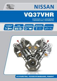
Руководство по техническому обслуживанию и ремонту бензинового двигателя Nissan модели VQ37VHR объемом 3,7 л.
- Автор: —
- Издательство: Автонавигатор
- Год издания: —
- Страниц: 136
- Формат: —
- Размер: —
Руководство по техническому обслуживанию и ремонту бензиновых двигателей Nissan моделей RB20E/RB25DE/RB25DET/RB26DETT.
- Автор: —
- Издательство: Автонавигатор
- Год издания: 2006
- Страниц: 129
- Формат: —
- Размер: —
Руководство по техническому обслуживанию и ремонту дизельных двигателей Nissan серии YD.
- Автор: —
- Издательство: Автонавигатор
- Год издания: 2005
- Страниц: 94
- Формат: —
- Размер: —
Руководство по техническому обслуживанию и ремонту дизельного двигателя Nissan модели YD25DDTi.
- Автор: —
- Издательство: Автонавигатор
- Год издания: —
- Страниц: 104
- Формат: —
- Размер: —


< PREV PAGE
NEXT PAGE >
G37 Coupe V6-3.7L (VQ37VHR) (2008)
Body and Frame > Radiator Support > Component Information > Service and Repair
/Page-1540001.png)
Radiator Support: Service and Repair
RADIATOR CORE SUPPORT
Exploded View
DLK-214 Exploded View
Removal and Installation
REMOVAL
1. Remove the front bumper fascia and front bumper reinforcement.
2. Remove the radiator reservoir tank.
3. Remove horn (High/Low).
4. Remove the radiator core support ornament.
—
Remove the radiator core support ornament mounting bolts and clips.
Body and Frame > Radiator Support > Component Information > Service and Repair
< PREV PAGE
NEXT PAGE >