-
Contents
-
Table of Contents
-
Troubleshooting
-
Bookmarks
Quick Links
USER’S GUIDE
Anemometer
WAA151
M210293en-A
Related Manuals for Vaisala WAA151
Summary of Contents for Vaisala WAA151
-
Page 1
USER’S GUIDE Anemometer WAA151 M210293en-A… -
Page 2
The contents are subject to change without prior notice. Please observe that this manual does not create any legally binding obligations for Vaisala towards the customer or end user. All legally binding commitments and agreements are included exclusively in the… -
Page 3: Table Of Contents
Safety ……………4 General Safety Considerations……4 Product Related Safety Precautions …..5 ESD Protection ………….5 Regulatory Compliances……..6 Warranty …………..6 CHAPTER 2 PRODUCT OVERVIEW………….7 Introduction to WAA151 Anemometer ….7 CHAPTER 3 INSTALLATION …………….9 Selecting Location ……….9 Installation Procedure ……….10 Mounting………….10 Alignment…………12 Verification…………12 Connector …………..12 CHAPTER 4 MAINTENANCE …………..15…
-
Page 4
Manual Revisions …………. 4 Table 2 Related Manuals …………4 Table 3 Available Spare Parts……….20 Table 4 Some Common Problems and their Remedies ..21 Table 5 WAA151 Anemometer Specifications….. 25 Table 6 MTBF Values…………26 2 ______________________________________________________ M210293en-A… -
Page 5: Chapter 1 General Information
This manual consists of the following chapters: — Chapter 1, General Information, provides important safety and revision history information for the product. — Chapter 2, Product Overview, introduces the WAA151 Anemometer features. — Chapter 3, Installation, provides you with information that is intended to help you install this product.
-
Page 6: Version Information
User’s Guide ________________________________________________________ Version Information Table 1 Manual Revisions Manual Code Description M210293en-A This manual, the first version of the WAA151 Anemometer User’s Guide. Related Manuals Table 2 Related Manuals Manual Code Manual Name M210294en WAV151 Wind Vane — User’s Guide…
-
Page 7: Product Related Safety Precautions
Chapter 1 ___________________________________________ General Information Product Related Safety Precautions The WAA151 Anemometer delivered to you has been tested for safety and approved as shipped from the factory. Note the following precautions: WARNING Ground the product, and verify outdoor installation grounding periodically to minimize shock hazard.
-
Page 8: Regulatory Compliances
— Always hold the boards by the edges and avoid touching the component contacts. Regulatory Compliances The WAA151 complies with the following performance and environmental test standards: — Wind tunnel tests per ASTM standard method D5096-96 (for starting threshold, distance constant, transfer function;…
-
Page 9: Chapter 2 Product Overview
Chapter 2 ____________________________________________ Product Overview CHAPTER 2 PRODUCT OVERVIEW This chapter introduces the WAA151 Anemometer features. Introduction to WAA151 Anemometer The WAA151 is an optoelectronic, fast-response, low- threshold anemometer. In the cup wheel it has three light- weight conical cups providing excellent linearity over the entire operating range, up to 75 m/s.
-
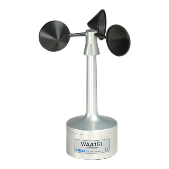
Page 10: Figure 1 Waa151 Anemometer
User’s Guide ________________________________________________________ 0204-039 Figure 1 WAA151 Anemometer The following numbers refer to Figure 1 above: 1 = Cup wheel assembly 2 = Sensor shaft 3 = Lower body 8 ______________________________________________________ M210293en-A…
-
Page 11: Chapter 3 Installation
Chapter 3 __________________________________________________ Installation CHAPTER 3 INSTALLATION This chapter provides you with information that is intended to help you install this product. Selecting Location Allow sufficient clearance for the wind sensors. Wind sensors should not be located next to a building or any other object that might affect the flow of air.
-
Page 12: Installation Procedure
When the diagonal (W) is less than the height (H) the minimum length of the mast is 1.5 × W. Installation Procedure Mounting Sensor installation is most convenient when you use a Vaisala manufactured cross arm for mounting the sensor. 10 _____________________________________________________ M210293en-A…
-
Page 13: Figure 4 Mounting Of Wind Sensor
Chapter 3 __________________________________________________ Installation Always mount the WAA151 Anemometer to the southern end of the cross arm. It is recommended that you remove the cup assembly to ease installation. Fit the 6-pin cable plug through the mounting flange at the end of the cross arm, then connect it to the sensor.
-
Page 14: Alignment
If your sensor is connected to the data collection system and powered up, check that the speed readings are changing when you rotate the cup wheel manually. Connector The connector for the WAA151 is shown in Figure 5 below. 0002-027 Figure 5 WAA151 Connector The following letters refer to Figure 5 above.
-
Page 15
Chapter 3 __________________________________________________ Installation The heating element in the shaft tunnel is connected between pins D and E. You can supply the heating element with 20 VDC or VAC. The recommended cable connector for the sensor is SOURIAU MS3116F10-6P. VAISALA__________________________________________________________13… -
Page 16
User’s Guide ________________________________________________________ This page intentionally left blank. 14 _____________________________________________________ M210293en-A… -
Page 17: Chapter 4 Maintenance
Chapter 4 ________________________________________________ Maintenance CHAPTER 4 MAINTENANCE This chapter provides information that is needed in the basic maintenance of the WAA151 Anemometer. Periodic Maintenance Cleaning Heavy contamination in the cups, such as bird dropplets or ice will deteriorate the accuracy of the anemometer. Clean the cups when necessary.
-
Page 18: Replacing Consumables
User’s Guide ________________________________________________________ Replacing Consumables Replacement of the bearings should only be done by a trained technician. To replace the ball bearings, follow the procedure below and refer to Figure 6 on page 19. Open the cup wheel fixing screw with a 2-mm Allen key.
-
Page 19
Chapter 4 ________________________________________________ Maintenance 10. Remove the internal retaining ring at the bottom of the shaft (using narrow-pointed pliers). 11. Remove the lower bearing. 12. Push out the shaft downwards through the upper body. 13. Remove the top bearing after pulling out the shaft. To reassemble the sensor, reverse the above work order . -
Page 20
User’s Guide ________________________________________________________ When placing the lower body assembly, make sure that the NOTE O-ring is correctly positioned between the upper and lower bodies. It is recommended to replace the O-rings with a new ones before reassembling. Tighten the hexagon nut of the connector (2). Connect the cable plug to the sensor body connector. -
Page 21: Figure 6 Waa151 Assembly
Chapter 4 ________________________________________________ Maintenance 0204-043 Figure 6 WAA151 Assembly VAISALA__________________________________________________________19…
-
Page 22: Parts List For Consumables
User’s Guide ________________________________________________________ Parts List for Consumables Table 3 Available Spare Parts Spare Part Order Code Cup assembly 7150WA Set of bearings and gasket 16644WA Sensor board (PCB) 1433WA 20 _____________________________________________________ M210293en-A…
-
Page 23: Chapter 5 Troubleshooting
The sensor is not powered Check that the supply voltage properly. is from 9.5 to15.5 VDC Some Vaisala products, for Check that the sensor output example, WAT12, switch rises above (U in — 1.5 V) at the power on to the sensor only end of the power pulse.
-
Page 24: Getting Help
User’s Guide ________________________________________________________ Problem Probable Cause Remedy The sensor shaft is The heating element does not Send the sensor to Vaisala for covered with ice function. repair. See section Return and snow. Instructions on page 23 for details. The heating element is not Open the sensor and check properly connected.
-
Page 25: Return Instructions
Pack the faulty product using an ESD protection bag of good quality with proper cushioning material in a strong box of adequate size. Please include the Problem Report in the same box. Send the box to: Vaisala Oyj SSD Service Vanha Nurmijärventie 21 FIN-01670 Vantaa Finland…
-
Page 26
User’s Guide ________________________________________________________ This page intentionally left blank. 24 _____________________________________________________ M210293en-A… -
Page 27: Chapter 6 Technical Data
Chapter 6 _______________________________________________Technical Data CHAPTER 6 TECHNICAL DATA This chapter provides the technical data of the WAA151 Anemometer. Specifications Table 5 WAA151 Anemometer Specifications Property Description/Value Sensor/Transducer type Cup anemometer/Opto-chopper Measuring range 0.4 … 75 m/s Starting threshold < 0.5 m/s Distance constant 2.0 m…
-
Page 28: Mtbf
User’s Guide ________________________________________________________ Property Description/Value Recommended SOURIAU MS3116F10-6P connector at cable end -50 … +55 °C (with shaft heating) Operating temperature -60 … +70 °C Storage temperature Housing material AlMgSi, gray anodized Cup material PA, reinforced with carbon fiber Dimensions 240 (h) ×…
-
Page 29
*M210293EN*…
 Loading…

USER’S GUIDE
Anemometer
WAA151
M210293en-A
|
PUBLISHED BY |
|||
|
Vaisala Oyj |
Phone (int.):+358 |
9 8949 1 |
|
|
P.O. Box 26 |
Fax: |
+358 |
9 8949 2227 |
|
FIN-00421 Helsinki |
|||
|
Finland |
Visit our Internet pages at http://www.vaisala.com/
© Vaisala 2002
No part of this manual may be reproduced in any form or by any means, electronic or mechanical (including photocopying), nor may its contents be communicated to a third party without prior written permission of the copyright holder.
The contents are subject to change without prior notice.
Please observe that this manual does not create any legally binding obligations for Vaisala towards the customer or end user. All legally binding commitments and agreements are included exclusively in the applicable supply contract or Conditions of Sale.
___________________________________________________________________
|
Table of Contents |
|
|
CHAPTER 1 |
|
|
GENERAL INFORMATION………………………………………………. |
3 |
|
About This Manual………………………………………….. |
3 |
|
Contents of This Manual………………………………… |
3 |
|
Version Information……………………………………….. |
4 |
|
Related Manuals…………………………………………… |
4 |
|
Safety…………………………………………………………….. |
4 |
|
General Safety Considerations……………………….. |
4 |
|
Product Related Safety Precautions………………… |
5 |
|
ESD Protection …………………………………………….. |
5 |
|
Regulatory Compliances…………………………………. |
6 |
|
Warranty ………………………………………………………… |
6 |
|
CHAPTER 2 |
|
|
PRODUCT OVERVIEW……………………………………………………. |
7 |
|
Introduction to WAA151 Anemometer ……………… |
7 |
|
CHAPTER 3 |
|
|
INSTALLATION ……………………………………………………………… |
9 |
|
Selecting Location………………………………………….. |
9 |
|
Installation Procedure …………………………………… |
10 |
|
Mounting……………………………………………………. |
10 |
|
Alignment…………………………………………………… |
12 |
|
Verification…………………………………………………. |
12 |
|
Connector…………………………………………………….. |
12 |
|
CHAPTER 4 |
|
|
MAINTENANCE ……………………………………………………………. |
15 |
|
Periodic Maintenance……………………………………. |
15 |
|
Cleaning ……………………………………………………. |
15 |
|
Testing Proper Operation …………………………….. |
15 |
|
Replacing Consumables………………………………. |
16 |
|
Parts List for Consumables …………………………… |
20 |
VAISALA___________________________________________________________1
User’s Guide ________________________________________________________
|
CHAPTER 5 |
|
|
TROUBLESHOOTING…………………………………………………… |
21 |
|
Common Problems ………………………………………. |
21 |
|
Getting Help…………………………………………………. |
22 |
|
Return Instructions ………………………………………. |
23 |
|
CHAPTER 6 |
|
|
TECHNICAL DATA……………………………………………………….. |
25 |
|
Specifications………………………………………………. |
25 |
|
MTBF …………………………………………………………… |
26 |
|
MTTR …………………………………………………………… |
26 |
|
List of Figures |
||
|
Figure 1 |
WAA151 Anemometer………………………………………. |
8 |
|
Figure 2 |
Recommended Mast Location in Open Area………… |
9 |
|
Figure 3 |
Recommended Mast Length on the Top of |
|
|
Building ………………………………………………………… |
10 |
|
|
Figure 4 |
Mounting of Wind Sensor ………………………………… |
11 |
|
Figure 5 |
WAA151 Connector………………………………………… |
12 |
|
Figure 6 |
WAA151 Assembly…………………………………………. |
19 |
|
List of Tables |
||
|
Table 1 |
Manual Revisions …………………………………………….. |
4 |
|
Table 2 |
Related Manuals ……………………………………………… |
4 |
|
Table 3 |
Available Spare Parts……………………………………… |
20 |
|
Table 4 |
Some Common Problems and their Remedies …… |
21 |
|
Table 5 |
WAA151 Anemometer Specifications………………… |
25 |
|
Table 6 |
MTBF Values…………………………………………………. |
26 |
2 ______________________________________________________ M210293en-A
Chapter 1 ___________________________________________ General Information
CHAPTER 1
GENERAL INFORMATION
About This Manual
This manual provides information for installing, operating, and maintaining the WAA151 Anemometer.
Contents of This Manual
This manual consists of the following chapters:
—Chapter 1, General Information, provides important safety and revision history information for the product.
—Chapter 2, Product Overview, introduces the WAA151 Anemometer features.
—Chapter 3, Installation, provides you with information that is intended to help you install this product.
—Chapter 4, Maintenance, provides information that is needed in the basic maintenance of the WAA151 Anemometer.
—Chapter 5, Troubleshooting, describes common problems, their probable causes and remedies, and contact information.
—Chapter 6, Technical Data, provides the technical data of the WAA151 Anemometer.
VAISALA___________________________________________________________3

User’s Guide ________________________________________________________
Version Information
Table 1 Manual Revisions
|
Manual Code |
Description |
|
M210293en-A |
This manual, the first version of the |
|
WAA151 Anemometer User’s Guide. |
Related Manuals
|
Table 2 |
Related Manuals |
|
|
Manual Code |
Manual Name |
|
|
M210294en |
WAV151 Wind Vane — User’s Guide |
Safety
General Safety Considerations
Throughout the manual, important safety considerations are highlighted as follows:
WARNING Warning alerts you to a serious hazard. If you do not read and follow instructions very carefully at this point, there is
a risk of injury or even death.
|
CAUTION |
Caution warns you of a potential hazard. If you do not read |
|
and follow instructions carefully at this point, the product |
|
|
could be damaged or important data could be lost. |
|
|
NOTE |
Note highlights important information on using the product. |
4 ______________________________________________________ M210293en-A

Chapter 1 ___________________________________________ General Information
Product Related Safety
Precautions
The WAA151 Anemometer delivered to you has been tested for safety and approved as shipped from the factory. Note the following precautions:
WARNING Ground the product, and verify outdoor installation grounding periodically to minimize shock hazard.
|
CAUTION |
Do not modify the unit. Improper modification can damage |
|
the product or lead to malfunction. |
|
ESD Protection
Electrostatic Discharge (ESD) can cause immediate or latent damage to electronic circuits. Vaisala products are adequately protected against ESD for their intended use. However, it is possible to damage the product by delivering electrostatic discharges when touching, removing, or inserting any objects inside the equipment housing.
To make sure you are not delivering high static voltages yourself:
—Handle ESD sensitive components on a properly grounded and protected ESD workbench. When this is not possible, ground yourself to the equipment chassis before touching the boards. Ground yourself with a wrist strap and a resistive connection cord. When neither of the above is possible, touch a conductive part of the equipment chassis with your other hand before touching the boards.
VAISALA___________________________________________________________5
User’s Guide ________________________________________________________
—Always hold the boards by the edges and avoid touching the component contacts.
Regulatory Compliances
The WAA151 complies with the following performance and environmental test standards:
—Wind tunnel tests per ASTM standard method D5096-96 (for starting threshold, distance constant, transfer function; refer to Chapter 6, Technical Data on page 25)
—Exploratory vibration test per MIL-STD-167-1
—Humidity test per MIL-STD-810E, Method 507.3
—Salt fog test per MIL-STD-810E, Method 509.3
Warranty
For certain products Vaisala normally gives a limited one year warranty. Please observe that any such warranty may not be valid in case of damage due to normal wear and tear, exceptional operating conditions, negligent handling or installation, or unauthorized modifications. Please see the applicable supply contract or conditions of sale for details of the warranty for each product.
6 ______________________________________________________ M210293en-A
Chapter 2 ____________________________________________ Product Overview
CHAPTER 2
PRODUCT OVERVIEW
This chapter introduces the WAA151 Anemometer features.
Introduction to WAA151 Anemometer
The WAA151 is an optoelectronic, fast-response, lowthreshold anemometer. In the cup wheel it has three lightweight conical cups providing excellent linearity over the entire operating range, up to 75 m/s. Rotated by the wind, a chopper disc attached to the cup wheel’s shaft cuts an infrared light beam 14 times per revolution, generating a pulse train output from a phototransistor.
The output pulse rate can be regarded directly proportional to wind speed, for example, 246 Hz = 24.6 m/s. For best available accuracy, however, the characteristic transfer function should be used, see section Specifications on page 25, to compensate for starting inertia and slight overspeeding.
The heating element in the shaft tunnel keeps the temperature of the bearings above the freezing level in cold climates. Nominally it provides 10 W of heating power. It is recommended to use a thermostat switch in the sensor cross arm for switching the heating power on below +4 °C.
VAISALA___________________________________________________________7
- Manuals
- Brands
- Vaisala Manuals
- Test Equipment
- WAA151
- User manual
Anemometer
Hide thumbs
Also See for WAA151:
- User manual (26 pages)
1
2
Table Of Contents
3
4
5
6
7
8
9
10
11
12
13
14
15
16
17
18
19
20
21
22
23
24
25
26
27
28
29
-
page
of
29/
29 -
Contents
-
Table of Contents
-
Troubleshooting
-
Bookmarks
Table of Contents
Advertisement
User’s Guide ________________________________________________________
8 ______________________________________________________ M210293en-A
Figure 1
WAA151 Anemometer
The following numbers refer to Figure 1 above:
1 = Cup wheel assembly
2 = Sensor shaft
3 = Lower body
0204-039
Table of Contents
Previous Page
Next Page
- 1
- …
- 7
- 8
- 9
- 10
- 11
- 12
- 13
- 14
Advertisement
Table of Contents
Related Manuals for Vaisala WAA151
-
Measuring Instruments Vaisala WAA151 User Manual
Anemometer (26 pages)
-
Test Equipment Vaisala HMP4 User Manual
Vaisala humicap humidity and temperature probes (60 pages)
-

Test Equipment Vaisala HUMICAP HMP155 User Manual
Humidity and temperature probes (84 pages)
-
Test Equipment Vaisala PTB220 Series User Manual
Digital barometers (113 pages)
-
Test Equipment Vaisala HMP60 User Manual
Humidity and temperature probes (66 pages)
-
Test Equipment Vaisala HMP Series User Manual
Humidity and temperature probes (118 pages)
-
Test Equipment Vaisala HUMICAP HMP41 User Manual
(72 pages)


-
Test Equipment Vaisala PTB210 SERIES User Manual
Digital barometers with serial output (32 pages)
-
Test Equipment Vaisala PTB330TS User Manual
Barometric pressure transfer stadard (89 pages)
-
Test Equipment Vaisala HMK15 User Manual
Humidity calibrator (39 pages)
-
Test Equipment Vaisala PTB220TS / CASE User Manual
Barometer (10 pages)
-
Test Equipment Vaisala PTB210 SERIES User Manual
Digital barometers with analog output (27 pages)
-
Test Equipment Vaisala HUMICAP HM44 User Manual
Set for measuring humidity in concrete (52 pages)
-
Test Equipment Vaisala AQT400 User Manual
Air quality transmitter (52 pages)


Related Products for Vaisala WAA151
- Vaisala WAC151
- Vaisala WAC155
- Vaisala WAT12
- Vaisala WAV151
- Vaisala WXT520
- Vaisala WINDCAP WS425
- Vaisala WXT510
- Vaisala WMS301
- Vaisala WHP25
- Vaisala WS425 F/G
- Vaisala WXT532
- Vaisala WXT535
- Vaisala WXT534
- Vaisala WXT531
- Vaisala AviMet WID511
- Vaisala WM30
More products and manuals for Unknown Vaisala
| Models | Document Type |
|---|---|
|
WAC151 |
User’s Guide
24 pages |
|
HMP130 |
User’s Guide
14 pages |
|
PMB100 |
User Manual
4 pages |
|
HUMICAP HMT330 SERIES |
User Manual
39 pages |
|
PMB100 |
User Manual
14 pages |
|
Spectracap OMT355 |
User Manual
1 pages |
|
WAT12 |
User’s Guide
28 pages |
|
HUMICAP HMP140A |
User’s Guide
52 pages |
|
HMP260 SERIES |
User Manual
40 pages |
|
WAT12 |
User’s Guide
26 pages |
|
HMDW20 |
User’s Guide
36 pages |
|
HUMICAP HMP140A |
User’s Guide
30 pages |
|
WINDCAP WS425 |
User’s Guide
80 pages |
|
WINDCAP WMT52 |
User’s Guide
143 pages |
|
WAC155 |
User’s Guide
60 pages |
|
WINDCAP WS425 |
User’s Guide
86 pages |
|
WINDCAP WS425 |
User’s Guide
91 pages |
|
WAV151 |
User’s Guide
30 pages |
|
WMS302 |
User’s Guide
32 pages |
|
CARBOCAP GM K220 |
User Manual
18 pages |


Specifications:
|
Accompanying Data:
Vaisala WAA151 Measuring Instruments, Test Equipment PDF Operation & User’s Manual (Updated: Friday 24th of February 2023 01:50:53 AM)
Rating: 4.8 (rated by 35 users)
Compatible devices: M212551EN-B, WA252, DRYCAP DM70, HUMICAP HMP41, PTB210 SERIES, Humicap HM40, DMP5, AQT400.
Recommended Documentation:
Vaisala WAA151: Text of Operation & User’s Manual
(Ocr-Read Version Summary of Contents, UPD: 24 February 2023)
Vaisala WAA151: Recommended Instructions
2ZRP7, AT-DP300, Cadence A50 Treadmill, 101, TS2, GE Profile WNCK2050HWC


-
APPLICATION GUIDEPut Bar Code Here63-4526-01PIR Application Guide for TB7200 and TB7300 Series ThermostatsPRODUCT OVERVIEWThis application guide provides application information and for Honeywell TB7200 and TB7300 Series communicating thermostats. When equipped with an occupancy sensor cover or a remote PIR sensor (wired to one of the remote inputs), these thermostats provide adv …
TB7200 Series 36
-
Leakage Current and Insulation Resistance Measurements Using the Model 2450 SourceMeter® SMU InstrumentIntroductionTo measure the leakage current or insulation resistance of a device, you need to apply a fixed voltage to the device and measure the resulting current. Depending on the device under test, the measured current is typically very small, usually less than 10nA.This application co …
2450 6
-
MTN/VC20Vibraon calibratorMonitran Ltd | Monitor House | 33 Hazlemere Road | Penn | Bucks | UK | HP10 8ADTelephone +44 (0)1494 816569 | E-mail [email protected] | Website www.monitran.comQUALITYMANAGEMENT001ISO 9001 : 2008siraRegistered CompanyC E R T I F I C A T I O NHB054.1Instruction Manual …
MTN/VC20 8
-
January 2010 ©2010 Fluke Corporation. All rights reserved.All product names are trademarks of their respective companies.Wi-Fi® is a registered trademark of the WiFi Alliance.AirCheck™Wi-Fi TesterUsers Manual …
AIRCHECK 102
-
OPERATOR’S GUIDE TruBurst Pneumatic Bursting Strength Tester With TestWise Lite Datalogger And Optional TestWise Pro Software v2 Covering Serial Numbers 1440/15/1001 & upwards James H. Heal & Co. Ltd. Publication 290-1440-1$D Halifax, England © 2019 …
TruBurst 54
-
BT Tele 300BItem: 026578DigAlertTMTest Telephone with Loud SpeakercompatibleADSLGround-start linesELR: Earth Loop RecallField repairLine-cord changingLine-cord storageImpactOn units fitted with optional third wire (item 315628):On units fitted with optional third wire (item 315628):(item 315629)connect green wire to ground, pressTALK momentarily and check for dial tone. Ground …
Tele 300B 2
-
1TEST PROGRAM FOR DISHWASHER MODELDW21CODES CONTROLS01 Filling02 Draining03 Heating04 NTC (Thermistor)05 Flow-meter06 Turbidimeter07 Leakage⇒ IMPORTANT INFORMATION• The change from one step to the next is performed by pressing the START button. It istherefore possible to skip one or more steps (except those where level control isnecessary).• It is possible to disconnect the appliance du …
DW21 3
-
User Guide Model 380363 Insulation Tester / Megohmmeter Introduction Congratulations on your purchase of Extech’s Insulation Tester/Megohmmeter. The Model 380363 provides three test ranges plus continuity and AC/DC voltage measurement. Manual datalogging stores up to 9 data sets. This professional meter, with proper care, will provide years of reliable servic …
380363 10
-
Service GuidePublication Number 54642-97004September 2002For Safety Information and Regulatory information, see the pages at the end of this book.© Copyright Agilent Technologies 2002All Rights ReservedAgilent 54641A/42AOscilloscopes and Agilent 54641D/42D Mixed-Signal Oscilloscopesservice.book Page i Wednesday, August 28, 2002 3:25 PM …
54641A 124
-
Artisan Technology Group is your source for quality new and certied-used/pre-owned equipment• FAST SHIPPING AND DELIVERY• TENS OF THOUSANDS OF IN-STOCK ITEMS• EQUIPMENT DEMOS• HUNDREDS OF MANUFACTURERS SUPPORTED• LEASING/MONTHLY RENTALS• ITAR CERTIFIED SECURE ASSET SOLUTIONSSERVICE CENTER REPAIRSExperienced engineers and technicians on staff at our full-service, in …
2701C 8
-
002002001001005050150150STARTERAMPSSTARTERAMPS00224466881010MILLIAMPEREMETERMILLIAMPEREMETER0000303030301010101020202020ALTERNATOR VOLTAGEALTERNATOR VOLTAGESTARTER / STATORVOLTAGESTARTER / STATORVOLTAGE00303010102020ALTERNATORAMPSALTERNATORAMPSSTARTER VOLTAGESTATOR VOLTAGE0STARTER VOLTAGESTATOR VOLTAGE0STARTER AMPERAGE0STARTER AMPERAGE04amp4ampBlueBlueGreenGreenRedR …
881 48
-
Thank you very much for selecting our digital AC current clamp-on tester. This model is complex instrument and employ a very reliable mechanical/electronic design. Before you use your new instrument, read this Instruction Manual completely and familiarize yourself thoroughly wit …
MCL-800D 4