-
Contents
-
Table of Contents
-
Troubleshooting
-
Bookmarks
Quick Links
Service Manual for WD10 Mechanical Pump Series Engine
x
Service Manual for WD10 Diesel Engine
Related Manuals for WEICHAI WD10
Summary of Contents for WEICHAI WD10
-
Page 1
Service Manual for WD10 Mechanical Pump Series Engine Service Manual for WD10 Diesel Engine… -
Page 3
Service Manual for WD10 Diesel Engine WD10 China II series diesel engine (China II emission standard) -
Page 4
Please add fuel of specified brand at a normal gas station, Weichai Power shares no responsibility for fuel system damage caused by inferior fuel, and the “three guarantees” we committed shall automatically become invalid. -
Page 5
This manual briefly introduced the technical parameters, structural features, operation and maintenance methods, and overhaul tips of WD10 diesel engine, for users to refer to; provided service technologies of diesel engine to help serviceman profoundly understand disassembly and assembly methods of the engine, also laid a solid technical foundation for serviceman to do troubleshooting. -
Page 6: Table Of Contents
Service Manual for WD10 Diesel Engine CONTENTS Usage Instructions for Diesel Engine …………..1 11 External View of Diesel Engine …………….1 12 Diesel Engine Model Composition and Significance ……….3 13 Diesel Engine Main Technical Parameters …………. 3 14 Unseal of Diesel engine ………………5 15 Lifting of Diesel Engine ………………
-
Page 7
Service Manual for WD10 Diesel Engine Diagnosis and Troubleshooting of Diesel Engine Common Faults ….. 21 31 Diagnostic Methods ………………..21 32 Fault Causes and Elimination Methods …………..22 321 Diesel Engine Couldn’t Be Started ………….. 22 322 Diesel Engine Stops Soon after Starting …………23 323 Underpower ……………….. -
Page 8
Service Manual for WD10 Diesel Engine 422 Disassembly, Inspection, Maintenance and Assembly of Cylinder Cover Shield ………………….38 423 Disassembly, Inspection, Maintenance and Assembly of Water Outlet Pipe ……………………………………………………………………………39 424 Disassembly, Inspection, Maintenance and Assembly of Oil-Gas Separator ……………………………………………………………………………41 425 Disassembly, Inspection, Maintenance and Assembly of Hanger Plates ..42 426 Disassembly, Inspection, Maintenance and Assembly of Cylinder Cover .. -
Page 9
Service Manual for WD10 Diesel Engine 453 Disassembly, Inspection, Maintenance and Assembly of Rocker and Rocker Shaft ………………….79 454 Disassembly, Inspection, Maintenance and Assembly of Valve Tappet and Pushrod ………………….82 455 Disassembly, Inspection, Maintenance and Assembly of Valve ….83 456 Disassembly, Inspection, Maintenance and Assembly of Intermediate Gear ……………………………………………………………………………85… -
Page 10
Service Manual for WD10 Diesel Engine 497 Disassembly, Inspection, Maintenance and Assembly of Main Oil Gallery Pressure Limiting Valve …………….111 498 Disassembly, Inspection, Maintenance and Assembly of Engine Oil Cooler Bypass Valve ………………..112 499 Disassembly, Inspection, Maintenance and Assembly of Engine Oil Strainer ………………………………………………………………………….113… -
Page 11: Usage Instructions For Diesel Engine
Service Manual for WD10 Diesel Engine 1 Usage Instructions for Diesel Engine 11 External View of Diesel Engine…
-
Page 12
Service Manual for WD10 Diesel Engine… -
Page 13: Diesel Engine Model Composition And Significance
Power code Application code Product series code 13 Diesel Engine Main Technical Parameters Table 1-1 Main Technical Parameters of WD10 China II series diesel engine Water-cooling, 4-stroke, brake with build-in air Engine type bleeding valve, in-line, direct injection, supercharged and intercooling…
-
Page 14
(° ) side Crankshaft rotating direction (View from free Clockwise end) Table 1-2 Main Technical Parameters of WD10 China II series diesel engine Unit WD10 engine G240E211 G220E221 G210E211 G210E241 G200E251 G175E251 Engine model G220E211 220E231 G210E221 G175E231 G200E251 G156E261 Water-cooling, 4-stroke, brake with build-in air bleeding valve, —… -
Page 15: Unseal Of Diesel Engine
Service Manual for WD10 Diesel Engine Minimum fuel consumption under g/(kWh) full load Cold start—with aid White smoke Light After 20s idling≤15% discharge obscuration Noise at 1m dB(A) <104 service life 800,000 14 Unseal of Diesel engine After opened the engine packing container, the user should firstly check the engine and its…
-
Page 16: Lifting Of Diesel Engine
Service Manual for WD10 Diesel Engine 15 Lifting of Diesel Engine Keep the center line of engine crankshaft horizontal during lifting, tilting or unilateral lifting is strictly forbidden. Keep the lifting-up and putting-down process slowly (refer to Fig. 1-1). Correct Wrong Fig.
-
Page 17: Start The Engine
Service Manual for WD10 Diesel Engine on instrument panel or check the fuel tank. (3) Check engine oil level Engine oil level should between the bottom scale and top scale on oil dipstick, add engine oil through oil filling port if necessary.
-
Page 18
Service Manual for WD10 Diesel Engine (5) Parameters and check points that should always be noticed during normal use: Engine oil pressure (main gallery) 350~500kPa. Engine oil temperature in oil sump <110 Coolant outlet temperature 80+5 C, should not exceed 93 ≤550… -
Page 19: Maintenance Guidelines For Diesel Engine
15W/40CF-4 or 5W/40CF-4 engine oil. If ambient temperature is higher than -15 C, select 15W/40CF-4 engine oil and 5W/40CF-4 is applicable for ambient temperature lower than -15 (Weichai dedicated engine oil is recommended, and only choose Weichai dedicated engine oil for the first replacement). Table 2-1 Lubricating oil brand option list…
-
Page 20: Lubrication Of Tensioning Wheel
Service Manual for WD10 Diesel Engine 213 Lubrication of Tensioning Wheel Apply general purpose lithium lubricating grease for lubrication of tensioning wheel (refer to GB/T5671-1995) 214 Antifreeze Additive in Engine Cooling System The adopted antifreeze additive is ethylene glycol, and it is allowed to replace it with domestic long-acting antifreeze additive with reliable quality, refer to related description for specific application method.
-
Page 21: Auxiliary Materials
Service Manual for WD10 Diesel Engine We can get that required antifreeze additive for -20 C is 13.5L Difference value between -30 C and -20 C is 4L For the difference value 4L, another 50% of that is required and necessary, because of before adding antifreeze additive, a part of coolant must be drained out, and antifreeze additive in this part of coolant will be drained out too.
-
Page 22: Daily Maintenance
Service Manual for WD10 Diesel Engine Used for the seal Loctite 277 between core and Other bowl type plugs hole Used to seal top end - Loctite 270 face cylinder Pushrod bush Cylinder cover cover Fitting surface between cylinder block and…
-
Page 23: Check Engine Oil Level
Service Manual for WD10 Diesel Engine Expansion water tank Fig. 2-3 Expansion water tank 222 Check Engine Oil Level Check whether engine oil level is between the bottom scale and top scale on oil dipstick. Under no circumstances should the engine be started if the oil level is lower than the bottom scale (L) or higher than the top scale (H).
-
Page 24: Check Fuel Level
Service Manual for WD10 Diesel Engine 223 Check Fuel Level Check fuel level gauge on instrument panel and add fuel timely. 224 Check “Three Leakages” Check engine appearance for water leakage, air leakage and oil leakage. 225 Check Fan Visually check whether fan blades are damaged, and whether connecting bolts are tightened.
-
Page 25: Check Whether Running Sound Is Normal
Service Manual for WD10 Diesel Engine 228 Check Whether Running Sound is Normal 229 Check Whether Rotating Speed and Vibration are Normal 23 Periodic Maintenance Replace engine oil Screw off oil drain plug on the bottom of oil sump to drain all engine oil out and then screw on the plug, refer to Fig.
-
Page 26
(3) Measure the clearance between rocker and valve rod upper surface with feeler gauge. Required intake valve clearance for WD10 diesel engine is 0.3mm; while that for exhaust valve is 0.4mm. If the clearance is too large or too small, you can rotate the adjusting screw to adjust until the clearance meets the requirements. -
Page 27: Replace Fuel Filter Element
Service Manual for WD10 Diesel Engine ATTENTION: In the adjusting process, you should rotate the bolt assembly 2 until the feeler gauge is gently infibulated, so that valve rocker piston 5 can be pushed to the bottom and no clearance between piston and piston hole bottom.
-
Page 28
Service Manual for WD10 Diesel Engine Fig. 2-11 Deflating of coarse filter Drain water in water collector: ATTENTION: When water collector is full or spinning coarse filter is replaced, it is required to drain the water in water collector out. -
Page 29
Service Manual for WD10 Diesel Engine Install the screw with hand and tighten it with tool. If the collector needs to be used on a new spinning filter, check it for damage first. Install the collector with torque wrench, tightening torque is 20Nm. -
Page 30: Maintenance For Long-Term Storage
Service Manual for WD10 Diesel Engine infiltration of dust and impurities will lead to premature wear of engine. Remove the filter element from air filter, pat its end faces gently to clean the dust on it, blow it with compressed air reversely (from inside to outside) is also feasible.
-
Page 31: Diagnosis And Troubleshooting Of Diesel Engine Common Faults
3 Diagnosis and Troubleshooting of Diesel Engine Common Faults WD10 China II series diesel engine is designed and manufactured under strict quality guarantee system, each delivered engine has passed specified tests. Since diesel engine is precision machinery, guarantee for long-term reliable service is inseparable from correct maintenance. Causes for diesel engine early failure are as follows: …
-
Page 32: Fault Causes And Elimination Methods
Service Manual for WD10 Diesel Engine ATTENTION: Diesel engine fault cause determination is an extremely careful job. Before basically be sure about the cause, it’s not allowed to disassemble the engine casually, otherwise instead of eliminating the fault, some severe trouble may occur due to improper reassembling.
-
Page 33: Diesel Engine Stops Soon After Starting
Service Manual for WD10 Diesel Engine 322 Diesel Engine Stops Soon after Starting Disassemble the filter body to clear up the water 1. Blockage of fuel filter and dirt, replace the filter element if necessary. Expel the air and check airtightness of joints, check 2.
-
Page 34: Large Fuel Consumption
Service Manual for WD10 Diesel Engine 12. Incorrect valve or injection timing Check and adjust it. 13. Governor high-speed regulating Check the speed control characteristic and adjust. performance is poor Check oil dipstick and drain redundant engine oil 14. High engine oil level in oil sump out.
-
Page 35: Engine Gives Off Black Smoke
Service Manual for WD10 Diesel Engine 325 Engine Gives off Black Smoke 1. Blockage of intake pipe or high exhaust Clean it up. back pressure 2. Inferior fuel Clean and replace. Adjust valve clearance and fuel supply advance 3. Incorrect valve or injection timing angle according related requirements.
-
Page 36: Turbocharger Intake Port And Intake Pipe Are Accumulated With Engine Oil
Service Manual for WD10 Diesel Engine 327 Turbocharger Intake Port and Intake Pipe Are Accumulated with Engine Oil 1. Turbocharger sealing failure Repair or replace the turbocharger. 2. Oil-gas separator failure Replace. Check oil dipstick and drain redundant engine oil 3.
-
Page 37: 3210 High Cooling Water Temperature
Service Manual for WD10 Diesel Engine 7. Large filtering resistance of engine oil Replace filter element. filter 8. Blockage of engine oil cooler Check and clean. 9. Blockage of main oil gallery Check and clean. 10. Large bearing shell clearance, Check and replace.
-
Page 38: 3212 Excessive Noise
Service Manual for WD10 Diesel Engine 9. Severe wear of parts, overhaul needs to Check working hour of engine, overhaul the engine. be done 10. Crankshaft and the follower main shaft Check the installing support, repair. are not concentric 11. The applied engine oil quality fails to Choose specified engine oil brand.
-
Page 39: 3214 Underpowered Starter Motor
Service Manual for WD10 Diesel Engine 3214 Underpowered Starter Motor 1. Undercharged battery Check, recharge or replace the battery. 2. Bearing sleeve wear Replace the assembly. 3. Bad contact of electric brush Clean the brush or replace it. Wipe out oil dirt and polish it with abrasive paper or 4.
-
Page 40: 3217 Unstable Charging Voltage
Service Manual for WD10 Diesel Engine 3217 Unstable Charging Voltage 1. Rotor coil or stator coil is about to in Repair or replace. open circuit or short circuit 2. Bad contact of electric brush Repair. 3. Loose terminals, bad contact Repair.
-
Page 41: Disassembly & Assembly Of Diesel Engine
Service Manual for WD10 Diesel Engine 4 Disassembly & Assembly of Diesel Engine 41 Overview Please comply with instructions in this manual strictly to disassemble and assemble the engine and pay special attention to operations which danger signs and safety signs are involved in this manual, in order to ensure personal safety and avoid accidents.
-
Page 42: Safety Signs
Service Manual for WD10 Diesel Engine Safety information described in this manual cannot cover all safety precautions, if the procedures or actions that are not recommended in this manual are used, you must ensure the safety of the operator and machine.
-
Page 43: Recommended Tools
Service Manual for WD10 Diesel Engine 413 Recommended Tools Signs Information 2.5mm hexagon wrench 5mm hexagon wrench 8mm socket Slotted screw driver Dedicated tool 10mm slotted hexagon wrench If the methods or tools that are not recommended in this manual are used, you must ensure safety to avoid life risk to yourself or other people, in the meantime make sure the operating, maintenance and repair methods wouldn’t bring damage to the engine or potential safety hazard.
-
Page 44: Environmental Protection Measures
Any violation of instructions in this manual may result in serious accident, even death. Weichai Power cannot foresee all potential dangers. Similarly, the rules and instructions in this manual cannot cover everything.
-
Page 45: Explode View Of The Whole Engine
Service Manual for WD10 Diesel Engine 417 Explode View of the Whole Engine Turbocharger Cylinder cover shield Cylinder cover Oil-gas separator Exhaust pipe Water outlet pipe Thermostat Intake pipe Cylinder Block Pushrod Valve Engine oil Tappet cooler cap Camshaft Engine oil filter…
-
Page 46: Cylinder Cover Assembly
Service Manual for WD10 Diesel Engine 42 Cylinder Cover Assembly 421 Disassembly and Assembly of Cylinder Cover Assembly 4211 Exploded View of Cylinder Cover Assembly Cylinder cover is located on top of cylinder block, combustion chamber is jointly formed by cylinder cover and piston head.
-
Page 47
Service Manual for WD10 Diesel Engine (6) Disconnect EVB oil pipe and pipe joint; (7) Disconnect injector wiring harness, remove injector oil return pipe and high pressure fuel pipe, refer to disassembly of fuel system for details; (8) Remove the injector, refer to disassembly of fuel system for details;… -
Page 48: Disassembly, Inspection, Maintenance And Assembly Of Cylinder Cover Shield
Service Manual for WD10 Diesel Engine 422 Disassembly, Inspection, Maintenance and Assembly of Cylinder Cover Shield 4221 Exploded View of Cylinder Cover Shield Cylinder cover shield bolt Cylinder cover shield Cylinder cover shield gasket Fig. 4-3 Exploded view of cylinder cover shield 4222 Steps to Disassemble Cylinder Cover Shield (1) Screw off cylinder cover shield bolts orderly;…
-
Page 49: Disassembly, Inspection, Maintenance And Assembly Of Water Outlet Pipe
Service Manual for WD10 Diesel Engine Check whether there is manufacturing defect, usage defect or damage on cylinder cover shield gaskets and cylinder cover before assembling. (2) Clean up cylinder cover upper surface and assemble cylinder cover shield gaskets orderly.
-
Page 50
Service Manual for WD10 Diesel Engine 4233 Inspection and Maintenance of Water Pipe (1) Check whether there is water leakage trace on the pipe before disassembling; check the pipe for damage like crack and corrosion, a cracked pipe should be replaced, for corrosion that may affect reliability of the pipe, the cause should be analyzed and corroded pipe should be replaced. -
Page 51: Disassembly, Inspection, Maintenance And Assembly Of Oil-Gas Separator
Service Manual for WD10 Diesel Engine 424 Disassembly, Inspection, Maintenance and Assembly of Oil-Gas Separator 4241 Exploded View of Oil-Gas Separator Front hanger plate Fixing bolt Oil-gas separator Oil-gas separator outlet pipe Flange and gasket Clamp Oil-gas separator oil return pipe…
-
Page 52: Disassembly, Inspection, Maintenance And Assembly Of Hanger Plates
Service Manual for WD10 Diesel Engine 4244 Steps to Assemble Oil-Gas Separator Assembling steps are contrary to disassembling ones. Do not mix up the rubber hoses and hoses joints (refer to Fig. 4-5), connect each hose to the engine properly.
-
Page 53: Disassembly, Inspection, Maintenance And Assembly Of Cylinder Cover
Service Manual for WD10 Diesel Engine 4254 Steps to Assemble Hanger Plates Firstly distinguish the front hanger plate and rear hanger plate, front hanger plate should be installed on front end of engine (fan end), and rear hanger plate should be installed on rear end of engine (flywheel end), fasten the plates with M12 hexagon bolts (as shown in Fig.
-
Page 54
Service Manual for WD10 Diesel Engine details). Besides, for engine with EVB oil pipe, the pipe need to be remove too. Disassembling of other parts is as follows: (1) Remove cylinder cover auxiliary nuts, and take down the clamp blocks, there are two kinds of clamp blocks: one is installed between two adjacent cylinder covers, the other is installed on two sides;… -
Page 55
Service Manual for WD10 Diesel Engine Fig. 4-8 Depth micrometer Refer to Table 4-1 for valve recession requirements. If valve recession exceeds allowed range, check wear condition of valve and valve seat, replace the valve with a new one to determine wear condition of valve seat by measuring the valve recession again, if the valve recession still exceeds allowed range, the cylinder cover must be replaced to ensure reliability of diesel engine. -
Page 56
Service Manual for WD10 Diesel Engine (7) Check the disassembled cylinder cover gaskets for visible damage and analyze the cause, cylinder cover gaskets are disposable, and should be replaced once removed. (8) Check whether valve rod seal cartridge rubber lip is damaged, whether the spring is in failure and whether there is other abnormal phenomenon before disassembling, seal cartridge should be replaced once removed. -
Page 57
Service Manual for WD10 Diesel Engine 2) Rub-up cylinder sleeve inner wall and apply clean engine oil on the wall; Clean up upper surface of cylinder block, and place cylinder gaskets correctly by aligning the holes; 3) Check and make sure the holes on cylinder cover gasket are correctly aligned to holes on cylinder block. -
Page 58
Service Manual for WD10 Diesel Engine 2) Check and make sure cylinder cover air passage and water passage are free of foreign matter; Check and make sure the cylinder is free of foreign matter, cylinder cover gasket and cylinder cover undersurface are clean;… -
Page 59
Service Manual for WD10 Diesel Engine 6) Tighten cylinder cover main bolts with torque wrench orderly to 200Nm and mark the bolts; 7) Tighten each cylinder cover auxiliary nut for further 90° with torque wrench orderly and mark the new position of the nuts;… -
Page 60
Service Manual for WD10 Diesel Engine Fig. 4-17 Assembly of cylinder cover main bolts Fan side Flywheel side Fig. 4-18 Tighten number 22~45 cylinder cover main bolts… -
Page 61: Engine Block Assembly
Service Manual for WD10 Diesel Engine 43 Engine Block Assembly 431 Disassembly, Inspection, Maintenance and Assembly of Engine Block Assembly 4311 Exploded View of Engine Block Assembly Engine block module Cylinder sleeve Cylinder cover auxiliary bolt Elastic cylindrical pin Pre-glued set screw…
-
Page 62
Service Manual for WD10 Diesel Engine Compound gasket Main oil gallery rear plug Bowl shape plug Rivet Seal ring Main bearing bolt Fig. 4-20 Exploded view of engine block assembly 4312 Steps to Disassemble Engine Block Assembly (1) Remove crankcase fastening bolts (key point 1);… -
Page 63
Service Manual for WD10 Diesel Engine Key point 2: Assembling: Apply clean lubricating oil on crankcase bearing surface and thread of main bearing bolts, and then tighten them according to following order: Tightening torque 265± 25Nm Key point 3: Assembling: Tighten cylinder cover auxiliary bolts according to the following order, cylinder cover auxiliary bolts are allowed to use twice at most. -
Page 64: Disassembly, Inspection, Maintenance And Assembly Of Engine Block Module
Service Manual for WD10 Diesel Engine 432 Disassembly, Inspection, Maintenance and Assembly of Engine Block Module 4321 Exploded View of Engine Block Module Cylinder Bowl shape plug Bowl shape plug block Camshaft sleeve Cylindrical pin with Crankcase internal thread Oil dipstick pipe head…
-
Page 65
Service Manual for WD10 Diesel Engine 4322 Steps to Disassemble Engine Block Module (1) Remove cylindrical pins (with internal thread); (2) Remove camshaft sleeve (key pint 1); (3) Remove main bearing bolts and crankcase fastening bolts (refer to 431); (4) Remove crankcase (key point 2);… -
Page 66: Disassembly, Inspection, Maintenance And Assembly Of Engine
Service Manual for WD10 Diesel Engine 433 Disassembly, Inspection, Maintenance and Assembly of Engine Front Cover 4331 Exploded View of Engine Front Cover Engine front cover Hexagon flange toothed bolt Seal ring Fig. 4-22 Exploded view of engine front cover 4332 Steps to Disassemble Engine Front Cover (1) Remove engine front cover fastening bolts (key point 1);…
-
Page 67: Disassembly, Inspection, Maintenance And Assembly Of Gear Housing
Service Manual for WD10 Diesel Engine 4334 Steps to Assemble Engine Front Cover Assembling steps are contrary to disassembling ones. 434 Disassembly, Inspection, Maintenance and Assembly of Gear Housing 4341 Exploded View of Gear Housing Timing gear housing Seal ring…
-
Page 68
Service Manual for WD10 Diesel Engine 4343 Inspection and Maintenance of Gear Housing Key point 1: Assembling: Tighten gear housing fastening bolts according to the following order crosswise. Tightening torque 44~58Nm Fig. 4-24 Key point 2: Assembling: Check whether seal ring is damaged, replace it if so. When assembling, seal ring should be applied with oil and fully pressed into seal groove, protect the ring in this process. -
Page 69: Disassembly, Inspection, Maintenance And Assembly Of Flywheel Housing
Service Manual for WD10 Diesel Engine 435 Disassembly, Inspection, Maintenance and Assembly of Flywheel Housing 4351 Exploded View of Flywheel Housing Stud Spring washer 1-type Flywheel housing hexagon bolt Flywheel housing bolt Monitoring window cap Hexagon bolt Cylindrical pin Fig. 4-25 Exploded view of flywheel housing 4352 Steps to Disassemble Flywheel Housing (7) Remove fastening bolts of flywheel housing (key point 1);…
-
Page 70: Disassembly, Inspection, Maintenance And Assembly Of Oil Sump
Service Manual for WD10 Diesel Engine Fig. 4-26 Key point 2: Assembling: Apply sealant on fitting surfaces of flywheel housing and engine block, pay attention not to crash flywheel housing during lifting. 4354 Steps to Assemble Flywheel Housing Assembling steps are contrary to disassembling ones.
-
Page 71
Service Manual for WD10 Diesel Engine 4362 Steps to Disassemble Oil Sump (1) Turn over the engine to keep oil sump upward (key point 1); (2) Remove oil sump fastening bolts (key point 2); (3) Remove oil sump support blocks;… -
Page 72: Disassembly, Inspection, Maintenance And Assembly Of Piston Nozzle
Service Manual for WD10 Diesel Engine 437 Disassembly, Inspection, Maintenance and Assembly of Piston Nozzle 4371 Exploded View of Piston Nozzle Hollow bolt Seal gasket Nozzle assembly Elastic cylindrical pin Fig. 4-29 Exploded view of piston nozzle 4372 Steps to Disassemble Piston Nozzle (1) Remove the hollow bolt (key point 1);…
-
Page 73: Disassembly, Inspection, Maintenance And Assembly Of Thrust Plates
Service Manual for WD10 Diesel Engine 4374 Steps to Assemble Piston Nozzle Assembling steps are contrary to disassembling ones. 438 Disassembly, Inspection, Maintenance and Assembly of Thrust Plates 4381 Exploded View of Thrust Plates Upper thrust plate Lower thrust plate Fig.
-
Page 74: Disassembly, Inspection, Maintenance And Assembly Of Front And Rear Oil Seals
Service Manual for WD10 Diesel Engine side with oil groove should be outward. 4384 Steps to Assemble Thrust Plates (1) Install crankshaft; (2) Install upper thrust plates (without lug); (3) Install lower thrust plates (key point 1). 439 Disassembly, Inspection, Maintenance and Assembly of Front and…
-
Page 75
Service Manual for WD10 Diesel Engine tool. Disassembling: Removed oil seals should not be reused. 4394 Steps to Assemble Front and Rear Oil Seals (1) Install crankcase; (2) Install rear oil seal; (3) Install gear housing; (4) Install front oil seal. -
Page 76: Crank-Rod Mechanism
Service Manual for WD10 Diesel Engine 44 Crank-Rod Mechanism 441 Disassembly and Assembly of Crank-Rod Mechanism 4411 Exploded View of Crank-Rod Mechanism Main bearing bolt Main bearing shell Crankcase Crankshaft Connecting rod big end cap Crankshaft Flywheel ring gear timing gear…
-
Page 77: Disassembly, Inspection, Maintenance And Assembly Of Piston-Rod Assembly
Service Manual for WD10 Diesel Engine 442 Disassembly, Inspection, Maintenance and Assembly of Piston-Rod Assembly 4421 Exploded View of Piston-Rod Assembly Crankshaft Piston-rod assembly Fig. 4-33 Schematic diagram of piston-rod assembly First compression ring Second compression ring Piston pin Oil ring…
-
Page 78
Service Manual for WD10 Diesel Engine 4422 Steps to Disassemble Piston-Rod Assembly (1) Remove circlip on two sides of piston with internal circlip plier and push piston pin out, take down the connecting rod body. Number the piston pins, connecting rod bodies and place them orderly. -
Page 79
Service Manual for WD10 Diesel Engine (5) Adjust opening direction of each ring: The opening direction of first compression ring should be 30° to piston pin center line, opening direction of the second compression ring should be 120° to that of the first compression ring, and opening direction of oil ring should be 120° to both that of first compression ring and second compression ring, also should be perpendicular to piston pin center line. -
Page 80: Disassembly, Inspection, Maintenance And Assembly Of Crankshaft
Service Manual for WD10 Diesel Engine 443 Disassembly, Inspection, Maintenance and Assembly of Crankshaft 4431 Exploded View of Crankshaft Main bearing bolt Crankcase Crankshaft Flywheel ring gear Flywheel Main bearing shell Bearing Crankshaft timing gear Baffle ring Damper Pulley Flywheel bolt…
-
Page 81
Service Manual for WD10 Diesel Engine (6) Check wear condition of crankshaft journal, check bend and distortion condition of crankshaft. 4434 Steps to Assemble Crankshaft (1) Clean up cylinder bottom holes. (2) Press main bearing upper shells into cylinder bottom holes and clean up scraped foreign matter. -
Page 82: Disassembly, Inspection, Maintenance And Assembly Of Flywheel And Ring Gear
Service Manual for WD10 Diesel Engine (11) Firstly pre-tighten each bolt with low-torque pneumatic impact wrench, and then tighten each bolt to 80Nm orderly, thirdly the torque should reach 250~280Nm. Assembly of crank shaft is finished. 444 Disassembly, Inspection, Maintenance and Assembly of Flywheel and…
-
Page 83
Service Manual for WD10 Diesel Engine 4444 Steps to Assemble Flywheel and Ring Gear (1) Fix the flywheel ring gear on flywheel with bolts; (2) Knock the pin into crankshaft rear end fully. (3) After inserting flywheel guide rod into crankshaft threaded hole, install flywheel and pre-tighten the bolts diagonally. -
Page 84: Disassembly, Inspection, Maintenance And Assembly Of Damper And Crankshaft Pulley
Service Manual for WD10 Diesel Engine 445 Disassembly, Inspection, Maintenance and Assembly of Damper and Crankshaft Pulley 4451 Exploded View of Damper and Crankshaft Pulley Crankshaft timing gear Flange Crankshaft Damper Crankshaft pulley Pulley bolt Fig. 4-39 Exploded view of damper and crankshaft pulley 4452 Steps to Disassemble Damper and Crankshaft Pulley Screw off pulley bolts and then take down pulley and damper orderly.
-
Page 85: Disassembly, Inspection, Maintenance And Assembly Of Crankshaft Bearing Shell
Service Manual for WD10 Diesel Engine 446 Disassembly, Inspection, Maintenance and Assembly of Crankshaft Bearing Shell 4461 Exploded View of Crankshaft Bearing Shell Main bearing upper shell Crankshaft Main bearing lower shell Fig. 4-40 Exploded view of crankshaft bearing shell…
-
Page 86: Valve Mechanism
Service Manual for WD10 Diesel Engine 45 Valve Mechanism 451 Disassembly and Assembly of Valve Mechanism 4511 Exploded View of Valve Mechanism Adjusting nut Hexagon screw Intake rocker Supporting arm Adjusting screw Adjusting bolt assembly Valve lock clamp Adjusting nut…
-
Page 87: Disassembly, Inspection, Maintenance And Assembly Of Camshaft
Service Manual for WD10 Diesel Engine (3) Install valve tappet and pushrod, refer to assembly of valve tappet and pushrod for details; (4) Assemble intake and exhaust valves, refer to assembly of valves for details; (5) Install rocker and rocker shaft, refer to assembly of rocker and rocker shaft for details;…
-
Page 88
Service Manual for WD10 Diesel Engine abrasion. (2) Measure camshaft main journal circular run-out. Maximum allowed Camshaft Measured value circular run-out The second main journal (Between cylinder 1 and 0.04 cylinder 2) The third main journal (Between cylinder 2 and 0.05… -
Page 89: Disassembly, Inspection, Maintenance And Assembly Of Rocker And Rocker Shaft
Service Manual for WD10 Diesel Engine (5) Turn the engine anticlockwise (view from timing gear housing end) until cylinder 1 and 6 reach TDC. At this point, piston upper end should be aligned to cylinder block upper surface. (6) Draw a straight line across flywheel housing and flywheel, install the dial and adjust it until 0°…
-
Page 90
Service Manual for WD10 Diesel Engine 4532 Steps to Disassemble Rocker and Rocker Shaft (1) Rotate crankshaft to check whether rocker is flexible. (2) Measure each valve clearance, and check the change of valve clearance. (3) If the rocker is not flexible or too big valve clearance, loosen hexagon nut and then take down the supporting arm, rocker shaft, intake and exhaust rocker assembly, mark them to prevent confusion. -
Page 91
Service Manual for WD10 Diesel Engine valve clearance: As shown in Fig. 4-44, firstly loose the adjusting bolt 2, and then adjust valve clearance adjusting screw on pushrod end 10 without compressing exhaust valve rocker sealing surface until total valve clearance is 0.4mm, and then tighten adjusting nut. (ATTENTION:… -
Page 92: Disassembly, Inspection, Maintenance And Assembly Of Valve Tappet And Pushrod
Service Manual for WD10 Diesel Engine 3) Rotate the engine for 360° , so that cylinder 6 can be in compression TDC, adjust intake valve clearance of No. 6, 5, 3 cylinder and exhaust valve clearance of No. 6, 4, 2 cylinder, and EVB valve clearance.
-
Page 93: Disassembly, Inspection, Maintenance And Assembly Of Valve
Service Manual for WD10 Diesel Engine (4) Check whether pushrod two ends are worn; (5) Check whether valve tappet surface and undersurface are worn; (6) Check whether valve tappet inner socket head is worn. 4544 Steps to Assemble Valve Tappet and Pushrod (1) Check valve tappets and pushrods, replace them if necessary.
-
Page 94
Service Manual for WD10 Diesel Engine 4552 Steps to Disassemble Valve (1) Depress valve springs with vale spring compressor or valve overhead plier or other tools, take out valve lock clamp, upper valve spring seat and lower valve spring seat and valve springs orderly;… -
Page 95: Disassembly, Inspection, Maintenance And Assembly Of Intermediate Gear
Service Manual for WD10 Diesel Engine 456 Disassembly, Inspection, Maintenance and Assembly of Intermediate Gear 4561 Exploded View of Intermediate Gear Sleeve Intermediate gear shaft Gasket Bolt Intermediate gear Fig. 4-49 Exploded view of intermediate gear 4562 Steps to Disassemble Intermediate Gear (1) Remove air compressor, refer to disassembly of engine accessory system for details;…
-
Page 96
Service Manual for WD10 Diesel Engine 4564 Steps to Assemble Intermediate Gear (1) Install engine oil pump, crankshaft and engine oil pump intermediate gear module orderly; (2) Install gear housing. Before assembling gear housing, put intermediate gear shaft into intermediate gear assembly (intermediate gear and sleeve). For intermediate gear the end with “V”… -
Page 97: Intake And Exhaust System
Service Manual for WD10 Diesel Engine 46 Intake and Exhaust System 461 Disassembly and Assembly of Intake and Exhaust System 4611 Exploded View of Intake and Exhaust System Intake pipe Turbocharger Exhaust pipe Fig. 4-50 Exploded view of valve intake and exhaust system 4612 Steps to Disassemble Intake and Exhaust System (1) Loosen air filter fixing bolts and hose clamps, take down air filter and hoses.
-
Page 98: Disassembly, Inspection, Maintenance And Assembly Of Intake Pipe
Service Manual for WD10 Diesel Engine 462 Disassembly, Inspection, Maintenance and Assembly of Intake Pipe 4621 Exploded View of Intake Pipe Stud Intake pipe end Intake pipe gasket cover gasket Intake pipe Intake pipe end cover Intake heater Intake heater…
-
Page 99: Disassembly, Inspection, Maintenance And Assembly Of Exhaust Pipe
Service Manual for WD10 Diesel Engine 463 Disassembly, Inspection, Maintenance and Assembly of Exhaust Pipe 4631 Exploded View of Intake Pipe Front exhaust pipe Exhaust pipe seal ring Exhaust pipe bolt Exhaust pipe gasket Rear exhaust pipe Exhaust pipe heat shield bolt…
-
Page 100: Disassembly, Inspection, Maintenance And Assembly Of Turbocharger System
Service Manual for WD10 Diesel Engine (2) Exhaust pipe bolts should be applied with molybdenum disulfide, recommended tightening torque for exhaust pipe fixing bolts is 65~80Nm. Exhaust pipe bolts cannot be reused more than twice. 464 Disassembly, Inspection, Maintenance and Assembly of Turbocharger…
-
Page 101
Service Manual for WD10 Diesel Engine Press measuring head of dial indicator against compressor end, push and pull the shaft axially and record value difference of the indicator. As shown in Fig. 4-54. Required range is 0.088~0.118mm, if exceeds this range, then it indicates that thrust bearing plate or thrust plate and bearing is worn, you must find out the cause and eliminate the problem. -
Page 102
Service Manual for WD10 Diesel Engine (1) Check whether the pipe connection between turbocharger and engine is loose, eliminate the problem in time. (2) Check turbocharger for air leakage and oil leakage, eliminate the fault in time. (3) Check whether turbocharger fastening screws are loose, eliminate the problem timely. -
Page 103: Fuel System
Service Manual for WD10 Diesel Engine 47 Fuel System 471 Disassembly and Assembly of Fuel System 4711 Exploded View of Fuel System Fig. 4-56 Exploded view of fuel system 4712 Steps to Disassemble Fuel System (1) Remove low pressure fuel pipe module;…
-
Page 104: Disassembly, Inspection, Maintenance And Assembly Of Fuel Injection Pump
Service Manual for WD10 Diesel Engine 472 Disassembly, Inspection, Maintenance and Assembly of Fuel Injection Pump 4721 Exploded View of Fuel Injection Pump Fig. 4-57 Exploded view of fuel injection pump 4722 Steps to Disassemble Fuel Injection Pump (1) Screw off the hexagon nuts that connecting fuel injection pump flange and gear housing;…
-
Page 105
Service Manual for WD10 Diesel Engine 4724 Steps to Assemble Fuel Injection Pump (1) Install fuel injection pump flange, apply a small amount of lubricating oil on pump rubber ring; (2) Screw on the hexagon bolts to connect fuel injection pump and the flange;… -
Page 106: Disassembly, Inspection, Maintenance And Assembly Of High Pressure Fuel Pipes
Service Manual for WD10 Diesel Engine 473 Disassembly, Inspection, Maintenance and Assembly of High Pressure Fuel Pipes 4731 Exploded View of High Pressure Fuel Pipes Fig. 4-59 Exploded view of high pressure fuel pipes 4732 Steps to Disassemble High Pressure Fuel Pipes (1) Remove high pressure fuel pipe support;…
-
Page 107: Disassembly, Inspection, Maintenance And Assembly Of Fuel Injector
Service Manual for WD10 Diesel Engine 474 Disassembly, Inspection, Maintenance and Assembly of Fuel Injector 4741 Exploded View of Fuel Injector Fig. 4-60 Exploded view of fuel injector 4742 Steps to Disassemble Fuel Injector (1) Remove the hexagon bolts that used to fix injector pressing block;…
-
Page 108
Service Manual for WD10 Diesel Engine (2) All kinds of protective caps only need to be removed before assembling; (3) Place the injector into cylinder cover and tighten injector clamping bolt to 3Nm; (4) Loose injector clamping bolt until axial force posed on injector is 0kN;… -
Page 109: Cooling System
Service Manual for WD10 Diesel Engine 48 Cooling System 481 Disassembly and Assembly of Cooling System 4811 Exploded View of Cooling System The function of cooling system is to ensure diesel engine can continuously work at proper temperature. Forced circulation cooling offers the best guarantee to keep the engine in normal operating temperature, which mainly consists of water pump, fan, expansion water tank, water tank and thermostat.
-
Page 110: Disassembly, Inspection, Maintenance And Assembly Of Fan
Service Manual for WD10 Diesel Engine (4) Remove generator, generator support, crankshaft pulley and damper. (5) Remove thermostat, refer to disassembly of thermostat for details. (6) Remove air compressor and hydraulic pump. (7) Remove pipe joints of water pump and take down the pump, refer to disassembly of water pump for details.
-
Page 111: Disassembly, Inspection, Maintenance And Assembly Of Water Pump
Service Manual for WD10 Diesel Engine 4823 Inspection and Maintenance of Fan Check fan, fan clutch, fan connecting plate and water pump pulley for crack and damage. 4824 Steps to Assemble Fan (1) Before the assembly, check fan, fan clutch, fan connecting plate and hexagon flange bolts, make sure there is no manufacturing and use defect and damage.
-
Page 112
Service Manual for WD10 Diesel Engine (4) Remove the hexagon flange nuts; (5) Remove the studs; (6) Remove the water pump and take down pump gaskets. 4833 Inspection and Maintenance of Water Pump (1) Check pipe joint and pipe joint module for blockage and crack damage, replace if necessary. -
Page 113: Disassembly, Inspection, Maintenance And Assembly Of Thermostat
Service Manual for WD10 Diesel Engine 484 Disassembly, Inspection, Maintenance and Assembly of Thermostat 4841 Exploded View of Thermostat Clamp Cooling water Cooling water pipe adapter pipe adapter Clamp Thermostat Block cap Fig. 4-64 Exploded view of thermostat 4842 Steps to Disassemble Thermostat As shown in Fig.
-
Page 114
Service Manual for WD10 Diesel Engine 4844 Steps to Assemble Thermostat (1) Before the assembly, check the clamps, cooling water adapters, thermostat and thermostat cap, make sure there is no manufacturing and use defect and damage. (2) Clean up cooling water outlet pipe and water pump outlet pipe. -
Page 115: Lubricating System
Service Manual for WD10 Diesel Engine 49 Lubricating System 491 Disassembly and Assembly of Lubricating System 4911 Exploded View of Lubricating System Hexagon plug Hollow bolt Crankshaft pulley and damper Engine oil cooler Oil strainer Engine oil pump Hexagon bolt…
-
Page 116: Disassembly, Inspection, Maintenance And Assembly Of Engine Oil Pump
Service Manual for WD10 Diesel Engine (10) Remove engine oil cooler bypass valve. 4913 Steps to Assemble Lubricating System Assembling steps are contrary to disassembling ones. 492 Disassembly, Inspection, Maintenance and Assembly of Engine Oil Pump 4921 Exploded View of Engine Oil Pump…
-
Page 117: Disassembly, Inspection, Maintenance And Assembly Of Engine Oil Pump Intermediate Gear
Service Manual for WD10 Diesel Engine (4) Install engine oil pump. (5) Install and tighten the two toothed hexagon bolts. 493 Disassembly, Inspection, Maintenance and Assembly of Engine Oil Pump Intermediate Gear 4931 Exploded View of Engine Oil Pump Intermediate Gear…
-
Page 118: Disassembly, Inspection, Maintenance And Assembly Of Engine Oil Filter
Service Manual for WD10 Diesel Engine (2) Clean up the fitting surface between crankcase and engine oil pump intermediate gear module. (3) Install the seal ring in intermediate gear. (4) Install engine oil pump intermediate gear (convex side face inward).
-
Page 119: Disassembly, Inspection, Maintenance And Assembly Of Engine Oil Cooler Cap
Service Manual for WD10 Diesel Engine no manufacturing and use defect and damage. (2) Clean up the fitting surface between engine oil filter assembly and engine block. (3) Install engine oil filter seat gasket and filter assembly. (4) Install the wave spring washers and bolts, tighten the bolts.
-
Page 120: Disassembly, Inspection, Maintenance And Assembly Of Engine Oil Cooler
Service Manual for WD10 Diesel Engine 4954 Steps to Assemble Engine Oil Cooler Cap (1) Check the cooler cap and gasket before assembling, make sure there is no manufacturing defect and damage. (2) Clean up the fitting surface between engine oil cooler cap and engine block, install cooler cap gasket.
-
Page 121: Disassembly, Inspection, Maintenance And Assembly Of Main Oil Gallery Pressure Limiting Valve
Service Manual for WD10 Diesel Engine (2) Clean up the fitting surface between engine oil cooler and engine block. (3) Install the seal rings and engine oil cooler. (4) Install the wave spring washers and the bolts, tighten the bolts.
-
Page 122: Disassembly, Inspection, Maintenance And Assembly Of Engine Oil Cooler Bypass Valve
Service Manual for WD10 Diesel Engine (3) Apply sealant on the valve thread. (4) Install the valve and tighten it. 498 Disassembly, Inspection, Maintenance and Assembly of Engine Oil Cooler Bypass Valve 4981 Exploded View of Engine Oil Cooler Bypass Valve…
-
Page 123: Disassembly, Inspection, Maintenance And Assembly Of Engine Oil Strainer
Service Manual for WD10 Diesel Engine (2) Clean up engine oil cooler bypass valve and valve fitting hole on engine block. (3) Install safety valve, safety valve spring and compound gasket orderly. (4) Install the hexagon plug and tighten it.
-
Page 124: Starting System
Service Manual for WD10 Diesel Engine 410 Starting System 4101 Disassembly and Assembly of Starting System 41011 Exploded View of Starting System 4 Ring gear 2 Stud 3 Hexagon nut 1 Starter motor Fig. 4-74 Exploded view of starting system 41012 Steps to Disassemble Starting System (1) Remove the starter motor;…
-
Page 125
Service Manual for WD10 Diesel Engine 41023 Inspection and Maintenance of Starter Motor Check the starter motor gear for damage, replace it if necessary. 41024 Steps to Assemble Starter Motor Assembling steps are contrary to disassembling ones. -
Page 126: Engine Accessory System
Service Manual for WD10 Diesel Engine 411 Engine Accessory System 4111 Disassembly and Assembly of Engine Accessory System 41111 Exploded View of Engine Accessory System 1 Air compressor water inlet pipe module 2 Air compressor oil inlet pipe module 3 Hydraulic pump module…
-
Page 127
Service Manual for WD10 Diesel Engine Fig. 4-76 Disassembly of steering pump Disassembly of air compressor and its pipelines (1) Remove air compressor intake pipe, water inlet pipe, water outlet pipe and oil inlet pipe. (2) Remove the three hexagon flange bearing surface toothed bolts of air compressor, and then take air compressor out, remove the O-shape seal ring in the meantime. -
Page 128
Service Manual for WD10 Diesel Engine Fig. 4-78 Disassembly of A/C compressor Disassembly of generator module (1) Screw off generator draw-in nut, remove connecting bolt and nut of draw-in block, take down the block and gasket. (2) Remove generator the other end fixing bolt, rotate the generator to remove the poly V-belt, take down the fixing bolt and generator, as shown in Fig. -
Page 129
Service Manual for WD10 Diesel Engine 41113 Steps to Assemble Engine Accessory System Assembly of generator module (1) Place the generator on generator support, loose-fit it on the support and draw-in rod with fixing bolts. (2) Install generator poly V-belt. -
Page 130
Service Manual for WD10 Diesel Engine Fig. 4-81 Assembly of A/C compressor (2) Install A/C compressor V-belt. (3) Adjust the location of compressor and tension the V-belt with the draw-in rod, tighten compressor fixing bolts and nuts, as shown in Fig. 4-81. -
Page 131
Service Manual for WD10 Diesel Engine Fig. 4-82 Assembly of air compressor and its pipelines Assembly of steering pump (1) Make sure steering pump main axis is perpendicular to engine timing gear housing fitting surface, and push the pump (with a sealing gasket) into the mounting hole gently, ensure the… -
Page 132: 4112 Disassembly, Inspection, Maintenance And Assembly Of Generator
Service Manual for WD10 Diesel Engine 4112 Disassembly, Inspection, Maintenance and Assembly of Generator 41121 Exploded View of Generator 1 V-belt 2 Poly V-belt 3 Generator 4 Draw-in block Fig. 4-84 Exploded view of generator 41122 Steps to Disassemble Generator (1) Remove A/C compressor draw-in bolt and disassemble A/C compressor V-belt (refer to disassembly of A/C compressor for details).
-
Page 133
Service Manual for WD10 Diesel Engine (3) Remove generator poly V-belt (8PK) (4) Screw off draw-bolt block bolt, remove the block Draw-in block (5) Remove generator M10 studs (6) Assembling steps are contrary to disassembling ones ATTENTION: The disassembly of generator should be performed by professional personnel. -
Page 134
Service Manual for WD10 Diesel Engine Turn on the machine power switch and connect test lamp to generator B+ terminal and E (negative) terminal. It means there is no voltage in B+ terminal, Is the test lamp on? the wire to battery positive is in failure. -
Page 135
Service Manual for WD10 Diesel Engine (2) Charging system fault diagnosis and troubleshooting a) No charging Fault 1: No charging Phenomenon Fault detection Troubleshooting a. Check whether there is voltage between (1) Turn on a. Check charging charging indicator and ground, if no starting key, indicator lamp. -
Page 136
Service Manual for WD10 Diesel Engine a. If B+ terminal to ground voltage is zero, then check generator to battery positive and negative circuits for breakover. b. If B+ terminal to ground voltage is obviously lower than battery voltage, then… -
Page 137
Service Manual for WD10 Diesel Engine Fault 2: Low charging voltage Phenomenon Fault detection Troubleshooting Measure generator B+ terminal voltage, which should be within 27.8~28.4V, if the voltage is normal, then it means voltmeter failure or voltmeter sampling point is in fault, repair or replace. -
Page 138
Service Manual for WD10 Diesel Engine c) High charging voltage Fault 3: High charging voltage Phenomenon Fault detection Troubleshooting a. Measure generator B+ terminal voltage, a. Check whether which should be within 27.8~28.4V, if the voltmeter is damaged. voltage is normal, then it means voltmeter b. -
Page 139
Service Manual for WD10 Diesel Engine e) Generator produces abnormal sound Fault 5: Generator produces abnormal sound Phenomenon Fault detection Troubleshooting a. Generator fixed support is a. Improve generator fixed deformed or interfered with support installation other parts. strength adjust b. -
Page 140: 4113 Disassembly, Inspection, Maintenance And Assembly Of A/C Compressor
Service Manual for WD10 Diesel Engine 4113 Disassembly, Inspection, Maintenance and Assembly of A/C Compressor 41131 Exploded View of A/C Compressor 1 V-belt 2 A/C compressor 3 Draw-in block Fig. 4-86 Exploded view of A/C compressor 41132 Steps to Disassemble A/C Compressor Disassembly of A/C compressor (1) Installation position of A/C compressor.
-
Page 141
Service Manual for WD10 Diesel Engine (3) Remove the V-belt. (2) Remove compressor fastening nut, stud and spacer block. Spacer block (5) Remove the other compressor fastening nut and stud, disassembly of A/C compressor is done. 41133 Inspection and Maintenance of A/C Compressor… -
Page 142
Service Manual for WD10 Diesel Engine The belt is too tight, which leads to Adjust the belt tension, it is suitable if the belt is vibration of A/C compressor depressed 10~14mm after loading 10kg force. Misalignment of pulley shafts, or the… -
Page 143
Service Manual for WD10 Diesel Engine 2) Before assembling the compressor, turn over the compressor all around for 2~3 times, so that lubricating oil in the compressor can be evenly distributed. After assembling compressor and its pipelines, rotate the compressor by hand for 10 circles at least. -
Page 144
Service Manual for WD10 Diesel Engine deformed fins with nipper plier carefully. 14) Adjust the belt tension periodically. A freshly installed belt should be adjust to required tension, adjust the belt tension again after 30min run-in period. 15) Pay attention to anti-loose and cleanliness of electric connectors. -
Page 145
Service Manual for WD10 Diesel Engine 1) Visual inspection method 2) Soap-suds inspection method Refrigerant and freezing engine oil are mutually Apply the to-be inspected part with soap-studs, soluble, so there must be oil trace at the leaking bubble will occur if there is leakage. -
Page 146
Service Manual for WD10 Diesel Engine 5) Positive pressure inspection method 6) Negative pressure inspection method After maintenance but before filling refrigerant, Pump the system into a vacuum, and check add a small amount of gaseous refrigerant and vacuum gauge after a while, if vacuum degree inflate the system with nitrogen to 1.4~1.5MPa,… -
Page 147: 4114 Disassembly, Inspection, Maintenance And Assembly Of Air Compressor
Service Manual for WD10 Diesel Engine 4114 Disassembly, Inspection, Maintenance and Assembly of Air Compressor 41141 Exploded View of Air Compressor 1 Hollow bolt 2 Combined sealing washer 3 Air compressor water inlet pipe 4 Combined sealing washer 5 O-shape seal ring…
-
Page 148
Service Manual for WD10 Diesel Engine 41142 Steps to Disassemble Air Compressor (1) Remove air compressor intake pipe, water inlet pipe, water outlet pipe and oil inlet pipe. (2) Remove the three hexagon flange bearing surface toothed bolts and take down the compressor and O-shape seal ring. -
Page 149
Service Manual for WD10 Diesel Engine 1) Air pressure gauge failure. 2) The transmission belt between air compressor and engine is loose and slipping; pipe from air compressor to gasholder is fractured or air leakage in the joints. 3) Oil-water separator, pipeline or air filter is blocked due to too much deposit sediment. -
Page 150
Service Manual for WD10 Diesel Engine 4) Insufficient cooling of air compressor. 5) Too much unclean matter in gasholder. 6) Long-running of air compressor. 7) High pressure in engine crankcase. High engine oil pressure. 9) Deteriorated engine oil. 10) Defective air compressor.
 -
Page 151
Service Manual for WD10 Diesel Engine 3) Check measure wear condition and fitting condition of air compressor cylinder sleeve, piston and piston ring, severely worn parts should be replaced. 4) For compressor air cooling parts, please: Clean up accumulated oil dirt, soot and other dirty materials on cooling fin. -
Page 152
Service Manual for WD10 Diesel Engine worn or damaged, whether connecting rod bolts are loose; check whether air compressor main oil gallery is unblocked; replace the severely worn or damaged bearing shells, sleeve and main bearing shell; tighten connecting rod bolts to 35Nm~40Nm; unblock the main oil gallery with compressed air. -
Page 153
Service Manual for WD10 Diesel Engine Check and adjust bearing shell clearance. (6) Air compressor leaking oil Fault phenomenon: Lubricating oil oozes from air compressor housing. Possible causes: 1) Oil seal has fallen off or oil seal is damaged. 2) Main shaft is loose. -
Page 154
Service Manual for WD10 Diesel Engine Troubleshooting: 1) Check relief valve module when unloading intake, clean the jammed valve or replace valid parts. Check unloading valve module when unloading exhaust, clean the jammed/blocked valve or replace valid parts. 2) Check brake system, replace unserviceable parts. -
Page 155
Service Manual for WD10 Diesel Engine Fig. 4-90 Assembly of air compressor pipelines… -
Page 156: 4115 Disassembly, Inspection, Maintenance And Assembly Of Steering Pump
Service Manual for WD10 Diesel Engine 4115 Disassembly, Inspection, Maintenance and Assembly of Steering Pump 41151 Exploded View of Steering Pump 1 Hexagon bolt (× 2, not the same) 2 Spring washer 3 Steering pump 4 Sealing gasket 5 Steering pump fitting hole Fig.
-
Page 157
Service Manual for WD10 Diesel Engine (2) Remove steering pump fastening bolts and spring washers, take down the pump and sealing gasket. 41153 Inspection and Maintenance of Steering Pump Three typical fault of steering pump are: leaking oil, hard steering and abnormal noise. Besides, faults like steering pump gear teeth collision, steering pump shaft breakage and steering pump housing cracking are also involved. -
Page 158
Service Manual for WD10 Diesel Engine (2) Hard steering Fault phenomenon: The steering wheel is hard to turn, or cannot be turned when engine is running but can be turned when engine is shut down, or hard to turn at engine idle speed but easy to turn when engine is speed up. -
Page 159
Service Manual for WD10 Diesel Engine 4) If the steering wheel is easy to turn at low oil temperature, but hard to turn after oil temperature raised, we divided this fault into two kinds: a) Easy steering after cold start, but hard to steer after the vehicle is warmed up: The problem indicates that the pump and steering gear is in good condition. -
Page 160
Service Manual for WD10 Diesel Engine 3) Poor cleanliness of steering system, leads to overwear and ablation of steering pump stator and rotor module, and produces noise. 4) Blockage, twisting or huge deformation of oil pipe results in poor oil supply, or poor system matching leads to resonance. -
Page 161
Service Manual for WD10 Diesel Engine 41154 Steps to Assemble Steering Pump (1) Installation specifications of steering pump Check before assembling the pump: 1) Oil paint on steering pump oil inlet and outlet holes should be removed completely. 2) Do not apply sealant on steering pump flange face if an O-shape ring is used for sealing. -
Page 162
Service Manual for WD10 Diesel Engine surface, and push the pump (with a sealing gasket) into the mounting hole gently, ensure the helical gears are normally engaged and steering pump flange face should be parallel with the fitting surface, loose-fit the pump with two M10 hexagon bolts and wave spring washers, and tighten the bolts diagonally with 16mm open end wrench (or double offset ring spanner) to 50~60Nm, make sure not to damage the sealing gasket in this process.
 High engine oil pressure. 9) Deteriorated engine oil. 10) Defective air compressor.
 Download Service manual of WEICHAI WD10 Engine for Free or View it Online on All-Guides.com.

1

2

3

4

5

6

7

8

9

10

11

12

13

14

15

16

17

18

19

20

21

22

23

24

25

26

27

28

29

30

31

32

33

34

35

36

37

38

39

40

41

42

43

44

45

46

47

48

49

50

51

52

53

54

55

56

57

58

59

60

61

62

63

64

65

66

67

68

69

70

71

72

73

74

75

76

77

78

79

80

81

82

83

84

85

86

87

88

89

90

91

92

93

94

95

96

97

98

99

100

101

102

103

104

105

106

107

108

109

110

111

112

113

114

115

116

117

118

119

120

121

122

123

124

125

126

127

128

129

130

131

132

133

134

135

136

137

138

139

140

141

142

143

144

145

146

147

148

149

150

151

152

153

154

155

156

157

158

159

160

161

162

163

Service Manual for WD10 Mechanical Pump Series Engine
x
Service Manual for WD10 Diesel Engine

57,2 Мб
Каталог деталей тяжелого автомобиля Sinotruk HOWO
Формат: pdf
-
Год:
2008
-
Страниц:
698
-
Язык:
русский
-
Размер:
57,2 Мб
-
Категории:
Владельцы грузовиков HOWO могут воспользоваться данным каталогом для получения информации о своем автомобиле. Это отличный каталог, который содержит подробные схемы деталей и таблицы с их номерами.
46,5 Мб
Руководство по эксплуатации и техническому обслуживанию
Формат: pdf
-
Год:
2007
-
Страниц:
312
-
Язык:
русский
-
Размер:
46,5 Мб
-
Категории:
Отличное руководство для автовладельцев HOWO, которое поможет вам очень быстро отыскать поломку, чтобы заняться ее устранением. К тому же, в руководстве приведено много информации по ремонту и эксплуатации автомобиля.
21,6 Мб
Каталог деталей дизельного двигателя Weichai (Steyr) WD615
Формат: doc
-
Год:
2008
-
Страниц:
66
-
Язык:
русский, английский
-
Размер:
21,6 Мб
-
Категории:
Издание предлагает ознакомиться с техническими характеристиками Weichai (Steyr) WD615 – двигателя известного как Steyr (модификационное название) и широко распространенного во всем мире, в том числе и у нас.
42 Мб
Cистема питания дизельных двигателей Weichai WD615 на
Формат: pdf
-
Год:
2006
-
Страниц:
294
-
Язык:
русский
-
Размер:
42 Мб
-
Категории:
Компания HOWO является лидером в сфере производства двигателей для грузовиков. Дизели данной марки широко известны как в ряде азиатских государств, так и в России. Неплохое качество и прекрасная производительность гарантирует двигателям заслуженную популярность.
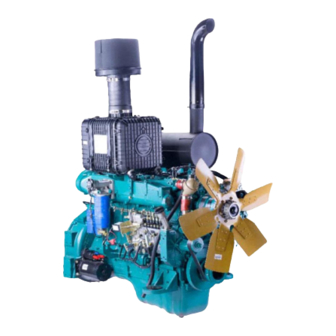
Технические характеристики двигателя WD10
Характеристика Значение Объём двигателя (куб. см.). 9726 Расположение / количество цилиндров. R / 6 Диаметр цилиндра (мм). 126 Ход поршня (мм). 130 Зазор впускного клапана(мм). 0.3 Зазор выпускного клапана(мм). 0.4 Охлаждение. водяное Порядок работы. 1-5-3-6-2-4 Тип топлива. дизель Впрыск. прямой Система управления. Механический рядный ТНВД Объём масляной системы(литр). ~25 Мощность кВт/ л.с. / об.мин. 154 / 220 / 2000 Экологический класс. 2 Турбина. да Охлаждение наддува. да Степень сжатия / компрессия. 17:1 / Диагностика двигателя WD10.
Перед проведением ремонта, необходимо провести диагностику двигателя. Диагностика двигателя выявляет степень отклонения от норм предусмотренных производителем и целесообразность демонтажа двигателя с техники.
Диагностика двигателя Weichai WD10 является одной из основных процедур. Правильно поставленный диагноз неисправности, позволяет избежать чрезмерных трат при проведении ремонта. При диагностике проводится визуальный осмотр двигателя на предмет подтекания эксплуатационных масел и жидкостей, замер компрессии, давления картерных газов, давления масла, давления наддува турбины, температуру и цвет выхлопных газов. А так же при возможности компьютерная диагностика. По результатам диагностики принимается решение о проведение ремонта на месте, частичной разборке. Или демонтаж двигателя для проведения ремонта в условиях мастерской.
Условием для проведения диагностики и ремонта двигателя WD10 :
- Повышенный расход масла.
- Сапунение двигателя (выброс масла, или белёсый дым из сапуна двигателя).
- Снижение мощности двигателя вплоть до остановки.
- Повышение или понижение уровней масел или эксплуатационных жидкостей.
- Повышенная дымность двигателя.
- Увеличенный расход топлива.
- Затруднённый запуск.
- Посторонние звуки при работе двигателя.
- Падение давления масла.
Причины возникновения:
- Естественный износ в процессе эксплуатации.
- Топливо низкого качества.
- Прогар, трещины в днище поршней.
- Залегание колец.
- Масляное «голодание» узлов и деталей.
- Износ сальниковых уплотнений стержней клапанов.
- Износ кулачков распредвала.
- Увеличение зазоров сопрягаемых поверхностей.
- Падение давления масла.
Работы по месту нахождения техники:
- Диагностика двигателей Weichai WD10 на автомобиле или спецтехнике.
- Частичный ремонт двигателей на месте (замена прокладки ГБЦ, демонтаж/монтаж топливной аппаратуры: форсунок, ТНВД, турбины, замена датчиков).
- Снятие двигателя WD10 .
- Установка двигателя и запуск в работу.
Работы по капитальному ремонту двигателя Weichai WD10 включает в себя:
- Заключение договора на ремонт.
- Предварительная мойка.
- Разборка двигателя.
- Мойка деталей двигателя.
- Визуальный осмотр и замер деталей: занесение размеров в дефектовочный лист с эталонными значениями.
- По результатам дефектовки составление заключения и согласование с заказчиком окончательной стоимости и сроков ремонта.
- Подбор и заказ запасных частей для двигателей Weichai WD10 .
- Производиться при необходимости расточка блока цилиндров под ремонтный размер поршней или гильзовка под номинальный размер.
- Ремонт форсунок Weichai WD10
- Замена втулок распредвала.
- Шлифовка и полировка шеек коленвала.
- Замена шатунных и коренных вкладышей.
- Замена втулок головки шатуна.
- Замена всех уплотнений (прокладки, сальники, резиновые кольца)
- Замена поршней.
- Ремонт головки блока цилиндров Weichai WD10
- Замена направляющих втулок клапанов.
- Правка сёдел клапанов или замена седла клапана.
- Восстановление привалочной плоскости ГБЦ.
- Притирку клапанов.
- Сборку двигателя.
- Обкатку двигателя.
- Отправку двигателя заказчику или установку мастерами компании «Большие машины».
При выполнении частичного или капитального ремонта применяются оригинальные запасные части или проверенных производителей хорошо зарекомендовавших себя во время эксплуатации грузовой и специальной техники, а расходные материалы (герметики силиконовые и анаэробные) надлежащего качества.
На все виды работ дается гарантия 1000 моточасов.
Записаться на техническое обслуживание, диагностику или ремонт двигателя Weichai WD10 можно по телефону : +7(495)095-05-35 или воспользоваться формой обратной связи.
Прайс на ремонт двигателя WD10
№ Наименование работ Нормо часы Цена, руб 1 Выезд мобильной бригады в пределах МКАД — от 4000 2 Выезд мобильной бригады от МКАД (рублей/километр) — 15 3 Т.О. двигателя от 2 от 3500 4 Диагностика двигателя от 1 от 1500 5 Демонтаж двигателя от 5 от 6000 6 Предварительная мойка двигателя от 1 от 1000 7 Разборка и дефектовка двигателя от 4 от 5000 8 Технологическая мойка деталей от 1 от 1200 9 Опресовка ГБЦ (головки блока цилиндров) от 8 от 1100 10 Опресовка БЦ (блока цилиндров) от 8 от 3800 11 Шлифовка коленчатого вала от 8 от 8000 12 Расточка и хонинговка блока цилиндров от 8 от 3600 13 Гильзовка и хонинговка (без стоимости гильз) от 8 от 1800 14 Восстановление плоскости ГБЦ от 8 от 1300 15 Восстановление плоскости БЦ от 8 от 3200 16 Замена направляющей клапана (за штуку) от 8 от 207 17 Замена седла клапана (за штуку) от 8 от 1000 18 Правка фаски седла клапана от 8 от 200 19 Замена втулки шатуна от 8 от 800 20 Сборка/регулировка/обкатка двигателя от 16 от 17000 * Данные о ценах носят справочный характер и ни при каких условиях не является публичной офертой, которая определяется положениями Статьи 437 (2) Гражданского кодекса РФ. Для получения подробной информации о наличии и стоимости указанных товаров и (или) услуг, пожалуйста, обращайтесь по телефону:+7(495)095-05-35
** Все технические данные представленные на данной странице носят исключительно справочно-информационный
Наши работы по WD10

Specifications:
|
Accompanying Data:
WEICHAI WD10 Engine PDF Service Manual (Updated: Wednesday 14th of December 2022 01:47:08 AM)
Rating: 4.4 (rated by 79 users)
Compatible devices: WP6GNA, WP10, WD615, WP13 Series, WP4GNA, WP7 Euro VI, WP13C450-18, WP6GTA.
Recommended Documentation:
WEICHAI WD10: Text of Service Manual
(Ocr-Read Version Summary of Contents, UPD: 14 December 2022)
-
34, Service Manual for WD10 Diesel Engine 24 12. Incorrect valve or injection timing Check and adjust it. 13. Governor high-speed regulating performance is poor Check the speed control characteristic and adjust. 14. High engine oil level in oil sump Check oil dipstick and drain redundant engine oil out. 15. Air leakage in cylinder gasket Check the compre…
-
129, Service Manual for WD10 Diesel Engine 119 41113 Steps to Assemble Engine Accessory System Assembly of generator module (1) Place the generator on generator support, loose-fit it on the support and draw-in rod with fixing bolts. (2) Install generator poly V-belt. (3) Adjust the location of generator and tension the poly V-belt with the draw-in rod, tighten gen…
-
30, Service Manual for WD10 Diesel Engine 20 infiltration of dust and impurities will lead to premature wear of engine. Remove the filter element from air filter, pat its end faces gently to clean the dust on it, blow it with compressed air reversely (from inside to outside) is also feasible. Fig. 2-15 Air filter element ATTENTION: Do not let the air broke filter paper and do not clean…
-
117, Service Manual for WD10 Diesel Engine 107 (4) Install engine oil pump. (5) Install and tighten the two toothed hexagon bolts. 493 Disassembly, Inspection, Maintenance and Assembly of Engine Oil Pump Intermediate Gear 4931 Exploded View of Engine Oil Pump Intermediate Gear Seal ring Hexagon bolt Intermediate gear shaft Engine oil pump intermediate gear module Fig…
-
62, Service Manual for WD10 Diesel Engine 52 Compound gasket Seal ring Main bearing bolt Main oil gallery rear plug Bowl shape plug Rivet Fig. 4-20 Exploded view of engine block assembly 4312 Steps to Disassemble Engine Block Assembly (1) Remove crankcase fastening bolts (key point 1); (2) Remove main bearing bolts (key point 2); (3) Remove seal rings; (4) Remove cylin…
-
114, Service Manual for WD10 Diesel Engine 104 4844 Steps to Assemble Thermostat (1) Before the assembly, check the clamps, cooling water adapters, thermostat and thermostat cap, make sure there is no manufacturing and use defect and damage. (2) Clean up cooling water outlet pipe and water pump outlet pipe. (3) Assembling steps are contrary to disassembling ones. …
-
3, Service Manual for WD10 Diesel Engine WD10 China II series diesel engine (China II emission standard)
… -
156, Service Manual for WD10 Diesel Engine 146 4115 Disassembly, Inspection, Maintenance and Assembly of Steering Pump 41151 Exploded View of Steering Pump 1 Hexagon bolt (×2, not the same) 2 Spring washer 3 Steering pump 4 Sealing gasket 5 Steering pump fitting hole Fig. 4-91 Exploded view of steering pump 41152 Steps to Disassemble Steering Pump …
-
22, Service Manual for WD10 Diesel Engine 12 Loctite 277 Used for the seal between core and hole Other bowl type plugs Loctite 270 Used to seal top end face of cylinder cover Pushrod bush-Cylinder cover Loctite 518 (Renewed product of 510) Apply on shining metallic surface for sealing Fitting surface between cylinder blo…
-
98, Service Manual for WD10 Diesel Engine 88 462 Disassembly, Inspection, Maintenance and Assembly of Intake Pipe 4621 Exploded View of Intake Pipe Intake pipe Intake pipe gasket Stud Intake heater Intake heater gasket Intake pipe adapter Nut Stud Intake pipe bolt Nut Intake pipe end cover gasket Intake pipe end cover Fig. 4-51 Exploded view of intake pip…
-
54, Service Manual for WD10 Diesel Engine 44 details). Besides, for engine with EVB oil pipe, the pipe need to be remove too. Disassembling of other parts is as follows: (1) Remove cylinder cover auxiliary nuts, and take down the clamp blocks, there are two kinds of clamp blocks: one is installed between two adjacent cylinder covers, the other is installed on two sides; (2) Remov…
-
44, Service Manual for WD10 Diesel Engine 34 (10) Be sure to seek for medical help immediately if any adverse reaction happened to your skin. (11) If possible, clear away oil dirt on parts before transporting the engine. (12) Please wear google or protective mask if there is risk of damaging your eyes. Eye washing fluid must be prepared within reach. (13) When maintaining…
-
146, Service Manual for WD10 Diesel Engine 136 5) Positive pressure inspection method After maintenance but before filling refrigerant, add a small amount of gaseous refrigerant and inflate the system with nitrogen to 1.4~1.5MPa, maintain the pressure for 12h. If pressure drop exceeds 0.005MPa, then it indicates that there is system leakage. Find out the leaking positi…
-
120, Service Manual for WD10 Diesel Engine 110 4954 Steps to Assemble Engine Oil Cooler Cap (1) Check the cooler cap and gasket before assembling, make sure there is no manufacturing defect and damage. (2) Clean up the fitting surface between engine oil cooler cap and engine block, install cooler cap gasket. (3) Install and tighten engine oil cooler cap fixing…
WEICHAI WD10: Recommended Instructions
MC-120, TO-25244, IC 10 SM, AF-S NIKKOR 200mm f/2G ED VR II, MOX6


-
1BULGuía rápida de instalación y programación MSB-017/01AVISOEsta guía rápida es un resumen del manual de instalación completo. Dicho manual contiene advertencias deseguridad y otras explicaciones que deben ser tenidas en cuenta. Puede descargar el manual de instalación enel apartado “Descargas” de la web de Erreka: http://www.erreka.com/Automatismos/descargaDocumentos.aspxE187A2x1mm22 …
BUL BL33 24
-
«‘( £ It IJ » ~ .., #J. l’ ‘» ~ ‘» o <) IlLD~’ OPERATORS MANUAL 8.0 KW • 60Hz 6.4 KW • 50Hz BEG 10.0 KW • 60Hz 8.0 KW • 50Hz BEG 12.5 KW • 60Hz 10.0 KW • 50Hz BEG 15.0 KW • 60Hz 12.0 KW • 50Hz BEG ——.—,’—- -MARINE GA L E GENERATORS PUBLICATION N .046221 FIRST EDITION JULY 2001 ~ .. WESTER …
10.0 KW-60Hz SBEG 57
-
Engine Printable View (1982 KB) Installation All vehicles 1. With the vehicle in NEUTRAL, position it on a hoist. For additional information, refer to Section 100-02. 2. Raise the engine high enough to clear the No. 1 crossmember, then position the engine into the vehicle. Vehicles with automatic transmission 3. Align the torque converter studs with the holes in the …
F-Super Duty 250 2003 9
-
TD407477_SHB Rev F06.11.2015MPE 850 MARINE – 408101 I2 846 MAR TC-100 (TC-80) (TC-120) – 408014 I2 846 MAR TC-120 – 408090 I2 846 MAR TC-155 – 408246 I2 846 MAR NA-80This service manual is valid for the following engine models:Read this service manual thoroughly before operating the engine for the first time. SERVICE MANUAL4-Stroke Engine en_English …
MPE 850 MARINE 96
-
SAVE THESE INSTRUCTIONS FOR FUTURE REFERENCEIF 1767ACE-DG1 Variable Frequency Drive SystemInstallation & Maintenance InformationIF 1767 • 09/15 Copyright© 2015, Eaton’s Crouse-Hinds Division Page 1TABLE OF CONTENTS1. Safety Instructions 1.1 Appli …
Crouse-hinds series 12
-
1EngineDLE85使用说明书USER MANUAL该发动机并非玩具,请特别注意安全,由此引起的所有安全问题我们将不予负责;为了您更好地使用该产品,请您在使用前仔细阅读说明书。This engine is not toy. For your own safety, please read the manual carefully beforeoperation. DLE is not responsible for all injuries result from the use. …
DLE-85 4
-
P. I. E. INEL Sp. z o. o., ul. Mostowa 1, 80-778 Gdańsk, [email protected] www.inel.gda.pl Operating instructions Obstacle detection motor with built in radio receiver and electronic limit switches YYGL35RE-10/17 YYGL45RE-20/15 1. SAFETY GUIDELINES 1.1 Basic guidelines The obstacle detection mo …
YYGL35RE-10/17 4
-
LZB 66 A0025-11Printed Matter No. 9836 4452 00 Air MotorsValid from Serial No. A0760001 Original Product instructions2010-018411 0600 83LZB 66 A0025-11 (240 r/min)WARNINGTo reduce risk of injury, everyone using,installing, repairing, maintaining, changingaccessories on, or working near this tool MUSTread and understand these instructions beforeperforming any such task.DO NOT DISCARD …
LZB 66 A0025-11 32
-
1DLE-60Operator’s ManualSpecifications61cc [3.7cu. in.]5.5HP/ 8,500RPM1, 4 0 0 R P MElectronic Ignition 22u10, 23u8, 23u10, 24u8CM6(Gap) 0.018 in.– 0.020in. [0.46–.051mm]1.42in. [36mm] u1.18in. [ 30mm ]7. 6 : 1 DLE with Manual ChokeMain Engine − 55oz [1,560 g] Mufflers (2) − 5.6oz [160g] Electronic Ignition − 5.6oz [160g]Standoffs − 1oz [28g]Spark Plugs − 1 …
DLE-60 24
-
HIRTH OPERATOR’S MANUAL F-23 engine IMPORTANT: THIS MANUAL CONTAINS IMPORTANT SAFETY AND MAINTENANCE INFORMATION CONCERNING YOUR ENGINE. IT MUST BE READ THROUGH IN ITS ENTIRETY AND COMPLIED WITH WHERE APPLICABLE IMMEDIATELY UPON RECEIPT OF ENGINE, EVEN IF THE ENGINE WILL NOT BE USED IMMEDIATELY. T …
F-23 34
Additional Information:
Product Types by WEICHAI:
- Inverter
- Engine
Popular Right Now:
Operating Impressions, Questions and Answers:
|
View errors |
The corresponding element in the |
Questions |
The cause of the error |
Method of eliminating |
Error code |
||
|
Errors associated with starting the engine |
AD converter malfunction in ECU |
ECU. Error in signal processing has led to failure, did not even start the engine. |
|
Replacing The ECU |
1 |
1 |
1 |
|
Bug synchronous signals |
Signal synchronization errors can lead to abnormal fuel injection, hard starting, exhaust black smoke, abnormal noise of engine etc. |
Error signals measured sensor crankshaft or camshaft speed sensor |
Check connections and crankshaft sensor. Check the clearances of the crankshaft sensor and the flywheel within 1.0 ± 0.5 mm |
1 |
1 |
2 |
|
|
1 |
1 |
3 |
|||||
|
1 |
1 |
4 |
|||||
|
Item error processing time at ECU |
Engine stalls, won’t start |
|
Replace The ECU |
1 |
1 |
5 |
|
|
|
Lack of engine power |
|
Switch off the power and ECU reset ECU, if the problem is not resolve itself, replace the ECU |
1 |
1 |
6 |
|
|
Error starting relay |
The engine does not start. |
Damage to the wiring harness, damage the actuator relay |
Check the Starter relay and its circuit |
1 |
2 |
1 |
|
|
Switch error T15 |
|
|
Check breaker T15 |
1 |
2 |
2 |
|
|
Switch error T50 |
|
Activation switch more 120s |
Check the switch T50 |
1 |
2 |
3 |
|
|
Battery |
Power fault |
Battery voltage too high (> 36V) or too low (< 6V) |
Check the wiring harness battery, engine and car |
1 |
2 |
4 |
|
|
Pulse spectrum diagram FMTC |
|
Error setting |
Change setting |
1 |
2 |
5 |
|
|
The power supply of the sensor in ECU |
Error in ECU or short circuit pressure sensor inlet (2.33), oil pressure sensor (2.32) with power car (24V) or grounding |
Check the wiring harnesses, pressure sensors, inlet oil pressure (maximum current supply 90mA) |
1 |
3 |
1 |
||
|
Lack of engine power |
Error in ECU or KZ supply (1.84) sensor no. 2 accelerator pedal |
Check sensor no. 2 accelerator pedal (maximum current supply for SSP2 90mA) |
|||||
|
Lack of engine power |
Error in ECU or shorted power supply (1.84) sensor no. 1 pedal or SHORT CIRCUIT pressure sensor line (2.13) |
Check sensor no. 1 pedal pressure sensor line (SSP3 power Max current 50mA) |
|||||
|
Error main relay |
General pipe pressure limiting valve (PRV) is open, the engine’s lack of |
Short circuit element flow measurement (3.09 3.10) |
Check wires on flow sensor SHORT CIRCUIT or open circuit |
1 |
3 |
2 |
|
|
Output short circuit power supply ECU (1.04 2.03) |
Check the wires for the presence of: 2.03 1.04? CZ (Note: you must use the power output of the ECU is not allowed to use external power |
||||||
|
The relevant elements of the common system backbone |
Pressure sensor line |
Open the pressure limiting valve tubes General Highway |
Flow measurement element damage or SHORT-CIRCUITS, open circuit |
Check flow measurement items and a bunch of wires on the presence of a SHORT CIRCUIT or breakage |
1 |
3 |
3 |
|
Faulty pressure limiting valve common Highway |
The issue of fuel lines. Pressure sensor line, the element flow measurement, occlusion and bypass the supplied fuel will lead to too many |
Check out toplioprovody and a pressure sensor line, flow measurement element |
1 |
3 |
4 |
||
|
Flow dimension member error |
Flow measurement element is damaged or kz, open circuit wiring harness |
Check flow measurement elements and a bundle of wires |
1 |
3 |
5 |
||
|
General line item |
Dekompressirovanija valve for line pipes |
Serious valve wear dekompressirovanija causes abnormal fluctuation of pressure line |
Occlusion the low pressure fuel line (including the fuel feed and bypass fuel) causes frequent opening or opening the valve of dekompressirovanija |
Replace the ramp |
1 |
3 |
6 |
|
Injector |
Error injector cylinder 1 |
Lack of engine power, unstable (engine troit) |
Bad contact harnesses atomizers or breakage of the wires |
Check wiring harness and their connection with nozzle |
1 |
4 |
1 |
|
Error injector cylinder 2 |
1 |
4 |
2 |
||||
|
Error injector cylinder 3 |
1 |
4 |
3 |
||||
|
Error injector cylinder 4 |
1 |
4 |
4 |
||||
|
Error injector cylinder 5 |
1 |
4 |
5 |
||||
|
Error injector cylinder 6 |
1 |
4 |
6 |
||||
|
Capacitor control injector |
Error 1 condenser control nozzles 1.2.3 |
1 |
5 |
1 |
|||
|
Error 1 condenser control nozzles 4.5.6 |
1 |
5 |
2 |
||||
|
Chip injection |
Injector control chip error |
1 |
5 |
3 |
|||
|
Injection |
Does not reach the minimum number of normal working nozzles |
Stopping the engine |
Short-circuit or disconnection harnesses more than 3 cylinders |
Check wiring harness injectors each cylinder |
1 |
5 |
4 |
|
Limitation of nozzles in ECU |
|
|
|
1 |
5 |
5 |
|
|
The important switches, sensors |
Water in fuel |
Water content indicator lamp in the fuel burning, the water level alarm |
Diesel fuel coarse purification filter filled with water |
Drain the water from diesel fuel |
2 |
1 |
1 |
|
Sensor error 1 pedals |
Revolutions of the crankshaft around 1000 rpm |
Open circuit or defective accelerator pedal |
Check the chain on the presence of breakage and SHORT CIRCUIT, Replace the accelerator pedal |
2 |
2 |
1 |
|
|
Sensor error 2 pedals |
|||||||
|
Clutch sensor error |
Cruise cannot be executed |
Faulty sensors or open circuit |
Check sensor wiring harness |
2 |
2 |
3 |
|
|
Brake switch error |
2 |
2 |
3 |
||||
|
Brake switch error |
Activating the brake fails, it is not allowed to carry out cruise |
Before the cruise, you should press the brake pedal |
2 |
2 |
3 |
||
|
Confidence check error valve gas and brake |
|
Simultaneous pressing the pedal of acceleration and brake pedals |
Check the chain sensor brakes on presence of CZ |
2 |
2 |
5 |
|
|
Motor protection |
|
Overclocking engine (> 2650rpm) |
|
2 |
2 |
6 |
|
|
|
|
|
2 |
2 |
7 |
||
|
Reconfiguring the engine torque |
Not successfully increase torque |
Too large an input torque transmission box |
|
2 |
2 |
8 |
|
|
Remote valve gas pedal |
Not effect pedal remote gas valve |
Sensor error valve gas pedal or short circuit, open wire harnesses |
Check the sensor wire harness, if necessary replacement pedals gas valve |
2 |
2 |
9 |
|
|
Inlet pressure sensor |
Emergency towing |
Sensor error or short circuit, open circuit |
Check the sensor wire harness, if necessary, replace the sensor |
2 |
3 |
1 |
|
|
Atmospheric pressure sensor |
This sensor installed on the ECU, check the likelihood of clogging |
2 |
3 |
2 |
|||
|
Intake temperature sensor |
Check the sensor wire harness, if necessary, replace the sensor |
2 |
3 |
3 |
|||
|
Coolant temperature sensor |
Emergency towing is not the normal operation of the heater air inlet |
Check the sensor wire harness, if necessary, replace the sensor |
2 |
4 |
1 |
||
|
Coolant temperature too high |
When the coolant temperature is above 105 degrees, the engine is operated with limited capacity |
Coolant temperature too high |
Check engine cooling system |
2 |
4 |
2 |
|
|
Oil pressure too high |
Oil pressure distortion if the device uses a CAN bus |
Error sensor oil pressure or oil pressure too high |
Too high oil temperature |
2 |
4 |
3 |
|
|
Oil pressure too low |
|
Oil pressure too low |
|||||
|
Oil temperature sensor |
|
Too high oil temperature |
2 |
4 |
4 |
||
|
Too high oil temperature alarm |
|
Too high oil temperature |
|||||
|
Test water temperature sensor |
|
|
|
2 |
4 |
5 |
|
|
Monitoring of fuel pressure in the line |
High-pressure fuel line issue/low pressure fuel line (leaked) |
Hard start, will not start. Open the pressure limiting valve, leaking large amount of high-pressure fuel |
Too much flow resistance of fuel or fuel leaks. |
Check the fuel lines to the engine. If you need replacement filters, fuel line, etc. |
2 |
5 |
1 |
|
2 |
5 |
2 |
|||||
|
2 |
5 |
3 |
|||||
|
2 |
5 |
4 |
|||||
|
2 |
5 |
5 |
|||||
|
2 |
5 |
6 |
|||||
|
2 |
5 |
7 |
|||||
|
ECU |
ECU system return to its original position |
Open the pressure limiting valve, emergency towing |
Internal error in ECU |
After disconnecting the AC switch. If the matter is not resolved, you should replace the ECU |
2 |
6 |
1 |
|
|
Test on overclocking |
|
|
|
2 |
6 |
2 |
|
ECU check and measurement equipment internal ECU |
Chip CJ940 |
Engine ignition fault |
Communication error |
After disconnecting the current restart System |
2 |
6 |
3 |
|
Too high tension |
|||||||
|
Too low internal stress |
|||||||
|
ECU chip and Watchdog |
Fault ignition engine (after AC restart) |
Communication error |
2 |
6 |
4 |
||
|
EEPROM (erasable programmable read only memory) |
On kilometre information may not be registered |
|
Replacing The ECU |
2 |
6 |
5 |
|
|
ECU functions and switches |
Solenoid valve exhaust brake |
Exhaust brake is defective |
Short circuit motor brake solenoid valve (2.06) with meals |
Check the exhaust brake solenoid valve circuit |
3 |
1 |
1 |
|
Short circuit motor brake solenoid valve (2.06) weighing |
|||||||
|
AC Compressor Relay |
AC compressor not working |
Error connecting AC Compressor Relay |
Check the relay and its compounds |
3 |
1 |
3 |
|
|
Inlet heating relay |
Heating air inlet may not function correctly. |
Short circuit relay with ground or power |
To verify a connection relay heating air inlet |
3 |
2 |
1 |
|
|
|
|
3 |
2 |
2 |
|||
|
3 |
2 |
3 |
|||||
|
Vehicle speed sensor |
May not be a cruise out of the car button has no effect |
Exceeding the maximum speed of the car or not reliable signals of the speed of the car, not a stable voltage |
Check the vehicle speed sensor connection, if necessary, replace the sensor |
3 |
2 |
4 |
|
|
Many provisions of the switch |
Torque limitation, limiting speed and other functions cannot be performed |
Error wiring harnesses or resistor |
Error wiring harnesses or resistor |
3 |
2 |
7 |
|
|
Lamp system |
The indicator function of the respective lamps are not met |
Connection failed or connection is not implemented |
Test connection |
3 |
3 |
1 |
|
|
Lamp cold start |
3 |
3 |
2 |
||||
|
Signal lamp |
3 |
3 |
3 |
||||
|
Water in fuel lamp |
3 |
3 |
4 |
||||
|
Cruise switch |
May not be a cruise/PTO, or cruise/PTO goes out of action |
Cruise switch error |
It is recommended that you switch samovosstanovitelnyj |
3 |
4 |
1 |
|
|
Exhaust brake switch |
|
|
|
3 |
4 |
2 |
|
|
Switch out of the car |
Start without a car could not be implemented |
Sticking switch |
Check the circuit breaker or circuit wires |
3 |
4 |
3 |
|
|
External dimension |
Check Disable ignition |
Lack of engine power, not stable operation |
Disabling cylinder No. 1 |
Check the appropriate nozzle, sealing lid cylinder, valve clearance, etc. |
5 |
1 |
1 |
|
Disabling cylinder No. 2 |
5 |
1 |
2 |
||||
|
Disabling cylinder # 3 |
5 |
1 |
3 |
||||
|
Disabling multiple cylinders |
5 |
1 |
4 |
||||
|
Disabling cylinder No. 4 |
5 |
3 |
1 |
||||
|
Disabling cylinder # 5 |
5 |
3 |
2 |
||||
|
Disabling cylinder # 6 |
5 |
3 |
3 |
||||
|
External dimension |
|
|
|
5 |
3 |
4 |
|
|
These faults relate to functional indication. When applying the diagnostic tool for the revitalization of internal measuring functions will turn |
5 |
2 |
1 |
||||
|
5 |
2 |
2 |
|||||
|
5 |
2 |
3 |
|||||
|
Issues related to starting |
The issue of synchronous signals |
|
Poor surface of the teeth of the flywheel |
Replacement flywheel |
5 |
4 |
1 |