-
Contents
-
Table of Contents
-
Bookmarks
Quick Links
Related Manuals for Weider Pro 5500
Summary of Contents for Weider Pro 5500
-
Page 5
M10 Nylon M6 Nylon M8 Nylon M12 Nut (112) Locknut (107) Locknut (77) Locknut (78) M4 Washer (104) M6 Washer M8 Washer (103) (114) M10 Washer (80) M10 Large Washer (105) M4 x 12mm M4 x 16mm M6 x 16mm Self-tapping M8 x 22mm Self-tapping… -
Page 6
Boulon à Épaulement M8 x 69mm (87) M8 x 75mm Carriage Bolt (83) Boulon de M10 x 65mm (85) M10 x 75mm Bolt (82) M8 x 80mm Bolt (100) Boulon de M8 x 65mm (101) Boulon en Bouton de M10 x 65mm (106) M10 x 80mm Bolt (84) Vis en Bouton de M6 x 60mm (91) M10 x 82mm Button Screw (92) -
Page 7
Backrest Adjustment Knob (53) Curl Adjustment Knob (58) Seat Adjustment Knob (52) -
Page 31
MUSCLE CHART A. Sternomastoid (neck) B. Pectoralis Major (chest) C. Biceps (front of arm) D. Obliques (waist) E. Brachioradials (forearm) F. Hip Flexors (upper thigh) G. Abductor (outer thigh) H. Quadriceps (front of thigh) Sartorius (front of thigh) J. Tibialis Anterior (front of calf) K. -
Page 34
70 71…
Modelnr. WEEVSY2996.0
Serienr.
Schrijf het serienummer in de lijn hier-
boven voor toekomstige referentie.
GEBRUIKERSHANDLEIDING
Serienummer Sticker (onder zitting)
VRAGEN?
Als fabrikant zijn wij gesteld op
uw volledige tevredenheid.
Mocht u nog vragen hebben,
mochten sommige onderdelen
ontbreken of beschadigd zijn
neem dan contact op met de
winkel waar u dit product hebt
gekocht.
WAARSCHUWING
Lees alle voorzorgsmaatregelen
en instructies in deze handlei-
ding zorgvuldig voor gebruik.
Bewaar deze handleiding voor
toekomstige referentie.

Model No. WEEVSY2996.0 Serial No.
Write the serial number in the space above for future reference.
Serial Nu
Nu mber
mber Decal (under seat)
QUESTIONS?
As a manufacturer, we are committed to providing complete customer satisfaction. If you have questions, or if there are missing or damaged parts, please call:
08457 089 009
Or write:
ICON Health & Fitness, Ltd.
Unit 4
Revie Road Industrial Estate
Revie Road, Beeston
Leeds, LS11 8JG
UK
email: csuk@iconeurope.com
CAUTION
Read all precautions and instructions in this manual before using this equipment. Save this manual for future reference.
USERʼS MANUAL
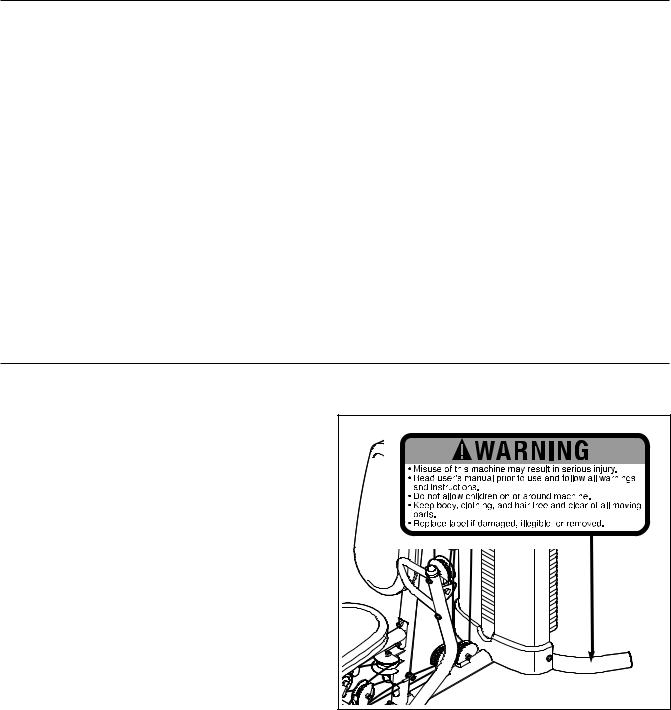
TABLE OF CONTENTS
WARNING DECAL PLACEMENT . . . . . . . . . . . . . . . . . . . . . . . . . . . . . . . . . . . . . . . . . . . . . . . . . . . . . . . . . . . . . .2 IMPORTANT PRECAUTIONS . . . . . . . . . . . . . . . . . . . . . . . . . . . . . . . . . . . . . . . . . . . . . . . . . . . . . . . . . . . . . . . . 3 BEFORE YOU BEGIN . . . . . . . . . . . . . . . . . . . . . . . . . . . . . . . . . . . . . . . . . . . . . . . . . . . . . . . . . . . . . . . . . . . . . . 4 PART IDENTIFICATION CHART . . . . . . . . . . . . . . . . . . . . . . . . . . . . . . . . . . . . . . . . . . . . . . . . . . . . . . . . . . . . . .5 ASSEMBLY . . . . . . . . . . . . . . . . . . . . . . . . . . . . . . . . . . . . . . . . . . . . . . . . . . . . . . . . . . . . . . . . . . . . . . . . . . . . . . 8 ADJUSTMENTS . . . . . . . . . . . . . . . . . . . . . . . . . . . . . . . . . . . . . . . . . . . . . . . . . . . . . . . . . . . . . . . . . . . . . . . . . . 25 WEIGHT RESISTANCE CHART . . . . . . . . . . . . . . . . . . . . . . . . . . . . . . . . . . . . . . . . . . . . . . . . . . . . . . . . . . . . . .27 CABLE DIAGRAM . . . . . . . . . . . . . . . . . . . . . . . . . . . . . . . . . . . . . . . . . . . . . . . . . . . . . . . . . . . . . . . . . . . . . . . . .28 MAINTENANCE . . . . . . . . . . . . . . . . . . . . . . . . . . . . . . . . . . . . . . . . . . . . . . . . . . . . . . . . . . . . . . . . . . . . . . . . . .29 EXERCISE GUIDELINES . . . . . . . . . . . . . . . . . . . . . . . . . . . . . . . . . . . . . . . . . . . . . . . . . . . . . . . . . . . . . . . . . . .30 PART LIST . . . . . . . . . . . . . . . . . . . . . . . . . . . . . . . . . . . . . . . . . . . . . . . . . . . . . . . . . . . . . . . . . . . . . . . . . . . . . .33 EXPLODED DRAWING . . . . . . . . . . . . . . . . . . . . . . . . . . . . . . . . . . . . . . . . . . . . . . . . . . . . . . . . . . . . . . . . . . . .34 ORDERING REPLACEMENT PARTS . . . . . . . . . . . . . . . . . . . . . . . . . . . . . . . . . . . . . . . . . . . . . . . . . .Back Cover
WARNING DECAL PLACEMENT
The decal shown at the right has been placed on the weight system in the location shown. If the decal is missing or illegible, call the telephone number on the front cover of this manual and order a free replacement decal. Apply the replacement decal in the location shown.
WEIDER is a registered trademark of ICON IP, Inc.
2
6. Inspect and properly tighten all parts regularly. Replace any worn parts immediately.
7. The weight system is designed to support a maximum user weight of 135 kg (295 lbs).
8. Keep children under 12 and pets away from the weight system at all times.
9. Keep hands and feet away from moving parts.
10. Always wear athletic shoes for foot protection while exercising.
11. Make sure that the cables remain on the pulleys at all times. If a cable binds while you are exercising, stop immediately and make sure that the cable is on the pulleys. Replace all cables at least every two years.
12. The weight system is designed to be used only with the included weight. Do not use the weight system with dumbbells or any other type of weight to increase the resistance.
13. Always make sure that the weight pin is inserted fully into the weight stack before you exercise.
14. If you feel pain or dizziness at any time while exercising, stop immediately and begin cooling down.
15. Do not use more than ten weights with the butterfly arms.
IMPORTANT PRECAUTIONS
WARNING: To reduce the risk of serious injury, read the following important precautions ore using the weight system.
1. Read all instructions in this manual and all warnings on the weight system before using the weight system. Use the weight system only as described in this manual.
2. It is the responsibility of the owner to ensure that all users of the weight system are adequately informed of all precautions.
3. The weight system is intended for home use only. Do not use the weight system in a commercial, rental, or institutional setting.
4. Keep the weight system indoors, away from moisture and dust. Place the weight system on a level surface, with a mat beneath it to protect the floor or carpet. Make sure that there is enough clearance around the weight system to mount, dismount, and use it.
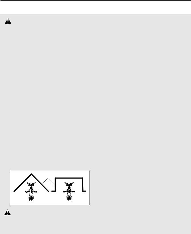
5. The weight system has an open weight stack; the weight stack must not be accessible from any point outside the userʼs field of view. To prevent access to the weight stack, place the weight system in a corner or bay of a room, as shown in the drawing below. There must be no more than 1 meter (3 ft. 4 in.) of clearance between the weight system and the adjacent walls.
Wall
WARNING: Before beginning this or any exercise program, consult your physician. This specially important for persons over the age of 35 or persons with pre-existing health problems.
Read all instructions before using. ICON assumes no responsibility for personal injury or property damage sustained by or through the use of this product.
3
BEFORE YOU BEGIN
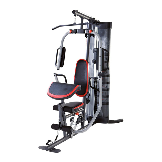
Thank you for selecting the versatile WEIDER™ PRO 5500 weight system. The weight system offers a selection of weight stations designed to develop every major muscle group of the body. Whether your goal is to tone your body, build dramatic muscle size and strength, or improve your cardiovascular system, the weight system will help you to achieve the specific results you want.
For your benefit, read this manual carefully before using the weight system. If you have questions after
reading this manual, please see the front cover of this manual. To help us assist you, note the product model number and serial number before contacting us. The model number is WEEVSY2996.0. The serial number can be found on a decal attached to the weight system (see the front cover of this manual).
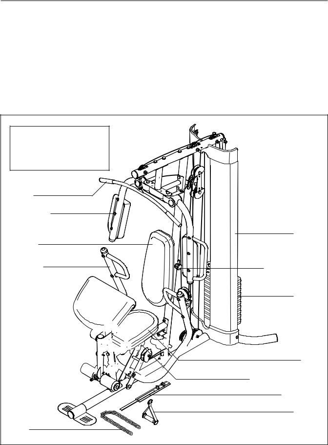
Before reading further, please review the drawing below and familiarize yourself with the parts that are labeled.
Note: The terms “right side” and “left side” are determined relative to a person facing away from the weight system; they do not correspond to right and left on the drawings in the manual.
Shroud
Backrest Adjustment Knob
Weight
Left Side
Seat
Seat Adjustment Knob
Ankle Strap
Handle
4

PART IDENTIFICATION CHART—Model No. WEEVSY2996.0 R0706A
Refer to the drawings below to identify small parts used in assembly. The number in parentheses by each drawing is the key number of the part, from the PART LIST in the center of this manual. Note: Some small parts may have been preattached. If a part is not in the parts bag, check to see if it has been preattached.
|
M6 Nylon |
M8 Nylon |
M10 Nylon |
M12 Nut (112) |
|
Locknut (107) |
Locknut (78) |
Locknut (77) |
|
M4 Washer |
||||
|
(104) |
M6 Washer |
M8 Washer (103) |
||
|
(114) |
M10 Washer (80) |
|||
|
M10 Large Washer (105) |
||||
|
M4 x 12mm |
M4 x 16mm |
M6 x 16mm |
M8 x 22mm |
|
|
Self-tapping |
Self-tapping |
Screw (88) |
||
|
Screw (102) |
Screw (110) |
Shoulder Bolt (90) |
M12 Large Washer (98) |
|
|
M10 x 70mm Bolt (113) |
M10 x 75mm Button Screw (118) |
|
90mm Spacer (59) |
19mm Spacer (67) |
|
|
56.5mm Spacer (69) |
13mm Steel Spacer (109) |
|
|
21mm Steel Spacer (108) |
11mm Spacer (99) |
|
|
5 |

PART IDENTIFICATION CHART—Model No. WEEVSY2996.0 R0706A
|
Boulon à Épaulement M8 x 69mm (87) |
M8 x 75mm Carriage Bolt (83) |
|
Boulon de M10 x 65mm (85) |
M10 x 75mm Bolt (82) |
|
Boulon de M8 x 65mm (101) |
M8 x 80mm Bolt (100) |
|
Boulon en Bouton de M10 x 65mm (106) |
M10 x 80mm Bolt (84) |
|
Vis en Bouton de M6 x 60mm (91) |
|
|
M10 x 82mm Button Screw (92) |
|
|
Boulon de M10 x 60mm (79) |
|
|
M10 x 85mm Bolt (81) |
|
|
Boulon de M10 x 50mm (97) |
|
|
M10 x 61mm Bolt Set (116) |
|
|
Boulon de M10 x 45mm (86) |
|
|
Vis de M6 x 32mm (89) |
M10 x 110mm Bolt (93) |
|
M6 x 28mm |
M10 x 120mm Bolt (115) |
|
Bolt (94) |
|
|
M10 x 155mm Bolt (96) |
6

PART IDENTIFICATION CHART—Model No. WEEVSY2996.0 R0706A
Backrest Adjustment Knob (53)
Curl Adjustment Knob (58)
Seat Adjustment Knob (52)
7
ASSEMBLY
Make Assembly Easier
Everything in this manual is designed to ensure that the weight system can be assembled successfully by anyone. Before beginning assembly, make sure to read the information on this page. This brief introduction will save you much more time than it takes to read it.
Assembly Requires Two Persons
For your convenience and safety, assemble the weight system with the help of another person.
Set Aside Enough Time
Due to the many features of the weight system, the assembly process will require several hours. By setting aside plenty of time and by deciding to make the task enjoyable, assembly will go smoothly. You may want to assemble the weight system over a couple of evenings.
Select a Location for the Weight System
Because of its weight and size, the weight system should be assembled in the location where it will be used. Make sure that there is enough room to walk around the weight system as you assemble it.
How to Unpack the Box
To make assembly as easy as possible, we have divided the assembly process into four stages. The parts needed for each stage are found in individual bags. Important: Wait until you begin each stage to open the parts bag for that stage. Place all parts of the weight system in a cleared area and remove the packing materials. Do not dispose of the packing materials until assembly is completed.
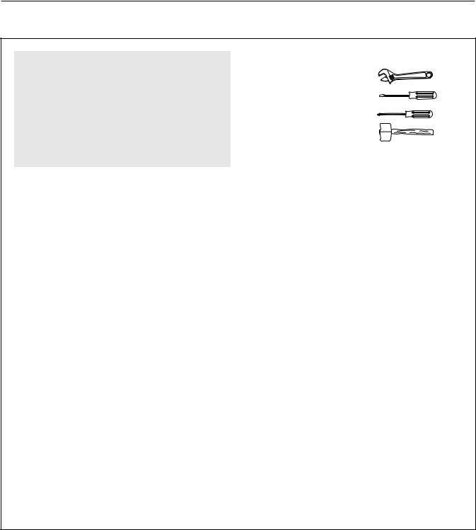
Make sure you have the following tools:
• Two adjustable wrenches
• One standard screwdriver
• One phillips screwdriver
• One rubber mallet
• You will also need grease or petroleum jelly, a small amount of soapy water, and clear tape or masking tape.
Note: Assembly will be more convenient if you have a socket set, a set of open-end or closed-end wrenches, or a set of ratchet wrenches.
How to Identify Parts
To help you identify the small parts used in assembly, we have included a PART IDENTIFICATION CHART in the center of this manual. Place the chart on the floor and use it to easily identify parts during each assembly step. Note: Some small parts may have been pre-attached. If a part is not in the parts bag, check to see if it has been pre-attached. How to Orient Parts
As you assemble the weight system, make sure all parts are oriented exactly as shown in the drawings.
Tightening Parts
Tighten all parts as you assemble them, unless instructed to do otherwise.
Questions?
If you have questions after reading these assembly instructions, please call the phone number on the front cover of this manual.
|
The Four Stages of the Assembly Process |
|||
|
Frame Assembly—You will begin by assembling |
Cable Assembly—During this stage you will |
||
|
the base and the uprights that form the skeleton of |
attach the cables and pulleys that connect the |
||
|
the weight system. |
arms to the weights. |
||
|
Arm Assembly—During this stage you will |
Seat Assembly—During the final stage you will |
||
|
assemble the arms and the leg lever. |
assemble the seats and the backrests. |
||
8

|
Frame Assembly |
1 |
||||||||||
|
1. |
Before beginning assembly, make sure you |
||||||||||
|
understand the information in the box on |
|||||||||||
|
page 8. See the PART IDENTIFICATION |
1 |
83 |
|||||||||
|
CHARTS on pages 5 and 6 of this manual |
|||||||||||
|
for help identifying small parts. |
|||||||||||
|
Insert four M8 x 75mm Carriage Bolts (83) up |
83 |
||||||||||
|
through the Base (1). |
Note: It may be helpful to |
||||||||||
|
place a piece of tape over each Bolt head to |
2 |
||||||||||
|
hold it in place. |
|||||||||||
|
2. Insert an M8 x 75mm Carriage Bolt (83) up |
|||||||||||
|
through the Stabilizer (3). |
|||||||||||
|
Attach the Base (1) and the two Weight Guides |
|||||||||||
|
(18) to the Stabilizer (3) with two M10 x 85mm |
|||||||||||
|
Bolts (81), two M10 Washers (80), two 21mm |
|||||||||||
|
Steel Spacers (108), two M10 Nylon Locknuts |
|||||||||||
|
(77), and an M8 Nylon Locknut (78). Make sure |
|||||||||||
|
the indicated holes in the Weight Guides are |
|||||||||||
|
nearer the bottom. Do not tighten the Nylon |
|||||||||||
|
Locknuts yet. |
|||||||||||
|
Attach the Upright (2) to the Base (1) with the two |
18 |
||||||||||
|
indicated M8 x 75mm Carriage Bolts (83) and two |
|||||||||||
|
M8 Nylon Locknuts (78). Do not tighten the |
|||||||||||
|
Nylon Locknuts yet. |
|||||||||||
|
Holes |
80 |
81 |
|||||||||
|
2 |
78 |
||||||||||
|
77 |
|||||||||||
|
80 |
|||||||||||
|
78 |
|||||||||||
|
78 |
108 |
83 |
3 |
||||||||
|
1 |
|||||||||||
|
83 |
|||||||||||
|
3. Attach the Front Leg (10) to the Base (1) with the |
3 |
||||||||||
|
two M8 x 75mm Carriage Bolts (83) and two M8 |
|||||||||||
|
Nylon Locknuts (78). |
Do not tighten the Nylon |
75 |
10 |
||||||||
|
Locknuts yet. |
104 |
||||||||||
|
Attach the Leg Lever Bumper (75) to the Front |
110 |
78 |
|||||||||
|
Leg (10) with an M4 x 16mm Self-tapping Screw |
|||||||||||
|
(110) and an M4 Washer (104). Make sure the |
78 |
||||||||||
|
end of the Leg Lever Bumper is pointing up. |
|||||||||||
|
1 |
83 |
||||||||||
|
9 |

4.Attach the Frame (9) to the Upright (2) with two M8 x 80mm Bolts (100), two M8 Washers (103), and two M8 Nylon Locknuts (78). Do not tighten the Nylon Locknuts yet.
Attach the Frame (9) to the Front Leg (10) with two M8 x 65mm Bolts (101), two M8 Washers (103), and two M8 Nylon Locknuts (78). Do not tighten the Nylon Locknuts yet.
5.Attach the Top Frame (4) to the Upright (2) with two M8 x 80mm Bolts (100), two M8 Washers (103), and two M8 Nylon Locknuts (78). Do not tighten the Nylon Locknuts yet.
6.Attach the Left Shroud (21) to the Top Frame (4) with two M4 x 12mm Self-tapping Screws (102). See drawing 6A. Attach the bottom of the Left Shroud (21) to the Base (1) with two M4 x 12mm Self-tapping Screws (102).
Repeat this step for the Right Shroud (22).
|
4 |
9 78 |
2 |
|||
|
78 |
103100 |
||||
|
78 |
|||||
|
78 |
103 100 |
||||
|
103 |
10 |
||||
|
101 |
|||||
|
5 |
|||||
|
100 |
103 |
||||
|
103 |
|||||
|
4 |
|||||
|
78 |
|||||
|
782 |
|||||
|
6 |
22 |
6A |
|||
|
4 |
|||||
|
102 |
|||||
|
21 |
|||||
|
1 |
|||||
|
102 |
21 |
10
![]()
|
7. Attach a Shroud Cover (23) to the Left and Right |
7 |
114 |
||||||||
|
Shrouds (21, 22) with two M6 x 28mm Bolts (94), |
94 |
107 |
||||||||
|
four M6 Washers (114), and two M6 Nylon |
114 |
114 |
||||||||
|
Locknuts (107). |
||||||||||
|
23 |
114 94 |
|||||||||
|
Attach the Shroud Cover (23) to the Top Frame |
||||||||||
|
(4) with four M4 x 16mm Self-tapping Screws |
110 |
110 |
||||||||
|
(110) and four M4 Washers (104). |
22 |
104 |
||||||||
|
See the inset drawing and attach the other |
||||||||||
|
4 |
104 |
|||||||||
|
Shroud Cover (23) in the same manner. |
||||||||||
|
21 |
||||||||||
|
23 |
||||||||||
|
8. Note: Some parts have been removed to show |
8 |
|||||||||
|
this step clearly. |
96 |
109 |
||||||||
|
Slide the two Weight Bumpers (71) onto the |
80 |
|||||||||
|
Weight Guides (18). Orient fourteen Weights (19) |
4 |
80 |
||||||||
|
with the pin holes on the bottom as shown. Slide |
||||||||||
|
the Weights onto the Weight Guides. |
77 |
|||||||||
|
Insert the Weight Tube (20) into the fourteen |
18 |
|||||||||
|
Grease |
||||||||||
|
Weights (19). Make sure the pin on the Weight |
||||||||||
|
Tube is oriented as shown. |
19 |
|||||||||
|
Lubricate the indicated holes in a Weight (19) |
||||||||||
|
Pin |
Pin |
|||||||||
|
with the included grease packet. Slide the Weight |
||||||||||
|
onto the Weight Guides (18). |
Hole |
|||||||||
|
Attach the Weight Guides (18) to the Top Frame |
20 |
|||||||||
|
(4) with an M10 x 155mm Bolt (96), two M10 |
||||||||||
|
Washers (80), two 13mm Steel Spacers (109), |
||||||||||
|
and an M10 Nylon Locknut (77). |
||||||||||
|
19 |
||||||||||
|
71 |
||||||||||
|
11 |
Specifications:
|
Accompanying Data:
Weider Pro 5500 Other PDF Operation & User’s Manual (Updated: Friday 17th of February 2023 07:25:00 AM)
Rating: 4.6 (rated by 10 users)
Compatible devices: D631 Home Trainer, Club 390 Power Tower Bench, Home Gym Flex Ez1, C135 Bench, B121bronze Medallion Bench, Vx20 Victory, 9900i, Pro 340 L Bench.
Recommended Documentation:
Weider Pro 5500: Text of Operation & User’s Manual
(Ocr-Read Version Summary of Contents, UPD: 17 February 2023)
-
8, 8 Make sure you have the following tools: • Two adjustable wrenches • One standard screwdriver • One phillips screwdriver • One rubber mallet • You will also need grease or petroleum jelly, a small amount of soapy water, and clear tape or masking tape. Note: Assembly will be more convenient if you have a socket set, a set of open-end or closed-end wrenches, or a set of ratche…
-
9, 9 2. Insert an M8 x 75mm Carriage Bolt (83) up through the Stabilizer (3). Attach the Base (1) and the two Weight Guides (18) to the Stabilizer (3) with two M10 x 85mm Bolts (81), two M10 Washers (80), two 21mm Steel Spacers (108), two M10 Nylon Locknuts (77), and an M8 Nylon Locknut (78). Make sure the indicated holes in the Weight Guides are nearer the bottom. Do not tighten the Nylon Lock…
-
14, 14 15. Orient a Press Arm Handle (17) with the 90° bend at the top as shown in the inset drawing. Attach a Press Arm Handle (17) to the Right Press Arm ( 16) with two M10 x 65mm Button Bolts (106), four M10 Washers (80), four 11mm Spacers (99), a nd two M10 Nylon Locknuts (77). Repeat this step for the Left Press Arm (not shown). 16. Attach the Left Press Arm (15) to the Right…
-
22, 22 39. Attach the Leg Lever Cable (51) to the Upright (2) with the M10 x 120mm Bolt (115), an M10 Washer (80), a 7mm Spacer (111), and an M10 N ylon Locknut (77). 40. Attach the Right Butterfly Pad (35) to the Right Butterfly Arm (26) with two M6 x 60mm Button Screws (91) and two M6 Washers (114). Repeat this step for the Left Butterfly Pad (34). 41. Attach the Backrest (31) to th…
-
33, Note: “#” indicates a non-illustrated part. Specifications are subject to change without notice. See the back cover of this manual for information about ordering replacement parts. PART LIST—Model No. WEEVSY2996.0 R 0706A Key N o. Qty. Description Key N o. Qty. Description Key N o. Qty. Description 11Base 21Upright 3 1 Stabilizer 41Top Frame 51Butterfly Frame 61Butterfl…
-
17, 17 24. Route the Lat Cable (49) over a Thin Pulley (24) and down through the Top Frame (4). Hold the Thin Pulley inside the Top Frame. Insert an M10 x 8 0mm Bolt (84) through an M10 Washer (80), a 19mm Spacer (67), the Top Frame, and the Thin Pulley. 25. Wrap the Lat Cable (49) under a 90mm Pulley (48). Attach the Pulley, a Cable Trap (56), and two Half Guards (55) …
-
35, 1 2 4 5 6 7 8 9 10 11 12 13 13 14 25 27 28 30 31 32 33 34 36 36 36 36 37 37 37 37 38 39 39 38 41 41 41 41 42 43 44 46 46 45 45 47 47 47 48 2 4 48 48 48 48 48 48 48 48 49 50 51 51 52 58 53 54 54 54 55 55 55 55 55 55 55 55 55 55 55 56 57 57 57 59 61 62 63 64 64 65 66 109 109 68 68 109 68 68 67 67 67 67 67 74 74 75 77 77 78 77 78 77 77 78 78 78 78 78 78 77 74 77 77 77 …
-
30, 30 EXERCISE GUIDELINES T HE FOUR BASIC TYPES OF WORKOUTS Muscle Building To increase the size and strength of your muscles, p ush them close to their maximum capacity. Your mus- cles will continually adapt and grow as you progres- sively increase the intensity of your exercise. You can adjust the intensity level of an individual exercise in two ways: • by changing the amount of wei…
-
7, 7 Backrest Adjustment Knob (53) Curl Adjustment Knob (58) Seat Adjustment Knob (52) PART IDENTIFICATION CHART—Model No. WEEVSY2996.0 R 0706A
… -
28, 28 CABLE DIAGRAM T he cable diagram shows the proper routing of the cables (49, 50, 51). Use the diagram to make sure that the cable and the cable traps have been assembled correctly. If the cable has not been correctly routed, the weight system will not function properly and damage may occur. The numbers show the correct route for the cable. Make sure that the cable traps do not touch o…
-
4, 4 Backrest Curl Pad Shroud Weight Backrest Adjustment Knob Seat Adjustment Knob Ankle Strap Handle Curl Adjustment Knob Butterfly Arm Seat Right Side Left Side Note: The terms “right side” and “left side” are deter- mined relative to a person facing away from the weight sys- tem; they do not correspond to right and left on the drawings in the manual. Leg Le…
-
2, W ARNING DECAL PLACEMENT . . . . . . . . . . . . . . . . . . . . . . . . . . . . . . . . . . . . . . . . . . . . . . . . . . . . . . . . . . . . . .2 I MPORTANT PRECAUTIONS . . . . . . . . . . . . . . . . . . . . . . . . . . . . . . . . . . . . . . . . . . . . . . . . . . . . . . . . . . . . . . . . 3 B EFORE YOU BEGIN . . . . . . . . . . . . . . . . . . . . . . . . . . . . . .…
Weider Pro 5500: Recommended Instructions
Front Implement Lift Kit 1691195, d-Color P26, ACE, 4.4.MFRA, 7906G — Unified IP Phone VoIP, LG15


-
VSX-527.1-Channel THX Select 2 Plus A/V Receiver Featuring AirPlay®, Pandora® Radio, Virtual Depth, Marvell® Video Processing, and 2-Zone A/VDIRECT ENERGY AMPLIFICATION › 110 W x 7 (20Hz – 20 kHz, THD 0.08% @ 8 ohms FTC) › 8 & 6 Ohm Impedance SelectBUILD › Advanced Direct Construction › Trans. StabilizerAUDIO FEATURES › THX Select 2 Plus › Dolby® TrueHD / Dolby Pro …
Elite VSX-52 2
-
Errata Title & Document Type: 8642A/B Synthesized Signal GeneratorOperation and Calibration Manual Manual Part Number: 08642-90224 Revision Date: 1996-03-01 HP References in this Manual This manual may contain references to HP or Hewlett-Packard. Please note that Hewlett-Packard’s former test and measurement, semiconductor products and chemical analysis businesses are now part o …
HP 8642A/B 326
-
GF8100 M2G+ BIOS Manual i BIOS Setup…………………………………………………………………………………….1 1 Main Menu…………………………………………………………………………………..3 2 Advanced Menu……………………………………………………………………………7 3 PCIPnP Menu………… …
GF8100 M2G PLUS — BIOS 38
-
i USER GUIDE Polycom® VVX® 300 and 310 Business Media Phones Software 4.1.4 | March 2013 | 1725-49089-001 Rev A Продажа оборудования Polycom [email protected] T +7-495-924-25-25 www.polycom-moscow.ru …
VVX 300 113
-
936.2671/-/1104/ZWT Technische Änderungen vorbehalten. Subject to technical modifications. Nous nous réservons le droit de toutes modifications techniques.Montage-Set für Receiver UFE 341/S und UFE 371/SMounting Set for Receiver UFE 341/S and UFE 371/SKit de montage pour récepteur UFE 341/S et UFE 371/SUFZ 34020410015Abb. 1- Halteblech mit den Orientierungspfeilen …
UFE 341/S 2
-
2100b specificationsWatts Per Channel @ 4Ω 2 x 50 Watts Per Channel @ 2Ω 2 x 100Watts Per Channel @ 4Ω Bridged 1 x 200Frequency Response: 5 Hz to 50 kHz +/– 1 dBDistortion (THD): < .04%Signal to Noise Ratio: > 100 dBDamping Factor: > 200 @ 100 Hz with 4Ω loadInput Sensitivity: 100 mV to 2 V RMS Operational Voltage: 11 to 15 VoltsOn-Board Crossover: 12 dB per Octave “Butterwo …
2100B 1
-
OBJEKTIVEwww.hasselblad.deHASSELBLAD HCD 4/28ALLGEMEINE OBJEKTIVDATENBrennweite 28,9 mmBlendenbereich 4 — 32Bildwinkel diag./horiz./vert. 95°/83°/66°Länge/Durchmesser 102 mm/100 mmGewicht (inkl. Schutzkappen und Streulichtblende) 850 gFilterdurchmesser 95 mmNACHBEREICHSDATENMinimale Entfernung zwischen Objekt und Aufzeichnungsebene 0,35 mMaximaler Abbildungs …
HCD 4-28 2
-
11111!RS-1200 instructions manualThank you for purchasing the Minoura RS-1200 bicycle repair stand.The RS-1200 is a stand for basic bike maintenance and repair work. It supports your bike at a height that allowseasy access. The bike is supported at 3 positions; the bottom bracket shell, the down-tube and the seat-tube.The angle of the down-tube support arm and the seat-tube support …
RS-1200 1
-
Model Name Using Similar Mechanism TC-WE635Transport Mechanism Type TCM-230ASR41BUS ModelCanadian ModelAEP ModelUK ModelE ModelAustralian ModelSTEREO CASSETTE DECKSPECIFICATIONSDolby noise reduction extension manufactured under licensefrom Dolby Laboratories Licensing Corporation.HX Pro originated by Bang & Olufsen. “DOLBY”, the double-Dsymbol ; and “HX PRO” ar …
TC-WE675 — Dual A/r Cassette Deck 40