-
Contents
-
Table of Contents
-
Troubleshooting
-
Bookmarks
Quick Links
Manual
This device is
compliant.
Related Manuals for Image Access WideTEK 36
Summary of Contents for Image Access WideTEK 36
-
Page 1
Manual This device is compliant. -
Page 2
File: WT36_OperationManual_M3.docx… -
Page 3
Image Access. All other trademarks are the property of their respective owners. Image Access reserves the right to change the described products, the specifications or documents at any time without prior notice. For the most recent version, always check our web site www.imageaccess.de… -
Page 4: Introduction
Dear Customer, We congratulate you on the acquisition of this innovative product from Image Access. We at Image Access are proud of the work we do; it is the result of our extremely high standards of production and stringent quality control.
-
Page 5: About This Manual
Note: Optional the WideTEK 36 can be delivered with an appropriate floor stand. It is recommended to always use the WideTEK 36 in combination with the floor stand. Section B Software. This section describes the integrated Scan2Net software. This section also describes the installation procedure for software options.
-
Page 6: Version History
Prev. chapter B.3.9 renumbered to B.3.10 October 2011 Chapter B.3.3, information about container format added. Update Technical Data. As an ENERGY STAR® Partner, Image Access has determined that this product meets the ENERGY STAR® guidelines for energy efficiency. Page 6 Manual…
-
Page 7: Table Of Contents
Scanning documents on light, thin paper material A.12.4 Scanning documents on normal or heavier paper A.13 Connecting an External Monitor …………….. 28 A.14 Powering up the WideTEK 36 …………….30 A.15 WideTEK 36 Touch Panel ……………… 30 A.15.1 Starting the WideTEK 36 from Stand-By Mode A.15.2 Turning-off the WideTEK 36 A.15.3…
-
Page 8
A.17.3 Lamp On / Off A.17.4 Exit Selftest A.17.5 Touch Adjust A.17.6 Touch Test A.17.7 Stitch Test A.17.8 EMV Test A.17.9 Sensor Test A.17.10 Shutdown Scanner A.18 Start Menu Screen ………………… 39 A.19 Output Control Screens ………………40 A.19.1 Output Control 1 A.19.1.1 Viewer Control A.19.1.2… -
Page 9
A.21.3 Format Control 3 A.21.3.1 Top edge A.21.3.2 Bottom edge A.21.3.3 Units A.21.3.4 Left edge A.21.3.5 Right edge A.22 File Control Screen ……………….. 54 A.22.1 JPEG A.22.2 TIFF A.22.3 A.22.4 A.23 Transport Control Screen ………………. 57 A.23.1 Start button A.23.2 Transport A.23.3 Scan mode… -
Page 10: Technical Data
B.3.5.4 Extended print parameters with iPF option installed B.3.5.5 Printing Enhancements with iPF option installed B.3.6 Output Option FTP Upload B.3.6.1 FTP Server B.3.7 Output Option Mail B.3.7.1 Mail Server B.3.7.2 Transaction mode interactive B.3.8 Output Option Network B.3.8.1 SMB Configuration B.3.9 Output Option Web B.3.9.1…
-
Page 11: Manual Page
Table of Pictures Picture 1: Minimum distances to the scanner …………..17 Picture 2: Transport box opened ………………19 Picture 3: Connectors at WideTEK 36 …………….20 Picture 4: Middle guide plate ………………..21 Picture 5: Allen head screw in slot hole …………….22 Picture 6: Removing the middle guide plate …………..22 Picture 7: Self locking nut on the bottom side of middle guide plate ………23…
-
Page 12
Table of Pictures, part 3 Picture 41: Ftp Server 2 ………………..43 Picture 42: Network parameters ………………44 Picture 43: Input a Network Address …………….44 Picture 44: Output Control 2 ……………….. 45 Picture 45: System events and sound files …………..45 Picture 46: Image Control 1 ………………… -
Page 13: Manual Page
Table of Pictures, part 3 Picture 81: Scan status window ………………78 Picture 82: Format screen ………………..79 Picture 83: Rectangle dragged with mouse …………..80 Picture 84: «Zoom in» result ………………..80 Picture 85: List of available clip size formats …………..80 Picture 86: Output options ………………..81 Picture 87: Output Option Save ………………82 Picture 88: Example for file name ………………82 Picture 89: Output Option Show ………………83…
-
Page 14: A Hardware
(Standard for Canada) EN 60950-1, Safety for Information Technology Equipment (European standard) General Notice This manual describes the functions of a complete equipped WideTEK 36 scanner. If your device is not equipped with all features, deviations are possible. Page 14…
-
Page 15: Safety Precautions
13. Always turn the power off and unplug the power cord from the wall receptacle before cleaning the scanner. 14. When cleaning, only use Image Access-approved cleaners. Do not use any type of solutions, abrasives, or acids such as acetone, benzene, kerosene, mineral spirits, ammonia, or nitric acid.
-
Page 16: Connecting To The Power Source
Connecting to the Power Source Before connecting the scanner to the electrical outlet check the following items: Ensure the electrical outlet is in perfect condition and that it is properly grounded. Ensure that the electrical outlet is equipped with a fuse with the proper capacity.
-
Page 17: Device Location
Do not operate the scanner in an area that has poor air circulation, and/or that is non- ventilated. Place the WideTEK 36 on a flat and solid base. The load bearing capacity of the base must correspond to the device weight.
-
Page 18: Maintenance
Ensure that no liquids will penetrate into the device housing. A.7.1 Touchscreen Before cleaning the touchscreen, switch the WideTEK 36 off and set the main power switch to position 0. The touchscreen can be cleaned with a micro fiber cloth.
-
Page 19: Content On Delivery
Content on Delivery The scanner is delivered in a wooden transport box. The transport box also contains the disassembled floor stand in a separate cardboard box and the paper catch basket. Picture 2: Transport box opened 1: Paper catch basket 2: Scanner 3: White Reference Target 4: Box with cable set, manuals, and accessories (2x Recovery Key) .
-
Page 20: Connectors On The Scanner
Connectors on the Scanner The connectors are positioned at the left side of the housing, as seen from the operators view (i.e. from the front of the scanner). Picture 3: Connectors at WideTEK 36 1: Power connector 2: Foot pedal connector…
-
Page 21: A.11 Adjusting The Middle Guide Plate
Tools: Allen wrench, size 2.5 mm The WideTEK 36, 42 and 48 wide format scanners contain an adjustable guide plate which holds the paper against the glass plate without touching it. The amount of contact pressure exerted by the guide plate is user configurable.
-
Page 22: Picture 5: Allen Head Screw In Slot Hole
With the 2.5 mm Allen wrench loosen the two Allen head screws slightly. Picture 5: Allen head screw in slot hole The screws are mounted in slot holes. This allows moving the metal ballast. If the metal ballast is moved all the way to the front or outer edge of the guide plate, the contact pressure is minimal.
-
Page 23: Picture 7: Self Locking Nut On The Bottom Side Of Middle Guide Plate
Place the middle guide plate upside down on the front side guide plate. Picture 7: Self locking nut on the bottom side of middle guide plate Use a 7 mm ring spanner wrench (not supplied) or a pair of pliers to loosen the self- locking nuts.
-
Page 24: Paper Transport Wings
A.12 Paper Transport Wings To ensure proper functionality of the stitching function, special paper transport wings have to be inserted. Each WideTEK 36 scanner comes with a set of two black paper transport wings. Note: For special document types, e.g. semi-transparent documents, a set of two white paper transport wings and a white guide plate are available.
-
Page 25: How To Insert The Paper Transport Wings
A.12.1 How to insert the Paper Transport Wings Hold the paper transport wing near the two small notches and carefully bend it slightly in the middle. Picture 10 shows how to hold the paper transport wing. Picture 10: Bending the paper transport wing First insert the end of the paper transport wing with notches at the front side of the guide plate.
-
Page 26: Position Of The Paper Transport Wings
A.12.2 Position of the Paper Transport Wings For best results the paper transport wings should be inserted at the guide plate at a position between six and seven inches (approx. 15 to 19 cm) from the center position of the document input. Picture 12 shows the position where the paper transport wings have to be inserted on the guide plate.
-
Page 27: Scanning Documents On Normal Or Heavier Paper
A.12.4 Scanning documents on normal or heavier paper For best results, when scanning documents on normal or heavier paper, the paper transport wings must be inserted at the backside of the paper guide plate. Insert every paper transport wing with the long end forward into the notch at the back of the guide plate.
-
Page 28: Connecting An External Monitor
A.13 Connecting an External Monitor The external monitor will be connected to the VGA connector of the mainboard inside the scanner. To locate the VGA connector it is necessary to remove the middle guide plate at first. Open the upper part of the scanner by releasing the snap locks (see Picture 9) at the left and right side of the housing.
-
Page 29: Picture 19: Guiding The Cable To The Connector
Position the signal cable nearby the VGA connector of the mainboard. Picture 19: Guiding the cable to the connector It is recommended to position the cable connector at its final position with the help of a second person. One person can assist from the back of the scanner finding the VGA connector while the second person inserts the cable into the connector.
-
Page 30: Powering Up The Widetek 36
When the WideTEK 36 is powered up by using the main power switch, the touch panel is illuminated in a dimmed mode and shows the stand-by screen. The stand-by screen shows the Image Access logo and the blinking message Touch screen to power up.
-
Page 31: Turning-Off The Widetek 36
To turn off the WideTEK 36, press and hold the Stop button on the touch panel. While the Stop button is held, a counter in the button shows the remaining time until the WideTEK 36 is powered down.
-
Page 32: Navigating Through The Screens
A.16 Navigating through the Screens Some of the screens show on the bottom line the buttons Returns to the former screen. Sometimes only the symbol < is displayed. Switches to the next logical screen, e.g. from Format Control 1 to Format Control 2.
-
Page 33: Self Test Mode
A.17 Self Test Mode While the start sequence is running the WideTEK 36 can be switched to self-test mode. Tapping on the touch panel at least three times starts the setup mode. After the start sequence is finished, the touch panel shows the Self Test 1 screen.
-
Page 34: Ip Address
A.17.1 IP Address Touch the control field IP Address. The touch panel changes to the Network setup screen. Picture 27: Network setup Touch on the line to be changed, e.g. the Address line. The touch panel shows: Picture 28: Numeric key pad Enter the new values.
-
Page 35: White Balance
A.17.2 White Balance Note: The paper transport wings must be inserted before starting the white balance. Touch the White Balance button to start the white balance measurement sequence. Now insert the control sheet. It must be transported forward and reverse. Then touch the Cont. button.
-
Page 36: Picture 32: Testing The Touch Screen
A.17.5 Touch Adjust This function defines the dimension of the writing area of the touch panel. The first step after selecting this function must be done very quickly to activate the adjustment procedure. Note: It is recommended to read first, and then act. It is recommended to use for the following adjustment steps an appropriate pen, e.g.
-
Page 37: Picture 33: Stitch Test Screen
A.17.7 Stitch Test Picture 33: Stitch Test screen Press the Stitch Test button to start the stitch test. This starts a program in which you can see an automatically updated view of the stitching indicators for each camera. The measurement will be executed continuously, once every second. The cameras left, middle and right are identified as the left, middle and right cameras when looking at the scanner from the operator’s view (i.e.
-
Page 38: Picture 34: Sensor Status
No paper detected by the sensors. Paper detected at input side (PWT). Paper detected at input side (PWT) and at output side (POT). Picture 34: Sensor status A.17.10 Shutdown Scanner Touch this button to switch the WideTEK 36 scanner off. Page 38 Manual…
-
Page 39: Picture 35: Start Menu Screen
A.18 Start Menu Screen Picture 35: Start menu screen When all initial tests are finished, the display shows the start menu screen. At the top of the start menu, the main controls to start a scan sequence and to stop the current action are displayed.
-
Page 40: Picture 37: Output Control 1
Picture 37: Output Control 1 A.19.1.1 Viewer Control An external monitor can be connected to the WideTEK 36 to show the scanned image directly. Touching the Viewer Control button starts the Zoom/Move Control mode. When this mode is active, the displayed image on the screen can be moved and the zoom factor can be changed.
-
Page 41: Picture 39: E-Mail Address Parameters
A.19.1.2 Email Address This menu item enables the user to send the scanned image to any arbitrary e-mail address. Stores all parameters. Erases all changes. Picture 39: E-mail address parameters How to enter an E-mail address Tap on the line of the e-mail address. The screen changes to input mode as shown in Picture 23 and Picture 24.
-
Page 42: Picture 40: Ftp Server 1
A.19.1.3 FTP Server The Ftp Server button enables the user to enter all necessary information for data transfer to a dedicated FTP server. The parameters are entered in two screens named Ftp Server 1 and Ftp Server 2. Ftp Server 1 This screen contains the server IP address and the port, the user name and the password for the server access.
-
Page 43: Picture 41: Ftp Server 2
Ftp Server 2 This screen contains all data for the connection with a FTP server. Stores all parameters. Erases all changes. Picture 41: Ftp Server 2 Use proxy Select Yes to use a proxy server for the connection. Auth. Defines the type of authentication at the FTP server. By tapping on the field the methods will be switched.
-
Page 44: Picture 42: Network Parameters
A.19.1.4 Windows Network Allows the user to • define the network path where the image should be stored, • the define the authentication method, • define the user name, • define the password, • define the filename Picture 42: Network parameters To store all entries of this menu touch the button How to enter a Network Address Picture 43: Input a Network Address…
-
Page 45: Picture 44: Output Control 2
A.19.2 Output Control 2 Picture 44: Output Control 2 A.19.2.1 Sound Control The menu item Sound Control allows the user to link sounds to system events. Picture 45: System events and sound files To select a system event, touch the scroll bar in the left window or the up/down arrows. The currently selected sound file associated with this system event will be displayed in the right window.
-
Page 46: Picture 46: Image Control 1
A.20 Image Control Screen The parameters are set in two screens, Image Control 1 and Image Control 2. A.20.1 Image Control 1 Picture 46: Image Control 1 In general: • Tap on + or – to change the values in steps of one. •…
-
Page 47: A.20.1.4 Sharpness
A.20.1.4 Sharpness An automatic sharpening algorithm is applied to the image before any other operation is performed. The value zero disables the function. Very high values may produce artifacts, depending on the document characteristics. A.20.1.5 Resolution This parameter defines the scanner’s resolution. This button offers three ways to set the desired value: •…
-
Page 48: Picture 47: Image Control 2
A.20.2 Image Control 2 Picture 47: Image Control 2 Note: Depending on the selected color mode, some buttons may not be displayed. A.20.2.1 Threshold (only in Binary mode) Defines the contrast control mode. Available modes are Fixed and Auto. Fixed: The contrast is fixed to defined value.
-
Page 49: A.20.2.4 Stitching
A.20.2.4 Stitching Defines the stitching method which is used to merge the image data of the cameras to one image. Fixed: Merges the image data at a specified offset area, resulting from the camera calibration. Adapt.1D Recommended for all documents with good paper quality and plain surface. This setting delivers a high throughput with large-sized documents.
-
Page 50: Picture 48: Image Control 3
A.20.3 Image Control 3 Picture 48: Image Control 3 Note: Only in the color modes 24b color, 8b color, and Grayscale. A.20.3.1 Exposure Defines the exposure correction mode. Available are Black Cut, Auto and Fixed. Black cut All color values in the image which are below the threshold for black are displayed as black.
-
Page 51: Picture 49: Format Control 1
A.21 Format Control Screen The parameters are set in three screens; Format Control 1 to Format Control 3. To switch between these two screens use the buttons A.21.1 Format Control 1 Picture 49: Format Control 1 A.21.1.1 Format This control specifies the format of the document. In most cases the setting Auto should be selected.
-
Page 52: Picture 50: Format Control 2
A.21.2 Format Control 2 Picture 50: Format control 2 A.21.2.1 Auto margin The Auto margin control detects the edges of a document and cuts it out of the scanned image. If the value (in pixels) is negative, the resulting image will be smaller than the document. If the value is positive some of the background will remain in the scanned image.
-
Page 53: Picture 51: Format Control 3
A.21.3 Format Control 3 Picture 51: Format Control 3 In general: The units can have various units of measurement. Only positive values can be entered. A.21.3.1 Top edge Defines a zone on the document that is not scanned. The zone starts from the top of the document to the value specified via this function. A.21.3.2 Bottom edge Defines a zone on the document that is not scanned.
-
Page 54: Picture 52: File Control
A.22 File Control Screen Picture 52: File Control The control File format specifies the file format of the image file. Depending on the selected file format, the number and the content of the controls in this screen can vary. The list of formats includes JPEG, TIFF, PNM, and PDF (if the option is installed). A.22.1 JPEG When selecting the file format JPEG the functions of the controls are:…
-
Page 55: A.22.2 Tiff
A.22.2 TIFF When selecting the file format TIFF the functions of the controls are: Note: Depending on the selected color mode in Image Control the available compression methods vary. • TIFF compr. None: Available with all color modes. JPEG: Available with “24b color” and “Grayscale”. Additionally the controls “JPEG quality”…
-
Page 56: A.22.4 Pdf
A.22.4 When selecting the file format PDF the functions of the controls are: • JPEG quality: Defines the compression rate. The JPEG quality level is defined with this control. A higher percentage gives better quality but the file size will increase. A lower factor will show some artifacts in the image but the file size will be reduced.
-
Page 57: Picture 53: Transport Control
A.23 Transport Control Screen Picture 53: Transport control A.23.1 Start button Defines the start method of the scanner. • Direct: The scan starts when the scanner receives the start command from the application. • Wait: The scan will only start if the start button in the touch panel is pressed. The start button can also be a foot pedal.
-
Page 58: A.23.4 Feeder Delay
A.23.4 Feeder delay Defines the time delay the scanner waits between when it has detected paper in the transport and when it starts moving the paper. A value of zero disables the delay. The time delay is specified in seconds. A.23.5 Doc.
-
Page 59: Picture 54: List Of Available Jobs
A.24 Picture 54: List of available jobs The control Job allows the user to create and store specific settings of the scanner. This is useful if the scanner is operated by several users with different settings for document size, resolution or other parameters. A.24.1 Creating a Job Creating a “job”…
-
Page 60: Picture 56: Creating A Job
Tap on Create to save the job. Tap on with password to save the job in combination with a password. Tap on Cancel to cancel the procedure. Picture 56: Creating a job If a password should be used, tapping on the button with password opens a screen as shown in the picture on the left.
-
Page 61: Picture 59: Selecting A Job From The List
A.24.2 Selecting a Job New job names are added to the list of available jobs. Jobs can be selected from the list of available jobs by tapping on the selection arrow or directly on the job name. Tapping the Select button activates the job. Picture 59: Selecting a job from the list Selecting a password protected job opens a…
-
Page 62: Picture 61: Confirming To Delete The Job
A.24.3 Deleting a Job Select the job to be deleted from the list of available jobs. Tap on the Delete button. In the next screen tap on the Yes button to delete the job. Picture 61: Confirming to delete the job If the job is password protected, the password must be entered first.
-
Page 63: Picture 63: Touchpanel After Scanning
A.25 Software Option: Scan2VGA An external monitor can be connected to the WideTEK 36 to show, edit and save the actual scanned image on the fly. When the scan sequence has been finished, the menu in the touch panel will change.
-
Page 64: Picture 64: Start Screen
Software Essentially, the scanner is a web server and comes with its own HTML-based user interface. To access a Scan2Net scanner, any standard web browser can be utilized. A basic requirement before using the integrated user interface is to configure the browser as follows: •…
-
Page 65: Picture 65: Main Screen
The Main Screen After launching the scan application, the main screen of the integrated user interface will open. The main screen is structured in three parts. Switching between the sections is done with a mouse click. Picture 65: Main screen 1: The menu bar of the large frame on the upper right part has five menu items: …
-
Page 66: Picture 66: Shutdown Confirmation
2: The control buttons in the lower part of the screen control the output modes. When selecting Save the scanned image will not be displayed. Instead of the second window a box opens where the desired directory can be set. As default the output mode Show is selected.
-
Page 67: Picture 67: Options Screen
B.2.1 The Options Screen Options Picture 67: screen Paper Feed Delay Defines the delay time before the transport starts when a document is inserted. Transport Speed Slow reduces the transport speed to half of the normal speed. It is recommended with sensitive documents. Document Output Eject transports the document through the scanner and ejects it at the back side.
-
Page 68
Preview Scale Allows to set the preview relation. If set to Auto, the function will perform a best fit before the image is displayed on the screen. Preview Quality [%] Determines the compromise between quality and compression rate. A higher quality factor produces larger files. The default setting is a good compromise for most documents. -
Page 69: Picture 68: Properties Screen
B.2.2 The Properties Screen Properties Picture 68: screen Color Mode This mode allows the operator to select various different color modes. The available color modes are displayed in the picture on the left. To select a color mode first click on the selection arrow, then select a mode from the list.
-
Page 70: Picture 69: 24Bit Color, File Format: Pnm
File Format defines the file format that is used to store a scanned document. Note: There are some interdependencies between Color Mode File Format. That means, it is not possible to combine all color modes with all file formats. For example, if an image is scanned in “24bit Color” it cannot be stored in TIFF G4 file format.
-
Page 71
Resolution [DPI] field allows the operator to set the desired resolution in two ways. Selecting the resolution: Click the selection arrow beside the right field. Select the desired value from the list. Entering the resolution: Enter any value between 150 dpi and 1200 dpi into the left field. -
Page 72: Picture 71: Format List
This function is highly advanced and works properly with default values. If Maximum is selected, the size of the scanned area depends on the scanner specification. WideTEK 36: Maximum scan area size 36 inches. If User is selected the User defined format control opens. It…
-
Page 73: Picture 73: Set Deskew Angle
Use Deskew control activates the automatic deskew function. If Yes is selected, a slider is displayed which allows to set the maximum corrected angle. Picture 73: Set deskew angle The desired value can be entered as a numeric value or by clicking on the slider and moving it to the desired value.
-
Page 74: Picture 75: Camera Screen
B.2.3 The Camera Screen Camera Picture 75: screen Brightness slider defines the brightness of the resulting image. Lower brightness values make the image darker. Contrast slider defines the contrast of the resulting image. Higher contrast values show more details. If scanning in binary (i.e. Binary, Photo Mode), the behavior of the contrast slider changes.
-
Page 75: Picture 76: Exposure Control Slider
Exposure control sets the threshold value for the black cut function or for the auto exposure function. Picture 76: Exposure control slider Function disabled. Black Cut Sets the threshold for black. All pixel values found in the image below the selected value are set to black. Value range from 0 (zero) to 100.
-
Page 76: Picture 77: Threshold Method Selector
B.2.3.1 Threshold Dynamic / Threshold Fixed Picture 77: Threshold method selector In the color mode Binary an additional button allows to select between Dynamic Fixed threshold. Dynamic The contrast level in the image varies depending on the content of the document.
-
Page 77: Picture 79: Settings Screen
B.2.4 The Settings Screen Settings Picture 79: screen Language Selector Select the language of the user interface here. Available languages are: Czech (čeština) German (deutsch) English (english) Spanish (español) French (français) Polish (polski) Portuguese (português) Russian (русский Cyrillic script) Chinese (Chinese symbols) Note: After selecting the language the user interface changes immediately to the selected language.
-
Page 78: Picture 80: Available Skins
Skin Selector This selector allows the operator to choose between different surfaces (skins) for the user interface. The skins differ in color and in the graphic elements used for the buttons and controls. The cutout on the left shows the currently available skins.
-
Page 79: Picture 82: Format Screen
B.2.5 The Format Screen Format Picture 82: screen When selecting the Format screen, the test image as shown in the above picture is displayed. The dimension of the image and the color mode depends on the settings made in Properties screen.
-
Page 80: Picture 83: Rectangle Dragged With Mouse
To select a specific area of the image, click with the mouse in the preview area and drag a rectangle. Dragging with the mouse the rectangle starts in the upper left corner and ends in the lower right corner. Click the Zoom in button to display the selected area of the image in detail. …
-
Page 81: Picture 86: Output Options
Output Options Select output option here Picture 86: Output options Ten output options are available on a WideTEK 36 scanner. Each option is selectable at the bottom part of the main window. Manual Page 81…
-
Page 82: Picture 87: Output Option Save
B.3.1 Output Option Save Picture 87: Output Option Save Select the output mode by clicking with the mouse on the button Save. When the output option Save is selected a preview window will not open. This output option scans to a local or network disk drive. After the scan is performed, a window opens and the default file name is shown.
-
Page 83: Picture 89: Output Option Show
B.3.2 Output Option Show In most cases, the button Show is activated. Picture 89: Output Option Show After scanning, an additional window opens and shows the image. The headline of the additional window contains identical buttons as the main window, except the items Show and Print.
-
Page 84: Picture 91: Output Option Multipage
B.3.3 Output Option Multipage Picture 91: Output Option Multipage Selecting the output option Multipage allows saving scanned images in a so called “Container” format. The available “Container” format depends on the file format of the image (see chapter B.2.2) Note: Multipage is selected, a preview window will not open.
-
Page 85: Picture 92: Pop-Up Window To Select Images For The «Container
While the scan sequence is running, a status window shows the current status. At the end of the scan sequence the window closes. To view the scanned images and to select the images, click on the link Finalize below the Multipage button.
-
Page 86: Picture 93: Output Option Print
B.3.4 Output Option Print This output option prints the image at a locally configured printer. Picture 93: Output Option Print After the scan is executed, the standard printer interface opens. The user can select one of the available printers. Picture 94: Available List of Printers for Option Print Page 86 Manual…
-
Page 87: Picture 95: Output Option Copy
B.3.5 Output Option Copy This output option prints directly to a previously installed network printer. The Option is used to configure the remotely connected printer. Picture 95: Output Option Copy Click at the link Options to set the connection to the printer and to define specific parameters.
-
Page 88
Remote Printer, continued Parameter Description Network Type Select Homegroup Network or Workgroup Network. (with SMB Printer Queue only) Password Enter the password for the Homegroup Network. (with SMB Printer Queue Homegroup Network only) Select Yes or No. Server Authentication (with SMB Printer Queue … -
Page 89: B.3.5.2 Printing Enhancement
Remote Printer, continued Parameter Description Duplex Print Switch on/off printing on both sides of a sheet (duplex). (not with HP Design Jet) Duplex Mode Select between Book and Notepad. Book = binding at the wide side of the paper sheet Notepad = binding at the narrow side of the paper sheet Paper Feed Select the paper feed method for the remote printer.
-
Page 90: B.3.5.3 Accounting
B.3.5.3 Accounting Only available with Konica Minolta Bizhub Series Parameter Description Accounting Yes / No Account Name Enter the account name here. Yes / No Use Password Account Password Enter the password for the accounting here. Hold Job Yes / No Public / Private Job Type Hold Key…
-
Page 91: B.3.5.4 Extended Print Parameters With Ipf Option Installed
B.3.5.4 Extended print parameters with iPF option installed After activating the option for Canon iPF printer the number of printing parameters will be extended. The following additional parameters are available. Parameter Description Data Format After installing the option the list of data formats is extended by Canon iPF Series Changing the data format will also change the options.
-
Page 92: B.3.5.5 Printing Enhancements With Ipf Option Installed
B.3.5.5 Printing Enhancements with iPF option installed After activating the option for Canon iPF printer the number of printing enhancements will be extended. The following additional parameters are available. Parameter Description Quality Optimized Level Image: Optimized for color printouts. Linedrawing: Optimized for bitonal line drawings. Quality Level Toggle the printing quality from draft to high quality.
-
Page 93: Picture 96: Output Option Ftp Upload
B.3.6 Output Option FTP Upload The scanner can directly scan to an FTP server. Picture 96: Output Option FTP Upload Go to Options to configure the FTP interface. A configuration window will pop up. B.3.6.1 FTP Server Parameter Description Preset Choose a preconfigured set of parameters out of five possible sets of parameters.
-
Page 94
FTP Server, continued Parameter Description Address Enter the IP address of the remote FTP server. Port (21) Enter the IP port of the remote FTP server. Default is port 21. Server Authentication Select Anonymous FTP or Login/Password. Login Enter the login name. Password Enter the password for the login at the remote FTP server. -
Page 95: Picture 97: Output Option Mail
B.3.7 Output Option Mail The scanner can directly send each scan via e-mail. Picture 97: Output Option Mail Go to Options to configure the mail interface. The above configuration window will pop B.3.7.1 Mail Server Parameter Description Preset Choose a preset out of five possible sets of parameters. If you click on Change Name you can change the name of…
-
Page 96
Mail Server, continued Parameter Description Address Enter the IP address of the outgoing mail (SMTP/LMTP) server. Port (25) Enter the IP Port of the outgoing mail server. Default: Port 25. Set to YES if the mail server requires an authentication. Server Authentication Login Enter the user name for authentication at the outgoing mail… -
Page 97: Picture 98: Parameters For Transaction Mode «Interactive
B.3.7.2 Transaction mode interactive If “Transaction mode” interactive is selected, an additional window opens after scanning. Picture 98: Parameters for transaction mode “interactive” Here all parameters can be entered for the mail transfer. Click into the respective field and enter the desired parameters. Each recipient address will be stored when the Apply button is pressed.
-
Page 98: Picture 100: Output Option Network
B.3.8 Output Option Network SMB is a network protocol which is used by Microsoft Windows-based networks. If output option Network is selected, the scans will be stored directly in a network directory. Picture 100: Output Option Network Go to Option to configure the SMB Upload interface.
-
Page 99: B.3.8.1 Smb Configuration
B.3.8.1 SMB Configuration Parameter Description Preset Choose a preset out of five possible sets of parameters. If you click on Change Name you can change the name of this set. Port (139) Enter the IP port of the SMB network communication. Default is port 139.
-
Page 100: Picture 101: Output Option Web
B.3.9 Output Option Web This option allows the user to store its files and images in the so called “Cloud”; a web space, which is offered by providers at their servers. Three different kinds of web services are available from the scanner. Picture 101: Output Option Web Go to Option…
-
Page 101: B.3.9.1 Web Service Configuration
B.3.9.1 Web Service Configuration Parameter Description Preset Choose a preconfigured set of parameters out of five possible sets of parameters. If you click on Change Name you can change the name of this set. Use a Proxy? Switch on/off the use of a proxy for connecting to a remote server outside the local network.
-
Page 102: Picture 102: Output Option Usb
Picture 102: Output Option USB At the front of the WideTEK 36 scanner (right side of the document input) an USB connector can be found, where suitable storage media can be inserted. Picture 103: USB stick inserted in USB connector…
-
Page 103: B.3.10.1 Usb Storage Device
B.3.10.1 USB Storage Device Go to Options to configure the USB interface. A configuration window will pop up. Parameter Description Partition Shows the status and available memory of the actual mounted partition on the connected USB flash device. Directory Allows choosing a subdirectory on the connected USB drive for storing the scans.
-
Page 104: Picture 104: Information
Information The start screen (Picture 64) shows three buttons. The button Information gives a short summary of the device parameters. Picture 104: Information The screen is helpful if technical support is necessary. It shows e.g. the exact device type, the installed firmware version as well as currently installed options. Click the button Back to return to the start screen.
-
Page 105: Picture 105: Login Screen
The Setup Screen The system level is divided in three access levels. The access levels Poweruser and Admin are password protected. The User access level allows showing certain information about the system like power up time, remaining lamp life time or firmware version. Furthermore the access level User allows setting some basic parameters.
-
Page 106: Picture 106: User Screen
B.5.2 Access Level User Click the button User . This will open the below displayed screen. Picture 106: User screen The user screen is divided into two sections. The section Information shows some details of the scanner and gives a general operation information.
-
Page 107: Picture 107: Device Info Screen
Info. Picture 107: Device Info screen The tables following the keyword show the current status of the WideTEK 36 scanner. The most important information for users is the firmware version in the second table. Other information may be of interest if a service technician is onsite or if the service hotline is called.
-
Page 108: Picture 108: Operation Info Screen
Remaining Lamp Operating The typical remaining lifetime of the lamps. The lifetime of Time the lamps of the WideTEK 36 scanner is so long, that they last under normal work conditions for the complete lifetime of the device. To return to the USER screen (Picture 106) click the button Back to Main Menu or click on the “Return”…
-
Page 109: Picture 109: Available User Settings
B.5.2.3 User Settings Screen In the section User Settings click the button User Settings and the following screen will be displayed. Picture 109: Available user settings Click onto the links below the headline to set the respective parameters. To return to the Login screen (Picture 105) click the button Setup Menu To return to the USER screen (Picture 106) click the button Back to Main Menu .
-
Page 110: Picture 110: Language Selector Screen
Use the function Language Selector to set the language for the Scan2Net user interface of the WideTEK 36 scanner. Picture 110: Language Selector screen Click on the selection arrow and a list of available languages opens. Select the desired language for the user interface with a mouse click.
-
Page 111: Picture 111: List Of Power Down Times
B.5.2.3.2 Power Saving The WideTEK 36 scanner is Energy Star compliant. Use the function Power Saving to set the time until the scanner goes into stand-by mode. Click on the link Power Saving. Click on the selection arrow and select the desired value from the list.
-
Page 112: Picture 112: Volume Level
B.5.2.3.3 Volume Click the button Volume to set the loudspeakers volume of the scanner. Picture 112: Volume level A screen opens and shows a graphic to symbolize the volume. Click on the percentage value to change the volume level. The color of the graphic will change depending on the selected volume level.
-
Page 113: Picture 113: Foot Pedal Settings
B.5.2.3.4 Foot Pedal Click the button Foot Pedal to define a function for the foot pedal. Picture 113: Foot pedal settings The scanner has a foot pedal connector on its left side, seen from the operators position (Picture 3). For the foot pedal a specific action can be defined. Select from the drop-down list which action should be executed when the pedal is operated.
-
Page 114: Picture 114: Splitting Start Page
B.5.2.3.5 Splitting Start Page Click the button Splitting Start Page to define the first page for the splitting function. Picture 114: Splitting Start Page In some cases it is necessary to start splitting the documents image in reverse order, i.e. starting with the right side followed by the left side in the second step.
-
Page 115: Picture 115: Guide Plate Middle
Picture 115: Guide Plate Middle The WideTEK 36 scanner can be equipped with different colored types of guide plates. Black / White: The standard guide plate is black colored.
-
Page 116: C Tests And Troubleshooting
Tests and Troubleshooting Troubleshooting Matrix Fields with a light blue background need the power user access level. All other fields are available to all users. Problem Possible cause Action The touch screen does not No power Check main outlet, power cord, power- show the stand-by message.
-
Page 117: C.2 Error Codes
Error Codes The scanner does report error conditions on the display and through the API. Some errors are only sent to the API. A green problem description signals that operation of the scanner is still possible although the error will have an influence on the behavior or quality of the scanner. A red problem description signals that a problem occurred which will stop the scanner and further scanning is inhibited.
-
Page 118
Error codes, part 2 Error Error message shown in Error message sent to Problem description the display application File format not supported. The specified file format is not supported or it is invalid in combination with the color mode. The application specified an invalid Preview not possible. -
Page 119: C.3 Warnings
Error codes, part 3 Error Error message shown in Error message sent to Problem description the display application Error 70: ADC error camera 2 Camera 2 adc error. Test data transfer through analog digital converter failed. Check cables / connectors to camera 2. Error 71: ADC error camera 3 Camera 3 adc error.
-
Page 120: D Technical Data
Technical Data Scanner Specifications Optical System Maximum document width: 38 inches / 965 mm Scan width: Max. 36 inches / 915 mm Resolution: 1200 x 600 dpi Sensor type: 3x Tri-Color CCD, encapsulated and dust-proof 12 bit grayscale (internal resolution) 36 bit color (internal resolution) Sensor resolution: 68.400 pixels (3x 22.800)
-
Page 121: D.3 Electrical Specifications
Electrical Specifications This device is Energy Star compliant. Voltage 100–240V AC Frequency 50/60 Hz Power Consumption Sleep 0.1 W Standby Ready to scan, lamps off 60 W Scanning 110 W Dimensions and Weight Scanner outer dimensions 220 x 1094 x 555 mm (H x W x D) Scanner outer dimensions (incl.
-
Page 122: D.5 Ce Declaration Of Conformity
Image Access GmbH Hatzfelder Strasse 161 – 163 42281 Wuppertal, Germany herewith declares that the Product: WideTEK 36 Scanner Model Designation: WT36 –XXX XXX represents the device version number and configuration details) Serial number: is in conformity with the following European standards and IEC directives:…
-
Page 123: D.6 Fcc Declaration Of Conformity
Image Access GmbH Hatzfelder Strasse 161 – 163 42281 Wuppertal, Germany Product: WideTEK 36 Scanner Model Designation: WT36 –XXX XXX represents the device version number and configuration details) For unique identification of the product configuration, please submit the 12-digit serial number found on the product to the manufacturer.
-
Page 124
For your notes Page 124 Manual…
Image Access WideTEK 36: Available Instructions
Note for Owners:
Guidesimo.com webproject is not a service center of Image Access trademark and does not carries out works for diagnosis and repair of faulty Image Access WideTEK 36 equipment. For quality services, please contact an official service center of Image Access company. On our website you can read and download documentation for your Image Access WideTEK 36 device for free and familiarize yourself with the technical specifications of device.
-
Panasonic KV-S1025C SERIES
© 2006 Panasonic Communications Co., Ltd. Allrights reserved. Unauthorized copying and distribu-tion is a violation of law.Order Number KM70603158CECategory Number H19High Speed Color ScannerKV-S1025CSERIESKV-S1020CSERIES …
KV-S1025C SERIES Scanner, 117
-
Canon ELURA 50
MiniDigitalVideoCassetteNTSCPUB.DIM-551Digital video camcorderInstruction ManualCamescope vidéo numériqueManuel d’instructionVideocámara digitalManual de InstruccionesENGLISHFRANÇAISESPAÑOLEFEs …
ELURA 50 Camcorder, 342
-
Epson Expression 636
EPSON Expression 636document coverdocument tableScanning speed Line art:approx. 5.5 ms/line(A4,600 dpi, draft256 gray levels: approx. 5.5 ms/linemode): Full color:approx. 8 ms/line(line/byte sequence)Color separation:RGB color filters on CCDReading sequence: Monochrome mode:One-pass scanningColor page sequence mode:Three-pass scanning (R, G, B)Color byte sequenceOne-pass scanning (R, G, B)Zoom:Ima …
Expression 636 Scanner, 5
-
Ricoh Aficio MP C3500
Operating InstructionsTroubleshootingRead this manual carefully before you use this machine and keep it handy for future reference. For safe and correct use, be sure to read theSafety Information in «About This Machine» before using the machine.When the Machine Does Not Operate As wantedTroubleshooting When Using the Copy FunctionTroubleshooting When Using the Facsimile FunctionTroublesh …
Aficio MP C3500 All in One Printer, 136
-
Fujitsu fi-60F
imagingFaster scans, less desktop space.fi-60FA6 High-Speed Flatbed ScannerCompact scanner puts speed where you need it. True, 600-dpi optical resolution with one-secondscanning at 200 dpi Coverless scanning with auto-deskew and auto-cropping High-speed USB 2.0 connectivity Includes TWAIN, ISIS®and ScandAll Pro Lite Includes one year Limited Warranty …
fi-60F Scanner, 2
-
Canon CanoScan LiDE 70
Checking the Package Contents1 Scanner2 USB Interface Cable3 Stand4 CanoScan Setup Utility CD-ROM5 Quick Start GuideInstalling the Software• Do NOT connect the scanner to a computer before installing the software.• Quit all running applications before installation, including anti-virus software.• For Windows 2000/XP, log in as an administrator to install the software.1 Place the CanoScan Set …
CanoScan LiDE 70 Scanner, 2
-
Kodak Digital Ice Technology
DIGITAL ICE TECHNOLOGY©Eastman Kodak Company, 2006. Kodak and Digital Ice are trademarks.Not all scanners are created equal.New KODAK DIGITAL ICE Technology for Motion Picture Film lets you dust bust while you scan—improving overall efficiency and predictability within the postproduction workflow.KODAK DIGITAL ICE Technology works from within the scanner to detect and reduce dust and surfacescr …
Digital Ice Technology Scanner, 1
-
Epson 00000650 — Perfection 3200 PRO Color Scanner
Start Here1 Make sure you have everything:Note: If you’ll be connecting your scanner using IEEE 1394 (FireWire,®iLink™), you need to purchase an IEEE 1394 cable (not included).2 Remove all the packing tape, but leave the large sticker in placeuntil instructed to remove it.3 Insert the hinges on the coverinto the square holes at theback of the scanner. (Makesure the cable does not getcaught un …
00000650 — Perfection 3200 PRO Color Scanner Scanner, 8
Popular Scanner User Guides:
Download Operation manual of Image Access WideTEK 36 Printer, Scanner for Free or View it Online on All-Guides.com.

1

2

3

4

5

6

7

8

9

10

11

12

13

14

15

16

17

18

19

20

21

22

23

24

25

26

27

28

29

30

31

32

33

34

35

36

37

38

39

40

41

42

43

44

45

46

47

48

49

50

51

52

53

54

55

56

57

58

59

60

61

62

63

64

65

66

67

68

69

70

71

72

73

74

75

76

77

78

79

80

81

82

83

84

85

86

87

88

89

90

91

92

93

94

95

96

97

98

99

100

101

102

103

104

105

106

107

108

109

110

111

112

113

114

115

116

117

118

119

120

121

122

123

124

125

126

127

128

129

C.2
Error Codes
The scanner does report error conditions on the display and through the API. Some errors
are only sent to the API.
A green problem description signals that operation of the scanner is still possible although
the error will have an influence on the behavior or quality of the scanner.
A red problem description signals that a problem occurred which will stop the scanner and
further scanning is inhibited.
Note:
Problem description text with a red background indicates a critical error.
Text with green background indicate warnings.
White backgrounds indicate that the message is information only.
Error
Error message shown in
#
the display
1
2
4
5
E05 S2N BOARD
6
E06 POWER SUPPLY
FAILED
7
USER BREAK
8
9
10
11
12
14
15
Document feeding error.
16
Paper over exit sensor
17
Paper in transport
18
Paper jam
Manual
Error message sent to
application
Scanner in use.
Invalid session ID.
Invalid password
S2N board failure
Power supply failed
Stop button pressed.
User timeout
Warming up
Invalid setting value.
Setting does not exist.
Invalid user docsize.
Invalid resolution or color
mode.
Document feeding error.
Paper over exit sensor.
Paper in transport
Please clear transport
Paper jam
Please clear transport.
Problem description
An attempt to access the scanner was
made from a different application.
An attempt to access the scanner with
an invalid session ID was made.
An attempt to access the scanner with
an invalid password was made.
The S2N board is either not found or
found defective. Make sure board is
sitting correctly on the motherboard.
A problem with the internal power supply
was detected. Operation is not possible.
The stop button was pressed during the
operation.
The function ended because of a time
out
The device is still warming up and
cannot be used.
The value sent to the device is invalid.
The settings does not exist.
The size of the user format is invalid.
Either the resolution or the color mode is
invalid.
The document is not inserted correctly.
Please insert the document again.
Using «Transport speed» = «slow»
may help.
Paper is found in the exit sensor region.
Pull paper out of the device.
Paper is found in the transport. Clean
transport first.
Paper jam occurred. Clear transport first.
Page 117
Отзыв об этом товаре пока никто не оставлял. Вы можете стать первым.
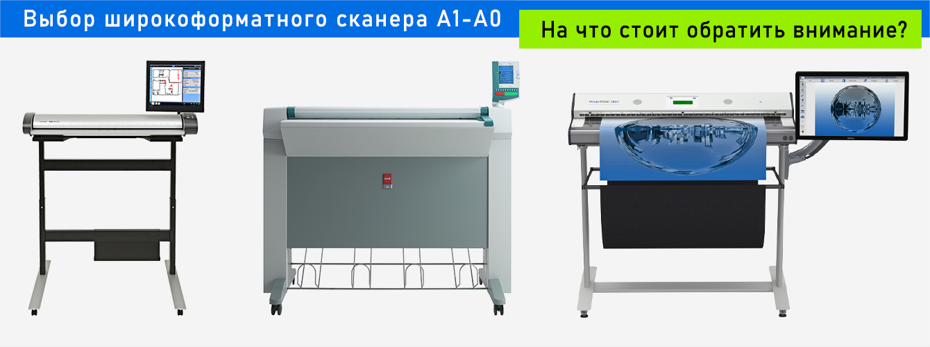
Описание WideTEK 36-600
Тишина и компактность делают WideTEK 36-600 идеальным как для офиса, так и для производства. Применение ярких белых LED-ламп гарантирует длительность срока службы и низкую стоимость использования, поскольку в сканере практически отсутствуют расходные материалы. Пылезащищенный, полностью герметичный бокс содержит CCD-систему, в которой применяется запатентованная технология, обеспечивающая высокое разрешение сканирования.

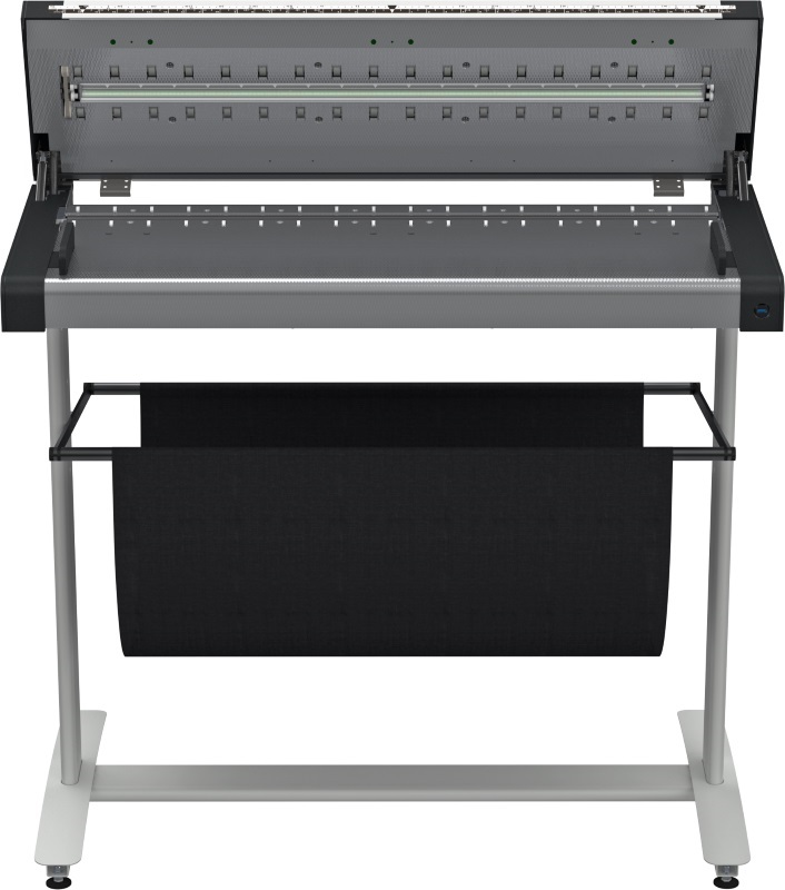
Аккуратен к архивным, историческим и ветхим документам
Специальные транспортные ролики
Аппарат бережно сканирует благодаря специальным транспортным роликам, которые служат точками давления, гарантирующими безопасную протяжку. Это чрезвычайно важно для архивных и ветхих документов.

Заменяемый прижимной барабан
Новый уникальный прижимной барабан никогда не соприкасается со стеклом, тем самым исключая возможность нанесения документу царапин и замятий. Для получения высококонтрастных изображений со светокопий или полупрозрачных носителей стандартный черный барабан может быть легко и без специальных инструментов заменен белым.

Преимущества
- Сканирование документов шириной до 36″
- Сканирование без ограничения длины материала с созданием многостраничных PDF-документов
- Захват 3D-поверхностей, текстур различных материалов, шрифта Брайля
- Цветное сканирование со скоростью 21,6 м/мин 200 DPI в цвете
- Разрешение сканирования — 1200 x 1200 DPI
- Scan2Pad: используйте планшет для управления сканированием
- Встроенная 64 бит ОС Linux на процессоре Intel i3 QUAD CORE, 8 ГБ оперативной памяти и 320 ГБ жестким диском
- Гигабитный сетевой интерфейс
- Большой цветной сенсорный экран для простоты управления
- Встроенное ПО для сканирования
- Сканирование «лицом вверх»
- Автоматическая обрезка и устранение перекоса
- Отображение результатов и изменение изображений в режиме реального времени без повторного сканирования
- LED-лампы, исключающие разогрев и УФ-излучение
- Белый цвет барабана опционально
- Легкая установка благодаря технологии Scan2Net

Функции сканера
- Scan2USB — возможность сканирования на USB
- Scan2Print — сканирование на принтер (копирование)
- Scan2Pad — управление с помощью планшета или телефона
- Scan2Network — сканирование в сеть (SMB, FTP)
- Scan2iPF и Scan2Oce — специализированное прямое копирование на технику Canon и Oce
- Форматы: PDF, PDF/A, JPEG, TIFF, PNM, многостраничный PDF
- Невосприимчив к вирусам благодаря работе на ОС Linux
- Независим от ОС, работает с Windows 7, 8, 10; Linux; Mac
- ScanWizard использует любой браузер: IE, Safari, Chrome, Firefox
- Удаленное управление и устранение неполадок
- Обновление прошивки через web-интерфейс
- Широкий цветовой диапазон поддерживает sRGB, Adobe RGB, обычный RGB

Scan2Net
Платформа Scan2Net является технологической основой всех сканеров WideTEK. Она заменяет драйверы и ПО, которые обычно необходимы для сканеров и соединения по сети. С сетевым интерфейсом устройства способны достичь непревзойденной производительности при чрезвычайно низкой стоимости подключения. Сканеры Scan2Net оснащены операционной системой, позволяющей увеличить скорость и производительность.

Преимущества Scan2Net
- Оснащенный 64-битной версией Linux встроенный компьютер быстр и максимально защищен от вирусов
- Простая интеграция в существующие сети
- Для начала работы со сканером необходим только один IP-адрес
- Интеграция и удаленный доступ через Интернет
- Сканирование напрямую в SMB, FTP, USB, е-mail или облачные сервисы без использования компьютера
- Легкое интуитивное управление, основанное на Java или HTML
- Четкая структура меню, управление с помощью сенсорного экрана
- Мультиязычная поддержка, настраиваемый интерфейс пользователя

Применение
WideTEK 36-600 является незаменимым устройством для множества рынков.
- Архитектура, инженерия, строительство, CAD
- Копировальные услуги, репрография
- Сервисы картографии, GIS
- СМИ
- Университеты, библиотеки, архивы

Применение может быть разнообразным. Аппарат подходит для решения почти любой задачи, где требуются широкий формат и скорость производства.
- Сканирование карт, цветные постеры, графика
- Архивирование иллюстраций и фотографий
- Архивирование газет, каталогов и журналов
- Архивирование светокопий
- Сканирование черновиков рекламных материалов и фотографий
Опции

- ПО Scan Wizard для получения высококачественных сканов
- WideTEK-UMFS — универсальная мультифункциональная стойка, внешний 19″ монитор
- Возможность расширенной гарантии до 5 лет
Купить сканер широкоформатный WideTEK 36-600
Магазин Принтер-Плоттер.ру является официальным поставщиком продукции WideTEK. В магазине вы можете купить сканер широкоформатный WideTEK 36-600 на выгодных условиях — звоните или напишите нам.
Специалисты Принтер-Плоттер.ру всегда будут рады помочь подобрать оптимальное оборудование для ваших задач!
Основные характеристики
Сканирование
Двустороннее сканирование:
Характеристики памяти
Процессор
Дисплей
цветной сенсорный экран; 19″ монитор (опционально)
Дополнительные
Максимальная толщина носителя:
PDF; PDF/A; JPEG; JPEG2000; TIFF; PNM
Максимальная длина оригинала:
Требования к электросети:
Габариты, вес, комплектация