инструкцияGigabyte X470 Aorus Ultra Gaming

To reduce the impacts on global warming, the packaging materials of this product
are recyclable and reusable. GIGABYTE works with you to protect the environment.
For more product details, please visit GIGABYTE’s website.
X470 AORUS ULTRA
GAMING
User’s Manual
Rev. 1001
12ME-X47ARUG-1001R
Посмотреть инструкция для Gigabyte X470 Aorus Ultra Gaming бесплатно. Руководство относится к категории Материнские платы, 19 человек(а) дали ему среднюю оценку 8.3. Руководство доступно на следующих языках: английский. У вас есть вопрос о Gigabyte X470 Aorus Ultra Gaming или вам нужна помощь? Задайте свой вопрос здесь
- X470 AORUS ULTRA GAMING Motherboard Layout
- Chapter 1 Hardware Installation
- Chapter 2 BIOS Setup
- Chapter 3 Appendix

Главная
| Gigabyte | |
| X470 Aorus Ultra Gaming | X470 AORUS ULTRA GAMING | |
| Материнская плата | |
| 0889523013311, 4719331802967, 5706998327932 | |
| английский | |
| Руководство пользователя (PDF), Инструкция по установке (PDF) |
Память
| Поддерживаемые типы памяти | DDR4-SDRAM |
| Каналы памяти | Dual-channel |
| Тип слотов памяти | DIMM |
| Максимальная внутренняя память | 64 GB |
| Количество слотов памяти | 4 |
| без функции коррекции ошибок | Да |
| Поддерживаемые объемы модулей памяти | 16GB |
| Поддерживаемые частоты памяти | 3200,3000,2933,2667,2400,2133 MHz |
Процессор
| Производитель процессора | AMD |
| Совместимые серии процессоров | AMD A, AMD Athlon, AMD Athlon X4, AMD Ryzen 3, AMD Ryzen 3 2nd Gen, AMD Ryzen 3 3rd Gen, AMD Ryzen 5, AMD Ryzen 5 2nd Gen, AMD Ryzen 5 3rd Gen, AMD Ryzen 7, AMD Ryzen 7 2nd Gen, AMD Ryzen 7 3rd Gen, AMD Ryzen 9 3rd Gen |
| Сокет процессора | Разъем AM4 |
Сеть
| Подключение Ethernet | Да |
| Тип Ethernet интерфейса | Гигабитный Ethernet |
Свойства
| Комплектующие для | ПК |
| Семейство чипсета материнской платы | AMD |
| Формат материнской платы | ATX |
| Выходные звуковые каналы | 7.1 канала |
| Поддерживаемые операционные системы Windows | Да |
| Поддерживаемые операционные системы Linux | Да |
| Чипсет материнской платы | AMD X470 |
| Тип источника питания | ATX |
Контроллеры хранения данных
Слоты расширения
| PCI Express x16 слоты | 3 |
| PCI Express x1 слоты | 2 |
| Количество M.2 (M) слотов | 2 |
BIOS
| Тип BIOS | UEFI AMI |
| Размер памяти BIOS | 16 Mbit |
| Перемычка Clear CMOS | Да |
Вес и размеры
| Глубина | 305 mm |
| Ширина | 244 mm |
Внутренние порты
| Разъем питания ATX (24-конт.) | Да |
| EPS разъем питания (8-конт) | Да |
| Разъем вентилятора центрального процессора | Да |
| Количество разъемов вентилятора корпуса | 6 |
| Количество параллельных разъемов ATA (PATA) | 0 |
| Количество разъемов SATA II | 0 |
| Количество разъемов SATA III | 6 |
| Разъем передней панели | Да |
| Аудиоразъем передней панели | Да |
| Разъем выхода S/PDIF | Да |
| Разъемы USB 2.0 | 2 |
| Разъемы USB 3.2 Gen 1 (3.1 Gen 1) | 2 |
| Разъемы USB 3.2 Gen 2 (3.1 Gen 2) | 1 |
| TPM коннектор | Да |
Порты на задней панели
| Количество портов USB 2.0 | 4 |
| Количество портов USB 3.2 Gen 1 (3.1 Gen 1) Type-A | 4 |
| Количество портов USB 3.2 Gen 1 (3.1 Gen 1) Type-С | 0 |
| Количество портов USB 3.2 Gen 2 (3.1 Gen 2) Type-A | 1 |
| Количество портов USB 3.2 Gen 2 (3.1 Gen 2) Type-С | 1 |
| Количество портов Ethernet LAN ( RJ-45) | 1 |
| Количество портов eSATA | 0 |
| Линейные выходы наушников | 1 |
| Линейный вход микрофона | Да |
| Порт выхода S/PDIF | Да |
| Количество портов PS/2 | 0 |
| Порты FireWire | 0 |
| Количество портов VGA (D-Sub) | 0 |
| Количество портов DVI-D | 0 |
| Количество HDMI портов | 1 |
показать больше
Не можете найти ответ на свой вопрос в руководстве? Вы можете найти ответ на свой вопрос ниже, в разделе часто задаваемых вопросов о Gigabyte X470 Aorus Ultra Gaming.
Какая ширина Gigabyte X470 Aorus Ultra Gaming?
Какая толщина Gigabyte X470 Aorus Ultra Gaming?
Инструкция Gigabyte X470 Aorus Ultra Gaming доступно в русский?
Не нашли свой вопрос? Задайте свой вопрос здесь
Смотреть руководство для Gigabyte X470 Aorus Ultra Gaming ниже. Все руководства на ManualsCat.com могут просматриваться абсолютно бесплатно. Нажав кнопку «Выбор языка» вы можете изменить язык руководства, которое хотите просмотреть.

MANUALSCAT | RU
Вопросы и ответы
У вас есть вопрос о Gigabyte X470 Aorus Ultra Gaming, но вы не можете найти ответ в пользовательском руководстве? Возможно, пользователи ManualsCat.com смогут помочь вам и ответят на ваш вопрос. Заполните форму ниже — и ваш вопрос будет отображаться под руководством для Gigabyte X470 Aorus Ultra Gaming. Пожалуйста, убедитесь, что вы опишите свои трудности с Gigabyte X470 Aorus Ultra Gaming как можно более детально. Чем более детальным является ваш вопрос, тем более высоки шансы, что другой пользователь быстро ответит на него. Вам будет автоматически отправлено электронное письмо, чтобы проинформировать вас, когда кто-то из пользователей ответит на ваш вопрос.
Ищу руководство X470 AORUS ULTRA GAMING на русском языке
Гелий 2019-02-03
Задать вопрос о Gigabyte X470 Aorus Ultra Gaming
- Бренд:
- Gigabyte
- Продукт:
- Материнские платы
- Модель/название:
- X470 Aorus Ultra Gaming
- Тип файла:
- Доступные языки:
- английский
Сопутствующие товары Gigabyte X470 Aorus Ultra Gaming
-
Contents
-
Table of Contents
-
Bookmarks
Quick Links
X470 AORUS
GAMING 7 WIFI
User’s Manual
Rev. 1001
12ME-X47AG7W-1001R
For more product details, please visit GIGABYTE’s website.
To reduce the impacts on global warming, the packaging materials of this product
are recyclable and reusable. GIGABYTE works with you to protect the environment.
Related Manuals for Gigabyte X470 AORUS GAMING 7 WIFI
Summary of Contents for Gigabyte X470 AORUS GAMING 7 WIFI
-
Page 1
GAMING 7 WIFI User’s Manual Rev. 1001 12ME-X47AG7W-1001R For more product details, please visit GIGABYTE’s website. To reduce the impacts on global warming, the packaging materials of this product are recyclable and reusable. GIGABYTE works with you to protect the environment. -
Page 2
Motherboard X470 AORUS GAMING 7 WIFI Motherboard X470 AORUS GAMING 7 WIFI Feb. 9, 2018 Feb. 9, 2018 Wireless Module Country Approvals: See the latest safety and regulatory documents at GIGABYTE’s website. -
Page 3
The trademarks mentioned in this manual are legally registered to their respective owners. Disclaimer Information in this manual is protected by copyright laws and is the property of GIGABYTE. Changes to the specifications and features in this manual may be made by GIGABYTE without prior notice. -
Page 4: Table Of Contents
Table of Contents X470 AORUS GAMING 7 WIFI Motherboard Layout …………5 Chapter 1 Hardware Installation ………………6 Installation Precautions ………………6 Product Specifications ………………7 Installing the CPU ………………10 Installing the Memory ………………10 Installing an Expansion Card …………….. 11…
-
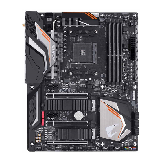
Page 5: X470 Aorus Gaming 7 Wifi Motherboard Layout
F_AUDIO LED_C1 F_USB2 SYS_FAN3 F_USB30_1 Box Contents 5 X470 AORUS GAMING 7 WIFI motherboard 5 M.2 screw(s)/M.2 standoff(s) 5 Motherboard driver disk 5 One Wi-Fi antenna 5 Wireless module driver disk 5 One GC-SLI2PL bridge connector 5 User’s Manual 5 One digital LED strip adapter cable…
-
Page 6: Chapter 1 Hardware Installation
Chapter 1 Hardware Installation Installation Precautions The motherboard contains numerous delicate electronic circuits and components which can become damaged as a result of electrostatic discharge (ESD). Prior to installation, carefully read the user’s manual and follow these procedures: • Prior to installation, make sure the chassis is suitable for the motherboard. •…
-
Page 7: Product Specifications
Support for ECC Un-buffered DIMM 1Rx8/2Rx8 memory modules Š Support for non-ECC Un-buffered DIMM 1Rx8/2Rx8/1Rx16 memory modules Š Support for Extreme Memory Profile (XMP) memory modules Š (Go to GIGABYTE’s website for the latest supported memory speeds and memory modules.) Audio Realtek ALC1220 codec ®…
-
Page 8
Chipset: Š 1 x USB Type-C port with USB 3.1 Gen 2 support, available through the ™ internal USB header 6 x USB 3.1 Gen 1 ports (2 ports on the back panel, 4 ports available through the internal USB headers) 6 x USB 2.0/1.1 ports (2 ports on the back panel, 4 ports available through the internal USB headers) CPU:… -
Page 9
System Form Factor ATX Form Factor; 30.5cm x 24.4cm Š * GIGABYTE reserves the right to make any changes to the product specifications and product-related information without prior notice. Please visit GIGABYTE’s website Please visit the SupportUtility List for support lists of CPU, memory page on GIGABYTE’s website to modules, SSDs, and M.2 devices. -
Page 10: Installing The Cpu
• Make sure that the motherboard supports the memory. It is recommended that memory of the same capacity, brand, speed, and chips be used. (Go to GIGABYTE’s website for the latest supported memory speeds and memory modules.) • Always turn off the computer and unplug the power cord from the power outlet before installing the memory to prevent hardware damage.
-
Page 11: Installing An Expansion Card
Due to CPU limitations, read the following guidelines before installing the memory in Dual Channel mode. Dual Channel mode cannot be enabled if only one memory module is installed. When enabling Dual Channel mode with two or four memory modules, it is recommended that memory of the same capacity, brand, speed, and chips be used.
-
Page 12: Back Panel Connectors
Back Panel Connectors Power/Reset Button The power/reset button allows users to quickly turn on/off or reset the computer in an open-case environment when they want to change hardware components or conduct hardware testing. This button is a power button by default. To change the button’s default to Reset function, refer to Chapter 2, «BIOS Setup,» «Power,»…
-
Page 13
• When removing the cable, pull it straight out from the connector. Do not rock it side to side to prevent an electrical short inside the cable connector. Please visit GIGABYTE’s website for details on configuring the audio software. — 13 -… -
Page 14: Onboard Leds, Buttons, And Switches
The OC button helps enthusiasts and overclockers not only get the most performance from their hardware, 1 2 3 1 2 3 but also the absolute most enjoyable OC experience. Press this button to load the most optimized GIGABYTE overclocking configuration for your hardware. BIOS Switches (BIOS_SW, SB) and BIOS LED Indicators The BIOS switch (BIOS_SW) allows users to easily select a different BIOS for boot up or overclocking, helping to reduce BIOS failure during overclocking.
-
Page 15: Internal Connectors
Internal Connectors ATX_12V/ATX_12V1 SATA3 0/1/2/3/4/5 M2A_SOCKET/M2B_SOCKET CPU_FAN F_PANEL SYS_FAN1/2/3/4 F_AUDIO SYS_FAN5/6_PUMP SPDIF_O CPU_OPT F_USB31C EC_TEMP1/EC_TEMP2 F_USB30_1/F_USB30_2 LED_CPU F_USB1/F_USB2 LED_C1/LED_C2 D_LED1/D_LED2 CLR_CMOS DLED_V_SW1/DLED_V_SW2 Read the following guidelines before connecting external devices: • First make sure your devices are compliant with the connectors you wish to connect. •…
-
Page 16
1/2) ATX_12V/ATX_12V1/ATX (2×4, 2×2, 12V Power Connectors and 2×12 Main Power Connector) With the use of the power connector, the power supply can supply enough stable power to all the components on the motherboard. Before connecting the power connector, first make sure the power supply is turned off and all devices are properly installed. The power connector possesses a foolproof design. Connect the power supply cable to the power connector in the correct orientation. -
Page 17
3/4) CPU_FAN/SYS_FAN1/2/3/4 (Fan Headers) All fan headers on this motherboard are 4-pin. Most fan headers possess a foolproof insertion design. When connecting a fan cable, be sure to connect it in the correct orientation (the black connector wire is the ground wire). The speed control function requires the use of a fan with fan speed control design. For optimum heat dissipation, it is recommended that a system fan be installed inside the chassis. -
Page 18
S B_ 1 2 3 S B_ 1 2 3 7) EC_TEMP1/EC_TEMP2 (Temperature Sensor Headers) Connect the thermistor cables to the headers for temperature detection. Pin No. Definition SENSOR IN EC_TEMP1 EC_TEMP2 LED_CPU (CPU Cooler LED Strip/RGB LED Strip Header) The header can be used to connect a CPU cooler LED strip or a standard 5050 RGB LED strip (12V/G/R/B), F_USB3 F with maximum power rating of 2A (12V) and maximum length of 2m.
 -
Page 19
10) D_LED1/D_LED2 (Digital LED Strip Headers) The headers can be used to connect a standard 5050 digital LED strip, with maximum power rating of 2A (12V or 5V) and maximum length of 5m or maximum number of 300 LEDs. There are 12V and 5V digital LED strips. -
Page 20
SATA RAID configuration. (Note) Refer to Chapter 3, «Configuring a RAID Set,» for instructions on configuring a RAID array. (NVME PCIe RAID support requires driver and BIOS updates. Visit the AMD or GIGABYTE official website for future update information. ) M2A_SOCKET M2B_SOCKET Follow the steps below to correctly install an M.2 SSD in the M.2 connector. -
Page 21
14) F_PANEL (Front Panel Header) Connect the power switch, reset switch, speaker, chassis intrusion switch/sensor and system status indicator on the chassis to this header according to the pin assignments below. Note the positive and negative pins before connecting the cables. •… -
Page 22
16) SPDIF_O (S/PDIF Out Header) This header supports digital S/PDIF Out and connects a S/PDIF digital audio cable (provided by expansion cards) for digital audio output from your motherboard to certain expansion cards like graphics cards and sound cards. For example, some graphics cards may require you to use a S/PDIF digital audio cable for S F_ digital audio output from your motherboard to your graphics card if you wish to connect an HDMI display to the graphics card and have digital audio output from the HDMI display at the same time. -
Page 23
B S_ 19) F_USB1/F_USB2 (USB 2.0/1.1 Headers) S B_ The headers conform to USB 2.0/1.1 specification. Each USB header can provide two USB ports via an optional USB bracket. For purchasing the optional USB bracket, please contact the local dealer. Pin No. -
Page 24
22) BAT (Battery) The battery provides power to keep the values (such as BIOS configurations, date, and time information) in the CMOS when the computer is turned off. Replace the battery when the battery voltage drops to a low level, or the CMOS values may not be accurate or may be lost. You may clear the CMOS values by removing the battery: 1. -
Page 25: Chapter 2 Bios Setup
To access the BIOS Setup program, press the <Delete> key during the POST when the power is turned on. To upgrade the BIOS, use either the GIGABYTE Q-Flash or @BIOS utility. Q-Flash allows the user to quickly and easily upgrade or back up BIOS without entering the operating system.
-
Page 26: The Main Menu
The Main Menu System Time Setup Menus Hardware Information Configuration Items Current Settings Quick Access Bar allows you to enter Easy Mode, select BIOS default language, configure fan settings, or enter Q-Flash. Classic Setup Function Keys <f><g> Move the selection bar to select a setup menu <h><i>…
-
Page 27
M.I.T. Whether the system will work stably with the overclock/overvoltage settings you made is dependent on your overall system configurations. Incorrectly doing overclock/overvoltage may result in damage to CPU, chipset, or memory and reduce the useful life of these components. This page is for advanced users only and we recommend you not to alter the default settings to prevent system instability or other unexpected results. -
Page 28
& Core Performance Boost Allows you to determine whether to enable the Core Performance Boost (CPB) technology, a CPU performance-boost technology. (Default: Auto) & AMD Cool&Quiet function Lets the AMD Cool’n’Quiet driver dynamically adjust the CPU clock and VID to Enabled reduce heat output from your computer and its power consumption. -
Page 29
& Memory Timing Mode Manual allows the memory timing settings below to be configurable. Options are: Auto (default), Manual. & Profile DDR Voltage When using a non-XMP memory module or Extreme Memory Profile (X.M.P.) is set to Disabled, the value is displayed according to your memory specification. When Extreme Memory Profile (X.M.P.) is set to Profile1 or Profile2, the value is displayed according to the SPD data on the XMP memory. -
Page 30
` Smart Fan 5 Settings & Monitor Allows you to select a target to monitor and to make further adjustment. (Default: CPU FAN) & Fan Speed Control Allows you to determine whether to enable the fan speed control function and adjust the fan speed. Allows the fan to run at different speeds according to the temperature. -
Page 31: System
System This section provides information on your motherboard model and BIOS version. You can also select the default language used by the BIOS and manually set the system time. & System Language Selects the default language used by the BIOS. &…
-
Page 32: Bios
System program. (Default) & Full Screen LOGO Show Allows you to determine whether to display the GIGABYTE Logo at system startup. Disabled skips the GIGABYTE Logo when the system starts up. (Default: Enabled) & Fast Boot Enables or disables Fast Boot to shorten the OS boot process. Ultra Fast provides the fastest bootup speed.
-
Page 33
& SATA Support All Sata Devices All SATA devices are functional in the operating system and during the POST. Last Boot HDD Only Except for the previous boot drive, all SATA devices are disabled before the OS boot process completes. (Default) This item is configurable only when Fast Boot is set to Enabled or Ultra Fast. -
Page 34
& Network Stack Disables or enables booting from the network to install a GPT format OS, such as installing the OS from the Windows Deployment Services server. (Default: Disabled) & Ipv4 PXE Support Enables or disables IPv4 PXE Support. This item is configurable only when Network Stack is enabled. &… -
Page 35: Peripherals
Peripherals & AMD CPU fTPM Enables or disables the TPM 2.0 function integrated in the AMD CPU. (Default: Disabled) & Initial Display Output Specifies the first initiation of the monitor display from the PCI Express graphics cards. PCIe 1 Slot Sets the graphics card on the PCIEX16 slot as the first display.
-
Page 36
& Port 60/64 Emulation Enables or disables emulation of I/O ports 64h and 60h. This should be enabled for full legacy support for USB keyboards/mice in MS-DOS or in operating system that does not natively support USB devices. (Default: Disabled) &… -
Page 37: Chipset
Chipset & IOMMU Enables or disables AMD IOMMU support. (Default: Auto) & SATA Mode Enables or disables RAID for the SATA controllers integrated in the Chipset or configures the SATA controllers to AHCI mode. Enables RAID for the SATA controller. RAID Configures the SATA controllers to AHCI mode.
-
Page 38: Power
Power & AC BACK Determines the state of the system after the return of power from an AC power loss. The system returns to its last known awake state upon the return of the AC power. Memory Always On The system is turned on upon the return of the AC power. Always Off The system stays off upon the return of the AC power.
-
Page 39: Save & Exit
& Rear Power Button Mode Allows you to change the function of the power/reset button on the back panel. Sets this button to Power function. (Default) On/Off Sets this button to Reset function. Reset & CEC 2019 Ready Allows you to select whether to allow the system to adjust power consumption when it is in shutdown, idle, or standby state in order to comply with the CEC (California Energy Commission) 2019 Standards.
-
Page 40: Chapter 3 Appendix
Chapter 3 Appendix 3-1 Configuring a RAID Set RAID Levels RAID 0 RAID 1 RAID 10 Minimum Number of ≥2 Hard Drives Array Capacity Number of hard drives * Size of the smallest drive (Number of hard drives/2) * Size of the smallest drive Size of the smallest drive Fault Tolerance Before you begin, please prepare the following items:…
-
Page 41
4. Select AMD-RAID Bottom Device first and click Next to load the driver. Then select AMD-RAID Controller and click Next to load the driver. Finally, continue the OS installation. Please visit GIGABYTE’s website for details on configuring a RAID array. — 41 -… -
Page 42: Drivers Installation
You can click the Xpress Install button and «Xpress Install» will install all of the selected drivers. Or click the arrow icon to individually install the drivers you need. Please visit GIGABYTE’s website for Please visit GIGABYTE’s website for more software information.
-
Page 43: Debug Led Codes
Debug LED Codes Regular Boot Code Description PEI Core is started. Pre-memory CPU initialization is started. 12~14 Reserved. Pre-memory North-Bridge initialization is started. 16~18 Reserved. Pre-memory South-Bridge initialization is started. 1A~2A Reserved. 2B~2F Memory initialization. Memory installed. 32~36 CPU PEI initialization. 37~3A IOH PEI initialization.
-
Page 44
Code Description PCI Bus initialization is started. PCI Bus hot plug initialization. PCI Bus enumeration for detecting how many resources are requested. Check PCI device requested resources. Assign PCI device resources. Console Output devices connect (ex. Monitor is lighted). Console input devices connect (ex. PS2/USB keyboard/mouse are activated). Super IO initialization. -
Page 45
Code Description USB device hot plug-in. PCI device hot plug. Clean-up of NVRAM. Reconfigure NVRAM settings. B8~BF Reserved. C0~CF Reserved. S3 Resume Code Description S3 Resume is started (called from DXE IPL). Fill boot script data for S3 resume. Initializes VGA for S3 resume. OS S3 wake vector call. -
Page 46
Code Description PCH initialization error. Some of the Architectural Protocols are not available. PCI resource allocation error. Out of Resources. No Space for Legacy Option ROM initialization. No Console Output Devices are found. No Console Input Devices are found. It is an invalid password. D9~DA Can’t load Boot Option. -
Page 47: Regulatory Statements
Contravention will be prosecuted. We believe that the information contained herein was accurate in all respects at the time of printing. GIGABYTE cannot, however, assume any responsibility for errors or omissions in this text. Also note that the information in this document is subject to change without notice and should not be construed as a commitment by GIGABYTE.
-
Page 48
FCC Notice (U.S.A. Only) Operation is subject to the following two conditions: (1) this device may not cause harmful interference, and (2) this device must accept any interference received, including interference that may cause undesired operation. WARNING: This equipment has been tested and found to comply with the limits for a Class B digital device, pursuant to Part 15 of the FCC Rules. -
Page 49
Canada-Industry Canada (IC): This device complies with Canadian RSS-210. This device complies with Industry Canada license-exempt RSS standard(s). Operation is subject to the following two conditions: (1) this device may not cause interference, and (2) this device must accept any interference, including interference that may cause undesired operation of the device. -
Page 50
European Community Radio Equipment Directive (RED) Compliance Statement: This equipment complies with all the requirements and other relevant provisions of Radio Equipment Directive 2014/53/EU. This equipment is suitable for home and office use in all the European Community Member States and EFTA Member States. The low band 5.15 -5.35 GHz is for indoor use only. Restrictions d’utilisation en France: Pour la France métropolitaine 2.400 — 2.4835 GHz (Canaux 1à… -
Page 51
— 51 -… -
Page 52: Contact Us
Contact Us GIGA-BYTE TECHNOLOGY CO., LTD. Address: No.6, Baoqiang Rd., Xindian Dist., New Taipei City 231, Taiwan TEL: +886-2-8912-4000, FAX: +886-2-8912-4005 Tech. and Non-Tech. Support (Sales/Marketing) : http://esupport.gigabyte.com WEB address (English): http://www.gigabyte.com WEB address (Chinese): http://www.gigabyte.tw GIGABYTE eSupport • To submit a technical or non-technical (Sales/Marketing) question, please link to: http://esupport.gigabyte.com…
 LED_CPU (CPU Cooler LED Strip/RGB LED Strip Header) The header can be used to connect a CPU cooler LED strip or a standard 5050 RGB LED strip (12V/G/R/B), F_USB3 F with maximum power rating of 2A (12V) and maximum length of 2m.