
Summary of Content for Yamaha FZ6RB C FZ6R 2012 Owner’s Manual PDF
DIC183
36P-28199-13
FZ6RB(C)
OWNERS MANUAL
Read this manual carefully before operating this vehicle.
LIT-11626-25-43
EAU10042
Read this manual carefully before operating this vehicle. This manual should stay with this vehicle if it is sold.
U36P13E0.book Page 1 Tuesday, July 5, 2011 8:45 AM
INTRODUCTION EAU10083
Congratulations on your purchase of the Yamaha FZ6RB(C). This model is the result of Yamahas vast experience in the production of fine sporting, touring, and pacesetting racing machines. It represents the high degree of craftsmanship and reliability that have made Yamaha a leader in these fields. This manual will give you an understanding of the operation, inspection, and basic maintenance of this motorcycle. If you have any questions concerning the operation or maintenance of your motorcycle, please consult a Yamaha dealer. The design and manufacture of this Yamaha motorcycle fully comply with the emissions standards for clean air applicable at the date of manufacture. Yamaha has met these standards without reducing the performance or economy of operation of the motorcycle. To maintain these high standards, it is important that you and your Yamaha dealer pay close attention to the recommended maintenance schedules and operating instructions contained within this manual. Yamaha continually seeks advancements in product design and quality. Therefore, while this manual contains the most cur- rent product information available at the time of printing, there may be minor discrepancies between your motorcycle and this manual. If there is any question concerning this manual, please consult a Yamaha dealer.
WARNING EWA10011
Please read this manual and the YOU AND YOUR MOTORCYCLE: RIDING TIPS booklet carefully before operating this motorcycle. Do not attempt to operate this motorcycle until you have attained adequate knowledge of its con- trols and operating features. Regular inspections and careful maintenance, along with good operating techniques, will help ensure that you safely enjoy the capabilities and reliability of this motorcycle.
U36P13E0.book Page 1 Tuesday, July 5, 2011 8:45 AM
IMPORTANT MANUAL INFORMATION EAU10133
Particularly important information is distinguished in this manual by the following notations:
*Product and specifications are subject to change without notice.
This is the safety alert symbol. It is used to alert you to potential personal injury hazards. Obey all safety messages that follow this symbol to avoid possible injury or death.
A WARNING indicates a hazardous situation which, if not avoided, could result in death or serious injury.
A NOTICE indicates special precautions that must be taken to avoid damage to the vehicle or other property.
A TIP provides key information to make procedures easier or clearer.
WARNING
NOTICE
TIP
U36P13E0.book Page 1 Tuesday, July 5, 2011 8:45 AM
IMPORTANT MANUAL INFORMATION
EAU10193
FZ6RB(C) OWNERS MANUAL
2011 by Yamaha Motor Corporation, U.S.A. 1st edition, June 2011
All rights reserved. Any reprinting or unauthorized use without the written permission of Yamaha Motor Corporation, U.S.A.
is expressly prohibited. Printed in Japan.
P/N LIT-11626-25-43
U36P13E0.book Page 2 Tuesday, July 5, 2011 8:45 AM
TABLE OF CONTENTS LOCATION OF IMPORTANT LABELS ………………………………………1-1
SAFETY INFORMATION ………………2-1
DESCRIPTION …………………………….3-1 Left view ……………………………………3-1 Right view ………………………………….3-2 Controls and instruments……………..3-3
INSTRUMENT AND CONTROL FUNCTIONS …………………………………4-1
Main switch/steering lock …………….4-1 Indicator lights and warning
lights ……………………………………..4-2 Multi-function meter unit ……………..4-5 Handlebar switches ……………………4-8 Clutch lever ……………………………….4-9 Shift pedal …………………………………4-9 Brake lever ……………………………..4-10 Brake pedal …………………………….4-10 Fuel tank cap …………………………..4-10 Fuel ………………………………………..4-11 Fuel tank breather hose and
overflow hose ……………………….4-12 Catalytic converter ……………………4-13 Seats ……………………………………..4-13 Adjusting the rider seat height ……4-15 Helmet holder ………………………….4-17 Storage compartment ……………….4-17 Handlebar position ……………………4-18
Rear view mirrors ……………………. 4-18 Adjusting the shock absorber
assembly …………………………….. 4-19 Sidestand ………………………………. 4-20 Ignition circuit cut-off system …….. 4-20
FOR YOUR SAFETY PRE-OPERATION CHECKS …………. 5-1
OPERATION AND IMPORTANT RIDING POINTS…………………………… 6-1
Starting the engine ……………………. 6-1 Shifting ……………………………………. 6-2 Engine break-in ………………………… 6-3 Parking ……………………………………. 6-4
PERIODIC MAINTENANCE AND ADJUSTMENT …………………………….. 7-1
Owners tool kit …………………………. 7-2 Periodic maintenance chart for
the emission control system ……. 7-3 General maintenance and
lubrication chart …………………….. 7-5 Removing and installing cowlings
and panels ……………………………. 7-9 Checking the spark plugs …………. 7-12 Canister (for California only) …….. 7-13 Engine oil and oil filter cartridge … 7-13 Coolant ………………………………….. 7-16 Replacing the air filter element ….. 7-19
Checking the engine idling speed …………………………………. 7-20
Checking the throttle grip free play ……………………………………. 7-21
Valve clearance ……………………… 7-21 Tires ……………………………………… 7-21 Cast wheels …………………………… 7-24 Adjusting the clutch lever free
play ……………………………………. 7-24 Checking the brake lever free
play ……………………………………. 7-25 Brake light switches ………………… 7-26 Checking the front and
rear brake pads …………………… 7-26 Checking the brake fluid level …… 7-27 Changing the brake fluid ………….. 7-28 Drive chain slack …………………….. 7-28 Cleaning and lubricating
the drive chain …………………….. 7-30 Checking and lubricating
the cables …………………………… 7-30 Checking and lubricating
the throttle grip and cable ……… 7-31 Checking and lubricating
the brake and shift pedals …….. 7-31 Checking and lubricating
the brake and clutch levers …… 7-32 Checking and lubricating
the sidestand ………………………. 7-32 Lubricating the swingarm
pivots …………………………………. 7-33
U36P13E0.book Page 1 Tuesday, July 5, 2011 8:45 AM
TABLE OF CONTENTS Checking the front fork ……………..7-33 Checking the steering ……………….7-34 Checking the wheel bearings …….7-34 Battery ……………………………………7-34 Replacing the fuses ………………….7-36 Replacing the headlight bulb ……..7-37 Replacing the tail/brake light
bulb …………………………………….7-38 Replacing a turn signal light
bulb …………………………………….7-38 Replacing the license plate light
bulb …………………………………….7-39 Supporting the motorcycle …………7-40 Front wheel ……………………………..7-40 Rear wheel ……………………………..7-42 Troubleshooting ……………………….7-43 Troubleshooting charts ……………..7-45
MOTORCYCLE CARE AND STORAGE ……………………………………8-1
Matte color caution …………………….8-1 Care …………………………………………8-1 Storage …………………………………….8-3
SPECIFICATIONS ………………………..9-1
CONSUMER INFORMATION………..10-1 Identification numbers ………………10-1 Reporting safety defects ……………10-3 Motorcycle noise regulation ……….10-4 Maintenance record ………………….10-5
YAMAHA MOTOR CORPORATION, U.S.A. STREET AND ENDURO MOTORCYCLE LIMITED WARRANTY ……………………….. 10-7
YAMAHA EXTENDED SERVICE (Y.E.S.) ………………………………. 10-9
U36P13E0.book Page 2 Tuesday, July 5, 2011 8:45 AM
LOCATION OF IMPORTANT LABELS
1-1
1
EAU10384
Read and understand all of the labels on your vehicle. They contain important information for safe and proper operation of your vehicle. Never remove any labels from your vehicle. If a label becomes difficult to read or comes off, a replacement label is available from your Yamaha dealer.
1 2 3 4 5,6,7
U36P13E0.book Page 1 Tuesday, July 5, 2011 8:45 AM
LOCATION OF IMPORTANT LABELS
1-2
1
4
5
6
1
2
3
Cleaning with alkaline or acid cleaner, gasoline or solvent will damage windshield. Use neutral detergent.
WARNING Improper loading can cause loss of control. Read owners manual for proper loading.
3JJ-28446-A1
NOTICE
4B5-2815K-00
U36P13E0.book Page 2 Tuesday, July 5, 2011 8:45 AM
LOCATION OF IMPORTANT LABELS
1-3
1
7 California only
U36P13E0.book Page 3 Tuesday, July 5, 2011 8:45 AM
LOCATION OF IMPORTANT LABELS
1-4
1
1
U36P13E0.book Page 4 Tuesday, July 5, 2011 8:45 AM
LOCATION OF IMPORTANT LABELS
1-5
1
1 California only
U36P13E0.book Page 5 Tuesday, July 5, 2011 8:45 AM
2-1
2
SAFETY INFORMATION EAU10289
Be a Responsible Owner As the vehicles owner, you are respon- sible for the safe and proper operation of your motorcycle. Motorcycles are single-track vehicles. Their safe use and operation are de- pendent upon the use of proper riding techniques as well as the expertise of the operator. Every operator should know the following requirements before riding this motorcycle. He or she should:
Obtain thorough instructions from a competent source on all aspects of motorcycle operation.
Observe the warnings and mainte- nance requirements in this Own- ers Manual.
Obtain qualified training in safe and proper riding techniques.
Obtain professional technical ser- vice as indicated in this Owners Manual and/or when made neces- sary by mechanical conditions.
Safe Riding Perform the pre-operation checks each time you use the vehicle to make sure it is in safe operating condition. Failure to inspect or maintain the vehicle properly increases the possibility of an accident or equipment damage. See page 5-1 for a list of pre-operation checks.
This motorcycle is designed to car- ry the operator and a passenger.
The failure of motorists to detect and recognize motorcycles in traf- fic is the predominating cause of automobile/motorcycle accidents. Many accidents have been caused by an automobile driver who did not see the motorcycle. Making yourself conspicuous appears to be very effective in reducing the chance of this type of accident. Therefore: Wear a brightly colored jacket. Use extra caution when you are
approaching and passing through intersections, since in- tersections are the most likely places for motorcycle accidents to occur.
Ride where other motorists can see you. Avoid riding in another motorists blind spot.
Many accidents involve inexperi- enced operators. In fact, many op- erators who have been involved in accidents do not even have a cur- rent motorcycle license. Make sure that you are qualified
and that you only lend your mo- torcycle to other qualified opera- tors.
Know your skills and limits. Staying within your limits may help you to avoid an accident.
We recommend that you prac- tice riding your motorcycle where there is no traffic until you have become thoroughly famil- iar with the motorcycle and all of its controls.
Many accidents have been caused by error of the motorcycle opera- tor. A typical error made by the op- erator is veering wide on a turn
U36P13E0.book Page 1 Tuesday, July 5, 2011 8:45 AM
SAFETY INFORMATION
2-2
2
due to excessive speed or under- cornering (insufficient lean angle for the speed). Always obey the speed limit and
never travel faster than warrant- ed by road and traffic conditions.
Always signal before turning or changing lanes. Make sure that other motorists can see you.
The posture of the operator and passenger is important for proper control. The operator should keep both
hands on the handlebar and both feet on the operator foot- rests during operation to main- tain control of the motorcycle.
The passenger should always hold onto the operator, the seat strap or grab bar, if equipped, with both hands and keep both feet on the passenger footrests. Never carry a passenger unless he or she can firmly place both feet on the passenger footrests.
Never ride under the influence of alcohol or other drugs.
This motorcycle is designed for on- road use only. It is not suitable for off-road use.
Protective Apparel The majority of fatalities from motorcy- cle accidents are the result of head in- juries. The use of a safety helmet is the single most critical factor in the preven- tion or reduction of head injuries.
Always wear an approved helmet. Wear a face shield or goggles.
Wind in your unprotected eyes could contribute to an impairment of vision that could delay seeing a hazard.
The use of a jacket, heavy boots, trousers, gloves, etc., is effective in preventing or reducing abrasions or lacerations.
Never wear loose-fitting clothes, otherwise they could catch on the control levers, footrests, or wheels and cause injury or an accident.
Always wear protective clothing that covers your legs, ankles, and feet. The engine or exhaust sys- tem become very hot during or af- ter operation and can cause burns.
A passenger should also observe the above precautions.
Avoid Carbon Monoxide Poisoning All engine exhaust contains carbon monoxide, a deadly gas. Breathing car- bon monoxide can cause headaches, dizziness, drowsiness, nausea, confu- sion, and eventually death. Carbon Monoxide is a colorless, odor- less, tasteless gas which may be present even if you do not see or smell any engine exhaust. Deadly levels of carbon monoxide can collect rapidly and you can quickly be overcome and unable to save yourself. Also, deadly levels of carbon monoxide can linger for hours or days in enclosed or poorly ventilated areas. If you experience any symptoms of carbon monoxide poison- ing, leave the area immediately, get fresh air, and SEEK MEDICAL TREAT- MENT.
Do not run engine indoors. Even if you try to ventilate engine exhaust with fans or open windows and doors, carbon monoxide can rap- idly reach dangerous levels.
U36P13E0.book Page 2 Tuesday, July 5, 2011 8:45 AM
SAFETY INFORMATION
2-3
2
Do not run engine in poorly venti- lated or partially enclosed areas such as barns, garages, or car- ports.
Do not run engine outdoors where engine exhaust can be drawn into a building through openings such as windows and doors.
Loading Adding accessories or cargo to your motorcycle can adversely affect stabili- ty and handling if the weight distribution of the motorcycle is changed. To avoid the possibility of an accident, use ex- treme caution when adding cargo or accessories to your motorcycle. Use extra care when riding a motorcycle that has added cargo or accessories. Here, along with the information about accessories below, are some general guidelines to follow if loading cargo to your motorcycle: The total weight of the operator, pas- senger, accessories and cargo must not exceed the maximum load limit. Operation of an overloaded vehicle could cause an accident.
When loading within this weight limit, keep the following in mind:
Cargo and accessory weight should be kept as low and close to the motorcycle as possible. Se- curely pack your heaviest items as close to the center of the vehicle as possible and make sure to distrib- ute the weight as evenly as possi- ble on both sides of the motorcycle to minimize imbalance or instabili- ty.
Shifting weights can create a sud- den imbalance. Make sure that ac- cessories and cargo are securely attached to the motorcycle before riding. Check accessory mounts and cargo restraints frequently. Properly adjust the suspension
for your load (suspension-ad- justable models only), and check the condition and pres- sure of your tires.
Never attach any large or heavy items to the handlebar, front fork, or front fender. These items, including such cargo as sleeping bags, duffel bags, or tents, can create unstable han- dling or a slow steering re- sponse.
This vehicle is not designed to pull a trailer or to be attached to a sidecar.
Genuine Yamaha Accessories Choosing accessories for your vehicle is an important decision. Genuine Yamaha accessories, which are avail- able only from a Yamaha dealer, have been designed, tested, and approved by Yamaha for use on your vehicle. Many companies with no connection to Yamaha manufacture parts and acces- sories or offer other modifications for Yamaha vehicles. Yamaha is not in a position to test the products that these aftermarket companies produce. Therefore, Yamaha can neither en- dorse nor recommend the use of ac- cessories not sold by Yamaha or
Maximum load: FZ6RB 188 kg (414 lb) FZ6RBC 187 kg (412 lb)
U36P13E0.book Page 3 Tuesday, July 5, 2011 8:45 AM
SAFETY INFORMATION
2-4
2
modifications not specifically recom- mended by Yamaha, even if sold and installed by a Yamaha dealer.
Aftermarket Parts, Accessories, and Modifications While you may find aftermarket prod- ucts similar in design and quality to genuine Yamaha accessories, recog- nize that some aftermarket accessories or modifications are not suitable be- cause of potential safety hazards to you or others. Installing aftermarket prod- ucts or having other modifications per- formed to your vehicle that change any of the vehicles design or operation characteristics can put you and others at greater risk of serious injury or death. You are responsible for injuries related to changes in the vehicle. Keep the following guidelines in mind, as well as those provided under Load- ing when mounting accessories.
Never install accessories or carry cargo that would impair the perfor- mance of your motorcycle. Care- fully inspect the accessory before using it to make sure that it does not in any way reduce ground
clearance or cornering clearance, limit suspension travel, steering travel or control operation, or ob- scure lights or reflectors. Accessories fitted to the handle-
bar or the front fork area can create instability due to improper weight distribution or aerody- namic changes. If accessories are added to the handlebar or front fork area, they must be as lightweight as possible and should be kept to a minimum.
Bulky or large accessories may seriously affect the stability of the motorcycle due to aerody- namic effects. Wind may at- tempt to lift the motorcycle, or the motorcycle may become un- stable in cross winds. These ac- cessories may also cause instability when passing or being passed by large vehicles.
Certain accessories can dis- place the operator from his or her normal riding position. This improper position limits the free- dom of movement of the opera-
tor and may limit control ability, therefore, such accessories are not recommended.
Use caution when adding electri- cal accessories. If electrical acces- sories exceed the capacity of the motorcycles electrical system, an electric failure could result, which could cause a dangerous loss of lights or engine power.
Aftermarket Tires and Rims The tires and rims that came with your motorcycle were designed to match the performance capabilities and to provide the best combination of handling, brak- ing, and comfort. Other tires, rims, siz- es, and combinations may not be appropriate. Refer to page 7-21 for tire specifications and more information on replacing your tires.
Transporting the Motorcycle Be sure to observe following instruc- tions before transporting the motorcy- cle in another vehicle.
Remove all loose items from the motorcycle.
U36P13E0.book Page 4 Tuesday, July 5, 2011 8:45 AM
SAFETY INFORMATION
2-5
2
Check that the fuel cock (if equipped) is in the OFF position and that there are no fuel leaks.
Point the front wheel straight ahead on the trailer or in the truck bed, and choke it in a rail to pre- vent movement.
Shift the transmission in gear (for models with a manual transmis- sion).
Secure the motorcycle with tie- downs or suitable straps that are attached to solid parts of the mo- torcycle, such as the frame or up- per front fork triple clamp (and not, for example, to rubber-mounted handlebars or turn signals, or parts that could break). Choose the lo- cation for the straps carefully so the straps will not rub against painted surfaces during transport.
The suspension should be com- pressed somewhat by the tie- downs, if possible, so that the mo- torcycle will not bounce excessive- ly during transport.
U36P13E0.book Page 5 Tuesday, July 5, 2011 8:45 AM
DESCRIPTION
3-1
3
EAU10410
Left view
1 2 3,4 5 6
789 1. Air filter element (page 7-19) 2. Passenger seat lock (page 4-13) 3. Main fuse (page 7-36) 4. Fuse box (page 7-36) 5. Storage compartment (page 4-17) 6. Owners tool kit (page 7-2) 7. Shift pedal (page 4-9) 8. Engine oil filter cartridge (page 7-13)
9. Engine oil drain bolt (page 7-13)
U36P13E0.book Page 1 Tuesday, July 5, 2011 8:45 AM
DESCRIPTION
3-2
3
EAU10420
Right view
678910
51 2 3 4
1. Helmet holder (page 4-17) 2. Battery (page 7-34) 3. Rear brake fluid reservoir (page 7-27) 4. Engine oil filler cap (page 7-13) 5. Radiator cap (page 7-16) 6. Coolant reservoir (page 7-16) 7. Coolant drain bolt (page 7-17) 8. Engine oil dipstick (page 7-13)
9. Brake pedal (page 4-10) 10.Shock absorber assembly spring preload adjusting ring (page 4-19)
U36P13E0.book Page 2 Tuesday, July 5, 2011 8:45 AM
DESCRIPTION
3-3
3
EAU10430
Controls and instruments
1 2 3 5 6 7 84
1. Clutch lever (page 4-9) 2. Left handlebar switches (page 4-8) 3. Main switch/steering lock (page 4-1) 4. Multi-function meter unit (page 4-5) 5. Front brake fluid reservoir (page 7-27) 6. Right handlebar switches (page 4-8) 7. Throttle grip (page 7-21) 8. Brake lever (page 4-10)
U36P13E0.book Page 3 Tuesday, July 5, 2011 8:45 AM
INSTRUMENT AND CONTROL FUNCTIONS
4-1
4
EAU10460
Main switch/steering lock
The main switch/steering lock controls the ignition and lighting systems, and is used to lock the steering. The various positions are described below.
EAU10540
ON All electrical circuits are supplied with power, and the meter lighting, taillight, license plate light and position lights come on, and the engine can be start- ed. The key cannot be removed.
TIP The headlight comes on automatically when the engine is started and stays on until the key is turned to OFF, even if the engine stalls.
EAU10661
OFF All electrical systems are off. The key can be removed.
WARNING EWA10061
Never turn the key to OFF or LOCK while the vehicle is moving. Otherwise the electrical systems will be switched off, which may result in loss of control or an accident.
EAU10683
LOCK The steering is locked, and all electrical systems are off. The key can be re- moved.
To lock the steering
1. Turn the handlebars all the way to the left.
2. Push the key in from the OFF po- sition, and then turn it to LOCK while still pushing it.
3. Remove the key.
1. Push. 2. Turn.
1 2
U36P13E0.book Page 1 Tuesday, July 5, 2011 8:45 AM
INSTRUMENT AND CONTROL FUNCTIONS
4-2
4
To unlock the steering
Push the key in, and then turn it to OFF while still pushing it.
EAU49391
Indicator lights and warning lights
EAU11020
Turn signal indicator light This indicator light flashes when the turn signal switch is pushed to the left or right.
EAU11060
Neutral indicator light This indicator light comes on when the transmission is in the neutral position.
EAU11080
High beam indicator light This indicator light comes on when the high beam of the headlight is switched on.
EAU11254
Oil level warning light This warning light comes on if the en- gine oil level is low. The electrical circuit of the warning light can be checked by turning the key to ON. The warning light should come on for a few seconds, and then go off. If the warning light does not come on initially when the key is turned to ON, or if the warning light remains on, have a Yamaha dealer check the electrical circuit.
TIP Even if the oil level is sufficient, the
warning light may flicker when riding on a slope or during sudden acceleration or deceleration, but this is not a malfunction.
This model is also equipped with a self-diagnosis device for the oil level detection circuit. If a problem is detected in the oil level detection
1. Push. 2. Turn.
1 2
1. Turn signal indicator light 2. Neutral indicator light 3. High beam indicator light 4. Engine trouble warning light 5. Oil level warning light 6. Coolant temperature warning light
1 2 3 4
6 5
U36P13E0.book Page 2 Tuesday, July 5, 2011 8:45 AM
INSTRUMENT AND CONTROL FUNCTIONS
4-3
4
circuit, the following cycle will be repeated until the malfunction is corrected: The oil level warning light will flash ten times, then go off for 2.5 seconds. If this occurs, have a Yamaha dealer check the vehicle.
EAU1142A
Coolant temperature warning light This warning light comes on if the en- gine overheats. If this occurs, stop the engine immediately and allow the en- gine to cool. The electrical circuit of the warning light can be checked by turning the key to ON. The warning light should come on for a few seconds, and then go off. If the warning light does not come on initially when the key is turned to ON, or if the warning light remains on, have a Yamaha dealer check the electrical circuit.
NOTICE ECA10021
Do not continue to operate the en- gine if it is overheating.
TIP For radiator-fan-equipped vehi-
cles, the radiator fan(s) automati- cally switch on or off according to the coolant temperature in the ra- diator.
If the engine overheats, see page 7-46 for further instructions.
U36P13E0.book Page 3 Tuesday, July 5, 2011 8:45 AM
INSTRUMENT AND CONTROL FUNCTIONS
4-4
4
Display Conditions What to do
Under 39 C (Under 103 F) Message Lo is displayed. OK. Go ahead with riding.
40116 C (104242 F)
Coolant temperature is dis- played. OK. Go ahead with riding.
117134 C (243274 F)
Coolant temperature flashes. Warning light comes on.
Stop the vehicle and allow it to idle until the coolant temperature goes down. If the temperature does not go down, stop the engine. (See page 7-46.)
Above 135 C (Above 275 F)
Message HI flashes. Warning light comes on.
Stop the engine and allow it to cool. (See page 7-46.)
U36P13E0.book Page 4 Tuesday, July 5, 2011 8:45 AM
INSTRUMENT AND CONTROL FUNCTIONS
4-5
4
EAU11534
Engine trouble warning light This warning light comes on or flashes if a problem is detected in the electrical circuit monitoring the engine. If this oc- curs, have a Yamaha dealer check the self-diagnosis system. (See page 4-8 for an explanation of the self-diagnosis device.) The electrical circuit of the warning light can be checked by turning the key to ON. The warning light should come on for a few seconds, and then go off. If the warning light does not come on initially when the key is turned to ON, or if the warning light remains on, have a Yamaha dealer check the electrical circuit.
EAU47342
Multi-function meter unit
WARNING EWA12422
Be sure to stop the vehicle before making any setting changes to the multi-function meter unit. Changing settings while riding can distract the operator and increase the risk of an accident.
The multi-function meter unit is equipped with the following:
a speedometer a tachometer an odometer two tripmeters (which show the
distance traveled since they were last set to zero)
a fuel reserve tripmeter (which shows the distance traveled since the left segment of the fuel meter started flashing)
a clock a fuel meter a coolant temperature display a self-diagnosis device
TIP Be sure to turn the key to ON be-
fore using the SELECT and RE- SET buttons.
To switch the speedometer and odometer/tripmeter displays be- tween kilometers and miles, press the SELECT button for at least one second.
1. Fuel meter 2. Coolant temperature display 3. Speedometer 4. Tachometer 5. Odometer/tripmeter/fuel reserve tripmeter 6. SELECT button 7. RESET button 8. Clock
1
8
2 3 4
7 6 5
U36P13E0.book Page 5 Tuesday, July 5, 2011 8:45 AM
INSTRUMENT AND CONTROL FUNCTIONS
4-6
4
Tachometer
The electric tachometer allows the rider to monitor the engine speed and keep it within the ideal power range. When the key is turned to ON, the ta- chometer needle will sweep once across the r/min range and then return to zero r/min in order to test the electri- cal circuit.
NOTICE ECA10031
Do not operate the engine in the ta- chometer red zone. Red zone: 11666 r/min and above
Clock
The clock displays when the key is turned to ON. In addition, the clock can be displayed for 10 seconds by pushing the SELECT button when the main switch is in the OFF or LOCK position.
To set the clock 1. Turn the key to ON. 2. Push the SELECT button and
RESET button together for at least two seconds.
3. When the hour digits start flashing, push the RESET button to set the hours.
4. Push the SELECT button, and the minute digits will start flashing.
5. Push the RESET button to set the minutes.
6. Push the SELECT button and then release it to start the clock.
Odometer and tripmeter modes
Push the SELECT button to switch the display between the odometer mode ODO and the tripmeter modes TRIP A and TRIP B in the following order: TRIP A TRIP B ODO TRIP A When the fuel amount in the fuel tank decreases to 3.2 L (0.85 US gal, 0.70 Imp.gal), the left segment of the fuel meter will start flashing, and the odometer display will automatically change to the fuel reserve tripmeter
1. Tachometer 2. Tachometer red zone
1
2
1. Clock
1
1. Odometer/tripmeter/fuel reserve tripmeter
1
U36P13E0.book Page 6 Tuesday, July 5, 2011 8:45 AM
INSTRUMENT AND CONTROL FUNCTIONS
4-7
4
mode F-TRIP and start counting the distance traveled from that point. In that case, push the SELECT button to switch the display between the various tripmeter and odometer modes in the following order: F-TRIP TRIP A TRIP B ODO F-TRIP To reset a tripmeter, select it by push- ing the SELECT button, and then push the RESET button for at least one second. If you do not reset the fuel reserve tripmeter manually, it will reset itself automatically and the display will return to the prior mode after refueling and traveling 5 km (3 mi).
Fuel meter
The fuel meter indicates the amount of fuel in the fuel tank. The display seg- ments of the fuel meter disappear to- wards E (Empty) as the fuel level decreases. When the last segment on the left starts flashing, refuel as soon as possible.
TIP This fuel meter is equipped with a self- diagnosis system. If a problem is de- tected in the electrical circuit, the follow- ing cycle is repeated until the malfunction is corrected: fuel level seg- ments and symbol flash eight times, then go off for approximately 3 seconds. If this occurs, have a Yamaha dealer check the electrical circuit.
Coolant temperature display
The coolant temperature display indi- cates the temperature of the coolant.
NOTICE ECA10021
Do not continue to operate the en- gine if it is overheating.
1. Fuel meter
1
1. Coolant temperature display
1
U36P13E0.book Page 7 Tuesday, July 5, 2011 8:45 AM
INSTRUMENT AND CONTROL FUNCTIONS
4-8
4
Self-diagnosis device
This model is equipped with a self-diag- nosis device for various electrical cir- cuits. If a problem is detected in any of those circuits, the engine trouble warning light will come on and the display will indi- cate an error code. If the display indicates any error codes, note the code number, and then have a Yamaha dealer check the vehicle.
NOTICE ECA11590
If the display indicates an error code, the vehicle should be checked as soon as possible in order to avoid engine damage.
EAU12349
Handlebar switches
Left
Right
EAU12400
Dimmer switch / Set this switch to for the high beam and to for the low beam.
EAU12460
Turn signal switch / To signal a right-hand turn, push this switch to . To signal a left-hand turn, push this switch to . When re- leased, the switch returns to the center position. To cancel the turn signal lights, push the switch in after it has re- turned to the center position.
EAU12500
Horn switch Press this switch to sound the horn.
EAU12660
Engine stop switch / Set this switch to before starting the engine. Set this switch to to stop the engine in case of an emergen- cy, such as when the vehicle overturns or when the throttle cable is stuck.
1. Error code display
1
1. Dimmer switch / 2. Turn signal switch / 3. Horn switch
1. Engine stop switch / 2. Start switch
1
2 3
U36P13E0.book Page 8 Tuesday, July 5, 2011 8:45 AM
INSTRUMENT AND CONTROL FUNCTIONS
4-9
4
EAU12711
Start switch Push this switch to crank the engine with the starter. See page 6-1 for start- ing instructions prior to starting the en- gine.
EAU41700
The engine trouble warning light will come on when the key is turned to ON and the start switch is pushed, but this does not indicate a malfunction.
EAU12820
Clutch lever
The clutch lever is located at the left handlebar grip. To disengage the clutch, pull the lever toward the handle- bar grip. To engage the clutch, release the lever. The lever should be pulled rapidly and released slowly for smooth clutch operation. The clutch lever is equipped with a clutch switch, which is part of the igni- tion circuit cut-off system. (See page 4-20.)
EAU12871
Shift pedal
The shift pedal is located on the left side of the motorcycle and is used in combination with the clutch lever when shifting the gears of the 6-speed con- stant-mesh transmission equipped on this motorcycle.
1. Clutch lever 1. Shift pedal
1
U36P13E0.book Page 9 Tuesday, July 5, 2011 8:45 AM
INSTRUMENT AND CONTROL FUNCTIONS
4-10
4
EAU26823
Brake lever The brake lever is located at the right handlebar grip. To apply the front brake, pull the lever toward the handle- bar grip.
The brake lever is equipped with a brake lever position adjusting dial. To adjust the distance between the brake lever and the handlebar grip, turn the adjusting dial while holding the lever pushed away from the handlebar grip. Make sure that the appropriate setting on the adjusting dial is aligned with the mark on the brake lever.
EAU12941
Brake pedal
The brake pedal is on the right side of the motorcycle. To apply the rear brake, press down on the brake pedal.
EAU13074
Fuel tank cap
To open the fuel tank cap Open the fuel tank cap lock cover, in- sert the key into the lock, and then turn it 1/4 turn clockwise. The lock will be re- leased and the fuel tank cap can be opened.
To close the fuel tank cap 1. Push the fuel tank cap into position
with the key inserted in the lock. 2. Turn the key counterclockwise to
the original position, remove it, and then close the lock cover.
1. Brake lever 2. Brake lever position adjusting dial 3. mark 4. Distance between brake lever and handlebar
grip
1. Brake pedal
1
1. Fuel tank cap lock cover 2. Unlock.
U36P13E0.book Page 10 Tuesday, July 5, 2011 8:45 AM
INSTRUMENT AND CONTROL FUNCTIONS
4-11
4
TIP The fuel tank cap cannot be closed un- less the key is in the lock. In addition, the key cannot be removed if the cap is not properly closed and locked.
WARNING EWA11091
Make sure that the fuel tank cap is properly closed after filling fuel. Leaking fuel is a fire hazard.
EAU13221
Fuel Make sure there is sufficient gasoline in the tank.
WARNING EWA10881
Gasoline and gasoline vapors are extremely flammable. To avoid fires and explosions and to reduce the risk of injury when refueling, follow these instructions.
1. Before refueling, turn off the en- gine and be sure that no one is sit- ting on the vehicle. Never refuel while smoking, or while in the vi- cinity of sparks, open flames, or other sources of ignition such as the pilot lights of water heaters and clothes dryers.
2. Do not overfill the fuel tank. When refueling, be sure to insert the pump nozzle into the fuel tank filler hole. Stop filling when the fuel reaches the bottom of the filler tube. Because fuel expands when it heats up, heat from the engine or the sun can cause fuel to spill out of the fuel tank.
3. Wipe up any spilled fuel immedi- ately. NOTICE: Immediately wipe off spilled fuel with a clean, dry, soft cloth, since fuel may deteri- orate painted surfaces or plastic parts. [ECA10071]
4. Be sure to securely close the fuel tank cap.
WARNING EWA15151
Gasoline is poisonous and can cause injury or death. Handle gaso- line with care. Never siphon gaso- line by mouth. If you should swallow some gasoline or inhale a lot of gas- oline vapor, or get some gasoline in your eyes, see your doctor immedi-
1. Fuel tank filler tube 2. Maximum fuel level
1 2
U36P13E0.book Page 11 Tuesday, July 5, 2011 8:45 AM
INSTRUMENT AND CONTROL FUNCTIONS
4-12
4
ately. If gasoline spills on your skin, wash with soap and water. If gaso- line spills on your clothing, change your clothes.
EAU13313
NOTICE ECA11400
Use only unleaded gasoline. The use of leaded gasoline will cause severe damage to internal engine parts, such as the valves and piston rings, as well as to the exhaust system.
Your Yamaha engine has been de- signed to use regular unleaded gaso- line with a pump octane number [(R+M)/2] of 86 or higher, or a research octane number of 91 or higher. If knocking (or pinging) occurs, use a gasoline of a different brand or premi-
um unleaded fuel. Use of unleaded fuel will extend spark plug life and reduce maintenance costs. Gasohol There are two types of gasohol: gaso- hol containing ethanol and that contain- ing methanol. Gasohol containing ethanol can be used if the ethanol con- tent does not exceed 10% (E10). Gas- ohol containing methanol is not recommended by Yamaha because it can cause damage to the fuel system or vehicle performance problems.
EAU51180
Fuel tank breather hose and overflow hose
TIP For California: See page 7-13 for breather hose information.
Before operating the motorcycle: Check each hose connection. Check each hose for cracks or
damage, and replace if damaged. Make sure that the end of each
hose is not blocked, and clean if necessary.
Make sure that the end of each hose is positioned inside of the clamp.
Recommended fuel: Unleaded gasoline only
Fuel tank capacity: 17.3 L (4.57 US gal, 3.81 Imp.gal)
Fuel reserve amount: 3.2 L (0.85 US gal, 0.70 Imp.gal)
1. Fuel tank breather hose and overflow hose 2. Clamp
1
2
U36P13E0.book Page 12 Tuesday, July 5, 2011 8:45 AM
INSTRUMENT AND CONTROL FUNCTIONS
4-13
4
EAU13433
Catalytic converter This model is equipped with a catalytic converter in the exhaust system.
WARNING EWA10862
The exhaust system is hot after op- eration. To prevent a fire hazard or burns:
Do not park the vehicle near possible fire hazards such as grass or other materials that easily burn.
Park the vehicle in a place where pedestrians or children are not likely to touch the hot exhaust system.
Make sure that the exhaust sys- tem has cooled down before do- ing any maintenance work.
Do not allow the engine to idle more than a few minutes. Long idling can cause a build-up of heat.
NOTICE ECA10701
Use only unleaded gasoline. The use of leaded gasoline will cause unre- pairable damage to the catalytic converter.
EAU47361
Seats
Passenger seat
To remove the passenger seat 1. Insert the key into the passenger
seat lock, and then turn it counter- clockwise.
2. Lift the front of the passenger seat and pull it forward.
1. Passenger seat lock 2. Unlock.
1
2
U36P13E0.book Page 13 Tuesday, July 5, 2011 8:45 AM
INSTRUMENT AND CONTROL FUNCTIONS
4-14
4
To install the passenger seat 1. Insert the projection on the rear of
the passenger seat into the seat holder as shown, and then push the front of the seat down to lock it in place.
2. Remove the key.
Rider seat
To remove the rider seat 1. Remove the passenger seat. 2. Remove the bolts, and then pull
the rider seat off.
To install the rider seat 1. Insert the projection on the front of
the rider seat into the seat holder as shown, place the seat in the original position, and then tighten the bolts.
2. Install the passenger seat.
TIP Make sure that the seats are prop-
erly secured before riding. The rider seat height can be ad-
justed to change the riding posi- tion. (See the Adjusting the rider seat height section.)
1. Projection 2. Seat holder
1
2 1. Rider seat 2. Bolt
1
2
1. Seat holder 2. Projection
1 2
U36P13E0.book Page 14 Tuesday, July 5, 2011 8:45 AM
INSTRUMENT AND CONTROL FUNCTIONS
4-15
4
EAU47450
Adjusting the rider seat height The rider seat height can be adjusted to one of two positions to suit the riders preference. The rider seat height was adjusted to the lower position at delivery.
To change the rider seat height to the high position
1. Remove the passenger and rider seats. (See page 4-13.)
2. Remove the rider seat height posi- tion adjuster by removing the ad- juster bolts.
3. Install the rider seat height position adjuster so that its bolt holes marked H are aligned with the bolt holes of the adjuster brackets, and then install the adjuster bolts.
4. Insert the projection on the front of the rider seat into seat holder B as shown.
5. Align the lower bolt holes in the rid- er seat with the bolt holes in the seat brackets, and then install the bolts.
1. Low position 2. High position
1 2
1. Rider seat height position adjuster 2. Adjuster bolt
1. Rider seat height position adjuster 2. H mark 3. Adjuster bracket
1 2
1
3
2
1. Projection 2. Seat holder B (for high position)
2
1
U36P13E0.book Page 15 Tuesday, July 5, 2011 8:45 AM
INSTRUMENT AND CONTROL FUNCTIONS
4-16
4 6. Install the passenger seat.
To change the rider seat height to the low position
1. Remove the passenger and rider seats. (See page 4-13.)
2. Remove the rider seat height posi- tion adjuster by removing the ad- juster bolts.
3. Install the rider seat height position adjuster so that its bolt holes marked L are aligned with the bolt holes of the adjuster brackets, and then install the adjuster bolts.
4. Insert the projection on the front of the rider seat into seat holder A as shown.
5. Align the upper bolt holes in the rider seat with the bolt holes in the seat brackets, and then install the bolts.
6. Install the passenger seat.
TIP Make sure that the seats are properly secured before riding.
1. Bolt
1
1. Rider seat height position adjuster 2. L mark 3. Adjuster bracket
1. Projection 2. Seat holder A (for low position)
1
3
2
2
1
1. Bolt
1
U36P13E0.book Page 16 Tuesday, July 5, 2011 8:45 AM
INSTRUMENT AND CONTROL FUNCTIONS
4-17
4
EAU47351
Helmet holder
The helmet holder is located under the passenger seat. A helmet holding cable is provided in the owners tool kit to se- cure a helmet to the helmet holder.
To secure a helmet to the helmet holder
1. Remove the passenger seat. (See page 4-13.)
2. Pass the helmet holding cable through the buckle on the helmet strap as shown, and then hook the cable loops over the helmet hold- er.
3. Place the helmet on the right side of the vehicle, and then install the passenger seat. WARNING! Nev- er ride with a helmet attached to the helmet holder, since the hel- met may hit objects, causing loss of control and possibly an accident. [EWA10161]
To release the helmet from the hel- met holder Remove the passenger seat, remove the helmet holding cable from the hel- met holder and the helmet, and then in- stall the passenger seat.
EAU14463
Storage compartment
The storage compartment is located under the passenger seat. (See page 4-13.) When storing the Owners Manual or other documents in the storage com- partment, be sure to wrap them in a plastic bag so that they will not get wet. When washing the vehicle, be careful not to let any water enter the storage compartment.
WARNING EWA10961
Do not exceed the load limit of 3 kg (7 lb) for the storage com- partment.
1. Helmet holder 2. Owners tool kit 3. Helmet holding cable
3
1
2
1. Helmet 2. Helmet holding cable 3. Helmet holder
1 2 3
1. Storage compartment
1
U36P13E0.book Page 17 Tuesday, July 5, 2011 8:45 AM
INSTRUMENT AND CONTROL FUNCTIONS
4-18
4
Do not exceed the maximum load of FZ6RB 188 kg (414 lb) FZ6RBC 187 kg (412 lb) for the vehicle.
EAU46831
Handlebar position The handlebar can be adjusted to one of two positions to suit the riders pref- erence. Have a Yamaha dealer adjust the position of the handlebar.
EAU47260
Rear view mirrors The rear view mirrors of this vehicle can be folded forward for parking in narrow spaces. Fold the mirrors back to their original position before riding.
WARNING EWA14371
Be sure to fold the rear view mirrors back to their original position before riding.
1. Handlebar
1
1. Riding position 2. Parking position
1 2 12
U36P13E0.book Page 18 Tuesday, July 5, 2011 8:45 AM
INSTRUMENT AND CONTROL FUNCTIONS
4-19
4
EAU47000
Adjusting the shock absorber assembly This shock absorber assembly is equipped with a spring preload adjust- ing ring.
NOTICE ECA10101
To avoid damaging the mechanism, do not attempt to turn beyond the maximum or minimum settings.
Adjust the spring preload as follows. To increase the spring preload and thereby harden the suspension, turn the adjusting ring in direction (a). To de- crease the spring preload and thereby soften the suspension, turn the adjust- ing ring in direction (b).
Align the appropriate notch in the adjusting ring with the position in- dicator on the shock absorber.
Use the special wrench and exten- sion bar included in the owners tool kit to make the adjustment.
WARNING EWA10221
This shock absorber assembly con- tains highly pressurized nitrogen gas. Read and understand the fol- lowing information before handling the shock absorber assembly.
Do not tamper with or attempt to open the cylinder assembly.
Do not subject the shock ab- sorber assembly to an open flame or other high heat source. This may cause the unit to ex- plode due to excessive gas pressure.
Do not deform or damage the cylinder in any way. Cylinder damage will result in poor damping performance.
Do not dispose of a damaged or worn-out shock absorber as- sembly yourself. Take the shock absorber assembly to a Yamaha dealer for any service.
1. Extension bar 2. Special wrench 3. Spring preload adjusting ring 4. Position indicator
Spring preload setting: Minimum (soft):
1 Standard:
3 Maximum (hard):
7
1 2
3
(a)
(b)
4
U36P13E0.book Page 19 Tuesday, July 5, 2011 8:45 AM
INSTRUMENT AND CONTROL FUNCTIONS
4-20
4
EAU15305
Sidestand The sidestand is located on the left side of the frame. Raise the sidestand or lower it with your foot while holding the vehicle upright.
TIP The built-in sidestand switch is part of the ignition circuit cut-off system, which cuts the ignition in certain situations. (See the following section for an expla- nation of the ignition circuit cut-off sys- tem.)
WARNING EWA10241
The vehicle must not be ridden with the sidestand down, or if the side- stand cannot be properly moved up (or does not stay up), otherwise the sidestand could contact the ground and distract the operator, resulting in a possible loss of control. Yamahas ignition circuit cut-off system has been designed to assist the operator in fulfilling the respon- sibility of raising the sidestand be- fore starting off. Therefore, check
this system regularly and have a Yamaha dealer repair it if it does not function properly.
EAU44892
Ignition circuit cut-off system The ignition circuit cut-off system (com- prising the sidestand switch, clutch switch and neutral switch) has the fol- lowing functions.
It prevents starting when the trans- mission is in gear and the side- stand is up, but the clutch lever is not pulled.
It prevents starting when the trans- mission is in gear and the clutch le- ver is pulled, but the sidestand is still down.
It cuts the running engine when the transmission is in gear and the sidestand is moved down.
Periodically check the operation of the ignition circuit cut-off system according to the following procedure.
U36P13E0.book Page 20 Tuesday, July 5, 2011 8:45 AM
INSTRUMENT AND CONTROL FUNCTIONS
4-21
4
With the engine turned off: 1. Move the sidestand down. 2. Make sure that the engine stop switch is set to 3. Turn the key on. 4. Shift the transmission into the neutral position. 5. Push the start switch. Does the engine start?
With the engine still running: 6. Move the sidestand up. 7. Keep the clutch lever pulled. 8. Shift the transmission into gear. 9. Move the sidestand down. Does the engine stall?
After the engine has stalled: 10. Move the sidestand up. 11. Keep the clutch lever pulled. 12. Push the start switch. Does the engine start?
The system is OK. The motorcycle can be ridden.
The neutral switch may not be working correctly. The motorcycle should not be ridden until checked by a Yamaha dealer.
The sidestand switch may not be working correctly. The motorcycle should not be ridden until checked by a Yamaha dealer.
The clutch switch may not be working correctly. The motorcycle should not be ridden until checked by a Yamaha dealer.
YES NO
YES NO
YES NO
If a malfunction is noted, have a Yamaha dealer check the system before riding.
WARNING
.
U36P13E0.book Page 21 Tuesday, July 5, 2011 8:45 AM
FOR YOUR SAFETY PRE-OPERATION CHECKS
5-1
5
EAU15596
Inspect your vehicle each time you use it to make sure the vehicle is in safe operating condition. Always follow the inspection and maintenance procedures and schedules described in the Owners Manual.
WARNING EWA11151
Failure to inspect or maintain the vehicle properly increases the possibility of an accident or equipment damage. Do not operate the vehicle if you find any problem. If a problem cannot be corrected by the procedures provided in this manual, have the vehicle inspected by a Yamaha dealer.
Before using this vehicle, check the following points:
ITEM CHECKS PAGE
Fuel
Check fuel level in fuel tank. Refuel if necessary. Check fuel line for leakage. Check fuel tank breather hose and overflow hose for obstructions, cracks or dam-
age, and check hose connections.
4-11, 4-12
Engine oil Check oil level in engine. If necessary, add recommended oil to specified level. Check vehicle for oil leakage.
7-13
Coolant Check coolant level in reservoir. If necessary, add recommended coolant to specified level. Check cooling system for leakage.
7-16
Front brake
Check operation. If soft or spongy, have Yamaha dealer bleed hydraulic system. Check brake pads for wear. Replace if necessary. Check fluid level in reservoir. If necessary, add specified brake fluid to specified level. Check hydraulic system for leakage.
7-26, 7-27
U36P13E0.book Page 1 Tuesday, July 5, 2011 8:45 AM
FOR YOUR SAFETY PRE-OPERATION CHECKS
5-2
5
Rear brake
Check operation. If soft or spongy, have Yamaha dealer bleed hydraulic system. Check brake pads for wear. Replace if necessary. Check fluid level in reservoir. If necessary, add specified brake fluid to specified level. Check hydraulic system for leakage.
7-26, 7-27
Clutch
Check operation. Lubricate cable if necessary. Check lever free play. Adjust if necessary.
7-24
Throttle grip
Make sure that operation is smooth. Check throttle grip free play. If necessary, have Yamaha dealer adjust throttle grip free play and lubricate cable
and grip housing.
7-21, 7-31
Control cables Make sure that operation is smooth. Lubricate if necessary. 7-30
Drive chain
Check chain slack. Adjust if necessary. Check chain condition. Lubricate if necessary.
7-28, 7-30
Wheels and tires
Check for damage. Check tire condition and tread depth. Check air pressure. Correct if necessary.
7-21, 7-24
Brake and shift pedals Make sure that operation is smooth. Lubricate pedal pivoting points if necessary. 7-31
Brake and clutch levers Make sure that operation is smooth. Lubricate lever pivoting points if necessary. 7-32
Sidestand Make sure that operation is smooth. Lubricate pivot if necessary. 7-32
ITEM CHECKS PAGE
U36P13E0.book Page 2 Tuesday, July 5, 2011 8:45 AM
FOR YOUR SAFETY PRE-OPERATION CHECKS
5-3
5
Chassis fasteners Make sure that all nuts, bolts and screws are properly tightened. Tighten if necessary.
Instruments, lights, signals and switches
Check operation. Correct if necessary.
Sidestand switch Check operation of ignition circuit cut-off system. If system is not working correctly, have Yamaha dealer check vehicle. 4-20
ITEM CHECKS PAGE
U36P13E0.book Page 3 Tuesday, July 5, 2011 8:45 AM
OPERATION AND IMPORTANT RIDING POINTS
6-1
6
EAU15951
Read the Owners Manual carefully to become familiar with all controls. If there is a control or function you do not understand, ask your Yamaha dealer.
WARNING EWA10271
Failure to familiarize yourself with the controls can lead to loss of con- trol, which could cause an accident or injury.
EAU47150
TIP This model is equipped with:
a lean angle sensor to stop the en- gine in case of a turnover. In this case, the multi-function meter unit indicates error code 30, but this is not a malfunction. Turn the key to OFF and then to ON to clear the error code. Failing to do so will pre- vent the engine from starting even though the engine will crank when pushing the start switch.
an engine auto-stop system. The engine stops automatically if left idling for 20 minutes. In this case, the multi-function meter unit indi- cates error code 70, but this is not a malfunction. Push the start switch to clear the error code and to restart the engine.
EAU40199
Starting the engine In order for the ignition circuit cut-off system to enable starting, one of the following conditions must be met.
The transmission is in the neutral position.
The transmission is in gear with the clutch lever pulled and the sidestand up. See page 4-20 for more informa- tion.
1. Turn the key to ON and make sure that the engine stop switch is set to . The following warning lights should come on for a few seconds, then go off.
Oil level warning light Coolant temperature warning
light Engine trouble warning light
NOTICE ECA15484
If a warning light does not come on initially when the key is turned to ON, or if a warning light remains on, see page 4-2 for the correspond- ing warning light circuit check.
U36P13E0.book Page 1 Tuesday, July 5, 2011 8:45 AM
OPERATION AND IMPORTANT RIDING POINTS
6-2
6
2. Shift the transmission into the neu- tral position. The neutral indicator light should come on. If not, ask a Yamaha dealer to check the elec- trical circuit.
3. Start the engine by pushing the start switch. If the engine fails to start, release the start switch, wait a few sec- onds, and then try again. Each starting attempt should be as short as possible to preserve the bat- tery. Do not crank the engine more than 10 seconds on any one at- tempt.
NOTICE ECA11042
For maximum engine life, never ac- celerate hard when the engine is cold!
EAU16671
Shifting
Shifting gears lets you control the amount of engine power available for starting off, accelerating, climbing hills, etc. The gear positions are shown in the il- lustration.
TIP To shift the transmission into the neu- tral position, press the shift pedal down repeatedly until it reaches the end of its travel, and then slightly raise it.
NOTICE ECA10260
Even with the transmission in the neutral position, do not coast for long periods of time with the engine off, and do not tow the motorcycle for long dis- tances. The transmission is properly lubricated only when the engine is running. Inade- quate lubrication may damage the transmission.
Always use the clutch while changing gears to avoid damag- ing the engine, transmission, and drive train, which are not designed to withstand the shock of forced shifting.
EAU16681
To start out and accelerate 1. Pull the clutch lever to disengage
the clutch. 2. Shift the transmission into first
gear. The neutral indicator light should go out.
3. Open the throttle gradually, and at the same time, release the clutch lever slowly.
1. Shift pedal 2. Neutral position
1 N 2 3 4 5 6
12
U36P13E0.book Page 2 Tuesday, July 5, 2011 8:45 AM
OPERATION AND IMPORTANT RIDING POINTS
6-3
6
4. At the recommended shift points shown in the following table, close the throttle, and at the same time, quickly pull the clutch lever in.
5. Shift the transmission into second gear. (Make sure not to shift the transmission into the neutral posi- tion.)
6. Open the throttle part way and gradually release the clutch lever.
7. Follow the same procedure when shifting to the next higher gear.
TIP When shifting gears in normal operat- ing conditions, use the recommended shift points.
EAU16700
To decelerate 1. Apply both the front and the rear
brakes to slow the motorcycle. 2. Shift the transmission into first
gear when the motorcycle reaches 25 km/h (16 mi/h). If the engine is about to stall or runs very roughly, pull the clutch lever in and use the brakes to stop the motorcycle.
3. Shift the transmission into the neu- tral position when the motorcycle is almost completely stopped. The neutral indicator light should come on.
EAU16740
Recommended shift points The recommended shift points during acceleration and deceleration are shown in the table below.
EAU16841
Engine break-in There is never a more important period in the life of your engine than the period between 0 and 1600 km (1000 mi). For this reason, you should read the follow- ing material carefully. Since the engine is brand new, do not put an excessive load on it for the first 1600 km (1000 mi). The various parts in the engine wear and polish themselves to the correct operating clearances. During this period, prolonged full-throt- tle operation or any condition that might result in engine overheating must be avoided.
EAU17093
01000 km (0600 mi) Avoid prolonged operation above 5800 r/min. NOTICE: After 1000 km (600 mi) of operation, the engine oil must be changed and the oil filter car- tridge or element replaced. [ECA10302]
10001600 km (6001000 mi) Avoid prolonged operation above 7000 r/min.
Shift up points: 1st 2nd: 20 km/h (12 mi/h) 2nd 3rd: 30 km/h (19 mi/h) 3rd 4th: 40 km/h (25 mi/h) 4th 5th: 50 km/h (31 mi/h) 5th 6th: 60 km/h (37 mi/h)
Shift down points: 6th 5th: 25 km/h (16 mi/h) 5th 4th: 25 km/h (16 mi/h) 4th 3rd: 25 km/h (16 mi/h) 3rd 2nd: 25 km/h (16 mi/h) 2nd 1st:
U36P13E0.book Page 3 Tuesday, July 5, 2011 8:45 AM
OPERATION AND IMPORTANT RIDING POINTS
6-4
6
1600 km (1000 mi) and beyond The vehicle can now be operated nor- mally.
NOTICE ECA10310
Keep the engine speed out of the tachometer red zone.
If any engine trouble should oc- cur during the engine break-in period, immediately have a Yamaha dealer check the vehi- cle.
EAU17213
Parking When parking, stop the engine, and then remove the key from the main switch.
WARNING EWA10311
Since the engine and exhaust system can become very hot, park in a place where pedestri- ans or children are not likely to touch them and be burned.
Do not park on a slope or on soft ground, otherwise the vehicle may overturn, increasing the risk of a fuel leak and fire.
Do not park near grass or other flammable materials which might catch fire.
U36P13E0.book Page 4 Tuesday, July 5, 2011 8:45 AM
PERIODIC MAINTENANCE AND ADJUSTMENT
7-1
7
EAU17244
Periodic inspection, adjustment, and lu- brication will keep your vehicle in the safest and most efficient condition pos- sible. Safety is an obligation of the vehi- cle owner/operator. The most important points of vehicle inspection, adjust- ment, and lubrication are explained on the following pages. The intervals given in the periodic maintenance charts should be simply considered as a general guide under normal riding conditions. However, de- pending on the weather, terrain, geo- graphical location, and individual use, the maintenance intervals may need to be shortened.
WARNING EWA10321
Failure to properly maintain the ve- hicle or performing maintenance ac- tivities incorrectly may increase your risk of injury or death during service or while using the vehicle. If you are not familiar with vehicle ser- vice, have a Yamaha dealer perform service.
WARNING EWA15122
Turn off the engine when performing maintenance unless otherwise specified.
A running engine has moving parts that can catch on body parts or clothing and electrical parts that can cause shocks or fires.
Running the engine while ser- vicing can lead to eye injury, burns, fire, or carbon monoxide poisoning possibly leading to death. See page 2-2 for more in- formation about carbon monox- ide.
WARNING EWA15460
Brake discs, calipers, drums, and linings can become very hot during use. To avoid possible burns, let brake components cool before touching them.
EAU17302
Emission controls not only function to ensure cleaner air, but are also vital to proper engine operation and maximum performance. In the following periodic maintenance charts, the services relat- ed to emissions control are grouped separately. These services require specialized data, knowledge, and equipment. Maintenance, replacement, or repair of the emission control devic- es and systems may be performed by any repair establishment or individual that is certified (if applicable). Yamaha dealers are trained and equipped to perform these particular services.
U36P13E0.book Page 1 Tuesday, July 5, 2011 8:45 AM
PERIODIC MAINTENANCE AND ADJUSTMENT
7-2
7
EAU17542
Owners tool kit
The owners tool kit is located under the passenger seat. (See page 4-13.) The service information included in this manual and the tools provided in the owners tool kit are intended to assist you in the performance of preventive maintenance and minor repairs. How- ever, additional tools such as a torque wrench may be necessary to perform certain maintenance work correctly.
TIP If you do not have the tools or experi- ence required for a particular job, have a Yamaha dealer perform it for you.
1. Owners tool kit
1
U36P13E0.book Page 2 Tuesday, July 5, 2011 8:45 AM
PERIODIC MAINTENANCE AND ADJUSTMENT
7-3
7
EAU48490
TIP From 24000 mi (37000 km) or 36 months, repeat the maintenance intervals starting from 8000 mi (13000 km) or 12
months. Items marked with an asterisk require special tools, data and technical skills, have a Yamaha dealer perform the service.
EAU17601
Periodic maintenance chart for the emission control system
No. ITEM ROUTINE
INITIAL ODOMETER READINGS
600 mi (1000 km)
or 1 month
4000 mi (7000 km)
or 6 months
8000 mi (13000 km)
or 12 months
12000 mi (19000 km)
or 18 months
16000 mi (25000 km)
or 24 months
20000 mi (31000 km)
or 30 months
1 * Fuel line Check fuel hoses for cracks or
damage. Replace if necessary.
2 * Spark plugs
Check condition. Adjust gap and clean. Replace every 8000 mi (13000
km) or 12 months.
Replace. Replace.
3 * Valve clearance Check and adjust valve clearance when engine is cold. Every 26600 mi (42000 km)
4 * Crankcase breather system
Check breather hose for cracks or damage.
Replace if necessary.
5 * Fuel injection Check and adjust engine idle speed and synchronization.
6 * Exhaust system Check for leakage. Tighten if necessary. Replace gasket(s) if necessary.
U36P13E0.book Page 3 Tuesday, July 5, 2011 8:45 AM
PERIODIC MAINTENANCE AND ADJUSTMENT
7-4
7
7 * Evaporative emis- sion control system (for California only)
Check control system for dam- age.
Replace if necessary.
8 * Air induction sys- tem
Check the air cut-off valve, reed valve, and hose for damage.
Replace any damaged parts if necessary.
No. ITEM ROUTINE
INITIAL ODOMETER READINGS
600 mi (1000 km)
or 1 month
4000 mi (7000 km)
or 6 months
8000 mi (13000 km)
or 12 months
12000 mi (19000 km)
or 18 months
16000 mi (25000 km)
or 24 months
20000 mi (31000 km)
or 30 months
U36P13E0.book Page 4 Tuesday, July 5, 2011 8:45 AM
PERIODIC MAINTENANCE AND ADJUSTMENT
7-5
7
EAU32186
General maintenance and lubrication chart
No. ITEM ROUTINE
INITIAL ODOMETER READINGS
600 mi (1000 km)
or 1 month
4000 mi (7000 km)
or 6 months
8000 mi (13000 km)
or 12 months
12000 mi (19000 km)
or 18 months
16000 mi (25000 km)
or 24 months
20000 mi (31000 km)
or 30 months
1 Air filter element Replace. Every 24000 mi (37000 km)
2 * Clutch Check operation. Adjust or replace cable.
3 * Front brake Check operation, fluid level, and
for fluid leakage. Replace brake pads if necessary.
4 * Rear brake Check operation, fluid level, and
for fluid leakage. Replace brake pads if necessary.
5 * Brake hoses
Check for cracks or damage. Check for correct routing and
clamping.
Replace. Every 4 years
6 * Wheels Check runout and for damage. Replace if necessary.
7 * Tires
Check tread depth and for dam- age.
Replace if necessary. Check air pressure. Correct if necessary.
8 * Wheel bearings Check bearings for smooth oper-
ation. Replace if necessary.
U36P13E0.book Page 5 Tuesday, July 5, 2011 8:45 AM
PERIODIC MAINTENANCE AND ADJUSTMENT
7-6
7
9 * Swingarm pivot bearings
Check operation and for exces- sive play.
Moderately repack with lithium- soap-based grease. Every 32000 mi (50000 km)
10 Drive chain
Check chain slack, alignment and condition.
Adjust and lubricate chain with a special O-ring chain lubricant thoroughly.
Every 600 mi (1000 km) and after washing the motorcycle, riding in the rain or riding in wet areas
11 * Steering bearings
Check bearing assemblies for looseness.
Moderately repack with lithium- soap-based grease. Every 12000 mi (19000 km)
12 * Chassis fasteners Check all chassis fitting and fas-
teners. Correct if necessary.
13 Brake lever pivot shaft Apply silicone grease lightly.
14 Brake pedal pivot shaft
Apply lithium-soap-based grease lightly.
15 Clutch lever pivot shaft
Apply lithium-soap-based grease lightly.
16 Shift pedal pivot shaft
Apply lithium-soap-based grease lightly.
No. ITEM ROUTINE
INITIAL ODOMETER READINGS
600 mi (1000 km)
or 1 month
4000 mi (7000 km)
or 6 months
8000 mi (13000 km)
or 12 months
12000 mi (19000 km)
or 18 months
16000 mi (25000 km)
or 24 months
20000 mi (31000 km)
or 30 months
U36P13E0.book Page 6 Tuesday, July 5, 2011 8:45 AM
PERIODIC MAINTENANCE AND ADJUSTMENT
7-7
7
17 Sidestand pivot Check operation. Apply lithium-soap-based grease
lightly.
18 * Sidestand switch Check operation and replace if necessary.
19 * Front fork Check operation and for oil leak-
age. Replace if necessary.
20 * Shock absorber as- sembly
Check operation and for oil leak- age.
Replace if necessary.
21 Engine oil Change (warm engine before draining).
22 * Engine oil filter car- tridge Replace.
23 * Cooling system
Check hoses for cracks or dam- age.
Replace if necessary.
Change with ethylene glycol anti- freeze coolant every 24 months. Change.
24 * Front and rear brake switches Check operation.
25 * Control cables Apply Yamaha chain and cable lube or engine oil thoroughly.
No. ITEM ROUTINE
INITIAL ODOMETER READINGS
600 mi (1000 km)
or 1 month
4000 mi (7000 km)
or 6 months
8000 mi (13000 km)
or 12 months
12000 mi (19000 km)
or 18 months
16000 mi (25000 km)
or 24 months
20000 mi (31000 km)
or 30 months
U36P13E0.book Page 7 Tuesday, July 5, 2011 8:45 AM
PERIODIC MAINTENANCE AND ADJUSTMENT
7-8
7
EAU17650
TIP Air filter
This models air filter is equipped with a disposable oil-coated paper element, which must not be cleaned with com- pressed air to avoid damaging it.
The air filter element needs to be replaced more frequently when riding in unusually wet or dusty areas. Hydraulic brake service
After disassembling the brake master cylinders and calipers, always change the fluid. Regularly check the brake fluid levels and fill the reservoirs as required.
Every two years replace the internal components of the brake master cylinders and calipers, and change the brake fluid.
Replace the brake hoses every four years and if cracked or damaged.
26 * Throttle grip
Check operation. Check throttle grip free play, and
adjust if necessary. Lubricate cable and grip housing.
27 * Lights, signals and switches
Check operation. Adjust headlight beam.
No. ITEM ROUTINE
INITIAL ODOMETER READINGS
600 mi (1000 km)
or 1 month
4000 mi (7000 km)
or 6 months
8000 mi (13000 km)
or 12 months
12000 mi (19000 km)
or 18 months
16000 mi (25000 km)
or 24 months
20000 mi (31000 km)
or 30 months
U36P13E0.book Page 8 Tuesday, July 5, 2011 8:45 AM
PERIODIC MAINTENANCE AND ADJUSTMENT
7-9
7
EAU18712
Removing and installing cowl- ings and panels The cowlings and panels shown need to be removed to perform some of the maintenance jobs described in this chapter. Refer to this section each time a cowling or panel needs to be re- moved and installed.
EAU46740
Cowling A
To remove the cowling Remove the bolts, and then take the cowling off.
To install the cowling Place the cowling in the original posi- tion, and then install the bolts.
EAU47381
Cowlings B and C
To remove a cowling 1. Remove cowling A.
1. Cowling A 2. Cowling B
21 1. Cowling C 2. Panel A
1. Panel B 2. Panel C
2
1
1 2 1. Cowling A 2. Bolt
12
2
U36P13E0.book Page 9 Tuesday, July 5, 2011 8:45 AM
PERIODIC MAINTENANCE AND ADJUSTMENT
7-10
7
2. Remove the quick fastener and the bolts, and then take the cowl- ing off.
3. Remove the turn signal light lead from the guide, and then discon- nect the turn signal light lead cou- pler.
To install a cowling 1. Connect the turn signal light cou-
pler, and then route the turn signal light lead through the guide.
2. Place the cowling in the original position, and then install the bolts and the quick fastener.
3. Install cowling A.
EAU46770
Panel A
To remove the panel Remove the bolt and the quick fasten- er, and then take the panel off.
1. Cowling B 2. Quick fastener 3. Bolt
3
3
2
1
1. Turn signal light lead 2. Guide 3. Turn signal light lead coupler
1
2 3
U36P13E0.book Page 10 Tuesday, July 5, 2011 8:45 AM
PERIODIC MAINTENANCE AND ADJUSTMENT
7-11
7
To install the panel Place the panel in the original position, and then install the bolt and the quick fastener.
EAU47371
Panels B and C
To remove a panel 1. Remove the quick fastener and
the bolt.
2. Slide the panel backward, and then lift up the rear of the panel slightly.
3. Pull the panel backward to remove it.
To install a panel 1. Fit the projections on the panel into
the slots and slide it forward.
1. Panel A 2. Bolt 3. Quick fastener
1 2
3
1. Panel B 2. Quick fastener 3. Bolt
1
3
2
U36P13E0.book Page 11 Tuesday, July 5, 2011 8:45 AM
PERIODIC MAINTENANCE AND ADJUSTMENT
7-12
7
2. Install the bolt and the quick fas- tener.
EAU19642
Checking the spark plugs The spark plugs are important engine components, which should be checked periodically, preferably by a Yamaha dealer. Since heat and deposits will cause any spark plug to slowly erode, they should be removed and checked in accordance with the periodic mainte- nance and lubrication chart. In addition, the condition of the spark plugs can re- veal the condition of the engine. The porcelain insulator around the cen- ter electrode of each spark plug should be a medium-to-light tan (the ideal color when the vehicle is ridden normally), and all spark plugs installed in the en- gine should have the same color. If any spark plug shows a distinctly different color, the engine could be operating im- properly. Do not attempt to diagnose such problems yourself. Instead, have a Yamaha dealer check the vehicle. If a spark plug shows signs of electrode erosion and excessive carbon or other deposits, it should be replaced.
Before installing a spark plug, the spark plug gap should be measured with a wire thickness gauge and, if necessary, adjusted to specification.
Clean the surface of the spark plug gasket and its mating surface, and then wipe off any grime from the spark plug threads.
Specified spark plug: NGK/CR9E
1. Spark plug gap
Spark plug gap: 0.70.8 mm (0.0280.031 in)
Tightening torque: Spark plug:
13 Nm (1.3 mkgf, 9.4 ftlbf)
U36P13E0.book Page 12 Tuesday, July 5, 2011 8:45 AM
PERIODIC MAINTENANCE AND ADJUSTMENT
7-13
7
TIP If a torque wrench is not available when installing a spark plug, a good estimate of the correct torque is 1/41/2 turn past finger tight. However, the spark plug should be tightened to the speci- fied torque as soon as possible.
EAU19681
Canister (for California only)
This model is equipped with a canister to prevent the discharging of fuel vapor into the atmosphere. Before operating this vehicle, make sure to check the fol- lowing:
Check each hose connection. Check each hose and canister for
cracks or damage. Replace if dam- aged.
Make sure that the canister breath- er is not blocked, and if necessary, clean it.
EAU46721
Engine oil and oil filter car- tridge The engine oil level should be checked before each ride. In addition, the oil must be changed and the oil filter car- tridge replaced at the intervals speci- fied in the periodic maintenance and lubrication chart.
To check the engine oil level 1. Place the vehicle on a level sur-
face and hold it in an upright posi- tion. A slight tilt to the side can result in a false reading.
2. Start the engine, warm it up for several minutes, and then turn it off.
3. Wait a few minutes until the oil set- tles.
4. Remove the engine oil dipstick and wipe it clean, insert it back into the hole (without screwing it in), and then remove it again to check the oil level.
TIP The engine oil should be between the minimum and maximum level marks.
U36P13E0.book Page 13 Tuesday, July 5, 2011 8:45 AM
PERIODIC MAINTENANCE AND ADJUSTMENT
7-14
7
5. If the engine oil is at or below the minimum level mark, remove the oil filler cap, and then add sufficient oil of the recommended type to raise it to the correct level.
6. Insert and tighten the engine oil dipstick, and then install and tight- en the oil filler cap.
To change the engine oil (with or without oil filter cartridge replace- ment)
1. Remove cowling B. (See page 7-9.)
2. Start the engine, warm it up for several minutes, and then turn it off.
3. Place an oil pan under the engine to collect the used oil.
4. Remove the engine oil filler cap, the engine oil drain bolt and its gasket to drain the oil from the crankcase.
TIP Skip steps 57 if the oil filter cartridge is not being replaced.
5. Remove the oil filter cartridge with an oil filter wrench.
1. Engine oil dipstick 2. Maximum level mark 3. Minimum level mark
1. Engine oil filler cap
1
2
3
1
1. Engine oil drain bolt 2. Gasket
1. Oil filter cartridge 2. Oil filter wrench
1
2
1
2
U36P13E0.book Page 14 Tuesday, July 5, 2011 8:45 AM
PERIODIC MAINTENANCE AND ADJUSTMENT
7-15
7
TIP An oil filter wrench is available at a Yamaha dealer.
6. Apply a thin coat of clean engine oil to the O-ring of the new oil filter cartridge.
TIP Make sure that the O-ring is properly seated.
7. Install the new oil filter cartridge with an oil filter wrench, and then tighten it to the specified torque with a torque wrench.
8. Install the engine oil drain bolt and its new gasket, and then tighten the bolt to the specified torque.
9. Refill with the specified amount of the recommended engine oil, and then install and tighten the oil filler cap.
TIP Be sure to wipe off spilled oil on any parts after the engine and exhaust sys- tem have cooled down.
NOTICE ECA11620
In order to prevent clutch slip- page (since the engine oil also lubricates the clutch), do not mix any chemical additives. Do not use oils with a diesel speci- fication of CD or oils of a high- er quality than specified. In addition, do not use oils labeled ENERGY CONSERVING II or higher.
Make sure that no foreign mate- rial enters the crankcase.
1. O-ring
1. Torque wrench
Tightening torque: Oil filter cartridge:
17 Nm (1.7 mkgf, 12 ftlbf)
Tightening torque: Engine oil drain bolt:
43 Nm (4.3 mkgf, 31 ftlbf)
1
Recommended engine oil: See page 9-1.
Oil quantity: Without oil filter cartridge replace- ment:
2.50 L (2.64 US qt, 2.20 Imp.qt) With oil filter cartridge replacement:
2.80 L (2.96 US qt, 2.46 Imp.qt)
U36P13E0.book Page 15 Tuesday, July 5, 2011 8:45 AM
PERIODIC MAINTENANCE AND ADJUSTMENT
7-16
7
10. Start the engine, and then let it idle for several minutes while checking it for oil leakage. If oil is leaking, im- mediately turn the engine off and check for the cause.
TIP After the engine is started, the engine oil level warning light should go off if the oil level is sufficient.
NOTICE ECA10401
If the oil level warning light flickers or remains on even if the oil level is correct, immediately turn the engine off and have a Yamaha dealer check the vehicle.
11. Turn the engine off, wait a few min- utes until the oil settles, and then check the oil level and correct it if necessary.
12. Install the cowling.
EAU20070
Coolant The coolant level should be checked before each ride. In addition, the cool- ant must be changed at the intervals specified in the periodic maintenance and lubrication chart.
EAU47331
To check the coolant level 1. Place the vehicle on a level sur-
face. 2. Remove cowling A. (See page
7-9.) 3. Hold the vehicle in an upright posi-
tion.
TIP The coolant level must be checked
on a cold engine since the level varies with engine temperature.
Make sure that the vehicle is posi- tioned straight up when checking the coolant level. A slight tilt to the side can result in a false reading.
4. Check the coolant level in the cool- ant reservoir.
TIP The coolant should be between the minimum and maximum level marks.
5. If the coolant is at or below the minimum level mark, remove cowl- ing C. (See page 7-9.)
6. Remove the coolant reservoir breather hose from the guide, and then remove the coolant reservoir cap.
1. Coolant reservoir 2. Maximum level mark 3. Minimum level mark
1
2
3
U36P13E0.book Page 16 Tuesday, July 5, 2011 8:45 AM
PERIODIC MAINTENANCE AND ADJUSTMENT
7-17
7
7. Add coolant to the maximum level mark, and then install the coolant reservoir cap. WARNING! Re- move only the coolant reservoir cap. Never attempt to remove the radiator cap when the en- gine is hot. [EWA15161] NOTICE: If coolant is not available, use dis- tilled water or soft tap water in- stead. Do not use hard water or salt water since it is harmful to the engine. If water has been used instead of coolant, replace it with coolant as soon as possi- ble, otherwise the cooling sys- tem will not be protected
against frost and corrosion. If water has been added to the coolant, have a Yamaha dealer check the antifreeze content of the coolant as soon as possible, otherwise the effectiveness of the coolant will be reduced. [ECA10472]
8. Route the coolant reservoir breath- er hose through the guide as shown.
9. Install the cowlings.
EAU47321
To change the coolant 1. Place the vehicle on a level sur-
face and let the engine cool if nec- essary.
2. Remove cowlings A and C. (See page 7-9.)
3. Place a container under the engine to collect the used coolant.
4. Remove the radiator cap. WARNING! Never attempt to re- move the radiator cap when the engine is hot. [EWA10381]
5. Remove the coolant reservoir breather hose from the guide, and then remove the coolant reservoir cap.
1. Coolant reservoir cap 2. Coolant reservoir breather hose 3. Guide
3
1
2
Coolant reservoir capacity (up to the maximum level mark):
0.25 L (0.26 US qt, 0.22 Imp.qt)
1. Coolant reservoir breather hose 2. Guide
2 1
1. Radiator cap
1
U36P13E0.book Page 17 Tuesday, July 5, 2011 8:45 AM
PERIODIC MAINTENANCE AND ADJUSTMENT
7-18
7
6. Remove the coolant reservoir cov- er and coolant reservoir by remov- ing the bolts.
7. Drain the coolant from the coolant reservoir by turning it upside down.
8. Remove the coolant drain bolt and its gasket to drain the cooling sys- tem.
9. After the coolant is completely drained, thoroughly flush the cool- ing system with clean tap water.
10. Install the coolant drain bolt and its new gasket, and then tighten the bolt to the specified torque.
11. Install the coolant reservoir and its cover by placing them in the origi- nal position, and then installing the bolts.
12. Pour the specified amount of the recommended coolant into the ra- diator and reservoir.
13. Install the radiator cap. 14. Install the coolant reservoir cap. 15. Start the engine, let it idle for sev-
eral minutes, and then turn it off. 16. Remove the radiator cap to check
the coolant level in the radiator. If necessary, add sufficient coolant
1. Coolant reservoir cap 2. Coolant reservoir breather hose 3. Guide
1. Bolt 2. Coolant reservoir cover 3. Coolant reservoir
3
1
2
2
3
1
1. Coolant drain bolt 2. Gasket
Tightening torque: Coolant drain bolt:
10 Nm (1.0 mkgf, 7.2 ftlbf)
1
2
Antifreeze/water mixture ratio: 1:1
Recommended antifreeze: High-quality ethylene glycol anti- freeze containing corrosion inhibi- tors for aluminum engines
Coolant quantity: Radiator capacity (including all routes):
2.00 L (2.11 US qt, 1.76 Imp.qt) Coolant reservoir capacity (up to the maximum level mark):
0.25 L (0.26 US qt, 0.22 Imp.qt)
U36P13E0.book Page 18 Tuesday, July 5, 2011 8:45 AM
PERIODIC MAINTENANCE AND ADJUSTMENT
7-19
7
until it reaches the top of the radia- tor, and then install the radiator cap.
17. Check the coolant level in the res- ervoir. If necessary, remove the coolant reservoir cap, add coolant to the maximum level mark, and then install the cap.
18. Route the coolant reservoir breath- er hose through the guide as shown.
19. Start the engine, and then check the vehicle for coolant leakage. If coolant is leaking, have a Yamaha dealer check the cooling system.
20. Install the cowlings.
EAU47460
Replacing the air filter element The air filter element should be re- placed at the intervals specified in the periodic maintenance and lubrication chart. Replace the air filter element more frequently if you are riding in un- usually wet or dusty areas.
1. Remove the rider seat. (See page 4-13.)
2. Remove panels B and C. (See page 7-9.)
3. Remove the fuel tank bolts, and then lift the fuel tank away from the air filter case.
4. Remove the air filter case cover by removing the screws. NOTICE: When removing the air filter
case cover, be careful not to al- low foreign objects to drop into the air intake manifold. [ECA12881]
5. Pull the air filter element out.
1. Coolant reservoir breather hose 2. Guide
2 1
1. Fuel tank bolt
1
1. Air filter case cover 2. Screw
1. Air filter element 2. Air intake manifold
1
2 2
2
2
1
U36P13E0.book Page 19 Tuesday, July 5, 2011 8:45 AM
PERIODIC MAINTENANCE AND ADJUSTMENT
7-20
7
6. Insert a new air filter element into the air filter case. NOTICE: Make sure that the air filter element is properly seated in the air filter case. The engine should never be operated without the air filter element installed, otherwise the piston(s) and/or cylinder(s) may become excessively worn. [ECA10481]
7. Install the air filter case cover by in- stalling the screws.
8. Place the fuel tank in its original position. Make sure that the fuel hoses are properly connected and routed, and are not pinched. Be sure to place the hoses in their original position. WARNING! Be- fore placing the fuel tank in the original position, make sure that all hoses (i.e., fuel hose, fuel tank breather hose, fuel tank overflow hose) are not dam- aged, that they are properly con- nected and routed, and that they are not pinched. If any hose is damaged, have a Yamaha dealer replace the hose before starting
the engine, otherwise fuel may leak, creating a fire hazard. [EWA12463]
9. Install the fuel tank bolts. 10. Install the panels. 11. Install the rider seat.
EAU44734
Checking the engine idling speed Check the engine idling speed and, if necessary, have it corrected by a Yamaha dealer.
1. Hose
1. Original position (paint mark)
1
1
Engine idling speed: 12501350 r/min
U36P13E0.book Page 20 Tuesday, July 5, 2011 8:45 AM
PERIODIC MAINTENANCE AND ADJUSTMENT
7-21
7
EAU21384
Checking the throttle grip free play
The throttle grip free play should mea- sure 3.05.0 mm (0.120.20 in) at the inner edge of the throttle grip. Periodi- cally check the throttle grip free play and, if necessary, have a Yamaha deal- er adjust it.
EAU21401
Valve clearance The valve clearance changes with use, resulting in improper air-fuel mixture and/or engine noise. To prevent this from occurring, the valve clearance must be adjusted by a Yamaha dealer at the intervals specified in the periodic maintenance and lubrication chart.
EAU21755
Tires To maximize the performance, durabil- ity, and safe operation of your motorcy- cle, note the following points regarding the specified tires.
Tire air pressure The tire air pressure should be checked and, if necessary, adjusted before each ride.
WARNING EWA10503
Operation of this vehicle with im- proper tire pressure may cause se- vere injury or death from loss of control.
The tire air pressure must be checked and adjusted on cold tires (i.e., when the temperature of the tires equals the ambient temperature).
The tire air pressure must be ad- justed in accordance with the riding speed and with the total weight of rider, passenger, car- go, and accessories approved for this model.
1. Throttle grip free play
U36P13E0.book Page 21 Tuesday, July 5, 2011 8:45 AM
PERIODIC MAINTENANCE AND ADJUSTMENT
7-22
7
WARNING EWA10511
Never overload your vehicle. Opera- tion of an overloaded vehicle could cause an accident.
Tire inspection
Always check the tires before operating the motorcycle. If a tire tread shows crosswise lines (minimum tread depth), if the tire has a nail or glass fragments in it, or if the sidewall is cracked, con- tact a Yamaha dealer immediately and have the tire replaced.
WARNING EWA10581
It is dangerous to ride with a worn-out tire. When a tire tread begins to show crosswise lines, have a Yamaha dealer replace the tire immediately.
The replacement of all wheel- and brake-related parts, includ- ing the tires, should be left to a Yamaha dealer, who has the necessary professional knowl- edge and experience to do so.
Ride at moderate speeds after changing a tire since the tire surface must first be broken in for it to develop its optimal characteristics.
Tire air pressure (measured on cold tires):
090 kg (0198 lb): Front:
225 kPa (2.25 kgf/cm, 33 psi) Rear:
250 kPa (2.50 kgf/cm, 36 psi) FZ6RB 90188 kg (198414 lb) FZ6RBC 90187 kg (198412 lb):
Front: 250 kPa (2.50 kgf/cm, 36 psi)
Rear: 290 kPa (2.90 kgf/cm, 42 psi)
High-speed riding: Front:
225 kPa (2.25 kgf/cm, 33 psi) Rear:
250 kPa (2.50 kgf/cm, 36 psi) Maximum load*:
FZ6RB 188 kg (414 lb) FZ6RBC 187 kg (412 lb)
* Total weight of rider, passenger, car- go and accessories
1. Tire sidewall 2. Tire wear indicator 3. Tire tread depth
Minimum tire tread depth (front and rear):
1.0 mm (0.04 in)
U36P13E0.book Page 22 Tuesday, July 5, 2011 8:45 AM
PERIODIC MAINTENANCE AND ADJUSTMENT
7-23
7
Tire information
This motorcycle is equipped with tube- less tires, tire air valves and cast wheels.
WARNING EWA10481
The front and rear tires should be of the same make and de- sign, otherwise the handling characteristics of the motorcy- cle may be different, which could lead to an accident.
Always make sure that the valve caps are securely installed to prevent air pressure leakage.
Use only the tire valves and valve cores listed below to avoid tire deflation during a high-speed ride.
After extensive tests, only the tires list- ed below have been approved for this model by Yamaha Motor Co., Ltd.
WARNING EWA10600
This motorcycle is fitted with super- high-speed tires. Note the following points in order to make the most ef- ficient use of these tires.
Use only the specified replace- ment tires. Other tires may run the danger of bursting at super high speeds.
Brand-new tires can have a rela- tively poor grip on certain road surfaces until they have been broken in. Therefore, it is ad- visable before doing any high- speed riding to ride conserva- tively for approximately 100 km (60 mi) after installing a new tire.
The tires must be warmed up before a high-speed run.
Always adjust the tire air pres- sure according to the operating conditions.
1. Tire air valve 2. Tire air valve core 3. Tire air valve cap with seal
Front tire: Size:
120/70 ZR17M/C (58W) Manufacturer/model:
BRIDGESTONE/BT021 DUNLOP/ROADSMART
Rear tire: Size:
160/60 ZR17M/C (69W) Manufacturer/model:
BRIDGESTONE/BT021 DUNLOP/ROADSMART
FRONT and REAR: Tire air valve:
TR412 Valve core:
#9100 (original)
U36P13E0.book Page 23 Tuesday, July 5, 2011 8:45 AM
PERIODIC MAINTENANCE AND ADJUSTMENT
7-24
7
EAU21962
Cast wheels To maximize the performance, durabil- ity, and safe operation of your vehicle, note the following points regarding the specified wheels.
The wheel rims should be checked for cracks, bends, warpage or oth- er damage before each ride. If any damage is found, have a Yamaha dealer replace the wheel. Do not attempt even the smallest repair to the wheel. A deformed or cracked wheel must be replaced.
The wheel should be balanced whenever either the tire or wheel has been changed or replaced. An unbalanced wheel can result in poor performance, adverse han- dling characteristics, and a short- ened tire life.
EAU47390
Adjusting the clutch lever free play
The clutch lever free play should mea- sure 10.015.0 mm (0.390.59 in) as shown. Periodically check the clutch le- ver free play and, if necessary, adjust it as follows. To increase the clutch lever free play, turn the clutch lever free play adjusting bolt at the clutch lever in direction (a). To decrease the clutch lever free play, turn the adjusting bolt in direction (b).
TIP If the specified clutch lever free play cannot be obtained as described above, proceed as follows.
1. Fully turn the adjusting bolt at the clutch lever in direction (a) to loos- en the clutch cable.
2. Remove cowlings A and B. (See page 7-9.)
3. Loosen the locknut further down the clutch cable.
4. To increase the clutch lever free play, turn the clutch lever free play adjusting nut in direction (a). To decrease the clutch lever free play, turn the adjusting nut in direction (b).
1. Clutch lever free play adjusting bolt 2. Clutch lever free play
2
U36P13E0.book Page 24 Tuesday, July 5, 2011 8:45 AM
PERIODIC MAINTENANCE AND ADJUSTMENT
7-25
7
5. Tighten the locknut. 6. Install the cowlings.
EAU37913
Checking the brake lever free play
There should be no free play at the brake lever end. If there is free play, have a Yamaha dealer inspect the brake system.
WARNING EWA14211
A soft or spongy feeling in the brake lever can indicate the presence of air in the hydraulic system. If there is air in the hydraulic system, have a Yamaha dealer bleed the system be- fore operating the vehicle. Air in the hydraulic system will diminish the
braking performance, which may re- sult in loss of control and an acci- dent.
1. Locknut 2. Clutch lever free play adjusting nut
1 2
(a)
(b)
1. No brake lever free play
1
U36P13E0.book Page 25 Tuesday, July 5, 2011 8:45 AM
PERIODIC MAINTENANCE AND ADJUSTMENT
7-26
7
EAU22273
Brake light switches
The brake light, which is activated by the brake pedal and brake lever, should come on just before braking takes ef- fect. If necessary, adjust the rear brake light switch as follows, but the front brake light switch should be adjusted by a Yamaha dealer. Turn the rear brake light switch adjust- ing nut while holding the rear brake light switch in place. To make the brake light come on earlier, turn the adjusting nut in direction (a). To make the brake light come on later, turn the adjusting nut in direction (b).
EAU22392
Checking the front and rear brake pads The front and rear brake pads must be checked for wear at the intervals spec- ified in the periodic maintenance and lubrication chart.
EAU22420
Front brake pads
Each front brake pad is provided with a wear indicator groove, which allows you to check the brake pad wear with- out having to disassemble the brake. To check the brake pad wear, check the wear indicator groove. If a brake pad has worn to the point that the wear
indicator groove has almost disap- peared, have a Yamaha dealer replace the brake pads as a set.
EAU22500
Rear brake pads
Check each rear brake pad for damage and measure the lining thickness. If a brake pad is damaged or if the lining thickness is less than 1.5 mm (0.06 in), have a Yamaha dealer replace the brake pads as a set.
1. Rear brake light switch 2. Rear brake light switch adjusting nut
12
(a) (b)
1. Brake pad wear indicator groove
11 1. Lining thickness
11
U36P13E0.book Page 26 Tuesday, July 5, 2011 8:45 AM
PERIODIC MAINTENANCE AND ADJUSTMENT
7-27
7
EAU39372
Checking the brake fluid level Before riding, check that the brake fluid is above the minimum level mark. Check the brake fluid level with the top of the reservoir level. Replenish the brake fluid if necessary.
Front brake
Rear brake
TIP The rear brake fluid reservoir is located behind panel A. (See page 7-9.)
WARNING EWA15990
Improper maintenance can result in loss of braking ability. Observe these precautions:
Insufficient brake fluid may al- low air to enter the brake sys- tem, reducing braking performance.
Clean the filler cap before re- moving. Use only DOT 4 brake fluid from a sealed container.
Use only the specified brake flu- id; otherwise, the rubber seals may deteriorate, causing leak- age.
Refill with the same type of brake fluid. Adding a brake fluid other than DOT 4 may result in a harmful chemical reaction.
Be careful that water does not enter the brake fluid reservoir when refilling. Water will signifi- cantly lower the boiling point of the fluid and may result in vapor lock.
NOTICE ECA17640
Brake fluid may damage painted sur- faces or plastic parts. Always clean up spilled fluid immediately.
As the brake pads wear, it is normal for the brake fluid level to gradually go down. A low brake fluid level may indi- cate worn brake pads and/or brake sys- tem leakage; therefore, be sure to check the brake pads for wear and the
1. Minimum level mark
1. Minimum level mark
Specified brake fluid: DOT 4
1
U36P13E0.book Page 27 Tuesday, July 5, 2011 8:45 AM
PERIODIC MAINTENANCE AND ADJUSTMENT
7-28
7
brake system for leakage. If the brake fluid level goes down suddenly, have a Yamaha dealer check the cause before further riding.
EAU22731
Changing the brake fluid Have a Yamaha dealer change the brake fluid at the intervals specified in the TIP after the periodic maintenance and lubrication chart. In addition, have the oil seals of the master cylinders and calipers as well as the brake hoses re- placed at the intervals listed below or whenever they are damaged or leak- ing.
Oil seals: Replace every two years.
Brake hoses: Replace every four years.
EAU22760
Drive chain slack The drive chain slack should be checked before each ride and adjusted if necessary.
EAU22774
To check the drive chain slack 1. Place the motorcycle on the side-
stand.
TIP When checking and adjusting the drive chain slack, there should be no weight on the motorcycle.
2. Shift the transmission into the neu- tral position.
3. Measure the drive chain slack as shown.
Drive chain slack: 45.055.0 mm (1.772.17 in)
U36P13E0.book Page 28 Tuesday, July 5, 2011 8:45 AM
PERIODIC MAINTENANCE AND ADJUSTMENT
7-29
7
4. If the drive chain slack is incorrect, adjust it as follows.
EAU47033
To adjust the drive chain slack Consult a Yamaha dealer before ad- justing the drive chain slack.
1. Loosen the locknut at each end of the swingarm, and then loosen the axle nut.
2. To tighten the drive chain, turn the drive chain slack adjusting nut at each end of the swingarm in direc- tion (a). To loosen the drive chain, turn the adjusting nut at each end of the swingarm in direction (b), and then push the rear wheel for- ward. NOTICE: Improper drive
chain slack will overload the en- gine as well as other vital parts of the motorcycle and can lead to chain slippage or breakage. To prevent this from occurring, keep the drive chain slack with- in the specified limits. [ECA10571]
TIP Using the alignment marks on each side of the swingarm, make sure that the notch on the alignment plates is in the same position on both sides for proper wheel alignment.
3. Tighten the axle nut, and then tighten the locknuts to the speci- fied torques.
4. Make sure that the alignment plates are in the same position, the drive chain slack is correct, and the drive chain moves smoothly.
1. Drive chain slack
1
1. Axle nut 2. Alignment marks 3. Drive chain slack adjusting nut 4. Locknut
1 3
4
2
(a)
(b)
1. Alignment plate 2. Notch
Tightening torques: Axle nut:
90 Nm (9.0 mkgf, 65 ftlbf) Locknut:
16 Nm (1.6 mkgf, 12 ftlbf)
1 2
U36P13E0.book Page 29 Tuesday, July 5, 2011 8:45 AM
PERIODIC MAINTENANCE AND ADJUSTMENT
7-30
7
EAU23025
Cleaning and lubricating the drive chain The drive chain must be cleaned and lubricated at the intervals specified in the periodic maintenance and lubrica- tion chart, otherwise it will quickly wear out, especially when riding in dusty or wet areas. Service the drive chain as follows.
NOTICE ECA10583
The drive chain must be lubricated after washing the motorcycle, riding in the rain or riding in wet areas.
1. Clean the drive chain with kero- sene and a small soft brush. NOTICE: To prevent damaging the O-rings, do not clean the drive chain with steam cleaners, high-pressure washers or inap- propriate solvents. [ECA11121]
2. Wipe the drive chain dry. 3. Thoroughly lubricate the drive
chain with a special O-ring chain lubricant. NOTICE: Do not use engine oil or any other lubri- cants for the drive chain, as they
may contain substances that could damage the O-rings. [ECA11111]
EAU23095
Checking and lubricating the cables The operation of all control cables and the condition of the cables should be checked before each ride, and the ca- bles and cable ends should be lubricat- ed if necessary. If a cable is damaged or does not move smoothly, have a Yamaha dealer check or replace it. WARNING! Damage to the outer housing of cables may result in in- ternal rusting and cause interfer- ence with cable movement. Replace damaged cables as soon as possi- ble to prevent unsafe conditions. [EWA10711]
Recommended lubricant: Yamaha Chain and Cable Lube or engine oil
U36P13E0.book Page 30 Tuesday, July 5, 2011 8:45 AM
PERIODIC MAINTENANCE AND ADJUSTMENT
7-31
7
EAU49920
Checking and lubricating the throttle grip and cable The operation of the throttle grip should be checked before each ride. In addi- tion, the cable should be lubricated by a Yamaha dealer at the intervals speci- fied in the periodic maintenance chart.
EAU44272
Checking and lubricating the brake and shift pedals
Brake pedal
Shift pedal
The operation of the brake and shift pedals should be checked before each ride, and the pedal pivots should be lu- bricated if necessary.
Recommended lubricant: Lithium-soap-based grease
U36P13E0.book Page 31 Tuesday, July 5, 2011 8:45 AM
PERIODIC MAINTENANCE AND ADJUSTMENT
7-32
7
EAU23142
Checking and lubricating the brake and clutch levers
Brake lever
Clutch lever
The operation of the brake and clutch levers should be checked before each ride, and the lever pivots should be lu- bricated if necessary.
EAU23202
Checking and lubricating the sidestand
The operation of the sidestand should be checked before each ride, and the sidestand pivot and metal-to-metal contact surfaces should be lubricated if necessary.
WARNING EWA10731
If the sidestand does not move up and down smoothly, have a Yamaha dealer check or repair it. Otherwise, the sidestand could contact the ground and distract the operator, re- sulting in a possible loss of control.
Recommended lubricants: Brake lever:
Silicone grease Clutch lever:
Lithium-soap-based grease
Recommended lubricant: Lithium-soap-based grease
U36P13E0.book Page 32 Tuesday, July 5, 2011 8:45 AM
PERIODIC MAINTENANCE AND ADJUSTMENT
7-33
7
EAUM1652
Lubricating the swingarm piv- ots
The swingarm pivots must be lubricat- ed by a Yamaha dealer at the intervals specified in the periodic maintenance and lubrication chart.
EAU23272
Checking the front fork The condition and operation of the front fork must be checked as follows at the intervals specified in the periodic main- tenance and lubrication chart.
To check the condition Check the inner tubes for scratches, damage and excessive oil leakage.
To check the operation 1. Place the vehicle on a level sur-
face and hold it in an upright posi- tion. WARNING! To avoid injury, securely support the vehicle so there is no danger of it falling over. [EWA10751]
2. While applying the front brake, push down hard on the handlebars several times to check if the front fork compresses and rebounds smoothly.
NOTICE ECA10590
If any damage is found or the front fork does not operate smoothly, have a Yamaha dealer check or re- pair it.
Recommended lubricant: Lithium-soap-based grease
U36P13E0.book Page 33 Tuesday, July 5, 2011 8:45 AM
PERIODIC MAINTENANCE AND ADJUSTMENT
7-34
7
EAU23283
Checking the steering Worn or loose steering bearings may cause danger. Therefore, the operation of the steering must be checked as fol- lows at the intervals specified in the pe- riodic maintenance and lubrication chart.
1. Place a stand under the engine to raise the front wheel off the ground. (See page 7-40 for more information.) WARNING! To avoid injury, securely support the vehicle so there is no danger of it falling over. [EWA10751]
2. Hold the lower ends of the front fork legs and try to move them for- ward and backward. If any free play can be felt, have a Yamaha dealer check or repair the steering.
EAU23291
Checking the wheel bearings
The front and rear wheel bearings must be checked at the intervals specified in the periodic maintenance and lubrica- tion chart. If there is play in the wheel hub or if the wheel does not turn smoothly, have a Yamaha dealer check the wheel bearings.
EAU50210
Battery
The battery is located under the rider seat. (See page 4-13.) This model is equipped with a VRLA (Valve Regulated Lead Acid) battery. There is no need to check the electro- lyte or to add distilled water. However, the battery lead connections need to be checked and, if necessary, tightened.
WARNING EWA10760
Electrolyte is poisonous and dangerous since it contains sul- furic acid, which causes severe
1. Battery band 2. Battery cover 3. Negative battery lead (black) 4. Positive battery lead (red)
2
1
3
4
U36P13E0.book Page 34 Tuesday, July 5, 2011 8:45 AM
PERIODIC MAINTENANCE AND ADJUSTMENT
7-35
7
burns. Avoid any contact with skin, eyes or clothing and al- ways shield your eyes when working near batteries. In case of contact, administer the fol- lowing FIRST AID. EXTERNAL: Flush with plenty
of water. INTERNAL: Drink large quan-
tities of water or milk and im- mediately call a physician.
EYES: Flush with water for 15 minutes and seek prompt medical attention.
Batteries produce explosive hy- drogen gas. Therefore, keep sparks, flames, cigarettes, etc., away from the battery and pro- vide sufficient ventilation when charging it in an enclosed space.
KEEP THIS AND ALL BATTER- IES OUT OF THE REACH OF CHILDREN.
To charge the battery Have a Yamaha dealer charge the bat- tery as soon as possible if it seems to have discharged. Keep in mind that the
battery tends to discharge more quickly if the vehicle is equipped with optional electrical accessories.
NOTICE ECA16521
To charge a VRLA (Valve Regulated Lead Acid) battery, a special (con- stant-voltage) battery charger is re- quired. Using a conventional battery charger will damage the battery.
To store the battery 1. If the vehicle will not be used for
more than one month, remove the battery, fully charge it, and then place it in a cool, dry place. NOTICE: When removing the battery, be sure the key is turned to OFF, then discon- nect the negative lead before disconnecting the positive lead. [ECA16302]
2. If the battery will be stored for more than two months, check it at least once a month and fully charge it if necessary.
3. Fully charge the battery before in- stallation. NOTICE: When install- ing the battery, be sure the key
is turned to OFF, then con- nect the positive lead before connecting the negative lead. [ECA16840]
4. After installation, make sure that the battery leads are properly con- nected to the battery terminals.
NOTICE ECA16530
Always keep the battery charged. Storing a discharged battery can cause permanent battery damage.
U36P13E0.book Page 35 Tuesday, July 5, 2011 8:45 AM
PERIODIC MAINTENANCE AND ADJUSTMENT
7-36
7
EAU47470
Replacing the fuses The main fuse and the fuse box, which contains the fuses for the individual cir- cuits, are located under the rider seat. (See page 4-13.)
TIP To access the main fuse, remove the starter relay cover as shown.
If a fuse is blown, replace it as follows. 1. Turn the key to OFF and turn off
the electrical circuit in question. 2. Remove the blown fuse, and then
install a new fuse of the specified amperage. WARNING! Do not use a fuse of a higher amperage rating than recommended to avoid causing extensive dam- age to the electrical system and possibly a fire. [EWA15131]
3. Turn the key to ON and turn on the electrical circuit in question to check if the device operates.
4. If the fuse immediately blows again, have a Yamaha dealer check the electrical system.1. Starter relay cover
2. Main fuse 3. Spare main fuse 4. Fuse box
2
4
3
1 1. Spare fuse 2. Headlight fuse 3. Ignition fuse 4. Signaling system fuse 5. Backup fuse (for clock) 6. Fuel injection system fuse 7. Radiator fan fuse
1
234567
Specified fuses: Main fuse:
30.0 A Headlight fuse:
15.0 A Signaling system fuse:
15.0 A Ignition fuse:
10.0 A Radiator fan fuse:
20.0 A Fuel injection system fuse:
10.0 A Backup fuse:
10.0 A
U36P13E0.book Page 36 Tuesday, July 5, 2011 8:45 AM
PERIODIC MAINTENANCE AND ADJUSTMENT
7-37
7
EAU47411
Replacing the headlight bulb This model is equipped with a halogen bulb headlight. If the headlight bulb burns out, replace it as follows.
NOTICE ECA10650
Take care not to damage the follow- ing parts:
Headlight bulb Do not touch the glass part of the headlight bulb to keep it free from oil, otherwise the transpar- ency of the glass, the luminosity of the bulb, and the bulb life will be adversely affected. Thor- oughly clean off any dirt and fin- gerprints on the headlight bulb using a cloth moistened with al- cohol or thinner.
Headlight lens Do not affix any type of tinted film or stickers to the headlight lens. Do not use a headlight bulb of a wattage higher than specified.
1. Remove cowlings A and C. (See page 7-9.)
2. Disconnect the headlight coupler, and then remove the headlight bulb cover.
3. Unhook the headlight bulb holder, and then remove the burnt-out bulb.
4. Place a new headlight bulb into po- sition, and then secure it with the bulb holder.
5. Install the headlight bulb cover, and then connect the coupler.
6. Install the cowlings. 7. Have a Yamaha dealer adjust the
headlight beam if necessary.
1. Do not touch the glass part of the bulb.
1. Headlight bulb cover 2. Headlight coupler
12
1. Headlight bulb holder 2. Headlight bulb
1
2
U36P13E0.book Page 37 Tuesday, July 5, 2011 8:45 AM
PERIODIC MAINTENANCE AND ADJUSTMENT
7-38
7
EAU47401
Replacing the tail/brake light bulb
1. Remove the passenger seat. (See page 4-13.)
2. Remove the owners tool kit. 3. Remove the tail/brake light bulb
socket (together with the bulb) by turning it counterclockwise.
4. Remove the burnt-out bulb by pull- ing it out.
5. Insert a new bulb into the socket. 6. Install the socket (together with the
bulb) by turning it clockwise. 7. Install the owners tool kit. 8. Install the passenger seat.
EAU43004
Replacing a turn signal light bulb
1. Remove the turn signal light unit by removing the screw.
2. Remove the turn signal light bulb socket (together with the bulb) by turning it counterclockwise.1. Tail/brake light bulb socket
1 1. Tail/brake light bulb 2. Tail/brake light bulb socket
21
1. Turn signal light unit 2. Screw
1
2
U36P13E0.book Page 38 Tuesday, July 5, 2011 8:45 AM
PERIODIC MAINTENANCE AND ADJUSTMENT
7-39
7
3. Remove the burnt-out bulb by pull- ing it out.
4. Insert a new bulb into the socket. 5. Install the socket (together with the
bulb) by turning it clockwise. 6. Install the turn signal light unit by
installing the screw.
EAU24313
Replacing the license plate light bulb
1. Remove the license plate light unit by removing the screws.
2. Remove the license plate light bulb socket (together with the bulb) by pulling it out.
3. Remove the burnt-out bulb by pull- ing it out.
4. Insert a new bulb into the socket. 5. Install the socket (together with the
bulb) by pushing it in. 6. Install the license plate light unit by
installing the screws.
1. Turn signal light bulb socket
1. Turn signal light bulb
1
1
1. License plate light unit 2. Screw
2
1
1. License plate light bulb socket 2. License plate light bulb
1
2
U36P13E0.book Page 39 Tuesday, July 5, 2011 8:45 AM
PERIODIC MAINTENANCE AND ADJUSTMENT
7-40
7
EAU24350
Supporting the motorcycle Since this model is not equipped with a centerstand, follow these precautions when removing the front and rear wheel or performing other maintenance requiring the motorcycle to stand up- right. Check that the motorcycle is in a stable and level position before starting any maintenance. A strong wooden box can be placed under the engine for added stability.
To service the front wheel 1. Stabilize the rear of the motorcycle
by using a motorcycle stand or, if an additional motorcycle stand is not available, by placing a jack un- der the frame in front of the rear wheel.
2. Raise the front wheel off the ground by using a motorcycle stand.
To service the rear wheel Raise the rear wheel off the ground by using a motorcycle stand or, if a motor- cycle stand is not available, by placing
a jack either under each side of the frame in front of the rear wheel or under each side of the swingarm.
EAU24360
Front wheel
EAU47421
To remove the front wheel
WARNING EWA10821
To avoid injury, securely support the vehicle so there is no danger of it falling over.
1. Loosen the front wheel axle pinch bolt, then the wheel axle and the brake caliper bolts.
1. Front wheel axle pinch bolt 2. Wheel axle 3. Brake caliper bolt
2
3
1
U36P13E0.book Page 40 Tuesday, July 5, 2011 8:45 AM
PERIODIC MAINTENANCE AND ADJUSTMENT
7-41
7
2. Lift the front wheel off the ground according to the procedure in the previous section Supporting the motorcycle.
3. Remove the brake caliper (togeth- er with the reflector) on each side by removing the bolts. NOTICE: Do not apply the brake after the brake calipers have been re- moved, otherwise the brake pads will be forced shut. [ECA11051]
4. Pull the wheel axle out, and then remove the wheel.
EAU43101
To install the front wheel 1. Lift the wheel up between the fork
legs. 2. Insert the wheel axle. 3. Install the brake caliper (together
with the reflector) on each side by installing the bolts.
TIP Make sure that there is enough space between the brake pads before install- ing the brake calipers onto the brake discs.
4. Lower the front wheel so that it is on the ground, and then put the sidestand down.
5. Tighten the wheel axle, the front wheel axle pinch bolt and the brake caliper bolts to the specified torques.
6. Push down hard on the handlebar several times to check for proper fork operation.
1. Reflector 2. Brake caliper bolt 3. Brake caliper
1
2
3
Tightening torques: Wheel axle:
65 Nm (6.5 mkgf, 47 ftlbf) Front wheel axle pinch bolt:
19 Nm (1.9 mkgf, 14 ftlbf) Brake caliper bolt:
40 Nm (4.0 mkgf, 29 ftlbf)
U36P13E0.book Page 41 Tuesday, July 5, 2011 8:45 AM
PERIODIC MAINTENANCE AND ADJUSTMENT
7-42
7
EAU25080
Rear wheel
EAU34414
To remove the rear wheel
WARNING EWA10821
To avoid injury, securely support the vehicle so there is no danger of it falling over.
1. Loosen the locknut and drive chain slack adjusting nut on each side of the swingarm.
2. Loosen the axle nut.
3. Lift the rear wheel off the ground according to the procedure on page 7-40.
4. Remove the axle nut. 5. Push the wheel forward, and then
remove the drive chain from the rear sprocket.
TIP If the drive chain is difficult to re-
move, remove the wheel axle first, and then lift the wheel upward enough to remove the drive chain from the rear sprocket.
The drive chain does not need to be disassembled in order to re- move and install the rear wheel.
6. While supporting the brake caliper and slightly lifting the wheel, pull the wheel axle out.
TIP A rubber mallet may be useful to tap the wheel axle out.
7. Remove the wheel. NOTICE: Do not apply the brake after the wheel has been removed to- gether with the brake disc, oth- erwise the brake pads will be forced shut. [ECA11071]
1. Axle nut 2. Drive chain slack adjusting nut 3. Locknut
1
3
2
1. Brake caliper 2. Wheel axle
1
2
U36P13E0.book Page 42 Tuesday, July 5, 2011 8:45 AM
PERIODIC MAINTENANCE AND ADJUSTMENT
7-43
7
EAU34434
To install the rear wheel 1. Install the wheel and the brake cal-
iper bracket by inserting the wheel axle from the right-hand side.
TIP Make sure that the slot in the brake
caliper bracket is fit over the retain- er on the swingarm.
Make sure that there is enough space between the brake pads be- fore installing the wheel.
2. Install the drive chain onto the rear sprocket.
3. Install the axle nut.
4. Lower the rear wheel so that it is on the ground, and then put the sidestand down.
5. Adjust the drive chain slack. (See page 7-28.)
6. Tighten the axle nut, and then tighten the locknuts to the speci- fied torques.
EAU25871
Troubleshooting Although Yamaha motorcycles receive a thorough inspection before shipment from the factory, trouble may occur dur- ing operation. Any problem in the fuel, compression, or ignition systems, for example, can cause poor starting and loss of power. The following troubleshooting charts represent quick and easy procedures for checking these vital systems your- self. However, should your motorcycle require any repair, take it to a Yamaha dealer, whose skilled technicians have the necessary tools, experience, and know-how to service the motorcycle properly. Use only genuine Yamaha replace- ment parts. Imitation parts may look like Yamaha parts, but they are often inferi- or, have a shorter service life and can lead to expensive repair bills.
WARNING EWA15141
When checking the fuel system, do not smoke, and make sure there are no open flames or sparks in the ar- ea, including pilot lights from water
1. Brake caliper bracket 2. Slot 3. Retainer
2
31
Tightening torques: Axle nut:
90 Nm (9.0 mkgf, 65 ftlbf) Locknut:
16 Nm (1.6 mkgf, 12 ftlbf)
U36P13E0.book Page 43 Tuesday, July 5, 2011 8:45 AM
PERIODIC MAINTENANCE AND ADJUSTMENT
7-44
7
heaters or furnaces. Gasoline or gasoline vapors can ignite or ex- plode, causing severe injury or property damage.
U36P13E0.book Page 44 Tuesday, July 5, 2011 8:45 AM
PERIODIC MAINTENANCE AND ADJUSTMENT
7-45
7
EAU42503
Troubleshooting charts
Starting problems or poor engine performance
Check the fuel level in the fuel tank.
1. Fuel There is enough fuel.
There is no fuel.
Check the compression.
Supply fuel. The engine does not start. Check the compression.
Operate the electric starter.
2. Compression There is compression.
There is no compression.
Check the ignition.
Have a Yamaha dealer check the vehicle.
Remove the spark plugs and check the electrodes.
3. Ignition Wipe off with a dry cloth and correct the spark plug gaps, or replace the spark plugs.
Have a Yamaha dealer check the vehicle.
The engine does not start. Have a Yamaha dealer check the vehicle.
The engine does not start. Check the battery.
Operate the electric starter.
4. Battery The engine turns over quickly.
The engine turns over slowly.
The battery is good.
Check the battery lead connections, and have a Yamaha dealer charge the battery if necessary.
Dry
Wet Operate the electric starter.
U36P13E0.book Page 45 Tuesday, July 5, 2011 8:45 AM
PERIODIC MAINTENANCE AND ADJUSTMENT
7-46
7
Engine overheating
WARNING EWAT1040
Do not remove the radiator cap when the engine and radiator are hot. Scalding hot fluid and steam may be blown out under pressure, which could cause serious injury. Be sure to wait until the engine has cooled.
Place a thick rag, like a towel, over the radiator cap, and then slowly rotate the cap counterclockwise to the de- tent to allow any residual pressure to escape. When the hissing sound has stopped, press down on the cap while turning it counterclockwise, and then remove the cap.
TIP If coolant is not available, tap water can be temporarily used instead, provided that it is changed to the recommended coolant as soon as possible.
Wait until the engine has cooled.
Check the coolant level in the reservoir and radiator.
The coolant level is OK.
The coolant level is low. Check the cooling system for leakage.
Have a Yamaha dealer check and repair the cooling system.
Add coolant. (See TIP.)
Start the engine. If the engine overheats again, have a Yamaha dealer check and repair the cooling system.
There is leakage.
There is no leakage.
U36P13E0.book Page 46 Tuesday, July 5, 2011 8:45 AM
MOTORCYCLE CARE AND STORAGE
8-1
8
EAU37833
Matte color caution
NOTICE ECA15192
Some models are equipped with matte colored finished parts. Be sure to consult a Yamaha dealer for advice on what products to use be- fore cleaning the vehicle. Using a brush, harsh chemical products or cleaning compounds when cleaning these parts will scratch or damage their surface. Wax also should not be applied to any matte colored fin- ished parts.
EAU26014
Care While the open design of a motorcycle reveals the attractiveness of the tech- nology, it also makes it more vulnera- ble. Rust and corrosion can develop even if high-quality components are used. A rusty exhaust pipe may go un- noticed on a car, however, it detracts from the overall appearance of a motor- cycle. Frequent and proper care does not only comply with the terms of the warranty, but it will also keep your mo- torcycle looking good, extend its life and optimize its performance.
Before cleaning 1. Cover the muffler outlet with a
plastic bag after the engine has cooled down.
2. Make sure that all caps and covers as well as all electrical couplers and connectors, including the spark plug caps, are tightly in- stalled.
3. Remove extremely stubborn dirt, like oil burnt onto the crankcase, with a degreasing agent and a brush, but never apply such prod-
ucts onto seals, gaskets, sprock- ets, the drive chain and wheel axles. Always rinse the dirt and de- greaser off with water.
Cleaning
NOTICE ECA10772
Avoid using strong acidic wheel cleaners, especially on spoked wheels. If such products are used on hard-to-remove dirt, do not leave the cleaner on the af- fected area any longer than in- structed. Also, thoroughly rinse the area off with water, immedi- ately dry it, and then apply a cor- rosion protection spray.
Improper cleaning can damage plastic parts (such as cowlings, panels, windshields, headlight lenses, meter lenses, etc.) and the mufflers. Use only a soft, clean cloth or sponge with wa- ter to clean plastic. However, if the plastic parts cannot be thor- oughly cleaned with water, di- luted mild detergent with water may be used. Be sure to rinse
U36P13E0.book Page 1 Tuesday, July 5, 2011 8:45 AM
MOTORCYCLE CARE AND STORAGE
8-2
8
off any detergent residue using plenty of water, as it is harmful to plastic parts.
Do not use any harsh chemical products on plastic parts. Be sure to avoid using cloths or sponges which have been in contact with strong or abrasive cleaning products, solvent or thinner, fuel (gasoline), rust re- movers or inhibitors, brake flu- id, antifreeze or electrolyte.
Do not use high-pressure wash- ers or steam-jet cleaners since they cause water seepage and deterioration in the following ar- eas: seals (of wheel and swing- arm bearings, fork and brakes), electric components (couplers, connectors, instruments, switches and lights), breather hoses and vents.
For motorcycles equipped with a windshield: Do not use strong cleaners or hard sponges as they will cause dulling or scratching. Some cleaning com- pounds for plastic may leave scratches on the windshield.
Test the product on a small hid- den part of the windshield to make sure that it does not leave any marks. If the windshield is scratched, use a quality plastic polishing compound after washing.
After normal use Remove dirt with warm water, a mild detergent, and a soft, clean sponge, and then rinse thoroughly with clean water. Use a toothbrush or bottlebrush for hard-to-reach areas. Stubborn dirt and insects will come off more easily if the area is covered with a wet cloth for a few minutes before cleaning.
After riding in the rain, near the sea or on salt-sprayed roads Since sea salt or salt sprayed on roads during winter are extremely corrosive in combination with water, carry out the following steps after each ride in the rain, near the sea or on salt-sprayed roads.
TIP Salt sprayed on roads in the winter may remain well into spring.
1. Clean the motorcycle with cold wa- ter and a mild detergent, after the engine has cooled down. NOTICE: Do not use warm water since it increases the corrosive action of the salt. [ECA10791]
2. Apply a corrosion protection spray on all metal, including chrome- and nickel-plated, surfaces to prevent corrosion.
After cleaning 1. Dry the motorcycle with a chamois
or an absorbing cloth. 2. Immediately dry the drive chain
and lubricate it to prevent it from rusting.
3. Use a chrome polish to shine chrome, aluminum and stainless- steel parts, including the exhaust system. (Even the thermally in- duced discoloring of stainless- steel exhaust systems can be re- moved through polishing.)
U36P13E0.book Page 2 Tuesday, July 5, 2011 8:45 AM
MOTORCYCLE CARE AND STORAGE
8-3
8
4. To prevent corrosion, it is recom- mended to apply a corrosion pro- tection spray on all metal, including chrome- and nickel-plat- ed, surfaces.
5. Use spray oil as a universal clean- er to remove any remaining dirt.
6. Touch up minor paint damage caused by stones, etc.
7. Wax all painted surfaces. 8. Let the motorcycle dry completely
before storing or covering it.
WARNING EWA11131
Contaminants on the brakes or tires can cause loss of control.
Make sure that there is no oil or wax on the brakes or tires.
If necessary, clean the brake discs and brake linings with a regular brake disc cleaner or ac- etone, and wash the tires with warm water and a mild deter- gent. Before riding at higher speeds, test the motorcycles braking performance and cor- nering behavior.
NOTICE ECA10800
Apply spray oil and wax spar- ingly and make sure to wipe off any excess.
Never apply oil or wax to any rubber and plastic parts, but treat them with a suitable care product.
Avoid using abrasive polishing compounds as they will wear away the paint.
TIP Consult a Yamaha dealer for ad-
vice on what products to use. Washing, rainy weather or humid
climates can cause the headlight lens to fog. Turning the headlight on for a short period of time will help remove the moisture from the lens.
EAU26182
Storage
Short-term Always store your motorcycle in a cool, dry place and, if necessary, protect it against dust with a porous cover. Be sure the engine and the exhaust sys- tem are cool before covering the motor- cycle.
NOTICE ECA10810
Storing the motorcycle in a poorly ventilated room or cover- ing it with a tarp, while it is still wet, will allow water and humid- ity to seep in and cause rust.
To prevent corrosion, avoid damp cellars, stables (because of the presence of ammonia) and areas where strong chemi- cals are stored.
Long-term Before storing your motorcycle for sev- eral months:
1. Follow all the instructions in the Care section of this chapter.
U36P13E0.book Page 3 Tuesday, July 5, 2011 8:45 AM
MOTORCYCLE CARE AND STORAGE
8-4
8
2. Fill up the fuel tank and add fuel stabilizer (if available) to prevent the fuel tank from rusting and the fuel from deteriorating.
3. Perform the following steps to pro- tect the cylinders, piston rings, etc. from corrosion. a. Remove the spark plug caps
and spark plugs. b. Pour a teaspoonful of engine oil
into each spark plug bore. c. Install the spark plug caps onto
the spark plugs, and then place the spark plugs on the cylinder head so that the electrodes are grounded. (This will limit spark- ing during the next step.)
d. Turn the engine over several times with the starter. (This will coat the cylinder walls with oil.) WARNING! To prevent dam- age or injury from sparking, make sure to ground the spark plug electrodes while turning the engine over. [EWA10951]
e. Remove the spark plug caps from the spark plugs, and then install the spark plugs and the spark plug caps.
4. Lubricate all control cables and the pivoting points of all levers and pedals as well as of the side- stand/centerstand.
5. Check and, if necessary, correct the tire air pressure, and then lift the motorcycle so that both of its wheels are off the ground. Alterna- tively, turn the wheels a little every month in order to prevent the tires from becoming degraded in one spot.
6. Cover the muffler outlet with a plastic bag to prevent moisture from entering it.
7. Remove the battery and fully charge it. Store it in a cool, dry place and charge it once a month. Do not store the battery in an ex- cessively cold or warm place [less than 0 C (30 F) or more than 30 C (90 F)]. For more information on storing the battery, see page 7-34.
TIP Make any necessary repairs before storing the motorcycle.
U36P13E0.book Page 4 Tuesday, July 5, 2011 8:45 AM
SPECIFICATIONS
9-1
9
Dimensions: Overall length:
2120 mm (83.5 in) Overall width:
770 mm (30.3 in) Overall height:
1185 mm (46.7 in) Seat height:
785 mm (30.9 in) Wheelbase:
1440 mm (56.7 in) Ground clearance:
140 mm (5.51 in) Minimum turning radius:
2800 mm (110.2 in) Weight:
Curb weight: FZ6RB 212 kg (467 lb) FZ6RBC 213 kg (470 lb)
Engine: Engine type:
Liquid cooled 4-stroke, DOHC Cylinder arrangement:
Inline 4-cylinder Displacement:
600 cm Bore stroke:
65.5 44.5 mm (2.58 1.75 in) Compression ratio:
12.20 : 1 Starting system:
Electric starter Lubrication system:
Wet sump
Engine oil: Recommended brand:
YAMALUBE Type:
SAE 10W-30, 10W-40, 10W-50, 15W-40, 20W-40 or 20W-50
Recommended engine oil grade: API service SG type or higher, JASO standard MA
Engine oil quantity: Without oil filter cartridge replacement:
2.50 L (2.64 US qt, 2.20 Imp.qt) With oil filter cartridge replacement:
2.80 L (2.96 US qt, 2.46 Imp.qt) Cooling system:
Coolant reservoir capacity (up to the maximum level mark):
0.25 L (0.26 US qt, 0.22 Imp.qt) Radiator capacity (including all routes):
2.00 L (2.11 US qt, 1.76 Imp.qt) Air filter:
Air filter element: Oil-coated paper element
Fuel: Recommended fuel:
Unleaded gasoline only Fuel tank capacity:
17.3 L (4.57 US gal, 3.81 Imp.gal) Fuel reserve amount:
3.2 L (0.85 US gal, 0.70 Imp.gal) Fuel injection:
Throttle body: ID mark:
FZ6RB 20S1 00 FZ6RBC 36P2 00
Spark plug(s): Manufacturer/model:
NGK/CR9E Spark plug gap:
0.70.8 mm (0.0280.031 in) Clutch:
Clutch type: Wet, multiple-disc
Transmission: Primary reduction ratio:
1.955 (86/44) Final drive:
Chain Secondary reduction ratio:
2.875 (46/16) Transmission type:
Constant mesh 6-speed Operation:
Left foot operation Gear ratio:
1st: 2.846 (37/13)
20 10 0 10 20 30 40 50 C
10 30 50 70 90 1100 130 F
SAE 10W-30
SAE 15W-40
SAE 20W-40
SAE 20W-50
SAE 10W-40
SAE 10W-50
U36P13E0.book Page 1 Tuesday, July 5, 2011 8:45 AM
SPECIFICATIONS
9-2
9
2nd: 1.947 (37/19)
3rd: 1.556 (28/18)
4th: 1.333 (32/24)
5th: 1.190 (25/21)
6th: 1.083 (26/24)
Chassis: Frame type:
Diamond Caster angle:
26.00 Trail:
103 mm (4.1 in) Front tire:
Type: Tubeless
Size: 120/70 ZR17M/C (58W)
Manufacturer/model: BRIDGESTONE/BT021
Manufacturer/model: DUNLOP/ROADSMART
Rear tire: Type:
Tubeless Size:
160/60 ZR17M/C (69W) Manufacturer/model:
BRIDGESTONE/BT021
Manufacturer/model: DUNLOP/ROADSMART
Loading: Maximum load:
FZ6RB 188 kg (414 lb) FZ6RBC 187 kg (412 lb) (Total weight of rider, passenger, cargo and accessories)
Tire air pressure (measured on cold tires):
Loading condition: 090 kg (0198 lb) Front:
225 kPa (2.25 kgf/cm, 33 psi) Rear:
250 kPa (2.50 kgf/cm, 36 psi) Loading condition:
FZ6RB 90188 kg (198414 lb) FZ6RBC 90187 kg (198412 lb) Front:
250 kPa (2.50 kgf/cm, 36 psi) Rear:
290 kPa (2.90 kgf/cm, 42 psi) High-speed riding:
Front: 225 kPa (2.25 kgf/cm, 33 psi)
Rear: 250 kPa (2.50 kgf/cm, 36 psi)
Front wheel: Wheel type:
Cast wheel Rim size:
17M/C x MT3.50
Rear wheel: Wheel type:
Cast wheel Rim size:
17M/C x MT4.50 Front brake:
Type: Dual disc brake
Operation: Right hand operation
Specified brake fluid: DOT 4
Rear brake: Type:
Single disc brake Operation:
Right foot operation Specified brake fluid:
DOT 4 Front suspension:
Type: Telescopic fork
Spring/shock absorber type: Coil spring/oil damper
Wheel travel: 130.0 mm (5.12 in)
Rear suspension: Type:
Swingarm Spring/shock absorber type:
Coil spring/gas-oil damper Wheel travel:
130.0 mm (5.12 in)
U36P13E0.book Page 2 Tuesday, July 5, 2011 8:45 AM
SPECIFICATIONS
9-3
9
Electrical system: Ignition system:
TCI Charging system:
AC magneto Battery:
Model: GT12B-4
Voltage, capacity: 12 V, 10.0 Ah
Headlight: Bulb type:
Halogen bulb Bulb voltage, wattage quantity:
Headlight: 12 V, 60 W/55 W 1
Tail/brake light: 12 V, 5.0 W/21.0 W 1
Front turn signal/position light: 12 V, 21 W/5.0 W 2
Rear turn signal light: 12 V, 21.0 W 2
License plate light: 12 V, 5.0 W 1
Meter lighting: LED
Neutral indicator light: LED
High beam indicator light: LED
Oil level warning light: LED
Turn signal indicator light: LED
Coolant temperature warning light: LED
Engine trouble warning light: LED
Fuses: Main fuse:
30.0 A Headlight fuse:
15.0 A Signaling system fuse:
15.0 A Ignition fuse:
10.0 A Radiator fan fuse:
20.0 A Fuel injection system fuse:
10.0 A Backup fuse:
10.0 A
U36P13E0.book Page 3 Tuesday, July 5, 2011 8:45 AM
CONSUMER INFORMATION
10-1
10
EAU26353
Identification numbers Record the key identification number, vehicle identification number and mod- el label information in the spaces pro- vided below for assistance when ordering spare parts from a Yamaha dealer or for reference in case the vehi- cle is stolen.
KEY IDENTIFICATION NUMBER:
VEHICLE IDENTIFICATION NUMBER:
MODEL LABEL INFORMATION:
EAU26381
Key identification number
The key identification number is stamped into the key tag. Record this number in the space provided and use it for reference when ordering a new key.
EAU26400
Vehicle identification number
The vehicle identification number is stamped into the steering head pipe. Record this number in the space pro- vided.
TIP The vehicle identification number is used to identify your motorcycle and may be used to register your motorcy- cle with the licensing authority in your area.
1. Key identification number 1. Vehicle identification number
1
U36P13E0.book Page 1 Tuesday, July 5, 2011 8:45 AM
CONSUMER INFORMATION
10-2
10
EAU26520
Model label
The model label is affixed to the frame under the passenger seat. (See page 4-13.) Record the information on this la- bel in the space provided. This informa- tion will be needed when ordering spare parts from a Yamaha dealer.
EAU48270
Vehicle Emission Control Informa- tion label
The Vehicle Emission Control Informa- tion label is affixed at the location in the illustration. This label shows specifica- tions related to exhaust emissions as required by federal law, state law and Environment Canada.
1. Model label
1
1. Vehicle Emission Control Information label
1
U36P13E0.book Page 2 Tuesday, July 5, 2011 8:45 AM
CONSUMER INFORMATION
10-3
10
EAU26551
Reporting safety defects If you believe that your vehicle has a defect which could cause a crash or could cause injury or death, you should immediately inform the National Highway Traffic Safety Administration (NHTSA) in addition to notifying Yamaha Motor Corporation, U.S.A. If NHTSA receives similar complaints, it may open an investigation, and if it finds that a safety defect exists in a group of vehicles, it may order a recall and remedy campaign. However, NHTSA cannot become involved in individual problems between you, your dealer, or Yamaha Motor Corporation, U.S.A. To contact NHTSA, you may call the Vehicle Safety Hotline toll-free at 1-888-327-4236 (TTY: 1-800-424-9153); go to http://www.safercar.gov; or write to: Administrator, NHTSA, 400 Seventh Street, SW., Washington, DC 20590. You can also obtain other information about motor vehicle safety from http://www.safercar.gov.
U36P13E0.book Page 3 Tuesday, July 5, 2011 8:45 AM
CONSUMER INFORMATION
10-4
10
EAU26560
Motorcycle noise regulation TAMPERING WITH NOISE CONTROL SYSTEM PROHIBITED: Federal law prohibits the following acts or the causing thereof: (1) The removal or rendering inoperative by any person other than for purposes of maintenance, repair, or replacement of any device or element of design incorporated into any new ve- hicle for the purpose of noise control prior to its sale or delivery to the ultimate purchaser or while it is in use or (2) the use of the vehicle after such device or element of design has been removed or rendered inoperative by any person. AMONG THOSE ACTS PRESUMED TO CONSTITUTE TAMPERING ARE THE ACTS LISTED BELOW. These acts include tampering with the following systems; i.e., modification, removal, etc.
Exhaust system Muffler Exhaust pipe Silencer
Intake system Air cleaner case Air cleaner element Intake duct
U36P13E0.book Page 4 Tuesday, July 5, 2011 8:45 AM
CONSUMER INFORMATION
10-5
10
EAU26632
Maintenance record Copies of work orders and/or receipts for parts purchased and installed on your vehicle will be required to document that maintenance has been completed in accordance with the emissions warranty. The chart below is printed only as a reminder that maintenance work is required. It is not acceptable proof of maintenance work.
Maintenance interval
Date of service Mileage Servicing dealer
name and address Remarks
600 mi (1000 km) or
1 month 4000 mi
(7000 km) or 6 months 8000 mi
(13000 km) or 12 months 12000 mi
(19000 km) or 18 months 16000 mi
(25000 km) or 24 months 20000 mi
(31000 km) or 30 months 24000 mi
(37000 km) or 36 months 28000 mi
(43000 km) or 42 months 32000 mi
(49000 km) or 48 months
U36P13E0.book Page 5 Tuesday, July 5, 2011 8:45 AM
CONSUMER INFORMATION
10-6
10
36000 mi (55000 km) or
54 months 40000 mi
(61000 km) or 60 months
Maintenance interval
Date of service Mileage Servicing dealer
name and address Remarks
U36P13E0.book Page 6 Tuesday, July 5, 2011 8:45 AM
CONSUMER INFORMATION
10-7
10
EAU26663
YAMAHA MOTOR CORPORATION, U.S.A. STREET AND ENDURO MOTORCYCLE LIMITED WARRANTY
a) b)
c) d) e) f)
1.
2.
Yamaha Motor Corporation, U.S.A. hereby warrants that new Yamaha motorcycles will be free from defects in material and workmanship for the period of time stated herein, subject to certain stated limitations.
THE PERIOD OF WARRANTY for Yamaha motorcycles originally equipped with headlight, stoplight, and turn signals shall be one (1) year from the date of purchase, with no mileage limitation.
MODELS EXCLUDED FROM WARRANTY include those used for non-Yamaha-authorized renting, leasing or other commercial purposes, and TZ models.
DURING THE PERIOD OF WARRANTY, any authorized Yamaha motorcycle dealer will, free of charge, repair or replace any part adjudged defective by Yamaha due to faulty workmanship or material from the factory. Parts used in warranty repairs will be warranted for the balance of the products warranty period. All parts replaced under warranty become property of Yamaha Motor Corporation, U.S.A.
GENERAL EXCLUSIONS from this warranty shall include any failures caused by:
Competition or racing use. Installation of parts or accessories that are not qualitatively equivalent to genuine Yamaha parts. Abnormal strain, neglect, or abuse. Lack of proper maintenance. Accident or collision damage. Modification to original parts.
SPECIFIC EXCLUSIONS from this warranty shall include parts replaced due to normal wear or routine maintenance.
THE CUSTOMERS RESPONSIBILITY under this warranty shall be to:
Operate and maintain the motorcycle as specified in the appropriate Owners Manual, and Give notice to an authorized Yamaha motorcycle dealer of any and all apparent defects within ten (10) days after discovery, and make the machine available at that time for inspection and repairs at such dealers place of business.
WARRANTY TRANSFER: To transfer the warranty from the original purchaser to any subsequent purchaser, it is imperative that the machine be inspected and registered for warranty by an authorized Yamaha motorcycle dealer. In order for this warranty to remain in effect, this inspection and registration must take place within ten (10) days after transfer. An inspection and registration fee will be charged for this service.
EMISSION CONTROL SYSTEM WARRANTY: Yamaha Motor Corporation, U.S.A. also warrants to the ultimate purchaser and each subsequent purchaser of each Yamaha motorcycle covered by this warranty with a displacement of 50cc or greater, that the vehicle is designed, built, and equipped so as to conform at the time of sale with all U.S. emissions standards applicable at the time of manufacture and that it is free from defects in materials and workmanship which would cause it not to meet these standards within the period listed immediately below. Failures other than those resulting from defects in material or workmanship, which arise solely as a result of owner abuse and/or lack of proper maintenance, are not covered by this warranty.
Period 6,000 km (3,750 miles)
or five years, whichever occurs first
12,000 km (7,465 miles) or five years whichever occurs first
18,000 km (11,185 miles) or five years, whichever occurs first
30,000 km (18,641 miles) or five years, whichever occurs first
YAMAHA MOTOR CORPORATION, U.S.A. MAKES NO OTHER WARRANTY OF ANY KIND, EXPRESSED OR IMPLIED. ALL IMPLIED WARRANTIES OF MERCHANTABILITY AND FITNESS FOR A PARTICULAR PURPOSE WHICH EXCEED THE OBLIGATIONS AND TIME LIMITS STATED IN THIS WARRANTY ARE HEREBY DISCLAIMED BY YAMAHA MOTOR CORPORATION, U.S.A. AND EXCLUDED FROM THIS WARRANTY.
SOME STATES DO NOT ALLOW LIMITATIONS ON HOW LONG AN IMPLIED WARRANTY LASTS, SO THE ABOVE LIMITATION MAY NOT APPLY TO YOU. ALSO EXCLUDED FROM THIS WARRANTY ARE ANY INCIDENTAL OR CONSEQUENTIAL DAMAGES INCLUDING LOSS OF USE. SOME STATES DO NOT ALLOW THE EXCLUSION OR LIMITATION OF INCIDENTAL OR CONSEQUENTIAL DAMAGES, SO THE ABOVE EXCLUSION MAY NOT APPLY TO YOU.
THIS WARRANTY GIVES YOU SPECIFIC LEGAL RIGHTS, AND YOU MAY ALSO HAVE OTHER RIGHTS WHICH VARY FROM STATE TO STATE.
YAMAHA MOTOR CORPORATION, U.S.A. P.O. Box 6555
Cypress, California 90630
Engine Displacement Under 50cc
50cc to 169cc
170cc to 279cc
280cc and over
U36P13E0.book Page 7 Tuesday, July 5, 2011 8:45 AM
CONSUMER INFORMATION
10-8
10
WARRANTY QUESTIONS AND ANSWERS
What costs are my responsibility during the warranty period? The customers responsibility includes all costs of normal maintenance services, non-warranty repairs, accident and collision damages, and oil, oil filters, air filters, spark plugs, and brake shoes.
What are some examples of abnormal strain, neglect, or abuse? These terms are general and overlap each other in areas. Specific examples include: Running the machine out of oil, sustained high rpm, full-throttle, operating the machine with a broken or damaged part which causes another part to fail, damage or failure due to improper or careless transportation and/or tie-down. If you have any specific questions on operation or maintenance, please contact your dealer for advice.
Does the warranty cover incidental costs such as towing or transportation due to a failure? No. The warranty is limited to repair of the machine itself.
May I perform any or all of the recommended maintenance shown in the Owners Manual instead of having the dealer do them? Yes, if you are a qualified mechanic and follow the procedures specified in the Owners and Service Manual. We do recommend, however, that items requiring special tools or equipment be done by a Yamaha motorcycle dealer.
Will the warranty be void or cancelled if I do not operate or maintain my new motorcycle exactly as specified in the Owners Manual? No. The warranty on a new motorcycle cannot be voided or cancelled. However, if a particular failure is caused by operation or maintenance other than as described in the Owners Manual, that failure may not be covered under warranty.
What responsibility does my dealer have under this warranty? Each Yamaha motorcycle dealer is expected to:
Completely set up every new machine before sale. Explain the operation, maintenance, and warranty requirements to your satisfaction at the time of sale, and upon your request at any later date. Each Yamaha motorcycle dealer is held responsible for his setup, service and warranty repair work.
Is the warranty transferable to second owners? Yes. The remainder of the existing warranty can be transferred upon request. The unit has to be inspected and re-registered by an authorized Yamaha motorcycle dealer for the policy to remain effective.
CUSTOMER SERVICE
If your machine requires warranty service, you must take it to any authorized Yamaha motorcycle dealer within the continental United States. Be sure to bring your warranty registration card or other valid proof of the original date of purchase. If a question or problem arises regarding the warranty, first contact the owner of the dealership. Since all warranty matters are handled at the dealer level, this person is in the best position to help you. IF you are still not satisfied and require additional assistance, please write to:
YAMAHA MOTOR CORPORATION, U.S.A. CUSTOMER RELATIONS DEPARTMENT
P.O. Box 6555 Cypress, California 90630
When contacting Yamaha Motor Corporation, U.S.A., dont forget to include any important information such as names, addresses, model, V.I.N. (frame number), dates, and receipts.
CHANGE OF ADDRESS
The federal government requires each manufacturer of a motor vehicle to maintain a complete, up-to-date list of all first purchasers against the possibility of a safety- related defect and recall. This list is compiled from the purchase registrations sent to Yamaha Motor Corporation, U.S.A. by the selling dealer at the time of your purchase.
If you should move after you have purchased your new motorcycle, please advise us of your new address by sending a postcard listing your motorcycle model name, V.I.N. (frame number), dealer number (or dealers name) as it is shown on your warranty card, your name and new mailing address. Mail to:
YAMAHA MOTOR CORPORATION, U.S.A. P.O. Box 6555
Cypress, California 90630 Attention: Warranty Department
This will ensure that Yamaha Motor Corporation, U.S.A. has an up-to-date registration record in accordance with federal law.
Q. A.
Q. A.
Q.
A.
Q.
A.
Q.
A.
Q. A.
1. 2.
3.
Q. A.
U36P13E0.book Page 8 Tuesday, July 5, 2011 8:45 AM
CONSUMER INFORMATION
10-9
10
EAU26751
YAMAHA EXTENDED SERVICE (Y.E.S.) Keep your Yamaha protected even after your warranty expires with genuine Yamaha Extended Service (Y.E.S.).
Y.E.S. is designed and administered by Yamaha Motor Corporation to provide maximum owner satisfaction. You get uninterrupted factory-backed coverage for extra peace of mind.
Y.E.S. is flexible. You choose the plan thats right for you: 12 months, 24 months, 36 months or, on certain models, even 48 months beyond your warranty period.
Y.E.S. is designed and administered by the same Yamaha people who handle your warranty and it shows in the comprehensive coverage benefits. There are no mileage limitations. Coverage isnt limited to moving parts or the drive train like many other plans. And Y.E.S. covers manufacturing defects just like the warranty. See the sample contract at your Yamaha dealer to see how comforting uninterrupted factory- backed protection can be.
You dont have to pay anything for covered repairs. Theres no deductible to pay, and repairs arent pro-rated. You dont have any out-of-pocket expenses for covered repairs.
In addition, Travel and Recreation Interruption Protection (TRIP) is included at no extra cost. TRIP gives you up to $250 reimbursement per occurrence for any reasonable expenses you incur because your Yamaha needs covered service: replacement vehicle rental, emergency towing, phone calls, even food and lodging when you are away from home. This superb coverage goes into effect when you purchase Y.E.S., so it applies to any warranty repairs as well as covered repairs during your entire Y.E.S. plan period.
Y.E.S. coverage is honored at any authorized Yamaha dealer nationwide.
Y.E.S. coverage is transferable to a new owner if you sell or trade-in. That can make your Yamaha much more valuable!
This excellent Y.E.S. plan coverage is only available to Yamaha owners like you, and only while your Yamaha is still within the Yamaha Limited Warranty period. So visit your authorized Yamaha dealer to get all the facts. He can show you how easy it is to protect your investment with Yamaha Extended Service.
U36P13E0.book Page 9 Tuesday, July 5, 2011 8:45 AM
CONSUMER INFORMATION
10-10
10
We urge you to act now. Youll get the excellent benefits of TRIP coverage right away, and youll rest easy knowing youll have strong factory-backed protection even after your Yamaha Limited Warranty expires.
A special note: If visiting your dealer isnt convenient, contact Yamaha with your Primary ID number (your frame number). Well be happy to help you get the Y.E.S. coverage you need.
Yamaha Service Marketing P.O. Box 6555 Cypress, CA 90630 1-(866)-YES-EXTD (1-866-937-3983)
U36P13E0.book Page 10 Tuesday, July 5, 2011 8:45 AM
INDEX A
Air filter element, replacing ………………. 7-19 B
Battery…………………………………………… 7-34 Brake and clutch levers,
checking and lubricating ………………… 7-32 Brake and shift pedals,
checking and lubricating ………………… 7-31 Brake fluid, changing ………………………. 7-28 Brake fluid level, checking ……………….. 7-27 Brake lever…………………………………….. 4-10 Brake lever free play, checking…………. 7-25 Brake light switches ………………………… 7-26 Brake pedal……………………………………. 4-10
C Cables, checking and lubricating ………. 7-30 Canister (for California only) …………….. 7-13 Care ……………………………………………….. 8-1 Catalytic converter ………………………….. 4-13 Clutch lever ……………………………………… 4-9 Clutch lever free play, adjusting………… 7-24 Coolant………………………………………….. 7-16 Coolant temperature warning light ………. 4-3 Cowlings and panels,
removing and installing……………………. 7-9 D
Dimmer switch …………………………………. 4-8 Drive chain, cleaning and lubricating …. 7-30 Drive chain slack…………………………….. 7-28
E Engine break-in………………………………… 6-3 Engine idling speed, checking ………….. 7-20 Engine oil and oil filter cartridge………… 7-13 Engine stop switch ……………………………. 4-8
Engine trouble warning light ………………. 4-5 F
Front and rear brake pads, checking…. 7-26 Front fork, checking ………………………… 7-33 Fuel………………………………………………. 4-11 Fuel tank breather hose and
overflow hose ………………………………. 4-12 Fuel tank cap …………………………………. 4-10 Fuses, replacing …………………………….. 7-36
H Handlebar position, adjusting …………… 4-18 Handlebar switches ………………………….. 4-8 Headlight bulb, replacing …………………. 7-37 Helmet holder ………………………………… 4-17 High beam indicator light …………………… 4-2 Horn switch……………………………………… 4-8
I Identification numbers …………………….. 10-1 Ignition circuit cut-off system ……………. 4-20 Indicator lights and warning lights ………. 4-2
K Key identification number ………………… 10-1
L Labels, location………………………………… 1-1 License plate light bulb, replacing …….. 7-39
M Main switch/steering lock…………………… 4-1 Maintenance and lubrication, periodic …. 7-5 Maintenance,
emission control system………………….. 7-3 Maintenance record………………………… 10-5 Matte color, caution ………………………….. 8-1 Model label ……………………………………. 10-2 Multi-function meter unit ……………………. 4-5
N Neutral indicator light …………………………4-2 Noise regulation ………………………………10-4
O Oil level warning light …………………………4-2
P Parking …………………………………………….6-4 Part locations ……………………………………3-1
R Rear view mirrors …………………………….4-18 Rider seat height, adjusting……………….4-15
S Safety defects, reporting …………………..10-3 Safety information ……………………………..2-1 Seats ……………………………………………..4-13 Shifting …………………………………………….6-2 Shift pedal ………………………………………..4-9 Shock absorber assembly, adjusting ….4-19 Sidestand ……………………………………….4-20 Sidestand, checking and lubricating……7-32 Spark plugs, checking ………………………7-12 Specifications ……………………………………9-1 Starting the engine …………………………….6-1 Start switch……………………………………….4-9 Steering, checking……………………………7-34 Storage…………………………………………….8-3 Storage compartment……………………….4-17 Supporting the motorcycle ………………..7-40 Swingarm pivots, lubricating ……………..7-33
T Tail/brake light bulb, replacing …………..7-38 Throttle grip and cable,
checking and lubricating …………………7-31 Throttle grip free play, checking …………7-21
U36P13E0.book Page 1 Tuesday, July 5, 2011 8:45 AM
INDEX Tires……………………………………………… 7-21 Tool kit ……………………………………………. 7-2 Troubleshooting……………………………… 7-43 Troubleshooting charts ……………………. 7-45 Turn signal indicator light…………………… 4-2 Turn signal light bulb, replacing………… 7-38 Turn signal switch…………………………….. 4-8
V Valve clearance ……………………………… 7-21 Vehicle Emission Control
Information label…………………………… 10-2 Vehicle identification number……………. 10-1
W Warranty, extended ………………………… 10-9 Warranty, limited…………………………….. 10-7 Wheel bearings, checking ……………….. 7-34 Wheel (front) ………………………………….. 7-40 Wheel (rear)…………………………………… 7-42 Wheels………………………………………….. 7-24
U36P13E0.book Page 2 Tuesday, July 5, 2011 8:45 AM
U36P13E0.book Page 3 Tuesday, July 5, 2011 8:45 AM
EAU51390
For your best ownership experience, think Genuine Yamaha!
Genuine Yamaha Parts Genuine Yamaha replacement parts are the exact same parts as the ones originally equipped on your vehicle, providing you with the performance and durability you have come to expect. Why settle for aftermarket parts that may not provide full confidence and satisfaction?
Genuine Yamaha Accessories Yamaha only offers accessories that meet our high standards for quality and performance. Buy with confidence, knowing your Genuine Yamaha Accessories will fit right and perform right right out of the box.
Yamalube Take care of your Yamaha with legendary Yamalube oils, lubricants, and care products. Theyre formulated and approved by the toughest judges we know: the Yamaha engineering teams that know your Yamaha from the inside out.
Genuine Yamaha Service Manuals Get the same factory manual for your vehicle that the technicians at your authorized Yamaha dealer use. Service manuals are available through your Yamaha dealer or you can order them directly through yamahapubs.co
Manualsnet FAQs
If you want to find out how the FZ6RB C Yamaha works, you can view and download the Yamaha FZ6RB C FZ6R 2012 Owner’s Manual on the Manualsnet website.
Yes, we have the Owner’s Manual for Yamaha FZ6RB C as well as other Yamaha manuals. All you need to do is to use our search bar and find the user manual that you are looking for.
The Owner’s Manual should include all the details that are needed to use a Yamaha FZ6RB C. Full manuals and user guide PDFs can be downloaded from Manualsnet.com.
The best way to navigate the Yamaha FZ6RB C FZ6R 2012 Owner’s Manual is by checking the Table of Contents at the top of the page where available. This allows you to navigate a manual by jumping to the section you are looking for.
This Yamaha FZ6RB C FZ6R 2012 Owner’s Manual consists of sections like Table of Contents, to name a few. For easier navigation, use the Table of Contents in the upper left corner.
You can download Yamaha FZ6RB C FZ6R 2012 Owner’s Manual free of charge simply by clicking the “download” button in the upper right corner of any manuals page. This feature allows you to download any manual in a couple of seconds and is generally in PDF format. You can also save a manual for later by adding it to your saved documents in the user profile.
To be able to print Yamaha FZ6RB C FZ6R 2012 Owner’s Manual, simply download the document to your computer. Once downloaded, open the PDF file and print the Yamaha FZ6RB C FZ6R 2012 Owner’s Manual as you would any other document. This can usually be achieved by clicking on “File” and then “Print” from the menu bar.
Материал из BikesWiki — энциклопедия японских мотоциклов
Перейти к: навигация, поиск

Yamaha FZ6S (FZ6 Fazer)
Ниже представлены прямые ссылки на скачку сервисной документации.
Для Yamaha FZ6
- Руководство пользователя (Owners Manual) на Yamaha FZ6S (на русском)
- Руководство пользователя (Owners Manual) на Yamaha FZ6N (на русском)
- Руководство пользователя (Owners Manual) на Yamaha FZ6SA/S2 (на русском)
- Сервисный мануал (Service Manual) на Yamaha FZ6S (2004, USA)
- Сервисный мануал (Service Manual) на Yamaha FZ6S (2004, Europe)
- Сервисный мануал (Service Manual) на Yamaha FZ6N (2004, Europe)
- Сервисный мануал (Service Manual) на Yamaha FZ6 (2007, все версии)
- Каталог запчастей (микрофиши) на Yamaha FZ6S
- Каталог запчастей (микрофиши) на Yamaha FZ6N
Обзор модели
- Yamaha FZ6
Источник — «https://bikeswiki.ru/index.php?title=Yamaha_FZ6:_мануалы&oldid=9959»
Категория:
- Сервисная документация
Руководство по эксплуатации и техническому обслуживанию мотоциклов Yamaha моделей FZ1-N и FZ1-NA.
- Издательство: Yamaha Motor Co., Ltd.
- Год издания: 2010
- Страниц: 104
- Формат: PDF
- Размер: 3,7 Mb

Руководство по эксплуатации и техническому обслуживанию мотоциклов Yamaha моделей FZ1-S и FZ1-SA.
- Издательство: Yamaha Motor Co., Ltd.
- Год издания: 2010
- Страниц: 106
- Формат: PDF
- Размер: 4,3 Mb

Руководство по эксплуатации и техническому обслуживанию мотоциклов Yamaha FZ6-S Fazer.
- Издательство: Yamaha Motor Co., Ltd.
- Год издания: 2002
- Страниц: 104
- Формат: PDF
- Размер: 2,8 Mb

Руководство по эксплуатации и техническому обслуживанию мотоциклов Yamaha моделей FZ8-S и FZ8-SA Fazer.
- Издательство: Yamaha Motor Co., Ltd.
- Год издания: 2010
- Страниц: 101
- Формат: PDF
- Размер: 4,1 Mb

Руководство по эксплуатации и техническому обслуживанию мотоциклов Yamaha FZ8-N.
- Издательство: Yamaha Motor Co., Ltd.
- Год издания: 2010
- Страниц: 97
- Формат: PDF
- Размер: 3,7 Mb

Сборник руководств на английском языке по эксплуатации и техническому обслуживанию мотоциклов Yamaha моделей FZ1-N, FZ1-NA, FZ1-S и FZ1-SA Fazer.
- Издательство: Yamaha Motor Co., Ltd.
- Год издания: 2005-2011
- Страниц: —
- Формат: PDF
- Размер: 27,6 Mb

Сборник руководств на английском языке по эксплуатации и техническому обслуживанию мотоциклов Yamaha FZ6 Fazer различных моделей.
- Издательство: Yamaha Motor Co., Ltd.
- Год издания: 2003-2011
- Страниц: —
- Формат: PDF
- Размер: 46,7 Mb

Сборник руководств на английском языке по эксплуатации и техническому обслуживанию мотоциклов Yamaha моделей FZ8-N, FZ8-NA, FZ8-NAC, FZ8-S, FZ8-SA Fazer.
- Издательство: Yamaha Motor Co., Ltd.
- Год издания: 2010-2012
- Страниц: —
- Формат: PDF
- Размер: 13,0 Mb
Руководство на английском языке по техническому обслуживанию и ремонту мотоциклов Yamaha моделей FJ600, FZ600, XJ600 и YX600 Radian.
- Издательство: Haynes Publishing
- Год издания: —
- Страниц: 200
- Формат: PDF
- Размер: 89,6 Mb
Сборник руководств на английском языке по ремонту мотоциклов Yamaha моделей FZ1-N, FZ1-NA, FZ1-NV, FZ1-NX, FZ1-S, FZ1-SA, FZ1-SV, FZ1-SX Fazer 2006-2008 годов выпуска.
- Издательство: Yamaha Motor Co., Ltd.
- Год издания: 2005/2008
- Страниц: 451/546
- Формат: PDF
- Размер: 45,5 Mb
Руководство на английском языке по ремонту мотоциклов Yamaha моделей FZ6RY и FZ6RYC 2009 года выпуска.
- Издательство: Yamaha Motor Co., Ltd.
- Год издания: 2008
- Страниц: 420
- Формат: PDF
- Размер: 19,4 Mb
Руководство на английском языке по ремонту мотоциклов Yamaha моделей FZ6-SS и FZ6-SSC.
- Издательство: Yamaha Motor Co., Ltd.
- Год издания: 2003
- Страниц: 432
- Формат: PDF
- Размер: 13,1 Mb

Сборник руководств на английском, французском, немецком, испанском и итальянском языках по ремонту мотоциклов Yamaha моделей FZ-6N, FZ-6S и др.
- Издательство: Yamaha
- Год издания: —
- Страниц: —
- Формат: ISO
- Размер: 1,7 Gb
Руководство на немецком языке по техническому обслуживанию и ремонту мотоциклов Yamaha FZ750 с 1984 года выпуска.
- Издательство: —
- Год издания: —
- Страниц: 98
- Формат: PDF
- Размер: 4,4 Mb

Electric Yamaha VJ50RN (EN, 2.1 MB)
FZ 1 Service Manual (RU, 17.4 MB)
MT-03 service manual (EN, 20.4 MB)
Service Manial Yamaha VJ50RN (EN, 2.2 MB)
Service Manual Yamaha FZS 600 Fazer (EN, 7.3 MB)
Service Manual Yamaha MT-01 2005 (EN, 14.4 MB)
Service Manual Yamaha Super Tenere (XT1200Z) 2010-2014 (EN, 42.7 MB)
Service manual Yamaha YZF-R6 (EN, 9.0 MB)
Supplementary Service Manual XV1700 (дополнение к сервис-ману на XV1600) (EN, 11.4 MB)
V-Star 1300 Service Manual (RU, 17.3 MB)
V-Star 1300 User Manual (RU, 4.2 MB)
XVS 1100 Drag Star (V-Star) User Manual (RU, 4.8 MB)
Yamaha DragStar 650 (400) 97 — Service Manual (EN, 14.7 MB)
Yamaha Fazer FZS1000(R) Supplementary Service Manual (EN, 3.0 MB)
Yamaha FJR1300 Service Manual 2001 (EN, 18.9 MB)
Yamaha FJR1300A 1300 Service Manual (RU, 7.1 MB)
Yamaha FZ1-S(A) FZ1 — Руководство владельца (RU, 4.5 MB)
Yamaha FZ6R service manual (EN, 21.6 MB)
Yamaha FZ6S -Руководство пользователя (RU, 2.8 MB)
Yamaha FZR 750 Genesis — Cервисный мануал ( перевод промт) (RU, 6.4 MB)
Yamaha FZS1000 Fazer Parts Catalogue (EN, 1.6 MB)
Yamaha FZS1000(N) Service Manual (EN, 15.0 MB)
Yamaha FZS1000(S) Fazer. Руководство для владельца (RU, 3.4 MB)
Yamaha FZX 750 service information (EN, 5.9 MB)
Yamaha FZX750 owners manual (EN, 3.6 MB)
Yamaha Majesty 400 — Руководство по эксплуатации (RU, 5.5 MB)
Yamaha Majesty YP250 owners manual 2002 (EN, 2.1 MB)
Yamaha MT 03 Service Manual (EN, 20.4 MB)
Yamaha Roadstar — Инструкция по эксплуатации (Engl) (RU, 11.4 MB)
Yamaha Thunderace YZF1000RJ service manual (EN, 36.5 MB)
Yamaha V-Max 1700 — Руководство пользователя (RU, 17.6 MB)
Yamaha Venture XVZ1300 1999 Service Manual (EN, 54.1 MB)
Yamaha virago 535 700 1100 — Service Manual (EN, 47.3 MB)
Yamaha WR450FB 2012-2015 Owners Service Manual (EN, 24.8 MB)
Yamaha XJ 6 Parts List (EN, 1.3 MB)
Yamaha XJ600S/XJ600N Diversion руководство по эксплуатации (RU, 2.9 MB)
Yamaha XJ6S/XJ6SA Diversion 2009-12 Service manual (EN, 65.8 MB)
Yamaha XJR 1300 Service manual (EN, 7.4 MB)
Yamaha XJR 1300 Руководство пользователя (RU, 4.7 MB)
Yamaha XJR400R Manual (JP, 23.2 MB)
Yamaha XT225 L/LC Owner’s Manual (EN, 5.7 MB)
Yamaha XT500E/XT600E Руководство для владельца (RU, 3.1 MB)
Yamaha XT660X 2004 Service Manual (EN, 14.1 MB)
Yamaha XTZ750 Super Tenere service manual (EN, 38.9 MB)
Yamaha XV 1600 Parts Catalogue (EN, 1.3 MB)
Yamaha XV 1700 Warrior руководство владельца (RU, 6.8 MB)
Yamaha XV 535 Virago, XV 400 Virago Топливная система и выхлоп. Мануал на русском. (RU, 10.2 MB)
Yamaha XV 535 Virago. Руководство по ремонту. Двигатель. (RU, 14.5 MB)
Yamaha XV 535 Virago. Руководство по ремонту. Трансмисия. (RU, 7.6 MB)
Yamaha XV 535 Virago. Руководство по ремонту. Электрика. (RU, 8.5 MB)
Yamaha XV535-1100 virago-1981-2003 service (EN, 54.2 MB)
Yamaha XVS 1300 руководство пользователя (RU, 2.6 MB)
Yamaha XVS 400-650 Drag Star-Руководство пользователя (RU, 6.2 MB)
Yamaha YZ450F 06-09 service manual (EN, 21.0 MB)
Yamaha YZF-R3A, Руководство пользователя (RU, 3.7 MB)
Инструкция по эксплуатации Yamaha TDM 850 ’96 (RU, 48.5 MB)
Инструкция по эксплуатации Yamaha XVS 950 Midnight Star (RU, 1.7 MB)
Мануал Yamaha YZ 250 F (RU, 12.2 MB)
Мануал для XV 1900 Midnight Star (RU, 1.8 MB)
Мануал на TTR250 (RU, 13.6 MB)
Манул XV 1900 (RU, 1.8 MB)
Первое издание 2001 на BT 1100 Bulldog (RU, 3.4 MB)
Руководство для владельца FZS 600 Fazer (RU, 3.6 MB)
Руководство по эксплуатации Yamaha V-Max 1700 (RU, 17.6 MB)
Руководство по эксплуатации Yamaha YBR 125 (RU, 23.9 MB)
Руководство пользователя DragStar 650 (RU, 6.2 MB)
Руководство пользователя XVS 650 и XVS 650a (RU, 6.2 MB)
Руководство пользователя Yamaha XVS 1300 Stryker (RU, 2.6 MB)
Руководство пользователя Yamaha YBR125 (RU, 3.5 MB)
Сервис на Yamaha DragStar 650 (EN, 14.7 MB)
Сервисный мануал для XV 1900 Midnight Star/Stratoliner/Roadliner (EN, 19.9 MB)
Home /
Motorcycle Repair Service Manuals
/ Yamaha
/ FZ6R
Yamaha FZ6R Service Repair Manuals on Motor Era

Motor Era offers service repair manuals for your Yamaha FZ6R — DOWNLOAD your manual now! Yamaha FZ6R service repair manuals
Complete list of Yamaha FZ6R motorcycle service repair manuals:
YAMAHA FZ6R 2009-2010 WORKSHOP REPAIR SERVICE MANUAL
2009-2013 YAMAHA FZ6R Repair Repair MANUAL
Yamaha Fazer FZ6R 2007-2013 Motorcycle Service Manual
2009-2013 Yamaha FZ6R Service Manual, Repair Manuals -AND- Owner’s Manual, Ultimate Set PDF Download
2009 Yamaha FZ6RYC FZ6R Service Repair Workshop Manual DOWNLOAD
2009 Yamaha FZ6RYC FZ6R Service Repair Manual INSTANT DOWNLOAD
YAMAHA FZ6R DIGITAL WORKSHOP REPAIR MANUAL 2009-2010
Yamaha FZ6R 2009 Service Manual
YAMAHA FZ6R FZ6RY FZ6RYC SHOP MANUAL 2009-2011
Yamaha FZ6R 2009-2013 Service Repair Shop Manual Download
Yamaha FZ6R 2009-2013 Full Service & Repair Manual PDF Download
Yamaha FZ6R Motorcycle Complete Workshop Service Repair Manual 2009 2010 2011 2012 2013
Yamaha FZ6R FZ6RY FZ6RYC Motorcycle Complete Workshop Service Repair Manual 2009 2010 2011
2009 Yamaha FZ6RYC FZ6R Service Repair Manual DOWNLOAD 09
2009-2011 Yamaha FZ6R Service Repair Manual DOWNLOAD
2009-2013 YAMAHA FZ6R SERVICE REPAIR MANUAL
2010 YAMAHA FZ6R OWNERS MANUAL DOWNLOAD
2009 YAMAHA FZ6R SERVICE REPAIR MANUAL PDF DOWNLOAD
2009 YAMAHA FZ6R REPAIR SERVICE FACTORY MANUAL PDF DOWNLOAD
YAMAHA FZ6R 2009 ONWARD BIKE WORKSHOP SERVICE REPAIR MANUAL
YAMAHA FZ6R 2009 ONWARD BIKE WORKSHOP SERVICE REPAIR MANUAL
YAMAHA FZ6R 2009 ONWARD BIKE WORKSHOP SERVICE REPAIR MANUAL
NOW Yamaha FZ6 FZ 6 FZ6S 2007-2009 Repair Repair Workshop Manual
2012 Yamaha FZ6R Motorcycle Service Manual
2011 Yamaha FZ6R Motorcycle Service Manual
2010 Yamaha FZ6R Motorcycle Service Manual
2009 Yamaha FZ6R Motorcycle Service Manual
2012 Yamaha FZ6R Motorcycle Service Manual
2011 Yamaha FZ6R Motorcycle Service Manual
2010 Yamaha FZ6R Motorcycle Service Manual
2009 Yamaha FZ6R Motorcycle Service Manual
2012 Yamaha FZ6R Motorcycle Service Manual
2011 Yamaha FZ6R Motorcycle Service Manual
2010 Yamaha FZ6R Motorcycle Service Manual
2009 Yamaha FZ6R Motorcycle Service Manual
2012 Yamaha FZ6R Motorcycle Service Manual
2012 Yamaha FZ6R Motorcycle Service Manual
2012 Yamaha FZ6R Motorcycle Service Manual
2011 Yamaha FZ6R Motorcycle Service Manual
2012 Yamaha FZ6R Motorcycle Service Manual
2011 Yamaha FZ6R Motorcycle Service Manual
2012 Yamaha FZ6R Motorcycle Service Manual
2011 Yamaha FZ6R Motorcycle Service Manual
2010 Yamaha FZ6R Motorcycle Service Manual
2009 Yamaha FZ6R Motorcycle Service Manual
2012 Yamaha FZ6R Motorcycle Service Manual
2011 Yamaha FZ6R Motorcycle Service Manual
2010 Yamaha FZ6R Motorcycle Service Manual
2009 Yamaha FZ6R Motorcycle Service Manual
2012 Yamaha FZ6R Motorcycle Service Manual
2011 Yamaha FZ6R Motorcycle Service Manual
2010 Yamaha FZ6R Motorcycle Service Manual
2009 Yamaha FZ6R Motorcycle Service Manual
2012 Yamaha FZ6R Motorcycle Service Manual
2011 Yamaha FZ6R Motorcycle Service Manual
2010 Yamaha FZ6R Motorcycle Service Manual
2009 Yamaha FZ6R Motorcycle Service Manual
2012 Yamaha FZ6R Motorcycle Service Manual
2011 Yamaha FZ6R Motorcycle Service Manual
2010 Yamaha FZ6R Motorcycle Service Manual
2009 Yamaha FZ6R Motorcycle Service Manual
2012 Yamaha FZ6R Motorcycle Service Manual
2011 Yamaha FZ6R Motorcycle Service Manual
2010 Yamaha FZ6R Motorcycle Service Manual
2009 Yamaha FZ6R Motorcycle Service Manual
2012 Yamaha FZ6R Motorcycle Service Manual
2011 Yamaha FZ6R Motorcycle Service Manual
2010 Yamaha FZ6R Motorcycle Service Manual
2009 Yamaha FZ6R Motorcycle Service Manual
YAMAHA FZ6R WORKSHOP REPAIR MANUAL DOWNLOAD ALL 2009-2010 MODELS COVERED
2001-2009 YAMAHA FZ6R MOTORCYCLE SERVICE/REPAIR MANUAL
Yamaha FZ6RY (C) Service Repair Manual 2009
Yamaha FZ6RY (C) Service Repair Manual 2009
2012 Yamaha FZ6R Motorcycle Service Manual
2011 Yamaha FZ6R Motorcycle Service Manual
2010 Yamaha FZ6R Motorcycle Service Manual
2009 Yamaha FZ6R Motorcycle Service Manual
2012 Yamaha FZ6R Motorcycle Service Manual
2011 Yamaha FZ6R Motorcycle Service Manual
2010 Yamaha FZ6R Motorcycle Service Manual
2009 Yamaha FZ6R Motorcycle Service Manual
2012 Yamaha FZ6R Motorcycle Service Manual
2011 Yamaha FZ6R Motorcycle Service Manual
2010 Yamaha FZ6R Motorcycle Service Manual
2009 Yamaha FZ6R Motorcycle Service Manual
2012 Yamaha FZ6R Motorcycle Service Manual
2011 Yamaha FZ6R Motorcycle Service Manual
2010 Yamaha FZ6R Motorcycle Service Manual
2009 Yamaha FZ6R Motorcycle Service Manual
2012 Yamaha FZ6R Motorcycle Service Manual
2011 Yamaha FZ6R Motorcycle Service Manual
2010 Yamaha FZ6R Motorcycle Service Manual
2009 Yamaha FZ6R Motorcycle Service Manual
2012 Yamaha FZ6R Motorcycle Service Manual
2011 Yamaha FZ6R Motorcycle Service Manual
2010 Yamaha FZ6R Motorcycle Service Manual
2009 Yamaha FZ6R Motorcycle Service Manual
2012 Yamaha FZ6R Motorcycle Service Manual
2011 Yamaha FZ6R Motorcycle Service Manual
2010 Yamaha FZ6R Motorcycle Service Manual
2009 Yamaha FZ6R Motorcycle Service Manual
YAMAHA FZ6R FZ6RY FZ6RYC DIGITAL WORKSHOP REPAIR MANUAL 2009-2011
2007-2009 Yamaha FZ-6 Service Repair Manual DOWNLOAD
2009-2010 YAMAHA FAZER FZ6RY SERVICE REPAIR MANUAL
Yamaha FZ6RYC FZ6R 2009 Service Repair Manual
Yamaha FZ6R 2009 2010 2011 2012 2013 Service Repair Owners Manual
YAMAHA FZ6R SERVICE REPAIR MANUAL PDF 2009-2010
YAMAHA FZ6R 2009 ONWARD BIKE WORKSHOP SERVICE REPAIR MANUAL
YAMAHA FZ6R 2009 ONWARD BIKE WORKSHOP SERVICE REPAIR MANUAL
Yamaha FZ6R Workshop Manual 2009 2010
2012 Yamaha FZ6R Motorcycle Service Manual
2011 Yamaha FZ6R Motorcycle Service Manual
2010 Yamaha FZ6R Motorcycle Service Manual
2009 Yamaha FZ6R Motorcycle Service Manual
2012 Yamaha FZ6R Motorcycle Service Manual
2011 Yamaha FZ6R Motorcycle Service Manual
2010 Yamaha FZ6R Motorcycle Service Manual
2009 Yamaha FZ6R Motorcycle Service Manual
2012 Yamaha FZ6R Motorcycle Service Manual
2011 Yamaha FZ6R Motorcycle Service Manual
2010 Yamaha FZ6R Motorcycle Service Manual
2009 Yamaha FZ6R Motorcycle Service Manual
2012 Yamaha FZ6R Motorcycle Service Manual
2011 Yamaha FZ6R Motorcycle Service Manual
YAMAHA FZ6R PDF SERVICE REPAIR WORKSHOP MANUAL 2009-2011
DOWNLOAD Yamaha FZ6R FZ 6R 2009-2012 Service Repair Workshop Manual
YAMAHA FZ6R SERVICE REPAIR WORKSHOP MANUAL 2009-2010
YAMAHA FZ6R REPAIR MANUAL DOWNLOAD 2009-2011
YAMAHA FZ6R FZ6RY FZ6RYC SERVICE REPAIR MANUAL 2009-2011
YAMAHA FZ6R SERVICE REPAIR MANUAL 2009-2011
YAMAHA FZ6R FZ6RY FZ6RYC SERVICE REPAIR MANUAL 2009-2011
YAMAHA FZ6R COMPLETE WORKSHOP REPAIR MANUAL 2009-2011
YAMAHA FZ6R FULL SERVICE & REPAIR MANUAL 2009-2011
YAMAHA FZ6R FZ6RY FZ6RYC FULL SERVICE & REPAIR MANUAL 2009-2011
YAMAHA FZ6R WORKSHOP REPAIR MANUAL DOWNLOAD 2009-2011
YAMAHA FZ6Y FZ6RY FZ6RYC SERVICE REPAIR PDF MANUAL DOWNLOAD 2009-2011
-
Page 2
EAS00010 FZ6-SS/FZ6-SSC SERVICE MANUAL 2003 by Yamaha Motor Corporation, U.S.A. First edition, November 2003 All rights reserved. Any reproduction or unauthorized use without the written permission of Yamaha Motor Corporation, U.S.A. is expressly prohibited. Printed in U.S.A. P/N LIT-11616-17-50… -
Page 3: Important Manual Information
If there is any question about a service procedure, it is imperative that you contact a Yamaha dealer for any service information changes that apply to this model. This policy is intended to provide the customer with the most satisfaction from his vehicle and to conform to federal environmental quality objectives.
-
Page 4: How To Use This Manual
EAS00007 HOW TO USE THIS MANUAL This manual is intended as a handy, easy-to-read reference book for the mechanic. Comprehensive explanations of all installation, removal, disassembly, assembly, repair and check procedures are laid out with the individual steps in sequential order. 1 The manual is divided into chapters.
-
Page 5: Specifications
EAS00008 SYMBOLS The following symbols are not relevant to every SPEC vehicle. INFO Symbols 1 to 9 indicate the subject of each chapter. 1 General information 2 Specifications CHAS 3 Periodic checks and adjustments 4 Chassis 5 Engine 6 Cooling system COOL 7 Fuel injection system 8 Electrical system…
-
Page 6: Table Of Contents
EAS00012 TABLE OF CONTENTS GENERAL INFORMATION INFO SPECIFICATIONS SPEC PERIODIC CHECKS AND ADJUSTMENTS CHASSIS CHAS ENGINE COOLING SYSTEM COOL FUEL INJECTION SYSTEM ELECTRICAL SYSTEM ELEC TROUBLESHOOTING TRBL SHTG…
-
Page 7
CHAPTER 1 GENERAL INFORMATION MOTORCYCLE IDENTIFICATION ……VEHICLE IDENTIFICATION NUMBER ……MODEL LABEL . -
Page 8
ENGINE OIL LUBRICATION CHART ……2-29 LUBRICATION DIAGRAMS ……..2-30 CABLE ROUTING . -
Page 9
CHASSIS ……….. . 3-41 ADJUSTING THE FRONT BRAKE . -
Page 10
FRONT AND REAR BRAKES ……..4-16 FRONT BRAKE PADS . -
Page 11
SWINGARM AND DRIVE CHAIN ……. 4-68 REMOVING THE SWINGARM ……. 4-70 REMOVING THE DRIVE CHAIN . -
Page 12
SHIFT SHAFT ……….5-39 SHIFT SHAFT AND STOPPER LEVER . -
Page 13
CONNECTING RODS AND PISTONS ……5-67 REMOVING THE CONNECTING RODS AND PISTONS ..5-68 REMOVING THE CRANKSHAFT ASSEMBLY . -
Page 14
CHAPTER 7 FUEL INJECTION SYSTEM FUEL INJECTION SYSTEM ……..WIRING DIAGRAM . -
Page 15: Troubleshooting
ELECTRIC STARTING SYSTEM ……. . 8-14 CIRCUIT DIAGRAM ……..8-14 STARTING CIRCUIT CUT-OFF SYSTEM OPERATION .
-
Page 16
POOR MEDIUM-AND-HIGH-SPEED PERFORMANCE … . ENGINE ……….FUEL SYSTEM . -
Page 17: Gen Info
MOTORCYCLE IDENTIFICATION INFO EAS00014 GENERAL INFORMATION MOTORCYCLE IDENTIFICATION EAS00017 VEHICLE IDENTIFICATION NUMBER The vehicle identification number 1 is stamped into the right side of the steering head pipe. EAS00018 MODEL LABEL The model label 1 is affixed to the frame. This information will be needed to order spare parts.
-
Page 18: Features
FEATURES INFO EAS00896 FEATURES OUTLINE OF FI SYSTEM The main function of a fuel supply system is to provide fuel to the combustion chamber at the optimum air-fuel ratio in accordance with the engine operating conditions and the atmospheric temperature. In the conventional carburetor system, the air-fuel ratio of the mixture that is supplied to the combustion chamber is created by the volume of the intake air and the fuel that is metered by the jet used in the respective carburetor.
-
Page 19: Fi System
FEATURES INFO EAS00897 FI SYSTEM The fuel pump delivers fuel to the injector via the fuel filter. The pressure regulator maintains the fuel pressure that is applied to the injector at only 250 kPa (2.5 kg/cm ). Accordingly, when the energizing signal from the ECU energizes the injector, the fuel passage opens, causing the fuel to be injected into the intake manifold only during the time the passage remains open.
-
Page 20: Instrument Function
FEATURES INFO INSTRUMENT FUNCTION Multi-function display The multi-function display is equipped with the following: S a speedometer (which shows the riding speed) S an odometer (which shows the total distance traveled) S two tripmeters (which show the distance traveled since they were last set to zero) S a fuel reserve tripmeter (which shows the 1 Multi-function display distance traveled since the bottom segment…
-
Page 21
FEATURES INFO Clock mode To set the clock: 1. Push the “SELECT” button and “RESET” button together for at least two seconds. 2. When the hour digits start flashing, push the “RESET” button to set the hours. 3. Push the “SELECT” button, and the minute digits will start flashing. 4. -
Page 22: Important Information
5. Keep all parts away from any source of fire. EAS00021 REPLACEMENT PARTS Use only genuine Yamaha parts for all replace- ments. Use oil and grease recommended by Yamaha for all lubrication jobs. Other brands may be similar in function and appearance, but inferior in quality.
-
Page 23: Lock Washers/Plates And Cotter Pins
IMPORTANT INFORMATION INFO EAS00023 LOCK WASHERS/PLATES AND COTTER PINS After removal, replace all lock washers/plates 1 and cotter pins. After the bolt or nut has been tightened to specification, bend the lock tabs along a flat of the bolt or nut. EAS00024 BEARINGS AND OIL SEALS Install bearings and oil seals so that the…
-
Page 24: Checking The Connections
CHECKING THE CONNECTIONS INFO EAS00026 CHECKING THE CONNECTIONS Check the leads, couplers, and connectors for stains, rust, moisture, etc. 1. Disconnect: S lead S coupler S connector 2. Check: S lead S coupler S connector Moisture ! Dry with an air blower. Rust/stains ! Connect and disconnect sev- eral times.
-
Page 25: Special Tools
SPECIAL TOOLS INFO EAS00027 SPECIAL TOOLS The following special tools are necessary for complete and accurate tune-up and assembly. Use only the appropriate special tools as this will help prevent damage caused by the use of inappropriate tools or improvised techniques. Special tools, part numbers or both may differ depending on the country. When placing an order, refer to the list provided below to avoid any mistakes.
-
Page 26
SPECIAL TOOLS INFO Tool No. Tool name/Function Illustration Oil filter wrench 90890-01426 YU-38411 This tool is needed to loosen or tighten the oil filter cartridge. Fork seal driver Fork seal driver weight 90890-01367 Fork seal driver attachment YM-33963 Fork seal driver attachment This tool is used to install the front fork’s oil 90890-01374… -
Page 27
This tool is used to check the ignition system components. Vacuum/pressure pump gauge set 90890-06756 YB-35956 This tool used to measure the vacuum pres- sure. Yamaha bond No. 1215 90890-85505 ACC-11001- 05-01 This bond is used to seal two mating surfaces (e.g., crankcase mating surfaces). 1-11… -
Page 28: Spec
SPEC GENERAL SPECIFICATIONS SPECIFICATIONS GENERAL SPECIFICATIONS Item Standard Limit Model code 5VX3 (USA except for CAL) 5VX4 (CAL) Dimensions Overall length 2,095 mm (82.5 in) Overall width 750 mm (29.5 in) Overall height 1,215 mm (47.8 in) Seat height 795 mm (31.3 in) Wheelbase 1,440 mm (56.7 in) Minimum ground clearance…
-
Page 29: Engine Specifications
SPEC ENGINE SPECIFICATIONS ENGINE SPECIFICATIONS Item Standard Limit Engine Engine type Liquid-cooled, 4-stroke, DOHC Displacement 600 cm (36.61 cu.in) Cylinder arrangement Forward-inclined parallel 4-cylinder Bore stroke 65.5 44.5 mm (2.58 1.75 in) Compression ratio 12.2 : 1 1,250 X 1,350 r/min Engine idling speed Vacuum pressure at engine idling 29 kPa (218 mmHg, 8.6 inHg)
-
Page 30
SPEC ENGINE SPECIFICATIONS Item Standard Limit Oil filter Oil filter type Formed 80 X 120 kPa (0.8 X 1.2 kg/cm Bypass valve opening pressure 0.8 X 1.2 bar, 11.6 X 17.4 psi) Oil pump Oil pump type Trochoid 0.03 X 0.09 mm Inner-rotor-to-outer-rotor-tip 0.15 mm (0.0012 X 0.0035 in) -
Page 31
SPEC ENGINE SPECIFICATIONS Item Standard Limit Camshafts Drive system Chain drive (right) 23.008 X 23.029 mm (0.9058 X 0.9067 in) Camshaft cap inside diameter 22.967 X 22.980 mm (0.9042 X 0.9047 in) Camshaft journal diameter 0.028 X 0.062 mm (0.0011 X 0.0024 in) Camshaft-journal-to-camshaft- 0.08 mm cap clearance… -
Page 32
SPEC ENGINE SPECIFICATIONS Item Standard Limit Timing chain Model/number of links 92RH2015 /120 Tensioning system Automatic Valves, valve seats, valve guides Valve clearance (cold) 0.13 X 0.20 mm (0.0051 X 0.0079 in) Intake 0.23 X 0.30 mm (0.0091 X 0.0118 in) Exhaust Valve dimensions Head Diameter… -
Page 33
SPEC ENGINE SPECIFICATIONS Item Standard Limit Valve springs Free length Intake (inner) 37.0 mm (1.46 in) 35.2 mm (1.39 in) Intake (outer) 38.4 mm (1.51 in) 36.5 mm (1.44 in) Exhaust 41.8 mm (1.65 in) 39.7 mm (1.56 in) Installed length (valve closed) Intake (inner) 30 mm (1.18 in) Intake… -
Page 34
SPEC ENGINE SPECIFICATIONS Item Standard Limit Piston 0.010 X 0.035 mm (0.0004 X 0.0014 in) Piston-to-cylinder clearance 0.055 mm (0.0022 in) 65.475 X 65.490 mm (2.5778 X 2.5783 in) Diameter D Height H 4 mm (0.16 in) Piston pin bore (in the piston) 16.002 X 16.013 mm Diameter 16.043 mm… -
Page 35
SPEC ENGINE SPECIFICATIONS Item Standard Limit Connecting rods 0.028 X 0.052 mm (0.0011 X 0.0020 in) Crankshaft-pin-to-big-end-bearing 0.08 mm clearance (0.0032 in) Bearing color code 1 = Blue 2 = Black 3 = Brown 4 = Green Crankshaft 51.85 X 52.55 mm (2.04 X 2.06 in) Width A 268.8 X 270.0 mm (10.58 X 10.63 in) Width B… -
Page 36
SPEC ENGINE SPECIFICATIONS Item Standard Limit Transmission Transmission type Constant mesh, 6-speed Primary reduction system Spur gear Primary reduction ratio 86/44 (1.955) Secondary reduction system Chain drive Secondary reduction ratio 46/16 (2.875) Operation Left-foot operation Gear ratios 1st gear 37/13 (2.846) 2nd gear 37/19 (1.947) 3rd gear… -
Page 37: Chassis Specifications
SPEC CHASSIS SPECIFICATIONS CHASSIS SPECIFICATIONS Item Standard Limit Frame Frame type Diamond Caster angle Trail 97.5 mm (3.84 in) Front wheel Wheel type Cast wheel Size 17 M/C MT3.50 Material Aluminum Wheel travel 130 mm (5.12 in) Wheel runout Max. radial wheel runout 1 mm (0.04 in) Max.
-
Page 38
SPEC CHASSIS SPECIFICATIONS Item Standard Limit Rear tire Tire type Tubeless Size 180/55 ZR17 M/C (73W) Model (manufacturer) BT020R GG (BRIDGESTONE) D252 (DUNLOP) Tire pressure (cold) 0 X 90 kg (0 X 198 lb) 250 kPa (2.5 kgf/cm , 2.5 bar, 35.6 psi) 90 X 190 kg (198 X 419 lb) 290 kPa (2.9 kgf/cm , 2.9 bar, 41.3 psi) -
Page 39
SPEC CHASSIS SPECIFICATIONS Item Standard Limit Front suspension Suspension type Telescopic fork Front fork type Coil spring/oil damper Front fork travel 130 mm (5.12 in) Spring Free length 354.0 mm (13.94 in) 347 mm (13.66 in) Spacer length 131.5 mm (5.18 in) Installed length 347.0 mm (13.66 in) Spring rate (K1) -
Page 40
SPEC CHASSIS SPECIFICATIONS Item Standard Limit Steering Steering bearing type Angular bearing Rear suspension Suspension type Swingarm (monocross) Rear shock absorber assembly Coil spring/gas-oil damper type Rear shock absorber assembly 50 mm (1.97 in) travel Spring Free length 185.0 mm (7.28 in) Installed length 172.0 mm (6.77 in) Spring rate (K1) -
Page 41: Electrical Specifications
SPEC ELECTRICAL SPECIFICATIONS ELECTRICAL SPECIFICATIONS Item Standard Limit System voltage 12 V Ignition system Ignition system type DC. T.C.I. Ignition timing 5_ BTDC at 1,300 r/min Advancer type Digital 248 X 372 Ω at 20_C (68_F)/Gy-B Crankshaft position sensor resistance/color T.C.I.
-
Page 42
SPEC ELECTRICAL SPECIFICATIONS Item Standard Limit Indicator light (voltage /wattage quantity) Neutral indicator light High beam indicator light Oil level warning light Turn signal indicator light Engine trouble warning light Electric starting system System type Constant mesh Starter motor Model (manufacturer) SM-14 (MITSUBA) Power output 0.6 kW… -
Page 43
SPEC ELECTRICAL SPECIFICATIONS Item Standard Limit Fuses (amperage quantity) Main fuse 30 A Fuel injection system fuse 10 A Headlight fuse 20 A Signaling system fuse 10 A Ignition fuse 10 A Radiator fan motor fuse 20 A Backup fuse (odometer and clock) 10 A Taillight fuse 10 A… -
Page 44: Conversion Table
CONVERSION TABLE/ SPEC GENERAL TIGHTENING TORQUE SPECIFICATIONS EAS00028 EAS00030 CONVERSION TABLE GENERAL TIGHTENING TORQUE All specification data in this manual are SPECIFICATIONS listed in SI and METRIC UNITS. This chart specifies tightening torques for stan- Use this table to convert METRIC dard fasteners with a standard ISO thread unit data to IMPERIAL unit data.
-
Page 45: Tightening Torques
Bolt Camshaft caps Bolt Cylinder head cover Bolt Camshaft cap oil check bolt Bolt Air indication system reed valve Bolt Yamaha bond No.1215 cover Air-cut valve stay Bolt Camshaft sprockets Bolt Connecting rod caps (except for CAL) 15 + 150_ 1.5 + 150_…
-
Page 46
Crankcase Bolt Crankcase Bolt Crankcase Bolt Generator rotor cover Bolt Clutch cover Bolt Clutch cover Bolt Yamaha bond No.1215 Pickup coil rotor cover Bolt Clutch cable holder Bolt Pickup coil rotor cover Bolt Shift shaft cover Bolt Breather plate Screw… -
Page 47
SPEC TIGHTENING TORQUES Cylinder head tightening sequence: Crankcase tightening sequence. 2-20… -
Page 48: Chassis Tightening Torques
SPEC TIGHTENING TORQUES CHASSIS TIGHTENING TORQUES Tightening Thread Item Item Remarks Remarks size mSkg ftSlb Upper bracket pinch bolt Steering stem nut Upper bracket and upper handlebar holder Under bracket pinch bolt – Lower ring nut See NOTE 1 Front fork cap bolt Damper rod assembly bolt Pinch bolt (front wheel axle) Front brake master cylinder and master cylinder…
-
Page 49
SPEC TIGHTENING TORQUES Tightening Thread Item Item Remarks Remarks size mSkg ftSlb Side cover and rear frame Rear mud guard and rear frame Engine stop switch and frame Coolant reserver tank bracket and stay 1, 2 Stay 1, 2 and frame Coolant reserver tank bracket and coolant reserver tank Canister and canister bracket (for CAL) -
Page 50: Lubrication Points And Lubricant Types
Transmission gears (wheel and pinion) Main axle and drive axle Shift drum Shift forks and shift fork guide bars Shift shaft Shift shaft boss Yamaha bond Cylinder head cover mating surface No.1215 Yamaha bond Cylinder head cover semicircular No.1215 Yamaha bond Crankcase mating surface No.1215…
-
Page 51: Chassis
SPEC LUBRICATION POINTS AND LUBRICANT TYPES EAS00032 CHASSIS Lubrication point Lubricant Steering bearings and bearing races (upper and lower) Front wheel oil seal (right and left) Rear wheel oil seal Rear wheel drive hub oil seal Rear wheel drive hub mating surface Rear brake pedal shaft Sidestand pivoting point and metal-to-metal moving parts Link and sidestand switch contact point…
-
Page 52: Cooling System Diagrams
SPEC COOLING SYSTEM DIAGRAMS COOLING SYSTEM DIAGRAMS Radiator Oil cooler 2-25…
-
Page 53
SPEC COOLING SYSTEM DIAGRAMS Water pump Oil cooler Radiator 2-26… -
Page 54
SPEC COOLING SYSTEM DIAGRAMS Oil cooler Water pump 2-27… -
Page 55
SPEC COOLING SYSTEM DIAGRAMS Radiator Thermostat 2-28… -
Page 56: Engine Oil Lubrication Chart
SPEC ENGINE OIL LUBRICATION CHART ENGINE OIL LUBRICATION CHART 2-29…
-
Page 57: Lubrication Diagrams
SPEC LUBRICATION DIAGRAMS LUBRICATION DIAGRAMS Oil level switch Oil cooler Relief valve 2-30…
-
Page 58
SPEC LUBRICATION DIAGRAMS Oil pump Exhaust camshaft Intake camshaft Oil strainer 2-31… -
Page 59
SPEC LUBRICATION DIAGRAMS Oil cooler Oil strainer Oil level switch Oil pump 2-32… -
Page 60
SPEC LUBRICATION DIAGRAMS Main axle Oil pump Relief valve 2-33… -
Page 61
SPEC LUBRICATION DIAGRAMS Cylinder head Intake camshaft Exhaust camshaft Crankshaft 2-34… -
Page 62
SPEC LUBRICATION DIAGRAMS Main axle Drive axle 2-35… -
Page 63: Cable Routing
SPEC CABLE ROUTING CABLE ROUTING Left handlebar switch lead A Clamp the right and left handlebar switch leads and Main switch lead handlebars. Point the tip of the clamp downward in Clutch cable front of the handlebars. Throttle cables B Clamp the horn lead and main switch lead to the in- Right handlebar switch lead ner tube.
-
Page 64
SPEC CABLE ROUTING F Clamp the brake hose to the inner tube. Point the binding section to the outside of the vehicle body and cut the tip down to the length of 1 to 5 mm (0.04 to 0.20 in). G Pass the throttle cables through the wire guide. -
Page 65
SPEC CABLE ROUTING Right handlebar switch lead D Route the radiator hoses (2 pieces) under the cover Rear brake light switch lead Neutral switch lead E Route the crank shaft position sensor lead inner Fuel tank breather hose side of the radiator hose. Crankshaft position sensor lead F Pull down the mark-painted sections of the fuel tank breather hose, fuel tank drain hose and coolant res-… -
Page 66
SPEC CABLE ROUTING I Pass the neutral switch lead between the engine and coolant reservoir tank bracket. J To the starter motor. K Install the right handlebar switch lead coupler through the hole of the bracket 2 from the downside. L Route the starter motor lead by the inner side of the air cut-off valve hose. -
Page 67
SPEC CABLE ROUTING Main switch lead License plate light lead Stay assembly Rear turn signal light lead (right) Left handlebar switch lead Rear turn signal light lead (left) Clutch cable Speed sensor lead Throttle cables Side stand switch lead Battery negative lead coupler Oil level switch lead Starter relay lead A.C. -
Page 68
SPEC CABLE ROUTING A Route the throttle cables above the stay assy 1. K Clamp the rear turn signal lead and license plate B Route the main switch lead above the clutch cable. light lead to the frame. Hook the clamp to the brack- C Line up the left handlebar switch lead coupler and et. -
Page 69
SPEC CABLE ROUTING R To the rear turn signal light (left) X Make sure to pass the neutral switch lead through S Pass the fuel tank drain hose through the clamp lo- the hole of the flap. cated under the coolant reservoir tank. Y Clamp the seat lock wire to the frame as shown in T Route it behind the starter motor lead. -
Page 70
SPEC CABLE ROUTING Right handlebar switch lead Seat lock cable Throttle cables Rectifier/regulator Battery positive lead E.C.U Coolant reservoir tank hose Fuel tank drain hose Battery cover Cover Connecter cover Starter relay lead Fuel tank breather hose Battery negative lead Brake fluid reservoir hose Battery negative lead coupler Lean angle cut-off switch… -
Page 71
SPEC CABLE ROUTING A Either right or left side arrangement for the left han- H Set the 4-pin coupler in the connector cover after dlebar switch lead coupler and radiator fan motor wiring it. coupler can be accepted. I To the sidestand switch. B Point the L-shape terminal to the front side of the ve- J To the speed sensor. -
Page 72
SPEC CABLE ROUTING S To the license plate light. AD Press the battery negative lead into the space be- T To the tail/brake light. tween the ribs of the frame. U Insert the enwinding clamp of the wire harness into AE Pass the spark plug leads #1 and #4 through the the hole of the rear frame. -
Page 73
SPEC CABLE ROUTING AL Route the spark plug lead #4 by the front side of the spark plug leads #2 and #3. AM Route the spark plug leads #2 and #3 behind the air cut-off valve hose. 2-46… -
Page 74
SPEC CABLE ROUTING Fuel pump assembly a Fuel piping connector attachment directions. (fuel Fuel tank breather hose (except for CAL) pump side) Fuel tank drain hose 1. It is inserted until it makes a click sound the connec- Fuel hose tor, and it checks that a connector does not fail out. -
Page 75
SPEC CABLE ROUTING except for CAL A Front side. Coolant breather hose B Pass the coolant reservoir tank hose hangs down Coolant reservoir tank downward from back of the bolt. Coolant reservoir tank hose C Insert this portion securely. Clamp D Spittle is turned back. -
Page 76
SPEC CABLE ROUTING for CAL A Front side. Clip B Point the paint marking upward. Roll over valve C Pass the canister hose and balance hose behind Canister hoes the bolt. Balance hose D Pass the canister hose outside, pass the balance Coolant reservoir tank hose inside. -
Page 77
SPEC CABLE ROUTING K Insert the clamp certainly. L It may open and close to direction of which. All notches gear at the time of attachment. M Pass the coolant reservoir tank hose and the fuel tank drain hose inside of the clamp. N Point the knob of clamp downward. -
Page 78: Chk Adj
Air induction system hose for damage. (See page 7-32) S Replace any damaged parts if necessary. * Since these items require special tools, data and technical skills, have a Yamaha dealer perform the service. GENERAL MAINTENANCE AND LUBRICATION CHART INITIAL…
-
Page 79
(See page 3-20) Lubricate the throttle grip housing and cable. * Since these items require special tools, data and technical skills, have a Yamaha dealer perform the service. NOTE: From 24000 mi (37000 km) or 36 months, repeat the maintenance intervals starting from 8000 mi (13000 km) or 12 months. -
Page 80: Seat
SEAT EAS00038 SEAT Order Job/Part Q’ty Remarks Removing the seat Remove the parts in the order listed. Seat For installation, reverse the removal procedure.
-
Page 81: Fuel Tank
FUEL TANK EAS00040 FUEL TANK 7 Nm (0.7 mSkg, 5.1 ftSlb) 7 Nm (0.7 mSkg, 5.1 ftSlb) Order Job/Part Q’ty Remarks Removing the fuel tank Remove the parts in the order listed. Disconnect. Seat Refer to “SEAT”. Front cowling inner panel (left and Refer to “COWLINGS”.
-
Page 82
FUEL TANK 7 Nm (0.7 mSkg, 5.1 ftSlb) 7 Nm (0.7 mSkg, 5.1 ftSlb) Order Job/Part Q’ty Remarks Roll over valve (for CAL) For installation, reverse the removal procedure. Refer to the CABLE ROUTING for how to attach a hose. -
Page 83: Removing The Fuel Tank
FUEL TANK REMOVING THE FUEL TANK 1. Extract the fuel in the fuel tank through the fuel tank cap with a pump. 2. Remove: S fuel hose CAUTION: S Be sure to disconnect the fuel hose by hand. Do not forcefully disconnect the hose with tools.
-
Page 84: Installing The Fuel Pump
FUEL TANK INSTALLING THE FUEL PUMP 1. Install: S fuel pump 4 Nm (0.4 mSkg, 2.9 ftSlb) NOTE: S Do not damage the installation surfaces of the fuel tank when installing the fuel pump. S Always use a new fuel pump gasket. S Install the fuel pump as shown in the illustra- tion.
-
Page 85: Cowlings
COWLINGS COWLINGS 23 Nm (2.3 mSkg, 17 ftSlb) 33 Nm (3.3 mSkg, 24 ftSlb) 23 Nm (2.3 mSkg, 17 ftSlb) 10 Nm (1.0 mSkg, 7.2 ftSlb) 5 Nm (0.5 mSkg, 3.6 ftSlb) Order Job/Part Q’ty Remarks Removing the cowlings Remove the parts in the order listed. Seat Refer to “SEAT”.
-
Page 86: Air Filter Case
AIR FILTER CASE EAS00043 AIR FILTER CASE 7 Nm (0.7 mSkg, 5.1 ftSlb) Order Job/Part Q’ty Remarks Removing the air filter case Remove the parts in the order listed. Seat Refer to “SEAT”. Front cowling inner panel (left and Refer to “COWLINGS”. right) Fuel tank Refer to “FUEL TANK”.
-
Page 87: Battery Box And Battery Box Bracket
BATTERY BOX AND BATTERY BOX BRACKET BATTERY BOX AND BATTERY BOX BRACKET 7 Nm (0.7 mSkg, 5.1 ftSlb) 7 Nm (0.7 mSkg, 5.1 ftSlb) 7 Nm (0.7 mSkg, 5.1 ftSlb) Order Job/Part Q’ty Remarks Remove the parts in the order listed. Battery box NOTE: This part has to be set properly.
-
Page 88: Engine
ADJUSTING THE VALVE CLEARANCE EAS00045 ENGINE ADJUSTING THE VALVE CLEARANCE The following procedure applies to all of the valves. NOTE: S Valve clearance adjustment should be made on a cold engine, at room temperature. S When the valve clearance is to be measured or adjusted, the piston must be at top dead center (TDC) on the compression stroke.
-
Page 89
ADJUSTING THE VALVE CLEARANCE 4. Measure: S valve clearance Out of specification ! Adjust. Valve clearance (cold) Intake valve 0.13 X 0.20 mm (0.0051 X 0.0079 in) Exhaust valve 0.23 X 0.30 mm (0.0091 X 0.0118 in) a. Turn the crankshaft counterclockwise. b. -
Page 90
ADJUSTING THE VALVE CLEARANCE 5. Remove: S camshafts NOTE: S Refer to “CAMSHAFTS” in chapter 5. S When removing the timing chain and cam- shafts, fasten the timing chain with a wire to re- trieve it if it falls into the crankcase. 6. -
Page 91
ADJUSTING THE VALVE CLEARANCE c. Round off the original valve pad number ac- cording to the following table. Last digit Rounded value 0 or 2 EXAMPLE: Original valve pad number = 148 (thickness =1.48 mm (0.058 in)) Rounded value = 150 d. -
Page 92
ADJUSTING THE VALVE CLEARANCE NOTE: S Refer to “CAMSHAFTS” in chapter 5. S Lubricate the camshaft bearings, camshaft lobes and camshaft journals. S First, install the exhaust camshaft. S Align the camshaft marks with the camshaft cap marks. S Turn the crankshaft counterclockwise several full turns to seat the parts. -
Page 93
ADJUSTING THE VALVE CLEARANCE INTAKE INSTALLED PAD NUMBER MEASURED 120 125 130 135 140 145 150 155 160 165 170 175 180 185 190 195 200 205 210 215 220 225 230 235 240 CLEARANCE 0.00 X 0.02 120 125 130 135 140 145 150 155 160 165 170 175 180 185 190 195 200 205 210 215 220 225 0.03 X 0.07 120 125 130 135 140 145 150 155 160 165 170 175 180 185 190 195 200 205 210 215 220 225 230 0.08 X 0.12… -
Page 94: Synchronizing The Throttle Bodies
ADJUSTING THE VALVE CLEARANCE/ SYNCHRONIZING THE THROTTLE BODIES 7. Install: S all removed parts NOTE: For installation, reverse the removal procedure. SYNCHRONIZING THE THROTTLE BODIES NOTE: Prior to synchronizing the throttle bodies, the valve clearance and the engine idling speed should be properly adjusted and the ignition tim- ing should be checked.
-
Page 95
SYNCHRONIZING THE THROTTLE BODIES 6. Measure: S engine idling speed Out of specification ! Adjust. Refer to “ADJUSTING THE ENGINE IDLING SPEED”. Engine idling speed 1,250 X 1,350 r/min 7. Adjust: S throttle body synchronization a. With throttle body #1 as standard, adjust throttle bodies #2, #3, and #4 using the air screws 1 . -
Page 96: Adjusting The Engine Idling Speed
ADJUSTING THE ENGINE IDLING SPEED EAS00052 ADJUSTING THE ENGINE IDLING SPEED NOTE: Prior to adjusting the engine idling speed, the throttle bodies synchronization should be ad- justed properly, the air filter element should be clean, and the engine should have adequate compression.
-
Page 97: Adjusting The Throttle Cable Free Play
ADJUSTING THE THROTTLE CABLE FREE PLAY EAS00055 ADJUSTING THE THROTTLE CABLE FREE PLAY NOTE: Prior to adjusting the throttle cable free play, the engine idling speed and throttle bodies synchro- nization should be adjusted properly. 1. Check: S throttle cable free play a Out of specification ! Adjust.
-
Page 98
ADJUSTING THE THROTTLE CABLE FREE PLAY Handlebar side a. Loosen the locknut 1 . b. Turn the adjusting nut 2 in direction a or b until the specified throttle cable free play is obtained. Throttle cable free play is Direction increased. -
Page 99: Checking The Spark Plugs
CHECKING THE SPARK PLUGS EAS00059 CHECKING THE SPARK PLUGS The following procedure applies to all of the spark plugs. 1. Remove: S radiator lower bolt 1 S radiator lower hose bracket bolt 2 2. Remove: S spark plug caps S spark plugs A Right side #1 and #2 and #3 B Left side #4 CAUTION:…
-
Page 100: Measuring The Compression Pressure
CHECKING THE SPARK PLUGS/ MEASURING THE COMPRESSION PRESSURE 7. Install: S spark plug 18 Nm (1.8 mSkg, 13 ftSlb) S spark plug caps NOTE: Before installing the spark plug, clean the spark plug and gasket surface. 8. Install: S radiator lower hose bracket bolt S radiator lower bolt EAS00065 MEASURING THE COMPRESSION…
-
Page 101
MEASURING THE COMPRESSION PRESSURE CAUTION: Before removing the spark plugs, use com- pressed air to blow away any dirt accumu- lated in the spark plug wells to prevent it from falling into the cylinders. 5. Install: S compression gauge 1 S adapter Compression gauge 90890-03081, YU-33223… -
Page 102
MEASURING THE COMPRESSION PRESSURE d. If the compression pressure is below the minimum specification, pour a teaspoonful of engine oil into the spark plug bore and mea- sure again. Refer to the following table. Compression pressure (with oil applied into the cylinder) Reading Diagnosis Higher than… -
Page 103: Checking The Engine Oil Level
CHECKING THE ENGINE OIL LEVEL EAS00069 CHECKING THE ENGINE OIL LEVEL 1. Stand the motorcycle on a level surface. NOTE: S Place the motorcycle on a suitable stand. S Make sure the motorcycle is upright. 2. Start the engine, warm it up for several min- utes, and then turn it off.
-
Page 104: Changing The Engine Oil
CHECKING THE ENGINE OIL LEVEL/ CHANGING THE ENGINE OIL NOTE: Before checking the engine oil level, wait a few minutes until the oil has settled. 4. Start the engine, warm it up for several min- utes, and then turn it off. 5.
-
Page 105
CHANGING THE ENGINE OIL 5. If the oil filter cartridge is also to be replaced, perform the following procedure. a. Remove the oil filter cartridge 1 with an oil filter wrench 2 . Oil filter wrench 90890-01426, YU-38411 b. Lubricate the O-ring 3 of the new oil filter cartridge with a thin coat of engine oil. -
Page 106: Measuring The Engine Oil Pressure
CHANGING THE ENGINE OIL/ MEASURING THE ENGINE OIL PRESSURE 9. Install: S engine oil filler cap 10. Start the engine, warm it up for several min- utes, and then turn it off. 11. Check: S engine (for engine oil leaks) 12.
-
Page 107
MEASURING THE ENGINE OIL PRESSURE 5. Measure: S engine oil pressure (at the following conditions) Engine oil pressure 240 kPa (2.4 kg/cm , 2.4 bar, 34.1 psi) Engine speed Approx. 6,600 r/min Engine oil temperature 96_C (205_F) NOTE: Regarding the oil pressure as its own data may fluctuate depending on the oil temperature and viscosity, the oil pressure may fluctuate when measuring. -
Page 108: Adjusting The Clutch Cable Free Play
ADJUSTING THE CLUTCH CABLE FREE PLAY EAS00078 ADJUSTING THE CLUTCH CABLE FREE PLAY 1. Check: S clutch cable free play a Out of specification ! Adjust. Clutch cable free play (at the end of the clutch lever) 10 X 15 mm (0.39 X 0.59 in) 2.
-
Page 109: Cleaning The Air Filter Element
ADJUSTING THE CLUTCH CABLE FREE PLAY/ CLEANING THE AIR FILTER ELEMENT 4. Install: S air filter case Refer to “AIR FILTER CASE”. S fuel tank Refer to “FUEL TANK”. S front cowling inner panel (left and right) Refer to “COWLINGS”. S seat Refer to “SEAT”.
-
Page 110: Checking The Throttle Body Joints
CLEANING THE AIR FILTER ELEMENT/ CHECKING THE THROTTLE BODY JOINTS NOTE: When installing the air filter element into the air filter case cover, make sure their sealing sur- faces are aligned to prevent any air leaks. 6. Install: S fuel tank Refer to “FUEL TANK”.
-
Page 111: Checking The Fuel And Breather Hoses
CHECKING THE FUEL AND BREATHER HOSES/ CHECKING THE CRANKCASE BREATHER HOSE EAS00096 CHECKING THE FUEL AND BREATHER HOSES The following procedure applies to all of the fuel and breather hoses. 1. Remove: S rider seat Refer to “SEAT”. S front cowling inner panel (left and right) Refer to “COWLINGS”…
-
Page 112: Checking The Exhaust System
CHECKING THE CRANKCASE BREATHER HOSE/ CHECKING THE EXHAUST SYSTEM 3. Install: S fuel tank Refer to “FUEL TANK”. S front cowling inner panel (left and right) Refer to “COWLINGS”. S rider seat Refer to “SEAT”. EAS00099 CHECKING THE EXHAUST SYSTEM The following procedure applies to all of the ex- haust pipes and gaskets.
-
Page 113: Checking The Coolant Level
CHECKING THE COOLANT LEVEL EAS00102 CHECKING THE COOLANT LEVEL 1. Stand the motorcycle on a level surface. NOTE: S Place the motorcycle on a suitable stand. S Make sure the motorcycle is upright. 2. Check: S coolant level The coolant level should be between the maximum level mark a and minimum level mark b .
-
Page 114: Checking The Cooling System
CHECKING THE COOLING SYSTEM/ CHANGING THE COOLANT EAS00104 CHECKING THE COOLING SYSTEM 1. Check: S radiator 1 S radiator inlet hose 2 S radiator outlet hose 3 S oil cooler 4 S oil cooler inlet hose 5 S oil cooler outlet hose 6 S water jacket outlet joint 7 S water jacket hose 8 S water pump outlet pipe 9…
-
Page 115: Changing The Coolant
CHANGING THE COOLANT 3. Disconnect: S coolant reservoir cap 1 4. Drain: S coolant (from the coolant reservoir tank) 5. Remove: S radiator cap lock bolt 1 S radiator cap 2 CAUTION: A hot radiator is under pressure. Therefore, do not remove the radiator cap when the en- gine is hot.
-
Page 116
CHANGING THE COOLANT 10. Install: S coolant reservoir tank 11. Connect: S coolant reservoir hose 12. Fill: S cooling system (with the specified amount of the recom- mended coolant) Recommended antifreeze High-quality ethylene glycol antifreeze containing corrosion inhibitors for aluminum engines Mixing ratio 1:1 (antifreeze:water) Quantity… -
Page 117
CHANGING THE COOLANT S Use only distilled water. However, if dis- tilled water is not available, soft water may be used. S If coolant comes into contact with painted surfaces, immediately wash them with wa- ter. S Do not mix different types of antifreeze. 13. -
Page 118: Chassis
ADJUSTING THE FRONT BRAKE EAS00107 CHASSIS ADJUSTING THE FRONT BRAKE 1. Adjust: S brake lever position (distance a from the throttle grip to the brake lever) NOTE: S While pushing the brake lever forward, turn the adjusting dial 1 until the brake lever is in the desired position.
-
Page 119: Adjusting The Rear Brake
ADJUSTING THE REAR BRAKE EAS00110 ADJUSTING THE REAR BRAKE 1. Check: S brake pedal position (distance a from the top of the rider footrest to the top of the brake pedal) Out of specification ! Adjust. Brake pedal position (below the top of the rider footrest) 25.8 mm (1.02 in) 2.
-
Page 120: Checking The Brake Fluid Level
ADJUSTING THE REAR BRAKE/ CHECKING THE BRAKE FLUID LEVEL 3. Adjust: S rear brake light switch Refer to “ADJUSTING THE REAR BRAKE LIGHT SWITCH”. EAS00115 CHECKING THE BRAKE FLUID LEVEL 1. Stand the motorcycle on a level surface. NOTE: S Place the motorcycle on a suitable stand. S Make sure the motorcycle is upright.
-
Page 121: Checking The Front And Rear Brake Pads
CHECKING THE BRAKE FLUID LEVEL/ CHECKING THE FRONT AND REAR BRAKE PADS CAUTION: Brake fluid may damage painted surfaces and plastic parts. Therefore, always clean up any spilt brake fluid immediately. NOTE: In order to ensure a correct reading of the brake fluid level, make sure the top of the brake fluid reservoir is horizontal.
-
Page 122: Adjusting The Rear Brake Light Switch
ADJUSTING THE REAR BRAKE LIGHT SWITCH/ CHECKING THE FRONT AND REAR BRAKE HOSES EAS00128 ADJUSTING THE REAR BRAKE LIGHT SWITCH NOTE: The rear brake light switch is operated by move- ment of the brake pedal. The rear brake light switch is properly adjusted when the brake light comes on just before the braking effect starts.
-
Page 123
BLEEDING THE HYDRAULIC BRAKE SYSTEM EAS00135 BLEEDING THE HYDRAULIC BRAKE SYSTEM WARNING Bleed the hydraulic brake system whenev- S the system is disassembled. S a brake hose is loosened, disconnected or replaced. S the brake fluid level is very low. S brake operation is faulty. -
Page 124: Bleeding The Hydraulic Brake System
BLEEDING THE HYDRAULIC BRAKE SYSTEM/ ADJUSTING THE SHIFT PEDAL h. Tighten the bleed screw and then release the brake lever or brake pedal. i. Repeat steps (e) to (h) until all of the air bubbles have disappeared from the brake fluid in the plastic hose.
-
Page 125: Adjusting The Drive Chain Slack
ADJUSTING THE DRIVE CHAIN SLACK EAS00140 ADJUSTING THE DRIVE CHAIN SLACK NOTE: The drive chain slack must be checked at the tightest point on the chain. CAUTION: A drive chain that is too tight will overload the engine and other vital parts, and one that is too loose can skip and damage the swin- garm or cause an accident.
-
Page 126: Lubricating The Drive Chain
ADJUSTING THE DRIVE CHAIN SLACK/ LUBRICATING THE DRIVE CHAIN f. Tighten both locknuts to specification. Locknut 16 Nm (1.6 mSkg, 12 ftSlb) g. Tighten the wheel axle nut to specification. Wheel axle nut 120 Nm (12 mSkg, 87 ftSlb) EAS00142 LUBRICATING THE DRIVE CHAIN The drive chain consists of many interacting parts.
-
Page 127: Checking And Adjusting The Steering Head
CHECKING AND ADJUSTING THE STEERING HEAD EAS00146 CHECKING AND ADJUSTING THE STEERING HEAD 1. Stand the motorcycle on a level surface. WARNING Securely support the motorcycle so that there is no danger of it falling over. NOTE: Place the motorcycle on a suitable stand so that the front wheel is elevated.
-
Page 128
CHECKING AND ADJUSTING THE STEERING HEAD c. Loosen the lower ring nut 6 completely, then tighten it to specification. WARNING Do not overtighten the lower ring nut. Lower ring nut (final tightening torque) 18 Nm (1.8 mSkg, 13 ftSlb) d. Check the steering head for looseness or binding by turning the front fork all the way in both directions. -
Page 129: Checking The Front Fork
CHECKING AND ADJUSTING THE STEERING HEAD/ CHECKING THE FRONT FORK Steering head tension 200 X 500 g e. Repeat the above procedure on the opposite handlebar. f. If the steering head tension is out of specifi- cation (both handlebars should be within specification), remove the upper bracket and loosen or tighten the upper ring nut.
-
Page 130: Adjusting The Rear Shock Absorber Assembly
ADJUSTING THE REAR SHOCK ABSORBER ASSEMBLY EAS00156 ADJUSTING THE REAR SHOCK ABSORBER ASSEMBLY WARNING Securely support the motorcycle so that there is no danger of it falling over. Spring preload CAUTION: Never go beyond the maximum or minimum adjustment positions. 1.
-
Page 131: Checking The Tires
CHECKING THE TIRES WARNING S The tire pressure should only be checked and regulated when the tire temperature equals the ambient air temperature. S The tire pressure and the suspension must be adjusted according to the total weight (including cargo, rider, passenger and ac- cessories) and the anticipated riding speed.
-
Page 132
Ltd. for this model. The front and rear tires should always be by the same manufactur- er and of the same design. No guarantee concerning handling characteristics can be given if a tire combination other than one approved by Yamaha is used on this motorcycle. 3-55… -
Page 133
CHECKING THE TIRES/CHECKING THE WHEELS Front tire Manufacturer Size Model BRIDGESTONE 120/70ZR 17 BT020F M/C (58W) DUNLOP 120/70ZR 17 D252F M/C (58W) Rear tire Manufacturer Size Model BRIDGESTONE 180/55ZR 17 BT020R M/C (73W) DUNLOP 180/55ZR 17 D252 M/C (73W) WARNING New tires and wheels have a relatively low grip on the road surface until they have been slightly worn. -
Page 134: Checking And Lubricating The Cables
CHECKING AND LUBRICATING THE CABLES / LUBRICATING THE LEVERS AND PEDALS / LUBRICATING THE SIDESTAND/ LUBRICATING THE CENTERSTAND EAS00170 CHECKING AND LUBRICATING THE CABLES The following procedure applies to all of the in- ner and outer cables. WARNING Damaged outer cable may cause the cable to corrode and interfere with its movement.
-
Page 135: Lubricating The Rear Suspension
LUBRICATING THE REAR SUSPENSION EAS00174 LUBRICATING THE REAR SUSPENSION Lubricate the pivoting point and metal-to-metal moving parts of the rear suspension. Recommended lubricant Molybdenum disulfide grease 3-58…
-
Page 136: Electrical System
CHECKING AND CHARGING THE BATTERY EAS00178 ELECTRICAL SYSTEM CHECKING AND CHARGING THE BATTERY WARNING Batteries generate explosive hydrogen gas and contain electrolyte which is made of poi- sonous and highly caustic sulfuric acid. Therefore, always follow these preventive measures: S Wear protective eye gear when handling or working near batteries.
-
Page 137
CHECKING AND CHARGING THE BATTERY NOTE: Since MF batteries are sealed, it is not possible to check the charge state of the battery by mea- suring the specific gravity of the electrolyte. Therefore, the charge of the battery has to be checked by measuring the voltage at the battery terminals. -
Page 138
CHECKING AND CHARGING THE BATTERY 5. Charge: Charging Ambient temperature 20_C S battery (refer to the appropriate charging method il- lustration) WARNING Do not quick charge a battery. Time (minutes) Check the open-circuit CAUTION: voltage. S Never remove the MF battery sealing caps. S Do not use a high-rate battery charger since it forces a high-amperage current into the battery quickly and can cause bat-… -
Page 139
CHECKING AND CHARGING THE BATTERY Charging method using a variable-current (voltage) charger Measure the open-circuit NOTE: voltage prior to charging. Voltage should be measured 30 minutes after the machine is stopped. Connect a charged and NOTE: AMP meter to the battery Set the charging voltage at 16 X 17 V. -
Page 140
CHECKING AND CHARGING THE BATTERY Charging method using a constant voltage charger Measure the open-circuit NOTE: voltage prior to charging. Voltage should be measured 30 minutes after the machine is stopped. Connect a charger and AMP meter to the battery and start charging. -
Page 141
CHECKING AND CHARGING THE BATTERY Charging method using a variable-current (voltage) charger Charging method using a constant voltage charger 6. Install: S battery 7. Connect: S battery leads (to the battery terminals) CAUTION: First, connect the positive battery lead 1 , and then the negative battery lead 2 . -
Page 142: Checking The Fuses
CHECKING THE FUSES EAS00181 CHECKING THE FUSES The following procedure applies to all of the fuses. CAUTION: To avoid a short circuit, always set the main switch to “OFF” when checking or replacing a fuse. 1. Remove: S right side cover Refer to “COWLINGS”.
-
Page 143
CHECKING THE FUSES WARNING Never use a fuse with an amperage rating other than that specified. Improvising or us- ing a fuse with the wrong amperage rating may cause extensive damage to the electri- cal system, cause the lighting and ignition systems to malfunction and could possibly cause a fire. -
Page 144: Replacing The Headlight Bulbs
REPLACING THE HEADLIGHT BULBS EAS00183 REPLACING THE HEADLIGHT BULBS The following procedure applies to both of the headlight bulbs. 1. Remove: S front cowling inner panels Refer to “COWLINGS”. 2. Disconnect: S headlight bulb cover S headlight coupler 1 3. Remove: S headlight bulb holder 1 4.
-
Page 145: Adjusting The Headlight Beams
ADJUSTING THE HEADLIGHT BEAMS EAS00185 ADJUSTING THE HEADLIGHT BEAMS The following procedure applies to both of the headlights. 1. Adjust: S headlight beam (vertically) a. Turn the adjusting screw 1 in direction a or Direction Headlight beam is raised. Headlight beam is Direction lowered.
-
Page 146: Chas
CHAS FRONT WHEEL AND BRAKE DISCS EAS00514 CHASSIS FRONT WHEEL AND BRAKE DISCS 6 Nm (0.6 mSkg, 4.3 ftSlb) 10 Nm (1.0 mSkg, 7.2 ftSlb) 6 Nm (0.6 mSkg, 4.3 ftSlb) 4 Nm (0.4 mSkg, 2.9 ftSlb) 40 Nm (4.0 mSkg, 29 ftSlb) 23 Nm (2.3 mSkg, 17 ftSlb) 18 Nm (1.8 mSkg, 13 ftSlb) 72 Nm (7.2 mSkg, 52 ftSlb)
-
Page 147
CHAS FRONT WHEEL AND BRAKE DISCS EAS00518 Order Job/Part Q’ty Remarks Disassembling the front wheel Disassemble the parts in the order listed. Oil seal (left and right) Wheel bearing (left and right) Spacer For assembly, reverse the disassembly procedure. -
Page 148: Removing The Front Wheel
CHAS FRONT WHEEL AND BRAKE DISCS EAS00521 REMOVING THE FRONT WHEEL 1. Stand the motorcycle on a level surface. WARNING Securely support the motorcycle so that there is no danger of it falling over. NOTE: Place the motorcycle on a suitable stand so that the front wheel is elevated.
-
Page 149
CHAS FRONT WHEEL AND BRAKE DISCS 2. Check: S tire S front wheel Damage/wear ! Replace. Refer to “CHECKING THE TIRES” and “CHECKING THE WHEELS” in chapter 3. 3. Measure: S radial wheel runout 1 S lateral wheel runout 2 Over the specified limits ! Replace. -
Page 150: Checking The Brake Discs
CHAS FRONT WHEEL AND BRAKE DISCS c. Remove the wheel bearings 3 with a gener- al bearing puller. d. Install the new wheel bearings and oil seals in the reverse order of disassembly. CAUTION: Do not contact the wheel bearing inner race 1 or balls 2 .
-
Page 151: Installing The Front Wheel
CHAS FRONT WHEEL AND BRAKE DISCS 3. Measure: S brake disc thickness Measure the brake disc thickness at a few different locations. Out of specification ! Replace. Brake disc thickness limit (minimum) Front: 4.5 mm (0.18 in) Rear: 4.5 mm (0.18 in) 4.
-
Page 152: Adjusting The Front Wheel Static Balance
CHAS FRONT WHEEL AND BRAKE DISCS 3. Insert the wheel axle. NOTE: Install the tire and wheel with the mark 1 point- ing in the direction of wheel rotation. 4. Lower the front wheel so that it is on the ground.
-
Page 153
CHAS FRONT WHEEL AND BRAKE DISCS a. Spin the front wheel. b. When the front wheel stops, put an “X ” mark at the bottom of the wheel. c. Turn the front wheel 90_ so that the “X ” mark is positioned as shown. -
Page 154: Rear Wheel And Brake Disc
CHAS REAR WHEEL AND BRAKE DISC EAS00551 REAR WHEEL AND BRAKE DISC REAR WHEEL 22 Nm (2.2 mSkg, 16 ftSlb) 27 Nm (2.7 mSkg, 20 ftSlb) 120 Nm (12 mSkg, 87 ftSlb) Order Job/Part Q’ty Remarks Removing the rear wheel Remove the parts in the order listed.
-
Page 155: Rear Brake Disc And Rear Wheel Sprocket
CHAS REAR WHEEL AND BRAKE DISC EAS00556 REAR BRAKE DISC AND REAR WHEEL SPROCKET 30 Nm (3.0 mSkg, 22 ftSlb) 100 Nm (10 mSkg, 72 ftSlb) Order Job/Part Q’ty Remarks Removing the rear brake disc and Remove the parts in the order listed. rear wheel sprocket Rear brake disc Rear wheel sprocket…
-
Page 156
CHAS REAR WHEEL AND BRAKE DISC EAS00560 Order Job/Part Q’ty Remarks Disassembling the rear wheel Disassemble the parts in the order listed. Collar Bearing Spacer Oil seal Circlip Bearing For assembly, reverse the disassembly procedure. 4-11… -
Page 157: Removing The Rear Wheel
CHAS REAR WHEEL AND BRAKE DISC EAS00561 REMOVING THE REAR WHEEL 1. Stand the motorcycle on a level surface. WARNING Securely support the motorcycle so that there is no danger of it falling over. NOTE: Place the motorcycle on a suitable stand so that the rear wheel is elevated.
-
Page 158: Checking The Rear Wheel
CHAS REAR WHEEL AND BRAKE DISC EAS00565 CHECKING THE REAR WHEEL 1. Check: S wheel axle S rear wheel S wheel bearings S oil seals Refer “CHECKING FRONT WHEEL”. 2. Check: S tire S rear wheel Damage/wear ! Replace. Refer to “CHECKING THE TIRES” and “CHECKING THE WHEELS”…
-
Page 159: Installing The Rear Wheel
CHAS REAR WHEEL AND BRAKE DISC 2. Replace: S rear wheel sprocket a. Remove the self-locking nuts and the rear wheel sprocket. b. Clean the rear wheel drive hub with a clean cloth, especially the surfaces that contact the sprocket. c.
-
Page 160: Adjusting The Rear Wheel Static Balance
CHAS REAR WHEEL AND BRAKE DISC EAS00575 ADJUSTING THE REAR WHEEL STATIC BALANCE NOTE: S After replacing the tire, wheel or both, the rear wheel static balance should be adjusted. S Adjust the rear wheel static balance with the brake disc and rear wheel drive hub installed. 1.
-
Page 161: Front And Rear Brakes
CHAS FRONT AND REAR BRAKES EAS00577 FRONT AND REAR BRAKES FRONT BRAKE PADS 10 Nm (1.0 mSkg, 7.2 ftSlb) 6 Nm (0.6 mSkg, 4.3 ftSlb) 40 Nm (4.0 mSkg, 29 ftSlb) Order Job/Part Q’ty Remarks Removing the front brake pads Remove the parts in the order listed.
-
Page 162
CHAS FRONT AND REAR BRAKES REAR BRAKE PADS 3 Nm (0.3 mSkg, 2.2 ftSlb) 17 Nm (1.7 mSkg, 12 ftSlb) 6 Nm (0.6 mSkg, 4.3 ftSlb) 27 Nm (2.7 mSkg, 20 ftSlb) 22 Nm (2.2 mSkg, 16 ftSlb) Order Job/Part Q’ty Remarks Removing the rear brake pads. -
Page 163
CHAS FRONT AND REAR BRAKES EAS00579 CAUTION: Disc brake components rarely require dis- assembly. Therefore, always follow these preventive measures: WARNING S Never disassemble brake components un- less absolutely necessary. S If any connection on the hydraulic brake system is disconnected, the entire brake system must be disassembled, drained, cleaned, properly filled, and bled after reas- sembly. -
Page 164: Replacing The Front Brake Pads
CHAS FRONT AND REAR BRAKES EAS00582 REPLACING THE FRONT BRAKE PADS The following procedure applies to both brake calipers. NOTE: When replacing the brake pads, it is not neces- sary to disconnect the brake hose or disas- semble the brake caliper. 1.
-
Page 165
CHAS FRONT AND REAR BRAKES a. Connect a clear plastic hose 1 tightly to the bleed screw 2 . Put the other end of the hose into an open container. b. Loosen the bleed screw and push the brake caliper pistons into the brake caliper with your finger. -
Page 166: Replacing The Rear Brake Pads
CHAS FRONT AND REAR BRAKES EAS00583 REPLACING THE REAR BRAKE PADS NOTE: When replacing the brake pads, it is not neces- sary to disconnect the brake hose or disas- semble the brake caliper. 1. Remove: S screw plug 1 S brake pad pin 2 S brake caliper 3 S brake pad spring 4 2.
-
Page 167
CHAS FRONT AND REAR BRAKES b. Loosen the bleed screw and push the brake caliper pistons into the brake caliper with your finger. c. Tighten the bleed screw. Bleed screw 6 Nm (0.6 mSkg, 4.3 ftSlb) d. Install a new brake pad shim 3 onto each new brake pad 4 . -
Page 168: Front Brake Master Cylinder
CHAS FRONT AND REAR BRAKES EAS00584 FRONT BRAKE MASTER CYLINDER 2 Nm (0.2 mSkg, 1.4 ftSlb) 10 Nm (1.0 mSkg, 72 ftSlb) 30 Nm (3.0 mSkg, 22 ftSlb) Order Job/Part Q’ty Remarks Removing the front brake master Remove the parts in the order listed. cylinder Brake fluid Drain.
-
Page 169
CHAS FRONT AND REAR BRAKES 2 Nm (0.2 mSkg, 1.4 ftSlb) 10 Nm (1.0 mSkg, 72 ftSlb) 30 Nm (3.0 mSkg, 22 ftSlb) Order Job/Part Q’ty Remarks Master cylinder assembly For installation, reverse the removal procedure. 4-24… -
Page 170: Disassembling The Front Brake Master Cylinder
CHAS FRONT AND REAR BRAKES EAS00585 Order Job/Part Q’ty Remarks Disassembling the front brake Disassemble the parts in the order listed. master cylinder Dust boot Circlip Master cylinder kit Spring Master cylinder Push rod For assembly, reverse the disassembly procedure. 4-25…
-
Page 171
CHAS FRONT AND REAR BRAKES EAS00586 REAR BRAKE MASTER CYLINDER 30 Nm (3.0 mSkg, 22 ftSlb) 23 Nm (2.3 mSkg, 17 ftSlb) Order Job/Part Q’ty Remarks Removing the rear brake master Remove the parts in the order listed. cylinder Brake fluid Drain. -
Page 172: Disassembling The Rear Brake Master Cylinder
CHAS FRONT AND REAR BRAKES EAS00587 Order Job/Part Q’ty Remarks Disassembling the rear brake master Disassemble the parts in the order listed. cylinder Dust boot Circlip Master cylinder kit Spring Master cylinder body For assembly, reverse the disassembly procedure. 4-27…
-
Page 173: Master Cylinder
CHAS FRONT AND REAR BRAKES EAS00588 DISASSEMBLING THE FRONT BRAKE MASTER CYLINDER NOTE: Before disassembling the front brake master cylinder, drain the brake fluid from the entire brake system. 1. Disconnect: S brake light switch coupler 1 (from the brake light switch) 2.
-
Page 174
CHAS FRONT AND REAR BRAKES 3. Check: S rear brake fluid reservoir 1 Cracks/damage ! Replace. S rear brake fluid reservoir diaphragm 2 Cracks/damage ! Replace. 4. Check: S front brake master cylinder reservoir 1 Cracks/damage ! Replace. S front brake master cylinder reservoir dia- phragm 2 Damage/wear ! Replace. -
Page 175
CHAS FRONT AND REAR BRAKES EAS00598 ASSEMBLING AND INSTALLING THE FRONT BRAKE MASTER CYLINDER WARNING S Before installation, all internal brake com- ponents should be cleaned and lubricated with clean or new brake fluid. S Never use solvents on internal brake com- ponents. -
Page 176
CHAS FRONT AND REAR BRAKES NOTE: S While holding the brake hose, tighten the union bolt as shown. S Turn the handlebar to the left and right to make sure the brake hose does not touch other parts (e.g., wire harness, cables, leads). Correct if necessary. -
Page 177
CHAS FRONT AND REAR BRAKES EAS00608 ASSEMBLING THE REAR BRAKE MASTER CYLINDER 1. Install: S brake master cylinder kit S circlip S dust boot 2. Install: S copper washers S brake hoses S union bolt 30 Nm (3.0 mSkg, 22 ftSlb) WARNING Proper brake hose routing is essential to in- sure safe motorcycle operation. -
Page 178
CHAS FRONT AND REAR BRAKES CAUTION: Brake fluid may damage painted surfaces and plastic parts. Therefore, always clean up any spilt brake fluid immediately. 4. Bleed: S brake system Refer to “BLEEDING THE HYDRAULIC BRAKE SYSTEM” in chapter 3. 5. Check: S brake fluid level Below the minimum level mark a ! Add the recommended brake fluid to the proper level. -
Page 179
CHAS FRONT AND REAR BRAKES EAS00613 FRONT BRAKE CALIPERS 4 Nm (0.4 mSkg, 2.9 ftSlb) 30 Nm (3.0 mSkg, 22 ftSlb) 10 Nm (1.0 mSkg, 72 ftSlb) 40 Nm (4.0 mSkg, 29 ftSlb) 40 Nm (4.0 mSkg, 29 ftSlb) Order Job/Part Q’ty Remarks… -
Page 180
CHAS FRONT AND REAR BRAKES EAS00615 6 Nm (0.6 mSkg, 4.3 ftSlb) Order Job/Part Q’ty Remarks Disassembling the front brake Disassemble the parts in the order listed. calipers NOTE: The following procedure applies to both of the front brake calipers. Brake pad Brake caliper piston Brake caliper piston seal… -
Page 181
CHAS FRONT AND REAR BRAKES EAS00616 REAR BRAKE CALIPER 22 Nm (2.2 mSkg, 16 ftSlb) 30 Nm (3.0 mSkg, 22 ftSlb) 27 Nm (2.7 mSkg, 20 ftSlb) Order Job/Part Q’ty Remarks Removing the rear brake caliper Remove the parts in the order listed. Brake fluid Drain. -
Page 182: Disassembling The Rear Brake Caliper
CHAS FRONT AND REAR BRAKES EAS00617 6 Nm (0.6 mSkg, 4.3 ftSlb) 17 Nm (1.7 mSkg, 12 ftSlb) 3 Nm (0.3 mSkg, 2.2 ftSlb) Order Job/Part Q’ty Remarks Disassembling the rear brake caliper Disassemble the parts in the order listed. Screw plug Brake pad pin Brake pad…
-
Page 183: Calipers
CHAS FRONT AND REAR BRAKES EAS00625 DISASSEMBLING THE FRONT BRAKE CALIPERS The following procedure applies to both of the brake calipers. NOTE: Before disassembling the brake caliper, drain the brake fluid from the entire brake system. 1. Remove: S union bolt 1 S copper washers 2 S brake hose 3 NOTE:…
-
Page 184: Caliper
CHAS FRONT AND REAR BRAKES EAS00627 DISASSEMBLING THE REAR BRAKE CALIPER NOTE: Before disassembling the brake caliper, drain the brake fluid from the entire brake system. 1. Remove: S union bolt 1 S copper washers 2 S brake hose 3 S brake caliper 4 NOTE: Put the end of the brake hose into a container…
-
Page 185
CHAS FRONT AND REAR BRAKES EAS00633 CHECKING THE FRONT AND REAR BRAKE CALIPERS Recommended brake component replacement schedule Brake pads If necessary Piston seals Every two years Brake hoses Every four years Brake fluid Every two years and whenever the brake is disas- sembled 1. -
Page 186
CHAS FRONT AND REAR BRAKES EAS00638 ASSEMBLING AND INSTALLING THE FRONT BRAKE CALIPERS The following procedure applies to both of the brake calipers. WARNING S Before installation, all internal brake com- ponents should be cleaned and lubricated with clean or new brake fluid. S Never use solvents on internal brake com- ponents as they will cause the piston seals to swell and distort. -
Page 187
CHAS FRONT AND REAR BRAKES 2. Fill: S brake master cylinder reservoir (with the specified amount of the recom- mended brake fluid) Recommended brake fluid DOT 4 WARNING S Use only the designated brake fluid. Other brake fluids may cause the rubber seals to deteriorate, causing leakage and poor brake performance. -
Page 188
CHAS FRONT AND REAR BRAKES EAS00642 ASSEMBLING AND INSTALLING THE REAR BRAKE CALIPER WARNING S Before installation, all internal brake com- ponents should be cleaned and lubricated with clean or new brake fluid. S Never use solvents on internal brake com- ponents as they will cause the piston seals to swell and distort. -
Page 189
CHAS FRONT AND REAR BRAKES WARNING S Use only the designated brake fluid. Other brake fluids may cause the rubber seals to deteriorate, causing leakage and poor brake performance. S Refill with the same type of brake fluid that is already in the system. Mixing brake fluids may result in a harmful chemical reaction, leading to poor brake perfor- mance. -
Page 190: Front Fork
CHAS FRONT FORK EAS00647 FRONT FORK FRONT FORK LEGS 30 Nm (3.0 mSkg, 22 ftSlb) 6 Nm (0.6 mSkg, 4.3 ftSlb) 30 Nm (3.0 mSkg, 22 ftSlb) Order Job/Part Q’ty Remarks Removing the front fork legs Remove the parts in the order listed. Front wheel Refer to “FRONT WHEEL AND BRAKE DISCS”.
-
Page 191
CHAS FRONT FORK EAS00648 24 Nm (2.4 mSkg, 17 ftSlb) 23 Nm (2.3 mSkg, 17 ftSlb) Order Job/Part Q’ty Remarks Disassembling the front fork legs Disassemble the parts in the order listed. NOTE: The following the procedure applies to both of the front fork legs. Cap bolt O-ring Spacer… -
Page 192
CHAS FRONT FORK 24 Nm (2.4 mSkg, 17 ftSlb) 23 Nm (2.3 mSkg, 17 ftSlb) Order Job/Part Q’ty Remarks Inner tube Outer tube bushing Inner tube bushing Oil flow stopper Outer tube For assembly, reverse the disassembly procedure. 4-47… -
Page 193: Removing The Front Fork Legs
CHAS FRONT FORK EAS00649 REMOVING THE FRONT FORK LEGS The following procedure applies to both of the front fork legs. 1. Stand the motorcycle on a level surface. WARNING Securely support the motorcycle so that there is no danger of it falling over. Place the motorcycle on a suitable stand so that the front wheel is elevated.
-
Page 194
CHAS FRONT FORK 3. Remove: S dust seal 1 S oil seal clip 2 (with a flat-head screwdriver) CAUTION: Do not scratch the inner tube. 4. Remove: S damper rod assembly bolt NOTE: While holding the damper rod assembly with the damper rod holder 1 and T-handle 2 , loosen the damper rod assembly bolt. -
Page 195: Checking The Front Fork Legs
CHAS FRONT FORK EAS00657 CHECKING THE FRONT FORK LEGS The following procedure applies to both of the front fork legs. 1. Check: S inner tube 1 S outer tube 2 Bends/damage/scratches ! Replace. WARNING Do not attempt to straighten a bent inner tube as this may dangerously weaken it.
-
Page 196: Assembling The Front Fork Legs
CHAS FRONT FORK EAS00659 ASSEMBLING THE FRONT FORK LEGS The following procedure applies to both of the front fork legs. WARNING S Make sure the oil levels in both front fork legs are equal. S Uneven oil levels can result in poor han- dling and a loss of stability.
-
Page 197
CHAS FRONT FORK Damper rod holder 90890-01294 T-handle 90890-01326 4. Install: S outer tube bushing 1 (with the fork seal driver weight 2 and fork seal driver attachment 3 ) Fork seal driver weight 90890-01367 Fork seal driver attachment 90890-01374 5. -
Page 198
CHAS FRONT FORK 7. Install: S dust seal 1 (with the fork seal driver weight) Fork seal driver weight 90890-01367 8. Fill: S front fork leg (with the specified amount of the recom- mended fork oil) Quantity (each front fork leg) 0.467 L (0.41 Imp qt, 0.49 US qt) Recommended oil Suspension oil “01”… -
Page 199: Installing The Front Fork Legs
CHAS FRONT FORK 10. Install: S spring 1 S spring seat 2 S spacer 3 S cap bolt NOTE: S Install the spring with the smaller pitch a fac- ing up. S Before installing the cap bolt, lubricate its O- ring with grease.
-
Page 200: Handlebar
CHAS HANDLEBAR EAS00664 HANDLEBAR 26 Nm (2.6 mSkg, 19 ftSlb) 10 Nm (1.0 mSkg, 7.2 ftSlb) 11 Nm (1.1 mSkg, 8.0 ftSlb) 23 Nm (2.3 mSkg, 17 ftSlb) Order Job/Part Q’ty Remarks Removing the handlebar Remove the parts in the order listed. Grip end Handlebar grip (left) Clutch switch connector…
-
Page 201: Removing The Handlebar
CHAS HANDLEBAR EAS00666 REMOVING THE HANDLEBAR 1. Stand the motorcycle on a level surface. WARNING Securely support the motorcycle so that there is no danger of it falling over. 2. Remove: S grip end S handlebar grip 1 NOTE: Blow compressed air between the handlebar and the handlebar grip, and gradually push the grip off the handlebar.
-
Page 202: Installing The Handlebar
CHAS HANDLEBAR EAS00672 INSTALLING THE HANDLEBAR 1. Stand the motorcycle on a level surface. WARNING Securely support the motorcycle so that there is no danger of it falling over. 2. Install: S handlebar 1 S upper handlebar holders 2 23 Nm (2.3 mSkg, 17 ftSlb) S upper handlebar holder caps 3 CAUTION: S First, tighten the bolts on the front side of…
-
Page 203
CHAS HANDLEBAR 5. Install: S grip end 26 Nm (2.6 mSkg, 19 ftSlb) 6. Adjust: S throttle cable free play Refer to “ADJUSTING THE THROTTLE CABLE FREE PLAY” in chapter 3. Throttle cable free play (at the flange of the throttle grip) 3 X 5 mm (0.12 X 0.20 in) 7. -
Page 204: Steering Head
CHAS STEERING HEAD EAS00676 STEERING HEAD UNDER BRACKET 110 Nm (11 mSkg, 80 ftSlb) 30 Nm (3.0 mSkg, 22 ftSlb) 30 Nm (3.0 mSkg, 22 ftSlb) Order Job/Part Q’ty Remarks Removing the under bracket Remove the parts in the order listed. Front wheel Refer to “FRONT WHEEL AND BRAKE DISCS”.
-
Page 205
CHAS STEERING HEAD 110 Nm (11 mSkg, 80 ftSlb) 30 Nm (3.0 mSkg, 22 ftSlb) 30 Nm (3.0 mSkg, 22 ftSlb) Order Job/Part Q’ty Remarks Upper ring nut Rubber washer Lower ring nut Under bracket Bearing cover Bearing inner race Upper bearing Lower bearing Dust seal… -
Page 206: Removing The Under Bracket
CHAS STEERING HEAD EAS00677 REMOVING THE UNDER BRACKET 1. Stand the motorcycle on a level surface. WARNING Securely support the motorcycle so that there is no danger of it falling over. 2. Remove: S steering stem nut S washer S upper bracket S lock washer S rubber washer S ring nut 1…
-
Page 207: Installing The Steering Head
CHAS STEERING HEAD 3. Replace: S bearing balls S bearing races a. Remove the bearing races 1 from the steer- ing head pipe with a long rod 2 and hammer. b. Remove the bearing race 3 from the lower bracket with a floor chisel 4 and hammer. c.
-
Page 208
CHAS STEERING HEAD 3. Install: S upper bracket S washer S steering stem nut 110 Nm (11 mSkg, 80 ftSlb) 4. Install: S front fork legs Refer to “INSTALLING THE FRONT FORK LEGS”. 4-63… -
Page 209: Rear Shock Absorber Assembly
CHAS REAR SHOCK ABSORBER ASSEMBLY EAS00685 REAR SHOCK ABSORBER ASSEMBLY 40 Nm (4.0 mSkg, 29 ftSlb) 40 Nm (4.0 mSkg, 29 ftSlb) Order Job/Part Q’ty Remarks Removing the rear shock absorber Remove the parts in the order listed. assembly Rear wheel Refer to “REAR WHEEL AND BRAKE DISC”.
-
Page 210: Removing The Rear Shock Absorber Assembly
CHAS REAR SHOCK ABSORBER ASSEMBLY EAS00694 REMOVING THE REAR SHOCK ABSORBER ASSEMBLY 1. Stand the motorcycle on a level surface. WARNING Securely support the motorcycle so that there is no danger of it falling over. NOTE: Place the motorcycle on a suitable stand so that the rear wheel is elevated.
-
Page 211: Handling The Rear Shock Absorber
CHAS REAR SHOCK ABSORBER ASSEMBLY EAS00686 HANDLING THE REAR SHOCK ABSORBER WARNING This rear shock absorber contains highly compressed nitrogen gas. Before handling the rear shock absorber, read and make sure you understand the following information. The manufacturer cannot be held responsi- ble for property damage or personal injury that may result from improper handling of the rear shock absorber.
-
Page 212: Installing The Rear Shock Absorber Assembly
CHAS REAR SHOCK ABSORBER ASSEMBLY S spring Damage/wear ! Replace the rear shock ab- sorber assembly. S bushings Damage/wear ! Replace. S dust seals Damage/wear ! Replace. S bolts Bends/damage/wear ! Replace. EAS00697 INSTALLING THE REAR SHOCK ABSORB- ER ASSEMBLY 1.
-
Page 213: Swingarm And Drive Chain
CHAS SWINGARM AND DRIVE CHAIN SWINGARM AND DRIVE CHAIN 16 Nm (1.6 mSkg, 12 ftSlb) 7 Nm (0.7 mSkg, 5.1 ftSlb) 120 Nm (12 mSkg, 87 ftSlb) Order Job/Part Q’ty Remarks Removing the swingarm and drive Remove the parts in the order listed. chain Muffler assembly Catalyst assembly…
-
Page 214
CHAS SWINGARM AND DRIVE CHAIN 16 Nm (1.6 mSkg, 12 ftSlb) 7 Nm (0.7 mSkg, 5.1 ftSlb) 120 Nm (12 mSkg, 87 ftSlb) Order Job/Part Q’ty Remarks Drive chain guide Dust cover Bearing Spacer For installation, reverse the removal procedure. 4-69… -
Page 215: Removing The Swingarm
CHAS SWINGARM AND DRIVE CHAIN EAS00703 REMOVING THE SWINGARM 1. Stand the motorcycle on a level surface. WARNING Securely support the motorcycle so that there is no danger of it falling over. NOTE: Place the motorcycle on a suitable stand so that the rear wheel is elevated.
-
Page 216: Removing The Drive Chain
CHAS SWINGARM AND DRIVE CHAIN EAS00704 REMOVING THE DRIVE CHAIN 1. Stand the motorcycle on a level surface. WARNING Securely support the motorcycle so that there is no danger of it falling over. NOTE: Place the motorcycle on a suitable stand so that the rear wheel is elevated.
-
Page 217: Installing The Swingarm
CHAS SWINGARM AND DRIVE CHAIN 4. Check: S dust covers 1 S spacer 2 Damage/wear ! Replace. S bearings Damage/pitting ! Replace. AS00711 INSTALLING THE SWINGARM 1. Lubricate: S bearings S spacer S dust covers S pivot shaft Recommended lubricant Lithium-soap-based grease 2.
-
Page 218: Checking The Drive Chain
CHAS SWINGARM AND DRIVE CHAIN EAS00709 CHECKING THE DRIVE CHAIN 1. Measure: S ten-link section a of the drive chain Out of specification ! Replace the drive chain. Ten-link drive chain section limit (maximum) 150.1 mm (5.91 in) NOTE: S While measuring the ten-link section, push down on the drive chain to increase its tension.
-
Page 219
CHAS SWINGARM AND DRIVE CHAIN 4. Check: S O-rings 1 Damage ! Replace the drive chain. S drive chain rollers 2 Damage/wear ! Replace the drive chain. S drive chain side plates 3 Damage/wear ! Replace the drive chain. Cracks ! Replace the drive chain and make sure that the battery breather hose is proper- ly routed away from the drive chain and be- low the swingarm. -
Page 220: Eng
ENGINE EAS00188 ENGINE ENGINE DRIVE SPROCKET 10 Nm (1.0 mSkg, 7.2 ftSlb) 7 Nm (0.7 mSkg, 5.1 ftSlb) 10 Nm (1.0 mSkg, 7.2 ftSlb) 7 Nm (0.7 mSkg, 5.1 ftSlb) 90 Nm (9.0 mSkg, 65 ftSlb) Order Job/Part Q’ty Remarks Removing the drive sprocket Drive chain Loosen.
-
Page 221: Exhaust Pipe
ENGINE EAS00189 EXHAUST PIPE 20 Nm (2.0 mSkg, 15 ftSlb) 9 Nm (0.9 mSkg, 6.5 ftSlb) 20 Nm (2.0 mSkg, 15 ftSlb) 34 Nm (3.4 mSkg, 26 ftSlb) 20 Nm (2.0 mSkg, 15 ftSlb) 20 Nm (2.0 mSkg, 15 ftSlb) 16 Nm (1.6 mSkg, 11.6 ftSlb) 20 Nm (2.0 mSkg, 15 ftSlb) 20 Nm (2.0 mSkg, 15 ftSlb)
-
Page 222: Leads And Hoses
ENGINE EAS00191 LEADS AND HOSES Order Job/Part Q’ty Remarks Disconnecting the leads and hoses Disconnect the parts in the order listed. Seat Refer to “SEAT” in chapter 3. Front cowling inner panel (left and right) Refer to “COWLINGS” in chapter 3. Fuel tank Refer to “FUEL TANK”…
-
Page 223
ENGINE Order Job/Part Q’ty Remarks Radiator Refer to “COOLING SYSTEM” in chapter 6. Starter motor Refer to “STARTER MOTOR” in chapter 8. Battery negative lead Battery positive lead Clutch cable Ground lead Stator coil assembly coupler Disconnect. Crankshaft position sensor coupler Disconnect. -
Page 224
ENGINE EAS00191 ENGINE 55 Nm (5.5 mSkg, 40 ftSlb) 55 Nm (5.5 mSkg, 40 ftSlb) 55 Nm (5.5 mSkg, 40 ftSlb) 55 Nm (5.5 mSkg, 40 ftSlb) Order Job/Part Q’ty Remarks Removing the engine Remove the parts in the order listed. NOTE: Place a suitable stand under the frame and engine. -
Page 225: Installing The Engine
ENGINE EAS00192 INSTALLING THE ENGINE 1. Install: S rear engine mounting bolts 1 NOTE: Lubricate the rear engine mounting bolt threads with lithium-soap-based grease. 2. Install: S right front engine mounting bolt 2 S left front engine mounting bolts 3 NOTE: Do not fully tighten the bolts.
-
Page 226
ENGINE 5. Tighten S right front engine mounting bolts 6 55 Nm (5.5 mSkg, 40 ftSlb) 6. Install: S shift arm 7 10 Nm (1.0 mSkg, 7.2 ftSlb) NOTE: S Align the punch mark a in the shift shaft with the slot in the shift arm. -
Page 227: Camshafts
CAMSHAFTS EAS00194 CAMSHAFTS CYLINDER HEAD COVER 12 Nm (1.2 mSkg, 8.7 ftSlb) 18 Nm (1.8 mSkg, 13 ftSlb) Order Job/Part Q’ty Remarks Removing the cylinder head cover Remove the parts in the order listed. Battery Refer to “CHECKING AND CHARGING THE BATTERY”…
-
Page 228
CAMSHAFTS EAS00196 CAMSHAFTS 10 Nm (1.0 mSkg, 7.2 ftSlb) 20 Nm (2.0 mSkg, 15 ftSlb) 12 Nm (1.2 mSkg, 8.7 ftSlb) 20 Nm (2.0 mSkg, 15 ftSlb) 10 Nm (1.0 mSkg, 7.2 ftSlb) Order Job/Part Q’ty Remarks Removing the camshafts Remove the parts in the order listed. -
Page 229
CAMSHAFTS 10 Nm (1.0 mSkg, 7.2 ftSlb) 20 Nm (2.0 mSkg, 15 ftSlb) 12 Nm (1.2 mSkg, 8.7 ftSlb) 20 Nm (2.0 mSkg, 15 ftSlb) 10 Nm (1.0 mSkg, 7.2 ftSlb) Order Job/Part Q’ty Remarks Exhaust camshaft Timing chain guide (intake side) Cam sprocket For installation, reverse the removal procedure. -
Page 230: Removing The Camshafts
CAMSHAFTS EAS00198 REMOVING THE CAMSHAFTS 1. Remove: S pickup rotor cover Refer to “CRANKSHAFT POSITION SEN- SOR AND PICKUP ROTOR”. 2. Align: S “T” mark a on the pickup rotor (with the crankcase mating surface b ) a. Turn the crankshaft clockwise. b.
-
Page 231: Checking The Camshafts
CAMSHAFTS 7. Remove: S intake camshaft 1 S exhaust camshaft 2 NOTE: To prevent the timing chain from falling into the crankcase, fasten it with a wire a . 8. Remove: S camshaft sprockets EAS00204 CHECKING THE CAMSHAFTS 1. Check: S camshaft lobes Blue discoloration/pitting/scratches ! Re- place the camshaft.
-
Page 232
CAMSHAFTS 3. Measure: S camshaft runout Out of specification ! Replace. Camshaft runout limit 0.06 mm (0.0024 in) 4. Measure: S camshaft-journal-to-camshaft-cap clear- ance Out of specification ! Measure the camshaft journal diameter. Camshaft-journal-to-camshaft- cap clearance 0.028 X 0.062 mm (0.0011 X 0.0024 in) <Limit>: 0.08 mm (0.0032 in) a. -
Page 233: Checking The Timing Chain, Camshaft Sprockets
CAMSHAFTS EAS00208 CHECKING THE TIMING CHAIN, CAMSHAFT SPROCKETS, AND TIMING CHAIN GUIDES The following procedure applies to all of the camshaft sprockets and timing chain guides. 1. Check: S timing chain 1 Damage/stiffness ! Replace the timing chain and camshaft sprockets as a set. 2.
-
Page 234: Installing The Camshafts
CAMSHAFTS b. Remove the screwdriver and slowly release the timing chain tensioner rod. c. Make sure that the timing chain tensioner rod comes out of the timing chain tensioner housing smoothly. If there is rough move- ment, replace the timing chain tensioner. 3.
-
Page 235
CAMSHAFTS 3. Install: S dowel pins S exhaust camshaft caps S intake camshaft caps NOTE: S Make sure each camshaft cap is installed in its original place. S Make sure the arrow mark a on each cam- shaft cap points towards the right side of the engine. -
Page 236
CAMSHAFTS 6. Install: S timing chain tensioner a. While lightly pressing the timing chain ten- sioner rod by hand, turn the tensioner rod ful- ly clockwise with a thin screwdriver 1 . b. With the timing chain tensioner rod turned all the way into the timing chain tensioner hous- ing (with the thin screwdriver still installed), install the gasket and the timing chain ten-… -
Page 237
CAMSHAFTS 10. Measure: S valve clearance Out of specification ! Adjust. Refer to “ADJUSTING THE VALVE CLEAR- ANCE” in chapter 3. 5-18… -
Page 238: Cylinder Head
CYLINDER HEAD EAS00221 CYLINDER HEAD 19 Nm (1.9 mSkg, 14 ftSlb) 50 Nm (5.0 mSkg, 36 ftSlb) 12 Nm (1.2 mSkg, 8.7 ftSlb) Order Job/Part Q’ty Remarks Removing the cylinder head Remove the parts in the order listed. Intake and exhaust camshaft Refer to “CAMSHAFTS”.
-
Page 239: Removing The Cylinder Head
CYLINDER HEAD EAS00222 REMOVING THE CYLINDER HEAD 1. Remove: S cylinder head bolts NOTE: S Loosen the bolts in the proper sequence as shown. S Loosen each bolt 1/2 of a turn at a time. After all of the bolts are fully loosened, remove them.
-
Page 240: Installing The Cylinder Head
CYLINDER HEAD EAS00233 INSTALLING THE CYLINDER HEAD 1. Install: S gasket S dowel pins 2 2. Install: S cylinder head NOTE: Pass the timing chain through the timing chain cavity. 3. Tighten: S cylinder head bolts 1 X 19 Nm (1.9 mSkg, 14 ftSlb) 50 Nm (5.0 mSkg, 36 ftSlb) S cylinder head bolts 12 Nm (1.2 mSkg, 8.7 ftSlb)
-
Page 241: Valves And Valve Springs
VALVES AND VALVE SPRINGS EAS00236 VALVES AND VALVE SPRINGS Order Job/Part Q’ty Remarks Remove the valves and valve springs Remove the parts in the order listed. Cylinder head Refer to “CYLINDER HEAD”. Intake valve lifter Intake valve pad Intake valve cotter Intake valve upper spring seat Intake valve spring outer Intake valve spring inner…
-
Page 242
VALVES AND VALVE SPRINGS Order Job/Part Q’ty Remarks Exhaust valve upper spring seat Exhaust valve spring Refer to “REMOVING/INSTALLING Exhaust valve stem seal THE VALVES”. Exhaust valve lower spring seat Exhaust valve Exhaust valve guide For installation, reverse the removal procedure. -
Page 243: Removing The Valves
VALVES AND VALVE SPRINGS EAS00238 REMOVING THE VALVES The following procedure applies to all of the valves and related components. NOTE: Before removing the internal parts of the cylin- der head (e.g., valves, valve springs, valve seats), make sure the valves properly seal. 1.
-
Page 244: Checking The Valves And Valve Guides
VALVES AND VALVE SPRINGS Valve spring compressor 90890-04019, YM-04019 Valve spring compressor attachment 90890-04108, YM-01253 4. Remove: S upper spring seat 1 S valve spring outer 2 S valve spring inner (intake only) 3 S valve 4 S valve stem seal 5 S lower spring seat 6 NOTE: Identify the position of each part very carefully…
-
Page 245
VALVES AND VALVE SPRINGS 2. Replace: S valve guide NOTE: To ease valve guide removal and installation, and to maintain the correct fit, heat the cylinder head to 100_C (212_F) in an oven. a. Remove the valve guide with the valve guide remover 1 . -
Page 246: Checking The Valve Seats
VALVES AND VALVE SPRINGS 5. Measure: S valve margin thickness a Out of specification ! Replace the valve. Valve margin thickness 0.6 X 0.8 mm (0.0236 X 0.0315 in) <Limit>: 0.5 mm (0.02 in) 6. Measure: S valve stem runout Out of specification ! Replace the valve.
-
Page 247
VALVES AND VALVE SPRINGS NOTE: Where the valve seat and valve face contacted one another, the blueing will have been re- moved. 4. Lap: S valve face S valve seat NOTE: After replacing the cylinder head or replacing the valve and valve guide, the valve seat and valve face should be lapped. -
Page 248: Checking The Valve Springs
VALVES AND VALVE SPRINGS j. Measure the valve seat width c again. If the valve seat width is out of specification, reface and lap the valve seat. EAS00241 CHECKING THE VALVE SPRINGS The following procedure applies to all of the valve springs.
-
Page 249
VALVES AND VALVE SPRINGS 3. Measure: S valve spring tilt a Out of specification ! Replace the valve spring. Spring tilt limit Intake valve spring (inner) 2.5_/1.6 mm (0.06 in) (outer) 2.5_/1.7 mm (0.07 in) Exhaust valve spring 2.5_/1.8 mm (0.07 in) EAS00242 CHECKING THE VALVE LIFTERS The following procedure applies to all of the… -
Page 250
VALVES AND VALVE SPRINGS NOTE: S Make sure that each valve is installed in its original place. S Install the valve springs with the larger pitch a facing up. b Smaller pitch 4. Install: S valve cotters 1 NOTE: Install the valve cotters by compressing the valve springs with the valve spring compressor 2 and the valve spring compressor attachment Valve spring compressor… -
Page 251: Starter Clutch And Generator
STARTER CLUTCH AND GENERATOR EAS00341 STARTER CLUTCH AND GENERATOR STATOR COIL ASSEMBLY 10 Nm (1.0 mSkg, 7.2 ftSlb) 32 Nm (3.2 mSkg, 23 ftSlb) 75 Nm (7.5 mSkg, 54 ftSlb) 10 Nm (1.0 mSkg, 7.2 ftSlb) 12 Nm (1.2 mSkg, 8.7 ftSlb) Order Job/Part Q’ty…
-
Page 252
STARTER CLUTCH AND GENERATOR 10 Nm (1.0 mSkg, 7.2 ftSlb) 32 Nm (3.2 mSkg, 23 ftSlb) 75 Nm (7.5 mSkg, 54 ftSlb) 10 Nm (1.0 mSkg, 7.2 ftSlb) 12 Nm (1.2 mSkg, 8.7 ftSlb) Order Job/Part Q’ty Remarks Stator coil assembly Generator rotor bolt Refer to “REMOVING/INSTALLING Washer… -
Page 253: Removing The Generator
STARTER CLUTCH AND GENERATOR EAS00347 REMOVING THE GENERATOR 1. Remove: S seat Refer to “SEAT” in chapter 3. S front cowling inner panel (left and right) Refer to “COWLINGS” in chapter 3. S fuel tank Refer to “FUEL TANK” in chapter 3. 2.
-
Page 254: Removing The Starter Clutch
STARTER CLUTCH AND GENERATOR 5. Remove: S generator rotor 1 (with the flywheel puller 2 and flywheel pull- er attachment) S woodruff key CAUTION: To protect the end of the crankshaft, place an appropriate sized socket between the fly- wheel puller set’s center bolt and the crank- shaft.
-
Page 255: Checking The Starter Clutch
STARTER CLUTCH AND GENERATOR EAS00351 CHECKING THE STARTER CLUTCH 1. Check: S starter clutch rollers 1 Damage/wear ! Replace. 2. Check: S starter clutch idle gear 1 S starter clutch drive gear 2 Burrs/chips/roughness/wear ! Replace the defective part(s). 3. Check: S starter clutch gear’s contacting surfaces a Damage/pitting/wear ! Replace the starter clutch gear.
-
Page 256: Installing The Generator
Sheave holder 90890-01701, YS-01880-A 3. Apply: S sealant (onto the stator coil assembly lead grommet) Yamaha bond No.1215 90890-85505, ACC-11001-05-01 4. Install: S stator coil 5. Install: S generator rotor cover 12 Nm (1.2 mSkg, 8.7 ftSlb)
-
Page 257
STARTER CLUTCH AND GENERATOR NOTE: Tighten the generator rotor cover bolts in stages and in a crisscross pattern. 6. Fill: S engine oil Refer to “CHANGING THE ENGINE OIL” in chapter 3. S coolant Refer to “CHANGING THE COOLANT” in chapter 3. -
Page 258: Shift Shaft
SHIFT SHAFT EAS00327 SHIFT SHAFT SHIFT SHAFT AND STOPPER LEVER 22 Nm (2.2 mSkg, 16 ftSlb) 12 Nm (1.2 mSkg, 8.7 ftSlb) Order Job/Part Q’ty Remarks Removing the shift shaft and stopper Remove the parts in the order listed. lever Drain.
-
Page 259
SHIFT SHAFT 22 Nm (2.2 mSkg, 16 ftSlb) 12 Nm (1.2 mSkg, 8.7 ftSlb) Order Job/Part Q’ty Remarks Stopper lever Collar Washer Shift shaft spring stopper For installation, reverse the removal procedure. 5-40… -
Page 260: Checking The Shift Shaft
SHIFT SHAFT EAS00328 CHECKING THE SHIFT SHAFT 1. Check: S shift shaft 1 Bends/damage/wear ! Replace. S shift shaft spring 2 Damage/wear ! Replace. EAS00330 CHECKING THE STOPPER LEVER 1. Check: S stopper lever 1 Bends/damage ! Replace. Roller turns roughly ! Replace the stopper lever.
-
Page 261: Crankshaft Position Sensor And Pickup Rotor
CRANKSHAFT POSITION SENSOR AND PICKUP ROTOR CRANKSHAFT POSITION SENSOR AND PICKUP ROTOR 10 Nm (1.0 mSkg, 7.2 ftSlb) 15 Nm (1.5 mSkg, 11 ftSlb) 12 Nm (1.2 mSkg, 8.7 ftSlb) 35 Nm (3.5 mSkg, 25 ftSlb) Order Job/Part Q’ty Remarks Removing the crankshaft position Remove the parts in the order listed.
-
Page 262
CRANKSHAFT POSITION SENSOR AND PICKUP ROTOR 10 Nm (1.0 mSkg, 7.2 ftSlb) 15 Nm (1.5 mSkg, 11 ftSlb) 12 Nm (1.2 mSkg, 8.7 ftSlb) 35 Nm (3.5 mSkg, 25 ftSlb) Order Job/Part Q’ty Remarks Crankshaft position sensor Pickup rotor Plug screw For installation, reverse the removal procedure. -
Page 263: Removing The Pickup Rotor
CRANKSHAFT POSITION SENSOR AND PICKUP ROTOR REMOVING THE PICKUP ROTOR 1. Remove: S pickup rotor cover 1 NOTE: Loosen each bolt 1/4 of a turn at a time, in stages and in a crisscross pattern. After all of the bolts are fully loosened, remove them. 2.
-
Page 264
3 , tighten the pickup rotor bolt. Sheave holder 90890-01701, YS-01880-A 3. Apply: S sealant (onto the crankshaft position sensor lead grommet) Yamaha bond No.1215 90890-85505, ACC-11001-5-01 4. Install: S pickup rotor cover S gasket NOTE: S When installing the pickup rotor cover, align the timing chain guide (intake side) pin 1 with the hole 2 in the pickup rotor cover. -
Page 265: Clutch
CLUTCH EAS00273 CLUTCH CLUTCH COVER : YAMAHA BOND No. 1215 12 Nm (1.2 mSkg, 8.7 ftSlb) 12 Nm (1.2 mSkg, 8.7 ftSlb) Order Job/Part Q’ty Remarks Removing the clutch cover Remove the parts in the order listed. Engine oil Drain.
-
Page 266
CLUTCH Order Job/Part Q’ty Remarks Disassembling the clutch cover Disassemble the parts in the order listed. Circlip Washer Pull lever Pull lever spring Washer Oil seal Bearing Pull lever shaft Washer For assembly, reverse the disassembly procedure. 5-47… -
Page 267
CLUTCH EAS00274 CLUTCH 90 Nm (9.0 mSkg, 65 ftSlb) 8 Nm (0.8 mSkg, 5.8 ftSlb) Order Job/Part Q’ty Remarks Removing the clutch Remove the parts in the order listed. Compression spring Pressure plate Pull rod Bearing Friction plate (Brown) Clutch plate (t=2.0 mm, 0.08 in) Friction plate Clutch plate (t=2.3 mm, 0.09 in) Clutch boss nut… -
Page 268
CLUTCH EAS00276 REMOVING THE CLUTCH 1. Remove: S clutch cable holder 1 S clutch cover 2 S gasket NOTE: Loosen each bolt 1/4 of a turn at a time, in stages and in a crisscross pattern. After all of the bolts are fully loosened, remove them. -
Page 269: Checking The Clutch Plates
CLUTCH 2. Measure: S friction plate thickness Out of specification ! Replace the friction plates as a set. NOTE: Measure the friction plate at four places. Friction plate thickness 2.9 X 3.1 mm (0.114 X 0.122 in) <Limit>: 2.8 mm (0.110 in) EAS00281 CHECKING THE CLUTCH PLATES The following procedure applies to all of the…
-
Page 270: Checking The Clutch Housing
CLUTCH 2. Measure: S clutch spring free length a Out of specification ! Replace the clutch springs as a set. Clutch spring free length 55 mm (2.17 in) <Limit>: 52.3 mm (2.06 in) EAS00284 CHECKING THE CLUTCH HOUSING 1. Check: S clutch housing dogs Damage/pitting/wear ! Deburr the clutch housing dogs or replace the clutch housing.
-
Page 271: Checking The Pull Lever Shaft And Pull Rod
CLUTCH EAS00287 CHECKING THE PULL LEVER SHAFT AND PULL ROD 1. Check: S pull lever shaft pinion gear teeth a S pull rod teeth b Damage/wear ! Replace the pull rod and pull lever shaft pinion gear as a set. 2.
-
Page 272
CLUTCH 4. Install: S friction plates S clutch plates NOTE: First, install a clutch plate and then alternate be- tween a friction plate and a friction plate. a. Install the clutch plate and friction plate as shown in the illustration. Clutch plate 1 : t=2.3 mm (0.09 in) Clutch plate 2 : t=2.0 mm (0.08 in) Friction plate 3… -
Page 273
CLUTCH 8. Install: S clutch cover S gasket S clutch cable holder NOTE: S Install the pull rod so that the teeth a face to- wards the rear of the motorcycle. Then, install the clutch cover. S Apply oil onto the bearing. S Apply molybdenum disulfide grease onto the pull rod. -
Page 274: Oil Pan And Oil Pump
OIL PAN AND OIL PUMP EAS00356 OIL PAN AND OIL PUMP 12 Nm (1.2 mSkg, 8.7 ftSlb) 12 Nm (1.2 mSkg, 8.7 ftSlb) 12 Nm (1.2 mSkg, 8.7 ftSlb) 12 Nm (1.2 mSkg, 8.7 ftSlb) 12 Nm (1.2 mSkg, 8.7 ftSlb) 43 Nm (4.3 mSkg, 31 ftSlb) 10 Nm (1.0 mSkg, 7.2 ftSlb) Order…
-
Page 275
OIL PAN AND OIL PUMP 12 Nm (1.2 mSkg, 8.7 ftSlb) 12 Nm (1.2 mSkg, 8.7 ftSlb) 12 Nm (1.2 mSkg, 8.7 ftSlb) 12 Nm (1.2 mSkg, 8.7 ftSlb) 12 Nm (1.2 mSkg, 8.7 ftSlb) 43 Nm (4.3 mSkg, 31 ftSlb) 10 Nm (1.0 mSkg, 7.2 ftSlb) Order Job/Part… -
Page 276
OIL PAN AND OIL PUMP 12 Nm (1.2 mSkg, 8.7 ftSlb) Order Job/Part Q’ty Remarks Disassembling the oil pump Disassemble the parts in the order listed. assembly Oil pump cover Oil pump inner rotor Oil pump outer rotor Washer Oil pump rotor housing Oil pump driver sprocket For assembly, reverse the disassembly procedure. -
Page 277: Removing The Oil Pan
OIL PAN AND OIL PUMP EAS00362 REMOVING THE OIL PAN 1. Remove: S oil level switch 1 S oil pan 2 S oil pan gasket S dowel pins NOTE: Loosen each bolt 1/4 of a turn at a time, in stages and in a crisscross pattern.
-
Page 278
OIL PAN AND OIL PUMP 3. Check: S oil pump operation Rough movement ! Repeat steps (1) and (2) or replace the defective part(s). EAS00365 CHECKING THE RELIEF VALVE 1. Check: S relief valve body 1 S relief valve 2 S spring 3 S O-ring 4 Damage/wear ! Replace the defective… -
Page 279
OIL PAN AND OIL PUMP EAS00374 ASSEMBLING THE OIL PUMP 1. Lubricate: S inner rotor S outer rotor S oil pump shaft (with the recommended lubricant) Recommended lubricant Engine oil 2. Install: S oil pump housing 1 S oil pump shaft 2 S washer 3 S pin 4 S inner rotor 5… -
Page 280: Installing The Oil Strainer
OIL PAN AND OIL PUMP EAS00378 INSTALLING THE OIL STRAINER 1. Install: S oil strainer 1 S relief valve 2 NOTE: Make sure to check the arrow mark a located on the oil strainer housing for the front and rear direction of the engine and then install the oil strainer so that its arrow mark points to the front side of the engine.
-
Page 281: Crankcase
CRANKCASE CRANKCASE 12 Nm (1.2 mSkg, 8.7 ftSlb) 12 Nm (1.2 mSkg, 8.7 ftSlb) Order Job/Part Q’ty Remarks Removing the crankcase Remove the parts in the order listed. Engine Refer to “ENGINE”. Cylinder head Refer to “CYLINDER HEAD”. Starter clutch and generator Refer to “STARTER CLUTCH AND GENERATOR”.
-
Page 282
CRANKCASE 12 Nm (1.2 mSkg, 8.7 ftSlb) 12 Nm (1.2 mSkg, 8.7 ftSlb) Order Job/Part Q’ty Remarks Thrust plate Washer Plate For installation, reverse the removal procedure. 5-63… -
Page 283
CRANKCASE EAS00384 DISASSEMBLING THE CRANKCASE 1. Place the engine upside down. 2. Remove: S crankcase bolts NOTE: S Loosen each bolt 1/4 of a turn at a time, in stages and in a crisscross pattern. After all of the bolts are fully loosened, remove them. S Loosen the bolts in decreasing numerical or- der (refer to the numbers in the illustration). -
Page 284: Checking The Crankcase
ASSEMBLING THE CRANKCASE 1. Lubricate: S crankshaft journal bearings (with the recommended lubricant) Recommended lubricant Engine oil 2. Apply: S sealant Yamaha bond No. 1215 90890-85505, ACC-1109-05-01 5-65…
-
Page 285
CRANKCASE NOTE: Do not allow any sealant to come into contact with the oil gallery or crankshaft journal bear- ings. Do not apply sealant to within 2 X 3 mm of the crankshaft journal bearings. 3. Install: S dowel pin 4. -
Page 286: Connecting Rods And Pistons
CONNECTING RODS AND PISTONS EAS00252 CONNECTING RODS AND PISTONS 15 Nm (1.5 mSkg, 11 ftSlb) +120_ 15 Nm (1.5 mSkg, 11 ftSlb) +150_ Order Job/Part Q’ty Remarks Removing the connecting rods and Remove the parts in the order listed. pistons Lower crankcase Refer to “CRANKCASE”.
-
Page 287: Removing The Connecting Rods And Pistons
CONNECTING RODS AND PISTONS EAS00393 REMOVING THE CONNECTING RODS AND PISTONS The following procedure applies to all of the connecting rods and pistons. 1. Remove: S connecting rod cap 1 S big end bearings NOTE: Identify the position of each big end bearing so that it can be reinstalled in its original place.
-
Page 288: Removing The Crankshaft Assembly
CONNECTING RODS AND PISTONS EAS00387 REMOVING THE CRANKSHAFT ASSEMBLY 1. Remove: S crankshaft assembly S crankshaft journal upper bearings (from the upper crankcase) Refer to “CRANKSHAFT”. NOTE: Identify the position of each crankshaft journal upper bearing so that it can be reinstalled in its original place.
-
Page 289: Checking The Piston Rings
CONNECTING RODS AND PISTONS 65.50 X 65.51 mm Cylinder bore “C” (2.5787 X 2.5791 in) 65.56 mm Wear limit (2.5811 in) Taper limit “T” 0.05 mm (0.002 in) Out of round “R” 0.05 mm (0.002 in) “C” = maximum of D “T”…
-
Page 290: Checking The Piston Pins
CONNECTING RODS AND PISTONS Piston ring side clearance Top ring 0.030 X 0.065 mm (0.0012 X 0.0026 in) <Limit>: 0.115 mm (0.0045 in) 2nd ring 0.030 X 0.065 mm (0.0012 X 0.0026 in) <Limit>: 0.125 mm (0.0049 in) 2. Install: S piston ring (into the cylinder) NOTE:…
-
Page 291
CONNECTING RODS AND PISTONS 2. Measure: S piston pin outside diameter a Out of specification ! Replace the piston pin. Piston pin outside diameter 15.991 X 16.000 mm (0.6296 X 0.6299 in) <Limit>: 15.971 mm (0.6288 in) 3. Measure: S piston pin bore inside diameter b Out of specification ! Replace the piston. -
Page 292: Checking The Big End Bearings (Except For Cal)
CONNECTING RODS AND PISTONS CHECKING THE BIG END BEARINGS (except for CAL) 1. Measure: S crankshaft-pin-to-big-end-bearing clear- ance Out of specification ! Replace the big end bearings. Crankshaft-pin-to-big-end-bearing clearance 0.028 X 0.052 mm (0.0011 X 0.0020 in) The following procedure applies to all of the connecting rods.
-
Page 293
CONNECTING RODS AND PISTONS e. Tighten the connecting rod nuts. Connecting rod nut 15 Nm (1.5 mSkg, 11 ftSlb) + 150_ f. Replace the connecting rod bolts with new ones. CAUTION: Tighten the connecting rod nuts using the plastic-region tightening angle method. Always install new bolts and nuts. -
Page 294
CONNECTING RODS AND PISTONS 2. Select: S big end bearings (P1 X P4) NOTE: S The numbers A stamped into the crankshaft web and the numbers 1 on the connecting rods are used to determine the replacement big end bearing sizes. S “P1”… -
Page 295: Checking The Big End Bearings (For Cal)
CONNECTING RODS AND PISTONS CHECKING THE BIG END BEARINGS (for CAL) 1. Measure: S crankshaft-pin-to-big-end-bearing clear- ance Out of specification ! Replace the big end bearings. Crankshaft-pin-to-big-end-bearing clearance 0.028 X 0.052 mm (0.0011 X 0.0020 in) The following procedure applies to all of the connecting rods.
-
Page 296
CONNECTING RODS AND PISTONS e. Tighten the connecting rod bolts. NOTE: Install by carrying out the following procedures in order to assemble in the most suitable condi- tion. S connecting rod bolts Connecting rod bolt 24.5 Nm (2.5 mSkg, 17.7 ftSlb) f. -
Page 297
CONNECTING RODS AND PISTONS k. Tighten the connecting rod bolts. Connecting rod bolt 15 Nm (1.5 mSkg, 11 ftSlb) + 120_ CAUTION: Tighten the connecting rod bolts using the plastic-region tightening angle method. Always install new bolts. l. Clean the connecting rod bolts. m. -
Page 298
CONNECTING RODS AND PISTONS q. Remove the connecting rod and big end bearings. Refer to “REMOVING THE CONNECTING RODS AND PISTONS”. r. Measure the compressed Plastigauge width on the crankshaft pin. crankshaft-pin-to-big-end-bearing clearance is out of specification, select re- placement big end bearings. -
Page 299
CONNECTING RODS AND PISTONS INSTALLING THE CONNECTING ROD AND PISTON (except for CAL) The following procedure applies to all of the connecting rods and pistons. 1. Install: S top ring 1 S 2nd ring 2 S upper oil ring rail 3 S oil ring expander 4 S lower oil ring rail 5 NOTE:… -
Page 300
CONNECTING RODS AND PISTONS 4. Offset: S piston ring end gaps a Top ring b Lower oil ring rail c Upper oil ring rail d 2nd ring e Oil ring expander 5. Lubricate: S crankshaft pins S big end bearings S connecting rod big end inner surface (with the recommended lubricant) Recommended lubricant… -
Page 301
CONNECTING RODS AND PISTONS b. Clean the connecting rod bolts and nuts. c. Tighten the connecting rod nuts. d. Put a mark 1 on the corner of the connecting rod nut 2 and the connecting rod cap 3 . e. Tighten the nut further to reach the specified angle (150_). -
Page 302
CONNECTING RODS AND PISTONS INSTALLING THE CONNECTING ROD AND PISTON (for CAL) The following procedure applies to all of the connecting rods and pistons. 1. Install: S top ring 1 S 2nd ring 2 S upper oil ring rail 3 S oil ring expander 4 S lower oil ring rail 5 NOTE:… -
Page 303
CONNECTING RODS AND PISTONS 4. Offset: S piston ring end gaps a Top ring b Lower oil ring rail c Upper oil ring rail d 2nd ring e Oil ring expander 5. Lubricate: S crankshaft pins S big end bearings S connecting rod big end inner surface (with the recommended lubricant) Recommended lubricant… -
Page 304
CONNECTING RODS AND PISTONS 7. Tighten: NOTE: Install by carrying out the following procedures in order to assemble in the most suitable condi- tion. S connecting rod bolts. 24.5 Nm (2.5 mSkg, 17.7 ftSlb) a. Replace the connecting rod bolts with new ones. -
Page 305
CONNECTING RODS AND PISTONS 9. Tighten: S connecting rod bolts 15 Nm (1.5 mSkg, 11 ftSlb) + 120_ CAUTION: Tighten the connecting rod bolts using the plastic-region tightening angle method. a. Clean the connecting rod bolts. b. Tighten the connecting rod bolts. c. -
Page 306: Crankshaft
CRANKSHAFT EAS00381 CRANKSHAFT Order Job/Part Q’ty Remarks Removing the crankshaft Remove the parts in the order listed. Crankcase Separate. Refer to “CRANKCASE”. Connecting rod caps Refer to “CONNECTING RODS AND PISTONS”. Crankshaft Crankshaft journal lower bearing Crankshaft journal upper bearing For installation, reverse the removal procedure.
-
Page 307: Checking The Crankshaft
CRANKSHAFT EAS00395 CHECKING THE CRANKSHAFT 1. Measure: S crankshaft runout Out of specification ! Replace the crank- shaft. Crankshaft runout Less than 0.03 mm (0.0012 in) 2. Check: S crankshaft journal surfaces S crankshaft pin surfaces S bearing surfaces Scratches/wear ! Replace the crankshaft. CHECKING THE CRANKSHAFT JOURNAL BEARINGS 1.
-
Page 308
CRANKSHAFT c. Install the crankshaft journal upper bearings 1 and the crankshaft into the upper crank- case. NOTE: Align the projections a on the crankshaft jour- nal upper bearings with the notches b in the up- per crankcase. d. Put a piece of Plastigauge 2 on each crankshaft journal. -
Page 309
CRANKSHAFT g. Remove the lower crankcase and the crank- shaft journal lower bearings. h. Measure the compressed Plastigauge width c on each crankshaft journal. If the crankshaft-journal-to-crankshaft-jour- nal-bearing clearance is out of specification, select replacement crankshaft journal bear- ings. 2. -
Page 310: Installing The Crankshaft
CRANKSHAFT EAS00407 INSTALLING THE CRANKSHAFT 1. Install: S crankshaft journal upper bearings 1 (into the upper crankcase) NOTE: S Align the projections a on the crankshaft jour- nal upper bearings with the notches b in the upper crankcase. S Be sure to install each crankshaft journal up- per bearing in its original place.
-
Page 311: Transmission
TRANSMISSION EAS00419 TRANSMISSION TRANSMISSION, SHIFT DRUM ASSEMBLY AND SHIFT FORKS 12 Nm (1.2 mSkg, 8.7 ftSlb) 12 Nm (1.2 mSkg, 8.7 ftSlb) 10 Nm (1.0 mSkg, 7.2 ftSlb) 10 Nm (1.0 mSkg, 7.2 ftSlb) Order Job/Part Q’ty Remarks Removing the transmission, shift Remove the part in the order listed.
-
Page 312
TRANSMISSION 12 Nm (1.2 mSkg, 8.7 ftSlb) 12 Nm (1.2 mSkg, 8.7 ftSlb) 10 Nm (1.0 mSkg, 7.2 ftSlb) 10 Nm (1.0 mSkg, 7.2 ftSlb) Order Job/Part Q’ty Remarks Main axle assembly Oil pipe Oil baffle plate Thrust plate Washer For installation, reverse the removal procedure. -
Page 313
TRANSMISSION Order Job/Part Q’ty Remarks Disassembling the main axle Disassemble the parts in the order listed. assembly Bearing 2nd pinion gear Toothed lock washer Toothed lock washer retainer 6th pinion gear Collar Washer Circlip 3rd pinion gear Circlip Washer 5th pinion gear Collar Main axle 5-94… -
Page 314
TRANSMISSION Order Job/Part Q’ty Remarks Bearing housing Bearing For installation, reverse the removal procedure. 5-95… -
Page 315
TRANSMISSION Order Job/Part Q’ty Remarks Disassembling the drive axle Disassemble the parts in the order listed. assembly Washer 1st wheel gear Collar 5th wheel gear Circlip Washer Collar 3rd wheel gear Toothed lock washer Toothed lock washer retainer 4th wheel gear Collar Washer Circlip… -
Page 316
TRANSMISSION Order Job/Part Q’ty Remarks 6th wheel gear Circlip Washer 2nd wheel gear Collar Collar Oil seal Bearing Circlip Drive axle For installation, reverse the removal procedure. 5-97… -
Page 317: Removing The Transmission
TRANSMISSION EAS00420 REMOVING THE TRANSMISSION 1. Remove: S main axle assembly 1 (with the Torx wrench T30) a. Insert two bolts 2 of the proper size, as shown in the illustration, into the main axle assembly bearing housing. b. Tighten the bolts until they contact the crank- case surface.
-
Page 318: Checking The Shift Drum Assembly
TRANSMISSION EAS00422 CHECKING THE SHIFT DRUM ASSEMBLY 1. Check: S shift drum grooves Damage/scratches/wear ! Replace the shift drum assembly. S shift drum segment 1 Damage/wear ! Replace the shift drum as- sembly. S shift drum bearing 2 Damage/pitting ! Replace the shift drum assembly.
-
Page 319: Installing The Transmission
TRANSMISSION 4. Check: S transmission gear engagement (each pinion gear to its respective wheel gear) Incorrect ! Reassemble the transmission axle assemblies. 5. Check: S transmission gear movement Rough movement ! Replace the defective part(s). 6. Check: S circlips Bends/damage/looseness ! Replace. EAS00430 INSTALLING THE TRANSMISSION 1.
-
Page 320
TRANSMISSION 3. Install: S shift fork “R” 1 and “L” 2 S drive axle 3 S shift fork guide bar S shift drum retainer 10 Nm (1.0 mSkg, 7.2 ftSlb) NOTE: S Install shift fork “L” into the groove in the 6th wheel gear and shift fork “R”… -
Page 321: Cool
COOL RADIATOR EAS00454 COOLING SYSTEM RADIATOR 7 Nm (0.7 mSkg, 5.1 ftSlb) 10 Nm (1.0 mSkg, 7.2 ftSlb) 7 Nm (0.7 mSkg, 5.1 ftSlb) Order Job/Part Q’ty Remarks Removing the radiator Remove the parts in the order listed. Seat Refer to “SEAT” in chapter 3. Front cowling inner panel (left and right) Refer to “COWLINGS”…
-
Page 322
COOL RADIATOR 7 Nm (0.7 mSkg, 5.1 ftSlb) 10 Nm (1.0 mSkg, 7.2 ftSlb) 7 Nm (0.7 mSkg, 5.1 ftSlb) Order Job/Part Q’ty Remarks Radiator fan For installation, reverse the removal procedure. -
Page 323: Checking The Radiator
COOL RADIATOR EAS00455 CHECKING THE RADIATOR 1. Check: S radiator fins Obstruction ! Clean. Apply compressed air to the rear of the radia- tor. Damage ! Repair or replace. NOTE: Straighten any flattened fins with a thin, flat- head screwdriver. 2.
-
Page 324: Installing The Radiator
COOL RADIATOR EAS00456 INSTALLING THE RADIATOR 1. Install: S radiator S coolant hoses 2. Fill: S cooling system (with the specified amount of the recom- mended coolant) Refer to “CHANGING THE COOLANT” in chapter 3. 3. Check: S cooling system Leaks ! Repair or replace any faulty part.
-
Page 325: Oil Cooler
COOL OIL COOLER EAS00457 OIL COOLER 10 Nm (1.0 mSkg, 7.2 ftSlb) 63 Nm (6.3 mSkg, 46 ftSlb) Order Job/Part Q’ty Remarks Removing the oil cooler Remove the parts in the order listed. Radiator assembly Refer to “RADIATOR”. Engine oil Drain.
-
Page 326
COOL OIL COOLER 10 Nm (1.0 mSkg, 7.2 ftSlb) 63 Nm (6.3 mSkg, 46 ftSlb) Order Job/Part Q’ty Remarks O-ring Water pump outlet hose Radiator outlet hose For installation, reverse the removal procedure. -
Page 327: Checking The Oil Cooler
COOL OIL COOLER EAS00458 CHECKING THE OIL COOLER 1. Check: S oil cooler Cracks/damage ! Replace. 2. Check: S oil cooler inlet hose S oil cooler outlet hose Cracks/damage/wear ! Replace. EAS00459 INSTALLING THE OIL COOLER 1. Clean: S mating surfaces of the oil cooler and the crankcase (with a cloth dampened with lacquer thinner) 2.
-
Page 328: Thermostat
COOL THERMOSTAT EAS00460 THERMOSTAT 12 Nm (1.2 mSkg, 8.7 ftSlb) Order Job/Part Q’ty Remarks Removing the thermostat Remove the parts in the order listed. Seat Refer to “SEAT” in chapter 3. Front cowling inner panel (left and right) Refer to “COWLINGS” Fuel tank Refer to “FUEL TANK”…
-
Page 329: Checking The Thermostat
COOL THERMOSTAT EAS00462 CHECKING THE THERMOSTAT 1. Check: S thermostat 1 Does not open at 71 X 85_C (160 X 185_F) ! Replace. a. Suspend the thermostat in a container filled with water. b. Slowly heat the water. c. Place a thermometer in the water. d.
-
Page 330: Installing The Thermostat
COOL THERMOSTAT EAS00466 INSTALLING THE THERMOSTAT 1. Install: S thermostat NOTE: Install the thermostat with its breather hole a facing up. 2. Install: S thermostat cover 12 Nm (1.2 mSkg, 8.7 ftSlb) NOTE: Before installing the thermostat cover to the cyl- inder head, lubricate the O-ring with a thin coat of lithium soap based grease.
-
Page 331: Water Pump
COOL WATER PUMP EAS00468 WATER PUMP 10 Nm (1.0 mSkg, 7.2 ftSlb) 12 Nm (1.2 mSkg, 8.7 ftSlb) Order Job/Part Q’ty Remarks Removing the water pump Remove the parts in the order listed. NOTE: It is not necessary to remove the water pump unless the coolant level is extremely low or the coolant contains engine oil.
-
Page 332
COOL WATER PUMP 10 Nm (1.0 mSkg, 7.2 ftSlb) Order Job/Part Q’ty Remarks Disassembling the water pump Disassemble the parts in the order listed. Water pump cover O-ring Impeller shaft Circlip Water pump seal Oil seal Bearing Water pump housing O-ring Copper washer For assembly, reverse the disassembly… -
Page 333: Disassembling The Water Pump
COOL WATER PUMP EAS00471 DISASSEMBLING THE WATER PUMP 1. Remove: S water pump cover S O-ring S circlip S impeller shaft 2. Remove: S water pump seal 1 NOTE: Remove the water pump seal from the outside of the water pump housing. 2 Water pump housing 3.
-
Page 334: Checking The Water Pump
Never lubricate the water pump seal surface with oil or grease. NOTE: S Install the water pump seal with the special tools. S Before installing the water pump seal, apply Yamaha bond No.1215 or Quick Gasket 2 to the water pump housing 3 . 6-14…
-
Page 335
WATER PUMP Mechanical seal installer 90890-04078, YM-33221 4 Middle driven shaft bearing driver 90890-04058, YM-04058 5 Quick Gasket ACC-11001-05-01 Yamaha bond #1215 90890-85505 A Push down. 3. Install: S rubber damper S rubber damper holder NOTE: Before installing the rubber damper, apply tap water or coolant onto its outer surface. -
Page 336: Installing The Water Pump
COOL WATER PUMP INSTALLING THE WATER PUMP 1. Install: S O-ring S copper washer S water pump assembly 10 Nm (1.0 mSkg, 7.2 ftSlb) NOTE: Align the projection a at the oil pump shaft and water pump shaft groove b . 2.
-
Page 337: Fuel Injection System
FUEL INJECTION SYSTEM FUEL INJECTION SYSTEM FUEL INJECTION SYSTEM Ignition coil Throttle position sensor Battery Air filter case Fuel injector Intake air temperature sensor Catalytic converter Fuel injection system relay Fuel delivery hose Crankshaft position sensor Engine trouble warning light Fuel tank Coolant temperature sensor Lean angle cut-off switch…
-
Page 338: Wiring Diagram
FUEL INJECTION SYSTEM WIRING DIAGRAM Main switch Fuse (fuel injection) Fuse (main) Battery Starting circuit cut-off relay Sidestand switch Neutral switch Fuel pump Throttle position sensor Intake air pressure sensor Lean angle cut-off switch Crankshaft position sensor Intake air temperature sensor Coolant temperature sensor Cylinder #1-injector Cylinder #2-injector…
-
Page 339: Ecu’s Self-Diagnostic Function
FUEL INJECTION SYSTEM EAS00899 ECU’S SELF-DIAGNOSTIC FUNCTION The ECU is equipped with a self-diagnostic function in order to ensure that the engine control system is operating normally. If this function detects a malfunction in the system, it immediately operates the en- gine under substitute characteristics and illuminates the engine trouble warning light to alert the rider that a malfunction has occurred in the system.
-
Page 340: Fail-Safe Action
FUEL INJECTION SYSTEM EAS00902 ALTERNATE INSTRUCTIONS OPERATION CONTROL (FAIL-SAFE ACTION) If the ECU detects an abnormal signal from a sensor while the vehicle is being driven, the ECU illumi- nates the engine trouble warning light and provides the engine with alternate operating instructions that are appropriate for the type of malfunction.
-
Page 341
FUEL INJECTION SYSTEM Communication error with the meter ECU internal malfunction No signals are received from Er-1 – Unable Unable (output signal error) the ECU. No signals are received from ECU internal malfunction Er-2 the ECU within the specified – Unable Unable (output signal error) -
Page 342: Troubleshooting Chart
FUEL INJECTION SYSTEM EAS00904 TROUBLESHOOTING CHART Engine operation is not normal or the engine trouble warning light is on. * Engine trouble warning light may not come on even if the engine operation is not normal. The engine trouble warning light does not come The engine trouble warning light comes on.
-
Page 343: Diagnostic Mode
FUEL INJECTION SYSTEM EAS00905 DIAGNOSTIC MODE It is possible to monitor the sensor output data or check the activation of actuators without con- necting the measurement equipment by simply switching the meter indication from the normal mode to the diagnostic monitoring mode. Setting the diagnostic mode 1.
-
Page 344
FUEL INJECTION SYSTEM 7. Verify the operation of the sensor or actuator. S Sensor operation The data representing the operating condi- tions of the sensor appears on the trip LCD. S Actuator operation Set the engine stop switch to “ON” to operate the actuator. -
Page 345
FUEL INJECTION SYSTEM Fault code table Fault Diagnostic Symptom Probable cause of malfunction code No. code S Open or short circuit in wiring harness. No normal signals are received from S Defective crankshaft position sensor. the crankshaft position sensor. S Malfunction in pickup rotor. —… -
Page 346
FUEL INJECTION SYSTEM Fault Diagnostic Symptom Probable cause of malfunction code No. code S Malfunction in ECU. (The program and data are not Faulty ECU memory. When this malfunction is detected, the code properly written on or read from the internal memory.) —… -
Page 347
FUEL INJECTION SYSTEM EAS00907 Diagnostic mode table Switch the meter display from the regular mode to the diagnostic mode. To switch the display, refer to “DIAGNOSTIC MODE”. NOTE: S Check the intake air temperature and coolant temperature as close as possible to the intake air tem- perature sensor and the coolant temperature sensor respectively. -
Page 348
FUEL INJECTION SYSTEM Diagnostic Data displayed on meter Item Description of action code (reference value) AI system solenoid After 1 second has elapsed from the time the engine stop Check the operating sound of switch has been turned from OFF to ON, it actuates the AI the AI system solenoid 5 times system solenoid five times every second and illuminates the with the engine stop… -
Page 349: Troubleshooting Details
FUEL INJECTION SYSTEM EAS00908 TROUBLESHOOTING DETAILS This section describes the countermeasures per fault code number displayed on the meter. Check and service the items or components that are the probable cause of the malfunction following the order. After the check and service of the malfunctioned part has been completed, reset the meter display ac- cording to the “Reinstatement method”.
-
Page 350
FUEL INJECTION SYSTEM Fault code No. Symptom Intake air pressure sensor — open or short circuit detected. Used diagnostic code No. 03 (intake air pressure sensor) Order Inspection operation item and probable Operation item and countermeasure Reinstatement cause method Connected condition of connector If there is a malfunction, repair it and connect it Reinstated by Inspect the coupler for any pins that… -
Page 351
FUEL INJECTION SYSTEM Fault code No. Symptom Intake air pressure sensor — hose system malfunction (clogged or detached hose). Used diagnostic code No. 03 (intake air pressure sensor) Order Inspection operation item and probable Operation item and countermeasure Reinstatement cause method Reinstated by Intake air pressure sensor hose de-… -
Page 352
FUEL INJECTION SYSTEM Fault code No. Symptom Stuck throttle position sensor detected. Used diagnostic code No. 01 (throttle position sensor) Order Inspection operation item and probable Operation item and countermeasure Reinstatement cause method Installed condition of throttle position Check the installed area for looseness or pinching. Reinstated by sensor. -
Page 353
FUEL INJECTION SYSTEM Fault code No. Symptom Open or short circuit detected from the intake air temperature sensor. Used diagnostic code No. 05 (intake air temperature sensor) Order Inspection operation item and probable Operation item and countermeasure Reinstatement cause method Installed condition of sensor Check the installed area for looseness or Reinstated by… -
Page 354
FUEL INJECTION SYSTEM Fault code No. Symptom The motorcycle has overturned. Used diagnostic code No. 08 (lean angle cut-off switch) Order Inspection operation item and probable Operation item and countermeasure Reinstatement cause method Reinstated by The motorcycle has overturned. Raise the motorcycle upright. turning the Installed condition of the lean angle cut- Check the installed area for looseness or… -
Page 355
FUEL INJECTION SYSTEM Fault code No. Symptom Malfunction detected in the primary lead of the ignition coil (#1, #4). Used diagnostic code No. 30 (ignition coil #1, #4) Order Inspection operation item and probable Operation item and countermeasure Reinstatement cause method Connected condition of connector If there is a malfunction, repair it and connect it… -
Page 356
FUEL INJECTION SYSTEM Fault code No. Symptom 1 No normal signals are received from the speed sensor. 2 Open or short circuit is detected in the neutral switch. Used diagnostic code No. 07 (speed sensor) ! A1 X A4 No. 21 (neutral switch) ! B1 X B4 Order Inspection operation item and probable Operation item and countermeasure Reinstatement… -
Page 357
FUEL INJECTION SYSTEM Fault code No. Symptom The ECU is unable to monitor the battery voltage. Used diagnostic code No. 09 (fuel system voltage) Order Inspection operation item and probable Operation item and countermeasure Reinstatement cause method Reinstated by Connected condition of connector If there is a malfunction, repair it and connect it Inspect the coupler for any pins that securely. -
Page 358
FUEL INJECTION SYSTEM Fault code No. Symptom Error is detected while reading or writing on EEP-ROM (CO adjustment value). Used diagnostic No. 60 (EEP-ROM improper cylinder indication) Order Inspection operation item and probable Operation item and countermeasure Reinstatement cause method Malfunction in ECU Execute diagnostic code 60 Reinstated by… -
Page 359
FUEL INJECTION SYSTEM Fault code No. Er-1 Symptom No signals are received from the ECU. Used diagnostic code No. – – Order Inspection operation item and probable Operation item and countermeasure Reinstatement cause method Reinstated by Connected condition of connector If there is a malfunction, repair it and connect it Inspect the coupler for any pins that securely. -
Page 360
FUEL INJECTION SYSTEM Fault code No. Er-4 Symptom Non-registered data has been received from the meter. Used diagnostic code No. – – Order Inspection operation item and probable Operation item and countermeasure Reinstatement cause method Reinstated by Connected condition of connector If there is a malfunction, repair it and connect it Inspect the coupler for any pins that securely. -
Page 361: Throttle Bodies
THROTTLE BODIES EAS00909 THROTTLE BODIES Order Job/Part Q’ty Remarks Removing the throttle bodies Remove the parts in the order listed. Seat Refer to “SEAT” in chapter 3. Front cowling inner panel (left and right) Refer to “COWLINGS” in chapter 3. Fuel tank Refer to “FUEL TANK”…
-
Page 362
THROTTLE BODIES Order Job/Part Q’ty Remarks Plunger control unit hose Disconnect For installation, reverse the removal procedure. 7-26… -
Page 363: Injectors
THROTTLE BODIES EAS00910 INJECTORS Order Job/Part Q’ty Remarks Removing the injectors Remove the parts in the order listed. Throttle position sensor coupler Disconnect Intake air pressure sensor coupler Disconnect Cylinder #1-injector coupler Cylinder #2-injector coupler Cylinder #3-injector coupler Cylinder #4-injector coupler Sub wire harness Negative pressure hose Intake air pressure sensor…
-
Page 364: Checking The Injectors
THROTTLE BODIES EAS00911 CAUTION: The throttle bodies should not be disas- sembled. EAS00912 CHECKING THE INJECTORS 1. Check: S injectors Damage ! Replace. EAS00913 CHECKING THE THROTTLE BODIES 1. Check: S throttle bodies Cracks/damage ! Replace the throttle bo- dies as a set. 2.
-
Page 365: Checking The Fuel Pump And Pressure Regulator Operation
THROTTLE BODIES CHECKING THE FUEL PUMP AND PRESSURE REGULATOR OPERATION 1. Check: S fuel pump operation Refer to “FUEL TANK” in chapter 3. a. Remove the seat fuel tank. Refer to “SEAT AND FUEL TANK” in chapter b. Connect the pressure gauge 1 and adapter 2 onto the fuel injection pipe.
-
Page 366: Checking And Adjusting The Throttle Position Sensor
THROTTLE BODIES EAS00916 CHECKING AND ADJUSTING THE THROTTLE POSITION SENSOR NOTE: Before adjusting the throttle position sensor, the engine idling speed should be properly ad- justed. 1. Check: S throttle position sensor a. Disconnect the throttle position sensor cou- pler. b.
-
Page 367
THROTTLE BODIES f. While slowly opening the throttle, check that the throttle position sensor resistance is with- in the specified range. The resistance does not change or it changes abruptly ! Replace the throttle position sensor. The slot is worn or broken ! Replace the throttle position sensor. -
Page 368: Air Induction System
AIR INDUCTION SYSTEM EAS00507 AIR INDUCTION SYSTEM AIR INJECTION The air induction system burns unburned ex- haust gases by injecting fresh air (secondary air) into the exhaust port, reducing the emission of hydrocarbons. When there is negative pressure at the exhaust port, the reed valve opens, allowing secondary air to flow into the exhaust port.
-
Page 369: Air Induction System Diagrams
AIR INDUCTION SYSTEM EAS00509 AIR INDUCTION SYSTEM DIAGRAMS 1 Air cut-off valve A To cylinder #1 and #2 2 Reed valve B To cylinder #3 and #4 3 To air filter case 7-33…
-
Page 370: Checking The Air Induction System
AIR INDUCTION SYSTEM EAS00510 CHECKING THE AIR INDUCTION SYSTEM 1. Check: S hoses Loose connection ! Connect properly. Cracks/damage ! Replace. S pipes Cracks/damage ! Replace. 2. Check: S reed valve 1 S reed valve stopper S reed valve seat Cracks/damage ! Replace the reed valve.
-
Page 371
AIR INDUCTION SYSTEM 5. Check S AI system solenoid a. Remove the AI system solenoid coupler from the wire harness. b. Connect the pocket tester (Ω 1) to the AI system solenoid terminal as shown. Tester positive probe ! brown/red 1 Tester negative probe ! red/white 2 c. -
Page 372: Elec
ELEC ELECTRICAL COMPONENTS EAS00729 ELECTRICAL SYSTEM ELECTRICAL COMPONENTS Main switch Oil level switch Front brake light switch Radiator fan motor Starter relay Horn Battery Ignition coil Fuse box Rear brake light switch Neutral switch Sidestand switch…
-
Page 373
ELEC ELECTRICAL COMPONENTS Coolant temperature sensor Radiator fan motor relay Intake air temperature sensor Turn signal relay Intake air pressure sensor Rectifier/ regulator Fuel pump Throttle position sensor Lean angle cut-off switch Starting circuit cut-off relay Dimmer relay… -
Page 374: Checking Switch Continuity
ELEC CHECKING SWITCH CONTINUITY EAS00730 CHECKING SWITCH CONTINUITY Check each switch for continuity with the pocket tester. If the continuity reading is incorrect, check the wiring connections and if necessary, replace the switch. CAUTION: Never insert the tester probes into the cou- pler terminal slots.
-
Page 375: Checking The Switches
ELEC CHECKING THE SWITCHES EAS00731 CHECKING THE SWITCHES Check each switch for damage or wear, proper connections, and also for continuity between the termi- nals. Refer to “CHECKING SWITCH CONTINUITY”. Damage/wear ! Repair or replace. Improperly connected ! Properly connect. Incorrect continuity reading ! Replace the switch.
-
Page 376: Checking The Bulbs And Bulb Sockets
ELEC CHECKING THE BULBS AND BULB SOCKETS EAS00732 CHECKING THE BULBS AND BULB SOCKETS Check each bulb and bulb socket for damage or wear, proper connections, and also for continu- ity between the terminals. Damage/wear ! Repair or replace the bulb, bulb socket or both.
-
Page 377: Checking The Condition Of The Bulb Sockets
ELEC CHECKING THE BULBS AND BULB SOCKETS CAUTION: S Be sure to hold the socket firmly when re- moving the bulb. Never pull the lead, other- wise it may be pulled out of the terminal in the coupler. S Avoid touching the glass part of the head- light bulb to keep it free from oil, otherwise the transparency of the glass, the life of the bulb, and the luminous flux will be adverse-…
-
Page 378: Checking The Leds
ELEC CHECKING THE BULBS AND BULB SOCKETS Pocket tester 90890-03112, YU-3112 NOTE: Check each bulb socket for continuity in the same manner as described in the bulb section; however, note the following. a. Install a good bulb into the bulb socket. b.
-
Page 379: Ignition System
ELEC IGNITION SYSTEM EAS00735 IGNITION SYSTEM CIRCUIT DIAGRAM Main switch Fuse (main) Ignition coil #1 and #4 Battery ignition coil #2 and #3 Starting circuit cut-off relay Spark plug Sidestand switch Engine stop switch Neutral switch Fuse (ignition) Lean angle cut-off switch Clutch switch Crankshaft position sensor…
-
Page 380: Troubleshooting
ELEC IGNITION SYSTEM EAS00737 EAS00739 TROUBLESHOOTING 2. Battery S Check the condition of the battery. The ignition system fails to operate (no Refer to “CHECKING AND CHARGING spark or intermittent spark). THE BATTERY” in chapter 3. Check: Minimum open-circuit voltage 1.
-
Page 381
ELEC IGNITION SYSTEM EAS00743 4. Ignition spark gap The following procedure applies to all of the spark plugs. S Disconnect the spark plug cap from the spark plug. S Connect the ignition checker and spark plug cap as shown. S Set the main switch to “ON”. S Measure the ignition spark gap Spark plug cap resistance S Crank the engine by pushing the starter… -
Page 382
ELEC IGNITION SYSTEM Negative tester probe ! Crankshaft position sensor resis- spark plug lead tance Positive tester probe ! 248 X 372 Ω at 20_C (68_F) spark lug lead (between gray and black) S Is the crankshaft position sensor OK? Replace the crank- shaft position sen- sor. -
Page 383
ELEC IGNITION SYSTEM EAS00752 Positive tester probe ! 11. Sidestand switch sky blue S Check the sidestand switch for continuity. Negative tester probe ! Refer to “CHECKING THE SWITCHES”. black/red S Is the sidestand switch OK? Positive tester probe ! continuity blue/green Negative tester probe ! -
Page 384
ELEC IGNITION SYSTEM EAS00754 15. Wiring S Check the entire ignition system’s wiring. Refer to “CIRCUIT DIAGRAM”. S Is the ignition system’s wiring properly con- nected and without defects? Replace the ECU. Properly connect or repair the ignition system’s wiring. 8-13… -
Page 385: Electric Starting System
ELEC ELECTRIC STARTING SYSTEM EAS00755 ELECTRIC STARTING SYSTEM CIRCUIT DIAGRAM Main switch Sidestand switch Fuse (main) Neutral switch Starter relay Engine stop switch Starter motor Start switch Battery Fuse (ignition) Starting circuit cut-off relay Clutch switch 8-14…
-
Page 386: Starting Circuit Cut-Off System Operation
ELEC ELECTRIC STARTING SYSTEM EAS00756 STARTING CIRCUIT CUT-OFF SYSTEM OPERATION If the engine stop switch is set to “ ” and the main switch is set to “ON” (both switches are closed), the starter motor can only operate if at least one of the following conditions is met: S The transmission is in neutral (the neutral switch is closed).
-
Page 387: Troubleshooting
ELEC ELECTRIC STARTING SYSTEM EAS00757 EAS00739 TROUBLESHOOTING 2. Battery S Check the condition of the battery. The starter motor fails to turn. Refer to “CHECKING AND CHARGING Check: THE BATTERY” in chapter 3. 1. main and ignition fuses Minimum open-circuit voltage 2.
-
Page 388
ELEC ELECTRIC STARTING SYSTEM EAS00759 4. Starting circuit cut-off relay S Disconnect the starting circuit cut-off relay coupler from the wire harness. S Connect the pocket tester (Ω 1) and bat- tery (12 V) to the starting circuit cut-off relay coupler as shown. -
Page 389
ELEC ELECTRIC STARTING SYSTEM EAS00752 EAS00766 9. Sidestand switch 12. Wiring S Check the sidestand switch for continuity. S Check the entire starting system’s wiring. Refer to “CHECKING THE SWITCHES”. Refer to “CIRCUIT DIAGRAM”. S Is the sidestand switch OK? S Is the starting system’s wiring properly con- nected and without defects? Replace the side-… -
Page 390: Starter Motor
ELEC STARTER MOTOR EAS00767 STARTER MOTOR 10 Nm (1.0 mSkg, 7.2 ftSlb) 5 Nm (0.5 mSkg, 3.6 ftSlb) Order Job/Part Q’ty Remarks Removing the starter motor Remove the parts in the order listed. Seat Refer to “SEAT” in chapter 3. Front cowling inner panel (left and right) Refer to “COWLINGS”…
-
Page 391
ELEC STARTER MOTOR EAS00768 7.8 Nm (0.78 mSkg, 5.6 ftSlb) 3.4 Nm (0.34 mSkg, 2.5 ftSlb) Order Job/Part Q’ty Remarks Disassembling the starter motor Disassembly the parts in the order listed. O-ring Front cover Lock washer Oil seal Bearing Washer set Rear cover Washer set O-ring… -
Page 392: Checking The Starter Motor
ELEC STARTER MOTOR EAS00770 CHECKING THE STARTER MOTOR 1. Check: S commutator Dirt ! Clean with 600 grit sandpaper. 2. Measure: S commutator diameter a Out of specification ! Replace the starter motor. Commutator wear limit 27 mm (1.06 in) 3.
-
Page 393: Assembling The Starter Motor
ELEC STARTER MOTOR 5. Measure: S brush length a . Out of specification ! Replace the brushes as a set. Brush length wear limit 3.5 mm (0.14 in) 6. Measure: S brush spring force Out of specification ! Replace the brush springs as a set.
-
Page 394
ELEC STARTER MOTOR 3. Install: S starter motor yoke 1 S O-ring 2 S front cover 3 Srear cover 4 S bolts 5 3.4 Nm (0.34 mSkg, 2.5 ftSlb) NOTE: Align the match marks a on the starter motor yoke with the match marks b on the front and starter motor rear covers. -
Page 395: Charging System
ELEC CHARGING SYSTEM EAS00773 CHARGING SYSTEM CIRCUIT DIAGRAM A.C. magneto Rectifier/ regulator Fuse (main) Battery 8-24…
-
Page 396: Troubleshooting
ELEC CHARGING SYSTEM EAS00774 Minimum open-circuit voltage TROUBLESHOOTING 12.8 V or more at 20_C (68_F) The battery is not being charged. S Is the battery OK? Check: 1. main fuse 2. battery S Clean the battery 3. charging voltage 4. stator coil lead terminals.
-
Page 397
ELEC CHARGING SYSTEM EAS00776 4. Stator coil lead 5. Stator coil resistance S Disconnect stator coil lead coupler. S Remove the generator cover. S Connect the pocket tester (Ω S Connect the pocket tester (Ω 1) to the sta- 1) to the sta- tor coil lead coupler as shown. -
Page 398: Lighting System
ELEC LIGHTING SYSTEM EAS00780 LIGHTING SYSTEM CIRCUIT DIAGRAM 8-27…
-
Page 399
ELEC LIGHTING SYSTEM Main switch Fuse (main) Battery High beam indicator light Fuse (headlight) Fuse (ignition) Fuse (tail) License plate light Tail / brake light Dimmer switch Dimmer relay Headlight (high beam) Headlight (low beam) Front turn signal/position light (right) Front turn signal/position light (left) 8-28… -
Page 400: Troubleshooting
ELEC LIGHTING SYSTEM EAS00781 Minimum open-circuit voltage TROUBLESHOOTING 12.8 V or more at 20_C (68_F) Any of the following fail to light: headlight, S Is the battery OK? high beam indicator light, taillight, licence light or meter light. Check: S Clean the battery 1.
-
Page 401
ELEC LIGHTING SYSTEM 5. Dimmer relay S Disconnect the dimmer relay from the cou- pler. S Connect the pocket tester (Ω 1) and bat- tery (12 V) to the dimmer relay as shown. Positive battery lead ! red/yellow Negative battery lead ! yellow/black Positive tester probe ! red/yellow Negative tester probe ! green S Does the dimmer relay have continuity be-… -
Page 402: Checking The Lighting System
ELEC LIGHTING SYSTEM EAS00788 Headlight CHECKING THE LIGHTING SYSTEM Positive tester probe ! black 1. The headlight and the high beam indicator Negative tester probe ! black/yellow light fail to come on. Headlight coupler (wire harness side) 1. Headlight bulb and socket High beam S Check the headlight bulb and socket for con- tinuity.
-
Page 403
ELEC LIGHTING SYSTEM EAS00792 2. The license plate light fails to come on. 1. License plate light bulb and socket S Check the license plate light bulb and socket for continuity. Refer to “CHECKING THE BULBS AND BULB SOCKETS”. S Are the license plate light bulb and socket Replace the license plate light bulb, sock- et or both. -
Page 404
ELEC LIGHTING SYSTEM EAS00790 EAS00791 3. The tail/brake light fails to come on. 4. The turn signal/position light fails to come on. 1. Tail/brake light bulb and socket 1. Turn signal/position light and socket S Check the tail/brake light bulb and socket for S Check the turn signal/position light bulb and continuity. -
Page 405: Signaling System
ELEC SIGNALING SYSTEM EAS00793 SIGNALING SYSTEM CIRCUIT DIAGRAM 8-34…
-
Page 406
ELEC SIGNALING SYSTEM Main switch Fuse (backup) Fuse (main) Battery Starting circuit cut-off relay Neutral switch Fuel pump Oil level waning light Neutral indicator light Multi-function meter Turn signal indicator light Oil level switch Front brake light switch Fuse (signal) Fuse (ignition) Fuse (tail) Turn signal relay… -
Page 407: Troubleshooting
ELEC SIGNALING SYSTEM EAS00794 TROUBLESHOOTING S Any of the following fail to light: turn sig- nal light, brake light or an indicator light. S Clean the battery S The horn fails to sound. terminals. S Recharge or re- Check: place the battery. 1.
-
Page 408
ELEC SIGNALING SYSTEM EAS00797 2. Voltage 2. The tail/brake light fails to come on. S Connect the pocket tester (DC 20 V) to the 1. Tail/brake light bulb and socket horn connector at the horn terminal as S Check the tail/brake light bulb and socket for shown. -
Page 409
ELEC SIGNALING SYSTEM S Turn the main switch to “ON”. S Measure the voltage (DC 12 V) on brown/ green at the turn signal relay coupler (wire wiring circuit This circuit is OK. harness side). from the main switch S Is the voltage within specification? to the tail/brake light coupler is faulty and must be repaired. -
Page 410
ELEC SIGNALING SYSTEM Left turn signal/position light Positive tester probe ! ground Negative tester probe ! chocolate Replace the meter Right turn signal/position light assembly. Positive tester probe ! ground Negative tester probe ! dark green 2. Neutral switch S Check the neutral switch for continuity. Refer to “CHECKING THE SWITCHES”. -
Page 411
ELEC SIGNALING SYSTEM EAS00802 S Are the tester readings correct? 5. The oil level warning light fails to come on. 1. Oil level warning light (LEDs) S Check the oil level warning light for continu- ity. Replace the starting When the main switch is turn to “ON”, the oil circuit cut-off relay. -
Page 412
ELEC SIGNALING SYSTEM EAS00803 3. Voltage 6. The fuel level warning light fails to come on. S Connect the pocket tester (DC 20 V) to the 1. Fuel sender meter assembly coupler (wire harness side) S Drain the fuel from the fuel tank and remove as shown. -
Page 413
ELEC SIGNALING SYSTEM 2. Voltage S Connect the pocket tester (DC 20 V) to the meter assembly coupler (wire harness side) as shown. Positive tester probe ! green/white Negative tester probe ! black/white S Turn the main switch to “ON”. S Measure the voltage (DC 12 V) of green/white and black/white… -
Page 414: Cooling System
ELEC COOLING SYSTEM EAS00807 COOLING SYSTEM CIRCUIT DIAGRAM Main switch Fuse (main) Battery Coolant temperature sensor Fuse (radiator fan motor) Radiator fan motor relay Radiator fan motor Fuse (ignition) 8-43…
-
Page 415: Troubleshooting
ELEC COOLING SYSTEM EAS00808 EAS00739 TROUBLESHOOTING 2. Battery S Check the condition of the battery. S The radiator fan motor fails to turn. S The coolant temperature indicator light Refer to “CHECKING AND CHARGING THE BATTERY” in chapter 3. fails to light when the engine is warm. Minimum open-circuit voltage Check: 12.8 V or more at 20_C (68_F)
-
Page 416
ELEC COOLING SYSTEM EAS00809 5. Radiator fan motor relay 4. Radiator fan motor S Disconnect the radiator fan motor coupler S Disconnect the radiator fan motor relay from the wire harness. form the wire harness. S Connect the battery (DC 12 V) as shown. S Connect the pocket tester (Ω… -
Page 417
ELEC COOLING SYSTEM EAS00812 6. Coolant temperature sensor S Remove the coolant temperature sensor. S Connect the pocket tester (Ω 1k) to the coolant temperature sensor as shown. S Immerse the coolant temperature sensor in a container filled with coolant NOTE: Make sure the coolant temperature sensor terminals do not get wet. -
Page 418: Fuel Pump System
ELEC FUEL PUMP SYSTEM EAS00814 FUEL PUMP SYSTEM CIRCUIT DIAGRAM Main switch Fuse (fuel injection) Fuse (main) Battery Starting circuit cut-off relay Fuel pump Engine stop switch Fuse (ignition) 8-47…
-
Page 419
ELEC FUEL PUMP SYSTEM EAS00815 FUEL PUMP SYSTEM Battery The ECU includes the control unit for the Fuse (main) fuel pump. Main switch Fuse (ignition) Engine stop switch Fuse (fuel injection) Starting circuit cut-off relay (fuel injection system relay) Fuel pump 8-48… -
Page 420: Troubleshooting
ELEC FUEL PUMP SYSTEM EAS00816 EAS00739 TROUBLESHOOTING 2. Battery If the fuel pump fails to operate. S Check the condition of the battery Refer to “CHECKING AND CHARGING Check: THE BATTERY” in chapter 3. 1. main, ignition and fuel injection fuses Minimum open-circuit voltage 2.
-
Page 421
ELEC FUEL PUMP SYSTEM EAS00759 EAS00817 5 Starting circuit cut-off relay (fuel injection 6. Fuel pump resistance system relay) S Disconnect the fuel pump coupler from the S Disconnect the starting circuit cut-off relay wire harness. S Connect the pocket tester (Ω coupler from the wire harness. -
Page 422: Checking The Fuel Pump
ELEC FUEL PUMP SYSTEM EAS00819 CHECKING THE FUEL PUMP WARNING Gasoline is extremely flammable and under certain circumstances there can be a danger of an explosion or fire. Be extremely careful and note the following points: S Stop the engine before refueling. S Do not smoke, and keep away from open flames, sparks, or any other source of fire.
-
Page 423: Self-Diagnosis
ELEC SELF-DIAGNOSIS SELF-DIAGNOSIS The FZ6-SS/FZ6-SSC features a self-diagnosing system for the following circuit(-s): S Fuel pump thermistor S Oil level switch If any of these circuits are defective, their respective condition codes will be displayed on the warning light when the main switch is turned “ON” (irrespective of whether the engine is running or not).
-
Page 424
ELEC SELF-DIAGNOSIS TROUBLESHOOTING 1. Wire harness The warning light starts to indicate the S Check the wire harness for continuity. self-diagnosis sequence. Refer to “CIRCUIT DIAGRAM”. S Is the wire harness OK? Check: 1. fuel pump thermistor 2. oil level switch NOTE: S Before troubleshooting, remove the following Repair or replace the… -
Page 425
ELEC SELF-DIAGNOSIS 2. Oil level switch 2. Oil level switch CIRCUIT DIAGRAM S Check the oil level switch for continuity. Refer to “The oil level warning light fails to come on”. S Is the oil level switch OK? Replace the multi- Replace the oil level function meter. -
Page 426: Troubleshooting
TRBL STARTING FAILURES SHTG EAS00844 TROUBLESHOOTING NOTE: The following guide for troubleshooting does not cover all the possible causes of trouble. It should be helpful, however, as a guide to basic troubleshooting. Refer to the relative procedure in this manual for checks, adjustments, and replacement of parts.
-
Page 427: Trbl Shtg
STARTING FAILURE/INCORRECT ENGINE IDLING SPEED/ TRBL POOR MEDIUM-AND-HIGH-SPEED PERFORMANCE SHTG Switches and wiring Starting system S Faulty main switch S Faulty starter motor S Faulty engine stop switch S Faulty starter relay S Broken or shorted wiring S Faulty starting circuit cut-off relay S Faulty neutral switch S Faulty starter clutch S Faulty start switch…
-
Page 428: Faulty Gear Shifting
TRBL FAULTY GEAR SHIFTING/FAULTY CLUTCH SHTG EAS00850 FAULTY GEAR SHIFTING SHIFTING IS DIFFICULT JUMPS OUT OF GEAR Refer to “CLUTCH DRAGS”. Shift shaft S Incorrect shift pedal position SHIFT PEDAL DOES NOT MOVE S Improperly returned stopper lever Shift shaft S Improperly adjusted shift rod Shift forks S Bent shift shaft.
-
Page 429: Overheating
OVERHEATING/OVERCOOLING/ TRBL POOR BRAKING PERFORMANCE SHTG EAS00855 OVERHEATING ENGINE FUEL SYSTEM Clogged coolant passages Throttle body(-ies) S Cylinder head(s) and piston(s) S Damaged or loose carburetor joint S Heavy carbon buildup Air filter S Clogged air filter element Engine oil S Incorrect oil level CHASSIS S Incorrect oil viscosity…
-
Page 430: Faulty Front Fork Legs
TRBL FAULTY FRONT FORK LEGS/UNSTABLE HANDLING SHTG EAS00861 FAULTY FRONT FORK LEGS LEAKING OIL S Bent, damaged or rusty inner tube S Cracked or damaged outer tube S Improperly installed oil seal S Damaged oil seal lip S Incorrect oil level (high) S Loose damper rod assembly bolt S Damaged damper rod assembly bolt copper washer S Cracked or damaged cap bolt O-ring…
-
Page 431: Faulty Lighting Or Signaling System
TRBL FAULTY LIGHTING OR SIGNALING SYSTEM SHTG EAS00866 FAULTY LIGHTING OR SIGNALING SYSTEM HEADLIGHT DOES NOT COME ON TURN SIGNAL DOES NOT COME ON S Wrong headlight bulb S Faulty turn signal switch S Too many electrical accessories S Faulty turn signal relay S Hard charging S Burnt-out turn signal bulb S Incorrect connection…
-
Page 432
FZ6-SS/FZ6-SSC WIRING DIAGRAM Br/W G/W Br/W Y R/B R/L R/W L/R Y Y/L R/G P/W B/L G/B L G/W W Ch Dg Lg B/W WIRE HARNESS SUB-WIRE HARNESS 2 WIRE HARNESS SUB-WIRE HARNESS 1 WIRE HARNESS HEADLIGHT SUB WIRE HARNESS 2… -
Page 433
FZ6-SS/FZ6-SSC WIRING DIAGRAM… -
Page 434
FZ6-SS/FZ6-SSC WIRING DIAGRAM Main switch Hazard switch A.C. magneto Turn signal switch Rectifier/ regulator Horn switch Fuse (backup) Horn Fuse (fuel injection) Dimmer relay Fuse (main) Headlight (high beam) Starter relay Headlight (low beam) Starter motor Rear turn signal light (right)
(скачивание инструкции бесплатно)
Формат файла: PDF
Доступность: Бесплатно как и все руководства на сайте. Без регистрации и SMS.
Дополнительно: Чтение инструкции онлайн

13S-F8199-X0
YZF-R6
Страница:
(1 из 114)
навигация

1
2
3
4
5
6
7

8
9
10
11
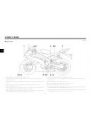
12
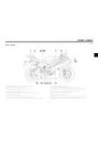
13

14
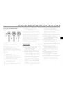
15
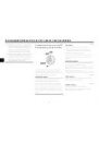
16
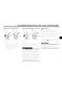
17
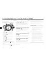
18
19
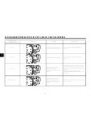
20
21
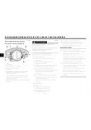
22
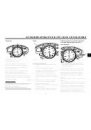
23
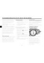
24
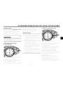
25
26
27
28
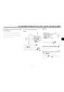
29
30

31
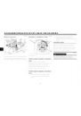
32
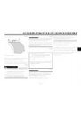
33
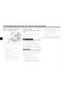
34

35
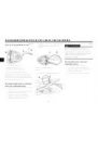
36

37
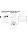
38

39
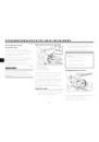
40
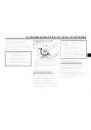
41
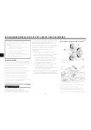
42
43

44
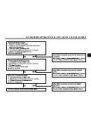
45
46
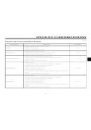
47
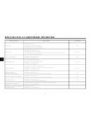
48
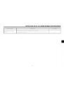
49

50
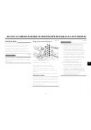
51

52
53
54

55

56

57
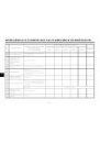
58

59
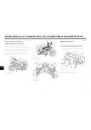
60
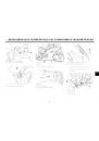
61
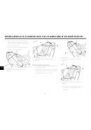
62
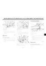
63
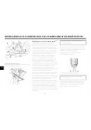
64

65

66
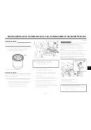
67

68
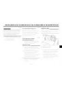
69
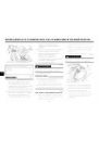
70
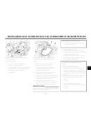
71
72

73
74
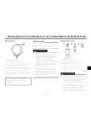
75
76
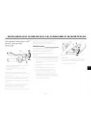
77

78
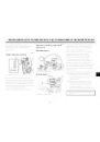
79

80
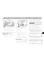
81
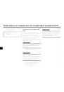
82
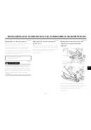
83
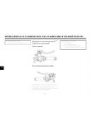
84
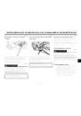
85
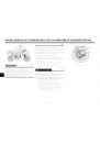
86
87

88

89

90
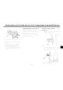
91

92

93
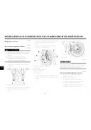
94
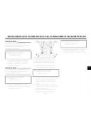
95

96

97
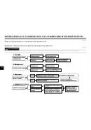
98
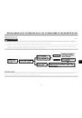
99
100
101
102
103
104
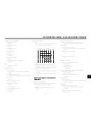
105
106
107
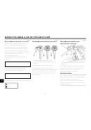
108

109

110

111

112

113

114
Оглавление инструкции
- Страница 1 из 115
YZF-R6 13S-F8199-X0 - Страница 2 из 115
XAU26944 YAMAHA MOTOR ELECTRONICS CO., LTD. YAMAHA MOTOR ELECTRONICS CO., LTD. 1450-6, Mori, Mori-machi, Shuchi-gun, Shizuoka-ken, 437-0292 Japan DECLARATION of CONFORMITY We Company: YAMAHA MOTOR ELECTRONICS CO., LTD. Address: 1450-6, Mori, Mori-Machi, Shuchi-gun, Shizuoka-Ken, 437-0292 Japan - Страница 3 из 115
ȼȼȿȾȿɇɂȿ XAU10100 Ⱦɨɛɪɨ ɩɨɠɚɥɨɜɚɬɶ ɜ ɦɢɪ ɦɨɬɨɰɢɤɥɨɜ Yamaha! Ʉɚɤ ɜɥɚɞɟɥɟɰ ɦɨɞɟɥɢ YZF-R6, ɜɵ ɩɨɥɭɱɚɟɬɟ ɜɵɝɨɞɭ ɨɬ ɛɨɥɶɲɨɝɨ ɨɩɵɬɚ ɢ ɧɨɜɟɣɲɢɯ ɬɟɯɧɨɥɨɝɢɣ ɮɢɪɦɵ Yamaha, ɤɚɫɚɸɳɢɯɫɹ ɤɨɧɫɬɪɭɤɰɢɢ ɢ ɢɡɝɨɬɨɜɥɟɧɢɹ ɜɵɫɨɤɨɤɚɱɟɫɬɜɟɧɧɵɯ ɩɪɨɞɭɤɬɨɜ, ɤɨɬɨɪɵɟ ɡɚɪɚɛɨɬɚɥɢ ɮɢɪɦɟ Yamaha ɪɟɩɭɬɚɰɢɸ ɝɚɪɚɧɬɢɪɨɜɚɧɧɨɣ ɧɚɞɟɠɧɨɫɬɢ. - Страница 4 из 115
ȼȺɀɇȺə ɂɇɎɈɊɆȺɐɂə ȼ ɊɍɄɈȼɈȾɋɌȼȿ XAU10151 ɇɚɢɛɨɥɟɟ ɜɚɠɧɚɹ ɢɧɮɨɪɦɚɰɢɹ ɜɵɞɟɥɟɧɚ ɜ ɞɚɧɧɨɦ ɪɭɤɨɜɨɞɫɬɜɟ ɫɥɟɞɭɸɳɢɦɢ ɨɛɨɡɧɚɱɟɧɢɹɦɢ: ȼɨɫɤɥɢɰɚɬɟɥɶɧɵɣ ɡɧɚɤ ɜ ɬɪɟɭɝɨɥɶɧɢɤɟ ɨɡɧɚɱɚɟɬ ȼɇɂɆȺɇɂȿ! ȻɍȾɖɌȿ ɈɋɌɈɊɈɀɇɕ! Ɋȿɑɖ ɂȾȿɌ Ɉ ȼȺɒȿɃ ȻȿɁɈɉȺɋɇɈɋɌɂ! ɇɟɫɨɛɥɸɞɟɧɢɟ ɭɤɚɡɚɧɢɣ, ɨɬɦɟɱɟɧɧɵɯ ɧɚɞɩɢɫɶɸ ɈɋɌɈɊɈɀɇɈ, ɦɨɠɟɬ ɫɬɚɬɶ - Страница 5 из 115
ȼȺɀɇȺə ɂɇɎɈɊɆȺɐɂə ȼ ɊɍɄɈȼɈȾɋɌȼȿ XAU10200 YZF-R6 ɊɍɄɈȼɈȾɋɌȼɈ ɉɈɅɖɁɈȼȺɌȿɅə ©Yamaha Motor Co., Ltd. 2007 -ɟ ɢɡɞɚɧɢɟ, ɚɜɝɭɫɬ 2007 ɝ. ȼɫɟ ɩɪɚɜɚ ɡɚɳɢɳɟɧɵ . Ʌɸɛɚɹ ɩɟɪɟɩɟɱɚɬɤɚ ɢɥɢ ɧɟɩɪɚɜɨɦɨɱɧɨɟ ɢɫɩɨɥɶɡɨɜɚɧɢɟ ɛɟɡ ɩɢɫɶɦɟɧɧɨɝɨ ɪɚɡɪɟɲɟɧɢɹ Yamaha Motor Co., Ltd. ɩɨɥɧɨɫɬɶɸ ɡɚɩɪɟɳɟɧɨ. Ɉɬɩɟɱɚɬɚɧɨ ɜ Ɋɨɫɫɢɢ. - Страница 6 из 115
ɋɈȾȿɊɀȺɇɂȿ ɂɇɎɈɊɆȺɐɂə ɉɈ ɌȿɏɇɂɄȿ ȻȿɁɈɉȺɋɇɈɋɌɂ …………………………. 1-1 ɈɉɂɋȺɇɂȿ …………………………………… 2-1 ȼɢɞ ɫɥɟɜɚ………………………………………. 2-1 ȼɢɞ ɫɩɪɚɜɚ…………………………………….. 2-2 Ɉɪɝɚɧɵ ɭɩɪɚɜɥɟɧɢɹ ɢ ɩɪɢɛɨɪɵ………. 2-3 - Страница 7 из 115
ɋɈȾȿɊɀȺɇɂȿ ɉɪɨɜɟɪɤɚ ɢ ɫɦɚɡɤɚ ɩɟɞɚɥɟɣ ɬɨɪɦɨɡɚ ɢ ɩɟɪɟɤɥɸɱɟɧɢɹ ɩɟɪɟɞɚɱ ………….. 6-30 ɉɪɨɜɟɪɤɚ ɢ ɫɦɚɡɤɚ ɪɵɱɚɝɨɜ ɬɨɪɦɨɡɚ ɢ ɫɰɟɩɥɟɧɢɹ …………………………….. 6-31 ɉɪɨɜɟɪɤɚ ɢ ɫɦɚɡɤɚ ɨɩɨɪɧɨɣ ɫɬɨɣɤɢ …………………………………….. 6-32 ɋɦɚɡɤɚ ɩɨɜɨɪɨɬɧɵɯ ɲɤɜɨɪɧɟɣ ɦɚɹɬɧɢɤɚ - Страница 8 из 115
ɂɇɎɈɊɆȺɐɂə ɉɈ ɌȿɏɇɂɄȿ ȻȿɁɈɉȺɋɇɈɋɌɂ XAU10281 1 ɆɈɌɈɐɂɄɅɕ — ɗɌɈ ȾȼɍɏɄɈɅȿɋɇɕȿ ɌɊȺɇɋɉɈɊɌɇɕȿ ɋɊȿȾɋɌȼȺ. ɂɏ ȻȿɁɈɉȺɋɇɈȿ ɂɋɉɈɅɖɁɈȼȺɇɂȿ ɂ ɊȺȻɈɌȺ ɁȺȼɂɋəɌ ɈɌ ɂɋɉɈɅɖɁɈȼȺɇɂə ɉɊȺȼɂɅɖɇɈɃ ɌȿɏɇɂɄɂ ȼɈɀȾȿɇɂə ɂ ɉɊɈɎȿɋɋɂɈɇȺɅɖɇɕɏ ɁɇȺɇɂɃ ȼɈȾɂɌȿɅə. ȾɈ ȼɈɀȾȿɇɂə ɗɌɈȽɈ ɆɈɌɈɐɂɄɅȺ ɄȺɀȾɕɃ ȼɈȾɂɌȿɅɖ ȾɈɅɀȿɇ ɁɇȺɌɖ ɋɅȿȾɍɘɓɂȿ - Страница 9 из 115
ɂɇɎɈɊɆȺɐɂə ɉɈ ɌȿɏɇɂɄȿ ȻȿɁɈɉȺɋɇɈɋɌɂ ɫɥɟɞɭɟɬ ɧɟ ɨɡɧɚɤɨɦɢɬɟɫɶ ɫ ɦɨɬɨɰɢɤɥɨɦ ɢ ɜɫɟɦɢ ɟɝɨ ɫɢɫɬɟɦɚɦɢ ɭɩɪɚɜɥɟɧɢɹ. ● Ɇɧɨɝɨ ɞɨɪɨɠɧɨ-ɬɪɚɧɫɩɨɪɬɧɵɯ ɩɪɨɢɫɲɟɫɬɜɢɣ ɩɪɨɢɡɨɲɥɨ ɢɡ-ɡɚ ɨɲɢɛɤɢ ɜɨɞɢɬɟɥɹ ɦɨɬɨɰɢɤɥɚ. Ɍɢɩɢɱɧɨɣ ɨɲɢɛɤɨɣ, ɫɨɜɟɪɲɚɟɦɨɣ ɜɨɞɢɬɟɥɟɦ, ɹɜɥɹɟɬɫɹ ɲɢɪɨɤɢɣ ɭɜɨɞ ɬɪɚɧɫɩɨɪɬɧɨɝɨ ɫɪɟɞɫɬɜɚ ɧɚ ɩɨɜɨɪɨɬɟ ɢɡɡɚ - Страница 10 из 115
ɂɇɎɈɊɆȺɐɂə ɉɈ ɌȿɏɇɂɄȿ ȻȿɁɈɉȺɋɇɈɋɌɂ Ʉɪɨɦɟ ɬɨɝɨ, ɜɧɟɫɟɧɢɟ ɢɡɦɟɧɟɧɢɣ ɜ ɤɨɧɫɬɪɭɤɰɢɸ ɦɨɠɟɬ ɫɞɟɥɚɬɶ ɷɤɫɩɥɭɚɬɚɰɢɸ ɦɨɬɨɰɢɤɥɚ ɧɟɡɚɤɨɧɧɨɣ. 1 ɇɚɝɪɭɡɤɚ ɢ ɚɤɫɟɫɫɭɚɪɵ Ⱦɨɛɚɜɥɟɧɢɟ ɚɤɫɟɫɫɭɚɪɨɜ ɢɥɢ ɝɪɭɡɚ ɧɚ ɦɨɬɨɰɢɤɥ ɦɨɠɟɬ ɨɬɪɢɰɚɬɟɥɶɧɨ ɩɨɜɥɢɹɬɶ ɧɚ ɭɫɬɨɣɱɢɜɨɫɬɶ ɢ ɭɩɪɚɜɥɹɟɦɨɫɬɶ, ɟɫɥɢ ɢɡɦɟɧɢɬɫɹ ɪɚɫɩɪɟɞɟɥɟɧɢɟ ɜɟɫɚ - Страница 11 из 115
ɂɇɎɈɊɆȺɐɂə ɉɈ ɌȿɏɇɂɄȿ ȻȿɁɈɉȺɋɇɈɋɌɂ • Ƚɪɨɦɨɡɞɤɢɟ ɢɥɢ ɛɨɥɶɲɢɟ ɚɤɫɟɫɫɭɚɪɵ ɦɨɝɭɬ ɫɟɪɶɟɡɧɨ ɩɨɜɥɢɹɬɶ ɧɚ ɭɫɬɨɣɱɢɜɨɫɬɶ ɦɨɬɨɰɢɤɥɚ ɢɡ-ɡɚ ɚɷɪɨɞɢɧɚɦɢɱɟɫɤɢɯ ɷɮɮɟɤɬɨɜ. ȼɟɬɟɪ ɦɨɠɟɬ ɩɨɩɵɬɚɬɶɫɹ ɩɨɞɧɹɬɶ ɦɨɬɨɰɢɤɥ ɢɥɢ ɦɨɬɨɰɢɤɥ ɦɨɠɟɬ ɫɬɚɬɶ ɧɟɭɫɬɨɣɱɢɜɵɦ ɩɪɢ ɛɨɤɨɜɵɯ ɜɟɬɪɚɯ. ɗɬɢ ɚɤɫɟɫɫɭɚɪɵ ɦɨɝɭɬ ɬɚɤɠɟ ɩɪɢɜɟɫɬɢ ɤ - Страница 12 из 115
ɈɉɂɋȺɇɂȿ XAU10410 ȼɢɞ ɫɥɟɜɚ 2 1. Ȼɥɨɤ ɩɥɚɜɤɢɯ ɩɪɟɞɨɯɪɚɧɢɬɟɥɟɣ 2 (ɫɬɪ. 6-35) 2. Ɋɟɝɭɥɢɪɨɜɨɱɧɵɣ ɛɨɥɬ ɩɪɟɞɜɚɪɢɬɟɥɶɧɨɝɨ ɧɚɬɹɝɚ ɩɪɭɠɢɧɵ ɩɟɪɟɞɧɟɣ ɜɢɥɤɢ (ɫɬɪ. 3-23) 3. Ɋɟɝɭɥɢɪɨɜɨɱɧɵɣ ɜɢɧɬ ɞɟɦɩɮɢɪɭɸɳɟɣ ɫɢɥɵ ɨɬɛɨɹ ɩɟɪɟɞɧɟɣ ɜɢɥɤɢ (ɫɬɪ. 3-23) 4. Ɋɟɝɭɥɢɪɨɜɨɱɧɨɟ ɤɨɥɶɰɨ ɩɪɟɞɜɚɪɢɬɟɥɶɧɨɝɨ ɧɚɬɹɝɚ ɩɪɭɠɢɧɵ ɛɥɨɤɚ - Страница 13 из 115
ɈɉɂɋȺɇɂȿ XAU10420 ȼɢɞ ɫɩɪɚɜɚ 2 1. 2. 3. 4. 5. 6. 7. 8. 9. Ʉɪɵɲɤɚ ɪɚɞɢɚɬɨɪɚ (ɫɬɪ. 6-16) 10.Ɋɟɡɟɪɜɭɚɪ ɫ ɨɯɥɚɠɞɚɸɳɟɣ ɠɢɞɤɨɫɬɶɸ (ɫɬɪ. 6-16) 11.Ʉɪɵɲɤɚ ɦɚɫɥɨɡɚɩɪɚɜɨɱɧɨɝɨ ɨɬɜɟɪɫɬɢɹ ɞɜɢɝɚɬɟɥɹ (ɫɬɪ. 6-12) 12.Ȼɨɥɬ ɞɪɟɧɚɠɚ ɨɯɥɚɠɞɚɸɳɟɣ ɠɢɞɤɨɫɬɢ (ɫɬɪ. 6-17) 13.Ɇɚɫɥɨɦɟɪɧɚɹ ɥɢɧɟɣɤɚ (ɫɬɪ. 6-12) 14.ɉɟɞɚɥɶ ɬɨɪɦɨɡɚ - Страница 14 из 115
ɈɉɂɋȺɇɂȿ XAU10430 Ɉɪɝɚɧɵ ɭɩɪɚɜɥɟɧɢɹ ɢ ɩɪɢɛɨɪɵ 2 1. 2. 3. 4. 5. 6. 7. Ɋɵɱɚɝ ɜɵɤɥɸɱɟɧɢɹ ɫɰɟɩɥɟɧɢɹ (ɫɬɪ. 3-17) Ʌɟɜɵɟ ɪɭɥɟɜɵɟ ɩɟɪɟɤɥɸɱɚɬɟɥɢ (ɫɬɪ. 3-15) Ƚɥɚɜɧɵɣ ɜɵɤɥɸɱɚɬɟɥɶ/ɡɚɦɨɤ ɛɥɨɤɢɪɨɜɤɢ ɪɭɥɟɜɨɣ ɤɨɥɨɧɤɢ (ɫɬɪ. 3-2) Ɇɧɨɝɨɮɭɧɤɰɢɨɧɚɥɶɧɵɣ ɢɡɦɟɪɢɬɟɥɶɧɵɣ ɩɪɢɛɨɪ (ɫɬɪ. 3-8) ɉɪɚɜɵɟ ɪɭɥɟɜɵɟ ɩɟɪɟɤɥɸɱɚɬɟɥɢ (ɫɬɪ. - Страница 15 из 115
ɎɍɇɄɐɂɂ ɉɊɂȻɈɊɈȼ ɂ ɈɊȽȺɇɈȼ ɍɉɊȺȼɅȿɇɂə XAU10974 ɋɢɫɬɟɦɚ ɢɦɦɨɛɢɥɚɣɡɟɪɚ 1. Ʉɥɸɱ ɞɥɹ ɩɟɪɟɪɟɝɢɫɬɪɚɰɢɢ ɤɨɞɚ (ɤɪɚɫɧɚɹ ɪɭɱɤɚ ) 2. ɋɬɚɧɞɚɪɬɧɵɟ ɤɥɸɱɢ (ɱɟɪɧɵɟ ɪɭɱɤɢ) ɗɬɨ ɬɪɚɧɫɩɨɪɬɧɨɟ ɫɪɟɞɫɬɜɨ ɨɛɨɪɭɞɨɜɚɧɨ ɫɢɫɬɟɦɨɣ ɢɦɦɨɛɢɥɚɣɡɟɪɚ ɞɥɹ ɩɪɟɞɨɬɜɪɚɳɟɧɢɹ ɤɪɚɠɢ ɩɨɫɪɟɞɫɬɜɨɦ ɩɟɪɟɪɟɝɢɫɬɪɢɪɭɟɦɵɯ ɤɨɞɨɜ ɜ ɫɬɚɧɞɚɪɬɧɵɯ ɤɥɸɱɚɯ. - Страница 16 из 115
ɎɍɇɄɐɂɂ ɉɊɂȻɈɊɈȼ ɂ ɈɊȽȺɇɈȼ ɍɉɊȺȼɅȿɇɂə ● ɇɟɨɛɯɨɞɢɦɨ ɞɟɪɠɚɬɶ ɫɬɚɧɞɚɪɬɧɵɟ 3 ɤɥɸɱɢ, ɬɚɤɠɟ ɤɚɤ ɢ ɤɥɸɱɢ ɞɪɭɝɢɯ ɫɢɫɬɟɦ ɢɦɦɨɛɢɥɚɣɡɟɪɨɜ, ɜɞɚɥɢ ɨɬ ɤɥɸɱɚ ɞɥɹ ɩɟɪɟɪɟɝɢɫɬɪɚɰɢɢ ɤɨɞɚ ɞɚɧɧɨɝɨ ɬɪɚɧɫɩɨɪɬɧɨɝɨ ɫɪɟɞɫɬɜɚ. ● ɇɟɨɛɯɨɞɢɦɨ ɞɟɪɠɚɬɶ ɤɥɸɱɢ ɞɪɭɝɢɯ ɫɢɫɬɟɦ ɢɦɦɨɛɢɥɚɣɡɟɪɨɜ ɜɞɚɥɢ ɨɬ ɝɥɚɜɧɨɝɨ ɜɵɤɥɸɱɚɬɟɥɹ, ɩɨɫɤɨɥɶɤɭ - Страница 17 из 115
ɎɍɇɄɐɂɂ ɉɊɂȻɈɊɈȼ ɂ ɈɊȽȺɇɈȼ ɍɉɊȺȼɅȿɇɂə Ⱦɥɹ ɛɥɨɤɢɪɨɜɤɢ ɪɭɥɟɜɨɝɨ ɭɩɪɚɜɥɟɧɢɹ 1. ɇɚɠɚɬɶ. 2. ɉɨɜɟɪɧɭɬɶ. 1. ɉɨɜɟɪɧɭɬɶ ɪɭɥɶ ɧɚɥɟɜɨ ɞɨ ɭɩɨɪɚ. 2. ȼɞɚɜɢɬɶ ɤɥɸɱ ɜ ɩɨɥɨɠɟɧɢɢ “OFF” (ɜɵɤɥ.) ɢ ɡɚɬɟɦ, ɭɞɟɪɠɢɜɚɹ ɟɝɨ ɜɨ ɜɞɚɜɥɟɧɧɨɦ ɩɨɥɨɠɟɧɢɢ, ɩɨɜɟɪɧɭɬɶ ɜ ɩɨɥɨɠɟɧɢɟ “LOCK” (ɛɥɨɤ.). 3. ȼɵɬɚɳɢɬɶ ɤɥɸɱ. Ⱦɥɹ ɫɧɹɬɢɹ - Страница 18 из 115
ɎɍɇɄɐɂɂ ɉɊɂȻɈɊɈȼ ɂ ɈɊȽȺɇɈȼ ɍɉɊȺȼɅȿɇɂə XAU11003 ɂɧɞɢɤɚɬɨɪɧɵɟ ɢ ɩɪɟɞɭɩɪɟɞɢɬɟɥɶɧɵɟ ɥɚɦɩɵ 12 TRIP A 3 10 ɉɪɢ ɩɟɪɟɤɥɸɱɟɧɢɢ ɩɟɪɟɤɥɸɱɚɬɟɥɹ ɫɢɝɧɚɥɚ ɩɨɜɨɪɨɬɚ ɧɚɥɟɜɨ ɢɥɢ ɧɚɩɪɚɜɨ ɧɚɱɢɧɚɟɬ ɦɢɝɚɬɶ ɫɨɨɬɜɟɬɫɬɜɭɸɳɚɹ ɢɧɞɢɤɚɬɨɪɧɚɹ ɥɚɦɩɚ. 34 5 km/h 9 ˚C XAU11030 ɂɧɞɢɤɚɬɨɪɧɵɟ ɥɚɦɩɵ ɫɢɝɧɚɥɨɜ ɩɨɜɨɪɨɬɚ “ ” ɢ “ ” 6 7 8 1. - Страница 19 из 115
ɎɍɇɄɐɂɂ ɉɊɂȻɈɊɈȼ ɂ ɈɊȽȺɇɈȼ ɍɉɊȺȼɅȿɇɂə XAU11361 ɉɪɟɞɭɩɪɟɞɢɬɟɥɶɧɚɹ ɥɚɦɩɚ ɭɪɨɜɧɹ ɬɨɩɥɢɜɚ “ ” ɗɬɚ ɩɪɟɞɭɩɪɟɞɢɬɟɥɶɧɚɹ ɥɚɦɩɚ ɡɚɝɨɪɚɟɬɫɹ, ɤɨɝɞɚ ɭɪɨɜɟɧɶ ɬɨɩɥɢɜɚ ɩɚɞɚɟɬ ɧɢɠɟ ɩɪɢɛɥɢɡɢɬɟɥɶɧɨ 3.5 ɥ (0.92 ɚɦɟɪ. Ƚɚɥɥɨɧɚ) (0.77 ɚɧɝɥ. Ƚɚɥɥɨɧɚ). Ʉɨɝɞɚ ɷɬɨ ɩɪɨɢɫɯɨɞɢɬ, ɧɟɨɛɯɨɞɢɦɨ ɤɚɤ ɦɨɠɧɨ ɫɤɨɪɟɟ ɞɨɡɚɩɪɚɜɢɬɶɫɹ. - Страница 20 из 115
ɎɍɇɄɐɂɂ ɉɊɂȻɈɊɈȼ ɂ ɈɊȽȺɇɈȼ ɍɉɊȺȼɅȿɇɂə Ɍɟɦɩɟɪɚɬɭɪɚ ɨɯɥɚɠɞɚɸɳɟɣ ɠɢɞɤɨɫɬɢ Ⱦɢɫɩɥɟɣ Ɋɟɠɢɦ Ⱦɨ 39 °C TRIP A ˚C 40–116 °C TRIP A ˚C ɑɬɨ ɞɟɥɚɬɶ Ɉɬɨɛɪɚɠɚɟɬɫɹ ɫɨɨɛɳɟɧɢɟ “Lo” (ɧɢɡɤɚɹ ɬɟɦɩɟɪɚɬɭɪɚ). ȼɫɟ ɜ ɩɨɪɹɞɤɟ. Ɇɨɠɧɨ ɩɪɨɞɨɥɠɚɬɶ ɩɨɟɡɞɤɭ. Ɉɬɨɛɪɚɠɚɟɬɫɹ ɬɟɦɩɟɪɚɬɭɪɚ. ȼɫɟ ɜ ɩɨɪɹɞɤɟ. Ɇɨɠɧɨ ɩɪɨɞɨɥɠɚɬɶ ɩɨɟɡɞɤɭ. - Страница 21 из 115
ɎɍɇɄɐɂɂ ɉɊɂȻɈɊɈȼ ɂ ɈɊȽȺɇɈȼ ɍɉɊȺȼɅȿɇɂə XAU42770 ɉɪɟɞɭɩɪɟɞɢɬɟɥɶɧɚɹ ɥɚɦɩɚ ɫɢɫɬɟɦɵ ɤɨɧɬɪɨɥɹ ɧɟɢɫɩɪɚɜɧɨɫɬɢ ɜ ɞɜɢɝɚɬɟɥɟ “ ” ɗɬɚ ɩɪɟɞɭɩɪɟɞɢɬɟɥɶɧɚɹ ɥɚɦɩɚ ɡɚɝɨɪɚɟɬɫɹ ɩɪɢ ɧɟɢɫɩɪɚɜɧɨɣ ɷɥɟɤɬɪɢɱɟɫɤɨɣ ɰɟɩɢ, ɨɫɭɳɟɫɬɜɥɹɸɳɟɣ ɦɨɧɢɬɨɪɢɧɝ ɞɜɢɝɚɬɟɥɹ. Ʉɨɝɞɚ ɷɬɨ ɩɪɨɢɫɯɨɞɢɬ, ɧɟɨɛɯɨɞɢɦɨ, ɱɬɨɛɵ ɞɢɥɟɪ ɮɢɪɦɵ Yamaha ɩɪɨɜɟɪɢɥ - Страница 22 из 115
ɎɍɇɄɐɂɂ ɉɊɂȻɈɊɈȼ ɂ ɈɊȽȺɇɈȼ ɍɉɊȺȼɅȿɇɂə XAU39042 Ɇɧɨɝɨɮɭɧɤɰɢɨɧɚɥɶɧɵɣ ɢɡɦɟɪɢɬɟɥɶɧɵɣ ɩɪɢɛɨɪ 3 1. 2. 3. 4. 5. 6. ɑɚɫɵ ɋɩɢɞɨɦɟɬɪ Ʉɧɨɩɤɚ “SELECT” (ɜɵɛɨɪ) Ʉɧɨɩɤɚ “RESET” (ɫɛɪɨɫ) Ɍɚɯɨɦɟɬɪ Ɉɬɨɛɪɚɠɟɧɢɟ ɬɟɦɩɟɪɚɬɭɪɵ ɨɯɥɚɠɞɚɸɳɟɣ ɠɢɞɤɨɫɬɢ/ɨɬɨɛɪɚɠɟɧɢɟ ɬɟɦɩɟɪɚɬɭɪɵ ɜɨɡɞɭɯɨɡɚɛɨɪɧɢɤɚ 7. ɋɱɟɬɱɢɤ ɩɪɨɛɟɝɚ/ɫɱɟɬɱɢɤɢ - Страница 23 из 115
ɎɍɇɄɐɂɂ ɉɊɂȻɈɊɈȼ ɂ ɈɊȽȺɇɈȼ ɍɉɊȺȼɅȿɇɂə ɑɚɫɵ Ɍɚɯɨɦɟɬɪ 1 Ɋɟɠɢɦɵ ɪɚɛɨɬɵ ɫɱɟɬɱɢɤɚ ɩɪɨɛɟɝɚ, ɫɱɟɬɱɢɤɚ ɩɪɨɣɞɟɧɧɨɝɨ ɩɭɬɢ ɢ ɫɟɤɭɧɞɨɦɟɪɚ 1 km/h TRIP A TRIP A 2 ˚C 1 1. Ɍɚɯɨɦɟɬɪ 2. Ʉɪɚɫɧɚɹ ɡɨɧɚ ɬɚɯɨɦɟɬɪɚ 1. ɑɚɫɵ ɗɥɟɤɬɪɢɱɟɫɤɢɣ ɬɚɯɨɦɟɬɪ ɩɨɡɜɨɥɹɟɬ ɜɨɞɢɬɟɥɸ ɫɥɟɞɢɬɶ ɡɚ ɱɚɫɬɨɬɨɣ ɜɪɚɳɟɧɢɹ ɞɜɢɝɚɬɟɥɹ ɢ ɞɟɪɠɚɬɶ ɟɝɨ ɜ - Страница 24 из 115
ɎɍɇɄɐɂɂ ɉɊɂȻɈɊɈȼ ɂ ɈɊȽȺɇɈȼ ɍɉɊȺȼɅȿɇɂə 3 ɷɬɨɣ ɬɨɱɤɢ. ȼ ɷɬɨɦ ɫɥɭɱɚɟ ɧɟɨɛɯɨɞɢɦɨ ɧɚɠɚɬɶ ɤɧɨɩɤɭ “SELECT” ( ɜɵɛɨɪ ) ɞɥɹ ɩɟɪɟɤɥɸɱɟɧɢɹ ɞɢɫɩɥɟɹ ɦɟɠɞɭ ɪɚɡɥɢɱɧɵɦɢ ɪɟɠɢɦɚɦɢ ɫɱɟɬɱɢɤɨɜ ɩɪɨɣɞɟɧɧɨɝɨ ɩɭɬɢ, ɫɱɟɬɱɢɤɚ ɩɪɨɛɟɝɚ ɢ ɫɟɤɭɧɞɨɦɟɪɚ ɜ ɫɥɟɞɭɸɳɟɦ ɩɨɪɹɞɤɟ: F-TRIP → ɫɟɤɭɧɞɨɦɟɪ → TRIP A → TRIP B → ODO → F-TRIP Ⱦɥɹ - Страница 25 из 115
ɎɍɇɄɐɂɂ ɉɊɂȻɈɊɈȼ ɂ ɈɊȽȺɇɈȼ ɍɉɊȺȼɅȿɇɂə ( ɫɛɪɨɫ ) ɞɥɹ ɩɟɪɟɯɨɞɚ ɨɬ ɪɟɠɢɦɚ ɨɬɨɛɪɚɠɟɧɢɹ ɬɟɦɩɟɪɚɬɭɪɵ ɨɯɥɚɠɞɚɸɳɟɣ ɠɢɞɤɨɫɬɢ ɤ ɪɟɠɢɦɭ ɨɬɨɛɪɚɠɟɧɢɹ ɬɟɦɩɟɪɚɬɭɪɵ ɜɨɡɞɭɯɨɡɚɛɨɪɧɢɤɚ. ɉɊɂɆȿɑȺɇɂȿ: ɉɪɢ ɜɵɛɨɪɟ ɪɟɠɢɦɚ ɨɬɨɛɪɚɠɟɧɢɹ ɬɟɦɩɟɪɚɬɭɪɵ ɨɯɥɚɠɞɚɸɳɟɣ ɠɢɞɤɨɫɬɢ ɧɚ ɞɢɫɩɥɟɟ ɜ ɬɟɱɟɧɢɟ ɨɞɧɨɣ ɫɟɤɭɧɞɵ ɨɬɨɛɪɚɠɚɟɬɫɹ “C”, ɚ - Страница 26 из 115
ɎɍɇɄɐɂɂ ɉɊɂȻɈɊɈȼ ɂ ɈɊȽȺɇɈȼ ɍɉɊȺȼɅȿɇɂə ɉɊɂɆȿɑȺɇɂȿ: ȿɫɥɢ ɧɚ ɩɪɚɜɨɦ ɞɢɫɩɥɟɟ ɨɬɨɛɪɚɡɢɥɫɹ ɤɨɞ ɨɲɢɛɤɢ 52, ɬɨ ɷɬɨ ɦɨɝɥɨ ɩɪɨɢɡɨɣɬɢ ɢɡ-ɡɚ ɢɧɬɟɪɮɟɪɟɧɰɢɢ ɩɪɢɟɦɨɩɟɪɟɞɚɬɱɢɤɚ. ȿɫɥɢ ɜɨɡɧɢɤ ɬɚɤɨɣ ɤɨɞ ɨɲɢɛɤɢ, ɬɨ ɧɟɨɛɯɨɞɢɦɨ ɩɨɩɪɨɛɨɜɚɬɶ ɜɵɩɨɥɧɢɬɶ ɫɥɟɞɭɸɳɢɟ ɞɟɣɫɬɜɢɹ. 3 1. ɂɫɩɨɥɶɡɨɜɚɬɶ ɤɥɸɱ ɞɥɹ ɩɟɪɟɪɟɝɢɫɬɪɚɰɢɢ ɤɨɞɚ, - Страница 27 из 115
ɎɍɇɄɐɂɂ ɉɊɂȻɈɊɈȼ ɂ ɈɊȽȺɇɈȼ ɍɉɊȺȼɅȿɇɂə ● Ⱥɤɬɢɜɧɨɫɬɶ ɢɧɞɢɤɚɬɨɪɧɨɣ ɥɚɦɩɵ ɜɪɟɦɟɧɢ ɩɟɪɟɤɥɸɱɟɧɢɹ ɩɟɪɟɞɚɱ: ɗɬɨɬ ɪɟɝɭɥɹɬɨɪ ɩɨɡɜɨɥɹɟɬ ɜɵɛɪɚɬɶ, ɛɭɞɟɬ ɢɥɢ ɧɟɬ ɚɤɬɢɜɢɪɨɜɚɬɶɫɹ ɢɧɞɢɤɚɬɨɪɧɚɹ ɥɚɦɩɚ ɢ ɞɨɥɠɧɚ ɥɢ ɨɧɚ ɦɢɝɚɬɶ ɢɥɢ ɝɨɪɟɬɶ ɧɟɩɪɟɪɵɜɧɨ, ɤɨɝɞɚ ɨɧɚ ɚɤɬɢɜɢɪɨɜɚɧɚ. ● Ⱥɤɬɢɜɚɰɢɹ ɢɧɞɢɤɚɬɨɪɧɨɣ ɥɚɦɩɵ ɜɪɟɦɟɧɢ - Страница 28 из 115
ɎɍɇɄɐɂɂ ɉɊɂȻɈɊɈȼ ɂ ɈɊȽȺɇɈȼ ɍɉɊȺȼɅȿɇɂə ɩɟɪɟɣɞɟɬ ɜ ɪɟɠɢɦ ɪɟɝɭɥɹɬɨɪɚ ɚɤɬɢɜɚɰɢɢ ɢɧɞɢɤɚɬɨɪɧɨɣ ɥɚɦɩɵ ɜɪɟɦɟɧɢ ɩɟɪɟɤɥɸɱɟɧɢɹ ɩɟɪɟɞɚɱ. Ⱦɥɹ ɭɫɬɚɧɨɜɤɢ ɪɟɝɭɥɹɬɨɪɚ ɚɤɬɢɜɚɰɢɢ ɢɧɞɢɤɚɬɨɪɧɨɣ ɥɚɦɩɵ ɜɪɟɦɟɧɢ ɩɟɪɟɤɥɸɱɟɧɢɹ ɩɟɪɟɞɚɱ 3 ɉɊɂɆȿɑȺɇɂȿ: Ɋɟɝɭɥɹɬɨɪ ɚɤɬɢɜɚɰɢɢ ɢɧɞɢɤɚɬɨɪɧɨɣ ɥɚɦɩɵ ɜɪɟɦɟɧɢ ɩɟɪɟɤɥɸɱɟɧɢɹ ɩɟɪɟɞɚɱ ɦɨɠɟɬ - Страница 29 из 115
ɎɍɇɄɐɂɂ ɉɊɂȻɈɊɈȼ ɂ ɈɊȽȺɇɈȼ ɍɉɊȺȼɅȿɇɂə XAU12331 ɉɪɨɬɢɜɨɭɝɨɧɧɚɹ ɫɢɝɧɚɥɢɡɚɰɢɹ (ɩɨ ɜɵɛɨɪɭ) ɗɬɚ ɦɨɞɟɥɶ ɦɨɠɟɬ ɛɵɬɶ ɨɛɨɪɭɞɨɜɚɧɚ ɩɪɨɬɢɜɨɭɝɨɧɧɨɣ ɫɢɝɧɚɥɢɡɚɰɢɟɣ ɩɨ ɜɵɛɨɪɭ ɞɢɥɟɪɨɦ ɮɢɪɦɵ Yamaha. Ⱦɥɹ ɩɨɥɭɱɟɧɢɹ ɛɨɥɟɟ ɩɨɞɪɨɛɧɨɣ ɢɧɮɨɪɦɚɰɢɢ ɫɜɹɠɢɬɟɫɶ ɫ ɞɢɥɟɪɨɦ ɮɢɪɦɵ Yamaha. XAU12347 Ɋɭɥɟɜɵɟ ɩɟɪɟɤɥɸɱɚɬɟɥɢ ɉɪɚɜɵɟ - Страница 30 из 115
ɎɍɇɄɐɂɂ ɉɊɂȻɈɊɈȼ ɂ ɈɊȽȺɇɈȼ ɍɉɊȺȼɅȿɇɂə XAU12460 ɉɟɪɟɤɥɸɱɚɬɟɥɶ ɫɢɝɧɚɥɚ ɩɨɜɨɪɨɬɚ “ / ” 3 Ⱦɥɹ ɜɤɥɸɱɟɧɢɹ ɫɢɝɧɚɥɚ ɩɪɚɜɨɝɨ ɩɨɜɨɪɨɬɚ ɧɟɨɛɯɨɞɢɦɨ ɩɟɪɟɜɟɫɬɢ ɷɬɨɬ ɩɟɪɟɤɥɸɱɚɬɟɥɶ ɜ ɩɨɥɨɠɟɧɢɟ “ ”. Ⱦɥɹ ɜɤɥɸɱɟɧɢɹ ɫɢɝɧɚɥɚ ɥɟɜɨɝɨ ɩɨɜɨɪɨɬɚ ɧɟɨɛɯɨɞɢɦɨ ɩɟɪɟɜɟɫɬɢ ɷɬɨɬ ɩɟɪɟɤɥɸɱɚɬɟɥɶ ɜ ɩɨɥɨɠɟɧɢɟ “ ”. ȿɫɥɢ ɨɬɩɭɫɬɢɬɶ ɷɬɨɬ - Страница 31 из 115
ɎɍɇɄɐɂɂ ɉɊɂȻɈɊɈȼ ɂ ɈɊȽȺɇɈȼ ɍɉɊȺȼɅȿɇɂə XAU12820 Ɋɵɱɚɝ ɜɵɤɥɸɱɟɧɢɹ ɫɰɟɩɥɟɧɢɹ XAU12870 ɉɟɞɚɥɶ ɩɟɪɟɤɥɸɱɟɧɢɹ ɩɟɪɟɞɚɱ XAU33850 Ɋɵɱɚɝ ɬɨɪɦɨɡɚ 3 1. Ɋɵɱɚɝ ɜɵɤɥɸɱɟɧɢɹ ɫɰɟɩɥɟɧɢɹ 1. ɉɟɞɚɥɶ ɩɟɪɟɤɥɸɱɟɧɢɹ ɩɟɪɟɞɚɱ Ɋɵɱɚɝ ɜɵɤɥɸɱɟɧɢɹ ɫɰɟɩɥɟɧɢɹ ɪɚɫɩɨɥɨɠɟɧ ɧɚ ɥɟɜɨɣ ɪɭɱɤɟ ɪɭɥɹ. Ⱦɥɹ ɜɵɤɥɸɱɟɧɢɹ ɫɰɟɩɥɟɧɢɹ ɧɟɨɛɯɨɞɢɦɨ ɜɵɠɚɬɶ - Страница 32 из 115
ɎɍɇɄɐɂɂ ɉɊɂȻɈɊɈȼ ɂ ɈɊȽȺɇɈȼ ɍɉɊȺȼɅȿɇɂə XAU12941 ɉɟɞɚɥɶ ɬɨɪɦɨɡɚ XAU13072 Ʉɪɵɲɤɚ ɬɨɩɥɢɜɧɨɝɨ ɛɚɤɚ 2. ɉɨɜɟɪɧɭɬɶ ɤɥɸɱ ɩɪɨɬɢɜ ɱɚɫɨɜɨɣ ɫɬɪɟɥɤɢ ɜ ɢɫɯɨɞɧɨɟ ɩɨɥɨɠɟɧɢɟ, ɜɵɬɚɳɢɬɶ ɟɝɨ ɢ ɡɚɬɟɦ ɡɚɤɪɵɬɶ ɤɨɥɩɚɱɨɤ ɡɚɦɤɚ. ɉɊɂɆȿɑȺɇɂȿ: Ʉɪɵɲɤɚ ɬɨɩɥɢɜɧɨɝɨ ɛɚɤɚ ɧɟ ɦɨɠɟɬ ɛɵɬɶ ɡɚɤɪɵɬɚ ɞɨ ɬɟɯ ɩɨɪ, ɩɨɤɚ ɤɥɸɱ ɧɟ ɛɭɞɟɬ ɜɫɬɚɜɥɟɧ - Страница 33 из 115
ɎɍɇɄɐɂɂ ɉɊɂȻɈɊɈȼ ɂ ɈɊȽȺɇɈȼ ɍɉɊȺȼɅȿɇɂə XAU13220 Ɍɨɩɥɢɜɨ XCA10070 ȼɇɂɆȺɇɂȿ: ɇɟɨɛɯɨɞɢɦɨ ɧɟɦɟɞɥɟɧɧɨ ɭɛɪɚɬɶ ɩɪɨɥɢɬɨɟ ɬɨɩɥɢɜɨ ɫ ɩɨɦɨɳɶɸ ɱɢɫɬɨɣ, ɫɭɯɨɣ, ɦɹɝɤɨɣ ɬɤɚɧɢ, ɩɨɫɤɨɥɶɤɭ ɬɨɩɥɢɜɨ ɦɨɠɟɬ ɢɫɩɨɪɬɢɬɶ ɨɤɪɚɲɟɧɧɵɟ ɩɨɜɟɪɯɧɨɫɬɢ ɢɥɢ ɩɥɚɫɬɢɤɨɜɵɟ ɞɟɬɚɥɢ. XAU13390 1. Ƚɨɪɥɨɜɢɧɚ ɬɨɩɥɢɜɧɨɝɨ ɛɚɤɚ 2. ɍɪɨɜɟɧɶ ɬɨɩɥɢɜɚ - Страница 34 из 115
ɎɍɇɄɐɂɂ ɉɊɂȻɈɊɈȼ ɂ ɈɊȽȺɇɈȼ ɍɉɊȺȼɅȿɇɂə XAU39450 ɒɥɚɧɝ ɫɚɩɭɧɚ/ɩɟɪɟɩɭɫɤɧɨɣ ɲɥɚɧɝ ɬɨɩɥɢɜɧɨɝɨ ɛɚɤɚ XAU13442 Ʉɚɬɚɥɢɬɢɱɟɫɤɢɟ ɧɟɣɬɪɚɥɢɡɚɬɨɪɵ ɨɬɪɚɛɨɬɚɜɲɢɯ ɝɚɡɨɜ ɗɬɨ ɬɪɚɧɫɩɨɪɬɧɨɟ ɫɪɟɞɫɬɜɨ ɨɛɨɪɭɞɨɜɚɧɨ ɤɚɬɚɥɢɬɢɱɟɫɤɢɦɢ ɧɟɣɬɪɚɥɢɡɚɬɨɪɚɦɢ ɨɬɪɚɛɨɬɚɜɲɢɯ ɝɚɡɨɜ ɜ ɫɢɫɬɟɦɟ ɜɵɩɭɫɤɚ ɨɬɪɚɛɨɬɚɜɲɢɯ ɝɚɡɨɜ. 3 XWA10860 - Страница 35 из 115
ɎɍɇɄɐɂɂ ɉɊɂȻɈɊɈȼ ɂ ɈɊȽȺɇɈȼ ɍɉɊȺȼɅȿɇɂə 2. ɍɞɟɪɠɢɜɚɹ ɤɥɸɱ ɜ ɷɬɨɦ ɩɨɥɨɠɟɧɢɢ, ɩɨɞɧɹɬɶ ɩɟɪɟɞɧɸɸ ɱɚɫɬɶ ɩɚɫɫɚɠɢɪɫɤɨɝɨ ɫɢɞɟɧɶɹ ɢ ɜɵɬɹɧɭɬɶ ɟɝɨ ɜɩɟɪɟɞ. XAU39031 ɋɢɞɟɧɶɹ ɋɢɞɟɧɶɟ ɜɨɞɢɬɟɥɹ Ⱦɥɹ ɫɧɹɬɢɹ ɫɢɞɟɧɶɹ ɜɨɞɢɬɟɥɹ Ɉɬɬɹɧɭɬɶ ɧɚɡɚɞ ɡɚɞɧɸɸ ɱɚɫɬɶ ɫɢɞɟɧɶɹ ɜɨɞɢɬɟɥɹ, ɤɚɤ ɩɨɤɚɡɚɧɨ ɧɚ ɪɢɫɭɧɤɟ, ɭɞɚɥɢɬɶ ɛɨɥɬɵ ɢ ɡɚɬɟɦ - Страница 36 из 115
ɎɍɇɄɐɂɂ ɉɊɂȻɈɊɈȼ ɂ ɈɊȽȺɇɈȼ ɍɉɊȺȼɅȿɇɂə XAU39072 Ɍɪɨɫ ɞɥɹ ɭɞɟɪɠɚɧɢɹ ɲɥɟɦɚ ɡɚɳɟɥɤɧɭɬɶ ɷɬɨɬ ɤɪɸɤ ɫ ɤɚɪɚɛɢɧɨɦ ɧɚ ɞɟɪɠɚɬɟɥɟ ɬɪɨɫɚ, ɤɚɤ ɩɨɤɚɡɚɧɨ ɧɚ ɪɢɫɭɧɤɟ. XWA14330 ɈɋɌɈɊɈɀɇɈ ɇɢɤɨɝɞɚ ɧɟ ɫɨɜɟɪɲɚɣɬɟ ɩɨɟɡɞɨɤ ɫɨ ɲɥɟɦɨɦ, ɩɪɢɤɪɟɩɥɟɧɧɵɦ ɤ ɬɪɨɫɭ ɞɥɹ ɭɞɟɪɠɚɧɢɹ ɲɥɟɦɚ, ɩɨɫɤɨɥɶɤɭ ɷɬɨɬ ɲɥɟɦ ɦɨɠɟɬ ɭɞɚɪɹɬɶɫɹ ɨ - Страница 37 из 115
ɎɍɇɄɐɂɂ ɉɊɂȻɈɊɈȼ ɂ ɈɊȽȺɇɈȼ ɍɉɊȺȼɅȿɇɂə XAU38942 Ɋɟɝɭɥɢɪɨɜɤɚ ɩɟɪɟɞɧɟɣ ɜɢɥɤɢ Ⱦɚɧɧɚɹ ɩɟɪɟɞɧɹɹ ɜɢɥɤɚ ɨɛɨɪɭɞɨɜɚɧɚ ɪɟɝɭɥɢɪɨɜɨɱɧɵɦɢ ɛɨɥɬɚɦɢ ɩɪɟɞɜɚɪɢɬɟɥɶɧɨɝɨ ɧɚɬɹɝɚ ɩɪɭɠɢɧɵ, ɪɟɝɭɥɢɪɨɜɨɱɧɵɦɢ ɜɢɧɬɚɦɢ ɞɟɦɩɮɢɪɭɸɳɟɣ ɫɢɥɵ ɨɬɛɨɹ, ɪɟɝɭɥɢɪɨɜɨɱɧɵɦɢ ɛɨɥɬɚɦɢ ɞɟɦɩɮɢɪɭɸɳɟɣ ɫɢɥɵ ɫɠɚɬɢɹ (ɞɥɹ ɞɟɦɩɮɢɪɨɜɚɧɢɹ ɛɵɫɬɪɨɝɨ ɫɠɚɬɢɹ) - Страница 38 из 115
ɎɍɇɄɐɂɂ ɉɊɂȻɈɊɈȼ ɂ ɈɊȽȺɇɈȼ ɍɉɊȺȼɅȿɇɂə Ⱦɟɦɩɮɢɪɭɸɳɚɹ ɫɢɥɚ ɨɬɛɨɹ 3 ɇɚɫɬɪɨɣɤɚ ɞɟɦɩɮɢɪɨɜɚɧɢɹ ɨɬɛɨɹ: Ɇɢɧɢɦɚɥɶɧɚɹ (ɫɥɚɛɚɹ): 25 ɳɟɥɱɤɨɜ ɜ ɧɚɩɪɚɜɥɟɧɢɢ (b)* ɋɬɚɧɞɚɪɬɧɨɟ ɩɨɥɨɠɟɧɢɟ: 20 ɳɟɥɱɤɨɜ ɜ ɧɚɩɪɚɜɥɟɧɢɢ (b)* Ɇɚɤɫɢɦɚɥɶɧɚɹ (ɫɢɥɶɧɚɹ): 1 ɳɟɥɱɨɤ ɜ ɧɚɩɪɚɜɥɟɧɢɢ (b)* * ɉɪɢ ɩɨɜɨɪɨɬɟ ɜɢɧɬɚ ɪɟɝɭɥɢɪɨɜɤɢ ɞɨ ɭɩɨɪɚ ɜ - Страница 39 из 115
ɎɍɇɄɐɂɂ ɉɊɂȻɈɊɈȼ ɂ ɈɊȽȺɇɈȼ ɍɉɊȺȼɅȿɇɂə Ⱦɥɹ ɪɟɝɭɥɢɪɨɜɤɢ ɞɟɦɩɮɢɪɭɸɳɟɣ ɫɢɥɵ ɫɠɚɬɢɹ (ɞɥɹ ɞɟɦɩɮɢɪɨɜɚɧɢɹ ɦɟɞɥɟɧɧɨɝɨ ɫɠɚɬɢɹ) ɇɚɫɬɪɨɣɤɚ ɞɟɦɩɮɢɪɨɜɚɧɢɹ ɫɠɚɬɢɹ (ɞɥɹ ɞɟɦɩɮɢɪɨɜɚɧɢɹ ɦɟɞɥɟɧɧɨɝɨ ɫɠɚɬɢɹ): Ɇɢɧɢɦɚɥɶɧɚɹ (ɫɥɚɛɚɹ): 20 ɳɟɥɱɤɨɜ ɜ ɧɚɩɪɚɜɥɟɧɢɢ (b)* ɋɬɚɧɞɚɪɬɧɨɟ ɩɨɥɨɠɟɧɢɟ: 15 ɳɟɥɱɤɨɜ ɜ ɧɚɩɪɚɜɥɟɧɢɢ (b)* - Страница 40 из 115
ɎɍɇɄɐɂɂ ɉɊɂȻɈɊɈȼ ɂ ɈɊȽȺɇɈȼ ɍɉɊȺȼɅȿɇɂə XAU42940 Ɋɟɝɭɥɢɪɨɜɤɚ ɛɥɨɤɚ ɚɦɨɪɬɢɡɚɬɨɪɚ 3 Ⱦɚɧɧɵɣ ɛɥɨɤ ɚɦɨɪɬɢɡɚɬɨɪɚ ɨɛɨɪɭɞɨɜɚɧ ɪɟɝɭɥɢɪɨɜɨɱɧɵɦ ɤɨɥɶɰɨɦ ɩɪɟɞɜɚɪɢɬɟɥɶɧɨɝɨ ɧɚɬɹɝɚ ɩɪɭɠɢɧɵ, ɪɟɝɭɥɢɪɨɜɨɱɧɵɦ ɜɢɧɬɨɦ ɞɟɦɩɮɢɪɭɸɳɟɣ ɫɢɥɵ ɨɬɛɨɹ, ɪɟɝɭɥɢɪɨɜɨɱɧɵɦ ɛɨɥɬɨɦ ɞɟɦɩɮɢɪɭɸɳɟɣ ɫɢɥɵ ɫɠɚɬɢɹ (ɞɥɹ ɞɟɦɩɮɢɪɨɜɚɧɢɹ ɛɵɫɬɪɨɝɨ - Страница 41 из 115
ɎɍɇɄɐɂɂ ɉɊɂȻɈɊɈȼ ɂ ɈɊȽȺɇɈȼ ɍɉɊȺȼɅȿɇɂə ɩɨɜɨɪɚɱɢɜɚɬɶ ɪɟɝɭɥɢɪɨɜɨɱɧɵɣ ɜɢɧɬ ɜ ɧɚɩɪɚɜɥɟɧɢɢ (a). Ⱦɥɹ ɭɦɟɧɶɲɟɧɢɹ ɞɟɦɩɮɢɪɭɸɳɟɣ ɫɢɥɵ ɨɬɛɨɹ ɢ, ɬɚɤɢɦ ɨɛɪɚɡɨɦ, ɫɦɹɝɱɟɧɢɹ ɞɟɦɩɮɢɪɨɜɚɧɢɹ ɨɬɛɨɹ ɧɟɨɛɯɨɞɢɦɨ ɩɨɜɨɪɚɱɢɜɚɬɶ ɪɟɝɭɥɢɪɨɜɨɱɧɵɣ ɜɢɧɬ ɜ ɧɚɩɪɚɜɥɟɧɢɢ (b). ɇɚɫɬɪɨɣɤɚ ɞɟɦɩɮɢɪɨɜɚɧɢɹ ɨɬɛɨɹ: Ɇɢɧɢɦɚɥɶɧɚɹ (ɫɥɚɛɚɹ): 20 - Страница 42 из 115
ɎɍɇɄɐɂɂ ɉɊɂȻɈɊɈȼ ɂ ɈɊȽȺɇɈȼ ɍɉɊȺȼɅȿɇɂə 3 ɇɚɫɬɪɨɣɤɚ ɞɟɦɩɮɢɪɨɜɚɧɢɹ ɫɠɚɬɢɹ (ɞɥɹ ɞɟɦɩɮɢɪɨɜɚɧɢɹ ɦɟɞɥɟɧɧɨɝɨ ɫɠɚɬɢɹ): Ɇɢɧɢɦɚɥɶɧɚɹ (ɫɥɚɛɚɹ): 20 ɳɟɥɱɤɨɜ ɜ ɧɚɩɪɚɜɥɟɧɢɢ (b)* ɋɬɚɧɞɚɪɬɧɨɟ ɩɨɥɨɠɟɧɢɟ: 16 ɳɟɥɱɤɨɜ ɜ ɧɚɩɪɚɜɥɟɧɢɢ (b)* Ɇɚɤɫɢɦɚɥɶɧɚɹ (ɫɢɥɶɧɚɹ): 1 ɳɟɥɱɨɤ ɜ ɧɚɩɪɚɜɥɟɧɢɢ (b)* * ɉɪɢ ɩɨɜɨɪɨɬɟ ɛɨɥɬɚ ɪɟɝɭɥɢɪɨɜɤɢ - Страница 43 из 115
ɎɍɇɄɐɂɂ ɉɊɂȻɈɊɈȼ ɂ ɈɊȽȺɇɈȼ ɍɉɊȺȼɅȿɇɂə ɧɚ ɩɚɫɫɚɠɢɪɫɤɨɦ ɫɢɞɟɧɶɟ ɧɟɨɛɯɨɞɢɦɨ ɭɞɚɥɢɬɶ ɩɚɫɫɚɠɢɪɫɤɨɟ ɫɢɞɟɧɶɟ, ɨɬɰɟɩɢɬɶ ɪɟɦɧɢ ɨɬ ɤɪɸɱɤɨɜ ɢ ɡɚɬɟɦ ɭɫɬɚɧɨɜɢɬɶ ɫɢɞɟɧɶɟ ɬɚɤ, ɱɬɨɛɵ ɷɬɢ ɪɟɦɧɢ ɫɜɢɫɚɥɢ ɧɚɪɭɠɭ ɢɡ-ɩɨɞ ɩɚɫɫɚɠɢɪɫɤɨɝɨ ɫɢɞɟɧɶɹ. (ɋɦ. ɫɬɪ. 3-21.) XAU41940 XAU15301 ɋɢɫɬɟɦɚ EXUP Ɉɩɨɪɧɚɹ ɫɬɨɣɤɚ ɗɬɚ ɦɨɞɟɥɶ - Страница 44 из 115
ɎɍɇɄɐɂɂ ɉɊɂȻɈɊɈȼ ɂ ɈɊȽȺɇɈȼ ɍɉɊȺȼɅȿɇɂə ɢ ɨɛɪɚɳɚɬɶɫɹ ɤ ɞɢɥɟɪɭ ɮɢɪɦɵ Yamaha ɡɚ ɪɟɦɨɧɬɨɦ ɷɬɨɣ ɫɢɫɬɟɦɵ, ɟɫɥɢ ɨɧɚ ɮɭɧɤɰɢɨɧɢɪɭɟɬ ɧɟɩɪɚɜɢɥɶɧɨ. 3 XAU44890 ɋɢɫɬɟɦɚ ɨɬɤɥɸɱɟɧɢɹ ɰɟɩɢ ɡɚɠɢɝɚɧɢɹ ɋɢɫɬɟɦɚ ɨɬɤɥɸɱɟɧɢɹ ɰɟɩɢ ɡɚɠɢɝɚɧɢɹ (ɜɤɥɸɱɚɹ ɩɟɪɟɤɥɸɱɚɬɟɥɶ ɨɩɨɪɧɨɣ ɫɬɨɣɤɢ, ɩɟɪɟɤɥɸɱɚɬɟɥɶ ɦɭɮɬɵ ɫɰɟɩɥɟɧɢɹ ɢ ɩɟɪɟɤɥɸɱɚɬɟɥɶ - Страница 45 из 115
ɎɍɇɄɐɂɂ ɉɊɂȻɈɊɈȼ ɂ ɈɊȽȺɇɈȼ ɍɉɊȺȼɅȿɇɂə 3 3-31 - Страница 46 из 115
ɉɊȿȾɗɄɋɉɅɍȺɌȺɐɂɈɇɇɕȿ ɉɊɈȼȿɊɄɂ XAU15593 Ɉɬɫɥɟɠɢɜɚɧɢɟ ɬɟɯɧɢɱɟɫɤɨɝɨ ɫɨɫɬɨɹɧɢɹ ɬɪɚɧɫɩɨɪɬɧɨɝɨ ɫɪɟɞɫɬɜɚ ɹɜɥɹɟɬɫɹ ɨɬɜɟɬɫɬɜɟɧɧɨɫɬɶɸ ɟɝɨ ɜɥɚɞɟɥɶɰɚ. ɋɢɥɨɜɵɟ ɭɡɥɵ ɦɨɝɭɬ ɛɵɫɬɪɨ ɢ ɧɟɨɠɢɞɚɧɧɨ ɧɚɱɚɬɶ ɢɡɧɚɲɢɜɚɬɶɫɹ, ɞɚɠɟ ɟɫɥɢ ɬɪɚɧɫɩɨɪɬɧɨɟ ɫɪɟɞɫɬɜɨ ɧɟ ɷɤɫɩɥɭɚɬɢɪɭɟɬɫɹ (ɧɚɩɪɢɦɟɪ, ɜ ɪɟɡɭɥɶɬɚɬɟ ɜɨɡɞɟɣɫɬɜɢɹ ɧɚ ɞɟɬɚɥɢ). - Страница 47 из 115
ɉɊȿȾɗɄɋɉɅɍȺɌȺɐɂɈɇɇɕȿ ɉɊɈȼȿɊɄɂ XAU15605 ɉɟɪɟɱɟɧɶ ɩɪɟɞɷɤɫɩɥɭɚɬɚɰɢɨɧɧɵɯ ɩɪɨɜɟɪɨɤ ɄɈɆɉɈɇȿɇɌ ɉɊɈȼȿɊɄɂ ɋɌɊȺɇɂɐȺ Ɍɨɩɥɢɜɨ • ɉɪɨɜɟɪɢɬɶ ɭɪɨɜɟɧɶ ɬɨɩɥɢɜɚ ɜ ɬɨɩɥɢɜɧɨɦ ɛɚɤɟ. • Ⱦɨɛɚɜɢɬɶ, ɟɫɥɢ ɬɪɟɛɭɟɬɫɹ. • ɉɪɨɜɟɪɢɬɶ ɬɨɩɥɢɜɨɩɪɨɜɨɞ ɧɚ ɭɬɟɱɤɢ. 3-19 Ɇɨɬɨɪɧɨɟ ɦɚɫɥɨ • ɉɪɨɜɟɪɢɬɶ ɭɪɨɜɟɧɶ ɦɚɫɥɚ ɜ ɞɜɢɝɚɬɟɥɟ. • ȿɫɥɢ - Страница 48 из 115
ɉɊȿȾɗɄɋɉɅɍȺɌȺɐɂɈɇɇɕȿ ɉɊɈȼȿɊɄɂ ɄɈɆɉɈɇȿɇɌ ɉɊɈȼȿɊɄɂ ɋɰɟɩɥɟɧɢɟ • • • • Ɋɭɱɤɚ ɝɚɡɚ • ɉɪɨɜɟɪɢɬɶ ɩɥɚɜɧɨɫɬɶ ɯɨɞɚ. • ɉɪɨɜɟɪɢɬɶ ɫɜɨɛɨɞɧɵɣ ɯɨɞ ɬɪɨɫɚ. • ȿɫɥɢ ɧɟɨɛɯɨɞɢɦɨ, ɨɬɪɟɝɭɥɢɪɨɜɚɬɶ ɫɜɨɛɨɞɧɵɣ ɯɨɞ ɬɪɨɫɚ, ɫɦɚɡɚɬɶ ɬɪɨɫ ɢ ɤɨɪɩɭɫ ɪɭɱɤɢ ɧɚ ɫɬɚɧɰɢɢ ɞɢɥɟɪɚ Yamaha . Ɍɪɨɫɵ ɭɩɪɚɜɥɟɧɢɹ • ɉɪɨɜɟɪɢɬɶ ɩɥɚɜɧɨɫɬɶ ɯɨɞɚ. • - Страница 49 из 115
ɉɊȿȾɗɄɋɉɅɍȺɌȺɐɂɈɇɇɕȿ ɉɊɈȼȿɊɄɂ ɄɈɆɉɈɇȿɇɌ ɉɟɪɟɤɥɸɱɚɬɟɥɶ ɨɩɨɪɧɨɣ ɫɬɨɣɤɢ ɉɊɈȼȿɊɄɂ • ɉɪɨɜɟɪɢɬɶ ɪɚɛɨɬɭ ɫɢɫɬɟɦɵ ɨɬɤɥɸɱɟɧɢɹ ɰɟɩɢ ɡɚɠɢɝɚɧɢɹ. • ɉɪɢ ɧɟɢɫɩɪɚɜɧɨɫɬɢ ɫɢɫɬɟɦɵ ɨɛɪɚɬɢɬɶɫɹ ɤ ɞɢɥɟɪɭ ɮɢɪɦɵ Yamaha ɞɥɹ ɩɪɨɜɟɪɤɢ ɬɪɚɧɫɩɨɪɬɧɨɝɨ ɫɪɟɞɫɬɜɚ. ɋɌɊȺɇɂɐȺ 3-29 4 4-4 - Страница 50 из 115
ɗɄɋɉɅɍȺɌȺɐɂə ɂ ȼȺɀɇɕȿ ɆɈɆȿɇɌɕ ɉɊɂ ɉɈȿɁȾɄȺɏ ɇȺ ɆɈɌɈɐɂɄɅȿ XAU15950 XAU33011 Ɂɚɩɭɫɤ ɞɜɢɝɚɬɟɥɹ XWA10270 ɈɋɌɈɊɈɀɇɈ ● Ⱦɨ ɩɨɟɡɞɨɤ ɧɚ ɦɨɬɨɰɢɤɥɟ ɧɟɨɛɯɨɞɢɦɨ 5 ɬɳɚɬɟɥɶɧɨ ɨɡɧɚɤɨɦɢɬɶɫɹ ɫɨ ɜɫɟɦɢ ɫɢɫɬɟɦɚɦɢ ɭɩɪɚɜɥɟɧɢɹ ɢ ɢɯ ɮɭɧɤɰɢɹɦɢ. ɉɪɨɤɨɧɫɭɥɶɬɢɪɭɣɬɟɫɶ ɭ ɞɢɥɟɪɚ ɮɢɪɦɵ Yamaha ɨɬɧɨɫɢɬɟɥɶɧɨ ɥɸɛɵɯ ɫɢɫɬɟɦ ɭɩɪɚɜɥɟɧɢɹ - Страница 51 из 115
ɗɄɋɉɅɍȺɌȺɐɂə ɂ ȼȺɀɇɕȿ ɆɈɆȿɇɌɕ ɉɊɂ ɉɈȿɁȾɄȺɏ ɇȺ ɆɈɌɈɐɂɄɅȿ XAU16671 ɉɊɂɆȿɑȺɇɂȿ: ȿɫɥɢ ɞɜɢɝɚɬɟɥɶ ɧɟ ɡɚɩɭɫɤɚɟɬɫɹ, ɨɬɩɭɫɬɢɬɟ ɩɟɪɟɤɥɸɱɚɬɟɥɶ ɡɚɩɭɫɤɚ ɢ ɱɟɪɟɡ ɧɟɫɤɨɥɶɤɨ ɫɟɤɭɧɞ ɩɨɜɬɨɪɢɬɟ ɩɨɩɵɬɤɭ. ɑɬɨɛɵ ɧɟ ɪɚɡɪɹɞɢɥɫɹ ɚɤɤɭɦɭɥɹɬɨɪ, ɩɨɩɵɬɤɢ ɩɭɫɤɚ ɞɨɥɠɧɵ ɛɵɬɶ ɤɚɤ ɦɨɠɧɨ ɤɨɪɨɱɟ. ɇɟ ɜɤɥɸɱɚɣɬɟ ɫɬɚɪɬɟɪ ɛɨɥɟɟ ɱɟɦ ɧɚ 10 - Страница 52 из 115
ɗɄɋɉɅɍȺɌȺɐɂə ɂ ȼȺɀɇɕȿ ɆɈɆȿɇɌɕ ɉɊɂ ɉɈȿɁȾɄȺɏ ɇȺ ɆɈɌɈɐɂɄɅȿ XAU16810 ɉɨɞɫɤɚɡɤɢ ɩɨ ɭɦɟɧɶɲɟɧɢɸ ɪɚɫɯɨɞɚ ɬɨɩɥɢɜɚ 5 Ɋɚɫɯɨɞ ɬɨɩɥɢɜɚ ɜ ɡɧɚɱɢɬɟɥɶɧɨɣ ɫɬɟɩɟɧɢ ɡɚɜɢɫɢɬ ɨɬ ɫɬɢɥɹ ɟɡɞɵ. Ɋɚɫɫɦɨɬɪɢɬɟ ɫɥɟɞɭɸɳɢɟ ɩɨɞɫɤɚɡɤɢ ɞɥɹ ɭɦɟɧɶɲɟɧɢɹ ɪɚɫɯɨɞɚ ɬɨɩɥɢɜɚ: ● ȼ ɯɨɞɟ ɪɚɡɝɨɧɚ ɛɵɫɬɪɨ ɩɟɪɟɯɨɞɢɬɟ ɧɚ ɛɨɥɟɟ ɜɵɫɨɤɭɸ ɩɟɪɟɞɚɱɭ ɢ - Страница 53 из 115
ɗɄɋɉɅɍȺɌȺɐɂə ɂ ȼȺɀɇɕȿ ɆɈɆȿɇɌɕ ɉɊɂ ɉɈȿɁȾɄȺɏ ɇȺ ɆɈɌɈɐɂɄɅȿ XAU17212 ɉɚɪɤɨɜɤɚ ɉɪɢ ɩɚɪɤɨɜɤɟ ɧɟɨɛɯɨɞɢɦɨ ɨɫɬɚɧɨɜɢɬɶ ɞɜɢɝɚɬɟɥɶ ɢ ɜɵɬɚɳɢɬɶ ɤɥɸɱ ɢɡ ɝɥɚɜɧɨɝɨ ɜɵɤɥɸɱɚɬɟɥɹ. XWA10310 ɈɋɌɈɊɈɀɇɈ ● ɉɨɫɤɨɥɶɤɭ ɞɜɢɝɚɬɟɥɶ ɢ ɫɢɫɬɟɦɚ ɜɵɩɭɫɤɚ ɨɬɪɚɛɨɬɚɜɲɢɯ ɝɚɡɨɜ ɦɨɝɭɬ ɫɢɥɶɧɨ ɧɚɝɪɟɜɚɬɶɫɹ, ɫɬɚɜɶɬɟ ɦɨɬɨɰɢɤɥ ɜ ɬɚɤɢɯ ɦɟɫɬɚɯ, - Страница 54 из 115
ɉȿɊɂɈȾɂɑȿɋɄɈȿ ɌȿɏɇɂɑȿɋɄɈȿ ɈȻɋɅɍɀɂȼȺɇɂȿ ɂ ɆȿɅɄɂɃ ɊȿɆɈɇɌ XAU17240 6 Ɉɛɟɫɩɟɱɟɧɢɟ ɛɟɡɨɩɚɫɧɨɫɬɢ ɹɜɥɹɟɬɫɹ ɨɛɹɡɚɧɧɨɫɬɶɸ ɩɨɥɶɡɨɜɚɬɟɥɹ. ɉɟɪɢɨɞɢɱɟɫɤɢɟ ɩɪɨɜɟɪɤɢ, ɪɟɝɭɥɢɪɨɜɤɢ ɢ ɫɦɚɡɵɜɚɧɢɟ ɨɛɟɫɩɟɱɚɬ ɧɚɢɛɨɥɟɟ ɛɟɡɨɩɚɫɧɨɟ ɢ ɷɮɮɟɤɬɢɜɧɨɟ ɜɨɡɦɨɠɧɨɟ ɫɨɫɬɨɹɧɢɟ ɜɚɲɟɝɨ ɬɪɚɧɫɩɨɪɬɧɨɝɨ ɫɪɟɞɫɬɜɚ. ɇɚ ɫɥɟɞɭɸɳɢɯ ɫɬɪɚɧɢɰɚɯ - Страница 55 из 115
ɉȿɊɂɈȾɂɑȿɋɄɈȿ ɌȿɏɇɂɑȿɋɄɈȿ ɈȻɋɅɍɀɂȼȺɇɂȿ ɂ ɆȿɅɄɂɃ ɊȿɆɈɇɌ XAU1770A Ʉɚɪɬɚ ɩɟɪɢɨɞɢɱɟɫɤɨɝɨ ɬɟɯɧɢɱɟɫɤɨɝɨ ɨɛɫɥɭɠɢɜɚɧɢɹ ɢ ɫɦɚɡɤɢ ɉɊɂɆȿɑȺɇɂȿ: ● ȿɠɟɝɨɞɧɵɟ ɩɪɨɜɟɪɤɢ ɞɨɥɠɧɵ ɜɵɩɨɥɧɹɬɶɫɹ ɤɚɠɞɵɣ ɝɨɞ, ɡɚ ɢɫɤɥɸɱɟɧɢɟɦ ɫɥɭɱɚɟɜ, ɤɨɝɞɚ ɜɦɟɫɬɨ ɧɢɯ ɧɟɨɛɯɨɞɢɦɨ ɩɪɨɜɨɞɢɬɶ ɬɟɯɧɢɱɟɫɤɨɟ ɨɛɫɥɭɠɢɜɚɧɢɟ ɧɚ ɨɫɧɨɜɟ ɜɟɥɢɱɢɧɵ ɩɪɨɛɟɝɚ ɜ - Страница 56 из 115
ɉȿɊɂɈȾɂɑȿɋɄɈȿ ɌȿɏɇɂɑȿɋɄɈȿ ɈȻɋɅɍɀɂȼȺɇɂȿ ɂ ɆȿɅɄɂɃ ɊȿɆɈɇɌ ʋ 7 ɄɈɆɉɈɇȿɇɌ * Ɂɚɞɧɢɣ ɬɨɪɦɨɡ ɉɊɈȼȿɊɄȺ ɂɅɂ ɊȺȻɈɌȺ ɉɈ ɌȿɏɇɂɑȿɋɄɈɆɍ ɈȻɋɅɍɀɂȼȺɇɂɘ • ɉɪɨɜɟɪɢɬɶ ɪɚɛɨɬɭ, ɭɪɨɜɟɧɶ ɠɢɞɤɨɫɬɢ ɢ ɬɪɚɧɫɩɨɪɬɧɨɟ ɫɪɟɞɫɬɜɨ ɧɚ ɧɚɥɢɱɢɟ ɭɬɟɱɟɤ ɠɢɞɤɨɫɬɢ. ɉɈɄȺɁȺɇɂə ɋɑȿɌɑɂɄȺ ɉɊɈȻȿȽȺ 000 ɤɦ 0000 ɤɦ 20000 ɤɦ 30000 ɤɦ 40000 ɤɦ √ √ √ - Страница 57 из 115
ɉȿɊɂɈȾɂɑȿɋɄɈȿ ɌȿɏɇɂɑȿɋɄɈȿ ɈȻɋɅɍɀɂȼȺɇɂȿ ɂ ɆȿɅɄɂɃ ɊȿɆɈɇɌ ʋ 4 * ɄɈɆɉɈɇȿɇɌ Ɋɭɥɟɜɵɟ ɩɨɞɲɢɩɧɢɤɢ ɉɊɈȼȿɊɄȺ ɂɅɂ ɊȺȻɈɌȺ ɉɈ ɌȿɏɇɂɑȿɋɄɈɆɍ ɈȻɋɅɍɀɂȼȺɇɂɘ • ɉɪɨɜɟɪɢɬɶ ɥɸɮɬ ɩɨɞɲɢɩɧɢɤɚ ɢ ɪɭɥɟɜɨɟ ɭɩɪɚɜɥɟɧɢɟ ɧɚ ɧɟɪɨɜɧɨɫɬɶ. ɉɈɄȺɁȺɇɂə ɋɑȿɌɑɂɄȺ ɉɊɈȻȿȽȺ 000 ɤɦ 0000 ɤɦ 20000 ɤɦ 30000 ɤɦ 40000 ɤɦ √ √ √ √ ȿɀȿȽɈȾɇȺə - Страница 58 из 115
ɉȿɊɂɈȾɂɑȿɋɄɈȿ ɌȿɏɇɂɑȿɋɄɈȿ ɈȻɋɅɍɀɂȼȺɇɂȿ ɂ ɆȿɅɄɂɃ ɊȿɆɈɇɌ ʋ ɄɈɆɉɈɇȿɇɌ ɉɊɈȼȿɊɄȺ ɂɅɂ ɊȺȻɈɌȺ ɉɈ ɌȿɏɇɂɑȿɋɄɈɆɍ ɈȻɋɅɍɀɂȼȺɇɂɘ ɉɈɄȺɁȺɇɂə ɋɑȿɌɑɂɄȺ ɉɊɈȻȿȽȺ 000 ɤɦ 0000 ɤɦ 20000 ɤɦ 30000 ɤɦ 40000 ɤɦ ȿɀȿȽɈȾɇȺə ɉɊɈȼȿɊɄȺ 23 * Ȼɥɨɤ ɚɦɨɪɬɢɡɚɬɨɪɚ • ɉɪɨɜɟɪɢɬɶ ɪɚɛɨɬɭ ɢ ɚɦɨɪɬɢɡɚɬɨɪ ɧɚ ɭɬɟɱɤɢ ɦɚɫɥɚ. √ √ √ √ Ɍɨɱɤɢ - Страница 59 из 115
ɉȿɊɂɈȾɂɑȿɋɄɈȿ ɌȿɏɇɂɑȿɋɄɈȿ ɈȻɋɅɍɀɂȼȺɇɂȿ ɂ ɆȿɅɄɂɃ ɊȿɆɈɇɌ ʋ 3 * ɄɈɆɉɈɇȿɇɌ Ʉɨɪɩɭɫ ɢ ɬɪɨɫ ɪɭɱɤɢ ɝɚɡɚ ɋɢɫɬɟɦɚ ɜɩɭɫɤɚ 32 * ɜɨɡɞɭɯɚ ɉɊɈȼȿɊɄȺ ɂɅɂ ɊȺȻɈɌȺ ɉɈ ɌȿɏɇɂɑȿɋɄɈɆɍ ɈȻɋɅɍɀɂȼȺɇɂɘ ɉɈɄȺɁȺɇɂə ɋɑȿɌɑɂɄȺ ɉɊɈȻȿȽȺ 000 ɤɦ ȿɀȿȽɈȾɇȺə ɉɊɈȼȿɊɄȺ 0000 ɤɦ 20000 ɤɦ 30000 ɤɦ 40000 ɤɦ • ɉɪɨɜɟɪɢɬɶ ɪɚɛɨɬɭ ɢ ɫɜɨɛɨɞɧɵɣ ɯɨɞ. - Страница 60 из 115
ɉȿɊɂɈȾɂɑȿɋɄɈȿ ɌȿɏɇɂɑȿɋɄɈȿ ɈȻɋɅɍɀɂȼȺɇɂȿ ɂ ɆȿɅɄɂɃ ɊȿɆɈɇɌ XAU18712 XAU44931 2 ɍɞɚɥɟɧɢɟ ɢ ɭɫɬɚɧɨɜɤɚ ɞɟɮɥɟɤɬɨɪɨɜ ɢ ɩɚɧɟɥɟɣ Ⱦɟɮɥɟɤɬɨɪɵ A ɢ B Ⱦɥɹ ɭɞɚɥɟɧɢɹ ɨɞɧɨɝɨ ɢɡ ɞɟɮɥɟɤɬɨɪɨɜ 1. ɍɞɚɥɢɬɶ ɛɨɥɬɵ, ɛɵɫɬɪɨɪɚɡɴɟɦɧɵɟ ɮɢɤɫɚɬɨɪɵ ɢ ɜɢɧɬ ɛɵɫɬɪɨɪɚɡɴɟɦɧɨɝɨ ɤɪɟɩɥɟɧɢɹ. Ⱦɥɹ ɜɵɩɨɥɧɟɧɢɹ ɧɟɤɨɬɨɪɵɯ ɪɚɛɨɬ ɬɟɯɧɢɱɟɫɤɨɝɨ - Страница 61 из 115
ɉȿɊɂɈȾɂɑȿɋɄɈȿ ɌȿɏɇɂɑȿɋɄɈȿ ɈȻɋɅɍɀɂȼȺɇɂȿ ɂ ɆȿɅɄɂɃ ɊȿɆɈɇɌ 1. Ȼɵɫɬɪɨɪɚɡɴɟɦɧɵɣ ɮɢɤɫɚɬɨɪ 1. Ⱦɟɮɥɟɤɬɨɪ B 2. Ȼɨɥɬ 3. Ȼɵɫɬɪɨɪɚɡɴɟɦɧɵɣ ɮɢɤɫɚɬɨɪ 1. ȼɢɧɬ ɛɵɫɬɪɨɪɚɡɴɟɦɧɨɝɨ ɤɪɟɩɥɟɧɢɹ 2. Ȼɵɫɬɪɨɪɚɡɴɟɦɧɵɣ ɮɢɤɫɚɬɨɪ 2. ɍɛɪɚɬɶ ɜɵɫɬɭɩ ɞɟɮɥɟɤɬɨɪɚ A ɢɡ ɨɬɜɟɪɫɬɢɹ ɜ ɞɟɮɥɟɤɬɨɪɟ B, ɤɚɤ ɩɨɤɚɡɚɧɨ. 6 1. ȼɢɧɬ ɛɵɫɬɪɨɪɚɡɴɟɦɧɨɝɨ - Страница 62 из 115
ɉȿɊɂɈȾɂɑȿɋɄɈȿ ɌȿɏɇɂɑȿɋɄɈȿ ɈȻɋɅɍɀɂȼȺɇɂȿ ɂ ɆȿɅɄɂɃ ɊȿɆɈɇɌ 3. ɍɛɪɚɬɶ ɫɚɦɵɣ ɩɟɪɟɞɧɢɣ ɜɵɫɬɭɩ ɢɡ ɩɚɡɚ, ɜɵɬɹɧɭɬɶ ɞɟɮɥɟɤɬɨɪ ɜɩɟɪɟɞ ɢ ɡɚɬɟɦ ɭɛɪɚɬɶ ɨɫɬɚɜɲɢɟɫɹ ɜɵɫɬɭɩɵ ɢɡ ɩɚɡɨɜ, ɤɚɤ ɩɨɤɚɡɚɧɨ. 4. Ɉɬɫɨɟɞɢɧɢɬɶ ɫɨɟɞɢɧɢɬɟɥɶ ɩɪɨɜɨɞɚ ɥɚɦɩɵ ɫɢɝɧɚɥɚ ɩɨɜɨɪɨɬɚ. 1. Ⱦɟɮɥɟɤɬɨɪ B 2. ɋɨɟɞɢɧɢɬɟɥɶ ɩɪɨɜɨɞɚ ɥɚɦɩɵ ɫɢɝɧɚɥɚ ɩɨɜɨɪɨɬɚ - Страница 63 из 115
ɉȿɊɂɈȾɂɑȿɋɄɈȿ ɌȿɏɇɂɑȿɋɄɈȿ ɈȻɋɅɍɀɂȼȺɇɂȿ ɂ ɆȿɅɄɂɃ ɊȿɆɈɇɌ ɑɬɨɛɵ ɭɫɬɚɧɨɜɢɬɶ ɞɟɮɥɟɤɬɨɪ 1. Ɋɚɡɦɟɫɬɢɬɶ ɩɚɡ ɞɟɮɥɟɤɬɨɪɚ C ɧɚɞ ɜɵɫɬɭɩɨɦ ɩɟɪɟɞɧɟɝɨ ɞɟɮɥɟɤɬɨɪɚ. 1. Ⱦɟɮɥɟɤɬɨɪ A 2. Ⱦɟɮɥɟɤɬɨɪ B 4. ɍɫɬɚɧɨɜɢɬɶ ɛɨɥɬɵ, ɛɵɫɬɪɨɪɚɡɴɟɦɧɵɟ ɮɢɤɫɚɬɨɪɵ ɢ ɜɢɧɬ ɛɵɫɬɪɨɪɚɡɴɟɦɧɨɝɨ ɤɪɟɩɥɟɧɢɹ. 1. ɉɥɚɫɬɢɤɨɜɵɣ ɡɚɠɢɦ 2. ȼɵɫɬɭɩ 3. ɀɝɭɬ - Страница 64 из 115
ɉȿɊɂɈȾɂɑȿɋɄɈȿ ɌȿɏɇɂɑȿɋɄɈȿ ɈȻɋɅɍɀɂȼȺɇɂȿ ɂ ɆȿɅɄɂɃ ɊȿɆɈɇɌ XAU19652 ɉɪɨɜɟɪɤɚ ɫɜɟɱɟɣ ɡɚɠɢɝɚɧɢɹ 1. ɉɚɧɟɥɶ B 2. Ȼɨɥɬ 6 ɑɬɨɛɵ ɭɫɬɚɧɨɜɢɬɶ ɩɚɧɟɥɶ ɉɨɦɟɫɬɢɬɟ ɩɚɧɟɥɶ ɜ ɢɡɧɚɱɚɥɶɧɨɟ ɩɨɥɨɠɟɧɢɟ ɢ ɡɚɬɟɦ ɭɫɬɚɧɨɜɢɬɟ ɛɨɥɬɵ. ɋɜɟɱɢ ɡɚɠɢɝɚɧɢɹ ɹɜɥɹɸɬɫɹ ɜɚɠɧɵɦɢ ɤɨɦɩɨɧɟɧɬɚɦɢ ɞɜɢɝɚɬɟɥɹ, ɤɨɬɨɪɵɟ ɞɨɥɠɧɵ ɩɟɪɢɨɞɢɱɟɫɤɢ - Страница 65 из 115
ɉȿɊɂɈȾɂɑȿɋɄɈȿ ɌȿɏɇɂɑȿɋɄɈȿ ɈȻɋɅɍɀɂȼȺɇɂȿ ɂ ɆȿɅɄɂɃ ɊȿɆɈɇɌ XAU38995 Ʉɪɭɬɹɳɢɣ ɦɨɦɟɧɬ ɡɚɬɹɠɤɢ: ɋɜɟɱɚ ɡɚɠɢɝɚɧɢɹ: 12.5 ɇɦ (1.25 ɦ·ɤɝɫ ) Ɇɨɬɨɪɧɨɟ ɦɚɫɥɨ ɢ ɩɚɬɪɨɧ ɦɚɫɥɹɧɨɝɨ ɮɢɥɶɬɪɚ ɉɊɂɆȿɑȺɇɂȿ: ȿɫɥɢ ɩɪɢ ɭɫɬɚɧɨɜɤɟ ɫɜɟɱɢ ɡɚɠɢɝɚɧɢɹ ɧɟɬ ɬɚɪɢɪɨɜɚɧɧɨɝɨ ɤɥɸɱɚ, ɬɨ ɯɨɪɨɲɟɣ ɨɰɟɧɤɨɣ ɩɪɚɜɢɥɶɧɨɝɨ ɤɪɭɬɹɳɟɝɨ ɦɨɦɟɧɬɚ ɹɜɥɹɟɬɫɹ - Страница 66 из 115
ɉȿɊɂɈȾɂɑȿɋɄɈȿ ɌȿɏɇɂɑȿɋɄɈȿ ɈȻɋɅɍɀɂȼȺɇɂȿ ɂ ɆȿɅɄɂɃ ɊȿɆɈɇɌ ɦɚɫɥɚ ɪɟɤɨɦɟɧɞɨɜɚɧɧɨɝɨ ɬɢɩɚ, ɱɬɨɛɵ ɩɨɞɧɹɬɶ ɟɝɨ ɭɪɨɜɟɧɶ ɞɨ ɩɪɚɜɢɥɶɧɨɝɨ ɡɧɚɱɟɧɢɹ. 4. ɉɨɫɬɚɜɶɬɟ ɩɨɞ ɞɜɢɝɚɬɟɥɶ ɦɚɫɥɹɧɵɣ ɩɨɞɞɨɧ ɞɥɹ ɫɛɨɪɚ ɨɬɪɚɛɨɬɚɧɧɨɝɨ ɦɚɫɥɚ. 5. ɍɞɚɥɢɬɟ ɤɪɵɲɤɭ ɦɚɫɥɨɡɚɩɪɚɜɨɱɧɨɝɨ ɨɬɜɟɪɫɬɢɹ ɢ ɛɨɥɬ ɫɥɢɜɚ ɦɨɬɨɪɧɨɝɨ ɦɚɫɥɚ ɢ ɫɥɟɣɬɟ ɦɚɫɥɨ - Страница 67 из 115
ɉȿɊɂɈȾɂɑȿɋɄɈȿ ɌȿɏɇɂɑȿɋɄɈȿ ɈȻɋɅɍɀɂȼȺɇɂȿ ɂ ɆȿɅɄɂɃ ɊȿɆɈɇɌ XCA15341 ɉɊɂɆȿɑȺɇɂȿ: ȼɇɂɆȺɇɂȿ: Ƚɚɟɱɧɵɣ ɤɥɸɱ ɞɥɹ ɦɚɫɥɹɧɨɝɨ ɮɢɥɶɬɪɚ ɦɨɠɧɨ ɩɪɢɨɛɪɟɫɬɢ ɭ ɞɢɥɟɪɚ ɮɢɪɦɵ Yamaha. 9. ɇɚɧɟɫɢɬɟ ɬɨɧɤɢɣ ɫɥɨɣ ɦɨɬɨɪɧɨɝɨ ɦɚɫɥɚ ɧɚ ɭɩɥɨɬɧɢɬɟɥɶɧɨɟ ɤɨɥɶɰɨ ɧɨɜɨɝɨ ɩɚɬɪɨɧɚ ɦɚɫɥɹɧɨɝɨ ɮɢɥɶɬɪɚ. 1. Ɍɚɪɢɪɨɜɚɧɧɵɣ ɤɥɸɱ Ⱦɥɹ ɨɛɟɫɩɟɱɟɧɢɹ - Страница 68 из 115
ɉȿɊɂɈȾɂɑȿɋɄɈȿ ɌȿɏɇɂɑȿɋɄɈȿ ɈȻɋɅɍɀɂȼȺɇɂȿ ɂ ɆȿɅɄɂɃ ɊȿɆɈɇɌ 13. ɍɫɬɚɧɨɜɢɬɟ ɧɚ ɦɟɫɬɨ ɛɨɥɬ ɫɥɢɜɚ ɦɨɬɨɪɧɨɝɨ ɦɚɫɥɚ ɢ ɡɚɬɹɧɢɬɟ ɟɝɨ ɫ ɭɤɚɡɚɧɧɵɦ ɤɪɭɬɹɳɢɦ ɦɨɦɟɧɬɨɦ. ɉɊɂɆȿɑȺɇɂȿ: ɉɪɨɜɟɪɶɬɟ ɲɚɣɛɭ ɧɚ ɧɚɥɢɱɢɟ ɩɨɜɪɟɠɞɟɧɢɣ ɢ ɡɚɦɟɧɢɬɟ ɟɟ, ɟɫɥɢ ɧɟɨɛɯɨɞɢɦɨ. ɉɊɂɆȿɑȺɇɂȿ: 1 ɉɨɫɥɟ ɨɯɥɚɠɞɟɧɢɹ ɞɜɢɝɚɬɟɥɹ ɢ ɫɢɫɬɟɦɵ ɜɵɩɭɫɤɚ - Страница 69 из 115
ɉȿɊɂɈȾɂɑȿɋɄɈȿ ɌȿɏɇɂɑȿɋɄɈȿ ɈȻɋɅɍɀɂȼȺɇɂȿ ɂ ɆȿɅɄɂɃ ɊȿɆɈɇɌ XCA10400 XAU20070 ɉɊɂɆȿɑȺɇɂȿ: ȼɇɂɆȺɇɂȿ: Ɉɯɥɚɠɞɚɸɳɚɹ ɠɢɞɤɨɫɬɶ ȿɫɥɢ ɩɪɟɞɭɩɪɟɞɢɬɟɥɶɧɚɹ ɥɚɦɩɚ ɭɪɨɜɧɹ ɦɚɫɥɚ ɦɢɝɚɟɬ ɢɥɢ ɨɫɬɚɟɬɫɹ ɜɤɥɸɱɟɧɧɨɣ, ɬɨ ɧɟɦɟɞɥɟɧɧɨ ɜɵɤɥɸɱɢɬɟ ɞɜɢɝɚɬɟɥɶ, ɢ ɩɭɫɬɶ ɞɢɥɟɪ ɮɢɪɦɵ Yamaha ɩɪɨɜɟɪɢɬ ɞɚɧɧɨɟ ɬɪɚɧɫɩɨɪɬɧɨɟ ɫɪɟɞɫɬɜɨ. - Страница 70 из 115
ɉȿɊɂɈȾɂɑȿɋɄɈȿ ɌȿɏɇɂɑȿɋɄɈȿ ɈȻɋɅɍɀɂȼȺɇɂȿ ɂ ɆȿɅɄɂɃ ɊȿɆɈɇɌ ɫɢɫɬɟɦɚ ɨɯɥɚɠɞɟɧɢɹ ɧɟ ɛɭɞɟɬ ɡɚɳɢɳɟɧɚ ɨɬ ɡɚɦɨɪɚɠɢɜɚɧɢɹ ɢ ɤɨɪɪɨɡɢɢ. ● ȿɫɥɢ ɤ ɨɯɥɚɠɞɚɸɳɟɣ ɠɢɞɤɨɫɬɢ ɛɵɥɚ ɞɨɛɚɜɥɟɧɚ ɜɨɞɚ, ɬɨ ɧɟɨɛɯɨɞɢɦɨ, ɱɬɨɛɵ ɤɚɤ ɦɨɠɧɨ ɫɤɨɪɟɟ ɞɢɥɟɪ ɮɢɪɦɵ Yamaha ɩɪɨɜɟɪɢɥ ɫɨɞɟɪɠɚɧɢɟ ɚɧɬɢɮɪɢɡɚ ɜ ɨɯɥɚɠɞɚɸɳɟɣ ɠɢɞɤɨɫɬɢ, ɢɧɚɱɟ ɛɭɞɟɬ - Страница 71 из 115
ɉȿɊɂɈȾɂɑȿɋɄɈȿ ɌȿɏɇɂɑȿɋɄɈȿ ɈȻɋɅɍɀɂȼȺɇɂȿ ɂ ɆȿɅɄɂɃ ɊȿɆɈɇɌ Ʉɪɭɬɹɳɢɣ ɦɨɦɟɧɬ ɡɚɬɹɠɤɢ: Ȼɨɥɬ ɫɥɢɜɚ ɨɯɥɚɠɞɚɸɳɟɣ ɠɢɞɤɨɫɬɢ: 10 ɇɦ (1.0 ɦ·ɤɝɫ ) 1. Ȼɨɥɬ ɞɪɟɧɚɠɚ ɨɯɥɚɠɞɚɸɳɟɣ ɠɢɞɤɨɫɬɢ 2. Ɂɚɠɢɦ ɲɥɚɧɝɚ 3. ɒɥɚɧɝ ɪɚɞɢɚɬɨɪɚ 7. ɍɞɚɥɢɬɟ ɛɚɱɨɤ ɨɯɥɚɠɞɚɸɳɟɣ ɠɢɞɤɨɫɬɢ, ɭɞɚɥɢɜ ɛɨɥɬɵ. 8. ɍɞɚɥɢɬɟ ɤɪɵɲɤɭ ɛɚɱɤɚ ɨɯɥɚɠɞɚɸɳɟɣ - Страница 72 из 115
ɉȿɊɂɈȾɂɑȿɋɄɈȿ ɌȿɏɇɂɑȿɋɄɈȿ ɈȻɋɅɍɀɂȼȺɇɂȿ ɂ ɆȿɅɄɂɃ ɊȿɆɈɇɌ XCA10471 ȼɇɂɆȺɇɂȿ: ● ȿɫɥɢ ɧɟɬ ɨɯɥɚɠɞɚɸɳɟɣ ɠɢɞɤɨɫɬɢ, ɬɨ 6 ɜɦɟɫɬɨ ɧɟɟ ɦɨɠɧɨ ɢɫɩɨɥɶɡɨɜɚɬɶ ɞɢɫɬɢɥɥɢɪɨɜɚɧɧɭɸ ɢɥɢ ɦɹɝɤɭɸ ɜɨɞɨɩɪɨɜɨɞɧɭɸ ɜɨɞɭ. ɇɟ ɢɫɩɨɥɶɡɭɣɬɟ ɠɟɫɬɤɭɸ ɢɥɢ ɫɨɥɟɧɭɸ ɜɨɞɭ, ɩɨɫɤɨɥɶɤɭ ɨɧɚ ɜɪɟɞɧɚ ɞɥɹ ɞɜɢɝɚɬɟɥɹ. ● ȿɫɥɢ ɜɦɟɫɬɨ ɨɯɥɚɠɞɚɸɳɟɣ - Страница 73 из 115
ɉȿɊɂɈȾɂɑȿɋɄɈȿ ɌȿɏɇɂɑȿɋɄɈȿ ɈȻɋɅɍɀɂȼȺɇɂȿ ɂ ɆȿɅɄɂɃ ɊȿɆɈɇɌ XAU44730 ɉɪɨɜɟɪɤɚ ɱɚɫɬɨɬɵ ɜɪɚɳɟɧɢɹ ɞɜɢɝɚɬɟɥɹ ɧɚ ɯɨɥɨɫɬɨɦ ɯɨɞɭ XAU21382 ɉɪɨɜɟɪɤɚ ɫɜɨɛɨɞɧɨɝɨ ɯɨɞɚ ɬɪɨɫɚ ɞɪɨɫɫɟɥɶɧɨɣ ɡɚɫɥɨɧɤɢ ɑɚɫɬɨɬɚ ɜɪɚɳɟɧɢɹ ɞɜɢɝɚɬɟɥɹ ɧɚ ɯɨɥɨɫɬɨɦ ɯɨɞɭ ɞɨɥɠɧɚ ɩɪɨɜɟɪɹɬɶɫɹ, ɤɚɤ ɭɤɚɡɚɧɨ ɞɚɥɟɟ, ɢ, ɟɫɥɢ ɧɟɨɛɯɨɞɢɦɨ, ɪɟɝɭɥɢɪɨɜɚɬɶɫɹ - Страница 74 из 115
ɉȿɊɂɈȾɂɑȿɋɄɈȿ ɌȿɏɇɂɑȿɋɄɈȿ ɈȻɋɅɍɀɂȼȺɇɂȿ ɂ ɆȿɅɄɂɃ ɊȿɆɈɇɌ XAU21771 ɒɢɧɵ Ⱦɥɹ ɦɚɤɫɢɦɢɡɚɰɢɢ ɯɚɪɚɤɬɟɪɢɫɬɢɤ, ɫɪɨɤɚ ɫɥɭɠɛɵ ɢ ɛɟɡɨɩɚɫɧɨɫɬɢ ɪɚɛɨɬɵ ɦɨɬɨɰɢɤɥɚ ɧɟɨɛɯɨɞɢɦɨ ɨɬɦɟɬɢɬɶ ɫɥɟɞɭɸɳɢɟ ɦɨɦɟɧɬɵ, ɤɚɫɚɸɳɢɟɫɹ ɭɤɚɡɚɧɧɵɯ ɲɢɧ. Ⱦɚɜɥɟɧɢɟ ɜɨɡɞɭɯɚ ɜ ɲɢɧɚɯ Ⱦɚɜɥɟɧɢɟ ɜɨɡɞɭɯɚ ɜ ɲɢɧɚɯ ɞɨɥɠɧɨ ɩɪɨɜɟɪɹɬɶɫɹ ɢ, ɟɫɥɢ ɧɟɨɛɯɨɞɢɦɨ, - Страница 75 из 115
ɉȿɊɂɈȾɂɑȿɋɄɈȿ ɌȿɏɇɂɑȿɋɄɈȿ ɈȻɋɅɍɀɂȼȺɇɂȿ ɂ ɆȿɅɄɂɃ ɊȿɆɈɇɌ ɉɪɨɜɟɪɤɚ ɲɢɧ ɂɧɮɨɪɦɚɰɢɹ ɨ ɲɢɧɟ ɉɊɂɆȿɑȺɇɂȿ: ɉɪɟɞɟɥɵ ɝɥɭɛɢɧɵ ɪɢɫɭɧɤɚ ɩɪɨɬɟɤɬɨɪɚ ɲɢɧɵ ɦɨɝɭɬ ɨɬɥɢɱɚɬɶɫɹ ɜ ɪɚɡɧɵɯ ɫɬɪɚɧɚɯ. ȼɫɟɝɞɚ ɫɨɛɥɸɞɚɣɬɟ ɦɟɫɬɧɵɟ ɧɨɪɦɚɬɢɜɵ. XWA10470 ɈɋɌɈɊɈɀɇɈ ● Ⱦɥɹ ɡɚɦɟɧɵ ɱɪɟɡɦɟɪɧɨ ɢɡɧɨɲɟɧɧɵɯ 1. Ȼɨɤɨɜɚɹ ɫɬɟɧɤɚ ɲɢɧɵ 2. Ƚɥɭɛɢɧɚ - Страница 76 из 115
ɉȿɊɂɈȾɂɑȿɋɄɈȿ ɌȿɏɇɂɑȿɋɄɈȿ ɈȻɋɅɍɀɂȼȺɇɂȿ ɂ ɆȿɅɄɂɃ ɊȿɆɈɇɌ ● Ⱦɥɹ ɩɪɟɞɨɬɜɪɚɳɟɧɢɹ ɭɬɟɱɟɤ ɞɚɜɥɟɧɢɹ ɜɨɡɞɭɯɚ ɧɟɨɛɯɨɞɢɦɨ ɜɫɟɝɞɚ ɧɚɞɟɠɧɨ ɭɫɬɚɧɚɜɥɢɜɚɬɶ ɤɪɵɲɤɢ ɤɥɚɩɚɧɨɜ. ● ɑɬɨɛɵ ɢɡɛɟɠɚɬɶ ɫɩɭɫɤɚ ɲɢɧɵ ɜ ɯɨɞɟ ɩɨɟɡɞɤɢ ɧɚ ɛɨɥɶɲɨɣ ɫɤɨɪɨɫɬɢ, ɧɟɨɛɯɨɞɢɦɨ ɢɫɩɨɥɶɡɨɜɚɬɶ ɬɨɥɶɤɨ ɩɟɪɟɱɢɫɥɟɧɧɵɟ ɧɢɠɟ ɤɥɚɩɚɧɵ ɲɢɧ ɢ ɡɨɥɨɬɧɢɤɢ - Страница 77 из 115
ɉȿɊɂɈȾɂɑȿɋɄɈȿ ɌȿɏɇɂɑȿɋɄɈȿ ɈȻɋɅɍɀɂȼȺɇɂȿ ɂ ɆȿɅɄɂɃ ɊȿɆɈɇɌ XAU33890 Ɋɟɝɭɥɢɪɨɜɤɚ ɫɜɨɛɨɞɧɨɝɨ ɯɨɞɚ ɪɵɱɚɝɚ ɜɵɤɥɸɱɟɧɢɹ ɫɰɟɩɥɟɧɢɹ Ⱦɥɹ ɭɦɟɧɶɲɟɧɢɹ ɫɜɨɛɨɞɧɨɝɨ ɯɨɞɚ ɪɵɱɚɝɚ ɜɵɤɥɸɱɟɧɢɹ ɫɰɟɩɥɟɧɢɹ ɩɨɜɟɪɧɢɬɟ ɪɟɝɭɥɢɪɨɜɨɱɧɵɣ ɛɨɥɬ ɜ ɧɚɩɪɚɜɥɟɧɢɢ (b). ɉɊɂɆȿɑȺɇɂȿ: ȿɫɥɢ ɧɟɜɨɡɦɨɠɧɨ ɩɨɥɭɱɢɬɶ ɭɤɚɡɚɧɧɵɣ ɫɜɨɛɨɞɧɵɣ ɯɨɞ ɪɵɱɚɝɚ - Страница 78 из 115
ɉȿɊɂɈȾɂɑȿɋɄɈȿ ɌȿɏɇɂɑȿɋɄɈȿ ɈȻɋɅɍɀɂȼȺɇɂȿ ɂ ɆȿɅɄɂɃ ɊȿɆɈɇɌ XAU22270 Ɋɟɝɭɥɢɪɨɜɤɚ ɩɟɪɟɤɥɸɱɚɬɟɥɹ ɫɜɟɬɨɜɨɝɨ ɫɢɝɧɚɥɚ ɡɚɞɧɟɝɨ ɬɨɪɦɨɡɚ ɩɨɜɟɪɧɢɬɟ ɪɟɝɭɥɢɪɨɜɨɱɧɭɸ ɝɚɣɤɭ ɜ ɧɚɩɪɚɜɥɟɧɢɢ (a). ɑɬɨɛɵ ɫɜɟɬɨɜɨɣ ɫɢɝɧɚɥ ɡɚɝɨɪɚɥɫɹ ɩɨɡɠɟ, ɩɨɜɟɪɧɢɬɟ ɪɟɝɭɥɢɪɨɜɨɱɧɭɸ ɝɚɣɤɭ ɜ ɧɚɩɪɚɜɥɟɧɢɢ (b). XAU22390 ɉɪɨɜɟɪɤɚ ɩɟɪɟɞɧɢɯ ɢ ɡɚɞɧɢɯ - Страница 79 из 115
ɉȿɊɂɈȾɂɑȿɋɄɈȿ ɌȿɏɇɂɑȿɋɄɈȿ ɈȻɋɅɍɀɂȼȺɇɂȿ ɂ ɆȿɅɄɂɃ ɊȿɆɈɇɌ ɩɨɱɬɢ ɤɚɫɚɟɬɫɹ ɬɨɪɦɨɡɧɨɝɨ ɞɢɫɤɚ, ɬɨ ɧɟɨɛɯɨɞɢɦɨ, ɱɬɨɛɵ ɞɢɥɟɪ ɮɢɪɦɵ Yamaha ɡɚɦɟɧɢɥ ɬɨɪɦɨɡɧɵɟ ɤɨɥɨɞɤɢ ɩɨɥɧɵɦ ɤɨɦɩɥɟɤɬɨɦ. XAU22580 ɉɪɨɜɟɪɤɚ ɭɪɨɜɧɹ ɬɨɪɦɨɡɧɨɣ ɠɢɞɤɨɫɬɢ ɉɟɪɟɞɧɢɣ ɬɨɪɦɨɡ XAU22500 Ɂɚɞɧɢɟ ɬɨɪɦɨɡɧɵɟ ɤɨɥɨɞɤɢ 1. Ɇɢɧɢɦɚɥɶɧɵɣ ɭɪɨɜɟɧɶ 1. - Страница 80 из 115
ɉȿɊɂɈȾɂɑȿɋɄɈȿ ɌȿɏɇɂɑȿɋɄɈȿ ɈȻɋɅɍɀɂȼȺɇɂȿ ɂ ɆȿɅɄɂɃ ɊȿɆɈɇɌ ● Ɂɚɧɨɜɨ ɡɚɩɨɥɧɢɬɟ ɛɚɱɨɤ ɬɨɪɦɨɡɧɨɣ 6 ɠɢɞɤɨɫɬɶɸ ɬɨɝɨ ɠɟ ɬɢɩɚ. ɋɦɟɲɢɜɚɧɢɟ ɠɢɞɤɨɫɬɟɣ ɦɨɠɟɬ ɩɪɢɜɟɫɬɢ ɤ ɜɪɟɞɧɨɣ ɯɢɦɢɱɟɫɤɨɣ ɪɟɚɤɰɢɢ ɢ ɩɥɨɯɢɦ ɬɨɪɦɨɡɧɵɦ ɯɚɪɚɤɬɟɪɢɫɬɢɤɚɦ. ● ɉɪɢ ɞɨɥɢɜɤɟ ɬɨɪɦɨɡɧɨɣ ɠɢɞɤɨɫɬɢ ɧɟ ɞɨɩɭɫɤɚɣɬɟ ɩɨɩɚɞɚɧɢɹ ɜɨɞɵ ɜ ɛɚɱɨɤ ɬɨɪɦɨɡɧɨɣ - Страница 81 из 115
ɉȿɊɂɈȾɂɑȿɋɄɈȿ ɌȿɏɇɂɑȿɋɄɈȿ ɈȻɋɅɍɀɂȼȺɇɂȿ ɂ ɆȿɅɄɂɃ ɊȿɆɈɇɌ ɧɚɯɨɞɢɥɢɫɶ ɜ ɨɞɧɨɦ ɢ ɬɨɦ ɠɟ ɩɨɥɨɠɟɧɢɢ. ɂɫɩɨɥɶɡɭɣɬɟ ɤɨɧɟɰ ɦɚɹɬɧɢɤɚ ɜ ɤɚɱɟɫɬɜɟ ɨɩɨɪɧɨɣ ɬɨɱɤɢ ɞɥɹ ɦɟɬɨɤ ɫɨɜɦɟɳɟɧɢɹ. XCA10570 ȼɇɂɆȺɇɂȿ: 1. ɉɪɨɜɢɫɚɧɢɟ ɩɪɢɜɨɞɧɨɣ ɰɟɩɢ 4. ȿɫɥɢ ɩɪɨɜɢɫɚɧɢɟ ɩɪɢɜɨɞɧɨɣ ɰɟɩɢ ɧɟɩɪɚɜɢɥɶɧɨɟ, ɬɨ ɧɟɨɛɯɨɞɢɦɨ ɟɝɨ ɨɬɪɟɝɭɥɢɪɨɜɚɬɶ, - Страница 82 из 115
ɉȿɊɂɈȾɂɑȿɋɄɈȿ ɌȿɏɇɂɑȿɋɄɈȿ ɈȻɋɅɍɀɂȼȺɇɂȿ ɂ ɆȿɅɄɂɃ ɊȿɆɈɇɌ 5. Ɂɚɬɹɧɢɬɟ ɤɨɧɬɪɝɚɣɤɢ ɞɨ ɢɯ ɭɤɚɡɚɧɧɵɯ ɤɪɭɬɹɳɢɯ ɦɨɦɟɧɬɨɜ. Ʉɪɭɬɹɳɢɣ ɦɨɦɟɧɬ ɡɚɬɹɠɤɢ: Ʉɨɧɬɪɝɚɣɤɚ: 16 ɇɦ (1.6 ɦ·ɤɝɫ ) XAU23022 Ɉɱɢɫɬɤɚ ɢ ɫɦɚɡɤɚ ɩɪɢɜɨɞɧɨɣ ɰɟɩɢ ɉɪɢɜɨɞɧɚɹ ɰɟɩɶ ɞɨɥɠɧɚ ɨɱɢɳɚɬɶɫɹ ɢ ɫɦɚɡɵɜɚɬɶɫɹ ɫ ɩɟɪɢɨɞɢɱɧɨɫɬɶɸ, ɭɤɚɡɚɧɧɨɣ ɜ ɤɚɪɬɟ - Страница 83 из 115
ɉȿɊɂɈȾɂɑȿɋɄɈȿ ɌȿɏɇɂɑȿɋɄɈȿ ɈȻɋɅɍɀɂȼȺɇɂȿ ɂ ɆȿɅɄɂɃ ɊȿɆɈɇɌ XAU23100 ɉɪɨɜɟɪɤɚ ɢ ɫɦɚɡɤɚ ɬɪɨɫɨɜ Ɋɚɛɨɬɚ ɢ ɫɨɫɬɨɹɧɢɟ ɜɫɟɯ ɬɪɨɫɨɜ ɭɩɪɚɜɥɟɧɢɹ ɞɨɥɠɧɵ ɩɪɨɜɟɪɹɬɶɫɹ ɩɟɪɟɞ ɤɚɠɞɨɣ ɩɨɟɡɞɤɨɣ, ɚ ɫɚɦɢ ɬɪɨɫɵ ɢ ɢɯ ɧɚɤɨɧɟɱɧɢɤɢ ɞɨɥɠɧɵ ɫɦɚɡɵɜɚɬɶɫɹ, ɟɫɥɢ ɧɟɨɛɯɨɞɢɦɨ. ȿɫɥɢ ɬɪɨɫ ɩɨɜɪɟɠɞɟɧ ɢɥɢ ɞɜɢɠɟɬɫɹ ɧɟɪɨɜɧɨ, ɬɨ ɧɟɨɛɯɨɞɢɦɨ, - Страница 84 из 115
ɉȿɊɂɈȾɂɑȿɋɄɈȿ ɌȿɏɇɂɑȿɋɄɈȿ ɈȻɋɅɍɀɂȼȺɇɂȿ ɂ ɆȿɅɄɂɃ ɊȿɆɈɇɌ Ɋɟɤɨɦɟɧɞɭɟɦɚɹ ɫɦɚɡɤɚ: ɋɦɚɡɤɚ ɧɚ ɨɫɧɨɜɟ ɥɢɬɢɟɜɨɝɨ ɦɵɥɚ XAU23142 ɉɪɨɜɟɪɤɚ ɢ ɫɦɚɡɤɚ ɪɵɱɚɝɨɜ ɬɨɪɦɨɡɚ ɢ ɫɰɟɩɥɟɧɢɹ Ɋɵɱɚɝ ɬɨɪɦɨɡɚ Ɋɵɱɚɝ ɜɵɤɥɸɱɟɧɢɹ ɫɰɟɩɥɟɧɢɹ 6 Ɋɚɛɨɬɚ ɪɵɱɚɝɨɜ ɬɨɪɦɨɡɚ ɢ ɫɰɟɩɥɟɧɢɹ ɞɨɥɠɧɚ ɩɪɨɜɟɪɹɬɶɫɹ ɩɟɪɟɞ ɤɚɠɞɨɣ ɩɨɟɡɞɤɨɣ, ɚ ɩɨɜɨɪɨɬɧɵɟ - Страница 85 из 115
ɉȿɊɂɈȾɂɑȿɋɄɈȿ ɌȿɏɇɂɑȿɋɄɈȿ ɈȻɋɅɍɀɂȼȺɇɂȿ ɂ ɆȿɅɄɂɃ ɊȿɆɈɇɌ XAU23201 ɉɪɨɜɟɪɤɚ ɢ ɫɦɚɡɤɚ ɨɩɨɪɧɨɣ ɫɬɨɣɤɢ XAUM1650 ɋɦɚɡɤɚ ɩɨɜɨɪɨɬɧɵɯ ɲɤɜɨɪɧɟɣ ɦɚɹɬɧɢɤɚ XAU23271 ɉɪɨɜɟɪɤɚ ɩɟɪɟɞɧɟɣ ɜɢɥɤɢ ɋɨɫɬɨɹɧɢɟ ɢ ɪɚɛɨɬɚ ɩɟɪɟɞɧɟɣ ɜɢɥɤɢ ɞɨɥɠɧɵ ɩɪɨɜɟɪɹɬɶɫɹ, ɤɚɤ ɨɩɢɫɚɧɨ ɧɢɠɟ, ɫ ɩɟɪɢɨɞɢɱɧɨɫɬɶɸ, ɭɤɚɡɚɧɧɨɣ ɜ ɤɚɪɬɟ ɩɟɪɢɨɞɢɱɟɫɤɨɝɨ - Страница 86 из 115
ɉȿɊɂɈȾɂɑȿɋɄɈȿ ɌȿɏɇɂɑȿɋɄɈȿ ɈȻɋɅɍɀɂȼȺɇɂȿ ɂ ɆȿɅɄɂɃ ɊȿɆɈɇɌ XAU23280 ɉɪɨɜɟɪɤɚ ɪɭɥɟɜɨɝɨ ɭɩɪɚɜɥɟɧɢɹ XCA10590 ȼɇɂɆȺɇɂȿ: 6 ȿɫɥɢ ɨɛɧɚɪɭɠɟɧɨ ɤɚɤɨɟ-ɥɢɛɨ ɩɨɜɪɟɠɞɟɧɢɟ ɢɥɢ ɩɟɪɟɞɧɹɹ ɜɢɥɤɚ ɪɚɛɨɬɚɟɬ ɧɟɪɨɜɧɨ, ɬɨ ɧɟɨɛɯɨɞɢɦɨ, ɱɬɨɛɵ ɞɢɥɟɪ ɮɢɪɦɵ Yamaha ɩɪɨɜɟɪɢɥ ɢɥɢ ɨɬɪɟɦɨɧɬɢɪɨɜɚɥ ɟɟ. ɂɡɧɨɲɟɧɧɵɟ ɢɥɢ ɛɨɥɬɚɸɳɢɟɫɹ ɪɭɥɟɜɵɟ - Страница 87 из 115
ɉȿɊɂɈȾɂɑȿɋɄɈȿ ɌȿɏɇɂɑȿɋɄɈȿ ɈȻɋɅɍɀɂȼȺɇɂȿ ɂ ɆȿɅɄɂɃ ɊȿɆɈɇɌ XAU23290 XAU23441 ɉɪɨɜɟɪɤɚ ɩɨɞɲɢɩɧɢɤɨɜ ɤɨɥɟɫ Ⱥɤɤɭɦɭɥɹɬɨɪ ɉɨɞɲɢɩɧɢɤɢ ɩɟɪɟɞɧɟɝɨ ɢ ɡɚɞɧɟɝɨ ɤɨɥɟɫɚ ɞɨɥɠɧɵ ɩɪɨɜɟɪɹɬɶɫɹ ɫ ɩɟɪɢɨɞɢɱɧɨɫɬɶɸ, ɭɤɚɡɚɧɧɨɣ ɜ ɤɚɪɬɟ ɩɟɪɢɨɞɢɱɟɫɤɨɝɨ ɬɟɯɧɢɱɟɫɤɨɝɨ ɨɛɫɥɭɠɢɜɚɧɢɹ ɢ ɫɦɚɡɤɢ. ȿɫɥɢ ɟɫɬɶ ɥɸɮɬ ɜ ɫɬɭɩɢɰɟ ɤɨɥɟɫɚ ɢɥɢ ɟɫɥɢ - Страница 88 из 115
ɉȿɊɂɈȾɂɑȿɋɄɈȿ ɌȿɏɇɂɑȿɋɄɈȿ ɈȻɋɅɍɀɂȼȺɇɂȿ ɂ ɆȿɅɄɂɃ ɊȿɆɈɇɌ 4. ɉɨɫɥɟ ɭɫɬɚɧɨɜɤɢ ɧɟɨɛɯɨɞɢɦɨ ɭɞɨɫɬɨɜɟɪɢɬɶɫɹ ɜ ɬɨɦ, ɱɬɨ ɚɤɤɭɦɭɥɹɬɨɪɧɵɟ ɜɵɜɨɞɵ ɩɪɚɜɢɥɶɧɨ ɩɨɞɫɨɟɞɢɧɟɧɵ ɤ ɤɥɟɦɦɚɦ ɚɤɤɭɦɭɥɹɬɨɪɚ. 6 ɂɫɩɨɥɶɡɨɜɚɧɢɟ ɨɛɵɱɧɨɝɨ ɡɚɪɹɞɧɨɝɨ ɭɫɬɪɨɣɫɬɜɚ ɩɪɢɜɟɞɟɬ ɤ ɩɨɜɪɟɠɞɟɧɢɸ ɛɚɬɚɪɟɢ. ȿɫɥɢ ɭ ɜɚɫ ɧɟɬ ɜɨɡɦɨɠɧɨɫɬɢ ɢɫɩɨɥɶɡɨɜɚɬɶ - Страница 89 из 115
ɉȿɊɂɈȾɂɑȿɋɄɈȿ ɌȿɏɇɂɑȿɋɄɈȿ ɈȻɋɅɍɀɂȼȺɇɂȿ ɂ ɆȿɅɄɂɃ ɊȿɆɈɇɌ 1. Ȼɥɨɤ ɩɥɚɜɤɢɯ ɩɪɟɞɨɯɪɚɧɢɬɟɥɟɣ 2 2. ɉɪɟɞɨɯɪɚɧɢɬɟɥɶ ɜɟɧɬɢɥɹɬɨɪɚ ɥɟɜɨɝɨ ɪɚɞɢɚɬɨɪɚ 3. ɉɪɟɞɨɯɪɚɧɢɬɟɥɶ ɜɟɧɬɢɥɹɬɨɪɚ ɩɪɚɜɨɝɨ ɪɚɞɢɚɬɨɪɚ 4. ɉɪɟɞɨɯɪɚɧɢɬɟɥɶ ɫɢɝɧɚɥɶɧɨɣ ɫɢɫɬɟɦɵ 5. ɉɪɟɞɨɯɪɚɧɢɬɟɥɶ ɰɟɩɢ ɡɚɠɢɝɚɧɢɹ 6. ɉɪɟɞɨɯɪɚɧɢɬɟɥɶ ɡɚɞɧɟɝɨ ɫɜɟɬɚ 7. - Страница 90 из 115
ɉȿɊɂɈȾɂɑȿɋɄɈȿ ɌȿɏɇɂɑȿɋɄɈȿ ɈȻɋɅɍɀɂȼȺɇɂȿ ɂ ɆȿɅɄɂɃ ɊȿɆɈɇɌ XAU39010 ɨɬ ɝɨɪɹɳɟɣ ɥɚɦɩɵ ɮɚɪɵ ɢ ɧɟ ɤɚɫɚɬɶɫɹ ɷɬɨɣ ɥɚɦɩɵ ɞɨ ɬɟɯ ɩɨɪ, ɩɨɤɚ ɨɧɚ ɧɟ ɨɫɬɵɧɟɬ. Ɂɚɦɟɧɚ ɥɚɦɩɵ ɮɚɪɵ ɗɬɚ ɦɨɞɟɥɶ ɨɛɨɪɭɞɨɜɚɧɚ ɮɚɪɚɦɢ ɫ ɤɜɚɪɰɟɜɵɦɢ ɥɚɦɩɚɦɢ. ȿɫɥɢ ɥɚɦɩɚ ɮɚɪɵ ɩɟɪɟɝɨɪɟɥɚ, ɬɨ ɡɚɦɟɧɢɬɟ ɟɟ, ɤɚɤ ɨɩɢɫɚɧɨ ɧɢɠɟ. 1. ɍɞɚɥɢɬɟ ɤɪɵɲɤɭ ɥɚɦɩɵ - Страница 91 из 115
ɉȿɊɂɈȾɂɑȿɋɄɈȿ ɌȿɏɇɂɑȿɋɄɈȿ ɈȻɋɅɍɀɂȼȺɇɂȿ ɂ ɆȿɅɄɂɃ ɊȿɆɈɇɌ XAU24181 Ɂɚɞɧɢɣ ɮɨɧɚɪɶ/ɫɬɨɩ-ɫɢɝɧɚɥ ɗɬɚ ɦɨɞɟɥɶ ɨɛɨɪɭɞɨɜɚɧɚ ɡɚɞɧɢɦ ɮɨɧɚɪɟɦ/ɫɬɨɩ-ɫɢɝɧɚɥɨɦ ɫɜɟɬɨɞɢɨɞɧɨɝɨ ɬɢɩɚ. ȿɫɥɢ ɡɚɞɧɢɣ ɮɨɧɚɪɶ/ɫɬɨɩ-ɫɢɝɧɚɥ ɧɟ ɡɚɝɨɪɚɟɬɫɹ, ɬɨ ɧɟɨɛɯɨɞɢɦɨ, ɱɬɨɛɵ ɞɢɥɟɪ Yamaha ɩɪɨɜɟɪɢɥ ɟɝɨ. XAU24202 Ɂɚɦɟɧɚ ɥɚɦɩɵ ɫɢɝɧɚɥɚ ɩɨɜɨɪɨɬɚ 1. - Страница 92 из 115
ɉȿɊɂɈȾɂɑȿɋɄɈȿ ɌȿɏɇɂɑȿɋɄɈȿ ɈȻɋɅɍɀɂȼȺɇɂȿ ɂ ɆȿɅɄɂɃ ɊȿɆɈɇɌ 3. ȼɫɬɚɜɶɬɟ ɧɨɜɭɸ ɥɚɦɩɭ ɜ ɝɧɟɡɞɨ, ɧɚɞɚɜɢɬɟ ɧɚ ɧɟɟ ɢ ɡɚɬɟɦ ɡɚɜɢɧɬɢɬɟ ɟɟ ɩɨ ɱɚɫɨɜɨɣ ɫɬɪɟɥɤɟ ɞɨ ɭɩɨɪɚ. 4. ɍɫɬɚɧɨɜɢɬɟ ɪɚɫɫɟɢɜɚɬɟɥɶ, ɭɫɬɚɧɨɜɢɜ ɜɢɧɬ. XAU24310 Ɂɚɦɟɧɚ ɥɚɦɩɵ ɨɫɜɟɳɟɧɢɹ ɧɨɦɟɪɧɨɝɨ ɡɧɚɤɚ 1. ɍɞɚɥɢɬɟ ɛɥɨɤ ɨɫɜɟɳɟɧɢɹ ɧɨɦɟɪɧɨɝɨ ɡɧɚɤɚ, ɭɞɚɥɢɜ - Страница 93 из 115
ɉȿɊɂɈȾɂɑȿɋɄɈȿ ɌȿɏɇɂɑȿɋɄɈȿ ɈȻɋɅɍɀɂȼȺɇɂȿ ɂ ɆȿɅɄɂɃ ɊȿɆɈɇɌ XAU44940 ȼɫɩɨɦɨɝɚɬɟɥɶɧɨɟ ɨɫɜɟɳɟɧɢɟ 1. ȼɫɩɨɦɨɝɚɬɟɥɶɧɨɟ ɨɫɜɟɳɟɧɢɟ ɗɬɚ ɦɨɞɟɥɶ ɨɛɨɪɭɞɨɜɚɧɚ ɜɫɩɨɦɨɝɚɬɟɥɶɧɵɦ ɨɫɜɟɳɟɧɢɟɦ ɫɜɟɬɨɞɢɨɞɧɨɝɨ ɬɢɩɚ. ȿɫɥɢ ɜɫɩɨɦɨɝɚɬɟɥɶɧɨɟ ɨɫɜɟɳɟɧɢɟ ɧɟ ɡɚɝɨɪɚɟɬɫɹ, ɬɨ ɧɟɨɛɯɨɞɢɦɨ, ɱɬɨɛɵ ɞɢɥɟɪ ɮɢɪɦɵ Yamaha ɩɪɨɜɟɪɢɥ ɟɝɨ. XAU24350 - Страница 94 из 115
ɉȿɊɂɈȾɂɑȿɋɄɈȿ ɌȿɏɇɂɑȿɋɄɈȿ ɈȻɋɅɍɀɂȼȺɇɂȿ ɂ ɆȿɅɄɂɃ ɊȿɆɈɇɌ 3. ɍɞɚɥɢɬɟ ɞɟɪɠɚɬɟɥɢ ɬɨɪɦɨɡɧɨɝɨ ɲɥɚɧɝɚ ɧɚ ɨɛɟɢɯ ɫɬɨɪɨɧɚɯ, ɭɞɚɥɢɜ ɛɨɥɬ ɢ ɝɚɣɤɭ. 4. ɍɞɚɥɢɬɟ ɫɭɩɩɨɪɬɵ ɬɨɪɦɨɡɚ ɧɚ ɨɛɟɢɯ ɫɬɨɪɨɧɚɯ, ɭɞɚɥɢɜ ɛɨɥɬɵ. XAU24360 ɉɟɪɟɞɧɟɟ ɤɨɥɟɫɨ XAU33921 Ⱦɥɹ ɫɧɹɬɢɹ ɩɟɪɟɞɧɟɝɨ ɤɨɥɟɫɚ XWA10820 ɈɋɌɈɊɈɀɇɈ ● Ɋɟɤɨɦɟɧɞɭɟɬɫɹ - Страница 95 из 115
ɉȿɊɂɈȾɂɑȿɋɄɈȿ ɌȿɏɇɂɑȿɋɄɈȿ ɈȻɋɅɍɀɂȼȺɇɂȿ ɂ ɆȿɅɄɂɃ ɊȿɆɈɇɌ Ʉɪɭɬɹɳɢɣ ɦɨɦɟɧɬ ɡɚɬɹɠɤɢ: ɋɬɹɠɧɨɣ ɛɨɥɬ ɨɫɢ ɤɨɥɟɫɚ: 21 ɇɦ (2.1 ɦ·ɤɝɫ ) ɉɊɂɆȿɑȺɇɂȿ: Ⱦɨ ɭɫɬɚɧɨɜɤɢ ɫɭɩɩɨɪɬɨɜ ɬɨɪɦɨɡɚ ɧɚ ɬɨɪɦɨɡɧɵɟ ɞɢɫɤɢ ɧɟɨɛɯɨɞɢɦɨ ɨɛɟɫɩɟɱɢɬɶ ɞɨɫɬɚɬɨɱɧɨɟ ɩɪɨɫɬɪɚɧɫɬɜɨ ɦɟɠɞɭ ɬɨɪɦɨɡɧɵɦɢ ɤɨɥɨɞɤɚɦɢ. 12. ȼɵɠɢɦɚɹ ɩɟɪɟɞɧɢɣ ɬɨɪɦɨɡ, ɧɟɫɤɨɥɶɤɨ - Страница 96 из 115
ɉȿɊɂɈȾɂɑȿɋɄɈȿ ɌȿɏɇɂɑȿɋɄɈȿ ɈȻɋɅɍɀɂȼȺɇɂȿ ɂ ɆȿɅɄɂɃ ɊȿɆɈɇɌ XAU25080 Ɂɚɞɧɟɟ ɤɨɥɟɫɨ XAU44950 Ⱦɥɹ ɫɧɹɬɢɹ ɡɚɞɧɟɝɨ ɤɨɥɟɫɚ XWA10820 ɈɋɌɈɊɈɀɇɈ ● Ɋɟɤɨɦɟɧɞɭɟɬɫɹ ɨɛɪɚɬɢɬɶɫɹ ɤ ɞɢɥɟɪɭ ɮɢɪɦɵ Yamaha ɡɚ ɨɛɫɥɭɠɢɜɚɧɢɟɦ ɤɨɥɟɫɚ. ● Ɉɛɟɫɩɟɱɶɬɟ ɧɚɞɟɠɧɭɸ ɨɩɨɪɭ ɦɨɬɨɰɢɤɥɭ ɬɚɤ, ɱɬɨɛɵ ɧɟ ɛɵɥɨ ɨɩɚɫɧɨɫɬɢ ɟɝɨ ɨɩɪɨɤɢɞɵɜɚɧɢɹ. 1. - Страница 97 из 115
ɉȿɊɂɈȾɂɑȿɋɄɈȿ ɌȿɏɇɂɑȿɋɄɈȿ ɈȻɋɅɍɀɂȼȺɇɂȿ ɂ ɆȿɅɄɂɃ ɊȿɆɈɇɌ ɉɊɂɆȿɑȺɇɂȿ: ● ȼɫɬɚɜɶɬɟ ɮɢɤɫɚɬɨɪ ɧɚ ɤɪɨɧɲɬɟɣɧɟ ɫɭɩɩɨɪɬɚ ɬɨɪɦɨɡɚ ɜ ɩɚɡ ɜ ɦɚɹɬɧɢɤɟ. Ʉɪɭɬɹɳɢɣ ɦɨɦɟɧɬ ɡɚɬɹɠɤɢ: Ʉɨɧɰɟɜɚɹ ɝɚɣɤɚ ɩɨɥɭɨɫɢ: 110 ɇɦ (11.0 ɦ·ɤɝɫ) ● Ⱦɨ ɭɫɬɚɧɨɜɤɢ ɤɨɥɟɫɚ ɧɟɨɛɯɨɞɢɦɨ ɨɛɟɫɩɟɱɢɬɶ ɞɨɫɬɚɬɨɱɧɨɟ ɩɪɨɫɬɪɚɧɫɬɜɨ ɦɟɠɞɭ ɬɨɪɦɨɡɧɵɦɢ - Страница 98 из 115
ɉȿɊɂɈȾɂɑȿɋɄɈȿ ɌȿɏɇɂɑȿɋɄɈȿ ɈȻɋɅɍɀɂȼȺɇɂȿ ɂ ɆȿɅɄɂɃ ɊȿɆɈɇɌ XAU42500 Ʉɚɪɬɵ ɨɛɧɚɪɭɠɟɧɢɹ ɢ ɭɫɬɪɚɧɟɧɢɹ ɧɟɢɫɩɪɚɜɧɨɫɬɟɣ ɉɪɨɛɥɟɦɵ ɫ ɡɚɩɭɫɤɨɦ ɢɥɢ ɩɥɨɯɢɟ ɪɚɛɨɱɢɟ ɯɚɪɚɤɬɟɪɢɫɬɢɤɢ ɞɜɢɝɚɬɟɥɹ XWA10840 ɈɋɌɈɊɈɀɇɈ ɉɪɢ ɩɪɨɜɟɪɤɟ ɬɨɩɥɢɜɧɨɣ ɫɢɫɬɟɦɵ ɢɥɢ ɪɚɛɨɬɟ ɫ ɧɟɣ ɧɟɨɛɯɨɞɢɦɨ ɧɟ ɞɨɩɭɫɤɚɬɶ ɩɨɛɥɢɡɨɫɬɢ ɨɬɤɪɵɬɨɝɨ ɨɝɧɹ ɢ ɧɟɥɶɡɹ - Страница 99 из 115
ɉȿɊɂɈȾɂɑȿɋɄɈȿ ɌȿɏɇɂɑȿɋɄɈȿ ɈȻɋɅɍɀɂȼȺɇɂȿ ɂ ɆȿɅɄɂɃ ɊȿɆɈɇɌ ɉɟɪɟɝɪɟɜ ɞɜɢɝɚɬɟɥɹ XWAT1040 ɈɋɌɈɊɈɀɇɈ ● ɇɟ ɫɧɢɦɚɣɬɟ ɤɪɵɲɤɭ ɪɚɞɢɚɬɨɪɚ, ɤɨɝɞɚ ɞɜɢɝɚɬɟɥɶ ɢ ɪɚɞɢɚɬɨɪ ɝɨɪɹɱɢɟ. ȼɵɪɜɚɜɲɢɟɫɹ ɩɨɞ ɞɚɜɥɟɧɢɟɦ ɩɚɪ ɢ ɛɪɵɡɝɢ ɝɨɪɹɱɟɣ ɠɢɞɤɨɫɬɢ ɦɨɝɭɬ ɜɵɡɜɚɬɶ ɫɢɥɶɧɵɟ ɨɠɨɝɢ. ɉɨɞɨɠɞɢɬɟ, ɩɨɤɚ ɞɜɢɝɚɬɟɥɶ ɨɫɬɵɧɟɬ. ● ɉɨɥɨɠɢɬɟ ɬɨɥɫɬɭɸ - Страница 100 из 115
ɍɏɈȾ ɁȺ ɆɈɌɈɐɂɄɅɈɆ ɂ ȿȽɈ ɏɊȺɇȿɇɂȿ XAU37833 Ɇɟɪɵ ɩɪɟɞɨɫɬɨɪɨɠɧɨɫɬɢ, ɤɚɫɚɸɳɢɟɫɹ ɦɚɬɨɜɨɣ ɨɤɪɚɫɤɢ XCA15192 ȼɇɂɆȺɇɂȿ: 7 ɇɟɤɨɬɨɪɵɟ ɦɨɞɟɥɢ ɨɛɨɪɭɞɨɜɚɧɵ ɦɚɬɨɜɵɦɢ ɨɤɪɚɲɟɧɧɵɦɢ ɩɨɥɢɪɨɜɚɧɧɵɦɢ ɞɟɬɚɥɹɦɢ. Ⱦɨ ɨɱɢɫɬɤɢ ɬɪɚɧɫɩɨɪɬɧɨɝɨ ɫɪɟɞɫɬɜɚ ɧɟɨɛɯɨɞɢɦɨ ɩɪɨɤɨɧɫɭɥɶɬɢɪɨɜɚɬɶɫɹ ɭ ɞɢɥɟɪɚ ɮɢɪɦɵ Yamaha ɨɬɧɨɫɢɬɟɥɶɧɨ ɬɨɝɨ, - Страница 101 из 115
ɍɏɈȾ ɁȺ ɆɈɌɈɐɂɄɅɈɆ ɂ ȿȽɈ ɏɊȺɇȿɇɂȿ ɫɪɟɞɫɬɜɨɦ ɢ ɜɨɞɨɣ. Ɉɞɧɚɤɨ, ɟɫɥɢ ɝɥɭɲɢɬɟɥɶ ɧɟ ɦɨɠɟɬ ɛɵɬɶ ɩɨɥɧɨɫɬɶɸ ɨɱɢɳɟɧ ɫ ɩɨɦɨɳɶɸ ɦɹɝɤɨɝɨ ɦɨɸɳɟɝɨ ɫɪɟɞɫɬɜɚ, ɬɨ ɦɨɠɧɨ ɢɫɩɨɥɶɡɨɜɚɬɶ ɳɟɥɨɱɧɵɟ ɫɪɟɞɫɬɜɚ ɢ ɦɹɝɤɭɸ ɳɟɬɤɭ. ● ɇɟ ɢɫɩɨɥɶɡɭɣɬɟ ɞɥɹ ɨɱɢɫɬɤɢ ɩɥɚɫɬɢɤɨɜɵɯ ɞɟɬɚɥɟɣ ɢɥɢ ɝɥɭɲɢɬɟɥɹ ɧɢɤɚɤɢɟ ɚɝɪɟɫɫɢɜɧɵɟ ɯɢɦɢɱɟɫɤɢɟ - Страница 102 из 115
ɍɏɈȾ ɁȺ ɆɈɌɈɐɂɄɅɈɆ ɂ ȿȽɈ ɏɊȺɇȿɇɂȿ ɧɢɤɟɥɢɪɨɜɚɧɧɵɟ, ɩɨɜɟɪɯɧɨɫɬɢ (ɡɚ ɢɫɤɥɸɱɟɧɢɟɦ ɬɢɬɚɧɨɜɨɝɨ ɝɥɭɲɢɬɟɥɹ) ɞɥɹ ɩɪɟɞɨɬɜɪɚɳɟɧɢɹ ɤɨɪɪɨɡɢɢ. ɬɢɬɚɧɨɜɵɣ ɝɥɭɲɢɬɟɥɶ, ɹɜɥɹɟɬɫɹ ɧɨɪɦɚɥɶɧɵɦ ɹɜɥɟɧɢɟɦ ɢ ɧɟ ɦɨɠɟɬ ɛɵɬɶ ɭɫɬɪɚɧɟɧɨ. 8. ɉɨɞɨɠɞɢɬɟ, ɩɨɤɚ ɦɨɬɨɰɢɤɥ ɩɨɥɧɨɫɬɶɸ ɜɵɫɨɯɧɟɬ, ɩɪɟɠɞɟ ɱɟɦ ɫɬɚɜɢɬɶ ɟɝɨ ɧɚ ɯɪɚɧɟɧɢɟ ɢɥɢ - Страница 103 из 115
ɍɏɈȾ ɁȺ ɆɈɌɈɐɂɄɅɈɆ ɂ ȿȽɈ ɏɊȺɇȿɇɂȿ ● ɂɡɛɟɝɚɣɬɟ ɢɫɩɨɥɶɡɨɜɚɧɢɹ ɚɛɪɚɡɢɜɧɵɯ ɩɨɥɢɪɨɜɚɥɶɧɵɯ ɫɪɟɞɫɬɜ, ɩɨɫɤɨɥɶɤɭ ɨɧɢ ɛɭɞɭɬ ɩɪɢɜɨɞɢɬɶ ɤ ɢɫɬɢɪɚɧɢɸ ɨɤɪɚɫɤɢ. ɉɊɂɆȿɑȺɇɂȿ: ɉɪɨɤɨɧɫɭɥɶɬɢɪɭɣɬɟɫɶ ɭ ɞɢɥɟɪɚ ɮɢɪɦɵ Yamaha ɩɨ ɩɨɜɨɞɭ ɬɨɝɨ, ɤɚɤɢɟ ɧɚɞɨ ɢɫɩɨɥɶɡɨɜɚɬɶ ɫɪɟɞɫɬɜɚ. XAU26180 ɏɪɚɧɟɧɢɟ Ʉɪɚɬɤɨɫɪɨɱɧɨɟ ȼɫɟɝɞɚ ɯɪɚɧɢɬɟ - Страница 104 из 115
ɍɏɈȾ ɁȺ ɆɈɌɈɐɂɄɅɈɆ ɂ ȿȽɈ ɏɊȺɇȿɇɂȿ 7 4. ɋɦɚɠɶɬɟ ɜɫɟ ɬɪɨɫɵ ɭɩɪɚɜɥɟɧɢɹ ɢ ɬɨɱɤɢ ɜɪɚɳɟɧɢɹ ɜɫɟɯ ɪɵɱɚɝɨɜ ɢ ɩɟɞɚɥɟɣ, ɚ ɬɚɤɠɟ ɛɨɤɨɜɨɣ ɨɩɨɪɧɨɣ ɫɬɨɤɢ/ɰɟɧɬɪɚɥɶɧɨɣ ɨɩɨɪɧɨɣ ɫɬɨɣɤɢ. 5. ɉɪɨɜɟɪɶɬɟ ɢ, ɟɫɥɢ ɧɟɨɛɯɨɞɢɦɨ, ɢɫɩɪɚɜɶɬɟ ɞɚɜɥɟɧɢɟ ɜɨɡɞɭɯɚ ɜ ɲɢɧɚɯ, ɚ ɡɚɬɟɦ ɩɨɞɧɢɦɢɬɟ ɦɨɬɨɰɢɤɥ ɬɚɤ, ɱɬɨɛɵ ɨɛɚ ɟɝɨ ɤɨɥɟɫɚ ɧɟ - Страница 105 из 115
ɌȿɏɇɂɑȿɋɄɂȿ ɏȺɊȺɄɌȿɊɂɋɌɂɄɂ Ƚɚɛɚɪɢɬɧɵɟ ɪɚɡɦɟɪɵ: Ƚɚɛɚɪɢɬɧɚɹ ɞɥɢɧɚ: 2040 ɦɦ Ƚɚɛɚɪɢɬɧɚɹ ɲɢɪɢɧɚ: 705 ɦɦ Ƚɚɛɚɪɢɬɧɚɹ ɜɵɫɨɬɚ: 1100 ɦɦ ȼɵɫɨɬɚ ɫɢɞɟɧɶɹ: 850 ɦɦ Ʉɨɥɟɫɧɚɹ ɛɚɡɚ: 1380 ɦɦ Ⱦɨɪɨɠɧɵɣ ɩɪɨɫɜɟɬ: 130 ɦɦ Ɇɢɧɢɦɚɥɶɧɵɣ ɪɚɞɢɭɫ ɩɨɜɨɪɨɬɚ: 3600 ɦɦ ȼɟɫ: ɋ ɦɚɫɥɨɦ ɢ ɬɨɩɥɢɜɨɦ: 185.0 ɤɝ Ⱦɜɢɝɚɬɟɥɶ: Ɍɢɩ ɞɜɢɝɚɬɟɥɹ: ɋ - Страница 106 из 115
ɌȿɏɇɂɑȿɋɄɂȿ ɏȺɊȺɄɌȿɊɂɋɌɂɄɂ ȼɬɨɪɢɱɧɚɹ ɫɢɫɬɟɦɚ ɪɟɞɭɤɰɢɢ: ɐɟɩɧɚɹ ɩɟɪɟɞɚɱɚ ȼɬɨɪɢɱɧɨɟ ɩɟɪɟɞɚɬɨɱɧɨɟ ɨɬɧɨɲɟɧɢɟ: 45/16 (2.813) Ɍɢɩ ɩɟɪɟɞɚɱɢ: 6-ɫɤɨɪɨɫɬɧɚɹ, ɫ ɩɨɫɬɨɹɧɧɵɦ ɡɚɰɟɩɥɟɧɢɟɦ ɍɩɪɚɜɥɟɧɢɟ: ɍɩɪɚɜɥɟɧɢɟ ɥɟɜɨɣ ɧɨɝɨɣ ɉɟɪɟɞɚɬɨɱɧɨɟ ɱɢɫɥɨ: 1-ɟ: 31/12 (2.583) 2-ɟ: 32/16 (2.000) 3-ɟ: 30/18 (1.667) 4-ɟ: 26/18 - Страница 107 из 115
ɌȿɏɇɂɑȿɋɄɂȿ ɏȺɊȺɄɌȿɊɂɋɌɂɄɂ ɏɨɞ ɤɨɥɟɫɚ: 115.0 ɦɦ Ɂɚɞɧɹɹ ɩɨɞɜɟɫɤɚ: Ɍɢɩ: Ɇɚɹɬɧɢɤ (ɫɨɟɞɢɧɢɬɟɥɶɧɚɹ ɩɨɞɜɟɫɤɚ) Ɍɢɩ ɩɪɭɠɢɧɵ/ɚɦɨɪɬɢɡɚɬɨɪɚ: ȼɢɧɬɨɜɚɹ ɩɪɭɠɢɧɚ/ɭɫɩɨɤɨɢɬɟɥɶ ɧɚ ɝɚɡɨɣɥɟ ɏɨɞ ɤɨɥɟɫɚ: 120.0 ɦɦ ɗɥɟɤɬɪɢɱɟɫɤɚɹ ɫɢɫɬɟɦɚ: ɋɢɫɬɟɦɚ ɡɚɠɢɝɚɧɢɹ: Ɍɪɚɧɡɢɫɬɨɪɧɨɟ ɡɚɠɢɝɚɧɢɟ ɫ ɤɚɬɭɲɤɨɣ ɢɧɞɭɤɬɢɜɧɨɫɬɢ (ɰɢɮɪɨɜɨɟ) - Страница 108 из 115
ɂɇɎɈɊɆȺɐɂə ȾɅə ɉɈɌɊȿȻɂɌȿɅȿɃ XAU26351 ɂɞɟɧɬɢɮɢɤɚɰɢɨɧɧɵɟ ɧɨɦɟɪɚ XAU26381 ɂɞɟɧɬɢɮɢɤɚɰɢɨɧɧɵɣ ɧɨɦɟɪ ɤɥɸɱɚ Ɂɚɩɢɲɢɬɟ ɢɞɟɧɬɢɮɢɤɚɰɢɨɧɧɵɣ ɧɨɦɟɪ ɤɥɸɱɚ, ɢɞɟɧɬɢɮɢɤɚɰɢɨɧɧɵɣ ɧɨɦɟɪ ɬɪɚɧɫɩɨɪɬɧɨɝɨ ɫɪɟɞɫɬɜɚ ɢ ɢɧɮɨɪɦɚɰɢɸ ɦɨɞɟɥɶɧɨɝɨ ɹɪɥɵɤɚ ɜ ɧɢɠɟɩɪɢɜɟɞɟɧɧɵɯ ɩɭɫɬɵɯ ɪɚɦɤɚɯ ɞɥɹ ɭɞɨɛɫɬɜɚ ɩɪɢ ɡɚɤɚɡɟ ɡɚɩɚɫɧɵɯ ɞɟɬɚɥɟɣ ɭ - Страница 109 из 115
ɂɇɎɈɊɆȺɐɂə ȾɅə ɉɈɌɊȿȻɂɌȿɅȿɃ XAU26520 Ɇɨɞɟɥɶɧɵɣ ɹɪɥɵɤ 1. Ɇɨɞɟɥɶɧɵɣ ɹɪɥɵɤ Ɇɨɞɟɥɶɧɵɣ ɹɪɥɵɤ ɩɪɢɤɪɟɩɥɟɧ ɤ ɪɚɦɟ ɩɨɞ ɩɚɫɫɚɠɢɪɫɤɢɦ ɫɢɞɟɧɶɟɦ. (ɋɦ. ɫɬɪ. 3-21.) Ɂɚɩɢɲɢɬɟ ɢɧɮɨɪɦɚɰɢɸ ɧɚ ɷɬɨɦ ɹɪɥɵɤɟ ɜ ɩɪɟɞɨɫɬɚɜɥɟɧɧɨɣ ɩɭɫɬɨɣ ɪɚɦɤɟ. ɗɬɚ ɢɧɮɨɪɦɚɰɢɹ ɩɨɧɚɞɨɛɢɬɫɹ ɩɪɢ ɡɚɤɚɡɟ ɡɚɩɚɫɧɵɯ ɞɟɬɚɥɟɣ ɭ ɞɢɥɟɪɚ ɮɢɪɦɵ Yamaha. 9 - Страница 110 из 115
ɂɇȾȿɄɋ Ⱥ Ⱥɤɤɭɦɭɥɹɬɨɪ …………………………………………..34 Ȼ Ȼɥɨɤ ɚɦɨɪɬɢɡɚɬɨɪɚ, ɪɟɝɭɥɢɪɨɜɤɚ …………….. 26 ȼ ȼɫɩɨɦɨɝɚɬɟɥɶɧɨɟ ɨɫɜɟɳɟɧɢɟ …………………… 40 ȼɵɤɥɸɱɚɬɟɥɶ ɚɜɚɪɢɣɧɨɣ ɫɢɝɧɚɥɢɡɚɰɢɢ ……16 ȼɵɤɥɸɱɚɬɟɥɶ ɞɜɢɝɚɬɟɥɹ …………………………..16 ȼɵɤɥɸɱɚɬɟɥɶ - Страница 111 из 115
ɂɇȾȿɄɋ Ɋ ɑ Ɋɚɫɩɨɥɨɠɟɧɢɟ ɞɟɬɚɥɟɣ ……………………………… 1 Ɋɚɫɯɨɞ ɬɨɩɥɢɜɚ, ɩɨɞɫɤɚɡɤɢ ɩɨ ɭɦɟɧɶɲɟɧɢɸ………………………………………….. 3 Ɋɟɦɟɧɧɵɟ ɞɟɪɠɚɬɟɥɢ ɛɚɝɚɠɚ…………………… 28 Ɋɭɥɟɜɨɟ ɭɩɪɚɜɥɟɧɢɟ, ɩɪɨɜɟɪɤɚ ……………….. 33 Ɋɭɥɟɜɵɟ ɩɟɪɟɤɥɸɱɚɬɟɥɢ - Страница 112 из 115
- Страница 113 из 115
- Страница 114 из 115
YAMAHA MOTOR CO., LTD. - Страница 115 из 115