YAMAHA ELECTRONICS CORPORATION, USA 6660 ORANGETHORPE AVE., BUENA PARK, CALIF. 90620, U.S.A.
YAMAHA CANADA MUSIC LTD. 135 MILNER AVE., SCARBOROUGH, ONTARIO M1S 3R1, CANADA
YAMAHA ELECTRONIK EUROPA G.m.b.H. SIEMENSSTR. 22-34, 25462 RELLINGEN BEI HAMBURG, GERMANY
YAMAHA ELECTRONIQUE FRANCE S.A. RUE AMBROISE CROIZAT BP70 CROISSY-BEAUBOURG 77312 MARNE-LA-VALLEE CEDEX02, FRANCE
YAMAHA ELECTRONICS (UK) LTD. YAMAHA HOUSE, 200 RICKMANSWORTH ROAD WATFORD, HERTS WD18 7GQ, ENGLAND
YAMAHA SCANDINAVIA A.B. J A WETTERGRENS GATA 1, BOX 30053, 400 43 VÄSTRA FRÖLUNDA, SWEDEN
YAMAHA MUSIC AUSTRALIA PTY, LTD. 17-33 MARKET ST., SOUTH MELBOURNE, 3205 VIC., AUSTRALIA
© 2007 All rights reserved.
HTR-6080
Printed in Malaysia
WK01920
HTR-6080
AV Receiver
OWNER’S MANUAL
U
HTR-6080_U-cv.mif Page 1 Thursday, February 8, 2007 3:30 PM
-
Contents
-
Table of Contents
-
Troubleshooting
-
Bookmarks
Quick Links
U
HTR-6080
AV Receiver
OWNER’S MANUAL
Related Manuals for Yamaha HTR-6080
Summary of Contents for Yamaha HTR-6080
-
Page 1
HTR-6080 AV Receiver OWNER’S MANUAL… -
Page 2: Important Safety Instructions
IMPORTANT SAFETY INSTRUCTIONS Important safety instructions CAUTION RISK OF ELECTRIC SHOCK DO NOT OPEN CAUTION: TO REDUCE THE RISK OF ELECTRIC SHOCK, DO NOT REMOVE COVER (OR BACK). NO USER-SERVICEABLE PARTS INSIDE. REFER SERVICING TO QUALIFIED SERVICE PERSONNEL. • Explanation of Graphical Symbols The lightning flash with arrowhead symbol, within an equilateral triangle, is intended to alert you to the presence of uninsulated “dangerous voltage”…
-
Page 3
This product, when installed as indicated in the instructions contained in this manual, meets FCC requirements. Modifications not expressly approved by Yamaha may void your authority, granted by the FCC, to use the product. 2 IMPORTANT: When connecting this product to accessories and/or another product use only high quality shielded cables. -
Page 4
12 Only voltage specified on this unit must be used. Using this unit with a higher voltage than specified is dangerous and may cause fire, damage to this unit, and/or personal injury. Yamaha will not be held responsible for any damage resulting from use of this unit with a voltage other than specified. -
Page 5: Table Of Contents
INTRODUCTION Notice … 2 Features … 3 Supplied accessories … 3 Getting started … 4 Quick start guide … 5 PREPARATION Connections … 11 Optimizing the speaker setting for your listening room … 28 Using AUTO SETUP … 28 BASIC OPERATION Selecting the SCENE templates…
-
Page 6: Notice
– and, most importantly, without affecting your sensitive hearing. Since hearing damage from loud sounds is often undetectable until it is too late, Yamaha and the Electronic Industries Association’s Consumer Electronics Group recommend you to avoid prolonged exposure from excessive volume levels.
-
Page 7: Features
◆ Analog video deinterlacing and/or up-scaling (480i (NTSC)/ 576i (PAL) → 480p/576p → 720p or 1080i) iPod controlling capability ◆ DOCK terminal to connect a Yamaha iPod universal dock (such as the YDS-10, sold separately), which supports iPod (Click and Wheel), iPod nano, and iPod mini ◆…
-
Page 8: Getting Started
GETTING STARTED ■ Installing batteries in the remote control Take off the battery compartment cover. Insert the two supplied batteries (AA, R6, UM-3) according to the polarity markings (+ and –) on the inside of the battery compartment. Snap the battery compartment cover back into place.
-
Page 9: Quick Start Guide
The following steps describe the easiest way to enjoy DVD movie playback in your home theater. Front right speaker Video monitor Subwoofer Front left speaker Center speaker DVD player Surround back left Surround left speaker Step 1: Set up your speakers Step 2: Connect your DVD player and other components Step 3: Turn on the power and…
-
Page 10
Quick start guide Step 1: Set up your speakers Place your speakers in the room and connect them to this unit. AUDIO MULTI CH INPUT FRONT(6CH) CENTER DOCK PHONO DTV/CBL SB(8CH) SURROUND SUBWOOFER (PLAY) CD-R (REC) DTV/CBL DIGITAL OUTPUT OPTICAL MD/CD-R MD/CD-R MONITOR OUT… -
Page 11
Step 2: Connect your DVD player and other components AUDIO MULTI CH INPUT FRONT(6CH) CENTER DOCK PHONO DTV/CBL SB(8CH) SURROUND SUBWOOFER FRONT SURROUND (PLAY) CD-R (REC) DTV/CBL DIGITAL OUTPUT OPTICAL MD/CD-R MD/CD-R MONITOR OUT DTV/CBL COMPONENT VIDEO VIDEO /CBL SPEAKERS FRONT B/PRESENCE FRONT A CENTER… -
Page 12
Close the lever • Connecting an external amplifier • Connecting a DVD player via analog multi- channel audio connection • Connecting a Yamaha iPod universal dock • Using the REMOTE OUT jack • Using the VIDEO AUX jacks on the front panel •… -
Page 13
Start playback of the desired DVD on your player. If the connected DVD player is a Yamaha product and has capability of the SCENE control signals with the REMOTE OUT jack of this unit (see page 23), this unit can automatically activate the DVD player and start playback SCENE1 button. -
Page 14: Additional Feature
Quick start guide If you cannot find the desired situation, you can select and change the assigned SCENE template for the SCENE buttons. See page 33 for details. ■ After using this unit… Press A STANDBY/ON to set this unit to the standby mode.
-
Page 15: Connections
(U.S.A. and Canada models only) Connect the XM Mini- Tuner Dock (sold separately). ☞ P. 53 DOCK terminal AUDIO jacks Connect a Yamaha iPod Connect the analog audio universal dock cable plugs. (sold separately). ☞ P. 23 DOCK PHONO DTV/CBL…
-
Page 16: Placing Speakers
Subwoofer (SW) The use of a subwoofer with a built-in amplifier, such as the Yamaha Active Servo Processing Subwoofer System, is effective not only for reinforcing bass frequencies from any or all channels, but also for high fidelity sound reproduction of the LFE (low-frequency effect) channel included in Dolby Digital and DTS sources.
-
Page 17: Connecting Speakers
Connecting speakers Be sure to connect the left channel (L), right channel (R), “+” (red) and “–” (black) properly. If the connections are faulty, this unit cannot reproduce the input sources accurately. Caution • Before connecting the speakers, make sure that this unit is turned off (see page 25). •…
-
Page 18: Connecting The Speaker Cable
Connections ■ Connecting the speaker cable Remove approximately 10 mm (0.4 in) of insulation from the end of each speaker cable and then twist the exposed wires of the cable together to prevent short circuits. 10 mm (0.4 in) Loosen the knob. Red: positive (+) Black: negative (–) Insert one bare wire into the hole on the side…
-
Page 19: Information On Jacks And Cable Plugs
Information on jacks and cable plugs Audio jacks and cable plugs AUDIO DIGITAL COAXIAL (White) (Red) (Orange) Left and right Coaxial analog audio digital audio cable plugs cable plug ■ Audio jacks This unit has three types of audio jacks. Connection depends on the availability of audio jacks on your other components.
-
Page 20: Information On Hdmi
Connections Information on HDMI™ ■ HDMI compatibility with this unit Audio signal Audio signal types formats 2ch Linear PCM 2ch, 32-192 kHz, 16/20/24 bit Multi-ch Linear 8ch, 32-192 kHz, 16/20/24 bit 2/5.1ch, 2.8224 MHz, 1 bit Bitstream Dolby Digital, DTS This unit’s HDMI interface is based on the following standards: •…
-
Page 21: Audio And Video Signal Flow
Audio and video signal flow ■ Audio signal flow Input HDMI DIGITAL AUDIO (COAXIAL) DIGITAL AUDIO (OPTICAL) AUDIO Digital output Analog output Notes • 2-channel as well as multi-channel PCM, Dolby Digital and DTS signals input at the HDMI IN 1 or HDMI IN 2 jack can be output at the HDMI OUT jack only when “SUPPORT AUDIO”…
-
Page 22: Connecting A Tv Monitor Or Projector
Connections Connecting a TV monitor or projector Connect your TV (or projector) to the HDMI OUT jack, the COMPONENT VIDEO MONITOR OUT jacks, the S VIDEO MONITOR OUT jack or the VIDEO MONITOR OUT jack of this unit. Make sure that this unit and other components are unplugged from the AC wall outlets.
-
Page 23: Connecting Other Components
Connecting other components Make sure that this unit and other components are unplugged from the AC wall outlets. Notes • When “VIDEO CONV.” is set to “OFF” (see page 82), be sure to make the same type of video connections as those made for your TV (see page 18).
-
Page 24: Connecting A Dvd Recorder, Pvr Or Vcr
Connections ■ Connecting a DVD recorder, PVR or VCR AUDIO COMPONENT VIDEO Audio in Audio out ■ Connecting a set-top box DTV/CBL OPTICAL DIGITAL INPUT VIDEO S VIDEO VIDEO DVD recorder, PVR Satellite receiver, cable TV receiver or HDTV decoder AUDIO DTV/CBL COMPONENT VIDEO…
-
Page 25: Connecting Audio Components
■ Connecting audio components Notes • To make a digital connection to a component other than the default component assigned to each the DIGITAL INPUT jack or the DIGITAL OUTPUT jack, select the corresponding setting for “OPTICAL OUT”, “OPTICAL IN”, or “COAXIAL IN” in “I/O ASSIGNMENT”…
-
Page 26: Connecting An External Amplifier
Connections ■ Connecting an external amplifier This unit has more than enough power for any home use. However, if you want to add more power to the speaker output or if you want to use another amplifier, connect an external amplifier to the PRE OUT jacks. Each PRE OUT jack outputs the same channel signals as the corresponding SPEAKERS terminals.
-
Page 27
This unit is equipped with the DOCK terminal on the rear panel that allows you to connect a Yamaha iPod universal dock (such as the YDS-10, sold separately) where you can station your iPod and control playback of your iPod using the supplied remote control. -
Page 28: Connecting The Power Cable
• A properly installed outdoor antenna provides clearer reception than an indoor one. If you experience poor reception quality, install an outdoor antenna. Consult the nearest authorized Yamaha dealer or service center about outdoor antennas. AM loop Indoor FM antenna…
-
Page 29: Setting The Speaker Impedance
Setting the speaker impedance Caution If you are to use 6 ohm speakers, set “SP IMP.” to “6Ω MIN” as follows BEFORE using this unit. 4 ohm speakers can be also used as the front speakers. Make sure this unit is turned off. Refer to the right column for details.
-
Page 30: Front Panel Display
(see page 46). 6 DOCK indicator Lights up when you station your iPod in a Yamaha iPod universal dock (such as the YDS-10, sold separately) connected to the DOCK terminal of this unit (see page 23) and V-AUX is selected as the input source.
-
Page 31: Using The Remote Control
K Multi-information display Shows the name of the current sound field program and other information when adjusting or changing settings. L SLEEP indicator Lights up while the sleep timer is on (see page 41). M 96/24 indicator Lights up when a DTS 96/24 signal is input to this unit. N Input channel and speaker indicators LFE indicator Presence speaker indicators…
-
Page 32: Optimizing The Speaker Setting For Your Listening Room
OPTIMIZING THE SPEAKER SETTING FOR YOUR LISTENING ROOM Optimizing the speaker setting for your listening room This unit employs the YPAO (Yamaha Parametric Room Acoustic Optimizer) technology which lets you avoid troublesome listening-based speaker setup and achieves highly accurate sound adjustments automatically. The supplied optimizer microphone collects and this unit analyzes the sound your speakers produce in your actual listening environment.
-
Page 33
Press D l / h to select the desired setting for “EXTRA SP ASSIGN” and then press D n. Extra speaker assignment EXTRA SP ASSIGN Selects the function of the speakers connected to the EXTRA SP terminals. Choices: FRONT B, PRESENCE, NONE •… -
Page 34
Optimizing the speaker setting for your listening room This unit performs the following checks: Speaker wiring WIRING Checks which speakers are connected and the polarity of each speaker. Speaker size SIZE Checks the frequency response of each speaker and sets the appropriate low-frequency crossover for each channel. -
Page 35
Press D l / h repeatedly to toggle between the setup result displays. Press D k / n to toggle between the parameters in a results. Results of the speaker connection and wiring Results of the speaker distance from the listening position Results of the setting of each speaker size… -
Page 36
Optimizing the speaker setting for your listening room ■ If an error screen appears Press D k / n / l / h to select “RETRY” or “EXIT” and then press D ENTER. The following display is an example when “E-9:USER CANCEL”… -
Page 37: Selecting The Scene Templates
Selecting the SCENE templates This unit is equipped with 18 preset SCENE templates for various situations of using this unit. As the initial factory setting, the following SCENE templates are assigned to each SCENE button: SCENE 1: DVD Viewing SCENE 2: Disc Listening SCENE 3: TV Viewing SCENE 4: Radio Listening If you want to use other SCENE templates, you can select…
-
Page 38
XM Mini-Tuner Dock (sold separately) and activate the service (see page 53). DOCK iPod Listening To listening to the iPod, you need to connect a Yamaha iPod universal dock (sold separately) to this unit (see page 58). TV Viewing… -
Page 39
Select this SCENE template when you play back vinyl records on your turntable. You can select “V-AUX” as the input source even if your iPod is stationed in the Yamaha Universal Dock connected to this unit. Selecting the SCENE templates… -
Page 40: Creating Your Original Scene Templates
Selecting the SCENE templates Creating your original SCENE templates You can create your original SCENE templates for each SCENE button. You can refer to the preset 18 SCENE templates to create the original SCENE templates. Create an original SCENE Select the desired SCENE template CINEMA Playing…
-
Page 41: Playback
Caution Extreme caution should be exercised when you play back CDs encoded in DTS. If you play back a CD encoded in DTS on a DTS-incompatible CD player, you will only hear some unwanted noise that may damage your speakers. Check whether your CD player supports CDs encoded in DTS.
-
Page 42: Selecting The Multi Ch Input Component
Playback ■ A quick guide to contents When you want to… Enjoy pure hi-fi stereo sound Adjust the tonal quality of the front speakers Adjust the parameters of sound field programs Enjoy sources with a wide dynamic range at night Use headphones Enjoy multi-channel sources in 2-channel stereo Select a decoder to play back sources with…
-
Page 43: Selecting Audio Input Jacks (Audio Select)
Selecting audio input jacks (AUDIO SELECT) This unit comes with a variety of input jacks. Use this feature (audio input jack select) to switch between input jacks when more than one input jack is assigned to the same input source. •…
-
Page 44: Using Your Headphones
Playback Using your headphones Connect a pair of headphones with a stereo analog audio cable plug to the PHONES jack on the front panel. EDIT SEARCH MODE CATEGORY SPEAKERS PRESET/TUNING FM/AM A/B/C/D/E PRESET/TUNING/CH MEMORY SCENE PROGRAM PHONES TONE CONTROL STRAIGHT PURE DIRECT AUDIO SELECT STANDBY…
-
Page 45: Using The Sleep Timer
■ Audio information FORMAT Signal format. When this unit cannot detect a digital signal, it automatically switches to analog input. SAMPLING The number of samples per second taken from a continuous signal to make a discrete signal. CHANNEL The number of source channels in the input signal (front/surround/LFE).
-
Page 46: Sound Field Programs
This unit is equipped with a variety of precise digital decoders that allow you to enjoy multi-channel playback from almost any stereo or multi-channel sound source. This unit is also equipped with a Yamaha digital sound field processing (DSP) chip containing several sound field programs which you can use to enhance your playback experience.
-
Page 47: For Audio Music Sources
■ For audio music sources For audio music sources, we also recommend that you use the Pure Direct mode (see page 48). Notes • The available sound field parameters differ depending on the settings of the speakers. • “DIALG.LIFT” is available only when “EXTRA SP ASSIGN” in “SPEAKER SET” is set to “PRESENCE” (see page 72). CLASSICAL ENTERTAIN CLASSICAL…
-
Page 48: For Various Sources
Sound field programs ■ For various sources Notes • The available sound field parameters and the created sound fields differ depending on the input sources and the settings of this unit. • “DIALG.LIFT” is available only when “EXTRA SP ASSIGN” in “SPEAKER SET” is set to “PRESENCE” (see page 72). ENTERTAIN ENTERTAINMENT This program allows the listeners to enjoy stereo sport broadcasts and studio variety programs with enriched live feeling.
-
Page 49: For Movie Sources
■ For movie sources You can select the desired decoder used with following sound field program (except “Mono Movie”). See page 66 for details. Notes • The available sound field parameters and the created sound fields differ depending on the input sources and the settings of this unit. •…
-
Page 50: Stereo Playback
Sound field programs ■ Stereo playback Note The available parameters differ depending on the input sources and the settings of this unit. STEREO STEREO Use this program to mix down multi-channel sources to 2 channels. See page 49 for details. DIRECT STEREO STEREO…
-
Page 51: Enjoying Unprocessed Input Sources (Straight Decoding Mode)
Before performing the following operation, set the operation mode selector on the remote control to K AMP. Enjoying unprocessed input sources (Straight decoding mode) When this unit is in the “STRAIGHT” mode, 2-channel stereo sources are output from only the front left and right speakers.
-
Page 52: Using Audio Features
USING AUDIO FEATURES Before performing the following operations, set the operation mode selector on the remote control to K AMP. Enjoying pure hi-fi sound Use the Pure Direct mode to enjoy the pure high fidelity sound of the selected source. When the Pure Direct mode is activated, this unit plays back the selected source with the least circuitry.
-
Page 53: Enjoying Multi-Channel Sources In 2-Channel Stereo
Enjoying multi-channel sources in 2-channel stereo You can mix down multi-channel sources to 2 channels and enjoy playback in 2-channel stereo. Press P STEREO on the remote control repeatedly to select “2ch Stereo”. • You can use a subwoofer with this program when “LFE/BASS OUT”…
-
Page 54: Fm/Am Tuning
FM/AM TUNING There are 2 tuning methods: automatic and manual. Automatic tuning is effective when station signals are strong and there is no interference. If the signal from the station you want to select is weak, tune into it manually. You can also use the automatic and manual preset tuning features to store up to 40 stations (A1 to E8: 8 preset station numbers in each of the 5 preset station groups).
-
Page 55: Automatic Preset Tuning
Automatic preset tuning You can use the automatic preset tuning feature to store up to 40 FM stations with strong signals (A1 to E8: 8 preset station numbers in each of the 5 preset station groups) in order. You can then recall any preset station easily by selecting the preset station number.
-
Page 56: Selecting Preset Stations
FM/AM tuning Press 5 PRESET/TUNING/CH l / h to select a preset station number (1 to
 while the MEMORY indicator is flashing. • Press 5 h to select a higher preset station number. • Press 5 l to select a lower preset station number. A1:FM 88.9 MHz Preset station number Press 6 MEMORY while the MEMORY…
 -
Page 57: Xm Satellite Radio Tuning
XM Satellite Radio tuning XM Satellite Radio offers an extraordinary variety of commercial-free music, plus the best in sports, news, talk and entertainment. XM is broadcast in superior digital audio from coast to coast. From rock to reggae, from classical to hip hop, XM has something for every music fan.
-
Page 58: Activating Xm Satellite Radio
XM Satellite Radio tuning Activating XM Satellite Radio Once you have installed the XM Mini-Tuner Dock, inserted the XM Mini-Tuner, connected the XM Dock to your XM Ready® home audio system, and installed the antenna, you are ready to subscribe and begin receiving XM programming.
-
Page 59: All Channel Search Mode
Before performing the following operations, set the operation mode selector on the remote control to K SOURCE. ■ All Channel Search mode Press 2 SEARCH MODE (or N SRCH MODE) repeatedly to select “ALL CH SEARCH”. Press 5 PRESET/TUNING/CH l / h (or D PRESET/CH k / n) repeatedly to search for a channel within all channels.
-
Page 60: Setting The Xm Satellite Radio Preset Channels
XM Satellite Radio tuning Before performing the following operations, set the operation mode selector on the remote control to K SOURCE. Setting the XM Satellite Radio preset channels You can use this feature to store up to 40 XM Satellite Radio channels (A1 to E8: 8 preset channel numbers in each of the 5 preset channel groups).
-
Page 61: Displaying The Xm Satellite Radio Information
Before performing the following operations, set the operation mode selector on the remote control to K SOURCE. Displaying the XM Satellite Radio information You can display the XM Satellite Radio information (such as channel number, channel name, category, artist name, or song title) for the currently selected channel in the front panel display or in the OSD.
-
Page 62: Using Ipod
AUDIO OUT (REC) jacks for recording. • Your iPod battery is automatically charged when your iPod is stationed in a Yamaha iPod universal dock connected to the DOCK terminal of this unit as long as this unit is turned on. You can also select whether this unit charges the battery of the stationed iPod or not when this unit is in the standby mode by selecting the “STANDBY CHARGE”…
-
Page 63
Set the operation mode selector to K SOURCE and then press O DISPLAY on the remote control. The following display appears in the OSD. iPod Playlists Artists Albums Songs Genres Composers Settings Press D k / n / l / h to navigate the iPod menu and then press D ENTER to begin playback of the selected song. -
Page 64: Recording
RECORDING Recording adjustments and other operations are performed from the recording components. Refer to the operating instructions for those components. Caution The DTS signal is a digital bitstream. Attempting to digitally record the DTS bitstream will result in noise being recorded.
-
Page 65: Advanced Sound Configurations
Advanced sound configurations Changing sound field parameter settings You can enjoy good quality sound with the initial factory settings. Although you do not have to change the initial factory settings, you can change some of the parameters to better suit the input source or your listening room. Note You cannot change the sound field parameter values when “MEMORY GUARD”…
-
Page 66
Advanced sound configurations ■ Basic configuration of sound field programs Each sound field program has some parameters defining the characteristics of the program. To customize the selected sound field program, adjust “DSP LEVEL” and/ or “DIALG.LIFT” first, and then try other parameters. To change sound field parameter settings, see page 61 for details. -
Page 67
■ Sound field parameters for the advanced configurations Use the following sound field parameters to customize sound field programs in detail. To change sound field parameter settings, see page 61 for details. Sound field parameter INIT.DLY Initial delay. Presence, surround, and surround back sound field initial delay. Changes the apparent distance from the source sound by adjusting the delay between the direct sound and the P.INIT.DLY first reflection heard by the listener. -
Page 68
Advanced sound configurations Sound field parameter ROOM SIZE Room size. Presence, surround, and surround back room size. Adjusts the apparent size of the surround sound field. The larger the value, the larger the surround sound field becomes. As the P.ROOM SIZE sound is repeatedly reflected around a room, the larger the hall is, the longer the time between S.ROOM SIZE the original reflected sound and the subsequent reflections. -
Page 69
Sound field parameter REV.TIME Reverberation time. Adjusts the amount of time taken for the dense, subsequent reverberation sound to decay by 60 dB at 1 kHz. This changes the apparent size of the acoustic environment over an extremely wide range. Set a longer reverberation time for “dead” sources and listening room environments, and a shorter time for “live”… -
Page 70: Selecting Decoders
Advanced sound configurations Sound field parameter 2ch Stereo 2-channel stereo direct. Bypasses the decoders and the DSP processors of this unit for pure hi-fi stereo sound when playing 2-channel analog sources. DIRECT Choices: AUTO, OFF • Select “AUTO” to bypass the decoders, the DSP processors and the tone control circuitry only when “BASS”…
-
Page 71: Decoder Descriptions
■ Decoder descriptions Remote control Category of the button program SUR.DECODE SURROUND DECODE Dolby Pro Logic IIx (or Dolby Pro Logic II) processing for music sources. available when “SUR.B L/R SP” is set to “NONE” (see page 73). PANORAMA DIMENSION Available sound field parameters (see page 68) SUR.DECODE SURROUND DECODE…
-
Page 72
Advanced sound configurations Decoder parameter descriptions Decoder parameter PLIIx Music Pro Logic IIx Music and Pro Logic II Music panorama. Sends stereo signals to the surround speakers as well as the front speakers for a wraparound effect. PLII Music PANORAMA Choices: OFF, ON PLIIx Music Pro Logic IIx Music and Pro Logic II Music dimension. -
Page 73: Customizing This Unit (Manual Setup)
Customizing this unit (MANUAL SETUP) You can use the following parameters in “SET MENU” to adjust a variety of system settings and customize the way this unit operates. Change the initial settings (indicated in bold under each parameter) to reflect the needs of your listening environment.
-
Page 74
Customizing this unit (MANUAL SETUP) Option menu 3 OPTION MENU Use this menu to manually adjust the optional system parameters. Parameter A)DISPLAY SET Adjusts the brightness of the display and converts video signals. B)MEMORY GUARD Locks sound field program parameters and other “SET MENU” settings. C)AUDIO SELECT Designates the default audio input jack select setting for the input sources when you turn on the power of this unit. -
Page 75: Using Set Menu
Using SET MENU Use the remote control to access and adjust each parameter. • You can change the “SET MENU” parameters while this unit is reproducing sound. • Press E RETURN to return to the previous menu level. Set the operation mode selector to K AMP and then press N SET MENU to enter “SET MENU”.
-
Page 76: Sound Menu
Customizing this unit (MANUAL SETUP) 1 SOUND MENU Use this feature to manually adjust speaker settings or compensate for video signal processing delays when using LCD monitors or projectors. Most of the SOUND MENU parameters are set automatically when you run AUTO SETUP (see page 28).
-
Page 77
Woofer section of a speaker is 16 cm (6.5 in) or larger: large Woofer section of a speaker is smaller than 16 cm (6.5 in): small Front speakers FRONT SP Choices: SMALL, LARGE SOUND MENU FRONT SP SMALL >LARGE When the front speakers are large Select “LARGE”… -
Page 78
Customizing this unit (MANUAL SETUP) LFE/Bass out LFE/BASS OUT Use this feature to select the speakers that output the LFE (low-frequency effect) and the low-frequency signals. Choices: SWFR, FRNT, BOTH SOUND MENU LFE/BASS OUT SWFR FRNT>BOTH When a subwoofer is connected to this unit and you want to get natural bass sound Select “SWFR”… -
Page 79
■ Speaker distance C)SP DISTANCE Use this feature to manually adjust the distance of each speaker and the delay applied to the respective channel. Ideally, each speaker should be the same distance from the main listening position. However, this is not possible in most home situations. -
Page 80
Customizing this unit (MANUAL SETUP) Center graphic equalizer CENTER GEQ Use to match the tonal quality of the center speaker with that of the front left and right speakers. You can adjust 5 frequency bands (100 Hz, 300 Hz, 1 kHz, 3 kHz and 10 kHz). -
Page 81
HDMI OUT jack on the rear panel of this unit. Choices: HTR-6080, OTHER • Select “HTR-6080” to play back HDMI audio signals on this unit. The HDMI audio signals input at the HDMI IN jacks of this unit are not output to the HDMI component connected to the HDMI OUT jack on the rear panel of this unit. -
Page 82: Input Menu
Customizing this unit (MANUAL SETUP) Use this feature to activate the desired decoder manually when this unit cannot detect the signal flag encoded to the input sources correctly. Notes • The available decoders vary depending on the setting of the speakers and the input sources.
-
Page 83
• You can only rename DOCK when iPod is stationed in the Yamaha Universal Dock connected to this unit. Press one of the input selector buttons ( A ) on the remote control to select the input source you want to change the name of. -
Page 84
[RETURN]:Exit • You can adjust the value for DOCK only when iPod is stationed to the Yamaha Universal Dock connected to this unit. • The default name (“DVD” in the display example above) and the new name (“MY DVD”) of the selected input source appears in the OSD. -
Page 85: Option Menu
3 OPTION MENU Use this menu to adjust the optional system parameters. MANUAL SETUP MANUAL SETUP 3 OPTION MENU 3 OPTION MENU . A)DISPLAY SET . F)XM RADIO SET B)MEMORY GUARD G)DOCK SET C)AUDIO SELECT D)PARAM. INI [ ]/[ ]:Up/Down [ ]/[ ]:Up/Down [ENTER]:Enter [ENTER]:Enter…
-
Page 86
Customizing this unit (MANUAL SETUP) HDMI aspect ratio HDMI ASP Use this feature to adjust the aspect ratio for video signals output at the HDMI OUT jack. OPTION MENU A)DISPLAY SET VIDEO-CONV.;;;ON HDMI UP-SCALING *THRGH *480p >*1080i *720p . HDMI ASP;;;;;;THROUGH [ ]/[ ]:Up/Down [ ]/[ ]:Select Choices: THROUGH, 16:9 NORMAL, SMART ZOOM… -
Page 87
■ Memory guard B)MEMORY GUARD Use this feature to prevent accidental changes to DSP program parameter values and other system settings. Choices: OFF, ON OPTION MENU B)MEMORY GUARD >OFF [ ]/[ ]:Select [ENTER]:Return • Select “OFF” to turn off the “MEMORY GUARD” feature. -
Page 88
Customizing this unit (MANUAL SETUP) ■ XM Radio setting E)XM RADIO SET OPTION MENU F)XM RADIO SET XM ANTENNA;;;95% [ENTER]:Return XM Radio antenna XM ANTENNA Use this feature to check the current reception level of the XM Satellite Radio signals (see page 53). For the best reception, orient the XM Mini-Tuner so that a value of 60% or more is displayed here. -
Page 89: Remote Control Features
In addition to controlling this unit, the remote control can also operate other audiovisual components made by Yamaha and other manufacturers. To control your TV or other components, you must set up the appropriate remote control code for each input source (see page 88).
-
Page 90: Controlling This Unit, A Tv, Or Other Components
Remote control features Controlling this unit, a TV, or other components ■ Controlling this unit Set the operation mode selector to K AMP to control this unit. CODE SET TRANSMIT POWER POWER STANDBY POWER MULTI CH IN AUDIO SEL CD-R TUNER DOCK V-AUX…
-
Page 91: Controlling Other Components
■ Controlling other components Set the operation mode selector to K SOURCE to control other components selected with the input selector buttons. You must set the appropriate remote control code for each input source in advance (see page 88). The following table shows the function of each control button used to control other components assigned to each input selector button.
-
Page 92: Setting Remote Control Codes
PHONO – Note You may not be able to operate your Yamaha component even if a YAMAHA remote control code is preset as listed above. In this case, try setting another YAMAHA remote control code. Press one of the input selector buttons ( A ) on the remote control to select the input area you want to set up.
-
Page 93: Resetting All Remote Control Codes
Resetting all remote control codes Use this feature to clear all the remote control codes previously set and reset all of them to the initial factory settings. Press U CODE SET using a ballpoint pen or a similar object. The V TRANSMIT indicator on the remote control flashes twice.
-
Page 94: Advanced Setup
ADVANCED SETUP This unit has additional menus that are displayed in the front panel display. The advanced setup menu offers additional operations to adjust and customize the way this unit operates. Change the initial settings (indicated in bold under each parameter) to reflect the needs of your listening environment.
-
Page 95
■ Remote control AMP ID Use this feature to set the AMP ID of this unit for remote control recognition. This feature is useful when you operate this unit and the other Yamaha receivers/ amplifiers in the same room separately. Choices: ID1, ID2 •… -
Page 96
Advanced setup See page 90 for the operation of the advanced setup. ■ Remote control TUNER ID Use this feature to set the TUNER ID of this unit for remote control recognition. Choices: ID1, ID2 • Select “ID1” when the remote control TUNER ID code is set to “82005”. -
Page 97
SCENE mode. Choices: ON, OFF • Select “ON” when the component connected to the REMOTE OUT jack is the Yamaha component and has the capability of the SCENE control signals. This unit automatically sends the remote control signals to the component. -
Page 98: Troubleshooting
Refer to the table below when this unit does not function properly. If the problem you are experiencing is not listed below or if the instruction below does not help, turn off this unit, disconnect the power cable, and contact the nearest authorized Yamaha dealer or service center. ■ General…
-
Page 99
Problem The sound suddenly The protection circuitry has been activated goes off. because of a short circuit, etc. The sleep timer has turned this unit off. The sound is muted. Sound is heard from Incorrect cable connections. the speaker on one side only. -
Page 100
Troubleshooting Problem No sound is heard “LFE/BASS OUT” in “SET MENU” is from the subwoofer. set to “FRONT” when a Dolby Digital or DTS signal is being played. “LFE/BASS OUT” in “SET MENU” is set to “SWFR” or “FRONT” when a 2-channel source is being played. -
Page 101
Problem “CHECK SP WIRES” Speaker cables are short-circuited. appears in the front panel display. There is noise This unit is too close to the digital or high- interference from frequency equipment. digital or radio frequency equipment. The picture is The video source uses scrambled or disturbed. -
Page 102: Xm Satellite Radio
Troubleshooting ■ XM Satellite Radio If an operation takes longer than usual or an error occurs, one of the following messages may appear in the front panel display. In this case, read the cause and follow the corresponding remedies. Status message CHECK ANTENNA The XM Mini-Tuner and XM Dock are not connected to the XM jack of this unit…
-
Page 103: Auto Setup
Set “HDMI UP SCALING” to “THRGH” or “480p” (or “576p”). Cause Turn off this unit and reconnect the Yamaha iPod universal dock to the DOCK terminal of this unit. Try resetting your iPod. Only iPod (Click and Wheel), iPod nano, and iPod mini are supported.
-
Page 104
• If a warning message “W-1” appears, corrections are made, but they may not be optimal. • If a warning message “W-2” or “W-3” appears, no corrections are made. • If an error message “E-10” occurs repeatedly, contact a qualified Yamaha service center. Cause Check the front L/R speaker connections. -
Page 105: Resetting The System
Use this feature to reset all the parameters of this unit to the initial factory settings. Notes • This procedure completely resets all the parameters of this unit including the “SET MENU” parameters. However, the advanced setup menu parameters will not be initialized. •…
-
Page 106: Glossary
GLOSSARY ■ Bi-amplification connection A bi-amplification connection uses two amplifiers for a speaker. One amplifier is connected to the woofer section of a loudspeaker while the other is connected to the combined mid and tweeter section. With this arrangement each amplifier operates over a restricted frequency range. This restricted range presents each amplifier with a much simpler job and each amplifier is less likely to influence the sound in some way.
-
Page 107: Dts Digital Surround
■ DTS 96/24 DTS 96/24 offers an unprecedented level of audio quality for multi-channel sound on DVD video, and is fully backward-compatible with all DTS decoders. “96” refers to a 96 kHz sampling rate compared to the typical 48 kHz sampling rate.
-
Page 108: Sound Field Program Information
The acoustics in your room could be changed to those of a concert hall, a dance floor, or a room with virtually any size at all. This ability to create sound fields at will is exactly what Yamaha has done with the digital sound field processor. ■ CINEMA DSP…
-
Page 109: Parametric Equalizer Information
Parametric equalizer information This unit employs Yamaha Parametric Room Acoustic Optimizer (YPAO) technology to optimize the frequency characteristics of its parametric equalizer to match your listening environment. YPAO uses a combination of the following three parameters (Frequency, Gain and Q factor) to provide highly precise adjustment of the frequency characteristics.
-
Page 110: Specifications
SPECIFICATIONS AUDIO SECTION • Minimum RMS Output Power for Front, Center, Surround, Surround back 1 kHz, 0.7% THD, 8 Ω … 120 W • Dynamic Power (IHF) Front L/R, 8/6/4/2 Ω … 140/175/205/250 W • Maximum Output Power [Europe model] Speaker impedance setting: 8 Ω…
-
Page 111: Index
■ Numerics 1 SOUND MENU, Manual setup … 69 2 INPUT MENU, Manual setup … 69 2ch Enhancer, Sound field program … 46 2ch STEREO, Sound field program … 46 3 OPTION MENU, Manual setup … 70 7ch Enhancer, Sound field program … 46 7ch STEREO, Sound field program …
-
Page 112
Index EXTRA SP ASSIGN, Speaker settings … 72 Extra speaker assignment, Auto setup parameter … 29 Extra speaker assignment, Speaker settings … 72 ■ F)DYNAMIC RANGE, Sound menu … 76 F)XM RADIO SET, Option menu … 84 FL SCROLL, Display settings … 82 FM antenna … -
Page 113
Presence left speaker level, Sound field parameter … 66 Presence right speaker level, Sound field parameter … 66 Presence sound field initial delay, Sound field parameter … 63 Presence sound field room size, Sound field parameter … 64 Presence/Surround back channel priority, Speaker settings … -
Page 114
Index Tuner indicators … 26 Turning off … 25 Turning on … 25 Turntable connection … 21 TV Controlling, remote control … 86 TV monitor connection … 18 TYPE, Extended surround decoders … 77 ■ UNIT, Speaker distance … 75 Unit, Speaker distance … -
Page 115: Front Panel
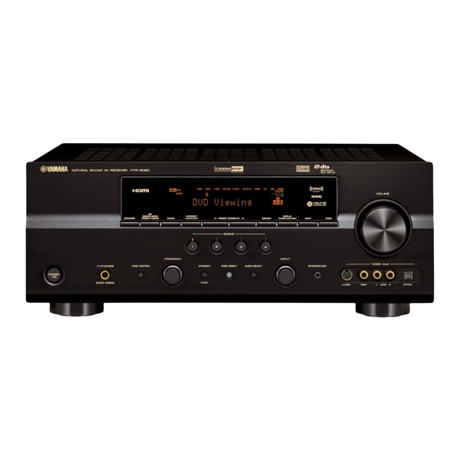
■ Front panel SPEAKERS PHONES TONE CONTROL STANDBY SILENT CINEMA 2 3 4 6 7 8 9 EDIT SEARCH MODE CATEGORY FM/AM A/B/C/D/E PRESET/TUNING/CH PRESET/TUNING SCENE PROGRAM STRAIGHT PURE DIRECT AUDIO SELECT EFFECT VOLUME DISPLAY MEMORY NIGHT SLEEP TUNING AUTO/MAN’L INPUT VIDEO AUX OPTIMIZER MIC…
-
Page 116: Remote Control
■ Remote control CODE SET TRANSMIT POWER POWER CD-R DOCK V-AUX TV VOL TV CH TV MUTE TV INPUT CLASSICAL LIVE/CLUB STEREO ENHANCER SUR. DECODE NIGHT PRESET/CH LEVEL TITLE BAND RETURN XM MEMORY SCENE STANDBY POWER MULTI CH IN AUDIO SEL TUNER PHONO SOURCE…
-
Page 117: List Of Remote Control Codes
List of remote control codes UNITED CABLE CABLE TV RECEIVER 10033 US ELECTRONICS A-MARK 10008, 10144 10237, 10003, 10008, 10033 VIDEOWAY ACCUPHASE 10003 ZENITH ACORN 10237 ACTION 10237 ACTIVE 10237 CABLE/PVR AMERICAST 10899 COMBINATION ARCHER 10237 10276 AMERICAST 10899 BELL SOUTH 10899 GENERAL INSTRUMENT BRITISH TELECOM 10003…
-
Page 118
CARVER 20054, 20170 EMERSON 20037 CELEBRITY 20000 CELERA 20765 CHANGHONG 20156, 20765, 20767, 20783 CINERAL 20092, 20451 CITEK 20047 ENVISION CITIZEN 20000, 20030, 20054, 20060, FISHER 20092, 20171, 20180, 20186, FORTRESS 20451, 20463 FUJITSU CLARION 20180 CLASSIC 20030, 20092 COLORTYME 20017, 20030, 20047, 20054, FUJITSU GENERAL 20060, 20178… -
Page 119
20250 20179, 20236, 20451, 20463, 20179 20623, 20889 WORLD 20180, 20236, 20451, 20463 20250 XR-1000 20154, 20171, 20179, 20180 YAMAHA 20030, 20650, 20769, 21405, 21406, 21407, 21522 YORX 20030 ZENITH 20000, 20017, 20030, 20037, 20047, 20092, 20093, 20145, 20160, 20171,… -
Page 120
ELECTROPHONIC A-MARK 30037, 30240, EMERALD 30000 EMEREX 31972 EMERSON ADMIRAL 30060, 30048, 30039, 30047, 30104, 30209 ADVENTURA 30037, 30240, 30000 FISHER AIWA 30037, 30000, 30307, 30348, FUJI 31284, 31291, FUJITSU 31332, 31336 FUNAI AKAI 30041 ALBA 30209 GARRARD ALIENWARE 31972 GATEWAY ALLEGRO 30039… -
Page 121
30037, 30048, 30000 WHITE WESTINGHOUSE SINGER 30037, 30240 SONIC BLUE 30614, 30616 WORLD SONY 30035, 30047, XR-1000 30032, 30033, 30000, 30067, YAMAHA 30034, 30226, ZENITH 30636, 31232, 31295, 31296, 31447, 31448, 31636, 31972 ZT GROUP SOUNDMASTER 30000 DVD PLAYER STACK 9… -
Page 122
40533, 40839 SONY SLIM ART 40784 TECHNICS SONIC BLUE 40573, 40783, TOSHIBA 40869, 41099 VICTOR SONY 40533, 41533, WARDS 40864, 40772, YAMAHA 41033, 41069, 41070, 41431, DVD RECORDER 41633 SUPERSCAN 40821 ACCURIAN 40717 APEX DIGITAL SYLVANIA 40675, 40821, 41268 ASPIRE DIGITAL… -
Page 123
YAMAHA ELECTRONICS (UK) LTD. YAMAHA HOUSE, 200 RICKMANSWORTH ROAD WATFORD, HERTS WD18 7GQ, ENGLAND YAMAHA SCANDINAVIA A.B. J A WETTERGRENS GATA 1, BOX 30053, 400 43 VÄSTRA FRÖLUNDA, SWEDEN YAMAHA MUSIC AUSTRALIA PTY, LTD. 17-33 MARKET ST., SOUTH MELBOURNE, 3205 VIC., AUSTRALIA… -
Page 124
PHONES TONE CONTROL STANDBY SILENT CINEMA EDIT SEARCH MODE CATEGORY FM/AM A/B/C/D/E PRESET/TUNING/CH PRESET/TUNING SCENE PROGRAM STRAIGHT PURE DIRECT AUDIO SELECT EFFECT HTR-6080/HTR-6060 DISPLAY MEMORY TUNING AUTO/MAN’L NIGHT SLEEP INPUT VIDEO AUX OPTIMIZER MIC S VIDEO VIDEO VOLUME AUDIO OPTICAL… -
Page 125
■ Remote control CODE SET POWER DOCK V-AUX TV VOL TV MUTE CLASSICAL STEREO SUR. DECODE LEVEL TITLE BAND RETURN XM MEMORY TRANSMIT POWER STANDBY POWER MULTI CH IN AUDIO SEL CD-R TUNER PHONO SOURCE TV CH VOLUME TV INPUT MUTE LIVE/CLUB ENTERTAIN…
 while the MEMORY indicator is flashing. • Press 5 h to select a higher preset station number. • Press 5 l to select a lower preset station number. A1:FM 88.9 MHz Preset station number Press 6 MEMORY while the MEMORY…
 -
Инструкции по эксплуатации
1

Yamaha HTR-6080 инструкция по эксплуатации
(125 страниц)
- Языки:Английский
-
Тип:
PDF -
Размер:
13.74 MB
Просмотр
На NoDevice можно скачать инструкцию по эксплуатации для Yamaha HTR-6080. Руководство пользователя необходимо для ознакомления с правилами установки и эксплуатации Yamaha HTR-6080. Инструкции по использованию помогут правильно настроить Yamaha HTR-6080, исправить ошибки и выявить неполадки.
Как пользоваться?
Наша цель — обеспечить Вам самый быстрый доступ к руководству по эксплуатации устройства Yamaha HTR-6080. Пользуясь просмотром онлайн Вы можете быстро просмотреть содержание и перейти на страницу, на которой найдете решение своей проблемы с Yamaha HTR-6080.
Для Вашего удобства
Если просмотр руководства Yamaha HTR-6080 непосредственно на этой странице для Вас неудобен, Вы можете воспользоваться двумя возможными решениями:
- Полноэкранный просмотр -, Чтобы удобно просматривать инструкцию (без скачивания на компьютер) Вы можете использовать режим полноэкранного просмотра. Чтобы запустить просмотр инструкции Yamaha HTR-6080 на полном экране, используйте кнопку Полный экран.
- Скачивание на компьютер — Вы можете также скачать инструкцию Yamaha HTR-6080 на свой компьютер и сохранить ее в своем архиве. Если ты все же не хотите занимать место на своем устройстве, Вы всегда можете скачать ее из ManualsBase.
Руководство по эксплуатации Yamaha HTR-6080
Печатная версия
Многие предпочитают читать документы не на экране, а в печатной версии. Опция распечатки инструкции также предусмотрена и Вы можете воспользоваться ею нажав на ссылку, находящуюся выше — Печатать инструкцию. Вам не обязательно печатать всю инструкцию Yamaha HTR-6080 а только некоторые страницы. Берегите бумагу.
Резюме
Ниже Вы найдете заявки которые находятся на очередных страницах инструкции для Yamaha HTR-6080. Если Вы хотите быстро просмотреть содержимое страниц, которые находятся на очередных страницах инструкции, Вы воспользоваться ими.

YAMAHA ELECTRONICS CORPORATION, USA
6660 ORANGETHORPE AVE., BUENA PARK, CALIF. 90620, U.S.A.
YAMAHA CANADA MUSIC LTD.
135 MILNER AVE., SCARBOROUGH, ONTARIO M1S 3R1, CANADA
YAMAHA ELECTRONIK EUROPA G.m.b.H.
SIEMENSSTR. 22-34, 25462 RELLINGEN BEI HAMBURG, GERMANY
YAMAHA ELECTRONIQUE FRANCE S.A.
RUE AMBROISE CROIZAT BP70 CROISSY-BEAUBOURG 77312 MARNE-LA-VALLEE CEDEX02, FRANCE
YAMAHA ELECTRONICS (UK) LTD.
YAMAHA HOUSE, 200 RICKMANSWORTH ROAD WATFORD, HERTS WD18 7GQ, ENGLAND
YAMAHA SCANDINAVIA A.B.
J A WETTERGRENS GATA 1, BOX 30053, 400 43 VÄSTRA FRÖLUNDA, SWEDEN
YAMAHA MUSIC AUSTRALIA PTY, LTD.
17-33 MARKET ST., SOUTH MELBOURNE, 3205 VIC., AUSTRALIA
2007 All rights reserved.
HTR-6080
Printed in Malaysia WK01920
AV R e c e i ve r
OWNER’S MANUAL
U
HTR-6080_U-cv.mif Page 1 Thursday, February 8, 2007 3:30 PM
Основные и самые важные характеристики модели собраны из надежных источников и по характеристикам можно найти похожие модели.
| Общие характеристики | |
| Тип | AV-ресивер, 7.1 |
| Количество каналов | 7 |
| Схемотехника | полупроводниковый |
| Параметры усилителя | |
| Мощность фронтальных каналов | 105 Вт (8 Ом, 20-20000 Гц), 155 Вт (4 Ом, 1 кГц, 0.7%) |
| Мощность фронтальных каналов (многоканальный режим) | 105 Вт |
| Мощность центрального канала | 105 Вт |
| Мощность тыловых каналов | 105 Вт |
| Мощность центральных тыловых каналов | 105 Вт |
| Рекомендуемое сопротивление нагрузки | 4 — 8 Ом |
| Воспроизводимый диапазон частот | 10 — 100000 Гц ( 0/-3 дБ) |
| Отношение сигнал/шум | 100 дБ |
| Разделение каналов | 60 дБ |
| Коэффициент демпфирования | 120 |
| Линейный вход/выход | |
| Чувствительность | 60 мВ |
| Фонокорректор | |
| Фонокорректор | есть, MM |
| Чувствительность (звукосниматель MM) | 3.5 мВ |
| Регулировки | |
| Регулировка баланса | есть |
| Регулировка тембра | есть |
| Диапазон регулировки тембра НЧ | 10 дБ |
| Диапазон регулировки тембра ВЧ | 10 дБ |
| Цифровая обработка звука | |
| DSP | есть |
| Частота дискретизации аудио ЦАП | 192 кГц |
| Разрядность аудио ЦАП | 24 бит |
| Количество предустановок DSP | 17 |
| Интерфейсы | |
| Входы | микрофонный x1, композитный x5, S-Video x5, компонентный x3, HDMI x2, коаксиальный x2, оптический x4, 5.1CH x1, линейный x8, вход для iPod, Phono |
| Выходы | композитный x3, S-Video x3, компонентный x1, HDMI x1, наушники x1, оптический x1, 7.1CH x1, линейный x5, триггер x1, PreAmp |
| Интерфейсы | внешний ИК-датчик |
| Разъемы на передней панели | наушники, линейный вход, композитный вход, S-Video-вход, оптический вход |
| Разъемы для акустики | винтовые |
| Функции | |
| Режим Direct | есть |
| Bi/Tri-amping | есть |
| Автоматическая калибровка объемного звука | есть |
| Увеличение разрешения видеосигнала | есть |
| Экранное меню | есть |
| Подключение дополнительных комплектов акустики | есть |
| Декодеры | |
| Dolby Digital | есть |
| Dolby Pro Logic | есть |
| Dolby Pro Logic II | есть |
| Dolby Pro Logic IIx | есть |
| Dolby Digital EX | есть |
| DTS | есть |
| DTS 96/24 | есть |
| DTS ES Matrix 6.1 | есть |
| DTS ES Discrete 6.1 | есть |
| DTS Neo:6 | есть |
| Dolby Headphone | есть |
| Тюнер | |
| Тип тюнера | цифровой |
| Режимы | AM/FM |
| Количество станций | общее: 40 |
| Функции | автоматическая настройка, ручная настройка |
| Питание | |
| Блок питания | встроенный |
| Потребляемая мощность | 440 Вт (850 ВА) |
| Потребляемая мощность в режиме ожидания | 0.1 Вт |
| Количество сетевых розеток | 2 |
| Конструкция | |
| Дисплей | есть |
| Цветовое оформление | черный, серебристый |
| Размеры (ШхВхГ) | 435x171x421 мм |
| Вес | 13.1 кг |
| Дополнительная информация | |
| Пульт ДУ | есть, управление другими компонентами, с режимом обучения |
| Сертификаты | THX |
 Loading…

OWNER’S MANUAL

Important safety instructions
|
CAUTION |
|
RISK OF ELECTRIC SHOCK |
|
DO NOT OPEN |
|
CAUTION: TO REDUCE THE RISK OF |
|
ELECTRIC SHOCK, DO NOT REMOVE |
|
COVER (OR BACK). NO USER-SERVICEABLE |
|
PARTS INSIDE. REFER SERVICING TO |
|
QUALIFIED SERVICE PERSONNEL. |
•Explanation of Graphical Symbols
The lightning flash with arrowhead symbol, within an equilateral triangle, is intended to alert you to the presence of uninsulated “dangerous voltage” within the product’s enclosure that may be of sufficient magnitude to constitute a risk of electric shock to persons.
The exclamation point within an equilateral triangle is intended to alert you to the presence of important operating and maintenance (servicing) instructions in the literature accompanying the appliance.
1Read Instructions – All the safety and operating instructions should be read before the product is operated.
2Retain Instructions – The safety and operating instructions should be retained for future reference.
3Heed Warnings – All warnings on the product and in the operating instructions should be adhered to.
4Follow Instructions – All operating and use instructions should be followed.
5Cleaning – Unplug this product from the wall outlet before cleaning. Do not use liquid cleaners or aerosol cleaners.
6Attachments – Do not use attachments not recommended by the product manufacturer as they may cause hazards.
7Water and Moisture – Do not use this product near water – for example, near a bath tub, wash bowl, kitchen sink, or laundry tub; in a wet basement; or near a swimming pool; and the like.
8Accessories – Do not place this product on an unstable cart, stand, tripod, bracket, or table. The product may fall, causing serious injury to a child or adult, and serious damage to the product. Use only with a cart, stand, tripod, bracket, or table recommended by the manufacturer, or sold with the product. Any mounting of the product should follow the manufacturer’s instructions, and should use a mounting accessory recommended by the manufacturer.
9A product and cart combination should be moved with care. Quick stops, excessive force, and uneven surfaces may cause the product and cart combination to
overturn.
10Ventilation – Slots and openings in the cabinet are provided for ventilation and to ensure reliable operation of the product and to protect it from overheating, and these openings must not be blocked or covered. The openings should never be blocked by placing the product on a bed, sofa, rug, or other similar surface. This product should not be placed in a built-in installation such as a bookcase or rack unless proper ventilation is provided or the manufacturer’s instructions have been adhered to.
11Power Sources – This product should be operated only from the type of power source indicated on the marking label. If you are not sure of the type of power supply to your home, consult your product dealer or local power company. For products intended to operate from battery power, or other sources, refer to the operating instructions.
12Grounding or Polarization – This product may be equipped with a polarized alternating current line plug (a plug having one blade wider than the other). This plug will fit into the power outlet only one way. This is a safety feature. If you are unable to insert the plug fully into the outlet, try reversing the plug. If the plug should still fail to fit, contact your electrician to replace your obsolete outlet. Do not defeat the safety purpose of the polarized plug.
13Power-Cord Protection – Power-supply cords should be routed so that they are not likely to be walked on or pinched by items placed upon or against them, paying particular attention to cords at plugs, convenience receptacles, and the point where they exit from the product.
14Lightning – For added protection for this product during a lightning storm, or when it is left unattended and unused for long periods of time, unplug it from the wall outlet and disconnect the antenna or cable system. This will prevent damage to the product due to lightning and power-line surges.
15Power Lines – An outside antenna system should not be located in the vicinity of overhead power lines or other electric light or power circuits, or where it can fall into such power lines or circuits. When installing an outside antenna system, extreme care should be taken to keep from touching such power lines or circuits as contact with them might be fatal.
16Overloading – Do not overload wall outlets, extension cords, or integral convenience receptacles as this can result in a risk of fire or electric shock.
17Object and Liquid Entry – Never push objects of any kind into this product through openings as they may touch dangerous voltage points or short-out parts that could result in a fire or electric shock. Never spill liquid of any kind on the product.
18Servicing – Do not attempt to service this product yourself as opening or removing covers may expose you to dangerous voltage or other hazards. Refer all servicing to qualified service personnel.
19Damage Requiring Service – Unplug this product from the wall outlet and refer servicing to qualified service personnel under the following conditions:
a)When the power-supply cord or plug is damaged,
b)If liquid has been spilled, or objects have fallen into the product,
c)If the product has been exposed to rain or water,
Caution-i En

d)If the product does not operate normally by following the operating instructions. Adjust only those controls that are covered by the operating instructions as an improper adjustment of other controls may result in damage and will often require extensive work by a qualified technician to restore the product to its normal operation,
e)If the product has been dropped or damaged in any way, and
f)When the product exhibits a distinct change in perfor-
mance — this indicates a need for service.
20Replacement Parts – When replacement parts are required, be sure the service technician has used replacement parts specified by the manufacturer or have the same characteristics as the original part. Unauthorized substitutions may result in fire, electric shock, or other hazards.
21Safety Check – Upon completion of any service or repairs to this product, ask the service technician to perform safety checks to determine that the product is in proper operating condition.
22Wall or Ceiling Mounting – The unit should be mounted to a wall or ceiling only as recommended by the manufacturer.
23Heat – The product should be situated away from heat sources such as radiators, heat registers, stoves, or other products (including amplifiers) that produce heat.
Note to CATV system installer:
This reminder is provided to call the CATV system installer’s attention to Article 820-40 of the NEC that provides guidelines for proper grounding and, in particular, specifies that the cable ground shall be connected to the grounding system of the building, as close to the point of cable entry as practical.
Important safety instructions
24Outdoor Antenna Grounding – If an outside antenna or cable system is connected to the product, be sure the antenna or cable system is grounded so as to provide some protection against voltage surges and built-up static charges. Article 810 of the National Electrical Code, ANSI/NFPA 70, provides information with regard to proper grounding of the mast and supporting structure, grounding of the lead-in wire to an antenna discharge unit, size of grounding conductors, location of antenna discharge unit, connection to grounding electrodes, and requirements for the grounding electrode.
EXAMPLE OF ANTENNA GROUNDING
|
MAST |
ANTENNA |
|
LEAD IN |
|
|
WIRE |
|
|
GROUND |
|
|
CLAMP |
|
|
ANTENNA |
|
|
DISCHARGE UNIT |
|
|
(NEC SECTION 810–20) |
|
|
ELECTRIC |
|
|
SERVICE |
|
|
EQUIPMENT |
GROUNDING CONDUCTORS |
|
(NEC SECTION 810–21) |
|
|
GROUND CLAMPS |
|
|
POWER SERVICE GROUNDING |
|
|
ELECTRODE SYSTEM |
|
|
(NEC ART 250. PART H) |
|
|
NEC – NATIONAL ELECTRICAL CODE |
FCC INFORMATION (for US customers)
1IMPORTANT NOTICE: DO NOT MODIFY THIS UNIT!
This product, when installed as indicated in the instructions contained in this manual, meets FCC requirements. Modifications not expressly approved by Yamaha may void your authority, granted by the FCC, to use the product.
2IMPORTANT: When connecting this product to accessories and/or another product use only high quality shielded cables. Cable/s supplied with this product MUST be used. Follow all installation instructions. Failure to follow instructions could void your FCC authorization to use this product in the USA.
3NOTE: This product has been tested and found to comply with the requirements listed in FCC Regulations, Part 15 for Class “B” digital devices. Compliance with these requirements provides a reasonable level of assurance that your use of this product in a residential environment will not result in harmful interference with other electronic devices.
This equipment generates/uses radio frequencies and, if not installed and used according to the instructions found in the users manual, may cause interference harmful to the operation of other electronic devices.
Compliance with FCC regulations does not guarantee that interference will not occur in all installations. If this product is found to be the source of interference, which can be determined by turning the unit “OFF” and “ON”, please try to eliminate the problem by using one of the following measures:
Relocate either this product or the device that is being affected by the interference.
Utilize power outlets that are on different branch (circuit breaker or fuse) circuits or install AC line filter/s.
In the case of radio or TV interference, relocate/reorient the antenna. If the antenna lead-in is 300 ohm ribbon lead, change the lead-in to coaxial type cable.
If these corrective measures do not produce satisfactory results, please contact the local retailer authorized to distribute this type of product. If you can not locate the appropriate retailer, please contact Yamaha Electronics Corp., U.S.A. 6660 Orangethorpe Ave., Buena Park, CA 90620.
The above statements apply ONLY to those products distributed by Yamaha Corporation of America or its subsidiaries.
Caution-ii En

Caution: Read this before operating your unit.
1To assure the finest performance, please read this manual carefully. Keep it in a safe place for future reference.
2Install this sound system in a well ventilated, cool, dry, clean place – away from direct sunlight, heat sources, vibration, dust, moisture, and/or cold. Allow ventilation space of at least 30 cm on the top, 20 cm on the left and right, and 20 cm on the back of this unit.
3Locate this unit away from other electrical appliances, motors, or transformers to avoid humming sounds.
4Do not expose this unit to sudden temperature changes from cold to hot, and do not locate this unit in an environment with high humidity (i.e. a room with a humidifier) to prevent condensation inside this unit, which may cause an electrical shock, fire, damage to this unit, and/or personal injury.
5Avoid installing this unit where foreign objects may fall onto this unit and/or this unit may be exposed to liquid dripping or splashing. On the top of this unit, do not place:
–other components, as they may cause damage and/or discoloration on the surface of this unit.
–burning objects (i.e. candles), as they may cause fire, damage to this unit, and/or personal injury.
–containers with liquid in them, as they may fall and liquid may cause electrical shock to the user and/or damage to this unit.
6Do not cover this unit with a newspaper, tablecloth, curtain, etc. in order not to obstruct heat radiation. If the temperature inside this unit rises, it may cause fire, damage to this unit, and/or personal injury.
7Do not plug in this unit to a wall outlet until all connections are complete.
8Do not operate this unit upside-down. It may overheat, possibly causing damage.
9Do not use force on switches, knobs and/or cords.
10When disconnecting the power cable from the wall outlet, grasp the plug; do not pull the cable.
11Do not clean this unit with chemical solvents; this might damage the finish. Use a clean, dry cloth.
12Only voltage specified on this unit must be used. Using this unit with a higher voltage than specified is dangerous and may cause fire, damage to this unit, and/or personal injury. Yamaha will not be held responsible for any damage resulting from use of this unit with a voltage other than specified.
13To prevent damage by lightning, keep the power cord and outdoor antennas disconnected from a wall outlet or the unit during a lightning storm.
14Do not attempt to modify or fix this unit. Contact qualified Yamaha service personnel when any service is needed. The cabinet should never be opened for any reasons.
15When not planning to use this unit for long periods of time (i.e. vacation), disconnect the AC power plug from the wall outlet.
16Install this unit near the AC outlet and where the AC power plug can be reached easily.
17Be sure to read the “Troubleshooting” section on common operating errors before concluding that this unit is faulty.
18Before moving this unit, press STANDBY/ON to set this unit in the standby mode, and then disconnect the AC power plug from the AC wall outlet.
19The batteries shall not be exposed to excessive heat such as sunshine, fire or like.
WARNING
TO REDUCE THE RISK OF FIRE OR ELECTRIC SHOCK, DO NOT EXPOSE THIS UNIT TO RAIN OR MOISTURE.
This unit is not disconnected from the AC power source as long as it is connected to the wall outlet, even if this unit itself is turned off by STANDBY/ON. This state is called the standby mode. In this state, this unit is designed to consume a very small quantity of power.
FOR CANADIAN CUSTOMERS
To prevent electric shock, match wide blade of plug to wide slot and fully insert.
This Class B digital apparatus complies with Canadian ICES-003.
POUR LES CONSOMMATEURS CANADIENS
Pour éviter les chocs électriques, introduire la lame la plus large de la fiche dans la borne correspondante de la prise et pousser jusqu’au fond.
Cet appareil numérique de la classe B est conforme à la norme NMB-003 du Canada.
IMPORTANT
Please record the serial number of this unit in the space below.
MODEL:
Serial No.:
The serial number is located on the rear of the unit. Retain this Owner’s Manual in a safe place for future reference.
Caution-iii En

Contents
|
INTRODUCTION |
|
|
Notice …………………………………………………………….. |
2 |
|
Features …………………………………………………………. |
3 |
|
Supplied accessories ………………………………………….. |
3 |
|
Getting started ……………………………………………….. |
4 |
|
Quick start guide ……………………………………………. |
5 |
|
PREPARATION |
|
|
Connections ………………………………………………….. |
11 |
|
Optimizing the speaker setting |
|
|
for your listening room ……………………………… |
28 |
|
Using AUTO SETUP ………………………………………. |
28 |
|
BASIC OPERATION |
|
|
Selecting the SCENE templates……………………… |
33 |
|
Selecting the desired SCENE template……………….. |
33 |
|
Creating your original SCENE templates……………. |
36 |
|
Playback ………………………………………………………. |
37 |
|
Basic procedure ………………………………………………. |
37 |
|
Selecting the MULTI CH INPUT component……… |
38 |
|
Selecting the front speaker set …………………………… |
38 |
|
Selecting audio input jacks |
|
|
(AUDIO SELECT)………………………………………. |
39 |
|
Displaying the current status of this unit |
|
|
on a video monitor……………………………………….. |
39 |
|
Using your headphones…………………………………….. |
40 |
|
Muting the audio output……………………………………. |
40 |
|
Playing video sources in the background |
|
|
of an audio source………………………………………… |
40 |
|
Displaying the input source information …………….. |
40 |
|
Using the sleep timer ……………………………………….. |
41 |
|
Sound field programs …………………………………… |
42 |
|
Selecting sound field programs …………………………. |
42 |
|
Sound field program descriptions………………………. |
42 |
|
Enjoying unprocessed input sources |
|
|
(Straight decoding mode) ……………………………… |
47 |
|
Using audio features ……………………………………… |
48 |
|
Enjoying pure hi-fi sound …………………………………. |
48 |
|
Adjusting the tonal quality………………………………… |
48 |
|
Adjusting the speaker level……………………………….. |
48 |
|
Enjoying multi-channel sources |
|
|
in 2-channel stereo……………………………………….. |
49 |
|
Selecting the night listening mode……………………… |
49 |
|
FM/AM tuning ……………………………………………… |
50 |
|
Automatic tuning …………………………………………….. |
50 |
|
Manual tuning…………………………………………………. |
50 |
|
Automatic preset tuning……………………………………. |
51 |
|
Manual preset tuning ……………………………………….. |
51 |
|
Selecting preset stations……………………………………. |
52 |
|
Exchanging preset stations ……………………………….. |
52 |
|
XM Satellite Radio tuning …………………………….. |
53 |
|
Connecting the XM Mini-Tuner Dock ……………….. |
53 |
|
Activating XM Satellite Radio ………………………….. |
54 |
|
Basic XM Satellite Radio operations………………….. |
54 |
|
Setting the XM Satellite Radio preset channels …… |
56 |
|
Displaying the XM Satellite Radio information…… |
57 |
|
Using iPod™…………………………………………………. |
58 |
|
Controlling iPod™…………………………………………… |
58 |
|
Recording …………………………………………………….. |
60 |
|
ADVANCED OPERATION |
|
|
Advanced sound configurations……………………… |
61 |
|
Changing sound field parameter settings…………….. |
61 |
|
Selecting decoders …………………………………………… |
66 |
|
Customizing this unit (MANUAL SETUP)……… |
69 |
|
Using SET MENU…………………………………………… |
71 |
|
1 SOUND MENU……………………………………………. |
72 |
|
2 INPUT MENU……………………………………………… |
78 |
|
3 OPTION MENU…………………………………………… |
81 |
|
Remote control features…………………………………. |
85 |
|
Using the remote control for the SCENE feature …. |
85 |
|
Controlling this unit, a TV, or other components…. |
86 |
|
Setting remote control codes …………………………….. |
88 |
|
Resetting all remote control codes……………………… |
89 |
|
Advanced setup……………………………………………… |
90 |
|
Using the advanced setup …………………………………. |
90 |
|
ADDITIONAL INFORMATION |
|
|
Troubleshooting…………………………………………….. |
94 |
|
Resetting the system…………………………………….. |
101 |
|
Glossary………………………………………………………. |
102 |
|
Sound field program information…………………. |
104 |
|
Parametric equalizer information ………………… |
105 |
|
Specifications ………………………………………………. |
106 |
|
Index …………………………………………………………… |
107 |
|
APPENDIX |
|
|
(at the end of this manual) |
|
|
Front panel………………………………………………………. |
i |
|
Remote control ………………………………………………. |
ii |
|
List of remote control codes …………………………… |
iii |
“1SPEAKER” or “ADVD” (example) indicates the name of the parts on the front panel or the remote control. Refer to the attached sheet or the pages at the end of this manual for the information about each position of the parts.
|
INTRODUCTION |
|
|
PREPARATION |
|
|
OPERATION |
BASIC |
|
OPERATION |
ADVANCED |
|
INFORMATION |
ADDITIONAL |
APPENDIX
English
1 En

Notice
About this manual
•yindicates a tip for your operation.
•Some operations can be performed by using either the buttons on the front panel or the ones on the remote control. In case the button names differ between the front panel and the remote control, the button name on the remote control is given in parentheses.
•This manual is printed prior to production. Design and specifications are subject to change in part as a result of improvements, etc. In case of differences between the manual and product, the product has priority.
•“1SPEAKER” or “ADVD” (example) indicates the name of the parts on the front panel or the remote control. Refer to the attached sheet or the pages at the end of this manual for the information about each position of the parts.
•The symbol “ ” with page number(s) indicates the corresponding reference page(s).
We Want You Listening For A Lifetime
Yamaha and the Electronic Industries Association’s Consumer Electronics Group want you to get the
most out of your equipment by playing it at a safe
level. One that lets the sound come through loud and
clear without annoying blaring or distortion – and, most importantly, without affecting your sensitive
hearing. Since hearing damage from loud sounds is often undetectable until it is too late, Yamaha and the Electronic Industries Association’s Consumer Electronics Group recommend you to avoid prolonged exposure from excessive volume levels.
Manufactured under license from Dolby Laboratories. “Dolby”, “Pro Logic”, and the double-D symbol are trademarks of Dolby Laboratories.
DTS-ES | NEO:6 | 96/24. Product “DTS” and “DTS-ES | NEO:6” are registered trademarks of DTS, Inc.
“96/24” is a trademark of DTS, Inc.
iPodTM
“iPod” is a trademark of Apple Inc., registered in the U.S. and other countries.
“HDMI”, the “HDMI” logo and “High-Definition Multimedia Interface” are trademarks or registered trademarks of HDMI Licensing LLC.
“SILENT CINEMA” is a trademark of YAMAHA CORPORATION.
The XM name and related logos are registered trademarks of XM Satellite Radio Inc.
Neural Surround™ name and related logos are trademarks owned by Neural Audio Corporation.
2 En

Features
Built-in 7-channel power amplifier
Minimum RMS output power (1 kHz, 0.7% THD, 8 Ω)
Front: 120 W + 120 W Center: 120 W
Surround: 120 W + 120 W Surround back: 120 W + 120 W
SCENE function
18 preset SCENE templates for various situations
4 original SCENE templates for customizing capability
Controlling Yamaha SCENE control signal support component (some models only) working with the SCENE function
Sound field programs
Proprietary Yamaha technology for the creation of sound fields
Compressed Music Enhancer mode to improve the sound quality of compression artifacts (such as the MP3 format) to that of a high-quality stereo
Dolby Digital/Dolby Digital EX decoder
DTS/DTS-ES Matrix, Discrete, DTS Neo:6, DTS 96/24 decoder
Dolby Pro Logic/Dolby Pro Logic II/Dolby Pro Logic IIx decoder
Neural Surround decoder
Virtual CINEMA DSP
SILENT CINEMA
Sophisticated FM/AM tuner
40-station random and direct preset tuning
Automatic preset tuning
Preset station shifting capability (preset editing)
XM Satellite Radio
XM Satellite Radio tuning capability (using the “XM MiniTuner Dock” sold separately)
Neural Surround decoder to play back the XM HD content of XM Satellite Radio broadcasts in multi-channels, resulting in a full surround sound experience
XM Satellite Radio information displaying capability
HDMI (High-Definition Multimedia Interface)
HDMI interface for standard, enhanced or high-definition video (includes 1080p video signal transmission) as well as multi-channel digital audio based on HDMI version 1.2a
Analog video to HDMI digital video up-conversion (composite video ↔ S-video ↔ component video → HDMI
digital video) capability for monitor out
Analog video deinterlacing and/or up-scaling (480i (NTSC)/ 576i (PAL) → 480p/576p → 720p or 1080i)
iPod controlling capability
DOCK terminal to connect a Yamaha iPod universal dock (such as the YDS-10, sold separately), which supports iPod (Click and Wheel), iPod nano, and iPod mini
Playback information displaying capability
Battery charging capability
Other features
YPAO (Yamaha Parametric Room Acoustic Optimizer) for automatic speaker setup
192-kHz/24-bit D/A converter
OSD (on-screen display) menus that allow you to optimize this unit to suit your individual audiovisual system
5.1 or 7.1-channel additional input jacks for discrete multichannel input
S-video signal input/output capability
Component video input/output capability includes
(3 COMPONENT VIDEO INs and 1 MONITOR OUT)
Digital video signal conversion (composite video ↔ S-video → component video) capability for monitor out
Optical and coaxial digital audio signal jacks
Pure Direct mode for pure hi-fi sound for all sources
Cinema and music night listening modes
Remote control with preset remote control codes capability
Bi-amplification connection capability
Sleep timer
Supplied accessories
Check that you received all of the following parts.
|
Remote control |
Batteries (2) |
AM loop antenna |
|||
|
(AA, R6, UM-3) |
|||||
|
TV |
AV |
||||
|
TV VOL TV CH VOLUME |
|||||
|
1 |
2 |
3 |
4 |
||
|
5 |
6 |
7 |
8 |
||
|
9 |
0 |
+10 |
ENT |
Optimizer microphone |
Indoor FM antenna |
|
1 |
2 |
3 |
4 |
Note
The form of the supplied accessories varies depending on the models.
3 En

Getting started
■ Installing batteries in the remote control
1
 3
3
2
1Take off the battery compartment cover.
2Insert the two supplied batteries
(AA, R6, UM-3) according to the polarity markings (+ and –) on the inside of the battery compartment.
3Snap the battery compartment cover back into place.
Notes
•Change all of the batteries if you notice the following conditions:
–the operation range of the remote control decreases.
–the VTRANSMIT indicator does not flash or its light becomes dim.
•Do not use an old battery together with a new one.
•Do not use different types of batteries (such as alkaline and manganese batteries) together. Read the packaging carefully as these different types of batteries may have the same shape and color.
•If the batteries have leaked, dispose of them immediately. Avoid touching the leaked material or letting it come into contact with clothing, etc. Clean the battery compartment thoroughly before installing new batteries.
•Do not throw away batteries with general house waste; dispose of them correctly in accordance with your local regulations.
•If the remote control is without batteries for more than 2 minutes, or if exhausted batteries remain in the remote control, the contents of the memory may be cleared. When the memory is cleared, insert new batteries, set up the remote control code and program any acquired functions that may have been cleared.
4 En

Quick start guide
The following steps describe the easiest way to enjoy DVD movie playback in your home theater.
Front right
speaker
Video monitor
Subwoofer
Front left
speaker Surround right speaker
Center
speaker
Surround back right speaker
DVD player
Surround back left speaker
Surround left speaker
Step 1: Set up your speakers
P. 6
Step 2: Connect your DVD player and other components
P. 7
Step 3: Turn on the power and press SCENE 1 button
P. 9
Preparation: Check the items
In these steps, you need the following supplied accessories.
AM loop antenna
Indoor FM antenna
The following items are not included in the package of this unit.
|
Speakers |
|
|
Front speakers ……………………………… |
2 |
|
Center speaker …………………………….. |
1 |
|
Surround speakers ……………………….. |
4 |
Select magnetically shielded speakers. The minimum required speakers are two front speakers. The priority of the requirement of other speakers is as follows:
|
1. |
Two surround speakers |
|
|
2. |
Center speaker |
|
|
3. |
One (or two) surround back speaker(s) |
|
|
Active subwoofer ……………………………… |
1 |
|
|
Select an active subwoofer equipped with an RCA |
||
|
input jack. |
||
|
Speaker cables …………………………………. |
7 |
|
|
Subwoofer cable ………………………………. |
1 |
|
|
Select a monaural RCA cable. |
||
|
DVD player ……………………………………….. |
1 |
|
|
Select DVD player equipped with coaxial digital |
||
|
audio output jack and composite video output |
||
|
jack. |
||
|
Video monitor……………………………………. |
1 |
Select a TV monitor, video monitor or projector equipped with a composite video input jack.
|
Video cable ………………………………………. |
1 |
|
Select an RCA composite video cable. |
|
|
Digital coaxial audio cable ………………… |
1 |
Enjoy DVD playback!
5 En

Quick start guide
Step 1: Set up your speakers
Place your speakers in the room and connect them to this unit.
|
AUDIO |
MULTI CH INPUT |
PRE |
OUT |
|
|
FRONT(6CH) |
CENTER |
SINGLE CENTER |
||
|
GND L |
L |
L |
|
DOCK |
R |
R |
R |
|||||||||||
|
XM |
||||||||||||||
|
PHONO |
CD |
IN |
MD/ |
OUT |
DVD DTV/CBL |
IN |
DVR |
OUT |
IN |
VCR |
OUT |
SB(8CH) SURROUND SUBWOOFER |
FRONT SURROUND SUR. BACK SUBWOOFER |
|
|
(PLAY) |
CD-R |
(REC) |
||||||||||||
|
DVD |
A |
DTV/CBL |
B |
|
DIGITAL OUTPUT |
VIDEO |
|||||||||||||||||||||
|
OPTICAL |
1 |
DVD |
IN1 |
|||||||||||||||||||
|
MD/CD-R |
||||||||||||||||||||||
|
S VIDEO |
||||||||||||||||||||||
|
MD/CD-R |
2 |
Y |
P |
P |
Y |
P |
C |
P |
MONITOR |
|||||||||||||
|
DTV |
MONITOR OUT |
DVR |
DVD |
DTV/CBL |
IN |
DVR OUT |
IN |
VCR OUT |
OUT |
|||||||||||||
|
DVD |
3 |
/CBL IN2 |
COMPONENT VIDEO |
SPEAKERS |
VIDEO |
SURROUND BACK/ |
||||||||||||||||
|
FRONT B/PRESENCE |
FRONT A |
CENTER |
SURROUND |
BI-AMP |
||||||||||||||||||
|
R EXTRA SP |
L |
R |
L |
R |
L |
R |
SINGLE L |
|||||||||||||||
|
DTV/CBL |
4 |
ANTENNA |
||||||||||||||||||||
|
FM |
GND AM |
|||||||||||||||||||||
|
OUT |
75 |
UNBAL. |
||||||||||||||||||||
|
OPTICAL |
||||||||||||||||||||||
|
COAXIAL |
||||||||||||||||||||||
|
CD |
||||||||||||||||||||||
|
5 |
HDMI |
REMOTE |
||||||||||||||||||||
|
OUT |
||||||||||||||||||||||
|
DVD |
||||||||||||||||||||||
|
6 |
||||||||||||||||||||||
|
DIGITAL INPUT |
AC OUTLETS |
1Place your speakers and subwoofer in the room.
2Connect speaker cables to each speaker.
Be sure to connect the “+” (red) and “–” (black) properly. Cables are colored or shaped differently, perhaps with a stripe, groove or ridge. Connect the striped (grooved, etc.) cable to the “+” (red) terminals of this unit and your speaker. Connect the plain cable to the “–” (black) terminals.
3Connect each speaker cable to the corresponding speaker terminal of this unit.
|
1 |
2 |
3 |
4 |
|||||
1Make sure that this unit and the subwoofer are unplugged from the AC wall outlets.
2Twist the exposed wires of the speaker cables together to prevent short circuits.
3Do not let the bare speaker wires touch each other.
4Do not let the bare speaker wires touch any metal part of this unit.
Be sure to connect the left channel (L), right channel (R), “+” (red) and “–” (black) properly.
Front speakers and center speaker
To the center speaker
|
To the front left |
|
|
Front right speaker |
speaker |
Surround and surround back speakers
|
To the surround |
To the surround |
|
|
right speaker |
||
|
back left |
||
|
speaker |
||
|
To the surround |
To the surround |
|
|
left speaker |
back right speaker |
5Connect the subwoofer cable to the SUBWOOFER PRE OUT jack of this unit and the input jack of the subwoofer.
Input jack
Subwoofer cable
SUBWOOFER PRE OUT jack
6 En
![]()
Step 2: Connect your DVD player and other components
|
AUDIO |
MULTI CH INPUT |
PRE |
OUT |
|
|
FRONT(6CH) |
CENTER |
SINGLE CENTER |
||
|
GND L |
L |
L |
|
DOCK |
R |
R |
R |
|||||||
|
XM |
||||||||||
|
PHONO |
CD |
IN |
MD/ |
OUT |
DVD DTV/CBL |
IN DVR OUT |
IN VCR OUT |
SB(8CH) SURROUND SUBWOOFER |
FRONT SURROUND SUR. BACK SUBWOOFER |
|
|
(PLAY) |
CD-R |
(REC) |
DVD |
A |
DTV/CBL |
B |
||||
|
DIGITAL OUTPUT |
VIDEO |
||||||||||||||||||||
|
OPTICAL |
1 |
DVD |
IN1 |
||||||||||||||||||
|
MD/CD-R |
|||||||||||||||||||||
|
S VIDEO |
|||||||||||||||||||||
|
MD/CD-R |
2 |
Y |
P |
P |
Y |
P |
C |
P |
MONITOR |
||||||||||||
|
DTV |
MONITOR OUT |
DVR |
DVD |
DTV/CBL |
IN |
DVR OUT |
IN |
VCR OUT |
OUT |
||||||||||||
|
DVD |
3 |
/CBL IN2 |
COMPONENT VIDEO |
SPEAKERS |
VIDEO |
||||||||||||||||
|
FRONT B/PRESENCE |
FRONT A |
CENTER |
SURROUND |
SURROUND BACK/ |
|||||||||||||||||
|
BI-AMP |
|||||||||||||||||||||
|
R EXTRA SP |
L |
R |
L |
R |
L |
R |
SINGLE L |
||||||||||||||
|
DTV/CBL |
4 |
ANTENNA |
|||||||||||||||||||
|
75 |
FM |
GND AM |
|||||||||||||||||||
|
OUT |
UNBAL. |
||||||||||||||||||||
|
OPTICAL |
|||||||||||||||||||||
|
COAXIAL |
|||||||||||||||||||||
|
CD |
REMOTE |
||||||||||||||||||||
|
5 |
HDMI |
OUT |
|||||||||||||||||||
|
DVD |
|||||||||||||||||||||
|
6 |
|||||||||||||||||||||
|
DIGITAL INPUT |
AC OUTLETS |
Make sure that this unit and the DVD player are unplugged from the AC wall outlets.
1Connect the digital coaxial audio cable to the digital coaxial audio output jack of your DVD player and the DVD DIGITAL INPUT COAXIAL jack of this unit.
Digital coaxial audio output
jack
Digital coaxial audio cable
DVD DIGITAL INPUT
COAXIAL jack
Quick start guide
2Connect the video cable to the composite video output jack of your DVD player and DVD VIDEO jack of this unit.
AV receiver
DVD player
DVD VIDEO jack
|
Composite video |
Video cable |
|
|
output jack |
||
3Connect the video cable to the VIDEO MONITOR OUT jack of this unit and the video input jack of your video monitor.
|
Video monitor |
AV receiver |
Video input jack
|
Video cable |
VIDEO MONITOR OUT jack |
7 En

Quick start guide
4Connect the supplied AM loop antenna and indoor FM antenna to this unit.
See page 24 for the connection information.
AM loop antenna
Indoor FM antenna
Note
The types of the supplied indoor FM antenna and FM antenna terminal of this unit are different depending on the models.
Connecting the wire of the AM loop antenna
|
Open the lever |
Insert |
Close the lever |
y
The wire of the AM loop antenna does not have any polarity and you can connect either end of the wire to AM or GND terminal.
Assembling the supplied AM loop antenna
5Connect the power plug of this unit and other components into the AC wall outlet.
y
This unit is equipped with AC OUTLETS for the power supply of the other components. See page 24 for details.
■For further connections
•Using the other kind of speaker combinations
P. 12
•Connecting a video monitor via various ways of the connection
P. 18
•Connecting a DVD player via various ways of the connection
P. 19
•Connecting a DVD recorder or a digital video recorder
P. 20
•Connecting a set-top box
P. 20
•Connecting a CD player, an MD recorder or a turntable
P. 21
•Connecting an external amplifier
P. 22
•Connecting a DVD player via analog multichannel audio connection
P. 22
•Connecting a Yamaha iPod universal dock
P. 23
•Using the REMOTE OUT jack
P. 23
•Using the VIDEO AUX jacks on the front panel
P. 23
•Connecting an outdoor FM/AM antenna
P. 24
•Connecting the XM Mini-Tuner Dock
P. 53
8 En

Step 3: Turn on the power and press SCENE 1 button
Check the type of the connected speakers.
If the speakers are 6 ohm speakers, set “SP IMP.” to “6Ω MIN” before using this unit (see page 25). 4 ohm speakers can be also used as the front speakers (see page 91).
1Turn on the video monitor connected to this unit.
2Press ESCENE1 button.
“DVD Viewing” appears in the front panel display, and this unit automatically optimize own status for the DVD playback.
y
The indicator on the selected SCENE button lights up while this unit is in the SCENE mode.
3Start playback of the desired DVD on your player.
y
If the connected DVD player is a Yamaha product and has capability of the SCENE control signals with the REMOTE OUT jack of this unit (see page 23), this unit can automatically activate the DVD player and start playback when you press the ESCENE1 button. Refer to the instruction manual of the DVD player for further information.
Quick start guide
4 Rotate 0VOLUME to adjust the volume.
Note
When you change the input source or sound field program, the SCENE mode is deactivated, and the indicator on the selected SCENE button turns off.
■ Using the other SCENE buttons
In the following cases, try pressing the corresponding SCENE button to enjoy the playback of the desired sources.
Case A: “I want to listen to a music disc from the connected DVD player as the background music for this room…”
 Press ESCENE2 (or
FSCENE2) to select “Disc
Listening”.
Case B: “I want to watch a TV program…”
 Press ESCENE3 (or
FSCENE3) to select “TV
Viewing”.
Note
To use the “TV Viewing” template (Case B), you must connect a satellite receiver, a cable TV receiver or an HDTV decoder to this unit in advance. See page 20 for details.
Case C: “I want to listen to a music program of the FM/AM radio station…”
 Press ESCENE4 (or
FSCENE4) to select “Radio
Listening”.
Notes
•To use the “Radio Listening” template (Case C), you have to tune into the desired radio station. See pages 50 to 52 for the tuning information.
•To achieve the best possible reception, orient the connected AM loop antenna, or adjust the position of the end of the indoor FM antenna.
9 En

Quick start guide
y
If you cannot find the desired situation, you can select and change the assigned SCENE template for the SCENE buttons. See
page 33 for details.
■ After using this unit…
Press ASTANDBY/ON to set this unit to the standby mode.
This unit is set to the standby mode and consumes a small amount of power in order to receive infrared signals from the remote control. To turn on this unit from the standby mode, press the desired ESCENE buttons (or FSCENE) or ASTANDBY/ON on the front panel (or HPOWER on the remote control). See page 25 for details.
What do you want to do with this unit?
■ Customizing the SCENE templates
• Using various SCENE templates
P. 33
•Creating your original SCENE templates
P. 36
■ Using various input sources
• Basic controls of this unit
P. 37
• Enjoying FM/AM radio programs
P. 50
•Enjoying XM Satellite Radio programs
P. 53
•Using your iPod with this unit
P. 58
■ Using various sound features
• Using various sound field programs
P. 42
•Using the pure direct mode for high fidelity sound
P. 48
•Customizing the sound field programs
P. 61
■ Adjusting the parameters of this unit
•Automatically optimizing the speaker parameters for your listening room (AUTO SETUP)
P. 28
•Manually adjusting various parameters of this unit
P. 71
•Setting the remote control
P. 85
•Adjusting the advanced parameters
P. 90
■ Additional feature
Automatically turning off this unit
P. 41
10 En

Connections
Rear panel
XM jack
(U.S.A. and Canada models only)
Connect the XM MiniTuner Dock (sold separately).
P. 53
DOCK terminal
Connect a Yamaha iPod universal dock
(sold separately).
P. 23
MULTI CH INPUT jacks
Connect the input source component equipped with the multi-channel output jacks.
|
P. 22 |
|
|
AUDIO jacks |
PRE OUT jacks |
|
Connect the analog audio |
Connect external amplifiers |
|
cable plugs. |
and an active subwoofer. |
|
P. 18-21 |
P. 22 |
|
AUDIO |
MULTI CH INPUT |
PRE OUT |
CENTER |
|||||||||||||||||||
|
FRONT(6CH) |
CENTER |
SINGLE |
||||||||||||||||||||
|
GND |
L |
L |
L |
|||||||||||||||||||
|
DOCK |
R |
R |
R |
|||||||||||||||||||
|
XM |
||||||||||||||||||||||
|
PHONO |
CD |
IN |
MD/ |
OUT |
DVD DTV/CBL |
IN |
DVR OUT |
IN VCR |
OUT |
SB(8CH) |
SURROUND |
SUBWOOFER |
FRONT |
SURROUND |
SUR. BACK |
SUBWOOFER |
||||||
|
(PLAY) |
CD-R |
(REC) |
DVD |
A |
DTV/CBL |
B |
||||||||||||||||
|
DIGITAL OUTPUT |
VIDEO |
|||||||||||||||||||||
|
OPTICAL |
1 |
DVD |
IN1 |
|||||||||||||||||||
|
MD/CD-R |
||||||||||||||||||||||
|
S VIDEO |
||||||||||||||||||||||
|
MD/CD-R |
2 |
Y |
PB |
PR |
Y |
PB |
C |
PR |
MONITOR |
|||||||||||||
|
DTV |
MONITOR OUT |
DVR |
DVD |
DTV/CBL |
IN DVR OUT |
IN |
VCR OUT |
OUT |
||||||||||||||
|
/CBL IN2 |
COMPONENT VIDEO |
VIDEO |
||||||||||||||||||||
|
DVD |
3 |
SPEAKERS |
||||||||||||||||||||
|
FRONT B/PRESENCE |
FRONT A |
CENTER |
SURROUND |
SURROUND BACK/ |
||||||||||||||||||
|
BI-AMP |
||||||||||||||||||||||
|
R EXTRA SP |
L |
R |
L |
R |
L |
R |
SINGLE L |
|||||||||||||||
|
DTV/CBL |
4 |
ANTENNA |
||||||||||||||||||||
|
FM |
GND AM |
|||||||||||||||||||||
|
OUT |
75 |
UNBAL. |
||||||||||||||||||||
|
OPTICAL |
||||||||||||||||||||||
|
COAXIAL |
||||||||||||||||||||||
|
CD |
||||||||||||||||||||||
|
5 |
HDMI |
REMOTE |
||||||||||||||||||||
|
DVD |
||||||||||||||||||||||
|
6 |
OUT |
|||||||||||||||||||||
|
DIGITAL INPUT |
AC OUTLETS |
|
HDMI connectors |
REMOTE OUT jacks |
Video jacks |
|
|
Connect the HDMI |
Connect the remote |
Connect the video cable plugs. |
|
|
components. |
control input jack of the |
P. 18-20 |
|
|
P. 16 |
Yamaha components. |
||
|
P. 23 |
|||
|
DIGITAL INPUT/ |
ANTENNA terminals |
Speaker terminals |
AC OUTLETS |
|
OUTPUT jacks |
Connect the FM and AM |
Connect the speakers. |
P. 24 |
|
Connect the digital audio |
antenna. |
P. 13 |
|
|
cable plugs. |
P. 24 |
||
|
P. 19-21 |
|||
PREPARATION
English
11 En

Connections
.
Placing speakers
The speaker layout below shows the speaker setting we recommend. You can use it to enjoy CINEMA DSP and multichannel audio sources.
|
PL |
FR |
||
|
FL |
SW |
||
|
30˚ |
SR |
||
|
C |
SBR |
||
|
SBL |
|||
|
SL |
SR |
SL |
|
|
60˚ |
|||
|
SL |
80˚ |
SR |
|
|
SBL |
SBR |
||
|
1.8 m (6 ft) |
|||
|
30 cm (12 in) or more |
Front left and right speakers (FL and FR)
The front speakers are used for the main source sound plus effect sounds. Place these speakers at an equal distance from the ideal listening position. The distance of each speaker from each side of the video monitor should be the same.
Center speaker (C)
The center speaker is for the center channel sounds (dialog, vocals, etc.). If for some reason it is not practical to use a center speaker, you can do without it. Best results, however, are obtained with the full system.
Surround left and right speakers (SL and SR)
The surround speakers are used for effect and surround sounds.
Surround back left and right speakers (SBL and SBR)
The surround back speakers supplement the surround speakers and provide more realistic front-to-back transitions.
Presence left and right speakers (PL and PR)
The presence speakers supplement the sound from the front speakers with extra ambient effects produced by the sound field programs (see page 42). To use the presence speakers, connect the speakers to EXTRA SP terminals and then set “EXTRA SP ASSIGN” to “PRESENCE” (see pages 29 and 72).
|
0.5 to 1 m (1 to 3 ft) |
0.5 to 1 m (1 to 3 ft) |
Subwoofer (SW)
The use of a subwoofer with a built-in amplifier, such as the Yamaha Active Servo Processing Subwoofer System, is effective not only for reinforcing bass frequencies from any or all channels, but also for high fidelity sound reproduction of the LFE (low-frequency effect) channel included in Dolby Digital and DTS sources. The position of the subwoofer is not so critical, because low bass sounds are not highly directional. But it is better to place the subwoofer near the front speakers. Turn it slightly toward the center of the room to reduce wall reflections.
12 En

Connections
Connecting speakers
Be sure to connect the left channel (L), right channel (R), “+” (red) and “–” (black) properly. If the connections are faulty, this unit cannot reproduce the input sources accurately.
Caution
•Before connecting the speakers, make sure that this unit is turned off (see page 25).
•Do not let the bare speaker wires touch each other or let them touch any metal part of this unit. This could damage this unit and/or the speakers. If the speaker wires are short-circuited, “CHECK SP WIRES” appears in the front panel display when you turn on this unit.
•Use the magnetically shielded speakers. If this type of speaker still creates interference with the monitor, place the speakers away from the monitor.
•If you are to use 6 ohm speakers, be sure to set “SP IMP.” to “6Ω MIN” before using this unit (see page 25). 4 ohm speakers can be also used as the front speakers (see page 91).
Note
A speaker cord is actually a pair of insulated cables running side by side. Cables are colored or shaped differently, perhaps with a stripe, groove or ridge. Connect the striped (grooved, etc.) cable to the “+” (red) terminals of this unit and your speaker. Connect the plain cable to the “–” (black) terminals.
EXTRA SP terminals
Connect the alternative front speaker system (FRONT B) or presence speakers. To select the
function of the speakers connected to the EXTRA SP terminals, set the “EXTRA SP ASSIGN” Subwoofer parameter in “SOUND MENU” (see page 72).
y
You can also select the function of the speakers connected to the EXTRA SP terminals in “AUTO SETUP” (see page 29).
PRE OUT
SUBWOOFER
|
SPEAKERS |
||||||
|
FRONT B/PRESENCE |
FRONT A |
CENTER |
SURROUND |
SURROUND BACK/ |
||
|
BI-AMP |
||||||
|
R EXTRA SP L |
R |
L |
R |
L |
R |
SINGLE L |
Center speaker
Right Left
Surround speakers
Right Left Front speakers (FRONT A)
Right Left Surround back speakers
When you use a single surround back speaker, connect the speaker to the left SURROUND BACK terminal (SINGLE).
13 En

Connections
■ Connecting the speaker cable
1Remove approximately 10 mm (0.4 in) of insulation from the end of each speaker cable and then twist the exposed wires of the cable together to prevent short circuits.
10 mm (0.4 in)
2 Loosen the knob.
Red: positive (+)
Black: negative (–)
3Insert one bare wire into the hole on the side of each terminal.
4 Tighten the knob to secure the wire.
■ Connecting the banana plug
Tighten the knob and then insert the banana plug connector into the end of the corresponding terminal.
Red: positive (+)
Black: negative (–)
■ Using bi-amplification connections
Caution
Remove the shorting bars or bridges of your speakers to separate the LPF (low pass filter) and HPF (high pass filter) crossovers.
This unit allows you to make bi-amplification connections to one speaker system. Check if your speakers support biamplification.
To make the bi-amplification connections, use the FRONT and SURROUND BACK/BI-AMP terminals as shown below. To activate the bi-amplification connections, set “BI-AMP” to “ON” in “ADVANCED SETUP” (see page 93).
Front speakers
|
FRONT A |
SURROUND BACK/ |
||
|
BI-AMP |
|||
|
R |
L |
R |
SINGLE L |
This unit
Note
When you make the conventional connection, make sure that the shorting bars are put into the terminals appropriately. Refer to the instruction manuals of the speakers for details.
14 En

Connections
Information on jacks and cable plugs
Audio jacks and cable plugs
|
AUDIO |
DIGITAL |
DIGITAL |
|
|
L |
R |
COAXIAL |
OPTICAL |
|
(White) |
(Red) |
(Orange) |
|
|
L |
R |
C |
O |
|
Left and right |
Coaxial |
Optical |
|
|
analog audio |
digital audio |
digital |
|
|
cable plugs |
cable plug |
audio cable |
|
|
plug |
Video jacks and cable plugs
|
COMPONENT VIDEO |
||||
|
VIDEO |
S VIDEO |
Y |
PB |
PR |
|
(Yellow) |
(Green) |
(Blue) |
(Red) |
|
|
V |
S |
Y |
PB |
PR |
|
Composite |
S-video |
Component |
||
|
video cable |
cable plug |
video cable |
||
|
plug |
plugs |
■ Audio jacks
This unit has three types of audio jacks. Connection depends on the availability of audio jacks on your other components.
AUDIO jacks
For conventional analog audio signals transmitted via left and right analog audio cables. Connect red plugs to the right jacks and white plugs to the left jacks.
DIGITAL COAXIAL jacks
For digital audio signals transmitted via coaxial digital audio cables.
DIGITAL OPTICAL jacks
For digital audio signals transmitted via optical digital audio cables.
Notes
•You can use the digital jacks to input PCM, Dolby Digital and DTS bitstreams. When you connect components to both the COAXIAL and OPTICAL jacks, priority is given to the signals input at the COAXIAL jack. All digital input jacks are compatible with digital signals with up to 96 kHz of sampling frequency.
•Pull out the cap from the optical jack before you connect the fiber optic cable. Do not discard the cap. When you are not using the optical jack, be sure to put the cap back in place. This cap protects the jack from dust.
■ Video jacks
This unit has three types of video jacks. Connection depends on the availability of input jacks on your video monitor.
VIDEO jacks
For conventional composite video signals transmitted via composite video cables.
S VIDEO jacks
For S-video signals, separated into the luminance (Y) and chrominance (C) video signals transmitted on separate wires of S-video cables.
COMPONENT VIDEO jacks
For component video signals, separated into the luminance (Y) and chrominance (PB, PR) video signals transmitted on separate wires of component video cables.
y
This unit is equipped with the video conversion function. See pages 17 and 82 for details.
PREPARATION
English
15 En

Connections
Information on HDMI™
■ HDMI compatibility with this unit
|
Audio signal |
Audio signal |
Compatible |
|
|
HDMI |
|||
|
types |
formats |
||
|
components |
|||
|
2ch Linear PCM |
2ch, 32-192 kHz, |
CD, DVD-Video, |
|
|
16/20/24 bit |
DVD-Audio, etc. |
||
|
Multi-ch Linear |
8ch, 32-192 kHz, |
DVD-Audio, etc. |
|
|
PCM |
16/20/24 bit |
||
|
DSD |
2/5.1ch, |
SACD, etc. |
|
|
2.8224 MHz, 1 bit |
|||
|
Bitstream |
Dolby Digital, DTS |
DVD-Video, etc. |
|
This unit’s HDMI interface is based on the following standards:
•HDMI Version 1.2a (High-Definition Multimedia Interface Specification Version 1.2a) licensed by HDMI Licensing, LLC.
•HDCP Revision 1.1 (High-bandwidth Digital Content Protection System Revision 1.1) licensed by Digital Content Protection, LLC.
Notes
•When CPPM copy-protected DVD audio is played back, video and audio signals may not be output depending on the type of the DVD player.
•This unit is not compatible with HDCP-incompatible HDMI or DVI components.
•You can check the potential problem about the HDMI connection (see page 41).
■ HDMI jack and cable plug
HDMI

 HDMI cable plug
y
•We recommend that you use an HDMI cable shorter than 5 meters (16 feet) with the HDMI logo printed on it.
•Use a conversion cable (HDMI jack ↔DVI-D jack) to connect this unit to other DVI components.
Notes
•Do not disconnect or connect the cable or turn off the power of the HDMI components connected to the HDMI OUT jack of this unit while data is being transferred. Doing so may disrupt playback or cause noise.
•Audio signals input at input jacks other than the HDMI IN 1 or HDMI IN 2 jack of this unit cannot be digitally output at the HDMI OUT jack.
•If you turn off the power of the video monitor connected to the HDMI OUT jack via a DVI connection, this unit may fail to establish the connection to the component.
•The analog video signals input at the composite video, S-video and component video jacks can be digitally up-converted to be output at the HDMI OUT jack. Set “VIDEO CONV.” to “ON” in “MANUAL SETUP” (see page 81) to activate this feature.
16 En
![]()
Audio and video signal flow
■ Audio signal flow
HDMI
DIGITAL AUDIO (COAXIAL)
DIGITAL AUDIO (OPTICAL)
AUDIO
 Digital output
 Analog output
Connections
■ Video signal flow
HDMI
COMPONENT
VIDEO
S VIDEO
VIDEO
 Through
 Video conversion ON (see page 82)
Notes
•2-channel as well as multi-channel PCM, Dolby Digital and DTS signals input at the HDMI IN 1 or HDMI IN 2 jack can be output at the HDMI OUT jack only when “SUPPORT AUDIO” is set to “OTHER” (see page 77).
•Audio signals input at the HDMI IN jacks are not output at the AUDIO output and DIGITAL OUTPUT jacks.
Notes
•When the analog video signals are input at the COMPONENT VIDEO, S VIDEO and VIDEO jacks, the priority order of the input signals is as follows:
1.COMPONENT VIDEO
2.S VIDEO
3.VIDEO
•Digital video signals input at the HDMI IN 1 or HDMI IN 2 jack cannot be output from analog video output jacks.
•The analog component video signals with
480i (NTSC)/576i (PAL) of resolution are converted to the S-video or composite video signals and output at the S VIDEO MONITOR OUT and VIDEO MONITOR OUT jacks.
•This unit does not accept analog component video signals with 1080p of resolution.
•The OSD signal is not output at the VCR OUT and DVR OUT jacks and is not recorded.
•Use the “HDMI UP-SCALING” parameter in “DISPLAY SET” to deinterlace and convert the resolution of the video signals output at the HDMI OUT jack (see page 81).
PREPARATION
English
17 En

Connections
Connecting a TV monitor or projector
Connect your TV (or projector) to the HDMI OUT jack, the COMPONENT VIDEO MONITOR OUT jacks, the S VIDEO MONITOR OUT jack or the VIDEO MONITOR OUT jack of this unit.
y
You can choose to play back HDMI audio signals on this unit or on another HDMI component connected to the HDMI OUT jack of this unit. Use the “SUPPORT AUDIO” parameter in “SOUND MENU” to select the component to play back HDMI audio signals (see page 77).
Make sure that this unit and other components are unplugged from the AC wall outlets.
Note
Some video monitors connected to this unit via a DVI connection fail to recognize the HDMI audio/video signals being input if they are in the standby mode. In this case, the HDMI indicator flashes irregularly.
|
VIDEO |
|||
|
S VIDEO |
|||
|
Y |
PB |
PR |
MONITOR |
|
MONITOR OUT |
|||
|
OUT |
|||
|
COMPONENT VIDEO |
VIDEO |
||
|
OUT |
|||
|
HDMI |
|
Y |
PB |
PR Component |
S |
V |
|
video in |
S-video in |
|||
|
HDMI in |
Video in |
|||
|
TV (or projector) |
||||
|
indicates recommended connections |
||||
|
indicates alternative connections |
18 En

Connecting other components
Make sure that this unit and other components are unplugged from the AC wall outlets.
Notes
•When “VIDEO CONV.” is set to “OFF” (see page 82), be sure to make the same type of video connections as those made for your TV (see page 18). For example, if you connected your TV to the VIDEO MONITOR OUT jack of this unit, connect your other components to the VIDEO jacks.
Connections
•When “VIDEO CONV.” is set to “ON” (see page 82), the converted video signals are output only at the MONITOR OUT jacks. To record a source, make the same type of video connections between each component.
•To make a digital connection to a component other than the default component assigned to each DIGITAL INPUT or DIGITAL OUTPUT jack, select the corresponding setting for “OPTICAL OUT”, “OPTICAL IN”, or “COAXIAL IN” in “I/O ASSIGNMENT” (see page 78).
•If you connect your DVD player to both the DIGITAL INPUT (OPTICAL) and the DIGITAL INPUT (COAXIAL) jacks, priority is given to the signals input at the DIGITAL INPUT (COAXIAL) jack.
■ Connecting a DVD player
|
Coaxial out |
DVD player |
S-video out |
||||
|
Optical out |
Video out |
|||||
|
HDMI out |
||||||
|
Audio out |
Component |
|||||
|
video out |
||||||
DVD 3
DVD
6
DIGITAL INPUT
|
R L |
PR |
PB |
Y |
V |
S |
AUDIO
DVD
|
DVD |
A |
|
|
DVD |
||
|
COMPONENT VIDEO |
VIDEO |
PREPARATION
indicates recommended connections
indicates alternative connections
English
19 En

|
Connections |
|||||||||||||
|
■ Connecting a DVD recorder, PVR or VCR |
|||||||||||||
|
L |
|||||||||||||
|
AUDIO |
R |
||||||||||||
|
L |
|||||||||||||
|
R |
L |
||||||||||||
|
IN |
DVR OUT |
IN |
VCR OUT |
R |
|||||||||
|
VIDEO |
|||||||||||||
|
S VIDEO |
Video in |
||||||||||||
|
Y |
DVR PB |
C |
PR |
V |
|||||||||
|
IN |
DVR OUT |
IN |
VCR OUT |
||||||||||
|
COMPONENT VIDEO |
VIDEO |
Video out |
|||||||||||
|
V |
|||||||||||||
|
. |
|||||||||||||
|
S |
|||||||||||||
|
S-video in |
|||||||||||||
|
S |
|||||||||||||
|
Component outvideo |
outVideo |
outvideo-S |
invideo-S |
S-video out |
|||||||||
|
S |
inVideo |
||||||||||||
|
PR |
PB |
Y |
V |
S |
V |
||||||||
|
L |
DVD recorder, PVR |
||||||||||||
|
R |
|||||||||||||
|
Audio in |
|||||||||||||
|
L |
|||||||||||||
|
R |
|||||||||||||
|
Audio out |
■ Connecting a set-top box
Satellite receiver, cable TV receiver or HDTV decoder
|
out Audio |
R |
out video |
Component |
out Video |
outvideo-S |
|||||
|
L |
PR |
PB |
Y |
V |
S |
|||||
|
AUDIO |
|
|
DTV/CBL |
|
|
DTV/CBL |
B |
|
DTV/CBL |
|
|
COMPONENT VIDEO |
VIDEO |
20 En

Connections
■ Connecting audio components
Notes
•To make a digital connection to a component other than the default component assigned to each the DIGITAL INPUT jack or the DIGITAL OUTPUT jack, select the corresponding setting for “OPTICAL OUT”, “OPTICAL IN”, or “COAXIAL IN” in “I/O ASSIGNMENT” (see page 78).
•Connect your turntable to the GND terminal of this unit to reduce noise in the signal. However, you may hear less noise without the connection to the GND terminal for some turntables.
•The PHONO jacks are only compatible with a turntable with an MM or a high-output MC cartridge. To connect a turntable with a lowoutput MC cartridge to the PHONO jacks, use an in-line boosting transformer or an MC-head amplifier.
•When you connect both the DIGITAL INPUT (OPTICAL) jack and the DIGITAL INPUT (COAXIAL) jack to an audio component, the priority is given to the DIGITAL INPUT (COAXIAL) jack.
Optical out
O
Optical in
O 
Turntable
CD recorder, MD recorder or tape deck
|
Ground |
Audio out |
Audio out |
Audio in |
|
L R |
L R |
L R |
PREPARATION
AUDIO
GND L
R
|
PHONO |
CD |
IN |
MD/ OUT |
|
(PLAY) |
CD-R (REC) |
DIGITAL OUTPUT
OPTICAL
MD/CD-R 1
MD/CD-R 2
OPTICAL
COAXIAL
CD
5
DIGITAL INPUT
|
C |
R L |
|
Coaxial |
Audio |
|
out |
out |
CD player
indicates recommended connections
indicates alternative connections
English
21 En

Connections
■ Connecting an external amplifier
This unit has more than enough power for any home use. However, if you want to add more power to the speaker output or if you want to use another amplifier, connect an external amplifier to the PRE OUT jacks. Each PRE OUT jack outputs the same channel signals as the corresponding SPEAKERS terminals.
Notes
•When you make connections to the PRE OUT jacks, do not make connections to the SPEAKERS terminals.
•The signals output at the FRONT PRE OUT jacks are affected by the TONE CONTROL settings (see page 48).
•Adjust the volume level of the subwoofer with the control on the subwoofer (see page 48).
•Some signals may not be output at the SUBWOOFER PRE OUT jack depending on the settings for “SPEAKER SET” (see page 72) and “LFE/BASS OUT” (see page 72).
5
PRE OUT
SINGLE CENTER
L
R
SUB
FRONT SURROUND SUR. BACK WOOFER
1 2 3 4
1FRONT PRE OUT jacks
Front channel output jacks.
2SURROUND PRE OUT jacks
Surround channel output jacks.
3 SUR.BACK PRE OUT jacks
Surround back channel output jacks. When you only connect one external amplifier for the surround back channel, connect it to the SINGLE jack.
Notes
•When “BI-AMP” is set to “ON”, this unit outputs the front channel audio signals at the SUR.BACK PRE OUT jacks.
•The audio signals output at the SUR.BACK PRE OUT jacks differ depending on the “EXTRA SP ASSIGN” setting (see page 72).
4SUBWOOFER PRE OUT jack
Connect a subwoofer with a built-in amplifier.
5CENTER PRE OUT jack
Center channel output jack.
■ Connecting a multi-format player or an external decoder
This unit is equipped with 6 additional input jacks (left and right FRONT, CENTER, left and right SURROUND and SUBWOOFER) for discrete multi-channel input from a multi-format player, external decoder, sound processor or preamplifier.
If you set “INPUT CH” to “8CH” in “MULTI CH SET” (see page 80), you can use the input jacks assigned as “FRONT” in “MULTI CH SET” (see page 80) together with the MULTI CH INPUT jacks to input 8-channel signals.
Connect the output jacks on your multi-format player or external decoder to the MULTI CH INPUT jacks. Be sure to match the left and right outputs to the left and right input jacks for the front and surround channels.
Notes
•When you select the component connected to the MULTI CH INPUT jacks as the input source (see page 38), this unit automatically turns off the digital sound field processor, and you cannot select sound field programs.
•This unit does not redirect signals input at the MULTI CH INPUT jacks to accommodate for missing speakers. We recommend that you connect at least a 5.1-channel speaker system before using this feature.
MULTI CH INPUT
|
CENTER |
||||||
|
L |
||||||
|
R |
||||||
|
FRONT(6CH) |
SURROUND |
SUB |
||||
|
SB(8CH) |
WOOFER |
|||||
|
L |
R |
out Surround |
L |
R |
||
|
out Front |
Subwoofer out |
out Center |
Multi-format player/External decoder (5.1-channel output)
|
MULTI CH INPUT |
|
|
CENTER |
|
|
L |
L |
|
*1 |
|
R |
outbackSurround |
R |
Subwoofer out |
outCenter |
|||||
|
outFront |
outSurround |
||||||||
|
FRONT(6CH) |
SURROUND |
SUB |
|||||||
|
SB(8CH) |
WOOFER |
||||||||
|
L |
R |
L |
R |
L |
R |
Multi-format player/External decoder (7.1-channel output)
*1 The analog audio input jacks assigned as “FRONT” in “MULTI CH SET” (see page 80).
22 En

■ Connecting a Yamaha iPod universal dock
This unit is equipped with the DOCK terminal on the rear panel that allows you to connect a Yamaha iPod universal dock (such as the YDS-10, sold separately) where you can station your iPod and control playback of your iPod using the supplied remote control. Connect a Yamaha iPod universal dock to the DOCK terminal on the rear panel of this unit using its dedicated cable.
DOCK
Yamaha iPod universal dock (such as the YDS-10, sold separately)
Connections
Using the VIDEO AUX jacks on the front panel
Use the VIDEO AUX jacks on the front panel to connect a game console or a video camera to this unit.
Caution
Be sure to turn down the volume of this unit and other components before making connections.
Notes
•The audio signals input at the DOCK terminal on the rear panel take priority over the ones input at the VIDEO AUX jacks.
•To reproduce the source signals input at these jacks, select “V-AUX” as the input source.
VOLUME
|
EDIT |
||||||||
|
SEARCH MODE |
CATEGORY |
DISPLAY |
||||||
|
SPEAKERS |
PRESET/TUNING |
FM/AM |
A/B/C/D/E |
PRESET/TUNING/CH |
MEMORY |
TUNING AUTO/MAN’L |
NIGHT |
SLEEP |
|
SCENE |
||||||||
|
1 |
2 |
3 |
4 |
|||||
|
PROGRAM |
INPUT |
|||||||
|
PHONES |
TONE CONTROL |
STRAIGHT |
PURE DIRECT |
AUDIO SELECT |
OPTIMIZER MIC |
VIDEO AUX |
||
|
STANDBY |
||||||||
|
ON/ |
||||||||
|
SILENT CINEMA |
EFFECT |
S VIDEO |
VIDEO |
L AUDIO R |
OPTICAL |
PREPARATION
■ Using REMOTE OUT jacks
Connect the component which is the Yamaha product and have the capability of the SCENE control signals to the REMOTE OUT jack as follows.
OUT
 Remote
control in
Yamaha component (CD or DVD player, etc.)
y
•If the components have the capability of the SCENE control signals, this unit can automatically activate the corresponding components and start the playback when you use one of the SCENE buttons. Refer to the owner’s manuals for details about the capability of the SCENE control signals of the components.
•Connect the REMOTE OUT jack of this unit and the remote control input jack of the components to control the components by using the SCENE feature.
•If the component connected to the REMOTE OUT jack is not the Yamaha product, set “SCENE IR” in the advanced setup menu to “OFF” (see page 93).
|
S VIDEO |
VIDEO |
L AUDIO R |
OPTICAL |
|
S |
V |
L |
R |
O |
|
|
Video-S |
Video |
Audio |
Optical |
||
|
output |
output |
output |
output |
Game console or video camera
English
23 En

Connections
Connecting the FM and AM antennas
Both FM and AM indoor antennas are supplied with this unit. Connect each antenna correctly to the designated terminals. In general, these antennas should provide sufficient signal strength.
y
See page 8 for connection information of the supplied indoor FM antenna and AM loop antenna.
Notes
•The AM loop antenna should be placed away from this unit.
•The AM loop antenna should always be connected, even if an outdoor AM antenna is connected to this unit.
•A properly installed outdoor antenna provides clearer reception than an indoor one. If you experience poor reception quality, install an outdoor antenna. Consult the nearest authorized Yamaha dealer or service center about outdoor antennas.
|
Indoor FM |
AM loop |
|
antenna |
antenna |
|
(supplied) |
(supplied) |
|
ANTENNA |
||
|
75 |
FM |
GND AM |
|
UNBAL. |
Ground (GND terminal)
Outdoor AM antenna
Use a 5 to 10 m (16 to 33 ft) vinyl-covered wire extended outdoors from a window.
For maximum safety and minimum interference, connect the antenna GND terminal to a good earth ground. A good earth ground is a metal stake driven into moist earth.
Connecting the power cable
To the AC wall outlet
■ AC OUTLETS (SWITCHED)
Use these 2 outlets to supply power to any connected components. Connect the power cable of your other components to these 2 outlets. Power to these 2 outlets is supplied when this unit is turned on. However, power to these 2 outlets is cut off when this unit is turned off. For information on the maximum power or the total power consumption of the components that can be connected to these 2 outlets, see “Specifications” on page 106.
Note
The power to AC OUTLETS of this unit is not cut off while this unit is charging connected iPod even when this unit is in the standby mode. When this unit completes charging or the iPod is disconnected, the power is cut off automatically when this unit is in the standby mode.
Memory back-up
The memory back-up circuit prevents the stored data from being lost even if this unit is in the standby mode. However, the stored data will be lost in case the power cable is disconnected from the AC wall outlet or if the power supply is cut off for more than one week.
24 En

Setting the speaker impedance
Caution
If you are to use 6 ohm speakers, set “SP IMP.” to “6Ω MIN” as follows BEFORE using this unit. 4 ohm speakers can be also used as the front speakers.
1Make sure this unit is turned off.
Refer to the right column for details.
2Press and hold BTONE CONTROL on the front panel and then press ASTANDBY/ON
inward to the ON position to turn on this unit.
This unit turns on, and the advanced setup menu appears in the front panel display.
|
TONE CONTROL |
While holding |
|
down |
STANDBY /ON
3Rotate the CPROGRAM selector on the front panel to select “SP IMP.”.
“SP IMP.” and the current speaker impedance setting (“8Ω MIN”) appear in the front panel display.
4Press BTONE CONTROL on the front panel repeatedly to select “6Ω MIN”.
5Press ASTANDBY/ON on the front panel to save the new setting and turn off this unit.
Note
The setting you made is reflected next time you turn on this unit.
Connections
Turning this unit on and off
■ Turning on this unit
Press ASTANDBY/ON on the front panel to turn on this unit.
y
When you turn on this unit, there will be a 4 to 5-second delay before this unit can reproduce sound.
■ Set this unit to the standby mode
Press ASTANDBY/ON (or GSTANDBY) to set this unit to the standby mode.
In the standby mode, this unit consumes a small amount of power in order to receive infrared signals from the remote control.
y
•You can also turn on this unit by pressing ESCENE (or FSCENE) buttons.
•When you turn on this unit, there will be a 4 to 5-second delay before this unit can reproduce sound.
25 En

Connections
Front panel display
|
1 |
2 |
3 |
4 |
5 |
6 |
7 |
8 |
9 |
0 |
A |
||||
|
t |
96 |
VCR DVR |
V-AUX |
DTV/CBL |
DVD |
MD/CD-R |
TUNER |
CD |
XM |
PHONO |
||||
|
24 |
DOCK |
YPAO AUTO TUNED STEREO MEMORY |
VOLUME |
|||||||||||
|
MATRIX DISCRETE |
VIRTUAL |
SP SILENT CINEMA |
HiFi DSP |
|||||||||||
|
DSD ENHANCER |
A B |
NIGHT |
SLEEP |
MUTE |
dB |
|||||||||
|
q EX |
qDIGITAL |
ft |
96/24 |
LFE |
||||||||||
|
q PL x q PL |
q PL |
L C R |
||||||||||||
|
mS |
||||||||||||||
|
PCM |
neural |
SL |
SB SR |
|||||||||||
|
dB |
||||||||||||||
|
B C D E F G H I |
J |
K |
L M N |
1B Input signal indicators
Lights up when this unit is reproducing DSD (Direct Stream Digital) or PCM (Pulse Code Modulation) digital audio signals.
2CD Decoder indicators
The respective indicator lights up when any of the decoders of this unit function.
3 ENHANCER indicator
Lights up when the Compressed Music Enhancer mode is selected (see page 46).
4 HDMI indicator
Lights up when the signal of the selected input source is input at HDMI IN 1 or HDMI IN 2 jacks (see page 16).
5 SILENT CINEMA indicator
Lights up when headphones are connected and a sound field program is selected (see page 46).
6 DOCK indicator
Lights up when you station your iPod in a Yamaha iPod universal dock (such as the YDS-10, sold separately) connected to the DOCK terminal of this unit (see page 23) and V-AUX is selected as the input source. The DOCK indicator also lights up when this unit is charging the battery of the stationed iPod in the standby mode.
7 Input source indicators
The corresponding cursor lights up to show the currently selected input source.
8 YPAO indicator
Lights up when you run “AUTO SETUP” and when the speaker settings set in “AUTO SETUP” are used without any modifications (see page 28).
9 Tuner indicators
Lights up when this unit is in the FM, AM or XM Satellite Radio tuning mode (see pages 50 to 57).
0 MUTE indicator
Flashes while the MUTE function is on (see page 40).
A VOLUME level indicator
Indicates the current volume level.
E Sound field indicators
Light up to indicate the active sound fields (see page 42).
F VIRTUAL indicator
Lights up when Virtual CINEMA DSP is active (see page 46).
G Headphones indicator
Lights up when headphones are connected (see page 40).
H SP A B indicators
Light up according to the set of front speakers activated (see page 38).
SP A: The FRONT A speakers are activated. SP B: The FRONT B speakers are activated.
SP A B: The FRONT A and FRONT B speakers are activated.
I NIGHT indicator
Lights up when you select a night listening mode (see page 49).
J DSP indicators
The respective indicator lights up when any of the sound field programs are selected (see page 42).
26 En
![]()
K Multi-information display
Shows the name of the current sound field program and other information when adjusting or changing settings.
L SLEEP indicator
Lights up while the sleep timer is on (see page 41).
M 96/24 indicator
Lights up when a DTS 96/24 signal is input to this unit.
N Input channel and speaker indicators
LFE indicator
 LFE
LFE 
 Presence speaker indicators
L C R
Input channel indicators
SL SB SR
 Surround back speaker indicators
LFE indicator
Lights up when the input signal contains the LFE signal.
Input channel indicators
Indicate the channel components of the current digital input signal.
Presence and surround back speaker indicators
Light up according to the number of presence and surround back speakers set for “EXTRA SP ASSIGN” (see page 72) and “SUR.B L/R SP” (see page 73) in “SOUND MENU” when this unit is in the auto setup (see page 28) or the speaker level setting in “SOUND MENU” (see page 74) procedure.
y
•You can make settings for surround back speakers automatically by running “AUTO SETUP” (see page 28) or manually by adjusting settings for “SUR.B L/R SP” (see page 73) in “SOUND MENU”.
•To use the presence speakers, set “EXTRA SP ASSIGN” to “PRESENCE” (see pages 29 or 72).
Connections
Using the remote control
The remote control transmits a directional infrared ray. Be sure to aim the remote control directly at the remote control sensor on this unit during operation.
Remote control sensor
|
Approximately 6 m (20 ft) |
30 |
30 |
Infrared window (W)
Outputs infrared control signals. Aim this window at the component you want to operate.
VTRANSMIT indicator
Flashes while the remote control is sending infrared signals.
Operation mode selector (K)
The function of some buttons depends on the operation mode selector position.
AMP
Operates the amplifier function of this unit.
SOURCE
Operates the component selected with an input selector button (see page 87).
TV
Operates the TV assigned to either DTV/CBL or PHONO (see page 86).
Notes
•Do not spill water or other liquids on the remote control.
•Do not drop the remote control.
•Do not leave or store the remote control in the following types of conditions:
–places of high humidity, such as near a bath
–places of high temperatures, such as near a heater or stove
–places of extremely low temperatures
–dusty places
•To set the remote control codes for other components, see page 88.
27 En

Optimizing the speaker setting for your listening room
This unit employs the YPAO (Yamaha Parametric Room Acoustic Optimizer) technology which lets you avoid troublesome listening-based speaker setup and achieves highly accurate sound adjustments automatically. The supplied optimizer microphone collects and this unit analyzes the sound your speakers produce in your actual listening environment.
Using AUTO SETUP
Notes
•Be advised that it is normal for loud test tones to be output during the “AUTO SETUP” procedure.
•To achieve the best results, make sure the room is as quiet as possible while the “AUTO SETUP” procedure is in progress. If there is too much ambient noise, the results may not be satisfactory.
y
•You can run “AUTO SETUP” using the system menu that appears in the OSD or in the front panel display. This manual uses the OSD illustrations to explain the “AUTO SETUP” procedure.
•Before performing operations, set the operation mode selector on the remote control to KAMP.
•This unit uses the speakers connected to the FRONT A speaker terminals as the front speakers for the adjustment.
1Make sure of the following check points before starting the AUTO SETUP operations.
Speakers are connected appropriately.
Headphones are disconnected from this unit.
This unit and the video monitor are turned on.
The connected subwoofer is turned on and the volume level is set to about half way (or slightly less).
The crossover frequency controls of the connected subwoofer is set to the maximum.
The room is sufficiently quiet.
2Connect the supplied optimizer microphone to the OPTIMIZER MIC jack on the front panel.
VIDEO AUX
OPTIMIZER MIC
|
S VIDEO |
VIDEO |
L AUDIO R |
OPTICAL |
|
 Omni-directional
microphone
The following menu screen appears on the video monitor.
AUTO:MENU
. EXTRA SP ASSIGN >FRONT B
PRESENCE NONE
SETUP;;;;;;;AUTO
EQ;;;;;;;NATURAL START
[[]/[[]:Up/Down [ ]/[ ]:Select
3Place the optimizer microphone at your normal listening position on a flat level surface with the omni-directional microphone heading upward.
Optimizer microphone
y
It is recommended that you use a tripod (etc.) to affix the optimizer microphone at the same height as your ears would be when you are seated in your listening position. You can use the attached screw of a tripod (etc.) to fix the optimizer microphone to the tripod (etc.).
28 En

4Press Dl/ hto select the desired setting for “EXTRA SP ASSIGN” and then press Dn.
Extra speaker assignment
EXTRA SP ASSIGN
Selects the function of the speakers connected to the EXTRA SP terminals.
Choices: FRONT B, PRESENCE, NONE
•When you use the alternative front speaker system (see page 38)
Select “FRONT B”.
•When you use the presence speakers (see page 12)
Select “PRESENCE” to set the function of the speakers to the presence speakers.
•When you do not use the EXTRA SP terminals
Select “NONE” to deactivate the EXTRA SP terminals.
Note
If you select “ON” in “BI-AMP” (see page 93), you cannot select “PRESENCE” in “EXTRA SP ASSIGN”.
5Press Dl/ hto select “SETUP” and then press Dn.
Choices: AUTO, RELOAD, UNDO, DEFAULT
•Select “AUTO” to automatically run the entire “AUTO SETUP” procedure.
•Select “RELOAD” to reload the last “AUTO SETUP” settings and override the previous settings.
•Select “UNDO” to undo the last “AUTO SETUP” settings and restore the previous settings.
•Select “DEFAULT” to reset the “AUTO SETUP” parameters to the initial factory settings.
Notes
•“RELOAD” or “UNDO” is available only when you have previously run “AUTO SETUP” and confirmed the results.
•“RELOAD” or “UNDO” is not available when you change the setting of “BI-AMP” in the advanced setup (see
page 93) or “EXTRA SP ASSIGN” in “SOUND MENU” (see page 72).
Optimizing the speaker setting for your listening room
6Press Dl/ hto select the desired setting of
“EQ”.
Parametric equalizer type EQ
Parametric equalizer adjusts the level of the specified frequency bands. This unit automatically selects the crucial frequency bands for the listening room and adjusts the level of the selected frequency bands to create a cohesive sound field in the room. You can select the type of the parametric equalizer adjustment from the following choices.
Choices: NATURAL, FLAT, FRONT
•Select “NATURAL” to average out the frequency response of all speakers with higher frequencies being less emphasized. Recommended if the FLAT setting sounds a little harsh.
•Select “FLAT” to average the frequency response of all speakers. Recommended if all of your speakers are of similar quality.
•Select “FRONT” to adjust the frequency response of each speaker in accordance with the sound of your front speakers. Recommended if your front speakers are of much higher quality than your other speakers.
7Press Dnto select “START” and then press
DENTER to start the setup procedure.
This unit starts the auto setup procedure. Loud test tones are output from each speaker during the auto setup procedure. Once all items are set, the “AUTO:RESULT” display appears in the OSD.
Notes
•During the auto setup procedure, do not perform any operation on this unit.
•We recommend that you get out of the room while this unit is in the auto setup procedure. It takes approximately 3 minutes for this unit to complete the auto setup procedure.
29 En

Optimizing the speaker setting for your listening room
This unit performs the following checks:
Speaker wiring WIRING
Checks which speakers are connected and the polarity of each speaker.
Speaker size SIZE
Checks the frequency response of each speaker and sets the appropriate low-frequency crossover for each channel.
Speaker distance DISTANCE
Checks the distance of each speaker from the listening position and adjusts the timing of each channel.
Equalizing EQUALIZING
Checks and adjusts the tonal characteristics of all the speakers by the setting of “EQ”.
Speaker level LEVEL
Checks and adjusts the volume level of each speaker.
The display changes as follows:
AUTO:MENU
EXTRA SP ASSIGN >FRONT B
PRESENCE NONE
SETUP;;;;;;;AUTO
EQ;;;;;;;NATURAL
.START [[]/[[]:Up/Down
[ ]/[ ]:Select
AUTO:CHECK
INITIALIZING
.WIRING SIZE/DISTANCE
EQUALIZING
LEVEL
CHECK CH=CENTER
|||||;;;;;;;;
[ ]:Exit
AUTO:RESULT
RESULT
SP : 3/4/0.1
DIST: 14.0/17.0ft
LVL : -9.0/+6.5dB
.>SET CANCEL
[ ]/[
]/[ ]:Up/Down
[ENTER]:Enter
The results displayed under “RESULT” are as follows:
Number of speakers SP
Displays the number of speakers connected to this unit in the following order: Front/Back/Subwoofer
Speaker distance DIST
Displays the speaker distance from the listening position in the following order:
Closest speaker distance/Farthest speaker distance
Speaker level LVL
Displays the speaker output level in the following order:
Lowest speaker output level/Highest speaker output level
Notes
•If “E-10:INTERNAL ERROR” appears during the testing procedure, restart from step 4.
•If you selected other than “AUTO” in step 5, no test tones are output.
•If an error occurs during the “AUTO:CHECK” procedure, the setup procedure is canceled and an error screen appears. For details, see “If an error screen appears” on page 32.
•When this unit detects potential problems during the “AUTO SETUP” procedure, “WARNING” and the number of warning messages appears in the above of “RESULT” (see page 32).
•Depending on the listening environment, “SWFR PHASE:REV” appears during the “AUTO:CHECK” procedure and “SUBWOOFER PHASE” in “SOUND MENU” (see page 74) is automatically set to “REVERSE”.
8Press Dkand then DENTER to display the setup results in detail.
AUTO:RESULT
. RESULT
SP : 3/4/0.1 DIST: 14.0/17.0ft LVL : -9.0/+6.5dB
>SET CANCEL
[ ]/[
]/[ ]:Up/Down [ENTER]:Enter
RESULT:WIRING
FRONT L;;;;;;;OK
[[]/[[]:Select [ENTER]:Return
30 En

9Press Dl/ hrepeatedly to toggle between
the setup result displays.
Press Dk/ nto toggle between the parameters in a results.
 Results of the speaker connection and wiring
Optimizing the speaker setting for your listening room
10Press DENTER to return to the top “AUTO:RESULT” display.
AUTO:RESULT
RESULT
SP : 3/4/0.1
DIST: 14.0/17.0ft
LVL : -9.0/+6.5dB
.>SET CANCEL
[ ]/[
]/[ ]:Up/Down [ENTER]:Enter
Results of the speaker distance from the listening position
Results of the setting of each speaker size
Results of the parametric equalizer of each speaker
Results of the speaker output level
y
If you are not satisfied with the results or want to manually adjust each parameter, use “MANUAL SETUP” (see
page 69).
Notes
•The distances displayed in the “DISTANCE” results may be longer than the actual distance depending on the characteristics of your subwoofer.
•In the “EQ” results, different values may be set for the same frequency to provide finer adjustments.
|
PREPARATION |
||||
|
11 |
Make sure the pointer is pointing at “SET” |
|||
|
and “CANCEL” and then press Dl/ hto |
||||
|
select “SET” or “CANCEL”. |
||||
|
AUTO:RESULT |
||||
RESULT
SP : 3/4/0.1
DIST: 14.0/17.0ft
LVL : -9.0/+6.5dB
.>SET CANCEL
[ ]/[
]/[ ]:Up/Down [ENTER]:Enter
Choices: SET, CANCEL
•Select “SET” to confirm the “AUTO SETUP” results.
•Select “CANCEL” to cancel the “AUTO SETUP” results.
12Press DENTER to confirm your selection.
The top “SET MENU” display appears in the OSD.
SET MENU
.;AUTO SETUP ;MANUAL SETUP
.A;SIGNAL INFO
[p]/[p]:Up/Down [ENTER]:Enter
13Press NSET MENU to exit from “SET MENU”.
14Disconnect the optimizer microphone from this unit.
The optimizer microphone is sensitive to heat. Keep it away from direct sunlight and do not place it on top of this unit.
y
If you change speakers, speaker positions, or the layout of your listening environment, run “AUTO SETUP” again to recalibrate your system.
English
31 En

Optimizing the speaker setting for your listening room
■ If an error screen appears
Press Dk/ n/ l/ hto select “RETRY” or
“EXIT” and then press DENTER.
The following display is an example when “E-9:USER CANCEL” appears in the OSD.
AUTO:ERROR
.E-9:USER CANCEL Don’t operate
any function.
>RETRY EXIT
[[]/[[]:Select [ENTER]:Enter
Choices: RETRY, EXIT
•Select “RETRY” to retry the “AUTO SETUP” procedure.
•Select “EXIT” to exit from the “AUTO SETUP” procedure.
■ If “WARNING” appears
When this unit detects potential problems during the “AUTO SETUP” procedure, “WARNING” appears in the “AUTO:RESULT” display. Check the warning messages to correct your speaker settings.
Note
Warnings differ from errors in that warnings do not cancel the “AUTO SETUP” procedure.
1Make sure the pointer is pointing at “WARNING” and then press DENTER to
display the detailed information about the warning.
The number on the right of “WARNING” indicates the number of warning messages.
AUTO:RESULT
. WARNING(3)
RESULT
SP : 3/4/0.1 DIST: 14.0/17.0ft LVL : -9.0/+6.5dB
>SET CANCEL
[ ]/[
]/[ ]:Up/Down [ENTER]:Enter
2Press Dl/ hrepeatedly to toggle between the warning displays.
WARNING:W-1
<OUT OF PHASE>
Reverse Channel
|
FL |
— |
|
CENTER |
|
|
PL |
PR |
|
SL |
SR |
|
SBL |
SBR |
[[]/[[]:Select
[ENTER]:Return
y
•For details about each warning message, see the “AUTO SETUP” section in “Troubleshooting” on page 99.
•When the corresponding warning message is not applicable to a speaker, “––” is displayed instead.
3 Press DENTER to return to the top “AUTO:RESULT” display.
32 En

Selecting the SCENE templates
This unit is equipped with 18 preset SCENE templates for various situations of using this unit. As the initial factory setting, the following SCENE templates are assigned to each SCENE button:
SCENE 1: DVD Viewing
SCENE 2: Disc Listening
SCENE 3: TV Viewing
SCENE 4: Radio Listening
If you want to use other SCENE templates, you can select the desired SCENE templates from the SCENE template library and assign the templates to the selected SCENE buttons on the front panel and the remote control.
Select the desired SCENE template
|
1 |
|
|
Assign the |
|
|
SCENE |
|
|
SCENE template library |
template to the |
|
(Image) |
SCENE button |
Selecting the desired SCENE template
1Press and hold the ESCENE (or FSCENE) button for 3 seconds.
The indicator on the selected SCENE button on the front panel starts to flash, and the name of the currently assigned SCENE template appears in the front panel display.
|
3 seconds |
3 seconds |
|
|
1 |
or |
1 |
|
Front panel |
Remote control |
|
2Rotate the HINPUT selector (or set the operation mode selector to KAMP and then press Dl/ h) to select the desired
template.
DVD Movie View
3Press the ESCENE (or FSCENE) button again to confirm the selection.
The selected SCENE template is assigned to the SCENE button.
|
1 |
or |
1 |
|
Front panel |
Remote control |
|
Notes
•If you do not carry out any operation within 30 seconds from the last operation in these steps, this procedure is automatically canceled.
•Once the desired SCENE templates are assigned to the corresponding SCENE buttons, you need to set the input source of the SCENE template on the remote control. See page 85 for details.
33 En

Selecting the SCENE templates
■ Which SCENE template would you like to select?
|
Which source do you like to |
Which component do you |
|||||
|
play back? |
like for playback? |
|||||
|
DVD |
||||||
|
Video sources |
||||||
|
(DVD video, |
||||||
|
Recorded video) |
||||||
|
Music discs (CD, |
DVR |
|||||
|
DVD |
||||||
|
SACD or DVD-Audio) |
||||||
|
CD |
||||||
|
Default |
|
|
SCENE templates |
SCENE buttons |
|
DVD Viewing |
|
|
1 |
|
|
DVD Movie Viewing |
|
|
DVD Live Viewing |
|
|
DVR Viewing |
|
|
Disc Hifi Listening |
|
|
Music Disc Listening |
|
|
Disc Listening |
|
|
2 |
|
|
CD Hifi Listening |
|
CD Listening
CD Music Listening
|
TUNER (FM/AM) |
Radio Listening |
4 |
|
XM |
XM Listening |
*To enjoy XM Satellite Radio programs, you need to connect the XM Mini-Tuner Dock (sold separately) and activate the service (see page 53).
|
DOCK |
iPod Listening |
||
*To listening to the iPod, you need to connect a Yamaha iPod universal dock (sold separately) to this unit
(see page 58).
|
TV programs |
DTV/CBL |
TV Viewing |
3 |
|
TV Sports Viewing |
|||
|
Video games |
V-AUX |
Action Game Playing |
|
|
RPG Playing |
|||
|
Vinyl records |
PHONO |
LP Record Listening |
y
You can create your original SCENE templates by editing the preset SCENE templates. See page 36 for details.
34 En