-
Contents
-
Table of Contents
-
Troubleshooting
-
Bookmarks
Quick Links
U
HTR-6250
AV Receiver
OWNER’S MANUAL
Related Manuals for Yamaha HTR 6250 — AV Receiver
Summary of Contents for Yamaha HTR 6250 — AV Receiver
-
Page 1
HTR-6250 AV Receiver OWNER’S MANUAL… -
Page 3: Important Safety Instructions
FCC requirements. Modifications turning the unit “OFF” and “ON”, please try to eliminate the not expressly approved by Yamaha may void your authority, problem by using one of the following measures: granted by the FCC, to use the product.
-
Page 4
Pour éviter les chocs électriques, introduire la lame la cause fire, damage to this unit, and/or personal injury. Yamaha plus large de la fiche dans la borne correspondante de will not be held responsible for any damage resulting from use la prise et pousser jusqu’au fond. -
Page 5: Table Of Contents
Connecting a TV monitor or projector ….14 DSP Parameter…………43 Connecting other components ……… 15 Memory Guard…………43 Connecting a Yamaha iPod universal dock or Controlling other components with the remote Bluetooth™ wireless audio receiver….16 control…………..44 Using the VIDEO AUX jacks on the front panel ..16 Setting remote control codes……..
-
Page 6: Introduction
■ • Audio input (analog) x 2 DOCK terminal • Dock input x 1 • DOCK terminal to connect a Yamaha iPod universal • V-AUX input dock (such as YDS-11, sold separately) or Bluetooth [Audio] Analog x 1 wireless audio receiver (such as YBA-10, sold…
-
Page 7: About This Manual
HD Master Audio are trademark of DTS, Inc. © 1996-2007 DTS, Inc. All Rights Reserved. iPod™ “SILENT CINEMA” is a trademark of Yamaha Corporation. “iPod” is a trademark of Apple Inc., registered in the U.S. and other countries. Supplied accessories Check that you received all of the following parts.
-
Page 8: Part Names And Functions
Part names and functions Front panel VOLUME HDMI THROUGH MEMORY TUNING INFO PRESET SCENE BD/DVD RADIO VIDEO AUX PHONES TONE CONTROL PROGRAM STRAIGHT DIRECT INPUT OPTIMIZER MIC STANDBY SILENT CINEMA EFFECT VIDEO AUDIO PORTABLE STANDBY/ON DIRECT Switches this unit between standby and on (see page 17). Changes a sound field program to direct mode (see page 22).
-
Page 9: Rear Panel
AV 6 AUDIO1 AUDIO2 PRE OUT DOCK terminal For connecting an optional Yamaha iPod universal dock (YDS- 11) or Bluetooth wireless audio receiver (YBA-10) (see page 16). HDMI OUT/HDMI 1-4 For connecting an HDMI-compatible video monitor or external components for HDMI inputs 1-4 (see page 15).
-
Page 10: Front Panel Display
Part names and functions Front panel display VOL. SLEEP STEREO MUTE TUNED SBL SB SBR HDMI indicator Lights up during normal communication when HDMI is selected as an input source. CINEMA DSP indicator Lights up when a sound field program that uses CINEMA DSP is selected.
-
Page 11: Remote Control
VOLUME +/– Adjust the volume of this unit (see page 21). DISPLAY Changes the operation mode of the iPod connected to the Yamaha iPod universal dock (see page 30). Remote control signal transmitter MUTE Transmits infrared signals. Turns the mute function of the sound output on and off (see TRANSMIT page 22).
-
Page 12: Quick Start Guide
☞P. 11 • Connecting speakers Front right speaker Video monitor • This unit has a YPAO (Yamaha Parametric Room Acoustic Optimizer) that automatically optimizes this unit based on room acoustic Subwoofer characteristics (audio characteristics of the speakers, speaker positions, Front left speaker and room acoustics, etc.).
-
Page 13: Preparation
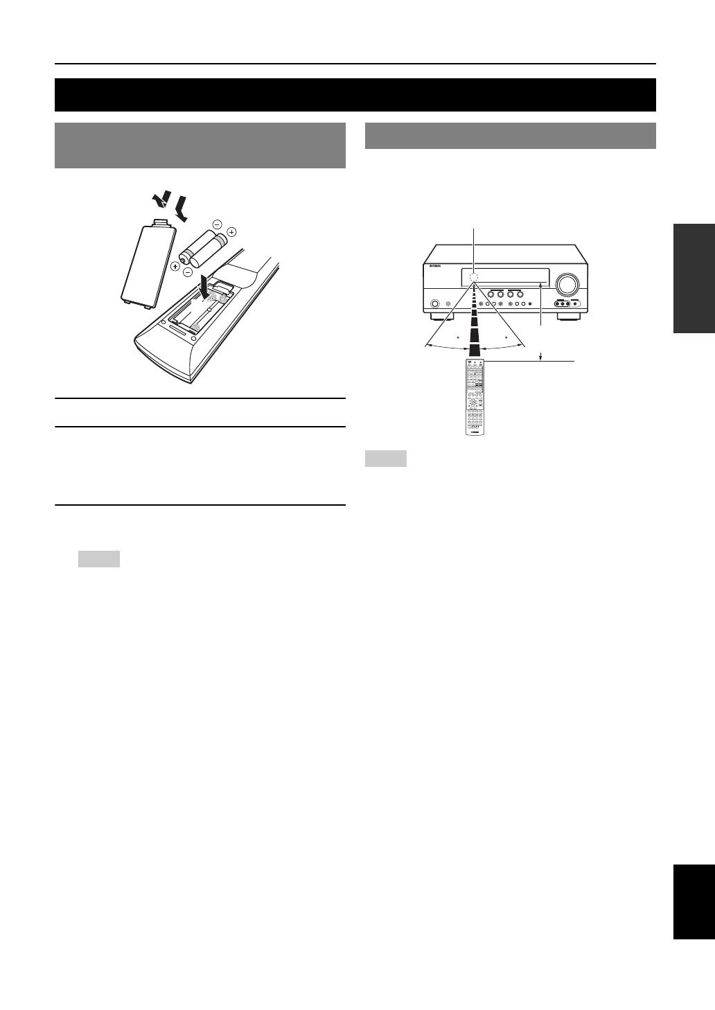
PREPARATION Preparing remote control Installing batteries in the remote Using the remote control control The remote control transmits a directional infrared ray. Be sure to aim the remote control directly at the remote control sensor on this unit during operation. Remote control sensor window within 6 m (20 ft) Take off the battery compartment cover.
-
Page 14: Connections
(LFE) sounds included in Dolby Digital and DTS signals. Use a subwoofer with a built-in 60˚ amplifier, such as the Yamaha Active Servo Processing 80˚ Subwoofer System. Place it exterior to the front left and right speakers facing slightly inward to reduce reflections…
-
Page 15: Connecting Speakers
Connections Connecting speakers When you connect speakers, connect them to the respective terminals as follows, according to your speaker layout. ■ 7.1-channel Speakers Jacks on this unit a Front speaker L FRONT (L) b Front speaker R FRONT (R) c Center speaker CENTER SPEAKERS d Surround speaker L…
-
Page 16
Connections Connecting the speaker cable Caution • A speaker cable is a pair of insulated cables running side by side in general. One of the cables is colored differently or striped to indicate a polarity. Connect one end of the colored/striped cable to the “+” (red) terminal of this unit and the other end to that of your speaker, and connect one end of the other cable to the “–”… -
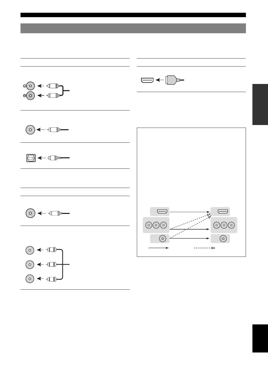
Page 17: Information On Jacks And Cable Plugs
Connections Information on jacks and cable plugs This unit has the following input and output jacks. Use jacks and cables appropriate for components that you are connecting. ■ ■ Audio jacks Video/audio jacks Jack and cables Description Jack and cables Description AUDIO jacks To transmit conventional analog…
-
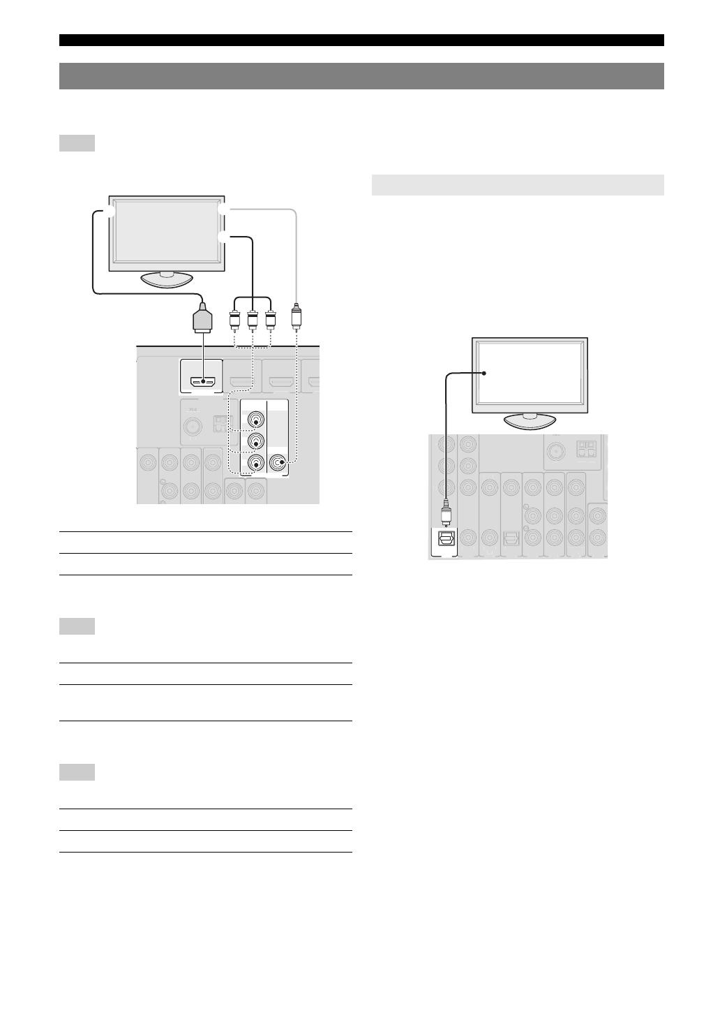
Page 18: Connecting A Tv Monitor Or Projector
Connections Connecting a TV monitor or projector Connect a video monitor such as a TV or projector to an output terminal of this unit. You can select one of the following three types according to the input signal format supported by the video monitor. Note •…
-
Page 19: Connecting Other Components
VIDEO • Input sources in parentheses are recommended to connect to the respective jacks. If your Yamaha component has the Remote in/out terminal, you can switch the input source to that component with a single key operation using the SCENE function (see page 21).
-
Page 20: Connecting A Yamaha Ipod Universal Dock Or Bluetooth™ Wireless Audio Receiver
This unit has the DOCK jack, to which you can connect a turn down the volume of this unit and other components Yamaha iPod universal dock (YDS-11, sold separately) or before making connections. a Bluetooth wireless audio receiver (YBA-10, sold separately).
-
Page 21: Connecting The Fm And Am Antennas
• Position the AM loop antenna away from this unit. • If you cannot get good reception, we recommend that you use an outdoor Press ASTANDBY/ON (or fPOWER) again antenna. For more details, consult the nearest authorized Yamaha dealer to turn off this unit (standby mode). or service center.
-
Page 22: Optimizing The Speaker Setting For Your Listening Room (Ypao)
Optimizing the speaker setting for your listening room (YPAO) This unit has a Yamaha Parametric Acoustic Optimizer (YPAO). With the YPAO, this unit automatically adjusts the output characteristics of your speakers based on speaker position, speaker performance, and the acoustic characteristics of the room.
-
Page 23
Optimizing the speaker setting for your listening room (YPAO) Flat Press nENTER to confirm the settings. This adjusts each speaker to obtain the same The speaker characteristics are adjusted according to characteristics. Select this if your speakers have measurement results. similar qualities. -
Page 24: When An Error Message Is Displayed During Measurement
Optimizing the speaker setting for your listening room (YPAO) When an error message is displayed When a warning message is displayed during measurement after measurement If a problem occurs during measurement, “WARNING” is Select “Retry” or “Exit” using nCursor l / h displayed on the result display screen.
-
Page 25: Basic Operation
BASIC OPERATION Playback Basic procedure Using the SCENE function This unit has a SCENE function that allows you to change Turn on external components (TV, DVD input sources and sound field programs with one key. Four player, etc.) connected to this unit. scenes are available for different usages, such as playing movies or music.
-
Page 26: Muting Audio Output Temporarily (Mute)
Playback Press gInput selection keys on the Enjoying pure hi-fi sound remote control for the input source whose Use Direct mode to enjoy the pure high fidelity sound of remote control code was registered in step 1 the selected source. When Direct mode is activated, this for about 3 seconds while pressing down unit plays back the selected source with the least circuitry.
-
Page 27: Displaying Input Signal Information
Playback Displaying input signal information Changing information on the front panel display When HDMI1-4 or AV1-4 is selected as the input source, you can display audio/video signal information. Information displayed on the front panel display can be changed by pressing CINFO (or iINFO). •…
-
Page 28: Enjoy The Sound Field Programs
Enjoy the sound field programs This unit is also equipped with a Yamaha digital sound field processing (DSP) chip. You can enjoy multi-channel sounds for almost all input sources using various sound field programs stored on the chip and a variety of surround decoders.
-
Page 29
Enjoy the sound field programs Program Descriptions Drama This sound field features stable reverberations that match a wide range of movie genres from serious dramas to musicals and comedies. The reverberations are modest but offer an optimum 3D feeling, reproducing effects tones and background music softly but cubically around clear words and center positioning in a way that does not fatigue the listener even after long hours of viewing. -
Page 30
Enjoy the sound field programs For Multi-channel stereo reproduction Program Descriptions 7ch Stereo Use this program to output sound from all speakers. When you play back multi-channel sources, this unit downmixes the source to 2 channels, and then outputs the sound from all speakers. This program creates a larger sound field and is ideal for background music at parties, etc. -
Page 31: Enjoying Unprocessed Input Sources (Straight Decoding Mode)
Enjoy the sound field programs Enjoying unprocessed input sources Enjoy sound field programs with (Straight decoding mode) headphones (SILENT CINEMA™) In straight decoding mode, sounds are reproduced without SILENT CINEMA allows you to enjoy multi-channel sound field effect. 2-channel stereo sources are output sources with your headphones.
-
Page 32: Fm/Am Tuning
FM/AM tuning The FM/AM tuner of this unit provides the following two • You can switch between stereo and monaural for FM broadcast in the modes for tuning. option menu (see page 34). ■ Frequency tuning mode (Auto tuning / To tune in by direct frequency tuning, enter Manual tuning) the frequency of the desired station using…
-
Page 33
FM/AM tuning During the automatic station preset, the upper area of the screen changes as follows: READY → SEARCH Calling a preset station (Preset tuning) → MEMORY each time a station is registered. You can call preset stations registered by automatic station When registration is complete, “FINISH”… -
Page 34: Using Ipod
• Some features may not be compatible depending on the model or the software version of your iPod. • Some features may not be available depending on the model of Yamaha iPod universal dock. The following sections describe the procedure when using the YDS-11.
-
Page 35
Using iPod™ Press nCursor k / n / l / h to select a Shuffle/repeat playback menu item and then nENTER to start You can use a special playback function such as shuffle playback. playback and repeat playback by setting the option menu. Menu items of “Music”… -
Page 36: Using Bluetooth™ Components
Using Bluetooth™ components You can connect a Yamaha Bluetooth wireless audio receiver (such as YBA-10, sold separately) to the DOCK terminal of this unit and enjoy the music contents stored in your Bluetooth component (such as a portable music player) without wiring between this unit and the Bluetooth component.
-
Page 37: Advanced Operation
ADVANCED OPERATION Setting the option menu for each input source (OPTION menu) This unit has an OPTION menu of frequently used menu items for input sources compatible with this unit. The procedure for setting the OPTION menu items is described below. Select an input source using NINPUT l / h OPTION menu items (gInput selection keys).
-
Page 38: Signal Info
Setting the option menu for each input source (OPTION menu) ■ Decoder Mode ■ Signal Info Input source: HDMI1-4, AV1-4 Input source: HDMI1-4, AV1-4 Auto*/DTS Choices: Displays information on audio and video signals on the Selects DTS digital audio signals for reproduction. video monitor and front panel display.
-
Page 39: Auto Preset
Setting the option menu for each input source (OPTION menu) ■ Auto Preset Input source: TUNER Automatically detects radio stations in the FM frequency band and registers them as preset stations (see page 28). ■ Clear Preset Input source: TUNER Clears the preset stations (see page 29).
-
Page 40: Editing Surround Decoders/Sound Field Programs
Editing surround decoders/sound field programs Press nCursor k / n to select the parameter Selecting a decoder used with a sound that you want to change, and press nCursor field program l / h to change the parameter. When using sound field programs for movies or TV An asterisk (*) appears on the left of the sound field programs (except for Mono Movie), you can select a parameter name displayed on the monitor when you…
-
Page 41: Effect Level
Editing surround decoders/sound field programs Parameters only usable in certain sound Decoder parameters field programs You can customize decoder effects by setting the ■ following parameters. For kinds of decoders, see page 26. 2ch Stereo only Direct ■ When PLIIx Music/PLII Music is selected Auto*/Off Choices: Panorama…
-
Page 42: Operating Various Settings For This Unit (Setup Menu)
Operating various settings for this unit (Setup menu) You can call the setup menu using the remote control and change the settings of various menus. You can change the following settings in the setup menu. For details, read “Basic operation of the setup menu” first, and see the respective pages.
-
Page 43: Basic Operation Of The Setup Menu
Operating various settings for this unit (Setup menu) “A)Config” display (example) Basic operation of the setup menu A)Config The setup menu screen appears on both video display Center SP (OSD) and front panel display. Video display (OSD) Setup Menu None >Small Large .
-
Page 44: Subwoofer Phase
Operating various settings for this unit (Setup menu) Sur. L/R SP LFE channel signals Choices: None/Small*/Large Front Other Parameter Subwoofer Sets sizes of left and right surround speakers. speakers speakers None Select this when no surround speakers are Both Output Not output Not output connected.
-
Page 45: Sound Setup
Operating various settings for this unit (Setup menu) ■ B)Level Adjustable range: -10.0dB to +10.0dB (0.5 dB step) 63Hz/160Hz/400Hz/1kHz/2.5kHz/ Choices: Defaults: “FR.L/FR.R/SWFR” 0dB* 6.3kHz/16kHz “CNTR/SUR.L/SUR.R/SBL/SBR” -1.0dB Adjustable range: -6.0dB to 0dB* to +6.0dB (0.5 dB step) Separately adjusts volume of each speaker so that the Adjusts sound quality of each speaker using a graphic sounds form speakers are at the same volume at the equalizer.
-
Page 46: Function Setup
Operating various settings for this unit (Setup menu) ■ Resolution Auto Delay Through*/480p/720p/1080i/1080p Choices: Adjustable range: 0 to 240ms (1 ms step) Upscales the resolution of HDMI output that is converted Fine adjust the correction time when “HDMI Auto” is set from analog video input signals and output from the to “On.”…
-
Page 47: Dsp Parameter
Operating various settings for this unit (Setup menu) ■ OSD Shift 4 Input Rename Adjustable range: -5 to 0* to +5 Adjusts top and bottom positions of the screen displayed Changes input source names to be displayed on the front on the video monitor.
-
Page 48: Controlling Other Components With The Remote Control
Default Input source Category Manufacturer Turns on and off an external component. code nCursor, ENTER, RETURN [DOCK] DOCK Yamaha 5011 Operates the menus of external components. [A]/[B] — — — pDISPLAY “—” indicates no assignment Switches between the screens of external components.
-
Page 49: Advanced Setup
ADVANCED SETUP Two IDs are provided for the remote control of this unit. If another Yamaha amplifier is in the same room, setting a Press KPROGRAM l / h repeatedly to different remote control ID to this unit prevents unwanted operation of the other amplifier.
-
Page 50: Appendix
Refer to the table below when this unit does not function properly. If the problem you are experiencing is not listed below or if the instruction below does not help, turn off this unit, disconnect the power cable, and contact the nearest authorized Yamaha dealer or service center. General…
-
Page 51
Troubleshooting Problem Cause Remedy page No picture. An appropriate video input is not selected Select an appropriate video input on the monitor. — on the monitor. The composite output terminals are used If your monitor does not support the HDMI to output a component video signal, or the connection, connect it to the COMPONENT OUT COMPONENT VIDEO jacks are used to… -
Page 52
Troubleshooting Problem Cause Remedy page No sound is heard “LFE/Bass Out” of “A)Config” in Set “LFE/Bass Out” to “SWFR” or “Both.” from the subwoofer. “Speaker Setup” of the setup menu (Speaker Setup→Manual Setup→A)Config) is set to “Front” when a Dolby Digital, DTS or AAC signal is being played. -
Page 53: Hdmi
Troubleshooting Problem Cause Remedy page The picture is The video software is copy-protected. disturbed. This unit suddenly The internal temperature becomes too Wait about 1 hour for this unit to cool down and then — enters the standby high and the overheat protection circuitry turn it back on.
-
Page 54: Remote Control
Connect error There is a problem with the signal path Turn off this unit and reconnect the Yamaha iPod from your iPod to this unit. universal dock to the DOCK terminal of this unit. Remove your iPod in the Yamaha iPod universal dock and then place it back in the dock.
-
Page 55: Bluetooth
• Warning message “W-2” or “W-3” indicates that the adjusted settings may not be optimal. • Depending on the speakers, warning message “W-1” may appears even if the speaker connections are correct. • If error message “E-10” occurs repeatedly, contact a qualified Yamaha service center. Before Auto Setup…
-
Page 56
Check whether the speakers are properly placed and connected. The optimizer microphone or OPTIMIZER MIC jack may be defective. Contact the nearest Yamaha dealer or service center. E-9:USER CANCEL “Auto Setup” was cancelled due to an Run “Auto Setup” again. -
Page 57: Glossary
Glossary ■ ■ Audio and video synchronization (lip sync) Dolby Digital Surround EX Lip sync, an abbreviation for lip synchronization, is a technical term Dolby Digital EX creates 6 full-bandwidth output channels from 5.1- that involves both a problem and a capability of maintaining audio and channel sources.
-
Page 58: Dts Digital Surround
Glossary ■ ■ HDMI Direct Stream Digital (DSD) technology stores audio signals on HDMI (High-Definition Multimedia Interface) is the first industry- digital storage media, such as Super Audio CDs. Using DSD, signals supported, uncompressed, all-digital audio/video interface. Providing are stored as single bit values at a high-frequency sampling rate of an interface between any source (such as a set-top box or AV receiver) 2.8224 MHz, while noise shaping and oversampling are used to and an audio/video monitor (such as a digital television), HDMI…
-
Page 59: Sound Field Program Information
Yamaha original sound field compression artifact. As a result, flattened complexity due to the loss technology combined with various digital audio systems.
-
Page 60: Specifications
Specifications AUDIO SECTION VIDEO SECTION • Video Signal Type (Gray Back) • Minimum RMS Output Power for Front, Center, Surround, [U.S.A., Canada, Korea and General models]…….NTSC Surround back [Other models]…………….PAL [U.S.A. and Canada models] 1 kHz, 0.9% THD, 8 Ω …………90 W •…
-
Page 61: Index
Index ■ Numerics Connecting iPod universal dock ….16 INFO, remote control ……..7 Connecting power cable …….. 17 INIT, advanced setup ……..45 1 Dynamic Range, sound setup ……41 Init. Volume, 3 Volume, function setup ..43 Connecting projector ……..14 1 HDMI, function setup ………42 Connecting set-top box ……..
-
Page 62
Index Roleplaying Game, sound field program ..25 Turning off ………….17 Turning on …………17 ■ TV control key, remote control ……7 TV monitor connection ……..14 SB Level, sound field parameter ….37 SCENE function ……….21 ■ SCENE, front panel ……… 4 SCENE, remote control …….. -
Page 63: List Of Remote Control Codes
List of remote control codes Ausind 0249 Clatronic 0243, 0249, 0259, Durabrand 0077, 0097, 0133, Autovox 0249, 0257, 0259, 0260, 0261, 0262, 0225 A.R. Systems 0274 0260, 0328 0268, 0269, 0273, 0271 Acme 0260 Aventura 0097 0274, 0328 Dwin 0224 Acura 0261, 0273 0327, 0328…
-
Page 64
Fujitsu Siemens 0425, 0426, 0427, Hinari 0261, 0262, 0266, Kaisui 0260, 0261, 0262, Magnavox 0072, 0088, 0090, 0428, 0429 0268, 0271, 0273, 0270, 0273, 0274, 0091, 0095, 0096, Funai 0033, 0034, 0035, 0274 0327, 0328 0098, 0114, 0115, 0036, 0037, 0097, Hisawa 0262, 0270, 0275 Kamosonic… -
Page 65
Neckermann 0243, 0257, 0260, 0114, 0135, 0143, 0071, 0072, 0073, SEI-Sinudyne 0257, 0263, 0265 0264, 0268, 0269, 0176, 0178, 0189, 0074, 0075, 0090, Seleco 0264, 0265, 0266 0271, 0274, 0328 0210, 0212, 0232, 0099, 0102, 0103, Sencora 0261, 0273 0268, 0271, 0274 0233, 0257, 0260, 0109, 0120, 0179, Sentra… -
Page 66
1020 1079, 1090 Tokai 0268, 0274, 0328 Xrypton 0274 CyberPower 1066 Headquarter 1019 Tokyo 0260, 0327 Yamaha 0000, 0001, 0002, Daewoo 1023, 1075, 1076, Hewlett Packard 1066 Tomashi 0270 0003, 0004, 0005, 1091, 1116, 1141 Hinari 1074, 1079, 1090, Toshiba… -
Page 67
Loewe Opta 1077, 1078 1111, 1113, 1122, Solavox 1076 XR-1000 1022, 1023 Logik 1079, 1090 1124, 1127, 1128, Sonic Blue 1041, 1068 Yamaha 1018, 1019 Lumatron 1075, 1091 1129 Sonneclair 1090 Yamishi 1079, 1090 Luxor 1090 Philips Magnavox 1030 Sonoko… -
Page 68
ATACOM 2318 Enzer 2302 2080, 2107, 2115, 2252, 2256, 2260, Audiovox 2111, 2199 Epson 2165 2116, 2141, 2188, 2268, 2282, 2332, Avious 2317 2219 2211, 2215, 2237, 2333, 2343, 2344, 2313 Finlux 2304, 2312, 2317 2239, 2285, 2293, 2345, 2367, 2371, Axion 2171 Fintec… -
Page 69
Archer 3020 3018 Sony 2005, 2006, 2007, Yamada 2097, 2313, 2315 Arcon 3048 NET Brazil 3007 2020, 2021, 2022, Yamaha 2000, 2001, 2002, AT&T 3013 Nokia 3051 2023, 2024, 2025, 2003, 2011, 2018, Axis 3048 Noos 3055 2069, 2072, 2073,… -
Page 70
Viewmaster 3045 Condor 4074, 4090, 4137 Fuba 4074, 4083, 4090, Lasat 4074, 4088, 4090, Vision 3045 Connexions 4074, 4092 4092, 4093, 4101, 4100, 4133, 4134, Visiopass 3051, 3054, 3055 Conrad 4074, 4133, 4136, 4133 4137 Vortex View 3045 4137 Galaxis 4074, 4087, 4090, Lasonic 4062… -
Page 71
Tandberg 4102 Zodiac 4086 Quelle 4093, 4133, 4137 Tandy 4086 Quiero 4102 Tantec 4084 RadioShack 4065 4090 Yamaha 5000, 5013 Radiola 4101, 4103 Techniland 4094 CD Recoder Radix 4092, 4119 TechniSat 4071, 4072, 4073, Rainbow 4086 4092, 4103, 4116, Yamaha… -
Page 72
© 2009 Yamaha Corporation All rights reserved. Printed in China WR90290… -
Page 73
UCTKEF HTR-6250/6240 The letters in circles and the numbers in squares correspond to those in the Owner’s Manual. Les lettres dans les cercles et les numéros dans les carrés correspondent à ceux du mode d’emploi. Le lettere cerchiate e i numeri nei quadratini corrispondono a quelli nel Manuale di istruzioni. Las letras enmarcadas en un círculo y los números enmarcados en un cuadrado se corresponden con aquellos del manual de instrucciones. -
Page 74
■ Remote control/Boîtier de télécommande/Telecomando/Mando a distancia/ Пульт ДУ/ 遥控器 / 리모콘 TRANSMIT CODE SET POWER POWER SOURCE SLEEP HDMI AUDIO V-AUX [ A ] [ B ] DOCK TUNER PRESET TUNING INFO MEMORY ENHANCER SUR. DECODE MOVIE MUSIC STEREO STRAIGHT DIRECT SCENE…

HTR-6250
AV Receiver
OWNER’S MANUAL
U

Caution-i En
• Explanation of Graphical Symbols
The lightning flash with arrowhead symbol, within an
equilateral triangle, is intended to alert you to the
presence of uninsulated “dangerous voltage” within
the product’s enclosure that may be of sufficient
magnitude to constitute a risk of electric shock to
persons.
The exclamation point within an equilateral triangle
is intended to alert you to the presence of important
operating and maintenance (servicing) instructions in
the literature accompanying the appliance.
1 Read these instructions.
2 Keep these instructions.
3 Heed all warnings.
4 Follow all instructions.
5 Do not use this apparatus near water.
6 Clean only with dry cloth.
7 Do not block any ventilation openings. Install in accordance
with the manufacturer’s instructions.
8 Do not install near any heat sources such as radiators, heat
registers, stoves, or other apparatus (including amplifiers)
that produce heat.
9 Do not defeat the safety purpose of the polarized or
grounding-type plug. A polarized plug has two blades with
one wider than the other. A grounding type plug has two
blades and a third grounding prong. The wide blade or the
third prong are provided for your safety. If the provided plug
does not fit into your outlet, consult an electrician for
replacement of the obsolete outlet.
10 Protect the power cord from being walked on or pinched
particularly at plugs, convenience receptacles, and the point
where they exit from the apparatus.
11 Only use attachments/accessories specified by the
manufacturer.
12 Use only with the cart, stand, tripod, bracket,
or table specified by the manufacturer, or sold
with the apparatus. When a cart is used, use
caution when moving the cart/apparatus
combination to avoid injury from tip-over.
13 Unplug this apparatus during lightning storms or when
unused for long periods of time.
14 Refer all servicing to qualified service personnel. Servicing
is required when the apparatus has been damaged in any
way, such as power-supply cord or plug is damaged, liquid
has been spilled or objects have fallen into the apparatus, the
apparatus has been exposed to rain or moisture, does not
operate normally, or has been dropped.
IMPORTANT SAFETY INSTRUCTIONS
Note to CATV system installer:
This reminder is provided to call the CATV system
installer’s attention to Article 820-40 of the NEC that
provides guidelines for proper grounding and, in
particular, specifies that the cable ground shall be
connected to the grounding system of the building, as
close to the point of cable entry as practical.
FCC INFORMATION (for US customers)
1 IMPORTANT NOTICE: DO NOT MODIFY THIS UNIT!
This product, when installed as indicated in the instructions
contained in this manual, meets FCC requirements. Modifications
not expressly approved by Yamaha may void your authority,
granted by the FCC, to use the product.
2 IMPORTANT:
When connecting this product to accessories
and/or another product use only high quality shielded cables.
Cable/s supplied with this product MUST be used. Follow all
installation instructions. Failure to follow instructions could void
your FCC authorization to use this product in the USA.
3NOTE:
This product has been tested and found to comply with
the requirements listed in FCC Regulations, Part 15 for Class “B”
digital devices. Compliance with these requirements provides a
reasonable level of assurance that your use of this product in a
residential environment will not result in harmful interference with
other electronic devices.
This equipment generates/uses radio frequencies and, if not
installed and used according to the instructions found in the users
manual, may cause interference harmful to the operation of other
electronic devices.
Compliance with FCC regulations does not guarantee that
interference will not occur in all installations. If this product is
found to be the source of interference, which can be determined by
turning the unit “OFF” and “ON”, please try to eliminate the
problem by using one of the following measures:
Relocate either this product or the device that is being affected by
the interference.
Utilize power outlets that are on different branch (circuit breaker or
fuse) circuits or install AC line filter/s.
In the case of radio or TV interference, relocate/reorient the
antenna. If the antenna lead-in is 300 ohm ribbon lead, change the
lead-in to coaxial type cable.
If these corrective measures do not produce satisfactory results,
please contact the local retailer authorized to distribute this type of
product. If you can not locate the appropriate retailer, please
contact Yamaha Electronics Corp., U.S.A. 6660 Orangethorpe
Ave, Buena Park, CA 90620.
The above statements apply ONLY to those products distributed by
Yamaha Corporation of America or its subsidiaries.
CAUTION
CAUTION: TO REDUCE THE RISK OF
ELECTRIC SHOCK, DO NOT REMOVE
COVER (OR BACK). NO USER-SERVICEABLE
PARTS INSIDE. REFER SERVICING TO
QUALIFIED SERVICE PERSONNEL.
RISK OF ELECTRIC SHOCK
DO NOT OPEN

Caution-ii En
1 To assure the finest performance, please read this manual
carefully. Keep it in a safe place for future reference.
2 Install this sound system in a well ventilated, cool, dry, clean
place – away from direct sunlight, heat sources, vibration,
dust, moisture, and/or cold. Allow ventilation space of at least
30 cm on the top, 20 cm on the left and right, and 20 cm on
the back of this unit.
3 Locate this unit away from other electrical appliances, motors,
or transformers to avoid humming sounds.
4 Do not expose this unit to sudden temperature changes from
cold to hot, and do not locate this unit in an environment with
high humidity (i.e. a room with a humidifier) to prevent
condensation inside this unit, which may cause an electrical
shock, fire, damage to this unit, and/or personal injury.
5 Avoid installing this unit where foreign objects may fall onto
this unit and/or this unit may be exposed to liquid dripping or
splashing. On the top of this unit, do not place:
– Other components, as they may cause damage and/or
discoloration on the surface of this unit.
– Burning objects (i.e. candles), as they may cause fire,
damage to this unit, and/or personal injury.
– Containers with liquid in them, as they may fall and liquid
may cause electrical shock to the user and/or damage to
this unit.
6 Do not cover this unit with a newspaper, tablecloth, curtain,
etc. in order not to obstruct heat radiation. If the temperature
inside this unit rises, it may cause fire, damage to this unit,
and/or personal injury.
7 Do not plug in this unit to a wall outlet until all connections
are complete.
8 Do not operate this unit upside-down. It may overheat,
possibly causing damage.
9 Do not use force on switches, knobs and/or cords.
10 When disconnecting the power cable from the wall outlet,
grasp the plug; do not pull the cable.
11 Do not clean this unit with chemical solvents; this might
damage the finish. Use a clean, dry cloth.
12 Only voltage specified on this unit must be used. Using this
unit with a higher voltage than specified is dangerous and may
cause fire, damage to this unit, and/or personal injury. Yamaha
will not be held responsible for any damage resulting from use
of this unit with a voltage other than specified.
13 To prevent damage by lightning, keep the power cord and
outdoor antennas disconnected from a wall outlet or the unit
during a lightning storm.
14 Do not attempt to modify or fix this unit. Contact qualified
Yamaha service personnel when any service is needed. The
cabinet should never be opened for any reasons.
15 When not planning to use this unit for long periods of time
(i.e. vacation), disconnect the AC power plug from the wall
outlet.
16 Install this unit near the AC outlet and where the AC power
plug can be reached easily.
17 Be sure to read the “Troubleshooting” section on common
operating errors before concluding that this unit is faulty.
18 Before moving this unit, press ASTANDBY/ON to set this
unit in the standby mode, and disconnect the AC power plug
from the wall outlet.
19 VOLTAGE SELECTOR (Asia and General models only)
The VOLTAGE SELECTOR on the rear panel of this unit
must be set for your local main voltage BEFORE plugging
into the AC wall outlet. Voltages are:
…….AC 110/120/220/230–240 V, 50/60 Hz (General model)
…………….………. AC 220/230–240 V, 50/60 Hz (Asia model)
20 The batteries shall not be exposed to excessive heat such as
sunshine, fire or like.
21 Excessive sound pressure from earphones and headphones can
cause hearing loss.
22 When replacing the batteries, be sure to use batteries of the
same type. Danger of explosion may happen if batteries are
incorrectly replaced.
Caution: Read this before operating your unit.
WARNING
TO REDUCE THE RISK OF FIRE OR ELECTRIC
SHOCK, DO NOT EXPOSE THIS UNIT TO RAIN
OR MOISTURE.
As long as this unit is connected to the AC wall outlet,
it is not disconnected from the AC power source even
if you turn off this unit by
A
STANDBY/ON. In this
state, this unit is designed to consume a very small
quantity of power.
FOR CANADIAN CUSTOMERS
To prevent electric shock, match wide blade of plug to
wide slot and fully insert.
This Class B digital apparatus complies with Canadian
ICES-003.
POUR LES CONSOMMATEURS CANADIENS
Pour éviter les chocs électriques, introduire la lame la
plus large de la fiche dans la borne correspondante de
la prise et pousser jusqu’au fond.
Cet appareil numérique de la classe B est conforme à
la norme NMB-003 du Canada.
IMPORTANT
Please record the serial number of this unit in the space
below.
MODEL:
Serial No.:
The serial number is located on the rear of the unit.
Retain this Owner’s Manual in a safe place for future
reference.

1 En
English
INTRODUCTION
APPENDIX
PREPARATION
BASIC
OPERATION
ADVANCED
OPERATION
Features……….…………………………………………………. 2
About this manual…………………………………………… 3
Supplied accessories…….………………………………….. 3
Part names and functions………………………………… 4
Front panel ………….………….…………….………………….. 4
Rear panel ………………..…………….…………….………….. 5
Front panel display…………..……………………….……….. 6
Remote control.……………………….…………….………….. 7
Quick start guide……………………………………………..8
L
Preparing remote control ………………………………… 9
Installing batteries in the remote control …………..….. 9
Using the remote control..………………………….……….. 9
Connections ……….……….…………………………………10
Placing speakers……………………………………….……… 10
Connecting speakers ………………………………………… 11
Information on jacks and cable plugs ….……………… 13
Connecting a TV monitor or projector ………..……… 14
Connecting other components ..…………….…………… 15
Connecting a Yamaha iPod universal dock or
Bluetooth™ wireless audio receiver………..……… 16
Using the VIDEO AUX jacks on the front panel …. 16
Connecting the FM and AM antennas ………………… 17
Connecting the power cable…………….………………… 17
Turning this unit on and off ………………….…………… 17
Optimizing the speaker setting for your listening
room (YPAO) ………………………………………….…18
Using Auto Setup………………….…………….…………… 18
When an error message is displayed during
measurement …………….………………………….……… 20
When a warning message is displayed after
measurement …………….………………………….……… 20
Playback…….…………………………………….……………21
Basic procedure…………………….…………….…………… 21
Using the SCENE function ….…………….……………… 21
Muting audio output temporarily (MUTE)………….. 22
Adjusting high/low frequency sound (tone control) 22
Enjoying pure hi-fi sound ………………….……………… 22
Using the sleep timer ……………………..………………… 22
Using your headphones…….……………………….……… 22
Displaying input signal information …………………… 23
Changing information on the front panel display …. 23
Enjoy the sound field programs ….…………………. 24
Selecting sound field programs…………..……………… 24
Enjoying unprocessed input sources (Straight
decoding mode) …………..…………….………………… 27
Enjoying sound field programs without surround
speakers (Virtual CINEMA DSP) ………………….. 27
Enjoy sound field programs with headphones
(SILENT CINEMA™) ……………….………………… 27
FM/AM tuning ……………..……………………………….28
Tuning in to the desired FM/AM station (Frequency
tuning)…….……………………….…………….…………… 28
Registering FM/AM stations and tuning in (Preset
tuning)…….……………………….…………….…………… 28
Using iPod™ ..……………………………………….………. 30
Controlling iPod™………..………………………….……… 30
Using Bluetooth™ components .…………………….. 32
Pairing the Bluetooth™ wireless audio receiver and
your Bluetooth component ……………………………. 32
Playback of the Bluetooth™ component …….………. 32
Setting the option menu for each input source
(OPTION menu) ..……………………………………… 33
OPTION menu items …..…………….………….…………. 33
Editing surround decoders/sound field programs
………..……….…………………………….………………… 36
Selecting a decoder used with a sound field program
…………….………….…………….……………………….…. 36
Setting sound field parameters.………………………….. 36
Sound field parameters ……………………………….……. 36
Operating various settings for this unit
(Setup menu) ………….…………………………………. 38
Basic operation of the setup menu …………..…………. 39
Speaker Setup ……………….…………….…………….……. 39
Sound Setup ………….…………….………………………….. 41
Function Setup ………………….……………………….……. 42
DSP Parameter …………………………….………….………. 43
Memory Guard…………………….………………………….. 43
Controlling other components with the remote
control………………………………………………………. 44
Setting remote control codes………….…………….……. 44
Resetting all remote control codes…….……………….. 44
Advanced setup…………………………………………….. 45
Troubleshooting…………..……….………………………. 46
General……..…………….………….………………………….. 46
HDMI……….…………….…………….……………………….. 49
Tuner (FM/AM) ………….…………….…………….………. 49
Remote control………………………….………….…………. 50
iPod™ ………………….…………….……………………….…. 50
Bluetooth™………..…………….………………………….…. 51
Auto Setup (YPAO).………….………………………….…. 51
Glossary ……………………………………………………….. 53
Sound field program information …………..……… 55
Information on HDMI™……………………………….. 55
Specifications…..……………………………………………. 56
Index ………………..……….…………………………………. 57
(at the end of this manual)
Contents
INTRODUCTION
PREPARATION
BASIC OPERATION
ADVANCED OPERATION
APPENDIX
List of remote control codes………………….………….i

2 En
INTRODUCTION
■ Built-in 7-channel power amplifier
• Minimum RMS Output Power (1 kHz, 0.9% THD, 8 Ω)
• FRONT L/R: 90 W + 90 W
• CENTER: 90 W
• SURROUND L/R: 90 W + 90 W
• SURROUND BACK L/R: 90 W + 90 W
■ Speaker/Preout outputs
• Speaker jacks (7-channel), preout output jacks
(subwoofer)
■ Input/Output terminals
Input terminals
• HDMI input x 4
• Audio/Visual input
[Audio] Digital input (coaxial) x 2, digital input
(optical) x 2, analog input x 2
[Video] Component video x 2, composite video x 4
• Audio input (analog) x 2
• Dock input x 1
• V-AUX input
[Audio] Analog x 1
[Video] Composite video x 1
Output terminals
• Monitor output
[Audio/Video] HDMI x 1
[Video] Component video x 1, Composite video x 1
• Audio/Visual output
[Audio] Analog x 1
[Video] Composite video x 1
• Audio output
Analog x 1
■ Proprietary Yamaha technology for the
creation of sound fields
• CINEMA DSP
• Compressed Music Enhancer mode
• Virtual CINEMA DSP
• SILENT CINEMA
■ Digital audio decoders
• Dolby TrueHD, Dolby Digital Plus decoder
• DTS-HD Master Audio, DTS-HD High Resolution
Audio, DTS Express
• Dolby Digital/Dolby Digital EX decoder
• DTS, DTS 96/24 decoder, DTS-ES Matrix 6.1,
DTS-ES Discrete 6.1
• Dolby Pro Logic/Dolby Pro Logic II/Dolby Pro Logic
IIx decoder
• DTS NEO:6 decoder
■ Sophisticated FM/AM tuner
• 40-station random and direct preset tuning
• Automatic preset tuning
■ HDMI™
(High-Definition Multimedia Interface)
• HDMI interface for standard, enhanced or high-
definition video as well as multi-channel digital audio.
– Automatic audio and video synchronization (lip sync)
information capability
– Deep Color video signal (30/36 bit) transmission
capability
– “x.v.Color” video signal transmission capability
– High refresh rate and high resolution video signals
capability
– High definition digital audio format signals capability
• Analog video to HDMI digital video up-conversion
(composite video → HDMI, component video →
HDMI) capability for monitor out
• Analog video input up-scaling for HDMI digital video
output 480i or 480p → 720p, 1080i or 1080p
■ DOCK terminal
• DOCK terminal to connect a Yamaha iPod universal
dock (such as YDS-11, sold separately) or Bluetooth
wireless audio receiver (such as YBA-10, sold
separately)
■ Automatic speaker setup features
• “YPAO” (Yamaha Parametric Room Acoustic
Optimizer) for automatically optimizing speaker
outputs suitable for listening environments.
■ Other features
• 192-kHz/24-bit D/A converter
• OSD (on-screen display) menus that allow you to
optimize this unit to suit your individual audiovisual
system
• Direct mode for pure hi-fi sound for all sources
• Adaptive dynamic range controlling capability
• Sleep timer
Features
3 En
English
INTRODUCTION
ADDITIONAL
INFORMATION APPENDIX
PREPARATION
BASIC
OPERATION
ADVANCED
OPERATION
Manufactured under license from Dolby Laboratories.
Dolby, Pro Logic and the double-D symbol are trademarks of Dolby
Laboratories
Manufactured under license under U.S. Patent No’s:
5,451,942;5,956,674;5,974,380;5,978,762;6,226,616;6,487,535 &
other U.S. and worldwide patents issued & pending. DTS is a
registered trademark and the DTS logos, Symbol, DTS-HD and DTS-
HD Master Audio are trademark of DTS, Inc. © 1996-2007 DTS, Inc.
All Rights Reserved.
iPod™
“iPod” is a trademark of Apple Inc., registered in the U.S. and other
countries.
Bluetooth™
Bluetooth is a registered trademark of Bluetooth SIG and is used by
Yamaha in accordance with a license agreement.
“HDMI,” the “HDMI” logo and “High-Definition Multimedia
Interface” are trademarks, or registered trademarks of HDMI
Licensing LLC.
x.v.Color™
“x.v.Color” is a trademark of Sony Corporation. “SILENT CINEMA”
is a trademark of Yamaha Corporation.
“SILENT CINEMA” is a trademark of Yamaha Corporation.
Check that you received all of the following parts.
• Remote control
• Batteries (2) (AAA, R03, UM-4)
• Optimizer microphone
• AM loop antenna
• Indoor FM antenna
About this manual
• y indicates a tip for your operation.
• Some operations can be performed by using either the keys on the front panel or the ones on the remote control. In case the key names differ between
the front panel and the remote control, the key name on the remote control is given in parentheses.
• This manual is printed prior to production. Design and specifications are subject to change in part as a result of improvements, etc. In case of
differences between the manual and product, the product has priority.
• “ASTANDBY/ON” or “gHDMI 1” (example) indicates the name of the parts on the front panel or the remote control. Refer to the attached sheet
or the pages at the end of this manual for the information about each position of the parts.
• ☞ indicates the page describing the related information.
Supplied accessories
4 En
A STANDBY/ON
Switches this unit between standby and on (see page 17).
B PHONES jack
For plugging headphones (see page 22).
C INFO
Changes information display screens on the front panel display
(see page 23).
D MEMORY
Registers FM/AM stations as preset stations (see page 29).
E PRESET l / h
Selects an FM/AM preset station (see page 29).
F FM
Sets the FM/AM tuner band to FM (see page 28).
G AM
Sets the FM/AM tuner band to AM (see page 28).
H TUNING l / h
Changes FM/AM tuner frequencies (see page 28).
I SCENE
Switches between linked sets of input sources and sound field
programs (see page 21).
J TONE CONTROL
Adjusts high-frequency/low-frequency output of speakers (see
page 22).
K PROGRAM l / h
Changes sound field programs (see page 24).
L STRAIGHT
Changes a sound field program to straight decoding mode (see
page 27).
M DIRECT
Changes a sound field program to direct mode (see page 22).
N INPUT l / h
Selects an input source (see page 21).
O OPTIMIZER MIC jack
For connecting the supplied optimizer microphone and adjusting
output characteristics of speakers (see page 18).
P VOLUME control
Controls the volume of this unit (see page 21).
Q VIDEO (VIDEO AUX) jack
For connecting the video output cable of a camcorder or game
console (see page 16).
R AUDIO L/R (VIDEO AUX) jack
For connecting the audio output cable of a camcorder or game
console (see page 16).
S PORTABLE (VIDEO AUX) jack
For connecting the audio output cable of a portable music player
(see page 16).
T Front panel display
Displays information on this unit (see page 6).
U HDMI THROUGH
Lights up during pass-through output of an HDMI signal input
to this unit while this unit is on standby (see page 42).
Part names and functions
Front panel
PHONES
SILENT
CINEMA
TONE
CONTROL
PROGRAM
STRAIGHT
INPUT
OPTIMIZER
MIC
VIDEO
AUDIO
PORTABLE
THROUGH
VIDEO
AUX
VOLUME
HDMI
EFFECT
l
h
l
h
BD/DVD
TV
CD
RADIO
SCENE
INFO
MEMORY
PRESET
l
h
l
h
TUNING
FM
AM
STANDBY
/ON
DIRECT
A
J MC OK N
I RBLQS
5 En
Part names and functions
English
INTRODUCTION
ADDITIONAL
INFORMATION APPENDIX
PREPARATION
BASIC
OPERATION
ADVANCED
OPERATION
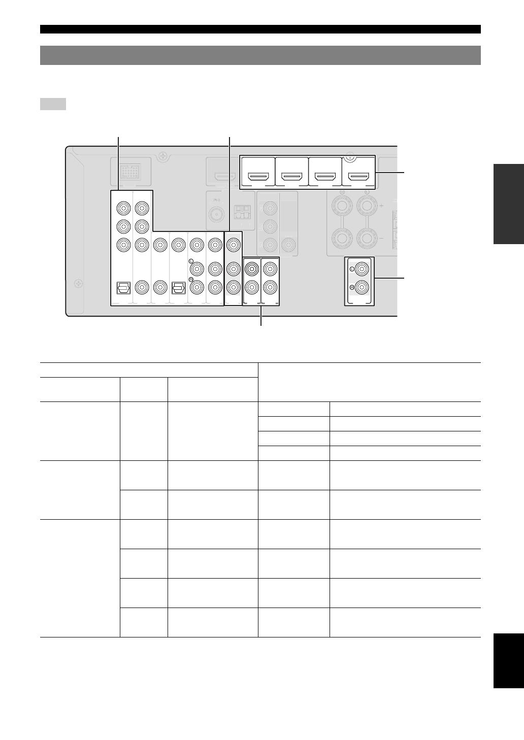
a DOCK terminal
For connecting an optional Yamaha iPod universal dock (YDS-
11) or Bluetooth wireless audio receiver (YBA-10) (see
page 16).
b HDMI OUT/HDMI 1-4
For connecting an HDMI-compatible video monitor or external
components for HDMI inputs 1-4 (see page 15).
c ANTENNA jack
For connecting supplied FM and AM antennas (see page 17).
d SPEAKERS terminal
For connecting front right and left, center, surround and
surround back speakers (see page 11).
e AV 1—6
For connecting external components for audio/visual inputs 1-6
(see page 15).
f AV OUT
Outputs audio/visual signals from a selected analog input source
to an external component (see page 16).
g AUDIO 1/2
For connecting external components for audio inputs 1-2 (see
page 16).
h MONITOR OUT
Outputs visual signals from this unit to a video monitor, such as
a TV (see page 14).
i AUDIO OUT
Outputs audio signals from a selected analog input source to an
external component (see page 16).
j PRE OUT
For connecting a subwoofer with a built-in amplifier (see
page 11).
k Power Cable
For connecting this cable to an AC wall outlet (see page 17).
Rear panel
UNBAL.
FM
GND
AM
ANTENNA
PR
PB
Y
COMPONENT
VIDEO
SPEAKERS
DOCK
VIDEO
PR
PB
Y
OPTICAL
(
TV
)
A
V
1
AV 2
COAXIAL
AV 3
(
CD
)
COAXIAL
OPTICAL
AV 4
AV 5
AV
OUT
AUDI O1
AUDIO2
VIDEO
HDMI
HDMI 1
(
BD/DVD
)
HDMI 2 HDMI 3
HDMI 4
OUT
AV 6
VIDEO
MONITOR OUT
AUDIO
OUT
FRONT
CENTER
SURROUND
PRE OUT
SUBWOOFER
BACK/
BI-AMP
SURROUND
COMPONENT
6 En
Part names and functions
a HDMI indicator
Lights up during normal communication when HDMI is
selected as an input source.
b CINEMA DSP indicator
Lights up when a sound field program that uses CINEMA DSP
is selected.
c Tuner indicator
Lights up while receiving a radio broadcast signal from an FM/
AM station (see page 28).
d SLEEP indicator
Lights up when the sleep timer is activated (see page 22).
e VOLUME indicator
Displays volume levels.
f MUTE indicator
Flashes when audio is muted.
g Cursor indicators
Light up if corresponding cursors on the remote control are
available for operations.
h Multi information display
Displays menu items and settings for the current operation.
i Speaker indicators
Indicate speaker terminals from which signals are currently
output.
Front panel display
STEREO
SLEEP
VOL.
TUNED
SW
C
LR
SL SR
SBL SB SBR
MUTE
gh ig
SW
C
LR
SL SR
SBL SB SBR
Subwoofer
Front L
Surround L
Surround back L
Center
Front R
Surround R
Surround back R
Surround back
7 En
Part names and functions
English
INTRODUCTION
ADDITIONAL
INFORMATION APPENDIX
PREPARATION
BASIC
OPERATION
ADVANCED
OPERATION
a Remote control signal transmitter
Transmits infrared signals.
b TRANSMIT
Lights up when a signal is output from the remote control.
c CODE SET
Sets remote control codes for external component operations
(see page 44).
d SOURCE POWER
Switches an external component on and off.
e SLEEP
Switches the sleep timer operations (see page 22).
f POWER
Switches this unit on and standby.
g Input selection keys
h Tuner keys
i INFO
Changes the information shown on the front panel display (see
page 23).
j Sound selection keys
Selects sound field programs (see page 24).
k SCENE
Switches between linked sets of input sources and sound field
programs (see page 21).
l SETUP
Displays the setup menu (see page 39).
m OPTION
Displays the option menu (see page 33).
n Cursors k / n / l / h/ENTER/RETURN
o VOLUME +/–
Adjust the volume of this unit (see page 21).
p DISPLAY
Changes the operation mode of the iPod connected to the
Yamaha iPod universal dock (see page 30).
q MUTE
Turns the mute function of the sound output on and off (see
page 22).
r External component operation keys
Operate recording, playback etc. of external components (see
page 44).
s Numeric keys
Enter numbers.
t TV control keys
Operate a monitor such as a TV or projector.
Remote control
POWER
1234
1256
1234
7856
90
10
1234
POWER
SOURCE
V-AU X
[ A ] [ B ] DOCK
TUNER
FM
MOVIE
BD
DVD
TOP
MENU
MUSIC
SCENE
TV
CD
OPTIONSETUP
RETURN
REC
ENT
POWER
TV
TV VOL
INPUT
MUTE
TV CH
ENTER
VOLUME
DISPLAY
MUTE
MENU
RADIO
STEREO
ENHANCER SUR. DECODE
DIRECTSTRAIGHT
INFO
MEMORY
AM
PRESET
SLEEP
HDMI
AV
AUDIO
TRANSMIT
CODE SET
TUNING
d
e
f
g
h
j
k
l
m
o
p
q
r
s
t
b
c
n
i
HDMI 1-4
Selects HDMI inputs 1 through 4.
AV 1—6
Selects AV inputs 1 through 6.
AUDIO 1/2
Selects AUDIO inputs 1 and 2.
V-AUX
Selects the V-AUX jack on the front
panel of this unit.
[A]/[B]
To control external components using
the rExternal component
operation keys separately from
operations of this unit (see page 44).
DOCK
Selects a Yamaha iPod universal dock/
Bluetooth wireless audio receiver
connected to the DOCK jack.
TUNER
Selects the FM/AM tuner.
FM
Switches a band between FM and AM.
AM
MEMORY
Presets radio stations.
PRESET k / n
Selects a preset station.
TUNING k / n
Changes tuning frequencies.
Cursors k / n / l / h
Select menu items displayed on the
front panel display or on a video
monitor, or change settings.
ENTER
Confirms a selected item.
RETURN
Returns to the previous screen or
ends the menu display.
8 En
When you use this product for the first time, perform setup following the steps below. See the related pages for details on
operations and settings.
Prepare speakers, DVD player, cables, and other items
necessary for setup.
For example, prepare the following items for setting up a
5.1-channel sound system.
y
• Prepare two speakers (for front). The priority of the requirement of other
speakers is as follows:
1 Two surround speakers
2 One center speaker
3 One (or two) surround back speaker(s)
• If your video monitor is a CRT, we recommend that you use magnetically
shielded speakers.
Place your speakers in the room and connect them to this
unit.
y
• This unit has a YPAO (Yamaha Parametric Room Acoustic Optimizer)
that automatically optimizes this unit based on room acoustic
characteristics (audio characteristics of the speakers, speaker positions,
and room acoustics, etc.).
You can enjoy good balanced sound without special knowledge by using
the YPAO technology (see page 18).
Connect your TV, DVD player, or other components.
Connect the power cable and turn on this unit.
Select the component connected in the step 3 as an input
source and start playback.
y
• This unit supports the SCENE function that changes the input source and
sound field program at one time. Four scenes are preset for different
purposes for Blu-ray disc, DVD and CD, and you can select from a scene
from those just by pressing a remote control key. See page 21 for details.
Quick start guide
Step 1: Prepare items for setup
Requirements qty.
Speakers Front speaker 2
Center speaker 1
Surround speaker 2
Active subwoofer 1
Speaker cable 5
Subwoofer cable 1
Reproduction component such as DVD player 1
Video monitor such as TV 1
Video cable or HDMI cable 2
Audio cable 2
Front right speaker
Subwoofer
Surround left speaker
Surround right speaker
Front left speaker
Video monitor
Center speaker
Components
(such as DVD player)
Step 2: Set up your speakers
• Placing speakers ☞P. 10
• Connecting speakers ☞P. 11
Step 3: Connect your components
• Connecting a TV monitor or projector ☞P. 14
• Connecting other components ☞P. 15
• Connecting a Yamaha iPod universal dock or
Bluetooth wireless audio receiver ☞P. 16
• Connecting the FM and AM antennas ☞P. 17
Step 4: Turn on the power
• Connecting the power cable ☞P. 17
• Turning this unit on and off ☞P. 17
Step 5: Select the input source and start
playback
• Basic procedure ☞P. 21
• Selecting sound field programs ☞P. 24
9 En
English
INTRODUCTION
ADDITIONAL
INFORMATION APPENDIX
PREPARATION
BASIC
OPERATION
ADVANCED
OPERATION
PREPARATION
1 Take off the battery compartment cover.
2 Insert the two supplied batteries (AAA, R03,
UM-4) according to the polarity markings (+
and –) on the inside of the battery
compartment.
3 Snap the battery compartment cover back
into place.
Notes
• Change all batteries if you notice the following conditions:
– the operation range of the remote control narrows
– the transmit indicator does not flash or is dim
• Do not use old batteries together with new ones.
This may shorten the life of the new batteries or cause old batteries
to leak.
• Do not use different types of batteries (such as alkaline and
manganese batteries) together. Specification of batteries may be
different even though they look the same.
• If you find leaking batteries, discard the batteries immediately,
taking care not to touch the leaked material. If the leaked material
comes into contact with your skin or gets into your eyes or mouth,
rinse it away immediately and consult a doctor. Clean the battery
compartment thoroughly before installing new batteries.
• Dispose of the old batteries correctly in accordance with your local
regulations.
• If the remote control is without batteries for more than 2 minutes,
or if exhausted batteries remain in the remote control, the contents
of the memory may be cleared. In such a case, install new batteries
and set the remote control code.
The remote control transmits a directional infrared ray. Be
sure to aim the remote control directly at the remote
control sensor on this unit during operation.
Notes
• Do not spill water or other liquids on the remote control.
• Do not drop the remote control.
• Do not leave or store the remote control in the following conditions:
– places of high humidity, such as near a bath
– places of high temperatures, such as near a heater or stove
– places of extremely low temperatures
– dusty places
y
• You can operate external components with this remote control by setting
the remote control code. See page 44 for details.
Preparing remote control
Installing batteries in the remote
control
1
3
2
Using the remote control
30 30
Remote control sensor window
within 6 m (20 ft)
10 En
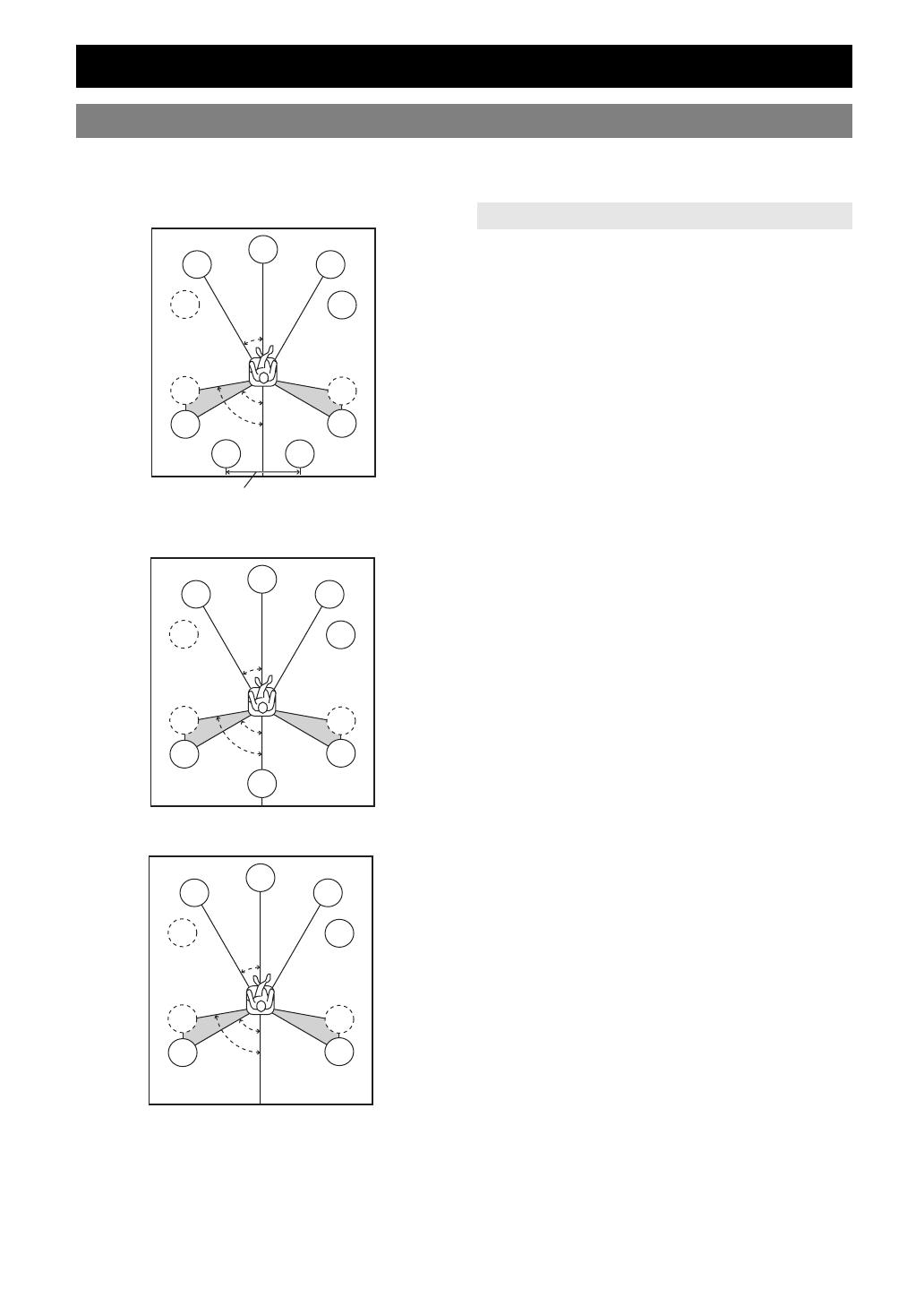
This unit supports up to 7.1-channel surround. We recommended the following speaker layout in order to obtain the
optimum surround effect.
7.1-channel speaker layout
6.1-channel speaker layout
5.1-channel speaker layout
■ Front left and right speakers (FL and FR)
The front speakers are used for the front channel sounds
(stereo sound) and effect sounds. Place these speakers at
an equal distance from the ideal listening position. When
using a screen, the appropriate top positions of the
speakers are about 1/4 of the screen from the bottom.
■ Center speaker (C)
The center speaker is for the center channel sounds
(dialog, vocals, etc.). Place it halfway between the left and
right speakers. When using a TV, place the speaker just
above or just under the center of the TV with the front
surfaces of the TV and the speaker aligned. When using a
screen, place it just under the center of the screen.
■ Surround left and right speakers (SL and SR)
The surround speakers are used for effect and surround
sounds.
Place them at the rear left and rear right facing the
listening position.
To obtain a natural sound flow in the 5.1-channel speaker
layout, place them slightly further back than in the 7.1-
channel speaker layout.
■ Surround back left and right speakers (SBL
and SBR) / Surround back speaker (SB)
The surround back left and right speakers are used for rear
effect sounds. Place them at the rear of the room facing the
listening position at least 30 cm away from each other,
ideally at the same distance as that between the front left
and right speakers.
In the 6.1-channel speaker layout, surround back left and
right channel sound signals are mixed down and output
from the single surround back speaker.
In the 5.1-channel speaker layout, surround back left and
right channel sound signals are output from the surround
left and right speakers.
■ Subwoofer (SW)
The subwoofer speaker is used for bass sounds and low-
frequency effect (LFE) sounds included in Dolby Digital
and DTS signals. Use a subwoofer with a built-in
amplifier, such as the Yamaha Active Servo Processing
Subwoofer System. Place it exterior to the front left and
right speakers facing slightly inward to reduce reflections
from a wall.
Connections
Placing speakers
60˚
30˚
SBR
SBL
FL
FR
C
SL
SR
SR
80˚
SL
SW
SW
30 cm (12 in) or more
60˚
30˚
SB
FL
FR
C
SL
SR
SR
80˚
SL
SW
SW
60˚
30˚
FL
FR
C
SL
SR
SR
80˚
SL
SW
SW
Speaker channels
11 En
Connections
English
INTRODUCTION
ADDITIONAL
INFORMATION APPENDIX
PREPARATION
BASIC
OPERATION
ADVANCED
OPERATION
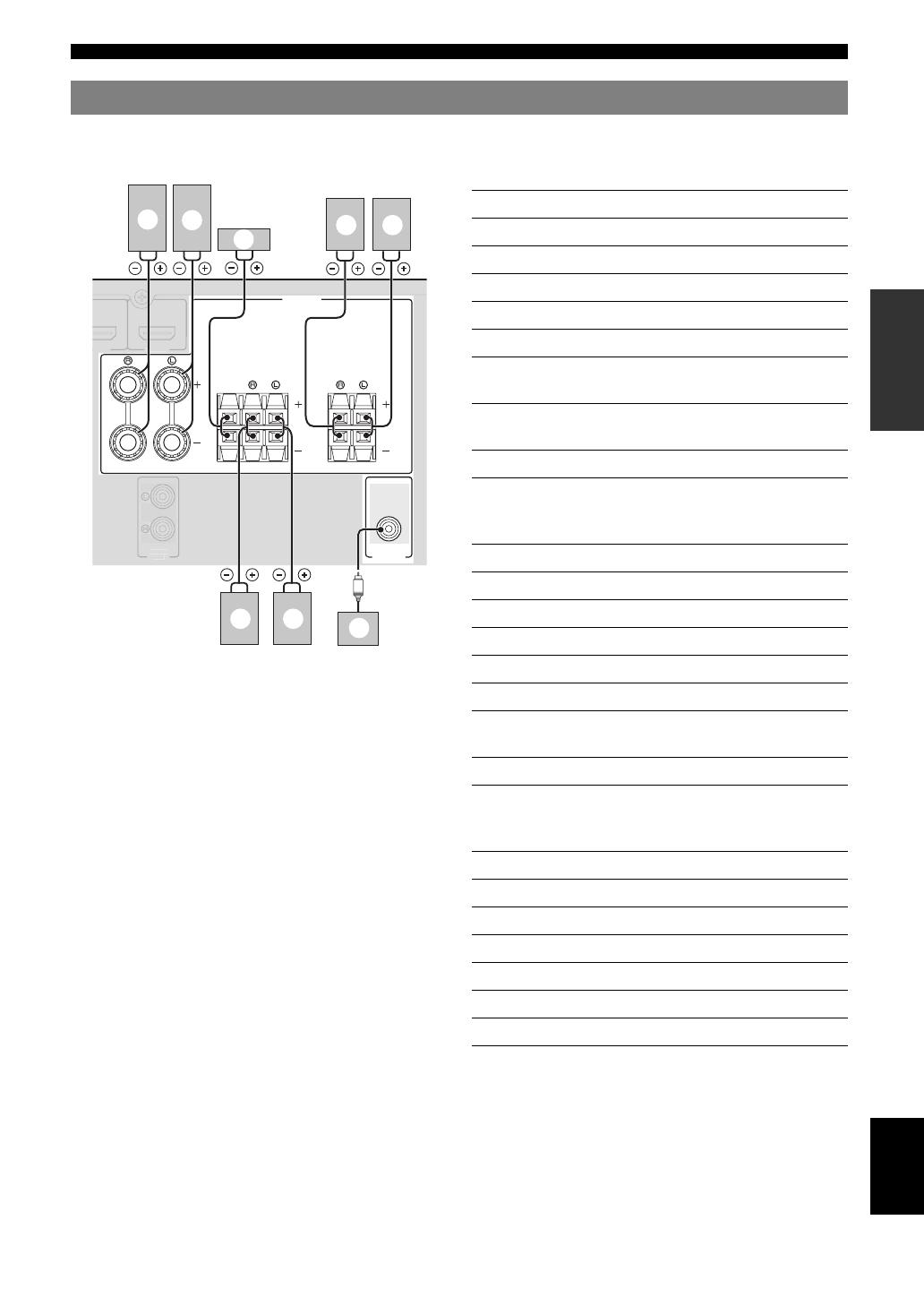
When you connect speakers, connect them to the respective terminals as follows, according to your speaker layout.
■ 7.1-channel
■ 6.1-channel
■ 5.1-channel
Connecting speakers
SPEAKERS
FRONT
CENTER
SURROUND
PRE OUT
SUBWOOFER
BACK/
BI-AMP
SURROUND
DI
e d
b
a
c
g f
h
Speakers Jacks on this unit
a Front speaker L FRONT (L)
b Front speaker R FRONT (R)
c Center speaker CENTER
d Surround speaker L SURROUND (L)
e Surround speaker R SURROUND (R)
f Surround back speaker L SURROUND
BACK/BI-AMP (L)
g Surround back speaker R SURROUND
BACK/BI-AMP (R)
h Subwoofer SUB WOOFER
Speakers Jacks on this unit
a Front speaker L FRONT (L)
b Front speaker R FRONT (R)
c Center speaker CENTER
d Surround speaker L SURROUND (L)
e Surround speaker R SURROUND (R)
f Surround back speaker SURROUND
BACK/BI-AMP (L)
h Subwoofer SUB WOOFER
Speakers Jacks on this unit
a Front speaker L FRONT (L)
b Front speaker R FRONT (R)
c Center speaker CENTER
d Surround speaker L SURROUND (L)
e Surround speaker R SURROUND (R)
h Subwoofer SUB WOOFER
12 En
Connections
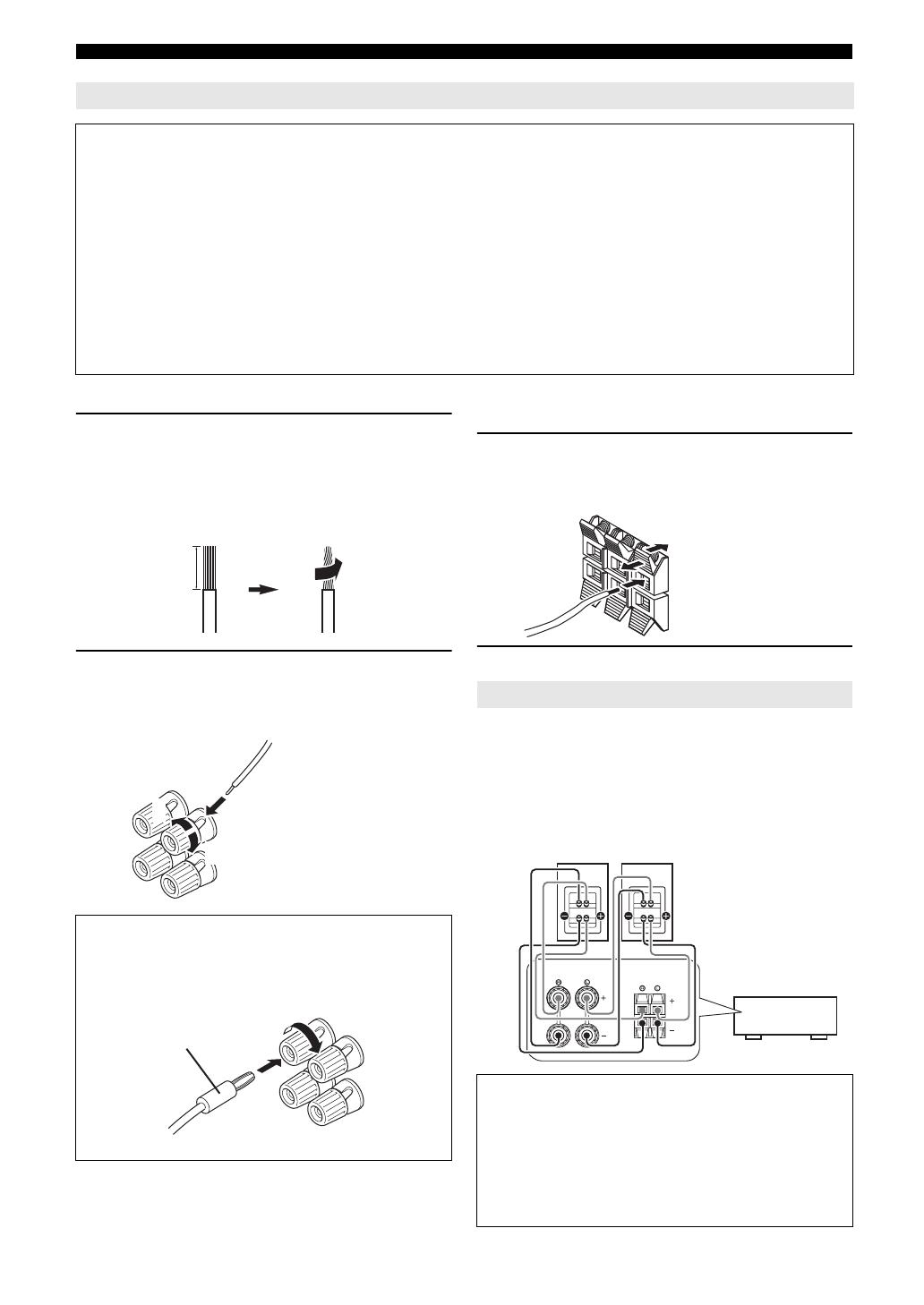
■ Connecting to the FRONT terminals
1 Remove approximately 10 mm (0.4 in) of
insulation from the end of each speaker
cable and then twist bare wires of the cable
together so that they will not cause a short
circuits.
2 Loosen the knob, insert the twisted bare
wires into the hole, and then tighten the
knob.
■ Connecting to the CENTER, SURROUND,
SURROUND BACK/BI-AMP terminals
1 Press down the tab and insert the bare end of
the speaker cable into the hole in the
terminal.
2 Release the tab to secure the wire.
You can connect speakers that support bi-amplification
connections to this unit. Before connecting the speakers,
set this unit to enable bi-amplification connections in
“ADVANCED SETUP” (see page 45), and connect the
speakers to this unit as shown below.
Connecting the speaker cable
Caution
• A speaker cable is a pair of insulated cables running side by side in general. One of the cables is colored differently
or striped to indicate a polarity. Connect one end of the colored/striped cable to the “+” (red) terminal of this unit
and the other end to that of your speaker, and connect one end of the other cable to the “–” (black) terminal of this
unit and the other end to that of your speaker.
• Before connecting the speakers, be sure to disconnect the power cable.
• Do not let the bare speaker wires touch each other or any metal part of this unit. This could damage this unit and/or
speakers. If the circuit shorts out, “CHECK SP WIRES!” appears on the front panel display when this unit is turned on.
• Use magnetically shielded speakers. If images on the monitor are still distorted even when you use the magnetically
shielded speakers, place the speakers away from the monitor.
• Use speakers with an impedance of 6-ohm or larger. Set speaker impedance in “ADVANCED SETUP” before
connecting the speakers (see page 45).
Connecting the banana plug (Except U.K.,
Europe, Asia and Korea models)
Tighten the knob, and then insert the banana plug into
the end of the terminal.
10 mm (0.4 in)
1
2
3
Red: positive (+)
Black: negative (–)
Banana plug
Using bi-amplification connections
Caution
Before making bi-amplification connections, remove
any or cables that connect a woofer with a tweeter.
Refer to the instruction manuals of speakers for details.
When not making bi-amplification connections, make
sure that the brackets or cables are connected before
connecting the speaker cables.
Red: positive (+)
Black: negative (–)
FRONT
BACK/
BI-AMP
SURROUND
Front speakers
Right Left
This unit
13 En
Connections
English
INTRODUCTION
ADDITIONAL
INFORMATION APPENDIX
PREPARATION
BASIC
OPERATION
ADVANCED
OPERATION
This unit has the following input and output jacks. Use jacks and cables appropriate for components that you are
connecting.
■ Audio jacks
■ Video jacks
■ Video/audio jacks
y
• We recommend that you use a commercially available 19-pin HDMI
cable no longer than 5 meters (16 feet) with the HDMI logo printed on it.
• You can check the potential problem about the HDMI connection (see
page 23).
• You can check error information on HDMI connections (see page 23).
Information on jacks and cable plugs
Jack and cables Description
AUDIO jacks To transmit conventional analog
left and right audio signals. Use
stereo pin cables. Connect red
plugs to red jacks (R) and white
plugs to white jacks (L).
COAXIAL jacks To transmit coaxial digital audio
signals. Use pin cables for digital
audio signals.
OPTICAL jacks To transmit optical digital audio
signals. Use optical fiber cables for
optical digital audio signals.
Jack and cables Description
VIDEO jacks To transmit conventional
composite video signals. Use video
pin cables.
COMPONENT VIDEO
jacks
To transmit component video
signals that include luminance (Y),
chrominance blue (PB) and
chrominance red (PR) components.
Use component video cables.
AUDIO
L
R
(white)
(red)
COAXIAL
C
(orange)
OPTICAL
O
VIDEO
V
(yellow)
PR
PB
Y
COMPONENT
VIDEO
P
B
Y
P
R
(red)
(blue)
(green)
Jack and cables Description
HDMI jacks To transmit digital video and
digital audio signals. Use HDMI
cables.
A video signal input to this unit is output from the
output terminals in MONITOR OUT for the same kind
of signal as the input signal.
For example, if a VCR with a composite output signal
and a DVD player with a COMPONENT VIDEO
output signal are connected, connect both VIDEO jack
and COMPONENT VIDEO jack in MONITOR OUT
to the video monitor.
If an HDMI input compatible monitor is connected, this
unit automatically converts an analog signal that is
input from a video input terminal to a digital video
signal, and then output it from the HDMI OUT jack.
HDMI
HDMI
HDMI
VIDEO
COMPONENT
VIDEO
Y
PB
PR
HDMI
VIDEO
COMPONENT
VIDEO
Y
PB
PR
Input Output
Repeat Converted
14 En
Connections
Connect a video monitor such as a TV or projector to an output terminal of this unit. You can select one of the following
three types according to the input signal format supported by the video monitor.
Note
• When you connect this unit to the video monitor, make sure that this unit is on standby.
■ To connect an HDMI video monitor
■ To connect component video monitor
Note
• Only video signals input from this unit via the component input terminal
are output from the component output terminal.
■ To connect composite video monitor
Note
• Only video signals input from this unit via the composite video input
terminal are output from the composite video output terminal.
To output sound of a TV from this unit, make connection
between the AV input 1-6 and an audio output terminal.
If the TV supports an optical digital output, we
recommend that you use the AV input 1. Connecting to the
AV input 1 allows you to switch an input source to the AV
input 1 with just a single key operation using the SCENE
function (see page 21).
Connecting a TV monitor or projector
Jacks on components Jacks on this unit
a HDMI input HDMI OUT
Jacks on components Jacks on this unit
b Component video output MONITOR OUT
(COMPONENT VIDEO)
Jacks on components Jacks on this unit
c Video input (composite) MONITOR OUT (VIDEO)
P
R
P
B
Y
COMPONENT
VIDEO
HDMI
OUT
VIDEO
MONITOR OUT
NBAL.
N
BD
DVD
HDMI 2 H
HDMI
V
a
c
b
P
B
YP
R
TV, or projector
Outputting sound of a TV from this unit
O
Digital output
(optical)
TV, or projector
15 En
Connections
English
INTRODUCTION
ADDITIONAL
INFORMATION APPENDIX
PREPARATION
BASIC
OPERATION
ADVANCED
OPERATION
This unit has input and output terminals for respective input and output sources. You can reproduce sound and movies
from input sources selected with the front panel display or remote control.
Note
• When you connect this unit to the external components, make sure that this unit is on standby.
■ Audio and video player / Set-top box
y
• Input sources in parentheses are recommended to connect to the respective jacks. If your Yamaha component has the Remote in/out terminal, you can
switch the input source to that component with a single key operation using the SCENE function (see page 21).
• You can change the name of the input source displayed on the front panel display or the OSD on the video monitor as necessary (see page 43).
Connecting other components
Output jacks on the connected external component
Input sources/jacks of this unit
External
components
Signals Output jacks
External component
with HDMI output
Audio/Video HDMI output HDMI 1 (BD/DVD) HDMI 1
HDMI 2 HDMI 2
HDMI 3 HDMI 3
HDMI 4 HDMI 4
External component
with component video
output
Audio Optical digital output AV 1 (TV) OPTICAL
Video Component video COMPONENT VIDEO
Audio Coaxial digital output AV 2 COAXIAL
Video Component video output COMPONENT VIDEO
External component
with composite video
output
Audio Coaxial digital output AV 3 (CD) COAXIAL
Video Composite output VIDEO
Audio Optical digital output AV 4 OPTICAL
Video Composite output VIDEO
Audio Analog audio output AV 5 AUDIO
Video Composite output VIDEO
Audio Analog audio output AV 6 AUDIO
Video Composite output VIDEO
VIDEO
P
R
P
B
Y
OPTICAL
(
TV
)
A
V
1
AV 2
COAXIAL
AV 3
(
CD
)
COAXIAL
OPTICAL
AV 4
AV 5
AV
OUT
AUDIO1
AUDIO2
VIDEO
HDMI 1
(
BD/DVD
)
HDMI 2 HDMI 3
HDMI 4
AV 6
AUDIO
OUT
COMPONENT
NBAL.
N
P
COMPONEN
IDE
K
DM
UT
VIDE
FR
N
Audio / video input (AV 1-6) Audio / video output (AV OUT)
Audio input (AUDIO 1-2)
HDMI input
(HDMI 1-4)
Audio output
(AUDIO OUT)
16 En
Connections
■ Audio player
y
• We recommend connecting the coaxial digital output terminal of a CD player to the AV3 jack.
This unit has the DOCK jack, to which you can connect a
Yamaha iPod universal dock (YDS-11, sold separately) or
a Bluetooth wireless audio receiver (YBA-10, sold
separately). You can play an iPod or a Bluetooth
component with this unit by connecting it to the DOCK
jack.
Use a dedicated cable for connection between the dock/
receiver and this unit.
Use the VIDEO AUX jacks on the front panel to connect a
game console or a video camera to this unit. Be sure to
turn down the volume of this unit and other components
before making connections.
Note
• When external components are connected both the PORTABLE jack and
AUDIO jack, sound input from the PORTABLE jack is output.
Output jacks on the connected external component
Input sources/jacks of this unit
External components Output jacks
External component with optical digital
output
Optical digital output AV 1 (TV) OPTICAL
AV 4 OPTICAL
External component with coaxial digital
output
Coaxial digital output AV 2 COAXIAL
AV 3 (CD) COAXIAL
External component with analog audio
output
Analog audio output AV 5 AUDIO
AV 6 AUDIO
AUDIO 1 AUDIO
AUDIO 2 AUDIO
About audio/video output terminals
Among the analog audio and analog video signals input to this unit via input terminals, the audio/video signals of the
selected input sources are output from the AV OUT jack and AUDIO OUT jack. An HDMI input signal,
COMPONENT VIDEO input signal or digital audio input signal cannot be output.
When using the AV OUT jack: connect an external component to the composite or analog audio terminal.
When using the AUDIO OUT jack: connect an external component to the analog audio terminal.
Connecting a Yamaha iPod universal
dock or Bluetooth™ wireless audio
receiver
.
N
IDE
IDE
MP
NENT
Yamaha iPod universal
dock/Bluetooth wireless
audio receiver
Using the VIDEO AUX jacks on the
front panel
VIDEO
AUDIO
PORTABLE
VIDEO
AUX
RA
TRAI
HT
PTIMIZE
MI
V
L
M
EFFE
l
D/DV
RADI
ENE
RE
ET
UNIN
DIRE
T
R
L
AUDIO
VIDEO
V
L
R
PORTABLE
Game console/Camcorder Music player
Analog audio
output
Analog audio
output
Video output
/
2
En
INTRODUCTION
■ Built-in 7-channel power amplifier
• Minimum RMS Output Power (1 kHz, 0.9% THD, 8
Ω)
• FRONT L/R: 90 W + 90 W
• CENTER: 90 W
• SURROUND L/R: 90 W + 90 W
• SURROUND BACK L/R: 90 W + 90 W
■ Speaker/Preout outputs
• Speaker jacks (7-channel), preout output jacks
(subwoofer)
■ Input/Output terminals
Input terminals
• HDMI input x 4
• Audio/Visual input
[Audio] Digital input (coaxial) x 2, digital input
(optical) x 2, analog input x 2
[Video] Component video x 2, composite video x 4
• Audio input (analog) x 2
• Dock input x 1
• V-AUX input
[Audio] Analog x 1
[Video] Composite video x 1
Output terminals
• Monitor output
[Audio/Video] HDMI x 1
[Video] Component video x 1, Composite video x 1
• Audio/Visual output
[Audio] Analog x 1
[Video] Composite video x 1
• Audio output
Analog x 1
■ Proprietary Yamaha technology for the
creation of sound fields
• CINEMA DSP
• Compressed Music Enhancer mode
• Virtual CINEMA DSP
• SILENT CINEMA
■ Digital audio decoders
• Dolby TrueHD, Dolby Digital Plus decoder
• DTS-HD Master Audio, DTS-HD High Resolution
Audio, DTS Express
• Dolby Digital/Dolby Digital EX decoder
• DTS, DTS 96/24 decoder, DTS-ES Matrix 6.1,
DTS-ES Discrete 6.1
• Dolby Pro Logic/Dolby Pro Logic II/Dolby Pro Logic
IIx decoder
• DTS NEO:6 decoder
■ Sophisticated FM/AM tuner
• 40-station random and direct preset tuning
• Automatic preset tuning
■ HDMI™
(High-Definition Multimedia Interface)
• HDMI interface for standard, enhanced or high-
definition video as well as multi-channel digital audio.
– Automatic audio and video synchronization (lip sync)
information capability
– Deep Color video signal (30/36 bit) transmission
capability
– “x.v.Color” video signal transmission capability
– High refresh rate and high resolution video signals
capability
– High definition digital audio format signals capability
• Analog video to HDMI digital video up-conversion
(composite video
→ HDMI, component video →
HDMI) capability for monitor out
• Analog video input up-scaling for HDMI digital video
output 480i or 480p
→ 720p, 1080i or 1080p
■ DOCK terminal
• DOCK terminal to connect a Yamaha iPod universal
dock (such as YDS-11, sold separately) or Bluetooth
wireless audio receiver (such as YBA-10, sold
separately)
■ Automatic speaker setup features
• “YPAO” (Yamaha Parametric Room Acoustic
Optimizer) for automatically optimizing speaker
outputs suitable for listening environments.
■ Other features
• 192-kHz/24-bit D/A converter
• OSD (on-screen display) menus that allow you to
optimize this unit to suit your individual audiovisual
system
• Direct mode for pure hi-fi sound for all sources
• Adaptive dynamic range controlling capability
• Sleep timer
Features