- Manuals
- Brands
- Yamaha Manuals
- Offroad Vehicle
- RAPTOR 700
- Owner’s manual
-
Contents
-
Table of Contents
-
Troubleshooting
-
Bookmarks
Quick Links
READ THIS MANUAL CAREFULLY!
It contains important safety information.
OWNER’S MANUAL
YFM700RV
w
This ATV should not be ridden by anyone under 16 years of age.
LIT-11626-19-59
1S3-28199-11
Related Manuals for Yamaha RAPTOR 700
Summary of Contents for Yamaha RAPTOR 700
-
Page 1
READ THIS MANUAL CAREFULLY! It contains important safety information. OWNER’S MANUAL YFM700RV This ATV should not be ridden by anyone under 16 years of age. LIT-11626-19-59 1S3-28199-11… -
Page 3
EBU13320 INTRODUCTION Congratulations on your purchase of the Yamaha YFM700R. It represents the result of many years of Yamaha experience in the production of fine sporting, touring, and pacesetting racing machines. With the purchase of this Yamaha, you can now appreciate the high degree of craftsmanship and reliability that have made Yamaha a leader in these fields. -
Page 4
EBU08010 IMPORTANT MANUAL INFORMATION FAILURE TO FOLLOW THE WARNINGS CONTAINED IN THIS MANUAL CAN RESULT IN SERI- OUS INJURY OR DEATH. Particularly important information is distinguished in this manual by the following notations: The Safety Alert Symbol means ATTENTION! BECOME ALERT! YOUR SAFETY IS INVOLVED! Failure to follow WARNING instructions could result in severe injury or death to the machine operator, a bystander or a person inspecting or repairing the… -
Page 5
Please check your local riding laws and regulations before operating this ATV. EBU13330 YFM700RV OWNER’S MANUAL ©2005 by Yamaha Motor Corporation, AFFIX DEALER U.S.A. LABEL HERE 1st edition, June 2005 All rights reserved. -
Page 6: Table Of Contents
EBU00140 CONTROL FUNCTIONS …… 4-1 Indicates a potential hazard that could result Main switch ……… 4-1 in serious injury or death. Indicator and warning lights ….4-2 Handlebar switches ……4-4 Throttle lever ……..4-6 CONTENTS Speed limiter ……..4-7 Clutch lever ……..
-
Page 7
Engine break-in ……..6-7 PRE-OPERATION CHECKS ….5-1 Parking ……….6-8 Front and rear brakes ……5-3 Parking on a slope ……6-8 Fuel ………… 5-4 Accessories and loading ….6-10 Engine oil ……….5-6 Coolant ……….5-6 RIDING YOUR ATV ……7-1 Chain ………. -
Page 8
PERIODIC MAINTENANCE AND Parking brake ad justment ….8-33 ADJUSTMENT ……..8-1 Adjusting the rear brake light switch ..8-35 Owner’s manual and tool kit ….8-1 Clutch lever free play adjustment ..8-36 Drive chain slack check ….8-38 Periodic maintenance chart for the emission control system …. -
Page 9
CLEANING AND STORAGE ….9-1 A. CLEANING ……..9-1 B. STORAGE ……..9-3 SPECIFICATIONS ……10-1 NOISE REGULATION ……11-1 MAINTENANCE RECORD ….12-1 ATV LIMITED WARRANTY ….13-1 YAMAHA EXTENDED SERVICE (Y.E.S.) ……….14-1… -
Page 10: Location Of The Warning And Specification Labels
EBU04640 LOCATION OF THE WARNING AND SPECIFICATION LABELS…
-
Page 11
They contain important information for safe and proper operation of your ATV. Never remove any labels from your ATV. If a label becomes difficult to read or comes off, a replacement label is available from your Yamaha dealer. 5FE-21697-01 5FE-21568-01… -
Page 12
WARNING NEVER ride as a passenger. Passengers can cause a loss of control, resulting in SEVERE INJURY or DEATH. 5FE-2151H-01 5FE-2151H-40… -
Page 13: Safety Information
EBU15760 SAFETY INFORMATION AN ATV IS NOT A TOY AND CAN BE HAZARDOUS TO OPERATE. An ATV handles differently from other vehicles including motorcycles and cars. A collision or rollover can occur quickly, even during routine maneuvers such as turning and riding on hills or over obstacles, if you fail to take proper precautions.
-
Page 14
8 Always avoid operating an ATV on any paved surfaces, including sidewalks, driveways, parking lots and streets. 8 Never operate an ATV on any public street, road or highway, even a dirt or gravel one. 8 Never operate an ATV without wearing an approved motorcycle helmet that fits properly. You should also wear eye protection (goggles or face shield), gloves, boots, a long-sleeved shirt or jack- et, and long pants. -
Page 15
8 Always follow proper procedures for turning as described in this manual. Practice turning at low speeds before attempting to turn at faster speeds. Do not turn at excessive speed. 8 Never operate the ATV on hills too steep for the ATV or for your abilities. Practice on smaller hills before attempting larger hills. -
Page 16
8 Always use proper procedures if you stall or roll backwards when climbing a hill. To avoid stalling, use the proper gear and maintain a steady speed when climbing a hill. If you stall or roll backwards, follow the special procedure for braking described in this manual. Dismount on the uphill side or to a side if pointed straight uphill. -
Page 17
8 Always use the size and type of tires specified in this manual. 8 Always maintain proper tire pressure as described in this manual. 8 Never modify an ATV through improper installation or use of accessories. 8 Never exceed the stated load capacity for an ATV. Cargo should be properly distributed and securely attached. -
Page 18
q WARNING When transporting the ATV in another vehicle, be sure it is kept upright. POTENTIAL HAZARD Otherwise, fuel may leak out of the fuel Improper handling of gasoline. tank. WHAT CAN HAPPEN WHAT CAN HAPPEN Gasoline can catch fire and you could be Gasoline is poisonous and can cause burned. -
Page 19
q WARNING POTENTIAL HAZARD Starting or running the engine in a closed area. WHAT CAN HAPPEN Exhaust fumes are poisonous and may cause loss of consciousness and death within a short time. HOW TO AVOID THE HAZARD Always operate your ATV in an area with adequate ventilation. -
Page 20: Description And Machine Identification
EBU00320 DESCRIPTION AND MACHINE IDENTIFICATION 1. Spark arrester 10. Clutch lever 2. Seat 11. Parking brake lever 3. Headlight 12. Main switch 4. Brake pedal 13. Brake lever 5. Engine oil tank 14. Throttle lever 6. Coolant reservoir 15. Reverse knob 7.
-
Page 21: Identification Number Records
This tion in the spaces provided for assistance when number can be used for ordering a new key. ordering spare parts from a Yamaha dealer or for reference in case the vehicle is stolen. 1. KEY IDENTIFICATION NUMBER: 2.
-
Page 22: Vehicle Identification Number
The model label is affixed to the location in the into the frame. illustration. Record the information on this label in the space provided. This information will be needed to order spare parts from your Yamaha dealer. 1. Vehicle identification number NOTE: The vehicle identification number is used to 1.
-
Page 23: Control Functions
EBU00390 CONTROL FUNCTIONS Indicates a potential hazard that could result in serious injury or death. EBU09420 Main switch Functions of the respective switch positions are as follows: The engine can be started only at this position and the headlights and taillight come on when the light switch is on.
-
Page 24: Indicator And Warning Lights
The electrical circuit of the warning light can be checked by turning the key to “ON”. If the warn- ing light does not come on, and then go off, have a Yamaha dealer check the electrical cir- 1. Neutral indicator light “N” 2. Reverse indicator light “R”…
-
Page 25
“RUN” and turning the key to “ON”. have a Yamaha dealer check the electrical cir- If the warning light does not come on, and then cuit. go off, have a Yamaha dealer check the electri- cal circuit. -
Page 26: Handlebar Switches
EBU00530 EBU11560 Handlebar switches Light switch “LIGHTS” Set the switch to the “LO” position to turn on the low beam and the taillight. Set the switch to the “HI” position to turn on the high beam and the taillight. Set the switch to the “OFF” position to turn off all of the lights.
-
Page 27
EBU11580 EBU06470 Engine stop switch “ENG. STOP” Start switch “START” Make sure that the engine stop switch is in the The starter motor cranks the engine when this “RUN” position before starting the engine. The switch is pushed. engine stop switch controls ignition and can be used at all times to stop the engine, especially in See the starting instructions on page an emergency. -
Page 28: Throttle Lever
Check the operation of the throttle lever before you start the engine. If it does not 1. Throttle lever work smoothly, check for the cause. Correct the problem before riding the ATV. Consult a Yamaha dealer if you canít find or solve the problem yourself.
-
Page 29: Speed Limiter
EBU11590 q WARNING Speed limiter The speed limiter keeps the throttle from fully POTENTIAL HAZARD opening, even when the throttle lever is pushed Improper adjustment of the speed limiter to the maximum. Turning in the adjusting screw and throttle. limits the maximum engine power available and WHAT CAN HAPPEN decreases the maximum speed of the ATV.
-
Page 30: Clutch Lever
EBU00690 EBU09880 Clutch lever Brake lever The clutch lever is located on the left handlebar The brake lever is located on the right handle- and the ignition circuit cut-off system is incorpo- bar. Pull it toward the handlebar to apply the rated in the clutch lever holder.
-
Page 31: Brake Pedal
EBU09890 Brake pedal The brake pedal is located on the right side of the machine. Push down on the pedal to apply the rear brake. 1. Brake pedal…
-
Page 32: Parking Brake Lever
EBU13870 Parking brake lever Use the parking brake when you have to start the engine or park the machine, especially on a slope. To apply the parking brake, move the parking brake lever in direction a. To release the parking brake, move the parking brake lever in direction b.
-
Page 33: Shift Pedal
EBU07880 q WARNING Shift pedal This machine is equipped with a constant-mesh POTENTIAL HAZARD 5-speed forward and 1-speed reverse transmis- Improper use of the parking brake. sion. The shift pedal is located on the left side of WHAT CAN HAPPEN the engine and is used in combination with the clutch when shifting.
-
Page 34: Reverse Knob
EBU10280 EBU00920 Reverse knob “REV” Fuel tank cap The reverse knob is used to shift into reverse Remove the fuel tank cap by turning it counter- gear. clockwise. Refer to the “Reverse knob operation and reverse driving” section (page 6-3) before oper- ating this machine in reverse gear.
-
Page 35: Seat
EBU16020 Seat To install the seat, insert the projections on the To remove the seat, insert your hand between front of the seat into the seat holders and push the rear of the seat and the rear fender, pull the down on the seat at the rear.
-
Page 36: Front Shock Absorber Adjustment
EBU11040 NOTE: Front shock absorber adjustment A special wrench can be obtained at a Yamaha The spring preload can be adjusted to suit the dealer to make this adjustment. rider’s weight and riding conditions. Adjust the spring preload as follows.
-
Page 37
q WARNING POTENTIAL HAZARD Improper shock absorber adjustment. WHAT CAN HAPPEN Uneven adjustment can cause poor han- dling and loss of stability, which could lead to an accident. HOW TO AVOID THE HAZARD Always adjust the shock absorbers on the left and right side to the same setting. -
Page 38: Adjusting The Rear Shock Absorber
8 Do not dispose of a damaged or worn absorber can be adjusted to suit the rider’s out shock absorber yourself. Take the weight and the riding conditions. unit to a Yamaha dealer. q WARNING Adjust the spring preload as follows. POTENTIAL HAZARD 1.
-
Page 39
NOTE: 4. Tighten the locknut to the specified torque. A special wrench can be obtained at a Yamaha dealer to make this adjustment. Tightening torque: 42 Nm (4.2 m0kgf, 30 ft0lbf) 3. The length of the spring (installed) changes 1.5 mm (0.06 in) per turn of the adjusting nut. -
Page 40
Adjust the rebound damping force as follows. Adjust the compression damping force as fol- Turn the rebound damping force adjusting screw lows. in direction a to increase the rebound damping Turn the compression damping force adjusting force and in direction b to decrease the screw in direction a to increase the compres- sion damping force and in direction b to rebound damping force. -
Page 41
q WARNING Never turn an adjusting mechanism beyond POTENTIAL HAZARD the minimum and maximum settings. Suspension components become hot dur- ing operation. NOTE: WHAT CAN HAPPEN Although the total number of clicks of a damping You could be burned. force adjusting mechanism may not exactly HOW TO AVOID THE HAZARD match the above specifications due to small dif- Never touch the compression damping… -
Page 42: Pre-Operation Checks
PRE-OPERATION CHECKS Before using this machine, check the following points: ITEM ROUTINE PAGE 9 Check operation, free play, fluid level and fluid leakage. 5-3–5-4 Front brake 9 Fill with DOT 4 brake fluid if necessary. 8-27–8-32 9 Check operation, free play, fluid level and fluid leakage. 5-3–5-4 Rear brake 9 Fill with DOT 4 brake fluid if necessary.
-
Page 43
q WARNING POTENTIAL HAZARD Failure to inspect the ATV before operat- ing. Failure to properly maintain the ATV. WHAT CAN HAPPEN Increases the possibility of an accident or equipment damage. HOW TO AVOID THE HAZARD Always inspect your ATV each time you use it to make sure the ATV is in safe operating condition. -
Page 44: Front And Rear Brakes
8 Check that there is no free play in the brake the pipe joints or brake fluid reservoirs. Apply lever. If there is free play, have a Yamaha the brakes firmly for one minute. If there is any dealer inspect the brake system.
-
Page 45: Fuel
Yamaha dealer check for the cause. ton rings, as well as to the exhaust system. Your Yamaha engine has been designed to use regular unleaded gasoline with a pump octane number ([R+M]/2) of 86 or higher, or research octane number of 91 or higher.
-
Page 46
10%. Gasohol containing methanol is not recommended by Fuel can spill, which can cause a fire and Yamaha because it may cause fuel system severe injury. damage or vehicle performance problems. Fuel expands when it heats up. If the fuel tank is overfilled, fuel could spill out due to heat from the engine or the sun. -
Page 47: Engine Oil
EBU10842 EBU12530 Engine oil Coolant Make sure the engine oil is at the specified level. Check the coolant level in the coolant reservoir Add oil as necessary. (See page 8-8.) when the engine is cold. (The coolant level will vary with engine temperature.) The coolant level is satisfactory if it is between the minimum and maximum level marks on the coolant reservoir.
-
Page 48: Chain
Check to see that the throttle lever operates cor- rectly. It must open smoothly and spring back to HOW TO AVOID THE HAZARD the idle position when released. Have a Yamaha Wait for the engine to cool before remov- dealer repair as necessary for proper operation.
-
Page 49: Tires
HOW TO AVOID THE HAZARD The following are minimums: 1. The tires listed below have been Front 24.5 kPa (0.245 kgf/cm , 3.5 psi) approved by Yamaha Motor Co., Ltd. Rear 24.5 kPa (0.245 kgf/cm , 3.5 psi) for this model. Other tire combinations 4.
-
Page 50: How To Measure Tire Pressure
EBU01590 How to measure tire pressure Use the low-pressure tire gauge. NOTE: The low-pressure tire gauge is included as stan- dard equipment. Make two measurements of the tire pressure and use the second reading. Dust or dirt in the gauge could cause the first reading to be incorrect.
-
Page 51: Tire Wear Limit
When the tire groove decreases to 3 mm (0.12 and fasteners before a ride. Take the machine in) due to wear, replace the tire. to a Yamaha dealer or refer to the Service Manual for correct tightening torque. EBU10030 Lights Check the headlights and tail/brake light to make sure they are in working condition.
-
Page 52: Operation
HOW TO AVOID THE HAZARD Read the Ownerís Manual carefully. If 1. Set the parking brake. there is a control or function you do not 2. Turn the main switch to “ON” and the engine understand, ask your Yamaha dealer. stop switch to “RUN”.
-
Page 53
5. Continue warming up the engine until it idles The neutral indicator light should come on. If smoothly. the light does not come on, ask a Yamaha dealer to inspect it. See the “Engine break-in” section prior to operating engine for the first time. -
Page 54: Reverse Knob Operation And Reverse Driving
If the light does not come on, ask 3. Apply the clutch lever and shift the transmis- a Yamaha dealer to inspect the machine. sion into reverse by pressing down on the shift pedal.
-
Page 55: Shifting
EBU11730 q WARNING Shifting This model has a 5-speed forward and 1-speed POTENTIAL HAZARD reverse transmission. The transmission allows Improperly operating in reverse. you to control the amount of power you have WHAT CAN HAPPEN available at a given speed or for starting, accel- erating, climbing hills, etc.
-
Page 56: To Start Out And Accelerate
EBU02030 To start out and accelerate: 1. Release the throttle lever. 8 Do not coast for long periods with the engine off, and do not tow the machine a long distance. Even in neutral position, the Always close the throttle while shifting transmission is only properly lubricated gears.
-
Page 57: To Decelerate
EBU02070 q WARNING To decelerate: When slowing down or stopping, release the POTENTIAL HAZARD throttle and apply the brakes smoothly and Opening the throttle abruptly or releasing evenly. As you slow down, shift to a lower gear. Be sure that the engine has sufficiently slowed the clutch lever too quickly.
-
Page 58: Engine Break-In
20 hours. If any abnormality is noticed during this period, For this reason, we ask that you carefully read consult a Yamaha dealer. the following material. Because the engine is brand new, you must not put an excessive load 0-10 hours: on it for the first several hours of running.
-
Page 59: Parking
EBU15970 EBU14200 Parking Parking on a slope When parking, stop the engine, shift into first q WARNING gear, and then apply the parking brake. POTENTIAL HAZARD Parking on a hill or other incline. WHAT CAN HAPPEN The ATV could roll out of control, increas- ing the chance of an accident.
-
Page 60
1. Bring the machine to a stop by applying the front brake. 2. With the front and rear brake applied, pull the clutch lever, shift into the neutral posi- tion, and then apply the parking brake. 3. Stop the engine by setting the engine stop switch to “OFF”. -
Page 61: Accessories And Loading
Yamaha accessories. Other acces- than it does without accessories. sories may also be available on the market. However, it is not possible for Yamaha to test all non-Yamaha accessories, nor have any control over the quality or suitability of them.
-
Page 62
EBU05840 8 Tie down cargo securely to the carriers. Make Loading As originally equipped, this ATV is not designed sure cargo in the trailer cannot move around. to carry cargo or tow a trailer. If you choose to A shifting load can cause an accident. 8 Make sure the load does not interfere with add accessories so that you can carry cargo or tow a trailer, you must use common sense and… -
Page 63
q WARNING POTENTIAL HAZARD Overloading this ATV or carrying or tow- ing cargo improperly. WHAT CAN HAPPEN Could cause changes in vehicle handling which could lead to an accident. HOW TO AVOID THE HAZARD Never exceed the stated load capacity for this ATV. -
Page 64
EBU13552 Indicates a potential hazard that could result in serious injury or death. 6-13… -
Page 65: Riding Your Atv
Riding Your…
-
Page 66: Getting To Know Your Atv
Indicates a potential hazard that could result in serious injury or death. GETTING TO KNOW YOUR ATV controls. Pay particular attention to the safety This ATV is intended for recreational use by information on pages 2-1–2-7. Please also read experienced operators only. all caution and warning labels on your ATV.
-
Page 67: Ride With Care And Good Judgement
Get training if you are inexperienced. should complete the certified training Beginners should get training from a certified course offered by Yamaha. They should instructor. then regularly practice the skills learned in Become familiar with this ATV at slow speeds the course and the operating techniques first, even if you are an experienced operator.
-
Page 68
Not recommended for children under 16 years of age. q WARNING POTENTIAL HAZARD Failure to follow the age recommendations for this ATV. WHAT CAN HAPPEN Use by children of ATVs that are not rec- ommended for their age can lead to severe injury or death of the child. -
Page 69
This ATV is designed to carry operator only — passengers prohibited. q WARNING POTENTIAL HAZARD Carrying a passenger on this ATV. WHAT CAN HAPPEN Greatly reduces your ability to balance and control this ATV. Could cause an acci- dent, resulting in harm to you and/or your passenger. -
Page 70
Apparel Operating without protective clothing q WARNING increases your chances of severe injury in the event of an accident. POTENTIAL HAZARD HOW TO AVOID THE HAZARD Operating this ATV without wearing an Always wear an approved motorcycle hel- approved motorcycle helmet, eye protec- met that fits properly. -
Page 71
Do not operate after consuming alcohol or q WARNING drugs. POTENTIAL HAZARD Operator’s performance capability is reduced by the influence of alcohol or drugs. Operating this ATV after consuming alco- hol or drugs. WHAT CAN HAPPEN Could seriously affect your judgment. Could cause you to react more slowly. -
Page 72
Pre-operation checks q WARNING Always perform the pre-operation checks listed POTENTIAL HAZARD on page 5-1 before riding for safety and proper care of the ATV. Operating this ATV with improper tires, or with improper or uneven tire pressure. q WARNING WHAT CAN HAPPEN Use of improper tires on this ATV, or oper- POTENTIAL HAZARD… -
Page 73
Speed limiter For riders inexperienced with this model, this Indicates a potential hazard that could result model is equipped with a speed limiter in the in serious injury or death. throttle lever housing. The speed limiter limits the power and top speed of the ATV. Turning Do not operate at speeds too fast for your the adjusting screw in decreases the top speed, skills or the conditions. -
Page 74
Loading and accessories q WARNING As originally equipped, this ATV is not designed POTENTIAL HAZARD to carry cargo or tow a trailer. If you choose to add accessories so that you can carry cargo or Overloading this ATV or carrying or tow- tow a trailer, you must use common sense and ing cargo improperly. -
Page 75
During operation q WARNING Always keep your feet on the footboards during POTENTIAL HAZARD operation. Otherwise your feet may contact the rear wheels. Removing hands from handlebars or feet from footboards during operation. WHAT CAN HAPPEN Removing even one hand or foot can reduce your ability to control the ATV or could cause you to lose your balance and fall off of the ATV. -
Page 76
Avoid wheelies and jumping. You may lose con- trol of the ATV or overturn. q WARNING POTENTIAL HAZARD Attempting wheelies, jumps, and other stunts. WHAT CAN HAPPEN Increases the chance of an accident, including an overturn. HOW TO AVOID THE HAZARD Never attempt stunts, such as wheelies or jumps. -
Page 77
Never modify this ATV through improper installation or use of accessories. All parts and accessories added to this vehicle should be genuine Yamaha or equivalent components designed for use on this ATV and should be installed and used accord- ing to instructions. If you have questions, consult an authorized ATV dealer. -
Page 78
Exhaust system HOW TO AVOID THE HAZARD The exhaust system on the ATV is very hot dur- Do not operate, idle, or park the ATV in dry ing and following operation. To prevent burns, grass or other dry ground cover. avoid touching the exhaust system. -
Page 79: Be Careful Where You Ride
BE CAREFUL WHERE YOU RIDE This ATV is designed for off-road use only. Riding on paved surfaces can cause loss of con- trol. q WARNING POTENTIAL HAZARD Operating this ATV on paved surfaces. WHAT CAN HAPPEN ATVs are designed for off-road use only. Paved surfaces may seriously affect han- dling and control of the ATV, and may cause the vehicle to go out of control.
-
Page 80
Do not ride on any public road, street, or high- way. Riding on public roads can result in collisions with other vehicles. q WARNING POTENTIAL HAZARD Operating this ATV on public streets, roads or highways. WHAT CAN HAPPEN You can collide with another vehicle. HOW TO AVOID THE HAZARD Never operate this ATV on any public street, road or highway, even a dirt or… -
Page 81
Know the terrain where you ride. Ride cautiously in unfamiliar areas. Stay alert for holes, rocks, or roots in the terrain, and other hidden haz- ards which may cause the ATV to upset. q WARNING POTENTIAL HAZARD Failure to use extra care when operating this ATV on unfamiliar terrain. -
Page 82
q WARNING POTENTIAL HAZARD Failure to use extra care when operating on excessively rough, slippery or loose terrain. WHAT CAN HAPPEN Could cause loss of traction or vehicle control, which could result in an accident, including an overturn. HOW TO AVOID THE HAZARD Do not operate on excessively rough, slip- pery or loose terrain until you have learned and practiced the skills necessary… -
Page 83
When riding in an area where you might not WHAT CAN HAPPEN easily be seen, such as desert terrain, mount a You could be in a collision. You could be caution flag on the ATV. DO NOT use the flag injured. -
Page 84
Select a large, flat area off-road to become With the engine idling, pull the clutch lever to familiar with your ATV. Make sure that this area disengage the clutch and shift into 1st gear, and is free of obstacles and other riders. You should then release the parking brake. -
Page 85
q WARNING When slowing down or stopping, release the throttle and apply the brakes smoothly and POTENTIAL HAZARD evenly. As you slow down, shift to a lower gear. Opening the throttle abruptly or releasing Be sure that the engine has sufficiently slowed the clutch lever too quickly. -
Page 86: Turning Your Atv
TURNING YOUR ATV HOW TO AVOID THE HAZARD To achieve maximum traction while riding off- Always follow proper procedures for turn- road, the two rear wheels are mounted solidly ing as described in this Owner’s Manual. on one axle and turn together at the same Practice turning at low speeds before speed.
-
Page 87
Once you have learned this technique you should be able to perform it at higher speeds or in tighter curves. Improper riding procedures such as abrupt throt- tle changes, excessive braking, incorrect body movements, or too much speed for the sharp- ness of the turn may cause the ATV to tip. -
Page 88: Climbing Uphill
CLIMBING UPHILL HOW TO AVOID THE HAZARD Use proper riding techniques to avoid vehicle Never operate the ATV on hills too steep overturns on hills. Be sure that you can maneu- for the ATV or for your abilities. ver your ATV well on flat ground before attempt- Practice on smaller hills before attempting ing any incline and then practice riding first on large hills.
-
Page 89
q WARNING Never go over the top of any hill at high speed. POTENTIAL HAZARD An obstacle, a sharp drop, or another Climbing hills improperly. vehicle or person could be on the other WHAT CAN HAPPEN side of the hill. Could cause loss of control or cause the ATV to overturn. -
Page 90
If you are climbing a hill and you find that you When crossing the side of a hill: have not properly judged your ability to make it Always follow proper procedures as to the top, you should turn the ATV around while described in the Owner’s Manual. -
Page 91
If your ATV has stalled or stopped and you q WARNING believe you can continue up the hill, restart care- POTENTIAL HAZARD fully to make sure you do not lift the front wheels Stalling, rolling backwards or improperly which could cause you to lose control. If you are dismounting while climbing a hill. -
Page 92
When fully stopped, apply the rear brake as well, and then lock the parking brake. Dismount on uphill side or to a side if pointed straight uphill. Turn the ATV around and remount, following the proce- dure described in the Owner’s Manual. 7-29… -
Page 93: Riding Downhill
RIDING DOWNHILL q WARNING When riding your ATV downhill, shift your weight POTENTIAL HAZARD as far to the rear and uphill side of the ATV as possible. Move back on the seat and sit with Going down a hill improperly. your arms straight.
-
Page 94
7-31… -
Page 95: Crossing A Slope
CROSSING A SLOPE q WARNING Traversing a sloping surface on your ATV POTENTIAL HAZARD requires you to properly position your weight to maintain proper balance. Be sure that you have Improperly crossing hills or turning on learned the basic riding skills on flat ground hills.
-
Page 96
Shift your weight to the uphill side of the ATV. 7-33… -
Page 97: Crossing Through Shallow Water
CROSSING THROUGH SHALLOW WATER Remember that wet brakes may have The ATV can be used to cross slow moving, reduced stopping ability. Test your brakes shallow water of up to a maximum of 35 cm (14 after leaving water. If necessary, apply inches) in depth.
-
Page 98
Test your brakes after leaving the water. Do not continue to ride your ATV without verifying that After riding your ATV in water, be sure to you have regained proper braking ability. drain the trapped water by removing the check hose at the bottom of the air filter case. -
Page 99: Riding Over Rough Terrain
RIDING OVER ROUGH TERRAIN q WARNING Riding over rough terrain should be done with POTENTIAL HAZARD caution. Look out for obstacles which could cause damage to the ATV or could lead to an Improperly operating over obstacles. upset or accident. Be sure to keep your feet WHAT CAN HAPPEN firmly mounted on the footboards at all times.
-
Page 100
7-37… -
Page 101: Sliding And Skidding
SLIDING AND SKIDDING If the rear wheels of your ATV start to slide side- Care should be used when riding on loose or ways, control can usually be regained (if there is slippery surfaces since the ATV may slide. If room to do so) by steering in the direction of the unexpected and uncorrected, sliding could lead slide.
-
Page 102
With practice, over a period of time, skill at con- q WARNING trolled sliding can be developed. The terrain POTENTIAL HAZARD should be chosen carefully before attempting Skidding or sliding improperly. such maneuvers, since both stability and control are reduced. Bear in mind that sliding maneu- WHAT CAN HAPPEN vers should always be avoided on extremely You may lose control of this ATV. -
Page 103: What To Do If
WHAT TO DO IF … 8 If your ATV starts to slide sideways: This section is designed to be a reference guide Steer in the direction of the slide if you have only. Be sure to read each section on riding the room.
-
Page 104
8 If your ATV is traversing a sloping surface: Be sure to ride with your weight positioned towards the uphill side of the ATV to maintain proper balance. If the ATV starts to tip, steer down the hill (if there are no obstacles in your way) to regain balance. -
Page 105: Periodic Maintenance And Adjustment
Turn off the engine when performing maintenance unless otherwise specified. Periodic inspection, adjustment and lubrication Have a Yamaha dealer perform service if will keep your machine in the safest and most you are not familiar with machine service. efficient condition possible. Safety is an obliga- tion of the machine owner.
-
Page 106
Never modify this ATV through improper during a service operation requiring one, take installation or use of accessories. All parts your machine to a Yamaha dealer to check the and accessories added to this vehicle torque settings and adjust them as necessary. -
Page 107: Periodic Maintenance Chart For The Emission Control System
ATV isn’t used for a long period of time, the month maintenance intervals should be followed. 8 Items marked with an asterisk should be performed by a Yamaha dealer as they require special tools, data and technical skills.
-
Page 108: General Maintenance And Lubrication Chart
EBU15720 General maintenance and lubrication chart INITIAL EVERY month Whichever comes first ITEM ROUTINE 1300 2500 2500 5000 (mi) (200) (800) (1600) (1600) (3200) hours 9 Clean. Every 20–40 hours Air filter element 9 Replace if necessary. (more often in wet or dusty areas) 9 Check operation.
-
Page 109
INITIAL EVERY month Whichever comes first ITEM ROUTINE 1300 2500 2500 5000 (mi) (200) (800) (1600) (1600) (3200) hours 9 Check operation. 9 Repair if damaged. Steering system* 9 Check toe-in. 9 Adjust if necessary. 9 Replace (Warm engine before draining). Engine oil Engine oil filter 9 Replace. -
Page 110
NOTE: 8 Recommended brake fluid: DOT 4 8 Brake fluid replacement: When disassembling the master cylinder or caliper cylinder, replace the brake fluid. Normally check the brake fluid level and add the fluid as required. On the inner parts of the master cylinder and caliper cylinder, replace the oil seals every two years. -
Page 111: Panel Removal And Installation
EBU08070 EBU10130 Panel removal and installation Panel A 1. Panel A 1. Panel A 2. Bolt (× 2) The panel illustrated needs to be removed to To remove perform some of the maintenance described in Remove the bolts, and then take the panel off. this chapter.
-
Page 112: Engine Oil And Oil Filter Element
EBU15912 Engine oil and oil filter element 3. Remove the engine oil tank filler cap, wipe The engine oil level should be checked before the dipstick clean with a clean rag, insert it each ride. In addition, the oil must be changed back into the filler hole (without screwing it and the oil filter element replaced at the intervals in), and then remove it again to check the…
-
Page 113
4. If the engine oil is below the minimum level To change the engine oil (with or without oil mark, add sufficient oil of the recommend- filter element replacement) ed type through the engine oil tank filler 1. Start the engine, warm it up for several hole to raise it to the correct level. -
Page 114
5. Check the washers for damage, and replace if necessary. NOTE: Skip steps 6–9 if the oil filter element is not being replaced. 6. Remove the oil filter element cover by removing the bolts, and then remove the oil filter element. 1. -
Page 115
7. Check the O-rings for damage, and 9. Install the oil filter element cover by replace them if necessary. installing the bolts, and then tighten them to the specified torque. Tightening torque: Oil filter element cover bolt: 10 Nm (1.0 m0kgf, 7.2 ft0lbf) 10. -
Page 116
11. Install the crankcase engine oil filler cap, and then tighten it to the specified torque. 8 In order to prevent clutch slippage (since Tightening torque: the engine oil also lubricates the clutch), Crankcase engine oil filler cap: do not mix any chemical additives. Do not 12 Nm (1.2 m0kgf, 8.7 ft0lbf) use oils with a diesel specification of “CD”… -
Page 117: Cooling System
You may use soft water if you can’t get distilled water. NOTE: 8 If water is added, have a Yamaha dealer check the antifreeze content of the coolant as soon as possible. 8 The radiator fan operation is completely auto- matic.
-
Page 118: Changing The Coolant
EBU10162 Changing the coolant 1. Place the ATV on a level surface. 2. Remove panel A. (See page 8-7 for panel q WARNING removal and installation procedures.) POTENTIAL HAZARD 3. Place a container under the engine, and then remove the coolant drain bolt. Removing the radiator cap when the engine and radiator are still hot.
-
Page 119
4. Remove the radiator cap. 5. Remove the coolant reservoir cap. 6. Disconnect the hose on the coolant reser- voir side, and then drain the coolant from the coolant reservoir. 1. Radiator cap 1. Coolant reservoir cap 2. Hose 7. After draining the coolant, thoroughly flush the cooling system with clean tap water. -
Page 120
15. Start the engine and then check for coolant Antifreeze and water mixing ratio: leakage. NOTE: Total amount: If any leakage is found, have a Yamaha dealer 1.61 L (1.42Imp qt, 1.70US qt) check the cooling system. Coolant reservoir capacity (up to the maximum level mark): 16. -
Page 121: Spark Plug Inspection
EBU14550 Spark plug inspection 2. Use the spark plug wrench in the owner’s Removal tool kit to remove the spark plug as shown. 1. Remove the spark plug cap. 1. Spark plug wrench 1. Spark plug cap 8-17…
-
Page 122
ATV that is being ridden normally. Do not attempt to diagnose such problems your- self. Instead, take the ATV to a Yamaha dealer. You should periodically remove and inspect the spark plug because heat and deposits will cause the spark plug to slowly break down and erode. -
Page 123: Air Filter Element Cleaning
EBU15800 3. Install the spark plug and tighten it to the Air filter element cleaning specified torque. NOTE: There is a check hose at the bottom of the air fil- Tightening torque: ter case. If dust or water collects in this hose, Spark plug: empty the hose and clean the air filter element 12.5 Nm (1.25 m0kgf, 9.1 ft0lbf)
-
Page 124
2. Remove the air filter case cover by unhooking the holders. 1. Wing bolt 2. Air filter element 4. Remove the sponge material from its frame. 1. Air filter case cover 2. Holder (× 4) 3. Remove the air filter element by removing the wing bolt. -
Page 125
5. Wash the sponge material gently but thor- 7. Inspect the sponge material and replace it oughly in solvent. if damaged. 8. Apply Yamaha foam air filter oil or other q WARNING quality foam air filter oil to the sponge POTENTIAL HAZARD material. -
Page 126: Spark Arrester Cleaning
EBU13633 Spark arrester cleaning NOTE: Select a well-ventilated area free of combustible The air filter element should be cleaned every materials and make sure the exhaust and muf- 20-40 hours. It should be cleaned and lubricated more often if the ATV is operated in extremely fler are cool.
-
Page 127
2. Remove the tailpipe by pulling it out of the 4. Insert the tailpipe into the muffler and align muffler. the bolt holes. 3. Tap the tailpipe lightly, then use a wire 5. Install the bolt and tighten it. brush to remove any carbon deposits from 6. -
Page 128
q WARNING 7. Start the engine and rev it up approximate- ly twenty times while momentarily creating POTENTIAL HAZARD exhaust system back pressure by blocking Improperly purging the exhaust system the end of the muffler with a shop towel. Hot exhaust system 8. -
Page 129: Idle Speed Adjustment
EBU15980 Idle speed adjustment NOTE: A diagnostic tachometer must be used for this procedure. 1. Start the engine and warm it up for a few minutes at approximately 1,000 to 2,000 r/min. Occasionally rev the engine to 4,000 to 5,000 r/min. The engine is warm when it 1.
-
Page 130: Valve Clearance Adjustment
To prevent this, the valve clearance must the throttle lever free play. be adjusted regularly. This adjustment however, should be left to a professional Yamaha service 1. Loosen the locknut. technician. 2. Turn the adjusting bolt until the throttle lever free play is 2–4 mm (0.08–0.16 in).
-
Page 131: Front And Rear Brake Pad Inspection
If a brake pad is worn to the point that the wear indicator grooves are almost in contact with the disc plate, ask a Yamaha dealer to replace the brake pads as a set. 1. Wear indicator groove Front 1.
-
Page 132: Brake Fluid Level Inspection
EBU15820 Rear Brake fluid level inspection Rear Insufficient brake fluid may let air enter the brake system, possibly causing the brakes to become ineffective. Before riding, check that the brake fluid is above the minimum level mark and replenish if neces- sary.
-
Page 133
NOTE: To access the rear brake fluid reservoir cap, remove the seat (see page 4-13), remove the cowling bolt and quick fastener, and then pull the cowling slightly outward as shown. 1. Cowling 2. Reservoir tank cap Observe these precautions: 8 When checking the brake fluid level, make sure the top of the brake fluid reservoir is level. -
Page 134: Brake Fluid Replacement
Yamaha dealer check the brake system. 8 Brake fluid may deteriorate painted surfaces or plastic parts. Always clean up spilled fluid immediately. 8 Have a Yamaha dealer check the cause if the brake fluid level goes down. EBU11860 Brake fluid replacement Complete fluid replacement should be done only a.
-
Page 135
8 Make sure the brakes do not drag. 8 Make sure the brakes are not spongy. All air must be bled from the brake sys- tem. Replacement of brake components requires professional knowledge. These procedures should be performed by a Yamaha dealer. 8-31… -
Page 136: Brake Pedal Height Adjustment
The top of the brake pedal should be positioned POTENTIAL HAZARD 15.3 mm (0.6 in) below the top of the footrest. If Operating with improperly serviced or not, have a Yamaha dealer adjust it. adjusted brakes. WHAT CAN HAPPEN You could lose braking ability, which could lead to an accident.
-
Page 137: Parking Brake Adjustment
EBU16050 Parking brake adjustment 1. Release the parking brake by moving the Parking brake adjustment may be required if the parking brake lever to the right. parking brake does not hold properly. The cable 2. Loosen the locknut on the brake cable. length “A”…
-
Page 138
WARNING NOTE: If the cable cannot be adjusted to specification, POTENTIAL HAZARD consult a Yamaha dealer. Operating with improperly adjusted brakes. 4. Tighten the locknut on the brake cable. WHAT CAN HAPPEN The brakes could malfunction, causing reduced braking performance. This could increase the chance of a collision or acci- dent. -
Page 139: Adjusting The Rear Brake Light Switch
EBU08330 Adjusting the rear brake light switch The rear brake light switch, which is activated by the brake pedal and brake lever, is properly adjusted when the brake light comes on just before braking takes effect. If necessary, adjust the brake light switch as follows. Turn the adjusting nut while holding the rear brake light switch in place.
-
Page 140: Clutch Lever Free Play Adjustment
EBU07410 Clutch lever free play adjustment The clutch lever free play should be adjusted to 5–10 mm (0.20–0.39 in). 1. Loosen the locknut at the clutch lever. 2. Turn the adjusting bolt at the clutch lever in direction a to increase the free play or in direction b to decrease the free play.
-
Page 141
6. Loosen the locknut at the crankcase side. 7. Turn the adjusting nut at the crankcase in direction a to increase the free play or in direction b to decrease the free play. 8. Tighten the locknut at the crankcase and the clutch lever. -
Page 142: Drive Chain Slack Check
EBU11440 Drive chain slack check NOTE: Move the ATV back and forth and find the tight- est position of the drive chain. Check and/or adjust the chain slack while it is in this tightest position. To check the drive chain slack, all tires must be touching the ground and there should be no weight on it.
-
Page 143: Adjusting The Drive Chain Slack
EBU15752 Adjusting the drive chain slack 3. Shift the transmission into the neutral posi- 1. Loosen the rear axle pinch bolts. tion. 2. Insert a rod of a diameter of 8 mm and a 4. To loosen the drive chain, push the ATV length of 10 cm into one of the holes in the forward, and to tighten the drive chain, drive chain tensioner as shown.
-
Page 144: Lubricating The Drive Chain
EBU08050 5. Tighten the rear axle pinch bolts in the Lubricating the drive chain order shown to the specified torque. The drive chain must be cleaned and lubricated at the intervals specified in the periodic mainte- nance and lubrication chart, otherwise it will quickly wear out, especially when riding in dusty or wet areas.
-
Page 145
1. Clean the drive chain with kerosene and a small soft brush. To prevent damaging the O-rings, do not clean the drive chain with steam cleaners, high-pressure washers or inappropriate sol- vents. 2. Wipe the drive chain dry. 3. Thoroughly lubricate the drive chain with a special O-ring chain lubricant. -
Page 146: Cable Inspection And Lubrication
WARNING Yamaha dealer to replace them. POTENTIAL HAZARD Recommended lubricant: Damaged control cables. Yamaha chain and cable lube or SAE WHAT CAN HAPPEN 10W30 motor oil Corrosion can result when the outer cov- ering of control cables becomes damaged.
-
Page 147: Front Upper And Lower Arm Pivot Lubrication
EBU10180 Right side Front upper and lower arm pivot lubrication Lubricate the upper and lower arm pivots. Recommended lubricant: Lithium-soap-based grease Left side 1. Upper grease nipple 2. Lower grease nipple (×2) 1. Upper grease nipple 2. Lower grease nipple (×2) 8-43…
-
Page 148: Rear Arm Pivot Lubrication
EBU09870 Rear arm pivot lubrication Lubricate the rear arm pivots. Recommended lubricant: Lithium-soap-based grease 1. Grease nipple 1. Grease nipple 1. Grease nipple 8-44…
-
Page 149
8-45… -
Page 150: Wheel Removal
EBU11120 Rear Wheel removal 1. Loosen the wheel nuts. 2. Elevate the ATV and place a suitable stand under the frame. 3. Remove the nuts from the wheel. 4. Remove the wheel. Front 1. Nut (×4) 1. Nut (×4) 8-46…
-
Page 151: Wheel Installation
EBU07390 Wheel installation Rear When installing the wheel, reverse the removal procedure. NOTE: The arrow mark on the tire must point toward the rotating direction of the wheel. Front 1. Arrow mark Tighten the wheel nuts to the specified torque. Wheel nut torque: Front: 45 Nm (4.5 m0kgf, 33 ft0lbf)
-
Page 152: Battery
Keep out of reach of children. tery. If the battery seems to have discharged, Antidote: consult a Yamaha dealer. EXTERNAL: Flush with water. INTERNAL: Drink large quantities of water Do not try to remove the sealing caps of the or milk.
-
Page 153: Battery Maintenance
EBU03850 Battery maintenance 1. When the machine is not used for a month or longer, remove the battery and store it in a cool, dark place. Completely recharge the battery before reinstallation. A special battery charger (constant voltage/ampere or constant voltage) is required for recharging a sealed-type bat- 1.
-
Page 154: Fuse Replacement
2. If a fuse is blown, turn off the main switch and install a new fuse of the specified amperage. Then turn on the switches. If the fuse immediately blows again, consult a Yamaha dealer. Specified fuses: 1. Main fuse 2. Main spare fuse…
-
Page 155
q WARNING POTENTIAL HAZARD Using an improper fuse. WHAT CAN HAPPEN An improper fuse can cause damage to the electrical system which could lead to a fire. HOW TO AVOID THE HAZARD Always use a fuse of the specified rating. Never use a material in place of the proper fuse. -
Page 156: Replacing A Headlight Bulb
EBU14040 Replacing a headlight bulb 2. Disconnect the headlight coupler. If a headlight bulb burns out, replace it as fol- 3. Remove the headlight bulb holder cover. lows. 1. Remove the headlight assembly by remov- ing the bolts. 1. Headlight bulb holder cover 2.
-
Page 157
5. Remove the defective bulb and replace it 4. Push the headlight bulb holder in and turn with a new bulb. it counterclockwise to remove. q WARNING POTENTIAL HAZARD A headlight bulb is hot when it is on and immediately after it is turned off. WHAT CAN HAPPEN You can be burned, or a fire could start if the bulb touches something flammable. -
Page 158
6. Push the headlight bulb holder in and turn it clockwise to install. 7. Install the headlight bulb holder cover. 8. Connect the headlight coupler. 9. Install the headlight assembly by installing the bolts. 10. Adjust the headlight beam if necessary. 1. -
Page 159: Headlight Beam Adjustment
Headlight beam adjustment Tail/brake light This model is equipped with an LED type of tail/brake light. It is advisable to have a Yamaha dealer make If the tail/brake light does not come on, have a this adjustment. Yamaha dealer check it.
-
Page 160: Troubleshooting
Fuel can ignite or explode, causing severe procedure for making checks. If your machine injury or property damage. requires any repair, take it to a Yamaha dealer. HOW TO AVOID THE HAZARD The skilled technicians at a Yamaha dealership Do not smoke when checking the fuel sys- have the tools, experience, and know-how to tem.
-
Page 161: Troubleshooting Charts
2. Compression Use the electric There is compresson Compression normal starter to see if there is compression No compression Ask a Yamaha dealer to inspect Wipe clean with 3. Ignition dry cloth Remove the spark plug Spark good Ignition system normal and check the electrodes.
-
Page 162
Wait until the reservoir tank and/or radiator. engine has cooled. Restart the engine. If the engine overheats again, ask a Yamaha dealer to inspect and/or Level is OK. repair the cooling system. NOTE: If it is difficult to get the recommended coolant, tap water can be temporarily used, provided that it is changed to the recommended coolant as soon as possible. -
Page 163: Cleaning And Storage
EBU04170 CLEANING AND STORAGE Excessive water pressure may cause water A. CLEANING seepage and deterioration of wheel bearings, Frequent, thorough cleaning of your machine brakes, transmission seals and electrical will not only enhance its appearance but will devices. Many expensive repair bills have improve its general performance and extend the resulted from improper high pressure deter- useful life of many components.
-
Page 164
q WARNING 7. Clean the seat with a vinyl upholstery cleaner to keep the cover pliable and POTENTIAL HAZARD glossy. Operation with wet brakes after washing. 8. Automotive type wax may be applied to all WHAT CAN HAPPEN painted and chrome plated surfaces. Avoid combination cleaner-waxes. -
Page 165: Storage
Do not apply oil to any rubber NOTE: parts or the seat cover. Use of fuel stabilizer and conditioner eliminates the need to drain the fuel system. Consult a Yamaha dealer if the fuel system needs to be drained instead.
-
Page 166
8. Remove the battery and charge it. Store it in a dry place and recharge it once a month. Do not store the battery in an excessively warm or cold place (less than 0° C (30° F) or more than 30° C (90° F)). NOTE: Make any necessary repairs before storing the machine. -
Page 167: Specifications
EBU04280 SPECIFICATIONS Model YFM700R Dimension: Overall length 1,845 mm ( 72.6 in) Overall width 1,170 mm ( 46.1 in) Overall height 1,130 mm ( 44.5 in) Seat height 815 mm ( 32.1 in) Wheel base 1,280 mm ( 50.4 in) Ground clearance 240 mm ( 9.45 in)
-
Page 168
Model YFM700R Engine oil: 0° 10° 30° 50° 70° 90° 110° 130°F Type YAMALUBE 4 (20W40) or SAE20W40 YAMALUBE 4 (10W30) or SAE10W30 SAE 5W30 –20° –10° 0° 10° 20° 30° 40° 50°C Recommended engine oil classification: API Service SE, SF, SG type or higher In order to prevent clutch slippage (since the engine oil also lubricates the clutch), do not mix any chemical additives. -
Page 169
Model YFM700R Cooling system: Radiator capacity (Including all routes) 1.61 L (1.42 Imp qt, 1.70 US qt) Coolant reservoir capacity (Up to the maximum level mark) 0.25 L (0.22 Imp qt, 0.26 US qt) Air filter: Wet type element Fuel: Type UNLEADED GASOLINE ONLY Tank capacity… -
Page 170
Model YFM700R Transmission: Primary reduction system Spur gear Primary reduction ratio 77/34 (2.265) Secondary reduction system Chain drive Secondary reduction ratio 38/14 (2.714) Transmission type Constant mesh 5-speed forward, 1-speed reverse Operation Left foot operation Gear ratio 38/13 (2.923) 28/14 (2.000) 25/17 (1.471) 25/22 (1.136) 22/24 (0.917) -
Page 171
Model YFM700R Brake: Front brake type Dual disc brake operation Right hand operation Rear brake type Single disc brake operation Right foot operation Suspension: Front suspension Double wishbone Rear suspension Swingarm (link suspension) Shock absorber: Front shock absorber Coil spring/Oil damper Rear shock absorber Coil spring/Gas-Oil damper Wheel travel:… -
Page 172
Model YFM700R Bulb voltage, wattage × quantity: 12V, 30W/30W × 2 Headlight Tail/brake light Indicator/warning light Neutral Fuel level Reverse Coolant temperature Engine trouble Fuses: Main 20.0 A Headlight 15.0 A Signaling system 10.0 A Ignition 10.0 A Fuel injection system 10.0 A 10-6… -
Page 173: Noise Regulation
EBU13640 NOISE REGULATION TAMPERING WITH NOISE CONTROL SYSTEM PROHIBITED: Federal law prohibits the following acts or the causing thereof: (1) The removal or rendering inopera- tive by any person other than for purposes of maintenance, repair, or replacement of any device or element of design incorporated into any new vehicle for the purpose of noise control prior to its sale or delivery to the ultimate purchaser or while it is in use or (2) the use of the vehicle after such device or element of design has been removed or rendered inoperative by any person.
-
Page 174: Maintenance Record
EBU15740 MAINTENANCE RECORD Copies of work orders and/or receipts for parts you purchase and install will be required to document maintenance done in accordance with the warranty. The chart below is printed only as a reminder to you that the maintenance work is required. It is not acceptable proof of maintenance work. MAINTENACE DATE OF SERVICING DEALER…
-
Page 175: Atv Limited Warranty
EBU26310 YAMAHA MOTOR CORPORATION, U.S.A. ATV LIMITED WARRANTY 13-1…
-
Page 176
13-2… -
Page 177
EBU13700 14-1… -
Page 178
14-2… -
Page 179
EEBU04360 Indicates a potential hazard that could result in serious injury or death. -
Page 180
EBU13710… -
Page 181
9 with a passenger — passengers affect balance and steering and increase risk of losing control. LOCATE AND READ OWNER’S MANUAL. FOLLOW ALL INSTRUCTIONS AND WARNINGS. (For replacement manual, call 1-800-532-1558) YAMAHA MOTOR CO., LTD. PRINTED IN JAPAN PRINTED ON RECYCLED PAPER 2005.6-6.8×1 ! -
Page 182
8 TAKE THE FREE HANDS-ON TRAINING COURSE OFFERED BY YAMAHA – ASK YOUR DEALER FOR DETAILS OR CALL 1-800-887-2887 If you have any questions about these points, or if you purchased your ATV from an authorized Yamaha dealership and were not informed of the age recommendation for your ATV by the dealership, please fill out the information below and mail this card to yamaha today. -
Page 183
NO POSTAGE NECESSARY IF MAILED IN THE UNITED STATES FIRST CLASS PERMIT NO. 4 CYPRESS, CA POSTAGE WILL BE PAID BY ADDRESSEE YAMAHA MOTOR CORPORATION U.S.A. P.O. BOX 6555 CYPRESS, CALIFORNIA 90630-9989 ATTN: SALES ADMINISTRATION…
 Loading…
![]()
|
LIT-11616-19-13 |
1S3-28197-10 |

EBS00001
YFM700RV
SERVICE MANUAL
©2005 by Yamaha Motor Corporation, U.S.A. First Edition, May 2005
All rights reserved.
Any reproduction or unauthorized use without the written permission of Yamaha Motor Corporation, U.S.A. is expressly prohibited.
Printed in U.S.A.
LIT-11616-19-13

EBS00002
NOTICE
This manual was produced by the Yamaha Motor Company primarily for use by Yamaha dealers and their qualified mechanics. It is not possible to include all the knowledge of a mechanic in one manual, so it is assumed that anyone who uses this book to perform maintenance and repairs on Yamaha vehicle has a basic understanding of the mechanical ideas and the procedures of vehicle repair. Repairs attempted by anyone without this knowledge are likely to render the vehicle unsafe and unfit for use.
Yamaha Motor Company, Ltd. is continually striving to improve all its models. Modifications and significant changes in specifications or procedures will be forwarded to all authorized Yamaha dealers and will appear in future editions of this manual where applicable.
NOTE:
Designs and specifications are subject to change without notice.
EBS00003
IMPORTANT INFORMATION
Particularly important information is distinguished in this manual by the following notations.
 WARNING
CAUTION:
NOTE:
The Safety Alert Symbol means ATTENTION! BECOME ALERT! YOUR SAFETY IS INVOLVED!
Failure to follow WARNING instructions could result in severe injury or death to the vehicle operator, a bystander or a person checking or repairing the vehicle.
A CAUTION indicates special precautions that must be taken to avoid damage to the vehicle.
A NOTE provides key information to make procedures easier or clearer.

EBS00004
HOW TO USE THIS MANUAL
MANUAL ORGANIZATION
This manual consists of chapters for the main categories of subjects. (See “symbols”)
1st title 1: This is the title of the chapter with its symbol in the upper right corner of each page. 2nd title 2: This title indicates the section of the chapter and only appears on the first page of each section. It is located in the upper left corner of the page.
3rd title 3: This title indicates a sub-section that is followed by step-by-step procedures accompanied by corresponding illustrations.
EXPLODED DIAGRAMS
To help identify parts and clarify procedure steps, there are exploded diagrams at the start of each removal and disassembly section.
1.An easy-to-see exploded diagram 4 is provided for removal and disassembly jobs.
2.Numbers 5 are given in the order of the jobs in the exploded diagram. A number that is enclosed by a circle indicates a disassembly step.
3.An explanation of jobs and notes is presented in an easy-to-read way by the use of symbol marks 6. The meanings of the symbol marks are given on the next page.
4.A job instruction chart 7 accompanies the exploded diagram, providing the order of jobs, names of parts, notes in jobs, etc.
5.For jobs requiring more information, the step-by-step format supplements 8 are given in addition to the exploded diagram and the job instruction chart.
|
1 |
2 |
|||
|
GEN |
SPEC |
|||
|
INFO |
||||
|
3 |
4 |
|||
|
CHK |
ENG |
|||
|
ADJ |
||||
|
5 |
6 |
|||
|
COOL |
FI |
|||
|
7 |
8 |
|||
|
CHAS |
ELEC – |
+ |
||
|
9 |
0 |
|||
|
TRBL |
||||
|
SHTG |
||||
|
A |
B |
|||
|
C |
D |
|||
|
T |
||||
|
. |
||||
|
R |
||||
|
. |
||||
|
E |
F |
G |
||
|
H |
I |
J |
||
|
E |
G |
M |
||
|
K |
L |
M |
||
|
B |
LS |
M |
||
|
N |
O |
|||
|
LT |
New |
|||
EBS00006
SYMBOLS
The following symbols are not relevant to every vehicle.
Symbols 1 to 9 indicate the subject of each chapter.
1 General information
2Specifications
3Periodic checks and adjustments
4Engine
5Cooling system
6Fuel injection system
7Chassis
8Electrical
9Troubleshooting
Symbols 0 to G indicate the following.
0 Serviceable with engine mounted A Filling fluid
BLubricant
CSpecial tool
DTightening torque
EWear limit, clearance
FEngine speed
GElectrical data (Ω, V, A)
Symbols H to M in the exploded diagrams indicate the types of lubricants and lubrication points.
H Apply engine oil I Apply gear oil
J Apply molybdenum disulfide oil K Apply wheel bearing grease
LApply lithium-soap-based grease
MApply molybdenum disulfide grease
Symbols N to O in the exploded diagrams indicate where to apply a locking agent N and when to install a new part O.
NApply the locking agent (LOCTITE®)
OReplace

EBS00008
TABLE OF CONTENTS
|
GENERAL INFORMATION |
|||
|
INFOGEN |
1 |
||
|
SPECIFICATIONS |
|||
|
SPEC |
2 |
||
|
PERIODIC CHECKS AND |
|||
|
ADJUSTMENTS |
CHKADJ |
3 |
ENGINE
ENG 4
COOLING SYSTEM
COOL 5
FUEL INJECTION SYSTEM
FI 6
CHASSIS
CHAS 7
TROUBLESHOOTING SHTGTRBL 9

CONTENTS
CHAPTER 1
GENERAL INFORMATION
|
VEHICLE IDENTIFICATION…………………………………………………………………. |
1-1 |
|
VEHICLE IDENTIFICATION NUMBER …………………………………………….. |
1-1 |
|
MODEL LABEL……………………………………………………………………………… |
1-1 |
|
FEATURES………………………………………………………………………………………… |
1-2 |
|
OUTLINE OF THE FI SYSTEM……………………………………………………….. |
1-2 |
|
FI SYSTEM…………………………………………………………………………………… |
1-3 |
|
SELF-ADJUSTING PARKING BRAKE MECHANISM…………………………. |
1-4 |
|
IMPORTANT INFORMATION ………………………………………………………………. |
1-7 |
|
PREPARATION FOR REMOVAL AND DISASSEMBLY……………………… |
1-7 |
|
REPLACEMENT PARTS………………………………………………………………… |
1-7 |
|
GASKETS, OIL SEALS AND O-RINGS ……………………………………………. |
1-7 |
|
LOCK WASHERS/PLATES AND COTTER PINS ………………………………. |
1-8 |
|
BEARINGS AND OIL SEALS ………………………………………………………….. |
1-8 |
|
CIRCLIPS …………………………………………………………………………………….. |
1-8 |
|
CHECKING THE CONNECTIONS…………………………………………………… |
1-9 |
|
SPECIAL TOOLS ……………………………………………………………………………… |
1-10 |
|
CHAPTER 2 |
|
|
SPECIFICATIONS |
|
|
GENERAL SPECIFICATIONS ……………………………………………………………… |
2-1 |
|
ENGINE SPECIFICATIONS …………………………………………………………………. |
2-4 |
|
CHASSIS SPECIFICATIONS ……………………………………………………………… |
2-12 |
|
ELECTRICAL SPECIFICATIONS ……………………………………………………….. |
2-14 |
|
TIGHTENING TORQUES …………………………………………………………………… |
2-16 |
|
ENGINE TIGHTENING TORQUES ……………………………………………….. |
2-16 |
|
CHASSIS TIGHTENING TORQUES ……………………………………………… |
2-19 |
|
HOW TO USE THE CONVERSION TABLE………………………………………….. |
2-22 |
|
GENERAL TIGHTENING TORQUE SPECIFICATIONS…………………………. |
2-22 |

|
LUBRICATION POINTS AND LUBRICANT TYPES ……………………………… |
2-23 |
|
ENGINE……………………………………………………………………………………… |
2-23 |
|
COOLANT FLOW DIAGRAMS …………………………………………………………… |
2-24 |
|
OIL FLOW DIAGRAMS ……………………………………………………………………… |
2-28 |
|
CABLE ROUTING …………………………………………………………………………….. |
2-33 |
|
CHAPTER 3 |
|
|
PERIODIC CHECKS AND ADJUSTMENTS |
|
|
INTRODUCTION…………………………………………………………………………………. |
3-1 |
|
PERIODIC MAINTENANCE CHART FOR THE EMISSION CONTROL |
|
|
SYSTEM …………………………………………………………………………………………… |
3-1 |
|
GENERAL MAINTENANCE AND LUBRICATION CHART………………………. |
3-2 |
|
SEAT, FENDERS AND FUEL TANK …………………………………………………….. |
3-3 |
|
REMOVING THE FUEL TANK ………………………………………………………… |
3-9 |
|
REMOVING THE FUEL PUMP ……………………………………………………….. |
3-9 |
|
INSTALLING THE FUEL PUMP…………………………………………………….. |
3-10 |
|
INSTALLING THE FUEL HOSE …………………………………………………….. |
3-10 |
|
ENGINE …………………………………………………………………………………………… |
3-11 |
|
ADJUSTING THE VALVE CLEARANCE ………………………………………… |
3-11 |
|
ADJUSTING THE ENGINE IDLING SPEED ……………………………………. |
3-13 |
|
ADJUSTING THE THROTTLE LEVER FREE PLAY ………………………… |
3-14 |
|
ADJUSTING THE SPEED LIMITER……………………………………………….. |
3-15 |
|
CHECKING THE SPARK PLUG ……………………………………………………. |
3-16 |
|
CHECKING THE IGNITION TIMING………………………………………………. |
3-17 |
|
MEASURING THE COMPRESSION PRESSURE……………………………. |
3-18 |
|
CHECKING THE ENGINE OIL LEVEL……………………………………………. |
3-20 |
|
CHANGING THE ENGINE OIL ……………………………………………………… |
3-22 |
|
ADJUSTING THE CLUTCH CABLE……………………………………………….. |
3-25 |
|
CLEANING THE AIR FILTER ELEMENT………………………………………… |
3-25 |
|
CHECKING THE THROTTLE BODY JOINT……………………………………. |
3-27 |
|
CHECKING THE FUEL HOSE ………………………………………………………. |
3-28 |
|
CHECKING THE BREATHER HOSES …………………………………………… |
3-28 |
|
CHECKING THE COOLANT LEVEL………………………………………………. |
3-29 |
|
CHANGING THE COOLANT…………………………………………………………. |
3-29 |
|
CHECKING THE COOLING SYSTEM ……………………………………………. |
3-32 |
|
CHECKING THE COOLANT TEMPERATURE WARNING LIGHT……… |
3-33 |
|
CHECKING THE EXHAUST SYSTEM……………………………………………. |
3-34 |
|
CLEANING THE SPARK ARRESTER ……………………………………………. |
3-34 |

|
CHASSIS …………………………………………………………………………………………. |
3-36 |
|
ADJUSTING THE FRONT BRAKE ………………………………………………… |
3-36 |
|
ADJUSTING THE REAR BRAKE…………………………………………………… |
3-36 |
|
ADJUSTING THE PARKING BRAKE……………………………………………… |
3-37 |
|
CHECKING THE BRAKE FLUID LEVEL…………………………………………. |
3-38 |
|
CHECKING THE FRONT BRAKE PADS ………………………………………… |
3-39 |
|
CHECKING THE REAR BRAKE PADS ………………………………………….. |
3-39 |
|
ADJUSTING THE REAR BRAKE LIGHT SWITCH …………………………… |
3-40 |
|
CHECKING THE BRAKE HOSES………………………………………………….. |
3-40 |
|
BLEEDING THE HYDRAULIC BRAKE SYSTEM …………………………….. |
3-41 |
|
ADJUSTING THE SHIFT PEDAL…………………………………………………… |
3-43 |
|
ADJUSTING THE REVERSE CONTROL CABLE ……………………………. |
3-43 |
|
ADJUSTING THE DRIVE CHAIN SLACK ……………………………………….. |
3-44 |
|
CHECKING THE STEERING SYSTEM ………………………………………….. |
3-46 |
|
ADJUSTING THE TOE-IN…………………………………………………………….. |
3-46 |
|
CHECKING THE FRONT AND REAR SHOCK ABSORBERS …………… |
3-48 |
|
ADJUSTING THE FRONT SHOCK ABSORBERS …………………………… |
3-48 |
|
ADJUSTING THE REAR SHOCK ABSORBER ……………………………….. |
3-49 |
|
CHECKING THE TIRES……………………………………………………………….. |
3-52 |
|
CHECKING THE WHEELS …………………………………………………………… |
3-54 |
|
CHECKING AND LUBRICATING THE CABLES ……………………………… |
3-54 |
|
LUBRICATING THE LEVERS AND PEDALS ………………………………….. |
3-55 |
|
ELECTRICAL SYSTEM……………………………………………………………………… |
3-56 |
|
CHECKING AND CHARGING THE BATTERY………………………………… |
3-56 |
|
CHECKING THE FUSES ……………………………………………………………… |
3-62 |
|
ADJUSTING THE HEADLIGHT BEAMS…………………………………………. |
3-64 |
|
REPLACING A HEADLIGHT BULB ……………………………………………….. |
3-64 |
|
CHAPTER 4 |
|
|
ENGINE |
|
|
ENGINE REMOVAL ……………………………………………………………………………. |
4-1 |
|
MUFFLER AND EXHAUST PIPES ………………………………………………….. |
4-1 |
|
INSTALLING THE EXHAUST PIPES AND MUFFLER ……………………….. |
4-2 |
|
OIL TANK …………………………………………………………………………………….. |
4-3 |
|
LEADS, CABLES AND HOSES ………………………………………………………. |
4-4 |
|
ENGINE MOUNTING BOLTS …………………………………………………………. |
4-6 |
|
INSTALLING THE ENGINE…………………………………………………………….. |
4-8 |
|
CYLINDER HEAD……………………………………………………………………………….. |
4-9 |
|
REMOVING THE CYLINDER HEAD………………………………………………. |
4-11 |
|
CHECKING THE CYLINDER HEAD ………………………………………………. |
4-12 |
|
CHECKING THE TAPPET COVERS AND CAMSHAFT SPROCKET |
|
|
COVER……………………………………………………………………………………… |
4-13 |
|
CHECKING THE TIMING CHAIN TENSIONER……………………………….. |
4-13 |
|
CHECKING THE CAMSHAFT SPROCKET…………………………………….. |
4-13 |
|
INSTALLING THE CYLINDER HEAD …………………………………………….. |
4-13 |

|
ROCKER ARMS AND CAMSHAFT …………………………………………………….. |
4-17 |
|
REMOVING THE ROCKER ARMS AND CAMSHAFT………………………. |
4-19 |
|
CHECKING THE CAMSHAFT……………………………………………………….. |
4-19 |
|
CHECKING THE DECOMPRESSION SYSTEM………………………………. |
4-20 |
|
CHECKING THE ROCKER ARMS AND ROCKER ARM SHAFTS …….. |
4-21 |
|
INSTALLING THE CAMSHAFT AND ROCKER ARMS …………………….. |
4-22 |
|
VALVES AND VALVE SPRINGS………………………………………………………… |
4-24 |
|
REMOVING THE VALVES AND VALVE SPRINGS …………………………. |
4-25 |
|
CHECKING THE VALVES AND VALVE SPRINGS ………………………….. |
4-26 |
|
INSTALLING THE VALVES AND VALVE SPRINGS ………………………… |
4-31 |
|
CYLINDER AND PISTON…………………………………………………………………… |
4-33 |
|
REMOVING THE PISTON ……………………………………………………………. |
4-34 |
|
CHECKING THE CYLINDER AND PISTON ……………………………………. |
4-34 |
|
CHECKING THE PISTON RINGS………………………………………………….. |
4-36 |
|
CHECKING THE PISTON PIN ………………………………………………………. |
4-37 |
|
INSTALLING THE PISTON AND CYLINDER ………………………………….. |
4-38 |
|
A.C. MAGNETO………………………………………………………………………………… |
4-41 |
|
REMOVING THE A.C. MAGNETO ROTOR…………………………………….. |
4-43 |
|
CHECKING THE STATOR COIL |
|
|
AND CRANKSHAFT POSITION SENSOR …………………………………….. |
4-43 |
|
CHECKING THE STARTER CLUTCH ……………………………………………. |
4-44 |
|
CHECKING THE TORQUE LIMITER……………………………………………… |
4-45 |
|
INSTALLING THE A.C. MAGNETO ROTOR …………………………………… |
4-45 |
|
CLUTCH ………………………………………………………………………………………….. |
4-47 |
|
REMOVING THE CLUTCH …………………………………………………………… |
4-51 |
|
REMOVING THE PRIMARY DRIVE GEAR |
|
|
AND BALANCER DRIVEN GEAR …………………………………………………. |
4-52 |
|
CHECKING THE FRICTION PLATES…………………………………………….. |
4-52 |
|
CHECKING THE CLUTCH PLATES ………………………………………………. |
4-53 |
|
CHECKING THE CLUTCH SPRINGS…………………………………………….. |
4-53 |
|
CHECKING THE CLUTCH HOUSING ……………………………………………. |
4-54 |
|
CHECKING THE CLUTCH BOSS………………………………………………….. |
4-54 |
|
CHECKING THE PRESSURE PLATE ……………………………………………. |
4-54 |
|
CHECKING THE PULL LEVER SHAFT AND PULL ROD …………………. |
4-54 |
|
CHECKING THE PRIMARY DRIVE GEARS …………………………………… |
4-55 |
|
CHECKING THE BALANCER DRIVE GEARS ………………………………… |
4-55 |
|
INSTALLING THE PRIMARY DRIVE GEAR |
|
|
AND BALANCER DRIVEN GEARS ………………………………………………. |
4-55 |
|
INSTALLING THE CLUTCH………………………………………………………….. |
4-56 |
|
OIL PUMP………………………………………………………………………………………… |
4-59 |
|
CHECKING THE OIL PUMP …………………………………………………………. |
4-61 |
|
ASSEMBLING THE OIL PUMP……………………………………………………… |
4-62 |
![]()
|
SHIFT SHAFT…………………………………………………………………………………… |
4-63 |
|
CHECKING THE SHIFT SHAFT ……………………………………………………. |
4-65 |
|
CHECKING THE STOPPER LEVER ……………………………………………… |
4-65 |
|
CHECKING THE SHIFT GUIDE…………………………………………………….. |
4-65 |
|
CHECKING THE SHIFT DRUM SEGMENT ……………………………………. |
4-65 |
|
INSTALLING THE SHIFT LEVER ………………………………………………….. |
4-65 |
|
INSTALLING THE SHIFT SHAFT ………………………………………………….. |
4-66 |
|
CRANKCASE …………………………………………………………………………………… |
4-67 |
|
CRANKCASE BEARINGS…………………………………………………………….. |
4-69 |
|
SEPARATING THE CRANKCASE…………………………………………………. |
4-70 |
|
CHECKING THE OIL STRAINER ………………………………………………….. |
4-70 |
|
CHECKING THE TIMING CHAIN AND GUIDE………………………………… |
4-71 |
|
CHECKING THE BEARINGS AND OIL SEALS……………………………….. |
4-71 |
|
CHECKING THE CRANKCASE …………………………………………………….. |
4-71 |
|
ASSEMBLING THE CRANKCASE…………………………………………………. |
4-72 |
|
CRANKSHAFT …………………………………………………………………………………. |
4-74 |
|
CRANKSHAFT AND BALANCER ………………………………………………….. |
4-74 |
|
REMOVING THE CRANKSHAFT ………………………………………………….. |
4-75 |
|
CHECKING THE CRANKSHAFT …………………………………………………… |
4-75 |
|
INSTALLING THE CRANKSHAFT …………………………………………………. |
4-76 |
|
TRANSMISSION……………………………………………………………………………….. |
4-77 |
|
MAIN AXLE ………………………………………………………………………………… |
4-79 |
|
DRIVE AXLE ………………………………………………………………………………. |
4-80 |
|
COUNTER AXLE…………………………………………………………………………. |
4-82 |
|
CHECKING THE SHIFT FORKS……………………………………………………. |
4-83 |
|
CHECKING THE SHIFT DRUM ASSEMBLY…………………………………… |
4-83 |
|
CHECKING THE TRANSMISSION ………………………………………………… |
4-83 |
|
ASSEMBLING THE MAIN AXLE AND DRIVE AXLE ………………………… |
4-84 |
|
INSTALLING THE TRANSMISSION ………………………………………………. |
4-85 |
|
CHAPTER 5 |
|
|
COOLING SYSTEM |
|
|
RADIATOR ………………………………………………………………………………………… |
5-1 |
|
CHECKING THE RADIATOR………………………………………………………….. |
5-3 |
|
INSTALLING THE RADIATOR………………………………………………………… |
5-4 |
|
THERMOSTAT …………………………………………………………………………………… |
5-5 |
|
CHECKING THE THERMOSTAT…………………………………………………….. |
5-6 |
|
INSTALLING THE THERMOSTAT…………………………………………………… |
5-6 |
|
WATER PUMP……………………………………………………………………………………. |
5-7 |
|
DISASSEMBLING THE WATER PUMP……………………………………………. |
5-9 |
|
CHECKING THE WATER PUMP …………………………………………………….. |
5-9 |
|
ASSEMBLING THE WATER PUMP……………………………………………….. |
5-10 |

CHAPTER 6
FUEL INJECTION SYSTEM
|
FUEL INJECTION SYSTEM…………………………………………………………………. |
6-1 |
|
CIRCUIT DIAGRAM ………………………………………………………………………. |
6-2 |
|
ECU’S SELF-DIAGNOSTIC FUNCTION…………………………………………… |
6-4 |
|
SELF-DIAGNOSTIC FUNCTION TABLE ………………………………………….. |
6-5 |
|
TROUBLESHOOTING CHART ……………………………………………………….. |
6-6 |
|
DIAGNOSTIC MODE …………………………………………………………………….. |
6-7 |
|
TROUBLESHOOTING DETAILS …………………………………………………… |
6-11 |
|
CHECKING THE SPEED SENSOR ……………………………………………….. |
6-25 |
|
CHECKING THE INTAKE AIR PRESSURE SENSOR ……………………… |
6-26 |
|
CHECKING THE INTAKE AIR TEMPERATURE SENSOR ……………….. |
6-27 |
|
THROTTLE BODY…………………………………………………………………………….. |
6-28 |
|
CHECKING THE INJECTOR ………………………………………………………… |
6-31 |
|
CHECKING THE THROTTLE BODY ……………………………………………… |
6-31 |
|
INSTALLING THE THROTTLE BODY ASSEMBLY………………………….. |
6-31 |
|
CHECKING THE FUEL PUMP |
|
|
AND PRESSURE REGULATOR OPERATION……………………………….. |
6-32 |
|
CHECKING AND ADJUSTING THE THROTTLE POSITION |
|
|
SENSOR …………………………………………………………………………………… |
6-33 |
|
CHAPTER 7 |
|
|
CHASSIS |
|
|
FRONT AND REAR WHEELS ……………………………………………………………… |
7-1 |
|
FRONT WHEELS ………………………………………………………………………….. |
7-1 |
|
REAR WHEELS ……………………………………………………………………………. |
7-3 |
|
CHECKING THE WHEELS …………………………………………………………….. |
7-4 |
|
CHECKING THE WHEEL HUBS……………………………………………………… |
7-4 |
|
CHECKING THE BRAKE DISCS …………………………………………………….. |
7-5 |
|
INSTALLING THE FRONT WHEEL HUB BEARINGS ………………………… |
7-6 |
|
INSTALLING THE FRONT BRAKE DISCS……………………………………….. |
7-6 |
|
INSTALLING THE FRONT WHEELS……………………………………………….. |
7-6 |
|
INSTALLING THE FRONT WHEEL HUBS ……………………………………….. |
7-7 |
|
INSTALLING THE REAR WHEEL HUBS………………………………………….. |
7-7 |
|
REAR AXLE AND REAR AXLE HUB ……………………………………………………. |
7-8 |
|
REMOVING THE REAR BRAKE CALIPER …………………………………….. |
7-10 |
|
REMOVING THE REAR AXLE………………………………………………………. |
7-10 |
|
CHECKING THE REAR AXLE ………………………………………………………. |
7-11 |
|
CHECKING THE DRIVEN SPROCKET ………………………………………….. |
7-11 |
|
CHECKING THE BRAKE DISC……………………………………………………… |
7-12 |
|
INSTALLING THE DRIVEN SPROCKET ………………………………………… |
7-12 |
|
INSTALLING THE REAR AXLE …………………………………………………….. |
7-12 |

|
FRONT AND REAR BRAKES…………………………………………………………….. |
7-14 |
|
FRONT BRAKE PADS …………………………………………………………………. |
7-14 |
|
REAR BRAKE PADS……………………………………………………………………. |
7-15 |
|
REPLACING THE FRONT BRAKE PADS ………………………………………. |
7-16 |
|
REPLACING THE REAR BRAKE PADS…………………………………………. |
7-18 |
|
FRONT BRAKE MASTER CYLINDER……………………………………………. |
7-20 |
|
REAR BRAKE MASTER CYLINDER ……………………………………………… |
7-22 |
|
REMOVING THE FRONT BRAKE LIGHT SWITCH …………………………. |
7-25 |
|
CHECKING THE MASTER CYLINDERS………………………………………… |
7-25 |
|
ASSEMBLING THE FRONT BRAKE MASTER CYLINDER ………………. |
7-26 |
|
ASSEMBLING THE REAR BRAKE MASTER CYLINDER…………………. |
7-26 |
|
INSTALLING THE FRONT BRAKE MASTER CYLINDER…………………. |
7-27 |
|
INSTALLING THE REAR BRAKE MASTER CYLINDER …………………… |
7-29 |
|
FRONT BRAKE CALIPERS ………………………………………………………….. |
7-31 |
|
REAR BRAKE CALIPER ………………………………………………………………. |
7-33 |
|
REMOVING THE REAR BRAKE CALIPER …………………………………….. |
7-36 |
|
DISASSEMBLING THE FRONT BRAKE CALIPERS………………………… |
7-36 |
|
DISASSEMBLING THE REAR BRAKE CALIPER ……………………………. |
7-37 |
|
CHECKING THE FRONT AND REAR BRAKE CALIPERS ……………….. |
7-37 |
|
ASSEMBLING THE FRONT BRAKE CALIPERS……………………………… |
7-38 |
|
ASSEMBLING THE REAR BRAKE CALIPER …………………………………. |
7-39 |
|
INSTALLING THE FRONT BRAKE CALIPERS ……………………………….. |
7-40 |
|
INSTALLING THE REAR BRAKE CALIPER……………………………………. |
7-41 |
|
STEERING SYSTEM …………………………………………………………………………. |
7-44 |
|
HANDLEBAR………………………………………………………………………………. |
7-44 |
|
REMOVING THE FRONT BRAKE LIGHT SWITCH |
|
|
AND CLUTCH SWITCH ………………………………………………………………. |
7-46 |
|
REMOVING THE HANDLEBAR GRIPS………………………………………….. |
7-46 |
|
CHECKING THE HANDLEBAR …………………………………………………….. |
7-46 |
|
INSTALLING THE HANDLEBAR …………………………………………………… |
7-47 |
|
INSTALLING THE HANDLEBAR GRIPS ………………………………………… |
7-47 |
|
INSTALLING THE CLUTCH LEVER ………………………………………………. |
7-48 |
|
INSTALLING THE BRAKE MASTER CYLINDER …………………………….. |
7-48 |
|
STEERING STEM ……………………………………………………………………….. |
7-49 |
|
REMOVING THE BEARING RETAINER ………………………………………… |
7-51 |
|
CHECKING THE STEERING STEM ………………………………………………. |
7-51 |
|
INSTALLING THE BEARING RETAINER ……………………………………….. |
7-51 |
|
INSTALLING THE LOCK WASHER……………………………………………….. |
7-51 |
|
INSTALLING THE PITMAN ARM…………………………………………………… |
7-52 |
|
TIE-RODS AND STEERING KNUCKLES ……………………………………….. |
7-53 |
|
REMOVING THE STEERING KNUCKLES ……………………………………… |
7-54 |
|
CHECKING THE TIE-RODS …………………………………………………………. |
7-54 |
|
CHECKING THE STEERING KNUCKLES………………………………………. |
7-54 |
|
INSTALLING THE TIE-RODS ……………………………………………………….. |
7-54 |
|
FRONT ARMS AND FRONT SHOCK ABSORBER ASSEMBLIES …………. |
7-55 |
|
REMOVING THE FRONT ARMS …………………………………………………… |
7-57 |
|
CHECKING THE FRONT ARMS……………………………………………………. |
7-57 |
|
CHECKING THE FRONT SHOCK ABSORBER ASSEMBLIES …………. |
7-57 |
|
CHECKING THE BALL JOINTS…………………………………………………….. |
7-58 |
|
INSTALLING THE FRONT ARMS………………………………………………….. |
7-59 |

|
REAR SHOCK ABSORBER AND RELAY ARM …………………………………… |
7-60 |
|
HANDLING THE REAR SHOCK ABSORBER AND GAS CYLINDER…. |
7-62 |
|
DISPOSING OF A REAR SHOCK ABSORBER |
|
|
AND GAS CYLINDER …………………………………………………………………. |
7-62 |
|
REMOVING THE REAR SHOCK ABSORBER ………………………………… |
7-63 |
|
CHECKING THE REAR SHOCK ABSORBER…………………………………. |
7-63 |
|
CHECKING THE RELAY ARM AND CONNECTING ARM………………… |
7-63 |
|
INSTALLING THE RELAY ARM AND CONNECTING ARM………………. |
7-64 |
|
INSTALLING THE REAR SHOCK ABSORBER……………………………….. |
7-64 |
|
SWINGARM AND DRIVE CHAIN………………………………………………………… |
7-65 |
|
REMOVING THE SWINGARM………………………………………………………. |
7-67 |
|
CHECKING THE SWINGARM ………………………………………………………. |
7-67 |
|
CHECKING THE DRIVE CHAIN ……………………………………………………. |
7-68 |
|
INSTALLING THE SWINGARM …………………………………………………….. |
7-70 |
|
INSTALLING THE DRIVE SPROCKET…………………………………………… |
7-70 |
|
CHAPTER 8 |
|
|
ELECTRICAL |
|
|
ELECTRICAL COMPONENTS……………………………………………………………… |
8-1 |
|
CHECKING SWITCH CONTINUITY………………………………………………………. |
8-2 |
|
CHECKING THE SWITCHES……………………………………………………………….. |
8-3 |
|
CHECKING THE BULBS AND BULB SOCKETS …………………………………… |
8-5 |
|
TYPES OF BULBS ………………………………………………………………………… |
8-5 |
|
CHECKING THE CONDITION OF THE BULBS ………………………………… |
8-5 |
|
CHECKING THE CONDITION OF THE BULB SOCKETS ………………….. |
8-7 |
|
IGNITION SYSTEM …………………………………………………………………………….. |
8-8 |
|
CIRCUIT DIAGRAM ………………………………………………………………………. |
8-8 |
|
TROUBLESHOOTING …………………………………………………………………… |
8-9 |
|
ELECTRIC STARTING SYSTEM ………………………………………………………… |
8-14 |
|
CIRCUIT DIAGRAM …………………………………………………………………….. |
8-14 |
|
STARTING CIRCUIT CUT-OFF SYSTEM OPERATION …………………… |
8-15 |
|
TROUBLESHOOTING …………………………………………………………………. |
8-16 |
|
STARTER MOTOR……………………………………………………………………………. |
8-20 |
|
CHECKING THE STARTER MOTOR …………………………………………….. |
8-22 |
|
ASSEMBLING THE STARTER MOTOR…………………………………………. |
8-23 |

|
CHARGING SYSTEM………………………………………………………………………… |
8-25 |
|
CIRCUIT DIAGRAM …………………………………………………………………….. |
8-25 |
|
TROUBLESHOOTING …………………………………………………………………. |
8-26 |
|
LIGHTING SYSTEM ………………………………………………………………………….. |
8-28 |
|
CIRCUIT DIAGRAM …………………………………………………………………….. |
8-28 |
|
TROUBLESHOOTING …………………………………………………………………. |
8-29 |
|
CHECKING THE LIGHTING SYSTEM……………………………………………. |
8-30 |
|
SIGNALING SYSTEM ……………………………………………………………………….. |
8-33 |
|
CIRCUIT DIAGRAM …………………………………………………………………….. |
8-33 |
|
TROUBLESHOOTING …………………………………………………………………. |
8-34 |
|
CHECKING THE SIGNALING SYSTEM …………………………………………. |
8-35 |
|
COOLING SYSTEM…………………………………………………………………………… |
8-42 |
|
CIRCUIT DIAGRAM …………………………………………………………………….. |
8-42 |
|
TROUBLESHOOTING …………………………………………………………………. |
8-43 |
|
CHAPTER 9 |
|
|
TROUBLESHOOTING |
|
|
STARTING FAILURE/HARD STARTING ………………………………………………. |
9-1 |
|
FUEL SYSTEM……………………………………………………………………………… |
9-1 |
|
ELECTRICAL SYSTEM………………………………………………………………….. |
9-1 |
|
COMPRESSION SYSTEM……………………………………………………………… |
9-1 |
|
POOR IDLE SPEED PERFORMANCE ………………………………………………….. |
9-2 |
|
POOR IDLE SPEED PERFORMANCE…………………………………………….. |
9-2 |
|
POOR MEDIUM AND HIGH-SPEED PERFORMANCE……………………………. |
9-2 |
|
POOR MEDIUM AND HIGH-SPEED PERFORMANCE ……………………… |
9-2 |
|
FAULTY GEAR SHIFTING…………………………………………………………………… |
9-2 |
|
HARD SHIFTING…………………………………………………………………………… |
9-2 |
|
SHIFT PEDAL DOES NOT MOVE …………………………………………………… |
9-2 |
|
JUMPS OUT GEAR……………………………………………………………………….. |
9-2 |
|
CLUTCH SLIPPING/DRAGGING………………………………………………………….. |
9-3 |
|
CLUTCH SLIPPING ………………………………………………………………………. |
9-3 |
|
CLUTCH DRAGGING ……………………………………………………………………. |
9-3 |
|
OVERHEATING………………………………………………………………………………….. |
9-3 |
|
OVERHEATING ……………………………………………………………………………. |
9-3 |
|
OVERCOOLING …………………………………………………………………………………. |
9-3 |
|
COOLING SYSTEM ………………………………………………………………………. |
9-3 |

|
FAULTY BRAKE ………………………………………………………………………………… |
9-4 |
|
POOR BRAKING EFFECT……………………………………………………………… |
9-4 |
|
SHOCK ABSORBER MALFUNCTION ………………………………………………….. |
9-4 |
|
MALFUNCTION…………………………………………………………………………….. |
9-4 |
|
UNSTABLE HANDLING………………………………………………………………………. |
9-4 |
|
UNSTABLE HANDLING …………………………………………………………………. |
9-4 |
|
LIGHTING SYSTEM ……………………………………………………………………………. |
9-5 |
|
HEADLIGHT DOES NOT COME ON ……………………………………………….. |
9-5 |
|
TAIL/BRAKE LIGHT DOES NOT COME ON …………………………………….. |
9-5 |
|
HEADLIGHT BULB BURNT OUT…………………………………………………….. |
9-5 |
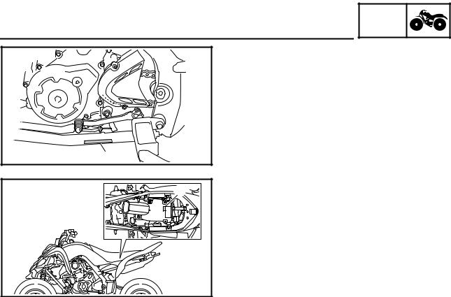
GEN
VEHICLE IDENTIFICATION INFO
EBS00009
GENERAL INFORMATION
VEHICLE IDENTIFICATION
EBS00010
VEHICLE IDENTIFICATION NUMBER
The vehicle identification number 1 is stamped into the left side of the frame.
EBS00011
MODEL LABEL
The model label 1 is affixed to the air filter case cover. This information will be needed to order spare parts.
1 — 1
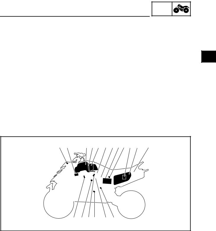
GEN
FEATURES INFO
EAS20170
FEATURES
OUTLINE OF THE FI SYSTEM
The main function of a fuel supply system is to provide fuel to the combustion chamber at the optimum air-fuel ratio in accordance with the engine operating conditions and the atmospheric temperature. In the conventional carburetor system, the air-fuel ratio of the mixture that is supplied to the combustion chamber is created by the volume of the intake air and the fuel that is metered by the jet used in the respective carburetor.
Despite the same volume of intake air, the fuel volume requirement varies with the engine operating conditions, such as acceleration, deceleration, or operating under a heavy load. Carburetors that meter the fuel through the use of jets have been provided with various auxiliary devices, so that an optimum air-fuel ratio can be achieved to accommodate the constant changes in the operating conditions of the engine.
As the requirements for the engine to deliver more performance and cleaner exhaust gases increase, it becomes necessary to control the air-fuel ratio in a more precise and finely tuned manner. To accommodate this need, this model has adopted an electronically controlled fuel injection (FI) system, in place of the conventional carburetor system. This system can achieve an optimum air-fuel ratio required by the engine at all times by using a microprocessor that regulates the fuel injection volume according to the engine operating conditions detected by various sensors.
The adoption of the FI system has resulted in a highly precise fuel supply, improved engine response, better fuel economy, and reduced exhaust emissions.
|
1 2 |
3 4 5 6 7 8 9 0 A B |
||||||
|
H G F E |
D C |
|
1 Engine trouble warning light |
0 ECU (electronic control unit) |
|
2 Ignition coil |
A Air filter case |
|
3 Fuel tank |
B Relay unit (fuel pump relay) |
|
4 Fuel hose |
C Speed sensor |
|
5 Fuel pump |
D Throttle position sensor |
|
6 Intake air pressure sensor |
E Crankshaft position sensor |
|
7 Lean angle sensor |
F Fuel injector |
|
8 Battery |
G Coolant temperature sensor |
|
9 Intake air temperature sensor |
H Spark plug |
1 — 2

The fuel pump delivers fuel to the fuel injector via the fuel filter. The pressure regulator maintains the fuel pressure that is applied to the fuel injector at only 324 kPa (3.24 kg/cm2, 46.1 psi). Accordingly, when the energizing signal from the ECU energizes the fuel injector, the fuel passage opens, causing the fuel to be injected into the intake manifold only during the time the passage remains open. Therefore, the longer the length of time the fuel injector is energized (injection duration), the greater the volume of fuel that is supplied. Conversely, the shorter the length of time the fuel injector is energized (injection duration), the lesser the volume of fuel that is supplied.
The injection duration and the injection timing are controlled by the ECU. Signals that are input from the throttle position sensor, crankshaft position sensor, intake air pressure sensor, intake air temperature sensor, coolant temperature sensor and speed sensor enable the ECU to determine the injection duration. The injection timing is determined through the signals from the crankshaft position sensor. As a result, the volume of fuel that is required by the engine can be supplied at all times in accordance with the driving conditions.
Illustration is for reference only.
|
Ê |
B |
|
|
4 |
||
|
1 |
2 |
|
|
È |
||
|
3 |
||
|
A |
||
|
0 |
||
|
É |
||
|
9 |
||
|
8 |
||
|
7 |
5 |
|
|
6 |
|
1 Fuel pump |
9 Intake air temperature sensor |
|
2 Fuel injector |
0 Air filter case |
|
3 Ignition coil |
A Throttle position sensor |
|
4 ECU (electronic control unit) |
B Speed sensor |
|
5 Coolant temperature sensor |
|
|
6 Crankshaft position sensor |
È Fuel system |
|
7 Intake air pressure sensor |
É Air system |
|
8 Throttle body |
Ê Control system |
1 — 3

FEATURES
SELF-ADJUSTING PARKING BRAKE MECHANISM
GEN  INFO
INFO 


Usually, for vehicles equipped with a parking brake that must be adjusted manually, it is necessary to adjust the adjusting bolt 5 to achieve the proper clearance between the brake caliper piston 7 and the adjusting bolt 5.
This adjustment procedure is unnecessary for vehicles equipped with a self-adjusting parking brake mechanism. The proper clearance is automatically maintained at all times, ensuring stable braking performance when parking the vehicle.
|
1 |
|||
|
2 |
|||
|
3 |
|||
|
7 |
6 |
5 |
4 |
|
1 Parking brake arm |
5 Adjusting bolt |
|
2 Parking brake shaft |
6 Nut |
|
3 Adjusting bolt |
7 Brake caliper piston |
|
4 Adjusting bolt sleeve |
1 — 4
![]()
FEATURES
Parking Brake Operation
GEN  INFO
INFO 


|
1 |
||
|
2 |
||
|
3 |
||
|
6 |
5 |
4 |
|
1 Parking brake arm |
4 Adjusting bolt sleeve |
|
2 Parking brake shaft |
5 Brake caliper piston |
|
3 Adjusting bolt |
6 Brake pad |
When the parking brake is operated, the parking brake cable turns the parking brake arm 1. The rotation of the parking brake arm is changed to axial thrust in the parking brake shaft 2 and the adjusting bolt 3 is pushed against the adjusting bolt sleeve 4.
When the adjusting bolt sleeve receives the force, the dark shaded area in the above illustration is pushed and the brake pad 6 is pushed against the brake disc.
When the brake pad wears, the clearance between the brake caliper piston 5 and the brake pad becomes larger and the force applied to the brake pad becomes weaker.
If this occurs, the self-adjusting parking brake mechanism adjusts automatically to achieve the proper clearance.
1 — 5
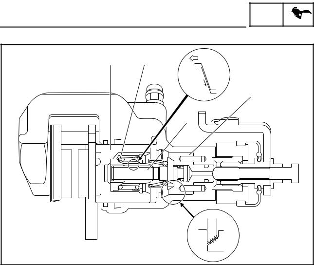
FEATURES
Parking Brake Operation
GEN  INFO
INFO 


|
1 |
2 |
È |
|
É |
||
|
4 |
||
|
3 |
||
|
Ê |
|
1 Brake caliper piston |
3 Adjusting bolt |
|
2 Nut |
4 Adjusting bolt sleeve |
When the brake pedal is operated, the brake fluid pressure in the master cylinder increases and the brake caliper piston 1 and the nut 2 are pushed.
When there is proper clearance between the brake caliper piston and the brake pad, no other parts move because the movement of the brake caliper piston and the nut is absorbed by the backlash of the threads of the nut and the adjusting bolt 3.
When the movement of the nut is greater than the backlash between the nut and the adjusting bolt, the parking brake adjusts automatically.
The amount of the adjustment varies with brake fluid pressure. Operating the parking brake makes no adjustment.
The adjustment operation is as follows.
1.When the brake pedal is operated, the brake fluid pressure increases and the brake caliper piston and the nut move.
2.When the movement of the brake caliper piston and the nut is greater than the backlash of the threads of the nut and the adjusting bolt, the force È will be required to pull the adjusting bolt. The force to pull the adjusting bolt will be turned into the rotation torque É by the shape of the threads of the nut and the adjusting bolt.
3.At this time, the clutch torque Ê between the adjusting bolt and the adjusting bolt sleeve 4 will decrease depending on the force required to pull the adjusting bolt.
When the rotation torque exceeds the clutch torque, the adjusting bolt rotates and the clearance between the brake caliper piston and the brake pad decreases by the movement of the threads of the nut and the adjusting bolt.
1 — 6

IMPORTANT INFORMATION
EBS00013
GEN  INFO
INFO 


IMPORTANT INFORMATION
PREPARATION FOR REMOVAL AND
DISASSEMBLY
1.Before removal and disassembly remove all dirt, mud, dust and foreign material.
2.Use only the proper tools and cleaning equipment.
Refer to “SPECIAL TOOLS”.
3.When disassembling always keep mated parts together. This includes gears, cylinders, pistons and other parts that have been “mated” through normal wear. Mated parts must always be reused or replaced as an assembly.
4.During disassembly, clean all of the parts and place them in trays in the order of disassembly. This will speed up assembly and allow for the correct installation of all parts.
5.Keep all parts away from any source of fire.
EBS00014
REPLACEMENT PARTS
1.Use only genuine Yamaha parts for all replacements. Use oil and grease recommended by Yamaha for all lubrication jobs. Other brands may be similar in function and appearance, but inferior in quality.
EBS00015
GASKETS, OIL SEALS AND O-RINGS
1.When overhauling the engine, replace all gaskets, seals and O-rings. All gasket surfaces, oil seal lips and O-rings must be cleaned.
2.During reassembly properly oil all mating parts and bearings, and lubricate the oil seal lips with grease.
1 — 7

IMPORTANT INFORMATION
EBS00016
GEN  INFO
INFO 


LOCK WASHERS/PLATES AND COTTER PINS
After removal, replace all lock washers/plates 1 and cotter pins. After the bolt or nut has been tightened to specification, bend the lock tabs along a flat of the bolt or nut.
EBS00017
BEARINGS AND OIL SEALS
Install bearings and oil seals so that the manufacturer’s marks or numbers are visible. When installing oil seals, lubricate the oil seal lips with a light coat of lithium-soap-based grease. Oil bearings liberally when installing, if appropriate.
1 Oil seal
CAUTION:
Do not spin the bearing with compressed air because this will damage the bearing surfaces.
1 Bearing
EBS00018
CIRCLIPS
Before reassembly, check all circlips carefully and replace damaged or distorted circlips. Always replace piston pin clips after one use. When installing a circlip 1, make sure the sharp-edged corner 2 is positioned opposite the thrust 3 that the circlip receives.
4 Shaft
1 — 8
GEN
IMPORTANT INFORMATION INFO
EBS00019
CHECKING THE CONNECTIONS
Check the leads, couplers, and connectors for stains, rust, moisture, etc.
1.Disconnect:
•lead
•coupler
•connector
2.Check:
•lead
•coupler
•connector
Moisture → Dry with an air blower. Rust/stains → Connect and disconnect sev-
eral times.
3.Check:
•all connections
Loose connection → Connect properly.
NOTE:
If the pin 1 on the terminal is flattened, bend it up.
4.Connect:
•lead
•coupler
•connector
NOTE:
Make sure all connections are tight.
5.Check:
•continuity (with the pocket tester)
Pocket tester 90890-03112
Analog pocket tester YU-03112-C
NOTE:
•If there is no continuity, clean the terminals.
•When checking the wire harness, perform steps (1) to (3).
•As a quick remedy, use a contact revitalizer available at most part stores.
1 — 9

SPECIAL TOOLS
EBS00021
SPECIAL TOOLS
GEN  INFO
INFO 


The following special tools are necessary for complete and accurate tune-up and assembly. Use only the appropriate special tools; this will help prevent damage caused by the use of inappropriate tools or improvised techniques. Special tools may differ by shape and part number from country to country. In such a case, two types are provided.
When placing an order, refer to the list provided below to avoid any mistakes. For US and CDN
P/N. YM-, YU-, YS-, YK-, ACCExcept for US and CDN
P/N. 90890-
|
Tool No. |
Tool name/Function |
Illustration |
|
Slide hammer bolt |
||
|
Slide hammer bolt (6 mm) |
||
|
90890-01083 |
||
|
YU-01083-1 |
||
|
This tool is used to remove the rocker arm |
||
|
shaft. |
||
|
Weight |
||
|
90890-01084 |
||
|
YU-01083-3 |
||
|
This tool is used to remove the rocker arm |
||
|
shaft. |
||
|
Crankcase separating tool |
||
|
Crankcase separator |
||
|
90890-01135 |
||
|
YU-01135-B |
||
|
This tool is used to separate the crank- |
||
|
case. |
||
|
Ring nut wrench |
||
|
Spanner wrench |
||
|
90890-01268 |
||
|
YU-01268 |
||
|
This tool is used to loosen or tighten the |
||
|
rear shock absorber locknuts. |
||
|
Crankshaft installer pot |
||
|
90890-01274 |
Installer pot |
|
|
Pot installer |
||
|
YU-90058 |
||
|
YU-90059 |
||
|
This tool is used to install the crankshaft. |
||
|
Crankshaft installer bolt |
||
|
Bolt |
||
|
90890-01275 |
||
|
YU-90060 |
||
|
This tool is used to install the crankshaft. |
||
1 — 10

|
SPECIAL TOOLS |
GEN |
|||||
|
INFO |
||||||
|
Tool No. |
Tool name/Function |
Illustration |
||||
|
Adapter (M16) |
||||||
|
Adapter #13 |
||||||
|
90890-04130 |
||||||
|
YM-04059 |
||||||
|
This tool is used to install the crankshaft. |
||||||
|
Spacer (crankshaft installer) |
||||||
|
Pot spacer |
||||||
|
90890-04081 |
||||||
|
YM-91044 |
||||||
|
This tool is used to install the crankshaft. |
||||||
|
Piston pin puller set |
||||||
|
Piston pin puller |
||||||
|
90890-01304 |
||||||
|
YU-01304 |
||||||
|
This tool is used to remove the piston pin. |
||||||
|
Tappet adjusting tool |
||||||
|
Valve adjuster (3 mm & 4 mm) |
||||||
|
90890-01311 |
||||||
|
YM-08035-A |
||||||
|
This tool is necessary for adjusting the |
||||||
|
valve clearance. |
||||||
|
Radiator cap tester |
||||||
|
Radiator pressure tester |
||||||
|
90890-01325 |
||||||
|
YU-24460-01 |
||||||
|
This tool is used to check the cooling sys- |
||||||
|
tem. |
||||||
|
Radiator cap tester adapter |
||||||
|
Radiator pressure tester adapter |
||||||
|
90890-01352 |
||||||
|
YU-33984 |
||||||
|
This tool is used to check the cooling sys- |
||||||
|
tem. |
||||||
|
Damper rod holder (30 mm) |
||||||
|
90890-01327 |
||||||
|
YM-01327 |
||||||
|
This tool is needed to loosen and tighten |
||||||
|
the steering stem bearing retainer. |
||||||
|
Flywheel puller |
90890-01404 YM-01404
This tool is used to remove the A.C.magneto rotor.
1 — 11

|
SPECIAL TOOLS |
GEN |
|||||
|
INFO |
||||||
|
Tool No. |
Tool name/Function |
Illustration |
||||
|
Steering nut wrench |
||||||
|
Spanner wrench |
||||||
|
90890-01443 |
||||||
|
YU-33975 |
This tool is needed to loosen and tighten |
|||||
|
the front shock absorber and rear shock |
||||||
|
absorber locknuts. |
||||||
|
Ball joint remover |
||||||
|
90890-01474 |
||||||
|
YM-01474 |
||||||
|
This tool is used to remove or install the |
||||||
|
ball joints. |
||||||
|
Ball joint remover attachment set |
||||||
|
Ball joint adapter set |
||||||
|
90890-01480 |
||||||
|
YM-01480 |
||||||
|
These tools are used to remove or install |
||||||
|
the ball joints. |
||||||
|
Rear axle nut wrench (46 mm) |
||||||
|
Axle nut wrench (46 mm) |
||||||
|
90890-01498 |
||||||
|
YM-37134 |
||||||
|
This tool is needed to loosen or tighten the |
||||||
|
rear axle nut. |
||||||
|
Sheave holder |
||||||
|
Primary clutch holder |
||||||
|
90890-01701 |
||||||
|
YS-01880-A |
This tool is used to hold the A.C. magneto |
|||||
|
rotor when loosen or tighten the A.C. mag- |
||||||
|
neto rotor nut. |
||||||
|
Thickness gauge |
||||||
|
Narrow gauge set |
||||||
|
90890-03079 |
||||||
|
YM-34483 |
||||||
|
This tool is used to measure the valve |
||||||
|
clearance. |
||||||
|
Compression gauge |
||||||
|
Engine compression tester |
||||||
|
90890-03081 |
||||||
|
YU-33223 |
||||||
|
This tool is used to measure engine com- |
||||||
|
pression. |
||||||
|
Extension |
90890-04082
This tool is used to measure engine compression.
1 — 12

|
SPECIAL TOOLS |
GEN |
||||
|
INFO |
|||||
|
Tool No. |
Tool name/Function |
Illustration |
Pocket tester Analog pocket tester
90890-03112 YU-03112-C
This instrument is needed for checking the electrical system.
Timing light
Inductive clamp timing light
90890-03141 YU-03141
This tool is necessary for checking ignition timing.
Pressure gauge
90890-03153 YU-03153
This tool is used to measure fuel pressure.
Fuel pressure adapter
90890-03176 YM-03176
This tool is used to measure fuel pressure.
Digital circuit tester
Model 88 Multimeter with tachometer
90890-03174 YU-A1927
This tool is used to check the electrical system.
FI diagnostic tool
90890-03182 YU-03182
This tool is used to check the diagnosis.
Valve spring compressor
90890-04019 YM-04019
This tool is needed to remove and install the valve assemblies.
Valve spring compressor attachment Valve spring compressor adapter (26 mm)
90890-01243 YM-01253-1
This tool is needed to remove and install the valve assemblies.
1 — 13

|
SPECIAL TOOLS |
GEN |
|||||
|
INFO |
||||||
|
Tool No. |
Tool name/Function |
Illustration |
||||
|
Middle driven shaft bearing driver |
||||||
|
Bearing driver (40 mm) |
||||||
|
90890-04058 |
||||||
|
YM-04058 |
||||||
|
This tool is used to install the water pump |
||||||
|
seal. |
||||||
|
Mechanical seal installer |
||||||
|
Water pump seal installer |
||||||
|
90890-04132 |
||||||
|
YM-33221-A |
||||||
|
This tool is used to install the water pump |
||||||
|
seal. |
||||||
|
Valve guide remover (ø6) |
||||||
|
Valve guide remover (6.0 mm) |
||||||
|
90890-04064 |
||||||
|
YM-4064-A |
||||||
|
This tool is needed to remove and install |
||||||
|
the valve guides. |
||||||
|
Valve guide installer (ø6) |
||||||
|
Valve guide installer (6.0 mm) |
||||||
|
90890-04065 |
||||||
|
YM-4065-A |
||||||
|
This tool is needed to install the valve |
||||||
|
guides. |
||||||
|
Valve guide reamer (ø6) |
||||||
|
Valve guide reamer (6.0 mm) |
||||||
|
90890-04066 |
||||||
|
YM-04066 |
||||||
|
This tool is needed to rebore the new |
||||||
|
valve guides. |
||||||
|
Universal clutch holder |
||||||
|
90890-04086 |
||||||
|
YM-91042 |
This tool is needed to hold the clutch boss |
|||||
|
when removing or installing the clutch |
||||||
|
boss nut. |
||||||
|
Ignition checker |
||||||
|
Opama pet-4000 spark checker |
||||||
|
90890-06754 |
||||||
|
YM-34487 |
||||||
|
This tool is used to check the ignition sys- |
||||||
|
tem components. |
||||||
|
Digital tachometer |
90890-06760 YU-39951-B
This tool is needed to observe engine rpm.
1 — 14
![]()
|
SPECIAL TOOLS |
GEN |
||||
|
INFO |
|||||
|
Tool No. |
Tool name/Function |
Illustration |
Yamaha bond No. 1215 (Three bond No. 1215)
90890-85505
This bond is used on crankcase mating surfaces, etc.
1 — 15

GENERAL SPECIFICATIONS SPEC
EBS01001
|
SPECIFICATIONS |
|
GENERAL SPECIFICATIONS |
|
|
Item |
Standard |
|
Model code |
1S31 |
|
Dimensions |
|
|
Overall length |
1,845 mm (72.6 in) |
|
Overall width |
1,170 mm (46.1 in) |
|
Overall height |
1,130 mm (44.5 in) |
|
Seat height |
815 mm (32.1 in) |
|
Wheelbase |
1,280 mm (50.4 in) |
|
Minimum ground clearance |
240 mm (9.45 in) |
|
Minimum turning radius |
3,500 mm (137.8 in) |
|
Basic weight |
|
|
With oil and full fuel tank |
192 kg (423 lb) |
|
Engine |
|
|
Engine type |
Liquid-cooled 4-stroke, SOHC |
|
Cylinder arrangement |
Forward-inclined single cylinder |
|
Displacement |
686 cm3 (41.86 cu in) |
|
Bore × stroke |
102.0 × 84.0 mm (4.02 × 3.31 in) |
|
Compression ratio |
9.20:1 |
|
Standard compression pressure (at sea level) |
450 kPa (4.5 kg/cm2, 64.0 psi) |
|
Starting system |
Electric starter |
|
Lubrication system |
Dry sump |
Oil type or grade
|
Engine oil |
||||||||
|
0° |
10° |
30° 50° 70° 90° 110° |
130°F |
API service SE, SF, SG type or higher |
||||
|
YAMALUBE4 (20W40) or SAE 20W40 |
||||||||
|
YAMALUBE4 (10W30) or SAE 10W30 |
||||||||
|
SAE 5W30 |
||||||||
|
-20° |
-10° |
0° |
10° |
20° |
30° |
40° |
50°C |
2 — 1

|
GENERAL SPECIFICATIONS |
SPEC |
|||
|
Item |
Standard |
|||
|
Oil capacity |
||||
|
Engine oil |
||||
|
Periodic oil change |
1.75 L (1.54 Imp qt, 1.85 US qt) |
|||
|
With oil filter replacement |
1.85 L (1.63 Imp qt, 1.96 US qt) |
|||
|
Total amount |
2.30 L (2.02 Imp qt, 2.43 US qt) |
|||
|
Radiator capacity (including all routes) |
1.61 L (1.42 Imp qt, 1.70 US qt) |
|||
|
Air filter |
Wet type element |
|||
|
Fuel |
||||
|
Type |
Regular unleaded gasoline only (For CDN, |
|||
|
Europe) |
||||
|
Unleaded gasoline only (For Oceania) |
||||
|
Fuel tank capacity |
11.0 L (2.42 Imp gal, 2.91 US gal) |
|||
|
Fuel reserve amount |
2.6 L (0.57 Imp gal, 0.69 US gal) |
|||
|
Fuel injector |
||||
|
Type/quantity |
297500-0390/1 |
|||
|
Manufacturer |
DENSO |
|||
|
Spark plug |
||||
|
Type/manufacturer |
CR8E/NGK |
|||
|
Spark plug gap |
0.7 ~ 0.8 mm (0.028 ~ 0.031 in) |
|||
|
Clutch type |
Wet, multiple disc |
|||
|
Transmission |
||||
|
Primary reduction system |
Spur gear |
|||
|
Primary reduction ratio |
77/34 (2.265) |
|||
|
Secondary reduction system |
Chain drive |
|||
|
Secondary reduction ratio |
38/14 (2.714) |
|||
|
Transmission type |
Constant mesh, 5-speed/forward, 1 speed/ |
|||
|
reverse |
||||
|
Operation |
Left foot operation |
|||
|
Gear ratio |
||||
|
1st gear |
38/13 (2.923) |
|||
|
2nd gear |
28/14 (2.000) |
|||
|
3rd gear |
25/17 (1.471) |
|||
|
4th gear |
25/22 (1.136) |
|||
|
5th gear |
22/24 (0.917) |
|||
|
Reverse gear |
24/13 × 29/12 (4.462) |
|||
|
Chassis |
||||
|
Frame type |
Aluminum die-cast and steel tube frame |
|||
|
Caster angle |
5° |
|||
|
Camber angle |
–1.0° |
|||
|
Kingpin angle |
14.8° |
|||
|
Kingpin offset |
2.8 mm (0.11 in) |
|||
|
Trail |
21.0 mm (0.83 in) |
|||
|
Tread front (STD) |
940 mm (37.01 in) |
|||
|
Tread rear (STD) |
900 mm (35.43 in) |
|||
|
Toe-in (with tires touching the ground) |
2 ~ 12 mm (0.08 ~ 0.47 in) |
|||
2 — 2

GENERAL SPECIFICATIONS SPEC
|
Item |
Standard |
|
|
Tire |
||
|
Type |
Tubeless |
|
|
Size |
front |
AT21 × 7-10 |
|
rear |
AT20 × 10-9 |
|
|
Manufacturer |
front |
DUNLOP |
|
rear |
DUNLOP |
|
|
Type |
front |
KT341 Radial |
|
rear |
KT345 Radial |
|
|
Tire pressure (cold tire) |
||
|
Maximum load* |
100 kg (220 lb) |
|
|
Off-road riding |
front |
27.5 kPa (0.28 kg/cm2, 4.0 psi) |
|
rear |
27.5 kPa (0.28 kg/cm2, 4.0 psi) |
|
|
*Load is total weight of cargo, rider and |
||
|
accessories |
||
|
Brake |
||
|
Front brake |
type |
Dual disc brake |
|
operation |
Right hand operation |
|
|
Rear brake |
type |
Single disc brake |
|
operation |
Right foot operation |
|
|
Suspension |
||
|
Front suspension |
Double wishbone |
|
|
Rear suspension |
Swingarm (link suspension) |
|
|
Shock absorber |
||
|
Front shock absorber |
Coil spring/oil damper |
|
|
Rear shock absorber |
Coil spring/gas-oil damper |
|
|
Wheel travel |
||
|
Front wheel travel |
230 mm (9.06 in) |
|
|
Rear wheel travel |
256 mm (10.08 in) |
|
|
Electrical system |
||
|
Ignition system |
Transistorized coil ignition (digital) |
|
|
Generator system |
A.C. magneto |
|
|
Battery type |
GT9B-4 |
|
|
Battery capacity |
12 V 8.0 Ah |
|
|
Bulb type |
Krypton bulb |
|
|
Bulb voltage/wattage × quantity |
||
|
Headlight |
12 V 30 W/30 W × 2 |
|
|
Tail/brake light |
LED |
|
|
Indicator light |
||
|
Neutral indicator light |
LED |
|
|
Fuel level warning light |
LED |
|
|
Reverse indicator light |
LED |
|
|
Coolant temperature warning light |
LED |
|
|
Engine trouble warning light |
LED |
|
2 — 3

ENGINE SPECIFICATIONS SPEC
EBS01002
ENGINE SPECIFICATIONS
|
Item |
Standard |
Limit |
|
|
Cylinder head |
|||
|
Maximum warpage |
—- |
0.03 mm |
|
|
(0.0012 in) |
|||
|
Cylinder |
||
|
Bore |
102.000 ~ 102.010 mm (4.0157 ~ 4.0161 in) |
102.080 mm |
|
(4.0189 in) |
||
|
Measuring point |
50.0 mm (1.97 in) |
—- |
|
Out of round |
0.05 mm |
|||
|
(0.002 in) |
||||
|
Camshaft |
||||
|
Drive system |
Chain drive (left) |
—- |
||
|
Camshaft lobe dimensions |
||||
A
|
B |
|||||||||||||
|
Intake measurement |
“A” |
43.300 ~ 43.400 mm (1.7047 ~ 1.7087 in) |
43.200 mm |
||||||||||
|
(1.7008 in) |
|||||||||||||
|
“B” |
37.026 ~ 37.126 mm (1.4577 ~ 1.4617 in) |
36.926 mm |
|||||||||||
|
(1.4538 in) |
|||||||||||||
|
Exhaust measurement |
“A” |
43.129 ~ 43.229 mm (1.6980 ~ 1.7019 in) |
43.029 mm |
||||||||||
|
(1.6941 in) |
|||||||||||||
|
“B” |
37.057 ~ 37.157 mm (1.4589 ~ 1.4629 in) |
36.957 mm |
|||||||||||
|
(1.4550 in) |
|||||||||||||
|
Maximum camshaft runout |
—- |
0.03 mm |
|||||||||||
|
(0.0012 in) |
|||||||||||||
|
Timing chain |
|||
|
Model/number of links |
98XRH2010/126 |
—- |
|
|
Tensioning system |
Automatic |
—- |
2 — 4

|
ENGINE SPECIFICATIONS |
SPEC |
||||||||||
|
Item |
Standard |
Limit |
|||||||||
|
Rocker arm/rocker arm shaft |
|||||||||||
|
Rocker arm inside diameter |
12.000 ~ 12.018 mm (0.4724 ~ 0.4731 in) |
—- |
|||||||||
|
Shaft outside diameter |
11.981 ~ 11.991 mm (0.4717 ~ 0.4721 in) |
—- |
|||||||||
|
Arm-to-shaft clearance |
0.009 ~ 0.037 mm (0.0004 ~ 0.0015 in) |
—- |
|||||||||
|
Valve, valve seat, valve guide |
|||||||||||
|
Valve clearance–intake (cold) |
0.09 ~ 0.13 mm (0.0035 ~ 0.0051 in) |
—- |
|||||||||
|
Valve clearance–exhaust (cold) |
0.16 ~ 0.20 mm (0.0063 ~ 0.0079 in) |
—- |
|||||||||
|
Valve dimensions |
|||||||||||
|
B |
C |
||||||||||
|
A |
D |
||||||||||
|
Head Diameter |
Face Width |
Seat Width |
Margin Thickness |
||||||||
|
Valve head diameter “A” |
|||||||||||
|
Intake |
37.9 ~ 38.1 mm (1.4921 ~ 1.5000 in) |
—- |
|||||||||
|
Exhaust |
31.9 ~ 32.1 mm (1.2559 ~ 1.2638 in) |
—- |
|||||||||
|
Valve face width “B” |
|||||||||||
|
Intake |
2.26 mm (0.0890 in) |
—- |
|||||||||
|
Exhaust |
2.26 mm (0.0890 in) |
—- |
|||||||||
|
Valve seat width “C” |
|||||||||||
|
Intake |
1.0 ~ 1.2 mm (0.0394 ~ 0.0472 in) |
1.6 mm |
|||||||||
|
(0.063 in) |
|||||||||||
|
Exhaust |
1.0 ~ 1.2 mm (0.0394 ~ 0.0472 in) |
1.6 mm |
|||||||||
|
(0.063 in) |
|||||||||||
|
Valve margin thickness “D” |
|||||||||||
|
Intake |
0.8 ~ 1.2 mm (0.0315 ~ 0.0472 in) |
—- |
|||||||||
|
Exhaust |
0.8 ~ 1.2 mm (0.0315 ~ 0.0472 in) |
—- |
|||||||||
|
Valve stem diameter |
|||||||||||
|
Intake |
5.975 ~ 5.990 mm (0.2352 ~ 0.2358 in) |
5.945 mm |
|||||||||
|
(0.2341 in) |
|||||||||||
|
Exhaust |
5.960 ~ 5.975 mm (0.2346 ~ 0.2352 in) |
5.930 mm |
|||||||||
|
(0.2335 in) |
|||||||||||
|
Valve guide inside diameter |
|||||||||||
|
Intake |
6.000 ~ 6.012 mm (0.2362 ~ 0.2367 in) |
6.050 mm |
|||||||||
|
(0.2382 in) |
|||||||||||
|
Exhaust |
6.000 ~ 6.012 mm (0.2362 ~ 0.2367 in) |
6.050 mm |
|||||||||
|
(0.2382 in) |
|||||||||||
|
Valve-stem-to-valve-guide clearance |
|||||||||||
|
Intake |
0.010 ~ 0.037 mm (0.0004 ~ 0.0015 in) |
0.080 mm |
|||||||||
|
(0.0031 in) |
|||||||||||
|
Exhaust |
0.025 ~ 0.052 mm (0.0010 ~ 0.0020 in) |
0.100 mm |
|||||||||
|
(0.0039 in) |
|||||||||||
2 — 5

|
ENGINE SPECIFICATIONS |
SPEC |
||||||||||||||||||
|
Item |
Standard |
Limit |
|||||||||||||||||
|
Valve stem runout |
—- |
0.01 mm |
|||||||||||||||||
|
(0.0004 in) |
|||||||||||||||||||
|
Valve seat width |
||
|
Intake |
1.0 ~ 1.2 mm (0.0394 ~ 0.0472 in) |
1.6 mm |
|
(0.0630 in) |
||
|
Exhaust |
1.0 ~ 1.2 mm (0.0394 ~ 0.0472 in) |
1.6 mm |
|
(0.0630 in) |
||
|
Valve spring |
||
|
Free length |
||
|
Intake |
38.79 mm (1.53 in) |
36.85 mm |
|
(1.45 in) |
||
|
Exhaust |
38.79 mm (1.53 in) |
36.85 mm |
|
(1.45 in) |
||
|
Installed length (valve closed) |
||
|
Intake |
35.00 mm (1.38 in) |
—- |
|
Exhaust |
35.00 mm (1.38 in) |
—- |
|
Compressed spring force (installed) |
||
|
Intake |
169.0 ~ 199.0 N |
—- |
|
(17.23 ~ 20.29 kg, 37.99 ~ 44.73 lb) |
||
|
Exhaust |
169.0 ~ 199.0 N |
—- |
|
(17.23 ~ 20.29 kg, 37.99 ~ 44.73 lb) |
||
|
Spring tilt |
|
Intake |
—- |
2.5°/1.70 mm |
|
(2.5°/0.067 in) |
||
|
Exhaust |
—- |
2.5°/1.70 mm |
|
(2.5°/0.067 in) |
||
|
Winding direction (top view) |
||
|
Intake |
Clockwise |
—- |
|
Exhaust |
Clockwise |
—- |
2 — 6

ENGINE SPECIFICATIONS SPEC
|
Item |
Standard |
Limit |
||
|
Piston |
||||
|
Piston-to-cylinder clearance |
0.030 ~ 0.055 mm (0.0012 ~ 0.0022 in) |
0.13 mm |
||
|
(0.0051 in) |
||||
|
Diameter “D” |
101.955 ~ 101.970 mm |
—- |
||
|
(4.0140 ~ 4.0146 in) |
||||
|
H |
|||||||||||
|
D |
|||||||||||
|
Height “H” |
10 mm (0.39 in) |
—- |
|||||||||
|
Offset |
0.5 mm (0.0197 in) |
—- |
|||||||||
|
Offset direction |
Intake side |
—- |
|||||||||
|
Piston pin bore inside diameter |
23.004 ~ 23.015 mm (0.9057 ~ 0.9061 in) |
23.045 mm |
|||||||||
|
(0.9073 in) |
|||||||||||
|
Piston pin outside diameter |
22.991 ~ 23.000 mm (0.9052 ~ 0.9055 in) |
22.971 mm |
|||||||||
|
(0.9044 in) |
|||||||||||
|
Piston-pin-to-piston-pin-bore clear- |
0.004 ~ 0.024 mm (0.0002 ~ 0.0009 in) |
0.074 mm |
|||||||||
|
ance |
(0.0029 in) |
||||||||||
|
Piston rings |
|||||||||||
|
Top ring |
|||||||||||
|
B |
|||||||||||
|
T |
|||||||||||
|
Ring type |
Barrel |
—- |
|||||||||
|
Dimensions (B × T) |
1.20 × 3.80 mm (0.05 × 0.15 in) |
—- |
|||||||||
|
End gap (installed) |
0.20 ~ 0.35 mm (0.008 ~ 0.014 in) |
0.60 mm |
|||||||||
|
(0.024 in) |
|||||||||||
|
Ring side clearance |
0.030 ~ 0.070 mm (0.0012 ~ 0.0028 in) |
0.12 mm |
|||||||||
|
(0.0047 in) |
|||||||||||
|
2nd ring |
|||||||||||
|
B |
|||||||||||
|
T |
|||||||||||
|
Ring type |
Taper |
—- |
|||||||||
|
Dimensions (B × T) |
1.20 × 4.00 mm (0.05 × 0.16 in) |
—- |
|||||||||
|
End gap (installed) |
0.35 ~ 0.50 mm (0.014 ~ 0.020 in) |
0.85 mm |
|||||||||
|
(0.033 in) |
|||||||||||
|
Ring side clearance |
0.030 ~ 0.070 mm (0.0012 ~ 0.0028 in) |
0.13 mm |
|||||||||
|
(0.0051 in) |
2 — 7

ENGINE SPECIFICATIONS SPEC
|
Item |
Standard |
Limit |
||||||||||||||||||
|
Oil ring |
||||||||||||||||||||
|
B |
||||||||||||||||||||
|
T |
||||||||||||||||||||
|
Dimensions (B × T) |
2.50 × 3.40 mm (0.10 × 0.13 in) |
—- |
||||||||||||||||||
|
End gap (installed) |
0.20 ~ 0.70 mm (0.008 ~ 0.028 in) |
—- |
||||||||||||||||||
|
Ring side clearance |
0.060 ~ 0.150 mm (0.0024 ~ 0.0059 in) |
—- |
||||||||||||||||||
|
Crankshaft |
||||||||||||||||||||
|
F |
||||||||||||||||||||
|
C |
C |
|||||||||||||||||||
|
E |
||||||||||||||||||||
|
D |
||||||||||||||||||||
|
A |
||||||||||||||||||||
|
Crank width “A” |
74.95 ~ 75.00 mm (2.951 ~ 2.953 in) |
—- |
||||||||||||||||||
|
Maximum runout “C” |
—- |
0.03 mm |
||||||||||||||||||
|
(0.0012 in) |
||||||||||||||||||||
|
Big end side clearance “D” |
0.350 ~ 0.650 mm (0.0138 ~ 0.0256 in) |
1.00 mm |
||||||||||||||||||
|
(0.040 in) |
||||||||||||||||||||
|
Big end radial clearance “E” |
0.010 ~ 0.025 mm (0.0004 ~ 0.0010 in) |
—- |
||||||||||||||||||
|
Small end free play “F” |
0.16 ~ 0.40 mm (0.0063 ~ 0.0157 in) |
—- |
||||||||||||||||||
|
Balancer |
||||||||||||||||||||
|
Balancer drive method |
Gear |
—- |
||||||||||||||||||
|
Clutch |
||||||||||||||||||||
|
Friction plate 1 (inside dia.: 121 mm) |
||||||||||||||||||||
|
Thickness |
2.92 ~ 3.08 mm (0.115 ~ 0.121 in) |
2.82 mm |
||||||||||||||||||
|
(0.111 in) |
||||||||||||||||||||
|
Quantity |
7 |
—- |
||||||||||||||||||
|
Friction plate 2 (inside dia.: 128 mm) |
||||||||||||||||||||
|
Thickness |
2.90 ~ 3.10 mm (0.114 ~ 0.122 in) |
2.80 mm |
||||||||||||||||||
|
(0.110 in) |
||||||||||||||||||||
|
Quantity |
1 |
—- |
||||||||||||||||||
|
Clutch plate |
||||||||||||||||||||
|
Thickness |
1.50 ~ 1.60 mm (0.059 ~ 0.063 in) |
—- |
||||||||||||||||||
|
Quantity |
7 |
—- |
||||||||||||||||||
|
Maximum warpage |
—- |
0.20 mm |
||||||||||||||||||
|
(0.0079 in) |
||||||||||||||||||||
|
Clutch spring |
||||||||||||||||||||
|
Free length |
50.0 mm (1.97 in) |
48.0 mm |
||||||||||||||||||
|
(1.89 in) |
||||||||||||||||||||
|
Quantity |
6 |
—- |
||||||||||||||||||
|
Clutch release method |
Outer pull, rack and pinion pull |
—- |
||||||||||||||||||
2 — 8

ENGINE SPECIFICATIONS SPEC
|
Item |
Standard |
Limit |
|
Transmission |
||
|
Maximum main axle runout |
—- |
0.08 mm |
|
(0.0031 in) |
||
|
Maximum drive axle runout |
—- |
0.08 mm |
|
(0.0031 in) |
||
|
Shifting mechanism |
||
|
Shift mechanism type |
Shift drum and guide bar |
—- |
|
Decompression device |
||
|
Device type |
Auto decomp |
—- |
|
Air filter oil grade |
Air-cooled 2-stroke engine oil |
—- |
|
Throttle body |
||
|
Model/manufacturer × quantity |
44EHS/MIKUNI × 1 |
—- |
|
Engine idle speed |
1,500 ~ 1,700 r/min |
—- |
|
Intake vacuum |
37.8 kPa (284 mmHg, 11.2 inHg) |
—- |
|
Fuel pump |
||
|
Pump type |
Electrical |
—- |
|
Model/manufacturer |
1S3/DENSO |
—- |
|
Maximum consumption amperage |
4.8 A |
—- |
|
Output pressure |
324 kPa (3.24 kg/cm2, 46.1 psi) |
—- |
|
Oil filter type |
Paper |
—- |
|
Oil pump |
||
|
Oil pump type |
Trochoid |
—- |
|
Inner-rotor-to-outer-rotor-tip clear- |
Less than 0.12 mm (0.0047 in) |
0.20 mm |
|
ance |
(0.0079 in) |
|
|
Outer-rotor-to-oil-pump-housing |
0.09 ~ 0.15 mm (0.0035 ~ 0.0059 in) |
0.22 mm |
|
clearance |
(0.0087 in) |
|
|
Bypass valve opening pressure |
40.0 ~ 80.0 kPa |
—- |
|
(0.40 ~ 0.80 kg/cm2, 5.70 ~ 11.4 psi) |
||
|
Oil pressure (hot) |
40.0 kPa at 1,600 r/min (0.40 kg/cm2 at |
—- |
|
1,600 r/min, 5.70 psi at 1,600 r/min) |
||
|
Pressure check location |
Element cover |
—- |
|
Cooling system |
||
|
Radiator core |
||
|
Width |
197 mm (7.76 in) |
—- |
|
Height |
300 mm (11.81 in) |
—- |
|
Depth |
22 mm (0.87 in) |
—- |
|
Radiator cap opening pressure |
93.3 ~ 122.7 kPa |
—- |
|
(0.933 ~ 1.227 kg/cm2, 13.27 ~ 17.45 psi) |
||
|
Coolant reservoir capacity |
||
|
Up to the maximum level mark |
0.25 L (0.22 Imp qt, 0.26 US qt) |
—- |
|
From low to full level |
0.15 L (0.13 Imp qt, 0.16 US qt) |
—- |
|
Water pump |
||
|
Water pump type |
Single-suction centrifugal pump |
—- |
|
Reduction ratio |
27/28 (0.964) |
—- |
2 — 9

|
ENGINE SPECIFICATIONS |
SPEC |
||
|
Lubrication chart |
|||
|
Counter axle |
Cylinder head |
||
|
Decompression |
|||
|
To oil tank |
Camshaft |
||
|
Main axle |
|||
|
Oil delivery pipe |
|||
|
Oil tank inlet pipe |
|||
|
A.C. magneto |
Drive axle |
||
|
cover |
|||
|
From oil tank |
|||
|
Oil filter |
Right crankcase |
||
|
element |
|||
|
Left |
Oil tank outlet |
||
|
crankcase |
hose joint |
||
|
Drain bolt |
|||
|
Right |
Right crankcase Clutch cover |
To clutch cover |
|
|
crankcase |
|||
|
Oil |
Oil pump |
||
|
strainer |
|||
|
Crankshaft |
|||
|
2 — 10 |

ENGINE SPECIFICATIONS SPEC
Cylinder head tightening sequence
|
5 |
||
|
7 |
2 |
|
|
3 |
||
|
8 |
1 |
|
|
4 |
||
|
6 |
2 — 11

CHASSIS SPECIFICATIONS SPEC
EBS01003
CHASSIS SPECIFICATIONS
|
Item |
Standard |
Limit |
|
Steering system |
||
|
Steering bearing type |
Ball and race bearing |
—- |
|
Front suspension |
||
|
Shock absorber travel |
115.0 mm (4.53 in) |
—- |
|
Spring free length |
269.0 mm (10.59 in) |
—- |
|
Installed length |
260.5 mm (10.26 in) |
—- |
|
Spring rate (K1) |
21.60 N/mm (2.20 kg/mm, 123.33 lb/in) |
—- |
|
Spring rate (K2) |
29.40 N/mm (3.00 kg/mm, 167.87 lb/in) |
—- |
|
Optional spring available |
No |
—- |
|
Rear suspension |
||
|
Shock absorber travel |
110.0 mm (4.33 in) |
—- |
|
Spring free length |
255.0 mm (10.04 in) |
—- |
|
Installed length |
236.0 mm (9.29 in) |
—- |
|
Spring rate (K1) |
46.00 N/mm (4.69 kg/mm, 262.66 lb/in) |
—- |
|
Spring stroke (K1) |
0 ~ 110.0 mm (0 ~ 4.33 in) |
—- |
|
Optional spring available |
No |
—- |
|
Swingarm |
||
|
Free play limit (radial) |
—- |
1.0 mm |
|
(0.04 in) |
||
|
Free play limit (axial) |
—- |
1.0 mm |
|
(0.04 in) |
||
|
Front wheel |
||
|
Type |
Panel wheel |
—- |
|
Rim size |
10 × 5.5 AT |
—- |
|
Rim material |
Aluminum |
—- |
|
Maximum radial wheel runout |
—- |
2.0 mm |
|
(0.08 in) |
||
|
Maximum lateral wheel runout |
—- |
2.0 mm |
|
(0.08 in) |
||
|
Rear wheel |
||
|
Type |
Panel wheel |
—- |
|
Rim size |
9 × 8.5 AT |
—- |
|
Rim material |
Aluminum |
—- |
|
Maximum radial wheel runout |
—- |
2.0 mm |
|
(0.08 in) |
||
|
Maximum lateral wheel runout |
—- |
2.0 mm |
|
(0.08 in) |
||
|
Drive chain |
||
|
Type/manufacturer |
520MXV/DAIDO |
—- |
|
Link quantity |
98 |
—- |
|
Drive chain slack |
25 ~ 35 mm (0.98 ~ 1.38 in) |
—- |
2 — 12

|
CHASSIS SPECIFICATIONS |
SPEC |
|||||
|
Item |
Standard |
Limit |
||||
|
Front disc brake |
||||||
|
Type |
Dual |
—- |
||||
|
Disc outside diameter × thickness |
161.0 × 3.5 mm (6.34 × 0.14 in) |
—- |
||||
|
Pad thickness inner |
4.3 mm (0.17 in) |
1.0 mm |
||||
|
(0.04 in) |
||||||
|
Pad thickness outer |
4.3 mm (0.17 in) |
1.0 mm |
||||
|
(0.04 in) |
||||||
|
Master cylinder inside diameter |
12.70 mm (0.50 in) |
—- |
||||
|
Caliper cylinder inside diameter |
25.40 mm (1.00 in) |
—- |
||||
|
Brake fluid type |
DOT 4 |
—- |
||||
|
Rear disc brake |
||||||
|
Type |
Single |
—- |
||||
|
Disc outside diameter × thickness |
200.0 × 3.6 mm (7.87 × 0.14 in) |
—- |
||||
|
Pad thickness inner |
5.6 mm (0.22 in) |
1.0 mm |
||||
|
(0.04 in) |
||||||
|
Pad thickness outer |
5.6 mm (0.22 in) |
1.0 mm |
||||
|
(0.04 in) |
||||||
|
Master cylinder inside diameter |
12.70 mm (0.50 in) |
—- |
||||
|
Caliper cylinder inside diameter |
32.03 mm (1.26 in) |
—- |
||||
|
Brake fluid type |
DOT 4 |
—- |
||||
|
Brake lever and brake pedal |
||||||
|
Brake pedal position |
15.3 mm (0.60 in) |
—- |
||||
|
Parking brake cable end length |
58 ~ 60 mm (2.28 ~ 2.36 in) |
—- |
||||
|
Clutch lever free play (lever end) |
5 ~ 10 mm (0.20 ~ 0.39 in) |
—- |
||||
|
Throttle lever free play |
2 ~ 4 mm (0.08 ~ 0.16 in) |
—- |
||||
|
Speed limiter length |
Less than 12 mm (0.47 in) |
—- |
||||
|
Shift pedal height |
48 mm (1.89 in) |
—- |
||||
2 — 13

ELECTRICAL SPECIFICATIONS SPEC
EBS01004
ELECTRICAL SPECIFICATIONS
|
Item |
Standard |
Limit |
|
|
System voltage |
12 V |
—- |
|
|
Ignition system |
|||
|
Ignition timing (B.T.D.C.) |
9.0°/1,600 r/min |
—- |
|
|
Advancer type |
Digital type |
—- |
|
|
Transistorized coil ignition |
|||
|
Crankshaft position sensor resis- |
192 ~ 288 Ω at 20 °C (68 °F)/ |
—- |
|
|
tance/color |
blue/yellow-green/white |
||
|
ECU |
|||
|
Model/manufacturer |
TBDF18/DENSO |
—- |
|
|
Ignition coil |
|||
|
Model/manufacturer |
JO267/DENSO |
—- |
|
|
Minimum ignition spark gap |
6.0 mm (0.24 in) |
—- |
|
|
Primary winding resistance |
3.4 ~ 4.6 Ω at 20 °C (68 °F) |
—- |
|
|
Secondary winding resistance |
10.4 ~ 15.6 kΩ at 20 °C (68 °F) |
—- |
|
|
Spark plug cap |
|||
|
Material |
Resin |
—- |
|
|
Resistance |
10.0 kΩ |
—- |
|
|
A.C. magneto |
|||
|
Model/manufacturer |
LMX58/DENSO |
—- |
|
|
Standard output |
14 V 17.2 A at 5,000 r/min |
—- |
|
|
Stator coil resistance/color |
0.248 ~ 0.372 Ω at 20 °C (68 °F)/ |
—- |
|
|
white-white |
|||
|
Rectifier/regulator |
|||
|
Type |
Semiconductor, short-circuit type |
—- |
|
|
Model/manufacturer |
SH650D-11/SHINDENGEN |
—- |
|
|
No load regulated voltage |
(DC) |
14.1 ~ 14.9 V |
—- |
|
Rectifier capacity |
18.0 A |
—- |
|
|
Withstand voltage |
200.0 V |
—- |
|
|
Electric starting system |
|||
|
Type |
Constant mesh type |
—- |
|
|
Starter motor |
|||
|
Model/manufacturer |
SM-13/MITSUBA |
—- |
|
|
Power output |
0.80 kW |
—- |
|
|
Armature coil resistance |
0.0250 ~ 0.0350 Ω at 20 °C (68 °F) |
—- |
|
|
Brush overall length |
12.5 mm (0.49 in) |
5.00 mm |
|
|
(0.20 in) |
|||
|
Spring force |
7.65 ~ 10.01 N |
—- |
|
|
(780 ~ 1,021 gf, 27.54 ~ 36.03 oz) |
|||
|
Commutator diameter |
28.0 mm (1.10 in) |
27.0 mm |
|
|
(1.06 in) |
|||
|
Mica undercut |
0.70 mm (0.03 in) |
—- |
|
2 — 14

|
ELECTRICAL SPECIFICATIONS |
SPEC |
|||||
|
Item |
Standard |
Limit |
||||
|
Starter relay |
||||||
|
Model/manufacturer |
2768106-A/JIDECO |
—- |
||||
|
Amperage rating |
180.0 A |
—- |
||||
|
Coil winding resistance |
4.18 ~ 4.62 Ω at 20 °C (68 °F) |
—- |
||||
|
Circuit breaker |
||||||
|
Circuit breaker type |
Fuse |
—- |
||||
|
Fuses |
||||||
|
Main fuse |
20 A |
—- |
||||
|
Headlight fuse |
15 A |
—- |
||||
|
Signaling system fuse |
10 A |
—- |
||||
|
Ignition fuse |
10 A |
—- |
||||
|
Fuel injection system fuse |
10 A |
—- |
||||
|
Spare fuse |
20 A |
—- |
||||
|
15 A |
—- |
|||||
|
10 A |
—- |
|||||
2 — 15

TIGHTENING TORQUES SPEC
EBS01005
TIGHTENING TORQUES
ENGINE TIGHTENING TORQUES
|
Part to be tightened |
Part name |
Thread |
Q’ty |
Tightening torque |
Remarks |
||||||
|
size |
Nm |
m · kg |
ft · lb |
||||||||
|
Cylinder head (exhaust pipe) |
Stud bolt |
M8 |
4 |
15 |
1.5 |
11 |
|||||
|
Cylinder head |
Bolt |
M9 |
4 |
35 |
3.5 |
25 |
M |
||||
|
Cylinder head |
Bolt |
M9 |
2 |
38 |
3.8 |
27 |
|||||
|
E |
|||||||||||
|
Cylinder head |
Bolt |
M6 |
2 |
10 |
1.0 |
7.2 |
|||||
|
Spark plug |
— |
M10 |
1 |
13 |
1.3 |
9.4 |
|||||
|
Oil gallery bolt |
Union bolt |
M8 |
1 |
10 |
1.0 |
7.2 |
|||||
|
Tappet cover |
Bolt |
M6 |
8 |
10 |
1.0 |
7.2 |
|||||
|
Camshaft sprocket cover |
Bolt |
M6 |
2 |
10 |
1.0 |
7.2 |
|||||
|
Camshaft sprocket |
Bolt |
M7 |
2 |
20 |
2.0 |
14 |
|||||
|
Decompressor assembly |
Bolt |
M7 |
2 |
20 |
2.0 |
14 |
|||||
|
Cylinder |
Bolt |
M10 |
4 |
50 |
5.0 |
36 |
See NOTE. |
||||
|
E |
|||||||||||
|
Cylinder |
Bolt |
M6 |
2 |
10 |
1.0 |
7.2 |
|||||
|
Cable guide |
Bolt |
M6 |
1 |
7 |
0.7 |
5.1 |
|||||
|
Water jacket joint |
Bolt |
M6 |
2 |
10 |
1.0 |
7.2 |
|||||
|
A.C. magneto rotor |
Nut |
M16 |
1 |
60 |
6.0 |
43 |
E |
||||
|
A.C. magneto cover |
Bolt |
M6 |
14 |
10 |
1.0 |
7.2 |
|||||
|
Balancer driven gear |
Nut |
M16 |
2 |
60 |
6.0 |
43 |
Use a lock |
||||
|
washer. |
|||||||||||
|
Breather plate |
Bolt |
M6 |
3 |
10 |
1.0 |
7.2 |
|||||
|
Use a lock |
|||||||||||
|
Primary drive gear |
Nut |
M20 |
1 |
110 |
11.0 |
80 |
washer. |
||||
|
Valve adjusting screw |
Nut |
M6 |
4 |
14 |
1.4 |
10 |
M |
||||
|
Camshaft bearing retainer |
Bolt |
M6 |
2 |
10 |
1.0 |
7.2 |
LT |
||||
|
Timing chain guide (intake side) |
Bolt |
M6 |
2 |
10 |
1.0 |
7.2 |
|||||
|
Timing chain tensioner cap bolt |
Bolt |
M16 |
1 |
20 |
2.0 |
14 |
|||||
|
Timing chain tensioner |
Bolt |
M6 |
2 |
10 |
1.0 |
7.2 |
|||||
|
Water pump outlet hose clamp |
Screw |
M4 |
2 |
2 |
0.2 |
1.4 |
|||||
|
Water pump |
Bolt |
M6 |
3 |
10 |
1.0 |
7.2 |
|||||
|
Water pump housing cover |
Bolt |
M6 |
3 |
11 |
1.1 |
8.0 |
|||||
|
Thermostat cover |
Bolt |
M6 |
2 |
10 |
1.0 |
7.2 |
|||||
|
Radiator |
Bolt |
M6 |
2 |
7 |
0.7 |
5.1 |
|||||
|
Engine oil drain bolt (crankcase) |
Bolt |
M14 |
1 |
23 |
2.3 |
17 |
|||||
|
Engine oil drain bolt (oil tank) |
Bolt |
M8 |
1 |
19 |
1.9 |
13 |
|||||
|
Oil baffle plate 1 |
Bolt |
M5 |
2 |
4 |
0.4 |
2.9 |
LT |
||||
|
Oil baffle plate 2 |
Bolt |
M6 |
2 |
10 |
1.0 |
7.2 |
|||||
|
Oil pump |
Bolt |
M6 |
1 |
10 |
1.0 |
7.2 |
|||||
|
Oil pump housing 2 |
Screw |
M6 |
1 |
7 |
0.7 |
5.1 |
|||||
|
Oil strainer |
Bolt |
M6 |
2 |
10 |
1.0 |
7.2 |
LT |
||||
2 — 16

|
TIGHTENING TORQUES |
SPEC |
||||||||||
|
Part to be tightened |
Part name |
Thread |
Q’ty |
Tightening torque |
Remarks |
||||||
|
size |
Nm |
m · kg |
ft · lb |
||||||||
|
Oil filter cover drain bolt |
Bolt |
M6 |
1 |
10 |
1.0 |
7.2 |
|||||
|
Oil filter cover |
Bolt |
M6 |
2 |
10 |
1.0 |
7.2 |
|||||
|
Check screw (oil filter cover) |
Screw |
M5 |
1 |
5 |
0.5 |
3.6 |
|||||
|
Oil delivery pipe |
Union bolt |
M10 |
2 |
20 |
2.0 |
14 |
|||||
|
Oil delivery pipe |
Bolt |
M6 |
1 |
10 |
1.0 |
7.2 |
|||||
|
Oil pipe joint |
Bolt |
M14 |
1 |
50 |
5.0 |
36 |
|||||
|
Oil tank inlet hose (oil tank side) |
Bolt |
M6 |
1 |
10 |
1.0 |
7.2 |
|||||
|
Oil tank inlet hose (engine side) |
Bolt |
M6 |
1 |
10 |
1.0 |
7.2 |
|||||
|
Oil tank outlet hose |
Nut |
M16 |
1 |
35 |
3.5 |
25 |
|||||
|
Oil tank outlet hose |
Bolt |
M6 |
2 |
10 |
1.0 |
7.2 |
|||||
|
Intake manifold clamp |
Screw |
M4 |
2 |
3 |
0.3 |
2.2 |
|||||
|
Air filter case joint clamp |
Screw |
M5 |
1 |
4 |
0.4 |
2.9 |
|||||
|
ECU bracket |
Bolt |
M6 |
2 |
7 |
0.7 |
5.1 |
|||||
|
Exhaust pipe 2 and exhaust pipe 1 |
Bolt |
M8 |
1 |
16 |
1.6 |
11 |
|||||
|
Spark arrester |
Bolt |
M6 |
1 |
8 |
0.8 |
5.8 |
|||||
|
Muffler and exhaust pipe 2 |
Bolt |
M8 |
1 |
18 |
1.8 |
13 |
|||||
|
Muffler |
Bolt |
M8 |
2 |
38 |
3.8 |
27 |
|||||
|
Exhaust pipes |
Nut |
M8 |
4 |
20 |
2.0 |
14 |
|||||
|
Muffler protector |
Screw |
M6 |
2 |
8 |
0.8 |
5.8 |
LT |
||||
|
Exhaust pipe protector |
Bolt |
M6 |
4 |
8 |
0.8 |
5.8 |
LT |
||||
|
Oil seal retainer (clutch cover) |
Bolt |
M6 |
2 |
10 |
1.0 |
7.2 |
LT |
||||
|
Timing mark accessing screw |
Screw |
M14 |
1 |
6 |
0.6 |
4.3 |
|||||
|
Crankshaft end accessing screw |
Screw |
M36 |
1 |
10 |
1.0 |
7.2 |
|||||
|
Crankcase bearing retainer |
Screw |
M6 |
2 |
10 |
1.0 |
7.2 |
LT |
||||
|
Crankcase bearing retainer |
Bolt |
M6 |
2 |
10 |
1.0 |
7.2 |
LT |
||||
|
Crankcase |
Bolt |
M6 |
17 |
10 |
1.0 |
7.2 |
|||||
|
Engine oil filler bolt |
Bolt |
M20 |
1 |
12 |
1.2 |
8.7 |
|||||
|
Starter clutch |
Bolt |
M8 |
3 |
30 |
3.0 |
22 |
LT |
||||
|
Clutch spring |
Bolt |
M6 |
6 |
8 |
0.8 |
5.8 |
|||||
|
Clutch boss |
Nut |
M20 |
1 |
95 |
9.5 |
68 |
Stake |
||||
|
Clutch cover |
Bolt |
M6 |
14 |
10 |
1.0 |
7.2 |
|||||
|
Drive sprocket |
Nut |
M22 |
1 |
85 |
8.5 |
61 |
Use a lock |
||||
|
washer. |
|||||||||||
|
Oil seal retainer (left crankcase) |
Bolt |
M6 |
2 |
10 |
1.0 |
7.2 |
|||||
|
Shift drum segment |
Bolt |
M8 |
1 |
30 |
3.0 |
22 |
|||||
|
Shift guide |
Bolt |
M6 |
2 |
10 |
1.0 |
7.2 |
LT |
||||
|
Reverse shift lever |
Bolt |
M6 |
1 |
13 |
1.3 |
9.4 |
|||||
|
Shift pedal |
Bolt |
M6 |
1 |
16 |
1.6 |
11 |
|||||
|
Stator coil |
Bolt |
M6 |
3 |
7 |
0.7 |
5.1 |
LT |
||||
|
Crankshaft position sensor |
Bolt |
M5 |
2 |
7 |
0.7 |
5.1 |
LT |
||||
|
A.C. magneto lead holder |
Bolt |
M5 |
1 |
7 |
0.7 |
5.1 |
LT |
||||
|
Coolant temperature sensor |
— |
M12 |
1 |
18 |
1.8 |
13 |
|||||
|
Starter motor |
Bolt |
M6 |
2 |
10 |
1.0 |
7.2 |
|||||
2 — 17

|
TIGHTENING TORQUES |
SPEC |
||||||||
|
Part to be tightened |
Part name |
Thread |
Q’ty |
Tightening torque |
Remarks |
||||
|
size |
Nm |
m · kg |
ft · lb |
||||||
|
Reverse switch |
— |
M10 |
1 |
17 |
1.7 |
12 |
|||
|
Neutral switch |
— |
M10 |
1 |
17 |
1.7 |
12 |
|||
NOTE:
Temporarily tighten the cylinder bolts to 15 Nm (1.5 m · kg, 11 ft · lb), and then tighten them to 50 Nm (5.0 m · kg, 36 ft · lb).
2 — 18

TIGHTENING TORQUES SPEC
EBS01006
CHASSIS TIGHTENING TORQUES
|
Part to be tightened |
Thread size |
Tightening torque |
Remarks |
||||
|
Nm |
m · kg |
ft · lb |
|||||
|
Engine upper bracket |
M8 |
33 |
3.3 |
24 |
|||
|
Engine mounting bolt (upper) |
M10 |
40 |
4.0 |
29 |
|||
|
Engine lower bracket |
M8 |
41 |
4.1 |
30 |
|||
|
Engine mounting bolt (middle) |
M10 |
66 |
6.6 |
48 |
|||
|
Engine mounting bolt (lower) |
M10 |
66 |
6.6 |
48 |
|||
|
Swingarm pivot shaft, engine, and frame |
M16 |
100 |
10.0 |
72 |
|||
|
Middle frame and rear frame |
M10 |
54 |
5.4 |
39 |
|||
|
Frame and oil tank |
M6 |
7 |
0.7 |
5.1 |
|||
|
Frame and coolant reservoir |
M6 |
7 |
0.7 |
5.1 |
|||
|
Rear shock absorber and frame |
M12 |
55 |
5.5 |
40 |
|||
|
Relay arm and swingarm |
M10 |
43 |
4.3 |
31 |
|||
|
Connecting arm and frame |
M12 |
55 |
5.5 |
40 |
|||
|
Relay arm and rear shock absorber |
M10 |
43 |
4.3 |
31 |
|||
|
Relay arm and connecting arm |
M10 |
43 |
4.3 |
31 |
|||
|
Rear axle pinch bolt |
M8 |
21 |
2.1 |
15 |
|||
|
Swingarm and guide pin |
M12 |
55 |
5.5 |
40 |
LT |
||
|
Swingarm skid plate and swingarm |
M6 |
7 |
0.7 |
5.1 |
|||
|
Drive chain guide 1 and swingarm |
M6 |
7 |
0.7 |
5.1 |
|||
|
Drive sprocket cover and engine |
M6 |
10 |
1.0 |
7.2 |
|||
|
Upper front arm and frame |
M10 |
38 |
3.8 |
27 |
|||
|
Lower front arm and frame |
M10 |
55 |
5.5 |
40 |
|||
|
Front shock absorber and frame |
M10 |
48 |
4.8 |
35 |
|||
|
Front shock absorber and lower front arm |
M10 |
48 |
4.8 |
35 |
|||
|
Steering stem, pitman arm, and frame |
M14 |
180 |
18.0 |
130 |
|||
|
Steering stem bushing and frame |
M8 |
23 |
2.3 |
17 |
Use a lock |
||
|
washer. |
|||||||
|
Steering stem and handlebar holder |
M8 |
23 |
2.3 |
17 |
|||
|
Tie-rod end and locknut |
M12 |
18 |
1.8 |
13 |
|||
|
Steering knuckle and front wheel hub |
M14 |
70 |
7.0 |
50 |
|||
|
Steering knuckle and front arm (upper and lower) |
M10 |
25 |
2.5 |
18 |
|||
|
Steering knuckle and tie-rod ball joint |
M10 |
25 |
2.5 |
18 |
|||
|
Pitman arm and tie-rod ball joint |
M10 |
25 |
2.5 |
18 |
|||
|
Frame and bearing retainer |
M42 |
65 |
6.5 |
47 |
|||
|
Fuel tank and fuel pump |
M6 |
7 |
0.7 |
5.1 |
|||
|
Fuel tank and frame |
M6 |
7 |
0.7 |
5.1 |
|||
|
Front wheel and front wheel hub |
M10 |
45 |
4.5 |
32 |
|||
|
Steering knuckle and front brake caliper bracket |
M8 |
28 |
2.8 |
20 |
|||
|
Front brake disc and front wheel hub |
M8 |
28 |
2.8 |
20 |
LT |
||
|
Rear brake caliper and brake caliper bracket |
M8 |
34 |
3.4 |
24 |
|||
|
Rear axle and rear wheel hub |
M16 |
200 |
20.0 |
145 |
See NOTE. |
||
|
Rear wheel and rear wheel hub |
M10 |
45 |
4.5 |
32 |
|||
2 — 19
![]()
4-я Красноармейская, 2А
Санкт-Петербург, 190005
Email: info@lenmoto.ru
Телефон: +7 (921) 930-81-18
Телефон: +7 (911) 928-08-06
Компания ЛенМото
Запчасти, аксессуары, экипировка, тюнинг для мотоциклов, скутеров, квадроциклов, снегоходов, багги, гидроциклов, катеров и лодочных моторов.
Подпишитесь на наши новости
Подписаться
Table of Contents for Yamaha RAPTOR 700:
-
EBU00690 Clutch lever The clutch lever is located on the left handlebar and the ignition circuit cut-off system is incorpo- rated in the clutch lever holder. Pull the clutch lever to the handlebar to disengage the clutch, and release the lever to engage the clutch. The lever should be pulled rapidly and released slowly for smooth clutch operation. (Refer to “Starting a cold engine” for a description of t
-
NO POSTAGE NECESSARY IF MAILED IN THE UNITED STATES FIRST CLASS PERMIT NO. 4 CYPRESS, CA POSTAGE WILL BE PAID BY ADDRESSEE YAMAHA MOTOR CORPORATION U.S.A. P.O. BOX 6555 CYPRESS, CALIFORNIA 90630-9989 ATTN: SALES ADMINISTRATION ATV card for US 4/2/03 9:06 AM Page 2
-
EBU16050 Parking brake adjustment Parking brake adjustment may be required if the parking brake does not hold properly. The cable length “A” should be adjusted to 58–60 mm (2.28–2.36 in). A. Cable length 1. Release the parking brake by moving the parking brake lever to the right. 2. Loosen the locknut on the brake cable. 3. Turn the adjusting nut on the brake cable in direction a to increase the cable length or in direction b to decrease the cable length. 1. Locknut 2. Adjusting bolt 8-33 A 1 2 a b 1S3-9-11-3 15/6/05 3:02 PM Page 8-33
-
7-31 1S3-9-11-2 15/6/05 3:01 PM Page 7-31
-
6-12 POTENTIAL HAZARD Overloading this ATV or carrying or tow- ing cargo improperly. WHAT CAN HAPPEN Could cause changes in vehicle handling which could lead to an accident. HOW TO AVOID THE HAZARD Never exceed the stated load capacity for this ATV. Cargo should be properly distributed and securely attached. Reduce speed when carrying cargo or pulling a trailer. Allow greater distance for braking. q WARNING 1S3-9-11-1 15/6/05 2:59 PM Page 6-12
-
5-1 PRE-OPERATION CHECKS Before using this machine, check the following points: ITEM ROUTINE PAGE Front brake 9 Check operation, free play, fluid level and fluid leakage. 5-3–5-4 9 Fill with DOT 4 brake fluid if necessary. 8-27–8-32 Rear brake 9 Check operation, free play, fluid level and fluid leakage. 5-3–5-4 9 Fill with DOT 4 brake fluid if necessary. 8-27–8-32 Clutch 9 Check operation, condition and lever free play. 8-36 Parking brake 9 Check operation, condition and cable length. 8-33–8-34 Fuel 9 Check fuel level. 9 Fill with fuel if necessary. 5-4–5-5
-
14-2 14 1S3-9-11-3 15/6/05 3:03 PM Page 14-2
-
PRE-OPERATION CHECKS ……………. 5-1 Front and rear brakes ……………………. 5-3 Fuel ……………………………………………. 5-4 Engine oil …………………………………….. 5-6 Coolant ……………………………………….. 5-6 Chain ………………………………………….. 5-7 Throttle lever ……………………………….. 5-7 Tires ……………………
-
8-1 EBU05150 PERIODIC MAINTENANCE AND ADJUSTMENT Periodic inspection, adjustment and lubrication will keep your machine in the safest and most efficient condition possible. Safety is an obliga- tion of the machine owner. The most important points of machine inspection, adjustment and lubrication are explained on the following pages. EBU12210 Owner’s manual and tool kit You are recommended to put this owner’s man- ual and low-pressure tire gauge in the vinyl bag and always carry them along with the owner’s t
-
11. Install the crankcase engine oil filler cap, and then tighten it to the specified torque. 12. Pour only 1.3 L (1.37 Imp qt, 1.16 US qt) of the specified amount of recommended engine oil through the engine oil tank filler hole, insert the dipstick, and then tighten the oil tank filler cap. 13. Start the engine, rev it several times, and then turn it off. 14. Remove the engine oil tank filler cap, and then gradually fi
-
3-1 EBU00320 1. Spark arrester 10. Clutch lever 2. Seat 11. Parking brake lever 3. Headlight 12. Main switch 4. Brake pedal 13. Brake lever 5. Engine oil tank 14. Throttle lever 6. Coolant reservoir 15. Reverse knob 7. Idle adjusting screw 16. Fuel tank cap 8. Tail/brake light 17. Handlebar switches 9. Shift pedal NOTE: The machine you have purchased may differ
-
EBU13640 NOISE REGULATION TAMPERING WITH NOISE CONTROL SYSTEM PROHIBITED: Federal law prohibits the following acts or the causing thereof: (1) The removal or rendering inopera- tive by any person other than for purposes of maintenance, repair, or replacement of any device or element of design incorporated into any new vehicle for the purpose of noise control prior to its sale or delivery to the ultimate purchaser or while it is in use or (2) the use of the vehicle after such device or element of design ha
-
7-33 Shift your weight to the uphill side of the ATV. 1S3-9-11-2 15/6/05 3:01 PM Page 7-33
-
2. Remove the tailpipe by pulling it out of the muffler. 3. Tap the tailpipe lightly, then use a wire brush to remove any carbon deposits from the spark arrester portion of the tailpipe and inside of the tailpipe housing. 1. Tailpipe 2. Spark arrester 4. Insert the tailpipe into the muffler and align the bolt holes. 5. Install the bolt and tighten it. 6. Remove the purging bolt. 1. Purging bolt 8-23 1 1S3-9-11-3 15/6/05 3:02 PM Pag
-
EBU00390 CONTROL FUNCTIONS w Indicates a potential hazard that could result in serious injury or death. EBU09420 Main switch Functions of the respective switch positions are as follows: ON: The engine can be started only at this position and the headlights and taillight come on when the light switch is on. OFF: All electrical circuits are switched off. The key can be removed in this position. 4-1 OFF ON 4 1S3-9-11-1 15/6/0
Questions, Opinions and Exploitation Impressions:
You can ask a question, express your opinion or share our experience of Yamaha RAPTOR 700 device using right now.
Table Of Contents
📚 Yamaha RAPTOR 700 Owner’s Manual
-
TABLE OF CONTENTS
- SAFETY INFORMATION
- DESCRIPTION AND MACHINE IDENTIFI- CATION
- Identification number records
- Vehicle identification number
- CONTROL FUNCTIONS
- Indicator and warning lights
- Handlebar switches
- Throttle lever
- Speed limiter
- Clutch lever
- Brake pedal
- Parking brake lever
- Shift pedal
- Reverse knob
- Seat
- Front shock absorber adjustment
- Adjusting the rear shock absorber
- SPECIFICATIONS
- PRE-OPERATION CHECKS
- Front and rear brakes
- Fuel
- Engine oil
- Tires
- How to measure tire pressure
- Tire wear limit
- Reverse knob operation and reverse driving
- Shifting
- To start out and accelerate:
- To decelerate:
- Parking
- Accessories and loading
- GETTING TO KNOW YOUR ATV
- RIDING YOUR ATV
- BE CAREFUL WHERE YOU RIDE
- TURNING YOUR ATV
- CLIMBING UPHILL
- RIDING DOWNHILL
- CROSSING A SLOPE
- CROSSING THROUGH SHALLOW WATER
- RIDING OVER ROUGH TERRAIN
- SLIDING AND SKIDDING
- ADJUSTMENT
- Periodic maintenance chart for the emission control system
- Chart
- Panel removal and installation
- Engine oil and oil filter element
- Cooling system
- Changing the coolant
- Spark plug inspection
- Air filter element cleaning
- Spark arrester cleaning
- Idle speed adjustment
- Valve clearance adjustment
- Front and rear brake pad inspection
- Brake fluid level inspection
- Brake fluid replacement
- Brake pedal height adjustment
- Parking brake ad justment
- Adjusting the rear brake light switch
- Clutch lever free play adjustment
- Drive chain slack check
- Adjusting the drive chain slack
- Lubricating the drive chain
- Cable inspection and lubrication
- Lubrication
- Rear arm pivot lubrication
- Wheel removal
- Wheel installation
- Battery
- Battery maintenance
- Fuse replacement
- Replacing a headlight bulb
- Headlight beam adjustment
- Troubleshooting
- Troubleshooting charts
- CLEANING AND STORAGE
- B. STORAGE
- Specifications
- NOISE REGULATION
- MAINTENANCE RECORD
- ATV LIMITED WARRANTY
-
171, 10-5 Model YFM700R Brake: Front brake type Dual disc brake operation Right hand operation Rear brake type Single disc brake operation Right foot operation Suspension: Front suspension Double wishbone Rear suspension Swingarm (link suspension) Shock absorber: Front shock absorber Coil spring/Oil damper Rear shock absorber Coil spring/Gas-Oil damper Wheel travel: Front wheel travel 230.0 mm …
-
142, EBU11440 Drive chain slack check NOTE: Move the ATV back and forth and find the tight- est position of the drive chain. Check and/or adjust the chain slack while it is in this tightest position. To check the drive chain slack, all tires must be touching the ground and there should be no weight on it. Check the drive chain slack at the position shown in the illustration Normal slack is approxi- mat…
-
60, 1. Bring the machine to a stop by applying the front brake. 2. With the front and rear brake applied, pull the clutch lever, shift into the neutral posi- tion, and then apply the parking brake. 3. Stop the engine by setting the engine stop switch to “OFF”. 4. With the front and rear brakes applied, pull the clutch lever, shift into 1st gear, and then slowly release the clutch lever, brake lev…
-
74, Loading and accessories As originally equipped, this ATV is not designed to carry cargo or tow a trailer. If you choose to add accessories so that you can carry cargo or tow a trailer, you must use common sense and good judgment. Use extra caution when riding the ATV with additional loads, such as accessories or cargo. The ATV’s handling may be adversely affected. Reduce your…
-
134, 8 Be careful that water does not enter the brake fluid reservoir when refilling. Water will signifi- cantly lower the boiling point of the fluid and may result in vapor lock. 8 Brake fluid may deteriorate painted surfaces or plastic parts. Always clean up spilled fluid immediately. 8 Have a Yamaha dealer check the cause if the brake fluid level goes down. EBU11860 Brake fluid replac…
-
95, 7-32 CROSSING A SLOPE Traversing a sloping surface on your ATV requires you to properly position your weight to maintain proper balance. Be sure that you have learned the basic riding skills on flat ground before attempting to cross a sloping surface. Avoid slopes with slippery surfaces or rough ter- rain that may upset your balance. As you travel across a slope…
-
130, EBU03030 Valve clearance adjustment The correct valve clearance changes with use, resulting in improper fuel/air supply or engine noise. To prevent this, the valve clearance must be adjusted regularly. This adjustment however, should be left to a professional Yamaha service technician. EBU03070 Throttle lever adjustment NOTE: Adjust the engine idling speed before adjusting the throttle lever free…
-
33, EBU07880 Shift pedal This machine is equipped with a constant-mesh 5-speed forward and 1-speed reverse transmis- sion. The shift pedal is located on the left side of the engine and is used in combination with the clutch when shifting. 1. Shift pedal 4-11 POTENTIAL HAZARD Improper use of the parking brake. WHAT CAN HAPPEN The ATV could start moving unexpectedly if the parking br…
-
17, 2-5 8 Always use the size and type of tires specified in this manual. 8 Always maintain proper tire pressure as described in this manual. 8 Never modify an ATV through improper installation or use of accessories. 8 Never exceed the stated load capacity for an ATV. Cargo should be properly distributed and securely attached. Reduce speed and follow instructions in this manual for carryin…
-
30, EBU00690 Clutch lever The clutch lever is located on the left handlebar and the ignition circuit cut-off system is incorpo- rated in the clutch lever holder. Pull the clutch lever to the handlebar to disengage the clutch, and release the lever to engage the clutch. The lever should be pulled rapidly and released slowly for smooth clutch operation. (Refer to “Starting a cold …
-
24, EBU08020 Indicator and warning lights 1. Neutral indicator light “N” 2. Reverse indicator light “R” 3. Coolant temperature warning light “ ” 4. Engine trouble warning light “ ” 5. Fuel level warning light “ ” EBU06030 Neutral indicator light “N” This indicator light comes on when the transmis- sion is in neutral. EBU06022 Reverse indicator ligh…
-
124, 8-20 2. Remove the air filter case cover by unhooking the holders. 1. Air filter case cover 2. Holder (× 4) 3. Remove the air filter element by removing the wing bolt. 1. Wing bolt 2. Air filter element 4. Remove the sponge material from its frame. 1. Sponge material 2. Frame 2 2 1 1 2 1S3-9-11-3 15/6/05 3:02 PM Page 8-20
… -
42, 5-1 PRE-OPERATION CHECKS Before using this machine, check the following points: ITEM ROUTINE PAGE Front brake 9 Check operation, free play, fluid level and fluid leakage. 5-3–5-4 9 Fill with DOT 4 brake fluid if necessary. 8-27–8-32 Rear brake 9 Check operation, free play, fluid level and fluid leakage. 5-3–5-4 9 Fill with DOT 4 brake fluid if necessary. 8-27–8-32 Clutc…
-
59, EBU15970 Parking When parking, stop the engine, shift into first gear, and then apply the parking brake. 1. Locked position EBU14200 Parking on a slope 6-8 POTENTIAL HAZARD Parking on a hill or other incline. WHAT CAN HAPPEN The ATV could roll out of control, increas- ing the chance of an accident. HOW TO AVOID THE HAZARD Avoid parking on hills or other inclines. If you must park o…
-
86, 7-23 TURNING YOUR ATV To achieve maximum traction while riding off- road, the two rear wheels are mounted solidly on one axle and turn together at the same speed. Therefore, unless the wheel on the inside of the turn is allowed to slip or lose some traction, the ATV will resist turning. A special turning technique must be used to allow the ATV to make turns quickly and easily. It is essential that…