-
Contents
-
Table of Contents
-
Troubleshooting
-
Bookmarks
Quick Links
G B
RX-V496RDS
Natural Sound AV Receiver
Ampli-tuner audio-vidéo
OWNER’S MANUAL
MODE D’EMPLOI
BEDIENUNGSANLEITUNG
BRUKSANVISNING
MANUALE DI ISTRUZIONI
MANUAL DE INSTRUCCIONES
GEBRUIKSAANWIJZING
Related Manuals for Yamaha RX-V496RDS
Summary of Contents for Yamaha RX-V496RDS
-
Page 1
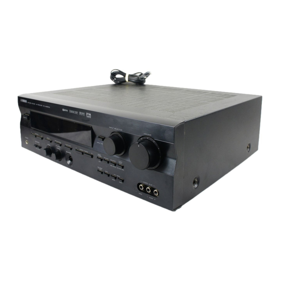
RX-V496RDS Natural Sound AV Receiver Ampli-tuner audio-vidéo OWNER’S MANUAL MODE D’EMPLOI BEDIENUNGSANLEITUNG BRUKSANVISNING MANUALE DI ISTRUZIONI MANUAL DE INSTRUCCIONES GEBRUIKSAANWIJZING… -
Page 2
Using this unit with a higher voltage than specified is dangerous and may result in fire or other accidents. YAMAHA will not be held responsible for any damage resulting from the use of this unit with a voltage other than that specified. -
Page 3: Table Of Contents
Dolby Digital Decoder Dolby Pro Logic Decoder DTS Decoder CINEMA DSP: Theater-like Sound Experience by the Combination of YAMAHA DSP Technology and Dolby Digital, Dolby Pro Logic or DTS Automatic Input Balance Control for Dolby Pro Logic decoding Sophisticated FM/AM Tuner…
-
Page 4: Getting Started
Checking the Package Contents Check that the following items are included in your package. Remote control Battery Installation in the Remote Control Turn the remote control over and slide the battery compartment cover in the direction of the arrow. Insert the batteries (AAA, R03 or UM-4 type) according the polarity markings on the inside of the battery compartment.
-
Page 5
Using the Remote Control Remote control sensor Within approximately 6 m (20 feet) The remote control transmits a directional infrared beam. Be sure to aim the remote control directly at the infrared sensor during operation. When the sensor is covered or there is a large object between the remote control and the sensor, the sensor cannot receive signals. -
Page 6: Controls And Functions
Front Panel – STANDBY/ON Press this switch to turn on the power of this unit or to set this unit in the standby mode. Before turning the power on, set VOLUME to the “m” position. Standby mode In this mode, this unit consumes a very small quantity of power to receive infrared-signals from the remote control.
-
Page 7: Controls And Functions
Tone controls These controls are only effective for the sound from the main speakers. a) BASS Turn this control clockwise to increase or counterclockwise to decrease the low-frequency response. The “0” position produces a flat response. b) TREBLE Turn this control clockwise to increase or counterclockwise to decrease the high-frequency response.
-
Page 8
CONTROLS AND FUNCTIONS Display t indicator The “t” indicator lights up when the built-in DTS decoder is turned on. DSP program indicators The name of the selected DSP program lights up in the following cases: • When the tuner is selected as the input source. •… -
Page 9: Remote Control
Remote Control This section describes basic operation of this unit with the remote control. First, press AMP(TUNER) on the component selector. Refer to “PRESET REMOTE CONTROL” on page 43 for full details. Indicator This flashes in red when pressing a button on the remote control.
-
Page 10: Preparation
LFE (low frequency effect) channel with high fidelity when playing back a source encoded with Dolby Digital or DTS. The YAMAHA Active Servo Processing Subwoofer System is ideal for natural and lively bass reproduction.
-
Page 11: Connections
When you connect other YAMAHA audio components (such as a tape deck, MD recorder and CD player or changer), connect it to the terminals with the same number labels as !, #, $ etc. YAMAHA applies this labeling system to all its products.
-
Page 12
CONNECTIONS Connecting the Antennas Both AM and FM indoor antennas are included with this unit. In general, these antennas should provide sufficient signal strength. However, a properly installed outdoor antenna provides clearer reception than an indoor one. If you experience poor reception quality, an outdoor antenna may improve the quality. -
Page 13: Connecting The Am Loop Antenna
AM loop antenna (included) AM loop antenna Connecting the AM loop antenna Antenna stand Outdoor AM antenna Vinyl covered wire (5 m to 10 m) Ground (GND terminal) The AM loop antenna can be removed from the stand and attached to a wall, etc. However, note that the reception sensitivity may deteriorate if the antenna is attached to a metal or steel reinforced wall.
-
Page 14
CONNECTIONS Connecting an Audio Component Turntable OUTPUT OUTPUT CD player Be sure to connect the right channel (R), left channel (L), input (IN) and output (OUT) properly. (Europe model) LINE OUT LINE IN Tape deck or MD recorder PHONO terminals These terminals are used to connect a turntable with an MM or high-output MC cartridge. -
Page 15
Connecting a Video Component DVD/LD player ANALOG VIDEO COAXIAL AUDIO OUT DIGITAL OUT AUDIO AUDIO Audio signal terminals Be sure to connect the right channel (R), left channel (L), input (IN) and output (OUT) properly. Video signal terminals Be sure to connect the input (IN) and output (OUT) properly. -
Page 16
CONNECTIONS S VIDEO terminals DVD/LD player TV Monitor S VIDEO OUT S VIDEO IN S VIDEO S VIDEO IN VIDEO AUX terminals (on the front panel) AUDIO OUT R AUDIO OUT L VIDEO OUT Connecting to an External Decoder External decoder MAIN SURROUND CENTER… -
Page 17: Connecting Speakers
Main speakers A Right Subwoofer connection If you have a subwoofer with built- in amplifier, including the YAMAHA Active Servo Processing Subwoofer System, connect the input terminal of the subwoofer system to the SUBWOOFER OUTPUT terminal of this unit. Be sure to connect the right channel (R), left channel (L), “+”…
-
Page 18
CONNECTIONS Speaker cables 10 mm (3/8”) Connecting to the MAIN SPEAKERS terminals Red: positive (+) Black: negative (–) Connecting to the REAR and CENTER SPEAKERS terminals Red: positive (+) Black: negative (–) Remove approx. 10 mm (3/8”) of insulation from each of the speaker cable. Twist the exposed wires of the cable together to prevent short circuits. -
Page 19: Impedance Selector Switch
IMPEDANCE SELECTOR Switch WARNING Do not change the IMPEDANCE SELECTOR switch setting while the power to this unit is on, otherwise the unit may be damaged. If this unit fails to turn on when STANDBY/ON is pressed, the IMPEDANCE SELECTOR switch may not be fully slide to either position.
-
Page 20: Adjusting The Speaker Balance
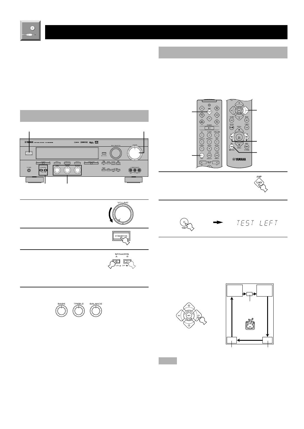
ADJUSTING THE SPEAKER BALANCE This procedure lets you adjust the sound output level balance between the main, center and rear speakers by using the built-in test tone generator. When this adjustment is performed, the sound output level heard at the listening position will be the same from each speaker.
-
Page 21: Adjusting The Speaker Balance
Adjust BALANCE on the front panel so that the sound output level of the right main speaker and the left main speaker is the same. Press TIME/LEVEL repeatedly to select the speaker to be adjusted. “CENTER”, “R SUR.” or “L SUR.” appears on the display.
-
Page 22: Basic Operation
When using the remote control, press AMP(TUNER) on the component selector. – – Set VOLUME to the “m” position. Turn the power on. Front panel Press SPEAKERS A or B to select the main speakers to be used. If you use two main speaker systems, press both A and B.
-
Page 23: Playing A Source
Play the source. Refer to the instructions for the source component (and page 28 for details about tuning). Note • When controlling an audio/video component (tape deck, MD recorder, CD player, DVD/LD player, etc.) with the remote control, press one of the component selector buttons, (TAPE/MD, CD, DVD/LD, etc.), which corresponds to the component you want to control.
-
Page 24
PLAYING A SOURCE Input Mode (for the DVD/LD and TV/ digital TV and satellite tuner sources) This unit allows you to switch the input mode for sources that send both digital and analog signals to this unit. The AUTO, DTS and ANALOG input modes are provided. When you turn on the power of this unit, the input mode for the DVD/LD source is always set to AUTO and for TV/ digital TV or satellite tuner source is set according to “SAT… -
Page 25
Notes on playing a source encoded with DTS • If “DATA ERROR” appears on the display while playing an LD source encoded with DTS, stop playback and turn the player off and then on again. • If the digital output data of the player has been processed in any way, you may not be able to perform DTS decoding even if you make a digital connection between this unit and the player. -
Page 26: Digital Sound Field Processor (Dsp) Effect
DIGITAL SOUND FIELD PROCESSOR (DSP) EFFECT Selecting a DSP Program You can enhance your listening experience by selecting a DSP program. Refer to pages 25 to 27 for details about each program. – – On the front panel Make sure that the effect speakers (center, rear, and subwoofer) are turned on.
-
Page 27: Sound Field Program
This unit incorporates a sophisticated, multi-program digital sound field processor (DSP). This processor allows you to electronically expand and change the shape of the audio sound field from both audio and video sources, creating a theater- like experience in your listening room. You can create outstanding audio sound by selecting a suitable DSP program (this will, of course, depend on what you are listening to).
-
Page 28
SOUND FIELD PROGRAM PROGRAM MOVIE [1] 70 mm SPECTACLE THEATER 1 ( o x ) • Input source: • Output channel: • DSP: [2] DGTL SPECTACLE ( g x ) • Input source: • Output channel: • DSP: [3] DTS SPECTACLE ( t x ) •… -
Page 29
PROGRAM MONO MOVIE • Input source: Monaural • Output channel: 1 channel • DSP: TV SPORTS • Input source: Audio/Video • Output channel: 2 to 5.1 channels • DSP: 2 to 3 (presence & surround) For Hi-Fi audio sources PROGRAM DISCO •… -
Page 30: Tuning
Automatic tuning is effective when station signals are strong and there is no interference. However, if the signal from the station you want to select is weak, you must tune in to it manually (manual tuning). – – Automatic Tuning Use INPUT SELECTOR to select the tuner as the input source.
-
Page 31
Automatic Preset Tuning (for RDS stations only) You can make use of the automatic preset tuning function for RDS stations only. This function enables the unit to automatically tune in with strong signals and to sequentially store up to 40 RDS stations (5 groups x 8 stations). (Refer to pages 32 to 34 for details on RDS stations.) –… -
Page 32: Manual Preset Tuning
TUNING Manual Preset Tuning You can also store up to 40 stations (5 groups x 8 stations) manually. – – Tune in to the desired station. Refer to page 28 for the tuning procedure. Press MEMORY. The “MEMORY” indicator flashes for about five seconds.
-
Page 33: Exchanging Preset Stations
Exchanging Preset Stations You can exchange the assignment of two preset stations with each other. Example: If you want to exchange preset station “E1” with “A5”. – – Recall preset station “E1”. Refer to the procedure in the section “To Recall a Preset Station”…
-
Page 34: Receiving Rds Stations
Radio Data System (RDS) is a data transmission system by FM stations in many countries. Stations using this system transmit an inaudible stream of data in addition to the normal radio signal. RDS data contains various information such as PI (Program Identification), PS (Program Service name), PTY (Program Type), RT (Radio Text), CT (Clock Time), EON (Enhanced Other Networks), etc.
-
Page 35
PTY SEEK Function If you select the desired program type, the unit automatically searches all preset RDS stations that are broadcasting a program of the required type. – – Press PTY SEEK MODE to set the unit in the PTY SEEK mode. The program type of the station being received or “NEWS”… -
Page 36: Eon Function
RECEIVING RDS STATIONS EON Function This function uses the EON data service on the RDS station network. If you simply select the desired program type (NEWS, INFO, AFFAIRS or SPORT), the unit automatically searches for all preset RDS stations that are scheduled to broadcast a program of the required type and switches from the station being currently received to the new station when the broadcasts starts.
-
Page 37: Recording A Source On Tape, Md Or Video Cassette
RECORDING A SOURCE ON TAPE, MD OR VIDEO CASSETTE Recording adjustments and other operations are performed from the tape deck, MD recorder or VCR. Refer to the instructions for these components. – – Set VOLUME to the “m” position. Select the source you want to record. Front panel Begin recording by the tape deck, MD recorder or VCR connected to this unit.
-
Page 38: Advanced Operation
This unit provides you with the following items in the SET MENU to maximize the performance of your system and expand your enjoyment for audio listening and video watching. 1. CENTER SP 2. REAR SP 3. MAIN SP 4. BASS OUT 5.
-
Page 39: Set Menu
Description of Each Item 1. CENTER SP Choices: LRG (Large)/SML (Small)/NONE Preset position: LRG (Large) LRG (Large) Select this position if your center speaker is approximately the same size as the main speakers. In this position, full- range signals on the center channel are directed to the center speaker.
-
Page 40
SET MENU 5. MAIN LVL Choices: NORM (Normal)/–10 dB Preset position: NORM (Normal) NORM (Normal) Normally select this position. –10 dB Select this position if the sound output from the main speakers is too loud and cannot be balanced with the sound output from the center and rear speakers. -
Page 41
8. DTS LFE (Adjusting the output level of the LFE channel for DTS) Control range: –10 dB to +10 dB (in 1 dB steps) Preset value: 0 dB Note • This adjustment is effective only when DTS is being decoded and the selected source encoded with DTS contains LFE signals. -
Page 42: Delay Time And Speaker Output Levels
DELAY TIME AND SPEAKER OUTPUT LEVELS When using the digital sound field processor with the Dolby Pro Logic decoder, Dolby Digital decoder or DTS decoder, you can adjust the delay time between the main sound and sound effect, and each speaker’s output level as you wish. Delay Time You can adjust the time difference between the beginning of the sound from the main speakers and the beginning of the…
-
Page 43: Delay Time And Speaker Output Levels
Adjusting Method Adjustments should be performed with the remote control while watching the information on the display. Press AMP(TUNER) on the component selector. Press TIME/LEVEL repeatedly to select the item you want to adjust. Each time you press TIME/LEVEL, the selected item changes and appears on the display as below.
-
Page 44: Sleep Timer
The SLEEP timer can be used to automatically set this unit in the standby mode. This timer is useful when you are going to sleep while enjoying a broadcast or other desired input source. The SLEEP timer can only be set with the remote control.
-
Page 45: Preset Remote Control
The provided remote control is factory set to control not only this unit but also most YAMAHA audio components connected to it. There are eight component selector buttons. Press one of these buttons which corresponds to the component you want to control with the remote control.
-
Page 46: Preset Remote Control
POWER (TAPE) This button turns this unit on if you have set the code for a YAMAHA tape deck. This button turns on the tape deck that has a remote control with a power button if you have set the code for another manufacturer.
-
Page 47
POWER This button turns this unit on if you have set the code for a YAMAHA CD player. This button turns on the CD player that has a remote control with a power button if you have set the code for another manufacturer. -
Page 48: Dvd Menu Mode
Press DVD/LD. POWER (DVD) This button turns this unit on if you have set the code for a YAMAHA DVD player. This button turns on the DVD player that has a remote control with a power button if you have set the code for another manufacturer.
-
Page 49: Vcr Mode
VCR MODE Note • TV VOLUME, TV INPUT and TV SLEEP function if you have set the code for your TV. VCR POWER VCR CHANNEL +/– VOLUME MUTE TV SLEEP VCR REC Press this button twice to start recording. VCR STOP VCR REWIND TV MODE Note…
-
Page 50: Setup Codes
PRESET REMOTE CONTROL Advanced Information Setup codes You can set the code for the manufacturer of your component after pressing the component selector buttons other than AMP(TUNER). Turn on your component to be used. Press one of the component selector buttons which corresponds to the component to be…
-
Page 51
0101 CBL/SAT Satellite tuner 0006 0002 DVD/LD DVD player 0008 (YAMAHA DVD player) CD player 0005 (YAMAHA CD player) TAPE/MD Tape deck 0004 (YAMAHA Tape deck) We recommend that you write all the code numbers you have set on the “Quick Reference Card”. -
Page 52: Appendix
If the unit fails to operate normally, check the following points to determine whether the fault can be corrected by the simple measures suggested. If it cannot be corrected, or if the fault is not listed in the SYMPTOM column, disconnect the power cord and contact your authorized YAMAHA dealer or service center. General…
-
Page 53: Troubleshooting
SYMPTOM No sound from the “BASS OUT” in the SET MENU is set to the subwoofer. SW or MAIN position when playing a 2-channel source. The source does not contain low bass signals (below 90 Hz). A “humming” sound can Incorrect cable connections.
-
Page 54
TROUBLESHOOTING Remote control SYMPTOM The remote control does Direct sunlight or lighting (from an inverter not work. type of fluorescent lamp, etc.) is striking the remote control sensor of this unit. The batteries are weak. The unit or other The component to be controlled has not been component cannot be selected. -
Page 55: Specifications
AUDIO SECTION • Minimum RMS Output Power 20 Hz to 20 kHz, 0.06% THD, 8 ohms Main L/R, Center, Rear L/R … 70 W*/65 W 1 kHz, 0.09% THD, 8 ohms Main L/R, Center, Rear L/R … 80 W*/70 W •…
-
Page 56: Glossary
Dolby Surround, Dolby Digital or DTS Digital Surround sounds. The YAMAHA “CINEMA DSP” logo indicates those programs that are created by the combination of YAMAHA DSP technology and Dolby Surround, Dolby Digital or DTS. LFE 0.1 Channel This channel is for reproduction of low bass signals.
-
Page 57: Index
Accessories … 2 AC outlet … 17 Antennas … 10, 11 BALANCE … 21 BGV (background video) function … 21 Canceling sound effect … 24 CINEMA DSP … 27, 54 Connections Antennas … 10, 11 Audio components (tape deck/MD recorder, CD player and turntable) …
-
Page 58
LIST OF MANUFACTURER’S CODES LISTES DES CODES FABRICANT VERZEICHNIS DER HERSTELLERCODES LISTA ÖVER TILLVERKARKODER ELENCO DEI CODICI DEL FABBRICANTE LISTA DE CÓDIGOS DE FABRICANTES LIJST VAN CODES VAN FABRIKANT Clarivox Clatronic Admiral 0411, 0451, 0911, Concerto 1021, 1081 Condor Aiko 0891 Contec Akai… -
Page 59
Konka 2701 Korting 0431, 1011, 1021, 1081, 1541 Neckermann 0601, 1171 Lenoir 0601, 1511 Leyeo 1181 Lifetec 2591, 2601, 2611, Nediator 2621, 2641, 2651, Nicamagic 2661, 2671, 2681, Nikkai 2691, 2711, 2761, 2771, 2781 Nobliko Loewe Opta 0121, 0131, 0581, 0611, 1081 Nogamatic Logic… -
Page 60
Thorn-Ferguson 0281, 0371, 0551, SATELLITE TUNER 0651, 0781, 0861, Akai 0881, 1131, 1181, Alba 1361, 1461, 1971, Amstrad 1991, 2281 0141, 0791, 1471 Ankaro Toshiba 0141, 0381, 0481, 1221, 1271, 1701, Astra 1741, 1851, 2151, Barcom 2801, 2811 Blaupunkt Trans Continens 0451 Bmc Satellite Tristar 2281… -
Page 61
0192, 0572, 0812, Samsung 0148 0822, 0912 Sharp 0068 0052, 0072, 0622, Sony 0028 0652, 1192 Toshiba 0088 0042, 0142 Yamaha 0008, 0048 0482, 0532, 0562, 0572 LD PLAYER 0052, 0152, 0182 Aiwa 0137 Funai 0137 0002, 0012, 0052, Hitachi 0047… -
Page 62
0255, 0285, 0295, MD RECORDER 0305, 0345, 0135, Yamaha 0755, 0765, 1315, 1325 TAPE DECK Nakamichi 0635, 0645, 1565 0405, 0535, 0775, Akai 0785 Denon Neckerman 0155, 0225 Grundig Nikko 0835, 1165 Harman Oceanic 0185 Okano 0155, 0225 Kenwood Onkyo… -
Page 63
YAMAHA ELECTRONIQUE FRANCE S.A. RUE AMBROISE CROIZAT BP70 CROISSY-BEAUBOURG 77312 MARNE-LA-VALLEE CEDEX02, FRANCE YAMAHA ELECTRONICS (UK) LTD. YAMAHA HOUSE, 200 RICKMANSWORTH ROAD WATFORD, HERTS WD1 7JS, ENGLAND YAMAHA SCANDINAVIA A.B. J A WETTERGRENS GATA 1, BOX 30053, 400 43 VÄSTRA FRÖLUNDA, SWEDEN Printed in Malaysia ID V502870-2 YAMAHA MUSIC AUSTRALIA PTY, LTD. -
Page 64
Quick Reference Card AMP(TUNER) POWER POWER Input selector buttons A/B/C/D/E EFFECT TEST PRESET+/– VOLUME VOLUME TV VOLUME MUTE MUTE SLEEP SLEEP TV INPUT REC/PAUSE +/– PLAY PRG+, DIR A (TAPE) PRG– SKIP– (MD) TIME LEVEL REWIND (TAPE) SEARCH (MD) MENU TAPE/MD POWER Input selector… -
Page 65
Quick Reference Card DVD MENU POWER Numeric buttons CLEAR CHANNEL+/– DISC SKIP+/– VOLUME VOLUME TV VOLUME MUTE RETURN TV SLEEP INDEX TV INPUT VCR REC MENU UP MENU SELECT VCR PLAY MENU LEFT MENU RIGHT TITLE MENU REWIND MENU DOWN Press this button twice to start recording.

OWNER’S MANUAL
MODE D’EMPLOI
BEDIENUNGSANLEITUNG
BRUKSANVISNING
MANUALE DI ISTRUZIONI
MANUAL DE INSTRUCCIONES
GEBRUIKSAANWIJZING
RX—V496RDS
Natural Sound AV Receiver
Ampli-tuner audio-vidéo
RX-V496RDS
G B
1/17/0, 6:25 PM
CAUTION
CAUTION: READ THIS BEFORE OPERATING YOUR UNIT.
1. To assure the finest performance, please read this
manual carefully. Keep it in a safe place for future
reference.
2. Install this unit in a cool, dry, clean place — away
from windows, heat sources, sources of excessive
vibration, dust, moisture and cold. Avoid sources of
humming (transformers, motors). To prevent fire or
electrical shock, do not expose the unit to rain or
water.
3. Never open the cabinet. If something drops into the
unit, contact your dealer.
4. Do not use force on switches, controls or connection
wires. When moving the unit, first disconnect the
power cord and then the wires connected to other
component. Never pull the wires themselves.
5. The openings on the cover assure proper ventilation
of the unit. If these openings are obstructed, the
temperature inside the unit will rise rapidly.
Therefore, avoid placing objects against these
openings, and install the unit in a well-ventilated area
to prevent fire and damage.
Be sure to allow a space of at least 20 cm behind,
20 cm on both sides and 30 cm above the top panel
of the unit to prevent fire and damage.
6. The voltage used must be the same as that specified
on this unit. Using this unit with a higher voltage than
specified is dangerous and may result in fire or other
accidents. YAMAHA will not be held responsible for
any damage resulting from the use of this unit with a
voltage other than that specified.
7. Digital signals generated by this unit may interfere
with other component such as tuners, receivers and
TVs. Move this unit farther away from such
component if interference is observed.
8. Always set VOLUME to the “m” position before
starting the audio source play. Increase the volume
gradually to an appropriate level after playback has
been started.
9. Do not attempt to clean the unit with chemical
solvents; this might damage the finish. Use a clean,
dry cloth.
10. Be sure to read the “TROUBLESHOOTING” section
regarding common operating errors before
concluding that the unit is faulty.
11. When not planning to use this unit for a long period
of time (e.g., a vacation), disconnect the AC power
cord from the wall outlet.
12. To prevent lightning damage, disconnect the AC
power cord and disconnect the antenna cable when
there is an electrical storm.
13. Grounding or polarization — Precautions should be
taken so that the grounding or polarization of the unit
is not defeated.
14. AC outlet — Do not connect audio component to the
AC outlet on the rear panel if that component
requires more power than the outlet is rated to
provide.
This unit is not disconnected from the AC power source
as long as it is connected to the wall outlet, even if this
unit itself is turned off. This state is called the standby
mode. In this state, this unit is designed to consume a
very small quantity of power.
■ For U.K. customers
If the socket outlets in the home are not suitable for the plug
supplied with this appliance, it should be cut off and an
appropriate 3 pin plug fitted. For details, refer to the
instructions described below.
Note
• The plug severed from the mains lead must be destroyed, as a
plug with bared flexible cord is hazardous if engaged in a live
socket outlet.
■ Special Instructions for U.K. Model
IMPORTANT
THE WIRES IN MAINS LEAD ARE COLOURED IN
ACCORDANCE WITH THE FOLLOWING CODE:
Blue: NEUTRAL
Brown: LIVE
As the colours of the wires in the mains lead of this
apparatus may not correspond with the coloured
markings identifying the terminals in your plug, proceed
as follows:
The wire which is coloured BLUE must be connected to
the terminal which is marked with the letter N or
coloured BLACK. The wire which is coloured BROWN
must be connected to the terminal which is marked with
the letter L or coloured RED.
Making sure that neither core is connected to the earth
terminal of the three pin plug.
0101V496RDS_caution_EN 1/6/0, 10:19 AM2

EnglishBASIC OPERATION
ADVANCED OPERA
TION APPENDIX
INTRODUCTION PREPARATION
1
FEATURES
5-Channel Power Amplification
◆ Minimum RMS Output
(0.06% THD, 20 Hz – 20 kHz)
Main: 65 W + 65 W (8 Ω)
Center: 65 W (8 Ω)
Rear: 65 W + 65 W (8 Ω)
Multi-mode Digital Sound Field
Processing
◆ Digital Sound Field Processor (DSP)
◆ Dolby Digital Decoder
◆ Dolby Pro Logic Decoder
◆ DTS Decoder
◆ CINEMA DSP: Theater-like Sound Experience by
the Combination of YAMAHA DSP Technology
and Dolby Digital, Dolby Pro Logic or DTS
◆ Automatic Input Balance Control for Dolby Pro
Logic decoding
Sophisticated FM/AM Tuner
◆ 40-Station Random Access Preset Tuning
◆ Automatic Preset Tuning
◆ Preset Station Shifting Capability (Preset Editing)
◆ Multi-Functions for RDS Broadcast Reception
Other Features
◆ “SET MENU” which Provides You with 11 Items
for Optimizing This Unit for Your Audio/Video
System
◆ Test Tone Generator for Easier Speaker Balance
Adjustment
◆ 6-Channel External Decoder Input for Other Future
Formats
◆ Video Signal Input/Output Capability
(Including S Video Connections)
◆ 2 Optical/1 Coaxial Digital Signal Input Terminals
◆ SLEEP Timer
◆ Remote Control with Preset Manufacturer Codes
INTRODUCTION
CONTENTS
PREPARATION
SPEAKER SETUP………………………………………………. 8
CONNECTIONS…………………………………………………. 9
ADJUSTING THE SPEAKER BALANCE ………… 18
BASIC OPERATION
PLAYING A SOURCE ………………………………………. 20
DIGITAL SOUND FIELD PROCESSOR (DSP)
EFFECT ………………………………………………………… 24
SOUND FIELD PROGRAM ……………………………… 25
TUNING …………………………………………………………… 28
RECEIVING RDS STATIONS…………………………… 32
RECORDING A SOURCE ON TAPE, MD OR
VIDEO CASSETTE ……………………………………….. 35
ADVANCED OPERATION
SET MENU……………………………………………………….. 36
DELAY TIME AND SPEAKER
OUTPUT LEVELS …………………………………………. 40
SLEEP TIMER …………………………………………………. 42
PRESET REMOTE CONTROL ………………………… 43
APPENDIX
TROUBLESHOOTING …………………………………….. 50
SPECIFICATIONS……………………………………………. 53
GLOSSARY………………………………………………………. 54
INDEX ……………………………………………………………… 55
INTRODUCTION
FEATURES ………………………………………………………… 1
CONTENTS ……………………………………………………….. 1
GETTING STARTED …………………………………………. 2
CONTROLS AND FUNCTIONS …………………………. 4
Manufactured under license from Dolby
Laboratories. “Dolby”, “Pro Logic” and the
double-D symbol are trademarks of Dolby
Laboratories. Confidential Unpublished Works.
©1992 – 1997 Dolby Laboratories, Inc. All
rights reserved.
Manufactured under license from Digital Theater Systems, Inc.
US Pat. No. 5,451,942 and other world-wide patents issued and
pending. “DTS”, “DTS Digital Surround”, are trademarks of
Digital Theater Systems, Inc. Copyright 1996 Digital Theater
Systems, Inc. All Rights Reserved.
y indicates a tip for your operation.
0102V496RDS01-07_EN 1/6/0, 10:19 AM1
2
GETTING STARTED
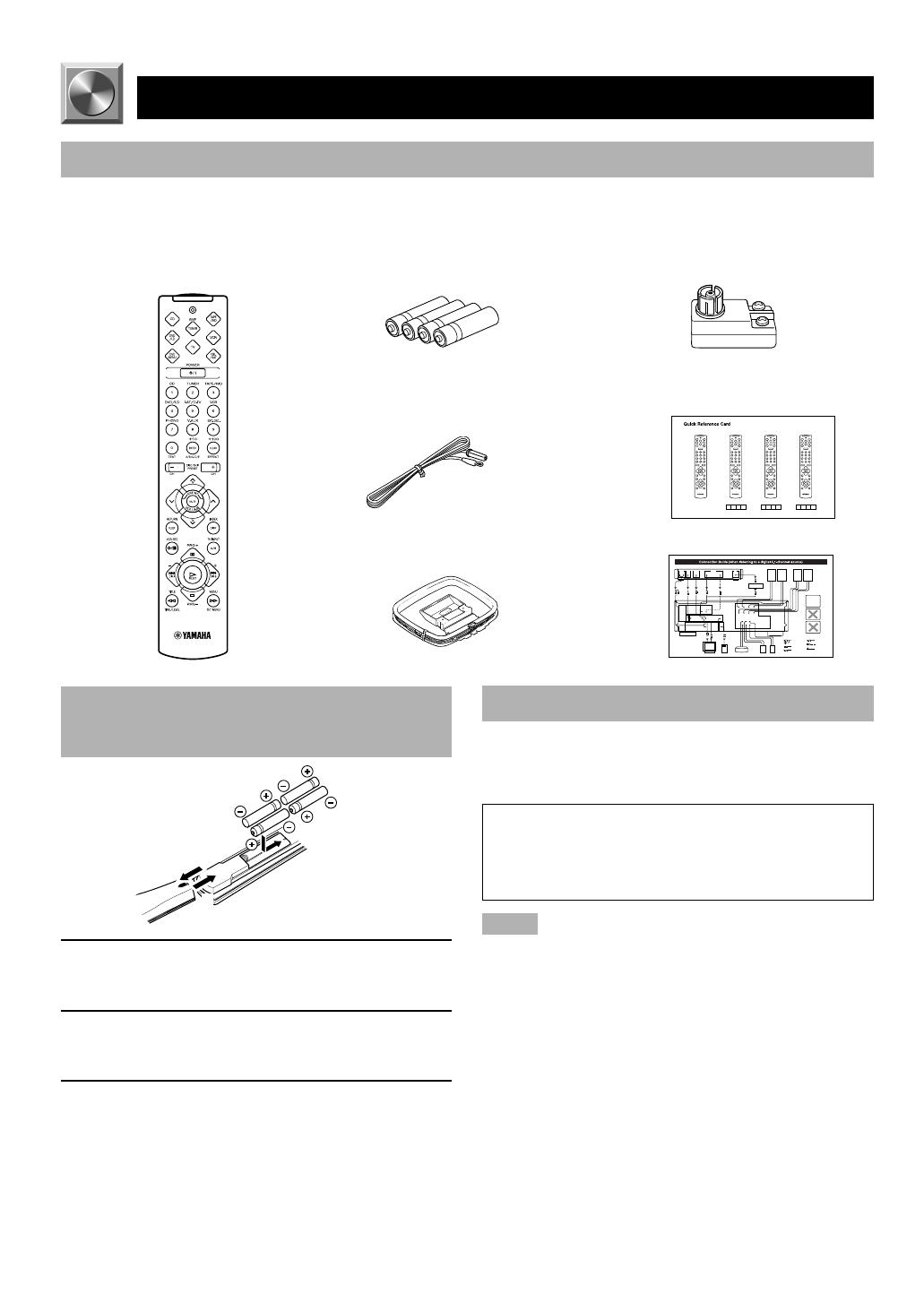
Checking the Package Contents
Check that the following items are included in your package.
2
1
3
Remote control Batteries (AAA, R03, UM-4 type) 75-ohm/300-ohm antenna adapter
(U.K. model only)
Indoor FM antenna
AM loop antenna
Battery Installation in the Remote
Control
1 Turn the remote control over and slide the
battery compartment cover in the direction of
the arrow.
2 Insert the batteries (AAA, R03 or UM-4 type)
according the polarity markings on the inside
of the battery compartment.
3 Close the battery compartment cover.
Battery Replacement
If the remote control operates only when it is close to the
unit, the batteries are weak. Replace all the batteries with
new ones.
Be sure to replace the batteries within about two minutes.
If it takes longer than two minutes, the codes preset for
the remote control will return to the factory settings.
(Refer to pages 43 to 49 about the remote control.)
Notes
• Use only AAA, R03 or UM-4 batteries for replacement.
• Be sure the battery polarity is correct. (See the illustration inside
the battery compartment.)
• Remove the batteries if the remote control will not be used for an
extended period of time.
• If the batteries have leaked, dispose of them immediately. Avoid
touching the leaked material or letting it come into contact with
clothing, etc. Clean the battery compartment thoroughly before
installing new batteries.
Quick reference card
Connection guide
0102V496RDS01-07_EN 1/6/0, 10:19 AM2

3
EnglishBASIC OPERATION
ADVANCED OPERA
TION APPENDIX
INTRODUCTION PREPARATION
Using the Remote Control
The remote control transmits a directional infrared beam. Be
sure to aim the remote control directly at the infrared sensor
during operation. When the sensor is covered or there is a
large object between the remote control and the sensor, the
sensor cannot receive signals. The sensor may not be able to
receive signals properly when it is exposed to direct sunlight
or a strong artificial light (such as a fluorescent or strobe
light). In this case, change the direction of the light or
reposition the unit to avoid direct lighting.
Notes
• Handle the remote control with care.
• Do not spill water, tea or other liquids on the remote control.
• Do not drop the remote control.
• Do not leave or store the remote control in the following
conditions:
– high humidity or temperature such as near a heater, stove or
bath;
– dusty places; or
– extremely low temperature.
GETTING STARTED
Remote control
sensor
Within approximately 6 m
(20 feet)
0102V496RDS01-07_EN 1/6/0, 10:19 AM3
4
LR
–
+
–
+
12 3 4 65
7890qwerty
uiopasdf
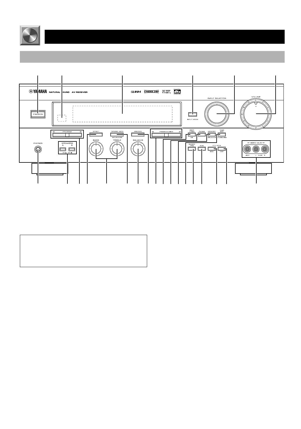
6VOLUME
Turn this control to turn up or down the volume.
7 PHONES jack
Connect the headphones to the PHONES jack. You can
listen to the sound to be output from the main speakers
through the headphones.
When using headphones only, set both SPEAKERS A and B
to the OFF position and press EFFECT to turn off the effect
speakers (center and rear) (so that no DSP program name
appear on the display).
8 SPEAKERS
Set A or B (or both A and B) to the ON position for the main
speaker system (connected to this unit) that you want to use.
Set the button(s) to the OFF position for the main speaker
system that you don’t want to use.
9 PROGRAM selector
Press l or h to select a DSP program when the effect
speakers (center and rear) are turned on. The name of the
selected program appears on the display.
0 EFFECT
Press this button to turn on or off the effect speakers (center
and rear). If you turn them off, all Dolby Digital and DTS
audio signals are directed to the right and left main
speakers. In that case, the output levels of the right and left
speakers may not match.
CONTROLS AND FUNCTIONS
Front Panel
1 STANDBY/ON
Press this switch to turn on the power of this unit or to set
this unit in the standby mode. Before turning the power on,
set VOLUME to the “m” position.
Standby mode
In this mode, this unit consumes a very small quantity of
power to receive infrared-signals from the remote
control.
2 Remote control sensor
This receives signals from the remote control.
3 Display
This shows various information. (Refer to page 6 for
details.)
4 INPUT MODE
Press this button to select the input mode among AUTO,
DTS and ANALOG for the DVD/LD, TV/digital TV and
satellite tuner sources.
5 INPUT SELECTOR
Turn this selector to select the input source (TUNER, CD,
PHONO, V-AUX, VCR, SAT/D-TV, DVD/LD) that you
want to listen to or watch. The arrow for the selected input
source indicator lights up on the display.
0102V496RDS01-07_EN 1/19/0, 10:26 AM4

5
EnglishBASIC OPERATION
ADVANCED OPERA
TION APPENDIX
INTRODUCTION PREPARATION
q Tone controls
These controls are only effective for the sound from the
main speakers.
a) BASS
Turn this control clockwise to increase or counterclockwise
to decrease the low-frequency response. The “0” position
produces a flat response.
b) TREBLE
Turn this control clockwise to increase or counterclockwise
to decrease the high-frequency response. The “0” position
produces a flat response.
w TAPE/MD MON / EXT. DECODER
Press this button to select a tape or an MD source. The
“TAPE/MD MONITOR” indicator lights up on the display.
When you press the button next, the “TAPE/MD
MONITOR” indicator goes off, “EXT. DECODER” appears
on the display and you can listen to a source connected to
the EXTERNAL DECODER INPUT terminals.
e BALANCE
This control is only effective for the sound from the main
speakers.
Turn the control to adjust the balance of the output volume
from the right and left main speakers to compensate for
sound imbalance caused by the speaker location or listening
room conditions.
r A/B/C/D/E
Press this button to select one of a group (A to E) of preset
stations.
t PRESET/TUNING
When “ z ” appears
This button is used to select a preset station number (1 to 8).
Press h to select a higher and l to select a lower preset
station number.
When “ z ” goes off
This button is used for tuning. Press h to tune in to higher
frequencies, and l to tune in to lower frequencies.
When this unit is in the PTY SEEK mode, press this button
to select a program type.
y PRESET/TUNING, EDIT
Press this button to turn on or off “ z ” on the display and
switch the function between for storing a broadcasting
station (preset tuning) and for tuning. This button is also
used to exchange the assignment of two preset stations with
each other.
u FM/AM
Press this button to switch the reception band between FM
and AM.
i MEMORY (MAN’L/AUTO FM)
Press this button to store the broadcasting stations. Hold
down this button for more than three seconds to begin
automatic preset tuning.
o TUNING MODE (AUTO/MAN’L MONO)
Press this button to switch the tuning mode between
automatic and manual. To use the automatic tuning method,
press this button so that the “AUTO” indicator lights up on
the display. To use the manual tuning method, press this
button so that the “AUTO” indicator goes off.
p RDS MODE/FREQ
When an RDS station is received, press this button to
change the display mode among the PS mode, PTY mode,
RT mode, CT mode (if the station offers those RDS data
services) and/or frequency display mode in turn.
a EON
Press this button to select the desired program type (NEWS,
INFO, AFFAIRS, SPORT) when you want to tune in to a
radio program of that type automatically.
s PTY SEEK MODE
Press this button to set the unit in the PTY SEEK mode.
d PTY SEEK START
Press this button to begin searching for a station after the
desired program type has been selected in the PTY SEEK
mode.
f VIDEO AUX terminals
Connect an auxiliary audio or video input source such as a
camcorder to these terminals. Use INPUT SELECTOR to
select the source connected to these terminals.
CONTROLS AND FUNCTIONS
0102V496RDS01-07_EN 1/6/0, 10:19 AM5
6
Display
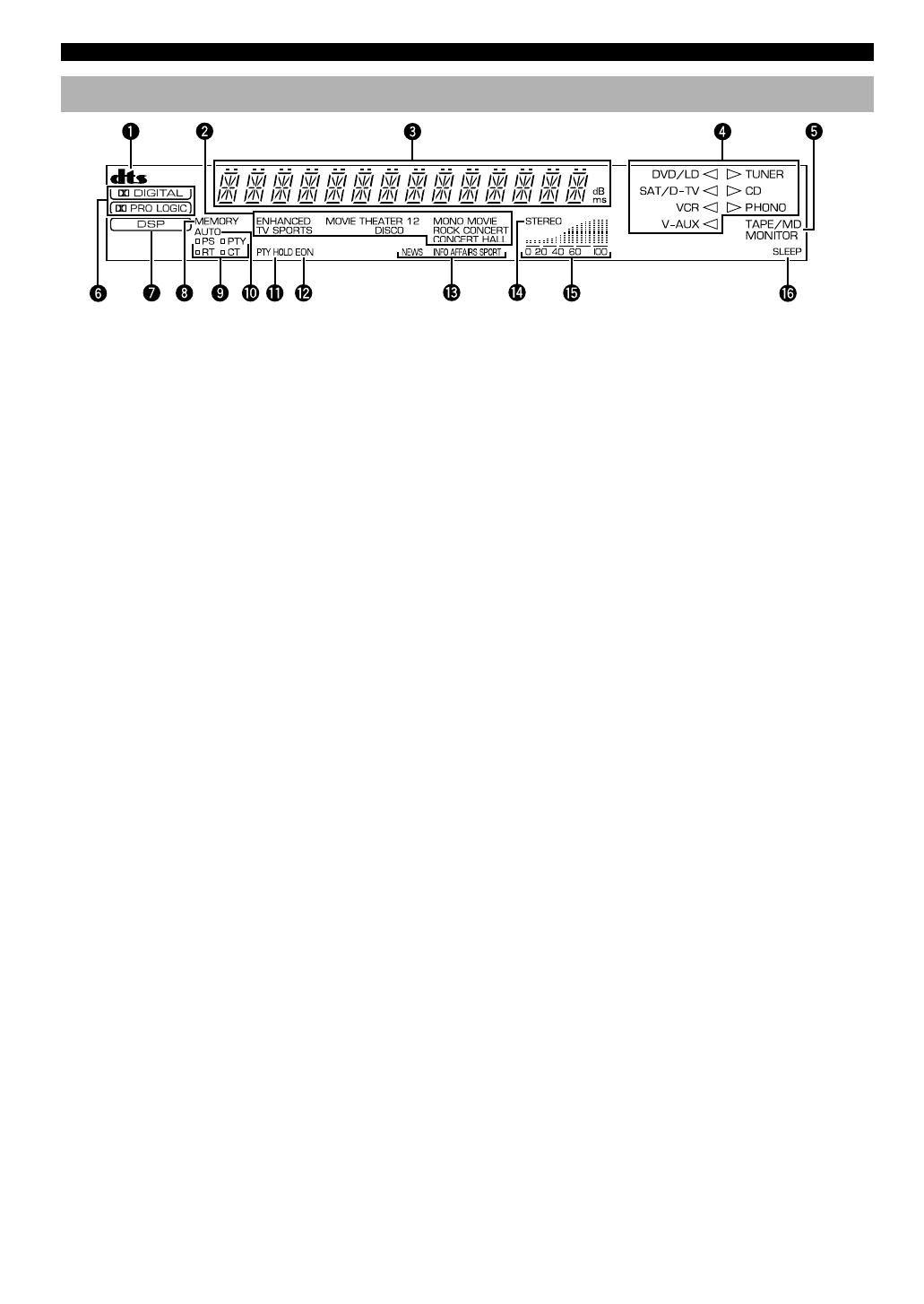
8 MEMORY indicator
This flashes for about five seconds after pressing
MEMORY. During this period, the displayed station can be
stored in the memory.
9 RDS mode indicators
The name(s) of the RDS data offered by the currently
received RDS station light(s) up. Illumination of the red
indicator next to the RDS data name shows that the
corresponding RDS mode is now selected.
0 AUTO indicator
This lights up when the unit is in the automatic tuning
mode.
q PTY HOLD indicator
This lights up while searching for stations in the PTY SEEK
mode.
w EON indicator
This lights up when an RDS station that offers the EON data
service is being received.
e Program type name indicators
The name of the selected program type lights up when the
“EON” indicator lights up.
r STEREO indicator
This lights up when an FM stereo broadcast with sufficient
signal strength is being received.
t Signal-level indicator
This indicates the signal level of the station being received.
If multipath interference is detected, the indication
decreases.
y SLEEP indicator
This lights up while the built-in SLEEP timer is on.
CONTROLS AND FUNCTIONS
1 t indicator
The “t” indicator lights up when the built-in DTS
decoder is turned on.
2 DSP program indicators
The name of the selected DSP program lights up in the
following cases:
• When the tuner is selected as the input source.
• When DSP program No. 2, 3 or the subprogram
“ENHANCED” of No.1 is selected.
3 Multi-information display
This display shows various information: for example the
name of the selected DSP program and the various settings
during adjustment with the SET MENU. The current station
frequency and band (FM or AM) also appear when the tuner
is selected as the input source.
4 Input source indicators
One of the arrows for these indicators lights up depending
on which source is selected.
5 TAPE/MD MONITOR indicator
This lights up when the tape deck or MD recorder, etc. is
selected as the input source by pressing TAPE/MD MON /
EXT. DECODER (or TAPE/MD).
6 g and o indicators
“ g ” lights up when the built-in Dolby Digital
decoder is on and the signals of the selected source encoded
with Dolby Digital are not in 2-channel. “ o ”
lights up when the built-in Dolby Pro Logic decoder is on.
7 x indicator
“ x ” lights up when the built-in digital sound
field processor is on.
0102V496RDS01-07_EN 1/12/0, 10:26 AM6
7
EnglishBASIC OPERATION
ADVANCED OPERA
TION APPENDIX
INTRODUCTION PREPARATION
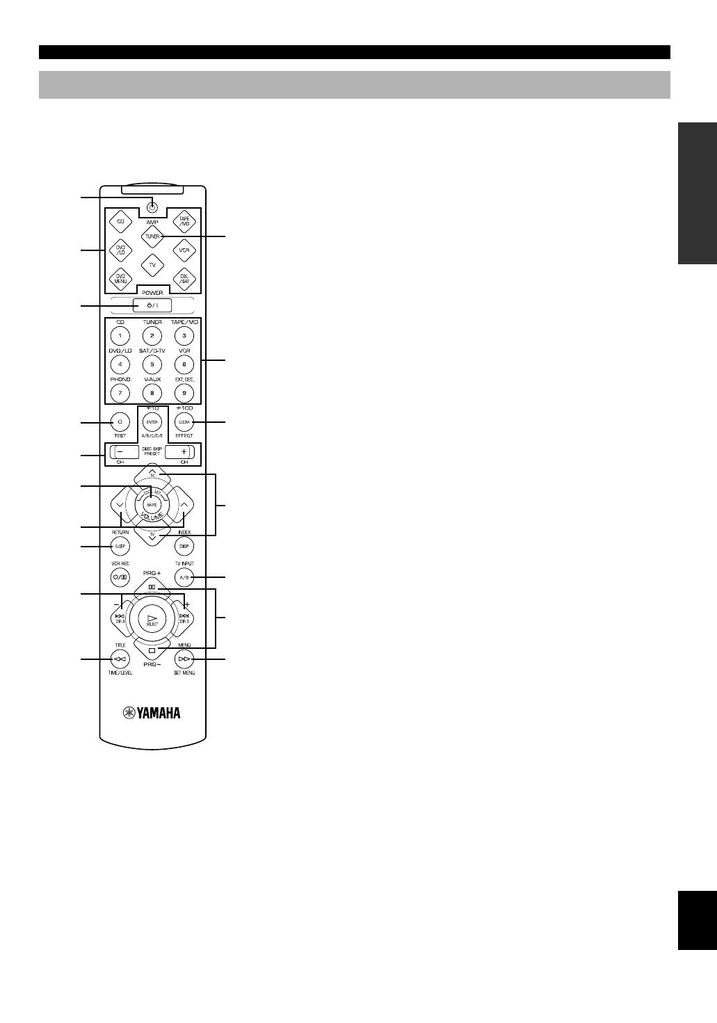
Remote Control
1 Indicator
This flashes in red when pressing a button on the remote
control. If it flashes rapidly several times, press the selected
button again.
2 Component selector buttons
Press one of these buttons which corresponds to the
component you want to control with the remote control.
(The proper code must be set for your component. Refer to
“Setup codes” on page 48.) When the component selector
button has been pressed, the remote control is set to that
component operation mode.
3 POWER
Each time you press this button, the unit switches between
the power on and standby mode.
4 TEST
Press this button to output the test tone for each speaker.
5 A/B/C/D/E, PRESET +/–
These buttons are used to select a preset station.
A/B/C/D/E: To select one of a group (A to E) of preset
stations
PRESET +/–: To select a preset station number (1 to 
6 MUTE
Press this button to mute the sound. To cancel mute, press
this button again.
7 VOLUME
These buttons are used to adjust the volume level.
u: To turn up the volume
d: To turn down the volume
8 SLEEP
Press this button to set the SLEEP timer.
9 +/–
These buttons adjust the settings of the SET MENU and
TIME/LEVEL mode.
0 TIME/LEVEL
Press this button to select the items in the TIME/LEVEL
mode.
q Input selector buttons
These buttons select the input source.
CD: To play a CD
TUNER: To listen to an FM (RDS) or AM broadcast
TAPE/MD: To play a tape or MD
DVD/LD: To play a DVD or LD
SAT/D-TV: To watch a TV or satellite broadcast
VCR: To play a video cassette
PHONO: To play an analog record
V-AUX: To use a camcorder
EXT. DEC.: To play other multi-channel source
w EFFECT
Press this button to turn on or off the effect speakers (center
and rear).
e PRG+, PRG–
Press these buttons to select a DSP program.
r SET MENU
Press this button to select the items in the SET MENU.
CONTROLS AND FUNCTIONS
1
2
3
q
w
e
r
4
5
6
7
8
9
0
TV VOLUME
TV INPUT
Press AMP(TUNER).
This section describes basic operation of this unit with the
remote control. First, press AMP(TUNER) on the
component selector. Refer to “PRESET REMOTE
CONTROL” on page 43 for full details.
0102V496RDS01-07_EN 1/19/0, 10:26 AM7
8
SPEAKER SETUP
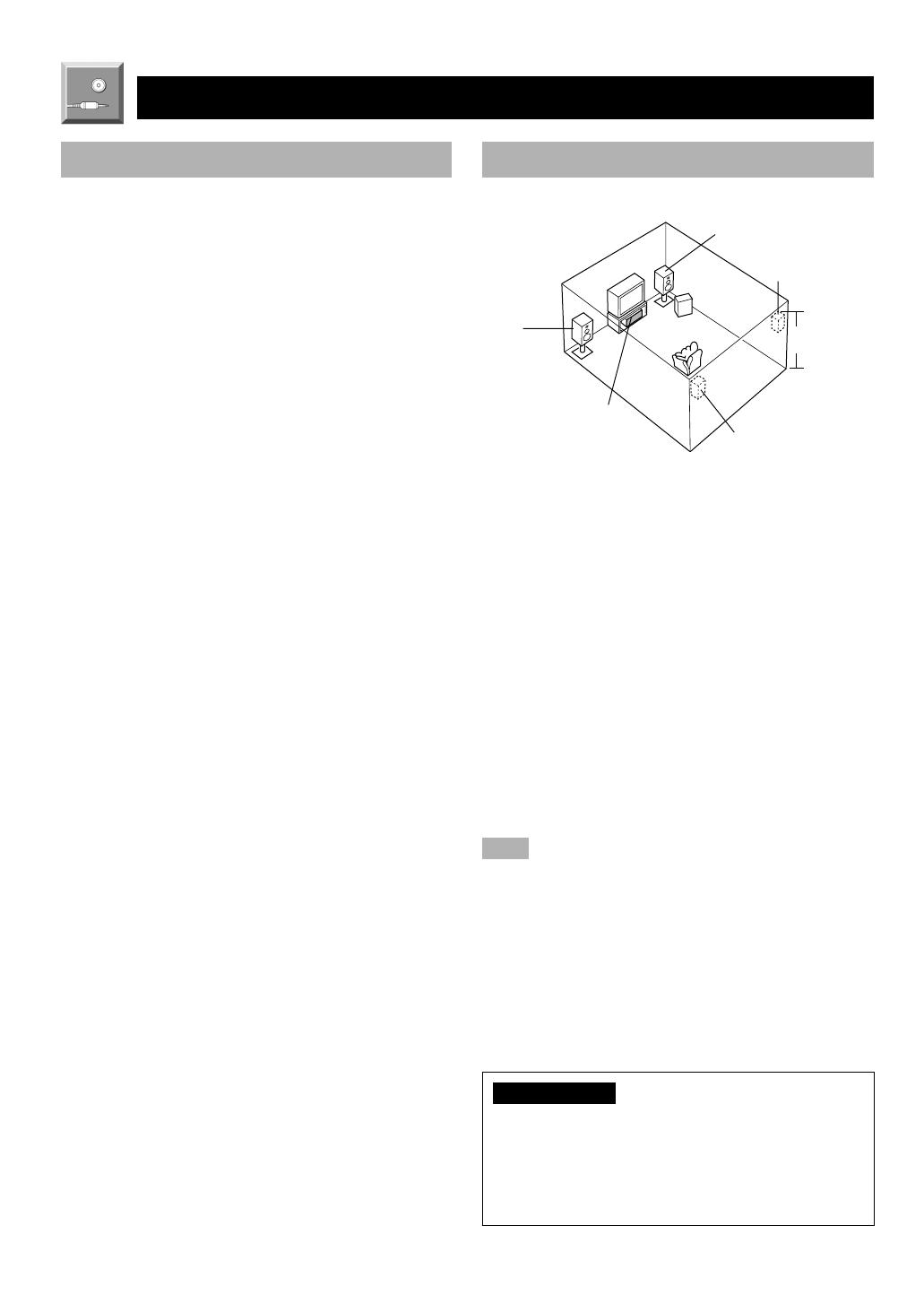
Speaker Placement
Refer to the following diagram when you place the
speakers.
Speakers to Be Used
This unit is designed to provide the best sound-field quality
with a 5-speaker system, using main speakers, rear speakers
and a center speaker. If you use different brands of speakers
(with different tonal qualities) in your system, the tone of a
moving human voice and other types of sound may not shift
smoothly. We recommend that you use speakers from the
same manufacture or speakers with the same tonal quality.
The main speakers are used for the main source sound plus
the effect sounds. They will probably be the speakers from
your present stereo system. The rear speakers are used for
the effect and surround sounds, and the center speaker is for
the center sounds (dialog, vocals, etc.). If for some reason it
is not practical to use a center speaker, you can do without
it. Best results, however, are obtained with the full system.
The main speakers should be high-performance models and
have enough power-handling capacity to accept the
maximum output of your audio system. The other speakers
do not have to be equal to the main speakers. For precise
sound localization, however, it is ideal to use high-
performance models that can reproduce sounds over the full
range for the center speaker and the rear speakers.
■ Use of a subwoofer expands your
sound field
It is also possible to further expand your system with the
addition of a subwoofer. The use of a subwoofer is effective
not only for reinforcing bass frequencies from any or all
channels, but also for reproducing the LFE (low frequency
effect) channel with high fidelity when playing back a
source encoded with Dolby Digital or DTS. The YAMAHA
Active Servo Processing Subwoofer System is ideal for
natural and lively bass reproduction.
Main
speaker (L)
Center speaker
Main speaker (R)
Subwoofer
Rear speaker (L)
Rear speaker (R)
1.8 m
■ Main speakers
Place the right and left main speakers an equal distance
from the ideal listening position. The distance of each
speaker from each side of the TV monitor should be the
same.
■ Rear speakers
Place these speakers behind your listening position, facing
slightly inwards, nearly 1.8 m (approx. 6 feet) above the
floor.
■ Center speaker
Align the front face of the center speaker with the front face
of your TV monitor. Place the speaker as close to the
monitor as possible, such as directly over or under the
monitor and centrally between the main speakers.
Note
• If the center speaker is not used, the sound will be heard from the
right and left main speakers. In that case, “CENTER SP” in the
SET MENU is set to the NONE position. (Refer to page 37 for
details.)
■ Subwoofer
The position of the subwoofer is not so critical, because low
bass sounds are not highly directional. But it is better to
place the subwoofer near the main speakers. Turn it slightly
toward the center of the room to reduce the wall reflections.
CAUTION
Some types of speakers interfere with a TV monitor. If
this problem occurs, move the speakers away from the
monitor. If you cannot avoid installing the center speaker
or subwoofer near the TV monitor, use magnetically
shielded speakers.
PREPARATION
0103V496RDS08-19_EN 1/6/0, 10:19 AM8
9
EnglishBASIC OPERATION
ADVANCED OPERA
TION APPENDIX
INTRODUCTION
PREPARATION
CONNECTIONS
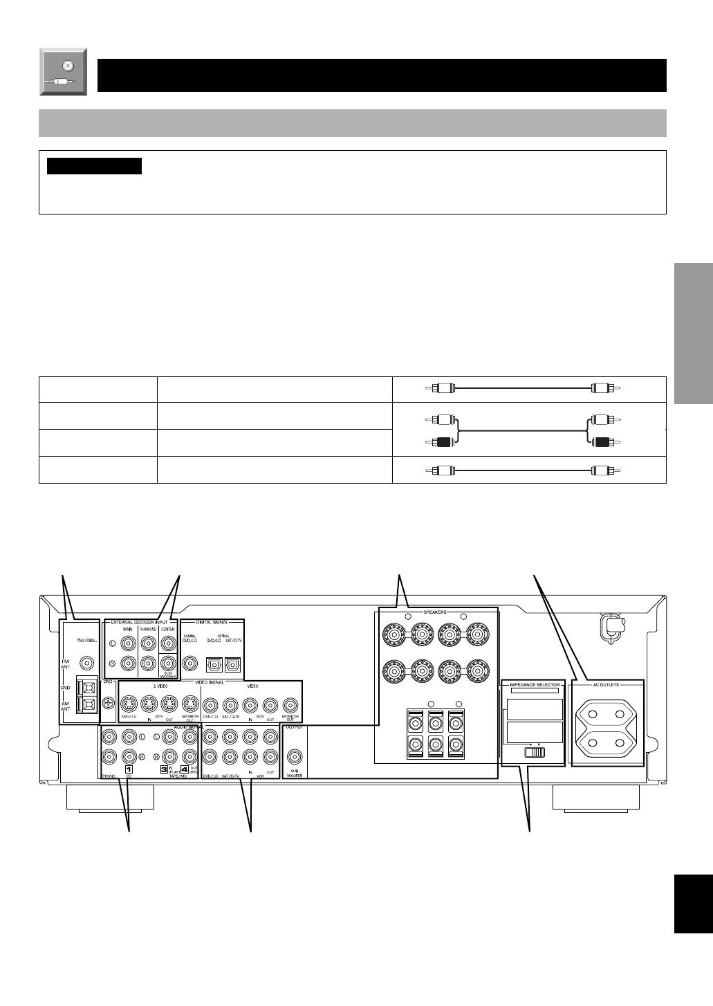
Before Connecting Components
CAUTION
Never connect this unit and other components to mains power until all connections between components have been
completed.
Be sure all connections are made correctly, that is to say L (left) to L, R (right) to R, “+” to “+” and “–” to “–”. Some
components require different connection methods and have different terminal names. Refer to the instructions for each
component to be connected to this unit.
When you connect other YAMAHA audio components (such as a tape deck, MD recorder and CD player or changer), connect
it to the terminals with the same number labels as !, #, $ etc. YAMAHA applies this labeling system to all its products.
Use RCA-type pin plug cables for connecting audio/video components with the exception described later.
The input and output terminals for pin plugs can be distinguished as follows:
Yellow video signals (composite)
White analog audio signals for the left channel
Red analog audio signals for the right channel
coaxial digital signals
After completing all connections, check them again to make sure they are correct.
MAINS
R
L
A
B
100W MAX. TOTAL
SWITCHED
MAIN A OR B
:
4ΩMIN. /SPEAKER
A
+
B
:
8ΩMIN. /SPEAKER
CENTER : 6ΩMIN. /SPEAKER
REAR : 6ΩMIN. /SPEAKER
MAIN A OR B
:
8ΩMIN. /SPEAKER
A
+
B
:
I6ΩMIN. /SPEAKER
CENTER : 8ΩMIN. /SPEAKER
REAR : 8ΩMIN. /SPEAKER
SET BEFORE POWER ON
REAR
(SURROUND)
CENTER
MAIN
––++
+
–
+
–
R
L
Connecting an Audio
Component (page 12)
Connecting a Video
Component (page 13)
IMPEDANCE SELECTOR
switch (page 17)
Connecting the
Antenna (page 10)
Connecting to an External
Decoder (page 14)
Connecting Speakers
(page 15)
Connecting the Power
Supply Cords (page 17)
(Europe model)
0103V496RDS08-19_EN 1/6/0, 10:19 AM9
10
Connecting the Antennas
Both AM and FM indoor antennas are included with this unit. In general, these antennas should provide sufficient signal
strength. However, a properly installed outdoor antenna provides clearer reception than an indoor one. If you experience poor
reception quality, an outdoor antenna may improve the quality.
Connect each antenna correctly to the designated terminals.
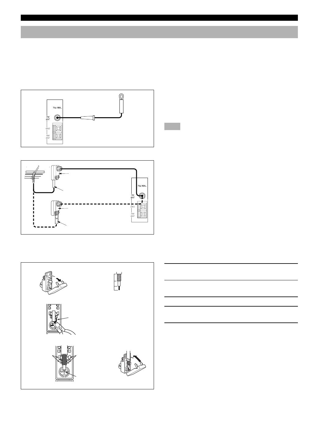
■ Indoor FM antenna (included)
Firmly insert the connector into the FM ANT terminal. The
indoor FM antenna is only a simple antenna. For reception
with better sound quality, installing the outdoor FM antenna
(commercially available) is recommended.
Note
• Do not connect an outdoor FM antenna and the indoor FM
antenna at the same time.
■ Outdoor FM antenna
You may be unable to obtain good FM radio reception
depending on your local conditions (distance from the
broadcasting station, interposing buildings and
mountains, etc.). Consult your dealer or authorized service
center and be sure to install an antenna that suits your local
conditions.
Install the outdoor FM antenna (commercially available) in
a high place as far away from any roads as possible to avoid
being affected by automobile ignition noise.
■ Connecting a coaxial cable to the included 75-ohm/300-ohm antenna
adapter (U.K. model only)
1 Open the cover of the included 75-ohm/
300-ohm antenna adapter.
2 Cut the external sleeve of the 75-ohm coaxial
cable and prepare it for connection.
3 Cut the lead wire and remove it.
4 Insert the cable wire into the slot, and clamp it
with pliers.
5 Snap the cover into place.
CONNECTIONS
75-ohm/300-ohm antenna
adapter (included for U.K.
model)
75-ohm coaxial cable
75-ohm/300-ohm antenna
adapter (included for U.K.
model)
300-ohm feeder
Unit: mm
(inch)
11 (7/16)
8 (5/16)
6 (1/14)
2
3
Lead wire
Insert the wire
into the slot.
4
Clamp with
pliers.
Clamp with
pliers.
1
Cover
5
Indoor FM
antenna
0103V496RDS08-19_EN 1/6/0, 10:20 AM10
11
EnglishBASIC OPERATION
ADVANCED OPERA
TION APPENDIX
INTRODUCTION
PREPARATION
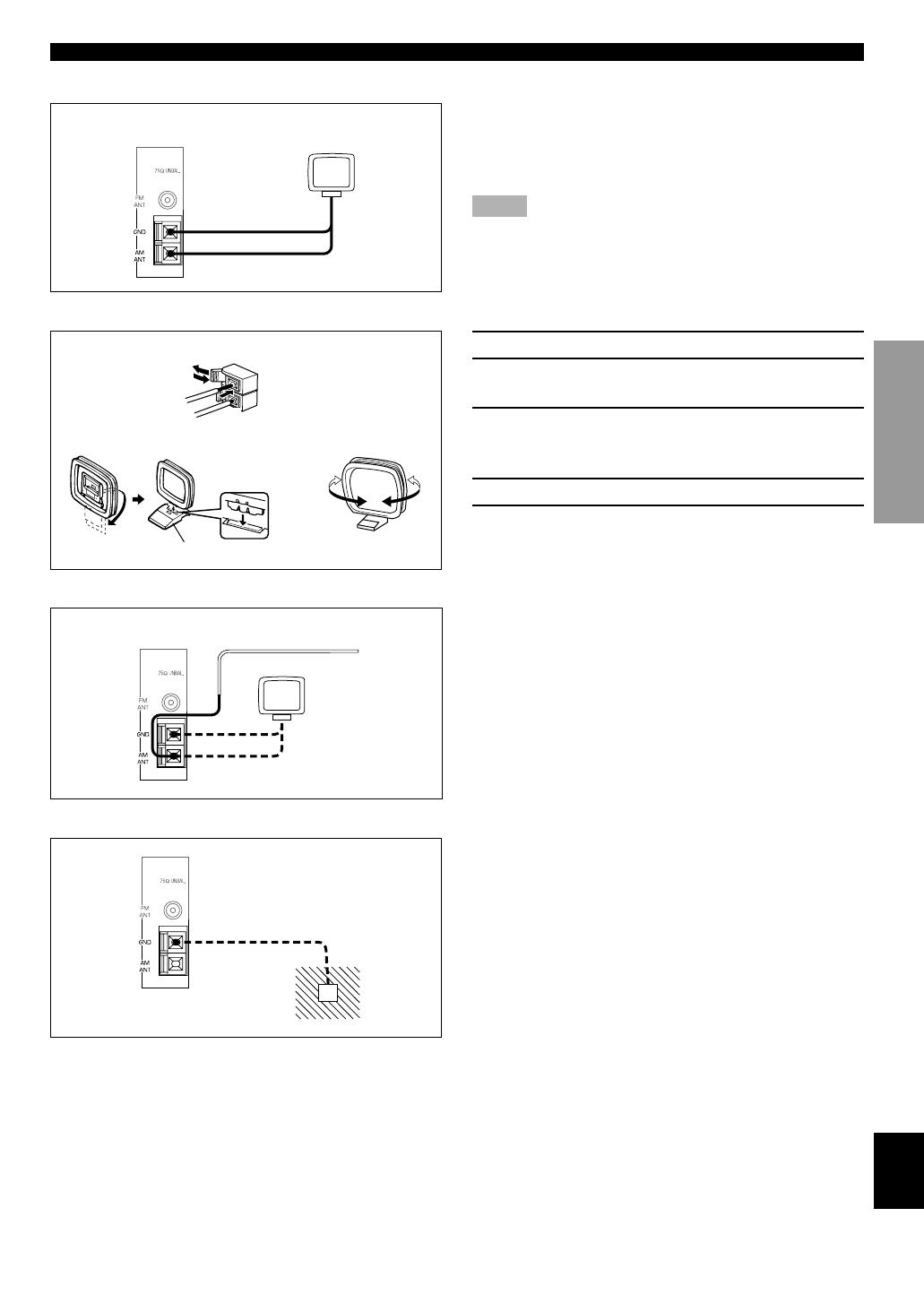
■ AM loop antenna (included)
The AM loop antenna can be removed from the stand and
attached to a wall, etc. However, note that the reception
sensitivity may deteriorate if the antenna is attached to a
metal or steel reinforced wall.
Notes
• The AM loop antenna should be placed away from this unit.
• The AM loop antenna should always be connected, even if an
outdoor AM antenna is connected to this unit.
■ Connecting the AM loop antenna
1 Press the tab and unlock the terminal hole.
2 Insert the AM loop antenna lead wires into the
AM ANT and GND terminals.
3 Return the tab to its original position to lock
the lead wires. Lightly pull the lead wires to
confirm a good connection.
4 Attach the loop antenna to the antenna stand.
5 Orient the AM loop antenna so that the best
reception is obtained.
■ Outdoor AM antenna
If you cannot obtain good reception with the AM loop
antenna, connect 5 m to 10 m of vinyl covered wire to the
AM ANT terminal and extend it outdoors from a window.
■ Ground (GND terminal)
For maximum safety and minimum interference, connect
the antenna GND terminal to a good earth ground. A good
earth ground is a metal stake driven into moist earth.
CONNECTIONS
1
2
3
Antenna stand
AM loop antenna
Vinyl covered wire (5 m to 10 m)
54
0103V496RDS08-19_EN 1/6/0, 10:20 AM11
12
Connecting an Audio Component
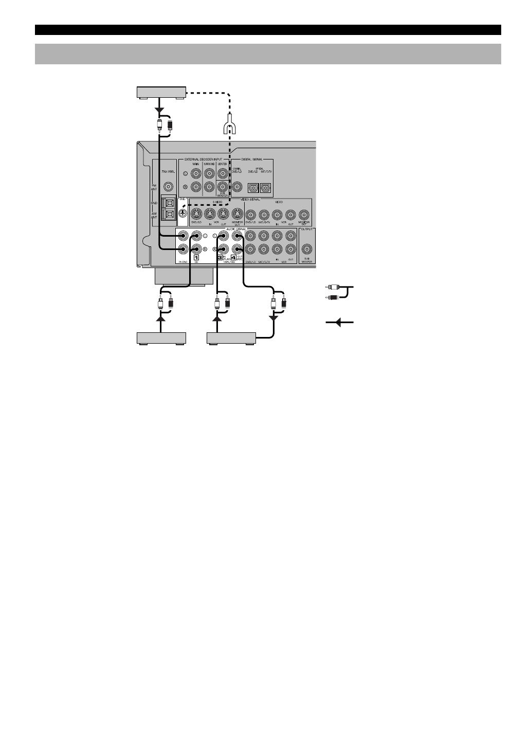
■ PHONO terminals
These terminals are used to connect a turntable with an MM
or high-output MC cartridge. If you have a turntable with a
low-output MC cartridge, use an inline boosting transformer
or MC head amplifier when connecting to these terminals.
y
Connecting the ground (earth) wire of the turntable to the GND
terminal will normally minimize hum, but in some cases, better
results may be obtained with the ground wire disconnected.
CONNECTIONS
Be sure to connect the right channel (R), left channel (L),
input (IN) and output (OUT) properly.
Tape deck or
MD recorder
L R
L R
L R L R
L
R
OUTPUT
OUTPUT LINE OUT LINE IN
GND
Turntable
(Europe model)
CD player
Analog signal
Signal flow
0103V496RDS08-19_EN 1/6/0, 10:20 AM12
13
EnglishBASIC OPERATION
ADVANCED OPERA
TION APPENDIX
INTRODUCTION
PREPARATION
Connecting a Video Component
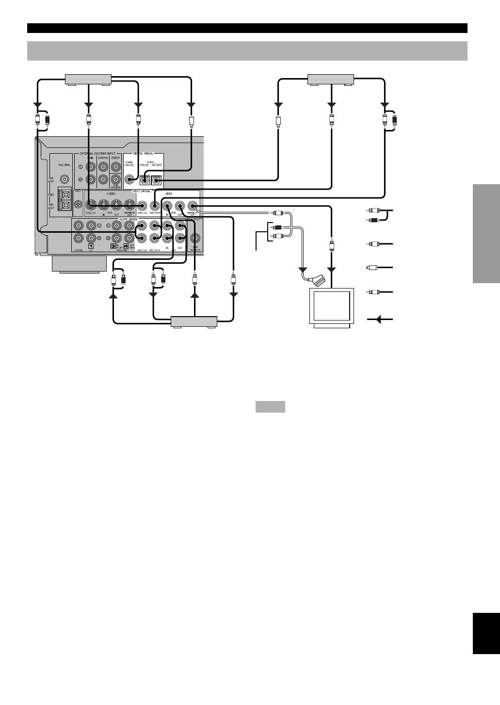
■ Audio signal terminals
Be sure to connect the right channel (R), left channel (L),
input (IN) and output (OUT) properly.
■ Video signal terminals
Be sure to connect the input (IN) and output (OUT)
properly.
■ Digital audio signal terminals
If your DVD/LD player, TV/digital TV or satellite
tuner, etc. has coaxial or optical digital signal output
terminals, they can be connected to this unit’s COAXIAL
and/or OPTICAL digital signal input terminals. To make a
connection between the optical digital signal terminals,
remove the cover from each terminal, and then connect
them by using a commercially available optical fiber cable
that conforms to EIA standards. Other cables might not
function correctly.
When making connections between the digital signal
terminals, you should connect the components to the same-
named analog audio signal terminals of this unit, because a
digital signal cannot be recorded by a tape deck, MD
recorder or VCR connected to this unit.
■ TV monitor with a 21-pin connector
Make a connection as shown above with a commercially
available SCART-plug connector cable.
Notes
• Be sure to attach the covers when the OPTICAL terminals are not
being used in order to protect them from dust.
• If your LD player has a Dolby Digital RF signal output terminal,
be sure to use the RF demodulator (separately purchased).
• No sound will be heard when connecting your LD player’s Dolby
Digital RF signal output terminal directly to this unit’s COAXIAL
DVD/LD digital signal input terminal.
y
• The input signal from the DVD/LD input terminals is selected in
the following order of priority with the input mode set to AUTO:
COAXIAL terminal → OPTICAL terminal → Analog terminal.
Refer to page 22 for details.
• All digital signal input terminals are applicable to sampling
frequencies of 32 kHz, 44.1 kHz and 48 kHz.
CONNECTIONS
L R
L R
L
R
C
C
V
V
L R
L R V V
V
V
ANALOG
AUDIO OUT
AUDIO
OUT
AUDIO
IN
VIDEO
OUT
VIDEO
IN
VIDEO
IN
ANALOG
AUDIO OUT
VIDEO
OUT
VIDEO
OUT
COAXIAL
DIGITAL OUT
OPTICAL
DIGITAL OUT
OPTICAL
DIGITAL OUT
V
L
R
O
OO
DVD/LD player TV/digital TV, satellite tuner, cable TV
(Europe model)
VCR
Analog signal
Video signal
Digital signal
(optical)
Digital signal
(coaxial)
Signal flow
TV monitor
SCART-plug
No connection
0103V496RDS08-19_EN 1/6/0, 10:20 AM13
14
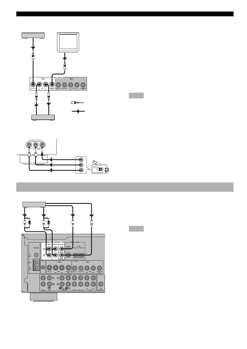
■ S VIDEO terminals
If your VCR, TV monitor or DVD/LD player has “S” (high-
resolution) video terminals, they can be connected to this
unit’s S VIDEO terminals. Connect the VCR’s “S” video
input and output terminals to this unit’s S VIDEO VCR
OUT and IN terminals, respectively. Connect the monitor’s
“S” video input terminal to this unit’s S VIDEO MONITOR
OUT terminal. Connect the DVD/LD player’s “S” video
output terminal to this unit’s S VIDEO DVD/LD terminal.
Otherwise, connect the composite video terminals of your
VCR, TV monitor or DVD/LD player to this unit’s
composite video terminals.
Notes
• Use a special S VIDEO cable (commercially available) for the S
VIDEO connection.
• If video signals are input from both the S VIDEO input and
composite input terminals, the signals will be directed to their
respective output terminals.
■ VIDEO AUX terminals (on the front panel)
These terminals are used to connect any video input source
such as a camcorder to this unit.
Connecting to an External Decoder
This unit has additional 6-channel audio signal input
terminals for connecting an external decoder to this unit.
Connect the 6-channel audio signal output terminals of the
decoder to the EXTERNAL DECODER INPUT terminals
of this unit.
Notes
• When a source connected to these terminals is selected, the digital
sound field processor cannot be used.
• The settings of “CENTER SP”, “REAR SP”, “MAIN SP” and
“BASS OUT” in the SET MENU have no effect on a source
connected to these terminals. The setting of “MAIN LVL” is
effective. (Refer to pages 37 and 38 for details.)
CONNECTIONS
L RV
AUDIO OUT R
AUDIO OUT L
VIDEO OUT
Camcorder
S VIDEO OUT
S VIDEO
OUT
S VIDEO IN
S VIDEO IN
S
S
S
S
S
DVD/LD player
TV Monitor
VCR
S Video signal
Signal flow
L R L R
MAIN
OUT
SURROUND
OUT
CENTER
OUT
SUBWOOFER
OUT
External decoder
(Europe model)
0103V496RDS08-19_EN 1/6/0, 10:20 AM14
15
EnglishBASIC OPERATION
ADVANCED OPERA
TION APPENDIX
INTRODUCTION
PREPARATION
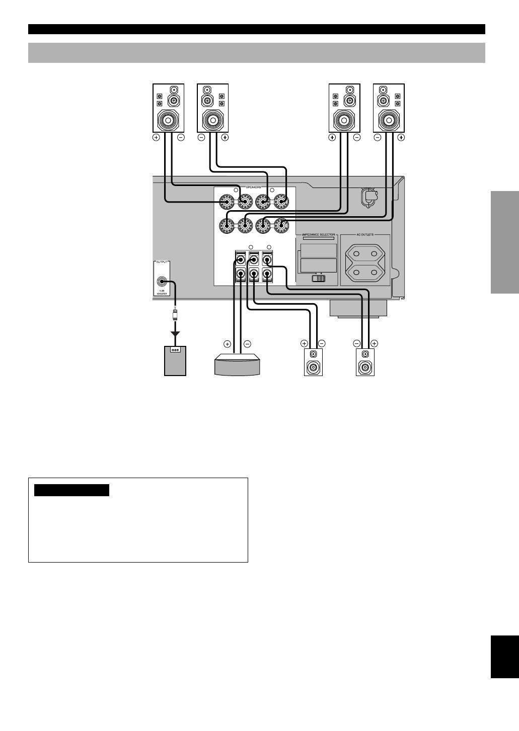
Connecting Speakers
Be sure to connect the right channel (R), left channel (L),
“+” (red) and “–” (black) properly. If the connections are
faulty, no sound will be heard from the speakers, and if the
polarity of the speaker connections is incorrect, the sound
will be unnatural and lack bass.
CAUTIONS
• Use speakers with the specified impedance shown on
the rear panel of this unit.
• Do not let the bare speaker wires touch each other and
do not let them touch any metal part of this unit. This
could damage the unit and/or speakers.
■ Main speaker terminals
One or two speaker systems can be connected to these
terminals. If you use only one speaker system, connect it to
either of the SPEAKERS A or B terminals.
■ Rear speaker terminals
A rear speaker system can be connected to these terminals.
■ Center speaker terminal
A center speaker can be connected to this terminal.
CONNECTIONS
MAINS
R
L
A
B
100W MAX. TOTAL
SWITCHED
MAIN A OR B
:
4ΩMIN. /SPEAKER
A
+
B
:
8ΩMIN. /SPEAKER
CENTER : 6ΩMIN. /SPEAKER
REAR : 6ΩMIN. /SPEAKER
MAIN A OR B
:
8ΩMIN. /SPEAKER
A
+
B
:
I6ΩMIN. /SPEAKER
CENTER : 8ΩMIN. /SPEAKER
REAR : 8ΩMIN. /SPEAKER
SET BEFORE POWER ON
REAR
(SURROUND)
CENTER
MAIN
––++
+
–
+
–
R
L
Main speakers A
Right Left
Main speakers B
Right Left
(Europe model)
Center speaker Rear speakers
Right Left
Subwoofer connection
If you have a subwoofer with built-
in amplifier, including the
YAMAHA Active Servo Processing
Subwoofer System, connect the
input terminal of the subwoofer
system to the SUBWOOFER
OUTPUT terminal of this unit.
0103V496RDS08-19_EN 1/6/0, 10:20 AM15
16
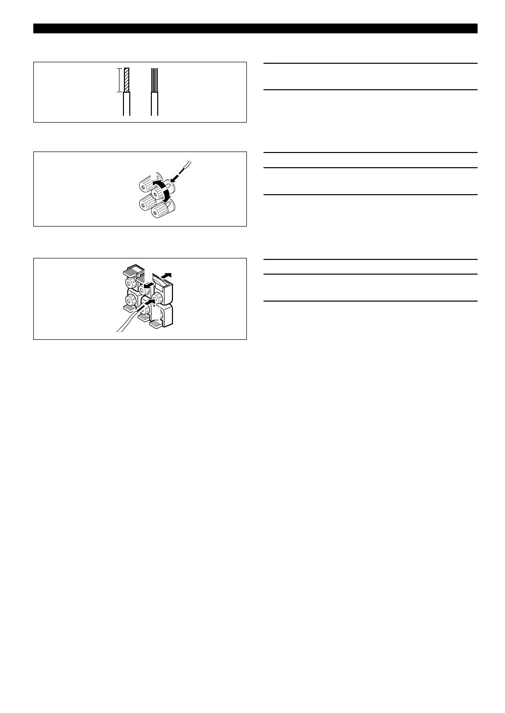
■ Speaker cables
1 Remove approx. 10 mm (3/8”) of insulation
from each of the speaker cable.
2 Twist the exposed wires of the cable together
to prevent short circuits.
■ Connecting to the MAIN SPEAKERS terminals
1 Unscrew the knob.
2 Insert one bare wire into the hole in the side of
each terminal.
3 Tighten the knob to secure the wire.
■ Connecting to the REAR and CENTER SPEAKERS terminals
1 Open the tab.
2 Insert one bare wire into the hole of each
terminal.
3 Return the tab to secure the wire.
CONNECTIONS
10 mm (3/8”)
2
1
3
Red: positive (+)
Black: negative (–)
2
3
1
Red: positive (+)
Black: negative (–)
0103V496RDS08-19_EN 1/6/0, 10:20 AM16
17
EnglishBASIC OPERATION
ADVANCED OPERA
TION APPENDIX
INTRODUCTION
PREPARATION
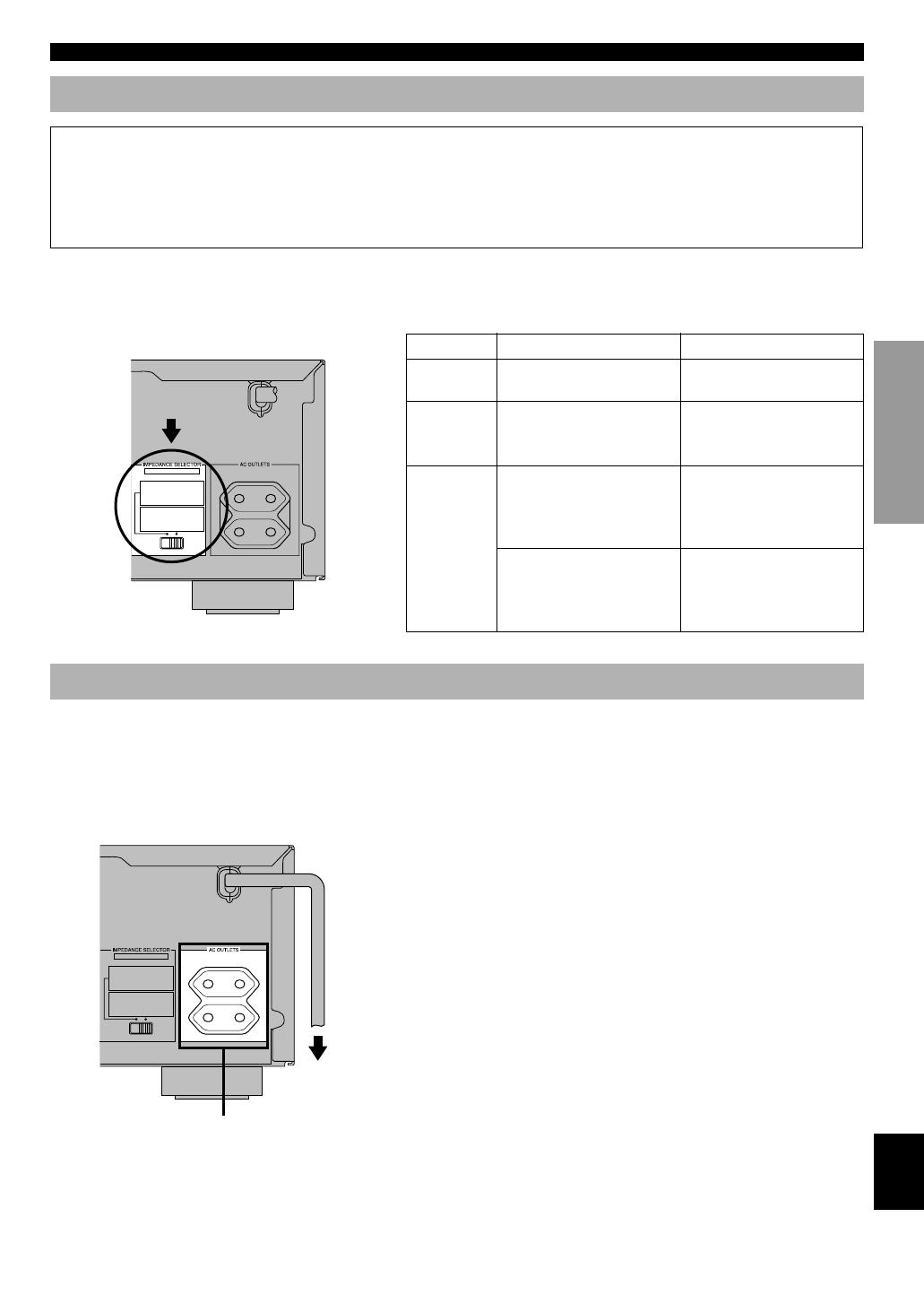
IMPEDANCE SELECTOR Switch
WARNING
Do not change the IMPEDANCE SELECTOR switch setting while the power to this unit is on, otherwise the unit may be
damaged.
If this unit fails to turn on when STANDBY/ON is pressed, the IMPEDANCE SELECTOR switch may not be fully slide
to either position. If so, slide the switch to either position fully when this unit is in the standby mode.
Select the right or left position according to the impedance of speakers in your system. Be sure to move this switch only
when this unit is in the standby mode.
Connecting the Power Supply Cords
After completing all connections, connect the AC power
cord to an AC power outlet. Disconnect the AC power cord
if you will not use this unit for a long period of time.
■ AC OUTLETS (SWITCHED)
Europe model ……………………………………………. 2 OUTLETS
U.K. model…………………………………………………. 1 OUTLET
Use these outlets to connect the power cords from your
components to this unit. The power to the AC OUTLET(S)
is controlled by this unit’s STANDBY/ON (or POWER).
These outlets will supply power to any connected
component whenever this unit is turned on. The maximum
power (total power consumption of components) that can be
connected to the AC OUTLET(S) is 100 W.
If you use left position right position
Center
speaker
The impedance must be 6 Ω
or higher.
The impedance must be 8 Ω
or higher.
Rear
speakers
The impedance of each
speaker must be 6 Ω or
higher.
The impedance of each
speaker must be 8 Ω or
higher.
If you use two pairs of main
speakers, the impedance of
each speaker must be 8 Ω or
higher.
If you use two pairs of main
speakers, the impedance of
each speaker must be 16 Ω or
higher.
Main
speakers
If you use one pair of main
speakers, the impedance of
each speaker must be 4 Ω or
higher.
If you use one pair of main
speakers, the impedance of
each speaker must be 8 Ω or
higher.
CONNECTIONS
(Europe model)
MAINS
100W MAX. TOTAL
SWITCHED
MAIN A OR B
:
4ΩMIN. /SPEAKER
A
+
B
:
8ΩMIN. /SPEAKER
CENTER : 6ΩMIN. /SPEAKER
REAR : 6ΩMIN. /SPEAKER
MAIN A OR B
:
8ΩMIN. /SPEAKER
A
+
B
:
I6ΩMIN. /SPEAKER
CENTER : 8ΩMIN. /SPEAKER
REAR : 8ΩMIN. /SPEAKER
SET BEFORE POWER ON
SWITCHED
(Europe model)
To AC outlet
MAINS
100W MAX. TOTAL
SWITCHED
MAIN A OR B
:
4ΩMIN. /SPEAKER
A
+
B
:
8ΩMIN. /SPEAKER
CENTER : 6ΩMIN. /SPEAKER
REAR : 6ΩMIN. /SPEAKER
MAIN A OR B
:
8ΩMIN. /SPEAKER
A
+
B
:
I6ΩMIN. /SPEAKER
CENTER : 8ΩMIN. /SPEAKER
REAR : 8ΩMIN. /SPEAKER
SET BEFORE POWER ON
IMPEDANCE
SELECTOR
0103V496RDS08-19_EN 1/6/0, 10:20 AM17
18
Using the Test Tone
The adjustment of each speaker sound output level should
be performed at your listening position with the remote
control. After completing the adjustments, use VOLUME
(u/d) at your listening position to check if the adjustments
are satisfactory.
1 Press AMP(TUNER) on the
component selector.
2 Press TEST.
“TEST LEFT” appears on the display.
3 Turn up the volume.
You will hear a test tone (like pink noise) from each
speaker for about two seconds in following order: left
main speaker, center speaker, right main speaker, right
rear speaker and left rear speaker. The display changes
as shown below.
Notes
• If the test tone cannot be heard, turn down the volume, set the unit
in the standby mode and check the speaker connections.
• If the test tone cannot be heard from the center speaker, check the
setting of “CENTER SP” in the SET MENU.
This procedure lets you adjust the sound output level
balance between the main, center and rear speakers by using
the built-in test tone generator. When this adjustment is
performed, the sound output level heard at the listening
position will be the same from each speaker. This is
important for the best performance of the digital sound field
processor, the Dolby Pro Logic decoder, Dolby Digital
decoder and DTS decoder.
Before You Start Adjusting
1 Set VOLUME to the “m”
position.
2 Turn the power on.
3 Press SPEAKERS A or B
to select the main
speakers to be used.
If you use two main speaker
systems, press both A and B.
4 Set BASS, TREBLE and BALANCE to the “0”
position.
ADJUSTING THE SPEAKER BALANCE
LR
–+–+
12
4
3
LR
–+–+
TEST
LEFT
TEST
RIGHT
TEST L SUR. TEST R SUR.
TEST CENTER
0103V496RDS08-19_EN 1/6/0, 10:20 AM18
-
Contents
-
Table of Contents
-
Bookmarks
Quick Links
RX-V496/RX-V496RDS
HTR-5240/HTR-5240RDS
CONTENTS
Front Panels ……………………………………………………. 2
Rear Panels ………………………………………………….. 3~4
Specifications ………………………………………………. 5~6
Internal View …………………………………………………… 7
Factory Preset ……………………………………………… 20
1 0 0 7 0 4
SERVICE MANUAL
IMPORTANT NOTICE
This manual has been provided for the use of authorized YAMAHA Retailers and their service personnel.
It has been assumed that basic service procedures inherent to the industry, and more specifically YAMAHA
Products, are already known and understood by the users, and have therefore not been restated.
WARNING:
Failure to follow appropriate service and safety procedures when servicing this product
may result in personal injury, destruction of expensive components, and failure of the
product to perform as specified. For these reasons, we advise all YAMAHA product
owners that any service required should be performed by an authorized YAMAHA
Retailer or the appointed service representative.
IMPORTANT:
The presentation or sale of this manual to any individual of firm does not constitute
authorization, certification or recognition of any applicable technical capabilities,
or establish a principle-agent relationship of any form.
The data provided is believed to be accurate and applicable to the unit(s) indicated on the cover. The research,
engineering, and service departments of YAMAHA are continually striving to improve YAMAHA products.
Modifications are, therefore, inevitable and specifications are subject to change without notice or obligation
to retrofit. Should any discrepancy appear to exist, please contact the distributor’s Service Division.
WARNING:
Static discharges can destroy expensive components. Discharge any static electricity
your body may have accumulated by grounding yourself to the ground buss in the unit
(heavy gauge black wires connect to this buss).
IMPORTANT:
Turn the unit OFF during disassembly and part replacement. Recheck all work before
you apply power to the unit.
Amp Adjustment …………………………………………….. 21
Tuner Adjustment ……………………………………. 22~25
Ic Data ………………………………………………………… 26~34
Display Data ………………………………………………….. 35
Block Diagram ………………………………………….. 36~39
Parts List …………………………………………………… 68~85
AV RECEIVER
Summary of Contents for Yamaha RX-V496
-
Руководства по ремонту
1
-
Инструкции по эксплуатации
1

Yamaha RX-V496RDS инструкция по эксплуатации
(66 страниц)
- Языки:Английский
-
Тип:
PDF -
Размер:
3.84 MB
Просмотр
На NoDevice можно скачать инструкцию по эксплуатации для Yamaha RX-V496RDS. Руководство пользователя необходимо для ознакомления с правилами установки и эксплуатации Yamaha RX-V496RDS. Инструкции по использованию помогут правильно настроить Yamaha RX-V496RDS, исправить ошибки и выявить неполадки.
Скачать
OWNER’S MANUAL
MODE D’EMPLOI
BEDIENUNGSANLEITUNG
BRUKSANVISNING
MANUALE DI ISTRUZIONI
MANUAL DE INSTRUCCIONES
GEBRUIKSAANWIJZING
RX-V496RDS
Natural Sound AV Receiver
Ampli-tuner audio-vidéo
RX-V496RDS
G B
1/17/0, 6:25 PM
Как пользоваться?
Наша цель — обеспечить Вам самый быстрый доступ к руководству по эксплуатации устройства Yamaha RX-V496RDS. Пользуясь просмотром онлайн Вы можете быстро просмотреть содержание и перейти на страницу, на которой найдете решение своей проблемы с Yamaha RX-V496RDS.
Для Вашего удобства
Если просмотр руководства Yamaha RX-V496RDS непосредственно на этой странице для Вас неудобен, Вы можете воспользоваться двумя возможными решениями:
- Полноэкранный просмотр -, Чтобы удобно просматривать инструкцию (без скачивания на компьютер) Вы можете использовать режим полноэкранного просмотра. Чтобы запустить просмотр инструкции Yamaha RX-V496RDS на полном экране, используйте кнопку Полный экран.
- Скачивание на компьютер — Вы можете также скачать инструкцию Yamaha RX-V496RDS на свой компьютер и сохранить ее в своем архиве. Если ты все же не хотите занимать место на своем устройстве, Вы всегда можете скачать ее из ManualsBase.
Руководство по эксплуатации Yamaha RX-V496RDS
Печатная версия
Многие предпочитают читать документы не на экране, а в печатной версии. Опция распечатки инструкции также предусмотрена и Вы можете воспользоваться ею нажав на ссылку, находящуюся выше — Печатать инструкцию. Вам не обязательно печатать всю инструкцию Yamaha RX-V496RDS а только некоторые страницы. Берегите бумагу.
Резюме
Ниже Вы найдете заявки которые находятся на очередных страницах инструкции для Yamaha RX-V496RDS. Если Вы хотите быстро просмотреть содержимое страниц, которые находятся на очередных страницах инструкции, Вы воспользоваться ими.
Table of Contents for Yamaha RX-V496RDS:
-
40 1. PRO LOGIC/Normal 15 to 30 20 DOLBY DIGITAL/Normal 0 to 15 5 DTS DIGITAL SUR/Normal 0 to 15 5 PRO LOGIC/ENHANCED 15 to 30 20 DOLBY DIGITAL/ENHANCED 0 to 15 5 DTS DIGITAL SUR/ENHANCED 0 to 15 5 2. 70 mm SPECTACLE 15 to 30 23 DGTL SPECTACLE 1 to 99 15 DTS SPECTACLE 1 to 99 15 70 mm SCI-FI 15 to 30 20 DGTL SCI-FI 1 to 99 16 DTS SCI-FI 1 to 99 16 3. 70 mm ADVENTURE 15 to 30 20 DGTL ADVENTURE 1 to 99 15 DTS ADVENTURE
-
18 Using the Test Tone The adjustment of each speaker sound output level should be performed at your listening position with the remote control. After completing the adjustments, use VOLUME (u/d) at your listening position to check if the adjustments are satisfactory. 1 Press AMP(TUNER) on the component selector. 2 Press TEST. “TEST LEFT” appears on the display. 3 Turn up the volume. You will hear a test tone (like pink noise) from each speaker for about two seconds in following order: left main
-
24 3 Press PRG+ or PRG– repeatedly to select the desired program. The name of the selected program appears on the display. y If desired, adjust the delay time and the sound output level of each speaker. (Refer to pages 40 and 41 for details.) Notes • You can select a DSP program for each of the input sources. Once you select a program, it is linked with the input source selected at that time. So, when you select the input source next time, the same program is automatically selected. • When a monaural source is being played with PRO LOGIC/ Normal or
-
4 LR – + – + 12 3 4 65 7890qwerty uiopasdf 6VOLUME Turn this control to turn up or down the volume. 7 PHONES jack Connect the headphones to the PHONES jack. You can listen to the sound to be output from the main speakers through the headphones. When using headphones only, set both SPEAKERS A and B to the OFF position and press EFFECT to turn off the effect speakers (center and rear) (so that no DSP program name appear on the display). 8 SPEAKERS Set A or B (or both A
-
45 EnglishBASIC OPERATION ADVANCED OPERA TION APPENDIXINTRODUCTION PREPARATION ■ CD MODE Note • TV VOLUME and TV INPUT function if you have set the code for your TV. e PAUSE This button gives a pause in operation. The button functions as PAUSE/STOP* for operating a YAMAHA CD player under factory setting. a SKIP+ This button skips to the beginning of the next track. s STOP This button stops operation. The button functions as PAUSE/STOP* for operating YAMAHA CD players. f SEARCH This button initiates a fast-forward search on the track that is playing
-
26 No. PROGRAM SUBPROGRAM FEATURES 2 MOVIE THEATER 1 3 MOVIE THEATER 2 [1] 70 mm SPECTACLE ( ox) • Input source: Dolby Surround 2-ch Dolby Digital • Output channel: 3 channels • DSP: 2 (presence & surround) [2] DGTL SPECTACLE ( g x ) • Input source: Dolby Digital • Output channel: 5.1 channels • DSP: 3 (presence & surround L, R) [3] DTS SPECTACLE ( tx ) • Input source: DTS • Output channel: 5.1 channels • DSP: 3 (presence &
-
48 Advanced Information ■ Setup codes You can set the code for the manufacturer of your component after pressing the component selector buttons other than AMP(TUNER). 1 Turn on your component to be used. 2 Press one of the component selector buttons which corresponds to the component to be controlled. 3 Press both VOLUME buttons (u/d) at the same time for about four sec
-
7 EnglishBASIC OPERATION ADVANCED OPERA TION APPENDIX INTRODUCTION PREPARATION Remote Control 1 Indicator This flashes in red when pressing a button on the remote control. If it flashes rapidly several times, press the selected button again. 2 Component selector buttons Press one of these buttons which corresponds to the component you want to control with the remote control. (The proper code must be set for your component. Refer to
-
5 EnglishBASIC OPERATION ADVANCED OPERA TION APPENDIX INTRODUCTION PREPARATION q Tone controls These controls are only effective for the sound from the main speakers. a) BASS Turn this control clockwise to increase or counterclockwise to decrease the low-frequency response. The “0” position produces a flat response. b) TREBLE Turn this control clockwise to increase or counterclockwise to decrease the high-frequency response. The “0” position produces a flat response. w TAPE/MD MON / EXT. DECODER
-
54 GLOSSARY CINEMA DSP ■ Dolby Surround Dolby Surround uses four discrete channels and five speakers to reproduce realistic and dynamic sound effects: two main channels (left and right), a center channel for dialog, and a rear channel for special sound effects. The rear channel reproduces sound within a narrow frequency range. Most video tapes and laser discs include Dolby Surround encoding, as do many TV and cable broadcasts. The Dolby Pro
-
3 EnglishBASIC OPERATION ADVANCED OPERA TION APPENDIX INTRODUCTION PREPARATION Using the Remote Control The remote control transmits a directional infrared beam. Be sure to aim the remote control directly at the infrared sensor during operation. When the sensor is covered or there is a large object between the remote control and the sensor, the sensor cannot receive signals. The sensor may not be able to receive signals properly when it is exposed to direct sunlight or a strong artificial light (such as a fluorescent or strobe light). In this case,
-
43 EnglishBASIC OPERATION ADVANCED OPERA TION APPENDIXINTRODUCTION PREPARATION ■ Example: To control YAMAHA CD player 1 Make sure that VOLUME is set to the “m” position. 2 Press AMP(TUNER) on the component selector. 3 Turn on the power. 4 Press CD on the input selector. PRESET REMOTE CONTROL The provided remote control is factory set to control not only this unit but also most YAMAHA audio components connected
-
i TV Admiral 0411, 0451, 0911, 1021, 1081 Aiko 0891 Akai 0061, 0101, 0231, 1191, 1351, 1591, 1641, 1791, 1891, 1981 Akura 1331 Alba 1241, 1331, 2361 Albiral 1971 Amstrad 1301, 1511 Anam 1171 Arc En Ciel 0571 Arcam 0571, 0761 Aristona 0751 Arthur Martin 0451, 1641 ASA 0411, 0451, 0521, 0781, 0871, 1021, 1081, 1421, 2051, 2091, 2151, 2551 Astra 1511 Atantic 0761 Atlantic 0761 Atori 1511 Audiosonic 1181, 1321, 1511 Ausind 0491, 1411 Autovox 0091, 0351, 0481, 0491, 0601, 0781, 0951, 1051, 1081, 1391, 1421 Baird 1101, 1351
-
16 ■ Speaker cables 1 Remove approx. 10 mm (3/8”) of insulation from each of the speaker cable. 2 Twist the exposed wires of the cable together to prevent short circuits. ■ Connecting to the MAIN SPEAKERS terminals 1 Unscrew the knob. 2 Insert one bare wire into the hole in the side of each terminal. 3 Tighten the knob to secure the wire. ■ Connecting to the REAR and CENTER SPEAKERS terminals 1 Open the tab. 2 Insert one bare w
-
19 EnglishBASIC OPERATION ADVANCED OPERA TION APPENDIX INTRODUCTION PREPARATION 4 Adjust BALANCE on the front panel so that the sound output level of the right main speaker and the left main speaker is the same. 5 Press TIME/LEVEL repeatedly to select the speaker to be adjusted. “CENTER”, “R SUR.” or “L SUR.” appears on the display. 6 Press + to raise and – to lower the level. Adjust the sound output levels of the center speaker and the rear speakers so that they become almost the same as that of the
Questions, Opinions and Exploitation Impressions:
You can ask a question, express your opinion or share our experience of Yamaha RX-V496RDS device using right now.