- Manuals
- Brands
- Yamaha Manuals
- Motorcycle
- XT250
- Owner’s manual
-
Contents
-
Table of Contents
-
Troubleshooting
-
Bookmarks
Quick Links
OWNER’S MANUAL
XT250X
XT250XC
LIT-11626-21-52
3C5-28199-10
Related Manuals for Yamaha XT250
Summary of Contents for Yamaha XT250
-
Page 1
OWNER’S MANUAL XT250X XT250XC LIT-11626-21-52 3C5-28199-10… -
Page 2
EAU10041… -
Page 3
Yamaha has met these standards without reducing the performance or economy of operation of the motorcycle. To maintain these high standards, it is important that you and your Yamaha dealer pay close attention to the… -
Page 4: Important Manual Information
This manual should be considered a permanent part of this motorcycle and should remain with it even if the motorcycle is subsequently sold. Yamaha continually seeks advancements in product design and quality. Therefore, while this manual contains the most current product information available at the time of printing, there may be minor discrepancies between your motorcycle and this manual.
-
Page 5
IMPORTANT MANUAL INFORMATION EAU10192 AFFIX DEALER LABEL HERE XT250X/XT250XC OWNER’S MANUAL ©2007 by Yamaha Motor Corporation, U.S.A. 1st edition, June 2007 All rights reserved. Any reprinting or unauthorized use without the written permission of Yamaha Motor Corporation, U.S.A. is expressly prohibited. -
Page 6: Table Of Contents
TABLE OF CONTENTS SAFETY INFORMATION ….1-1 OPERATION AND IMPORTANT Tires ……….6-19 Location of important labels …..1-5 RIDING POINTS……..5-1 Spoke wheels ……. 6-21 Starting and warming up a cold Accessories and replacement DESCRIPTION ……..2-1 engine ………. 5-1 parts ……….. 6-22 Left view ………..2-1 Starting a warm engine ….
-
Page 7
TABLE OF CONTENTS Battery ………..6-32 YAMAHA EXTENDED SERVICE Replacing the fuse ……6-33 (Y.E.S.) ……..9-9 Replacing the headlight bulb ..6-34 Replacing the tail/brake light bulb ……….6-35 Replacing a turn signal light bulb ……….6-36 Supporting the motorcycle …..6-37 Front wheel ……..6-37 Rear wheel ……..6-38… -
Page 8: Safety Information
SAFETY INFORMATION EAU10311 TIONS. motorist’s blind spot. Many accidents involve inexperi- MOTORCYCLES SINGLE Safe riding enced operators. In fact, many op- TRACK VEHICLES. THEIR SAFE Always make pre-operation erators who have been involved in USE AND OPERATION ARE DEPEN- checks. Careful checks may help accidents do not even have a cur- DENT UPON THE USE OF PROPER prevent an accident.
-
Page 9
Modifications made to this motorcycle juries. The use of a safety helmet is the not approved by Yamaha, or the re- When loading within this weight limit, single most critical factor in the preven-… -
Page 10
SAFETY INFORMATION Cargo accessory weight stallation and use of non-Yamaha the motorcycle due to aerody- should be kept as low and close to accessories. Use extreme caution namic effects. Wind may at- the motorcycle as possible. Make when selecting and installing any ac-… -
Page 11
SAFETY INFORMATION refueling. a flammable source (e.g., a ker- Take care not to spill any gaso- osene heater, or near an open line on the engine or exhaust flame), otherwise it could catch system when refueling. fire. Never refuel while smoking or in When transporting the motorcycle the vicinity of an open flame. -
Page 12: Location Of Important Labels
SAFETY INFORMATION EAU10381 Location of important labels Please read the following important labels carefully before operating this vehicle.
-
Page 13
SAFETY INFORMATION 1 California only CARB. FROM FUEL TANK CANISTER TO ATMOSPHERE 3TT-21668-00 4YN-21686-00 WARNING BEFORE YOU OPERATE THIS VEHICLE, READ THE OWNER’S MANUAL AND ALL LABELS. ALWAYS WEAR AN APPROVED MOTORCYCLE HELMET, eye protection, and protective clothing. 5GK-2118K-00… -
Page 14
SAFETY INFORMATION… -
Page 15
SAFETY INFORMATION WARNING This unit contains high pressure nitrogen gas. Mishandling can cause explosion. Read owner’s manual for instructions. Do not incinerate, puncture or open. 4AA-22259-80… -
Page 16: Description
DESCRIPTION EAU10410 Left view 1. Fuel cock (page 3-8) 2. Starter (choke) knob (page 3-9) 3. Air filter element (page 6-16) 4. Helmet holder (page 3-10)
-
Page 17: Right View
DESCRIPTION EAU10420 Right view 1. Spark arrester (page 6-17) 2. Battery (page 6-32) 3. Fuse (page 6-33) 4. Owner’s tool kit (page 6-1) 5. Engine oil level check window (page 6-13) 6. Engine oil filler cap (page 6-13)
-
Page 18: Controls And Instruments
DESCRIPTION EAU10430 Controls and instruments 1. Clutch lever (page 3-5) 9. Fuel tank cap (page 3-6) 2. Left handlebar switch (page 3-4) 3. Indicator lights (page 3-2) 4. Main switch/steering lock (page 3-1) 5. Multi-function display (page 3-3) 6. Right handlebar switches (page 3-4) 7.
-
Page 19: Instrument And Control Functions
INSTRUMENT AND CONTROL FUNCTIONS EAU10460 the engine stalls. 2. Push the key in from the “OFF” po- Main switch/steering lock sition, and then turn it to “LOCK” while still pushing it. EAU10660 3. Remove the key. All electrical systems are off. The key To unlock the steering can be removed.
-
Page 20: Indicator Lights
INSTRUMENT AND CONTROL FUNCTIONS sure that the vehicle is stopped be- EAU10980 EAU11080 Indicator lights High beam indicator light “ ” fore turning the key to “OFF” or This indicator light comes on when the “LOCK”. high beam of the headlight is switched 1.
-
Page 21: Multi-Function Display
INSTRUMENT AND CONTROL FUNCTIONS EAU44861 multi-function display will appear Multi-function display one after the other and then disap- EWA12311 pear, in order to test the electrical WARNING circuit. Be sure to stop the vehicle before To switch the speedometer and making any setting changes to the odometer/tripmeter displays be- multi-function display.
-
Page 22: Handlebar Switches
INSTRUMENT AND CONTROL FUNCTIONS “RESET” button together for at EAU12347 Right Handlebar switches least two seconds. 2. When the hour digits start flashing, Left push the “RESET” button to set the hours. 3. Push the “SELECT” button, and the minute digits will start flashing. 4.
-
Page 23: Clutch Lever
INSTRUMENT AND CONTROL FUNCTIONS EAU12500 EAU12820 EAU12870 Clutch lever Shift pedal Horn switch “ ” Press this switch to sound the horn. EAU12660 Engine stop switch “ ” Set this switch to “ ” before starting the engine. Set this switch to “ ”…
-
Page 24: Brake Lever
INSTRUMENT AND CONTROL FUNCTIONS EAU12890 EAU12941 EAUM1792 Brake lever Brake pedal Fuel tank cap To remove the fuel tank cap 1. Open the fuel tank cap lock cover. 2. Insert the key into the lock and turn it 1/4 turn clockwise. The lock will be released and the fuel tank cap can be removed.
-
Page 25: Fuel
Your Yamaha engine has been de- Avoid spilling fuel on the hot en- signed to use regular unleaded gaso- gine.
-
Page 26: Fuel Cock
10%. Gasohol containing methanol is not recom- mended by Yamaha because it can 1. Pointed end positioned over “ON” cause damage to the fuel system or ve- hicle performance problems.
-
Page 27: Starter (Choke) Knob «1
INSTRUMENT AND CONTROL FUNCTIONS This indicates reserve. If you run out of EAU13600 EAU13970 Starter (choke) knob “ ” Seat fuel while riding, move the lever to this position. Fill the tank at the first oppor- To remove the seat tunity.
-
Page 28: Helmet Holder
This shock absorber assembly is equipped with a spring preload adjust- ing ring. It is recommended to have a Yamaha dealer adjust the spring preload. How- ever, if you choose to make this adjust- ment yourself, obtain a special wrench 1.
-
Page 29
Tightening torque: will result in poor damping per- Locknut: formance. 30 Nm (3.0 m·kgf, 21.7 ft·lbf) Always have a Yamaha dealer service the shock absorber. ECA10130 CAUTION: Always tighten the locknut against the adjusting ring, and then tighten… -
Page 30: Sidestand
Yamaha dealer check the system be- the operator in fulfilling the respon- fore riding. sibility of raising the sidestand be- fore starting off. Therefore, check this system regularly as described below and have a Yamaha dealer re- 3-12…
-
Page 31
5. Push the start switch. Does the engine start? The neutral switch may be defective. The motorcycle should not be ridden until checked by a Yamaha dealer. With the engine still running: 6. Move the sidestand up. 7. Keep the clutch lever pulled. -
Page 32: Pre-Operation Checks
PRE-OPERATION CHECKS EAU15593 The condition of a vehicle is the owner’s responsibility. Vital components can start to deteriorate quickly and unexpectedly, even if the vehicle remains unused (for example, as a result of exposure to the elements). Any damage, fluid leakage or loss of tire air pressure could have serious consequences.
-
Page 33: Pre-Operation Check List
Lubricate cable if necessary. Clutch 6-22 Check lever free play. Adjust if necessary. Make sure that operation is smooth. Check cable free play. Throttle grip 6-19, 6-28 If necessary, have Yamaha dealer adjust cable free play and lubricate cable and grip housing.
-
Page 34
Make sure that all nuts, bolts and screws are properly tightened. Chassis fasteners — Tighten if necessary. Instruments, lights, signals Check operation. — and switches Correct if necessary. Check operation of ignition circuit cut-off system. Sidestand switch 3-12 If system is defective, have Yamaha dealer check vehicle. -
Page 35: Operation And Important Riding Points
EAU15950 EAU32290 position, the neutral indicator light Starting and warming up a should be on, otherwise have a EWA10270 cold engine Yamaha dealer check the electrical cir- WARNING In order for the ignition circuit cut-off cuit. Become thoroughly familiar system to enable starting, one of the 4.
-
Page 36: Starting A Warm Engine
OPERATION AND IMPORTANT RIDING POINTS starter (choke) off. EAU16640 EAU16671 Starting a warm engine Shifting NOTE: Follow the same procedure as for start- The engine is warm when it responds ing a cold engine with the exception normally to the throttle with the starter that the starter (choke) is not required (choke) turned off.
-
Page 37
OPERATION AND IMPORTANT RIDING POINTS the neutral position, do not the throttle, and at the same time, coast for long periods of time quickly pull the clutch lever in. with the engine off, and do not 5. Shift the transmission into second EAU16720 Recommended shift points tow the motorcycle for long dis-… -
Page 38: Engine Break-In
Yamaha dealer Do not park on a slope or on soft During this period, prolonged full-throt- check the vehicle.
-
Page 39: Periodic Maintenance And Minor Repair
TRAINED AND EQUIPPED TO PER- wrench may be necessary to perform FORM THESE PARTICULAR SER- certain maintenance work correctly. VICES. NOTE: If you do not have the tools or experi- ence required for a particular job, have a Yamaha dealer perform it for you.
-
Page 40
PERIODIC MAINTENANCE AND MINOR REPAIR EWA10340 WARNING Modifications approved Yamaha may cause loss of perfor- mance, excessive emissions, and render the vehicle unsafe for use. Consult a Yamaha dealer before at- tempting any changes. -
Page 41: Periodic Maintenance Chart For The Emission Control System
PERIODIC MAINTENANCE AND MINOR REPAIR EAU17580 Periodic maintenance chart for the emission control system INITIAL ODOMETER READINGS 600 mi 4000 mi 7000 mi 10000 mi 13000 mi 16000 mi ITEM ROUTINE (1000 km) (6000 km) (11000 km) (16000 km) (21000 km) (26000 km) 1 month 6 months…
-
Page 42
Check the air cut-off valve, reed valve, and hose for dam- √ √ 9 * Air induction system age. Replace any damaged parts. * Since these items require special tools, data and technical skills, have a Yamaha dealer perform the service. -
Page 43: General Maintenance And Lubrication Chart
PERIODIC MAINTENANCE AND MINOR REPAIR EAU32164 General maintenance and lubrication chart INITIAL ODOMETER READINGS 600 mi 4000 mi 7000 mi 10000 mi 13000 mi 16000 mi ITEM ROUTINE (1000 km) (6000 km) (11000 km) (16000 km) (21000 km) (26000 km) 1 month 6 months 12 months…
-
Page 44
PERIODIC MAINTENANCE AND MINOR REPAIR INITIAL ODOMETER READINGS 600 mi 4000 mi 7000 mi 10000 mi 13000 mi 16000 mi ITEM ROUTINE (1000 km) (6000 km) (11000 km) (16000 km) (21000 km) (26000 km) 1 month 6 months 12 months 18 months 24 months 30 months… -
Page 45
Front and rear brake √ √ √ √ √ √ 24 * Check operation. switches Apply Yamaha chain and cable √ √ √ √ √ √ 25 * Control cables lube or engine oil SAE 10W-30 thoroughly. Check operation and free play. -
Page 46
Adjust headlight beam. * Since these items require special tools, data and technical skills, have a Yamaha dealer perform the service. NOTE: From 19000 mi (31000 km) or 36 months, repeat the maintenance intervals starting from 7000 mi (11000 km) or 12 months. -
Page 47: Removing And Installing The Cowling And Panels
PERIODIC MAINTENANCE AND MINOR REPAIR EAU18721 2. Unhook both projections at the Removing and installing the bottom of the cowling by pulling it cowling and panels downward, and then pull the cowl- The cowling and panels shown need to ing forward as shown. be removed to perform some of the maintenance jobs described in this chapter.
-
Page 48
PERIODIC MAINTENANCE AND MINOR REPAIR by pulling it forward as shown. 1. Screw 1. Panel A 2. Collar 1. Panel A 3. Panel A 1. Panel B 1. Panel B 1. Screw Panel C 2. Collar To install the panel 3. -
Page 49: Checking The Spark Plug
PERIODIC MAINTENANCE AND MINOR REPAIR then remove the panel as shown. 2. Install the seat. EAU19603 Checking the spark plug The spark plug is an important engine component, which is easy to check. Since heat and deposits will cause any spark plug to slowly erode, the spark plug should be removed and checked in accordance with the periodic mainte-…
-
Page 50: To Check/Install Spark Plug
1. Spark plug gap ating improperly. Do not attempt to diagnose such problems yourself. In- Spark plug gap: stead, have a Yamaha dealer check 0.6–0.7 mm (0.024–0.028 in) the vehicle. 2. Clean the surface of the spark plug 2. Check the spark plug for electrode…
-
Page 51: Canister (For California Only)
PERIODIC MAINTENANCE AND MINOR REPAIR EAU19681 EAU37802 NOTE: Canister (for California only) Engine oil and oil filter The engine oil should be between the element minimum and maximum level marks. The engine oil level should be checked before each ride. In addition, the oil must be changed and the oil filter ele- ment replaced at the intervals specified in the General periodic maintenance…
-
Page 52
PERIODIC MAINTENANCE AND MINOR REPAIR 2. Place an oil pan under the engine bolt to drain the oil from the oil filter to collect the used oil. element. 3. Remove the engine oil filler bolt and drain bolt to drain the oil from the crankcase. -
Page 53
PERIODIC MAINTENANCE AND MINOR REPAIR Tightening torques: Engine oil drain bolt: 20 Nm (2.0 m·kgf, 14.5 ft·lbf) Oil filter element drain bolt: 10 Nm (1.0 m·kgf, 7.2 ft·lbf) 10. Add the specified amount of the recommended engine oil, and then install and tighten the oil filler bolt. -
Page 54: Replacing The Air Filter Element And Cleaning The Check Hose
PERIODIC MAINTENANCE AND MINOR REPAIR fication of “CD” or oils of a high- EAU44650 3. Pull the air filter element out. Replacing the air filter element er quality than specified. In 4. Insert a new air filter element into and cleaning the check hose addition, do not use oils labeled the air filter case as shown.
-
Page 55: Cleaning The Spark Arrester
PERIODIC MAINTENANCE AND MINOR REPAIR 6. Install the seat. EAU41220 Cleaning the spark arrester The spark arrester should be cleaned To clean the air filter check hose at the intervals specified in the periodic 1. Check the hose on the side of the maintenance and lubrication chart.
-
Page 56: Carburetor
Make sure to align the screw hole when adjustment. Therefore, carburetor ad- adjusted by a Yamaha dealer at the in- inserting the tailpipe. justments should be left to Yamaha tervals specified in the periodic mainte- dealer, who has the necessary profes- nance and lubrication chart.
-
Page 57: Checking The Throttle Cable Free Play
To prevent this cle, note the following points regarding from occurring, the valve clearance the specified tires. must be adjusted by a Yamaha dealer at the intervals specified in the periodic Tire air pressure maintenance and lubrication chart.
-
Page 58
Because loading has an enormous nail or glass fragments in it, or if the impact on the handling, braking, sidewall is cracked, have a Yamaha performance and safety characteris- dealer replace the tire immediately. tics of your motorcycle, you should… -
Page 59: Spoke Wheels
If any dam- ing the tires, should be left to a sign, otherwise the handling age is found, have a Yamaha Yamaha dealer, who has the characteristics of the vehicle dealer replace the wheel. Do not necessary professional knowl- cannot be guaranteed.
-
Page 60: Accessories And Replacement Parts
1. Loosen the locknut at the clutch le- parts manufactured by other compa- ver. nies, Yamaha cannot be held liable 2. To increase the clutch lever free for any consequences caused by play, turn the adjusting bolt in di- the use of items which have not rection (a).
-
Page 61: Adjusting The Brake Lever Free Play
5. Loosen the locknut further down system. If there is air in the hy- the clutch cable. draulic system, have a Yamaha 6. To increase the clutch lever free dealer bleed the system before 1. Locknut play, turn the adjusting nut in direc- operating the motorcycle.
-
Page 62: Adjusting The Rear Brake Light Switch
EAU22270 EAU22390 indicator groove has almost disap- Adjusting the rear brake light Checking the front and rear peared, have a Yamaha dealer replace switch brake pads the brake pads as a set. The front and rear brake pads must be…
-
Page 63: Checking The Brake Fluid Level
However, if the Observe these precautions: brake fluid level goes down sud- When checking the fluid level, denly, have a Yamaha dealer make sure that the top of the brake check the cause. fluid reservoir is level.
-
Page 64: Changing The Brake Fluid
EAU22730 EAU22760 Changing the brake fluid Drive chain slack Have a Yamaha dealer change the The drive chain slack should be brake fluid at the intervals specified in checked before each ride and adjusted the NOTE after the periodic mainte- if necessary.
-
Page 65: Cleaning And Lubricating The Drive Chain
PERIODIC MAINTENANCE AND MINOR REPAIR EAU23022 ECA11110 Cleaning and lubricating the CAUTION: drive chain Do not use engine oil or any other lu- The drive chain must be cleaned and bricants for the drive chain, as they lubricated at the intervals specified in may contain substances that could the periodic maintenance and lubrica- damage the O-rings.
-
Page 66: Checking And Lubricating The Cables
If a cable is damaged maintenance chart. or does not move smoothly, have a Yamaha dealer check or replace it. Recommended lubricant: Yamaha Chain and Cable Lube or engine oil SAE 10W-30…
-
Page 67: Checking And Lubricating The Brake And Clutch Levers
PERIODIC MAINTENANCE AND MINOR REPAIR EAU23142 bricated if necessary. Recommended lubricants: Checking and lubricating the Brake pedal: Recommended lubricants: brake and clutch levers Lithium-soap-based grease Brake lever: Shift pedal: Silicone grease Lithium-soap-based grease Brake lever Clutch lever: Lithium-soap-based grease Clutch lever The operation of the brake and clutch levers should be checked before each ride, and the lever pivots should be lu-…
-
Page 68: Checking And Lubricating The Sidestand
2. While applying the front brake, If the sidestand does not move up push down hard on the handlebars and down smoothly, have a Yamaha several times to check if the front dealer check or repair it. fork compresses and rebounds smoothly.
-
Page 69: Checking The Steering
If any damage is found or the front fork does not operate smoothly, Securely support the vehicle so that have a Yamaha dealer check or re- there is no danger of it falling over. pair it. 2. Hold the lower ends of the front fork legs and try to move them for- ward and backward.
-
Page 70: Checking The Wheel Bearings
Therefore, keep sparks, flames, cigarettes, etc., To charge the battery away from the battery and pro- Have a Yamaha dealer charge the bat- vide sufficient ventilation when tery as soon as possible if it seems to charging it in an enclosed have discharged.
-
Page 71: Replacing The Fuse
If you do not have access to a EAU23502 Replacing the fuse CHILDREN. sealed-type (MF) battery charg- er, have a Yamaha dealer charge your battery. To store the battery 1. If the model will not be used for more than one month, remove the battery, fully charge it, and then place it in a cool, dry place.
-
Page 72: Replacing The Headlight Bulb
1. Headlight coupler 4. If the fuse immediately blows 2. Headlight bulb cover again, have a Yamaha dealer 4. Remove the headlight bulb holder check the electrical system. by turning it counterclockwise, and then remove the defective bulb.
-
Page 73: Replacing The Tail/Brake Light Bulb
8. Install the cowling. ECA10660 9. Have a Yamaha dealer adjust the CAUTION: headlight beam if necessary. Do not touch the glass part of the headlight bulb to keep it free from…
-
Page 74: Replacing A Turn Signal Light Bulb
PERIODIC MAINTENANCE AND MINOR REPAIR EAU24202 Replacing a turn signal light bulb 1. Remove the turn signal light lens by removing the screw. 1. Tail/brake light bulb 1. Turn signal light bulb 3. Insert a new bulb into the socket, 3.
-
Page 75: Supporting The Motorcycle
EWA10820 wheel or performing other maintenance WARNING requiring the motorcycle to stand up- It is advisable to have a Yamaha right. Check that the motorcycle is in a dealer service the wheel. stable and level position before starting Securely support the motorcy- any maintenance.
-
Page 76: Rear Wheel
Do not apply the brake after the EWA10820 wheel has been removed together WARNING with the brake disc, otherwise the It is advisable to have a Yamaha brake pads will be forced shut. dealer service the wheel. Securely support the motorcy- EAUW0230…
-
Page 77
PERIODIC MAINTENANCE AND MINOR REPAIR caliper bracket by inserting the wheel axle from the right-hand side. NOTE: Make sure that the drive chain ad- justing plates are installed with the punched sides facing to the out- side and that the retainer on the swingarm is inserted into the slot in the brake caliper bracket. -
Page 78: Troubleshooting
However, should your motorcycle require any repair, take it to a Yamaha dealer, whose skilled technicians have the necessary tools, experience, and know-how to service the motorcycle properly.
-
Page 79: Troubleshooting Chart
Remove the spark plug and check the electrodes. The engine does not start. Have a Yamaha dealer check the vehicle. Check the battery. 4. Battery The engine turns over The battery is good.
-
Page 80: Motorcycle Care And Storage
Be ble. Rust and corrosion can develop Cleaning sure to consult a Yamaha dealer for even if high-quality components are ECA10771 CAUTION: advice on what products to use be- used.
-
Page 81
MOTORCYCLE CARE AND STORAGE contact with strong or abrasive washing. ECA10790 cleaning products, solvent or CAUTION: thinner, fuel (gasoline), rust re- Do not use warm water since it in- After normal use movers or inhibitors, brake flu- creases the corrosive action of the Remove dirt with warm water, a mild id, antifreeze or electrolyte. -
Page 82: Storage
7. Wax all painted surfaces. NOTE: dry place and, if necessary, protect it 8. Let the motorcycle dry completely Consult a Yamaha dealer for advice on against dust with a porous cover. before storing or covering it. what products to use.
-
Page 83
MOTORCYCLE CARE AND STORAGE “OFF”. install the spark plug and the [less than 0 °C (30 °F) or more 3. Drain the carburetor float chamber spark plug cap. than 30 °C (90 °F)]. For more in- by loosening the drain bolt; this will EWA10950 formation on storing the battery, WARNING… -
Page 84: Specifications
SPECIFICATIONS EAU2633K Lubrication system: Carburetor: Wet sump Manufacturer: Engine oil: Dimensions: TEIKEI Type × quantity: Type: Overall length: YAMALUBE 4, SAE10W30 or SAE20W40 MV33 x 1 2150 mm (84.6 in) Spark plug (s): Overall width: 0° 10° 30° 50° 70° 90° 110° 130°F 805 mm (31.7 in) Manufacturer/model:…
-
Page 85
SPECIFICATIONS 4th: Loading: Operation: 29/28 (1.035) Right hand operation Maximum load: 5th: Recommended fluid: 160 kg (353 lb) 23/28 (0.821) DOT 4 * (Total weight of rider, passenger, cargo Chassis: Rear brake: and accessories) Frame type: Tire air pressure (measured on cold Type: Semi double cradle Single disc brake… -
Page 86
SPECIFICATIONS Voltage, capacity: 12 V, 6.0 Ah Headlight: Bulb type: Halogen bulb Bulb voltage, wattage × quantity: Headlight: 12 V, 60 W/55.0 W × 1 Tail/brake light: 12 V, 8.0 W/27.0 W × 1 Front turn signal/position light: 12 V, 27 W/5.0 W × 2 Rear turn signal light: 12 V, 27.0 W ×… -
Page 87: Consumer Information
Record the key identification number, vehicle identification number and mod- el label information in the spaces pro- vided below for assistance when ordering spare parts from a Yamaha dealer or for reference in case the vehi- cle is stolen. KEY IDENTIFICATION NUMBER: 1.
-
Page 88
1. Model label The model label is affixed to the frame behind panel A. (See page 6-9.) Record the information on this label in the space provided. This information will be needed when ordering spare parts from a Yamaha dealer. -
Page 89: Reporting Safety Defects
If you believe that your vehicle has a defect which could cause a crash or could cause injury or death, you should immediately inform the National Highway Traffic Safety Administration (NHTSA) in addition to notifying Yamaha Motor Corporation, U.S.A. If NHTSA receives similar complaints, it may open an investigation, and if it finds that a safety defect exists in a group of vehicles, it may order a recall and remedy campaign.
-
Page 90: Motorcycle Noise Regulation
CONSUMER INFORMATION EAU26560 Motorcycle noise regulation TAMPERING WITH NOISE CONTROL SYSTEM PROHIBITED: Federal law prohibits the following acts or the causing thereof: (1) The removal or rendering inoperative by any person other than for purposes of maintenance, repair, or replacement of any device or element of design incorporated into any new ve- hicle for the purpose of noise control prior to its sale or delivery to the ultimate purchaser or while it is in use or (2) the use of the vehicle after such device or element of design has been removed or rendered inoperative by any person.
-
Page 91: Maintenance Record
CONSUMER INFORMATION EAU26611 Maintenance record Copies of work orders and/or receipts for parts purchased and installed on your motorcycle will be required to document that maintenance has been completed in accordance with the emissions warranty. The chart below is printed only as a reminder that maintenance work is required.
-
Page 92
CONSUMER INFORMATION Maintenance Date of Servicing dealer Mileage Remarks interval service name and address 25000 mi (41000 km) or 48 months 28000 mi (46000 km) or 54 months 31000 mi (51000 km) or 60 months… -
Page 93: Yamaha Motor Corporation, U.s.a. Street And Enduro Motorcycle Limited Warranty
CONSUMER INFORMATION EAU26663 YAMAHA MOTOR CORPORATION, U.S.A. STREET AND ENDURO MOTORCYCLE LIMITED WARRANTY Yamaha Motor Corporation, U.S.A. hereby warrants that CUSTOMER’S RESPONSIBILITY under this Engine new Yamaha motorcycles will be free from defects in warranty shall be to: Displacement Period…
-
Page 94
CUSTOMER SERVICE What costs are my responsibility during the warranty period? If your machine requires warranty service, you must take it to any authorized Yamaha The customer’s responsibility includes all costs of normal maintenance services, motorcycle dealer within the continental United States. Be sure to bring your warranty non-warranty repairs, accident and collision damages, and oil, oil filters, air filters, registration card or other valid proof of the original date of purchase. -
Page 95
This excellent Y.E.S. plan coverage is only available to dealer to see how comforting uninterrupted factory- Yamaha owners like you, and only while your Yamaha is still backed protection can be. within the Yamaha Limited Warranty period. So visit your authorized Yamaha dealer to get all the facts. -
Page 96
Yamaha Limited Warranty expires. A special note: If visiting your dealer isn’t convenient, contact Yamaha with your Primary ID number (your frame number). We’ll be happy to help you get the Y.E.S. coverage you need. -
Page 97
INDEX Accessories and replacement parts ..6-22 Front and rear brake pads, checking..6-24 Parking …………5-4 Air filter element and check hose, Front fork, checking……… 6-30 Part locations ……….2-1 replacing and cleaning ……6-16 Fuel …………3-7 Pre-operation check list……4-2 Fuel cock ……….. -
Page 98
INDEX Turn signal indicator light ……3-2 Turn signal light bulb, replacing ….6-36 Turn signal switch ……..3-4 Valve clearance ……..6-19 Vehicle identification number ….9-1 Warranty, extended……..9-9 Warranty, limited ……..9-7 Wheel bearings, checking……. 6-32 Wheel (front) ……….. 6-37 Wheel (rear) ………. -
Page 100
YAMAHA MOTOR CO., LTD. PRINTED ON RECYCLED PAPER PRINTED IN JAPAN 2007.8–1.3×1 !
Материал из BikesWiki — энциклопедия японских мотоциклов
Перейти к: навигация, поиск

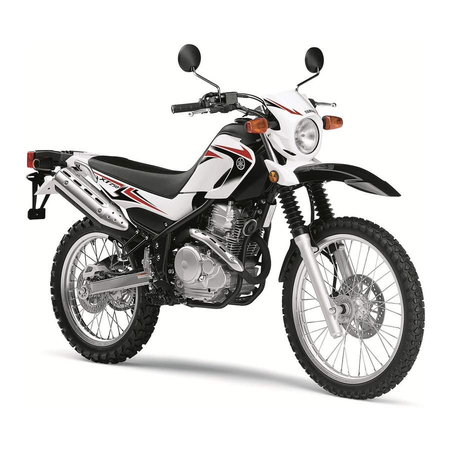
Yamaha Serow 250 (XT250)
Ниже представлены прямые ссылки на скачку сервисной документации.
Для Yamaha XT250 Serow
- Руководство пользователя (Owners Manual) для Yamaha XT250 Serow
- Сервисный мануал (Service Manual) Yamaha XT250 Serow (2008, USA, карбюраторная)
Обзор модели
- Yamaha XT 250 Serow
Источник — «https://bikeswiki.ru/index.php?title=Yamaha_XT250_Serow:_мануалы&oldid=10023»
Категория:
- Сервисная документация
- Manuals
- Brands
- Yamaha Manuals
- Motorcycle
- XT250
Manuals and User Guides for Yamaha XT250. We have 2 Yamaha XT250 manuals available for free PDF download: Service Manual, Owner’s Manual
Yamaha XT250 Service Manual (282 pages)
Brand: Yamaha
|
Category: Motorcycle
|
Size: 8.52 MB
Table of Contents
-
Table of Contents
7
-
How to Use this Manual
5
-
Symbols
6
-
General Information
9
-
Identification
10
-
Vehicle Identification Number
10
-
Model Label
10
-
-
Important Information
11
-
Preparation for Removal and Disassembly
11
-
Replacement Parts
11
-
Gaskets, Oil Seals and O-Rings
11
-
Lock Washers/Plates and Cotter Pins
11
-
Bearings and Oil Seals
11
-
Circlips
12
-
-
Checking the Connections
13
-
Special Tools
14
-
-
-
Specifications
19
-
General Specifications
20
-
Engine Specifications
21
-
Chassis Specifications
28
-
Electrical Specifications
30
-
Tightening Torques
32
-
General Tightening Torque Specifications
32
-
Engine Tightening Torques
32
-
Chassis Tightening Torques
34
-
-
Lubrication Points and Lubricant Types
37
-
Engine
37
-
Chassis
38
-
-
Lubrication System Chart and Diagrams
40
-
Engine Oil Lubrication Chart
40
-
Lubrication Diagrams
42
-
-
Cable Routing
44
-
-
Periodic Checks and Adjustments
55
-
Periodic Maintenance
56
-
Introduction
56
-
Periodic Maintenance Chart for the Emission Control System
56
-
General Maintenance and Lubrication Chart
57
-
-
Adjusting the Valve Clearance
60
-
Adjusting the Engine Idling Speed
61
-
Adjusting the Throttle Cable Free Play
62
-
Checking the Spark Plug
63
-
Checking the Ignition Timing
63
-
Measuring the Compression Pressure
64
-
Checking the Engine Oil Level
65
-
Changing the Engine Oil
66
-
Adjusting the Clutch Cable Free Play
67
-
Replacing the Air Filter Element
68
-
Checking the Carburetor Joint and Intake Manifold
69
-
Checking the Fuel Line
69
-
Checking the Cylinder Head Breather Hose
69
-
Checking the Exhaust System
69
-
-
Engine
60
-
Chassis
71
-
Adjusting the Front Disc Brake
71
-
Adjusting the Rear Disc Brake
71
-
Checking the Brake Fluid Level
72
-
Checking the Front Brake Pads
72
-
Checking the Rear Brake Pads
73
-
Checking the Front Brake Hose
73
-
Checking the Rear Brake Hose
73
-
Adjusting the Rear Brake Light Switch
73
-
Bleeding the Hydraulic Brake System
74
-
Adjusting the Drive Chain Slack
75
-
Lubricating the Drive Chain
75
-
Checking and Adjusting the Steering Head
76
-
Checking the Front Fork
77
-
Adjusting the Rear Shock Absorber Assembly
77
-
Checking the Tires
78
-
Checking the Wheels
79
-
Checking and Tightening the Spokes
80
-
Checking and Lubricating the Cables
80
-
Lubricating the Levers
80
-
Lubricating the Pedal
80
-
Lubricating the Sidestand
80
-
Lubricating the Rear Suspension
80
-
-
Electrical System
81
-
Checking and Charging the Battery
81
-
Checking the Fuses
81
-
Replacing the Headlight Bulb
81
-
Adjusting the Headlight Beam
81
-
-
-
-
Chassis
83
-
General Chassis
85
-
Front Wheel
86
-
Removing the Front Wheel
88
-
Checking the Front Wheel
88
-
Disassembling the Front Wheel
88
-
Assembling the Front Wheel
89
-
Adjusting the Front Wheel Static Balance
89
-
Installing the Front Wheel (Disc)
90
-
-
Rear Wheel
92
-
Removing the Rear Wheel (Disc)
94
-
Disassembling the Rear Wheel
94
-
Checking the Rear Wheel
94
-
Checking and Replacing the Rear Wheel Sprocket
94
-
Assembling the Rear Wheel
95
-
Adjusting the Rear Wheel Static Balance
95
-
Installing the Rear Wheel
95
-
-
Front Brake
96
-
Introduction
101
-
Checking the Front Brake Disc
101
-
Replacing the Front Brake Pads
102
-
Removing the Front Brake Caliper
103
-
Disassembling the Front Brake Caliper
103
-
Checking the Front Brake Caliper
103
-
Assembling the Front Brake Caliper
104
-
Installing the Front Brake Caliper
104
-
Removing the Front Brake Master Cylinder
105
-
Checking the Front Brake Master Cylinder
105
-
Assembling the Front Brake Master Cylinder
106
-
Installing the Front Brake Master Cylinder
106
-
-
Rear Brake
108
-
Introduction
113
-
Checking the Rear Brake Disc
113
-
Replacing the Rear Brake Pads
113
-
Removing the Rear Brake Caliper
114
-
Disassembling the Rear Brake Caliper
114
-
Checking the Rear Brake Caliper
115
-
Assembling the Rear Brake Caliper
115
-
Installing the Rear Brake Caliper
115
-
Removing the Rear Brake Master Cylinder
116
-
Checking the Rear Brake Master Cylinder
117
-
Assembling the Rear Brake Master Cylinder
117
-
Installing the Rear Brake Master Cylinder
117
-
Handlebar
119
-
Removing the Handlebars
120
-
Checking the Handlebar
120
-
Installing the Handlebar
120
-
-
Front Fork
123
-
Removing the Front Fork Legs
126
-
Disassembling the Front Fork Legs
126
-
Checking the Front Fork Legs
127
-
Assembling the Front Fork Legs
127
-
Installing the Front Fork Legs
130
-
-
Steering Head
131
-
Removing the Lower Bracket
133
-
Checking the Steering Head
133
-
Installing the Steering Head
133
-
-
Rear Shock Absorber Assembly
135
-
Handling the Rear Shock Absorber
136
-
Disposing of a Rear Shock Absorber
136
-
Removing the Rear Shock Absorber Assembly
136
-
Checking the Rear Shock Absorber Assembly
136
-
Checking the Connecting Arm and Relay Arm
136
-
Installing the Relay Arm
136
-
Installing the Rear Shock Absorber Assembly
137
-
-
Swingarm
138
-
Removing the Swingarm
139
-
Checking the Swingarm
139
-
Installing the Swingarm
139
-
-
Chain Drive
141
-
Removing the Drive Chain
142
-
Checking the Drive Chain
142
-
Checking the Drive Sprocket
143
-
Installing the Drive Chain
143
-
-
-
Engine
145
-
Engine Removal
147
-
Installing the Engine
150
-
Installing the Shift Pedal
150
-
-
Cylinder Head
152
-
Removing the Cylinder Head
154
-
Checking the Cylinder Head
155
-
Checking the Tappet Covers and Camshaft Sprocket Cover
155
-
Checking the Camshaft Sprocket and Timing Chain Guide (Exhaust System Side)
155
-
Checking the Timing Chain Tensioner
156
-
Installing the Cylinder Head
156
-
-
Camshaft
159
-
Removing the Rocker Arms and Camshaft
160
-
Checking the Camshaft
160
-
Checking the Rocker Arms and Rocker Arm Shafts
161
-
Installing the Camshaft and Rocker Arms
161
-
-
Valves and Valve Springs
164
-
Removing the Valves
164
-
Checking the Valves and Valve Guides
164
-
Checking the Valve Seats
166
-
Checking the Valve Springs
167
-
Installing the Valves
169
-
-
Cylinder and Piston
171
-
Removing the Piston
172
-
Checking the Cylinder and Piston
172
-
Checking the Piston Rings
173
-
Checking the Piston Pin
174
-
Installing the Piston and Cylinder
174
-
-
Clutch
176
-
Removing the Clutch
179
-
Checking the Friction Plates
179
-
Checking the Clutch Plates
179
-
Checking the Clutch Springs
179
-
Checking the Clutch Housing
180
-
Checking the Clutch Boss
180
-
Checking the Pressure Plate
180
-
Checking the Clutch Push Rods
180
-
Checking the Primary Drive Gear
180
-
Checking the Primary Driven Gear
180
-
Installing the Clutch
180
-
-
Oil Pump and Balancer Gear
184
-
Removing the Balancer Gear
186
-
Checking the Oil Pump
186
-
Checking the Oil Strainer
186
-
Assembling the Oil Pump
187
-
Install the Oil Pump and Balancer Gear
187
-
-
Shift Shaft
189
-
Checking the Shift Shaft
190
-
Checking the Stopper Lever
190
-
Installing the Shift Shaft
190
-
-
Generator and Starter Clutch
191
-
Removing the Generator
193
-
Removing the Starter Clutch
193
-
Checking the Starter Clutch
193
-
Installing the Starter Clutch
194
-
Installing the Generator
194
-
-
Electric Starter
196
-
Checking the Starter Motor
198
-
Assembling the Starter Motor
199
-
-
Crankcase
200
-
Disassembling the Crankcase
202
-
Checking the Crankcase
202
-
Checking the Timing Chain, Crankshaft Sprocket, Timing Chain Guide (Intake Side)
202
-
Checking the Bearing and Oil Seal
202
-
Assembling the Crankcase
202
-
-
Crankshaft Assembly
205
-
Removing the Crankshaft Assembly
205
-
Checking the Crankshaft and Connecting Rod
205
-
Installing the Crankshaft Assembly
205
-
-
Transmission
207
-
Checking the Shift Forks
209
-
Checking the Shift Drum Assembly
209
-
Checking the Transmission
209
-
Installing the Shift Forks and Shift Drum Assembly
210
-
-
-
Fuel System
211
-
Fuel Tank
213
-
Checking the Fuel Cock
213
-
-
Carburetor
214
-
Checking the Carburetor
217
-
Assembling the Carburetor
218
-
Installing the Carburetor
219
-
-
Air Induction System
220
-
Checking the Air Induction System
223
-
-
-
Electrical System
225
-
Ignition System
226
-
Circuit Diagram
226
-
Troubleshooting
228
-
-
Electric Starting System
230
-
Circuit Diagram
230
-
Starting Circuit Cut-Off System Operation
232
-
Troubleshooting
234
-
-
Charging System
236
-
Circuit Diagram
236
-
Troubleshooting
238
-
-
Lighting System
240
-
Circuit Diagram
240
-
Troubleshooting
242
-
-
Signaling System
244
-
Circuit Diagram
244
-
Troubleshooting
246
-
-
Carburetor Heating System
250
-
Circuit Diagram
250
-
Troubleshooting
252
-
-
Electrical Components
254
-
Checking the Switches
258
-
Checking the Bulbs and Bulb Sockets
261
-
Checking the Fuse
262
-
Checking and Charging the Battery
262
-
Checking the Relays
265
-
Checking the Turn Signal Relay
266
-
Checking the Diode
267
-
Checking the Spark Plug Cap
267
-
Checking the Ignition Coil
268
-
Checking the Pickup Coil
269
-
Checking the Stator Coil
269
-
Checking the Rectifier/Regulator
270
-
Checking the Horn
270
-
Checking the Speed Sensor
271
-
Checking the Thermo Switch
271
-
Checking the Carburetor Warmer
272
-
-
-
Troubleshooting
273
-
General Information
274
-
Incorrect Engine Idling Speed
274
-
Starting Failures
274
-
Faulty Clutch
275
-
Faulty Gear Shifting
275
-
Jumps out of Gear
275
-
Poor Medium-And-High-Speed Performance
275
-
Shift Pedal Does Not Move
275
-
Faulty Front Fork Legs
276
-
Faulty Lighting or Signaling System
276
-
Overheating
276
-
Poor Braking Performance
276
-
Unstable Handling
276
-
Advertisement
Yamaha XT250 Owner’s Manual (100 pages)
Brand: Yamaha
|
Category: Motorcycle
|
Size: 2.15 MB
Table of Contents
-
Important Manual Information
4
-
Table of Contents
6
-
Safety Information
8
-
Location of Important Labels
12
-
Description
16
-
Left View
16
-
Right View
17
-
Controls and Instruments
18
-
Instrument and Control Functions
19
-
Main Switch/Steering Lock
19
-
Indicator Lights
20
-
Multi-Function Display
21
-
Clock Mode
21
-
Handlebar Switches
22
-
Clutch Lever
23
-
Shift Pedal
23
-
Brake Lever
24
-
Brake Pedal
24
-
Fuel Tank Cap
24
-
Fuel
25
-
Fuel Cock
26
-
Starter (Choke) Knob «1
27
-
Seat
27
-
Helmet Holder
28
-
Adjusting the Shock Absorber
28
-
Assembly
28
-
Sidestand
30
-
Ignition Circuit Cut-Off System
30
-
Pre-Operation Checks
32
-
Pre-Operation Check List
33
-
Operation and Important Riding Points
35
-
Starting and Warming up a Cold Engine
35
-
Starting a Warm Engine
36
-
Shifting
36
-
Engine Break-In
38
-
Parking
38
-
Periodic Maintenance and Minor Repair
39
-
Periodic Maintenance
39
-
Owner’s Tool Kit
39
-
Periodic Maintenance Chart for the Emission Control System
41
-
General Maintenance and Lubrication Chart
43
-
Removing and Installing the Cowling and Panels
47
-
-
Checking the Spark Plug
49
-
To Check/Install Spark Plug
50
-
To Change Engine Oil
51
-
-
Canister (for California Only)
51
-
Engine Oil and Oil Filter Element
51
-
Replacing the Air Filter Element and Cleaning the Check Hose
54
-
Cleaning the Spark Arrester
55
-
-
Checking the Engine Idling
56
-
Carburetor
56
-
Speed
56
-
Checking the Throttle Cable Free Play
57
-
Valve Clearance
57
-
Tires
57
-
Spoke Wheels
59
-
Accessories and Replacement Parts
60
-
Adjusting the Clutch Lever Free Play
60
-
Adjusting the Brake Lever Free Play
61
-
Adjusting the Rear Brake Light Switch
62
-
Checking the Front and Rear Brake Pads
62
-
Checking the Brake Fluid Level
63
-
Changing the Brake Fluid
64
-
Drive Chain Slack
64
-
Cleaning and Lubricating the Drive Chain
65
-
Checking and Lubricating the Cables
66
-
Checking and Lubricating the Throttle Grip and Cable
66
-
Checking and Lubricating the Brake and Shift Pedals
66
-
Checking and Lubricating the Brake and Clutch Levers
67
-
Checking and Lubricating the Sidestand
68
-
Lubricating the Rear Suspension
68
-
Checking the Front Fork
68
-
Checking the Steering
69
-
Checking the Wheel Bearings
70
-
Battery
70
-
Replacing the Fuse
71
-
Replacing the Headlight Bulb
72
-
Replacing the Tail/Brake Light Bulb
73
-
Replacing a Turn Signal Light Bulb
74
-
Supporting the Motorcycle
75
-
Front Wheel
75
-
Rear Wheel
76
-
To Install Front Wheel
76
-
Troubleshooting
78
-
Troubleshooting Chart
79
-
Motorcycle Care and Storage
80
-
Matte Color Caution
80
-
Care
80
-
Storage
82
-
Specifications
84
-
Consumer Information
87
-
Identification Numbers
87
-
Reporting Safety Defects
89
-
Motorcycle Noise Regulation
90
-
Maintenance Record
91
-
Yamaha Motor Corporation, U.s.a. Street and Enduro Motorcycle Limited Warranty
93
-
Advertisement
Related Products
-
Yamaha XT250Z
-
Yamaha XT250ZC
-
Yamaha XT250XC
-
Yamaha XT250X
-
Yamaha XT250D
-
Yamaha XT250DC
-
Yamaha XT250L 2014
-
Yamaha XT250F 2014
-
Yamaha XT250 2009
-
Yamaha XT250Z 2009
Yamaha Categories
Motorcycle
Musical Instrument
Electronic Keyboard
Receiver
Amplifier
More Yamaha Manuals

Руководство по эксплуатации и техническому обслуживанию мотоциклов Yamaha моделей XT500E и XT600E.
- Издательство: Yamaha Motor Co., Ltd.
- Год издания: 2001
- Страниц: 104
- Формат: PDF
- Размер: 3,1 Mb

Руководство по эксплуатации и техническому обслуживанию мотоциклов Yamaha XT660Z Tenere.
- Издательство: Yamaha Motor Co., Ltd.
- Год издания: 2010
- Страниц: 96
- Формат: PDF
- Размер: 4,0 Mb
Руководство по эксплуатации и техническому обслуживанию мотоциклов Yamaha XT1200Z Super Tenere.
- Издательство: Yamaha Motor Co., Ltd.
- Год издания: 2010
- Страниц: 106
- Формат: PDF
- Размер: 4,3 Mb
Сборник руководств на английском языке по эксплуатации и техническому обслуживанию мотоциклов Yamaha моделей XT225, XT250, XT350, XT500, XT600, XT660 и XT1200 различных модификаций.
- Издательство: Yamaha Motor Co., Ltd.
- Год издания: —
- Страниц: —
- Формат: PDF
- Размер: 65,9 Mb
Сборник руководств на английском языке по ремонту мотоциклов Yamaha XT225 различных модификаций.
- Издательство: Yamaha Motor Co., Ltd.
- Год издания: 1995/1999
- Страниц: 389/414
- Формат: PDF
- Размер: 117,1 Mb
Руководство на английском языке по ремонту мотоциклов Yamaha XT350.
- Издательство: Yamaha Motor Co., Ltd.
- Год издания: 1985
- Страниц: 28
- Формат: PDF
- Размер: 12,1 Mb
Руководство на английском, французском и немецком языках по ремонту мотоциклов Yamaha моделей SR500 и XT500.
- Издательство: Yamaha Notor Co., Ltd.
- Год издания: —
- Страниц: —
- Формат: JPG
- Размер: 11,6 Mb
Сборник руководств на английском, немецком и испанском языках по ремонту мотоциклов Yamaha моделей XT600A, XT600AC, XT600E и XT600Z.
- Издательство: —
- Год издания: —
- Страниц: —
- Формат: PDF, JPG
- Размер: 135,3 Mb
Сборник руководств на английском языке по ремонту мотоциклов Yamaha XT660 различных модификаций 2004-2007 годов выпуска.
- Издательство: Yamaha Notor Co., Ltd.
- Год издания: 2003/2006
- Страниц: 462/81
- Формат: PDF
- Размер: 15,5 Mb
Руководство на английском языке по ремонту мотоциклов Yamaha моделей XT1200Z и XT1200ZZ Super Tenere 2010 года выпуска.
- Издательство: Yamaha Notor Co., Ltd.
- Год издания: 2010
- Страниц: 616
- Формат: PDF
- Размер: 34,7 Mb

Сборник руководств на английском, французском, немецком, испанском и итальянском языках по ремонту мотоциклов Yamaha моделей XT660R, XT660X и др.
- Издательство: Yamaha
- Год издания: —
- Страниц: —
- Формат: ISO
- Размер: 1,7 Gb

Electric Yamaha VJ50RN (EN, 2.1 MB)
FZ 1 Service Manual (RU, 17.4 MB)
MT-03 service manual (EN, 20.4 MB)
Service Manial Yamaha VJ50RN (EN, 2.2 MB)
Service Manual Yamaha FZS 600 Fazer (EN, 7.3 MB)
Service Manual Yamaha MT-01 2005 (EN, 14.4 MB)
Service Manual Yamaha Super Tenere (XT1200Z) 2010-2014 (EN, 42.7 MB)
Service manual Yamaha YZF-R6 (EN, 9.0 MB)
Supplementary Service Manual XV1700 (дополнение к сервис-ману на XV1600) (EN, 11.4 MB)
V-Star 1300 Service Manual (RU, 17.3 MB)
V-Star 1300 User Manual (RU, 4.2 MB)
XVS 1100 Drag Star (V-Star) User Manual (RU, 4.8 MB)
Yamaha DragStar 650 (400) 97 — Service Manual (EN, 14.7 MB)
Yamaha Fazer FZS1000(R) Supplementary Service Manual (EN, 3.0 MB)
Yamaha FJR1300 Service Manual 2001 (EN, 18.9 MB)
Yamaha FJR1300A 1300 Service Manual (RU, 7.1 MB)
Yamaha FZ1-S(A) FZ1 — Руководство владельца (RU, 4.5 MB)
Yamaha FZ6R service manual (EN, 21.6 MB)
Yamaha FZ6S -Руководство пользователя (RU, 2.8 MB)
Yamaha FZR 750 Genesis — Cервисный мануал ( перевод промт) (RU, 6.4 MB)
Yamaha FZS1000 Fazer Parts Catalogue (EN, 1.6 MB)
Yamaha FZS1000(N) Service Manual (EN, 15.0 MB)
Yamaha FZS1000(S) Fazer. Руководство для владельца (RU, 3.4 MB)
Yamaha FZX 750 service information (EN, 5.9 MB)
Yamaha FZX750 owners manual (EN, 3.6 MB)
Yamaha Majesty 400 — Руководство по эксплуатации (RU, 5.5 MB)
Yamaha Majesty YP250 owners manual 2002 (EN, 2.1 MB)
Yamaha MT 03 Service Manual (EN, 20.4 MB)
Yamaha Roadstar — Инструкция по эксплуатации (Engl) (RU, 11.4 MB)
Yamaha Thunderace YZF1000RJ service manual (EN, 36.5 MB)
Yamaha V-Max 1700 — Руководство пользователя (RU, 17.6 MB)
Yamaha Venture XVZ1300 1999 Service Manual (EN, 54.1 MB)
Yamaha virago 535 700 1100 — Service Manual (EN, 47.3 MB)
Yamaha WR450FB 2012-2015 Owners Service Manual (EN, 24.8 MB)
Yamaha XJ 6 Parts List (EN, 1.3 MB)
Yamaha XJ600S/XJ600N Diversion руководство по эксплуатации (RU, 2.9 MB)
Yamaha XJ6S/XJ6SA Diversion 2009-12 Service manual (EN, 65.8 MB)
Yamaha XJR 1300 Service manual (EN, 7.4 MB)
Yamaha XJR 1300 Руководство пользователя (RU, 4.7 MB)
Yamaha XJR400R Manual (JP, 23.2 MB)
Yamaha XT225 L/LC Owner’s Manual (EN, 5.7 MB)
Yamaha XT500E/XT600E Руководство для владельца (RU, 3.1 MB)
Yamaha XT660X 2004 Service Manual (EN, 14.1 MB)
Yamaha XTZ750 Super Tenere service manual (EN, 38.9 MB)
Yamaha XV 1600 Parts Catalogue (EN, 1.3 MB)
Yamaha XV 1700 Warrior руководство владельца (RU, 6.8 MB)
Yamaha XV 535 Virago, XV 400 Virago Топливная система и выхлоп. Мануал на русском. (RU, 10.2 MB)
Yamaha XV 535 Virago. Руководство по ремонту. Двигатель. (RU, 14.5 MB)
Yamaha XV 535 Virago. Руководство по ремонту. Трансмисия. (RU, 7.6 MB)
Yamaha XV 535 Virago. Руководство по ремонту. Электрика. (RU, 8.5 MB)
Yamaha XV535-1100 virago-1981-2003 service (EN, 54.2 MB)
Yamaha XVS 1300 руководство пользователя (RU, 2.6 MB)
Yamaha XVS 400-650 Drag Star-Руководство пользователя (RU, 6.2 MB)
Yamaha YZ450F 06-09 service manual (EN, 21.0 MB)
Yamaha YZF-R3A, Руководство пользователя (RU, 3.7 MB)
Инструкция по эксплуатации Yamaha TDM 850 ’96 (RU, 48.5 MB)
Инструкция по эксплуатации Yamaha XVS 950 Midnight Star (RU, 1.7 MB)
Мануал Yamaha YZ 250 F (RU, 12.2 MB)
Мануал для XV 1900 Midnight Star (RU, 1.8 MB)
Мануал на TTR250 (RU, 13.6 MB)
Манул XV 1900 (RU, 1.8 MB)
Первое издание 2001 на BT 1100 Bulldog (RU, 3.4 MB)
Руководство для владельца FZS 600 Fazer (RU, 3.6 MB)
Руководство по эксплуатации Yamaha V-Max 1700 (RU, 17.6 MB)
Руководство по эксплуатации Yamaha YBR 125 (RU, 23.9 MB)
Руководство пользователя DragStar 650 (RU, 6.2 MB)
Руководство пользователя XVS 650 и XVS 650a (RU, 6.2 MB)
Руководство пользователя Yamaha XVS 1300 Stryker (RU, 2.6 MB)
Руководство пользователя Yamaha YBR125 (RU, 3.5 MB)
Сервис на Yamaha DragStar 650 (EN, 14.7 MB)
Сервисный мануал для XV 1900 Midnight Star/Stratoliner/Roadliner (EN, 19.9 MB)
Материал из Enduro.team
Перейти к: навигация, поиск
Ниже представлены прямые ссылки на скачку сервисной документации.
Для Yamaha XT250 Serow
- Руководство пользователя для Yamaha XT250 Serow
- Сервисный мануал для Yamaha XT250 Serow
Обзор модели
- Yamaha XT 250 Serow
Категории:
- Сервисная документация
- Yamaha документация
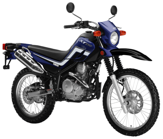
XT 250 — модель мотоцикла, марки Yamaha,
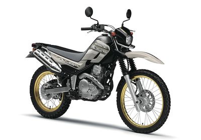
Модель софт-эндуро Yamaha XT250 Serow появилась в 2005 году, придя на смену Yamaha XT225 Serow. За основу модели был взят новый двигатель увеличенного объема (223 → 249 см³) и рама от Yamaha XG250 Tricker. В отличие от прошлого поколения XT225, новый XT250 получил более простую 5-ступенчатую КПП, вместо 6-ступенчатой.
Первое поколение модели Yamaha XT250 Serow выпускалось с 2005 по 2007 гг. включительно и было доступно только на внутреннем японском рынке. Главная особенность моделей этих годов — карбюраторная система питания.
Второе поколение началось с 2008 года и выпускалось по август 2018 года. Внутрияпонские модели этих годов получают инжектор, катализатор и оптимизированные настройки двигателя (для повышения крутящего момента на низких оборотах). С этого же года модель начинает поставляться на экспорт в страны Северной Америки (приставка Serow использовалась для канадских версий, в то время как в США модель называлась просто — Yamaha XT250). Североамериканские версии, выпущенные до 2013 года, идентичны первому поколению внутрияпонских версий (с карбюраторной системой питания). С 2013 года версии для США и Канады получают инжектор.
Третье поколение модели Yamaha XT250 Serow началось с 31 августа 2018 года (2019 модельный год) и коснулось только внутрияпонских версий. Модель получила обновления под новые экологические нормы, повысила степень сжатия двигателя с 9.5 до 9.7 и увеличила массу на 3 кг.
Помимо основной версии мотоцикла, на внутреннем японском рынке с 2012 года предлагалась также туринговая модификация, получившая название — Yamaha XT250 Touring Serow. Модель отличалась наличием лобового стекла, защиты двигателя, защиты рук и багажником.
На базе двигателя от Yamaha XT250 Serow была построена также модель — Yamaha XG250 Tricker.
По состоянию на 2019 год, модель Yamaha XT250 Serow официально доступна в Японии и странах Северной Америки.
Краткая история модели
2005 г. — начало производства и продаж. Первое поколение.
Модель: Yamaha XT250 Serow (Япония). Номер рамы: DG11J-. Заводское обозначение: 3C51, 3C52.
2006 г. — без существенных изменений.
Модель: Yamaha XT250 Serow (Япония). Заводское обозначение: 3C53, 3C54.
2007 г. — без существенных изменений.
Модель: Yamaha XT250 Serow (Япония). Заводское обозначение: 3C55, 3C57.
2008 г. — рестайлинг модели. Второе поколение. Начало производства и продаж на рынке Северной Америки.
Модель: Yamaha XT250 Serow; Yamaha XT250X (Япония; Северная Америка). Номер рамы: DG17J- (Япония). Заводское обозначение: 3C56 3C5C; 3C58, 3C59, 3C5A.
2009 г. — без существенных изменений.
Модель: Yamaha XT250Y (Северная Америка). Заводское обозначение: 3C5E, 3C5D, 3C5F.
2010 г. — без существенных изменений.
Модель: Yamaha XT250 Serow; Yamaha XT250Z (Япония; Северная Америка). Заводское обозначение: 3C5S, 3C5M; 3C5J, 3C5H, 3C5K.
2011 г. — без существенных изменений.
Модель: Yamaha XT250A (Северная Америка). Заводское обозначение: 3C5P, 3C5N, 3C5R.
2012 г. — без существенных изменений.
Модель: Yamaha XT250 Serow; Yamaha XT250B (Япония; Северная Америка). Заводское обозначение: 3C5Y; 3C5V, 3C5O, 3C5W.
2013 г. — без существенных изменений. Версии для Северной Америки получили инжектор.
Модель: Yamaha XT250D (Северная Америка). Заводское обозначение: 1YB1, 1YB2, 1YB3.
2014 г. — без существенных изменений.
Модель: Yamaha XT250 Serow; Yamaha XT250E (Япония; Северная Америка). Заводское обозначение: 1YB9, 1YBF; 1YB5, 1YB6, 1YB7.
2015 г. — без существенных изменений.
Модель: Yamaha XT250 Serow; Yamaha XT250F (Япония; Северная Америка). Заводское обозначение: 1YBL; 1YBB, 1YBC, 1YBD.
2016 г. — без существенных изменений.
Модель: Yamaha XT250 Serow; Yamaha XT250G (Япония; Северная Америка). Заводское обозначение: 1YBN; 1YBH, 1YBJ, 1YBK.
2017 г. — без существенных изменений.
Модель: Yamaha XT250 Serow; Yamaha XT250H (Япония; Северная Америка). Заводское обозначение: B1H1; 1YBR, 1YBS, 1YBT.
2018 г. — без существенных изменений.
Модель: Yamaha XT250J (Северная Америка). Заводское обозначение: 1YBX.
2019 г. — рестайлинг модели. Третье поколение.
Модель: Yamaha XT250 Serow; Yamaha XT250K (Япония; Северная Америка). Номер рамы: DG31J- (Япония).
2020 г. — без существенных изменений.
Модель: Yamaha XT250 (Северная Америка).
2021 г. — без существенных изменений.
Модель: Yamaha XT250 (Северная Америка).
Технические характеристики
Технические характеристики Yamaha Serow 250 (XT250):
| Модель | Yamaha XT250 (Serow) |
|---|---|
| Тип мотоцикла | эндуро |
| Год выпуска | 2005+ |
| Рама | стальная |
| Тип двигателя | 1-цилиндровый, 4-тактный |
| Рабочий объем | 249 см³ |
| Диаметр цилиндра/ход поршня | 74,0 x 58,0 мм |
| Степень сжатия | 9.5:1
9.7:1 – XT250 Serow (2019+, Япония) |
| Охлаждение | воздушное |
| Количество клапанов на цилиндр | SOHC, 2 клапана |
| Система подачи топлива | Карбюратор, 1x Teikei MV33 – XT250 Serow (2005-2007, Япония; 2008-2012, Северная Америка)
Инжектор, 1x – XT250 Serow (2008+, Япония; 2013+, Северная Америка) |
| Тип зажигания | CDI – XT250 Serow (карбюраторные версии)
TCI – XT250 Serow (инжекторные версии) |
| Максимальная мощность | 21,0 л.с. (16,0 кВт) при 7500 об/мин – XT250 Serow (карбюраторные версии)
19,0 л.с. (14,0 кВт) при 7500 об/мин – XT250 Serow (инжекторные версии) |
| Максимальный крутящий момент | 21,0 Нм (2,14 кг-м) при 6500 об/мин – XT250 Serow (карбюраторные версии)
19,0 Нм (1,9 кг-м) при 6500 об/мин – XT250 Serow (2008-2018) 20,0 Нм (2,1 кг-м) при 6000 об/мин – XT250 Serow (2019+) |
| Сцепление | Многодисковое в масляной ванне, тросовый привод |
| Коробка передач | 5-ступенчатая |
| Тип привода | цепь |
| Размер передней шины | 2.75-21 (45P) |
| Размер задней шины | 120/80-18 (62P) |
| Передние тормоза | 1 диск, 245 мм, 2-поршневой суппорт |
| Задние тормоза | 1 диск, 203 мм, 1-поршневой суппорт |
| Передняя подвеска | 35 мм телескопическая вилка, ход — 225 мм |
| Задняя подвеска | Маятниковая с моноамортизатором (рег. преднатяга и отбоя), ход — 180 мм |
| Длина мотоцикла | 2150 мм |
| Ширина мотоцикла | 805 мм |
| Высота мотоцикла | 1160 мм |
| Колесная база | 1360 мм |
| Высота по седлу | 810 мм |
| Минимальный дорожный просвет (клиренс) | 285 мм |
| Разгон 0-100 км/ч (0-60 миль/ч) | 10,35 сек.<a href=»#cite_note-1″>[1]</a> |
| Максимальная скорость | 122 км/ч<a href=»#cite_note-2″>[2]</a> |
| Емкость бензобака | 9,8 л – XT250 Serow (Япония, 2005-2007; Северная Америка)
9,6 л – XT250 Serow (Япония, 2008-2018) 9,3 л – XT250 Serow (Япония, 2019+) |
| Масса мотоцикла (сухая) | 115 кг – XT250 Serow (карбюраторные версии)
119 кг – XT250 Serow (инжекторные версии) |
| Масса мотоцикла (снаряженная) | 126 кг – XT250 Serow (карбюраторные версии)
130 кг – XT250 Serow (инжекторные версии) 133 кг – XT250 Serow (2019+) |
Расход топлива
Средний расход топлива на Yamaha XT250 Serow составляет 3,1 л на 100 км пути. Точное значение зависит от стиля езды и поверхности передвижения.
Мануал
Руководство пользователя (Owners Manual) для Yamaha XT250 Serow
Сервисный мануал (Service Manual) Yamaha XT250 Serow (2008, USA, карбюраторная)