-
Contents
-
Table of Contents
-
Troubleshooting
-
Bookmarks
Related Manuals for YASKAWA Sigma-7 Series
Summary of Contents for YASKAWA Sigma-7 Series
-
Page 1
-7-Series AC Servo Drive -7W SERVOPACK with FT/EX Specification for Gantry Applications Product Manual Model: SGD7W-A20A000F70 Basic Information on SERVOPACKs SERVOPACK Ratings and Specifications Position Correction Table Synchronized Stopping Position Deviation between Axes Overflow Detection Maintenance Parameter Lists MANUAL NO. SIEP S800002 29C… -
Page 2
Yaskawa. No patent liability is assumed with respect to the use of the informa- tion contained herein. Moreover, because Yaskawa is constantly striving to improve its high-quality products, the information contained in this manual is sub- ject to change without notice. -
Page 3: Table Synchronized Stopping
About this Manual This manual provides information on the Σ-7-Series AC Servo Drive Σ-7W SERVOPACK for Gantry Applications. Read and understand this manual to ensure correct usage of the Σ-7-Series AC Servo Drives. Keep this manual in a safe place so that it can be referred to whenever necessary. Outline of Manual The contents of the chapters of this manual are described in the following table.
-
Page 4
Continued from previous page. Σ -7-Series AC Servo Drive Σ -7W SERVOPACK Product Manual Item This Manual MECHATROLINK-III Communications Reference (Manual No.: SIEP S800001 29) Inspections and Part Replacement – 10.1 Alarm Displays – Maintenance Warning Displays – Troubleshooting Based on the Operation and –… -
Page 5
Related Documents The relationships between the documents that are related to the Servo Drives are shown in the following figure. The numbers in the figure correspond to the numbers in the table on the following pages. Refer to these documents as required. y tem Component Machine Controller… -
Page 6
Classification Document Name Document No. Description Describes the features and applica- Machine Controller and tion examples for combinations of Machine Controller and AC Servo Drive KAEP S800001 22 MP3000-Series Machine Control- Servo Drive lers and Σ-7-Series AC Servo Solutions Catalog General Catalog Drives. -
Page 7
Continued from previous page. Classification Document Name Document No. Description Σ-7-Series AC Servo Drive Provides detailed information for Σ-7S and Σ-7W SERVOPACK the safe usage of Σ-7-Series TOMP C710828 00 Safety Precautions SERVOPACKs. Σ-V-Series/Σ-V-Series for Large-Capacity Models/ Provides detailed information for Σ-7-Series TOBP C720829 00 the safe usage of Option Modules. -
Page 8
Continued from previous page. Classification Document Name Document No. Description Σ-7-Series AC Servo Drive Σ-7S SERVOPACK with MECHATROLINK-III SIEP S800001 28 Communications References Product Manual Σ-7-Series AC Servo Drive Σ-7S SERVOPACK with MECHATROLINK-II SIEP S800001 27 Communications References Product Manual Σ-7-Series AC Servo Drive Σ-7S SERVOPACK with Analog Voltage/Pulse Train… -
Page 9
Continued from previous page. Classification Document Name Document No. Description Σ-7-Series AC Servo Drive Σ-7S SERVOPACK with FT/EX Specification for SIEP S800001 84 Indexing Application Product Manual Σ-7-Series AC Servo Drive Σ-7S SERVOPACK with FT/EX Specification for SIEP S800001 89 Tracking Application Product Manual Σ-7-Series AC Servo Drive… -
Page 10
Continued from previous page. Classification Document Name Document No. Description AC Servo Drives Σ-V Series/Σ-V Series Provides detailed information for Large-Capacity Models/ SIEP C720829 06 required for the design and mainte- Option Module Σ-7 Series nance of a Safety Module. User’s Manual User’s Manual Safety Module… -
Page 11
Continued from previous page. Classification Document Name Document No. Description Provides detailed information on Machine Controller the ladder programming specifica- MP3000 Series SIEP C880725 13 tions and instructions for MP3000- Ladder Programming Series Machine Controllers and Σ- Manual 7-Series Σ-7C SERVOPACKs. Programming Provides detailed information on Manuals… -
Page 12
Using This Manual Technical Terms Used in This Manual The following terms are used in this manual. Term Meaning A Σ-7-Series Rotary Servomotor or Linear Servomotor. Servomotor A generic term used for a Σ-7-Series Rotary Servomotor (SGM7M, SGM7J, SGM7A, SGM7P, Rotary Servomotor SGM7G, or SGMMV). -
Page 13
Notation Used in this Manual Notation for Reverse Signals The names of reverse signals (i.e., ones that are valid when low) are written with a forward slash (/) before the signal abbreviation. Notation Example BK is written as /BK. … -
Page 14
Engineering Tools Used in This Manual This manual uses the interfaces of the SigmaWin+ for descriptions. Trademarks • QR code is a trademark of Denso Wave Inc. • MECHATROLINK is a trademark of the MECHATROLINK Members Association. • Other product names and company names are the trademarks or registered trademarks of the respective company. -
Page 15
Safety Precautions Safety Information To prevent personal injury and equipment damage in advance, the following signal words are used to indicate safety precautions in this document. The signal words are used to classify the hazards and the degree of damage or injury that may occur if a product is used incorrectly. Information marked as shown below is important for safety. -
Page 16
Safety Precautions That Must Always Be Observed General Precautions DANGER Read and understand this manual to ensure the safe usage of the product. Keep this manual in a safe, convenient place so that it can be referred to whenever necessary. Make sure that it is delivered to the final user of the product. -
Page 17
Storage Precautions CAUTION Do not place an excessive load on the product during storage. (Follow all instructions on the packages.) There is a risk of injury or damage. NOTICE Do not install or store the product in any of the following locations. •… -
Page 18
Installation Precautions CAUTION Install the Servomotor or SERVOPACK in a way that will support the mass given in technical documents. Install SERVOPACKs, Servomotors, regenerative resistors, and External Dynamic Brake Resis- tors on nonflammable materials. Installation directly onto or near flammable materials may result in fire. … -
Page 19
WARNING Wiring and inspections must be performed only by qualified engineers. There is a risk of electric shock or product failure. Check all wiring and power supplies carefully. Incorrect wiring or incorrect voltage application to the output circuits may cause short-circuit fail- ures. -
Page 20
Whenever possible, use the Cables specified by Yaskawa. If you use any other cables, confirm the rated current and application environment of your model and use the wiring materials specified by Yaskawa or equivalent materials. Securely tighten cable connector screws and lock mechanisms. -
Page 21
CAUTION Design the system to ensure safety even when problems, such as broken signal lines, occur. For example, the P-OT and N-OT signals are set in the default settings to operate on the safe side if a signal line breaks. Do not change the polarity of this type of signal. … -
Page 22
CAUTION Wait for at least six minutes after turning OFF the power supply (with a SERVOPACK for a 100- VAC power supply input, wait for at least nine minutes) and then make sure that the CHARGE indicator is not lit before starting wiring or inspection work. Do not touch the power supply ter- minals while the CHARGE lamp is lit because high voltage may still remain in the SERVOPACK even after turning OFF the power supply. -
Page 23
We will update the manual number of the manual and issue revisions when changes are made. Any and all quality guarantees provided by Yaskawa are null and void if the customer modifies the product in any way. Yaskawa disavows any responsibility for damages or losses that are caused by modified products. -
Page 24
• Events for which Yaskawa is not responsible, such as natural or human-made disasters Limitations of Liability • Yaskawa shall in no event be responsible for any damage or loss of opportunity to the customer that arises due to failure of the delivered product. -
Page 25
• It is the customer’s responsibility to confirm conformity with any standards, codes, or regulations that apply if the Yaskawa product is used in combination with any other products. • The customer must confirm that the Yaskawa product is suitable for the systems, machines, and equipment used by the customer. -
Page 26
• SGLGW* UL 1004-1 • SGLFW* Linear UL 1004-6 • SGLFW2 Servomotors (E165827) • SGLTW* Only products with derating specifications are in compliance with the UL Standards. Estimates are available for those prod- ucts. Contact your Yaskawa representative for details. xxvi… -
Page 27
EU Directives Product Model EU Directives Harmonized Standards EN 55011 group 1, class A EN 61000-6-2 EMC Directive EN 61000-6-4 2014/30/EU EN 61800-3 (Category C2, Second environment) SERVOPACKs SGD7W Low Voltage Directive EN 50178 2014/35/EU EN 61800-5-1 RoHS Directive EN 50581 2011/65/EU EN 55011 group 1, class A… -
Page 28: Table Of Contents
Contents About this Manual ……….iii Outline of Manual .
-
Page 29: Table Of Contents
Position Correction Table Settings….. . . 3-6 3.4.1 Measure the Positions Required for the Position Correction Table..3-6 3.4.2 Position Correction Table Details .
-
Page 30: Table Of Contents
Maintenance Alarm Displays ……..6-2 6.1.1 List of Alarms .
-
Page 31: Table Of Contents
Basic Information on SERVOPACKs This chapter provides information required to select SERVOPACKs, such as SERVOPACK models. Product Introduction ….1-2 Model Designations ….1-3 1.2.1 Interpreting SERVOPACK Model Numbers .
-
Page 32: Product Introduction
1.1 Product Introduction Product Introduction The FT70 features three built-in functions optimized for driving a gantry to provide an optimal solution for problems with gantry mechanisms. • Position Correction Table (minimizes wasted torque produced by mechanical differences to improve cycle times) •…
-
Page 33: Model Designations
1.2 Model Designations 1.2.1 Interpreting SERVOPACK Model Numbers Model Designations 1.2.1 Interpreting SERVOPACK Model Numbers GD7W — 1R6 14th 11th+12th+1 th 1 t+2nd+ rd 5th+6th 8th+9th+10th Σ-7- erie digit digit digit digit digit digit digit Σ-7W ERVOPACK Hardware Option Maximum Applicable 1 t+2nd+ rd digit 4th digit 8th+9th+10th digit…
-
Page 34: Interpreting Servomotor Model Numbers
1.2 Model Designations 1.2.2 Interpreting Servomotor Model Numbers 1.2.2 Interpreting Servomotor Model Numbers Refer to the following manuals for information on interpreting Σ-7-Series Servomotor model numbers. Σ-7-Series Rotary Servomotor Product Manual (Manual No.: SIEP S800001 36) Σ-7-Series Linear Servomotor Product Manual (Manual No.: SIEP S800001 37)
-
Page 35: Combinations Of Servopacks And Servomotors
1.3 Combinations of SERVOPACKs and Servomotors Combinations of SERVOPACKs and Servomotors Refer to the following manuals for details on combinations with Σ-7-Series Servomotors. Σ-7-Series Rotary Servomotor Product Manual (Manual No.: SIEP S800001 36) Σ-7-Series Linear Servomotor Product Manual (Manual No.: SIEP S800001 37)
-
Page 36: Functions
1.4 Functions 1.4.1 SERVOPACK Functions Functions This section lists the functions provided by SERVOPACKs. Refer to the following manual for details on the functions. Σ-7-Series Σ-7W SERVOPACK with MECHATROLINK-III Communications References Product Manual (Manual No.: SIEP S800001 29) Refer to the following section for details on restrictions to these functions. 1.4.2 Function Application Restrictions on page 1-9 1.4.1 SERVOPACK Functions…
-
Page 37
1.4 Functions 1.4.1 SERVOPACK Functions • Functions Related to the Host Controller Function Extended Address Setting Electronic Gear Settings I/O Signal Allocations ALM (Servo Alarm) Signal /WARN (Warning) Signal /TGON (Rotation Detection) Signal /S-RDY (Servo Ready) Signal /V-CMP (Speed Coincidence Detection) Signal /COIN (Positioning Completion) Signal /NEAR (Near) Signal Speed Limit during Torque Control… -
Page 38
1.4 Functions 1.4.1 SERVOPACK Functions • Functions for Inspection and Maintenance Function Write Prohibition Setting for Parameters Initializing Parameter Settings Automatic Detection of Connected Motor Monitoring Product Information Monitoring Product Life Alarm History Display Alarm Tracing… -
Page 39: Function Application Restrictions
1.4 Functions 1.4.2 Function Application Restrictions 1.4.2 Function Application Restrictions The following functional restrictions apply when the SERVOPACKs described in this manual are used. Function Restriction In this SERVOPACK, the default setting of the Servomotor stopping method Motor Stopping Method for for the group 2 alarms is stopping by applying the dynamic brake.
-
Page 40: Sigmawin+
1.5 SigmaWin+ SigmaWin+ To use the SigmaWin+, a model information file for the SERVOPACK must be added to Sig- maWin+ version 7. Contact your Yaskawa representative for the model information file. 1-10…
-
Page 41
SERVOPACK Ratings and Specifications This chapter provides the specifications required to select SERVOPACKs. Ratings ……2-2 SERVOPACK Overload Protection Characteristics . -
Page 42: Ratings
2.1 Ratings Ratings This section gives the ratings of SERVOPACKs. Three-Phase, 200 VAC Model SGD7W- 1R6A 2R8A 5R5A 7R6A Maximum Applicable Motor Capacity per Axis [kW] 0.75 Continuous Output Current per Axis [Arms] Instantaneous Maximum Output Current per Axis 16.9 17.0 [Arms] Power Supply…
-
Page 43
2.1 Ratings Single-Phase, 200 VAC Model SGD7W- 1R6A 2R8A 5R5A Maximum Applicable Motor Capacity per Axis [kW] 0.75 Continuous Output Current per Axis [Arms] Instantaneous Maximum Output Current per Axis 16.9 [Arms] Power Supply 200 VAC to 240 VAC, -15% to +10%, 50 Hz/60 Hz Main Circuit Input Current [Arms] Power Supply… -
Page 44: Servopack Overload Protection Characteristics
Note: The above overload protection characteristics do not mean that you can perform continuous duty operation with an output of 100% or higher. For a Yaskawa-specified combination of SERVOPACK and Servomotor, maintain the effective torque within the continuous duty zone of the torque-motor speed characteristic of the Servomotor.
-
Page 45: Specifications
2.3 Specifications Specifications This section gives the specifications of SERVOPACKs. Item Specification Control Method IGBT-based PWM control, sine wave current drive Serial encoder: 17 bits (absolute encoder) 20 bits or 24 bits (incremental encoder/absolute With Rotary Servomotor encoder) 22 bits (absolute encoder) Feedback •…
-
Page 46
2.3 Specifications Continued from previous page. Item Specification Number of input points: 2 Overheat Protection Input Input voltage range: 0 V to +5 V Allowable voltage range: 24 VDC ±20% Number of input points: 12 (Input method: Sink inputs or source inputs) Input Signals •… -
Page 47
2.3 Specifications Continued from previous page. Item Specification Communications Pro- MECHATROLINK-III tocol 03h to EFh (maximum number of slaves: 62) Station Address Settings The rotary switches (S1 and S2) are used to set the station address. MECHA- Extended Address Axis A: 00h, Axis B: 01h TROLINK-III Setting Communi-… -
Page 48
Position Correction Table This chapter provides information on the Position Correc- tion Table. Outline ……3-2 3.1.1 Position Correction Table Block Diagram . -
Page 49: Outline
3.1 Outline Outline The Position Correction Table is used to drive the Servomotors while correcting the position based on the correction amounts set in the table in order to minimize wasted torque produced by mechanical differences in the machine. Using this function can reduce cycle time because it can drive the Servomotors without pro- ducing wasted torque between two axes.
-
Page 50: Position Correction Table Block Diagram
• This product assumes a system that issues commands for the same target position to the master axis and slave axis. To use this product for any other application, contact your Yaskawa representative. If there is a deviation in the position of the origin, a deviation will occur in the values set in the Position Correction Table, and the function may not work effectively.
-
Page 51: Parameter Settings Related To The Position Correction Table
3.2 Parameter Settings Related to the Position Correction Table 3.2.1 Position Correction Table Enable/Disable Parameter Settings Related to the Position Correction Table This section describes the parameters necessary to use the Position Correction Table. 3.2.1 Position Correction Table Enable/Disable Enable and disable the Position Correction Table with Pn847 = n.
-
Page 52: Alarm Related To The Position Correction Table
3.3 Alarm Related to the Position Correction Table Alarm Related to the Position Correction Table The alarm related to the Position Correction Table is given in the following table. Refer to the following section for details on the causes of and corrections for the alarm. 6.1.2 Troubleshooting Alarms on page 6-7 Alarm Alarm Name…
-
Page 53: Position Correction Table Settings
3.4 Position Correction Table Settings 3.4.1 Measure the Positions Required for the Position Correction Table Position Correction Table Settings The Position Correction Table settings are configured with the following steps. Measure positions required for the Position Correction Table. Create the Position Correction Table. *1, *2 Write the Position Correction Table to the SERVOPACK.
-
Page 54: Position Correction Table Details
3.4 Position Correction Table Settings 3.4.2 Position Correction Table Details 3.4.2 Position Correction Table Details This section provides the following details on the Position Correction Table. Set the Position Correction Table as given below. If the Position Correction Table is not set as given below, A.E94 (Position Correction Table Setting Error) will occur, and the Position Correction Table cannot be written to the SERVOPACK.
-
Page 55: Setting Method With The Sigmawin+
3.4 Position Correction Table Settings 3.4.3 Setting Method with the SigmaWin+ NOTICE Set appropriate values for the correction amounts in the Position Correction Table. The machine may be damaged if the correction amounts are too large. 3.4.3 Setting Method with the SigmaWin+ Use the following procedure to configure the Position Correction Table.
-
Page 56
3.4 Position Correction Table Settings 3.4.3 Setting Method with the SigmaWin+ On the Table Number Setting Tab, enter the number of table entries. On the Position Correction Table Setting Tab, enter the pre-correction positions and cor- rection amounts. You can also copy data in Excel and paste it on the Position Correction Table. Information… -
Page 57
3.4 Position Correction Table Settings 3.4.3 Setting Method with the SigmaWin+ To write only the parts of the Position Correction Table that were edited to the SERVO- PACK, click Edited Parameters in the Write to Servo Group. To write the entire Position Correction Table to the SERVOPACK, click All Parameters in the Write to Servo Group. -
Page 58
3.4 Position Correction Table Settings 3.4.3 Setting Method with the SigmaWin+ Click Save to Flash Memory in the Write to Servo Group. Click the Yes Button. 3-11… -
Page 59
3.4 Position Correction Table Settings 3.4.3 Setting Method with the SigmaWin+ Click the OK Button. Saving to flash memory is completed. The background of the edited parameter cell will change to white. Turn the power supply to the SERVOPACK OFF and ON again. This concludes the procedure to configure the Position Correction Table. -
Page 60
3.4 Position Correction Table Settings 3.4.3 Setting Method with the SigmaWin+ Initializing the Position Correction Table Use the following procedure to initialize the Position Correction Table. Click Initialize in the Function Group. When the cursor is positioned on Initialize in the window, the “The SERVOPACK parame- Information ters are returned to the default settings”… -
Page 61
3.4 Position Correction Table Settings 3.4.3 Setting Method with the SigmaWin+ Click Save to Flash Memory in the Write to Servo Group. Click the Yes Button. Click the OK Button. Turn the power supply to the SERVOPACK OFF and ON again. This concludes the procedure to initialize the Position Correction Table. -
Page 62
3.4 Position Correction Table Settings 3.4.3 Setting Method with the SigmaWin+ Reading the Position Correction Table from the SERVO- PACK Use the following procedure to read the Position Correction Table from the SERVOPACK. Click All Parameters in the Read from Servo Group. Parameter will be used in the dialog box, but parameters are not read from the SERVO- Information PACK. -
Page 63
3.4 Position Correction Table Settings 3.4.3 Setting Method with the SigmaWin+ Writing the Position Correction Table Use the following procedure to write the Position Correction Table to a file. Click Export in the File Group. When the cursor is positioned on Export in the window, the “The displayed parameters Information are written to a file”… -
Page 64
3.4 Position Correction Table Settings 3.4.3 Setting Method with the SigmaWin+ Reading a Position Correction Table File Use the following procedure to read a Position Correction Table file. Click Import in the File Group. When the cursor is positioned on Import in the window, the “The parameters file is read Information to the display”… -
Page 65
3.4 Position Correction Table Settings 3.4.3 Setting Method with the SigmaWin+ Saving the Position Correction Table to a Project File Use the following procedure to save the Position Correction Table to a project file. Click Save to Project in the Project Group. When the cursor is positioned on Save to Project in the window, the “The parameter set- Information tings on the display are saved to a project file”… -
Page 66
3.4 Position Correction Table Settings 3.4.3 Setting Method with the SigmaWin+ Click the Save Button in the main window. This concludes the procedure to save the Position Correction Table to the project file. 3-19… -
Page 67: Setting Method With The Mem_Wr Command
3.4 Position Correction Table Settings 3.4.4 Setting Method with the MEM_WR Command 3.4.4 Setting Method with the MEM_WR Command Use the MEM_WR (Write Memory) command to set the Position Correction Table from the host controller. Setting the Position Correction Table …
-
Page 68
3.4 Position Correction Table Settings 3.4.4 Setting Method with the MEM_WR Command Example of Setting Pre-Correction Position [1] in the Position Correction Table to -500,000 The follow examples writes a pre-correction position in the Position Correction Table to volatile memory. -
Page 69
3.4 Position Correction Table Settings 3.4.4 Setting Method with the MEM_WR Command Initializing the Position Correction Table Example of Initializing the Position Correction Table Initialize the setting values in non-volatile memory to the default setting values of the settings table. -
Page 70
3.4 Position Correction Table Settings 3.4.4 Setting Method with the MEM_WR Command Reference: Details of Settings with MEM_WR (Write Memory: 1EH) Command Data Format Phases in which the Com- Command Clas- Common com- Asynchronous 2, 3 mand command mand can be Executed sification Σ… -
Page 71
3.4 Position Correction Table Settings 3.4.4 Setting Method with the MEM_WR Command Command Parameters The details of MODE/DATA_TYPE are described below. Bit 7 Bit 6 Bit 5 Bit 4 Bit 3 Bit 2 Bit 1 Bit 0 MODE DATA_TYPE MODE = 1: Volatile memory, 2: Non-volatile memory* DATA_TYPE = 1: Byte, 2: Short, 3: Long, 4: Not supported MECHATROLINK-III common parameters can directly write to non-volatile memory. -
Page 72: Monitoring
3.5 Monitoring 3.5.1 Monitoring with the SigmaWin+ Monitoring 3.5.1 Monitoring with the SigmaWin+ The current correction amount in the Position Correction Table can be monitored with the Motion Monitor Window. Button in Menu Dialog Box Name [Unit] Current Correction Amount in Position Motion Monitor Correction Table [reference unit] Refer to the following manual for detailed operating procedures for the SigmaWin+.
-
Page 73
3.5 Monitoring 3.5.3 MECHATROLINK-III Monitoring Continued from previous page. Monitor Name Selection Monitor Name When CMN or OMN Description Information Code Is Selected TPOS Target Position PnB12 (PnB14) = 0000H CMN1 Command Position IPOS PnB12 (PnB14) = 0001H (before filtering) TPOS Target Position PnB12 (PnB14) = 0000H… -
Page 74
Synchronized Stopping This chapter provides information on Synchronized Stop- ping. Outline ……4-2 4.1.1 Synchronized Stopping Timing Chart . -
Page 75
4.1 Outline Outline Synchronized Stopping is a function that synchronizes the axes and stops the Servomotors when an alarm occurs. Specifically, when an alarm occurs on either axis A or axis B, the syn- chronized stopping axis is synchronized to the active alarm axis, and both Servomotors are stopped together. -
Page 76: Synchronized Stopping Timing Chart
4.1 Outline 4.1.1 Synchronized Stopping Timing Chart 4.1.1 Synchronized Stopping Timing Chart The following timing chart shows when Synchronized Stopping mode 1 or 2 is selected. In Synchronized Stopping mode 3, both axes are almost simultaneously set to the servo OFF Information state immediately after an alarm occurs.
-
Page 77: Parameter Settings Related To Synchronized Stopping
4.2 Parameter Settings Related to Synchronized Stopping 4.2.1 Synchronized Stopping Mode Selection Parameter Settings Related to Synchronized Stopping 4.2.1 Synchronized Stopping Mode Selection Synchronized Stopping has three modes, and these modes are set with Pn665 = n. (Synchronized Stopping Selection). Synchronized Stopping Mode 1 If an alarm occurs on either axis A or axis B, position control will be performed on the synchro- nized stopping axis using the feedback position of the active alarm axis as the target position.
-
Page 78: Adjusting Synchronized Stopping
This parameter is valid for synchronized stopping mode 1. For details on the setting of this parameter, contact your Yaskawa representative. …
-
Page 79: Alarms Related To Synchronized Stopping
4.3 Alarms Related to Synchronized Stopping Alarms Related to Synchronized Stopping If an alarm without valid position data occurs, the servo will be turned OFF for the synchronized stopping axis and synchronized stopping will not be performed. The alarms without valid position data are given in the following table. Alarm Alarm Name Alarm Meaning…
-
Page 80: Warning Related To Synchronized Stopping
4.4 Warning Related to Synchronized Stopping Warning Related to Synchronized Stopping The warning related to Synchronized Stopping is given in the following table. Warning Warning Name Warning Meaning Number A.97C Synchronized Stopping Occurred Synchronized stopping occurred. Note: The warning can be hidden by setting Pn800 = n.X (Warning Check Masks) to 8 to F.
-
Page 81: Cstp_S In The I/O Signal Status Monitor
4.5 CSTP_S in the I/O Signal Status Monitor 4.5.1 SVCMD_IO (I/O Signal Status) Field CSTP_S in the I/O Signal Status Monitor CSTP_S (Synchronized Stopping Status) can be checked with bit 31 of the servo command I/O signal (SVCMD_IO) command through MECHATROLINK-III communications. 4.5.1 SVCMD_IO (I/O Signal Status) Field Bit 7…
-
Page 82: Servomotor Stopping Method For Alarms
4.6 Servomotor Stopping Method for Alarms Servomotor Stopping Method for Alarms • Set both axis A and axis B to the same stopping method for alarms. • In this product, the default setting of the Servomotor stopping method for group 1 and group 2 alarms is stopping by applying the dynamic brake.
-
Page 83
Position Deviation between Axes Overflow Detection This chapter provides information on Position Deviation between Axes Overflow Detection. Outline ……5-2 Parameter Settings Related to Position Deviation between Axes Overflow Detection . -
Page 84
5.1 Outline Outline When the operation of axis A and axis B is not synchronized, the frame of the machine may twist as shown in the below figure, which can damage the machine or impact the quality of products. Position Deviation between Axes Overflow Detection detects twisting of the frame of the machine. -
Page 85: Parameter Settings Related To Position Deviation Between Axes Overflow Detection
5.2 Parameter Settings Related to Position Deviation between Axes Overflow Detection Parameter Settings Related to Position Deviation between Axes Overflow Detection These parameters set the position deviation between axes allowed for the machine or product. Position Deviation between Axes Overflow Warning Level …
-
Page 86: Alarm Related To Position Deviation Between Axes Overflow Detection
5.3 Alarm Related to Position Deviation between Axes Overflow Detection Alarm Related to Position Deviation between Axes Overflow Detection The alarm related to Position Deviation between Axes Overflow Detection is given in the follow- ing table. Alarm Alarm Name Alarm Meaning Number The position deviation between axes A and B during the A.50D…
-
Page 87: Warning Related To Position Deviation Between Axes Overflow Detection
5.4 Warning Related to Position Deviation between Axes Overflow Detection Warning Related to Position Deviation between Axes Overflow Detection The warning related to Position Deviation between Axes Overflow Detection is given in the fol- lowing table. A.90D (Position Deviation Between Axes Overflow Warning) occurs when the value obtained with Pn66A ×…
-
Page 88
5.5 Monitoring 5.5.1 Monitoring with the SigmaWin+ Monitoring Monitoring the position deviation between axes can be useful for preventative maintenance. Position deviation between axes is an all axes monitor. Axis A and axis B both show the devia- tion based on axis A. 5.5.1 Monitoring with the SigmaWin+ Position deviation between axes can be monitored with the Motion Monitor Window. -
Page 89
Maintenance This chapter provides information on the meaning of, causes of, and corrections for alarms and warnings. Alarm Displays ….. . 6-2 6.1.1 List of Alarms . -
Page 90: Alarm Displays
6.1 Alarm Displays 6.1.1 List of Alarms Alarm Displays If an error occurs in the SERVOPACK, an alarm number will be displayed on the panel display. However, if no alarm number appears on the panel display, this indicates a SERVOPACK sys- tem error.
-
Page 91
6.1 Alarm Displays 6.1.1 List of Alarms Continued from previous page. Servo- Alarm motor Alarm Reset Alarm Name Alarm Meaning Stop- Number Possi- ping ble? Method The capacities of the SERVOPACK and Servomo- A.050 Combination Error Gr.1 tor do not match. Unsupported Device A.051 An unsupported device was connected. -
Page 92
6.1 Alarm Displays 6.1.1 List of Alarms Continued from previous page. Servo- Alarm motor Alarm Reset Alarm Name Alarm Meaning Stop- Number Possi- ping ble? Method Internal Temperature Error A.7A2 The surrounding temperature of the power PCB 2 (Power Board Tempera- Gr.2 is abnormal. -
Page 93
6.1 Alarm Displays 6.1.1 List of Alarms Continued from previous page. Servo- Alarm motor Alarm Reset Alarm Name Alarm Meaning Stop- Number Possi- ping ble? Method Phase Information A.C22 The phase information does not match. Gr.1 Disagreement A.C50 Polarity Detection Failure The polarity detection failed. -
Page 94
6.1 Alarm Displays 6.1.1 List of Alarms Continued from previous page. Servo- Alarm motor Alarm Reset Alarm Name Alarm Meaning Stop- Number Possi- ping ble? Method MECHATROLINK A synchronization error occurred during MECHA- A.E50* Gr.2 TROLINK communications. Synchronization Error A.E51 MECHATROLINK Synchronization failed during MECHATROLINK Gr.2… -
Page 95: Troubleshooting Alarms
6.1.2 Troubleshooting Alarms 6.1.2 Troubleshooting Alarms The causes of and corrections for the alarms are given in the following table. Contact your Yaskawa representative if you cannot solve a problem with the correction given in the table. Alarm Number: Possible Cause Confirmation…
-
Page 96
6.1 Alarm Displays 6.1.2 Troubleshooting Alarms Continued from previous page. Alarm Number: Possible Cause Confirmation Correction Reference Alarm Name A.024: System Alarm The SERVOPACK may be (An internal pro- A failure occurred in faulty. Replace the – – the SERVOPACK. gram error SERVOPACK. -
Page 97
6.1 Alarm Displays 6.1.2 Troubleshooting Alarms Continued from previous page. Alarm Number: Possible Cause Confirmation Correction Reference Alarm Name The speed of program jogging went below Check to see if the Decrease the setting of the setting range when the electronic the electronic gear ratio detection conditions gear ratio (Pn20E/… -
Page 98
6.1 Alarm Displays 6.1.2 Troubleshooting Alarms Continued from previous page. Alarm Number: Possible Cause Confirmation Correction Reference Alarm Name Set the parameters for a Linear Servomotor and A Rotary Servomotor reset the motor type was removed and a A.070: – alarm. -
Page 99
6.1 Alarm Displays 6.1.2 Troubleshooting Alarms Continued from previous page. Alarm Number: Possible Cause Confirmation Correction Reference Alarm Name Check the regenerative load ratio in the Sig- The regenerative pro- maWin+ Motion Monitor Recheck the operating cessing capacity was Tab Page to see how conditions and load. -
Page 100
6.1 Alarm Displays 6.1.2 Troubleshooting Alarms Continued from previous page. Alarm Number: Possible Cause Confirmation Correction Reference Alarm Name The Main Circuit Cable is not wired Check the wiring. Correct the wiring. correctly or there is faulty contact. Check for short-circuits There is a short-circuit across cable phases U, The cable may be short-… -
Page 101
6.1 Alarm Displays 6.1.2 Troubleshooting Alarms Continued from previous page. Alarm Number: Possible Cause Confirmation Correction Reference Alarm Name The power supply Set the power supply volt- Measure the power voltage exceeded the age within the specified – supply voltage. specified range. -
Page 102
6.1 Alarm Displays 6.1.2 Troubleshooting Alarms Continued from previous page. Alarm Number: Possible Cause Confirmation Correction Reference Alarm Name The power supply Set the AC/DC power Measure the power voltage exceeded the supply voltage within the – supply voltage. specified range. specified range. -
Page 103
6.1 Alarm Displays 6.1.2 Troubleshooting Alarms Continued from previous page. Alarm Number: Possible Cause Confirmation Correction Reference Alarm Name Resolve the twisting of mechanical parts between – Twisting of mechani- Check the position the axes. cal parts has occurred deviation between the between axes A and Set the Position Correc- axes. -
Page 104
6.1 Alarm Displays 6.1.2 Troubleshooting Alarms Continued from previous page. Alarm Number: Possible Cause Confirmation Correction Reference Alarm Name Reduce the load so that the moment of inertia ratio The Servomotor A.521: is within the allowable vibrated considerably Check the waveform of Autotuning Alarm value. -
Page 105
6.1 Alarm Displays 6.1.2 Troubleshooting Alarms Continued from previous page. Alarm Number: Possible Cause Confirmation Correction Reference Alarm Name The allowable fre- A.740: quency of the inrush Reduce the frequency of Inrush Current current limiting resis- turning the main circuit Limiting Resistor tor was exceeded –… -
Page 106
6.1 Alarm Displays 6.1.2 Troubleshooting Alarms Continued from previous page. Alarm Number: Possible Cause Confirmation Correction Reference Alarm Name Check the surrounding air temperature using a Decrease the surround- The surrounding air thermometer. Or, check ing temperature by temperature is too the operating status improving the SERVO- high. -
Page 107
6.1 Alarm Displays 6.1.2 Troubleshooting Alarms Continued from previous page. Alarm Number: Possible Cause Confirmation Correction Reference Alarm Name When Using an Abso- lute Encoder Set up the encoder again. If the alarm still occurs, the Servomotor may be faulty. -
Page 108
6.1 Alarm Displays 6.1.2 Troubleshooting Alarms Continued from previous page. Alarm Number: Possible Cause Confirmation Correction Reference Alarm Name Rotary Servomotor: The Servomotor Reduce the Servomotor Check the motor speed speed to a value less than speed was 200 min when the power supply –… -
Page 109
6.1 Alarm Displays 6.1.2 Troubleshooting Alarms Continued from previous page. Alarm Number: Possible Cause Confirmation Correction Reference Alarm Name The surrounding tem- Reduce the surrounding Measure the surround- perature around the air temperature of the ing temperature around – Servomotor is too Servomotor to 40°C or the Servomotor. -
Page 110
6.1 Alarm Displays 6.1.2 Troubleshooting Alarms Continued from previous page. Alarm Number: Possible Cause Confirmation Correction Reference Alarm Name Turn the power supply to the SERVOPACK OFF and A.b33: A failure occurred in ON again. If the alarm still the current detection –… -
Page 111
6.1 Alarm Displays 6.1.2 Troubleshooting Alarms Continued from previous page. Alarm Number: Possible Cause Confirmation Correction Reference Alarm Name Turn the power supply to the SERVOPACK OFF and A.bF5: A failure occurred in ON again. If the alarm still – –… -
Page 112
6.1 Alarm Displays 6.1.2 Troubleshooting Alarms Continued from previous page. Alarm Number: Possible Cause Confirmation Correction Reference Alarm Name Fine-tune the mounting of Check the voltage of The linear encoder the scale head. Or, the linear encoder sig- – signal level is too low. replace the linear nal. -
Page 113
6.1 Alarm Displays 6.1.2 Troubleshooting Alarms Continued from previous page. Alarm Number: Possible Cause Confirmation Correction Reference Alarm Name The settings of Pn282 (Linear Encoder Scale Check the linear Pitch) and Pn080 = The parameter set- encoder specifications n.X (Motor Phase tings are not correct. -
Page 114
6.1 Alarm Displays 6.1.2 Troubleshooting Alarms Continued from previous page. Alarm Number: Possible Cause Confirmation Correction Reference Alarm Name Wire the overtravel sig- A.C51: nals. Execute polarity The overtravel signal Check the overtravel detection at a position Overtravel was detected during position. -
Page 115
6.1 Alarm Displays 6.1.2 Troubleshooting Alarms Continued from previous page. Alarm Number: Possible Cause Confirmation Correction Reference Alarm Name There is a faulty con- tact in the connector Reconnect the encoder Check the condition of or the connector is connector and check the the encoder connector. -
Page 116
6.1 Alarm Displays 6.1.2 Troubleshooting Alarms Continued from previous page. Alarm Number: Possible Cause Confirmation Correction Reference Alarm Name Noise entered on the Implement countermea- signal line from the – sures against noise for the encoder. encoder wiring. Reduce machine vibra- Excessive vibration or Check the operating tion. -
Page 117
6.1 Alarm Displays 6.1.2 Troubleshooting Alarms Continued from previous page. Alarm Number: Possible Cause Confirmation Correction Reference Alarm Name The encoder is wired Make sure that the Check the wiring of the incorrectly or there is encoder is correctly encoder. faulty contact. -
Page 118
6.1 Alarm Displays 6.1.2 Troubleshooting Alarms Continued from previous page. Alarm Number: Possible Cause Confirmation Correction Reference Alarm Name Make sure that there are The Servomotor U, V, Check the wiring of the no faulty contacts in the and W wiring is not Servomotor’s Main Cir- –… -
Page 119
6.1 Alarm Displays 6.1.2 Troubleshooting Alarms Continued from previous page. Alarm Number: Possible Cause Confirmation Correction Reference Alarm Name Remove the cause of The MECHATROLINK transmission cycle fluctu- transmission cycle – – ation at the host control- fluctuated. ler. A.E02: MECHATROLINK Turn the power supply to Internal Synchro-… -
Page 120
6.1 Alarm Displays 6.1.2 Troubleshooting Alarms Continued from previous page. Alarm Number: Possible Cause Confirmation Correction Reference Alarm Name Correct the MECHATROLINK wir- Check the MECHA- MECHATROLINK Com- – ing is not correct. TROLINK wiring. munications Cable wiring. Implement countermea- sures against noise. -
Page 121
6.1 Alarm Displays 6.1.2 Troubleshooting Alarms Continued from previous page. Alarm Number: Possible Cause Confirmation Correction Reference Alarm Name Initialize the Position Cor- rection Table. Restart the SERVOPACK The data set in the after initialization. If it Check the pre-correc- Position Correction starts normally, set the tion positions and cor-… -
Page 122
6.1 Alarm Displays 6.1.2 Troubleshooting Alarms Continued from previous page. Alarm Number: Possible Cause Confirmation Correction Reference Alarm Name The three-phase Check the power sup- Make sure that the power power supply wiring is ply wiring. supply is correctly wired. not correct. -
Page 123
6.1 Alarm Displays 6.1.2 Troubleshooting Alarms Detection Conditions • Rotary Servomotor If either of the following conditions is detected, an alarm will occur. Encoder re olution Pn20E ] [min 6 10 Pn210 Pn20E Encoder re olution ] … -
Page 124: Warning Displays
6.2 Warning Displays 6.2.1 List of Warnings Warning Displays If a warning occurs in the SERVOPACK, a warning number will be displayed on the panel dis- play. Warnings are displayed to warn you before an alarm occurs. 6.2.1 List of Warnings The list of warnings gives the warning name and warning meaning in order of the warning num- bers.
-
Page 125
6.2 Warning Displays 6.2.1 List of Warnings Continued from previous page. Warning Warning Name Meaning Resetting Number Data Setting Warning 2 Automatically A.94b The command data is out of range. reset.* (Out of Range) Data Setting Warning 3 Automatically A.94C A calculation error was detected. -
Page 126
6.2 Warning Displays 6.2.1 List of Warnings Note: Use Pn008 = n.X (Warning Detection Selection) to control warning detection. However, the following warnings are not affected by the setting of Pn008 = n.X and other parameter settings are required in addition to Pn008 = n.X For details, refer to the following manual. -
Page 127: Troubleshooting Warnings
6.2.2 Troubleshooting Warnings 6.2.2 Troubleshooting Warnings The causes of and corrections for the warnings are given in the following table. Contact your Yaskawa representative if you cannot solve a problem with the correction given in the table. Warning Number: Possible Cause Confirmation…
-
Page 128
6.2 Warning Displays 6.2.2 Troubleshooting Warnings Continued from previous page. Warning Number: Possible Cause Confirmation Correction Reference Warning Name The wiring is not correct or there is Make sure that the Servo- a faulty contact in Check the wiring. motor and encoder are cor- –… -
Page 129
6.2 Warning Displays 6.2.2 Troubleshooting Warnings Continued from previous page. Warning Number: Possible Cause Confirmation Correction Reference Warning Name Check the surrounding temperature using a Decrease the surrounding The surrounding thermometer. Or, check temperature by improving temperature is too the operating status the SERVOPACK installa- high. -
Page 130
6.2 Warning Displays 6.2.2 Troubleshooting Warnings Continued from previous page. Warning Number: Possible Cause Confirmation Correction Reference Warning Name The power supply Set the power supply volt- voltage exceeded Measure the power age within the specified – the specified supply voltage. range. -
Page 131
6.2 Warning Displays 6.2.2 Troubleshooting Warnings Continued from previous page. Warning Number: Possible Cause Confirmation Correction Reference Warning Name Lower the surrounding tem- The surrounding Check the surrounding perature by improving the temperature is too temperature using a installation conditions of the –… -
Page 132
6.2 Warning Displays 6.2.2 Troubleshooting Warnings Continued from previous page. Warning Number: Possible Cause Confirmation Correction Reference Warning Name A.95A: The command Check the command Send the command after Command Warning conditions are not that caused the warn- the command conditions 1 (Unsatisfied Com- satisfied. -
Page 133
One of the con- A.9b0: Replace the part. Contact sumable parts has – your Yaskawa representa- Preventative Mainte- reached the end nance Warning tive for replacement. of its service life. For details, refer to the following manual. -
Page 134: Troubleshooting Based On The Operation And Conditions Of The Servomotor
6.3 Troubleshooting Based on the Operation and Conditions of the Servomotor Troubleshooting Based on the Operation and Conditions of the Servomotor This section provides troubleshooting based on the operation and conditions of the Servomo- tor, including causes and corrections. Problem Possible Cause Confirmation Correction…
-
Page 135
6.3 Troubleshooting Based on the Operation and Conditions of the Servomotor Continued from previous page. Problem Possible Cause Confirmation Correction Reference Turn OFF the power supply to the servo A failure occurred in the – system. – SERVOPACK. Replace the SERVO- PACK. -
Page 136
6.3 Troubleshooting Based on the Operation and Conditions of the Servomotor Continued from previous page. Problem Possible Cause Confirmation Correction Reference Turn OFF the power supply to the servo A failure occurred in the – system. – SERVOPACK. Replace the SERVO- PACK. -
Page 137
6.3 Troubleshooting Based on the Operation and Conditions of the Servomotor Continued from previous page. Problem Possible Cause Confirmation Correction Reference Turn OFF the power sup- ply to the servo system. Check to see if there is Align the coupling. –… -
Page 138
6.3 Troubleshooting Based on the Operation and Conditions of the Servomotor Continued from previous page. Problem Possible Cause Confirmation Correction Reference Turn OFF the power sup- ply to the servo system. Correct the cable lay- The Encoder Cable was sub- Check to see if the out so that no surge is jected to excessive noise… -
Page 139
6.3 Troubleshooting Based on the Operation and Conditions of the Servomotor Continued from previous page. Problem Possible Cause Confirmation Correction Reference Check to see if the servo Perform autotuning The servo gains are not bal- gains have been cor- without a host refer- anced. -
Page 140
6.3 Troubleshooting Based on the Operation and Conditions of the Servomotor Continued from previous page. Problem Possible Cause Confirmation Correction Reference Turn OFF the power sup- ply to the servo system. Check the Encoder Cable to see if it satisfies speci- Noise interference occurred fications. -
Page 141
6.3 Troubleshooting Based on the Operation and Conditions of the Servomotor Continued from previous page. Problem Possible Cause Confirmation Correction Reference Turn OFF the power supply to the servo A failure occurred in the – system. – Absolute encoder. Replace the Servomo- Encoder tor or linear encoder. -
Page 142
6.3 Troubleshooting Based on the Operation and Conditions of the Servomotor Continued from previous page. Problem Possible Cause Confirmation Correction Reference Check the servo OFF Select a Servomotor stopping method set in stopping method other Pn001 = n.X or than coasting to a stop. The selection of the Servo- Pn001 = n.X. -
Page 143
6.3 Troubleshooting Based on the Operation and Conditions of the Servomotor Continued from previous page. Problem Possible Cause Confirmation Correction Reference Turn OFF the power sup- ply to the servo system. Check to see if vibration from the machine occurred. Reduce machine vibra- The encoder was subjected Check the Servomotor… -
Page 144: Parameter Lists
Parameter Lists This chapter provides information on the parameters. Parameter Lists ….. . 7-2 7.1.1 Interpreting the Servo Parameter Lists ..7-2 7.1.2 Interpreting the MECHATROLINK-III Common Parameter Lists .
-
Page 145
7.1 Parameter Lists 7.1.1 Interpreting the Servo Parameter Lists Parameter Lists 7.1.1 Interpreting the Servo Parameter Lists The type of ervomotor to which the parameter applie . All: The parameter i u ed for both Rotary ervomotor and Linear ervomotor . Indicates when a change to the Rotary: The parameter i u ed for only Rotary ervomotor . -
Page 146: Interpreting The Mechatrolink-Iii Common Parameter Lists
7.1 Parameter Lists 7.1.2 Interpreting the MECHATROLINK-III Common Parameter Lists 7.1.2 Interpreting the MECHATROLINK-III Common Parameter Lists Indicate when a change to the The type of ervomotor to which the parameter applie . parameter will be effective. All: The parameter i u ed for both Rotary ervomotor and Linear ervomotor . “After restart”…
-
Page 147: List Of Servo Parameters
7.2 List of Servo Parameters List of Servo Parameters The following table lists the parameters. Note: Do not change the following parameters from their default settings. • Reserved parameters • Parameters not given in this manual • Parameters that are not valid for the Servomotor that you are using, as given in the parameter table Parameter Setting Setting…
-
Page 148
7.2 List of Servo Parameters Continued from previous page. Parameter Setting Setting Default Applicable When Classi- Refer- Name Range Unit Setting Motors Enabled fication ence Application Function 0000h After – 0011h – Setup – Selections 2 4213 restart MECHATROLINK Command Position and Speed Control Applicable Reference Option… -
Page 149
7.2 List of Servo Parameters Continued from previous page. Parameter Setting Setting Default Applicable When Classi- Refer- Name Range Unit Setting Motors Enabled fication ence Application Function 0000h Immedi- – 0002 Setup Selections 6 105F ately Analog Monitor 1 Signal Selection Motor speed (1 V/1,000 min Motor speed (1 V/1,000 mm/s) Speed reference (1 V/1,000 min… -
Page 150
7.2 List of Servo Parameters Continued from previous page. Parameter Setting Setting Default Applicable When Classi- Refer- Name Range Unit Setting Motors Enabled fication ence Application Function 0000h Immedi- – 0000 Setup Selections 7 105F ately Analog Monitor 2 Signal Selection Motor speed (1 V/1,000 min Motor speed (1 V/1,000 mm/s) Speed reference (1 V/1,000 min… -
Page 151
7.2 List of Servo Parameters Continued from previous page. Parameter Setting Setting Default Applicable When Classi- Refer- Name Range Unit Setting Motors Enabled fication ence Application Function 0000h After – 4000h Rotary Setup – Selections 8 7121 restart Low Battery Voltage Alarm/Warning Selection Reference … -
Page 152
7.2 List of Servo Parameters Continued from previous page. Parameter Setting Setting Default Applicable When Classi- Refer- Name Range Unit Setting Motors Enabled fication ence Application Function 0000h After – 0001 Setup – Selections A 1044 restart Motor Stopping Method for Group 2 Alarms Reference Apply the dynamic brake or coast the motor to a stop (use the stopping method set in Pn001 = n.X). -
Page 153
7.2 List of Servo Parameters Continued from previous page. Parameter Setting Setting Default Applicable When Classi- Refer- Name Range Unit Setting Motors Enabled fication ence Application Function 0000h After – 0000 – Setup Selections C 0131 restart Applicable Function Selection for Test without a Motor Motors … -
Page 154
7.2 List of Servo Parameters Continued from previous page. Parameter Setting Setting Default Applicable When Classi- Refer- Name Range Unit Setting Motors Enabled fication ence Application Function 0000h After – 0000 Linear Setup – Selections 80 1111 restart Polarity Sensor Selection Reference … -
Page 155
7.2 List of Servo Parameters Continued from previous page. Parameter Setting Setting Default Applicable When Classi- Refer- Name Range Unit Setting Motors Enabled fication ence Gain Application Selec- 0000h – 0000 – Setup – tions 5334 When Mode Switching Selection Reference Enabled Use the internal torque reference as the condition… -
Page 156
7.2 List of Servo Parameters Continued from previous page. Parameter Setting Setting Default Applicable When Classi- Refer- Name Range Unit Setting Motors Enabled fication ence Automatic Gain Switch- 0000h Immedi- – 0000 Tuning ing Selections 1 0052 ately Gain Switching Selection Use manual gain switching. -
Page 157
7.2 List of Servo Parameters Continued from previous page. Parameter Setting Setting Default Applicable When Classi- Refer- Name Range Unit Setting Motors Enabled fication ence Model Following Con- Immedi- Pn144 trol Bias in the Reverse 0 to 10,000 0.1% 1000 Tuning ately Direction… -
Page 158
7.2 List of Servo Parameters Continued from previous page. Parameter Setting Setting Default Applicable When Classi- Refer- Name Range Unit Setting Motors Enabled fication ence Anti-Resonance Filter -1,000 to Immedi- Pn164 Time Constant 1 Cor- 0.01 ms Tuning 1,000 ately rection Anti-Resonance Filter -1,000 to… -
Page 159
7.2 List of Servo Parameters Continued from previous page. Parameter Setting Setting Default Applicable When Classi- Refer- Name Range Unit Setting Motors Enabled fication ence Position Control Expan- 0000h After – 0000 Setup sion Function Selections 0001 restart Backlash Compensation Direction … -
Page 160
7.2 List of Servo Parameters Continued from previous page. Parameter Setting Setting Default Applicable When Classi- Refer- Name Range Unit Setting Motors Enabled fication ence After Pn385 Maximum Motor Speed 1 to 100 Linear Setup mm/s restart First Stage First Torque Immedi- Pn401 Reference Filter Time… -
Page 161
7.2 List of Servo Parameters Continued from previous page. Parameter Setting Setting Default Applicable When Classi- Refer- Name Range Unit Setting Motors Enabled fication ence First Stage Second Immedi- Pn412 Torque Reference Filter 0 to 65,535 0.01 ms Tuning ately Time Constant Torque-Related Func- 0000h… -
Page 162
7.2 List of Servo Parameters Continued from previous page. Parameter Setting Setting Default Applicable When Classi- Refer- Name Range Unit Setting Motors Enabled fication ence Release Time for Torque Immedi- Pn425 Limit at Main Circuit 0 to 1,000 1 ms Setup ately Voltage Drop… -
Page 163
7.2 List of Servo Parameters Continued from previous page. Parameter Setting Setting Default Applicable When Classi- Refer- Name Range Unit Setting Motors Enabled fication ence Polarity Detection Con- Immedi- Pn487 0 to 300 1 ms Linear Tuning – stant Speed Time ately Polarity Detection Refer- Immedi-… -
Page 164
7.2 List of Servo Parameters Continued from previous page. Parameter Setting Setting Default Applicable When Classi- Refer- Name Range Unit Setting Motors Enabled fication ence Input Signal Selections 0000h to After – 0881h Setup – FFF2h restart I/O Signal Allocation Mode Reference Reserved setting (Do not use.) … -
Page 165
7.2 List of Servo Parameters Continued from previous page. Parameter Setting Setting Default Applicable When Classi- Refer- Name Range Unit Setting Motors Enabled fication ence Input Signal Selections 0000h to After – 8881h Setup – FFFFh restart N-OT (Reverse Drive Prohibit) Signal Allocation Reference Axis A: Enable reverse drive when CN1-3 input signal is ON (closed). -
Page 166
7.2 List of Servo Parameters Continued from previous page. Parameter Setting Setting Default Applicable When Classi- Refer- Name Range Unit Setting Motors Enabled fication ence Continued from previous page. /P-CL (Forward External Torque Limit Input) Signal Allocation Reference Axis A: Active when CN1-3 input signal is ON (closed). Axis B: Active when CN1-9 input signal is ON (closed). -
Page 167
7.2 List of Servo Parameters Continued from previous page. Parameter Setting Setting Default Applicable When Classi- Refer- Name Range Unit Setting Motors Enabled fication ence Output Signal Selec- 0000h to After – 0000h Setup – tions 1 6666h restart /COIN (Positioning Completion Output) Signal Allocation Reference Disabled (the above signal output is not used). -
Page 168
7.2 List of Servo Parameters Continued from previous page. Parameter Setting Setting Default Applicable When Classi- Refer- Name Range Unit Setting Motors Enabled fication ence 0000h to Output Signal Selec- After – 0000h Setup – tions 3 restart 0666h /NEAR (Near Output) Signal Allocation Reference Disabled (the above signal output is not used). -
Page 169
7.2 List of Servo Parameters Continued from previous page. Parameter Setting Setting Default Applicable When Classi- Refer- Name Range Unit Setting Motors Enabled fication ence Input Signal Selections 0000h to After – 5432h Setup FFFFh restart /DEC (Origin Return Deceleration Switch Input) Signal Allocation Axis A: Active when CN1-3 input signal is ON (closed). -
Page 170
7.2 List of Servo Parameters Continued from previous page. Parameter Setting Setting Default Applicable When Classi- Refer- Name Range Unit Setting Motors Enabled fication ence Output Signal Inverse 0000h to After – 0000h Setup Settings 1111h restart Output Inversion for CN1-23, CN1-24, CN1-25, and CN1-26 Terminals (Axis A: CN1-23 and CN1-24, Axis B: CN1-25 and CN1-26) … -
Page 171
7.2 List of Servo Parameters Continued from previous page. Parameter Setting Setting Default Applicable When Classi- Refer- Name Range Unit Setting Motors Enabled fication ence Input Signal Selections 0000h to After – 8888h Setup – FFFFh restart FSTP (Forced Stop Input) Signal Allocation Reference Axis A: Enable drive when CN1-3 input signal is ON (closed). -
Page 172
7.2 List of Servo Parameters Continued from previous page. Parameter Setting Setting Default Applicable When Classi- Refer- Name Range Unit Setting Motors Enabled fication ence Base Current Derating After Pn52C at Motor Overload 10 to 100 Setup restart Detection Program Jogging- 0000h to Immedi- –… -
Page 173
7.2 List of Servo Parameters Continued from previous page. Parameter Setting Setting Default Applicable When Classi- Refer- Name Range Unit Setting Motors Enabled fication ence Output Signal Reference 0000h to After – 0000h Setup Method Selections 1 1111h restart SO1 Output Signal Reference Method Selection … -
Page 174
7.2 List of Servo Parameters Continued from previous page. Parameter Setting Setting Default Applicable When Classi- Refer- Name Range Unit Setting Motors Enabled fication ence Polarity Detection 0000h to Immedi- Execution Selection for – 0000h Linear Setup – 0001h ately Absolute Linear Encoder Polarity Detection Selection for Absolute Linear Encoder Reference… -
Page 175
7.2 List of Servo Parameters Continued from previous page. Parameter Setting Setting Default Applicable When Classi- Refer- Name Range Unit Setting Motors Enabled fication ence Axis A: N-OT (Reverse Drive 0000h to 1004h, After Prohibit) Signal Alloca- – Setup 3019h Axis B: restart tion… -
Page 176
7.2 List of Servo Parameters Continued from previous page. Parameter Setting Setting Default Applicable When Classi- Refer- Name Range Unit Setting Motors Enabled fication ence Axis A: /EXT1 (External Latch 0000h to 1006h, After Input 1) Signal Alloca- – Setup –… -
Page 177
7.2 List of Servo Parameters Continued from previous page. Parameter Setting Setting Default Applicable When Classi- Refer- Name Range Unit Setting Motors Enabled fication ence Axis A: /EXT3 (External Latch 0000h to 1008h, After Input 3) Signal Alloca- – Setup –… -
Page 178
7.2 List of Servo Parameters Continued from previous page. Parameter Setting Setting Default Applicable When Classi- Refer- Name Range Unit Setting Motors Enabled fication ence /P-CL (Forward Exter- 0000h to After nal Torque Limit Input) – 0000h Setup 3019h restart Signal Allocation Allocated Pin Number Allocate the signal to CN1-3. -
Page 179
7.2 List of Servo Parameters Continued from previous page. Parameter Setting Setting Default Applicable When Classi- Refer- Name Range Unit Setting Motors Enabled fication ence /COIN (Positioning 0000h to After Completion Output) Sig- – 0000h Setup 2039h restart nal Allocation Allocated Pin Number Allocate the signal to CN1-23. -
Page 180
7.2 List of Servo Parameters Continued from previous page. Parameter Setting Setting Default Applicable When Classi- Refer- Name Range Unit Setting Motors Enabled fication ence /S-RDY (Servo Ready) 0000h to After – 0000h Setup Signal Allocation 2039h restart Allocated Pin Number Allocate the signal to CN1-23. -
Page 181
7.2 List of Servo Parameters Continued from previous page. Parameter Setting Setting Default Applicable When Classi- Refer- Name Range Unit Setting Motors Enabled fication ence Axis A: /BK (Brake Output) Sig- 0000h to 1023h, After – Setup nal Allocation 2039h Axis B: restart 1025h… -
Page 182
X Overheat Protection Selection Disable overheat protection. Use overheat protection in the Yaskawa Linear Servomotor. Monitor a negative voltage input from a sensor attached to the machine and use overheat protection. Pn61A Monitor a positive voltage input from a sensor attached to the machine and use overheat protection. -
Page 183
7.2 List of Servo Parameters Continued from previous page. Parameter Setting Setting Default Applicable When Classi- Refer- Name Range Unit Setting Motors Enabled fication ence Synchronized Stopping 0000h to After page – 0000h Setup Function Selections 0003h restart Synchronized Stopping Selection Disable synchronized stopping. -
Page 184
7.2 List of Servo Parameters Continued from previous page. Parameter Setting Setting Default Applicable When Classi- Refer- Name Range Unit Setting Motors Enabled fication ence Communications Con- 0000h to Immedi- – 1040h Setup – trols 1FF3h ately MECHATROLINK Communications Check Mask for Debugging Do not mask. -
Page 185
7.2 List of Servo Parameters Continued from previous page. Parameter Setting Setting Default Applicable When Classi- Refer- Name Range Unit Setting Motors Enabled fication ence -1,073,741,823 1 refer- -10737 Immedi- Pn806 Reverse Software Limit ence Setup 41823 ately 1,073,741,823 unit -1,073,741,823 1 refer- Immedi-… -
Page 186
7.2 List of Servo Parameters Continued from previous page. Parameter Setting Setting Default Applicable When Classi- Refer- Name Range Unit Setting Motors Enabled fication ence Input Signal Monitor 0000h to Immedi- – 0000h Setup Selections AAAAh ately IO12 Signal Mapping Do not map. -
Page 187
7.2 List of Servo Parameters Continued from previous page. Parameter Setting Setting Default Applicable When Classi- Refer- Name Range Unit Setting Motors Enabled fication ence Option Monitor 1 Selec- 0000h to Immedi- – 0000h – Setup tion FFFFh ately Setting Monitor Applicable Motors High-Speed Monitor Region… -
Page 188
7.2 List of Servo Parameters Continued from previous page. Parameter Setting Setting Default Applicable When Classi- Refer- Name Range Unit Setting Motors Enabled fication ence Setting Monitor Applicable Motors Low-Speed Monitor Region (Communications Module only) Previous value of latched feedback position (LPOS1) [reference 0080h units] Pn824… -
Page 189
7.2 List of Servo Parameters Continued from previous page. Parameter Setting Setting Default Applicable When Classi- Refer- Name Range Unit Setting Motors Enabled fication ence Option Field Allocations 0000h to After – 1D1Ch Setup 1F1Fh restart V_PPI Allocation (Option) Allocate bit 0 to V_PPI. Allocate bit 1 to V_PPI. -
Page 190
7.2 List of Servo Parameters Continued from previous page. Parameter Setting Setting Default Applicable When Classi- Refer- Name Range Unit Setting Motors Enabled fication ence Option Field Allocations 0000h to After – 0000h Setup 1F1Ch restart BANK_SEL1 Allocation (Option) Allocate bits 0 to 3 to BANK_SEL1. Allocate bits 1 to 4 to BANK_SEL1. -
Page 191
7.2 List of Servo Parameters Continued from previous page. Parameter Setting Setting Default Applicable When Classi- Refer- Name Range Unit Setting Motors Enabled fication ence Option Field Allocations 0000h to After – 0000h Setup 1D1Fh restart Reserved parameter (Do not change.) … -
Page 192
7.2 List of Servo Parameters Continued from previous page. Parameter Setting Setting Default Applicable When Classi- Refer- Name Range Unit Setting Motors Enabled fication ence 10,000 refer- Immedi- Second Stage Linear 1 to Pn83C Setup ence Deceleration Constant 2 20,971,520 ately units/s 1 refer-… -
Page 193
7.2 List of Servo Parameters Continued from previous page. Parameter Setting Setting Default Applicable When Classi- Refer- Name Range Unit Setting Motors Enabled fication ence Latch Sequence 1 to 4 0000h to Immedi- – 0000h Setup Settings 3333h ately Latch Sequence 1 Signal Selection Phase C … -
Page 194
7.2 List of Servo Parameters Continued from previous page. Parameter Setting Setting Default Applicable When Classi- Refer- Name Range Unit Setting Motors Enabled fication ence SVCMD_IO Input Signal 0000h to Immedi- – 0000h Setup Monitor Allocations 1 1616h ately Input Signal Monitor Allocation for CN1-3 (SVCMD_IO) Allocate bit 24 (IO_STS1) to CN1-3 input signal monitor. -
Page 195
7.2 List of Servo Parameters Continued from previous page. Parameter Setting Setting Default Applicable When Classi- Refer- Name Range Unit Setting Motors Enabled fication ence SVCMD_IO Input Signal 0000h to Immedi- – 0000h Setup Monitor Allocations 3 1616h ately Input Signal Monitor Allocation for CN1-7 (SVCMD_IO) … -
Page 196
7.2 List of Servo Parameters Continued from previous page. Parameter Setting Setting Default Applicable When Classi- Refer- Name Range Unit Setting Motors Enabled fication ence SVCMD_IO Input Signal 0000h to Immedi- – 0000h Setup Monitor Allocations 6 1616h ately Input Signal Monitor Allocation for CN1-13 (SVCMD_IO) … -
Page 197
7.2 List of Servo Parameters Continued from previous page. Parameter Setting Setting Default Applicable When Classi- Refer- Name Range Unit Setting Motors Enabled fication ence SVCMD_IO Output Sig- 0000h to Immedi- nal Monitor Allocations – 0000h Setup 1616h ately Output Signal Monitor Allocation for CN1-27 and CN1-28 (SVCMD_IO) … -
Page 198
Σ-7-Series AC Servo Drive Σ-7S/Σ-7W SERVOPACK with Dynamic Brake Hardware Option Specifications Prod- uct Manual (Manual No.: SIEP S800001 73) The SGLFW2 is the only Yaskawa Linear Servomotor that supports this function. Enabled only when Pn61A is set to n.2 or n.3. -
Page 199: List Of Mechatrolink-Iii Common Parameters
7.3 List of MECHATROLINK-III Common Parameters List of MECHATROLINK-III Common Parameters The following table lists the common MECHATROLINK-III parameters. These common parame- ters are used to make settings from the host controller via MECHATROLINK communications. Do not change the settings with the Digital Operator or any other device. Parameter Setting Unit Default…
-
Page 200
7.3 List of MECHATROLINK-III Common Parameters Continued from previous page. Parameter Setting Unit Default Applicable When Classi- Size Name Setting Range [Resolution] Setting Motors Enabled fication Electronic Gear Ratio 1 to After – (Numerator) 1,073,741,824 restart PnA42 Electronic Gear Ratio 1 to After –… -
Page 201
7.3 List of MECHATROLINK-III Common Parameters Continued from previous page. Parameter Setting Unit Default Applicable When Classi- Size Name Setting Range [Resolution] Setting Motors Enabled fication Position Base Unit (Set the value of n After from the following – restart PnA88 formula: Position unit (43 PnA86) ×… -
Page 202
7.3 List of MECHATROLINK-III Common Parameters Continued from previous page. Parameter Setting Unit Default Applicable When Classi- Size Name Setting Range [Resolution] Setting Motors Enabled fication 1,000 to 0.001 Hz Immedi- Speed Loop Gain 40000 2,000,000 [0.1 Hz] ately PnAC2 1 μs Speed Loop Integral Immedi-… -
Page 203
7.3 List of MECHATROLINK-III Common Parameters Continued from previous page. Parameter Setting Unit Default Applicable When Classi- Size Name Setting Range [Resolution] Setting Motors Enabled fication Immedi- Monitor Select 2 0h to Fh – ately 0000h to PnB10 The settings are the same as those for Fixed Monitor Selection 1. 000Fh Monitor Select for Immedi-… -
Page 204
7.3 List of MECHATROLINK-III Common Parameters Continued from previous page. Parameter Setting Unit Default Applicable When Classi- Size Name Setting Range [Resolution] Setting Motors Enabled fication Monitor Select for Immedi- 0h to 9h – SEL_MON2 ately 0000h to PnB14 The settings are the same as those for SEL_MON Monitor Selection 1. 0009h Zero Point Detection 1 reference… -
Page 205
7.3 List of MECHATROLINK-III Common Parameters Continued from previous page. Parameter Setting Unit Default Applicable When Classi- Size Name Setting Range [Resolution] Setting Motors Enabled fication SVCMD_STAT bit 0FFF3F33 Enabled/Disabled – – – (read only) Bit 0 CMD_PAUSE_CMP (1: Enabled) Bit 1 CMD_CANCEL_CMP (1: Enabled) Bit 2 and 3… -
Page 206
7.3 List of MECHATROLINK-III Common Parameters Continued from previous page. Parameter Setting Unit Default Applicable When Classi- Size Name Setting Range [Resolution] Setting Motors Enabled fication I/O Bit Enabled/Dis- FF0FFEFE abled (Input) (read – – – only) Bit 0 Reserved (0: Disabled). Bit 1 DEC (1: Enabled) Bit 2… -
Page 207
Index Index Position Deviation between Axes Overflow , 5-3 — — — — — — — — — — — — — — — — — — — — — — — — 5-2 Detection — — — — — — — — — — — — — — — — — — — — — — — — — — — -5-4 Alarm — — — — — — — — — — — — — — — — — — — -5-3 Parameter Settings… -
Page 208
Revision History The date of publication, revision number, and web revision number are given at the bottom right of the back cover. Refer to the following example. MANUAL NO. SIEP S800002 29A <0>-1 Web revision number Revision number Published in Japan November 2017 Date of publication Date of Rev. -
Page 209
Phone: +81-4-2962-5151 Fax: +81-4-2962-6138 http://www.yaskawa.co.jp YASKAWA AMERICA, INC. 2121, Norman Drive South, Waukegan, IL 60085, U.S.A. Phone: +1-800-YASKAWA (927-5292) or +1-847-887-7000 Fax: +1-847-887-7310 http://www.yaskawa.com YASKAWA ELÉTRICO DO BRASIL LTDA. 777, Avenida Piraporinha, Diadema, São Paulo, 09950-000, Brasil Phone: +55-11-3585-1100 Fax: +55-11-3585-1187 http://www.yaskawa.com.br…
Choose improved efficiency for your application
The intelligent system design of our Sigma-7 series ensures high overall efficiency and performance of your machinery and equipment. Sigma-7 servo drives are easy to implement, commission and use. Sophisticated functions like vibration suppression reduce stress on machine parts and significantly improve throughput.
Seven reasons for Sigma-7
Wide power range
- Very compact motors from 50 W to 15 kW
- Linear motors iron core and ironless with a peak force up to 7,560 N
- Direct drives with torques from 2 Nm up to 600 Nm
Lower production costs
- Speed loop bandwidth of 3.1 kHz
- Shorter settling time, reduced positioning time, higher throughput
Higher performance
- Overload 350 % for 3 – 5 seconds
- High peak torque, fast acceleration
Energy savings and higher productivity
- High peak torque, fast acceleration, no amplifier oversizing
- Lightweight mechanics
Smooth integration of mandatory legal safety standards
- The STO function is implemented by default in all Sigma-7 series servo amplifiers
- Build safer machines — Sigma-7 safety modules satisfy the requirements of SIL3/PLe (Cat. 3)
- The functions SS1, SS2, SOS and SLS are standard in each safety module
- 3 different option modules are available with up to 14 safety functions
Very low heat generation
- Optimized magnetic circuit improves motor efficiency
- Improved motor efficiency reduces heat generation by about 20 %
- Ambient temperature from -5 to 55 °C (max. 60 °C with derating)
Next level 24-bit absolute encoder for maximum accuracy
- Resolution of 16 million pulses per revolution for extremely precise positioning
Very high precision teamed up with fast, smooth operation
- Ripple compensation for highest demands in smoothness and dynamics
- Even for machines for which speed loop gains cannot be set high
Even more reliability for your production
- More than 22 million servo systems in the field
- Improved machine reliability, reduced service and maintenance costs, less downtime
![]()
Quick setup in just 3 minutes
Presets in the amplifier software simplify commissioning. A ‚tuning-less‘ function allows immediate use without the need for complex parametrisation or special knowledge of control equipment, while an auto-tuning function ensures quick adjustment.
![]()
Space saving
New book-style housing supports gapfree, side-by-side installation of amplifiers even in small spaces. This makes it possible to realize high performance density inside a cabinet. The needed space is reduced to a minimum, allowing it and the drive electronics to be integrated in the machine.
![]()
Eco friendly
Motor efficiency reduces heat generation by up to 20 %. The possible DC power coupling of axes allows energy sharing and energy savings of up to 30 %.
![]()
Cost saving
Sigma-7 reduces the overall costs by providing faster machine setup, higher throughput with more products in less time and reduced machine downtimes due to it’s high reliability.
Savings through performance
With a best in class frequency response of 3.1 kHz, Sigma-7 SERVOPACKs can reduce settling time to less than 4 ms. Compared to a standard system with 40 ms settling time as an example, a pick & place unit based on Sigma-7 components can save a significant amount of money.
~23 €
Additional revenue per hour
~375 €
Additional revenue per 16 hours
>1,875 €
Additional revenue per 5 days
>93k €
Additional revenue per year
40 ms settling time using standard servo drives
| Axis length | Move | Settle | Move | Settle | Time per part | Parts per minute | Parts per hour | Price per part | Revenue per hour |
|---|---|---|---|---|---|---|---|---|---|
| X = 200 mm | 0.5 s | 0.04 s | 0.5 s | 0.04 s | 1.56 s | 38.46 | 2307 | 0.1 € | 230.77 € |
| X = 200 mm | 0.2 s | 0.04 s | 0.2 s | 0.04 s | |||||
| Total | 0.7 s | 0.08 s | 0.7 s | 0.08 s |
4 ms settling time using Sigma-7
| Axis length | Move | Settle | Move | Settle | Time per part | Parts per minute | Parts per hour | Price per part | Revenue per hour |
|---|---|---|---|---|---|---|---|---|---|
| X = 200 mm | 0.5 s | 0.004 s | 0.5 s | 0.004 s | 1.416 s | 42.37 | 2542 | 0.1 € | 254.24 € |
| X = 200 mm | 0.2 s | 0.004 s | 0.2 s | 0.004 s | |||||
| Total | 0.7 s | 0.008 s | 0.7 s | 0.008 s |
Next generation servo systems
With more than 22 million servo systems in the field, we have a lot of experience and technical know-how in motion and control. The Result: Excellent performance and an extremely low fault rate.
With our Sigma-7 series, we managed to create a masterpiece in reliable precision performance. Thanks to its smart features, start-up is possible in just a few minutes.
Quick, application specific drive adjustments and maximised product output are guaranteed.
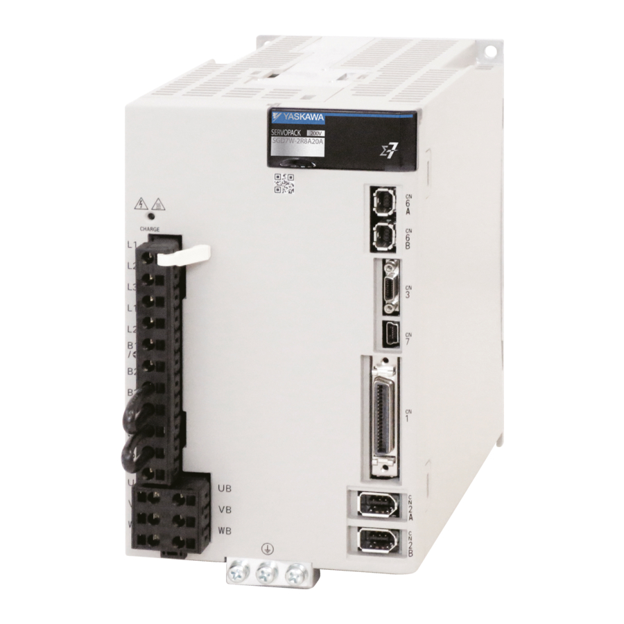
SERVOPACKs
- Single & dual axis amplifier
- One amplifier for linear & rotary motors
- SIL 3 for STO, PL-e CAT 3
- Speed frequency response: 3.1 kHz
- Advanced safety functions SS1, SS2, SLS
- Feedback options
- Ripple compensation, vibration suppression, etc.
Servomotors
- 24-bit high-resolution encoder installed
- High efficiency, low heat generation
- Three motor models available
- Low inertia SMG7A up to 7 kW
- Medium inertia SGM7J up to 1.5 kW
- Medium inertia SGM7G up to 15 kW
Bundles and individual components
We can offer our customers bundles as well as individual components for many applications in the automation industry.
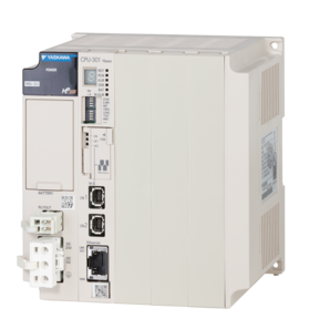
High performance machine controller for automation technology. Our machine controllers manage complex systems with servo and AC drives. Highspeed communication provides high-performance and high-accuracy motion control, even for complex movements.
- Up to 62 axes
- Communication: Modbus TCP/IP, MECHATROLINK-III, Ethernet (100 Mbit/s)
- PLCopen function blocks
- Reusable code library
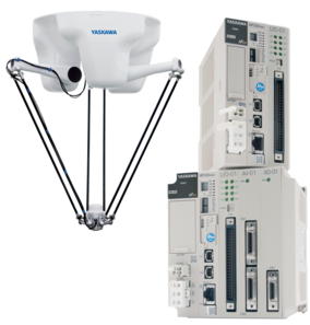
The 4-axis high-speed robot MOTOMAN MPP3 with parallel kinematic system combines the speed of the delta design with a high payload capacity and a large working range.
The MOTOMAN MPK is a high-speed, 5-axis picking robot that provides superior performance and reliability for food handling, picking, packing and other high-speed material handling applications.
- Minimal footprint
- Fast acceleration and high speed increase productivity
- Optional vision and conveyor tracking for maximum flexibility
- Manage every system component with one software package, running on one motion controller.
- Migrate a motion axis from servos to robots and back again, without changing the application code.
- Do it all with the same IEC 61131-3 programming format that your team is already skilled and comfortable with utilizing.
VIPA professional touch panels with display sizes from 4.3“ to 12.1“, operating system Windows Embedded CE 6.0 and Runtime Movicon 11 can be used universally.
VIPA eco panels in 4 different display sizes from 4.3“ to 15“ are designed for maximum reliability and flexibility, as well as longevity and quality.

Safety in Motion
Yaskawa offers a new generation of safety modules, which are geared to your requirements. They follow with SIL3/PLe and FSoE (FailSafe over EtherCAT) the latest standards of the industry.
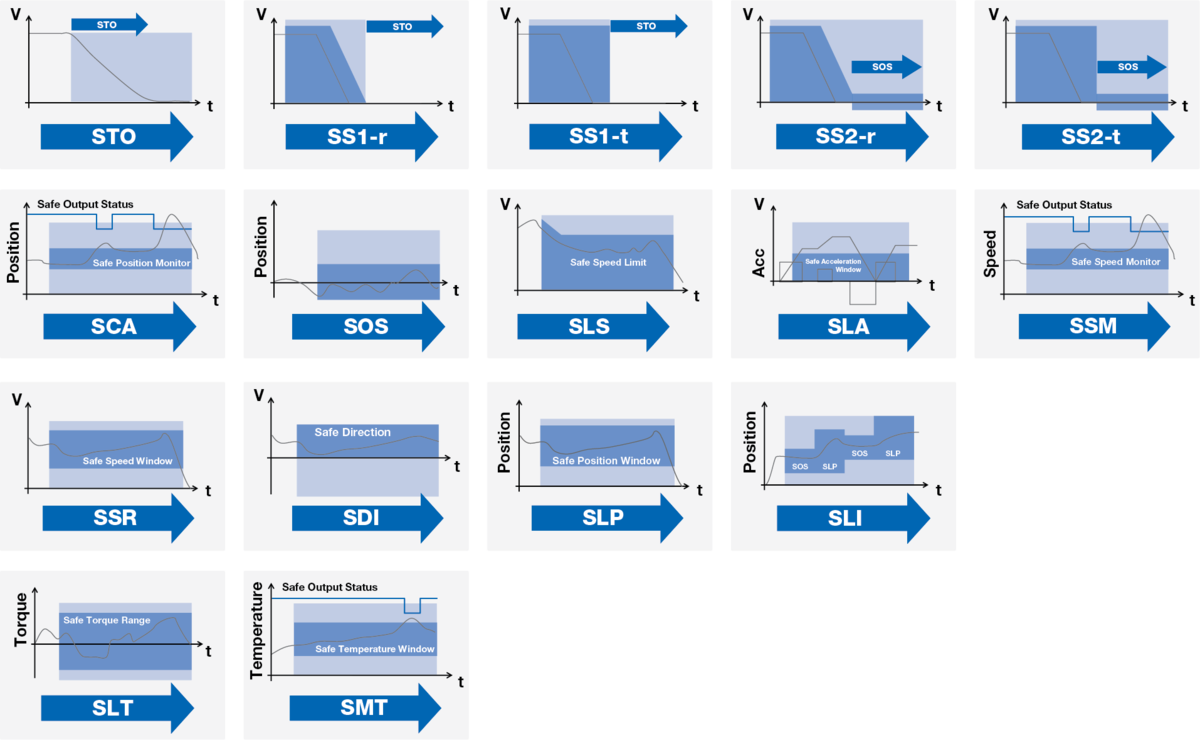
Advanced Safety Module
When it comes to safety, compromises are not an option. That‘s why Yaskawa Sigma-7 servo drives easily integrate into FSoE safety concepts. From the 14 available safety functions, 10 of them can work in parallel. This allows secure and easy control even for the most complex solutions. Sigma-7 safety cards enable high performance safe motion for your application.
- 14 freely configurable safety functions up to SIL3/PLe
- Up to 10 safety functions can be active in parallel
- Full safety function access over FSoE
- Quick and easy parametrization with certified Yaskawa configuration tool
- Internal parameter and plausibility check ensuring high integrity safety solutions
Advanced Safety Module with attached I/O terminal block
The safety module with attached I/O terminal block provides even more planning freedom and flexibility. The terminal block adds 6 safe digital I/O and 2 safe analog input channels to the card. Additionally, it enables the functions Safe Motor Temperature and Safely Limited Torque and offers a total of 16 safety functions.
- 16 safety functions: STO, SS1-r, SS1-t, SS2-r, SS2-t, SOS, SLS, SSM, SDI, SLP, SSR, SLI, SCA, SLA, SLT, SMT
- Up to 10 safety functions can be active in parallel
- Full safety function access over FSoE
- Quick and easy parametrization with certified Yaskawa configuration tool
- Internal parameter and plausibility check ensuring high integrity safety solutions
- 6 safe digital I/O cannels and 2 SIL2/PLd capable analog I/Os onboard
- PT1000 input for Safe Motor Temperature function
- Analog torque sensor input for Safely Limited Torque
- Activation of safety features without Safety PLC
Downloads
Already know what you need?
If you already know what you need and just want to make sure we offer the perfect Sigma-7 package, go ahead to the configurator. You will also find the technical data and any downloads you might need — be it CAD files for designing your machine, manuals, CAE files, brochures or software.
Curious? Questions?
Fill out and send the form. Then we will contact you as soon as possible and provide you with the information you want and need. Looking forward to your inquiry.
5.2 List of Alarms
Alarm
Number
A.100
A.101
A.300
A.320
A.330
A.400
A.410
A.510
A.511
A.520
A.521
A.550
A.710
A.720
A.730
A.731
A.740
A.7A1
A.7A2
A.7A3
A.7Ab
A.810
A.820
A.830
A.840
A.850
A.860
A.861
5-4
Alarm Name
Overcurrent Detected
Motor Overcurrent
Detected
Regeneration Error
Regenerative Overload
Main Circuit Power Supply
Wiring Error
Overvoltage
Undervoltage
Overspeed
Encoder Output Pulse
Overspeed
Vibration Alarm
Autotuning Alarm
Maximum Speed Setting
Error
Instantaneous Overload
Continuous Overload
Dynamic Brake Overload
Inrush Current Limiting
Resistor Overload
Internal Temperature Error
1 (Control Board Tempera-
ture Error)
Internal Temperature Error
2 (Power Board Tempera-
ture Error)
Internal Temperature Sen-
sor Error
SERVOPACK Built-in Fan
Stopped
Encoder Backup Alarm
Encoder Checksum Alarm
Encoder Battery Alarm
Encoder Data Alarm
Encoder Overspeed
Encoder Overheated
Motor Overheated
Alarm Meaning
An overcurrent flowed through the power trans-
former or the heat sink overheated.
The current to the motor exceeded the allowable
current.
There is an error related to regeneration.
A regenerative overload occurred.
• The AC power supply input setting or DC power
supply input setting is not correct.
• The power supply wiring is not correct.
The main circuit DC voltage is too high.
The main circuit DC voltage is too low.
The motor exceeded the maximum speed.
The pulse output speed for the setting of Pn212
(Encoder Output Pulses) was exceeded.
Abnormal oscillation was detected in the motor
speed.
Vibration was detected during autotuning for the
tuning-less function.
The setting of Pn385 (Maximum Motor Speed) is
greater than the maximum motor speed.
The Servomotor was operating for several sec-
onds to several tens of seconds under a torque
that largely exceeded the rating.
The Servomotor was operating continuously
under a torque that exceeded the rating.
When the dynamic brake was applied, the rota-
tional or linear kinetic energy exceeded the
capacity of the dynamic brake resistor.
The main circuit power supply was frequently
turned ON and OFF.
The surrounding temperature of the control PCB
is abnormal.
The surrounding temperature of the power PCB
is abnormal.
An error occurred in the temperature sensor cir-
cuit.
The fan inside the SERVOPACK stopped.
The power supplies to the encoder all failed and
the position data was lost.
There is an error in the checksum results for
encoder memory.
The battery voltage was lower than the specified
level after the control power supply was turned
ON.
There is an internal data error in the encoder.
The encoder was operating at high speed when
the power was turned ON.
The internal temperature of encoder is too high.
The internal temperature of motor is too high.
Continued from previous page.
Servo-
Alarm
motor
Reset
Stop-
Possi-
ping
ble?
Method
Gr.1
No
Gr.1
No
Gr.1
Yes
Gr.2
Yes
Gr.1
Yes
Gr.1
Yes
Gr.2
Yes
Gr.1
Yes
Gr.1
Yes
Gr.1
Yes
Gr.1
Yes
Gr.1
Yes
Gr.2
Yes
Gr.1
Yes
Gr.1
Yes
Gr.1
Yes
Gr.2
Yes
Gr.2
Yes
Gr.2
No
Gr.1
Yes
Gr.1
No
Gr.1
No
Gr.1
Yes
Gr.1
No
Gr.1
No
Gr.1
No
Gr.1
No
Continued on next page.
Sigma 7 — компактные, функциональные сервоприводы с широкой полосой пропускания контура скорости. При разработке Sigma 7, Yaskawa сфокусировалась на трех пунктах: быстрый ввод в эксплуатацию, высокая производительность и максимальная эксплуатационная надежность.
Основные особенности SIGMA 7:
• Возможность быстрой настройки без комплексного параметрирования
• Компактные размеры («книжный формат» и возможность монтажа сервоусилителей вплотную друг к другу)
• Энергосбережение (снижено тепловыделение, возможность организации общей шины постоянного тока)
• Полоса пропускания контура скорости 3.1 kHz
• Перегрузка 350% до 5 сек.
• Встроенные функции безопасности STO (удовлетворяет требованиям SIL 3 и PL-e)
• Высокая точность, новое поколение энкодеров 24 бит
• Одно- и двух-осевое исполнение сервоусилителей
• Один сервоусилитель для стандартных и линейных сервомоторов
Управление сервосистемой SIGMA 7:
• Аналоговое/импульсное
• MECHATROLINK-II
• MECHATROLINK-III
• EtherCAT
Напряжение питания, мощность сервопривода SIGMA 7:
• 1~ 200 В, 0.05 – 1,5 кВт
• 3~ 400 В, 0.2 – 15 кВт
Температура окружающей среды сервопривода SIGMA 7:
• Работа -5/+55 °С
• Хранение -20/+85 °С
Дополнительные опции для сервопривода SIGMA 7:
• Дополнительный модуль безопасности
• Модуль связи DeviceNet
• Модуль Indexer
• Опциональные модули обратной связи
• Соединительные кабели
• ЭМС фильтры
В зависимости от напряжения питания и мощности существуют следующие модели сервопривода SIGMA 7:
Питание 1×200 VAC:
SGD7S-R70A — 0,05 кВт
SGD7S-R90A — 0,1 кВт
SGD7S-1R6A — 0,2 кВт
SGD7S-2R8A — 0,4 кВт
SGD7S-5R5A — 0,75 кВт
SGD7S-7R6A — 1,0 кВт
SGD7S-120A — 1,5 кВт
SGD7S-180A — 2,0 кВт
SGD7S-200A — 3,0 кВт
SGD7S-330A — 5,0 кВт
SGD7S-470A — 6,0 кВт
SGD7S-550A — 7,5 кВт
SGD7S-590A — 11 кВт
SGD7S-780A — 15 кВт
SGD7W-1R6A — 2 × 0.2 кВт
SGD7W-2R8A — 2 × 0.4 кВт
SGD7W-5R5A — 2 × 0.75 кВт
SGD7W-7R6A — 2 × 1.0 кВт
Питание 3×400 VAC:
SGD7S — 1R9 — 0,5 кВт
SGD7S — 3R5 — 1,0 кВт
SGD7S — 5R4 — 1,5 кВт
SGD7S — 8R4 — 2,0 кВт
SGD7S — 120 — 3,0 кВт
SGD7S — 170 — 5,0 кВт
SGD7S — 210 — 6,0 кВт
SGD7S — 260 — 7,5 кВт
SGD7S — 280 — 11 кВт
SGD7S — 370 — 15 кВт
SGD7W — 2R6 — 2 × 0.75 кВт
SGD7W — 5R4 — 2 × 1.5 кВт